2018 Infiniti QX30 | Owner's Manual And Maintenance Information USA
User Manual: 2018-qx30
Open the PDF directly: View PDF ![]() .
.
Page Count: 538 [warning: Documents this large are best viewed by clicking the View PDF Link!]

2018 OWNER’S MANUAL
AND MAINTENANCE INFORMATION
For your safety, read carefully and keep in this vehicle.

Your INFINITI represents a new way of thinking about vehicle design. It integrates advanced engineering and superior craftsmanship with a
simple, refined aesthetic sensitivity associated with traditional Japanese culture.
The result is a different notion of luxury and beauty. The car itself is important, but so is the sense of harmony that the vehicle evokes in its driver,
and the sense of satisfaction you feel with the INFINITI — from the way it looks and drives to the high level of retailer service.
To ensure that you enjoy your INFINITI to the fullest, we encourage you to read this Owner's Manual immediately. It explains all of the features,
controls and performance characteristics of your INFINITI; it also provides important instructions and safety information.
A separate Warranty Information Booklet is included in your Owner's literature portfolio. Always carry it with you when you take your vehicle
to an INFINITI retailer. The Warranty Information Booklet contents provide complete information about all warranties covering this vehicle, the
requirements to keep the warranties in effect as well as the INFINITI Roadside Assistance Program.
Additionally, a separate Customer Care and Lemon Law Information Booklet will explain how to resolve any concerns you may have with your
vehicle, as well as clarify your rights under your state’s lemon law.
In addition to factory-installed options, your vehicle may also be equipped with additional accessories prior to delivery. It is recommended that
you visit an INFINITI retailer for this service. It is important that you familiarize yourself with all disclosures, warnings, cautions and instructions
concerning proper use of such accessories prior to operating the vehicle and/or accessory. It is recommended that you visit an INFINITI retailer
for details concerning the particular accessories with which your vehicle is equipped.
READ FIRST — THEN DRIVE
SAFELY
Before driving your vehicle, read this Owner's
Manual carefully. This will ensure familiarity
with controls and maintenance requirements,
assisting you in the safe operation of your
vehicle.
WARNING
Important safety information reminders!
Follow these important driving rules to
help ensure a safe and complete trip for you
and your passengers!
•NEVER drive under the influence of al-
cohol or drugs.
•ALWAYS observe posted speed limits
and never drive too fast for conditions.
•ALWAYS use your seat belts and appro-
priate child restraint systems. Preteen
children should be seated in the rear
seat.
•ALWAYS give your full attention to
driving and avoid using vehicle features
or taking other actions that could dis-
tract you.
•ALWAYS provide information about
the proper use of vehicle safety features
to all occupants of the vehicle.
FOREWORD

•ALWAYS review this Owner's Manual
for important safety information.
As with other vehicles with features for
off-road use, failure to operate all-wheel
drive models correctly may result in loss of
control or an accident. Be sure to read
“Driving safety precautions” in the “Start-
ing and driving” section of this manual.
ON-PAVEMENT AND OFF-ROAD
DRIVING
This vehicle will handle and maneuver differ-
ently from an ordinary passenger car be-
cause it has a higher center of gravity for
off-road use. As with other vehicles with
features of this type, failure to operate this
vehicle correctly may result in loss of control
or an accident.
For additional information, refer to “On-
pavement and off-road driving precau-
tions”, “Avoiding collision and rollover” and
“Driving safety precautions” in the “Starting
and driving” section of this manual.
MODIFICATION OF YOUR
VEHICLE
This vehicle should not be modified. Modifi-
cation could affect its performance, safety
or durability and may even violate govern-
mental regulations. In addition, damage or
performance problems resulting from modi-
fications may not be covered under INFINITI
warranties.
WARNING
Installing an aftermarket On-Board Diag-
nostic (OBD) plug-in device that uses the
port during normal driving, for example re-
mote insurance company monitoring, re-
mote vehicle diagnostics, telematics or en-
gine reprogramming, may cause
interference or damage to vehicle systems.
We do not recommend or endorse the use
of any aftermarket OBD plug-in devices,
unless specifically approved by INFINITI.
The vehicle warranty may not cover dam-
age caused by any aftermarket plug-in
device.
WHEN READING THE MANUAL
This manual includes information for all fea-
tures and equipment available on this model.
Features and equipment in your vehicle may
vary depending on model, trim level, options
selected, order, date of production, region or
availability. Therefore, you may find informa-
tion about features or equipment that are not
included or installed on your vehicle.
All information, specifications and illustra-
tions in this manual are those in effect at the
time of printing. INFINITI reserves the right
to change performance, design or compo-
nent suppliers without notice and without
obligation.
From time to time, INFINITI may update or
revise this manual to provide Owners with
the most accurate information currently
available. Please carefully read and retain
with this manual all revision updates sent to
you by INFINITI to ensure you have access to
accurate and up-to-date information regard-
ing your vehicle. Current versions of vehicle
Owner’s Manuals and any updates can also
be found in the Owner section of the
INFINITI website at https://
owners.infinitiusa.com/owners/navigation/
manualsandGuides. If you have questions
concerning any information in your Owner’s
Manual, contact INFINITI Consumer Affairs.
See the INFINITI CUSTOMER CARE PRO-
GRAM page in this Owner’s Manual for con-
tact information.
IMPORTANT INFORMATION
ABOUT THIS MANUAL
You will see various symbols in this manual.
They are used in the following ways:
WARNING
This is used to indicate the presence of a
hazard that could cause death or serious
personal injury. To avoid or reduce the risk,
the procedures must be followed precisely.
CAUTION
This is used to indicate the presence of a
hazard that could cause minor or moderate
personal injury or damage to your vehicle.
To avoid or reduce the risk, the procedures
must be followed carefully.
NOTE
Indicates additional helpful information.
If you see this symbol, it means “Do not do
this” or “Do not let this happen”.
If you see a symbol similar to these in an
illustration, it means the arrow points to the
front of the vehicle.
Arrows in an illustration that are similar to
these indicate movement or action.
Arrows in an illustration that are similar to
these call attention to an item in the illustra-
tion.
[]:
Square brackets are used to indicate mes-
sages, keys, or items displayed on a screen.
<>:
Chevrons or angle brackets are used to indi-
cate texts on controls like buttons or
switches inside or on the vehicle.
CALIFORNIA PROPOSITION 65
WARNING
WARNING
Engine Exhaust, some of its constituents,
and certain vehicle components contain or
emit chemicals known to the State of
California to cause cancer and birth de-
fects or other reproductive harm. In addi-
tion, certain fluids contained in vehicles
and certain products of component wear
contain or emit chemicals known to the
State of California to cause cancer and
birth defects or other reproductive harm.
Operating, servicing and maintaining a
passenger vehicle or off-road vehicle can
expose you to chemicals including engine
exhaust, carbon monoxide, phthalates,
and lead, which are known to the State of
California to cause cancer and birth de-
fects or other reproductive harm. To mini-
mize exposure, avoid breathing exhaust,
do not idle the engine except as necessary,
service your vehicle in a well-ventilated
area and wear gloves or wash your hands
frequently when servicing your vehicle. For
more information go to
www.P65Warnings.ca.gov.

CALIFORNIA PERCHLORATE
ADVISORY
Some vehicle parts, such as lithium batteries,
may contain perchlorate material. The fol-
lowing advisory is provided: “Perchlorate
Material - special handling may apply, See
www.dtsc.ca.gov/hazardouswaste/
perchlorate.”
The Bluetooth® word mark
and logos are registered
trademarks owned by
Bluetooth SIG, Inc. and any
use of such marks by DENSO
CORPORATION is under li-
cense. Other trademarks and
trade names are those of their
respective owners.
SiriusXM® services require a
subscription after trial period
and are sold separately or as
a package. The satellite ser-
vice is available only in the 48
contiguous USA and DC.
SiriusXM® satellite service is
also available in Canada: see
www.siriusxm.ca
Required SiriusXM Satellite
Radio and SiriusXM Travel
Link monthly subscriptions
are sold separately. Sirius XM
Travel Link is only available in
select markets. For more in-
formation, see
www.siriusxm.com/travellink
“Made for iPod®” and “Made
for iPhone®” mean that an
electronic accessory has been
designed to connect specifi-
cally to iPod® or iPhone®,
respectively, and has been
certified by the developer to
meet Apple performance
standards. Apple is not re-
sponsible for the operation of
this device or its compliance
with safety and regulatory
standards. Please note that
the use of this accessory with
iPod® or iPhone® may affect
wireless performance.
Apple, the Apple logo,
iPhone®, iPod®, iPod clas-
sic®, iPod nano®, and iPod
touch ® are trademarks of
Apple Inc., registered in the
U.S. and other countries.
Lightning is a trademark of
Apple Inc. App Store is a ser-
vice mark of Apple Inc.

Music recognition technology
and related data are provided
by Gracenote®. Gracenote is
the industry standard in music
recognition technology and
related content delivery. For
more information, visit
www.gracenote.com.
CD and music-related data
from Gracenote, Inc., copy-
right 䊊
c2000 to present
Gracenote. Gracenote Soft-
ware, copyright 䊊
c2000 to
present Gracenote. One or
more patents owned by
Gracenote apply to this prod-
uct and service. See the
Gracenote website for a non-
exhaustive list of applicable
Gracenote patents.
Gracenote, CDDB, MusicID,
MediaVOCS, the Gracenote
logo and logotype, and the
“Powered by Gracenote” logo
are either registered trade-
marks or trademarks of
Gracenote in the United
States and/or other countries.
© 2017 NISSAN MOTOR CO., LTD.
All rights reserved. No part of this Owner’s
Manual may be reproduced or stored in a
retrieval system, or transmitted in any form,
or by any means, electronic, mechanical, pho-
tocopying, recording or otherwise, without
the prior written permission of Nissan Motor
Co., Ltd.

INFINITI CUSTOMER CARE
PROGRAM
INFINITI CARES ...
Both INFINITI and your INFINITI retailer are dedicated to serving all your automotive needs. Your satisfaction with your vehicle and your
INFINITI retailer are our primary concerns. Your INFINITI retailer is always available to assist you with all your automobile sales and service
needs.
However, if there is something that your
INFINITI retailer cannot assist you with or
you would like to provide INFINITI directly
with comments or questions, please contact
our (INFINITI’s) Consumer Affairs Depart-
ment using our toll-free number:
For U.S. customers
1-800-662-6200
For Canadian customers
1-800-361-4792
The Consumer Affairs Department will ask
for the following information:
•Your name, address, and telephone num-
ber
•Vehicle identification number (on dash
panel)
•Date of purchase
•Current odometer reading
•Your INFINITI retailer’s name
•Your comments or questions
OR
You can write to INFINITI with the informa-
tion on the left at:
For U.S. customers
INFINITI Division Nissan North America, Inc.
Consumer Affairs Department
P.O. Box 685003
Franklin, TN 37068-5003
or via e-mail at:
nnaconsumeraffairs@nissan-usa. com
For Canadian customers
INFINITI Division
Nissan Canada Inc.
5290 Orbitor Drive
Mississauga, Ontario L4W 4Z5
or via e-mail at:
information.center@nissancanada. com
If you prefer, visit us at:
www.infinitiUSA.com (for U.S. customers) or
www.infiniti.ca (for Canadian customers)
We appreciate your interest in INFINITI and
thank you for buying a quality INFINITI
vehicle.

Table of contents
Illustrated table of contents
Safety — seats, seat belts and supplemental restraint system
Instruments and controls
Pre-driving checks and adjustments
Display screen, heater and air conditioner, and audio system
Starting and driving
In case of emergency
Appearance and care
Do-it-yourself
Maintenance and Schedules
Technical information
Index
0
1
2
3
4
5
6
7
8
9
10
11


0 Illustrated table of contents
Seats, Seat belts and Supplemental Restraint
System (SRS) ........................0-2
Exterior front ........................0-3
Exterior rear .........................0-4
Passenger compartment .................0-5
Cockpit ............................0-6
Instrument panel ......................0-7
Meters and gauges.....................0-8
Engine compartment ...................0-9
2.0L Gasoline engine .................0-9
Warning and indicator lights ..............0-10
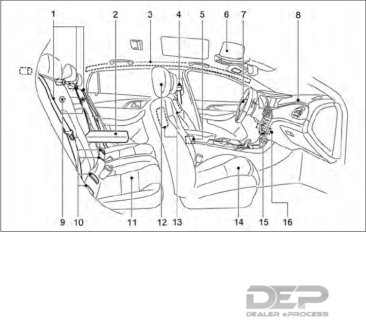
1. Rear seat belts (Page. 1-7)
3. Roof-mounted curtain side impact and
rollover supplemental air bags (P. 1-38)
4. Front seat belts (P.1-10)
5. Seat belt pretensioners (P.1-54)
6. Air bag warning label (P.1-55)
7. Driver Supplemental front-impact air bag
(P. 1-38)
8. Passenger supplemental front-impact air
bag (P.1-38)
9. Top tether strap anchors (P.1-23)
10. LATCH (Lower Anchors and Tethers for
CHildren)/ ISOFIX child restraint system
(P. 1-21)
11. Rear seats (P.1-5)
— Child restraints (P.1-19)
12. Head restraints/headrests (P.1-7)
13. Front seat-mounted side impact supple-
mental air bags (P.1-38)
14. Front seats (P.1-3)
— Occupant Classification System (OCS)
(P. 1-46)
15. Front passenger air bag status light
(P.1-46)
16. Driver and passenger supplemental knee
air bags (P.1-38)
*: if equipped
NIC2847
SEATS, SEAT BELTS AND
SUPPLEMENTAL RESTRAINT
SYSTEM (SRS)
0-2 Illustrated table of contents
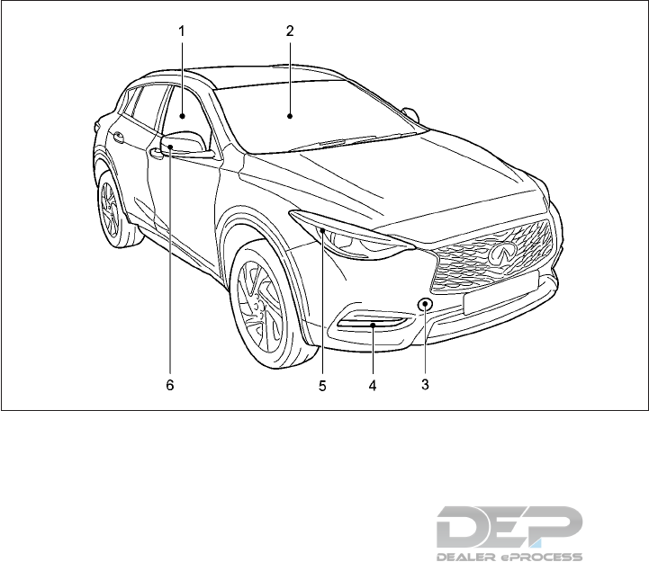
1. Power windows (P.2-73)
2. Windshield wipers and washers
— Switch operation (P.2-60)
— Blade replacement (P.8-13)
— Window washer fluid (P.8-8)
— Windshield de-icer* (P.2-63)
3. Recovery hook (P.6-14)
4. Front fog lights (P.2-70)
5. Headlights
— Switch operation (P.8-23)
6. Turn signal lights (P.2-66, 8-22)
— Side turn signal light (P.8-22)
Mirrors
— Adjustment (P.3-19)
*: if equipped
NIC2837
EXTERIOR FRONT
Illustrated table of contents 0-3
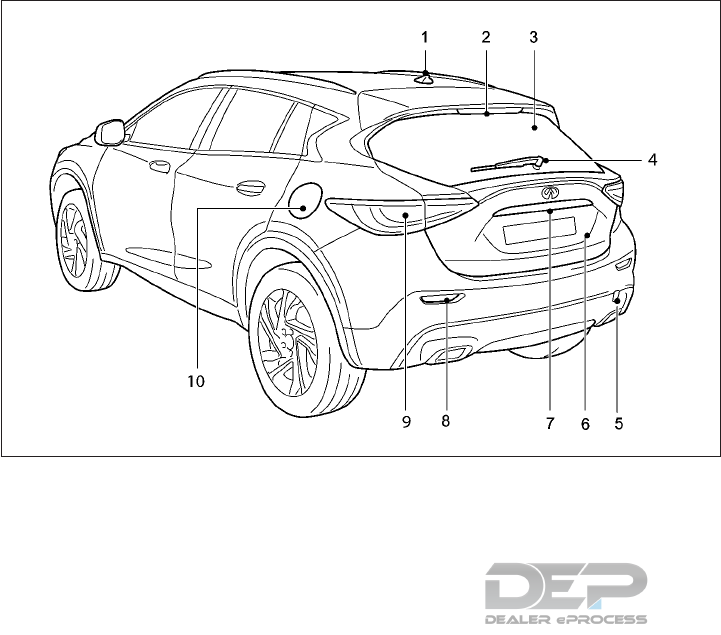
1. Antenna (P.4-53)
2. High-mounted stop light (Bulb replace-
ment) (P.8-22)
3. Rear window defroster (P.2-63)
4. Rear window wiper and washer
— Operation (P.2-62)
— Wiper blade replacement (P.2-13)
5. Recovery hook (P.6-15)
6. Lift gate (P.3-7)
— Intelligent Key system (P.6-4)
7. Rear view camera* (P.4-17)
8. Rear reflector
9. Rear combination lights (P.8-24)
10. Fuel-filler door
— Operation (P.3-16)
— Fuel information (P.8-2)
*: if equipped
NIC2836
EXTERIOR REAR
0-4 Illustrated table of contents

1. Rear armrest* (P.1-7)
2. Rear personal lights (P.2-87)
3. Overhead control panel (P.2-76)
4. Sunshade switch* (P.2-76)
5. Sun visor (P.2-18)
6. Security system buttons (P.3-59)
7. Interior rear-view mirror (P.3-18)
8. Door handle (P.3-6)
9. Door armrest
— Power windows controls (P.2-73)
— Exterior rear view mirror remote control
switch (P.2-18)
10. Front cup holders (P.2-80)
11. Air conditioner controls (P.4-43)
12. Glove box/storage (P.2-79)
*: if equipped
NIC2701
PASSENGER COMPARTMENT
Illustrated table of contents 0-5
1. Turn signal, wiper, washer, and high beam
switch (P.2-66, 2-60)
2. Steering-wheel-mounted controls (left
side) (P.2-15)
3. Ignition switch (P.5-15)
— Push button ignition switch* (P.5-16)
4. Steering-wheel-mounted controls (right
side) (P.4-3)
5. Light switch
— Headlight (P.2-64)
— Fog light (P.2-70)
6. Parking brake (P.3-27)
7. Cruise Control switch
— Cruise Control (P.5-46)
— Intelligent Cruise Control (P.2-49)
8. USB connection ports (P.4-4)
9. Shift lever (P.5-21)
10. Front cup holders (P.2-80)
11. INFINITI controller (P.4-2)
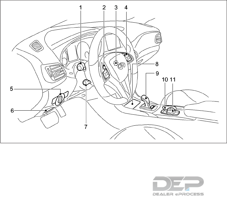
NIC2649
COCKPIT
0-6 Illustrated table of contents

1. Ventilators (P.4-42)
2. Center display* (P.4-4)
3. Meters and gauges (P.2-4)
4. Light switch (P.2-64)
5. Parking brake (P.3-27)
6. Steering wheel
— Power steering system (P.5-90)
— Horn (P. 2-71)
— Driver’s supplemental front-impact air
bag (P.1-38)
7. Audio system (P.4-53)
8. Ignition switch (P.5-15)
— Push button ignition switch* (P.5-16)
9. Heater and air conditioner (P.4-43)
10. Switch panel
— Seat heater switches* (P.2-72)
— Hazard indicator flasher switch (P.6-2)
— Idle Stop/Start system on/off switch
(P. 6-30)
— Front passenger air bag status light
(P.6-46)
11. Vehicle Information Display (P.2-15)
12. Glove box (P.2-79)
13. Front passenger supplemental air bag
(P.1-38)
*: if equipped
NIC2898
INSTRUMENT PANEL
Illustrated table of contents 0-7
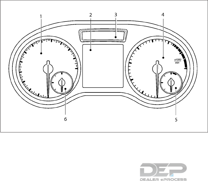
1. Speedometer (P.2-4)
2. Vehicle information display (P.2-15)
— Odometer/twin trip odometer (P.2-15)
3. Upper information display (P.2-15)
4. Tachometer (P.2-6)
5. Engine coolant temperature gauge
(P.2-6)
6. Fuel gauge (P.2-7)
NIC2651
METERS AND GAUGES
0-8 Illustrated table of contents
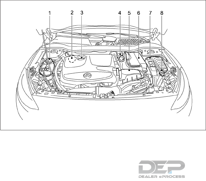
2.0L GASOLINE ENGINE
1. Engine coolant reservoir (P.8-3)
2. Engine oil dipstick (P.8-5)
3. Engine oil filler cap (P.8-5)
4. Brake fluid reservoir (P.8-7)
5. Engine air cleaner filter (P.8-13)
6. Battery (P.8-9)
7. Fuse box (P.8-17)
8. Window washer fluid reservoir (P.8-8)
NIC2833
ENGINE COMPARTMENT
Illustrated table of contents 0-9
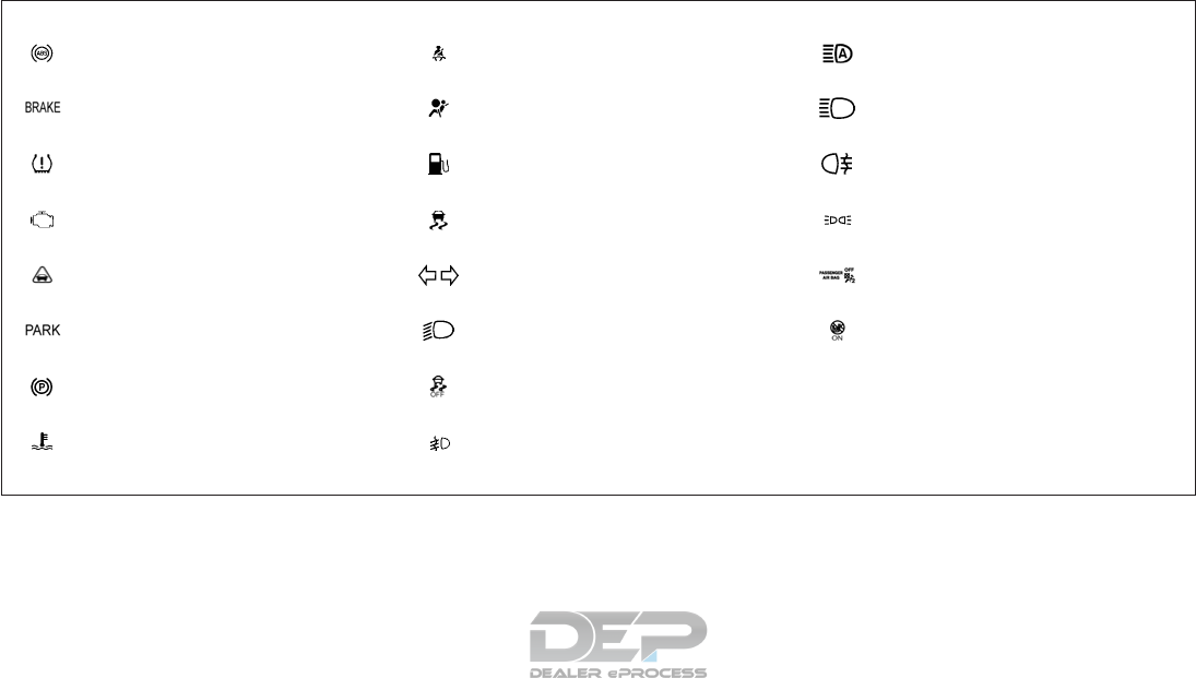
Light Name Page Light Name Page Light Name Page
Anti-lock Braking System
(ABS) warning light
2-8 Seat belt (driver and front pas-
senger) warning light
2-11 High beam assist indicator
light *
2-14
Brake warning light (red) 2-11 Supplemental Restraint Sys-
tem (SRS) air bag warning light
2-12 High beam indicator light 2-14
Low tire pressure warning
light*
2-9 Low fuel warning light 2-13 Rear fog light indicator light 2-14
Malfunction indicator light
(yellow)
2-10 Vehicle Dynamic Control
(VDC) warning light
2-13 Side light indicator light 2-14
Distance warning light* 2-11 Turn signal/hazard indicator
lights
2-13 Front passenger air bag status
light**
2-14
Electric parking brake warning
light (red)
2-11 Low beam indicator light 2-14
Electric parking brake warning
light (yellow)
2-11 Vehicle Dynamic Control
(VDC) OFF indicator light
2-13
Coolant warning light 2-13 Front fog light indicator light* 2-14 *: if equipped
**: located above heater and air condi-
tioner controls
WARNING AND INDICATOR LIGHTS
0-10 Illustrated table of contents

1 Safety — seats, seat belts and
supplemental restraint system
Seats ..............................1-2
Front seats ........................1-3
Rear seats.........................1-5
Armrest (if equipped) ..................1-7
Head restraints/Headrests ................1-7
Adjustable head restraint components.......1-8
Remove ..........................1-8
Install............................1-9
Adjust ...........................1-9
Seat belts ..........................1-10
Precautions on seat belt usage ..........1-10
Pregnant women ...................1-12
Injured persons.....................1-13
Seat belt warning light ................1-13
Three-point type seat belt with retractor . . . .1-13
Seat belt extenders ..................1-16
Seat belt maintenance ................1-16
Child safety .........................1-17
Infants ..........................1-18
Small children......................1-18
Larger children .....................1-18
Child restraints .......................1-19
Precautions on child restraints ...........1-20
Rear-facing child restraint installation using
LATCH .........................1-24
Rear-facing child restraint installation using
the seat belts ......................1-25
Forward-facing child restraint installation
using LATCH ......................1-27
Forward-facing child restraint installation
using the seat belts ..................1-30
Booster seats .....................1-35
Supplemental Restraint System (SRS) ........1-38
Precautions on Supplemental Restraint
System (SRS) ......................1-38
Supplemental air bag systems ...........1-44
Supplemental air bag warning labels .......1-55
Supplemental air bag warning light ........1-55
Repair and replacement procedure ........1-56
WARNING
•The seatback should not be reclined any
more than needed for comfort. Seat
belts are most effective when the pas-
senger sits well back and straight up in
the seat. If the seatback is reclined, the
risk of sliding under the lap belt and be-
ing injured is increased.
•For the most effective protection when
the vehicle is in motion, the seat should
be upright. Always sit well back and up-
right in the seat with both feet on the
floor and adjust the seat properly. (See
"Seat belts" later in this section.)
•After adjustment, gently rock in the seat
to make sure it is securely locked.
•To help avoid risk of injury or death
through unintended operation of the
vehicle and/or its systems, do not leave
children, people who require the assis-
tance of others, or pets unattended in
your vehicle. Additionally, the tempera-
ture inside a closed vehicle on a warm
day can quickly become high enough to
cause a significant risk of injury or death
to people and pets.
•Do not leave children unattended inside
the vehicle. They could unknowingly ac-
tivate switches or controls or move the
vehicle. Unattended children could be-
come involved in serious accidents.
•Do not adjust the driver’s seat while
driving so full attention may be given to
vehicle operation. The seat may move
suddenly and could cause loss of control
of the vehicle.
CAUTION
•When moving the seats forward or
backward, or returning a reclined seat-
back to its upright position, make sure
you hold onto the seatback while oper-
ating. If the seatback is not held, the
seat or seatback may move suddenly
and could cause injury.
•When adjusting the seat positions, be
sure not to contact any moving parts to
avoid possible injuries and/or damage.
SSS0133AZ
SEATS
1-2 Safety — seats, seat belts and supplemental restraint system
FRONT SEATS
Manual seat adjustment
Forward and backward:
Pull the lever 䊊
1up and hold it while sliding
the seat forward or backward to the pre-
ferred position. Release the lever to lock the
seat in position.
Seat cushion angle (if equipped):
Adjust the angles so that your thighs are
lightly supported. Turn handwheel 䊊
2for-
wards or backwards.
Seat lifter (if equipped):
Repeatedly pull up or push down the adjust-
ing lever 䊊
3, to adjust the seat height to the
desired position.
Seatback angle:
Relieve the pressure on the seatback and turn
handwheel 䊊
4forwards or backwards.
The reclining feature allows the adjustment
of the seatback for occupants of different
sizes to help obtain the proper seat belt fit.
(See "Seat belts" later in this section.)
The seatback may be reclined to allow occu-
pants to rest when the vehicle is parked.
Lumbar support:
The lumbar support feature provides lower
back support to the driver.
Push each side of the adjusting switch to
adjust the seat lumbar area until the desired
position is achieved.
䊊
1To raise the seatback contour
䊊
2To soften the seatback contour
䊊
3To lower the seatback contour
䊊
4To harden the seatback contour
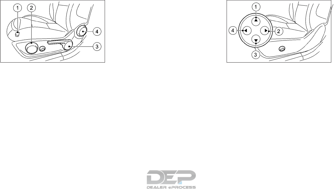
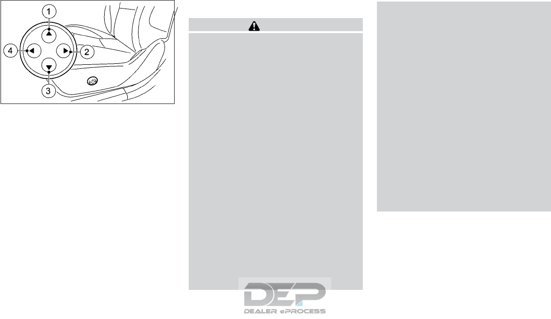
Power seat adjustment
Operating tips:
•The power seat motor has an auto-reset
overload protection circuit. If the motor
stops during the seat adjustment, wait 30
seconds, then reactivate the switch.
NIC2605 NIC2607
Safety — seats, seat belts and supplemental restraint system 1-3
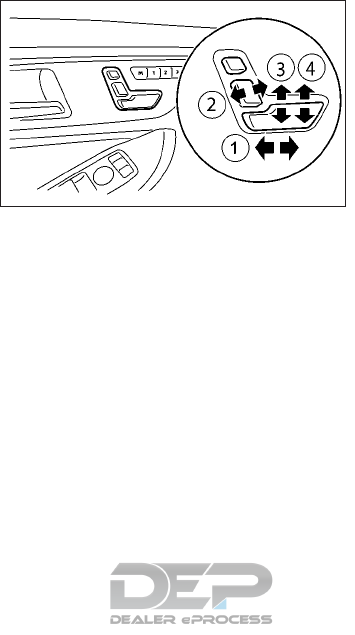
•To avoid discharge of the battery, do not
operate the power seats for a long period
of time when the engine is not running.
NOTE
You can store the seat settings using the
memory function (see " Memory function (if
equipped)" in the "2. Instruments and con-
trols" section).
Forward and backward:
Move the adjusting switch 䊊
1forward or
backward as shown to move the seat to the
desired position.
Reclining:
Move the adjusting switch 䊊
2forward or
backward as shown to move the seatback to
the desired position.
The reclining feature allows the adjustment
of the seatback for occupants of different
sizes to help obtain the proper seat belt fit.
(See "Seat belts" later in this section.)
The seatback may be reclined to allow occu-
pants to rest when the vehicle is parked.
Seat lifter (if equipped):
1. Pull up or push down the adjusting switch
䊊
3as shown to adjust the seat height until
the desired position is achieved.
2. Tilt up or down the adjusting switch 䊊
4as
shown to adjust the front angle of the
seat until the desired position is achieved.
NIC2606
1-4 Safety — seats, seat belts and supplemental restraint system
Lumbar support:
The lumbar support feature provides lower
back support to the driver.
Push each side of the adjusting switch to
adjust the seat lumbar area until the desired
position is achieved.
䊊
1To raise the seatback contour
䊊
2To soften the seatback contour
䊊
3To lower the seatback contour
䊊
4To harden the seatback contour
REAR SEATS
WARNING
•Never allow anyone to ride in the cargo
area or on the rear seat when it is in the
fold-down position. Use of these areas
by passengers without proper restraints
could result in serious injury or death in
an accident or sudden stop.
•Properly secure all cargo with ropes or
straps to help prevent it from sliding or
shifting. Do not place cargo higher than
the seatbacks. In a sudden stop or colli-
sion, unsecured cargo could cause per-
sonal injury.
•Do not allow people to ride in any area of
your vehicle that is not equipped with
seats and seat belts. Be sure everyone in
your vehicle is in a seat and using a seat
belt properly.
•Do not allow more than one person to
use the same seat belt.
•Do not fold down the rear seats when
occupants are in the rear seat area or
any luggage is on the rear seats.
–Make sure that the seat path is clear
before moving the seat.
–Be careful not to allow hands or feet
to get caught or pinched in the seat.
•Head restraints/headrests should be
adjusted properly as they may provide
significant protection against injury in
an accident. Always replace and adjust
them properly if they have been re-
moved for any reason.
•If the head restraints/headrests are re-
moved for any reason, they should be
securely stored to prevent them from
causing injury to passengers or damage
to the vehicle in case of sudden braking
or an accident.
•When returning the seatbacks to the
upright position, be certain they are
completely secured in the latched posi-
tion. If they are not completely secured,
passengers may be injured in an accident
or sudden stop.
NIC2607
Safety — seats, seat belts and supplemental restraint system 1-5
Folding
The luggage compartment loading capacity
can be increased by folding the rear seat-
backs forward.
To fold the seatback:
1. Ensure head restraints are properly
stowed, see "Head restraints/Headrests"
later in this section.
2. Release the seatback lock by pulling the
release handle as shown.
3. Fold the seatback forward as shown.
4. Insert the seat belt into the seat belt
holder as shown.
To return the seatback to an upright posi-
tion:
1. Make sure the seat belts are clear of the
seatback latch mechanism.
2. Lift the seatback up and push firmly to
lock.
3. If the red marker is visible then the seat-
back has not latched properly — release
and then re-latch the seat.
4. If the head restraint/headrest was re-
moved, reinstall and properly adjust the
head restraint/headrest before an occu-
pant uses the seating position. See "Head
restraints/Headrests" later in this section.
WARNING
Always use the seat belt holder, and ensure
that the seat belt is not trapped in the seat-
back latch mechanism. Failure to do so may
cause damage to the seat belt, and this may
increase the risk of serious injury or death
in a collision.
NPA1293 NIC2669
1-6 Safety — seats, seat belts and supplemental restraint system
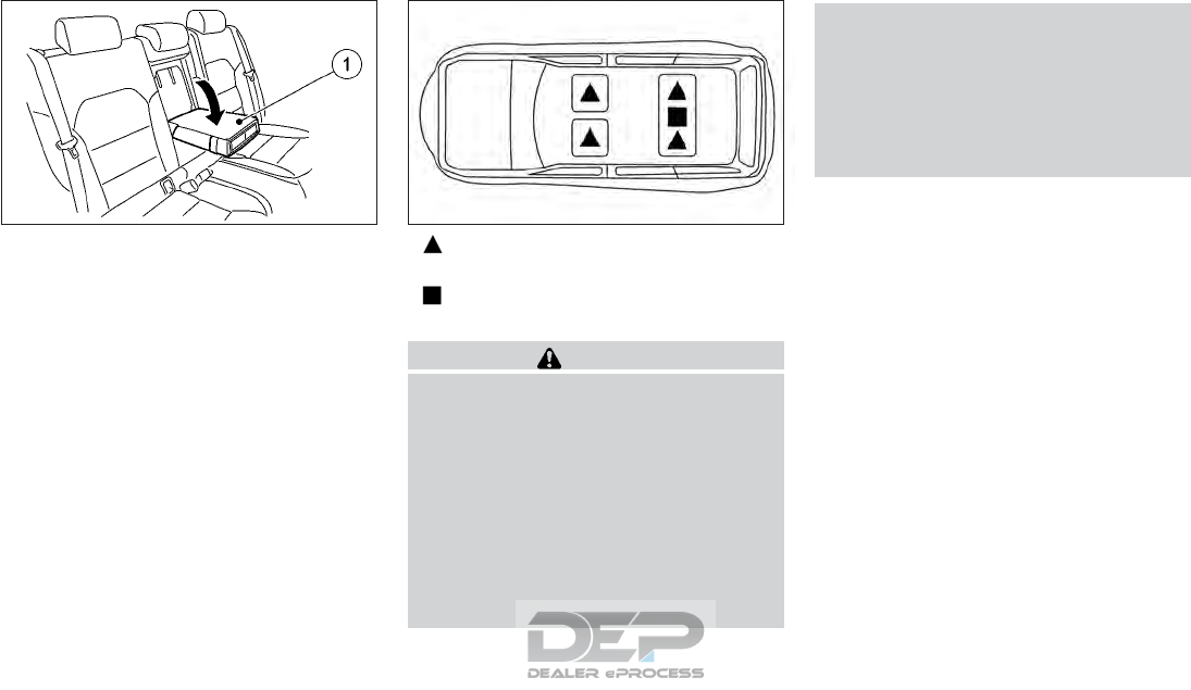
ARMREST (IF EQUIPPED)
Rear
Pull the tab and draw the armrest 䊊
1forward
as shown until it is horizontal.
Indicates that the seating position is
equipped with a head restraint.
Indicates that the seating position is
equipped with a non-removable head rest.
WARNING
Head restraints/headrests supplement the
other vehicle safety systems. They may
provide additional protection against in-
jury in certain rear end collisions. Adjust-
able head restraints/headrests must be
adjusted properly, as specified in this sec-
tion. Check the adjustment after someone
else uses the seat. Do not attach anything
to the head restraint/headrest stalks or
remove the head restraint/headrest. Do
not use the seat if the head restraint/
headrest has been removed. If the head
restraint/headrest was removed, reinstall
and properly adjust the head restraint/
headrest before an occupant uses the seat-
ing position. Failure to follow these in-
structions can reduce the effectiveness of
the head restraints/headrests. This may
increase the risk of serious injury or death
in a collision.
•Your vehicle is equipped with head
restraints/headrests that may be inte-
grated, adjustable or non-adjustable.
•Adjustable head restraints/headrests
have multiple notches along the stalk to
lock them in a desired adjustment position.
•The non-adjustable head restraints/
headrests have a single locking notch to
secure them to the seat frame.
•Proper Adjustment:
– For the adjustable type, align the head
restraint/headrest so the center of your
ear is approximately level with the cen-
ter of the head restraint/headrest.
– If your ear position is still higher than
the recommended alignment, place the
head restraint/headrest at the highest
position.
NIC2611 NPA1500
HEAD RESTRAINTS/HEADRESTS
Safety — seats, seat belts and supplemental restraint system 1-7
•If the head restraint/headrest has been
removed, ensure that it is reinstalled and
locked in place before riding in that desig-
nated seating position.
NOTE
For vehicles with sports seats you cannot
adjust the front head restraints/headrests
or the outer rear head restraints/headrests.
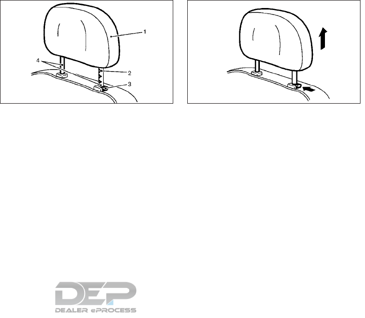
ADJUSTABLE HEAD RESTRAINT
COMPONENTS
1. Removable head restraint/headrest
2. Multiple notches
3. Lock knob
4. Stalks
REMOVE
Use the following procedure to remove the
head restraint/headrest.
1. Pull the head restraint/headrest up to the
highest position.
2. Push and hold the lock knob.
3. Remove the head restraint/headrest from
the seat.
4. Store the head restraint/headrest prop-
erly in a secure place so it is not loose in
the vehicle.
5. Reinstall and properly adjust the head
restraint/headrest before an occupant
uses the seating position.
SSS0992Z SSS1037Z
1-8 Safety — seats, seat belts and supplemental restraint system

INSTALL
1. Align the head restraint/headrest stalks
with the holes in the seat. Make sure that
the head restraint/headrest is facing the
correct direction. The stalk with the ad-
justment notch 䊊
1must be installed in the
hole with the lock knob 䊊
2.
2. Push and hold the lock knob and push the
head restraint/headrest down.
3. Properly adjust the head restraint/
headrest before an occupant uses the
seating position.
ADJUST
For adjustable head restraint/ headrest
Adjust the head restraint/headrest so the
center is level with the center of your ears. If
your ear position is still higher than the rec-
ommended alignment, place the head
restraint/headrest at the highest position.
Raise
To raise the head restraint/headrest, pull it
up.
Make sure the head restraint/headrest is po-
sitioned from the stored position or any non-
latch position so the lock knob is engaged in
the notch before riding in that designated
seating position.
SSS1038Z SSS0997Z SSS1035Z
Safety — seats, seat belts and supplemental restraint system 1-9
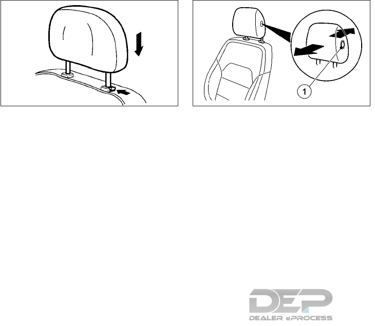
Lower
To lower, push and hold the lock knob 䊊
1and
push the head restraint/headrest down.
Make sure the head restraint/headrest is po-
sitioned so the lock knob is engaged in the
notch before riding in that designated seating
position.
Fore-aft
This function allows you to adjust the dis-
tance between the head restraint/headrest
and the back of the head.
•To move forwards: pull the head restraint/
headrest forwards in the direction of the
arrow until it engages. There are a number
of detents.
•To move backwards: press and hold but-
ton 䊊
1and push the head restraint/
headrest backwards.
•When the head restraint/headrest is in the
desired position, release the button and
make sure that the head restraint/
headrest is engaged in position.
PRECAUTIONS ON SEAT BELT
USAGE
If you are wearing your seat belt properly
adjusted, and you are sitting upright and well
back in your seat, your chances of being in-
jured or killed in an accident and/or the se-
verity of injury may be greatly reduced.
INFINITI strongly encourages you and all of
your passengers to buckle up every time you
drive, even if your seating position includes a
supplemental air bag.
Most U.S. states and Canadian provinces or
territories specify that seat belts be worn at
all times when a vehicle is being driven.
SSS1036Z NIC2610
SEAT BELTS
1-10 Safety — seats, seat belts and supplemental restraint system
WARNING
•Every person who drives or rides in this
vehicle should use a seat belt at all times.
Children should be in the rear seats and
in an appropriate restraint.
SSS0134AZ
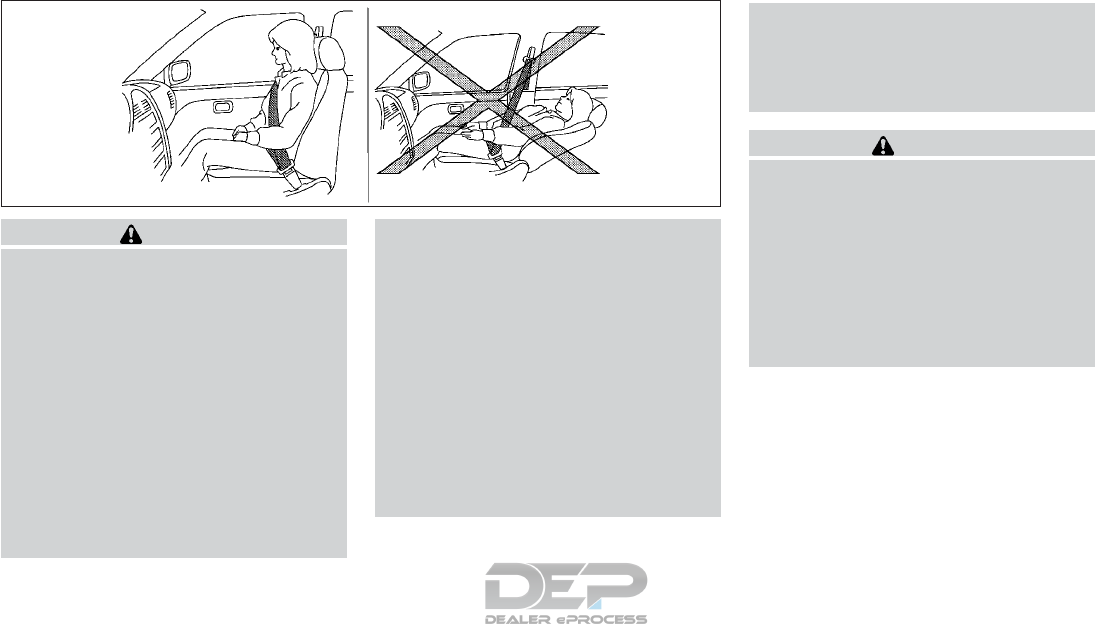
Sit upright and well back
SSS0136AZ
Sit upright and well back
SSS0016Z
SSS0014Z
Safety — seats, seat belts and supplemental restraint system 1-11

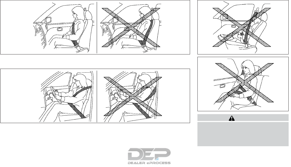
•The seat belt should be properly ad-
justed to a snug fit. Failure to do so may
reduce the effectiveness of the entire
restraint system and increase the
chance or severity of injury in an acci-
dent. Serious injury or death can occur if
the seat belt is not worn properly.
•Always route the shoulder belt over
your shoulder and across your chest.
Never put the belt behind your back, un-
der your arm or across your neck. The
belt should be away from your face and
neck, but not falling off your shoulder.
•Position the lap belt as low and snug as
possible AROUND THE HIPS, NOT THE
WAIST. A lap belt worn too high could
increase the risk of internal injuries in an
accident.
•Be sure the seat belt tongue is securely
fastened to the proper buckle.
•Do not wear the seat belt inside out or
twisted. Doing so may reduce its effec-
tiveness.
•Do not allow more than one person to
use the same seat belt.
•Never carry more people in the vehicle
than there are seat belts.
•If the seat belt warning light glows con-
tinuously while the ignition is turned ON
with all doors closed and all seat belts
fastened, it may indicate a malfunction
in the system. Have the system checked.
It is recommended that you visit an
INFINITI retailer for this service.
•No changes should be made to the seat
belt system. For example, do not modify
the seat belt, add material or install de-
vices that may change the seat belt
routing or tension. Doing so may affect
the operation of the seat belt system.
Modifying or tampering with the seat
belt system may result in serious per-
sonal injury.
•Once a seat belt pretensioner has acti-
vated, they cannot be reused and must
be replaced together with the retractor.
It is recommended that you visit an
INFINITI retailer for this service.
•All seat belt assemblies, including re-
tractors and attaching hardware,
should be inspected after any collision. It
is recommended that you visit an
INFINITI retailer for this service.
INFINITI recommends that all seat belt
assemblies in use during a collision be
replaced unless the collision was minor
and the belts show no damage and con-
tinue to operate properly. Seat belt as-
semblies not in use during a collision
should also be inspected and replaced if
either damage or improper operation is
noted.
•All child restraints and attaching hard-
ware should be inspected after any col-
lision. Always follow the restraint
manufacturer’s inspection instructions
and replacement recommendations. The
child restraints should be replaced if
they are damaged.
PREGNANT WOMEN
INFINITI recommends that pregnant women
use seat belts. The seat belt should be worn
snug, and always position the lap belt as low
as possible around the hips, not the waist.
Place the shoulder belt over your shoulder
and across your chest. Never put the lap/
shoulder belt over your abdominal area. Con-
tact your doctor for specific recommenda-
tions.
1-12 Safety — seats, seat belts and supplemental restraint system
INJURED PERSONS
INFINITI recommends that injured persons
use seat belts. Check with your doctor for
specific recommendations.
SEAT BELT WARNING LIGHT
The seat belt warning light reminds you to
fasten your seat belts. The light illuminates if
the engine is started, all doors are closed and
the driver’s and/or front passenger’s seat
belt is unfastened. It will remain illuminated
until the driver and/or front passenger fas-
tens their seat belt. A chime will sound once
the vehicle is in motion.
If the seat belt warning light flashes, together
with an intermittent warning tone, this means
that the driver or passenger has not fastened
their seat belt, and the speed of the vehicle is
exceeding 15 MPH (25 km/h).
For additional information, refer to "Warning
lights, indicator lights and audible reminders"
in the "2. Instruments and controls" section.
THREE-POINT TYPE SEAT BELT
WITH RETRACTOR
WARNING
•Every person who drives or rides in this
vehicle should use a seat belt at all times.
Children should be in the rear seats and
in an appropriate restraint.
•Do not ride in a moving vehicle when the
seatback is reclined. This can be danger-
ous. The shoulder belt will not be against
your body. In an accident, you could be
thrown into it and receive neck or other
serious injuries. You could also slide un-
der the lap belt and receive serious inter-
nal injuries.
•For the most effective protection when
the vehicle is in motion, the seat should
be upright. Always sit well back and up-
right in the seat with both feet on the
floor and adjust the seat belt properly.
•Do not allow children to play with the
seat belts. Most seating positions are
equipped with Automatic Locking Re-
tractor (ALR) mode seat belts. If the
seat belt becomes wrapped around a
child’s neck with the ALR mode acti-
vated, the child can be seriously injured
NIC2743
Safety — seats, seat belts and supplemental restraint system 1-13
or killed if the seat belt retracts and be-
comes tight. This can occur even if the
vehicle is parked. Unbuckle the seat belt
to release the child. If the seat belt can-
not be unbuckled or is already unbuck-
led, release the child by cutting the seat
belt with a suitable tool (such as a knife
or scissors) to release the seat belt.
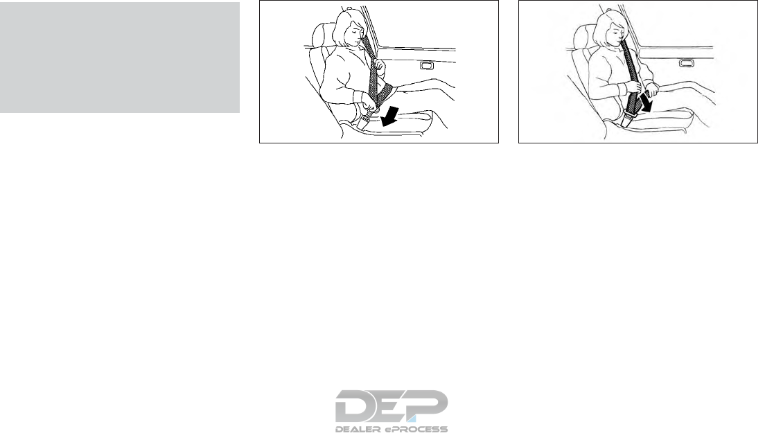
Fastening the seat belts
1. Adjust the seat. (See "Seats" earlier in this
section.)
2. Slowly pull the seat belt out of the retrac-
tor and insert the tongue into the buckle
until you hear and feel the latch engage.
•The retractor is designed to lock dur-
ing a sudden stop or on impact. A slow
pulling motion permits the belt to
move and allows you some freedom of
movement in the seat.
•If the seat belt cannot be pulled from
its fully retracted position, firmly pull
the belt and release it. Then smoothly
pull the belt out of the retractor.
3. Position the lap belt portion low and snug
on the hips as shown
4. Pull the shoulder belt portion toward the
retractor to take up extra slack. Be sure
the shoulder belt is routed over your
shoulder and across your chest.
The front passenger seat and the rear seating
positions three-point seat belts have two
modes of operation:
•Emergency Locking Retractor (ELR)
•Automatic Locking Retractor (ALR)
The ELR mode allows the seat belt to extend
and retract to allow the driver and passen-
gers some freedom of movement in the seat.
The ELR locks the seat belt when the vehicle
slows down rapidly or during certain impacts.
The ALR mode (child restraint mode) locks
the seat belt for child restraint installation.
When the ALR mode is activated, the seat
SSS0292Z SSS0290Z
1-14 Safety — seats, seat belts and supplemental restraint system
belt cannot be extended again until the seat
belt tongue is detached from the buckle and
fully retracted. The seat belt returns to the
ELR mode after the seat belt fully retracts.
For additional information, refer to "Child
restraints" later in this section. The ALR mode
should be used only for child restraint instal-
lation. During normal seat belt use by an oc-
cupant, the ALR mode should not be acti-
vated. If it is activated, it may cause
uncomfortable seat belt tension. It can also
change the operation of the front passenger
air bag. For additional information, refer to
"Front passenger air bag and status light" in
the "1. Safety — seats, seat belts and supple-
mental restraint system" section.
WARNING
When fastening the seat belts, be certain
that the seatbacks are completely secured
in the latched position. If they are not com-
pletely secured, passengers may be injured
in an accident or sudden stop.
Unfastening the seat belts
To unfasten the seat belt, push the button on
the buckle and guide the seat belt as it auto-
matically retracts.
Checking seat belt operation
Seat belt retractors are designed to lock seat
belt movement by two separate methods:
•When the belt is pulled quickly from the
retractor.
•When the vehicle slows down rapidly.
To increase your confidence in the seat belts,
check the operation as follows:
•Grasp the shoulder belt and pull forward
quickly. The retractor should lock and re-
strict further belt movement.
If the retractor does not lock during this
check, get the system checked. It is recom-
mended that you visit an INFINITI retailer for
this service, or to learn more about seat belt
operation.
SSS0326Z
Safety — seats, seat belts and supplemental restraint system 1-15
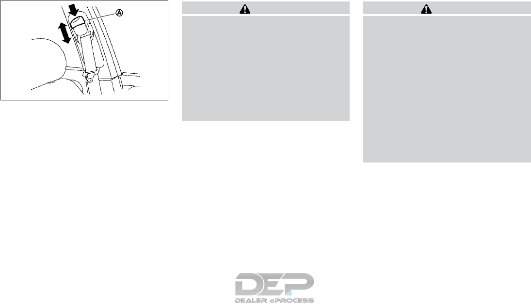
Shoulder belt height adjustment (if
equipped)
The shoulder belt anchor height should be
adjusted to the position that is best for you.
(See "Fastening the seat belts " earlier in this
section).
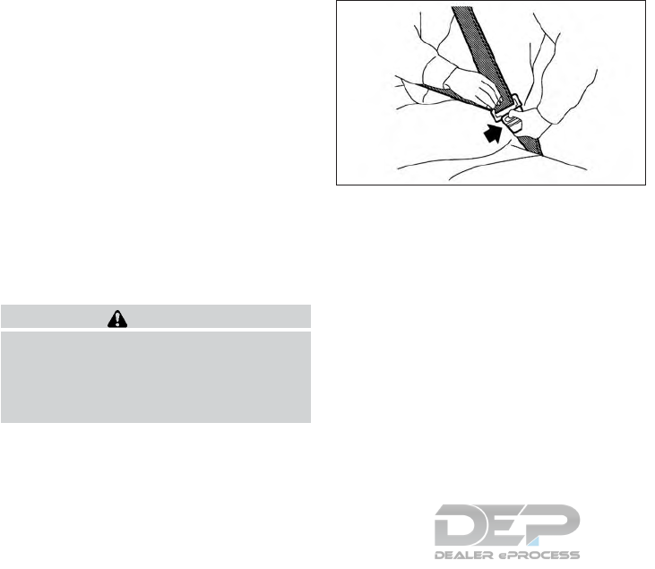
•To adjust, push the button 䊊
Aas shown
and then move the shoulder belt anchor to
the desired position so that the belt passes
over the center of the shoulder. The belt
should be away from your face and neck,
but not falling off of your shoulder. Re-
lease the adjustment button to lock the
shoulder belt anchor into position.
WARNING
•After adjustment, release the adjust-
ment button and then try to move the
shoulder belt down to make sure that it
is securely fixed in position.
•The shoulder belt anchor height should
be adjusted to the position that is best
for you. Failure to do so may reduce the
effectiveness of the entire restraint sys-
tem and increase the chance or severity
of injury in an accident.
SEAT BELT EXTENDERS
If, because of body size or driving position, it
is not possible to properly fit the lap/shoulder
belt and fasten it, an extender that is compat-
ible with the installed seat belts is available
that can be purchased. The extender adds
approximately 8 in (200 mm) of length and
may be used for either the driver or front
passenger seating position. It is recom-
mended you visit an INFINITI retailer for as-
sistance with purchasing an extender if an
extender is required.
WARNING
•Only INFINITI seat belt extenders, made
by the same company which made the
original equipment seat belts, should be
used with the INFINITI seat belts.
•Adults and children who can use the
standard seat belt should not use an ex-
tender. Such unnecessary use could re-
sult in serious personal injury in the
event of an accident.
•Never use seat belt extenders to install
child restraints. If the child restraint is
not secured properly, the child could be
seriously injured in a collision or a sud-
den stop.
SEAT BELT MAINTENANCE
•To clean the seat belt webbing, apply a
mild soap solution or any solution recom-
mended for cleaning upholstery or carpets.
Then wipe with a cloth and allow the seat
belts to dry in the shade. Do not allow the
seat belts to retract until they are com-
pletely dry.
SSS0896Z
1-16 Safety — seats, seat belts and supplemental restraint system

•If dirt builds up in the shoulder belt guide
of the seat belt anchors, the seat belts may
retract slowly. Wipe the shoulder belt
guide with a clean, dry cloth.
•Periodically check to see that the seat belt
and the metal components, such as buck-
les, tongues, retractors, flexible wires and
anchors, work properly. If loose parts, de-
terioration, cuts or other damage on the
webbing is found, the entire seat belt as-
sembly should be replaced.
WARNING
Do not allow children to play with the seat
belts. Most seating positions are equipped
with Automatic Locking Retractor (ALR)
mode seat belts. If the seat belt becomes
wrapped around a child’s neck with the
ALR mode activated, the child can be seri-
ously injured or killed if the seat belt re-
tracts and becomes tight. This can occur
even if the vehicle is parked. Unbuckle the
seat belt to release the child. If the seat belt
can not be unbuckled or is already unbuck-
led, release the child by cutting the seat
belt with a suitable tool (such as a knife or
scissors) to release the seat belt.
Children need adults to help protect them.
They need to be properly restrained.
In addition to the general information in this
manual, child safety information is available
from many other sources, including doctors,
teachers, government traffic safety offices,
and community organizations. Every child is
different, so be sure to learn the best way to
transport your child.
There are three basic types of child restraint
systems:
•Rear-facing child restraint
•Forward-facing child restraint
•Booster seat
The proper restraint depends on the child’s
size. Generally, infants up to about 1 year and
less than 20 lb (9 kg) should be placed in
rear-facing child restraints. Forward-facing
child restraints are available for children who
outgrow rear-facing child restraints and are
at least 1 year old. Booster seats are used to
help position a vehicle lap/ shoulder belt on a
child who can no longer use a forward-facing
child restraint.
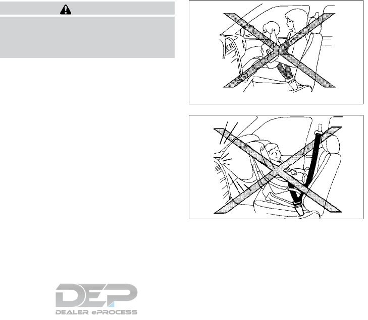
WARNING
Infants and children need special protec-
tion. The vehicle’s seat belts may not fit
them properly. The shoulder belt may come
too close to the face or neck. The lap belt
may not fit over their small hip bones. In an
accident, an improperly fitting seat belt
could cause serious or fatal injury. Always
use appropriate child restraints.
CHILD SAFETY
Safety — seats, seat belts and supplemental restraint system 1-17

All U.S. states and Canadian provinces or
territories require the use of approved child
restraints for infants and small children. See
"Child restraints" in the "1. Safety — seats,
seat belts and supplemental restraint system"
section for more information.
A child restraint may be secured in the vehicle
by using either the LATCH (Lower Anchor
and Tethers for CHildren) system or with the
vehicle seat belt. For additional information,
refer to "Child restraints" in the "1. Safety —
seats, seat belts and supplemental restraint
system" section.
INFINITI recommends that all pre-teens and
children be restrained in the rear seat. Stud-
ies show that children are safer when prop-
erly restrained in the rear seat than in the
front seat.
This is especially important because your ve-
hicle has a supplemental restraint system
(air bag system) for the front passenger.
(See "Supplemental Restraint System
(SRS)" later in this section.)
INFANTS
Infants up to at least 1 year old should be
placed in a rear-facing child restraint.
INFINITI recommends that infants be placed
in child restraints that comply with Federal
Motor Vehicle Safety Standards or Canadian
Motor Vehicle Safety Standards. You should
choose a child restraint which fits your ve-
hicle and always follow the manufacturer’s
instructions for installation and use.
SMALL CHILDREN
Children that are over 1 year old and weigh at
least 20 lbs (9 kg) should remain in a rear-
facing child restraint as long as possible up to
the height or weight limit of the child re-
straint. Children who outgrow the height or
weight limit of the rear-facing child restraint
and are at least 1 year old should be secured
in a forward-facing child restraint with a har-
ness. Refer to the manufacturer’s instructions
for minimum and maximum weight and
height recommendations. INFINITI recom-
mends that small children be placed in child
restraints that comply with Federal Motor
Vehicle Safety Standards or Canadian Motor
Vehicle Safety Standards. You should choose
a child restraint that fits your vehicle and
always follow the manufacturer’s instruc-
tions for installation and use.
LARGER CHILDREN
Children should remain in a forward-facing
child restraint with a harness until they reach
the maximum height or weight limit allowed
by the child restraint manufacturer.
Children who are too large for child restraints
should be seated and restrained by the seat
belts which are provided. The seat belt may
not fit properly if the child is less than 4 ft 9 in
(142.5 cm) tall and weighs between 40 lbs
(18 kg) and 80 lbs (36 kg). A booster seat
should be used to obtain proper seat belt fit.
Once a child outgrows the height or weight
limit of the harness-equipped forward-facing
child restraint, INFINITI recommends that
the child be placed in a commercially available
booster seat to obtain proper seat belt fit. For
a seat belt to fit properly, the booster seat
should raise the child so that the shoulder belt
is properly positioned across the chest and
the top, middle portion of the shoulder. The
shoulder belt should not cross the neck or
face and should not fall off the shoulder. The
lap belt should lie snugly across the lower hips
or upper thighs, not the abdomen. A booster
seat can only be used in seating positions that
have a three-point type seat belt. The
booster seat should fit the vehicle seat and
have a label certifying that it complies with
Federal Motor Vehicle Safety Standards or
Canadian Motor Vehicle Safety Standards.
1-18 Safety — seats, seat belts and supplemental restraint system
A booster seat should be used until the child
can pass the seat belt fit test below:
•Are the child’s back and hips against the
vehicle seatback?
•Is the child able to sit without slouching?
•Do the child’s knees bend easily over the
front edge of the seat with feet flat on the
floor?
•Can the child safely wear the seat belt (lap
belt low and snug across the hips and
shoulder belt across mid-chest and shoul-
der)?
•Is the child able to use the properly ad-
justed head restraint/headrest?
•Will the child be able to stay in position for
the entire ride?
If you answered no to any of these questions,
the child should remain in a booster seat us-
ing a three-point type seat belt.
NOTE
Laws in some communities may follow dif-
ferent guidelines. Check local and state
regulations to confirm your child is using the
correct restraint system before traveling.
WARNING
Never let a child stand or kneel on any seat
and do not allow a child in the cargo area.
The child could be seriously injured or killed
in a sudden stop or collision.
SSS0099Z
WRS0256Z
CHILD RESTRAINTS
Safety — seats, seat belts and supplemental restraint system 1-19

PRECAUTIONS ON CHILD
RESTRAINTS
WARNING
•Failure to follow the warnings and in-
structions for proper use and installa-
tion of child restraints could result in se-
rious injury or death of a child or other
passengers in a sudden stop or collision:
–The child restraint must be used and
installed properly. Always follow all
of the child restraint manufacturer’s
instructions for installation and use.
–Infants and children should never be
held on anyone’s lap. Even the stron-
gest adult cannot resist the forces of
a collision.
–Do not put a seat belt around both a
child and another passenger.
–INFINITI
recommends that all child re-
straints be installed in the rear seat.
Studies show that children are safer
when properly restrained in the rear
seat than in the front seat. If you must
install a forward-facing child restraint
in the front seat, see "Forward-facing
child restraint installation using the
seat belts" in the "1. Safety — seats,
seat belts and supplemental restraint
system" section.
–Even with the INFINITI Advanced Air
bag System, never install a rear-
facing child restraint in the front
seat. An inflating air bag could seri-
ously injure or kill a child. A rear-
facing child restraint must only be
used in the rear seat.
–Be sure to purchase a child restraint
that will fit the child and vehicle.
Some child restraints may not fit
properly in your vehicle.
–Child restraint anchorages are de-
signed to withstand only those loads
imposed by correctly fitted child re-
straints. Under no circumstances are
they to be used to attach adult seat
belts, or other items or equipment to
the vehicle. Doing so could damage
the child restraint anchorages. The
child restraint will not be properly in-
stalled using the damaged anchor-
ages, and a child could be seriously
injured or killed in a collision.
–Never use the anchor points for adult
seat belts or harnesses.
–A child restraint with a top tether
strap should not be used in the front
passenger seat.
–Keep seatbacks as upright as possible
after fitting the child restraint.
–Infants and children should always be
placed in an appropriate child re-
straint while in the vehicle.
–When the child restraint is not in use,
keep it secured with the LATCH sys-
tem or a seat belt. In a sudden stop or
collision, loose objects can injure oc-
cupants or damage the vehicle.
CAUTION
Remember that a child restraint left in a
closed vehicle can become very hot. Check
the seating surface and buckles before
placing your child in a child restraint.
This vehicle is equipped with a universal child
restraint anchor system, referred to as the
LATCH (Lower Anchors and Tethers for
CHildren) system. Some child restraints in-
clude rigid or webbing-mounted attachments
that can be connected to these anchors.
For details, see "LATCH (Lower Anchors and
Tethers for CHildren) system" in the "1. Safety
— seats, seat belts and supplemental restraint
system" section.
If you do not have a LATCH compatible child
restraint, the vehicle seat belts can be used.
1-20 Safety — seats, seat belts and supplemental restraint system

Several manufacturers offer child restraints
for infants and small children of various sizes.
When selecting any child restraint, keep the
following points in mind:
•Choose only a restraint with a label certi-
fying that it complies with Federal Motor
Vehicle Safety Standard 213 or Canadian
Motor Vehicle Safety Standard 213.
•Check the child restraint in your vehicle to
be sure it is compatible with the vehicle’s
seat and seat belt system.
•If the child restraint is compatible with
your vehicle, place your child in the child
restraint and check the various adjust-
ments to be sure the child restraint is com-
patible with your child. Choose a child re-
straint that is designed for your child’s
height and weight. Always follow all rec-
ommended procedures.
•If the combined weight of the child and
child restraint is less than 65 lb (29.5 kg),
you may use either the LATCH anchors or
the seat belt to install the child restraint
(not both at the same time).
•If the combined weight of the child and
child restraint is greater than 65 lb (29.5
kg), use the vehicle’s seat belt (not the
lower anchors) to install the child restraint.
•Be sure to follow the child restraint manu-
facturer’s instructions for installation.
NOTE
All U.S. states and Canadian provinces or
territories require that infants and small
children be restrained in an approved child
restraint at all times while the vehicle is be-
ing operated. Canadian law requires the top
tether strap on front-facing child restraints
to be secured to the designated anchor point
on the vehicle.
LATCH (Lower Anchors and
Tethers for CHildren) system
Your vehicle is equipped with special anchor
points that are used with LATCH system
compatible child restraints. This system may
also be referred to as the ISOFIX or ISOFIX
compatible system. With this system, you do
not have to use a vehicle seat belt to secure
the child restraint unless the combined
weight of the child and child restraint exceeds
65 lb (29.5 kg). If the combined weight of the
child and child restraint is greater than 65 lb
(29.5 kg), use the vehicle’s seat belt (not the
lower anchors) to install the child restraint. Be
sure to follow the child restraint manufactur-
er’s instructions for installation.
The LATCH anchor points are provided to
install child restraints in the rear outboard
seating positions only. Do not attempt to
install a child restraint in the center position
using the LATCH anchors.
LATCH lower anchor
WARNING
Failure to follow the warnings and instruc-
tions for proper use and installation of child
restraints could result in serious injury or
death of a child or other passengers in a
sudden stop or collision:
•Attach LATCH system compatible child
restraints only at the locations shown in
the illustration.
•Do not secure a child restraint in the cen-
ter rear seating position using the
LATCH lower anchors. The child re-
straint will not be secured properly.
•Inspect the lower anchors by inserting
your fingers into the lower anchor area.
Feel to make sure there are no obstruc-
tions over the anchors such as seat belt
webbing or seat cushion material. The
child restraint will not be secured prop-
erly if the lower anchors are obstructed.
Child restraint anchorages are designed to
withstand only those loads imposed by
correctly fitted child restraints. Under no
circumstances are they to be used to attach
adult seat belts, or other items or equip-
ment to the vehicle. Doing so could damage
Safety — seats, seat belts and supplemental restraint system 1-21
the child restraint anchorages. The child re-
straint will not be properly installed using
the damaged anchorage, and a child could
be seriously injured or killed in a collision.
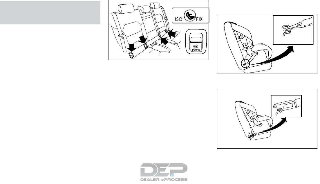
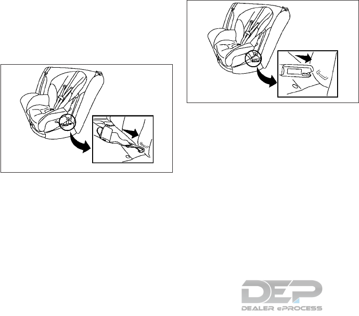
LATCH lower anchor location
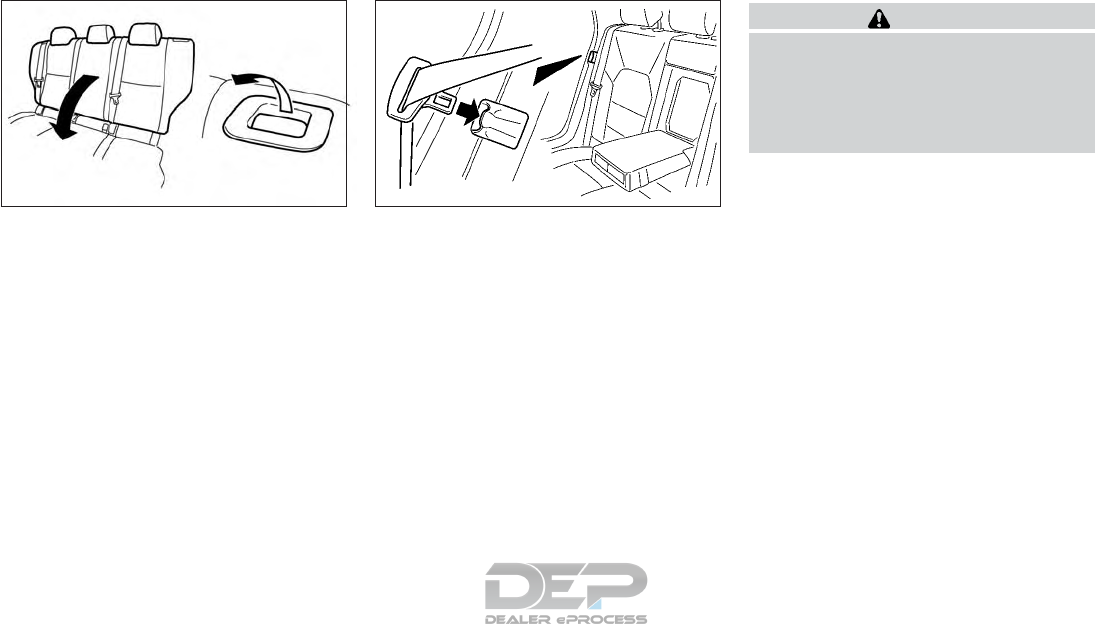
The LATCH lower anchors are located at the
rear of the seat cushion near the seatback, as
shown. A label is attached to the seatback to
help you locate the LATCH lower anchors.
Installing child restraint LATCH
lower anchor attachments
LATCH compatible child restraints include
two rigid or webbing-mounted attachments
NIC2612
LATCH lower anchor locations
SSS0643Z
LATCH webbing-mounted attachment
SSS0644Z
LATCH rigid-mounted attachment
1-22 Safety — seats, seat belts and supplemental restraint system
that can be connected to two anchors lo-
cated at certain seating positions in your ve-
hicle. With this system, you do not have to
use a vehicle seat belt to secure the child
restraint. Check your child restraint for a label
stating that it is compatible with LATCH. This
information may also be in the instructions
provided by the child restraint manufacturer.
When installing a child restraint, carefully
read and follow the instructions in this
manual and those supplied with the child re-
straints.
Top tether anchor
WARNING
•Child restraint anchorages are designed
to withstand only those loads imposed
by correctly fitted child restraints. Un-
der no circumstances are they to be used
to attach adult seat belts, or other items
or equipment to the vehicle. Doing so
could damage the child restraint an-
chorages. The child restraint will not be
properly installed using the damaged
anchorage, and a child could be seriously
injured or killed in a collision.
•If the cargo cover (if so equipped) con-
tacts the top tether strap when it is at-
tached to the top tether anchor, remove
the cargo cover from the vehicle or se-
cure it on the cargo floor below its at-
tachment location. If the cargo cover is
not removed, it may damage the top
tether strap during a collision. A child
could be seriously injured or killed in a
collision if the top tether strap is dam-
aged.
•Do not allow cargo to contact the top
tether strap when it is attached to the
top tether anchor. Properly secure the
cargo so it does not contact the top
tether strap. Cargo that is not properly
secured or cargo that contacts the top
tether strap may damage it during a col-
lision. A child could be seriously injured
or killed in a collision if the top tether
strap is damaged.
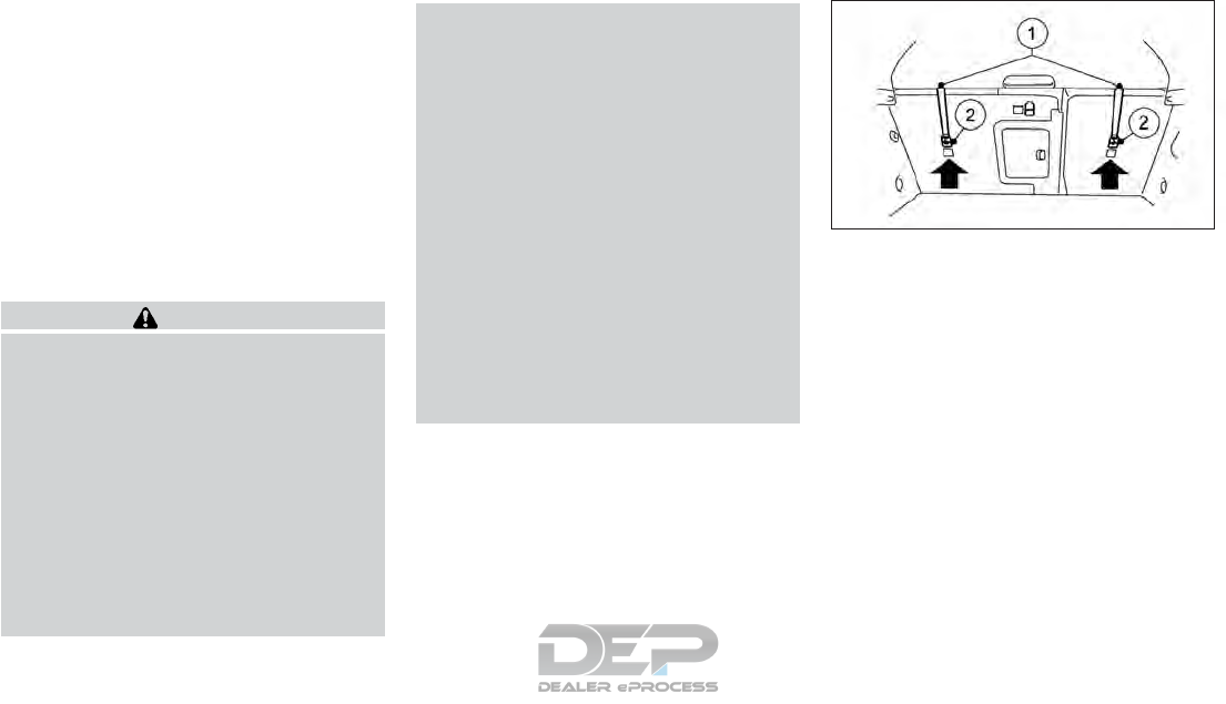
Top tether anchor point locations for
LATCH:
䊊
1Top tether straps
䊊
2Anchor points
The LATCH anchor points are provided to
install child restraints in the rear outboard
seating positions only, as shown. Do not at-
tempt to install a child restraint in the center
position using the LATCH anchors.
If you have any questions when installing a
top tether strap, it is recommended that you
visit an INFINITI retailer for this service.
NIC2849
Safety — seats, seat belts and supplemental restraint system 1-23

REAR-FACING CHILD
RESTRAINT INSTALLATION
USING LATCH
For additional information, refer to all Warn-
ings and Cautions in the "Child safety" in the
"1. Safety — seats, seat belts and supplemen-
tal restraint system" section and "Child re-
straints" in the "1. Safety — seats, seat belts
and supplemental restraint system" section
before installing a child restraint. Do not use
the lower anchors if the combined weight of
the child and the child restraint exceeds 65 lb
(29.5 kg). If the combined weight of the child
and the child restraint is greater than 65 lb
(29.5 kg), use the vehicle seat belt (not the
lower anchors) to install the child restraint. Be
sure to follow the child restraint manufactur-
er's instructions for installation. Follow these
steps to install a rear-facing child restraint in
the 2nd row seats using the LATCH system:
1. Position the child restraint on the seat.
Always follow the child restraint manu-
facturer's instructions.
2. Secure the child restraint anchor attach-
ments to the LATCH lower anchors.
Check to make sure the LATCH attach-
ment is properly attached to the lower
anchors.
3. For child restraints that are equipped with
webbing-mounted attachments, remove
any additional slack from the anchor at-
tachments. Press downward and rear-
ward firmly in the center of the child re-
straint with your hand to compress the
vehicle seat cushion and seatback while
tightening the webbing of the anchor at-
tachments.
WRS0801Z
Rear-facing web-mounted — step 2
WRS0802Z
Rear-facing rigid-mounted — step 2
LRS0673Z
Rear-facing — step 3
1-24 Safety — seats, seat belts and supplemental restraint system
4. After attaching the child restraint, test it
before you place the child in it. Push it
from side to side while holding the child
restraint near the LATCH attachment
path. The child restraint should not move
more than 1 inch (25 mm), from side to
side. Try to tug it forward and check to see
if the LATCH attachment holds the re-
straint in place. If the restraint is not se-
cure, tighten the LATCH attachment as
necessary, or put the restraint in another
seat and test it again. You may need to try
a different child restraint or try installing
by using the vehicle seat belt (if appli-
cable). Not all child restraints fit in all types
of vehicles.
5. Check to make sure the child restraint is
properly secured prior to each use. If the
child restraint is loose, repeat steps 2
through 4.
REAR-FACING CHILD
RESTRAINT INSTALLATION
USING THE SEAT BELTS
WARNING
The three-point seat belt with Automatic
Locking Retractor (ALR) must be used
when installing a child restraint. Failure to
use the ALR mode will result in the child
restraint not being properly secured. The
restraint could tip over or be loose and
cause injury to a child in a sudden stop or
collision.
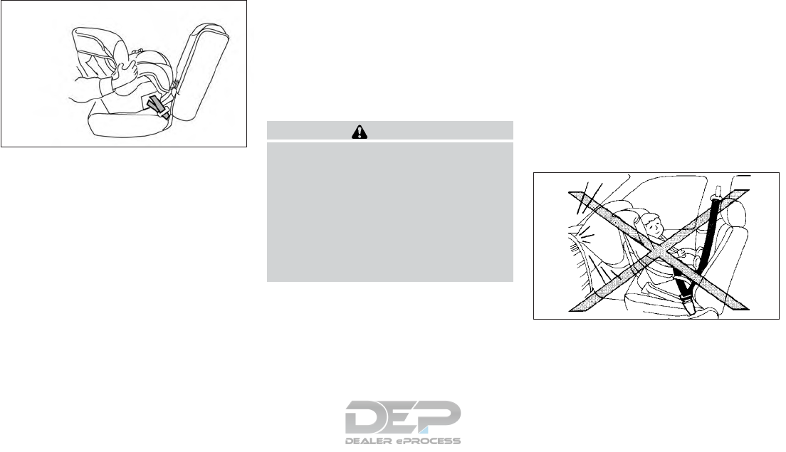
Rear-facing child restraints must not be
used on the front seats.
For additional information, refer to all Warn-
ings and Cautions in the "Child safety" in the
"1. Safety — seats, seat belts and supplemen-
tal restraint system" section and "Child re-
straints" in the "1. Safety — seats, seat belts
and supplemental restraint system" section
before installing a child restraint.
Do not use the lower anchors if the combined
weight of the child and the child restraint
exceeds 65 lb (29.5 kg). If the combined
weight of the child and the child restraint is
greater than 65 lb (29.5 kg), use the vehicle
seat belt (not the lower anchors) to install the
child restraint. Be sure to follow the child
restraint manufacturer's instructions for in-
stallation.
Follow these steps to install a rear-facing
child restraint using the vehicle seat belts in
the rear seats:
1. Child restraints for infants must be used
in the rear-facing direction and therefore
must not be used in the front seat. Posi-
tion the child restraint on the seat. Always
follow the child restraint manufacturer's
instructions.
LRS0674Z
Rear-facing — step 4
WRS0256Z
Rear-facing — step 1
Safety — seats, seat belts and supplemental restraint system 1-25
2. Route the seat belt tongue through the
child restraint and insert it into the buckle
until you hear and feel the tongue engage.
Be sure to follow the child restraint manu-
facturer's instructions for belt routing.
3. Pull the shoulder belt until the belt is fully
extended. At this time, the seat belt re-
tractor is in the ALR mode (child restraint
mode). It reverts to the ELR mode when
the seat belt is fully retracted.
4. Allow the seat belt to retract. Pull up on
the shoulder belt to remove any slack in
the belt.
WRS0761Z
Rear-facing — step 2
LRS0669Z
Rear-facing — step 3
LRS0670Z
Rear-facing — step 4
1-26 Safety — seats, seat belts and supplemental restraint system
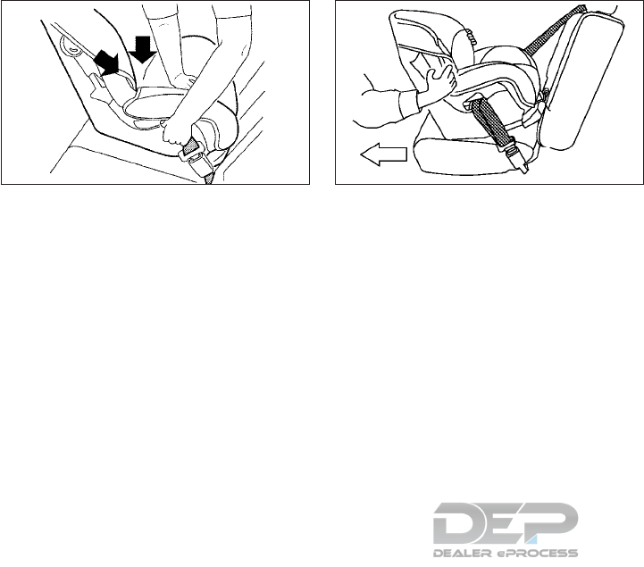
5. Remove any additional slack from the seat
belt; press downward and rearward firmly
in the center of the child restraint to com-
press the vehicle seat cushion and seat-
back while pulling up on the seat belt.
6. After attaching the child restraint, test it
before you place the child in it. Push it
from side to side while holding the child
restraint near the seat belt path. The child
restraint should not move more than 1
inch (25 mm), from side to side. Try to tug
it forward and check to see if the belt
holds the restraint in place. If the restraint
is not secure, tighten the seat belt as nec-
essary, or put the restraint in another seat
and test it again. You may need to try a
different child restraint. Not all child re-
straints fit in all types of vehicles.
7. Check to make sure that the child restraint
is properly secured prior to each use. If the
seat belt is not locked, repeat steps 1
through 6.
After the child restraint is removed and
the seat belt fully retracted, the ALR mode
(child restraint mode) is canceled.
FORWARD-FACING CHILD
RESTRAINT INSTALLATION
USING LATCH
For additional information, refer to all Warn-
ings and Cautions in the "Child safety" in the
"1. Safety — seats, seat belts and supplemen-
tal restraint system" section and "Child re-
straints" in the "1. Safety — seats, seat belts
and supplemental restraint system" section
before installing a child restraint.
Do not use the lower anchors if the combined
weight of the child and the child restraint
exceeds 65 lb (29.5 kg). If the combined
weight of the child and the child restraint is
greater than 65 lb (29.5 kg), use the vehicle
seat belt (not the lower anchors) to install the
child restraint. Be sure to follow the child
restraint manufacturer's instructions for in-
stallation.
WRS0762Z
Rear-facing — step 5
SSS0658Z
Rear-facing — step 6
Safety — seats, seat belts and supplemental restraint system 1-27
Follow these steps to install a forward-
facing child restraint in the rear seats using
the LATCH system:
1. Position the child restraint on the seat.
Always follow the child restraint manu-
facturer's instructions.
2. Secure the child restraint anchor attach-
ments to the LATCH lower anchors.
Check to make sure the LATCH attach-
ment is properly attached to the lower
anchors.
If the child restraint is equipped with a top
tether strap, route the top tether strap
and secure the tether strap to the tether
anchor point. For additional information,
refer to "Installing top tether strap" in the
"1. Safety — seats, seat belts and supple-
mental restraint system" section.
Do not install child restraints that require
the use of a top tether strap in seating
positions that do not have a top tether
anchor.
3. The back of the child restraint should be
secured against the vehicle seatback.
If necessary, adjust or remove the head
restraint/headrest to obtain the correct
child restraint fit. If the head restraint/
headrest is removed, store it in a secure
place. Be sure to reinstall the head
restraint/headrest when the child re-
straint is removed. For additional infor-
mation about head restraint/headrest ad-
justment, refer to "Head restraints/
Headrests" in the "1. Safety — seats, seat
belts and supplemental restraint system"
section. If the seating position does not
have an adjustable head restraint/
headrest and it is interfering with the
proper child restraint fit, try another seat-
ing position or a different child restraint.
SSS0645Z
Forward-facing web-mounted — step 2
SSS0646Z
Forward-rigid web-mounted — step 2
1-28 Safety — seats, seat belts and supplemental restraint system
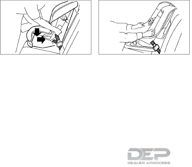
4. For child restraints that are equipped with
webbing-mounted attachments, remove
any additional slack from the webbing of
the anchor attachments. Press down-
ward and rearward firmly in the center of
the child restraint with your knee to com-
press the vehicle seat cushion and seat-
back while tightening the webbing of the
anchor attachments.
5. Tighten the tether strap according to the
manufacturer's instructions to remove
any slack.
6. After attaching the child restraint, test it
before you place the child in it. Push it
from side to side while holding the child
restraint near the LATCH attachment
path. The child restraint should not move
more than 1 inch (25 mm), from side to
side. Try to tug it forward and check to see
if the LATCH attachment holds the re-
straint in place. If the restraint is not se-
cure, tighten the LATCH attachment as
necessary, or put the restraint in another
seat and test it again. You may need to try
a different child restraint. Not all child re-
straints fit in all types of vehicles.
7. Check to make sure the child restraint is
properly secured prior to each use. If the
child restraint is loose, repeat steps 3
through 6.
Installing top tether strap
The child restraint top tether strap must be
used when installing the child restraint with
the LATCH lower anchor attachments. First,
secure the child restraint with the LATCH
lower anchors (rear outboard seating posi-
tions only).
SSS0647Z
Forward-facing — step 4
SSS0638Z
Forward-facing — step 6
Safety — seats, seat belts and supplemental restraint system 1-29

The LATCH anchor points are provided to
install child restraints in the rear outboard
seating positions only, as shown. Do not at-
tempt to install a child restraint in the center
position using the LATCH anchors.
WARNING
Child restraint anchorages are designed to
withstand only those loads imposed by
correctly fitted child restraints. Under no
circumstances are they to be used to attach
adult seat belts, or other items or equip-
ment to the vehicle. Doing so could damage
the child restraint anchorages. The child re-
straint will not be properly installed using
the damaged anchorage, and a child could
be seriously injured or killed in a collision.
Outboard seating positions with removable
head restraints/headrests:
1. If necessary, raise or remove the head
restraint/headrest and store it in a secure
place. Be sure to reinstall the head
restraint/headrest when the child re-
straint is removed. For additional informa-
tion about head restraint/headrest ad-
justment, removal and installation, refer to
"Head restraints/Headrests" in the "1.
Safety — seats, seat belts and supplemen-
tal restraint system" section.
2. Position the top tether strap 䊊
1over the
seatback as shown.
3. Secure the tether strap to the tether an-
chor point 䊊
2on the seatback behind the
child restraint as shown.
4. Tighten the tether strap according to the
manufacturer's instructions to remove
any slack.
Outboard seating positions with fixed head
restraints/headrests:
1. If the child restraint has a single tether
strap, route the strap 䊊
1over the top of
the outer head restraint/headrest. If the
child restraint has two tether straps, route
them round each side of the outer head
restraint/headrest.
2. Secure the tether strap to the tether an-
chor point 䊊
2on the seatback behind the
child restraint as shown.
3. Tighten the tether strap according to the
manufacturer's instructions to remove
any slack.
If you have any questions when installing
a top tether strap, it is recommended
that you visit an INFINITI retailer for this
service.
FORWARD-FACING CHILD
RESTRAINT INSTALLATION
USING THE SEAT BELTS
WARNING
The three-point seat belt with Automatic
Locking Retractor (ALR) must be used
when installing a child restraint. Failure to
use the ALR mode will result in the child
restraint not being properly secured. The
restraint could tip over or be loose and
cause injury to a child in a sudden stop or
collision. Also, it can change the operation
of the front passenger air bag. For addi-
tional information, refer to "Front passen-
ger air bag and status light" in the "1.
Safety — seats, seat belts and supplemen-
tal restraint system" section.
NIC2849
1-30 Safety — seats, seat belts and supplemental restraint system
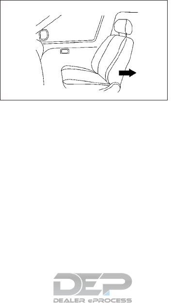
For additional information, refer to all Warn-
ings and Cautions in the "Child safety" in the
"1. Safety — seats, seat belts and supplemen-
tal restraint system" section and "Child re-
straints" in the "1. Safety — seats, seat belts
and supplemental restraint system" section
before installing a child restraint.
Do not use the lower anchors if the combined
weight of the child and the child restraint
exceeds 65 lb (29.5 kg). If the combined
weight of the child and the child restraint is
greater than 65 lb (29.5 kg), use the vehicle
seat belt (not the lower anchors) to install the
child restraint. Be sure to follow the child
restraint manufacturer's instructions for in-
stallation.
Follow these steps to install a forward-
facing child restraint using the vehicle seat
belt in the rear seats or in the front passenger
seat:
1. If you must install a child restraint in the
front seat, it should be placed in a
forward-facing direction only. Move the
seat to the rearmost position. Child re-
straints for infants must be used in the
rear-facing direction and, therefore,
must not be used in the front seat.
2. Position the child restraint on the seat.
Always follow the child restraint manu-
facturer's instructions. The back of the
child restraint should be secured against
the vehicle seatback. If necessary, adjust
or remove the head restraint/headrest to
obtain the correct child restraint fit. If the
head restraint/headrest is removed, store
it in a secure place. Be sure to reinstall the
head restraint/headrest when the child
restraint is removed. For additional infor-
mation about head restraint/headrest ad-
justment, removal and installation, refer
to "Head restraints/Headrests" in the "1.
Safety — seats, seat belts and supplemen-
tal restraint system" section.
If the seating position does not have an
adjustable head restraint/headrest and it
is interfering with the proper child re-
straint fit, try another seating position or a
different child restraint.
WRS0699Z
Forward-facing
(front passenger seat) — step 1
Safety — seats, seat belts and supplemental restraint system 1-31
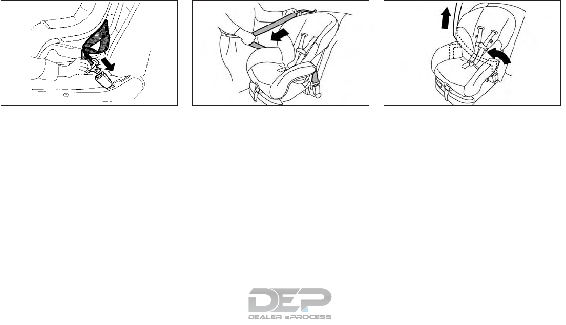
3. Route the seat belt tongue through the
child restraint and insert it into the buckle
until you hear and feel the tongue engage.
Be sure to follow the child restraint manu-
facturer's instructions for belt routing. If
the child restraint is equipped with a top
tether strap, route the top tether strap
and secure the tether strap to the tether
anchor point (rear seat installation only).
For additional information, refer to "In-
stalling top tether strap" in the "1. Safety —
seats, seat belts and supplemental re-
straint system" section.
Do not install child restraints that require
the use of a top tether strap in seating
positions that do not have a top tether
anchor.
4. Pull the shoulder belt until the belt is fully
extended. At this time, the seat belt re-
tractor is in the ALR mode (child restraint
mode). It reverts to ELR mode when the
seat belt is fully retracted.
5. Allow the seat belt to retract. Pull up on
the shoulder belt to remove any slack in
the belt.
WRS0680Z
Forward-facing — step 3
LRS0667Z
Forward-facing — step 4
LRS0668Z
Forward-facing — step 5
1-32 Safety — seats, seat belts and supplemental restraint system
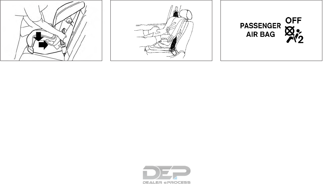
6. Remove any additional slack from the seat
belt; press downward and rearward firmly
in the center of the child restraint with
your knee to compress the vehicle seat
cushion and seatback while pulling up on
the seat belt.
7. Tighten the tether strap according to the
manufacturer's instructions to remove
any slack.
8. After attaching the child restraint, test it
before you place the child in it. Push it
from side to side while holding the child
restraint near the seat belt path. The child
restraint should not move more than 1
inch (25 mm), from side to side. Try to tug
it forward and check to see if the belt
holds the restraint in place. If the restraint
is not secure, tighten the seat belt as nec-
essary, or put the restraint in another seat
and test it again. You may need to try a
different child restraint. Not all child re-
straints fit in all types of vehicles.
9. Check to make sure the child restraint is
properly secured prior to each use. If the
seat belt is not locked, repeat steps 2
through 8.
10. If the child restraint is installed in the
front passenger seat, place the ignition
switch in the ON position. Either the
<PASSENGER AIR BAG ON> indicator
light or <PASSENGER AIR BAG OFF>
indicator light will illuminate depending
on the size of the child and the type of
child restraint used. See "Front passen-
ger air bag and status light" in the "1.
Safety — seats, seat belts and supple-
mental restraint system" section. After
the child restraint is removed and the
seat belt is fully retracted, the ALR mode
(child restraint mode) is canceled.
If necessary, system operation can be
checked by using a special tool. It is rec-
ommended that you visit an INFINITI
retailer for this service. Until you have
WRS0681Z
Forward-facing — step 6
WRS0698Z
Forward-facing — step 8
SSS0676Z
Forward-facing — step 10
Safety — seats, seat belts and supplemental restraint system 1-33
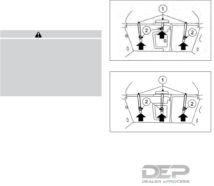
confirmed system operation, move the
child restraint to another position. See
"Troubleshooting" later in this section.
Installing top tether strap
WARNING
Child restraint anchorages are designed to
withstand only those loads imposed by
correctly fitted child restraints. Under no
circumstances are they to be used to attach
adult seat belts, or other items or equip-
ment to the vehicle. Doing so could damage
the child restraint anchorages. The child re-
straint will not be properly installed using
the damaged anchorage, and a child could
be seriously injured or killed in a collision.
The child restraint top tether strap must be
used when installing the child restraint with
seat belts.
First, secure the child restraint with the seat
belt.
Outboard seating positions with removable
head restraints/headrests:
1. If necessary raise or remove the head
restraint/headrest and store it in a secure
place. Be sure to reinstall the head
restraint/headrest when the child re-
straint is removed. For additional informa-
tion about head restraint/headrest ad-
justment, removal and installation, refer to
"Head restraints/Headrests" in the "1.
Safety — seats, seat belts and supplemen-
tal restraint system" section.
2. Position the top tether strap 䊊
1over the
seatback as shown.
3. Secure the tether strap to the tether an-
chor point 䊊
2on the seatback behind the
child restraint as shown.
4. Tighten the tether strap according to the
manufacturer's instructions to remove
any slack.
Outboard seating positions with fixed head
restraints/headrests:
1. If the child restraint has a single tether
strap, route the strap 䊊
1over the top of
the outer head restraint/headrest. If the
child restraint has two tether straps, route
them round each side of the outer head
restraint/headrest.
2. Secure the tether strap to the tether an-
chor point 䊊
2on the seatback behind the
child restraint as shown.
NIC2848
Rear seat - Type A
NIC2903
Rear seat - Type B
1-34 Safety — seats, seat belts and supplemental restraint system
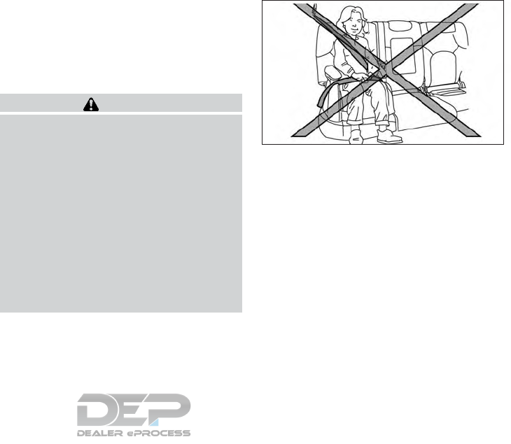
3. Tighten the tether strap according to the
manufacturer's instructions to remove
any slack.
Center seating position with adjustable
head restraint/headrest:
1. Raise the head restraint/headrest. For
additional information about head
restraint/headrest adjustment, removal
and installation, refer to "Head restraints/
Headrests" in the "1. Safety — seats, seat
belts and supplemental restraint system"
section.
2. Position the top tether strap 䊊
1under the
head restraint/head rest and over the
seatback, between the two head
restraint/headrest stalks as shown.
3. Secure the tether strap to the tether an-
chor point 䊊
2on the seatback behind the
child restraint as shown.
4. Tighten the tether strap according to the
manufacturer's instructions to remove
any slack.
If you have any questions when installing
a top tether strap, it is recommended
that you visit an INFINITI retailer for this
service.
BOOSTER SEATS
For additional information on installing a
booster seat in your vehicle, follow the in-
structions outlined in this section.
Precautions on booster seats
WARNING
If a booster seat and seat belt are not used
properly, the risk of a child being injured or
killed in a sudden stop or collision greatly
increases:
•Make sure the shoulder portion of the
belt is away from the child's face and
neck and the lap portion of the belt does
not cross the stomach.
•Make sure the shoulder belt is not be-
hind the child or under the child’s arm.
•A booster seat must only be installed in a
seating position that has a lap/shoulder
belt.
Booster seats of various sizes are offered by
several manufacturers. When selecting any
booster seat, keep the following points in
mind:
•Choose only a booster seat with a label
certifying that it complies with Federal
Motor Vehicle Safety Standard 213 or Ca-
nadian Motor Vehicle Safety Standard
213.
•Check the booster seat in your vehicle to
be sure it is compatible with the vehicle’s
seat and seat belt system.
•Make sure the child’s head will be properly
supported by the booster seat or vehicle
seat. The seatback must be at or above the
center of the child’s ears. For example, if a
low back booster seat 䊊
1is chosen, the
vehicle seatback must be at or above the
LRS0501Z
Safety — seats, seat belts and supplemental restraint system 1-35
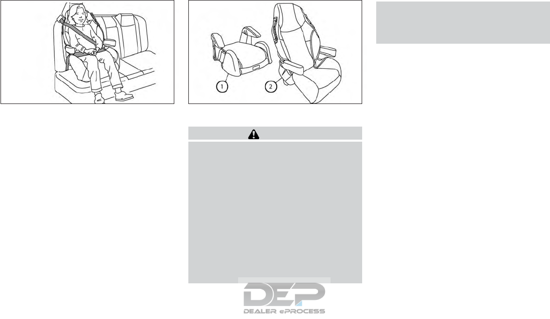
center of the child’s ears. If the seatback is
lower than the center of the child’s ears, a
high back booster seat 䊊
2should be used.
•If the booster seat is compatible with your
vehicle, place the child in the booster seat
and check the various adjustments to be
sure the booster seat is compatible with
the child. Always follow all recommended
procedures.
All U.S. states and Canadian provinces or
territories require that infants and small
children be restrained in an approved child
restraint at all times while the vehicle is be-
ing operated.
The instructions in this section apply to
booster seat installation in the rear seats or
the front passenger seat.
Booster seat installation
WARNING
If a booster seat and seat belt are not used
properly, the risk of a child being injured or
killed in a sudden stop or collision greatly
increases:
•Make sure the shoulder portion of the
belt is away from the child's face and
neck and the lap portion of the belt does
not cross the stomach.
•Make sure the shoulder belt is not be-
hind the child or under the child’s arm.
•A booster seat must only be installed in a
seating position that has a lap/shoulder
belt.
To avoid injury to a child, do not use the
lap/shoulder belt in the Automatic Locking
Retractor (ALR) mode when using a
booster seat with the seat belts.
For additional information, refer to all Warn-
ings and Cautions in the "Child safety" in the
"1. Safety — seats, seat belts and supplemen-
tal restraint system" section, "Child restraints"
in the "1. Safety — seats, seat belts and
supplemental restraint system" section and
"Booster seats" in the "1. Safety — seats, seat
belts and supplemental restraint system" sec-
tion before installing a child restraint.
Follow these steps to install a booster seat in
the rear seat or in the front passenger seat:
LRS0464Z LRS0455Z
1-36 Safety — seats, seat belts and supplemental restraint system
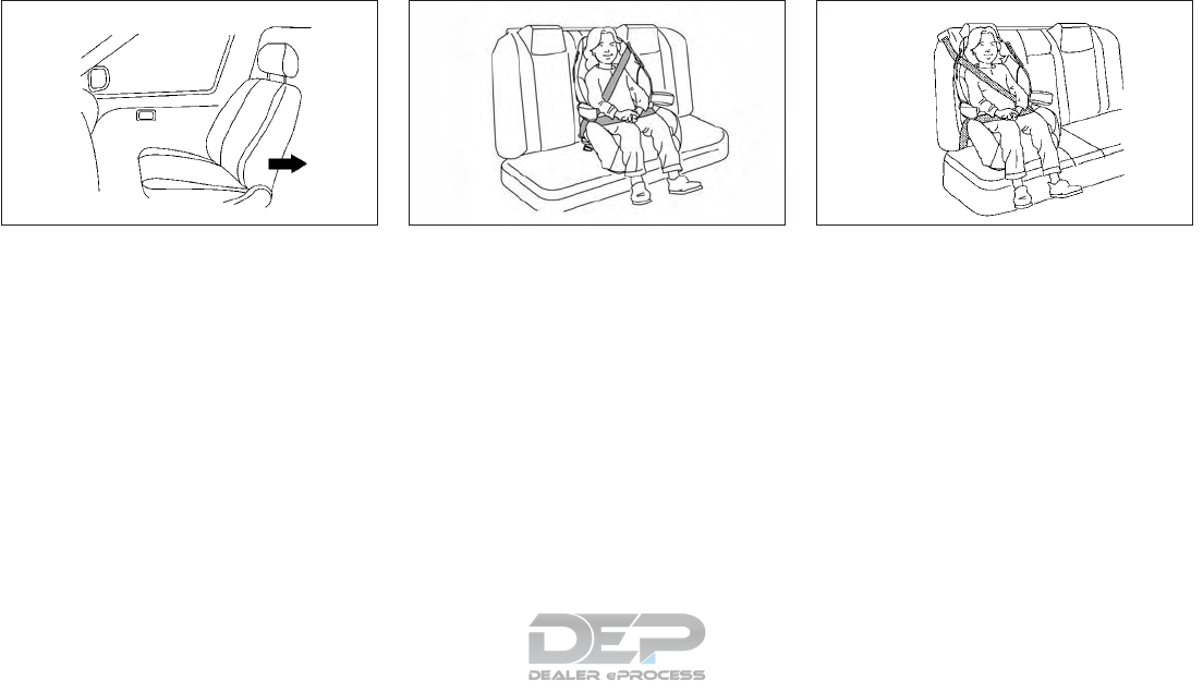
1. If you must install a booster seat in the
front seat, move the seat to the rearmost
position.
2. Position the booster seat on the seat.
Only place it in a front-facing direction.
Always follow the booster seat manufac-
turer’s instructions.
3. The booster seat should be positioned on
the vehicle seat so that it is stable.
If necessary, adjust or remove the head
restraint to obtain the correct booster
seat fit. If the head restraint is removed,
store it in a secure place. Be sure to rein-
stall the head restraint when the booster
seat is removed.
For additional information about head
restraint/headrest adjustment, removal
and installation, refer to "Head restraints/
Headrests" in the "1. Safety — seats, seat
belts and supplemental restraint system"
section.
If the seating position does not have an
adjustable head restraint/headrest and it
is interfering with the proper booster seat
fit, try another seating position or a differ-
ent booster seat.
4. Position the lap portion of the seat belt
low and snug on the child’s hips. Be sure to
follow the booster seat manufacturer’s
instructions for adjusting the seat belt
routing.
5. Pull the shoulder belt portion of the seat
belt toward the retractor to take up extra
slack. Be sure the shoulder belt is posi-
tioned across the top, middle portion of
the child’s shoulder. Be sure to follow the
booster seat manufacturer’s instructions
for adjusting the seat belt routing.
6. Follow the warnings, cautions and in-
structions for properly fastening a seat
belt shown in "Precautions on seat belt
usage" earlier in this section.
WRS0699Z LRS0451Z
Rear center position
LRS0452Z
Rear outboard position
Safety — seats, seat belts and supplemental restraint system 1-37
7. If the booster seat is installed in the front
passenger seat, place the ignition switch
in the ON position. Either the <PASSEN-
GER AIR BAGON> 䊊
1indicator light
or <PASSENGER AIR BAGOFF> 䊊
2
indicator light will illuminate depending on
the size of the child and the type of
booster seat used. See "Front passenger
air bag and status light" in the "1. Safety —
seats, seat belts and supplemental re-
straint system" section.
PRECAUTIONS ON
SUPPLEMENTAL RESTRAINT
SYSTEM (SRS)
This Supplemental Restraint System (SRS)
section contains important information con-
cerning the following systems:
•Driver and passenger supplemental front
impact air bags (INFINITI Advanced Air
Bag System)
•Driver and passenger supplemental knee
air bags
•Front seat-mounted side-impact supple-
mental air bags
•Roof-mounted curtain side-impact and
rollover supplemental air bags
•Seat belts with pretensioner
Supplemental front-impact air bag
system
The INFINITI Advanced Air Bag System can
help cushion the impact force to the head and
chest of the driver and front passenger in
certain frontal collisions.
Driver and passenger supplemental
knee air bags
This system can help cushion the impact
force to the driver's and passenger's knees in
certain collisions.
Front seat-mounted side-impact
supplemental air bag system
This system can help cushion the impact
force to the chest and pelvis areas of the
driver and front passenger in certain side-
impact collisions. The side air bag is designed
to inflate on the side where the vehicle is
impacted.
Roof-mounted curtain side-impact
and rollover supplemental air bags
This system can help cushion the impact
force to the head of occupants in the out-
board seating positions in certain side-impact
or rollover collisions. In a side impact, the
curtain air bags are designed to inflate on the
side where the vehicle is impacted. In a roll-
over, curtain air bags on both sides are de-
signed to inflate and remain inflated for a
short time.
NIC2740
SUPPLEMENTAL RESTRAINT
SYSTEM (SRS)
1-38 Safety — seats, seat belts and supplemental restraint system
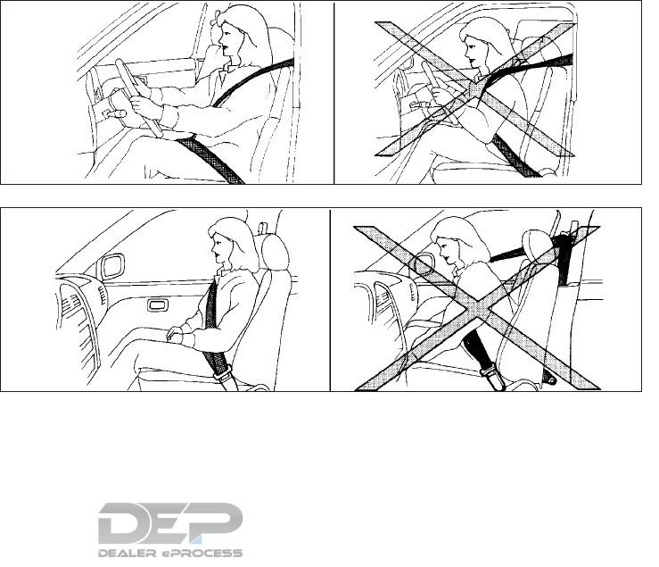
Curtain air bags are also designed to inflate in
certain types of rollover collisions or near
rollovers. As a result, certain vehicle move-
ments (for example, during severe off-
roading) may cause the curtain air bags to
inflate.
The SRS is designed to supplement the crash
protection provided by the driver and front
passenger seat belts and is not a substitute
for them. Seat belts should always be cor-
rectly worn and the occupant seated a suit-
able distance away from the steering wheel,
instrument panel and front door finishers. For
additional information, see "Seat belts" earlier
in this section.
The supplemental air bags operate only
when the ignition switch is placed in the ON
position.
After placing the ignition switch in the ON,
the air bag warning light will illuminate. The
air bag warning light will turn off within a
few seconds after the engine is started if the
system is operational. See "Warning lights,
indicator lights and audible reminders" in the
"2. Instruments and controls" section for
further details.
WRS0031Z
Sit upright and well back
ARS1133Z
Sit upright and well back
Safety — seats, seat belts and supplemental restraint system 1-39
WARNING
•The front-air bags ordinarily will not in-
flate in the event of a side impact, rear
impact, rollover, or lower severity fron-
tal collision. Always wear the seat belts
to help reduce the risk or severity of in-
jury in accidents.
•The front passenger air bag will not in-
flate if the <PASSENGER AIR BAG
OFF> indicator light is lit. For ad-
ditional information, refer to "Front
passenger air bag and status light" in
the "1. Safety — seats, seat belts and
supplemental restraint system" section.
•
The seat belts and the front-impact air
bags are most effective when you are sit-
ting well back and upright in the seat. The
front air bags inflate with great force.
Even with the INFINITI Advanced Air Bag
System, if you are unrestrained, leaning
forward, sitting sideways, or out of posi-
tion in any way, you are at greater risk of
injury or death in a crash. You may also
receive serious or fatal injuries from the
front air bag if you are up against it when
it inflates. Always sit back against the
seatback and as far away as practical
from the steering wheel. Always properly
use the seat belts.
•The driver and front passenger seat belt
buckles are equipped with sensors that
detect if the seat belts are fastened. The
INFINITI Advanced Air Bag System
monitors the severity of a collision and
seat belt usage then inflates the air bags
as needed. Failure to properly wear seat
belts can increase the risk or severity of
injury in an accident.
•The front passenger seat is equipped
with an occupant classification sensor
(pressure sensor) that turns the front
passenger air bag OFF under some con-
ditions. This sensor is only used in this
seat. Failure to be properly seated and
wearing the seat belt can increase the
risk or severity of injury in an accident.
For additional information, refer to
"Front passenger air bag and status
light" in the "1. Safety — seats, seat belts
and supplemental restraint system" sec-
tion.
•Keep hands on the outside of the steer-
ing wheel. Placing them inside the steer-
ing wheel rim could increase the risk that
they are injured when the front air bag
inflates.
WARNING
Never let children ride unrestrained or ex-
tend their hands or face out of the window.
Do not attempt to hold them in your lap or
arms. Some examples of dangerous riding
positions are shown in the illustrations.
1-40 Safety — seats, seat belts and supplemental restraint system
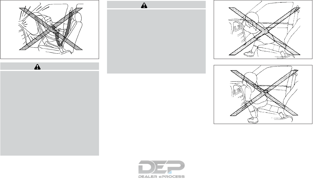
WARNING
•Even with the INFINITI Advanced Air
Bag System, never install a rear-facing
child restraint in the front seat. An in-
flating front air bag could seriously in-
jure or kill your child. For additional in-
formation, refer to "Child restraints" in
the "1. Safety — seats, seat belts and
supplemental restraint system" section.
•Children may be severely injured or
killed when the front air bags, side air
bags or curtain air bags inflate if they
are not properly restrained. Pre-teens
and children should be properly re-
strained in the rear seat, if possible.
WARNING
Front seat-mounted side-impact supple-
mental air bags and roof-mounted curtain
side-impact and rollover supplemental air
bags:
•The side air bags and curtain air bags
ordinarily will not inflate in the event of
a frontal impact, rear impact, or lower
severity side collision. Always wear your
seat belts to help reduce the risk or se-
verity of injury in various kinds of
accidents.
SSS0100Z ARS1041Z
ARS1042Z
Safety — seats, seat belts and supplemental restraint system 1-41
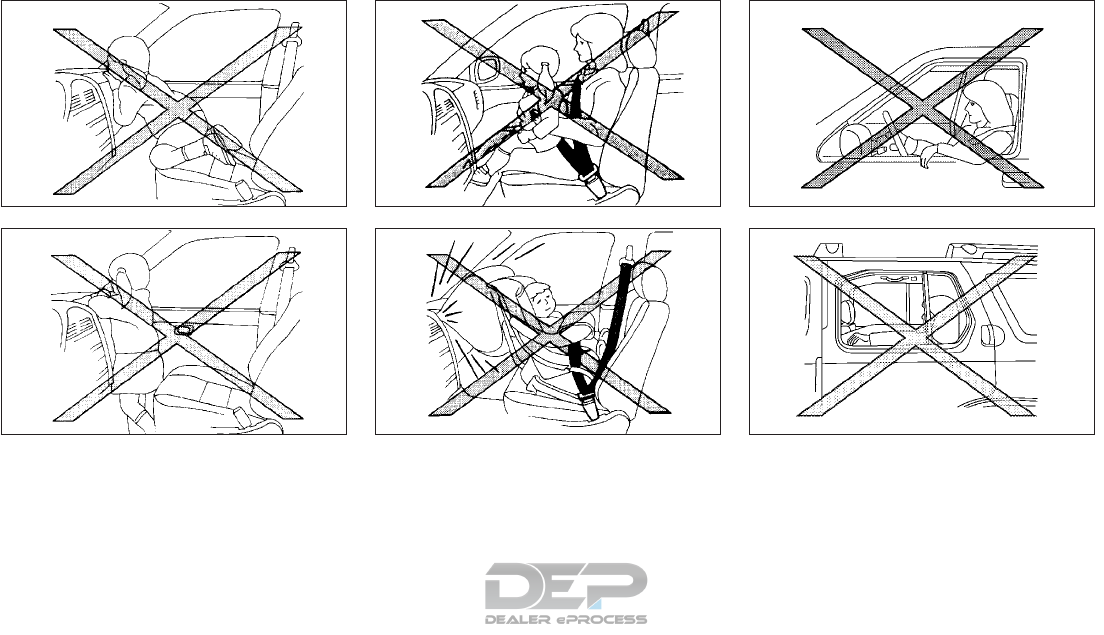
ARS1043Z
ARS1044Z
ARS1045Z
ARS1046Z
WRS0431Z
WRS0365Z
1-42 Safety — seats, seat belts and supplemental restraint system
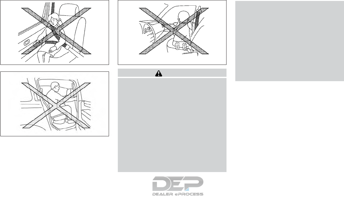
WARNING
•The seat belts, the side air bags and cur-
tain air bags are most effective when
you are sitting well back and upright in
the seat with both feet on the floor. The
side air bag and curtain air bag inflate
with great force. Do not allow anyone to
place their hand, leg or face near the side
air bag on the side of the seatback of the
front seat or near the side roof rails. Do
not allow anyone sitting in the front
seats or rear outboard seats to extend
their hand out of the window or lean
against the door. Some examples of
dangerous riding positions are shown in
the previous illustrations.
•When sitting in the rear seats, do not
hold onto the seatback of the front
seats. If side air bags and curtain air
bags inflate, you may be seriously in-
jured. Be especially careful with chil-
dren, who should always be properly re-
strained. Some examples of dangerous
riding positions are shown in the illus-
trations.
•Do not use seat covers on the front seat-
backs. They may interfere with the side
air bag inflation.
SSS0162Z
WRS0363Z
SSS0159Z
Safety — seats, seat belts and supplemental restraint system 1-43
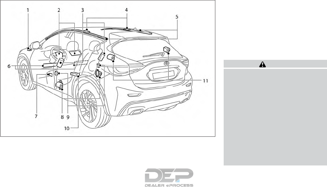
SUPPLEMENTAL AIR BAG
SYSTEMS
1. Crash zone sensor
2. Supplemental front-impact air bag mod-
ules
3. Front seat-mounted side-impact supple-
mental air bag modules
4. Roof-mounted curtain side-impact and
rollover supplemental air bag inflators
5. Roof-mounted curtain side-impact and
rollover supplemental air bag modules
6. Driver and passenger supplemental knee
air bags
7. Front door pressure sensors
8. Front seat belt with pretensioners
9. Satellite sensors
10. Air bag Control Unit (ACU)
11. Rear seat belt with pretensioners
Infiniti Advanced Air Bag System
(front seats)
WARNING
To ensure proper operation of the passen-
ger's INFINITI Advanced Air Bag System,
please observe the following items:
•If a forward-facing child restraint is in-
stalled in the front passenger seat, do
not position the front passenger seat so
the child restraint contacts the instru-
ment panel. If the child restraint does
contact the instrument panel, the sys-
tem may determine the seat is occupied
and the passenger air bag may deploy in
a collision. For additional information
about installing and using child re-
straints, refer to "Child restraints" in the
"1. Safety — seats, seat belts and
supplemental restraint system" section.
NIC2754
1-44 Safety — seats, seat belts and supplemental restraint system

•Confirm the operating condition with
the front passenger air bag status light.
•If you notice that the front passenger air
bag status light is not operating as de-
scribed in this section. It is recom-
mended that you visit an INFINITI re-
tailer to check the occupant
classification system.
•Until you have confirmed with a retailer
that your passenger seat occupant clas-
sification system is working properly,
position the occupants in the rear seat-
ing positions.
This vehicle is equipped with the INFINITI
Advanced Air Bag System for the driver and
front passenger seats. This system is de-
signed to meet certification requirements un-
der U.S. regulations. It is also permitted in
Canada.
All of the information, cautions and warn-
ings in this manual still apply and must be
followed. The driver supplemental front-
impact air bag is located in the center of the
steering wheel. The front passenger supple-
mental front-impact air bag is mounted in the
dashboard above the glove box. The front air
bags are designed to inflate in higher severity
frontal collisions, although they may inflate if
the forces in another type of collision are
similar to those of a higher severity frontal
impact. They may not inflate in certain frontal
collisions. Vehicle damage (or lack of it) is not
always an indication of proper front air bag
system operation.
The INFINITI Advanced Air Bag System
monitors information from the crash zone
sensor, the Air bag Control Unit (ACU), seat
belt buckle sensor and occupant classifica-
tion sensor (pressure sensor). Inflator opera-
tion is based on the severity of a collision and
seat belt usage for the driver. For the front
passenger, the occupant classification sensor
is also monitored. Based on information from
the sensor, only one front air bag may inflate
in a crash, depending on the crash severity
and whether the front occupants are belted
or unbelted. Additionally, the front passenger
air bag may be automatically turned off un-
der some conditions, depending on the infor-
mation provided by the Occupation Classifi-
cation System Sensor. If the front passenger
air bag is OFF, the <PASSENGER AIR BAG
OFF> indicator light will be illuminated.
For additional information, refer to "Front
passenger air bag and status light" in the "1.
Safety — seats, seat belts and supplemental
restraint system" section. One front air bag
inflating does not indicate improper perfor-
mance of the system.
If a crash occurs in which the vehicle's air
bags deploy, by design the vehicle may not
restart. If this occurs, it is recommended that
you visit an INFINITI retailer for repair.
If you have any questions about your air bag
system, it is recommended that you visit an
INFINITI retailer to obtain information about
the system. If you are considering modifica-
tion of your vehicle due to a disability, you
may also contact INFINITI. Contact informa-
tion is contained in the front of this Owner's
Manual.
When a front air bag inflates, a fairly loud
noise may be heard, followed by the release
of smoke. This smoke is not harmful and does
not indicate a fire. Care should be taken to
not inhale it, as it may cause irritation and
choking. Those with a history of a breathing
condition should get fresh air promptly.
Front air bags, along with the use of seat
belts, help to cushion the impact force on the
face and chest of the front occupants. They
can help save lives and reduce serious injuries.
However, an inflating front air bag may cause
facial abrasions or other injuries. Front air
bags do not provide restraint to the lower
body.
Safety — seats, seat belts and supplemental restraint system 1-45
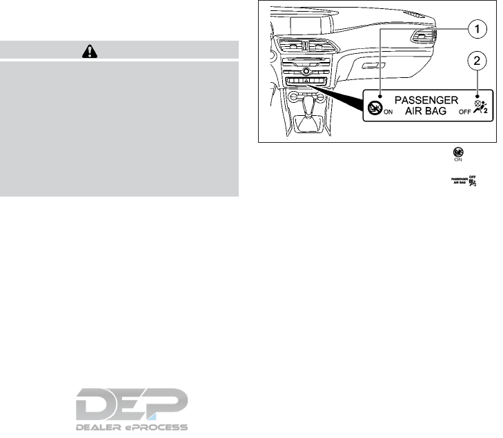
Even with INFINITI Advanced Air Bags, seat
belts should be correctly worn and the driver
and passenger seated upright as far as prac-
tical away from the steering wheel or instru-
ment panel. The front air bags inflate quickly
in order to help protect the front occupants.
Because of this, the force of the front air bag
inflating can increase the risk of injury if the
occupant is too close to, or is against, the
front air bag module during inflation. The
front air bags deflate quickly after a collision.
The front air bags operate only when the
ignition switch is placed in the ON position.
After placing the ignition switch in the ON
position, the supplemental air bag warning
light illuminates. The supplemental air bag
warning light will turn off a few seconds af-
ter the engine starts if the system is opera-
tional.
Front passenger air bag and status
light
WARNING
The front passenger air bag is designed to
automatically turn OFF under some condi-
tions. Read this section carefully to learn
how it operates. Proper use of the seat,
seat belt and child restraints is necessary
for most effective protection. Failure to
follow all instructions in this manual con-
cerning the use of seats, seat belts and
child restraints can increase the risk or se-
verity of injury in an accident.
䊊
1<PASSENGER AIR BAG ON> indi-
cator light
䊊
2<PASSENGER AIR BAG OFF> in-
dicator light
Status light
The front passenger seat is equipped with an
occupant classification sensor (pressure sen-
sor) that turns the front passenger air bag on
or off depending on the weight applied to the
front passenger seat. The indicator lights in-
form you whether the front passenger front
air bag is disabled or enabled.
Place the ignition in the ON position. The
system carries out a self-diagnosis.
NIC2740
1-46 Safety — seats, seat belts and supplemental restraint system

The <PASSENGER AIRBAGOFF> and <PAS-
SENGER AIRBAG ON> indicator lights will
light up simultaneously for approximately six
seconds.
The indicator lights display the status of the
front passenger front air bag:
•<PASSENGER AIRBAG ON> lights up: the
front passenger front air bag is enabled. If,
in the event of an accident, all deployment
criteria are met, the front passenger front
air bag is deployed.
•<PASSENGER AIRBAG OFF> lights up:
the front passenger front air bag is dis-
abled. It will then not be deployed in the
event of an accident.
If the status of the front passenger front air
bag changes while the vehicle is in motion, an
air bag display message appears in the ve-
hicle information display. When the front
passenger seat is occupied, always pay at-
tention to the <PASSENGER AIRBAG ON>
and <PASSENGER AIRBAG OFF> indicator
lights. Be aware of the status of the front
passenger front air bag both before and dur-
ing the journey.
If neither the <PASSENGER AIRBAG OFF>
or the <PASSENGER AIRBAG ON> indicator
lights light up, or if either indicator light only
lights up intermittently during the journey, the
front passenger seat may not be used for a
child restraint. Use another seating position
for the child restraint. INFINITI recommends
that all child restraints be installed in the rear
seat. Preteen children should be seated in the
rear seat. For further information see
"Troubleshooting" later in this section.
Front passenger air bag
The front passenger air bag is designed to
automatically turn OFF when the vehicle is
operated under some conditions as described
below in accordance with U.S. regulations. If
the front passenger air bag is OFF, it will not
inflate in a crash. The driver air bag and other
air bags in your vehicle are not part of this
system. The purpose of the regulation is to
help reduce the risk of injury or death from an
inflating air bag to certain front passenger
seat occupants, such as children, by requiring
the air bag to be automatically turned OFF
under some conditions. Certain sensors are
used to meet the requirements.
The occupant classification sensor in this ve-
hicle is a pressure sensor. It is designed to
detect an occupant and objects on the seat
by weight. For example, if a child up to the
approximate size and weight of a one year
old is properly restrained is in the front pas-
senger seat, the INFINITI Advanced Air Bag
System is designed to turn the front passen-
ger air bag OFF. For a properly restrained
child who is larger than the approximate size
and weight of a one year old, the front pas-
senger air bag may or may not be automati-
cally turned OFF, depending on the size of
the child and the type of child restraint being
used. After installing the child restraint and
positioning the child, place the ignition switch
in the ON position: if the <PASSENGER AIR
BAG OFF> indicator light is illuminated, the
air bag is OFF. If the <PASSENGER AIR BAG
ON> indicator light is illuminated, the air bag
will inflate in a crash. Front passenger seat
adult occupants who are properly seated and
using the seat belt as outlined in this manual
should not cause the front passenger air bag
to be automatically turned OFF. For small
adults it may be turned OFF, however if the
occupant takes his/her weight off the seat
cushion (for example, by not sitting upright,
by sitting on an edge of the seat, or by oth-
erwise being out of position), this could cause
the sensor to turn the air bag OFF. Always be
sure to be seated and wearing the seat belt
properly for the most effective protection by
the seat belt and supplemental air bag.
INFINITI recommends that pre-teens and
children be properly restrained in a rear seat.
INFINITI also recommends that appropriate
Safety — seats, seat belts and supplemental restraint system 1-47

child restraints and booster seats be properly
installed in a rear seat. If this is not possible,
the occupant classification sensor is designed
to operate as described above to turn the
front passenger air bag OFF for specified
child restraints as required by the regulations.
Failing to properly secure child restraints and
to use the ALR mode may allow the restraint
to tip or move in a collision or sudden stop.
This can also result in the passenger air bag
inflating in a crash instead of being OFF. For
additional information about proper use and
installation, refer to "Child restraints" in the "1.
Safety — seats, seat belts and supplemental
restraint system" section.
If the front passenger seat is not occupied,
the front passenger air bag is designed not to
inflate in a crash. However, heavy objects
placed on the seat could result in air bag
inflation, because of the object's weight de-
tected by the occupant classification sensor.
Other conditions could also result in air bag
inflation, such as if a child is standing on the
seat, or if two children are on the seat, con-
trary to the instructions in this manual. Al-
ways be sure that you and all vehicle occu-
pants are seated and restrained properly.
If the automatic front passenger air bag de-
activation system detects that:
•The front passenger seat is unoccupied,
the <PASSENGER AIRBAG OFF> indica-
tor light lights up after the system self-test
and remains lit. This indicates that the
front passenger front air bag is disabled.
•The front passenger seat is occupied by a
properly restrained child up to the approxi-
mate size and weight of a one year old, the
<PASSENGER AIRBAG OFF> indicator
light lights up after the system self-test
and remains lit. This indicates that the
front passenger front air bag is disabled.
If neither the <PASSENGER AIRBAG
OFF> or the <PASSENGER AIRBAG ON>
indicator lights light up, or if either indica-
tor light only lights up intermittently during
the journey, the front passenger seat may
not be used for a child restraint. Use an-
other seating position for the child re-
straint. For further information see
"Troubleshooting" later in this section.
•The front passenger seat is occupied by a
properly restrained child who is larger than
the approximate size and weight of a one
year old, either the <PASSENGER AIR-
BAGON> or <PASSENGER AIRBAGOFF>
indicator light lights up and remains lit af-
ter the system self-test depending on the
result of the classification. The result of
the classification is dependent on, among
other factors, the child restraint system
and the child's build.
Move the front passenger seat as far back
as possible. See "Child restraints" earlier in
this section.
•The front passenger seat is occupied by a
person with a smaller build (e.g. a teenager
or small adult), either the <PASSENGER
AIRBAG ON> or <PASSENGER AIRBAG
OFF> indicator light lights up and remains
lit after the system self-test depending on
the result of the classification.
– If the <PASSENGER AIRBAGON> indi-
cator light lights up, move the front
passenger seat as far back as possible.
Alternatively, a person with a small
build can sit on a rear seat.
– If the <PASSENGER AIRBAG OFF> in-
dicator light is lit, a person with a
smaller build should not use the front
passenger seat.
1-48 Safety — seats, seat belts and supplemental restraint system

•The front passenger seat is occupied by an
adult or a person with a build correspond-
ing to that of an adult, the <PASSENGER
AIRBAGON> indicator light lights up after
the system self-test and remains lit. This
indicates that the front passenger front air
bag is enabled.
If the automatic front passenger front air bag
deactivation system is malfunctioning, the
red restraint system warning light in the
combination meter and the <PASSENGER
AIRBAG OFF> indicator light light up simul-
taneously. The front passenger front air bag
is disabled in this case and does not deploy
during an accident. Have the system checked
as soon as possible by qualified technicians. It
is recommended that you visit an INFINITI
retailer for this service.
Safety — seats, seat belts and supplemental restraint system 1-49

Troubleshooting
Problem Possible causes/consequences and solutions
The <PASSENGER AIRBAGOFF>
indicator lamp lights up and
remains lit, even though the front
passenger seat is occupied by an
adult or a person with a build
corresponding to that of an adult
•Make sure the conditions for a correct classification of the person on the front passenger seat are met (see "Front
passenger air bag" earlier in this section).
•If the <PASSENGER AIRBAG OFF> indicator light remains lit, the front passenger seat may not be used.
•Have the automatic front passenger front air bag deactivation system checked as soon as possible. It is recommended
that you visit an INFINITI retailer for this service.
The <PASSENGER AIRBAGOFF>
indicator lamp does not light up
and/or does not stay on.
•Make sure there is nothing between the seat and the child restraint system.
•Make sure that the entire base of the child restraint system rests on the seat cushion of the front passenger seat.
•When installing the child restraint system, make sure that the seat belt is tight. Do not pull the seat belt tight with the front
passenger seat adjustment. This could result in the seat belt and the child restraint system being pulled too tightly.
•Check that the child restraint system is installed correctly.
•Make sure that no objects are applying additional weight to the seat.
•Have the automatic front passenger front air bag deactivation system checked as soon as possible. It is recommended
that you visit an INFINITI retailer for this service.
1-50 Safety — seats, seat belts and supplemental restraint system

Other supplemental front-impact
air bag precautions
WARNING
•Do not place any objects on the steering
wheel pad or on the instrument panel.
Also, do not place any objects between
any occupant and the steering wheel or
instrument panel. Such objects may be-
come dangerous projectiles and cause
injury if the front air bags inflate.
•Immediately after inflation, several
front air bag system components will be
hot. Do not touch them; you may se-
verely burn yourself.
•No unauthorized changes should be
made to any components or wiring of
the supplemental air bag system. This is
to prevent accidental inflation of the
supplemental air bag or damage to the
supplemental air bag system.
•Do not make unauthorized changes to
your vehicle's electrical system, suspen-
sion system or front end structure. This
could affect proper operation of the
front air bag system.
•
Tampering with the front air bag system
may result in serious personal injury. Tam-
pering includes changes to the steering
wheel and the instrument panel assembly
by placing material over the steering wheel
pad and above the instrument panel or by
installing additional trim material around
the air bag system.
•Removing or modifying the front pas-
senger seat may affect the function of
the air bag system and result in serious
personal injury.
•Modifying or tampering with the front
passenger seat may result in serious
personal injury. For example, do not
change the front seats by placing mate-
rial on the seat cushion or by installing
additional trim material, such as seat
covers, on the seat that are not specifi-
cally designed to assure proper air bag
operation. Additionally, do not stow any
objects under the front passenger seat
or the seat cushion and seatback. Such
objects may interfere with the proper
operation of the occupant classification
sensor (pressure sensor).
•No unauthorized changes should be
made to any components or wiring of
the seat belt system. This may affect the
front air bag system. Tampering with
the seat belt system may result in seri-
ous personal injury.
•It is recommended that you visit an
INFINITI retailer for work on and around
the front air bag. It is also recommended
that you visit an INFINITI retailer for
installation of electrical equipment. The
Supplemental Restraint System (SRS)
wiring harnesses* should not be modi-
fied or disconnected. Unauthorized
electrical test equipment and probing
devices should not be used on the air bag
system.
•A cracked windshield should be replaced
immediately by a qualified repair facil-
ity. A cracked windshield could affect
the function of the supplemental air bag
system.
* The SRS wiring harness connectors are
yellow and orange for easy identification.
When selling your vehicle, we request that
you inform the buyer about the front air bag
system and guide the buyer to the appropri-
ate sections in this Owner's Manual.
Safety — seats, seat belts and supplemental restraint system 1-51
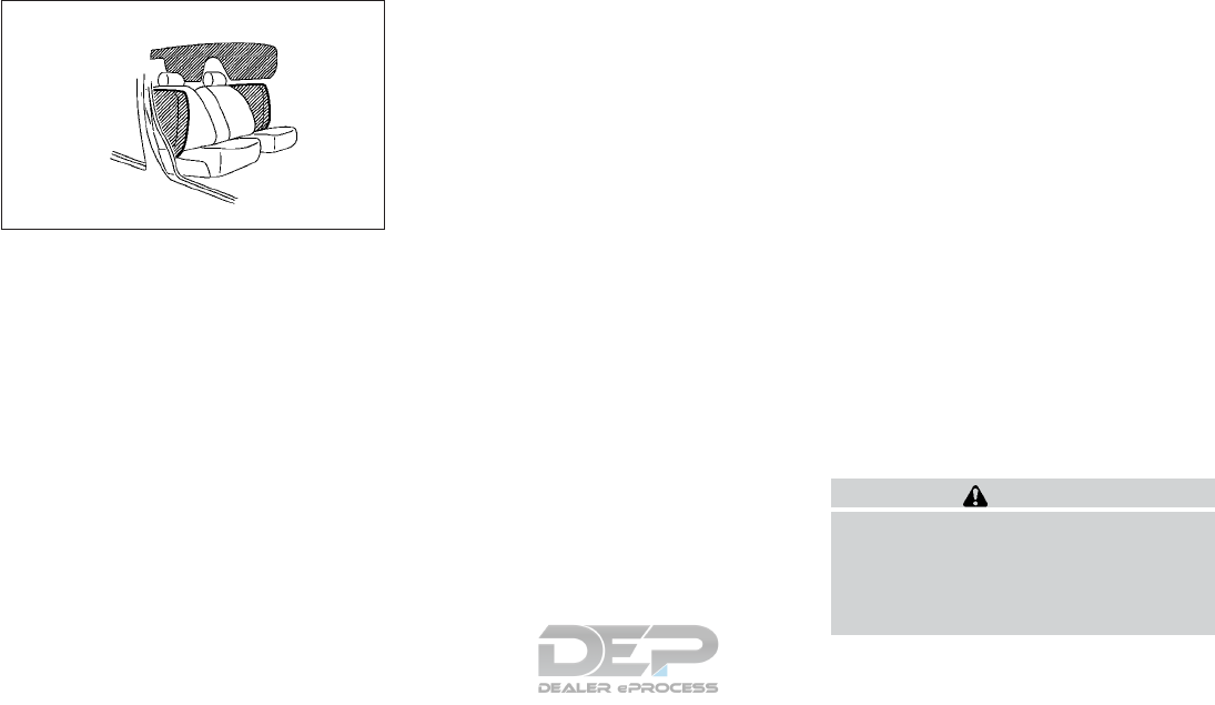
Front seat-mounted side-impact
supplemental air bag and
roof-mounted curtain side-impact
and rollover supplemental air bag
systems
The side air bags are located in the outside of
the seatback of the front seats. The curtain
air bags are located in the side roof rails. All of
the information, cautions and warnings in
this manual apply and must be followed. The
side air bags and curtain air bags are de-
signed to inflate in higher severity side colli-
sions, although they may inflate if the forces
in another type of collision are similar to
those of a higher severity impact. They are
designed to inflate on the side where the
vehicle is impacted. They may not inflate in
certain side collisions. Curtain air bags are
also designed to inflate in certain types of
rollover collisions or near rollovers. As a re-
sult, certain vehicle movements (for example,
during severe off-roading) may cause the
curtain air bags to inflate.
Vehicle damage (or lack of it) is not always an
indication of proper side air bag and curtain
air bag operation.
When the side air bags and curtain air bags
inflate, a fairly loud noise may be heard, fol-
lowed by release of smoke. This smoke is not
harmful and does not indicate a fire. Care
should be taken not to inhale it, as it may
cause irritation and choking. Those with a
history of a breathing condition should get
fresh air promptly.
Side air bags, along with the use of seat belts,
help to cushion the impact force on the chest
of the front occupants. Curtain air bags help
to cushion the impact force to the head of
occupants in the front and rear outboard
seating positions in all rows. They can help
save lives and reduce serious injuries. How-
ever, an inflating side air bag or curtain air
bag may cause abrasions or other injuries.
Side air bags and curtain air bags do not
provide restraint to the lower body.
The seat belts should be correctly worn and
the driver and front passenger seated upright
as far as practical away from the side air bag.
Rear seat passengers should be seated as far
away as practical from the door finishers and
side roof rails. The side air bags and curtain
air bags inflate quickly in order to help protect
the occupants. Because of this, the force of
the side air bags and curtain air bags inflating
can increase the risk of injury if the occupant
is too close to, or is against, these air bag
modules during inflation. The side air bag will
deflate quickly after the collision is over.
The curtain air bag will remain inflated for a
short time.
The side air bags and curtain air bags oper-
ate only when the ignition switch is placed in
the ON position. After placing the ignition
switch in the ON position, the supplemental
air bag warning light illuminates. The
supplemental air bag warning light will turn
off a few seconds after the engine starts if
the system is operational.
WARNING
•Do not place any objects near the seat-
back of the front seats. Also, do not
place any objects (an umbrella, bag, etc.)
between the front door finisher and the
front seat. Such objects may become
SSS0978Z
1-52 Safety — seats, seat belts and supplemental restraint system

dangerous projectiles and cause injury if
a side air bag inflates.
•Right after inflation, several side air bag
and curtain air bag system components
will be hot. Do not touch them; you may
severely burn yourself.
•No unauthorized changes should be
made to any components or wiring of
the side air bag and curtain air bag sys-
tems. This is to prevent damage to or
accidental inflation of the side air bag
and curtain air bag systems.
•Do not make unauthorized changes to
your vehicle’s electrical system, suspen-
sion system or side panel. This could af-
fect proper operation of the curtain air
bag systems.
•Tampering with the side air bag system
may result in serious personal injury. For
example, do not change the front seats
by placing material near the seatbacks
or by installing additional trim material,
such as seat covers, around the side air
bag.
•It is recommended that you visit an
INFINITI retailer for work on and around
the front air bag. It is also recommended
that you visit an INFINITI retailer for
installation of electrical equipment. The
SRS wiring harnesses* should not be
modified or disconnected. Unauthorized
electrical test equipment and probing
devices should not be used on the side air
bag or curtain air bag systems.
Driver and passenger supplemental
knee air bags
The driver's knee air bag deploys under the
steering column, while the passenger's knee
air bag deploys under the glove box. All of the
information, cautions and warnings in this
manual apply and must be followed. The driv-
er's and passenger's knee air bags are trig-
gered together with the front air bag. The
knee air bags are designed to inflate in higher
severity frontal collisions, although they may
inflate if the forces in another type of collision
are similar to those of a higher severity fron-
tal impact. They may not inflate in certain
collisions.
Vehicle damage (or lack of it) is not always an
indication of proper knee air bag operation.
When a knee air bag inflates, a fairly loud
noise may be heard, followed by release of
smoke. This smoke is not harmful and does
not indicate a fire. Care should be taken not
to inhale it, as it may cause irritation and
choking. Those with a history of a breathing
condition should get fresh air promptly
The knee air bags help to cushion the impact
force on the knees of the driver and front
passenger. They can help reduce serious inju-
ries. However, an inflating knee air bag may
cause abrasions or other injuries. The knee air
bag provides restraint to the lower body.
The knee air bag inflates quickly in order to
help protect the occupants. Because of this,
the force of the knee air bag inflating can
increase the risk of injury if the occupant is
too close to, or is against, this air bag module
during inflation. The knee air bag will deflate
quickly after the collision is over OR the knee
air bag will remain inflated for a short time.
The knee air bags operate only when the ig-
nition switch is placed in the ON position.
After placing the ignition switch in the ON
position, the supplemental air bag warning
light illuminates. The supplemental air bag
warning light will turn off a few seconds af-
ter the engine starts if the system is opera-
tional.
Safety — seats, seat belts and supplemental restraint system 1-53

WARNING
•Do not place any objects between the
knee bolster and the driver’s seat. Such
objects may become dangerous projec-
tiles and cause injury if a knee air bag
inflates.
•Right after inflation, the knee air bag
system components will be hot. Do not
touch them; you may severely burn
yourself.
•No unauthorized changes should be
made to any components or wiring of
the knee air bag system. This is to pre-
vent damage to or accidental inflation
of the knee air bag system.
•Do not make unauthorized changes to
your vehicle’s electrical system or sus-
pension system. This could affect proper
operation of the knee air bag system.
•Tampering with the knee air bag system
may result in serious personal injury. For
example, do not change the driver knee
bolster or install additional trim material
around the knee air bag.
•It is recommended that you visit an
INFINITI retailer for work on and around
the front air bag. It is also recommended
that you visit an INFINITI retailer for
installation of electrical equipment. The
SRS wiring harnesses* should not be
modified or disconnected. Unauthorized
electrical test equipment and probing
devices should not be used on the knee
air bag system.
* The SRS wiring harness or connectors
are yellow or orange for easy
identification.
When selling your vehicle, we request that
you inform the buyer about the knee air bag
system and guide the buyer to the appropri-
ate sections in this manual.
Seat belt with pretensioner(s)
WARNING
•The pretensioner(s) cannot be reused
after activation. They must be replaced
together with the retractor and buckle
as a unit.
•If the vehicle becomes involved in a col-
lision but pretensioner(s) are not acti-
vated, be sure to have the pretensioner
system checked and, if necessary, re-
placed. It is recommended that you visit
an INFINITI retailer for this service.
•No unauthorized changes should be
made to any components or wiring of
the pretensioner system. This is to pre-
vent damage to or accidental activation
of the pretensioner(s). Tampering with
the pretensioner system may result in
serious personal injury.
•It is recommended that you visit an
INFINITI retailer for work on and around
the pretensioner system. It is also rec-
ommended that you visit an INFINITI re-
tailer for installation of electrical equip-
ment. Unauthorized electrical test
equipment and probing devices should
not be used on the pretensioner system.
1-54 Safety — seats, seat belts and supplemental restraint system
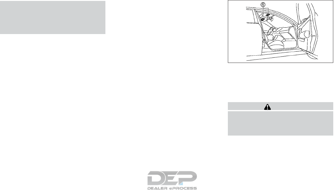
•If you need to dispose of the pretension-
er(s) or scrap the vehicle, it is recom-
mended that you visit an INFINITI re-
tailer for this service. Incorrect disposal
procedures could cause personal injury.
The pretensioner system may activate with
the supplemental air bag system in certain
types of collisions. Working with the seat belt
retractor, the pretensioner(s) help tighten the
seat belt when the vehicle becomes involved
in certain types of collisions, helping to re-
strain front seat and rear outboard occu-
pants. The pretensioner(s) are encased within
the seat belt retractor and to the seat belt
anchor affixed to the floor of the vehicle.
These seat belts are used the same way as
conventional seat belts. When pretension-
er(s) activate, smoke is released and a loud
noise may be heard. This smoke is not harm-
ful and does not indicate a fire. Care should
be taken not to inhale it, as it may cause
irritation and choking. Those with a history of
a breathing condition should get fresh air
promptly. After the pretensioner(s)'s activa-
tion, load limiters allow the seat belt to re-
lease webbing (if necessary) to reduce forces
against the chest. The supplemental air bag
warning light is used to indicate malfunctions
in the pretensioner system. For additional in-
formation, refer to Supplemental air bag
warning light in this section. If the operation
of the supplemental air bag warning light
indicates there is a malfunction, have the sys-
tem checked. It is recommended that you visit
an INFINITI retailer for this service. When
selling your vehicle, we request that you in-
form the buyer about the pretensioner sys-
tem and guide the buyer to the appropriate
sections in this Owner's Manual.
SUPPLEMENTAL AIR BAG
WARNING LABELS
Warning labels about the supplemental front
impact air bag system are placed in the ve-
hicle as shown in the illustration.
WARNING
Do not use a rear-facing child restraint on a
seat protected by an air bag in front of it. If
the air bag deploys, it may cause serious
injury or death.
SSS1016Z
Safety — seats, seat belts and supplemental restraint system 1-55

SUPPLEMENTAL AIR BAG
WARNING LIGHT
The supplemental air bag warning light, dis-
playing in the instrument panel, moni-
tors the circuits for the air bag systems, pre-
tensioner(s) and all related wiring.
When the ignition switch is placed in the ON
position, the supplemental air bag warning
light illuminates. The air bag warning light will
turn off within a few seconds after the engine
is started, if the system is operational.
If any of the following conditions occur, the
front air bag, side air bag, curtain air bag and
pretensioner systems need servicing:
•The supplemental air bag warning light
remains on after approximately 7 seconds.
•The supplemental air bag warning light
flashes intermittently.
•The supplemental air bag warning light
does not come on at all.
Under these conditions, the front air bag,
side air bag, curtain air bag, knee air bag or
pretensioner systems may not operate
properly. They must be checked and re-
paired. It is recommended that you visit an
INFINITI retailer for this service.
WARNING
If the supplemental air bag warning light is
on, it could mean that the front air bag, side
air bag, knee air bag, curtain air bag and/or
pretensioner systems will not operate in an
accident. To help avoid injury to yourself or
others, have your vehicle checked as soon
as possible. It is recommended that you
visit an INFINITI retailer for this service.
REPAIR AND REPLACEMENT
PROCEDURE
The front air bags, side air bags, curtain air
bags, knee air bags and pretensioner(s) are
designed to inflate on a one-time-only basis.
As a reminder, unless it is damaged, the
supplemental air bag warning light remains
illuminated after inflation has occurred.
These systems should be repaired and/or re-
placed as soon as possible. It is recom-
mended that you visit an INFINITI retailer for
this service.
When maintenance work is required on the
vehicle, the front air bags, side air bags, cur-
tain air bags, knee air bags, pretensioner(s)
and related parts should be pointed out to the
person performing the maintenance. The ig-
nition switch should always be in the LOCK
position when working under the hood or
inside the vehicle.
WARNING
•Once a front air bag, side air bag, knee
air bag, or curtain air bag has inflated,
the air bag module will not function
again and must be replaced. Addition-
ally, the activated pretensioner(s) must
also be replaced. The air bag module and
pretensioner(s) should be replaced. It is
recommended that you visit an INFINITI
retailer for this service. However, the air
bag module and pretensioner(s) cannot
be repaired.
•The front air bag, side air bag, knee air
bag, curtain air bag systems and the
pretensioner system should be in-
spected if there is any damage to the
front end or side portion of the vehicle. It
SPA1097Z
1-56 Safety — seats, seat belts and supplemental restraint system

is recommended that you visit an
INFINITI retailer for this service.
•If you need to dispose of a supplemental
air bag or pretensioner systems or scrap
the vehicle, it is recommended you visit
an INFINITI retailer. Incorrect disposal
procedures could cause personal injury.
•If there is an impact to your vehicle from
any direction, your automatic front pas-
senger air bag deactivation system
should be checked to verify it is still
functioning correctly. It is recommended
that you visit an INFINITI retailer for
this service. The system should be
checked even if no air bags deploy as a
result of the impact. Failure to verify
proper automatic front passenger air
bag deactivation system function may
result in an improper air bag deployment
resulting in injury or death.
Safety — seats, seat belts and supplemental restraint system 1-57

2 Instruments and controls
Cockpit ............................2-2
Instrument panel ......................2-3
Meters and gauges .....................2-4
Speedometer and odometer .............2-4
Outside temperature display .............2-5
Tachometer .......................2-6
Engine coolant temperature gauge .........2-6
Fuel gauge ........................2-7
Warning lights, indicator lights and audible
reminders ...........................2-8
Checking lights .....................2-8
Warning lights ......................2-8
Indicator lights .....................2-13
Audible reminders ...................2-14
Vehicle information display ...............2-15
Menus and submenus ................2-16
Display Messages ...................2-29
Security system ......................2-59
Immobiliser .......................2-59
Anti-theft alarm system (if equipped).......2-59
Wiper and washer switch ................2-60
Switching the windshield wipers on/off .....2-61
Switching the rear window wiper on/off . . . .2-62
Rear window and outside mirror defroster
switch ............................2-63
Windshield de-icer switch (if equipped) .......2-63
Headlight and turn signal switches ..........2-64
Headlight switch ...................2-64
Combination switch .................2-66
Adaptive front lighting system
(LED headlight only) (if equipped) .........2-67
High beam assist (LED headlight only)......2-68
Headlights misted up on the inside ........2-70
Instrument brightness control ...........2-70
Fog light switch (If so equipped)............2-70
Front fog lights ....................2-70
Rear fog light ......................2-71
Horn .............................2-71
Seat heating (if equipped) ................2-72
Windows ..........................2-73
Power windows ....................2-73
Fixed glass roof (if equipped) ..............2-76
Sunshade operation .................2-76
Clock .............................2-77
Adjusting time .....................2-77
Power outlet ........................2-78
Storage ...........................2-79
Glove box ........................2-79
Front console compartment ............2-79
Console box ......................2-80
Card holder.......................2-80
Cup holders ......................2-80
Coat hooks .......................2-81
Cargo tie-down hooks ................2-81

Luggage hooks ....................2-82
Front seat storage boxes (if equipped)......2-83
Map pocket (if equipped) ..............2-83
Storage nets (if equipped)..............2-83
Parcel shelf .......................2-84
Roof rack (if equipped)................2-84
Ski hatch (if equipped) ................2-85
Compartment under trunk floor ..........2-86
Interior lights ........................2-86
Front overhead control panel ...........2-86
Rear reading lights (if equipped) ..........2-87
Rear room light (if equipped) ............2-87
Vanity mirror lights ..................2-87
Luggage compartment light ............2-87
Battery saver system .................2-87
HomeLink® Universal Transceiver (if equipped) . .2-88
Programming HomeLink® .............2-88
Programming trouble diagnosis ..........2-90
Operating the HomeLink® Universal
Transceiver .......................2-91
Clearing the programmed information ......2-91
If your vehicle is stolen ................2-91

1. Turn signal, wiper, washer, and high beam
switch (P.2-66, 2-60)
2. Steering-wheel-mounted controls (left
side) (P.2-15)
3. Ignition switch (P.5-15)
— Push button ignition switch* (P.5-16)
4. Steering-wheel-mounted controls (right
side) (P.4-3)
5. Light switch
— Headlight (P.2-64)
— Fog light (P.2-70)
6. Parking brake (P.3-27)
7. Cruise Control switch
— Cruise Control (P.5-46)
— Intelligent Cruise Control (P.2-49)
8. USB connection ports (P.4-4)
9. Shift lever (P.5-21)
10. Front cup holders (P.2-80)
11. INFINITI controller (P.4-2)
NIC2649
COCKPIT
2-2 Instruments and controls
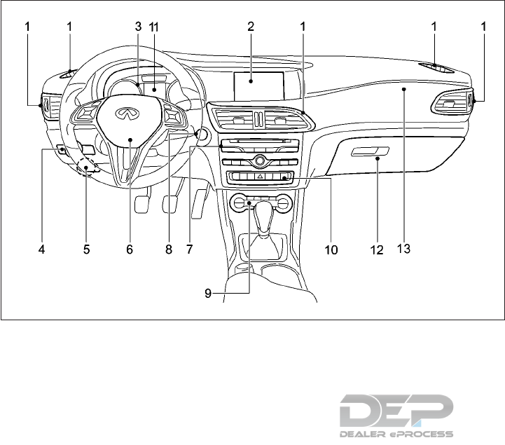
1. Ventilators (P.4-42)
2. Center display* (P.4-4)
3. Meters and gauges (P.2-4)
4. Light switch (P.2-64)
5. Parking brake (P.3-27)
6. Steering wheel
— Power steering system (P.5-90)
— Horn (P. 2-71)
— Driver’s supplemental front-impact air
bag (P.1-38)
7. Audio system (P.4-53)
8. Ignition switch (P.5-15)
— Push button ignition switch* (P.5-16)
9. Heater and air conditioner (P.4-43)
10. Switch panel
— Seat heater switches* (P.2-72)
— Hazard indicator flasher switch (P.6-2)
— Idle Stop/Start system on/off switch
(P. 6-30)
— Front passenger air bag status light
(P.6-46)
11. Vehicle Information Display (P.2-15)
12. Glove box (P.2-79)
13. Front passenger supplemental air bag
(P.1-38)
*: if equipped
NIC2898
INSTRUMENT PANEL
Instruments and controls 2-3

1. Speedometer (P.2-4)
2. Vehicle information display (P.2-15)
— Odometer/twin trip odometer (P.2-15)
3. Upper information display (P.2-15)
4. Tachometer (P.2-6)
5. Engine coolant temperature gauge
(P.2-6)
6. Fuel gauge (P.2-7)
NOTE
The needle indicators may move slightly af-
ter the ignition switch is put in the “OFF”
position. This is not a malfunction.
CAUTION
•For cleaning, use a soft cloth, dampened
with water. Never use a rough cloth, al-
cohol, thinner or any kind of solvent or
paper towel with a chemical cleaning
agent. They will scratch or cause discol-
oration to the lens.
•Do not spray any liquid such as water on
the meter lens. Spraying liquid may
cause the system to malfunction.
SPEEDOMETER AND
ODOMETER
This vehicle is equipped with a speedometer
and odometer. The speedometer is located
on the right side of the meter cluster. The
odometer is located below the vehicle infor-
mation display.
NIC2651
METERS AND GAUGES
2-4 Instruments and controls
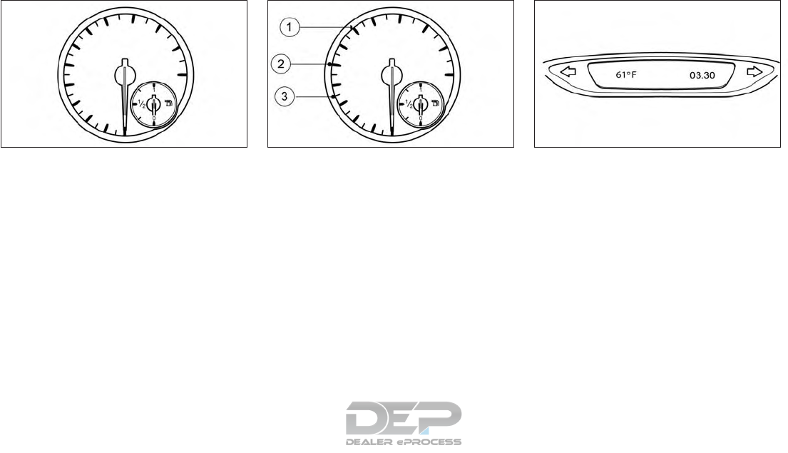
Speedometer
The speedometer indicates vehicle speed.
The speedometer is divided into segments
䊊
1,䊊
2and 䊊
3only on vehicles with Intelligent
Cruise Control.
The segments in the speedometer indicate
which speed range is available (see "Displays
in the speedometer" in the "5. Starting and
driving" section).
Odometer/Twin trip odometer
The odometer and the twin trip odometer are
displayed in the Vehicle Information Display
see "Vehicle information display" in the "5.
Starting and driving" section.
OUTSIDE TEMPERATURE
DISPLAY
You should pay special attention to road con-
ditions when temperatures are around freez-
ing point.
Bear in mind that the outside temperature
display indicates the measured air tempera-
ture and not the road surface temperature
Depending on the vehicle specification, the
outside temperature display is in either the
upper display or the main screen of the ve-
hicle information display. See "Vehicle infor-
mation display" in the "2. Instruments and
controls" section.
NIC2824Z NIC2824AZ
With segments
NSD659
Instruments and controls 2-5
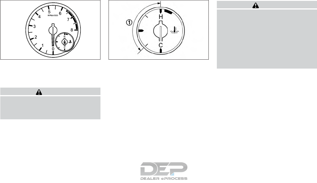
TACHOMETER
The tachometer indicates the engine speed in
revolutions per minute (rpm). Do not rev the
engine in the red zone.
CAUTION
When engine speed approaches the red
zone, shift to a higher gear or reduce engine
speed. Operating the engine in the red zone
may cause serious engine damage.
ENGINE COOLANT
TEMPERATURE GAUGE
The gauge indicates the engine coolant tem-
perature. The engine coolant temperature is
within the normal range 䊊
1when the gauge
needle points within the zone shown in the
illustration. The engine coolant temperature
varies with the outside air temperature and
driving conditions.
CAUTION
If the gauge indicates coolant temperature
near the hot (H) end of the normal range,
reduce vehicle speed to decrease tempera-
ture. If the gauge is over the normal range,
stop the vehicle as soon as safely possible.
If the engine is overheated, continued op-
eration of the vehicle may seriously dam-
age the engine. For additional information,
refer to "If your vehicle overheats" in the
"6. In case of emergency" section for imme-
diate action required.
NIC2829 NIC2831
2-6 Instruments and controls
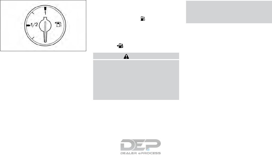
FUEL GAUGE
The fuel gauge indicates the approximate
fuel level in the tank when the ignition switch
is in the ON position.
The gauge may move slightly during braking,
turning, accelerating, or going up and down
hills due to movement of fuel in the tank.
The gauge needle returns to 0 (Empty) after
the ignition switch is placed in the OFF posi-
tion.
The low fuel warning appears on the
vehicle information display when the fuel
level in the tank is getting low.
Refill the fuel tank before the gauge regis-
ters 0 (Empty).
The arrow, , indicates that the fuel-filler
lid is located on the left side of the vehicle.
CAUTION
•If the vehicle runs out of fuel, the Mal-
function Indicator Light (MIL) may
come on. Refuel as soon as possible. Af-
ter a few driving trips. the light should
turn off. If the light remains on after a
few driving trips, have the vehicle in-
spected. It is recommended that you
visit an INFINITI retailer for this service.
•For additional information, refer to "
Malfunction Indicator light (MIL) (yel-
low)" in the "2. Instruments and con-
trols" section.
NIC2653
Instruments and controls 2-7
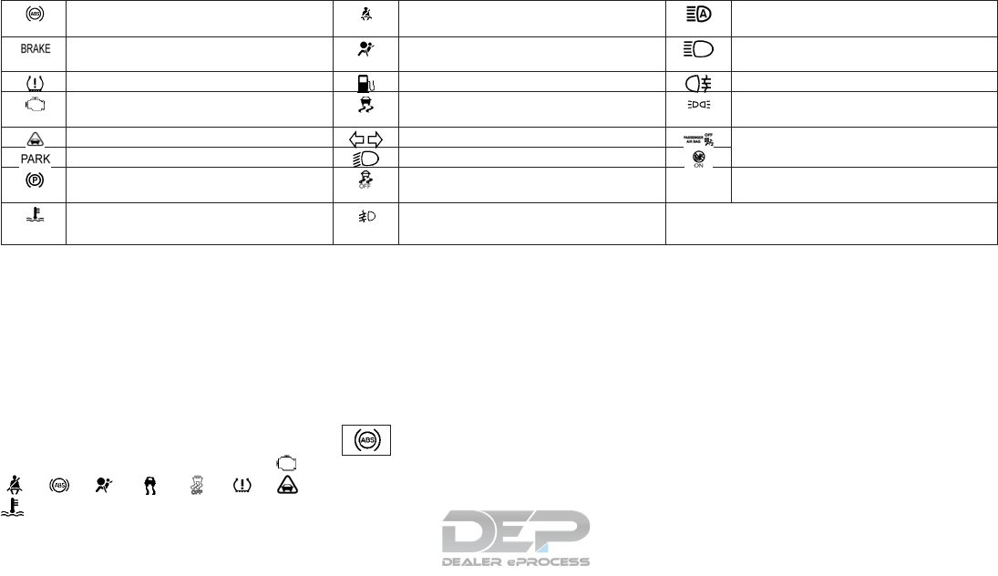
Anti-lock Braking System (ABS) warning
light
Seat belt (driver and front passenger)
warning light
High beam assist indicator light *
Brake warning light (red) Supplemental Restraint System (SRS) air
bag warning light
High beam indicator light
Low tire pressure warning light* Low fuel warning light Rear fog light indicator light
Malfunction indicator light (yellow) Vehicle Dynamic Control (VDC) warning
light
Side light indicator light
Distance warning light* Turn signal/hazard indicator lights Front passenger air bag status light**
Electric parking brake warning light (red) Low beam indicator light
Electric parking brake warning light (yel-
low)
Vehicle Dynamic Control (VDC) OFF in-
dicator light
Coolant warning light Front fog light indicator light* *: if equipped
**: located above heater and air conditioner controls
Some indicators and warnings are also dis-
played in the vehicle information display be-
tween the speedometer and tachometer see
"Vehicle information display" in the "2. Instru-
ments and controls" section.
CHECKING LIGHTS
With all doors closed, apply the parking
brake, fasten the seat belts and place the
ignition switch in the ON position without
starting the engine. The following lights (if so
equipped) will come on, <BRAKE>, ,
, , , , , , ,
. These lights should go out within a few
seconds after starting the engine. If any light
fails to come on or operates in a way other
than described, it may indicate a burned out
bulb and/or a system malfunction. Have the
system checked. It is recommended you visit
an INFINITI retailer for this service.
WARNING LIGHTS
Also see "Vehicle information display" later in
this section.
Anti-lock Braking System
(ABS) warning light
When the ignition switch is in the ON posi-
tion, the ABS warning light illuminates to in-
dicate that the ABS is operational. The light
then turns off within a few seconds after the
engine is started.
If the ABS light comes on while the engine is
running, it may indicate the anti-lock braking
system is not functioning properly. Have the
system checked. It is recommended that you
visit an INFINITI retailer for this service.
If the ABS warning light comes on while driv-
ing, it may indicate the ABS is not functioning
properly. Observe the additional display mes-
sages (if any) in the vehicle information dis-
play. Have the system checked by an
INFINITI retailer.
If an ABS malfunction occurs, the anti-lock
function is turned off. The brake system then
WARNING LIGHTS, INDICATOR
LIGHTS AND AUDIBLE REMINDERS
2-8 Instruments and controls
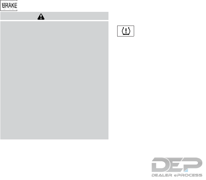
operates normally, but without anti-lock as-
sistance (see "Brake system" in the "5. Start-
ing and driving" section).
BRAKE warning light (red)
WARNING
•Your brake system may not be working
properly if the warning light is on. Driv-
ing could be dangerous. If you judge it to
be safe, drive carefully to the nearest
service station for repairs. Otherwise,
have your vehicle towed because driving
it could be dangerous.
•Pressing the brake pedal when the igni-
tion switch is not in the ON position
and/or when the brake fluid level is low
may increase the stopping distance and
braking will require greater pedal effort
as well as pedal travel.
•If the brake fluid level is below the mini-
mum or MIN mark on the brake fluid res-
ervoir, do not drive until the brake sys-
tem has been checked. It is
recommended that you visit an INFINITI
retailer for this service.
When the ignition switch is placed in the ON
position, the light remains illuminated and
turns off when the engine is started. If the
light illuminates at any other time, it may
indicate that the brake system is not func-
tioning properly. If the BRAKE warning light
illuminates, stop the vehicle immediately and
contact an INFINITI retailer.
This light functions for both the parking brake
and the foot brake systems.
Low tire pressure warning
light (if equipped)
Your vehicle is equipped with a Tire Pressure
Monitoring System (TPMS) that monitors the
tire pressure of all its tires.
The low tire pressure warning light warns of
low tire pressure or indicates that the TPMS
is not functioning properly.
When the ignition switch is in the ON posi-
tion, the Low tire pressure warming light illu-
minates to indicate that the system is opera-
tional. The light then tuns off within a few
seconds after the engine is started.
Low tire pressure warning:
If the vehicle is being driven with low tire
pressure, the warning light will illuminate. A
tire pressure warning message also appears
in the vehicle information display.
When the low tire pressure warning light il-
luminates, you should stop and adjust the
tire pressure of all 4 tires to the recom-
mended COLD tire pressure shown on the
Tire and Loading Information label located in
the driver's door opening, see "Tire and load-
ing information label" in the "9. Mainte-
nance and Schedules" section. The low tire
pressure warning light does not automati-
cally turn off when the tire pressure is ad-
justed. After the tire is inflated to the recom-
mended pressure, the vehicle must be driven
at speeds above 16 MPH (25 km/h) to acti-
vate the TPMS and turn off the low tire
pressure warning light. Use a tire pressure
gauge to check the tire pressure.
The low tire pressure warning message ap-
pears each time the ignition switch is placed
in the ON position as long as the low tire
pressure warning light remains illuminated.
For additional information, see "Vehicle in-
formation display" later in this section and
"Tire Pressure Monitoring System (TPMS)" in
the "5. Starting and driving" section.
TPMS malfunction:
If the TPMS is not functioning properly, the
low tire pressure warning light will flash for
approximately 1 minute when the ignition
switch is placed in the ON position. The light
will remain on after 1 minute. Have the sys-
tem checked. It is recommended that you visit
an INFINITI retailer for this service. The low
tire pressure warning does not appear if the
Instruments and controls 2-9

low tire pressure warning light illuminates to
indicate a TPMS malfunction.
For additional information, see "Tire Pressure
Monitoring System (TPMS)" in the "5. Start-
ing and driving" section.
WARNING
•Radio waves could adversely affect
electric medical equipment. Those who
use a pacemaker should contact the
electric medical equipment manufac-
turer for the possible influences before
use.
•If the light does not illuminate with the
ignition switch pushed ON, have the ve-
hicle checked. It is recommended you
visit an INFINITI retailer for this service.
•If the light illuminates while driving,
avoid sudden steering maneuvers or
abrupt braking, reduce vehicle speed,
pull off the road to a safe location and
stop the vehicle as soon as possible.
Driving with under-inflated tires may
permanently damage the tires and in-
crease the likelihood of tire failure. Seri-
ous vehicle damage could occur and may
lead to an accident and could result in
serious personal injury or death. Check
the tire pressure for all four tires. Adjust
the tire pressure to the recommended
COLD tire pressure shown on the tire
placard, located in the driver's door
opening, to turn the low tire pressure
warning light off. If the light still illumi-
nates while driving after adjusting the
tire pressure, a tire may be flat. If you
have a flat tire, replace it with a replace-
ment tire as soon as possible.
•If a replacement tire is mounted or a
wheel is replaced without a TPMS sen-
sor tire pressure will not be indicated,
the TPMS will not function and the low
tire pressure warning light will flash for
approximately 1 minute. The light will
remain on after 1 minute. Have your ve-
hicle's tires replaced and/or TPMS sys-
tem reset as soon as possible. It is rec-
ommended you visit an INFINITI retailer
for these services.
•Replacing tires with those not originally
specified by INFINITI could affect the
proper operation of the TPMS.
CAUTION
•The TPMS is not a substitute for the
regular tire pressure check. Be sure to
check the tire pressure regularly.
•If the vehicle is being driven at speeds of
less than 16 MPH (25 km/h), the TPMS
may not operate correctly.
•Be sure to install the specified size of
tires to all four wheels correctly.
Malfunction Indicator light
(MIL) (yellow)
When the ignition switch is turned to the ON
position, the yellow Malfunction Indicator
light illuminates. This means that the system
is operational.
If the yellow engine malfunction indicator
light lights up while the engine is running,
there may be a fault, for example:
•In the engine management
•In the fuel injection system
•In the exhaust system
•In the ignition system (for vehicles with
gasoline engines)
•In the fuel system
•In other monitored items, for example the
automatic transmission.
2-10 Instruments and controls

The emission limit values may be exceeded
and the engine may be running in emergency
mode.
CAUTION
Continued vehicle operation without hav-
ing the engine control system checked and
repaired as necessary could lead to poor
driveability, reduced fuel economy and
possible damage to the engine control
system.
Incorrect setting of the engine control system
may lead to non-compliance of local and na-
tional emission laws and regulations.
Have the vehicle checked as soon as possible.
It is recommended you visit an INFINITI re-
tailer for this service.
Distance warning light (if
equipped)
This light illuminates if the distance to the
vehicle in front is too small for the speed
selected.
If a warning tone also sounds, you are ap-
proaching a vehicle or stationary obstacle in
your line of travel at too high a speed. For
additional information see " Forward emer-
gency braking (FEB) system (if equipped)" in
the "5. Starting and driving" section.
Electric parking brake
warning light
The red indicator illuminates when the elec-
tric parking brake is engaged.
If the red indicator light for the electric park-
ing brake flashes or is lit and/or the yellow
warning light for the electric parking brake is
lit, observe the additional messages dis-
played in the vehicle information display.
For further parking brake operation informa-
tion see "Parking brake" in the "3. Pre-driving
checks and adjustments" section.
Seat belt (driver and front
passenger) warning light
The seat belt warning light reminds you to
fasten your seat belts. The light illuminates if
the engine is started, all doors are closed and
the driver’s and/or front passenger’s seat
belt is unfastened. It will remain illuminated
until the driver and/or front passenger fas-
tens their seat belt. A chime will sound once
the vehicle is in motion, see "Seat belt re-
minder chime" later in this section. See "Seat
belts" in the "1. Safety — seats, seat belts and
supplemental restraint system" section for
precautions on seat belt usage.
The seat belt warning light may also illumi-
nate if there are objects on the front passen-
ger seat. Remove the objects and stow them
in a safe place.
If the seat belt warning light flashes, together
with an intermittent warning tone, this means
that the driver or passenger has not fastened
their seat belt, and the speed of the vehicle is
exceeding 15 MPH (25 km/h).
Instruments and controls 2-11

Supplemental Restraint
System (SRS) air bag
warning light
WARNING
If the supplemental air bag warning light is
on, it could mean that the front air bag,
driver's knee air bag, side air bag, curtain
air bag and/or pretensioner systems will
not operate in an accident. To help avoid
injury to yourself or others, have your ve-
hicle checked by an INFINITI retailer as
soon as possible.
When the ignition switch is in the ON posi-
tion, the Supplemental Restraint System
(SRS) air bag warning light illuminates to in-
dicate that the system is operational. The
light then tuns off within a few seconds after
the engine is started.
If any of the following conditions occur, the
front air bag, front seat-mounted side-
impact air bag, roof-mounted curtain air bag
and pretensioner systems need servicing:
•The supplemental air bag warning light
remains on for longer than a few seconds
once the engine is running.
•The supplemental air bag warning light
flashes intermittently.
•The supplemental air bag warning light
does not come on at all.
It is recommended you visit an INFINITI re-
tailer for these services. Unless checked and
repaired, the supplemental restraint system
(air bag system) and/or the pretensioner sys-
tems may not function properly. For addi-
tional information, refer to "Supplemental
Restraint System (SRS)" in the "1. Safety —
seats, seat belts and supplemental restraint
system" section.
Coolant warning light
WARNING
If the coolant warning light is lit, the engine
may not be being cooled sufficiently and
may be damaged.
Never drive with an overheated engine.
Driving when your engine is overheated
can cause some fluids which may have
leaked into the engine compartment to
catch fire.
In addition, steam from an overheated en-
gine can cause serious burns, which can oc-
cur just by opening the hood.
There is a risk of injury
If the red coolant warning light lights up while
the engine is running and the coolant tem-
perature gauge is at the start of the scale, the
temperature sensor for the coolant tempera-
ture gauge is faulty. The coolant temperature
is no longer being monitored. There is a risk of
engine damage if the coolant temperature is
too high.
Stop the vehicle immediately, paying atten-
tion to road and traffic conditions, and switch
off the engine. Do not continue driving under
any circumstances.
Consult an INFINITI retailer.
If the red coolant warning light comes on
while the engine is running, with or without
an accompanying warning tone, it could
mean that:
•The coolant level is too low.
•If the coolant level is correct, the airflow to
the engine radiator may be blocked or the
electric engine radiator fan may be mal-
functioning.
•The coolant is too hot and the engine is no
longer being cooled sufficiently.
Observe the additional display messages in
the vehicle information display.
Stop the vehicle immediately, paying atten-
tion to road and traffic conditions, and switch
off the engine.
Secure the vehicle against rolling away.
2-12 Instruments and controls
Leave the vehicle and keep a safe distance
from the vehicle until the engine has cooled
down.
Check the coolant level and top up the cool-
ant, observing the warning notes (see "If your
vehicle overheats" in the "6. In case of emer-
gency" section).
If you have to top up the coolant frequently,
have the engine cooling system checked.
Make sure that the air supply to the engine
radiator is not blocked, e. g. by frozen slush.
Do not start the engine again until the cool-
ant temperature is below 250°F (120°C). The
engine may otherwise be damaged.
Low fuel warning light
This light comes on when the fuel level in the
fuel tank is getting low. Refuel as soon as it is
convenient, preferably before the fuel gauge
reaches 0 (Empty). There will be a small re-
serve of fuel in the tank when the fuel gauge
reaches 0 (Empty).
Vehicle Dynamic Control
(VDC) warning light
The VDC warning light blinks when the Ve-
hicle Dynamic Control (VDC) system is oper-
ating, thus alerting the driver to the fact that
the road surface is slippery and the vehicle is
nearing its traction limits.
You may feel or hear the system working, this
is normal.
The light will continue to blink for a few sec-
onds after the VDC system stops limiting
wheel spin.
Cruise control or Intelligent Cruise Control is
deactivated.
For additional information see " Vehicle Dy-
namic Control (VDC) OFF indicator light " in
the "2. Instruments and controls" section and
"Vehicle Dynamic Control (VDC) system" in
the "5. Starting and driving" section.
INDICATOR LIGHTS
Turn signal/hazard indicator
lights
The appropriate light flashes when the turn
signal switch is activated. Both lights flash
when the hazard switch is turned on.
Low beam indicator light
This light comes on when the switch is turned
to the position: The headlights will come
on and front side, tail, number plate and in-
strument lights remain on.
Vehicle Dynamic Control
(VDC) OFF indicator light
The light comes on when the Vehicle Dy-
namic Control (VDC) has been disabled. This
indicates that the VDC system is not operat-
ing.
Disabling the VDC system causes the For-
ward Emergency Braking system to become
unavailable. See " Forward emergency brak-
ing (FEB) system (if equipped)" in the "5.
Starting and driving" section for more details.
This light also comes on briefly when the
ignition switch is turned to the ON position.
The light will turn off after approximately 1
second if the VDC system is operational.
When the VDC OFF indicator light and VDC
warning light (see " Vehicle Dynamic Control
(VDC) warning light" later in this section)
come on with the VDC system turned on, it
alerts the driver to the fact that the system's
fail-safe mode is operating. This means that
the system may not be functioning properly.
Have the system checked. It is recommended
you visit an INFINITI retailer for these ser-
vices.
Instruments and controls 2-13

If an abnormality occurs in the system, the
VDC system function will be canceled, but
the vehicle is still driveable. For additional
information, see "Vehicle Dynamic Control
(VDC) system" in the "5. Starting and driving"
section.
WARNING
VDC should remain on unless freeing a ve-
hicle from mud or snow.
While the VDC system is operating, you
might feel a slight vibration or hear the sys-
tem working when starting the vehicle or ac-
celerating, but this is normal.
Front fog light indicator light (if
equipped)
The light comes on when the front fog lights
are switched on (see " Fog light switch (If so
equipped)" later in this section).
High beam assist indicator
light (if equipped)
The indicator light illuminates when the
headlights come on while the headlight
switch is in the AUTO position with the high
beam selected. This indicates that the high
beam assist system is operational. (See
2-64.)
High beam indicator light
This blue light comes on when the headlight
high beams are on and goes out when the
low beams are selected.
The high beam indicator light also comes on
when the passing signal is activated.
Rear fog light indicator light
The light comes on when the rear fog light is
switched on (see " Fog light switch (If so
equipped)" later in this section).
Side light and headlight
indicator light
This light comes on when the side light or
headlight position is selected, see "Headlight
and turn signal switches" later in this section
for further details.
/ Front passenger air
bag status light
The front passenger air bag status light (
) located on the center console above
the shift lever will illuminate when the front
passenger air bag is turned OFF. When the
front passenger air bag is turned on, the front
passenger air bag status light ON ( ) will
illuminate.
For more details, see "Front passenger air
bag and status light" in the "1. Safety — seats,
seat belts and supplemental restraint system"
section.
AUDIBLE REMINDERS
Parking brake reminder chime
A chime will sound when driving away if the
parking brake has not been released. Stop the
vehicle and release the parking brake.
Light reminder chime
With the ignition switch placed in the OFF
position, a chime sounds when the driver's
door is opened if the side lights are on. Turn
the headlight control switch off before leav-
ing the vehicle.
Seat belt reminder chime
A chime will sound for approximately 120
seconds if the vehicle's speed exceeds 16
2-14 Instruments and controls
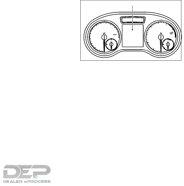
MPH (25 km/h) and the driver's seat belt or
front passenger's seat belt, if occupied is not
securely fastened. See "Seat belt warning
light" in the "1. Safety — seats, seat belts and
supplemental restraint system" section.
Idle Stop/Start System reminder
chime (if equipped)
The engine will shift to the normal stopped
state if any of the following operations is
made during Idle Stop/Start System activa-
tion, and the Idle Stop/Start System chime
will sound if:
– The vehicle engine hood is open.
When the above condition continues for over
3 minutes the Idle Stop/Start System chime
will sound in 5-minute intervals as a reminder
to prevent the possibility of a discharged bat-
tery. Use the ignition switch to turn off the
engine.
Close the hood or the driver’s door, or fasten
the seat belt then restart the engine using the
ignition switch.
For more information, see " Idle Stop/Start
System (if equipped)" in the "5. Starting and
driving" section. The vehicle information display 䊊
1is located
between the tachometer and the
speedometer.
NIC2751
VEHICLE INFORMATION DISPLAY
Instruments and controls 2-15
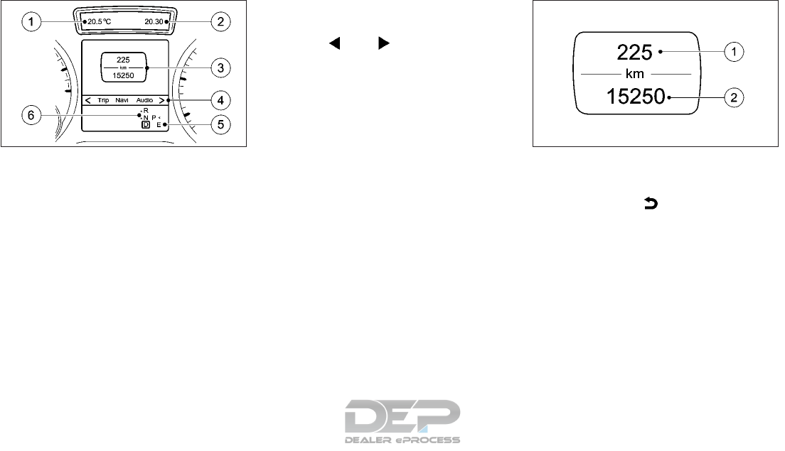
䊊
1Permanent display: depending on vehicle
specification: outside temperature or
speed
䊊
2Time
䊊
3Text field
䊊
4Menu bar
䊊
5Drive program
䊊
6Shift lever position
Text field 䊊
3shows the selected menu or
submenu as well as display messages.
NOTE
Set the time using the INFINITI controller
and the [Settings] menu available in the cen-
tral display (see "Clock settings" in the "4.
Display screen, heater and air conditioner,
and audio system" section).
MENUS AND SUBMENUS
To call up the menu bar 䊊
4and select a menu,
press the or button on the steer-
ing wheel. Menu bar 䊊
4disappears after a
few seconds.
Depending on the equipment fitted in the
vehicle, you can call up the following menus:
•[Trip] menu
•[Navi] menu (navigation instructions)
•[Audio] menu
•[DriveAssist] menu
•[Serv.] menu
•[Settings] menu
The [Audio] and [Navi] menus differ slightly
in vehicles with an audio system and in ve-
hicles with a navigation system. The ex-
amples given in this Owner's Manual apply to
vehicles equipped with navigation.
[Trip] menu
Standard display:
Press and hold the button on the steer-
ing wheel until the [Trip] menu with trip meter
䊊
1and total distance recorder 䊊
2is shown.
NIC2752 NIC2753
2-16 Instruments and controls
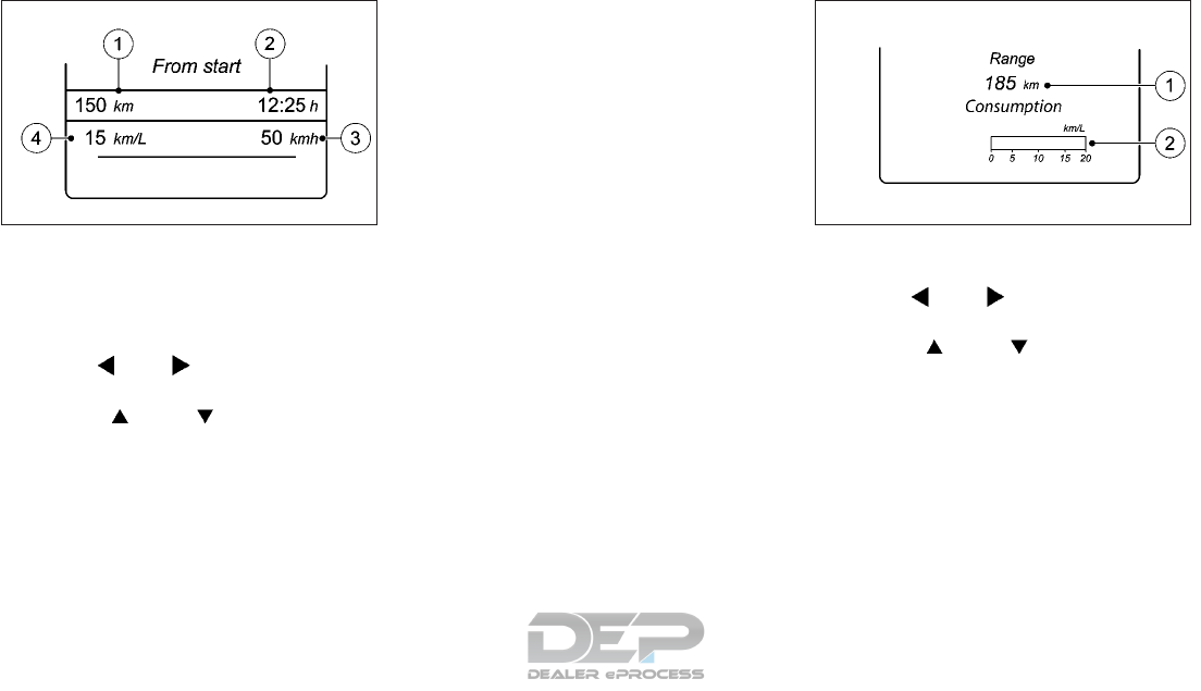
Trip computer [From start] or [From reset]:
䊊
1Distance
䊊
2Driving time
䊊
3Average speed
䊊
4Average fuel consumption
Press the or button on the steer-
ing wheel to select the [Trip] menu.
Press the or button to select
[From start] or [From reset].
The values in the [From start] submenu are
calculated from the start of a journey whilst
the values in the [From reset] submenu are
calculated from the last time the submenu
was reset.
The [From start] trip computer is automati-
cally reset when:
•The ignition has been switched off for
more than four hours.
•999 hours have been exceeded.
•9999 kilometers have been exceeded.
The [From reset] trip computer is automati-
cally reset if the value exceeds 9999 hours or
99999 kilometers.
Displaying the range and current fuel con-
sumption:
Press the or button on the steer-
ing wheel to select the [Trip] menu.
Press the or button to select
approximate range 䊊
1and current fuel con-
sumption 䊊
2.
Approximate range 䊊
1that can be covered is
calculated according to your current driving
style and the amount of fuel in the tank. If
there is only a small amount of fuel left in the
fuel tank, the display shows a vehicle being
refuelled instead of approximate range 䊊
1.
NIC2711 NIC2713
Instruments and controls 2-17
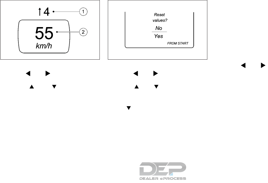
Digital speedometer:
Press the or button on the steer-
ing wheel to select the [Trip] menu.
Press the or button to select
digital speedometer 䊊
2.
A gearshift recommendation 䊊
1can also be
displayed.
Observe the information on gearshift recom-
mendation 䊊
1for automatic transmission
(shifting manually) (see "Driving with Auto-
matic Transmission" in the "5. Starting and
driving" section).
Resetting values:
Press the or button on the steer-
ing wheel to select the [Trip] menu.
Press the or button to select the
function that you wish to reset.
Press the <OK> button.
Select [Yes] and press <OK> to confirm.
You can reset the values of the following
functions:
•Trip meter
•[From start] trip computer
•[From reset] trip computer
Navigation menu ([Navi])
Displaying navigation instructions:
In the [Navi] menu, the vehicle information
display shows navigation instructions.
You can find further information on naviga-
tion in the audio system or navigation system
operating instructions.
Switch on the audio system or navigation
system.
Press the or button on the steer-
ing wheel to select the [Navi] menu.
NIC2714 NIC2718
2-18 Instruments and controls
Route guidance not active:
䊊
1Direction of travel
䊊
2Current road
Route guidance active — No change of di-
rection announced:
䊊
1Distance to the destination
䊊
2Distance to the next change of direction
䊊
3Symbol indicating "follow the road's
course".
䊊
4Current road
Route guidance active — Change of direc-
tion without lane recommendation:
䊊
1Road to which the change of direction
leads
䊊
2Distance to change of direction and vi-
sual distance display
䊊
3Change of direction symbol
When a change of direction is to be made,
you will see symbol 䊊
3for the change of
direction and distance graphic 䊊
2. This short-
ens towards the top of the display as you
approach the point of the announced change
of direction. The change of direction starts
once the distance display reaches zero.
NIC2719 NIC2720 NIC2721
Instruments and controls 2-19
Route guidance active — Change of direc-
tion announced with a lane recommenda-
tion:
䊊
1Road to which the change of direction
leads
䊊
2Distance to change of direction and vi-
sual distance display
䊊
3Recommended lane and new lane during
a change of direction
䊊
4Recommended lane
䊊
5Lanes not recommended
䊊
6Change of direction symbol
On multi-lane roads, new lane recommenda-
tions can be displayed for the next change of
direction if the digital map supports this data.
During the change of direction, new lanes
may be added.
Lane not recommended 䊊
5: you will not be
able to complete the next change of direction
if you stay in this lane.
Recommended lane and new lane during a
change of direction 䊊
3: in this lane you will be
able to complete the next two changes of
direction without changing lane.
Recommended lane 䊊
4: in this lane you will be
only able to complete the next change of
direction without changing lane.
Other status indicators of the navigation
system:
The navigation system displays additional in-
formation and the vehicle status. Possible
displays:
•[New route...] or [Calculating route...]
A new route is calculated.
•[Off map] or [Off road]
The vehicle position is outside of the area
of the digital map (off-map position).
•[No route]
No route could be calculated to the se-
lected destination.
•
You have reached the destination or an
intermediate destination.
NIC2838 NIC2723
2-20 Instruments and controls
Audio menu
Selecting a radio station:
䊊
1Frequency range
䊊
2Station frequency/name with memory
position
The memory position is only displayed along
with station 䊊
2if this has been stored.
1. Switch on the audio system or navigation
system and select Radio.
2. Press the or button on the
steering wheel to select the [Audio] menu.
3. To select a stored station, briefly press
or .
4. To select a station from the station list,
press and briefly hold the or
button.
If no station list is received:
5. To elect a station using the station search:
press and briefly hold the or
button.
NOTE
DAB radio mode (Digital Audio Broadcast-
ing) is an optimized digital transmission
standard designed for the cellular reception
of radio transmissions.
Audio player or audio media operation:
䊊
1Current track
Audio files from various audio players or me-
dia can be played, depending on the equip-
ment fitted in the vehicle.
1. Switch on the audio system or navigation
system and select audio CD or MP3 mode.
2. Press the or button on the
steering wheel to select the [Audio] menu.
3. To select the next/previous track, briefly
press or .
4. To select a track from the track list (rapid
scrolling): press and hold the or
. button until the desired track has
been reached.
NIC2724 NIC2839
Instruments and controls 2-21
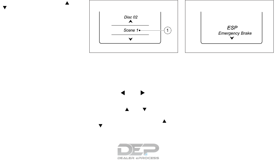
If you press and hold the or
button, the rapid scrolling speed is
increased. Not all audio players or media
support this function.
If track information is stored on the audio
player or media, the vehicle information dis-
play will show the number and title of the
track.
The current track does not appear in audio
AUX mode (Auxiliary audio mode: external
audio source connected). Video DVD operation (outside Europe only):
It is only possible to use the [Audio] menu to
operate video DVDs on vehicles with naviga-
tion system.
1. Switch on the audio system or navigation
system and select video DVD.
2. Press the or button on the
steering wheel to select the [Audio] menu.
3. To select the next or previous scene,
briefly press or .
4. To select a scene from the scene list (rapid
scrolling): press and hold the or
. button until the desired scene 䊊
1
has been reached.
Assistance menu
Depending on the equipment fitted in the
vehicle, you have the following options in the
[DriveAssist] menu:
•Showing the assistance graphic
•Activating/deactivating VDC
•Activating/deactivating Forward Emer-
gency Braking (FEB)
•Activating/deactivating Blind Spot Warn-
ing (BSW)
•Activating/deactivating Lane Departure
Warning (LDW)
NIC2726 NIC2873
2-22 Instruments and controls
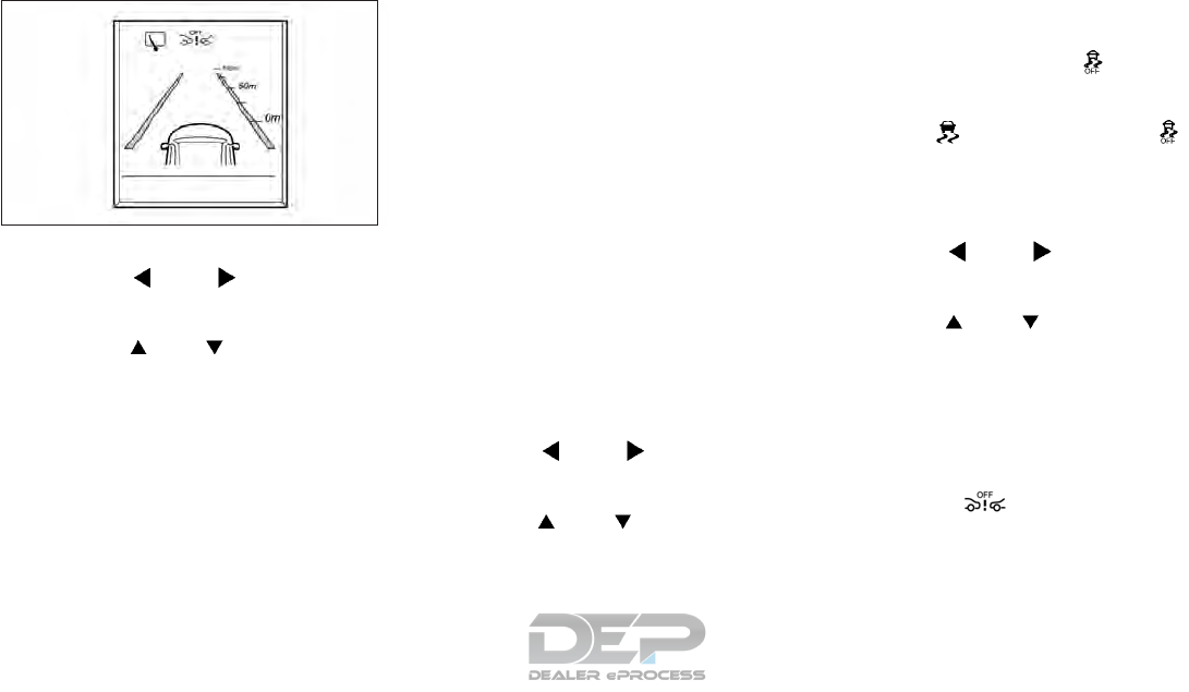
Showing the distance display:
1. Press the or button on the
steering wheel to select the [DriveAssist]
menu.
2. Press the or button to select
[Distance display].
3. Press the <OK> button.
The vehicle information display shows the
Intelligent Cruise Control (ICC) distance
display in the assistance graphic.
The distance display also shows you the
status of and/or information from the fol-
lowing driving systems or driving safety
systems:
•Intelligent Cruise Control (ICC)
•Forward Emergency Braking (FEB)
•Lane Departure Warning (LDW)
•Blind Spot Warning (BSW)
•Rear window wiper
Deactivating/activating VDC:
The vehicle should be driven with the Vehicle
Dynamic Control (VDC) system on for most
driving conditions.
If the vehicle is stuck in mud or snow, the
VDC system reduces the engine output to
reduce wheel spin. The engine speed will be
reduced even if the accelerator is depressed
to the floor. If maximum engine power is
needed to free a stuck vehicle, turn the VDC
system off.
For further information about VDC, see "Ve-
hicle Dynamic Control (VDC) system" in the
"5. Starting and driving" section.
1. Start the engine.
2. Press the or button on the
steering wheel to select the [DriveAssist]
menu.
3. Press the or button to select
[ESP].
4. Press the <OK> button.
The current selection is displayed.
5. To activate/deactivate: press the <OK>
button again.
VDC is deactivated if the warning
light in the combination meter lights up
continuously when the engine is running.
If both the warning light and
warning light are lit continuously, VDC is not
available due to a malfunction.
Activating/deactivating Forward Emer-
gency Braking:
1. Press the or button on the
steering wheel to select the [DriveAssist]
menu.
2. Press the or button to select
[Emergency Brake].
3. Press the <OK> button.
The current selection is displayed.
4. To activate/deactivate: press the <OK>
button again.
When Forward Emergency Braking is de-
activated, the symbol appears in the
vehicle information display in the assis-
tance graphic display.
For further information about Forward
Emergency Braking, see " Forward emer-
gency braking (FEB) system (if equipped)" in
the "5. Starting and driving" section.
NIC2729
Instruments and controls 2-23
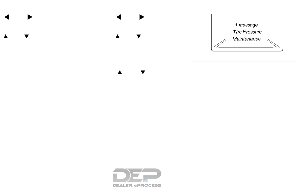
Activating/deactivating Blind Spot Warn-
ing (BSW):
1. Press the or button on the
steering wheel to select the [DriveAssist]
menu.
2. Press the or button to select
[Blind Spot Warning].
3. Press the <OK> button.
The current selection is displayed.
4. To activate/deactivate: press the <OK>
button again.
For further information about Blind Spot
Warning, see " Blind Spot Warning (BSW)
system (if equipped)" in the "5. Starting and
driving" section.
Activating/deactivating Lane Departure
Warning (LDW):
1. Press the or button on the
steering wheel to select the [DriveAssist]
menu on the Menu bar.
2. Press the or button to select
[Lane Departure Warning].
3. Press the <OK> button on the steering
wheel. The current selection is displayed.
4. Press the <OK> to confirm.
5. Press the or button to set
[Off], [Standard] or [Adaptive].
6. Press the <OK> button to save the setting.
For further information about Lane Depar-
ture Warning, see " Lane departure warning
(LDW) system (if equipped) " in the "5. Start-
ing and driving" section.
Service menu ([Serv.])
Depending on the equipment fitted in the
vehicle, you have the following options in the
[Serv.] menu:
•Calling up display messages in the mes-
sage memory (see "Message memory"
later in this section).
•Restarting the tire pressure monitoring
system (TPMS) (see "Restarting TPMS" in
the "5. Starting and driving" section.
•Checking the tire pressure electronically
(see "Checking the tire pressure electroni-
cally" in the "5. Starting and driving" sec-
tion).
•Calling up the service due date (see "Main-
tenance service messages" in the "9. Main-
tenance and Schedules" section).
NIC2874
2-24 Instruments and controls

Settings menu
Depending on the equipment fitted in the
vehicle, in the [Settings] menu you have the
following options:
•Changing the instrument cluster settings.
•Changing the light setting.
•Changing the vehicle setting.
•Changing the convenience setting.
•Restoring the factory setting.
Instrument cluster:
Unit of measurement for distance: The Dis-
play unit Speed-/odometer function allows
you to choose whether certain displays ap-
pear in kilometers or miles in the vehicle infor-
mation display.
1. Press the or button on the
steering wheel to select the [Settings]
menu.
2. Press the or button to select
[Instrument Cluster] submenu.
3. Press <OK> to confirm.
4. Press the or button to select
the [Display Unit Speed-/Odometer]
function.
You will see the selected setting: [miles] or
[km].
5. Press the <OK> button to change the set-
ting.
The selected unit of measurement for dis-
tance applies to:
•Digital speedometer in the [Trip] menu.
•Total distance recorder and the trip meter.
•Trip computer.
•Current fuel consumption and approxi-
mate range.
•Navigation instructions in the [Navi] menu.
•Cruise control.
•Speed limiter.
•Intelligent cruise control (ICC).
•Maintenance service interval display.
Switching the additional speedometer on/
off.
The [Speedometer (mph)] or [Speedometer
(km/h)] function allows you to choose
whether the vehicle information display in the
status area shows the speed in MPH or in
km/h instead of the outside temperature.
1. Press the or button on the
steering wheel to select the [Settings]
menu.
2. Press the or button to select
[Instrument Cluster] submenu.
3. Press <OK> to confirm.
4. Press the or button to select
the [Speedometer (mph)] or [Speedom-
eter (km/h)] function.
You will see the selected setting: [On] or
[off].
5. Press the <OK> button to change the set-
ting.
Selecting the permanent display function.
You can determine whether the vehicle infor-
mation display permanently shows the out-
side temperature or the speed in MPH.
NIC2731
Instruments and controls 2-25
1. Press the or button on the
steering wheel to select the [Settings]
menu.
2. Press the or button to select
[Instrument Cluster] submenu.
3. Press <OK> to confirm.
4. Press the or button to select
the [Outside Temperature] function.
You will see the selected setting: [outside
temperature] or [Speedometer (mph)].
5. Press the <OK> button to save the setting.
Lights
Switching the Adaptive Front Lighting Sys-
tem on/off:
1. Press the or button on the
steering wheel to select the [Settings]
menu.
2. Press the or button to select
[Light] submenu.
3. Press <OK> to confirm.
4. Press the or button to select
the [Adaptive front lighting system] func-
tion.
If the [Adaptive front lighting system]
function has been switched on, the cone
of light and the symbol in the vehicle
information display are shown in orange.
5. Press the <OK> button to save the setting.
When you switch the [Adaptive front lighting
system] function on, you activate the follow-
ing functions:
•Freeway mode
•Active light function
•Cornering light function
If you set the low beam headlights for driving
on the right/left, the vehicle information dis-
play shows the [Adaptive front lighting sys-
tem: System Inoperative Inactive For Left-
side Traffic] or [Adaptive front lighting
system: System Inoperative Inactive for
Right-side Traffic] display message instead
of the [Adaptive front lighting] function in the
[Light] submenu.
For further information about the Adaptive
Front Lighting system, see " Adaptive front
lighting system (LED headlight only) (if
equipped)" later in this section
Setting the low beam headlights for driving
on the left/right:
This function is only available on vehicles with
the Adaptive Front Lighting System (see "
Adaptive front lighting system (LED head-
light only) (if equipped)" later in this section).
1. Press the or button on the
steering wheel to select the [Settings]
menu.
2. Press the or button to select
[Light] submenu.
3. Press <OK> to confirm.
4. Press the or button to select
the [Low-b. Headl. Setting For:] function.
You will see the selected setting: [Right-
side Traffic] or [Left-side Traffic].
5. Press the <OK> button to save the setting.
If you change the setting, conversion does
not take place until the next time the ve-
hicle is stationary.
If you set the low beam headlights for driving
on the right/left, then freeway mode is un-
available. This is only deactivated if the set-
ting for driving on the left/right is set oppo-
site to your vehicle's country version.
An INFINITI retailer can set the low beam
headlights for driving on the left/right.
2-26 Instruments and controls

Setting the brightness of the ambient light-
ing:
1. Press the or button on the
steering wheel to select the [Settings]
menu.
2. Press the or button to select
[Light] submenu.
3. Press <OK> to confirm.
4. Press the or button to select
the [Ambient Light Brightness] function.
You will see the selected setting.
5. Change the setting with <OK>.
If you change the setting, conversion does
not take place until the next time the ve-
hicle is stationary.
6. Press the or button to adjust
the brightness to a level from [Off] to
[Level 5] (bright).
7. Press the <OK> or button to save the
setting.
Activating/deactivating the surround
lighting and exterior lighting delayed
switch-off:
If you have activated the Surround lighting
function and the light switch is set to
<AUTO>, the following functions are acti-
vated when it is dark:
•Surround lighting: the exterior lighting re-
mains lit for 40 seconds after unlocking
with the key. If you start the engine, the
surround lighting is switched off and auto-
matic headlight mode is activated .
•Exterior lighting delayed switch-off: the
exterior lighting remains lit for 60 seconds
after the engine is switched off. If you
close all the doors and the lift gate, the
exterior lighting goes off after 15 seconds.
1. Press the or button on the
steering wheel to select the [Settings]
menu.
2. Press the or button to select
[Light] submenu.
3. Press <OK> to confirm.
4. Press the or button to select
the [Surround Lighting] function.
5. Press the <OK> button to save the setting.
When the [Surround Lighting] function is
activated, the light cone and the area
around the vehicle are displayed in orange
in the vehicle information display
6. Press the <OK> button to confirm the set-
ting.
Deactivating delayed switch-off of the exte-
rior lighting temporarily:
1. Before leaving the vehicle, switch the igni-
tion switch to the OFF position.
2. Switch the ignition switch to the ON po-
sition.
The exterior lighting delayed switch-off is
deactivated.
Delayed switch-off of the exterior lighting is
reactivated the next time you start the en-
gine.
Depending on your vehicle's equipment,
when the surround lighting and delayed
switch-off exterior lighting are on, the fol-
lowing light up:
•Side lights
•Fog lights
•Low beam headlights
•Daytime driving lights
•Surround lighting in the exterior mirrors
Instruments and controls 2-27

Activating/deactivating the interior light-
ing delay:
If you activate the [Interior Lighting Delay]
function, the interior lighting remains on for
20 seconds after you remove the key from
the ignition lock.
1. Press the or button on the
steering wheel to select the [Settings]
menu.
2. Press the or button to select
[Light] submenu.
3. Press <OK> to confirm.
4. Press the or button to select
the [Interior Lighting Delay] function. If
the [Interior lighting delayed switch-off]
function has been switched on, the vehicle
interior is displayed in orange in the ve-
hicle information display
5. Press the <OK> button to save the setting.
Vehicle
Setting permanent speed limiter:
You can set permanent speed limiter using
the [Limit Speed (Winter Tires)] function.
1. Press the or button on the
steering wheel to select the [Settings]
menu.
2. Press the or button to select
[Vehicle] submenu.
3. Press <OK> to confirm.
4. Press the or button to select
the [Limit Speed (Winter Tires)] function.
You will see the selected setting.
5. Press <OK> to confirm.
6. Press the or button to adjust
permanent speed limiter in increments of
ten ([150 mph] to [100 mph]), [240
km/h] to [160 km/h]). The [Off] setting
switches permanent speed limiter off).
7. Press the <OK> or button to store
the entry.
Activating/deactivating the acoustic lock-
ing confirmation:
If you switch on the [Acoustic Lock Feed-
back] function, an acoustic signal sounds
when you lock the vehicle.
1. Press the or button on the
steering wheel to select the [Settings]
menu.
2. Press the or button to select
[Vehicle] submenu.
3. Press <OK> to confirm.
4. Press the or button to select
the [Acoustic Lock Feedback] function.
If the [Acoustic Lock Feedback] function
is activated, the symbol in the ve-
hicle information display lights up orange.
5. Press the <OK> button to save the setting.
Convenience
Switching the [Fold Mirrors in when Lock-
ing] function on/off:
This function is only available when the ve-
hicle is equipped with the electrical fold-in
function.
When you activate the [Fold Mirrors in when
Locking] function, the exterior mirrors are
folded in when the vehicle is locked. If you
unlock the vehicle and then open the driver's
or front passenger door, the exterior mirrors
fold out again.
If you have switched on the [Fold Mirrors in
when Locking] function and you fold in the
exterior mirrors using the button on the door
(see "Folding" in the "3. Pre-driving checks
and adjustments" section), they will not fold
out automatically. The exterior mirrors can
then only be folded out using the button on
the door.
2-28 Instruments and controls

1. Press the or button on the
steering wheel to select the [Settings]
menu.
2. Press the or button to select
[Convenience] submenu.
3. Press <OK> to confirm.
4.
Press the or button to select the
[Fold Mirrors in when Locking] function.
If the [Fold Mirrors in when Locking]
function is activated, the vehicle's exterior
mirror is shown in orange in the vehicle
information display.
5. Press the <OK> button to save the setting.
Resetting to factory settings
1.
Press the or button on the
steering wheel to select the [Settings] menu.
2. Press the or button to select
[Factory Setting] submenu.
3. Press <OK> to confirm.
The [Reset All Settings?] message appears.
4. Press the or button to select
[No] or [Yes].
5.
ress the <OK> button to confirm the selec-
tion.
If you have selected [Yes], the vehicle in-
formation display shows a confirmation
message.
For safety reasons, not all functions are reset:
the [Limit Speed (Winter Tires)] function in
permanent speed limiter can only be set in the
[Vehicle] submenu.
If you want to reset the Daytime driving lights
function in the Lights submenu, you must switch
the ignition switch to the ACC position.
DISPLAY MESSAGES
Display messages appear in the vehicle infor-
mation display.
Display messages with graphic symbols are
simplified in the Owner's Manual and may
differ from the symbols in the vehicle infor-
mation display.
Certain display messages are accompanied
by an audible warning tone or a continuous
tone.
When the ignition is switched off, all display
messages are deleted apart from some high-
priority display messages. Once the causes of
the high-priority display messages have been
rectified, these display messages are deleted as
well.
When you stop and park the vehicle, please
observe the notes on parking (see "Parking" in
the "5. Starting and driving" section).
Hiding display messages
Press the <OK> or button to hide the
display message. The display message is hid-
den.
The vehicle information display shows high-
priority display messages in red. Some high-
priority display messages cannot be hidden.
The vehicle information display shows these
messages continuously until the causes for
the messages have been remedied.
Message memory
The vehicle information display saves certain
messages in the message memory. You can
call up these display messages:
1. Press the or button on the
steering wheel to select the [Service]
menu.
If there are display messages, the vehicle
information display shows [2 messages],
for example.
2. Press the or button to select
the entry, e.g. [2 messages].
3. Press <OK> to confirm.
4. Press the or button to scroll
through the display messages.
Instruments and controls 2-29
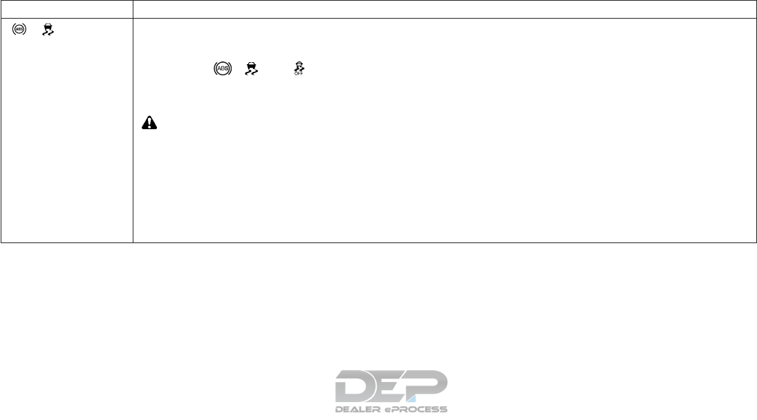
Safety systems
Message Possible causes/consequences and solutions
[Currently Unavailable See
Operator's Manual]
ABS (Anti-Lock Braking System), BAS (Brake Assist System), VDC (Vehicle Dynamic Control), and hill start assist are temporarily
unavailable.
Forward Emergency Braking (FEB) may also have failed.
In addition, the , and warning lights may light up in the combination meter.
Possible causes:
•Self-diagnosis is not yet complete.
•The on-board voltage may be insufficient.
WARNING
The brake system continues to function normally, but without the functions listed above. The wheels could therefore lock if you
brake hard, for example.
The steering and braking characteristics may be severely affected. The braking distance may increase in an emergency braking
situation.
If VDC is not operational, VDC is unable to stabilize the vehicle. There is an increased danger of skidding and risk of an accident.
Carefully drive on a suitable stretch of road, making slight steering movements, at a speed above 12 MPH (20 km/h). If the display
message disappears, the functions mentioned above are available again.
If the display message continues to be displayed, drive on carefully and have the system checked. It is recommended you visit an
INFINITI retailer for this service.
2-30 Instruments and controls

Message Possible causes/consequences and solutions
[Inoperative See
Operator's Manual]
ABS (Anti-Lock Braking System), BAS (Brake Assist System), VDC (Vehicle Dynamic Control), and hill start assist are not available
due to a malfunction.
Forward Emergency Braking (FEB) may also have failed.
In addition, the , , and warning lights may light up in the combination meter.
WARNING
The brake system continues to function normally, but without the functions listed above. The wheels could therefore lock if you
brake hard, for example.
The steering and braking characteristics may be severely affected. The braking distance may increase in an emergency braking
situation.
If VDC is not operational, VDC is unable to stabilize the vehicle. There is an increased danger of skidding and risk of an accident.
Drive on carefully and have the system checked immediately. It is recommended you visit an INFINITI retailer for this service.
[Currently Unavailable
See Operator's Manual]
BAS (Brake Assist System), VDC (Vehicle Dynamic Control), and hill start assist are temporarily unavailable.
Forward Emergency Braking (FEB) may also have failed.
In addition, the and warning lights may light up in the combination meter.
The self-diagnosis function, for example, may not be complete.
WARNING
The brake system continues to function normally, but without the functions listed above.
The braking distance may increase in an emergency braking situation.
If VDC is not operational, VDC is unable to stabilize the vehicle. There is an increased danger of skidding and risk of an accident.
Carefully drive on a suitable stretch of road, making slight steering movements, at a speed above 12 MPH (20 km/h). If the display
message disappears, the functions mentioned above are available again.
If the display message continues to be displayed, drive on carefully and have the system checked. It is recommended you an INFINITI
retailer for this service.
Instruments and controls 2-31
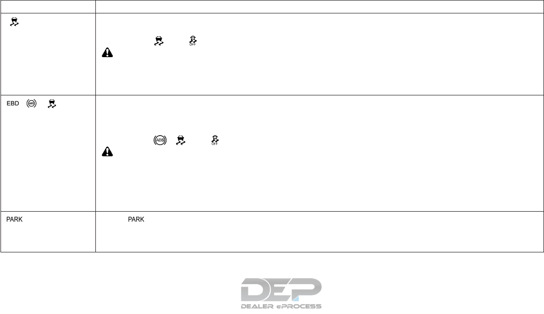
Message Possible causes/consequences and solutions
[Inoperative See
Operator's Manual]
BAS (Brake Assist System), VDC (Vehicle Dynamic Control), and hill start assist are not available due to a malfunction.
Forward Emergency Braking (FEB) may also have failed.
In addition, the and warning lights may light up in the combination meter.
WARNING
The brake system continues to function normally, but without the functions listed above.
The braking distance may increase in an emergency braking situation.
If VDC is not operational, VDC is unable to stabilize the vehicle. There is an increased danger of skidding and risk of an accident.
Drive on carefully and have the system checked. It is recommended you visit an INFINITI retailer for this service.
[Inoperative See Opera-
tor's Manual]
EBD (Electronic Brake Force Distribution) ABS (Anti-Lock Braking System), BAS (Brake Assist System), VDC (Vehicle Dynamic
Control), and hill start assist are not available due to a malfunction.
Forward Emergency Braking (FEB) may also have failed.
A warning tone sounds.
In addition, the , and warning lights may light up in the combination meter.
WARNING
The brake system continues to function normally, but without the functions listed above. The front and rear wheels could therefore
lock if you brake hard, for example.
The steering and braking characteristics may be severely affected. The braking distance may increase in an emergency braking
situation.
If VDC is not operational, VDC is unable to stabilize the vehicle. There is an increased danger of skidding and risk of an accident.
Drive on carefully and have the system checked immediately. It is recommended you visit an INFINITI retailer for this service.
[Turn On The Ignition to
Release the Parking
Brake]
The red indicator light lights up.
You attempted to release the electric parking brake while the ignition was switched off.
Key: turn the key to the ON position in the ignition switch
2-32 Instruments and controls

Message Possible causes/consequences and solutions
[Please Release Parking
Brake]
The red indicator light flashes and a warning tone sounds. A condition for automatic release of the electric parking brake is not
fulfilled (see " Applying automatically (vehicles with automatic transmission)" in the "5. Starting and driving" section).
You are driving with the electric parking brake applied.
Release the electric parking brake manually.
The red indicator light flashes and a warning tone sounds.
You are making an emergency stop using the electric parking brake (see "Emergency braking" in the "5. Starting and driving" section)
[Parking Brake See
Operator's Manual]
The yellow warning light lights up.
The electric parking brake is malfunctioning.
To apply:
1. Switch the ignition off.
2. Press the electric parking brake handle for at least ten seconds.
3. Press the P (Park) button.
4. Have the system checked. It is recommended you consult an INFINITI retailer.
The yellow warning light and the red indicator light are lit.
The electric parking brake is malfunctioning.
To release:
1. Switch the ignition off and turn it back on.
2. Release the electric parking brake manually.or
3. Release the electric parking brake automatically (see " Applying automatically (vehicles with automatic transmission)" in the "5.
Starting and driving" section).
If the electric parking brake still cannot be released: DO NOT drive on. It is recommended you consult an INFINITI retailer.
Instruments and controls 2-33

Message Possible causes/consequences and solutions
The yellow warning light is lit. The red indicator light flashes.
The electric parking brake is malfunctioning.
To release:
1. Switch the ignition off and turn it back on.
2. Release the electric parking brake manually.or
To apply:
1. Switch the ignition off and turn it back on.
2. Apply the electric parking brake manually.
If the red . indicator light continues to flash:
1 DO NOT drive on
2. Secure the vehicle against rolling away
3. Press the P (Park) button.
4. Turn the front wheels towards the curb.
It is recommended you consult an INFINITI retailer.
The yellow warning light is lit. The red indicator light flashes for about ten seconds after the electric parking brake has been
applied or released. It then goes out or remains lit.
The electric parking brake is malfunctioning.
To apply:
1. Switch the ignition off and turn it back on.
2. Apply the electric parking brake manually.If it is not possible to apply the electric parking brake:
3. Press the P (Park) button.
It is recommended you consult an INFINITI retailer.
If it is not possible to release the electric parking brake:
Release the electric parking brake automatically (see " Applying automatically (vehicles with automatic transmission)" in the "5.
Starting and driving" section).
If the electric parking: brake still cannot be released, it is recommended you consult an INFINITI retailer.
2-34 Instruments and controls
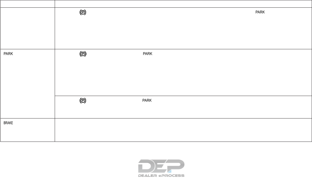
Message Possible causes/consequences and solutions
The yellow warning light is lit. If you manually apply or release the electric parking brake, the red indicator light flashes.
The electric parking brake is malfunctioning. It is not possible to apply the electric parking brake manually.
or
Insert the seat belt in the belt buckle and accelerate slightly more when pulling away.
Press the P (Park) button, as the electric parking brake is not applied automatically.
It is recommended you consult an INFINITI retailer.
If you do not wish the electric parking brake to be applied, leave the ignition switched on, e. g. when washing the vehicle in an
automatic car wash or when having the vehicle towed.
[Parking Brake
Inoperative]
The yellow warning light is lit. The red indicator light flashes for about ten seconds after the electric parking brake has
been applied or released. It then goes out or remains lit.
The electric parking brake is malfunctioning, e.g. because of overvoltage or undervoltage.
1. Rectify the cause of the overvoltage or undervoltage, e.g. by charging the battery or restarting the engine.
2. Apply or release the electric parking brake.
If the electric parking brake still cannot be applied or released:
1. Switch the ignition off and turn it back on.
2. Apply or release the electric parking brake manually.
If the electric parking brake still cannot be applied or released, it is recommended you consult an INFINITI retailer.
The yellow warning light is lit. The red indicator light flashes.
It is not possible to apply the electric parking brake manually.
1. Press the P (Park) button.
Consult an INFINITI retailer.
[Brake Immediately]
A tone may also sound at regular intervals. If you attempt to lock the vehicle, the tone becomes louder.
You cannot start the engine.
1. Paying attention to the traffic situation, immediately depress the brake pedal firmly and hold until the display message disappears.
2. Secure the vehicle against rolling away. You can restart the engine.
Instruments and controls 2-35
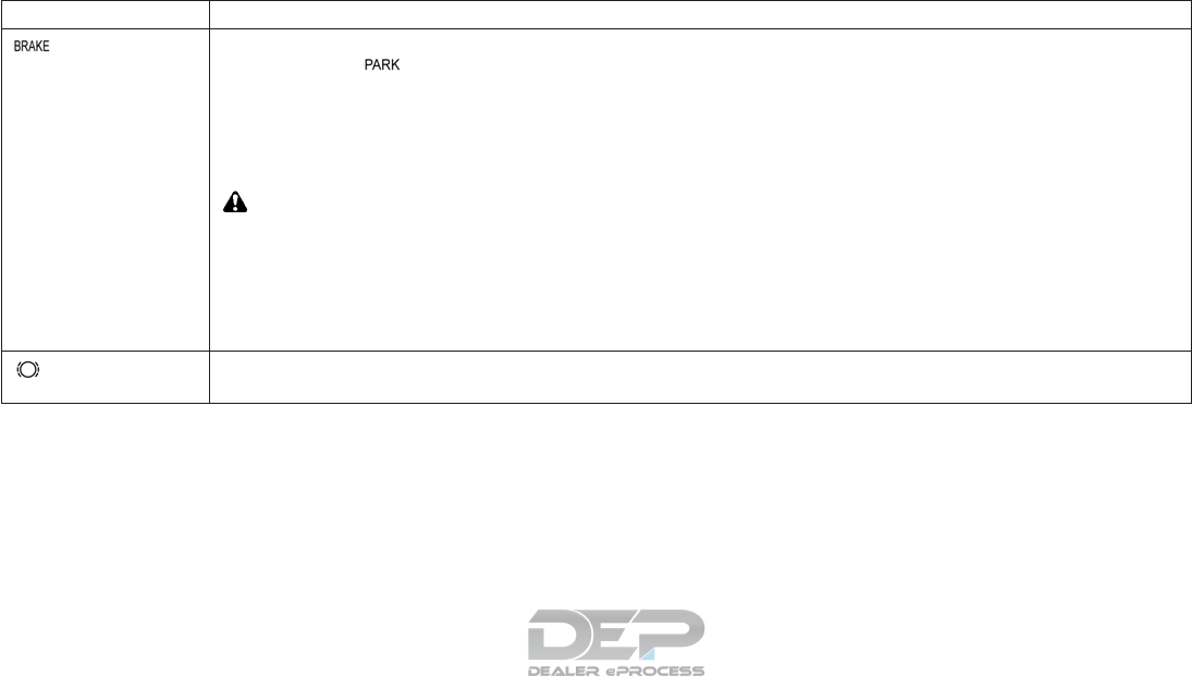
Message Possible causes/consequences and solutions
[Check Brake Fluid Level]
There is insufficient brake fluid in the brake fluid reservoir.
In addition, the red warning light lights up in the combination meter and a warning tone sounds.
1. Pull over and stop the vehicle safely as soon as possible, paying attention to road and traffic conditions. Do not continue driving
under any circumstances.
2. Secure the vehicle against rolling away.
3. Check the brake fluid level. If brake fluid is necessary, add fluid and have the system checked. It is recommended you visit an
INFINITI retailer for this service. See "Brake fluid" in the "8. Do-it-yourself" section.
4. If the brake fluid level is correct, have the warning system checked. It is recommended you visit an INFINITI retailer for this service.
WARNING
•Your brake system may not be working properly if the warning light is on. Driving could be dangerous. If you judge it to be safe,
drive carefully to the nearest service station for repairs. Otherwise, have your vehicle towed because driving it could be
dangerous.
•Pressing the brake pedal with the engine stopped and/or low brake fluid level may increase your stopping distance and braking
will require greater pedal effort as well as pedal travel.
•If the brake fluid level is below the minimum or MIN mark on the brake fluid reservoir, do not drive until the brake system has
been checked. It is recommended you visit an INFINITI retailer for this service.
[Check Brake Pad Wear]
The brake pads/linings have reached their wear limit.
It is recommended you visit an INFINITI retailer.
2-36 Instruments and controls

Message Possible causes/consequences and solutions
[Emergency Brake
Currently Unavailable See
Operator's Manual]
Forward Emergency Braking is temporarily inoperative.
Possible causes:
•The radar sensor system is temporarily inoperative, e.g. due to electromagnetic radiation emitted by nearby TV or radio stations
or other sources of electromagnetic radiation.
•The system is outside the operating temperature range.
•The on-board voltage is too low.
Once the causes listed above no longer apply, the display message goes out.
Forward Emergency Braking is operational again.
If the display message does not disappear:
1. Pull over and stop the vehicle safely as soon as possible, paying attention to road and traffic conditions.
2. Secure the vehicle against rolling away.
3. Restart the engine.
[Emergency Brake Inop-
erative]
Forward Emergency Braking is temporarily inoperative due to a malfunction.
Have the system checked. It is recommended you visit an INFINITI retailer for this service.
Instruments and controls 2-37

Message Possible causes/consequences and solutions
[Radar Sensor (See
Operator's Manual):]
At least one of the following driving systems or driving safety systems is temporarily restricted or inoperative:
•Forward Emergency Braking
•Intelligent Cruise Control
•Blind Spot Warning
Possible causes:
•The sensors in the radiator trim and/or at the sides of the rear bumpers are dirty.
•The function of the driving system and/or driving safety system is impaired due to heavy rain or snow.
A warning tone also sounds.
Once the causes listed above no longer apply, the display message goes out. All driving systems/driving safety systems are operative
again.
If the display message does not disappear:
1. Pull over and stop the vehicle safely as soon as possible, paying attention to road and traffic conditions
2. Secure the vehicle against rolling away.
3. Switch off the engine.
4. Clean the sensors in the following locations:
- In the radiator trim
- At the sides of the rear bumper
5. Restart the engine. The display message disappears.
[SRS Malfunction Service
Required]
The restraint system needs servicing. The warning light also lights up in the combination meter.
It is recommended you visit an INFINITI retailer for these services.
Unless checked and repaired, the Supplemental Restraint Systems and/or the pretensioner seat belt may not function properly.
WARNING
If this light is on, it could mean that the front air bag, side air bag, curtain air bag systems and/or pretensioner systems will not
operate in an accident. To help avoid injury to yourself or others, have your vehicle checked as soon as possible. It is recommended
you visit an INFINITI retailer for this service.
For further information about the restraint system, see "Supplemental Restraint System (SRS)" in the "1. Safety — seats, seat belts and
supplemental restraint system" section.
2-38 Instruments and controls

Message Possible causes/consequences and solutions
[Front Passenger Airbag
Disabled See Operator's
Manual]
The front-passenger front air bag is disabled during the journey although an adult or person of corresponding stature is on the front
passenger seat.
Front passenger seat adult occupants who are properly seated and using the seat belt as outlined in this manual should not cause
the front passenger air bag to be automatically turned OFF. For small adults it may be turned OFF, however if the occupant takes
his/her weight off the seat cushion (for example, by not sitting upright, by sitting on an edge of the seat, or by otherwise being out
of position), this could cause the sensor to turn the air bag OFF. Always be sure to be seated and wearing the seat belt properly for
the most effective protection by the seat belt and supplemental air bag.
If additional forces are applied to the seat, the system may interpret the occupant's weight as lower than it actually is.
1. Stop the vehicle in a safe area away from traffic as soon as possible, paying attention to road and traffic conditions.
2. Secure the vehicle against rolling away.
3. Switch the ignition off.
4. Have the occupant on the front-passenger seat step out of the vehicle.
5. Make sure that the seat is unoccupied, close the front passenger door and switch on the ignition.
6. Observe the <PASSENGER AIR BAG> indicator lights in the center console and the vehicle information display and check the
following. Seat unoccupied and ignition switched on:
- The <PASSENGER AIR BAG OFF> and <PASSENGER AIR BAG ON> indicator lights must light up simultaneously for
approximately six seconds.
- The <PASSENGER AIR BAG OFF> indicator lights must then light up and remain lit. If the indicator light is on, the automatic
front-passenger front air bag deactivation system has disabled the front-passenger front air bag (see "Front passenger air bag
and status light" in the "1. Safety — seats, seat belts and supplemental restraint system" section)
- the [Front Passenger Airbag Enabled See Operator's Manual] or [Front Passenger Airbag Disabled See Operator's Manual]
display messages must not be shown in the vehicle information display.
7. Wait for a period of at least 60 seconds until the necessary system checks have been completed.
8. Make sure that the display messages do not appear in the vehicle information display.
If these conditions are met, the front-passenger seat can be occupied again. Whether the <PASSENGER AIR BAG OFF> or <ON>
indicator light remains lit or goes out depends on how the automatic front passenger front air bag deactivation system classifies the
occupant.
If, after taking the steps above, you still believe the system is not operating properly, have it checked immediately. It is recommended
you visit an INFINITI retailer for this service.
For further information on the automatic front-passenger front air bag deactivation feature (see "Front passenger air bag and status
light" in the "1. Safety — seats, seat belts and supplemental restraint system" section).
Instruments and controls 2-39

Message Possible causes/consequences and solutions
[Front Passenger Airbag
Enabled See Operator's
Manual]
The front-passenger front air bag is enabled during the journey although:
•A child or child restraint as specified in U.S. regulations is located on the front-passenger seat.
or
•The front-passenger seat is not occupied.
The system may detect objects or forces that are adding to the weight applied to the seat.
1. Stop the vehicle in a safe area away from traffic as soon as possible, paying attention to road and traffic conditions.
2. Secure the vehicle against rolling away.
3. Switch the ignition off.
4. Open the front-passenger door.
5. Remove the child and the child restraint system from the front passenger seat.
6. Make sure there are no objects applying additional force to the seat. The system may otherwise detect the additional force and
interpret the seat occupant's weight as greater than it actually is.
7. Make sure that the seat is unoccupied, close the front passenger door and switch on the ignition.
8. Observe the <PASSENGER AIR BAG> indicator lights in the center console and the vehicle information display and check the
following. Seat unoccupied and ignition switched on:
- The <PASSENGER AIR BAG OFF> and <PASSENGER AIR BAG ON> indicator lights must light up simultaneously for
approximately six seconds.
- The <PASSENGER AIR BAG OFF> indicator light must then light up and remain lit. If the indicator light is on, the automatic
front-passenger front air bag deactivation system has disabled the front-passenger front air bag (see "Front passenger air bag
and status light" in the "1. Safety — seats, seat belts and supplemental restraint system" section).
- the [Front Passenger Airbag Enabled See Operator's Manual] or [Front Passenger Airbag Disabled See Operator's Manual]
display messages must not be shown in the vehicle information display.
7. Wait for a period of at least 60 seconds until the necessary system checks have been completed.
8. Make sure that the display messages do not appear in the vehicle information display.
If these conditions are met, the front-passenger seat can be occupied again. Whether the <PASSENGER AIR BAG OFF> or <ON>
indicator light remains lit or goes out depends on how the automatic front passenger front air bag deactivation system classifies the
occupant.
If, after taking the steps above, you still believe the system is not operating properly, have it checked immediately. It is recommended
you visit an INFINITI retailer for this service.
For further information on the automatic front-passenger front air bag deactivation feature (see "Front passenger air bag and status
light" in the "1. Safety — seats, seat belts and supplemental restraint system" section).
2-40 Instruments and controls

Lights
NOTE
Vehicles with LEDs in the light clusters: The display message for the corresponding light will only appear if all the LEDs have failed.
Message Possible causes/consequences and solutions
[Check Left Cornering
Light] or [Check Right Cor-
nering Light]
The left or right-hand cornering light is faulty.
Have the system checked. It is recommended you visit an INFINITI retailer for this service.
[Check Left Low Beam] or
[Check Right Low Beam]
The left or right-hand low beam headlight is faulty.
•Check whether you are permitted to replace the bulb yourself (see "Lights" in the "8. Do-it-yourself" section).
or:
•Have the system checked. It is recommended you visit an INFINITI retailer for this service.
[Check Rear Left Turn Sig-
nal] or [Check Rear Right
Turn Signal]
The rear left or right-hand turn signal is faulty.
Have the system checked. It is recommended you visit an INFINITI retailer for this service.
[Check Front Left Turn Sig-
nal] or [Check Front Right
Turn Signal]
The front left or right-hand turn signal is faulty.
•Check whether you are permitted to replace the bulb yourself (see "Lights" in the "8. Do-it-yourself" section).
or:
•Have the system checked. It is recommended you visit an INFINITI retailer for this service.
[Check Center Brake Lamp]
The third brake light is faulty.
Have the system checked. It is recommended you visit an INFINITI retailer for this service.
[Check Left Brake Lamp] or
[Check Right Brake Lamp]
The left-hand or right-hand brake light is faulty.
Have the system checked. It is recommended you visit an INFINITI retailer for this service.
Instruments and controls 2-41

Message Possible causes/consequences and solutions
[Check Left Main Beam] or
[Check Right Main Beam]
The left or right-hand high beam headlight is faulty.
•Check whether you are permitted to replace the bulb yourself (see "Lights" in the "8. Do-it-yourself" section).
or:
•Have the system checked. It is recommended you visit an INFINITI retailer for this service.
[License Plate Lamp]
The left or right-hand license plate light is faulty.
Have the system checked. It is recommended you visit an INFINITI retailer for this service.
[Check Left Fog Lamp] or
[Check Right Fog Lamp]
The left or right-hand fog light is faulty.
Have the system checked. It is recommended you visit an INFINITI retailer for this service.
[Rear Fog Lamp]
The rear fog light is faulty.
Have the system checked. It is recommended you visit an INFINITI retailer for this service.
[Check Front Left Side-
marker Lamp] or [Check
Front Right Sidemarker
Lamp]
The front left or front right parking light is faulty.
Have the system checked. It is recommended you visit an INFINITI retailer for this service.
[Backup Light]
The reversing light is faulty.
Have the system checked. It is recommended you visit an INFINITI retailer for this service.
[Check Left tail lamp] or
[Check Right tail lamp]
The left or right-hand tail light is faulty.
Have the system checked. It is recommended you visit an INFINITI retailer for this service.
[Check Left Daytime Run-
ning Light] or [Check Right
Daytime Running Light]
The left or right-hand daytime driving light is faulty.
Have the system checked. It is recommended you visit an INFINITI retailer for this service.
2-42 Instruments and controls

Message Possible causes/consequences and solutions
[Adaptive front lighting
system Inoperative]
The Adaptive Front Lighting System is faulty. The lights remain available without the Adaptive Front Lighting System.
Have the system checked. It is recommended you visit an INFINITI retailer for this service.
[Malfunction See Opera-
tor's Manual]
The exterior lighting is faulty.
Have the system checked. It is recommended you visit an INFINITI retailer for this service.
[Auto Lamp Function inop-
erative]
The light sensor is faulty.
Have the system checked. It is recommended you visit an INFINITI retailer for this service.
[Switch Off Lights]
The side lights are still switched on when you leave the vehicle. A warning tone also sounds.
Turn the light switch to .
[High beam assist Currently
Unavailable See Operator's
Manual]
High beam assist is deactivated and temporarily inoperative. Possible causes:
•The windshield is dirty in the camera's field of vision.
•Visibility is impaired due to heavy rain, snow or fog.
Clean the windshield.
If the system detects that the camera is fully operational again, the [High beam assist Available Again] message is displayed.
[High beam assist Inopera-
tive]
High beam assist is faulty.
Have the system checked. It is recommended you visit an INFINITI retailer for this service.
Instruments and controls 2-43
Engine
Message Possible causes/consequences and solutions
[Check Coolant Level See
Operators Manual]
The coolant level is too low.
CAUTION
Avoid making long journeys with too little coolant in the engine cooling system. The engine will otherwise be damaged.
Top up the coolant, observing the warning notes before doing so (see "If your vehicle overheats" in the "6. In case of emergency"
section).
If the coolant needs topping up more often than usual. have the engine coolant system checked. It is recommended you visit an
INFINITI retailer for this service.
The fan motor is faulty.
If the coolant temperature is below 250 °F (120 °C), you can continue driving to the nearest place you can have the system checked.
It is recommended that you visit an INFINITI retailer for this service.
Avoid putting the engine under heavy load as you do so, e.g. driving in mountainous terrain and stop-start traffic.
2-44 Instruments and controls

Message Possible causes/consequences and solutions
[Coolant Too Hot Stop
Vehicle Turn Engine Off]
The coolant is too hot.
A warning tone also sounds.
CAUTION
If the gauge indicates coolant temperature near the hot (H) end of the normal range, reduce vehicle speed to decrease tempera-
ture. If the gauge is over the normal range, stop the vehicle as soon as safely possible. If the engine is overheated, continued
operation of the vehicle may seriously damage the engine. For additional information, refer to "If your vehicle overheats" in the
"6. In case of emergency" section for immediate action required.
1. Stop the vehicle immediately, paying attention to road and traffic conditions, and switch off the engine.
2. Secure the vehicle against rolling away
3. Wait until the engine has cooled down.
4. Make sure that the air supply to the engine radiator is not blocked, e.g. by frozen slush.
5. Do not start the engine again until the display message goes out and the coolant temperature is below 120 °C. The engine may
otherwise be damaged.
6. Pay attention to the coolant temperature display.
7. If the temperature increases again, have the system checked immediately. It is recommended you visit an INFINITI retailer for
this service.
Under normal operating conditions and with the specified coolant level, the coolant temperature may rise to 250 °F (120 °C).
See "If your vehicle overheats" in the "6. In case of emergency" section.
[See Operator's Manual]
The battery is not being charged.
A warning tone also sounds.
Possible causes:
•Faulty alternator.
•Torn poly-V-belt.
•A malfunction in the electronics.
CAUTION
Do not continue driving. The engine could otherwise overheat.
1. Stop the vehicle immediately, paying attention to road and traffic conditions, and switch off the engine.
2. Secure the vehicle against rolling away
3. Have the system checked. It is recommended you visit an INFINITI retailer for this service.
Instruments and controls 2-45

Message Possible causes/consequences and solutions
[Stop Vehicle See
Operator's Manual]
The battery is no longer being charged and the battery charge level is too low.
A warning tone also sounds.
1. Stop the vehicle immediately, paying attention to road and traffic conditions, and switch off the engine.
2. Secure the vehicle against rolling away
3. Observe the instructions in the display message.
4. Have the system checked. It is recommended you visit an INFINITI retailer for this service.
[Check Engine Oil At Next
Refueling]
The engine oil level has dropped to the minimum level.
A warning tone also sounds.
CAUTION
Avoid long journeys when there is too little engine oil in the engine. Otherwise the engine will be damaged.
1. Check the oil level when next refueling, at the latest (see "Engine oil" in the "8. Do-it-yourself" section).
2. If necessary, top up the engine oil.
3. If the engine oil needs topping up more often than usual, have the engine checked. It is recommended you visit an INFINITI
retailer for this service.
[Check Engine Oil Level
(Add 1 Liter)]
The engine oil level has dropped to the minimum level.
A warning tone also sounds.
CAUTION
Avoid long journeys when there is too little engine oil in the engine. Otherwise the engine will be damaged.
1. Check the oil level when next refueling, at the latest (see "Engine oil" in the "8. Do-it-yourself" section).
2. If necessary, top up the engine oil.
3. If the engine oil needs topping up more often than usual, have the engine checked. It is recommended you visit an INFINITI
retailer for this service.
[Engine Oil Level Low Stop
vehicle Turn Engine Off]
The engine oil level is too low. There is risk of engine damage.
1. Stop the vehicle immediately, paying attention to road and traffic conditions, and switch off the engine.
2. Secure the vehicle against rolling away
3. Check the engine oil level (see "Engine oil" in the "8. Do-it-yourself" section)
4. If necessary, top up the engine oil .
2-46 Instruments and controls
Message Possible causes/consequences and solutions
[Engine Oil Pressure Stop
vehicle Turn Engine Off]
The engine oil pressure is too low. There is a serious risk of engine damage.
1. Stop the vehicle immediately, paying attention to road and traffic conditions, and switch off the engine.
2. Secure the vehicle against rolling away
3. It is recommended you consult an INFINITI retailer.
CAUTION
Running the engine while the engine oil pressure warning is displayed could cause serious damage to the engine.
[Gasoline: Reserve Fuel Re-
fuel Immediately]
The fuel level has dropped into the reserve range.
Operation of the auxiliary heating is deactivated if the fuel level drops into the reserve range.
Refuel at the nearest filling station.
There is very little fuel in the fuel tank.
Refuel at the nearest filling station.
Instruments and controls 2-47

Driving systems
Message Possible causes/consequences and solutions
[Lane Departure Warning
Currently Unavailable See
Operator's Manual]
Lane Departure Warning is deactivated and temporarily inoperative.
Possible causes:
•The windshield is dirty in the camera's field of vision.
•Visibility is impaired due to heavy rain, snow or fog.
•There have been no lane markings for an extended period.
•The lane markings are worn, dark or covered, e.g. by dirt or snow.
Once the causes listed above no longer apply, the display message goes out.
Lane Departure Warning is operational again.
If the display message does not disappear:
1. Pull over and stop the vehicle safely as soon as possible, paying attention to road and traffic conditions, and switch off the
engine.
2. Secure the vehicle against rolling away.
3. Clean the windshield
[Lane Departure Warning
Inoperative]
Lane Departure Warning is faulty.
Have the system checked. It is recommended you visit an INFINITI retailer for this service.
[Blind Spot Warning Cur-
rently Unavailable See Op-
erator's Manual]
Blind Spot Warning is temporarily inoperative. Possible causes:
•The function is impaired due to heavy rain or snow.
•The radar sensor system is temporarily inoperative, e.g. due to electromagnetic radiation emitted by nearby TV or radio stations
or other sources of electromagnetic radiation.
•The radar sensor system is outside the operating temperature range.
The yellow indicator lights also light up in the exterior mirrors.
Once the causes listed above no longer apply, the display message goes out.
Blind Spot Warning is operational again.
If the display message does not disappear:
1. Pull over and stop the vehicle safely as soon as possible, paying attention to road and traffic conditions, and switch off the
engine.
2. Secure the vehicle against rolling away.
3. Restart the engine
2-48 Instruments and controls

Message Possible causes/consequences and solutions
[Blind Spot Warning Not
Available When Towing a
Trailer See Operator's
Manual]
Blind Spot Warning is deactivated while towing a trailer.
You have established the electrical connection between the trailer and your vehicle.
Press <OK> on the steering wheel to confirm the display message.
[Blind Spot Warning
Inoperative]
Blind Spot Warning (BSW) is faulty.
The BSW indicator lights also light up.
Have the system checked. It is recommended you visit an INFINITI retailer for this service.
[Park Assist Canceled] The driver's door is open and the driver's seat belt has not been fastened.
Repeat the parking process with the seat belt fastened and the driver's door closed.
You inadvertently touched the steering wheel while steering intervention was active.
While steering intervention is active, make sure not to touch the steering wheel.
The vehicle has started to skid and VDC has intervened.
Use Intelligent Park Assist again later.
[Park Assist Inoperative] You have just carried out a large number of turning or parking maneuvers.
Intelligent Park Assist will become available again after approximately ten minutes.
1. Pull over and stop the vehicle safely as soon as possible, paying attention to road and traffic conditions, and switch off the
engine.
2. Restart the engine.
If the display message continues to be displayed, have the system checked. It is recommended you visit an INFINITI retailer for this
service.
The parking sensor system is faulty.
Have the system checked. It is recommended you visit an INFINITI retailer for this service.
[Park Assist Finished] The vehicle is parked. A warning tone also sounds.
The display message disappears automatically.
[ICC Off] Intelligent Cruise Control has been deactivated (see " Intelligent Cruise Control (ICC) system (Full speed range) (if equipped)" in the
"5. Starting and driving" section).
If it was not deactivated by the driver, a warning tone also sounds.
Instruments and controls 2-49

Message Possible causes/consequences and solutions
[ICC Now Available] Intelligent Cruise Control is operational again after having been temporarily unavailable. You can now reactivate Intelligent Cruise
Control (see " Intelligent Cruise Control (ICC) system (Full speed range) (if equipped)" in the "5. Starting and driving" section)
[ICC Currently Unavailable
See Operator's Manual]
Intelligent Cruise Control is temporarily inoperative.
Possible causes:
•The function is impaired due to heavy rain or snow.
•The radar sensor system is temporarily inoperative, e.g. due to electromagnetic radiation emitted by nearby TV or radio stations
or other sources of electromagnetic radiation.
•The system is outside the operating temperature range.
•The on-board voltage is too low.
A warning tone also sounds.
Once the causes listed above no longer apply, the display message goes out.
Intelligent Cruise Control is operational again.
If the display message does not disappear:
1. Pull over and stop the vehicle safely as soon as possible, paying attention to road and traffic conditions, and switch off the
engine.
2. Secure the vehicle against rolling away
3. Restart the engine
[ICC Inoperative] Intelligent Cruise Control is faulty. Forward Emergency Braking may also have become inoperative.
A warning tone also sounds.
Have the system checked. It is recommended you visit an INFINITI retailer for this service.
[ICC Suspended] You have depressed the accelerator pedal. Intelligent Cruise Control is no longer controlling the speed of the vehicle.
Remove your foot from the accelerator pedal.
[ICC - - - MPH] An activation condition for Intelligent Cruise Control is not fulfilled.
Check the activation conditions for Intelligent Cruise Control (see " Intelligent Cruise Control (ICC) system (Full speed range) (if
equipped)" in the "5. Starting and driving" section)
[ICC and Speed Limiter
Inoperative]
Intelligent Cruise Control and Speed Limiter are faulty.
A warning tone also sounds.
Have the system checked. It is recommended you visit an INFINITI retailer for this service.
2-50 Instruments and controls

Message Possible causes/consequences and solutions
[Cruise Control and Speed
Limiter Inoperative]
Cruise Control and Speed Limiter are faulty.
A warning tone also sounds.
Have the system checked. It is recommended you visit an INFINITI retailer for this service.
[Speed Limiter Suspended] While depressing the accelerator pedal beyond the pressure point (kickdown), Speed Limiter cannot be activated.
If conditions permit, drive faster than 20 MPH (30 km/h) and store the speed.
[Cruise Control---MPH] An activation condition for Intelligent Cruise Control is not fulfilled.
You have tried to store a speed below 20 MPH (30 km/h), for example.
If conditions permit, drive faster than 20 MPH (30 km/h) and store the speed.
Check the activation conditions for Intelligent Cruise Control (see " Intelligent Cruise Control (ICC) system (Full speed range) (if
equipped)" in the "5. Starting and driving" section)
Instruments and controls 2-51

Tires
Message Possible causes/consequences and solutions
[Please Correct Tire
Pressure]
The tire pressure is too low in at least one of the tires, or the tire pressure difference between the wheels is too great.
1. Check the tire pressures at the next opportunity (see "Wheels and tires" in the "8. Do-it-yourself" section)
2. If necessary, correct the tire pressure.
3. Restart the tire pressure monitoring system (see "Restarting TPMS" in the "5. Starting and driving" section)
[Check Tire(s)] The tire pressure in one or more tires has dropped significantly The wheel position is displayed in the vehicle information display
A warning tone also sounds.
WARNING
Underinflated tires pose the following risks:
•The tires may burst, especially as the load and vehicle speed increase.
•The tires may wear excessively and/or unevenly, which may greatly impair tire traction.
•The driving characteristics, as well as steering and braking, may be greatly impaired.
There is a risk of an accident.
1. Stop the vehicle without making any sudden steering or braking maneuvers. Pay attention to the traffic conditions as you do so.
2. Secure the vehicle against rolling away.
3. Check the tires and, if necessary, follow the instructions for a flat tire (see "Flat tire" in the "6. In case of emergency" section).
4. Check the tire pressures and, if necessary, correct the tire pressure.
[Warning Tire Malfunction] The tire pressure in one or more tires has dropped suddenly. The wheel position is displayed in the vehicle information display.
WARNING
If you drive with a flat tire, there is a risk of the following hazards:
•A flat tire affects the ability to steer or brake the vehicle.
•You could lose control of the vehicle.
•Continued driving with a flat tire will cause excessive heat buildup and possibly a fire.
There is a risk of an accident.
1. Stop the vehicle without making any sudden steering or braking maneuvers. Pay attention to the traffic conditions as you do so.
2. Secure the vehicle against rolling away.
3. Check the tires and, if necessary, follow the instructions for a flat tire (see "Flat tire" in the "6. In case of emergency" section).
2-52 Instruments and controls

Message Possible causes/consequences and solutions
[Tire Press. Monitor
Currently Unavailable]
No signals can be received from the tire pressure sensors due to strong RF interference. The tire pressure monitor is temporarily
malfunctioning.
Drive on. The tire pressure monitoring system restarts automatically as soon as the cause has been rectified.
[Tire Press. Sensor(s)
Missing]
There is no signal from the tire pressure sensor of one or several wheels. The pressure of the affected tire is not displayed in the
vehicle information display.
Have the faulty tire pressure sensor replaced. It is recommended you visit an INFINITI retailer for this service.
[Tire Press. Monitor
Inoperative No Wheel
Sensors]
The wheels fitted do not have suitable tire pressure sensors. The tire pressure monitoring system is deactivated.
Fit wheels with suitable tire pressure sensors The tire pressure monitoring system is activated automatically after driving for a few
minutes.
[Tire Press. Monitor
Inoperative]
The tire pressure monitoring system is faulty.
Instruments and controls 2-53

Vehicle
Message Possible causes/consequences and solutions
[Depress Brake to Start
Engine]
(DCT models only). You have attempted to start the engine with the transmission in position N (Neutral) without depressing the
brake pedal.
Depress the brake pedal.
[To Deselect P or N,
Depress Brake and Start
Engine]
You have attempted to shift the shift lever to position R (Reverse) or D (Drive) without starting the engine.
Start the engine and depress the brake pedal.
NOTE
•It is only possible to move the shift lever from position P (Park) to the desired position if you depress the brake pedal. Only then
can the parking lock be deactivated.
•At transmission fluid temperatures below -5 °F (-20 °C) you can only shift out of position P (Park) into another transmission
position when the engine is running.
[Apply Brake to Shift From
'P']
You have attempted to shift the shift lever to position R (Reverse), N (Neutral) or D (Drive) without depressing the brake pedal.
Depress the brake pedal.
[Risk of Rolling Transmis-
sion Not in P]
The driver's door is open/not fully closed and the shift lever is in position R (Reverse), N (Neutral) or D (Drive).
A warning tone also sounds
WARNING
The vehicle may roll away.
There is a risk of an accident.
1. Press the P (Park) button.
2. Secure the vehicle against rolling away.
3. Close the driver's door fully.
[Service Required Do Not
Shift Gears Visit Dealer]
You cannot change the transmission position due to a malfunction.
A warning tone also sounds.
If transmission position D (Drive) is selected, Drive to an INFINITI retailer without shifting the transmission from position D (Drive).
If transmission position R (Reverse), N (Neutral) or P (Park), secure the vehicle against rolling away. It is recommended you consult
an INFINITI retailer.
2-54 Instruments and controls

Message Possible causes/consequences and solutions
[Only Shift to 'P' when
Vehicle is Stationary]
The vehicle is moving.
1. Pull over and stop the vehicle safely as soon as possible, paying attention to road and traffic conditions.
2. Shift the shift lever to position P.
[Reversing Not Possible
Service Required]
The automatic transmission is malfunctioning. You cannot drive in reverse.
Have the system checked. It is recommended you visit an INFINITI retailer for this service.
[Transmission Malfunction] The automatic transmission is malfunctioning.
Have the system checked. It is recommended you visit an INFINITI retailer for this service.
[Transmission Malfunction
Stop]
The automatic transmission is malfunctioning.
1. Pull over and stop the vehicle safely as soon as possible, paying attention to road and traffic conditions, and switch off the
engine.
2. Secure the vehicle against rolling away
3. It is recommended you consult an INFINITI retailer.
[Stop vehicle Shift to P
Leave Engine Running]
The automatic transmission has overheated.
Drive on carefully. If the display message disappears, the automatic transmission is available again.
If the display message continues to be displayed:
1. Pull over and stop the vehicle safely as soon as possible, paying attention to road and traffic conditions, and switch off the
engine.
2. Secure the vehicle against rolling away
3. Wait until the automatic transmission has cooled down and the display message goes out.
[Auxiliary Battery Malfunc-
tion]
The auxiliary battery for the automatic transmission is no longer being charged.
1. It is recommended you visit an INFINITI retailer at the next opportunity.
2. Until then, press the P (Park) button before you switch off the engine.
3. Before leaving the vehicle, apply the electric parking brake.
[Trans. Oil Overheated
Drive On With Care]
Manual drive program M and the temporarily active manual drive program are no longer available. Engine power output is reduced
Allow the vehicle to cool down.
Instruments and controls 2-55

Message Possible causes/consequences and solutions
[4WD System Currently
Unavailable]
The 4WD system has overheated. The vehicle is only driven by the front wheels.
Drive on, the airflow cools the 4WD system more quickly.
When the display message goes out, the 4WD system is available again and the vehicle is driven by all four wheels.
[4WD system Inoperative] The 4WD system is malfunctioning. The vehicle is only driven by the front wheels.
Have the system checked. It is recommended you visit an INFINITI retailer for this service.
The lift gate is open.
WARNING
When the engine is running, exhaust gases can enter the vehicle interior if the lift gate is open.
There is a risk of poisoning
Close the lift gate.
The hood is open.
A warning tone also sounds.
WARNING
The open hood may then block your view when the vehicle is in motion.
There is a risk of an accident.
1. Pull over and stop the vehicle safely as soon as possible, paying attention to road and traffic conditions.
2. Secure the vehicle against rolling away.
3. Close the hood.
At least one door is open. A warning tone also sounds.
Close all doors.
2-56 Instruments and controls

Message Possible causes/consequences and solutions
[Power Steering
Malfunction See Operator's
Manual]
The power steering assistance is faulty.
A warning tone also sounds.
WARNING
You will need to use more force to steer.
There is a risk of an accident.
1. Check whether you are able to apply the extra force required.
2. If you are able to steer safely: carefully drive on to a qualified specialist workshop.
3. If you are unable to steer safely: do not drive on. It is recommended you contact the nearest INFINITI retailer.
[Steering Malfunction See
Operator's Manual]
The electric steering lock is malfunctioning.
WARNING
The steering may be locked by the electric steering lock.
There is a risk of an accident.
1. Pull over and stop the vehicle safely as soon as possible, paying attention to road and traffic conditions.
2. Secure the vehicle against rolling away.
3. Do not drive on. It is recommended you contact the nearest INFINITI retailer.
The electric steering lock was unable to unlock the steering.
1. Remove the key from the ignition switch.
2. To unlock the steering, move the steering wheel slightly.
3. Insert the key into the ignition lock again.
[Check Washer Fluid]
The washer fluid level in the washer fluid reservoir has dropped below the minimum.
Top up the washer fluid (see "Window washer fluid" in the "8. Do-it-yourself" section)
[Wiper Malfunctioning] The windshield wipers are defective.
Have the system checked. It is recommended you visit an INFINITI retailer for this service.
[Hazard Warning Flashers
Malfunctioning]
The hazard warning lights are faulty.
Visit an INFINITI retailer.
Instruments and controls 2-57

Key
Problem Possible causes/consequences and solutions
[Key Does Not Belong to
Vehicle]
You have put the wrong key in the ignition switch.
Use the correct key.
[Obtain a New Key]
The key needs to be replaced.
It is recommended you visit an INFINITI retailer for this service.
[Replace Key Battery]
The key battery is discharged.
Replace the battery (see "Checking the battery" in the "8. Do-it-yourself" section)
[Key Not Detected] (red
display message)
The key is not in the vehicle.
A warning tone also sounds.
If the engine is switched off, you can no longer lock the vehicle centrally or start the engine.
1. Pull over and stop the vehicle safely as soon as possible, paying attention to road and traffic conditions.
2. Secure the vehicle against rolling away.
3. Locate the key.
Because there is interference from a strong source of radio waves, the key is not detected whilst the engine is running.
A warning tone also sounds.
If the engine is switched off, you can no longer lock the vehicle centrally or start the engine.
1. Pull over and stop the vehicle safely as soon as possible, paying attention to road and traffic conditions.
2. Secure the vehicle against rolling away.
3. Insert the key into the ignition lock and bring into key mode.
[Remove 'Start' Button,
Then Insert Key]
The key is continually undetected.
The key detection function has a temporary malfunction or is faulty. A warning tone also sounds.
•Insert the key into the ignition lock and turn it to the desired position.
•It is recommended you consult an INFINITI retailer.
[Key Not Detected] (white
display message)
The key is currently undetected.
Change the location of the key in the vehicle.
If the key still cannot be detected, operate the vehicle with the key in the ignition switch if necessary.
2-58 Instruments and controls
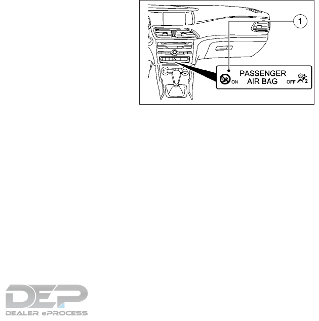
IMMOBILISER
The immobiliser prevents your vehicle from
being started without the correct key.
•To activate with the key: remove the key
from the ignition lock.
•To deactivate: switch on the ignition.
When leaving the vehicle, always take the key
with you and lock the vehicle. Anyone can
start the engine if a valid key has been left
inside the vehicle.
NOTE
The immobiliser is always deactivated when
you start the engine.
FCC Notice:
For USA:
This device complies with Part 15 of the FCC
Rules. Operation is subject to the following
two conditions: (1) This device may not
cause harmful interference, and (2) this de-
vice must accept any interference received,
including interference that may cause unde-
sired operation.
NOTE
Changes or modifications not expressly ap-
proved by the party responsible for compli-
ance could void the user’s authority to oper-
ate the equipment.
For Canada:
This device complies with Industry Canada
license-exempt RSS standard(s). Operation
is subject to the following two conditions: (1)
this device may not cause interference, and
(2) this device must accept any interference,
including interference that may cause unde-
sired operation of the device.
ANTI-THEFT ALARM SYSTEM (IF
EQUIPPED)
To arm: lock the vehicle with the key or Intel-
ligent Key. Indicator light 䊊
1flashes. The
alarm system is armed after approximately
15 seconds.
To deactivate: unlock the vehicle with the key
or Intelligent Key.
or
Insert the key into the ignition switch.
A visual and audible alarm is triggered if the
alarm system is armed and you open:
•A door.
•
The vehicle with the emergency key element.
•The lift gate.
•The hood.
NIC2750
SECURITY SYSTEM
Instruments and controls 2-59

To switch the alarm off with the key: press
the or button on the key. The
alarm is switched off
or
Vehicles with a push button ignition switch:
•Remove the start/stop button from the
ignition lock (see " Push-button ignition
switch (if equipped)" in the "5. Starting and
driving" section)
•Insert the key into the ignition lock. The
alarm stops.
The alarm is not switched off, even if you
close the open door that has triggered it, for
example.
WARNING
In freezing temperatures the washer solu-
tion may freeze on the windshield and ob-
scure your vision which may lead to an ac-
cident. Warm the windshield with the
defroster before you wash the windshield.
CAUTION
•Do not operate the washer continuously
for more than 30 seconds.
•Do not operate the washer if the win-
dow washer fluid reservoir is empty.
•Do not fill the window washer reservoir
tank with washer fluid concentrates at
full strength. Some methyl alcohol
based washer fluid concentrates may
permanently stain the grille if spilled
while filling the window washer reser-
voir tank.
•Pre-mix washer fluid concentrates with
water to the manufacturer’s recom-
mended levels before pouring the fluid
into the window washer reservoir tank.
Do not use the window washer reservoir
tank to mix the washer fluid concentrate
and water.
NOTE
•If the wiper operation is interrupted by
snow or ice, the wiper may stop moving to
protect its motor. If this occurs, turn the
wiper switch to the “OFF” position and
remove the snow or ice on and around the
wiper arms. In approximately 1 minute,
turn the switch on again to operate the
wiper.
•Do not operate the windshield wipers
when the windshield is dry, as this could
damage the wiper blades. Moreover, dust
that has collected on the windshield can
scratch the glass if wiping takes place
when the windshield is dry.
•If it is necessary to switch on the wipers in
dry weather conditions, always operate
them using washer fluid.
•If the windshield wipers leave smears on
the windshield after the vehicle has been
washed in an automatic car wash, this may
be due to wax or other residue. Clean the
windshield with washer fluid after an au-
tomatic car wash.
WIPER AND WASHER SWITCH
2-60 Instruments and controls
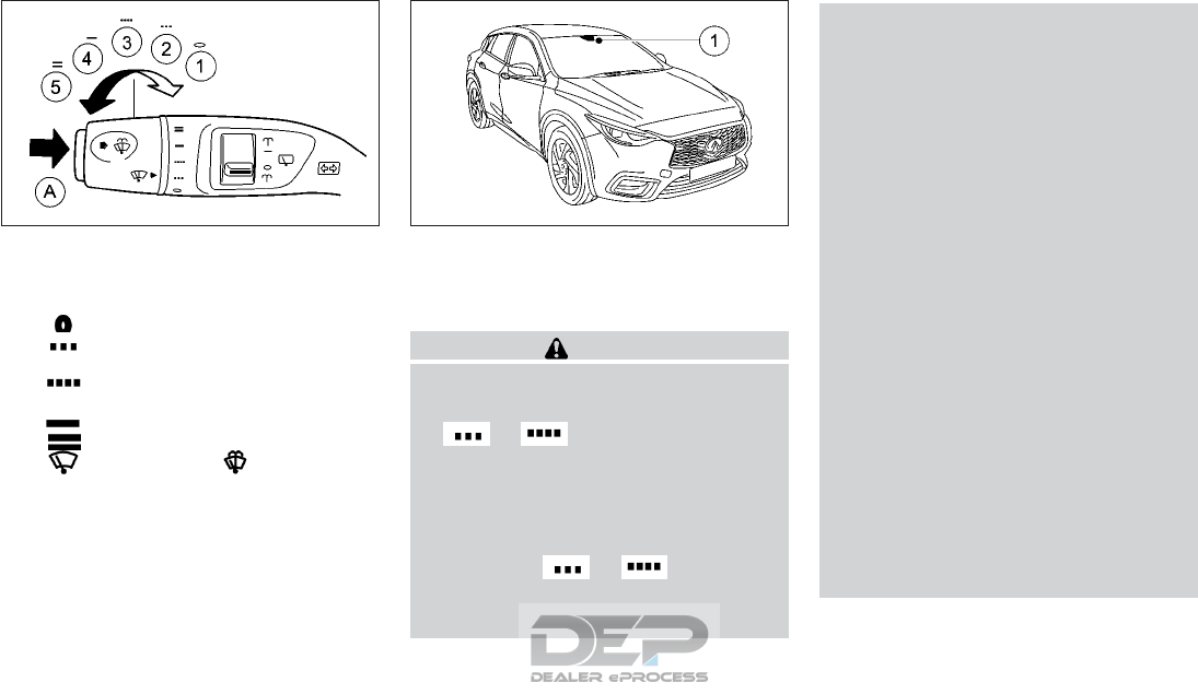
SWITCHING THE WINDSHIELD
WIPERS ON/OFF
䊊
1Windshield wipers off.
䊊
2Intermittent wipe, low (rain sensor
set to low sensitivity).
䊊
3Intermittent wipe, high (rain sen-
sor set to high sensitivity).
䊊
4Continuous wipe, slow.
䊊
5Continuous wipe, fast.
䊊
ASingle wipe/
wipe the windshield using washer fluid.
The windshield wiper and washer operate
when the ignition switch is in the ON position.
Turn the combination switch to the desired
position.
Rain sensor (if equipped)
The rain-sensing auto wiper system uses the
rain sensor located on the upper part of the
windshield 䊊
1.
CAUTION
•Do not touch the rain sensor and around
it 䊊
1when the wiper switch is in the
or position and the ignition
switch is in the ON position. The wipers
may operate unexpectedly and cause an
injury or may damage a wiper.
•The rain-sensing auto wipers are in-
tended for use during rain. If the switch
is left in the or position, the
wipers may operate unexpectedly when
dirt, fingerprints, oil film or insects are
stuck on or around the sensor. The wip-
ers may also operate when exhaust gas
or moisture affect the rain sensor.
•When the windshield glass is coated
with water repellent, the speed of the
rain-sensing auto wipers may be higher
even though the amount of the rainfall is
small.
•Be sure to turn off the rain-sensing auto
wiper system when you use a car wash.
•The rain-sensing auto wipers may not
operate if rain does not hit the rain sen-
sor even if it is raining.
•Using genuine wiper blades is recom-
mended for proper operation of the
rain-sensing auto wiper system. For ad-
ditional information, refer to "Wiper
blades" in the "8. Do-it-yourself" sec-
tion.
•Vehicles with a rain sensor: if the wind-
shield becomes dirty in dry weather con-
ditions, the windshield wipers may be
activated inadvertently. This could
damage the windshield wiper blades or
scratch the windshield.
For this reason, you should always
switch off the windshield wipers in dry
weather.
NIC2810
Combination switch
NSD610
Instruments and controls 2-61
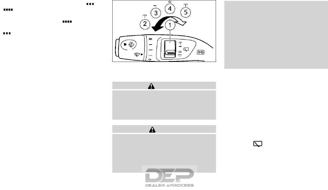
Vehicles with a rain sensor: in the or
position, the appropriate wiping fre-
quency is automatically set according to the
intensity of the rain. In the position, the
rain sensor is more sensitive than in the
position, causing the windshield wiper
to wipe more frequently.
If the wiper blades are worn, the windshield
will no longer be wiped properly. This could
prevent you from observing the traffic condi-
tions.
SWITCHING THE REAR WINDOW
WIPER ON/OFF
WARNING
In freezing temperatures the washer solu-
tion may freeze on the windshield and ob-
scure your vision which may lead to an ac-
cident. Warm the windshield with the
defroster before you wash the windshield.
CAUTION
•Do not operate the washer continuously
for more than 30 seconds.
•Do not operate the washer if the win-
dow washer fluid reservoir is empty.
•Do not fill the window washer reservoir
tank with washer fluid concentrates at
full strength. Some methyl alcohol
based washer fluid concentrates may
permanently stain the grille if spilled
while filling the window washer reser-
voir tank.
•Pre-mix washer fluid concentrates with
water to the manufacturer’s recom-
mended levels before pouring the fluid
into the window washer reservoir tank.
Do not use the window washer reservoir
tank to mix the washer fluid concentrate
and water.
䊊
1Switch
䊊
2Wipes with washer fluid
䊊
3Switches on intermittent wiping
䊊
4Switches off intermittent wiping
䊊
5Wipes with washer fluid
1. Switch the ignition switch to the ON po-
sition.
2. Turn switch 䊊
1on the combination switch
to the corresponding position.
When the rear window wiper is switched
on, the symbol appears in the as-
sistance graphic in the combination meter.
Further information on the assistance
graphic (see "Showing the distance
display" earlier in this section).
NIC2617
2-62 Instruments and controls
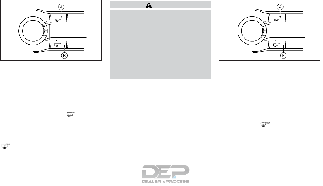
The defroster switch 䊊
Boperates when the
ignition switch is in the ON position for the
rear window, and (if equipped) for the outside
rear view mirrors.
The defroster is used to reduce the moisture,
fog or frost on the rear window surface and
on the outside mirror surface to improve the
rear view.
When the defroster switch is pushed,
the indicator light illuminates and the de-
froster operates for several minutes. After
the preset time has passed, the defroster will
turn off automatically. To turn off the de-
froster manually, push the defroster switch
again, and the indicator light turns off.
CAUTION
•When cleaning the inner side of the rear
window, be careful not to scratch or
damage the rear window defroster.
•When operating the defroster continu-
ously, be sure to start the engine. Oth-
erwise, it may cause the battery to dis-
charge.
•When cleaning the inner side of the win-
dow, be careful not to scratch or dam-
age the electrical conductors on the sur-
face of the window.
The windshield de-icer switch (defogger
switch) 䊊
Aoperates when the ignition switch
is in the ON position.
You can use this function to defrost the wind-
shield or to demist the inside of the wind-
shield and the side windows
NOTE
You should only select the windshield de-icer
function until the windshield is clear again.
When the switch is pushed, the indica-
tor light in the switch illuminates. The climate
control system switches to the following
functions:
•High airflow
•High temperature
•Air distribution to the windshield and front
side windows
•Air recirculation mode off
NAA1659 NAA1659
REAR WINDOW AND OUTSIDE
MIRROR DEFROSTER SWITCH WINDSHIELD DE-ICER SWITCH (IF
EQUIPPED)
Instruments and controls 2-63
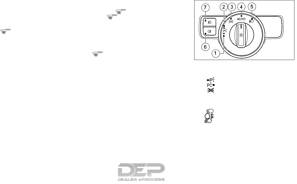
NOTE
The “Windshield demisting” function auto-
matically sets the blower output to the opti-
mum demisting effect. As a result, the air-
flow may increase or decrease automatically
after the button is pressed
NOTE
You can adjust the blower output manually
while the “Windshield demisting” function is
in operation: by adjusting the airflow control
for the air-conditioning or climate control
system (see "Heater and air conditioner" in
the "4. Display screen, heater and air condi-
tioner, and audio system" section).
To deactivate the de-icer:
•Press the button. The indicator light
in the button turns off. The previous
settings are reactivated. Air-recirculation
mode remains deactivated.
or
•Automatic climate control: press the
<AUTO> button. The indicator light in the
button turns off. Airflow and air dis-
tribution are set to automatic mode.
or
•Air-conditioning system or automatic cli-
mate control: adjust the temperature con-
trol (see "Heater and air conditioner" in the
"4. Display screen, heater and air condi-
tioner, and audio system" section).
HEADLIGHT SWITCH
䊊
1Left-hand parking lights
䊊
2Right-hand parking lights
䊊
3Side lights and license plate light-
ing
䊊
4<AUTO> Automatic headlight mode,
controlled by the light sensor
䊊
5Low beam/high beam headlights
䊊
6Rear fog light
䊊
7Front fog lights (if equipped)
䊊
8Headlight aiming control (halogen head-
lights only)
INFINITI recommends that you consult the
local regulations concerning the use of lights.
If you hear a warning tone when you leave
the vehicle, the side lights may still be
switched on. Turn the light switch to
<AUTO>.
NIC2619
LED headlights
HEADLIGHT AND TURN SIGNAL
SWITCHES
2-64 Instruments and controls
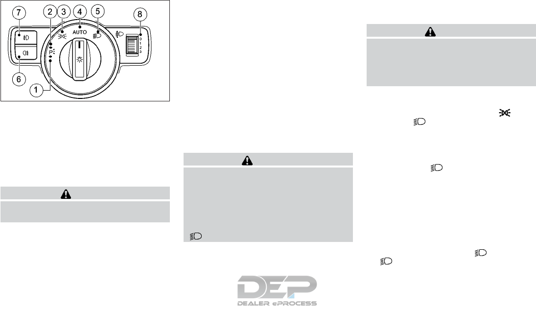
The exterior lighting (except the side lights/
parking lights) switches off automatically if
you:
•Remove the key from the ignition switch (if
equipped).
•Open the driver's door with the ignition
switch in the OFF position.
CAUTION
Use the headlights with the engine running
to avoid discharging the vehicle battery.
Automatic headlight mode
<AUTO> is the preferred light switch setting.
The light setting is automatically selected ac-
cording to the brightness of the ambient light
(exception: poor visibility due to weather con-
ditions such as fog, snow or spray):
•Ignition switch in ACC or ON position: the
side lights are switched on or off auto-
matically depending on the brightness of
the ambient light.
•With the engine running: if you have
switched on the daytime driving lights
function in the vehicle information display,
the side lights and low beam headlights
are switched on or off automatically de-
pending on the brightness of the ambient
light.
To switch on automatic headlight mode: turn
the light switch to <AUTO>.
WARNING
When the light switch is set to <AUTO>, the
low-beam headlights may not be switched
on automatically if there is fog, snow or
other causes of poor visibility due to the
weather conditions such as spray. There is
a risk of an accident
In such situations, turn the light switch to
.
The automatic headlight feature is only an
aid. The driver is responsible for the vehicle
lighting at all times.
The daytime driving lights improve the de-
tectability of your vehicle during the day.
WARNING
When the daytime running light system is
active, tail lights on your vehicle are not on.
It is necessary at dusk to turn on your
headlights. Failure to do so could cause an
accident injuring yourself and others.
When the side lights and low-beam head-
lights are switched on, the green (side
lights) and (low-beam headlights) indi-
cator lights in the combination meter light up.
Low-beam headlights
When the ignition is switched on and the light
switch is in the position, the side lights
and low-beam headlights are switched on
even if the light sensor does not sense dark
ambient light conditions. This is advanta-
geous when there is fog or rain.
To switch on the low-beam headlights:
•Switch the ignition switch to the ON posi-
tion, or start the engine.
•Turn the light switch to . The green
indicator light in the combination
meter lights up.
NIC2697
Halogen headlights
Instruments and controls 2-65
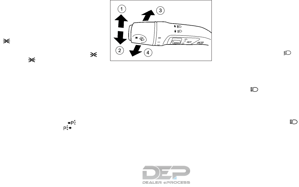
Side lights
NOTE
Always park your vehicle safely and suffi-
ciently lit according to legal standards. To
reduce the chance of a discharged vehicle
battery, avoid the continuous use of the
sidelights or parking lights for several
hours.
To switch on: turn the light switch to .
The green indicator light in the combi-
nation meter lights up.
Parking lights
Switching on the parking lights ensures that
the corresponding side of the vehicle is illumi-
nated.
To switch on the parking lights:
•The key is not in the ignition switch or the
switch is in the OFF position.
•Turn the light switch to (left-hand
side of the vehicle) or (right-hand
side of the vehicle).
COMBINATION SWITCH
䊊
1Turn signal, right
䊊
2Turn signal, left
䊊
3High beam headlights
䊊
4Headlight flasher
Turn signal
Move the lever up or down to signal the
turning direction. When the turn is com-
pleted, the turn signal cancels automatically.
Lane change signal
Move the lever up or down until the turn
signal begins to flash, but the lever does not
latch, to signal a lane change. Hold the lever
until the lane change is completed. Move the
lever up or down until the turn signal begins
to flash, but the lever does not latch, and
release the lever. The turn signal will auto-
matically flash three times. Choose the ap-
propriate method to signal a lane change
based on road and traffic conditions.
High beam headlights
To switch on the high beam headlights:
•Turn the ignition switch to the ON position
or start the engine.
•Turn the light switch to or <AUTO>.
•Press the combination switch beyond the
pressure point in the direction of arrow 䊊
3.
In the <AUTO> position, the high beam
headlights are only switched on when it is
dark and the engine is running.
The blue indicator light in the com-
bination meter lights up when the high
beam headlights are switched on.
To switch off the high beam headlights:
•Move the combination switch back to its
normal position. The blue indicator
light in the combination meter goes out.
NOTE
Vehicles with High beam Assist: when High
beam Assist is active, it controls activation
and deactivation of the high beam head-
lights (see " High beam assist (LED headlight
only)" later in this section)
NIC2618
2-66 Instruments and controls
ADAPTIVE FRONT LIGHTING
SYSTEM (LED HEADLIGHT
ONLY) (IF EQUIPPED)
The Adaptive Front Lighting System is a sys-
tem that adjusts the headlights automatically
to suit the prevailing driving and weather
conditions. It offers advanced functions for
improved illumination of the road surface,
e.g. depending on the vehicle speed or
weather conditions. The system includes the
active light function, cornering light function
and freeway mode. The system is only active
when it is dark.
You can activate or deactivate the “Adaptive
Front Lighting System” function using the
vehicle information display (see "Switching
the Adaptive Front Lighting System on/off"
earlier in this section)
Active light function
The active light function is a system that
moves the headlights according to the steer-
ing movements of the front wheels. In this
way relevant areas remain illuminated while
you are driving. This helps you to recognize
pedestrians, cyclists and animals. It is active
when the lights are switched on.
Cornering light function
The cornering light function improves the il-
lumination of the road over a wide angle in
the direction you are turning, enabling better
visibility in tight bends, for example. It can
only be activated when the low-beam head-
lights are switched on. It is active if you are
driving at speeds below 25 MPH (40 km/h)
and switch on the turn signal or turn the
steering wheel.
The cornering light function may remain lit for
a short time, but is automatically switched off
after no longer than three minutes.
NSD593 NSD592
Instruments and controls 2-67
Freeway mode
Freeway mode adjusts the light beam to re-
duce the amount of light that shines on the
opposite lane of the freeway, and oncoming
traffic.
Freeway mode is active if you are driving at a
speed above 68 MPH (110 km/h) and do not
make any large steering movements for at
least 3300 ft (1000 m) or if you are driving at
a speed above 81 MPH (130 km/h).
It is not active if you are driving at speeds
below 50 MPH (80 km/h) following activa-
tion.
HIGH BEAM ASSIST (LED
HEADLIGHT ONLY)
You can use this function to set the head-
lights to change between low beam and high
beam automatically. The system recognizes
vehicles with their lights on, either approach-
ing from the opposite direction or traveling in
front of your vehicle, and consequently
switches the headlights from high beam to
low beam.
The system automatically adapts the low
beam headlight range depending on the dis-
tance to the other vehicle. Once the system
no longer detects any other vehicles, it
switches on the high beam headlights again.
The system's optical sensor is located behind
the windshield near the overhead control
panel.
WARNING
•The high beam assist system is a conve-
nience but is not a substitute for safe
driving operation. The driver should re-
main alert at all times, ensure safe driv-
ing practices and switch the high beams
and low beam manually when necessary.
•The high beam or low beam may not
switch automatically under the follow-
ing conditions. Switch the high beam
and low beam manually.
–During bad weather (rain, fog, snow,
wind, etc.).
–When a light source similar to a head-
light or tail light is in the vicinity of
the vehicle.
–When the headlights of the oncoming
vehicle or the leading vehicle are
turned off, when the color of the light
is affected due to foreign materials
on the lights, or when the light beam
is out of position.
–When there is a sudden, continuous
change in brightness.
–When driving on a road that passes
over rolling hills, or a road that has
level differences.
–When driving on a road with many
curves.
NSD594 NDS595
2-68 Instruments and controls
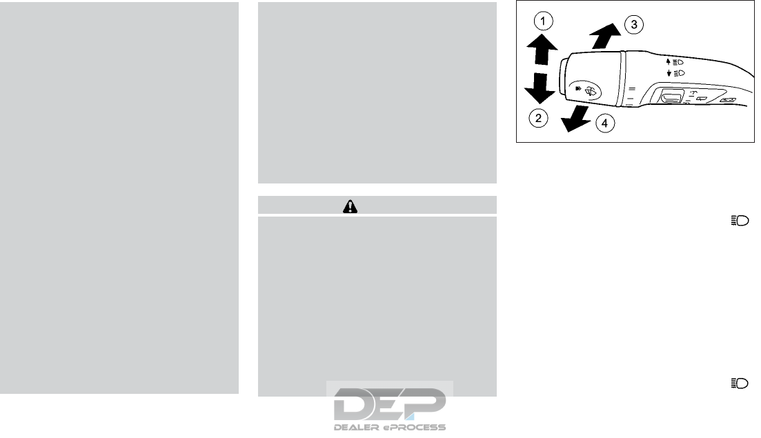
–When a sign or mirror-like surface is
reflecting intense light towards the
front of the vehicle.
–When the container, etc. being towed
by a leading vehicle is reflecting in-
tense light.
–When a headlight on your vehicle is
damaged or dirty.
–When the vehicle is leaning at an
angle due to a punctured tire, being
towed, etc.
•The timing of switching the low beam
and high beam may change under the
following situations.
–
The brightness of the headlights of the
oncoming vehicle or leading vehicle.
–
The movement and direction of the on-
coming vehicle and the leading vehicle.
–When only one light on the oncoming
vehicle or the leading vehicle is illumi-
nated.
–
When the oncoming vehicle or the lead-
ing vehicle is a two-wheeled vehicle.
–Road conditions (incline, curve, the
road surface, etc.).
–The number of passengers and the
amount of luggage.
•High beam Assist does not recognize
road users:
–Who have no lights, e.g. pedestrians.
–Who have low intensity lighting, e. g.
cyclists.
–Whose lighting is blocked, e.g. by a
barrier.
•In very rare cases, High beam Assist rec-
ognizes road users too late or not at all.
In this, or in similar situations, the auto-
matic high beam headlights will not be
deactivated or activated regardless.
There is a risk of an accident.
•Always carefully observe the traffic
conditions and switch off the high beam
headlights in good time.
CAUTION
High beam Assist cannot compensate for
road and weather circumstances while
driving. The system saves the driver from
having to operate the switch. The driver
always remains responsible for choosing
the correct light setting.
Specific situations in which to operate the
headlight switch manually:
•In heavy rain, snowy conditions. (gen-
eral poor visibility and bad weather con-
ditions).
•When the vehicle sensors are dirty, cov-
ered or broken.
Switching High Beam Assist on/off
To switch on:
Turn the light switch to <AUTO> and press
the combination switch beyond the pressure
point in the direction of arrow 䊊
3. The
indicator light in the vehicle information dis-
play lights up when it is dark and the light
sensor switches on the low-beam headlights.
If you are driving at speeds above approxi-
mately 28 MPH (45 km/h) the headlight
range is set automatically depending on the
distance between the vehicle and other road
users.
If you are driving at speeds above approxi-
mately 34 MPH (55 km/h) and no other road
users are detected, the high beam headlights
are switched on automatically. The
NIC2618
Instruments and controls 2-69
indicator light in the combination meter also
lights up.
If you are driving at speeds below approxi-
mately 28 MPH (45 km/h) or other road
users are detected or the roads are ad-
equately lit The high beam headlights are
switched off automatically. The indica-
tor light in the combination meter goes out.
The indicator light in the vehicle infor-
mation display remains lit.
To deactivate:
Move the combination switch back to its nor-
mal position The indicator light in the
vehicle information display goes out.
HEADLIGHTS MISTED UP ON
THE INSIDE
Certain climatic and physical conditions may
cause moisture to form in the headlight. This
moisture does not affect the functionality of
the headlight.
INSTRUMENT BRIGHTNESS
CONTROL
The light sensor in the combination meter
automatically controls the brightness of the
instrument panel
In daylight, the displays in the combination
meter are not illuminated
The lighting in the combination meter, dis-
plays and controls in the vehicle interior can
be adjusted using the brightness control
knob.
The brightness control knob 䊊
1is located
behind the steering wheel.
Turn the brightness control knob clockwise or
counterclockwise. If the light switch is set to
or the brightness is dependent
upon the brightness of the ambient light.
FRONT FOG LIGHTS
In conditions where visibility is poor due to
fog, snow or rain, the fog lights improve vis-
ibility as well as making it easier for other
road users to see you. They can be operated
together with the side lights or together with
the side lights and low beam headlights.
To switch on the fog lights:
•Turn the ignition switch to the ON position
or start the engine.
•Turn the light switch to or <AUTO>.
•Press the button. The green
indicator light in the combination meter
lights up
NIC2615 NIC2699
FOG LIGHT SWITCH (IF SO
EQUIPPED)
2-70 Instruments and controls
To switch off the front fog lights:
•press the button The green indi-
cator light in the combination meter turns
off.
Only vehicles with front fog lights are
equipped with the “Fog lights” function.
REAR FOG LIGHT
The rear fog light improves the visibility of
your vehicle in heavy fog for the following
traffic. Please observe the country-specific
laws on the use of rear fog lights.
NOTE
The front fog lights must be switched on be-
fore the rear fog light will operate.
To switch on the rear fog light:
•Turn the ignition switch to the ON position
or start the engine.
•Turn the light switch to or <AUTO>.
•Press the button. The yellow
indicator light in the combination meter
lights up
To switch off the rear fog light:
•press the button The yellow
indicator light in the combination meter
turns off.
The rear fog light should be used only when
visibility is seriously reduced. (Generally, to
less than 50 m (116 ft))
To sound the horn, push the center pad area
of the steering wheel.
WARNING
Do not disassemble the horn. Doing so
could affect proper operation of the
supplemental front air bag system. Tam-
pering with the supplemental front air bag
system may result in serious personal
injury.
NIC2717
HORN
Instruments and controls 2-71

WARNING
Do not use or allow occupants to use the
seat heater if you or the occupants cannot
monitor elevated seat temperatures or
have an inability to feel pain in body parts
that contact the seat. Use of the seat
heater by such people could result in seri-
ous injury.
CAUTION
•The battery could run down if the seat
heater is operated while the engine is
not running.
•Do not use the seat heater for extended
periods or when no one is using the seat.
•Do not put anything on the seat which
insulates heat, such as a blanket, cush-
ion, seat cover, etc. Otherwise, the seat
may become overheated.
•Do not place anything hard or heavy on
the seat or pierce it with a pin or similar
object. This may result in damage to the
heater.
•Any liquid spilled on the heated seat
should be removed immediately with a
dry cloth.
•When cleaning the seat, never use gaso-
line, benzine, thinner, or any similar ma-
terials.
•If any malfunctions are found or the
heated seat does not operate, turn the
switch off and have the system checked.
It is recommended you visit an INFINITI
retailer for this service.
The front seats are warmed by built-in heaters.
The switches are located on the center con-
sole and can be operated independently, for
the left-hand side seat and for the right-hand
side seat.
The three red indicator lights in the button indi-
cate the heating level you have selected The
system automatically switches from level 3 to
level 2 after approximately eight minutes The
system automatically switches from level 2 to
level 1 after approximately ten minutes. The sys-
tem automatically switches off approximately
20 minutes after it is set to level 1
1.
Turn the ignition switch to the ON position.
NOTE
The seat heater can only be activated
when the ignition switch is in the ON po-
sition.
NIC2634
SEAT HEATING (IF EQUIPPED)
2-72 Instruments and controls

2. Start the engine.
3. Select the heat range:
•To switch on: press button 䊊
1repeat-
edly until the desired heating level is
set.
•To switch off: press button 䊊
1repeat-
edly until all the indicator lights turn off.
NOTE
If the battery voltage is too low, the seat
heating may switch off.
POWER WINDOWS
WARNING
•Make sure that all passengers have their
hands, etc. inside the vehicle while it is in
motion and before closing the windows.
Use the window lock switch to prevent
unexpected use of the power windows.
•To help avoid risk of injury or death
through unintended operation of the
vehicle and or its systems, including en-
trapment in windows or inadvertent
door lock activation, do not leave chil-
dren, people who require the assistance
of others or pets unattended in your ve-
hicle. Additionally, the temperature in-
side a closed vehicle on a warm day can
quickly become high enough to cause a
significant risk of injury or death to
people and pets.
The switches for all side windows are located on
the driver's door. There is also a switch on each
door for the corresponding side window The
switches on the driver's door take precedence.
Auto-reverse function
The auto-reverse function can be activated
when a window is closed by automatic op-
eration.
Depending on the environment or driving
conditions, the auto-reverse function may
be activated if an impact or load similar to
something being caught in the window oc-
curs.
WARNING
There are some small distances immedi-
ately before the closed position which can-
not be detected. Make sure that all passen-
gers have their hands, etc., inside the
vehicle before closing the window.
If the vehicle's battery is disconnected, re-
placed, or jump started, the power window
auto-reverse function may not operate prop-
erly. If this occurs, it is recommended you visit
an INFINITI retailer to re-initialize the power
window auto-reverse system.
If the control unit detects something caught
in a window equipped with automatic opera-
tion as it is closing, the window will be imme-
diately lowered.
Driver’s window switch
The power windows operate when the igni-
tion switch is in the ON position.
WINDOWS
Instruments and controls 2-73

1. Front left side window
2. Front right side window
3. Rear left side window
4. Rear right side window
The driver’s switch, the main switch, can con-
trol all windows.
•To open manually: press and hold the cor-
responding button.
•To open fully: press the button beyond the
point of resistance to the second detent
and release it. Automatic operation is
started.
•To close manually: pull the corresponding
button and hold it.
•To close fully: pull the button beyond the
point of resistance and release it. Auto-
matic operation is started.
•To interrupt automatic operation: press/
pull the corresponding switch again.
NOTE
•If you press/pull the switch beyond the
point of resistance, automatic operation is
started in the corresponding direction. You
can stop automatic operation by pressing/
pulling again.
•You can continue to operate the side win-
dows after switching off the engine or
removing the key. This function remains
active for five minutes or until the driver's
or front-passenger door is opened.
•The side windows cannot be operated
from the rear when the override feature
for the side windows is activated.
Locking rear side windows:
To enable/disable the override feature for
the rear side windows, press button 䊊
2.If
indicator light 䊊
1is lit, operation of the rear
side windows is disabled. Operation is only
possible using the switches in the driver's
door. If indicator light 䊊
1is off, operation is
possible using the switches in the rear com-
partment.
NIC2715 NIC2716
2-74 Instruments and controls
Passenger’s window switch
The passenger’s switch can control its corre-
sponding window.
Convenience opening feature
For vehicles with Intelligent Key: you can
ventilate the vehicle before you start driving.
The key can also be used to carry out the
following functions simultaneously:
•Unlock the vehicle
•Open the side windows
NOTE
The convenience opening feature can only be
operated using the key.
The key must be in close proximity to the
vehicle.
Press and hold the button until the side
windows are in the desired position.
To interrupt convenience opening: release
the button.
Convenience closing feature
WARNING
When the convenience closing feature is
operating, parts of the body could become
trapped in the closing area of the side win-
dow. There is a risk of injury. Observe the
complete closing procedure when the con-
venience closing feature is operating.
When closing make sure that no parts of
the body are in the closing area.
For vehicles with Intelligent Key: The key can
also be used to carry out the following func-
tions simultaneously:
•Lock the vehicle
•Close the side windows
The driver's door and the door at which the
handle is used must both be closed. The key
must be outside the vehicle. The gap between
the key and the corresponding door handle
should not be greater than 1 m.
Press and hold the button until the side
windows are fully closed.
To interrupt convenience closing: release the
button.
You can also use the keyless locking feature
to activate convenience closing:
NIC2640
Instruments and controls 2-75
Touch recessed sensor surface 䊊
1on the
door handle until the side windows are fully
closed.
NOTE
Make sure you only touch recessed sensor
surface 䊊
1.
To interrupt convenience opening: release
the recessed sensor surface 䊊
1on the door
handle.
Resetting the side windows
If a side window can no longer be closed fully,
you must reset it.
1. Switch the ignition switch to the ON po-
sition.
2. Close the door.
3. Pull the corresponding switch on the door
control panel until the side window is
completely closed
4. Hold the switch for an additional second.
If the side window opens again slightly:
1. Immediately pull the corresponding switch
on the door control panel until the side
window is completely closed.
2. Hold the switch for an additional second.
3. If the corresponding side window remains
closed after the button has been released,
the side window has been reset correctly.
If this is not the case, repeat the steps
above again.
If the power window automatic function
does not operate properly after performing
the procedure above, have your vehicle
checked. It is recommended you visit an
INFINITI retailer for this service.
䊊
1Close
䊊
2Open
CAUTION
•Do not place heavy objects on the glass
roof or surrounding area.
•Do not hang from the sunshade or hang
any objects from it. It may cause damage
or deformation to the sunshade.
•Close the sunshade when you leave the
vehicle for extended periods of time to
prevent the inside of the vehicle from
reaching high temperatures.
SUNSHADE OPERATION
The sunshade operates only when the igni-
tion switch is in the ON position.
NPA1478 NIC2646
FIXED GLASS ROOF (IF EQUIPPED)
2-76 Instruments and controls
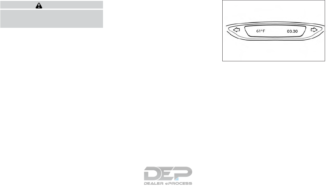
WARNING
To avoid personal injury, keep your hands,
fingers and head away from the sunshade
arm, the arm rail and sunshade inlet port.
NOTE
The following notes cover situations where
strong sun shining on the roof of the vehicle
causes the area around the sunshade motor
to reach high temperatures:
•If the temperature of the sunshade motor
reaches a value between 185 °F (85 °C)
and 212 °F (100 °C), “restricted mode” is
enabled, and the sunshade will only be
allowed to CLOSE.
•If the temperature of the sunshade motor
exceeds 212 °F (100 °C), the sunshade will
not operate.
Opening and closing
Manual control:
To close the sunshade, press and hold the
“CLOSE” side of the switch 䊊
1To stop the
sunshade from closing fully, release the
switch.
To open the sunshade press and hold the
“OPEN” side of the switch 䊊
2To stop the
sunshade from opening fully, release the
switch.
Automatic operation:
To fully open or close the sunshade auto-
matically, press briefly on the open or close
side of the switch and then release. To stop
the sunshade from opening or closing, press
either side of the switch.
Auto-reverse function:
When the control unit detects something
caught by the sunshade, the sunshade will
open automatically.
NOTE
The auto-reverse function remains active
whether the sunshade is being closed manu-
ally or automatically.
If the battery cable is disconnected, the clock
will need to be re-adjusted to the correct
time.
ADJUSTING TIME
Set the time using the INFINITI controller and
the [Settings] menu available in the central
display (see "Clock settings" in the "4. Display
screen, heater and air conditioner, and audio
system" section).
NOTE
On vehicles fitted with a navigation system,
the clock is automatically updated via GPS.
The initial clock setting may be incorrect.
NSD659
CLOCK
Instruments and controls 2-77
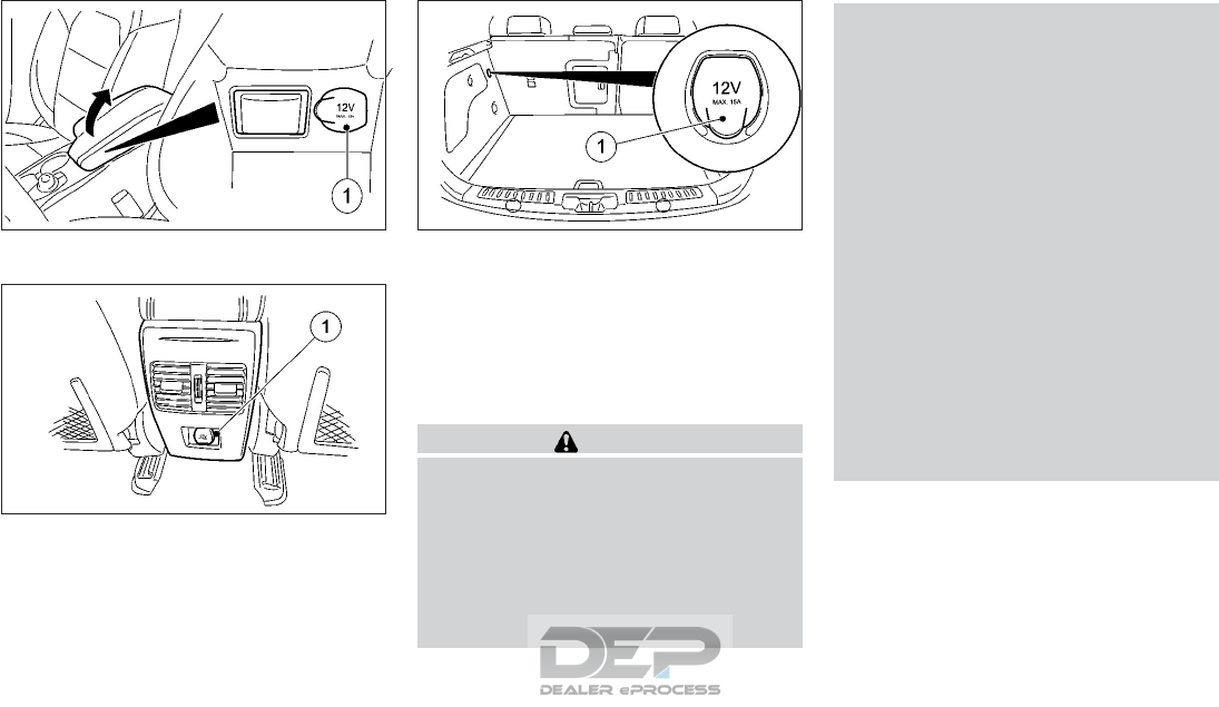
In the center console (LHD)
Rear console
Luggage compartment
The power outlet is used for powering elec-
trical accessories such as a cellular telephone.
An emergency cut-off ensures that the on-
board voltage does not drop too low. If the
on board voltage is too low, the power to the
sockets is automatically cut. This ensures that
there is sufficient power to start the engine.
CAUTION
•The outlet and plug may be hot during or
immediately after use.
•Only certain power outlets are designed
for use with a cigarette lighter unit. Do
not use any other power outlet for an
accessory lighter. It is recommended you
visit an INFINITI retailer for additional
information.
•Do not use with accessories that exceed
a 12 volt, 180W (15A) power draw. Do
not use double adapters or more than
one electrical accessory.
•Use this power outlet with the engine
running to avoid discharging the vehicle
battery.
•Avoid using when the air conditioner,
headlights or rear window defogger is
on.
•Push the plug in as far as it will go. If
good contact is not made, the plug may
overheat or the internal temperature
fuse may blow.
•Before inserting or disconnecting a plug,
be sure that the electrical accessory be-
ing used is turned OFF.
•When not in use, be sure to close the cap.
Do not allow water to contact the
outlet.
NIC2690
NIC2683
NIC2684
POWER OUTLET
2-78 Instruments and controls

WARNING
Keep the storage lids closed while driving
to help prevent injury in an accident or a
sudden stop.
GLOVE BOX
To open the glove box, pull the handle 䊊
1.
To close, push the lid 䊊
2until the lock latches.
NOTE
To lock/unlock the glove box, use the me-
chanical key. For the mechanical key usage,
see "Mechanical key" in the "3. Pre-driving
checks and adjustments" section.
FRONT CONSOLE
COMPARTMENT
To open the front console compartment,
push lid 䊊
1down and release. The lid will
open.
To close, push the lid 䊊
1down until the lock
latches.
NIC2823 NIC2663
STORAGE
Instruments and controls 2-79

CONSOLE BOX
To open, pull up the lid from the front.
CARD HOLDER
Pull the sun visor down and slide a card in the
card holder 䊊
2.
CUP HOLDERS
CAUTION
•Avoid abrupt starting and braking when
the cup holder is being used to prevent
spilling the drink. If the liquid is hot, it
can scald you or your passenger.
•Do not recline the rear seatback when
you use the cup holders on the rear arm-
rest (if equipped). Doing so may cause
the beverages to spill over, and if they
are hot, they may scald the passengers.
•Use only soft cups in the cup holder.
Hard objects can injure you in an
accident.
NIC2665 NIC2676
2-80 Instruments and controls
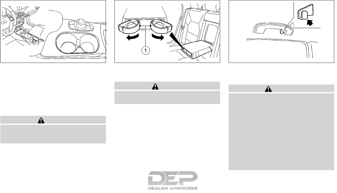
The cup holders 䊊
1for rear passengers are
located on the rear center armrest (if
equipped).
To open the rear cup holders (if equipped),
press the front of the cup holder 䊊
1.
To close, slide the cup holder 䊊
1back until it
engages.
CAUTION
Close the cup holder before folding the rear
armrest up, otherwise the cup holder could
be damaged.
COAT HOOKS
CAUTION
Do not apply a total load of more than 2 lb
(1 kg) to the hook.
The coat hooks are equipped at the rear as-
sist grips.
CARGO TIE-DOWN HOOKS
䊊
1Cargo tie-down hook
WARNING
•Properly secure all cargo with ropes or
straps to help prevent it from sliding or
shifting. Do not place cargo higher than
the seatbacks. In a sudden stop or colli-
sion, unsecured cargo could cause per-
sonal injury.
•Use suitable ropes and hooks to secure
cargo.
•Never allow anyone to ride in the cargo
area or on the rear seat when it is in the
fold-down position. Use of these areas
by passengers without proper restraints
NIC2674
Front
NIC2675
Rear (if equipped)
SIC3505Z
Instruments and controls 2-81
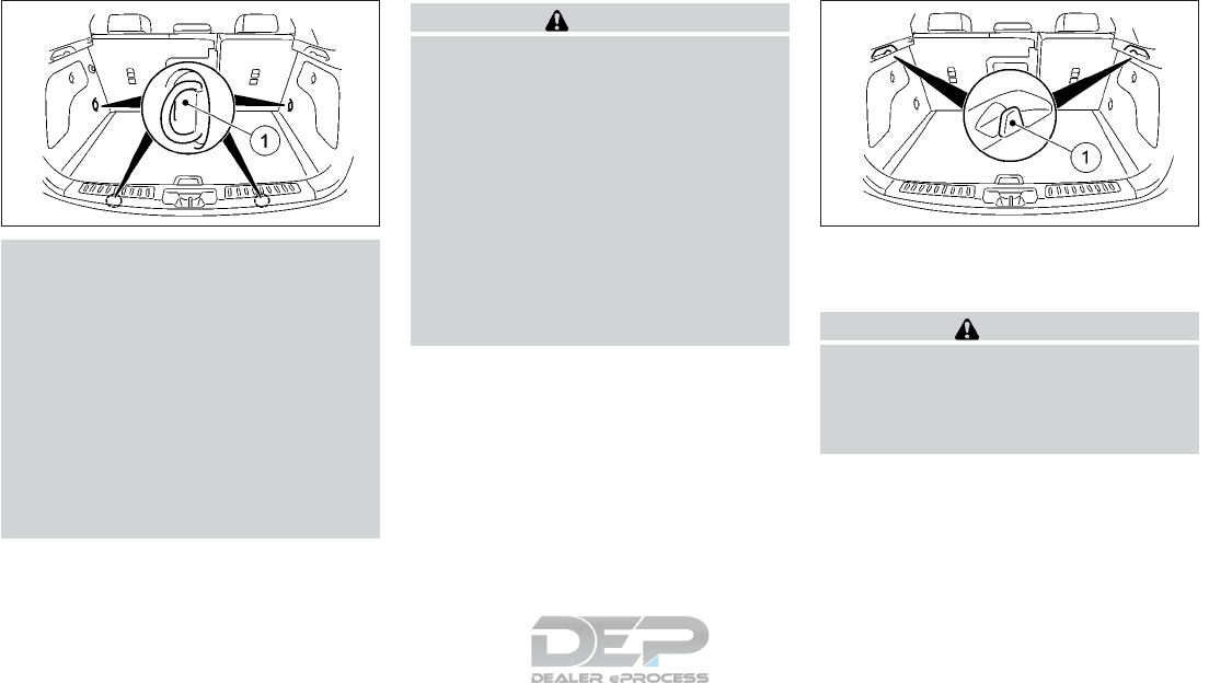
could result in serious injury or death in
an accident or sudden stop.
•Do not allow people to ride in any area of
your vehicle that is not equipped with
seats and seat belts.
•The child restraint top tether strap may
be damaged by contact with items in the
cargo area. Secure any items in the
cargo area. Your child could be seriously
injured or killed in a collision if the top
tether strap is damaged.
•Be sure everyone in your vehicle is in a
seat and using a seat belt properly.
CAUTION
•Do not apply a total load of more than
22 lb (10 kg) to a single eyelet.
•Secure the load using the cargo tie-
down hooks.
•Distribute the load on the cargo tie-
down hooks evenly.
•Do not use elastic straps or nets to se-
cure a load. These are only intended as
anti-slip protection for light loads.
•Do not route tie-down ropes or straps
across sharp edges or corners.
•Pad sharp edges for protection.
LUGGAGE HOOKS
The luggage hooks 䊊
1are for shopping bags,
etc.
CAUTION
•Do not apply a total load of more than 7
lb (3 kg) to the hook.
•Do not use luggage hooks to secure a
load.
NIC2670 NIC2671
2-82 Instruments and controls
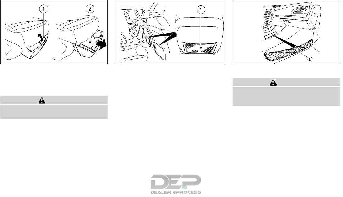
FRONT SEAT STORAGE BOXES
(IF EQUIPPED)
To open the front seat storage boxes, pull
handle 䊊
1up and fold cover 䊊
2forwards.
CAUTION
The maximum permissible load for the
front seat storage box is 2.6 lb (1.2 kg).
MAP POCKET (IF EQUIPPED)
Map pockets are located in the doors.
STORAGE NETS (IF EQUIPPED)
WARNING
Do not place sharp objects in the nets to
help prevent injury in an accident or sudden
stop.
Storage nets are fitted in the front-passenger
footwell and on the back of the driver's and
front passenger seat.
NIC2666 NIC2685 NIC2687
Instruments and controls 2-83
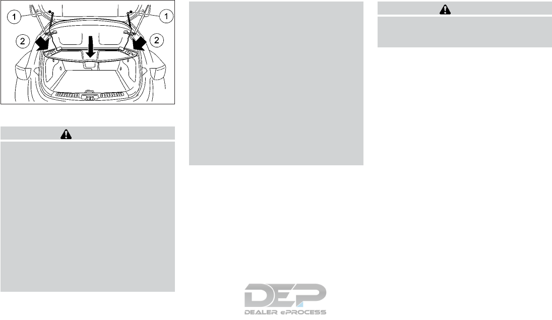
PARCEL SHELF
WARNING
•Never put anything on the parcel shelf,
no matter how small. Any object on it
could cause an injury in case of an acci-
dent or if the brakes are applied sud-
denly.
•Do not leave the parcel shelf in position
when it is disengaged from the grooves.
•Properly secure all cargo to help prevent
it from sliding or shifting. Do not place
cargo higher than the seatbacks. In a
sudden stop or collision, unsecured
cargo could cause personal injury
•Properly secure cargo and do not allow
it to contact the top tether strap when it
is attached to the top tether anchor.
Cargo that is not properly secured or
cargo that contacts the top tether strap
may damage the top tether strap during
a collision. If the cargo cover contacts
the top tether strap when it is attached
to the top tether anchor, remove the
cargo cover from the vehicle or secure it
on the cargo floor below its attachment
location. If the cargo cover is not re-
moved, it may damage the top tether
strap during a collision. Your child could
be seriously injured or killed in a collision
if the child restraint top tether strap is
damaged.
•Do not use the cargo cover if the rear
seats are folded down.
Removal
1. Open the lift gate (see "Lift gate lock" in
the "2. Instruments and controls" section).
2. Detach both of the cords (left and right)
䊊
1from the inside of the lift gate.
3. Detach the parcel shelf 䊊
2by simply pull-
ing it rearwards through the lift gate
opening.
CAUTION
Make sure the parcel shelf is carefully
stored when not in use in order to prevent
any damage.
Installation
1. Open the lift gate.
2. Insert the parcel shelf by pushing it for-
wards as far as possible through the lift
gate opening.
3. Attach the corresponding cords to each
side 䊊
1of the lift gate.
4. Close the lift gate (see "Lift gate lock" in
the "2. Instruments and controls" section).
ROOF RACK (IF EQUIPPED)
Genuine NISSAN accessory cross bars are
available through an INFINITI retailer. It is
recommended you visit an INFINITI retailer
for cross bar or other equipment information.
Always distribute the luggage evenly on the
cross bars. Do not load more than 221 lb
(100 kg) on the cross bars. Observe the maxi-
mum load limit shown on the crossbars or
roof carriers when you attach them on the
roof rails.
NIC2672
2-84 Instruments and controls
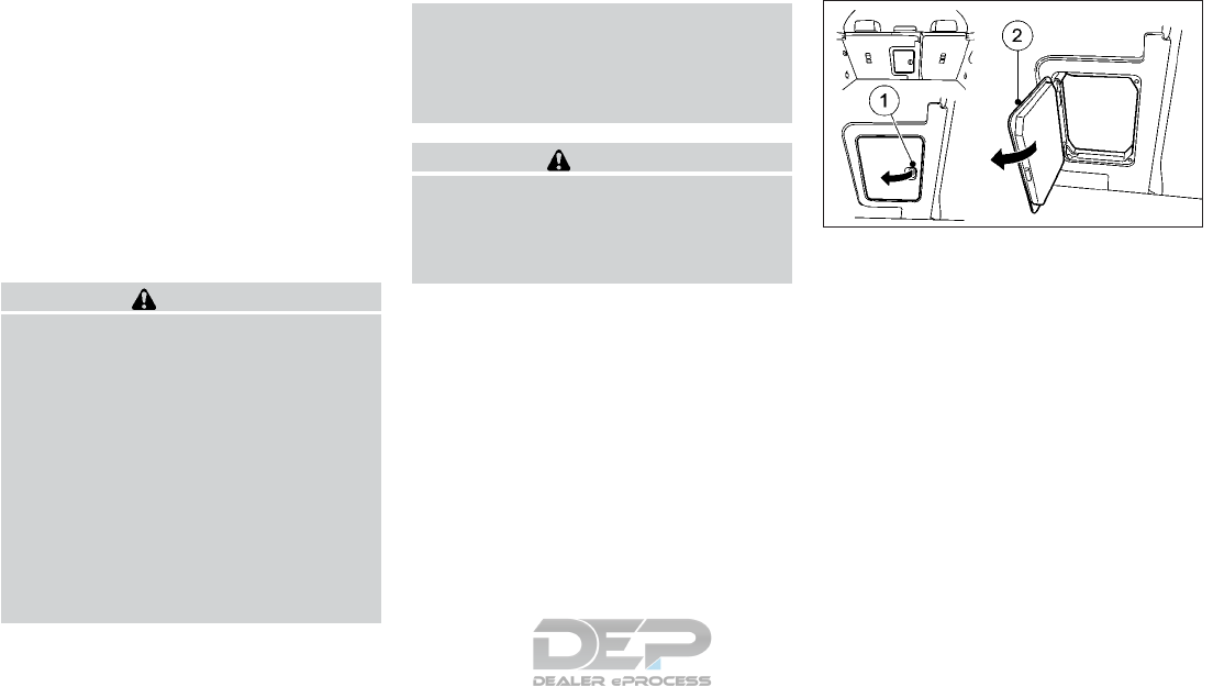
Do not apply any load directly to the roof side
rails. Cross bars (if so equipped) must be in-
stalled before applying load/cargo/luggage
to the roof of the vehicle.
Be careful that your vehicle does not exceed
the Gross Vehicle Weight Rating (GVWR) or
its Gross Axle Weight Rating (GAWR front
and rear). The GVWR and GAWR are located
on the F.M.V.S.S. or C.V.M.S.S. certification
label (located on the driver’s door pillar). For
additional information, refer to "Vehicle load-
ing information" in the "10. Technical infor-
mation" section.
WARNING
•Drive extra carefully when the vehicle is
loaded at or near the cargo carrying ca-
pacity, especially if the significant por-
tion of that load is carried on the roof
rack.
•Heavy loading of the roof rack has the
potential to affect the vehicle stability
and handling during sudden or unusual
handling maneuvers.
•Roof rack load should be evenly distrib-
uted.
•Do not exceed maximum roof rack load
weight capacity.
•Properly secure all cargo with ropes or
straps to help prevent it from sliding or
shifting. In a sudden stop or collision,
unsecured cargo could cause personal
injury.
CAUTION
Always install the cross bars (if so
equipped) onto the roof side rails before
loading cargo of any kind. Loading cargo
directly onto the roof side rails or the vehi-
cle's roof may cause vehicle damage. SKI HATCH (IF EQUIPPED)
To open the ski hatch:
1. Fold down rear seat armrest.
2. Pull the center head restraint on the rear
bench seat into the uppermost position.
3. Slide locking mechanism 䊊
1in the direc-
tion of the arrow
4. Swing flap 䊊
2fully to the side. The flap is
held open by a magnet.
To close the ski hatch:
1. Swing flap 䊊
1in the luggage compart-
ment back until it engages.
2. Fold armrest fully up if necessary.
NIC2668
Instruments and controls 2-85
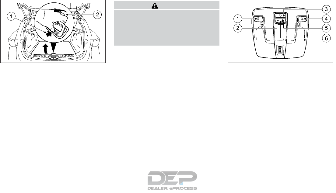
COMPARTMENT UNDER TRUNK
FLOOR
Lift the trunk floor to access the underfloor
storage area.
CAUTION
•Turn off the lights when you leave the
vehicle.
•Do not use the lights for extended peri-
ods of time with the engine stopped.
This could result in a discharged battery.
FRONT OVERHEAD CONTROL
PANEL
䊊
1Switches the left-hand front reading
light on/off
䊊
2Switches the front interior lighting on
䊊
3Switches the rear interior lighting on/off
䊊
4Switches the right-hand front reading
light on/off
䊊
5Switches the front interior lighting/
automatic interior lighting control off
䊊
6Switches the automatic interior lighting
control on
Automatic interior lighting control
•To switch on: set the switch to center po-
sition 䊊
6.
•To switch off: press switch 䊊
5.
NIC2673 NIC2630
INTERIOR LIGHTS
2-86 Instruments and controls
The interior lighting automatically switches
on if you:
•Unlock the vehicle
•Open a door
•Remove the key from the ignition lock.
The interior lighting is activated for a short
time when the key is removed from the igni-
tion lock. You can activate this delayed
switch-off using the vehicle information dis-
play (see "Activating/deactivating the interior
lighting delay" earlier in this section). REAR READING LIGHTS
(IF EQUIPPED)
䊊
1Switches the left hand reading light on/
off
䊊
2Switches the right hand reading light on/
off
REAR ROOM LIGHT
(IF EQUIPPED)
The rear room light (without switches) can be
switched on and off using the front overhead
control panel.
VANITY MIRROR LIGHTS
To access the vanity mirror, pull the sun visor
down and flip open the mirror cover.
The vanity mirror light illuminates when the
vanity mirror cover is opened. When the cover
is closed, the light will turn off.
LUGGAGE COMPARTMENT LIGHT
The light illuminates while the lift gate is
opened. When the lift gate is closed, the light
will turn off.
BATTERY SAVER SYSTEM
The interior light will automatically turn off
after a period of time when the ignition
switch has been put in the OFF position. To
turn on the light again, put the ignition switch
in the ON position.
NIC2632 SIC3869Z
Instruments and controls 2-87

The HomeLink® Universal Transceiver, inte-
grated in the vehicle's inside rear view mirror,
provides a convenient way to consolidate the
functions of up to three individual hand-held
transmitters into one built-in device.
HomeLink® Universal Transceiver:
•Will operate most Radio Frequency (RF)
devices such as garage doors, gates, home
and office lighting, entry door locks and
security systems.
•Is powered by your vehicle’s battery. No
separate batteries are required. If the ve-
hicle’s battery is discharged or is discon-
nected, HomeLink® will retain all pro-
gramming.
When the HomeLink® Universal Transceiver
is programmed, retain the original transmit-
ter for future programming procedures (Ex-
ample: new vehicle purchases). Upon sale of
the vehicle, the programmed HomeLink®
Universal Transceiver buttons should be
erased for security purposes. For additional
information, refer to "Programming
HomeLink® " later in this section.
WARNING
•Do not use the HomeLink® Universal
Transceiver with any garage door
opener that lacks safety stop and re-
verse features as required by federal
safety standards. (These standards be-
came effective for opener models manu-
factured after April 1, 1982). A garage
door opener which cannot detect an ob-
ject in the path of a closing garage door
and then automatically stop and re-
verse, does not meet current federal
safety standards. Using a garage door
opener without these features increases
the risk of serious injury or death.
•During the programming procedure
your garage door or security gate will
open and close (if the transmitter is
within range). Make sure that people or
objects are clear of the garage door,
gate, etc. that you are programming.
•Your vehicle’s engine should be turned
off while programming the HomeLink®
Universal Transceiver.
NOTE
Certain garage door drives are incompatible
with the integrated garage door opener. If
you have difficulty programing the inte-
grated garage door opener, it is recom-
mended you contact your INFINITI retailer.
PROGRAMMING HOMELINK®
If you have any questions or are having diffi-
culty programming your HomeLink® but-
tons, refer to the HomeLink® web site at:
www.homelink.com or call
1-800-355-3515.
HOMELINK® UNIVERSAL
TRANSCEIVER (IF EQUIPPED)
2-88 Instruments and controls
1. Turn the ignition key to the ON position.
2. Press and hold one of buttons 䊊
2to 䊊
4on
the HomeLink®.
HomeLink® is now in programing mode.
After a short time, indicator light 䊊
1lights
up yellow.
Indicator light 䊊
1lights up yellow as soon
as button 䊊
2,䊊
3or 䊊
4is programed for
the first time. If the selected button has
already been programed, indicator light
䊊
1will only light up yellow after ten sec-
onds have elapsed.
3. Release button 䊊
2,䊊
3or 䊊
4. Indicator
light 䊊
1flashes yellow.
4. Position the end of your hand-held trans-
mitter 䊊
52–8 inches (5–20 cm) away
from the HomeLink® surface, keeping the
HomeLink® indicator light 䊊
1in view.
5. Press and hold button 䊊
6on the hand held
transmitter until indicator light 䊊
1lights
up green. When indicator light 䊊
1: lights
up green: programing is finished.
When indicator light 䊊
1flashes green:
programing was successful. The next step
is to synchronize the rolling code.
6. Release button 䊊
6on the hand held trans-
mitter 䊊
5for the garage door drive sys-
tem.
If indicator light 䊊
1lights up red: repeat
the programing procedure for the corre-
sponding button on the rear-view mirror.
When doing so, vary the distance be-
tween the hand held transmitter 䊊
5and
the rear-view mirror.
The required distance between the hand
held transmitter 䊊
5and the integrated ga-
rage door opener depends on the garage
door drive system. Several attempts might
be necessary. You should test every posi-
tion for at least 25 seconds before trying
another position.
Synchronizing the rolling code
If the garage door system uses a rolling code,
you will also have to synchronize the garage
door system with the integrated garage door
opener in the rear-view mirror. To do this you
will need to use the programing button on the
door drive control panel. The programing
button may be positioned at different loca-
tions depending on the manufacturer. It is
usually located on the door drive unit on the
garage ceiling.
Familiarize yourself with the garage door
drive operating instructions before carrying
out the following steps.
Your vehicle must be within reach of the ga-
rage door or gate opener drive. Make sure
that neither your vehicle nor any persons/
objects are present within the sweep of the
door or gate.
1. Turn the ignition key to the ON position.
2. Get out of the vehicle.
3. Press the programing button on the door
drive unit.
Usually, you now have 30 seconds to ini-
tiate the next step.
4. Get into the vehicle.
5. Press previously programed button 䊊
2,䊊
3
or 䊊
4on the HomeLink® until the door
closes.
The rolling code synchronization is then com-
plete.
NDI1631
Instruments and controls 2-89

If you live in Canada
Canadian radio frequency laws require a
"break" (or interruption) of the transmission
signals after broadcasting for a few seconds.
Therefore, these signals may not last long
enough for the integrated garage door
opener. The signal is not recognized during
programing. Comparable with Canadian law,
some U.S. garage door openers also feature a
"break".
Proceed as follows:
•If you live in Canada
•If you have difficulties programing the ga-
rage door opener (regardless of where you
live) when using the programing steps.
1. Press and hold one of buttons 䊊
2to 䊊
4on
the HomeLink®. After a short time, indi-
cator light 䊊
1lights up yellow.
2. Release the button.
Indicator light 䊊
1flashes yellow.
3. Press button 䊊
6of the hand held trans-
mitter 䊊
5for two seconds, then release it
for two seconds.
4. Press button 䊊
6again for two seconds.
5. Repeat this sequence on button 䊊
6of the
hand held transmitter 䊊
5until indicator
light 䊊
1lights up green.
When indicator light 䊊
1lights up green:
programing is finished.
When indicator light 䊊
1flashes green:
programing was successful. The next step
is to synchronize the rolling code.
6. Release button 䊊
6of the hand held trans-
mitter 䊊
5for the garage door drive.
If indicator light 䊊
1lights up red: repeat
the programing process for the corre-
sponding button on the rear-view mirror.
When doing so, vary the distance be-
tween the hand held transmitter 䊊
5and
the rear-view mirror.
The required distance between the hand
held transmitter 䊊
5and the HomeLink®
depends on the garage door drive system.
Several attempts might be necessary. You
should test every position for at least 25
seconds before trying another position.
PROGRAMMING TROUBLE
DIAGNOSIS
If the HomeLink® does not quickly learn the
hand-held transmitter information:
•Check the transmitter frequency used by
garage door drive hand-held transmitter
䊊
5and whether it is supported. The trans-
mitter frequency can usually be found on
the back of the garage door drive hand-
held transmitter. HomeLink® is compat-
ible with devices that have units which
operate in the frequency range of 280 to
433 MHz.
•Replace the hand-held transmitter 䊊
5bat-
teries with new batteries.
This increases the likelihood that the hand-
held transmitter 䊊
5will transmit a strong
and precise signal to the HomeLink®.
•When programing, hold the hand-held
transmitter 䊊
5at varying distances and
angles from the button which you are pro-
graming. Try various angles at a distance
between 2 and 12 inches (5 to 30 cm) or at
the same angle but at varying distances.
•If another hand-held transmitter is avail-
able for the same garage door drive, re-
peat the same programing steps with this
hand-held transmitter 䊊
5. Before per-
forming these steps, make sure that new
batteries have been installed in the hand-
held transmitter 䊊
5.
•Note that some hand-held transmitters
only transmit for a limited amount of time
(the indicator light on the hand-held trans-
mitter goes out). Press button 䊊
6on re-
mote hand-held transmitter 䊊
5again be-
fore transmission ends.
2-90 Instruments and controls

•Align the antenna cable of the garage door
opener unit. This can improve signal
reception/ transmission.
If you have any questions or are having diffi-
culty programming your HomeLink® but-
tons, refer to the HomeLink® web site at:
www.homelink.com or 1-800-355-3515.
OPERATING THE HOMELINK®
UNIVERSAL TRANSCEIVER
The HomeLink® Universal Transceiver, after
it is programmed, can be used to activate the
programmed device.
1. Turn the ignition key to the ON position.
2. Press button 䊊
2,䊊
3or 䊊
4which you have
programed to operate the garage door.
Garage door system with a fixed code:
indicator light 䊊
1lights up green
Garage door system with a rolling code:
indicator light 䊊
1flashes green.
The transmitter will transmit a signal as long
as the button is pressed. The transmission is
halted after a maximum of ten seconds and
indicator light 䊊
1lights up yellow. Press but-
ton 䊊
2,䊊
3or 䊊
4again if necessary.
For convenience, the hand-held transmitter
of the device may also be used at any time.
CLEARING THE PROGRAMMED
INFORMATION
Make sure that you clear the memory of the
integrated garage door opener before selling
the vehicle.
1. Turn the ignition key to the ON position.
2. Press and hold buttons 䊊
2and 䊊
4.
The indicator light initially lights up yellow
and then green.
3. Release buttons 䊊
2and 䊊
4.
The memory of the integrated garage door
opener in the rear-view mirror is cleared.
IF YOUR VEHICLE IS STOLEN
If your vehicle is stolen, you should change
the codes of any non-rolling code device that
has been programmed into HomeLink®.
Consult the Owner’s Manual of each device
or call the manufacturer of those devices for
additional information or contact an
INFINITI retailer.
Instruments and controls 2-91

MEMO
2-92 Instruments and controls

3 Pre-driving checks and adjustments
Keys ..............................3-2
INFINITI Intelligent key ................3-2
INFINITI Vehicle immobilizer system keys.....3-3
Doors .............................3-4
Locking with the key ..................3-4
Locking with the mechanical key ..........3-5
Locking with inside door knob ............3-6
Locking with Power door lock switch .......3-6
Automatic door locks .................3-6
Child safety rear door lock ..............3-7
Lift gate lock .......................3-7
INFINITI Intelligent Key system .............3-8
Operating range.....................3-9
Door locks/unlocks precaution ..........3-10
INFINITI Intelligent Key operation ........3-10
Changing the settings of the locking system . .3-11
Troubleshooting guide ................3-12
Hood .............................3-15
Fuel-filler door .......................3-16
Opening fuel-filler door ...............3-16
Fuel-filler cap......................3-16
Steering wheel .......................3-17
Sun visors ..........................3-18
Vanity mirror ......................3-18
Mirrors............................3-18
Automatic anti-glare rear view mirror ......3-18
Outside mirrors ....................3-18
Memory function (if equipped) .............3-21
Storing settings ....................3-22
Calling up a stored setting .............3-22

INFINITI INTELLIGENT KEY
Your vehicle can only be driven with the Intel-
ligent Keys which are registered to your vehi-
cle's Intelligent Key System components and
INFINITI Vehicle Immobilizer System compo-
nents.
Never leave the keys in the vehicle.
As many as four Intelligent Keys can be reg-
istered and used with one vehicle. The new
keys must be registered prior to use with the
Intelligent Key System and INFINITI Vehicle
Immobilizer System of your vehicle. It is rec-
ommended that you visit an INFINITI retailer
for this service. Since the registration process
requires erasing all memory in the Intelligent
Key components when registering new keys,
be sure to take all Intelligent Keys that you
have to the INFINITI retailer.
A key number plate is supplied with your keys.
Record the key number and keep it in a safe
place (such as your wallet), not in the vehicle.
If you lose your keys, it is recommended that
you visit an INFINITI retailer for duplicates by
using the key number. INFINITI does not re-
cord key numbers so it is very important to
keep track of your key number plate.
A key number is only necessary when you
have lost all keys and do not have one to
duplicate from. If you still have a key, it can be
duplicated without knowing the key number.
CAUTION
Listed below are conditions or occurrences
which will damage the Intelligent Key:
•Do not allow the Intelligent Key, which
contains electrical components, to come
into contact with water or salt water.
This could affect the system function.
•Do not drop the Intelligent Key.
•Do not strike the Intelligent Key sharply
against another object.
•Do not change or modify the Intelligent
Key.
•Wetting may damage the Intelligent
Key. If the Intelligent Key gets wet, im-
mediately wipe until it is completely dry.
•Do not place the Intelligent Key for an
extended period in an area where tem-
peratures exceed 140 °F (60 °C).
•Do not attach the Intelligent Key with a
key holder that contains a magnet.
•Do not place the Intelligent Key near
equipment that produces a magnetic
field, such as a TV, audio equipment and
personal computers.
If an Intelligent Key is lost or stolen, INFINITI
recommends erasing the ID code of that In-
telligent Key. This will prevent the Intelligent
Key from unauthorized use to unlock the ve-
hicle. For information regarding the erasing
procedure, please contact an INFINITI re-
tailer.
Mechanical key
CAUTION
Always carry the mechanical key installed
in the Intelligent Key.
NPA1497
KEYS
3-2 Pre-driving checks and adjustments
Push release catch 䊊
1in the direction of the
arrow and, at the same time, remove emer-
gency key element 䊊
2from the key.
Valet hand-off
To prevent the glove box from being opened
during valet hand-off, follow the procedure
below.
1. Remove the mechanical key from the In-
telligent Key.
2. Lock the glove box with the mechanical
key.
3. Hand the Intelligent Key to the valet and
keep the mechanical key with you.
For additional information, refer to "Storage"
in the "2. Instruments and controls" section.
INFINITI VEHICLE IMMOBILIZER
SYSTEM KEYS
You can only drive your vehicle using the
Intelligent Keys which are registered to the
INFINITI Vehicle Immobilizer System compo-
nents in your vehicle.
The mechanical key can be used for all the
locks.
Never leave the keys in the vehicle.
Additional or replacement keys:
If you still have a key, the key number is not
necessary when you need extra INFINITI Ve-
hicle Immobilizer System keys. Your existing
key can be duplicated without knowing the
key number. As many as four INFINITI Ve-
hicle Immobilizer System keys can be used
with one vehicle. You should bring all
INFINITI Vehicle Immobilizer System keys
that you have to the INFINITI retailer for
registration. This is because the registration
process will erase the memory of all key
codes previously registered into the INFINITI
Vehicle Immobilizer System. After the regis-
tration process, these components will only
recognize keys coded into the INFINITI Ve-
hicle Immobilizer System during registration.
Any key that is not given to the retailer at the
time of registration will no longer be able to
start your vehicle.
CAUTION
Do not allow the immobilizer system key,
which contains an electrical transponder,
to come into contact with water or salt
water. This could affect system function.
NPA1494
Pre-driving checks and adjustments 3-3
When the doors are locked using one of the
following methods, the doors cannot be
opened using the inside or outside door
handles. The doors must be unlocked to open
the doors.
WARNING
•Before opening any door, always look
for and avoid oncoming traffic.
•Do not leave children unattended inside
the vehicle. They could unknowingly ac-
tivate switches or controls or move the
vehicle. Unattended children could be-
come involved in serious accidents.
•To help avoid risk of injury or death
through unintended operation of the
vehicle and/or its systems, do not leave
children, people who require the assis-
tance of others, or pets unattended in
your vehicle. Additionally, the tempera-
ture inside a closed vehicle on a warm
day can quickly become high enough to
cause a significant risk of injury or death
to people and pets.
LOCKING WITH THE KEY
䊊
1Locks the vehicle.
䊊
2Unlocks the vehicle.
䊊
3Panic button.
If you do not open the vehicle within approxi-
mately 40 seconds of unlocking, the vehicle
will lock again and protection against theft is
reactivated.
To lock centrally, press button 䊊
1. The key
centrally locks:
•Doors
•Lift gate
•Fuel filler lid
When unlocking, the turn signals flash once
When locking, they flash three times.
Intelligent Key
You can combine the Intelligent Key func-
tions with the functions of a conventional
key. Unlock the vehicle by using Intelligent
Key function, for instance, and lock it using
the button on the key.
The driver's door and the door at which the
handle is used, must both be closed. The key
must be outside the vehicle. When locking or
unlocking with Intelligent Key, the distance
between the key and the corresponding door
handle must not be greater than 1 m.
NPA1493
DOORS
3-4 Pre-driving checks and adjustments

To unlock the vehicle: touch the inner surface
of the door handle.
To lock the vehicle: touch sensor surface 䊊
1.
or 䊊
2.
Make sure that you do not touch the inner
surface of the door handle.
Convenience closing feature: touch recessed
sensor surface 䊊
1for an extended period.
(See "Convenience closing feature" in the
"2. Instruments and controls" section).
To unlock the lift gate: press the lift gate
switch 䊊
1.
When unlocking, the turn signals flash once
When locking, they flash three times.
NOTE
When the locator lighting is activated, it
lights up when it is dark after the vehicle is
unlocked with the Intelligent Key (see sepa-
rate operating instructions).
You can also set an audible signal to confirm
that the vehicle has been locked. The audible
signal can be activated or deactivated using
the on-board computer (see "Activating/
deactivating the acoustic locking confirma-
tion" in the "2. Instruments and controls"
section)
LOCKING WITH THE
MECHANICAL KEY
The driver's door can be locked/unlocked
from outside using the mechanical key if the
battery is dead.
To lock the door, insert the mechanical key
into the driver's door key cylinder and turn it
towards the front of the vehicle 䊊
1.
To unlock the door, turn the key towards the
rear of the vehicle 䊊
2.
See "Mechanical key" earlier in this section for
instructions on accessing the Intelligent Key
system mechanical key.
NOTE
The alarm system will be triggered when the
door is opened using the mechanical key
(alarm equipped models). To stop the alarm,
NPA1489 NPA1479 SPA2602Z
Pre-driving checks and adjustments 3-5

turn the ignition key to the ON position or
press the unlock button ( ) on the key.
There are several ways to deactivate the
alarm:
•To deactivate the alarm with the key:
press the or button on the key.
or
Insert the key into the ignition lock.
•Lock or unlock the vehicle using Intelligent
Key. The key must be outside the vehicle
If you unlock the vehicle using the emergency
key element, the fuel filler lid will not be un-
locked automatically. To unlock the fuel filler
lid, insert the key into the ignition lock.
LOCKING WITH INSIDE DOOR
KNOB
To unlock and open the door, pull the door
lock knob and 䊊
1up pull the inside door
handle 䊊
1.
LOCKING WITH POWER DOOR
LOCK SWITCH
䊊
1Press to unlock
䊊
2Press to lock
The power door lock switch, located on the
door trimming, can be used to unlock 䊊
1or
lock 䊊
2all doors.
AUTOMATIC DOOR LOCKS
The vehicle is locked automatically when the
ignition is switched on and the vehicle speed
reaches around 10 MPH (16 km/h).
All doors unlock automatically when the igni-
tion is placed in the OFF position.
NPA1476 NPA1477
3-6 Pre-driving checks and adjustments

You could therefore be locked out if:
•The vehicle is being pushed.
•The vehicle is being towed.
•The vehicle is being tested on a dynamom-
eter.
CHILD SAFETY REAR DOOR
LOCK
The child safety lock helps prevent doors
from being opened accidentally, especially
when small children are in the vehicle.
When the switch is in the LOCK 䊊
2position,
the rear door can only be opened from the
outside.
LIFT GATE LOCK
To open the lift gate, unlock it first with one
of the following operations, then push the
button 䊊
1.
•Push the button on the key or Intel-
ligent Key (if equipped). See "INFINITI In-
telligent Key system" later in this section.
•Unlock all the doors using the key.
To close the lift gate, pull it down until it
securely locks.
NIC2641 NPA1479
Pre-driving checks and adjustments 3-7
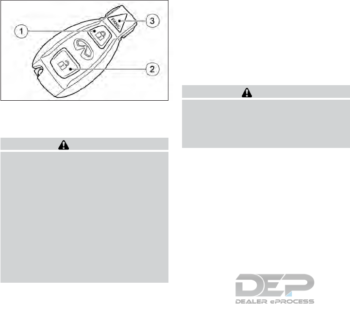
䊊
1Locks the vehicle.
䊊
2Unlocks the vehicle.
䊊
3Panic button.
WARNING
•
Radio waves could adversely affect elec-
tric medical equipment. Those who use a
pacemaker should contact the electric
medical equipment manufacturer for the
possible influences before use.
•The Intelligent Key transmits radio
waves when the buttons are pushed.
The FAA advises that the radio waves
may affect aircraft navigation and com-
munication systems. Do not operate the
Intelligent Key while on an airplane.
Make sure that the buttons are not op-
erated unintentionally when the unit is
stored for a flight.
The Intelligent Key system can operate all the
door locks using the remote control function
or touching the request switch on the vehicle
without taking the key out from a pocket or
purse. The operating environment and/or
conditions may affect the Intelligent Key sys-
tem operation.
Be sure to read the following before using the
Intelligent Key system.
CAUTION
•Be sure to carry the Intelligent Key with
you when operating the vehicle.
•Never leave the Intelligent Key in the
vehicle when you leave the vehicle.
The Intelligent Key is always communicating
with the vehicle as it receives radio waves.
The Intelligent Key system transmits weak
radio waves. Environmental conditions may
interfere with the operation of the Intelligent
Key system under the following operating
conditions:
•When operating near a location where
strong radio waves are transmitted, such
as a TV tower, power station and broad-
casting station.
•When in possession of wireless equip-
ment, such as a cellular telephone, trans-
ceiver or a CB radio.
•When the Intelligent Key is in contact with
or covered by metallic materials.
•When any type of radio wave remote con-
trol is used nearby.
•When the Intelligent Key is placed near an
electric appliance such as a personal com-
puter.
•When the vehicle is parked near a parking
meter.
In such cases, correct the operating condi-
tions before using the Intelligent Key function
or use the mechanical key.
Although the life of the battery varies de-
pending on the operating conditions, the bat-
tery's life is approximately two years. If the
battery is discharged, replace it with a new
one.
When the Intelligent Key battery is low, an
indicator illuminates in the vehicle informa-
tion display. For additional information, refer
to "Safety systems" in the "2. Instruments and
controls" section.
NPA1493
INFINITI INTELLIGENT KEY SYSTEM
3-8 Pre-driving checks and adjustments
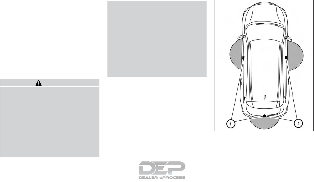
Since the Intelligent Key is continuously re-
ceiving radio waves, if the key is left near
equipment which transmits strong radio
waves, such as signals from a TV and per-
sonal computer, the battery life may become
shorter.
For additional information, refer to "Intelli-
gent Key battery replacement" in the "8. Do-
it-yourself" section.
As many as four Intelligent Keys can be reg-
istered and used with one vehicle. For infor-
mation about the purchase and use of addi-
tional Intelligent Keys, it is recommended that
you visit an INFINITI retailer.
CAUTION
Listed below are conditions or occurrences
which will damage the Intelligent Key:
•Do not allow the Intelligent Key, which
contains electrical components, to come
into contact with water or salt water.
This could affect the system function.
•Do not drop the Intelligent Key.
•Do not strike the Intelligent Key sharply
against another object.
•Do not change or modify the Intelligent
Key.
•Wetting may damage the Intelligent
Key. If the Intelligent Key gets wet, im-
mediately wipe until it is completely dry.
•Do not place the Intelligent Key for an
extended period in an area where tem-
peratures exceed 140 °F (60 °C).
•Do not attach the Intelligent Key with a
key holder that contains a magnet.
•Do not place the Intelligent Key near
equipment that produces a magnetic
field, such as a TV, audio equipment and
personal computers.
If an Intelligent Key is lost or stolen, INFINITI
recommends erasing the ID code of that In-
telligent Key from the vehicle. This may pre-
vent the unauthorized use of the Intelligent
Key to operate the vehicle. For information
regarding the erasing procedure, it is recom-
mended that you visit an INFINITI retailer.
OPERATING RANGE
The Intelligent Key functions can only be used
when the Intelligent Key is within the speci-
fied operating range from the request switch
䊊
1.
NPA1498
Pre-driving checks and adjustments 3-9
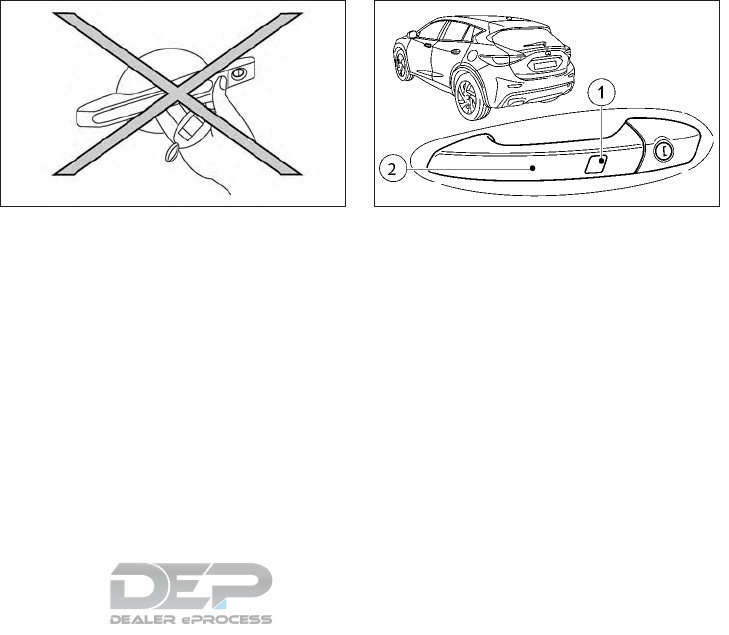
When the Intelligent Key battery is dis-
charged or strong radio waves are present
near the operating location, the Intelligent
Key operating range becomes narrower, and
the Intelligent Key may not function properly.
The operating range is within 31.5 in (80 cm)
from each request switch 䊊
1.
If the Intelligent Key is too close to the door
glass, handle or rear bumper, the request
switches may not function.
When the Intelligent Key is within the operat-
ing range, it is possible for anyone, even
someone who does not carry the Intelligent
Key, to push the request switch to lock/
unlock the doors.
DOOR LOCKS/UNLOCKS
PRECAUTION
•Do not touch the door handle request
switch with the Intelligent Key held in your
hand as illustrated. The close distance to
the door handle will cause the Intelligent
Key system to have difficulty recognizing
that the Intelligent Key is outside the ve-
hicle.
•To prevent the Intelligent Key from being
left inside the vehicle, make sure you carry
the Intelligent Key
INFINITI INTELLIGENT KEY
OPERATION
You can lock or unlock the doors without
taking the Intelligent Key out of your pocket
or bag.
When you carry the Intelligent Key with you,
you can lock or unlock all doors by pushing
the door handle request switch within the
range of operation.
Locking doors
1. Push the P (Park) button to engage the P
(Park) position, place the ignition switch in
the LOCK position and make sure you
carry the Intelligent Key with you.
2. Close all doors.
3. Touch any sensor surface 䊊
1or 䊊
2.
WPD0375Z NPA1489
3-10 Pre-driving checks and adjustments
4. All doors and the lift gate will lock.
5. The turn signals flash three times.
NOTE
•Doors do not lock by pushing the door
handle request switch while any door is
open. However, doors lock with the me-
chanical key even if any door is open.
•The driver's door and the door at which the
handle is used, must both be closed.
•The doors may not lock when the Intelli-
gent Key is in the same hand that is oper-
ating the request switch to lock the door.
Put the Intelligent Key in a purse, pocket or
your other hand.
CAUTION
•When locking the doors using the re-
quest switch, make sure to have the In-
telligent Key in your possession before
operating the request switch to prevent
the Intelligent Key from being left in the
vehicle.
•The request switch is operational only
when the Intelligent Key has been de-
tected by the Intelligent Key system.
Unlocking doors
1. Carry the Intelligent Key.
2. Touch the inner surface of the door
handle.
3. All doors and the lift gate will unlock.
4. The turn signals flash once.
CHANGING THE SETTINGS OF
THE LOCKING SYSTEM
You can change the settings of the locking
system. This means that only the driver's door
and the fuel-filler lid are unlocked when the
vehicle is unlocked. This is useful if you fre-
quently travel alone.
To change the setting: simultaneously press
the and buttons for approxi-
mately 6 seconds.
NOTE
If the setting of the locking system is
changed within the signal range of the ve-
hicle, pressing the and button will
lock or unlock the vehicle.
The key now functions as follows:
To unlock the driver's door: press the
button once.
To unlock centrally: press the button
twice.
To lock centrally: press the button.
The Intelligent Key function is changed as
follows:
To unlock the driver's door: touch the inner
surface of the door handle on the driver's
door.
To unlock centrally: touch the inner surface
of the door handle on the front passenger
door or the rear door.
To lock centrally: touch the outer sensor sur-
face on one of the door handles
To restore the factory settings: simultane-
ously press the and button for
approximately 6 seconds.
Pre-driving checks and adjustments 3-11

TROUBLESHOOTING GUIDE
Verify the location of all Intelligent Keys that are programmed for the vehicle. If another Intelligent Key is in range or inside the vehicle, the vehicle
system may respond differently than expected.
Symptom Possible cause Remedy
You cannot lock or unlock the vehicle using
the key
The key battery is discharged or nearly dis-
charged: •Vehicles without Intelligent Key: try again to lock/unlock the
vehicle using the remote control function of the key. Point the tip
of the key at the driver's door handle from close range and press
the / button.
If this does not work:
•Check the key battery (see "Checking the battery" in the "8.
Do-it-yourself" section) and replace it necessary
•Unlock (see "Locking with the mechanical key" later in this sec-
tion) or lock the vehicle using the emergency key element
There is interference from a powerful source
of radio waves •Vehicles without Intelligent Key: try again to lock/unlock the
vehicle using the remote control function of the key. Point the tip
of the key at the driver's door handle from close range and press
the / button.
If this does not work:
•Unlock (see "Locking with the mechanical key" later in this sec-
tion) or lock the vehicle using the emergency key element
The key is faulty •Unlock (see "Locking with the mechanical key" later in this sec-
tion) or lock the vehicle using the emergency key element
•Have the key checked. It is recommended you visit an INFINITI
retailer for this service.
3-12 Pre-driving checks and adjustments

Symptom Possible cause Remedy
You can no longer lock or unlock the vehicle
using Intelligent Key
The key battery is discharged or nearly dis-
charged •Check the key battery (see "Checking the battery" in the "8.
Do-it-yourself" section) and replace it necessary
If this does not work:
•Unlock (see "Locking with the mechanical key" later in this sec-
tion) or lock the vehicle using the emergency key element
There is interference from a powerful source
of radio waves •Unlock (see "Locking with the mechanical key" later in this sec-
tion) or lock the vehicle using the emergency key element
There is a fault with the Intelligent Key sys-
tem •Lock/unlock the vehicle using the remote control function of the
key.
•Have the vehicle and key checked. It is recommended you visit an
INFINITI retailer for this service.
If the vehicle can also not be locked/unlocked using the remote
control function
•Unlock (see "Locking with the mechanical key" later in this sec-
tion) or lock the vehicle using the emergency key element
•Have the vehicle and key checked. It is recommended you visit an
INFINITI retailer for this service.
The engine cannot be started using the key The on-board voltage is too low •Switch off non-essential consumers, e. g. seat heating or interior
lighting, and try to start the engine again
If this does not work:
•Check the starter battery and charge it if necessary (see "Battery"
in the "8. Do-it-yourself" section)
or
•Jump-start the vehicle (see "Jump starting" in the "6. In case of
emergency" section)
or
•Have the system checked. It is recommended you consult an
INFINITI retailer.
Pre-driving checks and adjustments 3-13

Symptom Possible cause Remedy
The engine cannot be started using the push
button ignition switch. The key is in the ve-
hicle
The vehicle is locked with the Intelligent Key. •Unlock the vehicle and try to start the vehicle again.
The key battery is weak or discharged. •Check the key battery (see "Checking the battery" in the "8.
Do-it-yourself" section) and replace it necessary
If this does not work:
•Start your vehicle with the key in the ignition lock.
There is interference from a powerful source
of radio waves. •Start the vehicle with the key in the ignition lock.
You have lost a key — •Have the key deactivated. It is recommended you visit an
INFINITI retailer for this service.
•Report the loss immediately to the vehicle insurers
•If necessary, have the locks changed as well
You have lost the emergency key element •Report the loss immediately to the vehicle insurers
•If necessary, have the locks changed as well.
3-14 Pre-driving checks and adjustments
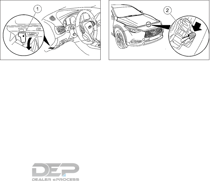
1. Make sure that the windshield wipers are
switched off.
2. Pull the hood lock release lever 䊊
1, lo-
cated below the instrument panel on the
driver's side; the hood will spring up
slightly.
3. Push the lever 䊊
2at the front of the hood,
to the left with your fingertips and raise
the hood.
NDI1603 NDI1627
HOOD
Pre-driving checks and adjustments 3-15
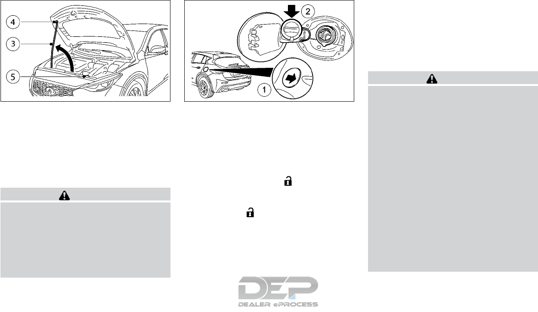
4. Insert the support rod 䊊
3into the slot 䊊
4
on the underside of the hood.
5. When closing the hood, replace the sup-
port rod in its original position 䊊
5, slowly
lower the hood to about8–12in.(20–
30 cm) above the hood lock, then let it
drop. Make sure the hood is securely
latched.
WARNING
•Make sure the hood is completely closed
and latched before driving. Failure to do
so could cause the hood to fly open and
result in an accident.
•If you see steam or smoke coming from
the engine compartment, to avoid injury
do not open the hood.
OPENING FUEL-FILLER DOOR
To open the fuel-filler door, unlock it using
one of the following operations, then push
the right side of the door 䊊
1.
•Push the door handle request switch with
the Intelligent Key carried with you.
•Push the “UNLOCK” button on the
Intelligent Key.
•Push the power door lock switch to the
“UNLOCK” position.
To close the fuel-filler door, close the door
until it securely latches. To lock the fuel filler
door, lock the vehicle using the intelligent key.
FUEL-FILLER CAP
Turn the fuel-filler cap counterclockwise to
remove. To tighten, turn the cap clockwise
until a single click is heard.
Put the fuel-filler cap on the cap holder 䊊
2
while refueling.
WARNING
•Gasoline is extremely flammable and
highly explosive under certain condi-
tions. You could be burned or seriously
injured if it is misused or mishandled. Al-
ways stop the engine and do not smoke
or allow open flames or sparks near the
vehicle when refueling.
•Do not attempt to top off the fuel tank
after the fuel pump nozzle shuts off au-
tomatically. Continued refueling may
cause fuel overflow, resulting in fuel
spray and possibly a fire.
•Use only an original equipment type
fuel-filler cap as a replacement. It has a
built-in safety valve needed for proper
operation of the fuel system and emis-
sion control system. An incorrect cap
can result in a serious malfunction and
possible injury.
NDI1605 NPA1482
FUEL-FILLER DOOR
3-16 Pre-driving checks and adjustments
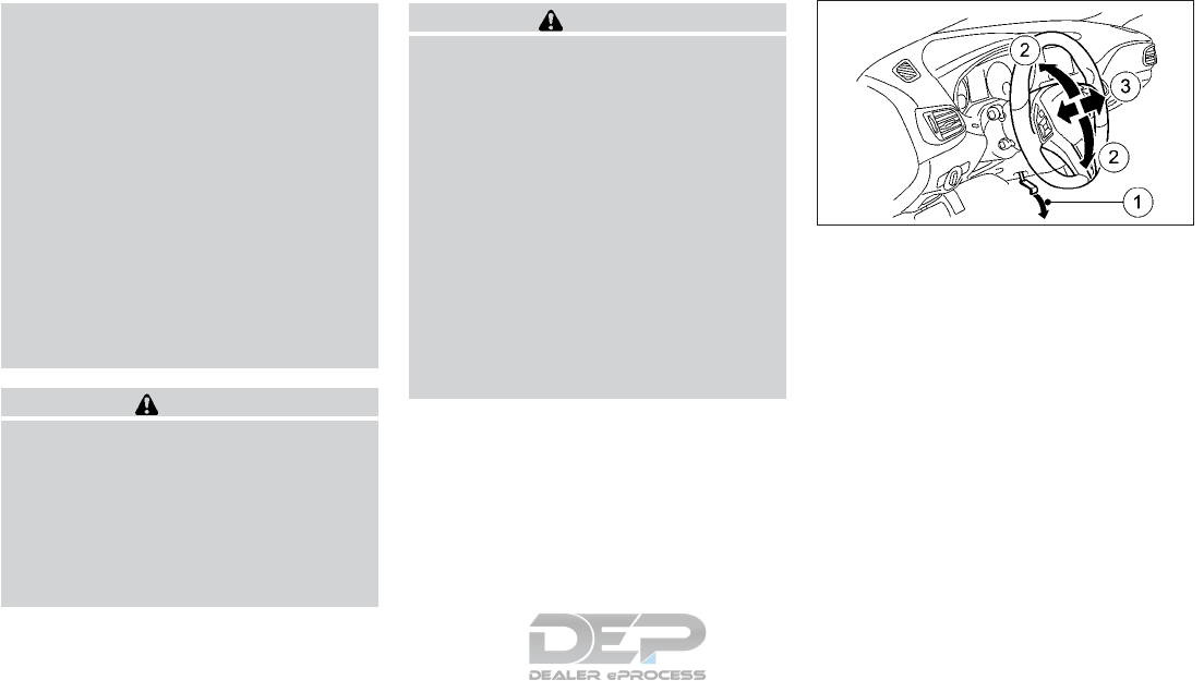
•Never pour fuel into the throttle body to
attempt to start your vehicle.
•Do not fill a portable fuel container in
the vehicle or trailer. Static electricity
can cause an explosion of flammable liq-
uid, vapor or gas in any vehicle or trailer.
To reduce the risk of serious injury or
death when filling portable fuel contain-
ers:
–Always place the container on the
ground when filling.
–Do not use electronic devices when
filling.
–Keep the pump nozzle in contact with
the container while you are filling it.
–Use only approved portable fuel con-
tainers for flammable liquid.
CAUTION
•Do not use E-15 or E-85 fuel in your
vehicle. For additional information, re-
fer to "Fuel Recommendation" in the
"Technical and consumer information"
section of this manual.
•If fuel is spilled on the vehicle body, flush
it away with water to avoid paint
damage.
WARNING
•Do not adjust the steering wheel while
driving. You could lose control of your
vehicle and cause an accident.
•Do not adjust the steering wheel any
closer to you than is necessary for
proper steering operation and comfort.
The driver’s air bag inflates with great
force. If you are unrestrained, leaning
forward, sitting sideways or out of po-
sition in any way, you are at greater risk
of injury or death in a crash. You may
also receive serious or fatal injuries from
the air bag if you are up against it when
it inflates. Always sit back against the
seatback and as far away as practical
from the steering wheel. Always use the
seat belts.
Release the lock lever 䊊
1as illustrated and
adjust the steering wheel to the desired posi-
tion (up or down 䊊
2, forwards or backwards
䊊
3). Firmly push the lock lever back into posi-
tion to lock the steering wheel in place.
NPA1481
STEERING WHEEL
Pre-driving checks and adjustments 3-17
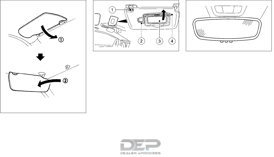
1. To block out glare from the front, swing
down the sun visor 䊊
1.
2. To block glare from the side, remove the
sun visor from the center mount and
swing the visor to the side 䊊
2.
VANITY MIRROR
To use the front vanity mirror 䊊
3, pull down
the sun visor 䊊
1and pull up the cover 䊊
4.
AUTOMATIC ANTI-GLARE REAR
VIEW MIRROR
The inside mirror is designed so that it automati-
cally dims according to the intensity of the head-
lights of the vehicle following you. The auto-
matic anti-glare feature operates only when the
ignition switch is in the ON position. It will not
operate if reverse gear is engaged or if the inte-
rior lighting is switched on.
OUTSIDE MIRRORS
The driver's-side outside mirror is designed so
that it automatically dims according to the
intensity of the headlights of the vehicle fol-
lowing you. The automatic anti-glare feature
operates only when the ignition switch is in
the ON position. It will not operate if reverse
gear is engaged or if the interior lighting is
switched on.
SIC2872
NIC2676 NDI1630
SUN VISORS MIRRORS
3-18 Pre-driving checks and adjustments
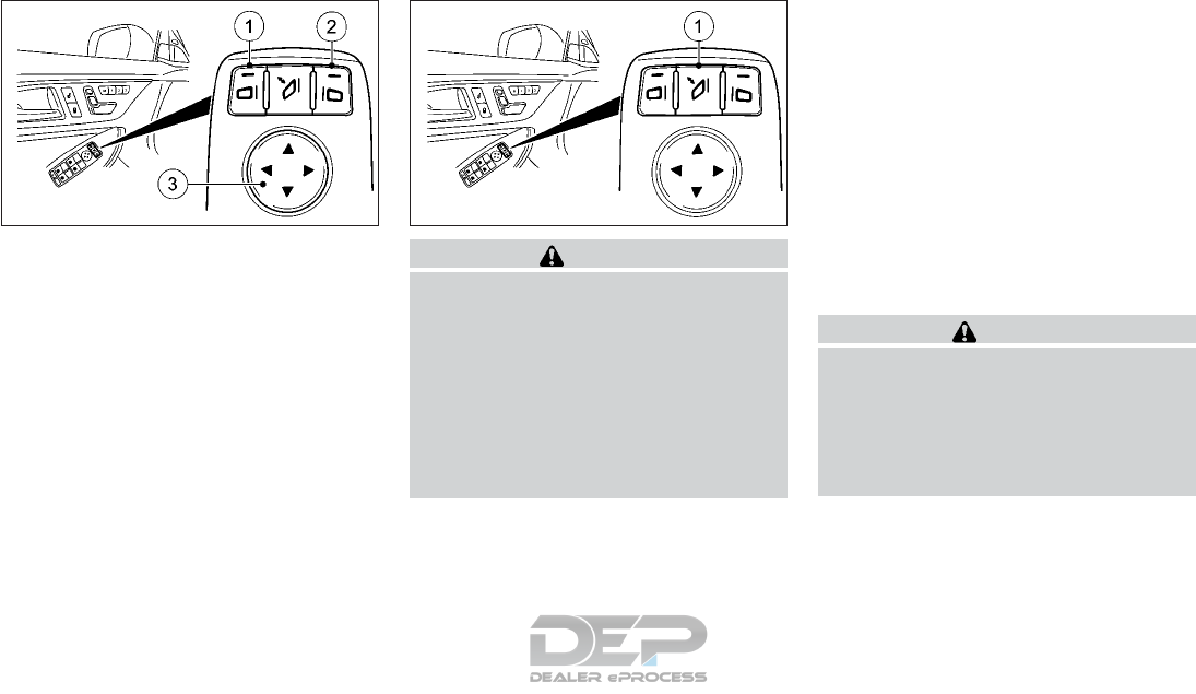
Adjusting
The outside rear view mirror remote control
will operate only when the ignition switch is in
the ACC or ON position.
1. Move the switch to select the left 䊊
1or
right mirror 䊊
2.
2. Adjust each mirror to the desired position
using the large switch 䊊
3.
Defogging
The exterior rear view mirrors will be heated
when the rear window defogger switch is
operated.
WARNING
•Objects viewed in the outside mirror on
the passenger side are closer than they
appear. Be careful when moving to the
right. Using only this mirror could cause
an accident. Use the inside mirror or
glance over your shoulder to properly
judge distances to other objects.
•Do not adjust the mirrors while driving.
You could lose control of your vehicle
and cause an accident.
Folding
Manual type (if equipped):
Fold the outside rear-view mirror by pushing
it towards the rear of the vehicle.
Remote control type (if equipped):
The exterior rear view mirror remote control
operates when the ignition switch is in the
ACC or ON position.
Briefly press button 䊊
1. Both exterior mirrors
fold in or out.
Power folding outside mirrors (if so
equipped)
CAUTION
•Do not touch the mirrors while they are
moving. Your hand may be pinched, and
the mirror may malfunction.
•Do not drive with the mirrors stored.
You will be unable to see behind the
vehicle.
The exterior rear-view mirrors automatically
unfold when the ignition is switched on or
when the vehicle doors are unlocked. Use the
[Fold Mirrors in when Locking] option under
the [CONVENIENCE] menu of the Vehicle
NIC2636 NIC2638
Pre-driving checks and adjustments 3-19
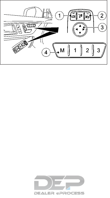
Information Display to specify that the mir-
rors are to be automatically folded and un-
folded. The Auto fold feature can also be
switched off. See "Switching the [Fold Mir-
rors in when Locking] function on/off" in the
"2. Instruments and controls" section.
If the [Fold Mirrors in when Locking] option
has been activated in the Vehicle information
display:
•The exterior mirrors fold in automatically
as soon as you lock the vehicle from the
outside.
•The exterior mirrors fold out again auto-
matically as soon as you unlock the vehicle
and then open the driver's or front-
passenger door.
Automatic parking positioner (if so
equipped)
The Parking position for the exterior mirror
on the front-passenger side function is only
available if the vehicle is equipped with the
Memory package.
䊊
1Button for the exterior mirror on the left
hand side.
䊊
2Button for the exterior mirror on the right
hand side.
䊊
3Adjustment button.
䊊
4Memory button M.
Setting and storing the parking position
using reverse gear:
You can set the front-passenger side exterior
mirror so that you can see the rear wheel on
that side as soon as you engage reverse gear.
You can store this position.
1. Make sure that the vehicle is stationary.
2. Switch the ignition switch to the ON po-
sition.
3. Press button 䊊
2for the external mirror on
the front-passenger side.
4. Engage reverse gear. The exterior mirror
on the front-passenger side moves to the
preset parking position.
5. Use adjustment button 䊊
3to adjust the
exterior mirror. You should see the rear
wheel and the curb in the exterior mirror
The parking position is stored.
NOTE
•If you shift the transmission to another
position, the exterior mirror on the front
passenger side returns to the driving posi-
tion.
•If the driver's side mirror is currently se-
lected, the passenger side mirror will not
move when reverse gear is engaged.
Setting and storing the parking position
using the memory button:
You can set the front-passenger side exterior
mirror so that you can see the rear wheel on
that side as soon as you engage reverse gear.
This setting can be stored using memory but-
ton M 䊊
4.
1. Make sure that the vehicle is stationary.
2. Switch the ignition switch to the ON po-
sition.
3. Press button 䊊
2for the external mirror on
the front-passenger side.
NIC2639
3-20 Pre-driving checks and adjustments
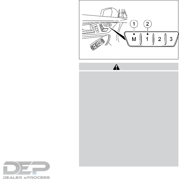
4. Engage reverse gear. The exterior mirror
on the front-passenger side moves to the
preset parking position.
5. Use adjustment button 䊊
3to adjust the
exterior mirror. You should see the rear
wheel and the curb in the exterior mirror.
6. Press memory button M 䊊
4and one of the
arrows on adjustment button 䊊
3within
three seconds. The parking position is
stored if the exterior mirror does not
move.
7. If the mirror moves out of position, repeat
the steps.
Calling up a stored parking position:
1. Switch the ignition switch to the ON po-
sition.
2. Adjust the exterior mirror on the front
passenger side with the corresponding
button.
3. Engage reverse gear. The exterior mirror
on the front-passenger side moves to the
stored parking position
The exterior mirror on the front-passenger
side moves back to its original position:
•As soon as you exceed a speed of 15 km/h.
•About ten seconds after you have disen-
gaged reverse gear.
•If you press button 䊊
1for the exterior
mirror on the driver's side.
WARNING
•If you use the memory function on the
driver's side while driving, the adjust-
ments could cause you to lose control of
the vehicle. There is a risk of an accident.
Only use the memory function on the
driver's side while the vehicle is station-
ary.
Only use the memory function on the
driver's side while the vehicle is station-
ary.
•If the memory function adjusts the seat,
you and other vehicle occupants-
particularly children-could become
trapped. There is a risk of injury.
While the memory function is making
adjustments, make sure that no one has
any part of their body within the sweep
NIC2637
MEMORY FUNCTION (IF EQUIPPED)
Pre-driving checks and adjustments 3-21

of the seat. If someone becomes
trapped, immediately release the
memory function position button The
adjustment is stopped.
•If children activate the memory func-
tion, they could become trapped, espe-
cially if they are unattended. There is a
risk of injury.
When leaving the vehicle, always take
the key with you and lock the vehicle.
Never leave children unattended in the
vehicle.
The memory function can be used at any
time, e.g. even when the key isn't in the igni-
tion lock.
STORING SETTINGS
With the memory function, you can store up
to three different settings.
•Seat and seatback position
•Driver's side: position of the exterior mir-
rors on the driver's and front-passenger
sides.
To store settings:
1.
Adjust the seat (see "Power seat adjustment"
in the "1. Safety — seats, seat belts and
supplemental restraint system" section).
2. Adjust the exterior mirror on the driver's
side (see "Adjusting" in the "3. Pre-driving
checks and adjustments" section).
3. Briefly press the M memory button 䊊
1,
and then press preset position button 1, 2
or 3 䊊
2within three seconds.
The settings are stored in the selected
preset position. A tone sounds when the
settings have been completed.
CALLING UP A STORED SETTING
Press and hold the relevant preset position
button 1, 2 or 3 until the seat and exterior
mirrors are in the stored position.
NOTE
The setting procedure is interrupted as soon
as you release the storage position button.
3-22 Pre-driving checks and adjustments

MEMO
Pre-driving checks and adjustments 3-23

4 Display screen, heater and air
conditioner, and audio system
Safety precautions .....................4-2
Center multi function control panel...........4-2
INFINITI Controller...................4-2
Steering wheel mounted controls ..........4-3
USB connection ports .................4-4
Starting system .....................4-4
Touch panel operation.................4-4
Operating menu screen ................4-6
Scrolling message or list ................4-7
Selecting item ......................4-7
Adjusting volume and settings ............4-7
How to input letters and numbers .........4-8
How to operate display ................4-9
Menu button operation ...............4-10
System status screen .................4-11
Items to be set initially ................4-11
Additional system information ...........4-16
RearView monitor (if so equipped) ..........4-17
RearView Monitor system operation .......4-18
How to read the displayed lines ..........4-19
Difference between predicted and actual
distances ........................4-19
How to park with predicted course lines.....4-21
Adjusting the screen .................4-22
RearView Monitor setting .............4-23
RearView Monitor system limitations ......4-24
System maintenance .................4-25
Around View Monitor (if so equipped) .......4-25
Around View Monitor system operation.....4-26
Difference between predicted and actual
distances ........................4-30
How to park with predicted course lines.....4-31
How to switch the display .............4-33
Adjusting the screen .................4-33
Around View Monitor setting ...........4-34
Around View
®
Monitor system limitations . . .4-34
System maintenance .................4-37
Sonar function settings (if so equipped) .....4-37
Moving Object Detection (if so equipped) .....4-38
MOD system operation ...............4-39
MOD setting......................4-40
MOD system limitations...............4-41
MOD malfunction...................4-41
System maintenance .................4-41
Ventilators .........................4-42
Center ventilators...................4-42
Side ventilators ....................4-42
Rear ventilators (if equipped)............4-42
Heater and air conditioner ...............4-43
Air conditioning system ...............4-44
Automatic climate control (2–zone) .......4-48
Servicing air conditioner ...............4-52
Audio system (if equipped) ...............4-53
Audio operation precautions ............4-53

Names and functions of audio control
buttons .........................4-64
Main audio operation ................4-65
Radio...........................4-67
Compact Disc (CD) player ..............4-71
USB (Universal Serial Bus) connection port . . .4-72
iPod player .......................4-75
Bluetooth® streaming audio ............4-78
Audio settings .....................4-82
Disc/USB memory device care and
cleaningDiscs .....................4-84
USB memory device .................4-84
Gracenote® End User License Agreement . . .4-84
Bluetooth® Hands-Free Phone System .......4-85
Regulatory information ...............4-87
Phone ..........................4-88
Connecting Bluetooth® device ..........4-90
Hands-free text messaging assistant.......4-91
Phone and text message settings .........4-94
Bluetooth® information ...............4-98
INFINITI InTouch Apps overview ...........4-98
Using Applications ..................4-99
Vehicle Apps ......................4-99
Vehicle Apps Manager (if equipped) ......4-102
Major Apps available for use in this system. .4-103
Examples of how Vehicle Apps is used . . . .4-104
Mobile Apps .....................4-104
Getting user ID and password ..........4-104
Notes on linking smartphone App to vehicle .4-105
Using smartphone applications .........4-105
INFINITI Voice Recognition system.........4-105
Using Voice Recognition system.........4-105
Before starting....................4-105
Giving voice commands ..............4-106
Voice recognition settings .............4-116
Information menu ....................4-117
SiriusXM Travel Link® ...............4-118
Settings menu ....................4-122
Troubleshooting guide .................4-124
Customer assistance ................4-124
System unit ......................4-124
Audio system .....................4-125
Bluetooth® Hands-Free Phone System . . . .4-132
Monitor system ...................4-135
Voice recognition ..................4-136
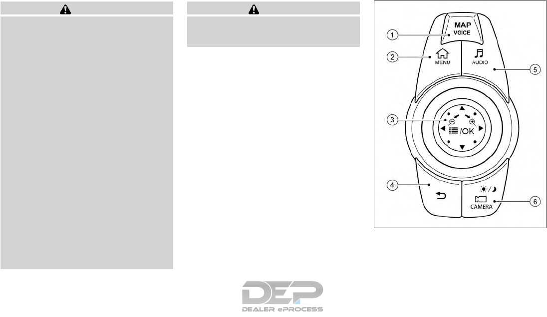
WARNING
•Do not adjust the heater and air condi-
tioner controls or audio controls while
driving so that full attention may be
given to vehicle operation.
•Do not use this system if you notice any
abnormality, such as a frozen screen or
lack of sound. Continued use of the sys-
tem may result in accident, fire or elec-
tric shock.
•If you noticed any foreign objects enter-
ing the system hardware, spilled liquid
on the system, or noticed smoke or
fumes coming out from the system, or
any other unusual operation is ob-
served, stop using the system immedi-
ately. It is recommended that you con-
tact the nearest INFINITI retailer.
Ignoring such conditions may lead to an
accident, fire or electric shock.
•Do not disassemble or modify this sys-
tem. If you do, it may lead to an accident,
fire, or electric shock.
•Park the vehicle in a safe location and
apply the parking brake to view the im-
ages on the front center display screen.
CAUTION
Do not use the system when the engine is
not running for extended periods of time to
prevent battery discharge.
INFINITI CONTROLLER
䊊
1<MAP/VOICE> (models with navigation
system)
Push to display the vehicle’s current location
on the map.
NAA1625
SAFETY PRECAUTIONS CENTER MULTI FUNCTION
CONTROL PANEL
4-2 Display screen, heater and air conditioner, and audio system
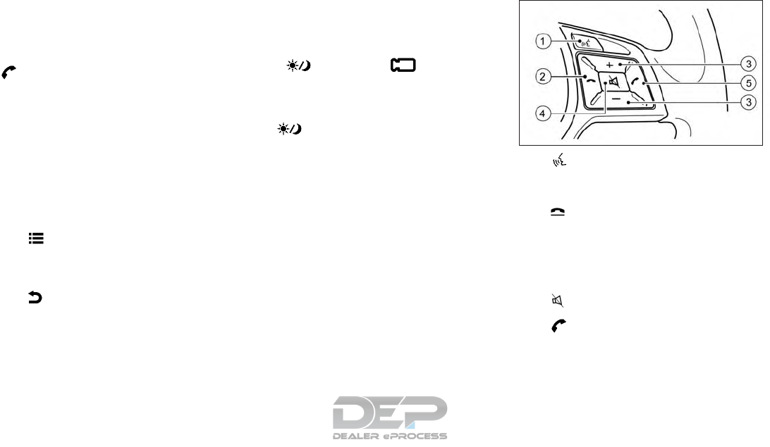
Push again to display the Display View Bar
and the display views.
Push and hold to hear the current guidance
for a programmed route.
<>(models without navigation system).
Push to display the hands-free phone opera-
tion screen.
When you receive a phone call, push this
switch to answer the call.
䊊
2<MENU> Almost all functions, such as
navigation, apps, phone connection, infor-
mation screen display and other settings can
be accessed from this menu. Icons and menus
displayed on the screen may differ depending
on the models and specifications.
䊊
3< /OK> Push to enter the selected
item. Nudge or rotate to select an item on the
screen or to adjust a setting (volume, bright-
ness, etc.).
䊊
4<>Push to go back to the previous
screen.
䊊
5<AUDIO> Display the audio screen.
When <AUDIO> is pushed while the audio
screen is displayed, the source list screen will
be displayed.
䊊
6< / CAMERA > (models with
Around View Monitor system).
Push to view the Around View Monitor
screen.
Push and hold to control the brightness.
<> (models without Around View
Monitor system)
Push for brightness control. Push and hold to
turn the display on/off.
STEERING WHEEL MOUNTED
CONTROLS
The steering wheel switch controls the vol-
ume, voice recognition or Bluetooth® Hands-
Free Phone, or selects a menu.
It can also control audio and hands-free text
messaging assistant features that are shown
on the display.
䊊
1< > (TALK):
Push to enter the voice recognition
mode.
Giving voice commands page 4-106
䊊
2< > (Phone End) :
End an active call and reject an incoming
call.
䊊
3Volume control switch:
The volume control switch allows you to
adjust the volume of the speakers by
pushing the + or − button.
䊊
4< > (Mute):
Push to turn on/off the audio system.
䊊
5<>(Phone Send):
Make a call and accept an incoming call.
NAA1624
Display screen, heater and air conditioner, and audio system 4-3
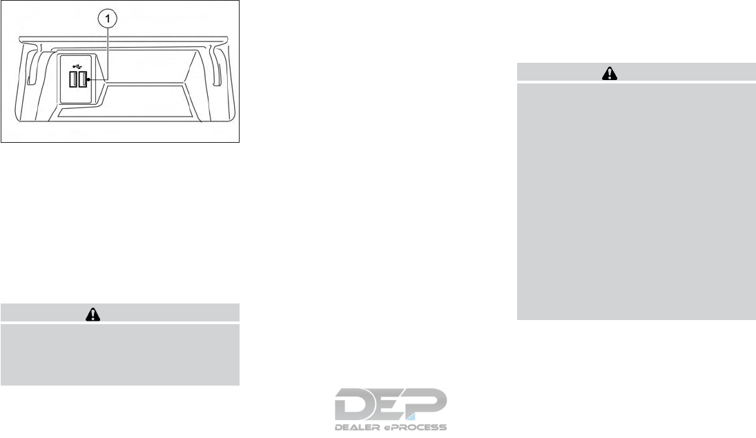
USB CONNECTION PORTS
The front console compartment contains the
USB connection ports.
䊊
1USB/iPod connection port:
Connect to play media from an iPod®,
iPhone® or a USB memory device. When
using INFINITI InTouch Apps with an
iPhone®, connect via a USB cable. Refer
to the device manufacturer’s owner in-
formation regarding the proper use and
care of the device.
CAUTION
•Depending on the size and shape of USB
device, the console lid may not fully
close. Do not force the console lid closed
as this may damage the USB device.
NOTE
•Even when iPods® or iPhones® are con-
nected to both of the two USB/iPod ®
connection ports, the system recognizes
only one of the connected iPods® or iP-
hones® at a time.
•Only one of the two connected USB de-
vices can be operated by the voice recog-
nition system.
STARTING SYSTEM
The system starts when the ignition switch is
placed in the ACC or ON position.
Start-up warning (models with
navigation system)
For this system, when the ignition switch is
placed in the ACC or ON position, the
start-up screen is displayed.
Touch [OK] after reading and agreeing to the
message. If you do not agree to the message,
some of Infiniti InTouch
TM
functions will be
disabled.
NOTE
•Do not keep the INFINITI InTouch system
turned on with the engine stopped. Doing
so may discharge the vehicle battery.
When you use INFINITI InTouch, always
keep the engine running.
•Once you select [Decline] on the start-up
screen, the [OK]/[Decline] screen will not
be displayed for 30 days.
TOUCH PANEL OPERATION
CAUTION
•The glass screen on the liquid crystal dis-
play may break if it is hit with a hard or
sharp object. If the glass screen breaks,
do not touch it. Doing so could result in
an injury.
•To clean the display, use a soft, dry
cloth. If additional cleaning is necessary,
use a small amount of neutral detergent
with a soft cloth. Never use a rough
cloth, alcohol, benzine, thinner or any
kind of solvent or paper towel with a
chemical cleaning agent. They will
scratch or deteriorate the panel.
•Do not splash any liquid such as water or
car fragrance on the display. Contact
with liquid will cause the system to
malfunction.
NAA1628
4-4 Display screen, heater and air conditioner, and audio system
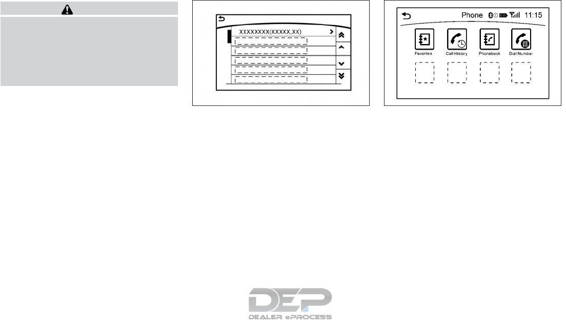
WARNING
•ALWAYS give your full attention to
driving.
•Avoid using vehicle features that could
distract you. If distracted, you could lose
control of your vehicle and cause an
accident.
Screen illustrations
•The illustrations in this manual are repre-
sentatives of various models and may not
be identical with the design and specifica-
tions of your vehicle.
•Icons and menu items displayed on the
screen may be abbreviated or omitted
from the screen illustrations when appro-
priate. The omitted icons and menu items
are described as dotted lines as illustrated.
Basic touch panel operation methods are ex-
plained here. •Touch
Select and execute the selected key on the
screen.
5GH0158XZ NAA1783
Display screen, heater and air conditioner, and audio system 4-5
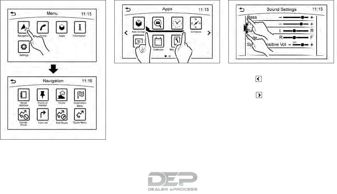
•Swipe
Menu screen pages will skip to the next page.
•Drag
Drag the scroll bar up or down to scroll the
menu screen.
OPERATING MENU SCREEN
䊊
1Touch to scroll to the previous page.
䊊
2Touch the preferred icon to execute a
function and display the next screen.
䊊
3Touch to scroll to the next page.
䊊
4Indicates the position of the currently
displayed page out of the total number of
available pages.
A swipe gesture can also be used to move
quickly between screens.
NAA1707
NAA1724 NAA1729
4-6 Display screen, heater and air conditioner, and audio system
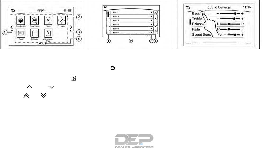
SCROLLING MESSAGE OR LIST
䊊
1Drag the scroll bar up or down to scroll
the message or list up or down.
䊊
2Touch the preferred item.
䊊
3If a listed item name is not completely
displayed (due to length), touch to
display the hidden part of the name.
䊊
4Touch [ ]or[ ] to scroll the
message or list one item at a time.
Touch [ ]or[ ] to skip to the next
page.
SELECTING ITEM
Touch an item to select it.
Touch [ ] to return to the previous
screen.
ADJUSTING VOLUME AND
SETTINGS
Level of volume, brightness, etc. can be ad-
justed.
NAA1725 5GH0030XZ NAA1730
Display screen, heater and air conditioner, and audio system 4-7
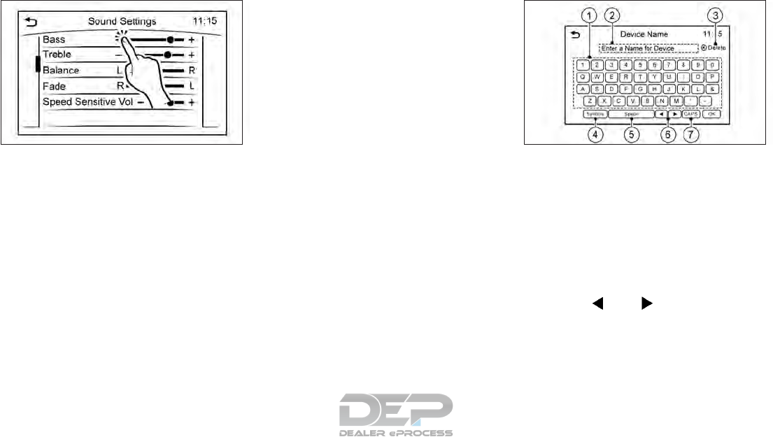
Touch adjustment keys, such as [+]/[-], [L]/
[R], etc., to adjust each item. Each time a key
is touched, the indicator moves along the bar.
HOW TO INPUT LETTERS AND
NUMBERS
The keyboard screen differs depending on
the model and specification.
Character (letters and numbers)
input screen
Alphanumeric characters can be entered us-
ing the keyboard.
The designs and the displayed items may vary
depending on the type of screen. 䊊
1Touch a character on the displayed key-
board. The selected character is entered.
䊊
2Entered characters are displayed.
䊊
3Touch [Delete] to delete the last charac-
ter entered.
Touch and hold [Delete] to delete all the
characters entered.
䊊
4The symbol keys are displayed by touch-
ing [Symbols]. The alphabet keys are dis-
played by touching [A-Z].
䊊
5Touch [Space] to enter a space.
䊊
6Touch or to move the cursor.
䊊
7Touch [CAPS] to toggle between upper
and lower case letters.
NAA1710 NAA1711
4-8 Display screen, heater and air conditioner, and audio system
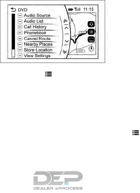
HOW TO OPERATE DISPLAY
Touch screen display
To operate the display, touch the display di-
rectly or use the INFINITI controller.
Shortcut menu
Models with navigation system:
The shortcut menu can be displayed on the
display. The display may differ depending on
the conditions of the current map screen. While the current vehicle location is displayed
on the map, push </OK> on the INFINITI
controller to display the shortcut menu on the
display.
Available items:
•[Audio Source]
•[Audio List]
•[Call History]
•[Phonebook]
•[Cancel Route]*
•[Nearby Places]*
•[Store Location]*
•[View Settings]*
•[Store Location]*
•[Select Add/Edit]*
* For these items see the separately provided
navigation manual (if equipped).
Models without navigation system:
The shortcut menu can be displayed on the
display.
Push </OK> on the INFINITI controller
to display the shortcut menu.
NAA1712
Display screen, heater and air conditioner, and audio system 4-9

Available items:
•[Audio Source]
•[Audio List]
•[Call History]
•[Phonebook]
•[Select Add/Edit]
Edit shortcut menu:
The following procedure can be used to edit
or sort the shortcut menu.
1. Select [Select Add/Edit] to register a new
item to the menu, or to change an existing
menu item.
2. Select the preferred setting.
•[Change Order]
Change the order in which shortcut menu
items are shown.
•[Edit Shortcut Items]
Select items to be displayed in the shortcut
menu.
MENU BUTTON OPERATION
Push <MENU> to display functions on the
display.
•[Navigation]
•[Phone]
•[Apps]
•[Information]
•[Settings]
5GH0183XZ NAA1651
4-10 Display screen, heater and air conditioner, and audio system
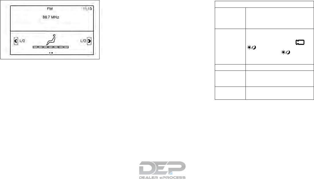
SYSTEM STATUS SCREEN
By pushing <STATUS> on the audio switch
the current status of the system can be dis-
played.
Models with navigation system:
Touch [<] / [>] to switch between air condi-
tioner status and navigation route informa-
tion screen.
ITEMS TO BE SET INITIALLY
The initial setting operations included in this
section should be performed before using the
system for the first time.
Screen settings
The display can be turned on/off and the
image quality of the display can be adjusted in
this menu.
1. Push <MENU>.
2. Touch [Settings].
3. Touch [Screen].
4. Touch the preferred item to be adjusted.
Available items
[Display Set-
tings]
Adjust the image quality of the
display.
See "Display settings" later in this
section
[Display OFF] Turns the screen off.
To turn the display back on, push
and hold <CAMERA /
>(models with Around View
Monitor) or <>(models
without Around View Monitor)
for more than 2 seconds.
[Day/Night] Adjust the screen brightness.
[Change Map
Color]*
Toggles the map color between
the daytime mode and the night
time mode.
[Reset Set-
tings]
Return the display settings to de-
fault.
*: For models with navigation system.
NAA1731
Display screen, heater and air conditioner, and audio system 4-11

Display settings
1. Push <MENU> and touch [Settings].
2. Touch [Screen] and touch [Display Set-
tings].
Available settings
[Brightness] Adjust the brightness.
[Contrast] Adjust the contrast.
[Black Level] Adjust the black level.
4-12 Display screen, heater and air conditioner, and audio system

Volume settings
Volume setting items can be turned on/off and the sound for various functions including audio, phone (ringtone, incoming, and outgoing
volumes), navigation voice guidance (if equipped) and the system beeps can be adjusted.
1. Push <MENU>.
2. Touch [Settings].
3. Touch [Volume].
Setting item Action
[Volume Adjustment] [Audio Volume] Adjust the volume level of the audio system.
[Voice Guidance]* Turn the voice guidance on/off.
[Guidance Volume]* Adjust the volume level of voice guidance.
[Ringtone Volume] Adjust the ringtone volume level.
[Incoming Call Vol.] Adjust the incoming call volume.
[Outgoing Call Vol.] Adjust the outgoing call volume.
[InTouch Services Vol.]* Adjust the volume level of the InTouch
TM
Services information channel.
Refer to the Navigation Owner's Manual for details.
[Sonar Volume] Adjust the warning tone volume by touching [+]/[-].
[Button Beep Sound] Turn the button beep sound and alarm for prohibited operation on/off.
*: For models with navigation system.
Display screen, heater and air conditioner, and audio system 4-13

Language settings
From the Language screen, you can change the display language used by the system.
1. Push <MENU>.
2. Touch [Settings].
3. Touch [Other].
4. Touch [Language].
Setting item Action
[System Language] Select the preferred language.
•Do not turn the ignition switch while changing the language.
•If the selected language is also supported by the combination meter, a confirmation message asking if you also wish to change the meter
language is displayed. Select [Yes] to apply the language setting to the meter as well.
•Depending on the language selected, available voice commands for the voice recognition system may differ.
4-14 Display screen, heater and air conditioner, and audio system

Clock settings
Clock settings can be changed.
1. Push <MENU>.
2. Touch [Settings].
3. Touch [Clock].
Setting item Action
[On-Screen Clock] Set the clock display on/off. When this item is on, the clock display appears.
[Daylight Savings Time] Select the setting for the daylight saving time from ON, OFF or Auto*. Each time this item is touched the
setting is changed.
[Clock Format (24h)] Toggle the clock format between 12-hour and 24-hour clocks. When the indicator light illuminates, the
clock is set to the 24-hour format.
[Time Zone] Select an appropriate time zone from the destination list. If [Auto]* is selected, the system selects the time
zone automatically.
[Offset Adjustment]* Adjust the offset value (hour and minutes).
[>]** [Time Adjustment] Adjust the time by increasing or decreasing the value.
[Calendar Adjustment] Adjust the year, month, and day.
*: For models with navigation system.
**: For models without navigation system.
Time is synchronized to the combination meter once the calendar setting is set.
Display screen, heater and air conditioner, and audio system 4-15

ADDITIONAL SYSTEM
INFORMATION
System Start-Up
Due to the large number of features and
capabilities that the INFINITI InTouch system
needs to load on start-up, it may take up to a
minute for all functions (such as Apps) to be
available. The system will display the mes-
sage indicating that the application is loading
during this time. During the start-up period,
hard button controls for audio will become
available before start-up is complete. Fea-
tures will become available in the following
order.
•Audio volume and music playback
•Audio Full Screen Access
•Full App Availability – System will display
the message indicating the completion of
the application loading process.
System Response Delay
INFINITI InTouch uses an operating system
like those found on many computers, tablets
and cell phones. Like these devices, process-
ing speed may vary, and system response
delays or resets may occur intermittently.
This does not indicate a malfunction, and
further information on system operation can
be found below.
In most situations, simply waiting a few mo-
ments longer should be sufficient for the
pending operations to complete.
If the system temporarily does not respond to
commands, the system can be easily reset.
Simply push down the Audio Power knob for
at least 5 seconds. The system will turn off
and restart.
After restart, all functions should be avail-
able.
•Audio will resume, but if you were using
Bluetooth® Audio or an Audio App, the
connection may need to be re-established.
•If a navigation route was set, the route
should resume automatically (models with
navigation system).
•If a phone call was in progress, the call may
be temporarily transferred back to the
handset.
System Reset
As noted above, intermittent system resets
may occur during normal operation. You may
also wish to reset the system if you find that a
particular feature is not loading or respond-
ing. Often, a quick system reset will resolve
any issue you may be experiencing. After re-
start, all functions will be available as de-
scribed above.
System Updates
Like many digital devices, the INFINITI
InTouch system is designed to allow for soft-
ware updates as enhancements are devel-
oped and additional features added. If you
have questions about system performance, it
is recommended you contact your INFINITI
retailer to ensure that your vehicle has had
the latest available software installed.
Operating Tips
INFINITI InTouch provides several methods
of operation to suit your preferences. The
following are suggested operating tips.
•Operating the INFINITI Controller, Steer-
ing Wheel Controls, or other controls too
quickly can cause a lag between the con-
trol and the display. Operate the controls
carefully and allow the system to respond
to your request.
•INFINITI recommends using Voice Recog-
nition whenever possible to select options
while driving. Some touch screen function-
ality is intentionally unavailable during
driving. Please view the available voice
commands by pushing <>on the steer-
ing wheel and then selecting a category on
the display.
4-16 Display screen, heater and air conditioner, and audio system
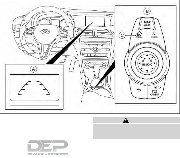
•In some situations, the system may not be
able to recognize your command even if
you say the exact command. This can be
due to noise conditions or an accent.
•Bluetooth® Compatibility: Some wireless
devices do not allow phonebook down-
loads, text messaging, or other
Bluetooth® audio functions. Some wire-
less devices may only have partial func-
tionality of these features even though the
phone is compatible for hands-free com-
munication. If your phone is listed as com-
patible and you are still experiencing is-
sues, please confirm that your phone also
has the latest software updates.
Additional help
For additional technical information, please
contact us online at OWNERS.www.infini-
tiusa.com or call us at 1–800–662–6200,
menu option 6.
䊊
ARearView Monitor display
䊊
BINFINITI controller
䊊
C<MENU> button
WARNING
Failure to follow the warnings and instruc-
tions for proper use of the RearView Moni-
tor could result in serious injury or death.
NSD627
REARVIEW MONITOR (IF SO
EQUIPPED)
Display screen, heater and air conditioner, and audio system 4-17
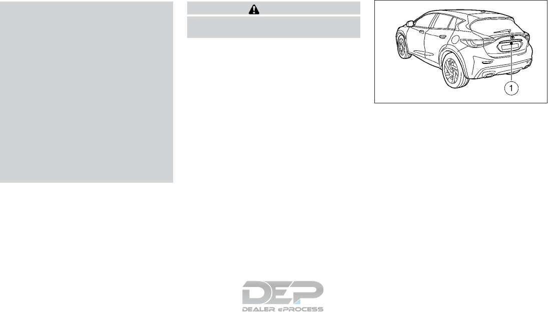
•The RearView Monitor is a convenience
feature but it is not a substitute for
proper backing up. Always turn and look
out the windows, and check mirrors to
be sure that it is safe to move before
operating the vehicle. Always back up
slowly.
•The system is designed as an aid to the
driver in showing large stationary ob-
jects directly behind the vehicle, to help
avoid damaging the vehicle.
•The distance guide line and the vehicle
width line should be used as a reference
only when the vehicle is on a level paved
surface. The distance viewed on the
monitor is for reference only and may be
different than the actual distance be-
tween the vehicle and displayed objects.
CAUTION
Do not scratch the camera lens when clean-
ing dirt or snow from the lens.
The RearView Monitor system automatically
shows a rear view of the vehicle when the
shift lever is placed in the R (Reverse) posi-
tion.
The radio can still be heard while the Rear-
View Monitor is active. To display the rear view, the RearView Moni-
tor system uses a camera located just above
the vehicle’s rear license plate 䊊
1.
REARVIEW MONITOR SYSTEM
OPERATION
With the ignition switch in the ON position,
move the shift lever to the R (Reverse) posi-
tion to operate the RearView Monitor.
NAA1642
4-18 Display screen, heater and air conditioner, and audio system

HOW TO READ THE DISPLAYED
LINES
Guiding lines which indicate the vehicle width
and distances to objects with reference to
the bumper line 䊊
Aare displayed on the moni-
tor.
Distance guide lines:
Indicate distances from the bumper.
•Red line 䊊
1: approx. 1.5 ft (0.5 m)
•Yellow line 䊊
2: approx. 3 ft (1 m)
•Green line 䊊
3: approx. 7 ft (2 m)
•Green line 䊊
4: approx. 10 ft (3 m)
Vehicle width guide lines 䊊
5:
Indicate the approximate vehicle width when
backing up.
Predicted course lines 䊊
6:
Indicate the predicted course when backing
up. The predicted course lines will be dis-
played on the monitor when the shift lever is
in the R (Reverse) position and the steering
wheel is turned. The predicted course lines
will move depending on how much the steer-
ing wheel is turned and will not be displayed
while the steering wheel is in the neutral po-
sition.
The vehicle width guide lines and the width
of the predicted course lines are wider than
the actual width and course.
DIFFERENCE BETWEEN
PREDICTED AND ACTUAL
DISTANCES
The displayed guidelines and their locations
on the ground are for approximate reference
only. Objects on uphill or downhill surfaces or
projecting objects will be actually located at
distances different from those displayed in
the monitor relative to the guidelines (refer to
illustrations). When in doubt, turn around and
view the objects as you are backing up, or
park and exit the vehicle to view the position-
ing of objects behind the vehicle.
Backing up on a steep uphill
When backing up the vehicle up a hill, the
distance guide lines and the vehicle width
guide lines are shown closer than the actual
distance. Note that any object on the hill is
viewed in the monitor farther than it appears.
SAA1896Z
NAA1675
Display screen, heater and air conditioner, and audio system 4-19
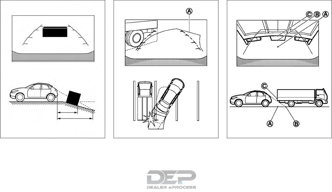
Backing up on a steep downhill
When backing up the vehicle down a hill, the
distance guide lines and the vehicle width
guide lines are shown farther than the actual
distance. Note that any object on the hill is
viewed in the monitor closer than it appears.
Backing up near a projecting object
The predicted course lines 䊊
Ado not touch
the object in the display. However, the vehicle
may hit the object if it projects over the actual
moving course.
Backing up behind a projecting
object
The position 䊊
Cis shown further than the
position 䊊
Bin the display. However, the po-
sition 䊊
Cis actually at the same distance as
the position 䊊
A. The vehicle may hit the object
NAA1676 SAA1923 SAA1980
4-20 Display screen, heater and air conditioner, and audio system
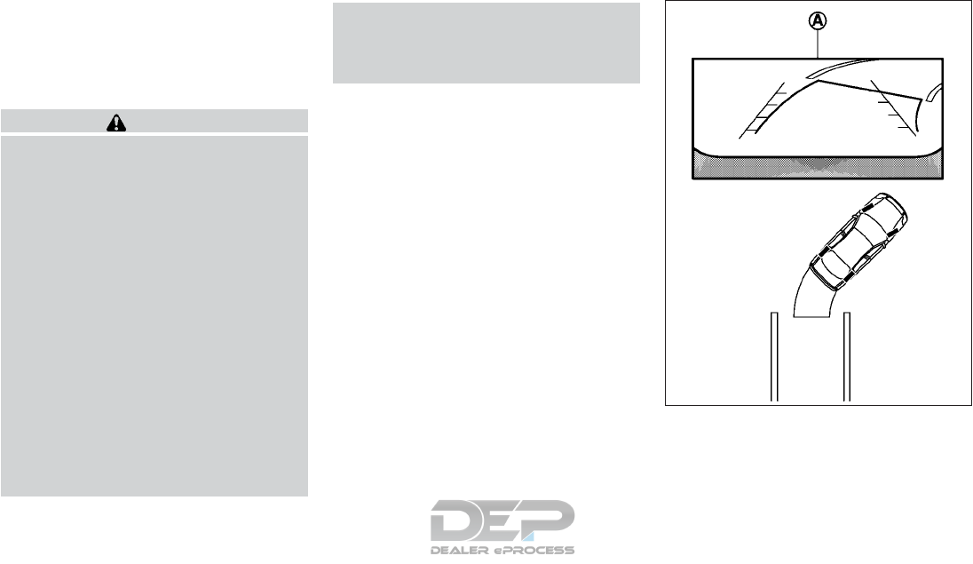
when backing up to the position 䊊
Aif the
object projects over the actual moving
course.
HOW TO PARK WITH
PREDICTED COURSE LINES
WARNING
•If the tires are replaced with different
sized tires, the predicted course line may
not be displayed correctly.
•On a snow-covered or slippery road,
there may be a difference between the
predicted course line and the actual
course line.
•The displayed lines will appear slightly
off to the right because the rear view
camera is not installed in the rear center
of the vehicle.
•If the battery is disconnected or be-
comes discharged, the predicted course
lines may be displayed incorrectly. If this
occurs, please perform the following
procedures:
–Turn the steering wheel from lock to
lock while the engine is running.
–Drive the vehicle on a straight road
for more than 5 minutes.
•When the steering wheel is turned with
the ignition switch in the ACC position,
the predicted course lines may be dis-
played incorrectly.
The vehicle width and predicted course lines
are wider than the actual width and course.
1. Visually check that the parking space is
safe before parking your vehicle.
SAA1897
Display screen, heater and air conditioner, and audio system 4-21
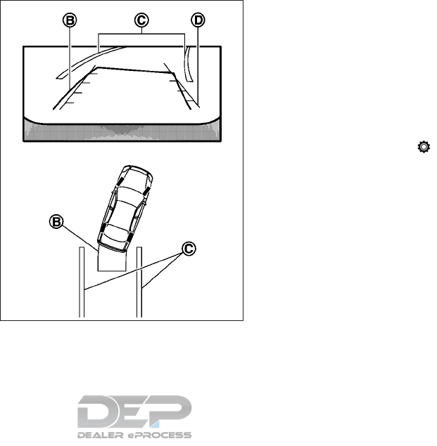
2. The rear view of the vehicle is displayed on
the screen 䊊
Aas illustrated when the shift
lever is moved to the R (Reverse) position.
3. Slowly back up the vehicle adjusting the
steering wheel so that the predicted
course lines 䊊
Benter the parking space
䊊
C.
4. When the rear of the vehicle enters the
parking space 䊊
C, maneuver the steering
wheel to make the vehicle width guide
lines 䊊
Dparallel to the parking space 䊊
C.
5. When the vehicle is parked in the space
completely, press the P (Park) button and
apply the parking brake.
ADJUSTING THE SCREEN
1. While the RearView Monitor is displayed,
touch the settings icon .
2. Select the item you wish to adjust:
[Brightness]:
Adjust display settings by touching [+]/[-].
[Contrast]:
Adjust display settings by touching [+]/[-].
[Black level]:
Adjust display settings by touching [+]/[-].
[Tint]:
Adjust display settings by touching [+]/[-].
[Color]:
Adjust display settings by touching [+]/[-].
[Reset Settings]:
Return all the settings to default
SAA1898
4-22 Display screen, heater and air conditioner, and audio system
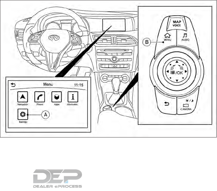
NOTE
Do not adjust any of the display settings of
the RearView Monitor while the vehicle is
moving. Make sure the parking brake is
firmly applied.
䊊
A[Settings] key
䊊
B<MENU> button
REARVIEW MONITOR SETTING
The RearView Monitor [Predictive Course
Lines] setting can be changed using the fol-
lowing procedure.
NSD628
Display screen, heater and air conditioner, and audio system 4-23

1. Push the <MENU> button 䊊
Bon the
INFINITI Controller and touch [Settings]
䊊
Ain the vehicle information display.
2. Touch [Camera]/[Sonar]
3. Touch [Camera]
4. Touch [Predictive Course Lines]
When this item is turned on, the predicted
course line is displayed on the rear view
screen when the shift lever is in the R
(Reverse) position.
REARVIEW MONITOR SYSTEM
LIMITATIONS
WARNING
Listed below are the system limitations for
RearView Monitor. Failure to operate the
vehicle in accordance with these system
limitations could result in serious injury or
death.
•
The system cannot completely eliminate
blind spots and may not show every object.
•Underneath the bumper and the corner
areas of the bumper cannot be viewed
on the RearView Monitor because of its
monitoring range limitation. The system
will not show small objects below the
bumper, and may not show objects close
to the bumper or on the ground.
•Objects viewed in the RearView Moni-
tor differ from actual distance because a
wide-angle lens is used.
•
Objects in the RearView Monitor will ap-
pear visually opposite than when viewed in
the rear view and outside mirrors.
•Use the displayed lines as a reference.
The lines are highly affected by the num-
ber of occupants, fuel level, vehicle posi-
tion, road conditions and road grade.
•Make sure that the lift gate is securely
closed when backing up.
•Do not put anything on the rear view
camera. The rear view camera is in-
stalled above the license plate.
•When washing the vehicle with high-
pressure water, be sure not to spray it
around the camera. Otherwise, water
may enter the camera unit causing wa-
ter condensation on the lens, a malfunc-
tion, fire or an electric shock.
•Do not strike the camera. It is a precision
instrument. Otherwise, it may malfunc-
tion or cause damage resulting in a fire
or an electric shock.
The following are operating limitations and
do not represent a system malfunction:
•When the temperature is extremely high or
low, the screen may not clearly display
objects.
•When strong light shines directly on to the
camera, objects may not be displayed
clearly.
•Vertical lines may be seen in objects on the
screen. This is due to strong reflected light
from the bumper.
•The screen may flicker under fluorescent
light.
•The colors of objects on the RearView
Monitor may differ somewhat from the
actual color of objects.
•Objects on the monitor may not be clear in
a dark environment.
•Do not use wax on the camera window.
Wipe off any wax with a clean cloth damp-
ened with mild detergent diluted with
water.
4-24 Display screen, heater and air conditioner, and audio system
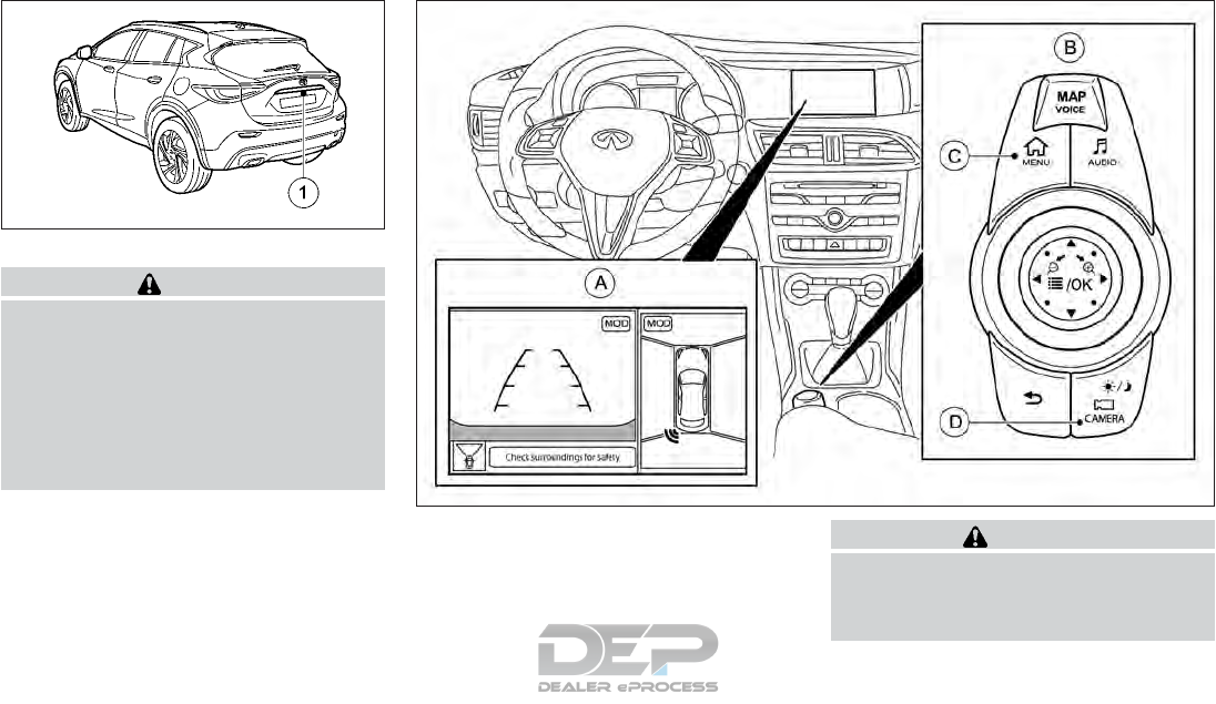
SYSTEM MAINTENANCE
CAUTION
•Do not use alcohol, benzine or thinner to
clean the camera. This will cause discol-
oration. To clean the camera, wipe with
a cloth dampened with diluted mild
cleaning agent and then wipe with a dry
cloth.
•Do not damage the camera as the moni-
tor screen may be adversely affected.
If dirt, rain or snow accumulates on the cam-
era 䊊
1, the RearView Monitor may not dis-
play objects clearly. Clean the camera by wip-
ing it with a cloth dampened with a diluted
mild cleaning agent and then wiping it with a
dry cloth.
䊊
AAround View Monitor display
䊊
BINFINITI controller
䊊
C<MENU> button
䊊
D<CAMERA> button
WARNING
Failure to follow the warnings and instruc-
tions for the proper use of the Around View
Monitor system could result in serious in-
jury or death.
NAA1688
NSD651
AROUND VIEW MONITOR (IF SO
EQUIPPED)
Display screen, heater and air conditioner, and audio system 4-25
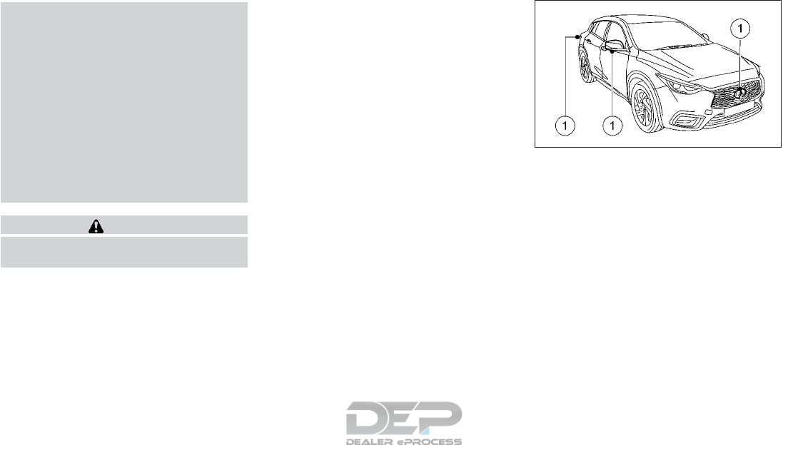
•The Around View Monitor is a conve-
nience feature and is not a substitute for
proper vehicle operation because it has
areas where objects cannot be viewed.
The four corners of the vehicle in par-
ticular, are areas where objects do not
always appear in the bird’s-eye, front,
or rear views. Always check your sur-
roundings to be sure that it is safe to
move before operating the vehicle. Al-
ways operate the vehicle slowly.
•The driver is always responsible for
safety during parking and other
maneuvers.
CAUTION
Do not scratch the lens when cleaning dirt
or snow from the front of the camera.
The Around View Monitor system is designed
as an aid to the driver in situations such as
slot parking or parallel parking.
The monitor displays various views of the
position of the vehicle in a split screen format.
All views are not available at all times.
Available views:
•Front View
An approximately 150-degree view of the
front of the vehicle.
•Rear View
An approximately 150-degree view of the
rear of the vehicle.
•Bird's-Eye View
The surrounding view of the vehicle from
above.
•Front-Side View
The view around and ahead of the front
passenger’s side wheel.
To display the multiple views, the Around
View Monitor system uses cameras 䊊
1lo-
cated in the front grille, on the vehicle’s out-
side mirrors and one just above the vehicle’s
rear number plate.
AROUND VIEW MONITOR
SYSTEM OPERATION
With the ignition switch in the ON position,
move the shift lever to the R (Reverse) posi-
tion or press the <CAMERA> button to oper-
ate the Around View Monitor.
The screen displayed on the Around View
Monitor will automatically return to the pre-
vious screen 3 minutes after the <CAMERA>
button has been pushed while the shift lever
is in a position other than the R (Reverse)
position.
NAA1638
4-26 Display screen, heater and air conditioner, and audio system
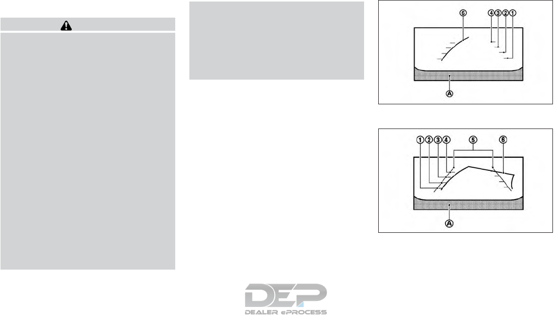
Available views
WARNING
•The distance guide lines and the vehicle
width lines should be used as a reference
only when the vehicle is on a paved, level
surface. The distance viewed on the
monitor is for reference only and may be
different than the actual distance be-
tween the vehicle and displayed objects.
•Use the displayed lines and the bird's-
eye view as a reference. The lines and the
bird's-eye view are greatly affected by
the number of occupants, fuel level, ve-
hicle position, road condition and road
grade.
•When driving the vehicle up a hill, ob-
jects viewed in the monitor are farther
than they appear. When driving the ve-
hicle down a hill, objects viewed in the
monitor are closer than they appear.
•Objects in the monitor will appear visu-
ally opposite compared to when viewed
in the rear view and outside mirrors.
•Use the mirrors or actually look to prop-
erly judge distances to other objects.
•The distance between objects viewed in
the rear view differs from actual dis-
tance because a wide-angle lens is used.
•The displayed lines on the rear view will
appear slightly off to the right because
the rear view camera is not installed in
the rear center of the vehicle.
Front view
Rear view
SAA1840Z
SAA1896Z
Display screen, heater and air conditioner, and audio system 4-27

Front and rear views:
Guiding lines, which indicate the vehicle
width and distances to objects with refer-
ence to the vehicle body line 䊊
A, are displayed
on the monitor.
Distance guide lines:
Indicate distances from the vehicle body:
•Red line 䊊
1: approx.1.5 ft (0.5 m)
•Yellow line 䊊
2: approx. 3 ft (1 m)
•Green line 䊊
3: approx. 7 ft (2 m)
•Green line 䊊
4: approx. 10 ft (3 m)
Vehicle width guide lines 䊊
5:
Indicate the approximate vehicle width when
backing up.
Predicted course lines 䊊
6:
Indicate the predicted course when operating
the vehicle. The predicted course lines will be
displayed on the monitor when the steering
wheel is turned. The predicted course lines
will move depending on how much the steer-
ing wheel is turned and will not be displayed
while the steering wheel is in the straight
ahead position.
The front view will not be displayed when the
vehicle speed is above 10 km/h (6 MPH).
NOTE
When the monitor displays the front view
and the steering wheel turns about 90 de-
grees or less from the neutral position, both
the right and left predicted course lines 䊊
6
are displayed. When the steering wheel
turns about 90 degrees or more, a line is dis-
played only on the opposite side of the turn.
Bird's-eye view:
WARNING
•Objects in the bird's-eye view will ap-
pear farther than the actual distance.
•Tall objects, such as a curb or a vehicle,
may be misaligned or not displayed at
the seam of the views.
•Objects that are above the camera can-
not be displayed.
•The view for the bird's-eye view may be
misaligned when the camera position
alters.
•A line on the ground may be misaligned
and is not seen as being straight at the
seam of the views. The misalignment will
increase as the line proceeds away from
the vehicle.
•Tire angle display does not indicate the
actual tire angle.
4-28 Display screen, heater and air conditioner, and audio system
The bird's-eye view shows the overhead view
of the vehicle, which helps confirm the vehicle
position.
The vehicle icon 䊊
1shows the position of the
vehicle.
NOTE
The size of the vehicle icon on the bird's-eye
view may differ somewhat from the actual
vehicle.
The areas that the cameras cannot cover 䊊
2
are indicated in black.
The non-viewable area 䊊
2is highlighted in
yellow for several seconds after the bird's-
eye view is displayed. It will be shown only the
first time after the ignition switch is placed in
the ON position.
When the corner of the vehicle moves closer
to an object, the corner sensor indicator 䊊
3
appears.
Front-side view:
Guiding lines that indicate the approximate
width and the front end of the vehicle are
displayed on the monitor.
The front-of-vehicle line 䊊
1shows the front
part of the vehicle.
The side-of-vehicle line 䊊
2shows the ap-
proximate vehicle width including the outside
mirrors.
The extensions 䊊
3of both the front 䊊
1and
side 䊊
2lines are shown with a green dotted
line.
The corner sensor indicator 䊊
4will appear
when a corner of the vehicle moves closer to
an object.
NAA1681 SAA1842Z
Left-Hand Drive (LHD) models*
Display screen, heater and air conditioner, and audio system 4-29
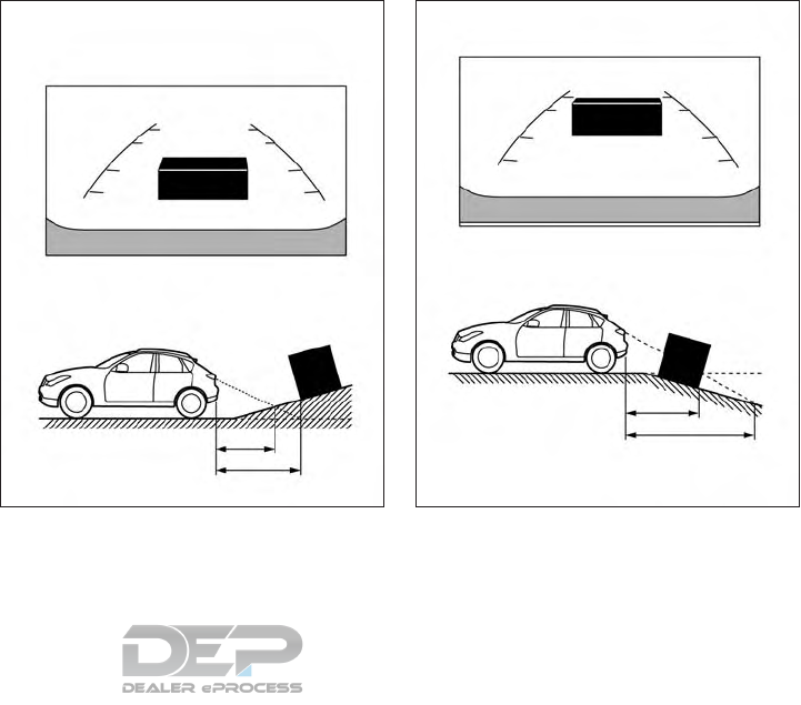
DIFFERENCE BETWEEN
PREDICTED AND ACTUAL
DISTANCES
The displayed guidelines and their locations
on the ground are for approximate reference
only. Objects on uphill or downhill surfaces or
projecting objects will be actually located at
distances different from those displayed in
the monitor relative to the guidelines (refer to
illustrations). When in doubt, turn around and
view the objects as you are backing up, or
park and exit the vehicle to view the position-
ing of objects behind the vehicle.
Backing up on a steep uphill
When backing up the vehicle up a hill, the
distance guide lines and the vehicle width
guide lines are shown closer than the actual
distance. Note that any object on the hill is
viewed in the monitor farther than it appears.
Backing up on a steep downhill
When backing up the vehicle down a hill, the
distance guide lines and the vehicle width
guide lines are shown farther than the actual
distance. Note that any object on the hill is
viewed in the monitor closer than it appears.
NAA1675 NAA1676
4-30 Display screen, heater and air conditioner, and audio system

Backing up near a projecting object
The predicted course lines 䊊
Ado not touch
the object in the display. However, the vehicle
may hit the object if it projects over the actual
moving course.
Backing up behind a projecting
object
The position 䊊
Cis shown farther than the
position 䊊
Bin the display. However, the po-
sition 䊊
Cis actually at the same distance as
the position 䊊
A. The vehicle may hit the object
when backing up to the position 䊊
Aif the
object projects over the actual moving
course.
HOW TO PARK WITH
PREDICTED COURSE LINES
WARNING
•If the tires are replaced with different
sized tires, the predicted course lines
may not be displayed correctly.
•On a snow-covered or slippery road,
there may be a difference between the
predicted course lines and the actual
course.
•The displayed lines will appear slightly
off to the right because the rear view
camera is not installed in the rear center
of the vehicle.
•If the battery is disconnected or be-
comes discharged, the predicted course
lines may be displayed incorrectly. If this
occurs, please perform the following
procedures:
–Turn the steering wheel from lock to
lock while the engine is running.
–Drive the vehicle on a straight road
for more than 5 minutes.
SAA1923 SAA1980
Display screen, heater and air conditioner, and audio system 4-31
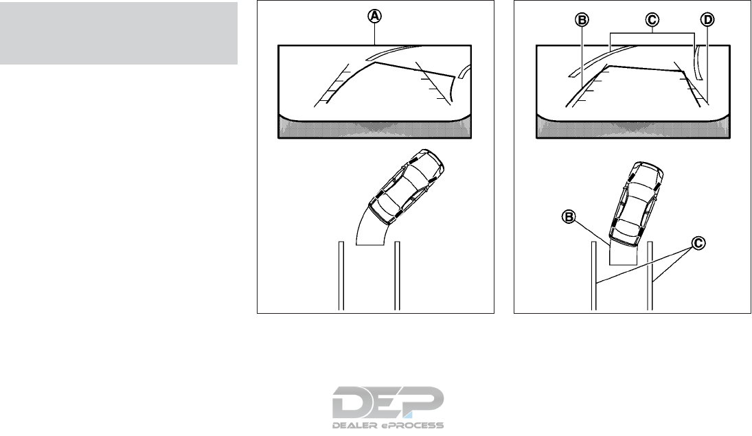
•When the steering wheel is turned with
the ignition switch in the ACC position,
the predicted course lines may be dis-
played incorrectly.
The vehicle width and predicted course lines
are wider than the actual width and course.
1. Visually check that the parking space is
safe before parking your vehicle.
2. The rear view of the vehicle is displayed on
the screen 䊊
Aas illustrated when the shift
lever is moved to the R (Reverse) position.
3.
Slowly back up the vehicle adjusting the
steering wheel so that the predicted course
lines
䊊
Benter the parking space 䊊
C.
4. When the rear of the vehicle enters the
parking space 䊊
C, maneuver the steering
wheel to make the vehicle width guide
lines 䊊
Dparallel to the parking space 䊊
C.
SAA1897 SAA1898
4-32 Display screen, heater and air conditioner, and audio system

5. When the vehicle is parked in the space
completely, press the P (Park) button and
apply the parking brake.
HOW TO SWITCH THE DISPLAY
The view on the Around View Monitor screen
can be switched by pressing the <CAMERA>
button or by changing the shift lever position.
Press the <CAMERA> button:
When the <CAMERA> button is pushed while
a screen other than a camera screen is dis-
played, the Around View Monitor operates
and the front view and bird's-eye view are
displayed. Push the <CAMERA> button to
switch the display to the front view and
front-side view screen.
ADJUSTING THE SCREEN
1. Push the <MENU> button 䊊
Bon the
INFINITI Controller and touch [Settings]
䊊
Ain the vehicle information display.
2. Touch [Camera]/[Sonar]
3. Touch [Display]
4. Select the item you wish to adjust:
[Brightness]:
Adjust display settings by touching [+]/[-].
[Contrast]:
Adjust display settings by touching [+]/[-].
[Black level]:
Adjust display settings by touching [+]/[-].
[Tint]:
Adjust display settings by touching [+]/[-].
[Color]:
Adjust display settings by touching [+]/[-].
[Reset Settings]:
Return all the settings to default
NOTE
Do not adjust any of the display settings of
the Around View Monitor while the vehicle is
moving. Make sure the parking brake is
firmly applied.
Display screen, heater and air conditioner, and audio system 4-33

䊊
A[Settings] key
䊊
B<MENU> button
AROUND VIEW MONITOR
SETTING
Around View Monitor settings can be
changed using the following procedure:
1. Push the <MENU> button 䊊
Bon the
INFINITI Controller and touch [Settings]
䊊
Ain the vehicle information display.
2. Touch [Camera]/[Sonar]
3. Touch [Camera]
4. Touch [Moving Object Detection]
Activate or deactivate the Moving Object
Detection (MOD) mode.
AROUND VIEW
® MONITOR SYSTEM
LIMITATIONS
WARNING
Listed below are the system limitations for
Around View Monitor. Failure to operate
the vehicle in accordance with these sys-
tem limitations could result in serious in-
jury or death.
•Do not use the Around View Monitor
with the outside mirror in the stored po-
sition, and make sure that the lift gate is
securely closed when operating the ve-
hicle using the Around View Monitor.
•The apparent distance between objects
viewed on the Around View Monitor dif-
fers from the actual distance.
•The cameras are installed on the front
grille, the outside mirrors and above the
rear license plate. Do not put anything
on the cameras.
•When washing the vehicle with high-
pressure water, be sure not to spray it
NSD628
4-34 Display screen, heater and air conditioner, and audio system
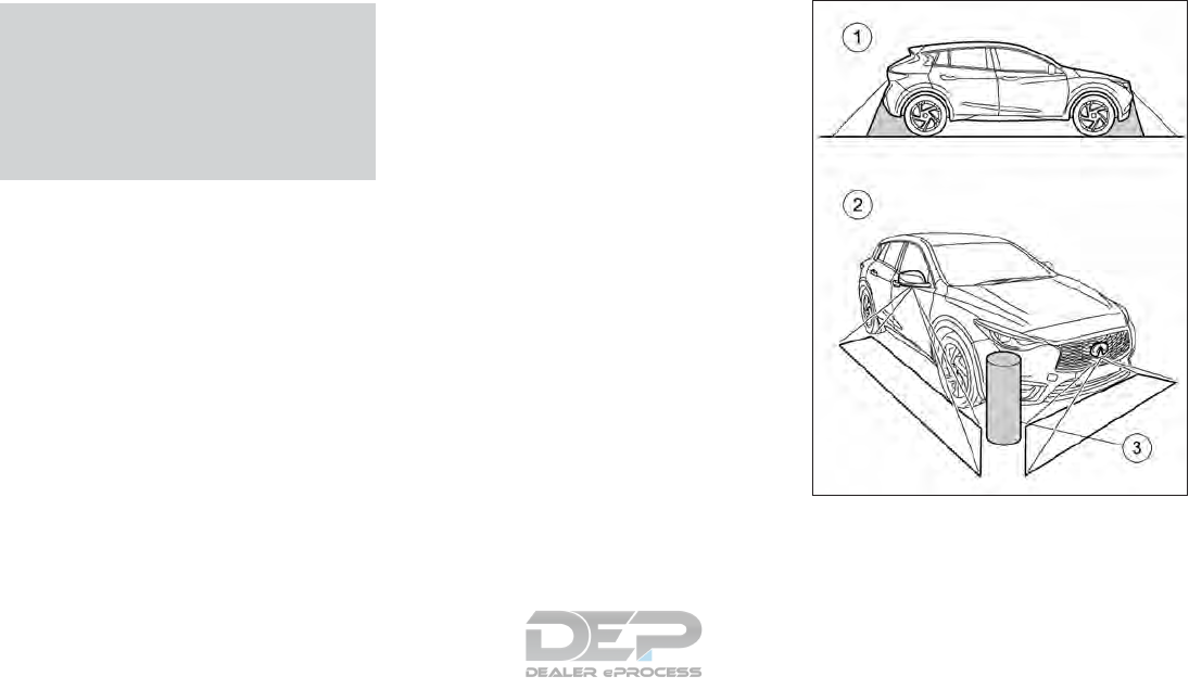
around the cameras. Otherwise, water
may enter the camera unit causing wa-
ter condensation on the lens, a malfunc-
tion, fire or an electric shock.
•Do not strike the cameras. They are pre-
cision instruments. Doing so could cause
a malfunction or cause damage resulting
in a fire or an electric shock.
The following are operating limitations and
do not represent a system malfunction:
•There may be a delay when switching be-
tween views.
•When the temperature is extremely high or
low, the screen may not display objects
clearly.
•When strong light is directly shines on the
camera, objects may not be displayed
clearly.
•The screen may flicker under fluorescent
light.
•The colors of objects on the Around View
Monitor may differ somewhat from the
actual color of objects.
•Objects on the monitor may not be clear
and the color of the object may differ in a
dark environment.
•There may be differences in sharpness be-
tween each camera view of the bird’s-eye
view.
•Do not use wax on the camera lens. Wipe
off any wax with a clean cloth that has
been dampened with a diluted mild clean-
ing agent, then wipe with a dry cloth.
There are some areas where the system will
not show objects and the system does not
warn of moving objects. When in the front or
the rear view display, an object below the
bumper or on the ground may not be viewed
䊊
1. When in the bird's-eye view, a tall object
NAA1639
Display screen, heater and air conditioner, and audio system 4-35
near the seam 䊊
3of the camera viewing ar-
eas will not appear in the monitor 䊊
2.
System temporarily unavailable
When the [ !] icon is displayed on the screen,
there are abnormal conditions in the Around
View Monitor. This will not hinder normal
driving operation but the system should be
inspected. It is recommended you visit an
INFINITI retailer for this service.
When the [ X] icon is displayed on the screen,
the camera image may be receiving tempo-
rary electronic disturbances from surround-
ing devices. This will not hinder normal driving
operation but the system should be in-
spected. It is recommended you visit an
INFINITI retailer for this service.
NAA1779 NAA1780
4-36 Display screen, heater and air conditioner, and audio system
SYSTEM MAINTENANCE
CAUTION
•Do not use alcohol, benzine or thinner to
clean the camera. This will cause discol-
oration. To clean the camera, wipe with
a cloth dampened with diluted mild
cleaning agent and then wipe with a dry
cloth.
•Do not damage the camera as the moni-
tor screen may be adversely affected.
If dirt, rain or snow accumulates on any of the
cameras, the Around View Monitor may not
display objects clearly. Clean the cameras by
wiping with a cloth dampened with a diluted
mild cleaning agent and then wiping with a
dry cloth.
䊊
A[Settings] key
䊊
B<MENU> button SONAR FUNCTION SETTINGS (IF
SO EQUIPPED)
The sonar function settings can be changed
using the following procedure.
1. Push <MENU>䊊
Band touch [Settings] 䊊
A.
NAA1638
NSD628
Display screen, heater and air conditioner, and audio system 4-37
2. Touch [Camera/Sonar]
3. Touch [Sonar]
[Sonar sensitivity]:
Adjust the sonar sensor sensitivity level by
touching [+]/[-].
[Sonar volume]:
Adjust the buzzer volume by touching [+]/[-].
䊊
AAround View Monitor display
䊊
BINFINITI controller
䊊
C<MENU> button
䊊
D<CAMERA> button
WARNING
Failure to follow the warnings and instruc-
tions for proper use of the Moving Object
Detection system could result in serious in-
jury or death.
NSD651
MOVING OBJECT DETECTION (IF SO
EQUIPPED)
4-38 Display screen, heater and air conditioner, and audio system
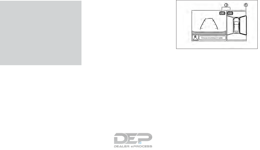
•The MOD system is not a substitute for
proper vehicle operation and is not de-
signed to prevent contact with objects
surrounding the vehicle. When maneu-
vering, always use the outside mirror
and rearview mirror and turn and check
the surroundings to ensure it is safe to
maneuver.
•The system is deactivated at speeds
above 5 MPH (8 km/h). It is reactivated
at lower speeds.
•The MOD system is not designed to de-
tect the surrounding stationary objects.
The Moving Object Detection (MOD) system
can inform the driver of moving objects sur-
rounding the vehicle when driving out of ga-
rages, maneuvering into parking lots and in
other such instances.
The MOD system detects moving objects by
using image processing technology on the
image shown on the display.
MOD SYSTEM OPERATION
The MOD system will activate automatically
under the following conditions:
•When the shift lever is in the R (Reverse)
position.
•When the <CAMERA> button is pressed
to switch from a different screen to the
camera view on the display.
•When vehicle speed decreases below ap-
proximately 5 MPH (8 km/h).
•When the ignition switch is placed in the
OFF position and then back to the ON
position.
NOTE
•The MOD system does not detect moving
objects in the front-side view. The MOD
icon is not displayed on the screen when in
this view.
•While the parking sensor warning tone is
sounding, the MOD system does not
chime.
The MOD system operates in the following
conditions when the camera view is dis-
played:
When the shift lever is in the R (Reverse)
position and the vehicle speed is approxi-
mately 5 MPH (8 km/h ) or less, the MOD
system detects moving objects in the camera
view. The MOD system will not operate if the
lift gate is open.
When the MOD system detects moving ob-
jects near the vehicle, a chime will be heard
and a yellow frame 䊊
1will be displayed on
the monitor.
While the MOD system continues to detect
moving objects, the yellow frame continues
to be displayed.
The yellow frame 䊊
1is displayed on each
view in the rear view modes.
NAA1781
Bird's-eye view
Display screen, heater and air conditioner, and audio system 4-39
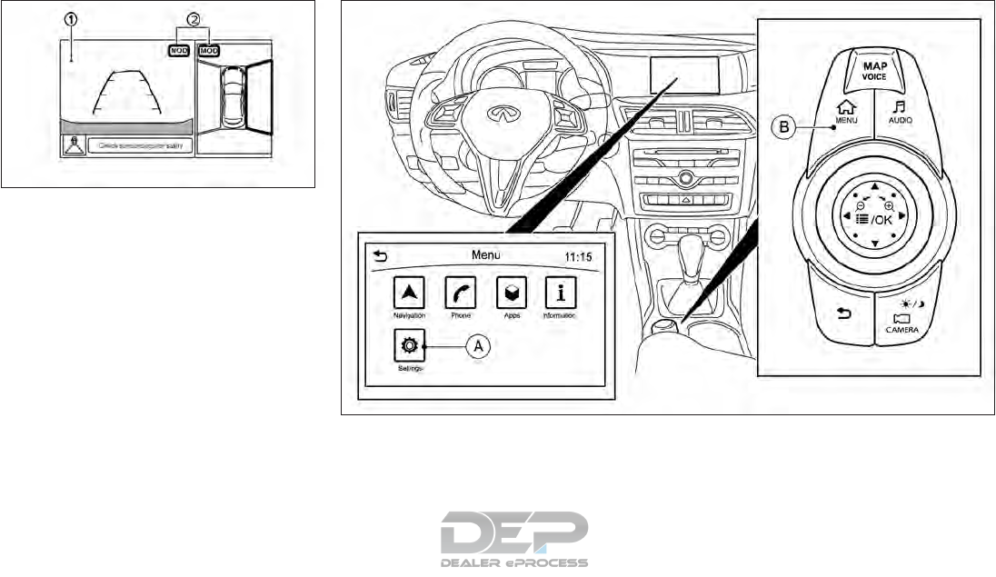
A blue <MOD> icon is displayed in the view
where the MOD system is operative. A gray
MOD icon is displayed in the view where the
MOD system is not operative.
䊊
A[Settings] key
䊊
B<MENU> button
MOD SETTING
MOD system settings can be changed using
the following procedure.
1. Push the <MENU> button 䊊
Bon the
INFINITI Controller and touch [Settings]
䊊
Ain the vehicle information display.
2. Touch [Camera/Sonar]
3. Touch [Camera]
NAA1782
Front view / rear view
NSD628
4-40 Display screen, heater and air conditioner, and audio system
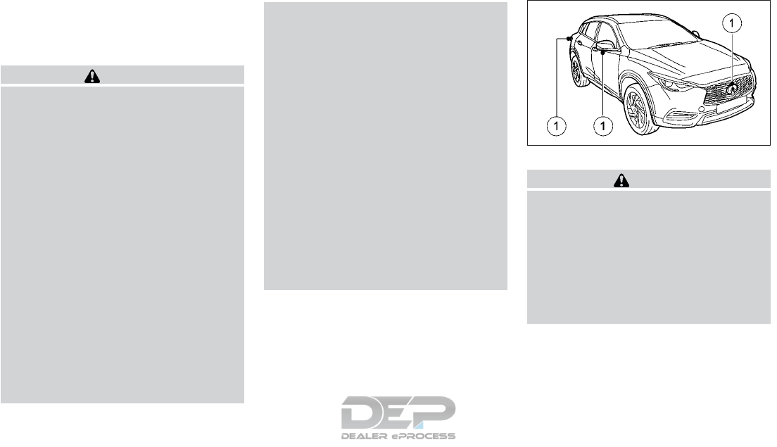
4. Touch [Moving Object Detection].
5. Turn the MOD system on/off.
MOD SYSTEM LIMITATIONS
WARNING
Listed below are the system limitations for
MOD. Failure to operate the vehicle in ac-
cordance with these system limitations
could result in serious injury or death.
•Do not use the MOD system when tow-
ing a trailer (if available). The system
may not function properly.
•Excessive noise (for example, audio sys-
tem volume or open vehicle window) will
interfere with the chime sound, and it
may not be heard.
•The MOD system performance will be
limited according to environmental con-
ditions and surrounding objects such as:
–When there is low contrast between
background and the moving objects.
–When there is blinking source of light.
–When strong light such as another
vehicle’s headlight or sunlight is pres-
ent.
–When camera orientation is not in its
usual position, such as when mirror is
folded.
–When there is dirt, water drops or
snow on the camera lens.
–When the position of the moving ob-
jects in the display is not changed.
•The MOD system might detect some-
thing like flowing water droplets on the
camera lens, white smoke from the muf-
fler, moving shadows, etc.
•The MOD system may not function
properly depending on the speed, direc-
tion, distance or shape of the moving
objects.
•If your vehicle sustains damage to the
parts where the camera is installed,
leaving it misaligned or bent, the sensing
zone may be altered and the MOD sys-
tem may not detect objects properly.
•When the temperature is extremely high
or low, the screen may not display ob-
jects clearly. This is not a malfunction.
MOD MALFUNCTION
If the orange MOD icon is displayed in the
view, the system is not functioning properly.
This will not hinder normal driving operation,
but the system should be inspected. It is rec-
ommended you visit an INFINITI retailer for
this service.
SYSTEM MAINTENANCE
CAUTION
•Do not use alcohol, benzine or thinner to
clean the cameras. This will cause discol-
oration. To clean the cameras, wipe with
a cloth dampened with diluted mild
cleaning agent and then wipe with a dry
cloth.
•Do not damage the cameras as the
monitor screen may be adversely
affected.
If dirt, rain or snow accumulates on any of the
cameras 䊊
1, the MOD system may not oper-
ate properly. Clean the cameras by wiping
with a cloth dampened with a diluted mild
cleaning agent and then wiping with a dry
cloth.
NAA1689
Display screen, heater and air conditioner, and audio system 4-41
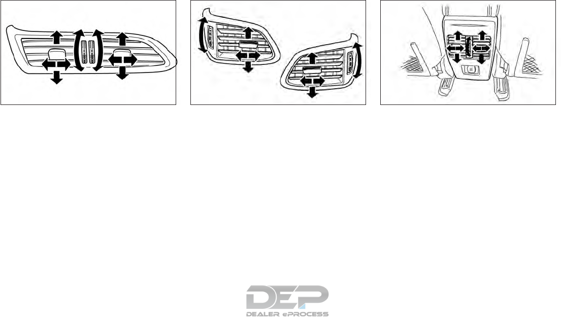
CENTER VENTILATORS
Open/close the ventilators by turning the
control wheel.
Adjust the air flow direction of the ventilators
by moving the center knob (up/down, left/
right) until the desired position is achieved.
SIDE VENTILATORS
Open/close the ventilators by turning the
control wheel.
Adjust the air flow direction of the ventilators
by moving the center knob (up/down, left/
right) until the desired position is achieved.
REAR VENTILATORS (IF
EQUIPPED)
Open/close the ventilators by turning the
control wheel.
Adjust the air flow direction of the ventilators
by moving the center knob (up/down, left/
right) until the desired position is achieved.
NAA1636
Center
NAA1637
Side
NAA1635
Rear
VENTILATORS
4-42 Display screen, heater and air conditioner, and audio system

WARNING
•The heater and air conditioner operate
only when the engine is running.
•Never leave children or adults who
would normally require the support of
others alone in the vehicle. Pets should
not be left alone either. They could un-
knowingly activate switches or controls
and inadvertently become involved in a
serious accident and injure themselves.
On hot, sunny days, temperatures in a
closed vehicle could quickly become high
enough to cause severe or possibly fatal
injuries to people or animals.
•Do not use the recirculation mode for
long periods as it may cause the interior
air to become stale and the windows to
fog up.
•Do not adjust the heating and air condi-
tioning controls while driving so that full
attention may be given to vehicle
operation.
The heater and air conditioner operate when
the engine is running. The air blower will op-
erate even if the engine is turned off and the
ignition switch is in the ON position.
NOTE
•Condensation forms inside the air condi-
tioning unit when the air conditioner (if
equipped) is running, and is safely dis-
charged underneath your vehicle.
Traces of water on the ground are there-
fore normal.
•Odors from inside and outside the vehicle
can build up in the air conditioner unit.
Odor can enter the passenger compart-
ment through the ventilators.
When parking, set the heater and air con-
ditioner controls to turn off air recircula-
tion to allow fresh air into the passenger
compartment. This should help reduce
odors inside the vehicle.
Observe the settings recommended on the
following pages. The windows could other-
wise mist up. To prevent the windows from
misting up
•Switch off climate control only briefly.
•Switch on air-recirculation mode only
briefly.
•Switch on the cooling with air dehumidifi-
cation function.
•Switch on the windshield demisting func-
tion briefly, if required.
The air-conditioning system/automatic cli-
mate control regulates the temperature and
the humidity of the vehicle interior and filters
undesirable substances from the air.
The air-conditioning system/automatic cli-
mate control can only be operated when the
engine is running. Optimum operation is only
achieved with the side windows closed.
Always keep the ventilation flaps behind the
side panelling clear. Otherwise the vehicle will
not be ventilated correctly.
NOTE
•Ventilate the vehicle for a brief period dur-
ing warm weather. This will speed up the
cooling process and the desired interior
temperature will be reached more quickly.
•The integrated filter filters out most par-
ticles of dust and soot and completely fil-
ters out pollen. With automatic climate
control, gaseous pollutants and odors will
also be reduced. A clogged filter reduces
the amount of air supplied to the vehicle
interior. For this reason, you should always
observe the interval for replacing the filter,
which is specified in the Service Booklet.
As this depends on environmental condi-
tions, for example heavy air pollution, the
interval may be shorter than stated in the
Service Booklet.
HEATER AND AIR CONDITIONER
Display screen, heater and air conditioner, and audio system 4-43
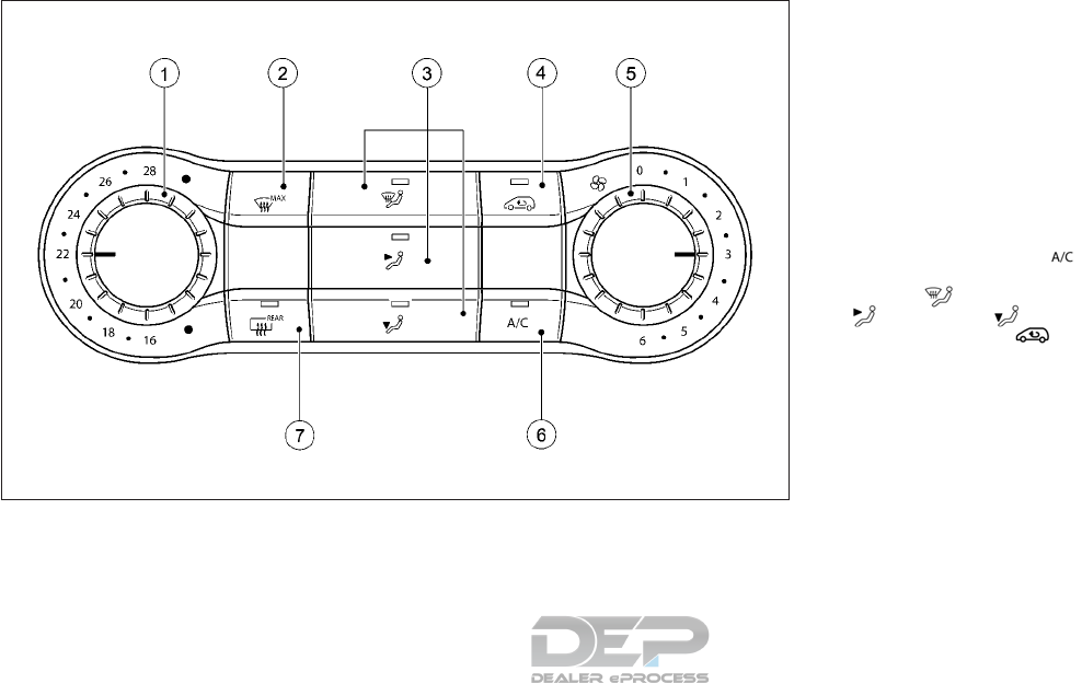
AIR CONDITIONING SYSTEM
䊊
1Sets the temperature
䊊
2De-ices/defogs the windshield
䊊
3Set the air distribution
䊊
4Activates/deactivates air-recirculation
mode
䊊
5Sets the airflow
䊊
6Activates/deactivates cooling with air
dehumidification
䊊
7Switches the rear window defroster on/
off
Operating tips
A number of tips and recommendations for
optimum use of the air-conditioning system
are listed below:
•Switch on the air-conditioning system by
turning control knob 䊊
5clockwise to the
desired position (except position 0)
•Set the temperature to 70°F(22°C)
•Recommendation for avoiding misted
windows at low exterior temperatures or
in rain: switch on the cooling with
dehumidification function. Set air distribu-
tion to and if possible switch off
and . Deactivate air-
recirculation mode .
Set airflow control 䊊
5to a setting be-
tween 3 and 6.
•Recommendation for rapid cooling or
heating of the vehicle interior: briefly set
airflow control 䊊
5to a setting between 3
and 6.
•Recommendation for a constant vehicle
interior temperature: set airflow control
䊊
5to a setting between 1 and 3.
NAA1644
4-44 Display screen, heater and air conditioner, and audio system

•Recommendation for air distribution in
winter: select the and settings.
Recommendation for air distribution in
summer: select the or and
settings.
•Only use the "Windshield demisting" func-
tion briefly until the windshield is clear
again
•Only use air-recirculation mode briefly, for
example if there are unpleasant outside
odors or when in a tunnel. The windows
could otherwise mist up as no fresh air is
drawn into the vehicle in air-recirculation
mode
•If you change the settings of the climate
control system, the climate status display
appears for approximately three seconds
at the bottom of the screen in the central
display (see separate operating instruc-
tions). You will see the current settings of
the various climate control functions.
Switching air-conditioning system
on/off
Make sure the ignition switch is in the ON
position.
To switch on: turn control 䊊
5clockwise to the
desired position (except position 0).
To switch off: turn control 䊊
5counter-
clockwise to position 0.
Activating/deactivating the cooling
with air dehumidification function
If you deactivate the "Cooling with air dehu-
midification" function, the air inside the ve-
hicle will not be cooled. The air inside the
vehicle will also not be dehumidified. The
windows can mist up more quickly. There-
fore, only deactivate the "Cooling with air
dehumidification" function briefly.
The "Cooling with air dehumidification" func-
tion is only available when the engine is run-
ning. The air inside the vehicle is cooled and
dehumidified according to the temperature
selected.
Condensation may drip from the underside of
the vehicle when cooling mode is active. This
is normal and not a sign that there is a mal-
function.
To activate:
Press the button The indicator light in
the button lights up.
To deactivate:
Press the button. The indicator light in
the button goes out. The cooling with
air dehumidification function has a delayed
switch-off feature.
Problems with the "Cooling with air dehu-
midification" function:
Problem: The indicator light in the but-
ton flashes three times or remains off. The
cooling with air dehumidification function
cannot be activated.
Cause and solution: The cooling with air de-
humidification function has been deactivated
due to a malfunction. Have the system
checked. It is recommended you visit an
INFINITI retailer for this service.
Setting the temperature
You can set the temperature for the entire
vehicle. The set temperature is automatically
maintained at a constant level.
To increase or reduce the temperature: turn
control 䊊
1counterclockwise or clockwise.
Only change the temperature setting in small
increments. Start at 70°F(22°C).
Display screen, heater and air conditioner, and audio system 4-45

Setting the air distribution
Directs the airflow through the demis-
ter ventilators.
Directs the airflow through the center
and side air ventilators.
Directs the airflow through the foot-
well air ventilators.
NOTE
•You can also activate several of the air
distribution settings simultaneously. In or-
der to do this, press several of the air dis-
tribution buttons. The air is then routed
through different air ventilators.
•Regardless of the air distribution setting,
airflow is always directed through the side
air ventilators. The side air ventilators can
only be closed if the adjusters are turned
clockwise until they engage.
To set air distribution:
1. Make sure the engine is running.
2. Press one or more of the ,,or
buttons. The corresponding indica-
tor light comes on.
Setting the airflow
1. Make sure the ignition switch is in the ON
position.
2. To increase or reduce airflow: turn control
䊊
5counterclockwise or clockwise.
Defogging the windshield
You can use this function to de-ice the wind-
shield or to defog the inside of the windshield
and the side windows.
NOTE
You should only select the "Windshield de-
misting" function until the windshield is clear
again.
Activating the "Windshield demisting"
function:
Make sure the ignition switch is in the ON
position.
To activate: press the button The indi-
cator light in the button lights up.
The climate control system switches to the
following functions:
•High airflow
•High temperature
•Air distribution to the windshield and front
side windows
•Air-recirculation mode off
NOTE
•The "Windshield demisting" function auto-
matically sets the blower output to the
optimum demisting effect. As a result, the
airflow may increase or decrease auto-
matically after the button is pressed.
•You can adjust the blower output manu-
ally while the "Windshield demisting" func-
tion is in operation. Turn airflow control 䊊
5
counterclockwise or clockwise.
Deactivating the "Windshield demisting"
function:
Press the button. The indicator light in
the button goes out. The previous set-
tings are reactivated. Air-recirculation mode
remains deactivated.
or
Turn temperature control 䊊
1counterclock-
wise or clockwise.
Defogging the windows
Windows misted up on the inside:
1. Activate the "Cooling with air dehu-
midification" function.
2. If the windows continue to mist up, acti-
vate the "Windshield demisting"
function.
4-46 Display screen, heater and air conditioner, and audio system
NOTE
You should only select this setting until the
windshield is clear again.
Windows misted up on the outside:
1. Activate the windshield wipers.
2. Set the air distribution to or .
NOTE
You should only select this setting until the
windows are clear again.
Air recirculation mode
You can deactivate the flow of fresh air if
unpleasant odors are entering the vehicle
from outside. The air already inside the ve-
hicle will then be recirculated.
If you activate air-recirculation mode, the
windows can mist up more quickly, in particu-
lar at low temperatures. Only use air recircu-
lation mode briefly to prevent the windows
misting up.
Activating air recirculation mode:
Make sure the ignition switch is in the ON
position.
Press the button. The indicator light in
the button lights up.
Deactivating air recirculation mode:
Press the button. The indicator light in
the button goes out.
NOTE
Air-recirculation mode is deactivated auto-
matically:
•After approximately five minutes at out-
side temperatures below approximately
45°F(7°C).
•After approximately five minutes if the
"Cooling with air dehumidification" func-
tion is deactivated.
•After approximately 30 minutes at outside
temperatures above approximately 45 ° F
(7 °C) if the cooling with air dehumidifica-
tion function is activated.
Idle Stop/Start function
During automatic engine switch-off, the Cli-
mate control only operates at a reduced ca-
pacity. If you require the full climate control
output, you can switch off the Idle Stop/
Start function by pressing the ECO button
(see " Idle Stop/Start System (if equipped)" in
the "5. Starting and driving" section).
Display screen, heater and air conditioner, and audio system 4-47
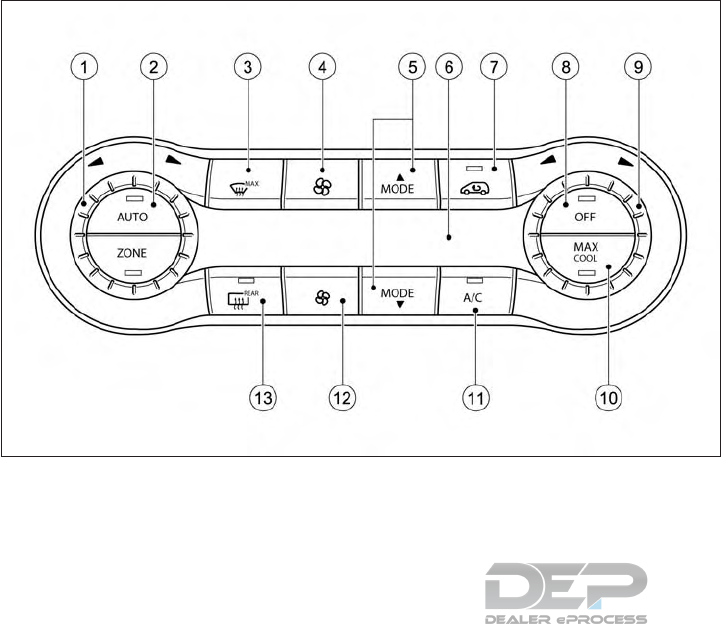
AUTOMATIC CLIMATE
CONTROL (2–ZONE)
䊊
1Sets the temperature, left
䊊
2Sets climate control to automatic mode
䊊
3Demists the windshield
䊊
4Increases the airflow
䊊
5Sets the air distribution
䊊
6Display
䊊
7Activates/deactivates air-recirculation
mode
䊊
8Switches climate control on/off
䊊
9Sets the temperature, right
NAA1705
4-48 Display screen, heater and air conditioner, and audio system

䊊
10 Activates/deactivates the Max Cool
function
䊊
11 Activates/deactivates cooling with air
dehumidification
䊊
12 Reduces the airflow
䊊
13 Switches the rear window heating on/
off
䊊
14 Switches the ZONE function on/off
Operating tips
A number of tips and recommendations to
enable you to get the most out of your auto-
matic climate control are listed below:
•Activate climate control using the
and buttons. The indicator lights in
the and buttons light up.
•Set the temperature to 70°F(22°C)
•Only use the "Windshield demisting" func-
tion briefly until the windshield is clear
again.
•Only use air-recirculation mode briefly, for
example if there are unpleasant outside
odors or when in a tunnel. The windows
could otherwise mist up as no fresh air is
drawn into the vehicle in air-recirculation
mode
•Use the function to adopt the tem-
perature settings on the driver's side for
the front-passenger side as well. The indi-
cator light in the button goes out.
•If you change the settings of the climate
control system, the climate status display
appears for approximately three seconds
at the bottom of the screen in the center
display (see separate operating instruc-
tions). You will see the current settings of
the various climate control functions.
Idle Stop/Start function
During automatic engine switch-off, the Cli-
mate control only operates at a reduced ca-
pacity. If you require the full climate control
output, you can switch off the Idle Stop/
Start function by pressing the ECO button
(see " Idle Stop/Start System (if equipped)" in
the "5. Starting and driving" section).
Switching automatic climate
control on/off
When the climate control is switched off, the
air supply and air circulation are also
switched off. The windows could mist up.
Therefore, only switch off climate control
briefly.
Make sure the ignition switch is in the ON
position.
To activate:
Press the button The indicator light in
the button lights up. Airflow and air
distribution are set to automatic mode.
or
Press the button. The indicator light in
the button goes out. The previous set-
tings are reactivated.
To deactivate:
Press the button. The indicator light in
the button lights up.
NOTE
Automatic climate control: switch on climate
control primarily using the button.
Activating/deactivating the cooling
with air dehumidification function
If you deactivate the "Cooling with air dehu-
midification" function, the air inside the ve-
hicle will not be cooled. The air inside the
vehicle will also not be dehumidified. The
windows can mist up more quickly. There-
fore, only deactivate the "Cooling with air
dehumidification" function briefly.
The "Cooling with air dehumidification" func-
tion is only available when the engine is run-
ning. The air inside the vehicle is cooled and
dehumidified according to the temperature
selected.
Condensation may drip from the underside of
the vehicle when cooling mode is active. This
is normal and not a sign that there is a mal-
function.
Display screen, heater and air conditioner, and audio system 4-49
To activate:
Press the button The indicator light in
the button lights up.
To deactivate:
Press the button. The indicator light in
the button goes out. The cooling with
air dehumidification function has a delayed
switch-off feature.
Problems with the "Cooling with air dehu-
midification" function:
Problem: The indicator light in the but-
ton flashes three times or remains off. The
cooling with air dehumidification function
cannot be activated.
Cause and solution: The cooling with air de-
humidification function has been deactivated
due to a malfunction. Have the system
checked. It is recommended you visit an
INFINITI retailer for this service.
Setting automatic climate control
to automatic mode
Only automatic climate control features the
"Control climate control automatically" func-
tion.
In automatic mode, the set temperature is
maintained automatically at a constant level
The system automatically regulates the tem-
perature of the dispensed air, the airflow and
the air distribution.
The automatic mode functions optimally
when the "Cooling with air dehumidification"
function is activated. If desired, cooling with
air dehumidification can be deactivated.
If you deactivate the "Cooling with air-
dehumidification" function, the air inside the
vehicle will not be cooled. The air inside the
vehicle will also not be dehumidified. The
windows can mist up more quickly. There-
fore, only deactivate the "Cooling with air-
dehumidification" function briefly.
To set climate control to automatic mode:
Make sure the ignition switch is in the ON
position.
Set the desired temperature.
To activate: press the button The indi-
cator light in the button lights up. Au-
tomatic air distribution and airflow are acti-
vated.
To switch to manual mode: press the or
button
or
Press the or button. The indicator
light in the button goes out. Automatic
air distribution and airflow are deactivated.
Setting the temperature
Different temperatures can be set for the
driver's and front-passenger sides. The set
temperature is automatically maintained at a
constant level.
Make sure the ignition switch is in the ON
position.
To increase or reduce temperature: turn con-
trol 䊊
1or 䊊
9counterclockwise or clockwise.
Only change the temperature setting in small
increments. Start at 70°F(22°C).
Setting the air distribution
Directs the airflow through the demis-
ter ventilators.
Directs the airflow through the center
and side air ventilators.
Directs the airflow through the foot-
well air ventilators.
Directs the airflow through the center
and side air ventilators as well as the
footwell air ventilators.
Directs the airflow through the center
and side air ventilators as well as the
demister ventilators.
Directs the airflow through the foot-
well and demister ventilators.
Directs the airflow through the demis-
ter ventilators, the center and side air
ventilators as well as the footwell air
ventilators.
4-50 Display screen, heater and air conditioner, and audio system
NOTE
Regardless of the air distribution setting,
airflow is always directed through the side
air ventilators. The side air ventilators can
only be closed if the adjusters are turned
clockwise until they engage.
To set the air distribution:
1. Make sure the engine is running.
2. Press the or button repeat-
edly until the desired symbol appears in
the display.
Setting the airflow
1. Make sure the ignition switch is in the ON
position.
2. To increase or reduce airflow: press the
or button.
Switching the ZONE function
on/off
This function is only available with automatic
climate control.
To activate: press the button. The in-
dicator light in the button lights up. The
temperature setting for the driver's side is not
adopted for the front-passenger side.
To deactivate: press the button. The
indicator light in the button goes out.
The temperature setting for the driver's side
is adopted for the front-passenger side.
Defogging the windshield
You can use this function to de-ice the wind-
shield or to defog the inside of the windshield
and the side windows.
NOTE
You should only select the "Windshield de-
misting" function until the windshield is clear
again.
Activating the "Windshield demisting"
function:
Make sure the ignition switch is in the ON
position.
To activate: press the button The indi-
cator light in the button lights up.
The climate control system switches to the
following functions:
•High airflow
•High temperature
•Air distribution to the windshield and front
side windows
•Air-recirculation mode off
NOTE
•The "Windshield demisting" function auto-
matically sets the blower output to the
optimum demisting effect. As a result, the
airflow may increase or decrease auto-
matically after the button is pressed.
•You can adjust the blower output manu-
ally while the "Windshield demisting" func-
tion is in operation. Press the or
button.
Deactivating the "Windshield demisting"
function:
Press the button. The indicator light in
the button goes out. The previous set-
tings are reactivated Air-recirculation mode
remains deactivated.
or
Turn temperature control 䊊
1or 䊊
9counter-
clockwise or clockwise.
Defogging the windows
Windows misted up on the inside:
1. Activate the "Cooling with air dehu-
midification" function.
2. Activate automatic mode .
3. If the windows continue to mist up, acti-
vate the "Windshield demisting"
function.
Display screen, heater and air conditioner, and audio system 4-51
NOTE
You should only select this setting until the
windshield is clear again.
Windows misted up on the outside:
1. Activate the windshield wipers.
2. Set the air distribution to or .
NOTE
You should only select this setting until the
windows are clear again.
Air recirculation mode
You can deactivate the flow of fresh air if
unpleasant odors are entering the vehicle
from outside. The air already inside the ve-
hicle will then be recirculated.
If you activate air-recirculation mode, the
windows can mist up more quickly, in particu-
lar at low temperatures. Only use air recircu-
lation mode briefly to prevent the windows
misting up.
Activating air recirculation mode:
Make sure the ignition switch is in the ON
position.
Press the button. The indicator light in
the button lights up.
Air-recirculation mode is activated automati-
cally at high outside temperatures or high
levels of pollution. When air-recirculation
mode is activated automatically, the indicator
light in the button is not lit. Outside air
is added after about 30 minutes.
Deactivating air recirculation mode:
Press the button. The indicator light in
the button goes out.
NOTE
Air-recirculation mode is deactivated auto-
matically:
•After approximately five minutes at out-
side temperatures below approximately
45°F(7°C).
•After approximately five minutes if the
"Cooling with air dehumidification" func-
tion is deactivated.
•After approximately 30 minutes at outside
temperatures above approximately 45 ° F
(7 °C) if the cooling with air dehumidifica-
tion function is activated.
SERVICING AIR CONDITIONER
WARNING
The air conditioner system contains refrig-
erant under high pressure. To avoid per-
sonal injury, any air conditioner service
should be done only by an experienced
technician with the proper equipment.
The air conditioner system in your vehicle is
charged with a refrigerant designed with the
environment in mind.
This refrigerant will not harm the earth’s
ozone layer.
Special charging equipment and lubricant are
required when servicing your vehicle’s air
conditioner. Using improper refrigerants or
lubricants will cause severe damage to the air
conditioner system. (See "Air conditioner sys-
tem refrigerant and oil recommendations" in
the "9. Maintenance and Schedules" section.)
An INFINITI retailer will be able to service
your environmentally friendly air conditioner
system.
Air conditioner filter
The air conditioner system is equipped with
an air conditioner filter. To make sure the air
conditioner heats, defogs, and ventilates ef-
ficiently, replace the filter in accordance with
the specified maintenance intervals listed in
the separate maintenance booklet. It is rec-
ommended you visit an INFINITI retailer for
this service.
4-52 Display screen, heater and air conditioner, and audio system

The filter should be replaced if the air flow
decreases significantly or if windows fog up
easily when operating the heater or air con-
ditioner.
AUDIO OPERATION
PRECAUTIONS
WARNING
•The driver must not attempt to operate
the audio system while the vehicle is in
motion, so that full attention may be
given to vehicle operation.
•Park the vehicle in a safe location and
apply the parking brake before operat-
ing the audio system and playing movies
(if equipped).
CAUTION
•Operate the audio system only when the
vehicle engine is running. Operating the
audio system for extended periods of
time with the engine turned off can dis-
charge the vehicle battery.
•Do not allow the system to get wet. Ex-
cessive moisture such as spilled liquids
may cause the system to malfunction.
Radio
Turn the ignition switch to the ACC or ON
position before turning on the radio. If you
listen to the radio when the engine is not
running, the ignition switch should be pushed
to the ACC position.
Radio reception is affected by station signal
strength, distance from radio transmitter,
buildings, bridges, mountains and other ex-
ternal influences. Intermittent changes in re-
ception quality are normally caused by these
external influences.
Using a cellular phone in or near the vehicle
may influence radio reception quality.
Radio reception
Your radio system is equipped with state-of-
the-art electronic circuits to enhance radio
reception. These circuits are designed to ex-
tend reception range, and to enhance the
quality of that reception.
However there are some general character-
istics of both FM and AM radio signals that
can affect radio reception quality in a moving
vehicle, even when the best quality equip-
ment is used. These characteristics are com-
pletely normal in a given reception area, and
do not indicate any malfunction in your radio
system.
AUDIO SYSTEM (IF EQUIPPED)
Display screen, heater and air conditioner, and audio system 4-53
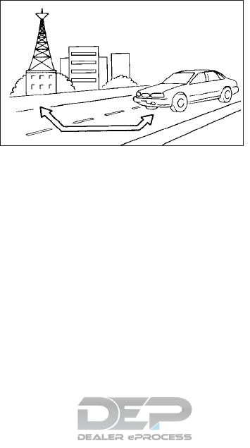
Reception conditions will constantly change
because of vehicle movement. Buildings, ter-
rain, signal distance and interference from
other vehicles can adversely affect ideal re-
ception. Described below are some of the
factors that can affect radio reception.
Some cellular phones or other devices may
cause interference or a buzzing noise to come
from the audio system speakers. Storing the
device in a different location may reduce or
eliminate the noise.
FM radio reception
MAXIMUM SIGNAL DISTANCES
•FM : 25 to 30 miles (40 to 48 km)
•AM : 60 to 130 miles (97 to 209 km)
Range: FM range is normally limited to 25 to
30 miles (40 to 48 km), with monaural (single
station) FM having slightly more range than
stereo FM. External influences may some-
times interfere with FM station reception
even if the FM station is within 25 miles (40
km). The strength of the FM signal is directly
related to the distance between the transmit-
ter and receiver. FM signals follow a line-of-
sight path, exhibiting many of the same char-
acteristics as light. For example they will
reflect off objects.
Fade and drift: As your vehicle moves away
from a station transmitter, the signals will
tend to fade and/or drift.
Static and flutter: During signal interference
from buildings, large hills or due to antenna
position, usually in conjunction with an in-
creased distance from the station transmit-
ter, static or flutter can be heard. This can be
reduced by lowering the treble setting to re-
duce the treble response.
Multipath reception: Because of the reflec-
tive characteristics of FM signals, direct and
reflected signals reach the receiver at the
same time. The signals may cancel each
other, resulting in momentary flutter or loss
of sound.
AM radio reception
AM signals, because of their low frequency,
can bend around objects and skip along the
ground. In addition, the signals can bounce
off the ionosphere and be bent back to earth.
Because of these characteristics, AM signals
are also subject to interference as they travel
from transmitter to receiver.
Fading: This occurs while the vehicle is pass-
ing through freeway underpasses or in areas
with many tall buildings. It can also occur for
several seconds during ionospheric turbu-
lence even in areas where no obstacles exist.
SAA0306Z
4-54 Display screen, heater and air conditioner, and audio system

Static: Caused by thunderstorms, electrical
power lines, electric signs and even traffic
lights.
HD Radio
TM
Technology reception
(for U.S.)
HD Radio
TM
Technology reception needs to
be activated to receive HD Radio broadcasts,
see "Audio settings" later in this section.
This enables you to receive radio broadcasts
digitally (where available), providing a better
quality sound with clear reception. When this
feature is not activated or HD Radio broad-
casts are not available, you will receive ana-
log radio (AM/FM) broadcasts.
Satellite radio reception
When the satellite radio is used for the first
time or the battery has been replaced, the
satellite radio may not work properly. This is
not a malfunction. Wait more than 10 min-
utes with the satellite radio ON and the ve-
hicle outside of any metal or large building for
the satellite radio to receive all of the neces-
sary data.
The satellite radio requires an active SiriusXM
Satellite Radio subscription. The satellite ser-
vice is a available only to those at least 18 and
older in the 48 contiguous United States.
The satellite radio performance may be af-
fected if cargo carried on the roof blocks the
satellite radio signal.
If possible, do not put cargo near the satellite
antenna.
The build up of ice on the satellite radio an-
tenna can affect satellite radio performance.
Remove the ice to restore satellite radio re-
ception.
Trademarks
HD Radio Technology manufactured under
license from iBiquity Digital Corporation. U.S.
and Foreign Patents. HD Radio
TM
and the
HD, HD Radio, and Arc logos are proprietary
trademarks of iBiquity Digita; Corp.
The Bluetooth® word mark and logos are
registered trademarks owned by Bluetooth
SIG, Inc. and any use of such marks by
DENSO CORPORATION is under license.
Other trademarks and trade names are those
of their respective owners.
SiriusXM services require a subscription after
trial period and are sold separately or as a
package. Our satellite service is available only
to those at least 18 and older in the 48 con-
tiguous USA and DC. For more information
visit www.siriusxm.com.
Required SiriusXM Satellite Radio and
SiriusXM Travel Link monthly subscriptions
are sold separately. Sirius XM Travel Link is
only available in select markets. For more
information, see www.sirius.com/travellink
“Made for iPod®” and “Made for iPhone®”
mean that an electronic accessory has been
designed to connect specifically to iPod® or
iPhone®, respectively, and has been certified
by the developer to meet Apple performance
standards. Apple is not responsible for the
operation of this device or its compliance
with safety and regulatory standards. Please
note that the use of this accessory with
iPod® or iPhone® may affect wireless per-
formance.
Apple, the Apple logo, iPhone®, iPod®, iPod
classic®, iPod nano®, and iPod touch® are
trademarks of Apple Inc., registered in the
U.S. and other countries. Lightning is a trade-
mark of Apple Inc. App Store is a service mark
of Apple Inc.
Music recognition technology and related
data are provided by Gracenote®. Gracenote
Display screen, heater and air conditioner, and audio system 4-55
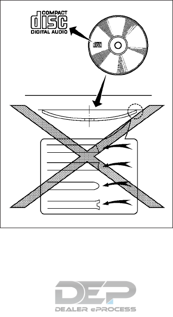
is the industry standard in music recognition
technology and related content delivery. For
more information, visit www.gracenote.com.
CD and music-related data from Gracenote,
Inc., copyright 䊊
c2000 to present
Gracenote. Gracenote Software, copyright
䊊
c2000 to present Gracenote. One or more
patents owned by Gracenote apply to this
product and service. See the Gracenote web-
site for a non-exhaustive list of applicable
Gracenote patents. Gracenote, CDDB, Musi-
cID, MediaVOCS, the Gracenote logo and
logotype, and the “Powered by Gracenote”
logo are either registered trademarks or
trademarks of Gracenote in the United States
and/or other countries.
App Store SM
Apple and the Apple logo are trademarks of
Apple Inc., registered in the U.S. and other
countries. App Store is a service mark of
Apple Inc.
Google Play
TM
Google Play is a trademark of Google Inc.
Google
䊊
c2012 Google Inc. All rights reserved.
Google Calendar
TM
calendaring application is
a trademark of Google Inc.
Compact Disc (CD) player
•Do not force a compact disc into the CD
insert slot. This could damage the CD
and/or CD player.
•Trying to load a CD with the CD door
closed could damage the CD and/or CD
player.
•During cold or rainy weather, the player
may malfunction due to the humidity. If
this occurs, remove the CD and dehu-
midify or ventilate the player completely.
•The player may skip while driving on rough
roads.
•The CD player sometimes cannot function
when the passenger compartment tem-
perature is extremely high. Decrease the
temperature before use.
•Only use high quality 4.7 in (12 cm) round
discs that have the “COMPACT disc DIGI-
TAL AUDIO” logo on the disc or packag-
ing.
•Do not expose the CD to direct sunlight.
•CDs that are of poor quality, are dirty,
scratched, or covered with fingerprints, or
that have pin holes may not work properly.
•The following CDs may not work properly:
– Copy control compact discs (CCCD)
– Recordable compact discs (CD-R)
– Rewritable compact discs (CD-RW)
•Do not use the following CDs as they may
cause the CD player to malfunction.
– 3.1 in (8 cm) discs
SAA0480
4-56 Display screen, heater and air conditioner, and audio system
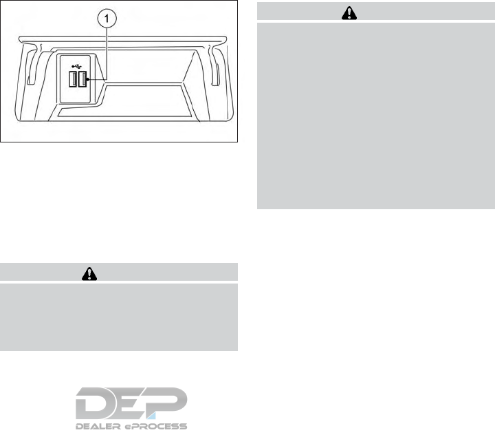
– CDs that are not round
– CDs with a paper label
– CDs that are warped, scratched, or
have abnormal edges
•This audio system can only play prere-
corded CDs. It has no capabilities to record
or burn CDs.
•If a CD cannot be played, one of the fol-
lowing messages will be displayed.
[Disc Reading Error]
Indicates a CLV/Focus, TOC or Access
error. Check and re-insert the CD. Make
sure that it is inserted correctly.
[Please Eject Disc]
Indicates a mechanism error. If the CD can
be ejected, eject and re-insert the CD. If
the CD cannot be ejected, have the system
checked. It if recommended you contact
an INFINITI retailer for this service.
[File type is not supported]
Indicates that no readable files are found
on the inserted CD. Check the data on your
CD.
USB (Universal Serial Bus)
connection port/ iPod
The Media Hub is located in the center con-
sole and consists of the USB connectors.
1) USB/iPod connection port
Connect to play media from an iPod®,
iPhone® or a USB memory device. When
using INFINITI InTouch Apps with an
iPhone®, connect via a USB cable. Refer
to the device manufacturer’s owner infor-
mation regarding the proper use and care
of the device.
WARNING
Do not connect, disconnect or operate the
USB device while driving. Doing so can be a
distraction. If distracted you could lose
control of your vehicle and cause an acci-
dent or serious injury.
CAUTION
•Do not force the USB device into the
USB port. Inserting the USB device
tilted or upside down into the port may
damage the port. Make sure that the
USB device is connected correctly into
the USB port.
•Do not grab the USB port cover (if
equipped) when pulling the USB device
out of the port. This could damage the
port and the cover.
•Do not leave the USB cable in a place
where it can be pulled unintentionally.
Pulling the cable may damage the port.
The vehicle is not equipped with a USB de-
vice. USB devices should be purchased sepa-
rately as necessary.
This system cannot be used to format USB
devices. To format a USB device, use a per-
sonal computer.
In some areas, the USB device for the front
seats plays only sound without images for
regulatory reasons, even when the vehicle is
parked.
NAA1628
Display screen, heater and air conditioner, and audio system 4-57

This system supports various USB memory
devices, USB hard drives and iPod players.
Some USB devices may not be supported by
this system.
•Partitioned USB devices may not play cor-
rectly.
•Some characters used in other languages
(Chinese, Japanese, etc.) may not appear
properly in the display. Using English lan-
guage characters with a USB device is
recommended.
General notes for USB use:
Refer to your device manufacturer’s owner
information regarding the proper use and
care of the device.
Notes for iPod use:
iPod is a trademark of Apple Inc., registered in
the U.S. and other countries.
•Improperly plugging in the iPod may cause
a checkmark to be displayed on and off
(flickering). Always make sure that the
iPod is connected properly.
•An iPod nano (1st Generation) may remain
in fast forward or rewind mode if it is
connected during a seek operation. In this
case, please manually reset the iPod.
•An iPod nano (2nd Generation) will con-
tinue to fast-forward or rewind if it is dis-
connected during a seek operation.
•An incorrect song title may appear when
the Play Mode is changed while using an
iPod nano (2nd Generation)
•Audiobooks may not play in the same or-
der as they appear on an iPod.
•Large video files cause slow responses in
an iPod. The vehicle display may momen-
tarily black out, but will soon recover.
•If an iPod automatically selects large video
files while in the shuffle mode, the vehicle
display may momentarily black out, but will
soon recover.
4-58 Display screen, heater and air conditioner, and audio system

Specification chart for USB
Supported media USB2.0
Supported file systems FAT32
Folder levels Folder levels: 8, Folders: 512 (including root folder), Files: 5000
Format Sampling rate Supported/Not supported
MPEG1 Layer-1 - Not supported
Layer-2 - Not supported
Layer-3 44.1, 48, 32 kHz Supported (32-320 kbps)
MPEG2 Layer-1 - Not supported
Layer-2 - Not supported
Layer-3 22.05, 24, 16 kHz Supported (16-160 kbps)
MPEG2.5 Layer-1 - Not supported
Layer-2 - Not supported
Layer-3 11.025, 12, 8 kHz Supported (16-160 kbps)
WMA *1 32, 44.1, 48 kHz Supported VER.7/8 (48-192 bps)
VER.9/9.1/9.2 (48-320 bps)
AAC (MPEG4) *2
(Extension “m4a” only)
8, 11.025, 12, 16, 22.05, 24, 32,
44.1, 48 kHz
Supported (16-320 kbps)
*1 Professional (voice, lossless, multichannel) is not supported.
*2 AAC (MPEG-2) is not supported.
Display screen, heater and air conditioner, and audio system 4-59
Compressed audio files
(MP3/WMA/AAC)
Explanation of terms:
•MP3 — MP3 is short for Moving Pictures
Experts Group Audio Layer 3. MP3 is the
most well known compressed digital audio
file format. This format allows for near
“CD quality” sound, but at a fraction of the
size of normal audio files. MP3 conversion
of an audio track can reduce the file size by
approximately a 10:1 ratio (sampling: 44.1
kHz, bit rate: 128 kbps) with virtually no
perceptible loss in quality. The compres-
sion reduces certain parts of sound that
seem inaudible to most people.
•WMA — Windows Media Audio (WMA) is
a compressed audio format created by Mi-
crosoft as an alternative to MP3. The
WMA codec offers greater file compres-
sion than the MP3 codec, enabling stor-
age of more digital audio tracks in the
same amount of space when compared to
MP3s at the same level of quality.
•Bit rate — Bit rate denotes the number of
bits per second used by a digital music file.
The size and quality of a compressed digi-
tal audio file is determined by the bit rate
used when encoding the file.
•Sampling frequency — Sampling frequency
is the rate at which the samples of a signal
are converted from analog to digital (A/D
conversion) per second.
•Multisession — Multisession is one of the
methods for writing data to media. Writing
data once to the media is called a single
session, and writing more than once is
called a multisession.
•ID3/WMA Tag — The ID3/WMA tag is
the part of the encoded MP3 or WMA file
that contains information about the digital
music file such as song title, artist, album
title, encoding bit rate, and track time du-
ration, etc. ID3 tag information is dis-
played on the Album/Artist/Track title line
on the display.
* Windows® and Windows Media® are reg-
istered trademarks or trademarks of Micro-
soft Corporation in the United States of
America and/or other countries.
Playback order:
䊊
ARoot folder
䊊
BFolder
䊊
CAudio file
NAA984
4-60 Display screen, heater and air conditioner, and audio system

•The folder names of folders not containing
compressed audio files are not shown on
the display.
•If there is a file in the top level of a disc/
USB, the root folder is displayed.
•The playback order is the order in which
the files were written by the writing soft-
ware, so the files might not play in the
desired order.
•The music playback order of compressed
audio files is as illustrated.
Display screen, heater and air conditioner, and audio system 4-61

Specification chart for CD:
Supported media CD, CD-R, CD-RW
Supported file systems CD, CD-R, CD-RW
Supported ver-
sions*1
MP3 Version MPEG1 Audio Layer3, MPEG2 Audio Layer3, MPEG2.5 Audio Layer3
Sampling fre-
quency
MPEG2.5 Audio Layer3: 8kHz, 11.025kHz, 12kHz
MPEG2 Audio Layer3: 16kHz, 22.05kHz, 24kHz
MPEG1 Audio Layer3: 32kHz, 44.1kHz, 48kHz
Bit rate 8 kbps - 320 kbps, VBR
WMA*2 Version WMA7, WMA8, WMA9, WMA9.1, WMA9.2
Bit rate/
Sampling fre-
quency
Bit rate: Ver7, Ver8: 32-192kbps Ver9,Ver9.1,Ver9.2: 32-192kbps, VBR
Sampling frequency: Ver7, Ver8: 8k/11.025k/16k/22k/32k/44.1k Ver9,Ver9.1,Ver9.2: 8k/11.025k/
16k/22k/32k/44.1k/48 kHz
AAC*4 Bit rate/
Sampling fre-
quency
Bit rate: 8-320 kbps, VBR
Sampling frequency: 11.025-48kHz
Tag information (Song title, Artist name and Album
name)
ID3 tag VER1.0, VER1.1, VER2.2, VER2.3, VER2.4 (MP3 only)
WMA tag (WMA only)
AAC Tag (AAC only)
Folder levels CD, CD-R, CD-RW: Folder levels: 8, Folders: 255 (including root folder), Files: 510 (Max. 255 files for one
folder)
Displayable character codes*3 01: SHIFT-JIS, ASCII, ISO-8859-1, UTF-8, UTF-16 BOM, UTF-16 Big Endian, UTF-16 Little Endian, 02:
UNICODE, 03: UTF-16
*1 Files created with a combination of 48 kHz sampling frequency and 64 kbps bit rate cannot be played.
*2 Protected WMA files (DRM) cannot be played.
*3 Available codes depend on what kind of media, versions, and information are going to be displayed.
*4 Made by iTunes.
4-62 Display screen, heater and air conditioner, and audio system

Windows Media Player:
This product is protected by certain intellec-
tual property right of Microsoft. Use or dis-
tribution of such technology outside of this
product is prohibited without a license from
Microsoft.
Bluetooth® Audio player
The Bluetooth® word mark and logos are
registered trademarks owned by Bluetooth
SIG, Inc. and any use of such marks by
DENSO CORPORATION is under license.
Other trademarks and trade names are those
of their respective owners.
•Some Bluetooth® streaming audio de-
vices may not be recognized by the in-
vehicle audio system.
•It is necessary to set up the wireless con-
nection between a compatible Bluetooth®
streaming audio device and the in-vehicle
Bluetooth® module before using the
Bluetooth® streaming audio.
•The Bluetooth® streaming audio may be
stopped under the following conditions:
– When receiving a hands-free call
– When checking the connection to the
hands-free phone
– When connecting the hands-free
phone or the audio device
– When downloading a phonebook
memory from a connected cellular
phone
•Do not place a Bluetooth® streaming au-
dio device in an area surrounded by metal
or far away from the in-vehicle
Bluetooth® module to prevent tone qual-
ity degradation and wireless connection
disruption.
•While an audio device is connected
through Bluetooth® wireless connection,
the battery of the device may discharge
quicker than usual.
•This system supports the Bluetooth® Ad-
vanced Audio Distribution Profile (A2DP)
and Audio/Video Remote Control Profile
(AVRCP).
•Wireless LAN (Wi-Fi) and the Bluetooth®
functions share the same frequency band
(2.4 GHz). Using the Bluetooth® and the
wireless LAN functions at the same time
may slow down or disconnect the commu-
nication and cause undesired noise. It is
recommended that you turn off the wire-
less LAN (Wi-Fi) when using the
Bluetooth® functions.
Display screen, heater and air conditioner, and audio system 4-63
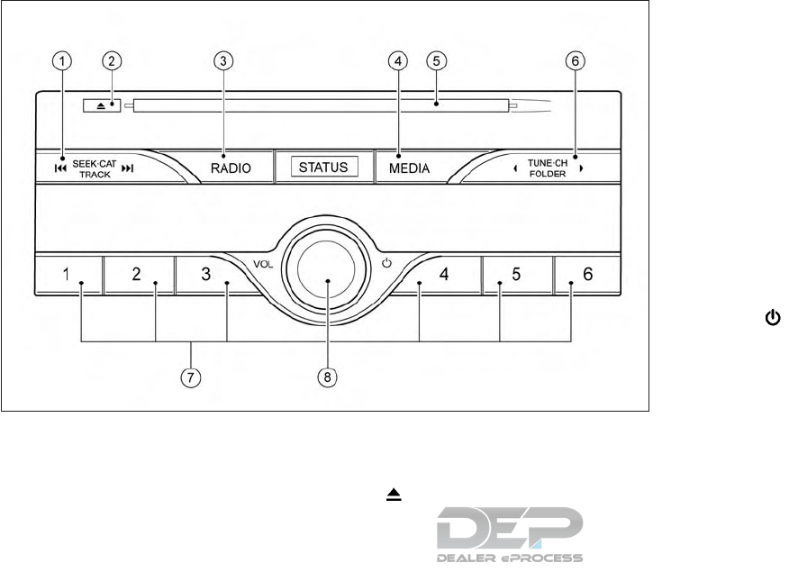
NAMES AND FUNCTIONS OF
AUDIO CONTROL BUTTONS
Main audio buttons
䊊
1<SEEK•CAT•TRACK>:
Functions to seek radio stations or to skip
and fast-forward/rewind through
tracks.
䊊
2< >:
Push to eject a disc.
䊊
3<RADIO>:
Push to switch to the radio mode. The
radio band will switch between AM, FM,
and SXM (SiriusXM) each time the button
is pushed.
䊊
4<MEDIA>:
Each time the button is pushed, a differ-
ent audio source (CD, iPod, USB or
Bluetooth® Streaming Audio) will be se-
lected.
䊊
5Disc slot:
Insert a disc with the label side facing up.
䊊
6<TUNE•CH•FOLDER>:
Functions to manually tune AM/FM , to
select SXM categories and to select
MP3/WMA/AAC folders.
䊊
7Radio memory buttons: Up to six pre-
ferred stations can be registered in the
preset list for each band.
䊊
8<VOL/ >:
Push to turn the audio system on/off.
Turn to adjust the volume.
Audio APPS information will be displayed
when music is played via INFINITI InTouch
Apps.
NAA1704
4-64 Display screen, heater and air conditioner, and audio system
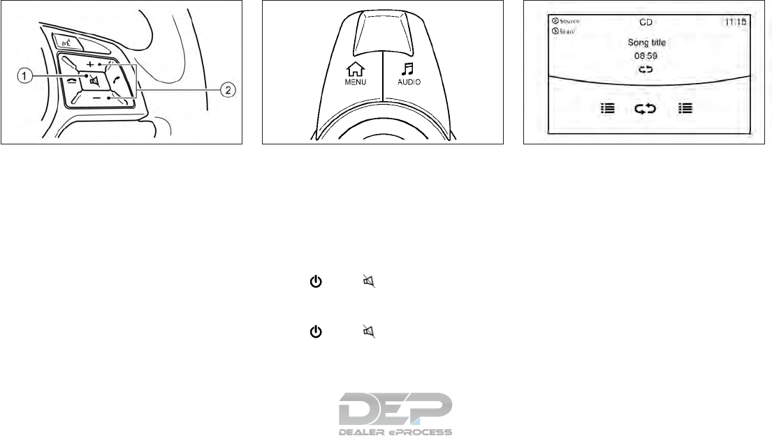
Steering wheel mounted audio
control buttons
䊊
1System on/off: Push to turn on/off the
audio system.
䊊
2Volume control: Push the upper <+> or
lower <-> buttons to increase or decrease
the volume.
INFINITI controller AUDIO button
Push <AUDIO> to display the current audio
screen.
MAIN AUDIO OPERATION
Turning audio system on/off
The ignition switch must be in the ACC or ON
position to turn on the audio system. Push
<VOL/ >or < > on the steering wheel
to turn on the last audio source which was
playing immediately before the system was
turned off. To turn off the audio system, push
<VOL/ >or < > on the steering wheel
again.
Selecting audio source
1. Turn on the audio source menu screen by
touching [Source] on the upper left corner
of the audio screen.
2. Select an item from the audio source
menu screen.
•Pushing <RADIO> or <MEDIA> can also
change the audio source.
See "Main audio buttons" earlier in this
section.
•If the audio system has been turned off
while one of the audio sources was play-
ing, turning the audio system back on will
play the audio source that was playing
when the system was turned off.
•The audio source can also be changed
with the source bar on top of the audio
screen.
NAA1620 NAA1726 NAA1714
Display screen, heater and air conditioner, and audio system 4-65

•Audio APPS information will be displayed
when music is played via INFINITI InTouch
Apps.
Audio source bar
The audio source can be changed with the
source bar on top of the audio screen. The
source bar display can be turned on/off.
Turning source bar on/off:
You can select whether the source bar on top
of the audio screens is displayed or not. 1. Touch [Source] on the upper left corner of
the audio screen.
2. Touch [Show Source Bar] to turn the in-
dicator on/off.
Editing source bar:
The audio sources to be displayed on the
source bar can be changed.
1. Touch [Source] on the upper left corner of
the audio screen.
2. Touch [Edit Source Bar].
3. Touch one of the keys on the source bar
and then touch one of the audio sources
from the source list to register the audio
source in the source bar.
NAA1715
4-66 Display screen, heater and air conditioner, and audio system

RADIO
How to view radio operation screen
* For models with radio status indicator and
reception information display.
The radio screen can be viewed and operated
on the display.
䊊
1Radio mode indicator: The current radio
mode is displayed.
䊊
2[Source]: Touch to switch to the source
select screen. See "Selecting audio
source" later in this section
䊊
3[Control]: Touch to display the control
screen. See "Radio Controls" later in this
section
䊊
4HD Radio reception status indicator (for
AM and FM):
The icon is displayed when HD Radio
digital signal is received. The icon flashes
when the radio is acquiring the digital
signal but the sound output is not yet in
the HD mode.
䊊
5Radio band indicator: The currently se-
lected radio band (AM, FM or SXM) is
displayed.
䊊
6Reception information display: Reception
information available at the time such as
frequency, station/channel name, etc..
are displayed.
On the SXM screen, touch this area to
display the category list.
䊊
736 stations/channels can be registered in
the preset list.
See "Presetting" later in this section.
NOTE
HD Radio reception needs to be activated to
receive HD Radio broadcasts. This enables
you to receive radio broadcasts digitally
NAA1716
Display screen, heater and air conditioner, and audio system 4-67

(where available), providing a better quality
sound with clear reception. When this fea-
ture is not activated or HD Radio broadcasts
are not available, you will receive analog ra-
dio (AM/FM broadcasts).
Radio source control
There are 2 elements used in the preset list
area that are associated with radio source:
䊊
1Highlight for INFINITI controller opera-
tion.
䊊
2(With triangle) Indicator of current se-
lected preset station.
Radio operation
Radio activation and band selection:
Push <RADIO> or select the preferred radio
band (AM, FM or SXM) from the audio
source list to turn on the radio. Each time
<RADIO> is pushed, the radio band will
change.
For details, see "Selecting audio source" later
in this section.
NOTE
When the stereo broadcast signal is weak,
the radio will automatically change from
stereo to monaural reception.
Seeking stations/channels:
AM and FM Radio
Push <SEEK•CAT•TRACK> to tune from low
to high or high to low frequencies and to stop
at the next broadcasting station.
SiriusXM Satellite Radio
Push <SEEK•CAT•TRACK> to tune to the
first channel of the next or previous category.
Scan tuning:
To tune the stations/channels, touch [Con-
trol] on the display and touch [Scan]. The
stations/channels will be tuned form low to
high frequencies and stop at each broadcast-
ing station/channel for 5 seconds. Touching
[Scan] again during this 5 second period will
stop scan tuning and the radio will remain
tuned to that station/channel.
Presetting:
Up to 36 stations/channels can be registered
for AM, FM and SXM in the preset list.
1. Select a radio band (AM, FM or SXM).
NAA1717
4-68 Display screen, heater and air conditioner, and audio system

2. Tune to the station/channel you wish to
store in the preset list.
3. (Radio screen operation) Touch and hold
one of the preset numbers in the preset
list.
(Radio memory buttons operation) Push
and hold the desired station/channel pre-
set button <1> to <6>.
4. The information such as frequency (AM/
FM), channel number (SXM), etc. will be
displayed on the preset list.
To change the preset stations/channels,
touch and hold one of the preset numbers.
You can select whether to change the
station/channel or to delete the preset set-
ting.
Alert notification (SXM only):
Favorite artists and songs can be registered
to receive an alert notice wen a song of the
registered conditions is on the radio. To tune
to the respective channel, touch [Listen to be
consistent]. The alert can be ignored by
touching [Cancel].
Satellite Radio:
•The satellite mode requires and active
SiriusXM Satellite Radio subscription. The
satellite service is available only to those at
least 18 and older in the 48 contiguous
United States.
•It may take some time to receive the acti-
vation signal after the initiation of the
SiriusXM Satellite Radio subscription. Af-
ter receiving the activation signal, an avail-
able channel list will automatically be up-
dated in the radio. Switch the ignition
switch from LOCK to ACC to update the
SiriusXM channel list.
Radio Controls
Touch [Control] on the AM, FM or SXM
screen to display the control screen.
The following items are available:
FM/AM:
•[Station List]
Touch to display the available station list.
While listening to FM radio, Auto Update
is not performed.
•[Scan]
Touch to scan tune the stations
See "Radio operation" earlier in this section
•[HD mode]
When this item is turned on, the analog
and digital reception switches automati-
cally. When this item is turned off, the
reception is fixed in the analog mode.
•[HD Info]
Touch to display the HD Radio informa-
tion such as name of song, artist and al-
bum.
This item is available when [RDS Info] is
not active.
•[Tag] (HD Radio broadcasts only)
Touch to register the tag information for
iTunes Tagging. If an iPod is plugged in
after the registration, the tag information
can be stored in an iPod and be used to
purchase the songs via iTunes.
•[RDS Info] (FM only)
Touch to display the RDS information.
This item is available only when [HD Radio
Info] is not active.
SXM:
•[Categories]
Touch to display the category list.
Display screen, heater and air conditioner, and audio system 4-69

•[Direct Tune]
Touch to display the keypad to enter the
frequency and directly tune to the channel.
See "Radio operation" earlier in this section
•[Scan]
Touch to scan tune the channels.
See "Radio operation" earlier in this section
•[Instant Replay]
Up to 30 minutes of the broadcast of the
channel that has been tuned in to can be
replayed.
Touch to select from , , , ,
and
•[Tag]
Touch to register the tag information for
iTunes Tagging. If an iPod is plugged in
after the registration, the tag information
can be stored in an iPod and be use to
purchase the songs via iTunes.
•[Other]-[Favorite Artists]
Touch to set a favorite artists alert notifi-
cation. Up to 8 artists can be registered.
While a song of your favorite artist is play-
ing, touch the list and touch [Add]/
[Update]. To receive the alert notification,
select [Turn ALL Alerts ON].
•[Other]-[Favorite Songs]
Touch to set a favorite songs alert notifi-
cation. Up to 8 songs can be registered.
While a song of your favorite artist is play-
ing, touch the list and touch [Add]/
[Update]. To receive the alert notification,
select [Turn ALL Alerts ON].
•[Other]-[Customize Channel List]
Touch to customize the channel list. Only
the selected channels will be tuned in to
when you seek or scan the channels. You
can select each item or [Select All]/
[Deselect All].
•[Other]-[Favorite Artists Now Playing]
Touch to display the artist list for an alert
notice.
•[Other]-[Favorite Songs Now Playing]
Touch to display the song list for an alert
notice.
•[Other]-[Favorite Alert Settings]
Touch to turn on/off the alert notice for
the registered favorite artists and songs.
•[Other]-[Channel Locking Settings]
Touch to select or unselect the channel
that you wish to lock out. A passcode is
required to change the settings. The de-
fault passcode is 1234.
4-70 Display screen, heater and air conditioner, and audio system

COMPACT DISC (CD) PLAYER
How to view CD operation screen
䊊
1[Source]:
Touch to switch to the source list screen.
For details, see "Selecting audio source"
later in this section
䊊
2[Scan]:
Touch to play the first 10 seconds of the
tracks. Touch again to stop scanning.
䊊
3Track information:
Track information such as the song title,
artist name, and album name is displayed.
䊊
4Audio source indicator:
Indicates that CD is currently selected.
䊊
5Play time:
The play time of the track is displayed.
䊊
6Track number:
This indicates the current track number
and the total number of tracks.
䊊
7CD menu:
CD menu items are displayed. Touch an
icon to display the list or to change the
setting.
- [Track]
- [Folder] (for MP3, WMA, AAC)
- [Play Mode]
䊊
8Play Mode Indicator:
This indicates the current play mode.
Touch to change the play mode.
䊊
9Folder number (for MP3, WMA, AAC):
This indicates the folder number when a
CD with compressed audio files is
loaded.
NAA1718
Display screen, heater and air conditioner, and audio system 4-71
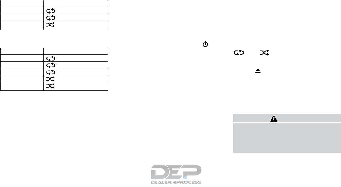
For CDs without compressed audio files:
Mode Screen display
Disc Repeat Disc
1 Track Repeat 1 Track
Disc Random Disc
For CDs with compressed audio files:
Mode Screen display
Disc Repeat Disc
1 Folder Repeat 1 Folder
1 Track Repeat 1 Track
Disc Random Disc
1 Folder Random 1 Folder
CD player operation
Loading:
Insert the CD into the slot with the label side
facing up. The CD will be guided automati-
cally into the slot and starts playing.
After loading the CD, the CD screen will ap-
pear on the display.
Activation and playing:
The CD mode can be selected from the
source list or by pushing the <MEDIA> button
with a CD loaded to play the CD.
For details, see "Selecting audio source" ear-
lier in this section and "Main audio buttons"
earlier in this section.
If the system has been turned off while the
CD was playing, pushing <VOL/ >will
start the Audio system set to the CD screen.
Selecting track/folder:
Touch [Track] or [Folder] in the CD menu and
select a preferred track or folder from the list.
Push <SEEK•CAT•TRACK> to move to the
next or previous track.
For CDs with compressed audio files, push
<TUNE•CH•FOLDER> to move to the next or
previous folder.
For details, see "Main audio buttons" earlier in
this section.
Fast-forwarding/rewinding:
Push and hold <SEEK•CAT•TRACK> to fast-
forward or rewind the track. Release <SEEK-
•CAT•TRACK> to play the track at normal
speed.
Scanning:
Touch [Scan] on the display to scan the
tracks in the CD. While scanning, the CD will
play the first 10 seconds of each track and
move on to the next track. Pushing [Scan]
again within the 10 seconds will stop scan-
ning.
Changing play mode:
Touch [Play Mode] or the play mode icon ([
]or[ ]) to select the play mode.
Ejecting CD:
Push <>to eject the CD. If the CD is
ejected and left unremoved, it will be re-
loaded into the slot to protect the CD.
USB (UNIVERSAL SERIAL BUS)
CONNECTION PORT
Connecting USB memory device
WARNING
Do not connect, disconnect or operate the
USB device while driving. Doing so can be a
distraction. If distracted you could lose
control of your vehicle and cause an acci-
dent or serious injury.
4-72 Display screen, heater and air conditioner, and audio system
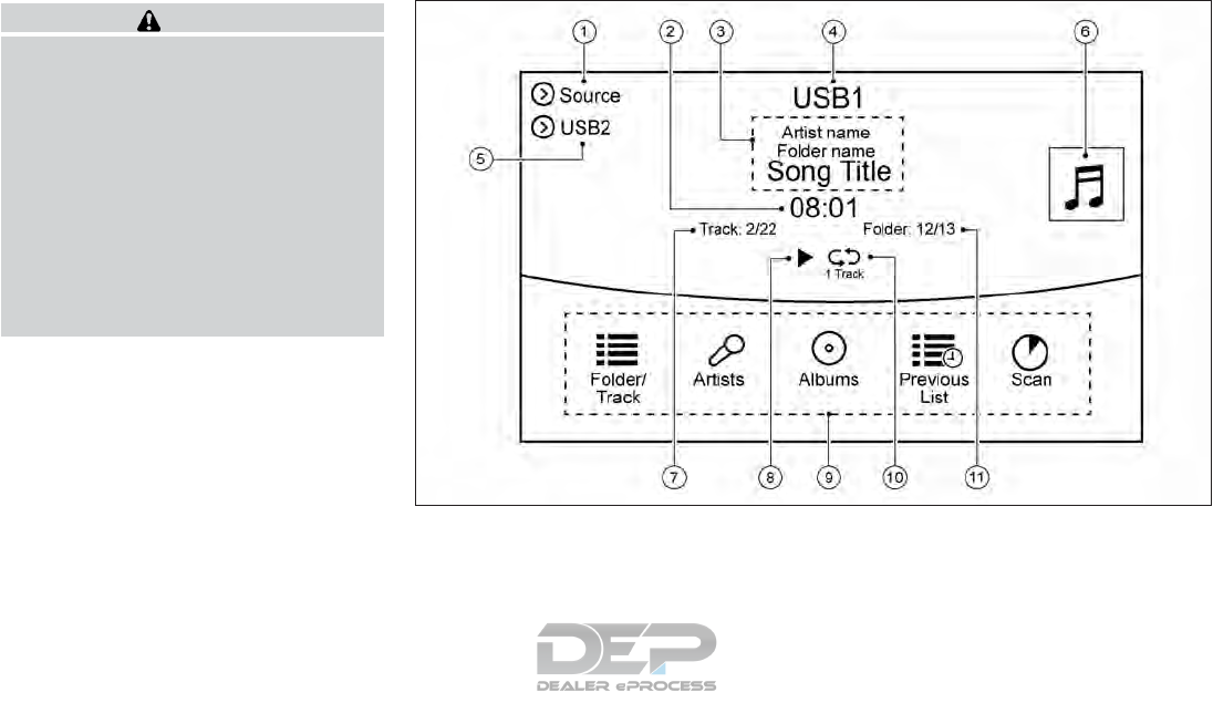
CAUTION
•Do not force the USB device into the
USB port. Inserting the USB device
tilted or upside down into the port may
damage the port. Make sure that the
USB device is connected correctly to the
USB port.
•Do not grab the USB port cover (if
equipped) when pulling the USB device
out of the port. This could damage the
port and the cover.
•Do not leave the USB cable in a place
where it can be pulled unintentionally.
Pulling the cable may damage the port.
Refer to your device manufacturer's owner
information regarding the proper use and
care of the device.
Two USB connectors are located on the cen-
ter console box.
USB (Universal Serial Bus) connection port/
iPod page 4-57
When compatible storage devices are
plugged into the jack, compatible audio files
on the storage devices can be played through
the vehicle's audio system.
How to view USB operation screen
䊊
1[Source]:
Touch to switch to the source list screen.
Selecting audio source page 4-65
䊊
2Play time:
The play time of the track is displayed.
䊊
3Track information:
Track information such as the song title,
artist name and folder name is displayed.
䊊
4Audio source indicator:
Indicates which of the two USB memory
device is selected.
NAA1719
Display screen, heater and air conditioner, and audio system 4-73
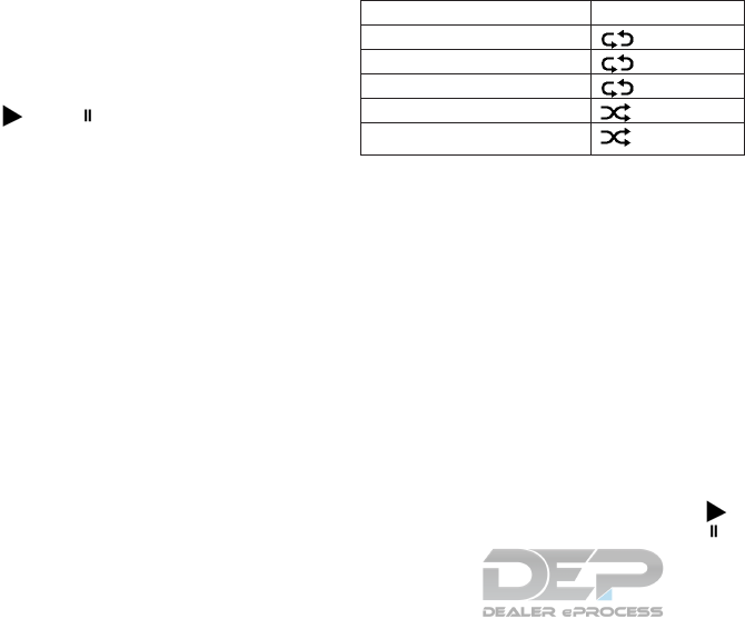
䊊
5[USB1]/[USB2]:
Touch to switch to the other connected
USB memory device.
䊊
6Album artwork (if equipped):
An image of the CD cover is displayed
when available.
䊊
7Track number:
This indicates the track number and the
total number of tracks.
䊊
8[]/[ ]:
Touch to play or pause the track.
䊊
9USB menu:
USB menu items are displayed. Touch an
icon to display the list or to change the
setting.
- [Folder/Track]
- [Artists]
- [Albums]
- [Previous List]
- [Scan]
- [Play Mode]
䊊
10 Play mode indicator:
This indicates the current play mode.
Touch to change the play mode.
Mode Screen display
All Track Repeat All
1 Folder Repeat 1 Folder
1 Track Repeat 1 Track
All Random All
1 Folder Random 1 Folder
䊊
11 Folder number:
This indicates the folder, artist or album
number and the total number of folders/
lists.
USB memory device player
operation
Activation and playing:
USB memory device mode can also be acti-
vated from the audio source list and the audio
source bar by the touch panel operation or by
pushing <MEDIA>.
Selecting audio source page 4-65
Main audio buttons page 4-64
To play the USB memory device touch [ ],
and to pause the USB memory touch [ ]
on the USB operation screen.
Selecting play list:
Select a play list by touching an icon in the
USB menu.
•Folder/Track (List)
•Artist (List)
•Album (List)
•Previous List
Skipping tracks/folders:
Push <SEEK•CAT•TRACK> to skip to the next
or previous track.
To skip to the next or previous folder, Push
<TUNE•CH•FOLDER>.
Fast-forwarding/rewinding:
Push and hold <SEEK•CAT•TRACK> to fast-
forward or rewind the track. Release <SEEK-
•CAT•TRACK> to play the track at normal
speed.
Scanning:
Touch [Scan] on the display to scan the
tracks in the USB memory device. While
scanning, the USB memory device will play
the first 10 seconds of each track and move
on to the next track. Touching [Scan] again
within the 10 seconds will stop scanning.
4-74 Display screen, heater and air conditioner, and audio system

Changing play mode:
Touch [Play Mode] on the display to select
the play mode.
Only one of the two connected USB memory
devices can be operated by the voice recog-
nition system.
IPOD PLAYER
Connecting iPod
WARNING
Do not connect, disconnect or operate the
iPod while driving. Doing so can be a dis-
traction. If distracted you could lose con-
trol of your vehicle and cause an accident or
serious injury.
CAUTION
•Do not force the iPod device into the
USB port. Inserting the iPod cable tilted
or upside down into the port may dam-
age the port. Make sure that the iPod
cable is connected correctly to the USB
port.
•Do not grab the USB port cover (if
equipped) when pulling the iPod cable
out of the port. This could damage the
port and the cover.
•Do not leave the iPod cable in a place
where it can be pulled unintentionally.
Pulling the cable may damage the port.
Refer to your device manufacturer's owner
information regarding the proper use and
care of the device.
Two USB (iPod) connectors are located on
the center console box.
USB (Universal Serial Bus) connection port/
iPod page 4-57
The battery of the iPod will be charged while
the device is connected to the vehicle if the
iPod supports USB connection charging.
Depending on the model and firmware ver-
sion of the iPod, the display on the iPod
shows an INFINITI or Accessory Attached
screen when the connection is completed.
When the iPod is connected to the vehicle,
the iPod music library can only be operated
using the vehicle audio controls.
Compatibility:
Made for
•iPod touch® (5th generation)
•iPod touch® (4th generation)
•iPod touch® (3rd generation)
•iPod touch® (2nd generation)
•iPod touch® (1st generation)
•iPod touch®
•iPod® with video
•iPod classic®
•iPod nano® (7th generation)
•iPod nano® (6th generation)
•iPod nano® (5th generation)
•iPod nano® (4th generation)
•iPod nano® (3rd generation)
•iPod nano® (2nd generation)
•iPod nano® (1st generation)
•iPhone® 6 Plus
•iPhone® 6
•iPhone® 5S
•iPhone® 5
•iPhone® 4S
•iPhone® 4
•iPhone® 3GS
•iPhone® 3G
•iPhone®
Display screen, heater and air conditioner, and audio system 4-75

The iPod touch® may not respond quickly
with the system in some cases.
Make sure that the iPod® firmware is up-
dated.
The Lightning
TM
connector works with
iPhone® 5, iPhone® 5S, iPhone® 6, iPhone®
6 Plus, iPod touch® (5th generation), and
iPod nano® (7th generation).
The 30-pin connector works with iPhone®
4S, iPhone® 4, iPhone® 3GS, iPhone® 3G,
iPhone®, iPod touch® (1st through 4th gen-
eration), iPod classic®, and iPod nano® (1st
through 6th generation).
USB works with iPhone® 5, iPhone® 4S,
iPhone® 4, iPhone® 3GS, iPhone® 3G,
iPhone®, iPod touch® (1st through 5th gen-
eration), iPod classi®c, and iPod nano ® (1st
through 7th generation).
4-76 Display screen, heater and air conditioner, and audio system

How to view iPod operation screen
䊊
1Search condition indicator:
This indicates the current search
condition.
䊊
2[Source]:
Touch to switch to the source list screen.
Selecting audio source page 4-65
䊊
3Play time:
The play time of the track is displayed.
䊊
4Track information:
Track information such as the song title,
artist name and album name is displayed.
䊊
5Audio source indicator:
This indicates that iPod is currently se-
lected among other sources.
䊊
6Album artwork (if equipped):
An image of the album artwork is dis-
played when available.
䊊
7Track number:
This indicates the track number and the
total number of tracks.
䊊
8Shuffle mode indicator:
Touch to change the shuffle mode.
Mode Screen display
Shuffle albums Albums
All Songs Songs
Shuffle Off OFF
䊊
9[ ]/[ ]:
Touch to play/pause the track.
䊊
10 iPod menu:
- [Previous List]
- [Playlists]
- [Artists]
- [Songs]
- [Albums]
- [Genres]
- [Composers]
- [Podcasts]
NAA1633
Display screen, heater and air conditioner, and audio system 4-77

- [Audiobooks]
- [Shuffle]
- [Repeat]
䊊
11 Repeat mode indicator:
Touch to change the repeat mode.
Mode Screen display
All Track Repeat All
1 Track Repeat 1 Track
Repeat Off OFF
iPod player operation
Activation and playing:
Inserting the iPod cable into the connector
will activate the iPod mode.
iPod can also be selected from the audio
sources list and the source bar by touch panel
operation or by pushing <MEDIA>.
Selecting audio source page 4-65
Main audio buttons page 4-64
To play and pause the iPod, touch [Play]/
[Pause] in the iPod menu.
Selecting search method:
A list of search methods is displayed in the
iPod menu. Touch and select an item to play
the iPod in your preferred settings.
Fast-forwarding/rewinding:
Push and hold <SEEK•CAT•TRACK> to fast-
forward or rewind the song. Release <SEEK-
•CAT•TRACK> to play the song at normal
speed.
Changing play mode:
Touch [Shuffle] or [Repeat] from the iPod
menu to select the play mode.
Skipping songs:
Push <SEEK•CAT•TRACK> to skip to the
next or previous song.
Even when iPods or iPhones are inserted into
both of the two USB connectors, the system
recognizes only one of the connected iPods
or iPhones at a time.
BLUETOOTH® STREAMING
AUDIO
Your vehicle is equipped with Bluetooth®
Streaming Audio.
If you have a compatible Bluetooth® device
with streaming audio (A2DP profile), you can
set up a wireless connection between your
Bluetooth® device and the in-vehicle audio
system. This connection allows you to listen
to the audio from the Bluetooth® device us-
ing your vehicle speakers. It may also allow
basic control of the device for playing and
skipping audio files using the AVRCP
Bluetooth® profile. Not all Bluetooth® de-
vices have the same level of controls for
AVRCP. Please consult the manual for your
Bluetooth® device for more details.
Wireless LAN (Wi-Fi) and the Bluetooth®
functions share the same frequency band
(2.4 GHz). Using the Bluetooth® and the
wireless LAN functions at the same time may
slow down or disconnect the communication
and cause undesired noise. It is recom-
mended that you turn off the wireless LAN
(Wi-Fi) when using the Bluetooth® functions.
Regulatory Information
FCC Regulatory information:
FCC ID : HYQDNNS075
NOTE: This device complies with part 15 of
the FCC Rules. Operation is subject to the
following two conditions: (1) This device may
not cause harmful interference, and (2) this
device must accept any interference received,
including interference that may cause unde-
sired operation.
FCC WARNING: Changes or modifications
not expressly approved by the party respon-
sible for compliance could void the user’s au-
thority to operate the equipment.
CAUTION : Radio Frequency Radiation Ex-
posure
4-78 Display screen, heater and air conditioner, and audio system

This equipment complies with FCC radiation
exposure limits set forth for uncontrolled en-
vironment and meets the FCC radio fre-
quency (RF) Exposure Guidelines. This equip-
ment has very low levels of RF energy that it
deemed to comply without maximum permis-
sive exposure evaluation (MPE). But it is de-
sirable that it should be installed and oper-
ated with at least 20 cm and more between
the radiator and person’s body.
Co-location: This transmitter must not be co-
located or operated in conjunction with any
other antenna or transmitter.
IC Regulatory information:
The antenna cannot be removed (and
changed) by user.
NOTE: This device complies Industry Canada
license-exempt RSS standard(s). Operation is
subject to the following two conditions: (1)
This device may not cause interference, and
(2) this device must accept any interference,
including interference that may cause unde-
sired operation of the device.
CAUTION : Radio Frequency Radiation Ex-
posure
This equipment complies with IC radiation
exposure limits set forth for uncontrolled en-
vironment and meets RSS-102 of the IC ra-
dio frequency (RF) exposure rules. This equip-
ment has very low levels of RF energy that it
deemed to comply without maximum permis-
sive exposure evaluation (MPE). But it is de-
sirable that it should be installed and oper-
ated with at least 20 cm and more between
the radiator and person’s body.
Co-location: This transmitter must not be co-
located or operated in conjunction with any
other antenna or transmitter.
This Class B digital apparatus meets all re-
quirements of the Canadian Interference
Causing Equipment Regulations.
Connecting Bluetooth® streaming
audio device
Bluetooth® streaming audio device must be
connected to the vehicle before operation.
Connecting Bluetooth® device page 4-90
Display screen, heater and air conditioner, and audio system 4-79
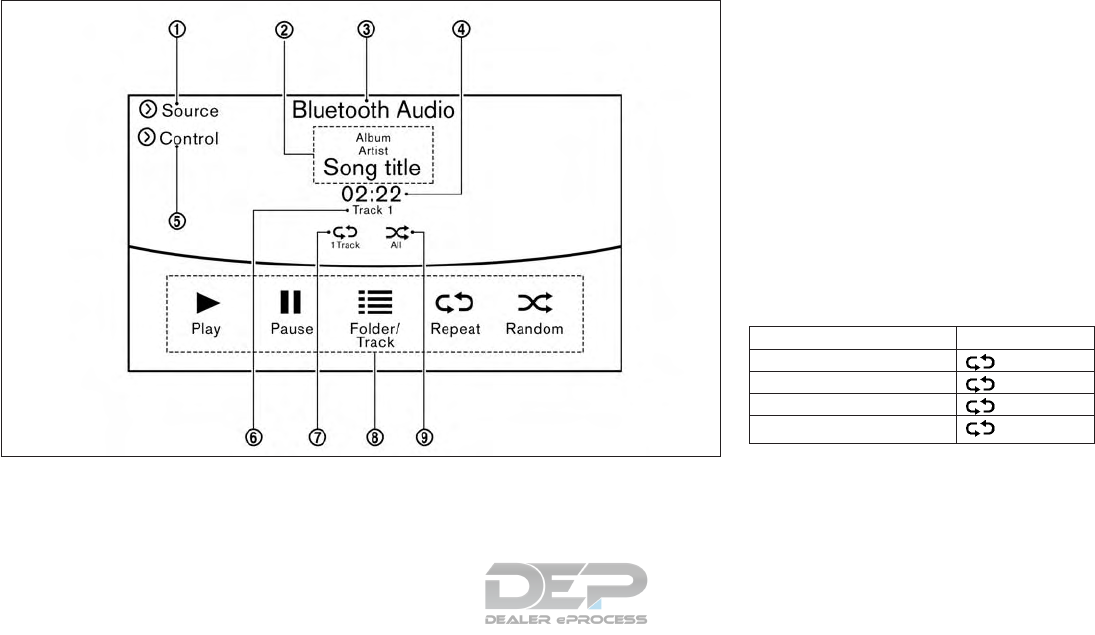
How to view Bluetooth® streaming
audio operation screen
䊊
1[Source]:
Touch to switch to the source list screen.
Selecting audio source page 4-65
䊊
2Track information:
Track information such as the song title,
artist name and folder name is displayed.
䊊
3Audio source indicator:
This indicates that Bluetooth® streaming
audio is currently selected among other
sources.
䊊
4Play time:
The play time of the track is displayed.
䊊
5[Control]:
Touch to display the control screen.
Bluetooth® streaming audio operation
page 4-82
䊊
6Track number
This indicates the track number.
䊊
7Repeat mode indicator:
Touch to change the repeat mode.
Mode Screen display
All repeat All
1 Folder Repeat 1 Folder
1 Track Repeat 1 Track
Repeat Off OFF
䊊
8Bluetooth® streaming audio menu:
- [Play]
- [Pause]
- [Folder/Track]
- [Repeat]
- [Random]
NAA1634
4-80 Display screen, heater and air conditioner, and audio system

䊊
9Random mode indicator:
Touch to change the random mode.
Mode Screen display
All Random All
1 Folder Random 1 Folder
Random Off OFF
Depending on the audio device that is con-
nected to the vehicle, track information may
not be displayed.
Bluetooth® streaming audio
operation
The ability to pause, change tracks, fast-
forward, rewind, randomize and repeat music
may be different between devices. Some or
all of these functions may not be supported
on each device.
•Depending on the Bluetooth® streaming
audio device that is connected, it may not
be possible to perform audio operations.
•Depending on the Bluetooth® streaming
audio device that is connected, a time lag
may occur before music is played back.
•Depending on the application except for
the native audio application that is played
on the Bluetooth® streaming audio device,
incorrect behavior (information lacking,
timer skipping, etc.) may occur.
Activation and playing:
Bluetooth® streaming audio device can be
selected from audio sources list by touching
[Source] or by pushing <MEDIA>.
Selecting audio source page 4-65
Main audio buttons page 4-64
To play the Bluetooth® streaming audio de-
vice, touch [Play], and to pause the
Bluetooth® streaming audio device touch
[Pause] in the Bluetooth® streaming audio
menu.
Selecting folder/track:
Touch [Folder/Track] to select a folder/
track.
Changing play mode:
Touch [Repeat] or [Random] in the
Bluetooth® streaming audio menu to change
the play mode.
Fast-forwarding/rewinding:
Push and hold <SEEK•CAT•TRACK> to fast-
forward or rewind the song. Release <SEEK-
•CAT•TRACK> to play the song at normal
speed.
Skipping songs/folders:
Push <SEEK•CAT•TRACK> to skip to the next
or previous song.
To skip to the next or previous folder, Push
<TUNE•CH•FOLDER>.
Bluetooth® streaming audio
controls
Touch [Control] on the Bluetooth® Audio
operation screen to display the control
screen.
[Select Au-
dio Device]
Touch to select a different
Bluetooth® streaming audio device
from a list of registered Bluetooth®
devices.
See "Bluetooth® settings" later in
this section
[Connect
Device]
Touch to connect a new
Bluetooth® device.
Display screen, heater and air conditioner, and audio system 4-81

AUDIO SETTINGS
Audio settings can be adjusted or audio related functions can be turned on/off using the following procedure.
Some of the setting items may not be displayed when the audio system is turned off.
1. Push <MENU>.
2. Touch [Settings].
3. Touch [Audio].
The following setting items are available:
*: Availability of the item depends on the model and specifications.
• [Sound Settings]
Setting items Action
[Bass] Adjust the speaker tone quality and sound balance by touching [+]/[-], [L]/[R] or [R]/[F].
[Treble]
[Balance]
[Fade]
[Bose®Centerpoint]* When this item is turned on, surround sound playback is generated from a traditional stereo recording. Turn on this item to activate
Bose®Centerpoint and to change its effect level with [Surround Vol].
[Bose®AudioPilot]* This adjusts the volume and sound quality depending on the changes of the vehicle speeds and the noise picked up by the
microphone. It compensates for noise for different road surface conditions and open windows. Turn on this item to activate
Bose®AudioPilot.
[Surround Vol.]* Touch [+]/[-] to adjust the [Surround Vol] level if Bose®Centerpoint is turned on.
[Speed Sensitive Vol]* This automatically adjusts the volume depending on the vehicle speed. Touch [+]/[-] to change the sensitivity level.
[Driver's Audio Stage]* When this item is turned on, a better sound quality will be provided to the driver's position. The driver can enjoy a more crisp and
clear sound that is specialized for the driver's seat position. The prominence of the effect of this feature depends on the type of
music that is played. For some music, it may be difficult to recognize the effect of this feature.
4-82 Display screen, heater and air conditioner, and audio system
• [Display Album Cover Art]
Turn this item on to display image files from the media device. If the media device does not contain images, no image will be displayed.
• [Radio Settings]
Setting items Action
[HD Mode AM] When this item is turned on, the analog and digital reception switches
automatically. When this item is turned off, the reception is fixed in the
analog mode.
[HD Mode FM]
Display screen, heater and air conditioner, and audio system 4-83
DISC/USB MEMORY DEVICE
CARE AND CLEANING
DISCS
•Handle a disc by its edges. Never touch the
surface of the disc. Do not bend the disc.
•Always place discs in their storage cases
when they are not being used.
•To clean a disc, wipe the surface from the
center to the outer edge using a clean, soft
cloth. Do not wipe the disc using a circular
motion.
Do not use a conventional record cleaner
or alcohol intended for industrial use.
•The inner and outer edges of a new disc
may be rough. Remove the rough edges by
rubbing the inner and outer edges with the
side of a pen or pencil as illustrated.
USB MEMORY DEVICE
•Never touch the terminal portion of the
USB memory device.
•Do not place heavy objects on the USB
memory device.
•Do not store the USB memory device in
very humid locations.
•Do not expose the USB memory device to
direct sunlight.
•Do not spill any liquids on the USB memory
device.
Refer to the owner's manual for the USB
memory device for details.
GRACENOTE® END USER
LICENSE AGREEMENT
This application or device contains software
from Gracenote, Inc. of Emeryville, California
(“Gracenote”). The software from Gracenote
(the “Gracenote Software”) enables this ap-
plication to perform disc and/or file identifi-
cation and obtain music-related information,
including name, artist, track, and title infor-
mation (“Gracenote Data”) from online serv-
ers or embedded databases (collectively,
“Gracenote Servers”) and to perform other
functions. You may use Gracenote Data only
by means of the intended End-User functions
of this application or device.
You agree that you will use Gracenote Data,
the Gracenote Software, and Gracenote
Servers for your own personal non-
commercial use only. You agree not to assign,
copy, transfer or transmit the Gracenote
Software or any Gracenote Data to any third
party. YOU AGREE NOT TO USE OR EX-
PLOIT GRACENOTE DATA, THE
GRACENOTE SOFTWARE, OR
GRACENOTE SERVERS, EXCEPT AS EX-
PRESSLY PERMITTED HEREIN.
You agree that your non-exclusive license to
use the Gracenote Data, the Gracenote Soft-
ware, and Gracenote Servers will terminate if
you violate these restrictions. If your license
terminates, you agree to cease any and all
use of the Gracenote Data, the Gracenote
Software, and Gracenote Servers. Gracenote
reserves all rights in Gracenote Data, the
Gracenote Software, and the Gracenote
Servers, including all ownership rights. Under
no circumstances will Gracenote become li-
able for any payment to you for any informa-
tion that you provide. You agree that
Gracenote, Inc. may enforce its rights under
this Agreement against you directly in its own
name.
The Gracenote service uses a unique identi-
fier to track queries for statistical purposes.
SAA0451Z
4-84 Display screen, heater and air conditioner, and audio system

The purpose of a randomly assigned numeric
identifier is to allow the Gracenote service to
count queries without knowing anything
about who you are. For more information,
see the web page for the Gracenote Privacy
Policy for the Gracenote service.
The Gracenote Software and each item of
Gracenote Data are licensed to you “AS IS.”
Gracenote makes no representations or war-
ranties, express or implied, regarding the ac-
curacy of any Gracenote Data from in the
Gracenote Servers. Gracenote reserves the
right to delete data from the Gracenote Serv-
ers or to change data categories for any
cause that Gracenote deems sufficient. No
warranty is made that the Gracenote Soft-
ware or Gracenote Servers are error-free or
that functioning of Gracenote Software or
Gracenote Servers will be uninterrupted.
Gracenote is not obligated to provide you
with new enhanced or additional data types
or categories that Gracenote may provide in
the future and is free to discontinue its ser-
vices at any time.
GRACENOTE DISCLAIMS ALL WARRAN-
TIES EXPRESS OR IMPLIED, INCLUDING,
BUT NOT LIMITED TO, IMPLIED WAR-
RANTIES OF MERCHANTABILITY, FIT-
NESS FOR A PARTICULAR PURPOSE,
TITLE, AND NON-INFRINGEMENT.
GRACENOTE DOES NOT WARRANT THE
RESULTS THAT WILL BE OBTAINED BY
YOUR USE OF THE GRACENOTE SOFT-
WARE OR ANY GRACENOTE SERVER. IN
NO CASE WILL GRACENOTE BE LIABLE
FOR ANY CONSEQUENTIAL OR INCI-
DENTAL DAMAGES OR FOR ANY LOST
PROFITS OR LOST REVENUES.
© Gracenote, Inc. 2009
WARNING
•Only use a phone after stopping your
vehicle in a safe location. If you have to
use a phone while driving, exercise ex-
treme caution at all times so full atten-
tion may be given to vehicle operation.
•If you find yourself unable to devote full
attention to vehicle operation while
talking on the phone, pull off the road in
a safe location and stop your vehicle be-
fore doing so.
CAUTION
To avoid draining the vehicle battery, only
use a phone after starting the engine.
Your vehicle is equipped with a Bluetooth®
Hands-Free Phone System. If you are an
owner of a compatible Bluetooth® enabled
cellular phone, you can set up the wireless
connection between your cellular phone and
the in-vehicle phone module. With
Bluetooth® wireless technology, you can
make or receive a telephone call with your
cellular phone in your pocket.
Once a cellular phone is connected to the
in-vehicle phone module, the procedure for
connecting the phone does not need to be
BLUETOOTH® HANDS-FREE PHONE
SYSTEM
Display screen, heater and air conditioner, and audio system 4-85

performed again. Your phone is automatically
selected by the in-vehicle phone module
when the ignition switch is switched to the
ON position with the selected cellular phone
turned on and carried in the vehicle.
You can register up to 5 different Bluetooth®
cellular phones to the in-vehicle phone mod-
ule. However, you can talk on only one cellu-
lar phone at a time.
The Voice Recognition system supports
phone commands, so dialing a phone number
using your voice is possible.
See "INFINITI Voice Recognition system"
later in this section
Before using the Bluetooth® Hands-Free
Phone System, refer to the following notes.
•Wireless LAN (Wi-Fi) and the Bluetooth®
functions share the same frequency band
(2.4 GHz). Using the Bluetooth® and wire-
less LAN functions at the same time may
slow down or disrupt communications and
could cause undesired noise. It is recom-
mended that you turn wireless LAN (Wi-
Fi) off when using the Bluetooth® func-
tions.
•Set up the wireless connection between a
compatible cellular phone and the in-
vehicle phone module before using the
Bluetooth® Hands-Free Phone System.
•Some Bluetooth® enabled cellular phones
may not be recognized by the in-vehicle
phone module. Please visit
www.infinitiusa.com/bluetooth and
search for a recommended phone list.
•You will not be able to use a hands-free
phone under the following conditions:
– Your vehicle is outside the service area
for your cellular phone network.
– Your vehicle is in an area where it is
difficult to receive radio waves, such as
in a tunnel, in an underground parking
garage, behind a tall building or in a
mountainous area.
– Your cellular phone is locked in order to
prevent dialing.
•When the radio wave condition is not ideal
or ambient sound is too loud, it may be
difficult to hear the other person's voice
during a call.
•This Bluetooth® system supports Wide-
band speech, which enhances the sound
quality of phone calls placed over
Bluetooth®. To take advantage of this
feature, the cellular device should be used
on a carrier supporting Adaptive Multi-
Rate Wideband (AMR-WB) or HD voice
technology. The performance of
AMR-WB may vary by carrier and calling
area. Consult your cellular carrier if you
experience issues with call quality or con-
nection.
•Immediately after the ignition switch is
turned ON, it may be impossible to receive
a call for a short period of time.
•Do not place the cellular phone in an area
surrounded by metal or far away from the
in-vehicle phone module to prevent tone
quality degradation and wireless connec-
tion disruption.
•While a cellular phone is connected
through the Bluetooth® wireless connec-
tion, the battery of the cellular phone may
discharge quicker than usual.
•If the Bluetooth® Hands-Free Phone Sys-
tem seems to be malfunctioning, please
visit www.infinitiusa.com/bluetooth for
troubleshooting help.
•Some cellular phones or other devices may
cause interference or a buzzing noise to be
emitted from the audio system speakers.
Storing the device in a different location
may reduce or eliminate the noise.
•Refer to the owner's manual for the cellu-
lar phone for information regarding the
telephone pairing procedure specific to
your phone, battery charging, and cellular
phone antenna, etc.
4-86 Display screen, heater and air conditioner, and audio system

•The antenna display on the monitor may
not match the antenna display of some
cellular phones.
•The battery display on the monitor may
not match the battery display of some cel-
lular phones.
•Keep the interior of the vehicle as quiet as
possible to hear the caller's voice clearly as
well as to minimize echoes.
•If reception between callers is unclear, ad-
justing the incoming or outgoing call vol-
ume may improve the clarity.
REGULATORY INFORMATION
FCC Regulatory Information
FCC ID : HYQDNNS075
NOTE: This device complies with part 15 of
the FCC Rules. Operation is subject to the
following two conditions: (1) This device may
not cause harmful interference, and (2) this
device must accept any interference received,
including interference that may cause unde-
sired operation.
FCC WARNING: Changes or modifications
not expressly approved by the party respon-
sible for compliance could void the user’s au-
thority to operate the equipment.
CAUTION : Radio Frequency Radiation Ex-
posure
This equipment complies with FCC radiation
exposure limits set forth for uncontrolled en-
vironment and meets the FCC radio fre-
quency (RF) Exposure Guidelines. This equip-
ment has very low levels of RF energy that it
deemed to comply without maximum permis-
sive exposure evaluation (MPE). But it is de-
sirable that it should be installed and oper-
ated with at least 20 cm and more between
the radiator and person’s body.
Co-location: This transmitter must not be co-
located or operated in conjunction with any
other antenna or transmitter.
IC Regulatory information
The antenna cannot be removed (and
changed) by user.
NOTE: This device complies Industry Canada
license-exempt RSS standard(s). Operation is
subject to the following two conditions: (1)
This device may not cause interference, and
(2) this device must accept any interference,
including interference that may cause unde-
sired operation of the device.
CAUTION : Radio Frequency Radiation Ex-
posure
This equipment complies with IC radiation
exposure limits set forth for uncontrolled en-
vironment and meets RSS-102 of the IC ra-
dio frequency (RF) exposure rules. This equip-
ment has very low levels of RF energy that it
deemed to comply without maximum permis-
sive exposure evaluation (MPE). But it is de-
sirable that it should be installed and oper-
ated with at least 20 cm and more between
the radiator and person’s body.
Co-location: This transmitter must not be co-
located or operated in conjunction with any
other antenna or transmitter.
This Class B digital apparatus meets all re-
quirements of the Canadian Interference
Causing Equipment Regulations.
The Bluetooth® word mark and logos are
registered trademarks owned by Bluetooth
SIG, Inc. and any use of such marks by
DENSO CORPORATION is under license.
Other trademarks and trade names are those
of their respective owners.
Display screen, heater and air conditioner, and audio system 4-87
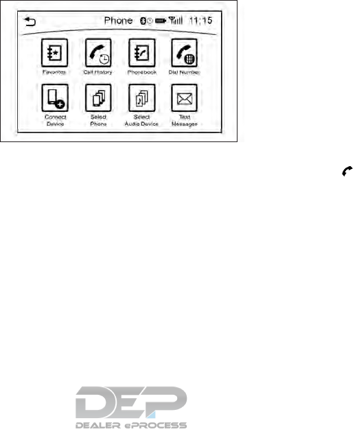
PHONE
Connecting Bluetooth®
Hands-Free Phone
The cellular phone must be connected to the
Bluetooth® Hands-Free Phone System be-
fore commencing operation. Up to 5 cellular
phones can be connected to the system.
See "Connecting Bluetooth® device" later in
this section
Phone selection
Select one of the connected devices for op-
eration.
1. Push <MENU> and touch [Phone], then
touch [Select Phone]. A list of the con-
nected cellular phones is displayed.
2. Select one of the connected cellular
phones from the list.
3. When selection of the device is successful,
a message on the display indicates that
the cellular phone was selected.
Making a call
1. Push <MENU> and touch [Phone].
2. Select one of the following methods to
make a call.
Available methods
•[Favorites]:
Select a telephone number from a list
of personally selected numbers.
•[Call History]:
Select a telephone number from recent
incoming or outgoing calls.
•[Phonebook]:
Select a telephone number from the
phonebook.
The telephone number must be trans-
ferred to the phonebook from the cel-
lular phone prior to using this method.
"Phone and text message settings" ear-
lier in this section
•[Dial Number]:
Input the phone number manually using
the keypad displayed on the screen.
Touch [ ] to call the number.
"How to input letters and numbers"
earlier in this section
3. The number will be dialed and the screen
will change to the call in progress screen.
NAA1720
4-88 Display screen, heater and air conditioner, and audio system

Receiving a call
When you received a phone call, a notifica-
tion message is displayed on the touch screen
display with a ring tone.
Taking a call:
To answer a call, take one of the following
actions.
•Push < > on the steering wheel.
•Push < > on the INFINITI controller
(models without navigation system).
•Touch [Answer].
Reject a call:
To reject a call, touch [Decline].
Receiving a call while on the line to another
person:
When another phone call is received while on
the line to another person, a message box
informing you of the incoming call will appear
on the display.
Available items
Avail-
able
items
Action
[An-
swer]
Take the second call and put the first
call on hold.
[De-
cline]
Reject the second call and keep the first
call on line.
During a call
There are various options available during a
call. Select one of the following options dis-
played on the screen if necessary.
Available items
Avail-
able
items
Action
[Switch
Call]*
Answer another incoming call. The per-
son you are talking to will be placed on
hold. Push once more to speak to the
person on hold again.
[Hang
Up]
This disconnects the person you are
currently connected to and will connect
you to the person who is on hold.
[Mute]/
[Cancel
Mute]
When muted, your voice will not be
heard by the person on the other end of
the line.
NAA1654 NAA1655 NAA1721
Display screen, heater and air conditioner, and audio system 4-89

Avail-
able
items
Action
[Hold
Call]**
Place the call on hold.
[Enter
Digits]
Using the touch tone, send digits to the
connected party for using services such
as voicemail.
[Use
Hand-
set]
Transfer the call to the cellular phone.
[End All
Calls]*
Hang up all calls including the ones that
were on hold.
*: Available when multiple lines are con-
nected.
**: Available when a single line is connected.
•To adjust the volume of the person's voice
to be louder or quieter, push <->/<+> on
the steering wheel or turn <VOL/ >
on the audio main button, while talking on
the phone.
•Touch [Mute] if you do not want your
voice to be heard by the person on the
other end of the line.
CONNECTING BLUETOOTH®
DEVICE
Your vehicle is equipped with a Bluetooth®
Hands-Free Phone System and Bluetooth®
streaming audio device. If you are an owner
of a compatible Bluetooth® enabled cellular
phone or Bluetooth® audio device, you can
set up the wireless connection between your
cellular phone and the in-vehicle phone mod-
ule, or Bluetooth® audio and in-vehicle audio
module. With Bluetooth® wireless technol-
ogy, you can make or receive a telephone call
with your cellular phone in your pocket and
listen to music on your Bluetooth® streaming
audio device via the in-vehicle system.
Connecting cellular phone/audio
device
1. Push <MENU> and touch [Settings].
2. Touch [Bluetooth] and touch [Connect
Device]
3. Touch [Add New (X/5 Free)] to register a
device.
4. When a PIN code appears on the screen,
operate the compatible Bluetooth® cellu-
lar phone to enter the PIN code.
The pairing procedure for cellular phones
varies depending on the model of cellular
phone. Refer to the owner’s manual for
the cellular phone for details.
When pairing is complete, the screen will
change to the Bluetooth® setup display.
If the registered device has both audio
and phone functions, the system displays
a message asking if you would like to
register the device for another function.
The procedure for connecting a cellular
phone/audio device varies depending on
the Bluetooth® device. Refer to the own-
er’s manual for the Bluetooth® device for
details.
NOTE
Some cellular phones or other devices may
cause interference or a buzzing noise to be
emitted from the audio system speakers.
Storing the device in a different location may
reduce or eliminate the noise.
You can also visit www.infinitiusa.com/
Bluetooth or call INFINITI Consumer Affairs
Department for instructions on pairing
INFINITI recommended cellular phones or
audio devices.
4-90 Display screen, heater and air conditioner, and audio system
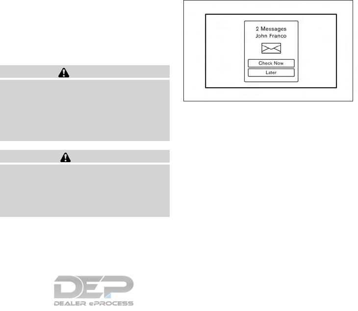
Bluetooth® settings
The Bluetooth® settings can be set in detail
according to the user's preference.
1. Push <MENU> and touch [Settings].
2. Touch [Bluetooth].
3. Touch the preferred item.
•[Bluetooth]
Turn the Bluetooth® connection to the
vehicle on/off.
•[Connect Device]
Touch this item to connect to the
Bluetooth® device. You can also delete a
registered device and display information
for the registered device.
•[Select Phone]
Registered Bluetooth® Hands-Free
Phones are shown on the list. Select a
device from the list to disconnect or con-
nect a Bluetooth® device.
•[Select Audio Device]
Registered Bluetooth® audio players are
shown on the list. Select a device from the
list to disconnect or connect a Bluetooth®
device.
•[Vehicle Bluetooth Device Info.]
The registered device name and the PIN
code can be changed.
HANDS-FREE TEXT MESSAGING
ASSISTANT
WARNING
•Use the text messaging feature after
parking your vehicle in a safe location. If
you have to use the feature while driv-
ing, exercise extreme caution at all times
so full attention may be given to vehicle
operation.
CAUTION
•This feature is disabled if the connected
device does not support the Message
Access Profile (MAP). Refer to the own-
er's manual for your phone for further
details and instructions.
Laws in some jurisdictions may restrict the
use of "Text-to-Speech". Check local regula-
tions before using this feature.
The text messaging assistant system allows
the sending and receiving of the text mes-
sages through the vehicle interface.
Receiving a message
When the cellular phone connected to the
vehicle receives a text message, a notification
is displayed on the display accompanied by a
tone.
To check the message, touch [Check Now].
Touch [Later] to save the message to be
checked later.
Using the text message function with iPhone
®. If you would like to use the text message
function with your iPhone, please make the
below steps.
1) Connect iPhone® to the Bluetooth®
Hands-Free Phone System.
2) Disconnect iPhone® from vehicle setting
menu.
5GF0038XZ
Display screen, heater and air conditioner, and audio system 4-91
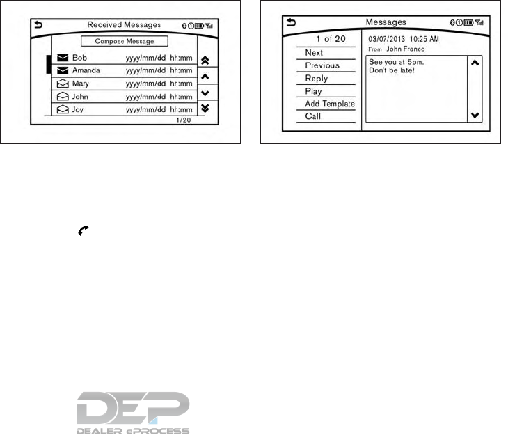
3) Turn “Show Notification” ON from
Bluetooth® setting menu on your iPhone
®.
4) Connect iPhone® from vehicle setting
menu.
Displaying received message list
1. To display the phone menu screen, take
one of the following actions:
•Push <MENU> and touch [Phone].
•Push < > on the steering wheel or
INFINITI controller (models without
navigation system).
2. Touch [Text Messages].
3. Touch an item on the list to read or to
reply to the message.
Up to 20 messages can be stored on the
message list.
Received message screen
Touching [Check Now] on the new message
notification screen or selecting a message
from the message list will show details of the
received message on the display.
Available actions:
•[Next]:
Touch to read the next message.
•[Previous]:
Touch to read the previous message.
•[Reply]:
A reply template can be selected.
"Sending a text message" later in this
section
5GF0040XZ NAA1656
4-92 Display screen, heater and air conditioner, and audio system
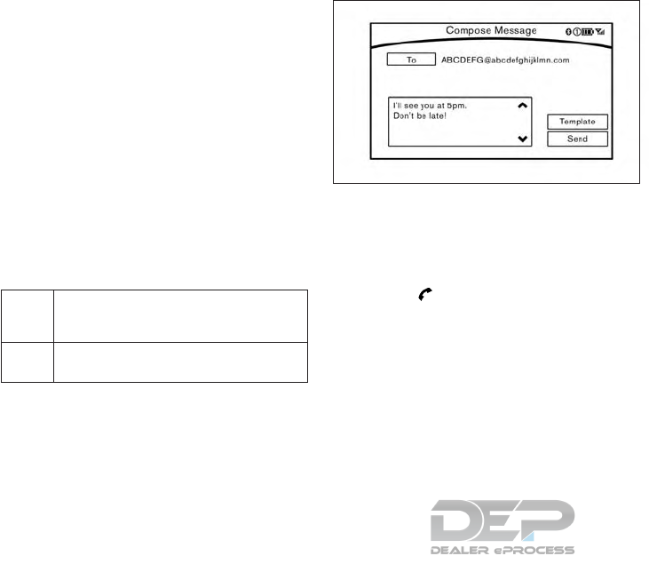
•[Play]/[Stop]:
Touch [Play] to have the hands-free
phone system read out the received mes-
sage. Touch [Stop] to stop reading.
•[Add Template]:
The received text message can be added
to the template (text list).
•[Call]:
If the sender of the message is registered
in the Phonebook, touch this menu to
make a call to the sender.
•After the message is read out, a message
box will appear and an action can be se-
lected.
[Reply] Create a reply message.
"Sending a text message" later in this
section
[Next] Have the system read out the next mes-
sage.
•If the sender's name and address is regis-
tered in the Phonebook, the name of the
sender is displayed as sender information
on the screen.
Sending a text message
To display the phone menu screen, take one
of the following actions:
•Push <MENU> and touch [Phone].
•Push < > on the steering wheel or
INFINITI controller (models without navi-
gation system).
2. Touch [Text Message].
3. Touch [Compose Message].
The following items are available.
5GF0003XZ
Display screen, heater and air conditioner, and audio system 4-93

Available item Action
[To] [Keypad] Type in the address of the recipient using the keypad. Touch
[OK] to confirm the address.
[Phonebook] Select a recipient from the phonebook and touch [OK] to
confirm.
[Template] Select from list Select an item from the message list. The selected text will be
added to the message to be sent.
[Edit Text Message
Replies]
Select an item in the message list to be edited. Use the keypad
to edit the text and touch [OK] to complete editing.
[Send] Touch to send the message.
PHONE AND TEXT MESSAGE
SETTINGS
Phone settings
The Bluetooth® Hands-Free Phone System
can be set in detail according to the user's
preference.
1. Push <MENU> and touch [Settings].
2. Touch [Phone/Mail].
3. Touch [Phone Settings].
The following phone setting items are avail-
able.
4-94 Display screen, heater and air conditioner, and audio system

Incoming Call Settings:
Setting item Action
[Ringtone] Select a type of ringtone.
Phonebook/Favorites Settings:
Setting item Action
[Configure
Phonebook
Settings]
[Automatic Transfer Set-
tings]
[Phonebook Auto
Download]
Turn automatic download of the phonebook from the cellular phone on/off.
[Call History Download] Turn automatic download of the cellular phone call history on/off.
[Manual Phonebook
Transfer]
[Transfer and Overwrite]
(Depending on cellular
phone)
Manually transfer information from the phonebook on the cellular phone.
[Transfer and Add] (De-
pending on cellular
phone)
[Delete Phonebook] To delete a single item, select the item you wish to delete from the list. Touch [Delete All]
to delete all items. To delete multiple items, touch [Multiple Selection].
[Favorites Set-
tings]
[Delete Favorites] To delete a single item, select the item you wish to delete from the list. Touch [Delete All]
to delete all items. To delete multiple items, touch [Multiple Selection].
[Add to Favorites] [From Phonebook] Select items from the phonebook of the in-vehicle system to add to the favorites.
[From Outgoing Calls] Select items from the outgoing calls list of the in-vehicle system to add to the favorites.
[From Incoming Calls] Select items from the incoming calls list of the in-vehicle system to add to the favorites.
[From Missed Calls] Select items from the missed calls list of the in-vehicle system to add to the favorites.
[Delete Call
History]
[Delete Outgoing Call History] To delete a single item, select the item you wish to delete from the list. Touch [Delete All]
to delete all items. To delete multiple items, touch [Multiple Selection].
[Delete Incoming Call History]
[Delete Missed Call History]
[Delete All Call History]
The volume of the ringtone, incoming call and outgoing call can also be adjusted.
Display screen, heater and air conditioner, and audio system 4-95

Mail settings
Various settings can be changed from the Mail Settings screen.
1. Push <MENU> on the steering wheel.
2. Touch [Settings].
3. Touch [Phone/Mail].
4. Touch [Mail Settings].
The following mail setting items are available.
Setting item Action
[Message Down-
load Settings]
The transfer function can be turned on/off. When the transfer function is on, the phonebook on the cellular phone will be automatically
downloaded to the hands-free text messaging system when connected.
[Attempts for
Sending]
The number of reattempts after failing to send a text message can be selected between 0 and 3.
[New Message
Alert]
The type of tone used for the notification sound can be selected.
[Edit Text Message
Replies]
The template (text to select from when composing an outgoing message) can be edited.
4-96 Display screen, heater and air conditioner, and audio system
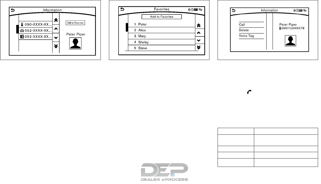
Phonebook
Information in the phonebook on cellular
phones can be downloaded.
"Phone and text message settings" earlier in
this section
1. Push <MENU> and touch [Phone].
2. Touch [Phonebook] and select from the
list.
This can be viewed on the display and used to
make calls or send text messages.
Favorites
Up to 40 phone numbers can be transferred
to the favorites list from a cellular phone.
1. Push <MENU> and touch [Phone].
2. Touch [Favorite] and touch from list
It can be viewed on the display and used to
make calls or send text messages.
Voice Tag:
A custom voice tag can be recorded for
phone numbers on the favorites list and used
to dial the number by speaking it.
1. Push < > on the steering wheel or
INFINITI controller (if equipped).
2. Touch [Favorites].
3. Select an item from the list.
4. Touch [Voice Tag].
Available Items Action
[Register] Touch to record a voice tag for
the phone number.
[Re-registration] Touch to record the voice tag.
[Play] Play the recorded voice tag.
[Delete] Touch to delete the voice tag.
NAA1784 NAA1785 5GF0023XZ
Display screen, heater and air conditioner, and audio system 4-97

BLUETOOTH® INFORMATION
Information about the connected
Bluetooth® device can be viewed.
1. Push <MENU> on the steering wheel.
2. Touch [Settings].
3. Touch [Bluetooth].
4. Touch [Vehicle Bluetooth Device Info.].
The following items are available.
Available item Action
[Device Name] The name of the connected
Bluetooth® device is dis-
played. Touch [Device Name]
to display the keyboard input
screen for editing.
[Enter PIN Code] The passkey of the connected
Bluetooth® device is dis-
played.
Touch [Enter PIN Code] to
display the keyboard input
screen.
Device Address The device address of the
connected Bluetooth® device
is displayed.
Laws in some jurisdictions may restrict the
use of some of the applications and features,
such as social networking and texting. Check
local regulations for any requirements.
INFINITI InTouch provides in-vehicle access
to two types of applications: Vehicle Apps
and Mobile Apps. Vehicle Apps can be down-
loaded from App Garage in the menu screen.
Mobile Apps are a limited selection of popu-
lar smartphone-based Apps that have been
customized for in-vehicle use. Mobile Apps
can be accessed by connecting a compatible
smartphone to the vehicle.
The system allows you to download new ap-
plications, update downloaded applications
and delete downloaded applications in a
similar manner to popular smartphone oper-
ating systems.
Some pre-installed Vehicle Apps can be used
without taking any further action. However,
you will need to connect a compatible smart-
phone to the vehicle in order to update Ve-
hicle Apps or use Mobile Apps.
To view a list of compatible smartphones,
visit www.infinitiusa.com/bluetooth.
The use of applications is only guaranteed for
smartphones that have been tested and ap-
proved for use with INFINITI InTouch Apps.
Only iPhone® and Android devices are cur-
rently supported. Android smartphones must
support Bluetooth® and SPP (Serial Port
Profile).
Using with iPhone®:
To use InTouch Apps with your iPhone®, the
iPhone® must be connected with a USB
cable. If an additional iPhone® is connected
by wired connection while an iPod® is being
used via a wired connection, the service will
not be available. To use the service, it is first
necessary to unplug the iPod® cable from the
USB port where the iPod® is connected.
"Steering wheel mounted controls" earlier in
this section
Using with Android smartphone:
To use InTouch Apps with your Android
smartphone, the device must be connected
via Bluetooth® and registered as a hands-
free device.
"Bluetooth® Hands-Free Phone System"
earlier in this section
A compatible smartphone is required to use
Mobile Apps or to access connected features
of certain Vehicle Apps. Please visit
www.infinitiusa.com/bluetooth for a list of
compatible devices.
INFINITI INTOUCH APPS OVERVIEW
4-98 Display screen, heater and air conditioner, and audio system

CAUTION
•To use Mobile Apps, the INFINITI
InTouch App must be installed and run-
ning on the compatible smartphone.
This App can be downloaded from the
iTunes APP Store or the Google Play
store.
•Mobile Apps also require an active sub-
scription and valid INFINITI Owner Por-
tal account. Please see
www.infinitiusa.com/InfinitiInTouch/
support/ (for United States) or
www.infiniti.ca/InfinitiInTouch (for
Canada) for more information
•Communication fees may be charged
depending on the contents of the con-
tract between the user and the cellular
phone carrier.
•Before using this service, some applica-
tions may require individual subscrip-
tions.
•For some applications, the system may
not support all functions of the applica-
tions that are installed on your smart-
phone. Additionally, due to service pro-
vider policies, the contents of
application services may be changed or
terminated.
•If the smartphone is outside the net-
work range, some functions cannot be
used.
•While driving, some operations are lim-
ited in order to prevent distracting the
driver. While driving, avoid looking at
the display.
•Before changing ownership of the ve-
hicle, delete application data (Email
data, etc.) stored on the in-vehicle de-
vice. It is also recommended that you call
your INFINITI customer center to notify
them of change of ownership.
•Some application services may be sub-
ject to change or be terminated without
prior notice.
USING APPLICATIONS
NOTE
To use Apps functions on models without
navigation system, please complete the cal-
endar setting from Clock setting screen.
"Clock settings" in the "5. Starting and driving"
section
Main operation
Push <MENU> and touch [Apps] to display
the Apps screen.
Touch the icon for the preferred application.
The selected application will be launched.
•The applications shown on the menu
screen and the display order can be cus-
tomized.
"App Garage Settings screen" later in this
section
•Some applications can be set to launch
automatically as the ignition switch is
turned on.
VEHICLE APPS
Vehicle Apps are unique applications devel-
oped by INFINITI that can be downloaded
and installed on the in-vehicle hardware.
NOTE
The INFINITI InTouch App must be installed
and running on a compatible smartphone in
order to download updates or use Vehicle
Apps that require a network connection. See
"Getting user ID and password" later in this
section.
Display screen, heater and air conditioner, and audio system 4-99
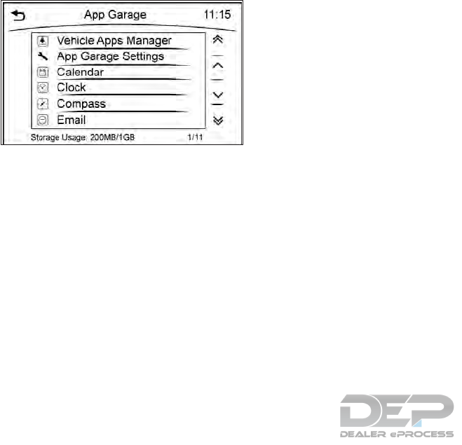
App Garage screen
1. Push <MENU> and touch [Apps].
2. Touch [App Garage].
Available settings
•[Vehicle Apps Manager] (if equipped)
Install, uninstall, and update the Vehicle
Apps application.
•[App Garage Settings]
Select icons to be displayed on the menu
screen and change the auto start and net-
work connection settings.
•Available application list
Display downloaded Vehicle Apps appli-
cations and selected Mobile Apps applica-
tions.
NAA1672
4-100 Display screen, heater and air conditioner, and audio system

App Garage Settings screen
Application settings can be changed on the App Garage Settings screen.
1. Push <MENU> and touch [Apps].
2. Touch [App Garage].
3. Touch [App Garage Settings].
Menu Item Action
[All Apps] Show all applications. Select an application from the list to modify additional
application-specific settings.
[Running Apps] Applications list Display all running applications. To display application information or stop an appli-
cation, select the preferred application from the list.
[Stop All] Stop all running applications.
[Menu Icon Location Setting] Applications list Show or hide the application icon on the Apps screen.
[Delete All] Delete all application icons on the Apps screen.
[Auto Start Setting] Enable this setting to automatically launch the application upon vehicle ignition.
[System Information] Display system information.
[Install Apps via USB] Install an application via USB from the INFINITI owner portal.
[Automatic Connection] (if equipped) Set the connecting interval. Vehicle Apps Manager (if equipped) connects to the
server at regular intervals in order to obtain up-to-date information (such as checking
for application updates).
[Network Notification] (if equipped) If Network Notification is on, a pop-up message is displayed when a network
connection is established.
[Installation Notification] (if equipped) If Install Notification is on, a pop-up message is displayed when a new application is
installed.
[Factory Data Reset] Discard downloaded or stored application data.
Display screen, heater and air conditioner, and audio system 4-101
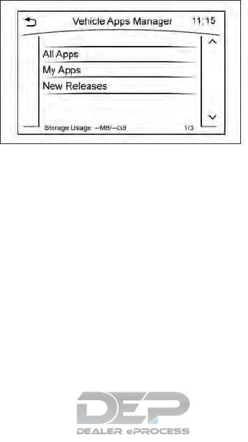
NOTE
•If the Auto Start Setting is enabled, some
applications may be accessible to other
drivers of your vehicle.
•Depending on the type of application,
some applications may not be displayed in
the [Running Apps] field even if they are
running.
•When [Network Notification] (if equipped)
is turned off, some Apps will be started
automatically, meaning that network
communication will be used and commu-
nication fees will be charged.
•The Auto Start function may not be avail-
able for some applications.
VEHICLE APPS MANAGER (IF
EQUIPPED)
On this screen, you can update, uninstall, and
install Vehicle Apps.
1. Push <MENU> and touch [Apps].
2. Touch [App Garage].
3. Touch [Vehicle Apps Manager].
Available setting items
•[All Apps]
Display all Vehicle Apps. You can select to
display application information, update,
install and uninstall applications.
•[My Apps]
Display installed Vehicle Apps. You can
select to display application information,
update and uninstall applications.
•[New Releases] (if equipped)
Display newly released Vehicle Apps. You
can select an item to display application
information.
In order to display the application list screen
or the installation and update screens using
the [Vehicle Apps Manager], connection via a
smartphone is required to establish commu-
nication.
NAA1723
4-102 Display screen, heater and air conditioner, and audio system

MAJOR APPS AVAILABLE FOR
USE IN THIS SYSTEM
The major applications currently available for INFINITI InTouch are introduced here.
Note that the applications are subject to updates and changes.
Apps Descriptions
[Maintenance Note] You can check maintenance items inside the vehicle at your convenience.
[Calendar]* (if equipped) The day's schedule can be checked. The schedule in the [Calendar] works with web-based services.
[Email]* (if equipped) The Email account you use can also be accessed through the vehicle system. You will be informed when
a new incoming message is received. This application works with web-based services.
[Compass]
(models with navigation system)
The current traveling direction of the vehicle is shown in various kinds of skins.
Accurate information cannot be provided if GPS position information cannot be obtained.
[Clock] [Clock] shows the current time in various kinds of skins.
Mobile Apps Many popular applications you usually use on your smartphone can also be used in your vehicle.
After registering a subscription in “INFINITI InTouch Apps” you can use these applications by operating
the in-vehicle display.
Applications such as Facebook, etc.
*: Requires an account to be set up. To use [Calendar], [Email] and Mobile Apps, INFINITI InTouch Apps must be downloaded to your
smartphone.
WARNING
•Look at the display screen only briefly
while driving. Keep your eyes on the
road. Inattentive driving may lead to a
crash resulting in serious injuries or
death.
NOTE
When Email service and calendar schedule
information are displayed on the in-vehicle
display, the system controls the display
based on the in-vehicle profiles (user ID and
password). Therefore, users are required to
create a profile to make use of Email and
calendar services.
IMPORTANT:
A PIN code can be used so that other people
cannot see your Email and calendar apps.
When the engine is turned OFF and then ON
again, the PIN code has to be entered.
After the PIN code is entered, regardless of
whether your smartphone is connected to
the vehicle or not, Email and calender apps
will be viewable until the engine is turned
Display screen, heater and air conditioner, and audio system 4-103

OFF. When the system is set to valet park-
ing, or the relevant account is erased, Email
and schedule will be erased from the system.
EXAMPLES OF HOW VEHICLE
APPS IS USED
Example Email application (if
equipped)
This App allows you to access web-based
Email through the in-vehicle interface. When
you use this application for the first time, you
will need to create a new user.
To use the Email application service, connect
a smartphone to the vehicle.
1. Push <MENU> and touch [Apps].
2. Touch [Email].
3. Touch [Create new user]. The new user
input screen will be displayed.
4. Input your name and PIN code and select
Instant Access ON or OFF, and then
touch [Save].
NOTE
If the Instant Access mode is set to ON, it
is not necessary to enter a PIN code each
time.
5. Display the Select User screen, and touch
a user name.
6. Input the PIN code and touch [OK]. The
mail box screen will be displayed.
If an account is not yet set up, touch [Cre-
ate New User] to set an account (Google
account, etc.) in the Manage Account
screen displayed.
NOTE
•On the Receive Message screen, touch
sender name or address to display sender
detail screen.
•System folders (Inbox, Draft, Send, etc.)
cannot be modified.
MOBILE APPS
Mobile Apps are a limited selection of popu-
lar smartphone-based Apps that have been
customized for in-vehicle use. Mobile Apps
can be accessed by connecting your compat-
ible smartphone to the vehicle.
GETTING USER ID AND
PASSWORD
When you activate the INFINITI InTouch
Apps service for the first time, you should
acquire a user ID and a password in advance.
The acquisition of a user ID and a setup of a
password which logs into exclusive applica-
tions are required.
•It is also possible to acquire an ID and a
password directly form an INFINITI portal
site.
•The vehicle information is required for en-
tering the user information.
5GD0021XZ
4-104 Display screen, heater and air conditioner, and audio system

NOTE
Other applications may not operate as a re-
sult of installing InTouch App. (It is impos-
sible to perform verification tests that com-
bine the system with all possible applications
available for a smartphone.
For details of Mobile Apps, please refer to
www.infinitiusa.com/InfinitiInTouch/
support/ (for United States) or
www.infiniti.ca/InfinitiInTouch or
www.infiniti.ca/InfinitiInTouch/fr (for
Canada).
NOTES ON LINKING
SMARTPHONE APP TO VEHICLE
NOTE
•The configuration setting for each appli-
cation within the Infiniti InTouch Apps
must be set to ON in order for the applica-
tion to be accessible through the in-vehicle
interface.
•Some applications may not run unless they
are installed on a smartphone.
•The set of applications shown on the in-
vehicle display is determined by the user ID
information registered in the INFINITI
InTouch Apps of the connected smart-
phone.
•The application services are provided on
the assumption that you have agreed to
the user policy of each application in ad-
vance. Note that the accuracy of the infor-
mation obtained from the applications is
not guaranteed.
•Updates of regular applications on smart-
phones may not always synchronize with
the Mobile Apps updates.
USING SMARTPHONE
APPLICATIONS
1. Connect a smartphone to the vehicle.
2. Push <MENU> and touch [Apps].
3. Touch [App Garage].
4. Touch an application to display the appli-
cation information.
NOTE
•The screen shown on the display and the
smartphone may not be identical.
•Mobile Apps services cannot be used un-
less the smartphone is connected to the
vehicle.
USING VOICE RECOGNITION
SYSTEM
Initialization
The voice recognition system will activate a
few seconds after the ignition switch is
turned on. Once activation is complete, you
can start using the system by pushing <>
on the steering wheel and speaking voice
commands. If <>on the steering wheel is
pushed before the activation completes, the
display will show a message to wait until the
system is ready.
BEFORE STARTING
To get the best recognition performance
from the voice recognition system, observe
the following items.
•The interior of the vehicle should be as
quiet as possible. Close the windows to
eliminate surrounding noises (traffic noise
and vibration sounds, etc.), which may pre-
vent the system from correctly recognizing
the voice commands.
•Wait until the tone sounds before speak-
ing a command.
•Speak in a natural conversational voice
without pausing between words.
INFINITI VOICE RECOGNITION
SYSTEM
Display screen, heater and air conditioner, and audio system 4-105
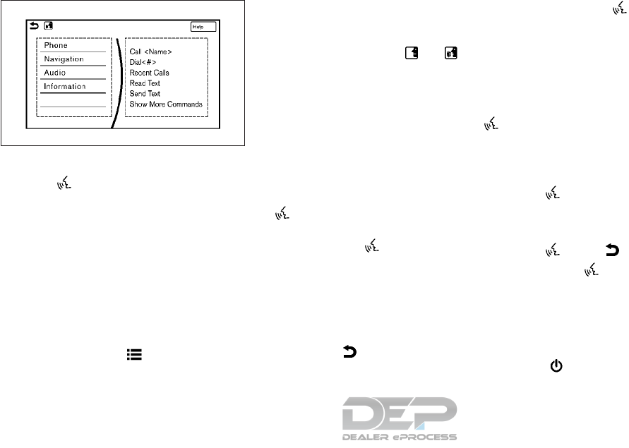
GIVING VOICE COMMANDS
1. Push < > located on the steering wheel.
2. A list of commands appears on the screen,
and the system provides a voice menu
prompt.
When this screen is displayed, almost all of
the commands can be recognized. Available
commands for each categories can be
shown on the right side of the screen. High-
light a category listed in the left side of the
screen with the INFINITI controller to find
your preferred command.
Selecting a category by touching the
screen or pushing </OK> will execute
the command. After executing the cat-
egory command, only the commands re-
lated to the selected category can be rec-
ognized.
"Command list" in the "5. Starting and
driving" section
3. After the tone sounds and the icon on the
screen changes from to , speak a
command. You can also select a command
by directly touching the screen.
The Voice Recognition system will pause
operation when the INFINITI controller is
moved. To resume operation, push <>
on the steering wheel.
4. Continue to follow the voice menu
prompts and speak after the tone sounds
until the preferred operation is completed.
To cancel the voice command, push and hold
<>.
You can interrupt the voice prompt at any
time by pushing <>.
Operating tips
•Speak a command after the tone.
•If the command is not accepted, the sys-
tem announces, “Please say again”. Repeat
the command in a clear voice.
•Push < > on the steering-wheel
switch once to return to the previous
screen.
•Voice commands spoken from the passen-
ger seat cannot be recognized.
•When the < > on the steering wheel is
pressed while the air conditioner is set to
the Auto mode, the system controls the air
conditioner fan speed in order to improve
voice recognition performance. When the
fan speed is set higher than the 4th speed
position, the fan speed is decreased to 4th
speed. When the air conditioner is set to
the manual mode, the fan speed does not
change. The accuracy of voice recognition
may be affected depending on the fan
speed and the air direction.
•To skip the voice guidance function and
give the command immediately, push <
>on the steering-wheel to interrupt
the system. Remember to speak after the
tone.
•To cancel the command, push and hold <
>or < > on the steering-wheel.
•Push < > on the steering-wheel to stop
the voice prompt and give the command at
once. Remember to wait for the tone be-
fore speaking.
•To adjust the volume of the system feed-
back, push the volume switch on the steer-
ing wheel or use the audio system <VOL/
>while the system is making an an-
nouncement.
NAA1732
4-106 Display screen, heater and air conditioner, and audio system
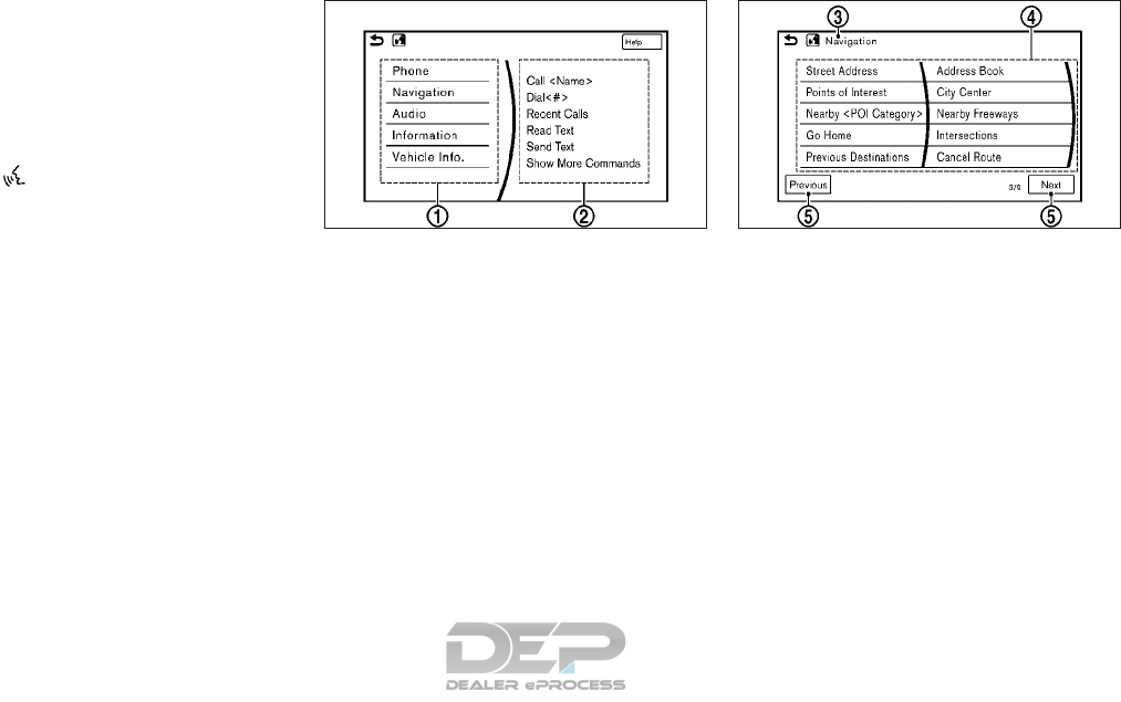
•For searching with Street Address, Point
of Interest and City Center, the searching
area is automatically set to the state
where your vehicle is located. Use Change
State/Province to change the search area
to another state if necessary.
How to see voice command screen
1. Push < > to display the first screen of
the voice command list.
2. Speak a command or select an item from
the voice command list. The second
screen is displayed.
3. Speak a command. The list screen is dis-
played.
4. Speak the preferred number from the list
to perform operation.
The voice commands can be spoken one at a
time following prompts step by step or the
command can be spoken successively in one
step.
䊊
1Shows available command list. It is also
available to select a command from this
list by touching or using the INFINITI
controller.
䊊
2Shows available command list. Displayed
commands are only available to execute
through voice recognition. You can say
commands from the left screen and the
right screen continuously.
䊊
3Previously selected command.
䊊
4Command list:
You can say a command from the list,
touch the screen directly or select, using
steering switch or the INFINITI control-
ler. You can say preferred word for < >
enclosed part of the command.
䊊
5[Previous]/[Next]:
Say as a command or touch to go to the
previous/next screen. It cannot be se-
lected using the steering switch or
INFINITI controller.
5GD0015XZ
First screen
5GD0016XZ
Second screen
Display screen, heater and air conditioner, and audio system 4-107
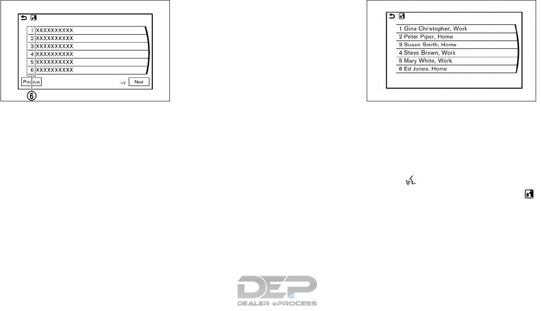
䊊
6Command numbers:
Speak 1 to 6 numbers to select. Also, you
can touch the screen directly, using the
steering switch or INFINITI controller.
How to speak numbers
Voice Recognition requires the user speak
numbers in a certain way when giving voice
commands.
General rule:
Only single digits 0 (zero) to 9 can be used.
(For example, if speaking 500, “five zero
zero” can be used, but “five hundred” cannot.)
Examples:
1-800-662-6200
“One eight zero zero six six two six two zero
zero”
For the best recognition, speak “zero” for the
number “0” and “oh” for the letter “o”.
Voice command examples
As examples, some additional basic opera-
tions that can be performed by voice com-
mands are described here.
Example 1- Placing call from hands-free
phonebook:
1. Push <>located on the steering wheel.
2. Wait for the indicator to change to
and speak “Phone”.
You can also speak “Phone” and then “Call
<Name>” successively.
3. Speak “Call <Name>”.
When options (Home, Work, etc.) are reg-
istered to a name in the contact list of a
cellular phone, the option can be com-
manded directly.
5GE0015XZ
List screen
5GE0022XZ
4-108 Display screen, heater and air conditioner, and audio system

Example, “Call Steve Brown Work” or “Call
Steve Brown Other”
4. The system prompts you to speak or se-
lect an item number from the displayed
list. To select a displayed matching item
speak a number from between 1 and 6.
If the selected number has more than one
phone number registered to it, the phone
number list screen is displayed.
Example 2 - Playing radio:
1. Push <>located on the steering wheel.
2. Wait for the indicator to change to
and speak “Audio”.
3. Speak “Play FM” to turn on the FM radio.
Command list
To use the Voice Recognition function, you can speak commands in the order of 1st command, 2nd command and 3rd command. You can also
operate the system with directly speaking the 2nd or 3rd command.
Variable numbers or words such as names can be applied in < > when speaking a command.
See the separate Navigation System Owner’s Manual (if equipped) for the navigation command.
General command
Command Action
Show More Com-
mands
Display other commands of the same category.
Go Back Correct the last recognition result to return to the previous screen.
Exit Cancel Voice Recognition.
Next Skip to next page.
Previous Skip to previous page.
Display screen, heater and air conditioner, and audio system 4-109

General phone command
The following commands can be used during the phone Voice Recognition session.
Command Action
Dial The system makes a call to spoken phone number.
Change Number Correct the phone number when it is not recognized (available during phone number entry).
4-110 Display screen, heater and air conditioner, and audio system

Phone command
1st command 2nd command 3rd command 4th command Action
Phone Call <Name> <1 - 6> Make a call to a contact that is stored on the cellular phone.
Select from the list of displayed on the right side screen.
Call <phonebook name> Make a call to a contact that is stored on the cellular phone.
<phonebook name> <type> Make a call to a contact that is stored on the cellular phone. You can select type
from <Work>, <Cellular>, <Home> or <Other>.
Dial <#> Dial Make a call to a spoken phone number.
Change Number Change the number to call.
Dial <area code> Make a call to a spoken phone number.
Speak “3 columns or 4 columns (1–****)”
<phone number static> Make a call to a spoken phone number.
Speak “7 columns or 10 columns or 11 columns or 3 columns” (“911” or “411” or
“611”).
Recent Calls <1 - 6> Make a call to the recent incoming, outgoing or missed call number.
Read Text <1 - 6> Play Listen to recent text messages received.
Reply Reply to received message.
Call Call the sender of the message.
Send Text <phonebook name> Select a text message from the list and send it a contact name. You can select type
from <Work>, <Cellular>, <Home> or <Other>.
<phonebook name> <type>
Phonebook <phonebook name> Make a call to a contact that is stored on the cellular phone. You can select type
from “Work”, “Mobile”, “Home” or “Other”.
Select “Reply” to reply by message. Select “Call” to call the sender.
<phonebook name> <type>
Display screen, heater and air conditioner, and audio system 4-111

Phone command
1st command 2nd command 3rd command 4th command Action
Phone Favorites <favorite name>
<1-6>
Access frequently called contacts by storing into them in the favorite list.
<favorite name>
<Type>
Redial Make a call to the last outgoing phone number.
International Call <phone number> Makes an international call by allowing more than 11 digits to be spoken.
You may need to include the international call prefixes and country codes.
Add Phone Use this command to connect a compatible Bluetooth® device to the system.
Follow the on screen instructions to complete the pairing process from your
handset.
Call <Name> Work <1 - 6> To call someone's work place, say the person's name stored in the phonebook on
your cellular phone between “Call” and “Work”.
Call <Name> Cellu-
lar
<1 - 6> To call someone's cellular phone, say the person's name stored in the phonebook
on your cellular phone between “Call” and “Mobile”.
Call <Name> Home <1 - 6> To call someone's home, say the person's name stored in the phonebook on your
cellular phone between “Call” and “Home”.
Call <Name> Other <1 - 6> To call someone at a place categorized as “Other”, say the person's name stored
in the phonebook on your cellular phone between “Call” and “Other”.
NOTE
The system can read out SMS text messages
in voice. However, it cannot always read the
text correctly.
4-112 Display screen, heater and air conditioner, and audio system

Audio command
1st command 2nd command 3rd command Action
Audio AM Switches to the AM band, selecting the station last played.
FM Switches to the FM band, selecting the station last played.
FM ,87.9–107.9. Switches to the FM band, selecting the station of the preferred frequency.
SXM ,channel #> Switches to the SiriusXM Satellite Radio band, selecting the preferred channel.
SXM Switches to the SiriusXM Satellite Radio band, selecting the channel last played.
USB Play Artist
<Name>
<1 - 6> Turns on the USB mode, selecting the artist.
iPod Play Artist
<Name>
<1 - 6> Turns on the iPod mode, selecting the artist.
USB Play Artist <artist> Turns on the USB mode, selecting the artist.
iPod Play Artist <artist> Turns on the iPod mode, selecting the artist.
USB Turns on the USB mode, selecting the last played mode.
iPod Turns on the iPod mode, selecting the last played mode.
USB Play Album
<Name>
<1 - 6> Turns on the USB mode selecting the album.
iPod Play Album
<Name>
<1 - 6> Turns on the iPod mode selecting the album.
USB Play Album <album name> Turns on the USB mode, selecting the album.
iPod Play Album <album name> Turns on the iPod mode, selecting the album.
AM <530–1710> Switches to the AM band, selecting the preferred station
FM <87.7–107.9> HD <#> Switches to the FM HD band, selecting the preferred station
CD Track <#> Turns on the CD, selecting the track number.
Display screen, heater and air conditioner, and audio system 4-113

1st command 2nd command 3rd command Action
Audio USB Play Song
<Name>
iPod Play Song
<Name>
Switches to the USB or iPod, selecting the track. You can speak the commands successively.
USB Play Song
iPod Play Song
Switches to the USB or iPod, selecting the track. You can speak the commands successively.
Play <Source Name> Plays the spoken audio source.
Play AM Switches to the AM band, selecting the station last played.
FM Switches to the FM band, selecting the station last played.
SXM SiriusXM Satellite Radio band, selecting the channel last played
USB Turns on the USB, selecting the last played mode.
iPod Turns on the iPod, selecting the last played mode.
CD Turns on the CD, selecting the last played mode.
Bluetooth Audio Turns on the Bluetooth Audio, selecting the last played mode.
iPod Playlist <name> <1 — 6> Turns on the iPod, playing the spoken playlist.
iPod Play Playlist <playlist> Turns on the iPod, playing the spoken playlist.
USB All Artists Displays the USB all artists list.
USB All Albums Displays the USB all albums list.
USB All Folders Displays the USB all folders list.
iPod All Artists Displays the iPod all artists list.
iPod All Albums Displays the iPod all albums list.
iPod All Songs Displays the iPod all songs list.
4-114 Display screen, heater and air conditioner, and audio system

Notes on operating audio by voice recogni-
tion:
•An audio device connected via Bluetooth®
cannot be operated with the Voice Recog-
nition system. Source change is only avail-
able for Bluetooth® streaming Audio.
•Song title and Artist name information will
be overwritten when another iPod®/
iPhone® is connected after song titles and
artist names in the previously connected
iPod®/iPhon®e have been installed.
•If two USB devices are connected at the
same time, voice operation will only be
available for use with one registered and
selected device. When selecting “YES” in
the pop-up screen that displays after a
new USB audio device is connected, the
USB audio device is registered in the voice
recognition system and is selected auto-
matically. One iPod and one USB device
can be registered in the system. If a USB
audio device is newly registered, old data
is overwritten. It may take a few moments
to register an audio device. If you want to
enable voice operation for music stored on
a previously registered audio device, select
the device you want to use in advance.
"Voice recognition settings" in the "5.
Starting and driving" section
Even when a device has been previously
registered, simply connecting the device
will not result in it being selected auto-
matically.
•The Voice Recognition system may not
function when the song information is too
long (artist names, album titles, song titles
and playlists, etc.).
•The SXM function will not operate without
a subscription to SiriusXM Satellite Radio.
Display screen, heater and air conditioner, and audio system 4-115

Information command
1st command 2nd command Action
Information Voice Menu Connects to the INFINITI InTouch
TM
Services Response Specialists. Refer to the Navigation Owner's Manual
for details.
Operator Connects to the INFINITI InTouch
TM
Services Response Specialists. Refer to the Navigation Owner's Manual
for details.
Where am I?* Displays the information of the current position.
Fuel Prices Displays the fuel prices.
Weather Forecast Displays the weather forecast.
Current Weather Displays the nearby weather (current weather).
Sports Scores Displays the sports scores.
Traffic Information* Turns the traffic information system on or off.
Route Information* Displays the route information.
*: Models with navigation system only.
NOTE
The Fuel Prices, Weather Forecast, Current
Weather, Sports Scores and Traffic Infor-
mation will not operate without a subscrip-
tion to SiriusXM Radio.
VOICE RECOGNITION SETTINGS
Voice recognition functions can be set.
1. Push <MENU> and touch [Settings].
2. Touch [Voice Recognition].
3. Touch the item you want to set.
Available settings
•[Minimize Voice Feedback]:
Set the Minimize Voice Feedback function
[ON] (short feedback) or [OFF] (long
feedback).
•[Audio Device Setting]
Select an audio device to be operated via
voice recognition system from the list of
devices registered to the in-vehicle audio
system. The device with an indicator light
illuminated can be operated with voice
recognition system.
4-116 Display screen, heater and air conditioner, and audio system

The information screen sets or displays various information that is helpful for using the vehicle. Available items include vehicle information, traffic
information, current location information and navigation software version (if equipped).
1. Push <MENU>.
2. Touch [Information].
Menu item Result
[Eco Drive Report] Display the Eco Drive Report for “Start”/”Cruise”/”Deceleration”.
[History] The Eco Drive Report History screen can be scrolled.
Touching [ <]/[ >] while the Eco Drive Report History screen is displayed will display a previous or newest
history.
[Reset] Reset the Eco Drive Report screen.
The average for the Reset-to-Reset period is stored as an Eco Drive Report history.
[Traffic Information.]* Allows traffic information setup. Refer to the Navigation Owner's Manual for details.
[Map Information]* Display the navigation system unit identification number, the current map version, and the software
version. Refer to the Navigation Owner's Manual for details.
[InTouch Services]* Display the INFINITI InTouchTM Services information. Refer to the Navigation System Owner's Manual for
details.
[SXM Info] Display the SiriusXM Travel Link information.
*: Models with navigation system only.
NOTE
•A SiriusXM Traffic subscription is necessary to view Traffic Info.
•The actual fuel economy information may differ from the information displayed on the vehicle information display. This is due to the timing
difference in updating the information and does not indicate a malfunction.
INFORMATION MENU
Display screen, heater and air conditioner, and audio system 4-117
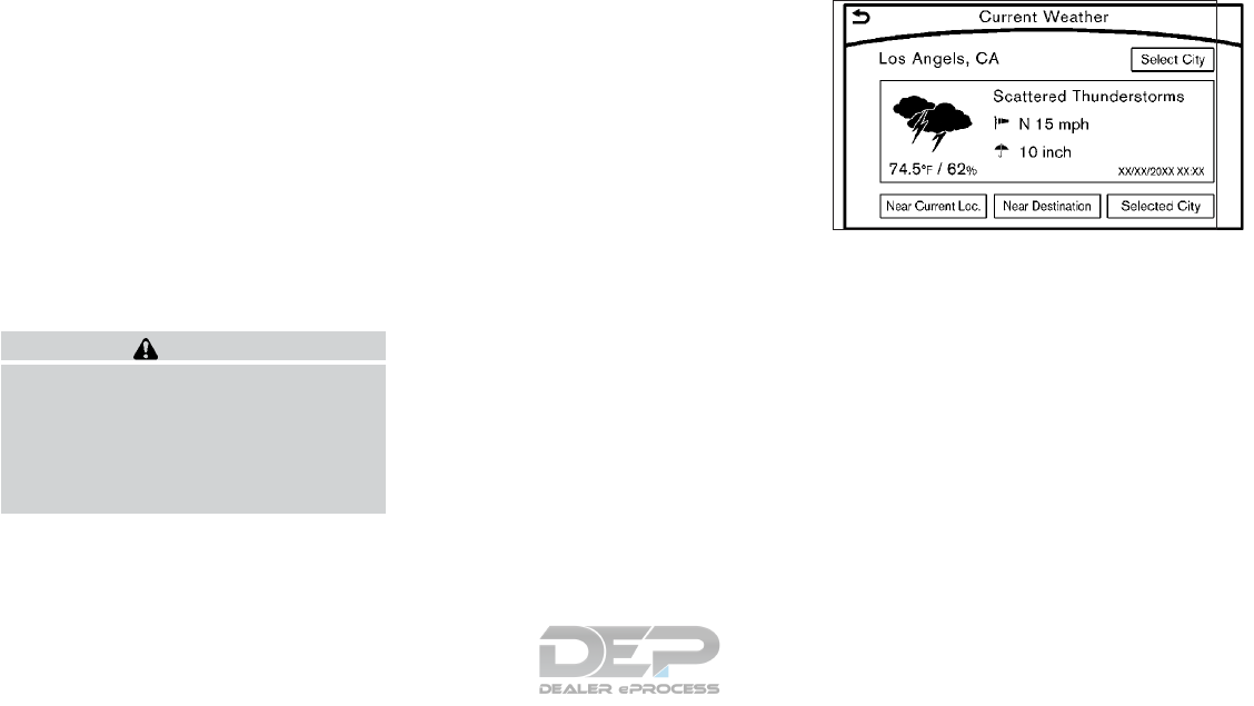
SIRIUSXM TRAVEL LINK®
SiriusXM Travel Link Information is a sub-
scription service offered by SiriusXM Satellite
Radio. It is necessary to subscribe to use the
SiriusXM Travel Link information.
This service provides real-time information
regarding current weather, fuel prices, sports
scores, stock tickers and movie times where
available. The SiriusXM Travel Link is broad-
cast to the vehicle by SiriusXM Satellite Ra-
dio.
The service enables you to view detailed in-
formation and forecasts of an area of inter-
est.
WARNING
SiriusXM Travel Link information is not a
substitute for attentive driving. Weather
conditions change constantly and emer-
gency situations can arise without warn-
ing. Relying only on SiriusXM Travel Link
information could result in serious personal
injury.
Viewing SiriusXM Travel Link®
SiriusXM Travel Link information is available
in limited markets. To subscribe to or check if
this service is available in the area, call
1–866–635–2349 or access
www.siriusxm.com/travellink.
NOTE
•If a contract is not completed for the
SiriusXM Travel Link information service, a
message appears.
•The weather information is available only
for areas that provide weather informa-
tion to SiriusXM Travel Link.
To access the SiriusXM Information menu:
1. Push <MENU>.
2. Touch [SXM Info]
5GB0496X
Example
4-118 Display screen, heater and air conditioner, and audio system

Automotive Weather information
Menu item Action
[Automotive Weather] [Current Weather] Display default setting city current weather condition information. Touch [Selected City] to change the city.
[5–DAY Forecast] Display the five-day weather forecast information for the default setting city. Touch [Selected City] to
change the city.
[Graphical Map]* Display a graphical map of the weather information on the display. Refer to the Navigation Owner's
Manual for details.
[Alert Map]* Show Alert Map information on the display. Refer to the Navigation Owner's Manual for details.
[Alert List]* Display the list of weather alerts. Refer to the Navigation Owner's Manual for details.
*: Models with navigation system only.
Fuel Prices information
Menu item Action
[Fuel Prices] Display fuel prices. Select Gas station from the fuel prices list to display detail information or call a selected
gas station from the list.
Touch [Select Fuel Type] to select fuel type information, touch [Prices] to display the fuel price list.
Display screen, heater and air conditioner, and audio system 4-119

Sports Score information
Menu item Action
[Sports Scores] Select from list Display current event state
(scheduled game, during the
game, match results)
Select from list XM channels to display information Select to listen to the radio.
[Select League] [Add League] Add favorite sports genre for
the list. When the number of
registration is 10, it will be
grayed out.
[Delete League] [Multi Select] Delete multiple selected sports
scores.
[Delete All] Delete all sports scores.
Select from list Delete a selected sports score.
Select from list Display the detail of a score.
Stock Tickers information
Menu item Action
[StockTicker] Display stock names, stock prices, fluc-
tuation contents, variable stock prices,
and the receiving date/time.
[Add Stock] Add displaying stock
[Delete Stock] [Delete All] Delete all stocks.
[Multi Select] Delete multiple selected stock.
Select from list Delete a selected stock.
4-120 Display screen, heater and air conditioner, and audio system

Movie Times information
Menu item Action
[Movie Listings] [Select City] Select from list Select the city.
[Theater] [Movies] Select from list Display detailed movie infor-
mation.
[Theater Info] Display theater information.
[GO]* Set a destination selected
from the list of theaters.
[Near Destination]* Display the theater near the
vehicle's destination.
[Near Current Loc.]* Display the theater near the
vehicle's current location.
[Selected City] Change the city.
[Movie] Select from list Display information for the
movie theater selected from
the list.
[Details] Display movie title, rating and
run time.
*: Models with navigation system only.
SXM Info Settings information
Menu item Action
[SXM Info Settings] [Weather Alert] Set weather alert on/off.
Display screen, heater and air conditioner, and audio system 4-121
Default City Settings information
Menu item Action
[Default City] State list City list Set the current location. This setting is
necessary to display weather informa-
tion and movie information.
[Change Country] Select country.
SETTINGS MENU
The Infiniti InTouch system can be customized to make it easier for you to use by adjusting various settings.
Push <MENU> and touch [Settings].
Setting item Result
[Bluetooth] Set the Bluetooth® Audio and Phone.
"Connecting Bluetooth® device" earlier in this section
[Phone/Mail] Display the Phone & Mail setting screen.
"Phone and text message settings" earlier in this section
4-122 Display screen, heater and air conditioner, and audio system

Setting item Result
[Navigation]* Display the Navigation setting screen.
Refer to the Navigation Owner's Manual for details.
[Audio] Display the Audio settings screen.
See "Audio settings" earlier in this section
[Screen] Set the screen display to the preferred settings.
See "Screen settings" earlier in this section
[Volume Adjustment] Set the volume for each item.
See "Volume settings" earlier in this section
[Clock] Set the Clock to your preferred settings.
See "Clock settings" earlier in this section
[InTouch Services] Set INFINITI InTouch
TM
Services.
Refer to the Navigation Owner's Manual for details.
[Voice recognition] Set Minimize Voice Feedback to on/off and the audio setting for voice
recognition use.
[Camera/Sonar] Set the camera and parking sensor (sonar) to the preferred settings.
See "Around View Monitor setting" earlier in this section
[Other] [Language] Set the language to the preferred settings.
See "Language settings" earlier in this section
[Keyboard Type] Set the Keyboard Type to [QWERTY] or [ABC].
[Low on Fuel Alert] Set the fuel low notification to on/off.
[Software information] Display the software information.
* : Models with navigation system.
NOTE
•The displayed items vary depending on the vehicle model and equipped options.
•The order of displayed items can be sorted.
Display screen, heater and air conditioner, and audio system 4-123

CUSTOMER ASSISTANCE
For assistance or inquiries about Infiniti InTouch, or to order updated map data for the navigation system (if equipped), it is recommended you
contact an INFINITI retailer.
SYSTEM UNIT
Liquid crystal display
Symptom Possible cause Possible solution
The screen is too dark. The cabin temperature is too low. Wait until the cabin temperature becomes
moderate.
Screen brightness is set to the maximum darkness. Adjust the brightness setting of the screen.
"Screen settings" earlier in this section
The screen is too bright. Screen brightness is set to the maximum
brightness.
Adjust the brightness setting of the screen.
"Screen settings" earlier in this section
A small black spot or a small bright spot appears on
the screen.
This is a phenomenon typical to liquid crystal
displays.
This is not a malfunction.
A dot or stripe pattern appears on the screen. Electromagnetic waves that are generated from
neon billboards, high voltage electric power
cables, ham radios or other radio devices equipped
to other vehicles may adversely affect the screen.
This is not a malfunction.
Image lag appears on the screen. Phenomenon typical of liquid crystal displays. This is not a malfunction.
Image motion displayed on the screen is slow. The cabin temperature is below 32 °F (0 °C). Wait until the in-cabin temperature rises to above
32 °F (0 °C).
When looking at the screen from an angle, the screen
lightens or darkens.
This is a phenomenon typical to liquid crystal
displays.
Adjust the brightness setting of the screen.
"Screen settings" earlier in this section
TROUBLESHOOTING GUIDE
4-124 Display screen, heater and air conditioner, and audio system

Symptom Possible cause Possible solution
The screen turns blue or an error message is displayed
on the display.
The SD card is not inserted into the slot correctly. If the SD card containing map data is accidentally
removed, after re-inserting the SD card
containing map data into the slot, place the
ignition switch in the OFF position and then back
in the ON position again.
A system malfunction has occurred. It is recommended you contact an INFINITI
retailer for inspection.
AUDIO SYSTEM
HD Radio Technology
Sound:
Symptom Possible cause Possible solution
Delay in digital audio on HD Radio broadcasts. The radio acquires an analog station first and
blends to a digital signal.
This is not a malfunction.
Audio skip, stutter or echo. The radio station has not properly aligned the digi-
tal and analog audio.
Verify correct operation on another station. Report
any station with poor performance.
Volume changing up/down. The radio station has not properly aligned digital
and analog audio level.
Verify correct operation on another station and
check www.hdradio.com for stations in the area.
Report any station with poor performance.
Sound fading in and out. The transition between analog and digital is taking
place (blending).
Verify transition performance on several stations in
the area. Report any station with poor perfor-
mance.
Excessive blending (Transition between analog and
digital).
The receiver is located near the edge of the digital
coverage area.
Refer to www.hdradio.com to verify stations in
your coverage area.
Digital audio not better than analog audio. Audio processing on the digital audio at a station
can potentially decrease the digital audio sound
quality.
Verify correct operation on another station. Report
any station with poor performance.
Display screen, heater and air conditioner, and audio system 4-125

Functional:
Symptom Possible cause Possible solution
Keep losing my local stations. The digital coverage is slightly less than the analog
signal coverage.
Verify correct operation on another station. This is
expected behavior.
Shadowing (urban/terrain) can cause reduced digi-
tal coverage.
Verify correct operation on another station.
Some data fields are blank. Text information is sent at the broadcaster's discre-
tion.
Verify correct operation on another station. Report
station issues.
Text information is truncated / appears to be more
available.
The display is limited to a fixed number of charac-
ters and more data is being sent than can be
shown.
This is intended behavior. Refer to the Owner's
Manual for ability to access addition.
AM reception changes at night. AM stations are required by the government (FCC)
to lower their power at night.
This is not a malfunction.
4-126 Display screen, heater and air conditioner, and audio system

Compact Disc (CD) player
Symptom Possible cause Possible solution
Music cannot be played back. The disc is inserted upside down. Insert a CD with the label side facing up.
Moisture has accumulated inside the unit. Wait until the moisture evaporates. (approximately
1 hour)
The cabin temperature is too high. Wait until the cabin temperature becomes
moderate.
The disc is scratched or dirty. Wipe off any dirt from the disc.
Scratched discs cannot be recovered. Replace the
disc.
Depending on the condition in which they are
stored, discs may become unreadable due to
deterioration (for example, keeping the discs in the
passenger compartment, etc.).
Replace the disc with a deterioration-free disc. Do
not use a deteriorated disc. The label surface of the
disc may crack or chip, and the layer of the label
surface may eventually peel off.
Compressed audio files cannot be played back. If both music CD files (CD-DA data) and
compressed audio files (MP3 data, etc.) are mixed
on one disc, the compressed audio files cannot be
played back.
Prepare a disc that contains compressed audio files
only.
The files are not named using characters that are
compliant with the specifications.
Use the character codes and the number of
characters that are compliant with the
specifications for folder names and file names. In
addition, always use “.MP3”, “.WMA”, “.mp3” or
“.wma” file extensions.
It takes a long time before the music starts playing. The disc contains a large amount of data. Some time may be required to check the files. It is
recommended that unnecessary folders or any files
other than compressed audio files should not be
recorded on a disc.
The sound quality is poor. The disc is dirty. Wipe off any dirt from the disc.
Display screen, heater and air conditioner, and audio system 4-127

Symptom Possible cause Possible solution
No sounds are played although the CD play time is
displayed.
The system is playing the first track of a mix mode
disc. (Mix mode is a format in which data except
music is recorded on the first track and music data
is recorded on one other than the first track in a
session.)
Play music data in other tracks.
Music cuts off or skips. The combination of writing software and hardware
might not match; or the writing speed, writing
depth, writing width, etc. might not match the
specifications.
Create a disc using different writing speed settings,
etc.
The system skips the selected track and moves to
the next track.
A non-MP3/WMA file has been given an extension
of “.MP3”, “.WMA”, “.mp3” or “.wma”.
Prepare MP3/WMA files.
Some of the file cannot be played due to copyright
protection.
Prepare playable files.
The tracks do not play back in the desired order. The folder locations on the disc are changed by the
writing software while the files are written on the
disc.
Check the settings of the writing software and
create a new disc.
4-128 Display screen, heater and air conditioner, and audio system

iPod player
Symptom Possible cause Possible solution
The system does not recognize an iPod. The connector cable is not correctly connected or
the iPod does not correctly operate.
Connect the connector cable again. If the system
does not recognize the iPod after performing the
procedure above, reset the iPod.
The iPod that is to be connected is not compatible
with the system.
Check the iPod model and firmware versions
available for the system.
The USB extension cable is not correctly connected. Do not use a USB extension cable.
The cable is rapidly connected to or disconnected
from the USB connector.
Slowly connect or disconnect the USB cable.
An iPod cannot be operated. The iPod is connected to the in-vehicle audio
system while headsets, etc. are connected to the
iPod.
Remove all equipment from the iPod after
disconnecting the iPod from the system, and then
connect it to the system again.
The iPod is not operating normally. Disconnect and reconnect the iPod to the
in-vehicle audio system.
The system plays back an album/track that includes
particular album art.
Disconnect the iPod from the in-vehicle audio
system and then reset the iPod. Disable the album
art and then reconnect the iPod to the system.
An iPod does not respond. There are too many tracks in a category. Decrease the number of tracks in a category (less
than 3,000 tracks).
The shuffle function is turned on. Turn off the shuffle function if many tracks are
stored on the iPod.
Music cannot be played back. The connector is not connected to the iPod. Firmly connect the connector until it clicks.
Music stops playing. The sound cuts off due to vibration resulting from
the iPod being in an unstable location.
Place the iPod in a stable location where it does
not roll over.
The sound is distorted. The EQ (equalizer) function of the iPod is turned on. Turn off the EQ (equalizer) function.
The iPod battery requires more time than usual to
charge.
Charging the iPod battery may take longer while
the iPod is playing.
If the iPod requires charging, it is recommended to
stop playback
Display screen, heater and air conditioner, and audio system 4-129

Symptom Possible cause Possible solution
An iPod cannot be charged while connected to the
system.
The cable connected to the iPod may be
deteriorated (cable disconnection, etc.).
Check the cable.
The connected iPod cannot be operated with the
in-vehicle system.
- The operation of an iPod must be performed using
the in-vehicle audio system after the iPod is
connected to the system.
The sound skips. Surrounding circumstances (noise, etc.) may cause
the audio to skip.
This does not indicate a malfunction.
The USB extension cable is not correctly connected. Do not use a USB extension cable.
USB memory
Symptom Possible cause Possible solution
The system does not recognize a USB device. A USB extension cable is used. Do not use a USB extension cable.
A USB hub is used. Do not use a USB hub.
Connection or disconnection operation of the USB
device was too abrupt.
Connect or disconnect the USB device slowly.
4-130 Display screen, heater and air conditioner, and audio system

Bluetooth® streaming audio
Symptom Possible cause Possible solution
Registration cannot be performed. The Bluetooth® audio device is not compatible
with the in-vehicle audio system.
Check the Owner’s Manual for the Bluetooth®
audio device.
The PIN code is incorrect. Check the PIN code for the Bluetooth® audio
device that is to be registered.
Check that the PIN code for the Bluetooth® audio
device is consistent with that for the in-vehicle
audio system.
Another Bluetooth® device is used in the vehicle. Turn off the other Bluetooth® device and wait until
registration is completed.
Music cannot be played. The Bluetooth® audio device is not compatible
with the in-vehicle audio system.
Check the Owner’s Manual for the Bluetooth®
audio device.
The system is not in the Bluetooth® audio mode. Push <AUDIO> to select the Bluetooth® audio
mode.
The Bluetooth® adapter is turned off. Turn on the Bluetooth® adapter when it is used for
a Bluetooth® audio device.
Music stops playing. The Bluetooth® audio device is not compatible
with the in-vehicle audio system.
Visit www.infinitiusa.com/bluetooth/ to search for
a recommended Bluetooth® audio device.
A cellular phone is connected. This is not a malfunction.
The sound may cut off when a Bluetooth® audio
device is operated.
Push <AUDIO> to select the Bluetooth® audio
mode, and then operate the device on the vehicle’s
display screen.
Audio operation cannot be performed. A Bluetooth® audio device that does not support
audio operations is in use.
This is not a malfunction.
Refer to the owner’s manual for the Bluetooth®
audio device.
An error occurs when connecting to a Bluetooth®
audio profile.
Turn the power source of the Bluetooth® audio
player off and on, and then resume connection with
the system.
Display screen, heater and air conditioner, and audio system 4-131

BLUETOOTH® HANDS-FREE
PHONE SYSTEM
Symptom Possible cause Possible solution
A cellular phone cannot be registered. The cellular phone is not compatible with the
in-vehicle hands-free phone system.
Use a cellular phone compatible with the system. Visit
the website (www.infinitiusa/bluetooth) for model
compatibility.
Registration of the cellular phone has been
performed incorrectly.
Check the registration procedure, and then register the
cellular phone again.
A cellular phone cannot be connected or
becomes disconnected after registration is
complete.
The Bluetooth® setting of the in-vehicle hands-free
phone system is turned off.
Turn on the Bluetooth® setting of the system.
The Bluetooth® setting of the cellular phone is
turned off.
Turn on the Bluetooth® setting of the cellular phone.
The remaining battery level of the cellular phone is
low.
Charge the battery of the cellular phone.
The wireless Bluetooth® connection may be
disrupted depending on the location of the cellular
phone.
Do not place the cellular phone in an area surrounded by
metal or far away from the in-vehicle hand-free phone
system. Do not place the cellular phone close to the
seats or your body.
Registration of the cellular phone is not complete. Perform registration of the cellular phone.
A call to a particular phone number fails. If the system tries to make a call several times to
the same phone number (for example: the party
does not respond to the call, the party is out of the
network service area, or the call is abandoned
before the party responds), the system may reject a
request to make a call to the phone number.
Turn the cellular phone off and then on again to reset
the connection.
4-132 Display screen, heater and air conditioner, and audio system

Symptom Possible cause Possible solution
The system does not recognize the
connection of a cellular phone and cannot
receive or make a call.
The cellular phone is not compatible with the
in-vehicle hands-free phone system.
Use a cellular phone compatible with the system. Visit
the website (www.infinitiusa/bluetooth) for model
compatibility.
The cellular phone is not connected. Check the registration procedure, and then register the
cellular phone again.
The phone operation is limited by the functions
(such as dial lock, etc.) of the registered cellular
phone.
Remove any settings that are limiting use of the cellular
phone, and then perform registration again.
Registered voice tag is cut short. Speaking of the voice tag did not fit within the 5
second recording period after the beep.
Speak the voice tag within 5 seconds after the beep.
The other party cannot hear your voice. The
other party can hear your voice, but it cracks
or cuts out.
The cellular phone is not connected. Check the registration procedure, and then register the
cellular phone again.
The fan speed of the air conditioner is too fast. Decrease the fan speed of the air conditioner.
The ambient noise level is excessive. (For example:
heavy rain, construction sites, inside a tunnel,
oncoming vehicles, etc.)
Close the windows to shut out ambient noise.
The noise generated by driving the vehicle is too
loud.
Reduce the vehicle speed, and then speak a command.
The incoming or outgoing voice level is too loud. Adjust the incoming or outgoing voice level properly.
The voice is cut out or noise is heard during a
call.
The wireless Bluetooth® connection may be
disrupted depending on the location of the cellular
phone.
Do not place the cellular phone in an area surrounded by
metal or far away from the in-vehicle hands-free phone
system. Do not place a cellular phone close to the seats
or your body.
When a cellular phone is operated to make a
call, the hands-free function is no longer
available.
Some models of a cellular phone do not switch to
the hands-free mode when they are operated to
make a call.
This is not a malfunction. Make a call again using the
hands-free function.
The other party's voice cannot be heard.
There is no ring tone.
The volume level is set to the minimum. Adjust the volume level.
A cellular phone is not connected. Check the registration procedure, and then register the
cellular phone again.
Display screen, heater and air conditioner, and audio system 4-133

Symptom Possible cause Possible solution
Each volume level (ring tone, incoming voice
or outgoing voice) is different.
Each volume level is not adjusted properly. Adjust each volume level properly.
The antenna display is different between the
navigation screen (if equipped) and the screen
on a cellular phone. Making or receiving a call
is unavailable even though the antenna
display indicates that it is possible to do so.
The antenna display varies depending on the model
of cellular phone.
This does not indicate a malfunction. The antenna
display and remaining battery level shown on the
navigation screen may be different from those shown on
the cellular phone screen. Use them as a reference.
A voice cannot be heard clearly when using a
cellular phone behind tall buildings.
Some structures such as tall buildings, etc. may
cause irregular reflection of radio waves or
completely shut out radio waves that are used for
cellular phones.
This is not a malfunction.
Noise is heard when using a cellular phone
under/near areas of elevated railroads, high
voltage electric power cables, traffic signals,
or neon billboards, etc.
Electromagnetic waves that are generated from
radio devices may adversely affect the cellular
phone.
This is not a malfunction.
Noise is heard in the sound from the audio
system while using a cellular phone.
Radio waves that are generated from a cellular
phone may adversely affect the sound from the
audio system.
This is not a malfunction.
The sound skips. The cellular phone may have turned on the wireless
LAN (Wi-Fi).
Turn off the wireless LAN (Wi-Fi).
Phonebook cannot be downloaded. An error occurred during the phone pairing process. Re-register the Bluetooth® pairing information after
deleting the pairing information from both the cellular
phone and the vehicle system.
4-134 Display screen, heater and air conditioner, and audio system

MONITOR SYSTEM
Symptom Possible cause Possible solution
The image on the display is not clear. The front of the camera lens is dirty. Gently wipe off the dirt with a damp soft cloth.
Moisture drops such as rain or snow form on the
camera lens.
Gently wipe off the drops with a soft cloth.
Light such as sunlight or a headlight beam from
another vehicle directly enters the camera.
This is not a malfunction. It will return to normal
when the light disappears.
Moisture condensation occurs in the camera lens
due to rapid temperature change.
This is not a malfunction. It will return to normal
after driving for short period of time.
Objects on the display may not be clear in a dark
place or at night.
Adjust the brightness or the contrast settings of
the screen.
The image on the display flickers. The vehicle is under fluorescent light. This is not a malfunction.
The colors of the object on the display look
different from those of the actual object.
This is a typical phenomenon for cameras. This is not a malfunction.
Image does not appear on the display. The shift lever is not shifted to the R (Reverse)
position.
Shift the shift lever to the R (Reverse) position.
[Automatic Display with Sonar] is OFF. Set [Automatic Display with Sonar] to ON.
The image appears on the display from the wrong
angle.
The lift gate is open. Close the lift gate.
The image on the display is not clearly visible. Strong light or reflected light enters the camera. This is not a malfunction.
The sensor is not detective. There is ice or snow on the sensor. Flush out ice and snow with warm water.
There is dirt, mud or wax on the sensor. Gently wipe off the dirt with a damp soft cloth.
Vertical lines appear on the image. Strong reflected light from the bumper enters the
camera.
This is not a malfunction.
Display screen, heater and air conditioner, and audio system 4-135

VOICE RECOGNITION
Symptom Possible cause Possible solution
The system does not operate or fails to interpret
the command correctly.
The interior of the vehicle is too noisy. Close the windows or make sure the other
occupants are quiet.
The fan speed of the air conditioner is too fast. Decrease the fan speed of the air conditioner.
The noise generated by driving the vehicle is too
loud.
Reduce the vehicle speed, and then speak the
command.
The voice command is spoken in a low voice. Speak the command in a louder voice.
The command is spoken too fast. Speak the command after confirming the following:
voice guidance is announced, a tone sounds, and
an icon on the screen changes from white to
orange.
The command is spoken too slowly. Speak in a natural voice without pausing between
words.
The system prompts to repeat a command. Pronunciation is unclear. Speak clearly.
The command is spoken too late after the tone. Speak the command within 5 seconds after
confirming the following: a voice guidance is
announced, a tone sounds, and an icon on the
screen changes from white to orange.
An improper command is spoken. Speak the command or a number that is displayed
in white on the screen.
Speak a command that is shown in the command
list.
The system does not correctly recognize a number
spoken.
Many numbers are spoken at once. Place a pause between the appropriate digits for
correct recognition by the system. When speaking
a telephone number, place a pause between area
codes and dial codes, etc.
Voice recognition does not operate, and a tone
sounds twice after pushing the <>.
The <>is pushed before the system is ready to
accept voice commands.
After turning on Infiniti InTouch, wait for the voice
recognition system to be ready before giving voice
commands.
4-136 Display screen, heater and air conditioner, and audio system

Symptom Possible cause Possible solution
The USB memory device cannot operate with voice
recognition.
Depending on the device, an iPhone® or iPod® may
be recognized as a USB memory device.
This is not a malfunction
More than one audio device is connected to USB
port.
Only one audio device can be operated with the
voice recognition system even when multiple
numbers of devices are connected. Select an audio
source to operate with the voice recognition
system.
The USB/iPod operation screen is grayed out. The audio device is not connected. Connect an audio device to the system.
An audio source to be operated with the voice
recognition system has not been selected.
Select an audio source to be operated with the
voice recognition system.
An error message is displayed when trying to select
a track and operate the USB/iPod.
The track information is being processed for
registration by the system.
Song information will be loaded into the system
when a new audio device is registered for the first
time or when the song information in the
pre-registered device has been changed. Wait for
the loading to complete (this may take from a few
minutes to up to an hour).
The number of songs stored on the connected
audio device exceeds its capacity.
Decrease the number of songs stored on the audio
device.
No song is stored on the audio device. Store songs on the connected audio device. Storing
songs with information such as artist name, album
name, song name, and playlist, etc., will make voice
recognition song search available.
The Navigation item is not displayed in the voice
operation menu screen.
Voice Recognition command preparation for the
navigation system is not completed immediately
after the system is started.
Display any screen other than the Voice
Recognition screen, and then push <>.
Display screen, heater and air conditioner, and audio system 4-137

Symptom Possible cause Possible solution
The system does not correctly recognize a Point of
Interest (POI) name spoken.
There are some rare cases where a POI is
unavailable by Voice Recognition but the location
can be found on the map.
This is not a malfunction. Consider using an
alternative search method, like street address.
Partial or Alias name is spoken. For best results, speak the full name.
Some POI category names can only be searched
when nearby.
This is not a malfunction.
4-138 Display screen, heater and air conditioner, and audio system

5 Starting and driving
Precautions when starting and driving.........5-4
Exhaust gas (carbon monoxide) ...........5-4
Three-way catalyst (if equipped) ..........5-4
Tire Pressure Monitoring System (TPMS).....5-5
On pavement and off-road driving
precautions .......................5-10
Avoiding collision and rollover ...........5-10
Off-road recovery ...................5-11
Rapid air pressure loss ................5-11
Drinking alcohol/drugs and driving ........5-12
Driving safety precautions .............5-12
All-wheel drive (AWD) driving safety
precautions (if so equipped).............5-14
Infiniti Vehicle Immobilizer system...........5-14
Ignition switch .......................5-15
Steering lock ......................5-15
Key positions ......................5-15
Push-button ignition switch (if equipped) ......5-16
Key positions with the push-button ignition
switch ..........................5-17
Removing the start/stop button ..........5-17
Emergency engine shut off .............5-18
Before starting engine ..................5-18
Starting engine.......................5-18
Starting procedure with the key ..........5-18
Starting procedure using the push-button
ignition switch (if equipped) .............5-19
Driving the vehicle ....................5-20
Driving with Automatic Transmission ......5-20
Parking brake........................5-27
Applying/releasing manually ............5-27
Applying automatically (vehicles with
automatic transmission) ...............5-28
Releasing automatically ...............5-28
Emergency braking ..................5-28
Idle Stop/Start System (if equipped) .........5-29
Automatic engine switch-off ............5-29
Automatic engine start ...............5-30
Deactivating/activating the Idle Stop/Start
function .........................5-30
Lane departure warning (LDW) system
(if equipped) ........................5-31
LDW system operation ...............5-32
How to enable/disable the LDW system . . . .5-33
LDW system limitations ...............5-33
LDW system temporarily unavailable.......5-35
System malfunction .................5-35
System maintenance .................5-36
Blind Spot Warning (BSW) system (if equipped) . .5-36
BSW system operation ...............5-38
How to enable/disable the BSW system . . . .5-40
BSW system limitations ...............5-40
System temporarily unavailable ..........5-45
Radar maintenance ..................5-46

FCC Notice .......................5-46
Cruise control .......................5-46
Cruise control operations ..............5-47
Intelligent Cruise Control (ICC) system (Full speed
range) (if equipped) ....................5-49
ICC system operation ................5-50
ICC switch (cruise control lever) ..........5-51
ICC system display and indicators.........5-52
Operating ICC .....................5-53
ICC Limitations ....................5-57
Tips for driving with the ICC system .......5-58
System temporarily unavailable ..........5-61
System maintenance .................5-62
Forward emergency braking (FEB) system (if
equipped) ..........................5-63
FEB system operation ................5-64
Turning the FEB system on/off ..........5-66
FEB system limitations................5-67
System temporarily unavailable ..........5-68
System maintenance .................5-69
FCC Notice .......................5-69
Active sound enhancement ...............5-70
Active sound enhancement .............5-70
Intelligent Parking Assist (IPA) (if equipped).....5-71
Important safety notes................5-71
Detecting parking spaces ..............5-72
Parking .........................5-73
Exiting a parking space ...............5-74
Canceling IPA .....................5-76
Camera Aiding Sonar (parking sensor) function
(if equipped) ........................5-76
Sonar function overview...............5-78
Range of the sensors.................5-82
Sonar function OFF switch.............5-82
Sonar function settings ...............5-83
Sonar function limitations..............5-83
Problems with sonar function ...........5-84
System maintenance .................5-85
Break-in schedule .....................5-85
Fuel efficient driving tips ................5-86
Increasing fuel economy.................5-87
Four-Wheel Drive (4WD) (if equipped)........5-87
Parking ...........................5-88
Switching off the engine ..............5-89
Extended parking ...................5-90
Electric power steering system ............5-90
Brake system ........................5-91
Brake precautions ...................5-91
Anti-lock Braking System (ABS) ..........5-92
Vehicle Dynamic Control (VDC) system .......5-93
Traction Control System (TCS)...........5-95
Characteristics of VDC ...............5-95
EBD (electronic brake force distribution) . . . .5-96
Steer Control......................5-96

Hill Start Assist (HSA) ..................5-96
Cold weather driving ...................5-97
Freeing a frozen door lock .............5-97
Antifreeze ........................5-97
Battery..........................5-97
Draining of engine coolant .............5-97
Tire equipment .....................5-97
Special winter equipment ..............5-98
Driving on snow or ice ................5-98

WARNING
•Never leave children or adults who
would normally require the support of
others alone in your vehicle. Pets should
not be left alone either. They could un-
knowingly activate switches or controls
and inadvertently become involved in a
serious accident and injure themselves.
On hot, sunny days, temperatures in a
closed vehicle could quickly become high
enough to cause severe or possibly fatal
illness to people or animals.
•Properly secure all cargo to help prevent
it from sliding or shifting. Do not place
cargo higher than the seatbacks. In a
sudden stop or collision, unsecured
cargo could cause personal injury.
•To avoid raising the center of gravity
excessively, do not exceed the rated ca-
pacity of the roof rack (if so equipped)
and evenly distribute the load.
EXHAUST GAS (CARBON
MONOXIDE)
WARNING
•Do not breathe exhaust gas; it contains
colorless and odorless carbon monoxide.
Carbon monoxide is dangerous. It can
cause unconsciousness or death.
•If you suspect that exhaust fumes are
entering the vehicle, drive with all win-
dows fully open, and have the vehicle
inspected immediately.
•Do not run the engine in closed spaces
such as a garage.
•Do not park the vehicle with the engine
running for an extended period of time.
•Keep the lift gate closed while driving,
otherwise exhaust gas could be drawn
into the passenger compartment. If you
must drive with the lift gate open, fol-
low these precautions:
–Open all the windows.
–Turn the air recirculation switch off
and set the fan control to the highest
level to circulate the air.
•If electrical wiring or other cable con-
nections must pass to a trailer through
the seal ion the lift gate or body, follow
the manufacturer's recommendations
to prevent carbon monoxide entry into
the vehicle.
•The exhaust system and body should be
inspected by a qualified mechanic when-
ever:
–You suspect that exhaust fumes are
entering into the passenger compart-
ment.
–You notice a change in the sound of
the exhaust system.
–You have had an accident involving
damage to the exhaust system, un-
derbody, or rear of the vehicle.
THREE-WAY CATALYST (IF
EQUIPPED)
The three-way catalyst is an emission control
device installed in the exhaust system. Ex-
haust gas in the three-way catalyst is burned
at high temperatures to help reduce pollut-
ants.
WARNING
•The exhaust gas and the exhaust system
are very hot. Keep people, animals and
flammable materials away from the ex-
haust system components.
PRECAUTIONS WHEN STARTING
AND DRIVING
5-4 Starting and driving

•Do not stop or park the vehicle over
flammable materials such as dry grass,
wastepaper or rags. They may ignite
and cause a fire.
CAUTION
•Do not use leaded gasoline. (See "Rec-
ommended fluids/lubricants and ca-
pacities" in the "9. Maintenance and
Schedules" section.) Deposits from
leaded gasoline seriously reduce the
ability of the three-way catalyst to help
reduce exhaust pollutants and/or dam-
age the three-way catalyst.
•Keep your engine tuned up. Malfunc-
tions in the ignition, fuel injection, or
electrical systems may cause overrich
fuel to flow into the three-way catalyst,
causing it to overheat. Do not keep driv-
ing if the engine misfires, or if noticeable
loss of performance or other unusual op-
erating conditions are detected. Have
the vehicle inspected promptly. It is rec-
ommended you visit an INFINITI retailer
for this service.
•Avoid driving with an extremely low fuel
level. Running out of fuel could cause the
engine to misfire, damaging the three-
way catalyst.
•Do not race the engine while warming it
up.
•Do not push or tow your vehicle to start
the engine.
TIRE PRESSURE MONITORING
SYSTEM (TPMS)
Each tire, including the spare (if present),
should be checked monthly when cold and
inflated to the inflation pressure recom-
mended by the vehicle manufacturer on the
vehicle placard or tire inflation pressure label.
(If your vehicle has tires of a different size
than the size indicated on the vehicle placard
or tire inflation pressure label, you should
determine the proper tire inflation pressure
for those tires.)
As an added safety feature, your vehicle has
been equipped with a tire pressure monitor-
ing system (TPMS) that illuminates a low tire
pressure telltale when one or more of your
tires is significantly under-inflated. Accord-
ingly, when the low tire pressure telltale illu-
minates, you should stop and check your tires
as soon as possible, and inflate them to the
proper pressure. Driving on a significantly
under-inflated tire causes the tire to overheat
and can lead to tire failure. Under-inflation
also reduces fuel efficiency and tire tread life,
and may affect the vehicle’s handling and
stopping ability.
Please note that the TPMS is not a substitute
for proper tire maintenance, and it is the driv-
er’s responsibility to maintain correct tire
pressure, even if under-inflation has not
reached the level to trigger illumination of the
TPMS low tire pressure telltale.
Your vehicle has also been equipped with a
TPMS malfunction indicator to indicate
when the system is not operating properly.
The TPMS malfunction indicator is combined
with the low tire pressure telltale. When the
system detects a malfunction, the telltale will
flash for approximately one minute and then
remain continuously illuminated. This se-
quence will continue upon subsequent vehicle
start-ups as long as the malfunction exists.
When the malfunction indicator is illumi-
nated, the system may not be able to detect
or signal low tire pressure as intended. TPMS
malfunctions may occur for a variety of rea-
sons, including the installation of replace-
ment or alternate tires or wheels on the ve-
hicle that prevent the TPMS from working
properly. Always check the TPMS telltale af-
ter replacing one or more tires or wheels on
your vehicle to ensure that the replacement
or alternate tires and wheels allow the TPMS
to continue to function properly.
Starting and driving 5-5
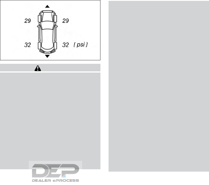
The vehicle's wheels have sensors fitted that
monitor the tire pressures in all four tires The
tire pressure monitor warns you if the pres-
sure drops in one or more of the tires The tire
pressure monitor only functions if the corre-
sponding sensors are fitted to all wheels.
Information on tire pressures is shown in the
vehicle information display. After a few min-
utes of driving, the current tire pressure of
each tire is shown in the [Serv.] menu of the
vehicle information display.
WARNING
•Radio waves could adversely affect
electrical medical equipment. Those who
use a pacemaker should contact their
electrical medical equipment manufac-
turer for the possible influences before
use.
•If the low tire pressure warning light il-
luminates or a tire pressure-related
warning is displayed by the vehicle in-
formation display while driving, avoid
sudden steering maneuvers or abrupt
braking, reduce vehicle speed, pull off
the road to a safe location and stop the
vehicle as soon as possible. Driving with
under-inflated tires may permanently
damage the tires and increase the likeli-
hood of tire failure. Serious vehicle dam-
age could occur and may lead to an acci-
dent and could result in serious personal
injury. Check the tire pressure for all
four tires. Adjust the tire pressure to the
recommended COLD tire pressure
shown on the tire and loading informa-
tion label to turn the low tire pressure
warning light OFF. If you have a flat tire,
replace it with a replacement tire as
soon as possible.
•If a replacement wheel is fitted without
an INFINITI TPMS Sensor, the TPMS
will not function and the low tire pres-
sure warning light will flash for approxi-
mately 1 minute. The light will remain on
after 1 minute. It is recommended you
contact an INFINITI retailer as soon as
possible for tire replacement and/or
system resetting.
•For models with run-flat tires, although
you can continue driving with a punc-
tured run-flat tire, remember that ve-
hicle handling stability is reduced, which
could lead to an accident and personal
injury. Also, driving a long distance at
high speeds may damage the tires.
–Do not drive at speeds above 50
MPH (80 km/h) and do not drive
more than approximately 93 miles
(150 km) with a punctured run-flat
tire. The actual distance the vehicle
NSD660
5-6 Starting and driving
can be driven on a flat tire depends on
outside temperature, vehicle load,
road conditions and other factors.
–If you detect any unusual sounds or
vibrations while driving with a punc-
tured run-flat tire, pull off the road to
a safe location and stop the vehicle as
soon as possible. The tire may be se-
riously damaged and need to be re-
placed.
•Replacing tires with those not originally
specified by INFINITI could affect the
proper operation of the TPMS.
•If you used Emergency Tire Sealant to
repair a minor tire puncture, the TPMS
sensor should be checked when repair-
ing or replacing the tire (for models
equipped with the emergency tire punc-
ture repair kit). It is recommended you
visit an INFINITI retailer for this service.
•INFINITI recommends using only
INFINITI Genuine Emergency Tire Seal-
ant provided with your vehicle. Other
tire sealants may damage the valve stem
seal which can cause the tire to lose air
pressure (for models equipped with the
emergency tire puncture repair kit).
CAUTION
•The TPMS may not function properly
when the wheels are equipped with
snow chains or the wheels are buried in
snow.
•Do not place metallized film or any metal
parts (antenna, etc.) on the windows.
This may cause poor reception of the
signals from the tire pressure sensors,
and the TPMS will not function
properly.
It is the driver's responsibility to set the tire
pressure to the recommended cold tire pres-
sure suitable for the operating situation (see
"Wheels and tires" in the "8. Do-it-yourself"
section). Note that the correct tire pressure
for the current operating situation must first
be taught-in to the tire pressure monitor (see
"Restarting TPMS" later in this section).
If there is a substantial loss of pressure, the
warning threshold for the warning message
is aligned to the reference values taught-in.
Restart the tire pressure monitor after ad-
justing to the cold tire pressure. The current
pressures are saved as new reference values.
This will ensure that a warning message will
only appear if the tire pressure drops signifi-
cantly.
The tire pressure monitor does not warn you
of an incorrectly set tire pressure.
TPMS is not able to warn you of a sudden
loss of pressure, e. g. if the tire is penetrated
by a foreign object. In the event of a sudden
loss of pressure, bring the vehicle to a halt by
braking carefully. Avoid abrupt steering ma-
neuvers.
TPMS has a yellow warning light in the com-
bination meter for indicating a pressure loss
or malfunction. Depending on how the warn-
ing light flashes or lights up, a tire pressure
that is too low or a malfunction in TPMS is
indicated:
•If the warning light is lit continuously, the
tire pressure on one or more tires is signifi-
cantly too low. TPMS is not malfunction-
ing.
•If the warning light flashes for around a
minute and then remains lit constantly, the
TPMS is malfunctioning.
In addition to the warning light, a message
appears in the vehicle information display.
Observe the information on display mes-
sages (see "Safety systems" in the "2. Instru-
ments and controls" section
It may take up to ten minutes for a malfunc-
tion of the tire pressure monitor to be indi-
cated. A malfunction will be indicated by the
Starting and driving 5-7
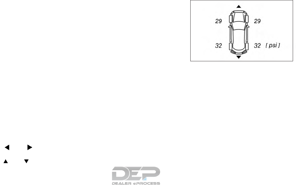
tire pressure warning light flashing for ap-
proximately one minute and then remaining
lit. When the fault has been rectified, the tire
pressure warning light goes out after you
have driven for a few minutes.
The tire pressure values indicated by the ve-
hicle information display may differ from
those measured at a filling station using a
pressure gauge. The tire pressures shown by
the vehicle information display are those
measured at sea level. At high altitudes, the
tire pressure values indicated by a pressure
gauge are higher than those shown by the
vehicle information display. In this case, do
not reduce the tire pressures.
The operation of the tire pressure monitor
can be affected by interference from radio
transmitting equipment (e.g. radio head
phones, two-way radios) that may be being
operated in or near the vehicle.
Checking the tire pressure
electronically
1. Make sure that the ignition switch is in the
ON position.
2. Press the or button on the
steering wheel to select the [Serv.] menu.
3. Press the or button to select
[Tire Pressure].
4. Press <OK> to confirm.
The current tire pressure for each wheel
will be displayed in the vehicle information
display.
If the vehicle was parked for longer than 20
minutes, the [Tire pressures will be displayed
after driving a few minutes] message is
shown.
After a teach-in period, the tire pressure
monitor automatically detects new wheels or
new sensors. If a clear allocation of tire pres-
sure to individual wheels is not possible, the
Tire pressure monitor active message is
shown instead of the tire pressure display.
The tire pressures are already being moni-
tored.
If a replacement wheel is fitted, for a few
minutes the system may continue to show
the tire pressure of the wheel that has been
removed. If this occurs, note that the value
displayed for the position where the replace-
ment wheel is fitted is not the same as the
current tire pressure of the replacement
wheel.
NSD660
5-8 Starting and driving

Tire Pressure Monitoring System
warning messages
If the tire pressure monitor detects a pressure
loss in one or more tires, a warning message
is shown in the vehicle information display
and the yellow tire pressure monitor warning
light comes on.
•If the [Please Correct Tire Pressure] (yel-
low) message appears in the vehicle infor-
mation display, the tire pressure in at least
one tire is too low and must be corrected
at the next opportunity. If the system de-
tects that new sensors have been fitted
(IDs do not match those stored, and the
pressure is not feasible, or is less than 14%
under the norm then the [Please Correct
Tire Pressure] message will be displayed in
white.
•If the [Check Tires] (red) message appears
in the vehicle information display, the tire
pressure in one or more tires has dropped
significantly and the tires must be checked.
•If the [Warning Tire Malfunction] (red)
message appears in the vehicle informa-
tion display, the tire pressure in one or
more tires has dropped suddenly and the
tires must be checked.
•If the [Tire Press. Sensor(s) Missing] mes-
sage appears in the vehicle information
display, one or more sensors are missing or
cannot be detected. This could be the re-
sult of fitting a replacement wheel/tire.
Observe the instructions and safety notes in
the display messages in the vehicle informa-
tion display.
If the wheel positions on the vehicle are inter-
changed, the tire pressures may be displayed
for the wrong positions for a short time. After
a few minutes of driving, this is rectified and
the tire pressures are displayed for the cor-
rect positions.
Restarting TPMS
To keep the TPMS functioning properly, the
restart operation must be performed in the
following cases:
•When the tire pressure is adjusted
•When a tire or a wheel is replaced
•When the tires are rotated
When you restart the tire pressure monitor,
all existing warning messages are deleted
and the warning lights go out. The monitor
uses the currently set tire pressures as the
reference values for monitoring. In most
cases, the tire pressure monitor will auto-
matically detect the new reference values af-
ter you have changed the tire pressure. How-
ever, you can also define reference values
manually as described here. The tire pressure
monitor then monitors the new tire pressure
values.
Perform the following procedures to restart
the TPMS.
NOTE
Before restarting, make sure that the tire
pressures are set properly on all four tires for
the respective operating conditions. The
recommended tire pressures can be found in
the tire pressure placard on the driver' door
pillar.
1. Make sure that the ignition switch is in the
ON position.
2. Press the or button on the
steering wheel to select the [Serv.] menu.
3. Press the or button to select
[Tire Pressure].
4. Press <OK> to confirm.
The vehicle information display shows the
current tire pressure for each tire or the
[Tire pressures will be displayed after
driving a few minutes] message.
If you wish to confirm the restart:
5. Press <OK> to confirm.
Starting and driving 5-9

The [Tire Press. Monitor Restarted] mes-
sage appears in the vehicle information
display.
After you have driven for a few minutes,
the system checks whether the current
tire pressures are within the specified
range The new tire pressures are then
accepted as reference values and moni-
tored
If you wish to cancel the restart:
6. Press the button.
The tire pressure values stored at the last
restart will continue to be monitored
FCC Notice:
For USA:
This device complies with Part 15 of the FCC
Rules. Operation is subject to the following
two conditions: (1) This device may not
cause harmful interference, and (2) this de-
vice must accept any interference received,
including interference that may cause unde-
sired operation.
NOTE
Changes or modifications not expressly ap-
proved by the party responsible for compli-
ance could void the user’s authority to oper-
ate the equipment.
For Canada:
This device complies with Industry Canada
license-exempt RSS standard(s). Operation
is subject to the following two conditions: (1)
this device may not cause interference, and
(2) this device must accept any interference,
including interference that may cause unde-
sired operation of the device.
ON PAVEMENT AND OFF-ROAD
DRIVING PRECAUTIONS
Utility vehicles have a significantly higher
rollover rate than other types of vehicles.
They have higher ground clearance than pas-
senger cars to make them capable of per-
forming in a variety of on-pavement and off-
road applications. This gives them a higher
center of gravity than ordinary vehicles. An
advantage of higher ground clearance is a
better view of the road, allowing you to an-
ticipate problems. However, they are not de-
signed for cornering at the same speeds as
conventional 2-wheel drive vehicles any more
than low-slung sports cars are designed to
perform satisfactorily under off-road condi-
tions. If at all possible, avoid sharp turns at
high speeds. As with other vehicles of this
type, failure to operate this vehicle correctly
may result in loss of control or vehicle roll-
over. In a rollover crash, an unbelted person is
significantly more likely to die than a person
wearing a seat belt.
For additional information, refer to "Driving
safety precautions" later in this section.
AVOIDING COLLISION AND
ROLLOVER
WARNING
Failure to operate this vehicle in a safe and
prudent manner may result in loss of con-
trol or an accident.
Be alert and drive defensively at all times.
Obey all traffic regulations. Avoid excessive
speed, high speed cornering, or sudden steer-
ing maneuvers, because these driving prac-
tices could cause you to lose control of your
vehicle.
As with any vehicle, loss of control could re-
sult in a collision with other vehicles or ob-
jects or cause the vehicle to roll over, par-
ticularly if the loss of control causes the
vehicle to slide sideways. Be attentive at all
times, and avoid driving when tired. Never
drive when under the influence of alcohol or
drugs (including prescription or over the-
counter drugs which may cause drowsiness).
Always wear your seat belt as outlined in the
“Safety – Seats, seat belts and supplemental
5-10 Starting and driving

restraint system” section of this manual, and
also instruct your passengers to do so.
Seat belts help reduce the risk of injury in
collisions and rollovers. In a rollover crash, an
unbelted or improperly belted person is sig-
nificantly more likely to be injured or killed
than a person properly wearing a seat belt.
OFF-ROAD RECOVERY
While driving, the right side or left side wheels
may unintentionally leave the road surface. If
this occurs, maintain control of the vehicle by
following the procedure below. Please note
that this procedure is only a general guide.
The vehicle must be driven as appropriate
based on the conditions of the vehicle, road
and traffic.
1. Remain calm and do not overreact.
2. Do not apply the brakes.
3. Maintain a firm grip on the steering wheel
with both hands and try to hold a straight
course.
4.
When appropriate, slowly release the accel-
erator pedal to gradually slow the vehicle.
5. If there is nothing in the way, steer the
vehicle to follow the road while vehicle
speed is reduced. Do not attempt to drive
the vehicle back onto the road surface
until vehicle speed is reduced.
6. When it is safe to do so, gradually turn the
steering wheel until both tires return to
the road surface. When all tires are on the
road surface, steer the vehicle to stay in
the appropriate driving lane.
If you decide that it is not safe to return
the vehicle to the road surface based on
vehicle, road or traffic conditions, gradu-
ally slow the vehicle to a stop in a safe
place off the road.
RAPID AIR PRESSURE LOSS
Rapid air pressure loss or a “blow-out” can
occur if the tire is punctured or is damaged
due to hitting a curb or pothole. Rapid air
pressure loss can also be caused by driving on
under-inflated tires.
Rapid air pressure loss can affect the han-
dling and stability of the vehicle, especially at
highway speeds.
Help prevent rapid air pressure loss by main-
taining the correct air pressure and visually
inspect the tires for wear and damage. For
additional information, refer to “Wheels and
tires” in the “Maintenance and do-it-yourself”
section of this manual. If a tire rapidly loses air
pressure or “blows-out” while driving, main-
tain control of the vehicle by following the
procedure below. Please note that this pro-
cedure is only a general guide. The vehicle
must be driven as appropriate based on the
conditions of the vehicle, road and traffic.
WARNING
The following actions can increase the
chance of losing control of the vehicle if
there is a sudden loss of tire air pressure.
Losing control of the vehicle may cause a
collision and result in personal injury.
•The vehicle generally moves or pulls in
the direction of the flat tire.
•Do not rapidly apply the brakes.
•Do not rapidly release the accelerator
pedal.
•Do not rapidly turn the steering wheel.
1. Remain calm and do not overreact.
2. Maintain a firm grip on the steering wheel
with both hands and try to hold a straight
course.
3. When appropriate, slowly release the ac-
celerator pedal to gradually slow the ve-
hicle.
4. Gradually steer the vehicle to a safe loca-
tion off the road and away from traffic if
possible.
Starting and driving 5-11

5. Lightly apply the brake pedal to gradually
stop the vehicle.
6. Turn on the hazard warning flashers and
contact a roadside emergency service to
change the tire. For additional informa-
tion, refer to "Flat tire" in the "6. In case of
emergency" section.
DRINKING ALCOHOL/DRUGS
AND DRIVING
WARNING
Never drive under the influence of alcohol
or drugs. Alcohol in the bloodstream re-
duces coordination, delays reaction time
and impairs judgement. Driving after
drinking alcohol increases the likelihood of
being involved in an accident injuring your-
self and others. Additionally, if you are in-
jured in an accident, alcohol can increase
the severity of the injury.
INFINITI is committed to safe driving. How-
ever, you must choose not to drive under the
influence of alcohol. Every year thousands of
people are injured or killed in alcohol-related
accidents. Although the local laws vary on
what is considered to be legally intoxicated,
the fact is that alcohol affects all people dif-
ferently and most people underestimate the
effects of alcohol.
Remember, drinking and driving don’t mix!
And that is true for drugs, too (over-the-
counter, prescription, and illegal drugs). Don’t
drive if your ability to operate your vehicle is
impaired by alcohol, drugs, or some other
physical condition.
DRIVING SAFETY PRECAUTIONS
Your INFINITI is designed for both normal
and off-road use. However, avoid driving in
deep water or mud as your INFINITI is mainly
designed for leisure use, unlike a conventional
off-road vehicle.
Remember that 2–wheel drive vehicles are
less capable than all-wheel drive (AWD)
models for rough road driving and extrication
when stuck in deep snow or mud, or the like.
Please observe the following precautions:
WARNING
•Spinning the front wheels on slippery
surfaces may cause the AWD warning
message to display and the AWD system
to automatically switch from the AWD
to 2WD mode. This could reduce the
traction. Be especially careful when
towing a trailer. (AWD models)
•Drive carefully when off the road and
avoid dangerous areas. Every person
who drives or rides in this vehicle should
be seated with their seat belt fastened.
This will keep you and your passengers
in position when driving over rough ter-
rain.
•Do not drive across steep slopes. Instead
drive either straight up or straight down
the slopes. Off-road vehicles can tip
over sideways much more easily than
they can forward or backward.
•Many hills are too steep for any vehicle.
If you drive up them, you may stall. If you
drive down them, you may not be able to
control your speed. If you drive across
them, you may roll over.
•Do not shift gears while driving on
downhill grades as this could cause loss
of control of the vehicle.
•Stay alert when driving to the top of a
hill. At the top there could be a drop-off
or other hazard that could cause an ac-
cident.
•If your engine stalls or you cannot make
it to the top of a steep hill, never at-
tempt to turn around. Your vehicle could
tip or roll over. Always back straight
down in R (Reverse) gear and apply
brakes to control your speed.
5-12 Starting and driving

•Heavy braking going down a hill could
cause your brakes to overheat and fade,
resulting in loss of control and an acci-
dent. Apply brakes lightly and use a low
gear to control your speed.
•Unsecured cargo can be thrown around
when driving over rough terrain. Prop-
erly secure all cargo so it will not be
thrown forward and cause injury to you
or your passengers.
•Secure heavy loads in the cargo area as
far forward and as low as possible. Do
not equip the vehicle with tires larger
than specified in this manual. This could
cause your vehicle to roll over.
•Do not grip the inside or spokes of the
steering wheel when driving off-road.
The steering wheel could move suddenly
and injure your hands. Instead drive with
your fingers and thumbs on the outside
of the rim.
•Before operating the vehicle, ensure
that the driver and all passengers have
their seat belts fastened.
•Always drive with the floor mats in place
as the floor may become hot.
•Lower your speed when encountering
strong crosswinds. With a higher center
of gravity, your INFINITI is more af-
fected by strong side winds. Slower
speeds ensure better vehicle control.
•Do not drive beyond the performance
capability of the tires, even with AWD
engaged.
•For AWD equipped vehicles, do not at-
tempt to raise two wheels off the
ground and shift the transmission to any
drive or reverse position with the engine
running. Doing so may result in drive-
train damage or unexpected vehicle
movement which could result in serious
vehicle damage or personal injury.
•Do not attempt to test an AWD
equipped vehicle on a 2-wheel dyna-
mometer (such as the dynamometers
used by some states for emissions test-
ing), or similar equipment even if the
other two wheels are raised off the
ground. Make sure you inform test facil-
ity personnel that your vehicle is
equipped with AWD before it is placed
on a dynamometer. Using the wrong
test equipment may result in drivetrain
damage or unexpected vehicle move-
ment which could result in serious ve-
hicle damage or personal injury.
•When a wheel is off the ground due to an
unlevel surface, do not spin the wheel
excessively.
•Accelerating quickly, sharp steering ma-
neuvers or sudden braking may cause
loss of control.
•If at all possible, avoid sharp turning ma-
neuvers, particularly at high speeds.
Your INFINITI vehicle has a higher cen-
ter of gravity than a passenger car. The
vehicle is not designed for cornering at
the same speeds as passenger cars. Fail-
ure to operate this vehicle correctly
could result in loss of control and/or a
rollover accident.
•Always use tires of the same type, size,
brand, construction (bias, bias-belted,
or radial), and tread pattern on all four
wheels. Install tire chains on the front
wheels when driving on slippery roads
and drive carefully.
•Be sure to check the brakes immediately
after driving in mud or water. .
•Avoid parking your vehicle on steep hills.
If you get out of the vehicle and it rolls
forward, backward or sideways, you
could be injured.
Starting and driving 5-13

•Whenever you drive off-road through
sand, mud or water as deep as the wheel
hub, more frequent maintenance may be
required. For additional information, re-
fer to "Maintenance schedules" in the
"9. Maintenance and Schedules"
section.
ALL-WHEEL DRIVE (AWD)
DRIVING SAFETY PRECAUTIONS
(IF SO EQUIPPED)
WARNING
•Replacing tires with those not originally
specified by INFINITI could affect the
proper operation of the TPMS.
•Always use tires of the same type, size,
brand, construction (bias, bias-belted or
radial), and tread pattern on all four
wheels. Install tire chains on the front
wheels when driving on slippery roads
and drive carefully.
•This vehicle is not designed for off-road
(rough road) use. Do not drive on sandy
or muddy roads that tires may get stuck
in.
•For AWD equipped vehicles, do not at-
tempt to raise two wheels off the
ground and shift the transmission to any
D (Drive) or R (Reverse) position with
the engine running. Doing so may result
in drivetrain damage or unexpected ve-
hicle movement which could result in se-
rious vehicle damage or personal injury
•Do not attempt to test an AWD
equipped vehicle on a 2-wheel dyna-
mometer, (such as the dynamometers
used by some states for emissions test-
ing), or similar equipment even if the
other two wheels are raised off the
ground. Make sure you inform test facil-
ity personnel that your vehicle is
equipped with AWD before it is placed
on a dynamometer. Using the wrong
test equipment may result in drivetrain
damage or unexpected vehicle move-
ment which could result in serious ve-
hicle damage or personal injury.
•When a wheel is off the ground due to an
unlevel surface, do not spin the wheel
excessively.
The INFINITI Vehicle Immobilizer System will
not allow the engine to start without the use
of the registered key.
If the engine fails to start using the registered
key, it may be due to interference caused by
another registered key, an automated toll
road device or automated payment device on
the key ring. Restart the engine using the
following procedures:
1. Leave the ignition switch in the ON posi-
tion for approximately 5 seconds.
2. Turn the ignition switch to the OFF or
LOCK position and wait approximately 5
seconds.
3. Repeat Step 1 and 2 again.
4. Restart the engine while holding the de-
vice (which may have caused the interfer-
ence) separate from the registered key.
If the no start condition re-occurs, INFINITI
recommends placing the registered key on a
separate key ring to avoid interference from
other devices.
INFINITI VEHICLE IMMOBILIZER
SYSTEM
5-14 Starting and driving
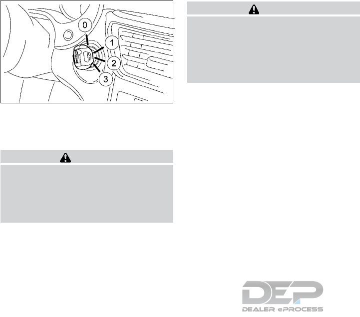
䊊
0OFF position
䊊
1ACC position
䊊
2ON position
䊊
3START position
WARNING
Never remove the key or turn the ignition
switch to the OFF position while driving.
The steering wheel will lock and could
cause the driver to lose control of the ve-
hicle. This could result in serious vehicle
damage or personal injury.
CAUTION
Use electrical accessories with the engine
running to avoid discharging the vehicle
battery. If you must use accessories while
the engine is not running, do not use them
for extended periods of time and do not use
multiple electrical accessories at the same
time.
The switch includes an anti-theft steering
lock device.
STEERING LOCK
To lock the steering wheel
1. Turn the key to the OFF position.
2. Remove the key from the ignition switch.
3. Turn the steering wheel 1/6 of a turn
clockwise from the straight up position.
To unlock the steering wheel
1. Insert the key into the ignition switch.
2. Gently turn the key while rotating the
steering wheel slightly right and left.
KEY POSITIONS
OFF (Normal parking position) 䊊
0
The ignition key can only be removed when in
this position.
The steering lock can only be locked in this
position.
ACC (Accessories)/ 䊊
1
The engine is turned off without locking the
steering wheel. This position activates elec-
trical accessories, such as the radio, when the
engine is not running.
ON (Normal operating position) 䊊
2
This position turns on the ignition system and
electrical accessories.
START 䊊
3
The engine starter activates and the engine
will start. As soon as the engine has started,
release the key immediately. It will return to
the ON position.
NOTE
For vehicles fitted with Idle Stop/Start Sys-
tem:
When the engine is automatically stopped
by the Idle Stop/Start System the ignition
switch can still be operated as usual.
NPA1483
IGNITION SWITCH
Starting and driving 5-15

At the end of a journey turn the ignition OFF
to avoid a discharged battery. The Idle
Stop/Start System does not automatically
turn ignition off.
Vehicles with Intelligent Key are equipped
with keys featuring an integrated Intelligent
Key function and in some cases a detachable
push-button ignition switch (Start/Stop but-
ton).
A check which periodically establishes a radio
connection between the vehicle and the key
determines whether a valid key is in the ve-
hicle. This occurs, for example, when starting
the engine.
When you insert the push-button ignition
switch into the ignition lock, the system
needs approximately two seconds recogni-
tion time. You can then use the push-button
ignition switch.
WARNING
Do not operate the push-button ignition
switch while driving the vehicle except in
an emergency. (The engine will stop when
the ignition switch is pressed 3 consecutive
times in quick succession or the ignition
switch is pushed and held for more than 2
seconds.) If the engine stops while the ve-
hicle is being driven, this could lead to a
crash and serious injury.
Before operating the push-button ignition
switch:
•Select P (Park).
Pressing the Start/Stop button several times
in succession corresponds to the different
key positions in the ignition lock. Prerequisite
for this is that:
•You do not depress the brake pedal.
If you depress the brake pedal and press the
Start/Stop button, the engine starts immedi-
ately.
To start the vehicle without actively using the
key:
•The push-button ignition switch must be
inserted in the ignition lock.
•The key must be in the vehicle.
•The vehicle must not be locked with the
key or Intelligent Key (see "Keys" in the "3.
Pre-driving checks and adjustments" sec-
tion).
Do not keep the Intelligent Key:
•With electronic devices, for example a mo-
bile phone or another key.
•With metallic objects, for example coins or
metal film.
•Inside metallic objects, for example a metal
case.
This can affect the functionality of the Intel-
ligent Key.
PUSH-BUTTON IGNITION SWITCH
(IF EQUIPPED)
5-16 Starting and driving
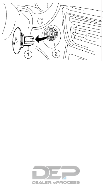
If you lock the vehicle with the key's remote
control or with the Intelligent Key, after a
short time:
•You will not be able to switch on the igni-
tion with the push-button ignition switch.
•You will not be able to start the engine
with the push-button ignition switch until
the vehicle is unlocked again.
If you lock the vehicle centrally using the but-
ton on the front door (see "Locking with in-
side door knob" in the "3. Pre-driving checks
and adjustments" section). you can continue
to start the engine with the push-button ig-
nition switch.
KEY POSITIONS WITH THE
PUSH-BUTTON IGNITION
SWITCH
䊊
1Start/Stop button
䊊
2Ignition lock
When you switch on the ignition, all of the
indicator lights in the combination meter light
up. For further information on situations
where an indicator light either fails to go out
after starting the engine or lights up while
driving see "Warning lights, indicator lights
and audible reminders" in the "2. Instruments
and controls" section.
If the push-button ignition switch 䊊
1has not
yet been pressed, this corresponds to the key
being removed from the ignition.
To switch on the power supply (accessory
mode): press the push-button ignition switch
䊊
1once without depressing the brake pedal.
The power supply is switched on. You can
now activate the windshield wipers, for ex-
ample.
The power supply is switched off again if the
driver's door is opened and you press the
push-button ignition switch 䊊
1twice when in
this position.
To switch on the ignition: press the push-
button ignition switch 䊊
1twice without de-
pressing the brake pedal. The ignition is
switched on.
The ignition is switched off if the driver's door
is opened and you press the push-button
ignition switch 䊊
1when in this position.
REMOVING THE START/STOP
BUTTON
You can remove the start/stop button from
the ignition lock and start the vehicle as nor-
mal using the key.
You can only switch between push-button
ignition switch mode and key operation when
the vehicle is stationary.
You must also engage park position P (Park).
Remove the start/stop button 䊊
1from igni-
tion lock 䊊
2.
NPA1484
Starting and driving 5-17
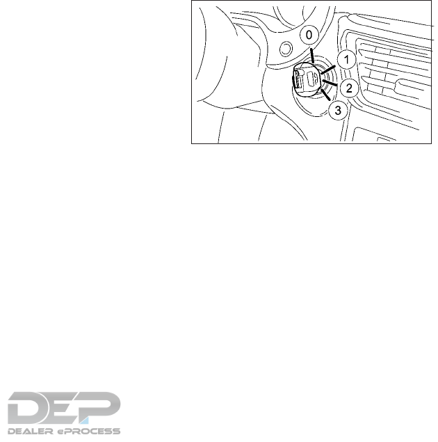
You do not have to remove the start/stop
button from the ignition lock when you leave
the vehicle. You should, however, always
take the key with you when leaving the ve-
hicle. As long as the key is in the vehicle:
•The vehicle can be started using the push-
button ignition switch.
•The electrically powered equipment can be
operated.
EMERGENCY ENGINE SHUT OFF
To shut off the engine in an emergency situ-
ation while driving, perform the following
procedure:
•Rapidly push the push-button ignition
switch 3 consecutive times in less than 1.5
seconds, or
•Push and hold the push-button ignition
switch for more than 2 seconds.
•Make sure the area around the vehicle is
clear.
•Check fluid levels such as engine oil, cool-
ant, brake fluid, and windshield-washer
fluid as frequently as possible, or at least
whenever you refuel.
•Check that all windows and lights are
clean.
•Visually inspect tires for their appearance
and condition. Measure and check the tire
pressure for proper inflation.
•Check that all doors are closed.
•Position seat and adjust head restraints/
headrests.
•Adjust the inside and outside rear view
mirrors.
•Fasten your seat belt and ask all passen-
gers to do likewise.
•Check the operation of the warning lights
when the ignition switch is pushed to the
ON position.
STARTING PROCEDURE WITH
THE KEY
䊊
0OFF position
䊊
1ACC position
䊊
2ON position
䊊
3START position
1. Apply the parking brake.
2. Shift the transmission to position P (Park)
by pressing the <P> button.
The transmission position indicator in the
vehicle information display shows <P>
When the transmission is in position N
(Neutral), you can also start the engine
with the brake pedal depressed.
The starter is designed not to operate if the
shift lever is in any of the driving positions.
NPA1483
BEFORE STARTING ENGINE STARTING ENGINE
5-18 Starting and driving

3. Turn the key to the START position 䊊
3in
the ignition lock and release it as soon as
the engine is running.
If the engine is very hard to start because it is
flooded, depress the accelerator pedal all the
way to the floor and hold it. Turn the ignition
switch to the START position to start crank-
ing the engine. After 5 or 6 seconds, stop
cranking by turning the ignition switch to
OFF. After cranking the engine, release the
accelerator pedal. Crank the engine with your
foot off the accelerator pedal by depressing
the brake pedal and turning the ignition
switch to start the engine. If the engine starts,
but fails to run, repeat the above procedure.
CAUTION
Do not operate the starter for more than
15 seconds at a time. If the engine does not
start, turn the ignition key to the OFF po-
sition and wait 10 seconds before cranking
again, otherwise the starter could be
damaged.
4. Warm-up
Allow the engine to idle for at least 30
seconds after starting. Do not race the
engine while warming it up. Drive at mod-
erate speed for a short distance first, es-
pecially in cold weather. In cold weather,
keep the engine running for a minimum of
2 - 3 minutes before shutting it off. Start-
ing and stopping the engine over a short
period of time may make the vehicle more
difficult to start.
5. To stop the engine, Shift the transmission
to position P (Park) by pressing the <P>
button. and turn the ignition switch to the
OFF position.
NOTE
Care should be taken to avoid situations
that can lead to potential battery discharge
and potential no-start conditions such as:
•Installation or extended use of electronic
accessories that consume battery power
when the engine is not running (Phone
chargers, GPS, DVD players, etc.)
•Vehicle is not driven regularly and/or only
driven short distances. In these cases, the
battery may need to be charged to main-
tain battery health.
STARTING PROCEDURE USING
THE PUSH-BUTTON IGNITION
SWITCH (IF EQUIPPED)
The push-button ignition switch can be used
to start the vehicle manually without insert-
ing the key into the ignition lock. The key must
be in the vehicle and the start/stop button
must be inserted in the ignition lock (see "Re-
moving the start/stop button" earlier in this
section). This mode for starting the engine
operates independently of the ECO start/
stop automatic engine start function.
You can start the engine if a valid key is in the
vehicle. Switch off the engine and always
take the key with you when leaving the ve-
hicle, even if you only leave it for a short time.
Pay attention to the important safety notes.
•Depress the brake pedal and keep it de-
pressed.
•Press the push button ignition switch once
(see " Push-button ignition switch (if
equipped)" earlier in this section). The en-
gine starts.
Starting and driving 5-19

DRIVING WITH AUTOMATIC
TRANSMISSION
Driving precautions
•Do not depress the accelerator pedal
while shifting from P (Park) or N (Neutral)
to R (Reverse), D (Drive), or M (Manual
shift mode). Always depress the brake
pedal until shifting is completed. Failure
to do so could cause you to lose control
and have an accident.
•Cold engine idle speed is high, so use cau-
tion when shifting into a forward or re-
verse gear before the engine has warmed
up.
•Never shift to either the P (Park) or R
(Reverse) position while the vehicle is
moving forward and P (Park) or D (Drive)
position while the vehicle is reversing.
This could cause an accident or damage
the transmission.
•Except in an emergency, do not shift to
the N (Neutral) position while driving.
Coasting with the transmission in the N
(Neutral) position may cause serious
damage to the transmission.
WARNING
•Do not downshift abruptly on slippery
roads. this may cause a loss of control.
CAUTION
•To avoid possible damage to your ve-
hicle; when stopping the vehicle on an
uphill grade, do not hold the vehicle by
depressing the accelerator pedal. The
foot brake should be used for this pur-
pose.
•Except in an emergency, do not shift to
the N (Neutral) position while driving.
Coasting with the transmission in the N
(Neutral) position may cause serious
damage to the transmission.
Starting the vehicle
1. After starting the engine, fully depress the
brake pedal before shifting the shift lever
to R (Reverse), D (Drive) or Manual shift
mode.
2. Keep the brake pedal depressed and push
the shift lever to shift into a driving gear.
3. Release the parking brake and brake, then
gradually put the vehicle in motion by
pressing the accelerator pedal.
The automatic transmission is designed so
that the brake pedal MUST be depressed
before shifting from P (Park) to any drive
position while the ignition switch is ON.
DRIVING THE VEHICLE
5-20 Starting and driving
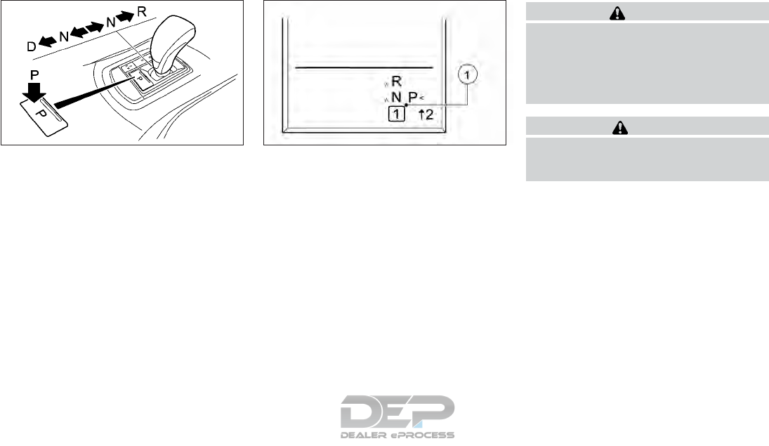
Shifting
P Park position with parking lock
R Reverse
N Neutral
D Drive
Transmission position display:
NOTE
If the transmission position display in the ve-
hicle information display is not working, you
should pull away carefully to check whether
the desired transmission position IS en-
gaged. Ideally, you should select transmis-
sion position D and automatic drive program
EorS.
The shift lever indicator 䊊
1located in the
lower part of the vehicle information display
shows the current position of the transmis-
sion.
It shows the P,R,N,D modes when the trans-
mission is in auto mode or the shift position
when the transmission is in manual mode.
WARNING
Apply the parking brake if the shift lever is
in any position while the engine is not run-
ning. Failure to do so could cause the ve-
hicle to move unexpectedly or roll away
and result in serious personal injury or
property damage.
CAUTION
Use the P (Park) or R (Reverse) position
only when the vehicle is completely
stopped.
NSD585 NSD649
Starting and driving 5-21
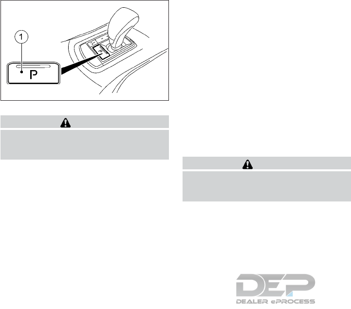
P (Park):
CAUTION
To prevent transmission damage, use the P
(Park) position only when the vehicle is
completely stopped.
Use this position when the vehicle is parked
or when starting the engine. Always make
sure that the vehicle is completely stopped
before pressing button 䊊
1to engage the P
(Park) position. For maximum safety, the
brake pedal must be depressed before en-
gaging the P (Park) position. Use this position
together with the parking brake. When park-
ing on a hill, first depress the brake pedal,
apply the parking brake and then engage the
P (Park) position. The parking lock should not
be used as a brake when parking. In order to
secure the vehicle, always apply the electric
parking brake in addition to the parking lock.
In the event of a malfunction of the vehicle's
electronics, the transmission may lock in po-
sition P (Park). Have the vehicle electronics
checked immediately. It is recommended you
visit an INFINITI retailer for this service.
Park position P is automatically engaged if:
•You switch off the engine using the key
and remove the key.
•You open the driver's door when the ve-
hicle is stationary or driving at very low
speed and the transmission is in position D
(Drive) or R (Reverse).
R (Reverse):
CAUTION
To prevent transmission damage, use the R
(Reverse) position only when the vehicle is
completely stopped.
Use this position to back up the vehicle.
Make sure the vehicle is completely stopped
before selecting the R (Reverse) position. The
brake pedal must be depressed and the shift
lever button pushed in to move the shift le-
ver from P (Park), N (Neutral) or any drive
position to R (Reverse).
N (Neutral):
Neither forward nor reverse gear is engaged.
The engine can be started in this position. You
may shift to N (Neutral) and restart a stalled
engine while driving the vehicle.
D (Drive):
Use this position for all normal forward driv-
ing.
The automatic transmission changes gear
automatically. All forward gears are avail-
able.
Changing gear
The automatic transmission shifts to the in-
dividual gears automatically when it is in
transmission position D (Drive). Shifting is de-
termined by:
•The selected drive program.
•The position of the accelerator pedal.
•The road speed.
Accelerator pedal position:
Your style of driving influences how the au-
tomatic transmission shifts gear:
•little throttle: early upshifts
•more throttle: late upshifts
NSD586
5-22 Starting and driving
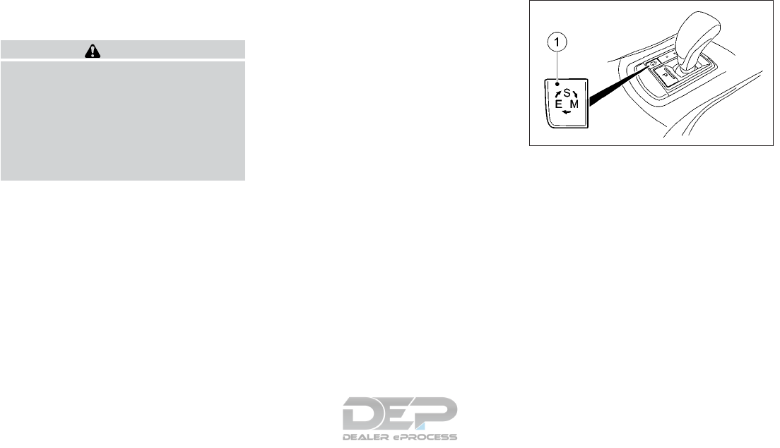
Holding the vehicle stationary on
uphill gradients
WARNING
If the transmission overheats, the elec-
tronic management system is automati-
cally deactivated. This interrupts the
power transmission from the engine to the
wheels. The vehicle may, for example, roll
backwards on gradients. There is a risk of
an accident. Never hold the vehicle station-
ary on uphill gradients by depressing the
accelerator.
The transmission may overheat if you hold
the vehicle stationary on uphill gradients by
depressing the accelerator pedal. If the trans-
mission overheats, a warning tone sounds
and the [Stop Vehicle Shift to P Leave Engine
Running] display message appears in the ve-
hicle information display. You will only be able
to continue your journey once the transmis-
sion has cooled down and the display mes-
sage in the vehicle information display has
disappeared.
Never hold the vehicle stationary on uphill
gradients by depressing the accelerator. In-
stead, only ever hold the vehicle stationary on
uphill gradients by:
•Depressing the brake pedal.
•Engaging the electric parking brake.
Kickdown
Use kickdown for maximum acceleration:
•Depress the accelerator pedal beyond the
pressure point.
The transmission shifts to a lower gear
depending on the engine speed.
•Ease off the accelerator pedal once the
desired speed is reached.
The automatic transmission shifts back up.
Drive mode switch
The drive mode switch allows you to choose
between drive programs with different driv-
ing characteristics.
Press drive mode switch 䊊
1. The selected
drive program appears in the vehicle informa-
tion display.
The automatic transmission switches to drive
program E each time the engine is started.
E (Economy): comfortable, economical driv-
ing
S (Sport): sporty driving style
M (Manual): manual gear shifting
For more details of the manual drive program
see "Manual drive program" later in this sec-
tion.
NSD587
Starting and driving 5-23
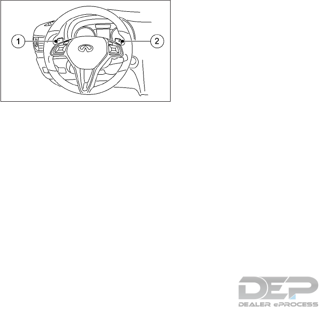
Steering wheel gearshift paddles
䊊
1Left steering wheel gearshift paddle
(shifts down)
䊊
2Right steering wheel gearshift paddle
(shifts up)
In drive program M, you can change gear
yourself using the steering wheel gearshift
paddles.
If you pull the left or right steering wheel
gearshift paddle when in automatic drive
program E or S, the automatic transmission
shifts into drive program M for a limited time.
Depending on which gearshift paddle is
pulled, the automatic transmission immedi-
ately shifts into the next gear down or up.
Automatic drive programs
Drive program E is characterized by the fol-
lowing:
•Comfort-oriented engine settings.
•Optimal fuel consumption resulting from
the automatic transmission shifting up
sooner.
•The vehicle pulling away more gently in
forward and reverse gears unless the ac-
celerator pedal is depressed fully.
•Increased sensitivity. This improves han-
dling on slippery road surfaces, for ex-
ample.
•The automatic transmission shifting up
sooner. This results in the vehicle being
driven at lower engine speeds and the
wheels being less likely to spin.
Drive program S is characterized by the fol-
lowing:
•Sporty engine settings.
•The automatic transmission shifting up
later.
•As a result of the later automatic transmis-
sion shift points, the fuel consumption
possibly being higher.
Manual drive program
In manual drive program M, you can change
gear yourself by using the steering wheel
gearshift paddles. For this, the transmission
must be in position D (Drive). The gear cur-
rently selected and engaged is shown in the
vehicle information display
Manual drive program M differs from drive
programs E and S with regard to spontaneity,
responsiveness and smoothness of gear
changes.
Using manual gears:
3 To use the engine's braking effect
2 To use the braking effect of the engine on
downhill gradients and for driving on steep
mountain roads, in mountainous terrain or
in arduous conditions.
1 To use the braking effect of the engine on
extremely steep downhill gradients and on
long downhill stretches.
NSD584
5-24 Starting and driving
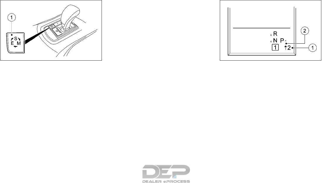
Activating the manual drive program:
•Permanently: Press the drive mode switch
䊊
1repeatedly until M appears in the ve-
hicle information display. Manual drive
program M remains active until drive pro-
gram E or S is engaged.
•Temporarily: Pull the right or left steering
wheel gearshift paddle (see "Steering
wheel gearshift paddles" later in this sec-
tion). Manual drive program M is tempo-
rarily active. Depending on which gearshift
paddle is pulled, the automatic transmis-
sion immediately shifts into the next gear
down or up.
When manual drive program M is activated
via the steering wheel gearshift paddles, the
temporarily active manual drive program M
will be deactivated automatically after a lim-
ited time, if the driving situation permits. The
automatic transmission switches to the pre-
viously activated drive program E or S. When
driving on downhill gradients, the temporarily
active manual drive program M will only be
deactivated if the accelerator pedal is de-
pressed while the vehicle is rolling downhill.
Upshifting:
Pull the right-hand steering wheel gearshift
paddle (see "Steering wheel gearshift
paddles" earlier in this section). The auto-
matic transmission shifts up to the next gear.
In order to prevent engine damage the auto-
matic transmission automatically shifts up if
the maximum engine speed on the currently
engaged gear is reached and you depress the
accelerator pedal.
Gearshift recommendation:
The gearshift recommendations assist you in
adopting an economical driving style. The
recommended gear is shown in the vehicle
information display.
Shift to recommended gear 䊊
1according to
gearshift recommendation 䊊
2when shown in
the vehicle information display.
Downshifiting:
Pull the left-hand steering wheel gearshift
paddle (see "Steering wheel gearshift
paddles" earlier in this section). The auto-
matic transmission shifts down to the next
gear.
If you slow down or stop without shifting
down, the automatic transmission automati-
cally shifts down.
NSD587 NSD589
Starting and driving 5-25

For maximum acceleration, pull the left-hand
steering wheel gearshift paddle until the
transmission selects the optimum gear for
the current speed.
If the engine exceeds the maximum engine
speed when shifting down, the automatic
transmission protects against engine dam-
age by not shifting down.
Kickdown:
You can also use kickdown for maximum ac-
celeration in manual drive program M
•Depress the accelerator pedal beyond the
pressure point The transmission shifts to a
lower gear depending on the engine
speed.
•Shift back up once the desired speed is
reached.
During kickdown, you cannot shift gears us-
ing the steering wheel gearshift paddles.
If you apply full throttle, the automatic trans-
mission shifts up to the next gear when the
maximum engine speed is reached. This pre-
vents the engine from overrevving.
Deactivating the temporary manual drive
program:
Pull and hold the right steering wheel gear-
shift paddle until the automatic transmission
shifts into the last active automatic drive pro-
gram E or S.
When manual drive program M is deacti-
vated, the automatic transmission in auto-
matic drive program E or S may shift from the
current gear into a higher or lower gear. This
is dependent on the position of the accelera-
tor pedal, speed and load.
Problems with the transmission:
Problem Possible causes/consequences and solutions
The transmission has
problems shifting
gear
The transmission is losing oil.
Have the transmission checked immediately. It is recommended you visit an INFINITI retailer for this service.
The acceleration abil-
ity is deteriorating
The transmission no
longer shifts into all
of the gears Reverse
gear can no longer be
engaged
The transmission is in emergency mode.
•Stop.
•Shift the transmission to position P (Park).
•Switch off the engine.
•Wait at least ten seconds before restarting the engine.
•Shift the transmission to position D (Drive).
•Have the transmission checked immediately. It is recommended you visit an INFINITI retailer for this service.
5-26 Starting and driving
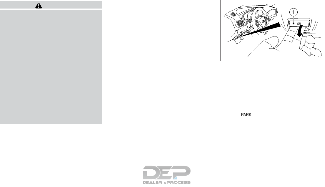
WARNING
•Be sure the parking brake is fully re-
leased before driving. Failure to do so
can cause brake failure and lead to an
accident.
•Do not release the parking brake from
outside the vehicle.
•Do not use the shift lever in place of the
parking brake. When parking, be sure
the parking brake is fully engaged.
•To help avoid risk of injury or death
through unintended operation of the
vehicle and/or its systems, do not leave
children, people who require the assis-
tance of others, or pets unattended in
your vehicle. Additionally, the tempera-
ture inside a closed vehicle on a warm
day can quickly become high enough to
cause a significant risk of injury or death
to people and pets.
The function of the electric parking brake is
dependent on the on-board voltage. If the
on-board voltage is low or if there is a mal-
function in the system, it may not be possible
to apply the released parking brake. If this is
the case:
•Only park the vehicle on level ground and
secure it to prevent it from rolling away.
•Shift the automatic transmission to posi-
tion P (Park).
•It is recommended you contact an
INFINITI retailer.
It may not be possible to release an applied
parking brake if the on-board voltage is low
or if there is a malfunction in the system. It is
recommended you contact an INFINITI re-
tailer.
The electric parking brake carries out a func-
tion check at regular intervals when the en-
gine is switched off. Noises that occur are
normal.
APPLYING/RELEASING
MANUALLY
The electric parking brake can be applied or
released by operating the parking brake
handle 䊊
1.
To apply: Push handle 䊊
1.
When the electric parking brake is applied,
the red indicator light lights up in the
combination meter.
The electric parking brake can also be applied
when the ignition switch is in the OFF posi-
tion or the key is removed.
To release: With the ignition switch in the ON
position, pull handle 䊊
1.
NPA1485
PARKING BRAKE
Starting and driving 5-27

Before driving, check that the brake warning
light goes out. For additional informa-
tion, see "Warning lights, indicator lights and
audible reminders" in the "2. Instruments and
controls" section.
The electric parking brake can only be re-
leased when the ignition switch is in the ON
position.
APPLYING AUTOMATICALLY
(VEHICLES WITH AUTOMATIC
TRANSMISSION)
The electric parking brake is automatically
applied when:
•Intelligent cruise control (if equipped)
brings the vehicle to a standstill.
or
•Intelligent Parking Assist (if equipped) is
keeping the vehicle stationary.
The red indicator light lights up in the
combination meter.
The electric parking brake is not automati-
cally applied if the engine is switched off by
the Idle Stop/Start function.
RELEASING AUTOMATICALLY
The electric parking brake can only be re-
leased automatically in vehicles with auto-
matic transmission.
The electric parking brake of your vehicle is
released automatically when all of the fol-
lowing conditions are fulfilled:
•The engine is running.
•The transmission is in position D (Drive) or
R (Reverse).
•The seat belt is fastened.
•You depress the accelerator pedal.
If the transmission is in position R, the lift
gate must be closed.
If your seat belt is not fastened, the following
conditions must be fulfilled to automatically
release the electric parking brake:
•The driver's door is closed
•You have shifted out of transmission posi-
tion P (Park) or you have previously driven
faster than 2 MPH (3 km/h).
Ensure that you do not depress the accelera-
tor pedal unintentionally. Otherwise, the
parking brake will be released and the vehicle
will start to move.
EMERGENCY BRAKING
The vehicle can also be braked during an
emergency by using the electric parking
brake.
While driving, push handle 䊊
1of the electric
parking brake. The vehicle is braked as long as
you keep handle 䊊
1of the electric parking
brake pressed. The longer the electric parking
brake handle 䊊
1is depressed, the greater the
braking force.
During braking:
•A warning tone sounds.
•The [Please Release Parking Brake] mes-
sage appears.
•The red indicator light in the combi-
nation meter flashes.
When the vehicle has been braked to a stand-
still, the electric parking brake is applied.
5-28 Starting and driving
The Idle Stop/Start function switches the
engine off automatically if the vehicle is
stopped under certain conditions.
When pulling away again, the engine starts
automatically. The Idle Stop/Start function
thereby helps you to reduce the fuel con-
sumption and emissions of your vehicle.
WARNING
If the engine is switched off automatically
and you exit the vehicle, the engine is re-
started automatically. The vehicle may be-
gin moving There is a risk of accident and
injury.
If you wish to exit the vehicle, always turn
off the ignition and secure the vehicle
against rolling away.
If the Idle Stop/Start symbol is shown
in green in the vehicle information display, the
Idle Stop/Start function switches the engine
off automatically once the vehicle stops mov-
ing.
The Idle Stop/Start function is automatically
activated each time you start the engine with
the ignition key.
If the Idle Stop/Start function has been
manually deactivated (see "Deactivating/
activating the Idle Stop/Start function" later
in this section) or a malfunction has caused
the system to be deactivated, the Idle
Stop/Start symbol is not displayed.
AUTOMATIC ENGINE
SWITCH-OFF
The Idle Stop/Start function is operational
and the Idle Stop/Start symbol is dis-
played in green in the vehicle information dis-
play, if:
•The indicator light in the ECO button is lit
green.
•The outside temperature is within the
range that is suitable for the system.
•The engine is at normal operating tem-
perature.
•The set temperature for the vehicle interior
has been reached.
•The battery is sufficiently charged.
•The system detects that the windshield is
not misted up when the air-conditioning
system is switched on.
•The hood is closed.
•The driver's door is closed and the driver's
seat belt is fastened.
If the conditions for automatic engine
switch-off are not all fulfilled, the Idle
Stop/Start symbol is shown in yellow.
NSD620
Idle Stop/Start symbol
IDLE STOP/START SYSTEM (IF
EQUIPPED)
Starting and driving 5-29
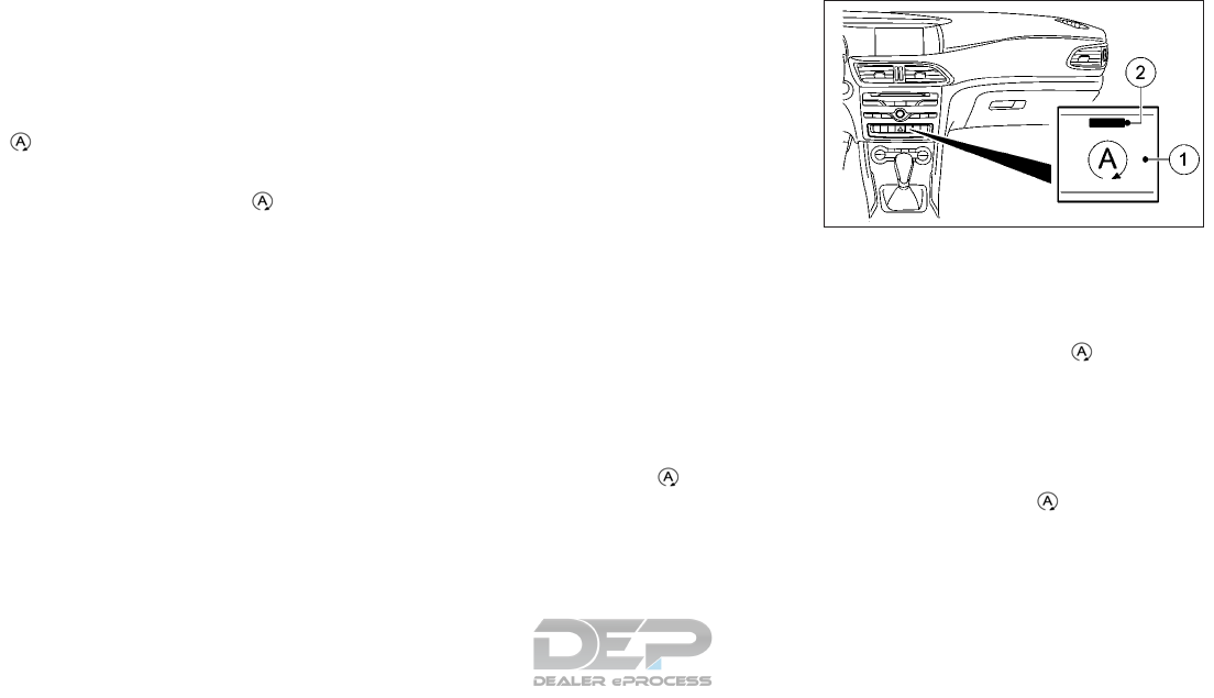
All of the vehicle's systems remain active
when the engine is switched off automati-
cally.
The engine can be switched off automatically
a maximum of four times (initial stop, then
three subsequent stops) in succession. The
Idle Stop/Start symbol is shown in yel-
low in the vehicle information display after
the engine has been started automatically for
the fourth time. When the Idle Stop/
Start symbol is shown in green in the vehicle
information display, automatic engine
switch-off is again possible.
NOTE
If the hood is opened while the engine is run-
ning and the Idle Stop/Start function is op-
erational, the engine will switch off auto-
matically.
If the vehicle is brought to a standstill in D or
N, the Idle Stop/Start function switches off
the engine automatically.
AUTOMATIC ENGINE START
The engine is started automatically if:
•You switch off the Idle Stop/Start func-
tion by pressing the ECO button.
•You engage Reverse R or Drive D.
•You unfasten your seat belt or open the
driver's door.
•The vehicle starts to roll.
•The brake system requires this.
•The temperature in the vehicle interior de-
viates from the set range.
•The system detects moisture on the wind-
shield when the air-conditioning system is
switched on.
•The battery's charge status is too low.
The engine is started automatically if you:
•Release the brake pedal in transmission
position D (Drive) or N (Neutral).
•Depress the accelerator pedal.
•Move the transmission out of position P
(Park).
Shifting the transmission to position P (Park)
does not start the engine.
If you shift the transmission from R (Reverse)
to D (Drive), the Idle Stop/Start function is
available again once the Idle Stop/
Start symbol reappears in green in the vehicle
information display.
DEACTIVATING/ACTIVATING
THE IDLE STOP/START
FUNCTION
•To deactivate: press ECO button 䊊
1. Indi-
cator light 䊊
2and the Idle Stop/
Start symbol in the vehicle information dis-
play turn off.
•To activate: press ECO button 䊊
1. Indica-
tor light 䊊
2lights up. If all conditions for
automatic engine switch-off (see "Auto-
matic engine switch-off" earlier in this sec-
tion) are fulfilled, the Idle Stop/Start
symbol is shown in green in the vehicle
information display.
NIC2633
5-30 Starting and driving

If not all conditions for automatic engine
switch-off are met, the Idle Stop/
Start symbol is lit yellow in the vehicle
information display. If this is the case, the
Idle Stop/Start function is not active.
If indicator light 䊊
2on ECO button 䊊
1is off,
the Idle Stop/Start function has been deacti-
vated manually or as the result of a malfunc-
tion. The engine will then not be switched off
automatically when the vehicle stops.
WARNING
Failure to follow the warnings and instruc-
tions for proper use of the LDW system
could result in serious personal injury or
death. The LDW system will not steer the
vehicle or prevent loss of control. It is the
driver’s responsibility to stay alert, drive
safely, keep the vehicle in the traveling
lane, and be in control of the vehicle at all
times.
The LDW system warns the driver with a
warning light and intermittent steering vibra-
tion that the vehicle is beginning to leave the
traveling lane.
The LDW system uses a camera 䊊
1installed
behind the windshield to monitor the lane
markers of your traveling lane.
NSD644
LANE DEPARTURE WARNING (LDW)
SYSTEM (IF EQUIPPED)
Starting and driving 5-31
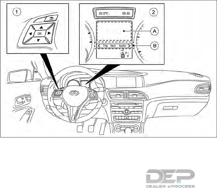
LDW SYSTEM OPERATION
䊊
1Steering wheel mounted controls
䊊
2Vehicle information display
䊊
ADisplay area
䊊
BMenu bar
The LDW system operates at speeds of ap-
proximately 40 MPH (60 km/h) and above,
when the lane markings are clear.
If the system detects that the vehicle's front
wheel has passed over the lane marking, a
warning will be provided. It will warn you by
means of intermittent vibration through the
steering wheel for up to 1.5 seconds and a
visual alert.
NOTE
The LDW system is designed not to warn
when you operate the lane change signal and
change traveling lanes in the direction of the
signal.
No warning vibration occurs if you activate
the turn signals. In this event, the warnings
are suppressed for a certain period of time.
NSD626
5-32 Starting and driving

HOW TO ENABLE/DISABLE THE
LDW SYSTEM
1. Press the or button on the
steering wheel 䊊
1to select the [DriveAs-
sist] menu on the Menu bar 䊊
B.
2. Press the or button to select
[Lane Departure Warning].
3. Press the <OK> button on the steering
wheel 䊊
1. The current selection is dis-
played.
4. Press the <OK> to confirm.
5. Press the or button to set
[Off], [Standard] or [Adaptive].
6. Press the <OK> button to save the setting.
When the LDW is activated, the vehicle
information display shows the lane mark-
ings as bright lines in the assistance
graphic in the display area 䊊
A
When [Standard] is selected, no warning vi-
bration occurs if:
•You have switched on the turn signals. In
this event, the warnings are suppressed
for a certain period of time.
•A driving safety system intervenes, such as
ABS, brake assist system (BAS) or VDC.
When [Adaptive] is selected, no warning vi-
bration occurs if:
•You have switched on the turn signals. In
this case the warnings are suppressed for
a certain period of time.
•A driving system intervenes, such as ABS,
BAS or VDC.
•You accelerate forcefully.
•You brake forcefully.
•You steer actively, for example, swerve to
avoid an obstacle or change lane quickly.
•You cut the corner on a sharp bend.
The system may detect certain conditions
and warns you accordingly.
The warning vibration occurs earlier if:
•You approach the outer lane marking on a
bend.
•The road has very wide lanes, for example,
a freeway.
•The system detects solid lane markings.
The warning vibration occurs later if:
•The road has narrow lanes.
•You cut across a corner on a bend.
LDW SYSTEM LIMITATIONS
WARNING
Listed below are the system limitations for
the LDW system. Failure to operate the
vehicle in accordance with these system
limitations could result in serious injury or
death.
•This system is only a warning device to
inform the driver of a potential unin-
tended lane departure. It will not steer
the vehicle or prevent loss of control. It
is the driver’s responsibility to stay
alert, drive safely, keep the vehicle in the
traveling lane, and be in control of the
vehicle at all times.
NSD599
Assistance graphic
Starting and driving 5-33

•The system will not operate at speeds
below approximately 40 MPH (60
km/h) or if it cannot detect lane mark-
ers.
•The LDW system is primarily intended
for use on well-developed freeways or
highways. It may not detect the lane
markers in certain roads, weather or
driving conditions.
•Do not use the LDW system under the
following conditions as it may not func-
tion properly:
–During bad weather (rain, fog, snow,
etc.).
–When driving on slippery roads, such
as on ice or snow, etc.
–When driving on winding or uneven
roads.
–When there is a lane closure due to
road repairs.
–When driving in a makeshift or tem-
porary lane.
–When driving on roads where the lane
width is too narrow.
–When driving without normal tire
conditions (for example, tire wear,
low tire pressure, installation of
spare tire, tire chains, non-standard
wheels).
–When the vehicle is equipped with
non-original brake parts or suspen-
sion parts.
•The camera may not detect lane markers
in the following situations and the LDW
system may not operate properly.
–On roads where there are multiple
parallel lane markers; lane markers
that are faded or not painted clearly;
yellow painted lane markers; non-
standard lane markers; or lane mark-
ers covered with water, dirt, snow,
etc.
–On roads where the discontinued lane
markers are still detectable.
–On roads where there are sharp
curves.
–On roads where there are sharply
contrasting objects, such as shad-
ows, snow, water, wheel ruts, seams
or lines remaining after road repairs.
(The LDW system could detect these
items as lane markers.)
–On roads where the traveling lane
merges or separates.
–When the vehicle’s traveling direc-
tion does not align with the lane
marker.
–When traveling close to the vehicle in
front of you, which obstructs the lane
camera unit detection range.
–When rain, snow or dirt adheres to
the windshield in front of the lane
camera unit.
–When the headlights are not bright
due to dirt on the lens or if the aiming
is not adjusted properly.
–When strong light enters the lane
camera unit. (For example, the light
directly shines on the front of the ve-
hicle at sunrise or sunset.)
–When a sudden change in brightness
occurs. (For example, when the ve-
hicle enters or exits a tunnel or under
a bridge.)
–When there is poor visibility. (For ex-
ample, due to insufficient illumina-
tion of the road, or due to snow, rain,
fog or spray.
–When there is glare. (For example,
from oncoming traffic, the sun or re-
flection when the road is wet).
5-34 Starting and driving

䊊
1Steering wheel mounted controls
䊊
2Vehicle information display
䊊
ADisplay area
䊊
BMenu bar
LDW SYSTEM TEMPORARILY
UNAVAILABLE
Under the following conditions, the LDW
system will be canceled automatically, and
the message [Lane Departure Warning Cur-
rently Unavailable See Operator's Manual] is
displayed in the vehicle information display
䊊
2. The LDW system is temporarily unavail-
able.
•The windshield is dirty in the camera's field
of vision.
•Visibility is impaired due to heavy rain,
snow or fog.
•There have been no lane markings for an
extended period.
•The lane markings are worn, dark, or cov-
ered by dirt or snow, etc.
Action to take: When the above conditions
no longer exist, the message goes out and the
LDW system is operational again. If the mes-
sage continues to appear, stop the vehicle in
a safe location, press the P (Park) button , and
clean the windshield.
SYSTEM MALFUNCTION
If the LDW system malfunctions, it will cancel
automatically, and the message [Lane De-
parture Warning Inoperative] will appear.
Action to take: Stop the vehicle in a safe
location, engage P (Park), turn the engine off
and restart the engine. If the message contin-
ues to appear, have the system checked. It is
recommended you visit an INFINITI retailer
for this service.
NSD626
Starting and driving 5-35

SYSTEM MAINTENANCE
The lane camera unit 䊊
1for the LDW system
is located above the inside mirror.
To ensure the proper operation of the LDW
system and prevent a system malfunction, be
sure to observe the following:
•Always keep the windshield clean.
•Do not attach a sticker (including transpar-
ent material) or install an accessory near
the camera unit.
•Do not place reflective materials, such as
white paper or a mirror, on the instrument
panel. The reflection of sunlight may ad-
versely affect the camera unit’s capability
of detecting the lane markers.
•Do not strike or damage the areas around
the camera unit. Do not touch the camera
lens or remove parts from the camera unit.
If the camera unit is damaged due to an
accident, it is recommended you contact
an INFINITI retailer.
WARNING
Failure to follow the warnings and instruc-
tions for proper use of the BSW system
could result in serious injury or death.
•The Blind Spot Warning (BSW) system
is not a replacement for proper driving
procedure and is not designed to pre-
vent contact with vehicles or objects.
When changing lanes, always use the
side and rear mirrors and turn and look in
the direction you will move to ensure it is
safe to change lanes. Never rely solely
on the BSW system.
The Blind Spot Warning (BSW) system can
help alert the driver of other vehicles in adja-
cent lanes when changing lanes.
NSD644
BLIND SPOT WARNING (BSW)
SYSTEM (IF EQUIPPED)
5-36 Starting and driving
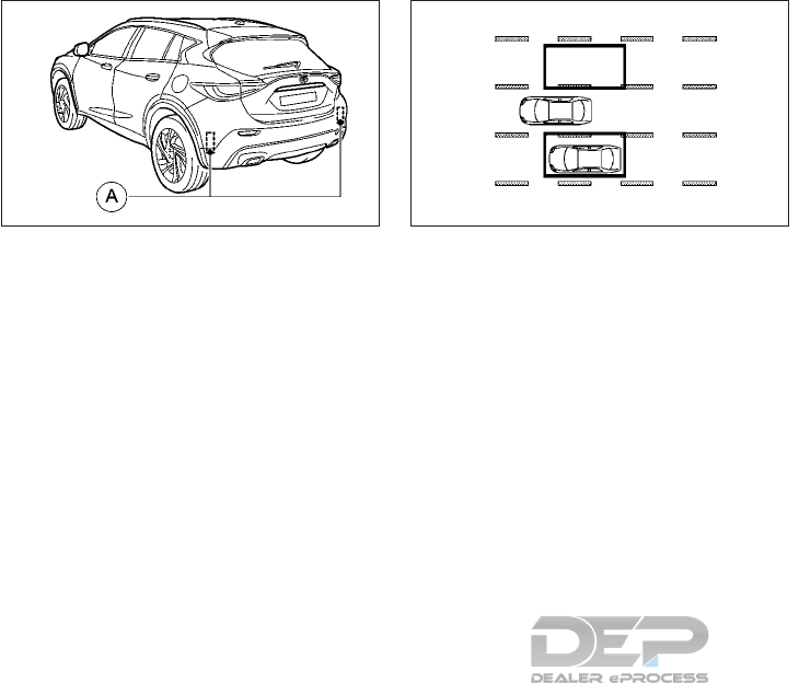
The BSW system uses radar sensors 䊊
Ain-
stalled near the rear bumper to detect other
vehicles beside your vehicle in an adjacent
lane.
The radar sensors can detect vehicles on ei-
ther side of your vehicle within the detection
zone shown as illustrated. This detection
zone starts from the outside mirror of your
vehicle and extends approximately 10 ft (3 m)
behind the rear bumper, and approximately
10 ft (3 m) sideways.
NAA1727 SSD1030Z
Detection zone
Starting and driving 5-37

BSW SYSTEM OPERATION
䊊
1Side indicator light
䊊
2Steering wheel mounted controls
䊊
3Vehicle information display
䊊
AMENU bar
The BSW system operates above approxi-
mately 20 MPH (30 km/h). When the BSW is
activated, the side indicator light illuminates
in yellow up to a speed of 20 MPH (30
km/h). At speeds above 20 MPH (30 km/h),
the indicator light goes out and the BSW
system is operational.
Illustration 1: If the radar sensors detect a
vehicle in the detection zone, the BSW indi-
cator light 䊊
1located by the outside mirrors
illuminates.
NSD623
SSD1026Z
Illustration 1
5-38 Starting and driving

Illustration 2: If the turn signal is then acti-
vated, the system chimes (twice) and the
BSW indicator light flashes. The BSW indica-
tor light continues to flash until the detected
vehicles leave the detection zone.
NOTE
•The BSW indicator lights illuminate for a
few seconds when the ignition switch is
placed in the ON position.
•The brightness of the BSW indicator lights
is adjusted automatically depending on the
brightness of the ambient light.
•If a vehicle comes into the detection zone
after the driver activates the turn signal,
then only the BSW indicator light flashes
and no chime sounds. (See "Another ve-
hicle approaching from behind" later in this
section.)
A chime sounds if the radar sensors have
already detected vehicles when the driver ac-
tivates the turn signal.
WARNING
•Do not use the BSW system when tow-
ing a trailer because the system may not
function properly.
•Excessive noise (for example audio sys-
tem volume, open vehicle window) will
interfere with the chime sound, and it
may not be heard.
•The radar sensors may not be able to
detect and activate BSW when certain
objects are present such as:
–Pedestrians, bicycles, animals
–Several types of vehicles such as mo-
torcycles
–Oncoming vehicles
–Vehicles remaining in the detection
zone when you accelerate from a
stop.
–A vehicle merging into an adjacent
lane at a speed approximately the
same as your vehicle.
–A vehicle approaching rapidly from
behind.
–A vehicle which your vehicle over-
takes rapidly.
•Severe weather or road spray conditions
may reduce the ability of the radar to
detect other vehicles.
•The radar sensors detection zone is de-
signed based on a standard lane width.
When driving in a wider lane, the radar
sensors may not detect vehicles in an
adjacent lane. When driving in a narrow
lane, the radar sensors may detect ve-
hicles driving two lanes away.
•The radar sensors are designed to ignore
most stationary objects, however ob-
jects such as guardrails, walls, foliage
and parked vehicles may occasionally be
detected. This is a normal operating
condition.
SSD1031Z
Illustration 2
Starting and driving 5-39
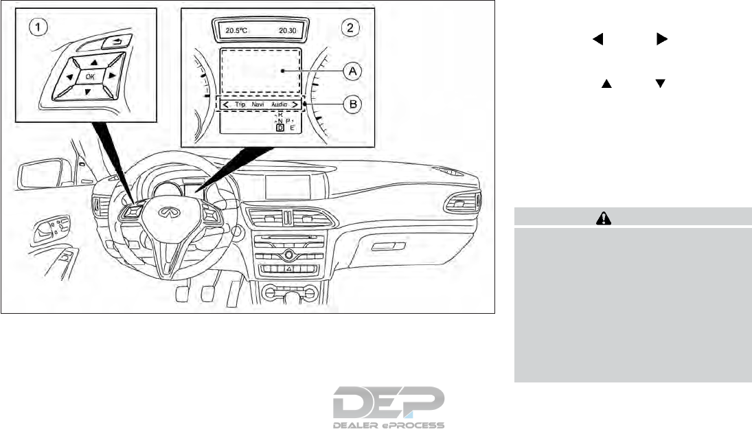
HOW TO ENABLE/DISABLE THE
BSW SYSTEM
䊊
1Steering wheel mounted controls (left
side)
䊊
2Vehicle information display
䊊
ADisplay area
䊊
BMENU bar
To enable/disable the BSW system, use the
following procedure:
1. Press the <or> button on the
steering wheel 䊊
1to select the [DriveAs-
sist ] menu on the Menu bar 䊊
B.
2. Press the or button 䊊
1to
select Blind Spot Warning.
3. Press the <OK> button on the steering
wheel 䊊
1. The current selection is dis-
played.
4. To activate/deactivate BSW: press the
<OK> button 䊊
1again
BSW SYSTEM LIMITATIONS
WARNING
Listed below are the system limitations for
the BSW system. Failure to operate the
vehicle in accordance with these system
limitations could result in serious injury or
death.
•The BSW system cannot detect all ve-
hicles under all conditions.
•The radar sensors may not be able to
detect and activate BSW when certain
objects are present such as:
–Pedestrians, bicycles, or animals.
NSD626
5-40 Starting and driving
–Vehicles such as motorcycles, low
height vehicles, or high ground clear-
ance vehicles.
–Oncoming vehicles.
–Vehicles remaining in the detection
zone when you accelerate from a
stop.
–A vehicle merging into an adjacent
lane at a speed approximately the
same as your vehicle.
–A vehicle that is too close to your
vehicle.
–A vehicle approaching rapidly from
behind.
–A vehicle which your vehicle over-
takes rapidly.
•The radar sensors detection zone is de-
signed based on a standard lane width.
When driving in a wider lane, the radar
sensors may not detect vehicles in an
adjacent lane. When driving in a narrow
lane, the radar sensors may detect ve-
hicles driving two lanes away.
•The radar sensors are designed to ignore
most stationary objects, however ob-
jects such as guardrails, walls, foliage
and parked vehicles may occasionally be
detected. This is a normal operating
condition.
•The following conditions may reduce the
ability of the radar to detect other ve-
hicles:
–Severe weather
–Road spray
–Ice/frost/dirt build-up on the vehicle
•Do not attach stickers (including trans-
parent material), install accessories or
apply additional paint near the radar
sensors. These conditions may reduce
the ability of the radar to detect other
vehicles.
•Do not use the BSW system when tow-
ing a trailer because the system may not
function properly.
•Excessive noise (e.g. audio system vol-
ume, open vehicle window) will interfere
with the chime sound, and it may not be
heard.
•The BSW system may not provide a
warning for vehicles that pass through
the detection zone quickly.
Another vehicle approaching from
behind
Illustration 1: The BSW indicator light illumi-
nates if a vehicle enters the detection zone
from behind in an adjacent lane.
However, if the overtaking vehicle is travel-
ling much faster than your vehicle, the indica-
tor light may not illuminate before the de-
tected vehicle is beside your vehicle. Always
use the side and rear mirrors and turn and
look in the direction your vehicle will move to
ensure it is safe to change lanes.
SSD1026Z
Illustration 1 – Approaching from behind
Starting and driving 5-41
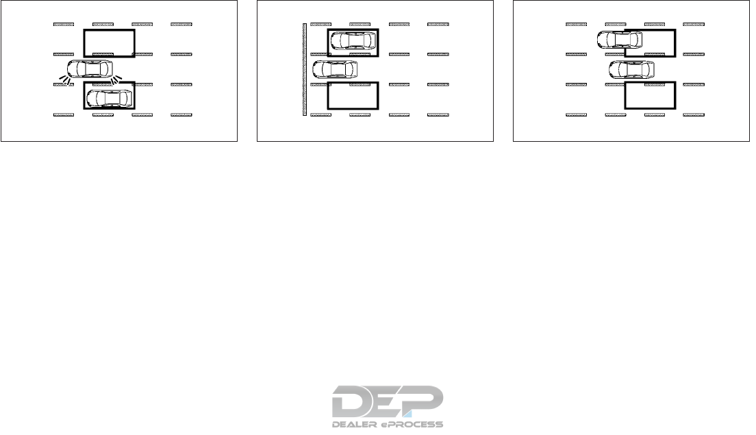
Illustration 2: If the driver activates the turn
signal, then the system chimes (twice) and the
BSW indicator light flashes.
NOTE
•The radar sensors may not detect vehicles
which are approaching rapidly from be-
hind.
•If the driver activates the turn signal be-
fore a vehicle enters the detection zone,
the BSW indicator light will flash but no
chime will sound when the other vehicle is
detected.
Accelerate from a stop
NOTE
Illustration 3: If you accelerate from a stop
with a vehicle in the detection zone, the
other vehicle may not be detected.
Overtaking another vehicle
When you overtake a vehicle, the warning
only occurs if the difference in speed is less
than 7 MPH (12 km/h).
Illustration 4: The side indicator light illumi-
nates if you overtake a vehicle and that ve-
hicle stays in the detection zone for approxi-
mately 3 seconds.
SSD1031Z
Illustration 2 – Approaching from behind
SSD1032Z
Illustration3–Acceleratefromastop
SSD1033Z
Illustration 4 – Overtaking another vehicle
5-42 Starting and driving

Illustration 5: If the driver activates the turn
signal while another vehicle is in the detection
zone, then the system chimes (twice) and the
BSW indicator light flashes.
NOTE
•When overtaking several vehicles in a row,
the vehicles after the first vehicle may not
be detected if they are travelling close to-
gether.
•The radar sensors may not detect slower
moving vehicles if they are passed quickly.
•If the driver activates the turn signal be-
fore a vehicle enters the detection zone,
the side indicator light will flash but no
chime will sound when the other vehicle is
detected.
Overtaking several vehicles
Illustration 6: When overtaking several ve-
hicles in a row, the vehicles after the first
vehicle may not be detected if they are trav-
elling close together.
SSD1034Z
Illustration 5 – Overtaking another vehicle
SSD1036Z
Illustration 6 – Overtaking several vehicles
Starting and driving 5-43
Entering from the side
Illustration 7: The side indicator light illumi-
nates if a vehicle enters the detection zone
from either side.
Illustration 8: If the driver activates the turn
signal, then the BSW indicator light flashes
and a chime will sound twice.
NOTE
•The radar sensors may not detect a vehicle
which is travelling at about the same
speed as your vehicle when it enters the
detection zone.
•If the driver activates the turn signal be-
fore a vehicle enters the detection zone,
the BSW indicator light will flash but no
chime will sound when another vehicle is
detected.
SSD1037Z
Illustration 7 – Entering from the side
SSD1038Z
Illustration 8 – Entering from the side
5-44 Starting and driving
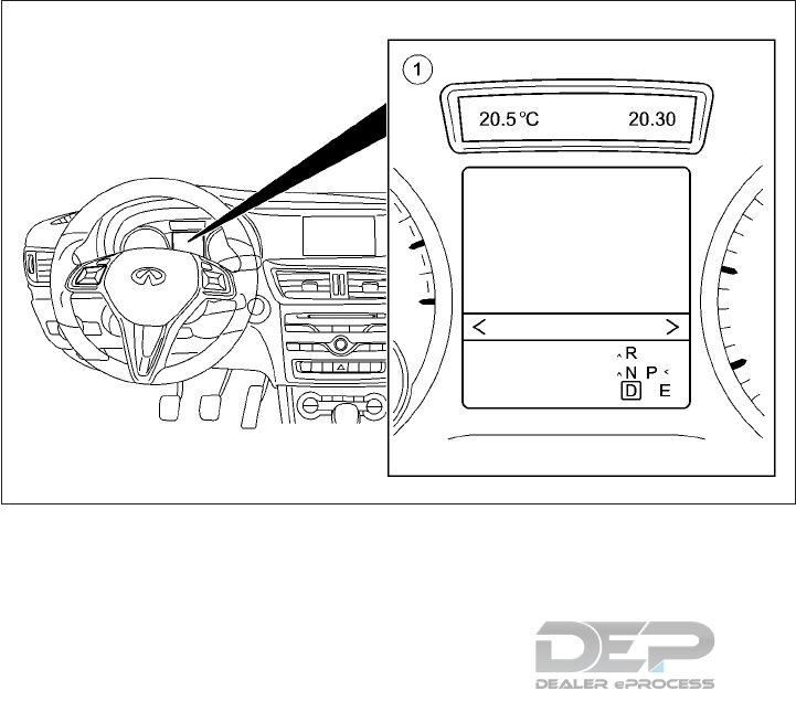
SYSTEM TEMPORARILY
UNAVAILABLE
䊊
1Vehicle information display
If radar blockage is detected, the system will
be turned off automatically, and the [Blind
Spot Warning Currently Unavailable See Op-
erator's Manual] message appears in the ve-
hicle information display 䊊
1. The system is
not available until the conditions no longer
exist.
The radar sensors may be blocked by tempo-
rary ambient conditions such as splashing
water, mist or fog. The blocked condition
may also be caused by objects such as ice,
frost or dirt obstructing the radar sensors.
Action to take: When the above conditions
no longer exist, the system will resume auto-
matically. If the message still appears, have
the system checked. It is recommended you
visit an INFINITI retailer for this service.
System malfunction
If the system malfunctions, it will be turned
off automatically, and the [Blind Spot Warn-
ing Inoperative] message appears in the ve-
hicle information display 䊊
1.
Action to take: Stop the vehicle in a safe
location, place the vehicle in the P (Park) po-
sition, turn the engine off and restart the
engine.
If the message still appears, have the system
checked. It is recommended you visit an
INFINITI retailer for this service.
NSD631
Starting and driving 5-45
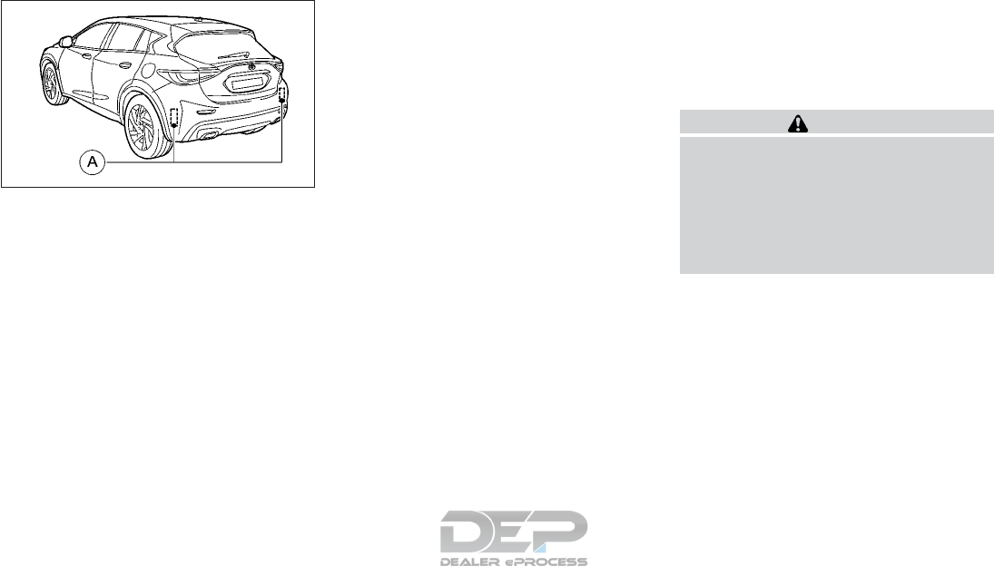
RADAR MAINTENANCE
The two radar sensor units 䊊
Afor the BSW
system are located near the rear bumper.
Always keep the area near the radar sensors
clean.
The radar sensors may be blocked by tempo-
rary ambient conditions such as splashing
water, mist or fog.
The blocked condition may also be caused by
objects such as ice, frost or dirt obstructing
the radar sensors.
Check for and remove objects obstructing
the area around the radar sensors.
Do not attach stickers (including transparent
material), install accessories or apply addi-
tional paint near the radar sensors.
Do not strike or damage the area around the
radar sensors. It is recommended you consult
an INFINITI retailer if the area around the
radar sensors is damaged due to a collision.
FCC NOTICE
For USA:
This device complies with Part 15 of the FCC
Rules. Operation is subject to the following
two conditions: (1) This device may not
cause harmful interference, and (2) this de-
vice must accept any interference received,
including interference that may cause unde-
sired operation.
NOTE
Changes or modification not expressly ap-
proved by the party responsible for compli-
ance could void the user’s authority to oper-
ate the equipment.
For Canada:
This device complies with Industry Canada
license-exempt RSS standard(s). Operation
is subject to the following two conditions: (1)
this device may not cause harmful interfer-
ence, and (2) this device must accept any
interference received, including interference
that may cause undesired operation of the
device.
Cruise control maintains a constant road
speed for you. It brakes automatically in order
to avoid exceeding the set speed. You must
select a lower gear in good time on long and
steep downhill gradients, especially if the ve-
hicle is laden or towing a trailer.
WARNING
For vehicles with automatic transmission,
you need to have selected manual drive
program M (see "Manual drive program"
earlier in this section). By doing so, you will
make use of the braking effect of the en-
gine. This relieves the load on the brake
system and prevents the brakes from over-
heating and wearing too quickly.
Use cruise control only if road and traffic
conditions are appropriate for maintaining a
steady speed for a prolonged period. You can
set the cruise control at any road speed
above 20 MPH (30 km/h).
The speed indicated in the speedometer may
differ slightly from the set speed.
NAA1640
CRUISE CONTROL
5-46 Starting and driving
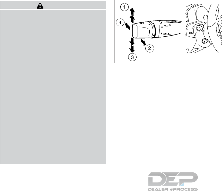
WARNING
•If you fail to adapt your driving style,
cruise control can neither reduce the risk
of an accident nor override the laws of
physics. Cruise control cannot take into
account road, weather or traffic condi-
tions. Cruise control is only an aid. You
are responsible for the distance to the
vehicle in front, for vehicle speed, for
braking in good time, and for staying in
lane.
•Always observe the posted speed limits
and do not set the speed over them.
•Do not use the cruise control when driv-
ing under the following conditions. Do-
ing so could cause a loss of vehicle con-
trol and result in an accident.
–When it is not possible to keep the
vehicle at a constant speed
–When driving in heavy traffic
–When driving in traffic that varies
speed
–When driving in windy areas
–When driving on winding or hilly
roads
–When driving on slippery (rain, snow,
ice, etc.) roads
CRUISE CONTROL OPERATIONS
䊊
1Store the current speed or a higher speed
䊊
2Store the current speed, or if a speed has
previously been stored, call up the last
stored speed.
䊊
3Store the current speed or a lower speed
䊊
4Deactivate the cruise control system
When you activate cruise control, the stored
speed is shown in the vehicle information
display for five seconds.
Activation conditions
To activate cruise control, all of the following
activation conditions must be fulfilled:
•The electric parking brake must be re-
leased.
•You are driving faster than 20 MPH (30
km/h).
•VDC must be switched on, but not inter-
vening.
Storing, maintaining and calling up
a speed
Storing and maintaining the current speed:
You can store the current speed if you are
driving faster than 20 MPH (30 km/h):
1. Accelerate the vehicle to the desired
speed.
2. Briefly press the cruise controller lever up
䊊
1or down 䊊
3.
3. Remove your foot from the accelerator
pedal.
Cruise control is activated. The vehicle auto-
matically maintains the speed.
NSD618A
Starting and driving 5-47

NOTE
Cruise control may be unable to maintain the
stored speed on uphill gradients. The stored
speed is resumed when the gradient evens
out. Cruise control maintains the stored
speed on downhill gradients by automati-
cally braking the vehicle.
Storing the current speed or calling up the
last stored speed:
WARNING
If you call up a stored speed and this is
different from the current speed, the ve-
hicle accelerates or brakes. If you do not
know what the stored speed is, the vehicle
may accelerate or brake unexpectedly.
There is a risk of an accident.
Take the traffic conditions into account
before calling up the stored speed. If you do
not know what the stored speed is, store
the desired speed again.
1. Briefly pull the cruise control lever to-
wards you 䊊
2.
2. Remove your foot from the accelerator
pedal. The first time cruise control is acti-
vated, it stores the current speed or if a
speed has previously been stored, it regu-
lates the speed of the vehicle to the pre-
viously stored speed.
Setting a speed
Bear in mind that it may take a brief moment
until the vehicle has accelerated or braked to
the set speed.
1. Press the cruise control lever up 䊊
1for a
higher speed or down 䊊
3for a lower
speed.
2. Keep the cruise control lever pressed until
the desired speed is reached.
3. Release the cruise control lever, The new
speed is stored.
4. To adjust the set speed in 1 MPH (1 km/h)
increments: briefly press the cruise control
lever up 䊊
1or down 䊊
3to the pressure
point. The last stored speed increases or
decreases in 1 MPH (1 km/h) increments.
5. To adjust the set speed in 10 MPH (10
km/h) increments: briefly press the cruise
control lever up 䊊
1or down 䊊
3beyond the
pressure point. The last stored speed in-
creases or decreases in 10 MPH
(10 km/h) increments.
NOTE
Cruise control is not deactivated if you de-
press the accelerator pedal. For example, if
you accelerate briefly to overtake, cruise
control adjusts the vehicle's speed to the last
speed stored after you have finished over-
taking.
Deactivating cruise control
There are several ways to deactivate cruise
control:
•Briefly press the cruise control lever for-
ward 䊊
4.
or
•Brake.
Cruise control is automatically deactivated if:
•The vehicle is secured with the electric
parking brake.
•You are driving at less than 20 MPH (30
km/h).
•VDC intervenes or you deactivate VDC.
If cruise control is deactivated, you will hear a
warning tone. You will see the [Cruise Control
Off] message in the vehicle information dis-
play for approximately five seconds.
NOTE
The last speed stored is cleared when you
switch off the engine.
5-48 Starting and driving

WARNING
Failure to follow the warnings and instruc-
tions for proper use of the ICC system
could result in serious injury or death.
•ICC is not a collision avoidance or warn-
ing device. For highway and freeway
way use only and not intended for con-
gested areas or city driving. Failure to
apply the brakes could result in an acci-
dent. It is the driver’s responsibility to
stay alert, drive safely, and be in control
of the vehicle at all times.
•Always observe posted speed limits and
do not set the speed over them.
•Always drive carefully and attentively
when using the ICC. Read and under-
stand the Owner’s Manual thoroughly
before using the ICC system. To avoid
serious injury or death, do not rely on the
system to prevent accidents or to con-
trol the vehicle’s speed in emergency
situations. Do not use the ICC system
except in appropriate road and traffic
conditions.
INTELLIGENT CRUISE CONTROL
(ICC) SYSTEM (FULL SPEED RANGE)
(IF EQUIPPED)
Starting and driving 5-49
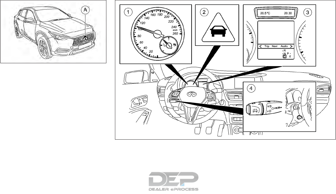
ICC SYSTEM OPERATION
䊊
1Speedometer
䊊
2Distance warning light
䊊
3Vehicle information display
䊊
4Cruise control lever
The ICC system is intended to enhance the
operation of the vehicle when following a
vehicle traveling in the same lane and direc-
tion.
If the distance sensor 䊊
Adetects a slower
moving vehicle ahead, the system will reduce
NSD645
NSD625
5-50 Starting and driving
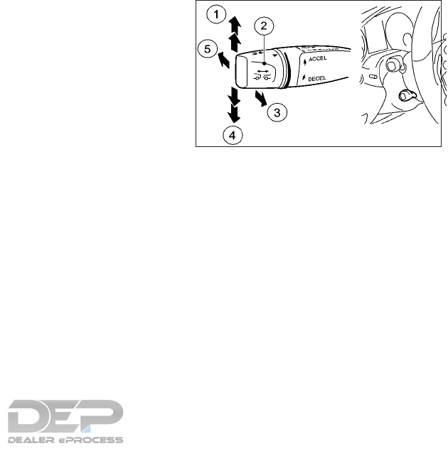
the vehicle speed so that your vehicle follows
the vehicle in front at the selected distance.
The ICC system maintains a selected distance
from the vehicle in front of you within the
speed range of 0 to 125 MPH (0 to 200
km/h) up to the set speed. The set speed can
be selected by the driver between 20 to 125
MPH (30 to 200 km/h).
The vehicle travels at a set speed when the
road ahead is clear.
The ICC system is designed to maintain a
selected distance from the vehicle in front of
you and reduce the speed to match a slower
vehicle ahead. The system will decelerate the
vehicle as necessary and if the vehicle ahead
comes to a stop, the vehicle decelerates to a
standstill. However, the ICC system can only
apply up to 50% of the vehicle’s total braking
power. This system should only be used when
traffic conditions allow vehicle speeds to re-
main fairly constant or when vehicle speeds
change gradually. If a vehicle moves into the
traveling lane ahead or if a vehicle traveling
ahead rapidly decelerates, the distance be-
tween vehicles may become closer because
the ICC system cannot decelerate the vehicle
quickly enough. If this occurs, the ICC system
will sound a warning chime and illuminate the
distance warning light to notify the driver to
take necessary action.
The following items are controlled in the ICC
system:
•When there are no vehicles traveling
ahead, the ICC system maintains the
speed set by the driver. The set speed
range is between approximately 20 and
125 MPH (30 and 200 km/h).
•When there is a vehicle traveling ahead,
the ICC system adjusts the speed to main-
tain the distance, selected by driver, from
the vehicle ahead. The adjusting speed
range is up to the set speed. If the vehicle
ahead comes to a stop, the vehicle decel-
erates to a standstill within the limitations
of the system. Once the vehicle is station-
ary, it remains stationary and you do not
need to depress the brake pedal.
•When the vehicle traveling ahead has
moved out from its lane of travel, pull the
cruise control lever or push the accelerator
pedal briefly. The ICC system accelerates
and maintains vehicle speed up to the set
speed.
The ICC system does not control vehicle
speed or warn you when you approach sta-
tionary and slow moving vehicles. You must
pay attention to vehicle operation to main-
tain proper distance from vehicles ahead
when approaching toll gates or traffic con-
gestion.
ICC SWITCH (CRUISE CONTROL
LEVER)
䊊
1Store the current speed or a higher speed
䊊
2Set the specified minimum distance
䊊
3Store the current speed or call up the last
stored speed
䊊
4Store the current speed or a lower speed
䊊
5Deactivate the ICC system
The ICC system is operated by the cruise
control lever, located on the steering column.
NSD582A
Starting and driving 5-51

ICC SYSTEM DISPLAY AND
INDICATORS
Displays in the speedometer
When the ICC system is activated and there
are no vehicles detected ahead, one or two
segments 䊊
2in the set speed range light up.
If the ICC system detects a vehicle ahead,
segments 䊊
2between speed of the vehicle
ahead 䊊
3and stored speed 䊊
1light up.
NOTE
For design reasons, the speed displayed in
the speedometer may differ slightly from the
speed set for the ICC system.
Display when the ICC system is
deactivated
䊊
1Vehicle ahead, if detected
䊊
2Distance indicator: current distance to
the vehicle ahead
䊊
3Specified minimum distance to the ve-
hicle ahead; adjustable
䊊
4Own vehicle
Display when the ICC system is
activated
You will initially see the stored speed for
about five seconds when you activate the
ICC system.
䊊
1Vehicle ahead, if detected
䊊
2Specified minimum distance to the ve-
hicle ahead; adjustable
䊊
3Own vehicle
䊊
4ICC stored speed (text only appears
when the cruise control lever is actuated)
NIC2824A NSD614 NSD601
5-52 Starting and driving
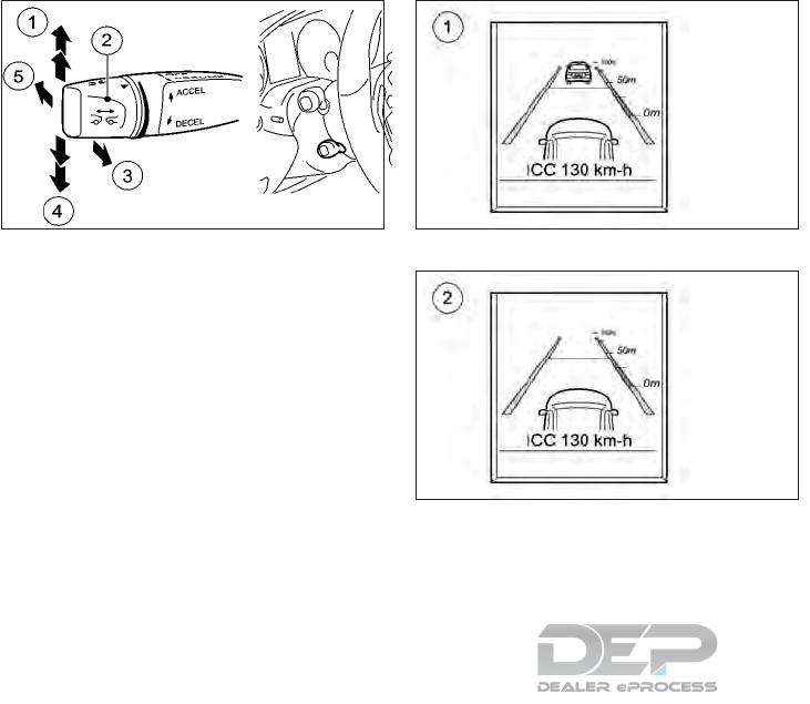
OPERATING ICC
To set cruising speed, accelerate your vehicle
to the desired speed and quickly push the
cruise control lever, up 䊊
1or down 䊊
4. Take
your foot off the accelerator pedal. Your ve-
hicle will maintain the set speed.
NOTE
If you do not fully release the accelerator
pedal, the [ICC Suspended] message ap-
pears in the vehicle information display. The
set distance to a slower-moving vehicle in
front will then not be maintained. You will be
driving at the speed you determine by the
position of the accelerator pedal.
You can also activate the ICC when station-
ary. The lowest speed that can be set is 20
MPH (30 km/h ).
System operation
The driver sets the desired vehicle speed
based on the road conditions. The ICC sys-
tem maintains the set vehicle speed, similar to
standard cruise control, as long as no vehicle
is detected in the lane ahead. The ICC system
displays the set speed for 5 seconds after the
cruise control lever is activated.
Vehicle detected ahead:
When a vehicle is detected in the lane ahead,
the ICC system decelerates the vehicle by
controlling the throttle and applying the
brakes to match the speed of a slower vehicle
ahead. The system then controls the vehicle
speed based on the speed of the vehicle
ahead to maintain the driver selected dis-
tance.
The brake lights of the vehicle come on when
braking is performed by the ICC system.
When the brake operates, a noise may be
heard. This is not a malfunction.
When a vehicle ahead is detected, the vehicle
ahead symbol 䊊
1appears in the vehicle infor-
mation display.
Vehicle ahead not detected:
When a vehicle is no longer detected ahead,
the ICC system gradually accelerates your
vehicle to resume the previously set vehicle
speed. The ICC system then maintains the set
speed.
When a vehicle is no longer detected, the
vehicle ahead display turns off 䊊
2.
NSD582A NSD615
System set display with vehicle ahead
NSD616
System set display without vehicle ahead
Starting and driving 5-53
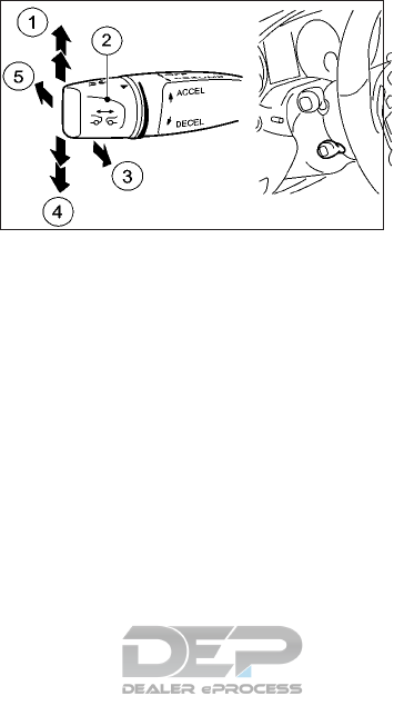
If a vehicle ahead appears during accelera-
tion to the set vehicle speed or any time the
ICC system is in operation, the system con-
trols the distance to that vehicle.
Changing lanes to pass another
vehicle:
When you changes lane to pass another ve-
hicle, ICC supports the action if:
•The vehicle speed is more than 45 MPH
(70 km/h)
•The ICC is maintaining the distance to a
vehicle in front
•The respective turn signal is activated
If these conditions are met, the vehicle will be
accelerated. Acceleration will be interrupted
if changing lanes takes too long or if the
distance between your vehicle and the ve-
hicle in front becomes too small.
How to change the set vehicle
speed
To cancel the preset speed, use any of these
methods:
•Tap the brake pedal when the vehicle is
moving.
•Quickly push the cruise control lever in the
direction of arrow 䊊
5.
The message [ICC OFF] appears in the ve-
hicle information display for 5 seconds.
To reset at a higher cruising speed, use one of
the following methods:
•Depress the accelerator pedal. When the
vehicle attains the desired speed, quickly
pull the cruise control lever towards you
䊊
3.
•Pull the cruise control lever up 䊊
1beyond
the pressure point. The set vehicle speed
will increase by approximately 10 MPH
(10 km/h).
•
Pull the cruise control lever up (1) at the
pressure point. The set vehicle speed will
increase by approximately 1 MPH (1 km/h).
To reset at a lower cruising speed, use one of
the following methods:
•Lightly tap the brake pedal. When the ve-
hicle attains the desired speed, quickly pull
the cruise control lever towards you 䊊
3.
•Pull the cruise control lever down 䊊
4be-
yond the pressure point. The set vehicle
speed will decrease by approximately 10
MPH (10 km/h).
•
Pull the cruise control lever down
䊊
4
to the
pressure point. The set vehicle speed will de-
crease by approximately 1 MPH (1 km/h).
To resume the preset speed, quickly pull the
cruise control lever towards you 䊊
4. The ve-
hicle will resume the last set cruising speed
when the vehicle speed is over 20 MPH
(30 km/h).
NOTE
If you do not fully release the accelerator
pedal, the [ICC Deactivated Automatically]
message appears in the vehicle information
NSD582A
5-54 Starting and driving

display. The set distance to a slower-moving
vehicle in front will then not be maintained.
You will be driving at the speed you deter-
mine by the position of the accelerator pedal.
You can also activate ICC when stationary.
The lowest speed that can be set is 20 MPH
(30 km/h).
Stopping
WARNING
•To help avoid risk of injury or death
through unintended operation of the
vehicle and/or its systems, do not leave
children, people who require the assis-
tance of others, or pets unattended in
your vehicle.
•The ICC system should only be used to
keep the vehicle stationary when the
driver is actively using the system.
When parking the vehicle, make sure to
turn OFF the ICC system, use the brake,
press the PARK (P) button, and place
the ignition switch in the LOCK position
prior to exiting the vehicle. Failure to do
so could lead to serious injury or death.
The ICC system will not hold the vehicle
in place after coming to a stop when any
of the following conditions occur:
–There is a malfunction in the system
or in the voltage supply.
–The ICC system has been deactivated
with the cruise control lever, e. g. by a
vehicle occupant.
–The accelerator pedal has been de-
pressed, e.g. by a vehicle occupant.
For further information on deactivating the
ICC system, see "ICC switch (cruise control
lever)" earlier in this section
If the ICC system detects that the vehicle in
front is stopping, it brakes your vehicle until it
is stationary (within the braking limitations of
the system).
Once your vehicle is stationary, it remains
stationary and you do not need to depress
the brake.
NOTE
•After a short period, the vehicle is secured
by the electric parking brake, thus relieving
the service brake.
•Depending on the specified minimum dis-
tance, your vehicle will come to a standstill
at a sufficient distance behind the vehicle
in front. The specified minimum distance is
set using the control on the cruise control
lever.
The electric parking brake secures the vehicle
automatically if the ICC system is activated
when the vehicle is stationary and:
•A system fault occurs.
•The power supply is insufficient.
If a malfunction in the electric parking brake
occurs, then the transmission may also be
shifted into position P (Park) automatically.
Starting and driving 5-55
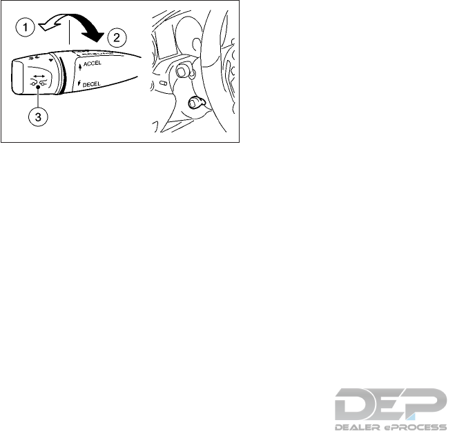
How to change the set distance to
the vehicle ahead
The distance to the vehicle ahead can be
selected at any time depending on the traffic
conditions.
To increase the distance to the vehicle ahead,
turn the knob 䊊
3toward the rear 䊊
2.To
decrease the distance to the vehicle ahead,
turn the knob 䊊
3toward the front 䊊
1.
You can see this distance in the vehicle infor-
mation display.
The distance to the vehicle ahead will change
according to the vehicle speed. The higher the
vehicle speed, the longer the distance.
Approach warning
If your vehicle comes closer to the vehicle
ahead due to rapid deceleration of that ve-
hicle or if another vehicle cuts in, the system
warns the driver with the chime and distance
warning light. Decelerate by depressing the
brake pedal to maintain a safe vehicle dis-
tance if:
•The chime sounds.
•The distance warning light is illuminated.
The warning chime may not sound and the
distance warning light may not illuminate in
some cases when there is a short distance
between vehicles. Some examples are:
•When the vehicles are traveling at the
same speed and the distance between ve-
hicles is not changing. In this case, the
distance warning light will be on.
•When the vehicle ahead is traveling faster
and the distance between vehicles is in-
creasing.
•When a vehicle cuts in near your vehicle
•The warning chime will not sound and the
distance warning light will not illuminate
when:
– The vehicle approaches other vehicles
that are parked or moving slowly.
– The accelerator pedal is depressed,
overriding the system.
Also, the sensor sensitivity can be affected by
vehicle operation (steering maneuver or driv-
ing position in the lane) or traffic or vehicle
condition (for example, if a vehicle is being
driven with some damage).
Automatic cancellation
A chime sounds and the message [ICC off] is
displayed in the vehicle information display
for 5 seconds under the following conditions
and the control is automatically canceled.
•The electric parking brake is applied.
•The VDC intervenes or the VDC is deacti-
vated.
•The P (Park), R (Reverse) or N (Neutral)
position is engaged.
•The cruise control lever is pulled in order to
pull away but the front passenger door or
one of the rear doors is open.
•The vehicle is skidding or a wheel slips.
•Active Park Assist is activated.
NSD583A
5-56 Starting and driving

ICC LIMITATIONS
WARNING
Listed below are the system limitations for
the ICC system. Failure to operate the ve-
hicle in accordance with these system limi-
tations could result in serious injury or
death.
•This system is only an aid to assist the
driver and is not a collision warning or
avoidance device. It is the driver’s re-
sponsibility to stay alert, drive safely
and be in control of the vehicle at all
times.
•The system is primarily intended for use
on straight, dry, open roads with light
traffic. It is not advisable to use the sys-
tem in city traffic or congested areas.
•This system will not adapt automati-
cally to road conditions. This system
should be used in evenly flowing traffic.
Do not use the system on roads with
sharp curves, or on icy roads, in heavy
rain or in fog.
•As there is a performance limit to the
distance control function, never rely
solely on the ICC system. This system
does not correct careless, inattentive or
absent-minded driving, or overcome
poor visibility in rain, fog, or other bad
weather. Decelerate the vehicle speed
by depressing the brake pedal, depend-
ing on the distance to the vehicle ahead
and the surrounding circumstances in
order to maintain a safe distance be-
tween vehicles.
•If the vehicle ahead comes to a stop, the
vehicle decelerates to a standstill within
the limitations of the system. Once the
vehicle is stationary, it remains station-
ary and you do not need to depress the
brake pedal.
•Always pay attention to the operation
of the vehicle and be ready to manually
control the proper following distance.
The ICC system may not be able to main-
tain the selected distance between ve-
hicles (following distance) or selected
vehicle speed under some circum-
stances.
•Normally when controlling the distance
to a vehicle ahead, this system auto-
matically accelerates or decelerates
your vehicle according to the speed of
the vehicle ahead. If required, depress
the accelerator to properly accelerate
your vehicle when acceleration is re-
quired for a lane change. Depress the
brake pedal when deceleration is re-
quired to maintain a safe distance to the
vehicle ahead due to its sudden braking
or if a vehicle cuts in. Always stay alert
when using the ICC system.
•The system may not detect the vehicle in
front of you in certain road or weather
conditions. To avoid accidents, never
use the ICC system under the following
conditions:
–On roads where the traffic is heavy or
there are sharp curves.
–On slippery road surfaces such as on
ice or snow, etc.
–During bad weather (rain, fog, snow,
etc.).
–When rain, snow or dirt adhere to the
system sensor.
–On steep downhill roads (the vehicle
may go beyond the set vehicle speed
and frequent braking may result in
overheating the brakes).
–On repeated uphill and downhill
roads.
–When traffic conditions make it diffi-
cult to keep a proper distance be-
tween vehicles because of frequent
acceleration or deceleration.
–If there is interference by other radar
sources.
Starting and driving 5-57
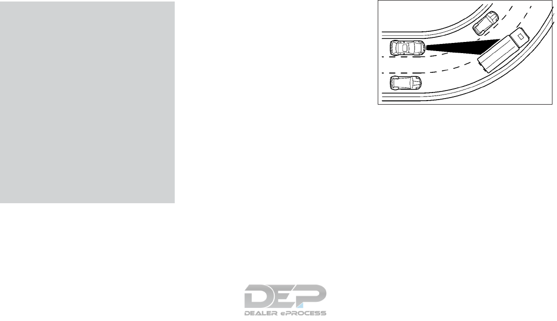
•Do not use the ICC system if you are
towing a trailer. The system may not de-
tect a vehicle ahead.
•In some road or traffic conditions, a ve-
hicle or object can unexpectedly come
into the sensor detection zone and cause
automatic braking. You may need to
control the distance from other vehicles
using the accelerator pedal. Always stay
alert and avoid using the ICC system
when it is not recommended in this sec-
tion.
•The distance sensor will not detect the
following objects:
–Stationary and slow moving vehicles.
–Pedestrians or objects in the road-
way.
–Oncoming vehicles in the same lane.
–Motorcycles traveling offset in the
travel lane.
The following are some conditions in which
the sensor cannot properly detect a vehicle
ahead and the system may not operate prop-
erly:
•When the snow or road spray from travel-
ing vehicles reduces the sensor’s visibility.
•When excessively heavy baggage is
loaded in the rear seat or the luggage room
of your vehicle.
The ICC system is designed to automatically
check the sensor’s operation within the limi-
tation of the system. When the sensor is cov-
ered with dirt or is obstructed, the system will
automatically be canceled. If the sensor is
covered with ice, a transparent or translucent
vinyl bag, etc., the ICC system may not detect
them. In these instances, the ICC system may
not cancel and may not be able to maintain
the selected following distance from the ve-
hicle ahead. Be sure to check and clean the
sensor regularly.
TIPS FOR DRIVING WITH THE ICC
SYSTEM
General notes
The following contains descriptions of cer-
tain road and traffic conditions in which you
must be particularly attentive. In such situa-
tions, brake if necessary. The ICC system is
then deactivated
Cornering, entering and exiting a
bend
The ability of the ICC system to detect ve-
hicles when cornering is limited. Your vehicle
may brake unexpectedly or late.
NSD603
5-58 Starting and driving
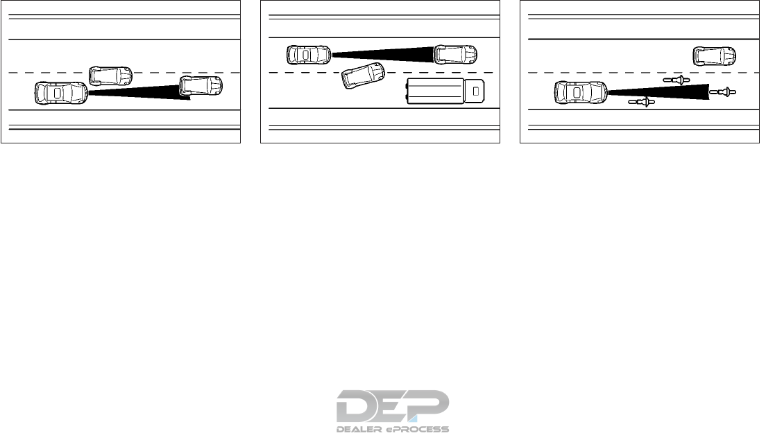
Vehicles that are not driving in the
middle of their lane
The ICC system may not detect vehicles
which are not driving in the middle of their
lane. The system will not brake for or keep a
following distance to the car which is offset.
Other vehicles changing lanes
The ICC system has not detected the vehicle
cutting in yet. The system will not brake for or
keep a following distance to this vehicle.
Narrow vehicles (including
motorcycles)
The ICC system has not yet detected the
vehicle ahead on the edge of the lane be-
cause of its narrow width. The system will not
brake for or keep a following distance to this
vehicle.
NSD606 NSD604 NSD605
Starting and driving 5-59

Obstructions and stationary
vehicles
The ICC system does not brake for obstacles
or stationary vehicles. If, for example, the
detected vehicle turns a corner and reveals an
obstacle or stationary vehicle The ICC system
will not brake for these.
Crossing vehicles
The ICC system may detect vehicles that are
crossing your lane by mistake. Activating the
ICC system at traffic lights with crossing traf-
fic, for example, could cause your vehicle to
pull away unintentionally.
NSD607 NSD608
5-60 Starting and driving

䊊
1Steering wheel mounted controls (left
side)
䊊
2Vehicle information display
䊊
ADisplay area
䊊
BMENU bar
SYSTEM TEMPORARILY
UNAVAILABLE
When the radar sensor area is covered with
dirt or is obstructed, the system will auto-
matically be canceled. If the radar sensor area
is covered with ice, a transparent or translu-
cent vinyl bag, etc., the ICC system may not
detect them. In these instances, the ICC sys-
tem may not cancel and may not be able to
maintain the selected following distance
from the vehicle ahead.
If the ICC system stops working due to a
malfunction or some other reason, one of the
following messages will be displayed in the
vehicle information display 䊊
2.
•[ICC off]
•[ICC Now Available]
•[ICC Currently Unavailable See Operator's
Manual]
•[ICC Inoperative]
•[ICC Suspended]
•[ICC – – – MPH]
[ICC off]: The ICC system has been deacti-
vated. If it was not deactivated by the driver,
a warning tone also sounds.
[ICC Now Available]: The ICC system is op-
erational again after having been temporarily
unavailable. You can now reactivate the ICC
system.
NSD626
Starting and driving 5-61

[ICC Currently Unavailable See Operator's
Manual]: The ICC system is temporarily inop-
erative. Possible causes:
•The function is impaired due to heavy rain
or snow.
•The radar sensor system is temporarily in-
operative, e. g. due to electromagnetic ra-
diation emitted by nearby TV or radio sta-
tions or other sources of electromagnetic
radiation.
•The system is outside the operating tem-
perature range.
•The on-board voltage is too low.
A warning tone also sounds.
Once the causes listed above no longer apply,
the display message goes out.
If the display message does not disappear:
•Pull over and stop the vehicle safely as
soon as possible, paying attention to road
and traffic conditions.
•Secure the vehicle against rolling away.
•Restart the engine.
[ICC Inoperative]: The ICC system is mal-
functioning. The adaptive brake assist func-
tion may also have failed. A warning tone also
sounds. Have the system checked. It is rec-
ommended you visit an INFINITI retailer for
this service.
[ICC Suspended]: You have depressed the
accelerator pedal. The ICC system is no lon-
ger controlling the speed of the vehicle.
The display message should disappear when
you remove your foot from the accelerator
pedal
[ICC–––MPH]: An activation condition for
the ICC system is not fulfilled.
Check the activation conditions for the ICC
system.
SYSTEM MAINTENANCE
The sensor for the ICC system 䊊
Ais located
behind the INFINITI logo at the front of the
vehicle.
To keep the ICC system operating properly,
be sure to observe the following:
•Always keep area around the sensor clean.
•Do not strike or damage the areas around
the sensor. Do not touch or remove the
screw located on the sensor. Doing so
could cause failure or malfunction. If the
sensor is damaged due to an accident, it is
recommended you contact an INFINITI re-
tailer.
•Do not cover or attach stickers (including
transparent material) or install an acces-
sory near the sensor. This could cause fail-
ure or malfunction.
NSD645
5-62 Starting and driving
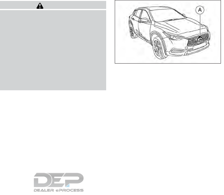
Radio frequency statement
For USA:
This device complies with Part 15 of the FCC
Rules. Operation is subject to the following
two conditions: (1) This device may not
cause harmful interference, and (2) this de-
vice must accept any interference received,
including interference that may cause unde-
sired operation.
NOTE
Changes or modification not expressly ap-
proved by the party responsible for compli-
ance could void the user’s authority to oper-
ate the equipment.
For Canada:
This device complies with Industry Canada
license-exempt RSS standard(s). Operation
is subject to the following two conditions: (1)
this device may not cause harmful interfer-
ence, and (2) this device must accept any
interference received, including interference
that may cause undesired operation of the
device.
WARNING
Failure to follow the warnings and instruc-
tions for proper use of the FEB system
could result in serious personal injury or
death.
•The FEB system is a supplemental aid to
the driver. It is not a replacement for the
driver’s attention to traffic conditions
or responsibility to drive safely. It can-
not prevent accidents due to careless-
ness or dangerous driving techniques.
•The FEB system does not function in all
driving, traffic, weather and road
conditions.
The FEB system can assist the driver when
there is a risk of a forward collision with the
vehicle ahead in the traveling lane.
The FEB system uses a radar sensor 䊊
Alo-
cated behind the INFINITI logo to measure
the distance to the vehicle ahead in the trav-
eling lane.
NSD645
FORWARD EMERGENCY BRAKING
(FEB) SYSTEM (IF EQUIPPED)
Starting and driving 5-63
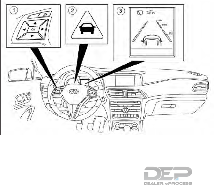
FEB SYSTEM OPERATION
䊊
1Steering wheel mounted controls (left
side)
䊊
2Distance warning light
䊊
3Forward emergency braking OFF display
The FEB system consists of a distance warn-
ing function with an autonomous emergency
braking function and adaptive brake assist
function.
The FEB system can help you to minimize the
risk of a collision with the vehicle in front or
reduce the effects of such a collision
If the FEB system detects that there is a risk
of a collision, you will be warned visually and
audibly. If you do not react to the visual and
audible collision warning, autonomous brak-
ing can be initiated in critical situations. If you
apply the brake yourself in a critical situation,
the adaptive brake assist function assists
you.
NSD624
5-64 Starting and driving
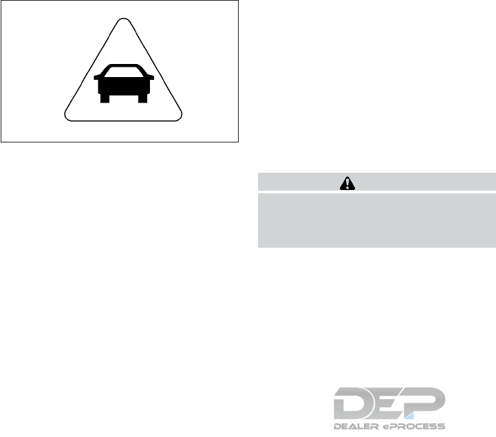
Distance warning function
The distance warning function can help you
to minimize the risk of a collision with the
vehicle in front or reduce the effects of such a
collision. If the distance warning function de-
tects that there is a risk of a collision, you will
be warned visually and audibly.
The distance warning function issues a warn-
ing at speeds:
•Of approximately 20 MPH (30 km/h) or
more, if, over several seconds the distance
maintained to the vehicle traveling in front
is insufficient. The distance warning light
then lights up in the combination meter.
•Of approximately 4 MPH (7 km/h) or
more, if you rapidly approach a vehicle in
front. An intermittent warning tone will
then sound and the distance warning light
will light up in the combination meter.
If a warning is issued:
•Brake immediately in order to increase the
distance from the vehicle in front.
or
•Take evasive action provided it is safe to
do so.
WARNING
Due to the nature of the system, particu-
larly complicated but non-critical driving
conditions may also cause the system to
display a warning.
Up to a speed of approximately 45 MPH (70
km/h), the distance warning function can
also react to stationary (stopped or parked)
vehicles.
If you approach a stationary vehicle and the
distance warning function detects a risk of a
collision, the system will alert you both visu-
ally and acoustically.
Autonomous braking function
If the driver does not react to the distance
warning signal in a critical situation, the FEB
system can assist with the autonomous brak-
ing function
The autonomous braking function can help
the driver to avoid an accident or reduces the
effects of an accident.
The autonomous braking function is available
in the following speed ranges:
•4–125 MPH (7-200 km/h) for moving ve-
hicles
•4–30 MPH (7 -50 km/h) for stationary
vehicles
Adaptive brake assist function
Adaptive brake assist function provides brak-
ing assistance in hazardous situations at
speeds above 4 MPH (7 km/h). It uses radar
sensor technology to assess the traffic situa-
tion.
If the system detects a risk of collision with
the vehicle in front, it calculates the braking
force necessary to avoid a collision. If you
apply the brakes forcefully, the adaptive
brake assist function will automatically in-
crease the braking force to a level suitable for
the traffic conditions.
NSD598
Distance warning light
Starting and driving 5-65
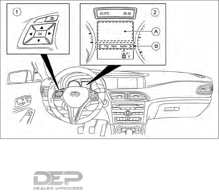
If the adaptive brake assist function acti-
vates, keep the brake pedal depressed until
the emergency braking situation is over. ABS
prevents the wheels from locking.
The brakes will work normally again if:
•You release the brake pedal.
•There is no longer any danger of a collision.
•No obstacle is detected in front of your
vehicle.
The brake assist function is then deactivated.
At high speeds, the adaptive brake assist
function is capable of reacting to moving ob-
jects that have already been detected as such
at least once over the period of observation.
Up to a speed of approximately 45 MPH (70
km/h), the adaptive brake assist function re-
acts to stationary vehicles.
TURNING THE FEB SYSTEM
ON/OFF
䊊
1Steering-wheel mounted controls (left
side)
䊊
2Vehicle information display
䊊
ADisplay area
䊊
BMenu bar
NSD626
5-66 Starting and driving
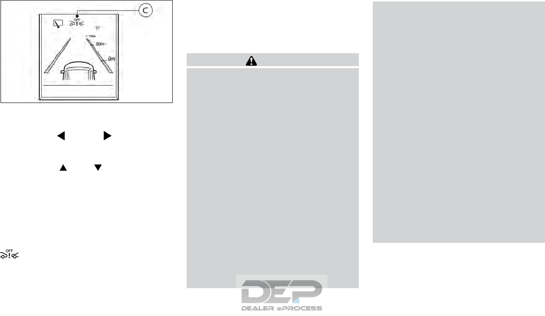
Use the following procedure to turn the FEB
system on or off:
1. Press the <or> button on the
steering wheel 䊊
1to select the [DriveAs-
sist] menu on the Menu bar 䊊
B.
2. Press the or button to select
[Emergency Brake].
3. Press the <OK> button on the steering
wheel 䊊
1. The current selection is dis-
played.
4. To activate/deactivate the FEB system:
press the <OK> button again
When the FEB system is deactivated, the
symbol 䊊
Cappears in the vehicle infor-
mation display.
NOTE
The FEB system will be automatically turned
on when the engine is restarted.
FEB SYSTEM LIMITATIONS
WARNING
Listed below are the system limitations for
the FEB system. Failure to operate the ve-
hicle in accordance with these system limi-
tations could result in serious injury or
death.
•The FEB system cannot detect all ve-
hicles under all conditions.
•The radar sensor does not detect the
following objects:
–Pedestrians or animals
–Oncoming vehicles
–Crossing vehicles
•The radar sensor has some performance
limitations. For stationary vehicles, the
FEB system will not function when the
vehicle is driven at speeds over:
–
Approximately 31 MPH (50 km/h) for
the Autonomous braking function.
•The radar sensor may not detect a ve-
hicle ahead in the following conditions:
–Dirt, ice, snow or other material cov-
ering the radar sensor.
–Interference by other radar sources.
–Snow or heavy rain.
–If the vehicle ahead is narrow (e.g.
motorcycle).
–If the vehicle ahead is in a different
lane.
–Under strong radar reflections, for
example, in a multi-level parking ga-
rage.
–New vehicle or after a maintenance
of the FEB system. For additional in-
formation, see "Break-in schedule"
later in this section
–When driving on a steep downhill
slope or roads with sharp curves.
–When towing a trailer.
•In some road or traffic conditions, the
FEB system may intervene unnecessar-
ily or give an unnecessary warning. Al-
ways pay careful attention to the traffic
situation. Do not rely solely on the dis-
tance warning function and terminate
the intervention if necessary.
•Braking distances increase on slippery
surfaces.
NSD630
Starting and driving 5-67

•The system is designed to automatically
check the sensor’s functionality, within
certain limitations. The system may not
detect some forms of obstruction of the
sensor area such as ice, snow, stickers,
for example. In these cases, the system
may not be able to warn the driver prop-
erly. Be sure that you check, clean and
clear the sensor area regularly.
•Excessive noise will interfere with the
warning chime sound, and the chime
may not be heard.
SYSTEM TEMPORARILY
UNAVAILABLE
If the FEB stops working due to a malfunc-
tion or some other reason, one of the follow-
ing three messages will be displayed in the
vehicle information display.
•[Emergency Brake Currently Unavailable
See Operator's Manual]
•[Emergency Brake Inoperative]
•[Radar Sensors Dirty See Operator's
Manual]
For each of these messages, possible causes
and solutions are listed below.
[Emergency Brake Currently Unavailable
See Operator's Manual]: The FEB system is
temporarily inoperative. Possible causes:
•The radar sensor system is temporarily in-
operative, for example, due to electro-
magnetic radiation emitted by nearby TV
or radio stations or other sources of elec-
tromagnetic radiation.
•The system is outside the operating tem-
perature range.
•The on-board voltage is too low.
Once the causes listed above no longer apply,
the display message goes out. The FEB sys-
tem is operative again.
If the display message does not disappear:
•Pull over and stop the vehicle safely as
soon as possible, paying attention to road
and traffic conditions.
•Secure the vehicle against rolling away.
•Switch off the engine.
[Emergency Brake Inoperative]: The FEB
system is temporarily inoperative due to a
malfunction. The adaptive brake assist func-
tion may also have failed.
It is recommended you visit an INFINITI re-
tailer.
[Radar Sensors Dirty See Operator's
Manual]: The FEB system is temporarily re-
stricted or inoperative. Possible causes:
•The sensor behind the INFINITI logo is
dirty.
•The function of the FEB system is im-
paired due to heavy rain or snow.
A warning tone also sounds.
Once the causes listed above no longer apply,
the display message goes out. The FEB sys-
tem is operative again.
If the display message does not disappear:
•Pull over and stop the vehicle safely as
soon as possible, paying attention to road
and traffic conditions.
•Secure the vehicle against rolling away.
•Switch off the engine.
•Clean the area around the sensors.
•Restart the engine. The display message
disappears.
5-68 Starting and driving
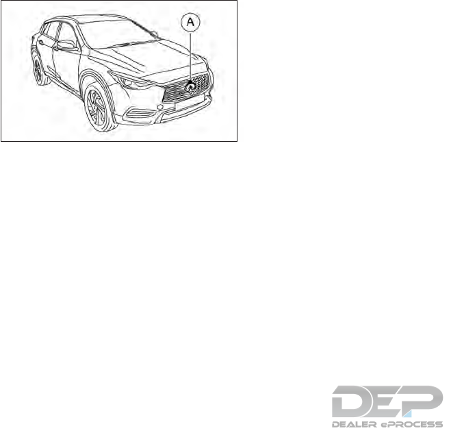
SYSTEM MAINTENANCE
The sensor 䊊
Ais located behind the INFINITI
logo at the front of the vehicle.
To keep the system operating properly, be
sure to observe the following:
•Always keep the sensor area of the
INFINITI logo clean.
•Do not strike or damage the areas around
the sensor.
•Do not cover or attach stickers or similar
objects on the front bumper near the sen-
sor area. This could cause failure or mal-
function.
•Do not attach metallic objects near the
sensor area (brush guard, etc.). This could
cause failure or malfunction.
•Do not alter, remove or paint the front
grille or INFINITI logo.
FCC NOTICE
For USA:
This device complies with Part 15 of the FCC
Rules. Operation is subject to the following
two conditions: (1) This device may not
cause harmful interference, and (2) this de-
vice must accept any interference received,
including interference that may cause unde-
sired operation.
NOTE
Changes or modification not expressly ap-
proved by the party responsible for compli-
ance could void the user’s authority to oper-
ate the equipment.
For Canada:
This device complies with Industry Canada
license-exempt RSS standard(s). Operation
is subject to the following two conditions: (1)
this device may not cause harmful interfer-
ence, and (2) this device must accept any
interference received, including interference
that may cause undesired operation of the
device.
NSD645
Starting and driving 5-69
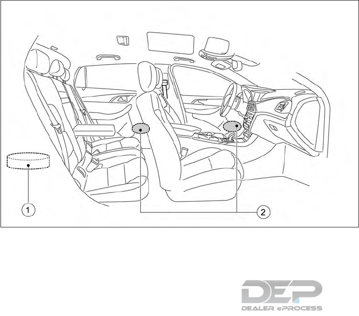
NOTE
To operate the active sound enhancement
properly:
•Do not cover the speakers or woofer.
•Do not change or modify speakers includ-
ing the woofer and any audio related parts
such as the amplifier.
•Do not make any modification including
sound deadening or modifications around
the speakers or woofer.
ACTIVE SOUND ENHANCEMENT
The active sound enhancement generates
sounds according to engine speed through
the speakers 䊊
2and woofer 䊊
1(if equipped)
to enhance the quality of the engine sound.
NSD648
ACTIVE SOUND ENHANCEMENT
5-70 Starting and driving

IPA is an electronic parking aid with ultra-
sound. It detects vehicles and open spaces on
both sides of the vehicle. A parking symbol
indicates a suitable parking space. Active
steering intervention can assist you during
parking and when exiting a parking space.
The driver controls the accelerator, brake and
gear shift. You may also use the Camera Aid-
ing Sonar (parking sensor) function (see "
Camera Aiding Sonar (parking sensor) func-
tion (if equipped)" later in this section).
IMPORTANT SAFETY NOTES
WARNING
•IPA is only an aid. It is not a substitute
for your attention to the immediate sur-
roundings. The responsibility for safe
maneuvering and parking remains with
you.
•Make sure that no persons, animals or
objects are in the maneuvering range
•When the sonar (parking sensor) func-
tion is deactivated, IPA is also unavail-
able.
•While parking or pulling out of a parking
space, the vehicle swings out and can
drive onto areas of the oncoming lane.
This could cause you to collide with
other road users. There is a risk of an
accident.
•Pay attention to other road users. Stop
the vehicle if necessary or cancel the IPA
parking procedure
•This system is not designed to prevent
contact with small or moving objects.
•If your vehicle sustains damage to the
bumper fascia, leaving it misaligned or
bent, the sensing zone may be altered
causing inaccurate measurement of ob-
stacles or false alarms.
•This system is not designed to prevent
contact with small or moving objects.
•If your vehicle sustains damage to the
bumper fascia, leaving it misaligned or
bent, the sensing zone may be altered
causing inaccurate measurement of ob-
stacles or false alarms.
CAUTION
Do not drive over obstacles such as curbs,
as you may damage the wheels or tires.
IPA may also display spaces not suitable for
parking, for example:
•Parking or stopping prohibition.
•In front of driveways or entrances and
exits.
•Unsuitable surfaces.
Parking tips:
•On narrow roads, drive as closely as pos-
sible past the parking space.
•Parking spaces that are littered or over-
grown might be identified or measured
incorrectly.
•Parking spaces that are partly occupied by
trailer towing bars might not be identified
as such or be measured incorrectly.
•Snowfall or heavy rain may lead to a park-
ing space being measured inaccurately.
•Pay attention to the sonar function warn-
ing messages during the parking proce-
dure.
•You can intervene in the steering proce-
dure to correct it at any time. IPA will then
be canceled.
•When transporting a load which protrudes
from your vehicle, you should not use IPA.
•Never use IPA when snow chains are fit-
ted.
•Make sure that the tire pressures are al-
ways correct. This has a direct influence on
the parking characteristics of the vehicle.
INTELLIGENT PARKING ASSIST (IPA)
(IF EQUIPPED)
Starting and driving 5-71

Use IPA for parking spaces that are:
•Parallel or at right angles to the direction
of travel.
•On straight roads, not bends.
•On the same level as the road, e. g. not on
the sidewalk.
For vehicles with the towbar folded out, the
minimum length for parking spaces is slightly
longer.
If you have attached a trailer to your vehicle,
you may not use IPA. Once the electrical
connection is established between your ve-
hicle and the trailer, IPA is no longer available.
The sonar function is deactivated for the rear
area
DETECTING PARKING SPACES
The IPA system can only be used to park in
spaces that have vehicles directly on either
side of the parking space.
Objects located above the height range of
IPA will not be detected when the parking
space is measured. These are not taken into
account when the parking procedure is calcu-
lated, e. g. overhanging loads, tail sections or
loading ramps of goods vehicles.
WARNING
If there are objects above the detection
range, IPA may steer too early. This could
cause a collision. There is a risk of an acci-
dent.
If objects are located above the detection
range, stop and switch off the IPA.
For further information on the detection
range see "Range of the sensors" later in this
section.
IPA does not assist you parking in spaces at
right angles to the direction of travel if:
•Two parking spaces are located directly
next to one another.
•The parking space is directly next to a low
obstacle such as a low curb.
•You forward park.
IPA does not assist you parking in spaces that
are parallel or at right angles to the direction
of travel if:
•The parking space is on a curb.
•The system reads the parking space as
being blocked, for example, by foliage or
grass paving blocks.
•The area is too small for the vehicle to
maneuver into.
•The parking space is bordered by an ob-
stacle, e.g. a tree, a post or a trailer.
5-72 Starting and driving
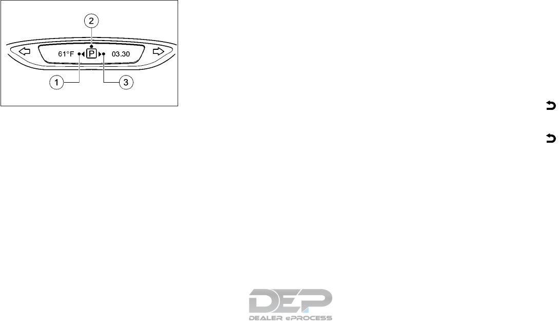
䊊
1Detected parking space on the left.
䊊
2Parking symbol.
䊊
3Detected parking space on the right.
IPA is activated automatically when driving
forwards. The system is operational at
speeds of up to approximately 19 MPH (30
km/h). While in operation, the system inde-
pendently locates and measures parking
spaces on both sides of the vehicle
IPA will only detect parking spaces:
•Adjacent to the vehicle.
•Parallel or at right angles to the direction
of travel.
•That are parallel to the direction of travel
and are at least 5 ft (1.5 m) wide.
•That are parallel to the direction of travel
and at least 3.3 ft (1.0 m) longer than your
vehicle.
•That are at right angles to the direction of
travel and at least 3.3 ft (1.0 m) wider than
your vehicle.
NOTE
IPA cannot measure the length of a parking
space if it is at right angles to the direction of
travel. You will need to judge whether your
vehicle will fit in the parking space
When driving at speeds below 19 MPH (30
km/h) you will see parking symbol 䊊
2as a
status indicator in the vehicle information
display. When a parking space has been de-
tected, an arrow towards the right 䊊
3or the
left 䊊
1also appears. IPA only displays park-
ing spaces on the front-passenger side as
standard. Parking spaces on the driver's side
are displayed as soon as the turn signal on the
driver's side is activated. When parking on the
driver's side, this must remain activated until
you confirm the use of IPA by pressing the
<OK> button on the steering wheel. The sys-
tem automatically determines whether the
parking space is parallel or at right angles to
the direction of travel.
A parking space is displayed while you are
driving past it, and until you are approxi-
mately 50 ft (15 m) away from it.
PARKING
NOTE
When the sonar function detects obstacles,
you are responsible for braking in good time.
1. Stop the vehicle when the parking symbol
shows the desired parking space in the
combination meter
2. Shift into position R.
The [Start Park Assist? Yes: OK No:]
message appears in the vehicle informa-
tion display.
3. To cancel the procedure: press the
button on the steering wheel or pull away
or
4. To park using IPA press the <OK> button
on the steering wheel. The Park Assist
[Observe surroundings] message appears
in the vehicle information display.
5. Release the steering wheel.
6. Back up the vehicle, being ready to brake
at all times. When backing up, drive at a
speed below 5 MPH (10 km/h). Other-
wise, IPA will be canceled.
NSD696
Upper display
Starting and driving 5-73

7. Stop as soon as the sonar function sounds
the continuous warning tone, if not be-
fore. Maneuvering may be required in
tight parking spaces.
The [Park Assist active Select D Observe
surroundings] message appears in the ve-
hicle information display.
8. Select transmission position D (Drive)
while the vehicle is stationary.
IPA immediately steers in the other direc-
tion.
The [Park Assist Observe surroundings]
message appears in the vehicle informa-
tion display.
NOTE
You will achieve the best results by wait-
ing for the steering procedure to com-
plete before pulling away.
9. Drive forwards and be ready to brake at
all times.
Maneuvering may be required in tight
parking spaces. Drive forward and back
up as prompted by the IPA and sonar
function warning displays, several times if
necessary.
10. Stop as soon as the sonar function
sounds the continuous warning tone, if
not before.
The [Park Assist active Select R] [Ob-
serve surroundings] message appears in
the vehicle information display.
As soon as the parking procedure is
complete the [Park Assist switched off]
message appears and a warning tone
sounds. The vehicle is now parked.
11. Before leaving the vehicle, secure the ve-
hicle against rolling away unintentionally:
•The electric parking brake must be ap-
plied.
•The transmission must be in position P
(Park) and the transmission position
display must show P in the vehicle
information display.
•The key must be removed from the
ignition switch.
•On uphill or downhill gradients, the
front wheels must be turned towards
the curb.
IPA no longer supports you with steering in-
terventions. When IPA is finished, you must
steer again yourself. The sonar function is still
available.
Parking tips:
•The way your vehicle is positioned in the
parking space after parking is dependent
on various factors. These include the posi-
tion and shape of the vehicles parked in
front and behind it and the conditions of
the location. It may be the case that IPA
guides you too far into a parking space, or
not far enough into it. In some cases, it
may also lead you across or onto the curb.
If necessary you should cancel the parking
procedure with IPA.
•During the parking maneuver, the system
will indicate when you should shift to R
(Reverse) or D (Drive). However, you can
freely choose to shift gear whenever you
feel you need to. Should the transmission
change take place too early, the parking
procedure will be canceled. A sensible
parking position can no longer be achieved
from this position.
EXITING A PARKING SPACE
In order that IPA can support when exiting
the parking space:
•You need to have parked using IPA.
•The border of the parking space must be
high enough at the front and the rear. A
curb stone is too small, for example.
5-74 Starting and driving

•The border of the parking space must not
be too wide, as the position of the vehicle
must not exceed an angle of 45 degrees to
the starting position as it is manoeuvred
into the parking space.
•A total front and back maneuvering dis-
tance of at least 1.0 m must be available.
IPA can only assist you with exiting a parking
space if you have parked the vehicle parallel
to the direction of travel using IPA.
WARNING
•IPA is only an aid. It is not a substitute
for your attention to the immediate sur-
roundings. The responsibility for safe
maneuvering and parking remains with
you.
•Make sure that no persons, animals or
objects are in the maneuvering range.
•When the sonar function is deactivated,
IPA is also unavailable.
•While parking or pulling out of a parking
space, the vehicle swings out and can
drive onto areas of the oncoming lane.
This could cause you to collide with
other road users. There is a risk of an
accident.
•Pay attention to other road users. Stop
the vehicle if necessary or cancel the IPA
parking procedure.
1. Start the engine.
2. Release the electric parking brake.
3. Switch on the turn signal in the direction
you are pulling away.
4. Vehicles with automatic transmission:
shift the transmission to position D or R
The [Start Park Assist? Yes: OK No:]
message appears in the vehicle informa-
tion display.
5. To cancel the procedure: press the
button on the steering wheel or pull away
or
6. To exit a parking space using IPA: press
the <OK> button on the steering wheel
The Park Assist [Observe surroundings]
message appears in the display.
7. Release the steering wheel.
8. Pull away, being ready to brake at all
times Do not exceed a maximum speed of
approximately 5 MPH (10 km/h) when
exiting a parking space. Otherwise, IPA
will be canceled.
WARNING
While parking or pulling out of a parking
space, the vehicle swings out and can drive
onto areas of the oncoming lane. This could
cause you to collide with other road users.
There is a risk of an accident.
9. Depending on the message or as required,
shift the transmission to position D or R.
IPA immediately steers in the other direc-
tion. The [Observe surroundings] mes-
sage appears in the display.
NOTE
You will achieve the best results by wait-
ing for the steering procedure to com-
plete before pulling away.
If you back up after activation, the steer-
ing wheel is moved to the straight-ahead
position.
10. Drive forward and back up as prompted
by the IPA and sonar function warning
displays, several times if necessary.
Once you have exited the parking space com-
pletely, the steering wheel is moved to the
straight-ahead position. You hear a tone and
the [Park Assist switched off] message ap-
pears in the display. You will then have to
steer and merge into traffic on your own. The
Starting and driving 5-75

sonar function is still available. You can take
over the steering before the vehicle has ex-
ited the parking space completely. This is use-
ful, for example when you recognize that it is
already possible to pull out of the parking
space.
CANCELING IPA
Stop the movement of the steering wheel or
steer yourself. IPA will be immediately can-
celed. The [Park Assist canceled] message
appears in the vehicle information display.
or
Press the sonar function OFF switch. The
sonar function is switched off and IPA is
immediately canceled The [Park Assist can-
celed] message appears in the vehicle infor-
mation display.
IPA is canceled automatically if:
•The electric parking brake is applied
•Parking using IPA is no longer possible
•You are driving faster than 5 MPH (10
km/h)
•A wheel spins and VDC intervenes or fails.
The warning light lights up in the
combination meter.
A warning tone sounds. The parking symbol
disappears and the vehicle information dis-
play shows the [Park Assist canceled] mes-
sage.
When IPA is canceled, you must steer again
yourself.
WARNING
•The sonar function is a convenience but
it is not a substitute for proper parking.
Always look around and check that it is
safe to do so before parking. Always
move slowly.
•Read and understand the limitations of
the sonar function as contained in this
section. Inclement weather may affect
the function of the sonar function; this
may include reduced performance or a
false activation.
•The driver is always responsible for
safety during parking and other maneu-
vers.
•The system is designed as an aid to the
driver in detecting large stationary ob-
jects to help avoid damaging the vehicle.
The system will not detect small objects
below the bumper, and may not detect
objects that are too close to the bumper
or on the ground.
•Always look around and check that it is
safe to move before parking.
CAMERA AIDING SONAR (PARKING
SENSOR) FUNCTION (IF EQUIPPED)
5-76 Starting and driving
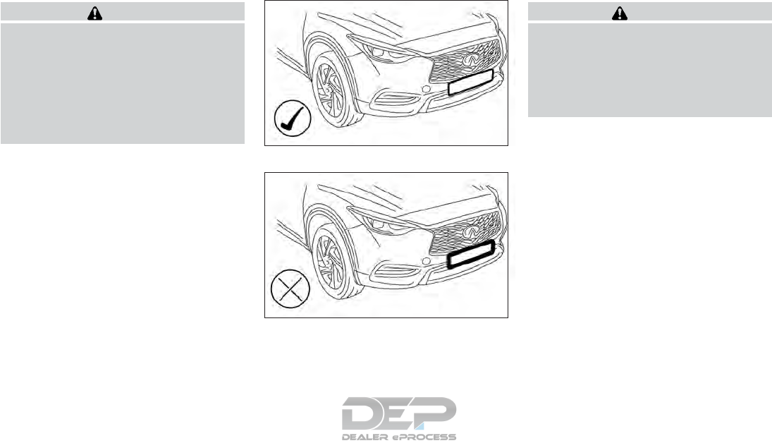
CAUTION
•Keep the interior of the vehicle as quiet
as possible to hear the tone clearly.
•Keep the sensors (located on the bumper
fascia) free from snow, ice and large ac-
cumulations of dirt. Do not clean the
sensors with sharp objects. If the sen-
sors are covered, the accuracy of the
sensor function will be diminished.
WARNING
INFINITI recommends only to use frame-
less type license plate holders.
The sonar sensors may not function cor-
rectly if the license plate is placed in a frame
as illustrated.
Please contact an INFINITI retailer for
advice.
NSD642
No frame/frameless
NSD643
Frame type
Starting and driving 5-77
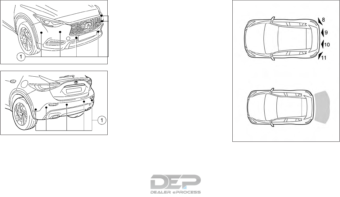
SONAR FUNCTION OVERVIEW
䊊
1Possible sonar sensor locations
The sonar function is an electronic parking
aid with ultrasonic sensors. The sonar func-
tion indicates audibly the distance between
your vehicle and an object. It monitors the
area around your vehicle using sensors in the
front and rear bumper. Possible sensor con-
figurations include a 4 sensor, 10 sensor or
12 sensor configuration.
NSD040
NSD041
NSD636
Type A: 4 sensor system
5-78 Starting and driving
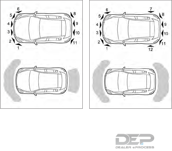
For the vehicle equipped with rear sensors
(Type A):
The system informs you about rear obstacles
with visual and audible signals when the shift
lever is in the R (Reverse) position.
The intermittent tone will stop after 3 sec-
onds when an obstacle is detected by only
the corner sensor and the distance does not
change. The tone will stop when the obstacle
moves away from the vehicle.
For the vehicle equipped with front and rear
sensors (Type B and C):
The system informs you about front ob-
stacles with visual and audible signals when
the shift lever is in the D (Drive) position and
both front and rear obstacles when the shift
lever is in the R (Reverse) position.
The intermittent tone will stop after 3 sec-
onds when an obstacle is detected by only
the corner sensor and the distance does not
change. The tone will stop when the obstacle
moves away from the vehicle.
NSD635
Type B: 10 sensor system
NSD634
Type C: 12 sensor system
Starting and driving 5-79
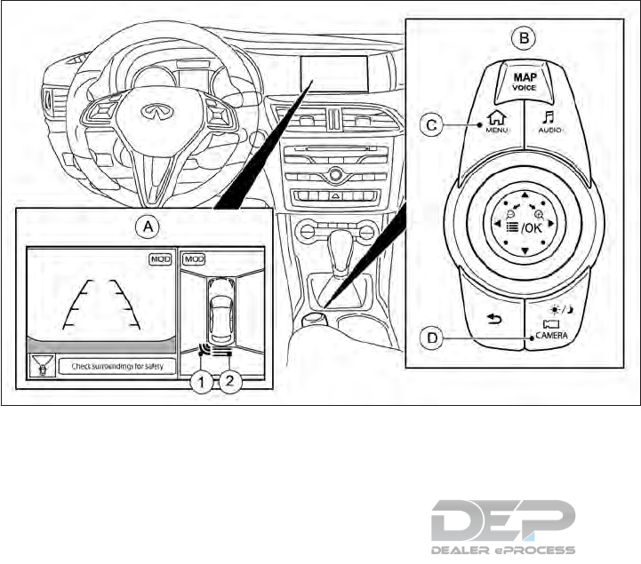
NSD706
With Around View monitor
5-80 Starting and driving
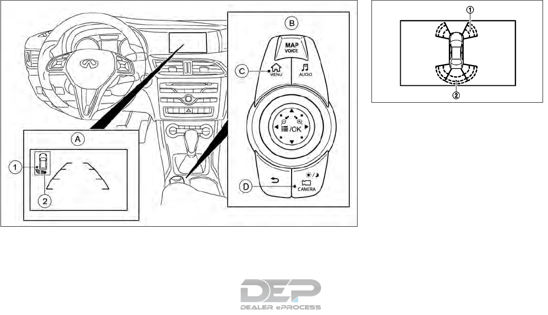
䊊
ARearView/Around View monitor display
䊊
BINFINITI controller
䊊
C<MENU> button
䊊
D<CAMERA> button
When the corner of the vehicle moves closer
to an object, the corner sensor indicators 䊊
1
appear (if equipped).
When the center of the vehicle moves close
to an object, the center indicator 䊊
2appears.
When the object is detected, the indicator
(green) appears and blinks and the tone
sounds intermittently. When the vehicle
moves closer to the object, the color of the
indicator turns yellow and the rate of the
blinking increases. When the vehicle is very
close to the object, the indicator stops blink-
ing and turns red, and the tone sounds con-
tinuously.
The sonar function is activated automatically
when you:
•Switch on the ignition
•Shift to position D (Drive), or R (Reverse)
on vehicles with automatic transmission
•Release the electric parking brake
The sonar function is deactivated at speeds
above 10 MPH (16 km/h). It is reactivated at
lower speeds.
NSD707
With RearView monitor
NAA1547
Starting and driving 5-81
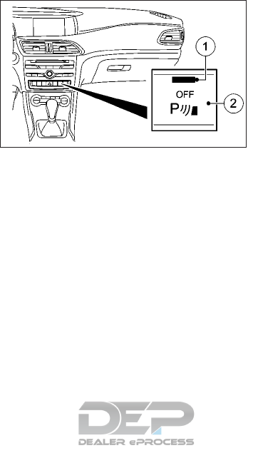
The sonar function is deactivated for the rear
area when you establish an electrical connec-
tion between your vehicle and a trailer.
RANGE OF THE SENSORS
The sonar function does not take into ac-
count obstacles located:
•Below the detection range, e.g. persons,
animals or objects.
•Above the detection range, e.g. overhang-
ing loads, tail sections or loading ramps of
goods vehicles. SONAR FUNCTION OFF SWITCH
The sonar function OFF switch 䊊
2on the
lower side of the instrument panel allows the
driver to turn the sonar function on and off.
To turn the sonar function system on and off,
the ignition switch must be in the ON posi-
tion. The indicator light 䊊
1on the switch will
illuminate when the system is turned off.
The sonar function will turn on automatically
when the ignition switch is turned from the
OFF position to the ON position.
NIC2635
5-82 Starting and driving
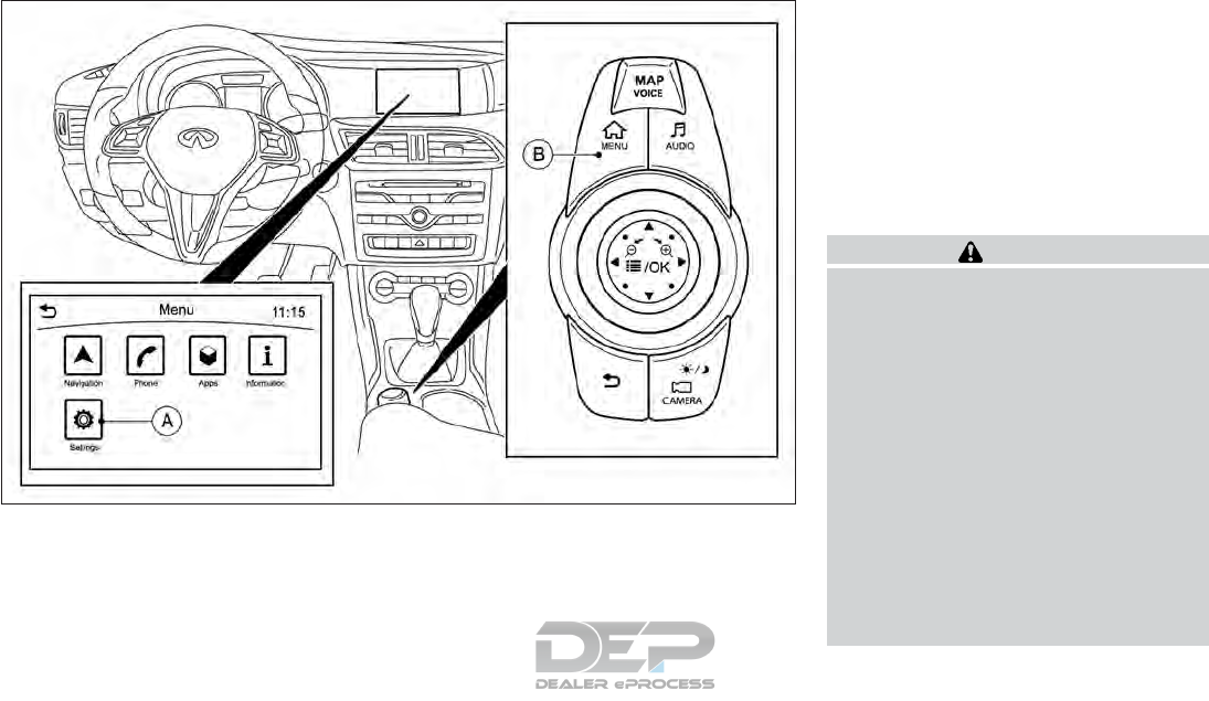
䊊
ASettings key
䊊
B<MENU> button SONAR FUNCTION SETTINGS
The sonar function settings can be changed
using the following procedure.
1. Push <MENU>䊊
Band touch [Settings] 䊊
A.
2. Touch [Camera/Sonar]
3. Touch [Sonar]
[Sonar sensitivity]:
Adjust the sonar sensitivity by touching [+]/
[-].
[Sonar volume]:
Adjust the warning tone volume by touching
[+]/[-].
SONAR FUNCTION LIMITATIONS
WARNING
Listed below are the system limitations for
the sonar function. Failure to operate the
vehicle in accordance with these system
limitations could result in serious injury or
death.
•Inclement weather or ultrasonic sources
such as an automatic car wash, a truck’s
compressed-air brakes or a pneumatic
drill may affect the function of the sys-
tem, including reduced performance or a
false activation.
•The system is not designed to prevent
contact with small or moving objects.
•The system will not detect small objects
below the bumper, and may not detect
objects close to the bumper or on the
ground.
NSD628
Starting and driving 5-83
•The system may not detect the follow-
ing objects:
–Fluffy objects such as snow, cloth,
cotton, grass or wool.
–Thin objects such as rope, wire or
chain.
–Wedge-shaped objects.
•If your vehicle sustains damage to the
bumper fascia, leaving it misaligned or
bent, the sensing zone may be altered
causing inaccurate measurement of ob-
jects or false alarms.
CAUTION
Excessive noise (such as audio system vol-
ume or an open vehicle window) will inter-
fere with the tone and it may not be heard.
PROBLEMS WITH SONAR FUNCTION
Problem Possible causes/consequences and solutions
Only the red segments in the sonar function displays
are lit. You also hear a warning tone for approximately
two seconds.
The sonar function is then deactivated and the
indicator light on the sonar function OFF switch lights
up.
The sonar function has malfunctioned and has been deactivated.
If problems persist, have the sonar function checked. It is recommended you visit an INFINITI retailer for
this service.
Only the red segments in the sonar function displays
are lit. The sonar function is then deactivated.
The sonar sensors are dirty or there is interference.
•Clean the sensors.
•Switch the ignition back on.
The problem may be caused by an external source of radio or ultrasound waves.
See if the sonar system functions in a different location.
5-84 Starting and driving

SYSTEM MAINTENANCE
CAUTION
Keep the surface of the sonar sensors (if
equipped) (located on the front and rear
bumper fascia) free from accumulations of
snow, ice and dirt. Do not scratch the sur-
face of the sonar sensors when cleaning. If
the sensors are covered, the accuracy of
the sonar function will be diminished.
During the first 1,200 miles (2,000 km), fol-
low these recommendations to obtain maxi-
mum engine performance and ensure the fu-
ture reliability and economy of your new
vehicle. Failure to follow these recommenda-
tions may result in shortened engine life and
reduced engine performance.
•Avoid driving for long periods at constant
speed, either fast or slow, and do not run
the engine over 4,000 RPM.
•Do not accelerate at full throttle in any
gear.
•Avoid quick starts.
•Avoid hard braking as much as possible.
•Do not tow a trailer for the first 500 mi
(805 km). Your engine, axle or other parts
could be damaged.
You should also observe these notes on
break-in if the engine or parts of the drive
train on your vehicle have been replaced.
CAUTION
In certain driving and driving safety sys-
tems, the sensors adjust automatically
while a certain distance is being driven af-
ter the vehicle has been delivered or after
repairs. Full system effectiveness is not
reached until the end of this teach-in pro-
cess.
Brake pads/linings and rotors that are ei-
ther new or have been replaced only
achieve optimum braking effect after sev-
eral hundred miles of driving. Compensate
for the reduced braking effect by applying
greater force to the brake pedal
BREAK-IN SCHEDULE
Starting and driving 5-85

Follow these easy-to-use Fuel Efficient Driv-
ing Tips to help you achieve the most fuel
economy from your vehicle.
1. Use Smooth Accelerator and Brake Pedal
Application
•Avoid rapid starts and stops.
•Use smooth, gentle accelerator and
brake application whenever possible.
•Maintain constant speed while com-
muting and coast whenever possible.
2. Maintain Constant Speed
•Look ahead to try and anticipate and
minimize stops.
•Synchronizing your speed with traffic
lights allows you to reduce your num-
ber of stops.
•Maintaining a steady speed can mini-
mize red light stops and improve fuel
efficiency.
3. Use Air Conditioning (A/C) at Higher Ve-
hicle Speeds
•Below 40 MPH (64 km/h), it is more
efficient to open windows to cool the
vehicle due to reduced engine load.
•Above 40 MPH (64 km/h), it is more
efficient to use A/C to cool the vehicle
due to increased aerodynamic drag.
•Recirculating the cool air in the cabin
when the A/C is on reduces cooling
load.
4. Drive at Economical Speeds and Dis-
tances
•Observing the speed limit and not ex-
ceeding 60 MPH (97 km/h) (where le-
gally allowed) can improve fuel effi-
ciency due to reduced aerodynamic
drag.
•Maintaining a safe following distance
behind other vehicles reduces unneces-
sary braking.
•Safely monitoring traffic to anticipate
changes in speed permits reduced
braking and smooth acceleration
changes.
•Select a gear range suitable to road
conditions.
5. Use Cruise Control
•Using cruise control during highway
driving helps maintain a steady speed.
•Cruise control is particularly effective in
providing fuel savings when driving on
flat terrains.
Utilize a map or navigation system to deter-
mine the best route to save time.
6. Avoid Idling
•Shutting off your engine when safe for
stops exceeding 30 seconds saves fuel
and reduces emissions.
7. Buy an Automated Pass for Toll Roads
•Automated passes permit drivers to
use special lanes to maintain cruising
speed through the toll and avoid stop-
ping and starting.
8. Winter Warm Up
•Limit idling time to minimize impact to
fuel economy.
•Vehicles typically need no more than
30 seconds of idling at start-up to ef-
fectively circulate the engine oil before
driving.
•Your vehicle will reach its ideal operat-
ing temperature more quickly while
driving versus idling.
9. Keeping your Vehicle Cool
•Park your vehicle in a covered parking
area or in the shade whenever possible.
•When entering a hot vehicle, opening
the windows will help to reduce the
inside temperature faster, resulting in
reduced demand on your A/C system.
FUEL EFFICIENT DRIVING TIPS
5-86 Starting and driving

•Keep your engine tuned up.
•Follow the recommended scheduled
maintenance.
•Keep the tires inflated to the correct pres-
sure. Low tire pressure increases tire wear
and lowers fuel economy.
•Keep all the wheels in correct alignment.
Improper alignment increases tire wear
and lowers fuel economy.
•Use the recommended viscosity engine oil.
For additional information, see "Recom-
mended fluids/lubricants and capacities"
in the "10. Technical information" section
WARNING
•Do not drive beyond the performance
capability of the tires, even with 4WD
engaged. Accelerating quickly, sharp
steering maneuvers or sudden braking
may cause loss of control.
•Always use tires of the same type, size,
brand, construction (bias, bias-belted or
radial), and tread pattern on all four
wheels.
•This vehicle is not designed for off-road
(rough road) use. Do not drive on sandy
or muddy roads that tires may get stuck
in.
•For 4WD equipped vehicles, do not at-
tempt to raise two wheels off the
ground and shift the transmission to any
drive or reverse position with the engine
running. Doing so may result in drive-
train damage or unexpected vehicle
movement which could result in serious
vehicle damage or personal injury.
•Do not attempt to test a 4WD equipped
vehicle on a 2-wheel dynamometer
(such as the dynamometers used by
some states for emissions testing) or
similar equipment even if the other two
wheels are raised off the ground. Make
sure that you inform the test facility
personnel that your vehicle is equipped
with 4WD before it is placed on a dyna-
mometer. Using the wrong test equip-
ment may result in drivetrain damage or
unexpected vehicle movement which
could result in serious vehicle damage or
personal injury.
•When a wheel is off the ground due to an
uneven surface, do not spin the wheel
excessively.
INCREASING FUEL ECONOMY FOUR-WHEEL DRIVE (4WD) (IF
EQUIPPED)
Starting and driving 5-87

CAUTION
Never tow the vehicle with one axle raised.
This may damage the differential. Damage
of this sort is not covered by the warranty.
All wheels must be fully raised (see "Four-
Wheel Drive (4WD) models" in the "6. In
case of emergency" section)
4WD, together with VDC, improves the trac-
tion of your vehicle whenever a drive wheel
spins due to insufficient grip.
If you fail to adapt your driving style, 4WD
can neither reduce the risk of an accident nor
override the laws of physics. 4WD cannot
take account of road, weather, and traffic
conditions. 4WD is only an aid. You are re-
sponsible for the distance to the vehicle in
front, for vehicle speed, for braking in good
time, and for staying in lane.
If a drive wheel spins due to insufficient grip
•When pulling away, only depress the ac-
celerator pedal as far as is necessary.
•Accelerate less when driving.
NOTE
In wintry driving conditions, the maximum
effectiveness of 4WD can only be achieved if
you use winter tires (M+S tires), with snow
chains if necessary.
WARNING
•Do not stop or park the vehicle over
flammable materials such as dry grass,
waste paper or rags. They may ignite
and cause a fire.
•Safe parking procedures require that
both the parking brake be applied and
the P (Park) position engaged. Failure to
do so could cause the vehicle to move
unexpectedly or roll away and result in
an accident.
•When parking the vehicle, make sure the
P (Park) position is engaged. The shift
lever cannot be moved out of the P
(Park) position without depressing the
brake pedal.
•Never leave the engine running while the
vehicle is unattended.
•Do not leave children unattended inside
the vehicle. They could unknowingly ac-
tivate switches or controls or move the
vehicle. Unattended children could be-
come involved in serious accidents.
•To help avoid risk of injury or death
through unintended operation of the
vehicle and/or its systems, do not leave
children, people who require the assis-
tance of others, or pets unattended in
your vehicle. Additionally, the tempera-
ture inside a closed vehicle on a warm
day can quickly become high enough to
cause a significant risk of injury or death
to people and pets.
CAUTION
Always secure the vehicle correctly against
rolling away. Otherwise, the vehicle or its
drive train could be damaged.
To ensure that the vehicle is secured against
rolling away unintentionally:
•The electric parking brake must be applied.
•The transmission must be in position P
(Park) and the transmission position dis-
play must show P in the vehicle informa-
tion display.
•The key must be removed from the ignition
switch.
•On uphill or downhill gradients, the front
wheels must be turned towards the curb.
PARKING
5-88 Starting and driving
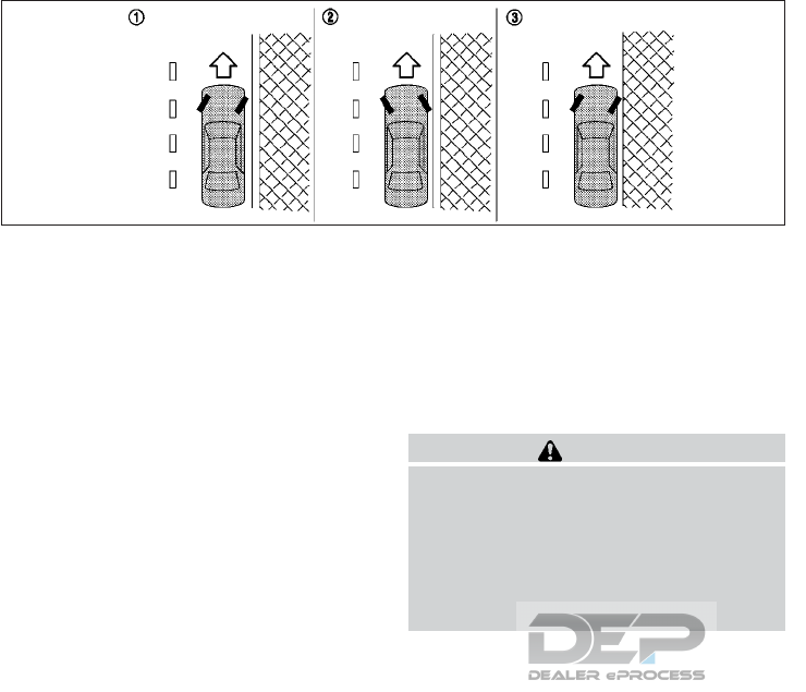
1. Firmly apply the parking brake.
2. Press the P (Park) button.
3. To help prevent the vehicle from moving
into traffic when parked on an incline, it is
a good practice to turn the wheels as
illustrated.
HEADED DOWNHILL WITH CURB 䊊
1
Turn the wheels into the curb and move
the vehicle forward until the curb side
wheel gently touches the curb. Then apply
the parking brake.
HEADED UPHILL WITH CURB 䊊
2
Turn the wheels away from the curb and
allow the vehicle to move back until the
curb side wheel gently touches the curb.
Then apply the parking brake.
HEADED UPHILL OR DOWNHILL,
WITHOUT CURB 䊊
3
Turn the wheels toward the side of the
road so the vehicle will move away from
the center of the road if the vehicle moves.
Then apply the parking brake.
4.
Put the ignition switch in the OFF position.
SWITCHING OFF THE ENGINE
WARNING
The automatic transmission switches to
position N (Neutral) when you switch off
the engine. The vehicle may roll away.
There is a risk of an accident.
After switching off the engine, always
switch to position P (Park). Prevent the
parked vehicle from rolling away by apply-
ing the parking brake.
Procedure
1. Apply the electric parking brake.
2. Shift the transmission to position P (Park).
3. With the key: turn the key to the position
OFF in the ignition switch and remove it
The immobilizer is activated.
If you switch the engine off with the trans-
mission in position R (Reverse) or D (Drive),
the automatic transmission shifts to N (Neu-
tral) automatically.
With the key: if you then open the driver's
door or the front-passenger door or remove
the key from the ignition, the automatic
transmission shifts to P (Park) automatically.
If you want the automatic transmission to
remain in neutral N (Neutral), e.g. when hav-
ing the vehicle cleaned in an automatic car
wash with a towing system:
With the key:
1. Switch the ignition on.
2. Depress the brake pedal and keep it de-
pressed.
3. Shift to N (Neutral).
SSD0488Z
Starting and driving 5-89

4. Release the brake pedal.
5. Release the electric parking brake.
6. Switch off the ignition and leave the key in
the ignition switch.
EXTENDED PARKING
If you leave the vehicle parked up for longer
than four weeks, the battery may be dam-
aged by exhaustive discharging.
If you leave the vehicle parked up for longer
than six weeks, it may suffer from lack of use.
Visit an INFINITI retailer and seek advice
NOTE
You can obtain information about trickle
chargers from an INFINITI retailer.
The electric power steering system is de-
signed to reduce the driver effort required to
steer the vehicle.
WARNING
If during operation a fault is detected the
following message will be displayed in the
vehicle information display along with an
audible warning tone.
[Power Steering Malfunction See Opera-
tors Manual]
In conjunction with this warning, steering
assistance will no longer be provided by the
system.
The effort required to steer the vehicle will
increase. This will be most noticeable at
low speed and when performing a tight
turning maneuver.
Check whether you are able to provide the
extra effort required.
If you are able to steer safely: Carefully
drive on to an INFINITI retailer.
If you are unable to steer safely: Do NOT
drive on. It is recommended you contact
the nearest INFINITI retailer for
assistance.
CAUTION
•If wheels or tires other than INFINITI
recommended ones are used, the power
steering system may not operate prop-
erly and the [Power Steering Malfunc-
tion See Operators Manual] warning
may appear in the vehicle information
display.
•Do not modify the vehicle's suspension.
If suspension parts such as shock ab-
sorbers, struts, springs, stabilizer bars,
bushings and wheels are not INFINITI
recommended for your vehicle or are ex-
tremely deteriorated, the power steer-
ing system may not operate properly
and the [Power Steering Malfunction
See Operators Manual] warning may
appear in the vehicle information dis-
play.
•Do not modify the vehicle's steering. If
steering parts are not INFINITI recom-
mended for your vehicle or are ex-
tremely deteriorated, the power steer-
ing system may not operate properly
and the [Power Steering Malfunction
See Operators Manual] warning may
appear in the vehicle information dis-
play.
ELECTRIC POWER STEERING
SYSTEM
5-90 Starting and driving

•Do not place the ignition switch in the on
position while the steering wheel or a
tire is removed.
•Do not turn the steering wheel as much
as possible while the ignition switch is in
any position other than the ON position.
•Installing an accessory on the steering
wheel, or changing the steering wheel,
may reduce the steering performance.
NOTE
When the steering wheel is operated repeat-
edly or continuously while parking or driving
at a very low speed, the power assistance for
the steering wheel will be reduced. This is to
prevent overheating of the electric power
steering system and protect it from becom-
ing damaged. While the power assistance is
reduced, steering wheel operation will be-
come heavy. When the temperature of the
electric power steering system decreases,
the power assistance level will return to nor-
mal. Avoid repeating such steering wheel
operations that could cause the electric
power steering system to overheat.
The brake system has two separate hydraulic
circuits. If one circuit malfunctions, you will
still have braking ability at two wheels.
BRAKE PRECAUTIONS
WARNING
While driving on a slippery surface, be
careful when braking, accelerating or
downshifting. Abrupt braking or acceler-
ating could cause the wheels to skid and
result in an accident.
Vacuum assisted brakes
The brake booster aids braking by using en-
gine vacuum. If the engine stops, you can
stop the vehicle by depressing the brake
pedal. However, greater foot pressure on the
brake pedal will be required to stop the ve-
hicle. The stopping distance will be longer.
WARNING
•If the engine is not running or is turned
off while driving, the power assist for
the brakes will not work. Braking will be
harder.
•Do not coast with the engine stopped.
When the brake pedal is depressed slowly
and firmly, you may hear a clicking noise and
feel a slight pulsation. This is normal and
indicates that the Brake Assist System is op-
erating (if equipped).
Using brakes
Avoid resting your foot on the brake pedal
while driving. This will overheat the brakes,
wear out the brake linings/pads faster, and
increase fuel consumption.
To help reduce brake wear and to prevent the
brakes from overheating, reduce speed and
downshift to a lower gear before going down
a slope or long grade. Overheated brakes
may reduce braking performance and could
result in loss of vehicle control.
While driving on a slippery surface, be careful
when braking, accelerating or downshifting.
Abrupt braking or acceleration could cause
the wheels to skid and result in an accident.
Wet brakes
When the vehicle is washed or driven through
water, the brakes may get wet. As a result,
your braking distance will be longer and the
vehicle may pull to one side during braking.
To dry the brakes, drive the vehicle at a safe
speed while lightly depressing the brake
pedal to heat up the brakes. Do this until the
brakes return to normal. Avoid driving the
BRAKE SYSTEM
Starting and driving 5-91

vehicle at high speeds until the brakes func-
tion correctly.
Driving uphill
When starting on a steep gradient, it is some-
times difficult to operate the brake. Use the
parking brake to hold the vehicle. When ready
to start, make sure that the shift lever is in an
appropriate forward or reverse driving posi-
tion, release the parking brake while depress-
ing the accelerator pedal. If your vehicle has
an electric parking brake, this will automati-
cally release when you depress the accelera-
tor pedal (DCT models).
Driving downhill
The engine braking action is effective for
controlling the vehicle while descending hills.
A low gear position in the manual shift mode,
low enough to obtain sufficient engine brak-
ing, should be selected.
Parking brake break-in
Break in the parking brake shoes whenever
the stopping effect of the parking brake is
weakened or whenever the parking brake
shoes and/or drums/rotors are replaced, in
order to assure the best braking perfor-
mance.
This procedure is described in the vehicle ser-
vice manual and can be performed by an
INFINITI retailer.
ANTI-LOCK BRAKING SYSTEM
(ABS)
WARNING
The Anti-lock Braking System (ABS) is a
sophisticated device, but it cannot prevent
accidents resulting from careless or dan-
gerous driving techniques. It can help
maintain vehicle control during braking on
slippery surfaces. Remember that stopping
distances on slippery surfaces will be lon-
ger than on normal surfaces even with
ABS. Stopping distances may also be lon-
ger on rough, gravel or snow covered
roads, or if you are using tire chains. Al-
ways maintain a safe distance from the ve-
hicle in front of you. Ultimately, the driver
is responsible for safety.
Tire type and condition may also affect
braking effectiveness.
–When replacing tires, install the specified
size of tires on all four wheels.
–When installing a replacement tire, make
sure that it is the proper size and type as
specified on the tire and loading informa-
tion label. (See "Wheels and Tires" in the
"9. Maintenance and Schedules" section.)
–For detailed information, see "Wheels and
tires" in the "8. Do-it-yourself" section.
The Anti-lock Braking System (ABS) controls
the brakes so the wheels do not lock during
hard braking or when braking on slippery sur-
faces. The system detects the rotation speed
at each wheel and varies the brake fluid pres-
sure to prevent each wheel from locking and
sliding. By preventing each wheel from lock-
ing, the system helps the driver maintain
steering control and helps to minimize swerv-
ing and spinning on slippery surfaces.
Using system
Depress the brake pedal and hold it down.
Depress the brake pedal with firm steady
pressure, but do not pump the brakes. The
ABS will operate to prevent the wheels from
locking up. Steer the vehicle to avoid ob-
stacles.
WARNING
Do not pump the brake pedal. Doing so may
result in increased stopping distances.
5-92 Starting and driving

Self-test feature
The ABS includes electronic sensors, electric
pumps, hydraulic solenoids and a computer.
The computer has a built-in diagnostic fea-
ture that tests the system each time you start
the engine and move the vehicle at a low
speed in forward or reverse. When the self-
test occurs, you may hear a “clunk” noise
and/or feel a pulsation in the brake pedal.
This is normal and does not indicate a mal-
function. If the computer senses a malfunc-
tion, it switches the ABS off and illuminates
the ABS warning light on the instrument
panel. The brake system then operates nor-
mally, but without anti-lock assistance. If the
ABS warning light illuminates during the self-
test or while driving, have the vehicle
checked. It is recommended you visit an
INFINITI retailer for this service.
Normal operation
The ABS operates at speeds above 3 to 6
MPH (5 to 10 km/h). The speed varies ac-
cording to road conditions.
When the ABS senses that one or more
wheels are close to locking up, the actuator
rapidly applies and releases hydraulic pres-
sure. This action is similar to pumping the
brakes very quickly. You may feel a pulsation
in the brake pedal and hear a noise from
under the hood or feel a vibration from the
actuator when it is operating. This is normal
and indicates that the ABS is operating prop-
erly. However, the pulsation may indicate
that road conditions are hazardous and extra
care is required while driving.
The Vehicle Dynamic Control (VDC) system
uses various sensors to monitor driver inputs
and vehicle motion. Under certain driving
conditions, the VDC system helps to perform
the following functions.
•Controls brake pressure to reduce wheel
slip on one slipping drive wheel so power is
transferred to a non slipping drive wheel
on the same axle.
•Controls brake pressure and engine output
to reduce drive wheel slip based on vehicle
speed (traction control function).
•Controls brake pressure at individual
wheels and engine output to help the
driver maintain control of the vehicle in the
following conditions:
– understeer (vehicle tends to not follow
the steered path despite increased
steering input)
– oversteer (vehicle tends to spin due to
certain road or driving conditions).
The VDC system can help the driver to main-
tain control of the vehicle, but it cannot pre-
vent loss of vehicle control in all driving situ-
ations.
VEHICLE DYNAMIC CONTROL (VDC)
SYSTEM
Starting and driving 5-93
When the VDC system operates, the VDC
warning light in the instrument panel flashes
so note the following:
•The road may be slippery or the system
may determine some action is required to
help keep the vehicle on the steered path.
•You may feel a pulsation in the brake pedal
and hear a noise or vibration from under
the hood. This is normal and indicates that
the VDC system is working properly.
•Adjust your speed and driving to the road
conditions.
See " Vehicle Dynamic Control (VDC) warning
light" in the "2. Instruments and controls" sec-
tion.
If a malfunction occurs in the system, the
VDC warning light illuminates in the
instrument panel. The VDC system automati-
cally turns off.
WARNING
•
The VDC system is designed to help the
driver maintain stability but does not pre-
vent accidents due to abrupt steering op-
eration at high speeds or by careless or
dangerous driving techniques. Reduce ve-
hicle speed and be especially careful when
driving and cornering on slippery surfaces
and always drive carefully.
•Do not modify the vehicle’s suspension.
If suspension parts such as shock ab-
sorbers, struts, springs, stabilizer bars,
bushings and wheels are not INFINITI
recommended for your vehicle or are ex-
tremely deteriorated, the VDC system
may not operate properly. This could
adversely affect vehicle handling per-
formance, and the VDC warning light
may illuminate.
•If brake related parts such as brake
pads, rotors and calipers are not
INFINITI recommended or are extremely
deteriorated, the VDC system may not
operate properly and the VDC warning
light may illuminate.
•If engine control related parts are not
INFINITI recommended or are extremely
deteriorated, the VDC warning light
may illuminate.
•When driving on extremely inclined sur-
faces such as higher banked corners, the
VDC system may not operate properly
and the VDC warning light may illu-
minate. Do not drive on these types of
roads.
•When driving on an unstable surface
such as a turntable, ferry, elevator or
ramp, the VDC warning light may
illuminate. This is not a malfunction. Re-
start the engine after driving onto a
stable surface.
•If wheels or tires other than the INFINITI
recommended ones are used, the VDC
system may not operate properly and
the VDC warning light may illumi-
nate.
•The VDC system is not a substitute for
winter tires or tire chains on a snow cov-
ered road.
•If VDC is malfunctioning, VDC is unable
to stabilize the vehicle. In addition,
other driving safety systems are
switched off. This increases the risk of
skidding and an accident. Drive on care-
fully. Have VDC checked. It is recom-
mended you visit an INFINITI retailer for
this service.
CAUTION
•When VDC is deactivated, the
VDC OFF warning light lights up con-
tinuously.
5-94 Starting and driving

•If both the warning light and
warning light are lit continuously, VDC
is not available due to a malfunction.
TRACTION CONTROL SYSTEM
(TCS)
The Traction Control System (TCS) is part of
VDC.
Traction control brakes the drive wheels indi-
vidually if they spin. This enables you to pull
away and accelerate on slippery surfaces, for
example if the road surface is slippery on one
side. In addition, more drive torque is trans-
ferred to the wheel or wheels with traction.
Traction control remains active if you deacti-
vate VDC.
CHARACTERISTICS OF VDC
If the VDC warning light goes out before
beginning the journey, VDC is automatically
active.
If VDC intervenes, the VDC warning
light flashes in the combination meter.
If VDC intervenes:
•Do not deactivate VDC under any circum-
stances.
•When pulling away, only depress the ac-
celerator pedal as far as is necessary.
•Adapt your driving style to suit the prevail-
ing road and weather conditions.
Deactivating/activating VDC
WARNING
If you deactivate VDC, VDC no longer sta-
bilizes the vehicle. There is an increased risk
of skidding and an accident.
Only deactivate VDC in the situations de-
scribed in the following section.
You can select between the following sta-
tuses of VDC:
•VDC is activated.
•VDC is deactivated.
It may be best to deactivate VDC in the fol-
lowing situations:
•When using snow chains.
•In deep snow.
•On sand or gravel.
NOTE
Activate VDC as soon as the situations de-
scribed above no longer apply. VDC will oth-
erwise not be able to stabilize the vehicle if
the vehicle starts to skid or a wheel starts to
spin.
You can activate/deactivate VDC using the
vehicle information display. To activate/
deactivate VDC:
1. Start the engine
2. Press the or button on the
steering wheel to select the [DriveAssist]
menu in the vehicle information display.
3. Press the or button to select
VDC.
4. Press the <OK> button on the steering
wheel. The current selection is displayed.
5. To activate/deactivate: press the <OK>
button again.
VDC is deactivated if the warning
light in the combination meter lights up
continuously when the engine is running.
Characteristics when VDC is deactivated:
If VDC is deactivated and one or more wheels
start to spin, the VDC warning light
flashes in the combination meter. In such
situations, VDC will not stabilize the vehicle.
Starting and driving 5-95

If you deactivate VDC:
•VDC no longer intervenes in understeer or
oversteer situations.
•Engine torque is no longer limited and the
drive wheels are able to spin.
The spinning of the wheels results in a
cutting action, so the tires cut through the
loose surface until the hit solid ground,
giving better traction.
•Traction control is still activated.
•VDC still provides support when you
brake.
EBD (ELECTRONIC BRAKE
FORCE DISTRIBUTION)
EBD monitors and controls the brake pres-
sure on the rear wheels to help improve han-
dling during braking.
WARNING
If EBD is malfunctioning, the EBD [Inop-
erative See Operator's Manual] warning is
displayed in the vehicle information dis-
play. The VDC warning light may also
light up.
If EBD is malfunctioning as a result of a
VDC malfunction, the rear wheels can lock,
e.g. under full braking. This increases the
risk of skidding and an accident.
You should therefore adapt your driving
style to the different handling characteris-
tics. Have the brake system checked. It is
recommended you see an INFINITI retailer.
STEER CONTROL
STEER CONTROL helps you by transmitting
a noticeable steering force to the steering
wheel in the direction required for vehicle
stabilisation.
This steering support is provided in particular
if:
•Both right wheels or both left wheels are
on a wet or slippery road surface when
you brake.
•The vehicle starts to skid.
WARNING
No steering support is provided from
STEER CONTROL, if:
•VDC is malfunctioning.
•The steering is faulty.
Power steering will, however, continue to
function.
WARNING
•Never rely solely on the Hill Start Assist
(HSA) system to prevent the vehicle
from moving backward on a hill. Always
drive carefully and attentively. Depress
the brake pedal when the vehicle is
stopped on a steep hill. Be especially
careful when stopped on a hill on frozen
or muddy roads. Failure to prevent the
vehicle from rolling backwards may re-
sult in a loss of control of the vehicle and
possible serious injury or death.
•The Hill Start Assist system is not de-
signed to hold the vehicle at a standstill
on a hill. Depress the brake pedal when
the vehicle is stopped on a steep hill.
Failure to do so may cause the vehicle to
roll backwards and may result in a colli-
sion or serious personal injury.
•The Hill Start Assist system may not
prevent the vehicle from rolling back-
wards on a hill under all load or road
conditions. Always be prepared to de-
press the brake pedal to prevent the ve-
hicle from rolling backwards. Failure to
do so may result in a collision or serious
personal injury.
•After a short time, hill start assist will no
longer brake your vehicle and it could
HILL START ASSIST (HSA)
5-96 Starting and driving

roll away There is a risk of an accident
and injury. Therefore, quickly move your
foot from the brake pedal to the accel-
erator pedal. Never leave the vehicle
when it is held by hill start assist.
Hill start assist helps you when pulling away
forwards or in reverse on an uphill gradient. It
holds the vehicle for a short time after you
have removed your foot from the brake
pedal. This gives you enough time to move
your foot from the brake pedal to the accel-
erator pedal and depress it before the vehicle
begins to roll.
Hill start assist is not active if
•You are pulling away on a level road or a
downhill gradient.
•On vehicles with automatic transmission,
the transmission is in position N.
•The electric parking brake is applied.
•VDC is malfunctioning.
FREEING A FROZEN DOOR LOCK
To prevent a door lock from freezing, apply
deicer through the key hole. If the lock be-
comes frozen, heat the key before inserting it
into the key hole, or use the INFINITI Intelli-
gent Key.
ANTIFREEZE
In the winter when it is anticipated that the
temperature will drop below 32°F (0°C),
check the antifreeze to assure proper winter
protection. For additional information, see
"Engine cooling system" in the "8. Do-it-
yourself" section.
BATTERY
If the battery is not fully charged during ex-
tremely cold weather conditions, the battery
fluid may freeze and damage the battery. To
maintain maximum efficiency, the battery
should be checked regularly. For details, see
"Battery" in the "8. Do-it-yourself" section of
this manual.
DRAINING OF ENGINE COOLANT
If the vehicle is to be left outside without
antifreeze, drain the cooling system, including
the engine block. Refill before operating the
vehicle. For details, see "Changing engine
coolant" in the "8. Do-it-yourself" section of
this manual.
TIRE EQUIPMENT
1. SUMMER tires have a tread designed to
provide superior performance on dry
pavement. However, the performance of
these tires will be substantially reduced in
snowy and icy conditions. If you operate
your vehicle on snowy or icy roads,
INFINITI recommends the use of MUD &
SNOW or ALL SEASON TIRES on all four
wheels. It is recommended that you visit
an INFINITI retailer for the tire type, size,
speed rating and availability information.
2. For additional traction on icy roads, stud-
ded tires may be used. However, some
U.S. states and Canadian provinces pro-
hibit their use. Check local, state and pro-
vincial laws before installing studded tires.
Skid and traction capabilities of studded
snow tires, on wet or dry surfaces, may be
poorer than that of non-studded snow tires.
3. Tire chains may be used if desired. Make
sure they are the proper size for the tires
on your vehicle and are installed according
to the chain manufacturer’s instructions.
Use chain tensioners when recommended
by the tire chain manufacturer to ensure a
tight fit. Loose end links of the tire chains
must be secured or removed to prevent
the possibility of whipping action damage
to the fenders or underbody. In addition,
COLD WEATHER DRIVING
Starting and driving 5-97

drive at a reduced speed, otherwise, your
vehicle may be damaged and/or vehicle
handling and performance may be ad-
versely affected.
SPECIAL WINTER EQUIPMENT
It is recommended that the following items
be carried in the vehicle during the winter:
•A scraper and stiff-bristled brush to re-
move ice and snow from the windows.
•A sturdy, flat board to be placed under the
jack to give it firm support.
•A shovel to dig the vehicle out of snow-
drifts.
•Extra washer fluid to refill the windshield
washer fluid reservoir.
DRIVING ON SNOW OR ICE
WARNING
•Wet ice (32°F, 0°C and freezing rain),
very cold snow or ice can be slick and
very hard to drive on. The vehicle will
have much less traction or “grip” under
these conditions. Try to avoid driving on
wet ice until the road is salted or sanded.
•Whatever the condition, drive with cau-
tion. Accelerate and slow down with
care. If accelerating or downshifting too
fast, the drive wheels will lose even more
traction.
•Allow more stopping distance under
these conditions. Braking should be
started sooner than on dry pavement.
•Allow greater following distances on
slippery roads.
•Watch for slippery spots (glare ice).
These may appear on an otherwise clear
road in shaded areas. If a patch of ice is
seen ahead, brake before reaching it. Try
not to brake while on the ice, and avoid
any sudden steering maneuvers.
•Do not use cruise control on slippery
roads.
•Snow can trap dangerous exhaust gas
under your vehicle. Keep snow clear of
the exhaust pipe and from around your
vehicle.
5-98 Starting and driving

6 In case of emergency
Hazard warning flasher switch .............6-2
Flat tire ............................6-2
Tire Pressure Monitoring System (TPMS).....6-2
Stopping vehicle.....................6-3
Warning triangle (if equipped) ............6-4
Run-flat tires.......................6-4
Removing and fitting wheels .............6-5
Jump starting .......................6-10
Push starting ........................6-12
If your vehicle overheats.................6-13
Towing your vehicle ...................6-14
Towing recommended by INFINITI ........6-14

The hazard warning flasher switch 䊊
1oper-
ates regardless of the ignition switch position
except when the battery is discharged.
The hazard warning flasher is used to warn
other drivers when you have to stop or park
under emergency conditions.
When the hazard warning flasher switch is
pushed, all turn signal lights will flash. To turn
off the hazard warning flasher, push the haz-
ard warning switch again.
WARNING
•If stopping for an emergency, be sure to
move the vehicle well off the road.
•Do not use the hazard warning flashers
while moving on the highway unless un-
usual circumstances force you to drive
so slowly that your vehicle might be-
come a hazard to other traffic.
•Turn signals do not work when the haz-
ard warning flasher lights are on.
Some jurisdictions may prohibit the use of
the hazard warning flasher switch while
driving.
If you have a flat tire, follow the instructions
in this section.
TIRE PRESSURE MONITORING
SYSTEM (TPMS)
WARNING
•If the low tire pressure warning light il-
luminates or a tire pressure-related
warning is displayed by the vehicle in-
formation display while driving, avoid
sudden steering maneuvers or abrupt
braking, reduce vehicle speed, pull off
the road to a safe location and stop the
vehicle as soon as possible. Driving with
under-inflated tires may permanently
damage the tires and increase the likeli-
hood of tire failure. Serious vehicle dam-
age could occur and may lead to an acci-
dent and could result in serious personal
injury. Check the tire pressure for all
four tires. Adjust the tire pressure to the
recommended COLD tire pressure
shown on the tire and loading informa-
tion label to turn the low tire pressure
warning light OFF. If you have a flat tire,
replace it with a replacement tire as
soon as possible.
•When a replacement tire is mounted or a
wheel is replaced, the TPMS will not
NIC2621
HAZARD WARNING FLASHER
SWITCH FLAT TIRE
6-2 In case of emergency

function and the low tire pressure warn-
ing light will flash for approximately 1
minute. The light will remain on after 1
minute. It is recommended you Contact
an INFINITI retailer as soon as possible
for tire replacement and/or system re-
setting.
•Replacing tires with those not originally
specified by INFINITI could affect the
proper operation of the TPMS.
•If you used Emergency Tire Sealant to
repair a minor tire puncture, the TPMS
sensor should be checked when repair-
ing or replacing the tire. It is recom-
mended you visit an INFINITI retailer for
this service.
The Tire Pressure Monitoring System (TPMS)
monitors tire pressure of all tires. When the
low tire pressure warning light is lit, and a tire
pressure-related warning (if equipped) ap-
pears in the vehicle information display, one
or more of your tires is significantly under-
inflated. If the vehicle is being driven with low
tire pressure, the TPMS will activate and
warn you of it by the low tire pressure warn-
ing light (in the meter panel). This system will
activate only when the vehicle is driven at
speeds above 16 MPH (25 km/h).
For more details about the TPMS, see "Tire
Pressure Monitoring System (TPMS)" in the
"5. Starting and driving" section.
STOPPING VEHICLE
WARNING
•Be sure to apply the parking brake
firmly.
•Be sure that P (Park) is engaged.
•Never change tires when the vehicle is
on a slope, ice or slippery area. This is
hazardous.
•Never change tires when the oncoming
traffic is close to your vehicle. Call for
professional road assistance.
1. Safely move the vehicle off the road away
from traffic.
2. Turn on the hazard indicator flasher lights.
3. Park on a level surface.
4. Apply the parking brake.
5. Press the P (Park) button.
6. Turn off the engine.
7. Open the hood and set up the triangle
reflector (if equipped):
•To warn other traffic.
•To signal professional road assistance
personnel that you need assistance.
8. Have all passengers get out of the vehicle
and stand in a safe place, away from
other traffic and clear of the vehicle.
In case of emergency 6-3
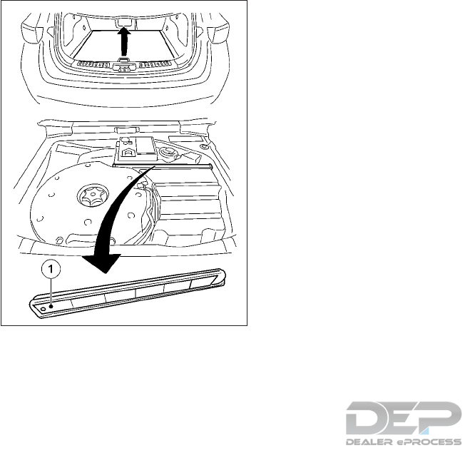
WARNING TRIANGLE (IF
EQUIPPED)
Removing and refitting the warning
triangle
To remove:
1. Open the lift gate and lift the luggage
compartment floor upwards.
2. To release warning triangle, push back the
retainers on the bracket.
3. Remove warning triangle 䊊
1from the
bracket.
To refit:
1. Place warning triangle 䊊
1back into the
bracket and push down to secure.
2. Fold down the luggage compartment
floor.
3. Close the lift gate.
Setting up the warning triangle
1. Fold legs out to the side.
2. Fold side reflectors upwards to form a
triangle and lock them at the top using
press stud.
RUN-FLAT TIRES
With special run-flat tires, you can continue
to drive your vehicle even if there is a total
loss of pressure in one or more tires. The
affected tire must not show any clearly visible
damage.
You can recognize run-flat tires by the mark-
ing which appears on the tire side wall. You
will find this marking next to the tire size
designation, the load-bearing capacity and
the speed index.
Run-flat tires may only be used in conjunction
with an activated tire pressure loss warning
system or tire pressure monitor.
Pressure loss warning message
If a pressure loss warning message appears
in the vehicle information display:
•Observe the instructions in the display
messages.
•Check the tire for damage.
•If driving on, observe the following notes.
The driving distance possible in run-flat mode
is approximately 50 miles (80 km) when the
vehicle is partially laden and approximately
20 miles (30 km) when the vehicle is fully
laden.
NIC2686
6-4 In case of emergency
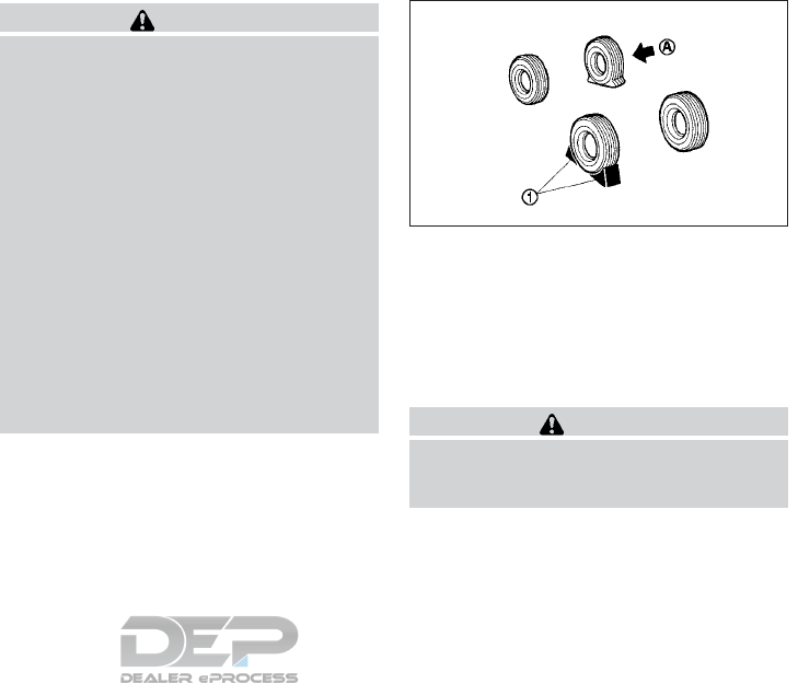
In addition to the vehicle load, the driving
distance possible depends upon:
•Vehicle speed.
•Road condition.
•Outside temperature.
The driving distance possible in run-flat mode
may be reduced by extreme driving
conditions/maneuvers, or it can be increased
through a moderate style of driving.
The driving distance possible in run-flat mode
is counted from the moment the tire pressure
loss warning appears in the vehicle informa-
tion display.
You must not exceed a maximum speed of 50
MPH (80 km/h).
When replacing one or all tires, observe the
following specifications for your vehicle's
tires:
•Size
•Type
•Run-flat mark
If a tire has gone flat and cannot be replaced
with a run flat tire, a standard tire may be
used as a temporary measure. Make sure that
you use the proper size and type (summer or
winter tire).
WARNING
Do not exceed the stated maximum speed.
Avoid abrupt steering and driving maneu-
vers, and driving over obstacles (curbs, pot
holes, off road). This applies in particular to
a laden vehicle.
Stop driving in emergency mode if:
•You hear banging noises.
•The vehicle starts to shake.
•You see smoke and smell rubber.
•VDC is intervening constantly.
•There are tears in the sidewalls of the
tire.
After driving in emergency mode, have the
wheel rims checked with regard to their
further use. It is recommended you visit an
INFINITI retailer for this service. The faulty
tire must be replaced.
REMOVING AND FITTING
WHEELS
NOTE
A spare wheel is not provided with your ve-
hicle.
Blocking the wheels
WARNING
Make sure to block the appropriate wheel
to prevent the vehicle from moving, which
may cause personal injury.
Place suitable blocks 䊊
1in front of and be-
hind the wheel diagonally opposite the flat
tire 䊊
Ato prevent the vehicle from moving
when it is on the jack.
MCE0001DZ
In case of emergency 6-5
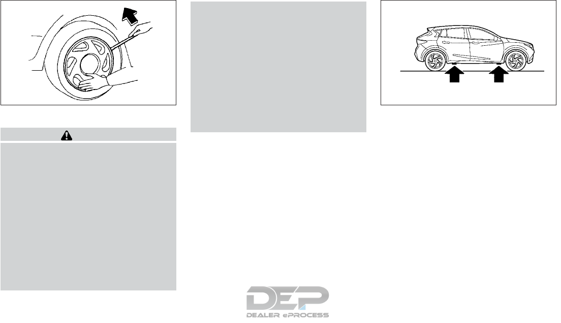
Removing the wheel
WARNING
•The jack must be placed on firm level
ground. Failure to observe this instruc-
tion could result in vehicle damage, or
serious injury or death.
•Make sure to read the caution label at-
tached to the jack body before use.
•DO NOT GET UNDER A VEHICLE THAT
IS SUPPORTED BY A JACK.
•Never use a jack which was not designed
for your vehicle.
•Use the correct jacking points. Never
use any other part of the vehicle for jack
support.
•Never lift the vehicle more than neces-
sary.
•Never use blocks on or under the jack.
•Do not start or run the engine while the
vehicle is on the jack. The vehicle may
move suddenly, and this may cause an
accident.
•Never allow passengers to stay in the
vehicle while the tire is off the ground.
•Remove all loads before lifting the ve-
hicle with the jack.
NOTE
A jack and rod are not provided as standard
equipment with your vehicle. These parts are
dealer options. It is recommended that you
contact an INFINITI retailer for more infor-
mation about obtaining these parts.
1. Vehicles without intelligent key: Remove
the key from the ignition lock.
Vehicles with a push button ignition
switch: remove the start/stop button
from the ignition lock (see " Push-button
ignition switch (if equipped)" in the "5.
Starting and driving" section).
2. Place the jack directly under the jack-up
point as illustrated so that the top of the
jack contacts the vehicle at the jack-up
point.
The jack must be placed on firm level
ground.
NCE453 NCE447
Jack-up points
6-6 In case of emergency
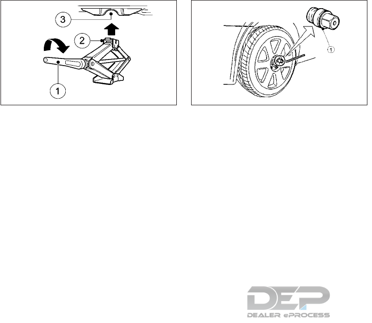
3. Align the center of both the jack head 䊊
2
and the notches at the jack-up point 䊊
3as
shown.
4. Fit the groove of the jack head between
the two notches as shown.
5. Loosen each wheel bolt by one or two
turns counterclockwise with the wheel
wrench.
Do not remove the wheel bolts until the
tire is off the ground.
Models with wheel lock bolts (if equipped) :
If the wheel is equipped with a wheel lock
bolt, insert the wheel lock key 䊊
1and
loosen it as previously described.
The wheel lock bolt can only be removed
with the wheel lock key. A key number is
necessary if you need to duplicate the
wheel lock key.
Record the key number as shown on the
key code card on the “Security informa-
tion” page at the end of this manual and
keep it in a safe place, not in the vehicle. If
you lose the wheel lock key, it is recom-
mended you see your INFINITI retailer for
a duplicate with the original wheel lock
key code.
Make sure to keep the lock key in the
vehicle. Otherwise, wheels cannot be re-
moved and the service cannot be per-
formed.
NCE449 NCE143Z
In case of emergency 6-7
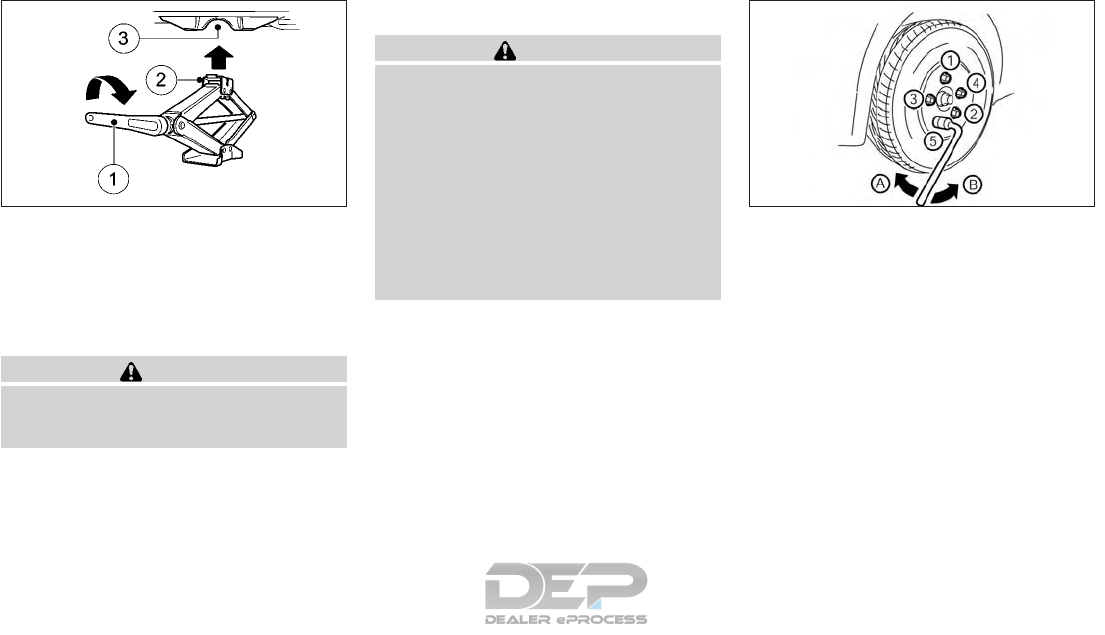
6. To lift the vehicle, securely hold and turn
the ratchet handle 䊊
1clockwise as shown.
7. Carefully raise the vehicle until the tire
clears the ground.
8. Remove the wheel bolts, then remove the
wheel with the flat tire.
WARNING
The wheel is heavy. Be sure that your feet
are clear of the wheel and use gloves as
necessary to avoid injury.
Installing the wheel
WARNING
•A temporary use spare wheel and tire is
designed for emergency use.
•Never use wheel bolts other than those
provided with your vehicle. Incorrect
wheel bolts or improperly tightened
wheel bolts may cause the wheel to be-
come loose or come off. This could cause
an accident.
•Never use oil or grease on the wheel
bolts. This may cause the wheel bolts to
become loose.
䊊
ATighten
䊊
BLoosen
1. Clean any mud or dirt from the surface
between the wheel and the hub.
2. Carefully fit the wheel and tighten the
wheel bolts with your fingers. Check that
all the wheel bolts contact the wheel sur-
face horizontally and on the bevelled side.
Models with wheel lock bolt (if equipped):
Insert the wheel lock key into the wheel
lock bolt and tighten into the wheel finger
tight.
3. With the wheel wrench, tighten the wheel
bolts alternately and evenly in the se-
quence as illustrated ( 䊊
1-䊊
5) until they
are tight.
NCE449 NCE435
6-8 In case of emergency
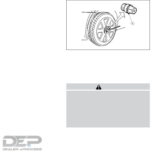
4. Lower the vehicle slowly until the tire
touches the ground.
5. Tighten the wheel bolts securely using the
wheel wrench in the sequence as illus-
trated.
6. Lower the vehicle completely.
7. Install the wheel cover (if equipped).
Wheel bolt tightening torque:
96 ft-lb (130 N•m, 13 kg-m)
As soon as possible, tighten the wheel bolts
to the specified torque with a torque wrench.
The wheel bolts must be kept tightened to
specification at all times. It is recommended
that the wheel bolts be tightened to specifi-
cation at each maintenance interval.
Adjust the tire pressure to the COLD pres-
sure.
COLD pressure is the tire pressure as mea-
sured after the vehicle has been parked for
three hours or more or driven for less than 1
mile (1.6 km).
COLD tire pressures are shown on the tire
and loading information label affixed to the
driver's side center pillar.
Wheel lock bolts (if equipped)
In order to prevent theft, the specially de-
signed wheel lock bolt is installed to each
wheel. The wheel lock bolt cannot be re-
moved with the commonly used tools.
When removing tires, use the lock key pro-
vided with your vehicle.
Removing the wheel lock bolt:
1. Insert the wheel lock key 䊊
1to the wheel
lock bolt.
2. To remove the wheel lock bolt, turn the
wheel lock key counterclockwise using the
wheel wrench.
CAUTION
•Do not use a power tool to remove the
wheel lock bolts.
•When installing the wheel, tighten the
wheel lock bolts to the same tightening
torque as the normal wheel bolts. For
details, see "Installing the wheel" earlier
in this section.
NCE143Z
In case of emergency 6-9

NOTE
•The wheel lock bolt has an individual code.
A wheel lock key with other than the indi-
vidual code cannot remove the wheel lock
bolt. If you lose the wheel lock key, it is
recommended you contact an INFINITI re-
tailer for a duplicate with the original
wheel lock key code.
•Record the key number and keep it in a
safe place, not in the vehicle.
•When you ask for a service at an INFINITI
retailer, make sure to keep the lock key in
the vehicle. Otherwise, wheels cannot be
removed and the service cannot be per-
formed.
For the jump-starting procedure, use only the
jump-starting connection point, consisting of
a positive terminal and an earth point, in the
engine compartment.
WARNING
•If done incorrectly, jump starting can
lead to a battery explosion, resulting in
severe injury or death. It could also dam-
age your vehicle.
•Explosive hydrogen gas is always pres-
ent in the vicinity of the battery. Keep all
sparks and flames away from the bat-
tery.
•Do not allow battery fluid to come into
contact with eyes, skin, clothes or
painted surfaces. Battery fluid is a cor-
rosive sulfuric acid which can cause se-
vere burns. If the fluid should come into
contact with anything, immediately
flush the contacted area with water.
•Keep the battery out of the reach of chil-
dren.
•The booster battery must be rated at 12
volts. Use of an improperly rated bat-
tery can damage your vehicle.
•Whenever working on or near a battery,
always wear suitable eye protectors (for
example, goggles or industrial safety
spectacles) and remove rings, metal
bands, or any other jewelry. Do not lean
over the battery when jump starting.
•Do not attempt to jump start a frozen
battery. It could explode and cause seri-
ous injury.
•Your vehicle has an automatic engine
cooling fan. It could come on at any time.
Keep hands and other objects away
from it.
JUMP STARTING
6-10 In case of emergency
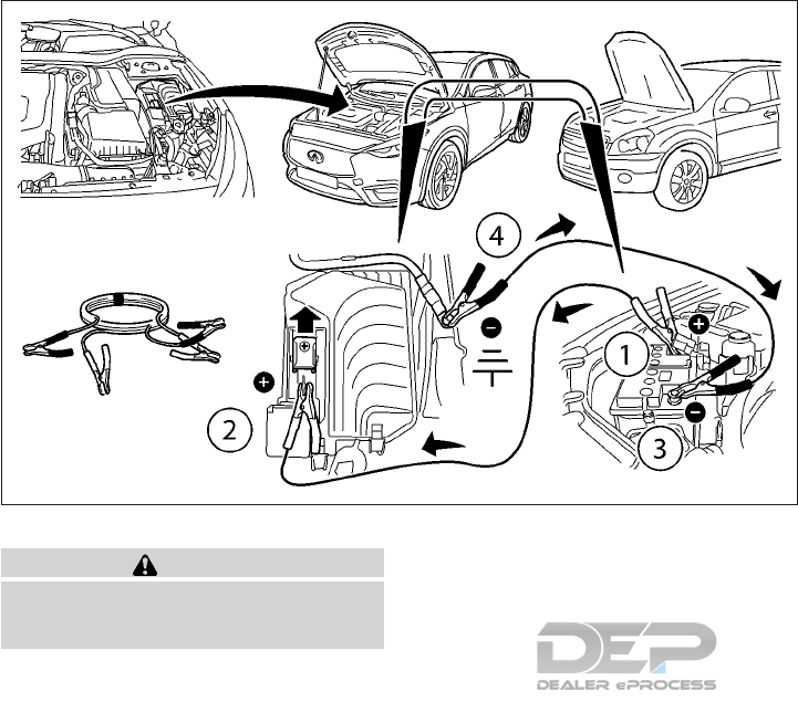
WARNING
Always follow the instructions below. Fail-
ure to do so could result in damage to the
charging system and cause personal injury.
1. If the booster battery is in another vehicle,
position the two vehicles to bring their
batteries near each other.
Do not allow the two vehicles to touch.
2. Check if the parking brake is applied.
If not, after connecting the vehicle with
the booster battery (after step 8), apply
the parking brake.
The vehicle has an electric parking brake,
for more information see, "Parking brake"
in the "3. Pre-driving checks and adjust-
ments" section
3. Press the P (Park) button.
4. Switch off all unnecessary electrical sys-
tems (headlights, hazard lights etc,).
5. Ensure that the ignition switch of the ve-
hicle being jump-started is in the OFF po-
sition.
6. Open the hood. For details, see "Hood" in
the "3. Pre-driving checks and adjust-
ments" section.
7. Remove the vent caps (if equipped) on the
battery and cover the battery with an old
cloth.
8. Connect the jump leads in the sequence (
䊊
1→䊊
2→䊊
3→䊊
4) as illustrated.
NDI1595
In case of emergency 6-11

CAUTION
•Always connect positive 䊊
+to positive
䊊
+and negative 䊊
-to body ground (for
example, strut mounting bolt, engine lift
bracket, etc.) – not to the battery's
negative 䊊
-.
•Be sure that the jumper cables do not
touch moving parts in the engine com-
partment and that the cable clamps do
not contact any other metal.
9. Start the engine of the other vehicle 䊊
A
and let it run for a few minutes. Keep the
engine speed at about 2,000 rpm.
10. Start the engine of your vehicle 䊊
Bin the
normal way.
CAUTION
Do not keep the starter motor engaged for
more than 10 seconds. If the engine does
not start right away, place the ignition
switch in the OFF position and wait 10 sec-
onds before trying again.
11. After starting the engine of your vehicle,
carefully disconnect the negative lead
and then the positive lead ( 䊊
4→䊊
3→䊊
2
→䊊
1).
12. Remove and dispose of the cloth that
was used to cover the ventilator holes as
it may be contaminated with corrosive
acid.
13. Install the ventilator caps (if equipped).
14. Close the hood.
NOTE
For models which incorporate the Idle Stop/
Start System:
•Ensure that the battery fitted is the special
battery that is enhanced with regard to the
charge-discharge capacity and life perfor-
mance. Avoid using any other battery for
the Idle Stop/Start System, as this may
cause early deterioration of the battery or
a malfunction of the Idle Stop/Start Sys-
tem. It is recommended that a Genuine
INFINITI battery is fitted. For more infor-
mation, it is recommended you contact an
INFINITI retailer.
•If the battery terminal is disconnected (for
battery replacement, etc.) and then recon-
nected, there may be some delay before
the Idle top/Start System reactivates.
Do not attempt to start the engine by pushing
the vehicle.
CAUTION
•Automatic Transmission (AT) model
cannot be push-started or tow-started.
Attempting to do so may cause damage
to the transmission.
•Three-way catalyst equipped models
should not be started by pushing. At-
tempting to do so may cause damage to
the three-way catalyst.
•Never try to start the vehicle by towing
it; when the engine starts, the forward
surge could cause the vehicle to collide
with the tow vehicle.
PUSH STARTING
6-12 In case of emergency

WARNING
•Do not continue to drive if your vehicle
overheats. Doing so could cause engine
damage or a vehicle fire.
•To avoid the danger of being scalded,
never remove the radiator or coolant
reservoir cap while the engine is hot.
When the radiator or coolant reservoir
cap is removed, pressurized hot water
will spurt out, possibly causing serious
injury.
•Do not open the hood if steam is coming
out.
If the engine of your vehicle is overheating
(indicated by the engine coolant temperature
gauge) or if you feel a lack of engine power,
detect unusual noise, etc., proceed as fol-
lows:
1. Move and park the vehicle safely off the
road and away from traffic.
2. Turn on the hazard warning flasher lights.
3. Apply the parking brake.
4. Press the P (Park) button.
DO NOT STOP THE ENGINE.
5. Open all windows.
6. Switch off the air conditioner system (if
equipped).
7. Set the heater or air conditioner tempera-
ture control to maximum “HOT” and fan
speed control to maximum speed.
8. Exit the vehicle.
9. Visually inspect and listen for steam or
coolant escaping from the radiator before
opening the hood.
WARNING
If steam or water is coming from the en-
gine, stand clear to prevent getting
burned.
10. Open the hood. For details, see "Hood"
in the "3. Pre-driving checks and adjust-
ments" section.
11. Visually check if the cooling fan is run-
ning.
12. Visually check the radiator and radiator
hoses for leakage.
WARNING
Be careful not to allow your hands, hair,
jewelry or clothing to come into contact
with, or get caught in, engine belts or the
engine cooling fan. The engine cooling fan
can start at any time.
13. After the engine cools down, check the
coolant level in the engine coolant reser-
voir with the engine running. Do not
open the radiator cap (if equipped).
14. If the level is low, remove the engine
coolant reservoir cap and add coolant
slowly into the reservoir. After refilling
the reservoir to the MAX level, install the
reservoir cap.
15. Close the hood.
Have your vehicle inspected or repaired. It is
recommended you visit an INFINITI retailer.
IF YOUR VEHICLE OVERHEATS
In case of emergency 6-13
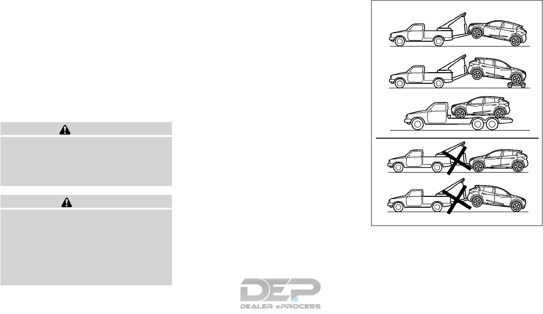
When towing your vehicle, all jurisdictions
and local regulations for towing must be fol-
lowed. Incorrect towing equipment could
damage your vehicle. Towing instructions are
available from an INFINITI retailer. Local ser-
vice operators are generally familiar with the
applicable laws and procedures for towing.
To assure proper towing and to prevent ac-
cidental damage to your vehicle, INFINITI
recommends having a service operator tow
your vehicle. It is advisable to have the service
operator carefully read the following precau-
tions.
WARNING
•Never ride in a vehicle that is being
towed.
•Never get under your vehicle after it has
been lifted by a tow truck.
CAUTION
•When towing, make sure that the trans-
mission, axles, steering system and
powertrain are in working condition. If
any of these conditions apply, dollies or
a flatbed tow truck must be used.
•Always attach safety chains before
towing.
TOWING RECOMMENDED BY
INFINITI
INFINITI recommends towing your vehicle
based upon the type of drivetrain. Please re-
fer to the diagrams in this section to ensure
that your vehicle is properly towed.
NCE451
FWD (2WD) models
TOWING YOUR VEHICLE
6-14 In case of emergency
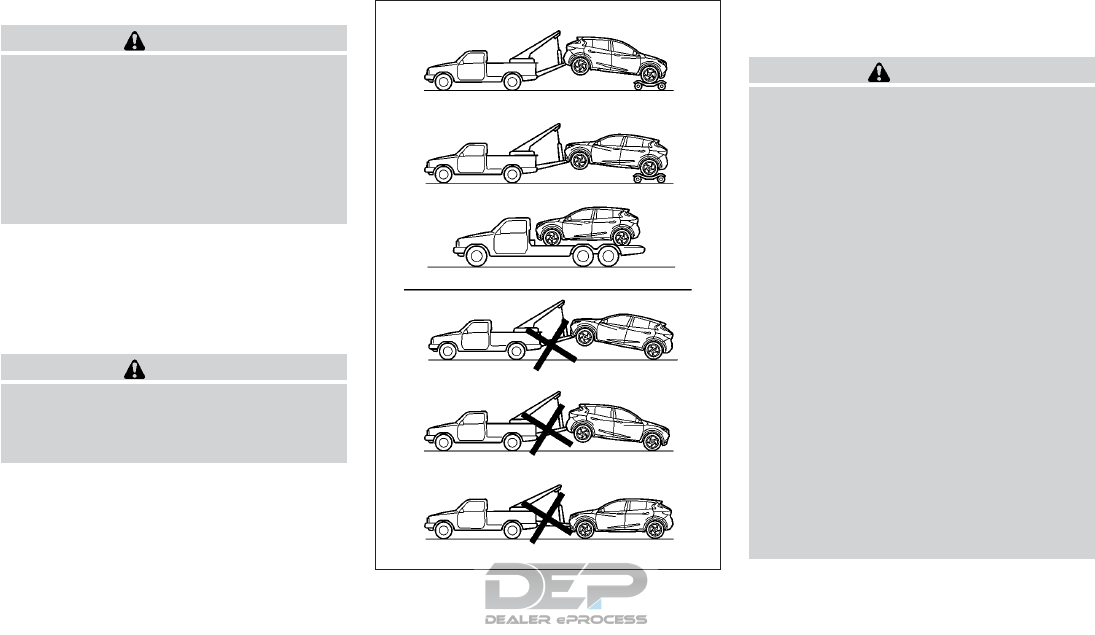
Two-Wheel Drive (FWD) models
CAUTION
NEVER tow automatic transmission (DCT)
models with the front wheels on the
ground or with all four wheels on the
ground (forwards or backwards), as this
may cause serious and expensive damage
to the transmission. If it is necessary to tow
the vehicle with the rear wheels raised, al-
ways use towing dollies under the front
wheels.
Four-Wheel Drive (4WD) models
INFINITI recommends that towing dollies be
used under the front or rear wheels when
towing your vehicle or the vehicle be placed
on a flatbed tow truck as illustrated.
CAUTION
Never tow 4WD models with any of the
wheels on the ground. Doing so will cause
serious and expensive damage to the
drivetrain.
Vehicle recovery (freeing a stuck
vehicle)
WARNING
To avoid vehicle damage, serious personal
injury or death when recovering a stuck ve-
hicle:
•Contact a professional towing service to
recover the vehicle if you have any ques-
tions regarding the recovery procedure.
•Tow chains or cables must be attached
only to main structural members of the
vehicle.
•Do not use the vehicle tie downs to tow
or free a stuck vehicle.
•Only use devices specifically designed
for vehicle recovery and follow the
manufacturer's instructions.
•Always pull the recovery device straight
out from the front of the vehicle. Never
pull at an angle.
•Route recovery devices so they do not
touch any part of the vehicle except the
attachment point.
•On vehicles with a push button ignition
switch: you must remove the start/stop
NCE450
4WD models
In case of emergency 6-15
button and use the key (see " Push-
button ignition switch (if equipped)" in
the "5. Starting and driving" section).
Otherwise the automatic transmission
may shift to position P (Park) when the
driver's or front passenger door are
opened, which could lead to damage to
the transmission.
If your vehicle is stuck in sand, snow, mud,
etc., use a tow strap or other device designed
specifically for vehicle recovery. Always fol-
low the manufacturer’s instructions for the
recovery device.
Rocking a stuck vehicle
WARNING
•To avoid potential injury, stand clear of
a stuck vehicle.
•Do not spin your tires at high speed. This
could cause them to explode and result
in serious injury. Parts of your vehicle
could also overheat and be damaged.
If your vehicle is stuck in sand, snow, mud,
etc., use the following procedure:
1. Turn off the Vehicle Dynamic Control
(VDC) system.
2. Make sure the area in front and behind the
vehicle is clear of obstructions.
3. Turn the steering wheel right and left to
clear an area around the front tires.
4. Slowly rock the vehicle forward and back-
ward.
•Shift back and forth between R (Reverse)
and D (Drive).
•Apply the accelerator as little as possible
to maintain the rocking motion.
•Release the accelerator pedal before shift-
ing between R (Reverse) and D (Drive).
•Do not spin the tires above 35 MPH (55
km/h).
5. If the vehicle cannot be freed after a few
tries, contact a professional towing ser-
vice to remove the vehicle.
6-16 In case of emergency

7 Appearance and care
Cleaning exterior ......................7-2
Washing..........................7-2
Waxing ..........................7-2
Removing spots .....................7-3
Underbody ........................7-3
Glass ............................7-3
Wheels...........................7-3
Aluminum alloy wheels ................7-3
Chrome parts ......................7-3
Tire dressings ......................7-3
Cleaning interior.......................7-4
Air fresheners ......................7-4
Floor mats (if equipped) ................7-5
Seat belts .........................7-5
Cleaning the seat tracks ................7-6
Genuine leather seat covers .............7-6
Corrosion protection ....................7-7
Most common factors contributing to vehicle
corrosion .........................7-7
Environmental factors influence the rate of
corrosion .........................7-7
To protect your vehicle from corrosion ......7-7

In order to maintain the appearance of your
vehicle, it is important to take proper care of
it.
To protect the paint surfaces, please wash
your vehicle as soon as you can:
•After a rainfall, to prevent possible dam-
age from acid rain.
•After driving on coastal roads.
•When contaminants such as soot, bird
droppings, tree sap, metal particles or
bugs get on the paint surface.
•When dust or mud builds up on the sur-
face.
Whenever possible, park your vehicle inside a
garage or in a covered area to minimize the
chances of damaging the paint surface of
your vehicle.
When it is necessary to park outside, park in a
shady area or protect the vehicle with a body
cover. Be careful not to scratch the paint
surface when putting on or removing the
body cover.
WASHING
Wash dirt off with a wet sponge and plenty
of water. Clean the vehicle thoroughly using a
mild soap, a special vehicle soap or general
purpose dishwashing liquid mixed with clean,
lukewarm (never hot) water.
CAUTION
•Do not use car washes that use acid in
the detergent. Some car washes, espe-
cially brushless ones, use some acid for
cleaning. The acid may react with some
plastic vehicle components, causing
them to crack. This could affect their ap-
pearance, and also could cause them not
to function properly. Always check with
your car wash to confirm that acid is not
used.
•Do not wash the vehicle with strong
household soap, strong chemical deter-
gents, gasoline or solvents.
•Do not wash the vehicle in direct sun-
light or while the vehicle body is hot, as
the paint surface may become water-
spotted.
•Avoid using tight-napped or rough
cloths, such as washing mitts. Care must
be taken when removing caked-on dirt
or other foreign substances so the paint
surface is not scratched or damaged.
Rinse the vehicle thoroughly with plenty of
clean water.
Inside edges, seams and folds on the doors,
hatches and hood are particularly vulnerable
to the effects of road salt. Therefore, these
areas must be cleaned regularly. Take care
that the drain holes in the lower edge of the
door are open. Spray water under the body
and in the wheel wells to loosen the dirt and
wash away road salt.
A damp chamois can be used to dry the ve-
hicle to avoid water spots.
WAXING
Regular waxing protects the paint surface
and helps maintain a new vehicle appear-
ance.
After waxing, polishing is recommended to
remove built-up residue and to avoid a
weathered appearance.
An INFINITI retailer can assist you in choos-
ing the appropriate waxing products.
•Wax your vehicle only after a thorough
washing. Follow the instructions supplied
with the wax.
•Do not use a wax containing any abra-
sives, cutting compounds or cleaners that
may damage the vehicle finish.
Machine compounding or aggressive polish-
ing on a base coat/clear coat paint finish may
dull the finish or leave swirl marks.
CLEANING EXTERIOR
7-2 Appearance and care

REMOVING SPOTS
Remove tar and oil spots, industrial dust, in-
sects, and tree sap as quickly as possible from
the paint surface to avoid lasting damage or
staining. Special cleaning products are avail-
able at an INFINITI retailer or any automotive
accessory store.
UNDERBODY
In areas where road salt is used in the winter,
it is necessary to clean the vehicle’s under-
body regularly in order to prevent dirt and salt
from building up and causing the acceleration
of corrosion on the underbody and suspen-
sion.
Before the winter and again in the spring, the
underseal must be checked and, if necessary,
re-treated.
GLASS
Use glass cleaner to remove smoke and dust
film from the glass surfaces. It is normal for
glass to become coated with a film after the
vehicle is parked in the hot sun. Glass cleaner
and a soft cloth will easily remove this film.
CAUTION
When cleaning the inside of the windows,
do not use sharp-edged tools, abrasive
cleaners or chlorine-based disinfectant
cleaners. They could damage the electrical
conductors, radio antenna elements or rear
window defroster elements.
WHEELS
•Wash the wheels when washing the ve-
hicle to maintain their appearance.
•Clean the inner side of the wheels when
the wheel is changed or the underside of
the vehicle is washed.
•Do not use abrasive cleaners when wash-
ing the wheels.
•Inspect wheel rims regularly for dents or
corrosion. This may cause loss of pressure
or damage the tire bead.
•INFINITI recommends that the road
wheels be waxed to protect against road
salt in areas where it is used during winter.
ALUMINUM ALLOY WHEELS
Wash the wheels regularly with a sponge
dampened in a mild soap solution, especially
during winter in areas where road salt is used.
The salt residue from road salt could discolor
the wheels if it is not washed off regularly.
CAUTION
Follow the directions below to avoid stain-
ing or discoloring the wheels:
•Do not use a cleaner that uses strong
acid or alkali contents to clean the
wheels.
•Do not apply wheel cleaners to the
wheels when they are hot. The wheel
temperature should be the same as am-
bient temperature.
•Rinse the wheel to completely remove
the cleaner within 15 minutes after the
cleaner is applied.
CHROME PARTS
Clean all chrome parts regularly with a non-
abrasive chrome polish to maintain the finish.
TIRE DRESSINGS
INFINITI does not recommend the use of tire
dressings. Tire manufacturers apply a coating
to the tires to help reduce discoloration of the
rubber. If a tire dressing is applied to the tires,
it may react with the coating and form a
compound. This compound may come off the
tire while driving and stain the vehicle paint.
Appearance and care 7-3

If you choose to use a tire dressing, take the
following precautions:
•Use a water-based tire dressing. The coat-
ing on the tire dissolves more easily than
with an oil-based tire dressing.
•Apply a light coat of tire dressing to help
prevent it from entering the tire tread/
grooves (where it would be difficult to re-
move).
•Wipe off excess tire dressing using a dry
towel. Make sure the tire dressing is com-
pletely removed from the tire tread/
grooves.
•Allow the tire dressing to dry as recom-
mended by tire dressing manufacturer.
Occasionally remove loose dust from the in-
terior trim, plastic parts and seats using a
vacuum cleaner or soft bristled brush. Wipe
the vinyl and leather surfaces with a clean,
soft cloth dampened in mild soap solution,
then wipe clean with a dry, soft cloth.
Regular care and cleaning is required in order
to maintain the appearance of the leather.
Before using any fabric protector, read the
manufacturer’s recommendations. Some
fabric protectors contain chemicals that may
stain or bleach the seat material.
Use a soft cloth dampened only with water to
clean the meter and gauge lens covers.
WARNING
Do not use water or acidic cleaners (hot
steam cleaners) on the seat. This can dam-
age the seat or occupant classification sen-
sor. This can also affect the operation of
the air bag system and result in serious per-
sonal injury.
CAUTION
•Never use benzine, thinner or any similar
material on the interior surfaces or sur-
face damage may occur. Such damage is
not covered under the INFINITI war-
ranty.
•Small dirt particles can be abrasive and
damaging to leather surfaces and should
be removed promptly. Do not use saddle
soap, car waxes, polishes, oils, cleaning
fluids, solvents, detergents or
ammonia-based cleaners as they dam-
age the leather's natural finish.
•Never use fabric protectors unless rec-
ommended by the manufacturer.
•Do not use glass or plastic cleaner on
meter or gauge lens covers. It may dam-
age the lens covers.
AIR FRESHENERS
Most air fresheners use a solvent that could
affect the vehicle interior. If you use an air
freshener, take the following precautions:
•Hanging-type air fresheners can cause
permanent discoloration when they con-
tact vehicle interior surfaces. Place the air
freshener in a location that allows it to
CLEANING INTERIOR
7-4 Appearance and care
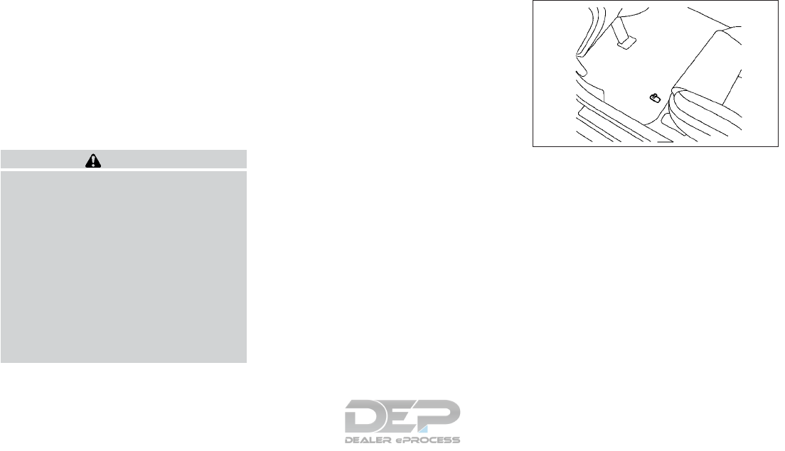
hang free and not contact an interior sur-
face.
•Liquid-type air fresheners typically clip on
the ventilators. These products can cause
immediate damage and discoloration
when spilled on interior surfaces.
Carefully read and follow the manufacturer’s
instructions before using air fresheners.
FLOOR MATS (IF EQUIPPED)
WARNING
To avoid potential pedal interference that
may result in a collision, injury or death:
•NEVER place a floor mat on top of an-
other floor mat in the driver front posi-
tion.
•It is recommended you use only genuine
INFINITI floor mats specifically de-
signed for use in your vehicle model. For
additional information, it is recom-
mended you contact an INFINITI re-
tailer.
•Properly position the mats in the floor-
well using the floor mat positioning aid.
The use of genuine INFINITI floor mats can
extend the life of your vehicle carpet and
make it easier to clean the interior. Mats
should be maintained with regular cleaning
and replaced if they become excessively
worn.
Floor mat positioning aid
This vehicle includes a front floor mat bracket
to act as a floor mat positioning aid. INFINITI
floor mats have been specially designed for
your vehicle model.
Position the mat by placing the floor mat
bracket hook through the floor mat grommet
hole while centring the mat in the foot area.
Periodically check that the mats are properly
positioned.
SEAT BELTS
The seat belts can be cleaned by wiping them
with a sponge dampened in a mild soap solu-
tion.
SAI0039Z
Example
Appearance and care 7-5

Allow the belts to dry completely in the shade
before using them. For additional informa-
tion, see "Seat belts" in the "1. Safety — seats,
seat belts and supplemental restraint system"
section.
WARNING
•Do not allow wet seat belts to roll up in
the retractor.
•NEVER use bleach, dye or chemical sol-
vents to clean the seat belts, since these
materials may severely weaken the seat
belt webbing.
CLEANING THE SEAT TRACKS
CAUTION
Periodically clean the seat tracks to pre-
vent reduction of ability to move the seats.
Clean periodically with a high-powered
vacuum cleaner. Dirt and debris may re-
duce the ability to adjust the seat. A wet
cleansing agent may be used if necessary.
GENUINE LEATHER SEAT
COVERS
Automotive leather is typically finished with
coatings which protect the surface from the
sun's damaging rays as well as making it re-
sistant to soiling. The finishes used in auto-
motive upholstery are unique; very different
to furniture, garment or shoe leathers.
Leather is extremely resilient and easy to
clean and maintain.
•Before cleaning leather upholstery,
vacuum it to remove dust.
•To clean leather, simply use a soft and
lint-free cloth dampened with lukewarm
water and mild soap. Do not soak the
leather.
•Use a gentle, circular motion. Do not run
the leather or apply extreme pressure
when cleaning.
•Wipe the leather again with another clean,
slightly damp cloth to remove soap resi-
due. Dry with a soft cloth.
Leather should be cleaned whenever it be-
comes soiled. Dust and dirt may harm leather
if allowed to work into the finish.
Never use alcohol, cleaning solvents, oils,
varnishes or polishes on your leather, and
avoid using unknown products as they dam-
age the finish. Only use leather care agents
approved by INFINITI.
Steaming or ironing is not recommended as it
may damage the leather.
Leather is a natural product and has natural
surface properties such as unevenness in
structure, marks caused by injury, and subtle
color differences. These are characteristics of
leather and not material faults.
Leather cleaning kit (if equipped)
Spray onto the leather cleaning cloth, then
gently wipe the surface of leather. Use a dry
towel to absorb any excess moisture.
Please refer to the instruction manual pro-
vided with the leather cleaner kit.
Clean light-colored leather more frequently
because soiling on such surfaces is much
more visible.
You can obtain the leather cleaner kit from an
INFINITI retailer.
7-6 Appearance and care

MOST COMMON FACTORS
CONTRIBUTING TO VEHICLE
CORROSION
Most vehicle corrosion is caused by:
•The accumulation of moisture-retaining
dirt and debris in body panel sections, cavi-
ties, and other areas.
•Damage to the paint surface and other
protective coatings caused by gravel and
stone chips or minor traffic accidents.
ENVIRONMENTAL FACTORS
INFLUENCE THE RATE OF
CORROSION
Moisture
The accumulation of sand, dirt and water on
the inside floor of the vehicle can accelerate
corrosion. Wet floor carpet/floor mats will
not dry completely inside the vehicle. They
should be removed and completely dried to
avoid floor panel corrosion.
Relative humidity
Corrosion will be accelerated in areas of high
relative humidity, especially those areas
where the temperatures stay above freezing
and where atmospheric pollution exists and
road salt is used.
Temperature
High temperatures accelerate the rate of cor-
rosion to those parts which are not well ven-
tilated.
Air pollution
Industrial pollution, the presence of salt in the
air in coastal areas, or heavy road salt use
accelerates the corrosion process. Road salt
also accelerates the disintegration of paint
surfaces.
TO PROTECT YOUR VEHICLE
FROM CORROSION
•Wash and wax your vehicle often to keep
the vehicle clean.
•Always check for minor damage to the
paint surface and repair it as soon as pos-
sible.
•Keep drain holes in the lower edge of the
doors open to avoid water accumulation.
•Check the underbody for accumulation of
sand, dirt or salt. If present, wash with
water as soon as possible.
CAUTION
•NEVER remove dirt, sand or other de-
bris from the passenger compartment
by washing it out with a hose. Remove
dirt with a vacuum cleaner or broom.
•Never allow water or other liquids to
come in contact with electronic compo-
nents inside the vehicle as this may dam-
age them.
Chemicals used for road surface deicing are
extremely corrosive. They accelerate corro-
sion and deterioration of underbody compo-
nents such as the exhaust system, fuel and
brake lines, brake cables, floor pan and fend-
ers.
In winter, the underbody must be cleaned
periodically.
For additional protection against rust and
corrosion, which may be required in some
areas, it is recommended that you visit an
INFINITI retailer.
CORROSION PROTECTION
Appearance and care 7-7

MEMO
7-8 Appearance and care

8 Do-it-yourself
Maintenance precautions .................8-2
Engine compartment check locations .........8-3
2.0L Gasoline engine .................8-3
Engine cooling system ...................8-3
Checking engine coolant level ............8-4
Changing engine coolant ...............8-4
Engine oil ...........................8-5
Checking engine oil level ...............8-5
Changing engine oil ..................8-5
Changing engine oil filter ...............8-6
Automatic Transmission Fluid (ATF) ..........8-7
Brake fluid ..........................8-7
Window washer fluid ...................8-8
Battery ............................8-9
Accessing Vehicle battery..............8-10
Maintenance free battery ..............8-10
Models with Idle Stop/Start System .......8-11
Battery replacement .................8-11
Reinitialisation procedure after battery
reconnection ......................8-12
Jump-starting .....................8-12
Drive belt ..........................8-12
Spark plugs .........................8-13
Air cleaner filter ......................8-13
Wiper blades ........................8-13
Cleaning .........................8-13
Replacing front window wiper blades ......8-14
Replacing rear window wiper blade .......8-16
Brakes ............................8-17
Self-adjusting brakes .................8-17
Fuses .............................8-17
Before replacing a fuse ...............8-17
Engine compartment .................8-17
Passenger compartment ..............8-18
Intelligent Key battery replacement .........8-20
Checking the battery.................8-20
Replacing the battery ................8-20
Lights ............................8-22
Exterior and interior lights..............8-22
Replacement procedures ..............8-24
Wheels and tires......................8-27
Tire Pressure ......................8-27
Tire inflation pressure ................8-29
Tire labeling ......................8-29
Types of tires......................8-31
Tire chains .......................8-32
Tire wear and damage................8-33
Tire rotation ......................8-34
Replacing wheels and tires .............8-34
Wheel balance .....................8-35

When performing any inspection or mainte-
nance work on your vehicle, always take care
to prevent serious accidental injury to your-
self or damage to the vehicle. The following
are general precautions which should be
closely observed.
WARNING
•Park the vehicle on a level surface, apply
the parking brake securely and block the
wheels to prevent the vehicle from mov-
ing. Press the P (Park) button.
•Be sure the ignition switch is in the OFF
position when performing any parts re-
placement or repairs.
•Do not work under the hood while the
engine is hot. Always turn off the engine
and wait until it cools down.
•If you must work with the engine run-
ning, keep your hands, clothing, hair and
tools away from moving fans, belts and
any other moving parts.
•It is advisable to secure or remove any
loose clothing and any jewelry, such as
rings, watches, etc. before working on
your vehicle.
•If you must run the engine in an enclosed
space such as a garage, be sure there is
proper ventilation for exhaust gases to
escape.
•Never get under the vehicle while it is
supported by a jack.
•Keep smoking materials, flame and
sparks away from fuel and the battery.
•Never connect or disconnect either the
battery or any transistorized compo-
nent connector while the ignition switch
is in the ON position.
•On gasoline engine models with the
Multiport Fuel Injection system, the fuel
filter and fuel lines should be serviced by
an INFINITI retailer or qualified work-
shop because the fuel lines are under
high pressure even when the engine is
turned off.
•Your vehicle is equipped with an auto-
matic engine cooling fan. It may come on
at any time without warning, even if the
ignition switch is in the OFF position
and the engine is not running. To avoid
injury, always disconnect the negative
battery cable before working near the
fan.
•Always wear eye protection whenever
you work on your vehicle.
•Never leave the engine or the transmis-
sion related component harness connec-
tor disconnected while the ignition
switch is in the ON position.
•Avoid direct contact with used engine oil
and coolant. Improperly disposed engine
oil, engine coolant, and/or other vehicle
fluids can hurt the environment. Always
conform to local regulations for disposal
of vehicle fluids.
This “ 8. Do-it-yourself” section provides in-
structions regarding only those items which
are relatively easy for an owner to perform.
You should be aware that incomplete or im-
proper servicing may result in operating diffi-
culties or excessive emissions, and could af-
fect your warranty coverage. If in doubt
about any servicing, it is recommended you
have it done by an INFINITI retailer.
MAINTENANCE PRECAUTIONS
8-2 Do-it-yourself
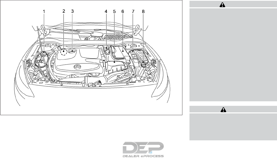
2.0L GASOLINE ENGINE
1. Engine coolant reservoir (P.8-3)
2. Engine oil dipstick (P.8-5)
3. Engine oil filler cap (P.8-5)
4. Brake fluid reservoir (P.8-7)
5. Engine air cleaner filter (P.8-13)
6. Battery (P.8-9)
7. Fuse box (P.8-17)
8. Window washer fluid reservoir (P.8-8)
WARNING
The engine cooling system is filled at the
factory with a high-quality, year-round,
antifreeze coolant solution. The antifreeze
solution contains rust and corrosion inhibi-
tors, therefore additional cooling system
additives are not necessary.
•Never remove the radiator or coolant
reservoir cap when the engine is hot.
Wait until the engine and radiator cool
down. Serious burns could be caused by
high-pressure fluid escaping from the
radiator. For additional information on
precautions, refer to "If your vehicle
overheats" in the "6. In case of emer-
gency" section
•The engine coolant reservoir tank is
equipped with a pressure type cap. To
prevent engine damage, use only a
genuine INFINITI pressure cap.
CAUTION
•Never use any cooling system additives
such as radiator sealer. Additives may
clog the cooling system and cause dam-
age to the engine, transmission and/or
cooling system.
NIC2833
ENGINE COMPARTMENT CHECK
LOCATIONS ENGINE COOLING SYSTEM
Do-it-yourself 8-3
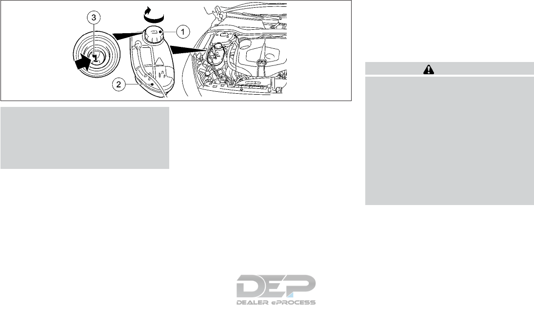
•When adding or replacing coolant, be
sure to use only INFINITI Genuine En-
gine Coolant, BASF Glysantin G40 or
equivalent in its quality. The use of other
types of engine coolant may damage the
engine cooling system.
CHECKING ENGINE COOLANT
LEVEL
NOTE
The coolant level must only be checked and
corrected when the engine is cold.
1. Park the vehicle on a level surface.
Only check the coolant level if the vehicle
is on a level surface and the engine is cold.
2. Slowly turn cap 䊊
1half a turn counter-
clockwise to allow excess pressure to es-
cape.
3. Turn cap 䊊
1further counter-clockwise
and remove it.
If the coolant is at the level of marker bar
䊊
3in the filler neck when cold, there is
enough coolant in coolant expansion tank
䊊
2.
4. If necessary, top up with INFINITI Genu-
ine Engine Coolant, BASF Glysantin G40
or equivalent in its quality.
5. Replace cap 䊊
1and turn it clockwise as
far as it will go.
If the cooling system frequently requires
coolant, have it checked. It is recommended
that you visit an INFINITI retailer for this
service.
CHANGING ENGINE COOLANT
An INFINITI retailer can change the engine
coolant.
Improper servicing can result in reduced
heater performance and engine overheating.
WARNING
•To avoid being scalded, never change
the coolant when the engine is hot.
•Never remove the radiator cap when the
engine is hot. Serious burns could be
caused by high pressure fluid escaping
from the radiator.
•Avoid direct skin contact with used
coolant. If skin contact is made, wash
thoroughly with soap or hand cleaner as
soon as possible.
•Keep coolant out of reach of children
and pets.
Engine coolant must be disposed of properly.
Check your local regulations.
NDI1602
8-4 Do-it-yourself
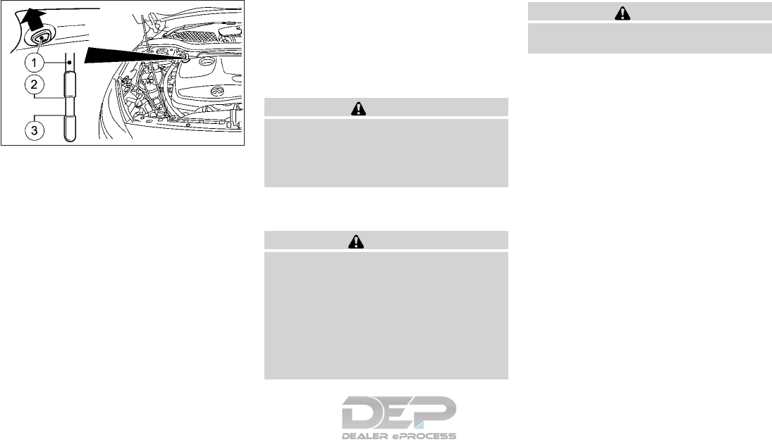
CHECKING ENGINE OIL LEVEL
1. Park the vehicle on a level surface and
apply the parking brake.
2. Start the engine and let it idle until it
reaches the normal operating tempera-
ture.
3. Turn off the engine. Wait more than 10
minutes for the oil to drain back into the oil
pan.
4. Remove the dipstick 䊊
1and wipe it clean.
Reinsert it all the way.
5. Remove the dipstick and check the oil
level. It should be within the range 䊊
2and
䊊
3.
If the oil level is below 䊊
3, remove the oil
filler cap and pour the recommended oil
into the opening. Do not overfill䊊
2.
It is normal to add some oil between oil main-
tenance intervals or during the break-in pe-
riod, depending on the severity of operating
conditions.
CAUTION
The oil level should be checked regularly.
Operating the engine with an insufficient
amount of oil can damage the engine, and
such damage is not covered by the
warranty.
CHANGING ENGINE OIL
WARNING
•Prolonged and repeated contact with
used engine oil may cause skin cancer.
•Try to avoid direct skin contact with
used oil. If skin contact is made, wash
thoroughly with soap or hand cleaner
and plenty of water as soon as possible.
•Keep used engine oil out of reach of
children.
CAUTION
Be careful not to burn yourself. The engine
oil may be hot.
NDI1596
2.0L gasoline engine
ENGINE OIL
Do-it-yourself 8-5
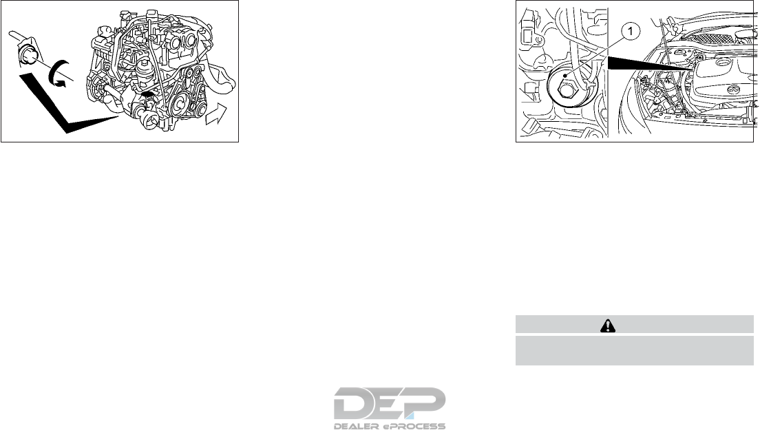
1. Park the vehicle on a level surface and
apply the parking brake.
2. Start the engine and let it idle until it
reaches the normal operating tempera-
ture, then turn it off.
3. Remove the oil filler cap by turning it
counterclockwise.
4. Remove the engine undershield.
5. Place a large drain pan under the drain
plug.
6. Remove the drain plug with a wrench by
turning it counterclockwise and com-
pletely drain the oil. If the oil filter is to be
changed, remove and replace it at this
time. For additional information, refer to
"Changing engine oil filter" later in this
section.
•Waste oil must be disposed of prop-
erly.
•Check your local regulations.
7. Clean and reinstall the drain plug and a
new washer. Securely tighten the drain
plug with a wrench. Do not use excessive
force.
Drain plug tightening torque: 22 ft-lb, 30
N•m
8. Refill engine with recommended oil
through the oil filler opening, then install
the oil filler cap securely.
For additional information on drain and
refill capacity, refer to "Recommended
fluids/lubricants and capacities" in the "9.
Maintenance and Schedules" section.
The drain and refill capacity depends on
the oil temperature and drain time. Use
these specifications for reference only.
Always use the dipstick to determine
when the proper amount of oil is in the
engine.
9. Start the engine. Check for leakage
around the drain plug and oil filter. Correct
as required.
10. Turn the engine off and wait more than
10 minutes. Check the oil level with the
dipstick. Add engine oil if necessary.
CHANGING ENGINE OIL FILTER
1. Park the vehicle on a level surface and
apply the parking brake.
2. Turn the engine off.
3. Place a large drain pan under the oil filter
䊊
1.
4. Loosen the oil filter 䊊
1with an oil filter
wrench by turning it counterclockwise.
Then remove the oil filter by turning it by
hand.
CAUTION
Be careful not to burn yourself. The engine
oil may be hot.
5. Wipe the engine oil filter sealing surface
with a clean rag.
NDI1622 NDI1610
2.0L gasoline engine
8-6 Do-it-yourself

CAUTION
•Be sure to remove any old gasket mate-
rial remaining on the sealing surface of
the engine. Failure to do so could lead to
an oil leak and engine damage.
•The dipstick must be inserted in place to
prevent oil spillage from the dipstick
hole when filling the engine with oil.
6. Coat the gasket on the new filter with
clean engine oil.
7. Screw on the oil filter until a slight resis-
tance is felt, then tighten an additional
2/3 turn.
Engine oil filter tightening torque: 19 ft-lb,
25 N•m
8. Start the engine and check for leakage
around the oil filter. Correct as required.
9. Turn the engine off and wait more than
10 minutes. Check the oil level. Add en-
gine oil if necessary.
It is recommended that you visit an INFINITI
retailer if checking or replacement is required.
CAUTION
•Use only Shell DCT-M1 or equivalent.
Do not mix with other fluids.
•Using automatic transmission fluid
other than Shell DCT-M1 may cause de-
terioration in driveability and automatic
transmission durability, and may dam-
age the automatic transmission. Dam-
age caused by the use of fluids other
than as recommended is not covered by
the warranty.
WARNING
•Use only new fluid. Old, inferior, or con-
taminated fluid may damage the brake
systems. The use of improper fluids can
damage the brake system and affect the
vehicle's stopping ability.
•Clean the filler cap before removing.
•Brake fluid is poisonous and should be
stored carefully in marked containers
out of the reach of children.
CAUTION
•Do not spill the fluid on painted surfaces.
This will damage the paint. If fluid is
spilled, wash with water.
NDI1599
AUTOMATIC TRANSMISSION FLUID
(ATF) BRAKE FLUID
Do-it-yourself 8-7

Check the fluid level in the reservoir. If the
brake fluid is below the MIN line 䊊
2, the brake
warning light will illuminate. Add brake fluid
up to the MAX line 䊊
1. Use Genuine INFINITI
brake fluid DOT4+ or equivalent. Never mix
different types of fluids. For additional infor-
mation on the recommended type of brake
fluid, refer "Recommended fluids/lubricants
and capacities" in the "9. Maintenance and
Schedules" section.
If the brake fluid must be added frequently,
the brake system should be thoroughly
checked. It is recommended that you visit an
INFINITI retailer for this service.
Fill the windshield-washer fluid reservoir pe-
riodically. Add fluid when the low washer
fluid warning appears on the vehicle informa-
tion display.
To fill the windshield-washer fluid reservoir,
lift the cap off the reservoir and pour the
windshield-washer fluid into the reservoir
opening.
Add a washer solvent to the washer for bet-
ter cleaning. In the winter season, add a
windshield-washer antifreeze. Follow the
manufacturer’s instructions for the mixture
ratio.
Refill the reservoir more frequently when
driving conditions require an increased
amount of windshield-washer fluid.
Recommended fluid is Genuine INFINITI
Windshield Washer Concentrate Cleaner &
Antifreeze or equivalent.
CAUTION
•Do not substitute engine antifreeze
coolant for window washer solution.
This may result in damage to the paint.
•Do not fill the window washer reservoir
tank with washer fluid concentrates at
full strength. Some methyl alcohol
based washer fluid concentrates may
permanently stain the grille if spilled
while filling the window washer reser-
voir tank.
•Pre-mix washer fluid concentrates with
water to the manufacturer’s recom-
mended levels before pouring the fluid
into the window washer reservoir tank.
Do not use the window washer reservoir
tank to mix the washer fluid concentrate
and water.
NDI1601
WINDOW WASHER FLUID
8-8 Do-it-yourself

•Keep the battery surface clean and dry.
Clean the battery with a solution of baking
soda and water.
•Make certain the terminal connections are
clean and securely tightened.
•If the vehicle is not used for 30 days or
longer, disconnect the 䊊
-negative battery
terminal cable to prevent discharge.
NOTE
Care should be taken to avoid situations
that can lead to potential battery discharge
and potential no-start conditions such as:
•Installation or extended use of electronic
accessories that consume battery power
when the engine is not running (Phone
chargers, GPS, DVD players, etc).
•Vehicle is not driven regularly and/or only
driven short distances.
In these cases, the battery may need to be
charged to maintain battery health.
WARNING
•Do not expose the battery to flames, an
electrical spark or a cigarette. Hydrogen
gas generated by the battery is explo-
sive. Explosive gases can cause blind-
ness or injury. Do not allow battery fluid
to contact your skin, eyes, fabrics or
painted surfaces. Sulfuric acid can cause
blindness or injury. After touching a bat-
tery or battery cap, do not touch or rub
your eyes. Thoroughly wash your hands.
If the acid contacts your eyes, skin or
clothing, immediately flush with water
for at least 15 minutes and seek medical
attention.
•Do not operate the vehicle if the fluid in
the battery is low. Low battery fluid can
cause a higher load on the battery which
can generate heat, reduce battery life,
and in some cases lead to an explosion.
•When working on or near a battery, al-
ways wear suitable eye protection and
remove all jewelry.
•Battery posts, terminals and related ac-
cessories contain lead and lead com-
pounds. Wash hands after handling.
•Keep battery out of the reach of chil-
dren.
•Do not tip the battery. Keep the vent
caps tight and the battery level.
BATTERY
Do-it-yourself 8-9
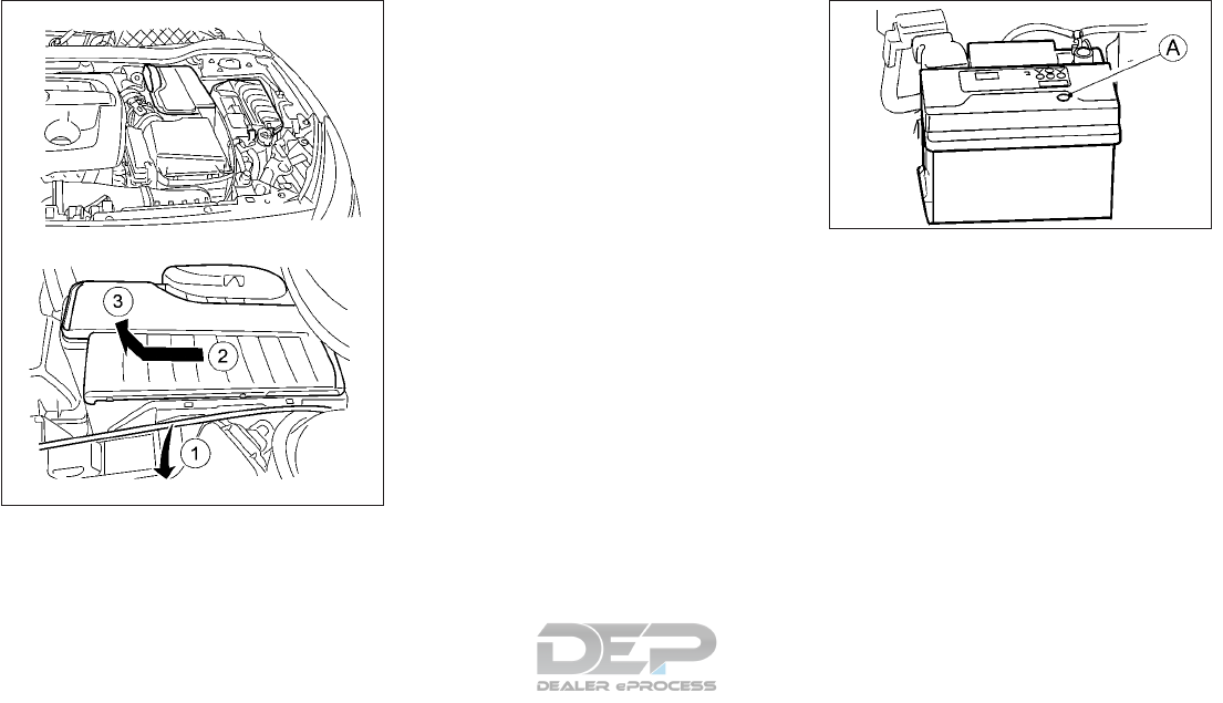
ACCESSING VEHICLE BATTERY
The vehicle battery is stored under a cover.
To remove the cover to gain access to the
battery:
1. Disconnect the hood release cable 䊊
1and
any other cables from the battery cover.
2. Hold the battery top cover firmly and slide
it towards the front of the car 䊊
2and
upwards 䊊
3.
3. Lift the cover up and away from the bat-
tery.
NOTE
When installing the battery cover, remem-
ber to replace cables in their original posi-
tion.
MAINTENANCE FREE BATTERY
For a maintenance free battery it is not re-
quired to check the fluid level. However,
INFINITI recommends to visually check the
status of the green indicator 䊊
A(if so
equipped) periodically. If it is not visible, re-
place the battery as soon as possible.
NDI1590
NDI920Z
8-10 Do-it-yourself
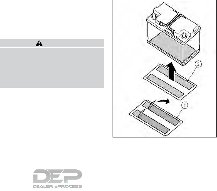
MODELS WITH IDLE
STOP/START SYSTEM
•Ensure that the battery fitted is the special
battery that is enhanced with regard to the
charge-discharge capacity and life perfor-
mance. Avoid using any other battery for
the Idle Stop/Start System, as this may
cause early deterioration of the battery or
a malfunction of the Idle Stop/Start Sys-
tem. It is recommended that a Genuine
INFINITI battery is fitted. For more infor-
mation, it is recommended that you con-
tact an INFINITI retailer.
•If the battery terminal is disconnected (for
battery replacement, etc.) and then recon-
nected, there may be some delay before
the Stop/Start System reactivates.
BATTERY REPLACEMENT
It is recommended that a Genuine INFINITI
battery is fitted. It is recommended that you
visit an INFINITI retailer for this service.
Protective plate for battery
WARNING
Whenever the battery is replaced, always
have the protective plate underneath the
battery also reinstalled or replaced. If this
plate is not reinstalled/replaced, in the
event of a collision a thermal incident could
occur, causing vehicle damage and poten-
tially causing serious injury of death.
If the vehicle battery is replaced, the protec-
tive plate underneath the battery must also
be replaced. This protective plate must be
fixed to the underside of the replacement
battery using the adhesive tape supplied with
the replacement plate. It is recommended
that you visit an INFINITI retailer to purchase
and replace the protective plate underneath
the battery. 1. Make sure the underside of the replace-
ment battery is dry and free of dust.
2. Remove the backing strips 䊊
1from the
adhesive strips.
3. Fix the protective plate to the underside
of the battery without any overlap 䊊
2.
NDI1634
Do-it-yourself 8-11
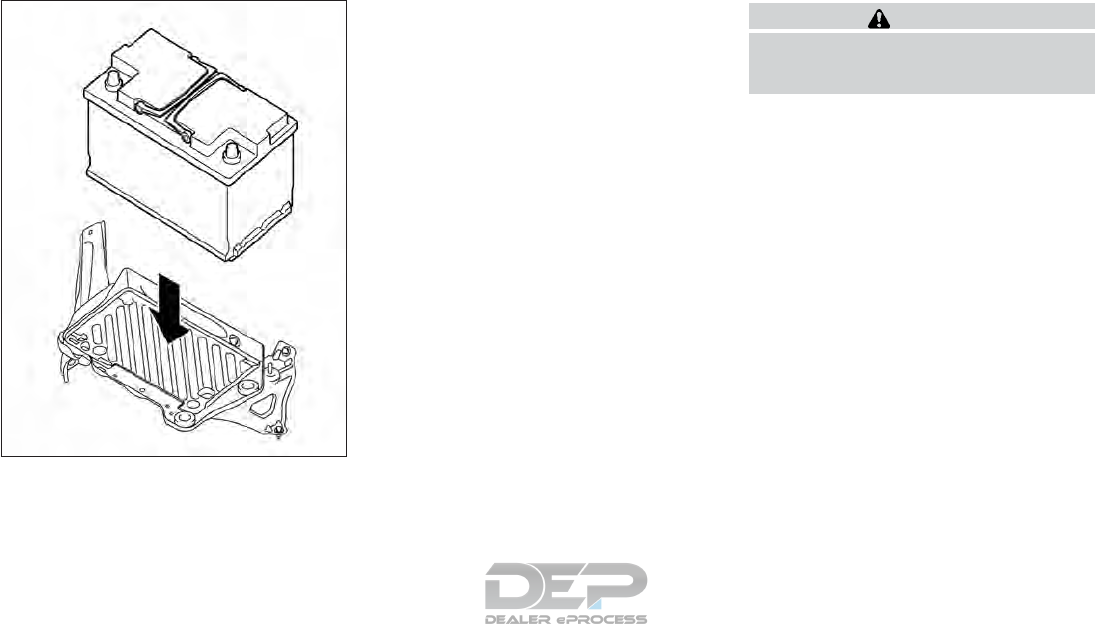
4. Fit the replacement battery in the vehicle.
REINITIALISATION PROCEDURE
AFTER BATTERY
RECONNECTION
If the battery has been reconnected, check
the following items:
•Clock setting (if so equipped). For details,
see "Clock" in the "2. Instruments and con-
trols" section, or the separately provided
navigation system Owner's Manual, or the
audio device descriptions in " Audio system
(if equipped)" in the "4. Display screen,
heater and air conditioner, and audio sys-
tem" section.
•Reset the desired radio stations to the pre-
set station buttons. For details, see the
audio device descriptions in the “4. Heater
and air conditioner, and audio system”.
JUMP-STARTING
If jump-starting is necessary, see "Jump
starting" in the "6. In case of emergency" sec-
tion. If the engine does not start by jump
starting, the battery may have to be replaced.
It is recommended that you visit an INFINITI
retailer for this service.
WARNING
Be sure the ignition switch is in the OFF
position before servicing drive belt. The en-
gine could rotate unexpectedly.
1. Visually inspect each belt for signs of un-
usual wear, cuts, fraying or looseness. If
the belt is in poor condition or loose, have
it replaced or adjusted. It is recommended
that you visit an INFINITI retailer for this
service.
2. Have the belts checked regularly for con-
dition and tension in accordance with the
maintenance schedule as shown in a
separately provided Warranty Informa-
tion and Maintenance booklet.
NDI1635
DRIVE BELT
8-12 Do-it-yourself

Replace the spark plugs according to the
maintenance schedule shown in a separate
maintenance booklet.
If replacement is required, it is recommended
that you visit an INFINITI retailer.
Always replace spark plugs with recom-
mended or equivalent ones.
WARNING
Be sure the engine and ignition switch are
off and that the parking brake is engaged
securely.
CAUTION
•Be sure to use the correct socket to re-
move the spark plugs. An incorrect
socket can cause damage to the spark
plugs.
It is recommended that you visit an INFINITI
retailer if checking or replacement is required.
WARNING
•Operating the engine with the air
cleaner filter off can cause you or others
to be burned. The air cleaner filter not
only cleans the intake air, it also stops
the flame if the engine backfires. If the
air cleaner is not installed and the engine
backfires, you could be burned. Never
drive with the air cleaner filter off. Be
cautious working on the engine when
the air cleaner is off.
•Never pour fuel into the throttle body or
attempt to start the engine with the air
cleaner removed. Doing so could result
in serious injury.
CLEANING
If the windshield or rear window is not clear
after using the window washer or if a wiper
blade chatters when running, wax or other
material may be on the blade or windshield.
Clean the outside of the windshield or rear
window with a washer solution or a mild
detergent. The windshield or rear window is
clean if beads do not form when rinsing with
clear water.
Clean the blade by wiping it with a cloth
soaked in a washer solution or a mild deter-
gent. Then rinse the blade with clear water. If
the windshield or rear window is still not clear
after cleaning the blades and using the wiper,
replace the blades.
CAUTION
Worn windshield wiper blades can damage
the windshield and impair driver vision.
SPARK PLUGS AIR CLEANER FILTER WIPER BLADES
Do-it-yourself 8-13
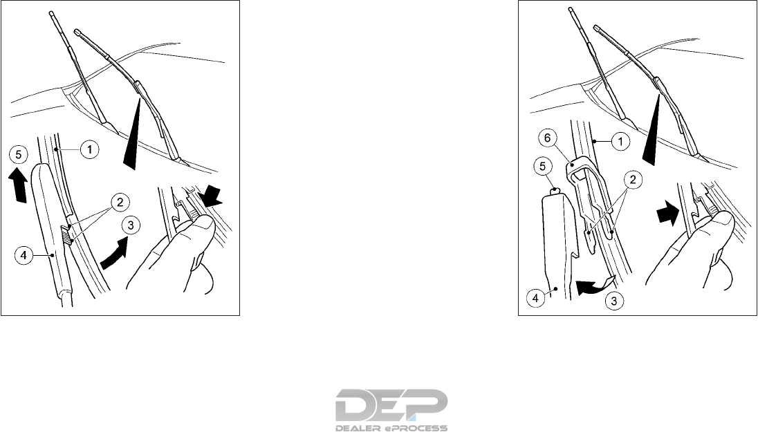
REPLACING FRONT WINDOW
WIPER BLADES
Replace the wiper blades if they are worn. To
replace the windshield wiper blades, follow
the procedure below:
1. Move the wiper arm away from the wind-
shield.
2. Press both release clips 䊊
2.
3. Move the wiper blade 䊊
1in the direction
of arrow 䊊
3away from wiper arm 䊊
4.
4. Remove wiper blade 䊊
1in the direction of
arrow 䊊
5.
5. Position new wiper blade 䊊
1with recess
䊊
6on lug 䊊
5.
6. Move wiper blade 䊊
1in the direction of
arrow 䊊
3onto the wiper arm until retain-
ing clips 䊊
2engage in bracket 䊊
4.
NDI1586 NDI1587
8-14 Do-it-yourself
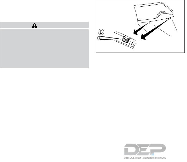
7. Make sure that wiper blade 䊊
1is seated
correctly.
8. Move the wiper arm back onto the wind-
shield.
CAUTION
•After wiper blade replacement, return
the wiper arm to its original position;
otherwise it may be damaged when the
hood is opened.
•Make sure the wiper blades contact the
glass; otherwise the arms may be dam-
aged from wind pressure.
If you wax the surface of the engine hood, be
careful not to let wax get into the washer
nozzle 䊊
A. This may cause clogging or im-
proper windshield washer operation. If wax
gets into the nozzle, remove it with a needle
or small pin 䊊
B.
NDI892Z
Do-it-yourself 8-15
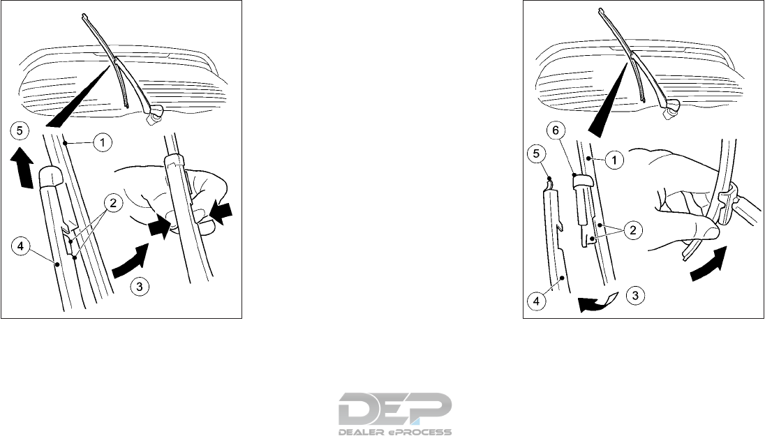
REPLACING REAR WINDOW
WIPER BLADE
Replace the wiper blades if they are worn. To
replace the rear window wiper blade, follow
the procedure below:
1. Move wiper arm 䊊
4away from the rear
window.
2. Press both release clips 䊊
2.
3. Move wiper blade 䊊
1in the direction of
arrow 䊊
3away from wiper arm 䊊
4.
4. Remove wiper blade 䊊
1in the direction of
arrow 䊊
5.
5. Position new wiper blade 䊊
1with recess
䊊
6on lug 䊊
5.
6. Move wiper blade 䊊
1in the direction of
arrow 䊊
3onto the wiper arm until retain-
ing clips 䊊
2engage in bracket 䊊
4.
7. Make sure that wiper blade 䊊
1is seated
correctly.
8. Move the wiper arm back onto the rear
window.
NDI1588 NDI1589
8-16 Do-it-yourself

If the brakes do not operate properly, it is
recommended that you have the brakes
checked. It is recommended that you visit an
INFINITI retailer for this service.
SELF-ADJUSTING BRAKES
Your vehicle is equipped with self-adjusting
brakes. The disc-type brakes self-adjust ev-
ery time the brake pedal is applied.
Blown fuses must be replaced with fuses of
the same rating, which you can recognize by
the color and fuse rating. The fuse ratings are
listed in the fuse allocation chart.
If the newly inserted fuse also blows, have
the cause traced and rectified. It is recom-
mended you visit an INFINITI retailer for this
service.
The fuses in your vehicle disconnect faulty
circuits. if a fuse blows, all the components on
the circuit and their functions will fail.
BEFORE REPLACING A FUSE
•Secure the vehicle against rolling away.
•Switch off all electrical consumers.
•Remove the key from the ignition lock.
The fuses are located in various fuse boxes:
•Fuse box in the engine compartment on
the left-hand side of the vehicle, when
viewed in the direction of travel.
•Fuse box in the front-passenger footwell.
The fuse allocation chart is on the fuse box in
the front-passenger footwell.
ENGINE COMPARTMENT
WARNING
Never use a fuse of higher or lower amper-
age rating than that specified on the fuse
box cover. This could damage the electrical
system or electronic control units or cause
a fire.
BRAKES FUSES
Do-it-yourself 8-17
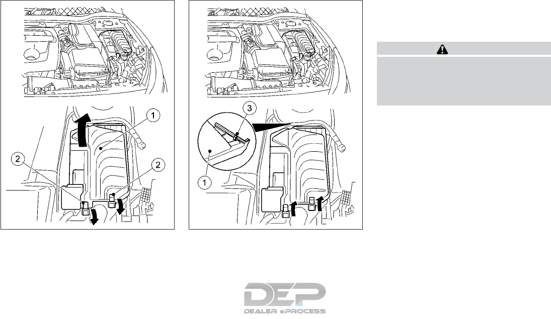
1. Open the hood
2. Remove any existing moisture from the
fuse box using a dry cloth
3. To open: open clamps 䊊
2.
4. Fold cover 䊊
1up in the direction of the
arrow and remove it.
To close:
1. Check whether the seal is lying correctly in
cover 䊊
1.
2. Insert cover 䊊
1at the back into openings
䊊
3on the fuse box.
3. Fold down cover 䊊
1.
4. Hook clamps into the fuse box and close
5. Close the hood.
PASSENGER COMPARTMENT
WARNING
Never use a fuse of higher or lower amper-
age rating than that specified on the fuse
box cover. This could damage the electrical
system or electronic control units or cause
a fire.
NDI1591 NDI1592
8-18 Do-it-yourself
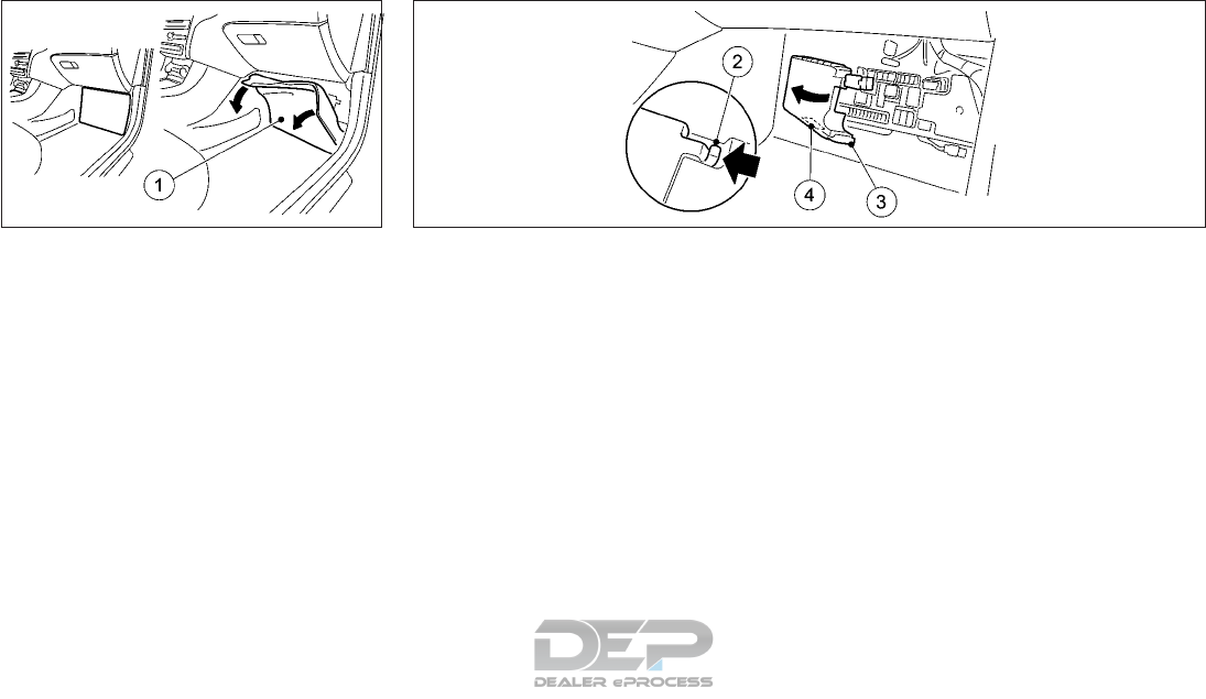
To open:
1. Open the front-passenger door.
2. Remove the floor mats.
3. Fold out perforated floor covering 䊊
1in
the direction of the arrow.
4. To release cover 䊊
3press retaining clamp
䊊
2.
5. Fold out cover 䊊
3in the direction of the
arrow to the catch.
6. Remove cover 䊊
3forwards.
NOTE
Fuse allocation chart 䊊
4is located on the
lower right-hand side of cover 䊊
3.
To close:
1. Insert cover 䊊
3on the left-hand side of
the fuse box into the retainer. Cover 䊊
3
engages in the retainers.
2. Fold down cover 䊊
3until clamps 䊊
2lock
audibly.
3. Fold back perforated floor covering 䊊
1.
4. Fit the floor mats.
NDI1593 NDI1594
Do-it-yourself 8-19
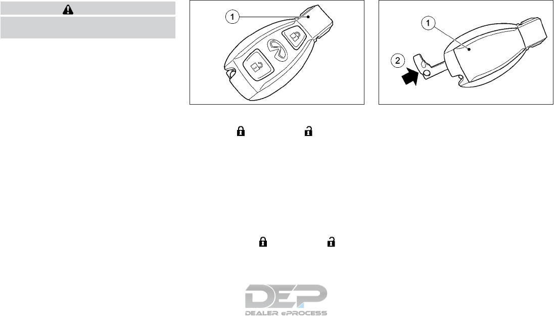
CAUTION
Be careful not to allow children to swallow
the battery or removed parts.
CHECKING THE BATTERY
Press the (LOCK) or (UNLOCK)
button.
The battery is working properly if the battery
check light 䊊
1lights up briefly.
The battery is discharged if the battery check
light 䊊
1does not light up briefly. Replace the
battery.
NOTE
•If the key battery is checked within the
signal reception range of the vehicle,
pressing the (LOCK) or (UN-
LOCK) button locks or unlocks the vehicle.
•You can obtain a battery from an INFINITI
retailer.
REPLACING THE BATTERY
You require a CR 2025 3 V cell battery.
Replace the battery in the Intelligent Key as
follows:
1. Take the emergency key element out of
the key (see "Mechanical key" in the "3.
Pre-driving checks and adjustments" sec-
tion)
2. Press emergency key element 䊊
2into the
opening into the key in the direction of the
arrow until the battery cover 䊊
1opens.
When doing so, do not hold cover 䊊
1shut.
3. Remove battery tray cover 䊊
1.
NPA1474 NPA1472
INTELLIGENT KEY BATTERY
REPLACEMENT
8-20 Do-it-yourself
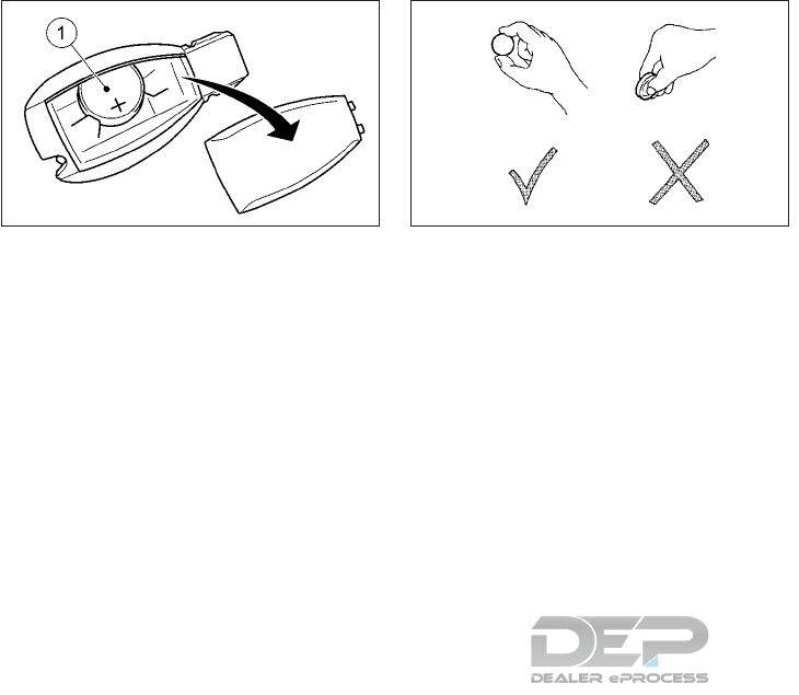
4. Repeatedly tap the key against your palm
until battery 䊊
1falls out.
5. Insert the new battery with the positive
terminal facing upwards. Use a lint-free
cloth to do so.
6. Make sure that the surface of the battery
is free of lint, grease and other contami-
nation.
7. Insert the front tabs of battery cover 䊊
1
and then press to close it.
8. Insert emergency key element into the key
(see "Mechanical key" in the "3. Pre-
driving checks and adjustments" section).
9. Check the function of all key buttons on
the vehicle.
If you need assistance with replacement, it is
recommended that you visit an INFINITI re-
tailer for this service.
FCC Notice:
For USA:
This device complies with Part 15 of the FCC
Rules. Operation is subject to the following
two conditions: (1) This device may not
cause harmful interference, and (2) this de-
vice must accept any interference received,
including interference that may cause unde-
sired operation.
NOTE
Changes or modifications not expressly ap-
proved by the party responsible for compli-
ance could void the user’s authority to oper-
ate the equipment.
For Canada:
This device complies with Industry Canada
license-exempt RSS standard(s). Operation
is subject to the following two conditions: (1)
this device may not cause interference, and
(2) this device must accept any interference,
including interference that may cause unde-
sired operation of the device.
NPA1473 SPA0784Z
Do-it-yourself 8-21

EXTERIOR AND INTERIOR LIGHTS
Item Wattage (W)
Front combination light
Headlight (Low or high beam: H9 type) 14 / 28
Headlight (Low or high beam: LED type, if so equipped) *1 LED
Front turn signal light (with halogen headlights) 24
Front turn signal light (LED type, if so equipped)*1 LED
Front side light *1 LED
Daytime driving light *1 LED
Front fog light *1 LED
Side turn signal light *1 LED
Puddle light *1 LED
Rear combination light
Turn signal light*1 LED
Stop/Tail light *1 LED
Reversing light *1 LED
Brake light *1 LED
High-mounted brake light *1 LED
License plate light*1 LED
Room light/Map lights (if so equipped)
Foot well light (if so equipped)
5
3
Reading light (rear)
Room light — rear (if so equipped)
5
5
Reading lights — rear (if so equipped) 8
Luggage compartment light 5
*1: It is recommended you visit an INFINITI
retailer for replacement.
It is recommended you check with the Parts
Department at an INFINITI retailer for the
latest parts information.
LIGHTS
8-22 Do-it-yourself
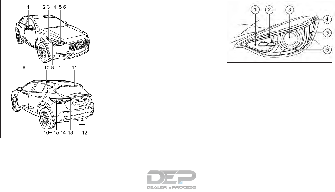
䊊
1Side turn signal light
䊊
2Room light / Map lights (if so equipped)
䊊
3Daytime driving light and sidelights and
turn signal (if so equipped)
䊊
4Low/High beam headlight
䊊
5High beam headlight or turn signal
䊊
6Cornering light (if so equipped)
䊊
7Front fog light (if so equipped)
䊊
8Daytime driving light and sidelights
䊊
9Footwell light (if so equipped)
䊊
10 Room light (if so equipped)
䊊
11 High mounted stop light
䊊
12 License plate light
䊊
13 Rear Fog and Reversing light
䊊
14 Brake light
䊊
15 Turn signal light
䊊
16 Tail light
Front light unit
Halogen type:
䊊
1Turn signal light
䊊
2Daytime driving light and sidelight
䊊
3High/Low beam halogen projector
headlights
䊊
4Side marker light (if so equipped)
䊊
5Reflector (if so equipped)
䊊
6Daytime driving light and sidelights
NDI1625
NDI1613
Do-it-yourself 8-23
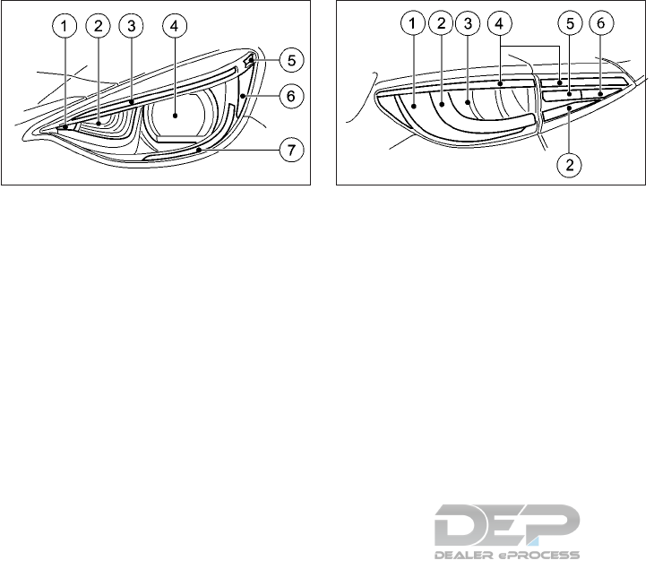
LED type:
䊊
1Cornering light
䊊
2Additional high-beam headlight
䊊
3Daytime driving light and sidelight and
turn signal light
䊊
4High/Low beam LED projector head-
lights and Adaptive Front Lighting sys-
tem (if so equipped)
䊊
5Side marker light (if so equipped)
䊊
6Reflector (if so equipped)
䊊
7Daytime driving light and sidelights
Rear light unit
䊊
1Tail light
䊊
2Turn signal light
䊊
3Brake light
䊊
4Tail light
䊊
5Reversing light
䊊
6Rear fog light (drivers side only)
REPLACEMENT PROCEDURES
LED lights (if so equipped)
The LED headlight is a projector style which
uses a LED module without serviceable parts.
If LED fog headlight , or any other LED light
replacement is required, it is recommended
that you visit an INFINITI retailer for this
service.
NDI1614 NDI1615
8-24 Do-it-yourself
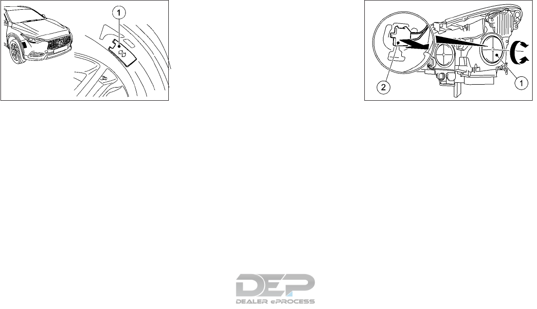
Halogen headlight bulb
Fitting/removing the access cover on the
front wheel arch:
You must remove the cover of the front
wheel arch before you can change the halo-
gen headlight bulb.
To remove: switch off the lights, turn the
steering so that the wheel behind the light in
question is pointing inwards . Slide cover 䊊
1
up and remove it.
To fit: inset cover 䊊
1again and slide it down
until it engages.
The headlight is a semi-sealed beam type
which uses a replaceable headlight (halogen)
bulb. A bulb can be replaced from inside the
engine compartment without removing the
headlight assembly.
If you need assistance for bulb replacement,
it is recommended that you visit an INFINITI
retailer.
Low/High beam Headlight bulb replace-
ment:
1. Open the hood. For details, see "Hood" in
the "3. Pre-driving checks and adjust-
ments" section.
2. Disconnect the negative (—) battery cable.
3. Remove the corresponding access cover
from the wheel arch.
4. Turn housing cover 䊊
1counterclockwise
and remove it.
5. Turn bulb holder 䊊
2counterclockwise and
pull out
6. Take the headlight bulb out of bulb holder
䊊
2.
7. Insert the new bulb into bulb holder 䊊
2.
8. Insert bulb holder 䊊
2and turn it clockwise.
NDI1626 NDI1611
Do-it-yourself 8-25
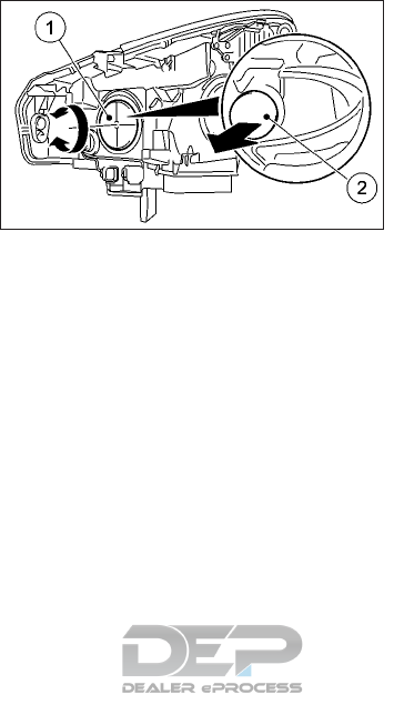
9. Press on housing cover 䊊
1and turn it to
the right.
10. Replace the cover in the front wheel arch
11. Reconnect the negative (—) battery cable
and close the hood.
NOTE
Fog may temporarily form inside the lens of
the exterior lights in the rain or in a car wash.
The fog is caused by a temperature differ-
ence between the inside and the outside of
the lens. This is not a malfunction. If large
droplets can be seen, it is recommended that
you visit an INFINITI retailer.
Front turn signal light bulb
replacement (non-LED system only)
1. Open the hood. For details, see "Hood" in
the "3. Pre-driving checks and adjust-
ments" section.
2. Disconnect the negative (—) battery cable.
3. Turn housing cover 䊊
1counterclockwise
and remove it.
4. Turn bulb holder 䊊
2counterclockwise and
pull out
5. Take the headlight bulb out of bulb holder
䊊
2.
6. Insert the new bulb into bulb holder 䊊
2.
7. Insert bulb holder 䊊
2and turn it clockwise.
8. Press on housing cover 䊊
1and turn it to
the right.
9. Reconnect the negative (—) battery cable
and close the hood.
NDI1612
8-26 Do-it-yourself

If you have a flat tire, refer to "Flat tire" in the
"6. In case of emergency" section.
TIRE PRESSURE
Tire Pressure Monitoring System
(TPMS)
The Tire Pressure Monitoring System (TPMS)
monitors tire pressure of all tires. When the
low tire pressure warning light is lit, one or
more of the tires is significantly under-
inflated.
The TPMS will activate only when the vehicle
is driven at speeds above 16 MPH (25 km/h).
Also, this system may not detect a sudden
drop in tire pressure (for example a flat tire
while driving).
For additional information, refer to "Tire
Pressure Monitoring System (TPMS)" in the
"5. Starting and driving" section.
Tire inflation pressure
Check the tire pressures (including the spare)
often and always prior to long distance trips.
The recommended tire pressure specifica-
tions are shown on the F.M.V.S.S./
C.M.V.S.S. label or the Tire and Loading In-
formation label (if so equipped) under the
Cold Tire Pressure heading. The Tire and
Loading Information label is affixed to the
driver side center pillar. Tire pressures should
be checked regularly because:
•Most tires naturally lose air over time.
•Tires can lose air suddenly when driven
over potholes or other objects or if the
vehicle strikes a curb while parking.
The tire pressures should be checked when
the tires are cold. The tires are considered
COLD after the vehicle has been parked for 3
or more hours, or driven less than 1 mile (1.6
km) at moderate speeds.
WARNING
•Improperly inflated tires can fail sud-
denly and cause an accident.
•The Gross Vehicle Weight rating
(GVWR) is located on the F.M.V.S. S./
C.M.V.S.S. certification label. The ve-
hicle weight capacity is indicated on the
Tire and Loading Information label (if so
equipped). Do not load your vehicle be-
yond this capacity. Overloading your
vehicle may result in reduced tire life,
unsafe operating conditions due to pre-
mature tire failure, or unfavorable han-
dling characteristics and could also lead
to a serious accident. Loading beyond
the specified capacity may also result in
failure of other vehicle components.
•Before taking a long trip, or whenever
you heavily load your vehicle, use a tire
pressure gauge to ensure that the tire
pressures are at the specified level.
•For additional information regarding
tires, refer to “Important Tire Safety In-
formation” (US) or “Tire Safety Infor-
mation” (Canada) in the Warranty In-
formation Booklet.
WHEELS AND TIRES
Do-it-yourself 8-27

Tire and Loading Information label
䊊
1
Seating capacity: The maximum number of
occupants that can be seated in the vehicle.
䊊
2Vehicle load limit: See "Vehicle loading
information" in the "10. Technical infor-
mation" section.
䊊
3Original size: The size of the tires origi-
nally installed on the vehicle at the fac-
tory.
䊊
4Cold tire pressure: Inflate the tires to this
pressure when the tires are cold. Tires are
considered COLD after the vehicle has
been parked for 3 or more hours, or
driven less than 1 mile (1.6 km) at moder-
ate speeds. The recommended cold tire
inflation is set by the manufacturer to
provide the best balance of tire wear,
vehicle handling, driveability, tire noise,
etc., up to the vehicle’s GVWR.
䊊
5Tire size — see "Tire labeling" later in this
section.
䊊
6Spare tire size or compact spare tire size
(if so equipped).
SDI2703
8-28 Do-it-yourself

TIRE INFLATION PRESSURE
Checking tire pressure
1. Remove the valve stem cap from the tire.
2. Press the pressure gauge squarely onto
the valve stem. Do not press too hard or
force the valve stem sideways, or air will
escape. If the hissing sound of air escap-
ing from the tire is heard while checking
the pressure, reposition the gauge to
eliminate this leakage.
3. Remove the gauge.
4. Read the tire pressure on the gauge stem
and compare it to the specification shown
on the Tire and Loading Information label.
5. Add air to the tire as needed. If too much
air is added, press the core of the valve
stem briefly with the tip of the gauge stem
to release pressure. Recheck the pressure
and add or release air as needed.
6. Install the valve stem cap.
7. Check the pressure of all other tires, in-
cluding the spare.
Tire Size Cold Tire Inflation
Pressure
Front Rear
235/50
R18
(2WD) 35 psi,
240kPa
35 psi,
240kPa
(4WD) 35 psi,
240kPa
29 psi,
200kPa
235/45 R19 32 psi,
220kPa
32 psi,
220kPa
Spare tire NONE
TIRE LABELING
Federal law requires tire manufacturers to
place standardized information on the side-
wall of all tires. This information identifies
and describes the fundamental characteris-
tics of the tire and also provides the tire iden-
tification number (TIN) for safety standard
certification. The TIN can be used to identify
the tire in case of a recall.
SDI1949Z SDI1575Z
Example
Do-it-yourself 8-29
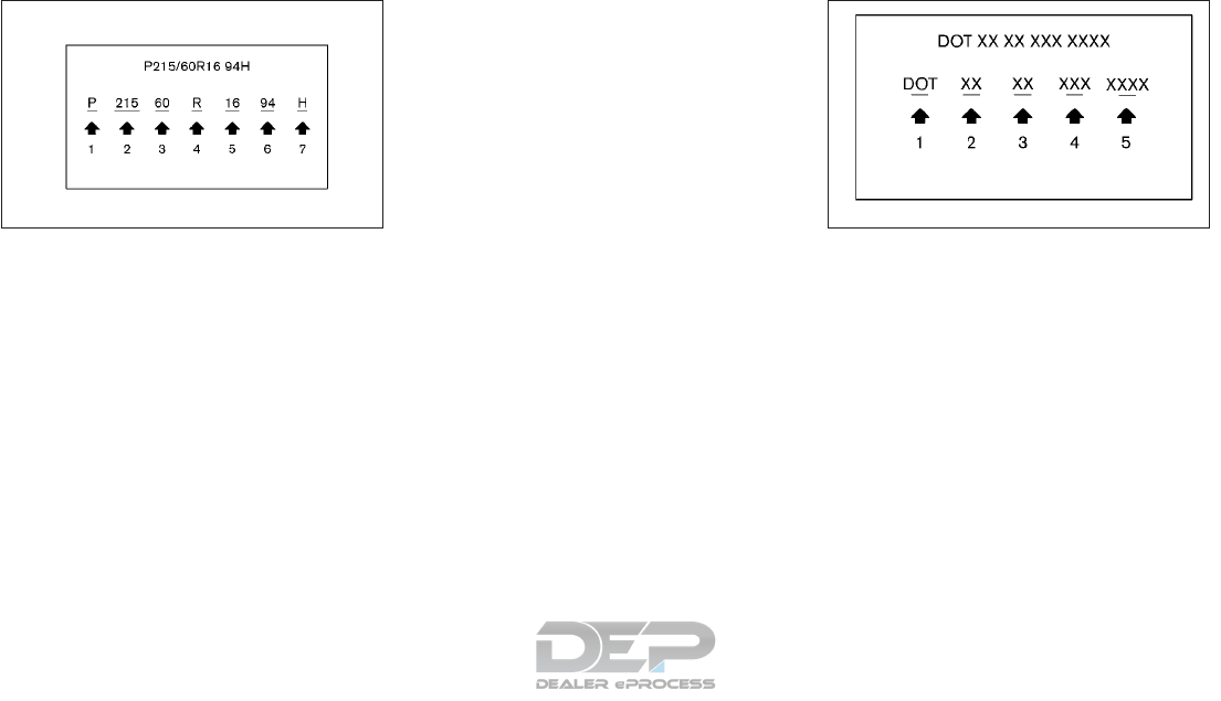
䊊
1Tire size (example: P215/60R16 94H)
1 P: The “P” indicates the tire is designed for
passenger vehicles. (Not all tires have this
information.)
2 Three-digit number (215): This number
gives the width in millimeters of the tire
from sidewall edge to sidewall edge.
3 Two-digit number (60): This number,
known as the aspect ratio, gives the tire’s
ratio of height to width.
4 R: The “R” stands for radial.
5 Two-digit number (16): This number is the
wheel or rim diameter in inches.
6 Two- or three-digit number (94): This
number is the tire’s load index. It is a mea-
surement of how much weight each tire
can support. You may not find this infor-
mation on all tires because it is not re-
quired by law.
7 H: Tire speed rating. You should not drive
the vehicle faster than the tire speed rat-
ing.
䊊
2TIN (Tire Identification Number) for a
new tire (example: DOT XX XX XXX
XXXX)
1 DOT: Abbreviation for the “Department of
Transportation”. The symbol can be placed
above, below or to the left or right of the
Tire Identification Number.
2 Two-digit code: Manufacturer’s identifi-
cation mark
3 Two-digit code: Tire size
4 Three-digit code: Tire type code (Optional)
5 Four numbers represent the week and
year the tire was built. For example, the
numbers 3103 means the 31st week of
2003. If these numbers are missing, then
look on the other sidewall of the tire.
SDI1606Z
Example
NDI1623
Example
8-30 Do-it-yourself

䊊
3Tire ply composition and material
The number of layers or plies of rubber-
coated fabric in the tire. Tire manufactur-
ers also must indicate the materials in the
tire, which include steel, nylon, polyester,
and others.
䊊
4Maximum permissible inflation pressure
This number is the greatest amount of air
pressure that should be put in the tire. Do
not exceed the maximum permissible in-
flation pressure.
䊊
5Maximum load rating
This number indicates the maximum load
in kilograms and pounds that can be car-
ried by the tire. When replacing the tires
on the vehicle, always use a tire that has
the same load rating as the factory in-
stalled tire.
䊊
6Term of “tubeless” or “tube type”
Indicates whether the tire requires an in-
ner tube (“tube type”) or not (“tubeless”).
䊊
7The word “radial”
The word “radial” is shown, if the tire has
radial structure.
䊊
8Manufacturer or brand name”
Manufacturer or brand name is shown.
Other tire-related terminology:
In addition to the many terms that are de-
fined throughout this section, Intended Out-
board Sidewall is (1) the sidewall that con-
tains a whitewall, bears white lettering or
bears manufacturer, brand and/or model
name molding that is higher or deeper than
the same molding on the other sidewall of the
tire, or (2) the outward facing sidewall of an
asymmetrical tire that has a particular side
that must always face outward when
mounted on a vehicle.
TYPES OF TIRES
WARNING
•When changing or replacing tires, be
sure all four tires are of the same type
(i.e, summer, all season or snow) and
construction. An INFINITI retailer may
be able to help you with information
about tire type, size, speed rating and
availability.
•Replacement tires may have a lower
speed rating than the factory equipped
tires, and they may not match the po-
tential maximum vehicle speed. Never
exceed the maximum speed rating of the
tire.
•Always use tires of the same type, size,
brand, construction and tread pattern
on all four wheels. Failure to do so may
result in a circumference difference be-
tween tires on the front and rear axles
which can cause the Vehicle Dynamic
Control (VDC) system to malfunction
resulting in personal injury or death, ex-
cessive tire wear and may damage the
transmission, transfer case and differ-
ential gears.
•For additional information regarding
tires, refer to “Important Tire Safety In-
formation” (US) or “Tire Safety Infor-
mation“ (Canada) in the Warranty In-
formation Booklet.
CAUTION
ONLY use spare tires specified for the
model.
If excessive tire wear is found, it is recom-
mended that all four tires be replaced with
tires of the same size, brand, construction
and tread pattern. The tire pressure and
wheel alignment should also be checked and
corrected as necessary. It is recommended
that you visit an INFINITI retailer for this
service.
Do-it-yourself 8-31

All season tires
INFINITI specifies all season tires on some
models to provide good performance all year,
including snowy and icy road conditions. All
season tires are identified by ALL SEASON
and/or M&S on the tire sidewall. Snow tires
have better snow traction than all season
tires and may be more appropriate in some
areas.
Summer tires
INFINITI specifies summer tires on some
models to provide superior performance on
dry roads. Summer tire performance is sub-
stantially reduced in snow and ice. Summer
tires do not have the tire traction rating M&S
on the tire sidewall.
If you plan to operate your vehicle in snowy or
icy conditions, INFINITI recommends the use
of snow or all season tires on all four wheels.
Snow tires
If snow tires are needed, it is necessary to
select tires equivalent in size and load rating
to the original equipment tires. If you do not,
it can adversely affect the safety and han-
dling of your vehicle.
Generally, snow tires have lower speed rat-
ings than factory equipped tires and may not
match the potential maximum vehicle speed.
Never exceed the maximum speed rating of
the tire. If you install snow tires, they must be
the same size, brand, construction and tread
pattern on all four wheels.
For additional traction on icy roads, studded
tires may be used. However, some U.S. states
and Canadian provinces prohibit their use.
Check local, state and provincial laws before
installing studded tires. Skid and traction ca-
pabilities of studded snow tires on wet or dry
surfaces may be poorer than that of non-
studded snow tires.
Four-Wheel Drive (4WD) models
If excessive tire wear is found, it is recom-
mended that all four tires be replaced with
tires of the same size, brand, construction
and tread pattern. The tire pressure and
wheel alignment should also be checked and
corrected as necessary. It is recommended
that you visit an INFINITI retailer.
TIRE CHAINS
CAUTION
Tire chains/cables should not be installed
on 235/45 R19 or 235/50 R18 size tires.
Installation of the tire chains/cables on
235/45 R19 or 235/50 R18 size tires will
cause damage to the vehicle. If you plan to
use tire chains/cables, you should install
215/60 R17 size tires on your vehicle.
Use of tire chains may be prohibited accord-
ing to location. Check the local laws before
installing tire chains. When installing tire
chains, make sure that they are of proper size
for the tires on your vehicle and are installed
according to the chain manufacturer’s in-
structions.
Use chain tensioners when recommended by
the tire chain manufacturer to ensure a tight
fit. Loose end links of the tire chains must be
secured or removed to prevent the possibility
of whipping action damage to the fenders or
underbody. If possible, avoid fully loading
your vehicle when using tire chains. In addi-
tion, drive at a reduced speed. Otherwise,
your vehicle may be damaged and/or vehicle
handling and performance may be adversely
affected.
Tire chains must be installed only on the
front wheels and not on the rear wheels.
8-32 Do-it-yourself
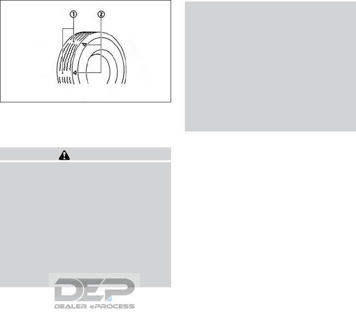
Never install tire chains on a T-type spare tire
(TEMPORARY USE ONLY).
Do not drive with tire chains on paved roads
which are clear of snow. Driving with chains
in such conditions can cause damage to the
various mechanisms of the vehicle due to
some overstress.
䊊
1: Wear indicator
䊊
2: Location mark
TIRE WEAR AND DAMAGE
WARNING
•Tires should be periodically inspected
for wear, cracking, bulging or objects
caught in the tread. If excessive wear,
cracks, bulging or deep cuts are found,
the tire should be replaced immediately.
•The original tires have a built-in tread
wear indicator. When the wear indicator
is visible, the tire should be replaced.
•Tires degrade with age and use. Have
tires, including the spare, over 6 years
old checked by a qualified technician be-
cause some tire damage may not be ob-
vious. Replace the tires as necessary to
prevent tire failure and possible per-
sonal injury.
•Improper service of the spare tire may
result in serious personal injury. If it is
necessary to repair the spare tire, it is
recommended that you visit an INFINITI
retailer for this service.
•For additional information regarding
tires, refer to “Important Tire Safety In-
formation” (US) or “Tire Safety Infor-
mation” (Canada) in the Warranty In-
formation Booklet.
Tires should be periodically inspected for
wear, cracking, bulging or objects caught in
the tread. If excessive wear, cracks, bulging
or deep cuts are found, the tire should be
replaced immediately.
The original tires have a built-in tread wear
indicator. When the wear indicator is visible,
the tire should be replaced.
Improper servicing of a tire may result in se-
rious personal injury. If it is necessary to re-
pair a tire, it is recommended you contact an
INFINITI retailer.
SDI1663Z
Do-it-yourself 8-33

TIRE ROTATION
INFINITI recommends rotating the tires ev-
ery 5,000 miles (8,000 km).
For additional information on tire replacing
procedures, refer to "Flat tire" in the "6. In
case of emergency" section. As soon as pos-
sible, tighten the wheel nuts to the specified
torque with a torque wrench.
Wheel nut tightening torque: 96 ft-lb (130
N·m)
The wheel nuts must be kept tightened to
specifications at all times. It is recommended
that wheel nuts be tightened to specification
at each tire rotation interval.
WARNING
•After rotating the tires, check and ad-
just the tire pressure.
•Do not include the spare tire in the tire
rotation.
•For additional information regarding
tires, refer to "Important Tire Safety In-
formation" (US) or "Tire Safety Infor-
mation" in the Warranty Information
Booklet.
REPLACING WHEELS AND TIRES
WARNING
Do not install a deformed wheel or tire even
if it has been repaired. Such wheels or tires
could have structural damage and could
fail without warning.
When replacing a tire, use the same size,
speed rating and load carrying capacity as
originally equipped. (See "Wheels and Tires" in
the "9. Maintenance and Schedules" section
for recommended types and sizes of tires and
wheels.)
If the wheels are changed for any reason,
always replace with wheels which have the
same offset dimension. Wheels of a different
offset could cause early tire wear, possibly
degraded vehicle handling characteristics
and/or interference with the brake discs/
drums. Such interference can lead to de-
creased braking efficiency and/or early brake
pad/shoe wear.
Confirm the following for the TPMS:
WARNING
•The use of tires other than those recom-
mended or the mixed use of tires of dif-
ferent brands, construction (bias, bias-
belted or radial), or tread patterns can
adversely affect the ride, braking, han-
dling, VDC system, ground clearance,
body-to-tire clearance, tire chain clear-
ance, speedometer calibration, head-
light aim and bumper height. Some of
these effects may lead to accidents and
could result in serious personal injury.
•For 2WD models, if your vehicle was
originally equipped with 4 tires that
were the same size and you are only re-
placing 2 of the 4 tires, install the new
tires on the rear axle. Placing new tires
on the front axle may cause loss of ve-
hicle control in some driving conditions
and cause an accident and personal in-
jury.
•If the wheels are changed for any rea-
son, always replace with wheels which
have the same offset dimension. Wheels
of a different offset could cause prema-
ture tire wear, degrade vehicle handling
characteristics, affect the VDC system
and/or interference with the brake
discs. Such interference can lead to de-
creased braking efficiency and/or early
8-34 Do-it-yourself

brake pad wear. For additional informa-
tion on wheel offset dimensions, refer to
"Wheels and Tires" in the "9. Mainte-
nance and Schedules" section.
•When a replacement tire is mounted or a
wheel is replaced, the TPMS will not
function and the low tire pressure warn-
ing light will flash for approximately 1
minute. The light will remain on after 1
minute. Contact an INFINITI retailer as
soon as possible for tire replacement
and/or system resetting.
•Replacing tires with those not originally
specified by INFINITI could affect the
proper operation of the TPMS.
•The TPMS sensor may be damaged if it
is not handled correctly. Be careful when
handling the TPMS sensor.
•When replacing the TPMS sensor, the ID
registration may be required. It is rec-
ommended that you visit an INFINITI re-
tailer for ID registration.
•Do not use a valve stem cap that is not
specified by INFINITI. The valve stem
cap may become stuck.
•Be sure that the valve stem caps are cor-
rectly fitted. Otherwise the valve may
be clogged up with dirt and cause a mal-
function or loss of pressure.
•Do not install a damaged or deformed
wheel or tire even if it has been repaired.
Such wheels or tires could have struc-
tural damage and could fail without
warning.
•The use of retread tires is not recom-
mended.
•For additional information regarding
tires, refer to "Important Tire Safety In-
formation" (US) or "Tire Safety Infor-
mation" (Canada) in the Warranty In-
formation Booklet.
Care of wheels
•Wash the wheels when washing the ve-
hicle to maintain their appearance.
•Clean the inner side of the wheels when
the wheel is changed or the underside of
the vehicle is washed.
•Do not use abrasive cleaners when wash-
ing the wheels.
•Inspect wheel rims regularly for dents or
corrosion. Such damage may cause loss of
pressure or poor seal at the tire bead.
•INFINITI recommends waxing the road
wheels to protect against road salt in ar-
eas where it is used during winter.
WHEEL BALANCE
Unbalanced wheels may affect vehicle han-
dling and tire life. Even with regular use,
wheels can get out of balance. Therefore,
they should be balanced as required.
Wheel balance service should be performed
with the wheels off the vehicle. Spin balanc-
ing the wheels on the vehicle could lead to
mechanical damage.
For additional information regarding tires,
refer to "Important Tire Safety Information"
(US) or "Tire Safety Information" (Canada)
in the Warranty Information Booklet.
Do-it-yourself 8-35

MEMO
8-36 Do-it-yourself

9 Maintenance and Schedules
Maintenance requirements ................9-2
General maintenance..................9-2
Scheduled maintenance ................9-2
Where to go for service ................9-2
General maintenance....................9-2
Explanation of general maintenance items . . . .9-2
Explanation of general maintenance items ......9-5
Emission control system maintenance .......9-6
Chassis and body maintenance ...........9-6
Maintenance schedules ..................9-7
Additional maintenance items for severe
operating systems ...................9-7
Oil change monitor ...................9-7
Maintenance service messages ...........9-7
Standard maintenance..................9-10
Emission control system maintenance
(For 2.0L turbo gasoline engine) .........9-10
Chassis & body maintenance ............9-13
Maintenance log......................9-15

Some day-to-day and regular maintenance is
essential to maintain your vehicle’s good me-
chanical condition, as well as its emission and
engine performance.
It is the owner’s responsibility to make sure
that the specified maintenance, as well as
general maintenance, is performed.
As the vehicle owner, you are the only one
who can ensure that your vehicle receives the
proper maintenance care. You are a vital link
in the maintenance chain.
GENERAL MAINTENANCE
General maintenance includes those items
which should be checked during normal day-
to-day operation of the vehicle. They are es-
sential if your vehicle is to continue to operate
properly. It is your responsibility to perform
these procedures regularly as prescribed.
Performing general maintenance checks re-
quires minimal mechanical skill and only a few
general automotive tools.
These checks and inspections can be done by
yourself, a qualified technician, or if you pre-
fer, an INFINITI retailer.
SCHEDULED MAINTENANCE
The maintenance items listed under "Mainte-
nance schedules" later in this section are re-
quired to be serviced at regular intervals.
However under severe driving conditions, ad-
ditional or more frequent maintenance will be
required.
WHERE TO GO FOR SERVICE
If maintenance service is required or your
vehicle appears to malfunction, have the sys-
tems checked and serviced. It is recom-
mended you visit an INFINITI retailer for this
service.
INFINITI technicians are well-trained spe-
cialists and are kept up to date with the latest
service information through technical bulle-
tins, service tips and training programs. They
are completely qualified to work on INFINITI
vehicles before work begins.
You can be confident that an INFINITI retail-
er’s service department can perform the ser-
vice needed to meet the maintenance re-
quirements on your vehicle.
During normal day-to-day operation of the
vehicle, general maintenance should be per-
formed regularly as prescribed in this section.
If you detect any unusual sounds, vibrations
or smells, be sure to check for the cause or
have an INFINITI retailer do it promptly. In
addition, it is recommended you notify an
INFINITI retailer if you think that repairs are
required.
When performing any checks or maintenance
work, closely observe "Explanation of general
maintenance items" later in this section.
EXPLANATION OF GENERAL
MAINTENANCE ITEMS
Additional information on the following
items with “*” is found later in the “Do-it-
yourself” section of this manual.
Outside the vehicle
The maintenance items listed here should be
performed from time to time, unless other-
wise specified.
Doors and engine hood:
Check that all doors, the lift gate and the
engine hood operate smoothly. Also make
sure that all latches lock securely. Lubricate if
necessary. Make sure that the secondary
latch keeps the hood from opening when the
MAINTENANCE REQUIREMENTS GENERAL MAINTENANCE
9-2 Maintenance and Schedules

primary latch is released. When driving in ar-
eas using road salt or other corrosive materi-
als, check lubrication frequently.
Lights*:
Clean the headlights on a regular basis. Make
sure that the headlights, stop lights, tail lights,
turn signal lights, and other lights are all op-
erating properly and installed securely. Also
check the aim of the headlights.
Road wheel nuts (lug nuts)*:
When checking the tires, make sure no wheel
nuts are missing, and check for any loose
wheel nuts. Tighten if necessary.
Tire rotation*:
Tires should be rotated every 5,000 miles
(8,000 km). Tires marked with directional
indicators can only be rotated between front
and rear. Make sure that the directional indi-
cators point in the direction of wheel rotation
after the tire rotation is completed.
Tires*:
Check the pressure with a gauge often and
always prior to long distance trips. Adjust the
pressure in all tires to the pressure specified.
Check carefully for damage, cuts or excessive
wear.
Tire Pressure Monitoring System (TPMS)
transmitter components:
Replace the TPMS transmitter grommet seal,
valve core and cap when the tires are re-
placed due to wear or age.
Wheel alignment and balance:
If the vehicle should pull to either side while
driving on a straight and level road, or if you
detect uneven or abnormal tire wear, there
may be a need for wheel alignment.
If the steering wheel or seat vibrates at nor-
mal highway speeds, wheel balancing may be
needed.
For additional information regarding tires, re-
fer to “Important Tire Safety Information”
(US) or “Tire Safety Information” (Canada) in
the INFINITI Warranty Information Booklet.
Windshield:
Clean the windshield on a regular basis.
Check the windshield at least every six
months for cracks or other damage. Have a
damaged windshield repaired by a qualified
repair facility.
Wiper blades*:
Check for cracks or wear if not functioning
correctly. Replace as necessary.
Inside the vehicle
The maintenance items listed here should be
checked on a regular basis, such as when
performing scheduled maintenance, cleaning
the vehicle, etc.
Accelerator pedal:
Check the pedal for smooth operation and
make sure that the pedal does not catch or
require uneven effort. Keep the floor mat
away from the pedal.
Automatic transmission P (Park) mecha-
nism:
On a fairly steep hill, check that your vehicle is
held securely when P (Park) has been acti-
vated, without applying any brakes.
Brake pedal*:
Check the pedal for smooth operation. If the
brake pedal suddenly goes down further than
normal, the pedal feels spongy or the vehicle
seems to take longer to stop, have your ve-
hicle checked immediately. It is recommended
you visit an INFINITI retailer for this service.
Keep the floor mat away from the pedal.
Brakes:
Check that the brakes do not pull the vehicle
to one side when applied.
Maintenance and Schedules 9-3

Parking brake*:
Check the parking brake operation regularly.
Also make sure that the vehicle is held se-
curely on a fairly steep hill when only the
parking brake is applied. If the parking brake
needs adjustment, it is recommended you
visit an INFINITI retailer for this service.
Seats:
Check seat position controls such as seat
adjusters, seatback recliner, etc. to ensure
they operate smoothly and that all latches
lock securely in every position. Check that the
head restraints move up and down smoothly
and that the locks (if so equipped) hold se-
curely in all latched positions.
Seat belts:
Check that all parts of the seat belt system
(for example, buckles, anchors, adjusters and
retractors) operate properly and smoothly,
and are installed securely. Check the belt
webbing for cuts, fraying, wear or damage.
Steering wheel:
Check for changes in the steering condition,
such as excessive free play, hard steering or
strange noises.
Warning lights and chimes:
Make sure that all warning lights and chimes
are operating properly.
Windshield defroster:
Check that the air comes out of the defroster
outlets properly and in good quantity when
operating the heater or air conditioner.
Windshield wiper and washer*:
Check that the wipers and washer operate
properly and that the wipers do not streak.
Under the hood and vehicle
The maintenance items listed here should be
checked periodically (for example, each time
you check the engine oil or refuel).
Battery*:
Except for maintenance free battery, check
the fluid level in each cell. It should be be-
tween the “UPPER” and “LOWER” lines. Ve-
hicles operated in high temperatures or under
severe conditions require frequent checks of
the battery fluid level.
NOTE
Care should be taken to avoid situations
that can lead to potential battery discharge
and potential no-start conditions such as:
1. Installation or extended use of electronic
accessories that consume battery power
when the engine is not running (Phone
chargers, GPS, DVD players, etc.)
2. Vehicle is not driven regularly and/or
only driven short distances.
In these cases, the battery may need to be
charged to maintain battery health.
Brake fluid level*:
Make sure that the brake fluid level is be-
tween the “MAX” and “MIN” lines on the res-
ervoir.
Coolant level*:
Check the coolant level when the engine is
cold.
Engine drive belt(s)*:
Make sure that no belt is frayed, worn,
cracked or oily.
Engine oil level*:
Check the level after parking the vehicle on a
level spot and turning off the engine. Wait
more than 15 minutes for the oil to drain back
into the oil pan.
Exhaust system:
Make sure there are no loose supports,
cracks or holes. If the sound of the exhaust
seems unusual or there is a smell of exhaust
fumes, immediately have the exhaust system
inspected. It is recommended you visit an
9-4 Maintenance and Schedules

INFINITI retailer for this service. See "Precau-
tions when starting and driving" in the "5.
Starting and driving" section.
Fluid leaks:
Check under the vehicle for fuel, oil, water or
other fluid leaks after the vehicle has been
parked for a while. Water dripping from the
air conditioner after use is normal. If you
should notice any leaks or if gasoline fumes
are evident, check for the cause and have it
corrected immediately.
Radiator and hoses:
Check the front of the radiator and clean off
any dirt, insects, leaves, etc., that may have
accumulated. Make sure the hoses have no
cracks, deformation, rot or loose connec-
tions.
Underbody:
The underbody is frequently exposed to cor-
rosive substances such as those used on icy
roads or to control dust. It is very important to
remove these substances, otherwise rust will
form on the floor pan, frame, fuel lines and
around the exhaust system. At the end of
winter, the underbody should be thoroughly
flushed with plain water, being careful to
clean those areas where mud and dirt may
accumulate. For additional information, see
"Cleaning exterior" in the "7. Appearance and
care" section.
Windshield washer fluid*:
Check that there is adequate fluid in the res-
ervoir.
The following descriptions are provided to
give you a better understanding of the sched-
uled maintenance items that should be regu-
larly checked or replaced. The maintenance
schedule indicates at which mileage/time in-
tervals each item requires service.
In addition to scheduled maintenance, your
vehicle requires that some items be checked
during normal day-to-day operation. Refer to
"General maintenance" in this section.
Items marked with “*” are recommended by
INFINITI for reliable vehicle operation. You
are not required to perform maintenance on
these items in order to maintain the warran-
ties which come with your vehicle. Other
maintenance items and intervals are required.
When applicable, additional information can
be found in the “Do-it-yourself” section in
Chapter 8.
NOTE
INFINITI does not advocate the use of non-
OEM approved aftermarket flushing sys-
tems and strongly advises against perform-
ing these services on an INFINITI product.
Many of the aftermarket flushing systems
use non-OEM approved chemicals or sol-
vents, the use of which has not been vali-
dated by INFINITI.
EXPLANATION OF GENERAL
MAINTENANCE ITEMS
Maintenance and Schedules 9-5

For recommended fuel, lubricants, fluids,
grease, and refrigerant, refer to "Recom-
mended fluids/lubricants and capacities" in
the "10. Technical information" section.
EMISSION CONTROL SYSTEM
MAINTENANCE
Drive belts*:
Check engine drive belts for wear, fraying or
cracking and for proper tension. Replace any
damaged drive belts
Engine air filter*:
Replace at specified intervals. When driving
for prolonged periods in dusty conditions,
check/replace the filter more frequently.
Engine coolant*:
Replace coolant at the specified interval.
When adding or replacing coolant, be sure to
use only Genuine INFINITI Engine Coolant or
equivalent in its quality (BASF Glysantin®
G40®). (For additional information, refer to
"Engine cooling system" in the "9. Mainte-
nance and Schedules" sectionnanceand
SchedulesMaintenance and Schedules" sec-
tion nanceand SchedulesMaintenance and
Schedules" section nanceand Schedules-
Maintenance and Schedules" section nance-
and SchedulesMaintenance and Schedules"
section nanceand SchedulesMaintenance
and Schedules" section nanceand Schedules-
Maintenance and Schedules" section nance-
and SchedulesMaintenance and Schedules"
section nanceand SchedulesMaintenance
and Schedules" section nanceand Schedules-
Maintenance and Schedules" section nance-
and SchedulesMaintenance and Schedules"
section nanceand SchedulesMaintenance
and Schedules" section.)
NOTE
Mixing any other type of coolant or the use
of non-distilled water may reduce the rec-
ommended service interval of the coolant.
Engine oil and oil filter:
Replace engine oil and oil filter at the speci-
fied intervals. For recommended oil grade
and viscosity refer to "Recommended fluids/
lubricants and capacities" in the "10. Techni-
cal information" section calinformationTech-
nical information" section information"
section.
Fuel filter:
Replace the fuel filter and drain the water at
the specified intervals.
Fuel lines*:
Check the fuel hoses, piping and connections
for leaks, looseness, or deterioration. Tighten
connections or replace parts as necessary.
Spark plugs:
Replace at specified intervals. Install new
plugs of the type as originally equipped.
CHASSIS AND BODY
MAINTENANCE
Brake lines and cables:
Visually inspect for proper installation. Check
for chafing, cracks, deterioration, and signs
of leaking. Replace any deteriorated or dam-
aged parts immediately.
Brake pads, rotors, drums, & linings:
Check for wear, deterioration and fluid leaks.
Replace any deteriorated or damaged parts
immediately.
Exhaust system:
Visually inspect the exhaust pipes, muffler
and hangers for leaks, cracks, deterioration,
and damage. Tighten connections or replace
parts as necessary.
In-cabin microfilter:
Replace at specified intervals. When driving
for prolonged periods in dusty conditions, re-
place the filter more frequently.
9-6 Maintenance and Schedules

Propeller shaft(s):
Check for damage, looseness, and grease
leakage. (4WD/AWD).
Steering gear and linkage, axle and suspen-
sion parts, drive shaft boots:
Check for damage, looseness, and leakage of
oil or grease. Under severe driving conditions,
inspect more frequently
Tire rotation:
Tires should be rotated every 5,000 miles
(8,000 km) according to the instructions un-
der "Tire rotation*" earlier in this section.
When rotating tires, check for damage and
uneven wear. Replace if necessary.
Transmission fluid/oil, differential oil,
transfer case oil:
Visually inspect for signs of leakage at speci-
fied intervals.
To ensure smooth, trouble-free, safe and
economical driving, INFINITI provides two
maintenance schedules that may be used,
depending upon the conditions in which you
usually drive. These schedules contain both
distance and time intervals, up to 120,000
miles (192,000 km)/144 months. For most
people, the odometer reading will indicate
when service is needed. However, if you drive
very little, your vehicle should be serviced at
the regular time intervals shown in the sched-
ule.
After 120,000 miles (192,000 km)/144
months, continue maintenance at the same
mileage/time intervals.
ADDITIONAL MAINTENANCE
ITEMS FOR SEVERE OPERATING
SYSTEMS
Additional maintenance items for severe op-
erating conditions; should be performed on
vehicles that are driven under especially de-
manding conditions. Additional maintenance
items should be performed if you primarily
operate your vehicle under the following con-
ditions:
•Repeated short trips of less than 5 miles in
normal temperatures or less than 10 miles
in freezing temperatures.
•Stop-and-go traffic in hot weather or low
speed driving for long distances.
•Driving in dusty conditions or on rough,
muddy or salt-spread roads.
•Towing a trailer, or using a camper or car-
top carrier.
OIL CHANGE MONITOR
This vehicle is equipped with oil change moni-
tor. It calculates engine oil and filter change
interval base on driving conditions. Driving in
severe conditions will shorten the engine oil
and filter change interval. When the Engine
Oil – Service Due Now warning appears in
the vehicle information display, the engine oil
and filter need to be replaced.
NOTE
For vehicles operated in Canada, both stan-
dard and severe maintenance items should
be performed at every interval.
MAINTENANCE SERVICE
MESSAGES
The maintenance service interval display in-
forms you of the next service due date.
NOTE
The maintenance service interval display
does not show any information on the engine
oil level.
MAINTENANCE SCHEDULES
Maintenance and Schedules 9-7
The vehicle information display shows a ser-
vice message for a few seconds, for example:
•[Service A In .. days]
•[Service A Due]
•[Service A Exceeded by .. days]
Depending on the operating conditions of the
vehicle, the remaining time or distance until
the next service due date is displayed.
The letter indicates which service is due. A
stands for a minor service and B for a major
service. A number or another letter may be
displayed after the letter.
Only for certain countries: the position after
the letter A or B indicates any necessary ad-
ditional maintenance work. If you notify an
INFINITI retailer of this display, you will re-
ceive a statement on the associated costs.
The maintenance service interval display
does not take into account any periods of
time during which the battery is discon-
nected.
Maintaining the time-dependent service
schedule:
Note down the service due date displayed in
the vehicle information display before dis-
connecting the battery.
or
After reconnecting the battery, subtract the
battery disconnection periods from the ser-
vice date shown on the display.
Hiding service messages
Press the <OK> or button on the steer-
ing wheel.
Displaying service messages
1. Switch the ignition on.
2. Press the or button on the
steering wheel to select the [Serv.] menu.
3. Press the or button to select
[Maintenance] submenu and confirm by
pressing the OK button.
The service due date appears in the vehicle
information display.
Information about service
Resetting the maintenance service interval
display:
CAUTION
If the maintenance service interval display
has been inadvertently reset, this setting
can be corrected at an INFINITI retailer.
Have service work carried out as described
in the Maintenance Schedule. This may
otherwise lead to increased wear and dam-
age to the major assemblies or the vehicle.
An INFINITI retailer will reset the mainte-
nance service interval display after the service
work has been carried out. You can also ob-
tain further information on maintenance
work, for example.
Special service requirements:
The prescribed service interval is based on
normal operation of the vehicle. Service work
will need to be performed more often if the
vehicle is operated under arduous conditions
or increased loads, for example:
•Regular city driving with frequent interme-
diate stops
•If the vehicle is primarily used to travel
short distance
9-8 Maintenance and Schedules

•For frequent operation in mountainous
terrain or on poor road surfaces
•If the engine is often left idling for long
periods
In these or similar operating conditions, have,
for example, the air filter, engine oil and oil
filter changed more frequently. The tires must
be checked more frequently if the vehicle is
operated under increased loads. Further in-
formation can be obtained at an INFINITI
retailer.
Maintenance and Schedules 9-9

The following tables show the standard maintenance schedule. Depending upon weather and atmospheric conditions, varying road surfaces,
individual driving habits and vehicle usage, additional or more frequent maintenance may be required. After 120,000 miles (192,000 km)/144
months, continue maintenance at the same mileage/time intervals.
EMISSION CONTROL SYSTEM MAINTENANCE (FOR 2.0L TURBO GASOLINE ENGINE)
Abbreviations: I = Inspect and correct or replace as necessary, R = Replace
MAINTENANCE OPERATION miles x
1,000
MAINTENANCE INTERVAL
Perform at number of miles,
kilometers or months, whichever
comes first.
51015202530354045505560
(km x
1,000)
(8) (16) (24) (32) (40) (48) (56) (64) (72) (80) (88) (96)
months 6 12 18 24 30 36 42 48 54 60 66 72
Engine compartment See NOTE
(1)
V-belt See NOTE
(2)
I* I* I*
Replace every 155,000 miles or 180 months
Air cleaner filter Replace every 45,000 miles or 48 months
Fuel lines I* I* I*
Fuel filter See NOTE
(3)
Engine coolant* Replace every 155,000 miles or 180 months
Engine oil R R R R R R
Engine oil filter R R R R R R
Spark plugs Replace every 45,000 miles or 48 months
STANDARD MAINTENANCE
9-10 Maintenance and Schedules

NOTE:
(1) All visible parts checked for leaks and damage.
(2) In visible area only.
(3) Maintenance-free item.
* Maintenance items and intervals with ”*” are recommended by INFINITI for reliable vehicle operation. The owner need not perform such
maintenance in order to maintain the emission warranty or manufacturer recall liability. Other maintenance items and intervals are required
Maintenance and Schedules 9-11

Abbreviations: I = Inspect and correct or replace as necessary, R = Replace
MAINTENANCE OPERATION miles x
1,000
MAINTENANCE INTERVAL
Perform at number of miles, kilo-
meters or months, whichever
comes first.
65 70 75 80 85 90 95 100 105 110 115 120
(km x
1,000)
(104) (112) (120) (128) (136) (144) (152) (160) (168) (176) (184) (192)
months 78 84 90 96 102 108 114 120 126 132 138 144
Engine compartment See NOTE
(1)
V-belt See NOTE
(2)
I* I* I*
Replace every 155,000 miles or 180 months
Air cleaner filter Replace every 45,000 miles or 48 months
Fuel lines I* I* I*
Fuel filter See NOTE
(3)
Engine coolant* Replace every 155,000 miles or 180 months
Engine oil R R R R R R
Engine oil filter R R R R R R
Spark plugs Replace every 45,000 miles or 48 months
NOTE:
(1) All visible parts checked for leaks and damage.
(2) In visible area only.
(3) Maintenance-free item.
* Maintenance items and intervals with ”*” are recommended by INFINITI for reliable vehicle operation. The owner need not perform such
maintenance in order to maintain the emission warranty or manufacturer recall liability. Other maintenance items and intervals are required
9-12 Maintenance and Schedules

CHASSIS & BODY MAINTENANCE
Abbreviations: I = Inspect and correct or replace as necessary, R = Replace
MAINTENANCE OPERATION miles x
1,000
MAINTENANCE INTERVAL
Perform at number of miles,
kilometers or months, whichever
comes first.
51015202530354045505560
(km x 1,000) (8) (16) (24) (32) (40) (48) (56) (64) (72) (80) (88) (96)
months 6 12 18 24 30 36 42 48 54 60 66 72
Brake lines and cables I I I I I I
Brake pads and rotors I I I I I I
Brake fluid R R R
Automatic transmission fluid I I I
Automatic transmission fluid and
filter
Replace every 60,000 miles or 60 months
Differential gear oil I I I I I I
Steering gear and linkage, axle and
suspension parts
III
Tire rotation See NOTE
(1)
Propeller shaft & drive shaft boots
(4WD models)
IIIIII
Exhaust system I I I
In-cabin microfilter R R R
I-key battery R R R R
NOTE:
(1) Refer to "Tire rotation*" earlier in this section.
Maintenance and Schedules 9-13

Abbreviations: I = Inspect and correct or replace as necessary, R = Replace
MAINTENANCE OPERATION miles x
1,000
MAINTENANCE INTERVAL
Perform at number of miles, kilo-
meters or months, whichever
comes first.
65 70 75 80 85 90 95 100 105 110 115 120
(km x
1,000)
(104) (112) (120) (128) (136) (144) (152) (160) (168) (176) (184) (192)
months 78 84 90 96 102 108 114 120 126 132 138 144
Brake lines and cables I I I I I I
Brake pads and rotors I I I I I I
Brake fluid R R R
Automatic transmission fluid I I I
Automatic transmission fluid and
filter
Replace every 60,000 miles or 60 months
Differential gear oil I I I I I I
Steering gear and linkage, axle and
suspension parts
III
Tire rotation See NOTE
(1)
Propeller shaft & drive shaft boots
(4WD models)
IIIIII
Exhaust system I I I
In-cabin microfilter R R R
I-key battery R R R R
NOTE:
(1) Refer to "Tire rotation*" earlier in this section.
9-14 Maintenance and Schedules

5,000 Miles or 6 Months 10,000 Miles or 12 Months 15,000 Miles or 18 Months
Retailer Name: Retailer Name: Retailer Name:
Date: Date: Date:
Mileage: Mileage: Mileage:
Retailer
Stamp:
Retailer
Stamp:
Retailer
Stamp:
20,000 Miles or 24 Months 25,000 Miles or 30 Months 30,000 Miles or 36 Months
Retailer Name: Retailer Name: Retailer Name:
Date: Date: Date:
Mileage: Mileage: Mileage:
Retailer
Stamp:
Retailer
Stamp:
Retailer
Stamp:
35,000 Miles or 42 Months 40,000 Miles or 48 Months 45,000 Miles or 54 Months
Retailer Name: Retailer Name: Retailer Name:
Date: Date: Date:
Mileage: Mileage: Mileage:
Retailer
Stamp:
Retailer
Stamp:
Retailer
Stamp:
MAINTENANCE LOG
Maintenance and Schedules 9-15

50,000 Miles or 60 Months 55,000 Miles or 66 Months 60,000 Miles or 72 Months
Retailer Name: Retailer Name: Retailer Name:
Date: Date: Date:
Mileage: Mileage: Mileage:
Retailer
Stamp:
Retailer
Stamp:
Retailer
Stamp:
65,000 Miles or 78 Months 70,000 Miles or 84 Months 75,000 Miles or 90 Months
Retailer Name: Retailer Name: Retailer Name:
Date: Date: Date:
Mileage: Mileage: Mileage:
Retailer
Stamp:
Retailer
Stamp:
Retailer
Stamp:
80,000 Miles or 96 Months 85,000 Miles or 102 Months 90,000 Miles or 108 Months
Retailer Name: Retailer Name: Retailer Name:
Date: Date: Date:
Mileage: Mileage: Mileage:
Retailer
Stamp:
Retailer
Stamp:
Retailer
Stamp:
9-16 Maintenance and Schedules

95,000 Miles or 114 Months 100,000 Miles or 120 Months 105,000 Miles or 126 Months
Retailer Name: Retailer Name: Retailer Name:
Date: Date: Date:
Mileage: Mileage: Mileage:
Retailer
Stamp:
Retailer
Stamp:
Retailer
Stamp:
110,000 Miles or 132 Months 115,000 Miles or 138 Months 120,000 Miles or 144 Months
Retailer Name: Retailer Name: Retailer Name:
Date: Date: Date:
Mileage: Mileage: Mileage:
Retailer
Stamp:
Retailer
Stamp:
Retailer
Stamp:
Maintenance and Schedules 9-17

MEMO
9-18 Maintenance and Schedules

10 Technical information
Recommended fluids/lubricants and capacities . .10-2
Fuel recommendation ................10-3
Engine oil and oil filter recommendations . . . .10-5
Air conditioner system refrigerant and oil
recommendations...................10-6
Engine specifications ...................10-7
Wheels and Tires .....................10-8
Dimensions .........................10-9
When traveling or registering in another
country ..........................10-10
Vehicle identification ..................10-10
Vehicle identification number (VIN) plate . . .10-10
Vehicle identification number (chassis
number) ........................10-11
Engine serial number ................10-11
F.M.V.S.S./C.M.V.S.S. Certification label. . . .10-11
Emission control information label .......10-12
Tire and loading information label ........10-12
Air conditioner specification label ........10-12
Installing front license plate ..............10-13
Vehicle loading information ..............10-14
TERMS ........................10-14
Vehicle load capacity ................10-15
Loading tips .....................10-16
Measurement of weights .............10-16
Trailer towing ......................10-16
Uniform tire quality grading ..............10-17
Treadwear ......................10-17
Traction AA, A, B and C ..............10-17
Temperature A, B and C ..............10-17
Emission control system warranty .........10-18
Reporting safety defects ...............10-18
Readiness for inspection/maintenance (I/M)
test .............................10-19
Event data recorders (EDR) (if so equipped) . . .10-20
Owner's manual/service manual order
information ........................10-20

The following are approximate capacities. The actual refill quantities may be slightly different. When refilling, follow the procedures instructed
in the “8. Maintenance and do-it-yourself” section to determine the proper refill capacity.
Fluid type Capacity (approximate) Recommended Fluids/Lubricants
Metric Measure US measure Imperial Measure
Fuel tank 50 L
(4WD: 56 L)
13.2 gal
(4WD: 14.8 gal
11 gal
(4WD: 12.3 gal) –See "Fuel recommendation" later in this section.
Engine oil (*)
Drain and refill with oil filter
change
5.6 L 6 qt 5 qt The approximate capacities listed are for refilling during an engine oil change. *:
For additional information, see "Changing engine oil" in the "8. Do-it-yourself"
section.
2.0L gasoline engine:
–Engine oil meeting specification MB229.5, viscosity SAE 0W-30 or equivalent
–As an alternative to this recommended oil, engine oils meeting specification
MB229.5, viscosity SAE 0W-40, 5W-30 and 5W-40 may be used and meet
all specifications and requirements necessary to maintain the new vehicle
limited warranty.
For additional information, see "Engine oil and oil filter recommendations" later in
this section.
Cooling system
with Reservoir
7.6 8.1 qt 6.7 qt –Genuine INFINITI Engine Coolant or equivalent in its quality
BASF Glysantin® G40®
–Use Genuine INFINITI Engine Coolant, or equivalent in its quality, in order to
avoid possible aluminum corrosion within the engine cooling system caused by
the use of non-genuine engine coolant. Note that any repairs for incidents
with the engine cooling system while using non-genuine engine coolant may
not be covered by the warranty even if such incidents occurred during the
warranty period.
Automatic Transmission
Fluid (ATF)
6.21 L 6.6 qt 5.5 qt Shell DCT-M1
Brake fluid Refill to the proper fluid level accord-
ing to the instructions in the “8. Main-
tenance and do-it-yourself” section.
–Genuine INFINITI brake fluid DOT4+ or equivalent.
–Never mix different types of fluids.
Differential gear oil 0.74 L 0.8 qt 0.65 qt –Castrol BOT 355 75W-85
RECOMMENDED FLUIDS/
LUBRICANTS AND CAPACITIES
10-2 Technical information
Fluid type Capacity (approximate) Recommended Fluids/Lubricants
Metric Measure US measure Imperial Measure
Multi-purpose grease — — — –NLGI No. 2 (Lithium soap base)
Air conditioner system refrig-
erant
—— —
–HFC-134a
Air conditioner system lubri-
cant
—— —
–INFINITI A/C System Oil Type S or equivalent
FUEL RECOMMENDATION
INFINITI recommends the use of unleaded
premium gasoline with an octane rating of at
least 91 AKI (Anti-Knock Index) number (Re-
search octane number 95).
If unleaded premium gasoline is not available,
unleaded regular gasoline with an octane rat-
ing of at least 89 AKI number (Research oc-
tane number 93) may be temporarily used,
but only under the following precautions:
•Have the fuel tank filled only partially with
unleaded regular gasoline, and fill up with
unleaded premium gasoline as soon as
possible.
•Avoid full throttle driving and abrupt ac-
celeration.
Use unleaded premium gasoline for maxi-
mum vehicle performance.
CAUTION
•Using a fuel other than that specified
could adversely affect the emission con-
trol system, and may also affect war-
ranty coverage.
•Under no circumstances should a leaded
gasoline be used, because this will dam-
age the three-way catalyst.
•Do not use E-15 or E-85 fuel in your
vehicle. Your vehicle is not designed to
run on E-15 or E-85 fuel. Using E-15 or
E-85 fuel in a vehicle not specifically de-
signed for E-15 or E-85 fuel can ad-
versely affect the emission control de-
vices and systems of the vehicle.
Damage caused by such fuel is not cov-
ered by the INFINITI New Vehicle Lim-
ited Warranty.
•Do not use fuel that contains the octane
booster methylcyclopentadienyl man-
ganese tricarbonyl (MMT). Using fuel
containing MMT may adversely affect
vehicle performance and vehicle emis-
sions. Not all fuel dispensers are labeled
to indicate MMT content, so you may
have to consult your gasoline retailer for
more details. Note that Federal and
California laws prohibit the use of MMT
in reformulated gasoline.
•U.S. government regulations require
ethanol dispensing pumps to be identi-
fied by a small, square, orange and black
label with the common abbreviation or
the appropriate percentage for that
region.
Technical information 10-3

Gasoline specifications
INFINITI recommends using gasoline that
meets the World-Wide Fuel Charter
(WWFC) specifications where it is available.
Many of the automobile manufacturers de-
veloped this specification to improve emis-
sion system and vehicle performance. Ask
your service station manager if the gasoline
meets the World-Wide Fuel Charter
(WWFC) specifications.
Reformulated gasoline
Some fuel suppliers are now producing refor-
mulated gasolines. These gasolines are spe-
cially designed to reduce vehicle emissions.
INFINITI supports efforts towards cleaner air
and suggests that you use reformulated
gasoline when available.
Gasoline containing oxygenates
Some fuel suppliers sell gasoline containing
oxygenates such as ethanol, MTBE and
methanol with or without advertising their
presence. INFINITI does not recommend the
use of fuels of which the oxygenate content
and the fuel compatibility for your INFINITI
cannot be readily determined. If in doubt, ask
your service station manager.
If you use oxygenate-blend gasoline, please
take the following precautions as the usage
of such fuels may cause vehicle performance
problems and/or fuel system damage.
•The fuel should be unleaded and have an
octane rating no lower than that recom-
mended for unleaded gasoline.
•If an oxygenate-blend, other than a
methanol blend, is used, it should contain
no more than 10% oxygenate. (MTBE
may, however, be added up to 15%.)
•E-15 fuel contains more than 10% oxy-
genate. E-15 fuel will adversely affect the
emission control devices and systems of
the vehicle and should not be used. Dam-
age caused by such fuel is not covered by
the INFINITI New Vehicle Limited War-
ranty.
•If a methanol blend is used, it should con-
tain no more than 5% methanol (methyl
alcohol, wood alcohol). It should also con-
tain a suitable amount of appropriate co-
solvents and corrosion inhibitors. If not
properly formulated with appropriate co-
solvents and corrosion inhibitors, such
methanol blends may cause fuel system
damage and/or vehicle performance
problems.
At this time, sufficient data is not avail-
able to ensure that all methanol blends
are suitable for use in INFINITI vehicles.
If any driveability problems such as engine
stalling and difficult hot-starting are experi-
enced after using oxygenate-blend fuels, im-
mediately change to a nonoxygenate fuel or a
fuel with a low blend of MTBE.
Take care not to spill gasoline during refuel-
ing. Gasoline containing oxygenates can
cause paint damage.
E-15 fuel
E-15 fuel is a mixture of approximately 15%
fuel ethanol and 85% unleaded gasoline.
E-15 can only be used in vehicles designed to
run on E-15 fuel. Do not use E-15 in your
vehicle. U.S. government regulations require
fuel ethanol dispensing pumps to be identi-
fied with small, square, orange and black la-
bel with the common abbreviation or the ap-
propriate percentage for that region.
E-85 fuel
E-85 fuel is a mixture of approximately 85%
fuel ethanol and 15% unleaded gasoline.
E-85 can only be used in a Flexible Fuel Ve-
hicle (FFV). Do not use E-85 fuel in your
vehicle. U.S. government regulations require
fuel ethanol dispensing pumps to be identi-
fied by a small, square, orange and black label
with the common abbreviation or the appro-
priate percentage for that region.
10-4 Technical information

Fuel containing MMT
MMT, or methylcyclopentadienyl manganese
tricarbonyl, is an octane boosting additive.
INFINITI does not recommend the use of fuel
containing MMT. Such fuel may adversely
affect vehicle performance, including the
emissions control system. Note that while
some fuel pumps label MMT content, not all
do, so you may have to consult your gasoline
retailer for more details.
Aftermarket fuel additives
INFINITI does not recommend the use of any
aftermarket fuel additives (Example: fuel in-
jector cleaner, octane booster, intake valve
deposit removers, etc.) which are sold com-
mercially. Many of these additives intended
for gum, varnish or deposit removal may con-
tain active solvent or similar ingredients that
can be harmful to the fuel system and engine.
Octane rating tips
Using unleaded gasoline with an octane rat-
ing lower than recommended above can
cause persistent, heavy spark knock. (Spark
knock is a metallic rapping noise.) If severe,
this can lead to engine damage. If you detect
a persistent heavy spark knock even when
using gasoline of the stated octane rating, or
if you hear steady spark knock while holding
a steady speed on level roads, it is recom-
mended you have an INFINITI retailer cor-
rect the condition. Failure to correct the con-
dition is misuse of the vehicle, for which
INFINITI is not responsible.
Incorrect ignition timing will result in knock-
ing, after-run and/or overheating. This in turn
may cause excessive fuel consumption or
damage to the engine. If any of the above
symptoms are encountered, have your ve-
hicle checked. It is recommended you visit an
INFINITI retailer.
However, now and then you may notice light
spark knock for a short time while accelerat-
ing or driving up hills. This is no cause for
concern, because you get the greatest fuel
benefit when there is light spark knock for a
short time under heavy engine load.
ENGINE OIL AND OIL FILTER
RECOMMENDATIONS
Selecting the correct oil
It is essential to choose the correct grade,
quality, and viscosity engine oil to ensure sat-
isfactory engine life and performance. For
additional information, refer to "Recom-
mended fluids/lubricants and capacities"
earlier in this section.
Select only engine oils that meet the
MB229.5 specification and SAE viscosity
standard. These oils have the MB229.5
specification label on the container. Oils
which do not have the specified quality label
should not be used as they could cause en-
gine damage.
Oil additives
INFINITI does not recommend the use of oil
additives. The use of an oil additive is not
necessary when the proper oil type is used
and maintenance intervals are followed.
Oil which may contain foreign matter or has
been previously used should not be used.
Oil viscosity
The engine oil viscosity or thickness changes
with temperature. Because of this, it is impor-
tant that the engine oil viscosity be selected
Technical information 10-5
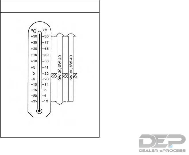
based on the temperatures at which the ve-
hicle will be operated before the next oil
change. Choosing an oil viscosity other than
that recommended could cause serious en-
gine damage.
Outside Temperature Range
Anticipated Before Next Oil Change
GASOLINE ENGINE OIL
JVT0428X
Selecting the correct oil filter
Your new vehicle is equipped with a high—
quality genuine INFINITI oil filter. When re-
placing, it is recommended you use the genu-
ine oil filter or its equivalent for the reason
described in “Change intervals”.
Change intervals
The oil and oil filter change intervals for your
engine are based on the use of the specified
quality oils and filters. Using engine oil and
filters that are not of the specified quality, or
exceeding recommended oil and filter change
intervals could reduce engine life. Damage to
engines caused by improper maintenance or
use of incorrect oil and filter quality and/or
viscosity is not covered by the new INFINITI
New Vehicle Limited Warranty.
Your engine was filled with a high quality
engine oil when it was built. You do not have
to change the oil before the first recom-
mended change interval. Oil and filter change
intervals depend upon how you use your
vehicle.
Operation under the following conditions
may require more frequent oil and filter
changes:
•Repeated short distance driving at cold
outside temperatures
•Driving in dusty conditions
•Extensive idling
•Stop and go “rush hour” traffic
Refer to the “INFINITI Service and Mainte-
nance Guide” for the maintenance schedule.
AIR CONDITIONER SYSTEM
REFRIGERANT AND OIL
RECOMMENDATIONS
The air conditioner system of your vehicle
must be charged with the refrigerant HFC-
134a and the lubricant INFINITI A/C System
Oil Type S or the exact equivalents.
10-6 Technical information

CAUTION
The use of any other refrigerant or oil may
cause severe damage to the air condition-
ing system and will require the replacement
of all air conditioner system components.
The refrigerant HFC-134a in your vehicle will
not harm the Earth’s ozone layer. However, it
may contribute in a small part to the global
warming effect.
Certain government regulations require the
recovery and recycling of any refrigerant dur-
ing automotive air conditioner system ser-
vice. An INFINITI retailer has the trained
technicians and equipment needed to recover
and recycle your air conditioner system re-
frigerant.
It is recommended that you visit an INFINITI
retailer when servicing your air conditioner
system.
Model 2.0L Gasoline
Type Gasoline, 4-cycle
Cylinder arrangement 4-cylinder in-line
Bore x Stroke in (mm) 3.268 x 3.622
(83.0 x 92.0)
Displacement cu in (cm
3)
121.55 (1,991)
Idling speed rpm
DCT in N position 700
Ignition timing (BTDC) degrees
DCT in N position -10°CA to +35°CA BTDC at
700rpm
Spark plug Standard Platinum tipped
Spark plug gap in (mm) 0.028 (0.7)
Camshaft operation Timing chain
This spark ignition system complies with the Canadian standard ICES-002.
ENGINE SPECIFICATIONS
Technical information 10-7

GT and Sport models:
Item Offset in (mm) Size
Road wheel 1.50 (38) 6.5J x 17
1.81 (46) 7.0J x 18
1.71 (43.5) 8.0J x 19
Tire size 215/60 R17 96V
235/50 R18 97V*
235/50 R18 97H* **
235/45 R19 95V*
* : Use of snow chains NOT permitted.
**: US only.
All Road models:
Item Offset in (mm) Size
Road wheel 1.61 (41) 6.5J x 17
(steel)
1.61 (41) 7.0J x 18
(alloy)
Tire size 215/60 R17 96V
235/50 R18 97V*
235/50 R18 97H* **
* : Use of snow chains NOT permitted.
**: US only.
WHEELS AND TIRES
10-8 Technical information

Dimension Model in (mm)
Overall length 174.2 (4425)
Overall width (incl. mirrors) 82.0 (2083)
Overall height GT without roof rails 58.9 (1495)
GT with roof rails 59.5 (1510)
Sport without roof rails 58.1 (1475)
Sport with roof rails 58.7 (1490)
Allroad without roof rails 58.7 (1515)
Allroad with roof rails 61.2 (1530)
Front track GT 17” wheels 61.9 (1572)
GT 18” wheels 61.3 (1556)
GT 19” wheels 61.5 (1561)
Sport 17” wheels 62 (1574)
Sport 19” wheels 61.5 (1563)
Allroad 17” wheels 61.7 (1566)
Allroad 18” wheels 61.5 (1561)
Rear track GT 17” wheels 61.9 (1573)
GT 18” wheels 61.2 (1555)
GT 19” wheels 61.7 (1566)
Sport 17” wheels 62.2 (1580)
Sport 19” wheels 61.7 (1567)
Allroad 17” wheels 62.0 (1574)
Allroad 18” wheels 61.7 (1566)
Wheelbase 106.3 (2700)
DIMENSIONS
Technical information 10-9
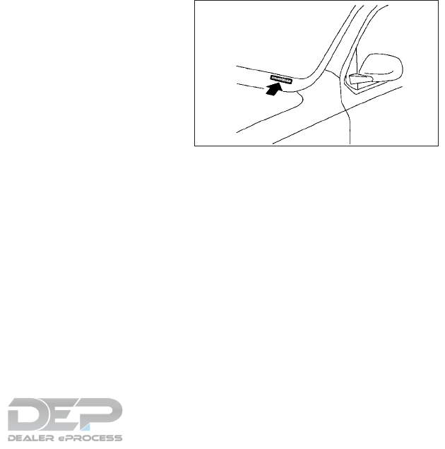
When planning to drive your INFINITI VE-
HICLE in another country, you should first
find out if the fuel available is suitable for
your vehicle's engine.
Using fuel with an octane rating that is too
low may cause engine damage. All gasoline
vehicles must be operated with unleaded
gasoline. Therefore, avoid taking your vehicle
to areas where appropriate fuel is not avail-
able.
When transferring the registration of your
vehicle to another country, state, province
or district, it may be necessary to modify the
vehicle to meet local laws and regulations.
The laws and regulations for motor vehicle
emission control and safety standards vary
according to the country, state, province or
district; therefore, the vehicle specification
may differ.
When any vehicles are to be taken into an-
other country, state, province or district, its
modification, transportation, registration,
and any other expenses which may result,
are the responsibility of the user. INFINITI is
not responsible for any inconveniences that
may result.
It is prohibited to cover, paint, weld, cut, drill,
alter or remove the Vehicle Identification
Number (VIN).
VEHICLE IDENTIFICATION
NUMBER (VIN) PLATE
The vehicle identification number plate is at-
tached as shown. This number is the identifi-
cation for your vehicle and is used in the
vehicle registration.
JVT0352XZ
WHEN TRAVELING OR
REGISTERING IN ANOTHER
COUNTRY
VEHICLE IDENTIFICATION
10-10 Technical information
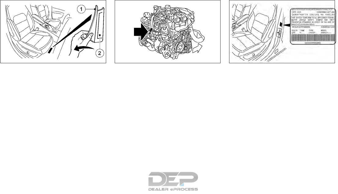
VEHICLE IDENTIFICATION
NUMBER (CHASSIS NUMBER)
The vehicle identification number is stamped
as shown.
ENGINE SERIAL NUMBER
The number is stamped on the engine as
shown.
F.M.V.S.S./C.M.V.S.S.
CERTIFICATION LABEL
The Federal/Canadian Motor Vehicle Safety
Standards (F.M.V.S.S./C.M.V.S.S.) certifica-
tion label is affixed as shown. This label con-
tains valuable vehicle information, such as:
GVWR, GAWR, month and year of manufac-
ture, VIN, etc. Review it carefully.
NTI314 NDI1621
2.0L gasoline engines
NTI324
Technical information 10-11
EMISSION CONTROL
INFORMATION LABEL
The emission control information label is at-
tached as shown.
TIRE AND LOADING
INFORMATION LABEL
The cold tire pressure is shown on the Tire
and Loading Information Label. The label is
located as shown.
AIR CONDITIONER
SPECIFICATION LABEL
The air conditioner specification label is at-
tached to the underside of the hood as
shown.
NTI323 NTI325 NTI322
10-12 Technical information

Use the following steps to mount the front
license plate:
Before mounting the license plate, confirm
that the following parts are enclosed in the
plastic bag:
Only use the recommended mounting posi-
tion, otherwise the obstruction of the Intelli-
gent Cruise Control (ICC) sensor (if so
equipped) may result.
•License plate bracket
•License plate screws x 2
•Screw grommets x 2
1) Park the vehicle on flat, level ground.
2) Locate the center position 䊊
Aas illus-
trated. Line up the license plate bracket
under the top of the front bumper with
the tabs 䊊
B. Hold the license plate bracket
in place.
3) Mark the center of the holes 䊊
Cwith a
felt-tip pen.
4) Carefully drill two pilot holes using a 10
mm (0.39 in) drill bit at the marked loca-
tions. (Be sure that the drill only goes
through the bumper fascia.)
5) Insert the grommets into the holes in the
bumper fascia.
6) Install the license plate bracket with the
provided screws.
7) Install the license plate on to the bracket
with bolts that are no longer than 14 mm
(0.55 in).
NTI327
INSTALLING FRONT LICENSE PLATE
Technical information 10-13
WARNING
•It is extremely dangerous to ride in a
cargo area inside a vehicle. In a collision,
people riding in these areas are more
likely to be seriously injured or killed.
•Do not allow people to ride in any area of
vehicle that is not equipped with seats
and seat belts.
•Be sure everyone in your vehicle is in a
seat and using a seat belt properly.
TERMS
It is important to familiarize yourself with the
following terms before loading your vehicle:
•Curb Weight (actual weight of your ve-
hicle) - vehicle weight including: standard
and optional equipment, fluids, emergency
tools, and spare tire assembly. This weight
does not include passengers and cargo.
•GVW (Gross Vehicle Weight) - curb weight
plus the combined weight of passengers
and cargo.
•GVWR (Gross Vehicle Weight Rating) -
maximum total combined weight of the
unloaded vehicle, passengers, luggage,
hitch, trailer tongue load and any other
optional equipment. This information is lo-
cated on the F.M.V.S.S./C.M.V.S.S. label.
•GAWR (Gross Axle Weight Rating) - maxi-
mum weight (load) limit specified for the
front or rear axle. This information is lo-
cated on the F.M.V.S.S./C.M.V.S.S. label.
•GCWR (Gross Combined Weight Rating) -
The maximum total weight rating of the
vehicle, passengers, cargo, and trailer.
•Vehicle Capacity Weight, Load limit, Total
load capacity - maximum total weight limit
specified of the load (passengers and
cargo) for the vehicle. This is the maximum
combined weight of occupants and cargo
that can be loaded into the vehicle. If the
vehicle is used to tow a trailer, the trailer
tongue weight must be included as part of
the cargo load. This information is located
on the Tire and Loading Information label.
•Cargo capacity - permissible weight of
cargo, the weight of total occupants
weight subtracted from the load limit.
VEHICLE LOADING INFORMATION
10-14 Technical information
VEHICLE LOAD CAPACITY
Do not exceed the load limit of your vehicle
shown as “The combined weight of occu-
pants and cargo” on the Tire and Loading
Information label. Do not exceed the number
of occupants shown as “Seating Capacity” on
the Tire and Loading Information label.
To get “the combined weight of occupants
and cargo”, add the weight of all occupants,
then add the total luggage weight. Examples
are shown in the illustration.
Steps for determining correct load
limit
1. Locate the statement “The combined
weight of occupants and cargo should
never exceed XXX kg or XXX lbs” on your
vehicle’s placard.
2. Determine the combined weight of the
driver and passengers that will be riding in
your vehicle.
3.
Subtract the combined weight of the driver
and passengers from XXX kg or XXX lbs.
4. The resulting figure equals the available
amount of cargo and luggage load capac-
ity. For example, if the XXX amount equals
1400 lbs. and there will be five 150 lb.
passengers in your vehicle, the amount of
available cargo and luggage load capacity
is 650 lbs. (1400 − 750 (5 x 150) = 650
lbs) or 640 − 340 (5 x 70) = 300 kg.)
5. Determine the combined weight of lug-
gage and cargo being loaded on the ve-
hicle. That weight may not safely exceed
the available cargo and luggage load ca-
pacity calculated in Step 4.
6. If your vehicle will be towing a trailer, load
from your trailer will be transferred to
your vehicle. Consult this manual to deter-
mine how this reduces the available cargo
and luggage load capacity of your vehicle.
STI0445
Technical information 10-15

Before driving a loaded vehicle, confirm that
you do not exceed the Gross Vehicle Weight
Rating (GVWR) or the Gross Axle Weight
Rating (GAWR) for your vehicle. (See "Mea-
surement of weights" later in this section.)
Also check tires for proper inflation pres-
sures. See the Tire and Loading Information
label.
LOADING TIPS
•The GVW must not exceed GVWR or
GAWR as specified on the F.M.V. S.S./
C.M.V.S.S. certification label.
•Do not load the front and rear axle to the
GAWR. Doing so will exceed the GVWR.
WARNING
•Properly secure all cargo to help prevent
it from sliding or shifting. Do not place
cargo higher than the seatbacks. In a
sudden stop or collision, unsecured
cargo could cause personal injury.
•Do not load your vehicle any heavier
than the GVWR or the maximum front
and rear GAWRs. If you do, parts of your
vehicle can break, tire damage could oc-
cur, or it can change the way your ve-
hicle handles. This could result in loss of
control and cause personal injury.
•Overloading could not only shorten the
life of your vehicle and the tires, but also
could cause unsafe vehicle handling and
longer braking distances. This may
cause a premature tire failure which
could result in a serious accident and
personal injury. Failures caused by over-
loading are not covered by the vehicle's
warranty.
MEASUREMENT OF WEIGHTS
Secure loose items to prevent weight shifts
that could affect the balance of your vehicle.
When the vehicle is loaded, drive to a scale
and weigh the front and the rear wheels
separately to determine axle loads. Individual
axle loads should not exceed either of the
gross axle weight ratings (GAWR). The total
of the axle loads should not exceed the gross
vehicle weight rating (GVWR). These ratings
are given on the vehicle certification label. If
weight ratings are exceeded, move or remove
items to bring all weights below the ratings.
Your vehicle was designed to be used to carry
passengers and luggage
CAUTION
Do not tow a trailer with your vehicle.
TRAILER TOWING
10-16 Technical information

DOT (Department Of Transportation) Qual-
ity Grades: All passenger car tires must con-
form to federal safety requirements in addi-
tion to these grades.
Quality grades can be found where appli-
cable on the tire sidewall between tread
shoulder and maximum section width. For
example:
Treadwear 200 Traction AA Temperature A
TREADWEAR
The treadwear grade is a comparative rating
based on the wear rate of the tire when
tested under controlled conditions on a
specified government test course. For ex-
ample, a tire graded 150 would wear one and
one-half (1 1/2) times as well on the govern-
ment course as a tire graded 100. The rela-
tive performance of tires depends upon ac-
tual conditions of their use, however, and
may depart significantly from the norm due
to variations in driving habits, service prac-
tices and differences in road characteristics
and climate.
TRACTION AA, A, B AND C
The traction grades, from highest to lowest,
are AA, A, B and C. Those grades represent
the tire’s ability to stop on wet pavement as
measured under controlled conditions on
specified government test surfaces of as-
phalt and concrete. A tire marked C may have
poor traction performance.
WARNING
The traction grade assigned to this tire is
based on straight-ahead braking traction
tests, and does not include acceleration,
cornering, hydroplaning, or peak traction
characteristics.
TEMPERATURE A, B AND C
The temperature grades A (the highest), B,
and C, representing the tire’s resistance to
the generation of heat and its ability to dissi-
pate heat when tested under controlled con-
ditions on a specified indoor laboratory test
wheel. Sustained high temperature can cause
the material of the tire to degenerate and
reduce tire life, and excessive temperature
can lead to sudden tire failure. The grade C
corresponds to a level of performance which
all passenger car tires must meet under the
Federal Motor Vehicle Safety Standard No.
109. Grades B and A represent higher levels
of performance on the laboratory test wheel
than the minimum required by law.
WARNING
The temperature grade for this tire is es-
tablished for a tire that is properly inflated
and not overloaded. Excessive speed,
under-inflation, or excessive loading, ei-
ther separately or in combination, can
cause heat build-up and possible tire
failure.
UNIFORM TIRE QUALITY GRADING
Technical information 10-17

Your INFINITI is covered by the following
emission warranties.
For USA:
•Emission Defects Warranty
•Emissions Performance Warranty
Details of these warranties may be found
with other vehicle warranties in your War-
ranty Information Booklet that comes with
your INFINITI. If you did not receive a War-
ranty Information Booklet, or it has become
lost, you may obtain a replacement by writing
to:
•INFINITI Division
Nissan North America, Inc.
Consumer Affairs Department
P.O. Box 685003
Franklin, TN 37068-5003
For Canada:
Emission Control System Warranty
Details of these warranties may be found
with other vehicle warranties in your War-
ranty and Roadside Assistance Information
that comes with your INFINITI. If you did not
receive a Warranty and Roadside Assistance
Information, or it has become lost, you may
obtain a replacement by writing to:
•Nissan Canada Inc.
5290 Orbitor Drive
Mississauga,
Ontario, L4W 4Z5
For USA:
If you believe that your vehicle has a defect
which could cause a crash or could cause
injury or death, you should immediately in-
form the National Highway Traffic Safety
Administration (NHTSA) in addition to noti-
fying INFINITI.
If NHTSA receives similar complaints, it may
open an investigation, and if it finds that a
safety defect exists in a group of vehicles, it
may order a recall and remedy campaign.
However, NHTSA cannot become involved in
individual problems between you, your re-
tailer, or INFINITI.
To contact NHTSA, you may call the Vehicle
Safety Hotline toll-free at 1- 888- 327-4236
(TTY: 1-800-424- 9153); go to http://
www.safercar. gov; or write to: Administra-
tor, NHTSA, 400 Seventh Street, SW.,
Washington, D.C. 20590. You can also ob-
tain other information about motor vehicle
safety from http:// www.safercar.gov.
You may notify INFINITI by contacting our
Consumer Affairs Department, toll-free, at
1-800-662-6200.
EMISSION CONTROL SYSTEM
WARRANTY REPORTING SAFETY DEFECTS
10-18 Technical information

For Canada:
If you believe that your vehicle has a defect
which could cause a crash or could cause
injury or death, you should immediately in-
form Transport Canada in addition to notify-
ing INFINITI.
If Transport Canada receives complaints, it
may open an investigation, and if it finds that
a safety defect exists in a group of vehicles, it
may request that INFINITI conduct a recall
campaign. However, Transport Canada can-
not become involved in individual problems
between you, your retailer, or INFINITI.
You may contact Transport Canada’s Defect
Investigations and Recalls Division toll free at
1-800-333- 0510. You may also report
safety defects online at:
https://wwwapps.tc.gc.ca/Saf-Sec- Sur/7/
PCDB-BDPP/Index.aspx.
Additional information concerning motor ve-
hicle safety may be obtained from Transport
Canada’s Road Safety Information Center at
1-800-333- 0371 or online at
www.tc.gc.ca/roadsafety (English speakers)
or www.tc.gc.ca/securiteroutiere (French
speakers).
To notify INFINITI of any safety concerns
please contact our Consumer Information
Center toll free at 1-800- 361-4792.
WARNING
A vehicle equipped with All-Wheel Drive
(AWD) should never be tested using a two
wheel dynamometer (such as the dyna-
mometers used by some states for emis-
sions testing), or similar equipment. Make
sure you inform test facility personnel that
your vehicle is equipped with AWD before
it is placed on a dynamometer. Using the
wrong test equipment may result in trans-
mission damage or unexpected vehicle
movement which could result in serious ve-
hicle damage or personal injury.
Due to legal requirements in some states and
Canadian Provinces, your vehicle may be re-
quired to be in what is called the “ready con-
dition” for an Inspection/Maintenance (I/M)
test of the emission control system.
The vehicle is set to the “ready condition”
when it is driven through certain driving pat-
terns. Usually, the “ready condition” can be
obtained by ordinary usage of the vehicle.
If a powertrain system component is repaired
or the battery is disconnected, the vehicle
may be reset to a “not ready condition”. Be-
fore taking the I/M test, check the vehicle’s
inspection/maintenance test readiness con-
dition. Place the ignition switch in the ON
position without starting the engine. If the
Malfunction Indicator Light (MIL) comes on
steady for 20 seconds and then blinks for 10
seconds, the I/M test condition is “not ready”.
If the MIL does not blink after 20 seconds,
the I/M test condition is “ready”.
It is recommended you contact an INFINITI
retailer to set the “ready condition” or to pre-
pare the vehicle for testing.
READINESS FOR INSPECTION/
MAINTENANCE (I/M) TEST
Technical information 10-19

This vehicle is equipped with an Event Data
Recorder (EDR). The main purpose of an EDR
is to record, in certain crash or near crash-like
situations, such as an air bag deployment or
hitting a road obstacle, data that will assist in
understanding how a vehicle’s systems per-
formed. The EDR is designed to record data
related to vehicle dynamics and safety sys-
tems for a short period of time, typically 30
seconds or less. The EDR in this vehicle is
designed to record such data as:
•How various systems in your vehicle were
operating.
•Whether or not the driver and passenger
safety belts were buckled/fastened.
•How far (if at all) the driver was depressing
the accelerator and/or brake pedal.
•How fast the vehicle was traveling.
•Sounds are not recorded.
This data can help provide a better under-
standing of the circumstances in which
crashes and injuries occur.
NOTE: EDR data are recorded by your ve-
hicle only if a nontrivial crash situation occurs;
no data are recorded by the EDR under nor-
mal driving conditions and no personal data
(e.g. name, gender, age and crash location)
are recorded. However, other parties, such as
law enforcement, could combine the EDR
data with the type of personally identifying
data routinely acquired during a crash inves-
tigation.
To read data recorded by an EDR, special
equipment is required and access to the ve-
hicle or the EDR is needed. In addition to the
vehicle manufacturer and INFINITI retailer,
other parties, such as law enforcement, that
have the special equipment, can read the in-
formation if they have access to the vehicle or
the EDR. EDR data will only be accessed with
the consent of the vehicle owner or lessee or
as otherwise required or permitted by law.
Genuine INFINITI Service Manuals for this
model year and prior can be purchased. A
Genuine INFINITI Service Manual is the best
source of service and repair information for
your vehicle. This manual is the same one
used by the factory trained technicians work-
ing at INFINITI retailers. Genuine INFINITI
Owner’s Manuals can also be purchased.
For USA:
For current pricing and availability of Genuine
INFINITI Service Manuals, contact:
www.infiniti-techinfo.com For current pric-
ing and availability of Genuine INFINITI
Owner's Manuals, contact: 1-800-247-
5321
For Canada:
To purchase a copy of a Genuine INFINITI
Service Manual or Owner's Manual, for this
model year and prior, it is recommended you
contact your nearest INFINITI retailer. For
the phone number and location of an
INFINITI retailer in your area call the
INFINITI Satisfaction Center at 1-800-361-
4792 and a bilingual INFINITI representative
will assist you.
EVENT DATA RECORDERS (EDR) (IF
SO EQUIPPED) OWNER'S MANUAL/SERVICE
MANUAL ORDER INFORMATION
10-20 Technical information

11 Index
A
ABS (Anti-lock Braking System) .......2-8
Warninglight................2-8
Active sound enhancement .........5-70
Operation .................5-70
Adaptive Front lighting System.......2-67
Aids.......................5-63
Forward emergency braking system . .5-63
Hill Start Assist (HSA) ..........5-96
Intelligent Parking Assist (IPA)......5-71
Air bags ....................1-46
Front passenger air bag switch .....1-46
Overview...................0-2
Repair and replacement .........1-56
Supplemental Restraint System.....1-38
Warning light . . . . . . . . . . . .1-56, 2-12
Air cleaner filter ................8-13
Air conditioner ................4-43
Heater and air conditioner........4-43
Refrigerant and lubricant . . . . . . . .10-6
Servicing ..................4-52
Specification label ............10-12
Air fresheners ..................7-4
Anti-theft alarm system ...........2-59
AppGarage.................4-100
Screen...................4-100
Settings screen. . . . . . . . . . . . . .4-101
Around View Monitor ............4-25
Moving object detection (MOD) ....4-38
Settings...................4-34
Audible reminders ..............2-14
Audio ......................4-53
Operation precautions ..........4-53
Settings...................4-82
Source bar .................4-66
System...................4-53
Automatic transmission ............8-7
Fluid (ATF) ..................8-7
Operation .................5-20
B
Battery......................8-9
Caution label ................8-9
Cold weather................5-97
Jump-starting ...............6-10
Replacement - Intelligent Key......8-20
Saver system................2-87
Vehicle battery ..............8-10
Blind Spot Warning (BSW) system.....5-36
Bluetooth®..................4-85
Hands-Free Phone System. . .4-85, 4-132
Information ................4-98
Streaming audio .............4-131
Boosterseats.................1-35
Precautions.................1-35
Brakes .....................8-17
ABS (Anti-Lock Braking System) . . . .5-92
Adjustment .................8-17
Fluid......................8-7
F
orward emergency braking system . . .5-63
Parking brake ...............5-27
Precautions.................5-91
System...................5-91
Warninglight................2-9
Break-in schedule ..............5-85
Brightness...................2-70
Instrument panel .............2-70
C
Capacities and recommendations .....10-2
Coolant ...................10-2
Fuel.....................10-2
Oil......................10-2
Refrigerant.................10-2
Cardholder..................2-80
Center multi-function control panel .....4-2
Changing ....................8-4
Engine coolant ...............8-4
Engine oil...................8-5
Engine oil filter ...............8-6
Tires and wheels .............8-34

Checking .....................8-4
Coolant level .................8-4
Engine oil level ................8-5
Child restraints .................1-19
Anchorage ..................1-23
ISOFIX installation .............1-24
Precautions .................1-20
Childsafety...................1-17
Rear door locks ................3-7
Cleaning......................7-3
Alloy wheels..................7-3
Chromeparts.................7-3
Exterior ....................7-2
Glass......................7-3
Interior.....................7-4
Leatherseatcovers.............7-6
Removing spots ...............7-3
Seat belts ...................7-5
Underbody ..................7-3
Washing ....................7-2
Waxing.....................7-2
Clock.......................2-77
Adjusting time................2-77
Coat hooks ...................2-81
Cockpit......................0-6
Overview ................0-6,2-2
Cold weather ..................5-97
Battery....................5-97
Driving on snow or ice. . . . . . . . . . .5-98
Engine coolant ...............5-97
Precautions .................5-97
Special equipment .............5-98
Tire equipment ...............5-97
Compact Disc (CD) ..............4-71
Player ................4-71,4-127
Compartment .................2-87
Connecting ...................4-90
Bluetooth® device .............4-90
Bluetooth® Hands-Free Phone .....4-88
Coolant .....................10-2
Capacities ..................10-2
Changing engine coolant ..........8-4
Checking coolant level ...........8-4
Cold weather ................5-97
Engine cooling system ...........8-3
Temperature gauge .............2-6
Corrosion protection . . . . . . . . . . . . . .7-7
Environmental factors ............7-7
Cruisecontrol .................5-46
Canceling ..................5-48
Operation ..................5-47
Cupholders ..................2-80
Customer assistance ............4-124
D
Defroster....................2-63
Switch ....................2-63
Dimensions...................10-9
Engine ....................10-7
Tires.....................10-8
Display .....................2-70
Brightness..................2-70
Vehicle information display ........2-15
Warnings and indicators . . . . . . . . .2-29
Doors .......................3-7
Liftgate....................3-7
Locking key ..................3-5
Locks .....................3-4
Map pocket .................2-83
Drive belts....................8-12
Driving......................5-20
Automatic Transmission .........5-20
Coldweather................5-97
Idle Stop/Start System ..........5-29
Onsnoworice...............5-98
Precautions..................5-4
E
Emergency key..................3-2
Engine ......................5-18
Before starting ...............5-18
Changing engine coolant ..........8-4
Changing engine oil .............8-5
Changing oil filter ..............8-6
Checking coolant level ...........8-4
Checking engine oil level ..........8-5
Coldweather................5-97
Compartment .............0-9,8-3
Coolingsystem................8-3
11-2 Index

Data.....................10-7
Oil .......................8-5
Serial number ...............10-11
Spark plugs .................8-13
Starting ...................5-18
Event data recorders (EDR) ........10-20
Exhaust gas ...................5-4
Precautions ..................5-4
Exterior......................7-2
Cleaning ....................7-2
Lights ....................8-22
Overview ...................0-3
Exterior rear view mirrors ..........3-18
F
Filter .......................8-13
Air cleaner ..................8-13
Engine Oil ...................8-6
Flat tire ......................6-2
Floormats....................7-5
Fluids......................10-2
Air conditioner ...............10-2
Automatic transmission fluid (ATF) ....8-7
Brake......................8-7
Coolant ....................8-3
Engine Oil ...................8-5
Recommendations and capacities ....10-2
Window washer ...............8-8
Foglights....................2-70
Bulbinformation..............8-22
Location ...................2-70
Forward emergency braking system ....5-63
Limitations..................5-67
Four-wheel drive ...............5-87
Freeing trapped vehicle ............6-15
Fuel.......................10-2
Capacities ..................10-2
Filler cap ...................3-16
Filler lid ....................3-16
Gauge .....................2-7
Fuel economy .................5-87
Fuel efficient driving tips ...........5-86
Fuses ......................8-17
Engine compartment............8-17
Passenger compartment .........8-18
G
Gasoline......................2-7
Gauge .....................2-7
Gauges ......................2-6
Engine coolant temperature ........2-6
Fuel.......................2-7
Meters and gauges .............2-4
Speedometer .................2-5
Tachometer ..................2-6
Glass........................7-3
Cleaning ....................7-3
Glassroof....................2-76
Sunshade operation ............2-76
Glovebox....................2-79
H
Hazard ......................6-2
Warning flasher switch ...........6-2
Headlights ...................8-25
Bulb replacement..............8-25
Replacement (bulb) ............8-24
Switch ....................2-64
Head restraints/Headrests ..........1-7
Adjustment ..................1-8
Installation ..................1-9
Removal....................1-8
Heatedseats..................2-72
Operation ..................2-72
Precautions.................2-72
Heater and air conditioner ..........4-43
Hill Start Assist (HSA).............5-96
HomeLink® Universal Transceiver .....2-88
Ifyourvehicleisstolen...........2-91
Operating ..................2-91
Programming ................2-88
Troubleshooting ..............2-90
Hood.......................3-15
Closing....................3-15
Engine compartment .........0-9,8-3
Opening ...................3-15
Index 11-3

Hooks ......................2-81
Horn.......................2-71
I
Idle Stop/Start System ............5-29
Ignition .....................5-15
Switch.................5-15,5-16
Switch positions ..............5-15
Indicatorlights.................0-10
Overview ...............0-10,2-8
Indicators....................2-29
Vehicle information display ........2-29
INFINITI ....................4-98
InTouch Apps overview ..........4-98
INFINITI Controller . . . . . . . . . . . . . . .4-2
Information menu ..............4-117
Settings...................4-122
Injuredpersons.................1-13
Inspection ...................10-19
Test.....................10-19
Instrument panel ................0-7
Overview ................0-7,2-3
Intelligent Cruise Control (ICC) system. . .5-49
Intelligent Key .................8-20
Battery replacement............8-20
Intelligent Parking Assist (IPA) ........5-71
Precautions .................5-71
Interior ......................7-4
Cleaning ....................7-4
Lights — Operation.............2-86
Overview...................0-5
Interior rear view mirror ...........3-18
Interior rear view mirrors ...........3-18
iPod player ..................4-129
ISOFIX......................1-24
Installation..................1-24
J
Jump starting .................6-10
K
Keys .....................3-2,3-8
Emergency key ................3-2
Intelligent Key battery replacement . . .8-20
Locking....................3-5
L
Labels .....................10-12
Air conditioner...............10-12
Battery.....................8-9
Chassis number ..............10-11
Tires.....................10-12
Lane Departure ................5-33
Limitations .................5-33
Warning(LDW)...............5-31
Lights......................8-22
Adaptive Front lighting System .....2-67
Bulbinformation..............8-22
Fog light switch ..............2-70
Frontfoglights...............2-70
Headlights ..............2-64, 8-24
Interior....................2-86
LED headlight ...............8-24
Locations..................8-22
Luggage compartment ..........2-87
Maplights..................2-86
Rearfoglights ...............2-71
Rear personal lights ............2-87
Rearroomlight...............2-87
Vanity mirror lights .............2-87
Warning/Indicator lights . . . . . .0-10, 2-8
Loading information.............10-14
Locks .......................3-7
Childsafety..................3-7
Door locks...................3-4
Liftgate....................3-7
Locking inside lock knob ..........3-6
Locking key ..................3-5
Locking power door lock switch......3-6
Steeringlock.................5-15
Unlocking inside door handle........3-6
11-4 Index

M
Maintenance ...................9-2
General maintenance .........9-2,9-5
Log......................9-15
Precautions ..................8-2
Requirements .................9-2
Schedules ...................9-7
Seat belts ..................1-16
Standard maintenance ..........9-10
Maplights ...................2-86
Meters and gauges ...............2-4
Engine coolant temperature ........2-6
Fuel.......................2-7
Overview ...................0-8
Speedometer .................2-5
Tachometer ..................2-6
Mirrors .....................3-18
Anti-glare rear view mirror ........3-18
Exterior rear view mirrors .........3-18
Interior rear view mirrors .........3-18
Vanity mirror ................3-18
Vanity mirror lights .............2-87
Mobile Apps .................4-104
Monitorsystem................4-135
Troubleshooting .............4-135
Moving object detection (MOD) ......4-38
O
Oil........................10-2
Capacities and recommendations ....10-2
Changing engine oil .............8-5
Changing engine oil filter ..........8-6
Checking engine oil level ..........8-5
Overheating ..................6-13
Engine ....................6-13
Engine coolant temperature gauge ....2-6
Overview .....................0-6
Cockpit .................0-6,2-2
Engine compartment .........0-9,8-3
Exterior....................0-3
Interior.....................0-5
Seats, Seat belts, Supplemental restraint
system .....................0-2
P
Parcelshelf...................2-84
Installation .................2-84
Removal ...................2-84
Parking.....................5-88
Brake.....................5-27
Parking sensor system ...........5-76
Sonar function ...............5-76
Parkingsensors................5-82
OFF switch .................5-82
Phone ......................4-88
Duringacall.................4-89
Favorites...................4-97
Makingacall................4-88
Phonebook .................4-97
Receiving a call ...............4-89
Selection...................4-88
Settings...................4-94
Power .......................3-6
Door lock switch ...............3-6
Outlet ....................2-78
Seat adjustment ...............1-3
Steering...................5-90
Windows...................2-73
Precautions...................4-53
Audio.....................4-53
Boosterseats................1-35
Brake.....................5-91
Childrestraints...............1-20
Intelligent Parking Assist (IPA) ......5-71
Maintenance .................8-2
Safety.....................4-2
Seat belt usage ...............1-10
Starting and driving .............5-4
Supplemental Restraint System .....1-38
Tire Pressure Monitoring System
(TPMS).....................5-5
Pregnant women................1-12
Protection ....................7-7
Corrosion...................7-7
Index 11-5

Push-button ignition .............5-16
Push-starting ..................6-12
R
Rear seats ....................1-5
Folding.....................1-6
RearView monitor ...............4-17
Maintenance ................4-25
Repairing ....................8-24
Headlights..................8-24
Replacement ..................1-56
Air bags ...................1-56
Air cleaner filter...............8-13
Engine coolant ................8-4
Engine oil ...................8-5
Engine oil filter ................8-6
Intelligent Key battery...........8-20
Spark plugs .................8-13
Tires and wheels ..............8-34
Wiper blades ................8-13
Roof .......................2-76
Glass.....................2-76
Sunshade operation ............2-76
Roof Rack ...................2-84
S
Safety......................1-17
Children ...................1-17
Child safety rear door locks ........3-7
Head restraints ................1-7
Injuredpersons...............1-13
Precautions..................4-2
Pregnant women ..............1-12
Reporting safety defects ........10-18
Seat belts ................1-10,1-13
Adjustment .................1-16
Children-Infants..............1-18
Children-Larger..............1-18
Children - Small ...............1-18
Childsafety.................1-17
Cleaning ....................7-5
Maintenance ................1-16
Overview...................0-2
Precautions.................1-10
Warninglight................2-11
Warnings...................1-13
Seats .......................1-2
Adjustment ..................1-3
Adjustment (Manual) ............1-3
Boosterseats................1-35
Head restraints ................1-7
Heating....................2-72
Leather ....................7-6
Memory ...................3-21
Overview...................0-2
Rear ......................1-5
Rear seats - Folding .............1-6
Seat belts ..................1-10
Security system ................2-59
Servicing ....................4-52
Airconditioner...............4-52
Sonar function .................5-82
OFF switch .................5-82
Spark plugs ...................8-13
Information.................8-13
Replacement ................8-13
Speedometer...................2-5
Starting .....................5-18
Before starting the engine ........5-18
Engine ....................5-18
Jump-starting................6-10
Precautions..................5-4
Push-starting ................6-12
Steering.....................5-90
Power steering system ..........5-90
Steeringlock.................5-15
Steeringlock..................5-15
Steering wheel .................3-17
Adjustment .................3-17
Steering wheel controls ............4-3
Storage.....................2-79
Luggage hooks ...............2-82
Luggage net.................2-83
Map pocket .................2-83
Sunshade ....................2-76
Operation ..................2-76
Sun visors ....................3-18
Supplemental Restraint System .......1-38
Overview ...................0-2
11-6 Index

Supplemental Restraint System (SRS) ....0-2
Air bags ....................0-2
Switches....................2-70
Brightness..................2-70
Defroster ..................2-63
Foglights..................2-70
Front passenger air bag ..........1-46
Hazard warning flasher . . . . . . . . . . .6-2
Headlight ..................2-64
Ignition ....................5-15
Ignition positions ..............5-15
Parking brake ................5-27
Parking sensor system...........5-82
Power door lock ...............3-6
Push-button ignition ............5-16
Seat......................3-21
Seat adjustment ...............1-3
Sonar function ...............5-82
Turn signal..................2-66
Windshield de-icer . . . . . . . . . . . . .2-63
Wiperandwasher.............2-60
T
Tachometer ...................2-6
Three-way catalyst . . . . . . . . . . . . . . .5-4
Precautions ..................5-4
Tire chains ...................8-32
Tires.......................8-34
Changing ..................8-34
Cold weather ................5-97
Equipment ..................5-97
Flat tire ....................6-2
Inflation pressure. . . . . . . . . . . . . .8-27
Placard...................10-12
Quality grading ..............10-17
Sizes.....................10-8
tire chains ..................8-32
Wear and damage .............8-33
Wheel balance ...............8-35
Wheels and tires ..........8-27,10-8
Touch panel ...................4-4
Operation ...................4-4
Towing .....................6-14
Recommendations .............6-14
Your vehicle .................6-14
Trailer.....................10-16
Towing ...................10-16
Transferring registration to another
country ....................10-10
Transmission ..................5-20
Automatic Transmission (AT)
operation ..................5-20
Automatic transmission fluid (ATF) ....8-7
Traveling ...................10-10
Turn signal ...................8-22
Bulbinformation..............8-22
Operation ..................8-22
U
USB connection .................4-4
V
Vanity mirror ..................3-18
Lights.....................2-87
Vehicle.....................4-102
Apps Manager ..............4-102
Vehicle Dynamic Control (VDC) .......5-93
Vehicle identification ............10-10
Air conditioner label ...........10-12
Engine serial number ...........10-11
Number (VIN) (chassis number).....10-11
Number (VIN) plate ...........10-10
Tire and loading information label . . .10-12
Vehicle Immobilizer system..........5-14
Vehicle information display..........2-15
Warnings and indicators . . . . . . . . .2-29
Vehicle loading information ........10-14
Ventilators ...................4-42
Voice Recognition system .........4-105
Command list ...............4-109
Giving voice commands .........4-106
Settings...................4-116
Voice recognition system ..........4-136
Troubleshooting .............4-136
Voice Recognition system .........4-107
Voice command screen .........4-107
Index 11-7

W
Warning lights . . . . . . . . . . . . . .0-10, 2-8
Airbag....................1-56
Warnings....................2-29
Vehicle information display ........2-29
Warranty...................10-18
Emission control system.........10-18
Washing .....................7-2
Waxing ......................7-2
Wheel lock bolts .................6-9
Wheels .....................8-35
Balancing ..................8-35
Blocking....................6-5
Care......................7-3
Changing tires and wheels ........8-34
Installation..................6-8
Removal ....................6-6
Sizes.....................10-8
Wheel lock bolts ...............6-9
Wheels and tires ..........8-27,10-8
Windows ....................2-73
Window washer.................8-8
Fluid......................8-8
Windshield...................2-63
Defroster ..................2-63
De-icer switch ...............2-63
Wiper and washer switch .........2-61
Winter......................5-97
Battery....................5-97
Driving on snow or ice. . . . . . . . . . .5-98
Engine coolant ...............5-97
Precautions.................5-97
Special equipment .............5-98
Tire equipment ...............5-97
Wipers......................8-13
Blade replacement . . . . . . . . . . . . .8-13
Rear - Operation ..............2-62
Washer nozzle ...............8-14
Wiper and washer switch. . . . .2-60, 2-61
11-8 Index

FUEL INFORMATION
Gasoline engine
CAUTION
Do not use leaded gasoline. Using leaded
gasoline will damage the three-way
catalyst.
2.0L gasoline engine model:
Use unleaded premium gasoline with an oc-
tane rating of at least 91 AKI (Anti-Knock
Index) number (Research octane number 95).
If unleaded premium gasoline is not available,
unleaded regular gasoline with an octane rat-
ing of at least 89 AKI number (Research oc-
tane number 93) may be temporarily used,
but only under the following precautions:
•Have the fuel tank filled only partially with
unleaded regular gasoline, and fill up with
unleaded premium gasoline as soon as
possible.
•Avoid full throttle driving and abrupt ac-
celeration.
Use unleaded premium gasoline for maxi-
mum vehicle performance.
CAUTION
•Using a fuel other than that specified
could adversely affect the emission con-
trol system, and may also affect war-
ranty coverage.
•Under no circumstances should a leaded
gasoline be used, because this will dam-
age the three-way catalyst.
•Do not use E-15 or E-85 fuel in your
vehicle. Your vehicle is not designed to
run on E-15 or E-85 fuel. Using E-15 or
E- 85 fuel in a vehicle not specifically
designed for E-15 or E-85 fuel can ad-
versely affect the emission control de-
vices and systems of the vehicle. Dam-
age caused by such fuel is not covered by
the INFINITI new vehicle limited war-
ranty.
•U.S. government regulations require
ethanol dispensing pumps to be identi-
fied by a small, square, orange and black
label with the common abbreviation or
the appropriate percentage for that
region.
RECOMMENDED ENGINE OIL
See "Recommended fluids/lubricants and ca-
pacities" in the "9. Maintenance and Sched-
ules" section.
TIRE COLD PRESSURE
See the tire and loading information label
affixed to the driver’s side center pillar.
GASOLINE STATION INFORMATION

•In case of emergency ... 6-2
(Flat tire, engine will not start, overheat-
ing, towing)
•How to start the engine ... 5-18
•How to read the meters and gauges ... 2-4
•Maintenance and do-it-yourself ... 8-2
•Technical information ... 9-2
QUICK REFERENCE

H15-D
Printing : March 2017
Publication No.:
Printed in the U.S.A.
OM18E0 0H15U0
