215793R2_E & F Series Single Double Service Cascade 215793R2 E&F SDService
User Manual: Cascade Single
Open the PDF directly: View PDF ![]() .
.
Page Count: 50
- Front Cover
- Contents
- Introduction, Section 1
- Installation. Section 2
- Periodic Maintenance, Section 3
- Troubleshooting, Section 4
- Service, Section 5
- Specifications, Section 6
- Back Cover

Cascade is a Registered Trademark of Cascade Corporation
cascade
corporation
ERVICE MANUAL
S
E & F-Series
Single-Double Pallet Handler
Manual Number 215793-R2

ONTENTS
C
i215793-R2
Page
INTRODUCTION, Section 1 1
Introduction 1
Special Definitions 1
INSTALLATION, Section 2 2
Truck System Requirements 2
Recommended Hydraulic Supply Options 3
Installation Procedures 4
PERIODIC MAINTENANCE, Section 3 11
TROUBLESHOOTING, Section 4 12
General Procedures 12
Plumbing 13
Hosing Diagram 13
Circuit Schematic 13
Fork Position Function 14
Sideshift Function 15
Electrical Circuit 16
SERVICE, Section 5 17
Attachment Removal 17
Forks 18
Outer Fork Removal 18
Inner Fork Removal 19
Outer Fork Bearing Service 22
Inner Fork Bearing Service 22
Fork Tip Alignment 23
Inner Fork Shimming 24
Sideshift Cylinder - Center Mount 25
Cylinder Removal 25
Cylinder Disassembly 26
Cylinder Inspection 26
Cylinder Reassembly 27
Sideshift Cylinder - Top Mount 28
Cylinder Removal 28
Cylinder Disassembly 29
Cylinder Inspection 29
Cylinder Reassembly 30
Fork Position Cylinders 31
Cylinder Removal 31
Cylinder Disassembly 32
Cylinder Inspection 33
Cylinder Reassembly 34
Valve and Manifold 36
Valve Removal 36
Valve Service 36
Manifold Service 38
Valve Relief Adjustment 39
Base Unit 40
Sideshift Bearing Service 40
Lower Mounted Gas Cylinder Service 41
Upper Mounter Gas Sylinder Service 42
Inner Fork Control (IFC) 42
Spring Cylinder Service 43
SPECIFICATIONS, Section 6 44
Hydraulics 44
Auxiliary Valve Functions 44
Truck Carriage 44
48E/55E/60E Torque Values 45
70E/80E Torque Values 46
58F/55F/60F Torque Values 47

NTRODUCTION
I
215793-R2 1
1.1 Introduction
This Manual provides the Installation, Periodic
Maintenance, Troubleshooting, Service and Specifications
for Cascade E and F Series Single-Double Pallet Handlers.
These attachments are designed for three-shift-a-day
continuous-duty operations with minimal maintenance.
They offer exceptional visibility for the lift truck driver and
provide optimized load handling.
In any communication about the attachment, refer to the
product I.D. number stamped on the nameplate as shown.
If the nameplate is missing, the numbers can be found
stamped on the right front web of the baseplate.
IMPORTANT: All hoses, tubes and fittings on these
attachments are JIC.
NOTE: Specifications are shown in both inch and (Metric)
units.
1.2 Special Definitions
The statements shown appear throughout this Manual
where special emphasis is required. Read all WARNINGS
and CAUTIONS before proceeding with any work.
Statements labeled IMPORTANT and NOTE are provided
as additional information of special significance or to make
your job easier.
WARNING - A statement preceded by
WARNING is information that should be
acted upon to prevent bodily injury. A
WARNING is always inside a ruled box.
Nameplate
S/N 55F-FDS-357-S-00001
MAXIMUM STRUCTURAL CAPACITY
OF ATTACHMENT ONLY IS:
CATALOG
NUMBER
SERIAL
NUMBER
ADDITIONAL
EQUIPMENT SYSTEM PRESSURE
PSI
BAR
INCH
LOAD
CENTER
mm
LOAD
CENTER
LBS
AT
Kg
AT
R
E
C
M
A
X
M
A
X
R
E
C
cascade� corporation
WEIGHT
Kg
FOR TECHNICAL ASSISTANCE CONTACT:
SERVICE: 1-800-227-2233 PORTLAND, OREGON USA
PARTS: 1-888-227-2233 SPRINGFIELD, OHIO USA
667635R6
CAPACITY OF TRUCK AND ATTACHMENT COMBINATION MAY BE LESS
THAN ATTACHMENT CAPACITY SHOWN ABOVE.
CONSULT TRUCK NAMEPLATE.
WEIGHT
LBS.
55F-FDS-357-S-0001
SD0634.eps
CAUTION - A statement preceded by CAUTION is
information that should be acted upon to prevent
machine damage.
IMPORTANT - A statement preceded by IMPORTANT is
information that possesses special significance.
NOTE - A statement preceded by NOTE is information that
is handy to know and may make your job easier.
2215793-R2
NSTALLATION
I
GA0082.eps
GA0080.eps
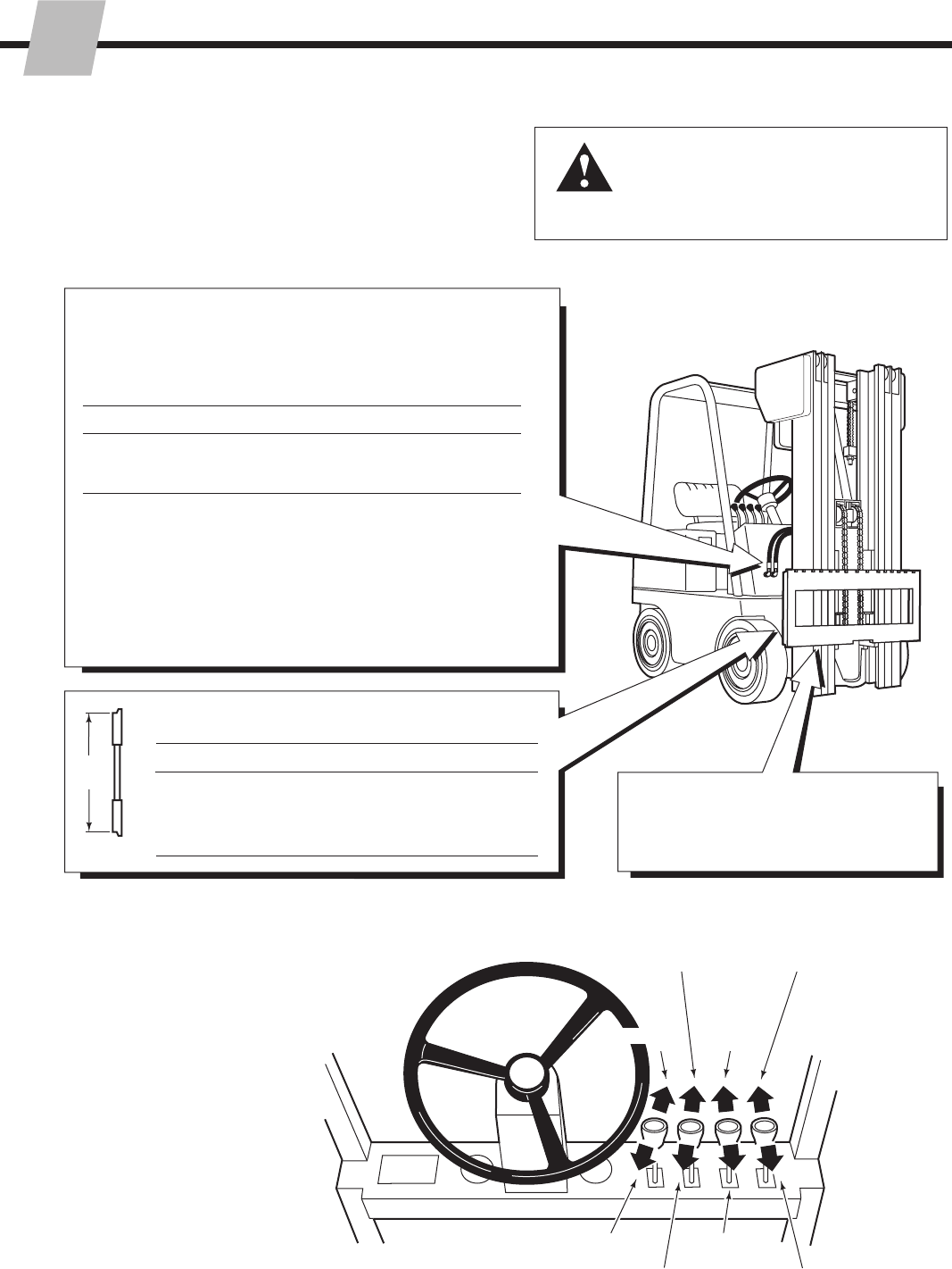
WARNING: Rated capacity of the truck/
attachment combination is a responsibility
of the original truck manufacturer and may
be less than that shown on the attachment
nameplate. Consult the truck nameplate.
Carriage
Clean carriage bars and inspect for
damaged notches.
Minimum Maximum
Auxiliary Valve Functions
Check for compliance with ANSI standards:
Carriage Mount Dimension (A) ITA (ISO)
Class II 14.96 in. (380.0 mm) 15.00 in. (381.0 mm)
Class III 18.68 in. (474.5 mm) 18.74 in. (476.0 mm)
Class IV 23.44 in. (595.5 mm) 23.50 in. (597.0 mm)
Hoist down
Tilt
forward
Sideshift
Left
Spread
Forks
Hoist up
Tilt
back
Sideshift
Right
Retract
Forks
2.1 Truck System
Requirements
The Single-Double Pallet Handler will provide maximum
operating efficiency and capability when the following
requirements are met.
Truck Relief Setting
2300 psi (160 bar) Recommended
2600 psi (180 bar) Maximum
Truck Flow Volume ➀
Min. ➁ Recommended Max. ➂
E-Series, 4 GPM 7 GPM 7 GPM
F-Series (15 L/min.) (26 L/min.) (26 L/min.)
➀ Cascade E-Series Single-Double Pallet Handlers are compatible
with SAE 10W petroleum base hydraulic fluid meeting Mil. Spec.
MIL-0-5606 or MIL-0-2104B. Use of synthetic or aqueous base
hydraulic fluid is not recommended. If fire resistant hydraulic fluid
is required, special seals must be used. Contact Cascade.
➁ Flow less than recommended will result in reduced or unequal arm
speed.
➂ Flow greater than maximum can result in excessive heating,
reduced system performance and reduced hydraulic system life.
A
GA0028.eps
3
215793-R2
NSTALLATION
I
GA0033.eps
2.2 Recommended Hydraulic
Supply Options
AB
C
The E and F Series Single-Double Pallet Handler will operate
with any of the hydraulic supply arrangements listed below.
• All hoses and fittings for FORK POSITION and SIDESHIFT
functions should be at least No. 6 with a minimum internal
diameter of 9/32 in. (7 mm).
Refer to Cascade Hose & Cable Reel Selection Guide, Part No.
212199, to select the correct hose reel for the mast and truck.
Sideshifting
A and B
RH and LH THINLINE™ 2-port hose reel groups.
OR
C Mast double internal hose reeving group.
Solenoid Adaption
A 6-N-1 cable/hose reel group.
OR
A and C
Cable reel and single internal hose reeving group.
4215793-R2
NSTALLATION
I
cascade
®
C-675514-1
CL0097.eps
SD0068.eps
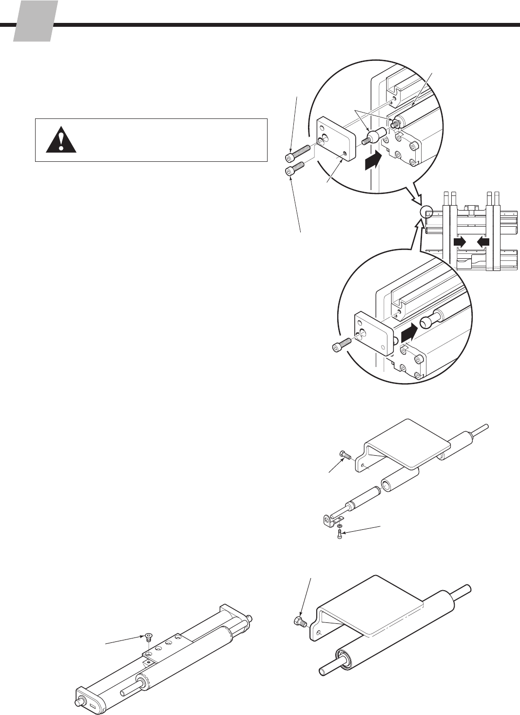
SD0069.eps
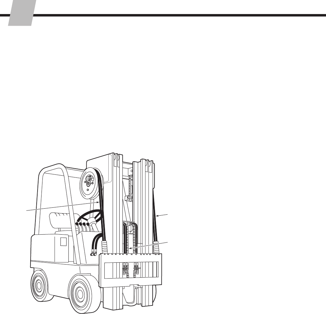
Follow the steps shown to install the Single-Double Pallet
Handler on the truck. Read all WARNINGS and CAUTIONS
carefully. If you don't understand a procedure, ask your
supervisor, or call the nearest Cascade Service Department
for assistance.
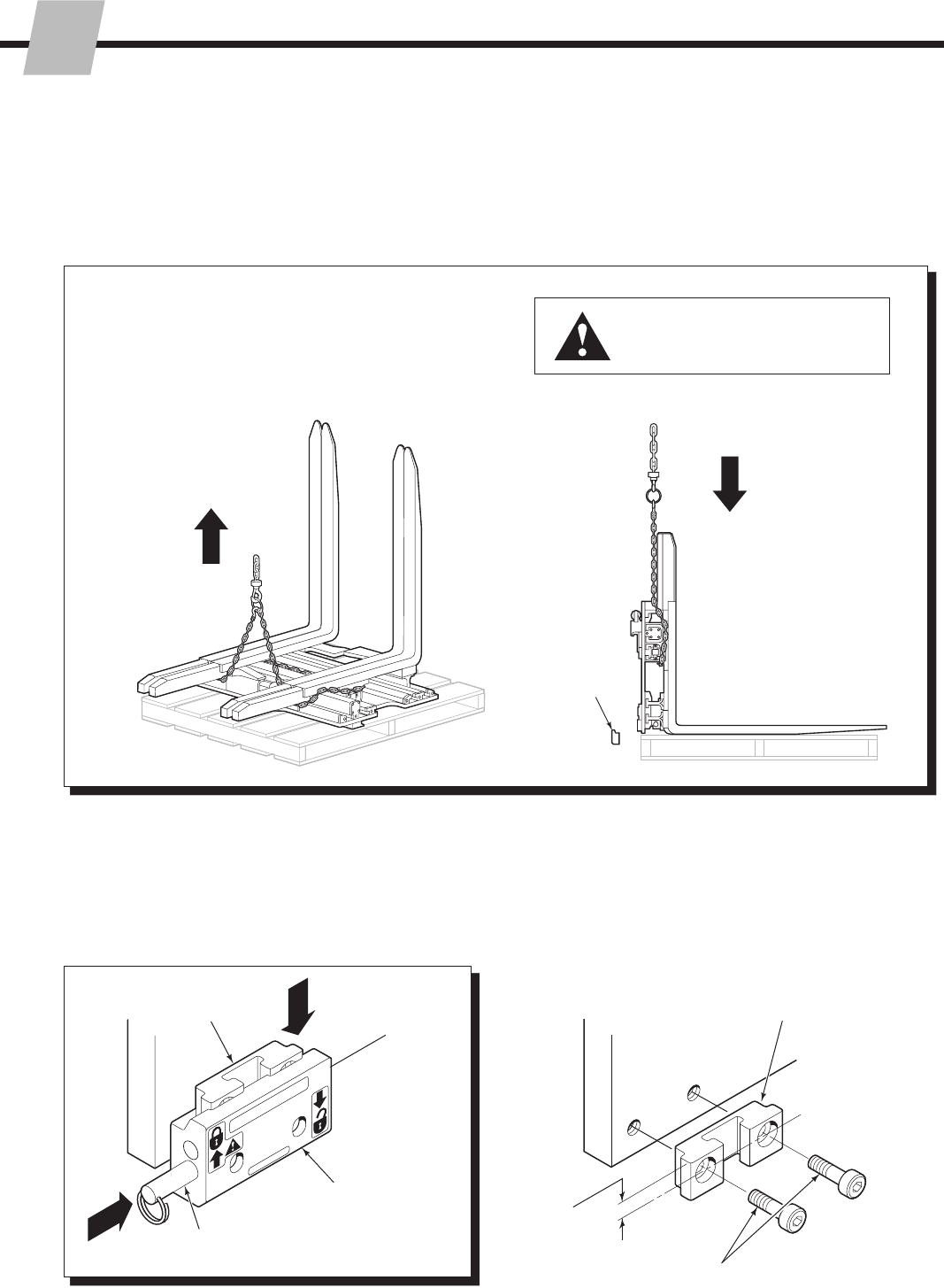
1Attach overhead hoist
A Remove banding.
B Set Attachment upright on pallet.
C Remove bolt-on lower hooks (if equipped).
WARNING: Make sure overhead
hoist has rated capacity of at least
2000 lbs. (900 kg).
2Unlock Quick-Change lower
mounting hooks
A Remove pin and drop hooks into unlocked position.
B Re-install pin in lower hole.
Tighten Capscrews to 125 ft.-lbs. (170 Nm)
Pin
LH Lower
Hook
NOTE: Guides can be reversed to
reduce hook-to-carriage clearance (See
Step 4).
5/8-in.
offset on top
provides
maximum
clearance.
Lower hooks
Guide A
B
B
C
2.3 Installation Procedures
B
5
215793-R2
NSTALLATION
I
cascade
®
C-675514-1
SD0065.eps
ADJUST
SD0066.eps
SD0071.eps
SD0493.eps
SD0489.eps
GA0035.eps
3Mount Attachment on truck
carriage
A Center truck behind attachment.
B Tilt forward and raise carriage into position.
C Engage top mounting hooks with carriage.
Make sure center locator tab engages
center notch on top carriage bar.
D Lift Attachment 2 in. (5 cm) off pallet.
BOLT-ON TYPE
(if tted)
QUICK-CHANGE TYPE
Tighten Capscrews to
120 ft.-lbs. (165 Nm)
4Install and engage lower hooks
Inspect hooks for
excessive clearance.
(Reverse guides to reduce
clearance – see Step 2.)
ITA Class II – 0.32–0.36 in. (8–9 mm)
ITA Class III – 0.39–0.43 in. (10–11 mm)
ITA Class III – 0.47–0.51 in. (12–13 mm)
B
Slide hook
up to engage
bar, install pin
in upper hole
(locked).
ITA Class II – 0.60–0.66 in. (15–17 mm)
ITA Class III – 0.72–0.78 in. (18–20 mm)
ITA Class IV – 0.72–0.78 in. (18-20 mm)
Center
Notch CC
C
Truck
Carriage
Upper
Bearings
Lower
Carriage
Bar
Lower
Carriage
Bar
A
3/16 in.
(5 mm)
max.
Tap into position.
Allow clearance for
sideshifting –
3/32 in. (2.5 mm) min.
3/16 in. (5 mm) max.
Class III shown
6215793-R2
NSTALLATION
I
SD0072.eps
SD0073.eps
SD0088.eps
SD0089.eps
SD0074.eps
SD0075.eps
5Prepare hoses
A Determine hose lengths required for hydraulic
supply configuration of truck.
B Cut hoses to length, install end fittings or
quick-disconnect kits.
CAUTION: Allow 4 in. (10 cm) extra hose length in
each direction for sideshifting movement between
Attachment valve and truck carriage.
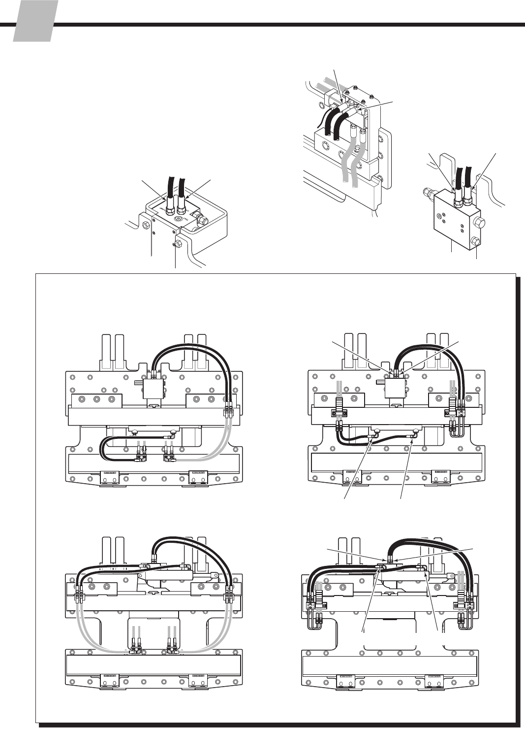
RH & LH 2-PORT THINLINE™
HOSE REELS
MAST DOUBLE INTERNAL REEVING
Class III Back
Close
Open
Close Open
Class II Back
55E CLASS II, 70E VALVE
45E, 55E CLASS III,
60E, 80E, F-SERIES
VALVE
NOTE: Attachment serial numbers
less than 55E-FD-500 use both
types of valves.
Close
Forks
Open
Forks
Sideshift Right Sideshift Left
Sideshift Right Sideshift Left
Open
Forks
Close
Forks
SD0173.eps
SOLENOID VALVE
Sideshift Left/ Open Forks
Sideshift Right/ Close Forks
55E - CLASS II
55E - CLASS III
48F/55F/65F
7
215793-R2
NSTALLATION
I
SD0172.eps
SD0171.eps
SD0492.eps
SD0491.eps
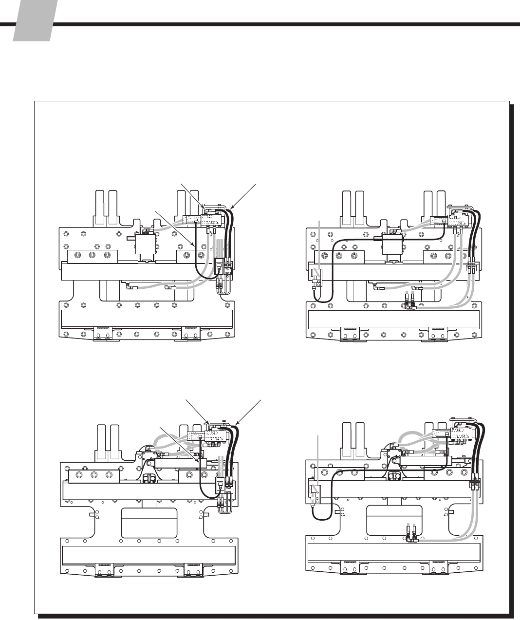
SINGLE INTERNAL HOSE
REEVING with CABLE REEL
6-N-1 CABLE / HOSE REEL
Sideshift Right/
Close Forks
Sideshift Left/
Open Forks
Solenoid
Cable
CAUTION: Allow 4 in. (10 cm) extra hose length in each
direction for sideshifting movement between solenoid valve
and truck carriage.
E-SERIES
F-SERIES
Sideshift Right/
Close Forks
Sideshift Left/
Open Forks
Solenoid
Cable
8215793-R2
NSTALLATION
I
SD0076.eps
SD0094.eps
SD0095.eps
SD0093.eps
SIDESHIFT
PRESS
BUTTON
TO POSITION
FORKS
Connect hoses as shown
in Step 5 to attachment fittings
Flush hydraulic supply hoses
A Install hoses as shown.
B Operate auxiliary valves for 30 sec.
C Remove hoses.
89
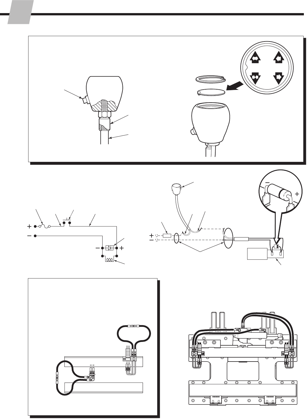
Install solenoid control knob –
(Solenoid equipped units)
6
Adapter
Truck control
valve handle
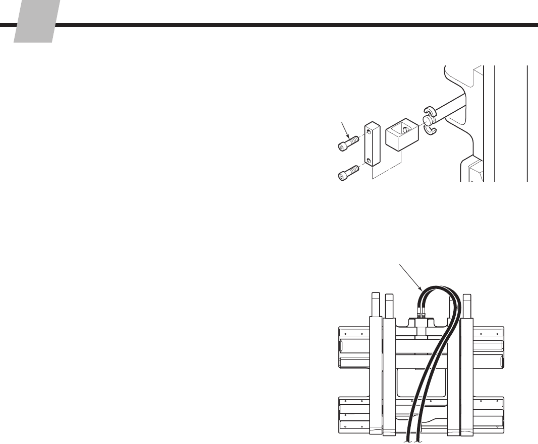
7Install wiring –
(Solenoid equipped units)
Button
toward
driver
White Black
7.5-Amp
Fuse
Solenoid
Coil
User-supplied wire
7.5-Amp
Fuse
Knob
Button
Solenoid
Coil
Diode
18-gauge wire
1/4-in. terminals
BlackWhite
Knob
GA0092.eps
9
215793-R2
NSTALLATION
I
BD
C
A
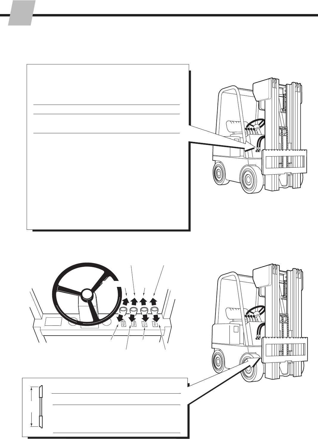
GA0005.eps
SD0064.eps
SD0064.eps
WARNING: Make sure all personnel
are clear of the attachment during
testing.
10
Auxiliary Valve Functions
Check Attachment functions
• With no load, cycle all Attachment
functions several times.
• Check for operation in accordance with
ITA (ISO) standards.
• Lift maximum load and sideshift left
and right. Check for smoothness and
adequate speed.
• Check for leaks at fittings, valve, manifold
and cylinders.
SIDESHIFTING WITH SOLENOID VALVE
A Sideshift Left
A Spread Forks (press knob button)
B Sideshift Right
B Retract Forks (press knob button)
A Sideshift Left
B Sideshift Right
C Spread Forks
D Retract Forks
SIDESHIFTING
B
AA
A
B
DC
C
A
B
Hoist down Tilt forward
Hoist up Tilt back
10 215793-R2
NSTALLATION
I
SD0490.eps
CL0623.eps
SD0501.eps
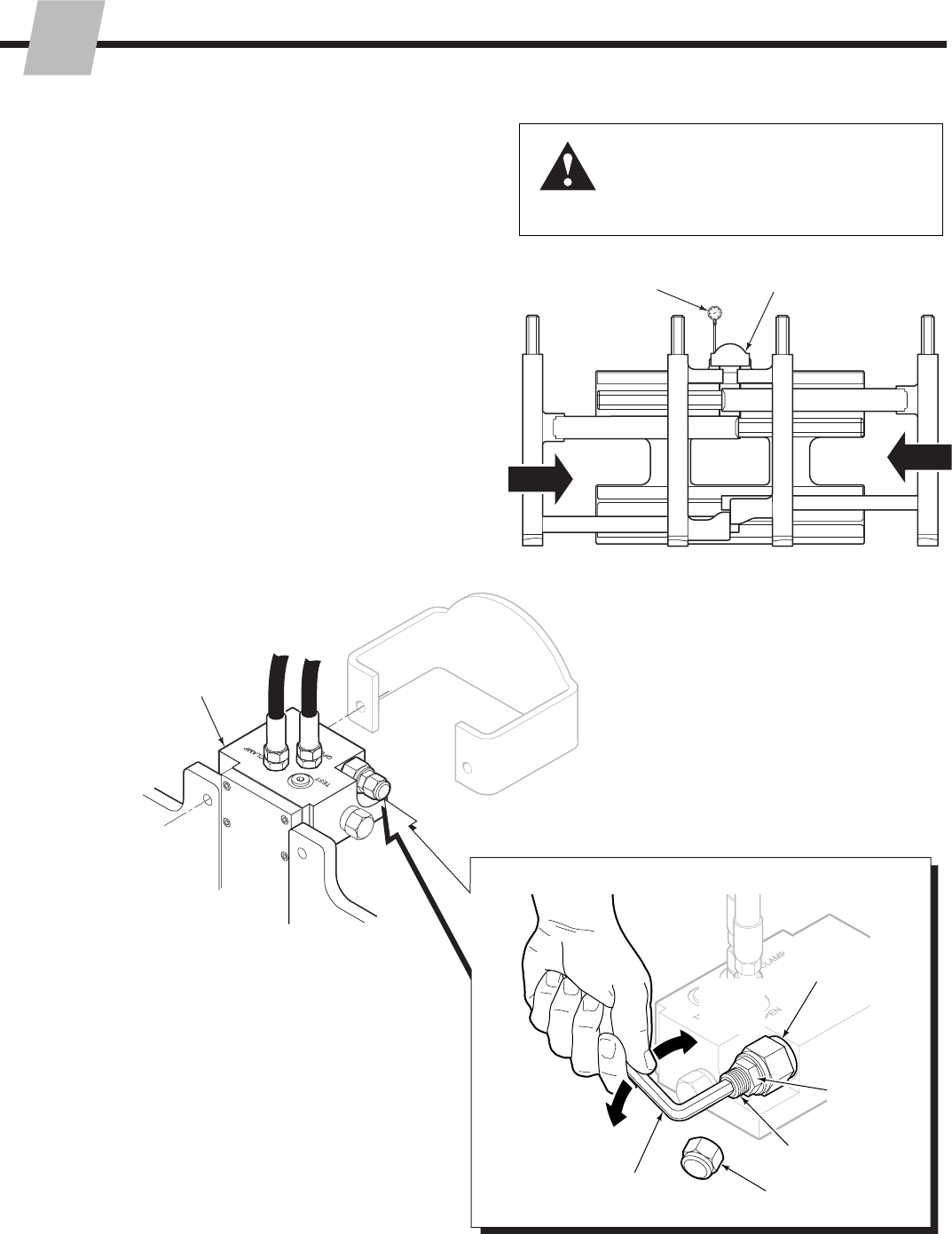
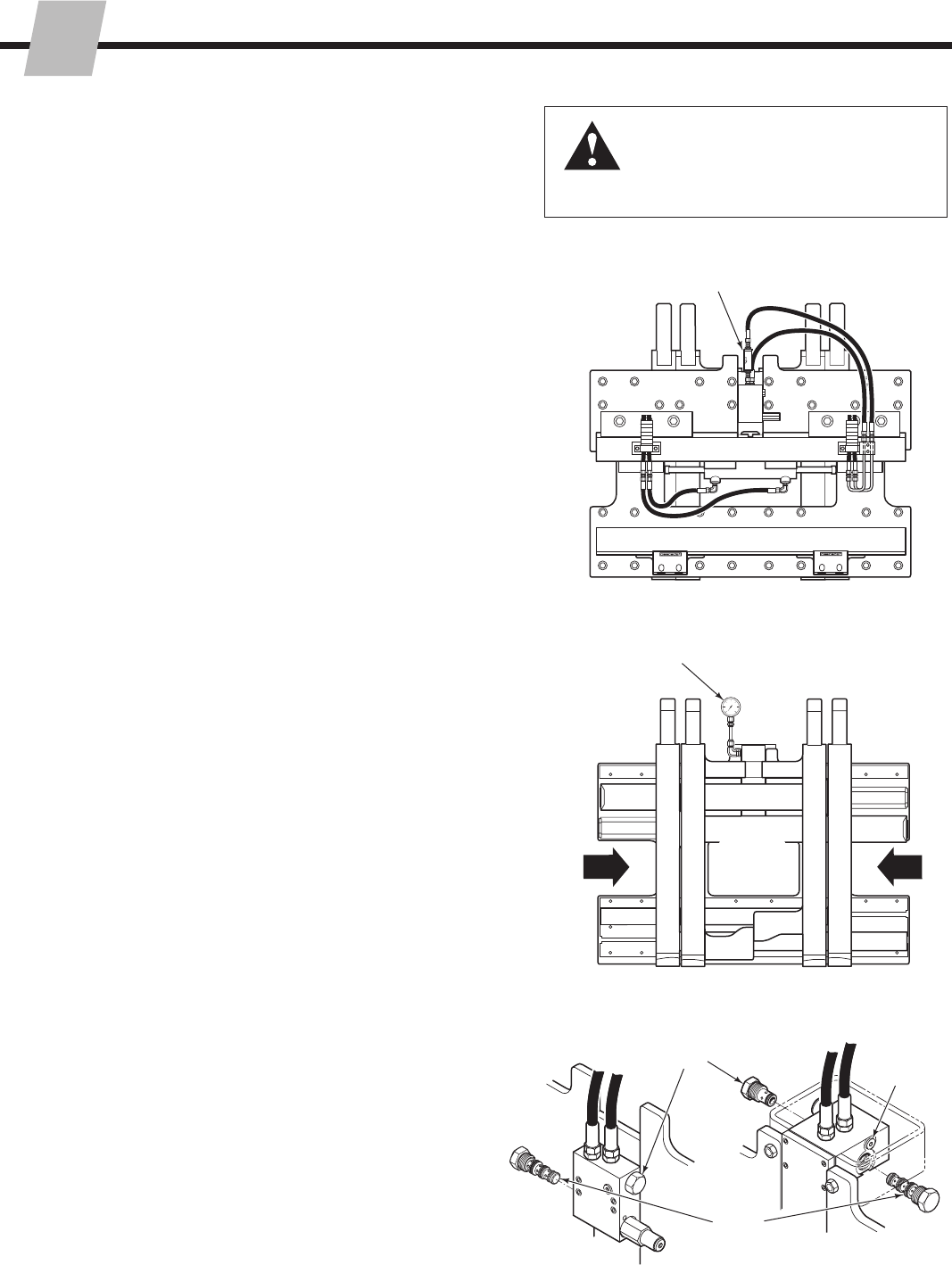
11 Adjust Relief Cartridge
For over-pressure protection, the relief valve
cartridge for the FORK POSITION function
should be adjusted to match the truck
hydraulic flow rate. MAXIMUM RELIEF VALVE
SETTING = 2600 psi (180 bar).
Fork positioning relief adjustment:
A Confirm that the truck pressure is between
2300–2600 psi (160–180 bar).
B Install a 3000-psi (200 bar) pressure gauge
on the TEST port of the main hydraulic
valve (No. 4 O-ring fitting required).
C Cycle forks to full open, then slowly close
forks fully. Hold lever in the CLOSE position
and accelerate engine to develop full
system pressure.
D Adjust the relief cartridge for an indicated
2300 psi (160 bar). Turn clockwise (CW)
to increase pressure, counterclockwise
(CCW) to decrease pressure. Tighten jam
nut and replace cap.
WARNING: Before removing hydraulic
lines or components, relieve pressure in
the hydraulic system. Turn the truck off
and open the truck auxiliary control valves
several times in both directions.
B
CC
CLASS III VALVE
Back (Driver's) View Relief Valve
Cartridge
Decrease
Pressure (CCW)
5/16-in. (8 mm)
Allen Wrench
Adjustment
Screw
Cap
Jam Nut
D
Increase
Pressure
(CW)
Front View
Valve
215793-R2
ERIODIC MAINTENANCE
P
11
SD0638.eps
SD0078.eps
WARNING: After completing maintenance
procedures, always test the Attachment
through five complete cycles. First test the
Attachment empty, then test with a load
to make sure the Attachment operates
correctly before returning it to the job.
IMPORTANT: Attachement is prelubed at the factory.
Lubrication is not required for installation. If required,
silicone spray or light grease is recommended.
3.1 100-Hour
Maintenance
Every time the lift truck is serviced or every 100 hours
of truck operation, whichever comes first, complete the
following maintenance on the attachment:
• Check for loose or missing bolts, worn or damaged
supply hoses and hydraulic leaks.
• Inspect the cylinder rod ends and anchor bars for
damage. Anchors operate with a loose clearance and
require no lubrication.
• Check for equal movement of the inner and outer forks.
3.2 500-Hour
Maintenance
After each 500 hours of truck operation, in addition to the
100-hour maintenance, perform the following procedures:
• Inspect the inner and outer fork bearing surfaces for
wear or damage. Lubricate with silicone spray or light
grease as required.
• Rock the inner forks to check for looseness. Install
shims as required. See Section 5.2-8.
• Apply chassis grease to the upper bearing grease
fittings and lower bearings.
• Check the clearance between the lower mounting hooks
and the truck carriage bar:
Quick-Change Hooks – 3/16 in. (4.8 mm) max.
Bolt-on Hooks – 3/32 in. (2.4 mm) min. and 3/16 in.
(4.8 mm) max. for sideshifting.
If adjustment is necessary, refer to Installation Step 4.
Tighten the lower hook capscrews to 125 ft.-lbs.
(170 Nm).
• Inspect the gas springs and inner fork springs for
damage or loose fasteners. Replace or tighten
fasteners as necessary.
3.3 1000-Hour
Maintenance
After each 1000 hours of truck operation, in addition to
the 100 and 500-hour maintenance, perform the following
procedures:
• Tighten the inner and outer fork capscrews to
225 ft.-lbs. (300 Nm).
• Tighten the frame capscrews to the following torque:
48, 55, 65 (E & F) – 75 ft.-lbs. (100 Nm)
70E, 80E Class III – 130 ft.-lbs. (175 Nm)
80E Class IV – 195 ft.-lbs. (265 Nm)
Upper
Mounting
Hooks Upper Bearing
Grease Fittings
Lower Mounting Hooks
Fork
Capscrews
Cylinder Rod
Ends and
Anchor Bars
Inner Fork
Bearings
Outer Fork
Bearings
Lower Bearings
Back view
Front view
Frame Capscrews
Gas Springs
(Alternate locations)
Inner Fork Springs
ROUBLESHOOTING
215793-R2
T
12
GA0013.eps
GA0014.eps
AC0127.eps
4.1 General Procedures
4.1-1 Truck System Requirements
WARNING: Before servicing any
hydraulic component, relieve pressure in
the system. Turn the truck off and move
the truck auxiliary control valves several
times in both directions.
After completing any service procedure, always
test the Attachment through several cycles.
First test the Attachment empty to bleed any air
trapped in the system to the truck tank. Then test
the Attachment with a load to be sure it operates
correctly before returning to the job.
Stay clear of the load while testing. Do not raise
the load more than 4 in. (10 cm) off the floor while
testing.
• Forks spread and close unevenly.
• Forks will not spread or close.
To correct these problems, see Section 4.3.
• Attachment will not sideshift.
• Attachment sideshifts slowly.
To correct these problems, see Section 4.4.
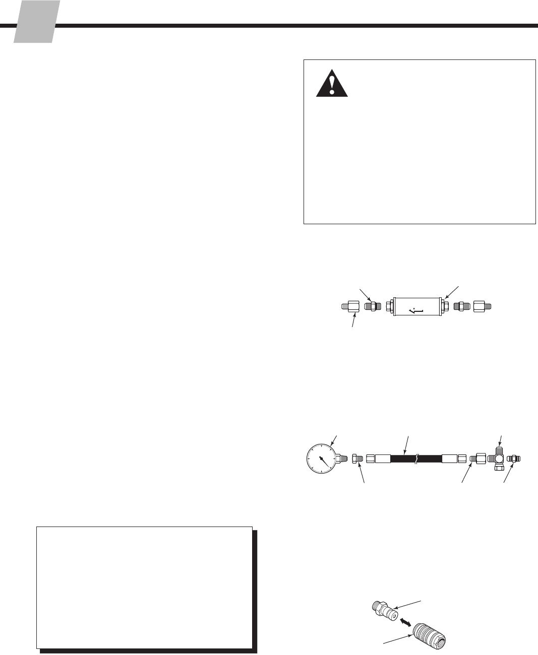
Pressure Gauge Kit 671212
Pressure
Gauge No. 6 and No. 8
JIC Swivel Tee
No. 4-6 Pipe/JIC
No. 6-6 Hose
Flow Meter Kit 671477
(2) No. 6-8 JIC Reducer
Flow Meter
No. 4, No.
6 and No. 8
JIC/O-Ring
No. 6-8 JIC
Reducer
(2) No. 8-12 JIC/
O-Ring
Quick-Coupler
No. 4 and No. 6 Male
Straight or JIC Thread
O-ring Coupler
No. 6 Female
Straight Thread
O-ring Coupler
4.1-2 Tools Required (Metric)
In addition to a normal selection of hand tools, the following
are required:
• 20 GPM (80 L/min) inline flow meter.
(Cascade Flow Meter Kit, part no. 671477).
• 3500 psi (240 bar) pressure gauge.
(Cascade Pressure Gauge Kit, part no. 671212).
• Assorted fittings, lines, drain hoses and quick-couplers
as required.
4.1-3 Troubleshooting Chart
Determine All The Facts – It is important to gather
all the facts about the problem before beginning any
service procedures. The first step is to talk to the
equipment operator. Ask for a complete description of
the malfunction. Guidelines below can then be used as a
starting point to begin troubleshooting.
• Truck hydraulic pressure should be within the pressure
range as shown in Section 6.1. PRESSURE MUST
NOT EXCEED 2600 psi (180 bar).
• Truck hydraulic flow should be within the volume range
as shown in Section 6.1-1.
• Truck hydraulic fluid supplied to the Attachment must
meet the specifications as shown in Section 6.1-1.
215793-R2
ROUBLESHOOTING
T
13
SD0162.eps
SD0158.eps
SIDESHIFT RIGHT,
CLOSE FORKS
Pressure:
Return:
SD0157.eps
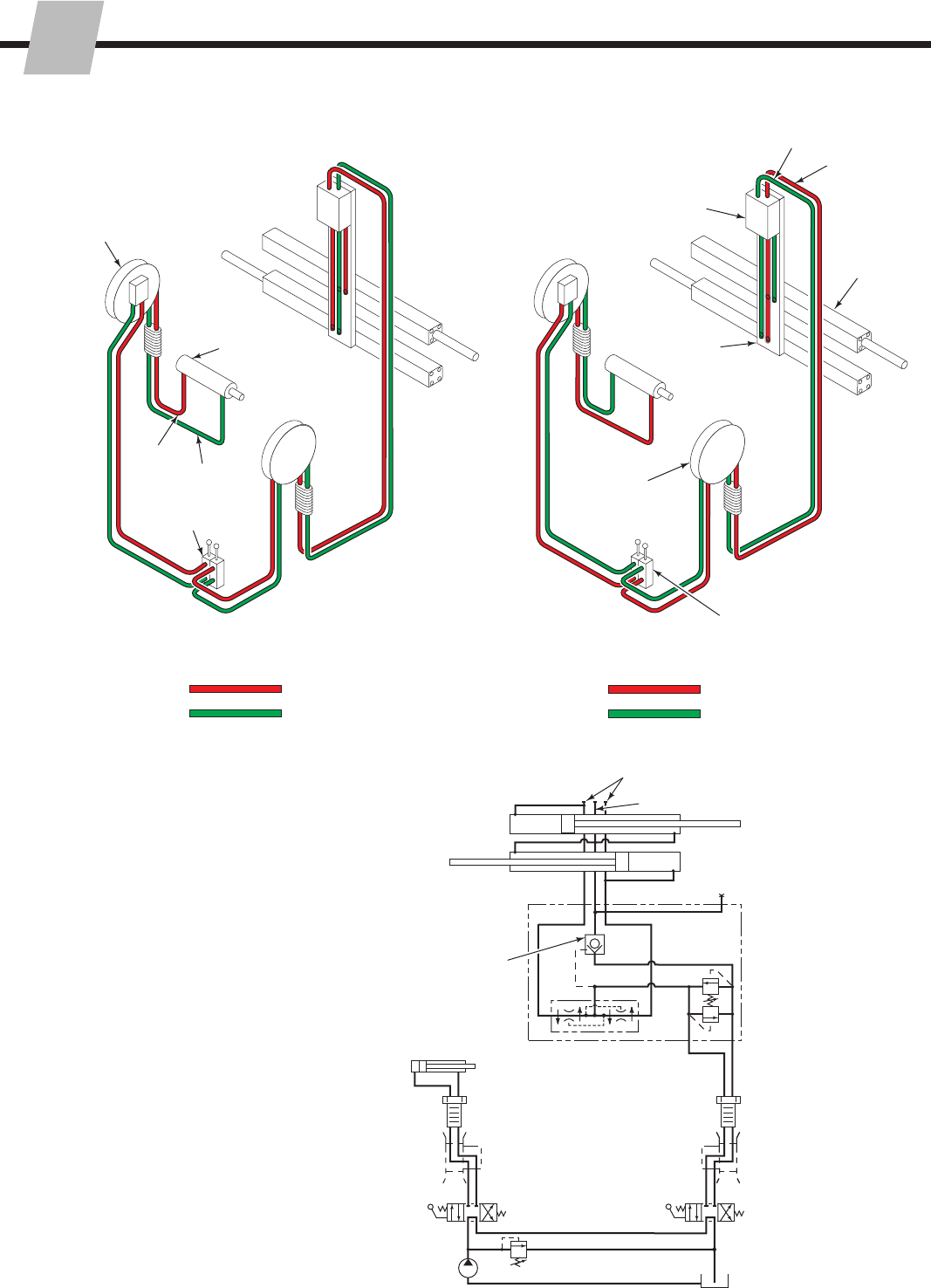
4.2 Plumbing
4.2-1 Hosing Diagram
OP
Flow Divider/
Combiner
SSL
SSR
CL
Manifold
Crossover
Relief
Close
Open
Truck Relief
Truck Pump
2-Port Hose Reels OR
Internal Reeving
Truck Auxiliary Valve
(Close Forks/Open Forks)
Truck Tank
Check
Valve
Cylinders
Test
Port
Attachment
Valve
Truck Auxiliary Valve
(Sideshift)
SSL
SSR
Open
Close
Truck Auxiliary
Valve (Sideshift)
Cylinders
Manifold
Valve
2-Port Hose Reel OR
Internal Reeving
Truck Auxiliary Valve
(Spread Forks/Close Forks)
Sideshift
Cylinder
4.2-2 Circuit Schematic
2-Port Hose Reel OR
Internal Reeving
Sideshift
Cylinder
SIDESHIFT LEFT,
OPEN FORKS
Pressure:
Return:
ROUBLESHOOTING
215793-R2
T
14
SD0150.eps
SD0149.eps
SD0165.eps
SD0164.eps
WARNING: Before removing hydraulic
lines or components, relieve pressure in
the hydraulic system. With the truck off,
open the truck auxiliary control valves
several times in both directions.
There are six potential problems that could affect the fork
positioning function:
• Bent arm bars.
• Incorrect hydraulic pressure or flow from lift truck.
• Defective gas cylinders.
• External leaks.
• Defective solenoid coil or valve (if equipped).
• Worn/defective cartridge valves or cylinder seals.
4.3-1 Fork Position Circuit Test
1 Check the truck pressure at the carriage hose
terminal. Pressure must be within 100 psi (7 bar) of
the specifications in the truck service manual. TRUCK
PRESSURE MUST NOT EXCEED 2600 psi (180 bar).
See Section 6.1 for recommended operating pressure.
2 Check the flow volume at the carriage hose terminal.
See Section 6.1 for recommended flow volume.
3 Spread the forks and check that the inner forks remain
in contact with the outer forks until reaching their stops.
If they do not, the gas cylinders or spring cylinders are
faulty. Replace the gas cylinders (see Section 5.7-2 or
3) or spring cylinders (see Section 5.7-5).
4 Spread the forks fully and hold the lever in the OPEN
position for 2 seconds. Release the lever and check for
external leaks at fittings, hoses, valve and manifold.
5 Press the solenoid button (if equipped) and listen for a
‘click’ at the solenoid valve. If no sound is heard, check
the fuse, wiring and coil (see Section 4.5).
IMPORTANT: Solenoid-operated valves must be
plumbed so that the solenoid is energized during the
fork positioning function.
6 Open and close the forks fully. If the arms move at
different speeds, the flow divider/combiner cartridge
may be faulty. Replace the cartridge.
7 Turn the truck off and connect a 3500 psi (240 bar)
pressure gauge to the TEST port on the main valve.
8 Start the truck and close the forks fully. Hold the lever in
the CLOSE position for a few seconds.
9 Release the lever and watch the pressure gauge:
• If the pressure drop is less than 150 psi (10 bar)
initially, and additional drop does not exceed 25 psi
(2 bar) per minute, the problem is not hydraulic (see
Section 4.1-3).
• If the pressure drop is more than above, the check
valve cartridge may be faulty. Replace the
cartridge.
10 Close the forks fully and hold the lever in the CLOSE
position for a few seconds. If the pressure still drops as
before, the cylinders are at fault and must be serviced
4.3 Fork Position Function
2Flow Meter
7
Pressure
Gauge on
TEST Port
8
6
9
Flow Divider
Cartridge
Check Valve
Cartridge
Test
Port
55E CLASS II, 70E VALVE
45E, 55E CLASS III,
60E, 80E, F-SERIES
VALVE
215793-R2
ROUBLESHOOTING
T
15
SD0148.eps
SD0153.eps
SD0154.eps
WARNING: Before removing hydraulic
lines or components, relieve pressure
in the hydraulic system. Turn the truck
off and open the truck auxiliary control
valves several times in both directions.
4.4 Sideshift Function
There are five potential problems that could affect the
sideshifting function:
• Inadequate sideshifter upper bearing lubrication or
worn bearings (see Section 5.7-1).
• Incorrect hydraulic pressure or flow from lift truck.
• External leaks.
• Lower mounting hooks installed incorrectly (see
Section 5.1 Step 6).
• Worn or defective cylinder seals.
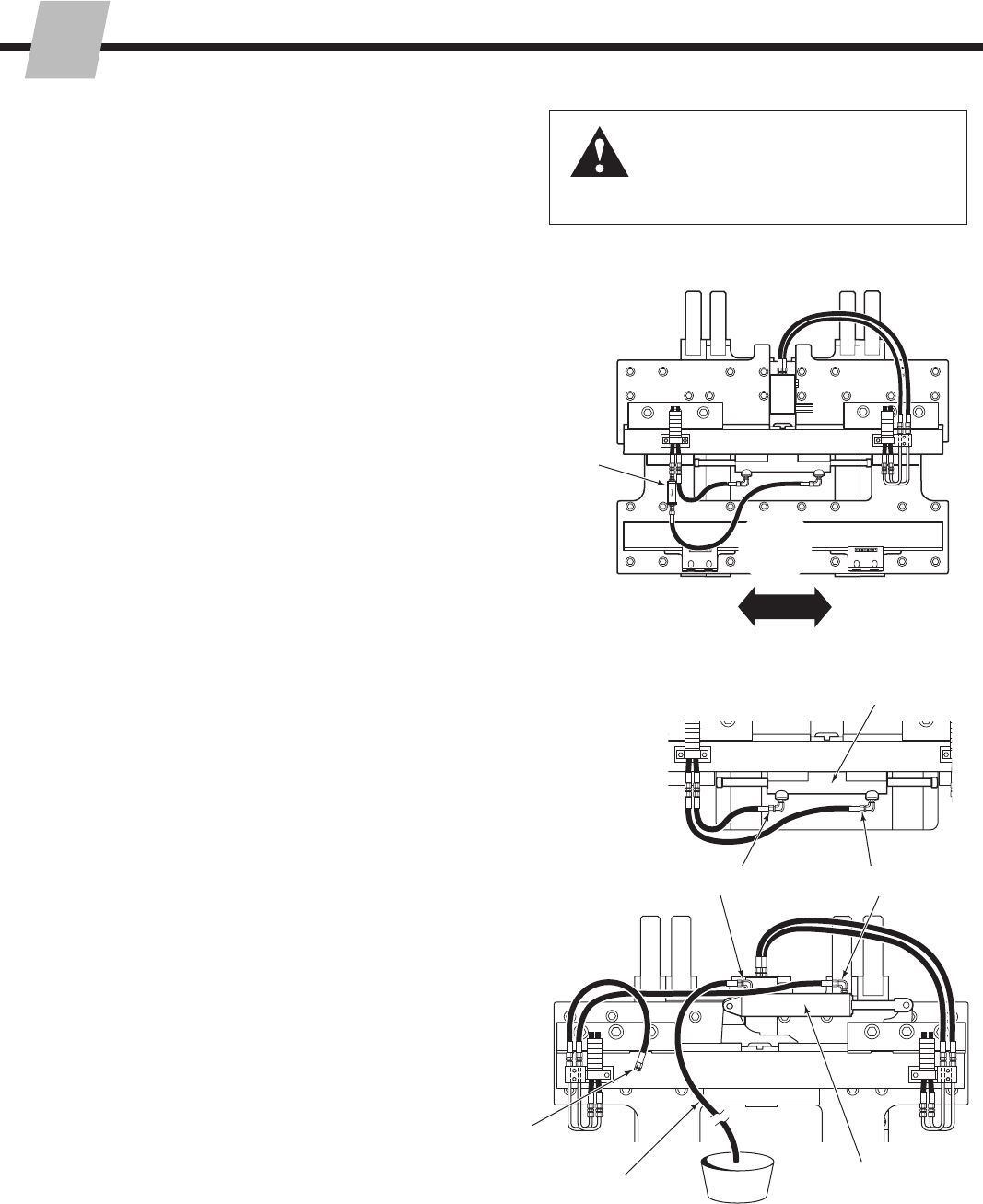
4.4-1 Sideshift Circuit Test
1 Check the truck pressure at the carriage hose terminal.
Pressure must be within 100 psi (7 bar) of that specified
in the truck service manual. TRUCK PRESSURE
MUST NOT EXCEED 2600 psi (180 bar). See Section
6.1 for recommended operating pressure.
2 Check the flow volume at the carriage hose terminal.
See Section 6.1 for recommended flow volume.
3 Sideshift left or right fully, holding the lever in the
SIDESHIFT position for a few seconds. Release the
lever and check for external leaks at fittings, hoses,
valve and manifold.
4 Press the solenoid button (if equipped) and listen for a
‘click’ at the solenoid valve. If no sound is heard, check
the fuse, wiring and coil (see Section 4.5).
IMPORTANT: Solenoid-operated valves must be
plumbed so that the solenoid is energized during the
fork positioning (not sideshifting) function.
5 Turn the truck off and relieve system pressure.
Disconnect the SIDESHIFT RIGHT supply hose from
the sideshift cylinder. Plug the hose end. Install a drain
hose from the cylinder fitting to a catch bucket.
6 Start the truck. Actuate the SIDESHIFT LEFT lever for 5
seconds.
• If there is substantial hydraulic flow out of the drain
hose, the sideshift cylinder is faulty and requires
service (see Section 5.3).
• If there is no hydraulic flow out of the hose, the
problem is not hydraulic (see Section 4.1-3).
2
Flow
Meter
5SSR
Upper Mount
Sideshift Cylinder
Center Mount
Sideshift Cylinder
SSL
Back (Driver’s) View
3
Drain Hose
Plug
ROUBLESHOOTING
215793-R2
T
16
SD0095.eps
SD0094.eps
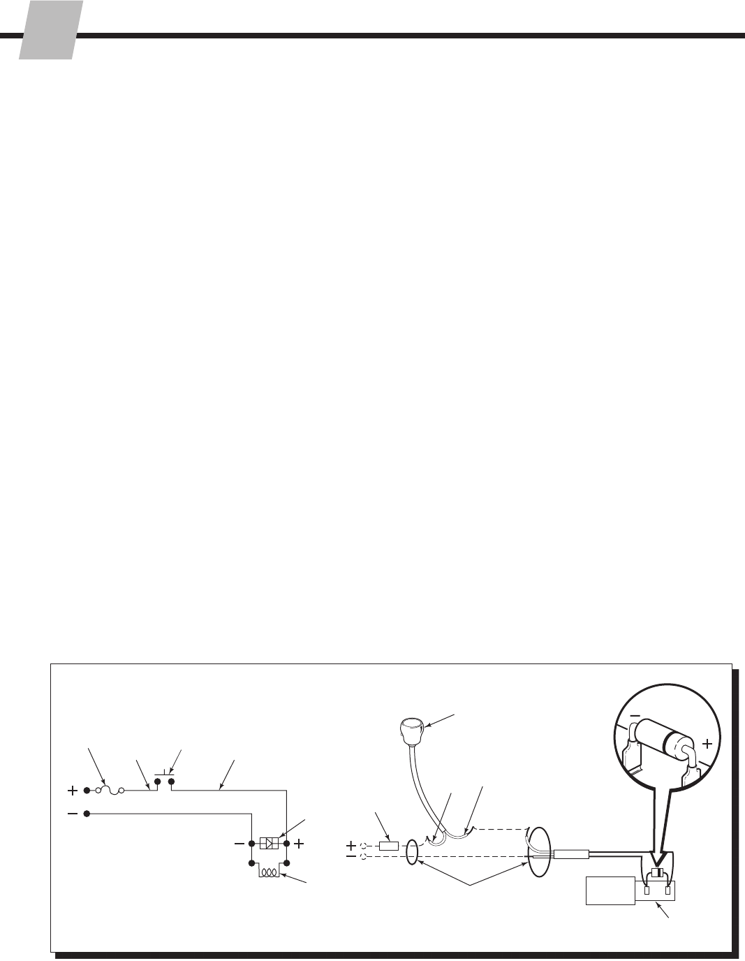
4.5 Electrical Circuit
(Solenoid-equipped attachments)
Use the schematic shown and follow the steps below.
1 Check the control knob circuit fuse. Replace if
necessary.
2 Check for loose electrical connections at the truck
ignition switch, control knob button, solenoid coil
terminals and diode.
3 Remove the diode from the solenoid coil terminal. Test
with an ohmmeter for high resistance in one direction
and no resistance in the other direction. If there is no
resistance in both directions, replace the diode.
NOTE: When replacing the diode, the banded end
must be connected to the coil and wiring as shown.
4 Disconnect the electrical leads from the solenoid coil
terminals. Use a voltmeter to take a current reading
at the electrical lead terminals when the button is
depressed.
• If there is no current to the solenoid, troubleshoot
the electrical circuit for shorts.
• If there is current to the solenoid, test for coil
continuity.
5 Test for coil continuity by placing an ohmmeter test lead
on each solenoid coil terminal (ohmmeter on Rx1 scale).
• If there is an ohmmeter reading, the coil is good.
• If the coil is good, but the solenoid does not ‘click’
when the control button is depressed, the solenoid
cartridge may be jammed.
• If there is no ohmmeter reading, the coil is defective
and should be replaced.
7.5 Amp
Fuse
Knob
Button
White Black
7.5 Amp
Fuse
Solenoid
Coil
Diode
User-supplied wire
White Black
Solenoid
Coil
Diode
Knob
215793-R2
ERVICE
S
17
SD0128.eps
SD0129.eps
SD0130.eps
SD0132.eps
SD0131.eps
.09 in.
(2.2 mm)
clearance
Lower Hook
Upper Bearing
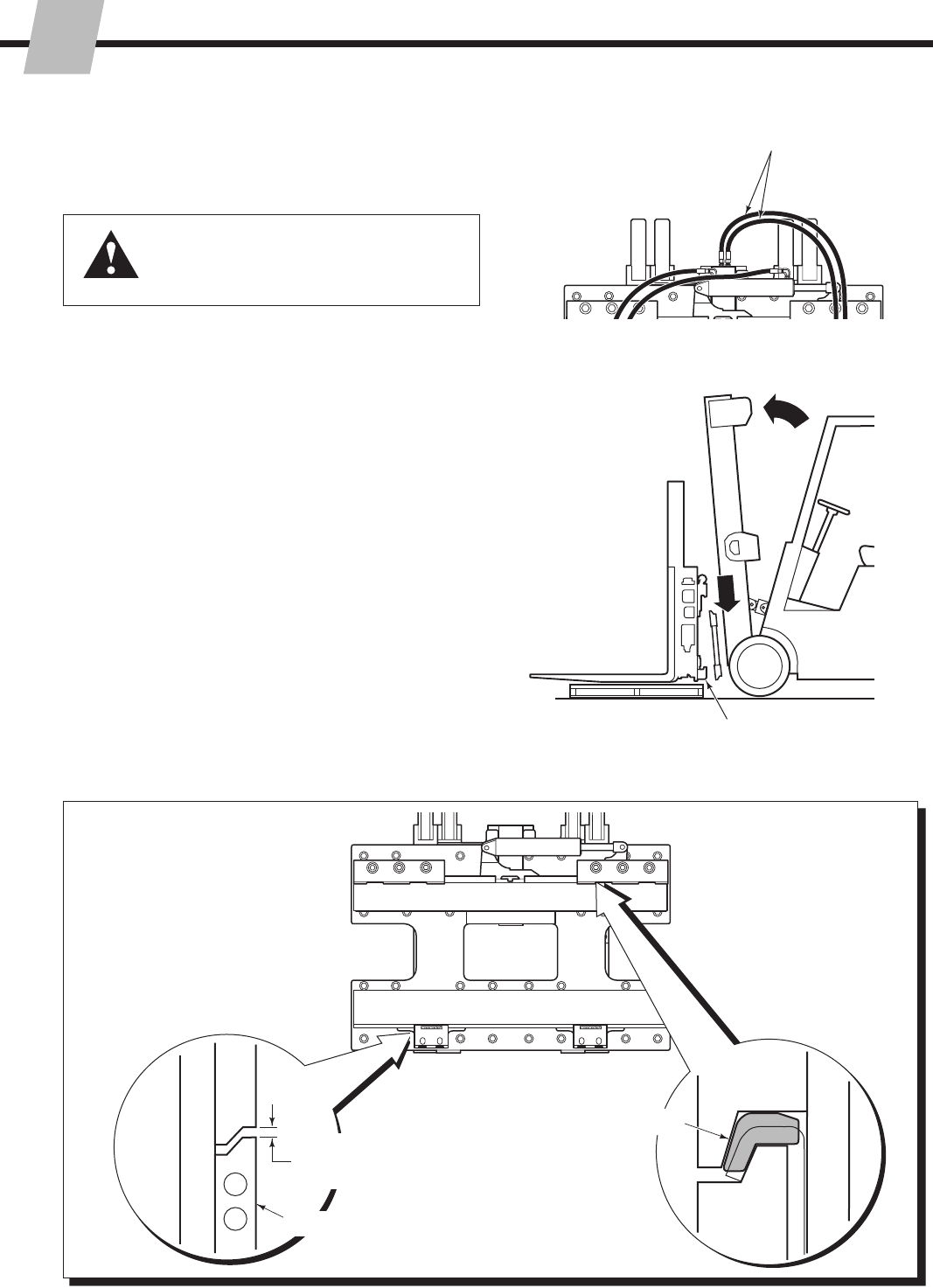
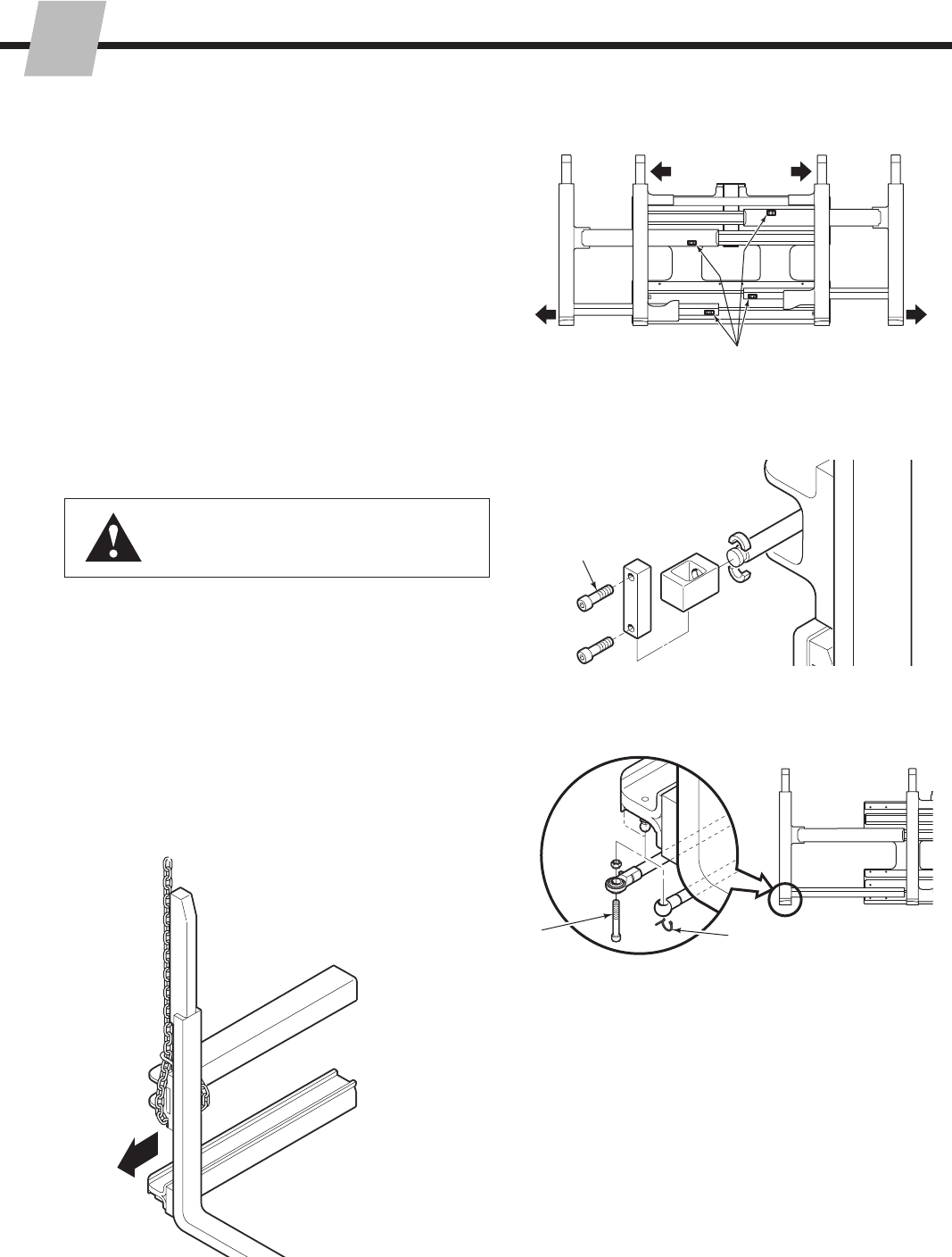
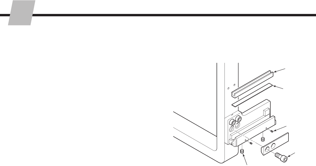
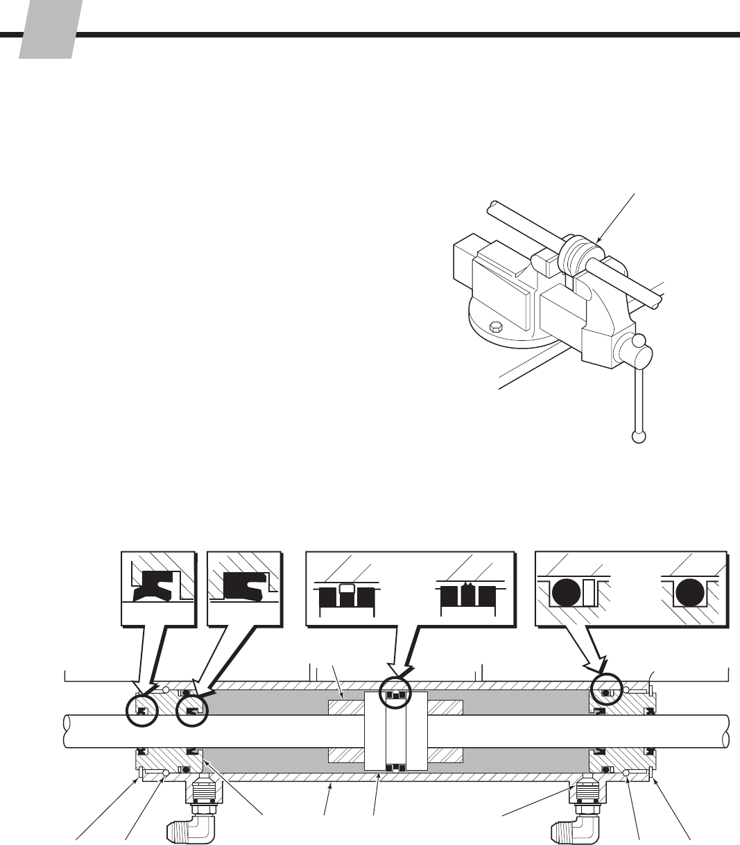
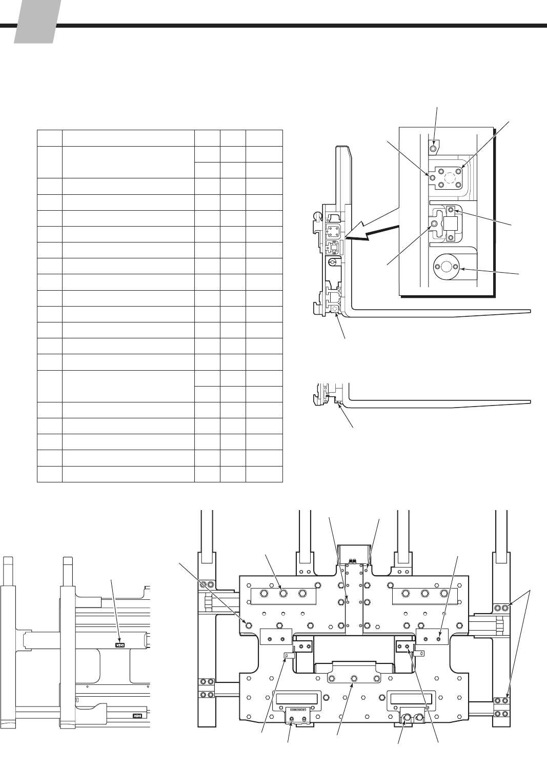
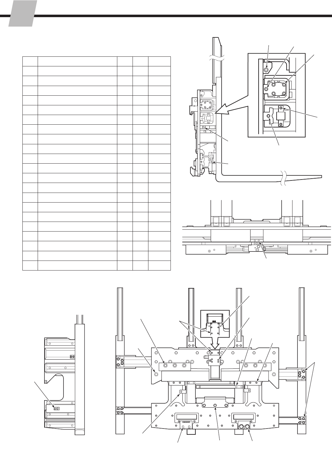
5.1 Attachment Removal
1 Position the outer forks approximately at the width of the
frame.
2
3
4
2 Disconnect the supply hoses from the valve and
sideshift cylinder fittings. Tag hoses for reassembly.
3 Remove the lower mounting hooks.
Quick Disconnect Hooks - Remove the pins to lower
the hooks.
Bolt-On Hooks - Remove the capscrews fastening
the hooks to the baseplate. For reassembly, install the
lower hooks to the truck lower carriage bar leaving
.09 in. (2.5 mm) clearance for sideshifting. Tighten the
hook capscrews to a torque of 125 ft.-lbs. (170 Nm).
4 Position the attachment over a pallet. Lower the
attachment onto the pallet. Tilt the truck carriage
forward and back away.
5 For installation, reverse the above procedures except
for the following special instructions:
Clean the upper and lower bearings and bearing
contact surfaces.
Locate the upper bearings in the anchor bracket
cutouts. Be careful not to install the bearings
backwards.
•
•
WARNING: Before removing any hoses,
relieve pressure in the hydraulic system.
Turn the truck off, then actuate the truck
control valve several times in both directions.
SD0128.eps
215793-R2
ERVICE
S
18
SD0639.eps
SD0215.eps
SD0122.eps
SD0135.eps
11
2
3
5
Wire clip
Rod end bolt
(May be installed from above)
WARNING: The outer forks must be fully
extended prior to disconnecting the gas
cylinder rod end.
4
5.2 Forks
5.2-1 Outer Fork Removal
1 Extend the outer forks outside the width of the frame.
Position the forks .5 in. (12 mm) above the floor.
2 Remove the bolt-on stops from the outer fork arms.
For reassembly, clean and dry capscews and threaded
holes. Apply Loctite 242 (blue) to the capscrew threads
and tighten to a torque of:
48E/55E/60E/80E – 30 ft.-lbs. (40 Nm)
48F/55F/60F/70E – 48 ft.-bs. (65 Nm)
3 Open the outer forks to full width. Remove the
capscrews fastening the cylinder rod anchor bars to the
outer forks. For reassembly, tighten capscrews of:
48/55/60 (E & F) – 30 ft.-lbs. (40 Nm)
70E/80E – 50 ft.-lbs. (70 Nm)
4 Units with Serial No.s less than 55E-FD-500
Disconnect the gas spring rod end from the anchor by
removing the wire clip or rod end bolt.
5 Attach a suitable overhead hoist around the fork.
Pull the fork assembly out of the frame.
6 Inspect the arm bearings for wear. If the bearing are
worn in any area to less than .06 in. (1.5 mm), they
should be replaced.
7 For reassembly, reverse the above procedures.
215793-R2
ERVICE
S
19
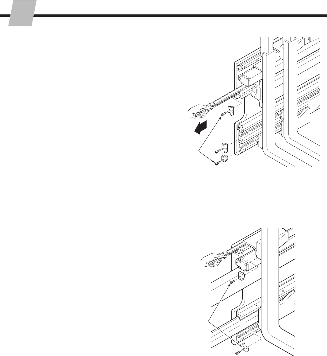
SD0138.eps
SD0169.eps
SD0121.eps
11
2
4
3
7,8
5
6
Wire Clip
6
Rod end bolt
(May be installed from above)
WARNING: The outer forks must be fully
extended prior to disconnecting the gas
cylinder rod end.
5.2-2 Inner Fork Removal
Serial numbers less than 55E-FD-500
1 Extend the outer forks outside the width of the frame.
Position the forks .5 in. (12 mm) above the floor.
2 Remove the bolt-on stops from the outer fork lower
arms. For reassembly, tighten the capscrews to a
torque of 30-ft.-lbs. (40 Nm).
3 Open the outer forks to full width. Remove the
capscrews fastening the cylinder rod anchor bars to the
outer forks. For reassembly, apply Loctite 242 to the
capscrew threads then tighten them to a torque of
30 ft.-lbs. (40 Nm).
4 Disconnect the gas spring rod end from the outer fork
anchor by removing the wire clip or rod end bolt.
5 Remove the gas spring by pulling with a quick jerk to
disengage the base end from the anchor.
6 Move the inner fork to center then lift up to remove.
7 Inspect the arm bearings for wear. If the bearing are
worn in any area to less than .06 in. (1.5 mm), they
should be replaced.
8 For reassembly, reverse the above procedures except
as follows:
Refer to Section 5.2-8 for properly shimming inner
lower hooks.
•
SD0122.eps
215793-R2
ERVICE
S
20
SD0215.eps
SD0122.eps
SD0214.eps
SD0213.eps
5.2-3 Inner Fork Removal
Serial Numbers greater than 55E-FD-499
and 70E/80E 11
2
4
3
5,6
4
1 Extend the outer forks outside the width of the frame.
Position the forks .5 in. (12 mm) above the floor.
2 Remove the bolt-on stops from the outer fork arms.
For reassembly, clean and dry capscrews and threaded
holes. Apply Loctite 242 (blue) to the capscrews
threads and tighten to a torque of:
55E/80E – 30 ft.-lbs. (40 Nm)
70E – 48 ft.-bs. (65 Nm)
3 Open the outer forks to full width. Remove the
capscrews fastening the cylinder rod anchor bars to the
outer forks. Tighten capscrews to a torque of:
55E – 30 ft.-lbs. (40 Nm)
70E/80E – 50 ft.-lbs. (70 Nm)
4 Move the inner fork to center then lift up to remove.
The upper gas cylinders will disengage with inner fork
bracket.
5 Inspect the arm bearings for wear. If the bearing are
worn in any area to less than .06 in. (1.5 mm), they
should be replaced.
6 For reassembly, reverse the above procedures except
as follows:
Place the rod end of the upper gas cylinders in the
pockets of the inner fork brackets.
Refer to Section 5.2-8 for properly shimming inner
lower hooks.
•
•
215793-R2
ERVICE
S
21
SD0645.eps
SD0644.eps
SD0122.eps
SD0213.eps
5.2-4 Inner Fork Removal
48E/60E, 55E-FDS, and all F-Series
11
2
4
3
6,7
5
1 Extend the outer forks outside the width of the frame.
Position the forks .5 in. (12 mm) above the floor.
2 Remove the bolt-on stops from the outer fork arms.
For reassembly, clean and dry capscrews and threaded
holes. Apply Loctite 242 (blue) to the capscrews
threads and tighten to a torque of:
48E/55E/60E – 30 ft.-lbs. (40 Nm)
48F/55F/60F – 48 ft.-bs. (65 Nm)
3 Open the outer forks to full width. Remove the
capscrews fastening the cylinder rod anchor bars to the
outer forks. Tighten capscrews to a torque of
30 ft.-lbs. (40 Nm).
4 Remove spring cylinder bracket from inner forks. For
reassembly, apply Loctite 242 blue to capscrews and
tighten to 30 ft.-lbs (40 Nm).
5 Move the inner fork to center then lift up to remove.
6 Inspect the arm bearings for wear. If the bearing are
worn in any area to less than .06 in. (1.5 mm), they
should be replaced.
7 For reassembly, reverse the above procedures except
as follows:
Refer to Section 5.2-8 for properly shimming
inner lower hooks and setting adjusting screw (if
equipped).
•
215793-R2
ERVICE
S
22
SD0134.eps
5.2-5 Outer Fork Bearing Service
1 Fully close the outer forks.
2 Remove the capscrews from the bearing retainers.
For reassembly, clean and dry capscrews and threaded
holes. Apply Loctite 242 (blue) to capscrews and
tighten to a torque of:
48E/55E/60E – 30 ft.-lbs. (40 Nm)
70E/80E/48F/55F/60F – 15 ft.-bs. (20 Nm)
3 Remove and replace one bearing at a time. Grab the
end of the bearing with vise grips to remove.
4 For reassembly, reverse the above procedures.
2
3
SD0137.eps
5.2-6 Inner Fork Bearing Service
1 Position outer forks just outside the width of the frame.
2 Remove the inner fork bearing retainers. For
reassembly, clean and dry capscrews and threaded
holes. Apply Loctite 242 (blue) to capscrews and
tighten to a torque of:
48E/55E/60E – 30 ft.-lbs. (40 Nm)
70E/80E (Upper Retainers) – 30 ft.-bs. (40 Nm)
70E/80E (Lower Retainers) – 15 ft.-bs. (20 Nm)
48F/55F/60F – 15 ft.-bs. (20 Nm)
3 Remove and replace one bearing at a time. Grab the
end of the bearing with vise grips to remove.
4 For reassembly, reverse the above procedures except
as follows:
Refer to Section 5.2-8 for properly shimming inner
lower hooks.
•
2
215793-R2
ERVICE
S
23
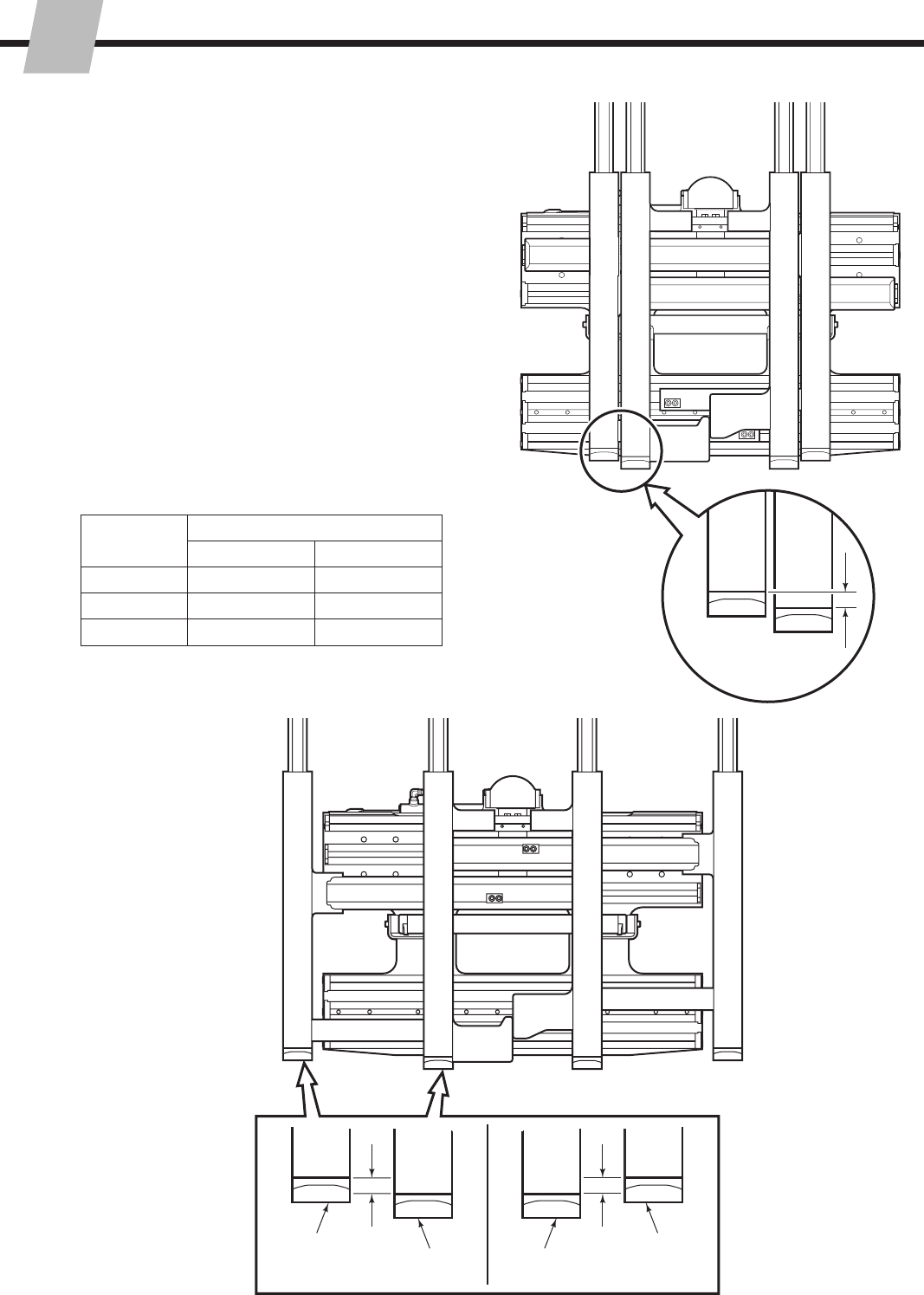
5.2-7 Fork Tip Alignment
1 Fully close forks.
2 Measure the vertical offset of the forks 5 in. (125 mm)
from the tip of the forks. Outer forks can have a
maximum vertical offset of .2 in. (5 mm) from the inner
fork. The inner fork must be lower then the outer fork.
3 Fully open forks.
4 Measure the vertical offset of the forks. Outer fork can
have a maximum vertical offset of .08 in. (2 mm) above
or .12 in. (3 mm) below the inner fork.
5 To align arm bars, remove forks from arm bars. For
reassembly, tighten capscrews to 220 ft.-lbs. (300 Nm).
IMPORTANT: For 70E, 80E, and F-Series apply Loctite
242 (blue) to capscrew threads for reassembly.
6 Place shims where needed. To lower fork tips, add
shim(s) to the upper arm bar. To raise fork tips, add
shim (shims) to lower arm bar.
IMPORTANT: Do not exceed 3 mm of shimming.
Series
Shim Part Numbers
Upper Arm Bars Lower Arm Bars
48E/55E/60E 797610 797611
70E/80E 6108554 6108555
48F/55F/60F 797610 797611
SD0646.eps
SD0647.eps
2
1
3
Inner Fork
Outer Fork
Outer Fork
Inner Fork
.08 in.
(2 mm)
max.
.12 in.
(3 mm)
max.
4
215793-R2
ERVICE
S
24
5.2-8 Inner Fork Shimming
1 Rock the inner forks to check for looseness.
2 Install shims as required to remove looseness. Use
Shim kit 219316 for E-Series attachments and shim
228395 for F-Series attachments. For E-Series, shim
packs should not exceed .25 in (6 mm) of shims.
3 Position the arm bars by hand. If the arm bars will not
move with minimum force, check the following:
Check the adjusting screws (if equipped). If the
adjusting screws are loose and the arm bars are
tight, the lower hooks may need to be inspected.
Check the inner fork timing. If the arm bars move
without the forks stops engaged, the bearing may
need to be loosened.
Arm bars that can not be positioned with minimal
force, should be inspected for further interferences.
4 If equipped, install locking screws into adjusting screws.
Tighten locking screw approximately one-quarter turn
after locking screw engages the adjusting screw.
•
•
•
SD0648.eps
Shim
Bearing
Locking
Screw
Capscrew
Adjusting Screw
215793-R2
ERVICE
S
25
SD0139.eps
SD0152.eps
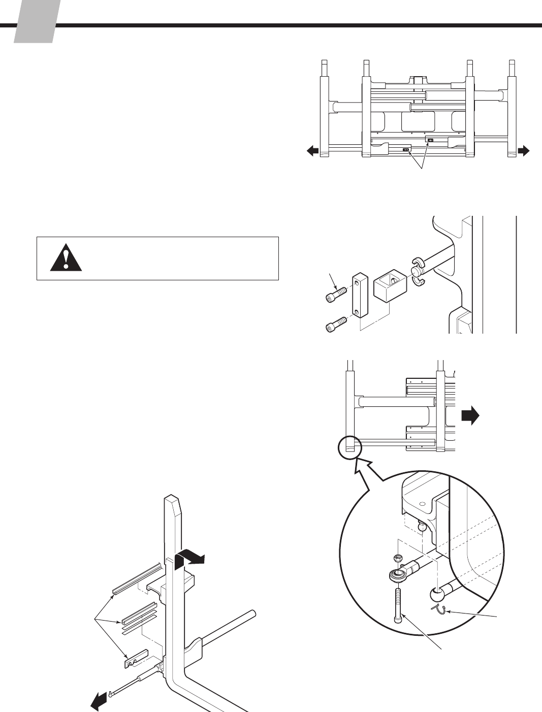
5.3 Sideshift Cylinder-
Center Mount
5.3-1 Cylinder Removal
2
3
WARNING: Before removing any hoses,
relieve pressure in the hydraulic system.
Turn the truck off, then actuate the
truck control valve several times in both
directions.
1 Remove the attachment from the truck as described in
Section 5.1.
2 Loosen the support bracket capscrews. Lift away the
cylinder. For reassembly, tighten the capscews to a
torque of:
48E/55E – 22 ft.-lbs. (30 Nm) ▲
70E/80E – 15 ft.-lbs. (20 Nm)
▲ Apply Loctite 242 (Blue) to threads.
3 For reassembly, reverse the above procedures except for
the following special instructions:
Clean the upper and lower bearings and bearing
contact surfaces.
Locate the upper bearings in the anchor bracket
cutouts. Be careful not to install the bearings
backwards.
•
•
215793-R2
ERVICE
S
26
SS0122.eps
SS0039.eps
SS0040.eps
SS0120.eps
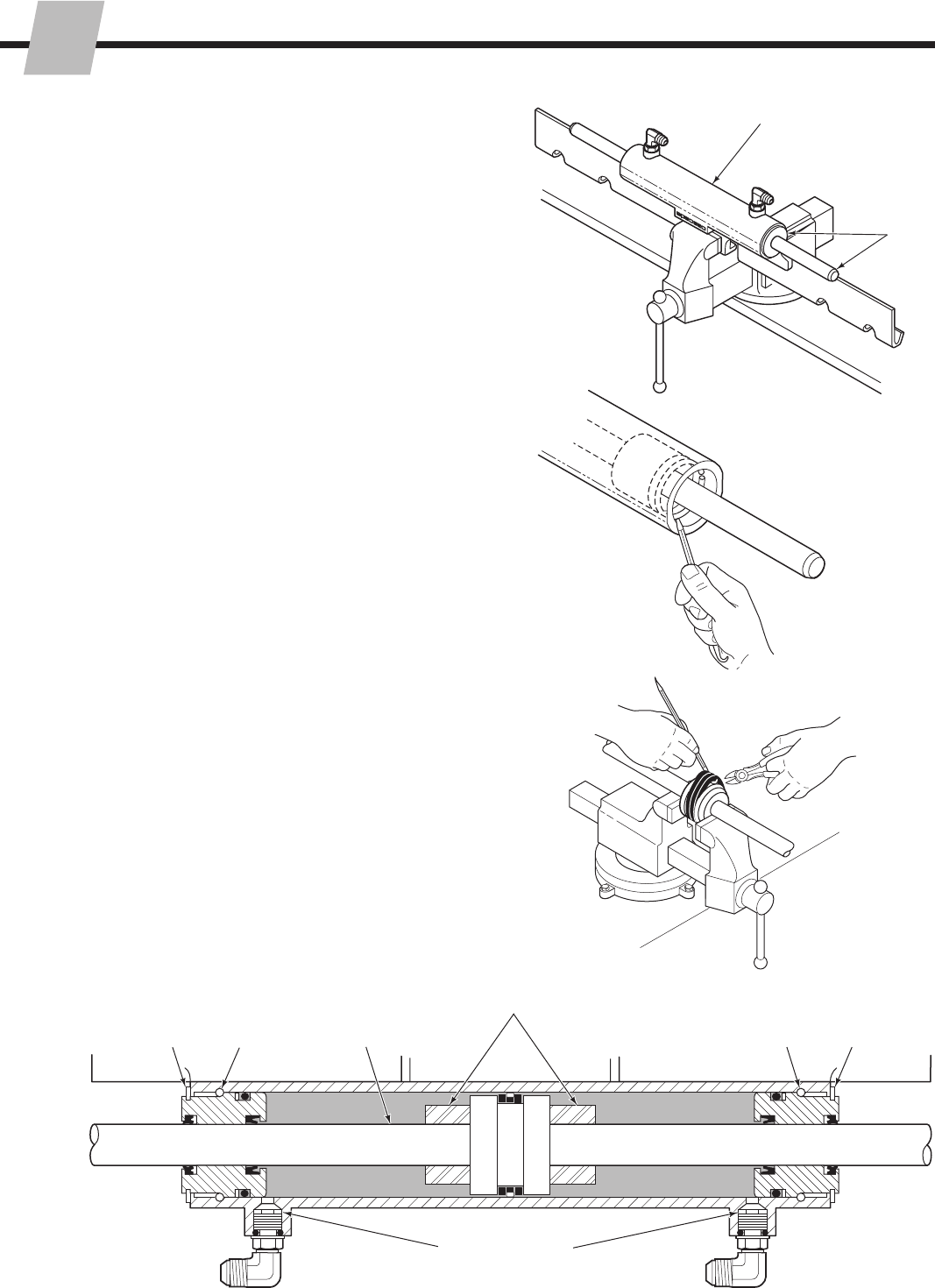
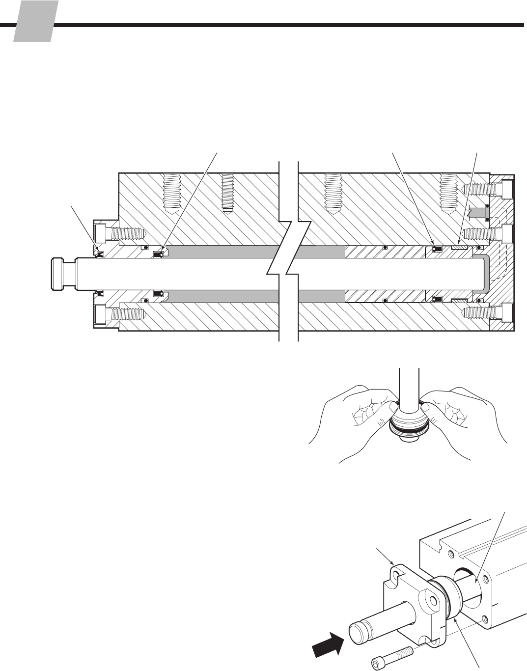
5.3-2 Cylinder Disassembly
1 Clamp the cylinder in a soft-jawed vise. Do not clamp
on the cylinder shell.
2 Center the cylinder rod in the cylinder. Remove the
spiral snap rings from the retainers. See the illustration
below.
3 Tap the retainers into the shell approximately 2 in.
(50 mm). Remove the retaining rings by prying one end
up and working the ring out of the groove.
Service Tool Kit 674424 includes two double-ended
brass tools that make seal and retaining ring removal
easy and won’t damage the cylinder components with
dents or scratches.
CAUTION: Do not scratch the cylinder bore.
4 Remove the rod assembly from the cylinder. See the
illustration below.
5 Clamp the rod assembly in a soft-jawed vise or between
two blocks of wood to remove the seals. Pry the seals
up with a brass tool. Cut the seals to remove.
CAUTION: Do not scratch the seal grooves.
5.3-3 Cylinder Inspection
Inspect all components for nicks or burrs. Minor nicks
or burrs can be removed with 400 grit emery cloth.
NOTE: Minor nicks are those that will not bypass oil
under pressure. If nicks cannot be removed with emery
cloth, replace the part.
Inspect the outside of the shell for deformities that could
weaken the shell’s performance when under pressure.
Replace if necessary.
Thread the fittings into the cylinder port to maximum
depth. This allows the restrictor washer to operate
correctly.
•
•
•
2
4 2
233
Optional
Spacers
1
5
3
Restrictor Washer
215793-R2
ERVICE
S
27
SS0046.eps
SS0740.eps
5.3-4 Cylinder Reassembly
1 Polish the piston and retainer chamfer angle with emery
cloth. This allows the seals to slide over the chamfer
easier.
2 Wash all components with cleaning solvent. Lubricate
all new seals and rings with petroleum jelly or STP.
3 Note the direction of the U-cup seals. If the seals are
installed backward they will not work properly. For
proper seal placement see the illustration below.
4 Install the new seals on the piston and retainer. Hook
one side of the seal in the groove and push it over the
piston or retainer.
5 Apply a thick film of petroleum jelly or STP to the inside
of the cylinder shell, piston seals and retainers.
6 Insert the rod assembly into the cylinder shell. If
resistance is encountered, tap the rod end with a rubber
mallet.
7 Tap the retainers into the shell far enough to install the
retaining rings in their grooves.
8 Pull the rod out to one side to the fully extended
position. This will position the retainer so the spiral snap
ring can be installed. Repeat for the retainer on the
other end.
8
877
Restrictor Washer
ShellRetainer Piston
3
Optional
Spacers
1
OR OR
215793-R2
ERVICE
S
28
SD0143.eps
5.4 Sideshift Cylinder -
Top Mount
5.4-1 Cylinder Removal
12
WARNING: Before removing any hoses,
relieve pressure in the truck hydraulic
system. Turn the truck off, then actuate the
truck control valve several times in both
directions.
1 Disconnect the hoses from the cylinder ports. Tag the
hoses for reassembly.
2 Remove the clevis pins from the cylinder ends. Remove
the cylinder.
3 For reassembly, reverse the above procedures except for
the following special instructions:
Operate the sideshifter through several full cycles
to force air in the system to the truck hydraulic tank.
Check for leaks at all fittings.
•
215793-R2
ERVICE
S
29
SS0059.eps
SS0060.eps
SS0061.eps
SS0088.eps
5.4-2 Cylinder Disassembly
1 Clamp the cylinder in a soft-jawed vise. Clamp lightly at
the extreme base end only.
2 Position the cylinder rod in the fully extended position.
Remove the spiral snap ring from the retainer. See the
illustration below.
3 Tap the retainer into the shell approximately 2 in.
(50 mm). Remove the retaining ring by placing a
screwdriver on one side of the ring near the split and
tapping with a hammer. The retaining ring will compress
and turn sideways for removal. Remove the retainer.
CAUTION: Do not scratch the cylinder bore.
4 Remove the rod assembly from the cylinder. See the
illustration below.
5 Clamp the rod assembly in a soft-jawed vise to remove
the seals. Never clamp directly on the rod sealing
surface. Remove the nut fastening the piston to the rod.
Pry the seals up with a blunt screwdriver or dental tool.
Cut the seals to remove.
CAUTION: Do not scratch the seal grooves.
5.4-3 Cylinder Inspection
Inspect all components for nicks or burrs. Minor nicks
or burrs can be removed with 400 grit emery cloth.
NOTE: Minor nicks are those that will not bypass oil
under pressure. If nicks cannot be removed with emery
cloth, replace the part.
Inspect the outside of the shell for deformities that could
weaken the shell’s performance when under pressure.
Replace if necessary.
•
•
1
3
Retainer
Retainer
Piston
5
5
2
4
Restrictor
Washer
SS0738.eps
215793-R2
ERVICE
S
30
SS0741.eps
SS0742.eps
SS0063.eps
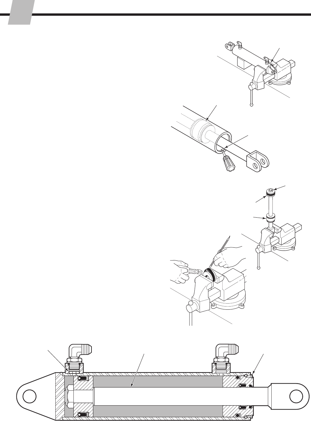
5.4-4 Cylinder Reassembly
1 Polish the piston and retainer chamfer angle with emery
cloth. This allows the seals to slide over the chamfer
easier.
2 Wash all components with cleaning solvent. Lubricate
all new seals and rings with petroleum jelly.
3 Note the direction of the U-cup seals. If the seals are
installed backward they will not work properly.
For proper seal placement see the illustration below.
4 Install the new seals on the piston and retainer. Hook
one side of the seal in the groove and push it over the
piston or retainer.
5 Install the retainer and piston on the rod and tighten the
piston retaining nut to 75 ft.-lbs. (102 Nm).
6 Apply a thick film of petroleum jelly to the inside of the
cylinder shell, piston seals and retainer.
7 Insert the rod assembly into the cylinder shell.
If resistance is encountered, tap the rod end with a
rubber mallet.
8 Tap the retainer into the shell far enough to install the
retaining ring in the groove.
9 Pull the rod out to the fully extended position. This
will position the retainer so the spiral snap ring can be
installed.
9
Retainer
RodPiston 8
6
5
Note seal
direction
3
Note seal
direction
3
Back-up RingBack-up Ring
Special O-Ring (oval) Do
not use a standard O-Ring.
Install new seals.
4
1
215793-R2
ERVICE
S
31
SD0167.eps
SD0155.eps
SD0156.eps
4
5
6
7
8
11
The cylinder internal components can be serviced with
the cylinder in place on the attachment. The following
procedures need to be followed only if the cylinder
assembly is being replaced.
1 Extend the outer forks outside the width of the frame.
2 Remove the outer fork that rides on the cylinder to be
removed. Refer to Section 5.2-1.
3 Remove the attachment from the truck as described in
Section 5.1.
4 Remove the sideshifting anchor bracket.
Center Mount – Loosen the support bracket
capscrews. For reassembly, tighten the capscrews
to a torque of:
48E/55E – 22 ft.-lbs. (30 Nm) ▲
70E/80E – 15 ft.-lbs. (20 Nm)
▲ Apply Loctite 242 (Blue) to threads
Top Mount – Remove the sideshift cylinder base end
pivot pin from the anchor bracket.
5 Remove the upper mounting hooks. For reassembly,
tighten the capscrews to a torque of 125 ft.-lbs.
(170 Nm).
6 Remove the capscrews fastening the valve and
manifold to the cylinder being removed. For
reassembly, tighten the capscrews to a torque of
15 ft.-lbs. (20 Nm).
7 Remove the capscrews fastening the cylinder to the
frame. For reassembly, tighten the capscrews to a
torque of 75 ft.-lbs. (100 Nm).
48/55/60 (E&F) – 75 ft.-lbs. (100 Nm)
70E/80E – 130 ft.-lbs. (175 Nm)
8 Lift the cylinder away from the frame. Collect the
O-rings between the cylinder and manifold.
9 For reassembly, reverse the above procedures except
for the following special instructions:
• Apply a small amount of petroleum jelly to hold the
O-rings in position while installing the cylinder.
• Apply an anti-seize compound such as Chesterton
725 Anti-Seize Compound to the cylinder and
baseplate mating surfaces.
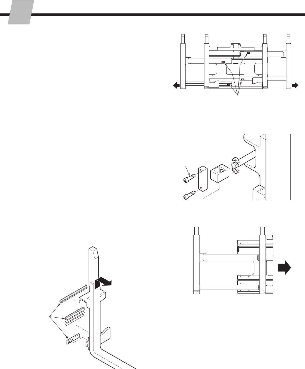
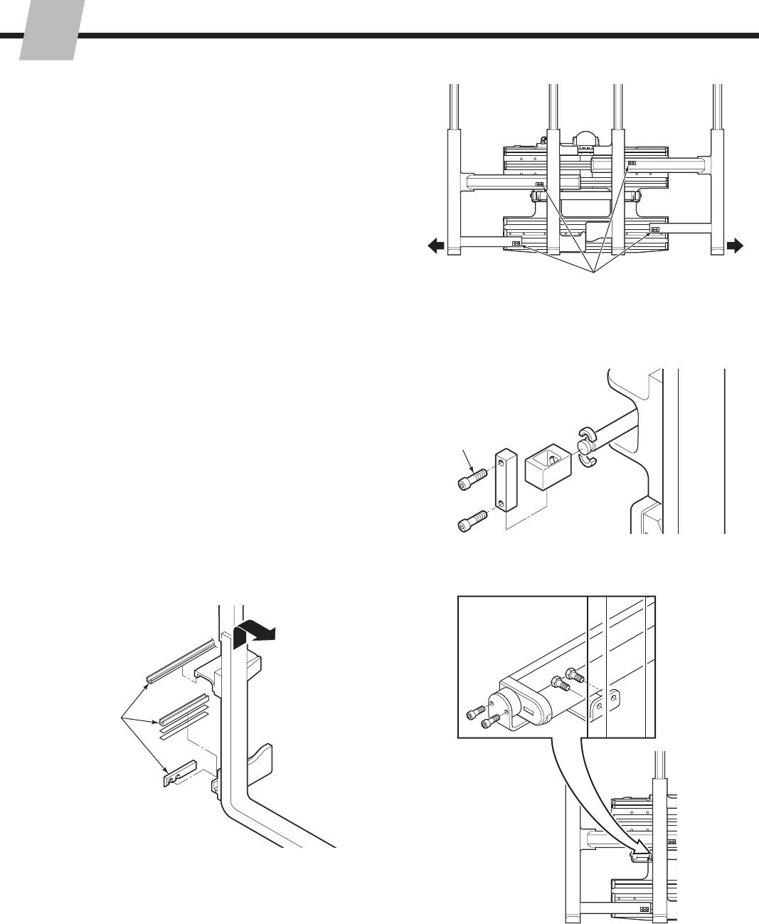
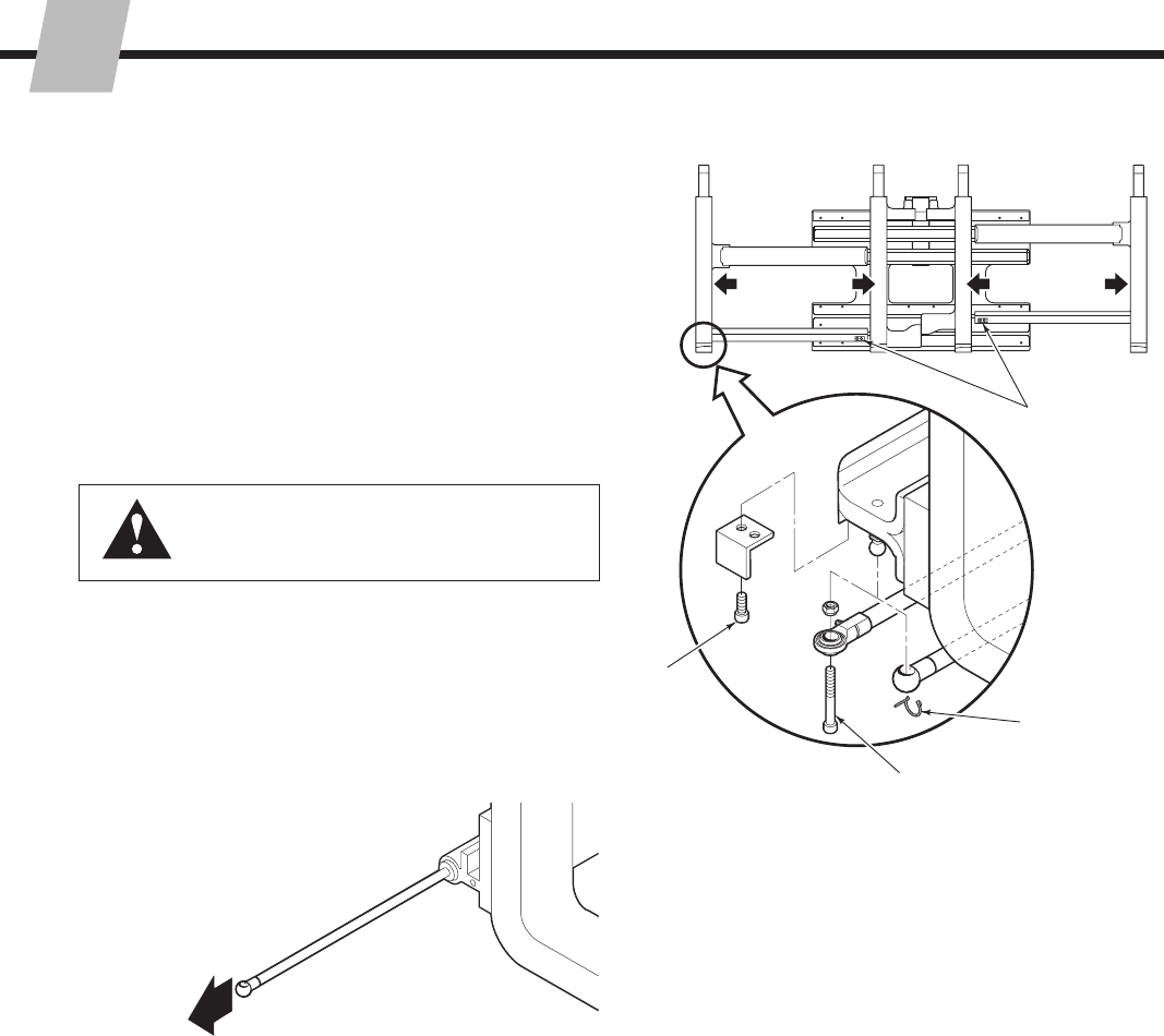
5.5 Fork Position Cylinders
5.5-1 Cylinder Removal
215793-R2
ERVICE
S
32
SD0160.eps
SD0640.eps
SD0161.eps
5.5-2 Cylinder Disassembly
These cylinders can be serviced in place on the
attachment. The following procedures can be performed
with the forks in place and the attachment mounted on the
truck. It is recommended that both cylinders be serviced
at the same time.
1 Fully close the forks.
2 Remove the capscrews fastening the cylinder rod
anchor bars to the arm.
3 Power the cylinders out 3 in. (75 mm) to expose the
cylinder rod end.
4 Slide the rod ends inward to to remove the split rings.
Remove rod ends from the cylinder rods.
5 Completely retract the cylinders.
1
5
2
4
76
WARNING: Before disconnecting hoses,
relieve pressure in the hydraulic system.
Turn the truck off and open the truck
auxiliary control valves several times in both
directions.
6 Disconnect the supply hose from the valve OPEN port
and plug the hose end. Install a No. 6 drain hose to the
fitting and place the hose end in a bucket.
7 Install a No. 4 fitting and drain hose to the valve TEST
port. Place the hose end in the bucket.
8 Starting with the bottom cylinder in the retracted
position, manually extend the cylinder rod to remove
oil from the shell and leave it extended. Repeat the
procedure for the top cylinder.
Rod End
Split Rings
215793-R2
ERVICE
S
33
SD0641.eps
CL0312.eps
CL0313.eps
CL0315.eps
9 Place a towel or drip pan under the cylinder retainer.
10 Scribe a mark on the cylinder retainer and shell for
alignment during reassembly.
11 Use a 6 mm hex extension to remove the capscrews
fastening the cylinder retainer to the shell. Be prepared
to collect a small amount of oil from the cylinder cavity
when the retainer is loosened from the shell. Remove
the retainer.
12 Remove the rod assembly and spacer (if included)
from the cylinder. Place a towel in the cylinder bore to
absorb oil.
13 Remove the end cap.
14 Remove all seals from the piston, spacer (if included),
retainer and end cap by prying them out with a brass
tool and cutting with diagonal cutters.
CAUTION: Do not scratch the seal grooves.
9
11
12 10
14
5.5-3 Cylinder Inspection
Inspect the rod, piston and retainer for nicks or burrs.
Minor nicks and burrs may be removed with 320 grit
emery cloth. If they cannot be removed, replace the
part.
Inspect the cylinder shell bore and remove any minor
nicks or burrs with a butterfly hone. If they cannot be
removed, replace the part.
Inspect the outside of the shell for any deformities or
cuts that could impair performance or cause leaks
under pressure. If necessary, replace the part.
•
•
•
Shell Bore Rod Piston
Retainer
13
End Cap
Shell
Spacer
(if included)
215793-R2
ERVICE
S
34
SD0642.eps
CL0318.eps
CL0319.eps
5.5-4 Cylinder Reassembly
1 Lubricate all new seals and O-rings with petroleum jelly.
2 Note the direction of the U-cup seals. Pressure seals
must always be installed with the lip toward the high
pressure side to the cylinder.
3 Install new seals on the piston, spacer (if included),
retainer and end cap. Install the piston seal on the
rod side of the piston. Hook one side of the seal in the
groove and carefully work it over the piston.
Pressure Seal Pressure Seal
3
7
4
6
5
Wiper
Bearing
4 Apply a thick film of petroleum jelly to the inside of the
cylinder shell and piston seals.
5 Using a rubber mallet, tap the rod assembly into the
cylinder shell.
6 Apply a thick film of petroleum jelly to the retainer.
7 Slide the retainer onto the rod and align with the scribe
mark and shell holes. Install the end cap. Install and
tighten the retainer and end cap capscrews to a torque
of 18 ft.-lbs. (25 Nm).
215793-R2
ERVICE
S
35
SD0122.eps
SD0159.eps
8 Reassemble the rod end, split rings and anchor bar to
the fork. Clean and dry capscews and threaded holes.
Apply Loctite 242 (blue) to the capscrew threads and
tighten to a torque of:
48E/55E/60E/80E – 30 ft.-lbs. (40 Nm)
48F/55F/60F/70E – 48 ft.-bs. (65 Nm) 8
9
10
9 Remove the hose from the valve OPEN port fitting.
Remove the hose and fitting from the valve TEST port.
Install the supply hose and TEST port plug.
10 Cycle the attachment through 10 complete cycles to
remove air from the hydraulic circuit. Check for leaks
and proper operation.
215793-R2
ERVICE
S
36
OPEN
CLAMP
TEST
SD0649.eps
SD0146.eps
SD0147.eps
210266
6034595
DFD
Deltrol
CL0341.eps
CL0340.eps
CL0342.eps
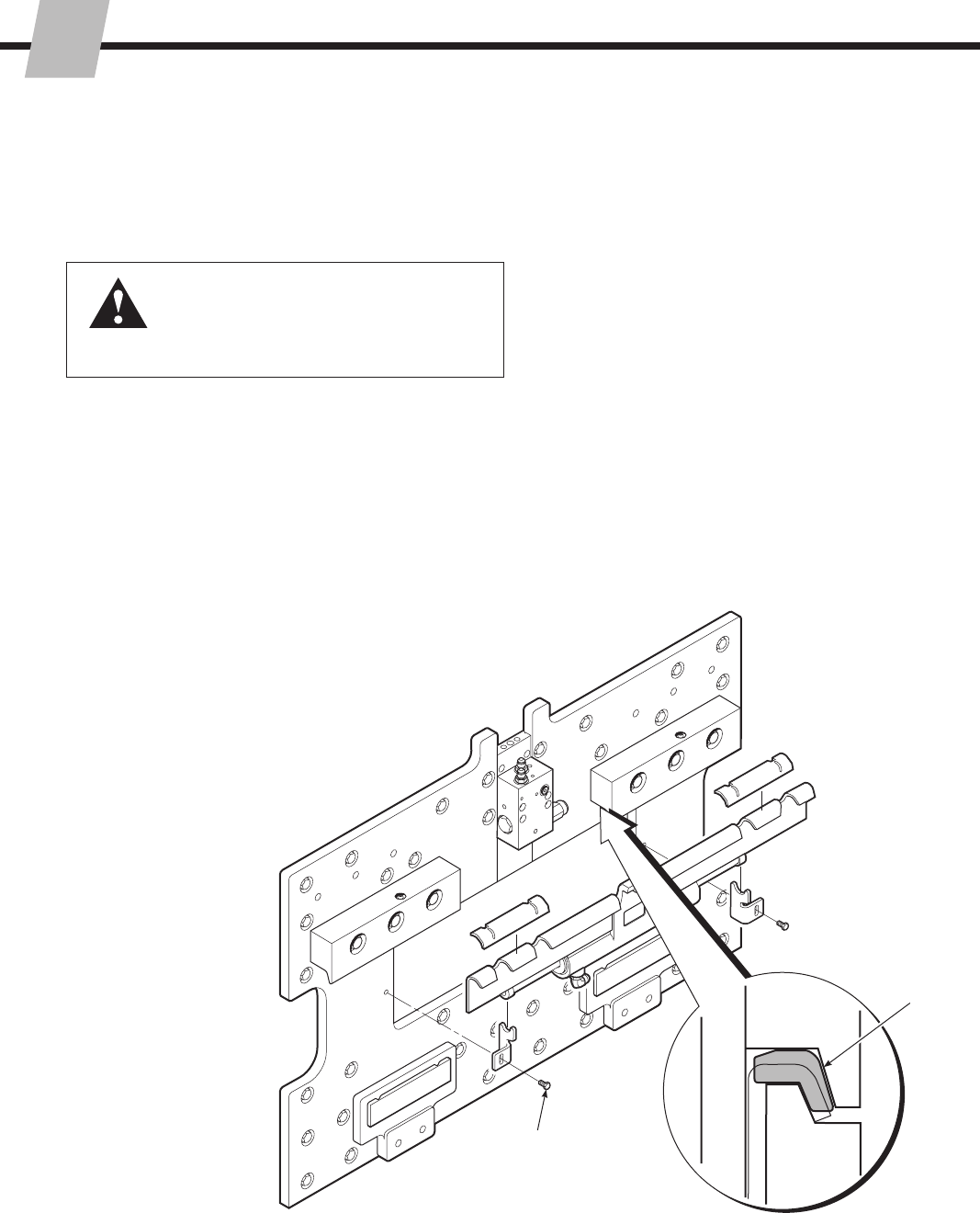
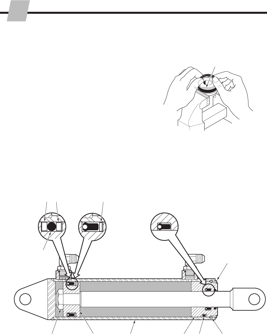
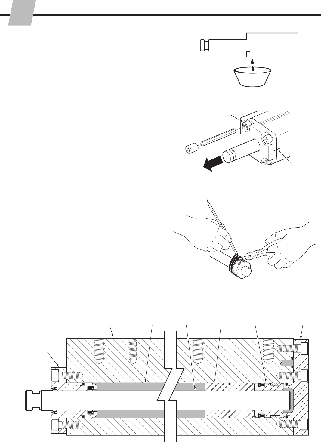
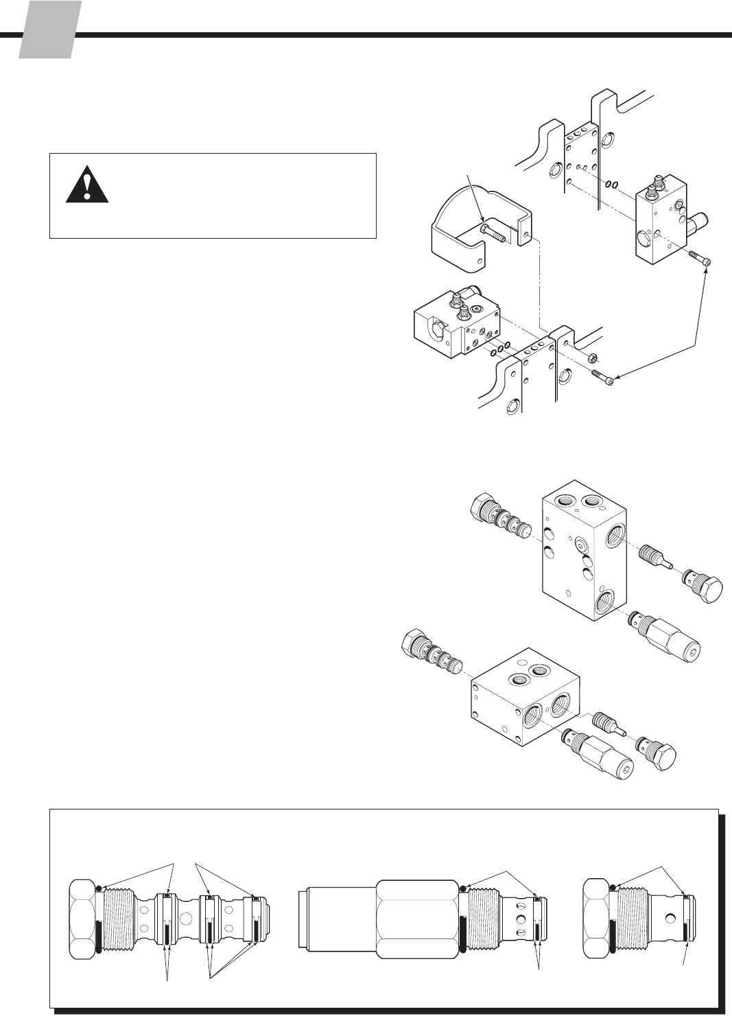
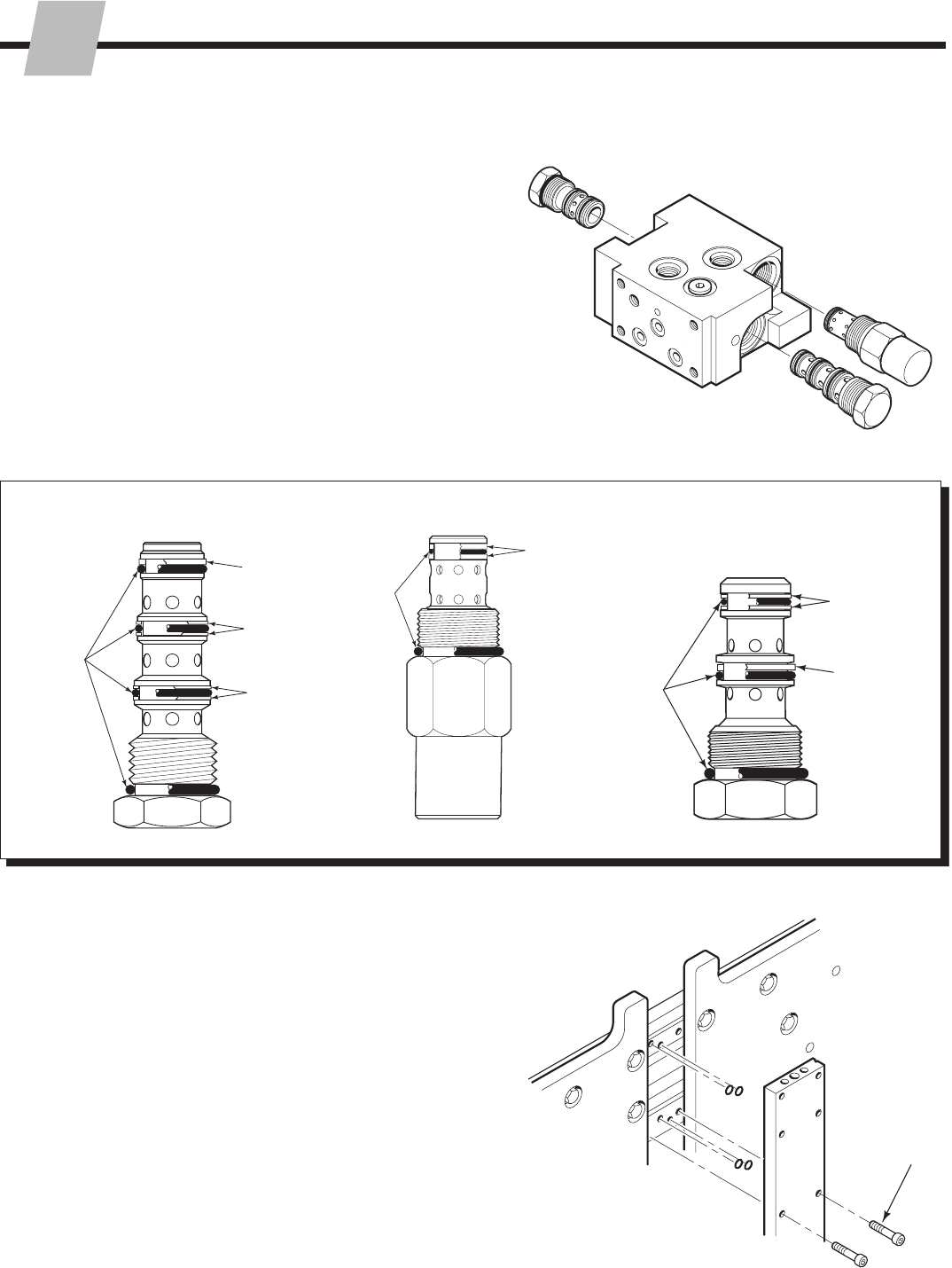
5.6 Valve and Manifold
5.6-1 Valve Removal
5.6-2 Valve Service
Class II Serial No.s less than 55E-FD-442
Class III Serial No.s less than 55E-FD-018
1 Remove the cartridges from the valve.
2 Remove the remaining fittings.
3 Remove the O-rings and back-up rings from the
cartridges.
4 Clean all parts with kerosene or cleaning solvent.
5 For reassembly, reverse the above procedures except
for the following special instructions:
The cartridge O-rings and back-up rings must be
installed as shown for proper hydraulic operation.
Lubricate the cartridges and seals with petroleum
jelly prior to reassembly.
•
•
Early 55E-FD
Class II Valve
Early 55E-FD
Class III Valve
O-Rings
Back-up Rings
O-Rings
Back-up Rings
O-Rings
Back-up Rings
2
3
Flow Divider Cartridge Crossover Relief Cartridge Check Valve Cartridge
1 Disconnect the hoses from the valve ports. Plug the
hoses and tag them for reassembly.
2 Attachments with Valve Guard – Remove the
capscrews fastening the valve guard to the frame.
For reassembly, tighten the capscrews to a torque of:
E-Series – 30 ft.-lbs. (40 Nm)
F-Series – 40 ft.-lbs. (55 Nm)
3 Remove the capscrews fastening the valve to the
manifold. For reassembly, tighten the capscrews to a
torque of 15 ft.-lbs. (20 Nm).
4 For reassembly, reverse the above procedures except
for the following special instructions:
Apply a small amount of thick grease to hold the
O-rings in position while installing the valve.
•
WARNING: Before removing any hoses,
relieve pressure in the hydraulic system.
Turn the truck off, then actuate the
truck control valve several times in both
directions.
Front Valve Type
3
Back Valve Type
215793-R2
ERVICE
S
37
SD0211.eps
CL0681.eps
GA0097.eps
O-Rings Back-up
Rings O-Rings
Back-up
Rings
O-Rings
Back-up
Rings
Flow Divider Cartridge Crossover Relief Cartridge Check Valve Cartridge
O-Rings
Back-up
Rings
Back-up
Ring
5.6-3 Valve Service
Class II Serial No.s greater than 55E-FD-509,
Class III Serial No.s greater than 55E-FD-104,
and 70E Models
1 Remove the cartridges from the valve.
2 Remove the remaining fittings.
3 Remove the O-rings and back-up rings from the
cartridges.
4 Clean all parts with kerosene or cleaning solvent.
5 For reassembly, reverse the above procedures except
for the following special instructions:
The cartridge O-Rings and back-up rings must be
installed as shown for proper hydraulic operation.
Lubricate the cartridges and seals with petroleum
jelly prior to reassembly.
•
•
SD0652.eps
215793-R2
ERVICE
S
38
SD0217.eps
5.6-5 Manifold Service
1 Remove the attachment from the truck as described in
Section 5.1.
2 Remove the valve from the manifold as described in
Section 5.6-1.
3 Remove the capscrews fastening the manifold to the
cylinders. Collect the O-rings. For reassembly, tighten
the capscrews to a torque of 15 ft.-lbs. (20 Nm).
4 Clean all parts with cleaning solvent.
5 Check for imperfections and scratches where O-rings
sit.
6 For reassembly, reverse the above procedures except
for the following special instructions:
• Apply a small amount of petroleum jelly to hold the
O-rings in position while installing the manifold.
3
5.6-4 Valve Service
45E/55E/65E-FDS Models, 80E and F-Series
Models
1 Remove the cartridges from the valve.
2 Remove the remaining fittings.
3 Remove the O-rings and back-up rings from the
cartridges.
4 Clean all parts with kerosene or cleaning solvent.
5 For reassembly, reverse the above procedures except
for the following special instructions:
The cartridge O-Rings and back-up rings must be
installed as shown for proper hydraulic operation.
Lubricate the cartridges and seals with petroleum
jelly prior to reassembly.
•
•
SD0652.eps
SD0651.eps
O-Rings
Back-up
Rings
O-Rings
O-Rings
Back-up
Rings
Flow Divider Cartridge Crossover Relief Cartridge
Back-up
Rings
Back-up
Ring
SD0653.eps
Back-up
Ring
Back-up
Rings
Check Valve Cartridge
CLAMP
TEST
OPEN
SD0650.eps
215793-R2
ERVICE
S
39
SD0490.eps
SD0198.eps
CL0623.eps
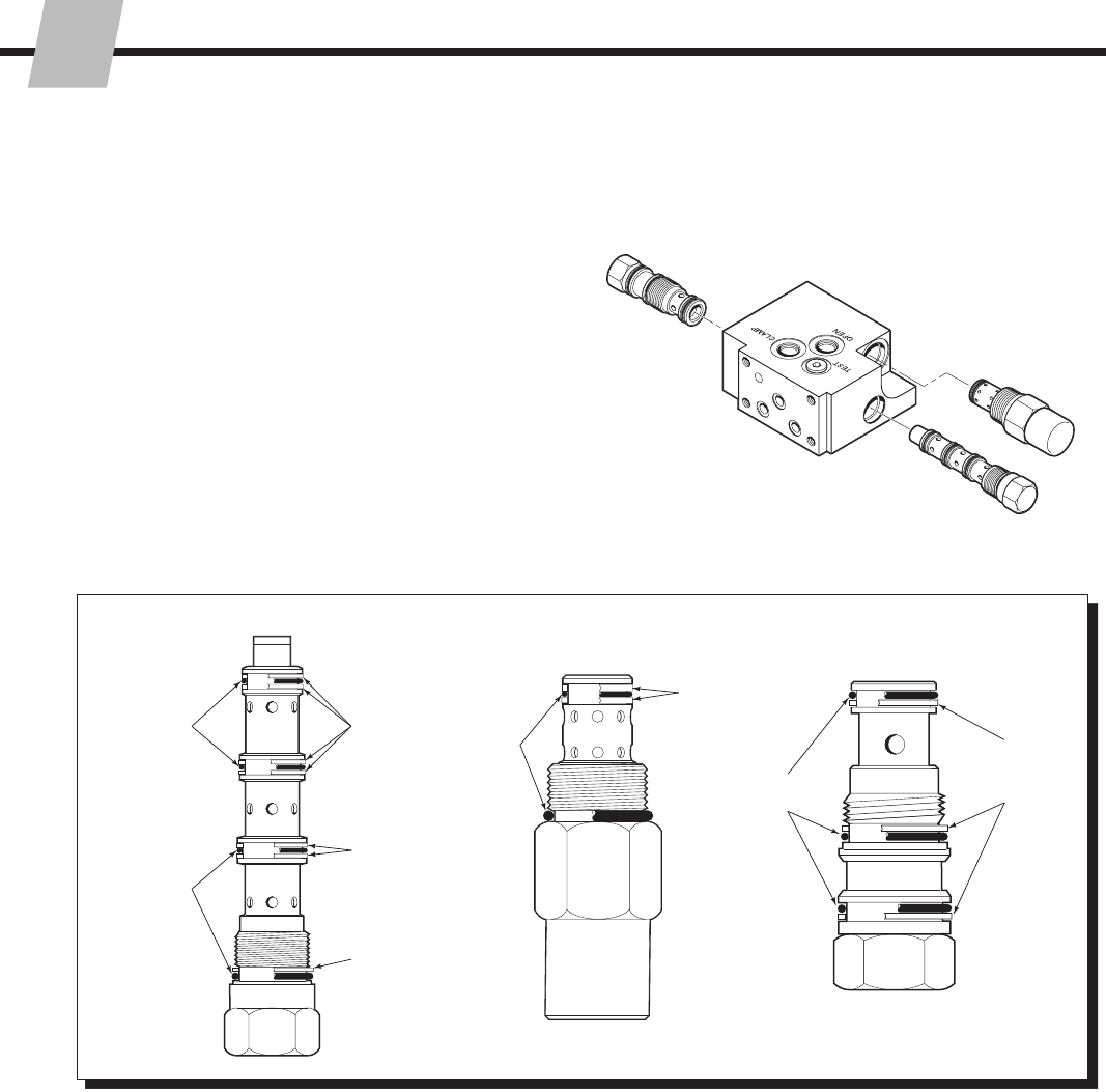
WARNING: Before installing
or removing hydraulic lines or
components, relieve pressure in the
hydraulic system. Turn the truck off
and open the truck auxiliary control
valves several times in both directions.
Relief Valve
Cartridge
Decrease
Pressure
(CCW)
5/16-in. (8 mm)
Allen Wrench
Adjustment
Screw
Cap
Increase
Pressure
(CW)
Valve
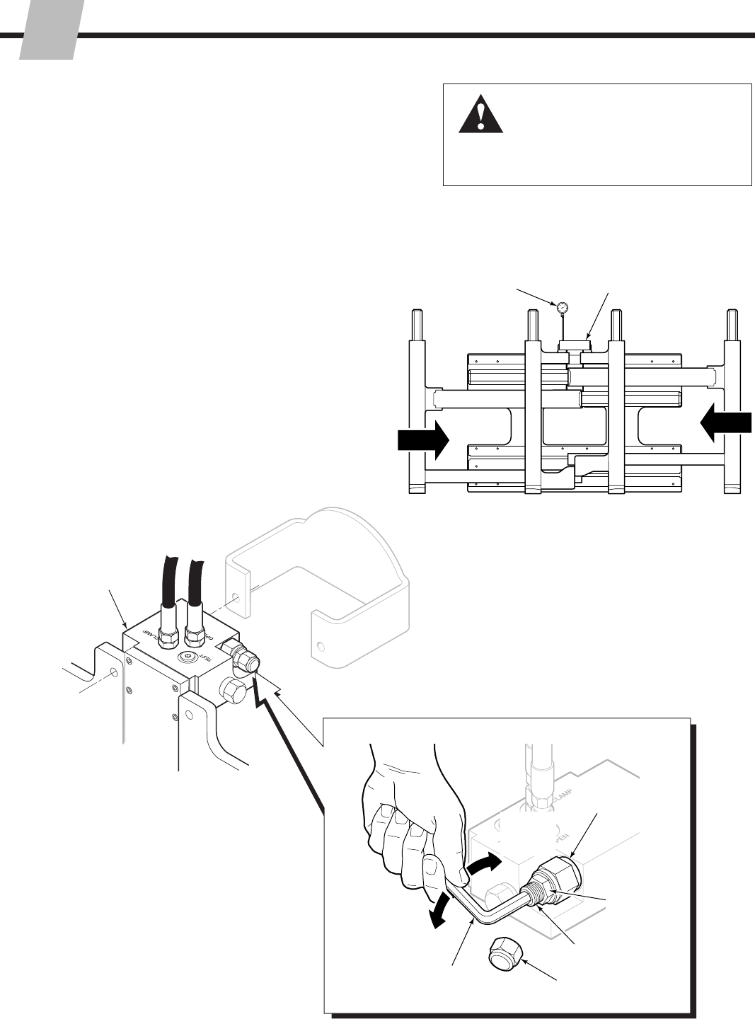
5.6-6 Valve Relief Adjustment
Class II Serial numbers greater than 55E-FD-509
Class III Serial numbers greater than 55E-FD-104
All FDS Models
4
2
3
Jam Nut
For over-pressure protection, the relief valve cartridge for
the FORK POSITION function should be adjusted to match
the truck hydraulic flow rate. MAXIMUM RELIEF VALVE
SETTING = 2600 psi (180 bar).
1 Confirm that the truck pressure is between 2300–2600
psi (160–180 bar).
2 Install a 3000 psi (200 bar) pressure gauge to the valve
TEST port (No. 4 O-ring fitting required).
3 Cycle the forks to full open, then slowly close the
forks fully. Hold the lever in the CLOSE position and
accelerate engine to develop full system pressure.
4 Adjust the relief cartridge for an indicated 2300 psi
(160 bar). Turn clockwise (CW) to increase pressure,
counterclockwise (CCW) to decrease pressure. Tighten
the jam nut and the replace cap.
215793-R2
ERVICE
S
40
SD0140.eps
5.7 Base Unit
5.7-1 Sideshift Bearing Service
1 Remove the attachment from the truck as described in
Section 5.1.
2 Center Mount Sideshifters – Loosen the support
bracket capscrews. Lift away the cylinder. For
reassembly, tighten the capscrews to a torque of:
48E/55E – 22 ft.-lbs. (30 Nm) ▲
70E/80E – 15 ft.-lbs. (20 Nm)
▲ Apply Loctite 242 (Blue) to threads
3 Inspect the upper bearing thickness. If either bearing
is worn to less than 1/16 in. (1.5 mm) thick on the back
surface, replace both bearings.
4 Inspect the lower bearing exposed thickness. If the
thickness is less than 1/16 in. (1.5 mm), replace both
bearings.
5 For reassembly, reverse the above procedures except
for the following special instructions:
Clean the upper and lower bearings and bearing
contact surfaces.
Locate the upper bearings in the anchor bracket
cutouts. Be careful not to install the bearings
backwards.
•
•2
Upper
Bearing
Upper
Bearing
1/16 in.
(1.5 mm)
minimum.
4
3
215793-R2
ERVICE
S
41
SD0141.eps
SD0142.eps
5.7-2 Lower Mounted Gas
Cylinder Service
1 Remove the bolt on stops from the outer fork lower
arms. For reassembly, clean and dry capscews
and threaded holes. Apply Loctite 242 (blue) to the
capscrew threads and tighten to a torque of:
48E/55E/60E/80E – 30 ft.-lbs. (40 Nm)
48F/55F/60F/70E – 48 ft.-bs. (65 Nm)
2 Remove the gas spring rod end guard. For reassembly,
tighten the capscrews to a torque of 22 ft.-lbs. (30 Nm).
5
2
4
3
1
Wire Clip
Rod end bolt
(May be installed from above)
WARNING: The outer forks must be fully
extended prior to disconnecting the gas
cylinder rod end.
3 Fully extend the outer forks.
4 Disconnect the gas spring rod end from the anchor by
removing the wire clip or rod end bolt.
5 Remove the gas spring by pulling with a quick jerk to
disengage the base end from the anchor.
6 For reassembly, reverse the above procedures.
215793-R2
ERVICE
S
42
SD0428.eps
5.7-3 Upper Mounted Gas
Cylinder Service
1 Fully close the inner forks.
WARNING: The outer forks must be fully
extended prior to disconnecting the gas
cylinder rod end.
2 Remove the capscrew fastening the gas cylinder
anchor plate to the frame. For reassembly, tighten the
capscrew to a torque of 22 ft.-lbs. (30 Nm).
3 Remove the gas spring by pulling with a quick jerk
to disengage the base end from the anchor plate, or
unscrew the threaded ball joint end.
4 For reassembly, reverse the above procedures except
as follows:
Assure rod end of gas cylinder is secure in pocket of
inner fork bracket, or, ball joint is properly connected.
A large “C”-Clamp may be helpful to compress the
gas cylinder during reassembly.
Use of a longer (M8 x 25L) capscrew will aid in
pulling the bearing retainer plates flush with the
frame during installation.
•
•
•
Longer Caspscrew
Bearing
Retainer
Plate
2Mounting
Capscrews
3
1
Gas Spring
TWO TYPES
Ball Joint,
Washer
5.7-4 Inner Fork Control (IFC)
E-Series
1 Remove attachment as described in Section 5.1
2 Remove capscrews from bracket. For reassembly,
tighten capscrews to a torque value of 30 ft.-lbs. (40 Nm).
3 IFC Spring Cylinder arrangement – Replace the
assembly.
4 IFC Gas Cylinder arrangement – Remove capscrew
from gas cylinder retainer. Remove gas cylinder. For
reassembly, tighten capscrews to a torque value of
6 ft.-lbs (8 Nm).
F-Series
1 Remove capscrews from spring can assembly. For
reassembly, apply Loctite 242 (blue) to capscrews and
tighten to a torque value of 30 ft.-lbs. (40 Nm).
2 Replace the assembly.
SD0654.eps
2
4
E-Series IFC Gas Cylinder
SD0655.eps
2
E-Series IFC Spring Cylinder
1
SD0656.eps
F-Series IFC Spring Cylinder
215793-R2
ERVICE
S
43
SD0658.eps
F-Series Spring Can Assembly
1 Open outer forks enough to not engage fork stops with
inner forks.
2 Remove attachment as described in Section 5.1
3 Remove anchor bracket from attachment by removing
the clevis pin and cotter hair pin from the sideshifter.
4 Remove spring cylinder capcrews from the back of the
attachment. For reassembly, tighten capscrews to a
torque of 30 ft.-lbs. (40 Nm).
5 Remove capscrews from the spring cylinder retainers.
For reassembly, apply Loctite 242 (blue) to capscrews
and tighten to a torque of 15 ft.-lbs. (20 Nm).
6 Remove spring cylinder assembly from the attachment.
7 Pull the rod out from spring cylinder and place a pin or
screwdriver into the second hole, as shown.
8 Move the retainer towards the spring cylinder assembly
and pull the rod pin out from the rod.
9 Remove the retainer from the rod.
5.7-5 Spring Cylinder Service
E-Series Spring Cylinder
1 Fully close the inner forks.
2 Remove capscrews from retainers. For reassembly,
tighten capscrews to a torque of 22 ft.-lbs. (30 Nm).
3 Remove retainer and pin.
4 Remove cylinder from brackets.
3
3
4
5
1
SD0161.eps
SD0657.eps
2
3
Pin
1
SD0659.eps
7
8
215793-R2
PECIFICATIONS
S
44
GA0091.eps
GA0082.eps
GA0090.eps
Truck Relief Setting
2300 psi (160 bar) Recommended
2600 psi (180 bar) Maximum
Truck Flow Volume ➀
Min. ➁ Recommended Max. ➂
E-Series 4 GPM 7 GPM 7 GPM
F-Series (15 L/min.) (26 L/min.) (26 L/min.)
➀ Single-Double Pallet Handlers are compatible with SAE 10W
petroleum base hydraulic fluid meeting Mil. Spec. MIL-0-5606 or
MIL-0-2104B. Use of synthetic or aqueous base hydraulic fluid
is not recommended. If fire resistant hydraulic fluid is required,
special seals must be used. Contact Cascade.
➁ Flow less than recommended will result in reduced or unequal arm
speed.
➂ Flow greater than maximum can result in excessive heating,
reduced system performance and reduced hydraulic system life.
Hoses and Fittings
All supply hoses must be at least No. 6 minimum.
All fittings must have an orifice size of 9/32 in. (7 mm)
minimum.
6.1-2 Auxiliary Valve Functions
ITA/ANSI Standards
6.1 Specifications
6.1-1 Hydraulics
6.1-3 Truck Carriage
Tilt
Back Retract
Forks
Sideshift
Right
Tilt
Forward
Hoist Up
Hoist Down
Spread
Forks
Sideshift
Left
Minimum Maximum
Carriage Mount Dimension (A) ITA (ISO)
Class II 14.96 in. (380.0 mm) 15.00 in. (381.0 mm)
Class III 18.68 in. (474.5 mm) 18.74 in. (476.0 mm)
Class IV 23.44 in. (595.5 mm) 23.50 in. (597.0 mm)
A
GA0028.eps
215793-R2
PECIFICATIONS
S
45
SD0661.eps
SD0660.eps
6.1-4 48E/55E/60E Torque Values
Fastener torque values for the E-Series Multi Load Handler
are shown in the table below in both U.S. and Metric units.
Torque values are also found in each specific service
procedure section throughout the Manual.
2
1
3
4
6
9
10
12
11
13 14
15
1
5
SD0662.eps
7
Ref. Fastener Location Size N.m Ft.-lbs.
1Bearing Retainer Capscrews M6 20 15 ■
M8 20 15 ■
2Cylinder Retainer Capscrew M8 25 18
3Cylinder End Cap Capscrews M8 25 18
4Anchor Bar Capscrews M10 20 15
5Center Spring Retainer Capscrews M8 20 15
6Lower Gas Spring Cylinder Capscrews M10 20 15
7Fork Stop Capscrews M10 65 48 ■
8Quick Disconnect Guide Capscrews M16 170 125 ■
9Inner Fork Control Bracket Capscrews M12 70 50
10 Center Sideshifter Bracket Capscrews M8 20 15 ■
11 Baseplate Bearing Capscrews M12 100 74
12 Upper Mounting Hook Capscrews M16 170 125
13 Manifold Capscrews M8 20 15
14 Valve Guard Capscrews M8 30 22
M10 65 48
15 Block Capscrew M10 20 15 ■
16 Inner/Outer Fork Capscrews M16 300 220 ■
17 Lower Hook Capscrews M16 170 125
18 Center Spring Bracket Capscrews M10 40 30
19 Inner Lower Bearing Retainer Capscrews M8 20 15
■ Use Loctite 242 (Blue)
8
16
17 18
19
215793-R2
PECIFICATIONS
S
46
SD0669.eps
SD0664.eps
SD0663.eps
6.1-5 70E/80E Torque Values
Ref. Fastener Location Size N.m Ft.-lbs.
1Top Bearing Retainer Capscrews M10 40 30 ■
2Cylinder Retainer Capscrews M8 25 18
3Cylinder End Cap Capscrews M8 25 18
4Bearing Retainer Capscrews M8 20 15 ■
5Gas Cylinder Head End Capscrew M10 40 30
6Inner Lower Bearing Retainer Capscrew M8 20 15
7Anchor Bar Capscrews M12 70 50
8Fork Stop Capscrews M10 65 48 ■
9Quick Disconnect Guide Capscrews M16 170 125 ■
10 Center Sideshifter Bracket Capscrews M8 20 15
11 Baseplate Bearing Capscrews M16 170 125
12 Upper Mounting Hook Capscrews M16 170 125
13 Manifold Capscrews M8 20 15
14 Valve Guard Capscrews M10 40 30
15 Class III Valve Capscrews M8 20 15
16 Gas Cylinder Bracket Capscrews M16 40 30
17 Spacer Block Capscrew M10 20 15
18 Inner/Outer Fork Capscrews M16 300 220 ■
19 Lower Hook Capscrews M16 170 125
20 Inner Fork Control Bracket Capscrews M12 70 50
21 Upper Fork Stop Capscrews M10 40 30
■ Use Loctite 242 (Blue)
2
13
4
6
9
10
12
11
13
14
15
5
7
16 17
18
19
20
SD0665.eps
8
21
215793-R2
PECIFICATIONS
S
47
SD0670.eps
SD0667.eps
SD0666.eps
6.1-6 48F/55F/60F Torque Values
Ref. Fastener Location Size N.m Ft.-lbs.
1Bearing Retainer Capscrews M8 20 15 ■
2Cylinder Retainer Capscrew M8 25 18
3Cylinder End Cap Capscrews M8 25 18
4Anchor Bar Capscrews M10 65 48
5Center Spring Retainer Capscrews M8 20 15
6Inner Lower Bearing Retainer Capscrews M8 20 15
7Inner Fork Control Bracket Capscrews M10 40 30 ■
8Fork Stop Capscrews M10 65 48 ■
9Quick Disconnect Guide Capscrews M16 170 125 ▲
10 Sideshift Plate Capscrews M6 20 15
11 Strap Capscrews M10 20 15 ■
12 Upper Mounting Hook Capscrews M16 170 125
13 Baseplate Bearing Capscrews M12 100 74
14 Valve Guard Capscrews M10 65 48
15 Manifold Capscrews M8 20 15
16 Anchor Bracket Capscrew M16 225 165
17 Inner/Outer Fork Capscrews M16 300 220 ■
18 Center Spring End Cap Capscrews M10 40 30
19 Lower Hook Capscrews M16 170 125
20 Center Spring Bracket Capscrews M10 40 30
21 Lower Bearing Bracket Capscrews M10 40 30
■ Use Loctite 242 (Blue)
▲ Use Loctite 277 (Red)
2
1
3
4
6
9
10
12
11
13
14
15
5
7
16
17
18
19
20
21
1
SD0668.eps
8
Cascade Corporation 2007 5-2007 Part Number 215793-R2
c
Do you have questions you need
answered right now? Call your
nearest Cascade Service Department.
Visit us online at www.cascorp.com
AMERICAS
Cascade Corporation
U.S. Headquarters
2201 NE 201st
Fairview, OR 97024-9718
Tel: 800-CASCADE (227-2233)
Fax: 888-329-8207
Cascade Canada Inc.
5570 Timberlea Blvd.
Mississauga, Ontario
Canada L4W-4M6
Tel: 905-629-7777
Fax: 905-629-7785
Cascade do Brasil
Rua João Guerra, 134
Macuco, Santos - SP
Brasil 11015-130
Tel: 55-13-2105-8800
Fax: 55-13-2105-8899
EUROPE-AFRICA
Cascade Italia S.R.L.
European Headquarters
Via Dell’Artigianato 1
37030 Vago di Lavagno (VR)
Italy
Tel: 39-045-8989111
Fax: 39-045-8989160
Cascade (Africa) Pty. Ltd.
PO Box 625, Isando 1600
60A Steel Road
Sparton, Kempton Park
South Africa
Tel: 27-11-975-9240
Fax: 27-11-394-1147
ASIA-PACIFIC
Cascade Japan Ltd.
2-23, 2-Chome,
Kukuchi Nishimachi
Amagasaki, Hyogo
Japan, 661-0978
Tel: 81-6-6420-9771
Fax: 81-6-6420-9777
Cascade Korea
121B 9L Namdong Ind.
Complex, 691-8 Gojan-Dong
Namdong-Ku
Inchon, Korea
Tel: +82-32-821-2051
Fax: +82-32-821-2055
Cascade-Xiamen
No. 668 Yangguang Rd.
Xinyang Industrial Zone
Haicang, Xiamen City
Fujian Province
P.R. China 361026
Tel: 86-592-651-2500
Fax: 86-592-651-2571
Cascade India Material
Handling Private Limited
No 34, Global Trade Centre
1/1 Rambaugh Colony
Lal Bahadur Shastri Road,
Navi Peth, Pune 411 030
(Maharashtra) India
Phone: +91 020 2432 5490
Fax: +91 020 2433 0881
Cascade Australia Pty. Ltd.
1445 Ipswich Road
Rocklea, QLD 4107
Australia
Tel: 1-800-227-223
Fax: +61 7 3373-7333
Cascade New Zealand
15 Ra Ora Drive
East Tamaki, Auckland
New Zealand
Tel: +64-9-273-9136
Fax: +64-9-273-9137
Sunstream Industries
Pte. Ltd.
18 Tuas South Street 5
Singapore 637796
Tel: +65-6795-7555
Fax: +65-6863-1368
