Osprey Hp Laser Jet Printer 2200 2200sm
User Manual: hp LaserJet Printer 2200
Open the PDF directly: View PDF ![]() .
.
Page Count: 324 [warning: Documents this large are best viewed by clicking the View PDF Link!]
- Table of contents
- List of figures
- List of tables
- Product information
- Operating requirements
- Site requirements
- Media specifications
- General media specifications
- Guidelines for selecting paper
- Media input options
- Tray 1 media sizes
- Tray 2 and tray 3 (250-sheet feeder)
- Tray 3 (500-sheet feeder)
- Envelope specifications
- Label specifications
- Transparency specifications
- Storing print media
- Shipping print media
- Paper fillers
- Testing media specifications
- Tools and suppliers
- Printer configuration
- Printer maintenance
- Theory of operation
- Removal and replacement
- Removal and replacement strategies
- Toner cartridge removal and replacement
- Cover and tray removal and replacement
- Internal disassembly and assembly
- Remove transfer roller
- Remove DIMM
- Remove formatter PCB
- Remove EIO shield and guide
- Remove fuser assembly
- Remove fuser-film heater assembly
- Remove pressure roller
- Remove duplexer tray
- Remove duplexer media guide
- Remove power supply assembly
- Remove upper output delivery roller
- Disassemble the upper output delivery roller
- Remove lower output delivery rollers
- Remove laser/scanner assembly
- Remove transport belts and rollers
- Remove ribbon cable harness
- Remove duplexer reverse motor
- Remove printer drive assembly
- Remove engine controller assembly
- Remove main motor
- Remove motor plate
- Remove printer drive assembly gears
- Remove tray 1 pickup roller
- Remove tray 1 pickup roller assembly
- Remove tray 1 separation pad assembly
- Remove tray 1 paper-sensor lever
- Remove tray 1 solenoid
- Remove tray 2 pickup roller assembly
- Replace tray 2 pickup roller
- Remove tray 2 pickup roller and refeeder assembly
- Remove tray 2 solenoid
- Remove duplexer drive gears and solenoid
- Remove registration assembly
- Remove tray 3 assembly connector
- Remove cooling fan
- Remove toner-cartridge guide
- Remove dc bias voltage contacts (leaf springs)
- Tray 3 disassembly and assembly
- Remove tray 3 (250-sheet feeder) cassette
- Remove tray 3 (250-sheet feeder) pickup roller
- Remove tray 3 (250-sheet feeder) feeder drive assembly
- Remove tray 3 (250 sheet-feeder) drive solenoid
- Remove tray 3 (500-sheet feeder) cassette
- Remove tray 3 (500-sheet feeder) pickup roller
- Remove tray 3 (500-sheet feeder) feeder drive assembly
- Remove tray 3 (500 sheet-feeder) drive solenoid
- Troubleshooting
- Parts and diagrams
- Introduction
- Illustrations and parts lists
- External covers and panels
- Top cover assembly
- Internal components
- Power supply assembly
- Printer drive assembly
- Cassette pickup assembly
- Fusing assembly
- PCB assembly location
- 250-sheet feeder external covers
- Tray 2 and 250-sheet feeder cassette
- 250-sheet feeder internal components
- 250-sheet feeder drive assembly
- 250-sheet feeder PCB assembly location
- 500-sheet feeder external covers
- 500-sheet feeder cassette
- 500-sheet feeder internal components
- 500-sheet feeder drive assembly
- 500-sheet feeder PCB assembly location
- Alphabetical parts list
- Numerical parts list
- Index

service
hp LaserJet 2200
HP LaserJet 2200 Series Printer
Service Manual _____________

Hewlett-Packard Company
11311 Chinden Boulevard
Boise, Idaho 83714 U.S.A.
© Copyright Hewlett-Packard Company,
1999, 2000
All Rights Reserved. Reproduction,
adaptation, or translation without prior written
permission is prohibited, except as allowed
under the copyright laws.
Part number: C4084-91077
First Edition, October 1999
Second Edition, September 2000
Warranty
The information contained in this document is
subject to change without notice.
Hewlett-Packard makes no warranty of any
kind with respect to this information.
HEWLETT-PACKARD SPECIFICALLY
DISCLAIMS THE IMPLIED WARRANTY OF
MERCHANTABILITY AND FITNESS FOR A
PARTICULAR PURPOSE.
Hewlett-Packard shall not be liable for any
direct, indirect, incidental, consequential, or
other damage alleged in connection with the
furnishing or use of this information.
Trademark Credits
Adobe® and PostScript® are trademarks of
Adobe Systems Incorporated which may be
registered in certain jurisdictions.
ENERGY STAR® is a U.S. registered service
mark of the United States Environmental
Protection Agency.
C7058-90936 iii
Table of contents
List of figures
List of tables
1 Product information
Printer features . . . . . . . . . . . . . . . . . . . . . . . . . . . . . . . . . . . . . . . . . . . . . . . . . . . 2
Identification . . . . . . . . . . . . . . . . . . . . . . . . . . . . . . . . . . . . . . . . . . . . . . . . . . . . . 4
Specifications . . . . . . . . . . . . . . . . . . . . . . . . . . . . . . . . . . . . . . . . . . . . . . . . . . . . 5
Product overview. . . . . . . . . . . . . . . . . . . . . . . . . . . . . . . . . . . . . . . . . . . . . . . . . . 7
External assembly locations . . . . . . . . . . . . . . . . . . . . . . . . . . . . . . . . . . . . . . 7
Internal assembly locations. . . . . . . . . . . . . . . . . . . . . . . . . . . . . . . . . . . . . . 10
Safety information . . . . . . . . . . . . . . . . . . . . . . . . . . . . . . . . . . . . . . . . . . . . . . . 11
Toner safety . . . . . . . . . . . . . . . . . . . . . . . . . . . . . . . . . . . . . . . . . . . . . . . . . 11
Laser safety . . . . . . . . . . . . . . . . . . . . . . . . . . . . . . . . . . . . . . . . . . . . . . . . . 12
LED safety . . . . . . . . . . . . . . . . . . . . . . . . . . . . . . . . . . . . . . . . . . . . . . . . . . 12
Regulatory information . . . . . . . . . . . . . . . . . . . . . . . . . . . . . . . . . . . . . . . . . 12
FCC regulations . . . . . . . . . . . . . . . . . . . . . . . . . . . . . . . . . . . . . . . . . . . . . . 12
Declaration of conformity . . . . . . . . . . . . . . . . . . . . . . . . . . . . . . . . . . . . . . . 12
Environmental Product Stewardship Program . . . . . . . . . . . . . . . . . . . . . . . . . . 13
Protecting the environment. . . . . . . . . . . . . . . . . . . . . . . . . . . . . . . . . . . . . . 13
Service approach . . . . . . . . . . . . . . . . . . . . . . . . . . . . . . . . . . . . . . . . . . . . . . . . 15
Bench repair warranty. . . . . . . . . . . . . . . . . . . . . . . . . . . . . . . . . . . . . . . . . . 15
HP Express Exchange . . . . . . . . . . . . . . . . . . . . . . . . . . . . . . . . . . . . . . . . . 15
Ordering information . . . . . . . . . . . . . . . . . . . . . . . . . . . . . . . . . . . . . . . . . . . 15
Supplemental documentation . . . . . . . . . . . . . . . . . . . . . . . . . . . . . . . . . . . 16
HP Direct ordering for genuine HP parts . . . . . . . . . . . . . . . . . . . . . . . . . . 16
Consumables . . . . . . . . . . . . . . . . . . . . . . . . . . . . . . . . . . . . . . . . . . . . . . . . 17
World Wide Web . . . . . . . . . . . . . . . . . . . . . . . . . . . . . . . . . . . . . . . . . . . . . 17
HP service parts information compact disc . . . . . . . . . . . . . . . . . . . . . . . . . 17
HP support assistant compact disc. . . . . . . . . . . . . . . . . . . . . . . . . . . . . . . . 17
Reseller sales and service support. . . . . . . . . . . . . . . . . . . . . . . . . . . . . . . . 17
Technical assistance. . . . . . . . . . . . . . . . . . . . . . . . . . . . . . . . . . . . . . . . . . . . . . 18
Worldwide sales and service offices. . . . . . . . . . . . . . . . . . . . . . . . . . . . . . . 18
iv Table of contents C7058-90936
2 Operating requirements
Site requirements . . . . . . . . . . . . . . . . . . . . . . . . . . . . . . . . . . . . . . . . . . . . . . . . 26
Operating environment. . . . . . . . . . . . . . . . . . . . . . . . . . . . . . . . . . . . . . . . . 26
Printer space requirement . . . . . . . . . . . . . . . . . . . . . . . . . . . . . . . . . . . . . . 27
Media specifications . . . . . . . . . . . . . . . . . . . . . . . . . . . . . . . . . . . . . . . . . . . . . . 28
General media specifications. . . . . . . . . . . . . . . . . . . . . . . . . . . . . . . . . . . . 28
Guidelines for selecting paper . . . . . . . . . . . . . . . . . . . . . . . . . . . . . . . . . . . 29
Media input options . . . . . . . . . . . . . . . . . . . . . . . . . . . . . . . . . . . . . . . . . . . 30
Tray 1 media sizes. . . . . . . . . . . . . . . . . . . . . . . . . . . . . . . . . . . . . . . . . . . . 31
Tray 2 and tray 3 (250-sheet feeder) . . . . . . . . . . . . . . . . . . . . . . . . . . . . . . 32
Tray 3 (500-sheet feeder) . . . . . . . . . . . . . . . . . . . . . . . . . . . . . . . . . . . . . . 32
Envelope specifications . . . . . . . . . . . . . . . . . . . . . . . . . . . . . . . . . . . . . . . . 33
Label specifications . . . . . . . . . . . . . . . . . . . . . . . . . . . . . . . . . . . . . . . . . . . 35
Transparency specifications. . . . . . . . . . . . . . . . . . . . . . . . . . . . . . . . . . . . . 36
Storing print media. . . . . . . . . . . . . . . . . . . . . . . . . . . . . . . . . . . . . . . . . . . . 36
Shipping print media . . . . . . . . . . . . . . . . . . . . . . . . . . . . . . . . . . . . . . . . . . 37
Paper fillers . . . . . . . . . . . . . . . . . . . . . . . . . . . . . . . . . . . . . . . . . . . . . . . . . 37
Testing media specifications . . . . . . . . . . . . . . . . . . . . . . . . . . . . . . . . . . . . 37
Tools and suppliers . . . . . . . . . . . . . . . . . . . . . . . . . . . . . . . . . . . . . . . . . . . 41
3 Printer configuration
Using the control panel . . . . . . . . . . . . . . . . . . . . . . . . . . . . . . . . . . . . . . . . . . . 44
Control panel . . . . . . . . . . . . . . . . . . . . . . . . . . . . . . . . . . . . . . . . . . . . . . . . 44
Control panel lights . . . . . . . . . . . . . . . . . . . . . . . . . . . . . . . . . . . . . . . . . . . 44
Job Cancel . . . . . . . . . . . . . . . . . . . . . . . . . . . . . . . . . . . . . . . . . . . . . . . . . . 44
Go . . . . . . . . . . . . . . . . . . . . . . . . . . . . . . . . . . . . . . . . . . . . . . . . . . . . . . . . 44
Printing a demo page. . . . . . . . . . . . . . . . . . . . . . . . . . . . . . . . . . . . . . . . . . 45
Self test/configuration page . . . . . . . . . . . . . . . . . . . . . . . . . . . . . . . . . . . . . 47
Self test/configuration-page elements . . . . . . . . . . . . . . . . . . . . . . . . . . . . . 48
JetDirect configuration page . . . . . . . . . . . . . . . . . . . . . . . . . . . . . . . . . . . . 49
JetDirect configuration-page elements. . . . . . . . . . . . . . . . . . . . . . . . . . . . . 50
Continuous self test . . . . . . . . . . . . . . . . . . . . . . . . . . . . . . . . . . . . . . . . . . . 50
Engine test . . . . . . . . . . . . . . . . . . . . . . . . . . . . . . . . . . . . . . . . . . . . . . . . . . . . . 51
Performing an engine test . . . . . . . . . . . . . . . . . . . . . . . . . . . . . . . . . . . . . . 51
Service mode . . . . . . . . . . . . . . . . . . . . . . . . . . . . . . . . . . . . . . . . . . . . . . . . . . . 52
Entering service mode . . . . . . . . . . . . . . . . . . . . . . . . . . . . . . . . . . . . . . . 52
Entering escape characters . . . . . . . . . . . . . . . . . . . . . . . . . . . . . . . . . . . . . 52
Setting the page count . . . . . . . . . . . . . . . . . . . . . . . . . . . . . . . . . . . . . . . . . 53
Setting the cold reset default . . . . . . . . . . . . . . . . . . . . . . . . . . . . . . . . . . . . 54
Resetting the printer . . . . . . . . . . . . . . . . . . . . . . . . . . . . . . . . . . . . . . . . . . . . . . 55
Cold reset. . . . . . . . . . . . . . . . . . . . . . . . . . . . . . . . . . . . . . . . . . . . . . . . . . . 55
NVRAM initialization . . . . . . . . . . . . . . . . . . . . . . . . . . . . . . . . . . . . . . . . . . 55
EIO card reset . . . . . . . . . . . . . . . . . . . . . . . . . . . . . . . . . . . . . . . . . . . . . . . 55
Network printing . . . . . . . . . . . . . . . . . . . . . . . . . . . . . . . . . . . . . . . . . . . . . . . . . 56
Installing an HP JetDirect EIO card . . . . . . . . . . . . . . . . . . . . . . . . . . . . . . . 56
IR printing . . . . . . . . . . . . . . . . . . . . . . . . . . . . . . . . . . . . . . . . . . . . . . . . . . . . . 58
Fast Infrared Receiver . . . . . . . . . . . . . . . . . . . . . . . . . . . . . . . . . . . . . . . . . 58
Using the FIR port . . . . . . . . . . . . . . . . . . . . . . . . . . . . . . . . . . . . . . . . . . . . 58
C7058-90936 v
4 Printer maintenance
Service check points . . . . . . . . . . . . . . . . . . . . . . . . . . . . . . . . . . . . . . . . . . . . . . 60
Periodic inspection of parts . . . . . . . . . . . . . . . . . . . . . . . . . . . . . . . . . . . . 60
Cleaning the printer and accessories . . . . . . . . . . . . . . . . . . . . . . . . . . . . . . . . . 61
General cleaning. . . . . . . . . . . . . . . . . . . . . . . . . . . . . . . . . . . . . . . . . . . . . . 61
Internal cleaning . . . . . . . . . . . . . . . . . . . . . . . . . . . . . . . . . . . . . . . . . . . . . . 62
Engine cleaning . . . . . . . . . . . . . . . . . . . . . . . . . . . . . . . . . . . . . . . . . . . . . . 64
Toner cartridge information . . . . . . . . . . . . . . . . . . . . . . . . . . . . . . . . . . . . . . . . . 65
Storage . . . . . . . . . . . . . . . . . . . . . . . . . . . . . . . . . . . . . . . . . . . . . . . . . . . . . 65
Handling instructions. . . . . . . . . . . . . . . . . . . . . . . . . . . . . . . . . . . . . . . . . . . 65
Refilled toner cartridges . . . . . . . . . . . . . . . . . . . . . . . . . . . . . . . . . . . . . . . . 66
Recycling toner cartridges . . . . . . . . . . . . . . . . . . . . . . . . . . . . . . . . . . . . . . 66
Toner cartridge weights . . . . . . . . . . . . . . . . . . . . . . . . . . . . . . . . . . . . . . . . 66
Toner cartridge life expectancy. . . . . . . . . . . . . . . . . . . . . . . . . . . . . . . . . . . 66
Saving toner with EconoMode . . . . . . . . . . . . . . . . . . . . . . . . . . . . . . . . . . . 66
Redistributing the toner. . . . . . . . . . . . . . . . . . . . . . . . . . . . . . . . . . . . . . . . . 67
5 Theory of operation
Basic operations . . . . . . . . . . . . . . . . . . . . . . . . . . . . . . . . . . . . . . . . . . . . . . . . . 70
Power-on sequence . . . . . . . . . . . . . . . . . . . . . . . . . . . . . . . . . . . . . . . . . . . 70
Basic print-period operating sequences . . . . . . . . . . . . . . . . . . . . . . . . . . . . 71
Printer timing. . . . . . . . . . . . . . . . . . . . . . . . . . . . . . . . . . . . . . . . . . . . . . . . . 72
Printer functionality and operation. . . . . . . . . . . . . . . . . . . . . . . . . . . . . . . . . . . . 73
Formatter system . . . . . . . . . . . . . . . . . . . . . . . . . . . . . . . . . . . . . . . . . . . . . 74
Formatter hardware . . . . . . . . . . . . . . . . . . . . . . . . . . . . . . . . . . . . . . . . . . . 75
Formatter subsystem . . . . . . . . . . . . . . . . . . . . . . . . . . . . . . . . . . . . . . . . . . 75
Engine control system. . . . . . . . . . . . . . . . . . . . . . . . . . . . . . . . . . . . . . . . . . 77
Engine control subsystems . . . . . . . . . . . . . . . . . . . . . . . . . . . . . . . . . . . . . 78
Image formation system . . . . . . . . . . . . . . . . . . . . . . . . . . . . . . . . . . . . . . . . 80
Pickup/feed system. . . . . . . . . . . . . . . . . . . . . . . . . . . . . . . . . . . . . . . . . . . . 86
Sheet feeder . . . . . . . . . . . . . . . . . . . . . . . . . . . . . . . . . . . . . . . . . . . . . . . . . . . . 88
Media detection. . . . . . . . . . . . . . . . . . . . . . . . . . . . . . . . . . . . . . . . . . . . . . . . . . 90
Media detection. . . . . . . . . . . . . . . . . . . . . . . . . . . . . . . . . . . . . . . . . . . . . . . 90
Media-size detection. . . . . . . . . . . . . . . . . . . . . . . . . . . . . . . . . . . . . . . . . . . 90
Jam detection . . . . . . . . . . . . . . . . . . . . . . . . . . . . . . . . . . . . . . . . . . . . . . . . . . . 91
Pickup sensors . . . . . . . . . . . . . . . . . . . . . . . . . . . . . . . . . . . . . . . . . . . . . . . 91
Delivery sensors . . . . . . . . . . . . . . . . . . . . . . . . . . . . . . . . . . . . . . . . . . . . . . 91
Reversing sensors . . . . . . . . . . . . . . . . . . . . . . . . . . . . . . . . . . . . . . . . . . . . 92
Duplexer sensors . . . . . . . . . . . . . . . . . . . . . . . . . . . . . . . . . . . . . . . . . . . . . 92
Paper-feed sensor . . . . . . . . . . . . . . . . . . . . . . . . . . . . . . . . . . . . . . . . . . . . 92
6 Removal and replacement
Removal and replacement strategies . . . . . . . . . . . . . . . . . . . . . . . . . . . . . . . . . 95
Required tools. . . . . . . . . . . . . . . . . . . . . . . . . . . . . . . . . . . . . . . . . . . . . . . . 95
Toner cartridge removal and replacement . . . . . . . . . . . . . . . . . . . . . . . . . . . . . 96
Remove the toner cartridge . . . . . . . . . . . . . . . . . . . . . . . . . . . . . . . . . . . . . 96
Cover and tray removal and replacement . . . . . . . . . . . . . . . . . . . . . . . . . . . . . . 97
Remove tray 3. . . . . . . . . . . . . . . . . . . . . . . . . . . . . . . . . . . . . . . . . . . . . . . . 97
Remove the cassette from tray 2 . . . . . . . . . . . . . . . . . . . . . . . . . . . . . . . . . 97
Remove I/O cover . . . . . . . . . . . . . . . . . . . . . . . . . . . . . . . . . . . . . . . . . . . . 98
Remove EIO card . . . . . . . . . . . . . . . . . . . . . . . . . . . . . . . . . . . . . . . . . . . . . 98
Remove DIMM cover . . . . . . . . . . . . . . . . . . . . . . . . . . . . . . . . . . . . . . . . . . 99
Remove rear cover . . . . . . . . . . . . . . . . . . . . . . . . . . . . . . . . . . . . . . . . . . . 100
Remove top cover. . . . . . . . . . . . . . . . . . . . . . . . . . . . . . . . . . . . . . . . . . . . 102
Remove left cover. . . . . . . . . . . . . . . . . . . . . . . . . . . . . . . . . . . . . . . . . . . . 105
Remove tray 1. . . . . . . . . . . . . . . . . . . . . . . . . . . . . . . . . . . . . . . . . . . . . . . 106
Internal disassembly and assembly . . . . . . . . . . . . . . . . . . . . . . . . . . . . . . . . . 109
vi Table of contents C7058-90936
Remove transfer roller . . . . . . . . . . . . . . . . . . . . . . . . . . . . . . . . . . . . . . . . 109
Remove DIMM . . . . . . . . . . . . . . . . . . . . . . . . . . . . . . . . . . . . . . . . . . . . . . 111
Remove formatter PCB . . . . . . . . . . . . . . . . . . . . . . . . . . . . . . . . . . . . . . . 112
Remove EIO shield and guide . . . . . . . . . . . . . . . . . . . . . . . . . . . . . . . . . . 113
Remove fuser assembly. . . . . . . . . . . . . . . . . . . . . . . . . . . . . . . . . . . . . . . 114
Remove fuser-film heater assembly. . . . . . . . . . . . . . . . . . . . . . . . . . . . . . 117
Remove pressure roller . . . . . . . . . . . . . . . . . . . . . . . . . . . . . . . . . . . . . . . 119
Remove duplexer tray . . . . . . . . . . . . . . . . . . . . . . . . . . . . . . . . . . . . . . . . 120
Remove duplexer media guide . . . . . . . . . . . . . . . . . . . . . . . . . . . . . . . . . 121
Remove power supply assembly . . . . . . . . . . . . . . . . . . . . . . . . . . . . . . . . 122
Remove upper output delivery roller . . . . . . . . . . . . . . . . . . . . . . . . . . . . . 125
Disassemble the upper output delivery roller . . . . . . . . . . . . . . . . . . . . . . . 126
Remove lower output delivery rollers. . . . . . . . . . . . . . . . . . . . . . . . . . . . . 127
Remove laser/scanner assembly. . . . . . . . . . . . . . . . . . . . . . . . . . . . . . . . 128
Remove transport belts and rollers . . . . . . . . . . . . . . . . . . . . . . . . . . . . . . 130
Remove ribbon cable harness . . . . . . . . . . . . . . . . . . . . . . . . . . . . . . . . . . 132
Remove duplexer reverse motor . . . . . . . . . . . . . . . . . . . . . . . . . . . . . . . . 133
Remove printer drive assembly . . . . . . . . . . . . . . . . . . . . . . . . . . . . . . . . . 134
Remove engine controller assembly . . . . . . . . . . . . . . . . . . . . . . . . . . . . . 135
Remove main motor. . . . . . . . . . . . . . . . . . . . . . . . . . . . . . . . . . . . . . . . . . 136
Remove motor plate. . . . . . . . . . . . . . . . . . . . . . . . . . . . . . . . . . . . . . . . . . 137
Remove printer drive assembly gears . . . . . . . . . . . . . . . . . . . . . . . . . . . . 139
Remove tray 1 pickup roller . . . . . . . . . . . . . . . . . . . . . . . . . . . . . . . . . . . . 140
Remove tray 1 pickup roller assembly . . . . . . . . . . . . . . . . . . . . . . . . . . . . 142
Remove tray 1 separation pad assembly. . . . . . . . . . . . . . . . . . . . . . . . . . 145
Remove tray 1 paper-sensor lever. . . . . . . . . . . . . . . . . . . . . . . . . . . . . . . 146
Remove tray 1 solenoid . . . . . . . . . . . . . . . . . . . . . . . . . . . . . . . . . . . . . . . 148
Remove tray 2 pickup roller assembly . . . . . . . . . . . . . . . . . . . . . . . . . . . . 149
Replace tray 2 pickup roller . . . . . . . . . . . . . . . . . . . . . . . . . . . . . . . . . . . . 152
Remove tray 2 pickup roller and refeeder assembly . . . . . . . . . . . . . . . . . 153
Remove tray 2 solenoid . . . . . . . . . . . . . . . . . . . . . . . . . . . . . . . . . . . . . . . 156
Remove duplexer drive gears and solenoid. . . . . . . . . . . . . . . . . . . . . . . . 157
Remove registration assembly. . . . . . . . . . . . . . . . . . . . . . . . . . . . . . . . . . 158
Remove tray 3 assembly connector. . . . . . . . . . . . . . . . . . . . . . . . . . . . . . 160
Remove cooling fan . . . . . . . . . . . . . . . . . . . . . . . . . . . . . . . . . . . . . . . . . . 161
Remove toner-cartridge guide . . . . . . . . . . . . . . . . . . . . . . . . . . . . . . . . . . 162
Remove dc bias voltage contacts (leaf springs). . . . . . . . . . . . . . . . . . . . . 164
Tray 3 disassembly and assembly . . . . . . . . . . . . . . . . . . . . . . . . . . . . . . . . . . 166
Remove tray 3 (250-sheet feeder) cassette. . . . . . . . . . . . . . . . . . . . . . . . 166
Remove tray 3 (250-sheet feeder) pickup roller. . . . . . . . . . . . . . . . . . . . . 167
Remove tray 3 (250-sheet feeder) feeder drive assembly. . . . . . . . . . . . . 168
Remove tray 3 (250 sheet-feeder) drive solenoid . . . . . . . . . . . . . . . . . . . 170
Remove tray 3 (500-sheet feeder) cassette. . . . . . . . . . . . . . . . . . . . . . . . 171
Remove tray 3 (500-sheet feeder) pickup roller. . . . . . . . . . . . . . . . . . . . . 172
Remove tray 3 (500-sheet feeder) feeder drive assembly. . . . . . . . . . . . . 173
Remove tray 3 (500 sheet-feeder) drive solenoid . . . . . . . . . . . . . . . . . . . 175
7 Troubleshooting
Troubleshooting process . . . . . . . . . . . . . . . . . . . . . . . . . . . . . . . . . . . . . . . . . 178
Preliminary operating checks . . . . . . . . . . . . . . . . . . . . . . . . . . . . . . . . . . 178
Basic fault isolation . . . . . . . . . . . . . . . . . . . . . . . . . . . . . . . . . . . . . . . . . . 178
Troubleshooting process flow . . . . . . . . . . . . . . . . . . . . . . . . . . . . . . . . . . 180
Power-on . . . . . . . . . . . . . . . . . . . . . . . . . . . . . . . . . . . . . . . . . . . . . . . . . . . . . 181
Troubleshooting with control-panel messages . . . . . . . . . . . . . . . . . . . . . . . . . 182
Control panel lights . . . . . . . . . . . . . . . . . . . . . . . . . . . . . . . . . . . . . . . . . . 182
Control-panel light messages . . . . . . . . . . . . . . . . . . . . . . . . . . . . . . . . . . 182
Media-handling problems . . . . . . . . . . . . . . . . . . . . . . . . . . . . . . . . . . . . . . . . . 192
Print test pages . . . . . . . . . . . . . . . . . . . . . . . . . . . . . . . . . . . . . . . . . . . . . 192
C7058-90936 vii
Engine test . . . . . . . . . . . . . . . . . . . . . . . . . . . . . . . . . . . . . . . . . . . . . . . . . 192
Self test/configuration page . . . . . . . . . . . . . . . . . . . . . . . . . . . . . . . . . . . . 192
Jam troubleshooting . . . . . . . . . . . . . . . . . . . . . . . . . . . . . . . . . . . . . . . . . . 193
Media problems . . . . . . . . . . . . . . . . . . . . . . . . . . . . . . . . . . . . . . . . . . . . . 197
Evaluate the test pages. . . . . . . . . . . . . . . . . . . . . . . . . . . . . . . . . . . . . . . . . . . 198
Status-log messages . . . . . . . . . . . . . . . . . . . . . . . . . . . . . . . . . . . . . . . . . 198
Verify installed options . . . . . . . . . . . . . . . . . . . . . . . . . . . . . . . . . . . . . . . . 198
Image-formation troubleshooting. . . . . . . . . . . . . . . . . . . . . . . . . . . . . . . . . . . . 199
Image defect tables. . . . . . . . . . . . . . . . . . . . . . . . . . . . . . . . . . . . . . . . . . . 201
Repetitive defect ruler. . . . . . . . . . . . . . . . . . . . . . . . . . . . . . . . . . . . . . . . . 207
Half self test functional check . . . . . . . . . . . . . . . . . . . . . . . . . . . . . . . . . . . 208
Drum-rotation functional check . . . . . . . . . . . . . . . . . . . . . . . . . . . . . . . . . . 208
Media troubleshooting. . . . . . . . . . . . . . . . . . . . . . . . . . . . . . . . . . . . . . . . . . . . 209
Determine the problem source: print media or printer . . . . . . . . . . . . . . . . 209
Isolate a paper path . . . . . . . . . . . . . . . . . . . . . . . . . . . . . . . . . . . . . . . . . . 209
Isolate a media brand . . . . . . . . . . . . . . . . . . . . . . . . . . . . . . . . . . . . . . . . . 210
Isolate a media type . . . . . . . . . . . . . . . . . . . . . . . . . . . . . . . . . . . . . . . . . . 211
Evaluate media use practices. . . . . . . . . . . . . . . . . . . . . . . . . . . . . . . . . . . 215
Evaluate environmental conditions . . . . . . . . . . . . . . . . . . . . . . . . . . . . . . . 215
Communication troubleshooting . . . . . . . . . . . . . . . . . . . . . . . . . . . . . . . . . . . . 217
Communications check. . . . . . . . . . . . . . . . . . . . . . . . . . . . . . . . . . . . . . . . 217
Test message . . . . . . . . . . . . . . . . . . . . . . . . . . . . . . . . . . . . . . . . . . . . . . . 217
EIO troubleshooting . . . . . . . . . . . . . . . . . . . . . . . . . . . . . . . . . . . . . . . . . . 217
JetDirect configuration-page elements . . . . . . . . . . . . . . . . . . . . . . . . . . . . 219
JetDirect configuration . . . . . . . . . . . . . . . . . . . . . . . . . . . . . . . . . . . . . . . . 219
Reference diagrams . . . . . . . . . . . . . . . . . . . . . . . . . . . . . . . . . . . . . . . . . . . . . 220
8 Parts and diagrams
Introduction . . . . . . . . . . . . . . . . . . . . . . . . . . . . . . . . . . . . . . . . . . . . . . . . . . . . 228
Ordering parts. . . . . . . . . . . . . . . . . . . . . . . . . . . . . . . . . . . . . . . . . . . . . . . 228
Ordering consumables . . . . . . . . . . . . . . . . . . . . . . . . . . . . . . . . . . . . . . . . 228
Consumables, accessories, and supplies. . . . . . . . . . . . . . . . . . . . . . . . . . 229
Common fasteners and torque values . . . . . . . . . . . . . . . . . . . . . . . . . . . . 230
Illustrations and parts lists . . . . . . . . . . . . . . . . . . . . . . . . . . . . . . . . . . . . . . . . . 231
External covers and panels. . . . . . . . . . . . . . . . . . . . . . . . . . . . . . . . . . . . . 231
Top cover assembly . . . . . . . . . . . . . . . . . . . . . . . . . . . . . . . . . . . . . . . . . . 233
Internal components . . . . . . . . . . . . . . . . . . . . . . . . . . . . . . . . . . . . . . . . . . 235
Power supply assembly . . . . . . . . . . . . . . . . . . . . . . . . . . . . . . . . . . . . . . . 245
Printer drive assembly . . . . . . . . . . . . . . . . . . . . . . . . . . . . . . . . . . . . . . . . 247
Cassette pickup assembly . . . . . . . . . . . . . . . . . . . . . . . . . . . . . . . . . . . . . 249
Fusing assembly. . . . . . . . . . . . . . . . . . . . . . . . . . . . . . . . . . . . . . . . . . . . . 251
PCB assembly location. . . . . . . . . . . . . . . . . . . . . . . . . . . . . . . . . . . . . . . . 253
250-sheet feeder external covers . . . . . . . . . . . . . . . . . . . . . . . . . . . . . . . 255
Tray 2 and 250-sheet feeder cassette . . . . . . . . . . . . . . . . . . . . . . . . . . . . 257
250-sheet feeder internal components . . . . . . . . . . . . . . . . . . . . . . . . . . . . 259
250-sheet feeder drive assembly . . . . . . . . . . . . . . . . . . . . . . . . . . . . . . . . 261
250-sheet feeder PCB assembly location . . . . . . . . . . . . . . . . . . . . . . . . . 263
500-sheet feeder external covers . . . . . . . . . . . . . . . . . . . . . . . . . . . . . . . 265
500-sheet feeder cassette . . . . . . . . . . . . . . . . . . . . . . . . . . . . . . . . . . . . . 267
500-sheet feeder internal components . . . . . . . . . . . . . . . . . . . . . . . . . . . . 269
500-sheet feeder drive assembly . . . . . . . . . . . . . . . . . . . . . . . . . . . . . . . . 271
500-sheet feeder PCB assembly location. . . . . . . . . . . . . . . . . . . . . . . . . . 273
Alphabetical parts list . . . . . . . . . . . . . . . . . . . . . . . . . . . . . . . . . . . . . . . . . . . . 275
Numerical parts list . . . . . . . . . . . . . . . . . . . . . . . . . . . . . . . . . . . . . . . . . . . . . . 284
Index
viii Table of contents C7058-90936
C7058-90936 ix
List of figures
Figure 1. Sample identification label . . . . . . . . . . . . . . . . . . . . . . . . . . . . . . . . . . 4
Figure 2. External assembly locations (1 of 5) . . . . . . . . . . . . . . . . . . . . . . . . . . . 7
Figure 3. External assembly locations (2 of 5) . . . . . . . . . . . . . . . . . . . . . . . . . . . 7
Figure 4. External assembly locations (3 of 5) . . . . . . . . . . . . . . . . . . . . . . . . . . . 8
Figure 5. External assembly locations (4 of 5) . . . . . . . . . . . . . . . . . . . . . . . . . . . 8
Figure 6. External assembly locations (5 of 5) . . . . . . . . . . . . . . . . . . . . . . . . . . . 9
Figure 7. Internal assembly locations (1 of 2) . . . . . . . . . . . . . . . . . . . . . . . . . . 10
Figure 8. Internal assembly locations (2 of 2) . . . . . . . . . . . . . . . . . . . . . . . . . . 10
Figure 9. Top view . . . . . . . . . . . . . . . . . . . . . . . . . . . . . . . . . . . . . . . . . . . . . . . 27
Figure 10. Side view . . . . . . . . . . . . . . . . . . . . . . . . . . . . . . . . . . . . . . . . . . . . . . 27
Figure 11. Media input trays (250-sheet feeder installed) . . . . . . . . . . . . . . . . . 30
Figure 12. Media input trays (500-sheet feeder installed) . . . . . . . . . . . . . . . . . 30
Figure 13. Double side seam . . . . . . . . . . . . . . . . . . . . . . . . . . . . . . . . . . . . . . . 34
Figure 14. Long, short, and diagonal grain curl . . . . . . . . . . . . . . . . . . . . . . . . . 39
Figure 15. Measuring curl . . . . . . . . . . . . . . . . . . . . . . . . . . . . . . . . . . . . . . . . . . 40
Figure 16. Control panel layout . . . . . . . . . . . . . . . . . . . . . . . . . . . . . . . . . . . . . 44
Figure 17. Demo page (front) . . . . . . . . . . . . . . . . . . . . . . . . . . . . . . . . . . . . . . . 45
Figure 18. Demo page (back) . . . . . . . . . . . . . . . . . . . . . . . . . . . . . . . . . . . . . . . 46
Figure 19. Self test/configuration page . . . . . . . . . . . . . . . . . . . . . . . . . . . . . . . . 47
Figure 20. JetDirect configuration page . . . . . . . . . . . . . . . . . . . . . . . . . . . . . . . 49
Figure 21. Engine-test button . . . . . . . . . . . . . . . . . . . . . . . . . . . . . . . . . . . . . . . 51
Figure 22. Power cord. . . . . . . . . . . . . . . . . . . . . . . . . . . . . . . . . . . . . . . . . . . . . 56
Figure 23. Interface cables. . . . . . . . . . . . . . . . . . . . . . . . . . . . . . . . . . . . . . . . . 56
Figure 24. HP JetDirect EIO card. . . . . . . . . . . . . . . . . . . . . . . . . . . . . . . . . . . . 56
Figure 25. Network cable. . . . . . . . . . . . . . . . . . . . . . . . . . . . . . . . . . . . . . . . . . 57
Figure 26. Interface cable door. . . . . . . . . . . . . . . . . . . . . . . . . . . . . . . . . . . . . . 57
Figure 27. FIR port . . . . . . . . . . . . . . . . . . . . . . . . . . . . . . . . . . . . . . . . . . . . . . . 58
Figure 28. Top cover . . . . . . . . . . . . . . . . . . . . . . . . . . . . . . . . . . . . . . . . . . . . . 62
Figure 29. Remove toner cartridge . . . . . . . . . . . . . . . . . . . . . . . . . . . . . . . . . . . 62
Figure 30. Wipe residue . . . . . . . . . . . . . . . . . . . . . . . . . . . . . . . . . . . . . . . . . . . 63
Figure 31. Replace toner cartridge . . . . . . . . . . . . . . . . . . . . . . . . . . . . . . . . . . . 63
Figure 32. Print sample . . . . . . . . . . . . . . . . . . . . . . . . . . . . . . . . . . . . . . . . . . . 64
Figure 33. Redistributing the toner . . . . . . . . . . . . . . . . . . . . . . . . . . . . . . . . . . . 67
Figure 34. Timing chart . . . . . . . . . . . . . . . . . . . . . . . . . . . . . . . . . . . . . . . . . . . 72
Figure 35. Printer functionality divided into systems . . . . . . . . . . . . . . . . . . . . . 73
Figure 36. Formatter system . . . . . . . . . . . . . . . . . . . . . . . . . . . . . . . . . . . . . . . 74
Figure 37. Engine control system . . . . . . . . . . . . . . . . . . . . . . . . . . . . . . . . . . . . 77
Figure 38. Power supply PCB . . . . . . . . . . . . . . . . . . . . . . . . . . . . . . . . . . . . . . 79
Figure 39. Image formation system . . . . . . . . . . . . . . . . . . . . . . . . . . . . . . . . . . 80
Figure 40. Toner cartridge . . . . . . . . . . . . . . . . . . . . . . . . . . . . . . . . . . . . . . . . . 81
Figure 41. Photosensitive drum . . . . . . . . . . . . . . . . . . . . . . . . . . . . . . . . . . . . . 81
Figure 42. Cleaning stage . . . . . . . . . . . . . . . . . . . . . . . . . . . . . . . . . . . . . . . . . 82
Figure 43. Primary charging roller . . . . . . . . . . . . . . . . . . . . . . . . . . . . . . . . . . . 82
Figure 44. Laser/scanner system . . . . . . . . . . . . . . . . . . . . . . . . . . . . . . . . . . . . 83
Figure 45. Latent electrostatic image formation . . . . . . . . . . . . . . . . . . . . . . . . . 84
Figure 46. Transferring the toner image on the drum . . . . . . . . . . . . . . . . . . . . . 85
Figure 47. Fuser film and pressure roller . . . . . . . . . . . . . . . . . . . . . . . . . . . . . . 85
Figure 48. Pickup/feed system . . . . . . . . . . . . . . . . . . . . . . . . . . . . . . . . . . . . . 87
Figure 49. Pickup feed paper-path . . . . . . . . . . . . . . . . . . . . . . . . . . . . . . . . . . 88
x List of figures C7058-90936
Figure 50. Pickup feed . . . . . . . . . . . . . . . . . . . . . . . . . . . . . . . . . . . . . . . . . . . . 89
Figure 51. Media detection sensors . . . . . . . . . . . . . . . . . . . . . . . . . . . . . . . . . 90
Figure 52. Open the toner cartridge door . . . . . . . . . . . . . . . . . . . . . . . . . . . . . 96
Figure 53. Remove the toner cartridge . . . . . . . . . . . . . . . . . . . . . . . . . . . . . . . 96
Figure 54. Remove tray 3 (500-sheet feeder shown) . . . . . . . . . . . . . . . . . . . . 97
Figure 55. Remove cassette from tray 2 . . . . . . . . . . . . . . . . . . . . . . . . . . . . . . 97
Figure 56. Remove the I/O Cover . . . . . . . . . . . . . . . . . . . . . . . . . . . . . . . . . . . 98
Figure 57. Remove the EIO card . . . . . . . . . . . . . . . . . . . . . . . . . . . . . . . . . . . . 98
Figure 58. DIMM cover release button . . . . . . . . . . . . . . . . . . . . . . . . . . . . . . . 99
Figure 59. Remove DIMM cover . . . . . . . . . . . . . . . . . . . . . . . . . . . . . . . . . . . . 99
Figure 60. Disengage the diverter locking pins . . . . . . . . . . . . . . . . . . . . . . . . 100
Figure 61. Rear cover mounting screws . . . . . . . . . . . . . . . . . . . . . . . . . . . . . 100
Figure 62. Rear cover retaining tabs . . . . . . . . . . . . . . . . . . . . . . . . . . . . . . . . 101
Figure 63. Remove rear cover . . . . . . . . . . . . . . . . . . . . . . . . . . . . . . . . . . . . . 101
Figure 64. Release door swing arm . . . . . . . . . . . . . . . . . . . . . . . . . . . . . . . . . 102
Figure 65. Remove mounting screws . . . . . . . . . . . . . . . . . . . . . . . . . . . . . . . 103
Figure 66. Remove mounting screws . . . . . . . . . . . . . . . . . . . . . . . . . . . . . . . 103
Figure 67. Release top cover tabs (left tab shown) . . . . . . . . . . . . . . . . . . . . . 104
Figure 68. Remove top cover . . . . . . . . . . . . . . . . . . . . . . . . . . . . . . . . . . . . . 104
Figure 69. Release left cover latches . . . . . . . . . . . . . . . . . . . . . . . . . . . . . . . 105
Figure 70. Disconnect tray 1 support springs . . . . . . . . . . . . . . . . . . . . . . . . . 106
Figure 71. Disconnect tray 1 pivot arms . . . . . . . . . . . . . . . . . . . . . . . . . . . . . 107
Figure 72. Remove tray 1 door . . . . . . . . . . . . . . . . . . . . . . . . . . . . . . . . . . . . 107
Figure 73. Disconnect pivot arms from tray 1 shelf . . . . . . . . . . . . . . . . . . . . . 108
Figure 74. Remove pivot arms . . . . . . . . . . . . . . . . . . . . . . . . . . . . . . . . . . . . 108
Figure 75. Transfer roller black bushing . . . . . . . . . . . . . . . . . . . . . . . . . . . . . 109
Figure 76. Removing the transfer roller . . . . . . . . . . . . . . . . . . . . . . . . . . . . . . 110
Figure 77. Remove the white bushing . . . . . . . . . . . . . . . . . . . . . . . . . . . . . . . 110
Figure 78. Remove DIMM . . . . . . . . . . . . . . . . . . . . . . . . . . . . . . . . . . . . . . . . 111
Figure 79. Remove formatter PCB . . . . . . . . . . . . . . . . . . . . . . . . . . . . . . . . . 112
Figure 80. Remove EIO shield . . . . . . . . . . . . . . . . . . . . . . . . . . . . . . . . . . . . 113
Figure 81. Fuser assembly (under the reverse guide) . . . . . . . . . . . . . . . . . . . 114
Figure 82. Unplug wire harness connectors . . . . . . . . . . . . . . . . . . . . . . . . . . 115
Figure 83. Remove mounting screws . . . . . . . . . . . . . . . . . . . . . . . . . . . . . . . 115
Figure 84. Remove fuser assembly . . . . . . . . . . . . . . . . . . . . . . . . . . . . . . . . . 116
Figure 85. Unplug fuser-film heater assembly wire harness . . . . . . . . . . . . . . 117
Figure 86. Remove pressure plate screws . . . . . . . . . . . . . . . . . . . . . . . . . . . 117
Figure 87. Remove pressure plate . . . . . . . . . . . . . . . . . . . . . . . . . . . . . . . . . 118
Figure 88. Remove the fuser-film heater assembly . . . . . . . . . . . . . . . . . . . . . 118
Figure 89. Remove pressure roller . . . . . . . . . . . . . . . . . . . . . . . . . . . . . . . . . 119
Figure 90. Duplexer tray . . . . . . . . . . . . . . . . . . . . . . . . . . . . . . . . . . . . . . . . . 120
Figure 91. Duplexer media guide . . . . . . . . . . . . . . . . . . . . . . . . . . . . . . . . . . 121
Figure 92. Unplug wire harness . . . . . . . . . . . . . . . . . . . . . . . . . . . . . . . . . . . . 122
Figure 93. Remove power supply assembly screws . . . . . . . . . . . . . . . . . . . . 123
Figure 94. Expose the harness connectors assembly . . . . . . . . . . . . . . . . . . . 123
Figure 95. Unplug harness connectors . . . . . . . . . . . . . . . . . . . . . . . . . . . . . . 124
Figure 96. Remove upper output roller . . . . . . . . . . . . . . . . . . . . . . . . . . . . . . 125
Figure 97. Remove gear and clips . . . . . . . . . . . . . . . . . . . . . . . . . . . . . . . . . . 126
Figure 98. Remove lower output delivery rollers . . . . . . . . . . . . . . . . . . . . . . . 127
Figure 99. Unplug harness connectors . . . . . . . . . . . . . . . . . . . . . . . . . . . . . . 128
Figure 100. Remove the laser/scanner assembly mount screws . . . . . . . . . . 129
Figure 101. Remove the laser/scanner assembly . . . . . . . . . . . . . . . . . . . . . . 129
Figure 102. Remove transport roller assembly screw . . . . . . . . . . . . . . . . . . . 130
Figure 103. Remove center roller . . . . . . . . . . . . . . . . . . . . . . . . . . . . . . . . . . 131
Figure 104. Transport rollers and belts installed . . . . . . . . . . . . . . . . . . . . . . . 131
Figure 105. Unplug the ribbon cables . . . . . . . . . . . . . . . . . . . . . . . . . . . . . . . 132
Figure 106. Remove duplexer reverse motor . . . . . . . . . . . . . . . . . . . . . . . . . 133
Figure 107. Remove mounting and ground screws . . . . . . . . . . . . . . . . . . . . . 134
Figure 108. Remove mounting screw (shown from threaded side) . . . . . . . . . 135
C7058-90936 xi
Figure 109. Remove main motor . . . . . . . . . . . . . . . . . . . . . . . . . . . . . . . . . . . 136
Figure 110. Remove motor plate . . . . . . . . . . . . . . . . . . . . . . . . . . . . . . . . . . . 137
Figure 111. Motor plate retaining clip . . . . . . . . . . . . . . . . . . . . . . . . . . . . . . . . 138
Figure 112. Remove printer drive-assembly gears . . . . . . . . . . . . . . . . . . . . . 139
Figure 113. Locate left idler roller release tab . . . . . . . . . . . . . . . . . . . . . . . . . 140
Figure 114. Release roller . . . . . . . . . . . . . . . . . . . . . . . . . . . . . . . . . . . . . . . . 141
Figure 115. Release tray 1 separation roller . . . . . . . . . . . . . . . . . . . . . . . . . . 141
Figure 116. Remove tray 1 pickup-roller gear . . . . . . . . . . . . . . . . . . . . . . . . . 142
Figure 117. Remove black bushing . . . . . . . . . . . . . . . . . . . . . . . . . . . . . . . . . 143
Figure 118. Remove white bushing . . . . . . . . . . . . . . . . . . . . . . . . . . . . . . . . . 143
Figure 119. Remove tray 1 pickup roller assembly . . . . . . . . . . . . . . . . . . . . . 144
Figure 120. Remove tray 1 separation-pad assembly . . . . . . . . . . . . . . . . . . . 145
Figure 121. Remove paper sensor . . . . . . . . . . . . . . . . . . . . . . . . . . . . . . . . . . 146
Figure 122. Remove the tray 1 paper-sensor lever . . . . . . . . . . . . . . . . . . . . . 147
Figure 123. Remove tray 1 solenoid . . . . . . . . . . . . . . . . . . . . . . . . . . . . . . . . 148
Figure 124. Top down with infrared sensor port facing forward . . . . . . . . . . . . 149
Figure 125. Unlock and rotate the white bushing . . . . . . . . . . . . . . . . . . . . . . . 149
Figure 126. Slide the bushing away from roller assembly . . . . . . . . . . . . . . . . 150
Figure 127. Remove black bushing . . . . . . . . . . . . . . . . . . . . . . . . . . . . . . . . . 150
Figure 128. Remove the pickup roller assembly . . . . . . . . . . . . . . . . . . . . . . . 151
Figure 129. Remove rollers . . . . . . . . . . . . . . . . . . . . . . . . . . . . . . . . . . . . . . . 152
Figure 130. Replace rollers . . . . . . . . . . . . . . . . . . . . . . . . . . . . . . . . . . . . . . . 152
Figure 131. Remove tray 2 pickup-roller gear and spring . . . . . . . . . . . . . . . . 153
Figure 132. Remove the duplex cover . . . . . . . . . . . . . . . . . . . . . . . . . . . . . . . 154
Figure 133. Remove tray 2 pickup-roller and refeeder assembly . . . . . . . . . . . 154
Figure 134. Remove tray 2 optic sensor and lever . . . . . . . . . . . . . . . . . . . . . . 155
Figure 135. Remove the tray 2 solenoid . . . . . . . . . . . . . . . . . . . . . . . . . . . . . 156
Figure 136. Remove duplexer drive gears and solenoid . . . . . . . . . . . . . . . . . 157
Figure 137. Remove registration-assembly drive gear . . . . . . . . . . . . . . . . . . . 158
Figure 138. Registration assembly . . . . . . . . . . . . . . . . . . . . . . . . . . . . . . . . . . 159
Figure 139. Remove the tray 3 connector . . . . . . . . . . . . . . . . . . . . . . . . . . . . 160
Figure 140. Remove cooling fan . . . . . . . . . . . . . . . . . . . . . . . . . . . . . . . . . . . 161
Figure 141. Release toner-cartridge guide pin . . . . . . . . . . . . . . . . . . . . . . . . . 162
Figure 142. Remove toner-cartridge guide . . . . . . . . . . . . . . . . . . . . . . . . . . . . 163
Figure 143. Identify dc bias contacts . . . . . . . . . . . . . . . . . . . . . . . . . . . . . . . . 164
Figure 144. Release dc bias spring coil and spring arm . . . . . . . . . . . . . . . . . 165
Figure 145. Spring loop . . . . . . . . . . . . . . . . . . . . . . . . . . . . . . . . . . . . . . . . . . 165
Figure 146. Remove tray 3 (250-sheet feeder) . . . . . . . . . . . . . . . . . . . . . . . . 166
Figure 147. Tray 3 (250-sheet feeder) roller . . . . . . . . . . . . . . . . . . . . . . . . . . 167
Figure 148. Remove tray 3 (250 sheet-feeder) drive cover . . . . . . . . . . . . . . . 168
Figure 149. Remove tray 3 (250 sheet-feeder) drive assembly . . . . . . . . . . . . 169
Figure 150. Remove tray 3 (500-sheet feeder) cassette . . . . . . . . . . . . . . . . . 171
Figure 151. Tray 3 (500-sheet feeder) pickup roller . . . . . . . . . . . . . . . . . . . . . 172
Figure 152. Remove tray 3 (500 sheet-feeder) drive cover . . . . . . . . . . . . . . . 173
Figure 153. Remove tray 3 (500 sheet-feeder) drive assembly . . . . . . . . . . . . 174
Figure 154. Troubleshooting process flow . . . . . . . . . . . . . . . . . . . . . . . . . . . . 180
Figure 155. Control panel layout . . . . . . . . . . . . . . . . . . . . . . . . . . . . . . . . . . . 182
Figure 156. Light states . . . . . . . . . . . . . . . . . . . . . . . . . . . . . . . . . . . . . . . . . . 182
Figure 157. Engine test button . . . . . . . . . . . . . . . . . . . . . . . . . . . . . . . . . . . . . 192
Figure 158. Frequency of jams process flow . . . . . . . . . . . . . . . . . . . . . . . . . . 194
Figure 159. Location of jams . . . . . . . . . . . . . . . . . . . . . . . . . . . . . . . . . . . . . . 195
Figure 160. Image defects examples . . . . . . . . . . . . . . . . . . . . . . . . . . . . . . . . 201
Figure 161. Repetitive defect ruler . . . . . . . . . . . . . . . . . . . . . . . . . . . . . . . . . . 207
Figure 162. Adhesive labels . . . . . . . . . . . . . . . . . . . . . . . . . . . . . . . . . . . . . . . 212
Figure 163. Envelope sample . . . . . . . . . . . . . . . . . . . . . . . . . . . . . . . . . . . . . . 213
Figure 164. JetDirect configuration page . . . . . . . . . . . . . . . . . . . . . . . . . . . . 218
Figure 165. Printer paper path, sensors, and signals . . . . . . . . . . . . . . . . . . . . 220
Figure 166. Tray 3 paper path, sensors, and signal lever . . . . . . . . . . . . . . . . 221
Figure 167. General printer-component locations (1 of 2) . . . . . . . . . . . . . . . . 222
xii List of figures C7058-90936
Figure 168. General printer-component locations (2 of 2) . . . . . . . . . . . . . . . . 222
Figure 169. Motor, fan, and solenoid locations . . . . . . . . . . . . . . . . . . . . . . . . 223
Figure 170. 250-sheet and 500-sheet tray 3 component locations . . . . . . . . . 223
Figure 171. Engine controller PCB . . . . . . . . . . . . . . . . . . . . . . . . . . . . . . . . . 224
Figure 172. Power supply PCB . . . . . . . . . . . . . . . . . . . . . . . . . . . . . . . . . . . . 225
Figure 173. Location of connectors (1 of 3) . . . . . . . . . . . . . . . . . . . . . . . . . . . 225
Figure 174. Location of connectors (2 of 3) . . . . . . . . . . . . . . . . . . . . . . . . . . . 226
Figure 175. Location of connectors (3 of 3) . . . . . . . . . . . . . . . . . . . . . . . . . . . 226
Figure 176. Printer external covers and panels . . . . . . . . . . . . . . . . . . . . . . . . 231
Figure 177. Top cover assembly . . . . . . . . . . . . . . . . . . . . . . . . . . . . . . . . . . . 233
Figure 178. Internal components (1 of 5) . . . . . . . . . . . . . . . . . . . . . . . . . . . . 235
Figure 179. Internal components (2 of 5) . . . . . . . . . . . . . . . . . . . . . . . . . . . . 237
Figure 180. Internal components (3 of 5) . . . . . . . . . . . . . . . . . . . . . . . . . . . . 239
Figure 181. Internal components (4 of 5) . . . . . . . . . . . . . . . . . . . . . . . . . . . . 241
Figure 182. Internal components (5 of 5) . . . . . . . . . . . . . . . . . . . . . . . . . . . . 243
Figure 183. Power supply assembly . . . . . . . . . . . . . . . . . . . . . . . . . . . . . . . . 245
Figure 184. Printer drive assembly . . . . . . . . . . . . . . . . . . . . . . . . . . . . . . . . . 247
Figure 185. Cassette pickup assembly . . . . . . . . . . . . . . . . . . . . . . . . . . . . . . 249
Figure 186. Fusing assembly . . . . . . . . . . . . . . . . . . . . . . . . . . . . . . . . . . . . . 251
Figure 187. PCB assembly location . . . . . . . . . . . . . . . . . . . . . . . . . . . . . . . . 253
Figure 188. 250-sheet feeder external covers . . . . . . . . . . . . . . . . . . . . . . . . . 255
Figure 189. Tray 2 and 250-sheet feeder cassette . . . . . . . . . . . . . . . . . . . . . 257
Figure 190. 250-sheet feeder internal components . . . . . . . . . . . . . . . . . . . . . 259
Figure 191. 250-sheet feeder drive assembly . . . . . . . . . . . . . . . . . . . . . . . . . 261
Figure 192. 250-sheet feeder PCB assembly location . . . . . . . . . . . . . . . . . . 263
Figure 193. 500-sheet feeder external covers . . . . . . . . . . . . . . . . . . . . . . . . . 265
Figure 194. 500-sheet feeder cassette . . . . . . . . . . . . . . . . . . . . . . . . . . . . . . 267
Figure 195. 500-sheet feeder internal components . . . . . . . . . . . . . . . . . . . . . 269
Figure 196. 500-sheet feeder drive assembly . . . . . . . . . . . . . . . . . . . . . . . . . 271
Figure 197. 500-sheet feeder PCB assembly location . . . . . . . . . . . . . . . . . . 273
C7058-90936 xiii
List of tables
Table 1. Printer features for the HP LaserJet 2200 series printers . . . . . . . . . . . 2
Table 2. Configuration comparison . . . . . . . . . . . . . . . . . . . . . . . . . . . . . . . . . . . 5
Table 3. Physical specifications . . . . . . . . . . . . . . . . . . . . . . . . . . . . . . . . . . . . . 5
Table 4. Electrical specifications . . . . . . . . . . . . . . . . . . . . . . . . . . . . . . . . . . . . . 5
Table 5. Environmental specifications . . . . . . . . . . . . . . . . . . . . . . . . . . . . . . . . 6
Table 6. Noise-level specifications . . . . . . . . . . . . . . . . . . . . . . . . . . . . . . . . . . . 6
Table 7. Supplemental documentation . . . . . . . . . . . . . . . . . . . . . . . . . . . . . . . . 16
Table 8. Worldwide offices . . . . . . . . . . . . . . . . . . . . . . . . . . . . . . . . . . . . . . . . . 18
Table 9. Guidelines for selecting paper . . . . . . . . . . . . . . . . . . . . . . . . . . . . . . . 29
Table 10. Tray 1 media sizes . . . . . . . . . . . . . . . . . . . . . . . . . . . . . . . . . . . . . . . 31
Table 11. Tray 2 and tray 3 (250-sheet feeder) paper sizes . . . . . . . . . . . . . . . 32
Table 12. Tray 3 (500-sheet feeder) paper sizes . . . . . . . . . . . . . . . . . . . . . . . . 32
Table 13. Automatic duplexer paper sizes . . . . . . . . . . . . . . . . . . . . . . . . . . . . 32
Table 14. Envelope specifications . . . . . . . . . . . . . . . . . . . . . . . . . . . . . . . . . . . 33
Table 15. Label specifications . . . . . . . . . . . . . . . . . . . . . . . . . . . . . . . . . . . . . . 35
Table 16. Transparency specifications . . . . . . . . . . . . . . . . . . . . . . . . . . . . . . . . 36
Table 17. Determining basis weight of paper . . . . . . . . . . . . . . . . . . . . . . . . . . . 37
Table 18. Paper weight equivalence . . . . . . . . . . . . . . . . . . . . . . . . . . . . . . . . . 38
Table 19. Tools and suppliers . . . . . . . . . . . . . . . . . . . . . . . . . . . . . . . . . . . . . . 41
Table 20. Escape character table . . . . . . . . . . . . . . . . . . . . . . . . . . . . . . . . . . . . 52
Table 21. PJL service mode commands . . . . . . . . . . . . . . . . . . . . . . . . . . . . . . 53
Table 22. Setting the page count . . . . . . . . . . . . . . . . . . . . . . . . . . . . . . . . . . . . 53
Table 23. Setting the cold reset default . . . . . . . . . . . . . . . . . . . . . . . . . . . . . . . 54
Table 24. Storing toner cartridges . . . . . . . . . . . . . . . . . . . . . . . . . . . . . . . . . . . 65
Table 25. Print period descriptions . . . . . . . . . . . . . . . . . . . . . . . . . . . . . . . . . . . 71
Table 26. Major steps for troubleshooting . . . . . . . . . . . . . . . . . . . . . . . . . . . . 179
Table 27. Primary status codes . . . . . . . . . . . . . . . . . . . . . . . . . . . . . . . . . . . 183
Table 28. Continuable attention error codes . . . . . . . . . . . . . . . . . . . . . . . . . . 184
Table 29. Continuable attention error secondary codes . . . . . . . . . . . . . . . . . . 184
Table 30. Fatal error codes . . . . . . . . . . . . . . . . . . . . . . . . . . . . . . . . . . . . . . . 187
Table 31. Fatal error secondary codes . . . . . . . . . . . . . . . . . . . . . . . . . . . . . . 188
Table 32. Accessory error codes . . . . . . . . . . . . . . . . . . . . . . . . . . . . . . . . . . . 190
Table 33. Accessory errors secondary codes . . . . . . . . . . . . . . . . . . . . . . . . . 190
Table 34. General jam troubleshooting questions . . . . . . . . . . . . . . . . . . . . . . 193
Table 35. Input jams . . . . . . . . . . . . . . . . . . . . . . . . . . . . . . . . . . . . . . . . . . . . 196
Table 36. Internal jams . . . . . . . . . . . . . . . . . . . . . . . . . . . . . . . . . . . . . . . . . . 196
Table 37. Duplex jams . . . . . . . . . . . . . . . . . . . . . . . . . . . . . . . . . . . . . . . . . . . 197
Table 38. Output jams . . . . . . . . . . . . . . . . . . . . . . . . . . . . . . . . . . . . . . . . . . 197
Table 39. Image-quality checks . . . . . . . . . . . . . . . . . . . . . . . . . . . . . . . . . . . . 199
Table 40. Image defects . . . . . . . . . . . . . . . . . . . . . . . . . . . . . . . . . . . . . . . . . . 202
Table 41. Consumables, accessories, and supplies . . . . . . . . . . . . . . . . . . . . 229
Table 42. Common fasteners . . . . . . . . . . . . . . . . . . . . . . . . . . . . . . . . . . . . . . 230
Table 43. Common torque values . . . . . . . . . . . . . . . . . . . . . . . . . . . . . . . . . . 230
Table 44. Printer external covers and panels . . . . . . . . . . . . . . . . . . . . . . . . . . 232
Table 45. Top cover assembly . . . . . . . . . . . . . . . . . . . . . . . . . . . . . . . . . . . . . 234
Table 46. Internal components (1 of 5) . . . . . . . . . . . . . . . . . . . . . . . . . . . . . . 236
Table 47. Internal components (2 of 5) . . . . . . . . . . . . . . . . . . . . . . . . . . . . . . 238
Table 48. Internal components (3 of 5) . . . . . . . . . . . . . . . . . . . . . . . . . . . . . . 240
Table 49. Internal components (4 of 5) . . . . . . . . . . . . . . . . . . . . . . . . . . . . . . 242
xiv List of tables C7058-90936
Table 50. Internal components (5 of 5) . . . . . . . . . . . . . . . . . . . . . . . . . . . . . . 244
Table 51. Power supply assembly . . . . . . . . . . . . . . . . . . . . . . . . . . . . . . . . . . 246
Table 52. Printer drive assembly . . . . . . . . . . . . . . . . . . . . . . . . . . . . . . . . . . . 248
Table 53. Cassette pickup assembly . . . . . . . . . . . . . . . . . . . . . . . . . . . . . . . . 250
Table 54. Fusing assembly . . . . . . . . . . . . . . . . . . . . . . . . . . . . . . . . . . . . . . . 252
Table 55. PCB assembly location . . . . . . . . . . . . . . . . . . . . . . . . . . . . . . . . . . 254
Table 56. 250-sheet feeder external covers . . . . . . . . . . . . . . . . . . . . . . . . . . 256
Table 57. Tray 2 and 250-sheet feeder cassette . . . . . . . . . . . . . . . . . . . . . . . 258
Table 58. 250-sheet feeder internal components . . . . . . . . . . . . . . . . . . . . . . 260
Table 59. 250-sheet feeder drive assembly . . . . . . . . . . . . . . . . . . . . . . . . . . 262
Table 60. 250-sheet feeder PCB assembly location . . . . . . . . . . . . . . . . . . . . 264
Table 61. 500-sheet feeder external covers . . . . . . . . . . . . . . . . . . . . . . . . . . 266
Table 62. 500-sheet feeder cassette . . . . . . . . . . . . . . . . . . . . . . . . . . . . . . . . 268
Table 63. 500-sheet feeder internal components . . . . . . . . . . . . . . . . . . . . . . 270
Table 64. 500-sheet feeder drive assembly . . . . . . . . . . . . . . . . . . . . . . . . . . 272
Table 65. 500-sheet feeder PCB assembly location . . . . . . . . . . . . . . . . . . . . 274
Table 66. Alphabetical parts list . . . . . . . . . . . . . . . . . . . . . . . . . . . . . . . . . . . . 275
Table 67. Numerical parts list . . . . . . . . . . . . . . . . . . . . . . . . . . . . . . . . . . . . . 284
C7058-90936 Chapter contents 1
1Product information
Chapter contents
Printer features . . . . . . . . . . . . . . . . . . . . . . . . . . . . . . . . . . . . . . . . . . . . . . . . . . . . . . . . . . . . . . . . 2
Identification . . . . . . . . . . . . . . . . . . . . . . . . . . . . . . . . . . . . . . . . . . . . . . . . . . . . . . . . . . . . . . . . . . 4
Specifications . . . . . . . . . . . . . . . . . . . . . . . . . . . . . . . . . . . . . . . . . . . . . . . . . . . . . . . . . . . . . . . . . 5
Product overview. . . . . . . . . . . . . . . . . . . . . . . . . . . . . . . . . . . . . . . . . . . . . . . . . . . . . . . . . . . . . . . 7
External assembly locations . . . . . . . . . . . . . . . . . . . . . . . . . . . . . . . . . . . . . . . . . . . . . . . . . . .7
Internal assembly locations. . . . . . . . . . . . . . . . . . . . . . . . . . . . . . . . . . . . . . . . . . . . . . . . . . .10
Safety information . . . . . . . . . . . . . . . . . . . . . . . . . . . . . . . . . . . . . . . . . . . . . . . . . . . . . . . . . . . . . 11
Toner safety . . . . . . . . . . . . . . . . . . . . . . . . . . . . . . . . . . . . . . . . . . . . . . . . . . . . . . . . . . . . . . 11
Laser safety . . . . . . . . . . . . . . . . . . . . . . . . . . . . . . . . . . . . . . . . . . . . . . . . . . . . . . . . . . . . . . 12
LED safety . . . . . . . . . . . . . . . . . . . . . . . . . . . . . . . . . . . . . . . . . . . . . . . . . . . . . . . . . . . . . . . 12
Regulatory information . . . . . . . . . . . . . . . . . . . . . . . . . . . . . . . . . . . . . . . . . . . . . . . . . . . . . . 12
FCC regulations . . . . . . . . . . . . . . . . . . . . . . . . . . . . . . . . . . . . . . . . . . . . . . . . . . . . . . . . . . . 12
Declaration of conformity . . . . . . . . . . . . . . . . . . . . . . . . . . . . . . . . . . . . . . . . . . . . . . . . . . . .12
Environmental Product Stewardship Program. . . . . . . . . . . . . . . . . . . . . . . . . . . . . . . . . . . . . . . . 13
Protecting the environment. . . . . . . . . . . . . . . . . . . . . . . . . . . . . . . . . . . . . . . . . . . . . . . . . . . 13
Service approach . . . . . . . . . . . . . . . . . . . . . . . . . . . . . . . . . . . . . . . . . . . . . . . . . . . . . . . . . . . . . 15
Bench repair warranty. . . . . . . . . . . . . . . . . . . . . . . . . . . . . . . . . . . . . . . . . . . . . . . . . . . . . . . 15
HP Express Exchange . . . . . . . . . . . . . . . . . . . . . . . . . . . . . . . . . . . . . . . . . . . . . . . . . . . . . . 15
Ordering information . . . . . . . . . . . . . . . . . . . . . . . . . . . . . . . . . . . . . . . . . . . . . . . . . . . . . . . . 15
Supplemental documentation . . . . . . . . . . . . . . . . . . . . . . . . . . . . . . . . . . . . . . . . . . . . . . . . . 16
HP Direct ordering for genuine HP parts . . . . . . . . . . . . . . . . . . . . . . . . . . . . . . . . . . . . . . . . 16
Consumables . . . . . . . . . . . . . . . . . . . . . . . . . . . . . . . . . . . . . . . . . . . . . . . . . . . . . . . . . . . . . 17
World Wide Web. . . . . . . . . . . . . . . . . . . . . . . . . . . . . . . . . . . . . . . . . . . . . . . . . . . . . . . . . . . 17
HP service parts information compact disc. . . . . . . . . . . . . . . . . . . . . . . . . . . . . . . . . . . . . . . 17
HP support assistant compact disc. . . . . . . . . . . . . . . . . . . . . . . . . . . . . . . . . . . . . . . . . . . . . 17
Reseller sales and service support. . . . . . . . . . . . . . . . . . . . . . . . . . . . . . . . . . . . . . . . . . . . . 17
Technical assistance . . . . . . . . . . . . . . . . . . . . . . . . . . . . . . . . . . . . . . . . . . . . . . . . . . . . . . . . . . . 18
Worldwide sales and service offices. . . . . . . . . . . . . . . . . . . . . . . . . . . . . . . . . . . . . . . . . . . . 18

2 Chapter 1 Product information C7058-90936
Printer features
Table 1. Printer features for the HP LaserJet 2200 series printers
Speed
l19 pages per minute (ppm) for letter-size print media, and 18 ppm for A4-
size media (with 133 MHz Motorola Coldfire V4® microprocessor).
lInstant-on fuser provides first page out in less than 15 seconds from
warm or cold start (simplex) and less than 26 seconds using duplex.
Resolution lHP FastRes 1200 (1200-dpi like quality at up to 19 ppm letter and 18
ppm A4).
lHP ProRes 1200 (true 1200 by 1200 dpi text and graphics).
lAdjustable line screen settings of 141 to 180 lines per inch to optimize
print quality.
Toner lHP UltraPrecise toner cartridge. Capacity rated at average 5,000 pages
with 5 percent coverage.
lEconoMode capability (saves up to 50 percent of toner at 600 dpi).
Flexible media handling HP LaserJet 2200d and 2200dn printers:
lTray 1 is a 100-sheet or 10-envelope multipurpose tray for automatic and
manual feeding of letterhead, envelopes, labels, transparencies, custom-
sized media, postcards, and heavy paper (3 by 5 inch to legal size).
lTray 2 is a 250-sheet tray that supports letter, A4, executive, legal, B5
(ISO), B5 (JIS), A5, and 8.5 by 13 inch print media.
lTwo output bins: select either the top output bin or the rear output bin for
the most convenient output location.
lStandard output capacity of 150 sheets in the top output bin and 100
sheets in the rear output bin.
lStraight-through paper path capability from tray 1 to the rear output bin.
lPaper input level indicators.
lPrinting on both sides of paper, or duplex printing, is a standard feature
of the printer, with the duplexer integrated into the paper path.
HP LaserJet 2200dt and 2200dtn printer:
lTray 1 is a 100-sheet or 10-envelope multipurpose tray for automatic and
manual feeding of letterhead, envelopes, labels, transparencies, custom-
sized media, postcards, and heavy paper (3 by 5 inch to legal size).
lTray 2 is a 250-sheet tray that supports letter, A4, executive, legal, B5
(ISO), B5 (JIS), A5, and 8.5 by 13 inch print media.
lFor the HP LaserJet 2200dt, tray 3 is a 250-sheet tray that supports
letter, A4, executive, legal, B5 (ISO), B5 (JIS), A5, and 8.5 by 13 inch
print media.
lFor the HP LaserJet 2200dtn, tray 3 is a 500-sheet tray that supports
letter and A4-size paper.
lTwo output bins: select either the top output bin or the rear output bin for
the most convenient output location.
lStandard output capacity of 150 sheets in the top output bin and 100
sheets in the rear output bin.
lStraight-through paper path capability from tray 1 to the rear output bin.
lPaper input level indicators.
lPrinting on both sides of paper, or duplex printing, is a standard feature
of the printer, with the duplexer integrated into the paper path.
Expandability lAll models accept tray 3, a 250-sheet or 500-sheet feeder to hold
additional print media.
lEnhanced input/output (EIO) cards.
lDual inline memory module (DIMM) slots for adding memory and fonts.

C7058-90936 Printer features 3
PCL printer
language and fonts
lFast printing performance, built-in Intellifont and TrueTypeTM scaling
technologies, built-in HP-GL/2 vector graphics, and advanced imaging
capabilities are benefits of the PCL 6 printer language. PCL 6 also
includes 45 scalable TrueType fonts and one bitmapped Line Printer
Font.
PS language
and fonts
lPostScript® (PS) Level 2 emulation with 35 built-in PS language fonts
included.
Automatic language
switching
lThe printer automatically determines and switches to the appropriate
language for the print job.
Wireless printing lThe printer supports wireless printing from an IrDA-compliant device,
such as a notebook computer, camera, cell phone, or a personal digital
assistant (PDA).
lIrReady 2000.
Interface connection lBidirectional ECP type-B parallel port (IEEE-1284 compliant).
lUniversal serial bus (USB) port.
lEIO slot.
lWireless Fast Infrared port (IrDA compliant).
Networking lThe printer provides an EIO slot for HP JetDirect EIO print servers for
fast and easy connectivity. HP 610N JetDirect print server included with
HP LaserJet 2200dn and 2200dtn.
Enhanced memory
and memory expansion
lThe HP LaserJet 2200 series printers come with 8 MB of memory and
can be expanded to 72 MB with the two available memory (DIMM) slots.
Energy savings lThe printer automatically conserves electricity by substantially reducing
power consumption when not printing.
lAs an ENERGY STAR® partner, Hewlett-Packard Company has
determined that this product meets ENERGY STAR ® guidelines for energy
efficiency.
Economical printing lN-up printing and two-sided printing with the built-in duplexer conserves
print media.
lEconoMode conserves toner.
lFor tips to reduce the amount of print media used or extend the life of the
toner cartridge see the user guide.
Duty cycle l40,000 pages per month average.
Table 1. Printer features for the HP LaserJet 2200 series printers (continued)
4 Chapter 1 Product information C7058-90936
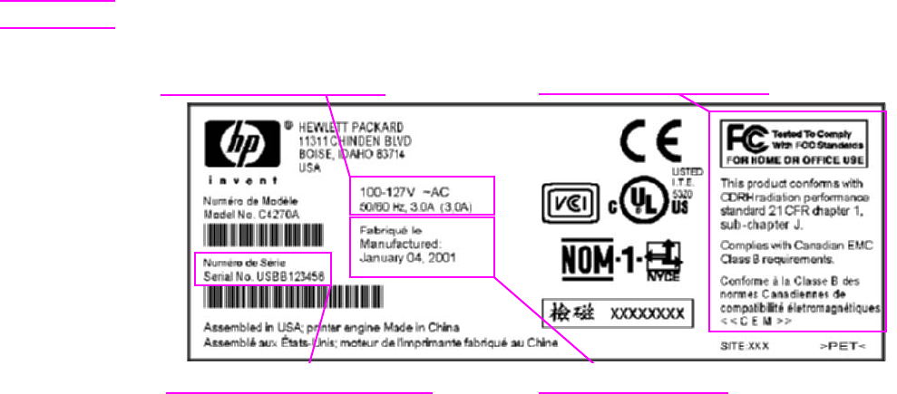
Identification
The model number and printer serial number are listed on an identification label located on the rear
output bin. The model number is alphanumeric, such as C7058A for the HP LaserJet 2200 printer.
The serial number contains information about the country of origin, the revision level, the production
code, and canon serial number of the printer. An example of a serial number is USBBX12345.
The top label also contains power rating and regulatory information. See figure 1.
Note The power rating and regulatory information vary by region.
Electrical Information Regional Certification
Model and Serial Number Manufacture Date
Figure 1. Sample identification label

C7058-90936 Specifications 5
Specifications
Note * A 250-sheet feeder and 500-sheet feeder cannot be installed at the same time.
WARNING! Power requirements are based on the region where the printer is sold. Do not convert operating
voltages. This can damage the printer and void the product warranty.
Table 2. Configuration comparison
HP LaserJet
2200d HP LaserJet
2200dn HP LaserJet
2200dt HP LaserJet
2200dtn
Standard memory
Maximum memory 8 MB
72 MB 8 MB
72 MB 8 MB
72 MB 16 MB
72 MB
PS Level 2
emulation Standard Standard Standard Standard
JetDirect 610N print
server Optional Standard Optional Standard
Duplex printing Standard Standard Standard Standard
250-sheet feeder * Optional Optional Standard Optional
500-sheet feeder * Optional Optional Optional Standard
Table 3. Physical specifications
HP LaserJet 2200d/
2200dn HP LaserJet 2200dt HP LaserJet 2200dtn
Height 259.2 mm (10.25 in) 361.7 mm (14.24 in) 396.7 mm (15.62 in)
Width 417.9 mm (16.45 in) 417.9 mm (16.45 in) 417.9 mm (16.45 in)
Depth 434.6 mm (17.11 in) 434.6 mm (17.11 in) 434.6 mm (17.11 in)
Weight (with toner
cartridge) 12.8 kg (28.219 lb) 15.8 kg (34.833 lb) 17.4 kg (38.360 lb)
Table 4. Electrical specifications
Volts Frequency Amperes (A) Watts (W) (typical)
100 to 127 Vac ± 10
percent 50/60 Hz ± 3 Hz Minimum recommended
current capacity =
5 amps
printing = 400 W
standby = 12 W
PowerSave on = 12 W
off = 0 W
(EPA ENERGY STAR®)
220 to 240 Vac ± 10
percent 50/60 Hz ± 3 Hz Minimum recommended
current capacity =
2.5 amps
printing = 400 W
standby = 12 W
PowerSave on = 12 W
off = 0 W
(EPA ENERGY STAR®)

6 Chapter 1 Product information C7058-90936
The following environmental specifications must be maintained to ensure the correct operation of the
printer. Consider the following points before installing the printer:
lPlace the printer on a sturdy, level surface.
lAllow adequate space around the printer for unimpeded operation.
lInstall the printer in a well-ventilated room.
lPrevent exposure to direct sunlight or chemicals, including ammonia-based cleaning solutions.
lEnsure that an adequate power supply is used.
lInstall the printer in a stable environment that experiences no abrupt temperature or humidity
changes.
Note Testing per International Standards Organization (ISO) 9296
Table 5. Environmental specifications
Operating/printing Storage/standby
Temperature
(printer and toner cartridge) 10 degrees to 32.5 degrees C
(50 degrees to 90.5 degrees F) -20 degrees to 40 degrees C
(-4 degrees to 104 degrees F)
Relative humidity 20 percent to 80 percent 10 percent to 90 percent
Table 6. Noise-level specifications
Operator position Bystander (1m) Sound power
Printing at 18 ppm LpAm 58 db(A) LpAm 51 db(A) LWAd 6.5 db(A)
Powersave LpAm inaudible LpAm inaudible LWAd inaudible
C7058-90936 Product overview 7
Product overview
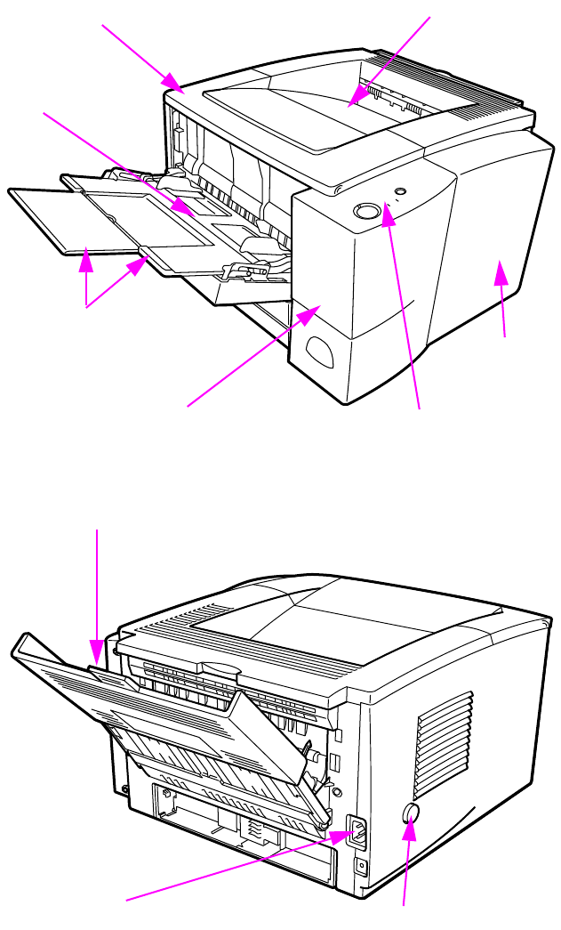
External assembly locations
Figure 2. External assembly locations (1 of 5)
Figure 3. External assembly locations (2 of 5)
Control panel
Tray 1
Top cover Top output bin
I/O cover
DIMM cover
Rear output bin
Power receptacle Power switch
Tray 1 extensions
8 Chapter 1 Product information C7058-90936
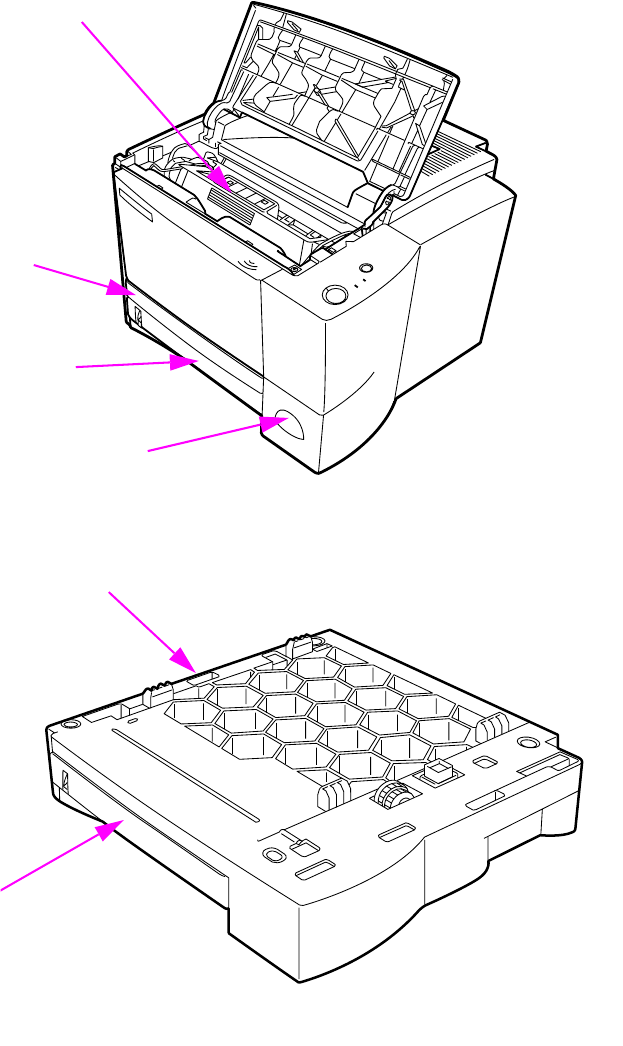
Figure 4. External assembly locations (3 of 5)
Figure 5. External assembly locations (4 of 5)
1537
Toner cartridge
1538
Tray 3 250-sheet feeder
Tray 2
Duplexer
Fast Infrared Receiver (FIR) port
Tray 3 cassette
C7058-90936 Product overview 9
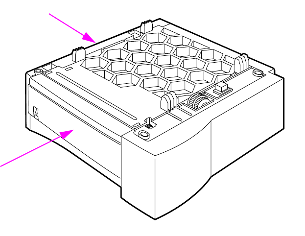
Figure 6. External assembly locations (5 of 5)
1539
Tray 3 500-sheet feeder
Tray 3 cassette
10 Chapter 1 Product information C7058-90936
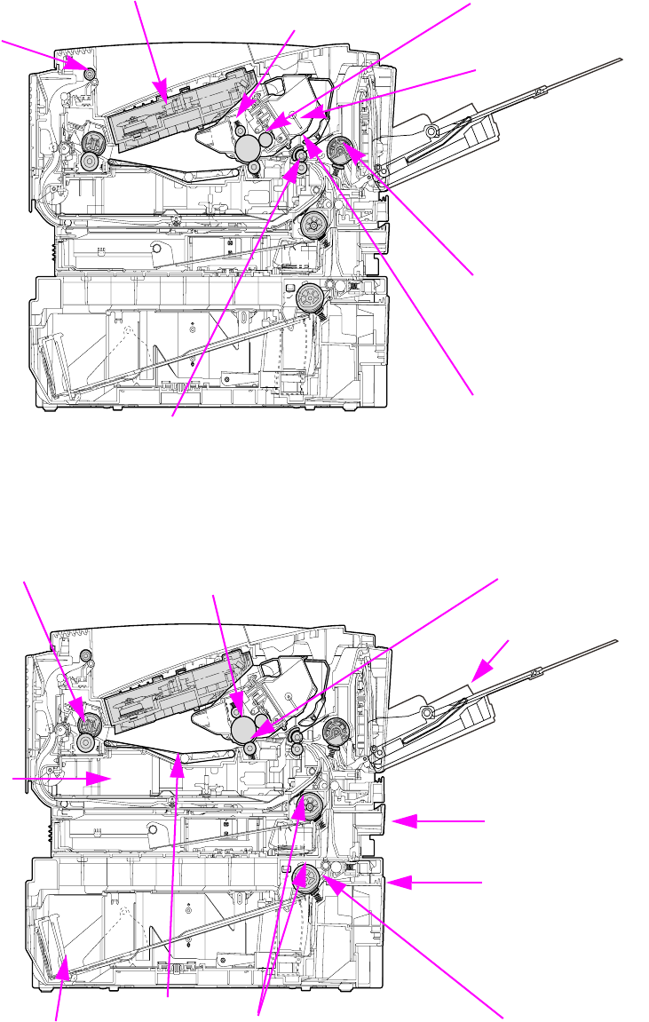
Internal assembly locations
Figure 7. Internal assembly locations (1 of 2)
Figure 8. Internal assembly locations (2 of 2)
Tray 1 pickup
roller
Laser/scanner assembly Developing cylinder
Primary charging roller
Registration shutter
Toner cartridge
Registration rollers
Fuser Transfer charging roller
Photosensitive drum
Tray 2
Tray 3
Paper feeder
Feed belt Tray separation pad
Tray 1
Tray pickup rollers
Delivery rollers
Duplexer

C7058-90936 Safety information 11
Safety information
Toner safety
Handling and storage
WARNING! Keep toner cartridges and toner particles away from excessive heat, sparks, and open flames.
If toner is spilled, avoid breathing in toner particles. Inhalation of toner particles causes respiratory
tract irritation. Vacuum or sweep the material into a bag or other sealed container. A vacuum
specifically designed for cleaning toner can be used if it is capable of filtering fine particles (5 microns
in diameter).
WARNING! Do not vacuum toner using a conventional vacuum. Toner particles used in this product might be too
fine for effective vacuuming and could result in damage to a conventional vacuum.
Dispose of waste toner in accordance with local requirements. Do not discharge toner particles in
drains.
First aid measures
lIngestion. If toner is ingested, rinse mouth out thoroughly with water and drink several glasses
of water. Get medical attention if symptoms persist.
lInhalation. If toner particles are inhaled, move to fresh air immediately. If symptoms occur,
consult a physician.
lEye contact. If toner comes in contact with the eyes, immediately flush with plenty of water for at
least 15 minutes. If irritation persists, consult a physician.
lSkin contact. If toner spills on skin, remove as much toner as possible with a dry tissue, and
then wash with cold water.
Clothing contact
Note Toner can stain clothing. Hot water or heat (from a clothes dryer) can cause toner to melt and
permanently fuse to clothing.
Clothing is best cleaned by removing as much toner as possible with a dry tissue, and then washing
with cold water. Air-dry clothing.
Additional information
The Toner Cartridge/Drum Material Safety Data Sheet (MSDS) can be obtained by contacting HP at
the following website:
http://www.hp.com/go/msds

12 Chapter 1 Product information C7058-90936
Laser safety
The Center for Devices and Radiological Health (CDRH) of the U.S. Food and Drug Administration
has implemented regulations for laser products manufactured since August 1, 1976. Compliance is
mandatory for products marketed in the United States. The printer is certified as a Class 1 laser
product under the U.S. Department of Health and Human Services (DHHS) Radiation Performance
Standard according to the Radiation Control for Health and Safety Act of 1968.
Because radiation emitted inside the printer is completely confined within protective housings and
external covers, the laser beam cannot escape during any phase of normal user operation.
WARNING! Using controls, making adjustments, bypassing safety switches, or performing procedures other than
those specified in this service manual can result in exposure to hazardous radiation.
LED safety
The infrared port on the control panel of this printer is classified as a Class 1 LED (light emitting
diode) device according to International Standard IEC 60825-1 (EN 60825-1). This device is not
considered harmful, but the following precautions are recommended.
lAvoid direct eye exposure to the infrared LED beam.
lBe aware that the beam is invisible light and cannot be seen.
lDo not attempt to view the infrared LED beam with any type of optical device.
Regulatory information
For regulatory information and requirements, please see the user guide.
FCC regulations
For FCC regulations, please see the user guide.
Declaration of conformity
For declaration of conformity information, please see the user guide.

C7058-90936 Environmental Product Stewardship Program 13
Environmental Product Stewardship Program
Protecting the environment
Hewlett-Packard Company is committed to providing quality products in an environmentally sound
manner. This product has been designed with several attributes to minimize impacts on our
environment.
Ozone production
This product generates no appreciable ozone gas (O3).
Energy consumption
Energy usage drops significantly while the printer is in PowerSave mode, which saves natural
resources and saves money without affecting the performance of the printer. This product qualifies
for ENERGY STAR ® which is a voluntary program established to encourage the development of
energy-efficient office products.
ENERGY STAR ® is a U.S. registered service mark of the United States Environmental Protection
Agency. As an ENERGY STAR ® partner, Hewlett-Packard Company has determined that this product
meets the ENERGY STAR ® guidelines for energy efficiency. For more information, see
http://www.epa.gov/energystar/
Toner consumption
EconoMode uses significantly less toner, which might extend the working life of the toner cartridge.
Paper use
This product’s duplex feature (two-sided printing) and N-up printing capability (multiple pages printed
on one sheet of paper) can reduce paper usage and the resulting demands on natural resources.
Plastics
Plastic parts more than 25 grams in weight are marked according to international standards that
enhance the ability to identify plastics for recycling purposes at the end of the product’s life.
14 Chapter 1 Product information C7058-90936
HP LaserJet printing supplies
In many countries, this product’s printing supplies (for example: toner cartridge, drum, fuser) can be
returned to HP through the HP Printing Supplies Returns and Recycling Program. An easy-to-use
takeback program is available in more than 25 countries. Multilingual program information and
instruction are included in every new HP LaserJet toner cartridge and consumables package.
HP Printing Supplies Environmental Program information
Since 1990, the HP Printing Supplies Returns and Recycling Program has collected more than 39
million used LaserJet toner cartridges that otherwise might have been discarded in the world’s
landfills. The HP LaserJet toner cartridges and consumables go to a collection center and are bulk-
shipped to our resource and recovery partners who disassemble the cartridge’s for recycling. After a
through quality inspection, selected parts are reclaimed for use in new cartridges. Remaining
materials are separated and converted into raw materials for use by other industries to make a
variety of useful products.
US returns
For a more environmentally responsible return of used cartridges and consumables, HP encourages
the use of bulk returns. Simply bundle two or more cartridges together and use the single, pre-paid,
pre-addressed UPS label that is supplied in the package. For more information in the United States,
call (1) (800) 340-2445 or visit the HP LaserJet Supplies website at
http://www.ljsupplies.com/planetpartners/.
Outside the US returns
Outside the US customers should call the local HP sales and service office for further information
regarding availability of the HP Supplies Returns and Recycling Program.
Paper
This printer is suited for the use of recycled papers when the paper meets the guidelines outlined in
the HP LaserJet Printer Family Print Media Guide. Also, this printer is suitable for the use of recycled
paper according to DIN 19309.
Material safety data sheet
Material Safety Data Sheets (MSDS) can be obtained by contacting the HP LaserJet Supplies
website at http://www.hp.com/go.msds. In the United States, if you do not have access to the
internet, call the U.S. HP FIRST (fax on demand service) at (1) (800) 231-9300. Use index number
seven for a listing of the material safety data sheets. Outside the US, see “Worldwide offices“in table
8 for appropriate phone numbers and information.

C7058-90936 Service approach 15
Service approach
Bench repair warranty
The warranty for this product is “return to bench” for a period of one year from the date of purchase.
This means that customers needing warranty repair must return their printer to an HP repair center
or an Authorized Service Provider (ASP). See “Reseller sales and service support” on page 17.
HP Express Exchange
Through Customer Care Centers In the United States and Canada, customers have an option to
initiate Express Exchange. Under this option, customers can have a factory-refurbished printer sent
to them within 24 hours.
1The customer contacts the local HP Customer Care Center listed in the product documentation.
A technician troubleshoots the situation and determines whether the printer has actually failed. If
so, the technician refers the customer to the HP Service Center.
2A representative from the service center requests product and customer information. In some
regions, collateral might also be requested.
3Hewlett-Packard Company ships a refurbished replacement unit to arrive the next day.
(Geographic distance might prevent next-day shipping.)
4The customer sends the defective printer to Hewlett-Packard at HP's expense.
Customers with onsite support service provided by HP should work directly with the local Customer
Care Center instead of following the steps outlined here.
Exchanged units carry the remainder of the original unit’s warranty or a 90-day warranty, whichever is
greater. The faster turnaround from HP Express Exchange minimizes downtime over traditional
service programs that require the user to ship the failed unit to the manufacturer and then wait for it to
be repaired and returned. Because HP pays the shipping charges, the user incurs no hidden costs
for the service.
Note For warranty information and requirements, please see the user guide.
Ordering information
"Ordering parts" in chapter 8 of this manual contains factory replacable unit (FRU) and accessory
part numbers. Replacement parts can be ordered from the HP Customer Services and Support
Organization.
Use only accessories specifically designed for this printer. Order accessories from an authorized
service or support provider. See “HP Direct ordering for genuine HP parts” on page 16.
Note See page ‘Worldwide sales and service offices” on page 18 for a local HP office in the appropriate
region.

16 Chapter 1 Product information C7058-90936
Supplemental documentation
HP Direct ordering for genuine HP parts
lCustomer Services and Support Organization (CSSO)
(1) (800) 227-8164 (U.S. only)
lCSSO (in Europe only)
(49 7031) 142253
Table 7. Supplemental documentation
Document Description Part number
Hp Laserjet Printer Family Print
Media Guide A guide to using paper and other print
media with HP LaserJet printers. 5963-7863
Laserjet User Guide A printed copy of the user guide English C7058-90915
Arabic C7058-90911
Czech C7058-90912
Danish C7058-90913
Dutch C7058-90914
Finnish C7058-90916
French C7058-90917
German C7058-90918
Greek C7058-90919
Hebrew C7058-90920
Hungarian C7058-90921
Italian C7058-90922
Korean C7058-90923
Norwegian C7058-90924
Portuguese Brazilian
C7058-90925
Polish C7058-90926
Russian C7058-90927
Simplified Chinese
C7058-90928
Slovak C7058-90929
Spanish Castilian C7058-90930
Swedish C7058-90931
Traditional Chinese
C7058-90932
Thai C7058-90933
Turkish C7058-90934
Hp Laserjet 2200 Getting
Started Guide A printed copy of the getting
started guide C7058-00901 (English version)
Hp Laserjet 2200 User CD-ROM English, German, Dutch, French,
Spanish, Italian, Portuguese Brazilian,
Finnish, Swedish, Norwegian, Danish,
Arabic
C7058-60106
Hp Laserjet 2200 User CD-ROM English, Turkish, Russian, Hungarian,
Polish, Czech, Hebrew, Greek, Slovak C7058-60108
HP LaserJet 2200 User CD-
ROM English, Thai, Korean, Simplified
Chinese, Traditional Chinese C7058-60107
HP LaserJet 2200 sErvice and
Support CD-ROM English C7058-60105
C7058-90936 Service approach 17
Consumables
Paper and toner cartridges can be ordered directly from Hewlett-Packard. See “HP Direct ordering
for genuine HP parts” on page 16.
World Wide Web
Printer drivers, updated HP printer software, and product and support information can be obtained
from the following URL:
in the U.S. http://www.hp.com/support/lj2200
Printer drivers can be obtained from the following sites:
lChina, ftp://www.hp.com.cn/support/lj2200
lJapan, ftp://www.jpn.hp.com/support/lj2200
lKorea, http://www.hp.co.kr/support/lj2200
lTaiwan, http://www.hp.com.tw/support/lj2200
or the local driver website, http://www.dds.com.tw
HP service parts information compact disc
This powerful, CD-ROM-based parts information tool is designed to give users fast, easy access to
parts information such as pricing and recommended stocking lists for a wide range of HP products.
To subscribe to this quarterly service in the U.S. or Canada, call (1) (800) 336-5987. In Asia Pacific,
call (65) 740-4484. Parts identification and pricing information can also be found on the World Wide
Web at: http://www.hp.com/go/partsinfo
HP support assistant compact disc
This support tool offers a comprehensive online information system designed to provide technical
and product information about Hewlett-Packard products. To subscribe to this quarterly service in the
U.S. or Canada, call (1) (800) 457-1762. In Hong Kong, Indonesia, Malaysia, or Singapore, call
Mentor Media at (65) 740-4477.
Reseller sales and service support
The HP Customer Care Center is available to assist resellers and service technicians. You can reach
this support center in the U.S. or Canada at (1) (800) 544-9976.
HP authorized resellers and support
To locate authorized HP resellers and support, call (1) (800) 243-9816 in the U.S. or (1) (800) 387-
3867 in Canada.
HP service agreements
Call (1) (800) 743-8305 in the U.S. or (1) (800) 268-1221 in Canada.
Other areas
Outside of North America and Europe, contact your local HP sales office for assistance in obtaining
technical support for resellers and service technicians. See “Technical assistance” on page 18.

18 Chapter 1 Product information C7058-90936
Technical assistance
Worldwide sales and service offices
Note Before calling an HP sales and service office, be sure to contact the appropriate HP Customer Care
Center. Products should not be returned to these offices. Product return information is also available
through the appropriate HP Customer Care Center.
Table 8. Worldwide offices
Argentina Hewlett-Packard Argentina S.A.
Montañeses 2140/50/60
1428 Buenos Aires
Phone: (54 11) 4787-7100
Fax: (54 11) 4787-7213
Australia Hewlett-Packard Australia Ltd.
31-41 Joseph Street
Blackburn, VIC 3130
Phone: (61) (3) 272-2895
Fax: (61) (3) 898-7831
Hardware Repair Center:
Phone: (61) (3) 272-8000
Extended Warranty Support:
Phone: (61) (3) 272-2577
Customer Information Center:
Phone: (61) (3) 272-8000
Austria Hewlett-Packard GmbH
Lieblgasse 1
A-1222 Vienna
Phone: (43) (1) 25000-555
Fax: (43) (1) 25000-500
Belgium Hewlett-Packard Belgium S.A. NV
Boulevard de la Woluwe-Woluwedal 100-102
B-1200 Brussels
Phone: (32) (2) 778-31-11
Fax: (32) (2) 763-06-13
Brazil Hewlett-Packard Brazil SA
R. Aruana 125
Tambore - Barueri - SP
06460-010
Phone: (0xx11) 829-6612
Fax: (0xx11) 829-0018
Bulgaria Hewlett-Packard Bulgaria EOD
Vaptzarov Blvd.,
1407 Sofia
Phone: (35) (9) 296-019 40
Fax: (35) (9) 296-019 88

C7058-90936 Technical assistance 19
Canada Hewlett-Packard (Canada) Ltd.
17500 Trans Canada Highway
South Service Road
Kirkland, Québec H9J 2X8
Phone: (1) (514) 697-4232
Fax: (1) (514) 697-6941
Hewlett-Packard (Canada) Ltd.
5150 Spectrum Way
Mississauga, Ontario L4W 5G1
Phone: (1) (905) 206-4725
Fax: (1) (905) 206-4739
Chile Hewlett-Packard de Chile
Avenida Andres Bello 2777 of. 1
Los Condes
Santiago, Chile
China China Hewlett-Packard Co. Ltd.
9/F, HP Building
No.2 Dong San Huan Nan Lu
Chao Yang District
Beijing 100022, P.R. China
Phone: 86-10-6564-3888
Fax: 86-10-6566-8280
Colombia Hewlett-Packard Colombia
Calle 100 No. 8A -55
Torre C Oficina 309
Bogotá, Colombia
Croatia Hewlett-Packard Trading S.A.
Cibona Business Tower
TRG Drazena Petrovica 3/13
10000 Zagreb
Phone: (385) (1) 488-1000
Fax: (385) (1) 488801010
Czech Republic Hewlett-Packard s. r. o.
Vyskocilova 1/1410
CZ-140-21 Praha
Czech Republic
Phone: (420) (2) 613-07111
Fax: (420) (2) 61307 613
Denmark Hewlett-Packard A/S
Kongevejen 25
DK-3460 Birkerød
Denmark
Phone: (45)3929 4099
Fax: (45) 4281-5810
Far East Region Hewlett-Packard Asia Pacific Ltd.
17-21/F Shell Tower, Times Square
1 Matheson Street, Causeway Bay
Hong Kong
Phone: (852) 2599-7777
Fax: (852) 2506-9261
Hardware Repair Center:
Phone: (852) 2599-7000
Extended Warranty Support:
Phone: (852) 2599-7000
Customer Information Center:
Phone: (852) 2599-7066
Table 8. Worldwide offices

20 Chapter 1 Product information C7058-90936
Finland Hewlett-Packard Oy
Piispankalliontie 17
FIN-02200 Espoo
Phone: (358) (9) 887-21
Fax: (358) (9) 887-2477
France Hewlett-Packard France
42 Quai du Point du Jour
F-92659 Boulogne Cedex
Phone: (33) (146) 10-1700
Fax: (33) (146) 10-1705
Germany Hewlett-Packard GmbH
Herrenberger Straße 130
71034 Böblingen
Phone: (49) (180) 532-6222
(49) (180) 525-8143
Fax: (49) (180) 531-6122
Greece Hewlett-Packard Hellas
62, Kifissias Avenue
Polis Center
Maroussi
151 24 Athens
Phone: (30) (1) 619-6411
Fax: (30) (1) 619-6512
Hungary Hewlett-Packard Magyarország Kft.
Info Park
Neumann Janos u.1
H-1111 Budapest
Phone: (36) (1) 382-6666
Fax: (36) (1) 382-6667
Hardware Repair Center:
Phone: (36) (1) 343-0312
Customer Information Center:
Phone: (36) (1) 343-0310
India Hewlett-Packard India Ltd.
Paharpur Business Centre
21 Nehru Place
New Delhi 110 019
Phone: (91) (11) 647-2311
Fax: (91) (11) 646-1117
Hardware Repair Center and Extended Warranty Support:
Phone: (91) (11) 642-5073
(91) (11) 682-6042
Israel Hewlett-Packard Israel
11Hashlosha St.
Tel-Aviv 67060
Phone: 972 3 5380300
Fax: 972 3 5380351
Italy Hewlett-Packard Italiana SpA
Via Giuseppe di Vittorio, 9
I-20063 Cernusco Sul Naviglio (Milano)
Phone: (39) (2) 921-21
Fax: (39) (2) 921-04473
Table 8. Worldwide offices

C7058-90936 Technical assistance 21
Japan Hewlett-Packard Japan, Ltd.
3-29-21 Takaido-higashi
Suginami-ku, Tokyo 168
Phone: (81) (3) 3335-8333
Fax: (81) (3) 3335-8338
Hardware Repair Center:
Phone: (81) (4) 7355-6660
Fax: (81) (4) 7352-1848
Kazakhstan Hewlett-Packard
International Trade BV
Branch Office Kazakhstan
135 Ablay Khan Ave
480091 Almaty}
Phone: (7) (3272) 980-824
Fax: (7) (33272) 980-825
Korea Hewlett-Packard Korea, Ltd.
HP Korea House
Yoido-dong Youngdeungpo-gu
Seoul 150-010 724
Phone: (82) (02) 7692 2199-0114 (02) 2199-0114
Fax: (82) (2) 784-7084
Hardware Repair Center:
Phone: (82) (2) 3270-0700
(82) (2) 707-2174
(82) (2) 3270-0710
Extended Warranty Support:
Phone: (82) (2) 3770-0365
(82) (2) 769-0500
Latin American
Headquarters
5200 Blue Lagoon Drive Suite 950
Miami, FL 33126,USA
Phone: (1) (305) 267-4220
México Hewlett-Packard de México, S.A. de C.V.
Prolongación Reforma No. 700
Lomas de Santa Fe
01210 México, D.F.
Phone: 01-800-22147
Outside México City
Phone: 01-800-90529
Middle East/Africa ISB HP Response Center
Hewlett-Packard S.A.
Rue de Veyrot 39
P.O. Box 364
CH-1217 Meyrin - Geneva
Switzerland
Phone: (41) (22) 780-4111
Morocco
Nortwest and Central Africa
Branch
Hewlett-Packard Morocco, Sarl.
Morocco Sales
17 Boulevard Moulay Youssef
Casablanca, Morocco
Phone: (212) (2) 22 13 40
Fax: (212) (2) 22 08 94
Netherlands Hewlett-Packard Nederland BV
Startbaan 16
NL-1187 XR Amstelveen
Phone: (31) (020) 547-6666
Fax: (31) (020) 547-7755
Table 8. Worldwide offices

22 Chapter 1 Product information C7058-90936
New Zealand Hewlett-Packard (NZ) Limited
Ports of Auckland Building
Princes Wharf, Quay Street
P.O. Box 3860
Auckland
Phone: (64) (9) 356-6640
Fax: (64) (9) 356-6620
Hardware Repair Center and Extended Warranty Support:
Phone: (64) (9) 0800-733547
Customer Information Center:
Phone: (64) (9) 0800-651651
Norway Hewlett-Packard Norge A/S
Postboks 60 Skøyen
Drammensveien 169
N-0212 Oslo
Phone: (47) 2273-5600
Fax: (47) 2273-5610
Poland Hewlett-Packard Polska Sp. z o.o.
Ochota Office Park
Al. Jerozolimskie 181
02-222 Warszawa
Phone: (48-22) 608-7700
Fax: (48-22) 608-7600
Portugal Hewlett-Packard Portugal
Quinta da Fonte
Edifico Bartolomeu Dias
Porto Salvo
2780-667 Oeiras
Portugal
Phone: (351) (21) 4 82 85 00
Romania Hewlett-packard Romania SRL
Boulevard Carol I 34-36
NBC Modern, 10th floor
Bucharest
Phone: (40) (1) 205-33-00
Fax: (40) (1) 250-60 95
Russia AO Hewlett-Packard
Business Complex Building #2
129223, Moskva, Prospekt Mira VVC
Phone: (7) (95) 797-3500
Fax: (7) (95) 797-3501
Singapore Hewlett-Packard Singapore
(Sales) Pte Ltd
450 Alexandra Road
Singapore (119960)
Phone: (65)275-3888
Fax: (65)275-6839Hardware Repair Center and Customer
Information Center:
Phone: (65) 272-5300
Extended Warranty Support:
Phone: (65) 272-5333
Slovakia Hewlett-Packard Slovakia s.r.o.
Kutlikova 17
85250 Bratislava
Phone: (42) (1) 7 682-090
Fax: (42) (1) 382-6777
Table 8. Worldwide offices

C7058-90936 Technical assistance 23
South Africa Hewlett-Packard South Africa
9 Eastern Services Road
Eastgate Ext.3 Sandton 2148
Private Bag Wendwood 2144
Republic of South Africa
Phone: 27 11 8 06 1000
Fax: 27 11 444 1725
Spain Hewlett-Packard Española, S.A.
Carretera de la Coruña km 16.500
E-28230 Las Rozas, Madrid
Phone: (34) 91-6311600
Fax: (34) 91-6311830
Sweden Hewlett-Packard Sverige AB
Skalholtsgatan 9
S-164 97 Kista
Phone: (46) (8) 444-2000
Fax: (46) (8) 444-2666
Switzerland Hewlett-Packard (Schweiz) AG
In der Luberzen 29
CH-8902 Urdorf/Zürich
Phone: (41) (0848) 88 44 66
Fax: (41) (1) 735-77 0
Warranty Support:
(41) (0848) 80 11 11
Taiw a n Hewlett-Packard Taiwan Ltd.
8th Floor
337, Fu-Hsing North Road
Taipei, 10483
Phone: (886)(02)717-0055
FAX: (886)(02)514-0276
Hardware Repair Center, call:
North (886)(02) 717-9673
Central (886)(04) 327-0153
South (886)(080)733-733
Extended Warranty Support Contact:
Phone: (886)(02) 714-8882
Thailand Hewlett-Packard (Thailand) Ltd.
23-25/f Vibulthani Tower II
2199 Rama 4 Rd, Klongton
Klintoey, Bangkok 10110
Thailand
Phone: (66) (2) 666-3900-34
Fax: (66) (2) 666-3935-37
Hardware Repair Center and Extended Warranty Support Contact:
Phone: (66) (2) 661-3900 ext. 6001/ 6002
Customer Information Center:
Phone: (66) (2) 661-3900 ext. 3211
Fax: (66) (2) 661-3943
Turkey Hewlett-Packard Company
Bilgisayar Ve ölçüm Sistemleri AS
19 Mayis Caddesi Nova
Baran Plaza Kat: 12
80220 Sisli-Istanbul
Phone: (90) (212) 224-5925
Fax: (90) (212) 224-5939
Table 8. Worldwide offices

24 Chapter 1 Product information C7058-90936
Ukraine Hewlett-Packard Trading S. A.
14, Bekhterevskiy Pereulok, Block E
04053 Kiev
Phone: (380) 44 490 61 20
Fax: (380) 44 490 61 21
United Arab Emirates Hewlett-Packard Middle East
P.O. Box 17295
Jebel Ali Free Zone
Dubai,U.A.E
Phone: (97) 14 88 15 456
Fax: (97) 14 88 14 529
United Kingdom Hewlett-Packard Ltd.
Cain Road
Bracknell
Berkshire RG12 1HN
Phone: (44) (134) 436-9222
Fax: (44) (134) 436-3344
Venezuela Hewlett-Packard de Venezuela S.A.
Los Ruices Norte
3A Transversal
Edificio Segre Caracas 1071
Phone: (58) (2) 239-4244
Fax: (58) (2) 239-3080
Table 8. Worldwide offices
C7058-90936 Chapter contents 25
2Operating requirements
Chapter contents
Site requirements . . . . . . . . . . . . . . . . . . . . . . . . . . . . . . . . . . . . . . . . . . . . . . . . . . . . . . . . . . . . . 26
Operating environment . . . . . . . . . . . . . . . . . . . . . . . . . . . . . . . . . . . . . . . . . . . . . . . . . . . . . .26
Printer space requirement . . . . . . . . . . . . . . . . . . . . . . . . . . . . . . . . . . . . . . . . . . . . . . . . . . . 27
Media specifications . . . . . . . . . . . . . . . . . . . . . . . . . . . . . . . . . . . . . . . . . . . . . . . . . . . . . . . . . . . 28
General media specifications . . . . . . . . . . . . . . . . . . . . . . . . . . . . . . . . . . . . . . . . . . . . . . . . . 28
Guidelines for selecting paper . . . . . . . . . . . . . . . . . . . . . . . . . . . . . . . . . . . . . . . . . . . . . . . . 29
Media input options. . . . . . . . . . . . . . . . . . . . . . . . . . . . . . . . . . . . . . . . . . . . . . . . . . . . . . . . . 30
Tray 1 media sizes . . . . . . . . . . . . . . . . . . . . . . . . . . . . . . . . . . . . . . . . . . . . . . . . . . . . . . . . . 31
Tray 2 and tray 3 (250-sheet feeder). . . . . . . . . . . . . . . . . . . . . . . . . . . . . . . . . . . . . . . . . . . . 32
Tray 3 (500-sheet feeder) . . . . . . . . . . . . . . . . . . . . . . . . . . . . . . . . . . . . . . . . . . . . . . . . . . . .32
Envelope specifications . . . . . . . . . . . . . . . . . . . . . . . . . . . . . . . . . . . . . . . . . . . . . . . . . . . . .33
Label specifications. . . . . . . . . . . . . . . . . . . . . . . . . . . . . . . . . . . . . . . . . . . . . . . . . . . . . . . . . 35
Transparency specifications . . . . . . . . . . . . . . . . . . . . . . . . . . . . . . . . . . . . . . . . . . . . . . . . . . 36
Storing print media . . . . . . . . . . . . . . . . . . . . . . . . . . . . . . . . . . . . . . . . . . . . . . . . . . . . . . . . . 36
Shipping print media . . . . . . . . . . . . . . . . . . . . . . . . . . . . . . . . . . . . . . . . . . . . . . . . . . . . . . . . 37
Paper fillers . . . . . . . . . . . . . . . . . . . . . . . . . . . . . . . . . . . . . . . . . . . . . . . . . . . . . . . . . . . . . . . 37
Testing media specifications . . . . . . . . . . . . . . . . . . . . . . . . . . . . . . . . . . . . . . . . . . . . . . . . . . 37
Tools and suppliers . . . . . . . . . . . . . . . . . . . . . . . . . . . . . . . . . . . . . . . . . . . . . . . . . . . . . . . . . . . . 41
26 Chapter 2 Operating requirements C7058-90936
Site requirements
Operating environment
The electrical and environmental specifications must be maintained to ensure the proper operation of
this printer. See "Specifications" in chapter 1. Consider the following points before installing the
printer:
lInstall in a well-ventilated, dust-free area.
lInstall on a level, flat, and continuous surface that can support the printer’s weight. Make sure all
four printer feet are level. Do not install on carpet or other soft surfaces.
lEnsure adequate power supply circuitry. See "Specifications" in chapter 1.
lInstall where there is stable temperature and humidity, with no abrupt changes (away from water
sources, humidifiers, air conditioners, refrigerators, or other major appliances). See
"Specifications" in chapter 1.
lInstall away from direct sunlight, areas with vibration, open flames, ultrasonic heaters, ammonia
fumes, or magnets and devices that emit a magnetic field. If the printer is placed near a window,
make sure the window has a curtain or blind to block any direct sunlight.
lMaintain enough space around the printer for proper access and ventilation. See “Printer space
requirement” on page 27

C7058-90936 Site requirements 27
Printer space requirement
Figure 9. Top view
Figure 10. Side view
110mm (4.3 in)
636mm (25 in)
1500mm (59 in)
100mm (4 in)
300mm
(11.8 in)
207mm (8 in) 629mm (24.8 in)
215mm (8.5 in)
489.9mm (19.2 in)
542.9mm (21.4 in)
407mm (16 in)
283mm (11 in)

28 Chapter 2 Operating requirements C7058-90936
Media specifications
General media specifications
The HP LaserJet 2200 series printers accept a variety of media, such as cut-sheet paper (including
up to 100 percent recycled-fiber-content paper), envelopes, labels, transparencies, and custom-size
paper. Properties such as weight, composition, grain, and moisture content are important factors
affecting printer performance and output quality. Media that does not meet the guidelines outlined in
this manual can cause the following problems:
lpoor print quality
lincreased jams
lpremature wear on the printer, requiring repair
Note Some print media might meet all of the guidelines in this manual and still not produce satisfactory
results. This might be the result of improper handling, unacceptable temperature and humidity levels,
or other variables over which Hewlett-Packard has no control.
CAUTION Using print media that does not meet HP specifications might cause problems for the printer, requiring
repair. This repair is not covered by the Hewlett-Packard warranty or service agreements.
Note Before purchasing large quantities of paper, make sure the paper meets the requirements specified
in this service manual and in the HP LaserJet Printer Family Print Media Guide. See “Supplemental
documentation” on page 16 Always test print media before buying large quantities. For more
information see the HP LaserJet Printer Family Print Media Guide at http://www.hp.com/cposupport/
printers/manuals/

C7058-90936 Media specifications 29
Guidelines for selecting paper
For best results, use conventional 80 g/m2 (20 lb) paper. Make sure the paper is of good quality, and
free of cuts, nicks, tears, spots, loose particles, dust, wrinkles, voids, and curled or bent edges.
If you are unsure what type of paper you are loading (such as bond or recycled), check the label on
the package of paper.
The following problems with paper can cause print quality deviations, jamming, or even damage to
the printer.
Table 9. Guidelines for selecting paper
Symptom Problem with paper Solution
Poor print quality, toner adhesion,
or problems with feeding Too moist, too rough, too heavy, too
smooth, or embossed; faulty paper
lot
Try another kind of paper, between
100 and 250 Sheffield,
4 percent to 6 percent moisture
content
Dropouts, jamming, or curl Stored improperly
Side-to-side variability of paper
Store paper flat in its moisture-
proof wrapping
Turn paper over
Increased gray background
shading, or printer wear Too heavy Use lighter paper; open the rear
output bin
Excessive curl or problems with
feeding Too moist, wrong grain direction, or
short-grain construction
Side-to-side variability of paper
Open the rear output bin;
use long-grain paper
Turn paper over
Jamming or damage to printer Cutouts or perforations Do not use paper with cutouts or
perforations
Problems with feeding Ragged edges
Side-to-side variability of paper
Use good, high-quality paper
Turn paper over
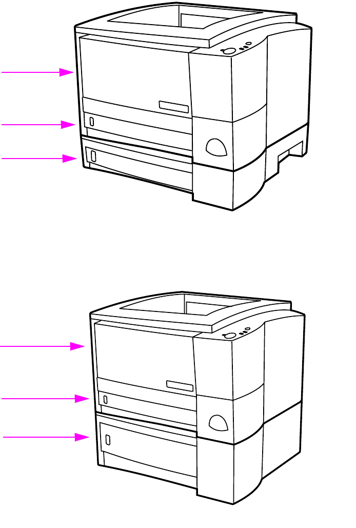
30 Chapter 2 Operating requirements C7058-90936
Media input options
The printer comes with two built-in paper trays, tray 1 and tray 2. Tray 3 is an optional tray that can be
added to the printer. By default, the printer draws first from tray 1. If tray 1 is empty, the printer draws
from tray 2. If tray 1 is empty and tray 3 is installed, the printer draws from tray 3 first and then tray 2.
Figure 11. Media input trays (250-sheet feeder installed)
Figure 12. Media input trays (500-sheet feeder installed)
Tray 1
Tray 2
Tray 3
Tray 1
Tray 2
Tray 3

C7058-90936 Media specifications 31
Note The printer supports a wide range of media sizes. Check the printer software for supported sizes.
Capacity can vary depending on media weight and thickness and on environmental conditions.
Smoothness should be between 100 and 250 (Sheffield).
lFor information about measuring basis weight, see "Basis-weight field test" on page 37.
lFor information about measuring caliper, see "Caliper field test" on page 39.
lFor information about smoothness, see "Paper-finish field test" on page 39.
Tray 1 media sizes
Tray 1 adjusts for sizes from 76 by 127 mm (3 by 5 in) to 216 by 356 mm (8.5 by 14 in). Send media
from tray 1 to the rear output bin when printing on the following:
lenvelopes
llabels
ltransparencies
lcustom-sized media or cardstock
lpostcards
Note Users might experience jams when using any media with a length less than 178 mm (7 in). This can
be caused by paper that has been affected by environmental conditions. For optimum performance,
make sure that users are storing and handling the paper correctly.
Table 10. Tray 1 media sizes
Tray 1 Dimensions Weight Capacity
Minimum size (custom) 76 by 127 mm
(3 by 5 in) 60 to 163 g/m2
(16 to 43 lb bond) 100 sheets of 75 g/m2
(20 lb bond) paper
Maximum size (custom) 216 by 356 mm
(8.5 by 14 in)
Transparency Same as minimum and
maximum paper sizes
listed above
Thickness:
.10 to .14 mm
(0.0039 to 0.0055 in)
75 typical
Labels Thickness:
.10 to .14 mm
(0.0039 to 0.0055 in)
50 typical
Envelopes Up to 90 g/m2
(16 to 24 lb) Up to 10

32 Chapter 2 Operating requirements C7058-90936
Tray 2 and tray 3 (250-sheet feeder)
Tray 2 and the tray 3 (250-sheet feeder) have settings for the paper sizes shown in table 11. Use
only standard copier paper when printing from tray 2 or tray 3 (250-sheet feeder). Other types of print
media might jam when printing from tray 2 or tray 3 (250-sheet feeder).
Tray 3 (500-sheet feeder)
Tray 3 (500-sheet feeder) has settings for the paper sizes shown in table 12. Use only standard
copier paper when printing from tray 3 (500-sheet feeder). Other types of print media might jam when
printing from tray 3 (500-sheet feeder).
Table 11. Tray 2 and tray 3 (250-sheet feeder) paper sizes
Tray 2 Dimensions Weight Capacity
Letter 216 by 279 mm
(8.5 by 11 in) 60 to 105 g/m2
(16 to 28 lb bond) 250 sheets of 75 g/m2
(20 lb bond) paper
A4 210 by 297 mm
(8.3 by 11.7 in)
Executive 191 by 267 mm
(7.3 by 10.5 in)
Legal 216 by 356 mm
(8.5 by 14 in)
B5 (ISO) 176 by 250 mm
(6.9 by 9.9 in)
B5 (JIS) 182 by 257 mm
(7.2 by 10 in)
A5 148 by 210 mm
(5.8 by 8.2 in)
8.5 by 13 in 216 by 330 mm
(8.5 by 13 in)
Table 12. Tray 3 (500-sheet feeder) paper sizes
500 sheet feeders Dimensions Weight Capacity
Letter 216 by 279 mm
(8.5 by 11 in) 60 to 105 g/m2
(16 to 28 lb bond) 250 sheets of 75 g/m2
(20 lb bond) paper
A4 210 by 297 mm
(8.3 by 11.7 in)
Table 13. Automatic duplexer paper sizes
Duplexer Dimensions Weight
Letter 216 by 279 mm
(8.5 by 11 in) 60 to 105 g/m2
(16 to 28 lb bond)
A4 210 by 297 mm
(8.3 by 11.7 in)
Legal 216 by 356 mm
(8.5 by 14 in)
8.5 by 13 in 216 by 330 mm
(8.5 by 13 in)

C7058-90936 Media specifications 33
Envelope specifications
Envelope construction is critical. Envelope fold lines can vary considerably, not only between
manufacturers, but also within a box from the same manufacturer. Successful printing on envelopes
depends upon the quality of the envelopes. When selecting envelopes, consider the following
components:
lWeight: The weight of the envelope paper should not exceed 105 g/m2 (28 lb) or jamming can
occur.
lConstruction: Prior to printing, envelopes should lie flat with less than 6 mm (0.25 in) curl, and
should not contain air.
lCondition: Envelopes should not be wrinkled, nicked, or otherwise damaged.
lTemperature: Envelopes should be compatible with the heat and pressure of the printer.
lSize: Envelopes must be within the following size ranges: minimum of 76 by 127 mm (3 by 5 in)
and maximum of 216 by 356 mm (8.5 by 14 in).
Note Use only tray 1 to print envelopes. Send envelopes straight through the printer, entering at tray 1 and
exiting from the rear output bin
CAUTION Jams might occur when using any media with a length less than 178 mm (7 in). This can be caused
by paper that has been affected by environmental conditions. See "Evaluate environmental conditions"
in chapter 7.
Envelopes might meet the general specifications listed in table 14 and still not print satisfactorily
because of the printing environment or other variables over which HP has no control.
Table 14. Envelope specifications
Description Specification
Paper Paper used for envelope construction must meet the paper specifications listed in
this manual and the HP LaserJet Printer Family Print Media Guide (except for
those listed below).
Basis weight 60 to 100 g/m2 (16 to 27 lb), single thickness. Jamming might result if 100 g/m2
(27 lb) weight is exceeded. See “Moisture-content field test” on page 39
Finish Avoid using envelopes with adhesive exposed to the printer. Envelopes must be
folded accurately so that there are no more than two thicknesses of paper
anywhere along the leading edge. All folds must be well scored and sharply
creased, and construction must be tight (not baggy). Avoid using envelopes that
are stuck together with excess seam gum. See “Furnish (fiber composition) field
test” on page 40
Fusing compatibility All inks, adhesives, and other materials used in the envelope must be compatible
with the heat and pressure of the fusing process. Materials must not discolor,
melt, offset materials, or release hazardous emissions when heated to
200 degrees C (392 degrees F) for 0.1 second. See “Fusing-compatibility field
test” on page 40
Curl (Pre-printed) Envelopes must lie flat, with no more than 5 mm (0.2 in) curl across the entire
surface. See “Curl field test” on page 40
Caliper Caliper of 0.084 to 0.14 mm (.0034 in to .0056 in), single thickness. See “Caliper
field test” on page 39
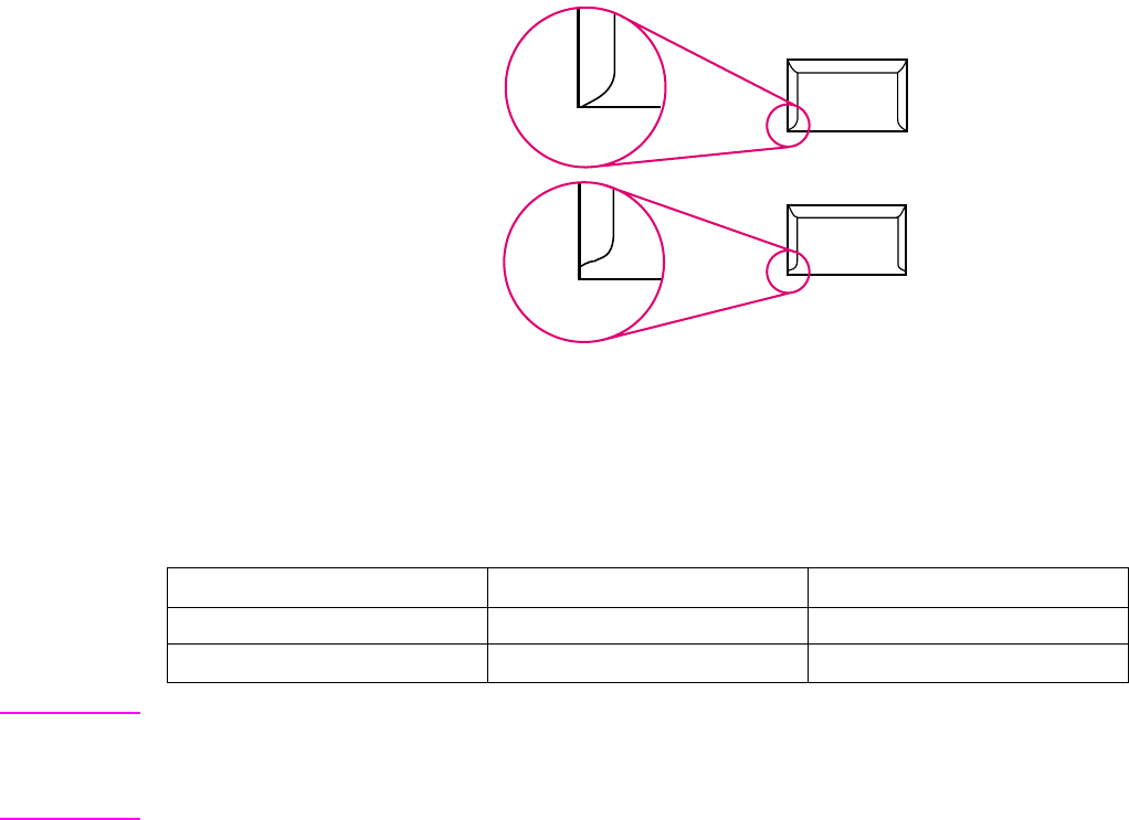
34 Chapter 2 Operating requirements C7058-90936
Envelopes with adhesive strips or flaps
Envelopes with a peel-off adhesive strip or with more than one flap that folds over to seal must use
adhesives compatible with the heat and pressure in the printer. The extra flaps and strips might
cause wrinkling, creasing, or jams and can even damage the fuser.
Envelope storage
Proper storage of envelopes contributes to good print quality. Envelopes should be stored flat. If air is
trapped in an envelope, creating an air bubble, then the envelope might wrinkle during printing.
Envelopes with double side seams
Double side-seam construction has vertical seams at both ends of the envelope rather than diagonal
seams. This style might be more likely to wrinkle. Be sure the seam extends all the way to the corner
of the envelope as illustrated below.
Figure 13. Double side seam
Envelope margins
The following gives typical address margins for a commercial #10 or DL envelope.
Note For the best print quality, position margins no closer than 15 mm (0.6 in) from the edges of the
envelope.
Avoid printing over the area where the envelope seams meet.
Table 1. Envelope margins
Type of address Top margin Left margin
Return address 15 mm (0.6 in) 15 mm (0.6 in)
Delivery address 51 mm (2 in) 89 mm (3.5 in)

C7058-90936 Media specifications 35
Label specifications
When selecting labels, consider the quality of each component:
lAdhesives: The adhesive material should be stable at 200 degrees C (392 degrees F), which is
the printer’s fusing temperature.
lArrangement: Only use labels with no exposed backing between them. Labels can peel off
sheets with spaces between the labels, causing jams.
lCurl: Prior to printing, labels must lie flat with no more than 13 mm (.5 in) of curl in any direction.
lCondition: Do not use labels with wrinkles, bubbles, or other indications of separation.
Note Use only tray 1 to print labels. Send labels straight through the printer, entering at tray 1 and exiting
from the rear output bin
CAUTION To avoid damaging the printer, use only labels recommended for laser printers.
Never print on the same sheet of labels more than once or print on a partial sheet of labels.
Table 15. Label specifications
Description Specification
Adhesive Must not be on any external surfaces of the label before, during, or after printing.
Label construction and die-cutting must not let labels peel off during transport,
printing, or fusing.
Caliper Must not exceed 0.19 mm (0.007 in). See “Caliper field test” on page 39
Curl In ream: flat within 5 mm (0.2 in). See “Curl field test” on page 40
Surface resistivity 2.0 to 15 by 10 to the 10th ohm square. See “Inspect the rollers for colored ink
buildup from preprinted logos or letterhead, and for toner buildup or spots.
Inspect printed output for repetitive defects and smearing. If necessary, have
users contact the forms vendor to ensure the paper’s fusing compatibility with HP
LaserJet printers.” on page 40
Volume resistivity 1.2 to 15 by 10 to the 11th ohm-centimeter. See “Inspect the rollers for colored
ink buildup from preprinted logos or letterhead, and for toner buildup or spots.
Inspect printed output for repetitive defects and smearing. If necessary, have
users contact the forms vendor to ensure the paper’s fusing compatibility with HP
LaserJet printers.” on page 40
Finishing precision Cut sheet within 0.79 mm (0.031 in) of nominal and +0.20 degrees square.
Fusing compatibility All adhesives, carrier sheets, top sheets, and other materials used in label
construction must be compatible with the heat and pressure of the fusing
process. Materials must not discolor, melt, offset materials, or release hazardous
emissions when heated to 200 degrees C (392 degrees F) for 0.1 second. See
“Furnish (fiber composition) field test” on page 40
Packaging Store in moisture-proof wrap to preserve properties.
Shelf life One year, maximum, stored at 22 degrees C (72 degrees F) and 50 percent
relative humidity.

36 Chapter 2 Operating requirements C7058-90936
Transparency specifications
Transparency construction is critical.
Note Use only tray 1 to print transparencies. Send transparencies straight through the printer, entering at
tray 1 and exiting from the rear output bin
CAUTION Transparencies used in the printer must be able to withstand 200 degrees C (392 degrees F), the
printer’s fusing temperature.
To avoid damaging the printer, use only transparencies recommended for use in laser printers.
Storing print media
Ideally, the printing and media storage environment should be at or near room temperature, and not
too dry or too humid. Remember that paper is hygroscopic; it absorbs and loses moisture rapidly.
Heat works with humidity to damage paper. Heat causes the moisture in paper to evaporate, while
cold causes it to condense on the sheets. Heating systems and air conditioners remove most of the
humidity from a room. As a paper package is opened and used, it loses moisture, causing streaks
and smudging. Humid weather or water coolers can cause the humidity to increase in a room. As
paper is opened and used it absorbs any excess moisture, causing light print and dropouts. Also, as
paper loses and gains moisture it can distort. This can cause jams.
As a result, paper storage and handling are as important as the paper-making process itself. Paper
storage environmental conditions directly affect the feed operation.
Users should not purchase more paper than can be easily used in a short time (about three months).
Paper stored for long periods might experience heat and moisture extremes, which can cause
damage. Planning is important to prevent damage to a large supply of paper.
Unopened paper in sealed reams can remain stable for several months before use. Opened
packages of paper have more potential for environmental damage, especially if they are not wrapped
with a moisture-proof barrier.
Table 16. Transparency specifications
Description Specification
Surface resistivity 2.0 to 15 by 10 to the 10th ohm square. See “Inspect the rollers for colored ink
buildup from preprinted logos or letterhead, and for toner buildup or spots.
Inspect printed output for repetitive defects and smearing. If necessary, have
users contact the forms vendor to ensure the paper’s fusing compatibility with
HP LaserJet printers.” on page 40
Volume resistivity 1.2 to 15 by 10 to the 11th ohm-cm. See “Inspect the rollers for colored ink
buildup from preprinted logos or letterhead, and for toner buildup or spots.
Inspect printed output for repetitive defects and smearing. If necessary, have
users contact the forms vendor to ensure the paper’s fusing compatibility with
HP LaserJet printers.” on page 40
Finishing precision Cut sheet within 0.79 mm (0.031 in) of nominal and +0.20 degrees square.
Fusing compatibility Transparency materials must be compatible with the heat and pressure of the
fusing process. Materials must not discolor, melt, offset materials, or release
hazardous emissions when heated to 200 degrees C (392 degrees F) for 0.1
second. See “Fusing-compatibility field test” on page 40
Caliper Caliper of 0.100 to 0.110 mm (.0039 to .0043 in). See “Caliper field test” on page
39

C7058-90936 Media specifications 37
The paper storage environment should be properly maintained to ensure optimum printer
performance. The required condition is 20 degrees to 24 degrees C (68 degrees to 75 degrees F),
with a relative humidity of 45 percent to 55 percent. The following guidelines should be helpful when
evaluating the papers storage environment:
lPaper should be stored at or near room temperature.
lThe air should not be too dry or too humid (because of the hygroscopic properties of paper).
lThe best way to store an opened ream of paper is to rewrap it tightly in its moisture-proof
wrapping. If the printer environment is subject to extremes, unwrap only the amount of paper to
be used during the day's operation to prevent unwanted moisture changes.
Shipping print media
When shipping print media through different environments, plastic-wrap all cartons on the shipping
pallet. When shipping media across bodies of water, wrap individual cartons as well. Packaging must
protect the media from physical damage.
Paper fillers
Additional chemicals and fillers are frequently added to paper during the manufacturing process.
These can affect the paper strength, pick resistance, printability, bulk, feel, and color.
An emulsion containing wax, rosin, starch, or other non-water soluble materials is added to the paper
pulp to help control penetration by water and other liquids. Dyes are added and the paper might be
bleached. Bleaching is a multistep process using such chemicals as hydrogen peroxide and chlorine
dioxide. This transforms the paper from its original brownish state to the desired color.
Finely ground fillers, such as clay, talc, and calcium carbonate, might be added to even out the
“peaks and valleys” that occur in the paper mixture, and serve as brighteners. Over time, these fillers
can build up on internal assemblies of the printer such as rollers or the toner cartridge. This buildup
can eventually cause jams and print defects. To minimize this risk, periodically clean the printer
according to procedures. See "Cleaning the printer and accessories" in chapter 4.
Testing media specifications
The following tests describe ways to qualify the media with respect to the specifications listed in this
manual and the HP LaserJet Printer Family Print Media Guide. See “Tools and suppliers” on page 41
for help obtaining tools needed to perform these tests.
Basis-weight field test
The basis weight should be indicated on the ream label. If the label is not available, a simple field test
can identify the basis weight of paper. The basis weight of paper is equal to the weight of 2000
sheets of paper, or four full reams. Weigh a full ream on a postal scale and then multiply that weight
by four. Or, weigh 10 sheets of paper, divide that weight by 10, multiply by 2000, and then divide by
16.
Table 17. Determining basis weight of paper
Amount Formula
4 reams weight = basis weight
1 ream weight x 4 = basis weight
10 sheets (weight divided by 10) x 2000 and then divided by 16 = basis weight

38 Chapter 2 Operating requirements C7058-90936
Note Example:
10 sheets weigh 1.6 ounces
0.16 ounce x 2000 = 320 ounces
320 ounce ÷ 16 ounce/lb = 20lb paper
Paper weight equivalence table
Use this table to determine approximate equivalent points in weight specifications other than U.S.
bond weight. For example, to determine the equivalent of 20 lb U.S. bond-weight paper in U.S.
cover-weight paper, locate the bond weight (in row 3, second column) and scan across the row to the
cover weight (in the fourth column). The equivalent is 28 lb media. Shaded areas indicate a standard
weight for that grade.
Note The U.S. postcard measurements are approximate. Use for reference only.
Metric Sizes
For metric-size paper (A4), use the following method to determine basis weight.
Take 16 sheets of A4 paper and weigh them. One square meter of paper contains approximately 16
A4 size sheets. Compare this weight to the appropriate weight in the “Paper weight equivalence
table” on page 2-38.
Table 18. Paper weight equivalence
U.S. post-
card
thick-
ness
(mm)
U.S. bond
weight
(lb)
U.S. text/
book
weight
(lb)
U.S. cover
weight
(lb)
U.S.
bristol
weight
(lb)
U.S. index
weight
(lb)
U.S. tag
weight
(lb)
Europe
metric
weight (g/
m2)
Japan
metric
weight (g/
m2)
116 41 22 27 33 37 60 60
217 43 24 29 35 39 64 64
320 50 28 34 42 46 75 75
421 54 30 36 44 49 80 80
522 56 31 38 46 51 81 81
624 60 33 41 50 55 90 90
727 68 37 45 55 61 100 100
828 70 39 49 58 65 105 105
932 80 44 55 67 74 120 120
10 34 86 47 58 71 79 128 128
11 36 90 50 62 75 83 135 135
12 .18 39 100 55 67 82 91 148 148
13 .19 42 107 58 72 87 97 157 157
14 .20 43 110 60 74 90 100 163 163
15 .23 47 119 65 80 97 108 176 176
16 53 134 74 90 110 122 199 199

C7058-90936 Media specifications 39
Caliper field test
The specified caliper differs with the type of media used. See “Operating environment” on page 26
Caliper can be measured in the field using a micrometer.
CAUTION Never use the coarse-adjustment end of the micrometer when measuring for caliper. The coarse
adjustment will compress the paper fibers, resulting in an inaccurate reading. For example, if the fibers
are compressed, 6 mil paper could measure as little as 3 mils. Always use the fine adjustment to
measure caliper.
Using the fine adjustment, slide the micrometer along the edge of the paper and measure at one
end. To double-check the accuracy of the reading, always measure again at the opposite end of the
paper.
Paper-finish field test
Paper finish, or smoothness, can be accurately measured with a Sheffield meter. If this tool is not
available, use a new U.S. dollar bill as a benchmark for comparing paper texture. A dollar bill has a
finish of 350 Sheffields, which is 100 over specifications. If paper feels as rough as a dollar bill, it is
recommended that users do not continually use this paper in the printer.
Moisture-content field test
Specification: Use paper with 4 percent to 6 percent moisture content.
A ream or sheet of paper can be measured with a moisture meter. In general, only evaluate the
customer’s storage environment when trying to determine if excess moisture or dryness is the cause
of a problem with paper.
Grain field test
The grain direction is usually specified on the ream label (written out “long” or “short”). The paper
dimensions listed on the label also indicate grain direction. For example, short-grain letter-size paper
will read “11 by 8.5" and long-grain paper will read “8.5 by 11."
If the grain direction is not included on the ream label, it can be determined by a simple wet test. Cut
a small square from the corner of a sheet of paper, wet it, and observe the manner in which it curls.
Envelopes should have a diagonal grain, which gives them the best stability. To determine this, cut a
square section from one corner of an envelope. Wet this section and observe the manner in which it
curls. Two opposite corners should curl toward each other.
Figure 14. Long, short, and diagonal grain curl
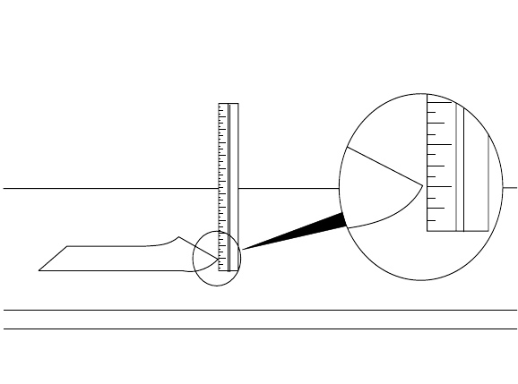
40 Chapter 2 Operating requirements C7058-90936
Curl field test
To check for paper curl, place a single sheet of paper onto a flat surface and measure curl at the
greatest deflection, holding a ruler perpendicular to the flat surface.
Figure 15. Measuring curl
Cut-edge condition field test
The condition of the cut edge can be easily observed with an eye loop. Under magnification, a good
edge will appear even. A poorly cut edge will show fraying, jagged edges, compressed fibers, and
other damage.
Furnish (fiber composition) field test
Use paper made from 100 percent chemical wood pulp and /or cotton fiber. Recycled paper made
with no more than 5 percent groundwood is also acceptable.
Read the ream label to determine the fiber composition of the paper. Paper is usually specified as
xerographic bond (suitable for copiers or laser printers) or cotton bond. Cotton bond paper of 25
percent, 50 percent, or 100 percent will be indicated on a watermark. If paper is less than 25 percent
cotton bond, the watermark will not indicate a percentage. A wood-pulp test kit can also be used to
test fiber composition.
Fusing-compatibility field test
Inspect the rollers for colored ink buildup from preprinted logos or letterhead, and for toner buildup or
spots. Inspect printed output for repetitive defects and smearing. If necessary, have users contact
the forms vendor to ensure the paper’s fusing compatibility with HP LaserJet printers.

C7058-90936 Media specifications 41
Tools and suppliers
Hewlett-Packard neither warrants nor recommends a particular manufacturer, supplier, or tool.
Products are subject to change and HP has no control over such changes. However, the following
table of tools and their suppliers is provided for convenience.
Table 19. Tools and suppliers
Tool Part Number Supplier Address
Paper moisture meter
Single-sheet clamp probe
2RRDMP
2R43E
Mitchell Instrument
1570DDD Cheroke St.
San Marcos, CA 92069-2433
Temperature/humidity meter #3T331 Industrial Motor Service
2000 Albright
Montgomery, IL 60538
Sheffield tester: precisionaire column
Sheffield tester: smoothcheck gauge
TM 58-25-01
TM 58-25-02
TMI Testing Machines Inc.
400 Bayview Avenue
Amityville, NY 11701
(516) 842-5400
Wood-pulp test kit
pH test kit
4280-2
4360-2
Shape Products
1127 57th Avenue
Oakland, CA 94621
(800) 444-0015
Resistivity test tool:
precision current/resistance meter
Resistivity test tool:
surface resistivity probe
278
96117-1
Monroe Electronics
100 Housel Avenue
PO Box 100
Lyndonville, NY 14098
(800) 821-6001
42 Chapter 2 Operating requirements C7058-90936
C7058-90936 Chapter contents 43
3Printer configuration
Chapter contents
Using the control panel . . . . . . . . . . . . . . . . . . . . . . . . . . . . . . . . . . . . . . . . . . . . . . . . . . . . . . . . . 44
Control panel. . . . . . . . . . . . . . . . . . . . . . . . . . . . . . . . . . . . . . . . . . . . . . . . . . . . . . . . . . . . . . 44
Control panel lights . . . . . . . . . . . . . . . . . . . . . . . . . . . . . . . . . . . . . . . . . . . . . . . . . . . . . . . . . 44
Job Cancel . . . . . . . . . . . . . . . . . . . . . . . . . . . . . . . . . . . . . . . . . . . . . . . . . . . . . . . . . . . . . . . 44
Go . . . . . . . . . . . . . . . . . . . . . . . . . . . . . . . . . . . . . . . . . . . . . . . . . . . . . . . . . . . . . . . . . . . . . . 44
Printing a demo page . . . . . . . . . . . . . . . . . . . . . . . . . . . . . . . . . . . . . . . . . . . . . . . . . . . . . . .45
Self test/configuration page . . . . . . . . . . . . . . . . . . . . . . . . . . . . . . . . . . . . . . . . . . . . . . . . . .47
Self test/configuration-page elements. . . . . . . . . . . . . . . . . . . . . . . . . . . . . . . . . . . . . . . . . . . 48
JetDirect configuration page . . . . . . . . . . . . . . . . . . . . . . . . . . . . . . . . . . . . . . . . . . . . . . . . . . 49
Continuous self test . . . . . . . . . . . . . . . . . . . . . . . . . . . . . . . . . . . . . . . . . . . . . . . . . . . . . . . . 50
Engine test . . . . . . . . . . . . . . . . . . . . . . . . . . . . . . . . . . . . . . . . . . . . . . . . . . . . . . . . . . . . . . . . . . 51
Performing an engine test. . . . . . . . . . . . . . . . . . . . . . . . . . . . . . . . . . . . . . . . . . . . . . . . . . . .51
Service mode . . . . . . . . . . . . . . . . . . . . . . . . . . . . . . . . . . . . . . . . . . . . . . . . . . . . . . . . . . . . . . . . 52
Entering service mode . . . . . . . . . . . . . . . . . . . . . . . . . . . . . . . . . . . . . . . . . . . . . . . . . . . . . .52
Entering escape characters . . . . . . . . . . . . . . . . . . . . . . . . . . . . . . . . . . . . . . . . . . . . . . . . . . 52
Setting the page count . . . . . . . . . . . . . . . . . . . . . . . . . . . . . . . . . . . . . . . . . . . . . . . . . . . . . . 53
Setting the cold reset default . . . . . . . . . . . . . . . . . . . . . . . . . . . . . . . . . . . . . . . . . . . . . . . . .54
Resetting the printer . . . . . . . . . . . . . . . . . . . . . . . . . . . . . . . . . . . . . . . . . . . . . . . . . . . . . . . . . . . 55
Cold reset . . . . . . . . . . . . . . . . . . . . . . . . . . . . . . . . . . . . . . . . . . . . . . . . . . . . . . . . . . . . . . . . 55
NVRAM initialization . . . . . . . . . . . . . . . . . . . . . . . . . . . . . . . . . . . . . . . . . . . . . . . . . . . . . . . . 55
EIO card reset. . . . . . . . . . . . . . . . . . . . . . . . . . . . . . . . . . . . . . . . . . . . . . . . . . . . . . . . . . . . . 55
Network printing . . . . . . . . . . . . . . . . . . . . . . . . . . . . . . . . . . . . . . . . . . . . . . . . . . . . . . . . . . . . . . 56
Installing an HP JetDirect EIO card . . . . . . . . . . . . . . . . . . . . . . . . . . . . . . . . . . . . . . . . . . . . 56
IR printing . . . . . . . . . . . . . . . . . . . . . . . . . . . . . . . . . . . . . . . . . . . . . . . . . . . . . . . . . . . . . . . . . . . 58
Fast Infrared Receiver. . . . . . . . . . . . . . . . . . . . . . . . . . . . . . . . . . . . . . . . . . . . . . . . . . . . . . . 58
Using the FIR port. . . . . . . . . . . . . . . . . . . . . . . . . . . . . . . . . . . . . . . . . . . . . . . . . . . . . . . . . . 58
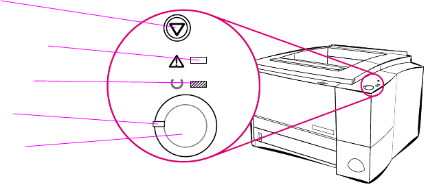
44 Chapter 3 Printer configuration C7058-90936
Using the control panel
Control panel
The printer control panel has only two buttons: JOB CANCEL and GO. See figure 16. Pressing one of
these buttons or a combination of the two does the following:
lcancels print jobs
lresumes printing when the printer is paused
lprints a demo page or a self test/configuration page
linitiates a continuous self test
lperforms a cold reset or a nonvolatile random access memory (NVRAM) initialization
lreveals secondary information (for example, light messages)
Other printer configurations must be performed using printer job language (PJL) commands or the
LaserJet configuration utility. See “Service mode” on page 52.
Figure 16. Control panel layout
Control panel lights
The control panel lights provide both status and error messages by using distinct light patterns. See
"Troubleshooting with control-panel messages" in chapter 7.
Job Cancel
Press JOB CANCEL to cancel a job the printer is currently printing. The control panel lights will cycle
while the print job is cleared from both the printer and the computer, and then return to the ready
state (Ready light on). This can take some time, depending on the size of the print job.
lIf JOB CANCEL is accidentally pushed, the job must be reprinted. There is no undo function.
lIf JOB CANCEL is pushed when the printer is idle nothing happens.
Go
lPress GO to resume printing when the printer is paused or when unprinted data is still in the
printer.
lPress GO to clear particular printer errors.
lPress GO to print a demo page. The printer must be in the ready state (Ready light on).
To identify and troubleshoot control panel light messages, see "Troubleshooting with control-panel
messages" in chapter 7.
GO button
Go light
Ready light
Attention light
JOB CANCEL
button
C7058-90936 Using the control panel 45
Printing a demo page
To print the demo page, press GO when the printer is ready (Ready light is on).
Figure 17. Demo page (front)

46 Chapter 3 Printer configuration C7058-90936
Figure 18. Demo page (back)
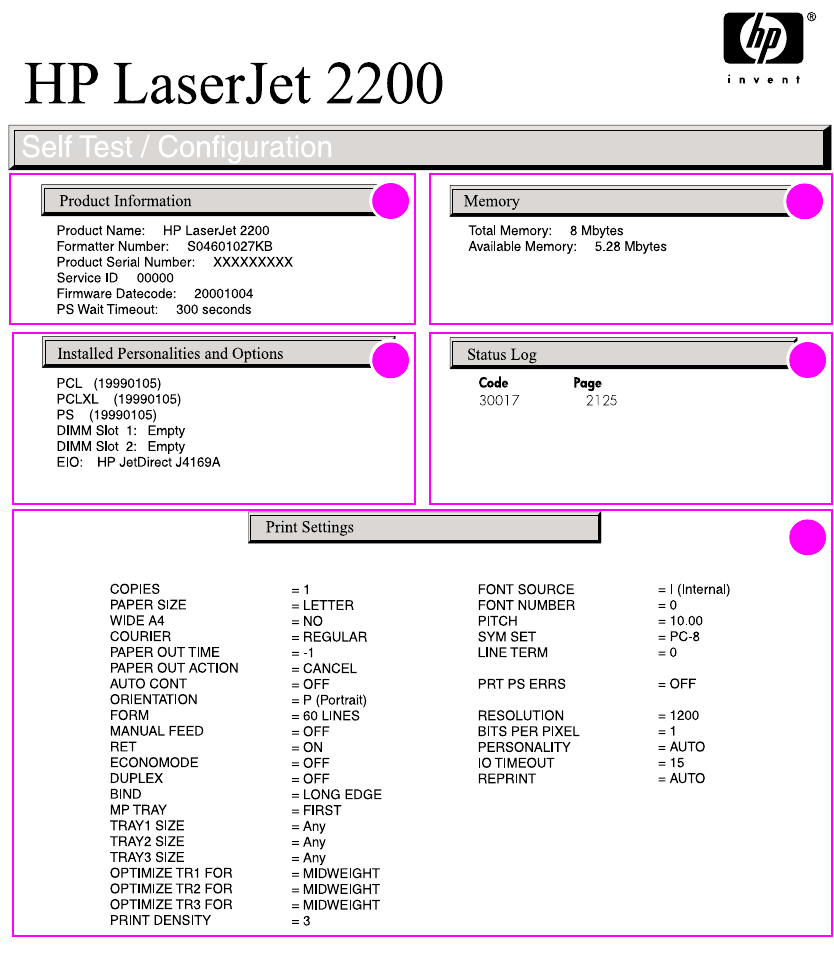
C7058-90936 Using the control panel 47
Self test/configuration page
The self test/configuration page lists many of the printer’s current settings and properties. To print
the self test/configuration page, press and release GO and JOB CANCEL simultaneously when the
printer is ready (Ready light is on). If you have an EIO print-server card installed, a second page, the
JetDirect Page, will print listing all of the HP JetDirect information.
The demo and self test/configuration pages can also be printed from the HP LaserJet device
configuration reports page.
Figure 19. Self test/configuration page
2
12
3
2
2
2
5
2
4
48 Chapter 3 Printer configuration C7058-90936
Self test/configuration-page elements
1Product information lists the name, formatter number, serial number, service ID, firmware
datecode, total pages printed, duplex page count, pages jammed in printer, pages mispicked in
printer, and PS wait timeout.
2Installed personalities and options lists the installed printer languages (PCL, PCL 6, and PS),
DIMM slot 1 and 2 information, and the EIO slot information.
3Memory lists total memory and available memory.
4Status log lists the PJL status code and the corresponding page count. (The status log only
appears when errors have been registered.)
5Print settings lists settings for copies, paper size, wide A4, courier, paper out time, paper out
action, auto continue, orientation, form, manual feed, Resolution Enhancement technology
(REt), EconoMode, duplex, bind, MP tray, tray 1 size, tray 2 size, tray 3 size, optimize tray 1 for,
optimize tray 2 for, optimize tray 3 for, print density, font source, font number, pitch, symbol set,
line term, PS error reporting, resolution, bits per pixel, personality, I/O timeout, and reprint.
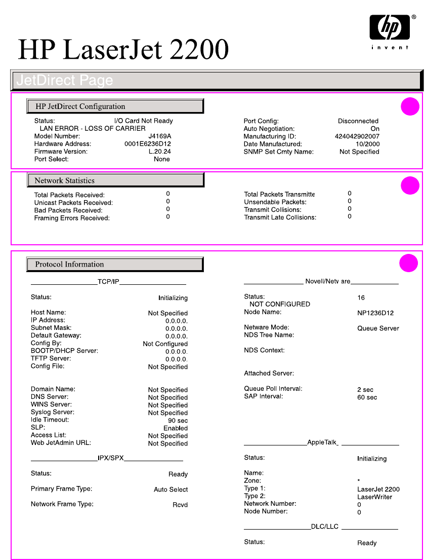
C7058-90936 Using the control panel 49
JetDirect configuration page
Figure 20. JetDirect configuration page
21
22
23
50 Chapter 3 Printer configuration C7058-90936
JetDirect configuration-page elements
1General information lists the HP JetDirect number, firmware revision, LAN hardware address,
selected port, manufacturing ID, I/O card status, and network statistics (unicast packets, total
packets, bad packets, framing errors received, packets transmitted, unsendable packets,
transmit collisions, and transmit late collisions).
2Network statistics lists total packets received, unicast packets received, bad packets received,
framing errors received, total packets received, unsendable packets, transmit collisions, transmit
late collisions.
3Protocol information lists TCP/IP status and configuration, the HP Web JetAdmin server name,
Novell NetWare status and configuration, AppleTalk status and configuration, and DLC/LLC
status.
Continuous self test
To initiate a continuous self test:
lTurn the printer power off.
lPress and hold GO.
lTurn the printer power back on and continue to hold GO until the Attention and Ready light turn
on.
lRelease GO.
lThe Ready light blinks indicating the device is in continuous self test mode.
lThe printer prints self test/configuration pages until JOB CANCEL is pressed.
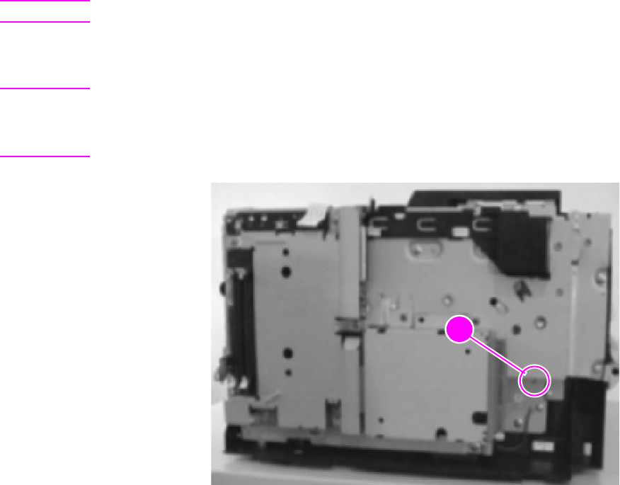
C7058-90936 Engine test 51
Engine test
Performing an engine test
The engine test can be used to verify that the print engine is functioning correctly. The formatter PCB
is completely bypassed during an engine test; therefore, this test is useful for isolating problems.
Because the engine test prints a full page of horizontal lines across the entire printable area, it is also
useful for checking registration.
To print an engine-test page, insert paper into tray 1 or tray 2, remove the EIO cover, and use a long,
nonconductive object to press the engine-test button (callout 1) shown in figure 21. A single page
prints.
Note The duplexer test will pull paper from tray 2, but paper must be present in tray 1.
To perform a duplexer test, insert paper into tray 1 and tray 2, remove the EIO cover, and use a long,
nonconductive object to press the engine-test button shown in figure 21. A duplexed page prints.
WARNING! Do not use an electrically conductive object to press the engine-test button.
Do not insert any object into the opening next to the power cord socket. This is not the engine-test
button.
Figure 21. Engine-test button
11
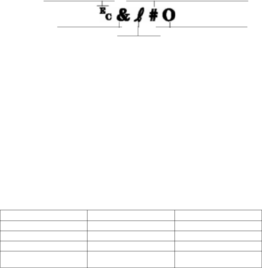
52 Chapter 3 Printer configuration C7058-90936
Service mode
In service mode the following can be performed:
lPrint a service mode self test.
lVerify and set the page count. See “Setting the page count” on page 53.
lSet the cold reset default. See “Setting the cold reset default” on page 54.
lSet the demo page = true/false (used to remove the demo page from the service mode self test).
lSet the diagnostic functions on or off (for software developers’ use only).
Entering service mode
Use PJL commands to enter service mode and perform various service-mode configurations. See
table 21. Users must use the exact character and case specified for PCL printer commands. The
following are elements of a typical printer command:
lescape character (begins escape sequence)
lparameterized character
lgroup character
lvalue field (contains both alpha and numeric characters)
ltermination character (uppercase)
Escape sequences can be combined into one escape sequence string. There are three important
rules to follow when combining code:
1The first two characters after the escape character (the parameterized and group characters)
must be the same in all of the commands to be combined.
2When combining escape sequences, change the uppercase (termination) character in each
individual escape sequence to lowercase.
3The final character of the combined escape sequence must be uppercase.
Entering escape characters
Printer commands always begin with the escape character (EC). The following table shows how the
escape character can be entered from various DOS software applications
Table 20. Escape character table
DOS software Application entry What appears
Lotus 1-2-3 Type \027 027
Word Perfect for DOS Type<27> <27>
MS-DOS Edit Hold down Ctrl-P, and press Esc <--
MS-DOS Edlin Hold down Ctrl-V, release, then
press [ ^[
value field
(contains both alpha and numeric characters)
parameterized character
group character
termination character (uppercase)
escape character
(begins escape sequence)

C7058-90936 Service mode 53
Table 21 shows how to use PJL commands to enter service mode and perform various service mode
configurations.
Setting the page count
The page count is stored in the printer’s NVRAM. If it is necessary to replace the formatter PCB, the
page count should be reset to the printer’s original page count to reflect the age of the print engine.
Before removing the old formatter PCB, print a self test/configuration page to verify the current page
count of the printer, if possible. See “Self test/configuration page” on page 47.
Table 21. PJL service mode commands
PJL Command Description
EC%-12345X@PJL Start PJL job
@PJL SET SERVICEMODE=HPBOISEID Enter service mode
@PJL SET PAGES=0 Set page count [= xxxxx]
@PJL SET SERIALNUMBER=USBBB12345 Set printer serial number (=chassis label serial
number)
@PJL SET CRPAPER=LETTER Set cold-reset page size [=letter/A4]
@PJL SET SKIPDEMO=FALSE Skip demo/PCL type page [=true/false]
@PJL SET DIAGNOSTICS=OFF Set diagnostics [=OFF/ON] (for ISV use)
@PJL SET SERVICEMODE=EXIT Exit service mode
DEFAULT PAPER=LETTER Select user paper-size default
@PJL RESET Perform PJL reset
EC%-12345X Exit PJL mode
ECZPrint self test/configuration page
ECEReset the printer
Table 22. Setting the page count
PJL Command Description
EC%-12345X@PJL Start PJL job
@PJL SET SERVICEMODE=HPBOISEID Enter service mode
@PJL SET PAGES=0 Set page count [= xxxxx]
@PJL SET SERVICEMODE=EXIT Exit service mode
@PJL RESET Perform PJL reset
EC%-12345X Exit PJL mode
ECZPrint self test/configuration page
ECEReset the printer

54 Chapter 3 Printer configuration C7058-90936
Setting the cold reset default
The customization variable will determine the default paper size after a cold reset. This is set to A4/
letter at the manufacturer. This variable might need to be reset when the formatter is replaced.
Table 23. Setting the cold reset default
PJL Command Description
EC%-12345X@PJL Start PJL job
@PJL SET SERVICEMODE=HPBOISEID Enter service mode
@PJL SET CRPAPER=LETTER Set cold-reset page size [=Letter/A4]
@PJL SET SERVICEMODE=EXIT Exit service mode
@PJL RESET Perform PJL reset
EC%-12345X Exit PJL mode
ECZPrint self test/configuration page
ECEReset the printer

C7058-90936 Resetting the printer 55
Resetting the printer
Cold reset
Note This feature will set all system parameters to the factory defaults.
To perform a cold reset:
lTurn the printer power off.
lPress and hold GO.
lTurn the printer power back on and continue to hold GO until the Attention light turns on.
lRelease GO.
lThe device lights will begin cycling from front to rear. The cold-reset process will run until
completion and the device will go to the ready state.
NVRAM initialization
This feature will reinitialize NVRAM and set all system parameters to the factory defaults. During the
NVRAM initilization process, all button presses will be ignored.
To perform a NVRAM initialization:
lTurn the printer power off.
lPress and hold GO.
lTurn the printer power back on and continue to hold GO until the Attention, Ready, and Go lights
turn on.
lRelease GO.
lThe device lights will begin cycling from font to rear. The NVRAM initilization will run until
completion and the device will go to the ready state.
EIO card reset
To perform a EIO card reset:
lTurn the printer power off.
lPress and hold GO.
lTurn the printer power back on and continue to hold GO until the Attention light turns on.
lRelease GO.
lThe device lights will begin cycling from front to rear. The cold-reset process will run until
completion and the device will go to the ready state.
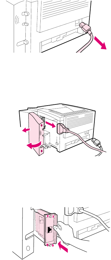
56 Chapter 3 Printer configuration C7058-90936
Network printing
Installing an HP JetDirect EIO card
Step 1 Turn the printer off, and disconnect the power cord.
Figure 22. Power cord.
Step 2 Open the interface cable door by pressing on the release tabs. Disconnect all interface
cables.
Figure 23. Interface cables.
Step 3 Locate the EIO slot. Firmly insert the HP JetDirect EIO card into the EIO slot. Install the
retaining screws.
Figure 24. HP JetDirect EIO card.
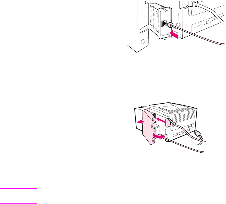
C7058-90936 Network printing 57
Step 4 Attach the appropriate network cable to the EIO card.
Figure 25. Network cable.
Step 5 Reinstall the interface cable(s), close the interface cable door, reinstall power cord, and
turn the printer on.
Figure 26. Interface cable door.
Note Print a self test/configuration page to verify that the HP JetDirect EIO card appears as an installed
option.
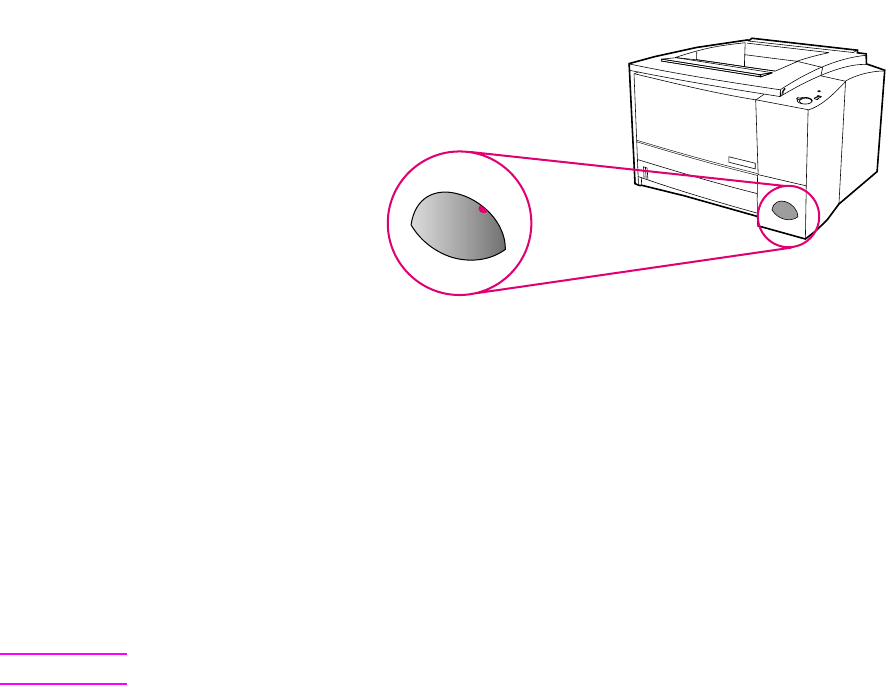
58 Chapter 3 Printer configuration C7058-90936
IR printing
Fast Infrared Receiver
The fast infrared receiver (FIR) port is located on the lower right corner of the printer. This port is
compliant with the specifications determined by the Infrared Data Association (IrDA). On the right
side of the FIR port is a status light that indicates when the port is active. The FIR port transmits data
at speeds of up to 4 MB per second. When the infrared (IR) connection is established, the FIR status
light comes on. If the connection is broken, or when the print job is complete, the FIR status light
goes off.
Figure 27. FIR port
Using the FIR port
To use the FIR port, you need the following:
lA computer or personal digital assistant (PDA) equipped with an IrDA-compliant IR port.
lAn infrared port driver that allows printing from the computer to the printer using the FIR port and
the IrDA communication protocol.
lA computer with a printer driver installed to generate data that the printer can print.
Note Check with your computer hardware or operating system manufacturer for the correct port driver.
To operate the FIR port, you need to meet the following conditions:
lA portable computer (or other portable device equipped with an IrDA-compliant IR window)
aligned within 1 meter (2 to 3 feet maximum) of the HP Fast InfraRed Receiver.
lThe IR window must be at an angle of +/- 15 degrees to ensure an effective connection for
printing.
C7058-90936 Chapter contents 59
4Printer maintenance
Chapter contents
Service check points . . . . . . . . . . . . . . . . . . . . . . . . . . . . . . . . . . . . . . . . . . . . . . . . . . . . . . . . . . . 60
Periodic inspection of parts. . . . . . . . . . . . . . . . . . . . . . . . . . . . . . . . . . . . . . . . . . . . . . . . . . .60
Cleaning the printer and accessories . . . . . . . . . . . . . . . . . . . . . . . . . . . . . . . . . . . . . . . . . . . . . .61
General cleaning. . . . . . . . . . . . . . . . . . . . . . . . . . . . . . . . . . . . . . . . . . . . . . . . . . . . . . . . . . . 61
Internal cleaning . . . . . . . . . . . . . . . . . . . . . . . . . . . . . . . . . . . . . . . . . . . . . . . . . . . . . . . . . . . 62
Engine cleaning . . . . . . . . . . . . . . . . . . . . . . . . . . . . . . . . . . . . . . . . . . . . . . . . . . . . . . . . . . . 64
Toner cartridge information . . . . . . . . . . . . . . . . . . . . . . . . . . . . . . . . . . . . . . . . . . . . . . . . . . . . . . 65
Storage . . . . . . . . . . . . . . . . . . . . . . . . . . . . . . . . . . . . . . . . . . . . . . . . . . . . . . . . . . . . . . . . . . 65
Handling instructions . . . . . . . . . . . . . . . . . . . . . . . . . . . . . . . . . . . . . . . . . . . . . . . . . . . . . . .65
Refilled toner cartridges . . . . . . . . . . . . . . . . . . . . . . . . . . . . . . . . . . . . . . . . . . . . . . . . . . . . . 66
Recycling toner cartridges . . . . . . . . . . . . . . . . . . . . . . . . . . . . . . . . . . . . . . . . . . . . . . . . . . .66
Toner cartridge weights. . . . . . . . . . . . . . . . . . . . . . . . . . . . . . . . . . . . . . . . . . . . . . . . . . . . . . 66
Toner cartridge life expectancy . . . . . . . . . . . . . . . . . . . . . . . . . . . . . . . . . . . . . . . . . . . . . . . . 66
Saving toner with EconoMode . . . . . . . . . . . . . . . . . . . . . . . . . . . . . . . . . . . . . . . . . . . . . . . . 66
Redistributing the toner. . . . . . . . . . . . . . . . . . . . . . . . . . . . . . . . . . . . . . . . . . . . . . . . . . . . . . 67
60 Chapter 4 Printer maintenance C7058-90936
Service check points
Periodic replacement parts are the parts that should be inspected and if required, replaced at regular
intervals. Failure of these parts can seriously affect the printer’s performance. These parts should be
inspected during a regular service visit near the end of the part’s expected life and replaced if found
to be worn or damaged.
Periodic inspection of parts
The following parts should be inspected and, if required, replaced after approximately 150,000 pages
of use:
lfuser assembly
ltransfer roller
lseparation pads (tray 1, tray 2, and tray 3)
lpickup rollers (tray 1, tray 2, and tray 3)
loutput feed rollers (upper and lower)
ltransport belts and rollers
See "Removal and replacement" in chapter 6 for procedures to remove and replace these parts.
See "Parts and diagrams" in chapter 8 for the part numbers.
Variables such as media, environment, and usage can cause premature wear of these parts. See
"Media specifications" in chapter 2 for information about suitable media, environment, and usage
conditions.

C7058-90936 Cleaning the printer and accessories 61
Cleaning the printer and accessories
To maintain superior print quality and performance, use the following procedures to clean the printer
and the paper-handling accessories thoroughly every time you change the toner cartridge or
whenever print-quality problems occur.
General cleaning
WARNING! Before you begin these steps, turn the printer off and unplug all power cords to avoid shock hazard.
CAUTION Do not use ammonia-based cleaners on or around the printer. While cleaning the printer, be careful
not to touch the transfer roller (located underneath the toner cartridge). Skin oils on the roller can cause
print-quality problems.
To prevent damage, do not expose the toner cartridge to light. Place a piece of paper over the top of
the toner cartridge to shield it while it is out of the printer.
lClean the outside of the printer with a water-dampened cloth.
lClean the inside of the printer with a dry, lint-free cloth:
•transfer roller
•tray 1, tray 2, and tray 3 pickup roller
•tray 1, tray 2, and tray 3 separation pad
•registration shutter
•transfer guide unit
•feed belt/feed guide unit
•fusing assembly entrance guide
Cleaning spilled toner
Defective toner cartridges can develop leaks. After a jam has occurred, some toner might remain on
the rollers and guides inside the printer. The pages that print immediately after the jam can pick up
this toner.
Note To clean skin and clothing if toner spills, remove as much toner as possible with dry tissue, then wash
with cold water. Hot water causes toner to permanently set into clothing.
Vacuum specifications
Do not vacuum the printer or any spilled toner using a conventional vacuum. Toner particles used in
this product might be too fine for effective vacuuming and could result in damage to conventional
vacuums.
A vacuum specifically designed for cleaning toner can be used if it is capable of filtering fine particles
(5 microns in diameter).

62 Chapter 4 Printer maintenance C7058-90936
Internal cleaning
During the printing process, paper, toner, and dust particles can accumulate inside the printer. Over
time, this buildup can cause print quality problems such as toner specks or smearing. This printer
has an internal cleaning mode that can correct and prevent these types of problems.
WARNING! Before you begin these steps, turn the printer off and unplug all power cords to avoid shock hazard.
Step 1 Open the top cover.
Figure 28. Top cover
Step 2 Remove the toner cartridge.
Figure 29. Remove toner cartridge
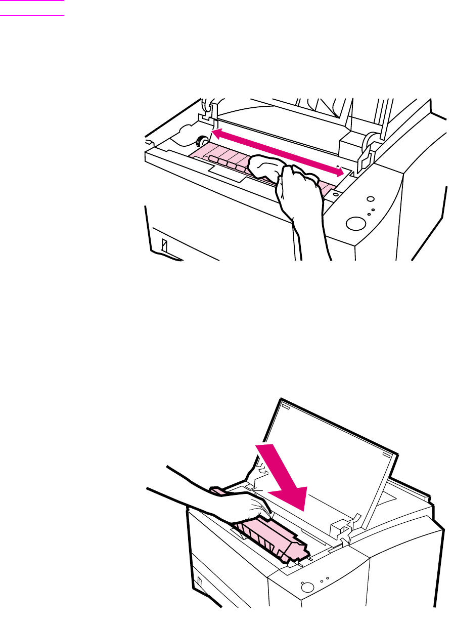
C7058-90936 Cleaning the printer and accessories 63
CAUTION To prevent damage, do not expose the toner cartridge to light.
Step 3 With a dry, lint-free cloth, wipe any residue from the paper-path area and the toner
cartridge cavity.
Figure 30. Wipe residue
Step 4 Replace the toner cartridge and close the top cover. Plug in the power cable, and turn
the printer on.
Figure 31. Replace toner cartridge
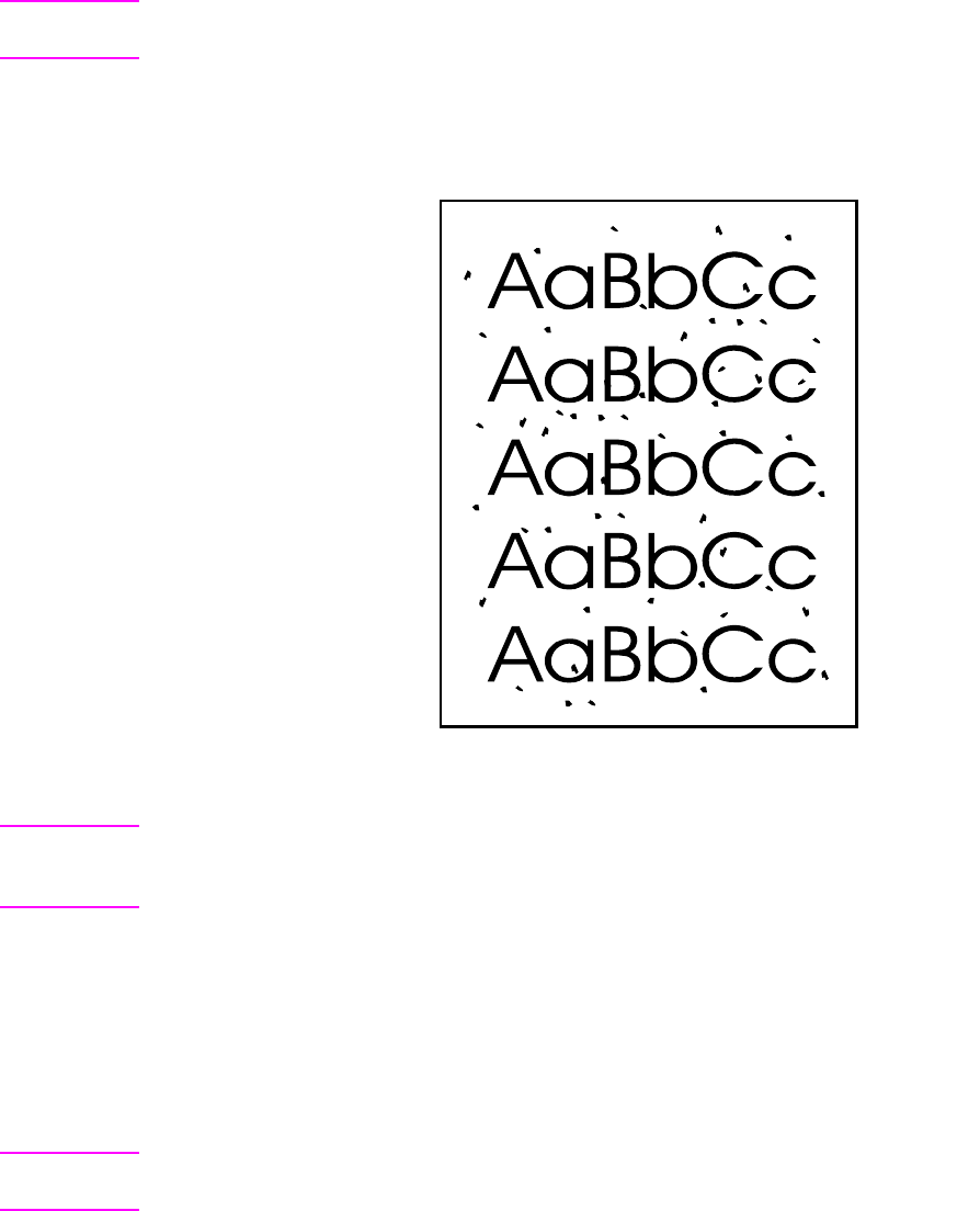
64 Chapter 4 Printer maintenance C7058-90936
Engine cleaning
Note For best results, use a transparency during this process. If a transparency is not available, use copier-
grade paper; do not use bond or rough paper.
This process uses a transparency from tray 1 to remove dust and toner from the paper path. Use this
process if toner specks or dots appear on printouts. This process will produce a blank page which
should be discarded.
Figure 32. Print sample
Note During the engine cleaning process, the printer pulls the transparency into the printer and then stops.
This is not a jam. The transparency will be slowly stepped through the printer to complete the engine
cleaning.
To start engine cleaning
Step 1 Make sure the printer is turned on and in the ready state. Load a transparency in tray 1.
Step 2 Press and hold 10 seconds.
Step 3 Release GO, the lights will cycle from front to back until the cleaning process has
completed.
Note If GO is not held long enough the device will print a demo page rather than performing the cleaning
process.
Step 4 Discard the blank page produced from the engine cleaning process.

C7058-90936 Toner cartridge information 65
Toner cartridge information
Toner cartridges contain components that are sensitive to light, temperature, and humidity. Make
sure the user follows the recommendations in this section to ensure the highest quality and longest
life of the toner cartridge.
Storage
The toner cartridge (C4096A) should not be removed from its package until installation. The shelf life
of a cartridge in an unopened package is approximately 2.5 years. The shelf life of a cartridge in an
opened package is approximately 6 months. The expiration date of the toner cartridge is stamped on
the cartridge box.
If cartridges are stored, the storage environment should meet the conditions listed in the following
table:
If the toner cartridge must be removed from the printer, always store the cartridge:
linside the protective bag in which it was originally packaged.
lin a dark cabinet, away from direct sunlight.
lcorrect side up and in a horizontal position (not standing on end).
lin a temperature listed in the table above.
laway from ammonia or other organic solvent fumes.
CAUTION Never ship the printer with a toner cartridge installed. Excessive vibration during shipping can cause
toner to leak, contaminating the printer.
Never expose the toner cartridge to direct sunlight, or to room light. Bright light and direct sunlight can
permanently damage a toner cartridge.
Handling instructions
lBefore installing a cartridge, evenly distribute the toner. See “Redistributing the toner” on page
67.
lDo not touch the surface of the photosensitive drum in the cartridge. Protect the drum from light
and contamination.
lDo not expose the cartridge to unnecessary vibrations or shock.
lDo not expose the photosensitive drum to strong light. Blurred areas on the page might indicate
that the drum has been exposed to light for too long. This causes permanent damage to the
photosensitive drum. Replace the cartridge.
lNever manually rotate the drum, especially in the reverse direction; it can cause internal damage
and toner spills.
Table 24. Storing toner cartridges
Category Temperature Humidity
Operating 10 degrees to 32.5 degrees C
(50 degrees to 90.5 degrees F) 35 percent to 85 percent RH
Storage -20 degrees to 40 degrees C
(-4 degrees to 104 degrees F) 15 percent to 90 percent RH
66 Chapter 4 Printer maintenance C7058-90936
Refilled toner cartridges
HP policy on non-HP toner cartridges
Hewlett-Packard Company cannot recommend use of new, refilled, or remanufactured, non-HP toner
cartridges. Because they are not HP products, HP cannot influence their design or control their
quality.
While Hewlett-Packard Company does not prohibit the use of refilled toner cartridges during the
warranty period or while under a maintenance contract, we do not recommend their use for the
following reasons:
lHewlett-Packard has no ability to ensure that a refilled toner cartridge functions at the high level
or reliability of a new HP toner cartridge. Hewlett-Packard also cannot predict the long-term
effect of the different toner formulations found in refilled cartridges.
lHewlett-Packard has no control over the print quality of a refilled toner cartridge. The print quality
of HP toner cartridges influences the customer’s perception of the printer.
lRepairs resulting from the use of refilled toner cartridges might not be covered under the HP
warranty or maintenance contract.
Recycling toner cartridges
In many countries, this product’s printing supplies (for example, toner cartridge) can be returned to
HP through the HP Printing Supplies Environmental Program. An easy-to-use take back component
of the program is available in more than 20 countries. Multilingual program information and
instructions are included in every new HP LaserJet toner cartridge and consumables box.
For more information, call (1) (800) 340-2445 (U.S. only) or visit the HP LaserJet supplies website:
U.S.: http://www.hp.com/ljsupplies/environment_main.html
Europe: http://www.hp.com/pays/eur_supplies/english/planetpartners
Customers outside the United States should call their local HP sales and service office for further
information regarding availability of the HP Printing Supplies Environmental Program.
Toner cartridge weights
The approximate weight of a toner cartridge when full and empty is as follows:
lFull: 1105 grams (39.07 ounce)
lEmpty: 900 grams (31.77 ounce)
Toner cartridge life expectancy
The life of the toner cartridge depends on the amount of toner used in each print job. When printing
text at 5 percent coverage, an HP LaserJet 2200 toner cartridge lasts an average of 5,000 pages.
This assumes the default print density setting and that EconoMode is off (default settings).
Saving toner with EconoMode
Toner cartridge usage can be extended by using the printer’s EconoMode feature. EconoMode can
be turned on or off through the driver or HP LaserJet device configuration.
lEconoMode functions in portrait orientation only.
lEconoMode does not function at 1200 dpi.
lSome software applications might refer to EconoMode as “draft mode.”
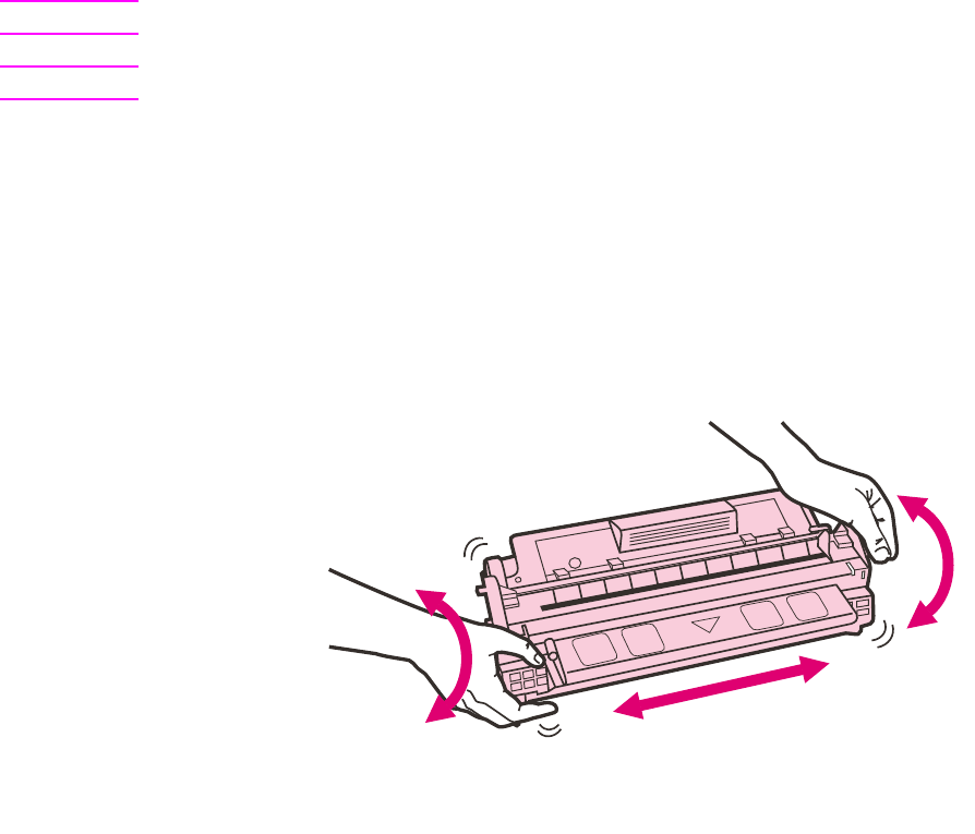
C7058-90936 Toner cartridge information 67
Redistributing the toner
When toner is low, faded or light areas might appear on a printed page. To temporarily improve print
quality, redistribute the toner. The cartridge will need to be replaced soon. Use the following
procedures to redistribute toner.
WARNING! Avoid reaching too far into the printer. The adjacent fusing area can be hot.
CAUTION To prevent damage, do not expose the toner cartridge to light.
Step 1 Remove the toner cartridge from the printer.
Step 2 Rotate the toner cartridge and gently shake from side to side to redistribute the toner.
(Do not tip the cartridge on end, or it might leak.)
If toner gets on clothing, wipe it off with a dry cloth and wash clothing in cold water. (Hot water sets
toner into fabric.)
Figure 33. Redistributing the toner
68 Chapter 4 Printer maintenance C7058-90936
C7058-90936 Chapter contents 69
5Theory of operation
Chapter contents
Basic operations . . . . . . . . . . . . . . . . . . . . . . . . . . . . . . . . . . . . . . . . . . . . . . . . . . . . . . . . . . . . . . 70
Power-on sequence . . . . . . . . . . . . . . . . . . . . . . . . . . . . . . . . . . . . . . . . . . . . . . . . . . . . . . . .70
Basic print-period operating sequences . . . . . . . . . . . . . . . . . . . . . . . . . . . . . . . . . . . . . . . . . 71
Printer timing. . . . . . . . . . . . . . . . . . . . . . . . . . . . . . . . . . . . . . . . . . . . . . . . . . . . . . . . . . . . . . 72
Printer functionality and operation. . . . . . . . . . . . . . . . . . . . . . . . . . . . . . . . . . . . . . . . . . . . . . . . . 73
Formatter system . . . . . . . . . . . . . . . . . . . . . . . . . . . . . . . . . . . . . . . . . . . . . . . . . . . . . . . . . . 74
Formatter hardware . . . . . . . . . . . . . . . . . . . . . . . . . . . . . . . . . . . . . . . . . . . . . . . . . . . . . . . . 75
Formatter subsystem . . . . . . . . . . . . . . . . . . . . . . . . . . . . . . . . . . . . . . . . . . . . . . . . . . . . . . .75
Engine control system. . . . . . . . . . . . . . . . . . . . . . . . . . . . . . . . . . . . . . . . . . . . . . . . . . . . . . . 77
Engine control subsystems. . . . . . . . . . . . . . . . . . . . . . . . . . . . . . . . . . . . . . . . . . . . . . . . . . . 78
Image formation system . . . . . . . . . . . . . . . . . . . . . . . . . . . . . . . . . . . . . . . . . . . . . . . . . . . . .80
Pickup/feed system. . . . . . . . . . . . . . . . . . . . . . . . . . . . . . . . . . . . . . . . . . . . . . . . . . . . . . . . . 86
Sheet feeder . . . . . . . . . . . . . . . . . . . . . . . . . . . . . . . . . . . . . . . . . . . . . . . . . . . . . . . . . . . . . . . . . 88
Media detection. . . . . . . . . . . . . . . . . . . . . . . . . . . . . . . . . . . . . . . . . . . . . . . . . . . . . . . . . . . . . . . 90
Media detection. . . . . . . . . . . . . . . . . . . . . . . . . . . . . . . . . . . . . . . . . . . . . . . . . . . . . . . . . . . . 90
Media-size detection . . . . . . . . . . . . . . . . . . . . . . . . . . . . . . . . . . . . . . . . . . . . . . . . . . . . . . . . 90
Jam detection . . . . . . . . . . . . . . . . . . . . . . . . . . . . . . . . . . . . . . . . . . . . . . . . . . . . . . . . . . . . . . . . 91
Pickup sensors . . . . . . . . . . . . . . . . . . . . . . . . . . . . . . . . . . . . . . . . . . . . . . . . . . . . . . . . . . . . 91
Delivery sensors . . . . . . . . . . . . . . . . . . . . . . . . . . . . . . . . . . . . . . . . . . . . . . . . . . . . . . . . . . . 91
Reversing sensors . . . . . . . . . . . . . . . . . . . . . . . . . . . . . . . . . . . . . . . . . . . . . . . . . . . . . . . . . 92
Duplexer sensors . . . . . . . . . . . . . . . . . . . . . . . . . . . . . . . . . . . . . . . . . . . . . . . . . . . . . . . . . . 92
Paper-feed sensor. . . . . . . . . . . . . . . . . . . . . . . . . . . . . . . . . . . . . . . . . . . . . . . . . . . . . . . . . . 92
70 Chapter 5 Theory of operation C7058-90936
Basic operations
Power-on sequence
The sequence from power-on until the printer enters the standby (STBY) mode:
1Power-on.
2CPU initialization.
3Formatter communication start.
4Fusing heater drive.
5Main motor, Reverse motor, and fan drive—Reads the paper-detecting status of each sensor in
the printer immediately before driving the main motor, and assesses a jam if residual media is
detected.
6High-voltage control—Detects the cartridge presence and cleans the transfer charging roller
after the primary charging ac bias is turned on.
7Residual paper check—After starting the main motor, detection of residual media in the printer
resumes. If residual media is detected, the printer assesses a jam or automatically delivers the
residual media, according to the situation.
8Failure or abnormality check—Detects door-open, fan-motor, and fuser-unit failures during the
other sequence periods.

C7058-90936 Basic operations 71
Basic print-period operating sequences
The operation sequences of this printer are controlled by the microprocessor (CPU) on the engine
controller printed circuit board (PCB). The table below describes the purpose of periods from power-
on until the main motor stops when printing is complete.
Table 25. Print period descriptions
Period Timing Purpose Remarks
WAIT (wait period) From power-on until
completion of the main-
motor initial drive.
Clears the drum surface
potential and cleans the
transfer charging roller.
Detects whether the
cartridge is installed or
not.
STBY (standby period) From the end of the WAIT
period until the print
instruction command is
received from the
formatter, or from the end
of the LSTR period until
the print instruction
command is input from
the formatter, or until the
power is switched on or
off.
Maintains the printer in a
ready state.
INTR (initial rotation
period) From receipt of the print
instruction command from
the formatter until the
media reaches the top-of-
page sensor.
Stabilizes the sensitivity of
the photosensitive drum in
preparation for printing.
PRINT (print period) From the end of the INTR
period until 1.2 seconds
after the top-of-page
sensor detects the trailing
edge of the media.
Forms an image on the
photosensitive drum in
preparation for printing.
LSTR (last rotation
period) From completion of
printing until the main
motor stops rotating.
Delivers the final page out
of the printer and cleans
the transfer charging
roller.
If a print instruction
command is received from
the formatter, the printer
bypasses the WAIT and
STANDBY periods and
immediately enters the
INTR period.
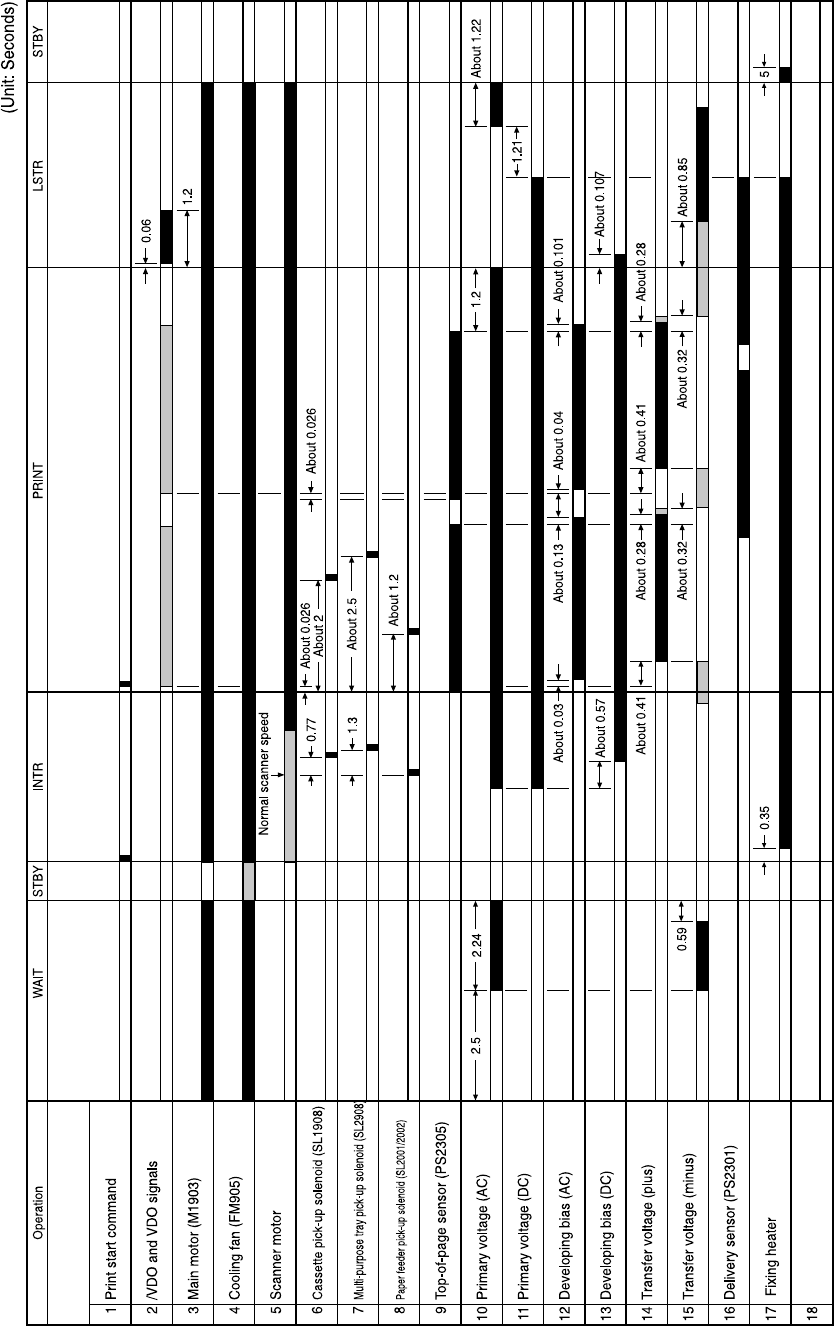
72 Chapter 5 Theory of operation C7058-90936
Printer timing
Figure 34. Timing chart
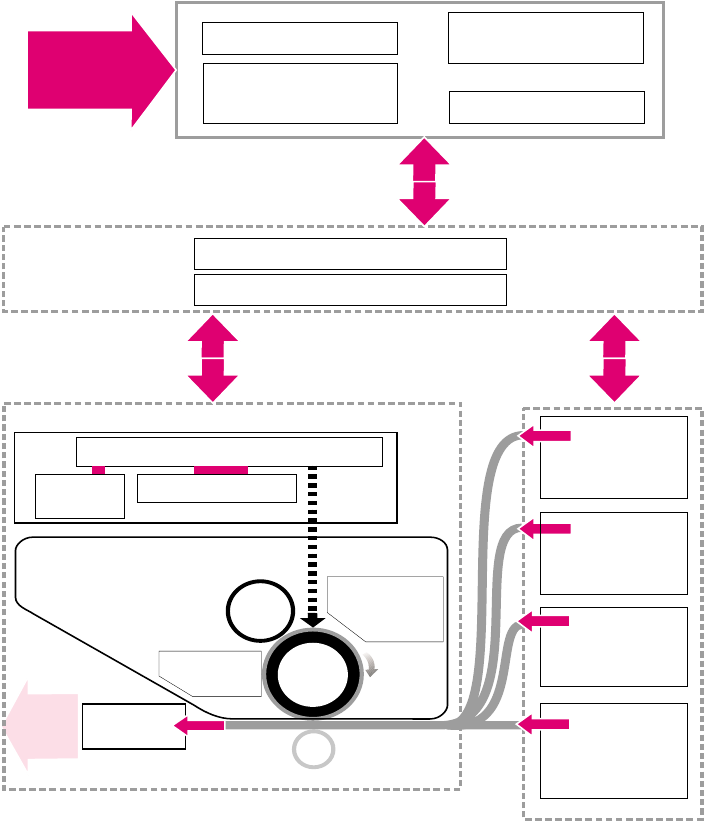
C7058-90936 Printer functionality and operation 73
Printer functionality and operation
Four major systems make up the HP LaserJet 2200 printer and allow it to operate. Each system
works independently to accomplish its task, but must be coordinated with the other systems to
successfully produce a printed page. Understanding these systems, their function, and how they
interact with each other is the key to troubleshooting any problem. See "Troubleshooting process" in
chapter 7 for detailed information about the HP LaserJet 2200.
The HP LaserJet 2200 printer’s four major systems are as follows:
l"Formatter system" page 74—Receives print data from the host, processes the image, and
transfers it to the engine control system. The formatter system also provides the interface
between the user and the printer (control panel).
l"Engine control system" page 77—Monitors and controls all of the printer’s mechanical and
electrical subsystems. It is the center of the printer’s operation.
l"Image formation system" page 80—Produces the actual physical image on the page.
l"Pickup/feed system" page 86—Moves paper or other print media through the printer from one of
the selected input trays (tray 1, 2, or 3) to the selected output bin (top or rear).
Figure 35. Printer functionality divided into systems
Formatter system
Control panel
Central processor
Print data
from
Host system
I/O subsystem
Memory
Engine control system
Engine controller PCB
Power supply
Image formation system
Laser/scanner assembly
Scanning mirror
Laser
diode Scanner motor
Tray 1
Duplexer
Tray 2
Tray 3
Toner cartridge
Primary charging
roller
Cleaning
unit
EP
drum
Developing
unit
Fuser
assembly
Paper
exits
printer Transfer
roller
Paper pickup and feed system
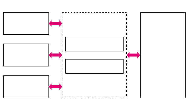
74 Chapter 5 Theory of operation C7058-90936
Formatter system
The formatter system is responsible for the following:
lreceiving and processing data from the various printer interfaces
lmonitoring control panel input and relaying printer status information (through the control panel
and the I/O)
ldeveloping and coordinating data placement and timing with the print engine
lstoring font information and macros
lcommunicating with the host computer
The formatter receives data from the I/O and converts it into a dot image. The formatter then sends a
print signal to the engine controller assembly. The engine controller assembly synchronizes the
image-formation system with the paper-feed system, and signals the formatter to send the print-
image data. The formatter sends the print-image data (dots) in the form of a video signal and the
printing process begins.
Figure 36. Formatter system
Laser/scanner
system
Image formation
system
Paper pickup/
feed system
Engine control system
Engine controller
PCB
Power supply
PCB
Formatter
system
C7058-90936 Printer functionality and operation 75
Formatter hardware
The formatter system contains the following:
lCPU—Is a 133 Mhz Motorola Coldfire V4 with a 66 MHz bus.
lRead-only memory (ROM)—Stores the dot patterns of internal character sets (fonts) in addition
to storing microprocessor control programs.
lRandom-access memory (RAM)—Stores printing and font information received from the host
system, and can also serve to temporarily store a full page of print-image data before the data is
sent to the print engine. Increasing the RAM will increase performance of graphic intense printing
operations but it will not increase the I/O buffer space or cause the printer to print more pages
per minute.
lNonvolatile memory (NVRAM)—Stores information about the I/O and print environment
configuration. The printer keeps the contents of NVRAM when the power is turned off or
disconnected. (As in other HP LaserJet printers, downloaded fonts and macros are saved in
conventional RAM and are lost when power is turned off.)
lInterfaces
•Parallel interface—Receives incoming data through its IEEE1284 B interface connector. The
IEEE1284 B interface provides high-speed, two-way communication between the printer and
the host, letting the user change printer settings from the host computer.
•USB—Receives incoming data through its universal serial bus (USB) connector. The USB
interface provides high-speed, two-way communication between the printer and the host,
letting the user change printer settings computer.
•EIO—The PCI-based enhanced input/output (EIO) slots support a wide range of print servers
and other add-on devices. HP JetDirect EIO cards provide high-speed, two-way
communication for network printing over Ethernet, Ethernet and LocalTalk, Token Ring, or
Fast Ethernet networks.
•FIR—This port is compliant with the specifications determined by the Infrared Data
Association (IrDA). On the right side of the FIR port is a status light that indicates when the
port is active. The FIR port transmits data at speeds of up to 4 MB per second. When the
infrared (IR) connection is established, the FIR status light comes on. If the connection is
broken, or when the print job is complete, the FIR status light goes off.
Formatter subsystem
Resolution Enhancement technology (300 and 600 dpi only)
Contains circuitry for Resolution Enhancement technology (REt), which modifies the standard video
dot data on its way to the engine controller assembly to produce smoothed black-to-white
boundaries. The default is on.
Print-density adjustment
Affects the line width (boldness) of the print image. This is accomplished by varying the developer dc
bias, which controls the amount of toner applied to the photosensitive drum. Settings range from 1
(lightest) to 5 (darkest). The default is 3.
EconoMode
Uses approximately 50 percent less toner than standard mode printing by reducing the dot density.
Users can adjust EconoMode, which can also be thought of as draft mode, through software
applications. The default setting is off. EconoMode does not affect print speed or memory usage.
76 Chapter 5 Theory of operation C7058-90936
Memory management
This printer uses various methods to conserve and make the most of available memory. Several of
these methods are explained below.
Memory Enhancement technology (MEt)
MEt enhances the printer's standard memory through a variety of font and data compression
methods. MEt also automatically compresses fonts for desktop publishing applications. MEt is
available in all printing modes (PCL 5e, PCL 6, and HP PS emulation). When printing graphics, MEt
analyzes each page as it is being printed and automatically applies a variety of compression
techniques to print the complete page at the correct resolution.
Image Adapt
Image Adapt uses a compression technique to allow printing of full-page graphics using the printer's
base memory. Image Adapt is only used in PCL 5e (PCL 6 and HP PS emulation do not require
Image Adapt). The available settings are auto, on, and off. The default is auto.
If Image Adapt is used some data might be lost. To see if there has been some loss of graphic detail,
print a self-test page and check the Image Adapt Used line in the Printer Information section. If the
printer invoked Image Adapt since the last time the self test was printed (or the last time the printer
was turned off and on), that line reads “Image Adapt Used: Yes.”
Page Protect
A page's complexity (rules, complex graphics, or dense text) might exceed the printer's ability to
create the page image fast enough to keep pace with the engine's printing process. If a page is too
complex, it might print in parts (for example, the top half of data on one page and the bottom half on
the next page). Some print data loss is likely in these instances, and the printer's Attention light
flashes.
Page Protect allows the formatter to create the entire page image in memory before moving the
paper through the printer. This process ensures that the entire page is printed. The default is off,
which provides the best performance. Page Protect should only be enabled when necessary.
Printer Job Language overview
Printer Job Language (PJL) is an integral part of the printer’s configuration, in addition to the
standard Printer Command Language (PCL). PJL allows the printer to perform functions such as:
lTwo-way communication with the host computer through an IEEE1284 B interface connection.
The printer can tell the host such things as the control panel settings and allow the control panel
settings to be set from the host.
lDynamic I/O switching allows the printer to be configured with a host on each I/O. The printer
can receive data from more than one I/O simultaneously until the buffer is full. This can occur
even when the printer is offline.
lContext-sensitive switching allows the printer to automatically recognize the personalities (PS
or PCL) of each host and configure itself to serve that personality.
lIsolating print environment settings from one print job to the next. For example, if a print job is
sent to the printer in landscape mode, subsequent print jobs only print in landscape if they are
formatted for landscape printing.
For more information, see the HP LaserJet 2200 Series Printer Software Technical Reference. The
complete PJL Status Code listing is contained in the appendix of the Printer Job Language Technical
Reference. Also see HP’s website at www.hp.com.

C7058-90936 Printer functionality and operation 77
Engine control system
The engine control system consists of the engine controller PCB and the power supply assembly.
The engine controller PCB coordinates all print engine activities. The figure below illustrates the
block diagram of this system, and the description of each subsystem follows.
Figure 37. Engine control system
The engine control system directly controls the following subsystems:
llaser/scanner control
lpaper-feed control
lmicroswitch control
lmotor control
lfuser-assembly control
lpower supply and control
Engine controller PCB
Sensors
Solenoids
Main motor
Cooling fan
Reverse
motor
Options
Beam
Scanner
motor
Laser/
scanner
driver
Fan motor
control
IC901
/RSTX
/BDI
Power
supply PCB Reset
IC
Formatter
detection
78 Chapter 5 Theory of operation C7058-90936
Engine control subsystems
Laser/scanner control
Based on information received from the engine controller PCB, the formatter sends a direct signal to
modulate the laser diode on and off. The modulated laser beam strikes the surface of a rotating
scanning mirror, then a focusing lens directs the beam onto the photosensitive drum.
The printing system synchronizes the process by continuously monitoring the beam detect signal.
Paper-feed control
The engine controller PCB controls paper motion by continuously monitoring the various paper-
sensor levers, and coordinating the timing with the other print processes and systems. See “Pickup/
feed system” on page 86.
Microswitch control
The engine controller PCB controls the following microswitches and reports any errors to the
formatter:
lTop door and toner cartridge switch. Activated if the top door is open. The toner cartridge is
detected electronically.
lEngine test switch. Activated manually through an access hole on the side of the gear plate. This
switch causes the print engine to perform a self-test diagnostic, bypassing the formatter. See
"Engine test" in chapter 7.
Motor control
The engine controller PCB controls the following motors and reports any failures to the formatter.
See “Basic print-period operating sequences” on page 71.
lMain motor. Rotates during interim period (following initial power on), print, and last rotation, or
when the top cover is opened or closed.
lScanner motor. Operates during the interim period and the print period.
lFan motor. Rotates at full speed while the main motor is rotating and continues rotating for 30
seconds after the main motor stops. Rotates at full speed, half speed, and then stops during
power-on and the standby period.
lReverse motor. A stepping motor responsible for changing the paper direction. It is capable of
clockwise and counterclockwise rotation.
Fuser-assembly control
The fuser assembly’s film contains a heater. The engine controller PCB controls the fuser heater
during the following temperature modes. See “Basic print-period operating sequences” on page 71.
linitial
lprint
lbetween-page
lpostprint
The engine controller PCB maintains the fuser at a temperature of 195 degrees C (383 degrees F)
during print temperature mode. If the fuser system overheats, reaching about 220 degrees C (428
degrees F), a relay opens the power circuit to the fuser heater, causing a fuser error message. If the
fuser system exceeds 230 degrees C (446 degrees F), the thermal fuse melts, cutting off power to
the fuser assembly. The engine controller PCB monitors the fuser heater temperature through a
thermistor.
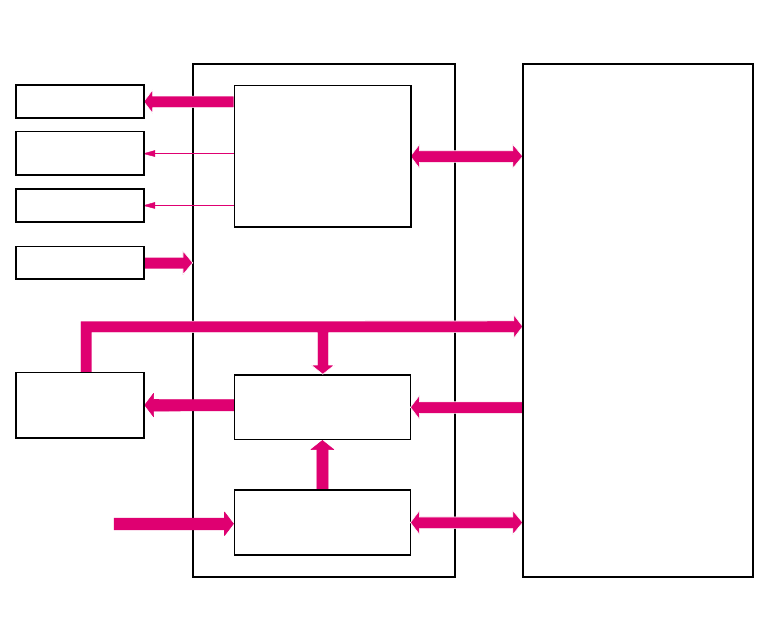
C7058-90936 Printer functionality and operation 79
Power supply and control
lThe power switch supplies ac power to the low-voltage power supply circuit when it is turned on.
This circuit supplies dc voltage (+24V, +5V, +3.3V) to the main motor, laser/scanner unit,
interlock switch, formatter, solenoids, paper feeder, high-voltage power supply, and formatter.
lThe dc voltage supplied to the high-voltage power supply circuit is interrupted when the top cover
is open.
lThe overcurrent/overvoltage protection circuit in the low-voltage power supply automatically
turns off the output voltage when an overcurrent condition occurs because of a short or
abnormal voltage on the load side.
lWhen input power is turned off then on, the protection circuit automatically resets. The low-
voltage power supply circuit also contains a fuse that shuts off the power supply to the circuit
when overcurrent conditions occur. See “Engine control system” on page 77.
In response to the engine controller PCB, the high-voltage power supply circuit supplies dc and ac
voltage to the various parts of the image formation system.
Figure 38. Power supply PCB
Power supply PCB
Engine controller PCB
High-voltage
power supply
circut
fuser control
circut
Low-voltage power
supply circut
Cartridge
Transfe r
Pressure roller
Sensors
Fuser assembly
ac input
charging roller
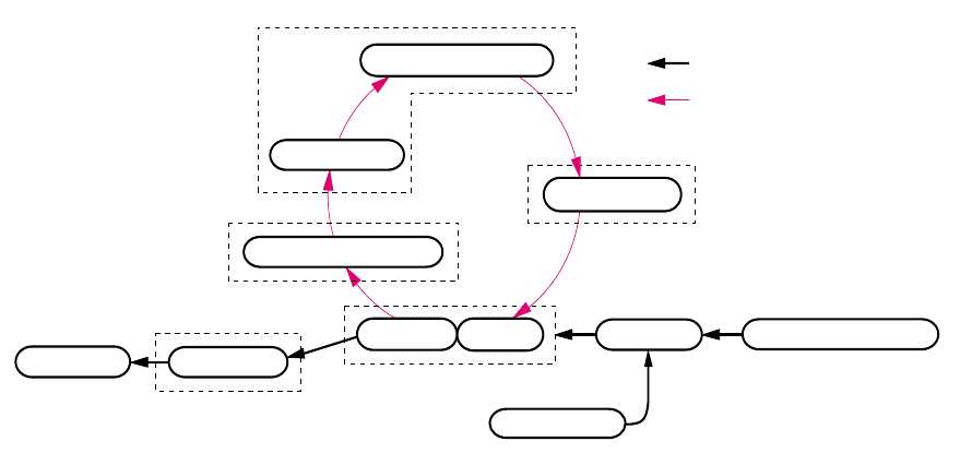
80 Chapter 5 Theory of operation C7058-90936
Image formation system
The image formation system is the central hub of the printer. The system consists of the cartridge,
transfer charging roller, and fuser unit.
When a print command is sent from the formatter, the engine controller drives the main motor to
rotate the photosensitive drum, primary charging roller, developing cylinder, transfer charging roller,
and pressure roller.
The primary charging roller uniformly applies negative charges to the photosensitive drum surface.
To form a latent image on the photosensitive drum, the laser beam modulated by the video signals is
exposed on the photosensitive drum surface.
The toner on the developing cylinder develops the latent image formed on the photosensitive drum
into a visible image, which is transferred onto media by the transfer charging roller. The transferred
toner is changed to a permanent image by heat and pressure in the fuser unit. The cleaning blade
scrapes off residual toner on the photosensitive drum. The potential on the drum is made uniform by
the primary charging roller in preparation for the next latent image.
Figure 39. Image formation system
Print process
The toner cartridge contains the cleaning, conditioning, and developing stages of the image
formation process. These components are subject to wear and are built into the replaceable toner
cartridge. This eliminates the need for a service call when replacement is required.
2.Laser exposure
3.Developing
1.Primary charge
7.Drum cleaning
fuser block
Paper delivery 6.Fuser
5.Separation 4.Transfer
Cassette pickup
Registration Tray 1 pickup
Rotation of drum
Paper path
Transfer block
Drum cleaning block
Developing block
Electrostatic latent image formation block
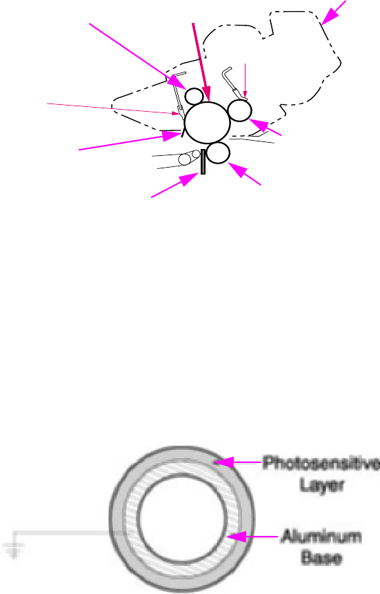
C7058-90936 Printer functionality and operation 81
Figure 40. Toner cartridge
Photosensitive drum
The photosensitive drum is the heart of the image formation system. This drum’s special properties
allow an image to form on the drum's surface and then transfer to paper. The drum is an aluminum
cylinder coated with an organic-photoconductive material (OPC). The photosensitive drum’s
aluminum base is electrically connected to ground. The OPC material becomes electrically
conductive when exposed to light. Areas not exposed to light remain nonconductive and maintain
their negative charge.
Figure 41. Photosensitive drum
Cleaning stage
At the cleaning stage, the photosensitive drum's surface is prepared to hold an image. During
printing, the drum rotates completely several times per printed page. Before forming the image for a
given section of print, a cleaning blade removes toner from the previous rotation of the drum. The
toner cartridge stores waste toner and prevents it from being used in later print jobs.
Laser beam
Blade
Cleaning blade
Primary charging roller
Photosensitive drum
Static charge eliminator
Cartridge
Developing cylinder
Transfer charging roller
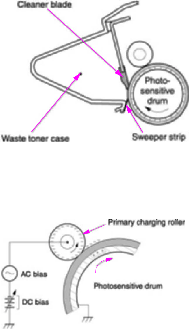
82 Chapter 5 Theory of operation C7058-90936
Figure 42. Cleaning stage
Conditioning stage
At the conditioning stage, the primary charging roller applies a uniform negative charge on the
photosensitive drum’s surface. The primary charging roller erases any residual charges and
maintains a constant potential on the drum’s surface. In addition, the primary charging roller creates
a uniform negative potential on the drum's surface.
Figure 43. Primary charging roller
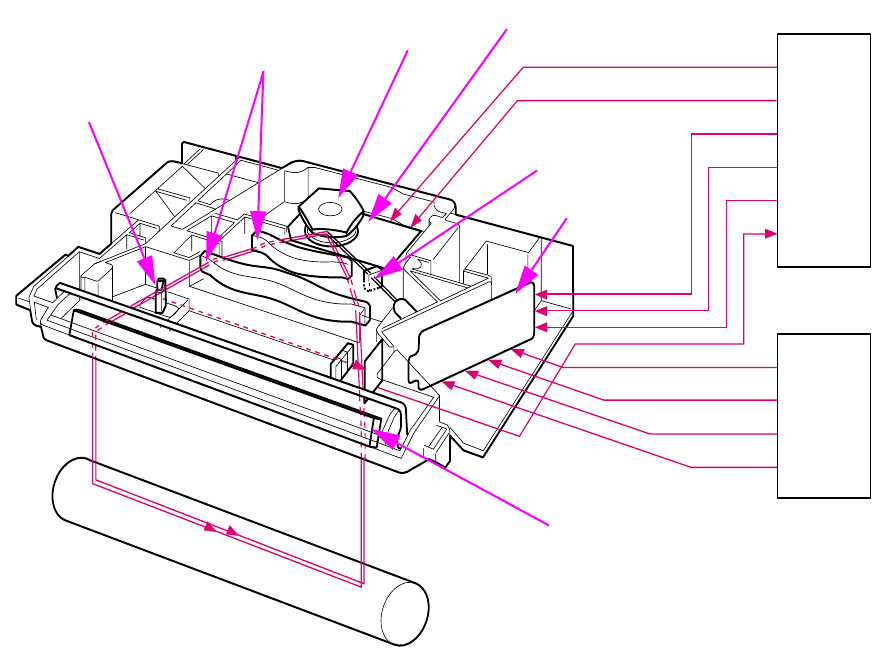
C7058-90936 Printer functionality and operation 83
Writing stage
At the laser/scanner assembly, two laser beams focus onto the photosensitive drum and discharge
the drum's negative potential. This creates a latent electrostatic image, which later is developed into
a visible image.
Two small laser diode beams shine onto a rotating, six-sided mirror. As the mirror rotates, the beams
reflect off the mirror and sweep the page from left to right.
A set of lenses and mirrors focuses the horizontal sweeping beams through the beam access slots in
the rear of the toner cartridge and onto the photosensitive drum. Because the beams sweep the
entire length of the drum while the drum rotates, the entire circumference of the drum can be
covered. Each successive sweep of the beams is offset 1/1200th of an inch. This is how the printer
achieves its 1200 dpi resolution.
At the beginning of each sweep (before the beams reach the drum), the beam detect mirror reflects
the beams. The momentary pulse of light goes to the engine controller PCB, which converts the light
to an electrical signal used to synchronize other activities in the printer and to diagnose problems
with the laser/scanner assembly.
Portions of the drum not exposed to the laser still contain the uniform negative potential (placed there
by the primary charging roller), but those portions exposed to light have been discharged to ground
to form the latent electrostatic image.
Figure 44. Laser/scanner system
Engine controller
formatter
/ACC
/DEC
CNT0
CNT1
CNT2
BDI
/VDATA1
VDATA1
/VDATA2
VDATA2
Cylindrical lens
Scanning mirror
Focusing lens
Laser driver
Scanner motor
Mirror
Beam Detect mirror
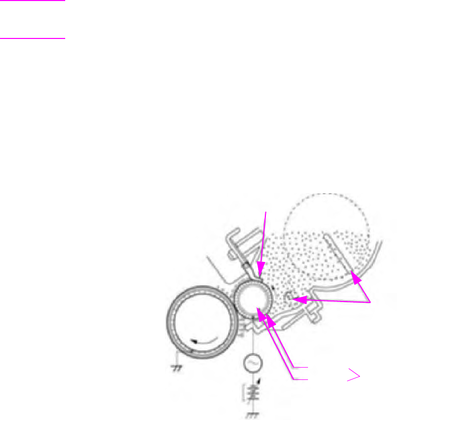
84 Chapter 5 Theory of operation C7058-90936
Developing stage
At the developing stage, the latent electrostatic image is developed into a visible image on the
photosensitive drum. The developing cylinder consists of a metallic cylinder that rotates around a
fixed magnetic core inside the toner cavity. Toner is a powdery substance made of black, plastic
resin bound to iron particles, which the magnetic core of the developing cylinder attracts. A rubber
blade brushes the toner on the developing cylinder to a uniform thickness.
Note Charges in the photosensitive drum’s exposed areas are shown as positive in figure 45 even though
they are actually negative. This means that the photosensitive drum potential is higher than that of the
developing cylinder.
To obtain a negative surface charge, the toner particles rub against each other and the developing
cylinder which is connected to a negative dc supply. The discharged (grounded) areas of the drum
exposed to laser light attract the negatively charged toner. The negatively charged (non-exposed)
areas repel the toner. An ac potential is applied to the developing cylinder to decrease the attraction
between the toner and the cylinder’s magnetic core and to increase the repelling action of toner
against the areas of the drum not exposed to laser light. This ac potential improves density and
contrast.
The print density setting (through the software) adjusts the developing cylinder’s dc bias to change
the force of attraction between the toner and drum.
Figure 45. Latent electrostatic image formation
Photo-
sensitive
drum
Blade
Stirrer
Cylinder
Magnet Developing cylinder
ac bias
dc bias
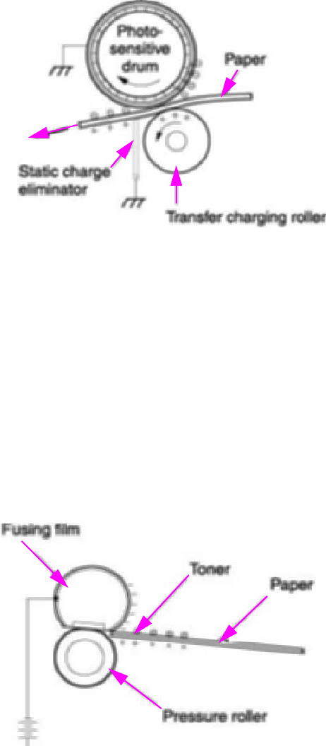
C7058-90936 Printer functionality and operation 85
Transferring stage
At the transferring stage, the toner image on the photosensitive drum's surface is moved to the
paper. The transfer roller applies a positive charge to the back of the paper, causing the paper to
attract the negatively charged toner on the drum's surface.
The drum’s small radius combined with the stiffness of the paper causes the paper to peel away from
the drum. The static charge eliminator helps separate the paper from the drum by weakening the
attractive forces between the negatively charged drum surface and the positively charged paper.
Without this help, thin paper might wrap around the drum. The static charge eliminator also prevents
droplets on the printed image at low temperature and humidity. After separation, the paper moves to
the fuser station and the drum rotates to the cleaning and conditioning stations.
Figure 46. Transferring the toner image on the drum
Fuser stage
At the fuser stage, heat and pressure fuse the toner to the paper to produce a permanent image. The
paper passes between a fuser film and a pressure roller. The fuser film melts the toner while the
pressure roller compresses it into the paper.
To prevent the toner from dispersing during the fuser stage, this printer applies a negative dc voltage
to the fuser film via the pressure roller shaft. A negative charge is applied to the surface of the paper,
which improves the adhesion force of the toner particles to the paper and prevents dispersion of the
toner particles.
The fuser heater comes up to fuser temperature very quickly and thus does not require any power
while the printer is on STBY. This feature saves power while virtually eliminating the warm-up period
(less than 10 seconds).
Figure 47. Fuser film and pressure roller
86 Chapter 5 Theory of operation C7058-90936
Pickup/feed system
When the formatter sends a print command to the engine controller PCB, the main motor and
scanner motor start rotating and the fuser heater temperature control starts.
The paper feed system automatically picks print media from tray 1, tray 2, or tray 3 (if installed) and
delivers it to the registration roller. Before the media reaches the registration roller, the separation
pad separates any excess sheets of media, and the registration shutter corrects the media skew.
After the top-of-page sensor detects the leading edge of the page, the engine controller PCB sends a
signal to the formatter. This signal functions as a synchronization between the engine controller PCB
and the formatter. This synchronization allows the leading edge of the image on the photosensitive
drum to match the leading edge of the page. After the transferring stage of the image formation
process, the paper is fed to the fuser assembly by the feed belts.
The delivery sensor detects the exiting paper, which is usually fed to the top or rear output bin unless
duplex is enabled.
To print duplex, this printer prints one side of paper, transports it to the face-down tray once, and
then reverses the paper by feeding it back to the duplex feed unit.
The face-up sensor detects paper delivered face-down, with one side printed.
The delivery sensor detects the trailing edge of the paper, then signals the engine controller. The
engine controller rotates the reverse motor counterclockwise to send the paper to the duplexer feed
unit.
The reversed paper sensor receives the paper, then signals the engine controller to turn the duplexer
solenoid on. The paper is transported by the oblique roller to the registration roller. If next paper is
picked up, the duplex-fed paper stops at the specified position. The top page sensor senses the next
paper, the specified period of time passes, then the duplex-fed paper is retransported.
The retransported paper is printed with the other side and delivered to the face-down tray.
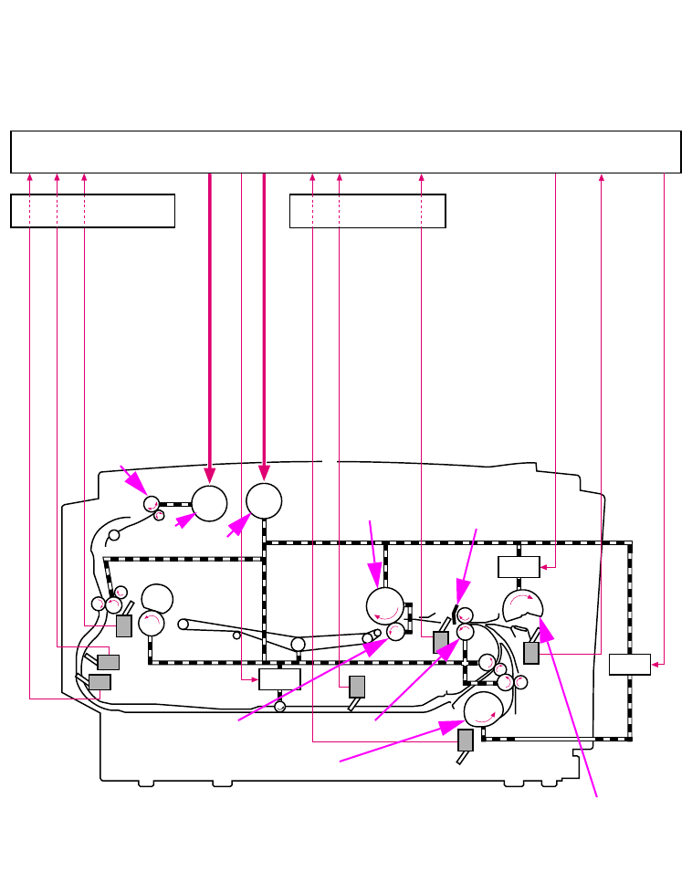
C7058-90936 Printer functionality and operation 87
Figure 48. Pickup/feed system
Engine controller PCB
Power supply PCB Power supply PCB
Face down
delivery rollers
Main motor
Reverse motor
Photosensitive
drum Registration
shutter
Feed belts
Pressure roller
Registration roller Feed rollers
Tray 1 pickup roller
Cassette pickup roller
Transfer charging
roller
Cassette
M904 M903
SL2908
SL1908
PS3208
PS2305
PS503
PS1305
SL909
PS501
PS502
PS2301
Reversed paper detection signal (REVSNS)
Face-up detection signal (/FOUSNS)
Delivery detection signal (/POSNS)
Reverse motor drive signals (DUPSL)
Duplex solenoid drive signals (DUPSL)
Main motor drive signals (/MON)
Cassette paper detection signal (/CSTSNS)
Duplex pickup paper detection signal (/DUPSNS)
Top of page detection signal (/TOPSNS)
Tray 1 pickup solenoid drive signal (MPTSL)
Tray 1 paper detection signal (/MPTSNS)
Cassette pickup solenoid drive signal (CSTSL)
PS501: Reversed paper sensor PS502: Face-up sensor
PS503: Duplex pickup paper sensor PS1305: Cassette paper sensor
PS2301: Delivery sensor PS2305: Top-of-page sensor
PS3208: Tray 1 paper sensor SL909: Duplex solenoid
SL1908: Cassette pickup solenoid SL2908: Tray 1 pickup solenoid
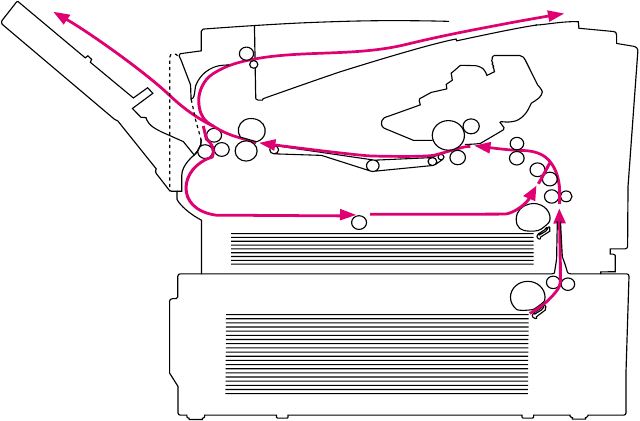
88 Chapter 5 Theory of operation C7058-90936
Sheet feeder
There are two optional sheet feeders: the 250-sheet feeder and the 500-sheet feeder.
The sheet feeders are driven by the printer and controlled by the printer’s engine controller. The
engine controller drives the solenoid at a necessary timing through the sheet feeder PCB. The paper
sensor detects media.
The sheet feeder picks up media loaded in the cassettes and transports it to the printer.
The flow of media is illustrated in figure 49 (the 500-sheet paper feeder shown).
Figure 49. Pickup feed paper-path
The main motor (M903) drives sheet feeder through the use of gears.
When a print command is received from the formatter, the main motor (M903), reverse motor
(M904), and scanner motor start rotating. The heating element temperature begins to rise.
The sheet feeder pickup solenoids (SL2001, SL2002) are turned on when the following three
requirements are met:
lthe main motor has been driven for 0.35 seconds
lthe scanner motor has reached the specified rotation number
lthe heating element temperature has been brought to the specified temperature, or the specified
period of time has elapsed after start of the temperature control
SL2001 and SL2002 transmit the main motor’s rotation to the pickup roller. The pickup roller makes
a rotation to pick up media in the cassette.
The separation pad separates the media and transports it to the printer. The media goes through the
transfer, separation, and fuser/delivery blocks, and is delivered to the selected tray.
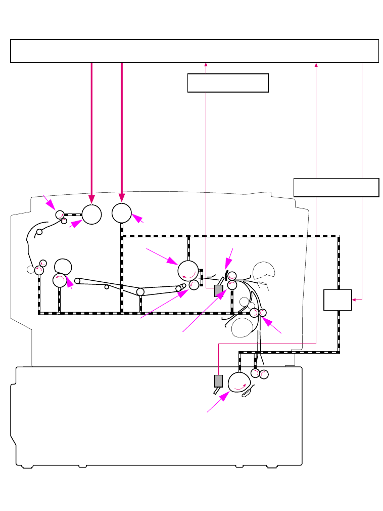
C7058-90936 Sheet feeder 89
Figure 50. Pickup feed
Face down
delivery rollers
Reverse motor drive signal
Main motor drive signal
Power supply PCB
Top of page detection signal (/TOPSNS)
Paper feeder paper detection
signal (/FDSNS)
drive signal (/FDSN, /FDSOL)
Paper feeder pickup solenoid
Paper feeder PCB
Reverse motor Main motor
Photosensitive
drum
Feed belts
Pressure roller
Registration shutter
Feed rollers
Transfer charging roller
Registration roller
Feed roller
Pickup roller
Tray 3 (250-sheet or 500-sheet feeder)
PS2003
(PS2001)
SL2002
(SL2001)
PS2305
M904 M903
Engine controller PCB
PS2305: Top-of-page sensor (printer) PS2001: Paper feeder paper sensor (250-sheet)
PS2003: Paper feeder paper sensor (500-sheet) SL2001: Paper feeder pickup solenoid (250-sheet)
SL2002: Paper feeder pickup solenoid (500-sheet)
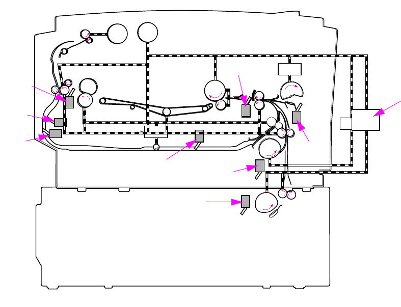
90 Chapter 5 Theory of operation C7058-90936
Media detection
Media detection
The model for media detection is essentially the same for all three trays.The paper sensor levers
shown below detect the presence of media in the trays. If the sensor does not detect any media, the
formatter illuminates the display LED until media is added.
Figure 51. Media detection sensors
Media-size detection
The HP LaserJet 2200 printer does not contain a media-size detection mechanism; therefore, the
printer cannot detect the size of media set in the trays. The printer detects the media size by
measuring the time from when the top-of-page sensor detects the leading edge of the page until the
trailing edge of the page clears the sensor.
PS2305
SL2002
(SL2001)
PS2003
(PS2001)
PS501
PS502
PS2301
PS1305
PS503
PS3208
PS2305: Top-of-page sensor (printer) PS2001: Paper feeder paper sensor (250-sheet)
PS2003: Paper feeder paper sensor (500-sheet) SL2001: Paper feeder pickup solenoid (250-sheet)
SL2002: Paper feeder pickup solenoid (500-sheet) PS502: Face-up sensor
PS501: Reversed paper sensor PS1305: Cassette paper sensor
PS503: Duplex pickup paper sensor PS3208: Tray 1 paper sensor
PS2301: Delivery sensor
C7058-90936 Jam detection 91
Jam detection
The presence of media and paper-feed condition are detected by:
ltop-of-page sensor (PS2305)
ldelivery sensor (PS2301)
lreversed paper sensor (PS501)
lduplexer pickup paper sensor (PS503)
A jam is detected by the CPU checking for the presence of media through sensors at the timing
stored in the CPU.
If the CPU determines a jam, it stops the print operation and notifies the formatter of a jam.
Pickup sensors
Pickup delay jam
This printer performs retry control to readdress the pickup delay jam caused by pickup error. Pickup
operation is conducted a maximum of twice at the all pickup sources except for the duplex feed unit.
If the top-of-page sensor (PS2305) cannot detect the media leading edge within a specified period of
time (T) the printer performs the pickup operation again. If PS2305 cannot detect the media leading
edge within the specified period of time (T), a jam is indicated.
lPaper pickup from the tray1: T=about 2.5 seconds
lPaper pickup from the cassette: T=about 3.0 seconds
lPaper pickup from the paper feeder: T=about 4.4 seconds
lPaper pickup from the duplexer feed unit: T=about 4.5 seconds
Pickup stationary jam
A. When WAIT period starts—a pickup stationary jam is assessed if the top-of-page sensor detects
media when the WAIT period starts.
B. During media feeding—a pickup stationary jam is assessed if the top-of-page sensor (PS2305)
does not detect the trailing edge of the media within 3.8 seconds after detecting the leading
edge.
Delivery sensors
Delivery delay jam
A delivery delay jam is assessed if the media does not reach the delivery sensor (PS2301) within a
specified period of time (T) after the top-of-page sensor (PS2305) detects the leading edge.
lpaper 270 mm or more: T=about 2.6 seconds
lpaper 200 mm to 270 mm: T=about 2.7 seconds
lpaper less than 200 mm: T=about 4.6 seconds
Delivery stationary jam
A. When WAIT period starts—a delivery stationary jam is assessed if the delivery sensor (PS2301)
detects media when the WAIT period starts.
92 Chapter 5 Theory of operation C7058-90936
B. During media feeding—a delivery stationary jam is assessed if the delivery sensor (PS2301)
does not detect the trailing edge of the media within a specified period of time (T) after the top-of-
page sensor (PS2305) detects the trailing edge.
lpaper 200 mm or more: T=about 2.7 seconds
lpaper less than 200 mm: T=about 5.2 seconds
C. When a pickup delay jam occurs—the printer enters the last rotation period to deliver the
jammed media. A delivery stationary jam is assessed if the delivery sensor (PS2301) does not
detect the trailing edge of the media within 8 seconds after the completion of the forced laser
emission.
D. During pressure roller cleaning—a delivery stationary jam is assessed if the delivery sensor
(PS2301) does not detect the trailing edge of the media within 8 seconds after the 35th feed
operation.
Reversing sensors
Reversing delay jam
A reversing delay jam is assessed if the reversed paper sensor (PS501) does not detect the leading
edge of the media within 3.9 seconds after the reversing motor starts rotating.
Reversing stationary jam
A reversing stationary jam is assessed when the reversed paper sensor (PS501) detects media after
duplex pickup operation has been performed for about 0.77 seconds.
Duplexer sensors
Duplexer pickup delay jam
A duplexer pickup delay jam is assessed if the duplexer pickup paper sensor (PS503) does not
detect media within 4.9 seconds after the reversed paper sensor (PS501) detects the leading edge.
Duplexer pickup stationary jam
A duplexer pickup stationary jam is assessed if the duplexer pickup paper sensor (PS503) detects
media after about 3.4 seconds has passed since the reversed paper sensor (PS501) detected the
trailing edge.
Paper-feed sensor
Paper feeder jam detection
Jam detection for the paper feeders during the pickup and feed operations is same as that for the
printer. For jam detection, see "Pickup delay jam" on page 91.
C7058-90936 Chapter contents 93
6Removal and replacement
Chapter contents
Removal and replacement strategies . . . . . . . . . . . . . . . . . . . . . . . . . . . . . . . . . . . . . . . . . . . . . . 95
Required tools. . . . . . . . . . . . . . . . . . . . . . . . . . . . . . . . . . . . . . . . . . . . . . . . . . . . . . . . . . . . . 95
Toner cartridge removal and replacement. . . . . . . . . . . . . . . . . . . . . . . . . . . . . . . . . . . . . . . . . . . 96
Remove the toner cartridge . . . . . . . . . . . . . . . . . . . . . . . . . . . . . . . . . . . . . . . . . . . . . . . . . . 96
Cover and tray removal and replacement . . . . . . . . . . . . . . . . . . . . . . . . . . . . . . . . . . . . . . . . . . . 97
Remove tray 3. . . . . . . . . . . . . . . . . . . . . . . . . . . . . . . . . . . . . . . . . . . . . . . . . . . . . . . . . . . . . 97
Remove the cassette from tray 2 . . . . . . . . . . . . . . . . . . . . . . . . . . . . . . . . . . . . . . . . . . . . . . 97
Remove I/O cover . . . . . . . . . . . . . . . . . . . . . . . . . . . . . . . . . . . . . . . . . . . . . . . . . . . . . . . . . . 98
Remove EIO card . . . . . . . . . . . . . . . . . . . . . . . . . . . . . . . . . . . . . . . . . . . . . . . . . . . . . . . . . . 98
Remove DIMM cover . . . . . . . . . . . . . . . . . . . . . . . . . . . . . . . . . . . . . . . . . . . . . . . . . . . . . . . 99
Remove rear cover . . . . . . . . . . . . . . . . . . . . . . . . . . . . . . . . . . . . . . . . . . . . . . . . . . . . . . . . 100
Remove top cover. . . . . . . . . . . . . . . . . . . . . . . . . . . . . . . . . . . . . . . . . . . . . . . . . . . . . . . . . 102
Remove left cover . . . . . . . . . . . . . . . . . . . . . . . . . . . . . . . . . . . . . . . . . . . . . . . . . . . . . . . . .105
Remove tray 1. . . . . . . . . . . . . . . . . . . . . . . . . . . . . . . . . . . . . . . . . . . . . . . . . . . . . . . . . . . . 106
Internal disassembly and assembly . . . . . . . . . . . . . . . . . . . . . . . . . . . . . . . . . . . . . . . . . . . . . . 109
Remove transfer roller. . . . . . . . . . . . . . . . . . . . . . . . . . . . . . . . . . . . . . . . . . . . . . . . . . . . . . 109
Remove DIMM . . . . . . . . . . . . . . . . . . . . . . . . . . . . . . . . . . . . . . . . . . . . . . . . . . . . . . . . . . . 111
Remove formatter PCB. . . . . . . . . . . . . . . . . . . . . . . . . . . . . . . . . . . . . . . . . . . . . . . . . . . . . 112
Remove EIO shield and guide . . . . . . . . . . . . . . . . . . . . . . . . . . . . . . . . . . . . . . . . . . . . . . . 113
Remove fuser assembly . . . . . . . . . . . . . . . . . . . . . . . . . . . . . . . . . . . . . . . . . . . . . . . . . . . . 114
Remove fuser-film heater assembly . . . . . . . . . . . . . . . . . . . . . . . . . . . . . . . . . . . . . . . . . . . 117
Remove pressure roller. . . . . . . . . . . . . . . . . . . . . . . . . . . . . . . . . . . . . . . . . . . . . . . . . . . . . 119
Remove duplexer tray . . . . . . . . . . . . . . . . . . . . . . . . . . . . . . . . . . . . . . . . . . . . . . . . . . . . . . 120
Remove duplexer media guide . . . . . . . . . . . . . . . . . . . . . . . . . . . . . . . . . . . . . . . . . . . . . . . 121
Remove power supply assembly . . . . . . . . . . . . . . . . . . . . . . . . . . . . . . . . . . . . . . . . . . . . . 122
Remove upper output delivery roller. . . . . . . . . . . . . . . . . . . . . . . . . . . . . . . . . . . . . . . . . . . 125
Disassemble the upper output delivery roller . . . . . . . . . . . . . . . . . . . . . . . . . . . . . . . . . . . . 126
Remove lower output delivery rollers . . . . . . . . . . . . . . . . . . . . . . . . . . . . . . . . . . . . . . . . . . 127
Remove laser/scanner assembly . . . . . . . . . . . . . . . . . . . . . . . . . . . . . . . . . . . . . . . . . . . . . 128
Remove transport belts and rollers. . . . . . . . . . . . . . . . . . . . . . . . . . . . . . . . . . . . . . . . . . . . 130
Remove ribbon cable harness . . . . . . . . . . . . . . . . . . . . . . . . . . . . . . . . . . . . . . . . . . . . . . . 132
Remove duplexer reverse motor . . . . . . . . . . . . . . . . . . . . . . . . . . . . . . . . . . . . . . . . . . . . . . 133
Remove printer drive assembly. . . . . . . . . . . . . . . . . . . . . . . . . . . . . . . . . . . . . . . . . . . . . . . 134
Remove engine controller assembly. . . . . . . . . . . . . . . . . . . . . . . . . . . . . . . . . . . . . . . . . . . 135
Remove main motor . . . . . . . . . . . . . . . . . . . . . . . . . . . . . . . . . . . . . . . . . . . . . . . . . . . . . . . 136
Remove motor plate . . . . . . . . . . . . . . . . . . . . . . . . . . . . . . . . . . . . . . . . . . . . . . . . . . . . . . . 137
Remove printer drive assembly gears. . . . . . . . . . . . . . . . . . . . . . . . . . . . . . . . . . . . . . . . . . 139
Remove tray 1 pickup roller. . . . . . . . . . . . . . . . . . . . . . . . . . . . . . . . . . . . . . . . . . . . . . . . . . 140
Remove tray 1 pickup roller assembly . . . . . . . . . . . . . . . . . . . . . . . . . . . . . . . . . . . . . . . . . 142
Remove tray 1 separation pad assembly . . . . . . . . . . . . . . . . . . . . . . . . . . . . . . . . . . . . . . . 145
Remove tray 1 paper-sensor lever . . . . . . . . . . . . . . . . . . . . . . . . . . . . . . . . . . . . . . . . . . . . 146
Remove tray 1 solenoid . . . . . . . . . . . . . . . . . . . . . . . . . . . . . . . . . . . . . . . . . . . . . . . . . . . . 148
Remove tray 2 pickup roller assembly . . . . . . . . . . . . . . . . . . . . . . . . . . . . . . . . . . . . . . . . . 149
94 Chapter 6 Removal and replacement C7058-90936
Replace tray 2 pickup roller . . . . . . . . . . . . . . . . . . . . . . . . . . . . . . . . . . . . . . . . . . . . . . . . . 152
Remove tray 2 pickup roller and refeeder assembly . . . . . . . . . . . . . . . . . . . . . . . . . . . . . . 153
Remove tray 2 solenoid . . . . . . . . . . . . . . . . . . . . . . . . . . . . . . . . . . . . . . . . . . . . . . . . . . . . 156
Remove duplexer drive gears and solenoid . . . . . . . . . . . . . . . . . . . . . . . . . . . . . . . . . . . . . 157
Remove registration assembly. . . . . . . . . . . . . . . . . . . . . . . . . . . . . . . . . . . . . . . . . . . . . . . 158
Remove tray 3 assembly connector . . . . . . . . . . . . . . . . . . . . . . . . . . . . . . . . . . . . . . . . . . . 160
Remove cooling fan . . . . . . . . . . . . . . . . . . . . . . . . . . . . . . . . . . . . . . . . . . . . . . . . . . . . . . . 161
Remove toner-cartridge guide . . . . . . . . . . . . . . . . . . . . . . . . . . . . . . . . . . . . . . . . . . . . . . . 162
Remove dc bias voltage contacts (leaf springs). . . . . . . . . . . . . . . . . . . . . . . . . . . . . . . . . . 164
Tray 3 disassembly and assembly . . . . . . . . . . . . . . . . . . . . . . . . . . . . . . . . . . . . . . . . . . . . . . . 166
Remove tray 3 (250-sheet feeder) cassette . . . . . . . . . . . . . . . . . . . . . . . . . . . . . . . . . . . . . 166
Remove tray 3 (250-sheet feeder) pickup roller . . . . . . . . . . . . . . . . . . . . . . . . . . . . . . . . . . 167
Remove tray 3 (250-sheet feeder) feeder drive assembly . . . . . . . . . . . . . . . . . . . . . . . . . . 168
Remove tray 3 (250 sheet-feeder) drive solenoid . . . . . . . . . . . . . . . . . . . . . . . . . . . . . . . . 170
Remove tray 3 (500-sheet feeder) cassette . . . . . . . . . . . . . . . . . . . . . . . . . . . . . . . . . . . . . 171
Remove tray 3 (500-sheet feeder) pickup roller . . . . . . . . . . . . . . . . . . . . . . . . . . . . . . . . . . 172
Remove tray 3 (500-sheet feeder) feeder drive assembly . . . . . . . . . . . . . . . . . . . . . . . . . . 173
Remove tray 3 (500 sheet-feeder) drive solenoid . . . . . . . . . . . . . . . . . . . . . . . . . . . . . . . . 175

C7058-90936 Removal and replacement strategies 95
Removal and replacement strategies
This chapter documents removal and replacement of field replaceable units (FRUs) only.
Replace parts in the reverse order of their removal. If replacement requires difficult or critical
installation procedures, notes are provided with detailed special instructions.
WARNING! To avoid serious injury, unplug the power cord from the power outlet before servicing the printer. Certain
functional checks must be performed during troubleshooting with power supplied to the product.
However, the power supply should be disconnected during disassembly.
Never operate or service the printer with the protective cover removed from the laser/scanner assembly.
The reflected beam, although invisible, can damage eyes.
The clip gasket attached to the formatter's radio frequency interference (RFI) shield contains nickel.
Do not touch the clip gasket with bare hands. Repair technicians should wear gloves to handle this
gasket. Be advised in accordance with European Union Directive 76/769/EEC that ingestion of water-
soluble nickel salts can cause nausea, vomiting, and diarrhea.
The printer might have sharp sheet metal edges. Exercise caution when working on the printer.
CAUTION The printer contains parts that are sensitive to electrostatic discharge (ESD). Always service the printer
at an ESD-protected workstation or use an ESD mat.
To install a self-tapping screw, first turn it counterclockwise to align it with the existing thread pattern,
then carefully turn clockwise to tighten. Do not overtighten. If a self-tapping screw-hole becomes
stripped, repair the screw-hole or replace the affected assembly.
Always remove the toner cartridge before removing or replacing assemblies and parts.
Note Note the lengths, diameters, and locations of screws. Be sure to use them in their original locations
during reassembly.
Note Incorrectly routed or loose wire harnesses can interfere with other internal components and become
damaged or broken. Frayed or pinched harness wires can be difficult to find. When replacing wire
harnesses, always use provided wire loops, lance points, or wire-harness guides.
Required tools
The following tools are required used to remove and replace assemblies detailed in this chapter:
lPhillips #2 screwdriver with magnetic tip
lSmall flatblade screwdriver
lNeedle-nose pliers
lESD mat
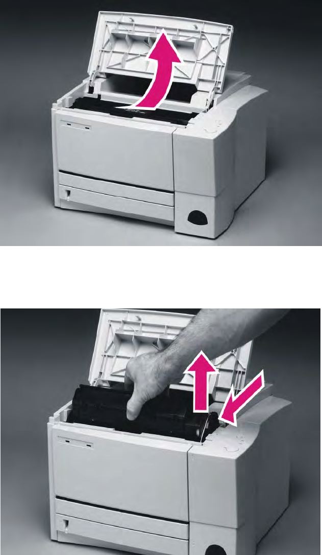
96 Chapter 6 Removal and replacement C7058-90936
Toner cartridge removal and replacement
Remove the toner cartridge
Step 1 Open the toner cartridge door.
Figure 52. Open the toner cartridge door
Step 2 Grasp the toner cartridge and pull it back and up to remove it.
Figure 53. Remove the toner cartridge
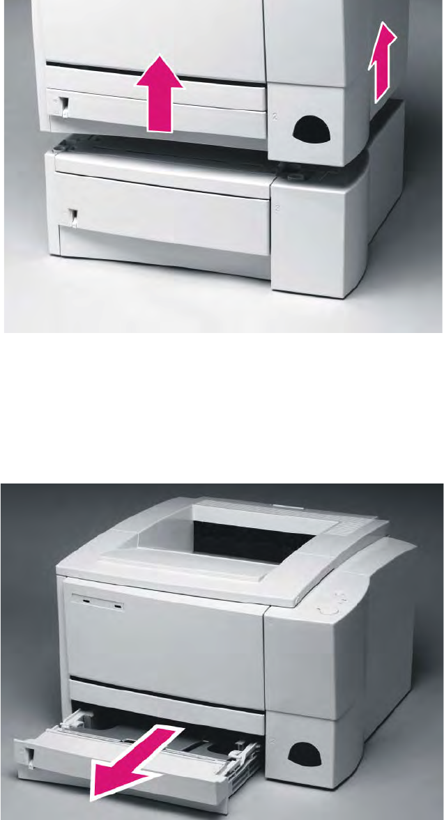
C7058-90936 Cover and tray removal and replacement 97
Cover and tray removal and replacement
Remove tray 3
Step 1 If installed, lift the printer up and off the sheet-feeder assembly.
Figure 54. Remove tray 3 (500-sheet feeder shown)
Remove the cassette from tray 2
Step 1 Position the printer as shown above.
Step 2 Firmly grasp the tray 2 cassette, and slide it out and away from the printer.
Figure 55. Remove cassette from tray 2
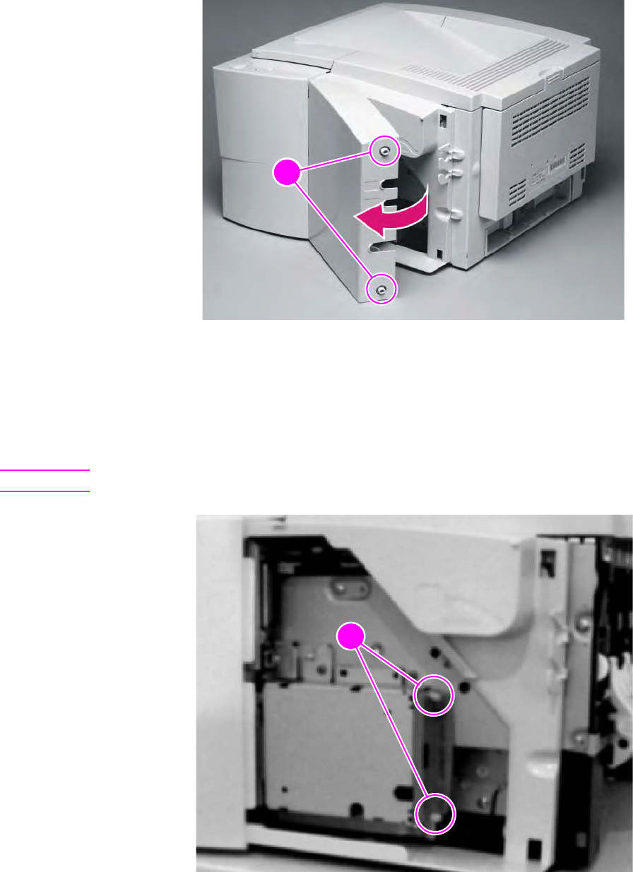
98 Chapter 6 Removal and replacement C7058-90936
Remove I/O cover
Step 1 Push in the two tabs (callout 1) on the back of the I/O cover.
Step 2 Rotate the I/O cover away from the printer.
Figure 56. Remove the I/O Cover
Remove EIO card
Step 1 Remove two mount screws (callout 1).
Step 2 Grasp the EIO card, and pull it out of the connector.
Note Do not remove the Radio Frequency Interference (RFI) clip if it is installed.
Figure 57. Remove the EIO card
2
1
11
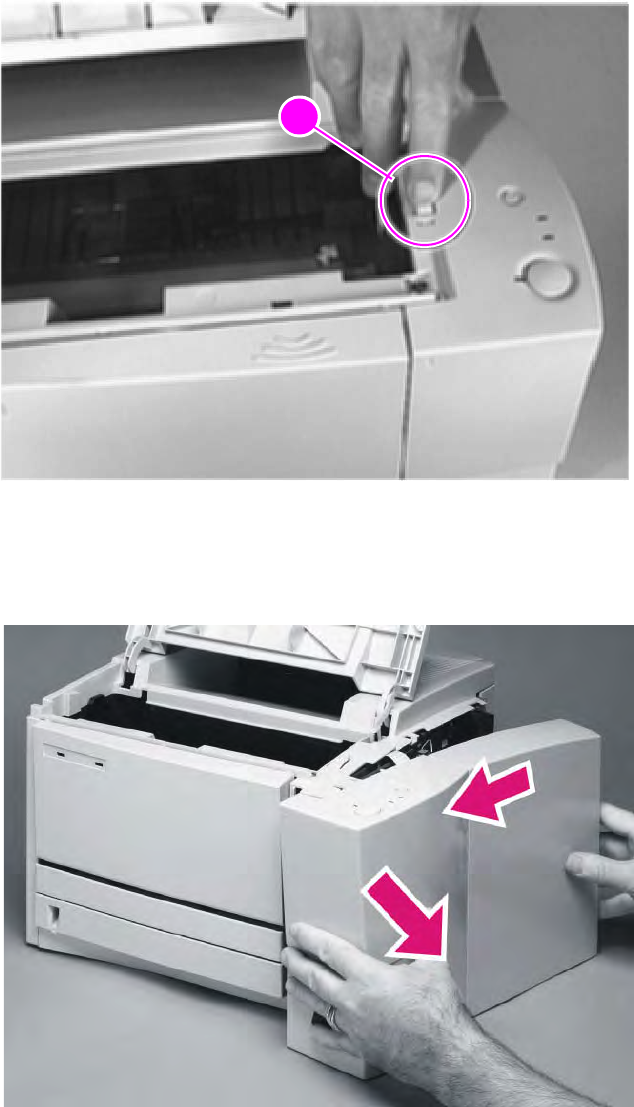
C7058-90936 Cover and tray removal and replacement 99
Remove DIMM cover
Step 1 Open the toner cartridge door.
Step 2 Press and hold the release button (callout 1).
Figure 58. DIMM cover release button
Step 3 Slightly shift the cover forward (toward the front of the printer) and then outward away
from the printer.
Figure 59. Remove DIMM cover
2
1
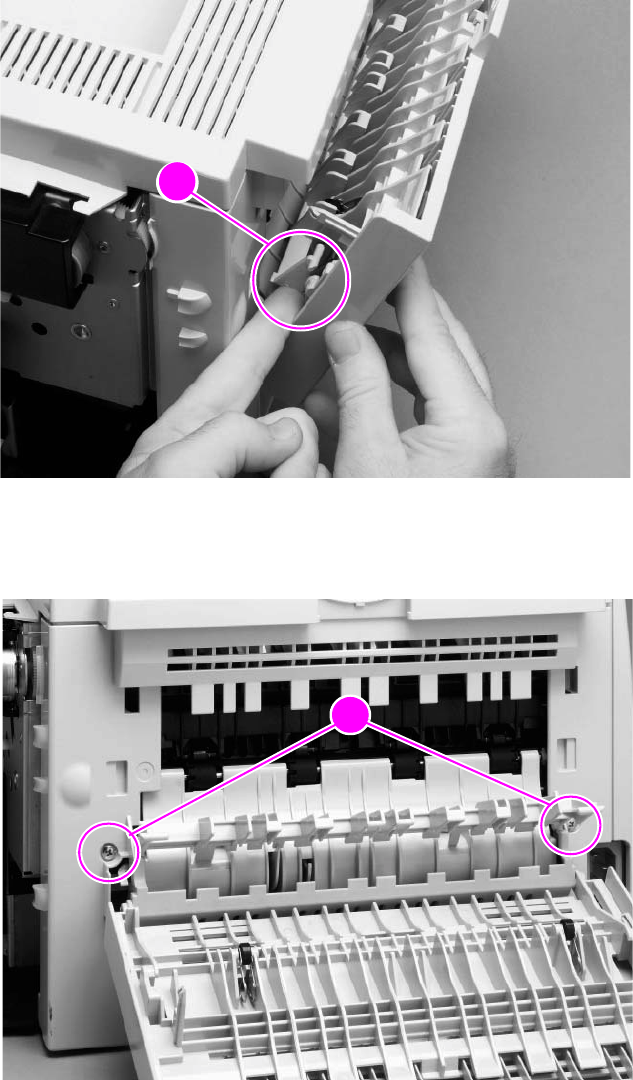
100 Chapter 6 Removal and replacement C7058-90936
Remove rear cover
Step 1 Remove the following assemblies:
•Remove the toner cartridge. See “Toner cartridge removal and replacement” on page 96.
•If installed, remove tray 3. See “Remove tray 3” on page 97.
•Remove the cassette from tray 2. See “Remove the cassette from tray 2” on page 97.
•Remove the DIMM cover. See “Remove DIMM cover” on page 99.
Step 2 Open the rear output bin and release the diverter pivot pins (callout 1). Let the open door
rest on the work surface.
Figure 60. Disengage the diverter locking pins
Step 3 Remove the two mounting screws (callout 1).
Figure 61. Rear cover mounting screws
2
1
11
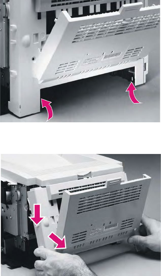
C7058-90936 Cover and tray removal and replacement 101
Step 4 Raise the door to engage the retaining locking bar pivot pins and leave the door open.
Step 5 Unlatch the two rear cover retaining tabs located inside the tray 2 slide area.
Figure 62. Rear cover retaining tabs
Step 6 Pull the rear cover down and then out to remove it.
Figure 63. Remove rear cover
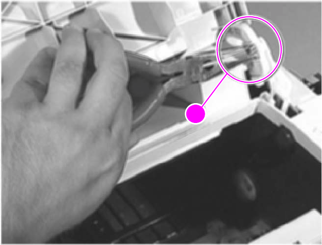
102 Chapter 6 Removal and replacement C7058-90936
Remove top cover
Step 1 Remove the following assemblies:
•Remove the toner cartridge. See “Toner cartridge removal and replacement” on page 96.
•If installed, remove tray 3. See “Remove tray 3” on page 97.
•Remove the cassette from tray 2. See “Remove the cassette from tray 2” on page 97.
•Remove the DIMM cover. See “Remove DIMM cover” on page 99.
•Remove the rear cover. See “Remove rear cover” on page 100.
Step 2 Release the swing arm from the toner cartridge door (callout 1) and push it down into the
opening.
Figure 64. Release door swing arm
2
1
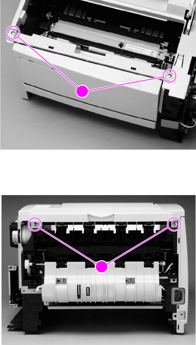
C7058-90936 Cover and tray removal and replacement 103
Step 3 Remove the top-cover mounting screws (callout 1).
Figure 65. Remove mounting screws
Step 4 With the rear of the printer facing forward as shown, remove the top-cover mounting
screws (callout 1).
Figure 66. Remove mounting screws
2
1
2
1
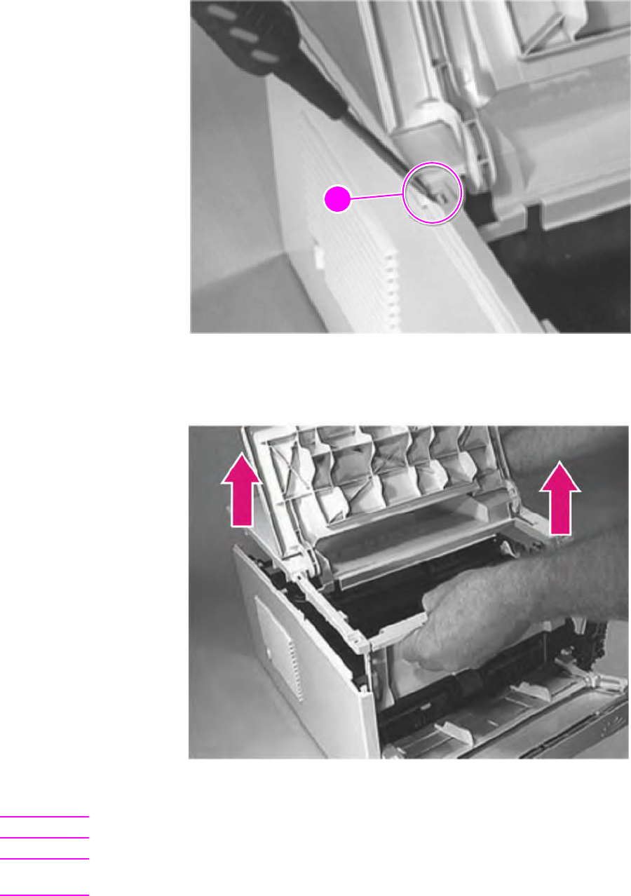
104 Chapter 6 Removal and replacement C7058-90936
Step 5 Open the tray 1 door.
Step 6 Release the two top cover tabs (callout 1) located on either side of the toner door.
Figure 67. Release top cover tabs (left tab shown)
Step 7 Lift the cover up and off the printer.
Figure 68. Remove top cover
CAUTION When replacing the top cover, make sure the drive release lever is attached to the swing arm.
Note When replacing the top cover, use the longer of the four mounting screws in the mounting screw-holes
located under the toner door.
2
1
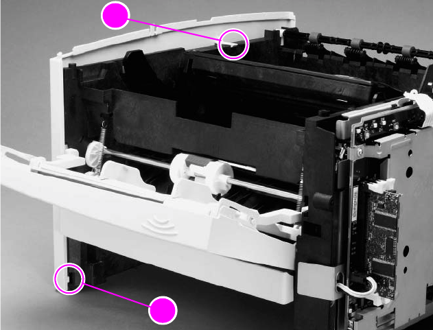
C7058-90936 Cover and tray removal and replacement 105
Remove left cover
Step 1 Remove the following assemblies:
•Remove the toner cartridge. See “Toner cartridge removal and replacement” on page 96.
•If installed, remove tray 3. See “Remove tray 3” on page 97.
•Remove the cassette from tray 2. See “Remove the cassette from tray 2” on page 97.
•Remove the DIMM cover. See “Remove DIMM cover” on page 99.
•Remove the rear cover. See “Remove rear cover” on page 100.
•Remove the top cover. See “Remove top cover” on page 102.
Step 2 Release the top latch (callout 1) and lower-front corner locking tab (callout 2).
Step 3 Lift off the cover.
Figure 69. Release left cover latches
2
1
2
2
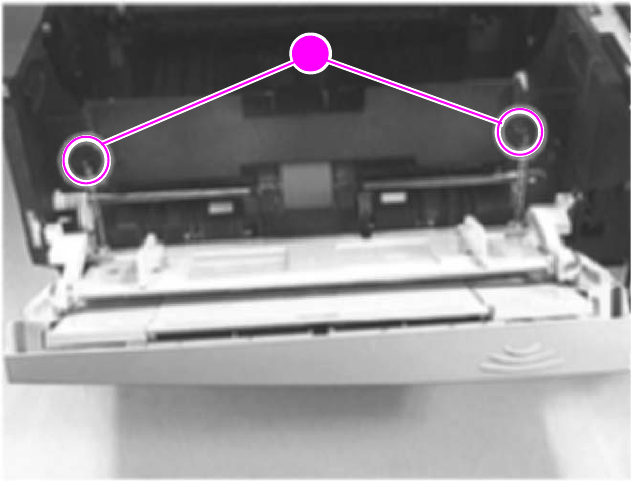
106 Chapter 6 Removal and replacement C7058-90936
Remove tray 1
Step 1 Remove the following assemblies:
•Remove the toner cartridge. See “Toner cartridge removal and replacement” on page 96.
•If installed, remove tray 3. See “Remove tray 3” on page 97.
•Remove the cassette from tray 2. See “Remove the cassette from tray 2” on page 97.
•Remove the DIMM cover. See “Remove DIMM cover” on page 99.
•Remove the rear cover. See “Remove rear cover” on page 100.
•Remove the top cover. See “Remove top cover” on page 102.
•Remove the left cover. See “Remove left cover” on page 105.
Step 2 Disconnect the springs (callout 1) from the tray 1 support arms.
Figure 70. Disconnect tray 1 support springs
2
1
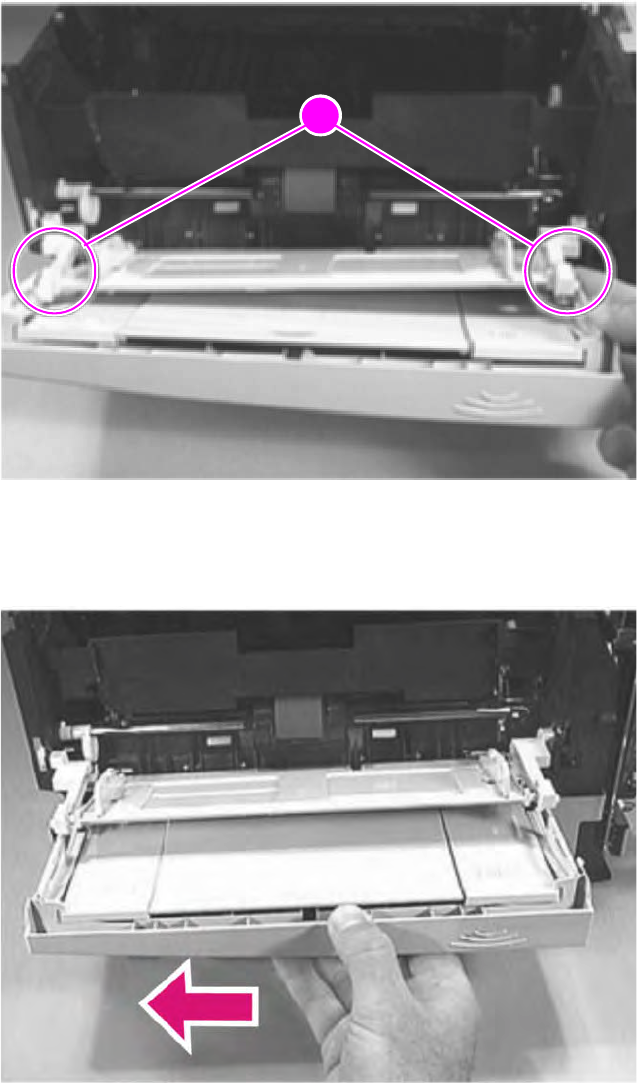
C7058-90936 Cover and tray removal and replacement 107
Step 3 Disconnect the pivot arms (callout 1).
Figure 71. Disconnect tray 1 pivot arms
Step 4 Slide the tray 1 door toward the fan and away from the printer.
Figure 72. Remove tray 1 door
2
1
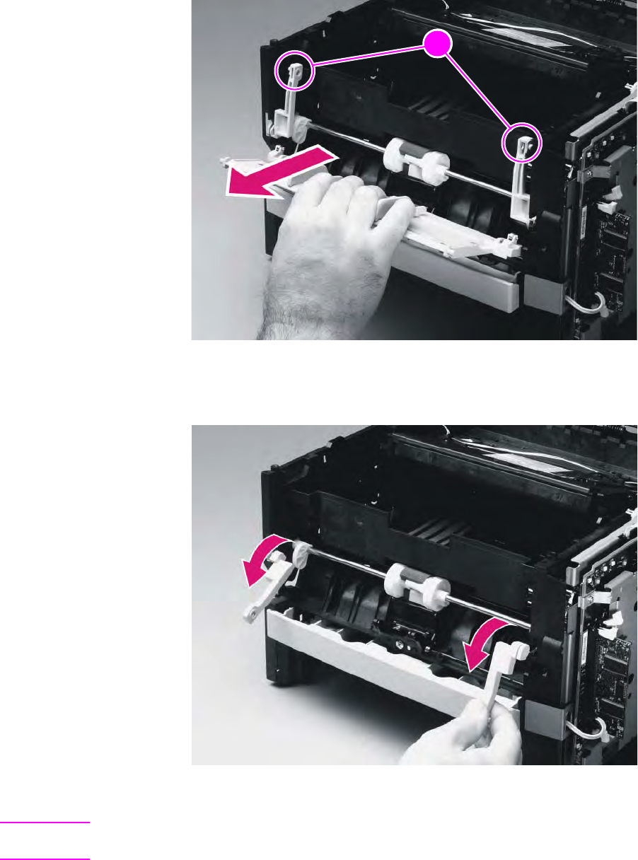
108 Chapter 6 Removal and replacement C7058-90936
Step 5 Disconnect the pivot arms (callout 1) from the tray 1 shelf and rotate them to the vertical
position.
Step 6 Remove the tray 1 shelf.
Figure 73. Disconnect pivot arms from tray 1 shelf
Step 7 Rotate the pivot arms downward and remove them from the tray.
Figure 74. Remove pivot arms
Note Pivot arms are not interchangeable. When replacing the pivot arms, verify that the right pivot arm
(marked R) and left pivot arm (marked L) are correctly installed.
2
1
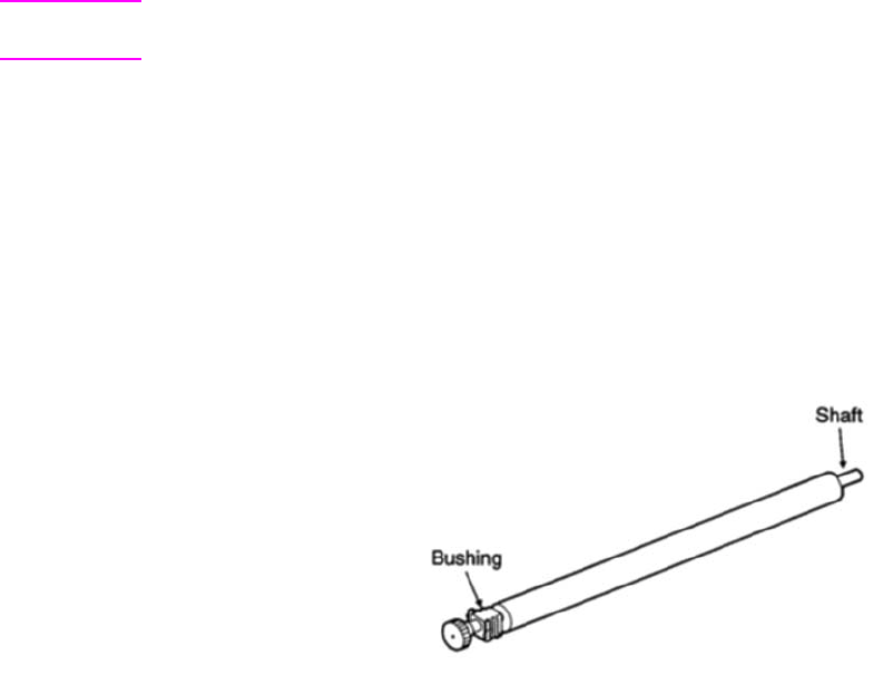
C7058-90936 Internal disassembly and assembly 109
Internal disassembly and assembly
Remove transfer roller
CAUTION Do not touch the surface of the transfer roller with bare hands. Skin oils can damage the roller. Instead,
grasp the bushing and shaft.
Step 1 Open the toner cartridge door.
Step 2 Remove the toner cartridge. See “Toner cartridge removal and replacement” on page
96.
Step 3 Locate the black bushing on the left end of the transfer roller shaft and just behind the
gear.
Figure 75. Transfer roller black bushing
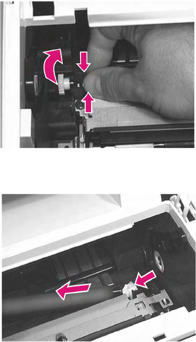
110 Chapter 6 Removal and replacement C7058-90936
Step 4 Squeeze both of the locking tabs on the black bushing, then slightly lift the gear end of
the transfer roller. Slide the roller left until the shaft clears the white bushing.
Figure 76. Removing the transfer roller
Step 5 Squeeze both of the locking tabs on the white bushing and slide the bushing out of its
mounting slot.
Figure 77. Remove the white bushing
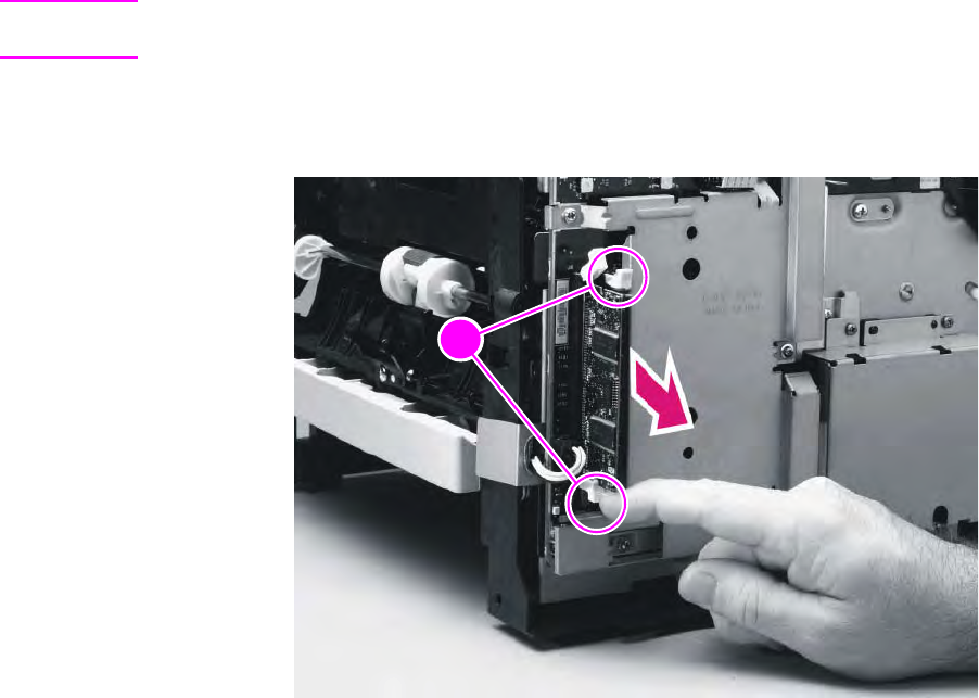
C7058-90936 Internal disassembly and assembly 111
Remove DIMM
Step 1 Remove the DIMM cover. See “Remove DIMM cover” on page 99.
CAUTION The printer contains parts that are sensitive to electrostatic discharge (ESD). Always service the printer
at an ESD-protected workstation or use an ESD mat.
Step 2 Rotate the DIMM socket release levers (callout 1) outward.
Step 3 Pull DIMM out of socket.
Figure 78. Remove DIMM
2
1
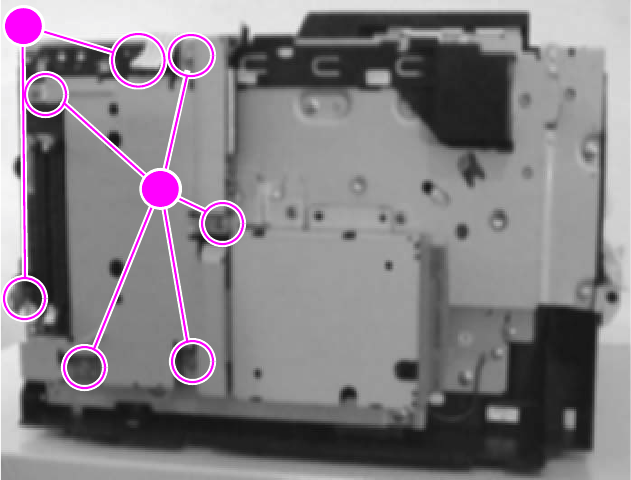
112 Chapter 6 Removal and replacement C7058-90936
Remove formatter PCB
Step 1 Remove the following assemblies:
•Remove the toner cartridge. See “Toner cartridge removal and replacement” on page 96.
•If installed, remove tray 3. See “Remove tray 3” on page 97.
•Remove the cassette from tray 2. See “Remove the cassette from tray 2” on page 97.
•Remove the DIMM cover. See “Remove DIMM cover” on page 99.
•Remove the EIO card (if installed). See “Remove I/O cover” on page 98.
Step 2 Disconnect the ribbon and power cable (callout 1) and remove the five mounting screws
(callout 2) that secure the PCB and shield to the printer drive assembly.
Step 3 Lift off the formatter PCB and shield.
Figure 79. Remove formatter PCB
2
2
1
2
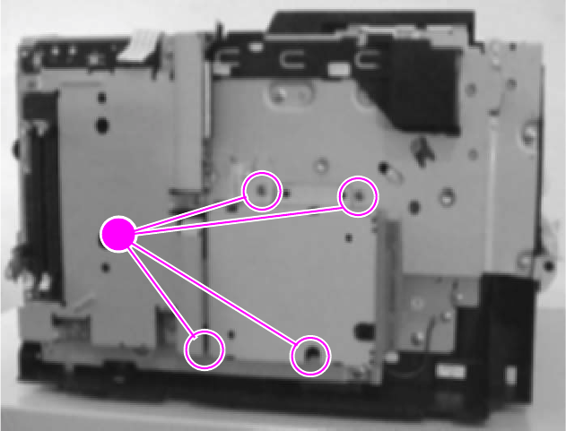
C7058-90936 Internal disassembly and assembly 113
Remove EIO shield and guide
Step 1 Remove the following assemblies:
•Remove the toner cartridge. See “Toner cartridge removal and replacement” on page 96.
•If installed, remove tray 3. See “Remove tray 3” on page 97.
•Remove the cassette from tray 2. See “Remove the cassette from tray 2” on page 97.
•Remove the DIMM cover. See “Remove DIMM cover” on page 99.
•Remove the EIO card (if installed). See “Remove EIO card” on page 98.
•Remove the formatter PCB. See “Remove formatter PCB” on page 112.
Step 2 Remove the four screws (callout 1) that secure the shield to the printer drive assembly.
Figure 80. Remove EIO shield
2
1
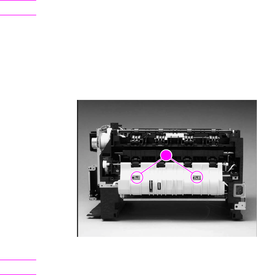
114 Chapter 6 Removal and replacement C7058-90936
Remove fuser assembly
CAUTION If the printer was recently operating, verify that the fuser assembly has sufficiently cooled before
handling.
Step 1 Remove the following assemblies:
•Remove the toner cartridge. See “Toner cartridge removal and replacement” on page 96.
•If installed, remove tray 3. See “Remove tray 3” on page 97.
•Remove the cassette from tray 2. See “Remove the cassette from tray 2” on page 97.
•Remove the DIMM cover. See “Remove DIMM cover” on page 99.
•Remove the rear cover. See “Remove rear cover” on page 100.
Step 2 Remove the two screws (callout 1) that secure the reverse guide to the fuser assembly
and lift the guide off.
Figure 81. Fuser assembly (under the reverse guide)
CAUTION When replacing the reverse guide, use the two screws (callout 1) removed in step 2. These screws
allow the cover to expand and contract when the fuser assembly heats up or cools down.
2
1
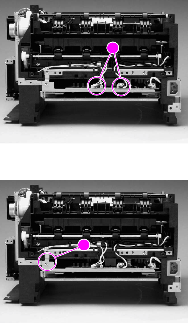
C7058-90936 Internal disassembly and assembly 115
Step 3 Unplug the two-pin, three-pin, and five-pin wire harness connectors (callout 1).
Figure 82. Unplug wire harness connectors
Step 4 Remove one grounding screw (callout 1) that secures the fuser assembly to the printer.
Figure 83. Remove mounting screws
2
1
2
1
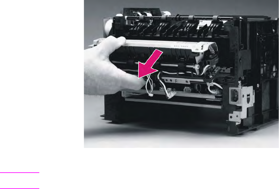
116 Chapter 6 Removal and replacement C7058-90936
Step 5 Pull the fuser assembly from the printer.
Figure 84. Remove fuser assembly
Note When replacing the fuser assembly, use the guide pins (located near the mounting screw-holes) to
correctly align it.
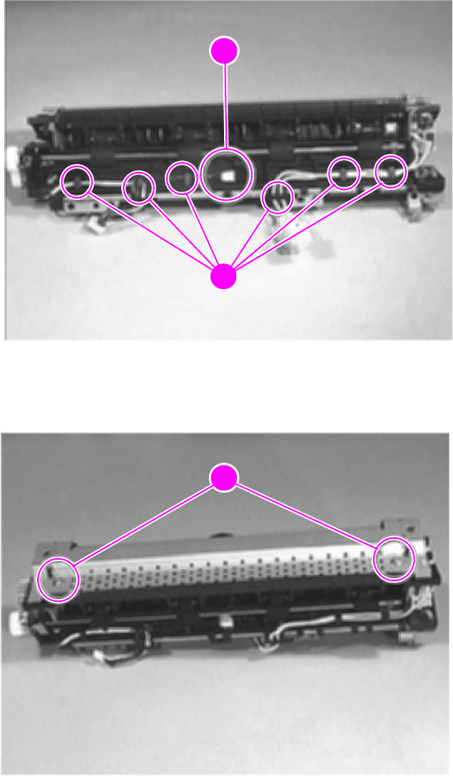
C7058-90936 Internal disassembly and assembly 117
Remove fuser-film heater assembly
Step 1 Remove the fuser assembly. See “Remove fuser assembly” on page 114.
Step 2 Disconnect the wire connector (callout 1) and remove the right and left wire harnesses
from the retainer clips (callout 2).
Figure 85. Unplug fuser-film heater assembly wire harness
Step 3 Remove the two pressure plate screws (callout 1).
Figure 86. Remove pressure plate screws
2
1
2
2
2
1
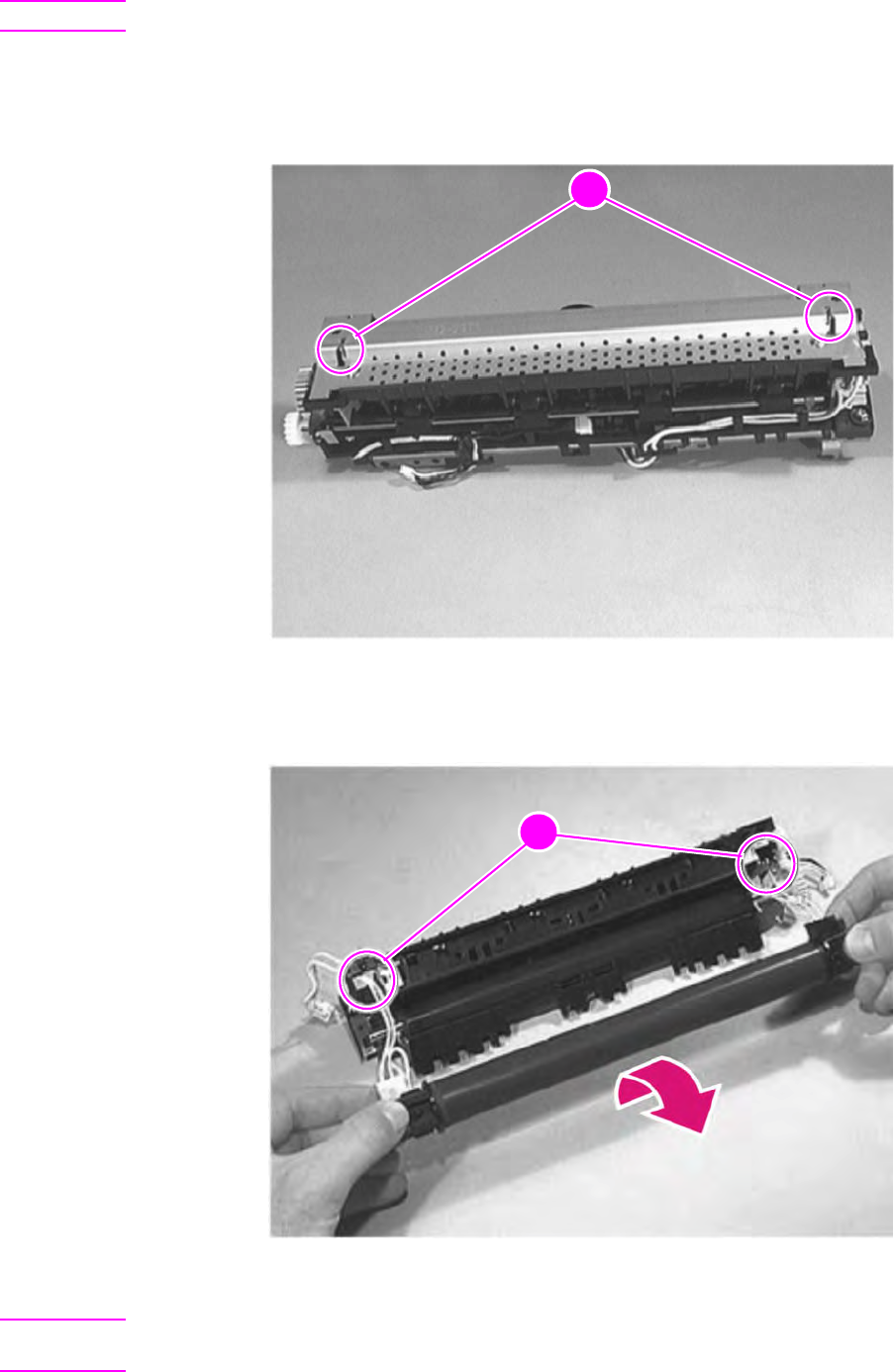
118 Chapter 6 Removal and replacement C7058-90936
CAUTION The pressure plate is spring-loaded. Exercise caution when removing the pressure plate.
Step 4 Use a small flatblade screwdriver to gently to detach the pressure plate retaining clips
(callout 1).
Step 5 Lift off the pressure plate.
Figure 87. Remove pressure plate
Step 6 Lift the fuser-film heater assembly out of the assembly carriage.
Figure 88. Remove the fuser-film heater assembly
Note When replacing the fuser-film heater assembly, verify that it is correctly oriented (callout 1). Position
the end with the two-wire harness (black and white wire) is over the shaft end of the pressure roller.
2
1
2
1
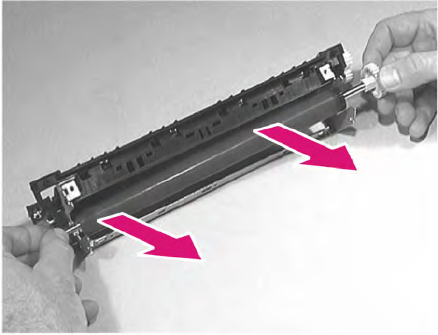
C7058-90936 Internal disassembly and assembly 119
Remove pressure roller
Step 1 Remove the following assemblies:
•Remove the fuser assembly. See “Remove fuser assembly” on page 114.
•Remove the fuser-film heater assembly. See “Remove fuser-film heater assembly” on page
117.
Step 2 Lift the pressure roller out of the assembly carriage.
Figure 89. Remove pressure roller
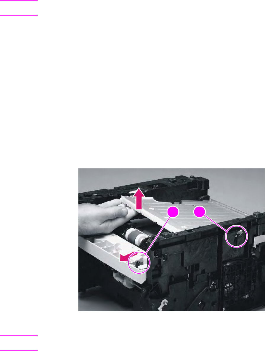
120 Chapter 6 Removal and replacement C7058-90936
Remove duplexer tray
CAUTION When picking up the printer with the rear cover removed, do not lift by holding the duplexer tray.
Whenever possible, handle the printer by holding the sides to prevent damaging internal components.
Step 1 Remove the following assemblies:
•Remove the toner cartridge. See “Toner cartridge removal and replacement” on page 96.
•If installed, remove tray 3. See “Remove tray 3” on page 97.
•Remove the cassette from tray 2. See “Remove the cassette from tray 2” on page 97.
•Remove the DIMM cover. See “Remove DIMM cover” on page 99.
•Remove the rear cover. See “Remove rear cover” on page 100.
Step 2 Turn the printer over, top down.
Step 3 Unsnap the locking lever of the pivot pin, rotate it to the vertical position, and remove it
from the mounting hole.
Step 4 Pull the green duplexer release lever (callout 1) forward to release the duplexer tray.
Step 5 Slightly raise the duplexer tray until the stop spring (callout 2) makes contact with the
chassis. Push the spring in until it clears the slot in the chassis. Raise the door to the
vertical position.
Step 6 Raise the corner of the tray nearest the duplex media guide. Slide the tray toward the
printer drive assembly.
Figure 90. Duplexer tray
Note When replacing the duplexer tray, verify that the stop spring (callout 2) correctly extends into the
provided slot in the chassis.
2
12
2
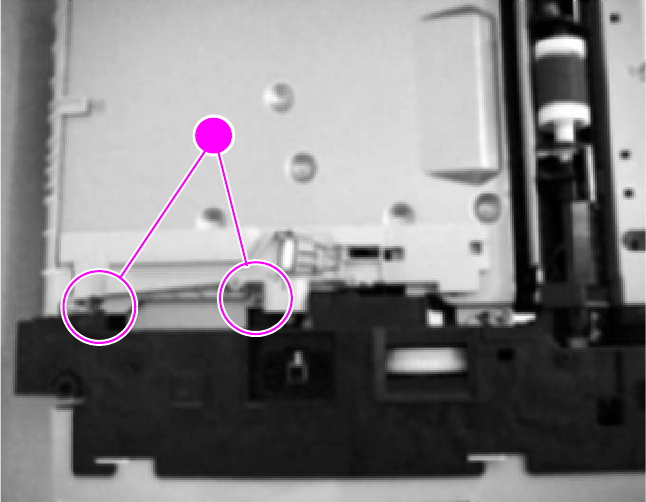
C7058-90936 Internal disassembly and assembly 121
Remove duplexer media guide
Step 1 Remove the following assemblies:
•Remove the toner cartridge. See “Toner cartridge removal and replacement” on page 96.
•If installed, remove tray 3. See “Remove tray 3” on page 97.
•Remove the cassette from tray 2. See “Remove the cassette from tray 2” on page 97.
•Remove the DIMM cover. See “Remove DIMM cover” on page 99.
•Remove the rear cover. See “Remove rear cover” on page 100.
•Remove the duplexer tray. See “Remove duplexer tray” on page 120.
Step 2 Remove the two duplexer media guide mounting screws (callout 1). Lift off the duplexer
media guide.
Figure 91. Duplexer media guide
2
1
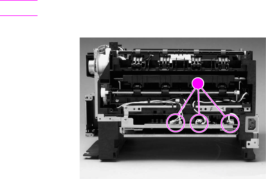
122 Chapter 6 Removal and replacement C7058-90936
Remove power supply assembly
Step 1 Remove the following assemblies:
•Remove the toner cartridge. See “Toner cartridge removal and replacement” on page 96.
•If installed, remove tray 3. See “Remove tray 3” on page 97.
•Remove the cassette from tray 2. See “Remove the cassette from tray 2” on page 97.
•Remove the DIMM cover. See “Remove DIMM cover” on page 99.
•Remove the rear cover. See “Remove rear cover” on page 100.
•Remove the rear pivot pin, duplexer tray, and duplex media guide. See “Remove duplexer
tray” on page 120.
Step 2 Remove the two mounting screws from the reverse guide and lift it off. See “Remove
fuser assembly” on page 114.
CAUTION The printer contains parts that are sensitive to electrostatic discharge (ESD). Always service the printer
at an ESD-protected workstation or use an ESD mat.
Step 3 Unplug two two-pin, a three-pin, and the five-pin harness connectors (callout 1).
Figure 92. Unplug wire harness
2
1
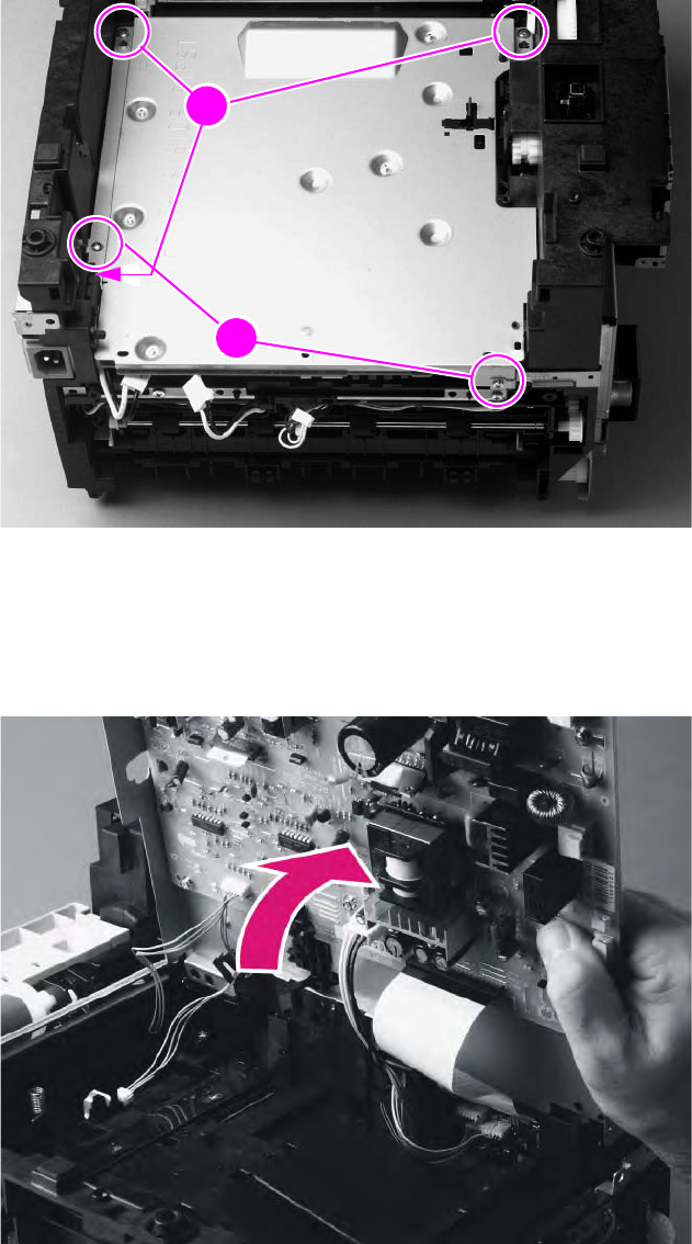
C7058-90936 Internal disassembly and assembly 123
Step 4 Place the printer top-down with the fuser assembly facing outward.
Step 5 Remove the three mounting screws (callout 1) and two ground screws (callout 2).
Figure 93. Remove power supply assembly screws
Step 6 Lift the side of the power supply assembly stamped “LIFT THIS SIDE FIRST” to expose
assembly harnessing. The harness connectors attach to the right side of the engine
power assembly.
Figure 94. Expose the harness connectors assembly
2
2
1
2
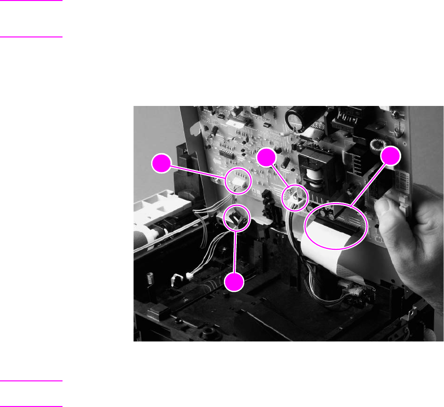
124 Chapter 6 Removal and replacement C7058-90936
CAUTION The printer contains parts that are sensitive to electrostatic discharge (ESD). Always service the printer
at an ESD-protected workstation or use an ESD mat.
Step 7 Unplug the formatter ribbon cable (callout 1), four-pin motor power harness (callout 2),
and the six-pin refeeder harness (callout 3). Unlace harness as required (callout 4).
Step 8 Lift off the power-supply assembly.
Figure 95. Unplug harness connectors
Note When replacing the power-supply assembly, verify that the refeeder harness is clipped to the wire clip
(callout 4) to prevent it from interfering with other internal components.
4
2
1
2
2
2
3
4
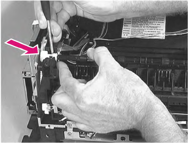
C7058-90936 Internal disassembly and assembly 125
Remove upper output delivery roller
Step 1 Remove the following assemblies:
•Remove the toner cartridge. See “Toner cartridge removal and replacement” on page 96.
•If installed, remove tray 3. See “Remove tray 3” on page 97.
•Remove the cassette from tray 2. See “Remove the cassette from tray 2” on page 97.
•Remove the DIMM cover. See “Remove DIMM cover” on page 99.
•Remove the rear cover. See “Remove rear cover” on page 100.
•Remove the top cover. See “Remove top cover” on page 102.
•Remove the left cover. See “Remove left cover” on page 105.
Step 2 Release both clips on the roller, geared end first.
Step 3 Lift off the upper output delivery roller.
Figure 96. Remove upper output roller
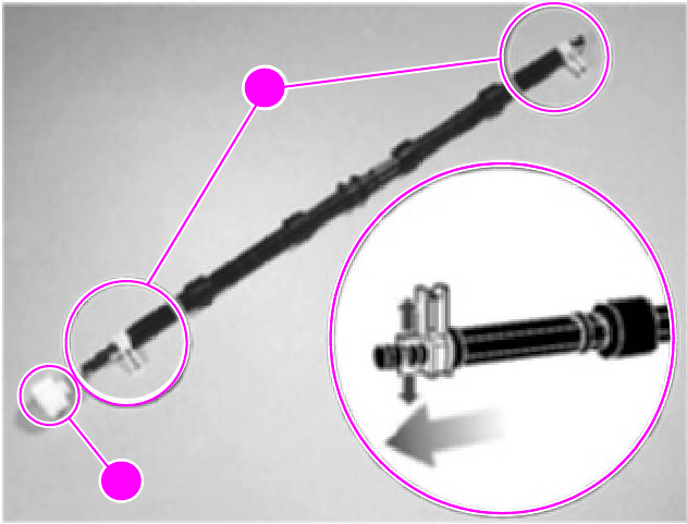
126 Chapter 6 Removal and replacement C7058-90936
Disassemble the upper output delivery roller
Step 1 Remove the following assemblies:
•Remove the toner cartridge. See “Toner cartridge removal and replacement” on page 96.
•If installed, remove tray 3. See “Remove tray 3” on page 97.
•Remove the cassette from tray 2. See “Remove the cassette from tray 2” on page 97.
•Remove the DIMM cover. See “Remove DIMM cover” on page 99.
•Remove the rear cover. See “Remove rear cover” on page 100.
•Remove the top cover. See “Remove top cover” on page 102.
•Remove the left cover. See “Remove left cover” on page 105.
•Remove the upper output delivery roller. See “Remove upper output delivery roller” on page
125.
Step 2 Remove the gear (callout 1) from the roller.
Step 3 Remove the clips (callout 2) from the roller.
Figure 97. Remove gear and clips
1
2
2
1
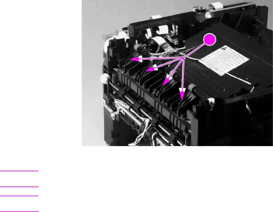
C7058-90936 Internal disassembly and assembly 127
Remove lower output delivery rollers
Step 1 Remove the following assemblies:
•Remove the toner cartridge. See “Toner cartridge removal and replacement” on page 96.
•If installed, remove tray 3. See “Remove tray 3” on page 97.
•Remove the cassette from tray 2. See “Remove the cassette from tray 2” on page 97.
•Remove the DIMM cover. See “Remove DIMM cover” on page 99.
•Remove the rear cover. See “Remove rear cover” on page 100.
•Remove the top cover. See “Remove top cover” on page 102.
•Remove the left cover. See “Remove left cover” on page 105.
•Remove the upper output delivery roller. See “Remove upper output delivery roller” on page
125.
Step 2 Rotate the rollers (callout 1) up to the vertical position (away from the laser/scanner), to
unseat the roller spring.
Step 3 Push down to disengage the pivot pins of the rollers.
Step 4 Lift out the rollers.
Figure 98. Remove lower output delivery rollers
Note When replacing the lower output delivery rollers (callout 1), remove the roller springs for use with the
new rollers.
CAUTION When installing the lower output delivery rollers (callout 1), verify that the two middle rollers are
equipped with the additional lower wheels.
2
1
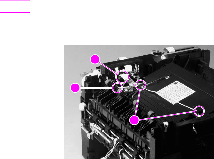
128 Chapter 6 Removal and replacement C7058-90936
Remove laser/scanner assembly
Step 1 Remove the following assemblies:
•Remove the toner cartridge. See “Toner cartridge removal and replacement” on page 96.
•If installed, remove tray 3. See “Remove tray 3” on page 97.
•Remove the cassette from tray 2. See “Remove the cassette from tray 2” on page 97.
•Remove the DIMM cover. See “Remove DIMM cover” on page 99.
•Remove the rear cover. See “Remove rear cover” on page 100.
•Remove the top cover. See “Remove top cover” on page 102.
CAUTION The printer contains parts that are sensitive to electrostatic discharge (ESD). Always service the printer
at an ESD-protected workstation or use an ESD mat.
Step 2 Unplug the seven-pin scanner harness (callout 1), scanner ribbon cable (callout 1), and
the two-pin fan harness (callout 2).
Step 3 Unlace the two-pin fan harness (callout 3) from the wire clips on the scanner.
Figure 99. Unplug harness connectors
2
2
1
2
2
3
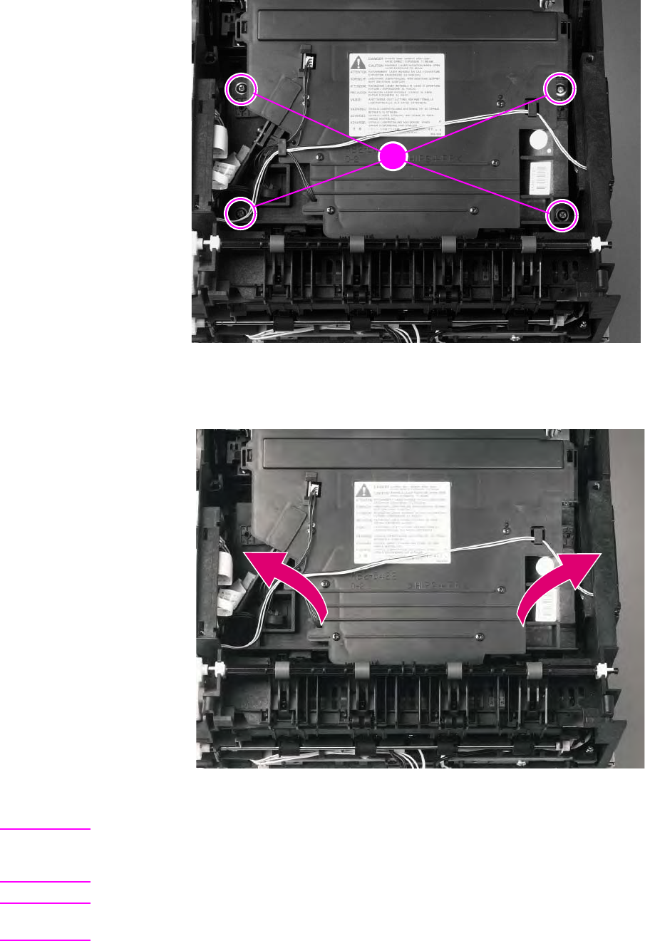
C7058-90936 Internal disassembly and assembly 129
Step 4 Remove the four mounting screws (callout 1).
Figure 100. Remove the laser/scanner assembly mount screws
Step 5 Lift the laser/scanner assembly out of the chassis.
Figure 101. Remove the laser/scanner assembly
CAUTION When replacing the scanner assembly, verify that the locator pins on the assembly are properly seated.
Failure to fully seat the locator pins can result in damage to the scanner assembly mounting surfaces
when the mounting screws are tightened down.
Note When replacing the scanner assembly, verify that the torrid ring on the seven-pin scanner harness is
fully recessed into the provided well to prevent it from interfering with other internal components.
2
1
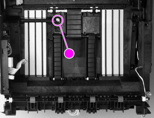
130 Chapter 6 Removal and replacement C7058-90936
Remove transport belts and rollers
Step 1 Remove the following assemblies:
•Remove the toner cartridge. See “Toner cartridge removal and replacement” on page 96.
•If installed, remove tray 3. See “Remove tray 3” on page 97.
•Remove the cassette from tray 2. See “Remove the cassette from tray 2” on page 97.
•Remove the DIMM cover. See “Remove DIMM cover” on page 99.
•Remove the rear cover. See “Remove rear cover” on page 100.
•Remove the top cover. See “Remove top cover” on page 102.
•Remove the laser/scanner assembly. See “Remove laser/scanner assembly” on page 128.
Step 2 Remove the roller assembly screw (callout 1).
Figure 102. Remove transport roller assembly screw
2
1
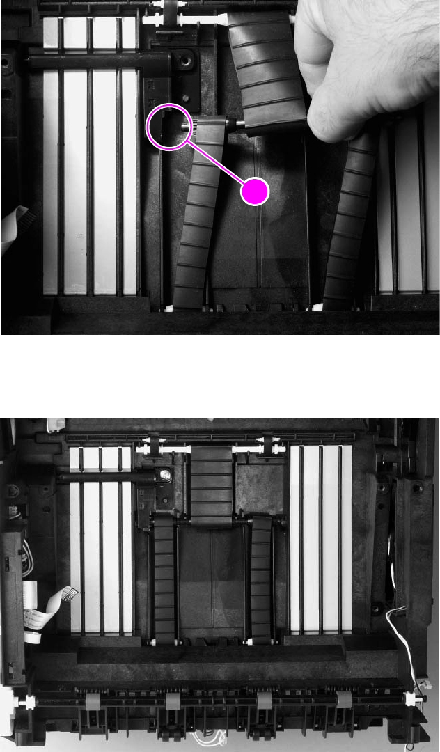
C7058-90936 Internal disassembly and assembly 131
Step 3 Lift up on the gear end of the middle roller until its shaft clears the hole in the gear
assembly (callout 1).
Step 4 Slide the roller out of the mounting post (end with no gears).
Step 5 Lift out the middle roller.
Step 6 Lift out the remaining belts and rollers.
Figure 103. Remove center roller
Step 7 Verify the correct installation of the transport belts and rollers, using figure 104.
Figure 104. Transport rollers and belts installed
2
1
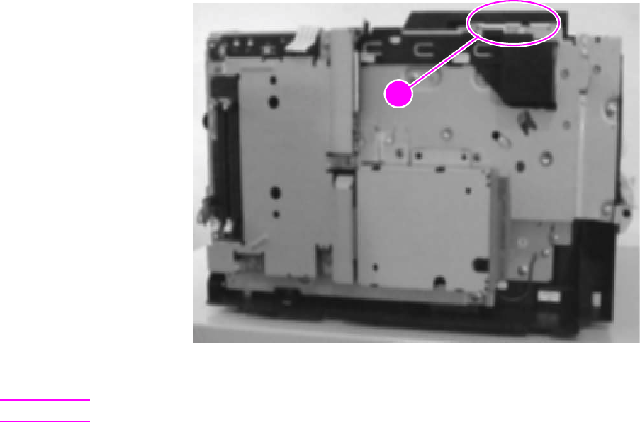
132 Chapter 6 Removal and replacement C7058-90936
Remove ribbon cable harness
Step 1 Remove the following assemblies:
•Remove the toner cartridge. See “Toner cartridge removal and replacement” on page 96.
•If installed, remove tray 3. See “Remove tray 3” on page 97.
•Remove the cassette from tray 2. See “Remove the cassette from tray 2” on page 97.
•Remove the DIMM cover. See “Remove DIMM cover” on page 99.
•Remove the rear cover. See “Remove rear cover” on page 100.
•Remove the top cover. See “Remove top cover” on page 102.
Step 2 Unplug the two ribbon cables (callout 1).
Step 3 Feed the cables through the opening towards the harness cover.
Step 4 Lift the harness cover locking tab away from the printer chassis and slide the cover away
from the duplexer reverse motor.
Step 5 Lift off the harness and cover.
Figure 105. Unplug the ribbon cables
Note When installing the ribbon cable harness (callout 1), feed the cables through the opening in the chassis.
11
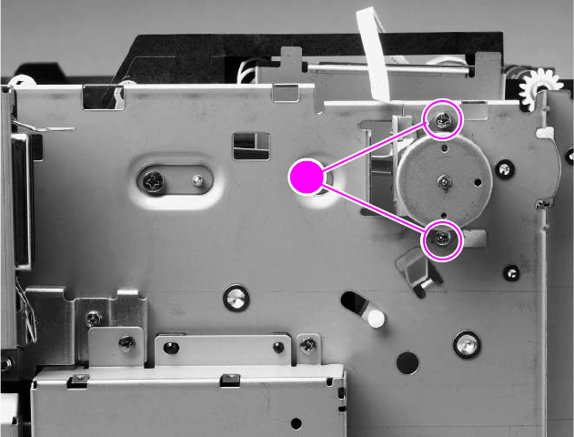
C7058-90936 Internal disassembly and assembly 133
Remove duplexer reverse motor
Step 1 Remove the following assemblies:
•Remove the toner cartridge. See “Toner cartridge removal and replacement” on page 96.
•If installed, remove tray 3. See “Remove tray 3” on page 97.
•Remove the cassette from tray 2. See “Remove the cassette from tray 2” on page 97.
•Remove the DIMM cover. See “Remove DIMM cover” on page 99.
•Remove the rear cover. See “Remove rear cover” on page 100.
•Remove the top cover. See “Remove top cover” on page 102.
•Remove the ribbon cable harness. See “Remove ribbon cable harness” on page 132.
Step 2 Remove the two duplexer reverse motor mounting screws (callout 1).
Step 3 Lift off the motor.
Figure 106. Remove duplexer reverse motor
2
1
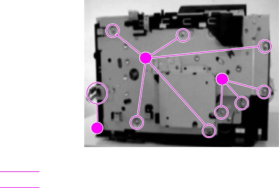
134 Chapter 6 Removal and replacement C7058-90936
Remove printer drive assembly
Step 1 Remove the following assemblies:
•Remove the toner cartridge. See “Toner cartridge removal and replacement” on page 96.
•If installed, remove tray 3. See “Remove tray 3” on page 97.
•Remove the cassette from tray 2. See “Remove the cassette from tray 2” on page 97.
•Remove the DIMM cover. See “Remove DIMM cover” on page 99.
•Remove the rear cover. See “Remove rear cover” on page 100.
•Remove the top cover. See “Remove top cover” on page 102.
•Remove the EIO card (if installed). See “Remove EIO card” on page 98.
•Remove the formatter PCB. See “Remove formatter PCB” on page 112.
•Unplug the two ribbon cables. See “Remove ribbon cable harness” on page 132.
Step 2 Remove the five self-tapping mounting screws (callout 1) and three ground screws
(callout 2).
Step 3 Tilt the printer drive assembly away from the chassis and unplug all harness connectors
and the I/F ribbon cable.
Step 4 Lift off the printer drive assembly.
Figure 107. Remove mounting and ground screws
Note When replacing the printer drive assembly, feed the formatter power harness (callout 3) though the
shield.
1
2
11
2
3
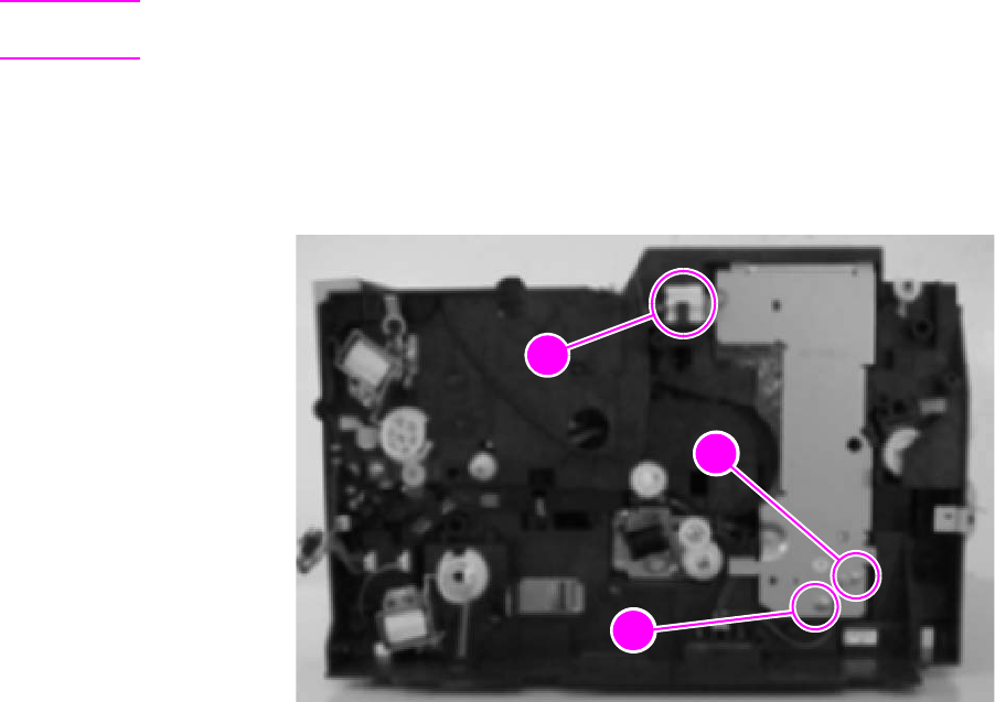
C7058-90936 Internal disassembly and assembly 135
Remove engine controller assembly
Step 1 Remove the following assemblies:
•Remove the toner cartridge. See “Toner cartridge removal and replacement” on page 96.
•If installed, remove tray 3. See “Remove tray 3” on page 97.
•Remove the cassette from tray 2. See “Remove the cassette from tray 2” on page 97.
•Remove the DIMM cover. See “Remove DIMM cover” on page 99.
•Remove the rear cover. See “Remove rear cover” on page 100.
•Remove the top cover. See “Remove top cover” on page 102.
•Remove the EIO card (if installed). See “Remove EIO card” on page 98.
•Remove the formatter PCB. See “Remove formatter PCB” on page 112.
•Unplug the two ribbon cables. See “Remove ribbon cable harness” on page 132.
•Remove the printer drive assembly. See “Remove printer drive assembly” on page 134.
CAUTION The printer contains parts that are sensitive to electrostatic discharge (ESD). Always service the printer
at an ESD-protected workstation or use an ESD mat.
Step 2 Remove the single mounting screw (callout 1) and ground cable screw (callout 2), and
unplug the harness connector (callout 3).
Step 3 Lift off the engine controller assembly.
Figure 108. Remove mounting screw (shown from threaded side)
3
2
2
2
1
3
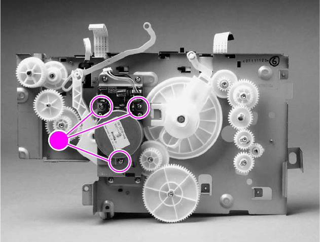
136 Chapter 6 Removal and replacement C7058-90936
Remove main motor
Step 1 Remove the following assemblies:
•Remove the toner cartridge. See “Toner cartridge removal and replacement” on page 96.
•If installed, remove tray 3. See “Remove tray 3” on page 97.
•Remove the cassette from tray 2. See “Remove the cassette from tray 2” on page 97.
•Remove the DIMM cover. See “Remove DIMM cover” on page 99.
•Remove the rear cover. See “Remove rear cover” on page 100.
•Remove the top cover. See “Remove top cover” on page 102.
•Remove the EIO card (if installed). See “Remove EIO card” on page 98.
•Remove the formatter PCB. See “Remove formatter PCB” on page 112.
•Unplug the two ribbon cables. See “Remove ribbon cable harness” on page 132.
•Remove the printer drive assembly. See “Remove printer drive assembly” on page 134.
Step 2 Remove the three mounting screws (callout 1).
Step 3 Lift off the main motor.
Figure 109. Remove main motor
2
1
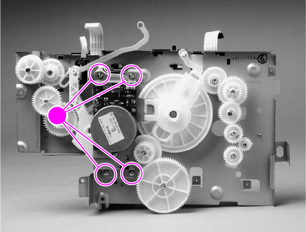
C7058-90936 Internal disassembly and assembly 137
Remove motor plate
Step 1 Remove the following assemblies:
•Remove the toner cartridge. See “Toner cartridge removal and replacement” on page 96.
•If installed, remove tray 3. See “Remove tray 3” on page 97.
•Remove the cassette from tray 2. See “Remove the cassette from tray 2” on page 97.
•Remove the DIMM cover. See “Remove DIMM cover” on page 99.
•Remove the rear cover. See “Remove rear cover” on page 100.
•Remove the top cover. See “Remove top cover” on page 102.
•Remove the EIO card (if installed). See “Remove EIO card” on page 98.
•Remove the formatter PCB. See “Remove formatter PCB” on page 112.
•Unplug the two ribbon cables. See “Remove ribbon cable harness” on page 132.
•Remove the printer drive assembly. See “Remove printer drive assembly” on page 134.
Step 2 Remove the four screws (callout 1).
Figure 110. Remove motor plate
2
1
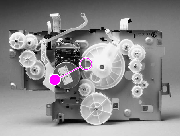
138 Chapter 6 Removal and replacement C7058-90936
Step 3 Press and hold the retaining clip (callout 1), and then slide the motor plate out of the
plastic holder while holding the bushing down with the other hand.
Figure 111. Motor plate retaining clip
2
1
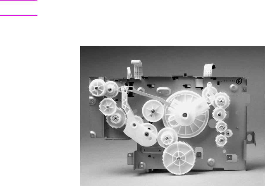
C7058-90936 Internal disassembly and assembly 139
Remove printer drive assembly gears
Step 1 Remove the following assemblies:
•Remove the toner cartridge. See “Toner cartridge removal and replacement” on page 96.
•If installed, remove tray 3. See “Remove tray 3” on page 97.
•Remove the cassette from tray 2. See “Remove the cassette from tray 2” on page 97.
•Remove the DIMM cover. See “Remove DIMM cover” on page 99.
•Remove the rear cover. See “Remove rear cover” on page 100.
•Remove the top cover. See “Remove top cover” on page 102.
•Remove the EIO card (if installed). See “Remove EIO card” on page 98.
•Remove the formatter PCB. See “Remove formatter PCB” on page 112.
•Unplug the two ribbon cables. See “Remove ribbon cable harness” on page 132.
•Remove the printer drive assembly. See “Remove printer drive assembly” on page 134.
•Remove the motor plate. See “Remove motor plate” on page 137.
Note The drive assembly gears are secured to the drive assembly plate by either the motor plate or a keyed
master gear positioned at the top of a gear cluster.
Step 2 Lift off the printer drive assembly gears. Remove the keyed master gear to free gears in
a gear cluster (some gear clusters contain more than one keyed master gear).
Figure 112. Remove printer drive-assembly gears
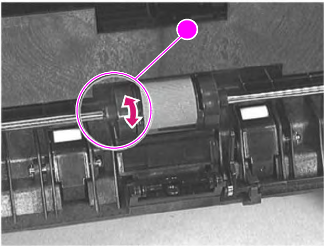
140 Chapter 6 Removal and replacement C7058-90936
Remove tray 1 pickup roller
Step 1 Remove the following assemblies:
•Remove the toner cartridge. See “Toner cartridge removal and replacement” on page 96.
•If installed, remove tray 3. See “Remove tray 3” on page 97.
•Remove the cassette from tray 2. See “Remove the cassette from tray 2” on page 97.
•Remove the DIMM cover. See “Remove DIMM cover” on page 99.
•Remove the rear cover. See “Remove rear cover” on page 100.
•Remove the top cover. See “Remove top cover” on page 102.
•Remove the left cover. See “Remove left cover” on page 105.
•Remove tray 1. See “Remove tray 1” on page 106.
Step 2 Rotate the left idler roller (callout 1) (on the cooling fan side) until its release tab is
exposed.
Figure 113. Locate left idler roller release tab
2
1
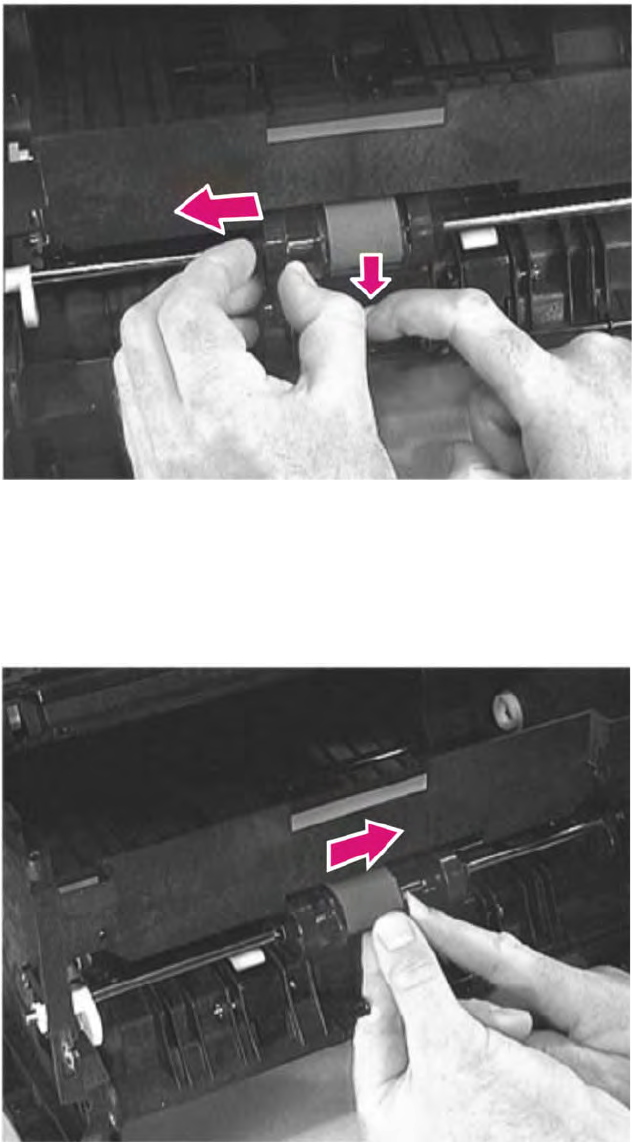
C7058-90936 Internal disassembly and assembly 141
Step 3 Press and hold down the separation pad.
Step 4 Grasp the roller, as shown below. Press and hold the release tab.
Step 5 Slide the idler roller to the left (toward the fan side).
Step 6 Repeat steps 2 through 5 for the right roller with all actions oriented toward the printer
drive-assembly side.
Figure 114. Release roller
Step 7 Press and hold the roller release tab that was exposed when the right roller was moved.
Step 8 Move the roller slightly to the right (toward the printer drive assembly), and rotate it
forward and out.
Figure 115. Release tray 1 separation roller
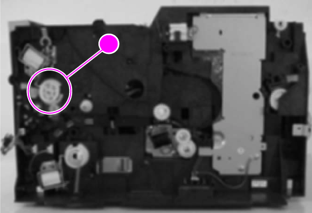
142 Chapter 6 Removal and replacement C7058-90936
Remove tray 1 pickup roller assembly
Step 1 Remove the following assemblies:
•Remove the toner cartridge. See “Toner cartridge removal and replacement” on page 96.
•If installed, remove tray 3. See “Remove tray 3” on page 97.
•Remove the cassette from tray 2. See “Remove the cassette from tray 2” on page 97.
•Remove the DIMM cover. See “Remove DIMM cover” on page 99.
•Remove the rear cover. See “Remove rear cover” on page 100.
•Remove the top cover. See “Remove top cover” on page 102.
•Remove the left cover. See “Remove left cover” on page 105.
•Remove tray 1. See “Remove tray 1” on page 106.
•Remove the formatter PCB. See “Remove formatter PCB” on page 112.
•Remove the printer drive assembly. See “Remove printer drive assembly” on page 134.
Step 2 Rotate the pickup-roller gear (callout 1) to clear the solenoid arm, and press the gear’s
locking tab.
Figure 116. Remove tray 1 pickup-roller gear
2
1
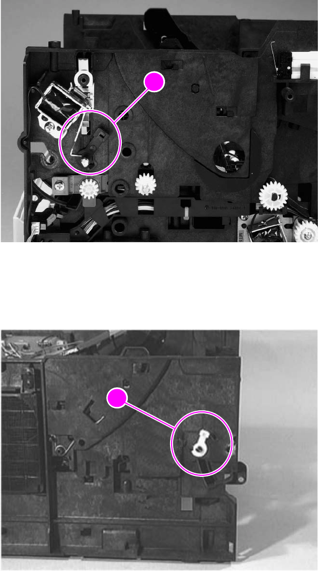
C7058-90936 Internal disassembly and assembly 143
Step 3 Unsnap the locking lever on the black bushing (callout 1). Rotate the bushing until its
locking tab aligns with the slot in the chassis. Remove the bushing.
Figure 117. Remove black bushing
Step 4 Unsnap the locking lever on the white bushing (callout 1) (located on the opposite side of
the printer chassis). Rotate the bushing until its locking tab aligns with the slot in the
chassis. Remove the bushing.
Figure 118. Remove white bushing
2
1
2
1
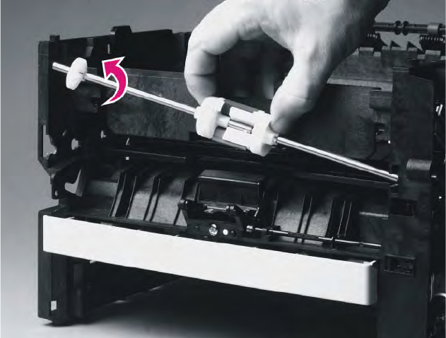
144 Chapter 6 Removal and replacement C7058-90936
Step 5 Slide the tray 1 pickup roller assembly towards the roller solenoid side of the printer until
the it clears the opening.
Step 6 Rotate the tray 1 pickup roller assembly away from the printer. Lift it off.
Figure 119. Remove tray 1 pickup roller assembly
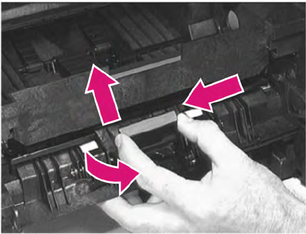
C7058-90936 Internal disassembly and assembly 145
Remove tray 1 separation pad assembly
Step 1 Remove the following assemblies:
•Remove the toner cartridge. See “Toner cartridge removal and replacement” on page 96.
•If installed, remove tray 3. See “Remove tray 3” on page 97.
•Remove the cassette from tray 2. See “Remove the cassette from tray 2” on page 97.
•Remove the DIMM cover. See “Remove DIMM cover” on page 99.
•Remove the rear cover. See “Remove rear cover” on page 100.
•Remove the top cover. See “Remove top cover” on page 102.
•Remove the left cover. See “Remove left cover” on page 105.
•Remove tray 1. See “Remove tray 1” on page 106.
•Remove the tray 1 pickup roller assembly. See “Remove tray 1 pickup roller” on page 140.
Step 2 Rotate the separation pad fully forward.
Step 3 Gently squeeze the mounting feet of the assembly to release it from the pivot pins.
Step 4 Lift off the tray 1 separation-pad assembly.
Step 5 If required, remove the single separation-pad mounting bracket mounting screw and
remove the mounting bracket.
Figure 120. Remove tray 1 separation-pad assembly
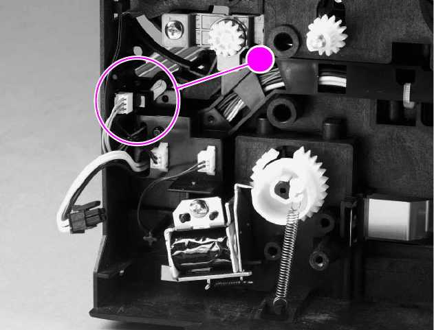
146 Chapter 6 Removal and replacement C7058-90936
Remove tray 1 paper-sensor lever
Step 1 Remove the following assemblies:
•Remove the toner cartridge. See “Toner cartridge removal and replacement” on page 96.
•If installed, remove tray 3. See “Remove tray 3” on page 97.
•Remove the cassette from tray 2. See “Remove the cassette from tray 2” on page 97.
•Remove the DIMM cover. See “Remove DIMM cover” on page 99.
•Remove the rear cover. See “Remove rear cover” on page 100.
•Remove the top cover. See “Remove top cover” on page 102.
•Remove the left cover. See “Remove left cover” on page 105.
•Remove tray 1. See “Remove tray 1” on page 106.
•Remove the formatter PCB. See “Remove formatter PCB” on page 112.
•Remove the printer drive assembly. See “Remove printer drive assembly” on page 134.
Step 2 Unplug the paper-sensor lever optic harness (callout 1).
Step 3 Grasp the paper sensor by the harness connector and squeeze the two locking tabs.
Step 4 Rotate the paper-sensor harness-connector away from the chassis.
Step 5 Lift off the paper sensor.
Figure 121. Remove paper sensor
2
1
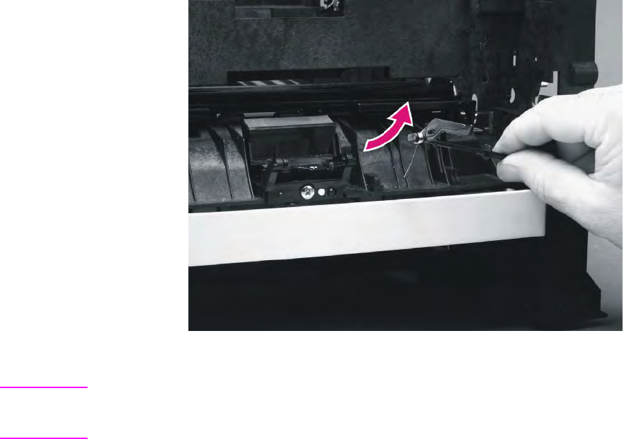
C7058-90936 Internal disassembly and assembly 147
Step 6 Pull the center of the paper-sensor lever outward, and then slide it toward the printer
drive side of the printer until it stops.
Step 7 Rotate the paper-sensor lever to the horizontal position and lift it out.
Figure 122. Remove the tray 1 paper-sensor lever
Note When replacing the paper-sensor lever, verify that the tail of the lever spring is correctly positioned to
produce a positive forward force on the lever and ensure correct paper-sensor lever operation. Verify
that the sensor lever moves freely after the paper-sensor lever or sensor optic has been replaced.
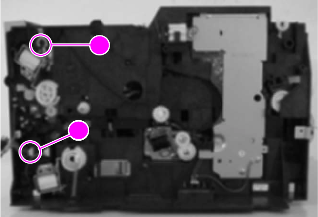
148 Chapter 6 Removal and replacement C7058-90936
Remove tray 1 solenoid
Step 1 Remove the following assemblies:
•Remove the toner cartridge. See “Toner cartridge removal and replacement” on page 96.
•If installed, remove tray 3. See “Remove tray 3” on page 97.
•Remove the cassette from tray 2. See “Remove the cassette from tray 2” on page 97.
•Remove the DIMM cover. See “Remove DIMM cover” on page 99.
•Remove the rear cover. See “Remove rear cover” on page 100.
•Remove the top cover. See “Remove top cover” on page 102.
•Remove left cover. See “Remove left cover” on page 105.
•Remove the formatter PCB. See “Remove formatter PCB” on page 112.
•Remove the printer drive assembly. See “Remove printer drive assembly” on page 134.
Step 2 Trace the two-pin solenoid wire harness (callout 1) and unplug it from the connector.
Step 3 Unlace the wire harness from the loops.
Step 4 Remove the mount screw (callout 2).
Step 5 Lift off the tray 1 solenoid.
Figure 123. Remove tray 1 solenoid
2
2
1
2
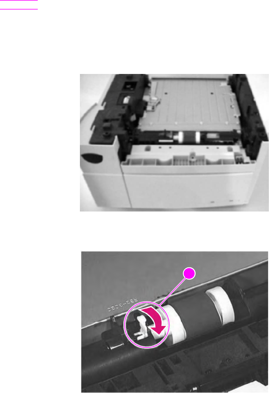
C7058-90936 Internal disassembly and assembly 149
Remove tray 2 pickup roller assembly
Note Do not touch the surface of the pickup roller with bare hands. Skin oils can damage the roller.
Step 1 Remove the following assemblies:
•Remove the toner cartridge. See “Toner cartridge removal and replacement” on page 96.
•If installed, remove tray 3. See “Remove tray 3” on page 97.
•Remove the cassette from tray 2. See “Remove the cassette from tray 2” on page 97.
Step 2 Place the printer top down with the infrared sensor port facing forward.
Figure 124. Top down with infrared sensor port facing forward
Step 3 Unsnap and rotate the locking lever of the white bushing (callout 1).
Figure 125. Unlock and rotate the white bushing
2
1
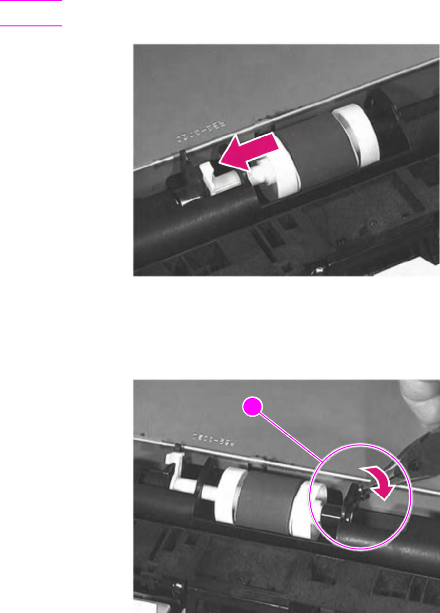
150 Chapter 6 Removal and replacement C7058-90936
Step 4 Align the locking tab bushing with the opening in the roller carriage.
Step 5 Slide the bushing away from the roller assembly.
Note To make the bushing slide more easily, rotate the bushing lever toward the rear of the printer (after the
locking tab clears the carriage opening).
Figure 126. Slide the bushing away from roller assembly
Step 6 Unsnap the locking lever of the black bushing (callout 1) and rotate to align the bushing’s
locking tab with the opening in the roller carriage.
Step 7 Slide the bushing away from the roller assembly and remove the it from the roller
assembly shaft.
Figure 127. Remove black bushing
2
1
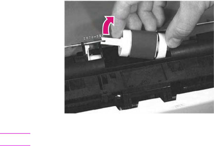
C7058-90936 Internal disassembly and assembly 151
Step 8 Slide the roller assembly away from the white bushing (allow the shaft extend into the
mounting hole of the black bushing).
Step 9 Tilt the roller assembly shaft out of the carriage, and lift it out.
Figure 128. Remove the pickup roller assembly
Note When replacing the pickup roller assembly, verify that the paper-to-tray sensor arm moves freely and
is correctly positioned. Verify that the pickup roller assembly completely engages the drive shaft.
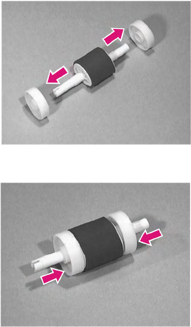
152 Chapter 6 Removal and replacement C7058-90936
Replace tray 2 pickup roller
Step 1 Remove the two rollers from the pickup roller.
Figure 129. Remove rollers
Step 2 Place the two rollers on the ends of the replacement pickup roller.
Figure 130. Replace rollers
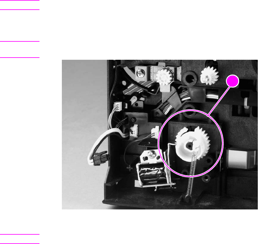
C7058-90936 Internal disassembly and assembly 153
Remove tray 2 pickup roller and refeeder assembly
Step 1 Remove the following assemblies:
•Remove the toner cartridge. See “Toner cartridge removal and replacement” on page 96.
•If installed, remove tray 3. See “Remove tray 3” on page 97.
•Remove the cassette from tray 2. See “Remove the cassette from tray 2” on page 97.
•Remove the DIMM cover. See “Remove DIMM cover” on page 99.
•Remove the rear cover. See “Remove rear cover” on page 100.
•Remove the top cover. See “Remove top cover” on page 102.
•Remove left cover. See “Remove left cover” on page 105.
•Remove the EIO card. See “Remove EIO card” on page 98.
•Remove the formatter PCB. See “Remove formatter PCB” on page 112.
•Remove duplexer tray. See “Remove duplexer tray” on page 120.
•Remove the power supply. See See “Remove power supply assembly” on page 122.
•Remove the printer drive assembly. See “Remove printer drive assembly” on page 134.
Note The following removal is only required if the refeeder sensor lever is being removed.
•Remove the registration assemble. See “Remove registration assembly” on page 158.
Step 2 Rotate the gear (callout 1) to clear the solenoid arm then remove the gear and spring.
Note To remove the tray 2 pickup-roller drive shaft, release the locking tab of the white bushing at the solenoid
end and slide the shaft out of the roller carriage.
Figure 131. Remove tray 2 pickup-roller gear and spring
Note When replacing the shaft, verify the tray 2 paper-sensor lever moves freely.
2
1
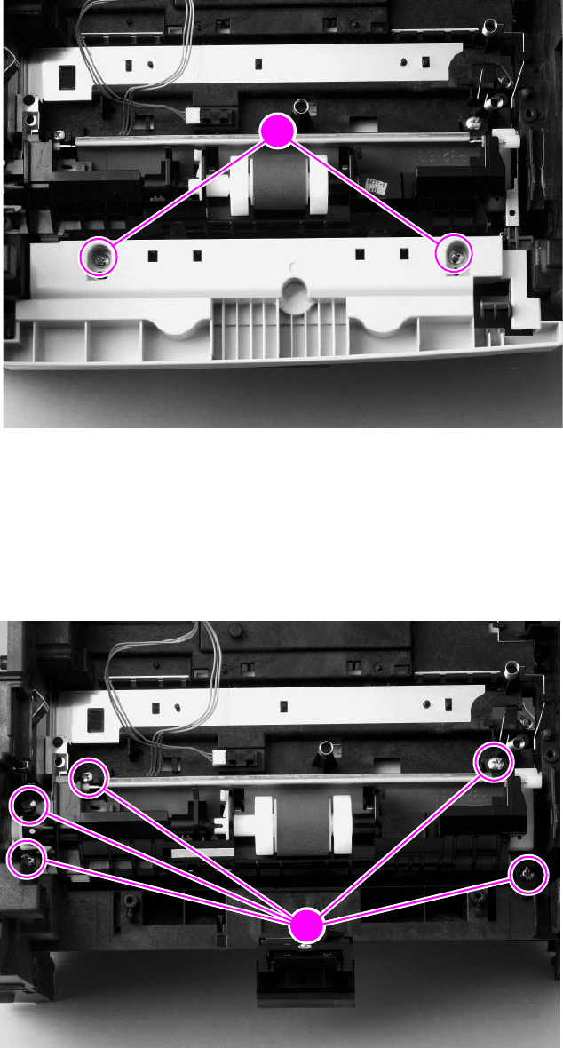
154 Chapter 6 Removal and replacement C7058-90936
Step 3 Place the printer top-down with the infrared port facing forward.
Step 4 Remove the two mounting screws from the duplex cover, disengage the duplexer release
lever from the refeeder assembly, and remove the lever.
Figure 132. Remove the duplex cover
Step 5 Unplug the refeeder three-pin harness.
Step 6 Remove the five mounting screws (callout 1) from the tray 2 pickup roller and refeeder
assembly.
Step 7 Lift off the tray 2 pickup roller and refeeder assembly.
Figure 133. Remove tray 2 pickup-roller and refeeder assembly
2
1
2
1
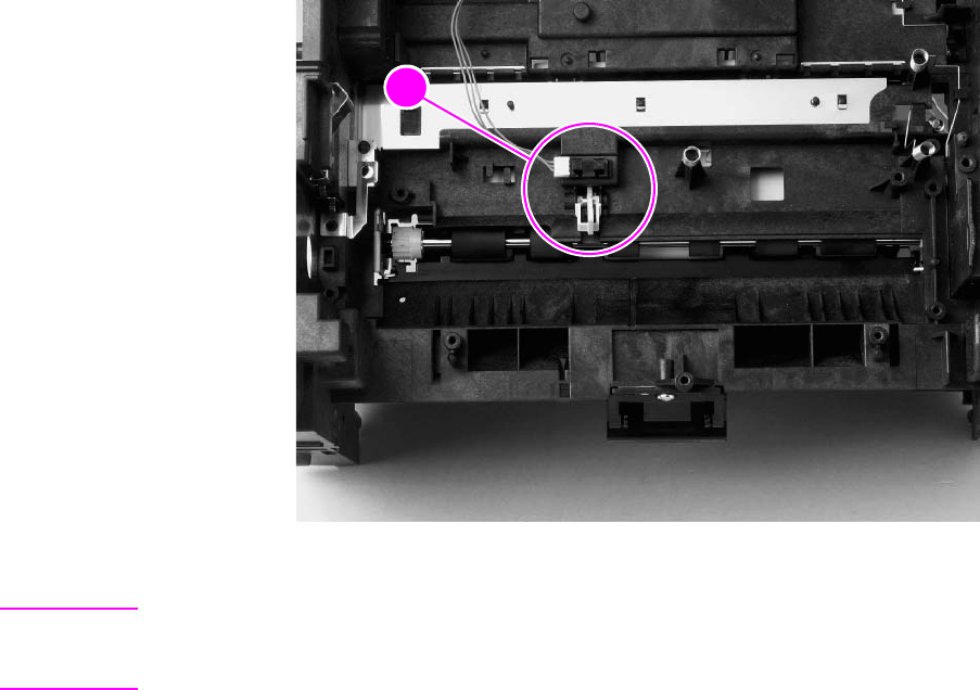
C7058-90936 Internal disassembly and assembly 155
Step 8 Unplug the optic sensor three-pin harness from the optic sensor.
Step 9 Grasp the optic sensor (callout 1) by the harness connector and squeeze the two locking
tabs. Rotate the sensors harness connector away from the chassis.
Step 10 Lift out the sensor.
Step 11 Squeeze the locking tabs of the sensor lever arm and push down on the lever (towards
the laser/scanner side).
Step 12 Lift out the paper-sensor lever.
Figure 134. Remove tray 2 optic sensor and lever
Note When replacing the paper-sensor lever, verify that the tail of the lever spring is correctly positioned to
produce a positive forward force on the lever and ensure correct paper-sensor lever operation. Verify
that the sensor lever moves freely after the paper-sensor lever or sensor optic has been replaced.
2
1
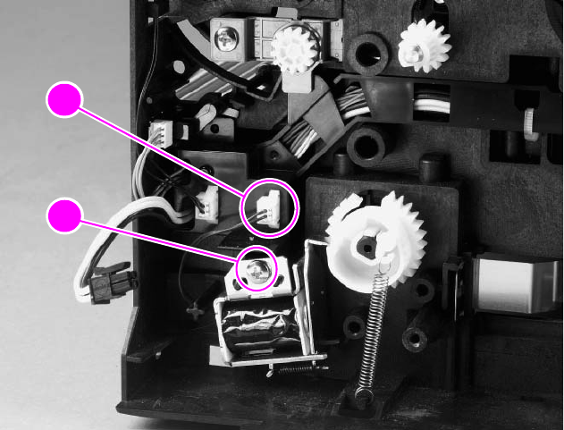
156 Chapter 6 Removal and replacement C7058-90936
Remove tray 2 solenoid
Step 1 Remove the following assemblies:
•Remove the toner cartridge. See “Toner cartridge removal and replacement” on page 96.
•If installed, remove tray 3. See “Remove tray 3” on page 97.
•Remove the cassette from tray 2. See “Remove the cassette from tray 2” on page 97.
•Remove the DIMM cover. See “Remove DIMM cover” on page 99.
•Remove the rear cover. See “Remove rear cover” on page 100.
•Remove the top cover. See “Remove top cover” on page 102.
•Remove left cover. See “Remove left cover” on page 105.
•Remove the EIO card. See “Remove EIO card” on page 98.
•Remove the formatter PCB. See “Remove formatter PCB” on page 112.
•Remove the printer drive assembly. See “Remove printer drive assembly” on page 134.
Step 2 Trace the two-pin solenoid wire harness and unplug it from the connector.
Step 3 Remove the screw, as shown.
Step 4 Lift out the tray 2 solenoid.
Figure 135. Remove the tray 2 solenoid
2
1
2
2
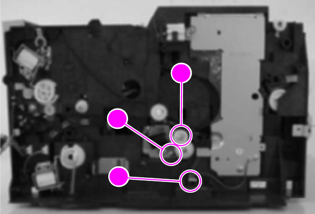
C7058-90936 Internal disassembly and assembly 157
Remove duplexer drive gears and solenoid
Step 1 Remove the following assemblies:
•Remove the toner cartridge. See “Toner cartridge removal and replacement” on page 96.
•If installed, remove tray 3. See “Remove tray 3” on page 97.
•Remove the cassette from tray 2. See “Remove the cassette from tray 2” on page 97.
•Remove the DIMM cover. See “Remove DIMM cover” on page 99.
•Remove the rear cover. See “Remove rear cover” on page 100.
•Remove the top cover. See “Remove top cover” on page 102.
•Remove left cover. See “Remove left cover” on page 105.
•Remove the EIO card. See “Remove EIO card” on page 98.
•Remove the formatter PCB. See “Remove formatter PCB” on page 112.
•Remove the printer drive assembly. See “Remove printer drive assembly” on page 134.
Step 2 Gently pry apart the two locking tabs on the topmost duplexer drive gear (callout 1) and
remove the gear. Repeat for the remaining drive gear.
Step 3 Unlace the 2-pin solenoid wire harness from the loops and disconnect the connector
(callout 2) (if an earlier printer driver assembly removal was performed, the connector
was previously unplugged).
Step 4 Remove the mount screw (callout 3).
Step 5 Lift out the duplexer solenoid.
Figure 136. Remove duplexer drive gears and solenoid
2
3
2
1
2
2
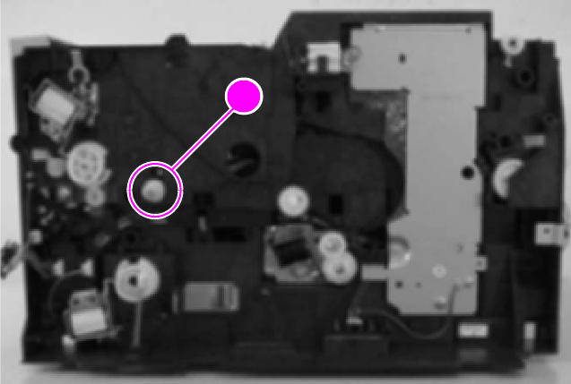
158 Chapter 6 Removal and replacement C7058-90936
Remove registration assembly
Step 1 Remove the following assemblies:
•Remove the toner cartridge. See “Toner cartridge removal and replacement” on page 96.
•If installed, remove tray 3. See “Remove tray 3” on page 97.
•Remove the cassette from tray 2. See “Remove the cassette from tray 2” on page 97.
•Remove the DIMM cover. See “Remove DIMM cover” on page 99.
•Remove the rear cover. See “Remove rear cover” on page 100.
•Remove the top cover. See “Remove top cover” on page 102.
•Remove left cover. See “Remove left cover” on page 105.
•Remove the EIO card. See “Remove EIO card” on page 98.
•Remove the formatter PCB. See “Remove formatter PCB” on page 112.
•Remove the printer drive assembly. See “Remove printer drive assembly” on page 134.
Step 2 Remove the registration-assembly drive gear (callout 1).
Figure 137. Remove registration-assembly drive gear
2
1

C7058-90936 Internal disassembly and assembly 159
Step 3 Remove the six mounting screws (callout 1).
Step 4 Lift the assembly to the left (the cooling-fan side), and then to the right (the printer-drive
assembly side) to free it.
Step 5 Lift out the registration assembly.
Figure 138. Registration assembly
2
1
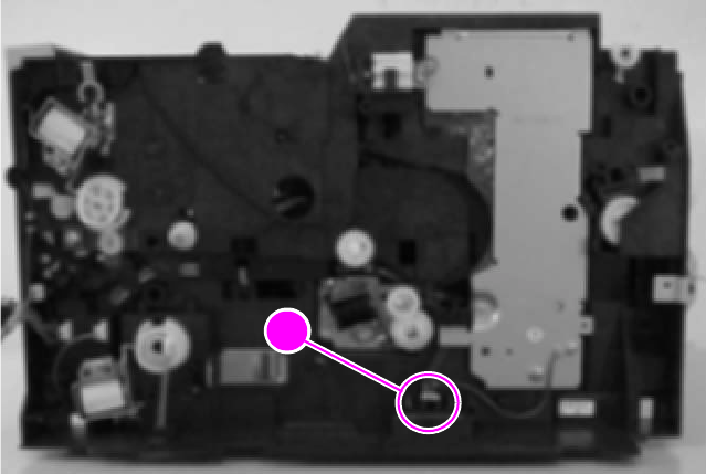
160 Chapter 6 Removal and replacement C7058-90936
Remove tray 3 assembly connector
Step 1 Remove the following assemblies:
•Remove the toner cartridge. See “Toner cartridge removal and replacement” on page 96.
•If installed, remove tray 3. See “Remove tray 3” on page 97.
•Remove the cassette from tray 2. See “Remove the cassette from tray 2” on page 97.
•Remove the DIMM cover. See “Remove DIMM cover” on page 99.
•Remove the rear cover. See “Remove rear cover” on page 100.
•Remove the top cover. See “Remove top cover” on page 102.
•Remove left cover. See “Remove left cover” on page 105.
•Remove the EIO card. See “Remove EIO card” on page 98.
•Remove the formatter PCB. See “Remove formatter PCB” on page 112.
•Remove the printer drive assembly. See “Remove printer drive assembly” on page 134.
Step 2 Unplug the four-pin and three-pin tray 3 harness connectors (callout 1).
Step 3 Squeeze the wing nuts with needle-nose pliers, and push the connector through the
opening.
Figure 139. Remove the tray 3 connector
2
1
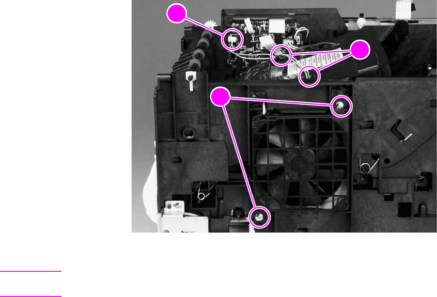
C7058-90936 Internal disassembly and assembly 161
Remove cooling fan
Step 1 Remove the following assemblies:
•Remove the toner cartridge. See “Toner cartridge removal and replacement” on page 96.
•If installed, remove tray 3. See “Remove tray 3” on page 97.
•Remove the cassette from tray 2. See “Remove the cassette from tray 2” on page 97.
•Remove the DIMM cover. See “Remove DIMM cover” on page 99.
•Remove the rear cover. See “Remove rear cover” on page 100.
•Remove the top cover. See “Remove top cover” on page 102.
•Remove left cover. See “Remove left cover” on page 105.
Step 2 Trace the 3-pin fan wire harness and unplug its connector (callout 1).
Step 3 Unlace the harness from the loops (callout 2) on the scanner assembly.
Step 4 Remove the two fan mounting screws (callout 3) and lift out the fan.
Figure 140. Remove cooling fan
CAUTION When replacing the fan, verify that the air flow is directed into the printer cabinet (the fan is marked
with a air flow directional arrow located at the top of the fan housing).
2
1
2
2
2
3
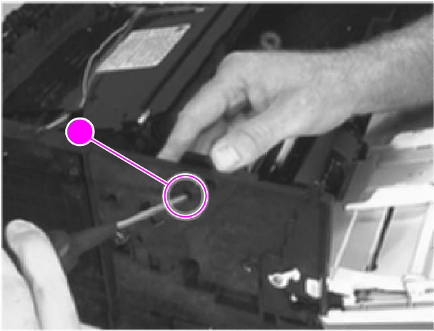
162 Chapter 6 Removal and replacement C7058-90936
Remove toner-cartridge guide
Step 1 Remove the following assemblies:
•Remove the toner cartridge. See “Toner cartridge removal and replacement” on page 96.
•If installed, remove tray 3. See “Remove tray 3” on page 97.
•Remove the cassette from tray 2. See “Remove the cassette from tray 2” on page 97.
•Remove the DIMM cover. See “Remove DIMM cover” on page 99.
•Remove the rear cover. See “Remove rear cover” on page 100.
•Remove the top cover. See “Remove top cover” on page 102.
•Remove left cover. See “Remove left cover” on page 105.
Step 2 Press and hold in the toner-cartridge guide pin (callout 1).
Figure 141. Release toner-cartridge guide pin
2
1
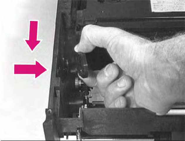
C7058-90936 Internal disassembly and assembly 163
Step 3 Slide the guide forward (away from the laser/scanner assembly) and lift it out.
Figure 142. Remove toner-cartridge guide
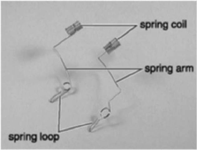
164 Chapter 6 Removal and replacement C7058-90936
Remove dc bias voltage contacts (leaf springs)
Step 1 Remove the following assemblies:
•Remove the toner cartridge. See “Toner cartridge removal and replacement” on page 96.
•If installed, remove tray 3. See “Remove tray 3” on page 97.
•Remove the cassette from tray 2. See “Remove the cassette from tray 2” on page 97.
•Remove the DIMM cover. See “Remove DIMM cover” on page 99.
•Remove the rear cover. See “Remove rear cover” on page 100.
•Remove the top cover. See “Remove top cover” on page 102.
•Remove left cover. See “Remove left cover” on page 105.
•Remove the duplexer tray and media handling assembly. See See “Remove duplexer tray” on
page 120.
•Remove the power supply assembly. See “Remove power supply assembly” on page 122.
Step 2 Identify the dc bias contact components.
Figure 143. Identify dc bias contacts
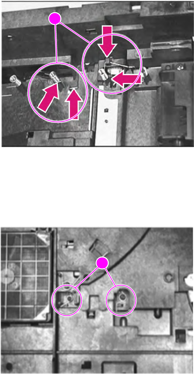
C7058-90936 Internal disassembly and assembly 165
Step 3 Release the spring coil (callout 1) from the retaining clip located on the bottom of printer.
Step 4 Remove the spring arm from the adjacent retaining clip.
Figure 144. Release dc bias spring coil and spring arm
Step 5 Remove the spring arm (callout 1) from the post on the fan side of printer. This releases
spring tension.
Step 6 Squeeze the spring loop and slide it out of its slot.
Step 7 Remove the spring from the side pivot pin.
Step 8 Lift out the dc bias voltage contact. Repeat for the remaining contact.
Figure 145. Spring loop
2
1
2
1
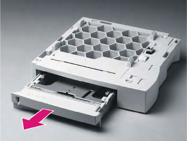
166 Chapter 6 Removal and replacement C7058-90936
Tray 3 disassembly and assembly
Remove tray 3 (250-sheet feeder) cassette
Step 1 If installed, remove tray 3. See “Remove tray 3” on page 97.
Step 2 Firmly pull the cassette forward and out of the sheet-feeder.
Figure 146. Remove tray 3 (250-sheet feeder)
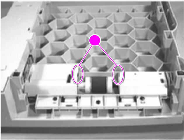
C7058-90936 Tray 3 disassembly and assembly 167
Remove tray 3 (250-sheet feeder) pickup roller
Step 1 Remove the following assemblies:
•If installed, remove tray 3. See “Remove tray 3” on page 97.
•Remove the cassette. See “Remove tray 3 (250-sheet feeder) cassette” on page 166.
Step 2 Place the sheet feeder top-down with the front facing outward.
Step 3 Place the blade of a small flatblade screwdriver in the slots (callout 1). Pop each cover
off the cassette body.
Step 4 Follow steps 3 through 6 in “Remove tray 2 pickup roller assembly” on page 6-149 to
complete removal.
Figure 147. Tray 3 (250-sheet feeder) roller
2
1
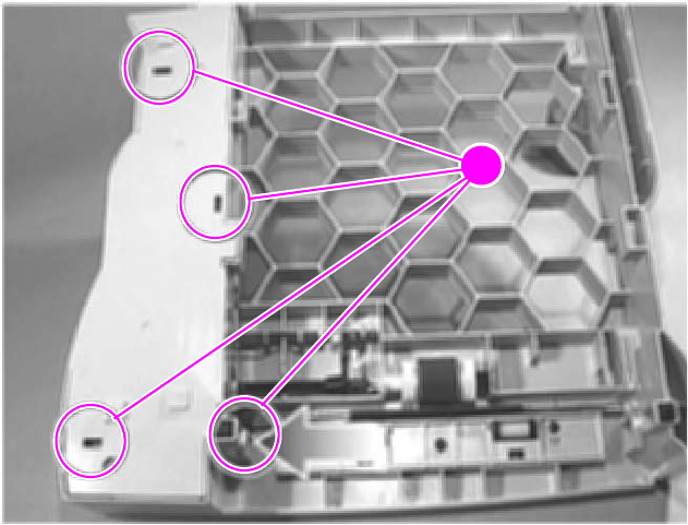
168 Chapter 6 Removal and replacement C7058-90936
Remove tray 3 (250-sheet feeder) feeder drive assembly
Step 1 Remove the following assemblies:
•If installed, remove tray 3. See “Remove tray 3” on page 97.
•Remove the cassette. See “Remove tray 3 (250-sheet feeder) cassette” on page 166.
Step 2 Place the sheet feeder top-down with the front facing outward.
Step 3 Use a small flatblade screwdriver to disengage the cover’s locking tabs (callout 1).
Step 4 Lift the cover off the cassette.
Figure 148. Remove tray 3 (250 sheet-feeder) drive cover
2
1
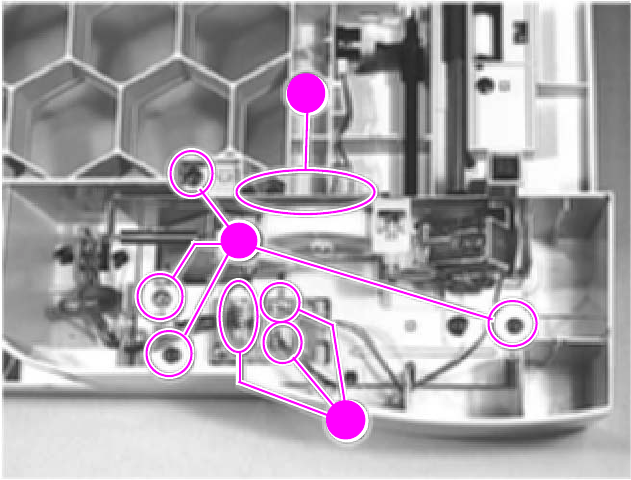
C7058-90936 Tray 3 disassembly and assembly 169
Step 5 Unplug the one-pin, two three-pin, and four-pin wire harnesses (callout 1) at the PCB.
Step 6 Unlace the harnesses from loops as required.
Step 7 Remove the four drive assembly mounting screws (callout 2).
Step 8 Depress the metal retaining latch (callout 3) (located on the tray side of the assembly).
Step 9 Lift out the drive assembly.
Figure 149. Remove tray 3 (250 sheet-feeder) drive assembly
2
2
3
2
2
1
170 Chapter 6 Removal and replacement C7058-90936
Remove tray 3 (250 sheet-feeder) drive solenoid
Step 1 Remove the following assemblies:
•If installed, remove tray 3. See “Remove tray 3” on page 97.
•Remove the cassette. See “Remove tray 3 (250-sheet feeder) cassette” on page 166.
•Remove the tray 3 feeder drive assembly. See “Remove tray 3 (250-sheet feeder) feeder
drive assembly” on page 168.
Step 2 Unplug the two-pin solenoid harness connector.
Step 3 Remove the single solenoid mounting screw.
Step 4 Lift out the solenoid.
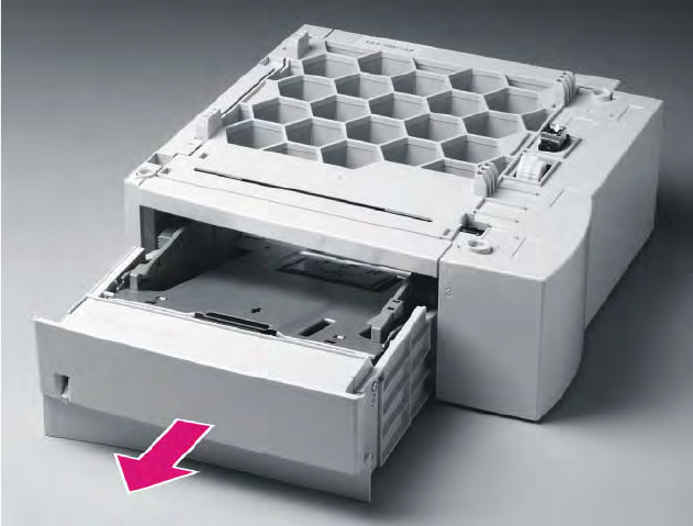
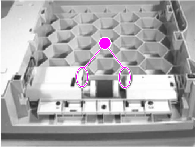
172 Chapter 6 Removal and replacement C7058-90936
Remove tray 3 (500-sheet feeder) pickup roller
Step 1 Remove the following assemblies:
•If installed, remove tray 3. See “Remove tray 3” on page 97.
•Remove the cassette. See “Remove tray 3 (500-sheet feeder) cassette” on page 171.
Step 2 Place the sheet feeder top-down with the front facing outward.
Step 3 Place the blade of a small flatblade screwdriver in the slots (callout 1). Pop each cover
off the cassette body.
Step 4 Remove the forward brace located directly over the pickup roller for easy access to the
pickup roller assembly.
Step 5 Follow steps 3 through 6 in "Remove tray 2 pickup roller assembly" page 149 to
complete removal.
Figure 151. Tray 3 (500-sheet feeder) pickup roller
2
1
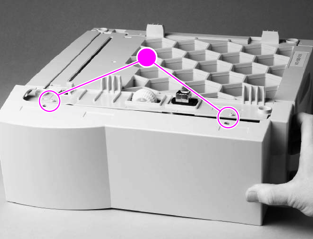
C7058-90936 Tray 3 disassembly and assembly 173
Remove tray 3 (500-sheet feeder) feeder drive assembly
Step 1 Remove the following assemblies:
•If installed, remove tray 3. See “Remove tray 3” on page 97.
•Remove the cassette. See “Remove tray 3 (500-sheet feeder) cassette” on page 171.
Step 2 Press down on the two locking pins (callout 1).
Step 3 Rotate the top of the cover away and down from the cassette.
Step 4 Lift the cover away from the cassette.
Figure 152. Remove tray 3 (500 sheet-feeder) drive cover
2
1
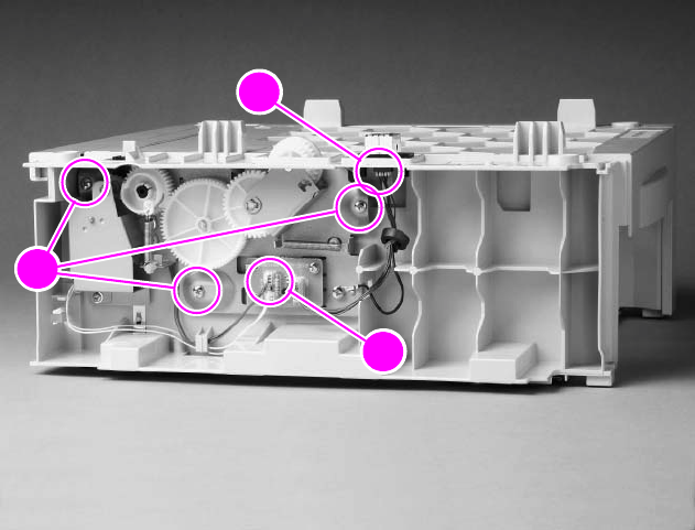
174 Chapter 6 Removal and replacement C7058-90936
Step 5 Unplug the one-pin, three-pin, and four-pin cassette docking plug wire harnesses
(callout 1) at the docking plug.
Step 6 Unplug three-pin optic sensor connector (callout 2) at the PCB.
Step 7 Unlace the harnesses from loops as required.
Step 8 Remove the three drive assembly mounting screws (callout 3).
Step 9 Depress the metal retaining latch (located on the tray side of the assembly).
Step 10Lift out the drive assembly.
Figure 153. Remove tray 3 (500 sheet-feeder) drive assembly
2
2
2
2
1
3
C7058-90936 Tray 3 disassembly and assembly 175
Remove tray 3 (500 sheet-feeder) drive solenoid
Step 1 Remove the following assemblies:
•If installed, remove tray 3. See “Remove tray 3” on page 97.
•Remove the cassette. See “Remove tray 3 (500-sheet feeder) cassette” on page 171.
•Remove the tray 3 feeder drive assembly. See “Remove tray 3 (500-sheet feeder) feeder
drive assembly” on page 173.
Step 2 Unplug the two-pin solenoid harness connector.
Step 3 Remove the two solenoid bracket-mounting screws.
Step 4 Turn the bracket over to expose the solenoid and remove the single solenoid mounting
screw.
Step 5 Lift out the solenoid.
176 Chapter 6 Removal and replacement C7058-90936
C7058-90936 Chapter contents 177
7Troubleshooting
Chapter contents
Troubleshooting process . . . . . . . . . . . . . . . . . . . . . . . . . . . . . . . . . . . . . . . . . . . . . . . . . . . . . . . 178
Preliminary operating checks . . . . . . . . . . . . . . . . . . . . . . . . . . . . . . . . . . . . . . . . . . . . . . . . 178
Basic fault isolation . . . . . . . . . . . . . . . . . . . . . . . . . . . . . . . . . . . . . . . . . . . . . . . . . . . . . . . . 178
Troubleshooting process flow . . . . . . . . . . . . . . . . . . . . . . . . . . . . . . . . . . . . . . . . . . . . . . . . 180
Power-on . . . . . . . . . . . . . . . . . . . . . . . . . . . . . . . . . . . . . . . . . . . . . . . . . . . . . . . . . . . . . . . . . . .181
Troubleshooting with control-panel messages. . . . . . . . . . . . . . . . . . . . . . . . . . . . . . . . . . . . . . . 182
Control panel lights . . . . . . . . . . . . . . . . . . . . . . . . . . . . . . . . . . . . . . . . . . . . . . . . . . . . . . . . 182
Control-panel light messages . . . . . . . . . . . . . . . . . . . . . . . . . . . . . . . . . . . . . . . . . . . . . . . . 182
Media-handling problems . . . . . . . . . . . . . . . . . . . . . . . . . . . . . . . . . . . . . . . . . . . . . . . . . . . . . . 192
Print test pages. . . . . . . . . . . . . . . . . . . . . . . . . . . . . . . . . . . . . . . . . . . . . . . . . . . . . . . . . . . 192
Engine test . . . . . . . . . . . . . . . . . . . . . . . . . . . . . . . . . . . . . . . . . . . . . . . . . . . . . . . . . . . . . . 192
Self test/configuration page . . . . . . . . . . . . . . . . . . . . . . . . . . . . . . . . . . . . . . . . . . . . . . . . . 192
Jam troubleshooting . . . . . . . . . . . . . . . . . . . . . . . . . . . . . . . . . . . . . . . . . . . . . . . . . . . . . . . 193
Media problems . . . . . . . . . . . . . . . . . . . . . . . . . . . . . . . . . . . . . . . . . . . . . . . . . . . . . . . . . . 197
Evaluate the test pages. . . . . . . . . . . . . . . . . . . . . . . . . . . . . . . . . . . . . . . . . . . . . . . . . . . . . . . . 198
Status-log messages . . . . . . . . . . . . . . . . . . . . . . . . . . . . . . . . . . . . . . . . . . . . . . . . . . . . . . 198
Verify installed options . . . . . . . . . . . . . . . . . . . . . . . . . . . . . . . . . . . . . . . . . . . . . . . . . . . . . 198
Image-formation troubleshooting. . . . . . . . . . . . . . . . . . . . . . . . . . . . . . . . . . . . . . . . . . . . . . . . . 199
Image defect tables. . . . . . . . . . . . . . . . . . . . . . . . . . . . . . . . . . . . . . . . . . . . . . . . . . . . . . . .201
Repetitive defect ruler . . . . . . . . . . . . . . . . . . . . . . . . . . . . . . . . . . . . . . . . . . . . . . . . . . . . . . 207
Half self test functional check . . . . . . . . . . . . . . . . . . . . . . . . . . . . . . . . . . . . . . . . . . . . . . . . 208
Drum-rotation functional check . . . . . . . . . . . . . . . . . . . . . . . . . . . . . . . . . . . . . . . . . . . . . . . 208
Media troubleshooting . . . . . . . . . . . . . . . . . . . . . . . . . . . . . . . . . . . . . . . . . . . . . . . . . . . . . . . . . 209
Determine the problem source: print media or printer . . . . . . . . . . . . . . . . . . . . . . . . . . . . . 209
Isolate a paper path . . . . . . . . . . . . . . . . . . . . . . . . . . . . . . . . . . . . . . . . . . . . . . . . . . . . . . . 209
Isolate a media brand . . . . . . . . . . . . . . . . . . . . . . . . . . . . . . . . . . . . . . . . . . . . . . . . . . . . . . 210
Isolate a media type . . . . . . . . . . . . . . . . . . . . . . . . . . . . . . . . . . . . . . . . . . . . . . . . . . . . . . . 211
Evaluate media use practices. . . . . . . . . . . . . . . . . . . . . . . . . . . . . . . . . . . . . . . . . . . . . . . . 215
Evaluate environmental conditions . . . . . . . . . . . . . . . . . . . . . . . . . . . . . . . . . . . . . . . . . . . . 215
Communication troubleshooting . . . . . . . . . . . . . . . . . . . . . . . . . . . . . . . . . . . . . . . . . . . . . . . . . 217
Communications check. . . . . . . . . . . . . . . . . . . . . . . . . . . . . . . . . . . . . . . . . . . . . . . . . . . . .217
Test message . . . . . . . . . . . . . . . . . . . . . . . . . . . . . . . . . . . . . . . . . . . . . . . . . . . . . . . . . . . . 217
EIO troubleshooting . . . . . . . . . . . . . . . . . . . . . . . . . . . . . . . . . . . . . . . . . . . . . . . . . . . . . . . 217
JetDirect configuration-page elements . . . . . . . . . . . . . . . . . . . . . . . . . . . . . . . . . . . . . . . . . 219
JetDirect configuration . . . . . . . . . . . . . . . . . . . . . . . . . . . . . . . . . . . . . . . . . . . . . . . . . . . . . 219
Reference diagrams . . . . . . . . . . . . . . . . . . . . . . . . . . . . . . . . . . . . . . . . . . . . . . . . . . . . . . . . . . 220

178 Chapter 7 Troubleshooting C7058-90936
Troubleshooting process
Preliminary operating checks
Make sure that the following conditions are met before troubleshooting a specific printer problem:
lThe printer is plugged in and power is delivered to the outlet as specified on the power rating
label.
lThe selected tray contains media that has been properly loaded.
lThe toner cartridge is installed properly.
lThe printer is receiving maintenance on a regular basis.
lAny I/O devices are properly installed.
lThe customer is using acceptable print media.
lThe printer is positioned on a solid, level surface.
lThe line voltage does not vary more than 10 percent from the nominal rated value specified on
the power rating label.
lThe operating environment for the printer is within the temperature and humidity specifications.
lThe printer is never exposed to ammonia fumes such as those produced by diazo copiers or
office cleaning materials.
lThe printer is not exposed to direct sunlight.
lNon-HP components (such as refilled toner cartridges, font cartridges, and memory boards) are
removed from the printer.
Note Sudden changes in the printer’s environment can cause image defects and media-handling problems.
Always make sure the printer is not exposed to direct sunlight or to heating or cooling vents. Allow time
for the printer and media to acclimate whenever changing environments (for example, moving from a
cold environment to a warm one). Acclimation can take anywhere from 3 to 24 hours depending on
the ambient conditions.
Basic fault isolation
The troubleshooting process is a systematic approach that first addresses the major problems first
and then other problems to discover the causes for printer malfunctions and errors. The
"Troubleshooting process flow" page 180 illustrates the major steps for troubleshooting the printing
system. Each heading depicts a major troubleshooting step. A “YES” answer to the questions allows
troubleshooting to proceed to the next major step.
A “NO” answer indicates that additional testing and correction is needed. Proceed to the referenced
location in the chapter and follow the directions there. After completing the additional testing and
correcting the problem, proceed to the next major step.
Note It is important to always follow this process in sequence. Failure to do so can result in increased repair
time, difficulty, and expense.

C7058-90936 Troubleshooting process 179
This list describes the basic questions for the customer to answer and the corresponding
troubleshooting section to help quickly define the problem(s).
Table 26. Major steps for troubleshooting
“Power-on” on page 181 Does the printer perform the initialization and power-on sequence?
This section contains the procedures for correcting power supply problems.
“Troubleshooting with control-
panel messages” on page 182 Does the control-panel light message indicate an error condition?
This section contains the procedures for clearing control panel messages.
“Media-handling problems” on
page 192 Is it possible to print a test page?
This section contains information about troubleshooting paper-path and
print-media problems.
“Evaluate the test pages” on
page 198 Is there information in the status log?
This section contains the procedures for printing the information pages and
evaluating and correcting the printer’s configuration.
“Image-formation
troubleshooting” on page 199 Does the print quality meet the customer’s expectations?
This section contains toner cartridge checks, information about EconoMode,
image defect examples, and the repetitive-defect ruler.
“Media troubleshooting” on page
209 This section contains information about how to determine print-media
problems and correct them.
“Communication
troubleshooting” on page 217 Can the customer print from the host system successfully?
This section describes how to determine whether the printer is
communicating properly with the host system.
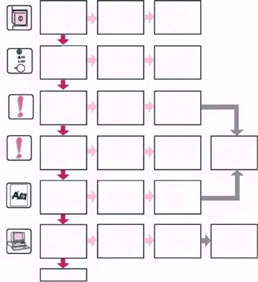
180 Chapter 7 Troubleshooting C7058-90936
Troubleshooting process flow
Figure 154. Troubleshooting process flow
Power-on
verification
Checks OK?
Troubleshooting
with control
panel messages
OK?
Media-handling
problems
Can you print
a test page?
Evaluate
test page
OK?
OK?
Image-
formation
troubleshooting
YES
YES
YES
YES
YES
Fix Fan motor
Do lights
illuminate
Fix power-on
problem
NO
NO
NO
NO
NO
Interpret the
light problem
Fix indicated
problem
See
paperpath
troubleshooting
Fix
paperpath
problem
Test pages Fix
indicated
problem
Investigate
potential
media
problems
Compare
information
page to
a sample
Fix problem
Communication
troubleshooting
Can you print
from host
system?
Evaluate the
JetDirect
page
Print
from LPT 1 Network
administration
required
End
YES
NO
1
2
3
4
5
6
C7058-90936 Power-on 181
Power-on
It is important to have the printer control panel lights functional as soon as possible in the
troubleshooting process so that the printer’s diagnostics can assist in locating printing errors.
Follow these steps to pinpoint power problems quickly.
Step 1 Confirm that the printer is plugged in to a reliable power source and the power switch is
on.
Step 2 Verify that the fan and motors rotate.
Step 3 Verify that the formatter cables are connected properly.
Step 4 Verify that the control panel light pipes in the DIMM cover are not broken or damaged.
Step 5 Verify that the DIMM cover is installed properly.
Step 6 Verify that all connections to the power supply assembly are intact and the assembly is
not damaged. If the power supply assembly is damaged, replace it.
Step 7 Check that connections to the engine controller assembly. If necessary, replace the
engine controller assembly.
Step 8 Check fuser connectors, fan and main motor connectors, and the laser/scanner
connector.
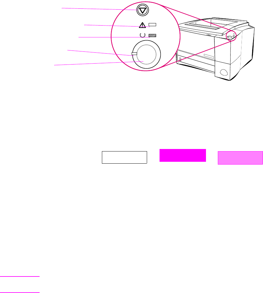
182 Chapter 7 Troubleshooting C7058-90936
Troubleshooting with control-panel messages
Control panel lights
Figure 155. Control panel layout
Control-panel light messages
Light patterns provide status and error messages. The lights can be in any one of the following
states:
Figure 156. Light states
The following control-panel light patterns indicate various conditions of the printer in preparation for,
or during, printing. If the Attention light is blinking, the printer is experiencing an error. The messages
are grouped according to error type: status, attendance, continuable, fatal, and accessory errors. In
many cases the error provides specific information about the defective component.
If the printer lights indicate a continuable, fatal, or accessory error, press GO and JOB CANCEL
simultaneously to display additional error information. The lights flash briefly to indicate transitions in
error states before displaying the next pattern.
See "Continuable, fatal, and accessory errors" page 184 for secondary information about each of
these three types of errors.
Note Secondary information about 79 fatal errors (unrecoverable firmware errors) is not included in the
scope of this document. If a 79 fatal error occurs, replace the formatter.
JOB CANCEL
button
Attention light
Ready light
Go light
GO
button
Off On Blinking
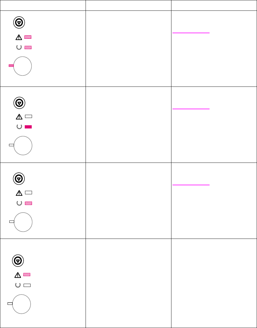
C7058-90936 Troubleshooting with control-panel messages 183
Table 27. Primary status codes
Control-panel light pattern Primary status message Recommended action
Start-up. The Go, Ready, and
Attention lights cycle one after
another.
lNo action is needed.
Note Pressing GO or JOB CANCEL
has no effect until the printer is
ready.
Ready. The Ready light is on and
the printer is ready to print.
lNo action is needed.
Note Pressing GO prints a demo
page.
Processing.The printer is receiving
or processing data.
lNo action is needed.
Note Pressing JOB CANCEL
cancels the current job. One or two
pages might print as the printer
clears the print job. The printer
returns to the ready state after the
job is cancelled.
Attention. The printer requires
attention for one of the following
reasons:
- a door is open
- the toner cartridge is missing
- print media is jammed in the
printer
- media supply is depleted
lPressing GO causes the printer
to attempt to clear the jam. It
might be necessary to clear the
jam manually and push GO or
close the top cover.
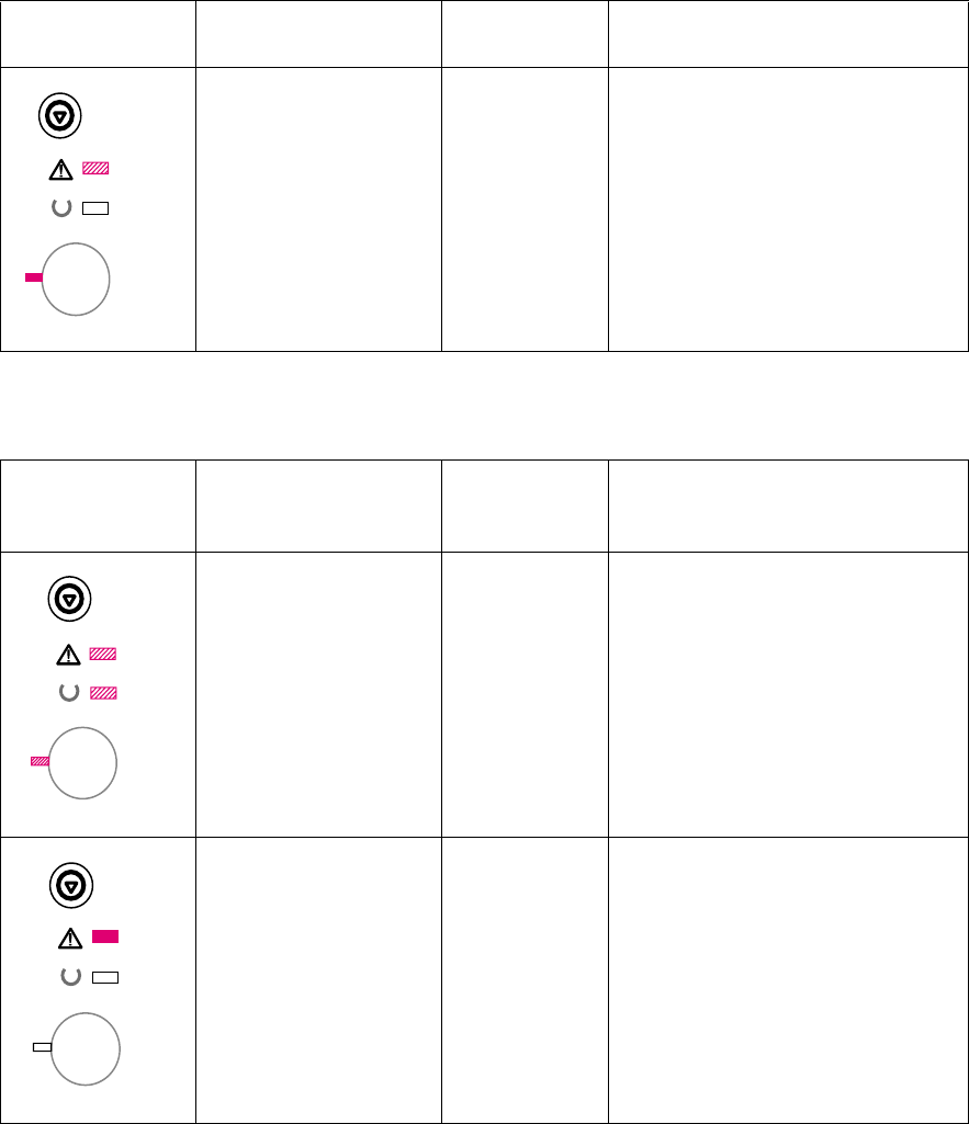
184 Chapter 7 Troubleshooting C7058-90936
Continuable, fatal, and accessory errors
Additional information in the form of a secondary error message is available for each of the following
three types of errors. The first entry in each of the following tables shows the primary error light
pattern. The remaining entries illustrate the secondary error messages. The tables also contain
information that typically appears in the status log area of the self test/configuration page.
Table 28. Continuable attention error codes
Control-panel
light pattern Continuable attention
error message Status log
code Recommended action
Continuable error or tray 1
is out of paper. Pressing
GO causes the printer to
attempt to recover from the
error and print whatever it
can. If the recovery is
unsuccessful, the printer
will return to the
continuable error state.
lPress GO to attempt an error
recovery and continue printing.
lIf the error persists, press GO and
JOB CANCEL simultaneously to
view the secondary continuable
error information. See table 29,
“Continuable attention error
secondary codes” on page 184.
Table 29. Continuable attention error secondary codes
Control-panel
light pattern Continuable attention
error secondary
message
Status log
code Recommended action
General continuable error lVerify that all of the power-supply
wire harness connections are
connected correctly and fully
seated.
lReplace the formatter PCB.
lReplace the engine controller.
Memory overflow/memory
full (20) 30016 lThe printer memory is full. Press
Go to resume printing. If you lose
some data, try to free some printer
memory by removing any
unnecessary fonts, macros, or any
other data currently in the printer
memory. If you continue to lose
data, you might need to add more
printer memory. For a temporary
solution, simplify the image or print
at a lower resolution.

C7058-90936 Troubleshooting with control-panel messages 185
Temporary engine error
(41.x) 30034 lPress GO. The page containing the
error will be printed.
lIf the error persists, reseat the
connections to the laser/scanner,
formatter, and engine controller.
lReplace the laser/scanner.
lReplace the formatter.
lReplace the engine controller.
Print overrun (21) 30017 lThe print job was too complex for
available printer memory. Press GO
to resume printing. If you lose some
data, you might need to add more
printer memory. For a temporary
solution, simplify the image or print
at a lower resolution.
Buffer flow error (22) 30027 lVerify that the printer cable is
connected properly and fully seated
at connections. Always use a high-
quality cable. Some non-HP cables
might be missing pin connections, or
might otherwise not conform to
IEEE-1284 specifications.
lReplace the formatter
Bad connection (40) 30018 lThe connection between the printer
and the EIO card is bad.
lPress Go to clear the error
message and continue printing.
lIf the error message persists, turn
the printer off and reset the EIO
card. Turn the printer on.
lReplace the EIO card.
Table 29. Continuable attention error secondary codes (continued)
Control-panel
light pattern Continuable attention
error secondary
message
Status log
code Recommended action

186 Chapter 7 Troubleshooting C7058-90936
NVRAM error (68) 30035
or
30036
lA memory error resulted in one or
more printer settings being reset to
factory defaults.
lPrint a configuration page and verify
that the printer setting are set
correctly.
lTurn the printer off. Press and hold
JOB CANCEL and turn the printer
on. Keep JOB CANCEL depressed
until all of the Control-panel lights
illuminate. Release JOB CANCEL
and send the print job again.
lReplace the formatter.
I/O error (81) lThe EIO accessory has
encountered a critical error.
lTurn the printer off and then on.
lIf the error message persists, turn
the printer off and reset the EIO
card. Turn the printer on.
lReplace the EIO card.
Memory configuration error lPerform a “cold reset”.
Note If both the Attention and Ready
lights come on before you release GO,
then you must repeat the procedure.
lIf the error persists, remove or
replace DIMM(s).
lReplace the formatter.
Personality or job-related
error 30076 lPerform a “cold reset”.
Note If both the Attention and Ready
lights come on before you release GO,
then you must repeat the procedure.
lIf the error persists, remove or
replace language DIMM.
lReplace the formatter.
Table 29. Continuable attention error secondary codes (continued)
Control-panel
light pattern Continuable attention
error secondary
message
Status log
code Recommended action
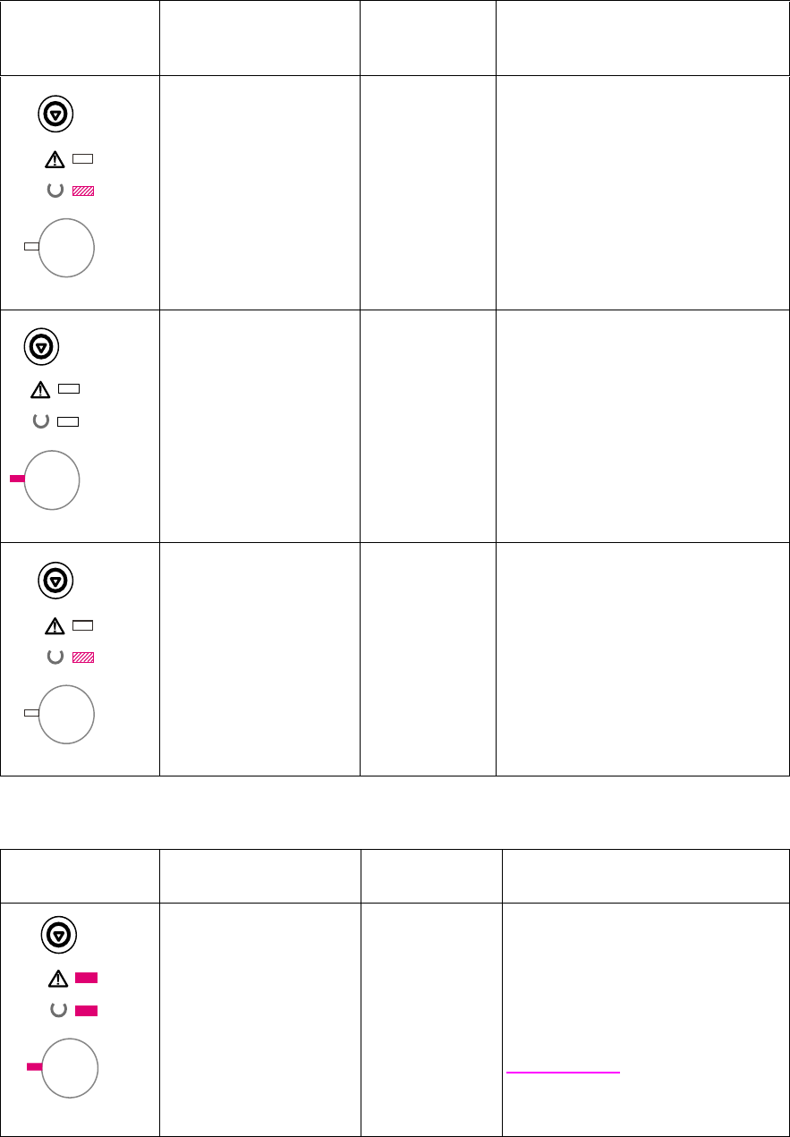
C7058-90936 Troubleshooting with control-panel messages 187
EIO port error lTurn the printer off and reseat the
EIO accessory. Turn the printer on.
lReplace the formatter.
DIMM slot 1 incompatible
error
lTurn the printer off. Reseat DIMM 1.
Turn the printer on.
lIf the problem persists, replace
DIMM 1.
lReplace the formatter.
DIMM slot 2 incompatible
error
lTurn the printer off. Reseat DIMM 2.
Turn the printer on.
lIf the problem persists, replace
DIMM 2.
lReplace the formatter.
Table 30. Fatal error codes
Control-panel
light pattern Fatal error message Status log code Recommended action
The printer has
experienced an error and
cannot recover. All the
lights are on.
lView the fatal error secondary
codes.
lTo clear the error, turn the printer
off, and then turn it on. If the error
persists, turn the printer off for 15
minutes and then turn it on.
Note Pressing GO and JOB CANCEL
shows the fatal secondary error codes.
Table 29. Continuable attention error secondary codes (continued)
Control-panel
light pattern Continuable attention
error secondary
message
Status log
code Recommended action
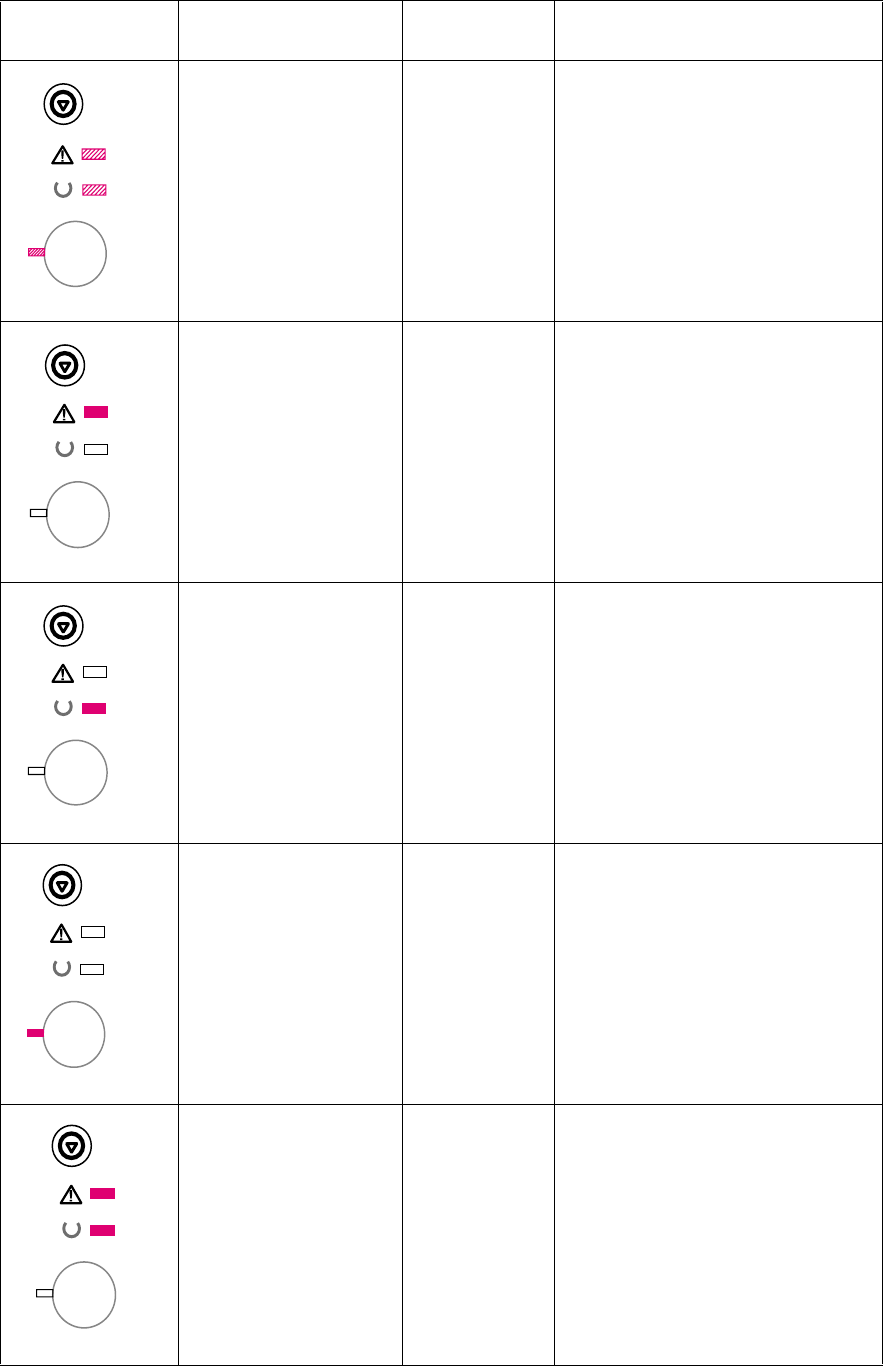
188 Chapter 7 Troubleshooting C7058-90936
Table 31. Fatal error secondary codes
Control-panel
light pattern Fatal error secondary
message Status log
code Recommended action
General fatal error (79) lTurn power off and back on.
lIf the error persists, turn off power.
Remove all accessories (for
example DIMM, EIO card). Turn on
the printer.
lReplace the formatter.
lReplace the engine controller.
lReplace the power supply.
Engine communication
error (55) 40055 lA printer error has occurred. Press
GO to clear the error message.
lCheck the connections to the
formatter and the engine controller
Assembly.
lReplace the formatter.
lReplace the engine controller.
lReplace the power supply.
Scanner error (52) 40052 lPress GO. The page containing the
error will automatically be reprinted.
lTurn the printer off and reseat the
laser scanner cables.
lReplace the laser scanner.
Bad beam detect error (51) 40051 lPress GO. The page containing the
error will automatically be reprinted.
lTurn the printer off and reseat the
laser scanner cables.
lReplace the laser/scanner.
Scan motor error (57) 40057 lTurn power off and back on.
lIf the error persists, turn the printer
off, reseat the connection between
the laser scanner assembly and the
engine controller. Turn the printer
on.
lReplace the laser/scanner.
lReplace the engine controller.
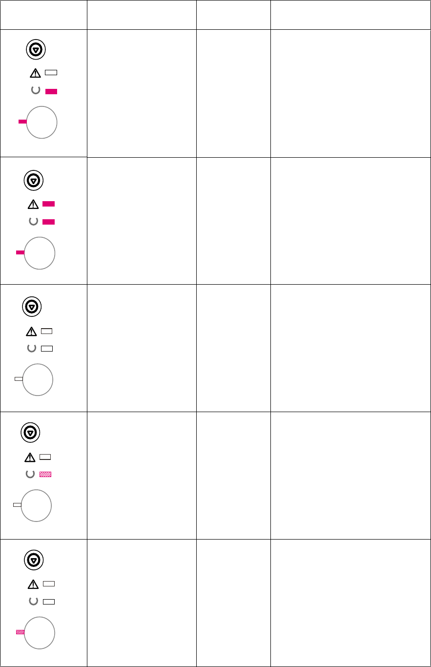
C7058-90936 Troubleshooting with control-panel messages 189
Bad fuser error (50) 40050 lBe sure that the fuser is installed
correctly and is fully seated.
lReseat the fuser cables.
lReplace the fuser.
lReplace the engine controller
assembly.
lReplace the power supply.
Formatter internal RAM or
ROM error
lTurn the printer off, then turn it back
on.
lReplace the formatter.
Fan motor error (58) 40058 lTurn the printer off, then turn it back
on.
lTurn the printer off, then reseat the
connection between the fan and the
formatter.
lReplace the fan.
lReplace the engine controller
assembly.
NVRAM error (68) lTurn the printer off, then turn it back
on.
lReplace the formatter.
Scan buffer error (64) 40064 lTurn the printer off, then turn it back
on.
lIf the message persists, replace the
formatter.
Table 31. Fatal error secondary codes (continued)
Control-panel
light pattern Fatal error secondary
message Status log
code Recommended action
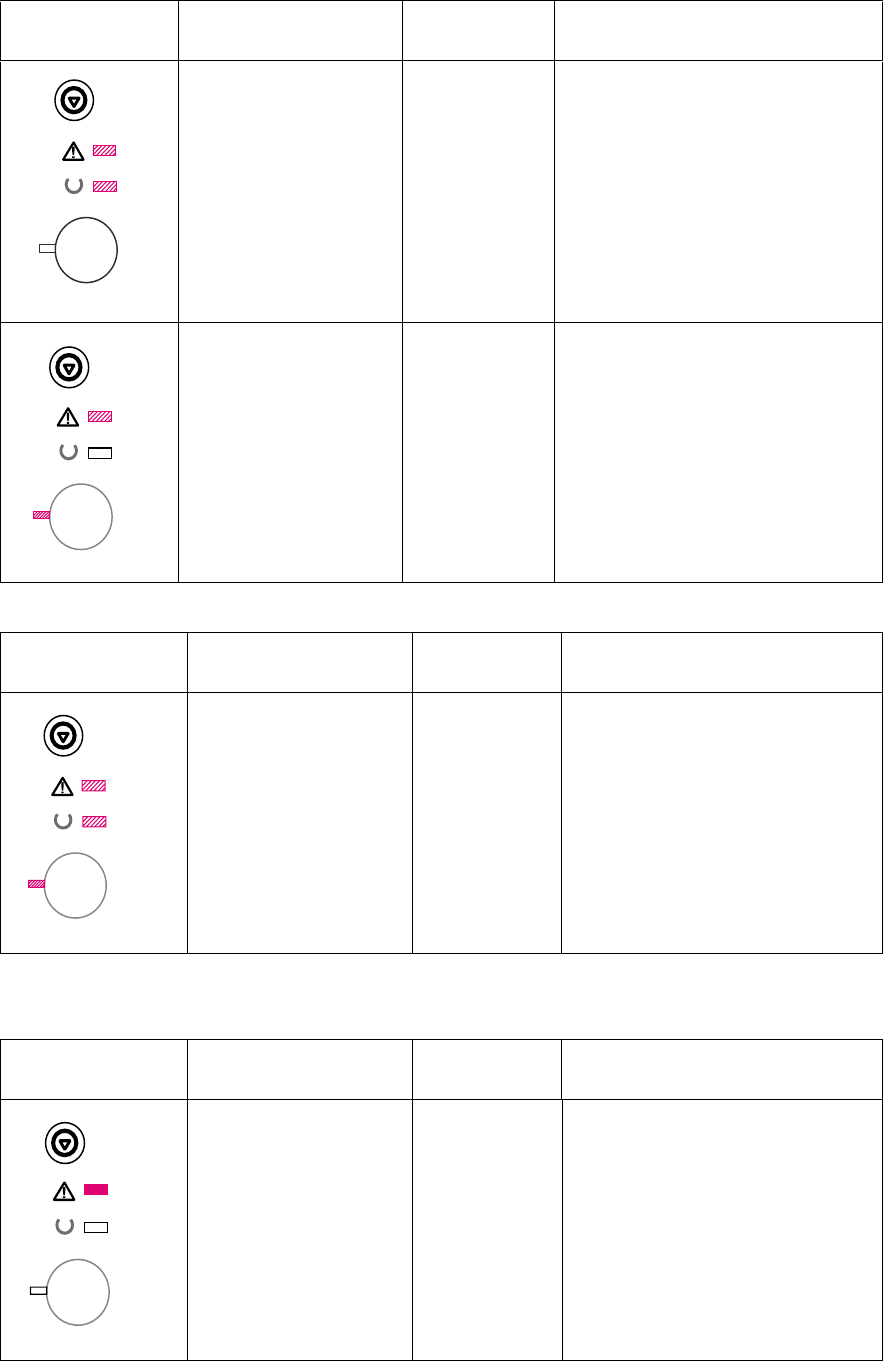
190 Chapter 7 Troubleshooting C7058-90936
RAM controller error (65) 40065 lTurn the printer off, then turn it back
on.
lReplace the formatter.
Miscellaneous interface
hardware error (67) 40067 lCheck the I/O connections.
lVerify that the cable is IEEE-1284
compliant (if applicable).
Table 32. Accessory error codes
Control-panel light
patterns Accessory error
message Status log
code Recommended action
An error has occurred with
either the EIO port or the
DIMM (memory) slots.
lPress GO and JOB CANCEL
simultaneously to view the
secondary information. See table
29, “Continuable attention error
secondary codes” on page 184 and
table 33, “Accessory errors
secondary codes” on page 190.
Table 33. Accessory errors secondary codes
Control-panel light
patterns Accessory secondary
error message Status log
code Recommended action
EIO port error lTurn the printer off and reseat the
EIO accessory. Turn the printer on.
lReplace the formatter.
Table 31. Fatal error secondary codes (continued)
Control-panel
light pattern Fatal error secondary
message Status log
code Recommended action

C7058-90936 Troubleshooting with control-panel messages 191
DIMM slot 1 incompatible
error
lTurn the printer off. Reseat DIMM
in slot 1. Turn the printer on.
lIf the problem persists, replace
DIMM in slot 1.
lReplace the formatter.
DIMM slot 2 incompatible
error
lTurn the printer off. Reseat DIMM
in slot 2. Turn the printer on.
lIf the problem persists, replace
DIMM in slot 2.
lReplace the formatter.
Table 33. Accessory errors secondary codes
Control-panel light
patterns Accessory secondary
error message Status log
code Recommended action
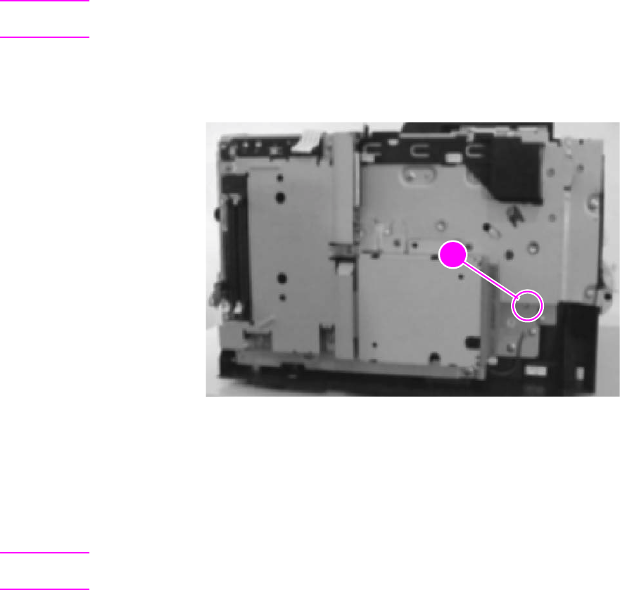
192 Chapter 7 Troubleshooting C7058-90936
Media-handling problems
Print test pages
To confirm that the printer can pick and move print media, generate a self test/configuration page by
pressing GO and JOB CANCEL simultaneously when the printer is in a ready state. If the printer cannot
produce a self test/configuration page, generate an engine-test page. If an engine-test page does not
print, see "Jam troubleshooting" on page 193.
Engine test
The engine test verifies that the print engine is functioning correctly. This test is very useful for
isolating printer problems, because it does not involve the formatter. Because the engine test prints a
full page of lines across the entire printable area, it is also useful for checking and adjusting
registration.
The engine test prints from the first tray found that contains media and can be activated with the
formatter installed or removed. See "Engine test" in chapter 3 for engine test procedures.
Note Make sure that the toner cartridge is installed in the printer. Also, the print motor must be idle and the
printer must be in standby mode.
In order to produce an engine test print, media must be loaded into the printer. The system checks
for media in tray 2, then in tray 1, and finally in tray 3 (if installed). If media is loaded in both tray 1
and tray 2 the media will be duplexed.
Figure 157. Engine test button
Self test/configuration page
Use the configuration page to view the current printer settings, to help troubleshoot printer problems,
or to verify installation of optional accessories such as memory (DIMMs), JetDirect cards, and printer
languages. See "Self test/configuration page" in chapter 3 for a sample page.
Note If status log information exists, it will print in the status area of the configuration page. If an HP JetDirect
print server EIO card is installed, a JetDirect configuration page will also be generated.
11

C7058-90936 Media-handling problems 193
Jam troubleshooting
Jams occur in the printer when print media does not reach or clear a photosensor along the printer
paper path within a specific amount of time. The following table contains general questions and
topics to explore before troubleshooting.
Locating and correcting jams
See "Pickup/feed system" in chapter 5 for an account of the operation of the paper-feed system.
After reading that section, use the diagrams listed below to locate and troubleshoot the possible
causes of the jam.
lSee figure 165, “Printer paper path, sensors, and signals,” on page 220.
lSee figure 166, “Tray 3 paper path, sensors, and signal lever,” on page 221.
lSee figure 167, “General printer-component locations (1 of 2),” on page 222.
The process of correcting jams might be simplified by categorizing jams according to frequency,
location, and type of jam. See figure 158, “Frequency of jams process flow,” on page 194 and figure
159, “Location of jams” on page 195.
Table 34. General jam troubleshooting questions
Problem Action
What is the frequency of the jams
(for example: continuous, one
jam per 100 pages, one jam per
1000 pages)?
Verify with the customer. See “Troubleshooting with control-panel
messages” on page 182 and “Status-log messages” on page 198, and
evaluate the Status Log.
Do jams occur with a specific
type of media? Try using media that you know is of good quality. See “Media
troubleshooting” on page 209
Where does the leading edge of
the first sheet of media in the
printer paper path stop when a
jam occurs? Are any sheets
damaged or torn?
Attempt to duplicate the problem. Inspect the paper path and all paper path
mechanical assemblies located before the leading edge of the jam.
Use the chapter 3 to aid in locating jams.
Is the customer loading the trays
or cassettes correctly? Observe the customer loading media. Instruct the customer to break the
ream, and not to fan the media. See “Media troubleshooting” on page 209
Is the customer overfilling the
trays or cassettes? Observe the customer loading media in the trays or cassettes. Make sure
that the media is not over the maximum fill marks in the trays or cassettes.
Are the tray guides set correctly? Make sure all front and rear tray 2 and optional 250-sheet or 500-sheet
feeder guides are set correctly.
Does the printer need cleaning? Inspect the paper path and paper-path rollers.
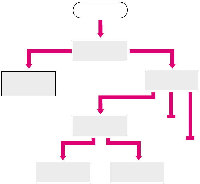
194 Chapter 7 Troubleshooting C7058-90936
Frequency of jams process flow
Use the troubleshooting process flow figure to help determine the cause of jams. See figure 154,
“Troubleshooting process flow,” on page 180. Jams in the paper path that occur intermittently are
most often related to a deficiency in the media or environment. See “Media troubleshooting” on page
209 for information about these defects.
Paper-path jams that occur frequently, and in the same location of the printer, are most likely the
result of a hardware problem.
Figure 158. Frequency of jams process flow
Start here
Jam frequency
Intermittent Continuous
Media/environment
related (usually) Location of jam
Input area
Type of jam
No pick Physical
Output areas
(including duplexer)
Internal printer
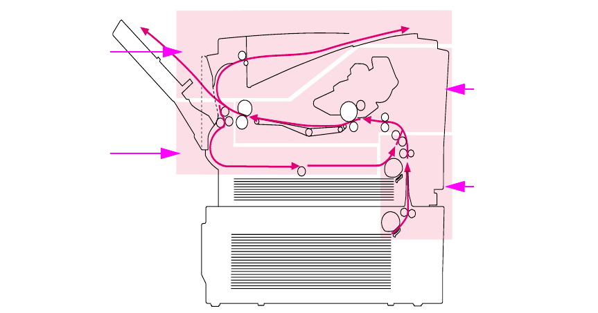
C7058-90936 Media-handling problems 195
Location of jams
Frequently occurring jams can be further categorized by their location in the printer. The four major
areas of the printer are the input area, the internal area, the duplexer, and the output area. Because
the pick-and-feed operation is almost identical for trays 1, 2, and 3, jams in the input area follow the
same pattern.
Figure 159. Location of jams
Internal area
Input area
Duplex area
Output area

196 Chapter 7 Troubleshooting C7058-90936
Type of jam
Input jams can result from either the failure of the printer to pick the media from a tray, or the failure
to move the media through the input area of the printer. Failure to pick up the media can result from
either a defect in the pickup roller or in the separation pad.
The following tables summarize the actions for input, internal, duplexer, and output jams.
Table 35. Input jams
Possible cause Recommended action
Tray photo sensors are blocked or inoperative Inspect and replace if necessary
PS23005 (tray 1)
PS1305 (tray 2)
PS2001 (250 sheet tray 3)
PS2103 (500 sheet tray 3)
Pickup roller is dirty or inoperative Clean or replace
RB2-2900-000CN (tray 1)
RB2-2891-000CN (tray 2)
RB2-2891-000CN (250-sheet feeder, tray 3)
RB2-6304-000CN(500-sheet feeder, tray 3)
Pickup assembly is defective Replace
RG5-4128-000CN (tray 1)
RG5-5551-000CN (tray 2)
Separation pad Inspect and replace if necessary
RF5-3272-000CN (tray 1)
RB2-6349-000CN (tray 2)
RB2-3008-000CN (250-sheet tray 3)
RB2-6474-000CN (500-sheet tray 3)
Feed rollers Inspect and replace if necessary
RB2-3490-0000CN (tray 2 and 250-sheet feeder, tray
3)
RB2-6476-0000CN (500 sheet feeder, tray 3)
Solenoids
Inspect and replace if necessary
SL2901908501 (tray 2)
SL2001 (250 sheet tray 3)
SL2002 (500 sheet tray 3)
Paper feeder PCB (250-sheet tray 3) is defective
Paper feeder PCB (500-sheet tray 3) is defective Replace RG5-4277-000CN (250 sheet tray 3)
Replace RG5-5630-000CN (500 sheet tray 3)
Engine controller PCB Replace RG5-5567-000CN
Power supply assembly Replace RG5-5563-000CN (110 V)
Replace RG5-5573-000CN (220 V)
Table 36. Internal jams
Possible cause Recommended action
Tray photo sensors are blocked or inoperative Inspect and replace if necessary
PS23005 (tray 1)
PS1305 (tray 2)
PS2001 (250-sheet tray 3)
PS2103 (500-sheet tray 3)
Registration assembly is defective Replace RG5-5556-000CN
Transfer Roller assembly is defective Replace RG5-5581-000CN
Toner cartridge is defective Inspect and replace if necessary C4096A
Transport assembly is defective Inspect and replace if necessary
RB2-6272-000CN (belt)
RB2-6272-000CN (belt)

C7058-90936 Media-handling problems 197
Media problems
If jams persist, even when the print engine is fully functional, the problem might be with the quality
and type of media being used. See “Media troubleshooting” on page 209
Engine controller PCB Replace RG5-5567-000CN
Power supply assembly Replace RG5-5563-000CN (110 V)
Replace RG5-5573-000CN (220 V)
Fusing assembly is defective Replace (includes PS2301)
RG5-5559-000CN (110 V)
RG5-5569-000CN (220 V)
Table 37. Duplex jams
Possible cause Recommended action
Unlatched duplexer tray Latch duplexer tray
Reverse-paper sensor
Duplexer pickup paper sensor Replace PS501
Replace PS503
Position guide assembly Replace RG5-5553-000CN
Engine controller PCB Replace RG5-5567-000CN
Power supply assembly Replace RG5-5563-000CN (110 V)
Replace RG5-5573-000CN (220 V)
Table 38. Output jams
Possible cause Recommended action
Fusing assembly is defective Replace (includes PS503)
RG5-5559-000CN (110 V)
RG5-5569-000CN (220 V)
Upper/lower face-down delivery rollers RG5-5541-000CN
RG5-5542-000CN
RF5-3275-000CN
Engine controller PCB Replace RG5-5567-000CN
Power supply assembly Replace RG5-5563-000CN (110 V)
Replace RG5-5573-000CN (220 V)
Table 36. Internal jams (continued)
Possible cause Recommended action

198 Chapter 7 Troubleshooting C7058-90936
Evaluate the test pages
Status-log messages
Use the status log to diagnose and troubleshoot intermittent printer errors, or to gain information
about multiple error conditions that occur simultaneously. You can either display or print the event
log.
Status log information prints automatically on the self test/configuration page. The status log retains
the printer’s last 10 error messages. (The status log only appears when errors have been
registered.)
Status-log messages are listed in “Control-panel light messages” on page 182, according to their
corresponding error light configuration. For a complete listing of status codes, see the HP LaserJet
2200 series printer software technical reference, (C7058-90937). The complete PJL status code
listing is contained in the appendix of the printer job language technical reference. Also refer to
Hewlett-Packard’s website: www.hp.com.
Hint If the message requesting that you load a tray persists, or if a message indicates that a previous print
job is still in the printer’s memory, press GO to print or press JOB CANCEL to clear the job from the
printer memory.
Verify installed options
Verify all options installed in the printer are reflected in the configuration page. If an installed device
is not shown, reseat the device and print a new configuration page.

C7058-90936 Image-formation troubleshooting 199
Image-formation troubleshooting
When working with customers, obtain a print sample before troubleshooting the printer. Ask the
customer to describe the quality expected from the printer. The print sample also helps clarify the
customer’s description of the problem.
Often an image-formation problem can be linked to media that is outside the specifications
Hewlett-Packard has established for optimum printer performance. See “Media troubleshooting” on
page 209 for help with persistent image-formation problems.
Table 39. Image-quality checks
Image-quality checks Action
Does the problem repeat on the
page? Use the “Repetitive defect ruler” on page 207.
Is the toner cartridge full and is it
manufactured by HP? See “Check the toner cartridge” on page 200.
Is the customer using print
media that meets all HP
specification standards?
See "Media specifications" in chapter 2.
Is the print sample similar to
those in the image defect tables? Compare the sample to the tables and perform the actions recommended in
the “Image defect tables” on page 201.
Is the problem on the toner
cartridge or the transfer roller? Perform the “Half self test functional check” on page 208 to determine the
location of the defect.
If a dark and distinct toner image is present on the drum’s surface, assume
that the first four functions of the electrophotographic process are functioning
(cleaning, conditioning, writing, and developing—See "Image formation
system" in chapter 5), and troubleshoot the failure as a transfer or fusing
problem.
Is the customer using a media
type recommended for this
product?
See “Media troubleshooting” on page 209.

200 Chapter 7 Troubleshooting C7058-90936
Check the toner cartridge
Image-formation defects are often the result of problems with the toner cartridge. Use the following
list to verify that the toner cartridge is still operating correctly.
Perform all of the following checks before replacing the toner cartridge.
lVerify that the toner cartridge has toner. The full toner cartridge weight is approximately 1105
grams; empty weight is approximately 900 grams.
lCheck the toner cartridge to see if it has been disassembled or refilled.
lVerify that the toner cartridge is seated properly in the printer cavity.
lInspect the cartridge for toner leaking through worn seals. (Manual rotation of the drum can
caused internal damage and toner spills can result.)
lWhite areas on the page can indicate the drum has been exposed to light for too long.
Note The toner cartridge is rated for 5,000 images at 5 percent coverage. Check the surface of the
photosensitive drum in the cartridge to see if it has been damaged or scratched. Touching the drum
will contaminate the photosensitive surface and may cause spotting and defects during printing.
EconoMode
EconoMode creates draft-quality printing by reducing the amount of toner on the printed page by up
to 50 percent. Advise the customer to turn EconoMode on or off either from the printer driver or a
software application.
CAUTION Hewlett-Packard does not recommend full-time use of EconoMode. If EconoMode is used full-time, it
is possible the toner supply will out last the mechanical parts in the toner cartridge.
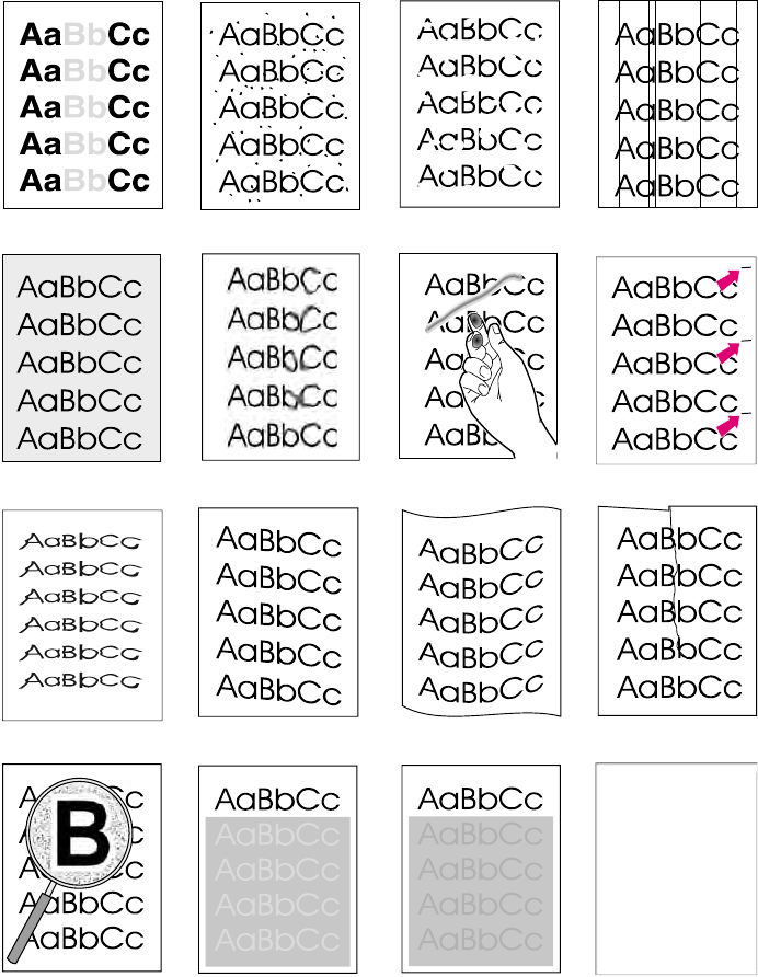
C7058-90936 Image-formation troubleshooting 201
Image defect tables
The printer output quality is subject to user judgment. This section of the manual helps define print-
quality defects and the factors that affect print quality.
The print samples shown in the following figures illustrate some print-quality defects. Keep copies of
print-quality defects you encounter in the field and an explanation of their causes to use for future
reference.
Figure 160. Image defects examples
Light print or fade Toner specks Dropouts Vertical lines
Gray background Toner smear Loose toner Repetitive defect
Misformed characters Page skew Curl or wave Wrinkles or creases
Toner scatter outline Ghosting (light) Ghosting (dark) White or missing image

202 Chapter 7 Troubleshooting C7058-90936
Table 40. Image defects
Problem Cause Solution
Light print, or fade Wrong toner density setting. lThrough the software, adjust the toner
density setting. Make sure EconoMode
is off.
Print media does not meet printer
specifications or is stored improperly.
lPrint a few more pages to see if the
problem corrects itself.
lTurn over the stack of media in the tray.
Also try rotating the media 180 degrees.
lIf the print media does not meet HP
specifications, replace the media and
advise the customer to use the
recommended print media and store it
properly.
The toner supply is low lTemporarily extend the toner cartridge
life by redistributing the toner.
lIf this does not improve the print quality,
install a new toner cartridge.
Toner specks The transfer roller is dirty. lClean the inside of the printer or use the
printer’s cleaning page.
Print media does not meet printer
specifications or is stored improperly.
lPrint a few more pages to see if the
problem corrects itself.
lTurn over the stack of media in the tray.
Also try rotating the media 180 degrees.
lIf the print media does not meet HP
specifications, replace the media and
advise the customer to use the
recommended print media and store it
properly.
The paper path is dirty. lClean the inside of the printer or use the
printer’s cleaning page.
Dropouts Single sheet of paper is defective. lTry to reprint the job.
Moisture content of the paper is uneven or
the paper has moist spots on it.
lTry paper from a different source.
Paper lot is bad. lTry a different kind or brand of paper.
The toner cartridge might be defective. lCheck vertical repetitive defects.
lReplace the toner cartridge.
Vertical lines Defective toner cartridge. lReplace the toner cartridge.
Contaminated fuser entrance guide. lClean the guide.
Scratches on the fuser. lReplace the fuser.

C7058-90936 Image-formation troubleshooting 203
Gray background Print media does not meet printer
specifications or is stored improperly.
lPrint a few more pages to see if the
problem corrects itself.
lTurn over the stack of media in the tray.
Also try rotating the media 180 degrees.
lIf the print media does not meet HP
specifications, replace the paper.
Printer’s operating environment does not
meet specifications.
lMake sure the printer’s operating
environment meets specifications.
Wrong toner density setting. lThrough the software, adjust the toner
density setting. Make sure EconoMode
is off.
Faulty toner cartridge. lReplace the toner cartridge.
Toner smear Contamination in the printer. lPrint a few more pages to see if the
problem corrects itself.
lClean the inside of the printer or use the
printer’s cleaning page.
Paper might be too smooth. lCheck the paper (or other print media)
type and quality.
Defective toner cartridge. lReplace the toner cartridge. (See
instructions with the toner cartridge.)
Wrong fuser setting for paper type. lFrom the control panel, change the
fuser mode setting or choose another
paper type from the printer driver.
Loose toner Contamination in the printer. lPrint a few more pages to see if the
problem corrects itself.
lClean the inside of the printer.
Toner cartridge is defective. lReplace the toner cartridge.
Paper might be too smooth. lCheck the paper (or other print media)
type and quality.
Defective fuser. l Replace the fuser.
Repetitive defects Contamination or defect on internal parts. lTry printing additional pages.
lClean the inside of the printer.
Toner cartridge is damaged. lSee the “Repetitive defect ruler” on
page 208.
lReplace the toner cartridge.
Defective fuser. l Replace the fuser.
Table 40. Image defects (continued)
Problem Cause Solution

204 Chapter 7 Troubleshooting C7058-90936
Misformed
characters Maintenance due. lPrint a few more pages to see if the
problem corrects itself.
lMake sure that the environmental
specifications for the printer are being
met.
lPrint a demo page to verify that the
problem persists.
lPerform maintenance actions as
required.
Paper might be too smooth. lCheck the paper (or other print media)
type and quality.
Page skew Print media does not meet printer
specifications or is stored improperly.
lPrint a few more pages to see if the
problem corrects itself.
lVerify that there are no torn pieces of
media inside the printer.
lTurn over the stack of media in the tray.
Also try rotating the media 180 degrees.
lIf the print media does not meet HP
specifications, replace the media.
Print media is not loaded correctly or trays
are not adjusted properly.
lMake sure print media is loaded
correctly and that the guides fit properly
against the media stack.
Registration assembly is improperly
installed.
lBe sure that the registration assembly is
installed correctly.
Curl or wave Print media does not meet printer
specifications or is stored improperly.
lPrint a few more pages to see if the
problem corrects itself.
lTurn over the stack of media in the tray.
Also try rotating the media 180 degrees.
lIf the print media does not meet HP
specifications, replace the media.
Printer’s operating environment does not
meet specifications.
lMake sure the printer’s operating
environment meets specifications.
Wrong output bin. lPrint to a different output bin (top or rear
output bin).
Wrinkles or creases Print media does not meet printer
specifications or is stored improperly.
lPrint a few more pages to see if the
problem corrects itself.
lTurn over the stack of media in the tray.
Also try rotating the media 180 degrees.
lIf the print media does not meet hp
specifications, replace the paper.
Print media is loaded incorrectly. lMake sure print media is loaded
correctly and that the guides fit properly
against the media stack.
Wrong tray. lPrint from a different tray (such as
tray 1).
Wrong output bin for print media type. lPrint to a different output bin (top or rear
output bin).
Table 40. Image defects (continued)
Problem Cause Solution

C7058-90936 Image-formation troubleshooting 205
Toner scatter
outline Print media does not meet printer
specifications or is stored improperly.
lPrint a few more pages to see if the
problem corrects itself.
lTurn over the stack of media in the tray.
Also try rotating the media 180 degrees.
lIf the print media does not meet HP
specifications, replace the paper.
Maintenance due. lPrint a few more pages to see if the
problem corrects itself.
lPrint a demo page to verify problem
persists.
lPerform maintenance actions as
required.
Ghosting (light) This type of defect might occur when using
preprinted forms, a large quantity of narrow
media, or a fuser mode that is set too high
for your media.
lPrint a few more pages and see if the
problem corrects itself.
lMake sure that print media type and
quality meet HP specifications.
lIf the defect occurs later in a print job,
turn the printer off for ten minutes, and
then turn the printer on to restart the
print job.
lCheck your fuser mode.
Ghosting (dark) This type of defect might occur when using
preprinted forms, a large quantity of narrow
media, or a fuser mode that is set too high
for your media.
lPrint a few more pages and see if the
problem corrects itself.
lMake sure that print media type and
quality meet HP specifications.
lIf the defect occurs later in a print job,
turn the printer off for ten minutes, and
then turn the printer on to restart the
print job.
lCheck your fuser mode.
Table 40. Image defects (continued)
Problem Cause Solution

206 Chapter 7 Troubleshooting C7058-90936
White or missing
image No toner is available for print. lRemove sealing tape or replace the
toner cartridge.
Defective laser shutter. lCheck that the laser shutter operates
freely when the toner cartridge is
installed.
Toner cartridge guide damaged, improperly
positioned, or missing.
lMake sure the guide is installed
properly above the toner cartridge.
No transfer roller voltage. lWithout transfer roller voltage, toner
cannot be attracted from the surface of
the drum to the print media. Perform the
half self test functional check to check
all other electrophotographic processes.
See “Half self test functional check” on
page 208. Replace the transfer roller if
necessary.
No developing bias. lClean the high-voltage power supply
contacts. With no developing bias
charge, toner is not attracted to the
drum.
lReplace the power supply.
No drum ground path. lWith no ground path, the drum cannot
discharge. The negative charge on the
drum repels toner, and leaves a white
page with bubble print.
lCheck the drum ground spring and
reconnect it, if necessary.
lReplace the power supply PCB.
Defective laser scanner cable assembly. lLow-level signals exchanged between
the laser/scanner assembly and the
engine controller PCB might be
affecting laser output. Replace the
laser/scanner cable assembly.
Table 40. Image defects (continued)
Problem Cause Solution
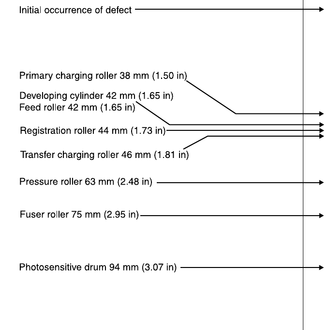
C7058-90936 Image-formation troubleshooting 207
Repetitive defect ruler
Repetitive print defects are usually caused by a specific roller in the printer or the toner cartridge.
Use the figure below to isolate the cause of repetitive print defects. Align the first occurrence of the
defect with the top of the “ruler” (at the top or bottom of the misprinted page), and measure to the
next occurrence of the defect to determine the roller in question. When the defect pattern matches
the pattern of the ruler, replace the indicated roller.
Figure 161. Repetitive defect ruler

208 Chapter 7 Troubleshooting C7058-90936
Half self test functional check
The electrophotographic process can be subdivided into the following stages:
lCleaning (removes excess toner from drum surface)
lConditioning (places a uniform electrical charge on drum)
lWriting (laser strikes surface of drum to create latent image)
lDeveloping (forms the toner image on drum)
lTransferring (charges transfer the image to paper)
lFusing (heat and pressure produces a permanent image)
The purpose of the half self test check is to determine which process is malfunctioning. Perform the
test as follows:
Step 1 Print a configuration page from tray 1.
Step 2 Open the top cover after the trailing edge of the paper enters the printer. At this point,
the leading edge of the paper should have advanced beyond the toner cartridge.
Step 3 Remove the toner cartridge.
Step 4 Open the toner cartridge drum shield to view the drum surface.
If a dark and distinct toner image is present on the drum’s surface, assume that the first four
functions of the electrophotographic process are functioning (cleaning, conditioning, writing, and
developing) and troubleshoot the failure as a transfer or fusing problem.
If no image is present on the photosensitive drum, perform the drum rotation functional check.
Drum-rotation functional check
The photosensitive drum, located in the toner cartridge, must rotate for the print process to work. The
photosensitive drum receives its drive from the main drive assembly. To verify whether the drum is
rotating:
1Open the top cover.
2Remove the toner cartridge.
3Mark the cartridge drive gear with a felt-tipped marker. Note the position of the mark.
4Install the toner cartridge and close the top cover. The start-up sequence should rotate the drum
enough to move the mark.
5Open the printer and inspect the gear that was marked in step 3. Verify that the mark moved. If
the mark did not move, inspect the main drive assembly to make sure it is meshing with the toner
cartridge gears. If the drive gears function and the drum does not move, replace the toner
cartridge.
Note This test is especially important when the customer is using refilled toner cartridges.
C7058-90936 Media troubleshooting 209
Media troubleshooting
Media defects can cause jams and image defects. If the previously described conditions are
corrected and do not eliminate the printing problem, continue to investigate the media as the source
of the defect.
Problems with print media are sometimes difficult to detect. Follow a standard troubleshooting
procedure to help isolate media-related problems. The steps to follow are:
l“Determine the problem source: print media or printer” on page 209.
l“Isolate a paper path” on page 209.
l“Isolate a media brand” on page 210.
l“Isolate a media type” on page 211.
l“Evaluate media use practices” on page 215.
l“Evaluate environmental conditions” on page 215.
Determine the problem source: print media or printer
When determining the cause of a printer failure, a distinction must be made between problems that
relate to the printer itself and those that involve print media. Often a problem that seems to be related
to the printer is actually a matter of poor print-media selection or handling. To determine if a problem
is caused by the printer or by the media, try a few simple steps to remedy the situation:
lTurn media over in the tray to print on the reverse side.
lRotate sheets 180 degrees (end to end) to feed with a different leading edge.
If the symptoms cease, or change in some way, it can be assumed that the problems are caused by
the print media.
Isolate a paper path
Try using the straightest paper path
Some problems can be avoided by using the straightest available paper path. Usually this means
paper feeds from the upper paper tray or manual feeder, and exits into the rear output bin (if
available). This path is recommended for envelopes and media with a heavy basis weight.
Determine if the problem is caused by duplexing
Paper that has just made a pass through the printer can show increased media curl. Media curl
increases image dropout, and creates pickup and stacking problems. When the second pass is
made, print media might not meet the specifications for moisture and curl. Dry paper can hold static
charges that affect print quality and stacking of the duplexed page. Media shrinkage resulting from a
second pass through the printer can cause image misalignment on the duplexed page.
210 Chapter 7 Troubleshooting C7058-90936
Isolate the source of the jam
Define the source of the media that is jamming:
ltray 1
ltray 2
ltray 3 (250-sheet or 500-sheet)
lduplexer
Determine where media jams occur
Check where media stops when a jam occurs. Types of jams include:
linput paper jams
linternal paper-path jams
lduplexer
loutput-bin jams
Determine whether the printer is experiencing misfeeds or multifeed jams
The following are some possible causes of misfeeds or multifeed jams:
lThe media might be too stiff. Check basis weight and measure caliper. See "Basis-weight field
test" in chapter 9 and "Caliper field test" in chapter 2.
lThe paper might be too smooth. Check the finish.
lThe paper might be too heavy or too light. Check basis weight.
lThe customer might be attempting to print embossed paper, pre printed forms, or perforated
paper that does not meet HP specifications. See “Isolate a media brand” on page 210 below or
details about issues involved in printing on embossed paper.
lThe paper might be loaded incorrectly. Turn over the sheets in the paper tray to determine if in-
ream curl is causing misfeeds.
lThe customer might be fanning media before loading it into the tray.
lThe customer might be adding media in small amounts. Do not add small amounts of media or
mix types of media in the tray.
lThe printer or media storage environment might be too humid or too dry. (As a result, media
might be too moist or too dry.) Determine if this is the case and advise the customer.
Isolate a media brand
If the printer jams with only one brand of media:
lTry switching media brands.
lIf the paper ream in use appears to be old, open a fresh ream of the same paper and load it
properly into the printer. If the problem disappears, investigate storage and handling conditions.

C7058-90936 Media troubleshooting 211
Isolate a media type
When jams and other problems occur frequently, it is often because the customer is using a special
paper. Customers must only use print media that conforms to all Hewlett-Packard specifications, and
should always test media before purchasing large quantities. Media should be tested before storage
to verify quality printing results. Then, if problems arise, storage or handling conditions can isolate
the most likely cause. Some types of media that might cause problems are:
lpreprinted forms and special letterhead
lembossed paper
lperforated paper
ladhesive labels
lenvelopes
ltransparencies
lchemically treated paper
lsynthetic paper
lcoated paper
lother special media
Preprinted forms and special letterhead
Many preprinted forms and special letterhead papers perform well in HP LaserJet printers. However,
these papers undergo processes that alter their original characteristics, and care must be taken to
ensure they conform to HP specifications. All special papers should be wrapped in moisture-proof
wrapping when purchased from the paper converter or printing house.
Forms and letterhead must be printed with inks that conform to the following specifications:
lOnly use ink that is heat-resistant, and that will not melt, scorch, or release hazardous emissions
when subjected to 200 degrees C (392 degrees F) for 0.1 second.
lInks must have resistance to silicon oils, and must not be affected by resin components in toner.
lInks must not be flammable.
lInks must not “offset” (transfer from the printed paper onto the printer, contaminating internal
printer components). The principle cause of offset is ink that is not fully dried or that cannot
withstand the printer fusing temperature.
Note Do not use low-temperature inks (the kind used with thermography).
Hint Do not purchase more media than can be easily used in a short time (about 3 months). Media stored
for long periods experiences heat and moisture extremes that can be damaging. Planning is important
to prevent damage to a large supply of media.
Hewlett-Packard neither warrants nor recommends the use of a particular brand of paper or print
media. Media properties are subject to manufacturing changes, and Hewllett-Packard has no control
over such changes. The customer assumes all responsibility for the quality and performance of media.
Although testing media helps to characterize its performance, process quality control by the
manufacturer.
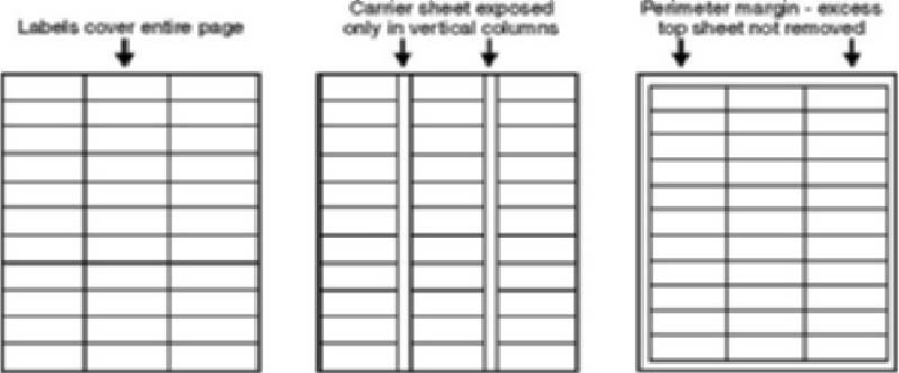
212 Chapter 7 Troubleshooting C7058-90936
Embossed media
Embossed media is not recommended for use in HP LaserJet printers. Media is embossed by
stamping an image into the media by compressing the media fibers together at approximately 200
degrees C (392 degrees F), and sometimes by applying a thin metal foil to the surface. The printer
fusing process can loosen the foil; loose foil can interfere with the mechanical and electronic
operation of the printer.
Embossed paper, with or without foil, can also cause multifeed jams. Multiple embossed print media
sheets tend to stick to one another.
Media with cutouts or perforations
Avoid media with cutouts or perforations for these reasons:
lCut fibers absorb more moisture and can increase waviness and media curl. This decreases the
print quality near the cutout or perforated area.
lThe cutting knife leaves a sharp edge on the cutout or perforation. If this sharp edge is facing the
toner cartridge drum during printing it can scratch the drum surface.
lIf printing occurs over a cutout hole the transfer roller is contaminated with unused toner. Light
streaks can result on the paper from the contaminated roller.
Adhesive labels
Labels are defined as media with a pressure-sensitive adhesive backing. Label stock includes the
top sheet, the adhesive, and the carrier sheet (also referred to as the backing). To prevent media
jams and feed problems, always use the rear output tray when printing on labels. You must use the
following guide lines when using labels:
lLabels must be cut long grain (as opposed to short grain).
lLabels must totally cover the carrier sheet (no spaces between the labels).
lLabels must contain only acrylic-based adhesives.
lLabels must contain no excessive adhesive. (Adhesive from some labels can cause jamming
resulting from buildup in the printer mechanism. The adhesive should not come into direct
contact with the printer at any time.)
lLabels must meet Hewlett-Packard specifications for fusing compatibility.
lLabels must meet Hewlett-Packard specifications for caliper.
lLabels must have a carrier sheet that is not too smooth (which can cause the feed rollers to slip).
Figure 162. Adhesive labels
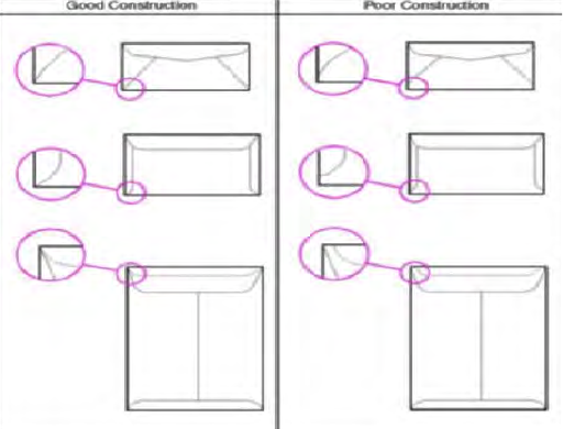
C7058-90936 Media troubleshooting 213
Envelopes
Because of the variety of folds and cuts available it is difficult to specify the types of envelopes that
will perform well with HP LaserJet printers. It is very important to test a sample envelope before
purchasing a large quantity. The specifications for media also apply to envelopes. Avoid envelopes
that contain contact adhesives.
Following are a few recommendations for feeding envelopes:
lClosely inspect the leading edge of the envelopes before feeding them into the printer. Verify the
leading edge is flat. Watch for envelope curl and loose folds. If necessary, flatten the leading
edge of the envelope before feeding.
lBe patient! In manual-feed mode, the printer displays a message when prepared to accept the
next envelope. Always wait for this message to appear before loading or feeding envelopes into
the printer.
lDo not allow a large quantity of envelopes to accumulate in the output tray. If too many
envelopes accumulate, they can interfere with the output path.
lUse the rear output tray when printing envelopes.
The main causes of problems with envelopes on HP LaserJet printers are:
lfolds (two or more thicknesses of paper)
ledge creases (sharp or rounded)
lglued edges (sealing when fused)
luneven printing surfaces
For fewer problems, follow these guidelines:
lCorner folds must be well-creased, and contain no more than two thicknesses of paper.
lEnvelopes must lie flat.
lPaper grain should be diagonal.
lAdhesives must meet HP specifications for fusing compatibility.
lBasis weight must not exceed 11 kg (28 lb).
lUnder no circumstances should envelopes have clasps, snaps, or windows, or use synthetic
materials. Severe damage to the printer can result.
Figure 163. Envelope sample
214 Chapter 7 Troubleshooting C7058-90936
Transparencies
Printing on transparencies presents a special set of challenges. The surface resistance of a
transparency can be infinite, causing the transparency to act like paper with 0 percent moisture
content. This can result in streaks and smudging. Static charges can accumulate on some
transparent stock and cause multifeed jams. Also, certain brands and types of transparencies do not
tolerate exposure to the fuser.
The user should only select transparencies that meet HP specifications. Among the common
precautions are:
lPrint transparencies to the top output bin to avoid jams.
lTransparencies must have correct resistivity (not built-up static charge).
lTransparencies must meet HP specifications for fusing compatibility.
lEach sheet should be removed from the tray and placed on a flat surface before printing the next
sheet. This will keep the toner form rubbing off from the one sheet to the sheet before it has had
time to cool.
Chemically treated media
Coatings such as lacquers, polymers, laminations, or other chemicals protect the paper but can
cause problems in the fuser and transfer areas of Hewlett-Packard LaserJet printers. The surface
resistivity and moisture content can be greatly altered, resulting in print-quality problems. Hard
surface coatings increase wear on the rollers and media guides. All chemically treated media must
meet Hewlett-Packard specifications for fusing compatibility.
Synthetic media
Synthetic medias (those manufactured from man-made fibers) do not perform as well as bond media
in any printer, especially Hewlett-Packard LaserJet printers. All synthetic media must meet Hewlett-
Packard specifications, especially for caliper and fusing compatibility.
Coated media
Do not use coated media. Most coated media does not meet specifications for fusing compatibility
and other specifications for HP LaserJet printers.
Other special media
1Odd sizes. Check minimum and maximum supported sizes in chapter 2.
2Carbonless media. No carbon required (NCR) media is not supported by HP LaserJet printers.
3Recycled media. Choose recycled media that meets Hewlett-Packard specifications. Note that
recycled media might not be as bright as indicated in the specifications. Hewlett-Packard
recommends that recycled media contain no more than 5 percent groundwood. See chapter 2
for testing information.

C7058-90936 Media troubleshooting 215
Evaluate media use practices
Handling and loading
Often differences in techniques, missed steps, or media-handling methods are responsible for
problems. Be sure the media is loaded correctly in the printer.
Note Make sure that all printer users are observing these guidelines.
Printer maintenance
General cleanliness of the printer is the most important part of printer maintenance. Printers using
media that creates a lot of dust and debris might require an aggressive maintenance schedule.
Media dust accumulates in the following areas:
lpickup rollers
lmedia guides
Take extra time to clean and inspect the paper path. If problems continue after cleaning, inspect for
wear or damage.
Media stacking
Consider the following guidelines when advising the customer about stacking media:
lDo not store cartons of reams directly on the floor; cartons should be placed on a pallet or on
shelves.
lDo not stack cartons more than six on top of one another.
lStack each carton squarely on top of the other.
lStack each carton upright.
lDo not store individual reams in such a manner that they will curl or warp along the edges.
lDo not place anything on top of stored media.
lDo not place the media close to heating or air conditioning vents or open windows.
Evaluate environmental conditions
Printing environment
Ideally, the printing environment should be at room temperature and not too dry or too humid. Print
media absorbs and loses moisture rapidly.
Temperature extremes and excessive humidity can damage print media. Heat causes the moisture
in the media to evaporate. Cold causes the moisture in the media to condense. Heating systems and
air conditioners remove most humidity. When media loses moisture, streaks and smudging result.
When paper absorbs moisture, light print and dropouts result.

216 Chapter 7 Troubleshooting C7058-90936
Media storage environment
Media storage environmental conditions directly affect the feed operation.
Hint Do not purchase more media than can be easily used in a short time (about 3 months). Media stored
for long periods experiences heat and moisture extremes that can be damaging. Planning is important
to prevent damage to a large supply of media.
Hewlett-Packard neither warrants nor recommends the use of a particular brand of paper or print
media. Media properties are subject to manufacturing changes Hewllett-Packard has no control over
such changes. The customer assumes all responsibility for the quality and performance of media.
Although testing media helps to characterize its performance, process quality control by the
manufacturer.
Unconverted media in sealed reams can remain stable for several months before use. Converted
media has greater potential for environmental damage, especially if it is not wrapped with a moisture-
proof barrier.
The media storage environment should be properly maintained to ensure optimum printer
performance. The required condition is 20 degrees to 24 degrees C (68 degrees to 75 degrees F),
with a relative humidity of 45 percent to 55 percent. The following guidelines should be considered
when evaluating the customer’s media storage environment:
lMedia should be stored at or near room temperature.
lThe air should not be too dry or too humid.
lThe best way to store an opened ream of paper is to rewrap it tightly in its moisture-proof
wrapping. If the printer environment is subject to extremes, unwrap only the amount of media to
be used during the day’s operation to prevent unwanted moisture changes.

C7058-90936 Communication troubleshooting 217
Communication troubleshooting
Communications check
Note Communication problems are normally the customer’s responsibility. Time spent attempting to resolve
these problems might not be covered by the Hewlett-Packard warranty.
Refer the customer to the network administrator for assistance in troubleshooting network problems.
Test message
After the printer is installed, verify communications between the printer and the IBM-compatible
computer. Enter the following at the DOS prompt:
C:\DIR>LPT1 ENTER (for printing to parallel port #1)
The printer should print a directory listing of the C: \ directory.
EIO troubleshooting
See “JetDirect configuration” on page 219 for information regarding the current status of the EIO
accessories. Before attempting to troubleshoot a network problem or notifying the network consultant
of a problem, always print a configuration page.
See the HP JetDirect Print Server Software Installation Guide for detailed explanations of network
issues (go to http:/www.hp.com/go/JetDirect).
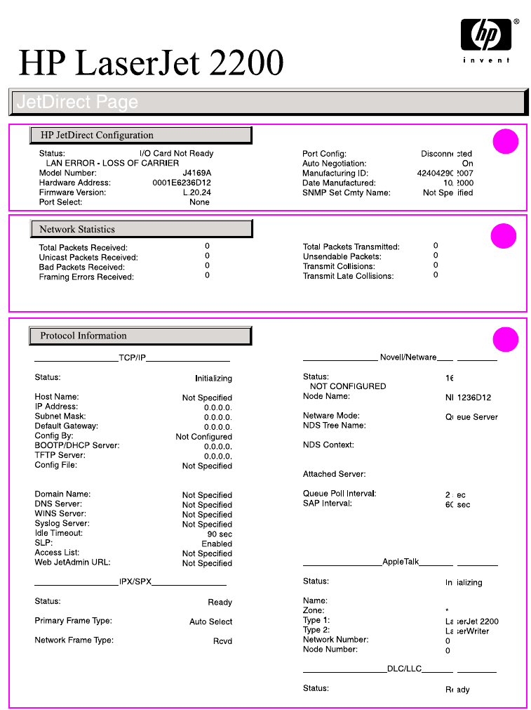
218 Chapter 7 Troubleshooting C7058-90936
Figure 164. JetDirect configuration page
2
3
2
1
2
2
C7058-90936 Communication troubleshooting 219
JetDirect configuration-page elements
1General information lists the HP JetDirect number, firmware revision, LAN hardware address,
selected port, manufacturing ID, I/O card status, and network statistics (unicast packets, total
packets, bad packets, framing errors received, packets transmitted, unsendable packets,
transmit collisions, and transmit late collisions).
2Network statistics lists total packets received, unicast packets received, bad packets received,
framing errors received, total packets received, unsendable packets, transmit collisions, transmit
late collisions.
3Protocol information lists TCP/IP status and configuration, the HP Web JetAdmin server name,
Novell NetWare status and configuration, AppleTalk status and configuration, and DLC/LLC
status.
JetDirect configuration
lIf the EIO JetDirect card has started successfully and completed its internal diagnostics, the I/O
CARD READY message appears on the JetDirect configuration page. If communication is lost,
an I/O NOT READY message appears followed by a two-digit error code. See the HP JetDirect
Network Interface Configuration Guide for further details and recommended action (go to http:/
www.hp.com/go/JetDirect).
lThe “Network Statistics” column indicates that network activity has been occurring. Bad packets,
framing errors, unsendable packets, and collisions should be minimal. If a high percentage
(greater than one percent) of these occur, contact the network administrator. All of the statistics
are set to zero when the printer is turned off.
lThe “Novell Status” block should state the Novell printer server name to which the printer is
connected. If the node name reads “NPIxxxxxx” (xxxxxx=last six digits of the EIO’s LAN
address), the EIO card has not been configured for a Novell server. This could indicate that the
card is operating under an IPX protocol other than Novell. Consult with the network administrator
if the node name is not present.
lIn the TCP/IP protocol block, the default IP address is “0.0.0.0.” It is acceptable to operate the
printer with this default address. The error message “ARP DUPLICATE ADDRESS” might
appear in this block. This is also an acceptable error code if the TCP/IP protocol is not being
used. Check with the network administrator to determine the correct IP address for the printer.
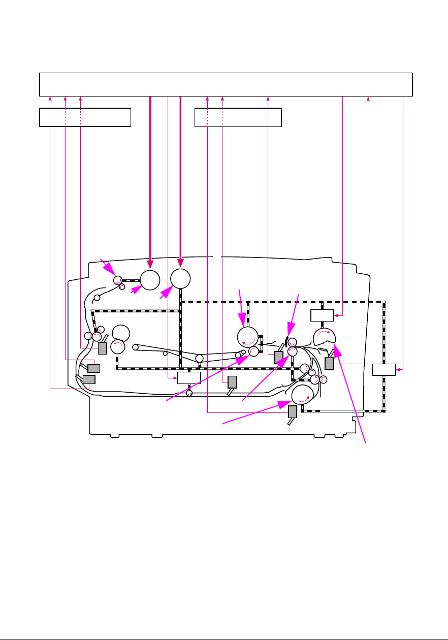
220 Chapter 7 Troubleshooting C7058-90936
Reference diagrams
This drawing shows key components, sensors, and switches that control the operation of the printer.
Figure 165. Printer paper path, sensors, and signals
Engine controller PCB
Power supply PCB Power supply PCB
Face down
delivery rollers
Main motor
Reverse motor
Photosensitive
drum Registration
shutter
Feed belts
Pressure roller
Registration roller Feed rollers
Tray 1 pickup roller
Cassette pickup roller
Transfer charging
roller
Cassette
M904 M903
SL2908
SL1908
PS3208
PS2305
PS503
PS1305
SL909
PS501
PS502
PS2301
Reversed paper detection signal (REVSNS)
Face-up detection signal (/FOUSNS)
Delivery detection signal (/POSNS)
Reverse motor drive signals (DUPSL)
Duplex solenoid drive signals (DUPSL)
Main motor drive signals (/MON)
Cassette paper detection signal (/CSTSNS)
Duplex pickup paper detection signal (/DUPSNS)
Top of page detection signal (/TOPSNS)
Tray 1 pickup solenoid drive signal (MPTSL)
Tray 1 paper detection signal (/MPTSNS)
Cassette pickup solenoid drive signal (CSTSL)
PS501: Reversed paper sensor PS502: Face-up sensor
PS503: Duplex pickup paper sensor PS1305: Cassette paper sensor
PS2301: Delivery sensor PS2305: Top-of-page sensor
PS3208: Tray 1 paper sensor SL909: Duplex solenoid
SL1908: Cassette pickup solenoid SL2908: Tray 1 pickup solenoid
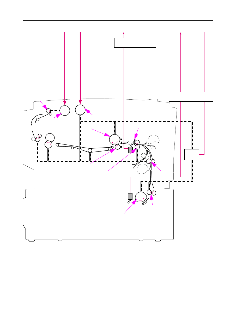
C7058-90936 Reference diagrams 221
Figure 166. Tray 3 paper path, sensors, and signal lever
Face down
delivery rollers
Reverse motor drive signal
Main motor drive signal
Power supply PCB
Top of page detection signal (/TOPSNS)
Paper feeder paper detection
signal (/FDSNS)
drive signal (/FDSN, /FDSOL)
Paper feeder pickup solenoid
Paper feeder PCB
Reverse motor Main motor
Photosensitive
drum
Feed belts
Pressure roller
Registration shutter
Feed rollers
Transfer charging roller
Registration roller
Feed rollers
Pickup roller
Tray 3 250-sheet or 500-sheet feeder
PS2003
(PS2101)
SL2002
(SL2001)
PS2305
M904 M903
Engine controller PCB
PS2305: Top-of-page sensor (printer) PS2001: Paper feeder paper sensor (250-sheet)
PS2003: Paper feeder paper sensor (500-sheet) SL2001: Paper feeder pickup solenoid (250-sheet)
SL2001: Paper feeder pickup solenoid (500-sheet)
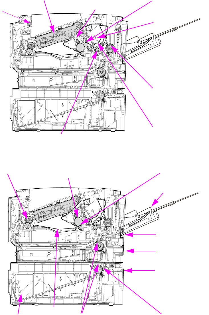
222 Chapter 7 Troubleshooting C7058-90936
Figure 167. General printer-component locations (1 of 2)
Figure 168. General printer-component locations (2 of 2)
Tray 1 pickup
roller
Laser/scanner assembly Developing cylinder
Primary charging roller
Registration shutter
Toner cartridge
Registration rollers
Fuser Transfer charging roller
Photosensitive drum
Tray 2
Tray 3
Paper feeder
Feed belt Tray separation pad
Tray 1
Duplexer
Tray pickup rollers
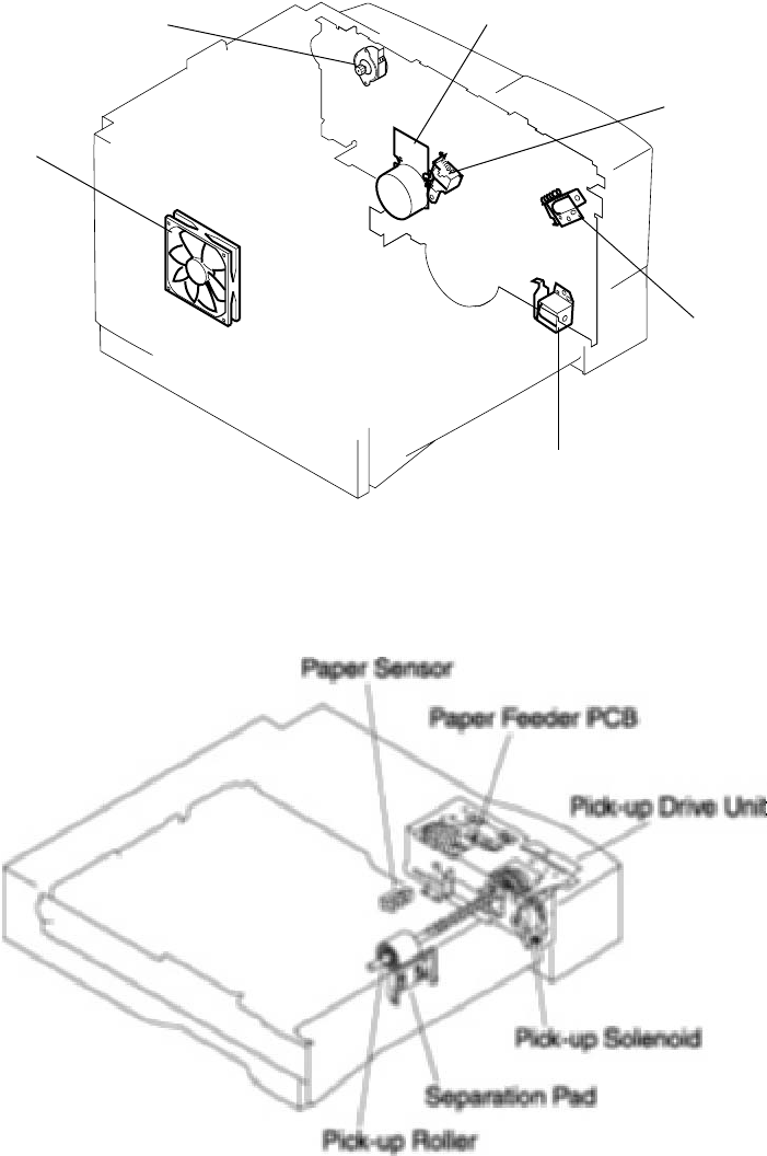
C7058-90936 Reference diagrams 223
Figure 169. Motor, fan, and solenoid locations
Figure 170. 250-sheet and 500-sheet tray 3 component locations
Cassette pickup
solenoid
Tray 1
pickup
solenoid
Duplex
solenoid
Main motor
Reverse motor
Delivery rollers
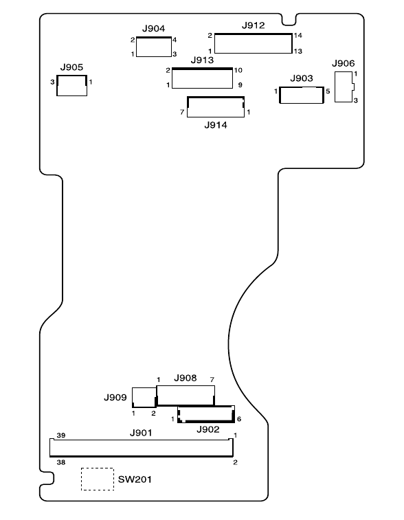
224 Chapter 7 Troubleshooting C7058-90936
Figure 171. Engine controller PCB
Cooling fan
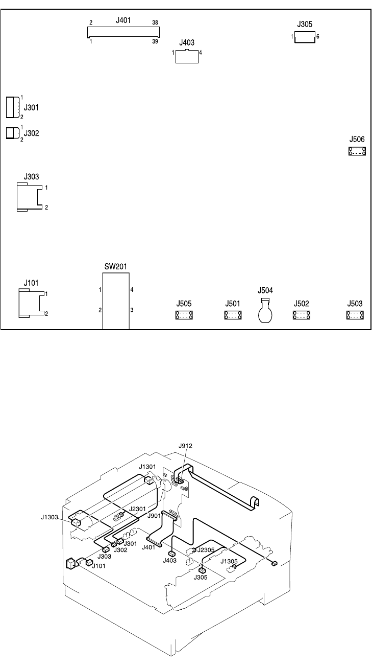
C7058-90936 Reference diagrams 225
Figure 172. Power supply PCB
Figure 173. Location of connectors (1 of 3)
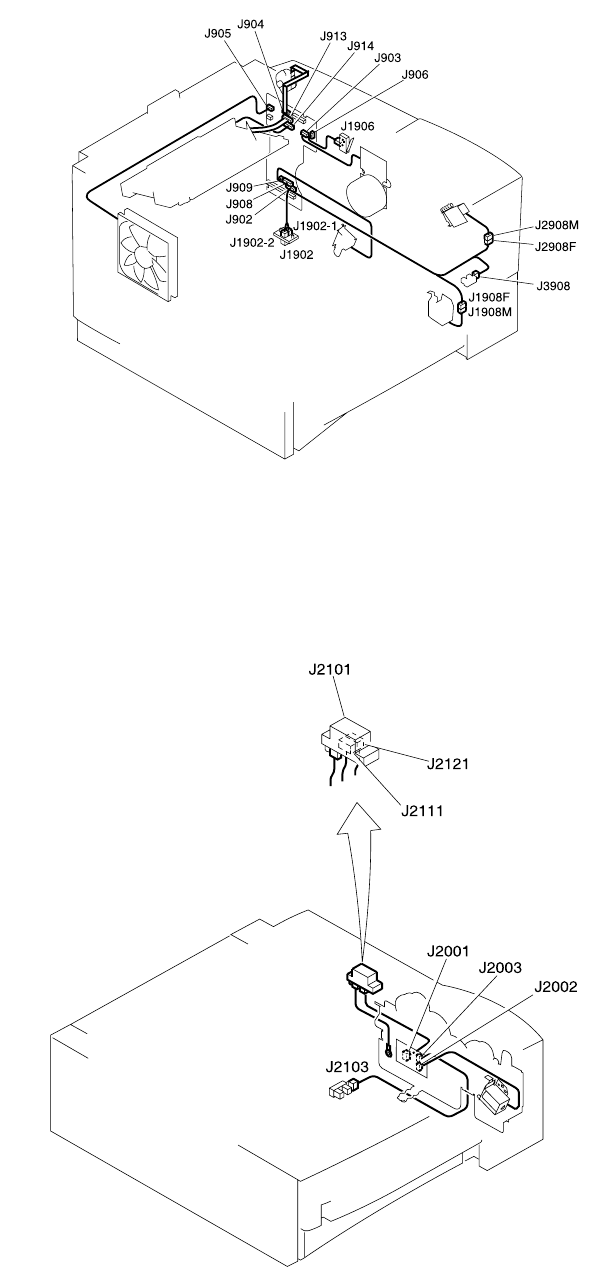
226 Chapter 7 Troubleshooting C7058-90936
Figure 174. Location of connectors (2 of 3)
Figure 175. Location of connectors (3 of 3)
C7058-90936 Chapter contents 227
8Parts and diagrams
Chapter contents
Introduction . . . . . . . . . . . . . . . . . . . . . . . . . . . . . . . . . . . . . . . . . . . . . . . . . . . . . . . . . . . . . . . . . 228
Ordering parts. . . . . . . . . . . . . . . . . . . . . . . . . . . . . . . . . . . . . . . . . . . . . . . . . . . . . . . . . . . . 228
Ordering consumables . . . . . . . . . . . . . . . . . . . . . . . . . . . . . . . . . . . . . . . . . . . . . . . . . . . . . 228
Consumables, accessories, and supplies. . . . . . . . . . . . . . . . . . . . . . . . . . . . . . . . . . . . . . . 229
Common fasteners and torque values . . . . . . . . . . . . . . . . . . . . . . . . . . . . . . . . . . . . . . . . . 230
Illustrations and parts lists. . . . . . . . . . . . . . . . . . . . . . . . . . . . . . . . . . . . . . . . . . . . . . . . . . . . . . 231
External covers and panels. . . . . . . . . . . . . . . . . . . . . . . . . . . . . . . . . . . . . . . . . . . . . . . . . . 231
Top cover assembly . . . . . . . . . . . . . . . . . . . . . . . . . . . . . . . . . . . . . . . . . . . . . . . . . . . . . . . 233
Internal components . . . . . . . . . . . . . . . . . . . . . . . . . . . . . . . . . . . . . . . . . . . . . . . . . . . . . . . 235
Power supply assembly . . . . . . . . . . . . . . . . . . . . . . . . . . . . . . . . . . . . . . . . . . . . . . . . . . . . 245
Printer drive assembly . . . . . . . . . . . . . . . . . . . . . . . . . . . . . . . . . . . . . . . . . . . . . . . . . . . . . 247
Tray 2 and 250-sheet feeder cassette. . . . . . . . . . . . . . . . . . . . . . . . . . . . . . . . . . . . . . . . . . 257
Cassette pickup assembly . . . . . . . . . . . . . . . . . . . . . . . . . . . . . . . . . . . . . . . . . . . . . . . . . . 249
Fusing assembly. . . . . . . . . . . . . . . . . . . . . . . . . . . . . . . . . . . . . . . . . . . . . . . . . . . . . . . . . .251
Fusing assembly. . . . . . . . . . . . . . . . . . . . . . . . . . . . . . . . . . . . . . . . . . . . . . . . . . . . . . . . . .251
PCB assembly location. . . . . . . . . . . . . . . . . . . . . . . . . . . . . . . . . . . . . . . . . . . . . . . . . . . . . 253
250-sheet feeder external covers . . . . . . . . . . . . . . . . . . . . . . . . . . . . . . . . . . . . . . . . . . . . . 255
Tray 2 and 250-sheet feeder cassette. . . . . . . . . . . . . . . . . . . . . . . . . . . . . . . . . . . . . . . . . . 257
250-sheet feeder internal components . . . . . . . . . . . . . . . . . . . . . . . . . . . . . . . . . . . . . . . . . 259
250-sheet feeder drive assembly . . . . . . . . . . . . . . . . . . . . . . . . . . . . . . . . . . . . . . . . . . . . . 261
250-sheet feeder PCB assembly location. . . . . . . . . . . . . . . . . . . . . . . . . . . . . . . . . . . . . . . 263
500-sheet feeder external covers . . . . . . . . . . . . . . . . . . . . . . . . . . . . . . . . . . . . . . . . . . . . . 265
500-sheet feeder cassette . . . . . . . . . . . . . . . . . . . . . . . . . . . . . . . . . . . . . . . . . . . . . . . . . . 267
500-sheet feeder internal components . . . . . . . . . . . . . . . . . . . . . . . . . . . . . . . . . . . . . . . . . 269
500-sheet feeder drive assembly . . . . . . . . . . . . . . . . . . . . . . . . . . . . . . . . . . . . . . . . . . . . . 271
500-sheet feeder PCB assembly location. . . . . . . . . . . . . . . . . . . . . . . . . . . . . . . . . . . . . . . 273
Alphabetical parts list . . . . . . . . . . . . . . . . . . . . . . . . . . . . . . . . . . . . . . . . . . . . . . . . . . . . . . . . . 275
Numerical parts list . . . . . . . . . . . . . . . . . . . . . . . . . . . . . . . . . . . . . . . . . . . . . . . . . . . . . . . . . . . 284

228 Chapter 8 Parts and diagrams C7058-90936
Introduction
The figures in this chapter illustrate the major subassemblies in the printer and their component
parts. A table accompanies each exploded-view diagram. Each table lists the item number for the
replaceable part, the associated part number for the item, the quantity, and a description of the part.
Note When looking for a part number, pay careful attention to the voltage listed in the description column
to ensure that the part number selected is for the correct printer model.
Ordering parts
All standard part numbers listed are stocked and can be ordered from HP’s Customer Services and
Support Center.
Hewlett-Packard Company
Customer Services and Support Center
8050 Foothills Blvd.
Roseville, CA 95678
Parts Direct Ordering: (1) (800) 227-8164 (U.S. Only)
Hewlett-Packard Company
Customer Services and Support Center
Wolf-Hirth Strasse 33
D-7030
Boblingen, Germany
(49 7031) 14-2253
Ordering consumables
Consumables and accessories like those listed in table 41 can be ordered from Hewlett-Packard.
The phone numbers are:
lIn the U.S.: (1) (800) 538-8787
lIn Canada: (1) (800) 387-3154
lIn Toronto: (1) (516) 671-8383
lIn the United Kingdom: 0734-441212
lIn Germany: 0130-3322
Contact your local HP Parts Coordinator for other phone numbers.
Note Parts that have no item number or part number listed are not field replacement parts (FRUs) and cannot
be ordered. See "Reference materials" page 229 for documentation part numbers.

C7058-90936 Introduction 229
Consumables, accessories, and supplies
Table 41. Consumables, accessories, and supplies
Product number Part number Description
Consumable items
C4096A Ultra Precise toner cartridge
C4097A Pallet quantity
Cables
C2950A 2 m (5 ft) parallel cable (IEEE-1284)
C2951A 3 m (9 ft) parallel cable (IEEE-1284)
C6518A CPC USB
168-pin memory (DIMMS)
C7842AX 8 MB
C7843AX 16 MB
C7845AX 32 MB
Network connectivity
J3110A HP JetDirect 600N Ethernet (10 Base-T [RJ-45])
J3111A HP JetDirect 600N Ethernet (10 Base-T [RJ-45], 10
Base-2 [BNC])
J4169A J4169-69001 HP JetDirect 610N Fast Ethernet (10/100 Base-TX [RJ-
45])
J4135A USB
Media handling
RG5-4137-000CN Tray 2 or 250-sheet feeder replacement
R75-5001-000CN 250-sheet feeder and tray assembly
R75-5009-000CN 500-sheet feeder and tray assembly
Reference materials
5963-7863 HP LaserJet Printer Family Print Media Guide
5961-0976 HP PCL/PJL Reference Set
5969-6818 HP JetDirect Print Server Administrator’s Guide
5969-3412 HP JetDirect Print Server JetAdmin Setup Guide
C7058-90915 HP Laserjet 2200 Series Printers User Guide (English
version)
C7058-00901 HP LaserJet 2200 Series Printers Getting Started Guide
(English version)
C7058-60106 HP LaserJet 2200 Series Printers Users CD-ROM
(English and European)
C7058-60107 HP LaserJet 2200 Series Printers Users CD-ROM (Asia
Pacific)
C7058-60108 HP LaserJet 2200 Series Printers Users CD-ROM
(European)
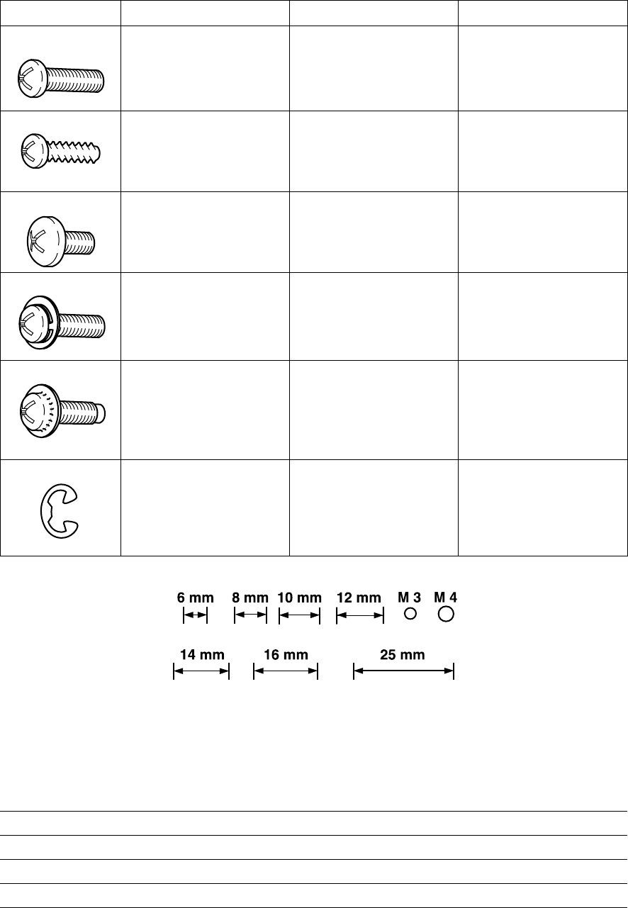
230 Chapter 8 Parts and diagrams C7058-90936
Common fasteners and torque values
Table 42. Common fasteners
Example Description Sizes Uses
Screw M3 by 6 mm
M4 by 8 mm
To hold plastic to plastic
Screw, tapping M3 by 4 mm
M3 by 6 mm
M4 by 6 mm
M4 by 12 mm
To hold plastic to metal
(excluding the control panel)
Screw, pan head M4 by 10 mm To hold plastic to plastic
Screw, w/washer M3 by 6 mm
M3 by 8 mm
M3 by 7 mm
M4 by 6 mm
M4 by 12 mm
To hold plastic to metal
(excluding the covers)
Screw, truss head M3 by 6 mm
M3 by 8 mm
M4 by 8 mm
M4 by 20 mm
To hold sheet metal to metal
(excluding the formatter)
E-ring To hold gears in place
Table 43. Common torque values
Material Canon-
recommended
torque value
Conversion HP-recommended
torque value
Plastic to metal 8 kg-cm 6.94 lb-in 5.5 lb-in
Metal to metal 10 kg-cm 8.68 lb-in 10 lb-in
PCBA 8 kg-cm 6.94 lb-in 5.5 lb-in
Plastic to plastic 8 kg-cm 6.94 lb-in 5.5 lb-in
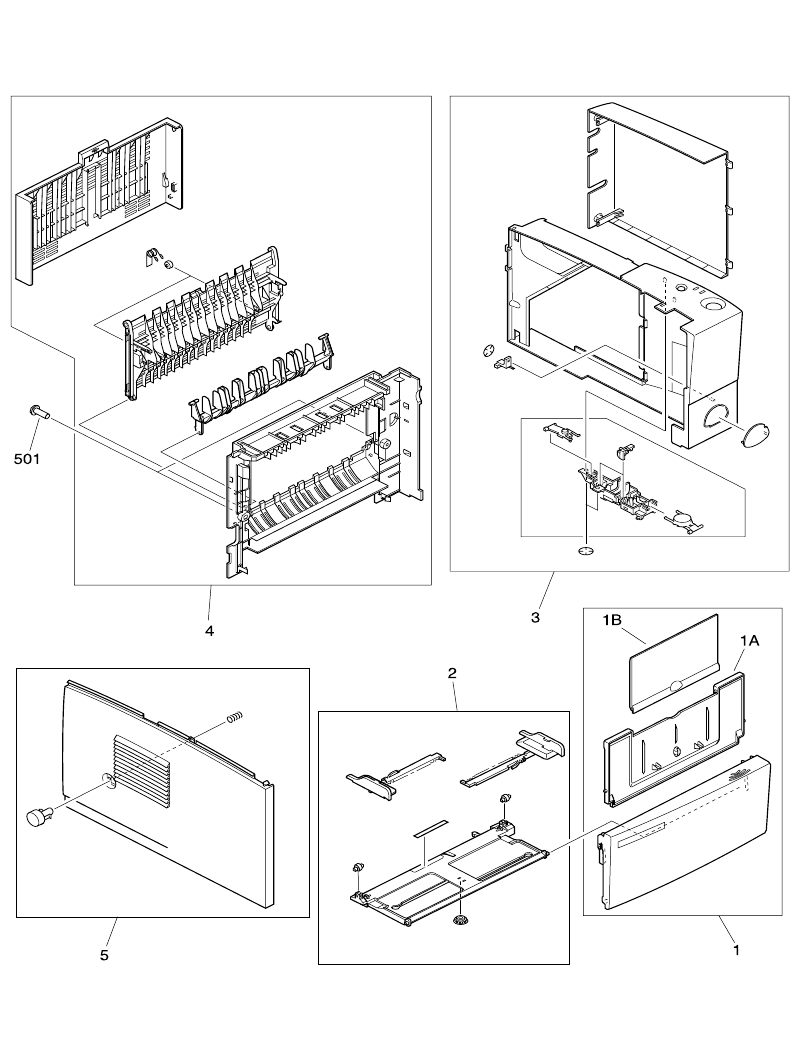
C7058-90936 Illustrations and parts lists 231
Illustrations and parts lists
The following illustrations and parts tables list the field replaceable units (FRU) for this printer. Two
tables at the end of this chapter list all of the parts shown in this chapter: table 66 lists the parts in
alphabetical order, and table 67 lists the parts in numerical order by part number. Both tables list the
appropriate figure in this chapter that shows the part.
External covers and panels
Figure 176. Printer external covers and panels

232 Chapter 8 Parts and diagrams C7058-90936
Table 44. Printer external covers and panels
Ref Description Part number Qty
1 Cover assembly, tray 1 RG5-4121-000CN 1
1A Expansion, tray 1 RB2-3036-000CN 1
1B Expansion, tray 1 RB2-3037-000CN 1
2 Tray assembly (tray 1) RG5-5576-000CN 1
3 DIMM cover assembly RG5-5545-000CN 1
4 Rear cover assembly RG5-5546-000CN 1
5 Left cover assembly RG5-5549-000CN 1
501 Screw, TP, Pan Head, m4 by 10 XB4-7401-007CN 2
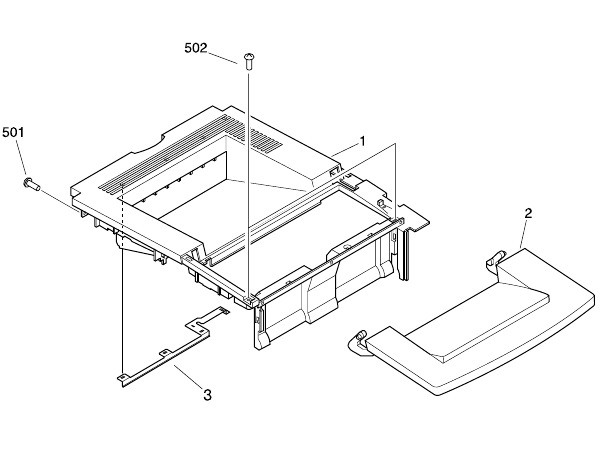
C7058-90936 Illustrations and parts lists 233
Top cover assembly
Figure 177. Top cover assembly

234 Chapter 8 Parts and diagrams C7058-90936
Table 45. Top cover assembly
Ref Description Part number Qty
1 Top cover RB2-6280-000CN 1
2 Cover, cartridge RB2-2856-000CN 1
3 Static charge eliminator RB2-6281-000CN 1
501 Screw, TP, Pan Head, M4 by 10 XB4-7401-007CN 2
502 Screw, TP, Truss Head, M4 by 20 XB4-7402-007CN 2
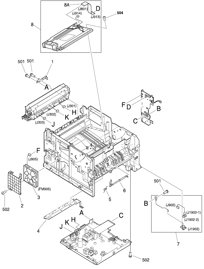
C7058-90936 Illustrations and parts lists 235
Internal components
Figure 178. Internal components (1 of 5)

236 Chapter 8 Parts and diagrams C7058-90936
Table 46. Internal components (1 of 5)
Ref Description Part number Qty
1 Plate, grounding RB2-6246-000CN 1
2 Mount, fan RB2-6255-000CN 1
3 Fan RH7-1463-000CN 1
4 Eliminator, static charge RB2-6261-000CN 1
5 Spring, torsion RB2-2837-000CN 1
6 Lever, sensor RB2-2836-000CN 1
7 Paper-feed cable RG5-5598-000CN 1
8 Laser/scanner assembly RG5-5591-000CN 1
8A Flat cable, laser RH2-5427-000CN 1
501 Screw, w/washer, M3 by 6 XB2-7300-607CN 3
502 Screw, TP, Pan Head, M4 by 10 XB4-7401-007CN 5
503 Screw, M3 by 4 XB6-7300-407CN 2
504 Screw, TP, M4 by 12 XA9-1273-000CN 4
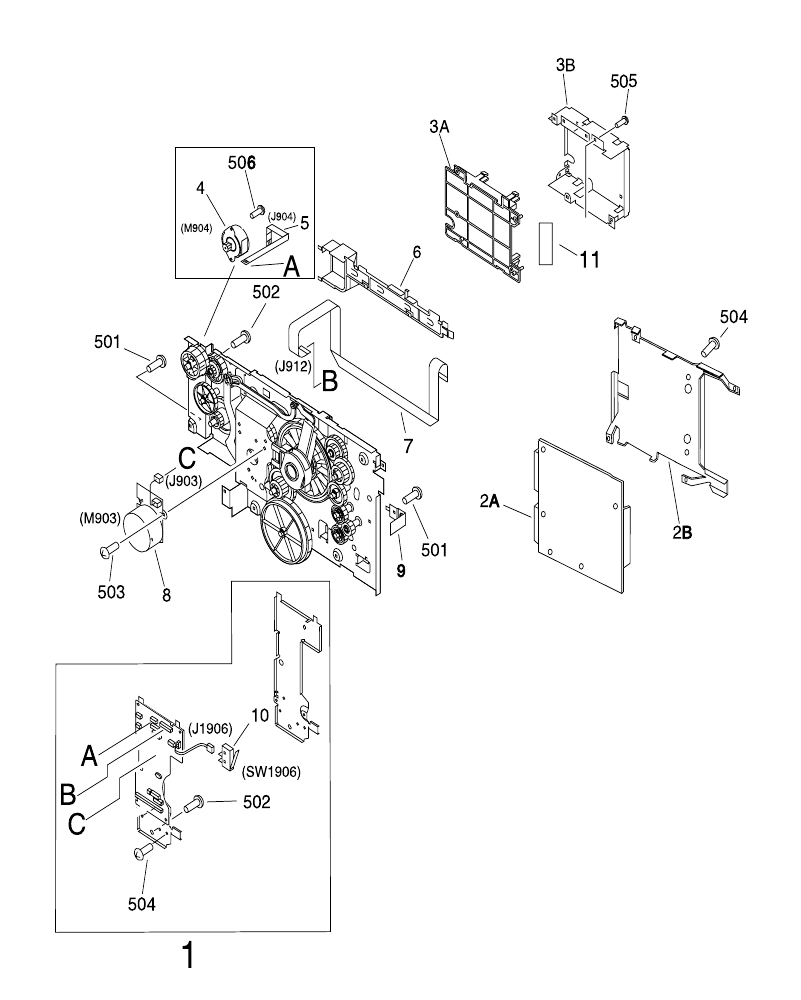
C7058-90936 Illustrations and parts lists 237
Figure 179. Internal components (2 of 5)

238 Chapter 8 Parts and diagrams C7058-90936
Table 47. Internal components (2 of 5)
Ref Description Part number Qty
1 Engine control assembly RG5-5566-000CN 1
2A Formatter PCB C4209-60001 1
2B Formatter RFI shield C7058-00001
3A Guide, EIO RB2-2944-000CN 1
3B Plate, mount, EIO RB2-2945-000CN 1
4 Reverse motor, 23 V dc RH7-1461-000CN 1
5 Flat cable, reverse motor RH2-5425-000cn 1
6 Guide, flat cable RB2-6247-000CN 1
7 Flat cable, I/F RH2-5423-000CN 1
8 Motor, dc RH7-1458-000CN 1
9 Plate, protection RB2-6252-000CN 1
10 Microswitch RH7-6051-000CN 1
11 RFI clip C7058-00010 1
501 Screw, w/washer, M3 by 6 XB2-7300-607CN 2
502 Screw, TP, Pan Head, M4 by 10 XB4-7401-007CN 6
503 Screw, M3 by 4 XB6-7300-407CN 4
504 Screw, TP, M3 by 6 XA9-1223-000CN 6
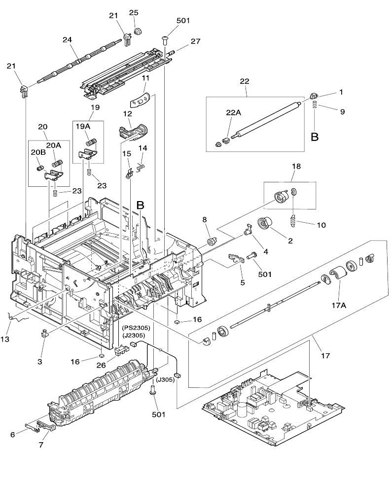
C7058-90936 Illustrations and parts lists 239
Figure 180. Internal components (3 of 5)

240 Chapter 8 Parts and diagrams C7058-90936
Table 48. Internal components (3 of 5)
Ref Description Part number Qty
1 Bushing, transfer, right RB2-2926-020CN 1
2 Gear, 26T RB2-3040-000CN 1
3 Bushing, left RB2-3043-000CN 1
4 Bushing, right RB2-3044-000CN 1
5 Damper RB2-6248-000CN 1
6 Rod, jam clearing RB2-6250-000CN 1
7 Lever, jam clearing RB2-6251-000CN 1
8 Gear, 14T RS6-0445-000CN 1
9 Spring, compression RS6-2022-000CN 1
10 Spring, tension RS6-2025-000CN 1
11 Guide, cartridge, right RB2-2830-020CN 1
12 Guide, cartridge, left RB2-2831-020CN 1
13 Spring, compression RB2-2832-000CN 1
14 Spring, torsion RB2-2843-000CN 1
15 Arm, sensor RB2-6264-000CN 1
16 Foot, rubber RB2-6297-000CN 4
17 Tray 1 pick-up assembly RG5-4128-000CN 1
17A Roller, pick-up RB2-2900-000CN 1
18 Cassette pick-up gear assembly RG5-4156-000CN 1
19 FD delivery roller assembly RG5-5541-000CN 2
19A Roller, face-down, lower 1 RB2-2849-000CN 1
20 FD delivery roller assembly RG5-5542-000CN 2
20A Roller, face-down, lower 1 RB2-2849-000CN 1
20B Roller, face-down, lower 2 RB2-6277-000CN 1
21 Bushing RB2-2850-000CN 2
22 Transfer roller assembly RG5-5581-000CN 1
23 Spring, compression RS6-2375-000CN 4
24 Roller, face-down, upper RF5-3275-000CN 1
25 Gear, 15T RS6-0441-000CN 1
26 Photo interrupter TLP1242 WG8-5382-000CN 1
27 Registration assembly RG5-5556-000CN 1
501 Screw, TP, Pan Head, M4 by 10 XB4-7401-007CN 12
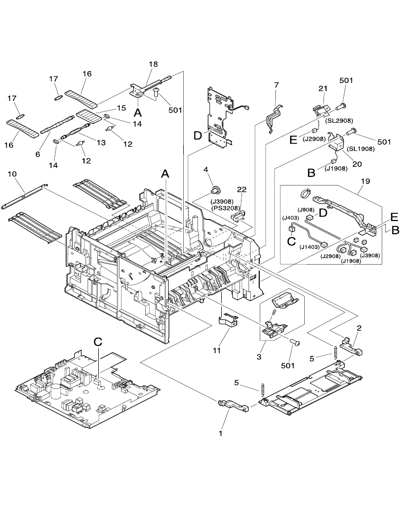
C7058-90936 Illustrations and parts lists 241
Figure 181. Internal components (4 of 5)

242 Chapter 8 Parts and diagrams C7058-90936
Table 49. Internal components (4 of 5)
Ref Description Part number Qty
1 Hinge, left RB2-3041-020CN 1
2 Hinge, right RB2-3042-020CN 1
3 Pad, separation RF5-3272-000CN 1
4 Gear, 20T RS6-0464-000CN 1
5 Spring, tension RS6-2030-000CN 2
6 Shaft, drive, 1 RB2-3073-000CN 1
7 Spring, leaf, grounding RB2-3075-000CN 1
10 Plate, grounding RB2-3080-000CN 1
11 Spring, leaf RB2-6266-000CN 1
12 Pulley RB2-6268-000CN 2
13 Shaft, drive, front RB2-6269-000CN 1
14 Belt, paper feed, 3 RB2-6270-000CN 2
15 Belt, paper feed, 1 RB2-6272-000CN 1
16 Belt, paper feed, 2 RB2-6273-000CN 2
17 Shaft, drive, rear RB2-6274-000CN 2
18 Gear assembly RG5-5577-000CN 1
19 Cable guide assembly RG5-5568-000CN 1
20 Solenoid RH7-5270-000CN 1
21 Solenoid RH7-5273-000CN 1
22 Photo interrupter TLP1242 WG8-5382-000CN 1
501 Screw, TP, pan head M4 by 10 XB4-7401-007CN 4
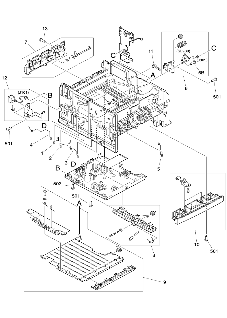
C7058-90936 Illustrations and parts lists 243
Figure 182. Internal components (5 of 5)

244 Chapter 8 Parts and diagrams C7058-90936
Table 50. Internal components (5 of 5)
Ref Description Part number Qty
1 Spring, compression RB2-6262-000CN 1
2 Spring, compression RB2-6263-000CN 1
3 Spring, compression RB2-6265-000CN 1
4 Spring, compression RB2-6267-000CN 1
5 Spring, compression RB2-6271-000CN 1
6 Duplex solenoid assembly RG5-5552-000CN 1
6B Screw, RS, M3 by 6 XA9-0686-000CN 1
7 Reverse guide assembly RG5-5548-000CN 1
8 Position guide assembly RG5-5553-000CN 1
9 Duplex feed guide assembly RG5-5554-000CN 1
10 Feed roller assembly RG5-5555-000CN 1
11 Hinge, feed guide RB2-6249-000CN 1
12 Inlet cable unit RG5-5565-000CN 1
13 Screw, w/washer, M4 by 12 XA9-1206-000CN 2
501 Screw, TP, Pan Head, M4 by 10 XB4-7401-007CN 5
502 Screw, w/washer, M3 by 6 XB2-7300-607CN 1
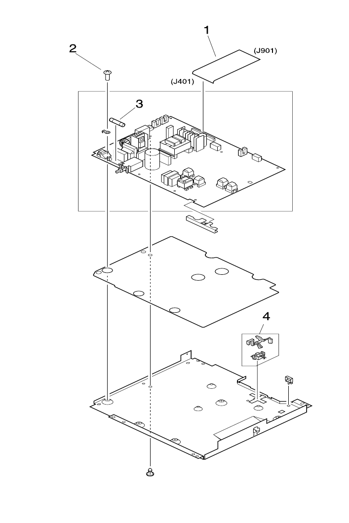
C7058-90936 Illustrations and parts lists 245
Power supply assembly
Figure 183. Power supply assembly

246 Chapter 8 Parts and diagrams C7058-90936
Table 51. Power supply assembly
Ref Description Part number Qty
Power supply assembly, 100 to127 V RG5-5563-000CN 1
Power supply assembly, 220 to240 V RG5-5573-000CN 1
1 Cable, flat RH2-5421-000CN 1
2 Screw, w/washer, M3 by 8 XA9-1226-000CN 5
3 Fuse, 250 V, 15 A, 100 to127 V WD1-0268-000CN 1
3 Fuse, 250 V, 8 A, 220 to240 V RH3-8006-000CN 1
4 Holder, sensor lever RF5-3279-000CN 1
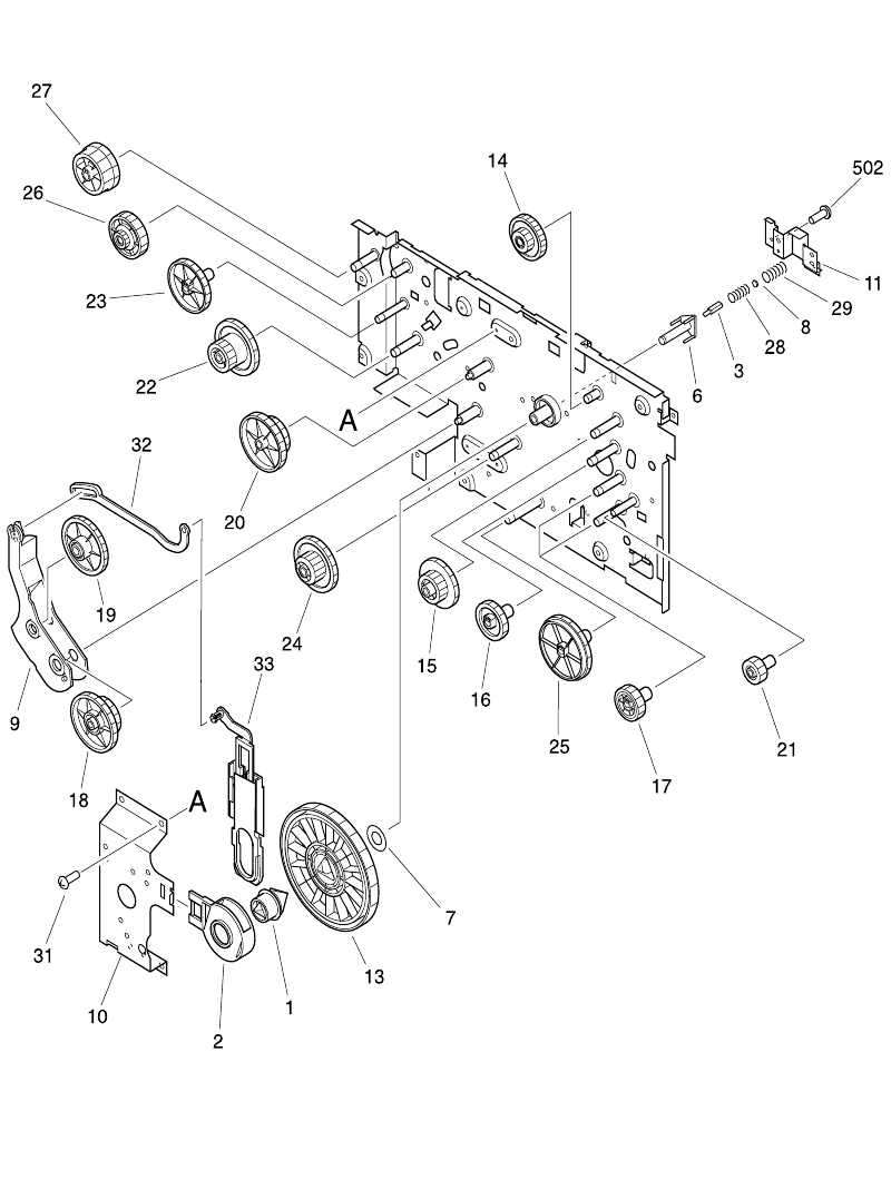
C7058-90936 Illustrations and parts lists 247
Printer drive assembly
Figure 184. Printer drive assembly

248 Chapter 8 Parts and diagrams C7058-90936
Table 52. Printer drive assembly
Ref Description Part number Qty
Printer drive assembly RG5-5562-000CN 1
1 Shaft, coupling RB2-2935-000CN 1
2 Bushing RB2-2936-000CN 1
3 Pin RB2-2943-000CN 1
6 Holder, pin RB2-2947-000CN 1
7 Washer RB2-2949-000CN 1
8 Flange, spring RB2-2950-000CN 1
9 Arm, drive RB2-6376-000CN 1
10 Plate, motor RB2-6377-000CN 1
11 Plate, spring RB2-6378-000CN 1
13 Gear, 201T RS6-0446-000CN 1
14 Gear, 17T/68T RS6-0448-000CN 1
15 Gear, 25T/41T RS6-0449-000CN 1
16 Gear, 31T RS6-0450-000CN 1
17 Gear, 26T RS6-0451-000CN 2
18 Gear, 91T/28T RS6-0910-000CN 1
19 Gear, 42T RS6-0911-000CN 1
20 Gear, 93T/73T RS6-0912-000CN 1
21 Gear, 17T RS6-0913-000CN 1
22 Gear, 46T/22T RS6-0914-000CN 1
23 Gear, 39T RS6-0915-000CN 1
24 Gear, 28T/88T RS6-0916-000CN 1
25 Gear, 75T RS6-0917-000CN 1
26 Gear, 75T/28T RS6-0918-000CN 1
27 Gear, 79T/36T RS6-0919-000CN 1
28 Spring, compression RS6-2031-000CN 1
29 Spring, compression RS6-2379-000CN 1
30 Screw, M3 by 6 XA9-0904-000CN 4
31 Screw, TP, M3 by 6 XA9-1223-000CN 4
32 Lever, drive release RB9-0641-000CN 1
33 Coupling assembly RG9-1473-000CN 1
501 Screw, machine, truss head, M3 by 6 XB1-2300-605CN 2
502 Screw, with star washer, M3 by 7 XB2-7300-407CN 2
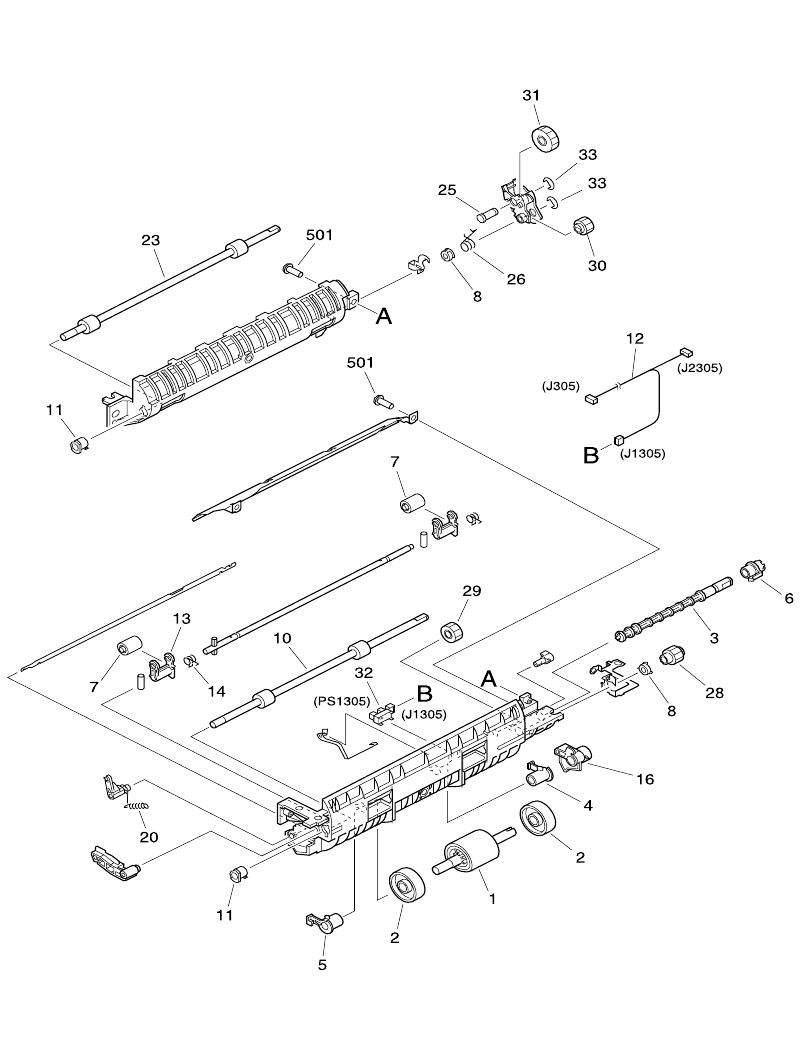
C7058-90936 Illustrations and parts lists 249
Cassette pickup assembly
Figure 185. Cassette pickup assembly

250 Chapter 8 Parts and diagrams C7058-90936
Table 53. Cassette pickup assembly
Ref Description Part number Qty
Cassette pick-up assembly RG5-5551-000CN 1
1 Roller, paper pick-up RB2-6304-000CN 1
2 Roller RB2-2892-000CN 2
3 Shaft, drive RB9-0681-000CN 1
4 Bushing, right RB2-2895-000CN 1
5 Bushing, left RB2-2896-000CN 1
6 Bushing RB2-2897-020CN 1
7 Roller RB2-3046-000CN 2
8 Bushing RB2-3081-000CN 2
10 Roller, feed RB2-6302-000CN 1
11 Bushing RB2-6303-000CN 2
12 Sensor cable RG5-5583-000CN 1
16 Arm, paper sensor RB2-6310-000CN 1
20 Spring, tension RB2-6314-000CN 1
23 Roller, feed RB2-6318-000CN 1
25 Shaft, gear RB2-6320-000CN 1
26 Spring, torsion RB2-6321-000CN 1
28 Gear, 15T RS6-0904-000CN 1
29 Gear, 16T RS6-0905-000CN 1
30 Gear, 15T RS6-0906-000CN 1
31 Gear, 24T RS6-0907-000CN 1
32 Photo-interrupter, GP1SQ73P WG8-5364-000CN 1
33 E-ring XD9-0135-000CN 2
501 Screw, TP, truss head, M4 by 8 XB4-7400-809CN 5
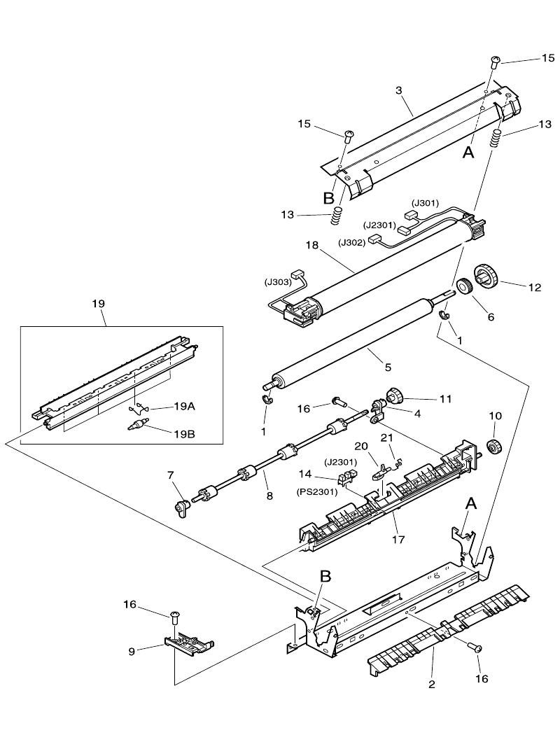
C7058-90936 Illustrations and parts lists 251
Fusing assembly
Figure 186. Fusing assembly

252 Chapter 8 Parts and diagrams C7058-90936
Table 54. Fusing assembly
Ref Description Part number Qty
Fusing assembly, 100-127 V RG5-5559-000CN 1
Fusing assembly, 220-240 V RG5-5569-000CN 1
1 Bushing RB2-2973-000CN 2
2 Guide, entrance RB2-6357-000CN 1
3 Plate, pressure RB2-6358-000CN 1
4 Bushing RB2-6359-000CN 1
5 Roller, pressure RB2-6368-000CN 1
6 Bushing RB2-6370-000CN 1
7 Bushing RB2-6371-000CN 1
8 Roller, delivery RB2-6372-000CN 1
9 Holder, contact RF5-2609-000CN 1
10 Gear, 14T RS6-0921-000CN 1
11 Gear, 16T RS6-0922-000CN 1
12 Gear, 27T RS6-0923-000CN 1
13 Spring, compression RS6-2378-000CN 2
14 Photo-interrupter, TLP1242 WG8-5382-000CN 1
15 Screw, TP, M3 by 6 XA9-1223-000CN 2
16 Screw, w/washer, M3 by 8 XA9-1226-000CN 3
17 Guide, delivery, lower RB2-6350-000CN 1
18 Fuser film assembly, 100-127 V RG5-5560-000CN 1
18 Fuser film assembly, 220-240 V RG5-5570-000CN 1
19 Guide, delivery upper RG5-5561-000CN 1
19A Spring, compression RB2-2978-000CN 4
19B Roller, delivery RB2-6374-000CN 4
20 Lever, delivery RB2-6351-000CN 1
21 Spring, torsion RB2-6352-000CN 1
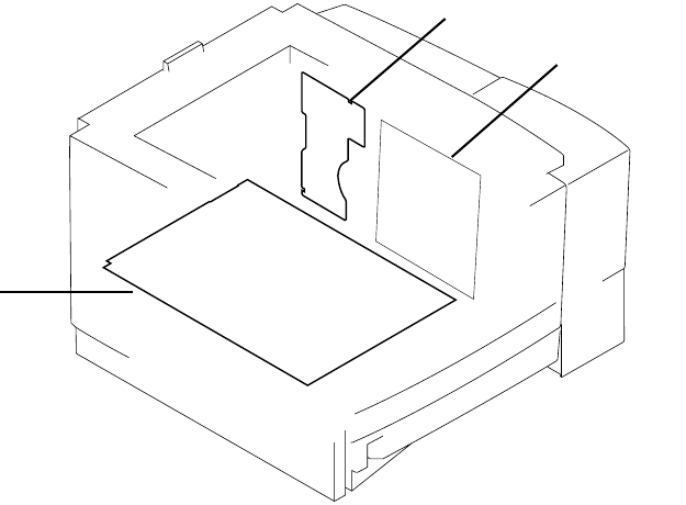
C7058-90936 Illustrations and parts lists 253
PCB assembly location
Figure 187. PCB assembly location
2
1
3

254 Chapter 8 Parts and diagrams C7058-90936
Table 55. PCB assembly location
Ref Description Part number Qty
1 Engine controller assembly RG5-5566-000CN 1
2 Power supply assembly, 100-127 V RG5-5563-000CN 1
Power supply assembly, 220-240 V RG5-5573-000CN 1
3 Formatter assembly C4209-60001 1

C7058-90936 Illustrations and parts lists 255
250-sheet feeder external covers
Figure 188. 250-sheet feeder external covers

256 Chapter 8 Parts and diagrams C7058-90936
Table 56. 250-sheet feeder external covers
Ref Description Part number Qty
1 Foot RB2-2816-000CN 4
3 Cover, lower left RB2-3489-000CN 1
4 Cover, lower right RB2-3479-000CN 1
5 Cover, drive RB2-3480-000CN 1
6 Lower feed roller assembly RG5-4394-000CN 1
6A Roller RB2-3484-000CN 2
6B Holder, roller RB2-3485-000CN 2
6C Spring, compression RS6-2063-000CN 2
7 Screw, M4 by 8 XA9-0605-000CN 3
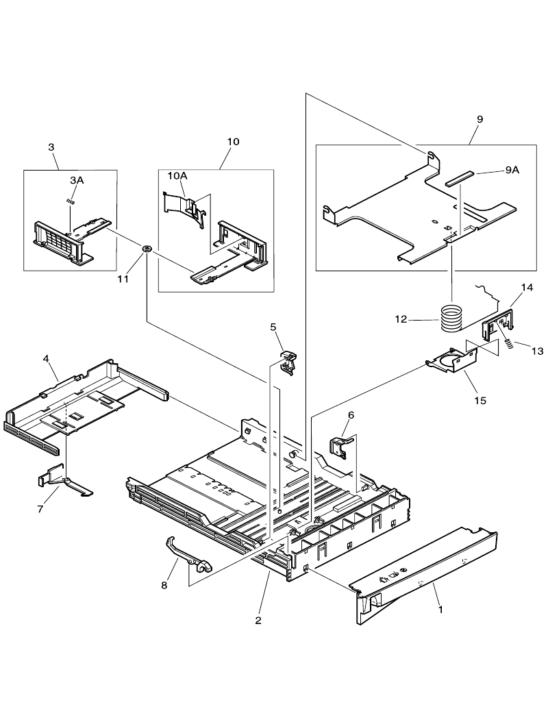
C7058-90936 Illustrations and parts lists 257
Tray 2 and 250-sheet feeder cassette
Figure 189. Tray 2 and 250-sheet feeder cassette

258 Chapter 8 Parts and diagrams C7058-90936
Table 57. Tray 2 and 250-sheet feeder cassette
Ref Description Part number Qty
Cassette assembly (250-sheet) RG5-5580-000CN 1
1 Cover, front RB2-3000-000CN 1
2 Body, cassette RB2-3001-040CN 1
3 Left side plate assembly RG5-4159-000CN 1
3A Spring, compression RS6-2035-000CN 1
4 Plate, end RB2-3003-000CN 1
5 Arm, release, left RB2-3004-000CN 1
6 Arm, release, right RB2-3005-000CN 1
7 Arm, lock RB2-3009-000CN 1
8 Arm, paper level RB2-3010-000CN 1
9 Plate, paper lifting RF5-2599-000CN 1
9A Sheet, separation RB2-3007-000CN 1
10 Right side plate assembly RF5-2606-020CN 1
10A Spring, leaf RB2-3012-000CN 1
11 Gear, 10T RS6-0440-000CN 1
12 Spring, compression RS6-2020-000CN 1
13 Spring, compression RS6-2021-000CN 1
14 Pad, separation, tray 2 RB2-6349-000CN 1
14 Pad, separation, 250-sheet feeder RB2-3008-000CN 1
15 Holder, separation pad RB2-3013-000CN 1
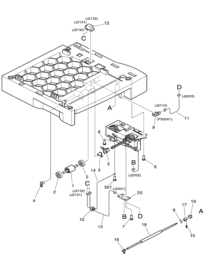
C7058-90936 Illustrations and parts lists 259
250-sheet feeder internal components
Figure 190. 250-sheet feeder internal components

260 Chapter 8 Parts and diagrams C7058-90936
Table 58. 250-sheet feeder internal components
Ref Description Part number Qty
1 Roller, paper pick-up RB2-2891-000CN 1
2 Roller RB2-2892-000CN 2
3 Bushing, right RB2-2895-000CN 1
4 Bushing, left RB2-2896-000CN 1
5 Lever, sensor RB2-3474-000CN 1
6 Screw, M4 by 8 XA9-0605-000CN 3
7 Screw, w/washer M3 by 8 XA9-0924-000CN 2
8 E-ring XD9-0136-000CN 1
9 Photo-interrupter TLP1242 WG8-5382-000CN 1
11 Sensor cable RG5-4278-000CN 1
12 Connector, 6P VS1-6174-006CN 1
13 Relay cable RG5-4280-000CN 1
14 FG cable RG5-4281-000CN 1
15 Spring, compression RS6-2064-000CN 1
16 Bushing, left RB2-6470-000CN 1
17 Bushing, right RB2-3487-000CN 1
18 Roller, feed RB2-3490-000CN 1
19 Gear, 15T RS6-0501-000CN 1
20 Drive PCB, paper feeder RG5-4277-000CN 1
501 Screw, w/washer M4 by 6 XB2-7400-607CN 1
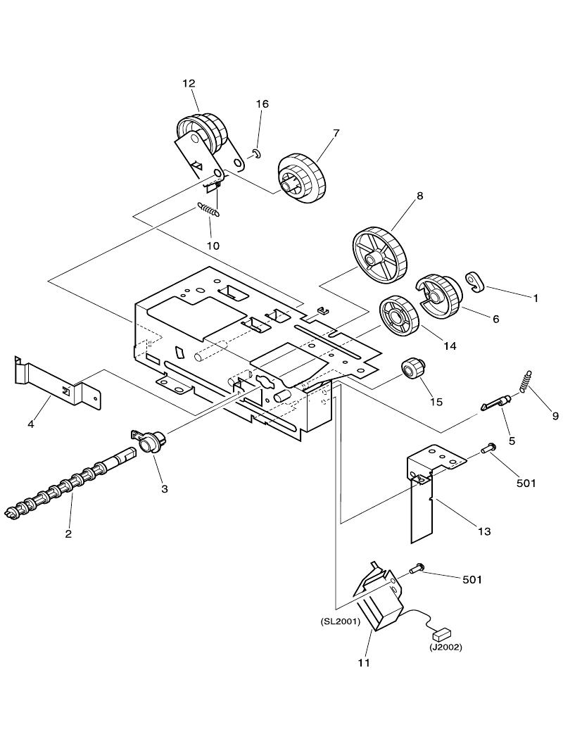
C7058-90936 Illustrations and parts lists 261
250-sheet feeder drive assembly
Figure 191. 250-sheet feeder drive assembly

262 Chapter 8 Parts and diagrams C7058-90936
Table 59. 250-sheet feeder drive assembly
Ref Description Part number Qty
Paper feeder drive assembly RG5-4391-040CN 1
1 Collar, spring RB1-2190-000CN 1
2 Shaft, drive RB2-2893-000CN 1
3 Bushing RB2-3475-000CN 1
4 Spring, leaf RB2-3478-000CN 1
5 Holder, spring RB1-6133-000CN 1
6 Gear, 27T RS6-0495-000CN 1
7 Gear, 39T/34T RS6-1497-000CN 1
8 Gear, 45T RS6-0498-000CN 1
9 Spring, tension RS6-2061-000CN 1
10 Spring, tension RS6-2062-000CN 1
11 Solenoid RH7-5213-000CN 1
12 Swing gear assembly RF5-2755-000CN 1
13 Plate RB2-3481-020CN 1
14 Gear, 39T RS6-0499-000CN 1
15 Gear, 17T RS6-0500-000CN 1
16 E-ring XD9-0136-000CN 1
501 Screw, TP, M4 by 6 XB6-7400-609CN 3
C7058-90936 Illustrations and parts lists 263
250-sheet feeder PCB assembly location
Figure 192. 250-sheet feeder PCB assembly location

264 Chapter 8 Parts and diagrams C7058-90936
Table 60. 250-sheet feeder PCB assembly location
Ref Description Part number Qty
1 Paper feeder driver PCB assembly RG5-4277-000CN 1
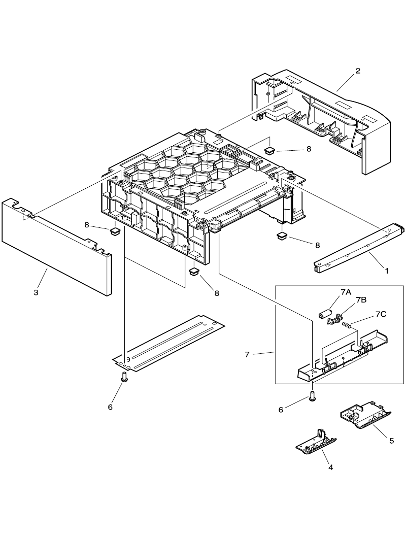
C7058-90936 Illustrations and parts lists 265
500-sheet feeder external covers
Figure 193. 500-sheet feeder external covers

266 Chapter 8 Parts and diagrams C7058-90936
Table 61. 500-sheet feeder external covers
Ref Description Part number Qty
1 Cover, front RB2-6454-000CN 1
2 Cover, right RB2-6456-000CN 1
3 Cover, left RB26457-000CN 1
4 Cover, lower left RB2-3489-000CN 1
5 Cover, sensor RB2-6453-000CN 1
6 Screw, M4 by 8 XA9-0605-000CN 7
7 Lower feed roller assembly RG5-4394-020CN 1
7A Roller RB2-3484-020CN 2
7B Holder, roller RB2-3485-000CN 2
7C Spring, compression RB2-2063-000CN 2
8 Foot RB2-6297-000CN 4
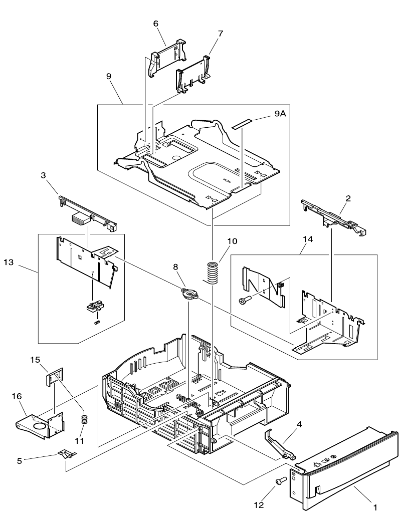
C7058-90936 Illustrations and parts lists 267
500-sheet feeder cassette
Figure 194. 500-sheet feeder cassette

268 Chapter 8 Parts and diagrams C7058-90936
Table 62. 500-sheet feeder cassette
Ref Description Part number Qty
Cassette RG5-5623-000CN 1
1 Cover, front RB2-6468-000CN 1
2 Cover, right edge RB2-6463-000CN 1
3 Cover, left edge RB2-6464-000CN 1
4 Arm, paper level RB2-6465-000CN 1
5 Plate, grounding RB2-6466-000CN 1
6 Cover, rear edge RB2-6467-000CN 1
7 Plate, end RB2-6469-000CN 1
8 Gear, 20T RB2-6471-000CN 1
9 Plate, paper lifting RF5-3303-000CN 1
9A Sheet, separation RB2,3007-000CN 1
10 Spring, compression RS6-2395-000CN 2
11 Spring, compression RS6-2396-000CN 1
12 Screw, M4 by 10 XA9-0606-000CN 2
13 Left side, plate assembly RG5-5626-000CN 1
14 right side, plate assembly RG5-5627-000CN 1
15 Pad, separation RB2-6474-000CN 1
16 Arm, pad RB2-6459-000CN 1
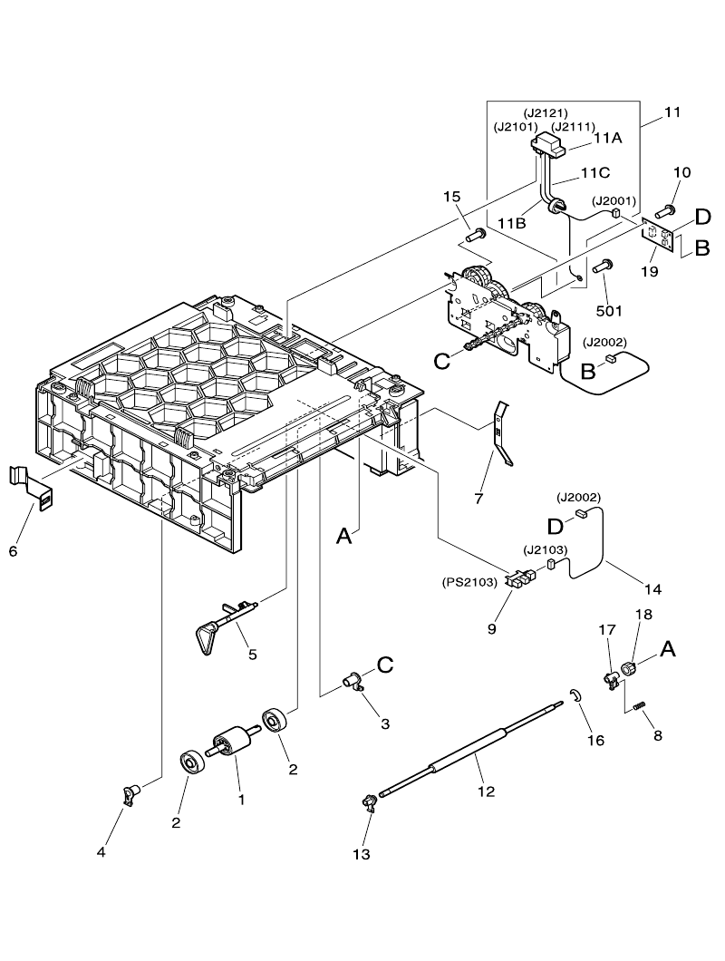
C7058-90936 Illustrations and parts lists 269
500-sheet feeder internal components
Figure 195. 500-sheet feeder internal components

270 Chapter 8 Parts and diagrams C7058-90936
Table 63. 500-sheet feeder internal components
Ref Description Part number Qty
1 Roller, paper pick-up RB2-6304-000CN 1
2 Roller RB2-2892-000CN 2
3 Bushing, right RB2-2895-000CN 1
4 Bushing, left RB2-2896-000CN 1
5 Arm, sensor RB2-6448-000CN 1
6 Spring, leaf RB2-6450-000CN 1
7 Spring, leaf RB2-6451-000CN 1
8 Spring, compression RS6-2064-000CN 1
9 Photo-interrupter GP1SQ73P WG8-5364-000CN 1
10 Screw w/washer M3 by 8 XA9-1226-000CN 1
11 Paper feeder cable RG5-4279-000CN 1
11A Connector 6P VS1-6174-006CN 1
11B Relay cable RG5-4280-000CN 1
11C FG cable RG5-4281-000CN 1
12 Roller, feed RB2-6476-000CN 1
13 Bushing RB2-6447-000CN 1
14 Sensor Cable RG5-5631-000CN 1
15 Screw, M4 by 8 XA9-0605-000CN 3
16 E-ring XD9-0136-000CN 1
17 Bushing RB2-6470-000CN 1
18 Gear, 15T RS6-0501-000CN 1
19 Drive PCB, paper feeder RG5-5630-000CN 1
501 Screw, w/washer, M4 by 6 XB2-7400-607CN 1
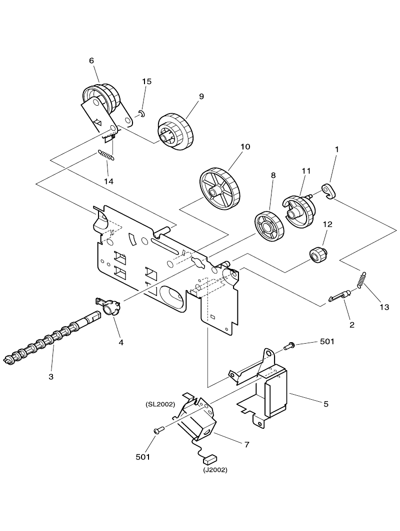
C7058-90936 Illustrations and parts lists 271
500-sheet feeder drive assembly
Figure 196. 500-sheet feeder drive assembly

272 Chapter 8 Parts and diagrams C7058-90936
Table 64. 500-sheet feeder drive assembly
Ref Description Part number Qty
Paper feeder drive assembly RG5-5622-000CN 1
1 Collar, spring RB1-2190-000CN 1
2 Holder, spring RB1-6133-000CN 1
3 Shaft, drive RB2-2893-000CN 1
4 Bushing RB2-6455-000CN 1
5 Plate, solenoid cross member RB2-6473-000CN 1
6 Gear, 31T/26T RF5-3304-000CN 1
7 Solenoid RH7-5276-000CN 1
8 Gear, 39T RS6-0499-000CN 1
9 Gear, 40T/24T RS6-0945-000CN 1
10 Gear, 70T RS6-0946-000CN 1
11 Gear, 34T RS6-0947-000CN 1
12 Gear, 17T RS6-0948-000CN 1
13 Spring, tension RS6-2061-000CN 1
14 Spring, tension RS6-2397-000CN 1
15 E-ring XD9-0136-000CN 1
501 Screw, TP, M4 by 8 XB6-7400-809CN 3

C7058-90936 Illustrations and parts lists 273
500-sheet feeder PCB assembly location
Figure 197. 500-sheet feeder PCB assembly location

274 Chapter 8 Parts and diagrams C7058-90936
Table 65. 500-sheet feeder PCB assembly location
Ref Description Part number Qty
1 Paper feeder driver PCB assembly RG5-5630-000CN 1

C7058-90936 Alphabetical parts list 275
Alphabetical parts list
Table 66. Alphabetical parts list
Description Part number Table and page
Arm, drive RB2-6376-000CN Table 52 on page 8-248
Arm, lock RB2-3009-000CN Table 57 on page 8-258
Arm, pad RB2-6459-000CN Table 62 on page 8-268
Arm, paper level RB2-3010-000CN Table 57 on page 8-258
Arm, paper level RB2-6465-000CN Table 62 on page 8-268
Arm, paper sensor RB2-6310-000CN Table 53 on page 8-250
Arm, release, left RB2-3004-000CN Table 57 on page 8-258
Arm, release, right RB2-3005-000CN Table 57 on page 8-258
Arm, roller holder RB2-6309-000CN Table 53 on page 8-250
Arm, sensor RB2-6264-000CN Table 48 on page 8-240
Arm, sensor RB2-6448-000CN Table 63 on page 8-270
Belt, paper feed, 1 RB2-6272-000CN Table 49 on page 8-242
Belt, paper feed, 2 RB2-6273-000CN Table 49 on page 8-242
Belt, paper feed, 3 RB2-6270-000CN Table 49 on page 8-242
Body, cassette RB2-3001-040CN Table 57 on page 8-258
Bushing RB2-2850-000CN Table 48 on page 8-240
Bushing RB2-2936-000CN Table 52 on page 8-248
Bushing RB2-2897-000CN Table 53 on page 8-250
Bushing RB2-3081-000CN Table 53 on page 8-250
Bushing RB2-6303-000CN Table 53 on page 8-250
Bushing RB2-2973-000CN Table 54 on page 8-252
Bushing RB2-6359-000CN Table 54 on page 8-252
Bushing RB2-6370-000CN Table 54 on page 8-252
Bushing RB2-6371-000CN Table 54 on page 8-252
Bushing RB2-6470-000CN Table 58 on page 8-260
Bushing RB2-3475-000CN Table 59 on page 8-262
Bushing RB2-6447-000CN Table 63 on page 8-270
Bushing RB2-6470-000CN Table 63 on page 8-270
Bushing RB2-6455-000CN Table 64 on page 8-272
Bushing, left RB2-3043-000CN Table 48 on page 8-240
Bushing, left RB2-2896-000CN Table 53 on page 8-250
Bushing, left RB2-2896-000CN Table 58 on page 8-260
Bushing, left RB2-3487-000CN Table 58 on page 8-260
Bushing, left RB2-2896-000CN Table 63 on page 8-270
Bushing, right RB2-3044-000CN Table 48 on page 8-240
Bushing, right RB2-2895-000CN Table 53 on page 8-250

276 Chapter 8 Parts and diagrams C7058-90936
Bushing, right RB2-2895-000CN Table 58 on page 8-260
Bushing, right RB2-2895-000CN Table 63 on page 8-270
Bushing, transfer, right RB2-2926-020CN Table 48 on page 8-240
Cable, flat RH2-5421-000CN Table 51 on page 8-246
Cassette RG5-5623-000CN Table 62 on page 8-268
Cassette assembly (250-sheet) RG5-5580-000CN Table 57 on page 8-258
Cassette pick-up assembly RG5-5551-000CN Table 53 on page 8-250
Cassette pick-up gear assembly RG5-4156-000CN Table 48 on page 8-240
Collar, spring RB1-2190-000CN Table 59 on page 8-262
Collar, spring RB1-2190-000CN Table 64 on page 8-272
Connector 6P VS1-6174-006CN Table 63 on page 8-270
Connector, 6P VS1-6174-006CN Table 58 on page 8-260
Coupling assembly RG9-1473-000CN Table 52 on page 8-248
Cover assembly, tray 1 RG5-4121-000CN Table 44 on page 8-232
Cover rear RG5-5546-000CN Table 44 on page 8-232
Cover, cartridge RB2-2856-000CN Table 45 on page 8-234
Cover, drive RB2-3480-000CN Table 56 on page 8-256
Cover, front RB2-3000-000CN Table 57 on page 8-258
Cover, front RB2-6454-000CN Table 61 on page 8-266
Cover, front RB2-6468-000CN Table 62 on page 8-268
Cover, left RB2-6457-000CN Table 61 on page 8-266
Cover, left edge RB2-6464-000CN Table 62 on page 8-268
Cover, lower left RB2-3489-000CN Table 56 on page 8-256
Cover, lower right RB2-3479-000CN Table 56 on page 8-256
Cover, lower, left RB2-3489-000CN Table 61 on page 8-266
Cover, rear edge RB2-6467-000CN Table 62 on page 8-268
Cover, right RB2-6456-000CN Table 61 on page 8-266
Cover, right edge RB2-6463-000CN Table 62 on page 8-268
Cover, sensor RB2-6453-000CN Table 61 on page 8-266
Cover, top RB2-6280-000CN Table 45 on page 8-234
Damper RB2-6248-000CN Table 48 on page 8-240
DIMM cover assembly RG5-5545-000CN Table 44 on page 8-232
Duplex feed guide assembly RG5-5554-000CN Table 50 on page 8-244
Duplex solenoid assembly RG5-5552-000CN Table 50 on page 8-244
Eliminator, static charge RB2-6261-000CN Table 46 on page 8-236
Engine control assembly RG5-5566-000CN Table 47 on page 8-238
E-ring XD9-0135-000CN Table 53 on page 8-250
E-ring XD9-0136-000CN Table 58 on page 8-260
E-ring XD9-0136-000CN Table 59 on page 8-262
E-ring XD9-0136-000CN Table 63 on page 8-270
Table 66. Alphabetical parts list (continued)
Description Part number Table and page

C7058-90936 Alphabetical parts list 277
E-ring XD9-0136-000CN Table 64 on page 8-272
Expansion, tray 1 RB2-3036-000CN Table 44 on page 8-232
Expansion, tray 1 RB2-3037-000CN Table 44 on page 8-232
Fan RH7-1463-000CN Table 46 on page 8-236
FD delivery roller assembly RG5-5541-000CN Table 48 on page 8-240
FD delivery roller assembly RG5-5542-000CN Table 48 on page 8-240
Feed roller assembly RG5-5555-000CN Table 50 on page 8-244
FG cable RG5-4281-000CN Table 58 on page 8-260
FG cable RG5-4281-000CN Table 63 on page 8-270
Flange, spring RB2-2950-000CN Table 52 on page 8-248
Flat cable, I/F RH2-5423-000CN Table 46 on page 8-236
Flat cable, laser RH2-5427-000CN Table 46 on page 8-236
Flat cable, reverse motor RH2-5425-000CN Table 47 on page 8-238
Foot RB2-2816-000CN Table 56 on page 8-256
Foot, rubber RB2-6297-000CN Table 48 on page 8-240
Foot, rubber RB2-6297-000CN Table 61 on page 8-266
Formatter PCB C4209-60001 Table 47 on page 8-238
Frame, feeder RB2-3471-000CN Table 56 on page 8-256
Fuse, 125 V, 15A, 100 to 127 V WD1-0268-000CN Table 51 on page 8-246
Fuse, 250 V, 8 A, 220 to 240 V RH3-8006-000CN Table 51 on page 8-246
Fuser assembly 110 V RG5-5559-000CN Table 54 on page 8-252
Fuser assembly 220 V RG5-5569-000CN Table 54 on page 8-252
Fuser film assembly 110 V RG5-5560-000CN Table 54 on page 8-252
Fuser film assembly 220 V RG5-5570-000CN Table 54 on page 8-252
Gear assembly RG5-5577-000CN Table 49 on page 8-242
Gear assembly RG5-5577-000CN Table 49 on page 8-242
Gear, 10T RS6-0440-000CN Table 57 on page 8-258
Gear, 14T RS6-0445-000CN Table 48 on page 8-240
Gear, 14T RS6-0921-000CN Table 54 on page 8-252
Gear, 15T RS6-0441-000CN Table 48 on page 8-240
Gear, 15T RS6-0904-000CN Table 53 on page 8-250
Gear, 15T RS6-0906-000CN Table 53 on page 8-250
Gear, 15T RS6-0501-000CN Table 58 on page 8-260
Gear, 15T RS6-0501-000CN Table 63 on page 8-270
Gear, 16T RS6-0905-000CN Table 53 on page 8-250
Gear, 16T RS6-0922-000CN Table 54 on page 8-252
Gear, 17T RS6-0924-000CN Table 48 on page 8-240
Gear, 17T RS6-0913-000CN Table 52 on page 8-248
Gear, 17T RS6-0500-000CN Table 59 on page 8-262
Gear, 17T RS6-0948-000CN Table 64 on page 8-272
Table 66. Alphabetical parts list (continued)
Description Part number Table and page

278 Chapter 8 Parts and diagrams C7058-90936
Gear, 17T/68T RS6-0448-000CN Table 52 on page 8-248
Gear, 201T RS6-0446-000CN Table 52 on page 8-248
Gear, 20T RS6-0464-000CN Table 49 on page 8-242
Gear, 20T RB2-6471-000CN Table 62 on page 8-268
Gear, 24T RS6-0907-000CN Table 53 on page 8-250
Gear, 25T/41T RS6-0449-000CN Table 52 on page 8-248
Gear, 26T RB2-3040-000CN Table 48 on page 8-240
Gear, 26T RS6-0451-000CN Table 52 on page 8-248
Gear, 27T RS6-0923-000CN Table 54 on page 8-252
Gear, 27T RS6-0495-000CN Table 59 on page 8-262
Gear, 28T/88T RS6-0916-000CN Table 52 on page 8-248
Gear, 31T RS6-0450-000CN Table 52 on page 8-248
Gear, 31T/26T RF5-3304-000CN Table 64 on page 8-272
Gear, 34T RS6-0947-000CN Table 64 on page 8-272
Gear, 39T RS6-0915-000CN Table 52 on page 8-248
Gear, 39T RS6-0499-000CN Table 59 on page 8-262
Gear, 39T RS6-0499-000CN Table 64 on page 8-272
Gear, 39T/34T RS6-0497-000CN Table 59 on page 8-262
Gear, 40T/24T RS6-0945-000CN Table 64 on page 8-272
Gear, 42T RS6-0911-000CN Table 52 on page 8-248
Gear, 45T RS6-0498-000CN Table 59 on page 8-262
Gear, 46T/22T RS6-0914-000CN Table 52 on page 8-248
Gear, 70T RS6-0946-000CN Table 64 on page 8-272
Gear, 75T RS6-0917-000CN Table 52 on page 8-248
Gear, 75T/28T RS6-0918-000CN Table 52 on page 8-248
Gear, 79T/36T RS6-0919-000CN Table 52 on page 8-248
Gear, 91T/28T RS6-0910-000CN Table 52 on page 8-248
Gear, 93T/73T RS6-0912-000CN Table 52 on page 8-248
Guide RB2-2944-000CN Table 52 on page 8-248
Guide, cable RG5-5568-000CN Table 49 on page 8-242
Guide, cartridge, left RB2-2831-000CN Table 48 on page 8-240
Guide, cartridge, right RB2-2830-000CN Table 48 on page 8-240
Guide, delivery, lower RB2-6350-000CN Table 54 on page 8-252
Guide, delivery, upper RG5-5561-000CN Table 54 on page 8-252
Guide, entrance RB2-6357-000CN Table 54 on page 8-252
Guide, flat cable RB2-6247-000CN Table 46 on page 8-236
Hinge, feed guide RB2-6249-000CN Table 50 on page 8-244
Hinge, left RB2-3041-000CN Table 49 on page 8-242
Hinge, right RB2-3042-000CN Table 49 on page 8-242
Holder, contact RF5-2609-000CN Table 54 on page 8-252
Table 66. Alphabetical parts list (continued)
Description Part number Table and page

C7058-90936 Alphabetical parts list 279
Holder, pin RB2-2947-000CN Table 52 on page 8-248
Holder, roller RB2-3485-000CN Table 56 on page 8-256
Holder, roller RB2-3485-000CN Table 61 on page 8-266
Holder, sensor lever RF5-3279-000CN Table 46 on page 8-236
Holder, separation pad RB2-3013-000CN Table 57 on page 8-258
Holder, spring RB1-6133-000CN Table 59 on page 8-262
Holder, spring RB1-6133-000CN Table 64 on page 8-272
Inlet cable unit RG5-5565-000CN Table 46 on page 8-236
Laser/scanner assembly RG5-5591-000CN Table 46 on page 8-236
Left cover assembly RG5-5549-000CN Table 44 on page 8-232
Left side plate assembly RG5-4159-000CN Table 57 on page 8-258
Left side, plate assembly RG5-5626-000CN Table 62 on page 8-268
Lever, delivery RB2-6351-000CN Table 54 on page 8-252
Lever, drive release RB9-0641-000CN Table 52 on page 8-248
Lever, jam clearing RB2-6251-000CN Table 48 on page 8-240
Lever, sensor RB2-2836-000CN Table 46 on page 8-236
Lever, sensor RB2-3474-000CN Table 58 on page 8-260
Lower feed roller assembly RG5-4394-000CN Table 56 on page 8-256
Lower feed roller assembly RG5-4394-020CN Table 61 on page 8-266
Microswitch RH7-6051-000CN Table 46 on page 8-236
Motor, 23 V, dc RH7-1461-000CN Table 52 on page 8-248
Motor, dc, 5 to 76W RH7-1458-000CN Table 46 on page 8-236
Mount, fan RB2-6255-000CN Table 46 on page 8-236
MP pick-up assembly RG5-4128-000CN Table 48 on page 8-240
Pad, separation RF5-3272-000CN Table 49 on page 8-242
Pad, separation RB2-3008-000CN Table 57 on page 8-258
Pad, separation RB2-6474-000CN Table 62 on page 8-268
Paper feeder cable RG5-4279-000CN Table 63 on page 8-270
Paper feeder drive assembly RG5-4391-000CN Table 59 on page 8-262
Paper feeder drive assembly RG5-5622-000CN Table 64 on page 8-272
Paper feeder drive PCB assembly RG5-4277-000CN Table 58 on page 8-260
Paper feeder drive PCB assembly RG5-4277-000CN Table 60 on page 8-264
Paper feeder driver PCB assembly RG5-5630-000CN Table 65 on page 8-274
Paper-feed cable RG5-5598-000CN Table 46 on page 8-236
Photo-interrupter GP1SQ73P WG8-5364-000CN Table 63 on page 8-270
Photo-interrupter, GP1SQ73P WG8-5364-000CN Table 53 on page 8-250
Photo-interrupter, TLP1242 WG8-5382-000CN Table 48 on page 8-240
Photo-interrupter, TLP1242 WG8-5382-000CN Table 49 on page 8-242
Photo-interrupter, TLP1242 WG8-5382-000CN Table 54 on page 8-252
Photo-interrupter, TLP1242 WG8-5382-000CN Table 58 on page 8-260
Table 66. Alphabetical parts list (continued)
Description Part number Table and page

280 Chapter 8 Parts and diagrams C7058-90936
Pin RB2-2943-000CN Table 52 on page 8-248
Plate RB2-3481-000CN Table 59 on page 8-262
Plate, end RB2-6349-000CN Table 57 on page 8-258
Plate, end RB2-6469-000CN Table 62 on page 8-268
Plate, feeding, left RB2-3078-000CN Table 49 on page 8-242
Plate, feeding, right RB2-3079-000CN Table 49 on page 8-242
Plate, grounding RB2-6246-000CN Table 46 on page 8-236
Plate, grounding RB2-3080-000CN Table 49 on page 8-242
Plate, grounding RB2-6466-000CN Table 62 on page 8-268
Plate, motor RB2-6377-000CN Table 52 on page 8-248
Plate, mount RB2-2945-000CN Table 52 on page 8-248
Plate, paper lifting RF5-2599-000CN Table 57 on page 8-258
Plate, paper lifting RF5-3303-000CN Table 62 on page 8-268
Plate, Pressure RB2-6358-000CN Table 54 on page 8-252
Plate, protection RB2-6252-000CN Table 46 on page 8-236
Plate, solenoid cross member RB2-6473-000CN Table 64 on page 8-272
Plate, spring RB2-6378-000CN Table 52 on page 8-248
Position guide assembly RG5-5553-000CN Table 50 on page 8-244
Power supply assembly 220 to 240 V RG5-5573-000CN Table 51 on page 8-246
Power supply assembly, 100 to127 V RG5-5563-000CN Table 51 on page 8-246
Printer drive assembly RG5-5562-000CN Table 52 on page 8-248
Pulley RB2-6268-000CN Table 49 on page 8-242
Registration assembly RG5-5556-000CN Table 48 on page 8-240
Relay cable RG5-4280-000CN Table 58 on page 8-260
Relay cable RG5-4280-000CN Table 63 on page 8-270
Reverse guide assembly RG5-5548-000CN Table 50 on page 8-244
RFI shield, formatter C7058-00001 Table 47 on page 8-238
Right side plate assembly RF5-2606-000CN Table 57 on page 8-258
right side, plate assembly RG5-5627-000CN Table 62 on page 8-268
Rod, jam clearing RB2-6250-000CN Table 48 on page 8-240
Roller RB2-2892-000CN Table 53 on page 8-250
Roller RB2-3046-000CN Table 53 on page 8-250
Roller RB2-3484-000CN Table 56 on page 8-256
Roller RB2-2892-000CN Table 58 on page 8-260
Roller RB2-2892-000CN Table 63 on page 8-270
Roller, delivery RB2-6372-000CN Table 54 on page 8-252
Roller, delivery RB2-6374-000CN Table 54 on page 8-252
Roller, face-down lower 1 RB2-2849-000CN Table 48 on page 8-240
Roller, face-down lower 1 RB2-2849-000CN Table 48 on page 8-240
Roller, face-down lower 2 RB2-6277-000CN Table 48 on page 8-240
Table 66. Alphabetical parts list (continued)
Description Part number Table and page

C7058-90936 Alphabetical parts list 281
Roller, face-down, upper RF5-3275-000CN Table 48 on page 8-240
Roller, feed RB2-6302-000CN Table 53 on page 8-250
Roller, feed RB2-6318-000CN Table 53 on page 8-250
Roller, feed RB2-3490-000CN Table 58 on page 8-260
Roller, feed RB2-6476-000CN Table 63 on page 8-270
Roller, feed RB2-6476-000CN Table 63 on page 8-270
Roller, paper pick-up RB2-2891-000CN Table 53 on page 8-250
Roller, paper pick-up RB2-6304-000CN Table 53 on page 8-250
Roller, paper pick-up RB2-6304-000CN Table 63 on page 8-270
Roller, pick-up RB2-2900-000CN Table 48 on page 8-240
Roller, pressure RB2-6368-000CN Table 54 on page 8-252
Screw, M3 by 6 XA9-0904-000CN Table 52 on page 8-248
Screw, M4 by 10 XA9-0606-000CN Table 46 on page 8-236
Screw, M4 by 8 XA9-0605-000CN Table 56 on page 8-256
Screw, M4 by 8 XA9-0605-000CN Table 58 on page 8-260
Screw, M4 by 8 XA9-0605-000CN Table 61 on page 8-266
Screw, M4 by 8 XA9-0605-000CN Table 63 on page 8-270
Screw, machine, truss head, M3 by 6 XB1-2300-605CN Table 52 on page 8-248
Screw, RS, M3 by 6 XA9-0686-000CN Table 50 on page 8-244
Screw, TP, M3 by 4 XB6-7300-407CN Table 46 on page 8-236
Screw, TP, M3 by 6 XA9-1223-000CN Table 47 on page 8-238
Screw, TP, M3 by 6 XA9-1223-000CN Table 52 on page 8-248
Screw, TP, M4 by 12 XA9-1273-000CN Table 46 on page 8-236
Screw, TP, M4 by 6 XB6-7400-609CN Table 59 on page 8-262
Screw, TP, pan head M4 by 10 XB4-7401-007CN Table 44 on page 8-232
Screw, TP, pan head M4 by 10 XB4-7401-007CN Table 45 on page 8-234
Screw, TP, pan head M4 by 10 XB4-7401-007CN Table 46 on page 8-236
Screw, TP, pan head M4 by 10 XB4-7401-007CN Table 48 on page 8-240
Screw, TP, pan head M4 by 10 XB4-7401-007CN Table 49 on page 8-242
Screw, TP, pan head M4 by 10 XB4-7401-007CN Table 50 on page 8-244
Screw, TP, truss head M4 by 20 XB4-740-007CN Table 45 on page 8-234
Screw, TP, truss head M4 by 8 XB4-7400-809CN Table 53 on page 8-250
Screw, TP, truss head, M3 by 8 XB6-7400-809CN Table 64 on page 8-272
Screw, w/washer M3 by 8 XA9-0924-000CN Table 58 on page 8-260
Screw, w/washer, M3 by 6 XB2-7300-607CN Table 46 on page 8-236
Screw, w/washer, M3 by 6 XB2-7300-607CN Table 50 on page 8-244
Screw, w/washer, M3 by 8 XA9-1226-000CN Table 51 on page 8-246
Screw, w/washer, M3 by 8 XA9-1226-000CN Table 54 on page 8-252
Screw, w/washer, M3 by 8 XA9-1226-000CN Table 63 on page 8-270
Screw, w/washer, M4 by 12 XA9-1206-000CN Table 50 on page 8-244
Table 66. Alphabetical parts list (continued)
Description Part number Table and page

282 Chapter 8 Parts and diagrams C7058-90936
Screw, w/washer, M4 by 6 XB2-7400-607CN Table 58 on page 8-260
Screw, w/washer, M4 by 6 XB4-7400-607CN Table 63 on page 8-270
Screw, with star washer, M3 by 7 XB2-7300-407CN Table 52 on page 8-248
Sensor cable RG5-5583-000CN Table 53 on page 8-250
Sensor cable RG5-4278-000CN Table 58 on page 8-260
Sensor Cable RG5-5631-000CN Table 63 on page 8-270
Shaft, coupling RB2-2935-000CN Table 52 on page 8-248
Shaft, drive RB2-3073-000CN Table 49 on page 8-242
Shaft, drive RB2-2893-000CN Table 53 on page 8-250
Shaft, drive RB9-0681-000CN Table 53 on page 8-250
Shaft, drive RB2-2893-000CN Table 64 on page 8-272
Shaft, drive, front RB2-6269-000CN Table 49 on page 8-242
Shaft, drive, rear RB2-6274-000CN Table 49 on page 8-242
Shaft, gear RB2-6320-000CN Table 53 on page 8-250
Sheet, separation RB2-3007-000CN Table 57 on page 8-258
Sheet, separation RB2-3007-000CN Table 62 on page 8-268
Solenoid RH7-5270-000CN Table 46 on page 8-236
Solenoid RH7-5273-000CN Table 46 on page 8-236
Solenoid RH7-5213-000CN Table 59 on page 8-262
Solenoid RH7-5276-000CN Table 64 on page 8-272
Spring, compression RB2-2832-000CN Table 48 on page 8-240
Spring, compression RS6-2022-000CN Table 48 on page 8-240
Spring, compression RS6-2375-000CN Table 48 on page 8-240
Spring, compression RB2-6262-000CN Table 50 on page 8-244
Spring, compression RB2-6263-000CN Table 50 on page 8-244
Spring, compression RB2-6265-000CN Table 50 on page 8-244
Spring, compression RB2-6271-000CN Table 50 on page 8-244
Spring, compression RS6-2031-000CN Table 52 on page 8-248
Spring, compression RS6-2379-000CN Table 52 on page 8-248
Spring, compression RB2-2978-000CN Table 54 on page 8-252
Spring, compression RS6-2378-000CN Table 54 on page 8-252
Spring, compression RS6-2063-000CN Table 56 on page 8-256
Spring, compression RS6-2020-000CN Table 57 on page 8-258
Spring, compression RS6-2021-000CN Table 57 on page 8-258
Spring, compression RS6-2064-000CN Table 58 on page 8-260
Spring, compression RS6-2063-000CN Table 61 on page 8-266
Spring, compression RS6-2395-000CN Table 62 on page 8-268
Spring, compression RS6-2396-000CN Table 62 on page 8-268
Spring, compression RS6-2064-000CN Table 63 on page 8-270
Spring, leaf RB2-6266-000CN Table 49 on page 8-242
Table 66. Alphabetical parts list (continued)
Description Part number Table and page

C7058-90936 Alphabetical parts list 283
Spring, leaf RB2-3012-000CN Table 57 on page 8-258
Spring, leaf RB2-3478-000CN Table 59 on page 8-262
Spring, leaf RB2-6450-000CN Table 63 on page 8-270
Spring, leaf RB2-6451-000CN Table 63 on page 8-270
Spring, leaf, grounding RB2-3075-000CN Table 49 on page 8-242
Spring, tension RS6-2025-000CN Table 48 on page 8-240
Spring, tension RS6-2030-000CN Table 49 on page 8-242
Spring, tension RB2-6314-000CN Table 53 on page 8-250
Spring, tension RS6-2061-000CN Table 59 on page 8-262
Spring, tension RS6-2062-000CN Table 59 on page 8-262
Spring, tension RS6-2061-000CN Table 64 on page 8-272
Spring, tension RS6-2397-000CN Table 64 on page 8-272
Spring, torsion RB2-2837-000CN Table 46 on page 8-236
Spring, torsion RB2-2843-000CN Table 48 on page 8-240
Spring, torsion RB2-6308-000CN Table 53 on page 8-250
Spring, torsion RB2-6321-000CN Table 53 on page 8-250
Spring, torsion RB2-6352-000CN Table 54 on page 8-252
Static charge eliminator RB2-6281-000CN Table 45 on page 8-234
Swing gear assembly RF5-2755-000CN Table 59 on page 8-262
Transfer roller assembly RG5-5581-000CN Table 48 on page 8-240
Tray assembly, (tray 1) RG5-5576-000CN Table 44 on page 8-232
Washer RB2-2949-000CN Table 52 on page 8-248
Table 66. Alphabetical parts list (continued)
Description Part number Table and page

284 Chapter 8 Parts and diagrams C7058-90936
Numerical parts list
Table 67. Numerical parts list
Part number Description Table and page
C4209-60001 Formatter PCB Table 47 on page 8-238
C7058-00001 RFI shield, formatter Table 47 on page 8-238
RB1-2190-000CN Collar, spring Table 59 on page 8-262
RB1-2190-000CN Collar, spring Table 64 on page 8-272
RB1-6133-000CN Holder, spring Table 59 on page 8-262
RB1-6133-000CN Holder, spring Table 64 on page 8-272
RB2-2816-000CN Foot Table 56 on page 8-256
RB2-2830-020CN Guide, cartridge, right Table 48 on page 8-240
RB2-2831-020CN Guide, cartridge, left Table 48 on page 8-240
RB2-2832-000CN Spring, compression Table 48 on page 8-240
RB2-2836-000CN Lever, sensor Table 46 on page 8-236
RB2-2837-000CN Spring, torsion Table 46 on page 8-236
RB2-2843-000CN Spring, torsion Table 48 on page 8-240
RB2-2849-000CN Roller, face-down lower 1 Table 48 on page 8-240
RB2-2849-000CN Roller, face-down lower 1 Table 48 on page 8-240
RB2-2850-000CN Bushing Table 48 on page 8-240
RB2-2856-000CN Cover, cartridge Table 45 on page 8-234
RB2-2891-000CN Roller, paper pick-up Table 58 on page 8-260
RB2-2892-000CN Roller Table 53 on page 8-250
RB2-2892-000CN Roller Table 58 on page 8-260
RB2-2892-000CN Roller Table 63 on page 8-270
RB2-2893-000CN Shaft, drive Table 53 on page 8-250
RB2-2893-000CN Shaft, drive Table 64 on page 8-272
RB2-2895-000CN Bushing, right Table 53 on page 8-250
RB2-2895-000CN Bushing, right Table 58 on page 8-260
RB2-2895-000CN Bushing, right Table 63 on page 8-270
RB2-2896-000CN Bushing, left Table 53 on page 8-250
RB2-2896-000CN Bushing, left Table 58 on page 8-260
RB2-2896-000CN Bushing, left Table 63 on page 8-270
RB2-2897-020CN Bushing Table 53 on page 8-250
RB2-2900-000CN Roller, pick-up Table 48 on page 8-240
RB2-2926-020CN Bushing, transfer, right Table 48 on page 8-240
RB2-2935-000CN Shaft, coupling Table 52 on page 8-248
RB2-2936-000CN Bushing Table 52 on page 8-248
RB2-2943-000CN Pin Table 52 on page 8-248
RB2-2944-000CN Guide Table 52 on page 8-248

C7058-90936 Numerical parts list 285
RB2-2945-000CN Plate, mount Table 52 on page 8-248
RB2-2947-000CN Holder, pin Table 52 on page 8-248
RB2-2949-000CN Washer Table 52 on page 8-248
RB2-2950-000CN Flange, spring Table 52 on page 8-248
RB2-2973-000CN Bushing Table 54 on page 8-252
RB2-2978-000CN Spring, compression Table 54 on page 8-252
RB2-3000-000CN Cover, front Table 57 on page 8-258
RB2-3001-040CN Body, cassette Table 57 on page 8-258
RB2-3004-000CN Arm, release, left Table 57 on page 8-258
RB2-3005-000CN Arm, release, right Table 57 on page 8-258
RB2-3007-000CN Sheet, separation Table 57 on page 8-258
RB2-3007-000CN Sheet, separation Table 62 on page 8-268
RB2-3008-000CN Pad, separation Table 57 on page 8-258
RB2-3009-000CN Arm, lock Table 57 on page 8-258
RB2-3010-000CN Arm, paper level Table 57 on page 8-258
RB2-3012-000CN Spring, leaf Table 57 on page 8-258
RB2-3013-000CN Holder, separation pad Table 57 on page 8-258
RB2-3036-000CN Expansion, tray 1 Table 44 on page 8-232
RB2-3037-000CN Expansion, tray 1 Table 44 on page 8-232
RB2-3040-000CN Gear, 26T Table 48 on page 8-240
RB2-3041-020CN Hinge, left Table 49 on page 8-242
RB2-3042-020CN Hinge, right Table 49 on page 8-242
RB2-3043-000CN Bushing, left Table 48 on page 8-240
RB2-3044-000CN Bushing, right Table 48 on page 8-240
RB2-3046-000CN Roller Table 53 on page 8-250
RB2-3073-000CN Shaft, drive Table 49 on page 8-242
RB2-3075-000CN Spring, leaf, grounding Table 49 on page 8-242
RB2-3080-000CN Plate, grounding Table 49 on page 8-242
RB2-3081-000CN Bushing Table 53 on page 8-250
RB2-3474-000CN Lever, sensor Table 58 on page 8-260
RB2-3475-000CN Bushing Table 59 on page 8-262
RB2-3478-000CN Spring, leaf Table 59 on page 8-262
RB2-3479-000CN Cover, lower right Table 56 on page 8-256
RB2-3480-000CN Cover, drive Table 56 on page 8-256
RB2-3481-020CN Plate Table 59 on page 8-262
RB2-3484-020CN Roller Table 56 on page 8-256
RB2-3484-020CN Roller Table 61 on page 8-266
RB2-3485-000CN Holder, roller Table 56 on page 8-256
RB2-3485-000CN Holder, roller Table 61 on page 8-266
RB2-3487-000CN Bushing, left Table 58 on page 8-260
Table 67. Numerical parts list (continued)
Part number Description Table and page

286 Chapter 8 Parts and diagrams C7058-90936
RB2-3489-000CN Cover, lower left Table 56 on page 8-256
RB2-3489-000CN Cover, lower, left Table 61 on page 8-266
RB2-3490-000CN Roller, feed Table 58 on page 8-260
RB2-6246-000CN Plate, grounding Table 46 on page 8-236
RB2-6247-000CN Guide, flat cable Table 46 on page 8-236
RB2-6248-000CN Damper Table 48 on page 8-240
RB2-6249-000CN Hinge, feed guide Table 50 on page 8-244
RB2-6250-000CN Rod, jam clearing Table 48 on page 8-240
RB2-6251-000CN Lever, jam clearing Table 48 on page 8-240
RB2-6252-000CN Plate, protection Table 46 on page 8-236
RB2-6255-000CN Mount, fan Table 46 on page 8-236
RB2-6261-000CN Eliminator, static charge Table 46 on page 8-236
RB2-6262-000CN Spring, compression Table 50 on page 8-244
RB2-6263-000CN Spring, compression Table 50 on page 8-244
RB2-6264-000CN Arm, sensor Table 48 on page 8-240
RB2-6265-000CN Spring, compression Table 50 on page 8-244
RB2-6266-000CN Spring, leaf Table 49 on page 8-242
RB2-6267-000CN Spring, compression Table 50 on page 8-244
RB2-6268-000CN Pulley Table 49 on page 8-242
RB2-6269-000CN Shaft, drive, front Table 49 on page 8-242
RB2-6270-000CN Belt, paper feed, 3 Table 49 on page 8-242
RB2-6271-000CN Spring, compression Table 50 on page 8-244
RB2-6272-000CN Belt, paper feed, 1 Table 49 on page 8-242
RB2-6273-000CN Belt, paper feed, 2 Table 49 on page 8-242
RB2-6274-000CN Shaft, drive, rear Table 49 on page 8-242
RB2-6277-000CN Roller, face-down lower 2 Table 48 on page 8-240
RB2-6280-000CN Cover, top Table 45 on page 8-234
RB2-6281-000CN Static charge eliminator Table 45 on page 8-234
RB2-6297-000CN Foot, rubber Table 48 on page 8-240
RB2-6297-000CN Foot, rubber Table 61 on page 8-266
RB2-6302-000CN Roller, feed Table 53 on page 8-250
RB2-6303-000CN Bushing Table 53 on page 8-250
RB2-6304-000CN Roller, paper pick-up Table 53 on page 8-250
RB2-6304-000CN Roller, paper pick-up Table 63 on page 8-270
RB2-6308-000CN Spring, torsion Table 53 on page 8-250
RB2-6309-000CN Arm, roller holder Table 53 on page 8-250
RB2-6310-000CN Arm, paper sensor Table 53 on page 8-250
RB2-6314-000CN Spring, tension Table 53 on page 8-250
RB2-6318-000CN Roller, feed Table 53 on page 8-250
RB2-6320-000CN Shaft, gear Table 53 on page 8-250
Table 67. Numerical parts list (continued)
Part number Description Table and page

C7058-90936 Numerical parts list 287
RB2-6321-000CN Spring, torsion Table 53 on page 8-250
RB2-6349-000CN Plate, end Table 57 on page 8-258
RB2-6350-000CN Guide, delivery, lower Table 54 on page 8-252
RB2-6351-000CN Lever, delivery Table 54 on page 8-252
RB2-6352-000CN Spring, torsion Table 54 on page 8-252
RB2-6357-000CN Guide, entrance Table 54 on page 8-252
RB2-6358-000CN Plate, Pressure Table 54 on page 8-252
RB2-6359-000CN Bushing Table 54 on page 8-252
RB2-6368-000CN Roller, pressure Table 54 on page 8-252
RB2-6370-000CN Bushing Table 54 on page 8-252
RB2-6371-000CN Bushing Table 54 on page 8-252
RB2-6372-000CN Roller, delivery Table 54 on page 8-252
RB2-6374-000CN Roller, delivery Table 54 on page 8-252
RB2-6376-000CN Arm, drive Table 52 on page 8-248
RB2-6377-000CN Plate, motor Table 52 on page 8-248
RB2-6378-000CN Plate, spring Table 52 on page 8-248
RB2-6447-000CN Bushing Table 63 on page 8-270
RB2-6448-000CN Arm, sensor Table 63 on page 8-270
RB2-6450-000CN Spring, leaf Table 63 on page 8-270
RB2-6451-000CN Spring, leaf Table 63 on page 8-270
RB2-6453-000CN Cover, sensor Table 61 on page 8-266
RB2-6454-000CN Cover, front Table 61 on page 8-266
RB2-6455-000CN Bushing Table 64 on page 8-272
RB2-6456-000CN Cover, right Table 61 on page 8-266
RB2-6457-000CN Cover, left Table 61 on page 8-266
RB2-6459-000CN Arm, pad Table 62 on page 8-268
RB2-6463-000CN Cover, right edge Table 62 on page 8-268
RB2-6464-000CN Cover, left edge Table 62 on page 8-268
RB2-6465-000CN Arm, paper level Table 62 on page 8-268
RB2-6466-000CN Plate, grounding Table 62 on page 8-268
RB2-6467-000CN Cover, rear edge Table 62 on page 8-268
RB2-6468-000CN Cover, front Table 62 on page 8-268
RB2-6469-000CN Plate, end Table 62 on page 8-268
RB2-6470-000CN Bushing, left Table 58 on page 8-260
RB2-6470-000CN Bushing, left Table 63 on page 8-270
RB2-6471-000CN Gear, 20T Table 62 on page 8-268
RB2-6473-000CN Plate, solenoid cross member Table 64 on page 8-272
RB2-6474-000CN Pad, separation Table 62 on page 8-268
RB2-6476-000CN Roller, feed Table 63 on page 8-270
RB2-6476-000CN Roller, feed Table 63 on page 8-270
Table 67. Numerical parts list (continued)
Part number Description Table and page

288 Chapter 8 Parts and diagrams C7058-90936
RB9-0641-000CN Lever, drive release Table 52 on page 8-248
RB9-0681-000CN Shaft, drive Table 53 on page 8-250
RF5-2599-000CN Plate, paper lifting Table 57 on page 8-258
RF5-2606-000CN Right side plate assembly Table 57 on page 8-258
RF5-2609-000CN Holder, contact Table 54 on page 8-252
RF5-2755-000CN Swing gear assembly Table 59 on page 8-262
RF5-3272-000CN Pad, separation Table 49 on page 8-242
RF5-3275-000CN Roller, face-down, upper Table 48 on page 8-240
RF5-3279-000CN Holder, sensor lever Table 46 on page 8-236
RF5-3303-000CN Plate, paper lifting Table 62 on page 8-268
RF5-3304-000CN Gear, 31T/26T Table 64 on page 8-272
RG5-4121-000CN Cover assembly, tray 1 Table 44 on page 8-232
RG5-4128-000CN MP pick-up assembly Table 48 on page 8-240
RG5-4156-000CN Cassette pick-up gear assembly Table 48 on page 8-240
RG5-4159-000CN Left side plate assembly Table 57 on page 8-258
RG5-4277-000CN Paper feeder drive PCB assembly Table 58 on page 8-260
RG5-4277-000CN Paper feeder drive PCB assembly Table 60 on page 8-264
RG5-4278-000CN Sensor cable Table 58 on page 8-260
RG5-4279-000CN Paper feeder cable Table 63 on page 8-270
RG5-4280-000CN Relay cable Table 58 on page 8-260
RG5-4280-000CN Relay cable Table 63 on page 8-270
RG5-4281-000CN FG cable Table 58 on page 8-260
RG5-4281-000CN FG cable Table 63 on page 8-270
RG5-4391-040CN Paper feeder drive assembly Table 59 on page 8-262
RG5-4394-020CN Lower feed roller assembly Table 56 on page 8-256
RG5-4394-020CN Lower feed roller assembly Table 61 on page 8-266
RG5-5541-000CN FD delivery roller assembly Table 48 on page 8-240
RG5-5542-000CN FD delivery roller assembly Table 48 on page 8-240
RG5-5545-000CN DIMM cover assembly Table 44 on page 8-232
RG5-5546-000CN Cover, rear Table 44 on page 8-232
RG5-5548-000CN Reverse guide assembly Table 50 on page 8-244
RG5-5549-000CN Left cover assembly Table 44 on page 8-232
RG5-5551-000CN Cassette pick-up assembly Table 53 on page 8-250
RG5-5552-000CN Duplex solenoid assembly Table 50 on page 8-244
RG5-5553-000CN Position guide assembly Table 50 on page 8-244
RG5-5554-000CN Duplex feed guide assembly Table 50 on page 8-244
RG5-5555-000CN Feed roller assembly Table 50 on page 8-244
RG5-5556-000CN Registration assembly Table 48 on page 8-240
RG5-5559-000CN Fuser assembly 110 V Table 54 on page 8-252
RG5-5560-000CN Fuser film assembly 110 V Table 54 on page 8-252
Table 67. Numerical parts list (continued)
Part number Description Table and page

C7058-90936 Numerical parts list 289
RG5-5561-000CN Guide, delivery, upper Table 54 on page 8-252
RG5-5562-000CN Printer drive assembly Table 52 on page 8-248
RG5-5563-000CN Power supply assembly, 100 to127 V Table 51 on page 8-246
RG5-5565-000CN Inlet cable unit Table 46 on page 8-236
RG5-5566-000CN Engine control assembly Table 47 on page 8-238
RG5-5568-000CN Guide, cable Table 49 on page 8-242
RG5-5569-000CN Fuser assembly 220 V Table 54 on page 8-252
RG5-5570-000CN Fuser film assembly 220 V Table 54 on page 8-252
RG5-5573-000CN Power supply assembly 220 to 240 V Table 51 on page 8-246
RG5-5576-000CN Tray assembly (tray 1) Table 44 on page 8-232
RG5-5577-000CN Gear assembly Table 49 on page 8-242
RG5-5577-000CN Gear assembly Table 49 on page 8-242
RG5-5580-000CN Cassette assembly (250-sheet) Table 57 on page 8-258
RG5-5581-000CN Transfer roller assembly Table 48 on page 8-240
RG5-5583-000CN Sensor cable Table 53 on page 8-250
RG5-5591-000CN Laser/scanner assembly Table 46 on page 8-236
RG5-5598-000CN Paper-feed cable Table 46 on page 8-236
RG5-5622-000CN Paper feeder drive assembly Table 64 on page 8-272
RG5-5623-000CN Cassette Table 62 on page 8-268
RG5-5626-000CN Left side, plate assembly Table 62 on page 8-268
RG5-5627-000CN right side, plate assembly Table 62 on page 8-268
RG5-5630-000CN Paper feeder driver PCB assembly Table 65 on page 8-274
RG5-5631-000CN Sensor Cable Table 63 on page 8-270
RG9-1473-000CN Coupling assembly Table 52 on page 8-248
RH2-5421-000CN Cable, flat Table 51 on page 8-246
RH2-5423-000CN Flat cable, I/F Table 46 on page 8-236
RH2-5425-000CN Flat cable, reverse motor Table 47 on page 8-238
RH2-5427-000CN Flat cable, laser Table 46 on page 8-236
RH3-8006-000CN Fuse, 250 V, 8 A, 220 to 240 V Table 51 on page 8-246
RH7-1458-000CN Motor, dc, 5 to 76W Table 46 on page 8-236
RH7-1461-000CN Motor, 23 V, dc Table 52 on page 8-248
RH7-1463-000CN Fan Table 46 on page 8-236
RH7-5213-000CN Solenoid Table 59 on page 8-262
RH7-5270-000CN Solenoid Table 46 on page 8-236
RH7-5273-000CN Solenoid Table 46 on page 8-236
RH7-5276-000CN Solenoid Table 64 on page 8-272
RH7-6051-000CN Microswitch Table 46 on page 8-236
RS6-0440-000CN Gear, 10T Table 57 on page 8-258
RS6-0441-000CN Gear, 15T Table 48 on page 8-240
RS6-0445-000CN Gear, 14T Table 48 on page 8-240
Table 67. Numerical parts list (continued)
Part number Description Table and page

290 Chapter 8 Parts and diagrams C7058-90936
RS6-0446-000CN Gear, 201T Table 52 on page 8-248
RS6-0448-000CN Gear, 17T/68T Table 52 on page 8-248
RS6-0449-000CN Gear, 25T/41T Table 52 on page 8-248
RS6-0450-000CN Gear, 31T Table 52 on page 8-248
RS6-0451-000CN Gear, 26T Table 52 on page 8-248
RS6-0464-000CN Gear, 20T Table 49 on page 8-242
RS6-0495-000CN Gear, 27T Table 59 on page 8-262
RS6-0497-000CN Gear, 39T/34T Table 59 on page 8-262
RS6-0498-000CN Gear, 45T Table 59 on page 8-262
RS6-0499-000CN Gear, 39T Table 59 on page 8-262
RS6-0499-000CN Gear, 39T Table 64 on page 8-272
RS6-0500-000CN Gear, 17T Table 59 on page 8-262
RS6-0501-000CN Gear, 15T Table 58 on page 8-260
RS6-0501-000CN Gear, 15T Table 63 on page 8-270
RS6-0904-000CN Gear, 15T Table 53 on page 8-250
RS6-0905-000CN Gear, 16T Table 53 on page 8-250
RS6-0906-000CN Gear, 15T Table 53 on page 8-250
RS6-0907-000CN Gear, 24T Table 53 on page 8-250
RS6-0910-000CN Gear, 91T/28T Table 52 on page 8-248
RS6-0911-000CN Gear, 42T Table 52 on page 8-248
RS6-0912-000CN Gear, 93T/73T Table 52 on page 8-248
RS6-0913-000CN Gear, 17T Table 52 on page 8-248
RS6-0914-000CN Gear, 46T/22T Table 52 on page 8-248
RS6-0915-000CN Gear, 39T Table 52 on page 8-248
RS6-0916-000CN Gear, 28T/88T Table 52 on page 8-248
RS6-0917-000CN Gear, 75T Table 52 on page 8-248
RS6-0918-000CN Gear, 75T/28T Table 52 on page 8-248
RS6-0919-000CN Gear, 79T/36T Table 52 on page 8-248
RS6-0921-000CN Gear, 14T Table 54 on page 8-252
RS6-0922-000CN Gear, 16T Table 54 on page 8-252
RS6-0923-000CN Gear, 27T Table 54 on page 8-252
RS6-0924-000CN Gear, 17T Table 48 on page 8-240
RS6-0945-000CN Gear, 40T/24T Table 64 on page 8-272
RS6-0946-000CN Gear, 70T Table 64 on page 8-272
RS6-0947-000CN Gear, 34T Table 64 on page 8-272
RS6-0948-000CN Gear, 17T Table 64 on page 8-272
RS6-2020-000CN Spring, compression Table 57 on page 8-258
RS6-2021-000CN Spring, compression Table 57 on page 8-258
RS6-2022-000CN Spring, compression Table 48 on page 8-240
RS6-2025-000CN Spring, tension Table 48 on page 8-240
Table 67. Numerical parts list (continued)
Part number Description Table and page

C7058-90936 Numerical parts list 291
RS6-2030-000CN Spring, tension Table 49 on page 8-242
RS6-2031-000CN Spring, compression Table 52 on page 8-248
RS6-2035-000CN Spring, compression Table 57 on page 8-258
RS6-2061-000CN Spring, tension Table 59 on page 8-262
RS6-2061-000CN Spring, tension Table 64 on page 8-272
RS6-2062-000CN Spring, tension Table 59 on page 8-262
RS6-2063-000CN Spring, compression Table 56 on page 8-256
RS6-2063-000CN Spring, compression Table 61 on page 8-266
RS6-2064-000CN Spring, compression Table 58 on page 8-260
RS6-2064-000CN Spring, compression Table 63 on page 8-270
RS6-2375-000CN Spring, compression Table 48 on page 8-240
RS6-2378-000CN Spring, compression Table 54 on page 8-252
RS6-2379-000CN Spring, compression Table 52 on page 8-248
RS6-2395-000CN Spring, compression Table 62 on page 8-268
RS6-2396-000CN Spring, compression Table 62 on page 8-268
RS6-2397-000CN Spring, tension Table 64 on page 8-272
VS1-6174-006CN Connector, 6P Table 58 on page 8-260
VS1-6174-006CN Connector 6P Table 63 on page 8-270
WD1-0268-000CN Fuse, 125 V, 15A, 100 to 127 V Table 51 on page 8-246
WG8-5364-000CN Photo-interrupter, GP1SQ73P Table 53 on page 8-250
WG8-5364-000CN Photo-interrupter GP1SQ73P Table 63 on page 8-270
WG8-5382-000CN Photo-interrupter TLP1242 Table 48 on page 8-240
WG8-5382-000CN Photo-interrupter, TLP1242 Table 49 on page 8-242
WG8-5382-000CN Photo-interrupter, TLP1242 Table 54 on page 8-252
WG8-5382-000CN Photo-interrupter, TLP1242 Table 58 on page 8-260
XA9-0605-000CN Screw, M4 by 8 Table 56 on page 8-256
XA9-0605-000CN Screw, M4 by 8 Table 58 on page 8-260
XA9-0605-000CN Screw, M4 by 8 Table 61 on page 8-266
XA9-0605-000CN Screw, M4 by 8 Table 63 on page 8-270
XA9-0606-000CN Screw, M4 by 10 Table 62 on page 8-268
XA9-0686-000CN Screw, RS, M3 by 6 Table 50 on page 8-244
XA9-0904-000CN Screw, M3 by 6 Table 52 on page 8-248
XA9-0924-000CN Screw, w/washer M3 by 8 Table 58 on page 8-260
XA9-1206-000CN Screw, w/washer, M4 by 12 Table 50 on page 8-244
XA9-1223-000CN Screw, TP, M3 by 6 Table 47 on page 8-238
XA9-1223-000CN Screw, TP, M3 by 6 Table 52 on page 8-248
XA9-1226-000CN Screw, w/washer, M3 by 8 Table 51 on page 8-246
XA9-1226-000CN Screw, w/washer, M3 by 8 Table 54 on page 8-252
XA9-1226-000CN Screw, w/washer, M3 by 8 Table 63 on page 8-270
XA9-1273-000CN Screw, TP, M4 by 12 Table 46 on page 8-236
Table 67. Numerical parts list (continued)
Part number Description Table and page

292 Chapter 8 Parts and diagrams C7058-90936
XB1-2300-605CN Screw, machine, truss head, M3 by 6 Table 52 on page 8-248
XB2-7300-407CN Screw, with star washer, M3 by 7 Table 52 on page 8-248
XB2-7300-607CN Screw, w/washer, M3 by 6 Table 46 on page 8-236
XB2-7300-607CN Screw, w/washer, M3 by 6 Table 50 on page 8-244
XB2-7400-607CN Screw, w/washer, M4 by 6 Table 58 on page 8-260
XB2-7400-607CN Screw, w/washer, M4 by 6 Table 63 on page 8-270
XB4-7400-809CN Screw, TP, truss head, M4 by 8 Table 53 on page 8-250
XB4-7401-007CN Screw, TP, Pan Head, M4 by 10 Table 44 on page 8-232
XB4-7401-007CN Screw, TP, Pan Head, M4 by 10 Table 45 on page 8-234
XB4-7401-007CN Screw, TP, Pan Head, M4 by 10 Table 46 on page 8-236
XB4-7401-007CN Screw, TP, Pan Head, M4 by 10 Table 48 on page 8-240
XB4-7401-007CN Screw, TP, Pan Head, M4 by 10 Table 49 on page 8-242
XB4-7401-007CN Screw, TP, Pan Head, M4 by 10 Table 50 on page 8-244
XB4-7402-007CN Screw, TP, Truss Head, M4 by 20 Table 45 on page 8-234
XB6-7300-407CN Screw, M3 by 4 Table 46 on page 8-236
XB6-7400-609CN Screw, TP, M4 by 6 Table 59 on page 8-262
XB6-7400-809CN Screw, TP, truss head, M3 by .8 Table 64 on page 8-272
XD9-0135-000CN E-ring Table 53 on page 8-250
XD9-0136-000CN E-ring Table 58 on page 8-260
XD9-0136-000CN E-ring Table 59 on page 8-262
XD9-0136-000CN E-ring Table 63 on page 8-270
XD9-0136-000CN E-ring Table 64 on page 8-272
Table 67. Numerical parts list (continued)
Part number Description Table and page
EN Index 293
Index
Numerics
250-sheet feeder
assembly connector, removing 160
cassette, diagrams and part numbers 257
cassette, removing 166
components 223
drive assembly, diagrams and part numbers 261
drive assembly, removing 168
drive solenoid, removing 170
external covers, diagrams and part numbers 255
feeding operations 30, 88
internal components 259
jam detection operations 92
locating 8
media supported 32
models including 5
ordering 229
PCB, diagrams and part numbers 263
removing 97
sensors 89, 90
500-sheet feeder
assembly connector, removing 160
cassette, diagrams and part numbers 267
cassette, removing 171
components 223
drive assembly, diagrams and part numbers 271
drive assembly, removing 173
drive solenoid, removing 175
external covers, diagrams and part numbers 265
feeding operations 30, 88
internal components 269
jam detection operations 92
locating 9
media supported 32
models including 5
ordering 229
PCB, diagrams and part numbers 273
pickup roller, removing 172
removing 97
sensors 89, 90
79 service errors 182
A
accessory errors 190
acclimating printer 178
acoustic specifications 6
address, IP 219
adhesion, toner 203
adhesive labels
sizes supported 31
specifications 35
troubleshooting 212
adhesives, envelopes 33, 34
agreements, service 17
alphabetical parts list 275
AppleTalk status 219
ARP duplicate address, error message 219
Attention LED
blinking 182
error messages 183
locating 44
authorized resellers 17
automatic language switching 3
B
background, gray 203
base memory 3
basis weight
See also weight
calculating 37
envelope specifications 33
metric 38
beam detect errors 188
beam operations 83
belts
cleaning 61
operations 86
removing 130
bench repair warranty 15
bidirectional communications
operations 75
troubleshooting 217
bins, output
capacities 2
feeding operations 86
jams, troubleshooting 197
locating 7
black dots, troubleshooting 202
black lines, troubleshooting 202
blade, cleaning 81
blank pages, troubleshooting 206
blinking lights 182
brands, media 210
buffer
errors 185, 189
operations 76
bulk returns, recycling 14
bushings
transfer roller 109, 110
tray 1 pickup roller assembly 143
tray 2 pickup roller assembly 149, 150
buttons
control panel 44
engine test 51
bypassing formatter 51
C
cable harness, removing 132
cables
connectivity options 3
part numbers 229
caliper
envelope specifications 33
label specifications 35
measuring 39
transparency specifications 36
canceling print jobs 44
capacity
output bins 2
toner cartridge 2
tray 1 31
tray 2 32
tray 3 32
294 Index EN
cardstock, sizes supported 31
cartons, media 215
cartridge door
opening 96
swing arm 102, 104
cartridge guide, removing 162
cartridges, toner
capacity 2
components 80
detection switch 78
handling instructions 65
image formation operations 80
inspecting 200
locating 8
Material Safety Data Sheet (MSDS) 11
part numbers 229
recycling 14, 66
redistributing toner 67
refilled 66
removing 96
safety information 11
storing 65
weight 66
case sensitivity, PJL commands 52
cassette paper sensor (PS1305) 87, 90
cassette pickup assembly, diagrams and part numbers 249
cassette pick-up solenoid (SL1908) 87, 223
cassettes. See trays
CD-ROMs
HP support assistant 17
part numbers 16
service parts information 17
central processing unit. See CPU
characters, PJL commands 52
characters, troubleshooting print quality 202, 204
charge eliminator 81, 85
charging rollers
locating 10
operations 80, 82
checklist, troubleshooting 180
checks
engine 51
half self-test 208
media 37
power-on 70
self-test, continuous 50
chemicals, paper 37, 214
circuit capacity 5
cleaning
engine 64
internal 62
media dust 215
precautions for 61
spilled toner 11
cleaning stage, image formation operations 81
clip gasket, handling precautions 95
clothing, toner on 11
coated media, troubleshooting 214
cold reset
default paper size, setting 54
performing 55
Coldfire processor. See processor
commands, service mode 52
communications
operations 74, 75
troubleshooting 217
compact discs
HP support assistant 17
service parts information 17
user documentation 16
comparison, features 5
complex pages, storing in memory 76
compression features, memory management 76
conditioning stage, image formation 82
configuration page
information on 48
JetDirect 218
printing 47
conformity, declaration of 12
connection errors 185
connectivity features 3
connectors, locating 225
consumables
ordering 228
recycling 14
consumption, power 5, 13
context-sensitive switching 76
continuable errors 184
continuous self-test 50
control panel
accessory error messages 190
buttons 44
continuable error messages 184
demo page, printing from 45
fatal error messages 187
LED safety 12
light patterns 182
locating 7
operations 74
primary error messages 183
secondary error messages 184
cooling fan
locating 223
power-on sequence 70
removing 161
coordination, systems 73
cotton bond paper 40
count, page
report 48
resetting 53
countries, sales and service offices 18
country of origin 4
covers, removing
250-sheet feeder, diagrams 255
500-sheet feeder, diagrams 265
DIMM 99
I/O 98
left 105
parts and diagrams 231
rear 100
top 102
CPU
initialization sequence 70
jam detection operations 91
operating sequences 71
speed 2
creases, troubleshooting 204
crooked pages, troubleshooting 204
CSSO (Customer Services and Support Organization) 16
curl
envelope specifications 33
label specifications 35
testing media 40
troubleshooting 204, 209
current capacity, minimum 5
custom media sizes, tray 1 31
Customer Care centers
HP Express Exchange program 15
EN Index 295
reseller sales and service support 17
sales and service offices, worldwide 18
Customer Services and Support Center 228
Customer Services and Support Organization (CSSO) 16
cut-edge condition test 40
cut-off pages, preventing 76
cutouts, troubleshooting media with 212
cylindrical lens 83
D
dark print, troubleshooting 202
data
compression features 76
processing operations 74
datecode, firmware 48
dc bias voltage contacts, removing 164
declaration of conformity 12
default size, paper 54
defaults, NVRAM initialization 55
defect tables 201
defects, repetitive
ruler 207
troubleshooting 203
delay jams 91, 92
delivery delay jams 91
delivery rollers, output
disassembling upper 126
locating 10
removing lower 127
removing upper 125
delivery sensor (PS2301)
diagram 87
jam detection 91
media detection 90
operations 86
delivery stationary jams 91
demo page, printing 45
density
operations 75, 84
troubleshooting 202
depth, printer 5, 27
detection operations
jams 91
media 90
toner cartridge 78
developing cylinder
locating 10
operations 80, 84
developing stage, image formation 84
dimensions, printer 5, 27
See also size
DIMM cover
locating 7
removing 99
DIMMs
errors 187, 190
ordering 229
removing 111
self-test/configuration page information 48
slots 3
disconnecting power supply 95
diverter pins, rear cover 100
DLC/LLC status 219
documentation 16
door, toner cartridge 96
door-open check 70
DOS, PJL commands 52
dots per inch 2
dots, troubleshooting 202
double side seams, envelopes 34
downloading printer drivers 17
dpi 2
draft mode 66, 200
DRAM errors 190
drive assembly
250-sheet feeder, removing 168
500-sheet feeder, removing 173
gears, removing 139
printer, diagrams and part numbers 247
printer, removing 134
drive gears, duplexer 157
drive solenoids, removing
250-sheet feeder 170
500-sheet feeder 175
drivers, downloading 17
dropouts, troubleshooting 202
drum
cleaning operations 81
conditioning stage 82
image development operations 84
image transfer operations 85
inspecting 200
laser/scanner operations 83
locating 10
Material Safety Data Sheet (MSDS) 11
properties 81
rotation test 208
duplex page count 48
duplex pick-up paper sensor (PS503)
diagram 87
jam detection 91
media detection 90
duplex solenoid (SL909) 87, 223
duplexer
drive gears, removing 157
feeding operations 86
jam detection operations 91
jams, troubleshooting 195, 197
locating 8
media guide, removing 121
media supported 32
models including 5
pick-up delay jams 92
pick-up stationary jams 92
reverse motor, removing 133
solenoid, removing 157
speed 2
tray, removing 120
duty cycle 3
dynamic RAM controller errors 190
E
EconoMode 66, 200
EIO cards
errors 185
features 75
installing 56
removing 98
resetting 55
troubleshooting 217, 219
EIO port errors 187, 190
EIO shield and guide, removing 113
EIO slots
included 3
self-test/configuration page information 48
electrical specifications 5
electrophotographic system. See image formation system
electrostatic discharge (ESD), precautions for 95
296 Index EN
eliminator, static charge 81, 85
embossed media, troubleshooting 212
end-of-life recycling programs 13
energy consumption 5, 13
Energy Star compliance 13
engine cleaning 64
engine control system
block diagram 77
coordination with other systems 73
subsystems 78
engine controller assembly, removing 135
engine controller PCB
diagrams 224
image formation operations 83
operating sequences 71
operations 77, 78
pick-up/feed system operations 86
engine errors 185, 188
engine test
performing 51
troubleshooting 192
envelopes
margins 34
sizes supported 31
specifications 33
troubleshooting 213
environment changes, acclimating to 178
environmental specifications
media storage 215, 216
printer 6, 26
toner cartridges 65
environmental stewardship 13
equivalence table, paper weight 38
e-rings 230
error log 48
error messages
accessory 190
continuable 184
control panel lights 182
fatal errors 187
primary 183
secondary 184
escape characters, PJL commands 52
ESD (electrostatic discharge), precautions for 95
Ethernet networks, supported 75
expansion, memory 5
expiration date, toner cartridges 65
exposure, drum 83
Express Exchange 15
extensions, tray 1 7
eye contact, toner 11
F
face-up sensor (PS502)
diagram 87
media detection 90
operations 86
factory defaults, NVRAM initialization 55
faded print, troubleshooting 202
failures, power-on check 70
fan
locating 223
power-on sequence 70
removing 161
fan motor
errors 189
rotation periods 78
Fast Ethernet networks, supported 75
Fast Infrared Receiver (FIR) port
features 3
locating 8
using 58
fasteners 230
fatal errors 187
FCC regulations 12
features
model comparisons 5
printer 2
feed belts
cleaning 61
locating 10
operations 86
feed rollers, replacement intervals 60
feed system
control 78
coordination with other systems 73
jam detection 91
paper feeding operations 86
sensors 87
sheet feeder operations 88
feeder trays. See 250-sheet feeder; 500-sheet feeder
feeding problems
See also jams
envelopes 213
troubleshooting 210
fiber composition test, media 40
field replaceable units
ordering 228
removal and replacement strategies 95
field tests, media 37
fillers, paper 37
film, transparency. See transparencies
finish, media 39
FIR port
features 3
locating 8
using 58
firmware
datecode 48
errors, unrecoverable 182
revision number 219
first aid, toner safety 11
first page out 2
flaps, envelopes 34
flashing lights 182
flowchart, troubleshooting 180
fonts
compression features 76
included 3
storage operations 75
formatter
bypassing 51
components, system 75
coordination with other systems 73
default paper size, resetting 54
handling precautions 95
number 48
operations 74
page count 53
pick-up/feed system operations 86
removing 112
frequency, jams 194
FRUs (field replaceable units)
ordering 228
removal and replacement strategies 95
furnish test, media 40
fuser assembly
diagrams and part numbers 251
EN Index 297
errors 189
locating 10
removing 114
replacement interval 60
replacing 116
temperature control 78
fuser film
heater assembly, removing 117
operations 85
fuser stage, image formation 85
fuses, overheated 78
fusing assembly entrance guide, cleaning 61
fusing compatibility
envelopes 33
labels 35
test 40
transparencies 36
G
gasket, handling precautions 95
gears, printer drive assembly 139
getting started guide 16
ghosting, troubleshooting 205
GL/2 vector graphics 3
gloves, parts requiring 95
Go button
demo page, printing with 45
displaying secondary error messages 182
locating 44
self-test/configuration page, printing with 47
Go LED
error messages 182
locating 44
grain, paper 39
graphics, compression features 76
gray background, troubleshooting 203
groundwood, recycled paper 40
group characters, PJL commands 52
guide, duplexer 121
H
half self-test functional check 208
handling precautions
parts removal 95
toner cartridges 65
harnesses
replacing 95
ribbon cable, removing 132
heater assembly, removing 117
heating operations, fuser assembly 78
heavy media, sizes supported 31
height, printer 5, 27
high-voltage power supply 79
host computer, communications
operations 74
troubleshooting 217
HP authorized resellers 17
HP Customer Care centers
Express Exchange 15
reseller sales and service support 17
sales and service offices, worldwide 18
HP Customer Services and Support Center 228
HP Express Exchange 15
HP Fast Infrared Receiver (FIR) port
features 3
locating 8
using 58
HP JetDirect EIO cards
errors 185
features 75
installing 56
removing 98
troubleshooting 217, 219
HP JetDirect print servers
configuration page 218
installation guide 217
models including 3
ordering 229
HP LaserJet printer family print media guide 16
HP Printing Supplies Returns and Recycling 14
HP service agreements 17
HP Service Center, Express Exchange 15
HP support assistant CD-ROM 17
HP UltraPrecise toner cartridges. See toner cartridges
HP Web JetAdmin information 219
HP-GL/2 vector graphics 3
humidity
changes, acclimating printer to 178
labels, storing 35
media, storing 36, 215, 216
printer requirements 6
toner cartridges, storing 65
I
I/O buffer
errors 185
operations 76
I/O cover
locating 7
removing 98
I/O errors 186
I/O operations 74
I/O switching, dynamic 76
Image Adapt 76
image defect tables 201
image formation system
cleaning stage 81
conditioning stage 82
coordination with other systems 73
developing stage 84
fuser stage 85
operations 80
transferring stage 85
troubleshooting 208
writing stage 83
image quality, troubleshooting 199, 201
images, repeating 205
in-country support 18
indicator lights. See lights, control panel
Infrared port
features 3
locating 8
using 58
ingestion, toner 11
inhalation, toner 11
inks, troubleshooting 211
input jams 195, 196
input trays
cassette pickup assembly, diagrams 249
feeding operations 30, 86
jam detection operations 91
jams, troubleshooting 196
locating 7
media detection 90
media supported 31
models including 5
ordering 229
298 Index EN
removing 97, 106
separation pad, locating 10
inspecting parts 60
installation requirements 26
installed personalities and options 48
instant-on fuser 2
Intellifont 3
interface
errors 190
operations 74, 75
internal components, parts and diagrams 235
internal jams 195, 196
international support 18
INTR (initial rotation) period 71
IP address 219
IR port. See Infrared port
IrDA-compliant devices, printing from 3, 58
isolating job settings 76
isolating problems 51
J
jams
causes of 193, 194
detection operations 91
locations 195
residual paper check 70
types of 196
JetAdmin, HP Web 219
JetDirect EIO cards
errors 185
features 75
installing 56
removing 98
troubleshooting 217, 219
JetDirect print servers
configuration page 218
installation guide 217
models including 3
ordering 229
JetSend IR-enabled devices. See Fast Infrared Receiver
(FIR) port
Job Cancel button
canceling print jobs 44
displaying secondary error messages 182
self-test/configuration page, printing with 47
jobs, isolating settings 76
K
keys. See buttons
L
labels
sizes supported 31
specifications 35
troubleshooting 212
LAN hardware address 219
languages, documentation 16
languages, printer
errors 186
features 3
list of installed 48
switching 76
laptops, printing from 58
laser safety 12
laser/scanner assembly
errors 188
locating 10
operations 78, 83
precautions 95
removing 128
replacing 129
LaserJet printer family print media guide 16
LaserJet supplies, recycling 14
latent electrostatic image 83, 84
leading edge, detection operations 86, 91
leaf springs, removing 164
LED safety 12
LEDs, control panel
accessory error messages 190
continuable error messages 184
fatal error messages 187
locating 44
primary error messages 183
secondary error messages 184
states 182
left cover, removing 105
lenses, image formation operations 83
letterhead, troubleshooting 211
levers, paper-sensor
media detection 90
tray 1, removing 146
tray 2, removing 155
life expectancies
parts 60
toner cartridges 66
light print, troubleshooting 202
light, Fast Infrared Receiver (FIR) status 58
lights, control panel
accessory error messages 190
continuable error messages 184
fatal error messages 187
locating 44
primary error messages 183
secondary error messages 184
states 182
lines per inch 2
lines, troubleshooting 202
lists, parts
alphabetical 275
numerical 284
localized documentation 16
LocalTalk networks, supported 75
loose toner, troubleshooting 203
lower output delivery rollers, removing 127
low-voltage power supply 79
lpi (lines per inch) 2
LSTR (last rotation) period 71
M
macros, downloaded 75
main motor (M903)
image formation operations 80
locating 223
power-on sequence 70
print-period sequences 71
removing 136
rotation periods 78
sheet feeder operations 88
maintenance
cleaning precautions 61
inspecting parts 60
manuals, ordering 16
margins, envelopes 34
Material Safety Data Sheet 11, 14
media
brands, troubleshooting 210
chemically treated, troubleshooting 214
EN Index 299
coated 214
detection operations 90
duplexer, supported sizes 32
dust, cleaning 215
envelope specifications 33
equivalence table 38
fusing compatibility 33
grain test 39
HP LaserJet printer family print media guide 16
input options 30
label specifications 35
recycled 14, 40
reducing use 13
shipping 37
size detection 90
special, troubleshooting 211
specifications 28
storing 36, 215, 216
tests 37
tools, testing 41
transparencies 36
tray 1, supported sizes 31
tray 2, supported sizes 32
tray 3, supported sizes 32
troubleshooting process 29, 209
media guide, duplexer 121
media jams. See jams
memory
base 3
configuration errors 186
full, errors 184, 185
management features 76
maximum 5
NVRAM 55, 75
ordering 229
RAM operations 75
ROM operations 75
self-test/configuration page information 48
Memory Enhancement technology (MEt) 76
messages, error. See error messages
MEt (Memory Enhancement technology) 76
metal
handling precautions 95
torque values 230
metric equivalents 38
microprocessor
initialization sequence 70
jam detection operations 91
operations sequences 71
speed 2
microswitch control 78
mirrors, image formation operations 83
misfeeds, troubleshooting 210
See also jams
misformed characters, troubleshooting 204
model number, locating 4
models, printer
feature comparison 5
moisture content, measuring 39
See also humidity
motor plate, removing 137
motors
image formation operations 80
locating 223
main, removing 136
operations 78
paper feeding operations 86
power-on sequence 70
print-period sequences 71
reverse, removing 133
MS-DOS, PJL commands 52
MSDS (Material Safety Data Sheet) 11, 14
multifeeds, troubleshooting 210
See also jams
multipurpose tray. See tray 1
N
NetWare, Novell 219
network cards. See EIO cards
networks
features for 3
statistics 219
troubleshooting 217
nickel, safety precautions 95
noise-level specifications 6
non-HP toner cartridges 66
nonvolatile memory (NVRAM)
errors 186, 189
initializing 55
operations 75
Novell NetWare status 219
numerical list, part numbers 284
NVRAM
errors 186, 189
initialization 55
operations 75
O
oblique roller 86
OPC (organic-photoconductive material) 81
operating environment, specifications 6, 26
operations
engine control system 77
formatter system 74
image formation system 80
jam detection 91
media detection 90
pick-up/feed system 86
power supplies 79
power-on sequence 70
print-period sequences 71
systems overview 73
timing diagram 72
optic sensor, tray 2 155
ordering
consumables 228
documentation 16
parts 16, 228
organic-photoconductive material (OPC) 81
out of paper error 184
output bins
capacities 2
feeding operations 86
jams, troubleshooting 197
locating 7
output delivery rollers
disassembling upper 126
removing lower 127
removing upper 125
output feed rollers, replacement intervals 60
output jams 195, 197
output quality, troubleshooting 199, 201
overcurrent/overvoltage protection 79
overhead transparencies. See transparencies
overheating, fuser assembly control 78
ozone emissions 13
300 Index EN
P
packaging media 37
packet information, network statistics 219
page count
report 48
resetting 53
Page Protect 76
pages per minute 2
pages per month 3
pan head screws 230
panels. See covers
paper
brands, troubleshooting 210
chemically treated, troubleshooting 214
coated 214
cold reset default size 54
detection operations 90
duplexer, supported sizes 32
dust, cleaning 215
fillers 37
fusing compatibility 33
grain test 39
HP LaserJet printer family print media guide 16
input options 30
recycled 14, 40
reducing use 13
shipping 37
size detection 90
special, troubleshooting 211
specifications 28
storing 36, 215, 216
tests 37
tools, testing 41
tray 1, supported sizes 31
tray 2, supported sizes 32
tray 3, supported sizes 32
troubleshooting process 29, 209
weight equivalence table 38
paper feeder paper sensors (PS2001, PS2003) 89, 90
paper feeder pick-up solenoids (SL2001, SL2002)
diagrams 89, 90
operations 88
paper input trays
cassette pickup assembly, diagrams 249
feeding operations 30, 86
jam detection operations 91
jams, troubleshooting 196
locating 7
media detection 90
media supported 31
models including 5
ordering 229
removing 97, 106
separation pad, locating 10
paper jams
causes of 193, 194
detection operations 91
locations 195
residual paper check 70
types of 196
paper output bins
capacities 2
feeding operations 86
jams, troubleshooting 197
locating 7
paper path
See also jams
500-sheet feeder 88
cleaning 62, 64
feeding operations 86
jam detection 91
troubleshooting 209
paper-sensor levers
media detection 90
tray 1, removing 146
tray 2, removing 155
parallel cables, part numbers 229
parallel interface operations 75
parallel port 3
parameterized characters, PJL commands 52
part numbers
alphabetical list 275
documentation 16
numerical list 284
parts
CD-ROM information 17
ordering 16, 228
removing and replacing 95
path, paper
See also jams
500-sheet feeder 88
cleaning 62, 64
feeding operations 86
jam detection 91
troubleshooting 209
PCBA torque values 230
PCBs, diagrams and part numbers 253
PCL 6 printer language 3
PCL commands 52
PDAs, printing from 58
perforated media, troubleshooting 212
periodic replacement, parts 60
personal digital assistants, printing from 58
personalities. See languages, printer
phone numbers
authorized resellers 17
Customer Services and Support Organization 16
ordering parts 228
reseller sales and service support 17
worldwide sales and service offices 18
photosensitive drum
cleaning operations 81
conditioning stage 82
image development operations 84
image transfer operations 85
inspecting 200
laser/scanner operations 83
locating 10
Material Safety Data Sheet (MSDS) 11
properties 81
rotation test 208
physical specifications 5
pick-up delay jams 91
pick-up/feed system
control 78
coordination with other systems 73
jam detection 91
paper feeding operations 86
sensors 87
sheet feeder operations 88
pick-up roller and refeeder assembly (tray 2), removing 153
pick-up roller assemblies, removing
tray 1 142
tray 2 149
pick-up rollers
250-sheet feeder, removing 167
500-sheet feeder, removing 172
cleaning 61
EN Index 301
locating 10
operations 88
replacement intervals 60
tray 1, removing 140
tray 2, replacing 152
pick-up solenoids, sheet feeders (SL2001, SL2002)
diagrams 89, 90
operations 88
pick-up stationary jams 91
pivot arms, tray 1 107, 108
PJL
commands 52
features 76
Planet Partners website 14
plastics
recycling 13
torque values 230
pliers, required 95
ports
FIR 58
included 3
locating 8
postcards
sizes supported 31
weight equivalence table 38
PostScript emulation 3
power
consumption 5, 13
specifications 5
troubleshooting 181
power receptacle, locating 7
power supply
diagrams 225, 245
disconnecting 95
operations 79
removing 122
replacing 124
power switch, locating 7
power-on sequence 70
PowerSave mode
noise specifications 6
power consumption 5
ppm (pages per minute) 2
precautions
parts removal 95
toner cartridges 65
preprinted media, troubleshooting 211
pressure plate, removing 118
pressure roller
operations 85
removing 119
primary charging roller
locating 10
operations 80, 82
primary error messages 183
print cartridges. See toner cartridges
print density
operations 75, 84
troubleshooting 202
print media. See media
PRINT period 71
print quality, troubleshooting 199, 201
print servers, JetDirect
configuration page 218
installation guide 217
models including 3
ordering 229
Printer Command Language (PCL) commands 52
printer drive assembly
diagrams and part numbers 247
gears, removing 139
removing 134
printer drivers, downloading 17
Printer Job Language
commands 52
features 76
processing state, LEDs 183
processor
initialization sequence 70
jam detection operations 91
operations sequences 71
speed 2
product information, self-test/configuration page 48
production code 4
protocol information 219
PS emulation 3
PS wait timeout 48
Q
quality, troubleshooting 199, 201
R
radiation, laser 12
radio frequency interference (RFI) shield, handling
precautions 95
RAM
errors 189, 190
operations 75
random access memory (RAM)
errors 189, 190
operations 75
read-only memory (ROM)
errors 189
operations 75
Ready LED
locating 44
status messages 183
reams, paper 36, 215
rear cover, removing 100
rear output bin
capacity 2
feeding operations 86
jams, troubleshooting 197
locating 7
special media, using with 31
recycled paper 14, 40
recycling
plastics 13
supplies 14
toner cartridges 66
redistributing toner 67
refeeder assembly (tray 2), removing 153
refilled toner cartridges 66
registration assembly, removing 158
registration rollers
locating 10
operations 86
registration shutter
cleaning 61
operations 86
registration, checking 51
regulatory information 12
relative humidity. See humidity
relays, fuser assembly 78
removing parts 95
repair centers, worldwide 18
repair warranty 15
302 Index EN
repeating images, troubleshooting 205
repetitive defects
ruler 207
troubleshooting 203
replacement intervals
parts 60
toner cartridges 66
replacing parts 95
reports
demo page 45
JetDirect configuration page 218
self-test/configuration page 47
status log 198
reseller sales and service support 17
reset default, paper size 54
resetting printer 55
residual paper check 70
residual toner, cleaning operations 81
resistivity specifications
labels 35
transparencies 36
Resolution Enhancement technology (REt) 75
resolution specifications 2
REt (Resolution Enhancement technology) 75
returns, recycling program 14
reverse motor
locating 223
operations 86
power-on sequence 70
removing 133
rotation periods 78
reversed paper sensor (PS501)
diagram 87
jam detection 91
media detection 90
operations 86
reversing delay jams 92
reversing stationary jams 92
revision level 4
RFI shield, handling precautions 95
ribbon cable harness, removing 132
rollers
250-sheet feeder, removing 167
500-sheet feeder, removing 172
cleaning 61
image defects, troubleshooting 207
image formation operations 80
locating 10
lower output delivery, removing 127
paper feed operations 86
replacement intervals 60
transfer, removing 109
transport, removing 130
tray 1 pick-up, removing 140, 142
tray 2 pick-up, removing 149
tray 2 pick-up, replacing 152
upper output delivery, disassembling 126
upper output delivery, removing 125
ROM
errors 189
operations 75
rotation
drum test 208
motors 78
ruler, repetitive defect 207
S
safety precautions
parts removal 95
toner cartridges 11
sales and service offices
United States 17
worldwide 18
scalable fonts, included 3
scan buffer errors 189
scanner assembly. See laser/scanner assembly
scanner errors 188
scanner motor
errors 188
rotation periods 78
scattered toner, troubleshooting 205
screwdrivers, required 95
screws
self-tapping, installing 95
types of 230
seams, envelopes 34
secondary error messages
accessory errors 190
continuable errors 184
displaying 182
fatal errors 187
selecting paper 29
self-tapping screws 95, 230
self-test, continuous 50
self-test/configuration page
information on 48
JetDirect 218
printing 47
sensor levers, paper
media detection 90
tray 1, removing 146
tray 2, removing 155
sensors
media detection 90
optic, tray 2 155
pick-up/feed system 86, 87
sheet feeders 89
separation pads
cleaning 61
locating 10
operations 86, 88
removing (tray 1) 145
replacement intervals 60
sequences
power-on 70
print periods 71
serial number, locating 4
servers, JetDirect
configuration page 218
installation guide 217
models including 3
ordering 229
service agreements 17
service and support CD-ROM 16
service centers, Express Exchange 15
service errors 182
service ID 48
service mode 52
service offices, worldwide 18
service parts CD-ROM 17
settings
cold reset default, paper size 54
factory defaults, restoring 55
isolating print job 76
page count 53
print quality 75
self-test/configuration page 48
setup requirements 26
EN Index 303
79 service errors 182
sheet metal
handling precautions 95
torque values 230
sheet-feeders. See 250-sheet feeder; 500-sheet feeder
Sheffield rating, media 31, 39
shelf life, toner cartridges 65
shield, EIO 113
shipping media 37
signals
laser/scanner system 83
pick-up/feed system 87
sheet feeder 89
site requirements 26
size
cold reset default, paper 54
duplexer media 32
envelopes 33
media, detection operations 90
printer 5, 27
tray 1 media 31
tray 2 media 32
tray 3 media 32
skew
correction operations 86
troubleshooting 204
skin contact, toner 11
slots 3
smeared toner, troubleshooting 203
smoothness, media 31, 39
solenoids
drive, removing (250-sheet feeder) 170
drive, removing (500-sheet feeder) 175
duplexer, removing 157
locating 223
pick-up/feed system 87
sheet feeder 88, 89
tray 1, removing 148
tray 2, removing 156
sound specifications 6
space requirements 27
special media
envelopes 33
labels 35
sizes supported 31
transparencies 36
troubleshooting 211
specifications
electrical 5
envelopes 33
environmental 6
labels 35
media 28
physical 5
resolution 2
site requirements 26
speed 2
transparencies 36
specks, toner 202
speed
Fast Infrared Receiver (FIR) port 58
printer 2
spilled toner 11, 61
springs, leaf 164
stages, image formation
cleaning 81
conditioning 82
developing 84
fuser 85
transferring 85
troubleshooting 208
writing 83
standby mode, power consumption 5
startup, LED sequence 183
static charge eliminator 81, 85
static discharge, precautions for 95
stationary jams 91, 92
status light, Fast Infrared Receiver (FIR) port 58
status lights, control panel. See lights, control panel
status log
accessory error codes 190
continuable error codes 184
fatal error codes 188
information on 48
printing 198
status messages. See error messages
STBY (standby) period 71
stopping print jobs 44
storing
envelopes 34
labels 35
media 36, 215, 216
printer 6
toner cartridges 65
supplemental documentation 16
supplies
media tests 41
ordering 228
recycling 14
support assistant CD-ROM 17
support, customer
HP Express Exchange 15
reseller sales and service 17
sales and service offices, worldwide 18
websites 17
surface resistivity specifications
labels 35
transparencies 36
swing arm 102, 104
switches
control operations 78
power, locating 7
switching, language 3
synthetic media, troubleshooting 214
systems, printing operations 73
T
TCP/IP status 219
technical support 17, 18
telephone numbers
authorized resellers 17
Customer Services and Support Organization 16
ordering parts 228
reseller sales and service support 17
worldwide sales and service offices 18
temperature
changes, acclimating printer to 178
fuser assembly operations 78
fusing compatibility, media 33
labels, storing 35
media, storing 36, 215, 216
printer requirements 6
toner cartridges, storing 65
temporary engine errors 185
termination character, PJL commands 52
tests
engine 51
half self-test functional check 208
304 Index EN
media 37
power-on 70
self-test, continuous 50
text, troubleshooting 202, 204
theory of operations. See operations
thermistor, fuser assembly 78
timeout settings 48
timing diagram 72
Token Ring networks, supported 75
toner
fusing operations 85
image formation operations 84
loose, troubleshooting 203
redistributing 67
safety information 11
scatter, troubleshooting 205
smeared, troubleshooting 203
specks, troubleshooting 202
vacuuming 61
waste cleaning operations 81
toner cartridge door
opening 96
swing arm 102, 104
toner cartridges
capacity 2
components 80
detection switch 78
handling instructions 65
image formation operations 80
inspecting 200
locating 8
Material Safety Data Sheet (MSDS) 11
part numbers 229
recycling 14, 66
redistributing toner 67
refilled 66
removing 96
safety information 11
storing 65
weight 66
toner-cartridge guide, removing 162
tools
media tests 41
service, required 95
top cover
locating 7
parts and diagrams 233
removing 102
top door, switch control 78
top output bin
capacity 2
feeding operations 86
jams, troubleshooting 197
locating 7
top-of-page sensor (PS2305)
diagram 87
jam detection 91
media detection 90
operations 86
torque values, fasteners 230
total pages printed 48
trailing edge, detection operations 86, 91
transfer charging roller
cleaning operations 70
locating 10
operations 80
transfer guide unit, cleaning 61
transfer roller
cleaning 61
operations 85
removing 109
replacement interval 60
transferring stage, image formation 85
transparencies
engine cleaning, using for 64
sizes supported 31
specifications 36
troubleshooting 214
transport belts and rollers
removing 130
replacement intervals 60
tray 1
capacity 31
extensions, locating 7
feeding operations 30, 86
jam detection operations 91
locating 7
media supported 31
out of paper error 184
paper sensor (PS3208) 87, 90
paper-sensor lever, removing 146
pick-up roller assembly, removing 142
pick-up roller, locating 10
pick-up roller, removing 140
pick-up solenoid (SL2908) 87, 223
removing 106
separation pad, removing 145
solenoid, removing 148
tray 2
capacity 32
cassette, diagrams and part numbers 257
drive assembly, diagrams and part numbers 261
external covers, diagrams and part numbers 255
feeding operations 30, 86
internal components 259
jam detection operations 91
locating 8
media supported 32
ordering 229
PCB, diagrams and part numbers 263
pick-up roller and refeeder assembly, removing 153
pick-up roller assembly, removing 149
pick-up roller, replacing 152
removing 97
solenoid, removing 156
tray 3
assembly connector, removing 160
capacity 32
cassette (250-sheet feeder) 166, 257
cassette (500-sheet feeder) 171, 267
components 223
drive assembly (250-sheet feeder) 168, 261
drive assembly (500-sheet feeder) 173, 271
drive solenoid, removing (250-sheet feeder) 170
drive solenoid, removing (500-sheet feeder) 175
external covers (250-sheet feeder) 255
external covers (500-sheet feeder) 265
feeding operations 30, 86
internal components (250-sheet feeder) 259
internal components (500-sheet feeder) 269
jam detection operations 91
locating 8, 9
media supported 32
models including 5
ordering 229
PCB (250-sheet feeder) 263
PCB (500-sheet feeder) 273
pick-up roller, removing (250-sheet feeder) 167
EN Index 305
pickup roller, removing (500-sheet feeder) 172
removing 97
sensors 89, 90
trays
cassette pickup assembly 249
feeding operations 30, 86
jam detection operations 91
jams, troubleshooting 196
locating 7
media detection 90
media supported 31
models including 5
ordering 229
removing 97, 106
separation pad, locating 10
troubleshooting
communications 217
continuable errors 184
control panel LED messages 182
drum rotation functional check 208
engine test 51, 192
envelopes 213
fatal errors 187
flowchart 180
half self-test functional check 208
image quality 199, 201
jams 193
labels 212
media 29, 209
power-on 181
preliminary operating checks 178
process 178
repetitive defect ruler 207
special media 211
status log 198
transparencies 214
TrueType fonts, included 3
truss head screws 230
two-way communications
operations 75
troubleshooting 217
typefaces, included 3
U
UltraPrecise toner cartridges. See toner cartridges
unplugging printer 95
upper output delivery roller
disassembling 126
removing 125
USB
cables, part numbers 229
interface operations 75
port 3
user guide 16
V
vacuuming toner 11, 61
value field, PJL commands 52
vector graphics, features 3
ventilation requirements 26
vertical lines, troubleshooting 202
voltage
part numbers 228
power supplies 79
specifications 5
voltage contacts (dc bias), removing 164
volume resistivity specifications
labels 35
transparencies 36
W
WAIT period 71
wait timeout 48
warranty 15
washing off toner 11
waste toner 81
wave. See curl
Web JetAdmin information 219
websites
drivers 17
Energy Star 13
HP JetDirect installation guide 217
Material Data Safety Sheet (MSDS) 11, 14
parts information 17
print media guide 28
recycling information 14
support information 17
weight
envelopes 33
equivalence table, paper 38
media, calculating 37
media, duplexer 32
media, tray 1 31
media, tray 2 32
media, tray 3 32
printer 5
toner cartridges 66
white pages, troubleshooting 206
width, printer 5, 27
wire harnesses, replacing 95
wireless printing 3, 58
wood-pulp test kits 40
worldwide sales and service offices 18
wrinkled pages, troubleshooting 204
writing stage, image formation 83
306 Index EN

copyright © 2001
Hewlett-Packard Company
www.hp.com/support/lj2200
english
C7058-90936
*C7058-90936*
*C7058-90936*
