Workshop Manual GALANT Mitsubishi Automatic Transmission 23
User Manual: Mitsubishi Galant Workshop Automatic Transmission Manual Troubleshoot Mitsubishi Galant Workshop Automatic Transmission |
Open the PDF directly: View PDF ![]() .
.
Page Count: 70

23-1
AUTOMATIC
TRANSMISSION
CONTENTS 23109000347
SERVICE SPECIFICATIONS 2.................
LUBRICANTS 2..............................
SPECIAL TOOLS 2..........................
TROUBLESHOOTING 4.......................
ON-VEHICLE SERVICE 46...................
Essential Service 46............................
A/T Control Component Location 51.............
A/T Control Component Check 52...............
Torque Converter Stall Test 54..................
Hydraulic Pressure Test 56.....................
Hydraulic Circuit 61............................
Line Pressure Adjustment 62....................
Selector Lever Operation Check 62..............
TRANSMISSION CONTROL* 63..............
TRANSMISSION ASSEMBLY 66..............
WARNING REGARDING SERVICING OF SUPPLEMENTAL RESTRAINT SYSTEM (SRS) EQUIPPED VEHICULES
WARNING!
(1) Improper service or maintenance of any component of the SRS, or any SRS-related component, can lead to personal
injury or death to service personnel (from inadvertent firing of the air bag) or to driver and passenger (from rendering
the SRS inoperative).
(2) Service or maintenance of any SRS component or SRS-related component must be performed only at an authorized
MITSUBISHI dealer.
(3) MITSUBISHI dealer personnel must thoroughly review this manual, and especially its GROUP 52B - Supplemental
Restraint System (SRS) before beginning any service or maintenance of any component of the SRSor any SRS-related
component.
NOTE
The SRS includes the following components: SRS-ECU, SRS warning lamp, air bag module, clock spring, side impact sensors and
interconnecting wiring. Other SRS-related components (that may have to be removed/installed in connection with SRS service or
maintenance) are indicated in the table of contents by an asterisk (*).
AUTOMATIC TRANSMISSION - Service Specifications/
Lubricants/Special Tools
23-2
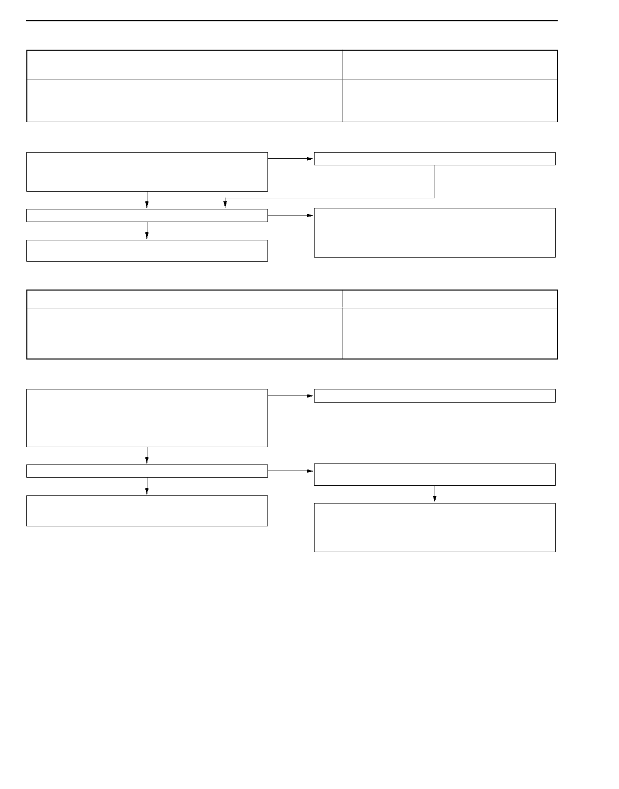
SERVICE SPECIFICATIONS 23100030222
Items Standard value
Oil temperature sensor kWat 0_C16.5 - 20.5
at 100_C0.57 - 0.69
Resistance of damper clutch control solenoid valve coil (at 20_C) W2.7 - 3.4
Resistance of Low-Reverse solenoid valve coil (at 20_C) W2.7 - 3.4
Resistance of second solenoid valve coil (at 20_C) W2.7 - 3.4
Resistance of underdrive solenoid valve coil (at 20_C) W2.7 - 3.4
Resistance of overdrive solenoid valve coil (at 20_C) W2.7 - 3.4
Stall speed r/min 2,100 - 2,600
LUBRICANTS 23100040034
Items Specified lubricant Quantity L
Transmission fluid DIA QUEEN ATF SPII or equivalent 7.8
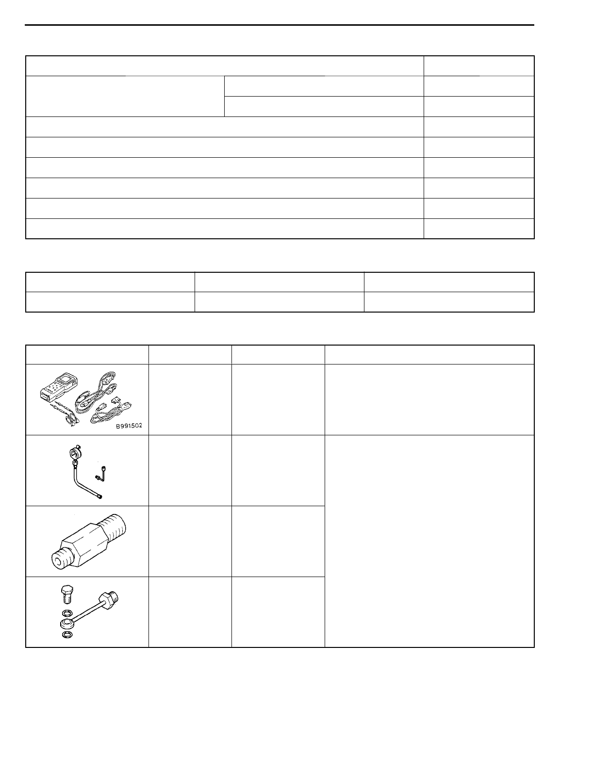
SPECIAL TOOLS 23100060214
Tool Number Name Use
MB991502 MUT-II sub
assembly Checking of the diagnosis code
MD998330
(including
MD998331)
Oil pressure gauge
(2,942 kPa) Measurement of oil pressure
MD998332 Adapter
MD998900 Adapter
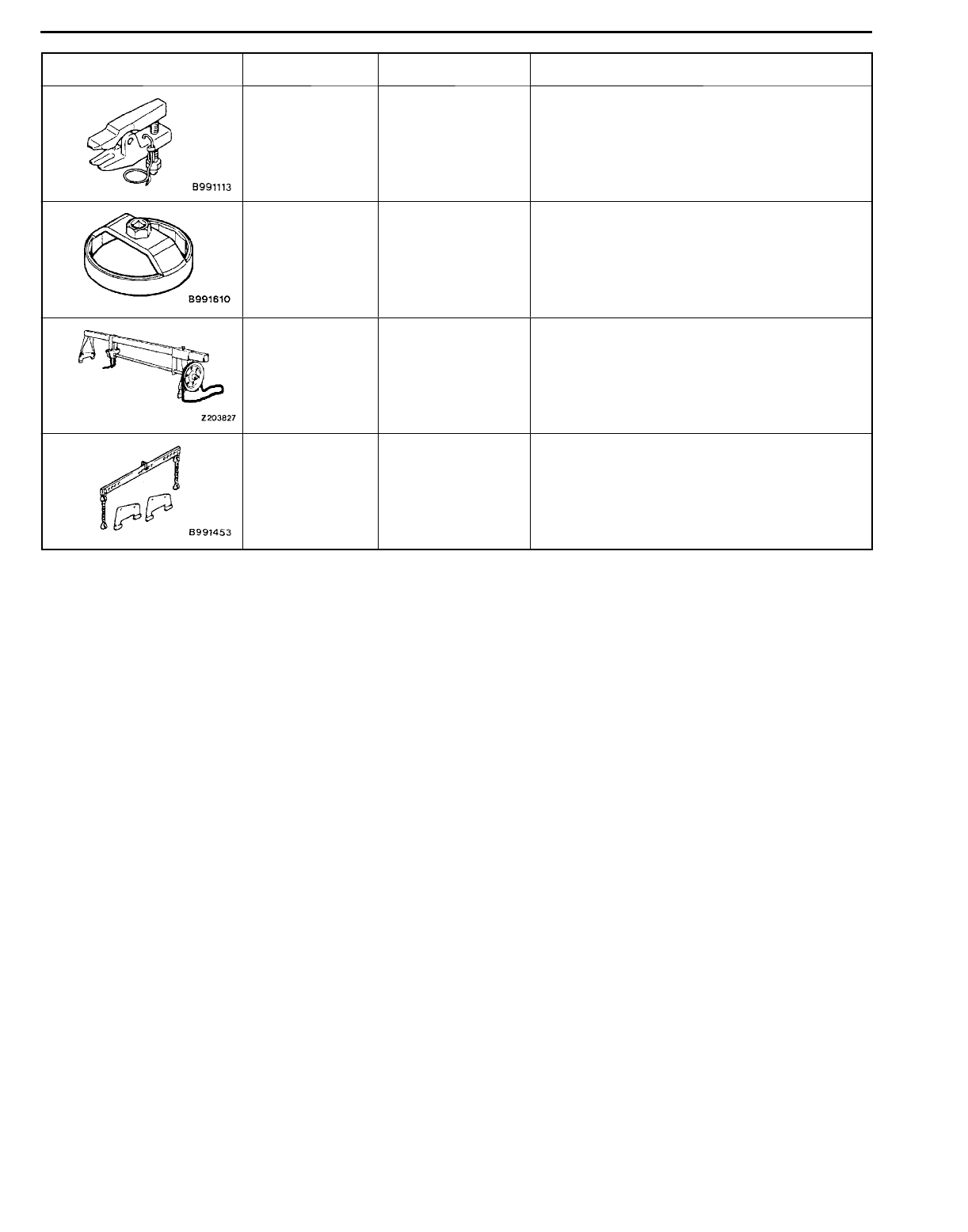
AUTOMATIC TRANSMISSION - Special Tools 23-3
Tool Number Name Use
MB990635 or
MB991113
Steering linkage
puller
Ball joint disconnection
MB991610 Oil filter wrench Removal and installation of automatic trans-
mission oil filter
GENERAL
SERVICE
TOOL
MZ203827
Engine lifter Supporting the engine assembly during
removal and installation of the transmission
MB991453 Engine hanger
assembly
Supporting the engine assembly during
removal and installation of the transmission
AUTOMATIC TRANSMISSION - Troubleshooting
23-4
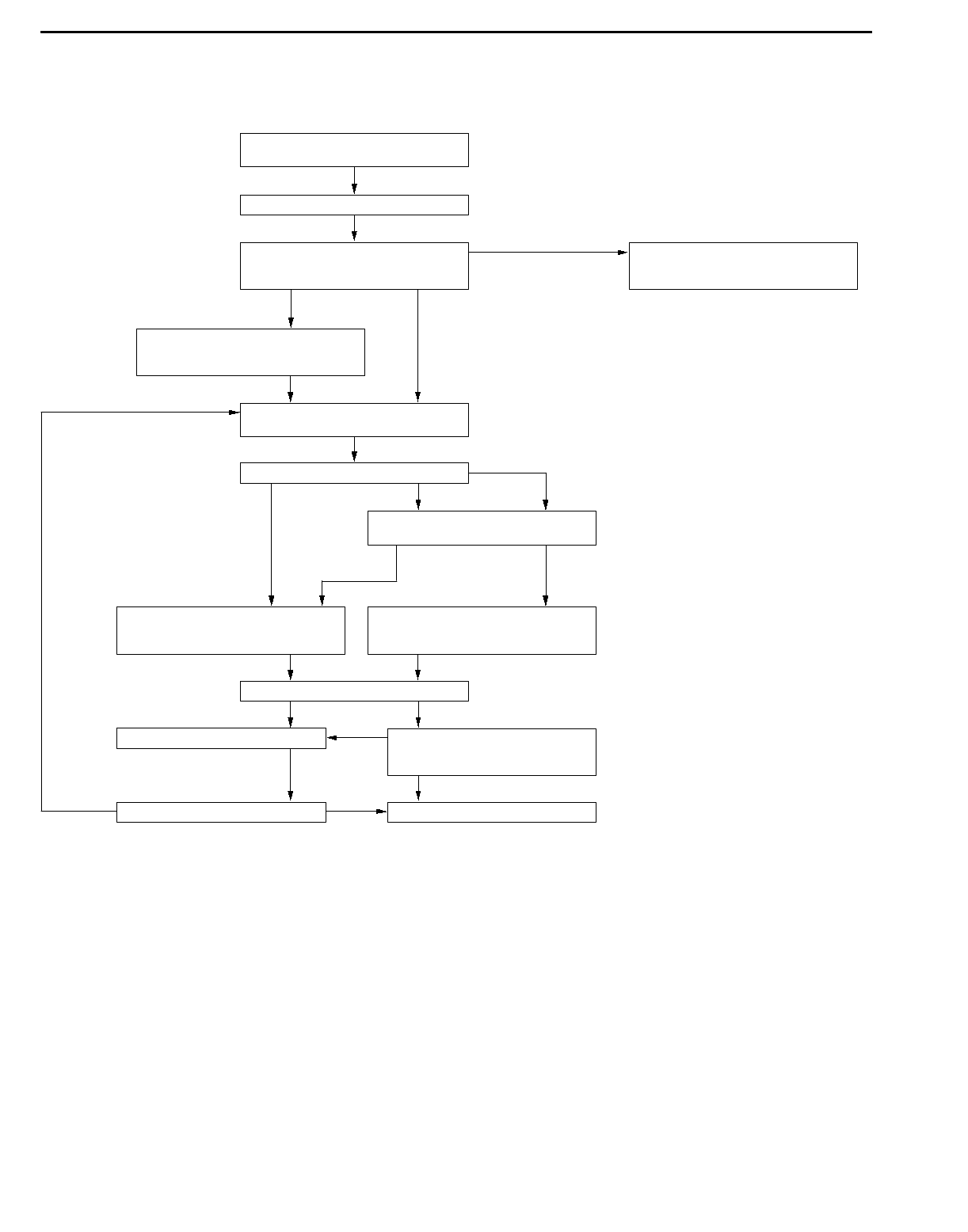
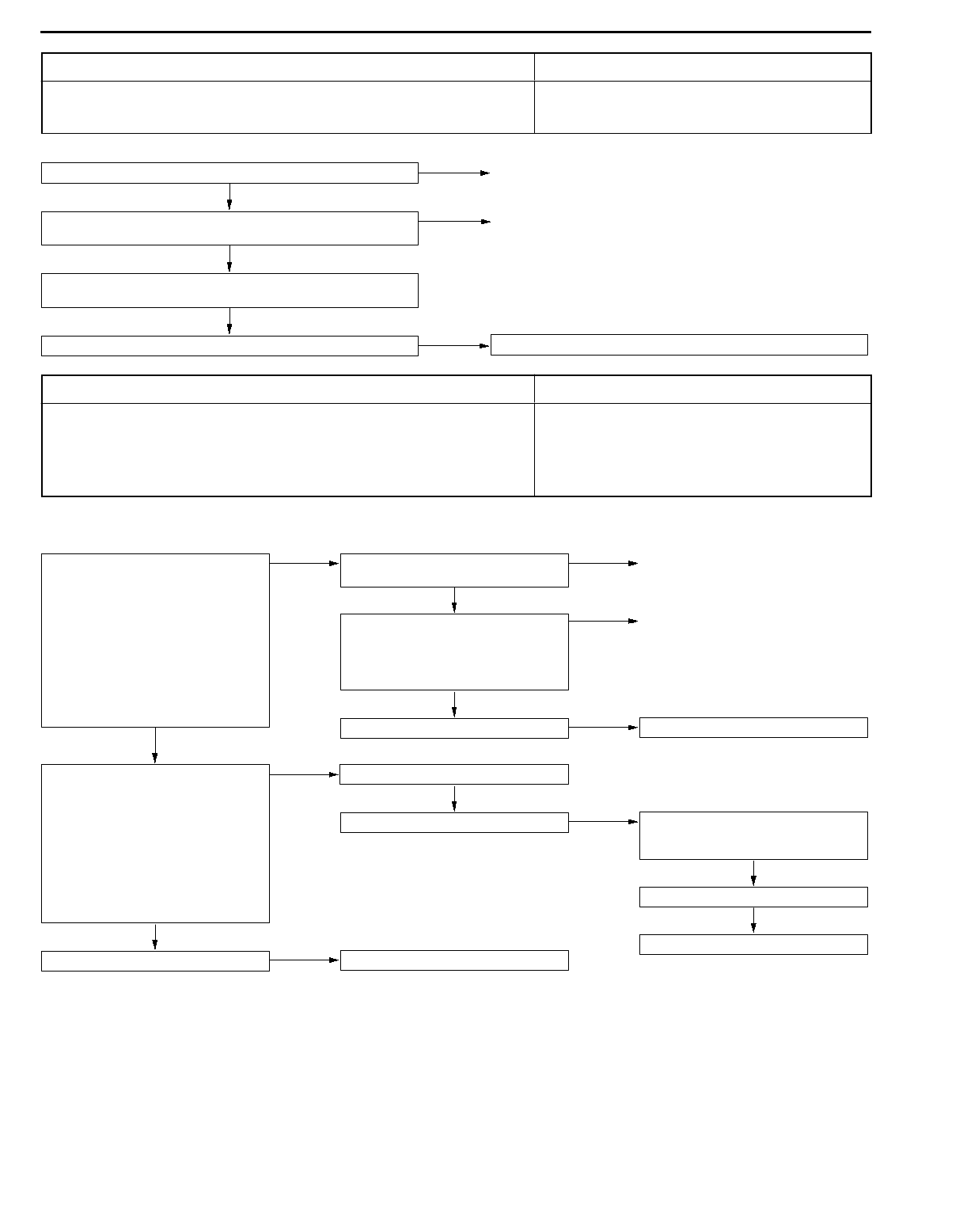
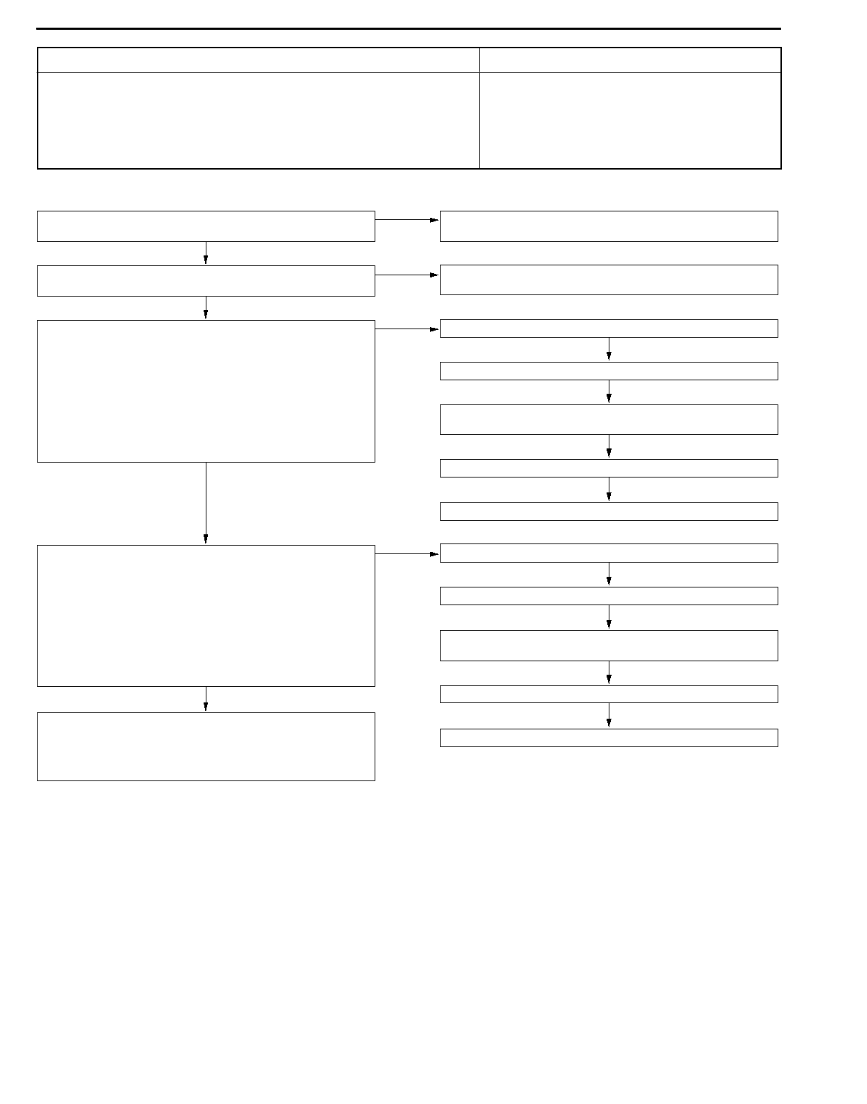
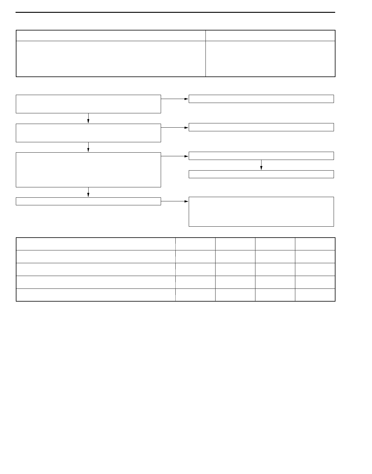
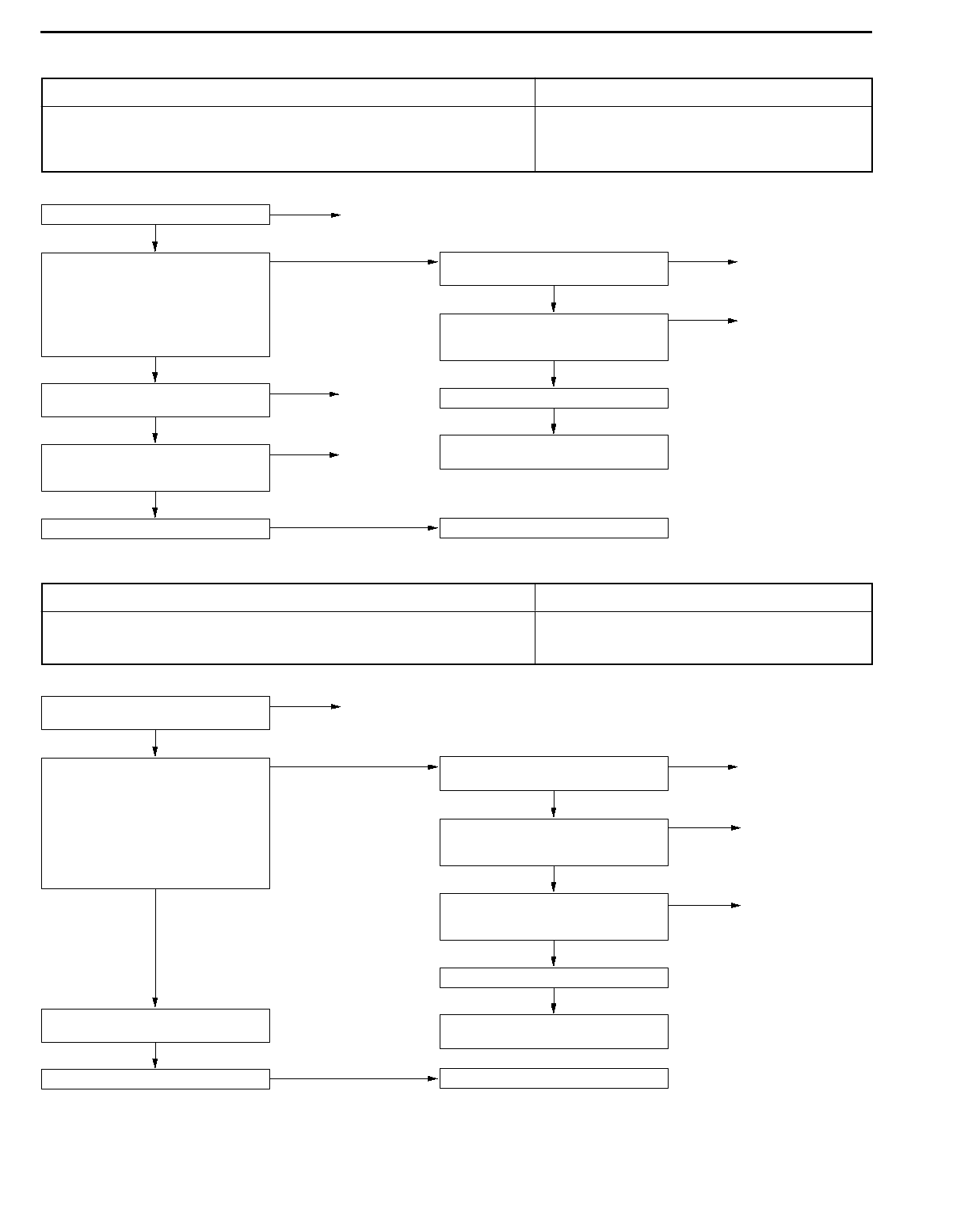
TROUBLESHOOTING 23100760275
STANDARD FLOW OF DIAGNOSIS TROUBLESHOOTING
Gathering information from custom-
er.
Check trouble symptoms.
Read the diagnosis code (GROUP 00
- How to Use Troubleshooting/In-
spection Service Points.)
Communication with
MUT-II not possible Inspection procedure No. 1 in
Inspection Chart For Trouble
Symptoms (Refer to P.23-27.)
Diagnosis code
displayed
Erase the diagnosis code (GROUP
00 - How to Use Troubleshooting/In-
spection Service Points.)
No diagnosis code displayed
Carry out the essential service
(Refer to P.23-46.)
Road test (Refer to P.23-6.) Abnormality exists (no diagnosis code)
No abnormality
Recheck diagnosis codes which
were read before the road test.
Abnormality exists
(diagnosis code
present)
Diagnosis
code displayed
No diagnosis
code displayed
To INSPECTION CHART FOR
DIAGNOSIS CODES
(Refer to P.23-14.)
To INSPECTION CHART FOR
TROUBLE SYMPTOMS
(Refer to P.23-26.)
Search for cause.
Found Not found
Repair
Confirmation test (road test)
NG
NG INTERMITTENT MALFUNCTION
(GROUP 00 - Points to Note for
Intermittent Malfunctions.)
OK Completed
OK
AUTOMATIC TRANSMISSION - Troubleshooting 23-5
DIAGNOSIS FUNCTION 23100770186
1. N range lamp
The N range lamp flashes at a frequency of approximately
1 Hz if there is an abnormality in any of the items in the
table below which are related to the A/T system. Check
the diagnosis code output if the N range lamp is flashing
at a frequency of approximately 1 Hz.
N range lamp flashing items
Crank angle sensor
Input shaft speed sensor
Output shaft speed sensor
Each solenoid valve
Out of phase at each shift point
Caution
If the N range lamp is flashing at a frequency of
approximately 2 Hz (faster than at 1 Hz), it means that
the automatic transmission fluid temperature is too high.
Stop the vehicle in a safe place and wait until the N range
lamp switches off.
2. Method of reading the diagnosis code
Use the MUT-II or the N range lamp to take a reading of
the diagnosis codes. (Refer to GROUP 00 - How to Use
Troubleshooting/Inspection Service Points.)

AUTOMATIC TRANSMISSION - Troubleshooting
23-6
ROAD TEST 23100780271
Check by the following procedure.
No. State prior to test
and operation
Test and operation Judgement value Check item Diag-
nosis
code
No.
Inspection
procedure page
if there is an
abnormality
1Ignition switch:
OFF
Ignition switch
(1) ON
Data list No. 54
Battery voltage [V]
Control relay 54 A/T Control
relay system
(23-25)
2Ignition switch:
ON
Engine: Stopped
Selector lever
position: P
Selector lever
position
(1) P, (2) R,
(3) N, (4) D,
(5) 3, (6) 2, (7) L
Data list No. 61
(1) P, (2) R, (3)N,
(4) D, (5) 3, (6) 2,
(7) L
Inhibitor switch -Inhibitor switch
system (23-36)
position: P
Accelerator pedal
(1) Released
(2) Half depressed
(3) Depressed
Data list No. 11
(1) 400 - 1,000 mV
(2) Gradually rises
from (1)
(3) 4,500 - 5,000
mV
Throttle posi-
tion sensor
<Vehicles
without TCL>
Accelerator
pedal position
sensor
<Vehicles with
TCL>
11
12
14
Throttle
position sensor
system (23-15)
Accelerator
pedal position
sensor system
(23-15)
Data list No. 25
(1) OFF
(2) ON
Wide open
throttle switch
25 Wide open
throttle switch
system (23-17)
Brake pedal
(1) Depressed
(2) Released
Data list No. 26
(1) ON
(2) OFF
Stop lamp
switch
26 Stop lamp switch
system (23-18)
3Ignition switch:
ST
Engine: Stopped
Starting test with
lever P or N range
Starting should be
possible
Starting
possible or
impossible
-Starting
impossible
(23-28)
4Warming up Drive for 15
minutes or more so
that the automatic
fluid temperature
becomes 70 -
90_C.
Data list No. 15
Gradually rises to
70 - 90_C
Oil temperature
sensor
15 Oil temperature
sensor system
(23-15)
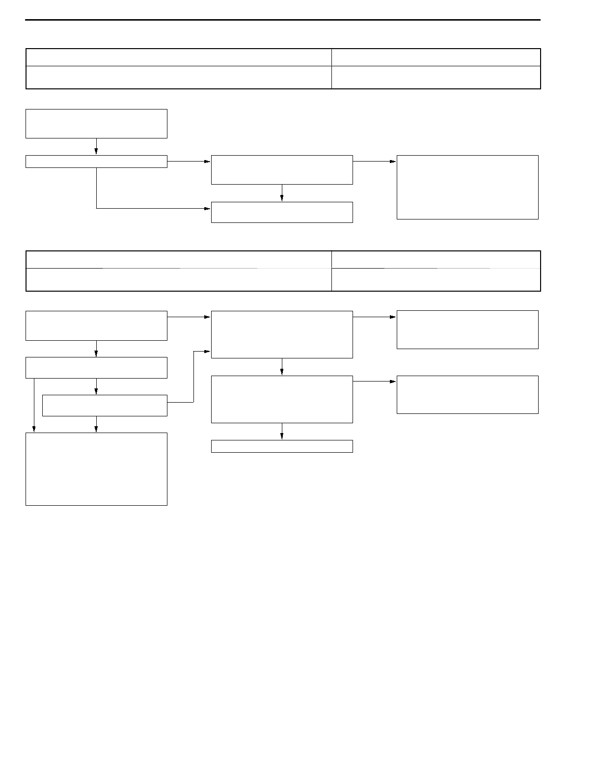
AUTOMATIC TRANSMISSION - Troubleshooting 23-7
No. State prior to test
and operation
Test and operation Judgement value Check item Diag-
nosis
code
No.
Inspection
procedure page
if there is an
abnormality
5Engine: Idling
Selector lever
position: N
Brake pedal
(Retest)
(1) Depressed
(2) Released
Data list No. 26
(1) ON
(2) OFF
Stop lamp
switch
26 Stop lamp switch
system (23-18)
A/C switch
(1) ON
(2) OFF
Data list No. 65
(1) ON
(2) OFF
Dual pressure
switch
-Dual pressure
switch system
(23-37)
Accelerator pedal
(1) Released
(2) Half depressed
Data list No. 64
(1) ON
(2) OFF
Idle position
switch
-Idle position
switch system
(23-37)
Data list No. 21
(1) 550 - 850 rpm
Gradually rises
from (1)
Crank angle
sensor
21 Crank angle
sensor system
(23-16)
Data list No. 57
(2) Data changes
Communication
with engine-
ECU
<Vehicles
without TCL>
Communication
with TCL-ECU
<Vehicles with
TCL>
51 Serial
communication
system (23-25)
Selector lever
position
(1) N ®D
Should be no
abnormal shifting
shocks
Malfunction
when starting
-Engine stalling
during shifting
(23-30)
(1) N ®D
(2) N ®RTime lag should be
within 2 seconds
-Shocks when
changing from N
to D and large
time lag (23-30)
-Shocks when
changing from N
to R and large
time lag (23-31)
-Shocks when
changing from N
to D,N to R and
large time lag
(23-32)
Driving
impossible
-Does not move
forward (23-28)
-Does not
reverse (23-29)
-Does not move
(forward or
reverse) (23-29)

AUTOMATIC TRANSMISSION - Troubleshooting
23-8
No. State prior to test
and operation
Test and operation Judgement value Check item Diag-
nosis
code
No.
Inspection
procedure page
if there is an
abnormality
6Selector lever
position: N
(Carry out on a
Selector lever
position and
vehicle speed
Data list No. 63
(2) 1st, (4) 3rd, (3)
2nd, (5) 4th
Shift condition - -
flat and straight
road.) (1) Idling in
L range
(Vehicle
stopped)
(2) Driving at
Data list No. 31
(2) 0 %, (4) 100 %,
(3) 100 %, (5) 100
%
Low and reverse
solenoid valve
31 Low and reverse
solenoid valve
system (23-18)
constant speed
of
10 km/h in
L position
Data list No. 32
(2) 0 %, (4) 0 %,
(3) 0 %, (5) 100 %
Underdrive
solenoid valve
32 Underdrive
solenoid valve
system (23-18)
(3) Driving at
constant speed
of
30 km/h in
Data list No. 33
(2)100 %, (4) 100
%, (3) 0 %, (5) 0 %
Second
solenoid valve
33 Second solenoid
valve system
(23-18)
2 position
(4) Driving at
50 km/h in
3 position with
accelerator fully
Data list No. 34
(2) 100 %, (4) 0 %,
(3) 100 %, (5) 0 %
Overdrive
solenoid valve
34 Overdrive
solenoid valve
system (23-18)
closed
(5) Driving at
constant speed
of
Data list No. 29
(1) 0 km/h
(4) 50 km/h
Vehicle speed
sensor
-Vehicle speed
sensor system
(23-38)
50 km/h in
D position
(Each
condition
Data list No. 22
(4) 1,800 - 2,100
rpm
Input shaft
speed sensor
22 Input shaft speed
sensor system
(23-16)
should be
maintained for
10 seconds or
more.)
Data list No. 23
(4) 1,800 - 2,100
rpm
Output shaft
speed sensor
23 Output shaft
speed sensor
system (23-17)
7Selector lever
position: 3
(Carry out on a
flat and straight
road.)
Selector lever
position and
vehicle speed
(1) Release the ac-
celerator pedal
Data list No. 36
(1) 0 %
(2) Approx. 70 - 90
%
Damper clutch
control solenoid
valve
36
52
Damper clutch
control solenoid
valve system
(23-19)
fully while driv-
ing at 50 km/h
in 3rd gear.
(2) Driving at
constant speed
of 50 km/h in
3rd gear.
Data list No. 52
(1) Approx.
100 - 300 rpm
(2) Approx.
0 - 10 rpm
AUTOMATIC TRANSMISSION - Troubleshooting 23-9
No. State prior to test
and operation
Test and operation Judgement value Check item Diag-
nosis
code
No.
Inspection
procedure page
if there is an
abnormality
8Use the MUT-II to
stop the INVECS-
II function.
Monitor data list
No. 11, 23, and 63
with the MUT-II.
For (1), (2) and (3),
the reading should
be the same as the
Malfunction
when shifting
-Shocks and
running up
(23-32)
Selector lever (1) Accelerate to specified output Displaced -All points (23-33)
position: D
(Carry out on a flat
and straight road.)
4th gear at a
throttle
position
shaft speed and no
abnormal shocks
should occur.
shifting points -Some points
(23-34)
and straight road.) position
sensor output
of 1.5V
should occur.
For (4), (5) and (6),
downshifting Does not shift -No diagnosis
code (23-34)
(accelerator
opening angle
of 30 %).
(2) Gently
should occur
immediately
after the shifting
operation is made.
22 Input shaft
speed sensor
system (23-16)
(2) Gently
decelerate to a
standstill.
(3) Accelerate to
operation is made.
23 Output shaft
speed sensor
system (23-17)
4th gear at a
throttle
position
sensor output
Does not shift
from 1 to 2 or 2
to 1
31 Low and reverse
solenoid valve
system (23-18)
of 2.5 V
(accelerator
opening angle
33 Second
solenoid valve
system (23-18)
of 50%).
(4) While driving at
60 km/h in 4th
gear, shift
41 1st gear ratio is
not specified
(23-20)
down to
3 range.
(5) While driving at
42 2nd gear ratio is
not specified
(23-21)
40 km/h in 3rd
gear, shift
down to
2 range.
Does not shift
from 2 to 3 or 3
to 2
33 Second
solenoid valve
system (23-18)
(6) While driving at
20 km/h in 2nd
gear, shift
down to
34 Overdrive
solenoid valve
system (23-18)
down to
L range. 42 2nd gear ratio is
not specified
(23-21)
43 3rd gear ratio is
not specified
(23-22)
Does not shift
from 3 to 4 or 4
to 3
32 Underdrive
solenoid valve
system (23-18)
33 Second
solenoid valve
system (23-18)
43 3rd gear ratio is
not specified
(23-22)
44 4th gear ratio is
not specified
(23-23)
AUTOMATIC TRANSMISSION - Troubleshooting
23-10
No. State prior to test
and operation
Test and operation Judgement value Check item Diag-
nosis
code
No.
Inspection
procedure page
if there is an
abnormality
9Selector lever
position: N
(Carry out on a
Monitor data list
No. 22
and No. 23 with the
II
The ratio between
data list No. 22 and
No. 23 should be
Does not shift 22 Input shaft
speed sensor
system (23-16)
(Carry out on a
flat and straight
road.)
MUT-II.
(1) Move selector
lever to
the same as the
gear ratio when
reversing.
23 Output shaft
speed sensor
system (23-17)
R range, drive
at constant
speed of
10 km/h.
46 Reverse gear
ratio is not
specified (23-24)
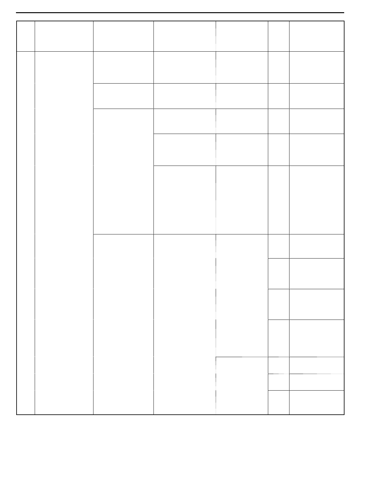
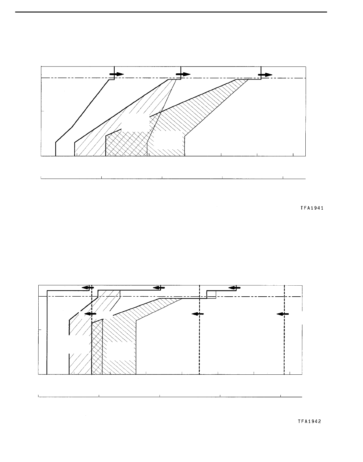
SHIFT PATTERN
<4G63 engine>
UPSHIFT PATTERN
Output shaft speed r/min
Thick line: Standard shift pattern
100
Throttle opening %
0 1,000 2,000 3,000 4,000 5,000 6,000 7,000
2®3
movement
range 3®4
movement
range
Vehicle speed km/h
0
50
0 50 100 150 200
12 23 34
AUTOMATIC TRANSMISSION - Troubleshooting 23-11
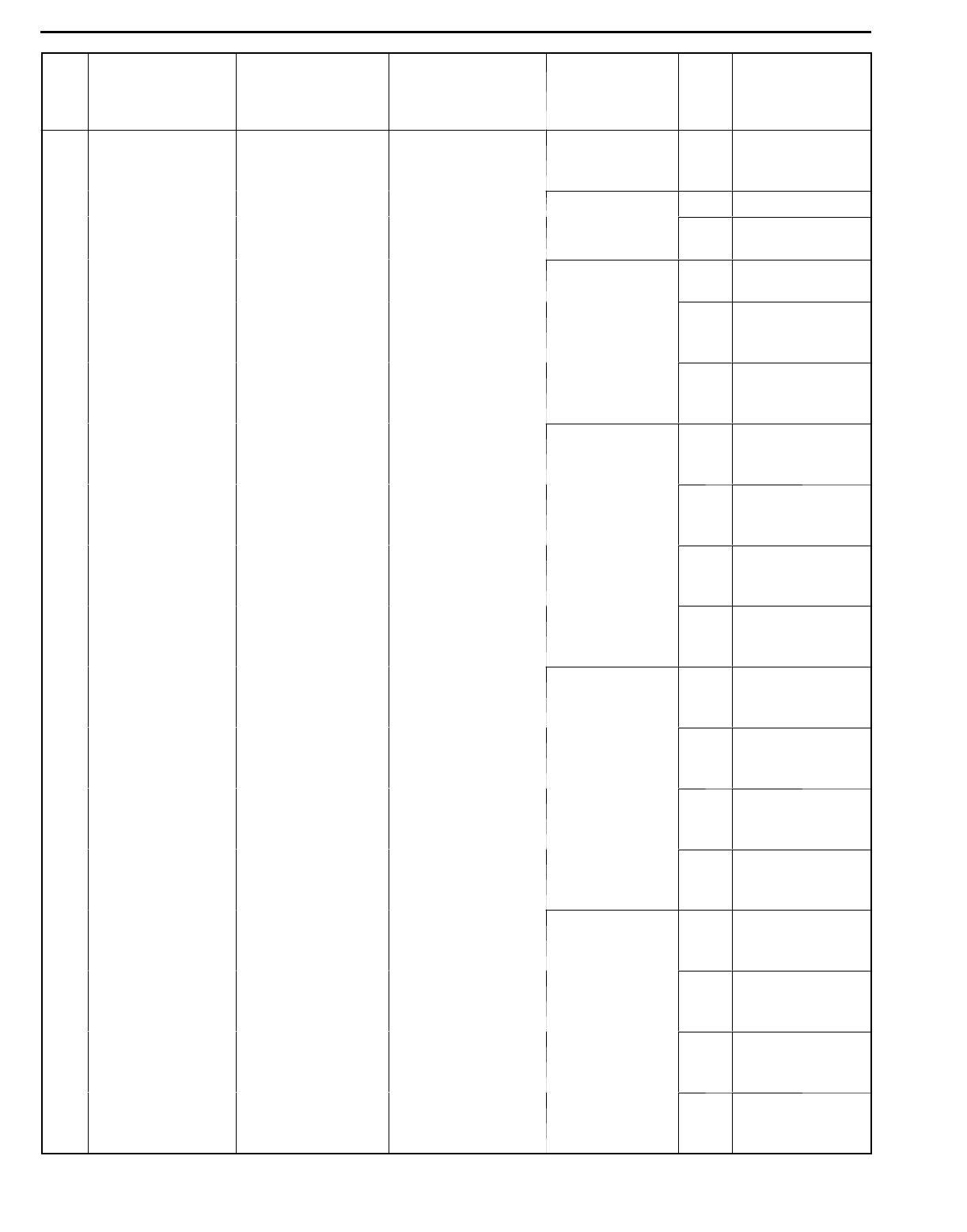
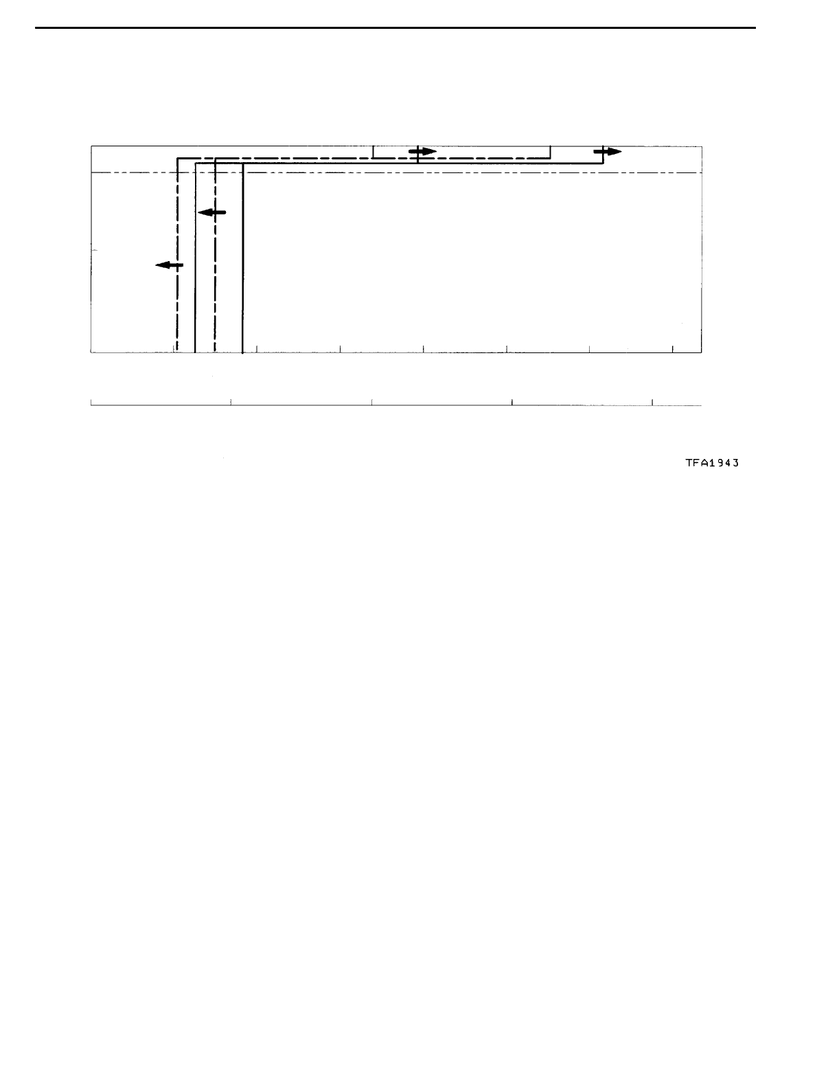
DOWNSHIFT PATTERN
3 (L,2) 4
(L,2,3)
3
Thick line: Standard shift patternThrottle opening %
2¬3
movement
range
3¬4
movement
range
100
0 1,000 2,000 3,000 4,000 5,000 6,000 7,000
Output shaft speed r/min
Vehicle speed km/h
0
50
0 50 100
12 23 34
200150
12 (L) 2
HOLD MODE PATTERN
Thick line: Standard shift pattern
Throttle opening %
100
0 2,000 4,000 6,000 8,000
Output shaft speed r/min
Vehicle speed km/h
0
50
0 50 100
12
23 34
200150
34
AUTOMATIC TRANSMISSION - Troubleshooting
23-12
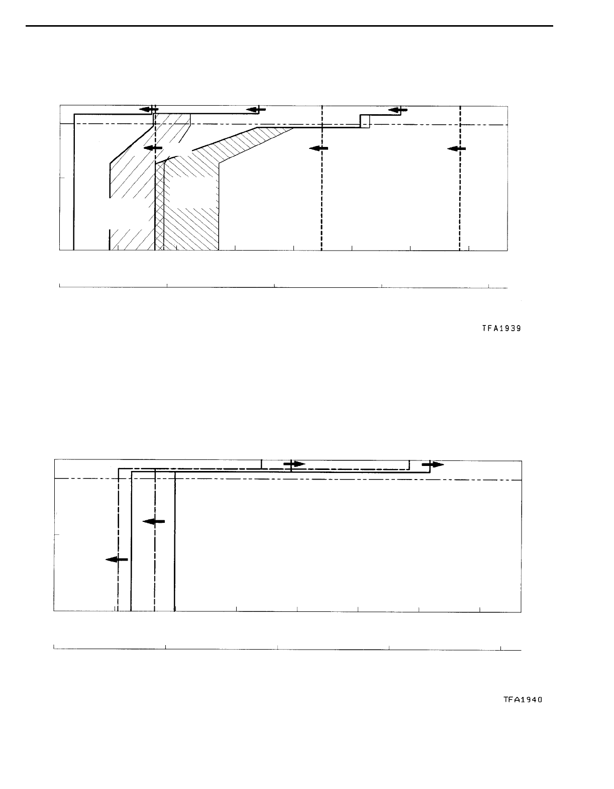
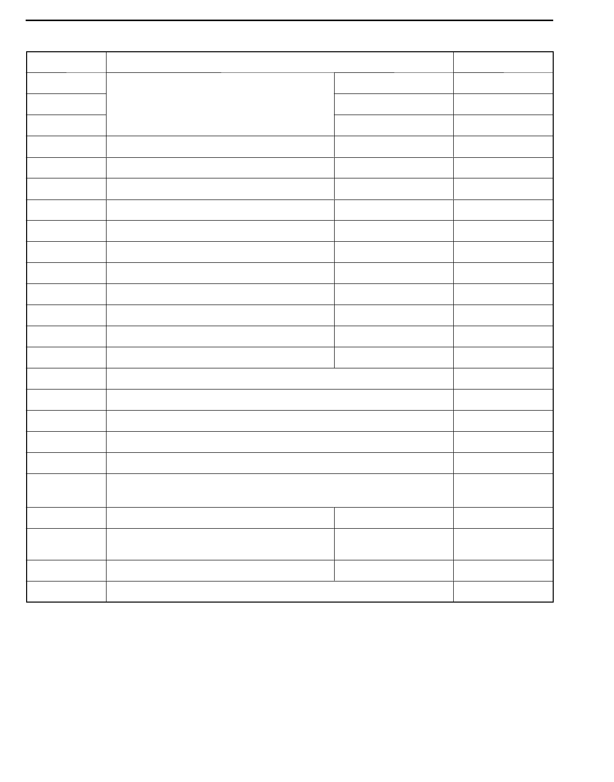
<6A13 engine>
UPSHIFT PATTERN
Thick line: Standard shift patternThrottle opening %
100
Output shaft speed r/min
Vehicle speed km/h
0
50
0 50 100
12 23 34
200150
2®3
movement
range
3®4
movement
range
0 1,000 2,000 3,000 4,000 5,000 6,000 7,000
DOWNSHIFT PATTERN
4
(L,2,3)
3
Thick line: Standard shift patternThrottle opening %
2¬3
movement
range 3¬4
movement
range
100
0 1,000 2,000 3,000 4,000 5,000 6,000 7,000
Output shaft speed r/min
Vehicle speed km/h
0
50
0 50 100
12 2 3 34
200150
12 (L) 23 (L,2)
AUTOMATIC TRANSMISSION - Troubleshooting 23-13
HOLD MODE PATTERN
Thick line: Standard shift patternThrottle opening %
100
0 2,000 4,000 6,000 8,000
Output shaft speed r/min
Vehicle speed km/h
0
50
0 50 100
34
23
12
200150
34
AUTOMATIC TRANSMISSION - Troubleshooting
23-14
INSPECTION CHART FOR DIAGNOSIS CODE 23100790243
Code Diagnosis item Reference page
11 Throttle position sensor system Short circuit 23-15
12 <Vehicles without TCL>
Accelerator pedal position sensor system Open circuit 23-15
14
Accelerator pedal position sensor system
<Vehicles with TCL> Sensor maladjustment 23-15
15 Oil temperature sensor system Open circuit 23-15
21 Crank angle sensor system Open circuit 23-16
22 Input shaft speed sensor system Short circuit/open circuit 23-16
23 Output shaft speed sensor system Short circuit/open circuit 23-17
25 Wide open throttle switch system Short circuit 23-17
26 Stop lamp switch system Short circuit/open circuit 23-18
31 Low and reverse solenoid valve system Short circuit/open circuit 23-18
32 Underdrive solenoid valve system Short circuit/open circuit 23-18
33 Second solenoid valve system Short circuit/open circuit 23-18
34 Overdrive solenoid valve system Short circuit/open circuit 23-18
36 Damper control clutch solenoid valve system Short circuit/open circuit 23-19
41 1st gear ratio does not meet the specification 23-20
42 2st gear ratio does not meet the specification 23-21
43 3rd gear ratio does not meet the specification 23-22
44 4th gear ratio does not meet the specification 23-23
46 Reverse gear ratio does not meet the specification 23-24
51 Abnormal communication with engine-ECU <Vehicles without TCL>
Abnormal communication with TCL-ECU <Vehicles with TCL>
23-25
52 Damper control clutch solenoid valve system Defective system 23-19
54 A/T Control relay system Short circuit to earth/
open circuit
23-25
56 N range lamp system Short circuit to earth 23-26
71 Malfunction of A/T-ECU 23-26
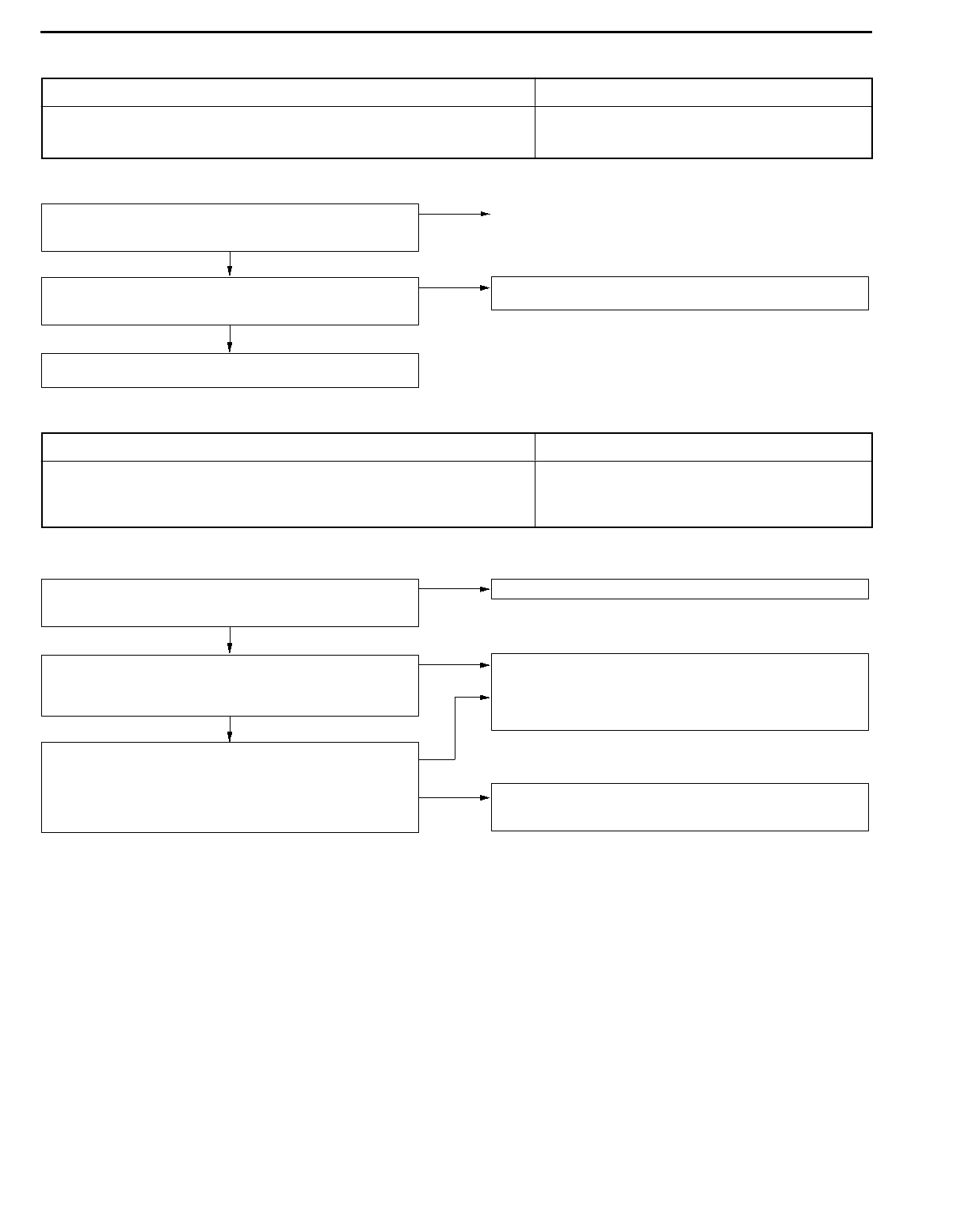
AUTOMATIC TRANSMISSION - Troubleshooting 23-15
INSPECTION PROCEDURES FOR DIAGNOSIS CODES
Code No. 11, 12, 14 Throttle position sensor system
<Vehicles without TCL>, accelerator pedal position
sensor <Vehicles with TCL>
Probable cause
If the TPS or APS output voltage is 4.8 V or higher when the engine is idling, the
output is judged to be too high and diagnosis code No. 11 is output. Code No. 11
is also output if there is a problem with the APS and an APS fail-safe signal is received
from the TCL-ECU. If the TPS or APS output voltage is 0.2 V or lower at times
other than when the engine is idling, the output is judged to be too low and diagnosis
code No. 12 is output. If the TPS or APS output voltage is 0.2 V or lower or if it
is 1.2 V or higher when the engine is idling, the TPS or APS adjustment is judged
to be incorrect and diagnosis code No. 14 is output.
DMalfunction of the throttle position sensor <Vehicles
without TCL>
DMalfunction of the accelerator pedal position sensor
<Vehicles with TCL>
DMalfunction of connector
DMalfunction of the A/T-ECU
Throttle position sensor check <Vehicles without TCL>
(Refer to GROUP 13A - On-vehicle Service.)
Accelerator pedal position sensor check<Vehicles with TCL>
(Refer to GROUP 13H - On-vehicle Service.)
NG Replace
OK
Check the following connectors:
B-07 <Vehicles without TCL>, B-41 <Vehicles with TCL>, C-29
NG Repair
OK
Harness check
DBetween throttle position sensor and A/T-ECU
<Vehicles without TCL>
DBetween accelerator pedal position sensor and A/T-ECU
<Vehicles with TCL>
NG Repair
OK
Check the trouble symptoms.
NG Replace the A/T-ECU.
Code No. 15 Oil temperature sensor system Probale cause
If the oil temperature sensor output voltage is 2.6 V or more even after driving for
10 minutes or more (if the oil temperature does not increase), it is judged that there
is an open circuit in the oil temperature sensor and diagnosis code No. 15 is output.
DMalfunction of the oil temperature sensor
DMalfunction of connector
DMalfunction of the A/T-ECU
Oil temperature sensor check (Refer to P.23-52.) NG Replace
OK
Check the follwing connectors: B-70, C-29 NG Repair
OK
Harness check
DBetween oil temperature sensor and A/T-ECU
NG Repair
OK
Check the trouble symptoms.
NG Replace the A/T-ECU.
AUTOMATIC TRANSMISSION - Troubleshooting
23-16
Code No. 21 Crank angle sensor system Probable cause
If no output pulse is detected from the crank angle sensor for 5 seconds or more
while driving at 25 km/h or more, it is judged that there is an open circuit in the
crank angle sensor and diagnosis code No. 21 is output.
DMalfunction of the crank angle sensor
DMalfunction of connector
DMalfunction of the A/T-ECU
Check the follwing connectors: B-77, C-29 NG Repair
OK
Harness check
DBetween crank angle sensor and A/T-ECU
NG Repair
OK
Crank angle sensor system check
(Refer to GROUP 13A - Troubleshooting.)
OK
Check the trouble symptoms.
NG Replace the A/T-ECU.
Code No. 22 Input shaft speed sensor system Probable cause
If no output pulse is detected from the input shaft speed sensor for 1 second or
more while driving in 3rd or 4th gear at a speed of 30 km/h or more, there is judged
to be an open circuit or short-circuit in the input shaft speed sensor and diagnosis
code No. 22 is output. If diagnosis code No. 22 is output four times, the transmission
is locked into 3rd gear (D range) or 2nd gear as a fail-safe measure, and the N
range lamp flashes at a frequency of 1 Hz.
DMalfunction of the input shaft speed sensor
DMalfunction of the underdrive clutch retainer
DMalfunction of connector
DMalfunction of A/T-ECU
L: Refer to the Transmission Workshop Manual.
Replace the A/T-ECU.
A/T overhaul K
DReplace the underdrive clutch
retainer.
Replace the A/T-ECU.
Check the trouble symptoms.
NG
Eliminate the cause of the noise.
NG
OK
Check the trouble symptoms.
OK
Check the following harness:
DBetween the input shaft speed
sensor and the ignition switch
DBetween the input shaft speed
sensor and A/T-ECU
NG Repair
NG
Check the trouble symptoms.
NG
OK
Check the trouble symptoms.
OK
Measure output waveform of the input
shaft speed sensor.
(using an oscilloscope)
DEngine: 2,000 r/min (approx. 50
km/h)
DTransmission: 3rd gear (Voltage)
OK: Conforms to the waveform
shown at page 23-45 (Inspec-
tion procedure using an oscil-
loscope). There is no noise
in the output waveform.
NG Replace the input shaft speed sensor.
Measure at the input shaft speed sensor
connector B-71.
DDisconnect the connector and
measure at the harness side.
(1) Voltage between 3 and earth
(Ignition switch: ON)
OK: Battery voltage
(2) Voltage between 2 and earth
(Ignition switch: ON)
OK approx. 5 V
(3) Continuity between 1 and earth
OK: Continuity
NG Check the following connectors:
B-71, C-29
NG Repair
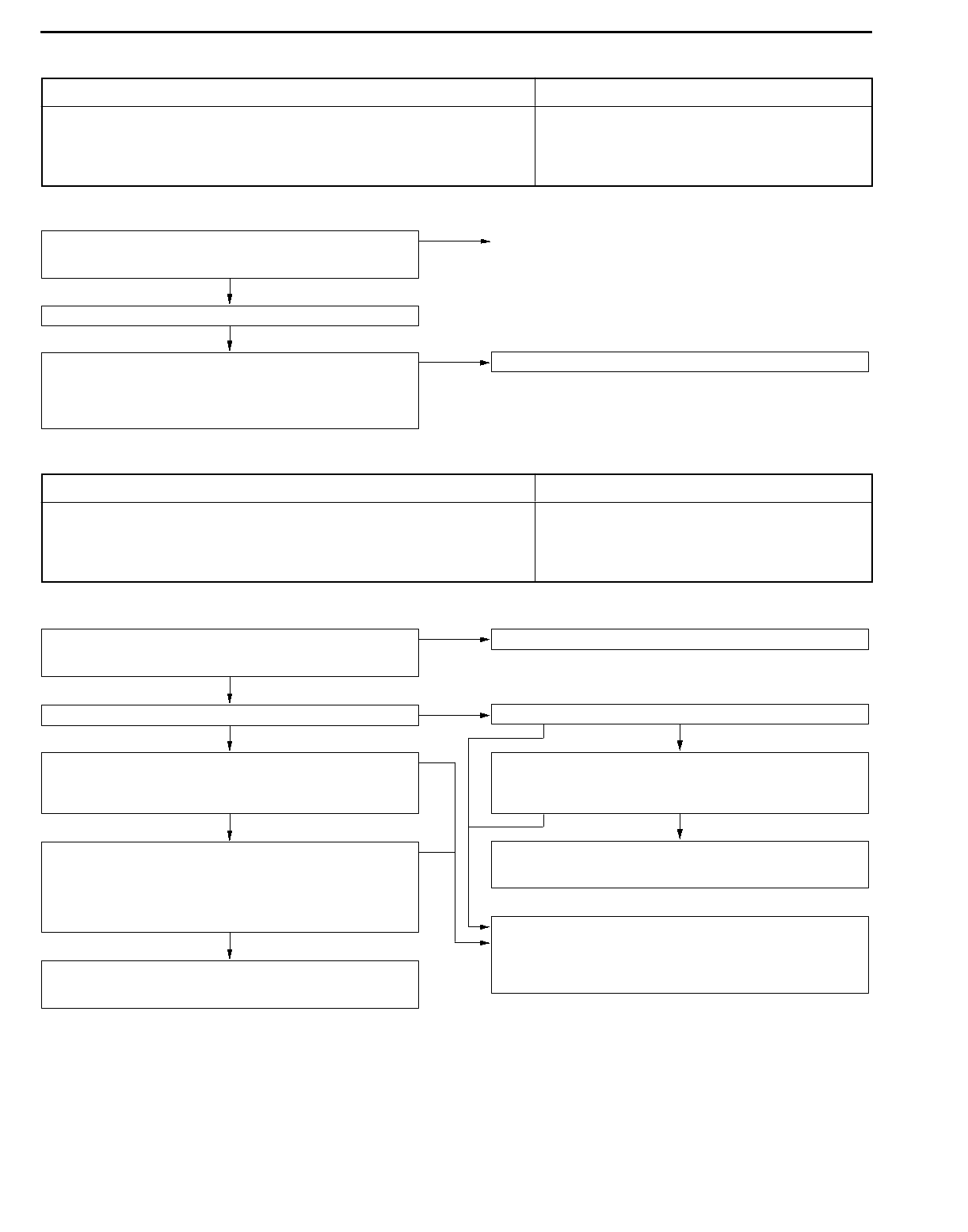
AUTOMATIC TRANSMISSION - Troubleshooting 23-17
Code No. 23 Output shaft speed sensor system Probable cause
If the output from the output shaft speed sensor is continuously 50% lower than the
vehicle speed for 1 second or more while driving in 3rd or 4th gear at a speed of
30 km/h or more, there is judged to be an open circuit or short-circuit in the output
shaft speed sensor and diagnosis code No. 23 is output.
If diagnosis code No. 23 is output four times, the transmission is locked into 3rd
gear (D range) or 2nd gear as a fail-safe measure, and the N range lamp flashes
at a frequency of 1 Hz.
DMalfunction of the output shaft speed sensor
DMalfunction of the transfer drive gear or driven gear
DMalfunction of connector
DMalfunction of the A/T-ECU
L: Refer to the Transmission Workshop Manual.
A/T overhaul L
DReplace the transfer drive gear and
driven gear.
Check the trouble symptoms.
NG
Eliminate the cause of the noise.
Replace the A/T-ECU.
Replace the A/T-ECU.
NG
OK
Check the trouble symptoms.
OK
Check the following harness:
DBetween the output shaft speed
sensor and the ignition switch
DBetween the output shaft speed
sensor and A/T-ECU
NG Repair
NG
Check the trouble symptoms.
NG
OK
Check the trouble symptoms.
OK
Measure output waveform of the output
shaft speed sensor.
(using an oscilloscope)
DEngine: 2,000 r/min
(approx. 50 km/h)
DTransmission: 3rd gear
(Voltage)
OK: Conforms to the waveform
shown at page 23-45 (Inspec-
tion procedure using an oscil-
loscope). There is no noise
in the output waveform.
NG Replace the output shaft speed sensor.
Measure at the output shaft speed sen-
sor connector B-68.
DDisconnect the connector and
measure at the harness side.
(1) Voltage between 3 and earth
(Ignition switch: ON)
OK: Battery voltage
(2) Voltage between 2 and earth
(Ignition switch: ON)
OK: approx. 5 V
(3) Continuity between 1 and earth
OK: Continuity
NG Check the following connectors:
B-68, C-29
NG Repair
Code No. 25 Wide open throttle switch system Probable cause
If the wide open throttle switch is on for 1 second or more with the throttle valve
opening angle at 70% or less, it is judged that there is a short circuit in the wide
open throttle switch and diagnosis code No. 25 is output.
DMalfunction of the wide open throttle switch
DMalfunction of connector
DMalfunction of A/T-ECU
Wide open throttle switch check (Refer to P.23-64). NG Replace
OK
Check the following connectors: C-18, C-30, C-83 NG Repair
OK
Harness check
DBetween the wide open throttle switch and the A/T-ECU.
NG Repair
OK
Check the trouble symptoms.
NG Replace the A/T-ECU.
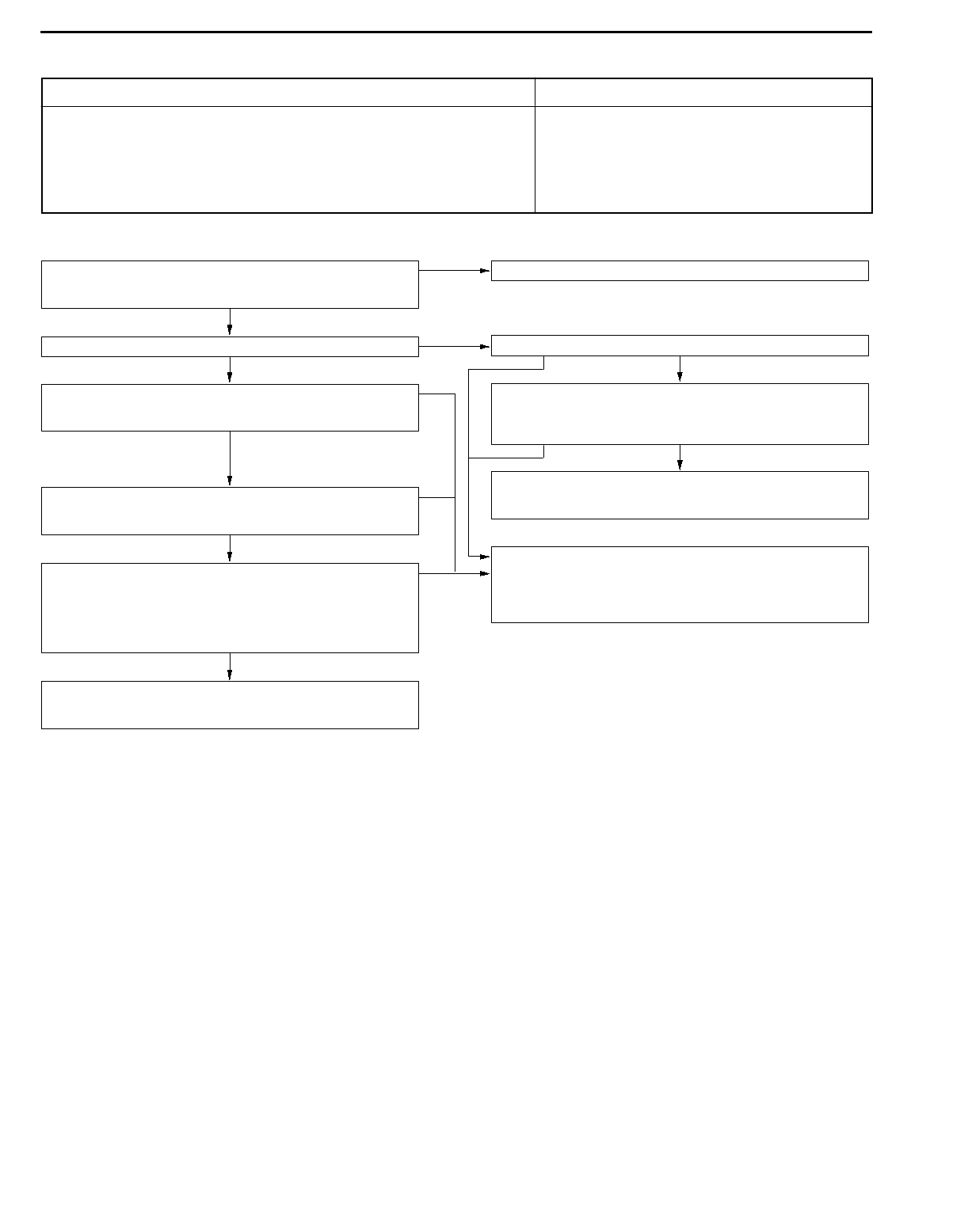
AUTOMATIC TRANSMISSION - Troubleshooting
23-18
Code No. 26 Stop lamp switch system Probable cause
If the stop lamp switch is on for 5 minutes or more while driving, it is judged that
there is a short circuit in the stop lamp switch and diagnosis code No. 26 is output.
DMalfunction of the stop lamp switch
DMalfunction of connector
DMalfunction of the A/T-ECU
Stop lamp switch check (Refer to GROUP 35 - Brake Pedal.) NG Replace
OK
Check the following connectors: C-02, C-30, C-65, C-83 NG Repair
OK
Harness check
DBetween stop lamp switch and A/T-ECU
NG Repair
OK
Check the trouble symptoms.
NG Replace the A/T-ECU.
Code No. 31 Low and reverse solenoid valve system Probable cause
Code No. 32 Underdrive solenoid valve system
Code No. 33 Second solenoid valve system
Code No. 34 Overdrive solenoid valve system
If the resistance value for a solenoid valve is too large or too small, it is judged
that there is a short-circuit or an open circuit in the solenoid valve and the respective
diagnosis code is output. The transmission is locked into 3rd gear as a fail-safe measure,
and the N range lamp flashes at a frequency of 1 Hz.
DMalfunction of solenoid valve
DMalfunction of connector
DMalfunction of the A/T-ECU
Solenoid valve check (Refer to P.23-54.) NG Replace
OK
Check the following connectors: B-70, C-28, C-30, C-41 NG Repair
OK
Harness check
DBetween solenoid valve and A/T-ECU
NG Repair
OK
Replace the solenoid valve.
Check the trouble symptoms.
NG Replace the A/T-ECU.
AUTOMATIC TRANSMISSION - Troubleshooting 23-19
Code No. 36, 52 Damper clutch control solenoid valve
system Probable cause
If the resistance value for the damper clutch control solenoid valve is too large or
too small, it is judged that there is a short-circuit or an open circuit in the damper
clutch control solenoid valve and diagnosis code No. 36 is output. If the drive duty
rate for the damper clutch control solenoid valve is 100 % for a continuous period
of 4 seconds or more, it is judged that there is an abnormality in the damper clutch
control system and diagnosis code No. 52 is output. When diagnosis code No. 36
is output, the transmission is locked into 3rd gear as a fail-safe measure, and the
N range lamp flashes at a frequency of 1 Hz.
DMalfunction of the damper clutch control solenoid valve
DMalfunction of connector
DMalfunction of the A/T-ECU
Damper clutch control solenoid valve check (Refer to P.23-54.) NG Replace
OK
Check the following connectors: B-70, C-28, C-41 NG Repair
OK
Harness check
DBetween damper clutch control solenoid valve and A/T-ECU
NG Repair
OK
Replace the damper clutch control solenoid valve.
Check the trouble symptoms.
NG Replace the A/T-ECU.

AUTOMATIC TRANSMISSION - Troubleshooting
23-20
Code No. 41 1st gear ratio does not meet the specification Probable cause
If the output from the output shaft speed sensor multiplied by the 1st gear ratio is
not the same as the output from the input shaft speed sensor after shifting to 1st
gear has been completed, diagnosis code No. 41 is output. If diagnosis code No.
41 is output four times, the transmission is locked into 3rd gear as a fail-safe measure,
and the N range lamp flashes at a frequency of 1 Hz.
DMalfunction of the input shaft speed sensor
DMalfunction of the output shaft speed sensor
DMalfunction of the underdrive clutch retainer
DMalfunction of the transfer drive gear or driven gear
DMalfunction of the low and reverse brake system
DMalfunction of the underdrive clutch system
DNoise generated
L: Refer to the Transmission Workshop Manual.
MUT-II Self-Diag code
Is the diagnosis code No. 22 output?
Yes
Code No. 22 Input shaft speed sensor system check
(Refer to P.23-16.)
No
MUT-II Self-Diag code
Is the diagnosis code No. 23 output?
Yes Code No. 23 Output shaft speed sensor system check
(Refer to P.23-17.)
No
Measure output waveform from the input shaft speed sensor. (using
an oscilloscope)
DConnect the connector B-71 and measure voltage between
31 and 43 at the A/T-ECU.
DEngine: 2,000 r/min (approx. 50 km/h)
DSelector lever position: 3
(Voltage)
OK: A waveform such as theone shown on P.23-45 (Inspection
Procedure Using an Oscilloscope) is output (flalshing
between 0 ¨ 5V) and there is no noise appearing
in the waveform.
NG Replace the input shaft speed sensor.
Check the trouble symptoms.
NG
A/T overhaul L
DReplace the underdrive clutch retainer.
Check the trouble symptoms.
NG
Eliminate the cause of the noise.
OK
Measure output waveform from the output shaft speed sensor.
(using an oscilloscope)
DConnect the connector B-68 and measure voltage between
32 and 43 at the A/T-ECU.
DEngine: 2,000 r/min (approx. 50 km/h)
DSelector lever position: 3
(Voltage)
OK: A waveform such as theone shown on P.23-45 (Inspection
Procedure Using an Oscilloscope) is output (flalshing
between 0 ¨ 5V) and there is no noise appearing
in the waveform.
NG Replace the output shaft speed sensor.
Check the trouble symptoms.
NG
A/T overhaul L
DReplace the transfer drive gear and driven gear.
Check the trouble symptoms.
NG
Eliminate the cause of the noise.
OK
A/T overhaul L
DUnderdrive clutch system check
(No. 42, No. 43, or no diagnosis code is output).
DLow and reverse brake system check
(No. 46 or no diagnosis code is output).
AUTOMATIC TRANSMISSION - Troubleshooting 23-21
Code No. 42 2nd gear ratio does not meet the specification Probable cause
If the output from the output shaft speed sensor multiplied by the 2nd gear ratio
is not the same as the output from the input shaft speed sensor after shifting to
2nd gear has been completed, diagnosis code No. 42 is output. If diagnosis code
No. 42 is output four times, the transmission is locked into 3rd gear as a fail-safe
measure, and the N range lamp flashes at a frequency of 1 Hz.
DMalfunction of the input shaft speed sensor
DMalfunction of the output shaft speed sensor
DMalfunction of the underdrive clutch retainer
DMalfunction of the transfer drive gear or driven gear
DMalfunction of the second brake system
DMalfunction of the underdrive clutch system
DNoise generated
L: Refer to the Transmission Workshop Manual.
MUT-II Self-Diag code
Is the diagnosis code No. 22 output?
Yes
Code No. 22 Input shaft speed sensor system check
(Refer to P.23-16.)
No
MUT-II Self-Diag code
Is the diagnosis code No. 23 output?
Yes Code No. 23 Output shaft speed sensor system check
(Refer to P.23-17.)
No
Measure output waveform from the input shaft speed sensor. (using
an oscilloscope)
DConnect the connector B-71 and measure voltage between
31 and 43 at the A/T-ECU.
DEngine: 2,000 r/min (approx. 50 km/h)
DSelector lever position: 3
(Voltage)
OK: A waveform such as theone shown on P.23-45 (Inspection
Procedure Using an Oscilloscope) is output (flalshing
between 0 ¨ 5V) and there is no noise appearing
in the waveform.
NG Replace the input shaft speed sensor.
Check the trouble symptoms.
NG
A/T overhaul L
DReplace the underdrive clutch retainer.
Check the trouble symptoms.
NG
Eliminate the cause of the noise.
OK
Measure output waveform from the output shaft speed sensor.
(using an oscilloscope)
DConnect the connector B-68 and measure voltage between
32 and 43 at the A/T-ECU.
DEngine: 2,000 r/min (approx. 50 km/h)
DSelector lever position: 3
(Voltage)
OK: A waveform such as theone shown on P.23-45 (Inspection
Procedure Using an Oscilloscope) is output (flalshing
between 0 ¨ 5V) and there is no noise appearing
in the waveform.
NG Replace the output shaft speed sensor.
Check the trouble symptoms.
NG
A/T overhaul L
DReplace the transfer drive gear and driven gear.
Check the trouble symptoms.
NG
Eliminate the cause of the noise.
OK
A/T overhaul L
DUnderdrive clutch system check
(No. 41, No. 43, or no diagnosis code is output).
DSecond brake system check
(No. 44 or no diagnosis code is output).

AUTOMATIC TRANSMISSION - Troubleshooting
23-22
Code No. 43 3rd gear ratio does not meet the specification Probable cause
If the output from the output shaft speed sensor multiplied by the 3rd gear ratio is
not the same as the output from the input shaft speed sensor after shifting to 3rd
gear has been completed, diagnosis code No. 43 is output. If diagnosis code No.
43 is output four times, the transmission is locked into 3rd gear as a fail-safe measure,
and the N range lamp flashes at a frequency of 1 Hz.
DMalfunction of the input shaft speed sensor
DMalfunction of the output shaft speed sensor
DMalfunction of the underdrive clutch retainer
DMalfunciton of the transfer drive gear or driven gear
DMalfunction of the underdrive clutch system
DMalfunction of the overdrive clutch system
DNoise generated
L: Refer to the Transmission Workshop Manual.
MUT-II Self-Diag code
Is the diagnosis code No. 22 output?
Yes
Code No. 22 Input shaft speed sensor system check
(Refer to P.23-16.)
No
MUT-II Self-Diag code
Is the diagnosis code No. 23 output?
Yes Code No. 23 Output shaft speed sensor system check
(Refer to P.23-17.)
No
Measure output waveform from the input shaft speed sensor. (using
an oscilloscope)
DConnect the connector B-71 and measure voltage between
31 and 43 at the A/T-ECU.
DEngine: 2,000 r/min (approx. 50 km/h)
DSelector lever position: 3
(Voltage)
OK: A waveform such as theone shown on P.23-45 (Inspection
Procedure Using an Oscilloscope) is output (flalshing
between 0 ¨ 5V) and there is no noise appearing
in the waveform.
NG Replace the input shaft speed sensor.
Check the trouble symptoms.
NG
A/T overhaul L
DReplace the underdrive clutch retainer.
Check the trouble symptoms.
NG
Eliminate the cause of the noise.
OK
Measure output waveform from the output shaft speed sensor.
(using an oscilloscope)
DConnect the connector B-68 and measure voltage between
32 and 43 at the A/T-ECU.
DEngine: 2,000 r/min (approx. 50 km/h)
DSelector lever position: 3
(Voltage)
OK: A waveform such as theone shown on P.23-45 (Inspection
Procedure Using an Oscilloscope) is output (flalshing
between 0 ¨ 5V) and there is no noise appearing
in the waveform.
NG Replace the output shaft speed sensor.
Check the trouble symptoms.
NG
A/T overhaul L
DReplace the transfer drive gear and driven gear.
Check the trouble symptoms.
NG
Eliminate the cause of the noise.
OK
A/T overhaul L
DUnderdrive clutch system check
(No. 41, No. 42, or no diagnosis code is output).
DOverdrive clutch system check
(No. 44 or no diagnosis code is output).

AUTOMATIC TRANSMISSION - Troubleshooting 23-23
Code No. 44 4th gear ratio does not meet thespecification Probable cause
If the output from the output shaft speed sensor multiplied by the 4th gear ratio is
not the same as the output from the input shaft speed sensor after shifting to 4th
gear has been completed, diagnosis code No. 44 is output. If diagnosis code No.
44 is output four times, the transmission is locked into 3rd gear as a fail-safe measure,
and the N range lamp flashes at a frequency of 1 Hz.
DMalfunction of the input shaft speed sensor
DMalfunction of the output shaft speed sensor
DMalfunction of the underdrive clutch retainer
DMalfunction of the transfer drive gear or driven gear
DMalfunction of the second brake system
DMalfunction of the overdrive clutch system
DNoise generated
L: Refer to the Transmission Workshop Manual.
MUT-II Self-Diag code
Is the diagnosis code No. 22 output?
Yes
Code No. 22 Input shaft speed sensor system check
(Refer to P.23-16.)
No
MUT-II Self-Diag code
Is the diagnosis code No. 23 output?
Yes Code No. 23 Output shaft speed sensor system check
(Refer to P.23-17.)
No
Measure output waveform from the input shaft speed sensor. (using
an oscilloscope)
DConnect the connector B-71 and measure voltage between
31 and 43 at the A/T-ECU.
DEngine: 2,000 r/min (approx. 50 km/h)
DSelector lever position: 3
(Voltage)
OK: A waveform such as theone shown on P.23-45 (Inspection
Procedure Using an Oscilloscope) is output (flashing be-
tween 0 ¨ 5V) and there is no noise appearing in
the waveform.
NG Replace the input shaft speed sensor.
Check the trouble symptoms.
NG
A/T overhaul L
DReplace the underdrive clutch retainer.
Check the trouble symptoms.
NG
Eliminate the cause of the noise.
OK
Measure output waveform from the output shaft speed sensor.
(using an oscilloscope)
DConnect the connector B-68 and measure voltage between
32 and 43 at the A/T-ECU.
DEngine: 2,000 r/min (approx. 50 km/h)
DSelector lever position: 3
(Voltage)
OK: A waveform such as theone shown on P.23-45 (Inspection
Procedure Using an Oscilloscope) is output (flalshing
between 0 ¨ 5V) and there is no noise appearing
in the waveform.
NG Replace the output shaft speed sensor.
Check the trouble symptoms.
NG
A/T overhaul L
DReplace the transfer drive gear and driven gear.
Check the trouble symptoms.
NG
Eliminate the cause of the noise.
OK
A/T overhaul L
DSecond brake system check
(No. 42 or no diagnosis code is output).
DOverdrive clutch system check
(No. 43 or no diagnosis code is output).
AUTOMATIC TRANSMISSION - Troubleshooting
23-24
Code No. 46 Reverse gear ratio does not meet the
specification Probable cause
If the output from the output shaft speed sensor multiplied by the reverse gear ratio
is not the same as the output from the input shaft speed sensor after shifting to
reverse gear has been completed, diagnosis code No. 46 is output. If diagnosis code
No. 46 is output four times, the transmission is locked into 3rd gear as a fail-safe
measure, and the N range lamp flashes at a frequency of 1 Hz.
DMalfunction of the input shaft speed sensor
DMalfunction of the output shaft speed sensor
DMalfunction of the underdrive clutch retainer
DMalfunciton of the transfer drive gear or driven gear
DMalfunction of the low and reverse brake system
DMalfunction of the reverse clutch system
DNoise generated
L: Refer to the Transmission Workshop Manual.
MUT-II Self-Diag code
Is the diagnosis code No. 22 output?
Yes
Code No. 22 Input shaft speed sensor system check
(Refer to P.23-16.)
No
MUT-II Self-Diag code
Is the diagnosis code No. 23 output?
Yes Code No. 23 Output shaft speed sensor system check
(Refer to P.23-17.)
No
Measure output waveform from the input shaft speed sensor. (using
an oscilloscope)
DConnect the connector B-71 and measure voltage between
31 and 43 at the A/T-ECU.
DEngine: 2,000 r/min (approx. 50 km/h)
DSelector lever position: 3
(Voltage)
OK: A waveform such as theone shown on P.23-45 (Inspection
Procedure Using an Oscilloscope) is output (flalshing
between 0 ¨ 5V) and there is no noise appearing
in the waveform.
NG Replace the input shaft speed sensor.
Check the trouble symptoms.
NG
A/T overhaul L
DReplace the underdrive clutch retainer.
Check the trouble symptoms.
NG
Eliminate the cause of the noise.
OK
Measure output waveform from the output shaft speed sensor.
(using an oscilloscope)
DConnect the connector B-68 and measure voltage between
32 and 43 at the A/T-ECU.
DEngine: 2,000 r/min (approx. 50 km/h)
DSelector lever position: 3
(Voltage)
OK: A waveform such as theone shown on P.23-45 (Inspection
Procedure Using an Oscilloscope) is output (flalshing
between 0 ¨ 5V) and there is no noise appearing
in the waveform.
NG Replace the output shaft speed sensor.
Check the trouble symptoms.
NG
A/T overhaul L
DReplace the transfer drive gear and driven gear.
Check the trouble symptoms.
NG
Eliminate the cause of the noise.
OK
A/T overhaul L
DLow and reverse brake system check
(No. 41 or no diagnosis code is output).
DReverse clutch system check (No diagnosis code is output).
AUTOMATIC TRANSMISSION - Troubleshooting 23-25
Code No. 51 Abnormal communication with engine-ECU
<Vehicles without TCL>
Abnormal communication with TCL-ECU
<Vehicles with TCL>
Probable cause
If normal communication is not possible for a continuous period of 1 second or more
when the ignition switch is at the ON position, the battery voltage is 10 V or more
and the engine speed is 450 r/min or more, diagnosis code No. 51 is output. Diagnosis
code No. 51 is also output if the data being received is abnormal for a continuous
period of 4 seconds under the same conditions.
DMalfunction of connector
DMalfunction of the engine-ECU <Vehicles without TCL>
DMalfunction of the TCL-ECU <Vehicles with TCL>
DMalfunction of the A/T-ECU
Replace the A/T-ECU.
NG
Check the trouble symptoms.
NG
Replace the engine-ECU.
<Vehicles without TCL>
Replace the TCL-ECU.
<Vehicles with TCL>
OK
Check the trouble symptoms.
OK
Harness check
DBetween engine-ECU and A/T-ECU
<Vehicles without TCL>
DBetween TCL-ECU and A/T-ECU
<Vehicles with TCL>
NG Repair
Check the following connectors:
DC-30, C-34, C-38
<4G6-vehicles without TCL>
DC-30, C-37
<6A1-vehicles without TCL>
DC-10, C-30, C-51
<Vehicles with TCL>
NG Repair
Code No. 54 A/T control relay system Probable cause
If the A/T control relay voltage is less than 7 V after the ignition switch has been
turned ON, it is judged that there is an open circuit or a short-circuit in the A/T control
relay earth and diagnosis code No. 54 is output.
Then the transmission is locked into 3rd gear as a fail-safe measure, and the N
range lamp flashes at a frequency of 1 Hz.
DMalfunction of the A/T control relay
DMalfunction of connector
DMalfunction of the A/T-ECU
Check the A/T control relay. (Refer to P.23-53.) NG Replace
OK
Check the following connectors: B-30, C-28, C-30, C-41, C-45 NG Repair
OK
Harness check
DBetween control relay and body earth
DBetween control relay and battery
DBetween control relay and A/T-ECU
NG Repair
OK
Check the trouble symptoms.
NG Replace the A/T-ECU.
AUTOMATIC TRANSMISSION - Troubleshooting
23-26
Code No. 56 N range lamp system Probable cause
If the N range signal is off after an N range lamp illumination instruction (ON instruction)
has been given, it is judged that there is a short-circuit in the N range lamp earth
and diagnosis code No. 56 is output.
DMalfunction of the N range lamp bulb
DMalfunction of connector
DMalfunction of the A/T-ECU
Check the N range lamp bulb
(Refer to GROUP 52A - Instrument Panel.)
NG Replace
OK
Check the following connectors: C-30, C-90, D-02 NG Repair
OK
Harness check
DBetween N range lamp bulb and A/T-ECU
NG Repair
OK
Check the trouble symptoms.
NG Replace the A/T-ECU.
Code No. 71 Malfunction of A/T-ECU Probale cause
There is an abnormality in the A/T-ECU. The transmission is locked into 3rd gear
as a fail-safe measure.
DMalfunction of the A/T-ECU
Replace the A/T-ECU.
INSPECTION CHART FOR TROUBLE SYMPTOMS 23100800267
Trouble symptom Inspection
procedure No.
Reference
page
Communication with MUT-II is not possible 123-27
Driving impossible Starting impossible 223-28
Does not move forward 323-28
Does not reverse 423-29
Does not move (forward or reverse) 523-29
Malfunction when starting Engine stalling when shifting 623-30
Shocks when changing from N to D and large time lag 723-30
Shocks when changing from N to R and large time lag 823-31
Shocks when changing from N to D, N to R and large
time lag
923-32
Malfunction when shifting Shocks and running up 10 23-32

AUTOMATIC TRANSMISSION - Troubleshooting 23-27
Trouble symptom Reference
page
Inspection
procedure No.
Displaced shifting points All points 11 23-33
Some points 12 23-34
Does not shift No diagnosis codes 13 23-34
Malfunction while driving Poor acceleration 14 23-35
Vibration 15 23-35
Inhibitor switch system 16 23-36
Mode control switch system 17 23-36
Idle position switch system 18 23-37
Dual pressure switch system 19 23-37
Vehicle speed sensor system 20 23-38
Auto-cruse-ECU signal system 21 23-38
INSPECTION PROCEDURE FOR TROUBLE SYMPTOMS
INSPECTION PROCEDURE 1
Communication with MUT-II is not possible Probable cause
If communication with the MUT-II is not possible, the cause is probably a defective
diagnosis line or the A/T-ECU is not functioning.
DMalfunction of diagnosis line
DMalfunction of connector
DMalfunction of the A/T-ECU
Is communication with other systems
possible using the MUT-II?
No Check the diagnosis line with MUT-II,
and repair if necessary.
Yes
Check the continuity and voltage of the
A/T-ECU connector.
DDisconnect the connector C-28 and
check at harness side.
DVoltage between terminals No. 11,
24 and earth
OK: Battery voltage
DVoltage between C-28 terminals
Nos.12, 13, 25, 26, C-30 terminal
No. 72 and earth
OK: Continuity
NG Check the following connectors:
C-28, C-30, C-45, C-83, C-131, C-134
NG Repair
OK
Harness check
DBetween power supply and
A/T-ECU
DBetween earth and A/T-ECU
NG Repair
OK
Check the trouble symptoms.
NG
Repalce the A/T-ECU.
OK
Check the following connectors:
C-20, C-28, C-30, C-49, C-66, C-83
NG Repair
OK
Harness check
DBetween diagnosis connector and
A/T-ECU
NG Repair
OK
Check the trouble symptoms. NG Replace the A/T-ECU.
AUTOMATIC TRANSMISSION - Troubleshooting
23-28
INSPECTION PROCEDURE 2
Starting impossible Probable cause
Starting is not possible when the selector lever is in P or N range.In such cases,
the cause is probably a defective engine system, torque converter or oil pump.
DMalfunction of the engine system
DMalfunction of the torque converter
DMalfunction of the oil pump
L: Refer to the Transmission Workshop Manual.
Check the engine system.
DControl system, ignition system, fuel system, main engine
system
NG Repair, replace
OK
Torque converter check
DCheck for incorrect installation (inserted at an angle, etc.) and
for damaged splines.
NG Repair if possible. If the splines are damaged and repairs are not
possible, replace the torque converter assembly.
OK
Repalce the oil pump assembly. L
(The oil pump cannot be disassembled.)
INSPECTION PROCEDURE 3
Does not move (forward) Probable cause
If the vehicle does not move forward when the selector lever is shifted from N to
D, 3, 2 or L range while the engine is idling, the cause is probably abnormal line
pressure or a malfunction of the underdrive clutch or valve body.
DAbnormal line pressure
DMalfunction of the underdrive solenoid valve
DMalfunction of the underdrive clutch
DMalfunction of the valve body
L: Refer to the Transmission Workshop Manual.
MUT-II Actuator test
DNo. 2 Underdrive solenoid valve
OK: Sound of operation can be heard.
NG
Replace the solenoid valve. L
OK
Hydraulic pressure test (Refer to P.23-56.)
DMeasure the hydraulic pressure for each element when in L
range.
Standard value: Refer to P.23-57.
NG Valve body disassembly, cleaning and reassembly L
DPay particular attention to loosening of bolts, and to damage
and slippage of O-rings, valves and valve bodies.
DIf the damage cannot be repaired, replace the valve body
assembly.
OK
Underdrive clutch system check L
DRemove the transmission assembly, valve body cover and valve
body.
DPistons should operate and pressure should be maintained
when air is blown through the underdrive clutch oil hole in the
transmission case.
OK
NG Underdrive clutch check L
DCheck for burning of the facing, defective piston seal rings
and interference at the retainer.
AUTOMATIC TRANSMISSION - Troubleshooting 23-29
INSPECTION PROCEDURE 4
Does not reverse Probable cause
If the vehicle does not reverse when the selector lever is shifted from N to R range
while the engine is idling, the cause is probably abnormal pressure in the reverse
clutch or low and reverse brake or a malfunction of the reverse clutch, low and reverse
brake or valve body.
DAbnormal reverse clutch pressure
DAbnormal low and reverse brake pressure
DMalfunction of the low and reverse solenoid valve
DMalfunction of the reverse clutch
DMalfunction of the low and reverse brake
DMalfunction of the valve body
L: Refer to the Transmission Workshop Manual.
MUT-II Actuator test
DNo. 1 Low and reverse solenoid valve
OK: Sound of operation can be heard.
NG
Replace the low and reverse solenoid valve. L
OK
Hydraulic pressure check (Refer to P.23-56.)
DMeasure the reverse clutch pressure in R range.
Standard value: Refer to P.23-57.
NG
OK
Hydraulic pressure check (Refer to P.23-56.)
DMeasure the low and reverse brake pressure in R range.
Standard value: Refer to P.23-57.
NG
OK
Reverse clutch system and low and reverse brake system check
L
DRemove the transmission assembly, valve body cover and valve
body.
DPistons should operate and pressure should be maintained
when air is blown through the reverse clutch oil hole and the
low reverse brake oil hole in the transmission case.
OK
NG Reverse clutch and low and reverse brake check L
DCheck for burning of the facing, defective piston seal rings
and interference at the retainer.
Valve body disassembly, cleaning and reassembly L
DPay particular attention to loosening of bolts, and to damage
and slippage of O-rings, valves and valve bodies.
DIf the damage cannot be repaired, replace the valve body
assembly.
INSPECTION PROCEDURE 5
Does not move (forward or reverse) Probable cause
If the vehicle does not move forward or reverse when the selector lever is shifted
to any position while the engine is idling, the cause is probably abnormal line pressure,
or a malfunction of the power train, oil pump or valve body.
DAbnormal line pressure
DMalfunction of power train
DMalfunction of the oil pump
DMalfunction of the valve body
L: Refer to the Transmission Workshop Manual.
Hydraulic pressure check (Refer to P.23-56.)
DMeasure the hydraulic pressure for each element when moving
forward and back.
Standard value: Refer to P.23-57.
OK
Power train check L
DDisassemble the transmission, check the condition of the
planetary carrier, output shaft and differential, etc.
NG
Replace the oil pump assembly. L
(The oil pump cannot be disassembled.)
NG Valve body disassembly, cleaning and reassembly L
DPay particular attention to loosening of bolts, and to damage
and slippage of O-rings, valves and valve bodies.
DIf the damage cannot be repaired, replace the valve body
assembly.
AUTOMATIC TRANSMISSION - Troubleshooting
23-30
INSPECTION PROCEDURE 6
Engine stalling when shifting Probable cause
If the engine stalls when the selector lever is shifted from N to D or R range while
the engine is idling, the cause is probably a malfunction of the engine system, damper
clutch solenoid valve, valve body or torque converter (damper clutch malfunction).
DMalfunction of the engine system
DMalfunction of the damper clutch control solenoid valve
DMalfunction of the valve body
DMalfunction of the torque converter (Malfuction of the
damper clutch)
L: Refer to the Transmission Workshop Manual.
Engine system check
DCheck the control system, ignition system, fuel system and
main system.
NG Repair, replace
OK
Replace the damper clutch control solenoid valve.
Valve body disassembly, cleaning and reassembly L
DPay particular attention to loosening of bolts, and to damage
and slippage of O-rings, valves and valve bodies.
DIf the damage cannot be repaired, replace the valve body
assembly.
NG Repalce the torque converter.
INSPECTION PROCEDURE 7
Shocks when changing from N to D and large time lag Probable cause
If abnormal shocks or a time lag of 2 seconds or more occur when the selector
lever is shifted from N to D range while the engine is idling, the cause is probably
abnormal underdrive clutch pressure or a malfunction of the underdrive clutch, valve
body or idle position switch.
DAbnormal underdrive clutch pressure
DMalfunction of the underdrive solenoid valve
DMalfunction of the underdrive clutch
DMalfunction of the valve body
DMalfunction of the idle position switch
L: Refer to the Transmission Workshop Manual.
MUT-II Actuator test
DNo. 2 Underdrive solenoid valve
OK: Sound of operation can be heard.
NG
Replace the underdrive solenoid valve. L
OK
When does the shock occur?
When starting
Shocks sometimes occur
No Yes
MUT-II Data list
DNo. 64 Idle position switch
OK: Turns from on to off when the accelerator pedal is slightly
depressed from the fully closed position.
OK NG
Idle position switch check
DINSPECTION PROCEDURE 18 - Idle position switch system
check (Refer to P.23-37.)
Valve body disassembly, cleaning and reassembly L
DPay particular attention to loosening of bolts, and to damage
and slippage of O-rings, valves and valve bodies.
DIf the damage cannot be repaired, replace the valve body
assembly.
When shifting
Hydraulic pressure test (Refer to P.23-56.)
DMeasure the underdrive clutch pressure when shifting from
NtoD.
Standard value: Refer to P.23-57.
NG
OK
Underdrive clutch system check L
DRemove the transmission assembly, valve body cover and valve
body.
DPistons should operate and pressure should be maintained
when air is blown through the underdrive clutch oil hole in the
transmission case.
OK
NG
Underdrive clutch check L
DCheck for burning of the facing, defective piston seal rings
and interference at the retainer.
AUTOMATIC TRANSMISSION - Troubleshooting 23-31
INSPECTION PROCEDURE 8
Shocks when changing from N to R and large time lag Probable cause
If abnormal shocks or a time lag of 2 seconds or more occurs when the selector
lever is shifted from N to R range while the engine is idling, the cause is probably
abnormal reverse clutch pressure or low and reverse brake pressure, or a malfunction
of the reverse clutch, low and reverse brake, valve body or idle position switch.
DAbnormal reverse clutch pressure
DAbnormal low and reverse brake pressure
DMalfunction of the low and reverse solenoid valve
DMalfunction of the reverse clutch
DMalfunction of the low and reverse brake
DMalfunction of the valve body
DMalfunction of the idle position switch
L: Refer to the Transmission Workshop Manual.
MUT-II Actuator test
DNo. 1 Low and reverse solenoid valve
OK: Sound of operation can be heard.
NG
Replace the low and reverse solenoid valve. L
OK
When does the shock occur?
When starting
Shocks sometimes occur
No Yes
MUT-II Data list
DNo. 64 Idle position switch
OK: Turns from on to off when the accelerator pedal is slightly
depressed from the fully closed position.
OK NG
Idle position switch check
DINSPECTION PROCEDURE 18 - Idle position switch system
check (Refer to P.23-37.)
Valve body disassembly, cleaning and reassembly L
DPay particular attention to loosening of bolts, and to damage
and slippage of O-rings, valves and valve bodies.
DIf the damage cannot be repaired, replace the valve body
assembly.
When shifting
Hydraulic pressure test (Refer to P.23-56.)
DMeasure the reverse clutch pressure in R range.
Standard value: Refer to P.23-57.
NG
OK
Hydraulic pressure test (Refer to P.23-56.)
DMeasure the low and reverse brake pressure in R range.
Standard value: Refer to P.23-57.
NG
OK
Reverse clutch system and low reverse brake system check L
DRemove the transmission assembly, valve body cover and valve
body.
DPistons should operate and pressure should be maintained
when air is blown through the reverse clutch oil hole and low
and reverse brake oil hole in the transmission case.
OK
NG
Reverse clutch and low reverse brake check L
DCheck for burning of the facing, defective piston seal rings
and interference at the retainer.
AUTOMATIC TRANSMISSION - Troubleshooting
23-32
INSPECTION PROCEDURE 9
Shocks when changing from N to D, N to R and large time
lag Probable cause
If abnormal shocks or a time lag of 2 seconds or more occur when the selector
lever is shifted from N to D range and from N to R range while the engine is idling,
the cause is probably abnormal line pressure or a malfunction of the oil pump or
valve body.
DAbnormal line pressure
DMalfunction of the oil pump
DMalfunction of the valve body
OK
When does the shock occur?
When
starting Valve body disassembly, cleaning and reassembly L
DPay particular attention to loosening of bolts, and to damage
and slippage of O-rings, valves and valve bodies.
DIf the damage cannot be repaired, replace the valve body
assembly.
L: Refer to the Transmission Workshop Manual.
Hydraulic pressure test (Refer to P.23-56.)
DMeasure the hydraulic pressure for each element when in D
range and R range.
Standard value: Refer to P.23-57.
NG
Adjust the line pressure. (Refer to P.23-62.)
NG
When shifting
Replace the oil pump assembly. L
(The oil pump cannot be disassembled.)
INSPECTION PROCEDURE 10
Shocks and running up Probable cause
If shocks occur when driving due to upshifting or downshifting and the transmission
speed becomes higher than the engine speed, the cause is probably abnormal line
pressure or a malfunction of a solenoid valve, oil pump, valve body or of a brake
or clutch.
DAbnormal line pressure
DMalfunction of each solenoid valve
DMalfunction of the oil pump
DMalfunction of the valve body
DMalfunction of each brake or each clutch
L: Refer to the Transmission Workshop Manual.
MUT-II Actuator test
DNo. 1 Low and reverse solenoid valve
DNo. 2 Underdrive solenoid valve
DNo. 3 Second solenoid valve
DNo. 4 Overdrive solenoid valve
OK: Sound of operation can be heard.
NG
Replace the solenoid valve.
OK
Adjust the line pressure. (Refer to P.23-62.)
NG Replace the oil pump assembly. L
(The oil pump cannot be disassembled.)
NG
Valve body disassembly, cleaning and reassembly L
DPay particular attention to loosening of bolts, and to damage
and slippage of O-rings, valves and valve bodies.
DIf the damage cannot be repaired, replace the valve body
assembly.
OK
Clutch and brake check L
DCheck for burning of the facing, defective piston seal rings
and interference at the retainer.
AUTOMATIC TRANSMISSION - Troubleshooting 23-33
INSPECTION PROCEDURE 11
All points (Displaced shifting points) Probable cause
If all shift points are displaced while driving, the cause is probably a malfunction
of the output shaft speed sensor, TPS or of a solenoid valve.
DMalfunction of the output shaft speed sensor
DMalfunction of the throttle position sensor
DMalfunction of each solenoid valve
DAbnormal line pressure
DMalfunction of the valve body
DMalfunction of the A/T-ECU
L: Refer to the Transmission Workshop Manual.
MUT-II Data list
DNo. 23 Output shaft speed sensor
OK: Increases in proportion to vehicle speed.
NG
Code No. 23 - Output shaft speed sensor system (Refer to P.23-17.)
OK
MUT-II Data list
DNo. 11 TPS/APS
OK: Increases in proportion to accelerator pedal opening angle
NG Code No. 11, 12, 14 TPS/APS system check (Refer to P.23-15.)
OK
MUT-II Data list
DNo. 31 Low and reverse solenoid valve duty %
DNo. 32 Underdrive solenoid valve duty %
DNo. 33 Second solenoid valve duty %
DNo. 34 Overdrive solenoid valve duty %
OK: Refer to the table below.
NG Replace the solenoid valve. L
NG
Repalce the A/T-ECU.
OK
Adjust the line pressure. (Refer to P.23-62.)
NG Valve body disassembly, cleaning and reassembly L
DPay particular attention to loosening of bolts, and to damage
and slippage of O-rings, valves and valve bodies.
DIf the damage cannot be repaired, replace the valve body
assembly.
No. 31 No. 32 No. 33 No. 34
Driving at constant speed in 1st gear 0% 0% 100 % 100 %
Driving at constant speed in 2nd gear 100 % 0% 0% 100 %
Driving at constant speed in 3rd gear 100 % 0% 100 % 0%
Driving at constant speed in 4th gear 100 % 100 % 0% 0%
AUTOMATIC TRANSMISSION - Troubleshooting
23-34
INSPECTION PROCEDURE 12
Some points (Displaced shifting points) Probable cause
If some of the shift points are displaced while driving, the cause is probably a malfunction
of the valve body, or it is related to control and is not an abnormality.
DMalfunction of the valve body
L: Refer to the Transmission Workshop Manual.
INVECS-II CANCEL COMMAND
DUse the MUT-II to stop the
INVECS-II function.
Does standard shifting occur normally? No Does the problem occur only when the
automatictransmissionfluidtemperature
is -29_C or lower or 125_C or higher?
No Valve body disassembly, cleaning and
reassembly L
DPay particular attention to loosening
of bolts, and to damage and slippage
of O-rings, valves and valve bodies.
DIf the damage cannot be repaired,
replace the valve body assembly.
Yes
It is related to control and is not an ab-
normality.
Yes
INSPECTION PROCEDURE 13
No diagnosis codes (Does not shift) Probable cause
If shifting does not occur while driving and no diagnosis codes are output, the cause
is probably a malfunction of the inhibitor switch, or A/T-ECU.
DMalfunction of the inhibitor switch
DMalfunction of the A/T-ECU
Does the transmission remain in 3rd
gear with selector lever in position
D?
No MUT-II Data list
DNo. 61 Inhibitor switch
OK: A/T-ECU input signal and se-
lector lever position should
match.
NG Inhibitor switch check
DINSPECTION PROCEDURE 16 -
Inhibitor switch system check.
(Refer to P.23-36.)
OK
Yes
Is backup power being supplied to the
A/T-ECU?
No Yes
Is power being supplied to the
A/T-ECU?
Yes
No
Power supply circuit check
DPay particular attention to open
circuits in the harnesses, poor
connector connections and open
circuits in fuses.
DIf there is a blown fuse, investigate
why a short-circuit has occurred and
then replace the fuse.
OK
Replace the A/T-ECU.
MUT-II Data list
DNo. 62 Hold mode signal
OK: The signal should change
when the mode control switch
position is changed.
NG Mode control switch check
DINSPECTION PROCEDURE 17 -
Mode control switch system check
(Refer to P.23-36.)
AUTOMATIC TRANSMISSION - Troubleshooting 23-35
INSPECTION PROCEDURE 14
Poor acceleration Probable cause
If acceleration is poor even if downshifting occurs while driving, the cause is probably
a malfunction of the engine system or of a brake or clutch.
DMalfunction of the engine system
DMalfunction of the brake or clutch
L: Refer to the Transmission Workshop Manual.
Engine system check
DCheck the control system, ignition system, fuel system and
main system.
NG Replace, repair
OK
Brake or clutch check L
DCheck for burning of the facing, defective piston seal rings
and interference at the retainer.
INSPECTION PROCEDURE 15
Vibration Probable cause
If vibration occurs when driving at constant speed or when accelerating and deceleration
in top range, the cause is probably abnormal damper clutch pressure or a malfunction
of the engine system, damper clutch control solenoid valve, torque converter or valve
body.
DAbnormal damper clutch pressure
DMalfunction of the engine system
DMalfunction of the damper clutch control solenoid valve
DMalfunction of the torque converter
DMalfunction of the valve body
L: Refer to the Transmission Workshop Manual.
MUT-II Actuator test
DNo. 6 Damper clutch control solenoid valve
OK: Sound of operation can be heard.
NG
Replace the damper clutch control solenoid valve. L
OK
Does the problem occur even when the oil temperature sensor
connector is disconnected?
Yes Engine system check
DCheck the control system, ignition system, fuel system and
main system.
No
Hydraulic pressure test (Refer to P.23-56.)
DMeasure the damper clutch pressure.
Standard value: Refer to P.23-57.
NG Valve body disassembly, cleaning and reassembly L
DPay particular attention to loosening of bolts, and to damage
and slippage of O-rings, valves and valve bodies.
DIf the damage cannot be repaired, replace the valve body
assembly.
OK
Replace the torque converter assembly.
AUTOMATIC TRANSMISSION - Troubleshooting
23-36
INSPECTION PROCEDURE 16
Inhibitor switch system Probable cause
The cause is probably a malfunction of the inhibitor switch circuit, ignition switch
circuit or a defective A/T-ECU.
DMalfunction of the inhibitor switch
DMalfunction of the ignition switch
DMalfunction of connector
DMalfunction of the A/T-ECU
Inhibitor switch check (Refer to P.23-49.) NG Replace
OK
Check the voltage of the inhibitor switch
connector B-72.
DDisconnect the connector and
measure at the harness side.
DVoltage between terminal No. 8 and
earth
OK: Battery voltage
NG Check the following connectors:
C-49, C-83, C-131, C-134
NG Repair
OK
Harness check
DBetween inhibitor switch and
ignition switch
NG Repair
OK
Check the trouble symptoms.
NG
Ignition switch check
(Refer to GROUP54 - Ignition Switch.)
OK
Check the following connectors:
B-72, C-30, C-47, C-48
NG Repair
OK
Harness check
DBetween inhibitor switch and
A/T-ECU connector
NG Repair
OK
Check the trouble symptoms. NG Repalce the A/T-ECU.
INSPECTION PROCEDURE 17
Mode control switch system Probable cause
The cause is probably a defective mode control switch circuit or a defective A/T-ECU. DMalfunction of the mode control switch
DMalfunction of connector
DMalfunction of the A/T-ECU
OK
Check the following the connector:
C-30
OK
Check the trouble symptoms. NG Replace the A/T-ECU.
NG Repair
NG Repair
NG
Ignition switch check (Refer to GROUP
54 - Ignition Switch.)
OK
Check the trouble symptoms.
OK
Harness check
DBetween mode control switch and
ignition switch
OK
Harness check.
DBetween mode control switch and
A/T-ECU
OK
Check the voltage of the A/T-ECU con-
nector C-30.
DDisconnect the connector and check
at the harness side.
DIgnition switch: ON
DSelect the HOLD mode.
DVoltage between terminal No. 70 and
earth
OK: Battery voltage
NG Check the following connectors:
C-49, C-83, C-89, C-131, C-134
NG Repair
Mode control switch check
(Refer to P.23A-65.)
NG Replace
AUTOMATIC TRANSMISSION - Troubleshooting 23-37
INSPECTION PROCEDURE 18
Idle position switch system Probable cause
The cause is probably a defective idle position switch circuit or a defective A/T-ECU. DMalfunction of the idle position switch
DMalfunction of connector
DMalfunction of the A/T-ECU
Idle position switch check
(Refer to GROUP 13A -On-vehicle Service.)
NG
Replace the throttle position sensor.
OK
Check the following connectors:
B-07 <Vehicles without TCL>, B-41 <Vehicles with TCL>, C-29
NG Repair
OK
Harness check
DBetween idle position switch and A/T-ECU
NG Repair
OK
Check the trouble symptoms.
NG Replace the A/T-ECU.
INSPECTION PROCEDURE 19
Dual pressure switch system Probable cause
The cause is probably a defective dual pressure switch circuit or a defective A/T-ECU. DMalfunction of the dual pressure switch
DMalfunction of connector
DMalfunction of A/C system
DMalfunction of the A/T-ECU
Dual pressure switch check (Refer to
GROUP 55 - On-vehicle service.)
NG Replace
OK
Check the voltage of the A/T-ECU con-
nector C-28.
DDisconnect the connector and
check at the harness side.
DIgnition switch: ON
DA/C switch: ON
DVoltage between terminal No. 10
and earth
OK: Battery voltage
OK Check the following connectors:
B-30, C-28
NG Repair
OK
Check the trouble symptoms.
NG
NG
Check the A/C system. (Refer to
GROUP 55 - Troubleshooting.)
Repair
OK
Replace the A/T-ECU.
NG
A/C system check (Refer to GROUP
55 - Troubleshooting.)
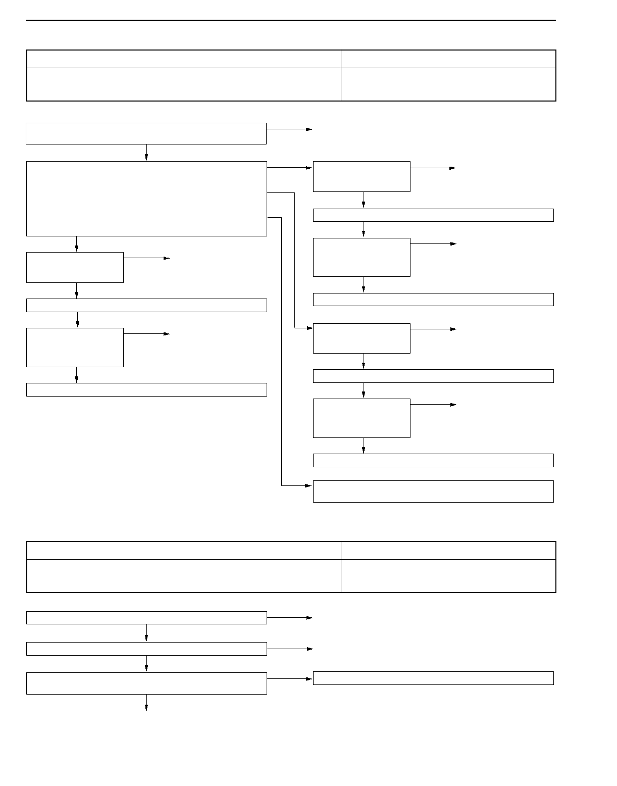
AUTOMATIC TRANSMISSION - Troubleshooting
23-38
INSPECTION PROCEDURE 20
Vehicle speed sensor system Probable cause
The cause is probably a defective vehicle speed sensor circuit or a defective A/T-ECU. DMalfunction of the vehicle speed sensor
DMalfunction of connector
DMalfunction of the A/T-ECU
2. NG
3. NG
OK
Check the ignition switch. (Refer to GROUP 54 - Ignition switch.)
NG
OK
OK
Replace the engine-ECU.
OK
Replace the engine-ECU.
Check the harness wire between the vehicle speed sensor and
the earth, and repair if necessary.
NG
Check the harness wire
between the engine-ECU
and the vehicle speed
sensor connector.
NG Repair
Check trouble symptom.
Check the following
connectors:
C-30, C-48
NG Repair
NG
Check the harness wire
between the vehicle
speed sensor and ignition
switch connector.
NG Repair
OK
Check trouble symptom.
Check the harness wire
between the engine-ECU
and the vehicle speed
sensor connector.
NG Repair
OK
Check trouble symptom.
OK
Check the following
connector:
B-67
NG Repair
OK
Measure at the vehicle speed sensor connector B-67.
DDisconnect the connector, and measure at the harness side.
1. Voltage between 1 and earth (Ignition switch: ON)
OK: Battery voltage
2. Voltage between 3 and earth (Ignition switch: ON)
OK: 4.8 - 5.2 V
3. Continuity between 2 and earth
OK: Continuity
1. NG Check the following
connectors:
C-90, C-131, C-135
NG Repair
Check the vehicle speed sensor.
(Refer to GROUP 54 - Combination Meters.)
NG Replace
INSPECTION PROCEDURE 21
Auto-cruise-ECU signal system Probable cause
The cause is probably a defective auto-cruise signal line circuit or a defective A/T-ECU. DMalfunction of connector
DMalfunction of the A/T-ECU
DMalfunction of the auto-cruise-ECU
Auto-cruise system check (Refer to GROUP 17 - Troubleshooting.) NG Repair
OK
Check the following connectors: C-28, C-82, C-83 NG Repair
OK
Harness check
DBetween auto-cruise-ECU and A/T-ECU
OK Replace the A/T-ECU.
NG
Repair
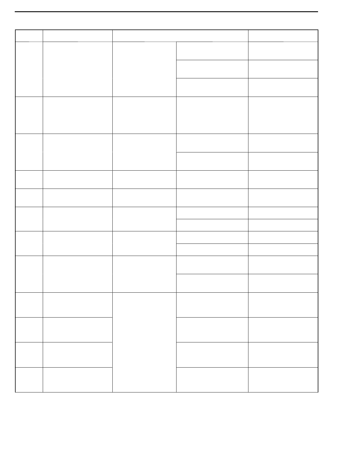
AUTOMATIC TRANSMISSION - Troubleshooting 23-39
DATA LIST REFERENCE TABLE 23100810208
Item No. Check item Check requirement Normal value
11 Throttle position sensor
<Vehicles without TCL>
Engine: Stopped
Selector lever
Accelerator pedal:
Released
400 - 1,000 mV
Accelerator pedal
position sensor
<Vehicles with TCL>
position: P Accelerator pedal:
Halfly depressed
Gradually rises from the
above value
Accelerator pedal:
Depressed
4,500 - 5,000 mV
15 Oil temperature sensor Warming up Drive for 15 minutes or
more so that the
automatic transmission
fluid temperature
becomes 70 - 90 _C.
Gradually rises to
70 - 90 _C
21 Crank angle sensor Engine: Idling
Selector lever
Accelerator pedal:
Released
550 - 900 rpm
position: P Accelerator pedal:
Halfly depressed
Gradually rises from the
above value
22 Input shaft speed
sensor
Selector lever
position: 3
Driving at constant speed
of 50 km/h in 3rd gear
1,800 - 2,100 rpm
23 Output shaft speed
sensor
Selector lever
position: 3
Driving at constant speed
of 50 km/h in 3rd gear
1,800 - 2,100 rpm
25 Wide open throttle Accelerator pedal Released OFF
switch position
Depressed ON
26 Stop lamp switch Ignition switch: ON Brake pedal: Depressed ON
Engine: Stopped Brake pedal: Released OFF
29 Vehicle speed sensor Selector lever
position: 3
Idling with 1st gear
(Vehicle stopped)
0 km/h
Driving at constant speed
of 50 km/h in 3rd gear
50 km/h
31 Low and reverse
solenoid valve duty %
Selector lever
position: L, 2, 3, D
10 km/h in 1st gear No. 31: 0 %, No. 32: 0
%, No. 33: 100 %,
No. 34: 100%
32 Underdrive solenoid
valve duty %
30 km/h in 2nd gear No. 31: 100 %, No. 32:
0 %, No. 33: 0 %,
No. 34: 100%
33 Second solenoid valve
duty %
50 km/h in 3rd gear No. 31: 100 %, No. 32:
0 %, No. 33: 100 %,
No. 34: 0%
34 Overdrive solenoid valve
duty %
70 km/h in 4th gear No. 31: 100 %, No. 32:
100 %, No. 33: 0 %,
No. 34: 0%
AUTOMATIC TRANSMISSION - Troubleshooting
23-40
Item No. Normal valueCheck requirementCheck item
36 Damper clutch control
solenoid valve duty %
Selector lever
position: 3
Driving at 50 km/h in
3rd gear with accelerator
released
0%
Driving at constant speed
of 70 km/h in 3rd gear
Approx. 70 - 90 %
52 Amount of damper
clutch slippage
Selector lever
position: 3
Driving at 50 km/h in 3rd
gear with accelerator
fully closed
Approx. 100 - 300 rpm*
Driving at constant speed
of 70 km/h in 3rd gear
Approx. 0 - 10 rpm
54 Control relay output
voltage
Ignition switch : OFF Ignition switch:
ON ®OFF
Battery voltage (mV) ®
0mV
57 Engine volumetric
efficiency
Selector lever
position: N
N range with accelerator
pedal released ®
depressed.
Data changes
61 Inhibitor switch Ignition switch: ON Selector lever position: P P
Engine: Stopped Selector lever position: R R
Selector lever position: N N
Selector lever position: D D
Selector lever position: 3 3
Selector lever position: 2 2
Selector lever position: L L
62 HOLD mode signal Mode control switch HOLD ON
position
AUTO OFF
63 Shift position Selector lever posi-
tion: L, 2, 3, D
Driving at constant speed
of 10 km/h in 1st gear
1st
Driving at constant speed
of 30 km/h in 2nd gear
2nd
Driving at constant speed
of 50 km/h in 3rd gear
3rd
Driving at constant speed
of 70 km/h in 4th gear
4th
64 Idle position switch Engine: Idling
Selector lever posi-
Accelerator pedal:
Released
ON
tion: N
Accelerator pedal:
Halfly depressed
OFF
65 Dual pressure switch Engine: Idling A/C switch: ON ON
Selector lever posi-
tion: N A/C switch: OFF OFF
AUTOMATIC TRANSMISSION - Troubleshooting 23-41
Item No. Normal valueCheck requirementCheck item
66 Auto-cruse-ECU signal While auto-cruise Plain road OFF
operating
Sloping road ON
NOTE
*: The damper clutch is released when the accelerator is fully closed (Idle position switch: ON).
ACTUATOR TEST JUDGEMENT VALUE 23100820065
Item No. Check item Test content Check requirement Normal value
1Low reverse solenoid valve Drive the solenoid Ignition switch: ON The operation sound should
2Underdrive solenoid valve
valve specified by
the MUT-II at 50 % Selector lever
position: P
be audible when the solenoid
valve is driven.
3Second solenoid valve
duty for 5 seconds.
No other solenoid Engine: 0 r/min
Vehicle speed:
4Overdrive solenoid valve valve should be
energised.
Vehicle speed:
0 km/h
6Damper clutch control
solenoid valve
(Vehicle stopped)
Throttle
(Accelerator)
12 A/T control relay Control relay is OFF
for 3 seconds.
opening voltage:
Less than 0 V
Idle switch: ON
Data list No. 54
(1) During test: 0 mV
(2) Normal: Battery voltage
[mV]
INVECS-II CANCEL COMMAND 23100950023
Item No. Item Content Remarks
14 INVECS-II Stop the INVECS-II control and change gears
according to the standard shift pattern.
Use this function when carrying
out procedure 8 in the road
tests.
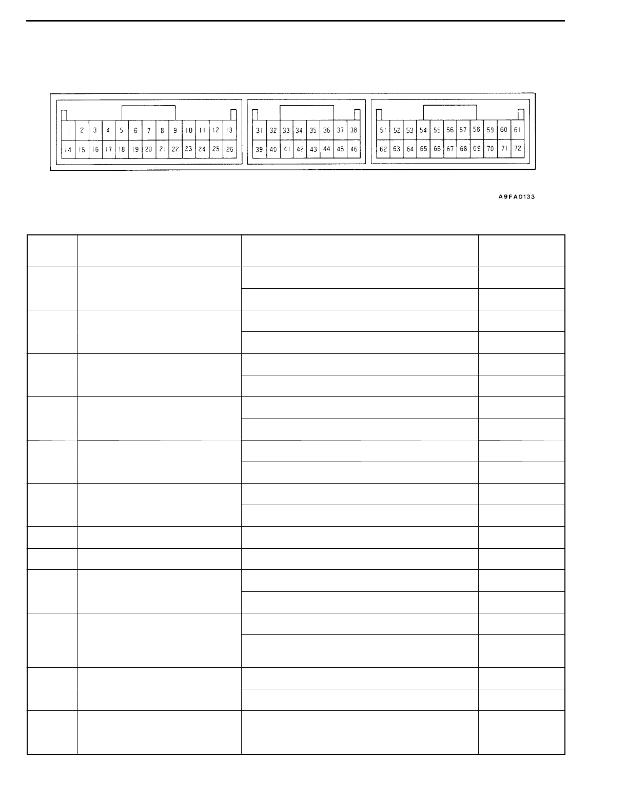
AUTOMATIC TRANSMISSION - Troubleshooting
23-42
CHECK AT A/T-ECU TERMINALS 23100840207
Terminal
No.
Check item Check requirement Standard value
1Underdrive solenoid valve Selector lever position: D (1st gear) Battery voltage
Selector lever position: P Approx.7 - 9 V
2Solenoid valve power supply Ignition switch: OFF 0V
Ignition switch: ON Battery voltage
3Solenoid valve power supply Ignition switch: OFF 0V
Ignition switch: ON Battery voltage
8Auto-cruse control unit No OD-OFF request Battery voltage
OD-OFF request 0V
10 A/C compressor load signal A/C switch: OFF 0V
A/C switch: ON Battery voltage
11 Power supply Ignition switch: OFF 0V
Ignition switch: ON Battery voltage
12 Earth Always 0V
13 Earth Always 0V
14 Overdrive solenoid valve Selector lever position: D (3rd gear) Battery voltage
Selector lever position: P Approx. 7 - 9 V
15 Damper clutch control solenoid Selector lever position: L (1st gear) Battery voltage
valve
Selector lever position: 3 (50 km/h in 3rd gear) Other than
battery voltage
16 Second solenoid valve Selector lever position: 2 (2nd gear) Battery voltage
Selector lever position: P Approx. 7 - 9 V
21 Engine-ECU torque reduction
request signal
<Vehicles with TCL>
Ignition switch: ON (except during shifting) 4-5V
AUTOMATIC TRANSMISSION - Troubleshooting 23-43
Terminal
No.
Standard valueCheck requirementCheck item
23 Diagnosis control - -
24 Power supply Ignition switch: OFF 0V
Ignition switch: ON Battery voltage
25 Earth Always 0V
26 Earth Always 0V
31 Input shaft speed sensor Measure between terminal No. 31 and No. 43 by
an oscilloscope.
Engine: 2,000 r/min
Selector lever position: 3
Refer to P.23-45,
Oscilloscope
inspection
procedure.
32 Output shaft speed sensor Measure between terminal No. 32 and No. 43 by
an oscilloscope.
Engine: 2,000 r/min
Selector lever position: 3
Refer to P.23-45,
Oscilloscope
inspection
procedure.
33 Crank angle sensor Engine: Idling 2.0 - 2.4 V
36 Idle position switch Engine: Idling 0V
Engine: Other than idling 5V
38 Back up power suuply Ignition switch: OFF Battery voltage
43 Sensor earth Always 0V
44 Oil temperature sensor ATF temperature: 25 _C3.8 - 4.0 V
ATF temperature: 80 _C2.3 - 2.5 V
45 Throttle position sensor (TPS)
<Vehicles without TCL>
Accelerator pedal: Released (Engine stopped) 0.5 - 1.0 V
Accelerator pedal position sensor
(APS) <Vehicles with TCL> Accelerator pedal: Depressed (Engine stopped) 4.5 - 5.0 V
53 Communication with engine-ECU
<Vehicles without TCL>
Communication with TCL-ECU
<Vehicles with TCL>
Engine: Idling
Selector lever position: D
Other than 0 V
54 Communication with engine-ECU
<Vehicles without TCL>
Communication with TCL-ECU
<Vehicles with TCL>
Engine: Idling
Selector lever position: D
Other than 0 V
55 Inhibitor switch P Selector lever position: P Battery voltage
Selector lever position: Other than above 0V
56 Inhibitor switch N Selector lever position: N Battery voltage
Selector lever position: Other than above 0V
57 Inhibitor switch 3 Selector lever position: 3 Battery voltage
Selector lever position: Other than above 0V
AUTOMATIC TRANSMISSION - Troubleshooting
23-44
Terminal
No.
Standard valueCheck requirementCheck item
58 Inhibitor switch L Selector lever position: L Battery voltage
Selector lever position: Other than above 0V
59 Stop lamp switch Brake pedal: Depressed Battery voltage
Brake pedal: Released 0V
62 Low and reverse solenoid valve Selector lever position: D (1st gear) Battery voltage
Selector lever position: D (2nd gear) Approx. 7 - 9 V
63 Diagnosis output Normal (No diagnosis code output) 0®5 V flashing
65 Wide open throttle switch Accelerator pedal: Released 4.5 - 5.5 V
Accelerator pedal: Depressed Less than 0.4 V
66 Inhibitor switch R Selector lever position: R Battery voltage
Selector lever position: Other than above 0V
67 Inhibitor switch D Selector lever position: D Battery voltage
Selector lever position: Other than above 0V
68 Inhibitor switch 2 Selector lever position: 2 Battery voltage
Selector lever position: Other than above 0V
69 Vehicle speed sensor When stopped 0V
Move forward slowly 0®5 V flashing
70 Mode control switch Select HOLD mode Battery voltage
Select AUTO mode 0V
71 A/T control relay Ignition switch: OFF 0V
Ignition switch: ON Battery voltage
72 Earth Ignition switch: ON 0V
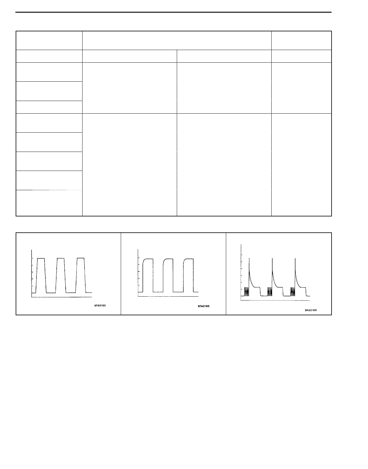
AUTOMATIC TRANSMISSION - Troubleshooting 23-45
OSCILLOSCOPE INSPECTION PROCEDURE 23100850064
Check item Check requirement Normal condition
(Waveform sample)
Crank angle sensor Selector lever position: N Idling (Vehicle stopped) Waveform A
Input shaft speed
sensor
Selector lever position: 3 Driving at constant speed of 50
km/h in 3rd gear
Waveform B
Output shaft
speed sensor
(Engine: 1,800 - 2,100 r/min)
Vehicle speed sensor
Low reverse
solenoid valve
Ignition switch: ON
Selector lever position: P
Force drive each solenoid valve
(Actuator test)
Waveform C
Underdrive solenoid
valve
Engine: 0 r/min
Vehicle speed: 0 km/h
(Vehicle stopped)
Second solenoid
valve
(Vehicle stopped)
Throttle (Accelerator) opening
angle: Less than 1 V
Overdrive solenoid
valve
Idle switch: ON
Damper clutch
control solenoid
valve
Waveform sample
Waveform A
(ms)
(V)
0
5
Waveform B
(ms)
(V)
0
5
Waveform C
(ms)
(V)
60
40
20
0

AUTOMATIC TRANSMISSION - On-vehicle Service
23-46
ON-VEHICLE SERVICE 23100090237
ESSENTIAL SERVICE
AUTOMATIC TRANSMISSION FLUID CHECK
1. Drive the vehicle until the fluid temperature rises to the
normal temperature (70 - 80_C).
2. Park the vehicle on a level surface.
3. Move the selector lever through all positions to fill the
torque converter and the hydraulic circuits with fluid, and
then move the selector lever to the N position.
4. After wiping off any dirt around the oil level gauge, remove
the oil level gauge and check the condition of the fluid.
NOTE
If the fluid smells as if it is burning, it means that the
fluid has been contaminated by the particles from the
bushes and friction materials, a transmission overhaul
and flushing the cooler line may be necessary.
5. Check that the fluid level is at the HOT mark on the
oil level gauge. If the fluid level is lower than this, pour
in more fluid until the level reaches the HOT mark.
Automatic transmission fluid:
Dia Queen ATF SP II or equivalent
NOTE
If the fluid level is low, the oil pump will draw in air along
with the fluid, which will cause bubbles to form inside
the hydraulic circuit. This will in turn cause the hydraulic
pressure to drop, which will result in late shifting and
slipping of the clutches and brakes.
If there is too much fluid, the gears can churn it up into
foam and cause the same conditions that can occur with
low fluid levels.
In either case, air bubbles can cause overheating and
oxidation of the fluid which can interfere with normal valve,
clutch, and brake operation. Foaming can also result in
fluid escaping from the transmission vent, in which case
it may be mistaken for a leak.
6. Securely insert the oil level gauge.
7. The fluid and oil filters should always be replaced in the
following conditions:
When troubleshooting the transmission
When overhauling the transmission
When the oil is noticeably dirty or deteriorates (driving
under the severe condition)
Furthermore, the oil filters are special filters which are
only to be used for the automatic transmission.
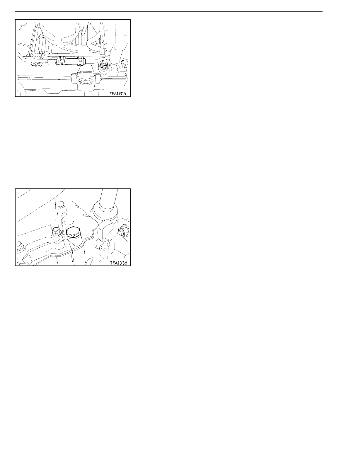
AUTOMATIC TRANSMISSION - On-vehicle Service 23-47
AUTOMATIC TRANSMISSION FLUID REPLACEMENT
23100100251
If you have a fluid changer, use this changer to replace the
fluid. If you do not have a fluid changer, replace the fluid
by the following procedure.
1. Disconnect the hose shown in the illustration which
connects the transmission and the oil cooler (inside the
radiator).
2. Start the engine and let the fluid drain out.
Running conditions: N range with engine idling
Caution
The engine should be stopped within one minute after
it is started. If the fluid has all drained out before
then, the engine should be stopped at that point.
Discharge volume: Approx. 3.5 L
3. Remove the drain plug from the bottom of the transmission
case to drain the fluid.
Discharge volume: Approx. 2.0 L
4. Replace the oil filters. (Refer to P.23-48.)
5. Install the drain plug via a new gasket, and tighten it
to the specified torque.
Tightening torque: 32 Nm
6. Pour the new fluid in through the oil filler tube.
Adding volume: Approx. 5.5 L
Caution
Stop pouring if the full volume of fluid cannot be
poured in.
7. Repeat the procedure in step 2.
NOTE
Drain the fluid from the cooler hose 7 L at least. Then
drain the fluid a little and check the fluid for dirt.
If it has been contaminated, repeat the steps 6 and 7.
8. Pour the new fluid in through the oil filler tube.
Adding volume: Approx. 3.5 L
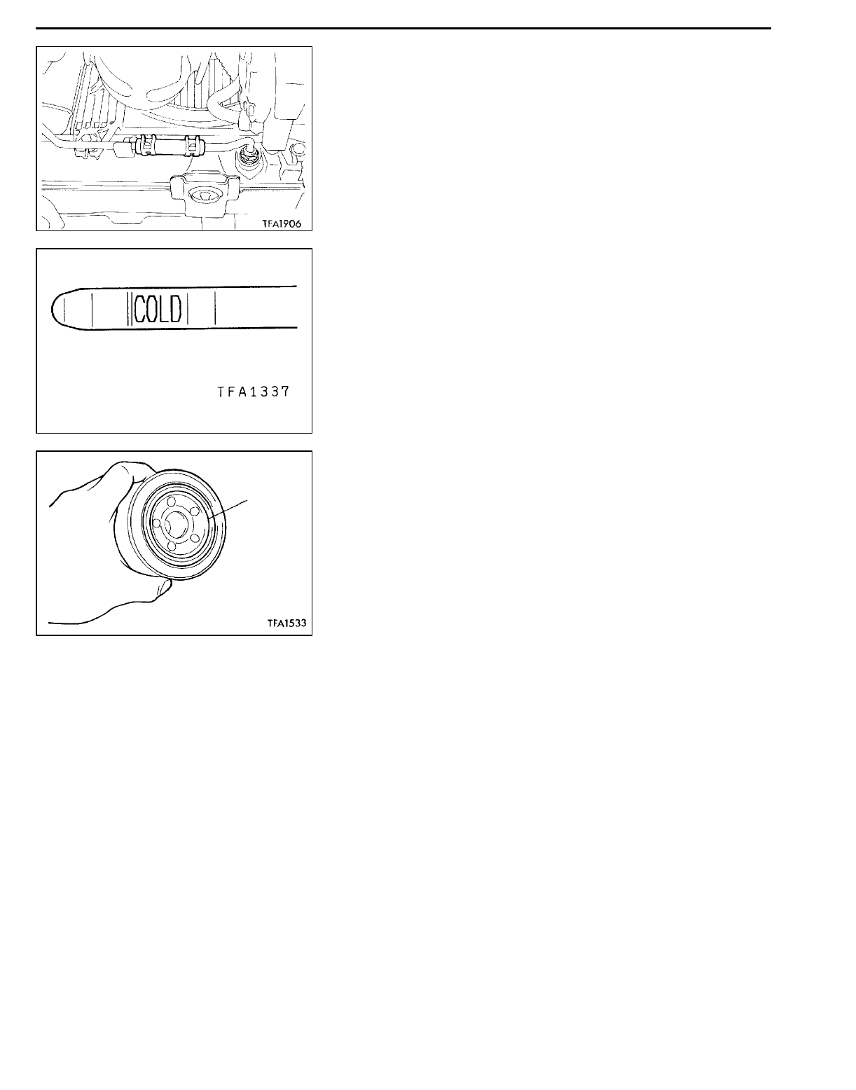
AUTOMATIC TRANSMISSION - On-vehicle Service
23-48
9. Reconnect the hose which was disconnected in step 1
above, and firmly replace the oil level gauge.
10. Start the engine and run it at idle for 1 - 2 minutes.
11. Move the selector lever through all positions, and then
move it to the N position.
12. Check that the fluid level is at the COLD mark on the
oil level gauge. If the level is lower than this, pour in
more fluid.
13. Drive the vehicle until the fluid temperature rises to the
normal temperature (70 - 80_C), and then check the
fluid level again.
The fluid level must be at the HOT mark.
NOTE
The COLD level is for reference only; the HOT level should
be regarded as the standard level.
14. Firmly insert the oil level gauge into the oil filler tube.
OIL FILTER REPLACEMENT 23101050067
1. Use the special tool (MB991610) to remove the automatic
transmission oil filter.
2. Clean the filter bracket side mounting surface.
3. Apply a small amount of automatic transmission fluid to
the O-ring of the new oil filter.
4. Use the special tool (MB991610) to install the automatic
transmission oil filter.
NOTE
Tightening torque: 12 Nm
5. Check the quantity of the automatic transmission fluid.
(Refer to P.23-46.)
THROTTLE POSITION SENSOR ADJUSTMENT
<Vehicles without TCL> 23100190142
Refer to GROUP 13A - On-vehicle Service.
ACCELERATOR PEDAL POSITION SENSOR
ADJUSTMENT <Vehicles with TCL> 23100250048
Refer to GROUP 13A - On-vehicle Service.
Apply ATF
to O-ring
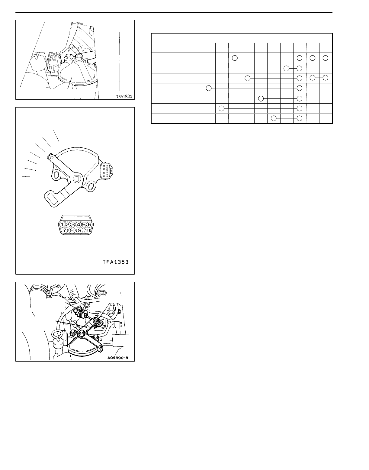
AUTOMATIC TRANSMISSION - On-vehicle Service 23-49
INHIBITOR SWITCH CONTINUITY CHECK 23100140345
Items Terminal No.
12345678910
P
R
N
D
3
2
L
INHIBITOR SWITCH AND CONTROL CABLE
ADJUSTMENT 23100150096
1. Set the selector lever to the “N” position.
2. Loosen the control cable to manual control lever coupling
nut to free the cable and lever.
3. Set the manual control lever to the neutral position.
Inhibitor switch
P
R
N
D
L
2
3
Transmission
control cable
Adjusting nut
Manual
control
lever
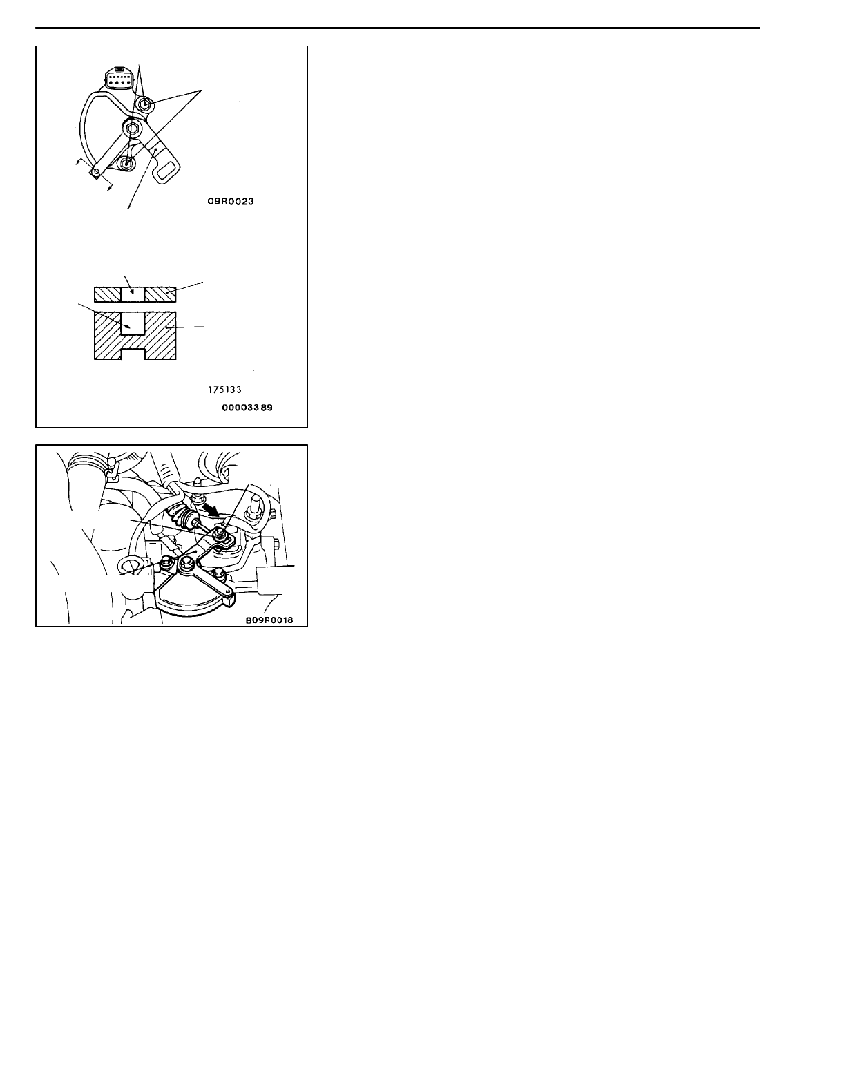
AUTOMATIC TRANSMISSION - On-vehicle Service
23-50
4. Loosen the inhibitor switch body mounting bolts and the
turn the inhibitor switch body so the hole in the end of
the manual control lever and the hole (cross section A-A
in the figure on the left) in the flange of the inhibitor
switch body flange are aligned.
5. Tighten the inhibitor switch body mounting bolts to the
specified torque. Be careful at this time that the position
of the switch body is not changed.
6. Gently pull the transmission control cable in the direction
of the arrow, and then tighten the adjusting nut.
7. Check that the selector lever is in the “N” position.
8. Check that each range on the transmission side operates
and functions correctly for each position of the selector
lever.
10 - 12 Nm
Mounting bolts
Manual
control lever
Section A-A
Hole in end
Hole in
flange
Manual control
lever
Inhibitor
switch body
A
A
Adjusting nut
12 Nm
Manual control lever
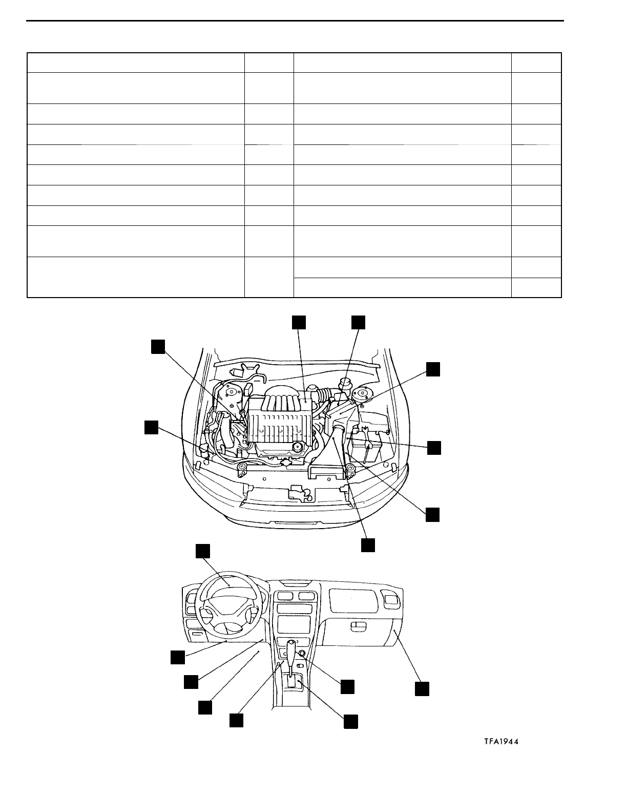
AUTOMATIC TRANSMISSION - On-vehicle Service 23-51
A/T CONTROL COMPONENT LOCATION 23100860234
Name Symbol Name Symbol
Accelerator position sensor (with idle position
switch) <Vehicles with TCL>
CMode control switch L
A/T control relay MOil temperature sensor G
A/T-ECU KOutput shaft speed sensor E
Crank angle sensor BShift indicator lamp I
Diagnosis connector OSolenoid valve G
Dual pressure switch AStop lamp switch P
Engine ECU KTCL-ECU J
Inhibitor switch FThrottle position sensor (with idle position
switch) <Vehicles without TCL>
C
Input shaft speed sensor HVehicle speed sensor D
Wide open throttle switch N
A
B
C D
E
F
G
H
I
J
K
L
M
N
O
P

AUTOMATIC TRANSMISSION - On-vehicle Service
23-52
A/T CONTROL COMPONENT CHECK 23100900011
CRANK ANGLE SENSOR CHECK
Refer to GROUP 13A - Troubleshooting.
THROTTLE POSITION SENSOR CHECK
<Vehicles without TCL> 23100390030
Refer to GROUP 13A - On-vehicle Service.
ACCELERATOR PEDAL POSITION SENSOR CHECK
<Vehicles with TCL> 23100420029
Refer to GROUP 13H - On-vehicle Service.
OIL TEMPERATURE SENSOR CHECK 23100450035
1. Remove the oil temperature sensor.
2. Measure the resistance between terminals No. 1 and
No. 2 of the oil temperature sensor connector.
Standard value:
Oil temperature (_C) Resistance (kW)
016.7- 20.5
100 0.57- 0.69
INHIBITOR SWITCH CHECK 23100140352
Refer to P.23A-49.
STOP LAMP SWITCH CHECK 23100910014
Refer to GROUP 35 - Brake Pedal.
VEHICLE SPEED SENSOR CHECK 23100460038
Refer to GROUP 54 - On-vehicle Service.
Oil temperature sensor
ATF
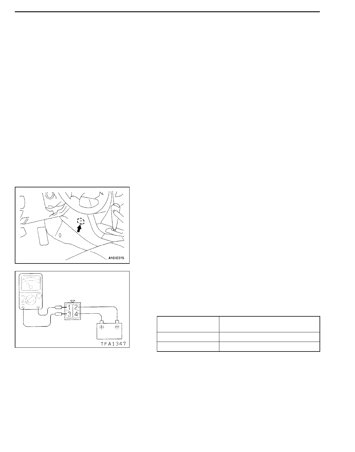
AUTOMATIC TRANSMISSION - On-vehicle Service 23-53
DUAL POSITION PRESSURE SWITCH CHECK
23100470031
Refer to GROUP 55 - On-vehicle Service.
IDLE POSITION SWITCH CHECK 23100410033
Refer to GROUP 13A - On-vehicle Service.
MODE CONTROL SWITCH CHECK 23100920048
Refer to P.23-65.
WIDE OPEN THROTTLE SWITCH CHECK 23100890080
Refer to P.23-64.
A/T CONTROL RELAY CHECK 23100930065
1. Remove the A/T control relay.
2. Use jumper wires to connect A/T control relay terminal
2 to the battery (- ) terminal and terminal 4 to the battery
(+) terminal.
3. Check the continuity between terminal 1 and terminal
3 of the A/T control relay when the jumper wires are
connected to and disconnected from the battery.
Jumper wire Continuity between terminals No. 1
and No. 3
Connected Continuity
Disconnected No continuity
4. If there is a problem, replace the A/T control relay.
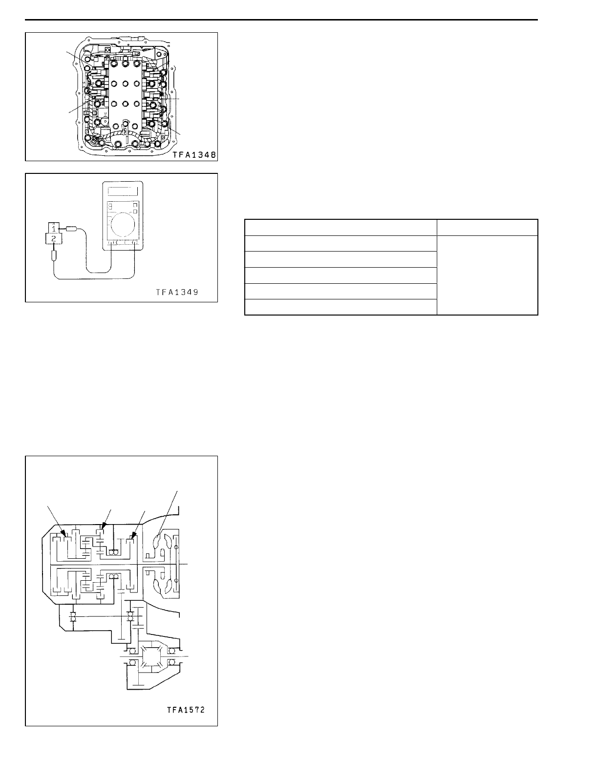
AUTOMATIC TRANSMISSION - On-vehicle Service
23-54
SOLENOID VALVE CHECK 23100940013
1. Remove the valve body cover.
2. Disconnect the connectors of each solenoid valve.
3. Measure the resistance between terminals 1 and 2 of
each solenoid valve.
Standard value:
Name Resistance
Damper clutch solenoid valve 2.7 - 3.4 W
Low and reverse solenoid valve (at 20_C)
Second solenoid valve
Underdrive solenoid valve
Overdrive solenoid valve
4. If the resistance is outside the standard value, replace
the solenoid valve.
TORQUE CONVERTER STALL TEST 23100540206
This test measures the maximum engine speed when the
selector lever is at the D or R position and the torque converter
stalls to test the operation of the torque converter, starter
motor and one-way clutch operation and the holding
performance of the clutches and brakes in the transmission.
Caution
Do not let anybody stand in front of or behind the vehicle
while this test is being carried out.
1. Check the automatic transmission fluid level and
temperature and the engine coolant temperature.
DFluid level: At the HOT mark on the oil level gauge
DFluid temperature: 80 - 100_C
DEngine coolant temperature: 80 - 100_C
Overdrive
solenoid
valve
Low and
reverse
solenoid
valve
Second
solenoid
valve
Damper
clutch
solenoid
valve
Underdrive
solenoid
valve
Reverse
clutch Low-reverse
brake
Underdrive
clutch
Torque
converter

AUTOMATIC TRANSMISSION - On-vehicle Service 23-55
2. Check both rear wheels (left and right).
3. Pull the parking brake lever on, with the brake pedal
fully depressed.
4. Start the engine.
5. Move the selector lever to the D position, fully depress
the accelerator pedal and take a reading of the maximum
engine speed at this time.
Caution
1. The throttle should not be left fully open for any
more than eight seconds.
2. If carrying out the stall test two or more times,
move the selector lever to the N position and run
the engine at 1,000 r/min to let the automatic
transmission fluid cool down before carrying out
subsequent tests.
Standard value
Stall speed: 2,100 - 2,600 r/min
6. Move the selector lever to the R position and carry out
the same test again.
Standard value
Stall speed: 2,100 - 2,600 r/min
TORQUE CONVERTER STALL TEST JUDGEMENT
RESULTS
a. Stall speed is too high in both D and R ranges
DLow line pressure
DLow & reverse brake slippage
b. Stall speed is too high in D range only
DUnderdrive clutch slippage
c. Stall speed is too high in R range only
DReverse clutch slippage
d. Stall speed too low in both D and R ranges
DMalfunction of torque converter
DInsufficient engine output
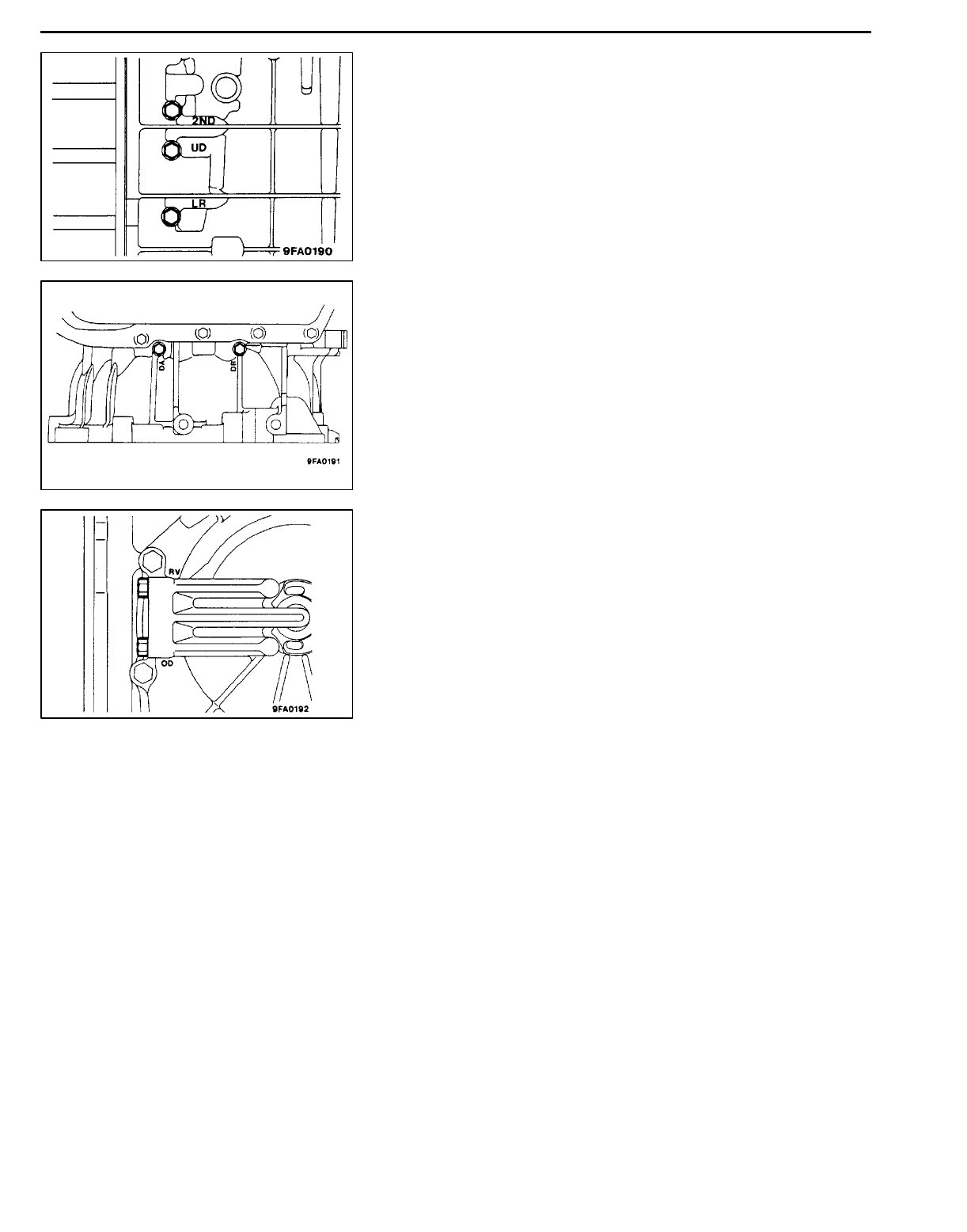
AUTOMATIC TRANSMISSION - On-vehicle Service
23-56
HYDRAULIC PRESSURE TEST 23100550216
1. Warm up the engine until the automatic transmission fluid
temperature is 80 - 100_C.
2. Jack up the vehicle so that the wheels are free to turn.
3. Connect the special tools (2,942 kPa oil pressure gauge
[MD998330] and joints [MD998332, MD998900]) to each
pressure discharge port.
4. Measure the hydraulic pressure at each port under the
conditions given in the standard hydraulic pressure table,
and check that the measured values are within the
standard value ranges.
5. If a value is outside the standard range, correct the
problem while referring to the hydraulic pressure test
diagnosis table.
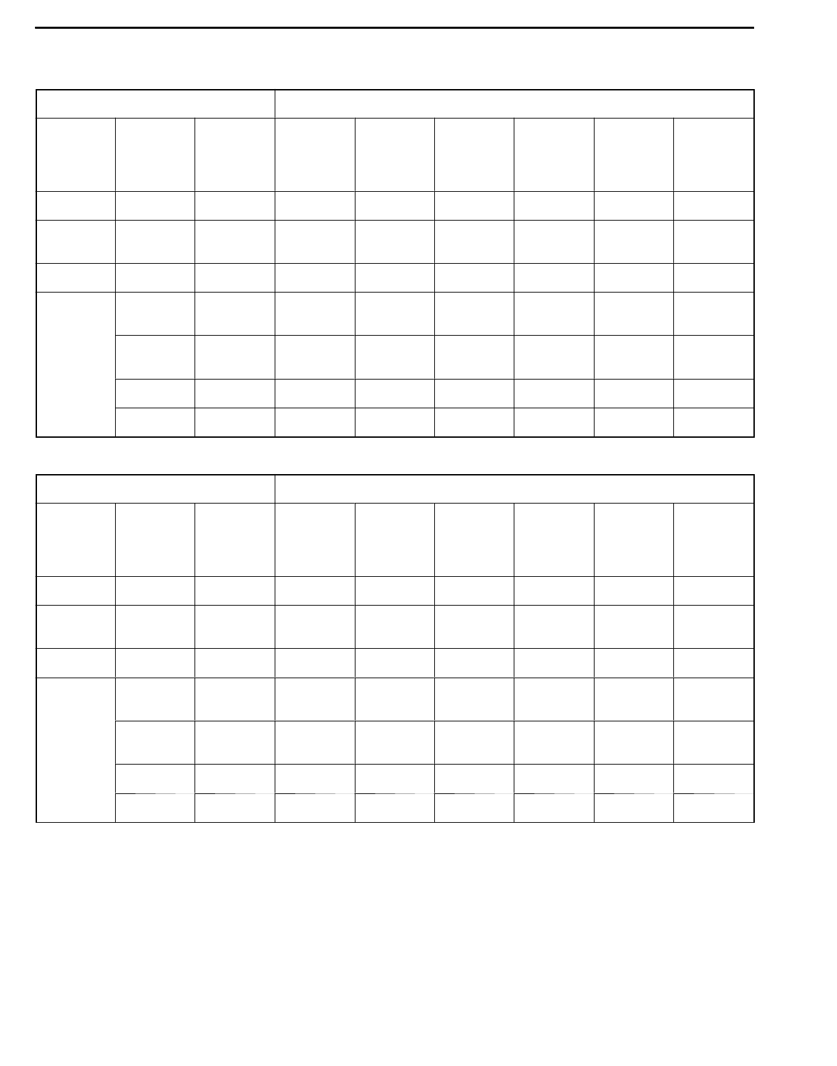
AUTOMATIC TRANSMISSION - On-vehicle Service 23-57
STANDARD HYDRAULIC PRESSURE TEST
<4G63>
Measurement condition Standard hydraulic pressure kPa
Selector
lever
position
Shift posi-
tion
Engine
speed
(r/min)
Under-
drive
clutch
pressure
Reverse
clutch
pressure
Overdrive
clutch
pressure
Low and
reverse
brake
pressure
Second
brake
pressure
Torque
converter
pressure
P - 2,500 - - - 310 - 390 -310 - 390
RReverse 2,500 -1,320 -
1,720
-1,320 -
1,720
-500 - 700
N - 2,500 - - - 310 - 390 -310 - 390
D1st gear 2,500 1,010 -
1,050
- - 1,010 -
1,050
-500 - 700
2nd gear 2,500 1,010 -
1,050
- - - 1,010 -
1,050
500 - 700
3rd gear 2,500 590 - 690 -590 - 690 - - 450 - 650
4th gear 2,500 - - 590 - 690 -590 - 690 450 - 650
<6A13>
Measurement condition Standard hydraulic pressure kPa
Selector
lever
position
Shift posi-
tion
Engine
speed
(r/min)
Under-
drive
clutch
pressure
Reverse
clutch
pressure
Overdrive
clutch
pressure
Low and
reverse
brake
pressure
Second
brake
pressure
Torque
converter
pressure
P - 2,500 - - - 260 - 340 -260 - 340
RReverse 2,500 -1,320 -
1,720
-1,320 -
1,720
-500 - 700
N - 2,500 - - - 260 - 340 -260 - 340
D1st gear 2,500 1,010 -
1,050
- - 1,010 -
1,050
-500 - 700
2nd gear 2,500 1,010 -
1,050
- - - 1,010 -
1,050
500 - 700
3rd gear 2,500 780 - 880 -780 - 880 - - 450 - 650
4th gear 2,500 - - 780 - 880 -780 - 880 450 - 650
AUTOMATIC TRANSMISSION - On-vehicle Service
23-58
HYDRAULIC PRESSURE TEST DIAGNOSIS TABLE
Trouble symptom Probable cause
All hydraulic pressures are high. Incorrect transmission control cable adjustment
Malfunction of the regulator valve
All hydraulic pressures are low. Incorrect transmission control cable adjustment
Malfunction of the oil pump
Clogged internal oil filter
Clogged external oil filter
Clogged oil cooler
Malfunction of the regulator valve
Malfunction of the relief valve
Incorrect valve body installation
Hydraulic pressure is abnormal Malfunction of the regulator valve
in “R” range only. Clogged orifice
Incorrect valve body installation
Hydraulic pressure is abnormal Malfunction of the overdrive solenoid valve
in “3” or “4” range only. Malfunction of the overdrive pressure control valve
Malfunction of the regulator valve
Malfunction of the switch valve
Clogged orifice
Incorrect valve body installation
Only underdrive hydraulic Malfunction of the oil seal K
pressure is abnormal. Malfunction of the oil seal L
Malfunction of the oil seal M
Malfunction of the underdrive solenoid valve
Malfunction of the underdrive pressure control valve
Malfunction of check ball
Clogged orifice
Incorrect valve body installation
Only reverse clutch hydraulic Malfunction of the oil seal A
pressure is abnormal. Malfunction of the oil seal B
Malfunction of the oil seal C
Clogged orifice
Incorrect valve body installation
AUTOMATIC TRANSMISSION - On-vehicle Service 23-59
Trouble symptom Probable cause
Only overdrive hydraulic Malfunction of the oil seal D
pressure is abnormal. Malfunction of the oil seal E
Malfunction of the oil seal F
Malfunction of the overdrive solenoid valve
Malfunction of the overdrive pressure control valve
Malfunction check ball
Clogged orifice
Incorrect valve body installation
Only low and reverse hydraulic Malfunction of the oil seal I
pressure is abnormal. Malfunction of the oil seal J
Malfunction of the low and reverse solenoid valve
Malfunction of the low and reverse pressure control valve
Malfunction of the switch valve
Malfunction of the fail safe valve A
Malfunction of check ball
Clogged orifice
Incorrect valve body installation
Only second hydraulic pressure Malfunction of the oil seal G
is abnormal. Malfunction of the oil seal H
Malfunction of the oil seal O
Malfunction of the second solenoid valve
Malfunction of the second pressure control valve
Malfunction of the fail safe valve B
Clogged orifice
Incorrect valve body installation
Only torque converter pressure Malfunction of the oil cooler
is abnormal. Malfunction of the oil seal N
Malfunction of the damper clutch control solenoid valve
Malfunction of the damper clutch control valve
Malfunction of the torque converter pressure control valve
Clogged orifice
Incorrect valve body installation
Pressure applied to non Incorrect transmission control cable adjustment
operating element. Malfunction of the manual valve
Malfunction of check ball
Incorrect valve body installation
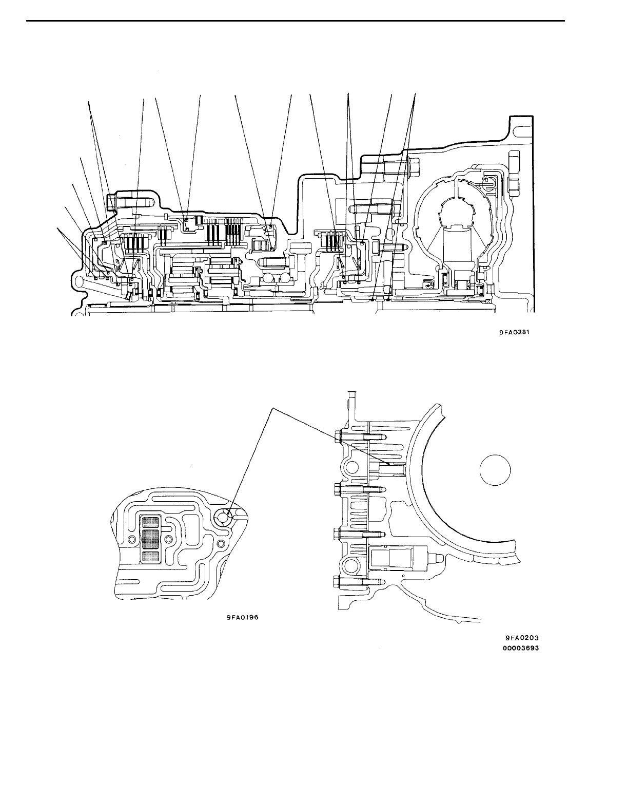
AUTOMATIC TRANSMISSION - On-vehicle Service
23-60
OIL SEAL LAYOUT
O
A
H
B
C
D
EFGIJKLMN
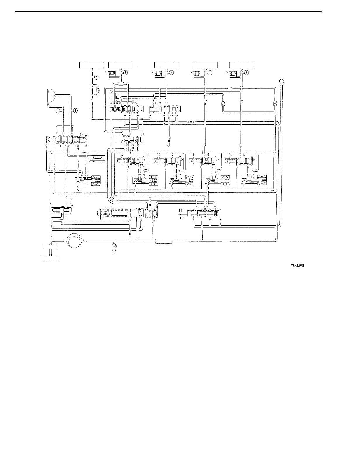
AUTOMATIC TRANSMISSION - On-vehicle Service 23-61
HYDRAULIC CIRCUIT 23100880070
PARKING AND NEUTRAL
12 3 4 5
67
8
910
11
12
13
14 15 16 17 18
19 20 21 22 23
24 25 26
27
28 29
30
32
31
666
RND
P3
2
L
1. Reverse clutch
2. Low-reverse brake
3. Second brake
4. Underdrive clutch
5. Overdrive clutch
6. Accumulator
7. Check ball
8. Damper clutch
9. Fail safe valve A
10. Fail safe valve B
11. Damper clutch control valve
12. Switch valve
13. Automatic transmission fluid cooler
14. Lubrication
15. Low-reverse pressure control valve
16. Second pressure control valve
17. Underdrive pressure control valve
18. Overdrive pressure control valve
19. Damper clutch control solenoid
valve
20. Low-reverse solenoid valve
21. Second solenoid valve
22. Underdrive solenoid valve
23. Overdrive solenoid valve
24. Torque converter pressure control
valve
25. Regulator valve
26. Manual valve
27. Oil filter
28. Oil pump
29. Oil strainer
30. Oil filter (Built in type)
31. Relief valve
32. Oil pan
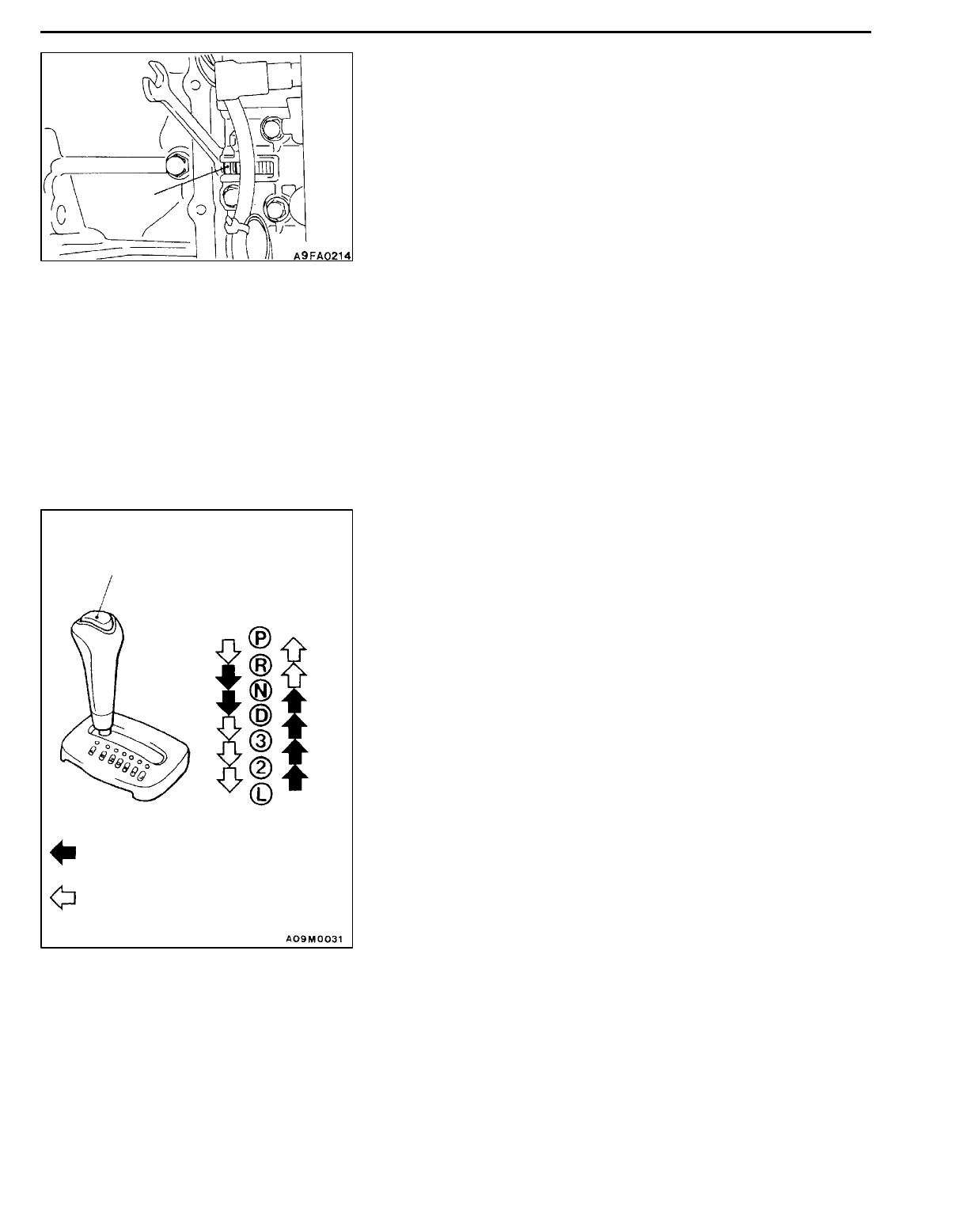
AUTOMATIC TRANSMISSION - On-vehicle Service
23-62
LINE PRESSURE ADJUSTMENT 23100170122
1. Discharge the automatic transmission fluid, and then
remove the valve body cover.
2. Turn the adjusting screw shown in the illustration at left
to adjust the underdrive pressure to the standard value.
The pressure increases when the screw is turned to the
left.
NOTE
When adjusting the underdrive pressure, adjust to the
middle of the standard value range.
Standard value: 1,010 - 1,050 kPa
Change in pressure for each turn of the adjusting screw:
35 kPa
3. Install the valve body cover, and pour in the standard
volume of automatic transmission fluid.
4. Carry out a hydraulic pressure test. (Refer to P.23-56.)
Readjust the line pressure if necessary.
SELECTOR LEVER OPERATION CHECK
23100130090
1. Shift selector lever to each range and check that lever
moves smoothly and is controlled. Check that position
indicator is correct.
2. Check the selector lever can be moved to each position
(by button operation as shown in the illustration).
3. Start the engine and check if the vehicle moves forward
when the selector lever is moved from N or D, and moves
backward when moved to R.
4. When the shift lever malfunctions, adjust control cable
and selector lever sleeve. Check for worm shift lever
assembly sliding parts.
Adjusting
screw
Push button
Button not pressed
Button pressed
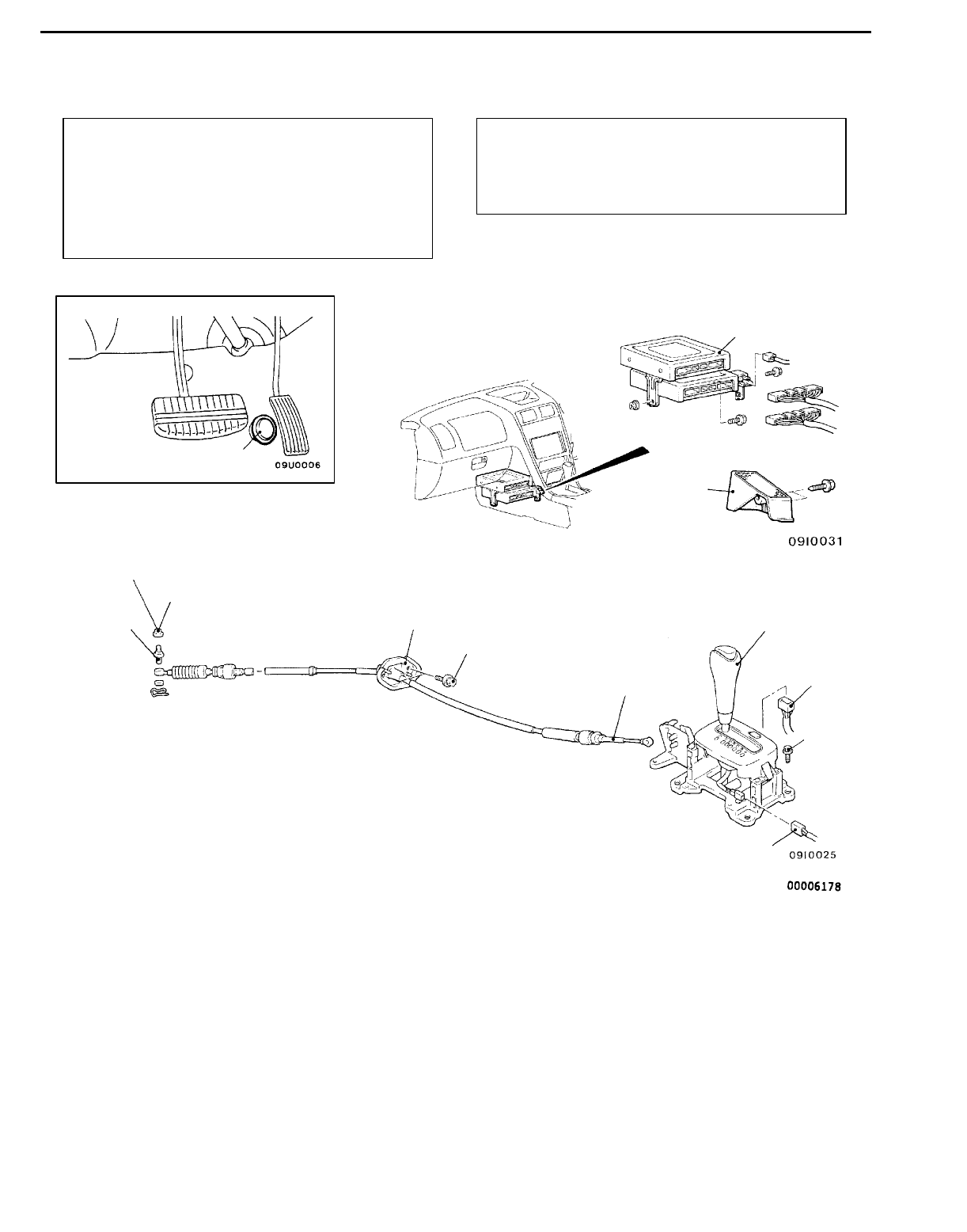
AUTOMATIC TRANSMISSION - Transmission Control 23-63
TRANSMISSION CONTROL 23100660247
REMOVAL AND INSTALLATION
Pre-removal and Post-installation Operation
DAir Cleaner Assembly Removal and Installation
DBattery and Battery Tray Removal and Installation
DLower Cover and Side Cover Removal and
Installation (Refer to GROUP 52A - Instrument
Panel.)
DFloor Console Box Removal and Installation
(Refer to GROUP 52A.)
Caution: SRS
Be careful not to subject the SRS-ECU to any
shocks during removal and installation of the
transmission control cable and selector lever
assembly.
12 Nm
12 Nm
12 Nm
1
2
3
4
5
6
7
8
9
7
Transmission control cable removal
steps
1. Foot rest <R.H. drive vehicles>
2. Engine-ECU, A/T-ECU and A/T
control relay assembly
"AA3. Nut
4. Adjuster
5. Transmission control cable connec-
tion
6. Transmission control cable assem-
bly
Selector lever assembly removal
steps
5. Transmission control cable connec-
tion
7. Wiring harness connector
8. Selector lever assembly
A/T-ECU removal steps
1. Foot rest <R.H. drive vehicles>
2. Engine-ECU, A/T-ECU and A/T
control relay assembly
Wide open throttle switch removal
step
9. Wide open throttle switch
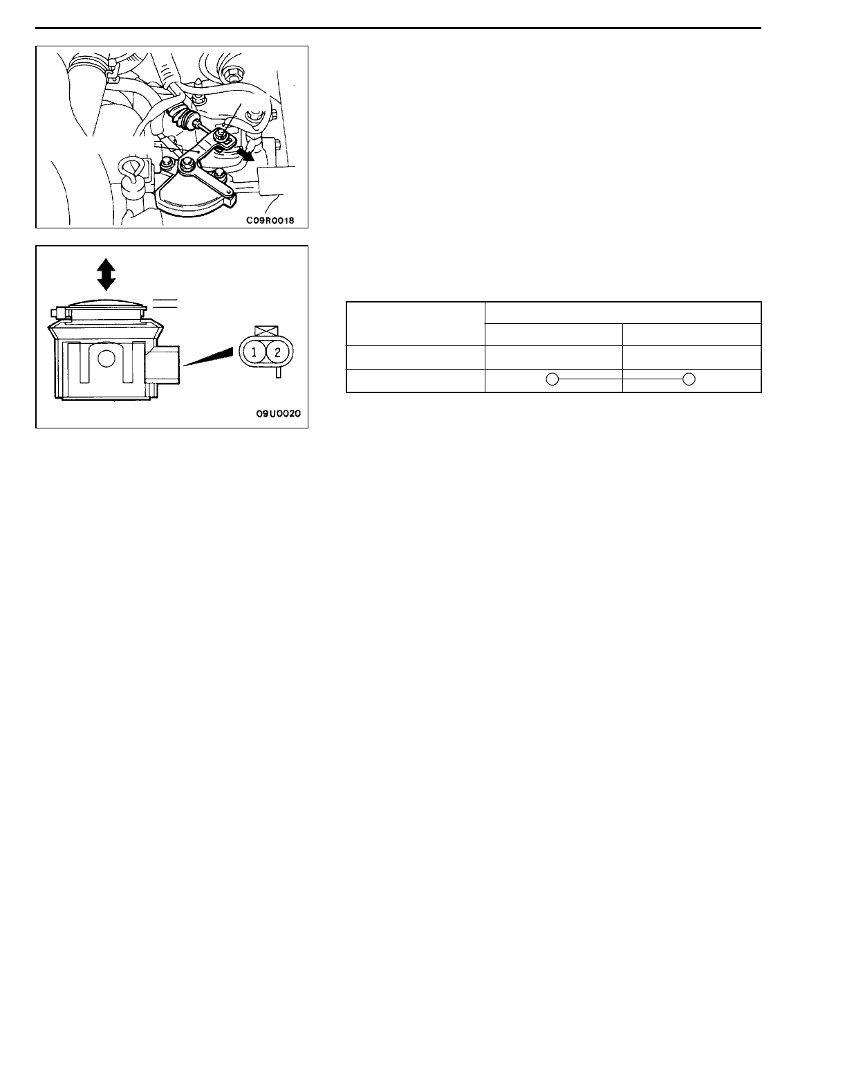
AUTOMATIC TRANSMISSION - Transmission Control
23-64
INSTALLATION SERVICE POINT
"AANUT INSTALLATION
1. Put the selector lever in the “N” position.
2. Loosen the adjusting nut, gently pull the transmission
control cable in the direction of the arrow and tighten
the nut.
INSPECTION 23100890097
WIDE OPEN THROTTLE SWITCH CHECK
Switch position Terminal No.
1 2
OFF
ON
Manual control lever
Nut
OFF
ON
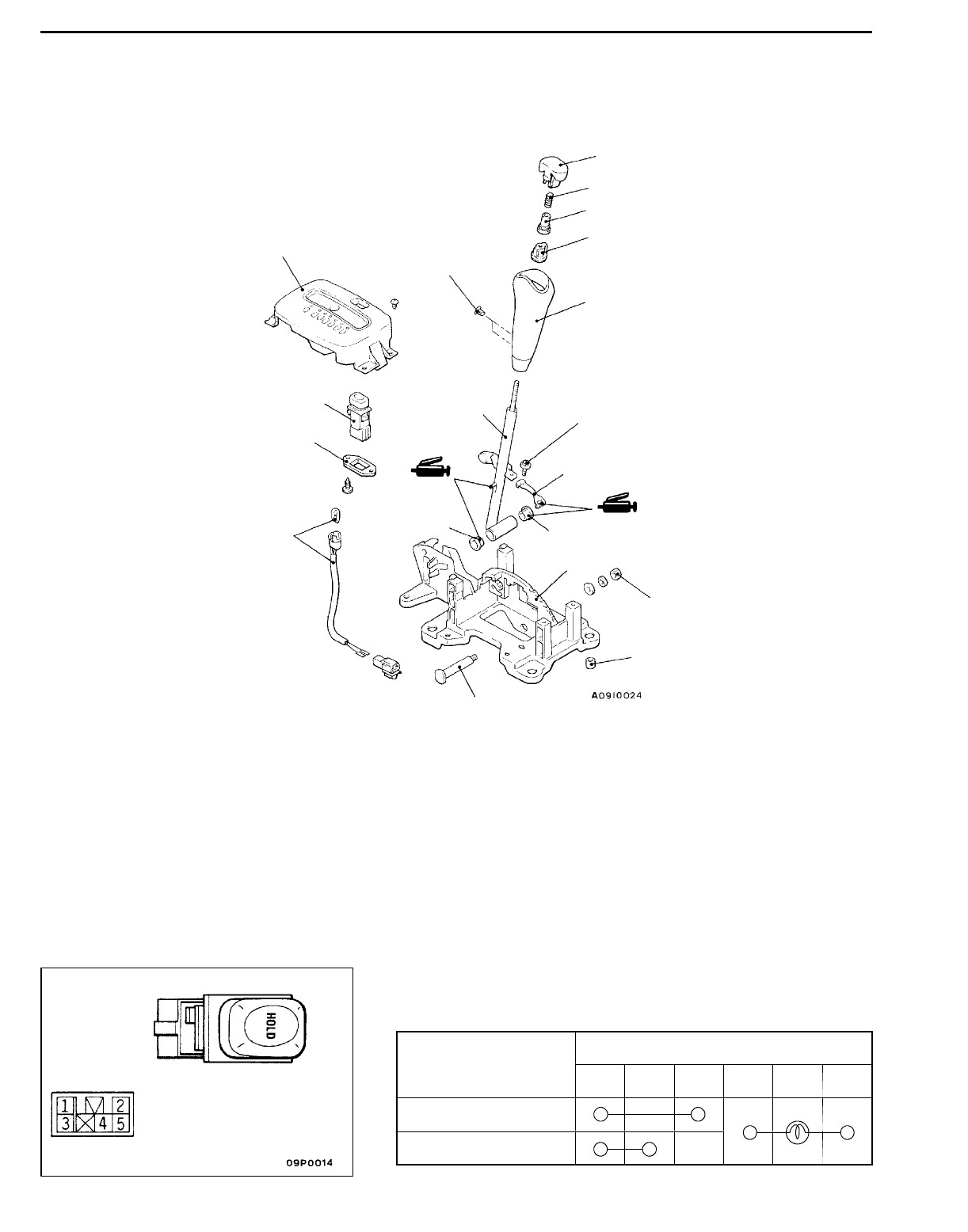
AUTOMATIC TRANSMISSION - Transmission Control 23-65
SELECTOR LEVER ASSEMBLY 23100680168
DISASSEMBLY AND REASSEMBLY
11
2Nm
1
2
3
4
5
6
8
9
10
11
14
13
2Nm
13 Nm
12
15
7
Disassembly steps
1. Push button
2. Spring
3. Bumper
4. Adjuster
5. Shift knob
6. Indicator panel assembly
7. Switch holder
8. A/T mode changeover switch
9. Bolt
10. Shift lever assembly
11. Bushing
12. Detent spring
13. Pipe
14. Position indicator lamp assembly
15. Bracket assembly
INSPECTION 23100670059
A/T MODE CHANGEOVER SWITCH CHECK
Switch position Terminal No.
1243 5
OFF
ON
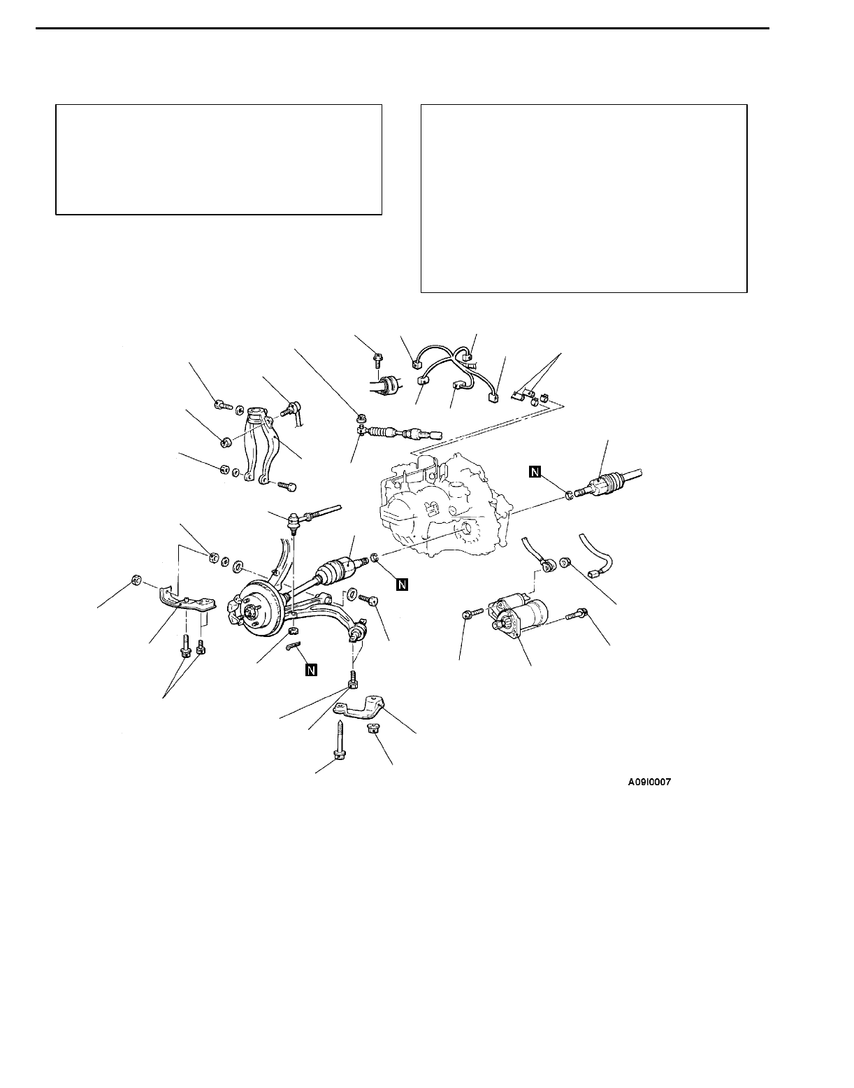
AUTOMATIC TRANSMISSION - Transmission Assembly
23-66
TRANSMISSION ASSEMBLY 23100570274
REMOVAL AND INSTALLATION
Pre-removal Operation
DCarry out the essential service for the
troubleshooting (Refer to P.23-46.)
DTransmission Fluid Draining (Refer to P.23-47.)
DUnder Cover Removal
DBattery and Battery Tray Removal
DAir Cleaner Assembly Removal
Post-installation Operation
DAir Cleaner Assembly Installation
DBattery and Battery Tray Installation
DUnder Cover Installation
DTransmission Fluid Supplying <Supplying should
be done before starting the engine>
(Refer to P.23-47.)
DCheck the Dust Cover for Cracks or Damage by
Pushing it with Finger.
DSelector Lever Operation Check
DSpeedometer Operation Check
DWheel Alignment Adjustment
(Refer to GROUP 33A - On-vehicle Service.)
88 Nm*1
98 - 118 Nm*1
12 Nm
103 Nm
44 Nm
81 Nm
67 - 78 Nm
24 - 33 Nm
81 Nm
98 - 118 Nm 88 Nm
30 Nm
30 Nm
10 - 12 Nm
1
2
34
5
6
7
8
9
10
11
12
13 14
15
16
17
17
Removal steps
1. Transmission control cable connec-
tion
2. Transmission fluid cooler hoses
connection
3. Bolt
4. Input shaft speed sensor connector
5. Output shaft speed sensor
connector
6. Inhibitor switch connector
7. A/T control solenoid valve assem-
bly connector
8. Vehicle speed sensor connector
9. Starter motor <6A1>
AA"10. Tie rod end connection
11. Stabilizer link connection
12. Damper fork
13. No. 2 stay
14. Lateral lower arm connection
AB"15. No. 3 stay
16. Compression lower arm connection
AC"17. Drive shaft
Caution
*1: Indicates parts which should be temporarily
tightened, and then fully tightened with the
vehicle on the ground in the unladen condition.
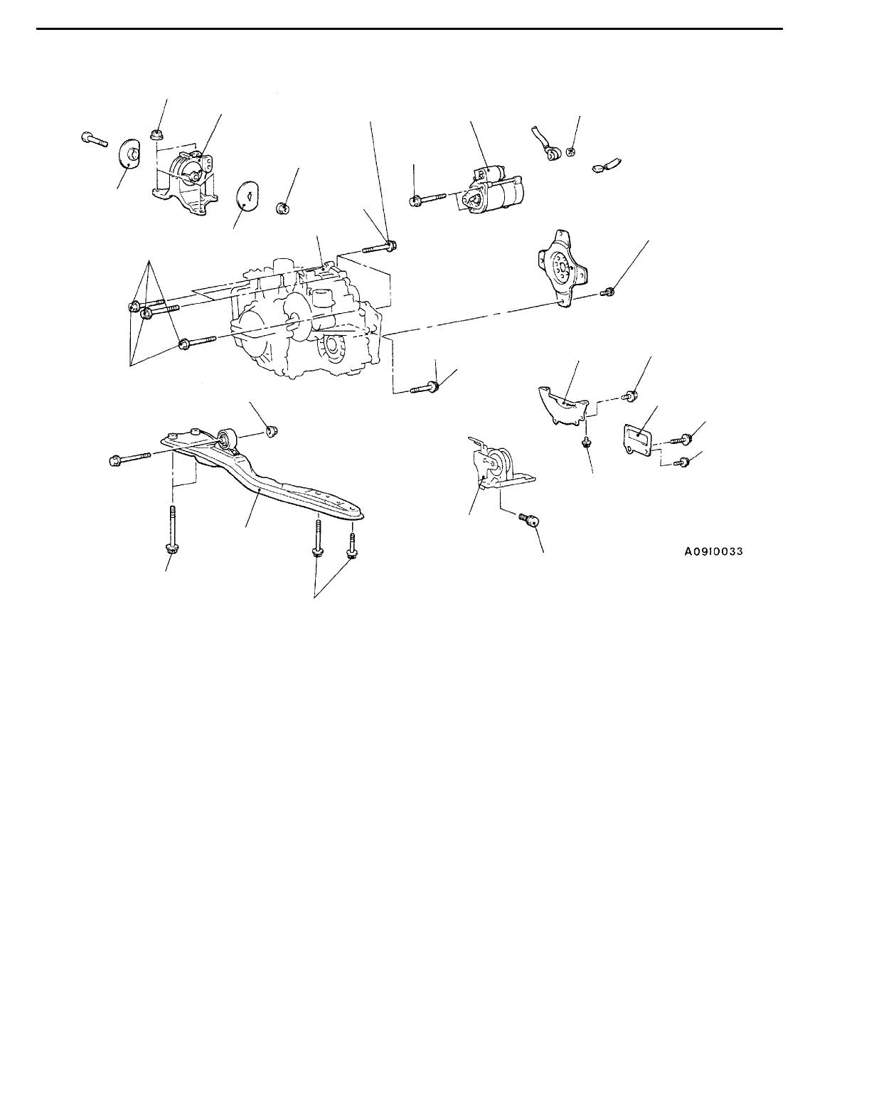
AUTOMATIC TRANSMISSION - Transmission Assembly 23-67
7Nm
44 Nm
18
57 Nm
57 Nm*2
69 Nm
10 Nm <Flange bolts>
9 Nm <Washer assembled bolts>
20
21
21
22 23
93 Nm
49 Nm
27
26
49 Nm
30 Nm
69 - 78 Nm
10 - 12 Nm
24 25 Nm
25
81 Nm*2
49 Nm
26
19
45 - 52 Nm
18. Starter motor <4G6>
19. Transmission assembly upper part
coupling bolts
AD"20. Transmission mount bracket
"BA21. Transmission mount stopper
AE"DEngine and transmission assembly
supporting
22. Centermember assembly
23. Rear roll stopper
24. Bell housing cover <4G6>
25. Cover <6A1>
AF"26. Transmission assembly lower part
coupling bolts
AF""
AA27. Transmission assembly
Caution
Mounting locations marked by *2 should be
provisionally tightened, and then fully tightened after
placing the vehicle horizontally and loading the full
weight of the engine on the vehicle body.
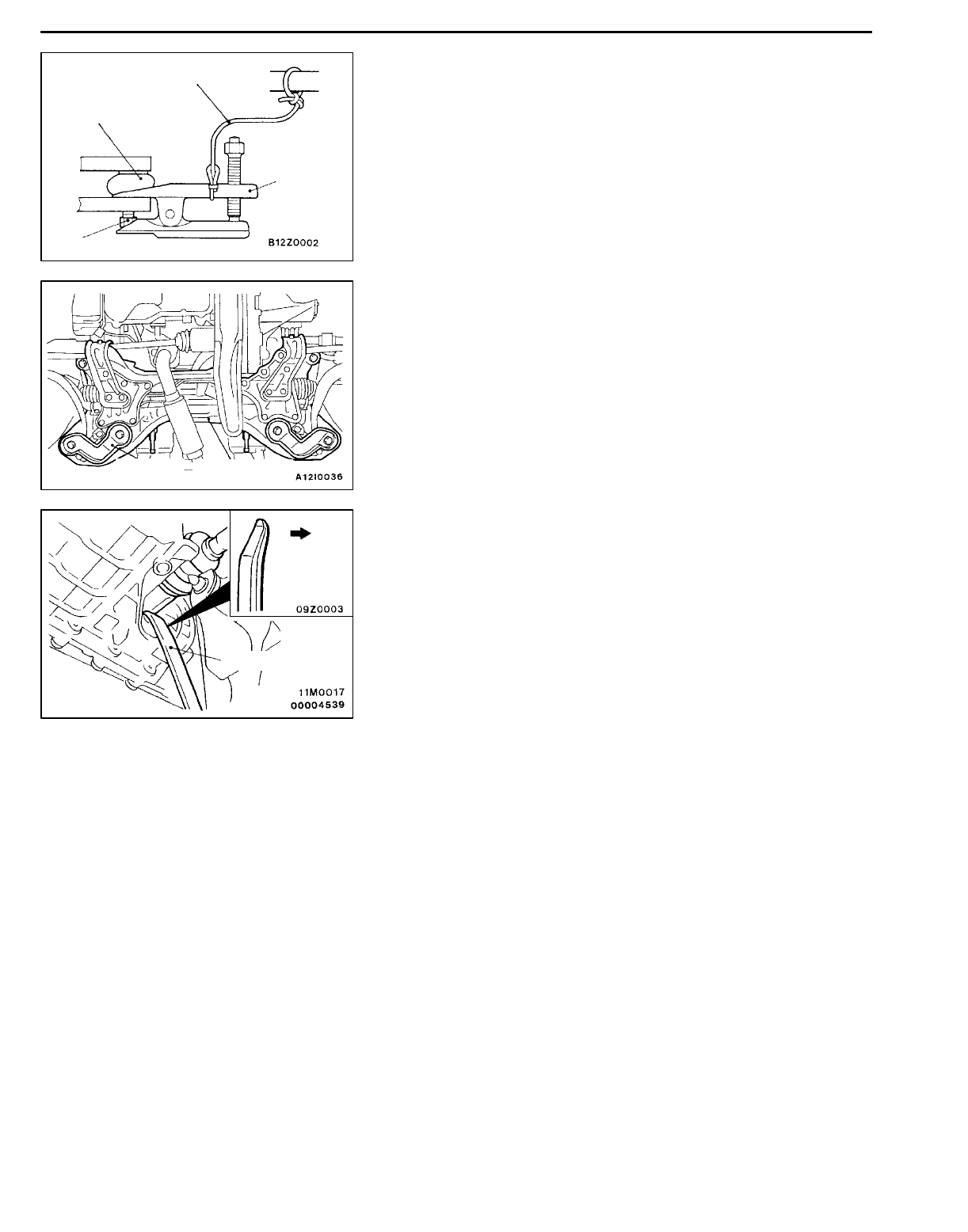
AUTOMATIC TRANSMISSION - Transmission Assembly
23-68
REMOVAL SERVICE POINTS
AA"TIE ROD END DISCONNECTION
Caution
1. Use the special tool to loosen the tie rod end mounting
nut. Only loosen the nut; do not remove it from the
ball joint.
2. Support the special tool with a cord, etc. not to let
it come off.
AB"NO.3 STAY REMOVAL
No.3 stay is tightened together with the crossmember.
Therefore, after removing No.3 stay, install the nut and bolt
to the crossmember provisionally.
AC"DRIVE SHAFT DISCONNECTION
1. Insert a pry bar between the transmission case and the
drive shaft as shown to remove the drive shaft.
NOTE
Do not remove the hub and knuckle from the drive shaft.
Caution
Always use a pry bar, or the TJ will be damaged.
2. Suspend the removed drive shaft with a wire so that
there are no sharp bends in any of the joints.
3. Use a shop towel to cover the transmission case not
to let foreign material get into it.
AD"TRANSMISSION MOUNT BRACKET REMOVAL
Jack up the transmission assembly gently with a garage jack,
and then remove the transmission mount bracket.
Cord
Ball joint
MB990635 or
MB991113
Nut
No.3 stay Crossmember
Pry bar
Trans-
mission
side
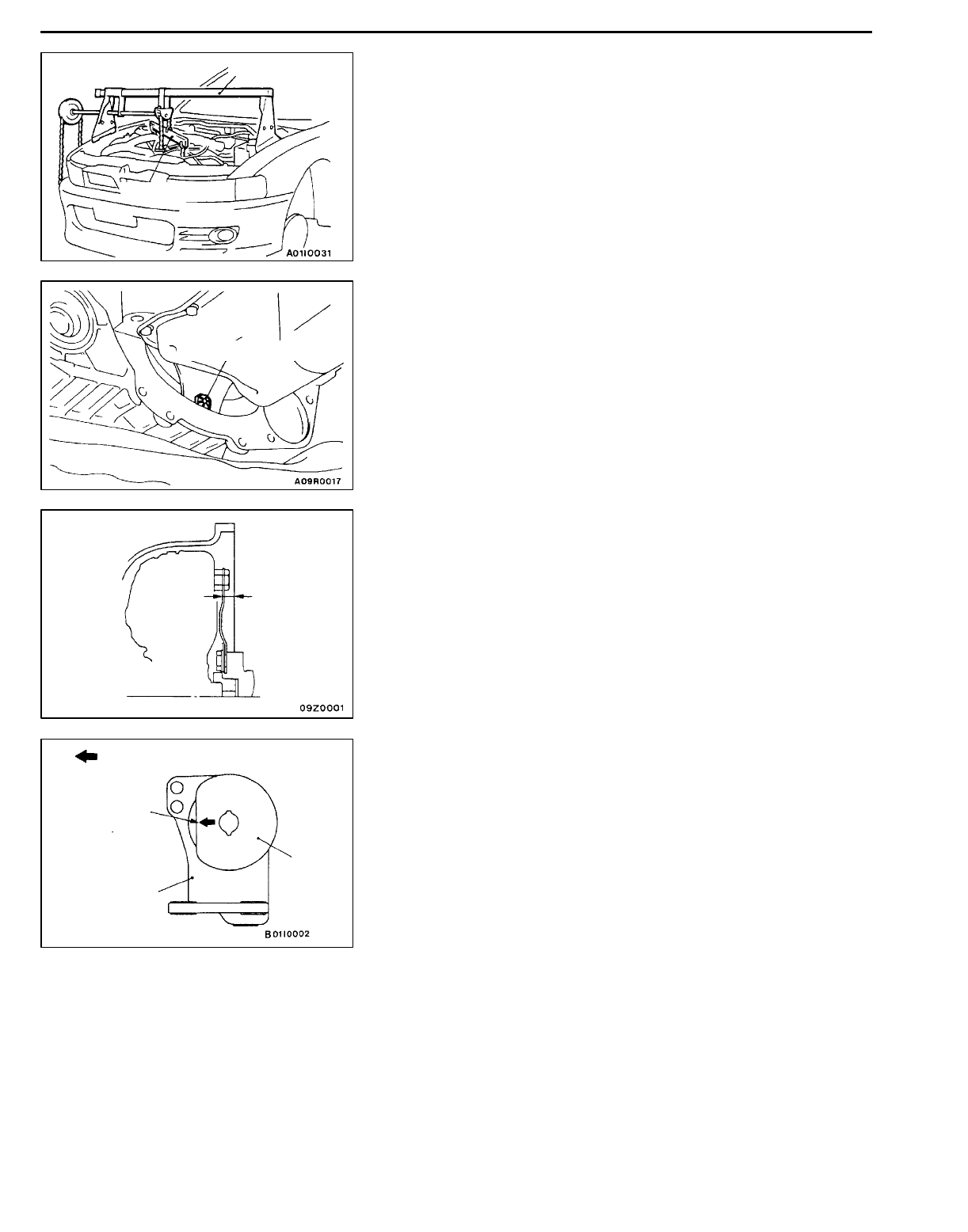
AUTOMATIC TRANSMISSION - Transmission Assembly 23-69
AE"ENGINE AND TRANSMISSION ASSEMBLY
SUPPORTING
Set the special tool to the vehicle to support the engine and
transmission assembly.
AF"TRANSMISSION ASSEMBLY LOWER PART
COUPLING BOLTS/TRANSMISSION ASSEMBLY
REMOVAL
1. Support the transmission assembly by using a
transmission jack.
2. Remove the drive plate bolts while turning the crank shaft.
3. Press in the torque converter to the transmission side
so that the torque converter does not remain on the engine
side.
4. Remove the transmission assembly lower bolts and lower
the transmission assembly.
INSTALLATION SERVICE POINTS
"AATRANSMISSION ASSEMBLY INSTALLATION
After securely inserting the torque converter into the
transmission side so that the value shown in the illustration
becomes the reference value, install the transmission
assembly to the engine.
Reference value (A): Approx. 12.2 mm
"BATRANSMISSION MOUNT STOPPER
INSTALLATION
Install the transmission mount stopper so that the arrow points
as shown in the illustration.
MZ203827
MB991453
Drive plate bolts
A
Transmis-
sion mount
stopper
Engine side
Arrow
Transmission
mount bracket

NOTES
