2310 RWA.ib RWA_ib RWA Ib
User Manual: 2310-RWA_ib
Open the PDF directly: View PDF ![]() .
.
Page Count: 25

2310-rwa.ib.doc Page 1 of 22 08/07/2002
IRT Eurocard
Type RWA-2310
Reverse Path Amplifier
Telstra serial items:
347/99 RWA-2310
347/105 Manual for RWA-2310
347/106 FRU-2300
347/108 PSU-2300
Designed and manufactured in Australia
IRT can be found on the Internet at:
http://www.irtelectronics.com
I R T Electronics Pty Ltd A.B.N. 35 000 832 575
26 Hotham Parade, ARTARMON N.S.W. 2064 AUSTRALIA
National: Phone: (02) 9439 3744 Fax: (02) 9439 7439
International: +61 2 9439 3744 +61 2 9439 7439
Email: sales@irtelectronics.com
Web: www.irtelectronics.com
2310-rwa.ib.doc Page 2 of 22 08/07/2002
IRT Eurocard
Type RWA-2310
Reverse Path Amplifier
Instruction Book
Table of Contents
Section Page
General description 3
Technical specifications 4
Technical description 5
Pre-installation 7
Operational safety 7
Installation 8
Maximum limits 8
Power supplies 8
Connections 9
Front & rear panel connector diagrams 10
FRU-2300 Eurocard RF module frame 11
Operational safety 14
Modules & PSU’s 14
PSU-2300 DC input PSU 16
Maintenance & storage 18
Warranty & service 18
Equipment return 18
HFC Cable TV Network Overview 19
Forward path 19
Reverse path 20
Application of the RWA-2310 in reverse path systems 21
Drawing index 22
This instruction book applies to units later than S/N 9612000.
2310-rwa.ib.doc Page 3 of 22 08/07/2002
General Description
The RWA-2310 has been designed to provide amplification of signals in the reverse path of cable TV distribution
systems.
An input attenuator with a 20 dB range provides gain control to optimise signal levels at the output.
The frequency response of the amplifier is tailored to give optimum low noise amplification to the reverse path
signals which normally lie between 5 and 100 MHz.
In addition the RWA-2310 is constructed with a high level of RF shielding which eliminates both ingress and egress
of unwanted RF signals.
Two types of frame are available for the RWA-2310 to suit different types of application:
The FRU-2300 allows 10 RWA-2310’s to be mounted in one 3 RU frame together with two PSU’s which
may be either 240 Vac or -48 Vdc.
The FRU-2310 allows 2 RWA-2310’s to be mounted in one 1 RU frame together with an inbuilt single
240 Vac PSU.
Standard features:
• 2 - 200 MHz frequency response specially contoured for use in reverse path of cable TV
distribution.
• Very low noise.
• 0 - 20 dB variable input gain control.
• Local or remote muting.
• Input and output monitoring on front panel.
• Power loss alarm output.
BLOCK DIAGRAM
REVERSE PATH AMPLIFIER
TYPE RWA-2310
24 dB AMP
INPUT
ISOLATED
OUTPUTS
INPUT
MONITOR
OUTPUT
MONITOR
0 - 20 dB
ADJUSTABLE
ATTENUATOR
20dB COUPLER
20 dB COUPLER
MUTE
RELAY
75 Ω
ΩΩ
Ω75 Ω
ΩΩ
Ω
2 WAY
SPLITTER
2310-rwa.ib.doc Page 4 of 22 08/07/2002
Technical Specifications
IRT Eurocard module
Type RWA-2310
RF:
Input:
Type DC coupled.
Number 1.
Impedance 75 Ω.
Return loss > 16 dB (2 - 200 MHz).
Maximum input level > +50 dBmV.
Outputs:
Type DC coupled.
Number 2.
Impedance 75 Ω.
Return Loss > 18 dB (2 - 200 MHz).
Isolation between outputs > 20 dB (2 - 200 MHz).
Maximum output level >+50 dBmV at 200 MHz.
Monitoring outputs:
Input monitor: AC coupled.
Impedance 75 Ω.
Level -20 dB
Output monitor: AC coupled.
Impedance 75 Ω.
Level -20 dB
Performance:
Gain 0 to +20 dB. Adjustable from front panel.
Frequency Response 2 to 200 MHz (-0.5 dB points).
-3dB frequency is typically 340MHz.
Noise Noise (f = 200 MHz) 6 dB at maximum gain
CTB (22 channels Vo = 47 dBmV) -67 dB
CSO (22 channels Vo = 47 dBmV) -67 dB
Connectors BNC
Power requirements 28 Vac or +28 Vdc.
Power consumption <300 mA
Other:
Temperature range 0 - 45° C ambient
Mechanical Mounts in IRT 19" rack chassis types FRU-2300
(10 modules in 3 RU*) or FRU-2310 (2 modules in 1 RU).
* Maximum number dependent on air circulation - See
installation section of manual.
Finish: Front panel Grey enamel, silk screened black lettering & red IRT logo
Rear Bright steel.
Case Alodine finished aluminium.
Dimensions 30 mm x 3 U x 231 mm IRT Eurocard
Optional accessories Instruction manual
2310-rwa.ib.doc Page 5 of 22 08/07/2002
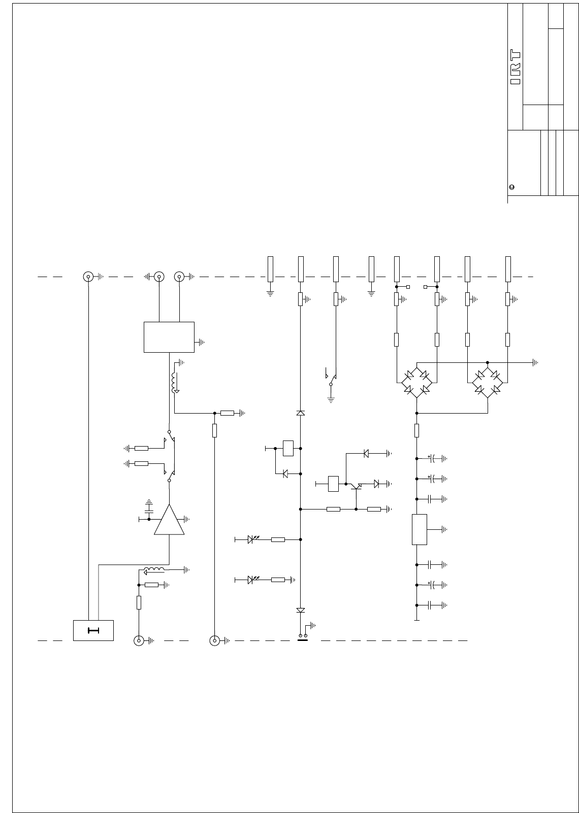
Technical Description
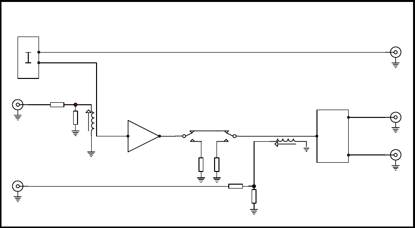
(For detail see diagram 803947)
Signal Path:
The block diagram for the signal path shows the basic layout of the amplifier and its inputs and outputs. The figures
in square brackets indicate the approximate signal levels at various points in the circuit when the amplifier is set to
unity gain.
The input signal is taken directly to a variable attenuator (maximum 20 dB) whose control is accessible through the
front panel of the module.
The attenuator output is connected to the 24 dB gain amplifier via a coupler, which provides a monitoring BNC
connector on the front panel with a signal of approximately -20 dB relative to the amplifier input.
This signal may be used to ensure that the signal at the input of the amplifier is sufficiently low as to avoid
overloading. The best level will depend on the number of carriers present in the signal and the desired operating
level for the system as a whole.
The amplifier output is connected to the output splitter via a muting relay operated switch, which terminates the
amplifier output and splitter input in 75 Ohms. This allows the output of the amplifier to be muted if a signal with
excessive noise is present which may cause problems for other equipment downstream.
The output of the amplifier is monitored immediately prior to the passive output splitter so as to not introduce a
variation in loading between outputs. When measuring output levels using this monitoring point it should be
remembered that the actual output level of the amplifier will be 3 dB lower at each output connector in addition to
the 20 dB loss in the coupler.
Due to the output splitter being of a passive type it is also essential that both outputs always be terminated in 75 Ohm
loads. If one output is not used a termination plug should be fitted to that output.
Amplifier gain. Each coupler itself introduces approximately 0.5 dB of loss in the signal and the output splitter
introduces a further 3 dB loss so that with the overall losses exclusive of the attenuator total 4 dB. The amplifier gain
is therefore chosen to be 24 dB so that the gain range overall is 0 to 20 dB.
+24 dB AMP
INPUT
ISOLATED
OUTPUTS
INPUT
MONITOR
OUTPUT
MONITOR
20 dB
ADJUSTABLE
ATTENUATOR
20dB COUPLER
20 dB COUPLER
RL1
75 Ω
ΩΩ
Ω75 Ω
ΩΩ
Ω
2 WAY
SPLITTER
[-3 dB]
[0 dB]
[-20 dB]
[-40 dB]
[-16 dB]
[+3.5 dB]
[+0 dB]
[+0 dB]
[+3 dB][-20.5 dB]
BLOCK DIAGRAM
REVERSE PATH AMPLIFIER
TYPE RWA-2310
2310-rwa.ib.doc Page 6 of 22 08/07/2002
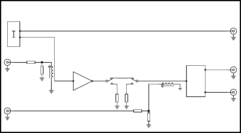
Alarms and controls:
General alarm. This alarm is generated whenever the output of the amplifier is not active due to either loss of
power or muting.
When no power is present the normal position for relay contacts RL 2 is with a connection to ground indicating the
alarm condition.
When power is applied and no muting signal is present the low impedance of relay coil RL 1 allows the muting
control line between diodes D 9 & 10 to rise to nearly the full 24 Vdc power rail. This signal is used to turn on
transistor Q 1 which operates relay RL 2 and releases the grounding contact on the alarm output.
When a muting control signal is applied the muting control line falls to near ground and transistor Q 1 turns off
resulting in the RL 2 relay contacts closing to ground.
Muting. The muting relay RL 1 may be operated either by the front panel switch or by remote contact closure
to ground. In its un-energised state the relay provides a connection between the amplifier and splitter and when
energised mutes the output.
The grounding control inputs from the switch and external connector are isolated by diodes D 9 & 10 which provide
an OR function. This means that whilst the amplifier may be muted by either means it is not possible to return the
amplifier to its normal operating mode unless both the front panel switch and the remote input are in the normal
setting.

2310-rwa.ib.doc Page 7 of 22 08/07/2002
Pre-Installation
Operational Safety:
WARNING
Operation of electronic equipment involves the use of voltages and currents that may
be dangerous to human life. Note that under certain conditions dangerous potentials
may exist in some circuits when power controls are in the OFF position.
Maintenance personnel should observe all safety regulations.
Do not make any adjustments inside equipment with power ON unless proper
precautions are observed. All internal adjustments should only be made by suitably
qualified personnel. All operational adjustments are available externally without the
need for removing covers or use of extender cards.
Pre-installation:
Handling:
This equipment may contain or be connected to static sensitive devices and proper static free handling precautions
should be observed.
Where individual circuit cards are stored, they should be placed in antistatic bags. Proper antistatic procedures
should be followed when inserting or removing cards from these bags.
Power:
AC mains supply: Ensure that operating voltage of unit and local supply voltage match and that correct rating fuse
is installed for local supply.
DC supply: Ensure that the correct polarity is observed and that DC supply voltage is maintained within the
operating range specified.
Earthing:
The earth path is dependent on the type of frame selected. In every case particular care should be taken to ensure that
the frame is connected to earth for safety reasons. See frame manual for details.
Signal earth: For safety reasons a connection is made between signal earth and chassis earth. No attempt should be
made to break this connection.

2310-rwa.ib.doc Page 8 of 22 08/07/2002
Installation
Installation in frame or chassis:
See details in separate manual for selected frame type.
Maximum limits:
The enclosed construction of the RWA-2310 gives excellent immunity to electromagnetic interference, but reduces
the ability of the electronics inside the casing to dissipate heat.
Adequate air flow should be ensured when modules are placed together in the 3 RU frame to prevent overheating
and premature failure of the modules.
Thermal budget:
A fully equipped FRU-2300 frame of RWA-2310’s with two PSU’s fitted will produce approximately 110 W of heat
output.
As a result the following rules should be observed:
1. Frame ventilation should not be obstructed by any equipment mounted immediately above or below the
FRU-2300. If possible a 1 RU blank panel should be mounted above and below the frame to ensure that
adequate air flow can occur.
2. No more than 8 RWA-2310’s should be mounted in an FRU-2300 when free air (unassisted) circulation is
the only cooling available or where the ambient temperature exceeds 30°C.
The RWA-2310’s should be mounted in the positions shown in the following diagram with front blank panels
type FB-700 fitted to the unused positions.
3. All 10 positions in the FRU-2300 may be used when fan forced cooling is available in the rack and the
ambient temperature is controlled to less than 30°C.
4. The RWA-2310 should not be mounted in a frame above other equipment which has a high heat output
which will increase the effective ambient temperature to above 30°C.
Power Supplies:
When fitted to an FRU-2300 frame the RWA-2310 may be powered by either the PSU-3001 240 Vac PSU or the
PSU-2300 -48 Vdc PSU.
In either case it is recommended that two PSU’s be fitted at all times so that the power load is shared between the
two supplies. In the event of failure of one supply the amplifiers should function within specification whilst operating
on the remaining supply as long as the correct input voltage is held to within the specifications for that supply.
However it is not recommended that a full frame of amplifiers be operated on a single supply for an extended period.
1
RWA-
2310
PSU 1
PT-701
or
PSU-2300
PSU 2
PT-701
or
PSU-2300
2
RWA-
2310
3
RWA-
2310
4
FB-700
BLANK
5
RWA-
2310
6
RWA-
2310
7
FB-700
BLANK
8
RWA-
2310
9
RWA-
2310
10
RWA-
2310
2310-rwa.ib.doc Page 9 of 22 08/07/2002
Connections:
RF input: This is a single connector with a 75 Ohm input impedance and should be fed from a suitably
impedance matched source.
RF outputs: Two outputs are provided which are obtained by a passive output splitter.
It is recommended that the two outputs be loaded in 75 Ohm terminations at all times.
If one output is not to be connected to external equipment it should be fitted with a 75 Ohm termination plug. Failure
to observe this may result in a noticeable drop in performance in the output being used.
Mute input: The external mute input presents an open circuit voltage of approximately +24 Vdc and may be
operated by either a contact closure to ground or by an open collector transistor driver. The connection to this input
must be capable of sinking a current of at least 15 mA.
The mute input is connected from the 9 pin ‘D’ connector at the rear of the module via the frame motherboard to a
Krone IDC connector mounted on the rear of the frame for each module. Connection details are marked on the
frame.
Alarm output: The alarm output makes contact to ground in the alarm condition and is open circuit in the
normal condition. The maximum rating on the relay contacts is 30 V (AC or DC) @ 500 mA.
The alarm output is connected from the 9 pin ‘D’ connector at the rear of the module via the frame motherboard to a
Krone IDC connector mounted on the rear of the frame for each module. Connection details are marked on the
frame.
9 pin ‘D’ connector:
The 9 pin ‘D’ connector provides connection to the selected frame for power supply inputs for either one or two
power supplies and for the alarm output and mute input signals.
This connector mates with a matching connector on the selected frame type and the necessary external connections
for the alarm and mute signals are made to the frame and not the module.
The following pin connection details for the 9 pin connector are therefore given for service and general information
purposes only.
Pin Connection
1 Gnd
2 AC 1 or DC +ve
3 AC 1 or DC -ve
4 No connection
5 Mute
6 AC 2 or DC +ve
7 AC 2 or DC -ve
8 Gnd
9 General alarm
2310-rwa.ib.doc Page 10 of 22 08/07/2002
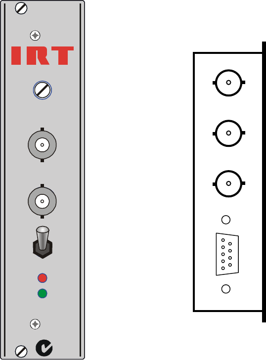
DC
MUTED
OPERATE
MUTE
OUT
IN
MONITOR
GAIN
RWA-2310
N140
Front & rear panel connector diagrams
The following front panel and rear assembly drawings are not to scale and are intended to show relative positions of
connectors, indicators and controls only.
INPUT
OUTPUT 1
OUTPUT 2
FRAME
2310-rwa.ib.doc Page 11 of 22 08/07/2002
IRT Eurocard Frame
Type FRU-2300
General Description
The purpose of the FRU-2300 is to provide an economical and compact mechanical framing system for IRT 2300
series Eurocard RF shielded modules.
In addition the frame provides a power supply bus to reticulate power from one or two common low voltage power
supply units to all modules in the frame.
A total of ten 2300 series IRT Euro-modules and two power supply units can be accommodated in one FRU-2300
3 Rack Unit Frame.
A choice of power supply units is available to provide power from either AC or DC supplies. Each supply is capable
of supporting a full frame of cards on its own and AC and DC fed supplies may be mixed in the same frame.
IRT 2000 series Eurocard RF shielded modules are fully enclosed boxes designed to prevent the ingress or egress of
electromagnetic interference. The module is complete with front fascia panel and rear signal and power connectors
which provides the necessary connections to the frame PSU’s other equipment.
The module can be inserted or removed from the frame from the front. When inserted one connector on the rear
mates with a motherboard connector which carries the data and power supply connections.
Although the module may be inserted or removed from the front of the frame, care must be taken when doing so to
ensure that the connections to the rear of the module have sufficient slack cable for this to be accomplished. If this is
not the case all cables should be disconnected before attempting to remove the module from the frame.
2310-rwa.ib.doc Page 12 of 22 08/07/2002
Technical Specifications
IRT Eurocard frame
Type FRU-2300
Power:
Input power: AC AC mains input (240 Vac ±10%)
and / or
DC -48 Vdc ±25%.
Input power fuses AC SLO-BLO 500 mA.
DC Fused in PSU-2300 PSU module.
Output power to module bus: AC 28 Vac from PT-701
and / or
DC +28 Vdc from PSU-2300
Connectors:
Modules DB female 9 pin RF filtered.
Power module to frame H15FP4 H15 female 4 mm PCB mounting.
Power input to frame AC IEC 320 with integral fuse holder.
DC Klippon MK 1/3 3 pin termination block 2616.
Alarm / control Krone IDC (1 per module).
Other:
Temperature range 0 - 50° C ambient.
Mechanical 3 RU (482 mm x 132 mm) standard 19” rack frame.
Suitable for mounting in standard 19" racks.
Finish Natural anodised aluminium frame with bright
passivated steel side panels & rear power connection
box with black silk screened lettering.
Dimensions 482 x 132 x 285 mm (Frame empty.)
Clearance width 445 mm.
Optional accessories PT-701 single power supply module 240 Vac input.
PSU-2300 single power supply module -48 Vdc
input.
2310-rwa.ib.doc Page 13 of 22 08/07/2002
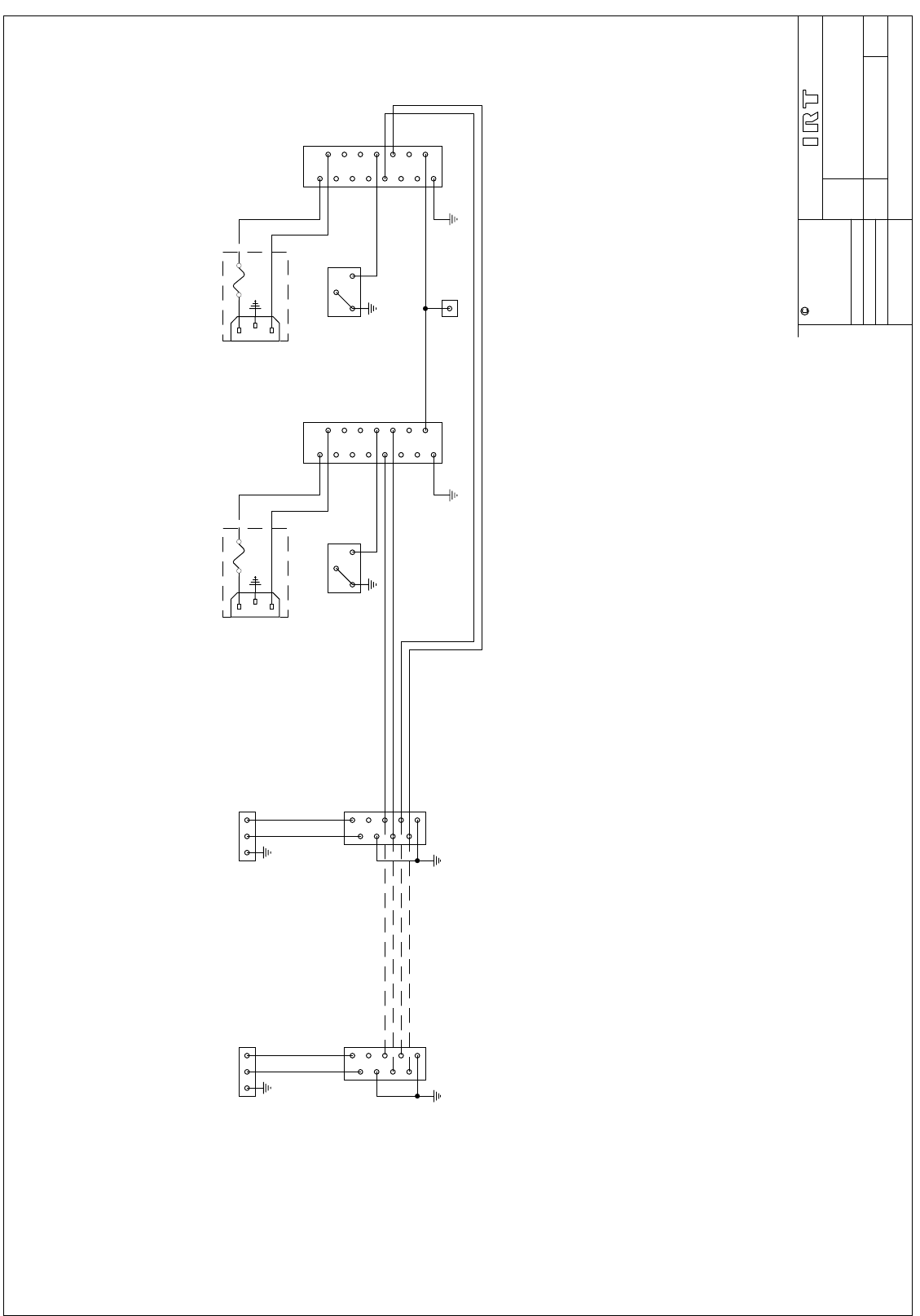
Circuit Description
The FRU-2300 provides a circuit path to the modules for two complementary supplies and a ground earth reference
making a total of five busses. One supply buss pair is obtained from each of the two PSU module locations. Each
supply buss may be either AC or DC according to the type of power supply module selected.
The outputs of the two types of supply are floating with respect to ground.
In the case of the AC type supply this will result in a symmetrical output for the two AC busses due to the action of
the bridge rectifiers in the connected modules.
In the case of the DC type supply the negative side will rise to approximately +0.7 Vdc due to the action of the
conducting diodes in the negative side of the bridge rectifiers in the connected modules.
The ground supply buss is connected directly to the chassis, safety earth of the 240 Vac IEC input connectors and the
+ve side of the -48 Vdc input connector.
The power supply modules connect to the mother board via special H15FP4 connectors. This allows the modules to
be inserted or removed safely whilst power is applied to the frame inputs.
An alarm circuit is provided which connects to the two PSU’s. When operating normally the alarm is open circuit.
When supply is lost the alarm line is grounded.
When both PSU’s are installed a failure of either PSU will enable the alarm.
Connection to modules is made via 9 pin D connectors as described in the General Description.
Connector pin designations are as follows:
9 pin D Eurocard module connector:
Pins Designation
1 Gnd.
2 AC/1 + or +32 Vdc/1.
3 AC/2 + or +32 Vdc/2.
4 No connection.
5 Mute.
6 AC/1 - or 0 Vdc/1.
7 AC/2 - or 0 Vdc/2.
8 Gnd.
9 Tally.
Special note: Whilst this frame appears at first sight to be similar to the FR-748A Eurocard frame for 700 &
3000 series Eurocards, there are major differences which make the two quite incompatible.
Please note especially that whilst the PT-701 PSU is able to be used in both the FR-748A &
FRU-2300 that the PT-748A PSU is incompatible and to safeguard against accidental insertion the
power supply contacts for the PT-748A PSU make no connection in the FRU-2300.

2310-rwa.ib.doc Page 14 of 22 08/07/2002
Installation
Operational Safety
WARNING
Operation of electronic equipment involves the use of voltages and currents which
may be dangerous to human life. Maintenance personnel should observe all safety
regulations. Do not change components or make adjustments inside the equipment
with power ON unless proper precautions are observed. Note that under certain
conditions dangerous potentials may exist in some circuits even though power
controls are in the OFF position.
Modules & PSU’s
FRU-2300 Frame:
Eurocard Module
Slide the module into its appropriate position and tighten the two retaining screws. If the module does not seem to be
fully inserted check that the module is not being fouled by any cables at the rear.
Rear Connections
Signal connections. These are made directly to the rear of the module. If it is desired to be able to remove the
module without accessing the rear of the frame to disconnect the cables it will be necessary to ensure that
approximately 300 mm of additional cable is provided, on each connection, which can readily be withdrawn through
the frame to a sufficient distance to disconnect at the front of the frame.
Data connections: These are made to a three way Krone IDC connector above each module. The three connections
are designated to suit the RWA-2300 reverse path RF amplifier module as follows:
Pin Connection
1 Mute - connected to pin 5 of the DB 9 module connector.
2 Tally - connected to pin 9 of the DB 9 module connector.
3 Ground - connected directly to chassis / PSU ground reference.
Power Supply
The frame will operate with either one or two power supply modules installed.
The power supply module should be slid into either slot 11 or 12 at the right hand end of the frame. The four
retaining screws on the front should be tightened.
Connect power input to rear of frame. For DC input; observe the polarity markings next to each connector.
Due to its weight if the frame is to be freighted for any purpose the power supply should be removed and packed
separately before shipment.
2310-rwa.ib.doc Page 15 of 22 08/07/2002
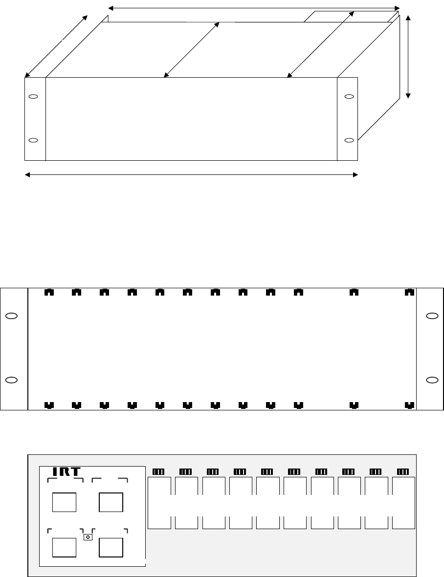
FRU-2300 Dimensional diagram
Note: Dimensions on this diagram are approximate only and do not take into account any connections at the front or
rear. Dimensions indicated are intended as a guide for cable installation purposes only.
The following diagrams are not to scale and are intended only to show relative locations.
FRU-2300 Front View
FRU-2300 Rear View
1 2 3 4 5 6 7 8 9 10 PSU 1 PSU 2
Module positions
S.347/66
SLOT 12
240 V 50 Hz
0.2 A
SLOT 11
240 V 50 Hz
0.2 A
+
FUSES
500 mA S.B.
-
-48 Vdc INPUT -48 Vdc INPUT
- +
ALARM
1 2 G 1 2 G 1 2 G 1 2 G 1 2 G 1 2 G 1 2 G 1 2 G 1 2 G 1 2 G
Module Positions
10 9 8 7 6 5 4 3 2 1
FRU-2300 Frame
132 mm
255 mm
436 mm
482 mm
240 mm
285 mm
2310-rwa.ib.doc Page 16 of 22 08/07/2002
IRT Power Supply for Eurocard
-48 Vdc to +29 Vdc
Type PSU-2300
GENERAL DESCRIPTION
The PSU-2300 is designed to provide complementary low voltage DC power supplies required for operation of up to
10 IRT RWA-2310 Eurocard modules.
The IRT PSU-2300 DC-DC converter converts a nominal 48V input voltage to +29V with respect to ground.
Two PSU-2300s can be operated redundantly when using an FRU-2300 Frame. The redundant power supply facility
of the PSU-2300 is enabled in each IRT RWA-2310 by having the power supply circuit of each module made up of
two bridge rectifier circuits with the outputs connected in parallel. This allows the +29 volts to be sourced from
either PSU-2300.
A front panel LED indicator provides visual confirmation of the presence of the low voltage output.
An alarm relay is also included which will activate the alarm if the output fails.
The PSU-2300 is available in -48 Vdc only and is not configurable by the user.
TECHNICAL SPECIFICATIONS
IRT Eurocard Dual Power Supply Module
Type PSU-2300
Power Requirements:
Voltage 48 Vdc ± 25% Positive ground.
Power 1.5 A maximum.
Fusing 2 A
Output voltage: +29V @ 2.8A
Connectors: DC power input / output H15MFAV32 male, Faston
Other:
Temperature range 0 - 50° C ambient
Mechanical Suitable for mounting in FRU-2300 rack frame
Finish: Front panel Grey enamel, silk screened black lettering & red IRT
logo
Body Passivated steel with silk screened black lettering.
Dimensions 6 HP x 3 U x 230 mm
2310-rwa.ib.doc Page 17 of 22 08/07/2002
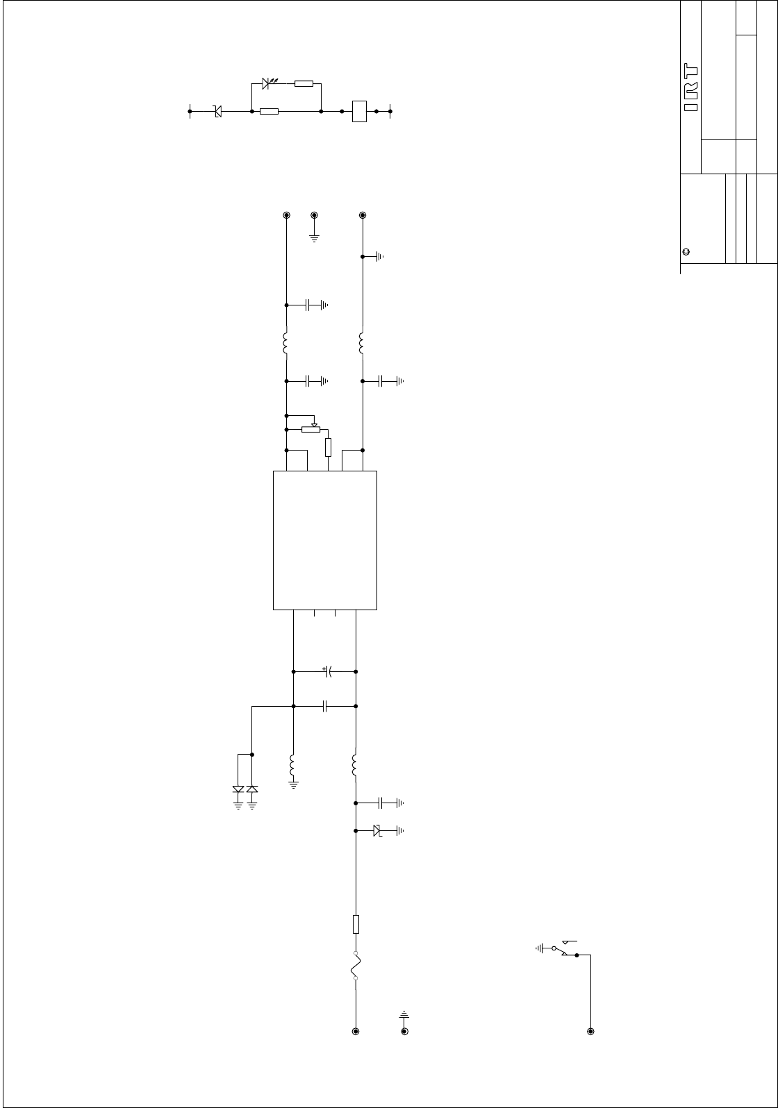
CIRCUIT DESCRIPTION
The PSU-2300 consists of a DC-DC converter circuit which provides a 29 Vdc output..
The DC input circuitry consists of a safety fuse followed by a low value series resistance and over-voltage
protection zener diode and a number of RF suppression components.
The front panel LED power indicator and alarm relay are powered from the output rail by way of a series zener
diode so that if the rail voltage falls there is insufficient voltage to operate the relay and the LED dims sufficiently to
indicate the fault condition.
The alarm is shown in the unenergised position. When operating normally the alarm is open circuit. When supply is
lost the alarm line is grounded.
INSTALLATION & SERVICING
FRU-2300 Frame:
The PSU-2300 should be slid firmly into either of the two double width slots (11 & 12) at the right of the frame. The
four retaining screws on the front should then be tightened.
Power to the PSU-2300 is supplied from a connector located on the rear of the FRU-2300 immediately to the rear of
the module. Care should be taken to observe the correct polarity as marked when connecting DC to this connector.
The alarm output connector is located on the rear of the FRU-2300 frame and is common to both supply units when
installed. The alarms for both units are in parallel such that when a fault develops in either PSU the alarm output will
be grounded.
WARNING - Each PSU-2300 dissipates up to 10 Watts and a full frame of ten RWA-2310s and two PSU-2300’s
dissipates nearly 100 Watts. Ensure that adequate ventilation is available to keep down the operating temperature. If
possible at least 44.5mm (1RU) should be left clear above each frame.
Internal adjustments:
The PSU-2300 is factory set for the correct output voltage and should not require re-adjustment unless one of the DC
- DC converters is replaced.
Adjust RV 2 for +29 Vdc
2310-rwa.ib.doc Page 18 of 22 08/07/2002
Maintenance & storage
Maintenance:
No regular maintenance is required.
Care however should be taken to ensure that all connectors are kept clean and free from contamination of any kind.
This is especially important in fibre optic equipment where cleanliness of optical connections is critical to
performance.
Storage:
If the equipment is not to be used for an extended period, it is recommended the whole unit be placed in a sealed
plastic bag to prevent dust contamination. In areas of high humidity a suitably sized bag of silica gel should be
included to deter corrosion.
Where individual circuit cards are stored, they should be placed in antistatic bags. Proper antistatic procedures
should be followed when inserting or removing cards from these bags.
Warranty & service
Equipment is covered by a limited warranty period of three years from date of first delivery unless contrary
conditions apply under a particular contract of supply. For situations when “No Fault Found” for repairs, a
minimum charge of $A100.00 will apply, whether the equipment is within the warranty period or not.
Equipment warranty is limited to faults attributable to defects in original design or manufacture. Warranty on
components shall be extended by IRT only to the extent obtainable from the component supplier.
Equipment return:
Before arranging service ensure that the fault is in the unit to be serviced and not in associated equipment. If
possible, confirm this by substitution.
Before returning equipment contact should be made with IRT or your local agent to determine whether the
equipment can be serviced in the field or should be returned for repair.
The equipment should be properly packed for return observing antistatic procedures.
The following information should accompany the unit to be returned:
1. A fault report should be included indicating the nature of the fault
2. The operating conditions under which the fault initially occurred.
3. Any additional information which may be of assistance in fault location and remedy.
4. A contact name and telephone and fax numbers.
5. Details of payment method for items not covered by warranty.
6. Full return address.
7. For situations when “No Fault Found” for repairs, a minimum charge of $A100.00 will apply, whether
the equipment is within the warranty period or not.
Please note that all freight charges are the responsibility of the customer.
The equipment should be returned to the agent who originally supplied the equipment or, where this is not
possible, to IRT direct as follows.
Equipment Service
IRT Electronics Pty Ltd
26 Hotham Parade
ARTARMON
N.S.W. 2064
AUSTRALIA
Phone: 61 2 9439 3744 Fax: 61 2 9439 7439
Email: service@irtelectronics.com
2310-rwa.ib.doc Page 19 of 22 08/07/2002
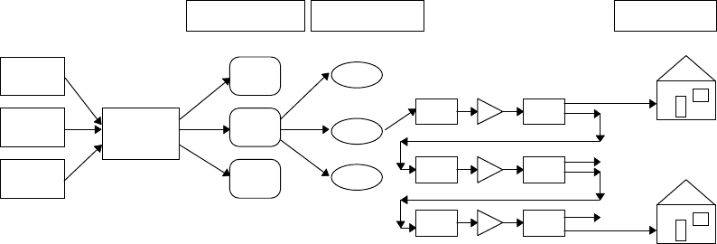
HFC Cable TV Network Overview
The Forward path:
In a Hybrid Fibre Co-axial cable (HFC) network the forward path has a broadband RF capacity bandwidth from
approximately 85 MHz to 750 MHz. This wide bandwidth is due to the large requirements of the pay TV
application.
Signals from various program providers are concentrated at HeadEnds for distribution through the system on a single
cable or fibre connection. The input signals to the HeadEnds may be provided over baseband coaxial cable or fibre
optic links or in the case of free to air broadcast channels may be demodulated from a locally available signal off air.
These signals are modulated and combined to provide a single wideband multichannel signal for distribution.
From the Headend the signals are amplified and converted into optical signals for transport down dedicated fibres to
a node. Each node is strategically located to cater for approximately 10,000 customers.
From each node the signals are distributed to a hub which may service between 500 and 1000 customer sites. At the
hub the signal is converted form optical to electrical and amplified before travelling down a coaxial cable for final
distribution.
Currently the final distribution to the customer uses amplitude modulation (AM) for ease of interfacing with current
set top decoders.
In the final distribution via coaxial cable a combination of splitters and amplifiers is employed and in any particular
connection a total of three amplifiers may be present.
This forward path topology ensures that the highest quality of signal is maintained with very low noise by the use of
optical fibre transport technology until the final stage of distribution. From this point the high signal level allows the
signal to noise ratio to be maintained at high levels as far as the subscriber connection.
Headend
Node Hub
Set top unit
&
TV receiver
Free to Air
TV
Channels
Pay TV
Service
Provider
Pay TV
Service
Provider
Node
Node
Hub
Hub
Splitter Splitter
Amp
Set top unit
&
TV receiver
Splitter Splitter
Amp
Splitter Splitter
Amp
Up to approximately
15 hubs per node.
Over 100 nodes per
headend.
600 to 1000
homes per hub.
Typical Hybrid Fibre - Coaxial Pay TV Distribution System
2310-rwa.ib.doc Page 20 of 22 08/07/2002
The Reverse path:
Whilst the forward path provides an adequate system for distribution of programme material to subscribers it is
unidirectional due to the amplifiers and other active hardware in the system. Yet the fibre optic and coaxial cables
themselves are able to carry traffic in either direction and so the opportunity is presented to make a bidirectional
system which makes provides a better return on the investment in cable and fibre installation.
Provided the bandwidth is sufficient and the signal to noise ratio is kept high the reverse path can be used to provide
a wide variety of services which may or may not be related to the primary signals carried in the forward path.
Examples of such services are telephony, high speed data for computer access to the Internet, ISDN services,
impulse pay per view (IPPV) registration, movies on demand, home shopping and status monitoring and
control (SM&C). Each of these services requires a link back to the service provider.
Whilst IPPV and SM&C services contain only small amounts of information and are suitable for a polled service
occupying a minimal bandwidth of less than 1 MHz, telephony, Internet and ISDN require both a larger bandwidth
and are typically connected for quite long durations. In addition, Internet, ISDN and data modem services in general
require a low noise path in order to minimise date errors.
In order to provide such a reverse path it is necessary to overcome the losses introduced by the passive splitters in
the forward path and at each point of amplification provide a reverse path around the forward amplifier. In addition
it should be noted that whilst the forward path is a divergent system, and noise levels are relatively easy to control,
that the reverse path is convergent and so the noise from every source adds to that of every other across the whole
available bandwidth.
It is therefore important that the amplifiers in the reverse path have a controlled bandwidth response to exclude
signals in the forward path and that the intrinsic noise of each amplifier be minimal both in band and out of band. In
addition to low noise, high speed data services require a minimal group delay through the system and this must
therefore be taken into account at every point in the system.
Different types of reverse path amplifier are required at different points in the reverse path.
In the cables leading from the hubs; small reverse path amplifiers with directional couplers are required to be located
in the same housing as the forward path amplifiers.
At the hub the reverse path signal is separated from the forward path signal so that it may be converted to an optical
signal and sent back to each node on a separate fibre to the forward path. At this point the reverse path signal
occupies a bandwidth from 5 MHz to 65 MHz.
Due to the noise ingress into the hubs from the coaxial customer network it is not possible to sum all of the reverse
path signals from the hubs together at the node. So at each node the signals are first converted back from optical to
electrical form so that they may be combined by Frequency Division Multiplexing (FDM).
This method together with the associated out of band filtering results in minimum noise increase in the combined
reverse path signals.
Before combining the signals it is important that the levels be adjusted to compensate for varying path losses from
the different hubs and so variable gain reverse path amplifiers with monitoring points are required in each node
input.
In addition it is desirable to be able to mute the signal from any path where a failure has occurred causing the noise
level to rise to a level where it may cause interference with other signals and thus corruption of services being
provided to customers on other hubs.
At each node the reverse path signal is converted back to an optical form for transmission back to the Headend on a
separate fibre to the forward path.
At the Headend (or at a node if heavy usage is indicated) the reverse path signal is converted back to electrical form
and delivered to decoding equipment for analysis and routing of individual signals. Not all signals will be required to
be passed further than the Headend and others will be required to be routed into the public telephony network or to
individual service providers.
2310-rwa.ib.doc Page 21 of 22 08/07/2002
Application of the RWA-2310 in the reverse path:
The RWA-2310 amplifier is a wideband low noise amplifier optimised for use with RF signals between 2 MHz and
200 MHz. The term reverse path amplifier arises out of its suitability for use in the reverse path of a cable TV
network although its use is not limited to reverse path applications.
Nodes:
The RWA-2310 is designed to be used in the reverse path immediately after the optical signal receivers where it is
required to boost the level of the signal to enable the various signals situated in the reverse path band to be split into
each piece of receiving equipment at the correct level.
In addition it provides signal monitoring at this point for identifying problems in particular node or hub feeds and a
muting facility to disable the output in the event of the line becoming to noisy to use.
HeadEnds:
At HeadEnds the received optical signals are once again converted from optical format to an electrical signal. The
RWA-2310 may once again be used to perform the same functions as at the nodes.
The reverse path signal at this point is processed by a computer controlled system which interprets the addressing of
the incoming signals and routes them to the appropriate destination, whether it be a pay TV provider, ISDN service
or Internet access provider.
The router for these signals requires that the signals from various sources be adjusted to the same level so that the
router output for a particular destination is held within the prescribed limits of the equipment which converts the
signal into the appropriate form for that provider.
General:
As the number of users of the reverse path grows, so does the number of amplifiers needed. The RWA-2310
provides an ideal solution to this expansion due to its modular nature. Additional amplifiers may be plugged in as
required into pre-wired rack frames.
It is also vital that in the event of any failure that maintenance is able to be carried out as quickly as possible. The
monitoring points on the RWA-2310 provide a ready access to the signals for locating faults and its modular nature
allows rapid replacement of a module should its performance be in doubt.
Dual power supplies with a choice of AC or DC options and external alarms enhance the reliability of the
RWA-2310 and the local and remote muting functions may be used to quickly isolate any source of noise in a given
path before it is combined with other signals to their detriment.
2310-rwa.ib.doc Page 22 of 22 08/07/2002
Drawing Index
Drawing # Sheet # Description
803947 RWA-2310 200 MHz Amplifier schematic
803980 FRU-2300 Eurocard frame schematic.
804039 1 PSU-2300 schematic diagram
TITLE
SCALE
SIZE
SHEET
DRAWN
CHECKED
ENG. APP.
CONTRACT No.
DO NOT COPY NOR
DISCLOSE TO ANY
THIRD PARTY
WITHOUT WRITTEN
CONSENT
OF11
IRT Electronics Pty. Ltd.
803947DRAWING No.
COPYRIGHT
ARTARMON NSW AUSTRALIA 2064
A3
RWA-2310
REVERSE PATH
AMPLIFIER
1 19/03/96
4
1+24
5
91
2,3,7,8
AMP 1 1
5
6
PCS
2-1-75
2,3,4,7,8
SPL 1
5
+24
+24+24
+24
SK1/5
SK1/9
SK1/6
SK1/2
SK1/3
SK1/7
SK1/8
SK1/1
8
3
INPUT
ISOLATED
OUTPUTS
ATT1
INPUT
MON
OUTPUT
MON
2 23/04/96
3 20/05/96
20dB
ATTENUATOR
ADJ
14
20
176
3
9
22
1
4 15/08/96
+24
1
4
3
1
34
2
PC803948
R.K.
ECR750
5 02/10/96
6 17/06/97
ECR861
RL2
FL1
FL2
D1-4
1N4004
I
1O3
G
2
U1
7824
D5-8
1N4004
FL4
FL3
21
D10
1N4148
21
LED1
PWR
21
LED 2
RF OFF
2 1
D9
1N4148
RL2
RL1
CPL1
20dB
CPL2
20dB
BNC
BNC
BNC
BNC
J1
BNC
RL1
R4
75
R5
75
2 1
D11
1N4148
R10
3K3
R9
3K3
R7
33R R6
56R
R3
56R
R2
33R
21
D12
1N4148
2 1
D13
1N4148
FL5
FL6
C6
100n
C5
100
C4
100n
C3
100n
C2
1500
C1
1500
R13
33K
R12
10K
Q1
BC108
C7
100n
F1
1R8
F2
1R8
F3
1R8
F4
1R8
R11
5R6
TITLE
SCALE
SIZE
SHEET
DRAWN
CHECKED
ENG. APP.
CONTRACT No.
DO NOT COPY NOR
DISCLOSE TO ANY
THIRD PARTY
WITHOUT WRITTEN
CONSENT
OF11
IRT Electronics Pty. Ltd.
803980DRAWING No.
COPYRIGHT
ARTARMON NSW AUSTRALIA 2064
A3
FRU-2300
FRAME
1
2
3
4
5
6
7
8
9
213
1
2
3
4
5
6
7
8
9
213
32Z
30D
28Z
24Z
20Z
16Z
12Z
8Z
4Z
6D
10D
14D
18D
22D
26D
1
2
3
+-
32Z
30D
28Z
24Z
20Z
16Z
12Z
8Z
4Z
6D
10D
14D
18D
22D
26D
1
2
3
+-
TB-1 TB-10
SK1 SK10
SK11 SK12
ALARM
-48V I/P -48V I/P
240VAC
I/P
240VAC
I/P
500mA SLOW500mA SLOW
1. MUTE CONTROL
2. TALLY INDIC
3. GROUND
1 15/07/97
L
G
N
SK11
L
G
N
SK12
TITLE
SCALE
SIZE
SHEET
DRAWN
CHECKED
ENG. APP.
CONTRACT No.
DO NOT COPY NOR
DISCLOSE TO ANY
THIRD PARTY
WITHOUT WRITTEN
CONSENT
OF11
IRT Electronics Pty. Ltd.
804039DRAWING No.
COPYRIGHT
ARTARMON NSW AUSTRALIA 2064
DC-DC CONVERTER
RBB
1
8
P1-32Z
GROUND
-48V
P1-20Z
+28V
P1-24Z
COMMON
P1-22D
3
P1-30D
ALARM
PCB 804040
PSU-2300
P1-18D
28V
RETURN
2 28/02/97
3 27/03/97
RV2
500K
L1
RFC
C7
10n
C9
10n
L2 RFC R5
470
RL1
21ND12
21
LD1
RL1
R4
270
C8
10n
2 1
ZD2
C11
C2
10n
21
ZD1
BZT03-C68
R1
.51
F1
FUSE
+ IN
4
- IN
1
GATE OUT
2
GATE IN
3
- OUT 9
+ OUT 5
+ SENSE 6
_ SENSE 8
TRIM 7
2
VI-2NL-EW-F4
C1
0.1
2 1
D3 1N4004
21
D2 1N4004
L3
RFC
L4
RFC
R2
1M5
C3
10u
