Installation For Adjuncts And Peripherals Avaya Communication Manager 555 233 116 233116 6
User Manual: 555-233-116
Open the PDF directly: View PDF ![]() .
.
Page Count: 114 [warning: Documents this large are best viewed by clicking the View PDF Link!]
- ===============
- MAIN MENU
- MASTER INDEX
- GLOSSARY
- ===============
- Installation for Adjuncts and Peripherals for Avaya Communication Manager
- Contents
- About this book
- 1 Sources of Information on Adjuncts
- 2 Terminal server installation
- 3 Call detail recording (CDR)
- 4 Multimedia communications
- 5 Printers
- 6 DS1/T1 CPE loopback jack
- Installing a loopback jack
- Administering the loopback jack
- Loopback testing with a smart jack
- Testing a loopback jack without a smart jack
- 7 External modems
- 8 ISDN converters and adapters
- 9 Busy tone disconnect equipment for non-U.S. installations
- 10 909A/B universal coupler
- 11 Malicious call trace
- 12 Music-on-hold
- 13 Paging and announcement equipment
- Index

,QVWDOODWLRQIRU$GMXQFWVDQG3HULSKHUDOV
IRU$YD\D&RPPXQLFDWLRQ0DQDJHU
Release 2.0
555-233-116
Issue 6
November 2003

Copyright 2003, Avaya Inc.
All Rights Reserved
Notice
Every effort was made to ensure that the information in this document
was complete and accurate at the time of printing. However,
information is subject to change.
Warranty
Avaya Inc. provides a limited warranty on this product. Refer to your
sales agreement to establish the terms of the limited warranty. In
addition, Avaya’s standard warranty language as well as information
regarding support for this product, while under warranty, is available
through the following Web site: http://www.avaya.com/support.
Preventing Toll Fraud
“Toll fraud” is the unauthorized use of your telecommunications
system by an unauthorized party (for example, a person who is not a
corporate employee, agent, subcontractor, or is not working on your
company's behalf). Be aware that there may be a risk of toll fraud
associated with your system and that, if toll fraud occurs, it can result
in substantial additional charges for your telecommunications
services.
Avaya Fraud Intervention
If you suspect that you are being victimized by toll fraud and you need
technical assistance or support, in the United States and Canada, call
the Technical Service Center's Toll Fraud Intervention Hotline at
1-800-643-2353.
How to Get Help
For additional support telephone numbers, go to the Avaya support
Web site: http://www.avaya.com/support. If you are:
• Within the United States, click the Escalation Management link.
Then click the appropriate link for the type of support you need.
• Outside the United States, click the Escalation Management link.
Then click the International Services link that includes telephone
numbers for the international Centers of Excellence.
Providing Telecommunications Security
Telecommunications security (of voice, data, and/or video
communications) is the prevention of any type of intrusion to (that is,
either unauthorized or malicious access to or use of) your company's
telecommunications equipment by some party.
Your company's “telecommunications equipment” includes both this
Avaya product and any other voice/data/video equipment that could be
accessed via this Avaya product (that is, “networked equipment”).
An “outside party” is anyone who is not a corporate employee, agent,
subcontractor, or is not working on your company's behalf. Whereas, a
“malicious party” is anyone (including someone who may be
otherwise authorized) who accesses your telecommunications
equipment with either malicious or mischievous intent.
Such intrusions may be either to/through synchronous (time-
multiplexed and/or circuit-based) or asynchronous (character-,
message-, or packet-based) equipment or interfaces for reasons of:
• Utilization (of capabilities special to the accessed equipment)
• Theft (such as, of intellectual property, financial assets, or toll
facility access)
• Eavesdropping (privacy invasions to humans)
• Mischief (troubling, but apparently innocuous, tampering)
• Harm (such as harmful tampering, data loss or alteration,
regardless of motive or intent)
Be aware that there may be a risk of unauthorized intrusions
associated with your system and/or its networked equipment. Also
realize that, if such an intrusion should occur, it could result in a
variety of losses to your company (including but not limited to,
human/data privacy, intellectual property, material assets, financial
resources, labor costs, and/or legal costs).
Responsibility for Your Company’s Telecommunications Security
The final responsibility for securing both this system and its
networked equipment rests with you - Avaya’s customer system
administrator, your telecommunications peers, and your managers.
Base the fulfillment of your responsibility on acquired knowledge and
resources from a variety of sources including but not limited to:
• Installation documents
• System administration documents
• Security documents
• Hardware-/software-based security tools
• Shared information between you and your peers
• Telecommunications security experts
To prevent intrusions to your telecommunications equipment, you and
your peers should carefully program and configure:
• Your Avaya-provided telecommunications systems and their
interfaces
• Your Avaya-provided software applications, as well as their
underlying hardware/software platforms and interfaces
• Any other equipment networked to your Avaya products
TCP/IP Facilities
Customers may experience differences in product performance,
reliability and security depending upon network configurations/design
and topologies, even when the product performs as warranted.
Standards Compliance
Avaya Inc. is not responsible for any radio or television interference
caused by unauthorized modifications of this equipment or the
substitution or attachment of connecting cables and equipment other
than those specified by Avaya Inc. The correction of interference
caused by such unauthorized modifications, substitution or attachment
will be the responsibility of the user. Pursuant to Part 15 of the Federal
Communications Commission (FCC) Rules, the user is cautioned that
changes or modifications not expressly approved by Avaya Inc. could
void the user’s authority to operate this equipment.
Product Safety Standards
This product complies with and conforms to the following
international Product Safety standards as applicable:
Safety of Information Technology Equipment, IEC 60950, 3rd Edition
including all relevant national deviations as listed in Compliance with
IEC for Electrical Equipment (IECEE) CB-96A.
Safety of Information Technology Equipment, CAN/CSA-C22.2
No. 60950-00 / UL 60950, 3rd Edition
Safety Requirements for Customer Equipment, ACA Technical
Standard (TS) 001 - 1997
One or more of the following Mexican national standards, as
applicable: NOM 001 SCFI 1993, NOM SCFI 016 1993, NOM 019
SCFI 1998
The equipment described in this document may contain Class 1
LASER Device(s). These devices comply with the following
standards:
• EN 60825-1, Edition 1.1, 1998-01
• 21 CFR 1040.10 and CFR 1040.11.

The LASER devices operate within the following parameters:
• Maximum power output: -5 dBm to -8 dBm
• Center Wavelength: 1310 nm to 1360 nm
Luokan 1 Laserlaite
Klass 1 Laser Apparat
Use of controls or adjustments or performance of procedures other
than those specified herein may result in hazardous radiation
exposures. Contact your Avaya representative for more laser product
information.
Electromagnetic Compatibility (EMC) Standards
This product complies with and conforms to the following
international EMC standards and all relevant national deviations:
Limits and Methods of Measurement of Radio Interference of
Information Technology Equipment, CISPR 22:1997 and
EN55022:1998.
Information Technology Equipment – Immunity Characteristics –
Limits and Methods of Measurement, CISPR 24:1997 and
EN55024:1998, including:
• Electrostatic Discharge (ESD) IEC 61000-4-2
• Radiated Immunity IEC 61000-4-3
• Electrical Fast Transient IEC 61000-4-4
• Lightning Effects IEC 61000-4-5
• Conducted Immunity IEC 61000-4-6
• Mains Frequency Magnetic Field IEC 61000-4-8
• Voltage Dips and Variations IEC 61000-4-11
• Powerline Harmonics IEC 61000-3-2
• Voltage Fluctuations and Flicker IEC 61000-3-3
Federal Communications Commission Statement
Part 15:
Part 68: Answer-Supervision Signaling
Allowing this equipment to be operated in a manner that does not
provide proper answer-supervision signaling is in violation of Part 68
rules. This equipment returns answer-supervision signals to the public
switched network when:
• answered by the called station,
• answered by the attendant, or
• routed to a recorded announcement that can be administered by
the customer premises equipment (CPE) user.
This equipment returns answer-supervision signals on all direct
inward dialed (DID) calls forwarded back to the public switched
telephone network. Permissible exceptions are:
• A call is unanswered.
• A busy tone is received.
• A reorder tone is received.
Avaya attests that this registered equipment is capable of providing
users access to interstate providers of operator services through the use
of access codes. Modification of this equipment by call aggregators to
block access dialing codes is a violation of the Telephone Operator
Consumers Act of 1990.
REN Number
For MCC1, SCC1, CMC1, G600, and G650 Media Gateways:
This equipment complies with Part 68 of the FCC rules. On either the
rear or inside the front cover of this equipment is a label that contains,
among other information, the FCC registration number, and ringer
equivalence number (REN) for this equipment. If requested, this
information must be provided to the telephone company.
For G350 and G700 Media Gateways:
This equipment complies with Part 68 of the FCC rules and the
requirements adopted by the ACTA. On the rear of this equipment is a
label that contains, among other information, a product identifier in
the format US:AAAEQ##TXXXX. The digits represented by ## are
the ringer equivalence number (REN) without a decimal point (for
example, 03 is a REN of 0.3). If requested, this number must be
provided to the telephone company.
For all media gateways:
The REN is used to determine the quantity of devices that may be
connected to the telephone line. Excessive RENs on the telephone line
may result in devices not ringing in response to an incoming call. In
most, but not all areas, the sum of RENs should not exceed 5.0. To be
certain of the number of devices that may be connected to a line, as
determined by the total RENs, contact the local telephone company.
REN is not required for some types of analog or digital facilities.
Means of Connection
Connection of this equipment to the telephone network is shown in the
following tables.
For MCC1, SCC1, CMC1, G600, and G650 Media Gateways:
Note: This equipment has been tested and found to comply with
the limits for a Class A digital device, pursuant to Part 15 of the
FCC Rules. These limits are designed to provide reasonable
protection against harmful interference when the equipment is
operated in a commercial environment. This equipment generates,
uses, and can radiate radio frequency energy and, if not installed
and used in accordance with the instruction manual, may cause
harmful interference to radio communications. Operation of this
equipment in a residential area is likely to cause harmful
interference in which case the user will be required to correct the
interference at his own expense.
Manufacturer’s Port
Identifier FIC Code SOC/REN/
A.S. Code Network
Jacks
Off premises station OL13C 9.0F RJ2GX,
RJ21X,
RJ11C
DID trunk 02RV2-T 0.0B RJ2GX,
RJ21X
CO trunk 02GS2 0.3A RJ21X
02LS2 0.3A RJ21X
Tie trunk TL31M 9.0F RJ2GX
Basic Rate Interface 02IS5 6.0F, 6.0Y RJ49C
1.544 digital interface 04DU9-BN 6.0F RJ48C,
RJ48M
04DU9-IKN 6.0F RJ48C,
RJ48M
04DU9-ISN 6.0F RJ48C,
RJ48M
120A4 channel service unit 04DU9-DN 6.0Y RJ48C
For G350 and G700 Media Gateways:
For all media gateways:
If the terminal equipment (for example, the media server or media
gateway) causes harm to the telephone network, the telephone
company will notify you in advance that temporary discontinuance of
service may be required. But if advance notice is not practical, the
telephone company will notify the customer as soon as possible. Also,
you will be advised of your right to file a complaint with the FCC if
you believe it is necessary.
The telephone company may make changes in its facilities, equipment,
operations or procedures that could affect the operation of the
equipment. If this happens, the telephone company will provide
advance notice in order for you to make necessary modifications to
maintain uninterrupted service.
If trouble is experienced with this equipment, for repair or warranty
information, please contact the Technical Service Center at
1-800-242- 2121 or contact your local Avaya representative. If the
equipment is causing harm to the telephone network, the telephone
company may request that you disconnect the equipment until the
problem is resolved.
A plug and jack used to connect this equipment to the premises wiring
and telephone network must comply with the applicable FCC Part 68
rules and requirements adopted by the ACTA. A compliant telephone
cord and modular plug is provided with this product. It is designed to
be connected to a compatible modular jack that is also compliant. It is
recommended that repairs be performed by Avaya certified
technicians.
The equipment cannot be used on public coin phone service provided
by the telephone company. Connection to party line service is subject
to state tariffs. Contact the state public utility commission, public
service commission or corporation commission for information.
This equipment, if it uses a telephone receiver, is hearing aid
compatible.
Canadian Department of Communications (DOC) Interference
Information
This Class A digital apparatus complies with Canadian ICES-003.
Cet appareil numérique de la classe A est conforme à la norme
NMB-003 du Canada.
This equipment meets the applicable Industry Canada Terminal
Equipment Technical Specifications. This is confirmed by the
registration number. The abbreviation, IC, before the registration
number signifies that registration was performed based on a
Declaration of Conformity indicating that Industry Canada technical
specifications were met. It does not imply that Industry Canada
approved the equipment.
Declarations of Conformity
United States FCC Part 68 Supplier’s Declaration of Conformity
(SDoC)
Avaya Inc. in the United States of America hereby certifies that the
equipment described in this document and bearing a TIA TSB-168
label identification number complies with the FCC’s Rules and
Regulations 47 CFR Part 68, and the Administrative Council on
Terminal Attachments (ACTA) adopted technical criteria.
Avaya further asserts that Avaya handset-equipped terminal
equipment described in this document complies with Paragraph
68.316 of the FCC Rules and Regulations defining Hearing Aid
Compatibility and is deemed compatible with hearing aids.
Copies of SDoCs signed by the Responsible Party in the U. S. can be
obtained by contacting your local sales representative and are
available on the following Web site: http://www.avaya.com/support.
All Avaya media servers and media gateways are compliant with FCC
Part 68, but many have been registered with the FCC before the SDoC
process was available. A list of all Avaya registered products may be
found at: http://www.part68.org by conducting a search using “Avaya”
as manufacturer.
European Union Declarations of Conformity
Avaya Inc. declares that the equipment specified in this document
bearing the “CE” (Conformité Europeénne) mark conforms to the
European Union Radio and Telecommunications Terminal Equipment
Directive (1999/5/EC), including the Electromagnetic Compatibility
Directive (89/336/EEC) and Low Voltage Directive (73/23/EEC). This
equipment has been certified to meet CTR3 Basic Rate Interface (BRI)
and CTR4 Primary Rate Interface (PRI) and subsets thereof in CTR12
and CTR13, as applicable.
Copies of these Declarations of Conformity (DoCs) can be obtained
by contacting your local sales representative and are available on the
following Web site: http://www.avaya.com/support.
Japan
This is a Class A product based on the standard of the Voluntary
Control Council for Interference by Information Technology
Equipment (VCCI). If this equipment is used in a domestic
environment, radio disturbance may occur, in which case, the user
may be required to take corrective actions.
To order copies of this and other documents:
Call: Avaya Publications Center
Voice 1.800.457.1235 or 1.207.866.6701
FAX 1.800.457.1764 or 1.207.626.7269
Write: Globalware Solutions
200 Ward Hill Avenue
Haverhill, MA 01835 USA
Attention: Avaya Account Management
E-mail: totalware@gwsmail.com
For the most current versions of documentation, go to the Avaya
support Web site: http://www.avaya.com/support.
Manufacturer’s Port
Identifier FIC Code SOC/REN/
A.S. Code Network
Jacks
Ground Start CO trunk 02GS2 1.0A RJ11C
DID trunk 02RV2-T AS.0 RJ11C
Loop Start CO trunk 02LS2 0.5A RJ11C
1.544 digital interface 04DU9-BN 6.0Y RJ48C
04DU9-DN 6.0Y RJ48C
04DU9-IKN 6.0Y RJ48C
04DU9-ISN 6.0Y RJ48C
Basic Rate Interface 02IS5 6.0F RJ49C

Contents
Issue 6 November 2003 5555-233-116
About this book 11
■Overview 11
■Conventions used in this book 12
Systems and circuit packs 13
Admonishments 13
Physical dimensions 14
■Antistatic protection 14
■Remove/install circuit packs 14
■Security 15
■Standards compliance 15
■LASER product 16
■Notice on DEFINITY® Server R 16
■Trademarks 16
■How to get this book on the Web 17
■How to get help 17
■Tell us what you think 17
1 Sources of Information on Adjuncts 19
■Call Management System 19
■INTUITY AUDIX Messaging Systems 19
■Avaya Modular Messaging System 20
■ASAI and DEFINITY LAN Gateway 20
■Avaya Interactive Response 20
■Property Management Systems 20
■Call Accounting Systems 20
■DEFINITY Wireless Business System 21
2 Terminal server installation 23
■Overview 23
■Installing and administering the terminal server 24

Contents
555-233-1166Issue 6 November 2003
Administering the IOLAN+ 27
Potential failure scenarios and repair actions 34
■Administering IP node names 34
■Administering IP services 35
3 Call detail recording (CDR) 37
■Connecting CDR Equipment 37
■Administering CDR Data Collection 38
Administering CDR parameters 39
Testing the switch-to-adjunct link 39
■Reliable Data Transport Tool (RDTT) Package 40
Contents of the RDTT 40
Downloading the tool 41
Installing RDTT 41
Administering RDTT 41
■Related Topics 41
4 Multimedia communications 43
■Wideband endpoints 43
Nonsignaling configuration 43
Signaling configuration 44
■Multimedia call handling (MMCH) 46
Connect the endpoints 46
Expansion services module 48
Administration 49
Place test call 50
Troubleshooting 50

Contents
Issue 6 November 2003 7555-233-116
5 Printers 51
■Connecting printers using TCP/IP 51
Task list 51
Administering adjunct parameters 52
Using the downloadable reliable session-layer
protocol (RSP) tool 52
6 DS1/T1 CPE loopback jack 53
■Installing a loopback jack 53
With a smart jack 53
Without a smart jack 54
■Administering the loopback jack 55
■Loopback testing with a smart jack 55
Testing the DS1 span from the ICSU to the loopback jack 55
Testing the DS1 span from the smart jack to the
network interface termination or fiber multiplexer (MUX) 62
Testing the DS1 span from the loopback jack to
the smart jack 62
■Testing a loopback jack without a smart jack 70
Configurations using fiber multiplexers 75
7 External modems 77
■Hardware required when configuring modems 77
■Paradyne COMSPHERE 3810 Plus and 3811 Plus 78
Configuring the 3810 Plus and 3811 Plus modems 78
■Paradyne COMSPHERE 3910 78
Configuring the 3910 for CMS 79
■U.S. Robotics modems 79
Configuring U.S. Robotics modems 79
■Multi-Tech MT5634ZBA-USB-V92 80
Configuring the MT5634ZBA-USB-V92 modem 80

Contents
555-233-1168Issue 6 November 2003
■Multi-Tech MT5634ZBA-V92-GLOBAL 80
■Administration 80
8 ISDN converters and adapters 83
■Converters for single-carrier cabinets 84
PRI-to-DASS and PRI-to-DPNSS converters 84
PRI-to-BRI converter 85
■Converters for multi-carrier cabinets 86
PRI-to-DASS and PRI-to-DPNSS converters 86
PRI-to-BRI converter 87
9 Busy tone disconnect equipment for
non-U.S. installations 89
10 909A/B universal coupler 91
11 Malicious call trace 95
12 Music-on-hold 97
■For MCC1, SCC1, CMC1, G600, and G650 Media Gateways 97
Registered music source 98
Nonregistered music source 99
■For G700 or G350 Media Gateways 100
Unregistered Music Source on a G700 or G350 Media Gateway 101
Registered Music Source on a G700 or G350 Media Gateway 103

Contents
Issue 6 November 2003 9555-233-116
13 Paging and announcement equipment 105
■Loudspeaker paging for MCC1, SCC1,
CMC1, G600, or G650 Media Gateways 105
Loudspeaker paging without paging adapter 105
Loudspeaker paging access without universal coupler 106
Loudspeaker paging with universal coupler 107
■ESPA radio paging 109
■External ringing 110
■Queue warning indicator 110
■Loudspeaker paging for G700 or G350 Media Gateways 111
IN Index 113

Contents
555-233-11610 Issue 6 November 2003

Issue 6 November 2003 11555-233-116
About this book
This book provides procedures for installing software (adjuncts) and equipment
(peripherals) to Avaya media servers and gateways. Not all adjuncts and
peripherals are addressed in this book. For those adjuncts and peripherals not
addressed, we are supplying other resources for the information.
The information in this book is intended for use by:
■Trained field installation and maintenance personnel
■Technical support personnel
■Network engineers and technicians
■Design center personnel
■Sales associates
■Business partners
Overview
Avaya media servers and gateways can work with a wide range of external
equipment, applications, and peripherals. For the purposes of this book, we define
the terms as follows:
■Adjuncts are software products that work with the various Avaya servers or
gateways.
■Peripherals are hardware products that connect directly or remotely to
Avaya media servers or gateways.
Be aware that some equipment and software work only with certain releases. See
your Avaya representative for the most current compatibility information.

About this book
555-233-116
12 Issue 6 November 2003
Conventions used in this book
Become familiar with the following terms and conventions. They help you use this
book with your Avaya Communication Manager.
■Commands are printed in bold face as follows: command.
We show complete commands in this book, but you can usually type an
abbreviated version of the command. For example, list configuration
station can be typed as list config sta.
■Screen displays and names of fields are printed in constant width as
follows: screen display.
A screen is any form displayed on your computer or terminal monitor.
■Variables are printed in italics as follows: variable.
■Keys and buttons are printed as follows: KEY.
■To move to a certain field, you can use the TAB key, arrows, or the ENTER
key (the ENTER key may appear as the RETURN key on your keyboard).
■If you use terminal emulation software, you need to determine what keys
correspond to ENTER, RETURN, CANCEL, HELP, NEXT PAGE, etc.
■In this book we use the terms “telephone” and “voice terminal” to refer to
phones.
■We show commands and screens from the newest release of
Communication Manager and refer to the most current books. Please
substitute the appropriate commands for your system and refer to the
manuals you have available.
■If you need help constructing a command or completing a field entry,
remember to use HELP.
— When you press HELP at any point on the command line, a list of
available commands appears.
— When you press HELP with your cursor in a field on a screen, a list of
valid entries for that field appears.
■The status line or message line can be found near the bottom of your
monitor display. This is where the system displays messages for you.
Check the message line to see how the system responds to your input.
Write down the message if you need to call our helpline.
■When a procedure requires you to press ENTER to save your changes, the
screen you were working on clears and the cursor returns to the command
prompt.
The message line shows “command successfully completed” to
indicate that the system accepted your changes.

Conventions used in this book
Issue 6 November 2003 13555-233-116
Systems and circuit packs
■The word “system” is a general term encompassing all references to an
Avaya media server or gateway running Communication Manager.
■Circuit pack codes (for example, TN780 or TN2182B) are shown with the
minimum acceptable alphabetic suffix (like the “B” in the code TN2182B).
Generally, an alphabetic suffix higher than that shown is also acceptable.
However, not every vintage of either the minimum suffix or a higher suffix
code is necessarily acceptable. A suffix of “P” means that firmware can be
downloaded to that circuit pack.
■The term “cabinet” refers to the external casing (shell) of an MCC1, SCC1,
CMC1, G600, or G650 Media Gateway. Circuit packs are installed in the
cabinet in a specific carrier (row) and in a specific slot within that carrier.
■The designation “UUCSSpp” refers to the location (address) of a circuit
pack in cabinet-carrier-slot order. In this address designation, UU is the
cabinet number, C is the carrier letter, SS is the slot number of a specific
circuit pack, and pp (if applicable) is a specific port on the circuit pack. A
sample address for port 4 on a circuit pack on an MCC1 Media Gateway
might look like this: 02A0704.
■A G700 or G350 Media Gateway uses media modules instead of circuit
packs. The media module address is designated as XXXVSpp, where XXX
is the administered number of the G700 or G350 Media Gateway, VS is the
slot number of a specific media module location on the G700 or G350
Media Gateway, and pp (if applicable) is a specific port on the media
module. The V is not a variable and needs to be included in the command
exactly where shown. A sample address for port 4 on an MM711 Media
Module on a G700 Media Gateway might look like this: 002V304. An
S8300 Media Server, if installed in a G700 or G350 Media Gateway, must
be in location V1.
Admonishments
Admonishments in this book have the following meanings:
Tip:
Draws attention to information that you may find helpful.
NOTE:
Draws attention to information that you must heed.
!CAUTION:
Denotes possible harm to software, possible loss of data, or possible service
interruptions.

About this book
555-233-116
14 Issue 6 November 2003
!WARNING:
Denotes possible harm to hardware or equipment.
!DANGER:
Denotes possible harm or injury to your body.
!SECURITY ALERT:
Indicates when system administration may leave your system open to toll
fraud.
Physical dimensions
■All physical dimensions in this book are in English units (feet [ft]) followed
by metric (centimeter [cm]) in parenthesis.
■Wire gauge measurements are in AWG followed by the diameter in
millimeters in parenthesis
Antistatic protection
!WARNING:
To minimize electrostatic discharge (ESD), always wear an authorized wrist
ground strap. Connect the strap to an approved ground, such as an
unpainted metal surface, before handling circuit packs, media modules, or
any components.
Remove/install circuit packs
!CAUTION:
Do not remove or install control circuit packs (circuit packs with white labels)
when the power is on in an MCC1 Media Gateway. Damage may occur.
Make sure the power is off before removing or installing control circuit packs.
Port circuit packs (circuit packs with gray labels—older version circuit packs
had purple labels) can be safely removed or installed when the power is on.
Do not remove or install media modules when the power is on in a G700 or
G350 Media Gateway. Damage may occur. Make sure the power is off
before removing or installing a media module.

Security
Issue 6 November 2003 15555-233-116
Security
To ensure the greatest security possible, Avaya offers services that can reduce
toll fraud liabilities. Contact your Avaya representative for more security
information.
Login security is an attribute of the Communication Manager software. Advise
customers that their existing passwords expire 24 hours after the upgrade. Also
explain that the new passwords must conform to strict requirements.
System administrators must keep network addresses confidential. A PPN or any
endpoint masquerading as a PPN on the ATM network can seize that EPN and
control it if that EPN is not already connected to its proper PPN.
Standards compliance
The equipment in this document complies with the following standards (as
applicable):
■ITU-T (Formerly CCITT)
■ECMA
■ETSI
■IPNS
■DPNSS
■National ISDN-1
■National ISDN-2
■ISO-9000
■ANSI
■FCC Part 15 and Part 68
■EN55022
■EN50081
■EN50082
■UNI 3.1
■CISPR22
■Australia AS3548 (AS/NZ3548)
■Australia AS3260
■IEC 825
■IEC 950
■UL1459

About this book
555-233-116
16 Issue 6 November 2003
■UL 1950
■CSA C222 Number 225
■TS001
■ILMI 3.1
LASER product
The Avaya Media Gateway may contain a Class 1 LASER device (IEC 825 1993)
if single-mode fiber optic cable is connected to a remote expansion port network
(EPN). The LASER device operates within the following parameters:
!DANGER:
Use of controls or adjustments or performance of procedures other than
those specified herein may result in hazardous radiation exposure.
Contact your Avaya representative for more information.
Notice on DEFINITY® Server R
The UN331C processor server circuit pack used in the DEFINITY Server R will
not be sold after November 3, 2003. The UN331C processor server circuit pack
cannot be upgraded to Avaya Communication Manager 2.0, but upgrades to
Avaya Communication Manager 1.3.x will be sold until November, 2004. Please
consult "Upgrades and Additions for Avaya DEFINITY Server R," 555-233-115, for
information about upgrading to Communication Manager 1.3.
Trademarks
All trademarks identified by ® or ™ are registered trademarks or trademarks,
respectively, of Avaya, Inc. All other trademarks are the property of their
respective owners.
Power output Wavelength Mode field diameter
-5 dBm 1310 nm 8.8 mm

How to get this book on the Web
Issue 6 November 2003 17555-233-116
How to get this book on the Web
If you have internet access, you can view and download the latest version of this
book. To view the book, you must have a copy of Acrobat Reader.
To access the latest version:
1. Access the Avaya Web site at http://www.avaya.com/support/.
2. Click Product Documentation.
3. In the Search Product Documentation dialog box, type the ID number of
this book (555-233-116) and click Search.
4. Find the latest issue number, then click the book title.
5. Download this book.
How to get help
If you need additional help, the following resources are available. You may need
to purchase an extended service agreement to use some of these resources. See
your Avaya representative for more information.
■If you are within the United States, go to the Avaya Web site at
http://www.avaya.com/support/ for support telephone numbers. Click
Escalation Lists, which includes escalation phone numbers within specific
regions of the United States.
■For all international resources, contact your local Avaya authorized dealer
for any additional help and questions.
Tell us what you think
Let us know what you like or don’t like about this book. Although we can’t respond
personally to all your feedback, we promise we will read each response we
receive.
Write to us at: Avaya Inc.
Product Documentation Group
1300 W. 120th St.
Westminster, CO 80234 USA
Fax to: 303-538-1741
Send email to: document@avaya.com

About this book
555-233-116
18 Issue 6 November 2003

Issue 6 November 2003 19555-233-116
1
Sources of Information on Adjuncts
This chapter lists documents you can use for installation of some of the key
adjunct systems that can connect to Avaya DEFINITY® and Media Servers.
Call Management System
For information on installing Call Management System R3V11, see the following:
■Avaya Call Management System (CMS) R3V11 Software Installation,
Maintenance, and Troubleshooting Guide, 585-215-117
■Avaya Call Management System (CMS) Sun® Enterprise™ 3000 and
SPARCserver Computers Hardware Maintenance and Troubleshooting,
585-214-016
■Avaya Call Management System (CMS) Sun Enterprise 3500 Computer
Hardware Installation, Maintenance, and Troubleshooting, 585-215-873
■Avaya Call Management System (CMS) Sun Ultra™ 5 Hardware
Installation, Maintenance and Troubleshooting, 585-215-871
INTUITY AUDIX Messaging Systems
For information on installing INTUITY™ AUDIX® Messaging systems, see one of
the following:
■For INTUITY AUDIX Release 5.1 Messaging, see INTUITY Messaging
Solutions Release 5 Installation for New Systems on the INTUITY
Messaging Solutions Release 5 Documentation CD-ROM, 585-313-803.

Sources of Information on Adjuncts
555-233-116
20 Issue 6 November 2003
■For INTUITY AUDIX LX Messaging, see INTUITY AUDIX LX Installation
Checklist on the INTUITY AUDIX LX Release 1 Documentation CD-ROM,
585-313-818.
■For IA770 INTUITY AUDIX Messaging, see IA 770 INTUITY AUDIX R1.1
Installation Instructions and Checklist, 585-313-159, on the Avaya S8300,
S8500, and S8700 Media Server Library CD-ROM, 555-233-825.
Avaya Modular Messaging System
For information on installing Avaya Modular Messaging systems, see Modular
Messaging Release 1 Documentation CD-ROM, 585-310-819.
ASAI and DEFINITY LAN Gateway
For information on installing ASAI systems and DEFINITY LAN Gateway, see
Avaya MultiVantage® ASAI Applications over MAPD, 555-230-136 and Avaya
Communication Manager Release 2.0 ASAI Technical Reference, 555-230-220
on the Avaya Communication Manager Release 2.0 ASAI Documents CD-ROM,
585-246-801.
Avaya Interactive Response
For information on installing Avaya Interactive Response systems, see Avaya
Interactive Response R1.2 Install and Troubleshooting Guide, 585-313-168 on the
Avaya Interactive Response R1.2 Documentation CD.
Property Management Systems
For information on installing property management systems, see Guestworks®
and DEFINITY Systems Technician Handbook for Hospitality Installations, 555-
231-743.
Call Accounting Systems
For information on installing Call Accounting Systems, see one of the following:
■For INTUITY Call Accounting System, see INTUITY AUDIX R5 Call
Accounting System User Guide, 585-310-780.
■For Guestworks Server INTUITY Lodging Call Accounting System, see
GuestWorks and DEFINITY Systems Technician Handbook for Hospitality
Installations, 555-231-743.

DEFINITY Wireless Business System
Issue 6 November 2003 21555-233-116
DEFINITY Wireless Business System
For information on installing DEFINITY Wireless Business System, see DEFINITY
Wireless Business System Installation and Test, 555-232-102.

Sources of Information on Adjuncts
555-233-116
22 Issue 6 November 2003
Issue 6 November 2003 23555-233-116
2
Terminal server installation
Overview
This chapter provides information on connecting adjunct equipment to the C-LAN
circuit pack, or to a G700 or G350 Media Gateway with an S8300 Media Server,
using a terminal server (Figure 1). Avaya supports the IOLAN+ 104 terminal
server.
Any device that does not support a direct TCP/IP connection, but that does
support an RS232 interface, can connect through a terminal server. Property
management systems (PMS), system printers, and some CDR devices use
RS232 connections and can connect through a terminal server.
You can connect up to four adjuncts through one terminal server.
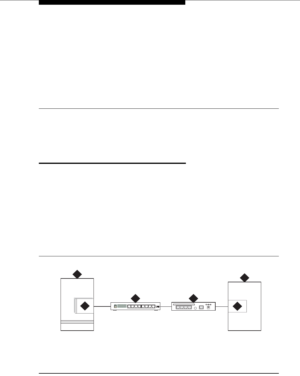
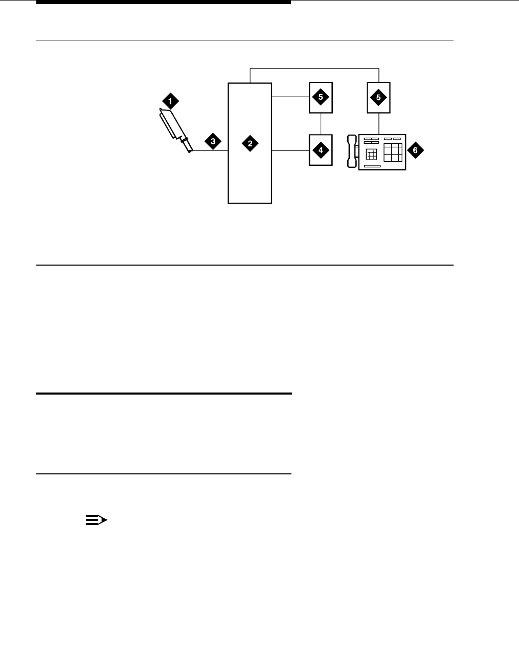
Figure 1. Switch-to-adjunct LAN connectivity through a terminal server
1. switch
2. C-LAN circuit pack, or IP connection on
an S8300/G700 or G350 configuration
3. 10/100Base-T Hub (optional)
4. terminal server
5. serial port
6. CDR adjunct
LAN
cydfadj KLC 091302
1
25
6
3
DATA CONNECTIONS ONLY - NOT FORTELECOM USE
1234 10BASE-T 5VDC
4

Terminal server installation
555-233-116
24 Issue 6 November 2003
Installing and administering the
terminal server
Make sure you have all the equipment on site before the installation. You must
have the hardware listed in Table 1.
You also need a computer (laptop) with the HyperTerminal software program for
the initial administration of the IOLAN+ and to set up the ports.
The general process is to
■Connect the IOLAN+ to the adjunct and the LAN
■Administer the ports on the IOLAN+ using a PC or laptop at the local site
■Test the connectivity back through the switch
Distance limits
The distance limit from the switch to the LAN hub is 328 feet (100 meters). The
distance limit from the LAN hub to the terminal server is 328 feet (100 meters). If
installed, the limit from the terminal server to the adjunct is 50 feet (15 meters).
Table 1. Required equipment
Comcode Description Qty Supplier
700015084 IOLAN+ 104 communications server 1 Avaya
NA RJ45-to-DB25 connector for IOLAN+
(supplied with 700015084) 4 Avaya
NA DB25-to-DB9 connector for PC COM port 1 Avaya
NA RS232 Null modem (if needed for PC or
printer connectivity) 1 or more Avaya
405369042 Male/female adapter (if necessary) 1 or more Avaya
846943306
or 104154414
NA
6-inch RJ45 crossover cord, or
10/100Base-T auto-sensing LAN hub or
router
1
1
Avaya
Customer
102631413
NA
259A adapter, or
CAT5 cross connect hardware and
connecting blocks
1 Avaya
Customer
NA RJ45 UTP Category 5 modular cords 1–2 Customer
NA 451A in-line RJ45 adapters, as needed to
connect modular cords together
Installing and administering the terminal server
Issue 6 November 2003 25555-233-116
However, to achieve greater distance limits, the switch’s LAN hub/router may be
connected to a WAN and the hub/router for the terminal server also connected to
the same WAN.
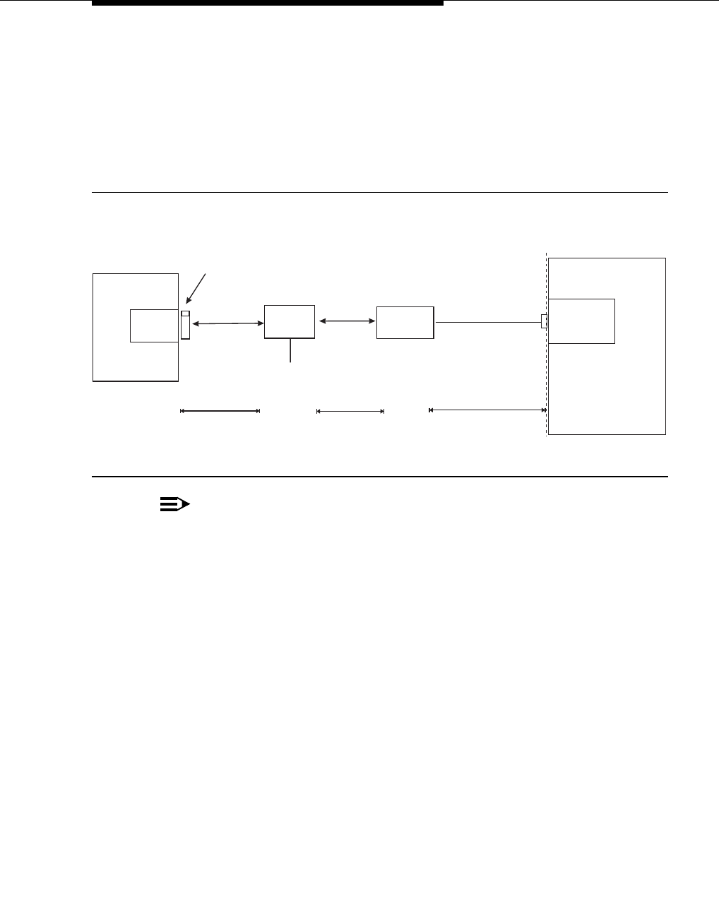
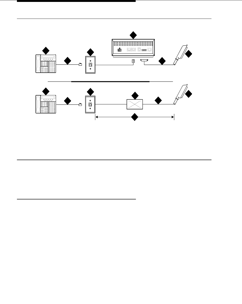
Cabling diagram
Figure 2 shows the connection between the terminal server port and a call
accounting system.
Figure 2. Stand-alone call accounting system link using a terminal server
NOTE:
You can connect the C-LAN circuit pack directly to the terminal server with a
data crossover cable. This connection eliminates the need for a hub or
router in the middle, but the connection also allows the C-LAN circuit pack
and the terminal server to communicate only with each other. With this
connection, the C-LAN circuit pack and the terminal server should be
configured with the same subnet.
clan2gca.cdr 50 Ft. Maximum
Standalone
Call Accounting
Call
Accounting
Port
Demarcation
Point
M25A or M25B
RS232 Cable
«
C-LAN
Switch
Hub or
Router
328 ft max
(100 m) 328 ft max
(100 m)
AC Power
Terminal Server
RJ45 Cat 5
Modular Cord RJ45 Cat 5
Modular Cord
259A Adapter,
356A Adapter (Jack #1), or
258B Adapter (Jack #1)
Terminal server installation
555-233-116
26 Issue 6 November 2003
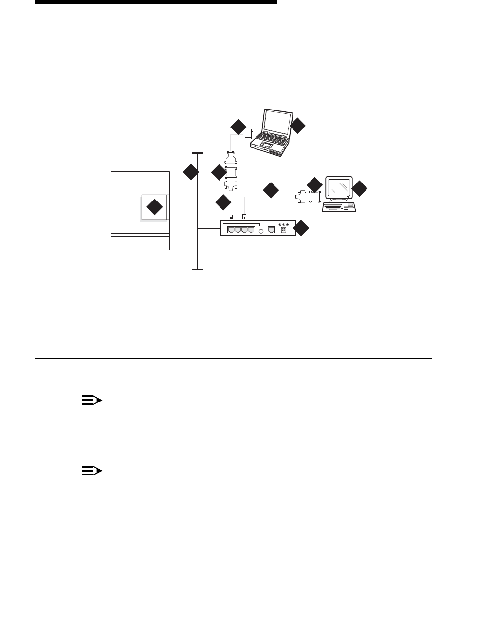
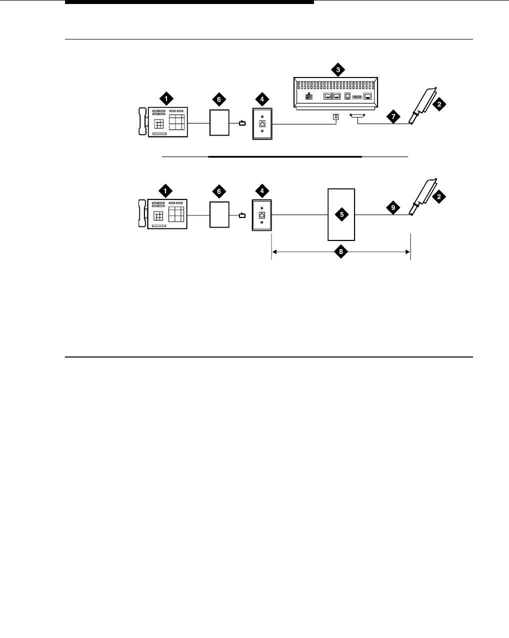
Making the connections
Connect the adjunct to the IOLAN+, using the RJ45-to-DB25 cable and the null
modem. You can use a male/female adapter. See Figure 3.
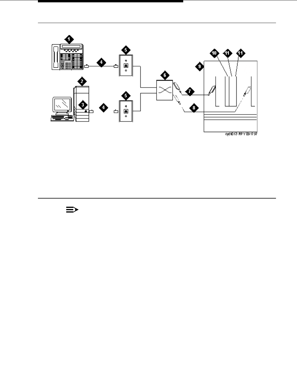
Figure 3. Connecting an adjunct to the IOLAN+
Follow these typical steps:
NOTE:
Depending on the adjunct’s connections, you may not need all of these
pieces.
1. Connect the null modem adapter to COM1 port on the adjunct.
NOTE:
The null modem is an important element in this setup. Without it, data may
not transfer correctly.
2. Connect the other end of the null modem adapter to the DB25 to RJ45
cable.
3. Connect the RJ45 end to any port on the IOLAN+.
1. C-LAN circuit pack, or IP connection on
an S8300/G700 or G350
2. Local area network (LAN)
3. IOLAN+ 104 terminal server
4. Adjunct (system management terminal
or a system printer, for example)
5. Null modem
6. PC or laptop (for initial administration)
7. DB25-to-RJ45 cable
8. DB25-to-DB9 cable
cydfrcon KLC 021201
1
2
4
DATA CONNECTIONS ONLY - NOT FORTELECOM USE
1234 10BASE-T 5VDC 3
7
7
8
5
5
6

Installing and administering the terminal server
Issue 6 November 2003 27555-233-116
Administering the IOLAN+
To administer the IOLAN+ the first time, you must connect a PC or laptop to the
RS232 Port 1 on the IOLAN+ terminal server. Follow these typical steps:
NOTE:
Depending on the computer’s COM port, you may not need all of these
pieces.
1. Connect the DB9 end of the DB9-to-DB25 cable to the COM port on the PC
or laptop.
2. Connect the DB25 end to the null modem adapter.
3. Connect the other end of the null modem adapter to the DB25 to RJ45
cable.
4. Connect the RJ45 end to Port 1 of the IOLAN+.
Before beginning the initial administration, make sure you have the following
information:
■New IP address and subnet mask for IOLAN+
■Host name for IOLAN+
■IP address of C-LAN Ethernet interface
■Port number of C-LAN Ethernet interface where adjunct connects.
Setting up HyperTerminal on the computer
Use the HyperTerminal software program that comes with Windows 95/98/NT/
2000 to administer the IOLAN+.
1. Open HyperTerminal.
2. Click on File > Properties > Connect tab. In the Connect using: field,
select COM n, where n is the communication port your computer is using.
3. Click on CONFIGURE and set the bits per second field to 9600 and the Flow
control field to Hardware.
4. Click OK.
5. Press ENTER to get the login prompt.
Navigating the IOLAN+ terminal server
Refer to the IOLAN+ user guide for details. In general,
■Use the arrow keys to move to a menu item
■Use the TAB key to move from field to field horizontally.
■Use the ENTER key to choose an item.

Terminal server installation
555-233-116
28 Issue 6 November 2003
Administering the IOLAN+ the first time
1. At the login prompt type any text and press ENTER.
2. At the second prompt type set term ansi and press ENTER to view the
Connections menu.
3. Under Connection select Port 1 (the port to which the adjunct is connected)
and press ENTER to access the Commands menu.
4. Select Admin mode > Password and press ENTER.
.
Name: port 2 CONNECTIONS MENU Terminal: 2
Connection Host
1 *** FREE ** === Commands ===
2 *** FREE ** | Telnet ^T|
3 *** FREE ** | Rlogin ^R|
4 *** FREE ** | Port ^P|
| Admin mode ^A|
| CLI |
| Lock |
| Logout ^D|
================
________________________________________________________________________________
IOLAN PLUS v4.02.00 a CDi iolan
Name: port 2 ADMINISTRATION MENU Terminal: 2
gateway Examine/modify gateway table.
host Examine/modify host table.
line Terminal configuration organised by line.
password Specify password to allow modification of menu items.
port Terminal configuration organised by port.
quit Return to connections menu.
server Examine/modify Server parameters.
stats Examine Server statistics.
Password [ ]
________________________________________________________________________________
IOLAN PLUS v4.02.00 a CDi iolan-st

Installing and administering the terminal server
Issue 6 November 2003 29555-233-116
5. Type iolan, the default password, and press ENTER.
The Administration Menu changes, offering more options.
6. Select server and press ENTER to view the Server Configuration menu.
7. Fill in the following fields with information appropriate to your network.
Leave the default settings for the other fields.
■Name:
■IP address: (for IOLAN+)
■Subnet mask:
8. Press ENTER and select Save & Exit to effect the changes.
** Administrator ** SERVER CONFIGURATION Terminal: 2
Name [iolan ] Debug mode [0 ]
IP address [123.45.67.89 ]
Subnet mask [222.222.0.0 ]
Ethernet address [00:80:d4:03:11:cd] Ethernet interface [AUTO ]
Language [English ]
Identification [ ]
Lock [Disabled]
Password limit [5 ]
CR to initiate [No ]
SNAP encoding [Disabled]
Boot host [ ] Boot diagnostics [Enabled ]
Boot file [ ]
Init file [ ]
MOTD file [ ]
Domain name [ ]
Name server [ ] NS Port [53 ]
WINS server [ ]
________________________________________________________________________________
Name used for prompts and message on bottom right of screen.
IOLAN PLUS v4.02.00 a CDi iolan

Terminal server installation
555-233-116
30 Issue 6 November 2003
Rebooting the IOLAN+
You must reboot the server any time you change an IP address or Local Port
value.
1. Press ENTER to view the Administration Menu.
.
NOTE:
The following steps re-initialize the IOLAN+ so it knows it’s connected to the
LAN through its IP address.
2. Select reboot and press ENTER.
3. Press the space bar to restart the IOLAN+.
** Administrator ** ADMINISTRATION MENU Terminal: 2
access Remote System Access (PPP).
change Change login and/or admin password.
gateway Examine/modify gateway table.
host Examine/modify host table.
kill Kill TCP connections on serial line.
line Terminal configuration organised by line.
port Terminal configuration organised by port.
quit Return to connections menu.
reboot Reboot Server.
server Examine/modify Server parameters.
stats Examine Server statistics.
trap Examine/modify SNMP Trap parameters.
Port [2 ]
________________________________________________________________________________
IOLAN PLUS v4.02.00 a CDi iolan

Installing and administering the terminal server
Issue 6 November 2003 31555-233-116
Administering the gateway
NOTE:
If the C-LAN circuit pack and IOLAN+ are in the same subnet, skip this step.
1. Select Admin mode > Password and press ENTER.
2. Type iolan and press ENTER.
3. Select gateway to access the Gateway menu
4. Fill in the following fields for Entry 1:
■Destination: C-LAN IP address
■Gateway: Gateway address
■Netmask: Subnet mask
NOTE:
The following steps re-initialize the IOLAN+ so it knows it’s connected
to the LAN through your gateway.
5. Select reboot and press ENTER.
6. Press the space bar to restart the IOLAN+.
Administering an IOLAN+ port
Use this procedure when connecting an adjunct or serial COM port on a PC
directly (locally) to the IOLAN+ (see Figure 3).
1. Select Admin mode > Password and press ENTER.
2. Type iolan and press ENTER.
3. Select port and press ENTER.
4. Type port number, where port number is the port that the adjunct
connects to, and press ENTER to view the Port Setup Menu.

Terminal server installation
555-233-116
32 Issue 6 November 2003
5. Fill in the following fields. Leave the default settings for the other fields.
■Speed: 9600
■Monitor DSR: Yes
■Monitor DCD: No
■Name: port number or other descriptive name
■Terminal type: undef
■CLI/Menu: CLI
■Reset Term: No
■Flow ctrl: xon/xoff
■IP addresses: leave blank
■Mask: leave blank
■Access: Remote
■Authentication: None
■Mode: Raw
■Connection: None
■Host: leave blank or enter C-LAN IP Address
■Remote Port: 0
■Local Port: must match the value of Remote Port on the IP Services
screen of the DEFINITY or Communication Manager software
6. Press ENTER and select Save & Exit to effect the changes.
** Administrator ** PORT SETUP MENU Terminal: 2
Hardware Flow ctrl Keys
Speed [9600 ] Flow ctrl [xon/xoff] Hot [^]] Intr [^C]
Parity [None] Input Flow [Enabled ] Quit [^@] Kill [^U]
Bit [8] Output Flow [Enabled ] Del [^@] Sess [^@]
Stop [1 ] Echo [^@]
Break [Disabled] IP Addresses
Monitor DSR [Yes ] Src [ ] Mask [ ]
Monitor DCD [No ] Dst [ ]
User Options Access
Name [port 2 ] Keepalive [No ] Access [Remote ]
Terminal type [undef ] Rlogin/Telnet [Telnet] Authentication [None ]
TERM [ ] Debug options [No ] Mode [Raw ]
Video pages [0] Map CR to CR LF [No ] Connection [None ]
CLI/Menu [CLI] Hex data [No ] Host [ ]
Reset Term [No ] Secure [No ] Remote Port [0 ]
MOTD [No ] Local Port [5101]
________________________________________________________________________________

Installing and administering the terminal server
Issue 6 November 2003 33555-233-116
7. Press ENTER again to view the Administration Menu.
8. Select kill to disable the port connection.
9. Repeat the steps for each additional port you want to administer.
10. When administration is complete, from the Connections Menu, select
logout (or press Ctrl D).
11. Close HyperTerminal.
At this point, you have established a connection path from the adjunct
through the IOLAN+ to the C-LAN circuit pack.
Testing
1. On the system management terminal, press ENTER to get the login prompt
to the DEFINITY or Communication Manager switch.
NOTE:
If you get garbled text, check the baud rate setting on the Port Setup
Menu. You can adjust it up or down.
2. If no login prompt appears, log back into the IOLAN+ through
HyperTerminal.
3. Select Admin mode > stats and press ENTER twice.
4. Select users and press ENTER.
5. Look at the port that the adjunct is connected to and see if there is any
traffic. If not, check all your connections and administration fields.
** Administrator ** SERVER STATISTICS Terminal: 2
1. port1 Talking to host 172.22.22.67.5111<DSR+CTS+DCD >DTR+RTS
2. port 2 SERVER STATISTICS <DSR+DCD >DTR+RTS
3. port 3 waiting for DSR or DCD >DTR+RTS
4. port 4 modem waiting for DSR or DCD >DTR+RTS
REM <unknown> logged out
LOG logger not enabled
________________________________________________________________________________
Press <RETURN> to see list of options.
IOLAN PLUS v4.02.00 a CDi iolan-st

Terminal server installation
555-233-116
34 Issue 6 November 2003
After you have successfully administered and validated the connection between
the adjunct and the C-LAN circuit pack through the IOLAN+, you can disconnect
the laptop or other PC from the IOLAN+. No further IOLAN+ administration is
required.
Potential failure scenarios and repair actions
If a link goes down between the terminal server and the switch, you must reboot
the terminal server for the link come back up. If you are performing a software
upgrade or if a system reset occurs, you must reboot the terminal server to restore
the link. See ‘‘Rebooting the IOLAN+’’ on page 30 for instructions.
Administering IP node names
You must administer the IP addresses of the C-LAN board, any adjunct that
connects directly to the LAN, the terminal server (if appropriate), and the PC
running the Reliable Session-Layer Protocol (if appropriate). You use the Node
Names screen to do this.
1. Type change node-names ip and press RETURN.
2. Enter the name and the IP address of the C-LAN board, as well as any
adjunct, terminal server or PC you need to administer.
3. Print a copy of this screen, or write down the node names you entered. You
need this information for the next administration task.
4. Press ENTER to save your changes.
change node-names ip Page 1 of 1
NODE NAMES
Name IP Address Name IP Address
1. switch-clan___ 123.456.7 .89 17. ______________ ___.___.___.___
2. callacctg_____ 123.456.9 .00 18. ______________ ___.___.___.___
3. termserver____ 123.456.11 .00 19. ______________ ___.___.___.___
4. pmslogpc______ 123.456.78 .00 20. ______________ ___.___.___.___
5. ______________ ___.___.___.___ 21. ______________ ___.___.___.___
6. ______________ ___.___.___.___ 22. ______________ ___.___.___.___
7. ______________ ___.___.___.___ 23. ______________ ___.___.___.___
8. ______________ ___.___.___.___ 24. ______________ ___.___.___.___
9. ______________ ___.___.___.___ 25. ______________ ___.___.___.___
10. ______________ ___.___.___.___ 26. ______________ ___.___.___.___
11. ______________ ___.___.___.___ 27. ______________ ___.___.___.___
12. ______________ ___.___.___.___ 28. ______________ ___.___.___.___
13. ______________ ___.___.___.___ 29. ______________ ___.___.___.___
14. ______________ ___.___.___.___ 30. ______________ ___.___.___.___
15. ______________ ___.___.___.___ 31. ______________ ___.___.___.___
16. ______________ ___.___.___.___ 32. ______________ ___.___.___.___
Administering IP services
Issue 6 November 2003 35555-233-116
Administering IP services
For each adjunct that you connect using TCP/IP, you need to administer IP
services to establish the IP address/TCP port pairing. The IP address is
associated with the node name that you just administered. In this example, we are
administering the primary CDR connection as end-to-end TCP/IP, and the PMS
connection through a terminal server.
1. Type change ip-services and press RETURN to assign the CDR endpoint.
2. In the Service Type field, enter CDR1 for the call accounting link, and
PMS for the property management system.
3. In the Local Node field, enter the node name for the switch. In this
example, switch-clan is the local node. This applies to DEFINITY servers,
S8500 Media Servers, and S8700 Media Servers. For an S8300 Media
Server, enter procr.
4. The Local Port field defaults to 0 for all client applications. You cannot
make an entry in this field.
5. In the Remote Node field, enter the node name for the adjunct, as
administered on the Node Names screen. For the call accounting
application, type callacctg. Since the PMS application routes through the
terminal server, termserver is the remote node for this service type.
6. In the Remote Port field, enter the TCP listen port assigned to the
adjunct. The recommended value for CDR1 is 5101, and the
recommended value for PMS is 5103.
NOTE:
This number must match the port administered on the end device. If
you are using the Downloadable Reliable Session-Layer Protocol
tool, this must match the port administered in the Server application.
If you are using a terminal server, this number must match the Local
Port number on the Port Setup menu. Consult the documentation
for your Call Accounting system to determine the appropriate port for
the CDR device.
change ip-services Page 1 of 3
IP SERVICES
Service Enabled Local Local Remote Remote
Type Node Port Node Port
CDR1 switch-clan 0 callacctg 5101
PMS switch-clan 0 termserver 5103
Terminal server installation
555-233-116
36 Issue 6 November 2003
7. Move to Page 3. Type n in the Reliable Protocol field for the CDR
Service Type. You do not use RSP with a terminal server.
8. Press ENTER to save your changes.
change ip-services Page 3 of 3
SESSION LAYER TIMERS
Service Reliable Packet Resp Session Connect SPDU Connectivity
Type Protocol Timer Message Cntr Cntr Timer
CDR1 n 3 1 1 1

Issue 6 November 2003 37555-233-116
3
Call detail recording (CDR)
This chapter provides information on connecting call detail recording (CDR)
equipment to a DEFINITY Server (such as an MCC1 Media Gateway) or an
S8100 Media Server, S8500 Media Server, S8700 Media Server, or S8300 Media
Server.
Connecting CDR Equipment
The interface between an Avaya media server and CDR equipment may be a:
■C-LAN card (DEFINITY Server, S8500 Media Server, or S8700 Media
Server)
CDR equipment connects to the CLAN board on an MCC1 or G650 Media
Gateway through a TCP/IP connection (that is, an Ethernet connection).
Any CDR equipment that supports the Reliable Session Protocol will
support a direct TCP/IP connection. A CDR application that supports an
RS232 interface can also connect to the CLAN through a terminal server
(see Chapter 2, ‘‘Terminal server installation’’ for more information on
connecting through a terminal server).
■Processor Ethernet Connection (S8300 Media Server)
CDR equipment connects to one of the two IP connections (EXT 1 or EXT
2) on the front of the G700 or G350 Media Gateway. As with C-LAN
connections, the CDR adjunct may be a terminal server or a CDR
application using RSP.
■Collection from file (S8100 Media Server, DEFINITY One, or IP600)
See Chapter 3, “Set Up Call Detail Recording” in Installation and Upgrades
for the Avaya S8100 Media Server with the Avaya G600 and the Avaya
CMC1 Media Gateways, 555-233-146.

Call detail recording (CDR)
555-233-116
38 Issue 6 November 2003
NOTE:
A printer or customer premises equipment (CPE) can also be used as the
output receiving device. Please see Chapter 2, ‘‘Terminal server
installation’’ of this book for instructions on using a printer.
Administering CDR Data Collection
NOTE:
To send CDR data via CLAN or a processor Ethernet interface to a device
on the LAN/WAN, you have the option to enable/disable RSP.
1. Setup the CDR adjunct to be ready to collect CDR data. Record the IP
address and the port number of the CDR adjunct, which could be a
terminal server or a CDR application that uses RSP.
If the CDR adjunct is an application that uses RSP, start the application to
listen for a client connection at the port.
2. Access the Node Names screen in Communication Manager (see
‘‘Administering IP node names’’ on page 34), and do the following:
a. Enter the CDR adjunct’s name from step 1 in the Name field.
b. Enter the CDR adjunct’s IP address in the IP Address field.
3. Access the IP Services screen in Communication Manager (see
‘‘Administering IP services’’ on page 35), and do the following:
a. In the Service Type field, enter CDR1 or CDR2.
b. In the Remote Node field, enter the node name you assigned to the
CDR adjunct in step 2.
c. In the Remote Port field, enter the port number used by the CDR
adjunct determined in step 1.
NOTE:
Enter procr in the Local Node field for an S8300 Media Server.
Otherwise, enter switch-clan.
4. Go to Page 3 and do the following:
a. Enter y in the Reliable Protocol field if you have a CDR application
using RSP. Enter n if the CDR adjunct is connected through a
terminal server.
b. If RSP is being used, complete the Packet Resp Timer and
Connectivity Timer fields with some reasonable value that matches
the network condition (the recommended values are 30 and 60
seconds, respectively).
c. Leave the defaults in the other fields.

Administering CDR Data Collection
Issue 6 November 2003 39555-233-116
5. Administer CDR parameters as described in ‘‘Administering CDR
parameters’’ on page 39.
Administering CDR parameters
You must administer CDR parameters to let the system know that the adjunct is
connected through TCP/IP. For details on all fields on the CDR System
Parameters screen, see Administrator’s Guide for Communication Manager, 555-
233-506.
1. Type change system-parameters cdr and press RETURN.
The CDR System Parameters screen appears.
2. In the Primary Output Format field, enter a format specific to the call
accounting system, if necessary. In the example, unformatted is used. If
you were sending data directly to a printer, you would use printer.
3. In the Primary Output Endpoint field, type CDR1.
4. If you use a secondary output device, and that device is also connected
through TCP/IP, complete the Secondary Output Format field. Also,
type CDR2 in the Secondary Output Endpoint field.
5. Press ENTER to save your changes.
Testing the switch-to-adjunct link
You can use the test, status, busyout and release commands to find and correct
problems with CDR links. For more information about these commands, see the
Maintenance manual for your switch.
change system-parameters cdr Page 1 of 1
CDR SYSTEM PARAMETERS
Node Number (Local PBX ID): CDR Date Format: month/day
Primary Output Format: unformatted Primary Output Endpoint: CDR1
Secondary Output Format: unformatted Secondary Output Endpoint: CDR2
Use ISDN Layouts? n EIA Device Bit Rate: 9600
Use Enhanced Formats? n Condition Code ‘T’ for Redirected Calls? n
Modified Circuit ID Display? n Remove # From Called Number? n
Record Outgoing Calls Only? y Intra-switch CDR? n
Suppress CDR for Ineffective Call Attempts? y CDR Call Splitting? y
Disconnect Information in Place of FRL? n Attendant Call Recording? y
Interworking Feat-flag? n
Force Entry of Acct Code for Calls Marked on Toll Analysis Form? n
Calls to Hunt Group - Record: member-ext
Record Called Vector Directory Number Instead of Group or Member? n
Record Called Agent Login ID Instead of Group or Member? n
Inc Trk Call Splitting? n
Record Non-Call-Assoc TSC? n
Record Call-Assoc TSC? n Digits to Record for Outgoing Calls: dialed
Privacy - Digits to Hide: 0 CDR Account Code Length: 4

Call detail recording (CDR)
555-233-116
40 Issue 6 November 2003
Work with the vendor to test the link from the call accounting adjunct.
If a link does not come up immediately, use the busyout cdr-link and release
cdr-link commands to bring up the link.
Additional administration procedures for CDR equipment are provided in the
Administrator’s Guide for Avaya Communication Manager.
Reliable Data Transport Tool (RDTT)
Package
Avaya provides this free software application to help vendors and customers
develop CDR applications that use the reliable session protocol to collect CDR
data from an Avaya Media Server. The Reliable Data Transport Tool (RDTT) is a
testing tool and thus is not supported by Avaya.
Contents of the RDTT
The RDTT package consists of the following:
■Specifications for the Reliable Session Protocol
■The Client application (Client.exe)
This application is designed to help you test the reliable session protocol
without use of an Avaya Media Server.
■The Server application (Server.exe)
This application is designed to help you understand the reliable session
protocol and to start building your products to work with the Avaya media
server.
■User Guide
This document contains information about the client and server
applications.
status cdr-link
CDR LINK STATUS
Primary Secondary
Link State: up extension not administered
Maintenance Busy? no

Related Topics
Issue 6 November 2003 41555-233-116
Downloading the tool
The RDTT tool is available from the Avaya support Web site as a self-extracting
executable. To download the RDTT:
1. Go to the Avaya Customer Support Web site at http://avaya.com/support.
2. In the Search For text box, type reliable and click Go.
3. Select Reliable Data Transport Client/Server Tool from the list of found
links.
4. When asked, save the RDTT.exe file to a temporary folder on your
computer. It is approximately 1.6 to 2.0-MB.
Installing RDTT
To install the RDTT:
1. Double-click the RDTT.exe file.
The Install Shield Wizard steps you through the installation.
2. When prompted to select Client or Server, select both programs.
3. Continue with the installation. Use the default destination folder and
program folder.
Administering RDTT
See the instructions in the user_guide.doc file to administer the RDTT tool on a
PC.
Related Topics
See the following topics related to CDR:
■Chapter 16, “Collecting Billing Information,” in Administrator’s Guide for
Avaya™ Communication Manager, 555-233-506.
■“Call Detail Recording” in Chapter 21, “Features and Technical Reference”
in Administrator’s Guide for Avaya™ Communication Manager.
■‘‘Connecting printers using TCP/IP’’ on page 51.

Call detail recording (CDR)
555-233-116
42 Issue 6 November 2003

Issue 6 November 2003 43555-233-116
4
Multimedia communications
This chapter provides information on connecting the following equipment to:
■Wideband endpoints
■Multimedia call handling (MMCH)
NOTE:
The information in this chapter does not apply to the G700 or G350 Media
Gateway configurations.
Wideband endpoints
Wideband endpoints include video equipment or bridges/routers for LANs. Use
the running list that accompanies the system to make cable connections.
Nonsignaling configuration
A nonsignaling connection to a wideband endpoint may connect to a channel
service unit (CSU). If not using a CSU, the distance between the system and the
endpoint is limited to a few hundred feet. See Figure 4. The maximum distance
depends on the type of cable and type of endpoint.
Multimedia communications
555-233-116
44 Issue 6 November 2003
Figure 4. Typical nonsignaling wideband configuration
If using a CSU, the distance between connections may be up to 1300 ft.
(397.2 m). The maximum distance to the endpoint depends on the type of cable
and the specifications of the endpoint.
Signaling configuration
A signaling connection from the system to a wideband endpoint passes through a
bandwidth controller. The distance between the system and the bandwidth
controller depends on the type of cable and controller. Figure 5 shows
connections with and without a CSU.
1. Wideband endpoint (wire per manufacturer)
2. Modular cord
3. 103A or modular wall jack
4. Channel service unit (CSU)
5. H600-307 cable to DTE connector on CSU
6. DS1/E1 circuit pack
7. Main distribution frame (MDF)
8. Distance limit depends on cable and
endpoint type.
9. A25D 25-pair cable (male-to-male)
cydf049 RPY 123097
AUX POR T COM P ORT MODEM
DTE
NETW ORK
POWER
1
1
2
2
3
3
4
5
6
6
7
8
9
Wideband endpoints
Issue 6 November 2003 45555-233-116
Figure 5. Typical signaling wideband configuration
The bandwidth controller connects directly to the wideband endpoint. The
controller typically installs near the endpoint where they directly connect (usually
within a few feet of each other).
■For non-CSU installations, cross the transmit and receive lines so a
transmit signal from the DS1/E1 circuit pack connects to the receive
connection on the bandwidth controller and a transmit signal from the
bandwidth controller connects to the receive connection on the DS1/E1
circuit pack.
■For CSU installations, cross the transmit and receive lines between the
CSU and the bandwidth controller.
Figure 6 shows a remote port module. In this configuration, there can be
considerable distance between the bandwidth controller and the wideband
endpoint. The maximum distance between elements depends on the quality of the
cables and on the specifications of the wideband equipment.
1. Wideband endpoint (wire per
manufacturer)
2. To DS1/E1 circuit pack
3. Optional channel service unit (CSU)
4. 103A or modular wall jack
5. Part of main distribution frame
6. Bandwidth controller
7. H600-307 cable to DTE connector on CSU
8. Distance limit depends on cable type and
bandwidth controller type
9. A25D 25-pair cable (male-to-male)
AUX PORT COM PORT MODEM DTE NETWORK
POWER
cydf047 PDH 091396
Multimedia communications
555-233-116
46 Issue 6 November 2003
Figure 6. Typical signaling wideband configuration with remote port module
1. For non-CSU installations, cross the transmit and receive lines so a
transmit signal from the TN464F connects to the receive connection on the
bandwidth controller and a transmit signal from the bandwidth controller
connects to the receive connection on the TN464F.
2. For CSU installations, cross the transmit and receive lines between the
CSU and the bandwidth controller.
Multimedia call handling (MMCH)
MMCH provides a single point to point conference call using voice, video, and
data from one endpoint to another. The customer must have endpoints and a
personal computer with H.320 desktop video installed.
Connect the endpoints
Use the following procedure and Figure 7 to connect the endpoints:
NOTE:
For a G700 or G350 Media Gateway configuration, the DCP telephones that
are supported — item 1 in Figure 7 — are only 2 wire.
1. To TN464F DS1/E1 circuit pack
2. Part of main distribution frame (MDF)
3. H600-307 cable
4. Bandwidth controller
5. Remote port module
6. Wideband endpoint (wire per manufacturer)
cydf048 PDH 091396
Multimedia call handling (MMCH)
Issue 6 November 2003 47555-233-116
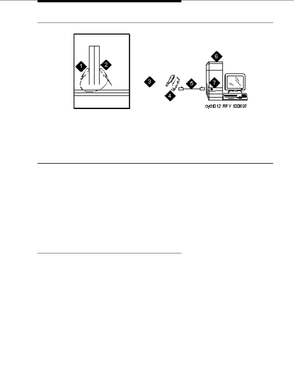
Figure 7. Typical multimedia call handling connections
NOTE:
The NT1 adapter (item #8) is not used with a MM720 BRI module. The NT1
is a 2/4 converter unit, and the MM720 currently only supports 4-wire
trunking.
In items #7 and #8 above, the connection to both an MM712 DCP media
module and to an MM720 BRI media module is not a 25-pair cable but
rather an RJ45 cable.
1. Each PC MMCH endpoint must contain a BRI adapter.
2. Connect a DCP telephone to a digital line circuit pack. The DCP telephone
must be used in conjunction with the PC. Refer to the tables at the end of
this chapter for the pinout of the digital line circuit pack.
3. Connect the PC BRI adapter to any BRI port on the Avaya Media Server.
Refer to the tables at the end of this chapter for the pinout of an ISDN BRI
circuit pack.
1. DCP telephone, 2 or 4 wire to match type
of circuit pack
2. Personal computer
3. BRI adapter
4. D8W cord
5. 103A or modular wall jack
6. Main distribution frame
7. 25-pair cable to digital line circuit pack
8. 25-pair cable to BRI circuit pack or NT1,
4-to-2 wire adapter
9. Avaya Media Server
10. Multimedia-interface circuit pack
11. Voice conditioner circuit pack

Multimedia communications
555-233-116
48 Issue 6 November 2003
Administer the system
1. Call INADS and notify the representative that the Multimedia Call
Handling (MMCH)? field on page 2 of the customer-options form must be
changed to y.
2. Logoff the terminal and then log back on the terminal to see your changes.
Administer the endpoints
1. Log in and enter add data-next <or a valid extension number>.
2. The data module form appears. On page 1 of the form, enter the Data
Extension: xxxx, Type: 7500, the Name: user’s name (such as
ProShare), and enter y in Multimedia? field.
3. On page 2 of the form, enter n in the XID? field, and enter n in the MIM
Support? field and press Enter.
Administer one number complex
1. Identify the voice telephone (DCP set) to associate with the data endpoint.
The station record for this voice station must be changed.
2. Type change station station number and press Enter.
3. On screen 1, type the data extension number in the MM Complex Data
Ext: field.
4. On screen 2, type y in the H.320 Conversion? field and press Enter.
5. Type y in the Multimedia Early Answer field and press Enter.
Expansion services module
The Expansion Services Module (ESM) provides T.120 data sharing capability on
a MMCH multipoint H.320 video conference. Each person in the conference must
have endpoints and a personal computer with the H.320 video application
installed. The Avaya Media Server must have the expansion service module
installed.
Multimedia call handling (MMCH)
Issue 6 November 2003 49555-233-116
Figure 8. Typical multimedia call handling ESM connections
ESM installation
Use the following procedure and Figure 8 to connect to the ESM equipment:
1. Install the TN2207 primary rate interface (PRI) circuit pack and the
TN787F/G/H/J/K multimedia interface (MMI) circuit pack in the port carrier.
2. Record the circuit pack locations.
3. Connect the ESM Y-cable as shown.
Administration
1. Enter list configuration all, and a list of the installed carriers, circuit
packs, and ports appears.
2. Record the location (board number) of the new circuit packs and verify that
all other required circuit packs (refer to ‘‘ESM installation’’) are present.
3. Enter add DS1 xxxxx, (where xxxxx is the location of the TN2207 PRI
circuit pack recorded in step 2), and the DS1 circuit pack administration
form appears.
4. Set the Name: field to ESM DS1
5. Set the Bit Rate: field to 2.048
6. Set the Line Coding: field to hdb3
7. Set the Signaling Mode: field to isdn-pri
8. Set the Connect: field to pbx
1. Port B Y-cable connector to a TN787
multimedia interface (MMI) circuit pack
2. Port A Y-cable connector to a TN2207 PRI
circuit pack
3. 25-pair Y-cable
4. 357A adapter
5. D8W cord connected to 357A adapter
S/B port 8
6. Expansion service module (ESM)
7. Port B on compatible primary rate
interface (PRI) card

Multimedia communications
555-233-116
50 Issue 6 November 2003
9. Set the Interface: field to network
10. Set the Country Protocol:field to 1
11. Set the Protocol Version:field to a
12. Set the CRC?:field to y
13. The Idle Code default is 11111111.
14. The DCP/Analog Bearer Capability default is 3.1 kHz.
15. Set the MMI Cabling Board: field to xxxxx (where xxxxx is the
location of the TN787F/H/J/K MMI circuit pack recorded in step 2). This
must be the slot for port B of the Y-cable.
16. The MMI Interface: field ESM appears.
17. Enter add signaling-group next and the signaling-group form appears.
18. Change Associated Signaling: field to y.
19. Change Primary D-Channel Port: field to xxxx17 (where xxxx is the
address of the TN2207 PRI circuit pack, for example: 1B0517).
20. The Max Number of NCA TSC: default is 0.
21. The Max Number of GA TSC: default is 0.
22. Trunk Group for NCA TSC: ____ (leave blank)
23. Trunk Group for Channel Selection:____ (leave blank)
24. Logoff the terminal and then log back on the terminal to view your changes.
Place test call
Place multimedia data-conference call to an endpoint with known video capability
to test the esm function.
Troubleshooting
To determine ESM link status enter the following commands from the system
administration terminal:
1. Status esm
2. Status signaling-group
3. List MMI
NOTE:
When you move ESM circuit packs, you MUST remove the DS1 and
signaling group translations. You cannot use the change circuit pack
command.
Refer to ‘‘Expansion services module’’ on page 48 for further information.

Issue 6 November 2003 51555-233-116
5
Printers
This chapter provides information on connecting and configuring printers that
work with your system and Avaya™ Communication Manager.
Connecting printers using TCP/IP
Printers can be connected to the switch using asynchronous TCP/IP links and a
terminal server. This section provides information on connecting adjuncts to the
C-LAN (for MCC1, SCC1, CMC1, G600, and G650 Media Gateways) and
providing the initial administration. For connecting a printer to a G700 or G350
Media Gateway, see Chapter 2, ‘‘Terminal server installation’’ for more
information.
Task list
Whether you use an end-to-end TCP/IP configuration, a terminal server or a PC
running RSP, you must complete the following tasks:
■‘‘Administering IP node names’’ on page 34.
■‘‘Administering IP services’’ on page 35.
■‘‘Administering adjunct parameters’’ on page 52.
■If you are using a terminal server, also complete ‘‘Installing and
administering the terminal server’’ on page 24.
■If you are using a PC with the Downloadable RSP Tool, complete ‘‘Using
the downloadable reliable session-layer protocol (RSP) tool’’ on page 52.

Printers
555-233-116
52 Issue 6 November 2003
Administering adjunct parameters
You must administer adjunct parameters to let the system know that the adjunct is
connected through TCP/IP.
PMS journal and PMS log printers
See Guestworks® and DEFINITY® Systems Technician Handbook for Hospitality
Installations, 555-231-743.
System printer
1. Type change system-parameters features and press RETURN.
The Feature-Related System Parameters screen appears.
2. Move to Page 4.
3. In the System Printer Endpoint field, type SYS_PRNT.
4. Press ENTER to save your changes.
Testing the switch-to-adjunct link
You can use the test, status, busyout and release commands for to find and
correct problems with system printer, PMS log printer, or PMS journal printer. For
more information about these commands, see the Maintenance manual for your
switch.
If a link does not come up immediately, try using the busyout (journal-link pms-log
and wakeup-log, and sp-link) and release (journal-link pms-log and wakeup-log,
and sp-link) commands.
NOTE:
Status sp-link can show a system printer link as down, when it is actually
properly connected. If no data is being transmitted, the switch may not see
this link as active.
Using the downloadable reliable session-layer
protocol (RSP) tool
The intent of the Reliable Session-Layer Protocol (RSP) is to guarantee delivery
of data records from the switch to an output device that connects to the switch
over an asynchronous TCP/IP link. The Downloadable RDTT tool allows you to
implement this protocol on a PC that collects data records in a file. The protocol
assures that the data records arrive safely at the PC. You can then send the
output file to a printer. See ‘‘Reliable Data Transport Tool (RDTT) Package’’ on
page 40.

Issue 6 November 2003 53555-233-116
6
DS1/T1 CPE loopback jack
This chapter provides information on how to install and use a DS1 loopback jack
to test the DS1 span between the Avaya Media Server or Gateway and the
network interface point. The loopback jack is required when DC power is at the
interface to the integrated channel service unit (ICSU).
NOTE:
Do not remove the loopback jack after installation. It should always be
available for remote tests of the DS1 span.
NOTE:
For G700 or G350 Media Gateway systems, the channel service unit (CSU)
is integrated within the MM710 board. This means that there is no need for a
separate external device. For earlier media gateway systems, the integrated
channel service unit (ICSU) — also known as the 120A2 — is a separate
device that plugs into the back of the media gateway.
For G700 or G350 Media Gateway systems, the loopback jack isolates the
MM710 internal CSU from the DC power and properly loops the DC span
power.
Installing a loopback jack
You can install a loopback jack with or without a smart jack.
With a smart jack
Install the loopback jack at the interface to the smart jack, if possible. This position
provides maximum coverage of CPE wiring when remote loopback tests are run.

DS1/T1 CPE loopback jack
555-233-116
54 Issue 6 November 2003
If the smart jack is not accessible, install the loopback jack at the extended
demarcation point.
If there is no extended demarcation point, install the loopback jack directly at the
network interface point as shown in Figure 9 and Figure 10.
If there is an extended demarcation point and the smart jack is not accessible,
install the loopback jack as shown in Figure 11 and Figure 12.
If there is an extended demarcation point, but the smart jack is accessible, install
the loopback jack as shown in Figure 13 and Figure 14.
1. To install the loopback jack, simply disconnect the RJ-48 (8-wide)
connector at the appropriate interface point and connect the loopback jack
in series with the DS1 span. See Figure 9 through Figure 18.
2. Plug the H600-383 cable from the ICSU, or from the MM710, into the
female connector on the loopback jack.
3. Plug the male connector on the loopback jack cable into the network
interface point.
NOTE:
Do not remove the loopback jack after installation. This is not a test
tool and should always be available to remotely test a DS1 span.
Without a smart jack
Install the loopback jack at the point where the cabling from the ICSU plugs into
the dumb block. If there is more than one dumb block, choose the one that is
closest to the Interface Termination feed or the fiber MUX to provide maximum
coverage for loopback jack tests. Refer to Figure 15 through Figure 18.
1. To install the loopback jack, simply disconnect the RJ-48 (8-wide)
connector at the appropriate interface point and connect the loopback jack
in series with the DS1 span. See Figure 9 through Figure 18.
2. Plug the H600-383 cable from the ICSU, or from the MM710, into the
female connector on the loopback jack.
3. Plug the male connector on the loopback jack cable into the network
interface point.
NOTE:
Do not remove the loopback jack after installation. This is not a test
tool and should always be available to remotely test a DS1 span.

Administering the loopback jack
Issue 6 November 2003 55555-233-116
Administering the loopback jack
1. At the management terminal, enter change ds1 location, where location
is the DS1 interface circuit pack corresponding to the loopback jack.
2. Be sure the near-end CSU type is set to integrated.
3. On page 2 of the form, change the supply CPE loopback jack power
field to y.
Setting this field to y informs the technician that a loopback jack is present
on the facility and allows the technician to determine that the facility is
available for remote testing.
4. Enter save translation to save the new information.
Loopback testing with a smart jack
The loopback jack and smart jack isolate faults by dividing the DS1 span into 3
sections (see Figure 9, through Figure 14):
■From the 120A2 (or later) ICSU, or from the MM710, to the loopback jack
■From the loopback jack to the smart jack (network interface point)
■From the smart jack to the CO
The first 2 sections are your responsibility. The last is the responsibility of the DS1
service provider.
Testing the DS1 span from the ICSU to the
loopback jack
The DS1 span test has 2 parts.
■Checking for circuit connectivity
The first part of the test powers-up the loopback jack and sends a signal
from the DS1 circuit pack, through the wiring, to the loopback jack. The test
allows about 10 seconds for the signal to loop around the loopback jack
and return to the DS1 circuit pack. Then it sends the results to the
management terminal and proceeds to the second part of the test.
■The second part of the test sends the standard, 3-in-24 DS1 stress-testing
pattern from the DS1 board, through the loopback jack, and back to a bit
error detector and counter on the DS1 board. A bit-error rate counter
displays the results on the management terminal until you terminates the
test.
Always perform both parts of the test. Proceed as follows.

DS1/T1 CPE loopback jack
555-233-116
56 Issue 6 November 2003
Checking the integrity of local equipment
Before you go any further, make sure that the problem is actually on the DS1 span
by testing the equipment that connects to the span at the near end. Test the DS1
circuit pack, and perform any needed maintenance or repairs.
Busying out the DS1 circuit pack
Now take the DS1 circuit out of service.
NOTE:
If you have a G700 or G350 Media Gateway, substitute XXXVS for UUCSS
in the following command, where XXX is the administered number of the
G700 or G350 (for example, 002), and VS is the slot number on the G700 or
G350 of the Media Module (for example, V3). The V is not a variable and
needs to be included in the command exactly where shown. A sample
address for a DS1 circuit pack on a G700 or G350 Media Gateway might
look like this: 002V3.
1. Once you are sure that the DS1 circuit pack and ICSU are functioning
correctly, go to the management terminal and busy out the DS1 circuit pack
by typing busyout board UUCSS, where UU is the cabinet number, C is
the carrier letter, and SS is the slot number of the DS1 board.
Administering the DS1 for the test
1. At the management terminal, open the DS1 administration form. Type
change ds1 UUCSS, where UU is the cabinet number, C is the carrier
letter, and SS is the slot number of the DS1 board.
2. Make sure that the near-end csu type field is set to integrated.
3. Change to page 2 of the DS1 administration form, and confirm that the
value of the TX LBO field is 0dB.
4. If the value of the TX LBO field is not 0dB, record the current value. Then
set the TX LBO field to 0dB for testing.
5. Press ENTER to make the changes, CANCEL to quit without changes.

Loopback testing with a smart jack
Issue 6 November 2003 57555-233-116
Testing the integrity of the loopback circuit
Now perform the first part of the actual loopback test.
NOTE:
If you have a G700 or G350 Media Gateway, substitute XXXVS for UUCSS
in the following command, where XXX is the administered number of the
G700 or G350 (for example, 002), and VS is the slot number on the G700 or
G350 of the Media Module (for example, V3). The V is not a variable and
needs to be included in the command exactly where shown. A sample
address for a DS1 circuit pack on a G700 or G350 Media Gateway might
look like this: 002V3.
1. At the management terminal, enter test ds1-loop UUCSS cpe-loopback-
jack, where UU is the cabinet number, C is the carrier letter, and SS is the
slot number of the DS1 board.
The loopback jack powers up. Active, DS1 facility alarms (if any) clear.
After about 20 seconds, the first set of results appears on the terminal.
2. If FAIL appears on the terminal display, there may be a fault in the wiring
between the ICSU and the loopback jack or the loopback jack may itself be
faulty. Isolate the problem by replacing the loopback jack and repeating
Step 1.
3. If FAIL still appears after the loopback jack has been replaced, suspect a
wiring problem. Replace the cable between the ICSU and the loopback
jack. Then repeat Step 1.
4. When PASS appears on the terminal, proceed with the second part of the
test, checking the integrity of transmitted data.
Testing the integrity of data sent over the loop
Now perform the second part of the test, checking for data errors.
NOTE:
The loss of signal (LOS) alarm (demand test #138) is not processed
during this test while the 3-in-24 pattern is active.

DS1/T1 CPE loopback jack
555-233-116
58 Issue 6 November 2003
Clearing the results of previous tests
NOTE:
If you have a G700 or G350 Media Gateway, substitute XXXVS for UUCSS
in the following commands, where XXX is the administered number of the
G700 or G350 (for example, 002), and VS is the slot number on the G700 or
G350 of the Media Module (for example, V3). The V is not a variable and
needs to be included in the commands exactly where shown. A sample
address for a DS1 circuit pack on a G700 or G350 Media Gateway might
look like this: 002V3.
1. Zero out the bit-error counter. At the management terminal, enter clear
meas ds1 loop UUCSS, where UU is the cabinet number, C is the carrier
letter, and SS is the slot number of the DS1 board.
2. Zero out the performance measurement counter. At the management
terminal, enter clear meas ds1 log UUCSS, where UU is the cabinet
number, C is the carrier letter, and SS is the slot number of the DS1 board.
3. Zero out the ESF error count. At the management terminal, enter clear
meas ds1 esf UUCSS, where UU is the cabinet number, C is the carrier
letter, and SS is the slot number of the DS1 board.
Running the data test
NOTE:
If you have a G700 or G350 Media Gateway, substitute XXXVS for UUCSS
in the following command, where XXX is the administered number of the
G700 or G350 (for example, 002), and VS is the slot number on the G700 or
G350 of the Media Module (for example, V3). The V is not a variable and
needs to be included in the command exactly where shown. A sample
address for a DS1 circuit pack on a G700 or G350 Media Gateway might
look like this: 002V3.
1. Display the bit error count. At the management terminal, enter list meas
ds1 sum UUCSS, where UU is the cabinet number, C is the carrier letter,
and SS is the slot number of the DS1 board.
2. Step through Table 2 to troubleshoot.

Loopback testing with a smart jack
Issue 6 November 2003 59555-233-116
NOTE:
If you have a G700 or G350 Media Gateway, substitute XXXVS for UUCSS
in the following commands, where XXX is the administered number of the
G700 or G350 (for example, 002), and VS is the slot number on the G700 or
G350 of the Media Module (for example, V3). The V is not a variable and
needs to be included in the commands exactly where shown. A sample
address for a DS1 circuit pack on a G700 or G350 Media Gateway might
look like this: 002V3.
3. Once you are fairly certain that the test is reporting no errors (after at least
1 error-free minute), confirm that the 3-in-24 pattern error detector is
operating. Enter test ds1-loop UUCSS inject-single-bit-error, where UU
is the cabinet number, C is the carrier letter, and SS is the slot number of
the DS1 board.
Table 2. DS1 Troubleshooting
Condition Solution
The value of the Test: cpe-loopback-
jack field is Pattern 3-in-24 The loopback jack test is active.
The value of the Synchronized field is NRetry the test 5 times.
The value of the Synchronized field
remains N after 5 tries. Excessive bit errors are likely. Check for
intermittent connections or broken wires in an
SPE receive or transmit pair, and repair as
necessary. Then repeat step 1.
The value of the Bit-error count field is
non-zero Repeat step 1 several times.
The value of the Synchronized is YThe DS1 circuit pack has synchronized to the
looped 3-in-24 pattern and is counting bit
errors in the pattern.
The value of the Bit-error count field
pegs at 75535 or increments by 100s or
1000s each time you repeat step 1.
Suspect loose or corroded connections,
severe crosstalk, or impedance imbalances
between the two conductors of the receive or
transmit pair. Wiring may need replacement.
The value of the Bit-error count field
is 0There are no obvious wiring problems. Verify
this by repeating step 1 at 1-minute to
10-minute intervals until you are certain.
If the test reports no errors for 1 minute, the
error rate is less than 1 in 108. If the test
reports no errors for 10 minutes, the error
rate is less than 1 in 109.

DS1/T1 CPE loopback jack
555-233-116
60 Issue 6 November 2003
4. Display the bit error count again. At the management terminal, enter list
meas ds1 sum UUCSS, where UU is the cabinet number, C is the carrier
letter, and SS is the slot number of the DS1 board.
5. End the test. Enter test ds1-loop location end cpe-loopback-jack-test.
6. Wait about 30 seconds for the DS1 to reframe on the incoming signal and
clear DS1 facility alarms.
Condition Solution
The value of the Bit-error count field is
greater than 1Replace the ICSU, and retest.
The value of the Bit-error count field is still
greater than 1 after you replace the ICSU. Replace the DS1 circuit pack, and retest.
The value of the Bit-error count field is 1The test passed.
Condition Solution
Loopback termination fails with
an error code of 1313. The span is still looped somewhere, possibly at the
loopback jack, at the ICSU, or somewhere in the
network.
The red LED on the loopback
jack is on. Replace the ICSU, and re-run the test.
Loopback termination still fails. Replace the DS1 circuit pack, and repeat the test
The DS1 cannot frame on the
incoming span’s signal after
the loopback jack power down.
There is something wrong with the receive signal into
the loopback jack from the dumb block or the smart
jack.
The span failed the service
provider’s loopback test. The problem is in the service provider’s network.

Loopback testing with a smart jack
Issue 6 November 2003 61555-233-116
Restoring DS1 administration
NOTE:
If you have a G700 or G350 Media Gateway, substitute XXXVS for UUCSS
in the following command, where XXX is the administered number of the
G700 or G350 (for example, 002), and VS is the slot number on the G700 or
G350 of the Media Module (for example, V3). The V is not a variable and
needs to be included in the command exactly where shown. A sample
address for a DS1 circuit pack on a G700 or G350 Media Gateway might
look like this: 002V3.
1. At the management terminal, open the DS1 administration form. Enter
change ds1 UUCSS, where UU is the cabinet number, C is the carrier
letter, and SS is the slot number of the DS1 board.
2. Change to page 2 of the DS1 administration form.
3. Change the value of the TX LBO field to the original value that you wrote
down when you were ‘‘Administering the DS1 for the test’’ on page 56.
4. Press ENTER to make the changes, CANCEL to quit without changes.
The service provider
successfully loop tested the
span, up to the smart jack.
The wiring between the loopback jack and the smart
jack is suspect. Test, and make repairs, as needed.
You cannot locate and repair
the problem in the time
available and must terminate
the test.
The test will not terminate normally in the absence of a
good framing signal. You have to reset the circuit pack.
Enter reset board UUCSS, where UU is the cabinet
number, C is the carrier letter, and SS is the slot
number of the DS1 board.
NOTE:
If you have a G700 or G350 Media Gateway,
substitute XXXVS for UUCSS in the above
command, where XXX is the administered
number of the G700 or G350 (for example, 002),
and VS is the slot number on the G700 or G350 of
the Media Module (for example, V3). The V is not
a variable and needs to be included in the
command exactly where shown. A sample
address for a DS1 circuit pack on a G700 or G350
Media Gateway might look like this: 002V3.
The test terminated normally. Proceed with ‘‘Restoring DS1 administration’’.
Condition Solution

DS1/T1 CPE loopback jack
555-233-116
62 Issue 6 November 2003
Releasing the DS1 circuit pack
NOTE:
If you have a G700 or G350 Media Gateway, substitute XXXVS for UUCSS
in the following command, where XXX is the administered number of the
G700 or G350 (for example, 002), and VS is the slot number on the G700 or
G350 of the Media Module (for example, V3). The V is not a variable and
needs to be included in the command exactly where shown. A sample
address for a DS1 circuit pack on a G700 or G350 Media Gateway might
look like this: 002V3.
1. Release the DS1 circuit pack. From the management terminal, enter
release board UUCSS, where UU is the cabinet number, C is the carrier
letter, and SS is the slot number of the DS1 board.
2. Leave the loopback jack in place.
Testing the DS1 span from the smart jack to the
network interface termination or fiber
multiplexer (MUX)
1. Have the service provider run a smart-jack loopback test against the
network interface wiring that links the smart jack to the CO (section 3 in
Figure 9 through Figure 14).
2. If the tests fails, there is a problem on the network side. Have the service
provider correct it.
Testing the DS1 span from the loopback jack to
the smart jack
Test the short length of customer premises wiring between the loopback jack and
the smart jack (Section 2 in the following 3 figures) using a loopback that overlaps
this section of the span.
■Have the DS1 service provider at the CO end run a local ICSU line
loopback test.
■Have the DS1 service provider at the CO end run a local DS1 payload
loopback test.
■Run a far-end ICSU line loopback, using the procedure below.
NOTE:
This test cannot isolate the problem if there are problems in the wiring
between the far-end CO and the far-end ICSU. You must coordinate
this test with the DS1 service provider.

Loopback testing with a smart jack
Issue 6 November 2003 63555-233-116
NOTE:
If you have a G700 or G350 Media Gateway, substitute XXXVS for UUCSS
in the following command, where XXX is the administered number of the
G700 (for example, 002), and VS is the slot number on the G700 of the
Media Module (for example, V3). The V is not a variable and needs to be
included in the command exactly where shown. A sample address for a DS1
circuit pack on a G700 or G350 Media Gateway might look like this: 002V3.
1. From the management terminal, enter test ds1-loop UUCSS far-
csu-loopback-test-begin, where UU is the cabinet number, C is
the carrier letter, and SS is the slot number of the DS1 board.
2. Examine the bit-error counts, as in ‘‘Testing the integrity of data sent
over the loop’’ on page 57."
3. Terminate the test. Enter test ds1-loop location end-loopback/
span-test.
3. If the tests fails and the there were no problems ‘‘Testing the DS1 span
from the ICSU to the loopback jack’’ or ‘‘Testing the DS1 span from the
smart jack to the network interface termination or fiber multiplexer (MUX)’’,
there is a problem between the loopback jack to the smart jack. Work with
the service provider to isolate the fault.
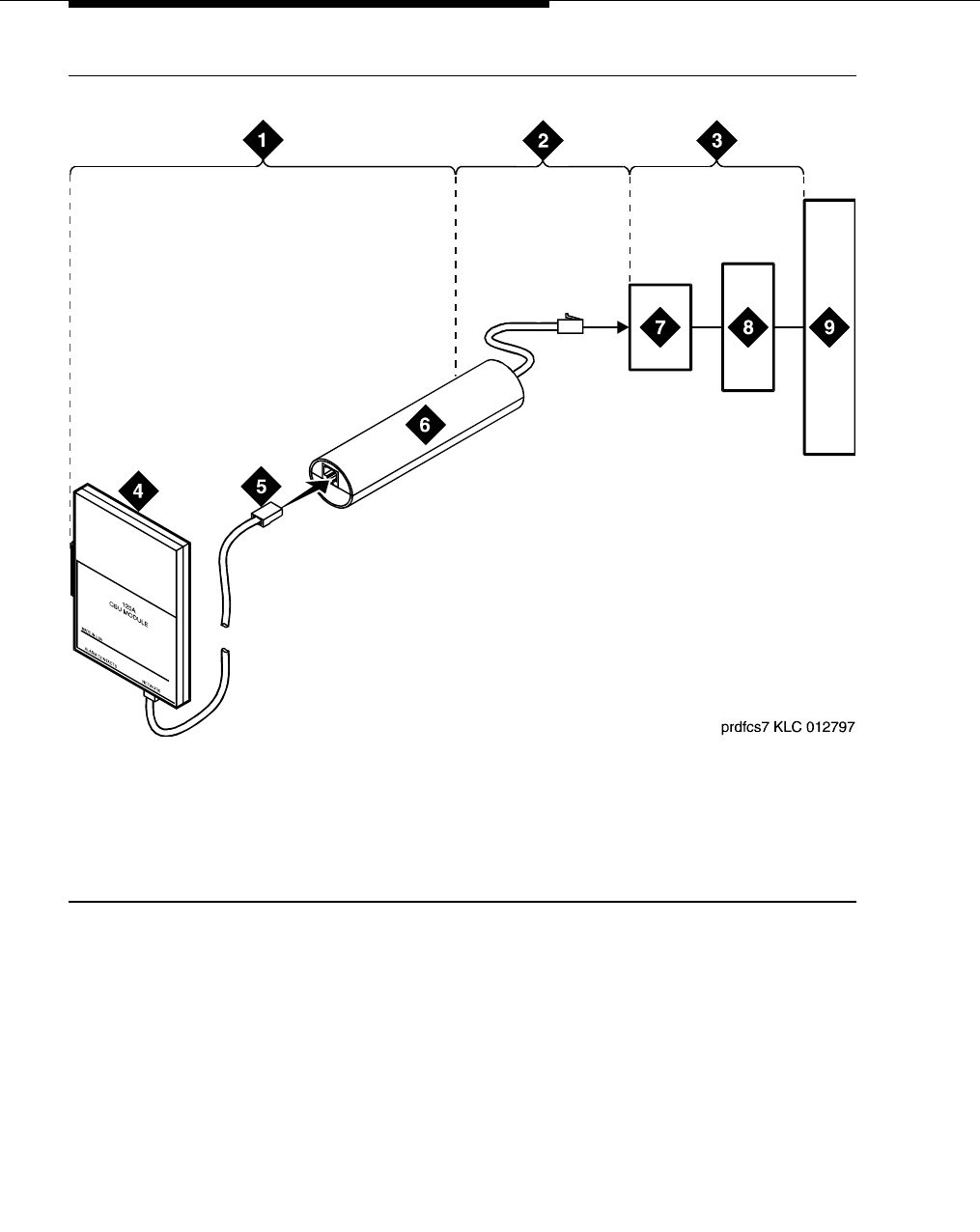
DS1/T1 CPE loopback jack
555-233-116
64 Issue 6 November 2003
Figure 9. Network interface at smart jack for a 120A2 (or later) ICSU
1. Span section 1
2. Span section 2
3. Span section 3
4. 120A2 (or later) ICSU
5. RJ-48 to network interface
(up to 1000 ft. [305 m])
6. Loopback jack
7. Network interface smart jack
8. Interface termination or fiber multiplexer (MUX)
9. Central office
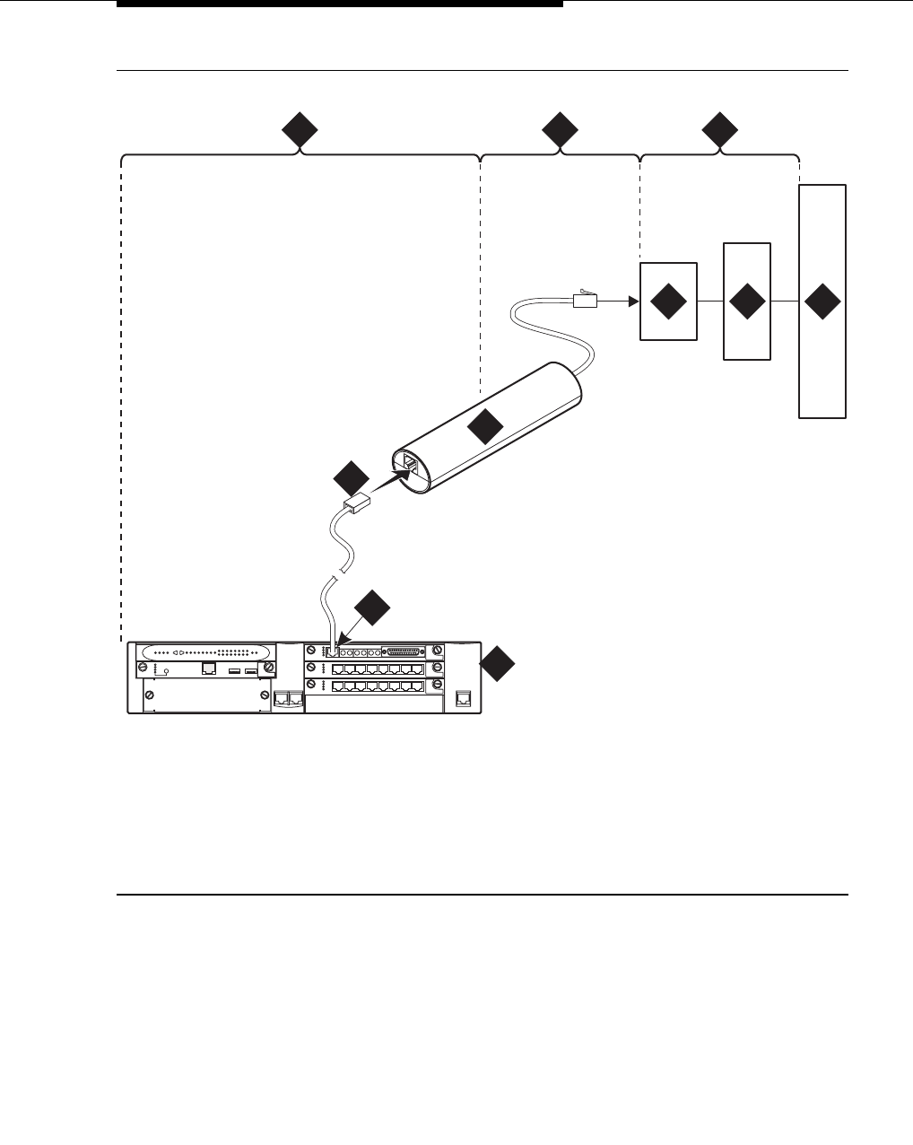
Loopback testing with a smart jack
Issue 6 November 2003 65555-233-116
Figure 10. Network interface at smart jack for an MM710 multi-media module
1. Span section 1
2. Span section 2
3. Span section 3
4. G700 or G350 Media
Gateway
5. E1/T1 port on an MM710
multi-media module
6. RJ-48 to network interface (up to 1000 ft. [305 m])
7. Loopback jack
8. Network interface smart jack
9. Interface termination or fiber multiplexer (MUX)
10. Central office
prdfcs7a KLC 080602
ALM
TST
ACT
123456 87
ALM
TST
ACT
123456 87
REMOVE
ALM
TST
ACT
OK TO SHUT DOWN
SERVICES USB1 USB 2
E1/T1 EIA 530A DCE
ALM
TST
ACT
SIG
EISO EMSM EOSI
1 2 3
4
5
6
7
8910
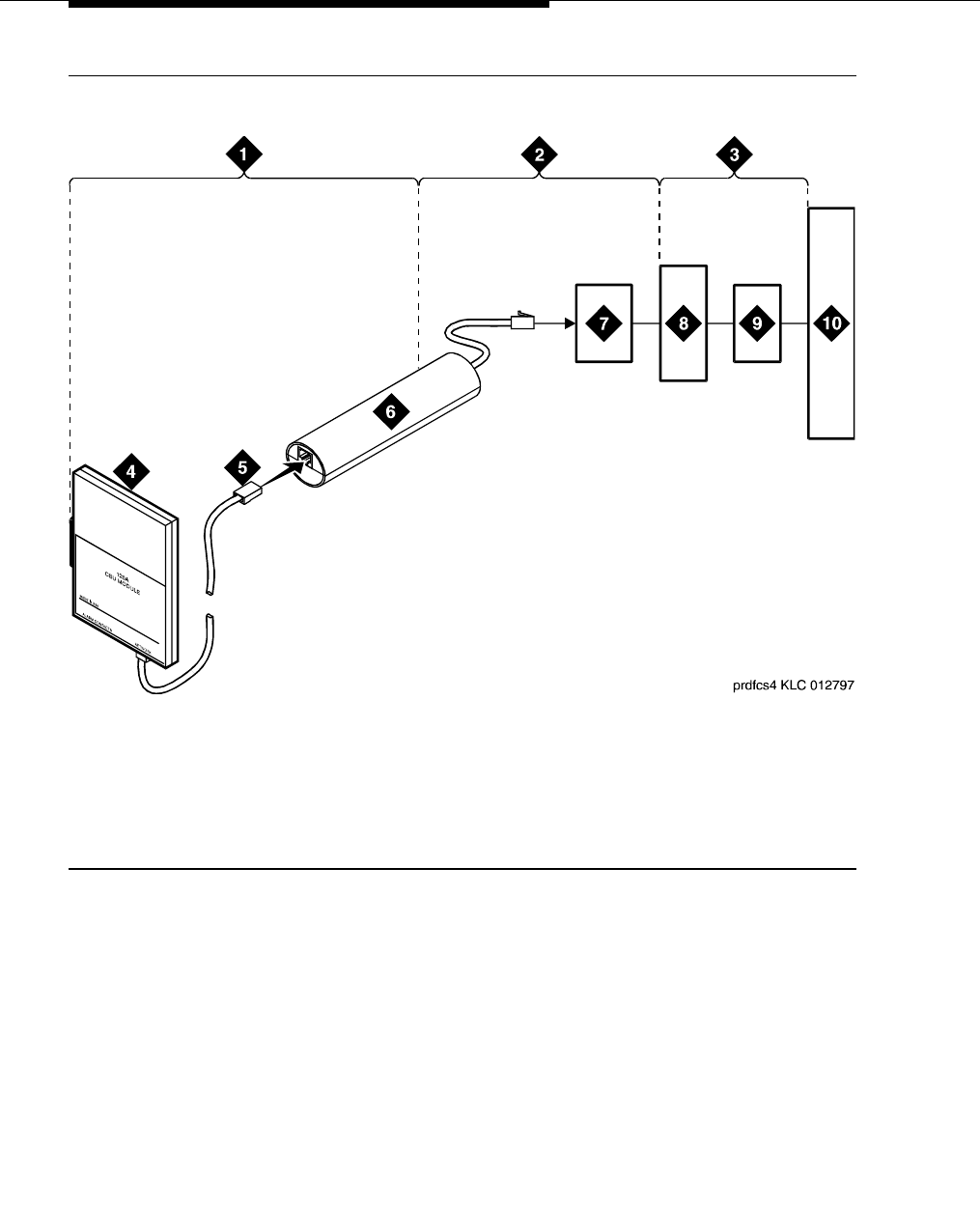
DS1/T1 CPE loopback jack
555-233-116
66 Issue 6 November 2003
Figure 11. Network interface at extended demarcation point (smart jack inaccessible) for
a 120A2 (or later) ICSU
1. Span section 1
2. Span section 2
3. Span section 3
4. 120A2 (or later) ICSU
5. RJ-48 to network interface
(up to 1000 ft. [305 m])
6. Loopback jack
7. Dumb block (extended demarcation)
8. Network interface smart jack
9. Interface termination or fiber multiplexer (MUX)
10. Central office
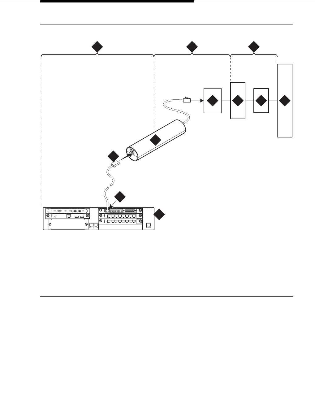
Loopback testing with a smart jack
Issue 6 November 2003 67555-233-116
Figure 12. Network interface at extended demarcation point (smart jack inaccessible) for
an MM710 multi-media module
1. Span section 1
2. Span section 2
3. Span section 3
4. G700 or G350 Media
Gateway
5. E1/T1 port on an MM710
multi-media module
6. RJ-48 to network interface (up to 1000 ft. [305 m])
7. Loopback jack
8. Dumb block (extended demarcation)
9. Network interface smart jack
10. Interface termination or fiber multiplexer (MUX)
11. Central office
prdfcs4a KLC 080602
ALM
TST
ACT
123456 87
ALM
TST
ACT
123456 87
REMOVE
ALM
TST
ACT
OKTO SHUTDOWN
SERVICES USB 1 USB 2
E1/T1 EIA 530A DCE
ALM
TST
ACT
SIG
EISO EMSM EOSI
1 2 3
4
5
6
7
8910 11
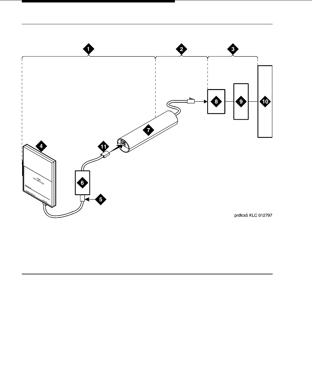
DS1/T1 CPE loopback jack
555-233-116
68 Issue 6 November 2003
Figure 13. Network interface at extended demarcation point (smart jack accessible) for a
120A2 (or later) ICSU
1. Span section 1
2. Span section 2
3. Span section 3
4. 120A2 (or later) ICSU
5. RJ-48 to network interface
(up to 1000 ft. [305 m])
6. Dumb block (extended demarcation)
7. Loopback jack
8. Network interface smart jack
9. Interface termination or fiber multiplexer (MUX)
10. Central office
11. Dumb block to smart jack RJ-48
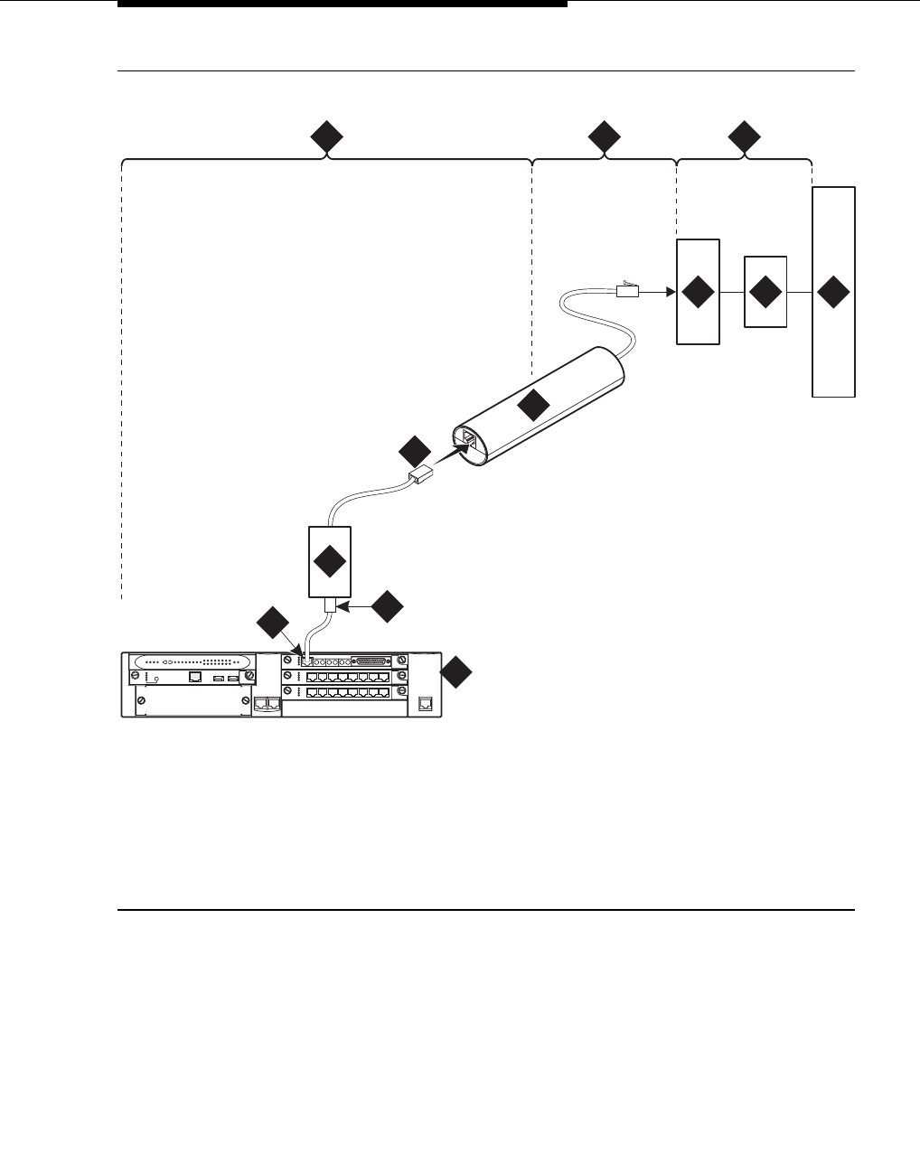
Loopback testing with a smart jack
Issue 6 November 2003 69555-233-116
Figure 14. Network interface at extended demarcation point (smart jack accessible) for
an MM710 multi-media module
1. Span section 1
2. Span section 2
3. Span section 3
4. G700 or G350 Media
Gateway
5. E1/T1 port on an MM710
multi-media module
6. RJ-48 to network interface (up to 1000 ft. [305 m])
7. Dumb block (extended demarcation)
8. Loopback jack
9. Network interface smart jack
10. Interface termination or fiber multiplexer (MUX)
11. Central office
12. Dumb block to smart jack RJ-48
prdfcs5a KLC 080602
ALM
TST
ACT
123456 87
ALM
TST
ACT
123456 87
REMOVE
ALM
TST
ACT
OKTO SHUTDOWN
SERVICES USB1 USB 2
E1/T1 EIA 530A DCE
ALM
TST
ACT
SIG
EISO EMSM EOSI
1 2 3
4
56
8
910
12
11
7
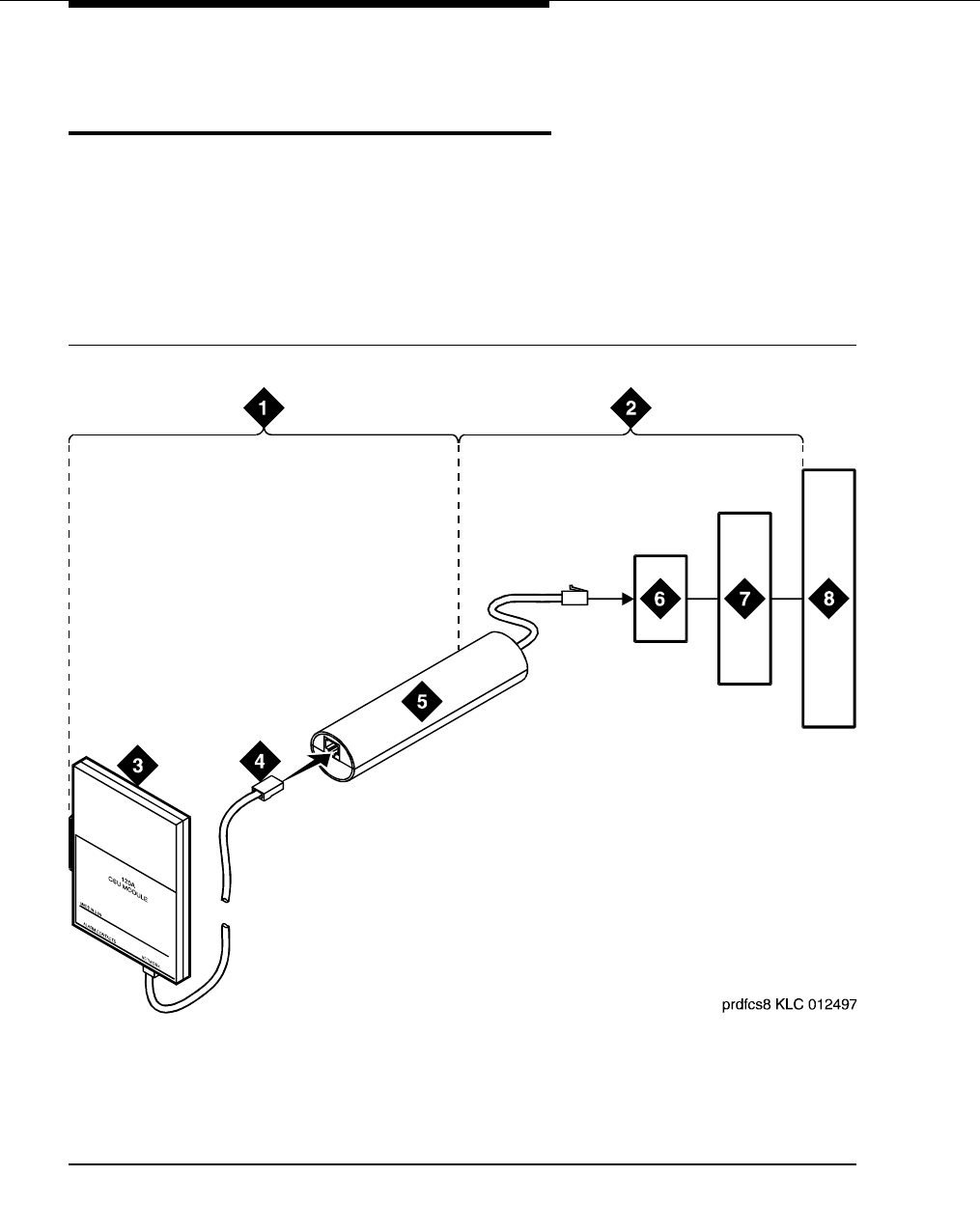
DS1/T1 CPE loopback jack
555-233-116
70 Issue 6 November 2003
Testing a loopback jack without a
smart jack
When the loopback jack is added to a span that does not contain a smart jack, the
span is divided into 2 sections: from the ICSU, or from the MM710, to the
loopback jack and from the loopback jack to the central office (CO). Section 2
includes the short cable from the loopback jack to the dumb block demarcation
point (part of the loopback jack). This cable is the only part of Section 2 that is part
of customer premises wiring. It is not covered in the loopback jack’s loopback
path. See Figure 15 through Figure 18.
Figure 15. Network interface at “dumb” block for a 120A2 (or later) ICSU
1. Span section 1
2. Span section 2
3. 120A2 (or later) ICSU
4. RJ-48 to network interface
(up to 1000 ft. [305 m])
5. Loopback jack
6. Dumb block (demarcation point)
7. Interface termination or fiber multiplexer (MUX)
8. Central office
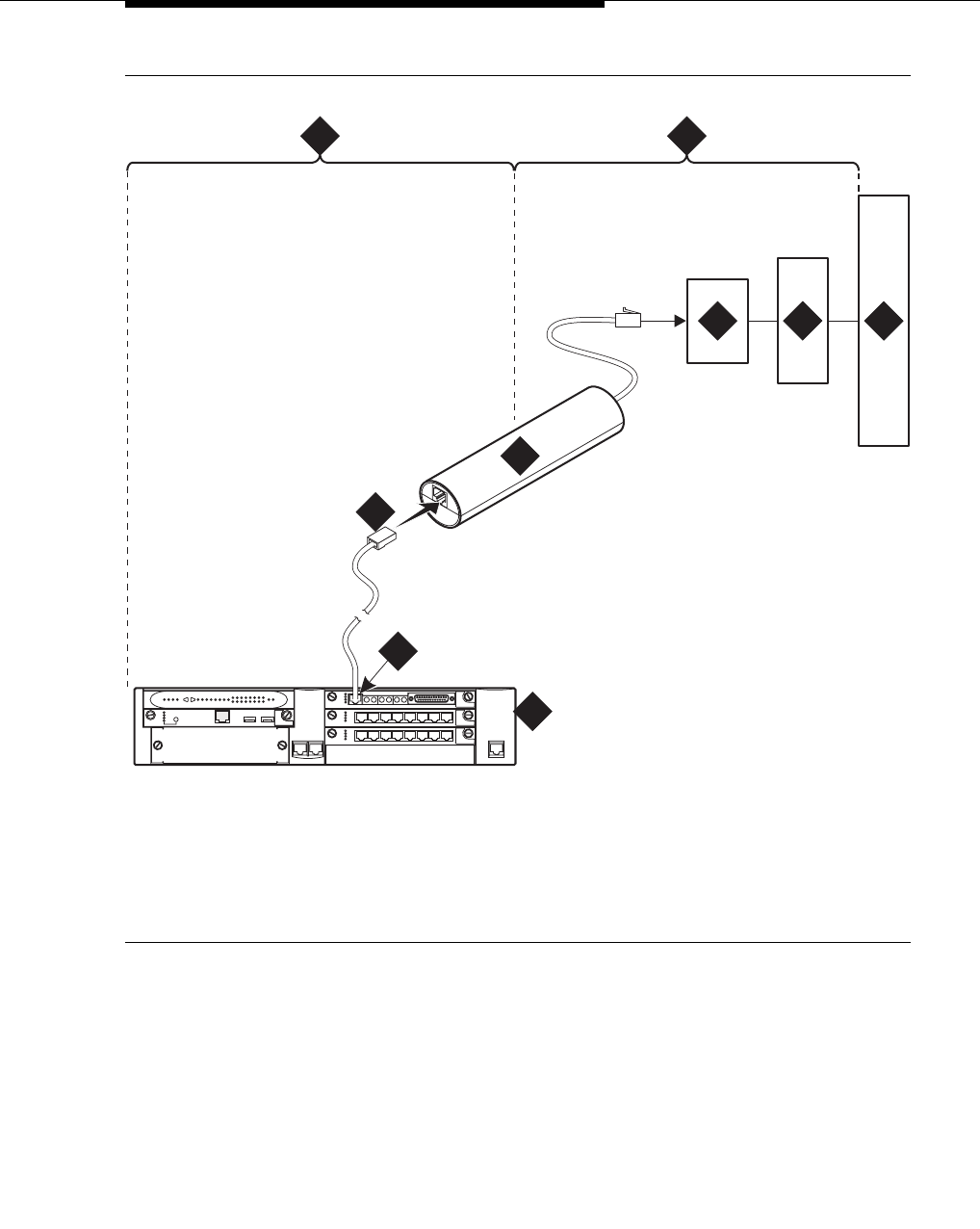
Testing a loopback jack without a smart jack
Issue 6 November 2003 71555-233-116
Figure 16. Network interface at “dumb” block for an MM710 multi-media module
1. Span section 1
2. Span section 2
3. G700 or G350 Media
Gateway
4. E1/T1 port on an MM710
multi-media module
5. RJ-48 to network interface (up to 1000 ft. [305 m])
6. Loopback jack
7. Dumb block (demarcation point)
8. Interface termination or fiber multiplexer (MUX)
9. Central office
prdfcs8a KLC 080602
ALM
TST
ACT
123456 87
ALM
TST
ACT
123456 87
REMOVE
ALM
TST
ACT
OK TO SHUT DOWN
SERVICES USB 1 USB2
E1/T1 EIA 530A DCE
ALM
TST
ACT
SIG
EISO EMSM EOSI
1 2
3
4
5
6
789
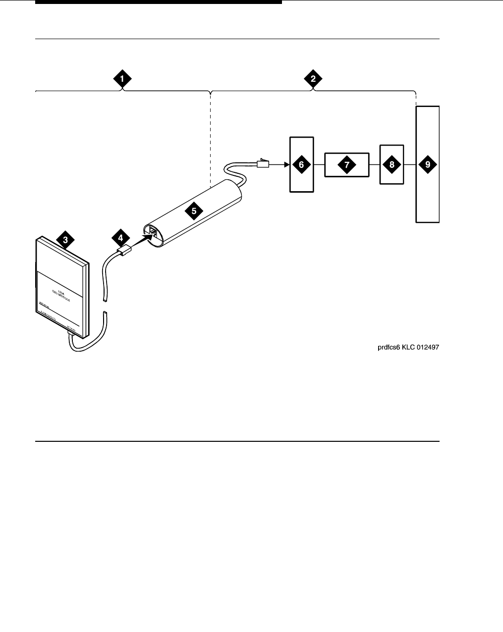
DS1/T1 CPE loopback jack
555-233-116
72 Issue 6 November 2003
Figure 17. Network interface at “dumb” block with repeater line to fiber MUX for a
120A2 (or later) ICSU
1. Span section 1
2. Span section 2
3. 120A2 (or later) ICSU
4. RJ-48 to network interface
(up to 1000 ft. [305 m])
5. Loopback jack
6. Dumb block (demarcation point)
7. Repeater
8. Fiber multiplexer (MUX)
9. Central office
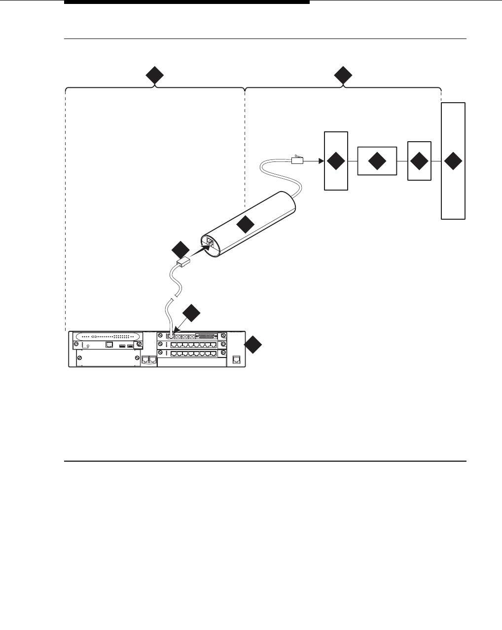
Testing a loopback jack without a smart jack
Issue 6 November 2003 73555-233-116
Figure 18. Network interface at “dumb” block with repeater line to fiber MUX for an
MM710 multi-media module
You are responsible for finding and correcting problems in the customer wiring
(section 1 and the loopback cable portion of section 2). The DS1 service provider
is responsible for finding and correcting problems in the majority of section 2.
1. Span section 1
2. Span section 2
3. G700 or G350 Media
Gateway
4. E1/T1 port on an MM710
multi-media module
5. RJ-48 to network interface (up to 1000 ft. [305 m])
6. Loopback jack
7. Dumb block (demarcation point)
8. Repeater
9. Fiber multiplexer (MUX)
10. Central office
prdfcs6a KLC 080602
ALM
TST
ACT
123456 87
ALM
TST
ACT
123456 87
REMOVE
ALM
TST
ACT
OKTO SHUTDOWN
SERVICES USB 1 USB2
E1/T1 EIA 530A DCE
ALM
TST
ACT
SIG
EISO EMSM EOSI
1 2
3
4
5
6
78 9 10

DS1/T1 CPE loopback jack
555-233-116
74 Issue 6 November 2003
Proceed as follows.
1. Test customer premises wiring from the ICSU, or from the MM710, to the
loopback jack, as described in the “DS1 Span Test” section.
2. Test the loopback jack-to-dumb block and dumb block-to-CO wiring
(section 2 in Figure 15 through Figure 18). This can be done using a
loopback that “overlaps” the section of the span. Any of the following
loopbacks can do this:
■The local ICSU’s line loopback, which the DS1 service provider at
the CO end typically activates, tests, and then deactivates.
■The local DS1 interface’s payload loopback, which the DS1 service
provider at the CO end activates and tests.
■The far-end ICSU’s line loopback. Activate this test at the
management terminal by entering test ds1-loop location far-csu-
loopback-test-begin, where location is the DS1 interface circuit
pack corresponding to the loopback jack. Terminate this test by
entering test ds1-loop location end-loopback/span-test, where
location is the DS1 interface circuit pack corresponding to the
loopback jack.
Bit error counts are examined as described in the “DS1 Span Test”
section. This test only isolates problems to Section 2 wiring if there
are no problems in the wiring between the far-end CO and the far-
end ICSU. Coordinate this test with the DS1 service provider.
Failure of any of the above tests (a, b, or c) indicate a problem in
Section 2. This could mean bad loopback jack -to-”dumb” block
cabling, but is more likely to indicate a problem somewhere between
the “dumb” block and the CO. This is the responsibility of the DS1
service provider.
If the DS1 Span Test confirms that there are no problems in
Section 1, the technician should proceed as follows to avoid
unnecessary dispatch.
1. Identify and contact the DS1 service provider.
2. Inform the DS1 provider that loopback tests of the CPE wiring
to the “dumb” block (section 1) showed no problems.
3. If the far-end ICSU line loopback test failed, inform the DS1
provider.
4. Request that the DS1 provider perform a loopback test of
their portion of the Section 2 wiring by sending someone out
to loop Section 2 back to the CO at the “dumb” block.
If this test fails, the problem is in the service provider’s wiring.
If the test passes, the problem is in the cable between the
loopback jack and the “dumb” block. Replace the loopback
jack.

Testing a loopback jack without a smart jack
Issue 6 November 2003 75555-233-116
Configurations using fiber multiplexers
Use the loopback jack when customer premises DS1 wiring connects to an on-site
fiber multiplexer (MUX) and allows wiring to the network interface point on the
MUX to be remotely tested. For a G700 or G350 Media Gateway, this requires
that the MM710 CSU be set so it can be used on DS1 wiring to the MUX.
Fiber MUXs can take the place of Interface termination feeds as shown in
Figure 9 through Figure 16. Test these spans using the same procedures as
metallic spans. Note the following points:
1. Fiber MUXs may have loopback capabilities that can the service provider
can activate from the CO end. These may loop the signal back to the CO or
back to the DS1 board. If the MUX provides the equivalent of a line
loopback on the “problem” DS1 facility, activate it after a successful
loopback jack test, and use it to isolate problems to the wiring between the
loopback jack and the MUX.
2. Be aware that there are installations that use repeatered metallic lines
between the MUX and the “dumb” block. These lines require DC power for
the repeaters and this DC power is present at the “dumb” block interface to
the CPE equipment. A loopback jack is required in this configuration to
properly isolate and terminate the DC power.
To check for the presence of DC, make the following 4 measurements at the
network interface jack:
1. From transmit tip (T, Pin 5) to receive tip (T1, Pin 2)
2. From transmit ring (R, Pin 4) to receive ring (R1, Pin 1)
3. From transmit tip (T, Pin 5) to transmit ring (R, Pin 4)
4. From receive tip (T1, Pin 2) to receive ring (R1, Pin 1)
All measurements should read 0 (zero) volts DC. For pin numbers and pin
designations, refer to Integrated Channel Service Unit (ICSU) Installation and
Operation.

DS1/T1 CPE loopback jack
555-233-116
76 Issue 6 November 2003

Issue 6 November 2003 77555-233-116
7
External modems
The following section assumes that you are using one of the recommended
external modems. However, any locally obtained, type-approved external modem
should work. Contact your Avaya representative for more information.
Recommended modems include:
■‘‘Paradyne COMSPHERE 3810 Plus and 3811 Plus’’
■‘‘Paradyne COMSPHERE 3910’’
■‘‘U.S. Robotics modems’’ (various models)
■‘‘Multi-Tech MT5634ZBA-USB-V92’’ (for an S8300. S8500, or S8700
configuration)
■‘‘Multi-Tech MT5634ZBA-V92-GLOBAL’’ (for an S8500 or G350
configuration)
Hardware required when configuring
modems
To configure many modems, you use the Hayes-compatible AT command set.
NOTE:
If your modem uses a USB connection, use the USB ports instead of the
serial port. Also, AT commands are not required, so you can skip this
section. Use the factory defaults.
Before you can enter AT configuration commands, you must first connect a
terminal or a PC with a keyboard, monitor, and terminal-emulation software to the
modem.

External modems
555-233-116
78 Issue 6 November 2003
Proceed as follows:
1. Connect one end of an RS-232 cable to an RS-232, serial-communications
port (often called a COM port) on the terminal or PC.
2. Connect the other end of the RS-232 cable to the modem.
3. If you are using a PC, start your terminal emulation software.
Paradyne COMSPHERE 3810 Plus and
3811 Plus
Configuring the 3810 Plus and 3811 Plus modems
1. Install the modem as described in the vendor’s documentation.
2. Attach a PC with terminal emulation software, as described in the vendor’s
documentation.
3. From the terminal, enter the following AT command string:
AT&F&D2&S4\D3S2=128x7V2S7=60S85=1
4. Then enter the following command string:
ATY0S10=100S78=2M0E0\N1&W
The modem is now configured.
Paradyne COMSPHERE 3910
You configure COMSPHERE 3910 modems using a front button panel (see
Figure 19) or Hayes-compatible AT commands. For instructions on how to
physically connect the modem and general configuration instructions, see the
documentation that came with the modem. This document describes configuring
the 3910 for particular, DEFINITY adjuncts.
Figure 19. COMPSPHERE 3910 modem, front panel
F1 F2 F3
Power On Selftst
Passed
modf3150 KLC 030899

U.S. Robotics modems
Issue 6 November 2003 79555-233-116
Configuring the 3910 for CMS
The COMSPHERE 3910 modem may be used as the Call Management System
(CMS) Remote Console Modem or as a device that provides serial connectivity to
CMS through the Network Terminal Server (NTS). For the instructions to set up
the modem for use in CMS (other configurations may work as well), see one of the
following:
■Avaya™ Call Management System (CMS) Sun® Enterprise™ 3500
Computer Hardware Installation, Maintenance, and Troubleshooting, 585-
215-873
■Avaya™ Call Management System (CMS) Sun® Ultra™ 5 Computer
Hardware Installation, Maintenance, and Troubleshooting, 585-215-871
U.S. Robotics modems
Avaya recommends using the U.S. Robotics external modem for DEFINITY
servers. For instructions on how to physically connect it and for general
configuration instructions, see the documentation that came with the modem. This
document describes configuring the modem for particular adjuncts.
Configuring U.S. Robotics modems
All configuration is done through hardware switches. Proceed as follows.
1. Set the DIP switches on the modem to match the settings listed in the table
below (for switch locations, consult the documentation that came with the
modem).
Table 3. U.S. Robotics External Modem Switch Settings
Switch Setting Function
1 OFF (Up) DTR (Data Terminal Ready) override
2 OFF (Up) Result codes
3 ON (Down) Result codes
4 OFF (Up) Keyboard command echo
5 ON (Down) Auto answer
6 OFF (Up) CD (Carrier Detect) override
7 OFF (Up) Power-on and ATZ reset software defaults
8 ON (Down) AT command recognition

External modems
555-233-116
80 Issue 6 November 2003
Multi-Tech MT5634ZBA-USB-V92
Avaya recommends using a Multi-Tech USB modem, model MT5634ZBA-USB-
V92, with an S8300/700, S8500, or S8700 configuration. This modem is used for
sending alarms, as well as for remote dial up to the server for maintenance and
administration.
Configuring the MT5634ZBA-USB-V92 modem
In the United States, the Multi-Tech MT5634ZBA-US-V92 modem gets configured
automatically through the USB port with the factory defaults. No special
configuration is necessary. In a non-US country, the modem may require settings
specific to the country in which the modem will be used.
Multi-Tech MT5634ZBA-V92-GLOBAL
Avaya recommends using a Multi-Tech serial modem, model MT5634ZBA-V92-
GLOBAL, with an S8500 media server or G350 media gateway.
For an S8500 media server, the Multi-Tech serial modem connects the Remote
Supervisor Adapter (RSA) to an external trunk. The RSA, which monitors S8500
components and software, can then send alarms to the services support group.
Additionally, the S8500 can be dialed up remotely to either turn power on or off.
For more information, see Installing the Avaya S8500 Media Server with an Avaya
G650 Media Gateway, 555-245-107.
For a G350, the Multi-Tech serial modem connects the G350 media gateway to an
external trunk. This connection enables remote dial in capability for administration
and troubleshooting. For more information, see Installation of the Avaya G350
Media Gateway Controlled by an Avaya S8300, S8500, or S8700 Media Server,
555-245-104.
NOTE:
The Multi-Tech serial modem, which requires its own power, comes with a
DC adapter and a separately shipped power cord and modular cord.
Administration
You have to administer each modem that you attach to a DEFINITY server. For
the S8300, S8500, and S8700 media servers, as well as the G700 and G350
media gateways, the Multi-Tech modems do not require administration if used in
the United States. In non-US countries, these modems may require
administration.

Administration
Issue 6 November 2003 81555-233-116
For the full range of modem options, see the Administrator’s Guide for Avaya
Communication Manager, 555-233-506. For DEFINITY server modem
administration, see Installation, Upgrades and Additions for Avaya CMC1 Media
Gateways, 555-233-118, or the Made-Easy Tool for DEFINITY Server SI
Upgrades and MCC1 or SCC1 Gateway Installations on the Avaya
Communication Manager, Avaya DEFINITY® Servers and Avaya S8100 Media
Server Library, 555-245-801.

External modems
555-233-116
82 Issue 6 November 2003

Issue 6 November 2003 83555-233-116
8
ISDN converters and adapters
This chapter provides information on ISDN converters and adapters that are
sometimes necessary when connecting to coaxial facilities in either a multicarrier
cabinet or a single carrier cabinet.
NOTE:
The information in this chapter does not apply to the G700 or G350 Media
Gateway configurations.
Connections include:
■Integated Services Data Network Primary Rate Interface (ISDN-PRI) to
Direct Access Secondary Storage (DASS)
■PRI to Digital Private Network Signaling System (DPNSS)
■PRI to ISDN Basic Rate Interface (ISDN-BRI)
Converter circuit packs known as common channel signaling converter (CCSC),
types 1 and 2.
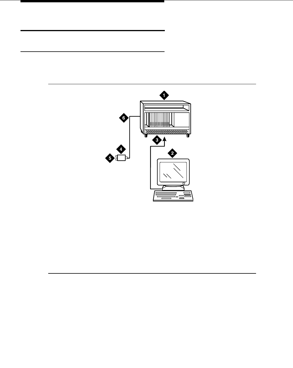
ISDN converters and adapters
555-233-116
84 Issue 6 November 2003
Converters for single-carrier cabinets
PRI-to-DASS and PRI-to-DPNSS converters
Figure 20 shows typical connections from the CCSC-1 PRI-to-DASS converter or
the CCSC-2 PRI-to-DPNSS converters to the coaxial facility.
Figure 20. Typical DASS or DPNSS converter cabling
1. Plug the PC into the RS-232 connector on the front of the PRI converter
circuit pack.
2. Connect the coaxial Y-cable from the TN464F to the PRI converter circuit
pack.
3. Connect the opposite end of the Y-cable to the 888B coaxial converter.
1. To TN464F DS1 circuit pack and
either a CSCC-1 PRI-to-DASS
converter or a CSCC-2 PRI-to-
DPNSS converter circuit pack
2. Administration PC
3. RS-232 cable to front of PRI
converter circuit pack
4. 888B coaxial converter
5. Coaxial connection to 2-Mbps
facility
6. Coaxial cable from PRI converter
circuit pack to coaxial converter
0001_0 RBP 051396
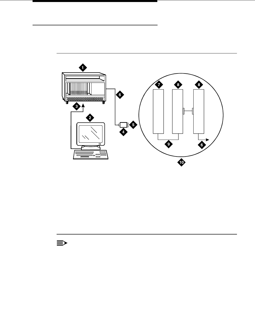
Converters for single-carrier cabinets
Issue 6 November 2003 85555-233-116
PRI-to-BRI converter
Figure 21 shows typical connections from the PRI-to-BRI converter to the coaxial
facility.
Figure 21. Typical PRI to BRI converter cabling
NOTE:
The inset shows details of the cable connections between the circuit packs.
Connect the DEFINITY administration PC to the RS-232 connector on the
front of the PRI converter circuit pack.
1. To TN464F DS1 circuit pack and
PRI-to-BRI converter circuit pack
2. DEFINITY administration PC
3. RS-232 cable to front of converter
circuit pack
4. 888B coaxial converter
5. Coaxial connection to 2-Mbps
facility
6. Coaxial cable from PRI converter
circuit pack to coaxial converter
7. TN464F circuit pack
8. PRI-to-BRI converter circuit pack
9. Jumper coaxial cable
10. Inset showing connections on rear of
carrier
0007_0 RBP 051396
7
(2B+D)
1
(2B+D)
8
(2B+D)
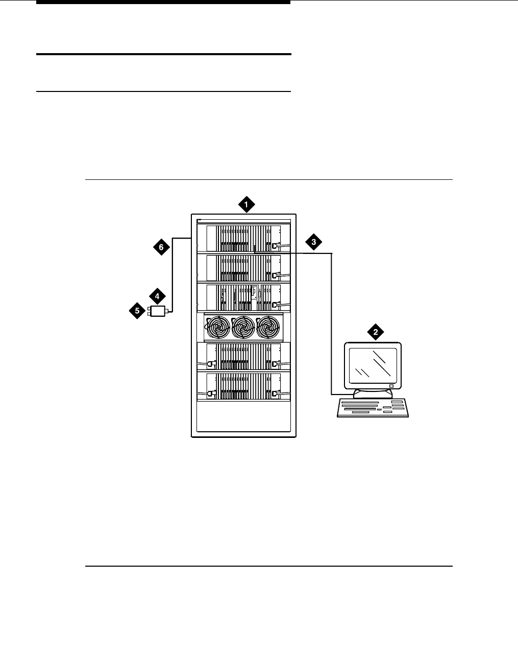
ISDN converters and adapters
555-233-116
86 Issue 6 November 2003
Converters for multi-carrier cabinets
PRI-to-DASS and PRI-to-DPNSS converters
1. Connect the DEFINITY administration PC to the RS-232 connector on the
front of the PRI converter circuit pack.
Figure 22 shows typical connections from the CCSC-1 PRI-to-DASS
converter or the CCSC-2 PRI-to-DPNSS converters to the coaxial facility.
Figure 22. Typical DASS or DPNSS converter cabling
1. To TN464F DS1 circuit pack and
either a CSCC-1 PRI-to-DASS
converter or a CSCC-2 PRI-to-
DPNSS converter circuit pack
2. DEFINITY administration PC
3. RS-232 cable to front of PRI
converter circuit pack
4. 888B coaxial converter
5. Coaxial connection to 2-Mbps
facility
6. Coaxial cable from PRI converter
circuit pack to coaxial converter
ALARMS
EMERTR C
A
R
D
I
N
U
S
E
ENTER
/YES
NEXT
/NO
BACK
AUDIX
BOOT/
SHUTDOWN
0011_0 RBP 060696
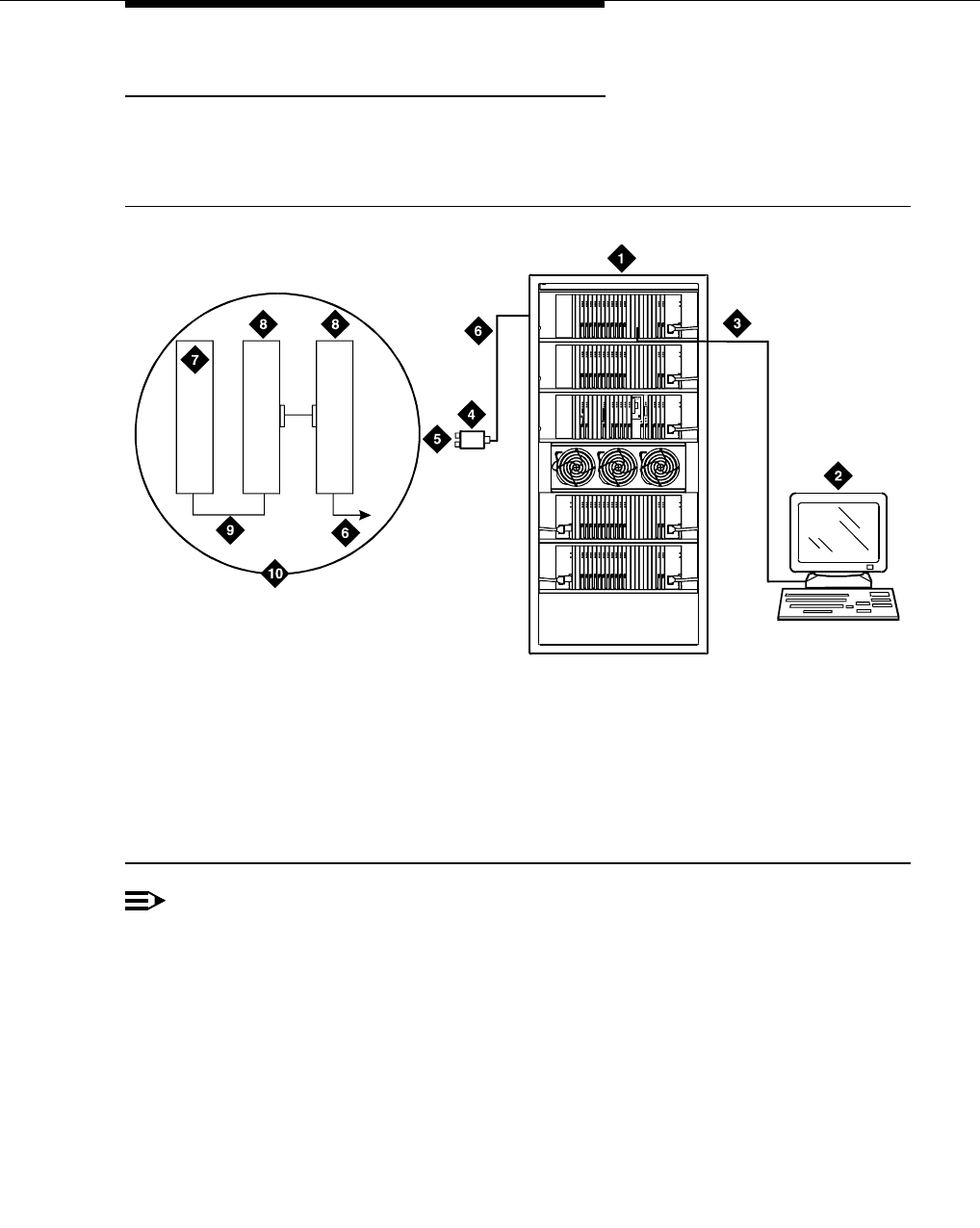
Converters for multi-carrier cabinets
Issue 6 November 2003 87555-233-116
PRI-to-BRI converter
Figure 23 shows typical connections from the PRI-to-BRI converter to the coaxial
facility. The DEFINITY administration PC is connected to the RS-232 connector
on the front of the PRI converter circuit pack.
Figure 23. Typical PRI to BRI converter cabling
NOTE:
The inset shows details of the cable connections between the circuit packs.
1. TN464F DS1 circuit pack and PR-to-BRI
converter circuit pack
2. DEFINITY administration PC
3. RS-232 cable to front of converter circuit
pack
4. 888B 75-ohm coaxial converter
5. Coaxial connection to 2-Mbps facility
6. Coaxial cable from PRI converter circuit
pack to coaxial converter
7. TN464F circuit pack
8. PRI-to-BRI converter circuit pack
9. Jumper coaxial cable
10. Inset showing connections on rear of
carrier
ALARMS
EMERTR C
A
R
D
I
N
U
S
E
ENTER
/YES
NEXT
/NO
BACK
AUDIX
BOOT/
SHUTDOWN
0022_1 PDH 062596
7
(2B+D)
1
(2B+D)
8
(2B+D)

ISDN converters and adapters
555-233-116
88 Issue 6 November 2003
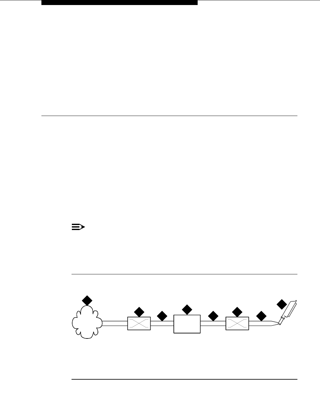
Issue 6 November 2003 89555-233-116
9
Busy tone disconnect equipment for
non-U.S. installations
Necessary only for G700 or G350 Media Gateways, the customer-provided busy
tone disconnect adjunct detects busy tone disconnects of incoming calls on loop-
start, 2-wire, analog trunks. In some non-U.S. countries where a G700 or G350
Media Gateway is used, the PSTN sends busy tone as the disconnect signal.
Therefore, the S8300 Media Server, G700 Media Gateway, or G350 Media
Gateway requires a busy tone disconnect adjunct. Figure 24 shows typical
connections.
NOTE:
DEFINITY Servers and S8500/S8700/S8100 Media Servers support the
busy tone disconnect feature and do not require an adjunct. Therefore, a
busy tone disconnect adjunct is recommended only for G700 and G350
Media Gateways.
Figure 24. Typical cabling for busy tone disconnect
1. Public switched telephone network
2. Main distribution frame
3. Busy tone disconnect device
4. Tip and ring wires
5. To loop-start, central-office, trunk
MM711 analog media module
cydf057 RPY 12309
7
1
2 2
3
4 4 4
5

Busy tone disconnect equipment for non-U.S.
installations
555-233-116
90 Issue 6 November 2003

Issue 6 November 2003 91555-233-116
10
909A/B universal coupler
The 909A/B universal coupler is used with paging, malicious call trace, and music-
on-hold equipment that is not approved for use with the public network.
NOTE:
The information in this chapter does not apply to the G700 or G350 Media
Gateway configurations.
Figure 25 shows a typical 909A/B universal coupler. For additional installation and
switch setting information, refer to 909A/909B Universal Coupler Installation
Instructions, which is normally shipped with the 909A/909B Universal Coupler.
NOTE:
If the music source is registered by the FCC (in the USA) or an equivalent
body, the 909A/B universal coupler is not required.
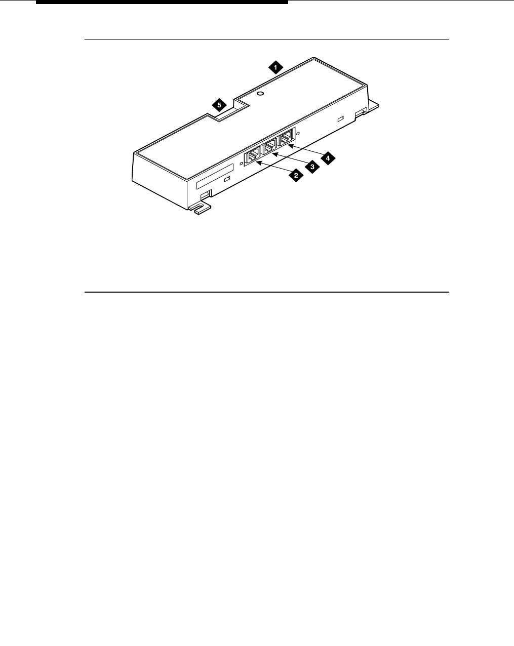
909A/B universal coupler
555-233-116
92 Issue 6 November 2003
Figure 25. Typical 909A/B universal coupler
The 909A is the direct current (DC) version of the coupler, and cabinet power
supplies -48 VDC power. The 909B is the alternating current (AC) version, and
power is supplied from a separate power supply (such as the KS-22911L2).
The DIP switches on the unit set:
■Protection/Paging selection — For AUX trunk paging and malicious call
trace, set to C2. Set the switch to C1 for all other applications.
■Output attenuation (-9 or -15 dBm) — Setting depends on output level of
music source.
■Output impedance (8 ohms, 1.5 kΩ, and 50 kΩ) —This switch only
requires setting if the Protection/Paging switch is set to C2 and the coupler
is supplying background music to a customer-supplied paging amplifier.
The pinouts for J1, J2, and J3 are provided in Table 4, Table 5, and Table 6. Refer
to these tables when connecting music or paging equipment.
1. 909A/B universal coupler
2. J1 8-pin modular jack
3. J2 8-pin modular jack
4. J3 7-pin modular jack
5. DIP switch location
909_brkt KLC 042296

909A/B universal coupler
Issue 6 November 2003 93555-233-116
!CAUTION:
Do not plug the cable into J3 before all cross-connects are completed.
Damage to the 909A/B universal coupler may occur.
Table 4. J1 Pin Assignments (System Connections)
Pin Color Designation Description
1 White-Orange —Not Used
2 Orange PG2/BZ2 Seizure control lead, connected to -48 VDC from
the system or from the 909A/B when the protection
paging switch is set to C2, or to -48 VDC on the
909A/B when protection/paging switch is set to C1
3 White-Green PG1/BZ1 Seizure control lead, connected to SZ lead from
the AUX trunk when the protection/paging switch
is set to C2, or to -48 VDC on the 909A/B when the
protection/paging switch is set to C1
4 Blue R Ring lead
5 White-Blue T Tip lead
7 Green BSY2/BY2 Busy/busy-out lead, connected to S1 lead from the
AUX trunk
7 White-Brown BSY1/BY1 Busy/busy-out lead, connected to S lead from the
AUX trunk
8Brown —Not Used
Table 5. J2 Pin Assignments (Accessory Connections)
Pin Color Designation Description
1 White-Orange CMS1/M1 Customer-supplied music source
2 Orange CMS2/M2 Customer-supplied music source
3 White-Green COS1 Remote busy-out control contact closure from
music source
4 Blue CR Customer ring lead
5 White-Blue CT Customer tip lead
7 Green COS2 Remote busy-out control contact closure from
music source
7 White-Brown CBS1/C1 Seizure indication provided to music source
8 Brown CBS2/C2 Seizure indication provided to music source
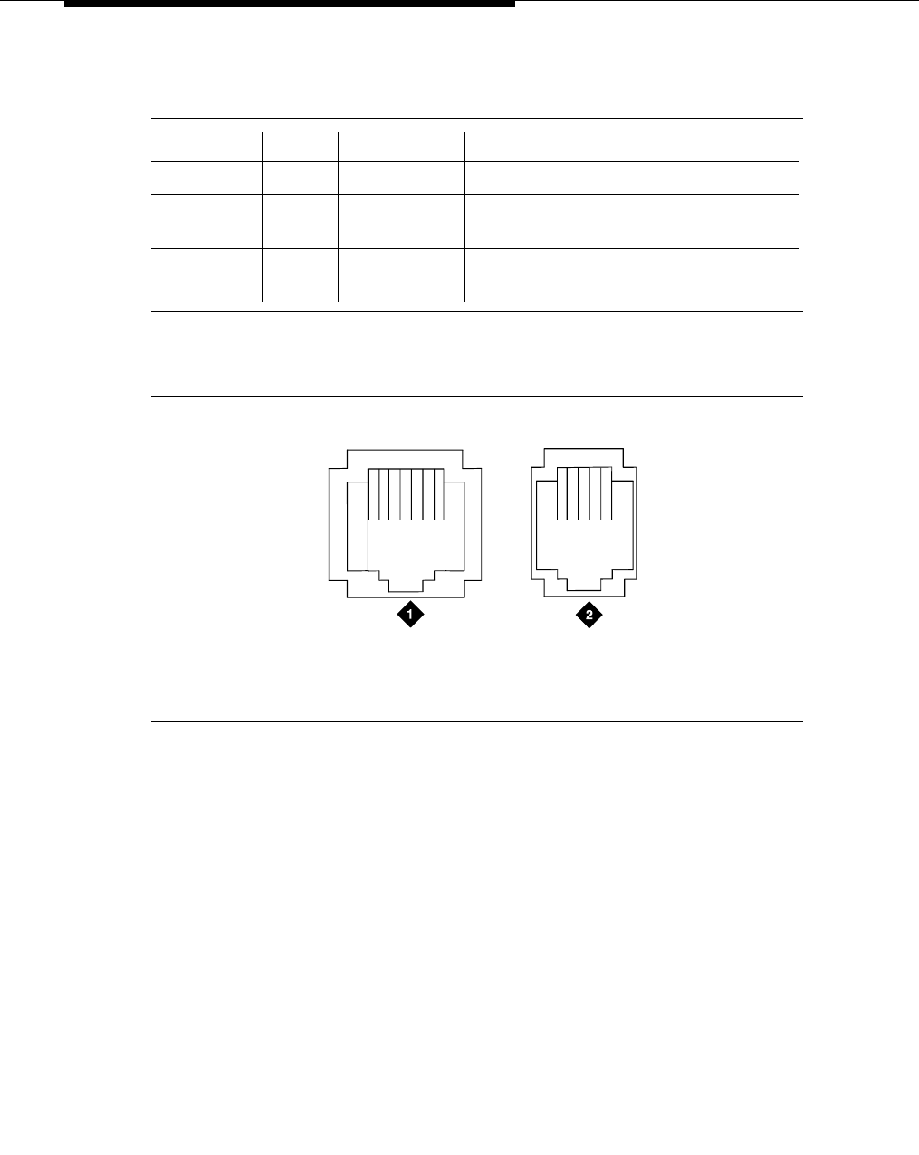
909A/B universal coupler
555-233-116
94 Issue 6 November 2003
Figure 26 shows the physical locations of the pins for J1, J2, and J3.
Figure 26. Typical modular jack pinout
Table 6. J3 Pin Assignments (Power Connections)
Pin Color Designation Description
1, 3, 4, & 7 — — Not used
2 Black GRD -48 RET or ground lead from system or
from positive lead of power supply
5 Yellow -48 VDC -48 VDC from system or from negative
lead of power supply
1. J1 and J2 8-pin modular jacks 2. J3 7-pin modular jack
18 25
mod_jack RBP 041796
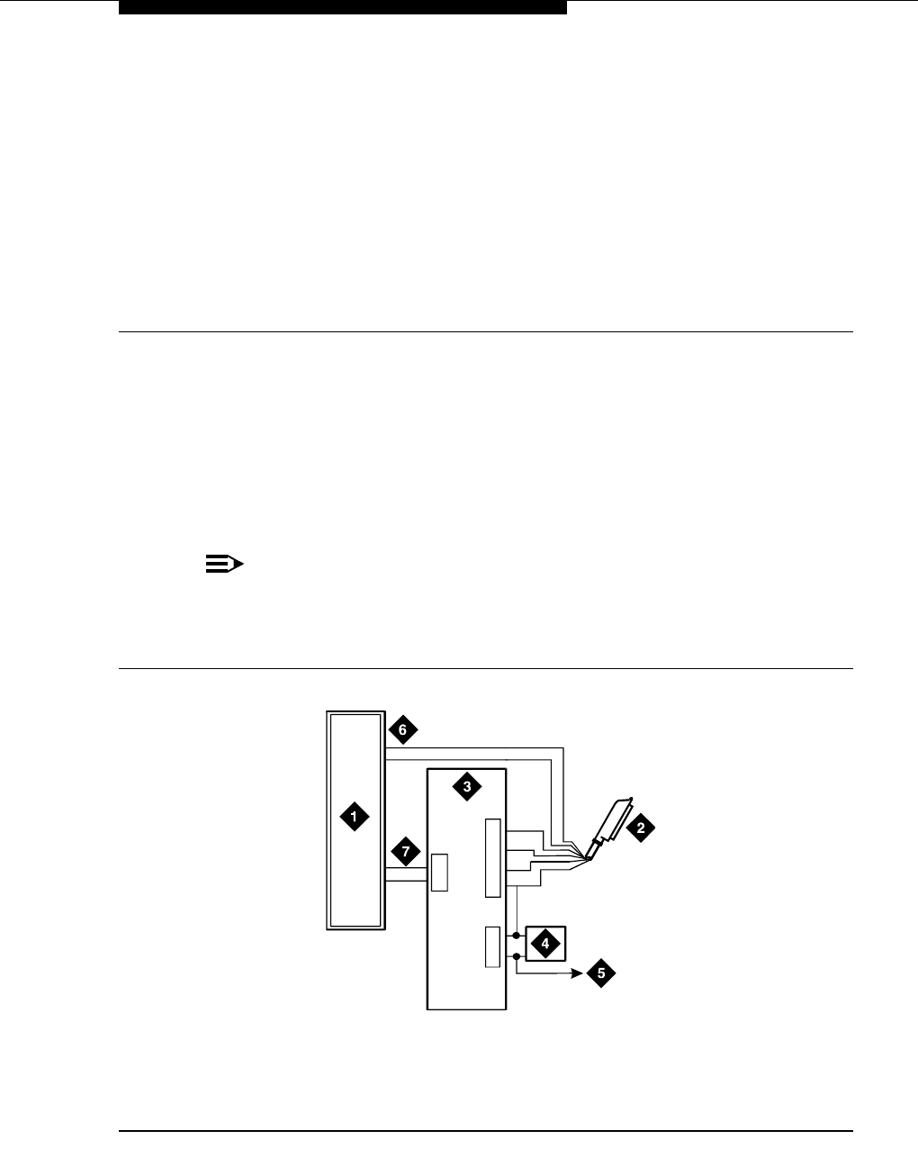
Issue 6 November 2003 95555-233-116
11
Malicious call trace
The malicious call trace (MCT) voice recorder connects directly to the tip and ring
connections of a TN763/D auxiliary trunk circuit pack. See Figure 27. The 909A/B
universal coupler provides seizure control to the recorder.
NOTE:
There is no auxiliary trunk circuit pack for the G700 or G350 Media
Gateway, so information in this chapter does not apply to these media
gateways. But you can access MCT equipment connected to a port network.
Figure 27. Malicious call trace
1. Malicious call trace voice recorder
2. 25-pair cable (T, R, S, S1, Sz, SZ1) to
TN763/D auxiliary trunk circuit pack
3. 909A/B universal coupler
4. Power supply for universal coupler
5. To SZ1 on TN763/D connector
6. Tip and ring wires
7. CBS1/C1 and CBS2/C2
cydf038 PDH 091696
J2
J3
J1
5
2
7
7
82
3
6

Malicious call trace
555-233-116
96 Issue 6 November 2003
NOTE:
A wiring block must be locally engineered.
NOTE:
909A couplers ships with one DW4B-DE cable and two DW8B-SE cables.
The 909B ships with one KS-22911L2 power supply, one DW4B-DE cable,
and two DW8B-SE cables.
1. Determine the port assignment of the recorder from the malicious call
tracing form.
2. Install the 909A/B universal coupler on a vertical surface.
3. Connect the SZ, SZ1, S, and S1 leads from the 909A/B to an auxiliary trunk
circuit pack.
a. Tip and ring connect from the voice recorder to the auxiliary trunk
circuit pack (J1 on the 909A/B).
b. CBS1/C1 and CBS2/C2 connect from the voice recorder to J2 on
the 909A/B.
4. On the 909A/B universal coupler:
a. Connect seizure control voltage of from -9 to -70 Volts to the PG2/
BZ2 connection (pin 2 of J1). Switching voltage to the PG2/BZ2
connection can be from the 909A/B -48 VDC supply.
b. Connect SZ1 to the ground lead of the DC power source used for
PG2/BZ2.
c. Set S1 to the “C2” position. Set S2 position 7 to “OPEN”.
d. Connect an approved -48 VDC power source to the -48 and GRD
terminals (pins 5 and 2, respectively, of J3 on the 909A/B).
5. Administer the switch for the call trace device.
NOTE:
For additional installation information, refer to 909A/909B Universal Coupler
Installation Instructions, which is normally shipped with the 909A/909B
Universal Coupler.

Issue 6 November 2003 97555-233-116
12
Music-on-hold
The music-on-hold (MOH) feature allows a caller to hear music when that caller is
placed on hold. Depending on the media gateway, music-on-hold can be
provided:
■through a two-wire TN2183 analog line circuit pack (or equivalent) or
auxiliary trunk circuit pack to a customer-supplied music source on an
MCC1, SCC1, CMC1, G600, or G650 Media Gateway.
■through a port on an MM711 Analog Media Module to a customer-supplied
music source on a G700 Media Gateway.
■through a port on an MM711 Analog Media Module or MM714 Analog
Media Module, or through a fixed analog port (LINE 1 or LINE 2) to a
customer-supplied music source on a G350 Media Gateway.
For MCC1, SCC1, CMC1, G600, and
G650 Media Gateways
Figure 28 shows the connections for music-on-hold, dial dictation, or recorded
announcement features when the music source is Federal Communications
Commission (FCC) registered (or equivalent). Figure 29 shows the connections
when the music source is not FCC-registered (or equivalent).
Local music-on-hold allows one music source. However, if you purchase the
multiple music-on-hold (tenant partitioning) feature, you can have up to 100 music
sources.
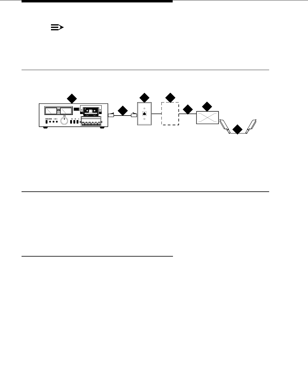
Music-on-hold
555-233-116
98 Issue 6 November 2003
NOTE:
Use the following connection instructions when the music source is not
located in the equipment room. If the music source is located in the
equipment room, do not route the connections through the information
outlet.
Figure 28. Typical registered equipment connections (auxiliary access) for an MCC1,
SCC1, CMC1, G600, and G650 Media Gateway
1. If the music source is registered, the system side of the MDF connects
directly to the system.
2. If the music source is not registered, the system side of the MDF connects
to a 909A/B universal coupler (see Chapter 10, ‘‘909A/B universal
coupler’’).
Registered music source
Refer to Figure 28 to install a registered music source.
1. Determine feature port assignment from Feature-Related System
Parameters form.
2. Install music source according to the manufacturer’s instructions.
3. Install patch cord/jumper wires at the main distribution frame.
4. Administer the switch for the new equipment.
1. Music source
2. 4-pair modular cord
3. 103A or modular wall jack
4. 122A music adapter (if required—primarily
required in France)
5. Tip (green) and ring (red)
6. Part of main distribution frame
7. A25D 25 pair cable (male-to-male) to
auxiliary trunk circuit pack
cydfmusc RPY 090397
1
2
34
56
7
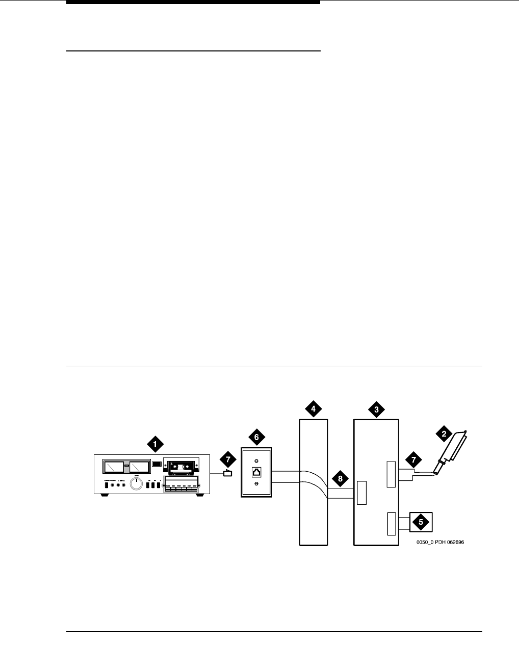
For MCC1, SCC1, CMC1, G600, and G650 Media
Gateways
Issue 6 November 2003 99555-233-116
Nonregistered music source
Refer to Figure 29 and Figure 30 when installing a nonregistered music source.
1. Determine feature port assignment from Feature-Related System
Parameters Form.
2. Install the music source according to the manufacturer’s instructions.
3. Connect a cable from the assigned port carrier slot to J1 on the 909A/B
universal coupler (see Chapter 10, ‘‘909A/B universal coupler’’). A wiring
block must be locally engineered.
a. Connect the T-lead at pin 5 and the R-lead at pin 4 of J1 on the
909A/B universal coupler to the corresponding leads from the
TN2183.
b. Connect the CT-lead at pin 5 and the CR-lead at pin 4 of J2 on the
909A/B universal coupler to the MDF.
4. Install patch cord/jumper wires at the MDF to connect tip and ring to the
information outlet at the music source.
5. Set the Protection/Paging switch to C1.
6. Connect a modular cord from the information outlet to the music source.
7. Connect -48V to pin 5 and -48V RET to pin 2 of J3 on the 909A/B. The
power source may be an 1151A, 1151A2, or other approved power supply.
8. Administer the switch for the new equipment.
Figure 29. Typical nonregistered equipment connections (auxiliary access) for an MCC1,
SCC1, CMC1, G600, or G650 Media Gateway
1. Customer-supplied music source
2. A25D 25-pair cable to auxiliary trunk circuit
pack
3. 909A/B universal coupler
4. Part of main distribution frame
5. Power supply for universal coupler
6. 103A or modular wall jack
7. 4-pair modular cord
8. Tip and ring wires
J2
J3
J1
5
2
4
5
4
5
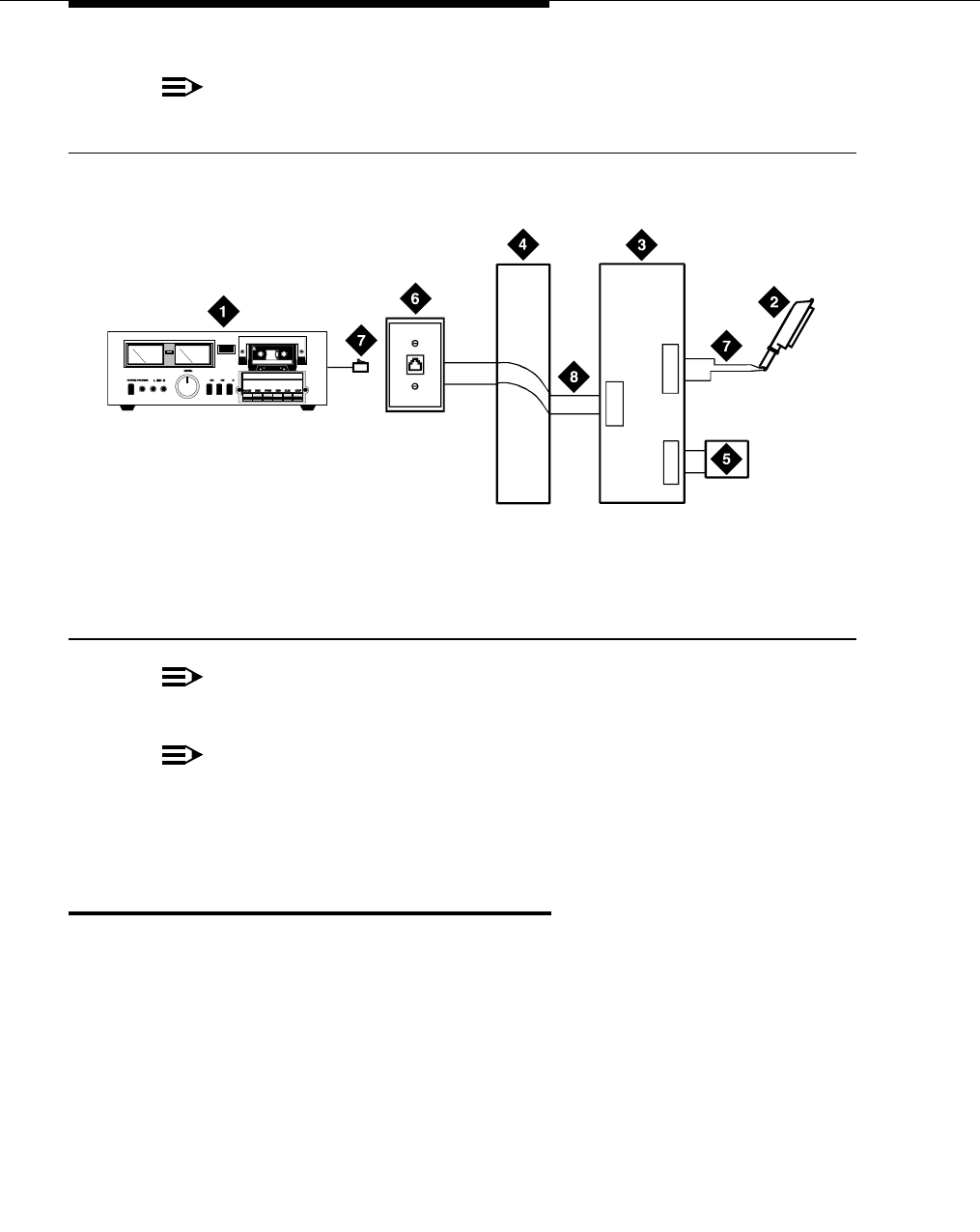
Music-on-hold
555-233-116
100 Issue 6 November 2003
NOTE:
A wiring block must be locally engineered.
Figure 30. Connections to nonregistered music-on-hold using analog line for an MCC1,
SCC1, CMC1, G600, or G650 Media Gateway
NOTE:
A wiring block must be locally engineered.
NOTE:
For additional installation information, refer to 909A/909B Universal Coupler
Installation Instructions, which is normally shipped with the 909A/909B
Universal Coupler.
For G700 or G350 Media Gateways
On a G700 or G350 Media Gateway, the music-on-hold feature is connected
through a port on an MM711 Analog Media Module or, for a G350 Media Gateway
only, an MM714 Analog Media Module or the analog LINE ports of the integrated
analog media module.
The G700 or G350 Media Gateway does not support an auxiliary trunk circuit
pack. Therefore, for S8300 Media Server users, the music-on-hold feature
through an auxiliary trunk is not supported. However, G700 or G350 Media
Gateway users with an S8500 or S8700 Media Server as primary controller can
access the music-on-hold feature if their equipment is physically connected to a
TN763 auxiliary trunk circuit pack in an EPN carrier of an S8500 or S8700 system.
1. Customer-supplied music source
2. 25-pair cable to analog line circuit pack
3. 909A/B universal coupler
4. Part of main distribution frame
5. Power supply for universal coupler
6. 103A or modular wall jack
7. 4-pair modular cord
8. Tip and ring wires
0051_0 PDH 062696
J2
J3
J1
5
2
4
5
4
5

For G700 or G350 Media Gateways
Issue 6 November 2003 101555-233-116
Unregistered Music Source on a G700 or G350
Media Gateway
Figure 31 and Figure 32 show the connections for the music-on-hold feature on a
G700 Media Gateway for an unregistered source.
NOTE:
The G350 Media Gateway’s physical connection with the MM711 Analog
Media Module, MM714 Analog Media Module, or fixed analog ports (LINE 1
or 2) on the front panel is the same as the G700 Media Gateway’s
connection with the MM711 Analog Media Module.
NOTE:
If you want multiple music sources, you must use multiple ports on the
MM711 Analog Media Module.
Figure 31. Unregistered music-on-hold equipment connecting to KS-23395-L3 for a G700
Media Gateway
To hook up an unregistered music-on-hold source to a G700 or G350 Media
Gateway using a KS-23395-L3 coupler:
1. Connect one end of an RJ-45 cable to a port in the MM711 Analog Media
Module. Or, for a G350 Media Gateway only, connect the RJ-45 cable to a
port in an MM714 Analog Media Module or a fixed analog (LINE 1 or 2) port
oon the G350 front panel.
2. Connect the other end of the RJ-45 cable to a KS-23395-L3 coupler.
3. Connect the KS-23395-L3 coupler to the customer-supplied music source.
Follow the manufacturer’s instructions to properly connect the music
source to the KS-23395-L3 coupler. Normally, you simply use an RCA
cord.
4. Administer the switch for the new equipment.
1. G700 Media Gateway
2. MM711 Analog Media Module
3. RJ-45 connection
4. KS-23395-L3 coupler
5. RCA cord
6. Music source
cydfhld2 KLC 021303
ALM
TST
ACT
123456 87
ALM
TST
ACT
123456 87
REMOVE
ALM
TST
ACT
OKTO SHUTDOWN
SERVICES USB1 USB 2
E1/T1 EIA 530A DCE
ALM
TST
ACT
SIG
EISO EMSM EOSI
12
4
6
5
3
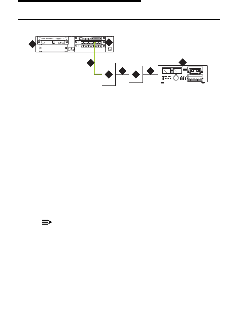
Music-on-hold
555-233-116
102 Issue 6 November 2003
Figure 32. Unregistered music-on-hold equipment connecting to KS-23395-L4 for a G700
Media Gateway
To hook up an unregistered music-on-hold source to a G700 or G350 Media
Gateway using a KS-23395-L4 coupler:
1. Connect one end of an RJ-45 cable to a port in the MM711 Analog Media
Module. Or, for a G350 Media Gateway only, connect the RJ-45 cable to a
port in an MM714 Analog Media Module or a fixed analog (LINE 1 or 2) port
oon the G350 front panel.
2. Connect the other end of the RJ-45 cable to a KS-23395-L4 coupler.
3. Connect the KS-23395-L4 coupler to the 909A/B universal coupler using a
8-pair modular cord.
4. Connect the 909A/B universal coupler to the music source using a 8-pair
modular cord.
5. Administer the switch for the new equipment.
NOTE:
For additional installation information, refer to 909A/909B Universal Coupler
Installation Instructions, which is normally shipped with the 909A/909B
Universal Coupler.
1. G700 Media Gateway
2. MM711 Analog Media Module
3. RJ-45 connection
4. KS-23395-L4 coupler
5. 8-pair modular cord
6. 909A/B universal coupler
7. 8-pair modular cord
8. Music source
cydfhld3 KLC 021303
ALM
TST
ACT
123456 87
ALM
TST
ACT
123456 87
REMOVE
ALM
TST
ACT
OKTO SHUTDOWN
SERVICES USB1 USB 2
E1/T1 EIA 530A DCE
ALM
TST
ACT
SIG
EISO EMSM EOSI
12
5
467
8
3
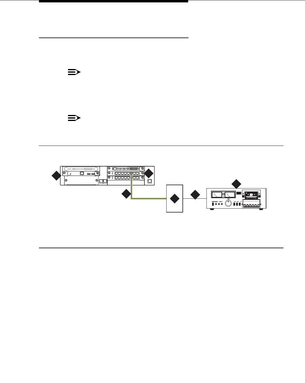
For G700 or G350 Media Gateways
Issue 6 November 2003 103555-233-116
Registered Music Source on a G700 or G350
Media Gateway
Figure 33 show the connections for the music-on-hold feature on a G700 Media
Gateway for an unregistered source.
NOTE:
The G350 Media Gateway’s physical connection with the MM711 Analog
Media Module, MM714 Analog Media Module, or fixed analog ports (LINE 1
or 2) on the front panel is the same as the G700 Media Gateway’s
connection with the MM711 Analog Media Module.
NOTE:
If you want multiple music sources, you must use multiple ports on the
MM711 Analog Media Module.
Figure 33. Registered music-on-hold equipment connecting to KS-23395-L4 for a G700
Media Gateway
To hook up an registered music-on-hold source to a G700 or G350 Media
Gateway using a KS-23395-L4 coupler:
1. Connect one end of an RJ-45 cable to a port in the MM711 Analog Media
Module. Or, for a G350 Media Gateway only, connect the RJ-45 cable to a
port in an MM714 Analog Media Module or a fixed analog (LINE 1 or 2) port
oon the G350 front panel.
2. Connect the KS-23395-L4 coupler to the customer-supplied music source.
Normally, you simply use a 8-pair modular cord.
3. Administer the switch for the new equipment.
1. G700 Media Gateway
2. MM711 Analog Media Module
3. RJ-45 connection
4. KS-23395-L4 coupler
5. 8-pair modular cord
6. Music source
cydfhld2 KLC 021303
ALM
TST
ACT
123456 87
ALM
TST
ACT
123456 87
REMOVE
ALM
TST
ACT
OKTO SHUTDOWN
SERVICES USB1 USB 2
E1/T1 EIA 530A DCE
ALM
TST
ACT
SIG
EISO EMSM EOSI
12
4
6
5
3

Music-on-hold
555-233-116
104 Issue 6 November 2003

Issue 6 November 2003 105555-233-116
13
Paging and announcement
equipment
This chapter explains the most common system configurations for the paging
feature of Avaya™ Communication Manager. This chapter provides information
on the following features:
■‘‘Loudspeaker paging for MCC1, SCC1, CMC1, G600, or G650 Media
Gateways’’
■‘‘ESPA radio paging’’
■‘‘External ringing’’
■‘‘Queue warning indicator’’
■‘‘Loudspeaker paging for G700 or G350 Media Gateways’’
Loudspeaker paging for MCC1, SCC1,
CMC1, G600, or G650 Media Gateways
In an MCC1, SCC1, CMC1, G600, or G650 Media Gateway, the loudspeaker
paging feature provides a connection from a TN763B/C/D auxiliary trunk circuit
pack (or equivalent) to a customer-supplied paging amplifier.
Loudspeaker paging without paging adapter
Figure 34 shows the connections for the loudspeaker paging feature. These
connections are used when the loudspeaker interface equipment is not located in
the equipment room. If the equipment is located in the equipment room, the
information outlet is not required. The connections shown are for one zone.
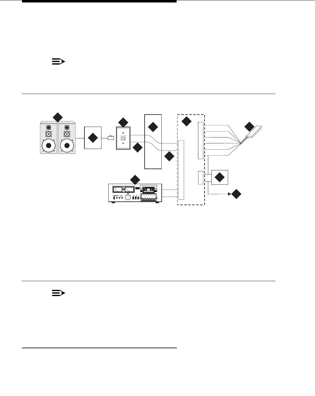
Paging and announcement equipment
555-233-116
106 Issue 6 November 2003
Figure 34 also shows connections from an optional customer-supplied music
source to the loudspeaker system through a paging amplifier, as well as
connections to the loudspeaker system through a 909A/B universal coupler (see
Chapter 10, ‘‘909A/B universal coupler’’).
NOTE:
If the loudspeaker paging system provides a talkback microphone at the
speakers, the microphone must be FCC approved (or equivalent), or a
909A/B universal coupler is required.
Figure 34. Connections for loudspeaker paging without paging adapter for an MCC1,
SCC1, CMC1, G600, or G650 Media Gateway
NOTE:
On the 25-pair cable to TN763B/C/D auxiliary trunk circuit pack, SZ1
connects to GRD on key 10. The 50 points amphenol is connected to the
back of a G600 or G650 Media Gateway.
Loudspeaker paging access without universal
coupler
1. Determine port assignment of paging zone(s) from loudspeaker paging
form.
2. At the main distribution frame, locate the connecting block and terminals
assigned to the selected port.
1. 25-pair cable to TN763B/C/D
auxiliary trunk circuit pack
2. Loudspeaker paging system
3. 909A/B universal coupler (if
required)
4. Part of main distribution frame
(MDF) circuits 1-16
5. Paging amplifier
6. Music source for background
music over loudspeakers
(optional)
7. 103A or modular wall jack
8. To SZ1 on TN763 connector
9. Tip and ring wires
10. -48 VDC power supply for 909B
cydfnzm KLC 091202
J2
J3
J1
5
1
2
2
7
4
4
52
3
6
51
23
4
5
7
8
9
9
10
6

Loudspeaker paging for MCC1, SCC1, CMC1, G600, or
G650 Media Gateways
Issue 6 November 2003 107555-233-116
3. On the locally engineered wiring block, place a strap between terminals S
and SZ. Place a strap between terminals S1 and SZ1.
4. Install patch cord/jumper wires at the main distribution frame.
5. Connect a 2-pair line cord (modular plug at one end) from the information
outlet to the paging amplifier (to the loudspeaker system).
6. Install loudspeaker equipment according to the manufacturer’s instructions.
7. Administer the switch for the new equipment.
Loudspeaker paging with universal coupler
An information outlet provides access to loudspeaker paging. The system side of
the main distribution frame connects to a 909A/B universal coupler. Make
provisions for the DC power that the 909A/B universal coupler requires, such as a
1151A, 1151A2, or other approved -48VDC power supply.
Six leads (T, R, SZ, SZ1, S, and S1) connect the adapter to an auxiliary trunk
circuit pack located in a port carrier.
1. Determine port assignment of paging zone(s) from loudspeaker Paging
form.
2. Identify carrier slot and label both ends of an A25D (male to male) cable.
3. Connect a cable from the 909A/B to the system side of the main
distribution frame. A wiring block must be locally engineered.
4. Chapter 10, ‘‘909A/B universal coupler’’ provides details of the connections
between the 909A/B universal coupler and the wiring blocks.
!CAUTION:
Damage to the 909A/B may occur if the cable is plugged into J3
before all cross-connects are completed.

Paging and announcement equipment
555-233-116
108 Issue 6 November 2003
5. On the 909A/B universal coupler:
■Connect seizure control voltage of from -9 to -70 volts to the PG2/
BZ2 connection (pin 2 of J1). Switching voltage to the PG2/BZ2
connection can be from the 909’s -48-volt supply.
■Connect a -48 VDC power source to the -48 and GRD terminals on
the 909A/B.
6. Install patch cord/jumper wires at the main distribution frame.
7. Connect a 2-pair line cord (modular plug at one end) from the information
outlet to the loudspeaker system.
8. Install loudspeaker equipment according to the manufacturer’s instructions.
9. Connect an approved -48 VDC power source to the -48 and GRD terminals
(pins 5 and 2, respectively, of J3).
10. Administer the switch for the new equipment.
NOTE:
For additional installation information, refer to 909A/909B Universal Coupler
Installation Instructions, which is normally shipped with the 909A/909B
Universal Coupler.
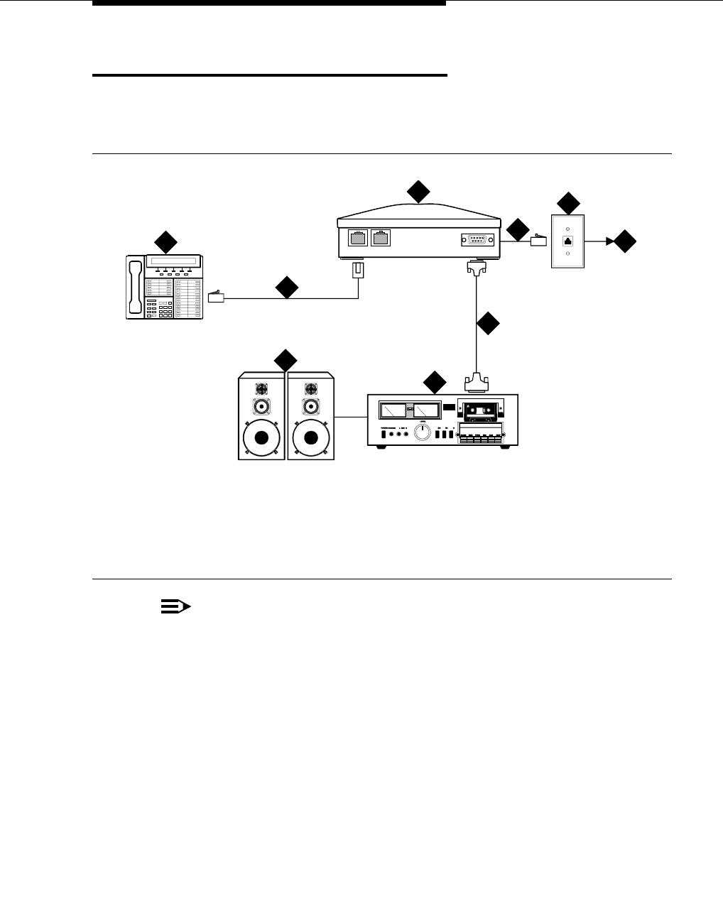
ESPA radio paging
Issue 6 November 2003 109555-233-116
ESPA radio paging
Figure 35 shows typical connections to European Standard Paging Access
(ESPA) equipment. Connect the LINE jack on the PassageWay interface to a
digital line 4-wire DCP circuit pack through the MDF.
Figure 35. Typical ESPA radio paging connections
NOTE:
The G700 or G350 Media Gateway does not support an auxiliary trunk
media module. Therefore, the loudspeaker paging feature through an
auxiliary trunk is not supported on a G700 or G350 Media Gateway.
ECC G700 or G350 Media Gateway users can access this equipment if
equipment is physically connected to a TN763 auxiliary trunk circuit pack in
an EPN carrier of an ECC system.
1. DCP telephone
2. 4-pair modular cord
3. PassageWay interface
4. 4-pair modular cord
5. 103A or modular wall jack
6. To digital line circuit pack
7. RS-232 connector
8. ESPA radio paging equipment
9. Loudspeaker paging system
cydf004 RPY 123097
PHONE LINE
POWER
1
2
3
4
5
6
7
8
9

Paging and announcement equipment
555-233-116
110 Issue 6 November 2003
External ringing
Connections for external ringing are at an information outlet. The system side of
the main distribution frame (MDF) is connected to a TN2183 (or equivalent)
analog line circuit pack in an MCC1, SCC1, CMC1, G600, or G650 Media
Gateway.
NOTE:
Up to three devices can be connected to one analog line circuit pack port.
This does not apply to the G700 or G350 Media Gateway.
1. Wire the ringing device to the information outlet.
2. Administer the switch for the new equipment.
Queue warning indicator
The connections for the queue warning indicator are the same as external ringing.
An AC indicator (light) such as a 21C49 can be used in a Uniform Call
Distribution/Direct Departmental Calling (UCD/DDC) queue. The light is
connected to an information outlet. The system side of the MDF is connected to
an analog line circuit pack located in a port carrier.
NOTE:
This does not apply to the G700 or G350 Media Gateway.
1. Wire the queue warning indicator to the information outlet.
2. Administer the switch for the new equipment.
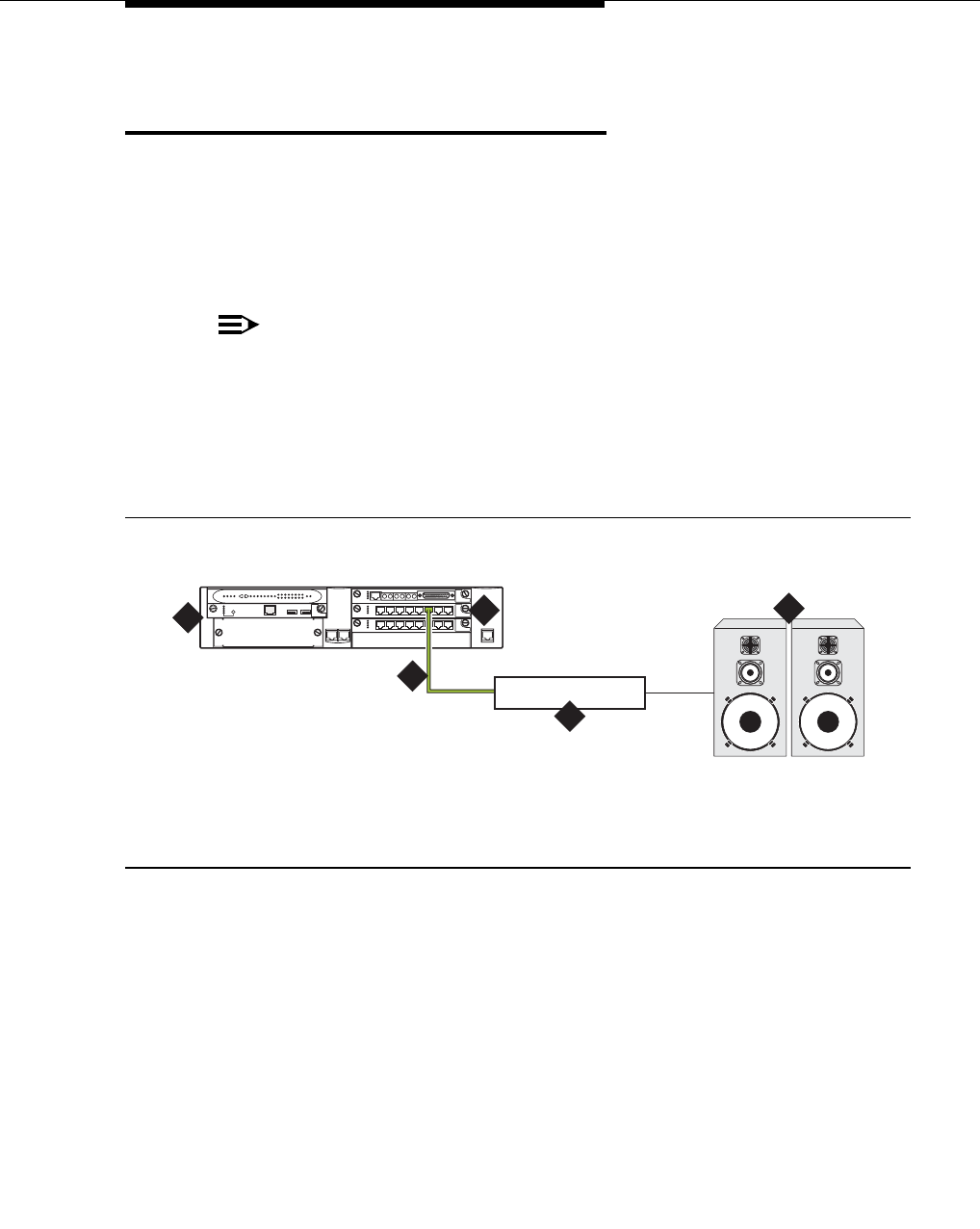
Loudspeaker paging for G700 or G350 Media Gateways
Issue 6 November 2003 111555-233-116
Loudspeaker paging for G700 or G350
Media Gateways
On a G700 or G350 Media Gateway, the loudspeaker paging feature is connected
through a port on an MM711 Analog Media Module.
The G700 or G350 Media Gateway does not support an auxiliary trunk circuit
pack. Therefore, the loudspeaker feature through an auxiliary trunk is not
supported on a G700 or G350 Media Gateway.
NOTE:
Users on a G700 or G350 Media Gateway controlled by an S8700 or S8500
can also access the loudspeaker paging feature if equipment is physically
connected to a TN763 auxiliary trunk circuit pack in an PN carrier of an the
S8700 or S8500 system.
Figure 36 shows the connections for loudspeaker paging, dial dictation, or
recorded announcement features on a G700 or G350 Media Gateway.
Figure 36. Typical loudspeaker equipment connections for a G700 or G350 Media
Gateway
To hook up loudspeaker paging from a G700 or G350 Media Gateway:
1. Connect one end of an RJ-45 cable to a port in the MM711 Analog Media
Module.
2. Connect the other end of the RJ-45 cable to a customer-supplied
telephone hybrid device.
3. Follow the manufacturer’s instructions to properly connect the telephone
hybrid device to your loudspeaker paging system.
4. Administer the switch for the new equipment.
1. G700 or G350 Media Gateway
2. MM711 Analog Media Module
3. RJ-45 connection
4. Telephone hybrid (third party) device
5. Loudspeaker paging system
cydfspkKLC 091802
ALM
TST
ACT
123456 87
ALM
TST
ACT
123456 87
REMOVE
ALM
TST
ACT
OKTO SHUTDOWN
SERVICES USB1 USB 2
E1/T1 EIA 530A DCE
ALM
TST
ACT
SIG
EISO EMSM EOSI
12
4
3
5

Paging and announcement equipment
555-233-116
112 Issue 6 November 2003

Issue 6 November 2003 113555-233-116
IN
Index
Numerics
120A ICSU, 55
120A2 ICSU, 53
888B converter, 84
909A coupler, DC version, 92
909A/B universal coupler, 91, 98, 99, 106, 107
DIP switch settings, 92
909B coupler, AC version, 92
KS-22911 power supply for, 92
A
address/location designation
circuit packs, 13
media modules, 13
adjuncts, definition of, 11
admonishments
caution, 13
danger, 14
note, 13
security alert, 14
tip, 13
warning, 14
asynchronous links, 51
B
busy tone disconnect, 89
C
calling queue, 110
caution, admonishment meaning of, 13
circuit packs
TN2183 analog line, 110
TNCCSC-1 PRI-to-DASS converter, 84, 86
TNCCSC-2 PRI-to-DPNSS converter, 84, 86
TNPRI/BRI converter, 85, 87
coaxial converter, 888B, 84
connecting a printer to a G700 or G350 Media Gateway, 51
connections, music-on-hold
FCC-registered equipment, 98
non-FCC-registered equipment, 99
conventions used in this book, 12
D
danger, admonishment meaning of, 14
document conventions, 12
DS1 loopback jack, 53
DS1 span, 54
T1, 53
E
electrostatic discharge (ESD), 14
endpoints, 46
European Standard Paging Access (ESPA) radio paging
equipment, 109
expansion services module (ESM), 48
external communications controller (ECC), 100
external ringing, 110
H
help, numbers to call, 17
I
integrated channel service unit (ICSU), 53
internal communications controller (ICC), 100
IOLAN+ 104 terminal server, 23
installation and administration, 24
IP services, 35
ISDN adapters, 83
ISDN converters, 83
for multi-carrier cabinets, 86
for single-carrier cabinets, 84
PRI-to-BRI, 85, 87
PRI-to-DASS, 84, 86
PRI-to-DPNSS, 84, 86
K
KS-22911 power supply, 92
KS-22911L2 power supply, 96
L
loopback jack, 53
administration, 55
installation, 53

Index
555-233-116114 Issue 6 November 2003
M
main distribution frame (MDF), 110
malicious call trace (MCT), 95
modems, external, 77
administration, 80
hardware to configure, 77
Multi-Tech MT5634ZBA-USB, 80
Multi-Tech MT5634ZBA-V92, 80
Paradyne COMSPHERE 3810 Plus, 78
Paradyne COMSPHERE 3811 Plus, 78
Paradyne COMSPHERE 3910, 78
U.S. Robotics, 79
multimedia call handling (MMCH), 46
multimedia endpoint, 46
Multi-Tech MT5634ZBA-USB modems, 80
Multi-Tech MT5634ZBA-V92 modems, 80
music-on-hold (MOH), 97
connecting FCC-registered equipment, 98
connecting non-FCC-registered equipment, 99
for G700 or G350 Media Gateways, 100
for MCC1, SCC1, CMC1, G600, and G650 Media Gate-
ways, 97
N
network interface, 55
node names, 34
note, admonishment meaning of, 13
P
paging equipment, 105
ESPA radio paging, 109
external ringing, 110
loudspeaker paging for G700 or G350 media gateways,
111
loudspeaker paging for MCC1, SCC1, CMC1, G600. or
G650 media gateways, 105
queue warning indicator, 110
Paradyne COMSPHERE modems
model 3810 Plus, 78
model 3811 Plus, 78
model 3910, 78
peripherals, definition of, 11
printers
connecting to a G700 or G350 Media Gateway, 51
TCP/IP connections, 51
Q
queue warning indicator, 110
S
security alert, admonishment meaning of, 14
security issues, 15
switch-to-call accounting link, testing, 39, 52
T
T1 DS1 span, 53
TCP/IP connections, 51
terminal server, 23
administering IP node names, 34
administering IP services, 35
IOLAN+ 104, 23
testing, switch-to-call accounting link, 39, 52
tip, admonishment meaning of, 13
TN2183 analog line circuit pack, 110
TNCCSC-1 PRI-to-DASS converter, 84, 86
TNCCSC-2 PRI-to-DPNSS converter, 84, 86
TNPRI/BRI converter, 85, 87
trademarks, 16
translations, CDR parameters, 39, 52
U
U.S. Robotics modems, 79
Uniform Call Distribution/Direct Departmental Calling (UCD/
DDC) queue, 110
UUCSSpp designation, 13
W
warning, admonishment meaning of, 14
wideband endpoints
non-signaling, 43
remote port module, 45
signaling, 44
X
XXXVSpp designation, 13
