Best Practices For Catalyst 6500/6000 Series And 4500/4000 Switches Running Cisco IOS Software 4000 24330 185 01
User Manual: 4000
Open the PDF directly: View PDF ![]() .
.
Page Count: 80

Products & Services
Best Practices for Catalyst 6500/6000 Series and Catalyst 4500/4000 Series Switches
Running Cisco IOS Software
Document ID: 24330
Introduction
This document provides best practices for Catalyst 6500/6000 and 4500/4000 series switches that run Cisco IOS®
Software on the Supervisor Engine.
The Catalyst 6500/6000 and Catalyst 4500/4000 series switches support one of these two operating systems that
run on the Supervisor Engine:
-Catalyst OS (CatOS)
-Cisco IOS Software
With CatOS, there is the option to run Cisco IOS Software on router daughter cards or modules such as:
-The Multilayer Switch Feature Card (MSFC) in the Catalyst 6500/6000
-The 4232 Layer 3 (L3) module in the Catalyst 4500/4000
In this mode, there are two command lines for configuration:
-The CatOS command line for switching
-The Cisco IOS Software command line for routing
CatOS is the system software, which runs on the Supervisor Engine. Cisco IOS Software that runs on the routing
module is an option that requires CatOS system software.
For Cisco IOS Software, there is only one command line for configuration. In this mode, the functionality of CatOS
has been integrated into Cisco IOS Software. The integration results in a single command line for both switching and
routing configuration. In this mode, Cisco IOS Software is the system software, and it replaces CatOS.
Both CatOS and Cisco IOS Software operating systems are deployed in critical networks. CatOS, with the Cisco IOS
Software option for router daughter cards and modules, is supported in these switch series:
-Catalyst 6500/6000
-Catalyst 5500/5000
-Catalyst 4500/4000
Contents
Introduction
Before You Begin
Background
References
Basic Configuration
Catalyst Control Plane Protocols
VLAN 1
Standard Features
VLAN Trunk Protocol
Fast Ethernet Autonegotiation
Gigabit Ethernet Autonegotiation
Dynamic Trunking Protocol
Spanning Tree Protocol
EtherChannel
UniDirectional Link Detection
Multilayer Switching
Jumbo Frames
Cisco IOS Software Security Features
Basic Security Features
AAA Security Services
TACACS+
Management Configuration
Network Diagrams
Switch Management Interface and Native VLAN
Out-of-Band Management
System Logging
SNMP
Network Time Protocol
Cisco Discovery Protocol
Configuration Checklist
Global Commands
Interface Commands
Cisco Support Community - Featured Conversations
Related Information

Cisco IOS system software is supported in these switch series:
-Catalyst 6500/6000
-Catalyst 4500/4000
Refer to the document Best Practices for Catalyst 4500/4000, 5500/5000, and 6500/6000 Series Switches Running
CatOS Configuration and Management for information on CatOS because this document covers Cisco IOS system
software.
Cisco IOS system software provides users with some of these advantages:
-A single user interface
-A unified network management platform
-Enhanced QoS features
-Distributed switching support
This document provides modular configuration guidance. Therefore, you can read each section independently and
make changes in a phased approach. This document assumes a basic comprehension and familiarity with the Cisco
IOS Software user interface. The document does not cover overall campus network design.
Before You Begin
Background
The solutions that this document offers represent years of field experience from Cisco engineers who work with
complex networks and many of the largest customers. Consequently, this document emphasizes real-world
configurations that make networks successful. This document offers these solutions:
-Solutions that have, statistically, the broadest field exposure and, thus, the lowest risk
-Solutions that are simple, which trade some flexibility for deterministic results
-Solutions that are easy to manage and that network operations teams configure
-Solutions that promote high availability and high stability
References
There are many reference sites for the Catalyst 6500/6000 and Catalyst 4500/4000 product lines on Cisco.com. The
references that this section lists provide additional depth into the topics that this document discusses.
Refer to the LAN Switching Support Page for more information on any of the topics that this document covers. The
support page provides product documentation as well as troubleshooting and configuration documents.
This document provides references to public online material so that you can read further. But, other good
foundational and educational references are:
-Cisco ISP Essentials
-Comparison of the Cisco Catalyst and Cisco IOS Operating Systems for the Cisco Catalyst 6500 Series
Switch
-Cisco LAN Switching (CCIE Professional Development series)
-Building Cisco Multilayer Switched Networks
-Performance and Fault Management
-SAFE: A Security Blueprint for Enterprise Networks
-Cisco Field Manual: Catalyst Switch Configuration
Basic Configuration
This section discusses features that are deployed when you use the majority of Catalyst networks.
Catalyst Control Plane Protocols
This section introduces the protocols that run between switches under normal operation. A basic comprehension of
the protocols is helpful when you tackle each section.
Supervisor Engine Traffic
Most features that are enabled in a Catalyst network require two or more switches to cooperate. Therefore, there
must be a controlled exchange of keepalive messages, configuration parameters, and management changes.

Whether these protocols are Cisco proprietary, such as Cisco Discovery Protocol (CDP), or standards-based, such
as IEEE 802.1D (Spanning Tree Protocol [STP]), all have certain elements in common when the protocols are
implemented on the Catalyst series.
In basic frame forwarding, user data frames originate from end systems. The source address (SA) and destination
address (DA) of the data frames are not changed throughout Layer 2 (L2)-switched domains. Content-addressable
memory (CAM) lookup tables on each switch Supervisor Engine are populated by an SA learning process. The
tables indicate which egress port forwards each frame that is received. If the destination is unknown or the frame is
destined to a broadcast or multicast address, the address learning process is incomplete. When the process is
incomplete, the frame is forwarded (flooded) out to all ports in that VLAN. The switch must also recognize which
frames are to be switched through the system and which frames are to be directed to the switch CPU itself. The
switch CPU is also known as the Network Management Processor (NMP).
Special entries in the CAM table are used in order to create the Catalyst control plane. These special entries are
called system entries. The control plane receives and directs traffic to the NMP on an internal switch port. Thus, with
the use of protocols with well-known destination MAC addresses, control plane traffic can be separated from the data
traffic.
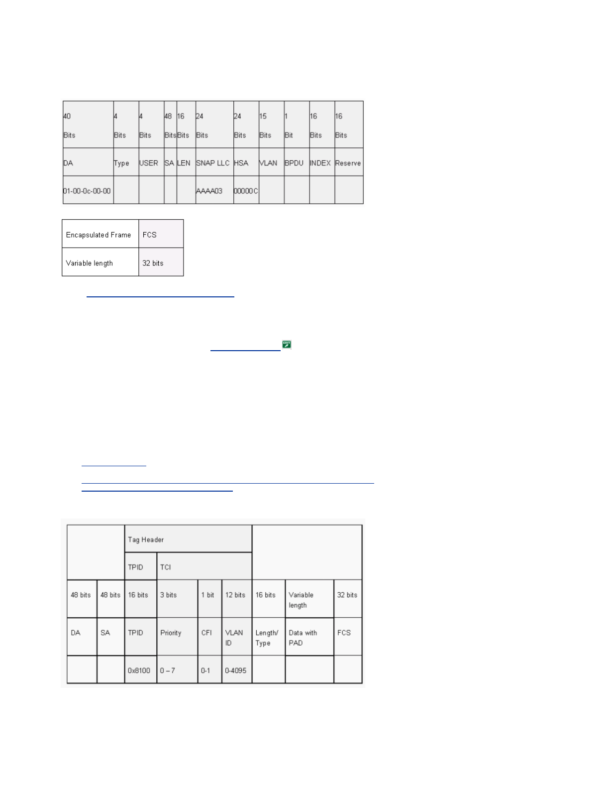
Cisco has a reserved range of Ethernet MAC and protocol addresses, as the table in this section shows. This
document covers each reserved address in detail, but this table provides a summary, for convenience:
1 SNAP = Subnetwork Access Protocol.
2 HDLC = High-Level Data Link Control.
3 PAgP = Port Aggregation Protocol.
4 PVST+ = Per VLAN Spanning Tree+ and RPVST+ = Rapid PVST+.
5 UDLD = UniDirectional Link Detection.
6 DTP = Dynamic Trunking Protocol.
7 DSAP = destination service access point.
8 SSAP = source service access point.
9 ISL = Inter-Switch Link.
10 VTP = VLAN Trunk Protocol.
The majority of Cisco control protocols use an IEEE 802.3 SNAP encapsulation, which includes Logical Link Control
(LLC) 0xAAAA03 and Organizational Unique Identifier (OUI) 0x00000C. You can see this on a LAN analyzer trace.
These protocols assume point-to-point connectivity. Note that the deliberate use of multicast destination addresses
enables two Catalyst switches to transparently communicate over non-Cisco switches. Devices that do not
understand and intercept the frames simply flood them. However, point-to-multipoint connections through
multivendor environments can result in inconsistent behavior. In general, avoid point-to-multipoint connections
through multivendor environments. These protocols terminate at Layer 3 routers and function only within a switch
domain. These protocols receive prioritization over user data by ingress application-specific integrated circuit (ASIC)
processing and scheduling.
Now the discussion turns to the SA. Switch protocols use a MAC address that is taken from a bank of available
addresses. An EPROM on the chassis provides the bank of available addresses. Issue the show module command
in order to display the address ranges that are available to each module for the sourcing of traffic such as STP bridge
protocol data units (BPDUs) or ISL frames. This is a sample command output:
Feature SNAP1 HDLC2
Protocol Type Destination
Multicast MAC
PAgP3 0x0104 01-00-0c-cc-cc-cc
PVST+, RPVST+4 0x010b 01-00-0c-cc-cc-cd
VLAN bridge 0x010c 01-00-0c-cd-cd-ce
UDLD5 0x0111 01-00-0c-cc-cc-cc
CDP 0x2000 01-00-0c-cc-cc-cc
DTP6 0x2004 01-00-0c-cc-cc-cc
STP UplinkFast 0x200a 01-00-0c-cd-cd-cd
IEEE spanning tree
802.1D N/A—DSAP7 42
SSAP8 42 01-80-c2-00-00-00
ISL9 N/A 01-00-0c-00-00-00
VTP10 0x2003 01-00-0c-cc-cc-cc
IEEE Pause 802.3x N/A—DSAP 81 SSAP
80 01-80-C2-00-00-
00>0F

>show module
…
Mod MAC-Address(es) Hw Fw Sw
--- -------------------------------------- ------ ---------- -----------------
1 00-01-c9-da-0c-1e to 00-01-c9-da-0c-1f 2.2 6.1(3) 6.1(1d)
00-01-c9-da-0c-1c to 00-01-c9-da-0c-1
00-d0-ff-88-c8-00 to 00-d0-ff-88-cb-ff
!--- These are the MACs for sourcing traffic.
VLAN 1
VLAN 1 has a special significance in Catalyst networks.
When trunking, the Catalyst Supervisor Engine always uses the default VLAN, VLAN 1, in order to tag a number of
control and management protocols. Such protocols include CDP, VTP, and PAgP. All switch ports, which includes
the internal sc0 interface, are configured by default to be members of VLAN 1. All trunks carry VLAN 1 by default.
These definitions are necessary in order to help clarify some well-used terms in Catalyst networking:
-The management VLAN is where sc0 resides for CatOS and low-end switches. You can change this VLAN.
Bear this in mind when you are interworking both CatOS and Cisco IOS switches.
-The native VLAN is the VLAN to which a port returns when it is not trunking. Also, the native VLAN is the
untagged VLAN on an IEEE 802.1Q trunk.
There are several good reasons to tune a network and alter the behavior of ports in VLAN 1:
-When the diameter of VLAN 1, like any other VLAN, gets large enough to be a risk to stability, particularly
from an STP perspective, you need to prune back the VLAN. See the Switch Management Interface and
Native VLAN section for details.
-You need to keep the control plane data on VLAN 1 separate from the user data in order to simplify
troubleshooting and maximize the available CPU cycles. Avoid Layer 2 loops in VLAN 1 when you design
multilayer campus networks without STP. In order to avoid the Layer 2 loops, manually clear VLAN 1 from
trunk ports.
In summary, note this information about trunks:
-CDP, VTP, and PAgP updates are always forwarded on trunks with a VLAN 1 tag. This is the case even if
VLAN 1 has been cleared from the trunks and is not the native VLAN. If you clear VLAN 1 for user data, the
action has no impact on control plane traffic that is still sent with the use of VLAN 1.
-On an ISL trunk, DTP packets are sent on VLAN1. This is the case even if VLAN 1 has been cleared from the
trunk and is no longer the native VLAN. On an 802.1Q trunk, DTP packets are sent on the native VLAN. This
is the case even if the native VLAN has been cleared from the trunk.
-In PVST+, the 802.1Q IEEE BPDUs are forwarded untagged on the common Spanning Tree VLAN 1 for
interoperability with other vendors, unless VLAN 1 has been cleared from the trunk. This is the case
regardless of the native VLAN configuration. Cisco PVST+ BPDUs are sent and tagged for all other VLANs.
See the Spanning Tree Protocol section for more details.
-802.1s Multiple Spanning Tree (MST) BPDUs are always sent on VLAN 1 on both ISL and 802.1Q trunks.
This applies even when VLAN 1 has been cleared from the trunks.
-Do not clear or disable VLAN 1 on trunks between MST bridges and PVST+ bridges. But, in the case that
VLAN 1 is disabled, the MST bridge must become root in order for all VLANs to avoid the MST bridge
placement of its boundary ports in the root-inconsistent state. Refer to Understanding Multiple Spanning Tree
Protocol (802.1s) for details.
Standard Features
This section of the document focuses on basic switching features that are common to any environment. Configure
these features on all Cisco IOS Software Catalyst switching devices in the customer network.
VLAN Trunk Protocol
Purpose
A
VTP domain, which is also called a VLAN management domain, is made up of one or more interconnected
switches via a trunk that share the same VTP domain name. VTP is designed to allow users to make VLAN
configuration changes centrally on one or more switches. VTP automatically communicates the changes to all the
other switches in the (network) VTP domain. You can configure a switch to be in only one VTP domain. Before you
create VLANs, determine the VTP mode that is to be used in the network.
Operational Overview

VTP is a Layer 2 messaging protocol. VTP manages the addition, deletion, and rename of VLANs on a network-wide
basis in order to maintain VLAN configuration consistency. VTP minimizes misconfigurations and configuration
inconsistencies that can result in a number of problems. The problems include duplicate VLAN names, incorrect
VLAN-type specifications, and security violations.
By default, the switch is in VTP server mode and is in the no-management domain state. These default settings
change when the switch receives an advertisement for a domain over a trunk link or when a management domain is
configured.
VTP protocol communicates between switches with the use of a well-known Ethernet destination multicast MAC (01-
00-0c-cc-cc-cc) and SNAP HDLC protocol type 0x2003. Similar to other intrinsic protocols, VTP also uses an IEEE
802.3 SNAP encapsulation, which includes LLC 0xAAAA03 and OUI 0x00000C. You can see this on a LAN analyzer
trace. VTP does not work over nontrunk ports. Therefore, messages cannot be sent until DTP has brought the trunk
up. In other words, VTP is a payload of ISL or 802.1Q.
Message types include:
-Summary advertisements every 300 seconds (sec)
-Subset advertisements and request advertisements when there are changes
-Joins when VTP pruning is enabled
The VTP configuration revision number is incremented by one with every change on a server, and that table
propagates across the domain.
A
t the deletion of a VLAN, ports that were once a member of the VLAN enter an inactive state. Similarly, if a
switch in client mode is unable to receive the VTP VLAN table at bootup, either from a VTP server or another VTP
client, all ports in VLANs other than the default VLAN 1 are deactivated.
You can configure most Catalyst switches to operate in any one of these VTP modes:
-Server—In VTP server mode, you can:
Create VLANs
Modify VLANs
Delete VLANs
Specify other configuration parameters, such as VTP version and VTP pruning, for the entire VTP
domain
VTP servers advertise their VLAN configuration to other switches in the same VTP domain. VTP servers also
synchronize their VLAN configuration with other switches on the basis of advertisements that are received
over trunk links. VTP server is the default mode.
-Client—VTP clients behave in the same way as VTP servers. But you cannot create, change, or delete
VLANs on a VTP client. Moreover, the client does not remember the VLAN after a reboot because no VLAN
information is written in NVRAM.
-Transparent—VTP transparent switches do not participate in VTP. A VTP transparent switch does not
advertise its VLAN configuration and does not synchronize its VLAN configuration on the basis of received
advertisements. But, in VTP version 2, transparent switches do forward VTP advertisements that the switches
receive out their trunk interfaces.
1 Cisco IOS Software does not have the option to disable VTP with use of the off mode.
This table is a summary of the initial configuration:
Feature Server Client Transparent Off1
Source VTP
messages Yes Yes No —
Listen to VTP
messages Yes Yes No —
Create VLANs Yes No Yes (locally significant
only) —
Remember VLANs Yes No Yes (locally significant
only) —
Feature Default Value
VTP Domain Name Null
VTP Mode Server
VTP Version Version 1 is Enabled
VTP Pruning Disabled

In VTP transparent mode, VTP updates are simply ignored. The well-known VTP multicast MAC address is removed
from the system CAM that is normally used to pick up control frames and direct them to the Supervisor Engine.
Because the protocol uses a multicast address, the switch in transparent mode or another vendor switch simply
floods the frame to other Cisco switches in the domain.
VTP version 2 (VTPv2) includes the functional flexibility that this list describes. But, VTPv2 is not interoperable with
VTP version 1 (VTPv1):
-Token Ring support
-Unrecognized VTP information support—Switches now propagate values that they cannot parse.
-Version-dependent transparent mode—Transparent mode no longer checks the domain name. This enables
support of more than one domain across a transparent domain.
-Version number propagation—If VTPv2 is possible on all switches, all switches can be enabled with the
configuration of a single switch.
Refer to Understanding VLAN Trunk Protocol (VTP) for more information.
VTP Operation in Cisco IOS Software
Configuration changes in CatOS are written to NVRAM immediately after a change is made. In contrast, Cisco IOS
Software does not save configuration changes to NVRAM unless you issue the copy run start command. VTP client
and server systems require VTP updates from other VTP servers to be immediately saved in NVRAM without user
intervention. The VTP update requirements are met by the default CatOS operation, but the Cisco IOS Software
update model requires an alternative update operation.
For this alteration, a VLAN database was introduced into Cisco IOS Software for the Catalyst 6500 as a method to
immediately save VTP updates for VTP clients and servers. In some versions of software, this VLAN database is in
the form of a separate file in NVRAM, called the vlan.dat file. Check your version of software in order to determine if
a backup of the VLAN database is required. You can view VTP/VLAN information that is stored in the vlan.dat file for
the VTP client or VTP server if you issue the show vtp status command.
The entire VTP/VLAN configuration is not saved to the startup config file in NVRAM when you issue the copy run
start command on these systems. This does not apply to systems that run as VTP transparent. VTP transparent
systems save the entire VTP/VLAN configuration to the startup config file in NVRAM when you issue the copy run
start command.
In Cisco IOS Software releases that are earlier than Cisco IOS Software Release 12.1(11b)E, you can only configure
VTP and VLANs via the VLAN database mode. VLAN database mode is a separate mode from the global
configuration mode. The reason for this configuration requirement is that, when you configure the device in VTP
mode server or VTP mode client, VTP neighbors can update the VLAN database dynamically via VTP
advertisements. You do not want these updates to automatically propagate to the configuration. Therefore, the VLAN
database and the VTP information are not stored in the main configuration, but are stored in NVRAM in a file with the
name vlan.dat.
This example shows how to create an Ethernet VLAN in VLAN database mode:
Switch#vlan database
Switch(vlan)#vlan 3
VLAN 3 added:
Name: VLAN0003
Switch(vlan)#exit
APPLY completed.
Exiting....
In Cisco IOS Software Release 12.1(11b)E and later, you can configure VTP and VLANs via VLAN database mode
or via the global configuration mode. In VTP mode server or VTP mode transparent, the configuration of VLANs still
updates the vlan.dat file in the NVRAM. However, these commands are not saved in the configuration. Therefore, the
commands do not show in the running configuration.
Refer to the VLAN Configuration in Global Configuration Mode section of the document Configuring VLANs for more
information.
This example shows how to create an Ethernet VLAN in global configuration mode and how to verify the
configuration:
Switch#configure terminal
Switch(config#vtp mode transparent
Setting device to VTP TRANSPARENT mode.
Switch(config#vlan 3
Switch(config-vlan)#end
Switch#
OR
Switch#vlan database
Switch(vlan#vtp server
Switch device to VTP SERVER mode.
Switch(vlan#vlan 3

Switch(vlan#exit
APPLY completed.
Exiting....
Switch#
Note: The VLAN configuration is stored in the vlan.dat file, which is stored in nonvolatile memory. In order to perform
a complete backup of your configuration, include the vlan.dat file in the backup along with the configuration. Then, if
the entire switch or the Supervisor Engine module requires replacement, the network administrator must upload both
of these files in order to restore the complete configuration:
-The vlan.dat file
-The configuration file
VTP and Extended VLANs
The Extended System ID feature is used to enable extended-range VLAN identification. When Extended System ID
is enabled, it disables the pool of MAC addresses used for the VLAN spanning tree, and leaves a single MAC
address that identifies the switch. The Catalyst IOS Software Release 12.1(11b)EX and 12.1(13)E introduce
Extended System ID support for Catalyst 6000/6500 to support 4096 VLANs in compliance with the IEEE 802.1Q
standard. This feature is introduced in Cisco IOS Software Release12.1(12c)EW for Catalyst 4000/4500 switches.
These VLANs are organized into several ranges, each of which can be used differently. Some of these VLANs are
propagated to other switches in the network when you use the VTP. The extended-range VLANs are not propagated,
so you must configure extended-range VLANs manually on each network device. This Extended System ID feature is
equivalent to MAC Address Reduction feature in Catalyst OS.
This table describes the VLAN ranges:
Switch protocols use a MAC address taken from a bank of available addresses that an EPROM provides on the
chassis as part of bridge identifiers for VLANs that run under PVST+ and RPVST+. Catalyst 6000/6500 and Catalyst
4000/4500 switches support either 1024 or 64 MAC addresses that depend on the chassis type.
Catalyst switches with 1024 MAC addresses do not enable Extended System ID by default. MAC addresses are
allocated sequentially, with the first MAC address in the range assigned to VLAN 1, the second MAC address in the
range assigned to VLAN 2, and so on. This enables the switches to support 1024 VLANs and each VLAN uses a
unique bridge identifier.
1 Chassis with 64 MAC addresses enables Extended System ID by default, and the feature can not be disabled.
Refer to the Understanding the Bridge ID section of Configuring STP and IEEE 802.1s MST for more information.
For Catalyst series switches with 1024 MAC addresses, to enable Extended System ID allows support of 4096
VLANs that run under PVST+ or 16 MISTP instances to have unique identifiers without the increase of the number of
MAC addresses that are required on the switch. Extended System ID reduces the number of MAC addresses that
are required by the STP from one per VLAN or MISTP instance to one per switch.
This figure shows the bridge identifier when Extended System ID is not enabled. The bridge identifier consists of a 2-
byte bridge priority and a 6-byte MAC address.
VLANs Range Usage Propagated
by VTP?
0, 4095 Reserved For system use only. You
cannot see or use these
VLANs. —
1Normal Cisco default. You can use
this VLAN, but you cannot
delete it. Yes
2–1001 Normal For Ethernet VLANs. You
can create, use, and delete
these VLANs. Yes
1002–
1005 Normal Cisco defaults for FDDI and
Token Ring. You cannot
delete VLANs 1002–1005. Yes
1006–
4094 Reserved For Ethernet VLANs only. No
Chassis Type Chassis
Address
WS-C4003-S1, WS-C4006-S2 1024
WS-C4503, WS-C4506 641
WS-C6509-E,WS-C6509, WS-C6509-NEB, WS-
C6506-E, WS-C6506, WS-C6009, WS-C6006, OSR-
7609-AC, OSR-7609-DC 1024
WS-C6513, WS-C6509-NEB-A, WS-C6504-E, WS-
C6503-E, WS-C6503, CISCO7603, CISCO7606,
CISCO7609, CISCO7613 641

Extended System ID modifies the Spanning Tree Protocol (STP) Bridge Identifier portion of the Bridge Protocol Data
Units (BPDU). The original 2-byte priority field is split into 2-fields; A 4-bit bridge priority field and a 12-bit system-ID
extension that allows for Vlan numbering of 0-4095.
When Extended System ID is enabled on Catalyst switches to leverage extended range VLANs, it needs to be
enabled on all switches within the same STP domain. This is necessary to keep the STP root calculations on all
switches consistent. Once Extended System ID is enabled, the root bridge priority becomes a multiple of 4096 plus
the VLAN ID. The switches without Extended System ID can possibly claim root inadvertently as they have a finer
granularity in the selection of its bridge ID.
While it is recommended to maintain consistent Extended System ID configuration within the same STP domain, it is
not practical to enforce Extended System ID on all network devices when you introduce new chassis with 64 MAC
address to the STP domain. But, it is important to understand when two systems are configured with the same
Spanning-tree priority, the system without Extended System ID has a better Spanning-tree priority. Issue this
command in order to enable Extended System ID configuration:
spanning-tree extend system-id
The internal VLANs are allocated in ascending order, starting at VLAN 1006. It is recommended to assign the user
VLANs as close to VLAN 4094 as possible in order to avoid conflicts between the user VLANs and the internal
VLANs. Issue the command show vlan internal usage on a switch in order to display the internally assigned
VLANs.
Switch#show vlan internal usage
VLAN Usage
---- --------------------
1006 online diag vlan0
1007 online diag vlan1
1008 online diag vlan2
1009 online diag vlan3
1010 online diag vlan4
1011 online diag vlan5
1012 PM vlan process (trunk tagging)
1013 Port-channel100
1014 Control Plane Protection
1015 L3 multicast partial shortcuts for VPN 0
1016 vrf_0_vlan0
1017 Egress internal vlan
1018 Multicast VPN 0 QOS vlan
1019 IPv6 Multicast Egress multicast
1020 GigabitEthernet5/1
1021 ATM7/0/0
1022 ATM7/0/0.1
1023 FastEthernet3/1
1024 FastEthernet3/2
------deleted------
In Native IOS, vlan internal allocation policy descending can be configured so the internal VLANs are allocated in
descending order. The CLI equivalent for CatOS software is not officially supported.
vlan internal allocation policy descending
Cisco Configuration Recommendation
VLANs can be created when a Catalyst 6500/6000 is in VTP server mode, even without VTP domain name.
Configure the VTP domain name first, before you configure VLANs on Catalyst 6500/6000 switches that run Cisco
IOS system software. Configuration in this order maintains consistency with other Catalyst switches that run CatOS.
There is no specific recommendation on whether to use VTP client/server modes or VTP transparent mode.
Some customers prefer the ease of management of VTP client/server mode, despite some considerations that this
section notes. The recommendation is to have two server mode switches in each domain for redundancy, typically
the two distribution-layer switches. Set the rest of the switches in the domain to client mode. When you implement
client/server mode with the use of VTPv2, remember that a higher revision number is always accepted in the same
VTP domain. If a switch that is configured in either VTP client or server mode is introduced into the VTP domain and
has a higher revision number than the VTP servers that exists, this overwrites the VLAN database within the VTP
domain. If the configuration change is unintentional and VLANs are deleted, this overwrite can cause a major outage
in the network. In order to ensure that client or server switches always have a configuration revision number that is
lower than that of the server, change the client VTP domain name to something other than the standard name, and

then revert back to the standard. This action sets the configuration revision on the client to 0.
There are pros and cons to the VTP ability to make changes easily on a network. Many enterprises prefer a cautious
approach and use VTP transparent mode for these reasons:
-This practice encourages good change control because the requirement to modify a VLAN on a switch or
trunk port must be considered one switch at a time.
-VTP transparent mode limits the risk of an administrator error, such as accidental deletion of a VLAN. Such
errors can impact the entire domain.
-VLANs can be pruned from trunks down to switches that do not have ports in the VLAN. This results in frame
flooding to be more bandwidth-efficient. Manual pruning also has a reduced spanning-tree diameter. See the
Dynamic Trunking Protocol section for more information. A per-switch VLAN configuration also encourages
this practice.
-There is no risk of the introduction into the network of a new switch with a higher VTP revision number that
overwrites the entire domain VLAN configuration.
-Cisco IOS Software VTP transparent mode is supported in Campus Manager 3.2, which is part of
CiscoWorks2000. The earlier restriction that requires you to have at least one server in a VTP domain has
been removed.
Other Options
VTPv2 is a requirement in Token Ring environments, where client/server mode is highly recommended.
The Cisco Configuration Recommendation section of this document advocates the benefits of pruning VLANs in
order to reduce unnecessary frame flooding. The vtp pruning command prunes VLANs automatically, which stops
the inefficient flooding of frames where they are not needed.
Note: Unlike manual VLAN pruning, automatic pruning does not limit the spanning-tree diameter.
The IEEE has produced a standards-based architecture in order to accomplish VTP-similar results. As a member of
the 802.1Q Generic Attribute Registration Protocol (GARP), the Generic VLAN Registration Protocol (GVRP) allows
VLAN management interoperability between vendors. However, GVRP is outside the scope of this document.
Note: Cisco IOS Software does not have VTP off mode capability, and it only supports VTPv1 and VTPv2 with
pruning.
Fast Ethernet Autonegotiation
Purpose
A
utonegotiation is an optional function of the IEEE 802.3u Fast Ethernet (FE) standard. Autonegotiation enables
devices to automatically exchange information about speed and duplex abilities over a link. Autonegotiation operates
at Layer 1 (L1). The function is targeted at ports that are allocated to areas where transient users or devices connect
to a network. Examples include access layer switches and hubs.
Operational Overview
A
utonegotiation uses a modified version of the link integrity test for 10BASE-T devices to negotiate speed and
exchange other autonegotiation parameters. The original 10BASE-T link integrity test is referred to as Normal Link
Pulse (NLP). The modified version of the link integrity test for 10/100-Mbps autonegotiation is referred to as Fast Link
Pulse (FLP). The 10BASE-T devices expect a burst pulse every 16 (+/-8) milliseconds (ms) as part of the link
integrity test. FLP for 10/100-Mbps autonegotiation sends these bursts every 16 (+/-8) ms with the additional pulses
every 62.5 (+/-7) microseconds. The pulses within the burst sequence generate code words that are used for
compatibility exchanges between link partners.
In 10BASE-T, a link pulse is sent out whenever a station comes up. This is a single pulse that is sent every 16 ms.
The 10BASE-T devices also send a link pulse every 16 ms when the link is idle. These link pulses are also called
heartbeat or NLP.
VTP Commands Comments
vtp domain name CDP checks the name in order to help prevent
miscabling between the domains. Domain
names are case sensitive.
vtp mode {server
| client |
transparent} VTP operates in one of the three modes.
vlan vlan_number This creates a VLAN with the ID provided.
switchport trunk
allowed
vlan_range
This is an interface command that enables
trunks to carry VLANs where needed. The
default is all VLANs.
switchport trunk
pruning
vlan_range
This is an interface command that limits the
STP diameter by manual pruning, such as on
trunks from the distribution layer to access
layer, where the VLAN does not exist. By
default, all VLANs are prune-eligible.

A
100BASE-T device sends out FLP. This pulse is sent out as a burst instead of one pulse. The burst is completed
within 2 ms and is again repeated every 16 ms. Upon initialization, the device transmits a 16-bit FLP message to the
link partner for the negotiation of speed, duplex, and flow control. This 16-bit message is sent repeatedly until the
message is acknowledged by the partner.
Note: As per the IEEE 802.3u specification, you cannot manually configure one link partner for 100-Mbps full duplex
and still autonegotiate to full duplex with the other link partner. An attempt to configure one link partner for 100-Mbps
full duplex and the other link partner for autonegotiation results in a duplex mismatch. Duplex mismatch results
because one link partner autonegotiates and does not see any autonegotiation parameters from the other link
partner. The first link partner then defaults to half duplex.
A
ll the Catalyst 6500 Ethernet switching modules support 10/100 Mbps and half duplex or full duplex. Issue the
show interface capabilities command in order to verify this functionality on other Catalyst switches.
One of the most common causes of performance issues on 10/100-Mbps Ethernet links occurs when one port on the
link operates at half duplex while the other port operates at full duplex. This situation occasionally happens when you
reset one or both ports on a link and the autonegotiation process does not result in the same configuration for both
link partners. The situation also happens when you reconfigure one side of a link and forget to reconfigure the other
side. You can avoid the need to place performance-related support calls if you:
-Create a policy that requires the configuration of ports for the required behavior for all nontransient devices
-Enforce the policy with adequate change control measures
Typical symptoms of the performance issue increase frame check sequence (FCS), cyclic redundancy check (CRC),
alignment, or runt counters on the switch.
In half duplex mode, you have one pair of receive and one pair of transmit wires. Both of the wires cannot be used at
the same time. The device cannot transmit when there is a packet on the receive side.
In full duplex mode, you have the same pair of receive and transmit wires. However, both can be used at the same
time because the Carrier Sense and Collision Detect functions have been disabled. The device can transmit and
receive at the same time.
Therefore, a half-duplex to full-duplex connection works, but there is a large number of collisions at the half-duplex
side that result in poor performance. The collisions occur becuse the device that is configured as full duplex can
transmit at the same time that the device receives data.
The documents in this list discuss autonegotiation in detail. These documents explain how autonegotiation works and
discuss various configuration options:
-Configuring and Troubleshooting Ethernet 10/100/1000Mb Half/Full Duplex Auto-Negotiation
-Troubleshooting Cisco Catalyst Switches to NIC Compatibility Issues
A
common misconception about autonegotiation is that it is possible to manually configure one link partner for 100-
Mbps full duplex and autonegotiate to full duplex with the other link partner. In fact, an attempt to do this results in a
duplex mismatch. This is a consequence because one link partner autonegotiates, does not see any autonegotiation
parameters from the other link partner, and defaults to half duplex.
Most Catalyst Ethernet modules support 10/100 Mbps and half/full duplex. However, you can confirm this if you issue
the show interface mod/port capabilities command.
FEFI
Far end fault indication (FEFI) protects 100BASE-FX (fiber) and Gigabit interfaces, while autonegotiation protects
100BASE-TX (copper) against physical layer/signaling-related faults.
A
far end fault is an error in the link that one station can detect while the other station cannot. A disconnected
transmit wire is an example. In this example, the sending station still receives valid data and detects that the link is
good via the link integrity monitor. The sending station cannot, however, detect that the other station does not
receive the transmission. A 100BASE-FX station that detects such a remote fault can modify its transmitted IDLE
stream in order to send a special bit pattern in order to inform the neighbor of the remote fault. The special bit pattern
is referred to as the FEFI-IDLE pattern. The FEFI-IDLE pattern subsequently triggers a shutdown of the remote
port (errDisable). See the UniDirectional Link Detection section of this document for further information on fault
protection.
These modules/hardware support FEFI:
-Catalyst 6500/6000 and 4500/4000:
All 100BASE-FX modules and GE modules
Cisco Infrastructure Port Recommendation
Whether to configure autonegotiation on 10/100-Mbps links or to hard code speed and duplex ultimately depends on
the type of link partner or end device that you have connected to a Catalyst switch port. Autonegotiation between end
devices and Catalyst switches generally works well, and Catalyst switches are compliant with the IEEE 802.3u
specification. However, when network interface card (NIC) or vendor switches do not conform exactly, problems can
result. In addition, vendor-specific advanced features that are not described in the IEEE 802.3u specification for
10/100-Mbps autonegotiation can cause hardware incompatibility and other issues. These types of advanced
features include autopolarity and cabling integrity. This document provides an example:

-Field Alert: Performance Issue with Intel Pro/1000T NICs connecting to CAT4K/6K
In some situations, you need to set host, port speed, and duplex. In general, complete these basic troubleshooting
steps:
-Make sure that autonegotiation is configured on both sides of the link or that hard coding is configured on
both sides.
-Check the release notes for common caveats.
-Verify the version of the NIC driver or operating system that you run. The latest driver or patch is often
required.
A
s a rule, first use autonegotiation for any type of link partner. There are obvious benefits to the configuration of
autonegotiation for transient devices such as laptops. Autonegotiation also works well with other devices, for
example:
-With nontransient devices such as servers and fixed workstations
-From switch to switch
-From switch to router
But, for some of the reasons that this section mentions, negotiation issues can arise. Refer to Configuring and
Troubleshooting Ethernet 10/100/1000Mb Half/Full Duplex Auto-Negotiation for basic troubleshooting steps in these
cases.
Disable autonegotiation for:
-Ports that support network infrastructure devices such as switches and routers
-Other nontransient end systems such as servers and printers
A
lways hard code the speed and duplex settings for these ports.
Manually configure these 10/100-Mbps link configurations for speed and duplex, which are usually 100-Mbps full
duplex:
-Switch-to-switch
-Switch-to-server
-Switch-to-router
If the port speed is set to auto on a 10/100-Mbps Ethernet port, both the speed and duplex are autonegotiated. Issue
this interface command in order to set the port to auto:
Switch(config)#interface fastethernet slot/port
Switch(config-if)#speed auto
!--- This is the default.
Issue these interface commands in order to configure speed and duplex:
Switch(config)#interface fastethernet slot/port
Switch(config-if)#speed {10 | 100 | auto}
Switch(config-if)#duplex {full | half}
Cisco Access Port Recommendations
End users, mobile workers, and transient hosts need autonegotiation in order to minimize management of these
hosts. You can make autonegotiation work with Catalyst switches as well. The latest NIC drivers are often required.
Issue these global commands in order to enable the autonegotiation of speed for the port:
Switch(config)#interface fastethernet slot/port
Switch(config-if)#speed auto
Note: If you set the port speed to auto on a 10/100-Mbps Ethernet port, both speed and duplex are autonegotiated.
You cannot change the duplex mode of autonegotiation ports.
When NICs or vendor switches do not conform exactly to the IEEE specification 802.3u, problems can result. In
addition, vendo
r
-specific advanced features that are not described in the IEEE 802.3u specification for 10/100-Mbps

autonegotiation can cause hardware incompatibility and other issues. Such advanced features include autopolarity
and cabling integrity.
Other Options
When autonegotiation is disabled between switches, Layer 1 fault indication can also be lost for certain problems.
Use Layer 2 protocols to augment failure detection such as aggressive UDLD.
A
utonegotiation does not detect these situations, even when autonegotiation is enabled:
-The ports get stuck and do not receive or transmit
-One side of the line is up but the other side has gone down
-Fiber cables are miswired
A
utonegotiation does not detect these problems because they are not at the physical layer. The problems can lead to
STP loops or traffic black holes.
UDLD can detect all these cases and errdisable both the ports on the link, if UDLD is configured on both ends. In this
way, UDLD prevents STP loops and traffic black holes.
Gigabit Ethernet Autonegotiation
Purpose
Gigabit Ethernet (GE) has an autonegotiation procedure that is more extensive than the procedure that is used for
10/100-Mbps Ethernet (IEEE 802.3z). With GE ports, autonegotiation is used to exchange:
-Flow-control parameters
-Remote fault information
-Duplex information
Note: Catalyst series GE ports only support full duplex mode.
IEEE 802.3z has been superseded by IEEE 802.3:2000 specs. Refer to the Local and Metropolitan Area Networks +
Drafts (LAN/MAN 802s) Standards Subscription for more information.
Operational Overview
Unlike autonegotiation with 10/100-Mbps FE, GE autonegotiation does not involve the negotiation of port speed.
A
lso, you cannot issue the set port speed command in order to disable autonegotiation. GE port negotiation is
enabled by default, and the ports on both ends of a GE link must have the same setting. The link does not come up if
the ports at each end of the link are set inconsistently, which means that the exchanged parameters are different.
For example, assume that there are two devices, A and B. Each device can have autonegotiation enabled or
disabled. This is a table that has possible configurations and their respective link states:
In GE, synchronization and autonegotiation (if they are enabled) are performed upon link startup through the use of a
special sequence of reserved link code words.
Note: There is a dictionary of valid words, and not all possible words are valid in GE.
The life of a GE connection can be characterized in this way:
A
loss of synchronization means that the MAC detects a link down. Loss of synchronization applies whether
autonegotiation is enabled or disabled. Synchronization is lost under certain failed conditions, such as the receipt of
three invalid words in succession. If this condition persists for 10 ms, a sync fail condition is asserted and the link is
changed to the link_down state. After synchronization is lost, another three consecutive valid idles are necessary
in order to resynchronize. Other catastrophic events, such as a loss of receive (Rx) signal, causes a link-down event.
A
utonegotiation is a part of the linkup process. When the link is up, autonegotiation is over. However, the switch still
monitors the status of the link. If autonegotiation is disabled on a port, the autoneg phase is no longer an option.
The GE copper specification (1000BASE-T) does support autonegotiation via a Next Page Exchange. Next Page
Negotiation B Enabled B Disabled
A Enabled up on both sides A down, B up
A Disabled A up, B down up on both sides

Exchange allows autonegotiation for 10/100/1000-Mbps speeds on copper ports.
Note: However, the GE fiber specification only makes provisions for the negotiation of duplex, flow control, and
remote fault detection. GE fiber ports do not negotiate port speed. Refer to sections 28 and 37 of the IEEE 802.3-
2002 specification for more information on autonegotiation.
Synchronization restart delay is a software feature that controls the total autonegotiation time. If autonegotiation is
not successful within this time, the firmware restarts autonegotiation in case there is a deadlock. The sync-restart-
delay command only has an effect when autonegotiation is set to enable.
Cisco Infrastructure Port Recommendation
The configuration of autonegotiation is much more critical in a GE environment than in a 10/100 Mbps environment.
Only disable autonegotiation in these situations:
-On switch ports that attach to devices that are not able to support negotiation
-Where connectivity issues arise from interoperability issues
Enable Gigabit negotiation on all switch-to-switch links and, generally, on all GE devices. The default value on
Gigabit interfaces is autonegotiation. Still, issue this command in order to ensure that autonegotiation is enabled:
switch(config)#interface type slot/port
switch(config-If)#no speed
!--- This command sets the port to autonegotiate Gigabit parameters.
One known exception is when you connect to a Gigabit Switch Router (GSR) that runs Cisco IOS Software that is
earlier than Cisco IOS Software Release 12.0(10)S, the release that added flow control and autonegotiation. In this
case, turn off those two features. If you do not turn off those features, the switch port reports not connected and the
GSR reports errors. This is a sample interface command sequence:
flowcontrol receive off
flowcontrol send off
speed nonegotiate
Cisco Access Port Recommendations
Since FLPs can vary between vendors, you must look at switch-to-server connections on a case-by-case basis.
Cisco customers have encountered some issues with Gigabit negotiation on Sun, HP, and IBM servers. Have all
devices use the Gigabit autonegotiation unless the NIC vendor specifically states otherwise.
Other Options
Flow control is an optional part of the 802.3x specification. Flow control must be negotiated if you use it. Devices can
or cannot possibly be able to send and/or respond to a PAUSE frame (well-known MAC 01-80-C2-00-00-00 0F). And
devices can possibly not agree to the flow-control request of the far-end neighbor. A port with an input buffer that
begins to fill up sends a PAUSE frame to the link partner. The link partner stops the transmission and holds any
additional frames in the link partner output buffers. This function does not solve any steady-state oversubscription
problem. But, the function effectively makes the input buffer larger by some fraction of the partner output buffer
throughout bursts.
The PAUSE function is designed to prevent the unnecessary discard of received frames by devices (switches,
routers, or end stations) because of buffer overflow conditions that short-term transient traffic overload causes. A
device under traffic overload prevents internal buffer overflow when the device sends a PAUSE frame. The PAUSE
frame contains a parameter that indicates the length of time for the full duplex partner to wait before the partner
sends more data frames. The partner that receives the PAUSE frame ceases to send data for the specified period.
When this timer expires, the station begins to send data frames again, from where the station left off.
A
station that issues a PAUSE can issue another PAUSE frame that contains a parameter of zero time. This action
cancels the remainder of the pause period. So, a newly received PAUSE frame overrides any PAUSE operation that
is currently in progress. Also, the station that issues the PAUSE frame can extend the PAUSE period. The station
issues another PAUSE frame that contains a nonzero time parameter before the expiration of the first PAUSE period.
This PAUSE operation is not rate-based flow control. The operation is a simple start-stop mechanism that allows the
device under traffic, the one that sent the PAUSE frame, a chance to reduce its buffer congestion.
The best use of this feature is on links between access ports and end hosts, where the host output buffer is
potentially as large as the virtual memory. Switch-to-switch use has limited benefits.
Issue these interface commands in order to control this on the switch ports:
flowcontrol {receive | send} {off | on | desired}
>show port flowcontrol

Port Send FlowControl Receive FlowControl RxPause TxPause
admin oper admin oper
----- -------- -------- -------- -------- ------- -------
6/1 off off on on 0 0
6/2 off off on on 0 0
6/3 off off on on 0 0
Note: All Catalyst modules respond to a PAUSE frame if negotiated. Some modules (for example, WS-X5410 and
WS-X4306) never send pause frames, even if they negotiate to do so, because they are nonblocking.
Dynamic Trunking Protocol
Purpose
In order to extend VLANs between devices, trunks temporarily identify and mark (link local) the original Ethernet
frames. This action enables the frames to be multiplexed over a single link. The action also ensures that separate
VLAN broadcast and security domains are maintained between switches. CAM tables maintain the frame to VLAN
mapping inside the switches.
Operational Overview
DTP is the second generation of Dynamic ISL (DISL). DISL only supported ISL. DTP supports both ISL and 802.1Q.
This support ensures that the switches at either end of a trunk agree on the different parameters of trunking frames.
Such parameters include:
-Configured encapsulation type
-Native VLAN
-Hardware capability
The DTP support also helps protect against the flooding of tagged frames by nontrunk ports, which is a potentially
serious security risk. DTP protects against such flooding because it ensures that ports and their neighbors are in
consistent states.
Trunking Mode
DTP is an Layer 2 protocol that negotiates configuration parameters between a switch port and its neighbor. DTP
uses another well-known multicast MAC address of 01-00-0c-cc-cc-cc and a SNAP protocol type of 0x2004. This
table describes the function on each of the possible DTP negotiation modes:
Mode Function DTP Frames
Transmitted? Final State
(Local Port)
Dynamic
Auto
(equivalent to
the mode Auto
in CatOS)
Makes the port
willing to
convert the link
to a trunk. The
port becomes a
trunk port if the
neighboring
port is set to on
or desirable
mode.
Yes, periodic Trunking
Trunk
(equivalent to
the mode ON in
CatOS)
Puts the port
into permanent
trunking
mode and
negotiates to
convert the link
into a trunk.
The port
becomes a
trunk port even
if the
neighboring
port does not
agree to the
change.
Yes, periodic Trunking,
unconditionally
Nonegotiate
Puts the port
into permanent
trunking
mode but does
not allow the
port to
generate DTP
frames. You
must manually
configure the
neighboring
port as a trunk
No Trunking,
unconditionally

Note: The ISL and 802.1Q encapsulation type can be set or negotiated.
In the default configuration, DTP assumes these characteristics on the link:
-Point-to-point connections and Cisco devices support 802.1Q trunk ports that are only point-to-point.
-Throughout DTP negotiation, the ports do not participate in STP. The port is added to STP only after the port
type becomes one of these three types:
Access
ISL
802.1Q
PAgP is the next process to run before the port participates in STP. PAgP is used for EtherChannel
autonegotation.
-VLAN 1 is always present on the trunk port. If the port is trunking in ISL mode, DTP packets are sent out on
VLAN 1. If the port is not trunking in ISL mode, the DTP packets are sent on the native VLAN (for 802.1Q
trunking or nontrunking ports).
-DTP packets transfer the VTP domain name, plus the trunk configuration and admin status. The VTP domain
name must match in order to get a negotiated trunk to come up. These packets are sent every second
throughout negotiation and every 30 seconds after negotiation. If a port in auto or desirable mode does
not detect a DTP packet within 5 minutes (min), the port is set as nontrunk.
Caution: You must understand that the modes trunk, nonegotiate, and access explicitly specify in
which state the port ends up. A bad configuration can lead to a dangerous/inconsistent state in which one side is
trunking and the other is not trunking.
Refer to Configuring ISL Trunking on Catalyst 5500/5000 and 6500/6000 Family Switches for more ISL details. Refer
to Trunking Between Catalyst 4500/4000, 5500/5000, and 6500/6000 Series Switches Using 802.1Q Encapsulation
with Cisco CatOS System Software for more 802.1Q details.
Encapsulation Type
ISL Operational Overview
ISL is a Cisco proprietary trunking protocol (VLAN tagging scheme). ISL has been in use for many years. In contrast,
802.1Q is much newer, but 802.1Q is the IEEE standard.
ISL completely encapsulates the original frame in a two-level tagging scheme. In this way, ISL is effectively a
tunneling protocol and, as an additional benefit, carries non-Ethernet frames. ISL adds a 26-byte header and a 4-
port in order to
establish a
trunk link. This
is useful for
devices that do
not support
DTP.
Dynamic
desirable
(CatOS
comparable
command is
desirable)
Makes the port
actively attempt
to convert the
link to a trunk
link. The port
becomes a
trunk port if the
neighboring
port is set to
on,
desirable, or
auto mode.
Yes, periodic
It ends up in
trunking
state only if the
remote mode is
on, auto, or
desirable.
Access
Puts the port
into permanent
non-
trunking
mode and
negotiates to
convert the link
into a nontrunk
link. The port
becomes a
nontrunk port
even if the
neighboring
port does not
agree to the
change.
No, in steady
state, but
transmits
informs in order
to speed up
remote-end
detection after a
change from
on.
Non-
trunking
byte FCS to the standard Ethernet frame. Ports that are configured to be trunks expect and handle the larger
Ethernet frames. ISL supports 1024 VLANs.
Frame Format – ISL Tag Is Shaded
Refer to InterSwitch Link and IEEE 802.1Q Frame Format for more information.
802.1Q Operational Overview
A
lthough the IEEE 802.1Q standard only pertains to Ethernet, the standard specifies much more than encapsulation
types. 802.1Q includes, among other Generic Attribute Registration Protocols (GARPs), spanning-tree
enhancements and 802.1p QoS tagging. Refer to IEEE Standards Online for more information
The 802.1Q frame format preserves the original Ethernet SA and DA. However, switches must now expect to receive
baby-giant frames, even on access ports where hosts can use tagging to express 802.1p user priority for QoS
signaling. The tag is 4 bytes. The 802.1Q Ethernet v2 frames are 1522 bytes, which is an IEEE 802.3ac working
group achievement. Also, 802.1Q supports numbering space for 4096 VLANs.
A
ll data frames that are transmitted and received are 802.1Q tagged, except for those data frames that are on the
native VLAN. In this case, there is an implicit tag that is based on the ingress switch port configuration. Frames on
the native VLAN are always transmitted untagged and are normally received untagged. However, these frames can
also be received tagged.
Refer to these documents for more information:
-VLAN Interoperability
-Trunking Between Catalyst 4500/4000, 5500/5000, and 6500/6000 Series Switches Using 802.1q
Encapsulation with Cisco CatOS System Software
802.1Q/802.1p Frame Format
Cisco Configuration Recommendation
One primary Cisco design principal is to strive for consistency in the network where consistency is possible. All
newer Catalyst products support 802.1Q and some only support 802.1Q, such as earlier modules in the Catalyst

4500/4000 and Catalyst 6500 series. Therefore, all new implementations need to follow this IEEE 802.1Q standard
and older networks need to gradually migrate from ISL.
Issue this interface commands in order to enable 802.1Q trunking on a particular port:
Switch(config)#interface type slot#/port#
Switch(config-if)#switchport
!--- Configure the interface as a Layer 2 port.
Switch(config-if)#switchport trunk encapsulation dot1q
The IEEE standard allows vendor interoperability. Vendor interoperability is advantageous in all Cisco environments
as new host 802.1p-capable NICs and devices become available. Although both ISL and 802.1Q implementations
are solid, the IEEE standard ultimately has greater field exposure and greater third-party support, which includes
support for network analyzers. Also, a minor consideration is that the 802.1Q standard also has a lower
encapsulation overhead than ISL.
For completeness, the implicit tagging on native VLANs creates a security consideration. The transmission of frames
from one VLAN, VLAN X, to another VLAN, VLAN Y, without a router is possible. The transmission can occur without
a router if the source port (VLAN X) is in the same VLAN as the native VLAN of an 802.1Q trunk on the same switch.
The workaround is to use a dummy VLAN for the native VLAN of the trunk.
Issue these interface commands in order to establish a VLAN as native (the default) for 802.1Q trunking on a
particular port:
Switch(config)#interface type slot#/port#
Switch(config-If)#switchport trunk native vlan 999
Because all newer hardware supports 802.1Q, have all new implementations follow the IEEE 802.1Q standard and
gradually migrate earlier networks from ISL. Until recently, many Catalyst 4500/4000 modules did not support ISL.
Therefore, 802.1Q is the only option for Ethernet trunking. Refer to the output of the show interface capabilities
command, or the show port capabilities command for CatOS. Because trunking support requires the appropriate
hardware, a module that does not support 802.1Q can never support 802.1Q. A software upgrade does not confer
support for 802.1Q. Most new hardware for the Catalyst 6500/6000 and Catalyst 4500/4000 switches supports both
ISL and 802.1Q.
If VLAN 1 is cleared from a trunk, as the Switch Management Interface and Native VLAN section discusses, although
no user data are transmitted or received, the NMP continues to pass control protocols on VLAN 1. Examples of
control protocols include CDP and VTP.
A
lso, as the VLAN 1 section discusses, CDP, VTP, and PAgP packets are always sent on VLAN 1 when trunking.
With the use of dot1q (802.1Q) encapsulation, these control frames are tagged with VLAN 1 if the switch native
VLAN is changed. If dot1q trunking to a router and the native VLAN is changed on the switch, a subinterface in VLAN
1 is necessary in order to receive the tagged CDP frames and provide the CDP neighbor visibility on the router.
Note: There is a potential security consideration with dot1q that the implicit tagging of the native VLAN causes. The
transmission of frames from one VLAN to another without a router can be possible. Refer to the Intrusion Detection
FAQ for further details. The workaround is to use a VLAN ID for the native VLAN of the trunk that is not used for
end-user access. In order to achieve this, the majority of Cisco customers simply leave VLAN 1 as the native VLAN
on a trunk and assign access ports to VLANs other than VLAN 1.
Cisco recommends an explicit trunk mode configuration of dynamic desirable at both ends. This mode is the
default mode. In this mode, network operators can trust syslog and command-line status messages that a port is up
and trunking. This mode is different from on mode, which can make a port appear up even though the neighbor is
misconfigured. In addition, desirable mode trunks provide stability in situations in which one side of the link cannot
become a trunk or drops the trunk state.
If the encapsulation type is negotiated between switches with the use of DTP, and ISL is chosen as the winner by
default if both ends support it, you must issue this interface command in order to specify dot1q1:
switchport trunk encapsulation dot1q
1 Certain modules that include WS-X6548-GE-TX and WS-X6148-GE-TX do not support ISL trunking. These
modules do not accept command switchport trunk encapsulation dot1q .
Note: Issue the switchport mode access command in order to disable trunks on a port. This disablement helps to
eliminate wasted negotiation time when host ports are brought up.
Switch(config-if)#switchport host
Other Options
A
nother common customer configuration uses dynamic desirable mode at the distribution layer and the simplest
default configuration (dynamic auto mode) at the access layer. Some switches, such as the Catalyst 2900XL,
Cisco IOS routers, or other vendor devices, do not currently support trunk negotiation via DTP. You can use

nonegotiate mode in order to set a port to trunk unconditionally with these devices. This mode can help
standardize on a common setting across the campus.
Cisco recommends nonegotiate when you connect to a Cisco IOS router. Throughout bridging, some DTP frames
that are received from a port that is configured with switchport mode trunk can return to the trunk port. Upon
reception of the DTP frame, the switch port tries to renegotiate unnecessarily. In order to renegotiate, the switch port
brings the trunk down and then up. If nonegotiate is enabled, the switch does not send DTP frames.
switch(config)#interface type slot#/port#
switch(config-if)#switchport mode dynamic desirable
!--- Configure the interface as trunking in desirable
!--- mode for switch-to-switch links with multiple VLANs.
!--- And...
switch(config-if)#switchport mode trunk
!--- Force the interface into trunk mode without negotiation of the trunk connection.
!--- Or...
switch(config-if)#switchport nonegotiate
!--- Set trunking mode to not send DTP negotiation packets
!--- for trunks to routers.
switch(config-if)#switchport access vlan vlan_number
!--- Configure a fallback VLAN for the interface.
switch(config-if)#switchport trunk native vlan 999
!--- Set the native VLAN.
switch(config-if)#switchport trunk allowed vlan vlan_number_or_range
!--- Configure the VLANs that are allowed on the trunk.
Spanning Tree Protocol
Purpose
Spanning tree maintains a loop-free Layer 2 environment in redundant switched and bridges networks. Without STP,
frames loop and/or multiply indefinitely. This occurrence causes a network meltdown because high traffic interrupts
all devices in the broadcast domain.
In some respects, STP is an early protocol that was initially developed for slow software-based bridge specifications
(IEEE 802.1D). However, STP can be complicated in order to implement it successfully in large switched networks
that have:
-Many VLANs
-Many switches in a domain
-Multivendor support
-Newer IEEE enhancements
Cisco IOS System Software has taken on new STP developments. New IEEE standards that include 802.1w Rapid
STP and 802.1s Multiple Spanning Tree protocols provide rapid convergence, load sharing and control plane scaling.
A
dditionally, STP enhancement features like RootGuard, BPDU filtering, Portfast BPDU guard and Loopguard
provide additional protection against Layer 2 forwarding loops.
PVST+ Operational Overview
The root bridge election per VLAN is won by the switch with the lowest root Bridge Identifier (BID). The BID is the
bridge priority combined with the switch MAC address.

Initially, BPDUs are sent from all switches and contain the BID of each switch and the path cost to reach that switch.
This enables the determination of the root bridge and the lowest-cost path to the root. Additional configuration
parameters that are carried in BPDUs from the root override those parameters that are locally configured so that the
whole network uses consistent timers. For every BPDU that a switch receives from the root, the Catalyst central
NMP processes a new BPDU and sends it out with the root information.
The topology then converges through these steps:
1. A single root bridge is elected for the entire spanning tree domain.
2. One root port (that faces the root bridge) is elected on every nonroot bridge.
3. A designated port is elected for BPDU forwarding on every segment.
4. Nondesignated ports become blocking.
Refer to these documents for more information:
-Configuring STP and IEEE 802.1s MST
-Understanding Rapid Spanning Tree Protocol (802.1w)
Cisco recommends that you do not change timers because this can adversely affect stability. The majority of
networks that are deployed are not tuned. The simple STP timers that are accessible via the command line (such as
hello-interval, maxage, and so on) are themselves comprised of a complex set of other assumed and intrinsic timers.
Therefore, it is difficult to tune timers and consider all the ramifications. Moreover, you can undermine UDLD
protection. See the UniDirectional Link Detection section for more details.
Note on STP Timers:
The default STP timer values are based on a computation that considers a network diameter of seven switches
(seven switch hops from the root to the edge of the network), and the time that is necessary for a BPDU to travel
from the root bridge to the edge switches in the network, which are seven hops away. This assumption computes
timer values that are acceptable for most networks. But, you can change these timers to more optimal values in orde
r
to speed up convergence times throughout network topology changes.
You can configure the root bridge with the network diameter for a specific VLAN, and the timer values are computed
accordingly. Cisco recommends that, if you must make changes, only configure the diameter and optional hello time
parameters on the root bridge for the VLAN.
spanning-tree vlan vlan-id [root {primary | secondary}]
[diameter diameter-value [hello hello-time]]
!--- This command needs to be on one line.
This macro makes the switch root for the specified VLAN, computes new timer values on the basis of the diameter
and hello time specified, and propagates this information in configuration BPDUs to all other switches in the topology.
The section New Port States and Port Roles describes 802.1D STP and compares and contrasts 802.1D STP with
Rapid STP (RSTP). Refer to Understanding Rapid Spanning Tree Protocol (802.1w) for more information on RSTP.
New Port States and Port Roles
802.1D is defined in four different port states:
-Listening
-Learning
Basic
Timers
Default Name Function
2 sec hello Controls the departure of BPDUs.
15 sec forward
delay
(Fwddelay)
Controls the length of time that a port
spends in listening state and
learning state and influences the
topology change process.
20 sec maxage
Controls the length of time that the switch
maintains the current topology before the
switch looks for an alternative path. After
the maximum aging (maxage) time, a
BPDU is considered stale and the switch
looks for a new root port from the pool of
blocking ports. If no blocked port is
available, the switch claims to be the root
itself on the designated ports.

-Blocking
-Forwarding
See the table in the Port States section for more information. The state of the port is mixed (whether it blocks or
forwards traffic), as is the role that the port plays in the active topology (root port, designated port, and so on). For
example, from an operational point of view, there is no difference between a port in blocking state and a port in
listening state. They both discard frames and do not learn MAC addresses. The real difference lies in the role that
the spanning tree assigns to the port. You can safely assume that a listening port is either designated or root and is
on its way to the forwarding state. Unfortunately, once the port is in forwarding state, there is no way to infer from the
port state whether the port is root or designated. This demonstrates the failure of this state-based terminology. RSTP
addresses this failure because RSTP decouples the role and the state of a port.
Port States
The total basic topology change is:
-20 + 2 (15) = 50 sec, if waiting for maxage to expire
-30 seconds for direct link failure
There are only three port states that are left in RSTP, which correspond to the three possible operational states. The
802.1D states disabled, blocking, and listening have been merged into a unique 802.1w discarding state.
Port Roles
The role is now a variable that is assigned to a given port. The root port and designated port roles remain, but the
blocking port role is now split into the backup and alternate port roles. The spanning tree algorithm (STA) determines
the role of a port on the basis of BPDUs. Remember this about BPDUs in order to keep things simple: there is
always a way to compare any two BPDUs and decide if one is more useful than the other. The basis of the decision
is the value that is stored in the BPDU and, occasionally, the port on which the BPDU is received. The remainder of
this section explains very practical approaches to port roles.
Root Port Role
The port that receives the best BPDU on a bridge is the root port. This is the port that is the closest to the root bridge
in terms of path cost. The STA elects a single root bridge in the whole bridged network (per-VLAN). The root bridge
sends BPDUs that are more useful than the ones that any other bridge can send. The root bridge is the only bridge in
the network that does not have a root port. All other bridges receive BPDUs on at least one port.
Port States in STP 802.1D
Ports
States Means Default Timings to Next
State
Disabled Administratively down.
Blocking Receives BPDUs and
stops user data.
Monitors reception of
BPDUs. 20 second wait
for maxage expiration or
immediate change if
direct/local link failure is
detected.
Listening
Sends or receives
BPDUs in order to
check if return to
blocking is necessary.
Wait 15 seconds
Fwddelay.
Learning Builds topology/CAM
table. Wait 15 seconds
Fwddelay.
Forwarding Sends/receives data.
STP
(802.1D)
Port State
RSTP
(802.1w)
Port State
Is Port
Included in
Active
Topology?
Is Port
Learning MAC
Addresses?
Disabled Discarding No No
Blocking Discarding No No
Listening Discarding Yes No
Learning Learning Yes Yes
Forwarding Forwarding Yes Yes
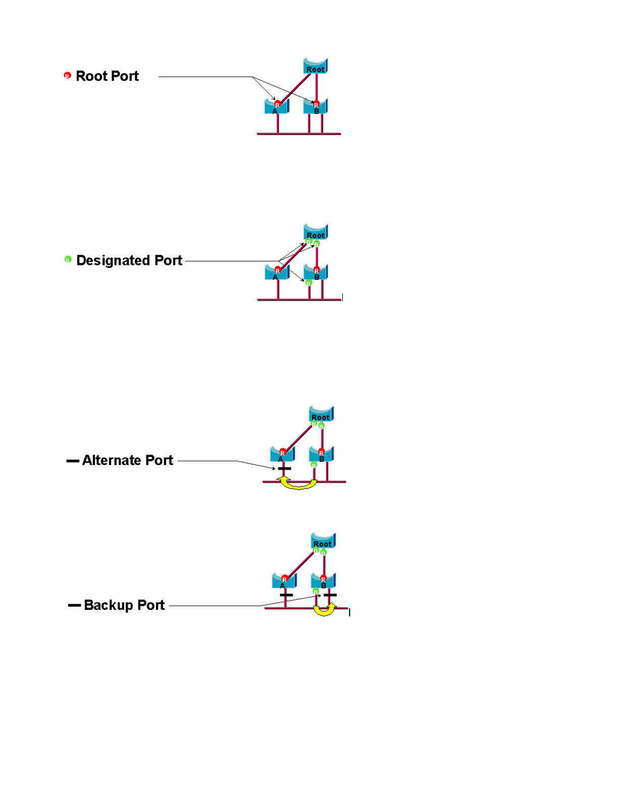
Designated Port Role
A
port is designated if it can send the best BPDU on the segment to which the port is connected. 802.1D bridges link
together different segments (Ethernet segments, for example) in order to create a bridged domain. On a given
segment, there can be only one path toward the root bridge. If there are two paths, there is a bridging loop in the
network. All bridges that are connected to a given segment listen to the BPDUs of the others and agree on the bridge
that sends the best BPDU as the designated bridge for the segment. The corresponding port on that bridge is
designated.
Alternate and Backup Port Roles
These two port roles correspond to the blocking state of 802.1D. The definition of a blocked port is a port that is not
the designated or root port. A blocked port receives a more useful BPDU than the BPDU that it sends out on its
segment. Remember that a port absolutely needs to receive BPDUs in order to stay blocked. RSTP introduces these
two roles for this purpose.
A
n alternate port is a port that is blocked by receiving more useful BPDUs from another bridge. This diagram
illustrates:
A
backup port is a port that is blocked by receiving more useful BPDUs from the same bridge that the port is on. This
diagram illustrates:
This distinction was already made internally within 802.1D. This is essentially how Cisco UplinkFast functions. The
rationale behind this is that an alternate port provides an alternate path to the root bridge. Therefore, this port can
replace the root port if it fails. Of course, a backup port provides redundant connectivity to the same segment and
cannot guarantee an alternate connectivity to the root bridge. Therefore, the backup port was excluded from the
uplink group.
A
s a result, RSTP calculates the final topology for the spanning tree with use of exactly the same criteria as 802.1D.
There is no change in the way that the different bridge and port priorities are used. The name blocking is used for the
discarding state in Cisco implementation. CatOS release 7.1 and later releases still display the listening and learning
states, which gives even more information about a port than the IEEE standard requires. But, the new feature is that
there is now a difference between the role that the protocol has determined for a port and its current state. For
example, it is now perfectly valid for a port to be designated and blocking at the same time. While this typically
happens for very short periods of time, it simply means that this port is in a transitory state toward designated
forwarding.

STP Interactions with VLANs
There are three different ways to correlate VLANs with Spanning Tree:
-A single Spanning Tree for all VLANs, or Common Spanning Tree Protocol (CST), such as IEEE 802.1D
-A Spanning Tree per VLAN, or shared Spanning Tree, such as Cisco PVST
-A Spanning Tree per set of VLANs, or Multiple Spanning Tree (MST), such as IEEE 802.1s
From a configuration standpoint, these three types of spanning tree modes as they relate to interaction with VLANs
can be configured in one of three types of modes:
-pvst—Per-VLAN Spanning Tree. This actually implements PVST+, but is noted in Cisco IOS Software as
simply PVST.
-rapid-pvst—The evolution of the 802.1D standard enhances convergence times and incorporates the
standards-based (802.1w) properties of UplinkFast and BackboneFast.
-mst—This is the 802.1s standard for a spanning tree per set of VLANs or MSTs. This also incorporates the
802.1w rapid component within the standard.
A
mono Spanning Tree fo
r
all VLANs allows only one active topology and therefore no load balancing. A STP
blocked port blocks for all VLANs and carries no data.
One Spanning Tree per VLAN or PVST+ allows load balancing but requires more BPDU CPU processing as the
number of VLANs increases.
The new 802.1s standard (MST) allow the definition of up to 16 active STP instances/topologies, and the mapping of
all VLANs to these instances. In a typical campus environment, only two instances need to be defined. This
technique allows STP scale to many thousands of VLANs while it enables load balancing.
The support for Rapid-PVST and pre-standard MST is introduced in Cisco IOS Software Release 12.1(11b)EX and
12.1(13)E for Catalyst 6500. Catalyst 4500with Cisco IOS Software Release 12.1(12c)EW and later releases support
pre-standard MST. Rapid PVST support is added in Cisco IOS Software Release12.1(19)EW for Catalyst 4500
platform. The standard compliant MST is supported in Cisco IOS Software Release 12.2(18)SXF for Catalyst 6500
and Cisco IOS Software Release12.2(25)SG for Catalyst 4500 series switches.
Refer to Understanding Rapid Spanning-Tree Protocol (802.1w) and Understanding Multiple Spanning-Tree Protocol
(802.1s) for more information.
Spanning Tree Logical Ports
The Catalyst 4500 and 6500 release notes provide guidance on the number of logical ports in the Spanning Tree per
switch. The sum of all logical ports equals the number of trunks on the switch times the number of active VLANs on
the trunks, plus the number of non-trunking interfaces on the switch. Cisco IOS software generates a system log
message if the maximum number of logical interfaces exceed the limitation. It is recommended to not exceed the
recommended guidance.
This table compares the number of logical ports supported with various STP mode and supervisor type:
Supervisor PVST+ RPVST+ MST
Catalyst 6500
Supervisor 1
6,0001 total
1,200 per
switching
module
6,000 total
1,200 per
switching
module
25,000 total
3,0002 per
switching
module
Catalyst 6500
Supervisor 2
13,0001 total
1,8002 per
switching
module
10,000 total
1,8002 per
switching
module
50,000 total
6,0002 per
switching
module
Catalyst 6500
Supervisor 720
13,000 total
1,8002 per
switching
module
10,000 total
1,8002 per
switching
module
50,0003 total
6,0002 per
switching
module
Catalyst 4500
Supervisor II
plus 1,500 total 1,500 total 25,000 total
Catalyst 4500
Supervisor II
plus-10GE 1,500 total 1,500 total 25,000 total
Catalyst 4500
Supervisor IV 3,000 total 3,000 total 50,000 total
Catalyst 4500
Supervisor V 3,000 total 3,000 total 50,000 total
Catalyst 4500
Supervisor V
10GE 3,000 total 3,000 total 80,000 total

1 The maximum number of total logical ports supported in PVST+ earlier than Cisco IOS Software Release 12.1(13)
E is 4,500.
2 10 Mbps, 10/100 Mbps, and 100 Mbps switching modules support a maximum of 1,200 logical interfaces per
module.
3 The maximum number of total logical ports supported in MST prior to Cisco IOS Software Release 12.2(17b)SXA is
30,000.
Recommendation
It is difficult to provide a spanning-tree mode recommendation without detail information such as hardware, software,
number of devices and number of VLANs. In general, if the number of logical ports does not exceed the
recommended guideline, Rapid PVST mode is recommended for new network deployment. Rapid PVST mode
provides fast network convergence without the need for additional configuration such as Backbone Fast and Uplink
Fast. Issue thise following command to set the spanning-tree in Rapid-PVST mode:
spanning-tree mode rapid-pvst
Other Options
In a network with a mixture of legacy hardware and older software, PVST+ mode is recommended. Issue this
command to set the spanning-tree in PVST+ mode:
spanning-tree mode pvst
----This is default and it shows in the configuration.
MST mode is recommended for VLAN everywhere network design with large number of VLANs. For this network, the
sum of the logical ports can exceed the guideline for PVST and Rapid-PVST. Issue this command to set the
spanning-tree in MST mode:
spanning-tree mode mst
BPDU Formats
In order to support the IEEE 802.1Q standard, Cisco extended the PVST protocol that exists in order to provide the
PVST+ protocol. PVST+ adds support for links across the IEEE 802.1Q mono spanning tree region. PVST+ is
compatible with both IEEE 802.1Q mono spanning tree and the Cisco PVST protocols that exist. In addition, PVST+
adds checking mechanisms in order to ensure that there is no configuration inconsistency of port trunking and VLAN
ID across switches. PVST+ is plug-and-play compatible with PVST, without the requirement of a new command-line
interface (CLI) command or configuration.
Here are some highlights of operational theory of the PVST+ protocol:
-PVST+ interoperates with 802.1Q mono spanning tree. PVST+ interoperates with 802.1Q-compliant switches
on common STP through 802.1Q trunking. Common spanning tree is on VLAN 1, the native VLAN, by default.
One common spanning tree BPDU is transmitted or received with the IEEE standard bridge-group MAC
address (01-80-c2-00-00-00, protocol type 0x010c) across 802.1Q links. Common spanning tree can be
rooted in the PVST or mono spanning tree region.
-PVST+ tunnels the PVST BPDUs across the 802.1Q VLAN region as multicast data. For each VLAN on a
trunk, BPDUs with the Cisco Shared STP (SSTP) MAC address (01-00-0c-cc-cd) are transmitted or received.
For VLANs that are equal to the Port VLAN Identifier (PVID), BPDU is untagged. For all other VLANs, BPDUs
are tagged.
-PVST+ is backward compatible with the existing Cisco switch on PVST through ISL trunking. ISL-
encapsulated BPDUs are transmitted or received through ISL trunks, which is the same as with previous
Cisco PVST.
-PVST+ checks for port and VLAN inconsistencies. PVST+ blocks those ports that receive inconsistent BPDUs
in order to prevent the occurrence of forwarding loops. PVST+ also notifies users via syslog messages about
any inconsistency.
Note: In ISL networks, all BPDUs are sent with use of the IEEE MAC address.
Cisco Configuration Recommendations
A
ll Catalyst switches have STP enabled by default. Even if you choose a design that does not include Layer 2 loops
and STP is not enabled in order to actively maintain a blocked port, leave the feature enabled for these reasons:
-If there is a loop, STP prevents issues that can be made worse by multicast and broadcast data. Often,
mispatching, a bad cable, or another cause induces a loop.
-STP protects against an EtherChannel breakdown.

-Most networks are configured with STP, and therefore, get maximum field exposure. More exposure generally
equates to a more stable code.
-STP protects against dual-attached NICs misbehavior (or bridging enabled on servers).
-Many protocols are closely related to STP in code. Examples include:
PAgP
Internet Group Message Protocol (IGMP) snooping
Trunking
If you run without STP, you can get undesirable results.
-During a reported network disruption, Cisco engineers usually suggest that nonusage of STP is at the center
of the fault, if at all conceivable.
In order to enable spanning tree on all VLANs, issue these global commands:
Switch(config)#spanning-tree vlan vlan_id
!--- Specify the VLAN that you want to modify.
Switch(config)#default spanning-tree vlan vlan_id
!--- Set spanning-tree parameters to default values.
Do not change timers, which can adversely affect stability. The majority of networks that are deployed are not
tuned. The simple STP timers that are accessible via the command line, such as hello-interval and maxage, have a
complex set of other assumed and intrinsic timers. Therefore, you can have difficulty if you try to tune timers and
consider all the ramifications. Moreover, you can undermine UDLD protection.
Ideally, keep user traffic off the management VLAN. This does not apply on the Catalyst 6500/6000 Cisco IOS
switch. Still, you need to respect this recommendation on the smaller-end Cisco IOS switches and CatOS switches
that can have a separate management interface and need to be integrated with Cisco IOS switches. Especially with
older Catalyst switch processors, keep the management VLAN separate from user data in order to to avoid problems
with STP. One misbehaving end station can potentially keep the Supervisor Engine processor so busy with
broadcast packets that the processor can miss one or more BPDUs. But, newer switches with more powerful CPUs
and throttling controls relieve this consideration. See the Switch Management Interface and Native VLAN section of
this document for more details.
Do not overdesign redundancy. This can lead to too many blocking ports and can adversely affect long-term
stability. Keep the total STP diameter under seven hops. Try to design to the Cisco multilayer model wherever this
design is possible. The model features:
-Smaller switched domains
-STP triangles
-Deterministic blocked ports
Refer to Gigabit Campus Network Design for details.
Influence and know where root functionality and blocked ports reside. Document this information on the
topology diagram. Know your spanning tree topology, which is essential in order to troubleshoot. The blocked ports
are where STP troubleshooting begins. The cause of the change from blocking to forwarding is often the key part of
root cause analysis. Choose the distribution and core layers as the location of the root/secondary root because these
layers are considered the most stable parts of the network. Check for optimal Layer 3 and Hot Standby Router
Protocol (HSRP) overlay with Layer 2 data-forwarding paths.
This command is a macro that configures the bridge priority. The root sets the priority to be much lower than the
default (32,768), and the secondary sets the priority to be reasonably lower than the default:
Switch(config)#interface type slot/port
Switch(config)#spanning-tree vlan vlan_id root primary
!--- Configure a switch as root for a particular VLAN.
Note: This macro sets the root priority to be either:
-8192 by default

-The current root priority minus 1, if another root bridge is known
-The current root priority, if its MAC address is lower than the current root
Prune unnecessary VLANs off trunk ports, which is a bidirectional exercise. The action limits the diameter of STP
and NMP processing overhead on portions of the network where certain VLANs are not required. VTP automatic
pruning does not remove STP from a trunk. You can also remove the default VLAN 1 from trunks.
Refer to Spanning Tree Protocol Problems and Related Design Considerations for additional information.
Other Options
Cisco has another STP protocol, called VLAN-bridge, that operates with the use of a well-known destination MAC
address of 01-00-0c-cd-cd-ce and protocol type of 0x010c.
This protocol is most useful if there is a need to bridge nonroutable or legacy protocols between VLANs without
interference with the IEEE spanning tree instances that run on those VLANs. If VLAN interfaces for nonbridged traffic
become blocked for Layer 2 traffic, the overlaying Layer 3 traffic is inadvertently pruned off as well, which is an
unwanted side effect. This Layer 2 blockage can easily happen if the VLAN interfaces for nonbridged traffic
participate in the same STP as IP VLANs. VLAN-bridge is a separate instance of STP for bridged protocols. The
protocol provides a separate topology that can be manipulated without an effect on IP traffic.
Run the VLAN-bridge protocol if bridging is required between VLANs on Cisco routers such as the MSFC.
STP PortFast Feature
You can use PortFast in order to bypass normal spanning tree operation on access ports. PortFast speeds up
connectivity between end stations and the services to which end stations need to connect after link initialization. The
Microsoft DHCP implementation needs to see the access port in forwarding mode immediately after the link state
goes up in order to request and receive an IP address. Some protocols, such as Internetwork Packet Exchange
(IPX)/Sequenced Packet Exchange (SPX), need to see the access port in forwarding mode immediately after the
link state goes up in order to avoid Get Nearest Server (GNS) problems.
Refer to Using PortFast and Other Commands to Fix Workstation Startup Connectivity Delays for more information.
PortFast Operational Overview
PortFast skips the normal listening, learning, and forwarding states of STP. The feature moves a port
directly from blocking to forwarding mode after the link is seen as up. If this feature is not enabled, STP
discards all user data until it decides that the port is ready to be moved to forwarding mode. This process can take
up (2 x ForwardDelay) time, which is 30 seconds by default.
Portfast mode prevents the generation of an STP Topology Change Notification (TCN) each time a port state
changes from learning to forwarding. TCNs are normal. But, a wave of TCNs that hits the root bridge can
extend the convergence time unnecessarily. A wave of TCNs often occurs in the morning, when people turn on their
PCs.
Cisco Access Port Configuration Recommendation
Set STP PortFast to on for all enabled host ports. Also, explicitly set STP PortFast to off for switch-switch links and
ports that are not in use.
Issue the switchport host macro command in interface configuration mode in order to implement the recommended
configuration for access ports. The configuration also helps autonegotiation and connection performance
significantly:
switch(config)#interface type slot#/port#
switch(config-if)#switchport host
switchport mode will be set to access
spanning-tree portfast will be enabled
channel group will be disabled
!--- This macro command modifies these functions.
Note: PortFast does not mean that spanning tree is not run at all on the ports. BPDUs are still sent, received, and
processed. Spanning tree is essential for a fully functional LAN. Without loop detection and blocking, a loop can
unintentionally bring down the entire LAN quickly.
A
lso, disable trunking and channeling fo
r
all host ports. Each access port is enabled by default for trunking and
channeling, yet switch neighbors are not expected by design on host ports. If you leave these protocols to negotiate,
the subsequent delay in port activation can lead to undesirable situations. Initial packets from workstations, such as
DHCP and IPX requests, are not forwarded.
A
better option is to configure PortFast by default in the global configuration mode with use of this command:
Switch(config)#spanning-tree portfast enable

Then, on any access port that has a hub or a switch in only one VLAN, disable the PortFast feature on each interface
with the interface command:
Switch(config)#interface type slot_num/port_num
Switch(config-if)#spanning-tree portfast disable
Other Options
PortFast BPDU guard provides a method to prevent loops. BPDU guard moves a nontrunking port into an
errDisable state at the reception of a BPDU on that port.
Under normal conditions, never receive any BPDU packets on an access port that is configured for PortFast. An
incoming BPDU indicates an invalid configuration. The best action is to shut down the access port.
Cisco IOS system software offers a useful global command that automatically enables BPDU-ROOT-GUARD on any
port that is enabled for UplinkFast. Always use this command. The command works on a per-switch basis, and not
per-port.
Issue this global command in order to enable BPDU-ROOT-GUARD:
Switch(config)#spanning-tree portfast bpduguard default
A
Simple Network Management Protocol (SNMP) trap or syslog message notifies the network manager if the port
goes down. You can also configure an automatic recovery time for errDisabled ports. See the UniDirectional Link
Detection section of this document for more details.
Refer to Spanning Tree PortFast BPDU Guard Enhancement for further details.
Note: PortFast for trunk ports was introduced in Cisco IOS Software Release 12.1(11b)E. PortFast for trunk ports is
designed to increase convergence times for Layer 3 networks. When you use this feature, be sure to disable BPDU
guard and BPDU filter on an interface basis.
UplinkFast
Purpose
UplinkFast provides fast STP convergence after a direct link failure in the network access layer. UplinkFast operates
without modification of STP. The purpose is to speed up convergence time in a specific circumstance to less than
three seconds, rather than the typical 30 second delay. Refer to Understanding and Configuring the Cisco UplinkFast
Feature.
Operational Overview
With the Cisco multilayer design model at the access layer, the blocking uplink is immediately moved to a
forwarding state if the forwarding uplink is lost. The feature does not wait for the listening and learning
states.
A
n uplink group is a set of ports per VLAN that you can think of as a root port and backup root port. Under normal
conditions, the root ports assure connectivity from the access toward the root. If this primary root connection fails for
any reason, the backup root link kicks in immediately, without the need to go through the typical 30 seconds of
convergence delay.
Because UplinkFast effectively bypasses the normal STP topology change-handling process (listening and
learning), an alternate topology correction mechanism is necessary. The mechanism needs to update switches in
the domain with the information that local end stations are reachable via an alternate path. Thus, the access layer
switch that runs UplinkFast also generates frames for each MAC address in its CAM table to a well-known multicast
MAC address (01-00-0c-cd-cd-cd HDLC protocol 0x200a). This process updates the CAM table in all switches in the
domain with the new topology.
Cisco Recommendation
Cisco recommends that you enable UplinkFast for access switches with blocked ports if you run 802.1D spanning
tree. Do not use UplinkFast on switches without the implied topology knowledge of a backup root link—typically
distribution and core switches in the Cisco multilayer design. In general terms, do not enable UplinkFast on a switch
with more than two ways out of a network. If the switch is in a complex access environment and you have more than
one link blocking and one link forwarding, either avoid use of this feature on the switch or consult your Advanced
Services engineer.
Issue this global command in order to enable UplinkFast:
Switch(config)#spanning-tree uplinkfast
This command in Cisco IOS Software does not automatically adjust all the bridge priority values to a high value.
Rather, the command only changes those VLANs with a bridge priority that has not been manually changed to some
other value. Additionally, unlike CatOS, when you restore a switch that had UplinkFast enabled, the no form of this
command (no spanning-tree uplinkfast) reverts all changed values to their defaults. Therefore, when you use this
command, you must check the current status of the bridge priorities before and after in order to assure that the
desired result is achieved.

Note: You need the all protocols keyword for the UplinkFast command when the protocol filtering feature is
enabled. Because the CAM records the protocol type as well as MAC and VLAN information when protocol filtering is
enabled, an UplinkFast frame must be generated for each protocol on each MAC address. The rate keyword
indicates the packets per second of the UplinkFast topology update frames. The default is recommended. You do not
need to configure UplinkFast with RSTP because the mechanism is natively included and automatically enabled in
RSTP.
BackboneFast
Purpose
BackboneFast provides rapid convergence from indirect link failures. BackboneFast reduces convergence times from
the default of 50 seconds to, typically, 30 seconds and, in this way, adds functionality to STP. Again, this feature is
only applicable when you run 802.1D. Do not configure the feature when you run Rapid PVST or MST (which
includes the rapid component).
Operational Overview
BackboneFast is initiated when a root port or blocked port on a switch receives inferior BPDUs from the designated
bridge. The port typically receives inferior BPDUs when a downstream switch loses the connection to the root and
starts to send BPDUs in order to elect a new root. An inferior BPDU identifies a switch as both the root bridge and
the designated bridge.
Under normal spanning tree rules, the receiving switch ignores inferior BPDUs for the maxage time that is
configured. By default, the maxage is 20 sec. But, with BackboneFast, the switch sees the inferior BPDU as a signal
of a possible change in the topology. The switch uses Root Link Query (RLQ) BPDUs in order to determine if it has
an alternate path to the root bridge. This RLQ protocol addition allows a switch to check if the root is still available.
RLQ moves a blocked port to forwarding earlier and notifies the isolated switch that sent the inferior BPDU that
the root is still there.
Here are some highlights of the protocol operation:
-A switch transmits the RLQ packet out the root port only (which means that the packet goes toward the root).
-A switch that receives an RLQ can reply if it is the root switch, or if that switch knows that it has lost
connection with the root. If the switch does not know these facts, it must forward the query out its root port.
-If a switch has lost connection to the root, the switch must reply in the negative to this query.
-The reply must be sent only out the port from which the query came.
-The root switch must always respond to this query with a positive reply.
-If the reply is received on a nonroot port, discard the reply.
The operation can reduce STP convergence times by up to 20 seconds because maxage does not need to expire.
Refer to Understanding and Configuring Backbone Fast on Catalyst Switches for more information.
Cisco Recommendation
Enable BackboneFast on all switches that run STP only if the entire spanning-tree domain can support this feature.
You can add the feature without disruption to a production network.
Issue this global command in order to enable BackboneFast:
Switch(config)#spanning-tree backbonefast
Note: You must configure this global-level command on all switches in a domain. The command adds functionality to
STP that all switches need to understand.
Other Options
BackboneFast is not supported on Catalyst 2900XL and 3500XL switches. In general, you need to enable
BackboneFast if the switch domain contains these switches in addition to Catalyst 4500/4000, 5500/5000, and
6500/6000 switches. When you implement BackboneFast in environments with XL switches, under strict topologies,
you can enable the feature where the XL switch is the last switch in line and is only connected to the core at two
places. Do not implement this feature if the architecture of the XL switches is in daisy-chain fashion.
You do not need to configure BackboneFast with RSTP or 802.1w because the mechanism is natively included and
automatically enabled in RSTP.
Spanning Tree Loop Guard
Loop guard is a Cisco proprietary optimization for STP. Loop guard protects Layer 2 networks from loops that occur
because of a network interface malfunction, busy CPU, or anything that prevents the normal forwarding of BPDUs. A
STP loop is created when a blocking port in a redundant topology erroneously transitions to the forwarding state.
This usually happens because one of the ports in a physically redundant topology (not necessarily the blocking port)
stopped receiving BPDUs.
Loop guard is only useful in switched networks where switches are connected by point-to-point links, as is the case
in most modern campus and data center networks. The idea is that, on a point-to-point link, a designated bridge

cannot disappear without sending an inferior BPDU or bringing the link down. The STP loop guard feature was
introduced in Cisco IOS Software Release 12.1(13)E of the Catalyst Cisco IOS Software for Catalyst 6500 and Cisco
IOS Software Release 12.1(9)EA1 for Catalyst 4500 switches.
Refer to Spanning-Tree Protocol Enhancements using Loop Guard and BPDU Skew Detection Features for more
information on loop guard.
Operational Overview
Loop guard checks if a root port or an alternate/backup root port receives BPDUs. If the port does not receive
BPDUs, loop guard puts the port into an inconsistent state (blocking) until it starts to receive BPDUs again. A port in
the inconsistent state does not transmit BPDUs. If such a port receives BPDUs again, the port (and link) is deemed
viable again. The loop-inconsistent condition is removed from the port, and STP determines the port state. In this
way, recovery is automatic.
Loop guard isolates the failure and lets spanning tree converge to a stable topology without the failed link or bridge.
Loop guard prevents STP loops with the speed of the STP version that is in use. There is no dependency on STP
itself (802.1D or 802.1w) or when tuning the STP timers. For these reasons, Cisco recommends that you implement
loop guard in conjunction with UDLD in topologies that rely on STP and where the software supports the features.
When loop guard blocks an inconsistent port, this message is logged:
%SPANTREE-SP-2-LOOPGUARD_BLOCK: Loop guard blocking port GigabitEthernet2/1 on VLAN0010
A
fte
r
the BPDU is received on a port in a loop-inconsistent STP state, the port transitions into another STP state.
A
ccording to the received BPDU, this means that the recovery is automatic, and no intervention is necessary. After
the recovery, this message is logged:
%SPANTREE-SP-2-LOOPGUARD_UNBLOCK: Loop guard unblocking port GigabitEthernet2/1 on
VLAN0010
Interaction with Other STP Features
Root Guard
Root guard forces a port to be designated always. Loop guard is effective only if the port is root port or an alternate
port, which means that their functions are mutually exclusive. Therefore, loop guard and root guard cannot be
enabled on a port at the same time.
UplinkFast
Loop guard is compatible with UplinkFast. If loop guard puts a root port into a blocking state, UplinkFast puts into
forwarding state a new root port. Also, UplinkFast does not select a loop-inconsistent port as a root port.
BackboneFast
Loop guard is compatible with BackboneFast. BackboneFast is triggered by the reception of an inferior BPDU that
comes from a designated bridge. Because BPDUs are received from this link, loop guard does not kick in. Therefore,
BackboneFast and loop guard are compatible.
PortFast
PortFast transitions a port into the forwarding designated state immediately upon linkup. Because a PortFast-
enabled port is not a root/alternate port, loop guard and PortFast are mutually exclusive.
PAgP
Loop guard uses the ports that are known to STP. Therefore, loop guard can take advantage of the abstraction of
logical ports that PAgP provides. But, in order to form a channel, all the physical ports grouped in the channel must
have compatible configurations. PAgP enforces uniform configuration of loop guard on all the physical ports in order
to form a channel. Note these caveats when you configure loop guard on an EtherChannel:
-STP always picks the first operational port in the channel to send the BPDUs. If that link becomes
unidirectional, loop guard blocks the channel, even if other links in the channel function properly.
-If a set of ports which are already blocked by loop guard are grouped together in order to form a channel, STP
loses all the state information for those ports, and the new channel port can possibly attain the forwarding
state with a designated role.
-If a channel is blocked by loop guard and the channel breaks, STP loses all the state information. The
individual physical ports can possibly attain the forwarding state with a designated role, even if one or more of
the links that formed the channel are unidirectional.
In these last two cases, there is a possibility of a loop until UDLD detects the failure. But loop guard cannot detect it.
Loop Guard and UDLD Feature Comparison
Loop guard and UDLD functionality partially overlap, partly in the sense that both protect against STP failures that
unidirectional links cause. These two features are different in the approach to the problem and also in functionality.
Specifically, there are specific unidirectional failures that UDLD is unable to detect, such as failures that are caused
by a CPU that does not send BPDUs. Additionally, the use of aggressive STP timers and RSTP mode can result in

loops before UDLD can detect the failures.
Loop guard does not work on shared links or in situations where the link has been unidirectional since the linkup. In
the case of a link that has been unidirectional since the linkup, the port never receives BPDUs and becomes
designated. This can be normal behavior, so loop guard does not cover this particular case. UDLD does provide
protection against such a scenario.
The enablement of both UDLD and loop guard provides the highest level of protection. For more information on a
feature comparison between loop guard and UDLD, refer to:
-Loop Guard vs. Unidirectional Link Detection section of Spanning-Tree Protocol Enhancements using Loop
Guard and BPDU Skew Detection Features
-UDLD section of this document
Cisco Recommendation
Cisco recommends that you enable loop guard globally on a switch network with physical loops. You can enable loop
guard globally on all ports. Effectively, the feature is enabled on all point-to-point links. The point-to-point link is
detected by the duplex status of the link. If duplex is full, the link is considered point-to-point.
Switch(config)#spanning-tree loopguard default
Other Options
For switches that do not support a global loop guard configuration, the recommendation is to enable the feature on
all individual ports, which includes port channel ports. Although there are no benefits if you enable loop guard on a
designated port, do not consider the enablement an issue. In addition, a valid spanning tree reconvergence can
actually turn a designated port into a root port, which renders the feature useful on this port.
Switch(config)#interface type slot#/port#
Switch(config-if)#spanning-tree guard loop
Networks with loop-free topologies can still benefit from loop guard in the case that loops are introduced accidentally.
But, the enablement of loop guard in this type of topology can lead to network isolation problems. If you build a loop-
free topology and wish to avoid network isolation problems, you can disable loop guard globally or individually. Do
not enable loop guard on shared links.
Switch(config)#no spanning-tree loopguard default
!--- This is the global configuration.
or
Switch(config)#interface type slot#/port#
Switch(config-if)#no spanning-tree guard loop
!--- This is the interface configuration.
Spanning Tree Root Guard
The root guard feature provides a way to enforce the root bridge placement in the network. Root guard ensures that
the port on which root guard is enabled is the designated port. Normally, root bridge ports are all designated ports,
unless two or more ports of the root bridge are connected together. If the bridge receives superior STP BPDUs on a
root guard-enabled port, the bridge moves this port to a root-inconsistent STP state. This root-inconsistent state is
effectively equal to a listening state. No traffic is forwarded across this port. In this way, the root guard enforces the
position of the root bridge. Root guard is available in the very early Cisco IOS Software Release 12.1E and later.
Operational Overview
Root guard is an STP built-in mechanism. Root guard does not have a timer of its own and relies on the reception of
BPDUs only. When root guard is applied to a port, it denies this port the possibility of becoming a root port. If the
reception of a BPDU triggers a spanning tree convergence that makes a designated port become a root port, the port
is then put into a root inconsistent state. This syslog message illustrates:
%SPANTREE-SP-2-ROOTGUARD_BLOCK: Root guard blocking port GigabitEthernet2/1 on VLAN0010
A
fte
r
the port ceases to send superior BPDUs, the port is unblocked again. Via STP, the port goes from the listening
state to the learning state, and eventually transitions to the forwarding state. This syslog message shows the
transition:
%SPANTREE-SP-2-ROOTGUARD_UNBLOCK: Root guard unblocking port GigabitEthernet2/1
on VLAN0010

Recovery is automatic. No human intervention is necessary.
Because root guard forces a port to be designated and loop guard is effective only if the port is a root port or an
alternate port, the functions are mutually exclusive. Therefore, you cannot enable loop guard and root guard on a
port at the same time.
Refer to Spanning Tree Protocol Root Guard Enhancement for more information.
Cisco Recommendation
Cisco recommends that you enable the root guard feature on ports that connect to network devices that are not
under direct administrative control. In order to configure root guard, use these commands when you are in interface
configuration mode:
Switch(config)#interface type slot#/port#
Switch(config-if)#spanning-tree guard root
EtherChannel
Purpose
EtherChannel encompasses a frame distribution algorithm that efficiently multiplexes frames across the component
10/100-Mbps or Gigabit links. The frame distribution algorithm allows the inverse multiplexing of multiple channels
into a single logical link. Although each platform differs from the next platform in implementation, you must
understand these common properties:
-There must be an algorithm to statistically multiplex frames over multiple channels. In Catalyst switches, this
is hardware-related. Here are examples:
Catalyst 5500/5000s—The presence or lack of an Ethernet Bundling Chip (EBC) on the module
Catalyst 6500/6000s—An algorithm that can read further into the frame and multiplex by IP address
-There is the creation of a logical channel so that a single instance of STP can be run or a single routing
peering can be utilized, which depends on if it is a Layer 2 or Layer 3 EtherChannel.
-There is a management protocol to check for parameter consistency at either end of the link and to help
manage bundling recovery from link failure or addition. This protocol can be PAgP or Link Aggregation Control
Protocol (LACP).
Operational Overview
EtherChannel encompasses a frame distribution algorithm that efficiently multiplexes frames across the component
10/100-Mbps, Gigabit or 10-Gigabit links. Differences in algorithms per platform arise from the capability of each type
of hardware to extract frame header information in order to make the distribution decision.
The load distribution algorithm is a global option for both channel control protocols. PAgP and LACP use the frame
distribution algorithm because the IEEE standard does not mandate any particular distribution algorithms. But, any
distribution algorithm ensures that, when frames are received, the algorithm does not cause the misordering of
frames that are part of any given conversation or duplication of frames.
This table illustrates the frame distribution algorithm in detail for each listed platform:
This table indicates the distribution methods that are supported on the various Catalyst 6500/6000 Supervisor Engine
models. The table also shows the default behavior:
Platform Channel Load Balancing Algorithm
Catalyst
3750 series
Catalyst 3750 that runs Cisco IOS Software load
balances algorithm that uses MAC addresses or IP
addresses, and either the message source or
message destination, or both.
Catalyst
4500 series
Catalyst 4500 that runs Cisco IOS Software load
balances algorithm that uses MAC addresses, IP
addresses, or Layer 4 (L4) port numbers, and either
the message source or message destination, or both.
Catalyst
6500/6000
series
There are two hashing algorithms that can be used,
which depends on the Supervisor Engine hardware.
The hash is a seventeenth-degree polynomial that is
implemented in hardware. In all cases, the hash takes
the MAC, IP address, or IP TCP/UDP port number and
applies the algorithm in order to generate a 3-bit value.
This process occurs separately for both the SAs and
DAs. The XOR operation is then used with the results
in order to generate another 3-bit value. The value
determines which port in the channel is used to
forward the packet. Channels on the Catalyst
6500/6000 can be formed between ports on any
module and can be up to eight ports.

Note: With Layer 4 distribution, the first fragmented packet uses Layer 4 distribution. All subsequent packets use
Layer 3 distribution.
Note: Refer to these documents in order to find more details about EtherChannel support on other platforms and
how to configure and troubleshoot EtherChannel:
-Understanding EtherChannel Load Balancing and Redundancy on Catalyst Switches
-Configuring Layer 3 and Layer 2 EtherChannel (Catalyst 6500 Series Cisco IOS Software Configuration
Guide, 12.2SX)
-Configuring Layer 3 and Layer 2 EtherChannel (Catalyst 6500 Series Cisco IOS Software Configuration
Guide, 12.1E)
-Configuring EtherChannel (Catalyst 4500 Series Switch Cisco IOS Software Configuration Guide, 12.2(31)
SG)
-Configuring EtherChannels (Catalyst 3750 Switch Software Configuration Guide, 12.2(25)SEE)
-Configure EtherChannel Between Catalyst 4500/4000, 5500/5000, and 6500/6000 Switches That Run CatOS
System Software
Cisco Recommendation
Catalyst 3750, Catalyst 4500, and Catalyst 6500/6000 series switches perform load balancing by hashing both the
source and destination IP addresses by default. This is recommended, with the assumption that IP is the dominant
protocol. Issue this command in order to set load balancing:
port-channel load-balance src-dst-ip
!--- This is the default.
Other Options
Depending on the traffic flows, you can utilize Layer 4 distribution in order to improve load balancing if the majority of
traffic is between the same source and destination IP address. You must understand that, when Layer 4 distribution
is configured, the hashing only includes Layer 4 source and destination ports. It does not combine Layer 3 IP
addresses into the hashing algorithm. Issue this command in order to set load balancing:
port-channel load-balance src-dst-port
Note: Layer 4 distribution is not configurable on Catalyst 3750 series switches.
Issue the show etherchannel load-balance command in order to check the frame distribution policy.
Depending on the hardware platforms, you can utilize CLI commands in order to determine which interface in the
EtherChannel forwards the specific traffic flow, with the frame distribution policy as a basis.
For Catalyst 6500 switches, issue the remote login switch command in order to log in remotely to the Switch
Processor (SP) console. Then, issue the test etherchannel load-balance interface port-channel number {ip |
l4port | mac} [source_ip_add | source_mac_add | source_l4_port] [dest_ip_add | dest_mac_add | dest_l4_port]
command.
For Catalyst 3750 switches, issue the test etherchannel load-balance interface port-channel number {ip | mac}
[source_ip_add | source_mac_add] [dest_ip_add | dest_mac_add] command.
For Catalyst 4500, the equivalent command is not yet available.
Hardware Description Distribution Methods
WS-F6020A
(Layer 2
engine) WS-
F6K-PFC
(Layer 3
engine)
Later Supervisor Engine
I and Supervisor Engine
IA Supervisor Engine
IA/Policy Feature Card 1
(PFC1)
Layer 2 MAC: SA; DA;
SA and DA Layer 3 IP:
SA; DA; SA and DA
(default)
WS-F6K-PFC 2 Supervisor Engine
II/PFC2
Layer 2 MAC: SA; DA;
SA and DA Layer 3 IP:
SA; DA; SA and DA
(default) Layer 4
session: S port; D port;
S and D port
WS-F6K-
PFC3A WS-
F6K-PFC3B
WS-F6K-
PFC3BXL
Supervisor Engine
720/PFC3A Supervisor
Engine 720/Supervisor
Engine 32/PFC3B
Supervisor Engine
720/PFC3BXL
Layer 2 MAC: SA; DA;
SA and DA Layer 3 IP:
SA; DA; SA and DA
(default) Layer 4
session: S port; D port;
S and D port

EtherChannel Configuration Guidelines and Restrictions
EtherChannel verifies port properties on all physical ports before it aggregates compatible ports into a single logical
port. Configuration guidelines and restrictions vary for different switch platforms. Complete these guidelines and
restrictions in order to avoid bundling problems. For example, if QoS is enabled, EtherChannels are not formed when
bundling Catalyst 6500/6000 series switching modules with different QoS capabilities. For Catalyst 6500 switches
that run Cisco IOS Software, you can disable the QoS port attribute check on the EtherChannel bundling with the no
mls qos channel-consistency port-channel interface command. The command show interface capability
mod/port displays the QoS port capability and determines if ports are compatible.
Refer to these guidelines for different platforms in order to avoid configuration problems:
-Configuring Layer 3 and Layer 2 EtherChannel (Catalyst 6500 Series Cisco IOS Software Configuration
Guide, 12.2SX)
-Configuring Layer 3 and Layer 2 EtherChannel (Catalyst 6500 Series Cisco IOS Software Configuration
Guide, 12.1E)
-Configuring EtherChannel (Catalyst 4500 Series Switch Cisco IOS Software Configuration Guide, 12.2(31)
SG)
-Configuring EtherChannels (Catalyst 3750 Switch Software Configuration Guide, 12.2(25)SEE)
The maximum number of EtherChannels that are supported also depends on the hardware platform and the software
releases. Catalyst 6500 switches that run Cisco IOS Software Release 12.2(18)SXE and later support a maximum of
128 port-channel interfaces. Software releases that are earlier than Cisco IOS Software Release 12.2(18)SXE
support a maximum of 64 port-channel interfaces. The configurable group number can be 1 through 256, regardless
of the software release. Catalyst 4500 series switches support a maximum of 64 EtherChannels. For Catalyst 3750
switches, the recommendation is not to configure more than 48 EtherChannels on the switch stack.
Spanning Tree Port Cost Calculation
You must understand the spanning tree port cost calculation for EtherChannels. You can calculate the spanning tree
port cost for EtherChannels with either the short or long method. By default, the port cost is calculated in short mode.
This table illustrates the spanning tree port cost for an Layer 2 EtherChannel on the basis of the number of interfaces
in the EtherChannel:
With use of the default short mode calculation, an eight-port GEC has a lower spanning tree port cost than a 10-GE.
If the desired behavior is to prefer the 10-GE, configure the long method calculation with use of the spanning-tree
pathcost method long command. Or manually configure spanning tree port cost with use of the spanning-tree
cost cost command.
Note: In CatOS, the spanning tree port cost for an EtherChannel stays the same after the port channel member link
failure. In Cisco IOS Software, the port cost for the EtherChannel is updated immediately in order to reflect the new
available bandwidth. If the desired behavior is to avoid unnecessary spanning tree topology changes, you can
statically configure the spanning tree port cost with use of the spanning-tree cost cost command.
Port Aggregation Protocol (PAgP)
Purpose
PAgP is a management protocol that checks for parameter consistency at either end of the link. PAgP also assists
the channel with adaptation to link failure or addition. Here are characteristics of PAgP:
-PAgP requires that all ports in the channel belong to the same VLAN or are configured as trunk ports.
Because dynamic VLANs can force the change of a port into a different VLAN, dynamic VLANs are not
included in EtherChannel participation.
Interface STP Port Cost
Short Mode (16-
Bit)
STP Port Cost
Long Mode (32-
Bit)
100-Mbps Ethernet 19 200,000
GE 420,000
Two-port Gigabit
EtherChannel (GEC) 310,000
Three-port GEC 26666
Four-port GEC 25000
Five-port GEC 24000
Six-port GEC 23333
Seven-port GEC 22857
Eight-port GEC 12500
10-GE 22000
Two-port 10-Gigabit
EtherChannel 11000

-When a bundle already exists and the configuration of a port is modified, all ports in the bundle are modified
to match that configuration. An example of such a change is a change of VLAN or a trunking mode change.
-PAgP does not group ports that operate at different speeds or port duplex. If speed and duplex are changed
when a bundle exists, PAgP changes the port speed and duplex for all ports in the bundle.
Operational Overview
The PAgP port controls each individual physical (or logical) port that is to be grouped. The same multicast group
MAC address that is used for CDP packets is used in order to send PAgP packets. The MAC address is 01-00-0c-cc-
cc-cc. But, the protocol value is 0x0104. This is a summary of the protocol operation:
-As long as the physical port is up, PAgP packets are transmitted every second during detection, and every 30
seconds in steady state.
-If data packets are received but no PAgP packets are received, it is assumed that the port is connected to a
device that is not PAgP-capable.
-Listen for PAgP packets that prove that the physical port has a bidirectional connection to another PAgP-
capable device.
-As soon as two such packets are received on a group of physical ports, try to form an aggregated port.
-If PAgP packets stop for a period, the PAgP state is torn down.
Normal Processing
These concepts help demonstrate the behavior of the protocol:
-Agport—A logical port that is composed of all physical ports in the same aggregation and can be identified by
its own SNMP ifIndex. An agport does not contain nonoperational ports.
-Channel—An aggregation that satisfies the formation criteria. A channel can contain nonoperational ports and
is a superset of agport. Protocols, which include STP and VTP but exclude CDP and DTP, run above PAgP
over the agports. None of these protocols can send or receive packets until PAgP attaches the agports to one
or more physical ports.
-Group capability—Each physical port and agport possesses a configuration parameter that is called the
group-capability. A physical port can be aggregated with any other physical port that has the same
group-capability, and only with such a physical port.
-Aggregation procedure—When a physical port reaches the UpData or UpPAgP state, the port is attached to
an appropriate agport. When the port leaves either of those states for another state, the port is detached from
the agport.
This table provides more details about the states:
Both ends of both connections must agree on the grouping. The grouping is defined as the largest group of ports in
the agport that both ends of the connection permit.
When a physical port reaches the UpPAgP state, the port is assigned to the agport that has member physical ports
that match the group-capability of the new physical port and that are in the BiDir state or the UpPAgP state.
A
ny such BiDir ports are moved to the UpPAgP state at the same time. If there is no agport that has constituent
physical port parameters that are compatible with the newly ready physical port, the port is assigned to an agport
with suitable parameters that has no associated physical ports.
A
PAgP timeout can occur on the last neighbor that is known on the physical port. The port that times out is removed
from the agport. At the same time, all physical ports on the same agport that have timers that have also timed out are
removed. This enables an agport whose other end has died to be torn down all at once, instead of one physical port
at a time.
Behavior in Failure
If a link in a channel that exists is failed, the agport is updated and the traffic is hashed over the links that remain
State Meaning
UpData
No PAgP packets have been received. PAgP packets are
sent. The physical port is the only port that is connected to
the agport. Non-PAgP packets are passed in and out
between the physical port and agport.
BiDir
Exactly one PAgP packet has been received that proves a
bidirectional connection exists to exactly one neighbor.
The physical port is not connected to any agport. PAgP
packets are sent and can be received.
UpPAgP
This physical port, perhaps in association with other
physical ports, is connected to an agport. PAgP packets
are sent and received on the physical port. Non-PAgP
packets are passed in and out between the physical port
and agport.

without loss. Examples of such a failure include:
-Port is unplugged
-Gigabit Interface Converter (GBIC) is removed
-Fiber is broken
Note: When you fail a link in a channel with a power off or removal of a module, the behavior can be different. By
definition, a channel requires two physical ports. If one port is lost from the system in a two-port channel, the logical
agport is torn down and the original physical port is reinitialized with respect to spanning tree. Traffic can be
discarded until STP allows the port to become available to data again.
This difference in the two failure modes is important when you plan the maintenance of a network. There can be an
STP topology change of which you need to take account when you perform an online removal or insertion of a
module. You must manage each physical link in the channel with the network management system (NMS) because
the agport can remain undisturbed through a failure.
Complete one of these recommendations in order to mitigate unwanted topology changes on the Catalyst
6500/6000:
-If a single port is used per module in order to form a channel, use three or more modules (three total).
-If the channel spans two modules, use two ports on each module (four total).
-If a two-port channel is necessary across two cards, use only the Supervisor Engine ports.
Configuration Options
You can configure EtherChannels in different modes, as this table summarizes:
The silent/non-silent settings affect how ports react to situations that cause unidirectional traffic. When a port
is unable to transmit because of a failed physical interface or a broken fiber or cable, the neighbor port can still be left
in an operational state. The partner continues to transmit data. But, data are lost because return traffic cannot be
received. Spanning-tree loops can also form because of the unidirectional nature of the link.
Some fiber ports have the desired capability to bring the port to a nonoperational state when the port loses its receive
signal (FEFI). This action causes the partner port to become nonoperational and effectively causes the ports at both
ends of the link to go down.
When you use devices that transmit data (BPDUs), and you cannot detect unidirectional conditions, use non-
Mode Configurable Options
On
PAgP is not in operation. The port channels,
regardless of how the neighbor port is
configured. If the neighbor port mode is on, a
channel is formed.
Auto
Aggregation is under the control of PAgP. A port
is placed into a passive negotiating state. No
PAgP packets are sent on the interface until at
least one PAgP packet is received that indicates
that the sender operates in desirable mode.
Desirable
Aggregation is under the control of PAgP. A port
is placed into an active negotiating state, in
which the port initiates negotiations with other
ports via the transmission of PAgP packets. A
channel is formed with another port group in
either desirable or auto mode.
Non-silent
This is the default
on Catalyst
5500/5000 fiber
FE and GE ports.
An auto or desirable mode keyword. If no
data packets are received on the interface, the
interface is never attached to an agport and
cannot be used for data. This bidirectionality
check was provided for specific Catalyst
5500/5000 hardware because some link failures
result in a break apart of the channel. When you
enable non-silent mode, a recovering
neighbor port is never allowed to come back up
and break the channel apart unnecessarily.
More-flexible bundling and improved
bidirectionality checks are present by default in
Catalyst 4500/4000 and 6500/6000 series
hardware.
Silent This is
the default on all
Catalyst
6500/6000 and
4500/4000 ports,
as well as
5500/5000
copper ports.
An auto or desirable mode keyword. If no
data packets are received on the interface, after
a 15-second timeout period, the interface is
attached alone to an agport. Thus, the interface
can be used for data transmission. Silent
mode also allows for channel operation when
the partner can be an analyzer or server that
never sends PAgP.

silent mode in order to allow the ports to remain nonoperational until receive data are present and the link is
verified to be bidirectional. The time that it takes PAgP to detect a unidirectional link is about 3.5 * 30 seconds = 105
sec. Thirty seconds is the time between two successive PAgP messages. Use UDLD, which is a more rapid detector
of unidirectional links.
When you use devices that do not transmit any data, use silent mode. Use of silent mode forces the port to
become connected and operational, regardless of whether received data are present or not. Additionally, for those
ports that can detect the presence of a unidirectional condition, silent mode is used by default. Examples of these
ports are newer platforms that use Layer 1 FEFI and UDLD.
In order to turn off channeling on an interface, issue the command no channel-group number :
Switch(config)#interface type slot#/port#
Switch(config-if)#no channel-group 1
Verification
The table in this section provides a summary of all the possible PAgP channeling mode scenarios between two
directly connected switches, Switch A and Switch B. Some of these combinations can cause STP to put the ports on
the channeling side into errDisable state, which means that those combinations shut down the ports on the
channeling side. The EtherChannel misconfiguration guard feature is enabled by default.
Cisco Configuration Recommendation for L2 Channels
Enable PAgP and use a setting of desirable-desirable on all EtherChannel links. See this output for more
information:
Switch(config)#interface type slot#/port#
Switch(config-if)#no ip address
!--- This ensures that there is no IP
!--- address that is assigned to the LAN port.
Switch(config-if)#channel-group number mode desirable
!--- Specify the channel number and the PAgP mode.
Verify the configuration in this way:
Switch#show run interface port-channel number
Switch A
Channel
Mode
Switch B
Channel
Mode
Switch A
Channel State Switch B
Channel State
On On Channel (non-
PAgP) Channel (non-
PAgP)
On Not configured Not Channel
(errDisable) Not Channel
On Auto Not Channel
(errDisable) Not Channel
On Desirable Not Channel
(errDisable) Not Channel
Not configured On Not Channel Not Channel
(errDisable)
Not configured Not configured Not Channel Not Channel
Not configured Auto Not Channel Not Channel
Not configured Desirable Not Channel Not Channel
Auto On Not Channel Not Channel
(errDisable)
Auto Not configured Not Channel Not Channel
Auto Auto Not Channel Not Channel
Auto Desirable PAgP Channel PAgP Channel
Desirable On Not Channel Not Channel
Desirable Not configured Not Channel Not Channel
Desirable Auto PAgP Channel PAgP Channel
Desirable Desirable PAgP Channel PAgP Channel

Switch#show running-
c
onfig interface type slot#
/
port#
Switch#show interfaces type slot#/port# etherchannel
Switch#show etherchannel number port-channel
Prevent EtherChannel Configurations Errors
You can misconfigure an EtherChannel and create a spanning-tree loop. This misconfiguration can overwhelm the
switch process. Cisco IOS system software includes the spanning-tree etherchannel guard misconfig feature in
order to prevent this issue.
Issue this configuration command on all Catalyst switches that run Cisco IOS Software as system software:
Switch(config)#spanning-tree etherchannel guard misconfig
Other Options
When channeling two devices that do not support PAgP but support LACP, the recommendation is to enable LACP
with the configuration of LACP active on both ends of the devices. See the Link Aggregation Control Protocol (LACP)
section of this document for more information.
When channeling to devices that do not support PAgP or LACP, you must hard code the channel to on. This
requirement applies to these example devices:
-Servers
-Local Director
-Content switches
-Routers
-Switches with earlier software
-Catalyst 2900XL/3500XL switches
-Catalyst 8540s
Issue these commands:
Switch(config)#interface type slot#/port#
Switch(config-if)#channel-group number mode on
Link Aggregation Control Protocol (LACP)
LACP is a protocol that allows ports with similar characteristics to form a channel through dynamic negotiation with
adjoining switches. PAgP is a Cisco-proprietary protocol that you can run only on Cisco switches and those switches
that licensed vendors release. But LACP, which is defined in IEEE 802.3ad, allows Cisco switches to manage
Ethernet channeling with devices that conform to the 802.3ad specification.
LACP is supported with these platforms and versions:
-Catalyst 6500/6000 series with Cisco IOS Software Release 12.1(11b)EX and later
-Catalyst 4500 series with Cisco IOS Software Release 12.1(13)EW and later
-Catalyst 3750 series with Cisco IOS Software Release 12.1(14)EA1 and later
There is very little difference between LACP and PAgP from a functional perspective. Both protocols support a
maximum of eight ports in each channel, and the same port properties are checked before forming the bundle. These
port properties include:
-Speed
-Duplex
-Native VLAN and trunking type
The notable differences between LACP and PAgP are:
-LACP protocol can run only on full-duplex ports and does not support half-duplex ports.
-LACP protocol supports hot standby ports. LACP always tries to configure the maximum number of
compatible ports in a channel, up to the maximum that the hardware allows (eight ports). If LACP is not able
to aggregate all the ports that are compatible (for example, if the remote system has more-restrictive
hardware limitations), all the ports that cannot be actively included in the channel are put in hot standby state
and used only if one of the used ports fails.

Note: For Catalyst 4500 series switches, the maximum number of ports for which you can assign the same
administrative key is eight. For Catalyst 6500 and 3750 switches that run Cisco IOS Software, LACP tries to
configure the maximum number of compatible ports in an EtherChannel, up to the maximum that the hardware
allows (eight ports). An additional eight ports can be configured as hot standby ports.
Operational Overview
The LACP controls each individual physical (or logical) port to be bundled. LACP packets are sent with use of the
multicast group MAC address 01-80-c2-00-00-02. The type/field value is 0x8809 with a subtype of 0x01. This is a
summary of the protocol operation:
-The protocol relies on the devices to advertise their aggregation capabilities and state information. The
transmissions are sent on a regular, periodic basis on each aggregatable link.
-As long as the physical port is up, LACP packets are transmitted every second during detection and every 30
seconds in steady state.
-The partners on an aggregatable link listen to the information that is sent within the protocol and decide what
action or actions to take.
-Compatible ports are configured in a channel, up to the maximum that the hardware allows (eight ports).
-The aggregations are maintained by the regular, timely exchange of up-to-date state information between the
link partners. If the configuration changes (because of a link failure, for example), the protocol partners time
out and take the appropriate action based on the new state of the system.
-In addition to periodic LACP data unit (LACPDU) transmissions, if there is a change to the state information,
the protocol transmits an event-driven LACPDU to the partners. The protocol partners take the appropriate
action based on the new state of the system.
LACP Parameters
In order to allow LACP to determine if a set of links connect to the same system and if those links are compatible
from the point of view of aggregation, it is necessary to be able to establish:
-A globally unique identifier for each system that participates in link aggregation.
Each system that runs LACP must be assigned a priority that can be chosen either automatically (with the
default priority of 32768) or by the administrator. The system priority is mainly used in conjunction with the
MAC address of the system in order to form the system identifier.
-A means to identify the set of capabilities that are associated with each port and with each aggregator, as
understood by a given system.
Each port in the system must be assigned a priority either automatically (with the default priority of 128) or by
the administrator. The priority is used in conjunction with the port number in order to form the port identifier.
-A means to identify a link aggregation group and its associated aggregator.
The ability of a port to aggregate with another is summarized by a simple 16-bit integer parameter strictly
greater than zero that is called key. Each key is determined on the basis of different factors, such as:
The port physical characteristics, which include data rate, duplexity, and point-to-point or shared
medium
Configuration constraints that are established by the network administrator
Two keys are associated with each port:
An administrative key
An operational key
The administrative key allows manipulation of key values by the management and, therefore, the user can
choose this key. The operational key is used by the system in order to form aggregations. The user cannot
choose or change this key directly. The set of ports in a given system that share the same operational key
value are said to be members of the same key group.
Thus, given two systems and a set of ports with the same administrative key, each system tries to aggregate the
ports, starting from the port with the highest priority in the highest-priority system. This behavior is possible because
each system knows these priorities:
-Its own priority, which either the user or software assigned
-Its partner priority, which was discovered through LACP packets
Behavior in Failure
The failure behavior for LACP is the same as the failure behavior for PAgP. If a link in an existing channel is failed
(for example, if a port is unplugged, a GBIC is removed, or a fiber is broken), the agport is updated and the traffic is
hashed over the remaining links within 1 second. Any traffic that does not require rehashing after the failure (which is

traffic that continues to send on the same link) does not suffer any loss. Restoring the failed link triggers another
update to the agport, and traffic is hashed again.
Configuration Options
You can configure LACP EtherChannels in different modes, as this table summarizes:
LACP utilizes a 30-second interval timer (Slow_Periodic_Time) after the LACP EtherChannels are established. The
number of seconds before invalidation of received LACPDU information when using long timeouts (3 times the
Slow_Periodic_Time) is 90. UDLD is recommended as a more rapid detector of unidirectional links. You cannot
adjust the LACP timers, and at this point, you cannot configure the switches to use the fast protocol data unit (PDU)
transmission (every second) in order to maintain the channel after the channel is formed.
Verification
The table in this section provides a summary of all the possible LACP channeling mode scenarios between two
directly connected switches (Switch A and Switch B). Some of these combinations can cause EtherChannel guard to
put the ports on the channeling side into the errdisable state. The EtherChannel misconfiguration guard feature is
enabled by default.
Cisco Recommendations
Cisco recommends that you enable PAgP on channel connections between Cisco switches. When channeling two
devices that do not support PAgP but support LACP, the recommendation is to enable LACP with the configuration
of LACP active on both ends of the devices.
On switches that run CatOS, all ports on a Catalyst 4500/4000 and a Catalyst 6500/6000 use PAgP channel protocol
by default. In order to configure ports to use LACP, you must set the channel protocol on the modules to LACP.
LACP and PAgP cannot run on the same module on switches that run CatOS. This limitation does not apply to
switches that run Cisco IOS Software. The switches that run Cisco IOS Software can support PAgP and LACP on
the same module. Issue these commands in order to set the LACP channel mode to active and to assign an
administrative key number:
Switch(config)#interface range type slot#/port#
Switch(config-if)#channel-group admin_key mode active
Mode Configurable Options
On
The link aggregation is forced to be formed without
any LACP negotiation. The switch neither sends the
LACP packet nor processes any incoming LACP
packet. If the neighbor port mode is on, a channel is
formed.
Off (or) Not
Configured The port is not channeling, regardless of how the
neighbor is configured.
Passive
(Default)
This is similar to the auto mode in PAgP. The switch
does not initiate the channel, but does understand
incoming LACP packets. The peer (in active state)
initiates negotiation (by sending out an LACP packet)
which the switch receives and to which the switch
replies, eventually forming the aggregation channel
with the peer.
Active
This is similar to the desirable mode in PAgP. The
switch initiates the negotiation to form an aggregate
link. The link aggregate is formed if the other end
runs in LACP active or passive mode.
Switch A
Channel
Mode
Switch B
Channel
Mode
Switch A
Channel State
Switch B
Channel
State
On On Channel (non-
LACP) Channel (non-
LACP)
On Off Not Channel
(errDisable) Not Channel
On Passive Not Channel
(errDisable) Not Channel
On Active Not Channel
(errDisable) Not Channel
Off Off Not Channel Not Channel
Off Passive Not Channel Not Channel
Off Active Not Channel Not Channel
Passive Passive Not Channel Not Channel
Passive Active LACP Channel LACP Channel
Active Active LACP Channel LACP Channel

The command show etherchannel summary displays a one-line summary per channel group that includes this
information:
-Group numbers
-Port channel numbers
-Status of the ports
-The ports that are part of the channel
The show etherchannel port-channel command displays detailed port channel information for all the channel
groups. The output includes this information:
-Status of the channel
-Protocol that is used
-The time since the ports were bundled
In order to display detailed information for a specific channel group, with the details of each port shown separately,
use the show etherchannel channel_number detail command. The command output includes the partner details
and the port channel details. Refer to Configuring LACP (802.3ad) Between a Catalyst 6500/6000 and a Catalyst
4500/4000 for more information.
Other Options
With channel devices that do not support PAgP or LACP, you must hard code the channel to on. This requirement
applies to these devices:
-Servers
-Local Director
-Content switches
-Routers
-Switches with older software
-Catalyst 2900XL/3500XL switches
-Catalyst 8540s
Issue these commands:
Switch(config)#interface range type slot#/port#
Switch(config-if)#channel-group admin_key mode on
UniDirectional Link Detection
Purpose
UDLD is a Cisco proprietary, lightweight protocol that was developed to detect instances of unidirectional
communications between devices. There are other methods to detect the bidirectional state of transmission media,
such as FEFI. But, there are instances in which the Layer 1 detection mechanisms are not sufficient. These
scenarios can result in:
-The unpredictable operation of STP
-The incorrect or excessive flooding of packets
-The black holing of traffic
The UDLD feature addresses these fault conditions on fiber and copper Ethernet interfaces:
-Monitors physical cabling configurations—Shuts down as errDisabled any miswired ports.
-Protects against unidirectional links—At the detection of a unidirectional link that occurs because of media or
port/interface malfunction, the affected port is shut down as errDisabled. A corresponding syslog message
is generated.
-Furthermore, UDLD aggressive mode checks that a previously deemed bidirectional link does not lose
connectivity in the event that the link becomes unusable because of congestion. UDLD aggressive mode
performs ongoing connectivity tests across the link. The primary purpose of UDLD aggressive mode is to
avoid the black holing of traffic in certain failed conditions that are not addressed by normal mode UDLD.

Refer to Understanding and Configuring the Unidirectional Link Detection Protocol (UDLD) Feature for more details.
Spanning tree has a steady-state unidirectional BPDU flow and can have the failures that this section lists. A port can
suddenly fail to transmit BPDUs, which causes an STP state change from blocking to forwarding on the
neighbor. Yet, a loop still exists because the port is still able to receive.
Operational Overview
UDLD is an Layer 2 protocol that works above the LLC layer (destination MAC 01-00-0c-cc-cc-cc, SNAP HDLC
protocol type 0x0111). When you run UDLD in combination with FEFI and autonegotiation Layer 1 mechanisms, you
can validate the physical (L1) and logical (L2) integrity of a link.
UDLD has provisions for features and protection that FEFI and autonegotiation cannot perform. These features
include:
-The detection and cache of neighbor information
-The shutdown of any misconnected ports
-Detection of logical interface/port malfunctions or faults on links that are not point-to-point
Note: When links are not point-to-point, they traverse media-converters or hubs.
UDLD employs these two basic mechanisms.
1. UDLD learns about the neighbors and keeps the information up to date in a local cache.
2. UDLD sends a train of UDLD probes/echo (hello) messages at the detection of a new neighbor or whenever a
neighbor requests a resynchronization of the cache.
UDLD constantly sends probes/echo messages on all ports. At the reception of a corresponding UDLD message on
a port, a detection phase and validation process is triggered. The port is enabled if all valid conditions are met. The
conditions are met if the port is bidirectional and is correctly wired. If the conditions are not met, the port is
errDisabled, which triggers this syslog message:
UDLD-3-AGGRDISABLE: Neighbor(s) of port disappeared on bidirectional link.
Port disabled
UDLD-3-AGGRDISABLEFAIL: Neighbor(s) of port disappeared on bidirectional link.
Failed to disable port
UDLD-3-DISABLE: Unidirectional link detected on port disabled.
UDLD-3-DISABLEFAIL: Unidirectional link detected on port, failed to disable port.
UDLD-3-SENDFAIL: Transmit failure on port.
UDLD-4-ONEWAYPATH: A unidirectional link from port to port of device [chars]
was detected.
For a complete list of system messages by facility, which includes UDLD events, refer to UDLD Messages (Cisco
IOS System Messages, Volume 2 of 2).
A
fter establishment of a link and its classification as bidirectional, UDLD continues to advertise probes/echo
messages at a default interval of 15 sec.
This table provides information on port states:
Neighbor Cache Maintenance
UDLD periodically sends hello probe/echo packets on every active interface in order to maintain the integrity of the
UDLD neighbor cache. At the reception of a hello message, the message is cached and kept in memory for a
maximum period, which is defined as the hold time. When the hold time expires, the respective cache entry is aged
out. If a new hello message is received within the hold time period, the new one replaces the older entry and the
corresponding time-to-live timer is reset.
Whenever a UDLD-enabled interface is disabled or whenever a device is reset, all the existing cache entries for the
interfaces that the configuration change affects are cleared. This clearance maintains the integrity of the UDLD
cache. UDLD transmits at least one message to inform respective neighbors of the need to flush the corresponding
cache entries.
Echo Detection Mechanism
Port State Comment
Undetermined Detection in progress/neighboring UDLD has been
disabled.
Not
applicable UDLD has been disabled.
Shutdown Unidirectional link has been detected and the port
has been disabled.
Bidirectional Bidirectional link has been detected.

The echoing mechanism forms the basis of the detection algorithm. Whenever a UDLD device learns about a new
neighbor or receives a resynchronization request from an out-of-sync neighbor, the device starts or restarts the
detection window on its side of the connection and sends a burst of echo messages in reply. Because this behavior
must be the same across all neighbors, the echo sender expects to receive echoes back in reply. If the detection
window ends without the reception of any valid reply messages, the link is considered unidirectional. From this point,
a link reestablishment or port shutdown process can be triggered. Other, rare anomalous conditions for which the
device checks are:
-Looped-back transmit (Tx) fibers to the Rx connector of the same port
-Miswirings in the case of a shared media interconnect (for example, a hub or similar device)
Convergence Time
In order to prevent STP loops, Cisco IOS Software Release 12.1 and later have reduced the UDLD default message
interval from 60 seconds to 15 seconds. This interval was changed in order to shut down a unidirectional link before
a formerly blocked port in 802.1D spanning tree is able to transition to a forwarding state. The message interval
value determines the rate at which a neighbor sends UDLD probes after the linkup or detection phase. The message
interval does not need to match on both ends of a link, although consistent configuration is desirable where possible.
When UDLD neighbors are established, the configured message interval is sent to the neighbor, and the timeout
interval for that peer is calculated as:
3 * (message interval)
A
s such, a peer relationship times out after three consecutive hellos (or probes) are missed. Because the message
intervals are different on each side, this timeout value is simply different on each side, and one side recognizes a
failure more quickly.
The approximate time that is necessary for UDLD to detect a unidirectional failure of a previously stable link is
approximately:
2.5 * (message interval) + 4 seconds
This is approximately 41 seconds with the default message interval of 15 seconds. This amount of time is far shorter
than the 50 seconds that are usually necessary for STP to reconverge. If the NMP CPU has some spare cycles and
if the user carefully monitors its utilization level (a good practice), a reduction of the message interval (even) to the
minimum of 7 seconds is acceptable. Also, this message-interval reduction helps speed up the detection by a
significant factor.
Note: The minimum is 1 second in Cisco IOS Software Release 12.2(25)SEC.
Therefore, UDLD has an assumed dependency on default spanning tree timers. If STP is tuned to converge more
rapidly than UDLD, consider an alternate mechanism, such as the STP loop guard feature. Consider an alternate
mechanism in this case when you implement RSTP (802.1w), too, because RSTP has convergence characteristics
in ms, depending on the topology. For these instances, use loop guard in conjunction with UDLD in order to provide
the most protection. Loop guard prevents STP loops with the speed of the STP version that is in use. And UDLD
takes care of the detection of unidirectional connections on individual EtherChannel links or in cases in which BPDUs
do not flow along the broken direction.
Note: UDLD is independent of STP. UDLD does not catch every STP failure situation, such as those failures that are
caused by a CPU that does not send BPDUs for a time that is greater than (2 * Fwddelay + maxage). For this
reason, Cisco recommends that you implement UDLD in conjunction with loop guard in topologies that rely on STP.
Caution: Beware of earlier releases of UDLD in the 2900XL/3500XL switches that use a nonconfigurable, 60-
second default message interval. They are susceptible to spanning-tree loop conditions.
UDLD Aggressive Mode
A
ggressive UDLD was created in order to specifically address those few cases in which an ongoing test of
bidirectional connectivity is necessary. As such, the aggressive mode feature provides enhanced protection against
dangerous unidirectional link conditions in these situations:
-When the loss of UDLD PDUs is symmetrical and both ends time out. In this case, neither port is errdisabled.
-One side of a link has a port stuck (both Tx and Rx).
-One side of a link remains up while the other side of the link has gone down.
-Autonegotiation, or another Layer 1 fault detection mechanism, is disabled.
-A reduction in the reliance on Layer 1 FEFI mechanisms is desirable.
-You need maximum protection against unidirectional link failures on point-to-point FE/GE links. Specifically,
where no failure between two neighbors is admissible, UDLD-aggressive probes can be considered as a
heartbeat, the presence of which guarantees the health of the link.
The most common case for an implementation of UDLD aggressive is to perform the connectivity check on a
member of a bundle when autonegotiation or another Layer 1 fault detection mechanism is disabled or unusable. It is
particularly useful with EtherChannel connections because PAgP and LACP, even if enabled, do not use very low
hello timers at steady state. In this case, UDLD aggressive has the added benefit of preventing possible spanning-

tree loops.
It is important to understand that UDLD normal mode does check for a unidirectional link condition, even after a link
reaches bidirectional status. UDLD is meant to detect Layer 2 problems that cause STP loops, and those problems
are usually unidirectional (because BPDUs flow only in one direction at steady state). Therefore, the use of UDLD
normal in conjunction with autonegotiation and loop guard (for networks that rely on STP) is almost always sufficient.
With UDLD aggressive mode enabled, after all the neighbors of a port have aged out, either in the advertisement or
in the detection phase, UDLD aggressive mode restarts the linkup sequence in an effort to resynchronize with any
potentially out-of-sync neighbors. If after a fast train of messages (eight failed retries) the link is still deemed
undetermined, the port is put into the errdisable state.
Note: Some switches are not aggressive UDLD-capable. Currently, the Catalyst 2900XL and Catalyst 3500XL have
hard coded message intervals of 60 seconds. This is not considered sufficiently fast to protect against potential STP
loops (with the default STP parameters assumed).
Automatic Recovery of UDLD Links
Errdisable recovery is globally disabled by default. After it is enabled globally, if a port goes into the errdisable state,
it is reenabled automatically after a selected time interval. The default time is 300 seconds, which is a global timer
and maintained for all ports in a switch. Depending on the software release, you can manually prevent a port
reenablement if you set the errdisable timeout for that port to disable with use of the errdisable timeout recovery
mechanism for UDLD:
Switch(config)#errdisable recovery cause udld
Consider use of the errdisable timeout feature when you implement UDLD aggressive mode with no out-of-band
network management capabilities, particularly in the access layer or on any device that can become isolated from the
network in the event of an errdisable situation.
Refer to errdisable recovery (Catalyst 6500 Series Cisco IOS Command Reference, 12.1 E) for more details on
how to configure a timeout period for ports in the errdisable state.
Errdisable recovery can be especially important for UDLD in the access layer when the access switches are
distributed across a campus environment and the manual visit of each switch in order to reenable both uplinks takes
considerable time.
Cisco does not recommend errdisable recovery at the core of the network because there are typically multiple entry
points into a core, and automatic recovery in the core can lead to recurring problems. Therefore, you must manually
reenable a port at the core if UDLD disables the port.
UDLD on Routed Links
For the purpose of this discussion, a routed link is either one of these two connection types:
-Point-to-point between two router nodes (configured with a 30-bit subnet mask)
-A VLAN with multiple ports but that supports only routed connections, such as in a split Layer 2 core topology
Each Interior Gateway Routing Protocol (IGRP) has unique characteristics with respect to how it handles neighbor
relationships and route convergence. This section describes the characteristics that are relevant to this discussion,
which contrasts two of the more prevalent routing protocols that are used today, Open Shortest Path First (OSPF)
Protocol and Enhanced IGRP (EIGRP).
Note: An Layer 1 or Layer 2 failure on any point-to-point routed network results in the almost immediate teardown of
the Layer 3 connection. Because the only switch port in that VLAN transitions to a not-connected state upon the
Layer 1/Layer 2 failure, the interface auto-state feature synchronizes the Layer 2 and Layer 3 port states in
approximately two seconds and place the Layer 3 VLAN interface in an up/down state (line protocol being down).
If you assume the default timer values, OSPF sends hello messages every 10 seconds and has a dead interval of 40
seconds (4 * hello). These timers are consistent for OSPF point-to-point and broadcast networks. Because OSPF
requires two-way communication in order to form an adjacency, the worse-case failover time is 40 seconds. This is
true even if the Layer 1/Layer 2 failure is not pure on a point-to-point connection and leaves a half-baked scenario
with which the Layer 3 protocol must deal. Because the detection time of UDLD is very similar to the detection time
of an OSPF dead timer expiring (approximately 40 seconds), the advantages of the configuration of UDLD normal
mode on an OSPF Layer 3 point-to-point link are limited.
In many cases, EIGRP converges more quickly than OSPF. But it is important to note that two-way communication is
not a requirement in order for neighbors to exchange routing information. In very specific half-baked failure
scenarios, EIGRP is vulnerable to the black holing of traffic that lasts until some other event brings the routes via that
neighbor active. UDLD normal mode can alleviate these circumstances because it detects the unidirectional link
failure and error disables the port.
For Layer 3 routed connections that use any routing protocol, UDLD normal still provides protection against issues
that are present upon initial link activation, such as miscabling or faulty hardware. Additionally, UDLD aggressive
mode provides these advantages on Layer 3 routed connections:
-Prevents unnecessary black holing of traffic (with minimum timers required in some cases)
-Places a flapping link into the errdisable state
-Protects against loops that result from Layer 3 EtherChannel configurations

Default Behavior of UDLD
UDLD is disabled globally and enabled in readiness on fiber ports by default. Because UDLD is an infrastructure
protocol that is needed between switches only, UDLD is disabled by default on copper ports, which tend to be used
for host access. Note that you must enable UDLD globally and at the interface level before neighbors can achieve
bidirectional status. The default message interval is 15 seconds. But, the default message interval can show as
seven seconds in some cases. Refer to Cisco bug ID CSCea70679 (registered customers only) for more
information. The default message interval is configurable between seven and 90 seconds, and UDLD aggressive
mode is disabled. Cisco IOS Software Release 12.2(25)SEC further reduces this minimum timer to one second.
Cisco Configuration Recommendation
In the vast majority of cases, Cisco recommends that you enable UDLD normal mode on all point-to-point FE/GE
links between Cisco switches, and set the UDLD message interval to 15 seconds when you use default 802.1D
spanning tree timers. Additionally, where networks rely on STP for redundancy and convergence (which means that
there is one or more ports in the STP blocking state in the topology), use UDLD in conjunction with the appropriate
features and protocols. Such features include FEFI, autonegotiation, loop guard, and so on. Typically, if
autonegotiation is enabled, aggressive mode is not necessary because autonegotiation compensates for the fault
detection at Layer 1.
Issue one of these two command options in order to enable UDLD:
Note: The syntax has changed across various platforms/version.
-udld enable
!--- Once globally enabled, all FE and GE fiber
!--- ports have UDLD enabled by default.
udld port
or
-udld enable
!--- The copper ports of some earlier Cisco IOS Software
!--- releases can have UDLD enabled by individual port command.
You must manually enable ports that are shut down because of unidirectional link symptoms. Use one of these
methods:
udld reset
!--- Globally reset all interfaces that UDLD shut down.
no udld port
udld port [aggressive]
!--- Per interface, reset and reenable interfaces that UDLD shut down.
The errdisable recovery cause udld and errdisable recovery interval interval global configuration commands can
be used to automatically recover from the UDLD error-disabled state.
Cisco recommends that you only use the errdisable recovery mechanism in the access layer of the network, with
recovery timers of 20 minutes or more, if physical access to the switch is difficult. The best situation is to allow time
for network stabilization and troubleshooting, before the port is brought back on line and causes network instability.
Cisco recommends that you not use the recovery mechanisms in the core of the network because this can cause
instability that relates to convergence events each time that a faulty link is brought back up. The redundant design of
a core network provides a backup path for a failed link and allow time for an investigation of the UDLD failure
reasons.
Use UDLD Without STP Loop Guard
For Layer 3 point-to-point, or Layer 2 links where there is a loop-free STP topology (no ports blocking), Cisco
recommends that you enable aggressive UDLD on point-to-point FE/GE links between Cisco switches. In this case,
the message interval is set to seven seconds, and 802.1D STP uses default timers.
UDLD on EtherChannels
Whether STP loop guard is deployed or is not deployed, UDLD aggressive mode is recommended for any
EtherChannel configurations, in conjunction with the desirable channel mode. In EtherChannel configurations, a
failure in the link of the channel that carries the spanning tree BPDUs and PAgP control traffic can cause immediate
loops between the channel partners if the channel links become unbundled. UDLD aggressive mode shuts down a
failed port. PAgP (auto/desirable channel mode) can then negotiate a new control link and effectively eliminate a
failed link from the channel.

UDLD with 802.1w Spanning Tree
In order to prevent loops when you use newer spanning tree versions, use UDLD normal mode and STP loop guard
with RSTPs like 802.1w. UDLD can provide protection from unidirectional links during a linkup phase, and STP loop
guard can prevent STP loops in the event that the links become unidirectional after UDLD has established the links
as bidirectional. Because you cannot configure UDLD to be less than the default 802.1w timers, STP loop guard is
necessary in order to fully prevent loops in redundant topologies.
Refer to Understanding and Configuring the Unidirectional Link Detection Protocol (UDLD) Feature for more details.
Test and Monitor UDLD
UDLD is not easy to test without a genuinely faulty/unidirectional component in the lab, such as a defective GBIC.
The protocol was designed to detect less-common failure scenarios than those scenarios that are usually employed
in a lab. For example, if you perform a simple test such as unplugging one strand of a fiber in order to see the
desired errdisable state, you need to first turn off Layer 1 autonegotiation. Otherwise, the physical port goes
down, which resets UDLD message communication. The remote end moves to the undetermined state in UDLD
normal mode, and moves to the errdisable state only with the use of UDLD aggressive mode.
A
n additional testing method simulates neighbo
r
PDU loss for UDLD. The method is to use MAC-layer filters in order
to block the UDLD/CDP hardware address while you allow other addresses to pass. Some switches do not send
UDLD frames when the port is configured to be a Switched Port Analyzer (SPAN) destination, which simulates an
unresponsive UDLD neighbor.
In order to monitor UDLD, use this command:
show udld gigabitethernet1/1
Interface Gi1/1
---
Port enable administrative configuration setting: Enabled
Port enable operational state: Enabled
Current bidirectional state: Bidirectional
Current operational state: Advertisement - Single neighbor detected
Message interval: 7
Time out interval: 5
A
lso, from enable mode in Cisco IOS Software Release 12.2(18)SXD or later switches, you can issue the hidden
show udld neighbor command in order to check the UDLD cache contents (in the way that CDP does). It is often
very useful to compare the UDLD cache to the CDP cache in order to verify if there is a protocol-specific anomaly.
Whenever CDP is also affected, it typically means that all BPDUs/PDUs are affected. Therefore, also check STP. For
example, check for recent root identity changes or root/designated port placement changes.
You can monitor UDLD status and configuration consistency with use of the Cisco UDLD SNMP MIB variables.
Multilayer Switching
Overview
In Cisco IOS system software, Multilayer Switching (MLS) is supported on the Catalyst 6500/6000 series, and only
internally. This means that the router must be installed in the switch. Newer Catalyst 6500/6000 Supervisor Engines
support MLS CEF, in which the routing table is downloaded to each card. This requires additional hardware, which
includes the presence of a Distributed Forwarding Card (DFC). DFCs are not supported in CatOS software, even if
you opt to use Cisco IOS Software on the router card. DFCs are only supported in Cisco IOS system software.
The MLS cache that is used in order to enable NetFlow statistics on Catalyst switches is the flow-based cache that
the Supervisor Engine I card and legacy Catalyst switches use in order to enable Layer 3 switching. MLS is enabled
by default on the Supervisor Engine 1 (or Supervisor Engine 1A) with MSFC or MSFC2. No additional MLS
configuration is necessary for default MLS functionality. You can configure the MLS cache in one of three modes:
-destination
-source-destination
-source-destination port
The flow mask is used to determine the MLS mode of the switch. These data are subsequently used to enable Layer
3 flows in the Supervisor Engine IA-provisioned Catalyst switches. The Supervisor Engine II blades do not utilize the
MLS cache in order to switch packets because this card is hardware CEF-enabled, which is a much more scalable
technology. The MLS cache is maintained in the Supervisor Engine II card in order to enable NetFlow statistical
export only. Therefore, the Supervisor Engine II can be enabled for full flow if necessary, with no negative impact on
the switch.
Configuration
The MLS aging time applies to all MLS cache entries. The aging-time value is applied directly to destination mode
aging. You divide the MLS aging-time value by two in order to derive the source-to-destination mode aging time.
Divide the MLS aging-time value by eight in order to find the full-flow aging time. The default MLS aging-time value is
256 sec.
You can configure the normal aging time in the range of 32 to 4092 seconds in eight second increments. Any aging-

time value that is not a multiple of eight seconds is adjusted to the closest multiple of 8 sec. For example, a value of
65 is adjusted to 64 and a value of 127 is adjusted to 128.
Other events can cause the purge of MLS entries. Such events include:
-Routing changes
-A change in the link state
For example, the PFC link is down.
In order to keep the MLS cache size under 32,000 entries, enable these parameters after you issue the mls aging
command:
Normal: configures the wait before aging out and deleting shortcut entries in
the L3 table.
Fast aging: configures an efficient process to age out entries created for flows that
only switch a few packets and then are never used again. The fast aging parameter uses
the time keyword value to check if at least the threshold keyword value of packets has
been switched for each flow. If a flow has not switched the threshold number of packets
during the time interval, then the entry in the L3 table is aged out.
Long: configures entries for deletion that have been up for the specified value even if
the L3 entry is in use. Long aging is used to prevent counter wraparound, which could
cause inaccurate statistics.
Configuration
A
typical cache entry that is removed is the entry for flows to and from a Domain Name Server (DNS) or TFTP server
that can possibly never be used again after the entry is created. The detection and ageout of these entries saves
space in the MLS cache for other data traffic.
If you need to enable MLS fast-aging time, set the initial value to 128 sec. If the size of the MLS cache continues to
grow over 32,000 entries, decrease the setting until the cache size stays under 32,000. If the cache continues to
grow over 32,000 entries, decrease the normal MLS aging time.
Cisco Recommended MLS Configuration
Leave MLS at the default value, destination only, unless NetFlow export is required. If NetFlow is required, enable
MLS full flow only on Supervisor Engine II systems.
Issue this command in order to enable MLS flow destination:
Switch(config)#mls flow ip destination
Jumbo Frames
Maximum Transmission Unit
The maximum transmission unit (MTU) is the largest datagram or packet size in bytes that an interface can send or
receive without fragmenting the packet.
A
s per the IEEE 802.3 standard, the maximum Ethernet frame size is:
-1518 bytes for regular frames (1500 bytes plus 18 additional bytes of Ethernet header and CRC trailer)
-1522 bytes for 802.1Q-encapsulated frames (1518 plus 4 bytes of tagging)
Baby Giants: The Baby Giants feature allows the switch to pass through/forward packets that are slightly larger than
the IEEE Ethernet MTU, rather than declaring the frames oversized and discarding them.
Jumbo: The definition of frame size is vendor-dependent, as the frames sizes are not part of the IEEE standard.
Jumbo frames are frames that are larger than the standard Ethernet frame size (which is 1518 bytes, which includes
the Layer 2 header and frame check sequence [FCS]).
The default MTU size is 9216 bytes after jumbo frame support has been enabled on the individual port.
When to Expect Packets That Are Larger Than 1518 Bytes
In order to transport traffic across switched networks, be sure that the transmitted traffic MTU does not exceed that
which is supported on the switch platforms. There are various reasons that the MTU size of certain frames can be
truncated:
-Vendor-specific requirements—Applications and certain NICs can specify an MTU size that is outside the
standard 1500 bytes. This change has occurred because of studies that prove that an increase in the size of
an Ethernet frame can increase average throughput.

-Trunking—In order to carry VLAN ID information between switches or other network devices, trunking has
been employed to augment the standard Ethernet frame. Today, the two most common forms of trunking are:
Cisco proprietary ISL encapsulation
802.1Q
-Multiprotocol Label Switching (MPLS)—After you enable MPLS on an interface, MPLS has the potential to
augment the frame size of a packet, which depends on the number of labels in the label stack for an MPLS-
tagged packet. The total size of a label is 4 bytes. The total size of a label stack is:
n * 4 bytes
If a label stack is formed, the frames can exceed the MTU.
-802.1Q tunneling—802.1Q tunneling packets contain two 802.1Q tags, of which only one at a time is usually
visible to the hardware. Therefore, the internal tag adds 4 bytes to the MTU value (payload size).
-Universal Transport Interface (UTI)/Layer 2 Tunneling Protocol Version 3 (Layer 2TPv3)—UTI/Layer
2TPv3 encapsulates Layer 2 data to be forwarded over the IP network. UTI/Layer 2TPv3 can increase the
original frame size by up to 50 bytes. The new frame includes a new IP header (20-byte), Layer 2TPv3 heade
r
(12-byte), and a new Layer 2 header. The Layer 2TPv3 payload consists of the complete Layer 2 frame,
which includes the Layer 2 header.
Purpose
High-speed (1-Gbps and 10-Gbps) hardware-based switching has made jumbo frames a very concrete solution to
problems of suboptimal throughput. Even though there is no official standard for jumbo frame size, a fairly common
value that is often adopted in the field is 9216 bytes (9 KB).
Network Efficiency Consideration
You can calculate the network efficiency for a packet forwarding if you divide its payload size by the sum of the
overhead value and the payload size.
Even if the networking efficiency increase with jumbo frames is only modest, and goes from 94.9 percent (1500
bytes) to 99.1 percent (9216 bytes), the processing overhead (CPU utilization) of the network devices and the end
hosts decreases proportionally to the packet size. This is why high-performance LAN and WAN networking
technologies tend to prefer rather large maximum frame sizes.
Performance improvement is only possible when long data transfers are performed. Example applications include:
-Server back-to-back communication (for example, Network File System [NFS] transactions)
-Server clustering
-High-speed data backups
-High-speed supercomputer interconnection
-Graphical applications data transfers
Network Performance Consideration
The performance of TCP over WANs (the Internet) has been extensively studied. This equation explains how TCP
throughput has an upper bound based on:
-The maximum segment size (MSS), which is the MTU length minus the length of the TCP/IP headers
-The round trip time (RTT)
-The packet loss
A
ccording to this formula, the maximum achievable TCP throughput is directly proportional to the MSS. This means
that, with constant RTT and packet loss, you can double the TCP throughput if you double the packet size. Similarly,
when you use jumbo frames instead of 1518-byte frames, a six-fold increase in size can yield a potential six-fold
improvement in the TCP throughput of an Ethernet connection.
Operational Overview
The IEEE 802.3 standard specification defines a maximum Ethernet frame size of 1518. The 802.1Q-encapsulated
frames, with a length of between 1519 and 1522 bytes, were added to the 802.3 specification at a later stage through
the IEEE Std 802.3ac-1998 addendum. They are sometimes referred to in the literature as baby giants.
In general, packets are classified as giant frames when they exceed the specified Ethernet maximum length for a
specific Ethernet connection. Giant packets are also known as
j
umbo frames.

The major point of confusion about jumbo frames is the configuration: different interfaces support different maximum
packet sizes and, sometimes, treat large packets in slightly different ways.
Catalyst 6500 Series
This table tries to summarize the MTU sizes that are currently supported by different cards on the Catalyst 6500
platform:
Refer to Configuring Ethernet, Fast Ethernet, Gigabit Ethernet, and 10-Gigabit Ethernet Switching for more
information.
Layer 2 and Layer 3 Jumbo Support in Catalyst 6500/6000 Cisco IOS Software
There is Layer 2 and Layer 3 jumbo support with PFC/MSFC1, PFC/MSFC2, and PFC2/MSFC2 on all GE ports that
are configured as Layer 2 and Layer 3 physical interfaces. The supports exists regardless of whether these ports are
trunking or channelling. This feature is available in Cisco IOS Software Release 12.1.1E and later.
-The MTU sizes of all the jumbo-enabled physical ports are tied together. A change in one of them changes all.
They always keep the same jumbo frame MTU size after they are enabled.
-During configuration, either enable all the ports in the same VLAN as jumbo-enabled, or enable none of them
jumbo-enabled.
-The switched virtual interface (SVI) (VLAN interface) MTU size is set separately from the physical ports MTU.
A change in the physical ports MTU does not change the SVI MTU size. Also, a change in the SVI MTU does
not affect the physical ports MTU.
-Layer 2 and Layer 3 jumbo frame support on FE interfaces began in Cisco IOS Software Release 12.1(8a)
EX01. The mtu 1500 command disables jumbo on FE, and the mtu 9216 command enables jumbo on FE.
Refer to Cisco bug ID CSCdv90450 (registered customers only) .
-Layer 3 jumbo frames on VLAN interfaces is supported only on:
PFC/MSFC2 (Cisco IOS Software Release 12.1(7a)E and later)
PFC2/MSFC2 (Cisco IOS Software Release 12.1(8a)E4 and later)
-It is not recommended to use jumbo frames with PFC/MSFC1 for VLAN interfaces (SVIs) because MSFC1
can possibly not be able to handle the fragmentation as desired.
-No fragmentation is supported for packets within the same VLAN (Layer 2 jumbo).
-Packets that need fragmentation across VLANs/subnets (Layer 3 jumbo) are sent to software for
fragmentation.
Understand Jumbo Frame Support in Catalyst 6500/6000 Cisco IOS Software
A
jumbo frame is a frame that is larger than the default Ethernet frame size. In order to enable jumbo frame support,
you configure a larger-than-default MTU size on a port or VLAN interface and, with Cisco IOS Software Release 12.1
(13)E and later, configure the global LAN port MTU size.
Bridged and Routed Traffic Size Check in Cisco IOS Software
Line Card MTU Size
Default 9216 bytes
WS-X6248-RJ-45, WS-X6248A-RJ-45, WS-
X6248-TEL, WS-X6248A-TEL, WS-X6348-
RJ-45, WS-X6348-RJ45V, WS-X6348-RJ-
21, and WX-X6348-RJ21V
8092 bytes (limited by
the PHY chip)
WS-X6148-RJ-45(V), WS-X6148-RJ-21(V),
WS-X6148-45AF, and WS-X6148-21AF
9100 bytes (at 100
Mbps) 9216 bytes (at
10 Mbps)
WS-X6516-GE-TX 8092 bytes (at 100
Mbps) 9216 bytes (at
10 or 1000 Mbps)
WS-X6148(V)-GE-TX, WS-X6148-GE-
45AF, WS-X6548(V)-GE-TX, and WS-
X6548-GE-45AF 1500 bytes
OSM ATM (OC12c) 9180 bytes
OSM CHOC3, CHOC12, CHOC48, and
CT3
9216 bytes (OCx and
DS3) 7673 bytes
(T1/E1)
FlexWAN
7673 bytes (CT3
T1/DS0) 9216 bytes
(OC3c POS) 7673
bytes (T1)
WS-X6148-GE-TX, and WS-X6548-GE-TX No support

Cisco Recommendations
If properly implemented, jumbo frames can provide a potential six-fold improvement in the TCP throughput of an
Ethernet connection, with reduced fragmentation overhead (plus lower CPU overhead on end devices).
You must make sure that there is no device in between that is unable to handle the specified MTU size. If this device
fragments and forwards the packets, it nullifies the entire process. This can result in added overhead on this device
for fragmentation and reassembling of packets.
In such cases, the IP path MTU discovery helps senders to find the minimum common packet length that is suitable
to transmit traffic along each path. Alternatively, you can configure jumbo frame-aware host devices with an MTU
size that is the minimum of all the ones that are supported in the network.
You must carefully check each device in order to make sure that it can support the MTU size. See the MTU size
support table in this section.
Jumbo frame support can be enabled on these types of interfaces:
-Port channel interface
-SVI
-Physical interface (Layer 2/Layer 3)
You can enable jumbo frames on the port channel or the physical interfaces that participate in the port channel. It is
very important to make sure that the MTU on all the physical interfaces is the same. Otherwise, a suspended
interface can result. You need to change the MTU of a port channel interface because it changes the MTU of all
member ports.
Note: If the MTU of a member port cannot be changed to the new value because the member port is the blocking
port, the port channel is suspended.
A
lways make sure that all physical interfaces in a VLAN are configured for jumbo frames before you configure jumbo
frame support on an SVI. The MTU of a packet is not checked on the ingress side of an SVI. But, it is checked on the
egress side of an SVI. If the packet MTU is larger than the egress SVI MTU, the packet is fragmented by software (if
the DF bit is not set), which results in poor performance. Software fragmentation only happens for Layer 3 switching.
Line
Card Ingress Egress
10-,
10/100-,
100-
Mbps
ports
MTU size check is done.
Jumbo frame support
compares ingress traffic
size with the global LAN
port MTU size at ingress
10-, 10/100-, and 100-
Mbps Ethernet and 10-GE
LAN ports that have a
nondefault MTU size
configured. The port drops
traffic that is oversized.
MTU size check is not done.
Ports that are configured
with a nondefault MTU size
transmit frames that contain
packets of any size larger
than 64 bytes. With a
nondefault MTU size
configured, 10-, 10/100-,
and 100-Mbps Ethernet
LAN ports do not check for
oversized egress frames.
GE ports
MTU size check is not
done. Ports that are
configured with a
nondefault MTU size
accept frames that contain
packets of any size larger
than 64 bytes and do not
check for oversized ingress
frames.
MTU size check is done.
Jumbo frame support
compares the egress traffic
size with the global egress
LAN port MTU size at
egress GE and 10-GE LAN
ports that have a nondefault
MTU size configured. The
port drops traffic that is
oversized.
10-GE
ports
MTU size check is done.
The port drops traffic that
is oversized.
MTU size check is done.
The port drops traffic that is
oversized.
SVI
MTU size check is not
done. The SVI does not
check for frame size on the
ingress side.
MTU size check is done.
MTU size is checked on the
egress side of the SVI.
PFC
All
routed
traffic
For traffic that must be routed, jumbo frame support on
the PFC compares traffic sizes to the configured MTU
sizes and provides Layer 3 switching for jumbo traffic
between interfaces that are configured with MTU sizes
that are large enough to accommodate the traffic.
Between interfaces that are not configured with large-
enough MTU sizes:
-If the Don't Fragment (DF) bit is not set, the PFC
sends the traffic to the MSFC in order to be
fragmented and routed in software.
-If the DF bit is set, the PFC drops the traffic.

When a packet is forwarded to an Layer 3 port or an SVI with a smaller MTU, software fragmentation occurs.
The MTU of an SVI need to always be smaller than the smallest MTU among all the switch ports in the VLAN.
Catalyst 4500 Series
Jumbo frames are supported mainly on the nonblocking ports of the Catalyst 4500 line cards. These nonblocking GE
ports have direct connections to the Supervisor Engine switching fabric and support jumbo frames:
-Supervisor Engines
WS-X4515, WS-X4516—Two uplink GBIC ports on Supervisor Engine IV or V
WS-X4516-10GE—Two 10-GE uplinks and the four 1-GE small form factor pluggable (SFP) uplinks
WS-X4013+—Two 1-GE uplinks
WS-X4013+10GE—Two 10-GE uplinks and the four 1-GE SFP uplinks
WS-X4013+TS—20 1-GE ports
-Line cards
WS-X4306-GB—Six-port 1000BASE-X (GBIC) GE module
WS-X4506-GB-T—Six-port 10/100/1000-Mbps and six-port SFP
WS-X4302-GB—Two-port 1000BASE-X (GBIC) GE module
The first two GBIC ports of an 18-port server switching GE module (WS-X4418-GB) and GBIC ports of
the WS-X4232-GB-RJ module
-Fixed configuration switches
WS-C4948—All 48 1-GE ports
WS-C4948-10GE—All 48 1-GE ports and two 10-GE ports
You can use these nonblocking GE ports in order to support 9-KB jumbo frames or hardware broadcast suppression
(Supervisor Engine IV only). All other line cards support baby giant frames. You can use baby giants for the bridging
of MPLS or for Q in Q passthrough with a maximum payload of 1552 bytes.
Note: The frame size increases with ISL/802.1Q tags.
Baby giants and jumbo frames are transparent to other Cisco IOS features with Supervisor Engines IV and V.
Cisco IOS Software Security Features
Basic Security Features
A
t one time, security was often overlooked in campus designs. But, security is now an essential part of every
enterprise network. Normally, the client has already established a security policy to help define which tools and
technologies from Cisco are applicable.
Basic Password Protection
Most Cisco IOS Software devices are configured with two levels of passwords. The first level is for Telnet access to
the device, which is also known as vty access. After vty access is granted, you need to get access to enable mode or
privileged exec mode.
Secure the Enable Mode of the Switch
The enable password allows a user to gain complete access to a device. Give the enable password only to trusted
people.
Switch(config)#enable secret password
Be sure that the password obeys these rules:
-The password must contain between one and 25 uppercase and lowercase alphanumeric characters.
-The password must not have a number as the first character.
-You can use leading spaces, but they are ignored. Intermediate and trailing spaces are recognized.
-The password checking is case sensitive. For example, the password Secret is different than the password
secret.

Note: The enable secret command uses a one-way cryptographic Message Digest 5 (MD5) hashing function. If you
issue the show running-config command, you can see this encrypted password. Use of the enable password
command is another way to set the enable password. But, the encryption algorithm that is used with the enable
password command is weak and can be easily reversed in order to obtain the password. Therefore, do not use the
enable password command. Use the enable secret command for better security. Refer to Cisco IOS Password
Encryption Facts for more information.
Secure Telnet/VTY Access to the Switch
By default, Cisco IOS Software supports five active Telnet sessions. These sessions are referred to as vty 0 to 4.
You can enable these lines for access. But in order to enable login, you also need the set the password for these
lines.
Switch(config)#line vty 0 4
Switch(config-line)#login
Switch(config-line)#password password
The login command configures these lines for Telnet access. The password command configures a password. Be
sure that the password obeys these rules:
-The first character cannot be a number.
-The string can contain any alphanumeric characters, up to 80 characters. The characters include spaces.
-You cannot specify the password in the format number-space-character. The space after the number causes
problems. For example, hello 21 is a legal password, but 21 hello is not a legal password.
-The password checking is case sensitive. For example, the password Secret is different than the password
secret.
Note: With this vty line configuration, the switch stores the password in cleartext. If someone issues the show
running-config command, this password is visible. In order to avoid this situation, use the service password-
encryption command. The command loosely encrypts the password. The command only encrypts the vty line
password and the enable password that is configured with the enable password command. The enable password
that is configured with the enable secret command uses a stronger encryption. Configuration with the enable secret
command is the recommended method.
Note: In order to have more flexibility in security management, be sure that all Cisco IOS Software devices
implement the authentication, authorization, and accounting (AAA) security model. AAA can use local, RADIUS, and
TACACS+ databases. See the TACACS+ Authentication Configuration section for more information.
AAA Security Services
AAA Operational Overview
A
ccess control controls who has permission to access the switch and what services these users can use. AAA
network security services provide the primary framework to set up access control on your switch.
These section describes the various aspects of AAA in detail:
-Authentication—This process validates the claimed identity of an end user or a device. First, the various
methods that can be used to authenticate the user are specified. These methods define the type of
authentication to perform (for example, TACACS+ or RADIUS). The sequence in which to attempt these
authentication methods is also defined. The methods are then applied to the appropriate interfaces, which
activates the authentication.
-Authorization—This process grants access rights to a user, groups of users, system, or a process. The AAA
process is able to perform one-time authorization or authorization on a per-task basis. The process defines
attributes (on the AAA server) on what the user has permission to perform. Whenever the user attempts to
initiate a service, the switch queries the AAA server and requests permission to authorize the user. If the AAA
server approves, the user is authorized. If the AAA server does not approve, the user does not get permission
to execute that service. You can use this process in order to specify that some users can only execute certain
commands.
-Accounting—This process enables you to track the services that users access and the amount of network
resources that the users consume. When accounting is enabled, the switch reports user activity to the AAA
server in the form of accounting records. Examples of user activity that is reported include the session time
and the start and stop time. Then, analysis of this activity can take place for management or billing purposes.
A
lthough AAA is the primary and recommended method for access control, Cisco IOS Software provides additional
features for simple access control that are outside the scope of AAA. These additional features include:
-Local username authentication
-Line password authentication
-Enable password authentication
But these features do not provide the same degree of access control that is possible with AAA.

In order to better understand AAA, refer to these documents:
-Authentication, Authorization, and Accounting (AAA)
-Configuring Basic AAA on an Access Server
-TACACS+ and RADIUS Comparison
These documents do not necessarily mention switches. But the AAA concepts that the documents describe are
applicable to switches.
TACACS+
Purpose
By default, nonprivileged and privileged mode passwords are global. These passwords apply to every user who
accesses the switch or router, either from the console port or via a Telnet session across the network.
Implementation of these passwords on network devices is time-consuming and noncentralized. Also, you can have
difficulty with implementation of access restrictions with the use of access control lists (ACLs) that can be prone to
configuration errors. In order to overcome these issues, take a centralized approach when you configure usernames,
passwords, and access polices on a central server. This server can be the Cisco Secure Access Control Server
(ACS) or any third-party server. The devices are configured to use these centralized databases for AAA functions. In
this case, the devices are Cisco IOS Software switches. The protocol that is used between the devices and the
central server can be:
-TACACS+
-RADIUS
-Kerberos
TACACS+ is a common deployment in Cisco networks and is the focus of this section. TACACS+ provides these
features:
-Authentication—The process that identifies and verifies a user. Several methods can be used in order to
authenticate a user. But the most common method includes a combination of username and password.
-Authorization—When the user attempts to execute a command, the switch can check with the TACACS+
server in order to determine if the user is granted permission to use that particular command.
-Accounting—This process records what a user does or has done on the device.
Refer to TACACS+ and RADIUS Comparison for a comparison between TACACS+ and RADIUS.
Operational Overview
The TACACS+ protocol forwards usernames and passwords to the centralized server. The information is encrypted
over the network with MD5 one-way hashing. Refer to RFC 1321 for more information. TACACS+ uses TCP port
49 as the transport protocol, which offers these advantages over UDP:
Note: RADIUS uses UDP.
-Connection-oriented transport
-Separate acknowledgment that a request has been received (TCP acknowledgment [ACK]), regardless of
how loaded the back-end authentication mechanism is
-Immediate indication of a server crash (reset [RST] packets)
During a session, if additional authorization checking is necessary, the switch checks with TACACS+ in order to
determine if the user is granted permission to use a particular command. This step provides greater control over the
commands that can be executed on the switch and provides decoupling from the authentication mechanism. With the
use of command accounting, you can audit the commands that a particular user has issued while the user is
attached to a particular network device.
This diagram shows the authorization process that is involved:

When a user authenticates to a network device with the use of TACACS+ in a simple ASCII login attempt, this
process typically occurs:
-When the connection is established, the switch contacts the TACACS+ daemon in order to obtain a username
prompt. The switch then displays the prompt for the user. The user enters a username, and the switch
contacts the TACACS+ daemon in order to obtain a password prompt. The switch displays the password
prompt for the user, who enters a password that is also sent to the TACACS+ daemon.
-The network device eventually receives one of these responses from the TACACS+ daemon:
ACCEPT—The user is authenticated and service can begin. If the network device is configured to
require authorization, authorization begins at this time.
REJECT—The user has failed to authenticate. The user is either denied further access or prompted to
retry the login sequence. The result depends on the TACACS+ daemon.
ERROR—An error occurred at some time during authentication. The error can be either at the daemon
or in the network connection between the daemon and the switch. If an ERROR response is received,
the network device typically tries to use an alternative method to authenticate the user.
CONTINUE—The user is prompted for additional authentication information.
-Users must first successfully complete TACACS+ authentication before they proceed to TACACS+
authorization.
-If TACACS+ authorization is required, the TACACS+ daemon is again contacted. The TACACS+ daemon
returns an ACCEPT or REJECT authorization response. If an ACCEPT response is returned, the response
contains data in the form of attributes that are used to direct the EXEC or NETWORK session for that user. This
determines which commands the user can access.
Basic AAA Configuration Steps
Configuration of AAA is relatively simple after you understand the basic process. In order to configure security on a
Cisco router or access server with use of AAA, perform these steps:
1. In order to enable AAA, issue the aaa new-model global configuration command.
Switch(config)#aaa new-model
Tip: Save your configuration before you configure your AAA commands. Save the configuration again only
after you have completed all your AAA configurations and are satisfied that the configuration works correctly.
Then, you can reload the switch in order to recover from unforeseen lockouts (before you save the
configuration), if necessary.
2. If you decide to use a separate security server, configure security protocol parameters such as RADIUS,
TACACS+, or Kerberos.
3. Use the aaa authentication command in order to define the method lists for authentication.
4. Use the login authentication command in order to apply the method lists to a particular interface or line.
5. Issue the optional aaa authorization command in order to configure authorization.
6. Issue the optional aaa accounting command in order to configure accounting.
7. Configure the AAA external server to process the authentication and authorization requests from the switch.
Note: Refer to your AAA server documentation for more information.
TACACS+ Authentication Configuration
Perform these steps in order to configure TACACS+ authentication:
1. Issue the aaa new-model command in global configuration mode in orde
r
to enable AAA on the switch.

2. Define the TACACS+ server and the associated key.
This key is used to encrypt the traffic between the TACACS+ server and the switch. In the tacacs-server
host 1.1.1.1 key mysecretkey command, the TACACS+ server is at IP address 1.1.1.1, and the encryption
key is mysecretkey. In order to verify that the switch can reach the TACACS+ server, initiate an Internet
Control Message Protocol (ICMP) ping from the switch.
3. Define a method list.
A method list defines the sequence of authentication mechanisms to try for various services. The various
services can be, for example:
Enable
Login (for vty/Telnet access)
Note: See the Basic Security Features section of this document for information on vty/Telnet access.
Console
This example considers login only. You must apply the method list to the interfaces/line:
Switch(config)#aaa authentication login METHOD-LIST-LOGIN group tacacs+ line
Switch(config)#line vty 0 4
Switch(config-line)#login authentication METHOD-LIST-LOGIN
Switch(config-line)#password hard_to_guess
In this configuration, the aaa authentication login command uses the made-up list name METHOD-LIST-
LOGIN and uses the method tacacs+ before it uses the method line. Users are authenticated with use of the
TACACS+ server as the first method. If the TACACS+ server does not respond or sends an ERROR
message, the password that is configured on the line is used as the second method. But if the TACACS+
server denies the user and responds with a REJECT message, AAA considers the transaction successful and
does not use the second method.
Note: The configuration is not complete until you apply the list (METHOD-LIST-LOGIN) to the vty line. Issue
the login authentication METHOD-LIST-LOGIN command in line configuration mode, as the example
shows.
Note: The example creates a backdoor for when the TACACS+ server is unavailable. Security administrators
can or possibly cannot accept the implementation of a backdoor. Be sure that the decision to implement such
backdoors complies with the security policies of the site.
RADIUS Authentication Configuration
The RADIUS configuration is nearly identical to the TACACS+ configuration. Simply substitute the word RADIUS for
TACACS in the configuration. This is a sample RADIUS configuration for COM port access:
Switch(config)#aaa new-model
Switch(config)#radius-server host 1.1.1.1 key mysecretkey
Switch(config)#aaa authentication login METHOD-LIST-LOGIN group radius line
Switch(config)#line con 0
Switch(config-line)#login authentication METHOD-LIST-LOGIN
Switch(config-line)#password hard_to_guess
Login Banners
Create appropriate device banners that specifically state the actions that are taken at unauthorized access. Do not
advertise the site name or network information to unauthorized users. The banners provide recourse in the case that
a device is compromised and the perpetrator is caught. Issue this command in order to create login banners:
Switch(config)#banner motd ^C
*** Unauthorized Access Prohibited ***
^C
Physical Security
Be sure that proper authorization is necessary in order to physically access devices. Keep the equipment in a
controlled (locked) space. In order to ensure that the network stays operational and unaffected by malicious
tampering or environmental factors, be sure that all equipment has:
-A proper Uninterruptible Power Supply (UPS), with redundant sources where possible
-Temperature control (air conditioning)
Remember that, if a person with malicious intent breaches physical access, disruption via password recovery or
other means is much more likely.

Management Configuration
Network Diagrams
Purpose
Clear network diagrams are a fundamental part of network operations. The diagrams become critical during
troubleshooting, and are the single most important vehicle for the communication of information during escalation to
vendors and partners during an outage. Do not underestimate the preparation, readiness, and accessibility that
network diagrams provide.
Recommendation
These three types of diagrams are necessary:
-Overall Diagram—Even for the largest networks, a diagram that shows the end-to-end physical or logical
connectivity is important. Often, enterprises that have implemented a hierarchical design document each layer
separately. When you plan and problem solve, a good knowledge of how the domains link together is what
matters.
-Physical Diagram—This diagram shows all switch and router hardware and cabling. Be sure that the
diagram labels each of these aspects:
Trunks
Links
Speeds
Channel groups
Port numbers
Slots
Chassis types
Software
VTP domains
Root bridge
Backup root bridge priority
MAC address
Blocked ports per VLAN
For better clarity, depict internal devices such as the Catalyst 6500/6000 MSFC router as a router on a stick
that is connected via a trunk.
-Logical Diagram—This diagram shows only Layer 3 functionality, which means that it shows routers as
objects and VLANs as Ethernet segments. Be sure that the diagram labels these aspects:
IP addresses
Subnets
Secondary addressing
HSRP active and standby
Access core-distribution layers
Routing information
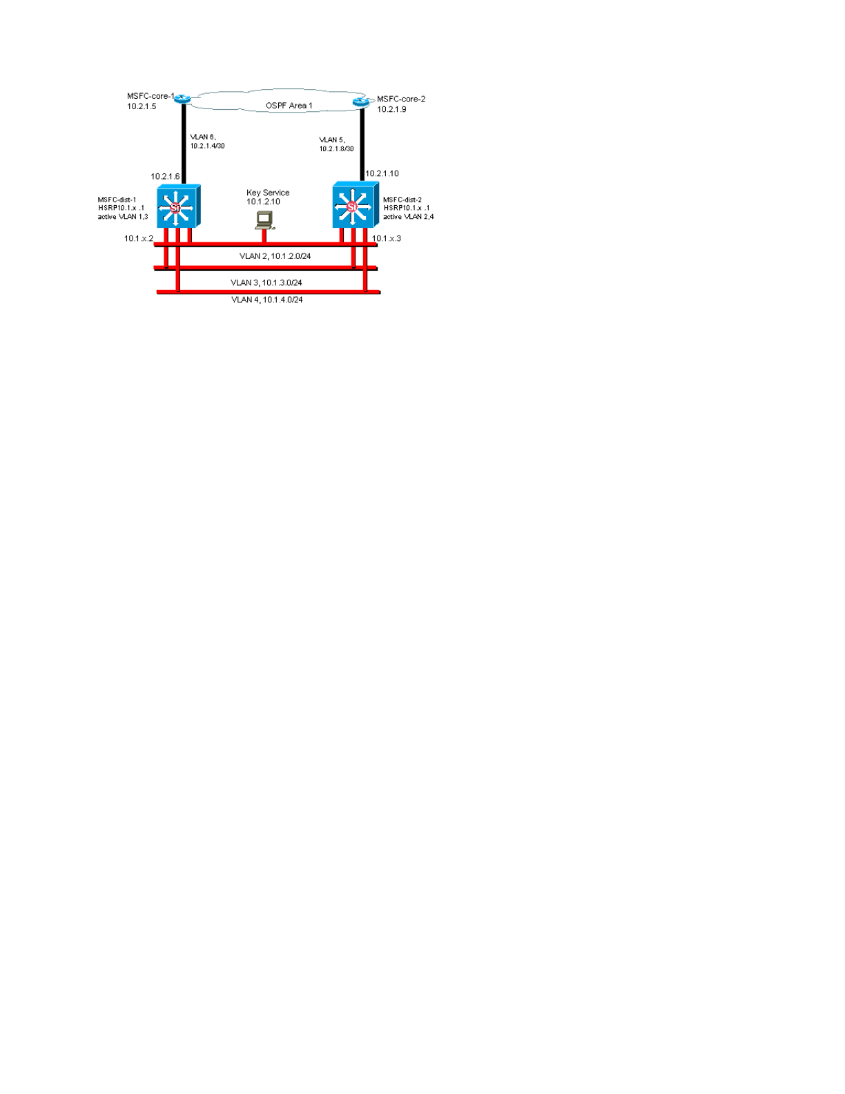
Switch Management Interface and Native VLAN
Purpose
This section describes the significance and potential problems of use of the default VLAN 1. This section also covers
potential problems when you run management traffic to the switch in the same VLAN as user traffic on 6500/6000
series switches.
The processors on the Supervisor Engines and MSFCs for the Catalyst 6500/6000 series use VLAN 1 for a number
of control and management protocols. Examples include:
-Switch control protocols:
STP BPDUs
VTP
DTP
CDP
-Management protocols:
SNMP
Telnet
Secure Shell Protocol (SSH)
Syslog
When the VLAN is used in this way, it is referred to as the native VLAN. The default switch configuration sets VLAN
1 as the default native VLAN on the Catalyst trunk ports. You can leave VLAN 1 as the native VLAN. But keep in
mind that any switches that run Cisco IOS system software in your network set all interfaces that are configured as
Layer 2 switch ports to access ports in VLAN 1 by default. Most likely, a switch somewhere in the network uses
VLAN 1 as a VLAN for user traffic.
The main concern with the use of VLAN 1 is that, in general, the Supervisor Engine NMP does not need to be
interrupted by much of the broadcast and multicast traffic that end stations generate. Multicast applications in
particular tend to send a lot of data between servers and clients. The Supervisor Engine does not need to see this
data. If the resources or buffers of the Supervisor Engine are fully occupied as the Supervisor Engine listens to
unnecessary traffic, the Supervisor Engine can fail to see management packets that can cause a spanning-tree loop
or EtherChannel failure (in the worst-case scenario).
The show interfaces interface_type slot/port counters command and the show ip traffic command can give you
some indication of:
-The proportion of broadcast to unicast traffic
-The proportion of IP to non-IP traffic (which is not typically seen in management VLANs)
VLAN 1 tags and handles most of the control plane traffic. VLAN 1 is enabled on all trunks by default. With larger
campus networks, you need to be careful of the diameter of the VLAN 1 STP domain. Instability in one part of the
network can affect VLAN 1 and can influence control plane stability and STP stability for all other VLANs. You can
limit the VLAN 1 transmission of user data and operation of STP on an interface. Simply do not configure the VLAN
on the trunk interface.
This configuration does not stop the transmission of control packets from switch to switch in VLAN 1, as with a

network analyzer. But no data are forwarded, and STP is not run over this link. Therefore, you can use this technique
to break up VLAN 1 into smaller failure domains.
Note: You cannot clear VLAN 1 from trunks to Catalyst 2900XL/3500XLs.
Even if you are careful to constrain user VLANs to relatively small switch domains and correspondingly small
failure/Layer 3 boundaries, some customers are still tempted to treat the management VLAN differently. These
customers try to cover the whole network with a single management subnet. There is no technical reason that a
central NMS application must be Layer 2-adjacent to the devices that the application manages, nor is this a qualified
security argument. Limit the diameter of the management VLANs to the same routed domain structure as that of user
VLANs. Consider out-of-band management and/or SSH support as a way to increase network management security.
Other Options
There are design considerations for these Cisco recommendations in some topologies. For example, a desirable and
common Cisco multilayer design is one that avoids the use of an active spanning tree. In this way, the design calls
for the constraint of each IP subnet/VLAN to a single access layer switch (or cluster of switches). In these designs,
no trunking can be configured down to the access layer.
Do you create a separate management VLAN and enable trunking in order to carry it between the Layer 2 access
and Layer 3 distribution layers? There is no easy answer to this question. Consider these two options for design
review with your Cisco engineer:
-Option 1—Trunk two or three unique VLANs from the distribution layer down to each access layer switch.
This configuration allows for a data VLAN, a voice VLAN, and a management VLAN, and still has the benefit
that STP is inactive. An extra configuration step is necessary in order to clear VLAN 1 from trunks. In this
solution, there are also design points to consider in order to avoid temporarily black holing routed traffic during
failure recovery. Use STP PortFast for trunks (in the future) or VLAN autostate synchronization with STP
forwarding.
-Option 2—A single VLAN for data and management can be acceptable. If you want to keep the sc0 interface
separate from the user data, newer switch hardware makes this scenario less of an issue than it once was.
The newer hardware provides:
More powerful CPUs and control-plane rate-limiting controls
A design with relatively small broadcast domains as advocated by the multilayer design
In order to make a final decision, examine the broadcast traffic profile for the VLAN and discuss the
capabilities of the switch hardware with your Cisco engineer. If the management VLAN contains all users on
that access layer switch, use IP input filters in order to secure the switch from users, as per the Cisco IOS
Software Security Features section.
Cisco Management Interface and Native VLAN Recommendation
Management Interface
Cisco IOS system software gives you the option to configure interfaces as Layer 3 interfaces or as Layer 2 switch
ports in a VLAN. When you use the switchport command in Cisco IOS Software, all switch ports are access ports in
VLAN 1 by default. So, unless you configure otherwise, user data can possibly also exist by default on VLAN 1.
Make the management VLAN a VLAN other than VLAN 1. Keep all user data out of the management VLAN. Instead,
configure a loopback0 interface as the management interface on each switch.
Note: If you use OSPF Protocol, this also becomes the OSPF router ID.
Be sure that the loopback interface has a 32-bit subnet mask, and configure the loopback interface as a pure Layer 3
interface on the switch. This is an example:
Switch(config)#interface loopback 0
Switch(config-if)#ip address 10.x.x.x 255.255.255.255
Switch(config-if)#end
Switch#
Native VLAN
Configure the native VLAN to be an obvious dummy VLAN that is never enabled on the router. Cisco recommended
VLAN 999 in the past, but the choice is purely arbitrary.
Issue these interface commands in order to establish a VLAN as the native (default) for 802.1Q trunking on a
particular port:
Switch(config)#interface type slot/port
Switch(config-if)#switchport trunk native vlan 999
For additional trunking configuration recommendations, see the Dynamic Trunking Protocol section of this document.
Out-of-Band Management
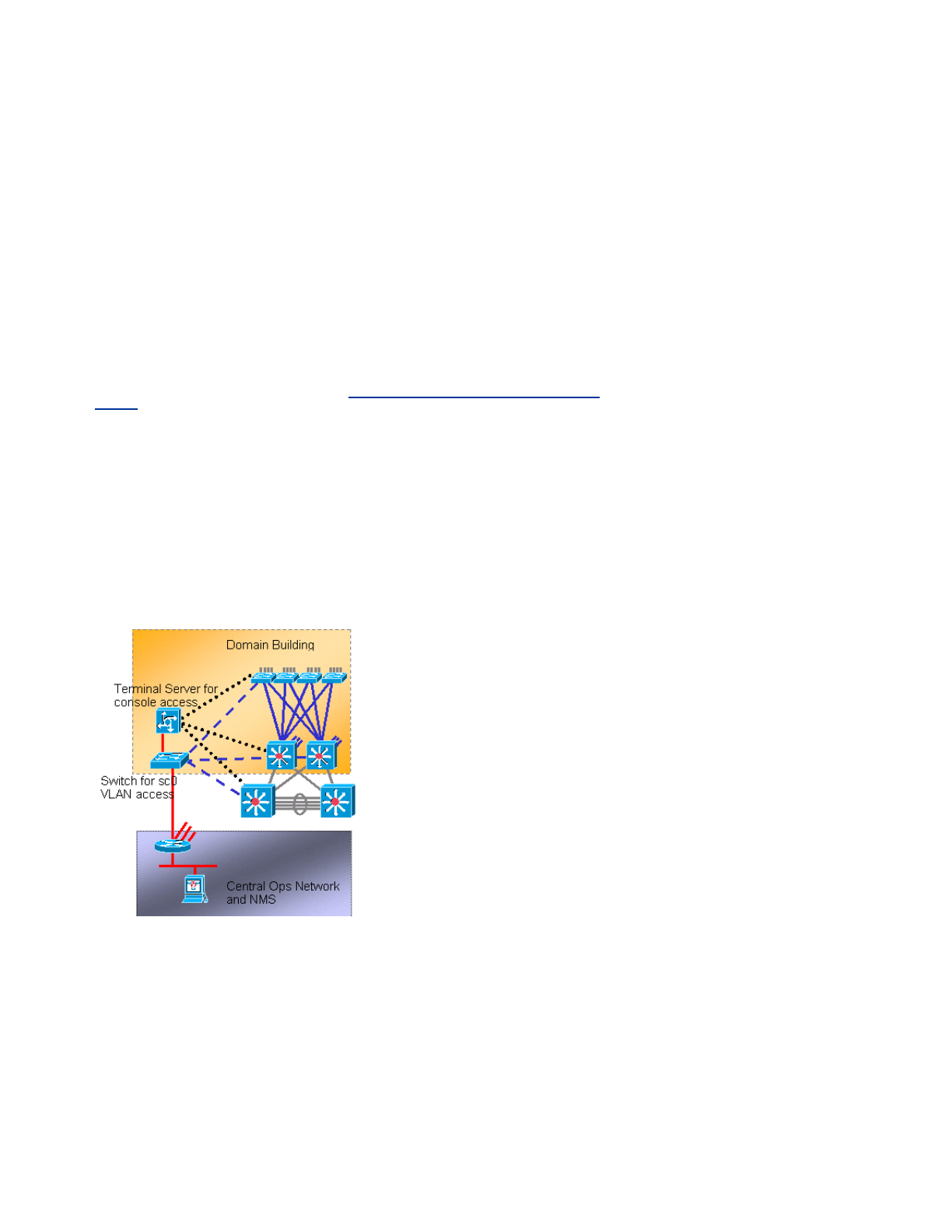
Purpose
You can make network management more highly available if you construct a separate management infrastructure
around the production network. This setup enables devices to be reachable remotely, despite the traffic that is driven
or the control-plane events that occur. These two approaches are typical:
-Out-of-band management with an exclusive LAN
-Out-of-band management with terminal servers
Operational Overview
You can provide every router and switch in the network with an out-of-band Ethernet management interface on a
management VLAN. You configure one Ethernet port on each device in the management VLAN and cable it outside
the production network to a separate switched management network.
Note: Catalyst 4500/4000 switches have a special me1 interface on the Supervisor Engine that is to be used for out-
of-band management only and not as a switch port.
In addition, you can achieve terminal server connectivity if you configure a Cisco 2600 or 3600 router with RJ-45
serial cables to access the console port of every router and switch in the layout. Use of a terminal server also avoids
the need to configure backup scenarios, such as modems on auxiliary ports for every device. You can configure a
single modem on the auxiliary port of the terminal server. This configuration provides dial-up service to the other
devices during a network connectivity failure. Refer to Connecting a Modem to the Console Port on Catalyst
Switches for more information.
Recommendation
With this arrangement, two out-of-band paths to every switch and router are possible, in addition to numerous in-
band paths. The arrangement enables highly available network management. The benefits are:
-The arrangement separates management traffic from user data.
-The management IP address is in a separate subnet, VLAN, and switch for security.
-There is higher assurance for management data delivery during network failures.
-There is no active spanning tree in the management VLAN. Redundancy here is not critical.
This diagram shows out-of-band management:
System Logging
Purpose
Syslog messages are Cisco-specific and can give more responsive and accurate information than standardized
SNMP. For example, management platforms such as Cisco Resource Manager Essentials (RME) and Network
A
nalysis Toolkit (NATKit) make powerful use of syslog information in order to collect inventory and configuration
changes.
Cisco Syslog Configuration Recommendation
System logging is a common and accepted operational practice. A UNIX syslog can capture and analyze
information/events on the router such as:
-Interface status

-Security alerts
-Environmental conditions
-CPU process hog
-Other events
Cisco IOS Software can do UNIX logging to a UNIX syslog server. The Cisco UNIX syslog format is compatible with
4.3 Berkeley Standard Distribution (BSD) UNIX. Use these Cisco IOS Software log settings:
-no logging console—By default, all system messages are sent to the system console. Console logging is a
high-priority task in Cisco IOS Software. This function was primarily designed to provide error messages to
the system operator before a system failure. Disable console logging in all device configurations in order to
avoid a situation in which the router/switch can hang while the device waits for a response from a terminal.
But console messages can be useful during trouble isolation. In these instances, enable console logging.
Issue the logging console level command in order to obtain the desired level of message logging. Logging
levels are from 0 to 7.
-no logging monitor—This command disables logging for terminal lines other than the system console.
Monitor logging can be required (with the use of logging monitor debugging or another command option). In
this case, enable monitor logging at the specific logging level that is necessary for the activity. See the no
logging console item in this list for more information about logging levels.
-logging buffered 16384—The logging buffered command needs to be added to log system messages in
the internal log buffer. The logging buffer is circular. Once the logging buffer is filled, older entries are
overwritten by newer entries. The size of the logging buffer is user-configurable and is specified in bytes. The
size of the system buffer varies by platform. 16384 is a good default that provides adequate logging in most
cases.
-logging trap notifications—This command provides notification level (5) messaging to the specified syslog
server. The default logging level for all devices (console, monitor, buffer, and traps) is debugging (level 7). If
you leave the trap logging level at 7, many extraneous messages are produced that are of little or no concern
to the health of the network. Set the default logging level for traps to 5.
-logging facility local7—This command sets the default logging facility/level for UNIX syslogging. Configure
the syslog server that receives these messages for the same facility/level.
-logging host—This command sets the IP address of the UNIX logging server.
-logging source-interface loopback 0—This command sets the default IP SA for the syslog messages. Hard
code the logging SA in order to make identification of the host that sent the message easier.
-service timestamps debug datetime localtime show-timezone msec—By default, log messages are not
timestamped. You can use this command to enable timestamping of log messages and configure
timestamping of system debug messages. Timestamping provides the relative timing of logged events and
enhances real-time debugging. This information is especially useful when customers send debugging output
to your technical support personnel for assistance. In order to enable timestamping of system debug
messages, use the command in global configuration mode. The command only has an effect when debugging
is enabled.
Note: Additionally, enable logging for link status and bundle status on all infrastructure Gigabit interfaces.
Cisco IOS Software provides a single mechanism to set the facility and log level for all system messages that are
destined to a syslog server. Set the logging trap level to notification (level 5). If you set the trap message level to
notification, you can minimize the number of informational messages that are forwarded to the syslog server. This
setting can significantly reduce the amount of syslog traffic on the network and can lessen the impact on syslog
server resources.
A
dd these commands to each router and switch that run Cisco IOS Software in order to enable syslog messaging:
-Global syslog configuration commands:
no logging console
no logging monitor
logging buffered 16384
logging trap notifications
logging facility local7
logging host-ip
logging source-interface loopback 0
service timestamps debug datetime localtime show-timezone msec
service timestamps log datetime localtime show-timezone msec
-Interface syslog configuration commands:
logging event link-status
logging event bundle-status
SNMP

Purpose
You can use SNMP to retrieve statistics, counters, and tables that are stored in network device MIBs. NMSs such as
HP OpenView can use the information in order to:
-Generate real-time alerts
-Measure availability
-Produce capacity planning information
-Help to perform configuration and troubleshooting checks
SNMP Management Interface Operation
SNMP is an application-layer protocol that provides a message format for communication between SNMP managers
and agents. SNMP provides a standardized framework and a common language for the monitor and management of
devices in a network.
The SNMP framework consists of these three parts:
-An SNMP manager
-An SNMP agent
-A MIB
The SNMP manager is the system that uses SNMP in order to control and monitor the activities of network hosts.
The most common management system is called an NMS. You can apply the term NMS to either a dedicated device
that is used for network management or the applications that are used on such a device. A variety of network
management applications are available for use with SNMP. These applications range from simple CLI applications to
feature-rich GUIs such as the CiscoWorks line of products.
The SNMP agent is the software component within the managed device that maintains the data for the device and
reports these data, as necessary, to managing systems. The agent and MIB reside on the routing device (the router,
access server, or switch). In order to enable the SNMP agent on a Cisco routing device, you must define the
relationship between the manager and the agent.
The MIB is a virtual information storage area for network management information. The MIB consists of collections of
managed objects. Within the MIB, there are collections of related objects that are defined in MIB modules. MIB
modules are written in the SNMP MIB module language, as STD 58, RFC 2578 , RFC 2579 , and RFC 2580
define.
Note: Individual MIB modules are also referred to as MIBs. For example, the interfaces group MIB (IF-MIB) is a MIB
module within the MIB on your system.
The SNMP agent contains MIB variables, the values of which the SNMP manager can request or change through get
or set operations. A manager can get a value from an agent or store a value into that agent. The agent gathers data
from the MIB, which is the repository for information about device parameters and network data. The agent can also
respond to manager requests to get or set data.
A
manager can send the agent requests to get and set MIB values. The agent can respond to these requests.
Independent of this interaction, the agent can send unsolicited notifications (traps or informs) to the manager in order
to notify the manager of network conditions. With some security mechanisms, an NMS can retrieve information in the
MIBs with get and get next requests, and can issue the set command in order to change parameters.
A
dditionally, you can set up a network device to generate a trap message to the NMS for real-time alerts. IP UDP
port 161 and 162 are used for traps.
SNMP Notifications Operational Overview
A
key feature of SNMP is the ability to generate notifications from an SNMP agent. These notifications do not require
requests to be sent from the SNMP manager. Unsolicited (asynchronous) notifications can be generated as traps or
inform requests. Traps are messages that alert the SNMP manager to a condition on the network. Inform requests
(informs) are traps that include a request for confirmation of receipt from the SNMP manager. Notifications can
indicate significant events such as:
-Improper user authentication
-Restarts
-The close of a connection
-The loss of connection to a neighbor router
-Other events
Traps are less reliable than informs because the receiver does not send any acknowledgment when the receiver
receives a trap. The sender cannot determine if the trap was received. An SNMP manager that receives an inform
request acknowledges the message with an SNMP response protocol data unit (PDU). If the manager does not
receive an inform request, the manager does not send a response. If the sender never receives a response, the
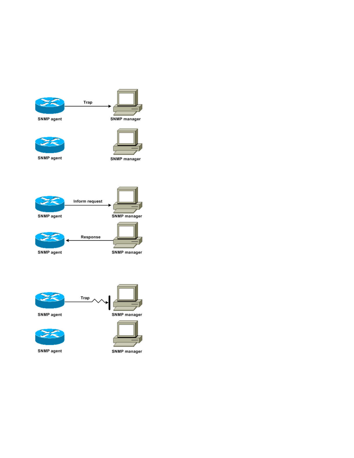
sender can send the inform request again. Informs are more likely to reach the intended destination.
But traps are often preferred because informs consume more resources in the router and in the network. A trap is
discarded as soon as it is sent. But an inform request must be held in memory until a response is received or the
request times out. Also, traps are sent only once, while an inform can be retried several times. The retries increase
traffic and contribute to a higher overhead on the network. Thus, traps and inform requests provide a trade-off
between reliability and resources. If you need the SNMP manager to receive every notification, use inform requests.
But if you have concerns about traffic on your network or memory in the router and you do not need to receive every
notification, use traps.
These diagrams illustrate the differences between traps and inform requests:
This diagram illustrates how the agent router successfully sends a trap to the SNMP manager. Although the manager
receives the trap, the manager does not send any acknowledgment to the agent. The agent has no way to know that
the trap reached the destination.
This diagram illustrates how the agent router successfully sends an inform request to the manager. When the
manager receives the inform request, the manager sends a response to the agent. In this way, the agent knows that
the inform request reached the destination. Notice that, in this example, there is twice as much traffic. But the agent
knows that the manager received the notification.
In this diagram, the agent sends a trap to the manager, but the trap does not reach the manager. The agent has no
way to know that the trap did not reach the destination, and so the trap is not sent again. The manager never
receives the trap.
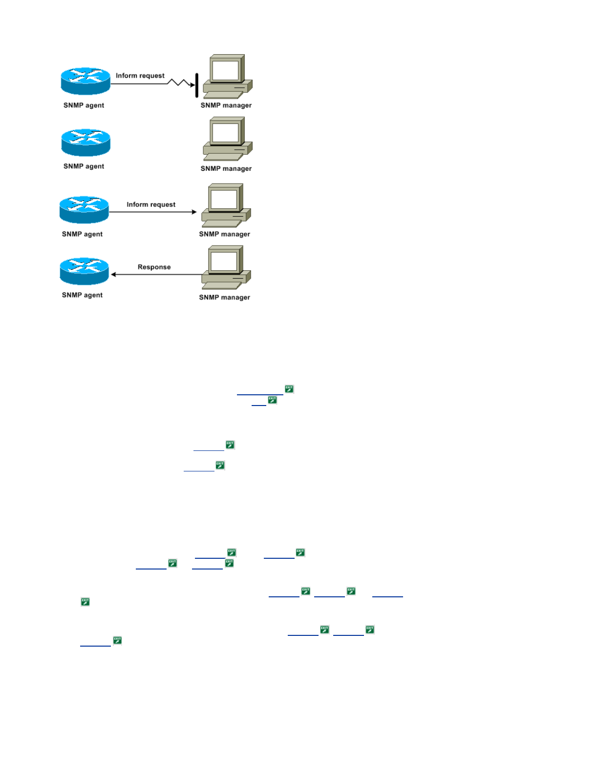
In this diagram, the agent sends an inform request to the manager, but the inform request does not reach the
manager. Because the manager did not receive the inform request, there is no response. After a period of time, the
agent resends the inform request. The second time, the manager receives the inform request and replies with a
response. In this example, there is more traffic. But the notification reaches the SNMP manager.
Cisco MIBs and RFCs Reference
RFC documents typically define MIB modules. RFC documents are submitted to the Internet Engineering Task Force
(IETF), an international standards body. Individuals or groups write RFCs for consideration by the Internet Society
(ISOC) and the Internet community as a whole. Refer to the Internet Society home page in order to learn about
the standards process and the activities of the IETF. Refer to the IETF home page in order to read the full text of
all RFCs, Internet Drafts (I-Ds), and STDs that Cisco documents reference.
The Cisco implementation of SNMP uses:
-The definitions of MIB II variables that RFC 1213 describes
-The definitions of SNMP traps that RFC 1215 describes
Cisco provides its own private MIB extensions with every system. Cisco enterprise MIBs comply with the guidelines
that the relevant RFCs describe, unless the documentation notes otherwise. You can find the MIB module definition
files and a list of the MIBs that are supported on each Cisco platform on the Cisco MIB home page.
SNMP Versions
Cisco IOS Software supports these versions of SNMP:
-SNMPv1—A full Internet standard that RFC 1157 defines. RFC 1157 replaces the earlier versions that
were published as RFC 1067 and RFC 1098 . Security is based on community strings.
-SNMPv2c—SNMPv2c is the community string-based administrative framework for SNMPv2. SNMPv2c (the c
represents community) is an experimental Internet protocol that RFC 1901 , RFC 1905 , and RFC 1906
define. SNMPv2c is an update of the protocol operations and data types of SNMPv2p (SNMPv2 Classic).
SNMPv2c uses the community-based security model of SNMPv1.
-SNMPv3—SNMPv3 is an interoperable standards-based protocol that RFC 2273 , RFC 2274 , and
RFC 2275 define. SNMPv3 provides secure access to devices with a combination of authentication and
packet encryption over the network.
The security features that SNMPv3 provides are:
Message integrity—Ensures that a packet has not been tampered with in transit.
Authentication—Determines that the message is from a valid source.

Encryption—Scrambles the contents of a packet, which prevents discovery by an unauthorized source.
Both SNMPv1 and SNMPv2c use a community-based form of security. An IP address ACL and password define the
community of managers that are able to access the agent MIB.
SNMPv2c support includes a bulk retrieval mechanism and more-detailed error message reporting to management
stations. The bulk retrieval mechanism supports the retrieval of tables and large quantities of information, which
minimizes the number of round trips that are necessary. The SNMPv2c improved error-handling support includes
expanded error codes that distinguish different kinds of error conditions. These conditions are reported through a
single error code in SNMPv1. Error return codes now report the error type.
SNMPv3 provides for both security models and security levels. A security model is an authentication strategy that is
set up for a user and the group in which the user resides. A security level is the permitted level of security within a
security model. The combination of a security model and a security level determines which security mechanism to
use when an SNMP packet is handled.
General SNMP Configuration
Issue these commands on all the customer switches in order to enable SNMP management:
-Command for SNMP ACLs:
Switch(config)#access-list 98 permit ip_address
!--- This is the SNMP device ACL.
-Global SNMP commands:
!--- These are sample SNMP community strings.
Switch(config)#snmp-server community RO-community ro 98
snmp-server community RW-community rw 98
snmp-server contact Glen Rahn (Home Number)
snmp-server location text
SNMP Trap Recommendation
SNMP is the foundation for network management, and is enabled and used on all networks.
A
n SNMP agent can communicate with multiple managers. For this reason, you can configure the software to
support communications with one management station with use of SNMPv1, and another management station with
use of SNMPv2. Most customers and NMSs still use SNMPv1 and SNMPv2c because SNMPv3 network device
support in NMS platforms lags somewhat.
Enable SNMP traps for all features that are in use. You can disable other features, if you desire. After you enable a
trap, you can issue the test snmp command and set up appropriate handling on the NMS for the error. Examples of
such handling include a pager alert or a popup.
A
ll traps are disabled by default. Enable all traps on core switches, as this example shows:
Switch(config)#snmp trap enable
Switch(config)#snmp-server trap-source loopback0
A
lso, enable port traps for key ports, such as infrastructure links to routers and switches, and key server ports.
Enablement is not necessary for other ports, such as host ports. Issue this command in order to configure the port
and enable link up/down notification:
Switch(config-if)#snmp trap link-status
Next, specify the devices to receive the traps and act on the traps appropriately. You can now configure each trap
destination as an SNMPv1, SNMPv2, or SNMPv3 recipient. For SNMPv3 devices, reliable informs can be sent rather
than UDP traps. This is the configuration:
Switch(config)#snmp-server host ip_address [traps | informs] [version {1 | 2c | 3}]
community-string
!--- This command needs to be on one line.
!--- These are sample host destinations for SNMP traps and informs.
snmp-server host 172.16.1.27 version 2c public
snmp-server host 172.16.1.111 version 1 public
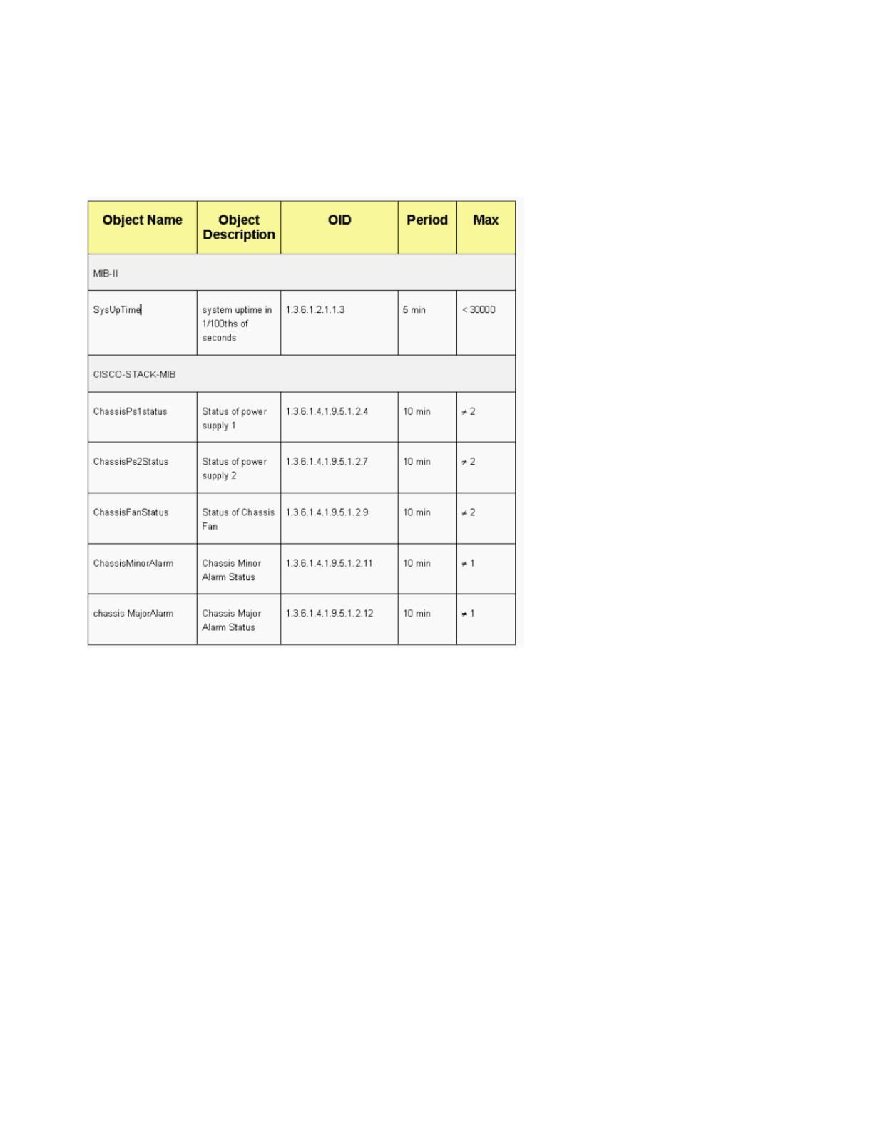
snmp-server host 172.16.1.111 informs version 3 public
snmp-server host 172.16.1.33 public
SNMP Polling Recommendations
Be sure that these MIBs are the key MIBs that are polled or monitored in campus networks:
Note: This recommendation is from the Cisco Network Management Consulting group.
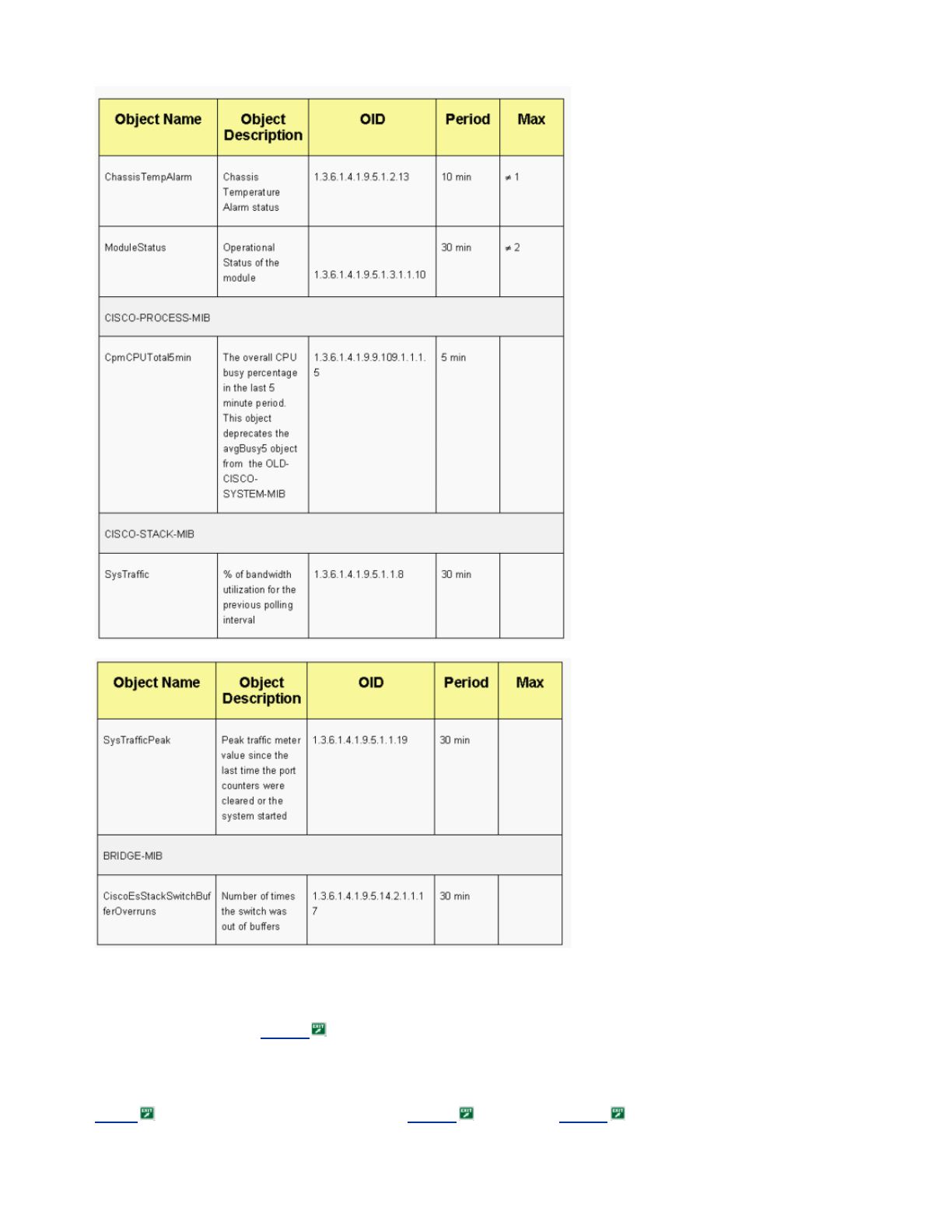
Network Time Protocol
Purpose
The Network Time Protocol (NTP), RFC 1305 , synchronizes timekeeping among a set of distributed time servers
and clients. NTP allows for the correlation of events at the creation of system logs and when other time-specific
events occur.
Operational Overview
RFC 958 documented NTP first. But NTP has evolved through RFC 1119 (NTP Version 2). RFC 1305
now defines NTP, which is in its third version.

NTP synchronizes the time of a computer client or server to another server or reference time source, such as a radio,
satellite receiver, or modem. NTP provides client accuracy that is typically within a ms on LANs and up to a few tens
of ms on WANs, relative to a synchronized primary server. For example, you can use NTP to coordinate Coordinated
Universal Time (UTC) via a global positioning service (GPS) receiver.
Typical NTP configurations utilize multiple redundant servers and diverse network paths in order to achieve high
accuracy and reliability. Some configurations include cryptographic authentication in order to prevent accidental or
malicious protocol attacks.
NTP runs over the UDP, which in turn, runs over IP. All NTP communication uses UTC, which is the same time as
Greenwich Mean Time.
Currently, NTP Version 3 (NTPv3) and NTP Version 4 (NTPv4) implementations are available. The latest software
release that is being worked on is NTPv4, but the official Internet standard is still NTPv3. In addition, some operating
system vendors customize the implementation of the protocol.
NTP Safeguards
NTP implementation also attempts to avoid synchronization to a machine on which the time cannot possibly be
accurate. NTP does this in two ways:
-NTP does not synchronize to a machine that is not synchronized itself.
-NTP always compares the time that is reported by several machines, and does not synchronize to a machine
on which the time is significantly different than the others, even if that machine has a lower stratum.
Associations
The communications between machines that run NTP, which are known as associations, are usually statically
configured. Each machine is given the IP addresses of all the machines with which it needs to form associations.
A
ccurate timekeeping is possible through the exchange of NTP messages between each pair of machines with an
association. But in a LAN environment, you can configure NTP to use IP broadcast messages. With this alternative,
you can configure the machine to send or receive broadcast messages, but the accuracy of timekeeping is
marginally reduced because the information flow is one-way only.
If the network is isolated from the Internet, the Cisco NTP implementation allows you to configure a machine so that
it acts as though it is synchronized with the use of NTP, when it actually has determined the time with the use of
other methods. Other machines synchronize to that machine with the use of NTP.
A
n NTP association can be either:
-A peer association
This means that this system can either synchronize to the other system or allow the other system to
synchronize to it.
-A server association
This means that only this system synchronizes to the other system. The other system does not synchronize to
this system.
If you want to form an NTP association with another system, use one of these commands in global configuration
mode:
Note: Only one end of an association needs to be configured. The other system automatically establishes the
association.
Access Public Time Servers
The NTP subnet presently includes over 50 public primary servers that are synchronized directly to UTC by radio,
satellite, or modem. Normally, client workstations and servers with a relatively small number of clients do not
synchronize to primary servers. There are about 100 public secondary servers that are synchronized to the primary
servers. These servers provide synchronization to a total in excess of 100,000 clients and servers on the Internet.
The Public NTP Servers page maintains the current lists and is updated frequently.
A
lso, there are numerous private primary and secondary servers that are not normally available to the public. Refer
to The Network Time Protocol Project (University of Delaware) for a list of public NTP servers and information
about how to use them. There is no guarantee that these public Internet NTP servers are available and produce the
correct time. Therefore, you must consider other options. For example, make use of various standalone GPS devices
that are directly connected to a number of routers.
Command Purpose
ntp peer ip-address [normal-sync]
[version number] [key key-id] [source
interface] [prefer]
Forms a peer
association with another
system
ntp server ip-address [version number]
[key key-id] [source interface] [prefer]
Forms a server
association with another
system

One other option is the use of various routers, set as a Stratum 1 master. But use of such a router is not
recommended.
Stratum
NTP uses a stratum in order to describe the number of NTP hops away a machine is from an authoritative time
source. A stratum 1 time server has a radio or atomic clock that is directly attached. A stratum 2 time server receives
its time from a stratum 1 time server, and so on. A machine that runs NTP automatically chooses as its time source
the machine with the lowest stratum number with which it is configured to communicate through NTP. This strategy
effectively builds a self-organizing tree of NTP speakers.
NTP avoids synchronization to a device on which the time is possibly not accurate. See the NTP Safeguards section
of Network Time Protocol for details.
Server Peer Relationship
-A server responds to client requests but does not try to incorporate any date information from a client time
source.
-A peer responds to client requests and tries to use the client request as a potential candidate for a better time
source and to aid in stabilization of its clock frequency.
-In order to be true peers, both sides of the connection must enter into a peer relationship, rather than a
situation in which one user serves as a peer and the other user serves as a server. Have peers exchange
keys so that only trusted hosts can talk to others as peers.
-In a client request to a server, the server answers the client and forgets that the client asked a question.
-In a client request to a peer, the server answers the client. The server keeps state information about the client
in order to track how well the client does at timekeeping and what stratum server the client runs.
A
n NTP server can handle many thousands of clients with no problem. But when an NTP server handles more than a
few clients (up to a few hundred), there is a memory impact on the server ability to retain state information. When an
NTP server handles more than the recommended amount, more CPU resources and bandwidth are consumed on
the box.
Modes of Communication with the NTP Server
These are two separate modes to communicate with the server:
-Broadcast mode
-Client/server mode
In the broadcast mode, the clients listen. In client/server mode, the clients poll the server. You can use NTP
broadcast if no WAN link is involved because of its speed. In order to go across a WAN link, use the client/server
mode (by polling). Broadcast mode is designed for a LAN, in which many clients can possibly need to poll the server.
Without broadcast mode, such polling can possibly generate a large number of packets on the network. NTP
multicast is not yet available in NTPv3, but is available in NTPv4.
By default, Cisco IOS Software communicates with the use of NTPv3. But the software is backward compatible with
earlier versions of NTP.
Polling
The NTP protocol allows a client to query a server at any time.
When you first configure NTP in a Cisco box, NTP sends out eight queries in rapid succession at NTP_MINPOLL
(2^4=16 sec) intervals. The NTP_MAXPOLL is 2^14 seconds (16,384 sec or 4 hours, 33 min, 4 sec). This period of
time is the longest period before NTP polls again for a response. Currently, Cisco does not have a method to allow
the user to manually force the POLL time.
The NTP polling counter starts at 2^6 (64) sec, or 1 min, 4 sec. This time is incremented by powers of 2, as the two
servers synchronize with each other, to 2^10. You can expect the sync messages to be sent at an interval of one of
64, 128, 256, 512, or 1024 sec, as per the server or peer configuration. The longer time between polls occurs as the
current clock becomes more stable because of the phase-locked loops. The phase-locked loops trim the local clock
crystal, up to 1024 seconds (17 min).
The time varies between 64 seconds and 1024 seconds as a power of 2 (which equates to once every 64, 128, 256,
512, or 1024 sec). The time is based on the phase-locked loop that sends and receives packets. If there is a lot of
j
itter in the time, polling occurs more often. If the reference clock is accurate and the network connectivity is
consistent, the poll times converge on 1024 seconds between each poll.
The NTP poll interval changes as the connection between the client and server changes. With a better connection,
the poll interval is longer. In this case, a better connection means that the NTP client has received eight responses
for the last eight requests. The poll interval is then doubled. A single missed response causes the poll interval to be
reduced by half. The poll interval starts out at 64 seconds and goes to a maximum of 1024 sec. In the best
circumstances, the time required for the poll interval to go from 64 seconds to 1024 seconds is a little more than 2
hours.
Broadcasts

NTP broadcasts are never forwarded. If you issue the ntp broadcast command, the router begins to originate NTP
broadcasts on the interface on which it is configured.
Typically, you issue the ntp broadcast command in order to send NTP broadcasts out onto a LAN in order to service
the client end stations and servers.
Time Synchronization
Synchronization of a client to a server consists of several packet exchanges. Each exchange is a request/reply pair.
When a client sends a request, the client stores its local time into the sent packet. When a server receives the
packet, it stores its own estimate of the current time into the packet, and the packet is returned. When the reply is
received, the receiver once more logs its own receipt time in order to estimate the travel time of the packet.
These time differences can be used in order to estimate the time that was necessary for the packet to transmit from
the server to the requester. That roundtrip time is taken into account for an estimation of the current time. The shorter
the roundtrip time is, the more accurate is the estimate of the current time.
The time is not accepted until several agreeing packet exchanges have taken place. Some essential values are put
into multistage filters in order to estimate the quality of the samples. Usually, about 5 minutes are necessary for an
NTP client to synchronize to a server. Interestingly, this is also true for local reference clocks that have no delay at all
by definition.
In addition, the quality of the network connection also influences the final accuracy. Slow and unpredictable networks
with varying delays have a bad effect on time synchronization.
A
time difference of less than 128 ms is required in order for NTP to synchronize. The typical accuracy on the
Internet ranges from about 5 ms to 100 ms, which can vary with network delays.
NTP Traffic Levels
The bandwidth that the NTP utilizes is minimal. The interval between polling messages that peers exchange usually
ratchets back to no more than one message every 17 min (1024 sec). With careful planning, you can maintain this
within router networks ove
r
the WAN links. Have the NTP clients peer to local NTP servers and not all the way
across the WAN to the central-site core routers, which are the Stratum 2 servers.
A
converged NTP client uses about 0.6-bits per second (bps) averages per server.
Cisco NTP Recommendation
-Cisco recommends that you have multiple time servers and diverse network paths in order to achieve high
accuracy and reliability. Some configurations include cryptographic authentication in order to prevent
accidental or malicious protocol attacks.
-As per the RFC, NTP is really designed to allow you to poll several different time servers and use complicated
statistical analysis in order to come up with a valid time, even if you are not certain that all the servers that you
poll are authoritative. NTP estimates the errors of all clocks. Therefore, all NTP servers return the time
together with an estimate of the current error. When you use multiple time servers, NTP also wants these
servers to agree on some time.
-The Cisco implementation of NTP does not support stratum 1 service. You cannot connect to a radio or
atomic clock. Cisco recommends that the time service for your network be derived from the public NTP
servers that are available on the IP Internet.
-Enable all the client switches to regularly send time-of-day requests to an NTP server. You can configure up
to 10 server/peer addresses per client so that you can achieve fast synchronization.
-In order to reduce the protocol overhead, the secondary servers distribute time via NTP to the remaining
local-net hosts. In the interest of reliability, you can equip selected hosts with less-accurate but less-expensive
clocks to use for backup in the case of a failure of either the primary and/or secondary servers or the
communication paths between them.
-ntp update-calendar—NTP usually changes only the system clock. This command allows NTP to update the
date/time information on the calendar. The update is done only if the NTP time is synchronized. Otherwise,
the calendar keeps its own time and is unaffected by the NTP time or system clock. Always use this on the
high-end routers.
-clock calendar-valid—This command declares that the calendar information is valid and synchronized. Use
this option on the NTP master. If this is not configured, the high-end router that has the calendar still thinks
that its time is unauthoritative, even if it has the NTP master line.
-Any stratum number that is over 15 is considered unsynchronized. This is why you see stratum 16 in the
output of the show ntp status command on routers for which the clocks are unsynchronized. If the master is
synchronized with a public NTP server, make sure that the stratum number on the NTP master line is one or
two higher than the highest stratum number on the public servers that you poll.
-Many customers have NTP configured in server mode on their Cisco IOS Software platforms, synchronized
from several reliable feeds from the Internet or a radio clock. Internally, a simpler alternative to server mode
when you operate a large number of switches is to enable NTP in broadcast mode on the management VLAN
in a switched domain. This mechanism allows the Catalyst to receive a clock from single broadcast
messages. But the accuracy of timekeeping is marginally reduced because the information flow is one-way.
-The use of loopback addresses as the source of updates can also help with consistency. You can address
security concerns in two ways:

With the control of server updates, which Cisco recommends
By authentication
NTP Global Configuration Commands
!--- For the client:
clock timezone EST -5 ????
ntp source loopback 0 ?????
ntp server ip_address key 1
ntp peer ip_address
!--- This is for a peer association.
ntp authenticate
ntp authentication-key 1 md5 xxxx
ntp trusted-key 1
!--- For the server:
clock timezone EST -5
clock summer-time EDT recurring 1 Sun Apr 3:00 last Sun Oct 3:00
clock calendar-valid
ntp source loopback0
ntp update-calendar
!--- This is optional:
interface vlan_id ntp broadcast
!--- This sends NTP broadcast packets.
ntp broadcast client
!--- This receives NTP broadcast packets.
ntp authenticate
ntp authentication-key 1 md5 xxxxx
ntp trusted-key 1
ntp access-group access-list
!--- This provides further security, if needed.
NTP Status Command
show ntp status
Clock is synchronized, stratum 8, reference is 127.127.7.1
nominal freq is 250.0000 Hz, actual freq is 249.9974 Hz, precision is 2**18
reference time is C6CF0C30.980CCA9D (01:34:00.593 IST Mon Sep 12 2005)
clock offset is 0.0000 msec, root delay is 0.00 msec
root dispersion is 0.02 msec, peer dispersion is 0.02 msec
This is the reference clock address for the Cisco router when the router acts as an NTP master. If the router has not
been synchronized with any NTP server, the router uses this address as the reference ID. For details on the
configuration and commands, refer to the Configuring NTP section of Performing Basic System Management .
Cisco Discovery Protocol
Purpose

CDP runs over Layer 2 (data link layer) on all Cisco routers, bridges, access servers, and switches. CDP allows
network management applications to discover Cisco devices that are neighbors of already-known devices. In
particular, network management applications can discover neighbors that run lower-layer transparent protocols. With
CDP, network management applications can learn the device type and the SNMP agent address of neighboring
devices. This feature enables applications to send SNMP queries to neighboring devices.
The show commands that are associated with the CDP feature enable the network engineer to determine this
information:
-The module/port number of other, adjacent CDP-enabled devices
-These addresses of the adjacent device:
MAC address
IP address
Port-channel address
-The adjacent device software version
-This information about the adjacent device:
Speed
Duplex
VTP domain
Native VLAN setting
The Operational Overview section highlights some of the enhancements of CDP version 2 (CDPv2) over CDP
version 1 (CDPv1).
Operational Overview
CDP runs on all LAN and WAN media that support SNAP.
Each CDP-configured device sends periodic messages to a multicast address. Each device advertises at least one
address at which the device can receive SNMP messages. The advertisements also contain the time-to-live, or hold
time, information. This information indicates the length of time for a receiving device to hold CDP information before
discard.
CDP uses SNAP encapsulation with type code 2000. On Ethernet, ATM, and FDDI, the destination multicast address
01-00-0c-cc-cc-cc is used. On Token Rings, the functional address c000.0800.0000 is used. CDP frames are sent
periodically every minute.
CDP messages contain one or more messages that allow the destination device to gather and store information
about every neighbor device.
This table provides the parameters that CDPv1 supports:
Parameter Type Description
1Device ID Host name of the device or hardware
serial number in ASCII
2Address The Layer 3 address of the interface that
sends the update
3Port ID The port on which the CDP update is
sent
4Capabilities
Describes the device functional
capabilities in this way:
-Router: 0x01
-SR1 bridge: 0x04
-Switch: 0x08 (provides Layer 2
and/or Layer 3 switching)
-Host: 0x10
-IGMP conditional filtering: 0x20
-Bridge or switch does not forward
IGMP report packets on nonrouter
ports.
5Version
A character string that contains the
software version
Note: The show version command
output shows the same information.
6Platform The hardware platform, for example, WS-

1 SR = source-route.
2 RSP = Route Switch Processor.
In CDPv2, additional type, length, values (TLVs) have been introduced. CDPv2 supports any TLV. But this table
provides the parameters that can be particularly useful in switched environments and that Catalyst software uses.
When a switch runs CDPv1, the switch drops CDPv2 frames. When a switch runs CDPv2 and receives a CDPv1
frame on an interface, the switch starts to send CDPv1 frames out of that interface, in addition to CDPv2 frames.
CDPv2/Power over Ethernet
Some switches, like the Catalyst 6500/6000 and 4500/4000, have the ability to supply power via unshielded twisted
pair (UTP) cables to powerable devices. Information that is received via CDP (Parameters 16, 25, 26) assists in the
optimization of switch power management.
CDPv2/Cisco IP Phone Interaction
Cisco IP phones provide connectivity for an externally attached 10/100-Mbps Ethernet device. This connectivity is
achieved through the integration of an internal three-port Layer 2 switch within the IP phone. The internal switch
ports are referred to as:
-P0 (internal IP phone device)
-P1 (external 10/100-Mbps port)
-P2 (external 10/100-Mbps port that connects to the switch)
You can transfer voice traffic on a separate VLAN on the switch port if you configure dot1q access trunk ports. This
additional VLAN is known as the auxiliary (CatOS) or voice (Cisco IOS Software) VLAN. Consequently, dot1q tagged
traffic from the IP phone can be sent on the auxiliary/voice VLAN, and untagged traffic can be sent via the external
10/100-Mbps port of the phone via the access VLAN.
Catalyst switches can inform an IP phone of the voice VLAN ID via CDP (Parameter-14: Appliance VLAN-ID TLV).
A
s a result, the IP phone tags all VoIP-related packets with the appropriate VLAN ID and 802.1p priority. This CDP
TLV is also used to identify if an IP phone is connected via the appliance ID parameter.
This concept can be exploited when you develop a QoS policy. You can configure the Catalyst switch to interact with
the IP phone in three ways:
C5000, WS-C6009, and Cisco RSP2
Parameter Type Description
9VTP Domain The VTP domain, if it is configured on
the device
10 Native VLAN
In dot1q, the frames for the VLAN,
which the port is in if the port is not
trunking, remain untagged. This is
usually referred to as the native
VLAN.
11 Full/Half
Duplex This TLV contains the duplex setting
of the sending port.
14 Appliance
VLAN-ID
Allows the VoIP traffic to be
differentiated from other traffic by
means of a separate VLAN ID
(auxiliary VLAN).
16 Power
Consumption
The maximum amount of power that
is expected to be consumed, in mW,
by the connected device.
17 MTU The MTU of the interface by which
the CDP frame is transmitted.
18 Extended Trust Indicates that the port is in Extended
Trust mode.
19 COS for
Untrusted
Ports
The class of service (CoS) value to
be used to mark all packets that are
received on the untrusted port of a
connected switching device.
20 SysName Fully qualified domain name of the
device (0, if unknown).
25 Power
Requested
Transmitted by a powerable device in
order to negotiate a suitable power
level.
26 Power
Available
Transmitted by a switch. Permits a
powerable device to negotiate and
select an appropriate power setting.

-Trust Device Cisco IP Phone
Conditionally trust CoS only when an IP phone is detected via CDP. Whenever an IP phone is detected via
CDP Parameter-14, the port trust state is set to Trust COS. If no IP phone is detected, the port is Untrusted.
-Extended Trust
The switch can inform the IP phone via CDP (Parameter-18) to trust all frames that are received on its
external 10/100-Mbps device port.
-Rewrite COS for Untrusted Ports
The switch can inform the IP phone via CDP (Parameter-19) to rewrite the 802.1p CoS values that are
received on its external 10/100-Mbps device port.
Note: By default, all traffic that is received on the IP phone external 10/100-Mbps ports is Untrusted.
Note: This is an example configuration for how to connect the non-Cisco IP Phone to a switch.
Note: For example,
Switch(config)#interface gigabitEthernet 2/1
Switch(config-if)#switchport mode trunk
!--- For example use VLAN 30 for voice VLAN, and VLAN 10 for access VLAN.
Switch(config-if)#switchport trunk native vlan 10
Switch(config-if)#switchport trunk allow vlan 10,30
Switch(config-if)#switchport voice vlan 30
Switch(config-if)#spanning-tree portfast trunk
!--- And besides that enable LLDP as Non Cisco IP Phone do not use CDP.
Switch(config)#lldp run
Cisco Configuration Recommendation
The information that CDP provides can be an extremely useful when you troubleshoot Layer 2 connectivity issues.
Enable CDP on all devices that support its operation. Issue these commands:
-In order to enable CDP globally on the switch:
Switch(config)#cdp run
-In order to enable CDP on a per-port basis:
Switch(config)#interface type slot#/port#
Switch(config-if)#cdp enable
Configuration Checklist
Global Commands
Log in, enable, and enter global configuration mode in order to begin the switch configuration process.
Switch>enable
Switch#
Switch#configure terminal
Switch(Config)#
Generic Global Commands (Enterprise-Wide)
This Global Commands section lists the global commands to apply to all the switches in the customer enterprise
network.
This configuration contains the recommended global commands to add to the initial configuration. You must change
the values in the output before you copy and paste the text into the CLI. Issue these commands in order to apply the
global configuration:
vtp domain domain_name
vtp mode transparent

spanning-tree portfast bpduguard
spanning-tree etherchannel guard misconfig
cdp run
no service pad
service password-encryption
enable secret password
clock timezone EST –5
clock summer-time EDT recurring 1 Sun Apr 3:00 last Sun Oct 3:00
clock calendar-valid
ip subnet-zero
ip host tftpserver your_tftp_server
ip domain-name domain_name
ip name-server name_server_ip_address
ip name-server name_server_ip_address
ip classless
no ip domain-lookup
no ip http server
no logging console
no logging monitor
logging buffered 16384
logging trap notifications
logging facility local7
logging syslog_server_ip_address
logging syslog_server_ip_address
logging source-interface loopback0
service timestamps debug datetime localtime show-timezone msec
service timestamps log datetime localtime show-timezone msec
access-list 98 permit host_ip_address_of_primary_snmp_server
access-list 98 permit host_ip_address_of_secondary_snmp_server
snmp-server community public ro 98
snmp-server community laneng rw 98
snmp-server enable traps entity
snmp-server host host_address traps public
snmp-server host host_address traps public
banner motd ^CCCCC
This is a proprietary system, NOT for public or personal use. All work products,
communications, files, data or information directly or indirectly created, input
or accessed on this system are and shall become the sole property of the company.
This system is actively monitored and accessed by the company. By logging onto
this system, the user consents to such monitoring and access.
USE OF THIS SYSTEM WITHOUT OR IN EXCESS OF THE PROPER AUTHORIZATION MAY SUBJECT
THE USER TO DISCIPLINE AND/OR CIVIL AND CRIMINAL PENALTIES
^C
line console 0
exec-timeout 0 0
password cisco
login
transport input none
line vty 0 4
exec-timeout 0 0
password cisco
login
length 25
clock calendar-valid
ntp server ntp_server_ip_address
ntp server ntp_server_ip_address
ntp update-calendar

Global Commands That Are Specific to Each Switch Chassis
The global commands in this section are specific to each switch chassis that is installed in the network.
Chassis-Specific Configuration Variables
In order to set the date and time, issue this command:
Switch#clock set hh:mm:ss day month year
In order to set the device host name, issue these commands:
Switch>enable
Switch#configure terminal
Enter configuration commands, one per line. End with CNTL/Z.
Switch(config)#hostname Cat6500
In order to configure loopback interface for management, issue these commands:
CbrCat6500(config)#interface loopback 0
Cat6500(config-if)#description Cat6000 - Loopback address and Router ID
Cat6500(config-if)#ip address ip_address subnet_mask
Cat6500(config-if)#exit
In order to show the Supervisor Engine Cisco IOS Software revision, issue these commands:
Cbrcat6500#show version | include IOS
IOS (tm) MSFC Software (C6MSFC-DSV-M), Version 12.1(13)E9, EARLY DEPLOYMENT RELE
ASE SOFTWARE (fc1)
cat6500#
In order to show the MSFC boot file revision, issue this command:
Cat6500#dir bootflash:
Directory of bootflash:/
1 -rw- 1879040 Aug 19 2003 19:03:29 c6msfc-boot-mz.121-19.E1a
15990784 bytes total (14111616 bytes free
In order to specify the SNMP server contact information and location, issue these commands:
Cat6500(config)#snmp-server contact contact_information
Cat6500(config)#snmp-server location location_of_device
Interface Commands
Cisco Functional Port Types
Switch ports in Cisco IOS Software are referred as interfaces. There are two types of interface modes in Cisco IOS
Software:
-Layer 3 routed interface
-Layer 2 switch interface
Interface function refers to how you have configured the port. The port configuration can be:
-Routed interface
-Switched virtual interface (SVI)
-Access port
-Trunk
-EtherChannel
-A combination of these
Interface type refers to a port type. The port type can be either:

-FE
-GE
-Port channel
This list briefly describes different Cisco IOS Software interface functions:
-Routed Physical Interface (default)—Each interface on the switch is a routed Layer 3 interface by default,
which is similar to any Cisco router. The routed interface must fall on a unique IP subnet.
-Access switch port interface—This function is used to place interfaces in the same VLAN. Ports must be
converted from a routed interface to a switched interface.
-SVI—An SVI can be associated with a VLAN that contains access switch ports for interVLAN routing.
Configure the SVI to be associated with a VLAN when you want a route or bridge between access switch
ports on different VLANs.
-Trunk switch port interface—This function is used to carry multiple VLANs to another device. Ports must be
converted from a routed interface to a trunk switch port.
-EtherChannel—An EtherChannel is used to bundle individual ports into a single logical port for redundancy
and load balancing.
Cisco Functional Port Type Recommendations
Use the information in this section in order to help determine the parameters to apply to the interfaces.
Note: Some interface-specific commands are incorporated where possible.
Autonegotiation
Do not use autonegotiation in either of these situations:
-For ports that support network infrastructure devices such as switches and routers
-For other nontransient end systems such as servers and printers
Manually configure for speed and duplex these 10/100-Mbps link configurations. The configurations are usually 100-
Mbps full-duplex:
-100 MB link switch-to-switch
-100 MB link switch-to-server
-100 MB link switch-to-router
You can configure these settings in this way:
Cat6500(config-if)#interface [type] mod#/port#
Cat6500(config-if)#speed 100
Cat6500(config-if)#duplex full
Cisco recommends 10/100-Mbps link configurations for end users. Mobile workers and transient hosts need
autonegotiation, as this example shows:
Cat6500(config-if)#interface [type] mod#/port#
Cat6500(config-if)#speed auto
The default value on Gigabit interfaces is auto-negotiation. But issue these commands in order to ensure that
autonegotiation is enabled. Cisco recommends the enablement of Gigabit negotiation:
Cat6500(config-if)#interface gigabitethernet mod#/port#
Cat6500(config-if)#no speed
Spanning Tree Root
With consideration of the design of the network, identify the switch that is best suited to be the root for each VLAN.
Generally, choose a powerful switch in the middle of the network. Put the root bridge in the center of the network and
directly connect the root bridge to the servers and routers. This setup generally reduces the average distance from
the clients to the servers and routers. Refer to Spanning Tree Protocol Problems and Related Design Considerations
for more information.
In order to force a switch to be the root for a designated VLAN, issue this command:

Cat6500(config)#spanning-tree vlan vlan_id root primary
Spanning Tree PortFast
PortFast bypasses normal spanning tree operation on access ports in order to speed up the initial connectivity delays
that occur when end stations are connected to a switch. Refer to Using PortFast and Other Commands to Fix
Workstation Startup Connectivity Delays for more information on PortFast.
Set STP PortFast to on for all enabled access ports that are connected to a single host. This is an example:
Cat6500(config-if)#interface [type] mod#/port#
Cat6500(config-if)#spanning-tree portfast
%Warning: portfast should only be enabled on ports connected to a single
host. Connecting hubs, concentrators, switches, bridges, etc... to this
interface when portfast is enabled, can cause temporary bridging loops.
Use with CAUTION
%Portfast has been configured on FastEthernet3/1 but will only have effect
when the interface is in a non-trunking mode.
UDLD
Enable UDLD only on fiber-connected infrastructure ports or copper Ethernet cables in order to monitor the physical
configuration of the cables. Issue these commands in order to enable UDLD:
Cat6500(config)#interface [type] mod#/port#
Cat6500(config-if)#udld enable
VLAN Configuration Information
Configure VLANs with these commands:
Cat6500(config)#vlan vlan_number
Cat6500(config-vlan)#name vlan_name
Cat6500(config-vlan)#exit
Cat6500(config)#spanning-tree vlan vlan_id
Cat6500(config)#default spanning-tree vlan vlan_id
Repeat the commands for each VLAN, and then exit. Issue this command:
Cat6500(config)#exit
Issue this command in order to verify all the VLANs:
Cat6500#show vlan
Routed SVIs
Configure the SVIs for interVLAN routing. Issue these commands:
Cat6500(config)#interface vlan vlan_id
Cat6500(config-if)#ip address svi_ip_address subnet_mask
Cat6500(config-if)#description interface_description
Cat6500(config-if)#no shutdown
Repeat these commands for each interface function that contains a routed SVI, and then exit. Issue this command:
Cat6500(config-if)#^Z
Routed Single Physical Interface
Issue these commands in order to configure the default routed Layer 3 interface:
Cat6500(config)#interface [type] mod#/port#

Cat6500(config-if)#ip address ip_address subnet_mask
Cat6500(config-if)#description interface_description
Repeat these commands for each interface function that contains a routed physical interface, and then exit. Issue
this command:
Cat6500(config-if)#^Z
Routed EtherChannel (L3)
In order to configure EtherChannel on Layer 3 interfaces, issue the commands in this section.
Configure a logical port-channel interface in this way:
Cat6500(config)#interface port-channel port_channel_interface_#
Cat6500(config-if)#description port_channel_description
Cat6500(config-if)#ip address port_channel_ip_address subnet_mask
Cat6500(config-if)#no shutdown
Perform the steps in this section for the ports that forms that particular channel. Apply the remaining information to
the port channel, as this example shows:
Cat6500(config)#interface range [type] mod/port_range
Cat6500(config-if)#channel-group 1-64 mode [active | auto | desirable | on | passive]
Cat6500(config-if)#no shutdown
Cat6500(config-if)#^Z
Note: After you configure an EtherChannel, the configuration that you apply to the port channel interface affects the
EtherChannel. The configuration that you apply to the LAN ports affects only the LAN port where you apply the
configuration.
EtherChannel (L2) with Trunking
Configure the Layer 2 EtherChannel for trunking in this way:
Cat6500(config)#interface port-channel port_channel_interface_#
Cat6500(config-if)#switchport
Cat6500(config-if)#switchport encapsulation encapsulation_type
Cat6500(config-if)#switchport trunk native vlan vlan_id
Cat6500(config-if)#no shutdown
Cat6500(config-if)#exit
Perform the steps in this section only for the ports that forms that particular channel.
Cat6500(config)#interface range [type] mod/port_range
Cat6500(config-if)#channel-group 1-64 mode [active | auto | desirable | on | passive]
Cat6500(config-if)#no shutdown
Cat6500(config-if)#exit
Note: After you configure an EtherChannel, the configuration that you apply to the port channel interface affects the
EtherChannel. The configuration that you apply to the LAN ports affects only the LAN port where you apply the
configuration.
Verify the creation of all the EtherChannels and trunks. This is an example:
Cat6500#show etherchannel summary
Cat6500#show interface trunk
Access Ports
If the interface function is an access port that is configured as a single interface, issue these commands:
Cat6500(config)#interface [type] mod#/port#

Cat6500(config-if)#switchport mode access
Cat6500(config-if)#switchport access vlan vlan_id
Cat6500(config-if)#exit
Repeat these commands for each interface that needs to be configured as an Layer 2 switch port.
If the switch port is to be connected to end stations, issue this command:
Cat6500(config-if)#spanning-tree portfast
Trunk Port (Single Physical Interface)
If the interface function is a trunk port that is configured as a single interface, issue these commands:
Cat6500(config)#interface [type] mod#/port#
Cat6500(config-if)#switchport
Cat6500(config-if)#switchport trunk encapsulation dot1q
Cat6500(config-if)#switchport trunk native vlan vlan_id
Cat6500(config-if)#no shutdown
Cat6500(config-if)#exit
Repeat these commands for each interface function that needs to be configured as a trunk port.
Password Information
Issue these commands for password information:
Cat6500(config)#service password-encryption
Cat6500(config)#enable secret password
CbrCat6500(config)#line con 0
Cat6500(config-line)#password password
CbrCat6500(config-line)#line vty 0 4
Cat6500(config-line)#password password
Cat6500(config-line)#^Z
Save the Configuration
Issue this command in order to save the configuration:
Cat6500#copy running-config startup-config
New Software Features in Cisco IOS Software Release 12.1(13)E
Refer to Configuring Cisco IP Phone Support for more information on IP phone support.
Refer to Network-Based Application Recognition and Distributed Network-Based Application Recognition for more
information on Network-Based Application Recognition (NBAR) for LAN ports.
Notes:
-NBAR for LAN ports is supported in software on the MSFC2.
-The PFC2 provides hardware support for input ACLs on LAN ports where you configure NBAR.
-When PFC QoS is enabled, the traffic through LAN ports where you configure NBAR passes through the
ingress and egress queues and drop thresholds.
-When PFC QoS is enabled, the MSFC2 sets egress class of service (CoS) equal to egress IP precedence.
-After traffic passes through an ingress queue, all traffic is processed in software on the MSFC2 on LAN ports
where you configure NBAR.
-Distributed NBAR is available on FlexWAN interfaces with Cisco IOS Software Release 12.1(6)E and later.
NetFlow Data Export (NDE) enhancements include:

-Destination-source-interface and full-interface flow masks
-NDE version 5 from the PFC2
-Sampled NetFlow
-An option to populate these additional fields in NDE records:
IP address of the next hop router
Ingress interface SNMP ifIndex
Egress interface SNMP ifIndex
Source autonomous system number
Refer to Configuring NDE for more information on these enhancements.
Other feature enhancements include:
-Configuring UDLD
-Configuring VTP
-Configuring Web Cache Services Using WCCP
These commands are new commands:
-standby delay minimum reload
-link debounce
-vlan internal allocation policy {ascending | descending}
-system jumbomtu
-clear catalyst6000 traffic-meter
These commands are enhanced commands:
-show vlan internal usage—This command was enhanced to include VLANs that WAN interfaces use.
-show vlan id—This command was enhanced to support the entry of a range of VLANs.
-show l2protocol-tunnel—This command was enhanced to support the entry of a VLAN ID.
Cisco IOS Software Release 12.1(13)E supports these software features, which were previously supported in Cisco
IOS Software Release 12.1 EX releases:
-Configuration of Layer 2 EtherChannels that include interfaces on different DFC-equipped switching modules
Refer to the Resolved General Caveats in Release 12.1(13)E section of Cisco bug ID CSCdt27074
(registered customers only) .
-Route Processor Redundancy Plus (RPR+) redundancy
Refer to Configuring RPR or RPR+ Supervisor Engine Redundancy.
Note: In Cisco IOS Software Release 12.1(13)E and later, the RPR and RPR+ redundancy features replace
enhanced high system availability (EHSA) redundancy.
-4,096 Layer 2 VLANs
Refer to Configuring VLANs.
Note: Cisco IOS Software Release 12.1(13)E and later releases support configuration of 4,096 Layer 3 VLAN
interfaces. Configure a combined total of no more than 2,000 Layer 3 VLAN interfaces and Layer 3 ports on
an MSFC2 with either a Supervisor Engine II or a Supervisor Engine I. Configure a combined total of no more
than 1,000 Layer 3 VLAN interfaces and Layer 3 ports on an MSFC.
-IEEE 802.1Q tunneling
Refer to Configuring IEEE 802.1Q Tunneling and Layer 2 Protocol Tunneling.
-IEEE 802.1Q protocol tunneling
Refer to Configuring IEEE 802.1Q Tunneling and Layer 2 Protocol Tunneling.

-IEEE 802.1s Multiple Spanning Tree (MST)
Refer to Configuring STP and IEEE 802.1s MST.
-IEEE 802.1w Rapid STP (RSTP)
Refer to Configuring STP and IEEE 802.1s MST.
-IEEE 802.3ad LACP
Refer to Configuring Layer 3 and Layer 2 EtherChannel.
-PortFast BPDU filtering
Refer to Configuring STP Features.
-Automatic creation of Layer 3 VLAN interfaces to support VLAN ACLs (VACLs)
Refer to Configuring Network Security.
-VACL capture ports that can be any Layer 2 Ethernet port in any VLAN
Refer to Configuring Network Security.
-Configurable MTU size on individual physical Layer 3 ports
Refer to Interface Configuration Overview.
-Configuration of SPAN destination ports as trunks so that all SPAN traffic is tagged
Refer to Configuring Local and Remote SPAN.
Cisco Support Community - Featured Conversations
Cisco Support Community is a forum for you to ask and answer questions, share suggestions, and collaborate with
your peers. Below are just some of the most recent and relevant conversations happening right now.
Related Information
-Switches Product Support
-LAN Switching Technology Support
-Tools & Resources - Cisco Systems
-Technical Support & Documentation - Cisco Systems
EtherChannel 8 years, 4 weeks ago
VLAN related question 10 months, 2 weeks ago
syslog help 6 years, 10 months ago
MST versus Rapid PVST 2 years, 2 months ago
Monitor Session not correct configured? 3 weeks, 4 days ago
dynamic desirable - is this a good... 6 years, 1 month ago
Management VLAN problem between c4506 &... 6 years, 1 month ago
4507R - QoS Provisioning 5 years, 1 month ago
VTP and vlan 1. 12 months, 2 days ago
ROOT Bridge timer value 11 months, 2 weeks ago
Want to see more? Join us by clicking here
j
4ss 3 Replies
rajuswarnaka
r
5 Replies
smahrous 5 Replies
kernst 9 Replies
s.helme
r
6 Replies
j
oseph-chapman 1 Reply
zeremy 1 Reply
nathan.deane 1 Reply
speculor_cisco 5 Replies
prashantdwivedi 1 Reply
Subscribe
Start A New Discussion
Updated: Sep 03, 2006 Document ID: 24330

Contacts | Feedback | Help | Site Map
© 1992-2010 Cisco Systems, Inc. All rights reserved. Terms & Conditions | Privacy Statement | Cookie Policy | Trademarks of Cisco Systems, Inc.
