Avaya Application Solutions Media Gateway G250 245600 4 3
User Manual: Media Gateway G250
Open the PDF directly: View PDF ![]() .
.
Page Count: 492 [warning: Documents this large are best viewed by clicking the View PDF Link!]
- Avaya Application Solutions: IP Telephony Deployment Guide
- Contents
- About This Book
- Section 1: Avaya Application Solutions product guide
- Avaya Application Solutions
- Avaya Application Solutions platforms
- Overview
- Small to mid-size enterprise
- Avaya S8300 Media Server and Avaya G700, G350, or G250 Media Gateway
- G700 hardware architecture
- Avaya IA770 INTUITY AUDIX Messaging Option for S8300/G700
- Voice Announcement over the LAN
- S8300 primary controller architecture
- S8300 as an LSP
- G250 and G350 Media Gateways
- G350 Configurations
- G350 Specifications
- G250 Configurations
- G250 DCP and G250 DS1 Media Gateways
- G150 Media Gateway
- Differentiating between the G150 and G250
- Avaya S8400 Media Server
- Avaya S8300 Media Server and Avaya G700, G350, or G250 Media Gateway
- Mid-market to large enterprise
- S8500 Media Server
- Avaya S8700-series Media Server, fiber connect configuration
- Avaya S8700-series Media Server IP connect configuration
- Combined IP and fiber connect Port Network Connectivity
- Media Gateway Capacity
- Capacity limit for media gateways
- Configuration rules
- MCC1 Media Gateway with one or more IP- and fiber-connected PNs
- Mixed reliability options
- Mixed CSS/IP connect and mixed reliability example
- Networking option of S8700-series Media Server pair for duplicated and single control networks
- ESS support for combined IP and fiber connect configurations
- S8720 Media Server
- Processor Ethernet
- Greenfield deployment
- Evolution from circuit-switched to IP
- Call processing
- Avaya LAN switching products
- Terminals
- Section 2: Deploying IP Telephony
- Traffic engineering
- Security
- Voice quality network requirements
- Avaya Integrated Management
- Reliability and Recovery
- Reliability
- Software and maintenance architecture recovery
- Avaya Linux servers
- Survivability solutions
- Survivability for branch office media gateways
- IP endpoint recovery
- Design for High Availability
- Section 3: Getting the IP network ready for telephony
- IP Telephony network engineering overview
- Network design
- Quality of Service guidelines
- CoS
- Layer 2 QoS
- Layer 3 QoS
- IEEE 802.1 p/Q
- DiffServ
- RSVP
- Queuing methods
- Traffic shaping and policing
- Fragmentation
- RTP
- Examples of QoS implementation
- Implementing Communication Manager on a data network
- S8700-series fiber connect
- S8700-series and S8500 IP connect
- S8700-series / S8500 / S8300 LSP
- S8300 / G700 / G350 / G250 (ICC)
- Sample fiber connect deployment
- Other Sample configurations
- Network connectivity between S8700-series servers and port networks
- Example 1: IP-Connect, single-site, single subnet
- Example 2: IP-Connect, single-site, with a dedicated "control" network
- Example 3: IP-Connect, single-site, with an isolated "control" network
- Example 4: IP-Connect, multi-site, single subnet, with a backup cluster/ESS
- Example 5: IP-Connect, multi-site, with a dedicated routed "control" network
- Example 6: Multi-site with a dedicated extended Layer 2 "control" network
- Example 7: Single-site, fiber connect or IP connect, with redundant control interfaces
- Control network on customer LAN (CNOCL)
- Control network C
- Network connectivity between S8700-series servers and port networks
- Network recovery
- Network assessment offer
- Appendixes
- Appendix A: Change control
- Appendix B: Access list
- Appendix C: Multi-VLAN example
- Appendix D: DHCP / TFTP
- Appendix E: CNA configuration and deployment
- Index

Avaya Application Solutions:
IP Telephony Deployment Guide
555-245-600
Issue 4.3
February 2006

© 2006 Avaya Inc.
All Rights Reserved.
Notice
While reasonable efforts were made to ensure that the information in this
document was complete and accurate at the time of printing, Avaya Inc. can
assume no liability for any errors. Changes and corrections to the information
in this document may be incorporated in future releases.
For full legal page information, please see the complete document,
Avaya Legal Page for Hardware Documentation, document number
03-600759.
To locate this document on our Web site, simply go to
http://www.avaya.com/support and search for the document number in the
search box.
Documentation disclaimer
Avaya Inc. is not responsible for any modifications, additions, or deletions to
the original published version of this documentation unless such modifications,
additions, or deletions were performed by Avaya. Customer and/or End User
agree to indemnify and hold harmless Avaya, Avaya's agents, servants and
employees against all claims, lawsuits, demands and judgments arising out of,
or in connection with, subsequent modifications, additions or deletions to this
documentation to the extent made by the Customer or End User.
Link disclaimer
Avaya Inc. is not responsible for the contents or reliability of any linked Web
sites referenced elsewhere within this documentation, and Avaya does not
necessarily endorse the products, services, or information described or offered
within them. We cannot guarantee that these links will work all of the time and
we have no control over the availability of the linked pages.
Warranty
Avaya Inc. provides a limited warranty on this product. Refer to your sales
agreement to establish the terms of the limited warranty. In addition, Avaya’s
standard warranty language, as well as information regarding support for this
product, while under warranty, is available through the following Web site:
http://www.avaya.com/support.
Copyright
Except where expressly stated otherwise, the Product is protected by copyright
and other laws respecting proprietary rights. Unauthorized reproduction,
transfer, and or use can be a criminal, as well as a civil, offense under the
applicable law.
Avaya support
Avaya provides a telephone number for you to use to report problems or to ask
questions about your product. The support telephone number
is 1-800-242-2121 in the United States. For additional support telephone
numbers, see the Avaya Web site: http://www.avaya.com/support.

Issue 4.3 February 2006 3
About This Book. . . . . . . . . . . . . . . . . . . . . . . . . . . . . . . 15
Overview . . . . . . . . . . . . . . . . . . . . . . . . . . . . . . . . . . . . . . . . 15
Audience . . . . . . . . . . . . . . . . . . . . . . . . . . . . . . . . . . . . . . . . 15
Using this book . . . . . . . . . . . . . . . . . . . . . . . . . . . . . . . . . . . . 16
Downloading this book and updates from the Web . . . . . . . . . . . . . . . . . 17
Downloading this book . . . . . . . . . . . . . . . . . . . . . . . . . . . . . . 17
Related resources . . . . . . . . . . . . . . . . . . . . . . . . . . . . . . . . . . . 17
Technical assistance . . . . . . . . . . . . . . . . . . . . . . . . . . . . . . . . . 18
Within the US. . . . . . . . . . . . . . . . . . . . . . . . . . . . . . . . . . . . 18
International . . . . . . . . . . . . . . . . . . . . . . . . . . . . . . . . . . . . 18
Trademarks. . . . . . . . . . . . . . . . . . . . . . . . . . . . . . . . . . . . . . . 18
Sending us comments. . . . . . . . . . . . . . . . . . . . . . . . . . . . . . . . . 19
Section 1: Avaya Application Solutions
product guide . . . . . . . . . . . . . . . . . . . . . . . 21
Avaya Application Solutions . . . . . . . . . . . . . . . . . . . . . . . . 23
Avaya Communication Manager . . . . . . . . . . . . . . . . . . . . . . . . . . . 25
Avaya Media Servers . . . . . . . . . . . . . . . . . . . . . . . . . . . . . . . 25
Avaya DEFINITY Servers . . . . . . . . . . . . . . . . . . . . . . . . . . . . . 26
Avaya Media Gateways . . . . . . . . . . . . . . . . . . . . . . . . . . . . . . 27
Avaya Integrated Management . . . . . . . . . . . . . . . . . . . . . . . . . . 27
Avaya communication devices . . . . . . . . . . . . . . . . . . . . . . . . . . 28
Avaya Communication Manager applications . . . . . . . . . . . . . . . . . . 28
Avaya Meeting Exchange Solutions . . . . . . . . . . . . . . . . . . . . . . . 30
Avaya SIP solutions . . . . . . . . . . . . . . . . . . . . . . . . . . . . . . . . 33
Avaya Application Solutions platforms . . . . . . . . . . . . . . . . . . 35
Overview . . . . . . . . . . . . . . . . . . . . . . . . . . . . . . . . . . . . . . . . 35
Terminology . . . . . . . . . . . . . . . . . . . . . . . . . . . . . . . . . . . . 38
Small to mid-size enterprise . . . . . . . . . . . . . . . . . . . . . . . . . . . . . 39
Avaya S8300 Media Server and Avaya G700,
G350, or G250 Media Gateway. . . . . . . . . . . . . . . . . . . . . . . . . . 39
Avaya S8400 Media Server . . . . . . . . . . . . . . . . . . . . . . . . . . . . 61
Mid-market to large enterprise . . . . . . . . . . . . . . . . . . . . . . . . . . . . 65
S8500 Media Server . . . . . . . . . . . . . . . . . . . . . . . . . . . . . . . . 65
Avaya S8700-series Media Server, fiber connect configuration . . . . . . . . 65
Avaya S8700-series Media Server IP connect configuration . . . . . . . . . . 82
Combined IP and fiber connect Port Network Connectivity . . . . . . . . . . 88
Contents

4 Avaya Application Solutions IP Telephony Deployment Guide
S8720 Media Server . . . . . . . . . . . . . . . . . . . . . . . . . . . . . . . . 95
Processor Ethernet . . . . . . . . . . . . . . . . . . . . . . . . . . . . . . . . . . 96
Avaya IP Office. . . . . . . . . . . . . . . . . . . . . . . . . . . . . . . . . . . 96
Greenfield deployment . . . . . . . . . . . . . . . . . . . . . . . . . . . 97
Components needed for Greenfield deployment . . . . . . . . . . . . . . . . . . 97
Media Server (H.323 Gatekeeper). . . . . . . . . . . . . . . . . . . . . . . . . 98
Avaya Communication Manager . . . . . . . . . . . . . . . . . . . . . . . . . 99
Media Gateways and Port Networks . . . . . . . . . . . . . . . . . . . . . . . 99
Greenfield configurations . . . . . . . . . . . . . . . . . . . . . . . . . . . . . . . 100
S8300 standalone solution
(small-to-midsize enterprise) . . . . . . . . . . . . . . . . . . . . . . . . . . 100
Medium-to-large enterprise solutions . . . . . . . . . . . . . . . . . . . . . . 101
Required circuit packs for S8700-series configuration . . . . . . . . . . . . . 104
Evolution from circuit-switched to IP . . . . . . . . . . . . . . . . . . . 109
Overview . . . . . . . . . . . . . . . . . . . . . . . . . . . . . . . . . . . . . . . . 109
Terminology . . . . . . . . . . . . . . . . . . . . . . . . . . . . . . . . . . . . 110
Migration from DEFINITY
Server R to S8700 fiber connect. . . . . . . . . . . . . . . . . . . . . . . . . . . 111
Phase 1: Processor replacement . . . . . . . . . . . . . . . . . . . . . . . . . 111
Phase 2: IP-enable the Port Networks to support IP endpoints . . . . . . . . 113
Phase 3: Server consolidation . . . . . . . . . . . . . . . . . . . . . . . . . . 114
Call processing . . . . . . . . . . . . . . . . . . . . . . . . . . . . . . . 117
Communication Manager capabilities . . . . . . . . . . . . . . . . . . . . . . . . 117
Voice and multimedia networking . . . . . . . . . . . . . . . . . . . . . . . . . . 118
Intelligent networking and call routing. . . . . . . . . . . . . . . . . . . . . . 118
IP Port Network / Media Gateway connectivity . . . . . . . . . . . . . . . . . 118
H.248 Media Gateway control . . . . . . . . . . . . . . . . . . . . . . . . . . . 118
Call Processing . . . . . . . . . . . . . . . . . . . . . . . . . . . . . . . . . . . . 119
Communication Manager gatekeepers. . . . . . . . . . . . . . . . . . . . . . 119
Call signaling. . . . . . . . . . . . . . . . . . . . . . . . . . . . . . . . . . . . 120
Media stream handling . . . . . . . . . . . . . . . . . . . . . . . . . . . . . . 121
Separation of Bearer and Signaling (SBS) . . . . . . . . . . . . . . . . . . . . 122
Multi-location. . . . . . . . . . . . . . . . . . . . . . . . . . . . . . . . . . . . 123
Modem/Fax/TTY over IP . . . . . . . . . . . . . . . . . . . . . . . . . . . . . . 123
IP-based trunks . . . . . . . . . . . . . . . . . . . . . . . . . . . . . . . . . . . . 125
IP tie trunks . . . . . . . . . . . . . . . . . . . . . . . . . . . . . . . . . . . . 126
Trunk signaling . . . . . . . . . . . . . . . . . . . . . . . . . . . . . . . . . . 126

Issue 4.3 February 2006 5
SIP . . . . . . . . . . . . . . . . . . . . . . . . . . . . . . . . . . . . . . . . . . . 127
SIP-Enablement Server . . . . . . . . . . . . . . . . . . . . . . . . . . . . . . 128
Communication Manager mediated SIP call flow . . . . . . . . . . . . . . . . 129
Mobility . . . . . . . . . . . . . . . . . . . . . . . . . . . . . . . . . . . . . . . . . 132
IP Telephones or IP Softphones . . . . . . . . . . . . . . . . . . . . . . . . . 132
Extension to Cellular . . . . . . . . . . . . . . . . . . . . . . . . . . . . . . . 132
Communication applications . . . . . . . . . . . . . . . . . . . . . . . . . . . . . 133
Call Center . . . . . . . . . . . . . . . . . . . . . . . . . . . . . . . . . . . . . 133
Computer Telephony Integration (CTI) . . . . . . . . . . . . . . . . . . . . . . 134
Application Programming Interfaces (APIs) . . . . . . . . . . . . . . . . . . . 134
Best Services Routing (BSR) polling. . . . . . . . . . . . . . . . . . . . . . . 135
Meet-me conferencing. . . . . . . . . . . . . . . . . . . . . . . . . . . . . . . 135
Avaya LAN switching products. . . . . . . . . . . . . . . . . . . . . . . 137
Converged infrastructure LAN switches . . . . . . . . . . . . . . . . . . . . . . . 137
C360 converged stackable switches . . . . . . . . . . . . . . . . . . . . . . . 137
Avaya Power over Ethernet (PoE) switches . . . . . . . . . . . . . . . . . . . 141
Midspan Power Unit . . . . . . . . . . . . . . . . . . . . . . . . . . . . . . . . . . 143
Description . . . . . . . . . . . . . . . . . . . . . . . . . . . . . . . . . . . . . 143
Converged infrastructure security gateways . . . . . . . . . . . . . . . . . . . . 144
VPN Client . . . . . . . . . . . . . . . . . . . . . . . . . . . . . . . . . . . . . . . 145
Terminals . . . . . . . . . . . . . . . . . . . . . . . . . . . . . . . . . . 147
Avaya IP Softphone . . . . . . . . . . . . . . . . . . . . . . . . . . . . . . . . . . 147
Softphone operating modes . . . . . . . . . . . . . . . . . . . . . . . . . . . 148
Avaya IP Agent. . . . . . . . . . . . . . . . . . . . . . . . . . . . . . . . . . . . . 149
Avaya Softconsole. . . . . . . . . . . . . . . . . . . . . . . . . . . . . . . . . . . 150
Avaya IP Softphone for Pocket PC . . . . . . . . . . . . . . . . . . . . . . . . . . 150
Features . . . . . . . . . . . . . . . . . . . . . . . . . . . . . . . . . . . . . . 151
Avaya 4600 Series IP Telephones. . . . . . . . . . . . . . . . . . . . . . . . . . . 152
Networking coordination . . . . . . . . . . . . . . . . . . . . . . . . . . . . . 154
Features and applications. . . . . . . . . . . . . . . . . . . . . . . . . . . . . 155
Communication Manager support for the 4600 IP Telephone Series . . . . . 160
Wireless . . . . . . . . . . . . . . . . . . . . . . . . . . . . . . . . . . . . . . . . 161
Avaya Extension to Cellular. . . . . . . . . . . . . . . . . . . . . . . . . . . . 161
Other digital wireless systems . . . . . . . . . . . . . . . . . . . . . . . . . . 164

6 Avaya Application Solutions IP Telephony Deployment Guide
Section 2: Deploying IP Telephony . . . . . . . . . . . . . . . . . . 165
Traffic engineering . . . . . . . . . . . . . . . . . . . . . . . . . . . . . 167
Introduction . . . . . . . . . . . . . . . . . . . . . . . . . . . . . . . . . . . . . . 167
Design inputs . . . . . . . . . . . . . . . . . . . . . . . . . . . . . . . . . . . . . 168
Topology . . . . . . . . . . . . . . . . . . . . . . . . . . . . . . . . . . . . . . 168
Endpoint specifications . . . . . . . . . . . . . . . . . . . . . . . . . . . . . . 170
Endpoint traffic usage. . . . . . . . . . . . . . . . . . . . . . . . . . . . . . . 170
Call usage rates . . . . . . . . . . . . . . . . . . . . . . . . . . . . . . . . . . . . 173
Communities of interest. . . . . . . . . . . . . . . . . . . . . . . . . . . . . . 173
Expanded COI matrices . . . . . . . . . . . . . . . . . . . . . . . . . . . . . . 181
COIs for multiple-site networks. . . . . . . . . . . . . . . . . . . . . . . . . . 187
Resource sizing . . . . . . . . . . . . . . . . . . . . . . . . . . . . . . . . . . . . 188
Overview . . . . . . . . . . . . . . . . . . . . . . . . . . . . . . . . . . . . . . 188
Signaling resources . . . . . . . . . . . . . . . . . . . . . . . . . . . . . . . . 189
Media processing and TDM resources . . . . . . . . . . . . . . . . . . . . . . 190
Processing occupancy . . . . . . . . . . . . . . . . . . . . . . . . . . . . . . 201
SIP traffic engineering. . . . . . . . . . . . . . . . . . . . . . . . . . . . . . . 203
IP bandwidth and Call Admission Control . . . . . . . . . . . . . . . . . . . . 206
Physical resource placement . . . . . . . . . . . . . . . . . . . . . . . . . . . 215
Final checks and adjustments . . . . . . . . . . . . . . . . . . . . . . . . . . 215
Security . . . . . . . . . . . . . . . . . . . . . . . . . . . . . . . . . . 217
Your security policy . . . . . . . . . . . . . . . . . . . . . . . . . . . . . . . . . . 217
Avaya Communication
Manager and Media Servers . . . . . . . . . . . . . . . . . . . . . . . . . . . . . 219
LAN isolation configurations . . . . . . . . . . . . . . . . . . . . . . . . . . . 223
Virus and worm protection . . . . . . . . . . . . . . . . . . . . . . . . . . . . 226
IP Telephony circuit pack security . . . . . . . . . . . . . . . . . . . . . . . . . . 228
TN2312BP IP Server Interface (IPSI) . . . . . . . . . . . . . . . . . . . . . . . 228
TN2302AP and TN2602AP Media Processors (MedPro). . . . . . . . . . . . . 229
TN799DP Control LAN (C-LAN) . . . . . . . . . . . . . . . . . . . . . . . . . . 230
Toll fraud . . . . . . . . . . . . . . . . . . . . . . . . . . . . . . . . . . . . . . . . 230
Avaya’s security design. . . . . . . . . . . . . . . . . . . . . . . . . . . . . . 231
Hacking methods . . . . . . . . . . . . . . . . . . . . . . . . . . . . . . . . . 231
Your toll fraud responsibilities . . . . . . . . . . . . . . . . . . . . . . . . . . 232
Toll fraud indemnification. . . . . . . . . . . . . . . . . . . . . . . . . . . . . 232
Additional toll fraud resources . . . . . . . . . . . . . . . . . . . . . . . . . . 232

Issue 4.3 February 2006 7
Voice quality network requirements . . . . . . . . . . . . . . . . . . . . 235
Network delay . . . . . . . . . . . . . . . . . . . . . . . . . . . . . . . . . . . . . 235
Codec delay . . . . . . . . . . . . . . . . . . . . . . . . . . . . . . . . . . . . 236
Jitter . . . . . . . . . . . . . . . . . . . . . . . . . . . . . . . . . . . . . . . . . . 237
Packet loss . . . . . . . . . . . . . . . . . . . . . . . . . . . . . . . . . . . . . . . 237
Network packet loss . . . . . . . . . . . . . . . . . . . . . . . . . . . . . . . . 238
Packet loss concealment (PLC). . . . . . . . . . . . . . . . . . . . . . . . . . 239
Echo . . . . . . . . . . . . . . . . . . . . . . . . . . . . . . . . . . . . . . . . . . 239
Signal levels . . . . . . . . . . . . . . . . . . . . . . . . . . . . . . . . . . . . . . 240
Echo and Signal Levels . . . . . . . . . . . . . . . . . . . . . . . . . . . . . . 241
Tone Levels . . . . . . . . . . . . . . . . . . . . . . . . . . . . . . . . . . . . 241
Codecs . . . . . . . . . . . . . . . . . . . . . . . . . . . . . . . . . . . . . . . . . 241
G.726 Codec and H.248 Media Gateways . . . . . . . . . . . . . . . . . . . . 243
Silence suppression/VAD . . . . . . . . . . . . . . . . . . . . . . . . . . . . . . . 243
Transcoding/tandeming . . . . . . . . . . . . . . . . . . . . . . . . . . . . . . . . 244
The CNA Application Performance Rating. . . . . . . . . . . . . . . . . . . . . . 244
Translating low level statistics to an Application Performance rating. . . . . 244
Avaya Integrated Management . . . . . . . . . . . . . . . . . . . . . . . 247
Avaya Integrated Management products . . . . . . . . . . . . . . . . . . . . . . 248
System management applications . . . . . . . . . . . . . . . . . . . . . . . . 248
Monitoring management applications . . . . . . . . . . . . . . . . . . . . . . 250
Avaya Network management applications and device managers . . . . . . . 251
Third-party network management products . . . . . . . . . . . . . . . . . . . . . 255
Multi Router Traffic Grapher . . . . . . . . . . . . . . . . . . . . . . . . . . . 255
HP OpenView Network Node Manager . . . . . . . . . . . . . . . . . . . . . . 256
Network management models . . . . . . . . . . . . . . . . . . . . . . . . . . . . 256
Distributed (component) . . . . . . . . . . . . . . . . . . . . . . . . . . . . . 257
Centralized (hybrid) . . . . . . . . . . . . . . . . . . . . . . . . . . . . . . . . 258
Reliability and Recovery . . . . . . . . . . . . . . . . . . . . . . . . . . 261
Reliability. . . . . . . . . . . . . . . . . . . . . . . . . . . . . . . . . . . . . . . . 263
Reliability and availability . . . . . . . . . . . . . . . . . . . . . . . . . . . . . 264
High availability – general design considerations. . . . . . . . . . . . . . . . 265
IP Bearer Duplication . . . . . . . . . . . . . . . . . . . . . . . . . . . . . . . 267
Software and maintenance architecture recovery. . . . . . . . . . . . . . . . . . 268
Software failure recovery levels . . . . . . . . . . . . . . . . . . . . . . . . . 269

8 Avaya Application Solutions IP Telephony Deployment Guide
Avaya Linux servers . . . . . . . . . . . . . . . . . . . . . . . . . . . . . . . . . . 271
Avaya S8700-series server complex . . . . . . . . . . . . . . . . . . . . . . . 272
Avaya S8500 Media Server . . . . . . . . . . . . . . . . . . . . . . . . . . . . 274
Avaya S8300 Media Server with Media Gateways . . . . . . . . . . . . . . . . 275
Avaya DEFINITY Server R . . . . . . . . . . . . . . . . . . . . . . . . . . . . . 276
Avaya DEFINITY Server CSI. . . . . . . . . . . . . . . . . . . . . . . . . . . . 276
Survivability solutions. . . . . . . . . . . . . . . . . . . . . . . . . . . . . . . . . 277
S8700-series Server Separation . . . . . . . . . . . . . . . . . . . . . . . . . 278
Enterprise survivable servers (ESS) . . . . . . . . . . . . . . . . . . . . . . . 279
ESS example configurations . . . . . . . . . . . . . . . . . . . . . . . . . . . 282
Connection preserving upgrades for duplex servers . . . . . . . . . . . . . . 291
Inter Gateway Alternate Routing (IGAR) . . . . . . . . . . . . . . . . . . . . . 291
Survivability for branch office media gateways . . . . . . . . . . . . . . . . . . . 293
G700/G350/G250 Media Gateway recovery via LSP . . . . . . . . . . . . . . . 293
Modem dial-up backup . . . . . . . . . . . . . . . . . . . . . . . . . . . . . . 294
Auto fallback to primary Communication Manager for H.248 media gateways 295
Connection preserving failover/failback for H.248 media gateways . . . . . . 295
G250 Media Gateway standard local survivability function (SLS) . . . . . . . 296
IP endpoint recovery . . . . . . . . . . . . . . . . . . . . . . . . . . . . . . . . . 297
IP endpoint recovery . . . . . . . . . . . . . . . . . . . . . . . . . . . . . . . 297
Recovery algorithm . . . . . . . . . . . . . . . . . . . . . . . . . . . . . . . . 298
Converged Network Analyzer for network optimization . . . . . . . . . . . . 299
Design for High Availability . . . . . . . . . . . . . . . . . . . . . . . . . . . . . . 300
Assessment Methodology and Criteria . . . . . . . . . . . . . . . . . . . . . 301
Hardware Availability Assessment . . . . . . . . . . . . . . . . . . . . . . . . 302
Software Availability Assessment . . . . . . . . . . . . . . . . . . . . . . . . 305
Data network availability . . . . . . . . . . . . . . . . . . . . . . . . . . . . . 306
Example: A geographically distributed solution . . . . . . . . . . . . . . . . 307
Section 3: Getting the IP network ready for telephony . . . . . . . 317
IP Telephony network engineering overview . . . . . . . . . . . . . . . 319
Overview . . . . . . . . . . . . . . . . . . . . . . . . . . . . . . . . . . . . . . . . 319
Voice quality . . . . . . . . . . . . . . . . . . . . . . . . . . . . . . . . . . . . . . 321
Best practices . . . . . . . . . . . . . . . . . . . . . . . . . . . . . . . . . . . . . 323
Common issues . . . . . . . . . . . . . . . . . . . . . . . . . . . . . . . . . . . . 324

Issue 4.3 February 2006 9
Network design . . . . . . . . . . . . . . . . . . . . . . . . . . . . . . . 325
LAN issues . . . . . . . . . . . . . . . . . . . . . . . . . . . . . . . . . . . . . . . 325
General guidelines. . . . . . . . . . . . . . . . . . . . . . . . . . . . . . . . . 325
VLANs . . . . . . . . . . . . . . . . . . . . . . . . . . . . . . . . . . . . . . . 328
IP addressing . . . . . . . . . . . . . . . . . . . . . . . . . . . . . . . . . . . . . 332
Overview of IP addressing . . . . . . . . . . . . . . . . . . . . . . . . . . . . 332
DHCP . . . . . . . . . . . . . . . . . . . . . . . . . . . . . . . . . . . . . . . . 333
Recommendations for IP Telephony . . . . . . . . . . . . . . . . . . . . . . . 333
IP terminals deployment . . . . . . . . . . . . . . . . . . . . . . . . . . . . . . . 334
IP Telephone . . . . . . . . . . . . . . . . . . . . . . . . . . . . . . . . . . . . 334
Telephone Basics . . . . . . . . . . . . . . . . . . . . . . . . . . . . . . . . . 335
An IP Telephone and an attached PC on the same VLAN. . . . . . . . . . . . 337
An IP Telephone and an attached PC on different VLANs . . . . . . . . . . . 338
DHCP and TFTP . . . . . . . . . . . . . . . . . . . . . . . . . . . . . . . . . . 339
HTTP and TLS Firmware Downloads . . . . . . . . . . . . . . . . . . . . . . . 341
Powering IP Telephones . . . . . . . . . . . . . . . . . . . . . . . . . . . . . 341
WAN. . . . . . . . . . . . . . . . . . . . . . . . . . . . . . . . . . . . . . . . . . . 344
Overview . . . . . . . . . . . . . . . . . . . . . . . . . . . . . . . . . . . . . . 344
Frame Relay . . . . . . . . . . . . . . . . . . . . . . . . . . . . . . . . . . . . 347
VPN . . . . . . . . . . . . . . . . . . . . . . . . . . . . . . . . . . . . . . . . . . . 349
Convergence advantages . . . . . . . . . . . . . . . . . . . . . . . . . . . . . 350
Managing IP Telephony VPN issues . . . . . . . . . . . . . . . . . . . . . . . 350
Conclusion . . . . . . . . . . . . . . . . . . . . . . . . . . . . . . . . . . . . . 352
NAT . . . . . . . . . . . . . . . . . . . . . . . . . . . . . . . . . . . . . . . . . . . 353
Quality of Service guidelines . . . . . . . . . . . . . . . . . . . . . . . . 355
CoS . . . . . . . . . . . . . . . . . . . . . . . . . . . . . . . . . . . . . . . . . . . 355
Layer 2 QoS . . . . . . . . . . . . . . . . . . . . . . . . . . . . . . . . . . . . . . 357
Layer 3 QoS . . . . . . . . . . . . . . . . . . . . . . . . . . . . . . . . . . . . . . 357
QoS guidelines. . . . . . . . . . . . . . . . . . . . . . . . . . . . . . . . . . . 358
IEEE 802.1 p/Q . . . . . . . . . . . . . . . . . . . . . . . . . . . . . . . . . . . . . 360
Recommendations for end-to-end QoS . . . . . . . . . . . . . . . . . . . . . 361
DiffServ . . . . . . . . . . . . . . . . . . . . . . . . . . . . . . . . . . . . . . . . . 361
RSVP . . . . . . . . . . . . . . . . . . . . . . . . . . . . . . . . . . . . . . . . . . 363
Queuing methods . . . . . . . . . . . . . . . . . . . . . . . . . . . . . . . . . . . 364
WFQ. . . . . . . . . . . . . . . . . . . . . . . . . . . . . . . . . . . . . . . . . 364
PQ. . . . . . . . . . . . . . . . . . . . . . . . . . . . . . . . . . . . . . . . . . 364
Round-robin . . . . . . . . . . . . . . . . . . . . . . . . . . . . . . . . . . . . 365

10 Avaya Application Solutions IP Telephony Deployment Guide
CB-WFQ / LLQ / CBQ . . . . . . . . . . . . . . . . . . . . . . . . . . . . . . . 365
RED / WRED . . . . . . . . . . . . . . . . . . . . . . . . . . . . . . . . . . . . 365
Traffic shaping and policing . . . . . . . . . . . . . . . . . . . . . . . . . . . . . 366
Frame Relay traffic shaping. . . . . . . . . . . . . . . . . . . . . . . . . . . . 366
Fragmentation . . . . . . . . . . . . . . . . . . . . . . . . . . . . . . . . . . . . . 367
MTU . . . . . . . . . . . . . . . . . . . . . . . . . . . . . . . . . . . . . . . . . 367
LFI. . . . . . . . . . . . . . . . . . . . . . . . . . . . . . . . . . . . . . . . . . 368
FRF.12 . . . . . . . . . . . . . . . . . . . . . . . . . . . . . . . . . . . . . . . 368
RTP . . . . . . . . . . . . . . . . . . . . . . . . . . . . . . . . . . . . . . . . . . . 368
Application perspective . . . . . . . . . . . . . . . . . . . . . . . . . . . . . . 369
Network perspective. . . . . . . . . . . . . . . . . . . . . . . . . . . . . . . . 369
The test . . . . . . . . . . . . . . . . . . . . . . . . . . . . . . . . . . . . . . . 370
Configuration . . . . . . . . . . . . . . . . . . . . . . . . . . . . . . . . . . . 371
Examples of QoS implementation . . . . . . . . . . . . . . . . . . . . . . . . . . 372
Example 1: Cisco router configuration for point-to-point WAN links . . . . . 372
Example 2: C-LANS cannot tag their traffic . . . . . . . . . . . . . . . . . . . 374
Example 3: More restrictions on the traffic . . . . . . . . . . . . . . . . . . . 375
Converged infrastructure LAN switches . . . . . . . . . . . . . . . . . . . . . 377
Implementing Communication
Manager on a data network . . . . . . . . . . . . . . . . . . . . . . . . . 379
S8700-series fiber connect . . . . . . . . . . . . . . . . . . . . . . . . . . . . . . 380
IPSI configuration . . . . . . . . . . . . . . . . . . . . . . . . . . . . . . . . . 381
Server separation . . . . . . . . . . . . . . . . . . . . . . . . . . . . . . . . . 381
Control Network on Customer LAN (CNOCL) . . . . . . . . . . . . . . . . . . 381
Network Engineering Guidelines . . . . . . . . . . . . . . . . . . . . . . . . . 381
Security Concerns . . . . . . . . . . . . . . . . . . . . . . . . . . . . . . . . . 383
Mixed Port Network Connectivity and Control Network C . . . . . . . . . . . 383
Other IP interfaces. . . . . . . . . . . . . . . . . . . . . . . . . . . . . . . . . 384
S8700-series and S8500 IP connect . . . . . . . . . . . . . . . . . . . . . . . . . 384
Introduction . . . . . . . . . . . . . . . . . . . . . . . . . . . . . . . . . . . . 384
Network connectivity between Avaya media servers and port networks . . . 385
IPSI configuration . . . . . . . . . . . . . . . . . . . . . . . . . . . . . . . . . 385
Network design . . . . . . . . . . . . . . . . . . . . . . . . . . . . . . . . . . 386
Provisioning Network Regions . . . . . . . . . . . . . . . . . . . . . . . . . . 387
QoS . . . . . . . . . . . . . . . . . . . . . . . . . . . . . . . . . . . . . . . . . 387
Security. . . . . . . . . . . . . . . . . . . . . . . . . . . . . . . . . . . . . . . 387
Enterprise Survivable Servers (ESS) . . . . . . . . . . . . . . . . . . . . . . . 388

Issue 4.3 February 2006 11
S8700-series / S8500 / S8300 LSP . . . . . . . . . . . . . . . . . . . . . . . . . . 389
Security. . . . . . . . . . . . . . . . . . . . . . . . . . . . . . . . . . . . . . . 389
G700/G350/G250/G150 connections to the C-LAN. . . . . . . . . . . . . . . . 389
LSP-to-S8700 connection . . . . . . . . . . . . . . . . . . . . . . . . . . . . . 389
S8300 / G700 / G350 / G250 (ICC) . . . . . . . . . . . . . . . . . . . . . . . . . . . 390
Native NIC . . . . . . . . . . . . . . . . . . . . . . . . . . . . . . . . . . . . . 390
Stacking . . . . . . . . . . . . . . . . . . . . . . . . . . . . . . . . . . . . . . 390
Sample fiber connect deployment . . . . . . . . . . . . . . . . . . . . . . . . . . 391
Other Sample configurations . . . . . . . . . . . . . . . . . . . . . . . . . . . . . 393
Network connectivity between S8700-series servers and port networks . . . 393
Control network on customer LAN (CNOCL) . . . . . . . . . . . . . . . . . . 400
Control network C . . . . . . . . . . . . . . . . . . . . . . . . . . . . . . . . . 402
Network recovery . . . . . . . . . . . . . . . . . . . . . . . . . . . . . . 405
Change control. . . . . . . . . . . . . . . . . . . . . . . . . . . . . . . . . . . . . 405
Layer 2 mechanisms to increase reliability . . . . . . . . . . . . . . . . . . . . . 406
Spanning tree . . . . . . . . . . . . . . . . . . . . . . . . . . . . . . . . . . . 406
Link Aggregation Groups . . . . . . . . . . . . . . . . . . . . . . . . . . . . . 406
Layer 3 availability mechanisms . . . . . . . . . . . . . . . . . . . . . . . . . . . 407
Routing protocols . . . . . . . . . . . . . . . . . . . . . . . . . . . . . . . . . 407
VRRP and HSRP . . . . . . . . . . . . . . . . . . . . . . . . . . . . . . . . . . 407
Multipath routing. . . . . . . . . . . . . . . . . . . . . . . . . . . . . . . . . . 408
Dial backup. . . . . . . . . . . . . . . . . . . . . . . . . . . . . . . . . . . . . . . 408
Convergence times . . . . . . . . . . . . . . . . . . . . . . . . . . . . . . . . . . 409
The Converged Network Analyzer . . . . . . . . . . . . . . . . . . . . . . . . . . 410
CNA components . . . . . . . . . . . . . . . . . . . . . . . . . . . . . . . . . 412
Configuration and deployment details . . . . . . . . . . . . . . . . . . . . . . 414
Network assessment offer . . . . . . . . . . . . . . . . . . . . . . . . . 415
Problems with data networks . . . . . . . . . . . . . . . . . . . . . . . . . . . . . 415
Avaya network readiness assessment services. . . . . . . . . . . . . . . . . . . 415
Basic network readiness assessment service. . . . . . . . . . . . . . . . . . 416
Detailed network readiness assessment service . . . . . . . . . . . . . . . . 418

12 Avaya Application Solutions IP Telephony Deployment Guide
Appendixes . . . . . . . . . . . . . . . . . . . . . . . . . . . . . . . . . 425
Appendix A: Change control . . . . . . . . . . . . . . . . . . . . . . . . 427
Introduction . . . . . . . . . . . . . . . . . . . . . . . . . . . . . . . . . . . . . . 427
Critical steps for creating a change management process. . . . . . . . . . . . . 427
Planning . . . . . . . . . . . . . . . . . . . . . . . . . . . . . . . . . . . . . . 428
Managing . . . . . . . . . . . . . . . . . . . . . . . . . . . . . . . . . . . . . . 429
High-Level process flow. . . . . . . . . . . . . . . . . . . . . . . . . . . . . . . . 430
Scope . . . . . . . . . . . . . . . . . . . . . . . . . . . . . . . . . . . . . . . . 431
Risk assessment. . . . . . . . . . . . . . . . . . . . . . . . . . . . . . . . . . 431
Test and validation . . . . . . . . . . . . . . . . . . . . . . . . . . . . . . . . 433
Change planning. . . . . . . . . . . . . . . . . . . . . . . . . . . . . . . . . . 434
Change controller . . . . . . . . . . . . . . . . . . . . . . . . . . . . . . . . . 435
Change management team . . . . . . . . . . . . . . . . . . . . . . . . . . . . 436
Communication . . . . . . . . . . . . . . . . . . . . . . . . . . . . . . . . . . 437
Implementation team . . . . . . . . . . . . . . . . . . . . . . . . . . . . . . . 437
Test evaluation of change. . . . . . . . . . . . . . . . . . . . . . . . . . . . . 438
Network management update. . . . . . . . . . . . . . . . . . . . . . . . . . . 438
Documentation. . . . . . . . . . . . . . . . . . . . . . . . . . . . . . . . . . . 439
High-Level process flow for emergency change management. . . . . . . . . . . 440
Issue determination . . . . . . . . . . . . . . . . . . . . . . . . . . . . . . . . 440
Limited risk assessment . . . . . . . . . . . . . . . . . . . . . . . . . . . . . 441
Communication . . . . . . . . . . . . . . . . . . . . . . . . . . . . . . . . . . 441
Documentation. . . . . . . . . . . . . . . . . . . . . . . . . . . . . . . . . . . 441
Implementation . . . . . . . . . . . . . . . . . . . . . . . . . . . . . . . . . . 442
Test and evaluation . . . . . . . . . . . . . . . . . . . . . . . . . . . . . . . . 442
Performance indicators for change management . . . . . . . . . . . . . . . . . . 443
Change management metrics by functional group . . . . . . . . . . . . . . . 443
Targeting change success . . . . . . . . . . . . . . . . . . . . . . . . . . . . 443
Change history archive . . . . . . . . . . . . . . . . . . . . . . . . . . . . . . 444
Change planning archive . . . . . . . . . . . . . . . . . . . . . . . . . . . . . 444
Periodic performance meeting . . . . . . . . . . . . . . . . . . . . . . . . . . 444
Appendix B: Access list. . . . . . . . . . . . . . . . . . . . . . . . . . . 445
Appendix C: Multi-VLAN example . . . . . . . . . . . . . . . . . . . . . 453
IP Telephone configuration . . . . . . . . . . . . . . . . . . . . . . . . . . . . . . 457
PC configuration. . . . . . . . . . . . . . . . . . . . . . . . . . . . . . . . . . . . 458

Issue 4.3 February 2006 13
Appendix D: DHCP / TFTP . . . . . . . . . . . . . . . . . . . . . . . . . 459
DHCP . . . . . . . . . . . . . . . . . . . . . . . . . . . . . . . . . . . . . . . . . . 459
Required information . . . . . . . . . . . . . . . . . . . . . . . . . . . . . . . 459
Choosing a DHCP configuration . . . . . . . . . . . . . . . . . . . . . . . . . 459
DHCP software alternatives . . . . . . . . . . . . . . . . . . . . . . . . . . . . 460
DHCP generic setup . . . . . . . . . . . . . . . . . . . . . . . . . . . . . . . . 460
Windows NT 4.0 DHCP server . . . . . . . . . . . . . . . . . . . . . . . . . . 462
Windows 2000 DHCP server . . . . . . . . . . . . . . . . . . . . . . . . . . . 466
TFTP . . . . . . . . . . . . . . . . . . . . . . . . . . . . . . . . . . . . . . . . . . 470
TFTP Generic Setup . . . . . . . . . . . . . . . . . . . . . . . . . . . . . . . . 470
Avaya TFTP (Suite Pro) configuration . . . . . . . . . . . . . . . . . . . . . . 471
Appendix E: CNA configuration and deployment . . . . . . . . . . . . . 473
Configuring CNA. . . . . . . . . . . . . . . . . . . . . . . . . . . . . . . . . . . . 474
Basic configuration . . . . . . . . . . . . . . . . . . . . . . . . . . . . . . . . 474
Measurements . . . . . . . . . . . . . . . . . . . . . . . . . . . . . . . . . . . 476
Decision making . . . . . . . . . . . . . . . . . . . . . . . . . . . . . . . . . . 477
Configuring the Routers. . . . . . . . . . . . . . . . . . . . . . . . . . . . . . . . 478
Edge Router GRE Tunnel Interfaces . . . . . . . . . . . . . . . . . . . . . . . 478
Route Maps. . . . . . . . . . . . . . . . . . . . . . . . . . . . . . . . . . . . . 479
Routing Configuration. . . . . . . . . . . . . . . . . . . . . . . . . . . . . . . 480
Command summary . . . . . . . . . . . . . . . . . . . . . . . . . . . . . . . . . . 482
CNA commands . . . . . . . . . . . . . . . . . . . . . . . . . . . . . . . . . . 482
Router Ra commands . . . . . . . . . . . . . . . . . . . . . . . . . . . . . . . 484
Router Rb commands . . . . . . . . . . . . . . . . . . . . . . . . . . . . . . . 485
Index . . . . . . . . . . . . . . . . . . . . . . . . . . . . . . . . . . 487

14 Avaya Application Solutions IP Telephony Deployment Guide

Issue 4.3 February 2006 15
About This Book
Overview
This book, Avaya Application Solutions IP Telephony Deployment Guide, 555-245-600,
describes Avaya’s Application Solutions product line, IP Telephony product deployment, and
network requirements for integrating IP Telephony products with an IP network. The guide can
used as a tool to provide a better understanding of the benefits of Avaya IP solutions and of the
many aspects of deploying IP Telephony on a customer’s data network.
This book does not contain procedural information for installing, configuring, or maintaining IP
telephony products. This type of procedural information is contained in other product
documentation available at http://www.avaya.com/support.
Audience
The primary audiences for this book are:
●Avaya employees and Business Partners working in sales and sales-support
organizations.
●Customers considering the purchase of Avaya’s IP Telephony products.
●Avaya customers who have purchased IP Telephony products and are seeking
suggestions for their implementation.
Secondary audiences include the Technical Service Center (TSC), training, and development.

About This Book
16 Avaya Application Solutions IP Telephony Deployment Guide
Using this book
This book is organized in three major sections:
Section I - Avaya Application Solutions product guide. Use this section to learn about Avaya’s
IP Telephony products including:
●Communication Manager
●Servers and gateways and their configurations and capacities
●Migration from circuit-switched to packet-switched products
●Call processing features
●LAN switching products
●IP terminals
Section II - Deploying IP Telephony. Use this section to learn about deployment issues
including:
●Traffic engineering
●Security
●Voice quality issues
●Network management
●Reliability and recovery
Section III - Getting the IP network ready for telephony. Use this section to learn about
preparing an IP network for telephony, including:
●Network design and engineering
●Quality of service
●Implementing Communication Manager on a data network
●Network recovery
●Network assessment
Five Appendices cover the following specific topics:
●Change control
●Port access list guidelines
●An example of a Multi-VLAN scenario
●DHCP/TFTP servers
●CNA Configuration

Downloading this book and updates from the Web
Issue 4.3 February 2006 17
Downloading this book and updates from the Web
You can download the latest version of the Avaya Application Solutions IP Telephony
Deployment Guide, 555-245-600, from the Avaya Support Web site. You must have access to
the Internet, and a copy of Acrobat Reader must be installed on your personal computer.
Avaya makes every effort to ensure that the information in this book is complete and accurate.
However, information can change after we publish this book. Therefore, the Avaya Web site
might also contain new product information and updates to the information in this book. You can
also download these updates from the Avaya Web site.
Downloading this book
To download the latest version of this book:
1. Access the Avaya web site at http://www.avaya.com/support.
2. On the upper left of the page, type 555-245-600 in the Search Support box, and then click
Go.
The system displays the Product Documentation Search Results page.
3. Scroll down to find the latest issue number, and then click the book title that is to the right of
the latest issue number.
Related resources
For more information on Avaya IP Telephony products, see the following documentation
libraries and CDs:
Title Number
Documentation for Avaya Communications Manager
Release 3.1, Media Gateways and Servers 03-300151
Avaya Communications Manager Quick Reference Set 03-300366
Documentation Ordering Instructions 03-300440

About This Book
18 Avaya Application Solutions IP Telephony Deployment Guide
Technical assistance
Avaya provides the following resources for technical assistance.
Within the US
For help with:
●Feature administration and system applications, call Technical Consulting System Support
(TCSS) at 1-800-225-7585
●Maintenance and repair, call the Avaya National Customer Care Support Line at
1-800-242-2121
●Toll fraud, call Avaya Toll Fraud Intervention at 1-800-643-2353
International
For all international resources, contact your local Avaya authorized dealer.
Trademarks
All trademarks identified by the ® or ™ are registered trademarks or trademarks, respectively,
of Avaya Inc. All other trademarks are the property of their respective owners.

Sending us comments
Issue 4.3 February 2006 19
Sending us comments
Avaya welcomes your comments about this book. To reach us by:
●Mail, send your comments to:
Avaya Inc.
Product Documentation Group
Room B3-H13
1300 W. 120th Ave.
Westminster, CO 80234 USA
●E-mail, send your comments to:
document@avaya.com
●Fax, send your comments to:
1-303-538-1741
Ensure that you mention the name and number of this book, Avaya Application Solutions IP
Telephony Deployment Guide, 555-245-600.

About This Book
20 Avaya Application Solutions IP Telephony Deployment Guide

Issue 4.3 February 2006 21
Section 1: Avaya Application Solutions
product guide

22 Avaya Application Solutions IP Telephony Deployment Guide
Issue 4.3 February 2006 23
Avaya Application Solutions
This chapter contains general discussions of the Avaya Application Solutions product line:
●Avaya Communication Manager
●Avaya Media Servers
●Avaya DEFINITY Servers
●Avaya Media Gateways
●Avaya Integrated Management
●Avaya communication devices
●Avaya Communication Manager applications
●Avaya SIP solutions
The next-generation Avaya Application Solutions portfolio powered by Avaya Communication
Manager delivers on the promise of IP by offering a no-compromise approach to convergence
in terms of reliability and functionality. “No compromise” means that Avaya allows customers to
migrate to IP Telephony without compromising on features (all features are maintained or
expanded), interfaces (all existing telephones and lines are supported, along with new IP
Telephones, Softphones, and IP trunks), or reliability. Avaya Communication Manager is the
centerpiece of Avaya Application Solutions.
Communication Manager runs on a variety of Avaya Media Servers, provides control to Avaya
Media Gateways and Avaya Communications Devices, and can operate in a distributed or
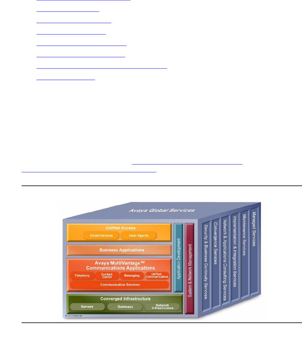
network call processing environment. Figure 1: Avaya Application Solutions on page 23 and
Figure 2: Communication Manager traffic flow on page 24 summarize the Avaya Application
Solutions.
Figure 1: Avaya Application Solutions
Avaya Application Solutions
24 Avaya Application Solutions IP Telephony Deployment Guide
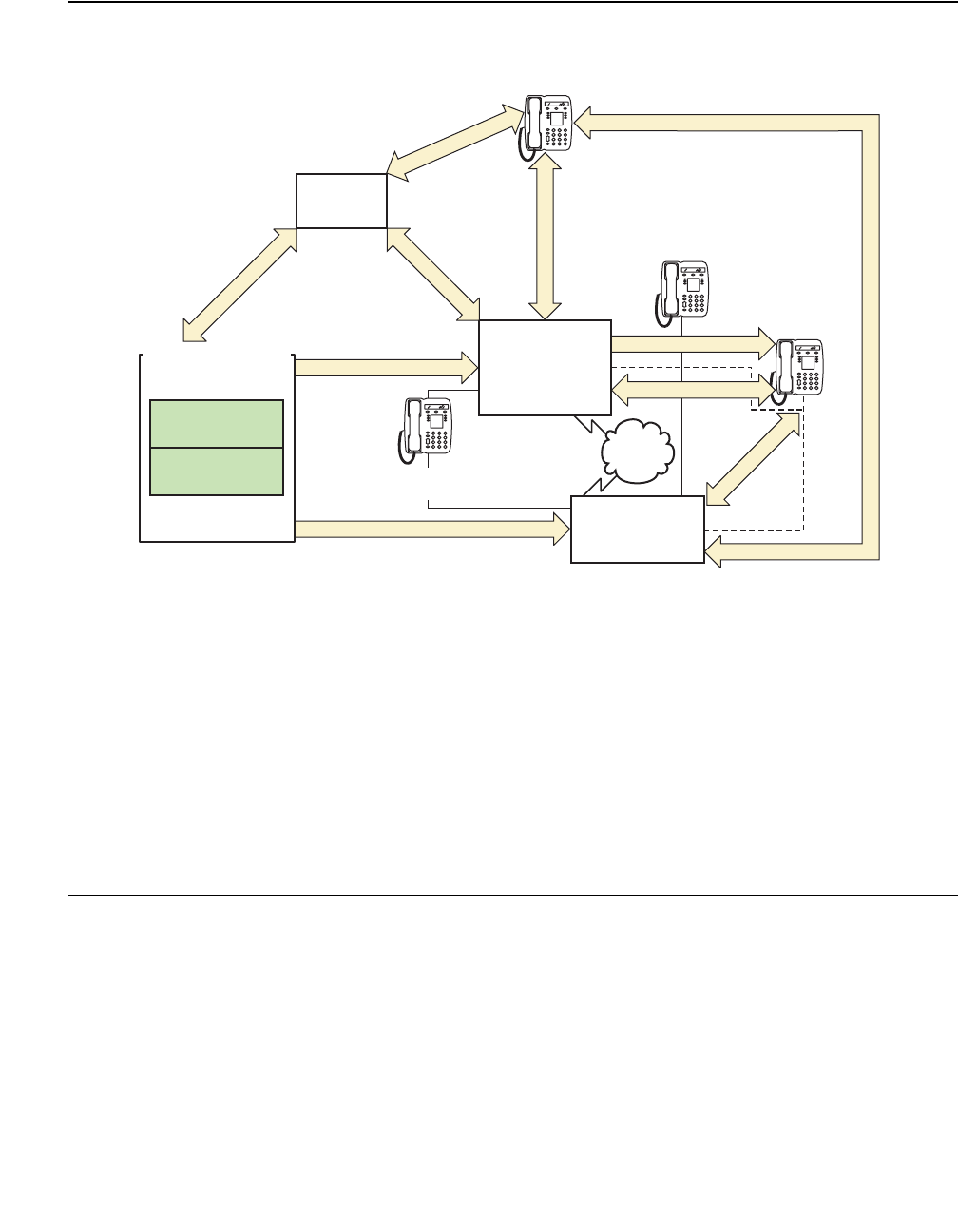
Figure 2: Communication Manager traffic flow
Figure notes:
1. SIP phones exchange RTP audio among themselves and with the G700, G650 Media
Gateways, and so forth, but not with IP phones.
2. SIP signaling from Avaya Communication Manager is always to/from SES.
3. SIP signaling can go through a C-LAN (on a G650, etc.), or directly Communication Manager
(if the server is the S8300 or S8500).
Note:
Note: This is actually true for both H.323 and H.248 signaling. The diagram gives the
impression that H.248 comes directly from Communication Manager and H.323
goes through the media gateways, when in fact both protocols can go both ways
depending on server type.
Communication Manager is the next generation of Avaya call processing software.
Communication Manager is an open, scalable, highly reliable, and secure telephony
application. Communication Manager operates on Avaya Media Servers, and on the existing
family of DEFINITY servers.
Communication Manager carries forward all the current DEFINITY capabilities, plus all the
enhancements that enable enterprises to take advantage of new, distributed technologies,
increased scalability, and redundancy. Communication Manager is evolved from DEFINITY
software and delivers no-compromise, enterprise IP Telephony.
cynds222 LAO 012506
Communications
Applications
Communications
Manager
Avaya Media Servers
Circuit-switched
Telephone
IP
Communications
Device
CCMS Signaling over IP
H.248 Signaling
H.323 Signaling
Avaya Media
Gateways
G650
MCC1
SCC1
RTP Audio
RTP Audio
PSTN
Avaya G700
Circuit-switched
Telephone
SIP
Phone
RTP Audio
SES
SIP Signaling
SIP Signaling
SIP Signaling
RTP Audio

Avaya Communication Manager
Issue 4.3 February 2006 25
Avaya Media Gateways support voice traffic and signaling traffic that is routed between
circuit-switched networks and packet-switched networks. The Gateways support all the
applications and adjuncts that can be used with the Avaya DEFINITY Enterprise
Communications Servers (DEFINITY ECS). These Gateways work with standards-based data
networks and easily connect with the Public Switched Telephone Network (PSTN).
Communication Manager is extensible to IP, digital and analog telephones, and wireless
business solutions. Avaya Communication Devices work with the full feature set of
Communication Manager to help enterprises be more productive by providing anytime,
anywhere access to maximize business continuity.
Avaya Communication Manager
Avaya Communication Manager provides user and system management functionality,
intelligent call routing, application integration and extensibility, and enterprise communications
networking. Communication Manager operates on Avaya Media Servers, and on the existing
family of DEFINITY servers. For more information on the Avaya Application Solutions related
features of Communication Manager, see Call processing.
The following additional resource provides even more details on Communication Manager:
http://www1.avaya.com/enterprise/telephony/cm/communication-manager/
Avaya Media Servers
An Avaya Media Server provides centralized, enterprise-class call processing. This call
processing can be distributed across a multi-protocol network (including IP) to support a highly
diversified network architecture that consists of headquarters, branch, remote, small, and home
offices.
Linux-based servers
The Avaya S8300, S8500, S8700-series, and SES-SIP are Linux-based Media Servers. These
servers support:
●Distributed IP Networking and centralized call processing across multi-service networks
●Dual server design with hot fail-over
●Redundant LAN Interfaces and remote survivable call processing
For more information on the architecture and the functionality of the Media Servers, see
Hardware Description and Reference for Avaya Communication Manager, 555-245-207.

Avaya Application Solutions
26 Avaya Application Solutions IP Telephony Deployment Guide
Avaya DEFINITY Servers
Avaya Communication Manager also runs on the following DEFINITY Servers, which can be
IP-enabled:
●Avaya DEFINITY Server R
●Avaya DEFINITY Server SI
●Avaya DEFINITY Server CSI
These servers run on the Oryx/Pecos proprietary operating system, and function in the same
way as the Media Servers in Figure 2: Communication Manager traffic flow on page 24. These
servers fit into Avaya CMC1, SCC1, and MCC1 Media Gateways.
The focus of this document is network design incorporating the newer Communication Manager
platforms. Therefore, the DEFINITY Servers are only discussed briefly here.

Avaya Communication Manager
Issue 4.3 February 2006 27
Avaya Media Gateways
An Avaya Media Gateway supports both bearer traffic and signaling traffic that is routed
between packet-switched networks and circuit-switched networks. Communication Manager
running on Avaya Media Servers controls voice and signaling over a variety of stackable and
modular Media Gateways:
●Avaya G150 Media Gateway
●Avaya G250 Media Gateway
●Avaya G350 Media Gateway
●Avaya G650 Media Gateway
●Avaya G700 Media Gateway
●Avaya CMC1 Media Gateway
●Avaya SCC1 Media Gateway
●Avaya MCC1 Media Gateway
●MultiTech MultiVoIP Gateway
The Media Gateways contain the network and the endpoint interfaces, as well as call
classification, announcement boards, and so on. Through these interfaces, Communication
Manager performs gateway/gatekeeper functions. For more information on the Media
Gateways, see Call processing.
Avaya Integrated Management
Avaya Integrated Management is systems-management software for managing converged
voice and data networks. The applications include network management, fault management,
performance management, configuration management, directory management, and policy
management functionality.
●Avaya Site Administration
●Avaya Terminal Emulator
●Avaya Communication Manager Configuration Manager
●Avaya Communication Manager Fault and Performance Manager
●Avaya Communication Manager Proxy Agent
●Avaya VoIP Monitoring Manager
●Avaya Directory Enabled Management
●Avaya Terminal Configuration
For more information on Avaya Integrated Management, see:
●Avaya Integrated Management products on page 248

Avaya Application Solutions
28 Avaya Application Solutions IP Telephony Deployment Guide
Avaya communication devices
Avaya Communication Manager provides intelligent control for these smart devices:
●Avaya IP Telephones: 4600 Series (4602, 4606, 4612, 4620, 4624, 4630)
●Avaya SIP IP Telephone: 4602
●Avaya digital telephones: 6400 Series, 2402, and 2420
●Avaya analog telephone (6200 Series, 2500, and 2554)
●Avaya IP Softphone
●Avaya IP Softphone for Pocket PC
●Avaya IP Agent
●Extension to Cellular Application
●DEFINITY Wireless DECT System
●Avaya Wireless Telephone Solutions
For more information about Avaya smart devices, see Wireless on page 161
Avaya Communication Manager applications
Avaya Communication Manager has embedded capabilities for:
●Call Center
●Compact Call Center
●Computer Telephony Integration (CTI)
●Messaging
●Conferencing systems
●Unified Communication Center
For more information on these applications, see http://www.avaya.com/support.
Call Center
The Avaya Call Center solution is built on proven and innovative automatic call distribution
(ACD) technology. This technology offers a suite of call routing capabilities that help agents
handle calls more effectively. Customers can select from a powerful assortment of features,
capabilities, and applications that are specially designed to enhance call center operations:
●Agent Access
●Avaya Call Management System

Avaya Communication Manager
Issue 4.3 February 2006 29
●Avaya Call Management System Supervisor
●Avaya Basic Call Management System
●Avaya Business Advocate
●Call Center
- Avaya Call Center Basic
- Avaya Call Center Deluxe
- Avaya Call Center Elite
●Call Recording
●CALLMASTER® series digital telephones
●Computer Telephony (ASAI)
●Avaya Visual Vectors
●Avaya IP Agent
●Avaya Network Reporting
●Avaya Virtual Routing
Compact Call Center
The Compact Call Center application includes:
●Basic Call Management
●Reporting Desktop
●Computer Telephony
Computer Telephony Integration (CTI)
CTI opens up Application Programmer Interfaces, which can be used to control the server from
an external application.
Messaging
The following messaging systems are supported by Avaya Communication Manager:
●INTUITY™ Messaging Systems
●Aria® Messaging Systems
●Serenade® Messaging Systems
●Modular Messaging®

Avaya Application Solutions
30 Avaya Application Solutions IP Telephony Deployment Guide
Conferencing systems
Conferencing & Collaboration Applications enable cost effective means to connect with key
people around the world in a way that enhances operations.
Unified Communication Center
Unified Communication Center lets mobile, remote and office workers easily access important
communications tools and information via any telephone using simple and intuitive speech
commands.
Avaya Meeting Exchange Solutions
Avaya Meeting Exchange is a family of comprehensive conferencing and collaboration solutions
that extends proven Avaya conferencing features to support a variety of network protocols and
enterprise implementations.
Meeting Exchange delivers proven voice quality and unsurpassed reliability in a solution that
scales from ten to tens of thousands of users. Valuable features like Web Conferencing,
conference scheduling and management tools, recording, reporting and customization
capabilities are built in.
Meeting Exchange is interoperable with media servers that run on open standards, and
provides a variety of deployment options. Meeting Exchange supports pure Internet Protocol
(IP), time division multiplexing (TDM) and mixed TDM/IP network environments. With Avaya
Meeting Exchange, enterprises can migrate quickly and effectively to IP-based conferencing.
Meeting Exchange Enterprise Edition
Avaya Meeting Exchange delivers a host of features and capabilities designed to make
conferencing easier, more flexible and more productive. These include:
Reservation-less Conferencing - Call it conferencing on demand. Authorized conferencing
users can arrange conferences on their own, whenever the need arises, without having to make
arrangements ahead of time. Because the conference host has full conference control, order
and security are well protected.
User Control of Conference Scheduling and Management - Maximize the value of flexible
conferencing system by providing both users and operators with access to easy-to-use
scheduling and management tools, seamlessly integrated with enterprise conferencing
platform.
Integration with Corporate Databases and Directories - Allows administrators to instantly
establish or disable user accounts and maintain accurate user information.

Avaya Communication Manager
Issue 4.3 February 2006 31
Value-added Features - These capabilities, including reporting, recording and billing, enable
enterprises to precisely manage use of their conferencing service by generating customized
conference reports and enabling internal bill back systems.
Integrated Web Conferencing - Provides comprehensive collaboration capability including
distribution of graphics and presentations, application viewing and sharing, white boarding, and
optional conference recording and playback.
Easy Scheduling - Integrated Microsoft Outlook or Lotus Notes calendar and web capabilities
make it simple to schedule conferences and notify participants using these familiar desktop
productivity tools.
Open Architecture - Enables seamless integration with a range of applications and services.
API-based developer tool kits allow development of integrated or custom features and
applications.
Integration Options - Avaya Meeting Exchange offers integration with corporate directories
and databases using standard Lightweight Directory Access Protocol (LDAP), for simple
maintenance of corporate accounts. Multi language options provide for translated conference
prompts and greetings. A Multi Site option reduces networking costs and network traffic by
linking multiple conference systems in dispersed locations.
Table 1: Meeting Exchange Conferencing Servers Feature and Capacity
CS700 CS780 C6200 S6800 S6100
Protocols TDM TDM TDM, IP or
Mixed IP TDM, IP or
Mixed
Capacity T1: 1152
ports
E1: 1200
ports
T3: 2016
ports
ISDN: 1104
ports
T1: 576 ports
E1: 600 ports
ISDN: 552
ports
IP: 240 ports
T1: 192 ports
E1: 240 ports
ISDN: 184
ports
9,000 ports
(per chassis) 300 ports
1 of 2

Avaya Application Solutions
32 Avaya Application Solutions IP Telephony Deployment Guide
Meeting Exchange Web Conferencing
Target Market: Mid-market, Service Providers
Integrated Solution Features:
●PowerPoint push and document annotation, white boarding, chat, polling
●Desktop or application sharing
●Workhorse application for 4-8 person, everyday meetings
●Customizable
●Integration w/ Meeting Exchange audio conferencing: synchronized recording and
playback of audio and web portions of the conference, Integrated participant roster (control
audio and web participants)
Strengths and Differentiators - Meeting Exchange Web Conferencing offers intuitive
application with features most-used by Web conferencing users. It is scalable, secure
behind-the firewall solution. The application is ideal for a 4 to 8 person meeting. It provided
optimized bandwidth for users with any connection speed.
Features Carrier-grade,
high
survivability
and reliability.
Available as
AC or DC.
Variety of
redundancy
options (RAID
5, N+1 P/S)
Hot
swappable
components.
Carrier-grade,
high
survivability
and reliability.
Available as
AC or DC.
Variety of
redundancy
options (RAID
5, N+1 P/S)
Hot
swappable
components.
Based on an
IBM x336 1U
server.
Includes
redundant
hard disks and
power
supplies.
Based on
Convedia
CMS-6000
Media Server.
S6200 is used
as an
Application
Server.
Available as
AC or DC.
Variety of
redundancy
options
available.
Based on an
IBM x336 1U
server.
Includes
redundant
hard disks and
power
supplies.
Networks T1, E1, T3, or
ISDN from
PBX or
telecom
provider
T1, E1, T3, or
ISDN from
PBX or
telecom
provider
IP Trunks, T1,
E1, or ISDN
from PBX or
telecom
provider
IP Trunks
from PBX or
telecom
provider
IP Trunks, T1,
E1, or ISDN
from PBX or
telecom
provider
Table 1: Meeting Exchange Conferencing Servers Feature and Capacity (continued)
CS700 CS780 C6200 S6800 S6100
2 of 2

Avaya Communication Manager
Issue 4.3 February 2006 33
Hardware and Software requirements include:
●Meeting Exchange audio conferencing bridge
●Off-the-shelf server, plus Web Conferencing software (license based capacity)
●Additional servers required for recording and playback (optional)
Avaya SIP solutions
SIP stands for Session Initiation Protocol, an endpoint-oriented messaging standard defined by
the Internet Engineering Task Force (IETF). SIP is a text-based protocol, similar to HTTP and
SMTP, for initiating interactive communication sessions between users. Such sessions include
voice, video, instant messaging, interactive games, and virtual reality.
As implemented by Avaya for Communication Manager release 3.0, SIP "trunking" functionality
will be available on any of the Linux-based media servers (S8300, S8400, S8500 or
S8700-series). SIP trunking allows Avaya Communication Manager to communicate with SIP
endpoints and gateways across an IP network. SIP trunks allows an enterprise to connect its
media server(s) to a SIP-enabled proxy server, specifically, an Avaya SIP-Enablement Server
(SES), and through this proxy, optionally to an external SIP service provider, if desired. The
trunk support in Communication Manager complies with SIP standards, specifically IETF RFC
3261, and so interoperates with any SIP-enabled endpoint/station that also complies with the
standard.
Avaya Communication Manager supports SIP endpoints, including the Avaya 4602 SIP
Telephone and Avaya IP Softphone Release 5. In addition to its IP telephony capabilities, IP
Softphone R5 also includes Instant Messaging (IM) client software, which is a SIP-enabled
application that connects to the SES for IM control. By means of having SIP-enabled endpoints
managed by Communication Manager, many features can be extended to these endpoints.

Avaya Application Solutions
34 Avaya Application Solutions IP Telephony Deployment Guide

Issue 4.3 February 2006 35
Avaya Application Solutions platforms
Overview
The Avaya Communication Manager portfolio covers small, medium, and large enterprises with
advanced communications needs between 2 and 44,000 ports per system. This chapter
provides an overview of the Avaya Communication Manager platforms architecture that
supports Avaya Application Solutions components and features.
Figure 3 shows the approximate port capacities for Avaya’s Application Solutions platforms.
Figure 3: Avaya Application Solutions platforms port capacities
An overview of the properties of the Avaya Media Servers described in this chapter is provided
in Table 2: Avaya Application Solutions comparison matrix — components, performance, and
capacities on page 36.
cynd103f LAO 013006
450 32002
S8500
IP Connect
S8700 Series
S8300
S8400
44K1300

Avaya Application Solutions platforms
36 Avaya Application Solutions IP Telephony Deployment Guide
Table 2: Avaya Application Solutions comparison matrix — components, performance,
and capacities1
Avaya S8300 Media
Server Avaya S8400
Media Server Avaya S8500 Media
Server Avaya S8700-series
Media Server
Processor/
RAM/
disk drive
Intel Celeron class
server
512 MB of RAM
30 GB hard disk drive
Intel Celeron M
512 MB RAM
30 GB hard disk
drive
2 GB Solid State
Disk (SSD)
Intel Pentium IV
Class Server
512 MB of RAM
80 GB hard disk
drive
Removable Flash
card backup
S8710:
Intel Pentium IV Class Server
512 MB RAM
72 GB disk drive
Removable Flash card backup
S8720:
AMD Opteron
1 GB RAM
72 GB disk drive
Removable Flash card backup
General
Business
analog
equivalent
BHCC rate
10,000 10,000 100,000 Fiber connect:
400,000
180,000 IP station to trunk calls
80,000 H.248 media gateway
calls
25,000 SIP calls
IP connect:
180,000
Maximum
Telephones
(IP + non-IP)
S8300: 450
S8300/G700: 450
S8300/G350: 40
S8300/G250: 12
900 2,400 36,000
Maximum
Trunks
(IP + non-IP)
S8300: 450
S8300/G700: 450
S8300/G3502: 40
S8300/G250: 10
400 800 8,000 Total
up to 5,000 can be SIP
1 of 2

Overview
Issue 4.3 February 2006 37
Maximum
IP Endpoints
(IP Telephones
+ IP Trunks)
S8300: 900 Total
S8300/G700: 900 Total
450 Trunks
450 Telephones
S8300/G350: 55 Total
15 Trunks
40 Telephones
S8300/G250: 20 Total
10 Trunks
10 Telephones
1,300 Total
400 Trunks
900 Telephones
3,200 Total
800 Trunks
2,400 Telephones
12,000 Total
8,000 Trunks
Maximum
Subtending
Media
Gateways
S8300/G700:
50 H.248:
G700/G350/G250
or
H.323:
G150/R300
S8300/G350/G250:
subtending gateways
not supported
5 H.248:
G700/G350/G250
or
80 H.323:
G150/R300
A single PN
composed of:
1–5 G650s
1–3 G600s
1–4 CMC1s
250 H.248:
G700/G350/G250
or
H.323:
G150/R300
3 MCC1 or SCC1
PNs Direct connect
64 G650 PNs
(IP connect)
250 H.248:
G700/G350/G250
or
H.323:
G150/R300
Fiber connect:
44
MCC1 or SCC1 PNs with CSS
64
MCC1 or SCC1 PNs with ATM
IP connect:
64
G650 PNs
Maximum
Media
Gateways per
LSP
50
per S8300 LSP 5
per S8300 LSP 250
per S8500 LSP
50
per S8300 LSP
250
per S8500 LSP
50
per S8300 LSP
Reliability /
survivability LSP
SLS3
LSP for
G700/G350/G250 LSP backup for
G700, G350, or
G250
S8500 ESS
Duplicated Processor
LSP backup for G700, G350,
or G250
S8700-series ESS
S8500 ESS
Duplicated control network
Duplicated bearer connectivity
1. The operating system for all media servers is Linux (Red Hat Enterprise Linux 4.0).
2. S8300/G350 trunks either H.323 or SIP. Up to 15 IP trunks
3. Each G250 has built-in Standard Local Survivability (SLS) that provides basic services for local IP and
non-IP phones and PSTN trunks. The G150 also has built-in survivability with features similar to those of
the IP Office communication product, on which the G150 is based.
Table 2: Avaya Application Solutions comparison matrix — components, performance,
and capacities1 (continued)
Avaya S8300 Media
Server Avaya S8400
Media Server Avaya S8500 Media
Server Avaya S8700-series
Media Server
2 of 2

Avaya Application Solutions platforms
38 Avaya Application Solutions IP Telephony Deployment Guide
Terminology
The terms IP connect and fiber connect are used in this chapter to distinguish between the two
types of port network connectivity (PNC).
Fiber-connected port networks (PNs) transport bearer traffic (voice, fax, video) between PNs
over fiber-optic cables using circuit-switched (TDM) protocol. IP-connected PNs transport
bearer traffic over Ethernet cables using packet-switched Internet Protocol (IP). Starting with
Communication Manager release 3.0, both types of port network connectivity can be combined
in the same system. This allows a system to be converted from fiber connect to IP connect
gradually, one port network at a time, if desired.
Note:
Note: The terms fiber connect or fiber-connected are used in this document with almost
the same meaning as the term multi-connect, which, in addition to
fiber-connected PNs to carry the bearer traffic, implies a dedicated control
network. The term fiber connect applies to configuration with either a dedicated
on non-dedicated control network.
There are three kinds of fiber-connected configurations:
Direct connect - One PN, the "control PN," is IPSI-connected to the control network and one or
two additional PNs are fiber-connected to the control PN. The call controller can be an
S8500 media server or an S8700-series Media Server pair. The fiber connections are
between the expansion interface (EI) circuit packs (TN570) in the PNs.
Center Stage Switch - All PNs are fiber-connected through the center-stage switch (CSS) and
one or more PNs are IPSI-connected to the control network. The call controller is an
S8700-series Media Server pair. The fiber connections are between the switch node
interface (SNI) circuit packs (TN573) in the switch node carrier and the expansion interface
(EI) circuit packs (TN570) in the PNs, or between SNIs in two switch-node carriers.
ATM - All PNs are fiber-connected through the Asynchronous Transfer Mode switch and one or
more PNs are IPSI-connected to the control network. The call controller is an S8700-series
Media Server pair. The fiber connections are between the ATM switch and the ATM
expansion interface (ATM-EI) circuit packs (TN2305B or TN2306B) in the PNs.
Small to mid-size enterprise
Issue 4.3 February 2006 39
Small to mid-size enterprise
Avaya S8300 Media Server and Avaya G700,
G350, or G250 Media Gateway
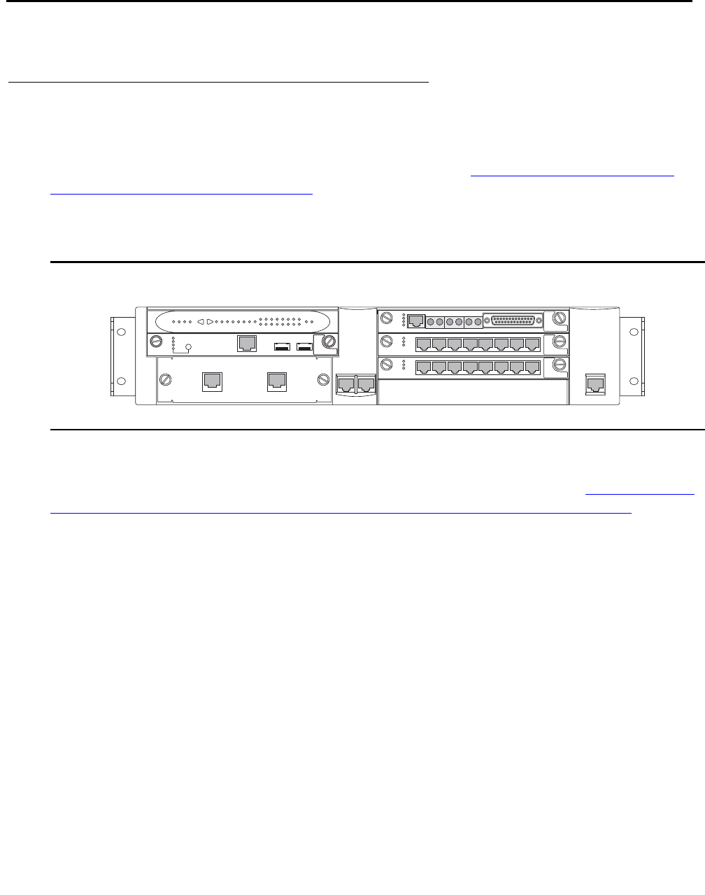
The S8300 Media Server and G700 Media Gateway solution (Figure 4: Avaya G700 Media
Gateway with the S8300 Media Server on page 39) seamlessly delivers voice, fax, and
messaging capabilities over an IP network. This unique solution converges the power of the
Avaya Communication Manager feature set with the power of distributed Ethernet switching
from the P330 Stackable Switching System.
Figure 4: Avaya G700 Media Gateway with the S8300 Media Server
The G250, G350, or G700 with an S8300 is a stand-alone solution. The Linux-based S8300
Media Server can support up to 50 G250, G350, or G700 Media Gateways. For more
information about performance and capacities of the S8300 Media Server, see Table 2: Avaya
Application Solutions comparison matrix — components, performance, and capacities on
page 36.
An S8300 Media Server and G250, G350, or G700 Media Gateway solution includes:
●A G700, G350, or G250 Media Gateway is always required. The G700, G350, or G250
hosts an S8300 Media Server and various media modules depending on the telephony
needs at a particular location.
●The S8300 Media Server. The S8300 Media Server is inserted into a media module slot. If
present, the S8300 supports Communication Manager that provides call-processing
capabilities and features for the system. The S8300 can be configured as the primary call
controller or as a Local Survivable Processor (LSP) standby server for another S8300
Media Server in the configuration.
Note:
Note: The S8300 / G350 solution is intended to be a standalone solution. Multiple
media gateways (either G700, G350, or G250) should be controlled by an S8300
Media Server installed in a G700 Media Gateway.
ALM
TST
ACT
123456 87
ALM
TST
ACT
123456 87
REMOVE
ALM
TST
ACT
OK TO SHUT DOWN
SERVICES USB 1 USB 2
E1/T1 EIA 530A DCE
ALM
TST
ACT
SIG
EISO EMSM EOSI
msdcs83b KLC 031402
V1
V2
V3
V4
EXT 1 EXT 2 CONSOLE
ALM PWR CPU MSTR LNK COL Tx Rx FDX FC Hspd LAG EXT 1
51 52 53 54 55 56 57 58
59 60 61 62 63 64 65 66
EXT 2
Avaya Application Solutions platforms
40 Avaya Application Solutions IP Telephony Deployment Guide
Multiple G700 Media Gateways can be connected to each other through an Octaplane 8-Gbps
stacking fabric, and Avaya P330 Expansion Modules, which allows adding additional Ethernet
ports, fiber interfaces, ATM access or WAN access modules without additional switches. The
system can be networked to other PBXs and Communication Manager platforms through an IP
network.
Some of the key characteristics of this platform are
●Expert System Diagnostic Capability
●Hot-swappable Media Modules
●Co-resident INTUITY AUDIX messaging.
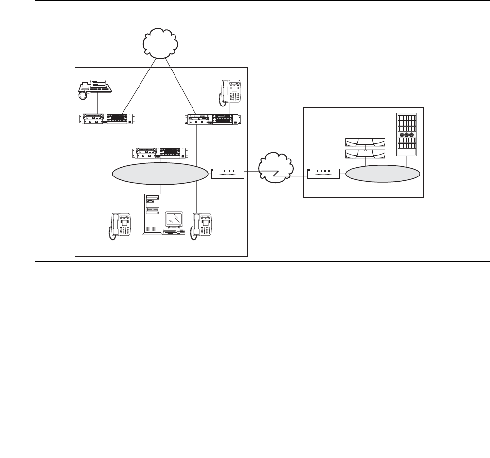
The platform is scalable, and has survivability and redundancy capability through a Local
Survivable Processor (LSP), which supports all of the features of Communication Manager.
Figure 5: Avaya S8300/G700, G350, or G250 in a stand-alone configuration
G700 hardware architecture
The design of the Media Gateway motherboard hardware brings together a multitude of
hardware functions into a single 2U 19-inch rack-mountable enclosure. Integrated on the
motherboard are:
●A gateway function that bridges the IP and telephony domains
●An Ethernet switching function and associated management features through an
integrated Layer 2 switch architecture
●Processing elements that are necessary to support traditional telephony interfaces, such
as trunks and analog/DCP lines
Avaya IP PBX
( S8300, S8700)
cynds110 LAO 101104
IP WAN
ALM
TST
ACT
ALM
TST
ACT
1 2 3 4 5 6 87
ALM
TST
ACT
ALM
TST
ACT
1 2 3 4 5 6 87
REMOVE
REMOVE
ALM
TST
ACT
OKTO
ALM
TST
ACT
OKTO SHUTDOWN
SERVICES
USB1
USB1
USB2
USB2
E1/T1
EIA 530A DCE
EIA 530A DCE
ALM
TST
ACT
SIG
ALM
TST
ACT
SIG
EISO EMSM EOSI
IP
Phone
PC
IP
Phone
PSTN
ALM
TST
ACT
ALM
TST
ACT
1 2 3 4 5 6 87
ALM
TST
ACT
ALM
TST
ACT
1 2 3 4 5 6 87
REMOVE
REMOVE
ALM
TST
ACT
OKTO
ALM
TST
ACT
OKTO SHUTDOWN
SERVICES
USB1
USB1
USB2
USB2
E1/T1 EIA 530A DCE
ALM
TST
ACT
SIG
ALM
TST
ACT
SIG
EI
SO
SO EMSM EOSI
ALM
TST
ACT
ALM
TST
ACT
1 2 3 4 5 6 87
ALM
TST
ACT
ALM
TST
ACT
1 2 3 4 5 6 87
REMOVE
ALM
TST
ACT
OKTO
ALM
TST
ACT
OKTO
SHUTDOWN
SHUTDOWN
SERVICES
SERVICES
USB1
USB1
USB2
USB2
E1/T1
E1/T1
EIA 530A DCE
EIA 530A DCE
ALM
TST
ACT
SIG
ALM
TST
ACT
SIG
EISO EMSM EOSI
Ethernet (LAN)Ethernet
Edge
Router
DCPFax
G700/G350 G700/G350
with S8300/ICC
Edge
Router
IP TIE Trunk
ISDN-PRIISDN-PRI
Stand alone Office
with IP Trunk link
to Avaya PBXs
G700/G350
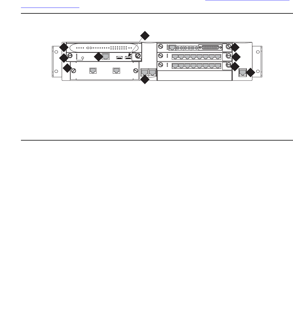
Small to mid-size enterprise
Issue 4.3 February 2006 41
These processing elements are controlled by Communication Manager, thus offering the
complete set of Communication Manager call features to both IP users and traditional telephony
users.
From a hardware perspective, the G700 Media Gateway is an enclosure with an internal power
supply and a motherboard. This design that provides the hardware resources for the Gateway
functions, and electrical connectivity for four media modules, one Cascade module, and one
Expansion module. The enclosure houses the power supply and the motherboard, and provides
the physical support to allow the insertion of the various modules. Figure 6: Avaya G700 Media
Gateway (front view) on page 41 shows the Media Gateway enclosure.
Figure 6: Avaya G700 Media Gateway (front view)
The four media module slots can be populated with any combination of media module types,
including:
●T1/E1 with integrated CSU/DSU (MM710)
●8-port analog line/trunk (MM711)
●8-port DCP line (MM712)
●24-port analog line (MM716)
●8-port BRI trunk (MM720)
●VoIP Engine (MM760)
●Internal Communications Controller (ICC-only 1 per gateway; must be in the first slot)
The Cascade module comes from the Converged Infrastructure LAN Switches product line, and
provides the Octaplane interface:
●One full-duplex 4-Gbps Ethernet port (8 Gbps bandwidth) for high-speed interconnection
of up to 10 media gateways and P330 data switches in a stack arrangement
●Expansion module interface allows the use of expansion modules in the gateway. These
expansion modules also allow WAN access routing.
Figure notes:
1. LED board
2. S8300 Media Server
3. Services port
4. USB ports
5. Avaya P330 Expansion Module
6. 10/100 Base T Ethernet ports
7. Media Modules
8. Serial (“Console”) connector
cynds111 KLC 121003
ALM
TST
ACT
123456 87
ALM
TST
ACT
123456 87
REMOVE
ALM
TST
ACT
OK TO SHUT DOWN
SERVICES USB 1 USB 2
E1/T1 EIA 530A DCE
ALM
TST
ACT
SIG
EISO EMSM EOSI
2
5
6
1
3
4
7
7
7
8

Avaya Application Solutions platforms
42 Avaya Application Solutions IP Telephony Deployment Guide
The G700 motherboard hardware design involves three major blocks:
●A DSP engine and associated packet processor complex. This complex performs IP/UDP/
RTP processing, echo cancellation, G.711 A/µ, G.729 (with or without silence
suppression), fax relay, silence suppression, jitter buffer management, packet loss
concealment, and so on.
●A Gateway Processor complex. This complex is the master controller of the Gateway, and
controls all resources inside the Gateway under the direction of the Gateway Controller.
Examples of the functions implemented here include the Media Module Manager, Tone/
Clock, PKTINT, Announcements (record/playback), and H.248 signaling to the Gateway
Controller.
●An Intel 960 processor complex. This complex is based on the architecture of the P330
data switch. This complex provides an eight-port Layer 2 switch function, and the i960
manages the Expansion and Cascade modules.
These major blocks are interconnected through two major communication paths: an Ethernet
link and the Time Division Multiplexed (TDM) bus similar to that in a port network. In addition,
the motherboard provides electrical and physical connectivity for four media modules.
VoIP Engine complex
The internal VoIP Engine block is where PCM voice samples are encoded and put into IP
packets, and vice-versa. This block implements all the functions that are normally associated
with a Gateway. Such functions include packet loss concealment, jitter buffer management,
transcoding, and so on.
The VoIP Engine of the G700 motherboard has three major components: two Digital Signal
Processors (DSPs), and a Motorola MPC8260 processor. The DSPs together provide the same
VoIP channel capacities as the TN2302AP IP Media Processor circuit pack: 64 G.711 channels
or 32 G.729 channels.
Each additional VoIP Media Module (MM760) increases the VoIP channel capacity of a G700
media gateway by the equivalent of a TN2302AP circuit pack.
The G700 Media Gateway Processor
The G700 Media Gateway Processor (MGP) is the master controller of the Media Gateway. The
Motorola 860T processor in this complex implements the H.248 protocol to communicate with
the Gateway Controller. Under the direction of the Gateway Controller, the 860T Gateway
Processor controls the flow of data through the Gateway. The 860T processor communicates
with other processors in the system – the VoIP Engine processor, the i960 processor, and any
processors on media modules – through either the control channel of the TDM bus, or an
Ethernet link (the i960 processor connects only through Ethernet).
Functions implemented within the MGP complex include:
●Management of the media modules (reset control, board and interface insertion, and so on)
●Termination of the LAPD protocol running on the D-channel of E1/T1 trunks and BRI lines
and trunks (32 channels capacity).

Small to mid-size enterprise
Issue 4.3 February 2006 43
●Recorded announcement playback (15 playback channels, 1 record channel)
●Tone detection and generation (15 ports of tone detection)
●System clock generation and synchronization to an external network timing reference
●Download agent for the media modules
●License/translation storage
●System maintenance
●H.248 signaling
●Connection management
Avaya IA770 INTUITY AUDIX Messaging Option for S8300/G700
The Avaya IA770 INTUITY AUDIX Messaging Application, (IA770), optionally embedded on the
S8300 Media Server installed in a G700, delivers voice, fax, and e-mail to enhance and simplify
the communications and the exchange of information within both small enterprises, and the
smaller locations of large enterprises. The IA770 uses the Linux operating system, which is
consistent with the operating system of the Media Gateway.
The IA770 supports INTUITY digital (TCP/IP) and AMIS networking protocols. More extensive
networking can be provided with the Avaya Interchange.
The IA770 consists of license-file-activated software that resides on the S8300 Server, and an
ICC daughter card, which is field-installable and upgradeable. For Communication Manager 2.2
and later, new installations will implement IA770 Embedded Messaging H.323 integration on the
S8300, and will no longer use the ICC daughter card.
Voice Announcement over the LAN
Voice Announcement over the LAN (VAL) capabilities are co-resident on the Avaya G700 Media
Gateway. This G700 VAL announcement capability allows backup and restore of
announcements to an external PC or a file server on the customer’s local area network (LAN),
in addition to internal backup in Flash memory. The announcements are stored as
industry-standard waveform (.wav) files. This enables customers to create high-quality, studio
announcements, save the announcements to their PC or server, and then share the same
announcements with multiple Avaya Application Solutions. Other features of the G700 VAL
announcement offer include:
●A G700 VAL announcement source functions the same as the TN2501AP for
administration, recording, file handling using FTP, playback, and measurements.
●Each G700 VAL announcement source used is counted as a VAL board towards the
Maximum VAL boards on the customer-options screen. The S8300 Media Server now
comes with a license entitlement for using up to 50 VAL circuit packs. The S8700-series
Media Server comes with a license entitlement for one, and requires the purchase of
additional licenses to enable the maximum of 50 which applies to both TN2501AP and
G700 VAL sources.

Avaya Application Solutions platforms
44 Avaya Application Solutions IP Telephony Deployment Guide
●Voice quality is impacted when played over IP. However, quality is acceptable even with 2
hops and 10-msec delay.
●The use of G700 VAL sourced announcements impacts that gateway’s overall occupancy,
and IP Telephony resources (for example, high use global announcements such as the
main greeting and some VOAs) should be handled by TN2501 circuit packs if the agents
are not homed to that G700.
●FTP access for the G700 announcements use the same IP address as the address that is
assigned to the G700 when installed (this address is displayed on the Media-Gateway
form).
S8300 primary controller architecture
The S8300 Media Server has the same form factor as the Avaya media modules. The S8300 is
installed in slot V1 of the G700, G350, or G250 Media Gateway. The S8300 can be configured
as either a primary controller (a.k.a. “ICC”) or as a local survivable processor (LSP).
Configured as a primary controller, the S8300 provides Communication Manager call control.
The controller targets the small-line-size, cost-conscious portion of the market, and as such,
must be cost competitive with other solutions. The controller is based on standard Intel IA32
architecture, and runs the industry-standard Linux operating system.
The S8300 runs the following co-resident applications:
●H.248 Media Gateway Controller
●H.323 GateKeeper
●Communication Manager Feature Server
●INTUITY AUDIX Messaging system (installed in the G700)
The S8300 primary controller, when installed in the G700, can be ordered both with and without
INTUITY AUDIX support.
The S8300 faceplate provides connectivity for two USB devices, and an Ethernet port for
technician access. The faceplate also has operational LEDs and a shutdown switch. The media
module backplane connector provides the interfaces for the internal 10/100 Ethernet bus and
the TDM Bus.
For information on S8300 performance and capacities, see Table 2: Avaya Application
Solutions comparison matrix — components, performance, and capacities on page 36.

Small to mid-size enterprise
Issue 4.3 February 2006 45
S8300 as an LSP
The S8300 Media Server installed in a G700, G350, or G250 Media Gateway can be configured
as a Local Survivable Processor (LSP). The LSP provides survivability when the primary
controller, either an S8300 ICC or an S8700 External Communications Controller (ECC), is
inaccessible. Each system can have multiple LSPs. Each LSP has a copy of the primary
controller’s translations. The translations are updated regularly from the primary controller b
way of a virtual link through an IP network. Typically, all LSPs are in idle mode, where the LSPs
are not processing any calls. When the Media Gateway's Processor (MGP) or individual IP
endpoints perceive the primary controller to be unreachable, the MGP or the IP endpoints
attempt to register with an LSP. The LSP does not actively take over when the primary controller
becomes unreachable, but waits for MGPs and IP endpoints to register with it. Each LSP runs in
license-normal mode until IP Telephones or MGPs register with it, which triggers the LSP to
move into a license-error mode. Each LSP can run in active mode for a maximum of 10 days
per outage before it must be reset manually. A “reset 3” command on the LSP forces devices
registered with it to return to their primary controller. When the customer resets the LSP, the
10-day license timer is reset after it contacts the primary controller.
Note:
Note: The S8500 can also be configured as an LSP.
G250 and G350 Media Gateways
The Avaya G250 and G350 Media Gateways form part of Avaya Enterprise Connect, Avaya’s
solution for extending communication capabilities from the headquarters of an organization to
all collaborative branch locations. Avaya Enterprise Connect helps you provide the same high
quality services to all organization members, regardless of their location.
The G250 and G350 are high-performance converged telephony and networking devices that
are located in small branch locations, providing all infrastructure needs in one box — telephone
exchange and data networking. The G250 and G350 each feature a VoIP engine, WAN router,
and Power-over-Ethernet (PoE) LAN switch. The G350 provides full support for legacy DCP
and analog telephones. The G250 supports legacy analog telephones, but not DCP telephones.
The G350 is designed for use in a 16- to 24-user environment, but can support sites with up to
40 stations. The G250 media gateway is designed for smaller branch offices with two to eight
users.
Telephone services on a G250/G350 are controlled by a Media Gateway Controller (MGC). You
can use a media server running Avaya Communication Manager (CM) call processing software
as an MGC. Both the G250 and the G350 integrate seamlessly with Avaya Media Servers
S8700, S8710, S8500, and S8300 to provide the same top quality telephony services to the
small branch office as to the headquarters of the organization.
The MGC can be located at the headquarters and serve the G250/G350 remotely. The G250/
G350 can optionally house an internal Avaya S8300 media server as a local survivable
processor (LSP) or as the primary MGC for standalone deployment. When the primary MGC is
located at a remote location, the G250 features Standard Local Survivability (SLS). SLS
consists of a module built into the G250 itself to provide partial backup MGC functionality in the
event that the connection with the primary MGC is lost. An additional option is Enhanced Local

Avaya Application Solutions platforms
46 Avaya Application Solutions IP Telephony Deployment Guide
Survivability (ELS). ELS can be provided for both the G250 and the G350 by installing an S8300
media server as an LSP, capable of providing full MGC functionality in the event that the
connection with the primary MGC is lost.
In addition to advanced and comprehensive telephony services, the G350 provides full data
networking services, precluding the need for a WAN router or LAN switch.
The G350 is a modular device, adaptable to support different combinations of endpoint devices.
Pluggable media modules provide interfaces for different types of telephones and trunks. A
combination is selected to suit the needs of the branch. A LAN media module with PoE
standard compliant Ethernet ports provides support for IP telephones as well as all other types
of data devices. A range of telephony modules provides full support for legacy equipment such
as analog and digital telephones.
The G250 supports the connection of PCs, LAN switches, IP phones, analog telephones, and
trunks, using fixed analog and PoE ports on the chassis. A media module slot supports either of
two WAN media modules, for connection to a WAN. The G250 is available in a special BRI
model (G250-BRI). The G250-BRI replaces three out of four of the G250’s fixed analog trunk
ports with two ISDN BRI trunk ports.
Features
G250 and G350 features include:
●Avaya Communication Manager (CM) media server management
●Call center capabilities
●DHCP client, server, and relay functions
●Dynamic Call Admission Control (CAC) for Fast Ethernet, Serial, and GRE tunnel
interfaces
●Dynamic IP addressing
●Extensive alarming and troubleshooting features
●Fax and modem over IP
●Frame-Relay
●GRE tunneling
●Inter-Gateway Alternate Routing (IGAR)
●MGC automatic switchover, migration, and survivability features
●Modem access for remote administration
●Modem backup connection to the MGC
●OSPF
●Policy-based routing
●Port mirroring
●Port redundancy (G350 only)

Small to mid-size enterprise
Issue 4.3 February 2006 47
●Power-over-Ethernet LAN Switching
●PPP
●PPPoE
●RADIUS Authentication support
●RIP
●SNMP traps (v1 and v2 only) sent to the primary controller
●SNMP v3
●Spanning Tree Protocols IEEE 802.1D (STP) and IEEE 802.1w (RSTP) (G350 only)
●SSH Authentication support
●Support for traditional telephones and trunks
●Survivability features for continuous voice services
●VLANs
●VoIP Media Gateway services
●VPN support
●WAN Quality of Service (QoS)
●WAN routing and connectivity
●Weighted Fair Queuing (WFQ)
Modes of Deployment
The G250 and G350 can each be deployed in one of two basic working modes:
●Distributed Avaya Enterprise Connect.
In this mode, the G250/G350 is controlled by an external MGC. This may be a standalone
media server, such as the S8500, S8700 or S8710, or a separate media gateway in a
standalone configuration. In systems with Enhanced Local Survivability (ELS), the G250/
G350 also houses an S8300 Media Server module to function as a Local Survivable
Processor (LSP), which can take over control of the G250/G350 if the external MGC stops
serving the G250/G350.
●Standalone.
In this mode, the G250/G350 is controlled by an internally housed S8300 Media Server
module.
Multiple G250s and G350s may be deployed in many remote branches of a large organization.
Large branches or main offices may deploy an Avaya G700 Media Gateway, which provides
similar functionality to the G350 for a larger number of users. Up to 250 G250, G350, and G700
Media Gateways may be controlled by a single external S8700-series Media Server.

Avaya Application Solutions platforms
48 Avaya Application Solutions IP Telephony Deployment Guide
G350 Configurations
The G350 is a modular device with multiple configuration possibilities to meet specific individual
needs. Six slots in the G350 chassis house various media modules, providing connections for
different telephones, telephone trunks, data devices, and data lines.
Media server configuration options for the G350 include:
●Standalone. In this configuration, one media module slot houses the S8300 internal Media
Server, which runs the call control applications for the G350. The remaining slots house a
customized selection of media modules, which connect to circuit-switched phones, trunks,
and data devices. This configuration is capable of supporting up to 40 stations (maximum
of 26 legacy Analog/DCP stations) and 35 trunks, including both circuit-switched and
packet-switched (IP) endpoints.
●Media Gateway. In this configuration, there is no internal media server. The G350 is
dependent on a separate controller. This may be an external standalone media server
such as the S8500 or S8700 or the S8300 housed in a separate media gateway. All six
media module slots are available to house a customized selection of media modules.
●Survivable. In this configuration, an external media server provides primary controlling
service to the G350. The S8300 populates one of the module slots as a backup controller
and functions in Local Survivable Processor (LSP) mode. If the external media server
stops serving the G350, the S8300 takes over the service. As for standalone configuration,
the remaining slots house a customized selection of media modules.
Each G350 should deploy as a single unit at a remote location. Multiple G350s may be
deployed in many remote branches of a large organization. Large branches or main offices
requiring more capacity than a single G350 should deploy one or more Avaya G700 Media
Gateways. In addition to media gateway functions similar to those of G700, the G350 can
optionally provide integrated power-over-Ethernet and WAN routing functions through media
modules.
The G350 now supports up to 10 concurrent call center agents. Customers requiring more call
center agents in a small branch office should consider the G700 media gateway.
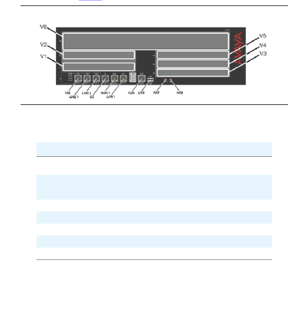
Small to mid-size enterprise
Issue 4.3 February 2006 49
G350 Specifications
The G350 chassis features six media module slots (V1 to V6) and various fixed ports and
buttons. V1 to V5 are G700 form factor media module slots capable of housing existing G700
media modules. V6 is a high-density media module (HDMM) slot for housing new high capacity
media modules (see Figure 7).
Figure 7: G350 chassis
The following tables describe the functions of the fixed ports and buttons on the G350 front
panel.
Table 3: Fixed ports on the G350 front panel
Port Description
TRK An analog trunk port. Part of an integrated analog media
module.
LINE 1, LINE2 Analog telephone ports of the integrated analog media module.
An analog relay between TRK and LINE 1 provides Emergency
Transfer Relay feature.
CC RJ-45 port for ACS (308) contact closure adjunct box.
WAN 1 RJ-45 10/100 Base TX Ethernet WAN port.
LAN 1 RJ-45 10/100 Base TX Ethernet LAN switch port.
CON Console port for direct connection of CLI console.
USB USB port

Avaya Application Solutions platforms
50 Avaya Application Solutions IP Telephony Deployment Guide
Table 4: Buttons on the G350 front panel
Button Description
RST Reset button. Resets chassis configuration.
ASB Alternate Software Bank button. Reboots the G350 with the
software image in the non-default bank.
Table 5: Supported media modules for G350
Media module Description
MM312 (HDMM) 24 DCP telephone ports
MM314 (HDMM) 24 10/100 Ethernet ports with Power over Ethernet and 1G
Fiber port
MM316 (HDMM) 40 10/100 Ethernet ports with Power over Ethernet and 1G/
10M/100M copper port.
MM340 1 E1/T1 WAN port
MM342 1 V.35/X.21 Universal Serial port (USP) WAN port
MM710 1 T1/E1 trunk port
MM711 8 universal analog ports
MM712 8 DCP telephone ports
MM714 4 analog telephone ports and 4 analog trunk ports
MM716 24 analog telephone ports
MM717 24 port DCP Media Module for G350/G700
MM720 8 ISDN BRI trunk ports
MM722 2 ISDN BRI trunk ports
(MM760) Not supported for G350
S8300 Media server (LSP)

Small to mid-size enterprise
Issue 4.3 February 2006 51
The MM710, MM711, MM712, and MM720 are existing G700 media modules.
Table 6: Additional G350 functions and capacities
Function Capacity
VoIP DSP engine 32 G.711 or 16 G.729 channels
Touch Tone Recognition
(TTR) 15 channels
Announcement 6 playback, 1 record
Number of telephones 40 (18 analog)
Number of trunks (T1/E1) 40 (15 IP, 17 analog)
G700 form factor MMs no more than three
MM710 no more than one
MM717 or MM712
(possibly with MM312) no more than one
MM711 and/or MM714 no more than two
WAN modules (MM340
and MM342) no more than two
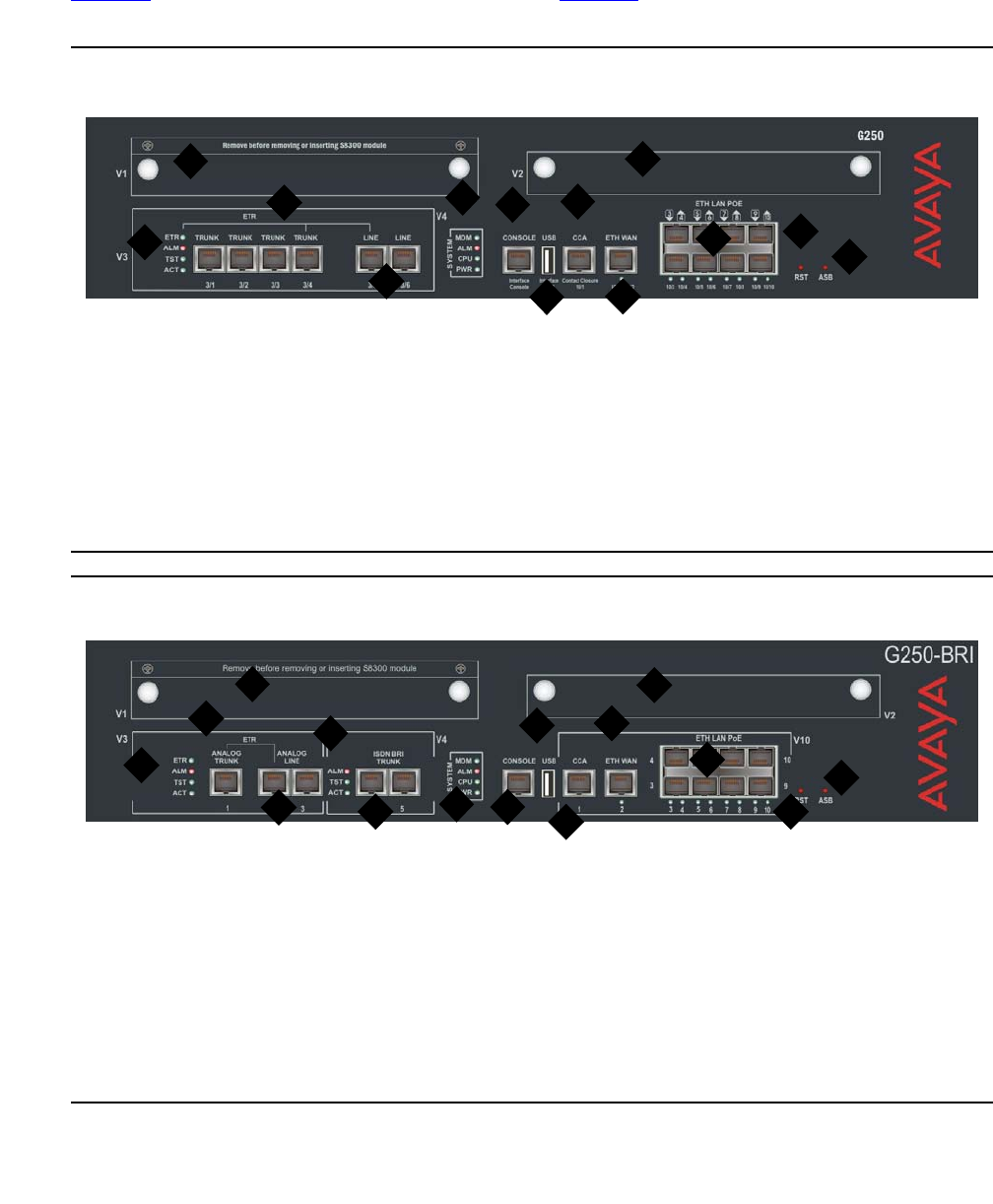
Avaya Application Solutions platforms
52 Avaya Application Solutions IP Telephony Deployment Guide
G250 Configurations
Figure 8 shows the G250 Media Gateway chassis. Figure 9 shows the G250-BRI Media
Gateway chassis.
Figure 8: The Avaya G250 analog Media Gateway Chassis,
Figure 9: The Avaya G250 BRI Media Gateway Chassis,
Figure notes:
1. V1 — ICC/LSP Slot
2. V2 — WAN Media Module Slot
3. Analog port LEDs
4. Analog trunks
5. Analog line ports
6. System LEDs
7. Console port
8. USB port
9. Contact Closure (CCA) port
10. Ethernet WAN (ETH WAN) port
11. PoE LAN (ETH LAN PoE) ports
12. Reset (RST) button
13. Alternate Software Bank (ASB) button
Figure notes:
1. V1 — ICC/LSP Slot
2. V2 — WAN Media Module Slot
3. Analog port LEDs
4. Analog trunk
5. Analog line ports
6. ISDN BRI LEDs
7. ISDN BRI trunks
8. System LEDs
9. Console port
10. USB port
11. Contact Closure (CCA) port
12. Ethernet WAN (ETH WAN) port
13. PoE LAN (ETH LAN PoE) ports
14. Reset (RST) button
15. Alternate Software Bank (ASB) button
2
3
4
513
12
11
1
67
8
9
10
7
12
13
14
1
2
3
4
5
6
89
10
11
15

Small to mid-size enterprise
Issue 4.3 February 2006 53
Table 7: Fixed ports and buttons on the G250 front panel describes the functions of the fixed
ports and buttons on the G250 front panel.
Table 7: Fixed ports and buttons on the G250 front panel
Port Description
TRUNK Four analog trunk ports (G250 analog Media Gateway) or
one analog trunk port (G250-BRI Media Gateway).
LINE Two analog telephone ports. An analog relay between
TRUNK port 3/4 and LINE port 3/5 provides Emergency
Transfer Relay (ETR) feature.
ISDN BRI
TRUNK
(G250-BRI
Media
Gateway)
Two 4 wire S/T ISDN BRI (Basic Rate Interface) 2B+D
access ports with RJ-45 jacks. Each port interfaces to the
central office at the ISDN T reference point. The ISDN BRI
trunk ports do not support:
●BRI stations
●Combining both B channels together to form a
128-kbps channel
CONSOLE Console RS-232 interface port for direct connection of CLI
console. RJ-45 connector.
USB USB port.
CCA RJ-45 port for ACS (308) contact closure adjunct box.
ETH WAN RJ-45 10/100 Base TX Ethernet port for connection to a
cable or DSL broadband modem/router.
ETH LAN POE Eight Power over Ethernet (PoE) LAN ports with 80 watts
(aggregated for all ports) for connecting IP phones or any
Ethernet devices, such as PCs.
RST Reset button. Resets chassis configuration.
ASB Alternate Software Bank button. Reboots the G250 with the
software image in the alternate bank.

Avaya Application Solutions platforms
54 Avaya Application Solutions IP Telephony Deployment Guide
G250 DCP and G250 DS1 Media Gateways
Release 3.1 of Communication Manager introduces two new versions of the G250 Media
Gateway.
The G250 DS1, supporting the T1/E1/PRI market, includes:
●One T1/E1/PRI trunk with fractional trunks allowed.
●One analog trunk with loop start only (no support for ground start or CAMA).
●Two analog lines and/or DID trunks (one with ETR).
●ETR.
●Eight Ethernet LAN PoE ports.
●10/100 Ethernet WAN.
●One expansion slot for an ACM server module.
●One expansion slot for a data WAN media module.
●One console RS232 interface.
●One USB host interface.
●One contact closure relay control.
The G250 DCP includes:
●Four analog trunks Loop Start only (no support for Ground Start or CAMA)
●Two analog stations and/or DID trunks.
●Twelve DCP ports
●Two Ethernet LAN ports
●One 10/10 Ethernet WAN port
●One expansion slot for an ACM server module
●One expansion slot for a data WAN media module
●One console RS232 interface
●One USB host interface
●One contact closure relay control
●ETR

Small to mid-size enterprise
Issue 4.3 February 2006 55
G150 Media Gateway
The G150 Media Gateway is a gateway aimed at small-office home office (SOHO) branch
offices (1-8 users) of large enterprises, that seek all-in-one, centrally managed solution, hence
turning the SOHO branch into a seamless part of the enterprise’s network. G150 offers
Communication Manager-based telephony services, local connectivity to the PSTN and WAN
connectivity to the enterprise headquarters. G150 serves as another building block in Avaya
Enterprise Connect — branch office solution, and extends the reach of Communication
Manager to the entire realm of the Branch office. The G150 in subtending mode operates as an
H.323 gateway that is managed by the Avaya Communication Manager (ACM) feature server in
accordance with the ACM Remote Office Feature group.
G150 is designed for the needs of SOHO branch offices of large enterprises (1-8 seats) with the
following networking needs:
●Being a seamless part of the large enterprise network, with access to the same network
applications, and with powerful redundancy options
●Various possible sets of networking requirements:
- Voice only + (3rd party LAN and WAN)
- Voice + WAN + (3rd party LAN)
- Voice + LAN (including Wireless) + WAN
●Low to Medium communication intensity between the branch and the headquarters
G150 offers customers the following added values:
●Driving full-featured ACM-based telephony solution into the smallest office; hence, turning
the enterprise’s network functionality ubiquitous.
●Single vendor, all-in-one-box solution.
●Advanced survivability option.
The G150 platform is based on IP Office’s Small-office Gateway working in a H.323 ‘Subtending
Mode’. The H.323 Subtending Gateway feature allows IP Office to cooperate with an Avaya
Communication Manager to form a single, distributed system. When operating in this manner,
all call processing and features delivered to IP Office users are under the full control of the ACM
(‘Subtending Mode)’. In the event of a failure, IP Office switches from ‘Subtending Mode’ to
‘Survivable mode’, where it acts as a standalone system, providing local telephony services.
G150 Models
The G150 Media Gateway is supplied in the following models (each model is available in two
versions to support either North American or International CO trunks):
●G150 2T + 4A (4 VoIP): Two Analog Trunks + 4 analog telephones + 4 VoIP compressors.
- North America version - SAP code: 700343569
- International version - SAP code: 700343577

Avaya Application Solutions platforms
56 Avaya Application Solutions IP Telephony Deployment Guide
●G150 4T + 4A (16 VoIP): Four Analog Trunks + 4 analog telephones + 16 VoIP
compressors.
- North America version - SAP code: 700343601
- International version - SAP code: 700343619
The layer 3 routing provided by G150 includes two Ethernet ports, LAN1 and LAN2. For LAN1,
G150 provides an in-built layer 2 Ethernet Switch, giving 4 switched ports (1 - 4), typically used
for attaching IP phones and PCs. For LAN2, G150 provides a single Ethernet port, typically
used for connection to a WAN service.
In the back of all G150 models, the following are supported:
●An additional WAN slot to support other network connections such as T1, PRI and BRI
central office lines and V.35, X.21.
●A twin PCMCIA socket for a Wireless LAN card when using the system as an Access Point
for 802.11b support of a wireless data application.
●The second PCMCI slot may be used to house a 64M flash memory card for providing a
TFTP server.
●A serial port dongle, plugged directly into the unit, for licensed applications.
G150 4T + 4A (16 VoIP)
This variant of the G150 includes the following:
●Four Analog Loop Start Trunks (Two-way CO Trunks)
●Four Analog Extension interfaces
●Sixteen VoIP Codecs (G.723.1, G.711a, G.711u and G.729a)
●4 Switched Ethernet ports (Layer 2)
●Dedicated Switched Ethernet WAN port (Layer 3)
●2x PCMCIA slots for Wireless and memory card support
●WAN slot for optional voice/data WAN card (V24, V35, X.21, quad-BRI and T1/PRI)
●DTE port
●Audio port (not used)
●External O/P socket (not used)
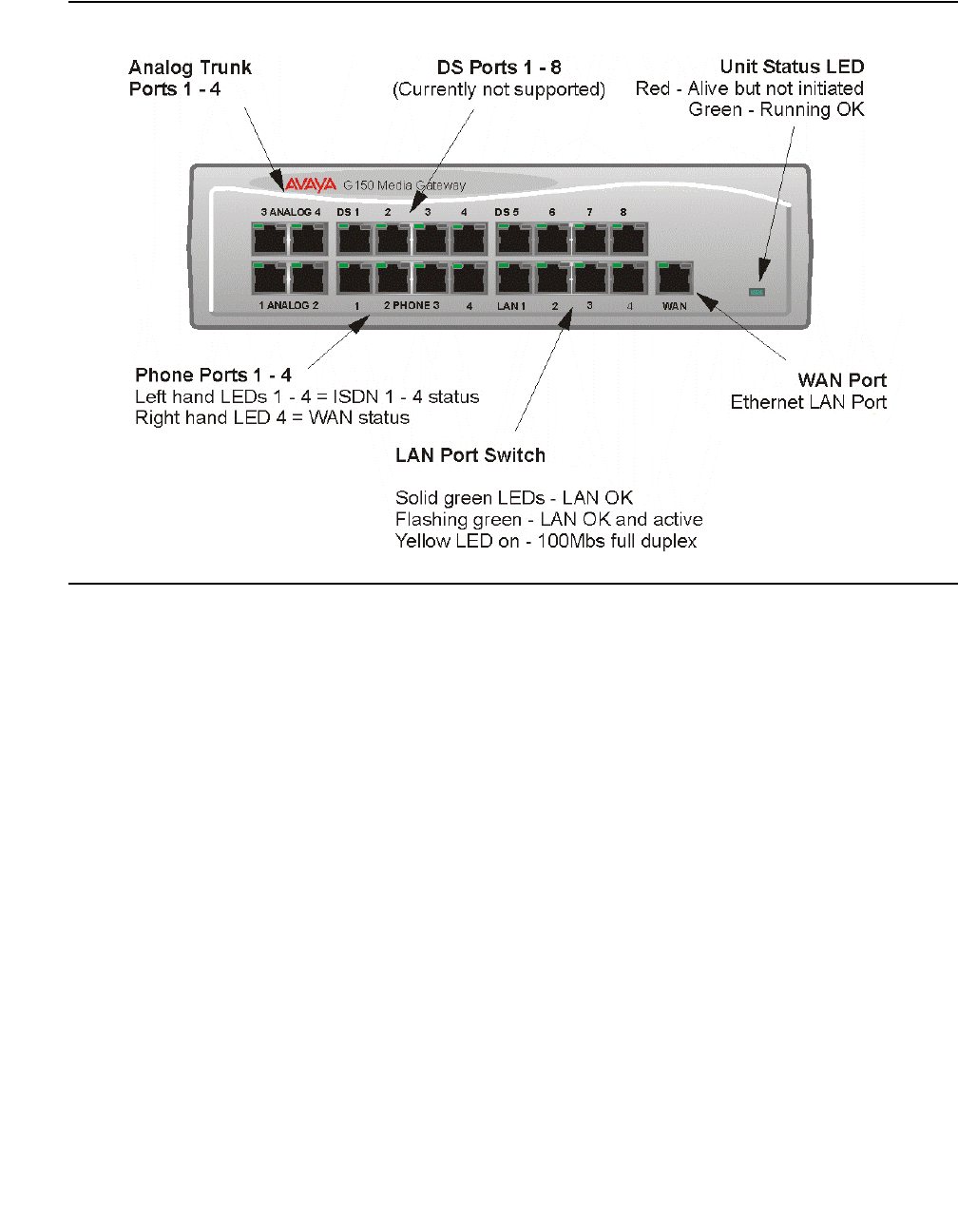
Small to mid-size enterprise
Issue 4.3 February 2006 57
Figure 10: G150 4T + 4A + DS (16 VoIP) front view
Port connections - The G150 4T + 4A +DS (16 VoIP) has the following port connections:
●DS Ports: Not currently supported on the G150.
●Analog Trunk Ports: These ports are used for connection to standard analog trunks (loop
start). Using standard structured wiring, these RJ45 ports can be extended to the required
trunk sockets. In the event of mains power supply failure, Analog Port 2 is automatically
switched to Phone port 1.
●Analog Telephone Ports: These ports are used for connection to standard analog
telephones, fax machines and modems. Using standard structured wiring, these RJ45
ports can be extended to the required telephone location. When telephones are equipped
with line cords that terminate in RJ11 plugs, then pin-to-pin RJ11/RJ45 adapters should be
used.
●LAN Ports: These are LAN 10/100Mbps Layer 2 Ethernet switches and are used for PC
and server connectivity. They have Auto MD1/MD1X capability and hence avoid the need
for LAN crossover cables when connecting to a hub. They can also be used to connect to
IP telephones (Avaya 4600 IP series). LAN ports allow information relating to incoming
and outgoing telephone calls to be forwarded to PC based applications. They also provide
access to the router functionality/configuration of the G150 platform for both data and
Voice over IP (VoIP) calls. Within the configuration software application (Manager), these
ports are referred to as LAN1.
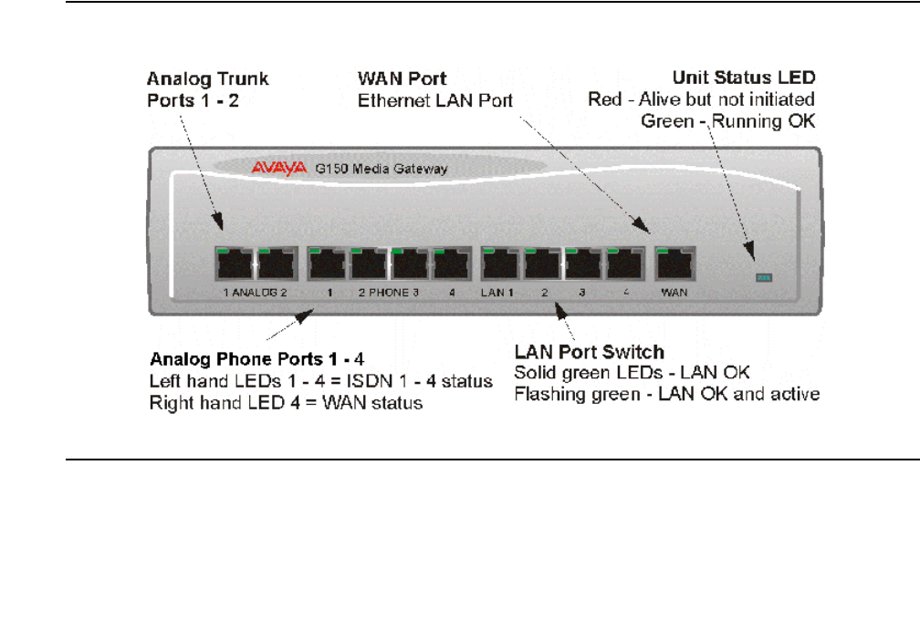
Avaya Application Solutions platforms
58 Avaya Application Solutions IP Telephony Deployment Guide
●WAN Port: This is a 10/100Mbs Ethernet LAN port for connection to an IP routed WAN
(e.g. DSL). Within the configuration software application (Manager), this port is referred to
as LAN2.
Cables - G150 is supplied with one red CAT 5E cable.
G150 2T + 4A (4 VoIP)
This variant of the G150 includes the following:
●Two Analog Loop Start Trunks (Two-way CO Trunks)
●Four Analog Extension interfaces
●Three VoIP Codecs (G.723.1, G.711a, G.711u and G.729a)
●4 Switched Ethernet ports (Layer 2)
●Dedicated Switched Ethernet WAN port (Layer 3)
●2x PCMCIA slots for Wireless and memory card support
●WAN slot for optional voice/data WAN card (V24, V35, X.21, quad-BRI and T1/PRI)
●DTE port
●Audio port (not used)
●External O/P socket (not used)
Figure 11: G150 2T + 4A (4 VoIP) front view

Small to mid-size enterprise
Issue 4.3 February 2006 59
Port connections - The G150 2T + 4A (4 VoIP) has the following port connections:
●Analog Trunk Ports: These ports are used for connection to standard analog trunks (loop
start). Using standard structured wiring, these RJ45 ports can be extended to the required
trunk sockets. In the event of mains power supply failure, Analog Port 2 is automatically
switched to Phone port 1.
●Analog Telephone Ports: These ports are used for connection to standard analog
telephones, fax machines and modems. Using standard structured wiring, these RJ45
ports can be extended to the required telephone location. When telephones are equipped
with line cords that terminate in RJ11 plugs, then pin-to-pin RJ11/RJ45 adapters should be
used.
Note:
Note: Fax/modem ports are used with local G150 trunks only.
●LAN Ports: These are LAN 10/100Mbps Layer 2 Ethernet switches and are used for PC
and server connectivity. They have Auto MD1/MD1X capability and hence avoid the need
for LAN crossover cables when connecting to a hub. They can also be used to connect to
IP telephones (Avaya 4600 IP series). LAN ports allow information relating to incoming
and outgoing telephone calls to be forwarded to PC based applications. They also provide
access to the router functionality/configuration of the G150 platform for both data and
Voice over IP (VoIP) calls. Within the configuration software application (Manager), these
ports are referred to as LAN1.
●WAN Port: This is a 10/100Mbs Ethernet LAN port for connection to a WAN (e.g. DSL).
Within the configuration software application (Manager), this port is referred to as LAN2.
Cables - G150 is supplied with one red CAT 5E cable.
Back Panel of the G150 (all models)
All models of the G150 have the same configuration when viewing the back of the control unit.
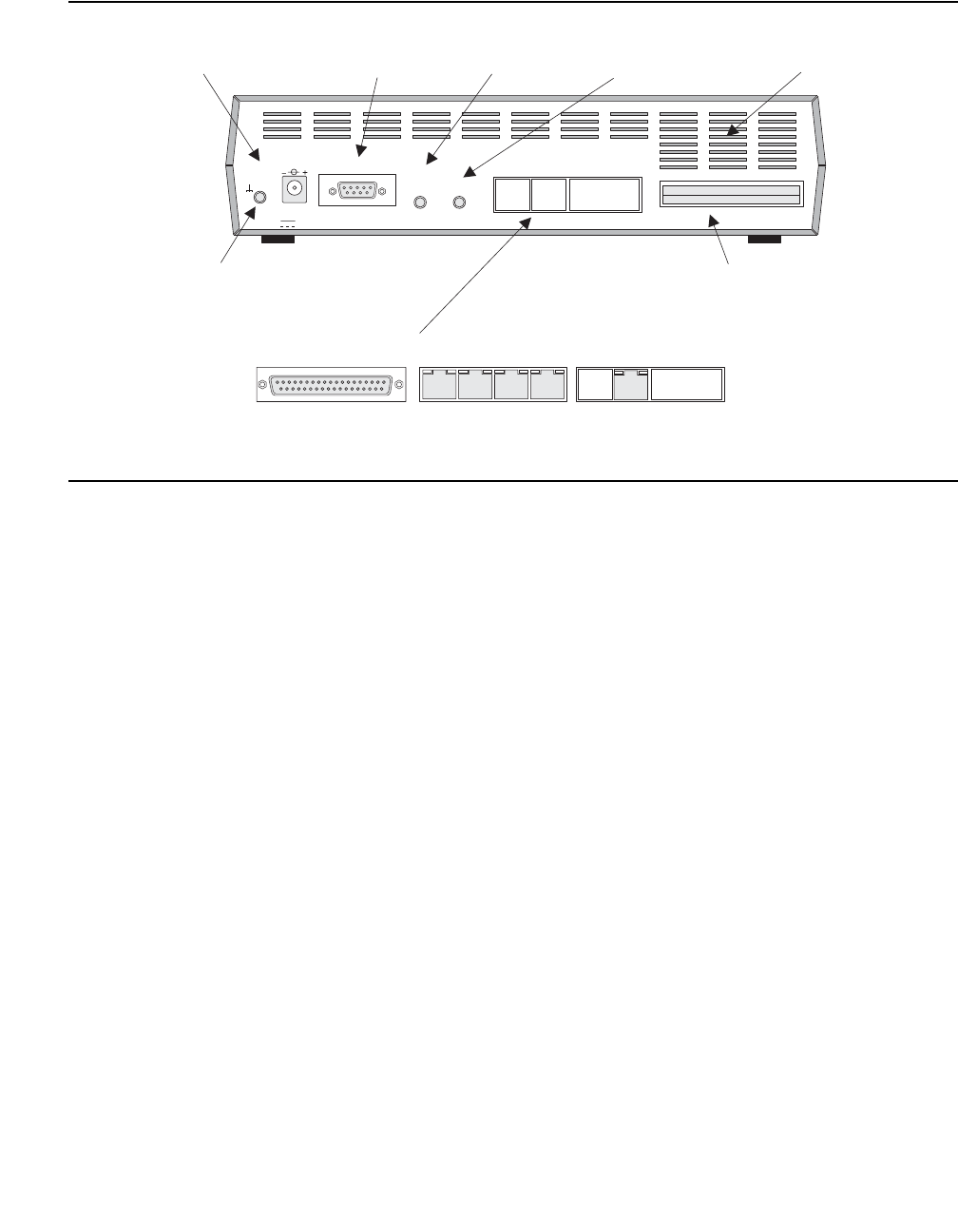
Avaya Application Solutions platforms
60 Avaya Application Solutions IP Telephony Deployment Guide
Figure 12: G150 back view
Connections - The G150 back panel has the following connections:
●External O/P Socket: Not used with the G150.
●DC Power I/P Socket: Socket for the external 24V DC unregulated power supply.
●DTE Port: A 9-way D-type socket. Used for applications Licence Key device (Dongle) and
connection to PCs, Servers and EFTPOS terminals.
●WAN Slot: This slot supports a single synchronous voice/data PSTN WAN interface of the
following types:
- G150 Quad BRI Card (Euro ISDN)
- G150 WAN Expansion Card (V35/V24/X21)
- G150 T1/PRI Card (23B+1D or 24B trunks)
●PCMCIA slots: Used for a Wireless LAN card when using the system as an Access Point
for 802.11b support of a wireless data application. The second PCMCIA slot may be used
to house a 64M flash memory card for providing a TFTP server.
●Audio I/P Socket: Not used with the G150.
●Functional Earth Socket: A single 3.5mm jack socket with all 3 pins connected to ground.
For use in areas with high lightning and/or ESD. Connect a 3.5mm jack plug (not
supplied), fitted with a green sleeve 14swg wire, to the buildings approved earth point
(must conform to local grounding (earthing) regulations).
h2cmbck1 LAO 033005
WAN X21/V24/V35
Comes with new
back panel
Quad BRI trunks T1 trunk
13
132
Knock-out panel(s) for trunk module kits as follows:
PCMCIA slots,
A wireless LAN and/or an additional Memory
card can be fitted in either slot. One of each only.
Functional Ground
Jack Socket
AUDIO
EXT
O/P
DTE
DC LP
24V DC
24
DC Power I/P Socket DTE Port External O/P Socket Audio I/P Socket Vents

Small to mid-size enterprise
Issue 4.3 February 2006 61
!CAUTION:
CAUTION: This is not a protective ground point. The unit is also earthed via the power cable
(through the lump in line PSU).
Differentiating between the G150 and G250
The G150 media gateway serves as a complementary component to the Avaya Enterprise
Connect family of branch gateways, alongside G250 (2-10 users), G350 (8-40 users), and G700
(25-450 users). The G250, G350, and G700, the H.248 media gateways, are all designed to
address the needs of high-intensity communication branches. That is, branches that are
characterized by intensive communication with their headquarters, run distributed applications
such as CRM and are centrally managed.
The G150, a H.323-based gateway, offers an affordable solution for branches that are more
loosely coupled with their headquarters, and therefore expect a less seamless connection to
their headquarters. The G150 is aimed, first and foremost, at serving as the SOHO branch
solution of price-sensitive, low communication-intensity type of customers that see value in
having a centralized, distributed, ACM-based solution, such as retail chains or manufacturing
industries.
Avaya S8400 Media Server
The S8400 Media Server is a Linux-based server that occupies a single slot in a standard TN
carrier. The S8400 Media Server provides Communication Manager processing functionality in
stand alone, single port network (PN), telephony systems supporting up to 900 stations.
The S8400 Media Server is composed of the:
●TN8400AP Media Server circuit pack
●TN8412AP S8400 IP Interface (SIPI) circuit pack
Table 2: Avaya Application Solutions comparison matrix — components, performance, and
capacities on page 36 summarizes the capacity specifications of the Avaya S8400 Media
Server.
TN8400AP circuit pack (S8400 Media Server) on page 62 shows the TN8400AP circuit pack.
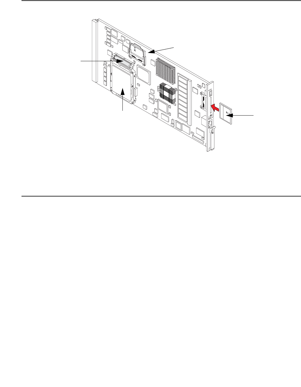
Avaya Application Solutions platforms
62 Avaya Application Solutions IP Telephony Deployment Guide
Figure 13: TN8400AP circuit pack (S8400 Media Server)
The S8400 Media Server can replace the following platforms:
●DEFINITY CSI
●DEFINITY One/S8100
●IP600/S8100
For new installations, the PNs use the G650 Media Gateways. For migrations of current
installations, use the S8400 Media Server as an upgrade path for current PNs based on G650
and G600 Media Gateways and CMC carriers. Since the S8400 Media Server supports only
one port network, and different media gateways cannot be mixed in the same port network, a
G650 Media Gateway cannot be added to an S8400 system that carries forward a CMC1 or
G600 Media Gateway as a result of a migration.
The S8400 Media Server uses the TN8412AP S8400 IP Interface (SIPI) or the TN2312BP
Internet Protocol Server Interface (IPSI-2) circuit pack to provide:
●circuit pack control within its port network
●cabinet maintenance
●tone-clocks
●emergency transfer switch functionality
●customer/external alarms.
Figure notes:
1. Compact flash
2. Hard disk drive 3. Ribbon cable to hard disk drive
4. Solid state drive
ALARM CARD IN USE
OK TO REMOVE
SERVICE
SD
ILICON RIVE
CF
4GB
SSD-C04G-3012
SILICON
SYSTEMS
SD
ILICON RIVE
CF
2GB
SSD-C02G-3012
SILICON
SYSTEMS
h2dp8400 LAO 062405
12
3
4

Small to mid-size enterprise
Issue 4.3 February 2006 63
The TN799DP Control-LAN (C-LAN) circuit pack provides firmware download functionality while
the TN2501 Voice Announcement over LAN (VAL) circuit pack provides announcement
functionality.
The S8400 Media Server provides a Voice over Internet Protocol (VoIP) based integrated
messaging capability for up to 450 light duty users. This option requires that 8 ports of VoIP
resources be provisioned with the S8400 Media Server. The hard disk drive stores the
messages and a TN2302AP IP Media Processor circuit pack usually provides the VoIP
resources.
An external messaging system is required when an S8400 Media Server based system is
configured for more than 450 light duty users that requires messaging.
The S8400 Media Server supports a single port network (PN), which can be composed of:
●up to 5 G650s
●up to 4 CMC1s
●up to 3 G600s
The S8400 also supports up to 5 H.248 media gateways, including:
●G700
●G350
●G250
The S8400 can support up to 80 G150 Media Gateways.
The S8400 Media Server cannot be configured as an Enterprise Survivable Server (ESS) or
Local Survivable Processor (LSP). But a G700, G350, or G250 Media Gateway connected to an
S8400 Media Server can have an LSP installed. In the event that the media gateway can no
longer communicate with the S8400, the LSP takes over all call processing functions for that
gateway. However, the LSP does not take on any of the call processing functions for those
trunks and endpoints that are directly connected to the S8400.
The S8400 Media Server consists of three separate TN circuit packs; two required and one
optional:
●TN8400AP circuit pack that provides
- Avaya Communication Manager call processing
- coresident voicemail
- on board diagnostics
- autonomous alarming
●TN8412AP S8400 IP Interface (SIPI) that provides
- low-level control functions and services for a TN port network
- tone detection and generation
- carrier maintenance and diagnostics

Avaya Application Solutions platforms
64 Avaya Application Solutions IP Telephony Deployment Guide
- input/output of alarm leads
- emergency transfer
●An optional TN2302AP IP Media Processor if you run the optional embedded messaging
(IA770) or run IP telephones. When running IP telephones, the TN2302AP interfaces
between the Time Division Multiplex (TDM) bus and the IP network.
The S8400 Media Server uses a solid state drive and a hard disk drive to:
●run Avaya Communication Manager
●hold translations
●function as the primary storage device
The solid state drive and CD/DVD-ROM drive each can be configured as a bootable device.
The boot sequence is as follows:
1. USB CD/DVD-ROM drive when you install it
2. Solid state drive
Communication between the S8400 and the TN8412AP is by IP link. The S8400 has an
Ethernet NIC for the TN8412AP control link. You can connect this link by an external switch or
point-to-point by a single Ethernet crossover cable. The TN8412AP has a single Ethernet
interface for control.
The optional IA770 integrated messaging supports the equivalent of 8 ports of voice messaging
simultaneously, and up to 450 light duty users. An external messaging system if more than 450
users are required or where the 450 users are "exceptionally heavy users." The exceptionally
heavy users are defined as users who require more than 4.5 disk minutes/user/day or 10 port
minutes/user/day. The following items are optional for all S8400 controlled systems:
●A TN799DP Control-LAN (C-LAN) circuit pack for the firmware download
●A TN2302AP IP Media Processor circuit pack might be needed to provide conversion
between TDM and IP for all IP-based voice mail solution (IA770) and IP telephony. Up to 8
ports of the TN2302AP can be utilized by the IA770 integrated messaging option and the
remaining ports may be used to support IP telephony systems.
●The S8400 generally uses the IA770 voice mail product that is an all IP solution and
co-resides on the circuit pack. IA770 is a VoIP based integrated messaging option that
requires up to 8 ports of VoIP resources.
●Customers provide an Ethernet switch if it is required.
●A TN771 Maintenance/Test circuit pack when:
- There are 3 or more G650, G600, or CMC1 cabinets (G150 and H.248 gateways should
not be included in this count) in the S8400 system, and
- There are IP or ISDN endpoints (BRI and PRI trunks and BRI stations)

Mid-market to large enterprise
Issue 4.3 February 2006 65
Mid-market to large enterprise
S8500 Media Server
The Avaya S8500 Media Server Platform is a simplex Linux-based server running Avaya
Communication Manager (CM) software that will replace the DEFINITY SI and R processing
platforms for small sites and for customers who do not require a duplicated server complex.
The S8500 supports all of the Avaya media gateways. The S8500 has the capacity to support
up to 64 IP-connect port networks. Up to 3 MCC1 port networks can be directly connected. The
S8500 can be configured as a primary controller, a Local Survivable Processor (LSP), or as an
Enterprise Survivable Server (ESS).
The S8500 Media Server allows for a seamless migration from DEFINITY SI and R platforms.
However, the S8500 will not support traditional circuit-switched Center Stage Switch or ATM
Port Network Connectivity.
S8500 capacities
Table 2: Avaya Application Solutions comparison matrix — components, performance, and
capacities on page 36 summarizes the performance and capacity specifications of the Avaya
S8500 Media Server.
Avaya S8700-series Media Server, fiber connect configuration
The S8700-series Media Server with an MCC1 or SCC1 Media Gateway is targeted at Avaya’s
largest customers. These customers are typically experiencing rapid growth, and looking for
ways to consolidate their network. These are customers who require high-end applications such
as DEFINITY Call Center Solutions, CTI applications, Unified Messaging, multimedia
conferencing, and voice/data network integration, and are evolving to an IP-intensive
environment. This solution supports up to 44,000 telephones.
This solution is also targeted at smaller customers who made an investment in DEFINITY, and
are looking for a smooth transition into industry-standard processors that will enable expanded
communications capabilities.
The S8700-series Media Server is a large-office solution with the media server in the
headquarter locations and optional servers/gateways in the branch offices. The option of
duplicated headquarters with branch and remote offices is also available.
For information on S8700-series Media Server performance and capacities, see Table 2: Avaya
Application Solutions comparison matrix — components, performance, and capacities on
page 36.

Avaya Application Solutions platforms
66 Avaya Application Solutions IP Telephony Deployment Guide
Because the inter port network TDM traffic flow is supported by a Center Stage Switch (CSS) or
an Asynchronous Transfer Mode (ATM) switch using fiber-optic cables, this configuration is
called fiber connect. The call control traffic between the media server and the gateways is
usually, but not necessarily, over a private dedicated Ethernet network that is provided by
Avaya.
This solution is scalable to up to 44 Port Networks (PNs) through CSS configuration, and up to
64 PNs in an ATM configuration. The fiber connect solution has three reliability options:
●Standard. S8700-series Media Server, with memory shadowing, two uninterruptible power
supplies (UPS), one switch, and one IPSI in each IPSI-connected PN
●High. Standard reliability, plus a second switch and a second IPSI in each IPSI-connected
PN. This design provides for a second redundant call control network
●Critical. High reliability plus duplication of the bearer network
S8700-series Media Server
Table 2: Avaya Application Solutions comparison matrix — components, performance, and
capacities on page 36 summarizes the performance and capacity specifications of the Avaya
S8700-series Media Servers.
The Avaya S8700-series Media Server always consists of two servers running on a Linux
operating system. In S8700-series fiber connect and IP connect configurations, the
S8700-series Media Server provides the main feature and management processing capabilities
of the system. The Media server is connected to other system and external components
primarily through IP networks.
S8700-series external features
●Six 10/100 Ethernet NICs per server, which are used as follows:
- Dual control network connections
- A heartbeat link to the duplicated server
- Administrative access from the corporate network
- Technician access
- One unused
●A PCMCIA Flash disk for translations backup
●USB ports for remote access connections (modems and other auxiliary devices)
●A reset button
●Support for global power
●A fiber-channel interface to support server duplication (except for S8720 software
duplication)
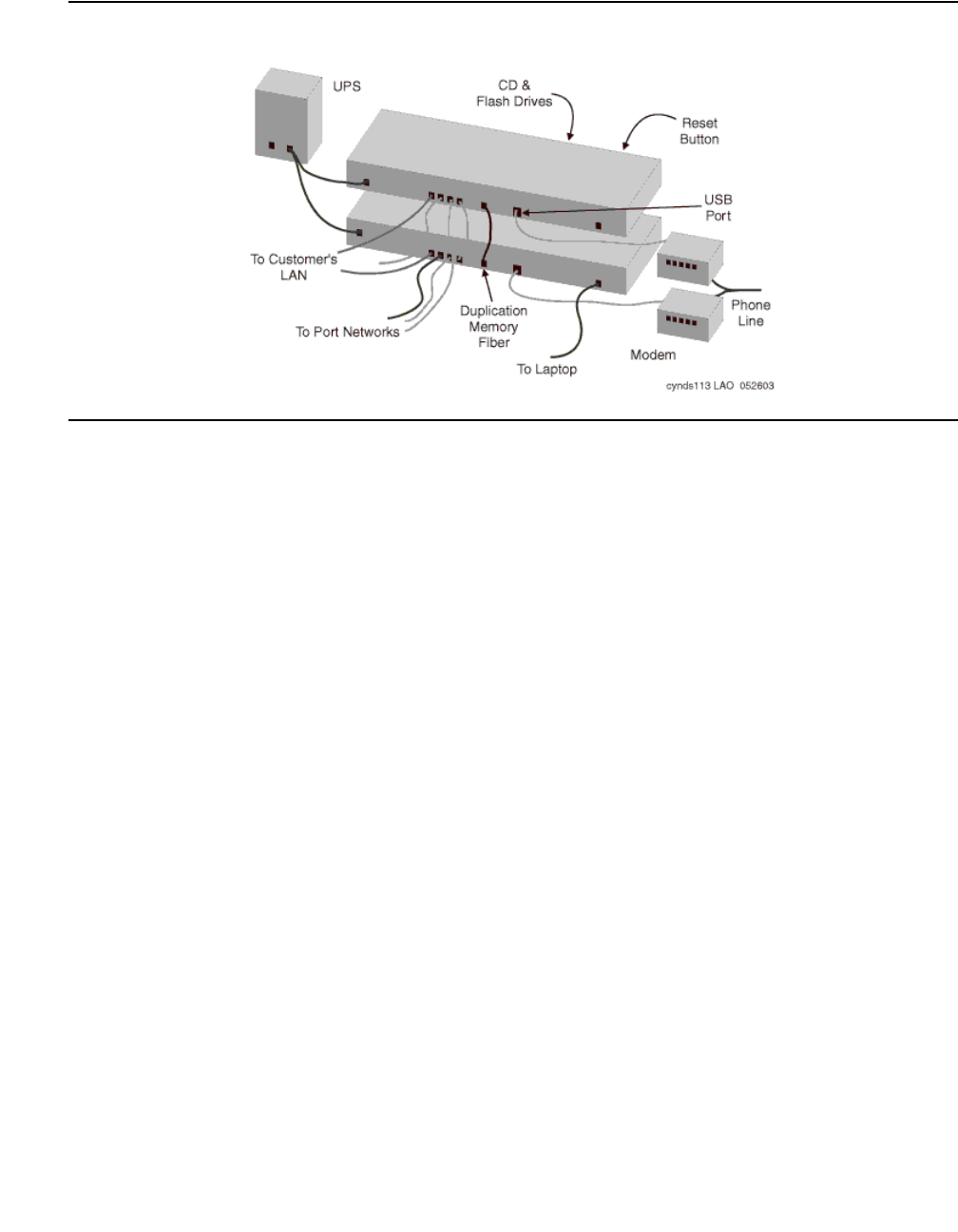
Mid-market to large enterprise
Issue 4.3 February 2006 67
Figure 14: Avaya S8700 external features
UPS or power backup - The S8700-series Media Servers always require power backup to
avoid power problems, and to ensure graceful shutdown of the system processes if the power
fails. The AS1 700-VA UPS provides approximately 30 minutes of power backup. Combinations
of battery extension modules and a 1500-VA UPS provide up to 8 hours of power backup.
The AS1 UPS units use SNMP traps to send an alarm when power fails. This action initiates a
graceful shutdown process of the Linux server, including the call processing software.
USB modem - Each S8700-series Media Server supports a Universal Serial Bus (USB)
modem. For customers with an Avaya service contract, the modem is used to send alarms to
the Avaya Services organization, and to facilitate maintenance by Avaya Services personnel.
Internal hardware elements
The server has the following specifications:
●512 MB (S8710) or 1 GB (S8720) of main memory
●SCSI hard disk for booting Linux and Communication Manager
●Combo DVD/CD-ROM drive for software installations and upgrades
●2 (S8710) or 3 (S8720) USB ports
●USB Compact Flash card support
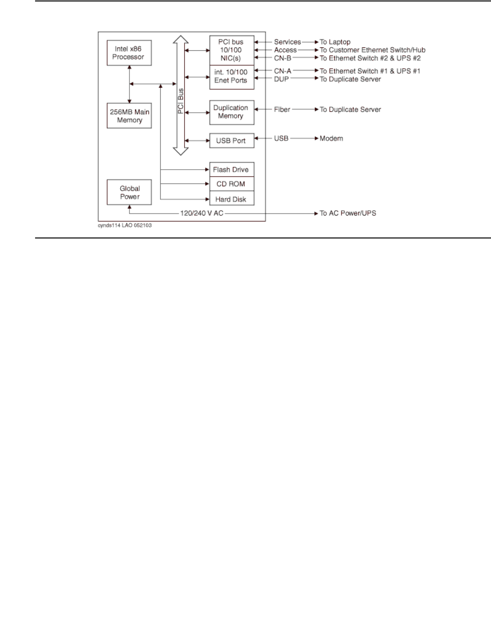
Avaya Application Solutions platforms
68 Avaya Application Solutions IP Telephony Deployment Guide
Figure 15: Avaya S8700-series Media Server schematic
Other components
The S8700 in a fiber connect solution also includes the following components:
●Avaya C360-series Ethernet switch with duplication option
●One or more IP Server Interface (IPSI) circuit packs (TN2312BP)
●A Center Stage Switch (CSS) or an ATM Switch for bearer connectivity
●One or more MCC1 or SCC1 Media Gateways, also known as port networks (PNs)
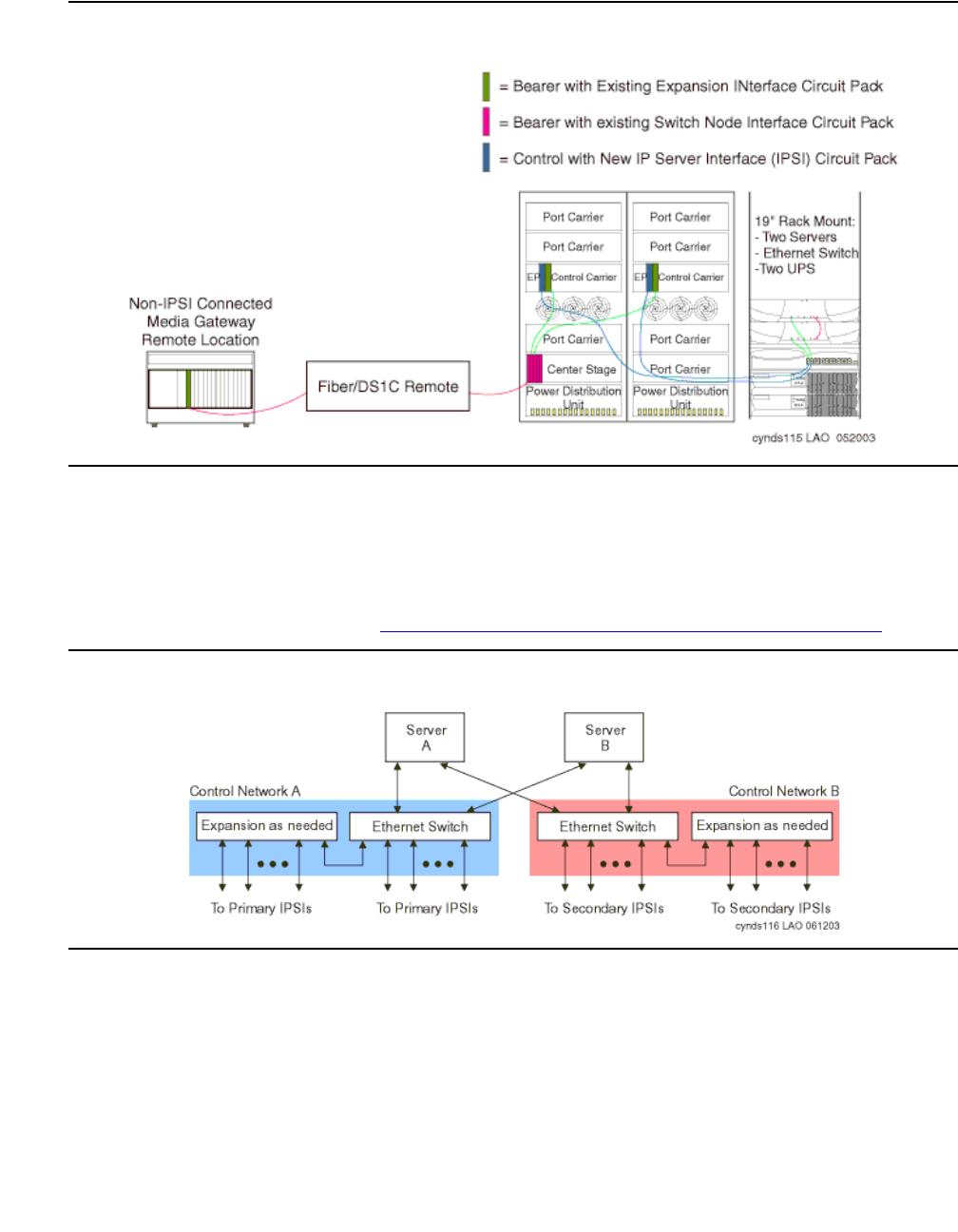
Mid-market to large enterprise
Issue 4.3 February 2006 69
Figure 16: Avaya S8700/MCC1 fiber connect major components
Control network through an Avaya Ethernet switch
When designing S8700-series fiber connect systems, a control network connects the servers to
the IPSIs through a 10/100 BaseT Ethernet. It consists of two separate Ethernet networks using
Ethernet switches. Control network A connects to the primary IPSIs, and control network B
connects to the secondary IPSIs (Figure 17: S8700-series fiber connect control network).
Figure 17: S8700-series fiber connect control network
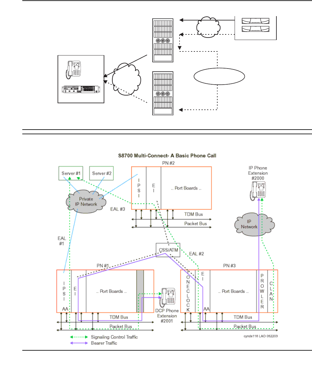
Avaya Application Solutions platforms
70 Avaya Application Solutions IP Telephony Deployment Guide
Circuit packs that support IP signaling and media traffic
Figure 18: S8700-series / MCC1 signaling path
Figure 19: S8700-series fiber connect — a basic phone call
cynds117 KLC 121003
IP
IP
PN1
PN2
H.323 endpoint
or H.248 Gateway
C
L
A
N
I
P
S
I
B
C
L
A
N
B
S8700
Center Stage
(non-IP)
IP
Phone
ALM
TST
ACT
ALM
TST
ACT
1 2 3 4 5 6 87
ALM
TST
ACT
ALM
TST
ACT
1 2 3 4 5 6 87
REMOVE
ALM
TST
ACT
OKTO
ALM
TST
ACT
OKTO SHUT DOWN
SERVICES
USB1
USB1
USB2
USB2
E1/T1
E1/T1
EIA 530A DCE
EIA 530A DCE
ALM
TST
ACT
SIG
ALM
TST
ACT
SIG
EISO
EM
EMSM EOSI
G700/G350

Mid-market to large enterprise
Issue 4.3 February 2006 71
IP Server Interface (TN2312BP) - The IP Server Interface (IPSI) is the communication
interface between the server and the Media Gateways (port networks). The IPSI is responsible
for gateway control, and for tunneling call control messages back to the S8700.
One IPSI circuit pack is required per IPSI-connected Media Gateway for standard reliability.
Duplicated IPSI circuit packs are required per IPSI-connected Media Gateway for high reliability
and critical reliability.
The IPSI is located in the tone/clock slots, and provides the following functions:
●PKTINT packet bus interface
●Archangel TDM bus interface
●Tone/Clock functionality found on the TN2182B Tone/Clock circuit pack
●Ethernet interface for technician access
●Ethernet interface for connectivity to Services laptop computers
●Maintenance board interface for communication with the EPN maintenance board
Each IPSI typically controls up to five gateways by tunneling control messages over the center
stage (TDM) network to the PNs that do not have IPSIs. For locations with high IP Telephone
traffic, Avaya recommends a greater number of IPSI circuit packs.
An IPSI cannot be placed in:
●A PN that has a Stratum-3 clock interface
●A remote PN that uses a DS1 converter
●A Survivable Remote Expansion Port Network (SREPN)
The IPSI supports the following functions:
●Supports eight global Call Classification ports
●Supports network diagnostic capabilities
●Provides PN clock generation and synchronization for Stratum-4 type II only
●Provides PN tone generation
●Provides distributed PN packet interface
●Supports the download of IPSI firmware
●Provides serial number support for License File feature activation
Control LAN (TN799DP) - The TN799DP Control LAN (C-LAN) circuit pack acts as front-end
processor and concentrator and provides the gateway between the public IP Telephony network
and the S8700-system. All H.323 signaling messages between IP Telephony endpoints and the
S8700-series media servers must pass through the C-LAN. The connectivity path between the
IP endpoint and the server is as follows:
Endpoint ⇔ IP Network ⇔ C-LAN ⇔ PN backplane ⇔ IPSI ⇔ IP network ⇔ S8700

Avaya Application Solutions platforms
72 Avaya Application Solutions IP Telephony Deployment Guide
The C-LAN circuit pack is used for all IP call signaling for both IP trunks and stations. This circuit
pack also provides TCP/IP connectivity to such adjuncts and synchronous applications as Call
Management System (CMS) and INTUITY AUDIX.
This circuit pack also supports firmware download capability for all firmware-downloadable
circuit packs in a PN, which allows administrators to remotely update the firmware or application
code of circuit packs such as the TN799DP (C-LAN) or TN2302AP Media Processor.
The S8700 platforms support a maximum of 64 C-LAN circuit packs per system. The number of
C-LAN circuit packs that are required depends on the number of IP endpoints that are
connected, and the options that the endpoints use. For example, it might be advantageous to
segregate IP voice control traffic from device control traffic.
IP Media Processor (TN2302AP, TN2602AP) - The TN2302AP IP Media Processor and the
TN2602AP IP Media Resource 320 circuit packs are media processors (MedPro) that provide
gateways between the TDM bus and the Ethernet network for audio streams.
Configurations using the S8700-series Media Servers require resources on TN2302AP and/or
TN2602AP media processor circuit packs for IP Telephony bearer communications. TN2302AP
and TN2602AP each include a 10/100 BaseT Ethernet interface to support IP trunks and H.323
endpoints. Media processor circuit packs can perform echo cancellation, silence suppression,
dual-tone multi-frequency (DTMF) detection, and conferencing.
As shown in Figure 20: TN2302AP Media Processor (MedPro) operation on page 73, the
media processor converts circuit-switched audio streams to packet-switched streams. The
media processor supports multiple codecs, so it can compress audio samples during
packetization. When needed for conference calls, it can also take multiple audio streams, sum
them together, and send the resulting audio stream to multiple recipients on the network. Note
that the TN2602AP uses the same media processor principles as the TN2302AP.
Starting with release 3.1 of Communication Manager, the TN2602AP IP Media Resource 320
can be duplicated to provide critical bearer reliability for IP-connected port networks.
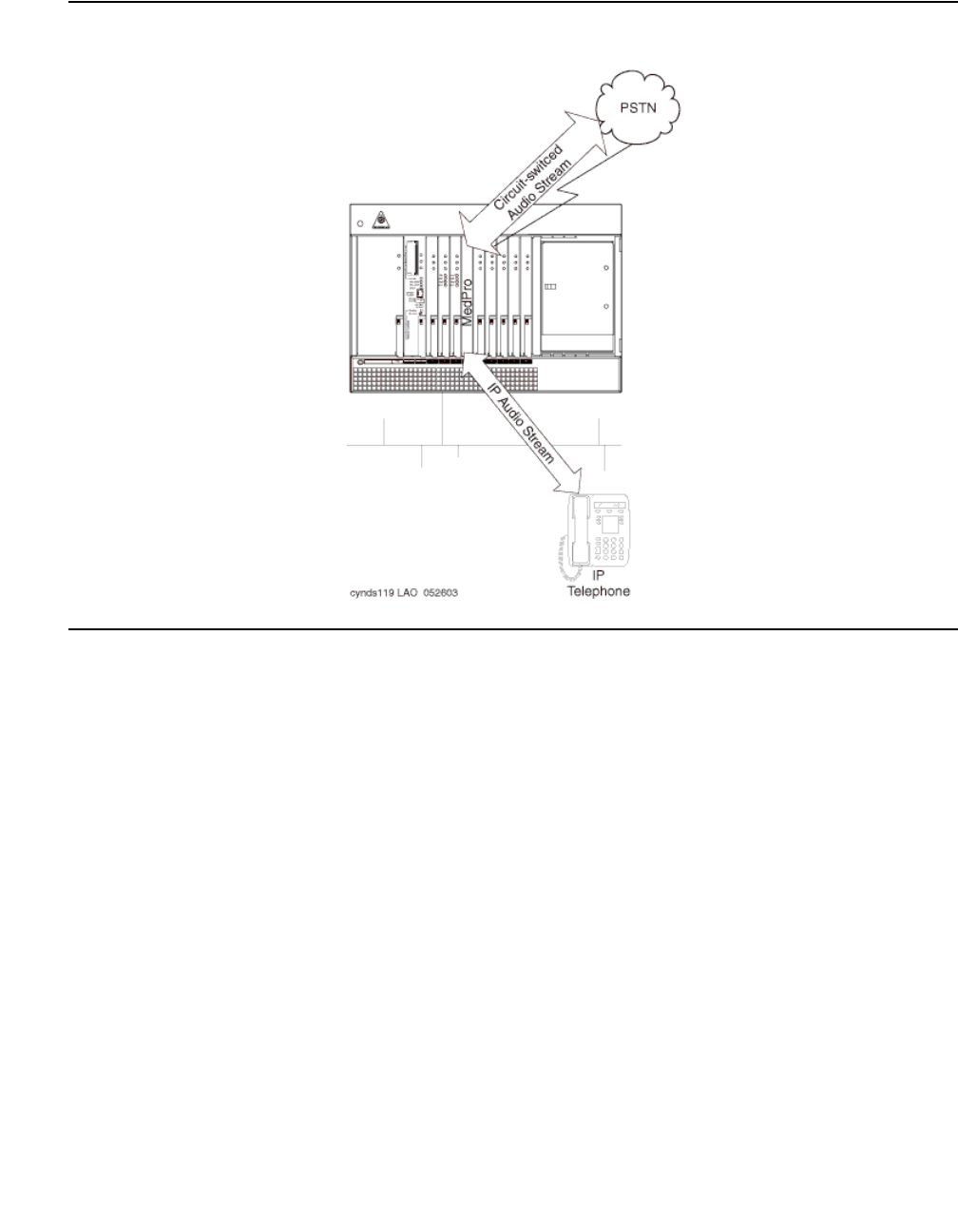
Mid-market to large enterprise
Issue 4.3 February 2006 73
Figure 20: TN2302AP Media Processor (MedPro) operation
To do the job, a media processing circuit pack has a set of DSP resources. These resources are
deployed dynamically and flexibly to any of a number of tasks, including:
●Originating and terminating IP-based packet-switched audio streams
●Establishing and maintaining an RTCP control channel for each IP audio channel
●Compressing and decompressing audio (for example, G.729 to G.711)
●Terminating TCP for an incoming T.120 data stream, and transcoding it to H.221-
compliant format for transmission onto the TDM bus and vice-versa
●Summing multiple audio channels into a composite signal for audio conferencing
The S8700 (or S8710) Media Server is responsible for sending messages to the circuit pack to
allocate and to configure the DSP resources to the required task and connecting multiple
resources into a chain that performs the desired media processing function. In addition, the
Media Server sends the information to the destination of these audio streams.

Avaya Application Solutions platforms
74 Avaya Application Solutions IP Telephony Deployment Guide
Since H.323 allows any of several different codecs to be used for encoding an audio stream on
the IP network, the Prowler board is able to use any of the following codecs:
●G.711
●G.723.1
●G.729 (A, B)
In the same way that a MedPro interfaces with IP Telephony endpoints, it can connect to
another MedPro to interconnect two or more Avaya switches in an IP network over an IP trunk.
Media Gateways
The MCC1, SCC1, and G650 Media Gateways are supported in a fiber connect configuration.
An S8700-series fiber connect configuration can have a mixture of MCC1 and SCC1 cabinets.
However, the type of cabinet cannot be split within a Port Network.
Multi-Carrier Cabinet (MCC1) Media Gateway - The MCC1 Media Gateway can contain up to
five of the following carriers:
●A Port Carrier that contains one or more of the following:
- Port circuit packs
- VOIP conversion resources
- Service circuit packs
- Tone clocks
- Expansion Interface (EI) circuit packs
●A Switch Node Carrier that contains Switch Node Interface circuit packs that compose the
Center Stage Switch (CSS).
●An Expansion Control Carrier that contains service slots and port slots.
The MCC1 Media Gateways can support a maximum of 98 trunk or line port circuit packs.
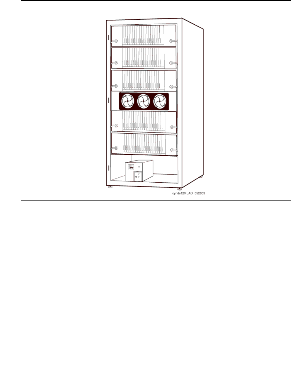
Mid-market to large enterprise
Issue 4.3 February 2006 75
Figure 21: MCC1 Media Gateway
Single-Carrier Cabinet (SCC1) Media Gateway - The SCC1 Media Gateway consists of a
single carrier. Up to four SCC1 Media Gateways can be connected together in one location to
form one port network. There are two types of SCC1 Media Gateways:
●An Expansion Control Cabinet that contains service slots and port slots.
●A Port Cabinet that contains ports and interfaces to an Expansion Control Cabinet.
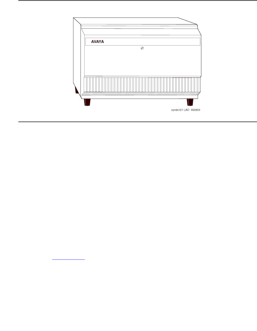
Avaya Application Solutions platforms
76 Avaya Application Solutions IP Telephony Deployment Guide
Figure 22: SCC1 Media Gateway
Non-IPSI connected Media Gateway - Typically, one of every five Port Networks (PNs)
contains one or two IPSI circuit packs. The remaining PNs are referred to as non-IPSI
connected. Non-IPSI connected PNs get their control information from the servers through one
of the PNs that does contain an IPSI. Such control messages are “tunneled” through the
circuit-switched network. The system software controls this communication and allocation. The
software automatically routes the control messages through an appropriate IPSI. There is no
need to administer which IPSI controls the non-IPSI connected PNs. The system automatically
allocates those resources, and also compensates for any component failure.
Remote MCC1\SCC1 Media Gateways - The dedicated control network for an S8700 with
MCC1 or SCC1 Media Gateway can be extended to an IPSI in a remote media gateway. But for
cost effectiveness and straightforward installation, Avaya recommends that all of the
IPSI-connected media gateways be collocated with the S8700 and Ethernet switches. The
circuit-switched network dictates the available options.
Non-IPSI connected media gateways’ circuit-switched network can be extended through all the
options available with DEFINITY G3r. Center Stage Switch configurations can use fiber
extenders or DS1-Converter (DS1-C) facilities, allowing the media gateway separation to be
essentially limitless. When ATM-PNC is used, the media gateway separation is also essentially
limitless (see ATM network on page 77).

Mid-market to large enterprise
Issue 4.3 February 2006 77
Remote G700, G350, G250, or G150 Media Gateway - The S8700-series Media Server can
provide the call processing features for a remote G700, G350, or G250 media gateway over an
H.248 link, and G150 gateway using H.323. In this configuration, the S8700 can support up to
250 G700, 350, 250, or 150 Media Gateways. An S8300 media module that is located in a
G700, G350, or G250 Media Gateway in a remote location provides survivability when the
primary controller is inaccessible. For more information, see S8300 as an LSP on page 45.
Another option for survivability of remote gateways is an S8500 media server configured as a
Local Survivable Processor (LSP).
Center Stage Switch
The Center Stage Switch (CSS) is a connection hub that provides inter-port network
communication between four or more port networks. Often, the CSS is incorporated into smaller
configurations to allow for growth. The CSS consists of from one to three switch nodes (SN),
which reside in a Port Network carrier. SNs are composed of one or two switch node carriers,
depending on whether the solution is being duplicated for critical reliability. Port Network
expansion depends on internal SN-to-SN traffic, according to the following guidelines:
●1 SN expands from 1 to up to 15 PNs.
●2 SNs expands to up to 29 PNs.
●3 SNs expands to up to 44 PNs.
ATM network
The Asynchronous Transfer Mode (ATM) switch is a replacement option for the CSS, or for the
direct-connect switch. Several Avaya ATM switch types can provide Port Network connectivity.
Non-Avaya ATM switches that comply with the ATM standards that are set by the European
Union can also provide Port Network connectivity.
ATM-Port Network Connectivity (ATM-PNC) allows any ATM switch or ATM network that
complies with specified standards and capacities to serve as the means to connect to the PNs.
In this type of configuration, the ATM switch or network replaces the CSS. ATM-PNC is used to
connect port networks within a single switch. The WAN Spare Processor (WSP) is not
supported. One ATM supports up to 64 PNs.

Avaya Application Solutions platforms
78 Avaya Application Solutions IP Telephony Deployment Guide
S8700-series Fiber Connect configuration for higher availability
When used with the MCC1 and SCC1 Media Gateways, the S8700-series Media Server has the
following reliability options:
●Standard reliability configuration
●High reliability configuration
●Critical reliability configuration
Standard reliability configuration
The standard reliability option is the most basic option that consists of the following
components:
●Two S8700-series Media Servers
●Server-to-IPSI control is not duplicated
●One UPS unit for each S8700-series Media Server. Using two UPS units ensures that a
single UPS failure or repair operation does not disable the system.
●One IPSI in each IPSI-connected port network
●Circuit-switched traffic between port networks is carried on a simplex network that is made
up of one Expansion Interface (EI) in each port network. The EIs are cabled with lightguide
fiber to either the Center Stage Switch (CSS) or an Asynchronous Transfer Mode (ATM)
switch.
Figure 23: S8700-series Fiber Connect in a standard reliability configuration on page 79 shows
an example of a standard reliability configuration.
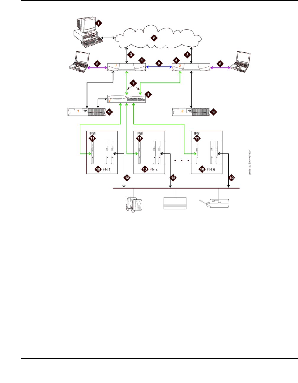
Mid-market to large enterprise
Issue 4.3 February 2006 79
Figure 23: S8700-series Fiber Connect in a standard reliability configuration
Figure notes:
1. The Administration PC accesses the
S8700-series Media Server over the
corporate data network.
2. Corporate IP network.
3. Corporate IP network interface. The Ethernet
4 link from the S8700 to the data network.1
4. Two S8700s are always present. One server
is in active mode, and the other server is on
standby.
5. Duplication interface, default Ethernet 2. The
dedicated Ethernet connection between the
S8700-series Media Servers.
6. Services interface, default Ethernet 1. The
server's dedicated Ethernet connection from
the S8700 to a laptop computer (active only
during on-site administration or on-site
maintenance).
1. The Ethernet connection to the corporate network in this figure is a nondedicated network. IP addresses for the various
components of the S8700-series fiber connect configuration must be administered to prevent conflicts with other
equipment that shares the network. In the default S8700 fiber connect configuration, all other Ethernet connections
operate on their own closed LANs.
7. Network control A interface, default Ethernet 0. The
server's Ethernet connection to one or two Ethernet
switches. This Ethernet link carries the control signals
for the PNs.
8. Ethernet switch. At least one Ethernet switch is required
to support the control network. If many PNs are present,
two Ethernet switches can be daisy-chained together to
provide sufficient Ethernet connections to the IPSI
boards in the PNs.
9. UPS. Keeps the S8700-series Media Servers and the
Ethernet switches functional during brief power
outages.
10. Port networks.
11. IPSI. The IPSI circuit pack carries the control network
signals to the PNs, and provides tone clock
functionality.
12. Bearer connectivity over Center Stage Switch or ATM.

Avaya Application Solutions platforms
80 Avaya Application Solutions IP Telephony Deployment Guide
High reliability configuration
The high reliability configuration option builds on the standard reliability option. The high
reliability option duplicates components, so that no single point of failure exists in the control
network. The high reliability configuration consists of the following components:
●Two S8700-series Media Servers
●Two IPSI circuit packs in each IPSI-connected port network
●Two Ethernet switches
●Two UPS units
Circuit-switched traffic between port networks is carried on a simplex network that is made up of
one Expansion Interface (EI) in each port network. The EIs are cabled with lightguide fiber to
either the Center Stage Switch (CSS) or an Asynchronous Transfer Mode (ATM) switch.
Figure 24: S8700-series Fiber Connect in a high reliability configuration on page 81 shows an
example of a high reliability configuration.
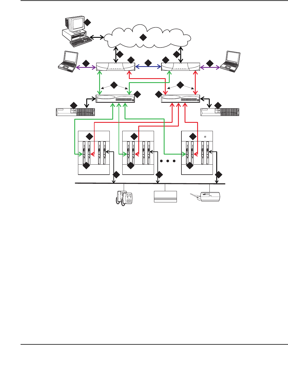
Mid-market to large enterprise
Issue 4.3 February 2006 81
Figure 24: S8700-series Fiber Connect in a high reliability configuration
Figure notes:
1. The Administration PC is used to access the
S8700-series Media Server over the corporate data
network.
2. Corporate IP network.
3. Corporate IP network interface. The Ethernet 4 link
from the S8700-series Media Server to the data
network.1
4. Two S8700-series Media Servers are always
present. One server is in active mode, and the
other server is on standby.
5. Duplication interface, default Ethernet 2. The
dedicated Ethernet connection between the
S8700-series Media Servers.
6. Services interface, default Ethernet 1. The server's
dedicated Ethernet connection from the
S8700-series Media Server to a laptop computer
(active only during on-site administration or
on-site maintenance).
1. The Ethernet connection to the corporate network in this figure is a nondedicated network. IP addresses for the various
components of the S8700-series fiber connect configuration must be administered to prevent conflicts with other
equipment that shares the network. In the default S8700 fiber connect configuration, all other Ethernet connections
operate on their own closed LANs.
7. Network control A interface, default Ethernet 0.
The server's Ethernet connection to one or two
Ethernet switches. This Ethernet link carries the
control signals for the PNs.
8. Network control B interface, default Ethernet 3.
The server's Ethernet connection to one or two
Ethernet switches. This Ethernet link carries the
control signals for the PNs.
9. Ethernet switches. If many PNs are present, two
Ethernet switches can be daisy-chained together
to provide sufficient Ethernet connections to the
IPSI boards in the PNs.
10. Duplicated UPSs. Keeps the S8700-series Media
Servers and the Ethernet switches functional
during brief power outages.
11. Port Networks.
12. Duplicated IPSI circuit packs
112
13 24
CONSOLE
112
13 24
CONSOLE
Ethernet 4 Ethernet 4
Ethernet 2
Ethernet 1 Ethernet 1
Ethernet 0Ethernet 0 Ethernet 3
PN 1 PN 2 PN
cynds146 LAO 012506
IPSI IPSI IPSI
1
2
3 3
4
1
1
1 2
2
2
4
5
6 6
78
9 9
11 11 11
12 12 12
10 10
13 13 13

Avaya Application Solutions platforms
82 Avaya Application Solutions IP Telephony Deployment Guide
Critical reliability configuration
The critical reliability configuration option is built upon the high reliability configuration. In the
critical reliability configuration, the bearer network has duplicated components so that there is
no single point of failure. The critical reliability configuration consists of the following
components:
●Two S8700-series Media Servers
●Two IPSI circuit packs in each IPSI-connected port network
●Two Ethernet switches
●Two UPS units
●Two CSS/ATM EI (Expansion Interface) in every port network
S8700-series fiber connect survivability
In addition to the high reliability of the duplicated S8700-series Media Servers, the S8300 or
S8500 Media Server in a Local Survivable Processor (LSP) configuration can be used to
provide survivability. Additional recovery capability is embedded in the Communication Manager
that resides on the S8700-series Media Server.
Avaya S8700-series Media Server IP connect configuration
The S8700 IP connect configuration is an all-IP solution that is built on open IP network
connection. This solution is designed for medium to large enterprises. The main difference
between the IP connect and fiber connect configurations is that IP connect uses the IP network
for all inter-port network communication whereas fiber connect uses optic-fiber connections
between the PNs in a CSS or ATM network.
The IP connect platform is scalable to 64 Port Networks, each of which can house up to four
G650s and up to 250 G700, G350, G250, or G150 Media Gateways. The Media Server complex
still consists of duplicated S8700-series Media Servers. One server is active, and the other
server is on standby. See Table 2: Avaya Application Solutions comparison matrix —
components, performance, and capacities on page 36 for information on the S8700-series
Media Server performance and capacities.
Figure 25: Avaya S8700-series Media Server with remote G650 / G700 / G350 Media
Gateways on page 83 shows an example of an S8700 with remote G700 Media Gateways.
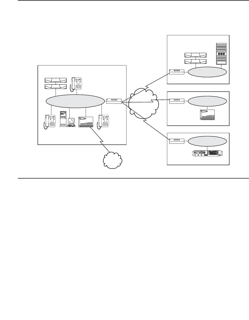
Mid-market to large enterprise
Issue 4.3 February 2006 83
Figure 25: Avaya S8700-series Media Server with remote G650 / G700 / G350 Media
Gateways
cynds125 LAO 101104
S8700 system with remote G650/G700 sites and
IP TIE Trunk links to other Avaya PBXs
ALM
TST
ACT
ALM
TST
ACT
1 2 3 4 5 6 87
ALM
TST
ACT
ALM
TST
ACT
1 2 3 4 5 6 87
REMOVE
ALM
TST
ACT
OKTO
ALM
TST
ACT
OKTO SHUT DOWN
SERVICES
USB1
USB1
USB2
USB2
E1/T1 EIA 530A DCE
ALM
TST
ACT
SIG
ALM
TST
ACT
SIG
EISO EMSM
EO
EOSI
PSTN
S8700
Servers
IP
Phone
IP
Phone
PC G650
Gateway
DCP
Edge
Router
Ethernet WAN
Edge
Router
Avaya IP PBX
(S8300,S8700)
Ethernet
Edge
Router
Ethernet
Edge
Router
Ethernet
Location with another
Avaya IP PBX
Remote site with G650
Remote site with G700/G350
G700/G350 gateway
G650 gateway
IP Trunk QSIG
PRI
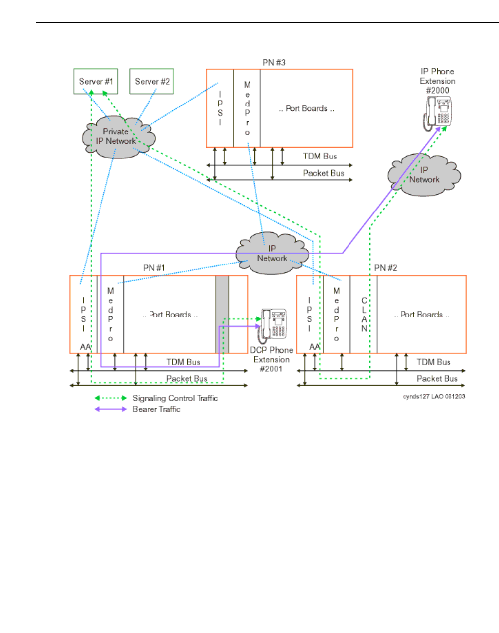
Avaya Application Solutions platforms
84 Avaya Application Solutions IP Telephony Deployment Guide
Figure 26: S8700-series Media Server IP connect — a basic phone call on page 84 shows a
call through an S8700 IP connect system.
Figure 26: S8700-series Media Server IP connect — a basic phone call
Main components
The S8700-series Media Server IP connect consists of the following main components:
●Duplicated S8700-series Media Servers
●Two UPS units, one for each server
●Two Abstract Control Modem (ACM) compliant Universal Serial Bus (USB) modem
●At least one IPSI per port network
●TN799DP C-LAN (for IP endpoint signaling)
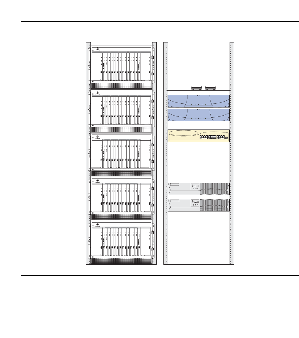
Mid-market to large enterprise
Issue 4.3 February 2006 85
●At least one TN2302AP IP Media Processor or TN2602AP IP Media Resource 320 to
support inter-port and intra-port network media connectivity
●The G650 Media Gateway
●Avaya Communication Manager
Figure 27: S8700-series Media Server IP connect major components on page 85 shows the
main S8700 IP connect components mounted in an open EIA-310-D- compliant, 19-inch data
rack.
Figure 27: S8700-series Media Server IP connect major components
1
1
13
12
24
CONSOLE
1
2
1
2
cynds126 KLC 121003
FAN OR POWER FAIL
FAN AND POWER OK
AC INPUT
DC INPUT
ACTIVE RING
FAN OR POWER FAIL
FAN AND POWER OK
AC INPUT
DC INPUT
ACTIVE RING
103 4 56 8 9Power 2711 12 13 Power
114
E
FAN OR POWER FAIL
FAN AND POWER OK
AC INPUT
DC INPUT
ACTIVE RING
FAN OR POWER FAIL
FAN AND POWER OK
AC INPUT
DC INPUT
ACTIVE RING
103 4 56 8 9Power 2711 12 13 Power
114
D
FAN OR POWER FAIL
FAN AND POWER OK
AC INPUT
DC INPUT
ACTIVE RING
FAN OR POWER FAIL
FAN AND POWER OK
AC INPUT
DC INPUT
ACTIVE RING
103 4 56 8 9Power 2711 12 13 Power
114
C
FAN OR POWER FAIL
FAN AND POWER OK
AC INPUT
DC INPUT
ACTIVE RING
FAN OR POWER FAIL
FAN AND POWER OK
AC INPUT
DC INPUT
ACTIVE RING
103 4 56 8 9Power 2711 12 13 Power114
B
FAN OR POWER FAIL
FAN AND POWER OK
AC INPUT
DC INPUT
ACTIVE RING
FAN OR POWER FAIL
FAN AND POWER OK
AC INPUT
DC INPUT
ACTIVE RING
103 4 56 8 9Power 2711 12 13 Power
114
A

Avaya Application Solutions platforms
86 Avaya Application Solutions IP Telephony Deployment Guide
The left data rack contains a stack of five G650 Media Gateways that are labeled A through E.
The right data rack contains the following (from top to bottom):
●Two USB-compliant modems
●Two S8700-series Media Servers
●One Avaya Ethernet switch
●Two AS1 UPS units
S8700-series IP connect reliability configurations
The S8700-series Media Servers are duplicated. The control and IP-bearer links can also be
duplicated. The clock functionality is provided by the IPSI circuit pack in each port network. As
an all-IP solution, the S8700 IP connect only supports IP media gateways. The S8700 IP
connect does not support traditional CSS- or ATM-connected media gateways.
Starting with release 3.1 of Communication Manager, the capabilities of the TN2602AP IP
Media Resource 320 have been expanded to provide duplicated bearer support. This enables
customers to administer IP-PNC with critical bearer reliability. A port network continues to
support a maximum of two TN2602AP circuit packs but they can now be administered for
duplication, in addition to the previously offered load balanced support.
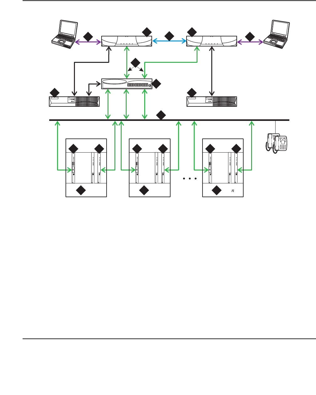
Mid-market to large enterprise
Issue 4.3 February 2006 87
S8700 IP Connect configuration
Figure 28: S8700 IP Connect configuration
Figure notes:
1. Two S8700-series Media Servers. One
server is in a active mode, and the
other server is on standby.
2. Duplication Interface. The Ethernet
connection between the two
S8700-series Media Servers.
3. A dedicated Ethernet connection to a
laptop computer. This connection is
active only during on-site
administration or maintenance, and the
Services interface can link to the
non-active server through a telnet
session.
4. Connection from the servers to the
Ethernet switch.
5. Ethernet switch. A device that provides
port multiplication on a LAN by
creating more than one network
segment.
6. UPS units. Two UPS units are required
7. Port Network. An optional
configuration of Media Gateways that
provides increased port capacity.
8. IPSI. A circuit pack that transports
control messages over IP. The IPSI
circuit pack is used so that the
S8700-series Media Server can
communicate with the Port Networks.
9. Customer LAN.
10. TN799DP Control-LAN (C-LAN)
112
13 24
CONSOLE
cynds128 KLC 121003
1 1
1
1
12
2
2
3 3
4
5
6 6
PN 1
7 7 PN 2 7PN
9
IPSI IPSI
8 8
100bT
LINK
TRMT
RCV
BBI
LINK
TRMT
RCV
100bT
LINK
TRMT
RCV
BBI
LINK
TRMT
RCV
100bT
LINK
TRMT
RCV
BBI
LINK
TRMT
RCV
8
IPSI
101010

Avaya Application Solutions platforms
88 Avaya Application Solutions IP Telephony Deployment Guide
Combined IP and fiber connect Port Network Connectivity
Communication Manager Release 3.0 enables the S8700-series and S8500 Media Servers to
support configurations that combine IP-connected port networks (PNs) with fiber-connected
PNs.
Note:
Note: Fiber-connected PNs include direct-connected, CSS-connected, and
ATM-connected PNs.
Additionally, in combined IP connect and fiber connect configurations with the S8700-series
Media Server, customers have the option of either single or duplicated control networks.
Combined IP and fiber connect configurations allow the following:
●Add IP-Connected PNs to a fiber-connected configuration using the simpler, less costly
connections over the customer LAN.
●Convert and consolidate, in an easy cost-effective way, remote standalone DEFINITY
servers (SI, CSI, or S8100) and their PNs into a single network of PNs controlled by, and
administered with, one server.
●Configure, within the single footprint of an MCC1 Media Gateway, multiple port networks
using IP connect PNC, fiber connect PNC, or a variety of combinations of the two. In this
way, customers have tremendous flexibility in configuring MCC1 Media Gateways to
balance reliability, call capacities, and feature richness.
●Configure reliability into a network in a more cost-effective, flexible way. Duplication of
control can be configured based on the criticality of the location or the needs of users
connected to a particular PN.
Combined IP and fiber connect configurations support the following platforms:
●S8500 and S8500B servers in both IP connect and direct connect configurations with
CMC1, MCC1, SCC1 and G650 Media Gateways
●S8700-series Media Server pairs in IP connect and direct connect configurations with
CMC1, MCC1, SCC1 and G650 Media Gateways
●S8700-series media server pairs in both IP connect and fiber connect with either CSS or
ATM configurations and CMC1, MCC1, SCC1 and G650 Media Gateways
Note:
Note: A single combined IP and fiber connect system cannot consist of both a CSS and
an ATM-PNC. There can be only one CSS (that is, one CSS with up to 3 switch
node carriers connected together as one switch) or one ATM-PNC. In addition,
mixing direct-connect PN connections with ATM or CSS port network
configurations is not allowed.

Mid-market to large enterprise
Issue 4.3 February 2006 89
The G650, SCC1, and MCC1 Media Gateways can connect to a combined IP and fiber connect
system using either IP connect or fiber connect options (direct/CSS/ATM). The CMC1 Media
Gateway can be IP connect only and cannot be fiber-connected in any of the combined IP and
fiber connect configurations. The following table lists, by server, the media gateways and
connection methods that may be simultaneously supported in a combined IP and fiber connect
configuration.
Media Gateway Capacity
The following capacity rules apply to a combined IP and fiber connect configuration:
Each combination of fiber connect and IP connect can support up to 64 port networks. When
the fiber connect portion is supported by CSS, it can have a maximum of 44 CSS PNs but the
system can be expanded to 64 PNs by adding an additional 20 IP-Connect PNs. When the fiber
connect portion is direct-connect, with two or three direct-connect PNs, the IP connect portion
can have up to 61 or 62 IP-connected PNs, respectively.
Server Supported
Central
Gateways
IP-
Connect Direct-
Connect CSS/ATM-
Connect1
1. For any system, either CSS or ATM connections may be used in a combined IP and fiber connect network,
but not both.
Reliabilities Supported
S8500/
S8500B
CMC1 yes no no single control and bearer
only
G650 yes yes no same as CMC1
SCC1 yes yes no same as CMC1
MCC1 yes yes no same as CMC1
S8700
series
CMC1 yes no no single control, single bearer
only
G650 yes yes yes
(requires
an MCC1
for CSS)
●single control and
bearer
●duplicated control
only
●duplicated control
and bearer
SCC1 yes yes yes
(requires
an MCC1
for CSS)
same as G650
MCC1 yes yes yes same as G650

Avaya Application Solutions platforms
90 Avaya Application Solutions IP Telephony Deployment Guide
Capacity limit for media gateways
A combined IP and fiber connect system can support up to 250 Media Gateways including the
G150, G250, G350, and G700.
Configuration rules
Combined IP and fiber connect requires CM3.0 or later software but does not require any new
hardware of firmware changes. The following configuration rules apply to combined IP and fiber
connect configurations:
●The current rules for IP connect and fiber connect (CSS or ATM) continue to apply. For
example, if IP connect port networks are added to an existing S8700/S8710 fiber connect
system, every IP connect port network must have one active IPSI circuit pack.
●The current rules for IP connect and the rules for direct connect continue to apply. In a
direct connect system, only one IPSI controls the direct connect PNs.
●There must be at least one IP Media Processor board (TN2302AP or TN2602AP) in a port
network of the fiber connect portion of the configuration. The PN or PNs that contain the IP
media processor circuit pack act as gateway port network(s) between the IP connect and
fiber connect portions of the configuration.
Note:
Note: The TN2602AP IP Media Resource 320 Circuit Pack is not supported in CMC1
Media Gateways. The CMC1 supports the TN2302AP IP Media Processor board.
●In an IP-connected port network, tone detectors (call classifiers, etc) must be engineered
per port network bases, while in a fiber connected CSS or ATM cluster, the tone detection
resources can be shared over the fiber connected link.
●There must be at least one C-LAN circuit pack in the fiber-connected portion of the
configuration.

Mid-market to large enterprise
Issue 4.3 February 2006 91
MCC1 Media Gateway with one or more IP- and fiber-connected PNs
In a combined IP and fiber connect configuration, an MCC1 Media Gateway may contain
●up to 5 fiber-connected PNs.
●up to 5 IP-connected PNs.
●both IP-connected and fiber-connect PNs (this only applies for migration and conversions
to CM3.0).
●up to two IP-connected PNs with duplicated control networks.
Thus, both IP- and fiber-connected PNs can exist in a single MCC1 Media Gateway.
The following table is an example of port network configuration options for IP-connected PNs in
an MCC1 Media Gateway.
MCC1 with 3 PNS
with single control
MCC1 with 3 PNS,
one with
duplicated control
C Carrier
B Carrier IPSI IPSI
A Carrier IPSI IPSI
D Carrier IPSI IPSI (Secondary)
E Carrier IPSI (Primary

Avaya Application Solutions platforms
92 Avaya Application Solutions IP Telephony Deployment Guide
Mixed reliability options
The reliability options separately available for each PNC method still apply. For example, IP
connect PNs may have duplex server and simplex control network, and may be mixed with a
fiber connected configuration that has duplicated control and bearer networks.
Thus, the PNs in an combined IP and fiber connect configuration may collectively have multiple
levels of reliability. Nevertheless, within the fiber-connected portion of a system (direct, CSS, or
ATM-connected PNs), all port networks must have the same reliability level --- all single control
and bearer network, all duplicated control network, or all duplicated control and bearer network.
The following table summarizes the valid IP-PNC reliability options in a combined IP and fiber
connect configuration.
Mixed CSS/IP connect and mixed reliability example
Figure 29 illustrates an S8700-series Media Server configuration that combines CSS PNC with
a single control network and IP connect PNC with a duplicated control network configuration.
PNC Connection Method
IP Port Network Connectivity1
1. Any of these configurations can also have duplicated IP bearer.
Direct-connect/CSS/ATM
Reliability Option
Single control network only and Single control network only
Single control network only and Duplicated control network 2
2. Not available with S8500 or S8500B
Single control network only and Duplicated control network and
duplicated bearer network1
Duplicated control network and Single control network only
Duplicated control network and Duplicated control network1
Duplicated control network and Duplicated control network and
duplicated bearer network1
Single control network for some PNs
and duplicated control network for
other PNs
and Single control network only
Single control network for some PNs
and duplicated control network for
other PNs
and Duplicated control network1
Single control network for some PNs
and duplicated control network for
other PNs. Duplicated IP bearer
network.
and Duplicated control network and
duplicated bearer network1
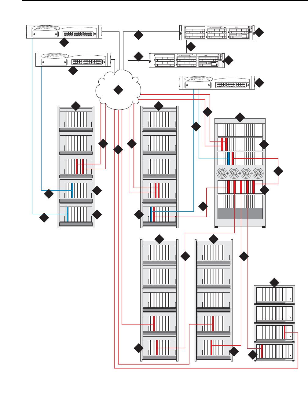
Mid-market to large enterprise
Issue 4.3 February 2006 93
Figure 29: Example of CSS PNC with single control network and IP connect PNC with
duplicated control network (with S8700-series Media Server)
cycm3019 KLC 011705
6
6
6
14
15
15
13
14
14
14
8
7
17
10
4
5
9
11
11 11
12
3
9
9
10 10
2
2
18
19
16
2
SimplexDuplexchch2
0
1
1
UID
2
1
1
0
3
23
2
5
45
4
disc
COMPACT
1
SimplexDuplexchch2
0
1
1
UID
2
1
1
0
3
23
2
5
45
4
disc
COMPACT
1

Avaya Application Solutions platforms
94 Avaya Application Solutions IP Telephony Deployment Guide
Figure notes: Example of CSS PNC with single control network and IP connect PNC with
duplicated control network (with S8700-series Media Server)
1. S8700/S8710 Media Server
2. Ethernet Switch
3. Fiber-connect MCC1 Media Gateway (CSS and PN)
4. Control carrier for PN 3, in the A position in the MCC1. The control carrier contains:
●A TN2312AP/BP IPSI circuit pack for IP connection to server.
●A TN570Bv7/C/D EI circuit pack for bearer network connections to the Switch Node Carrier (SNC).
5. Switch node carrier (SNC), which contains:
●Multiple TN573 SNI circuit packs for EI connections to PNs
6. IPSI-to-server control network connection via Ethernet switch
7. Second fiber-connect and IPSI-connected PN (G650 Media Gateway or stack [shown in figure], MCC1 Media Gateway, or
SCC1 Media Gateway stack).
8. Control gateway or carrier for PN 7, in the A position in the stack. The control gateway or carrier contains:
●A TN2312AP/BP IPSI circuit pack for IP connection to server.
●A TN570Bv7/C/D EI circuit pack for bearer network connections to the SNI.
9. Fiber-connect PN (MCC1 Media Gateway, SCC1 Media Gateway, or G650 Media Gateway stack [shown]) consisting of one
or more media gateways or carriers.
10. Control gateway or carrier for PN 9, in the A position in the stack. The control gateway or carrier contains:
●A TN570Bv7/C/D EI circuit pack for bearer network connections to the SNI.
NOTE: One TN2182 Tone Clock circuit pack must also be present per PN if the PN(s) consist of SCC1 or MCC1
Media Gateways. One maintenance-only TN2312AP/BP IPSI circuit pack must be present per PN if the PN(s) consist
of G650 Media Gateways.
11. TN 570Bv7/C/D to TN573 fiber connections between PNs and SNC
12. TN 573/570Bv7/C/D fiber connections between the SNCs and the B carriers (if the MCC1 is a PN)
13. Customer LAN
14. LAN connections of TN2302AP IP Media Interface or TN2602AP IP Media Resource 320 for IP-TDM voice processing and
optional TN799DP C-LAN for control of IP endpoints
NOTE: The number of TN2302AP, TN2602AP, and TN799DP circuit packs varies, depending on the number of IP
endpoints, port networks, and adjunct systems. These circuit packs may be inserted into a port carrier (shown in
figure) or the PN control carrier.
15. LAN connections of media servers for remote administration
16. Duplicated server links, including the fiber link for translations transfer and the DAL1 link for control data sharing
17. IP connect PN (G650 Media Gateway or stack [shown in figure]). May also be an MCC1 from a DEFINITY Server migration
or an SCC1.
18. Control gateway or carrier, in the A position in the gateway stack, for PN 17. The control gateway contains:
●A TN2312AP/BP IPSI circuit pack for IP connection to server.
19. Media gateway or carrier, in the B position in the gateway stack, with duplicatedTN2312AP/BP IPSI circuit pack for
duplicated control network to PN 17.

Mid-market to large enterprise
Issue 4.3 February 2006 95
Networking option of S8700-series Media Server pair for duplicated and
single control networks
For an S8700-series Media Server pair with direct/CSS/ATM PNC and duplicated control
networks, control network A and control network B interfaces are administered as dedicated
control networks and connected to duplicated IPSI circuit packs in the fiber-connected PNs. If a
remote IP connect PN is introduced into the configuration, the S8700-series Media Server and
IP connect PN may be administered for a single non-dedicated control network over the
customer’s LAN. In this case, a third control network C may be administered on the
S8700-series Media Server. The S8700-series Media Server automatically uses its own
customer LAN interface port for Control network C.
Although this configuration allows the mixing of dedicated and non-dedicated control networks,
it is discouraged. It is recommended that same control network to be configured across a
combined IP and fiber connect system.
ESS support for combined IP and fiber connect configurations
Any Enterprise Survivable Server (ESS) can also support a combined IP and fiber connect
configuration in the event of failover to the ESS. Both an S8500 and an S87XX-series ESS can
support single control and duplicated control networks for both the IP connect and fiber connect
portions of the configuration. However, the ESS can support only those CSS-connected PNs
that individually have an IPSI circuit pack and either a TN2302AP IP Media Processor or
TN2602AP IP Media Resource 320 circuit pack. This limitation exists because the ESS
provides only IP connect control and bearer service to PNs.
S8720 Media Server
The Avaya S8720 Media Server Platform is a high-performance server with an AMD Opteron
processor running Avaya Communication Manager software. The S8720 is a replacement
server for the S8700 and S8710 Media Servers. The S8720 supports a software duplication
option that eliminates the need for the DAJ1 and DAL1 hardware-assist duplication cards.
The S8720 system supports the Avaya MCC1, SCC1, CMC1, and G650 Media Gateways. The
Avaya G700, G350, G250, and G150 Media Gateways are also supported if there is a TCP/IP
connection between the media gateway and a C-LAN circuit pack located in a MCC1, SCC1,
CMC1, or G650 Media Gateway. The S8720 has the capacity to support up to 64 port networks.

Avaya Application Solutions platforms
96 Avaya Application Solutions IP Telephony Deployment Guide
Processor Ethernet
Processor Ethernet allows IP devices to register to an Avaya media server without a need for
TN799DP C-LAN boards. Prior to Communication Manager release 3.1, Processor Ethernet
was permitted only when using S8300 or Shared Servers (e.g. Hosted IP Telephony). As of
release 3.1, Processor Ethernet can also be used with the S8400 and S8500 Media Servers.
Furthermore, as of release 3.1, S8500 can be used as an LSP (Local Survivable Processor).
The following table describes the usage of Processor Ethernet as of release 3.1
:
Avaya IP Office
Avaya IP Office is another standalone Avaya platform that supports IP Telephony for the small
to mid-size market.
Avaya IP Office is an IP PBX for 10 to180 stations. Avaya IP Office is not part of the Avaya
Application Solutions offer, and thus is not covered extensively in this document. For more
information about the IP Office, see the Avaya Support website.
Table 8: Applications of Processor Ethernet as of Communication Manager release 3.1
Servers Processor Ethernet
Application Prior to release 3.1 As of release 3.1
Main Servers H.323 Endpoint Registration S8300 S8300, S8400,
S8500
H.248 Gateway Registration S8300 S8300, S8400,
S8500
IP Adjunct Connections S8300 S8300, S8400,
S8500
Simplex ESS
Servers H.323 Endpoint Registration Not permitted Not permitted
H.248 Gateway Registration Not permitted Not permitted
IP Adjunct Connections Not permitted Permitted for
Selected Adjuncts
LSP Servers H.323 Endpoint Registration S8300 LSP S8300 LSP, S8500
LSP
H.248 Gateway Registration S8300 LSP S8300 LSP, S8500
LSP
IP Adjunct Connections Not permitted Permitted for
Selected Adjuncts
on S8300 LSP,
S8500 LSP

Issue 4.3 February 2006 97
Greenfield deployment
This chapter explains how to implement Avaya Application Solutions components in a
Greenfield site. A Greenfield site is a business or an organization that does not have an existing
communication system. Most Greenfield systems are deployed into new businesses and
organizations, and these systems tend to be smaller in size. Occasionally, an established large
organization may completely remove its existing system and install a new system. In these
cases, the incumbent system is usually a leased service, such as a centrex service from a
telephony service provider.
In general, most organizations want to protect their investment in their PBX communications
system. Avaya provides ways for our circuit switched PBX customers to evolve from circuit
switched systems to IP-enabled systems. This solution provides most of the advantages of IP
Telephony with minimal equipment upgrades to an enterprise’s existing PBX. The evolution
approach is described in Evolution from circuit-switched to IP on page 109.
Components needed for Greenfield deployment
In a Greenfield deployment, the primary connection medium is IP. To provide the greatest
flexibility and the lowest costs for a converged solution, most endpoints should be IP
Telephones or IP Softphones. A mixture of IP endpoints and circuit-switched endpoints places
increased demand on Media Processor resources, and thus increases the cost of the
deployment. Intersite communications should also be IP based. This can be done either through
direct connections between IP Telephones or through IP trunks. Circuit-switched or TDM-based
communications should be kept to a minimum. The primary TDM connections should be for
PSTN access, where necessary, and connections to any analog telephones, modems, or fax
machines that exist (Figure 30: A Greenfield IP Telephony deployment on page 98).
In a Greenfield deployment, the emphasis is on IP Telephony. Multi-Connect systems that
emphasize TDM connections are not generally recommended, except in special circumstances.
Those circumstances include when there is a need for:
●Critical reliability
●Significant analog or DCP endpoints
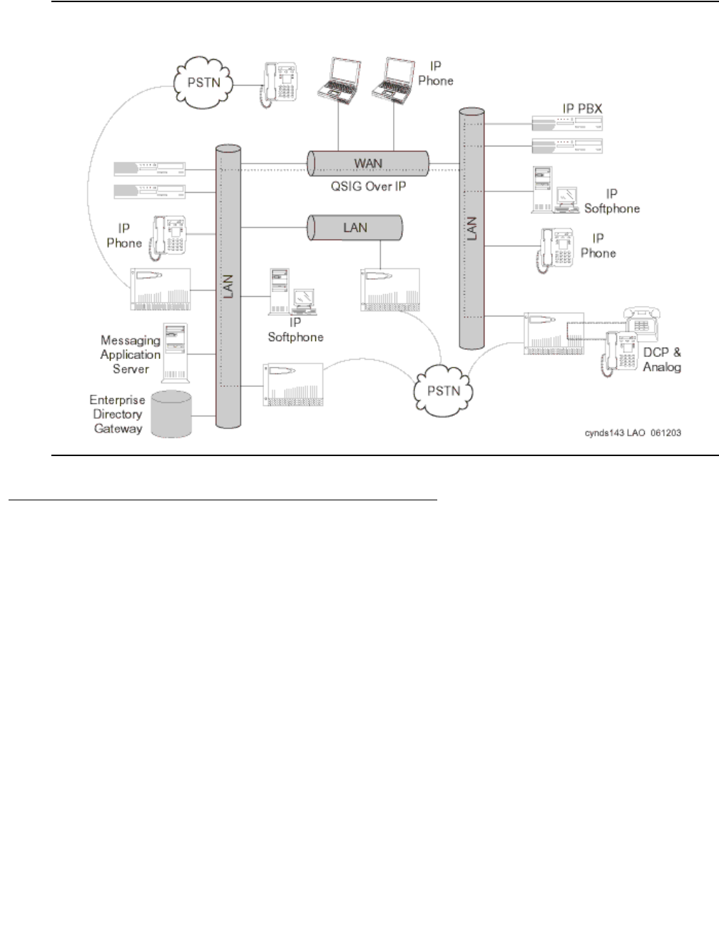
Greenfield deployment
98 Avaya Application Solutions IP Telephony Deployment Guide
Figure 30: A Greenfield IP Telephony deployment
Media Server (H.323 Gatekeeper)
The Media Servers are responsible for running Avaya Communication Manager and controlling
the Media Gateways and endpoints. The Media Servers control the dial plan translations and
call routing, call setup and teardown, Call Detail Record (CDR) generation, traffic management.
The Media Servers also offer H.323 gatekeeper functionality, and provide the extensive
telephony features that are included with Avaya Communication Manager.
Avaya’s Linux-based servers include:
●S8300 Media Server (The server resides in the G700, G350, or G250 Media Gateway)
●S8400 Media Server
●S8500 Media Server
●S8700-series Media Servers

Components needed for Greenfield deployment
Issue 4.3 February 2006 99
Avaya Communication Manager
Communication Manager IP capabilities and applications support voice over an IP network, and
ensure that remote workers have access to communication system features from their PCs.
Communication Manager also provides standards-based control between Media Servers and
Media Gateways, which allows the communications infrastructure to be distributed to the edge
of the network. The Communication Manager IP engine offers features that enable users to
increase the quality of voice communications. Quality of Service (QoS) features enable users to
optimize voice quality by assisting some routers in prioritizing audio traffic. Communication
Manager Media Processors allow for hairpinning and shuffling. These features make voice
communications more efficient by reducing both per-port costs and IP bandwidth usage. Avaya
IP Telephony Solutions support trunks, IP communications devices, IP Port Networks, and IP
control for Media Gateways. Avaya IP Telephony Solutions are implemented using various IP
Media Processor circuit packs inside the Avaya Media Gateways. The IP Media Processors
provide H.323 trunk connections, and H.323 voice processing for IP Telephones. H.323
signaling is handled by a C-LAN circuit pack or native processor Ethernet connectivity. The IP
network can be extended across geographically disparate locations. With Communication
Manager ISDN, Distributed Communication Services (DCS+), or QSIG services,
Communication Manager can extend feature transparency, centralized voice mail, centralized
attendant service, call center applications, and enhanced call routing across IP trunks.
For more information on Communication Manager architecture, see the Call processing
chapter.
Media Gateways and Port Networks
Avaya Media Gateways support voice and signaling traffic that is routed between
circuit-switched networks and packet-switched networks. Avaya Media Gateways support all
the applications and the adjuncts that are supported by the Avaya DEFINITY Enterprise
Communications Servers, accommodating Call Center and Customer Relationship
Management applications, messaging, remote workers, and remote offices. Avaya Media
Gateways work with standards-based IP networks, and connect easily with the Public Switched
Telephone Network (PSTN). The IP network infrastructure provides support for the
communication between the Media Servers and the Media Gateways.
In a Greenfield installation, the recommended gateways are the G150, G250, G350, G650, and
the G700. The G650 houses traditional circuit switch boards and boards that support IP
Telephony. The G700, G350, and G250 house Avaya Media Modules that provide ports for
non-IP endpoints, including analog and DCP telephones. Use the G150 and the G250 gateways
for large scale, small-branch deployments (2-8 users each). Avaya recommends using the
G250 for high-intensity, critical applications, and using the G150 for more affordable solutions
where branches are more loosely coupled to headquarters.

Greenfield deployment
100 Avaya Application Solutions IP Telephony Deployment Guide
Greenfield configurations
S8300 standalone solution
(small-to-midsize enterprise)
An S8300 Server with a G700, G250, or G350 gateway is designed for a small to mid-size
office. The S8300 fits into a media module slot in the G700, G350, or G250 Media Gateway.
See Table 2: Avaya Application Solutions comparison matrix — components, performance, and
capacities on page 36 for information on capacities when the S8300 is used with the G700,
G350, and G250. An S8300 server does not support G650 gateways or traditional port
networks.
As shown in Figure 31: An S8300/G700/G350/G250 system on page 100, the G700 is a 2U
19-inch rack-mountable chassis. The G700 contains a built-in Ethernet switch, an IP expansion
module slot, four Media Module slots, and an Octaplane stacking module slot. The built-in IP
Telephony module has the same functionality as the TN2302AP Media Processor (MedPro)
circuit pack. An extra VoIP Media Module can be inserted in the G700 for extra
media-processing resources. Other Media Modules support traditional endpoints.
Figure 31: An S8300/G700/G350/G250 system

Greenfield configurations
Issue 4.3 February 2006 101
Medium-to-large enterprise solutions
Note:
Note: The description of the duplicated S8700-series Media Server configuration in this
section, except for capacities, also applies to an S8500 simplex configuration.
S8700-series / G650 IP-Connect
The S8700-series IP-Connect system (Figure 32: S8700-series IP-Connect system on
page 102) is a scalable solution that supports up to 64 G650 Media Gateways in stacks of from
one to five rack-mounted G650 cabinets. See Table 2: Avaya Application Solutions comparison
matrix — components, performance, and capacities on page 36 for capacities information for
the S8700-series IP-Connect system.
The S8700-series Media Servers can be networked with other systems through IP or
circuit-switched trunks to provide for significantly larger telephony networks. The control link
between the Media Servers and the Media Gateways traverses the enterprise IP network. All
G650 Media Gateways require IPSI circuit packs to provide the Gateway’s control link. There is
no traditional circuit switch (Center Stage Switch), and the media traffic flow is entirely through
the enterprise data network. Each G650 has at least one Media Processor circuit pack, which
provides the gateway between the TDM bus and the circuit pack’s Ethernet connection for the
audio streams. Each G650 also has at least one C-LAN, which provides H.323 signaling to IP
endpoints.
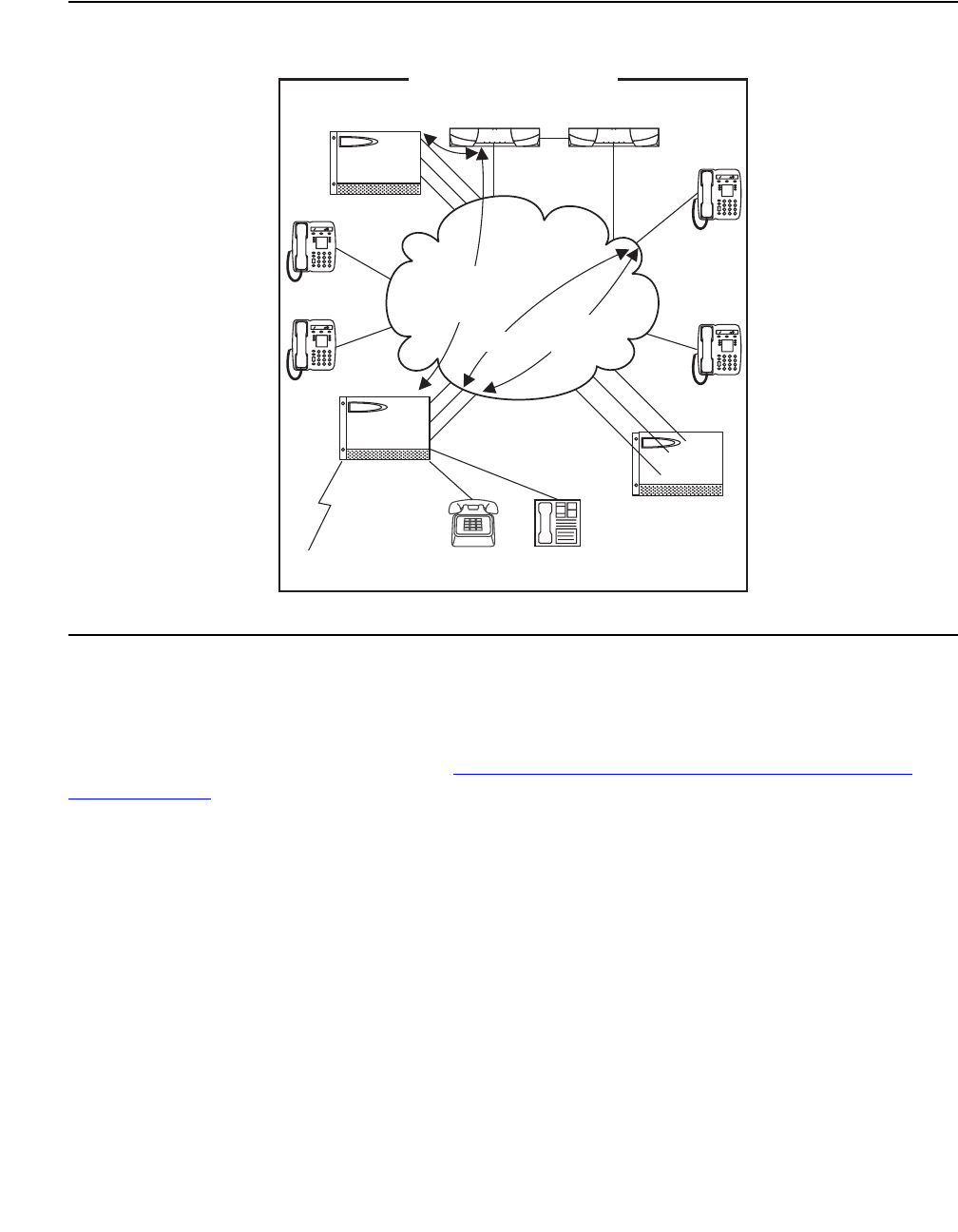
Greenfield deployment
102 Avaya Application Solutions IP Telephony Deployment Guide
Figure 32: S8700-series IP-Connect system
S8700-series IP-Connect with remote G700s or G350s
The IP-Connect solution can be expanded to support a remote office with G700 or G350 Media
Gateways in addition to G650 Gateways (Figure 33: S8700-series IP-Connect with remote
G700 or G350s on page 103). This solution is designed for enterprises that require a high
number of IP stations, but a low number of PSTN or traditional circuit-switched connections.
The S8700-series Media Server is the call controller that communicates with the G700 or G350
Gateways through the C-LAN. In this configuration, the C-LAN circuit pack acts as the front-end
processor for both the G700/G350 Media Gateways and IP endpoints.
cynds136 KLC 121003
IP
IP
Analog DCP
Medium/Large Enterprise
To PSTN
Enterprise
IP Network
IP
IP
S8700 S8700
IPSI
C-LAN
MedPro
IPSI
C-LAN
MedPro IPSI
C-LAN
MedPro
G600/G650
G600/G650
G600/G650
H.225
RTP
Audio
CCMS
over
TCP/IP
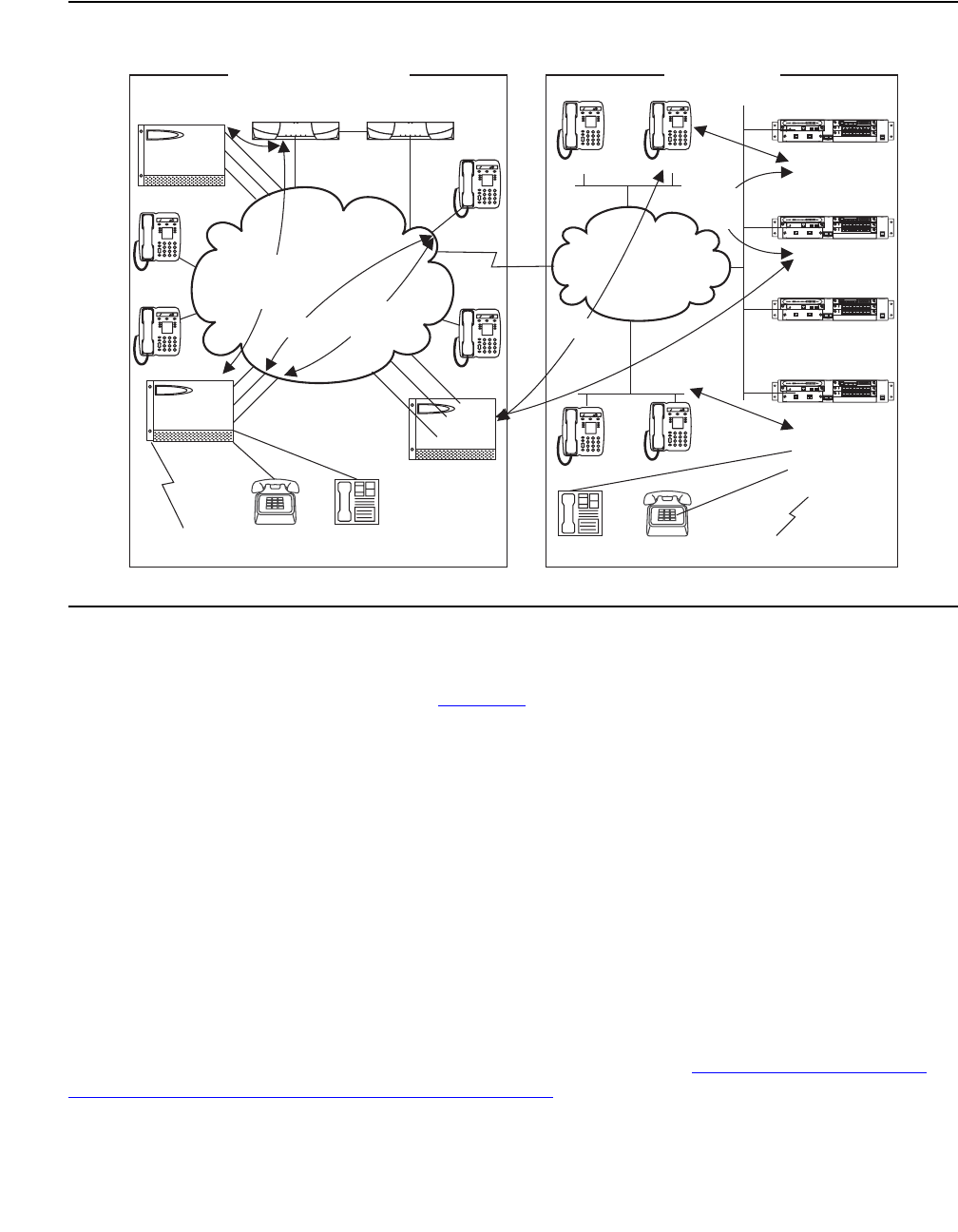
Greenfield configurations
Issue 4.3 February 2006 103
Figure 33: S8700-series IP-Connect with remote G700 or G350s
Note:
Note: A typical remote office is configured with a single gateway. Several gateways are
shown in the remote office in Figure 33 to illustrate additional possible
configurations.
S8700-series with G150/G250: large number of remote branches
The newer small gateways G150 and G250 are designed to be deployed individually in large
number (100’s to 1000’s) of small branches, with management and call control centralized at a
headquarter with S8700/S8710 servers. Each branch would have a single G150 or G250 with
2-10 stations (analog, DCP, or IP), and analog or T1/E1 PSTN trunks. Any location needing
more than 10 stations should consider using G350 or G700. G350 is also meant to be deployed
alone at a location; only the G700 should be used in multiple expandable unit configurations.
At each branch, LAN and WAN functions can be provided by external 3rd party or Avaya
networking devices, or as part of the integrated options within the gateways. WAN connection
back to HQ can utilize low cost options such as VPN over public internet via cable or DSL
(G250). Emergency fallback to phone modem is also possible. See Figure 34: S8700-series
with G150/G250 -- large number of remote branches on page 104.
Analog DCP
Medium/Large Enterprise
To PSTN
Enterprise
IP Network
S8700 S8700
IPSI
C-LAN
MedPro
IPSI
C-LAN
MedPro IPSI
C-LAN
MedPro
G650
G650
G650
H.225
RTP
Audio
CCMS
over
TCP/IP
cynds137 LAO 101104
ALM
TST
ACT
ALM
TST
ACT
1 2 3 4 5 6 87
ALM
TST
ACT
ALM
TST
ACT
1 2 3 4 5 6 87
REMOVE
REMOVE
ALM
TST
ACT
OKTO
ALM
TST
ACT
OKTO SHUTDOWN
SERVICES
USB1
USB1
USB2
USB2
E1/T1
EIA 530A DCE
EIA 530A DCE
ALM
TST
ACT
SIG
ALM
TST
ACT
SIG
EISO
EM
EMSM
EO
EOSI
IP G700 with
S8300 LSP
VoIP mod
ALM
TST
ACT
ALM
TST
ACT
1 2 3 4 5 6 87
ALM
TST
ACT
ALM
TST
ACT
1 2 3 4 5 6 87
REMOVE
REMOVE
ALM
TST
ACT
OKTO
ALM
TST
ACT
OKTO SHUTDOWN
SERVICES
USB1
USB1
USB2
USB2
E1/T1
EIA 530A DCE
EIA 530A DCE
ALM
TST
ACT
SIG
ALM
TST
ACT
SIG
EISO
EM
EMSM
EO
EOSI
G350
ALM
TST
ACT
ALM
TST
ACT
1 2 3 4 5 6 87
ALM
TST
ACT
ALM
TST
ACT
1 2 3 4 5 6 87
REMOVE
REMOVE
ALM
TST
ACT
OKTO
ALM
TST
ACT
OKTO SHUTDOWN
SERVICES
USB1
USB1
USB2
USB2
E1/T1
EIA 530A DCE
EIA 530A DCE
ALM
TST
ACT
SIG
ALM
TST
ACT
SIG
EISO
EM
EMSM
EO
EOSI
G350
ALM
TST
ACT
ALM
TST
ACT
1 2 3 4 5 6 87
ALM
TST
ACT
ALM
TST
ACT
1 2 3 4 5 6 87
REMOVE
REMOVE
ALM
TST
ACT
OKTO
ALM
TST
ACT
OKTO SHUTDOWN
SERVICES
USB1
USB1
USB2
USB2
E1/T1
EIA 530A DCE
EIA 530A DCE
ALM
TST
ACT
SIG
ALM
TST
ACT
SIG
EISO
EM
EMSM
EO
EOSI
G700 with
VoIP mod
DCP mod
Analog mod
T1/E1 mod
IP
IP
Analog
DCP
Backup
H.225
RTP
Remote Office
To PSTN
IP
Network
IP
IP
IP
IP
WAN
Backup
H.248
H.225
H.248 Media Gateway control
IP
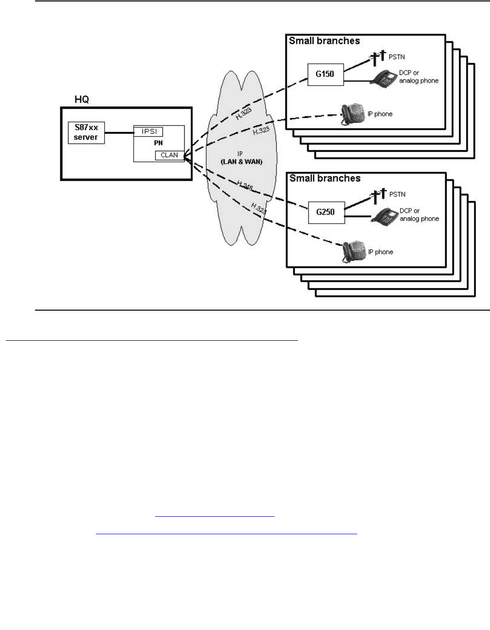
Greenfield deployment
104 Avaya Application Solutions IP Telephony Deployment Guide
Figure 34: S8700-series with G150/G250 -- large number of remote branches
Required circuit packs for S8700-series configuration
The circuit packs that are required for IP Telephony in a Communication Manager system
include:
●TN2312BP IP Server Interface (IPSI) for Port Network control
●TN799DP Control LAN (C-LAN) for signaling and TCP/IP socket termination
●TN2302AP and/or TN2602AP Media Processors (MedPro) for the media flow
These circuit packs can reside in the CMC1, SCC1, MCC1, or G650 Media Gateways in
widely-distributed locations.
The signaling connectivity path between the endpoint and the servers in the S8700
configuration is shown in Figure 37: Signaling flow on page 106.
As shown in Figure 35: Signaling path (S8700 / G650 configuration) on page 105, an IP
Telephone sends all IP Telephony signaling traffic to the C-LAN. The C-LAN multiplexes IP
Telephone signaling messages, and sends them to the S8700-series Media Server through the
IPSI.
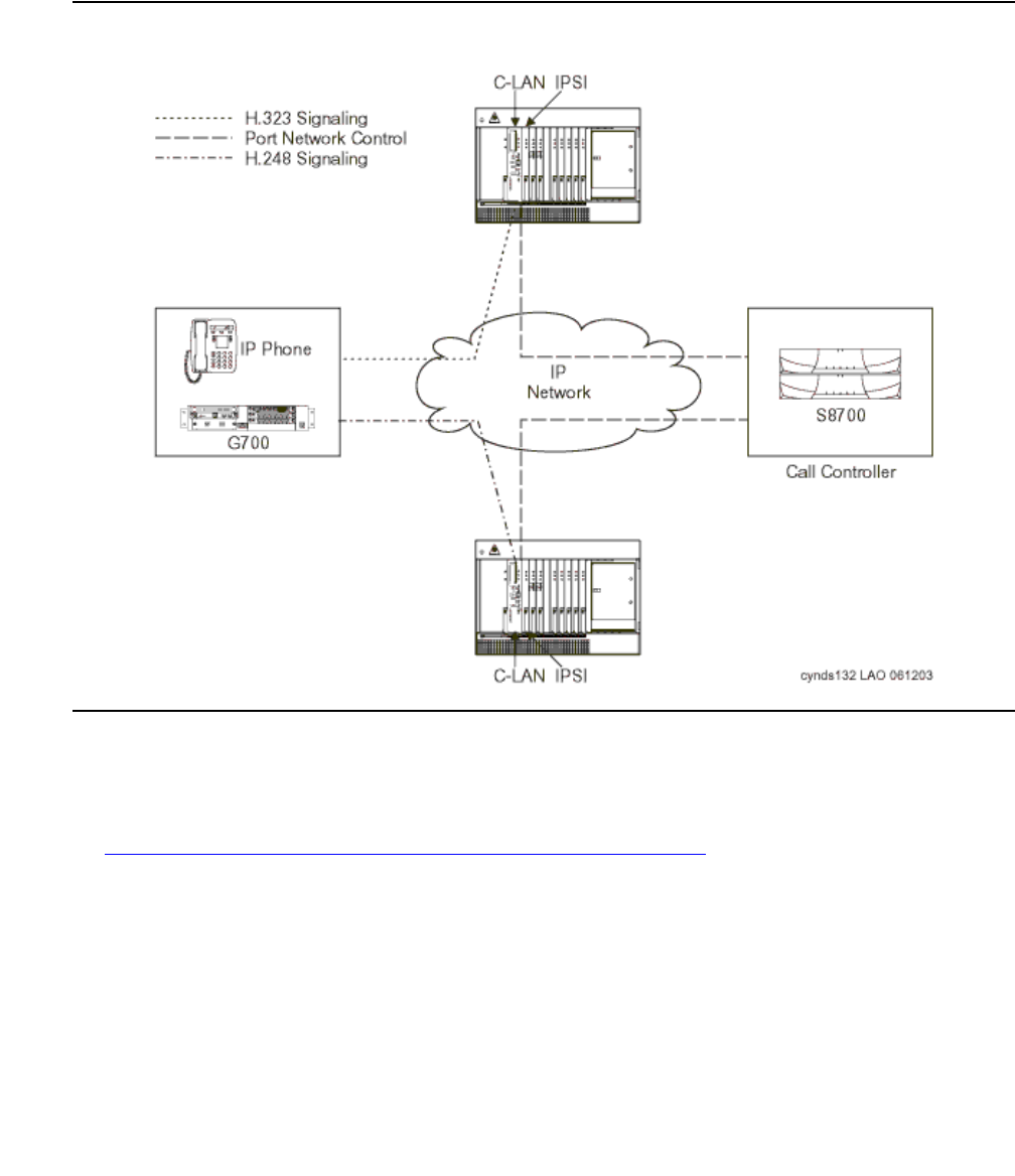
Greenfield configurations
Issue 4.3 February 2006 105
In an S8300 configuration, a C-LAN circuit pack is not needed. All signaling traffic is sent
directly to the S8300 Ethernet interface. The S8300 Server performs all C-LAN functions
natively. The connectivity between the endpoint and the server is:
Endpoint ⇔ IP network ⇔ S8300 Media Server
Figure 35: Signaling path (S8700 / G650 configuration)
Note:
Note: In the IP-Connect S8700 / G650 configuration each Port Network has an IPSI
circuit pack.
As Figure 36: Media flow path (S8700 IP-Connect configuration) on page 106 shows, an IP
Telephone sends all media streams to the MedPro. Once a call is established, if the remote
endpoint is another IP Telephone, the media stream might shuffle (be redirected to the other
endpoint) without requiring MedPro resources. Media Processors are also used to transport
media streams in IP tie trunks.
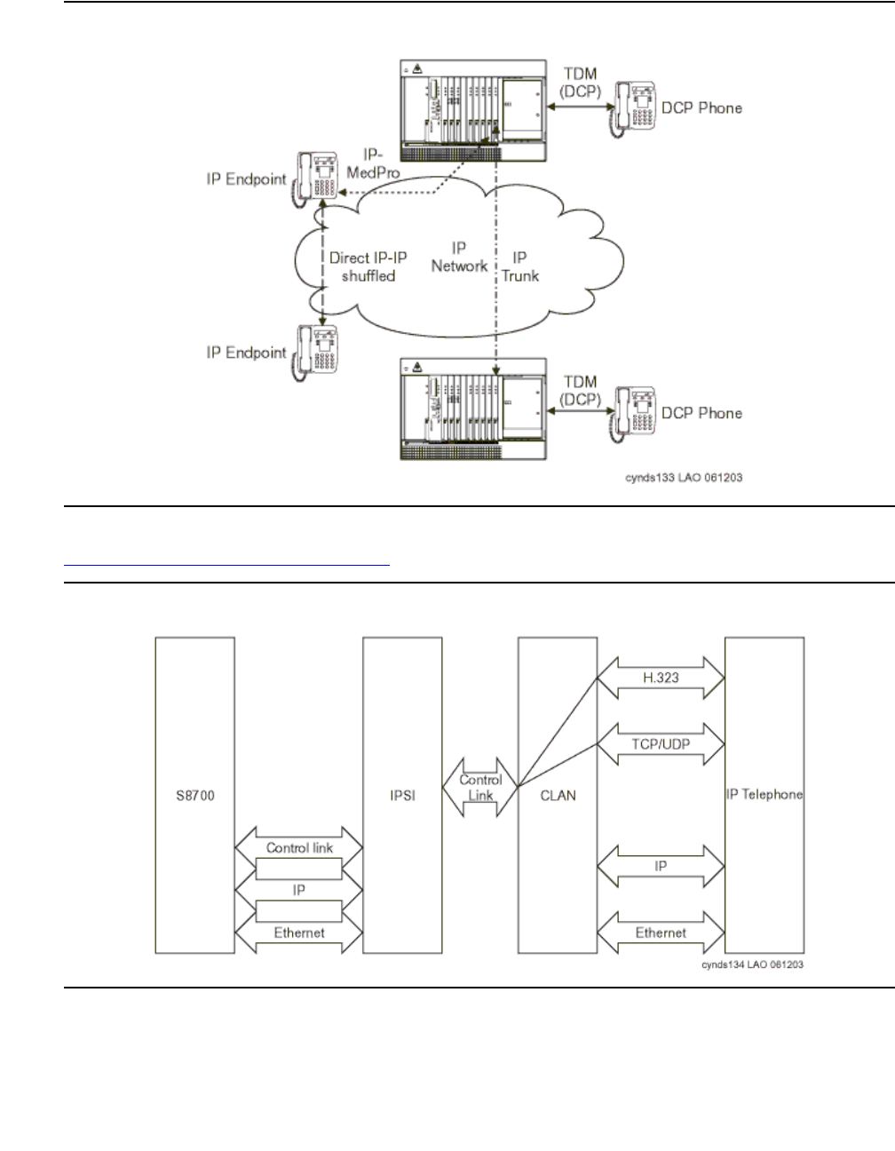
Greenfield deployment
106 Avaya Application Solutions IP Telephony Deployment Guide
Figure 36: Media flow path (S8700 IP-Connect configuration)
For detailed characteristics of the IPSI, C-LAN, and Media Processor circuit packs, see the
Avaya Application Solutions platforms chapter.
Figure 37: Signaling flow

Greenfield configurations
Issue 4.3 February 2006 107
Communication devices
Avaya stations include IP Telephones and IP Softphones. Avaya also supports IP trunks. In
addition, all the Media Gateways support traditional terminals, such as analog, BRI, and DCP
telephones. For detailed descriptions of Avaya IP Telephony endpoints, see the Terminals
chapter.

Greenfield deployment
108 Avaya Application Solutions IP Telephony Deployment Guide
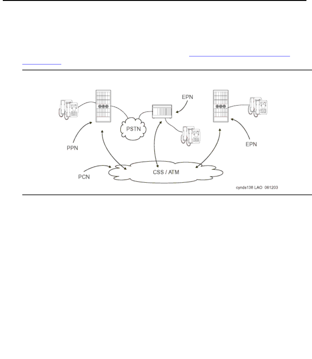
Issue 4.3 February 2006 109
Evolution from circuit-switched to IP
Overview
The Avaya DEFINITY® Enterprise Communications Server G3r has been the flagship product
in the DEFINITY family of communications servers. As technology changed, Avaya was able to
leverage the rapid advances in microprocessor technology to increase the capacity and
processing power of the traditional DEFINITY platform (Figure 38: Traditional DEFINITY
configuration) to benefit our customers.
Figure 38: Traditional DEFINITY configuration
Avaya also has the objective to protect our customers’ communications investment in the Avaya
DEFINITY platform by helping our customers leverage their existing investments in Avaya
solutions. Upgrading allows a customer to make a smooth transition to IP Telephony technology
without sacrificing the features or reliability of their current DEFINITY. A customer can make
small incremental investments to move from the circuit-switched world to a full IP PBX while
retaining their investment in TDM-based equipment and connections. On the endpoints, moving
to IP Telephony allows simplified moves, adds, and changes. It also simplifies the building
wiring plan by sharing one Ethernet connection with both the IP Telephone and the desktop PC.
It also adds IP mobility while retaining the rich set of DEFINITY features. For both IP Telephone
and traditional circuit-switched telephone users, migrating to IP Telephony offers the
opportunity to bypass tolls, and route traditionally metered long-distance calls across an
unmetered IP network instead, saving operational costs.

Evolution from circuit-switched to IP
110 Avaya Application Solutions IP Telephony Deployment Guide
With the S8700 fiber connect solution, Avaya is delivering a high-capacity server and a
migration path from DEFINITY. The S8700-series Media Server uses an industry-standard
Linux operating system on an industry-standard server, which enables all endpoints to use
Communication Manager. This solution allows customers to migrate to IP Telephony and to a
higher performance processor without sacrificing the reliability of the G3r platform.
There are three stages to upgrading from a DEFINITY G3r to an Avaya Communication
Manager IP PBX:
1. Replace the G3r processor with industry-standard S8700-series Media Servers.
2. Add IP circuit packs (C-LAN and MedPro) to support IP endpoints.
3. Consolidate multiple systems into a single system to simplify administration. Support
network or processor failure conditions with LSPs deployed at remote sites.
Steps 1 and 2 can be reversed. The next five diagrams show the migration from circuit-switched
DEFINITY to an IP-enabled S8700 fiber connect system with server consolidation and LSP
survivability at a remote site.
Terminology
The terms IP connect and fiber connect are used in this chapter to distinguish between the two
types of port network connectivity (PNC).
Fiber-connected port networks (PNs) transport bearer traffic (voice, fax, video) between PNs
over fiber-optic cables using circuit-switched (TDM) protocol. IP-connected PNs transport
bearer traffic over Ethernet cables using packet-switched Internet Protocol (IP). Starting with
Communication Manager release 3.0, both types of port network connectivity can be combined
in the same system. This allows a system to be converted from fiber connect to IP connect
gradually, one port network at a time, if desired.
Note:
Note: The terms fiber connect or fiber-connected are used in this document with almost
the same meaning as the term multi-connect, which, in addition to
fiber-connected PNs to carry the bearer traffic, implies a dedicated control
network. The term fiber connect applies to configuration with either a dedicated
on non-dedicated control network.
There are three kinds of fiber-connected configurations:
Direct connect - One PN, the "control PN," is IPSI-connected to the control network and one or
two additional PNs are fiber-connected to the control PN. The call controller can be an
S8500 media server or an S8700-series Media Server pair. The fiber connections are
between the expansion interface (EI) circuit packs (TN570) in the PNs.

Migration from DEFINITY Server R to S8700 fiber connect
Issue 4.3 February 2006 111
Center Stage Switch - All PNs are fiber-connected through the center-stage switch (CSS) and
one or more PNs are IPSI-connected to the control network. The call controller is an
S8700-series Media Server pair. The fiber connections are between the switch node
interface (SNI) circuit packs (TN573) in the switch node carrier and the expansion interface
(EI) circuit packs (TN570) in the PNs, or between SNIs in two switch-node carriers.
ATM - All PNs are fiber-connected through the Asynchronous Transfer Mode switch and one or
more PNs are IPSI-connected to the control network. The call controller is an S8700-series
Media Server pair. The fiber connections are between the ATM switch and the ATM
expansion interface (ATM-EI) circuit packs (TN2305B or TN2306B) in the PNs.
Migration from DEFINITY
Server R to S8700 fiber connect
Phase 1: Processor replacement
This section explains how an existing non-IP Avaya Communication Manager PBX can evolve
to an IP Telephony-based solution. We will examine the case of an existing system that is
based on the traditional PPN/EPN architecture, which will be applicable to all the G3 platforms.
When designing S8700 fiber connect systems, there are two options for setting up the call
control network. The control network can be set up on the enterprise LAN or on a private
network that is isolated from the enterprise LAN. See Voice quality network requirements for
more information on setting up an IP network that can support IP Telephony.
The S8700-series Media Server controls Media Gateways in a different manner than DEFINITY
controlled Port Networks. With DEFINITY, the control path signaling shared the same transport
media as the bearer channels. In a fiber connect system, call control signaling is established
from the S8700-series Media Server over an Ethernet connection to the TN2312BP IP Server
Interface (IPSI) in the IPSI-connected Media Gateway. Non-IPSI connected Port Networks get
their control information from the servers through the Center Stage Switch to one of the Port
Networks that does contain an IPSI. An IPSI can support up to five Port Networks.
The full migration from a G3r to an S8700-series Media Server fiber connect system, with
traditional or ATM center stage, involves the following simplified steps:
1. Decide which EPNs are to be IPSI connected, and replace processor complexes with IPSIs.
2. Install servers.
3. Install Ethernet switches.
4. Install UPS units.
5. For IPSI-connected port networks, upgrade each EPN.
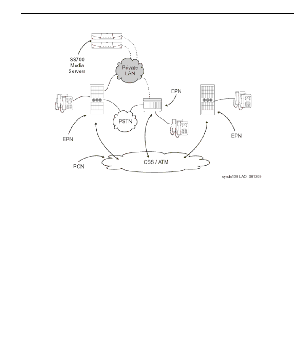
Evolution from circuit-switched to IP
112 Avaya Application Solutions IP Telephony Deployment Guide
6. Connect the duplication links.
7. Connect the servers and the IPSIs to the control LAN.
8. Sequentially bring up the duplicated servers.
Figure 39: S8700-series Media Servers (fiber connect configuration) shows the completion of
Phase 1, an S8700 fiber connect system that supports only traditional endpoints.
Figure 39: S8700-series Media Servers (fiber connect configuration)
Note:
Note: In the traditional PBX system, signaling and bearer traffic for all calls connects
through the TDM buses within Port Networks and the ATM or traditional center
stage
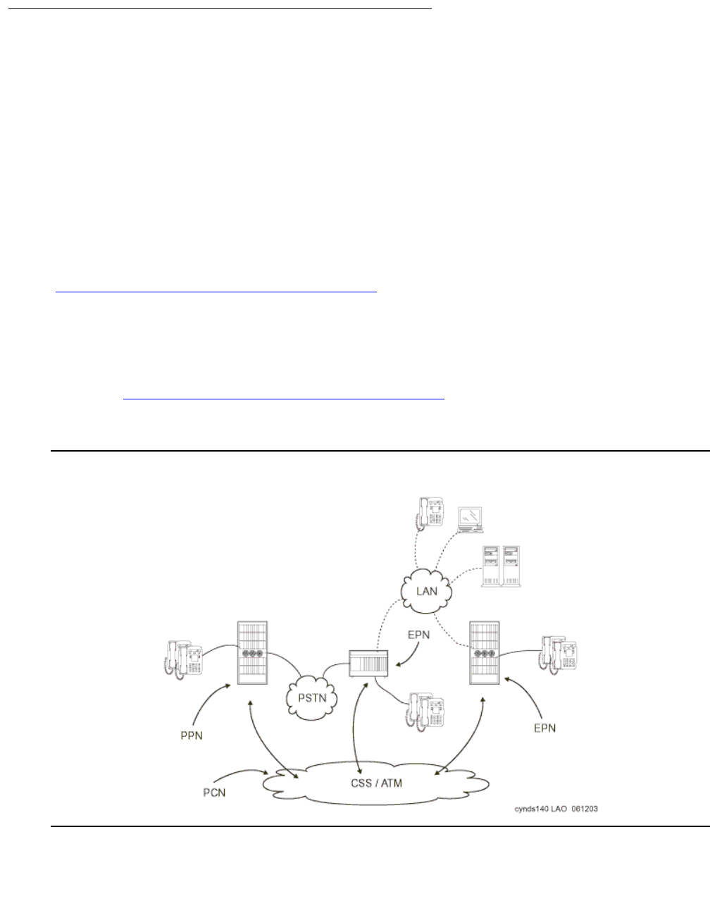
Migration from DEFINITY Server R to S8700 fiber connect
Issue 4.3 February 2006 113
Phase 2: IP-enable the Port Networks to support IP endpoints
Port Networks, with the addition of IP enabling circuit packs, are able to serve as Media
Gateways, representing the integration of IP and TDM telephony.
IP-enabling the existing system incrementally for IP endpoint support requires the following
circuit packs:
●TN799DP Control-LAN (C-LAN) for IP call signaling.
●TN2602AP IP Media Resource 320 and TN2302AP IP Media Processor (MedPro) for IP
audio media processing, including media streams that are intended for IP Softphones and
IP Telephones. Two per port network, maximum.
Signaling and bearer communication can connect through both the traditional TDM/center stage
route and the IP network infrastructure. This gentle migration to IP Telephony
(Figure 40: IP-enabled DEFINITY configuration) might have minimal impact on an existing,
non-IP system, while simultaneously enabling all new IP endpoints to fully access all the
Communication Manager features.
Note:
Note: If Phase 2 is implemented before Phase 1, the system will resemble
Figure 40: IP-enabled DEFINITY configuration. Also, a system that implements
Phase 2 but not Phase 1 cannot support as many IP endpoints as a system that
implements both Phase 1 and Phase 2.
Figure 40: IP-enabled DEFINITY configuration
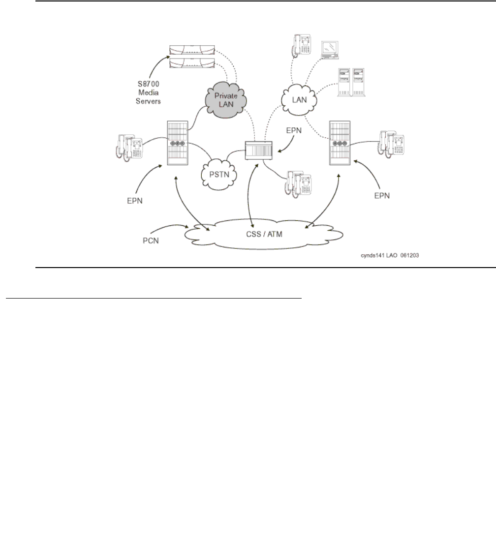
Evolution from circuit-switched to IP
114 Avaya Application Solutions IP Telephony Deployment Guide
At this stage, the media flow between two IP endpoints can be “shuffled.” That is, the media flow
proceeds directly between both endpoints without requiring Media Processor resources.
Shuffling may be used across multiple sites or multiple Avaya switches. Likewise, calls between
an IP endpoint at one site and a circuit-switched endpoint at another site can be shuffled so that
the media stream flows between the IP Telephone and the Media Processor circuit pack in the
Port Network that is connected to the circuit-switched endpoint. By using the IP network to the
greatest extent possible, enterprises can minimize the use of expensive circuit-switched trunks.
Figure 41: IP-enabling the S8700 fiber connect configuration
Phase 3: Server consolidation
Traditionally, some enterprises have elected to use multiple DEFINITY systems at remote sites
to protect against a circuit failure on the center stage network bringing down an entire remote
site. With the decision to run multiple servers came the need for additional administrative
resources and a more complex dial plan. Today, through the use of IP Telephony technology
and the enhanced processing capabilities of the S8700-series Media Servers, Avaya has a
solution to consolidate smaller remote DEFINITY servers, such as ProLogix or DEFINITY ONE
into an S8700 fiber connect system, while maintaining remote site survivability in the event of a
network or processor failure. By consolidating multiple DEFINITY servers into one S8700
system, an enterprise can realize cost savings in simplified administration and a simplified dial
plan. With support for up to 44,000 endpoints, the S8700-series system has the scalability to
support a remote site’s server consolidation.
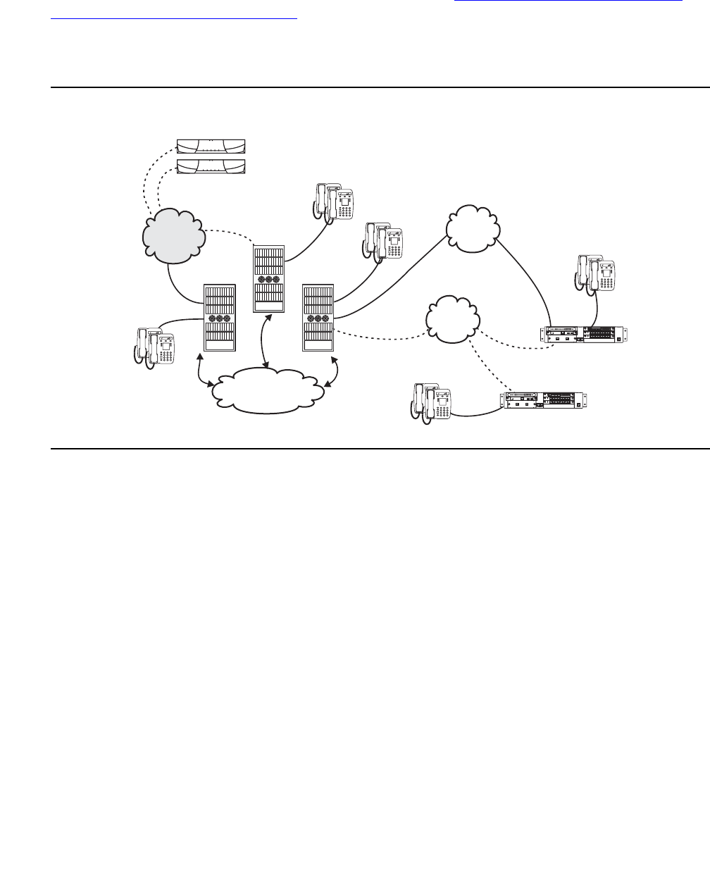
Migration from DEFINITY Server R to S8700 fiber connect
Issue 4.3 February 2006 115
Consolidating remote site servers into an S8700 system requires a G700 or G350 Media
Gateway with the option of Local Spare Processors (LSP) (Figure 42: S8700 / G700 / G350
system with Local Spare Processors). The LSP can be an S8300 or S8500 Media Server. In the
event of a network or processor failure, the LSP takes over active call processing and gateway
and endpoint management for the remote site, allowing continued operation with no loss of
features until the outage is repaired.
Figure 42: S8700 / G700 / G350 system with Local Spare Processors
Because the G700 and G350 rely on IP Telephony technology, this option is especially
attractive to customers who decide to use a majority of IP endpoints at the remote site. This
solution will, however, continue to support analog endpoints and DCP endpoints. Analog trunks
and ISDN trunks are also supported. To decrease operational expenses, the circuit-switched
trunks back to the main site can be replaced with IP trunks.
cynds142 KLC 121003
CSS / ATM
G700/LSP
G350/LSP
PSTN
LAN
Private
LAN
ALM
TST
ACT
ALM
TST
ACT
1 2 3 4 5 6 87
ALM
TST
ACT
ALM
TST
ACT
1 2 3 4 5 6 87
REMOVE
REMOVE
ALM
TST
ACT
OKTO
ALM
TST
ACT
OKTO SHUT DOWN
SERVICES
USB1
USB1
USB2
USB2
E1/T1
EIA 530A DCE
EIA 530A DCE
ALM
TST
ACT
SIG
ALM
TST
ACT
SIG
EISO EMSM EOSI
ALM
TST
ACT
ALM
TST
ACT
1 2 3 4 5 6 87
ALM
TST
ACT
ALM
TST
ACT
1 2 3 4 5 6 87
REMOVE
REMOVE
ALM
TST
ACT
OKTO
ALM
TST
ACT
OKTO SHUT DOWN
SERVICES
USB1
USB1
USB2
USB2
E1/T1
E1/T1
EIA 530A DCE
EIA 530A DCE
ALM
TST
ACT
SIG
ALM
TST
ACT
SIG
EI
SO
SO EMSM
EO
EOSI

Evolution from circuit-switched to IP
116 Avaya Application Solutions IP Telephony Deployment Guide

Issue 4.3 February 2006 117
Call processing
This chapter explains the features, the strengths, and the architecture of Communication
Manager call processing.
Communication Manager capabilities
This section lists and explains the major features of Avaya Communication Manager that are
over and above traditional PBX features:
●Terminal mobility
●User login
●IP Softphone
●Analog terminal
This chapter emphasizes the call processing components of Communication Manager and its
architecture, and briefly discusses IP-related applications in the areas of telephony,
convergence, networking and call routing, mobility, telecommuting, and remote office. This
chapter is not an exhaustive resource for Communication Manager features.
Communication Manager operates on the Avaya Media Servers, and on the existing family of
DEFINITY servers. Communication Manager seeks to solve business challenges by powering
voice communications and integrating with value-added applications. Communication Manager
provides user and system management functionality, intelligent call routing, application
integration and extensibility, and Enterprise Communications networking.
For more information on Communication Manager, see:
●Feature Description and Implementation for Avaya Communication Manager,
555-245-205, contains details about the full capabilities of Communication Manager by
release, application area, or both.
●Overview for Avaya Communication Manager, 03-300468, contains descriptions of each
feature.
●What’s New in Avaya Communication Manager for Release 3.1, 03-300682, provides a
delta view of new features in Communication Manager Release 3.1.
These documents are available at http://support.avaya.com.

Call processing
118 Avaya Application Solutions IP Telephony Deployment Guide
Voice and multimedia networking
Intelligent networking and call routing
With Avaya Communication Manager, servers can use IP trunks across an IP network to
communicate between switches without the need for dedicated leased lines. With
Communication Manager, IP trunks can use Distributed Communication Services (DCS+) or
QSIG Services to extend feature transparency, centralized voice mail, centralized attendant
service, call center applications, and enhanced call routing across IP trunks.
IP Port Network / Media Gateway connectivity
IP PNC allows S8700-series Media Servers and G650 Media Gateways to be connected over
IP networks. Avaya Communication Manager uses a proprietary method to package voice and
signaling messages over IP. This method allows deployment of communications systems
throughout a customer’s data network.
H.248 Media Gateway control
Communication Manager uses the standards-based H.248 media gateway control protocol to
perform call control of Avaya G700, G350, and G250 Media Gateways. H.248 defines a
framework of call control signaling between the intelligent Media Servers and multiple Media
Gateways. H.248 controls both IP (H.323) and non-IP connections into a media gateway. H.248
has been extended by Avaya to also tunnel proprietary CCMS messages, to allow for enhanced
call handling.

Call Processing
Issue 4.3 February 2006 119
Call Processing
Communication Manager gatekeepers
A gatekeeper is an H.323 entity on the network that provides address translation and controls
access to the network for H.323 endpoints. For Communication Manager platforms, these are
the Avaya S8300, S8400, S8500, and S8700-series Media Servers. H.323 RAS (Registration,
Admission, and Status) Protocol messages are exchanged between them and the IP endpoints
for the endpoint registration.
All IP endpoints (IP Softphones, IP agents, and IP Telephones) H.323 voice applications should
register with an Avaya gatekeeper before any calls are attempted. Communication Manager
enforces call signaling (Q.931) and call control (H.245) channels from endpoints to terminate on
the gatekeeper. This allows Communication Manager to provide many of its calling features to
H.323 calls.
Registration and alternate gatekeeper list
The RAS protocol is used by the IP endpoint to discover and register with the Communication
Manager gatekeeper.
When registration with the original gatekeeper (C-LAN or S8300) IP address is successful, the
switch sends back the IP addresses of all the C-LANs (or LSPs) in the IP Telephone’s network
region. These addresses are used if the call signaling to the original C-LAN circuit pack fails.
Figure 43: Discovery and registration process to the gatekeeper on page 120 shows the
registration process.
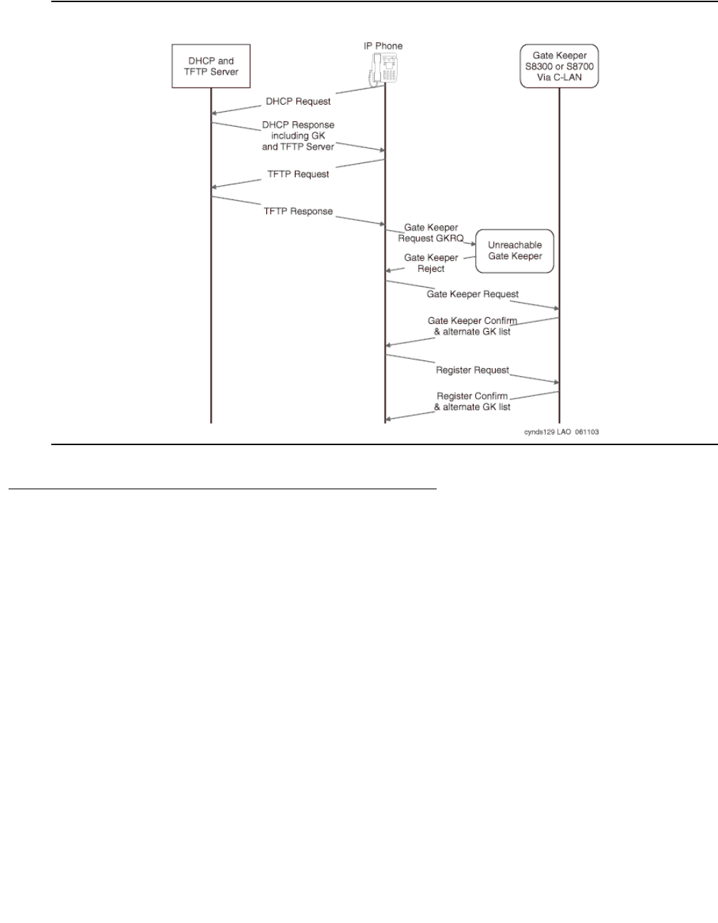
Call processing
120 Avaya Application Solutions IP Telephony Deployment Guide
Figure 43: Discovery and registration process to the gatekeeper
Call signaling
Communication Manager implements the gatekeeper routed call model of H.323. The
registration process that is described above allows the endpoint and the Communication
Manager gatekeeper to exchange addresses to establish a TCP connection for a “call signaling”
channel (the H.323/H.225 channel). Once the TCP connection is established for call signaling,
the H.225.0/Q.931 signaling protocol is used over that connection to route the call and
exchange addresses necessary to establish a second TCP connection. This second TCP
connection is used for “media control” (the H.245 channel).
When Communication Manager chooses to route the media flow streams through the switch, it
selects and allocates available media processor resources, and sets the corresponding circuit
packs up to receive and send the media stream or streams from/to the endpoints using the
negotiated capabilities for each terminal. Each terminal is told to send its media stream or
streams to the appropriate Media Processor circuit pack. The switch connects the two media
streams, and thus completes the bearer path between the terminals.

Call Processing
Issue 4.3 February 2006 121
Media stream handling
Media processing
The basic functions of the TN2302AP IP Media Processor and TN2602AP IP Media Resource
32 (MedPro) circuit packs include:
●Taking media streams off the IP network, terminating RTP/UDP (adjusting for variable
delay in arrival rate), and converting them into PCM audio for transmission on the TDM
bus.
●Taking media streams from the TDM bus, encoding them with the proper codec, and
transmitting them as RTP packets to an IP endpoint.
●Originating and terminating an RTCP control channel for each media stream.
The particulars of the media conversion that is to be performed on each media stream are
controlled by Communication Manager. The Quality of Service (QoS) information obtained from
the RTCP channel is passed from the circuit pack to Communication Manager.
DTMF tone handling
The Media Processor circuit pack listens for and detects DTMF tones coming from the TDM
bus, strips them out of the audio stream, and sends a message to the Media Server indicating
that it has done so. The Media Server in turn generates and sends the appropriate H.245 tone
message to the endpoint that is receiving the audio stream. The receiving endpoint then plays
the specified tone. Compressed codecs, such as G.729, generally do a poor job of passing
DTMF tones. By sending tones out of band, fidelity is maintained. This method is useful when
connecting to a voice mail or an integrated voice response (IVR) system, where DTMF digits
are used to navigate through prompts.
When this capability is used on an H.323 tie trunk between Communication Manager switches,
the switch that receiving the H.245 tone message plays the required tone onto all the ports
receiving the audio stream.
Media stream for audio conferencing
When calls between IP endpoints are conferenced, the media streams must be routed through
the MedPro circuit pack.
Communication Manager allows the audio streams from different parties to come into different
Media Processor circuit packs. Each Media Processor sends its received signal to the TDM bus
in Pulse Code Modulation (PCM) format. All the other processors serving endpoints on the call
can then receive and sum the audio signals coming from all parties, and send the resultant
composite audio stream to the IP parties that it supports.
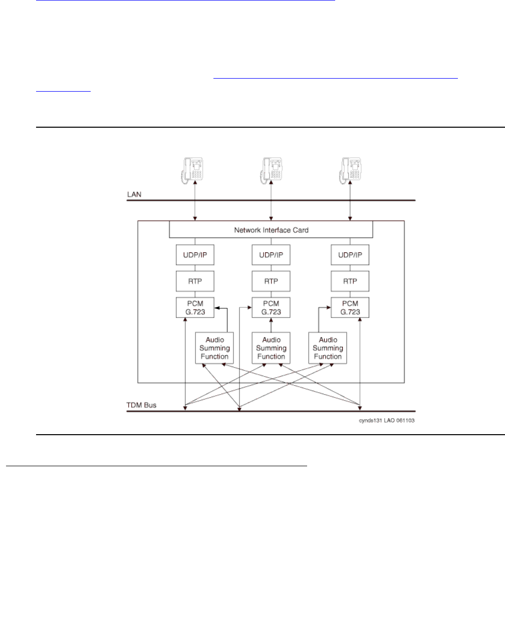
Call processing
122 Avaya Application Solutions IP Telephony Deployment Guide
Figure 44: MedPro support of a three-party audio conference on page 122 provides an
example to show how the MedPro circuit pack is configured for a three-party H.323 audio
conference using G.729. This conference is conventional in that it uses TDM bus timeslots to
allow each party to listen to all of the other parties. However, a more efficient form of
conferencing is possible when all the parties are IP endpoints, where the audio streams are
multiplexed directly on the Media Processor circuit pack, and no TDM timeslots are used. To
establish the configuration shown in Figure 44: MedPro support of a three-party audio
conference on page 122, the DSP resources on the MedPro are allocated as needed to audio
conferencing. Communication Manager balances the available media processing resources,
effectively sharing load among multiple MedPros.
Figure 44: MedPro support of a three-party audio conference
Separation of Bearer and Signaling (SBS)
In an Avaya IP Telephony system, call signaling and bearer traffic may be routed over separate
paths. This is useful for a remote branch office with only limited WAN bandwidth back to
headquarters. Call signaling traffic can be routed across the WAN, while bearer traffic is sent
over the PSTN.

Call Processing
Issue 4.3 February 2006 123
Multi-location
Communication Manager 2.2 allows a Linux-based media server located in one country to
control gateways located across national borders and provide appropriate country-specific
tones and features. Specifically, these features include the following:
●A-law & Mu-law Companding
●Call Progress Tone Generation
●Loss Plan
●Analog line board parameters
●Call Detail Recording
●R2-MFC (Multifrequency-Signaling) trunks
Multi-location functionality is subject to the following limitations:
●25 Countries
●R2-MFC: 8 signaling sets
●Additional Tone Generators (TN 2182 in Port Networks, built-in tone generators in Media
Gateways) are required to support country-specific tones
●No per-country alarms or traffic reports are available
●LSPs must be set to the same time zone as the server
●This feature is intended for IP-remoted gateways, not DS1-remoted Port Networks.
Modem/Fax/TTY over IP
In the past, many organizations have experienced problems transporting modem, fax, and TTY
tones over an IP Telephony network, regardless of vendor. Modems, faxes, and TTYs are very
sensitive to latency and jitter, and do not tolerate distortion induced through compression,
expansion, and transcoding. In order to overcome these difficulties, Avaya has enhanced its
modem, fax, and TTY-over-IP support in release 2.2.
There are two enhanced modes for supporting Modem-over-IP (MoIP): pass-through and relay.
Pass-through is essentially a best-effort transmission, and works by forcing the use of the
G.711 (uncompressed) codec for the call. Re-transmission is governed by the application.
Pass-through mode is suited to LAN environments where both ends of a call are synchronized
using a common clock source. Relay, on the other hand, uses redundant packet transmission to
protect against packet loss. Because relay mode does not force the use of G.711, it requires
less bandwidth than pass-through, however requires more DSP resources. Relay is more
effective than pass-through across a WAN.

Call processing
124 Avaya Application Solutions IP Telephony Deployment Guide
Avaya's TTYoIP support works by identifying TTY Baudot tones at the near-end Media
Processor, removing them from the voice path, and transporting them across the network in
RFC 2833 messages. The far-end Media Processor receives the RFC 2833 messages and
regenerates them for the far-end station. This feature is enabled by default on IP trunks and
inter-gateway calls, and is capable of toggling between text and voice modes.
Avaya's support for modem, fax, and TTY over IP can be summarized as follows:
●TTY over IP continues to be supported
●Modem Pass-through is supported between Avaya gateways
●Modem Relay at 9.6K is supported between Avaya gateways
●Avaya supports sending multiple instances of the same packet
Redundant transmission mitigates the effects of packet loss, but requires additional bandwidth.
Avaya's modem, fax, and TTY over IP support is subject to the following limitations:
●QOS is required, even on LAN.
●Avoid MoIP where possible (especially over a WAN environment)
●Use circuit-based resources on the same gateway
●Use different classes of service and restrictions
●Use centralized modem pooling for larger communities
●Only one TDM-to-IP-to-TDM conversion is allowed
●Send duplicate streams, where practical
Table 3 summarizes Avaya's fax, modem, and TTY options.
Table 9: Fax, Modem, and TTYoIP options
Fax relay Default, Avaya-proprietary mode, interoperates with previous
releases
Pass-thru Proprietary mode; uses more bandwidth, fewer DSP
resources
off system ignores fax tones, call remains in administered codec
Modem off Default, system ignores modem tones, call remains in
administered codec
relay Avaya-proprietary mode, most reliable modem-over-IP mode
pass-thru similar to Fax pass-thru
1 of 2

IP-based trunks
Issue 4.3 February 2006 125
IP-based trunks
In circuit switched networks, trunks provide the means to interconnect PBXs with each other
and to the PSTN. Connection to the public network allows PBX station users to call and be
called by terminals that are not part of the PBX private network of the PBX. An analogous
arrangement exists in packet-switched IP networks.
H.323 trunks connect H.323 systems or gateways over IP networks, similar to circuit-switched
tie trunks. Similarly, SIP trunks connect SIP systems or gateways over IP networks.
A set of Communication Manager switches can each be attached to an IP network, and voice
and fax calls can flow between them in the usual manner except that the call signaling and
audio/fax streams are carried over the IP network. The signaling is carried through the C-LAN
circuit packs, and the audio and fax streams are carried between switches through the Media
Processor circuit packs.
The benefits of using IP trunks include:
●Reducing long distance voice and fax expenses
●Facilitating global communications
●Providing a fully functional network with data and voice
●Converging and optimizing networks by using the available network resources
IP trunk calls can be compressed to save network bandwidth. Repeated compression and
decompression (transcoding) results in a loss of data at each stage and degrades the final
quality of the signal. The maximum recommended number of compression cycles on a call is
three. Normal corporate voice calls or fax calls typically go through fewer than three
compression cycles.
IP (H.323 and SIP) trunks can also connect to other vendors' compliant PBXs.
TTY US Default, 45.45 Baudot, interoperates with previous releases
UK 50 Baudot
pass-thru similar to Fax pass-thru
off system ignores TTY tones, call remains in administered
codec
Table 9: Fax, Modem, and TTYoIP options (continued)
2 of 2

Call processing
126 Avaya Application Solutions IP Telephony Deployment Guide
SIP trunk capacities
Table 10 shows the maximum number of SIP trunks supported out of the total number of IP
trunks supported.
IP tie trunks
IP tie trunks are used to connect switches to one another. When an IP trunk is used to
interconnect two switches, the trunk can also carry standard (QSIG) and proprietary (DCS+)
signaling for interswitch feature transparency. The location of each other node (switch) in the
network is administered, and node selection is based on the dial plan and call routing features
such as AAR/ARS.
H.323 or SIP tie trunks are administered as a new type of trunk group. Instead of administering
ports as members of the trunk group, only the number of channels must be specified. Each
channel is analogous to a member trunk. In addition, an IP tie trunk can be made a member of a
signaling group so that a virtual D-channel can be administered and used to carry feature
transparency information.
Trunk signaling
Several variations of IP signaling must be accommodated for the variety of trunks supported by
Communication Manager. These are specified as options in the trunk group administration.
When the IP trunk is used as -a tie trunk to another vendor's switch, gateway, or gatekeeper,
Communication Manager sets up a separate TCP connection for each call.
Note:
Note: As of Communication Manager release 3.1, the maximum number of members of
a single IP trunk signaling group has increased from 31 to 255.
For more on trunk signaling, see Overview for Avaya Communication Manager, 03-300468.
Table 10: SIP Trunk Capacities by Platform Configuration
Platform Configuration Maximum Number of SIP IP Trunks
of the Total IP Trunks Supported
S8700-series
(fiber connect or IP connect) 5000 of 8000
S8500 800 of 800
S8400 400 of 400
S8300/G700/G350 450 of 450
S8300/G250 10 of 10

SIP
Issue 4.3 February 2006 127
SIP
SIP stands for Session Initiation Protocol, an endpoint-oriented messaging standard defined by
the Internet Engineering Task Force (IETF). SIP is a text-based protocol, similar to HTTP and
SMTP, for initiating interactive communication sessions between users. Such sessions include
voice, video, instant messaging, interactive games, and virtual reality.
SIP "trunking" functionality is available on any of the Linux-based media servers (S8300,
S8400, S8500, or S8700-series). SIP trunking allows Avaya Communication Manager to
communicate with SIP endpoints and gateways across an IP network. SIP trunks allows an
enterprise to connect its media server(s) to a SIP-enabled proxy server, specifically, an Avaya
SIP-Enablement Server (SES), and through this proxy, optionally to an external SIP service
provider, if desired. The trunk support in Communication Manager complies with SIP standards,
specifically IETF RFC 3261, and so interoperates with any SIP-enabled endpoint/station that
also complies with the standard.
Avaya Communication Manager supports SIP endpoints, including the Avaya 4602 SIP
Telephone and Avaya IP Softphone Release 5. In addition to its IP telephony capabilities, IP
Softphone R5 also includes Instant Messaging (IM) client software, which is a SIP-enabled
application that connects to the Avaya Converged Communication Server for IM control. By
means of having SIP-enabled endpoints managed by Communication Manager, many features
can be extended to these endpoints. The media servers (S8300, S8500 or S8700-series)
function in four ways:
●As Plain Old Telephone Service (POTS) gateways
●As support for name and number delivery between and among the various non-SIP
endpoints supported by Communication Manager
For instance, analog, DCP (Digital Communications Protocol) or H.323 stations, and
analog, digital or IP (internet protocol) trunks.
●As support for new SIP-enabled endpoints, such as the Avaya 4602 SIP telephone
●As a telephony feature server to SIP endpoints
The set of features supported by SIP itself is augmented by those supported by
Communication Manager.

Call processing
128 Avaya Application Solutions IP Telephony Deployment Guide
SIP-Enablement Server
The Avaya SIP-Enablement Server (SES) is dedicated to performing proxy, registrar, presence,
and licensing functions associated with SIP applications, such as Instant Messaging and SIP
trunking. SIP-enabled endpoints need only register with the SES; they can be but do not need
to be managed by Avaya media servers. In addition, the SES supports the SIP-enabled Instant
Messaging application between users of IP Softphone R5.x client software; the IM clients can
be, but do not need to be managed by Avaya media servers.
A SIP proxy server serves as a routing server for SIP requests from clients or other proxy
servers. The proxy server receives signaling requests from endpoints or proxy servers, stays in
the signaling path for the duration of the transaction, and forwards requests to the destination
endpoint or to a server that is closer to the final destination.
A SIP registrar is a server to which SIP endpoints register, and which maintains the status of
such endpoints. The SIP registrar is also responsible for binding a user's "well-known" URI (for
example, wcoyote@acme.com) with a URI "closer" to the endpoint (for example,
wcoyote@roadrunner1.acme.com), and for making that information available to the SIP location
service.
As defined by the IETF, presence (or presence information) is the indication of whether a user is
capable or willing to take part in a communication session. Presence may also include contact
or address information for the means of joining the communication session, preferences about
which means to use and when, and state about availability at those means (for example, station
on-hook or off-hook).
A presence event occurs when users log in or out of a telephone, change their preferences
about reachability at some location, such as a phone or pager, or change their status at some
location. More generally, a presence event is any event which changes the current presence
information.
A presence server is a server that collects presence information from endpoints, and makes the
presence information available to other entities (endpoints or servers). Presence and presence
servers are useful when trying to send a message to a user, rather than an endpoint. Presence
information allows the message to be routed to the endpoint "closest" to the user, whether at his
desk, in a conference room, on a mobile phone, or at home.
By combining SIP proxy, registrar, presence, and licensing in a single SES server, Avaya
makes it easy for customers to take advantage of SIP in a straightforward manner without
requiring a significant investment in additional hardware.
In release 2.2, SES adds support for high availability features, direct IP-IP shuffling between
SIP devices, SNMP support, and several security enhancements. SES now supports 1+1
(active/standby) redundancy by using a shared virtual IP address and replicating state updates
between servers. Security enhancements include TLS-protected administration web pages,
digital certificates signed by the Avaya Root CA, Linux PAM support, and per-call SIP digest
authentication.
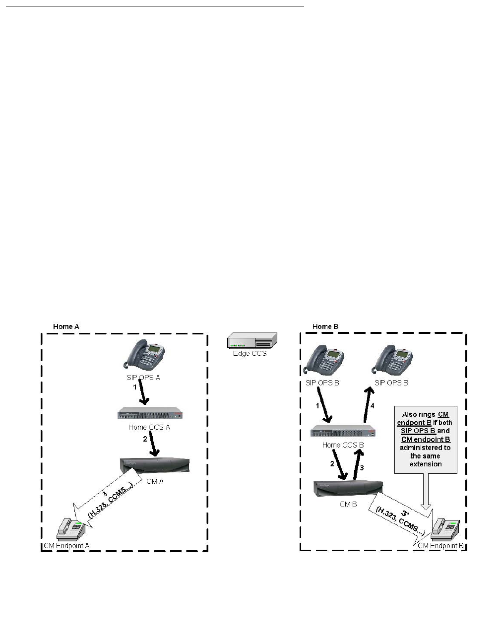
SIP
Issue 4.3 February 2006 129
Communication Manager mediated SIP call flow
This section briefly describes SIP signaling call flows. It does not include SSCAN, which is
covered in a separate section.
Within the Avaya SIP framework, each SIP phone, whether a physical SIP phone or a SIP
softphone running on a workstation, registers with a home SIP-Enablement Server (SES) acting
as a SIP home proxy. Each phone, in turn, is associated during the registration process with a
regular CM extension as an off-pbx station. This allows Communication Manager to provide all
the features available to any other type of Avaya telephone. In other words, Communication
Manager is a SIP feature server. At the same time, non-SIP telephones can dial the extension
of a SIP phone in the same digit-based dial plan used by all phones. Thus, Communication
Manager is acting as a SIP gateway mediating calls between SIP and non-SIP endpoints.
All SIP signaling to and from SIP phones must route through Communication Manager via SES.
This is called origination-based routing for SIP originated calls and termination routing for calls
to SIP endpoints. Keep in mind that SIP signaling to and from Communication Manager is over
an appropriate signaling socket similar to those used for H.323 endpoints and H.248 media
gateways:
●Port-network-based CLANs (S8700-series and S8500 Media Servers)
●Server-based Processor Ethernet CLANs (S8500 and S8300 Media Servers).
The following scenario diagrams illustrate SIP call flows.
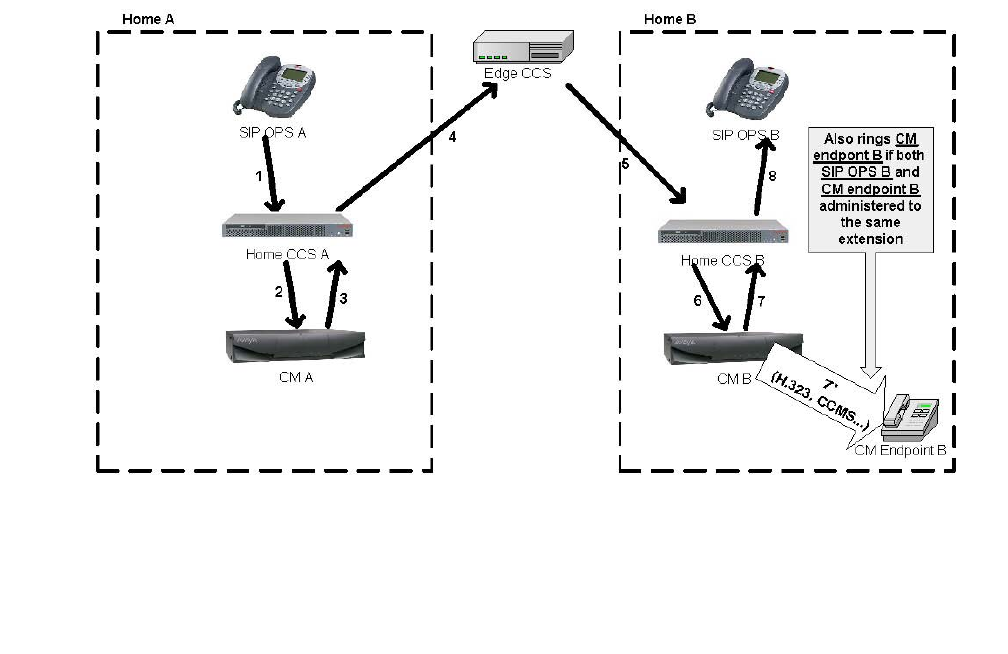
Call processing
130 Avaya Application Solutions IP Telephony Deployment Guide
On the left side in Home A, a SIP off-pbx station A (OPS A) calls a Communication Manager
phone. The arrows indicate direction of travel of the initial SIP INVITE message in the sequence
indicated. Communication Manager communicates with SES over a SIP trunk, which is held for
the duration of the call (see later section on SIP traffic engineering on SIP trunk allocations). In
this case, Communication Manager sets up the call with the SIP phone using SIP protocol, and
with the receiving non-SIP phone using whichever protocol the phone uses. The media stream
from the SIP phone is a VoIP stream similar to that of H.323 IP phones, with the same support
for shuffling, CODECs, and packet sizes. As of release 3.0 of Communication Manager, a SIP
phone can shuffle to direct media connect with another SIP phone and media gateway based
VoIP resources such as MedPro and H.248 media gateways. However, it cannot shuffle to
direct media connect with H.323 IP phones. A call from the Communication Manager endpoint
would follow the arrows and the sequence in reverse.
On the right side in Home B, a SIP phone calls another SIP phone on the same home SES.
Even though they share the same home SES, the SIP messages still must go through
Communication Manager because of origination and termination based routing. Note that this
call flow also shows that the extension of the receiving SIP phone actually has two
appearances. One appearance is on a non-SIP phone that is signaled via a non-SIP protocol by
Communication Manager.
If the receiving SIP phone answers, media flow directly from calling to receiving SIP phones
because of shuffling. If the two SIP phones are on different home SESs but have extensions on
the same Communication Manager server, the call flow would look similar except that the
outbound leg from Communication Manager in steps 3 and 4 would obviously go through a
separate SES.

SIP
Issue 4.3 February 2006 131
SIP communication between Communication Manager servers can substitute for regular TIE
trunk connection between the servers, as shown in the above diagram. This ‘W’ call flow sends
SIP message through the edge SES for calls between SIP phones on separate home SESs and
separate Communication Manager servers. Again, all outbound and inbound SIP message
must be routed through the respective Communication Manager servers because of origination
and termination based routing. SIP signaling to and from outside the domain (outside world)
also travels through the edge SES. Each leg of the call takes up one SIP trunk, therefore the
diagram above requires two SIP trunks in System A and two in System B.
SIP endpoints on two different Communication Manager systems can still use non-SIP regular
TIE trunks such as H.323 IP TIE trunks or circuit switched trunks such as T1/E1. In this case,
the two Communication Manager servers signal the call just like any other call. SIP signaling is
entirely confined within each Communication Manager system. The two SIP phones cannot
shuffle to direct media connect in this case. Each SIP phone must connect to media gateway
within its own Communication Manager system.

Call processing
132 Avaya Application Solutions IP Telephony Deployment Guide
Mobility
IP Telephones or IP Softphones
IP Telephones allow access to the features of Communication Manager without having to be
tied to one location. One of the major benefits of IP Telephones is that you can move the
telephones around on an IP network just by unplugging them and plugging them in somewhere
else. One of the main benefits of IP Softphones is that you can load them on a laptop computer,
and connect them to the Communication Manager switch from almost anywhere. Users can
place calls, and handle multiple calls on their PCs. For detail description and features of IP
Telephones and Softphones see the Terminals chapter.
Extension to Cellular
Extension to Cellular is an integrated mobility solution that offers users the freedom to work
anywhere, anytime, using any type of cellular or wireless telephone. With Extension to Cellular,
calls to an office number are extended to a cellular telephone, allowing users to receive
work-related calls wherever they are and whenever they need. Additionally, the cellular
telephone can be administered so that when a user calls into the office, the user’s name and
office telephone number appear in the caller ID display of the telephone being called. When the
Extension to Cellular cell phone is administered to send office caller ID, the user also has the
option of picking up an ongoing Extension to Cellular cell phone call on the office telephone
when the user enters the office.
Extension to Cellular works over PRI as well as an IP trunk interface. The cell phone user
receives the same features and capabilities for incoming calls as a caller ID-enabled analog
telephone that is connected directly to the Avaya Communications Server. Extension to Cellular
provides this capability regardless of the cell phone’s cellular service provider or the cellular
standard in use.

Communication applications
Issue 4.3 February 2006 133
Communication applications
Call Center
The Avaya Call Center provides a total solution for a customer’s sales and service needs.
Building on the performance and flexibility of the Avaya Communication Manager, customers
can select from a powerful assortment of features, capabilities, and applications that are
specially designed to enhance call center operations.
The objective of this offer, which involves new and existing versions of Avaya Media Servers
and Communication Manager, as well as a host of attached call center peripherals, is to
improve Avaya’s Call Center offers by supporting increased capacities. These capabilities
include 6-digit and 7-digit extensions, LAN backup of Call Management System for the High
Availability offer, and customer requested enhancements to be made available in a single global
release.
Avaya Call Center applications are designed to efficiently connect each caller with the
representative who is best suited to serve that caller. Avaya Communication Manager begins
the process by capturing information about the caller even before the call is routed. That
information is integrated with existing databases, and the combined data is used to match caller
to agent.
Avaya Communication Manager integrates with a variety of Call Center applications like the
Avaya Call Management System S) for real-time reporting and performance statistics, and with
Avaya Business Advocate for expert predictive routing according to incoming calls, not just
historical data.
Avaya Call Management System (CMS)
The Avaya Call Management System collects call traffic data, formats management reports,
and provides an administration interface for Automatic Call Distribution (ACD) on your
Communication Manager. CMS helps enterprises manage the people, traffic load, and
equipment in an ACD environment by answering such questions as:
●How many calls are we handling?
●How many callers abandon their calls before talking with an agent?
●Are all agents handling a fair share of the calling load?
●Are our lines busy often enough to warrant adding additional ones?
●How has traffic changed in a given ACD hunt group over the past year?
Site Statistics for Remote Port Networks forwards location IDs to CMS to provide call center
site-specific reports.

Call processing
134 Avaya Application Solutions IP Telephony Deployment Guide
CMS reliability and redundancy
Dual Links to CMS provides an additional TCP/IP link to a separate CMS for full, duplicated
CMS data collection functionality and high availability CMS configuration. The same data are
sent to both servers, and the administration can be done from either server. The ACD data is
delivered over different network routes to prevent any data loss from such conditions as ACD
link failures, CMS hardware or software failures, CMS maintenance, or CMS upgrades.
Computer Telephony Integration (CTI)
Computer Telephony Integration (CTI) enables Communication Manager to be controlled by
external applications, and allows integration of customer databases of information with call
control features. CTI is a LAN-based solution that consists of server software that runs in a
client/server configuration.
CTI opens up Application Programmer Interfaces like ASAI, Telephony Services Application
Programming Interface (TSAPI), and Java Telephony Application Programming Interface
(JTAPI), which can be used to control the server from an external application.
Application Programming Interfaces (APIs)
Communication Manager supports the following APIs to interface with other applications:
●Adjunct Switch Application Interface (ASAI) allows adjunct applications to access a
collection of Communication Manager features and services. Integration with adjuncts
occurs through APIs. ASAI is part of Avaya Computer Telephony.
●DEFINITY Application Programming Interface (DAPI) for accessing control and data paths
within Communication Manager.
●Java Telephony Application Programming Interface (JTAPI) is an open API supported by
Avaya Computer Telephony that enables integration to Communication Manager ASAI.
●Telephony Application Programming Interface (TAPI).
●Telephony Services Application Programming Interface (TSAPI) is an open API supported
by Avaya Computer Telephony that allows integration to Communication Manager ASAI.

Communication applications
Issue 4.3 February 2006 135
Best Services Routing (BSR) polling
Best Service Routing (BSR) polling over QSIG Call Independent Signaling Connections
(CISCs) and Temporary Signaling Connections (TSCs) provides the ability to do BSR polling
between multiple site over H.323 IP trunks without requiring an ISDN PRI B-channel. QSIG
CISC/TSCs are used by BSR polling software to reduce the need for the IP Media Processor
circuit pack, thereby making BSR a cost-effective, multi-site solution for an enterprise-wide
contact center.
Meet-me conferencing
Meet-me conferencing provides conferencing of up to six parties from any communication
device that is internal or external to the business network. This feature does not require any
special hardware. Meet-me conferencing uses a software approach that is based on Vector
Directory Number (VDN) vectors and announcements. An announcement source is necessary
to use meet-me conferencing. Supported announcement sources include:
●Voice Announcements over the LAN (VAL) circuit pack
●G700 local announcement
●Integrated Announcement circuit pack
●An external source

Call processing
136 Avaya Application Solutions IP Telephony Deployment Guide
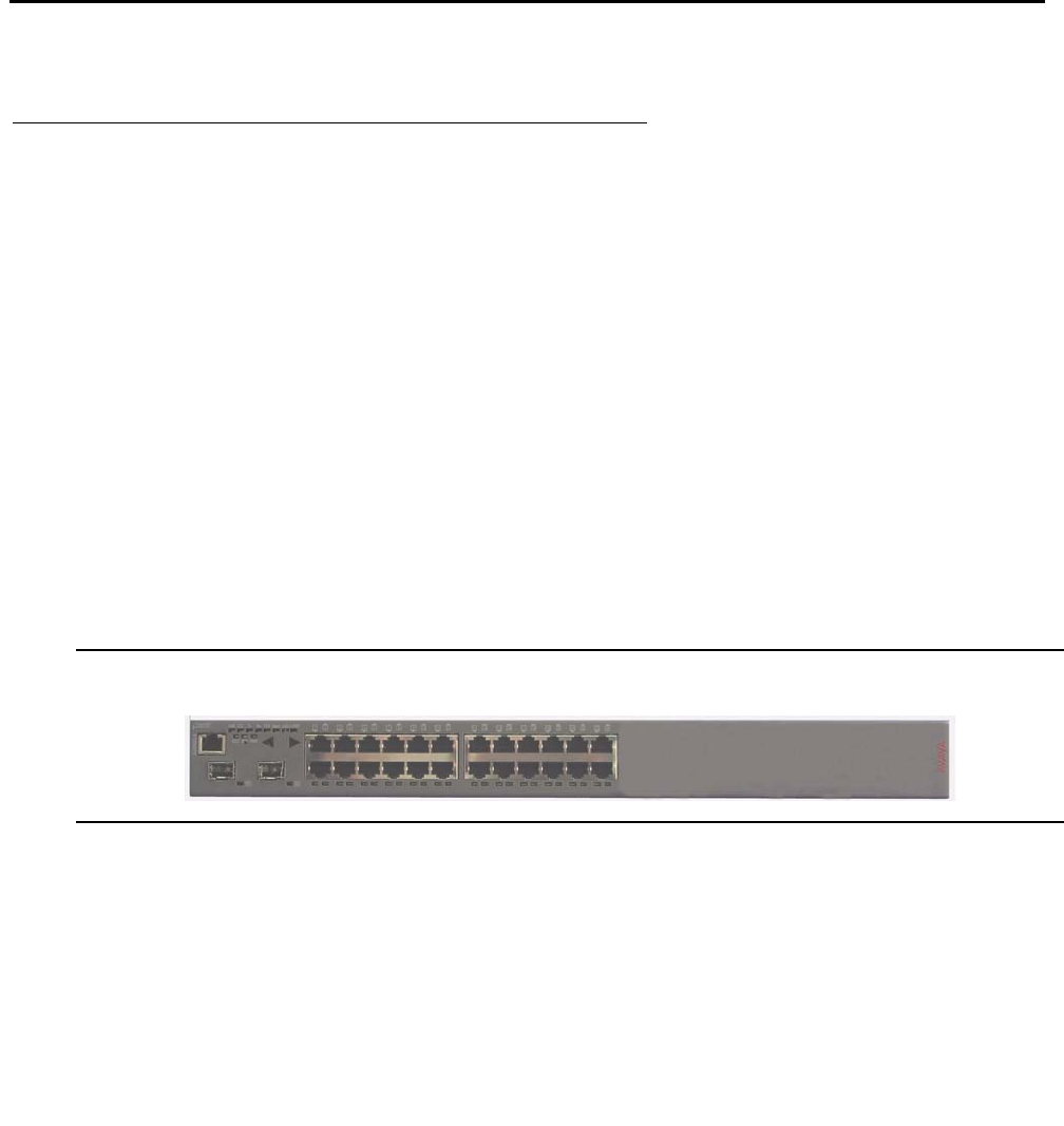
Issue 4.3 February 2006 137
Avaya LAN switching products
This chapter discusses how Avaya products add value to an IP Telephony deployment.
Converged infrastructure LAN switches
C360 converged stackable switches
The Avaya C360 converged stackable switch series is a line of stackable, multilayer switches
that provide high availability, quality of service (QoS), and Power over Ethernet (PoE) to
enhance converged network infrastructure operations. With a range of PoE and non-PoE
configurations, the C360 series is a powerful, yet cost-effective option for enterprise
applications. The C360 series offers a migration path for the P330 series, and can be stacked
with P330 switches and G700 Media Gateways.
The Avaya C360 series of converged stackable switches includes:
●A range of modules with 24 or 48 10/100 Mbps ports supporting PoE or non PoE and two
GBIC SFP slots for Gigabit Ethernet connections
●A Layer 3 capability
The available C360 switch models are as follows:
●C363T converged stackable switch
This switch has 24 10/100 Mbps ports and two GBIC SFP ports.
Figure 45: C363T Converged Stackable switch
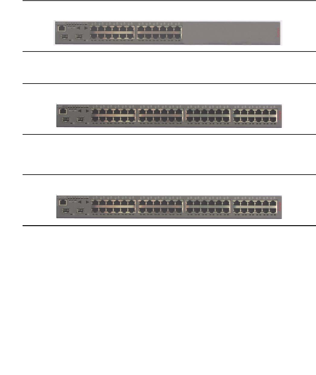
Avaya LAN switching products
138 Avaya Application Solutions IP Telephony Deployment Guide
●C363T-PWR converged stackable switch
This switch has 24 10/100 Mbps ports with Power over Ethernet (PoE) and two GBIC SFP
ports.
Figure 46: C363T-PWR Converged Stackable switch
●C364T converged stackable switch
This switch has 48 10/100 Mbps ports and two GBIC SFP ports.
Figure 47: C364T Converged Stackable switch
●C364T-PWR converged stackable switch
This switch has 48 10/100 Mbps ports with Power over Ethernet (PoE) and two GBIC SFP
ports.
Figure 48: C364T-PWR Converged Stackable switch
A C360 switch can co-reside in a stack with G700 media gateways and with selected P330
switches. A C360 stack can contain up to 10 switches and up to three backup power supply
units. The stacked switches connect using the stacking sub-modules that plug into a slot in the
back of the C360. The X330RC cable connects the top and bottom switches in the stack and
provides redundancy and hot-swappability in the same way that modules can be swapped in a
modular switching chassis.
Avaya C360 switches are multilayer switches and can be upgraded with a license to provide
routing (Layer3) functionality.

Converged infrastructure LAN switches
Issue 4.3 February 2006 139
Features of the C360 converged stackable switches
The C360 Converged Stackable switches offer features in the following categories:
●Stacking
●Layer 2 features
●Layer 3 features
●Management
●Power over Ethernet (PoE)
Stacking
●Up to 10 switches can be stacked together.
●Features such as Spanning Tree, redundancy, VLANs, and SMON are common to the
stack.
●The Octaplane stacking system provides 8 Gbps stacking bandwidth to all switches in the
stack.
●C360 stacks continue to function even if one switch or link fails.
●Switches in the stack can be added, removed, and replaced without disrupting operation.
●An advanced election algorithm ensures optimal stack master selection.
Layer 2 features
●Auto-sensing simplifies configuration of LAN connections by automatically selecting the
port speed for devices — either 10Mb or 100Mb.
●Auto-negotiation simplifies configuration of LAN connections by automatically selecting the
port transmission mode for devices — either half- or full-duplex.
●Auto-MDIX automatically adjusts for straight-through or crossover cables on all 10/100-TX
ports.
●Traffic prioritization (802.1p) allows real-time traffic classification into 8 priority levels
mapped to 4 queues.
●There are four egress queues on all switch ports. The queues can be configured with the
WRR (Weighted Round Robin) or strict priority scheduling algorithm.
●The use of the IEEE 802.1Q tagging for VLANs and per-port VLAN is supported.
●Multiple VLANs per port allow access to shared resources by stations that belong to
different VLANs.
●The use of the IEEE 802.1w standard for Rapid Spanning Tree Protocol (RSTP) provides
rapid convergence of the spanning tree in case of link failure.
●The use of the IEEE 802.1x standard for port-based network security ensures that only
authorized clients get network access.

Avaya LAN switching products
140 Avaya Application Solutions IP Telephony Deployment Guide
●Up to 20 redundant-port pairs are supported to increase link resiliency.
●Inter-module redundancy is supported with one pair in a stack. The switching time is
approximately 1 second.
●Link Aggregation Group (LAG) support of up to 7 trunks, with each trunk having up to 8 10/
100 links or 2 GB links, provides resiliency, load balancing, and bandwidth expansion.
●LAG redundancy is supported through resiliency between two LAG groups.
●Port mirroring of any switch port is supported.
●RMON/SMON port statistics provide real-time top-down analysis of network traffic.
●IP multicast filtering (snooping) filters multicast traffic to optimize network bandwidth.
●Classification of ports as regular or valuable is supported so that if a link fails, notification is
generated for valuable ports only.
●The L2 CAM table contains 16K MAC addresses.
Layer 3 features
Note:
Note: An additional license is required for Layer 3 features.
●Static, RIPv1, RIPv2, OSPF IP routing protocols are supported.
●Equal cost routing is used for load balancing and redundancy.
●Router redundancy (VRRP) is supported.
●NetBIOS rebroadcasting is available for applications such as WINS that use broadcasting
but may need to also communicate with stations on other subnets or VLANs.
●ICMP and ARP protocols are supported.
●DHCP/BootP relay allows broadcast requests to be forwarded to servers.
●Policy-based routing of packets provides enforcement of QoS and ACL rules.
●The L3 CAM table contains 4K IP addresses.
Management
●Access to the management interfaces are password-protected at three levels (read-only,
read-write access and supervisor) to prevent unauthorized configuration changes.
●You can access to the Command Line Interface (CLI) in the following ways:
- Direct console or modem connection
- Telnet (up to five simultaneous connections) or SSHv2 (up to two simultaneous
connections) over the IP network
●You can use TFTP for the download/upload of configuration files or the download of
firmware files

Converged infrastructure LAN switches
Issue 4.3 February 2006 141
●You can use SCP (Secure Copy Protocol) for secure download/upload of configuration
files
●You can use SSH encrypted login sessions as a secure way to manage the switches
remotely.
●A Java-based Device Manager provides an intuitive Web-based interface for access
●SNMPv1 is supported.
●Simple network time protocol (SNTP) or TIME protocols are available to provide a
consistent timestamp to all switches from an external source.
●Radius authentication enables centralized user management.
●You can use all appropriate tools of the Avaya Integrated Management suite for
administration.
●System logging can occur by terminal, internal file, or Syslog server.
●Switch access can be restricted to specified protocols or services.
●You an restrict access to management interfaces by IP address.
●You can invoke a telnet client from the CLI.
Power over Ethernet (PoE)
●PoE is supported on the C363T-PWR and C364T-PWR switches.
●PoE is fully compliant with the 802.3af-2003 standard.
●PoE provides up to 15.4W per port (on10/100 ports) over Ethernet cables to power IP
phones, wireless access points, and other end-points using 802.3af-2003 standards.
●PoE automatically detects device connections and removal.
●PoE automatic load detection does the following:
- Tests whether the device connected to the port requires remote powering.
- Controls the power injection to the wires.
●Power is distributed between the 24/48 PoE ports according to priorities that you
configure. Power priority can be configured on each port. Distribution is calculated from
actual power consumption.
Avaya Power over Ethernet (PoE) switches
Available PoE Switch Options
Data and power are combined in a (PoE) switch and sent over a single cable, thus simplifying
power management and cabling infrastructure and saving rack space.

Avaya LAN switching products
142 Avaya Application Solutions IP Telephony Deployment Guide
Avaya offers the following PoE Converged Stackable Switches: C363T-PWR and C364T-PWR.
All PoE Switches comply with the IEEE 802.3af standard.
PoE is carried over the signal leads, providing remote -48V power feeds on all 10/100 ports in
the switch/module (except on an expansion module in P333T-PWR). This allows the PD
(Powered Device) to be up to 100m away from the switch. Each port performs a standard
compatibility detection process before power is supplied to the Ethernet lines. If the PD is
removed or the link is interrupted, the port polling mechanism detects this, and power is cut off
to the port while the detection process is applied again.
The PoE switch applies power to the port only after it detects that a PD is actually connected to
the port. Each PD has a resistance range known as a "signature." The switch knows what
power has to be supplied to the device according to the signature.
Load detection is performed every 240 ms. All ports are checked for the resistance signature on
a port-by-port basis. Only non-powered ports participate in the periodic load detection. Once
power is provided to a port, it is checked periodically to see if a PD is still connected. If a PD is
disconnected from a powered port, then power is denied to the port. Disconnected ports then
automatically join the periodic load detection cycle. Each port of the switch is protected against
channel overload, short circuit, and reversed polarity that might be caused by faulty connection
between two feeding channels or by a crossed cable connection.
Power priority mechanism
The priority mechanism is implemented in order to handle cases where the power requested by
the PDs exceeds the switch PoE capacity. This priority mechanism determines the order in
which ports will be powered on after boot, and powered off if the power resources of the module
are exhausted. Three user-configurable port power priority levels are available: low, high &
critical. Within each priority level the lower the port number, the higher the priority (by default all
the ports have low priority).
Disconnected power will be automatically reconnected to the PDs based on their priority,
whenever there is an available power budget. Immediately after the PoE has booted up, it starts
to supply power to the ports where a load is detected. Ports are powered up one after another,
based on the port priority, until the limit is reached. Power calculation is based on the actual
power consumption of the PD. After this, no more ports are powered up until the total power
consumption drops lower than the limit. The limit is 18 Watts below the maximum PoE capacity.
The remaining 18W are reserve power for a change in the power draw of PDs.
Switch Maximum PoE Power (W) Number of Powered Ports in Switch
C363T-PW
R305 24
C364T-PW
R520 48

Midspan Power Unit
Issue 4.3 February 2006 143
Midspan Power Unit
Description
The official name for this device is the 1152A1 Power Unit, but the Midspan Power Unit can also
be called a powered data unit (PDU) or a power over Ethernet (POE) device. The Midspan
Power Unit is 1U in height (1.75 inches or 4.44 cm) and has 24 RJ45 data input jacks on the
bottom row, and 24 data and power output RJ45 jacks. Data flow is unaffected if power is
disrupted and if the endpoint does not require power. An example is a laptop computer that is
connected to the 1152A1. The computer does not receive power from the 1152A1. If the
120-volt power is disrupted to the 1152A1, the computer data stream would not be affected. The
1152A1 unit provides a maximum of 200 watts or a peak of 16.8 watts per port. This unit powers
any device that conforms to the 25-K Ohm resistive signature defined in the IEEE 802.3-2003 af
standard. This unit also powers devices that use the nonstandard capacitive signature, such as
Cisco IP telephones. The 1152A1 provides positive voltage on pins 4/5 and negative voltage on
pins 7/8, which is one of the three methods as described by the IEEE 802.3af standard.
Designed usage
The Midspan Power Unit is designed to mount in a 19-inch data rack, or can be stacked up to
four units high using the optional rubber feet. Its niche is to provide power to only those IP
endpoints that need power. The alternative is to have a switch that incorporates power.
However, any nonpowered device that uses that switch is not using the power capabilities of the
switch, and does not justify the higher price per port of that switch. The Midspan Power Unit
solves this problem by providing power without altering the network topology.
The 1152A1 can be collocated with the data equipment or closer to the endpoints. In all cases,
IEEE 802.3af capable IP devices must connect directly to this PDU. The PDU cannot power any
device if a hub or a switch is between itself and the endpoint because it will not sense the
resistive signature needed to authorize the release of power.
Power modes (Avaya IP Telephones)
The Avaya IP Telephone has four different power modes:
●Ethernet spare pairs (4/5 and 7/8)
●Ethernet signaling pairs (1/2 and 3/6)
●Traditional telephony (7/8)
●(4630 model only) External transformer with a barrel connector
The 1152A1 power unit powers only through pairs 4/5 (+) and 7/8 (-).

Avaya LAN switching products
144 Avaya Application Solutions IP Telephony Deployment Guide
Barrel connector through brick transformer
This brick type transformer provides 5 watts of power to the telephone. The Avaya telephone
treats this brick as the primary power source, and will not accept power from the Ethernet cable
if the barrel is seated into the telephone, with or without the brick attached to AC power.
Ethernet cable through 1152A1 PDU
Adequate power from the 1152A1 is supplied to the generation 2 telephones over the Ethernet
cable. Category 5 or better cable is required for Fast Ethernet to function from the IP
Telephone.
Power using adapters
Generation 1 telephones can receive power from the 1152A1 through an in-line adapter. This
adapter provides the resistive signature so that the 1152A1 allows power to flow to the
telephone. The generation-2 telephone does not need an adapter, but it might mistakenly be
used on a generation-2 telephone. Both generation phones work as designed through all tests
performed in Avaya labs.
Interoperability with Wireless Access Point products
The 1152A1 unit can also power Avaya’s Wireless Access Point systems. The AP1, AP2, or
AP3 act as a bridge between the wireless and the wired LAN. This system requires a 5-volt
power supply that can be replaced by a splitter, which fits in the same cavity as the original
power converter and allows power over the Ethernet, eliminating the need to find a power
source close to the unit.
Converged infrastructure security gateways
For information on the Avaya security gateways, please visit the following web sites.
SG5 and SG5x
The SG5/5X Security Gateways are compact VPN/firewall devices designed for telecommuter
and small office deployments.
http://www.avaya.com/gcm/master-usa/en-us/products/offers/sg5_sg5x.htm

VPN Client
Issue 4.3 February 2006 145
SG200
The SG200 Security Gateway is a VPN/firewall device designed for branch office and small/
mid-sized enterprise deployments.
http://www.avaya.com/gcm/master-usa/en-us/products/offers/sg200.htm
SG203 and SG208
The SG203 and SG208 Security Gateways integrate advanced stateful firewall, VPN,
bandwidth management, and IP telephony management capabilities for distributed mid-to-large
enterprises with IP contact centers or converged voice/data networks.
http://www.avaya.com/gcm/master-usa/en-us/products/offers/
sg203_sg208_security_gateways.htm
VPN Client
VPNremote® Client offers cost-effective, easy-to-install remote VPN connectivity that helps
increase the productivity of telecommuters and mobile workers by providing secure,
simple-to-use access to your enterprise network from any Internet access point.
VPNremote Client is a compatible with Microsoft Windows software, and provides secure,
authenticated access to enterprise network resources and applications over the Internet. This
application leverages the benefits of global access and cost-effective public network features to
support a remote or a mobile work force. VPNremote Client not only provides support for data
applications, but also delivers voice-over-VPN that enables you to use the Avaya IP Softphone
for secure, convenient telephony from your laptop computer. To protect the integrity and
confidentiality of data that travels outside of an enterprise network, VPNremote Client uses
standards-based IPSec technology to provide strong two-factor authentication, robust 3DES
encryption, and data compression.
VPNremote Client overcomes the complexities that are typical of deploying a remote access
solution. Easy installation and dynamic configuration dramatically reduces the burden for both
end users and administrators. The intuitive graphical user interface-based Connection Manager
helps you easily log on to your VPN by selecting a preconfigured user profile and entering your
password. User profiles can also be exported to enable users to connect to the VPN from any
computer using VPNremote. VPNremote also supports mobility by allowing users to securely
connect to many wireless LAN systems.

Avaya LAN switching products
146 Avaya Application Solutions IP Telephony Deployment Guide
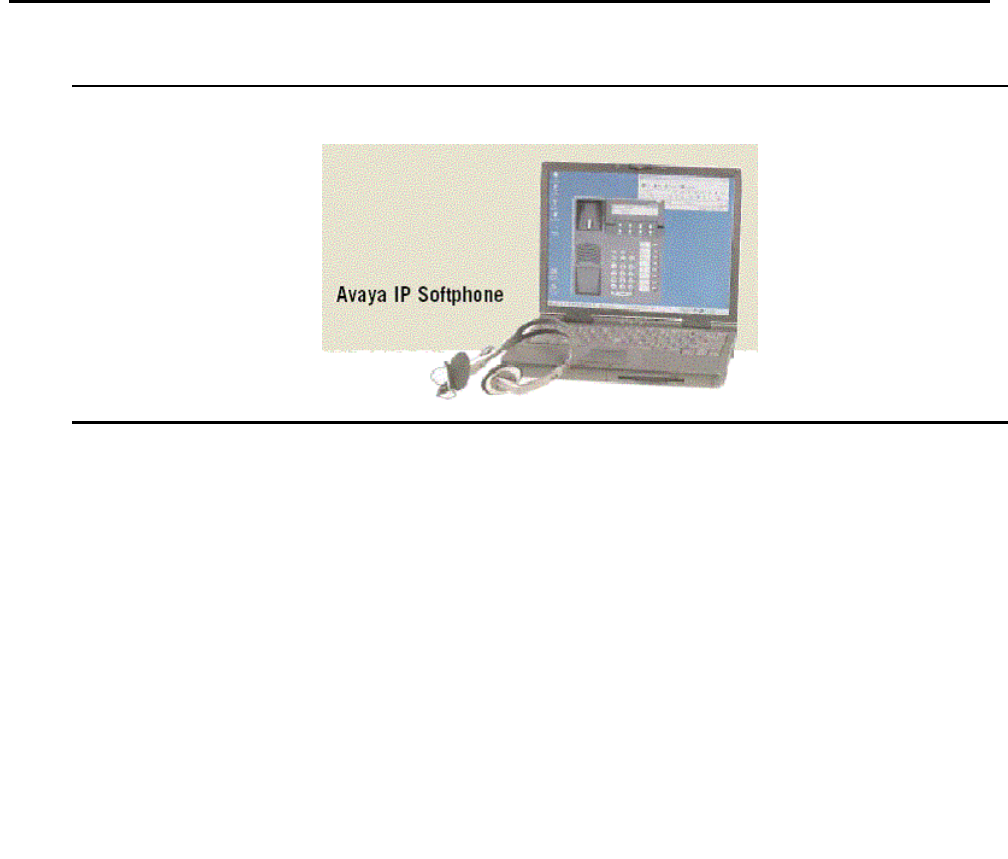
Issue 4.3 February 2006 147
Terminals
Avaya offers a wide range of communications devices to meet any company’s unique needs.
Since Avaya Communication Manager is extensible to IP, digital and analog telephones, and
wireless business solutions, the spectrum is covered, regardless of your environment. IP
Telephones and IP Softphones allow access to the features of Communication Manager from
more than one location. One of the major benefits of IP Telephones is that you can move the
telephones around on a LAN just by unplugging them and plugging them in somewhere else.
One of the main benefits of IP Softphones is that you can load them on a laptop computer, and
then use the modem on the computer to connect the Softphones to the switch from almost
anywhere.
Avaya IP Softphone
Figure 49: Avaya IP Softphone
Avaya IP Softphone is for employees who work remotely, on the road or at home. Accessed
through a simple graphical interface on the screen of a PC or laptop computer, the IP Softphone
gives mobile workers the full suite of Avaya Communication Manager features and functions,
whenever and wherever they need them.
Avaya IP Softphone R5.1 supports SIP-based Instant Messaging and presence tracking. If the
SES server is specified, all Softphone operating modes are capable of supporting instant
messaging and presence. Call control still uses H.323.
Avaya IP Softphone features include:
●Patented technology for high-quality IP Telephony
●Full access to your personalized desktop telephone
●Windows PC feature set

Terminals
148 Avaya Application Solutions IP Telephony Deployment Guide
●Microsoft Outlook integration (autodials from your Contacts list)
●Multiple call appearances
●Single or dual connect options
●Directory Access (LDAP)
Softphone operating modes
Road Warrior mode
The Road Warrior mode is used when there is only a single telephone line available to access
the IP network and Communication Manager, or when broadband Internet access is available,
for example, in homes or hotel rooms.
In Road Warrior mode the voice (audio) travels across the IP network along with call signaling
traffic for an IP Telephony configuration that uses the industry-standard H.323 protocol, and
offers a great amount of flexibility due to the widespread availability of IP networking.
Telecommuter configuration
The Telecommuter (Agent at Home) configuration is ideally suited for users who work from a
remote office and have two lines for remote access, or in situations where only low-speed
Internet connections are available. With this option, feature/access control and signaling is
maintained and delivered across the IP network (using H.323), but the voice is delivered across
a second line to either a public switched telephone network (PSTN), or digital line to help
ensure toll-quality voice. This capability can be extended to a cellular, PCS, or GSM telephone.
In the Telecommuter configuration, the Avaya communications server “binds” the two
connections as a single transaction or session.
Avaya IP Telephone mode
The Avaya IP Telephone mode enables users to log into and control their Avaya IP Telephone
from the Avaya IP Softphone. Users can speak and listen through their telephone, but unlike the
Telecommuter configuration, users can make and handle calls from both the Avaya IP
Softphone interface and the IP Telephone. This feature can help improve productivity by
integrating the IP Softphone capabilities and Personal Information Managers such as Microsoft
Outlook with the IP Telephone. The Avaya IP Telephone configuration is supported on the
Avaya 4606, 4610SW, 4612, 4620SW, 4624, 4630 IP telephones.

Avaya IP Agent
Issue 4.3 February 2006 149
Avaya Digital Telephone
The Avaya Digital Telephone mode is similar to the Avaya IP Telephone mode in that it enables
users to log into and control their Avaya Digital (or IP) Telephones from the Avaya IP Softphone.
Unlike the Avaya IP Telephone mode, the Softphone logs into the server, rather than directly
into the telephone. Users can speak and listen through their telephone, but unlike the
Telecommuter configuration, users can make and handle calls from both the Avaya IP
Softphone interface and the Digital Telephone. The Avaya Digital Telephone configuration is
supported on the Avaya 2400 and 6400 series digital telephones and the Avaya 4600 series IP
telephones.
Instant Messaging Only
In Instant Messaging Only mode, the Softphone only logs into the SES server, but not the CM
server. In this mode, the Softphone is capable of acting as an instant messaging and presence
client, but cannot make or receive telephone calls.
Avaya IP Agent
Avaya IP Agent is a Windows-based Softphone application that is specifically designed to
accommodate contact center agents who work remotely or in an office location. It runs on
Windows 98, Windows 2000, Windows XP, or Windows NT® 4.0 PCs, enabling agents to work
from their PC, anywhere, through remote connectivity to their corporate network. Agents have
access to the full range of Avaya agent capabilities using a graphical user interface with
standard drag-and-drop conventions.
●Screen pops are based on dialed number identification service (DNIS), automated number
identification (ANI), and prompted digits.
●The integrated call history feature provides agents with a detailed view of calls made and
received.
●“Road Warrior” and “Telecommuter” modes

Terminals
150 Avaya Application Solutions IP Telephony Deployment Guide
Avaya Softconsole
Avaya Softconsole™ is a software attendant console that builds on the features of the popular
Avaya 302 Attendant Console.
●Searches internal and external directories
●Displays detailed caller information on up to six calls simultaneously
●New interface
●Comprehensive setup wizards
●E-mail integration
●Enhanced directory capabilities
●Choice of two IP connections or DCP connection
●Voice over IP configuration (telecommuter)
●Dual connection (road warrior) for toll-quality audio
●DCP connection using the CallMaster VI
●Integrated iClarity for IP audio
●Directory lookup and dialing
●Integrated with directory management to support up to 100 directory databases
●Permanent and per-call notes
Avaya IP Softphone for Pocket PC
The Avaya IP Softphone for Pocket PC (Figure 50: Avaya IP Softphone for Pocket PC on
page 151) brings the full capabilities of Avaya IP Softphone to your Windows CE handheld
device, such as the Compaq iPAQ Pocket PC and gives you the full list of features and
functions of Avaya Communication Manager on your pocket PC.

Avaya IP Softphone for Pocket PC
Issue 4.3 February 2006 151
Figure 50: Avaya IP Softphone for Pocket PC
The Avaya IP Softphone for Pocket PC is a downloadable application for customers who own
an Avaya IP Softphone license. It delivers the full set of Communication Manager call features
through a graphical display of your Avaya multiline telephone, with its identical extension
number, speed dial buttons, and personal feature settings. Mobile workers can receive calls
virtually anywhere, and remote workers can connect to your enterprise with wireless local area
networks (LANs) and virtual private networks (VPNs).
The latest release of the Avaya IP Softphone for Pocket PC provides new user productivity
features and global support with multiple languages.
Features
●CTI control of IP Telephones.
Improve user productivity with Avaya IP Softphone for Pocket PC’s ability to control the
following Avaya IP Telephones:
●Globalization.
Supports multiple languages through language packs.
2420 4602 6408D+ 8405D
4606 6416D+ 8401D
4612 6424D+ 8411D
4620 8434
4624
4630
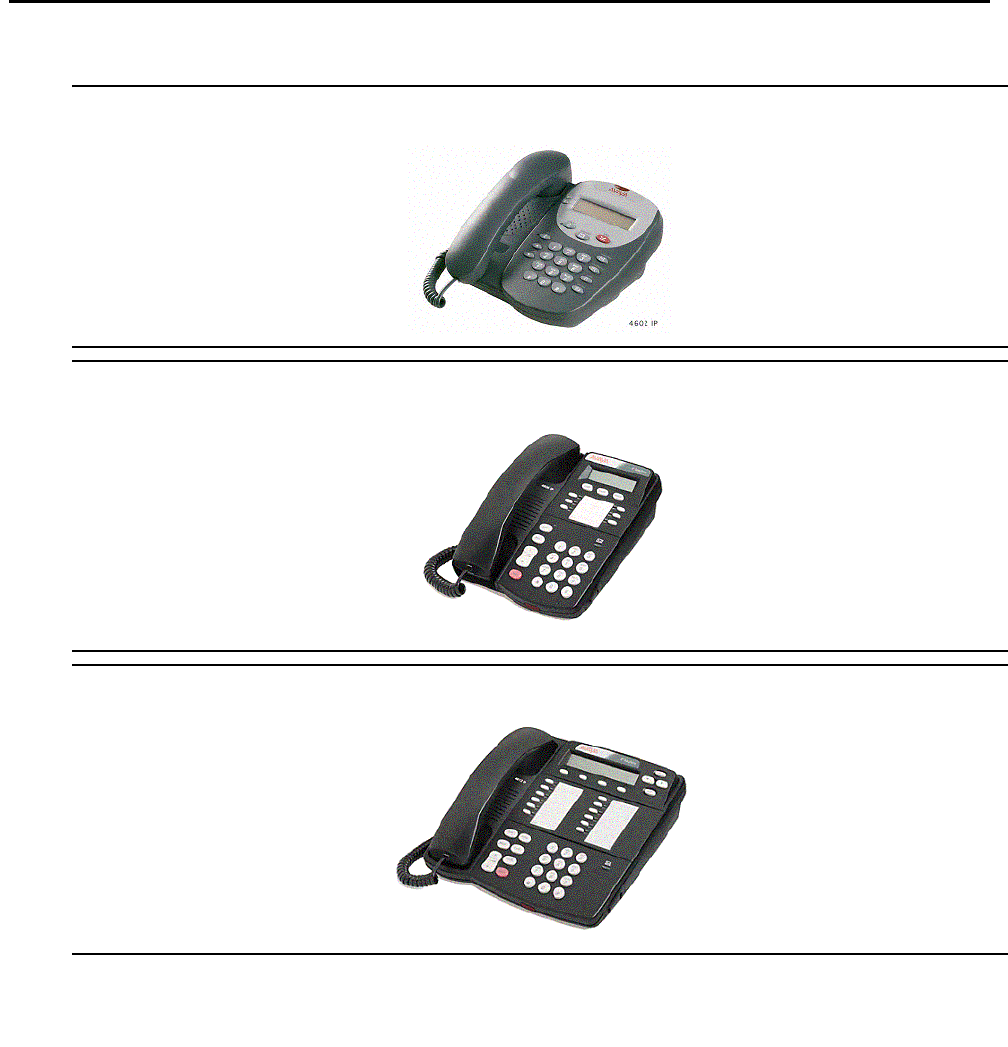
Terminals
152 Avaya Application Solutions IP Telephony Deployment Guide
●Emergency Call Handling 911.
●Ability to modify E 911 station feature settings.
●Ability to modify the look and feel of the graphical user interface with a swap skin
capability.
●Call log history.
Avaya 4600 Series IP Telephones
Figure 51: Avaya 4602 IP Telephone
Figure 52: Avaya 4606 IP Telephone
Figure 53: Avaya 4612 IP Telephone

Avaya 4600 Series IP Telephones
Issue 4.3 February 2006 153
Figure 54: Avaya 4620 IP Telephone
Figure 55: Avaya 4624 IP Telephone
Figure 56: Avaya 4630 IP Screenphone
The IP Telephone is a physical voice terminal that provides IP Telephony. Avaya IP Telephones
bring the rich features and functions of Avaya Communication Manager directly to the desktop.
They are an essential part of converged voice and data networks that are built with the Avaya
Application Solutions components. These telephones deliver an extensive set of features, high
audio quality, and have an attractive streamlined design.
The 4600 Series IP Telephone sets (or terminals) are a product platform of terminals that
support Avaya Application Solutions. The sets operate and function similar to the 6400 series
Digital Communications Protocol (DCP) terminals when connected to the Avaya servers with
Avaya Communication Manager, but provide added functions that are not possible within the
digital terminal product line.

Terminals
154 Avaya Application Solutions IP Telephony Deployment Guide
Networking coordination
The IP terminals use the Internet Protocol to communicate with the systems to which they are
attached. The protocol is H.323 with proprietary signaling added to provide access to the full
functionality that is available in the Avaya servers running Avaya Communication Manager.
IP Telephones are intended to connect to the customer’s data network. These networks
inherently contain products from many different vendors, and thus are less controlled than
circuit switched networks. Therefore a Network Assessment is recommended as outlined in
Network assessment offer.
The 4600 series voice terminals cannot be connected directly to the Public Switched Telephone
Network (PSTN). They can only be connected to an Ethernet-based IP network. Therefore,
network connection issues related to direct connection to the PSTN do not apply.
The IP Telephones provide connectivity to multiple external devices through a single Ethernet
connection. The telephones contain an integrated switch or hub to connect the user’s PC to the
network through the telephone, thus requiring only a single Ethernet connection for both
devices.
The 4600 series IP Telephones require the Avaya Application Solutions Circuit packs TN799C
or higher C-LAN board for registration to the gatekeeper and signaling stream, and the
TN2302AP (MedPro) for call setup and media stream. In the case of the G700 Media Gateway,
the VoIP Engine or VoIP Media Module provides the support for media stream.
IP Telephone installations require a Trivial File Transfer Protocol (TFTP) server on the network
for software transfer to the IP Telephones. Avaya strongly recommends DHCP servers. IP
Telephone investment protection is supported by the software download capability. Future
software releases for the telephones that offer feature enhancements or protocol changes are
possible without changing the hardware platform. Software updates are provided as required to
correct bugs, implement changes, and add new features and capabilities.
For customers who want an all switched network, the 4620 telephone contains an integrated
Layer 2 switch. In addition, the 30A Ethernet Switch Base adds fully switched capability to the
4612 and the 4624 telephones.

Avaya 4600 Series IP Telephones
Issue 4.3 February 2006 155
Features and applications
Table 11: Avaya 4600 series IP Telephone features and applications
Feature Application
Speakerphone High-quality, built-in speakerphone with echo cancellation,
directional microphone, and a tuned speaker cavity provides
the highest audio quality.
Infrared capabilities An infrared data association (IrDA) port is provided on the
front of each IP Telephone for Personal Digital Assistant
(PDA) and PC application integration (not available on 4602
sets). With the built-in IrDA port, users can communicate
with and command the telephone using a personal digital
assistant (PDA) or other infrared-equipped device.
Speed Dialing This feature allows the user to store telephone numbers that
are dialed at the touch of a feature button. Users can
program up to 120 speed-dial buttons.
Call Log Application (4620 and 4630 sets only)
This feature stores and displays information, such as
identifying the call as Outgoing, Incoming Answered, and
Incoming Unanswered. It presents information about all calls
in a given category.
●Up to 90 entries on 4620 sets
●Up to 100 entries on 4630 sets
Web Browser
Application (4620 and 4630 sets only)
This feature provides Web Access to HTML Web-based
information. The 4620 Web Access application is analogous
to the application on the 4630. However, different display
capabilities cause the 4620 telephones to have a simpler,
less capable Web interface than 4630 sets.
1 of 2

Terminals
156 Avaya Application Solutions IP Telephony Deployment Guide
Two features enhance reliability and application enablement. Reliability is enhanced using an
optional new DHCP mode which allows phones to maintain their IP addresses after DHCP
lease expiration. Application Enablement functionality is enhanced by adding phone push
technology.
Features that are
common to the 4600
Series
●G.711, G.729A/B Voice Coders.
●QoS options for UDP Port selection, Diffserv, 802.1p/
Q.
●Support for Simple Network Management Protocol
(SNMP), Version 2.
●DHCP client and Statically (Manual) Configurable IP
Addressing.
●Multiple power options, including support for power
over Ethernet LAN technology.
●10/100 Base T Ethernet connections.
●Integrated Ethernet Hub - optional connection (PC to
telephone).
●Infrared (IrDA) port.
●Built-in headset jack.
●Full-duplex speakerphone with echo cancellation.
Features that are
common to the 4600
Series (continued)
●Feature buttons for Conference, Transfer, Drop, Hold,
Redial, Mute, Speaker, Voice Mail, and so on.
●Set angle of 15o for display visibility with optional wall/
desk stand.
●Special handset supports AB styles.
●Message Waiting Indicator.
●Hearing aid compatibility.
Table 11: Avaya 4600 series IP Telephone features and applications (continued)
Feature Application
2 of 2

Avaya 4600 Series IP Telephones
Issue 4.3 February 2006 157
To enhance the reliability of IP telephones, phones now have the option of retaining their DHCP
lease in the event of a DHCP server failure. Users still have the option of strictly interpreting the
DHCP standard, in which case the IP telephone will give up its IP address after its lease expires
if the DHCP server is unavailable. In the new operational mode, the IP telephones may retain
their IP address after lease expiration while sending DHCP requests once per minute and ARP
requests for their IP address every five seconds. If another entity responds to the ARP request,
the phone immediately releases its address and reinitializes DHCP discovery.
An application enablement enhancement is "Push". Push allows audio streams, text strings,
and web pages to be "pushed" from a PC application directly to the phone. There are two
priorities: normal and barge-in. Barge-in pushes go through to the user unless the phone is in
Local Procedure mode or restoring a back-up file, while normal is more restrictive (e.g. audio
push would fail if the user were on a call). If a user is not on a call, audio pushes would take the
speaker off-hook. If a user is on a call, barge-in audio pushes would put the far end on hold.
Normal pushes are expected to be used for non-essential information (e.g. "Birthday cake in
Joe's office"), while barge-ins would be used for critical information worthy of interruption (e.g.
audio plays, "The building is closing due to snow," while the browser displays a weather report).
Avaya 4601 IP Telephone
The Avaya 4601 IP Telephone is a low-end phone designed for reception areas and other
applications where cost is the driving factor. It is similar to the 4602, however, it lacks a display.
Figure 57: Avaya 4601 IP Telephone

Terminals
158 Avaya Application Solutions IP Telephony Deployment Guide
Avaya 4602/4602SW SIP Phone
Figure 58: 4602 SIP Phone
The Avaya 4602/4602SW IP Telephone supports two call appearances and a one-way
speakerphone. Beginning with phone software version 2.1, the 4602 IP telephone can be
converted to a SIP phone by downloading SIP firmware from the file server. When operating in
SIP mode, the 4602 uses the Avaya SES proxy server as its call controller, rather than
connecting to CM. An administrative web interface on the phone allows administrators to set up
the SIP dial plan and administer features and other parameters. Similarly, a user web interface
allows end users to personalize the date format, ring type, and display name, and to access the
call log and speed dial list.
Avaya 4610SW IP telephone
The 4610SW is an Avaya IP Telephone providing a medium-screen graphic display (168x80
dots, grayscale). The Avaya 4610SW IP telephone provides advanced feature functionality with
an intuitive and innovative user interface. The Avaya 4610SW provides telephony, speed dial,
call log, and Web browsing functionality.
The Avaya 4610SW IP telephone has the following characteristics:
●User interface supports 48 speed dialing buttons, 45 call log entries, and up to three redial
buttons on display
●Supports call log
●Supports WML browser capability
●Receives and displays WML page content that is pushed from an application server
●Receives and plays streaming audio that is pushed from an application server
●Supports 12 call appearance or feature buttons with downloadable labels

Avaya 4600 Series IP Telephones
Issue 4.3 February 2006 159
Avaya 4620SW IP telephone
The 4620SW is an Avaya IP Telephone providing a large-screen graphic display (168x132 dots,
grayscale). The Avaya 4620 telephone provides telephony, speed dial, call log, and Web
browsing functionality.
The Avaya 4620SW IP telephone has the following characteristics:
●User interface supports 108 speed dialing buttons, 90 call log entries, and up to 6 redial
buttons on the display
●Supports call log
●Supports WML Browser
●“Push” support for WML page content and audio sent from an application server
● Infrared (IR) port supports IR dialing and other applications
● 24 call appearance or feature buttons with downloadable labels
Avaya 4621SW IP telephone
The Avaya 4621SW IP telephone is based on the 4620SW IP telephone hardware, but with a
backlit screen and without an IR port. The two phones have 99% of the same user interface.
The 4621 telephone provides advanced feature functionality with an intuitive and innovative
user interface. The Avaya 4621 telephone provides telephony, speed dial, call log, and Web
browsing functionality.
Avaya 4622SW IP telephone
The Avaya 4622SW IP telephone is based on the 4620SW IP telephone hardware. The 4622
telephone provides the same advanced feature functionality with an intuitive and innovative
user interface as the 4620 SW IP telephone. The 4622 telephone is designed for the call center
environment.
The changes in the 4622 are as follows:
● No handset or speakerphone microphone
●Two headset jacks
● Large screen white backlit graphic display
● No IR interface support
Avaya 4625SW IP telephone
The Avaya 4625SW IP telephone is similar to the Avaya 4620 telephone, but includes a
one-quarter VGA color backlit display, and does not support an IR interface. The Avaya 4625
telephone provides telephony, speed dial, call log, and Web browsing functionality.

Terminals
160 Avaya Application Solutions IP Telephony Deployment Guide
Avaya 4630 IP Screenphone
This full color, touch screen, Web access IP Telephone includes six telephony-related
applications, designed for ease of use with a menu-based interface. It can display a variety of
information, including Web pages specially downsized for small-format displays. Sample
applications are concierge desks at hotels, airline frequent travelers clubs, financial services
kiosks, and as an executive desktop phone.
●Multi-button capabilities supported by Avaya Communication Manager; 3 to 5 call
appearances plus 21 feature buttons
●Speed dial provides 120 speed dial “buttons” organized into groups for easier access;
names, numbers, and group names are user-programmable
●Call log lists of up to 100 incoming and outgoing calls
●Access to corporate directory information on a Lightweight Directory Access Protocol
(LDAP) server
●Web access provides “browsing” access to HTML Web-based information, including
support for downloaded Java™ applets
●Access to multimedia messaging capabilities of the Avaya DEFINITY AUDIX® or Avaya
INTUITY™ AUDIX systems using Avaya www.messenger
Communication Manager support for the 4600 IP Telephone
Series
The 4606, 4612, and 4624 IP Telephones are supported beginning with DEFINITY Enterprise
Communications Servers (ECS) Release 8.4, and Release 9. The IP Telephone sets will NOT
operate on any previous software releases but will operate with all later releases. In addition to
operating with all Communication Manager platforms, the endpoints also operate with Avaya
DEFINITY ECS G3r or G3si, DEFINITY ProLogix, as well as Avaya IP Office.
The 4630 telephone has been developed as an IP endpoint for the Avaya Media Servers using
Avaya Communication Manager and DEFINITY Servers. DEFINITY Release 10 and
Communication Manager Release 1.0 are the first releases of software to provide native
support for the 4630 Screenphone. The Screenphone will NOT operate with full functionality on
DEFINITY Release 9.5, and it will NOT work at all on any previous releases of the targeted
systems.
The Avaya 4602 and 4620 IP Telephone have been developed as IP endpoints for the Avaya
Media Servers using Avaya Communication Manager Release 1.1. These IP Telephone sets
will NOT operate on any previous releases, but will operate with all later releases. These
phones must be natively administered in Avaya Communication Manager 1.1 in order to support
the automatic button labeling and new features. Provision for labeling the buttons manually has
not been made.

Wireless
Issue 4.3 February 2006 161
Wireless
Avaya's family of wireless business systems offers mobility solutions that help your employees
stay connected and remain productive from wherever their work takes them—whether they are
in the office, moving around campus, or around the country.
Avaya Extension to Cellular
This is software that, when combined with a cellular phone, offers one-number access for
business connectivity anytime, anywhere with no missed calls. Avaya Communication Manager
enables the Avaya Extension to Cellular to transparently bridge calls from the Avaya server to
any digital cellular phone, regardless of service provider or cellular standard.
●One-number portability allows for a high level of accessibility because your office number
is bridged to your digital cell telephone.
●Simultaneous ringing keeps you and your associates in touch, so you can respond quickly
to urgent enterprise matters without delay.
●Software only solution does not require the expense of a wireless office service. It can
utilize your existing cellular telephone and service coupled with Communication Manager.
A new feature, OPTIM Cellular Voice Mail Avoidance, is designed to reduce the uncertainty as
to where unanswered calls may be sent. When CM software detects a cellular call forwarding to
coverage (when the Cellular Voice Mail is answering the call), it instead terminates the cellular
call and brings the call back to the desk phone.The call can then be treated as a normal call to
the desk set, ringing it the appropriate number of times before going to coverage.
The OPTIM (Off-PBX Telephony Integration with ACM) feature known as SCCAN (Seamless
Converged Communications Across Networks), which is the product of a collaboration between
Avaya, Motorola, and Proxim, can be thought of as an enhancement of the EC500 feature.
EC500 enables the administration of a cell phone as a Bridged Appearance of a
Communication Manager principal station. In such a configuration, every call intended for a
particular principal’s extension will ring the principal station (which is presumably in an
employee’s office) as well as the corresponding cell phone (which presumably remains in the
vicinity of the employee, regardless of his or her location) simultaneously. When one of those
two phones is answered, the attempts to place the call to the other are terminated.
In the case of EC500, use of the cell phone was limited to outside the office building, where the
cell phone could access the public cellular network, and in turn access the ACM ECS (Avaya
Communication Manager Enterprise Communication Server) via PSTN trunks. SCCAN not only
supports outdoor (off-premise) use in a manner similar to EC500, but it also supports use inside
the office building, where the cell phone is able to interface with an AP (Access Point) to a CMG
(Converged Mobility Gateway), and ultimately access ACM via a Motorola proxy and SIP
trunks. The term “seamless” in the acronym SSCAN refers to the fact that a person talking on
their SCCAN cell phone can enter or leave the office building with a seamless (imperceptible)
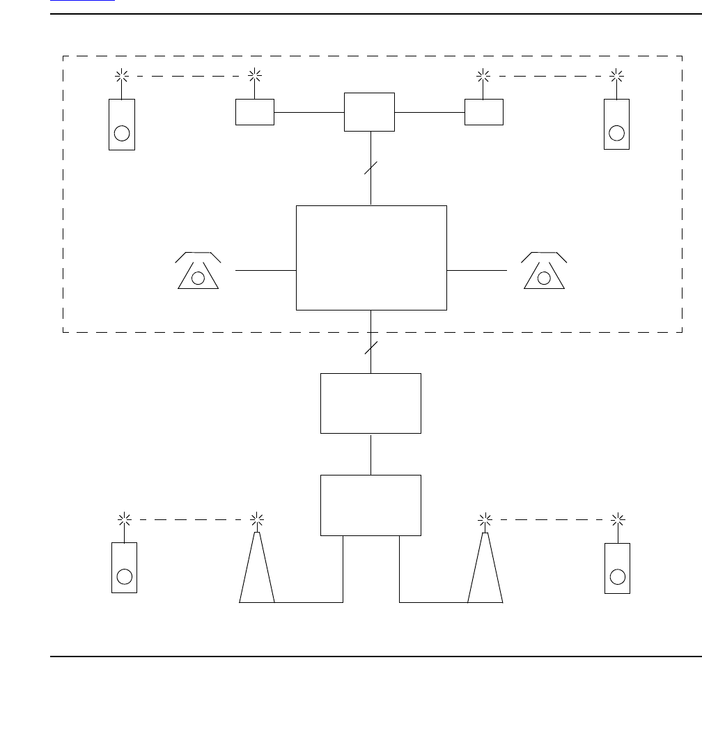
Terminals
162 Avaya Application Solutions IP Telephony Deployment Guide
transition between the two distinct (i.e. outdoor and indoor) modes of operation. Another way to
look at it is that SCCAN provides a direct link between ACM and the public cellular network,
while EC500 always accessed the public cellular network via the public switched telephone
network.
In SCCAN, the cell phone is an appearance of a principal extension, which may or may not
have an actual station (e.g. DCP, IP Telephone, etc.) associated with it. SCCAN phones
support up to the typical two call appearances when used outdoors, but they can support up to
four appearances indoors.
Figure 59 depicts the basic architecture of a SCCAN system.
Figure 59: SCCAN System
cell 1
indoors cell 2
indoors
AP AP
CMG
SIP Trunks
Avaya
Communication
Manager
Principal 1 Principal 2
Public
Telephone
Network
Public
Cellular
Network
PSTN Trunks
cell 1
outdoors cell 2
outdoors
Tower Tower

Wireless
Issue 4.3 February 2006 163
Call flows involving SCCAN endpoints will be described in a little more detail, for a variety of
different scenarios:
Intercom call between a SCCAN primary set and a non-SCCAN station: This is essentially the
same as a traditional intercom call.
Intercom call between a SCCAN cell phone indoors and a non-SCCAN station: This is
essentially the same as a SIP trunk call. Specifically, the cell phone talks to an AP (Access
Point) over a wireless connection, the AP talks to the CMG, and the CMG is connected to ACM
via SIP trunks (see Figure 59).
Intercom call between a SCCAN cell phone outdoors and a non-SCCAN station: This is
essentially the same as a PSTN trunk call. Specifically, the cell phone talks to a cellular tower
over a wireless connection, the tower, which is part of the public cellular network, talks to the
public telephone network, and the public telephone network is connected to ACM via PSTN
trunks (see Figure 59).
PSTN trunk call between a SCCAN primary set and a non-Avaya endpoint in the public domain:
This is essentially the same as a traditional PSTN trunk call.
PSTN trunk call between a SCCAN cell phone indoors and a non-Avaya endpoint in the public
domain: Such a call consists of both a SIP trunk call and a PSTN trunk call. Specifically, the cell
phone talks to an AP over a wireless connection, the AP talks to the CMG, the CMG is
connected to ACM via SIP trunks, and ACM is connected to the non-Avaya endpoint over PSTN
trunks (see Figure 59).
PSTN trunk call between a SCCAN cell phone outdoors and a non-Avaya endpoint in the public
domain: If the non-Avaya endpoint initiates the call, the talk path will go into ACM over an
inbound PSTN trunk, then back out another PSTN trunk to the public cellular network. On the
other hand, if the SCCAN cell phone initiates the call, the call path depends on whether or not
Idle Appearance Select is used to get dialtone from ACM. If the dialtone is obtained from ACM,
the talk path will go from the cell phone to the public cellular network to the public telephone
network, then over a PSTN trunk to ACM, and finally out another PSTN trunk to the called party.
If the dialtone is not obtained from ACM, the talk path will not require any ACM resources (it will
stay entirely in the public domain). The advantage of getting dialtone from ACM is that the call
can hand off if the cell phone enters the office during the call.
Intercom call between two SCCAN primary sets: This is essentially the same as a traditional
intercom call.
Intercom call between a SCCAN primary set and a SCCAN cell phone indoors: This is
essentially the same as a SIP trunk call. Specifically, the cell phone talks to an AP (Access
Point) over a wireless connection, the AP talks to the CMG, and the CMG is connected to ACM
via SIP trunks (see Figure 59).
Intercom call between a SCCAN primary set and a SCCAN cell phone outdoors: This is
essentially the same as a PSTN trunk call. Specifically, the cell phone talks to a cellular tower
over a wireless connection, the tower, which is part of the public cellular network, talks to the
public telephone network, and the public telephone network is connected to ACM via PSTN
trunks (see Figure 59).

Terminals
164 Avaya Application Solutions IP Telephony Deployment Guide
Intercom call between two SCCAN cell phones indoors: Although signaling for such a call must
traverse ACM, the bearer traffic does not. Specifically, the cell phone talks to an AP (Access
Point) over a wireless connection, and that AP is connected to another AP via SIP trunks.
Finally, the far-end AP talks to the far-end cell phone over a wireless connection. See Figure 59.
Note:
Note: Even if both cell phones utilize the same AP, SIP trunks are needed.
Intercom call between a SCCAN cell phone indoors and a SCCAN cell phone outdoors: Such a
call consists of both a SIP trunk call and a PSTN trunk call. Specifically, the cell phone talks to
an AP over a wireless connection, the AP talks to the CMG, the CMG is connected to ACM via
SIP trunks, ACM is connected to the public cellular network via PSTN trunks, and the outdoor
SCCAN cell phone talks to a tower in the public cellular network.
Intercom call between two SCCAN cell phones outdoors: The SCCAN cell phone initiating the
call will either choose to or choose not to use Idle Appearance Select to get dialtone from ACM.
If the dialtone is obtained from ACM, the talk path will go from one cell phone to the public
cellular network to the public telephone network, then over a PSTN trunk to ACM, then back out
to the public telephone network via another PSTN trunk, to the public cellular network, and
ultimately to the other cell phone. If the dialtone is not obtained from ACM, the talk path will not
require any ACM resources (it will stay entirely in the public domain). The advantage of getting
dialtone from ACM is that the call can hand off if either cell phone enters the office during the
call.
Other digital wireless systems
In addition to Extension to Cellular, Avaya also has other TDM-based digital wireless systems
available, including Avaya TransTalk 9000 Digital Wireless System and Avaya DEFINITY®
Wireless Business System.

Issue 4.3 February 2006 165
Section 2: Deploying IP Telephony

166 Avaya Application Solutions IP Telephony Deployment Guide

Introduction
Issue 4.3 February 2006 167
Traffic engineering
This chapter provides an introduction to traffic engineering. Specifically, this chapter discusses
various traffic models, algorithms, and resource sizing.
This section includes the following topics:
●Introduction
●Design inputs
-Topology
-Endpoint specifications
-Endpoint traffic usage
●Call usage rates
-Communities of interest
-Expanded COI matrices
-COIs for multiple-site networks
●Resource sizing
-Overview
-Signaling resources
-Media processing and TDM resources
-Signaling resources
-Processing occupancy
-IP bandwidth and Call Admission Control
-Physical resource placement
-Final checks and adjustments
Introduction
The process of configuring, engineering, and deploying a Communication Manager system, or a
network of Communication Manager systems, begins with specifying the quantity and the
nature of the endpoints to be accommodated. Principles of traffic engineering are then applied
to determine the quantity and the placement of the various necessary resources. Once the
designed configuration adheres to all specifications and system constraints, the process is
finished.

Traffic engineering
168 Avaya Application Solutions IP Telephony Deployment Guide
This discussion of the configuration, engineering, and deployment processes is intended as an
overview that is suitable for a fairly general audience. One example that is designed to exercise
all aspects of these processes continues throughout the chapter to present the finer points of
network design.
Design inputs
This section summarizes the essential design elements that the customer must specify.
Topology
An Avaya Communication Manager system consists of a server and all of the equipment under
that server’s control. Such equipment may be geographically dispersed among a variety of
sites, and the equipment at each site may be segregated into distinct logical collections known
as Network Regions. In cases where one server is insufficient for controlling all of the
equipment, multiple Avaya systems can be networked together. So, a Network Region is a
component of a site, which is a component of a system, which is a component of a network.
A single Avaya Communication Manager system is comprised of one or more Network Regions.
Each Network Region is a logical grouping of endpoints, including stations, trunks, and Media
Gateways. Customers can choose to establish various Network Regions on the basis of
geography, business sectors, or any of a variety of other considerations. For example, a
customer with facilities in both New York and Los Angeles might choose to use a single
Communication Manager system, with one Network Region in each of the two cities. Another
possibility is to assign two Network Regions to each city. In that case, each such geographical
grouping of Network Regions is said to comprise a site.
Alternatively, that same customer might want to administer three Network Regions, where one
region corresponds with Sales and Marketing, another with Customer Support and Services,
and a third with Research and Development. In this case, the Network Regions are established
independently of geographical considerations, because associates from each of the three
distinct business sectors may be physically located in both cities. Yet another possibility is to
construct Network Regions to correspond with IP subnets.
The various Network Regions within a Communication Manager system are interconnected by
an IP network. An IP network can consist of local area networks (LANs), wide area networks
(WANs), or a combination of both LANs and WANs. A common approach is to use a LAN at
each site, and interconnect those LANs through a WAN. Because Network Regions are used to
specify differences between the treatment of intrasite and intersite traffic, or to properly select
localized media resources for optimal voice quality, Network Regions should not span multiple
geographical locations.

Design inputs
Issue 4.3 February 2006 169
A Communication Manager system can operate as an independent entity, or can be networked
together with other Communication Manager systems. For networked systems, the various
Communication Manager systems in the network are generally interconnected by IP tie trunks.
If the two members of a given pair of Communication Manager systems in a network are not
directly interconnected by tie trunks, calls between the two systems must be tandemed through
other Communication Manager systems in the network.
When there is a need to accommodate endpoints in various geographic locations, the customer
has the choice to either set up a single Communication Manager system with a site at each
location, or use a network of multiple Communication Manager systems to span the locations.
The choice of which one is more appropriate pertains to the issue of scalability. An extremely
large number of endpoints might mandate the use of multiple systems.
While Communication Manager systems have been designed with an IP infrastructure, they
also support circuit-switched endpoints, and the full complement of traditional DEFINITY
features. However, customers usually realize a significant advantage when those customers
implement an IP-oriented solution for systems that are geographically dispersed.
Each endpoint and Media Gateway is assigned to a Network Region when its IP address is
administered. Also, each Network Region is administered with a codec preference list, which is
a list of up to five codecs that are supported by that Network Region. Uncompressed G.711 and
compressed G.729 are the most commonly used codecs in Communication Manager systems.
Each Communication Manager system is administered with the Internetwork Region
Connection Management (IRCM) matrix, which provides enough information to specify which
codecs to use when completing a call between Network Regions.
Conversely, if the IRCM does not specify a codec set between two Network Regions, calls
cannot be completed between those regions over an IP connection. For instance, the manager
of an office building can use a single Communication Manager system to service all the
individual lessees, with a separate Network Region for each company. Those Network Regions
generally would not be connected by the IRCM because independent companies would be
unwilling to share each others’ resources. Subsequent sections of this chapter further explain
sharing resources across connected Network Regions.
Multiple Communication Manager systems are often networked together by IP tie trunks,
although circuit-switched tie trunks can also be used. If the two members of a given pair of
Communication Manager systems in a network are not directly interconnected by tie trunks,
calls between the two systems must be routed through other Communication Manager systems
in the network, or through the public switched telephone network (PSTN).
Although Avaya products are IP enabled, the products must interface with circuit-switched
endpoints and systems. For example, Communication Manager systems require
circuit-switched trunks to access the PSTN because central offices today are not equipped for
IP trunking. Some customers also prefer to continue to use their circuit-switched telephones in
Communication Manager systems.
Circuit-switched endpoints interface to circuit packs that reside in media gateways or traditional
port networks (PN). Although each media gateway belongs to one particular Network Region,
no correlation exists between PNs and Network Regions. PNs are interconnected through a
circuit-switched center stage or an ATM center stage (S8700 fiber connect systems) or an IP
network (IP connect systems).

Traffic engineering
170 Avaya Application Solutions IP Telephony Deployment Guide
Endpoint specifications
Normally, a customer who submits a Request for Proposal (RFP) specifies the number of each
type of station to place in each site, in each Communication Manager system in the network.
Certain customers might want to specify station placement more precisely. For example, a
customer might specify the exact population of circuit-switched stations on a Media Gateway.
The majority of customers know exactly how many of each station type are needed at each site,
based on the population of their anticipated end-users. However, the issue of trunk sizing is not
as straightforward. Trunk traffic is tightly coupled with station traffic because at least one party in
every Communication Manager trunk call is a Communication Manager station (except in
relatively rare cases in which a Communication Manager system is used to tandem calls
between non-Communication Manager endpoints). That being the case, station traffic
effectively induces trunk traffic. The given topology of trunk groups dictates which pairs of
Communication Manager systems are directly connected by trunks, and which Communication
Manager systems are directly connected to the PSTN (or other non-Communication Manager
systems). However, the size of each trunk group must be engineered with consideration of the
amount of traffic that each such trunk group is anticipated to carry. A traffic engineer should
either specify the number of trunks in each trunk group directly, or allow the configuration
algorithm to size the trunk groups to a specified Grade of Service (GOS). This GOS is usually
P01, which is 1% blocking. In some cases, customers might choose to over-engineer or
under-engineer certain trunk groups based on non-traffic considerations, such as reliability,
cost, security, and so on.
Endpoint traffic usage
Traffic usage is typically expressed in Erlangs, which represent the average number of busy
servers in a given server group. For example, if a group of stations carries 100 Erlangs of call
usage, that means the average number of those stations that are busy at any given time is 100.
The usage of a single station, when expressed in Erlangs, represents the fraction of time that
the station is in use. So, a station that carries 0.1 Erlang of usage is in use 10% of the time.
The most common way to specify total station usage is to multiply the usage per station by the
total number of stations. A traffic engineer can either explicitly specify the per-station usage for
each group of stations, or allow the configuration algorithm to specify per-station usages
automatically, using default values. Common defaults for station traffic usage in general
business scenarios are:
●Light traffic—0.056 Erlangs per station (stations average 5.6% usage)
●Moderate traffic—0.11 Erlangs per station (stations average 11% usage)
●Heavy traffic—0.17 Erlangs per station (stations average 17% usage)
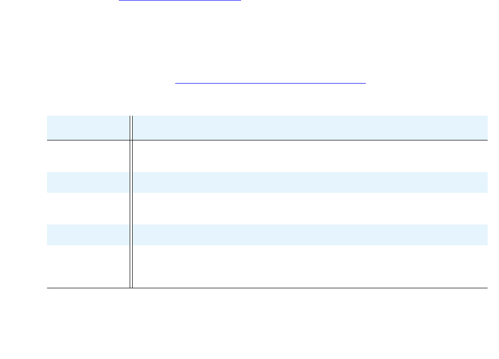
Design inputs
Issue 4.3 February 2006 171
The most commonly used default value for a general business system is 0.11 Erlangs per
station. The most common way to determine trunk usage rates is to divide the total traffic load
that is carried by each trunk group by the number of trunks in the group. It is difficult to assign a
typical default value for usage per trunk. Such usage can vary greatly from system to system,
and even from trunk group to trunk group within a particular system.
Traffic usage has two components:
●Average call duration (also known as call hold time)
●Average number of calls per hour
Systems are usually engineered to accommodate the busiest hour of a normal business day.
The number of calls that are completed during that busiest hour is denoted by Busy Hour Calls
Completed (BHCC). BHCC is not be confused with Busy Hour Calls Attempted (BHCA), which
represents the total number of calls attempted during the busiest hour, regardless of how many
of those calls are actually successfully completed. The general expression for the relationship
between BHCC, average call duration, and usage is:
A commonly used default value for average call duration in a general business system is 200
seconds per call. Example 1: Station usage shows how to calculate the station usages using the
data given.
Example 1: Station usage
Assume that an enterprise has sites in Atlanta, Boston, and Cleveland that it wants to populate
with the following endpoints (Table 12: Example 1 configuration data on page 171).
Usage (Erlangs) BHCC seconds per call×
3600
-------------------------------------------------------------
=
Table 12: Example 1 configuration data
Endpoints Atlanta Boston Cleveland
DCP
Telephones 540 180
IP Telephones 1,080 450 270
Analog
stations 108 18
Road Warriors 27
Other Two G350 Media Gateways, each of which
supports 18 analog stations, and a suitable
number of circuit-switched PSTN trunks

Traffic engineering
172 Avaya Application Solutions IP Telephony Deployment Guide
Additional design criteria
●Each site is to have a suitable number of PSTN trunks (which terminate on PNs in Atlanta
and Boston, and on the G350 Media Gateways in Cleveland).
●This is a general business application (for example, no Call Center agents), where the
average usage per station is assumed to be 0.11 Erlangs, and the average call duration is
assumed to be 200 seconds.
●Each site consists of a single Network Region, and all three Network Regions are
interconnected in the sense of the IRCM matrix.
●One-third of all calls are intercom calls (that is, calls between two stations), one-third are
inbound PSTN trunk calls, and one-third are outbound PSTN trunk calls.
Preliminary calculations
Based on the assumption of 0.11 Erlangs per station, Table 13: Example 1 station usage by
endpoint type on page 172 shows the total station usage for each station category in the
system.
Table 13: Example 1 station usage by endpoint type
Endpoints Atlanta
(Erlangs) Boston
(Erlangs) Cleveland
(Erlangs)
DCP Telephones 60 20
IP Telephones 120 50 30
Analog stations 12 2
Road Warriors 3
Analog stations administered
to G350 Media Gateways 4

Call usage rates
Issue 4.3 February 2006 173
Call usage rates
In the previous section, station usages and overall endpoint usages, including both stations and
trunks, were discussed. The overall endpoint usage is sometimes referred to as port usage rate
(PUR). The term station usage rate (SUR) applies when referring only to the stations. In
general, a traffic usage rate, when expressed in Erlangs, represents the average number of
busy servers in a given server group. So, SUR represents the average number of stations in a
particular group that are simultaneously in use, while PUR represents the average number of
endpoints, including stations and trunks, in a particular group that are simultaneously in use.
Similarly, the term call usage rate (CUR) represents the average number of simultaneous calls
that are carried by a particular facility. In an environment where essentially every call is either
inbound or outbound (such as a call center), CUR and SUR are equal, because there is exactly
one Communication Manager station used in each call. However, in an environment such as a
general business scenario in which some calls are intercom, some calls are inbound, and some
calls are outbound (such as a General Business scenario), CUR and SUR are not equal,
because some calls (the intercom calls) use two Communication Manager stations, and others
(inbound and outbound calls) use only one Communication Manager station.
The next step in the configuration process is to determine the amount of traffic flow between
Communication Manager systems in a network, and between the sites in each individual
Communication Manager system. Those traffic flows can be further refined to identify the traffic
flows between the various categories of endpoints within each site. All such traffic flows can be
represented in tabular form.
Communities of interest
The various sites within a particular Communication Manager system comprise communities of
interest (COI), in the sense that the endpoints in each particular site share some common trait
or interest, usually geographical proximity. A COI matrix offers a convenient representation of
the traffic flows between the various sites. For example, consider the COI matrix in
Table 14: 3-site standalone community of interest (COI) matrix on page 174 for a three-site,
stand-alone Communication Manager system.
In practice, a COI matrix that is associated with a given system is populated with actual traffic
values. In Table 14, each diagonal matrix entry represents intrasite call usage, and all other
entries represent intersite call usage. The call usages used to populate the table can be
determined empirically or through theoretical means. In some cases, actual call usage data can
be obtained through polling an existing system. In other cases, it might be appropriate to apply
a mathematical model to estimate the call usages.

Traffic engineering
174 Avaya Application Solutions IP Telephony Deployment Guide
One of the first steps in the process is to distinguish between intercom call usage, inbound
PSTN call usage, and outbound PSTN call usage. Inbound and outbound tie trunk usage must
also be considered when working with multiple Communication Manager systems that
networked together. However, that discussion is presented in a later section.
Although Avaya systems can be used as tandem switches for PSTN traffic, that possibility is not
considered here. Traffic between two other Avaya systems in a network is the only traffic that
can be routed through Communication Manager. So, in the case of a single stand-alone system,
there is typically no tandem traffic. Therefore, because every call involves at least one station,
one must be careful to reconcile the station usage with the call usage.
For example, suppose that the total station usage is 100 Erlangs, which could hypothetically
correspond to 20 Erlangs of intercom call usage, 30 Erlangs of inbound PSTN usage, and 30
Erlangs of outbound PSTN usage:
●Intercom station usage = 40 Erlangs (2 Avaya stations per call x 20 Erlangs of intercom
call usage)
●Inbound station usage = 30 Erlangs (1 Avaya station per call x 30 Erlangs of inbound call
usage)
●Outbound station usage = 30 Erlangs (1 Avaya station per call x 30 Erlangs of outbound
call usage)
The 40 Erlangs that are associated with intercom calls, plus the 30 Erlangs that are associated
with inbound calls, plus the 30 Erlangs that are associated with outbound calls total 100 Erlangs
of station usage.
Table 14: 3-site standalone community of interest (COI) matrix
CUR To endpoints in site __
123
From endpoints in Site ____
1Call usage generated by
Site 1 endpoints,
terminating at Site 1
endpoints
Call usage generated by
Site 1 endpoints,
terminating at Site 2
endpoints
Call usage generated by
Site 1 endpoints,
terminating at Site 3
endpoints
2Call usage generated by
Site 2 endpoints,
terminating at Site 1
endpoints
Call usage generated by
Site 2 endpoints,
terminating at Site 2
endpoints
Call usage generated by
Site 2 endpoints,
terminating at Site 3
endpoints
3Call usage generated by
Site 3 endpoints,
terminating at Site 1
endpoints
Call usage generated by
Site 3 endpoints,
terminating at Site 2
endpoints
Call usage generated by
Site 3 stations, terminating
at Site 3 endpoints

Call usage rates
Issue 4.3 February 2006 175
Alternatively, 100 Erlangs of total station usage could also hypothetically correspond to 35
Erlangs of intercom call usage, 10 Erlangs of inbound PSTN usage, and 20 Erlangs of outbound
PSTN usage. Using the procedure from the preceding example to verify this:
●Intercom station usage = 70 Erlangs (2 Avaya stations per call x 35 Erlangs of intercom
call usage)
●Inbound station usage = 10 Erlangs (1 Avaya station per call x 10 Erlangs of inbound call
usage)
●Outbound station usage = 20 Erlangs (1 Avaya station per call x 20 Erlangs of outbound
call usage)
The 70 Erlangs that are associated with intercom calls, plus the 10 Erlangs that are associated
with inbound calls, plus the 20 Erlangs that are associated with outbound calls total 100 Erlangs
of station usage.
However, suppose that once again the station usage is 100 Erlangs. Assuming that there is no
tandem traffic, this cannot correspond to 10 Erlangs of intercom call usage, 20 Erlangs of
inbound PSTN usage, and 30 Erlangs of outbound PSTN usage.
●Intercom station usage = 20 Erlangs (2 Avaya stations per call x 10 Erlangs of intercom
call usage)
●Inbound station usage = 20 Erlangs (1 Avaya station per call x 20 Erlangs of inbound call
usage)
●Outbound station usage = 30 Erlangs (1 Avaya station per call x 30 Erlangs of outbound
call usage)
The 20 Erlangs that are associated with intercom calls, plus the 20 Erlangs that are associated
with inbound calls, plus the 30 Erlangs that are associated with outbound calls total 70 Erlangs,
leaving 30 Erlangs of unaccounted station usage. This is a sign that the parsing of call traffic
into intercom, inbound, and outbound might have been done erroneously. One possible
explanation for the extra 30 Erlangs of station usage is adjunct traffic, such as stations that are
connected to voice mail, providing that 30 Erlangs of voice mail calls makes sense in the model.
The bottom line is, regardless of what model is used to parse call traffic into its various
components, one must be able to reconcile the overall station usage with the overall call usage.
Specifically, if there is no tandem traffic, the following relationship must hold:
Having established that point, several examples describe some methods for populating the COI
matrix. For the sake of continuity, all of the examples are built upon Example 1: Station usage.
SUR 2 intercom CUR×()inbound PSTN CUR outbound PSTN CUR++=

Traffic engineering
176 Avaya Application Solutions IP Telephony Deployment Guide
Example 2: Uniform Distribution model
In the case of a stand-alone Avaya system, the Uniform Distribution model works on the
assumption that when a given station places an intercom call, the call is equally likely to
terminate at any of the other stations in the entire system. Analogous statements regarding this
model can also be made for inbound trunk calls and outbound trunk calls. Specifically, any
inbound call is equally likely to terminate at any of the stations in the system, and any outbound
call is equally likely to have been originated by any of the stations in the system. The
fundamental concept underlying the Uniform Distribution model is that stations are essentially
indistinguishable from one another from a traffic engineering point of view. This model is usually
the most appropriate option when engineering a system for which little or no information about
the nature of the various stations exists. This model will now be applied to the system that is
described in Example 1: Station usage.
The design criteria for Example 1: Station usage was one-third of all calls being intercom,
one-third being inbound PSTN, and one-third being outbound PSTN. From the station usages
that are listed in Example 1: Station usage, it follows that the total station usage in Atlanta is 195
Erlangs, the total in Boston is 72 Erlangs, and the total in Cleveland is 34 Erlangs, for a
system-wide total of 301 Erlangs of station usage. Under the “one-third intercom, one-third
inbound, one-third outbound” assumption, this corresponds to a system-wide total of 75 Erlangs
of intercom call usage, 75 Erlangs of inbound call usage, and 75 Erlangs of outbound call usage
(rounding to the nearest Erlang in each case). To verify this, first consider the fact that all three
components are equal (each is 75 Erlangs) satisfies the “one-third, one-third, one-third”
requirement. Furthermore, since 75 Erlangs of intercom call usage corresponds to 150 Erlangs
of station usage, 75 Erlangs of inbound call usage corresponds to 75 Erlangs of station usage,
and 75 Erlangs of outbound call usage corresponds to 75 Erlangs of station usage, there is a
total of 150 + 75 + 75 = 300 Erlangs of station usage. This agrees with the specified 301 Erlangs
if one ignores error due to rounding off.
One could assume in this example that each PSTN trunk is capable of carrying both inbound
calls and outbound calls. Trunks are normally engineered to a desired Grade of Service (GOS),
or blocking level. A commonly used GOS for trunks is P01, which represents a nominal blocking
rate of 1 out of every 100 call attempts. To determine how many trunks are needed to attain
P01, one must know the call traffic load to be carried by those trunks. Both inbound call usage
and outbound call usage are included in that load.
Note:
Note: If IP Softphone telecommuters were used in this example, they would have also
contributed toward trunk load. Although the signaling link between a
telecommuter and the Communication Manager system to which the
telecommuter is registered is carried over IP, the media flow between the two
uses a PSTN trunk.
Example 1: Station usage indicates that the total load to be carried by the trunks is 75 + 75 =
150 Erlangs, which accounts for both inbound and outbound PSTN call usage. Use of the
standard Erlang blocking model indicates that 171 trunks (DS0s) would be required to carry the
150 Erlangs of trunk call usage at P01. However, one must consider the trunk selection process
for PSTN calls.

Call usage rates
Issue 4.3 February 2006 177
Communication Manager uses a first-site-preference algorithm for outbound trunk calls. This
algorithm specifies that all outbound calls first attempt to seize a trunk within the originating
station’s site, and tries to use a trunk in a different site if and only if it is blocked at its local
trunks. For inbound PSTN trunk calls, the CO selects the trunk. Therefore, Communication
Manager cannot use an analogous first-site-preference algorithm for inbound calls. However,
such an algorithm can be effectively imposed by assigning different calling numbers for the
three sites, which is typical in this example since the sites are in different area codes.
The goal of a first-site preference algorithm is to minimize intersite traffic. When this algorithm is
used, there is intersite traffic if and only if it overflows to a trunk on another site after having
been blocked at the trunks in its own site. Under the assumption that a first-site preference
algorithm is used in this example, the trunks at the three individual sites must be sized
independently, as opposed to all together. Initially, the overflow traffic is ignored, but that topic is
discussed later in this example.
Since overflow traffic is ignored for the time being, intersite trunk traffic is zero, which implies
that the off-diagonal entries of the inbound and outbound COI matrices will all be zero. To
determine the values of the diagonal entries, which correspond to intrasite trunk usage, the
Uniform Distribution model is applied. In particular, 65% (that is, 1755/2709) of the stations are
in Atlanta, 24% (that is, 648/2709) of the stations are in Boston, and 11% (that is, 306/2709) of
the stations are in Cleveland. Therefore, the Uniform Distribution model implies that 65% of the
75 Erlangs of inbound CUR (that is, 49 Erlangs) is assumed to terminate in Site 1 (Atlanta), 24%
(that is, 18 Erlangs) is assumed to terminate in Site 2 (Boston), and 11% (that is, 8 Erlangs) is
assumed to terminate in Site 3 (Cleveland). Similarly, 49 Erlangs of outbound CUR is assumed
to originate in Site 1, 18 Erlangs is assumed to originate in Site 2, and 8 Erlangs is assumed to
originate in Site 3.
It is instructive for this example to construct three different COI matrices rather than just one.
Specifically, it is useful to construct one for intercom CUR, one for inbound CUR, and one for
outbound CUR. The information from the previous paragraph can be used to populate the
following inbound and outbound COI matrices (Table 15: Inbound COI matrix for the Uniform
Distribution model in Example 2: Uniform Distribution model on page 177):
Table 15: Inbound COI matrix for the Uniform Distribution model in Example 2:
Uniform Distribution model
Inbound CUR To stations in Site __
1 2 3
From trunks in Site
____ 149 Erlangs 0 0
2018 Erlangs 0
30 0 8 Erlangs

Traffic engineering
178 Avaya Application Solutions IP Telephony Deployment Guide
Again, Table 15 and Table 16 are constructed without considering overflow traffic.These tables
imply that the Site 1 PSTN trunks carry 98 Erlangs (49 inbound and 49 outbound) of traffic, the
Site 2 trunks carry 36 Erlangs, and the Site 3 trunks carry 16 Erlangs. Applying the standard
Erlang loss model with a P01 GOS to each of the three sites implies that at least 116 trunks are
needed in Site 1, at least 49 trunks are needed in Site 2, and at least 26 trunks are needed in
Site 3. Note that this constitutes a total of 191 trunks, as opposed to the estimate of 171 trunks
that was obtained without sizing the three trunk groups separately. A total of 171 could be used
to attain an overall grade of service of P01, but that would induce a large amount of intersite
traffic. The use of 191 total trunks, distributed between the three sites as specified above,
ensures that at least 99% of the calls are guaranteed to be intrasite.
In some cases, there might be factors that justify over-engineering the trunk groups. For
example, a customer who is based in North America most likely leases T1 trunk facilities
between each of its sites and the appropriate COs. In this example, it might be reasonable to
use five T1 facilities (that is, 120 DS0 channels) for Atlanta, three T1 facilities (that is, 72 DS0
channels) for Boston, and two T1 facilities (that is, 48 DS0 channels) for Cleveland. This yields
an overall GOS much better than P01, and at the same time, the use of standardized equipment
reduces costs. In fact, the use of Erlang’s loss formula implies a blocking probability of 0.004 in
Atlanta, and negligible blocking probabilities (that is, several orders of magnitude better than
P01) for the other two sites. These extremely low-blocking probabilities justify the assumption
that intersite trunk traffic (overflow traffic) is negligible in this example.
Finally, the entries for the intercom COI matrix must be determined. Of the 195 Erlangs of
station usage in that site, 49 Erlangs are associated with inbound calls, and 49 Erlangs are
associated with outbound calls. That leaves 195 - 49 - 49 = 97 Erlangs of station usage in the
Atlanta site for intercom calls. Similarly, there are 72 - 18 - 18 = 36 Erlangs of station usage in
the Boston site for intercom calls, and 34 - 8 - 8 = 18 Erlangs of station usage in the Cleveland
site for intercom calls.
Table 16: Outbound COI matrix for Uniform Distribution Model in Example 2:
Uniform Distribution model
Outbound CUR To trunks in Site __
1 2 3
From stations in Site
____ 149 Erlangs 0 0
2018 Erlangs 0
30 0 8 Erlangs

Call usage rates
Issue 4.3 February 2006 179
It is assumed that half of each individual station’s usage is associated with calls that the station
generates, and the other half is associated with calls that the station receives. Therefore, half of
the 97 Erlangs of station usage (that is, 49 Erlangs) in the Atlanta site corresponds to intercom
calls originated in the Atlanta site. Similarly, half of the 36 Erlangs of station usage (that is, 18
Erlangs) in the Boston site corresponds to intercom calls originated in Boston, and half of the 18
Erlangs of station usage (that is, 9 Erlangs) in the Cleveland site corresponds to intercom calls
originated in Cleveland.
Using the percentages from earlier, the Uniform Distribution model implies that 65% of the
intercom traffic originated by each station in Atlanta is terminated in Atlanta, 24% is terminated
in Boston, and 11% is terminated in Cleveland. Applying those percentages to the 49 Erlangs of
intercom traffic that is generated in Atlanta implies that 32 Erlangs of intercom call usage is
generated in Atlanta for termination in Atlanta, 12 Erlangs of intercom call usage is generated in
Atlanta for termination in Boston, and 5 Erlangs of intercom call usage is generated in Atlanta
for termination in Cleveland. Analogous calculations can be made in relation to intercom traffic
that is generated in Boston and in Cleveland. The results are tabulated in the intercom COI
matrix that is associated with this example (Table 17: Intercom COI matrix for the Uniform
Distribution model in Example 2: Uniform Distribution model on page 179):
Table 17: Intercom COI matrix for the Uniform Distribution model in Example 2:
Uniform Distribution model
Intercom CUR To stations in Site __
(all data in Erlangs)
1 2 3
From stations in Site
____ 132 12 5
212 4 2
362 1

Traffic engineering
180 Avaya Application Solutions IP Telephony Deployment Guide
The general formulas used to populate the COI matrix entries in Table 15, Table 16, and
Table 17, respectively, for the Uniform Distribution model are:
Additional comments regarding Example 2: Uniform Distribution model
In the Uniform Distribution model introduced in Example 2: Uniform Distribution model on
page 176, the relative weights that are associated with the various sites correspond to the
distribution of stations throughout the sites. Alternatively, the weights could correspond to the
relative overall station usages in the various sites. Such a model takes into account not only the
number of stations, but also how busy the stations are. In Example 2: Uniform Distribution
model, since every station is assumed to have the same usage (specifically, 0.11 Erlangs), the
weights that are based on the number of stations per site are exactly the same as the weights
that are based on the overall station usage per site. Such a model is not always appropriate. For
example, consider a system with two sites, with 100 stations in each site. Suppose that the
average usage per station in Site 1 is 0.1 Erlangs, and that the average usage per station in Site
2 is 0.2 Erlangs. In a Uniform Distribution model where the weights are based on station usage
per endpoint, a caller in Site 1 is twice as likely to call a station in Site 2 than a station in Site 1
(because the total station usage in Site 2 is 20 Erlangs, and the total station usage in Site 1 is
only 10 Erlangs). The general formulas used to populate the COI matrix entries in Table 15,
Inbound CUR to Site i number of stations in Site i
total number of stations
------------------------------------------------------------------
⎝⎠
⎛⎞
total inbound CUR()×=
Outbound CUR from Site i number of stations in Site i
total number of stations
------------------------------------------------------------------
⎝⎠
⎛⎞
total outbound CUR()×=
Intercom CUR from Site i to Site j number of stations in Site j
total number of stations
------------------------------------------------------------------
⎝⎠
⎛⎞
total intercom CUR
originating in Site i
⎝⎠
⎛⎞
×=

Call usage rates
Issue 4.3 February 2006 181
Table 16, and Table 17, respectively, for the Uniform Distribution model based on relative SUR
are:
Example 3: Empirical approach for existing systems
Another possible means of populating the COI matrices exists for established systems. In such
cases, the necessary information can be read from traffic reports. This method is particularly
useful for customers who are considering an upgrade from their current equipment.
Expanded COI matrices
So far, all the discussion pertaining to COI matrices has focused on a macroscopic view of sites.
In particular, all the COI matrices presented have dedicated one cell for each pair of sites. In
preparation for Resource sizing on page 188, it is useful to partition each such cell into
collections of smaller cells that describe the call flows between different communities of
endpoint types within the sites.
One possible partitioning scheme for each site is to create the following three general endpoint
categories:
●IP endpoints
●Circuit-switched endpoints
●PSTN trunks
Inbound CUR to Site i total station usage in Site i
total station usage
------------------------------------------------------------------
⎝⎠
⎛⎞
total inbound CUR()×=
Outbound CUR from Site i total station usage in Site i
total station usage
------------------------------------------------------------------
⎝⎠
⎛⎞
total outbound CUR()×=
Intercom CUR from Site i to Site j total station usage in Site j
total station usage
------------------------------------------------------------------
⎝⎠
⎛⎞
total intercom CUR
originating in Site i
⎝⎠
⎛⎞
×=

Traffic engineering
182 Avaya Application Solutions IP Telephony Deployment Guide
Consider the COI matrix for a three-site, stand-alone Communication Manager system, as
presented in Table 14. A suitable expansion of that matrix might take the form of the matrix in
Table 18: Expanded COI matrix for a three-site system on page 182 in which
●I represents IP endpoints
●C represents circuit-switched endpoints
●P represents PSTN trunks
This finer categorization of endpoints permits the use of a single COI matrix for intercom,
inbound, and outbound call usage rates.
Example 4: Expanded COI matrices
In this example, we revisit Example 2: Uniform Distribution model, which pertains to the Uniform
Distribution model, in more detail. The various endpoints are grouped into the three categories
that are referenced in Table 18. The COI matrix in Table 17 lists the intercom call usage rates
between each pair of sites, including intrasite call usage. Those usage rates can be broken
down into finer components. Table 19: Endpoints in a three-site system on page 183 reviews
the various endpoints in each site.
Table 18: Expanded COI matrix for a three-site system
To endpoints in Site ___
1 2 3
I C P I C P I C P
From endpoints in Site ___
1
I
C
P
2
I
C
P
3
I
C
P

Call usage rates
Issue 4.3 February 2006 183
First consider the 32 Erlangs of intercom CUR between Site 1 stations (Table 17). Site 1
(Atlanta) has a total of 1755 stations, 1107 of which are IP stations, and 648 of which are
circuit-switched stations. So, 63% of the stations in Site 1 are IP, and 37% are circuit switched.
Therefore, 63% of Site 1 intercom calls are generated by IP stations, and 63% of those calls are
terminated by IP stations. Since 63% of 63% is 39.7%, 39.7% of Site 1 intercom calls are IP
station to IP station. Similarly, 37% of the Site 1 intercom calls that are generated by IP stations
are terminated by circuit-switched stations. Since 37% of 63% is 23.3%, 23.3% of Site 1
intercom calls are IP station to circuit-switched station.
Also, 37% of Site 1 intercom calls are generated by circuit-switched stations, and 63% of those
calls are terminated by IP stations. Since 63% of 37% is 23.3%, 23.3% of Site 1 intercom calls
are circuit-switched station to IP station. Finally, 37% of the Site 1 intercom calls that are
generated by circuit-switched stations are terminated by circuit-switched stations. Since 37% of
37% is 13.7%, 13.7% of Site 1 intercom calls are circuit-switched station to circuit-switched
station.
So, since 39.7% of Site 1 intercom calls are IP station to IP station, IP station to IP station call
usage is 39.7% of the 32 Erlangs of overall Site 1 intercom CUR, or 12.7 Erlangs. Similarly, both
the Site 1 IP station to circuit-switched station CUR and the Site 1 circuit-switched station to IP
station CUR are equal to 23.3% of 32 Erlangs, or 7.5 Erlangs. Finally, the Site 1 circuit-switched
station to circuit-switched station CUR is 13.7% of 32 Erlangs, or 4.4 Erlangs.
A similar process is used to break down the 12 Erlangs of intercom CUR into its components.
There are a total of 648 stations in Site 2 (Atlanta), 450 of which are IP stations, and 198 of
which are circuit-switched stations. So, 69% of the stations in Site 2 are IP, and 31% are
circuit-switched. We have already determined that 63% of intercom calls that are generated in
Site 1 are generated by IP stations. Similarly, 69% of intercom calls that are terminated in Site 2
are terminated by IP stations. Since 69% of 63% is 43.5%, 43.5% of Site 1 to Site 2 intercom
calls are IP station to IP station. Also, 31% of intercom calls that are terminated in Site 2 are
terminated by circuit-switched stations. Since 31% of 63% is 19.5%, 19.5% of Site 1 to Site 2
intercom calls are IP station to circuit-switched station.
Table 19: Endpoints in a three-site system
Endpoints Atlanta Boston Cleveland
IP stations 1107
(1080 IP
Telephones + 27
Road Warriors)
450
(450 IP
Telephones)
270
(270 IP
Telephones)
Circuit-switched
stations 648
(540 DCP stations
+ 108 analog
stations)
198
(180 DCP stations
+ 18 analog
stations)
36
(36 analog stations)
PSTN trunks 120 (DS0) PSTN
Trunks
(5 T1 facilities)
48 (DS0) PSTN
Trunks
(2 T1 facilities)
24 (DS0) PSTN
Trunks
(1 T1 facility)

Traffic engineering
184 Avaya Application Solutions IP Telephony Deployment Guide
In addition, 37% of intercom calls that are generated in Site 1 are generated by circuit-switched
stations, and 69% of those calls are terminated by IP stations. Since 69% of 37% is 25.5%,
25.5% of Site 1 to Site 2 intercom calls are circuit-switched station to IP station. Finally, 37% of
intercom calls that are generated in Site 1 are generated by circuit-switched stations, and 31%
of those calls are terminated by circuit-switched stations. Since 31% of 37% is 11.5%, 11.5% of
Site 1 to Site 2 intercom calls are circuit-switched station to circuit-switched station.
So, since 43.5% of Site 1 to Site 2 intercom calls are IP station to IP station, Site 1 IP station to
Site 2 IP station CUR is 43.5% of the 12 Erlangs of overall Site 1 to Site 2 intercom CUR, or 5.2
Erlangs. Similarly, the Site 1 IP station to Site 2 circuit-switched station CUR is equal to 19.5%
of 12 Erlangs, or 2.3 Erlangs, and the Site 1 circuit-switched station to Site 2 IP station CUR is
equal to 25.5% of 12 Erlangs, or 3.1 Erlangs. Finally, the Site 1 circuit-switched station to Site 2
circuit-switched station CUR is 11.5% of 12 Erlangs, or 1.4 Erlangs.
The values for the remaining COI cells that correspond to intercom traffic for this example are
calculated in a similar manner. Table 20: COI matrix for Example 4: Expanded COI matrices
(intercom CUR values only) summarizes the results of that exercise:
Table 20: COI matrix for Example 4: Expanded COI matrices (intercom CUR values
only)
To endpoints in site ___
1 2 3
I C P I C P I C P
From endpoints in site ___
1
I12.7 7.5 5.2 2.3 2.8 0.37
C7.5 4.4 3.1 1.4 1.6 0.22
P
2
I5.2 3.1 1.9 0.85 1.2 0.16
C2.3 1.4 0.85 0.37 0.54 0.07
P
3
I2.8 1.6 1.2 0.54 0.78 0.10
C0.37 0.22 0.16 0.07 0.10 0.01
P

Call usage rates
Issue 4.3 February 2006 185
The general formula that is used to determine the expanded intercom CUR entries in Table 20
is:
where:
●“Type t” refers to IP or circuit-switched
●
●
Now that the intercom CURs have been determined, CURs that involve trunks will be
addressed. First, because Communication Manager systems are rarely used to route PSTN
traffic, all of the COI matrix entries that correspond to PSTN-PSTN traffic are zero. Next,
Table 15 and Table 16 help us determine the entries that correspond to inbound and outbound
PSTN traffic.
According to Table 15, the inbound PSTN usage that arrives on Site 1 trunks and terminates at
Site 1 stations is 49 Erlangs. We have already determined that 63% of the stations in Site 1 are
IP and 37% are circuit switched. Therefore, the Uniform Distribution model implies that 63% of
the 49 Erlangs (that is, 30.9 Erlangs) is inbound to Site 1 IP stations, and 37% of the 49 Erlangs
(that is, 18.1 Erlangs) is inbound to Site 1 circuit-switched stations. Similarly, the Uniform
Distribution model and Table 16 together imply that 63% of the 49 Erlangs of Site 1 outbound
PSTN usage (that is, 30.9 Erlangs) is outbound from Site 1 IP stations through Site 1 PSTN
trunks, and 37% (that is, 18.1 Erlangs) is outbound from Site 1 circuit-switched stations through
Site 1 PSTN trunks. Note that by an assumption in Example 2: Uniform Distribution model, Site
1 inbound and outbound traffic only terminates and originates at Site 1 stations. This completes
the work for Site 1. Sites 2 and 3 are handled in a similar manner, and the resulting completed
COI matrix for Example 4: Expanded COI matrices is provided in Table 21: Completed COI
matrix for Example 4: Expanded COI matrices on page 186.
CUR generated by stations of type t in Site i
and terminated by stations of type t in Site j fi
t fj
t
×intercom CUR from Site i to Site j ()×=
fi
t number of type t stations in Site i
total number of stations in Site i
----------------------------------------------------------------------------------
=
fj
t number of type t stations in Site j
total number of stations in Site j
----------------------------------------------------------------------------------
=

Traffic engineering
186 Avaya Application Solutions IP Telephony Deployment Guide
The general formula that is used to determine the expanded inbound and outbound CUR
entries in Table 21 is:
where:
●“Type t” refers to IP or circuit-switched
●
●
Table 21: Completed COI matrix for Example 4: Expanded COI matrices
To endpoints in Site ___
1 2 3
I C P I C P I C P
From endpoints in Site ___
1
I12.7 7.5 0 5.2 2.3 0 2.8 0.37 0
C7.5 4.4 03.1 1.4 01.6 0.22 0
P30.918.100000 0 0
2
I5.2 3.1 01.9 0.85 01.2 0.16 0
C2.3 1.4 0 0.85 0.37 0 0.54 0.07 0
P00012.5 5.5 0 0 0 0
3
I2.8 1.6 0 1.2 0.54 0 0.78 0.10 0
C0.37 0.22 00.16 0.07 00.10 0.01 0
P0000007.10.940
Inbound CUR to stations of type t
in Site j over PSTN trunks in Site i fj
t inbound CUR from trunks in Site i
to stations in Site j
⎝⎠
⎛⎞
×=
Outbound CUR from stations of type t
in Site i over PSTN trunks in Site j fi
t outbound CUR from stations in Site i
to trunks in Site j
⎝⎠
⎛⎞
×=
fi
t num
b
er o
f
type t stat
i
ons
i
n
Si
te i
total number of stations in Site i
----------------------------------------------------------------------------------
=
fj
t number of type t stations in Site j
total number of stations in Site j
----------------------------------------------------------------------------------
=
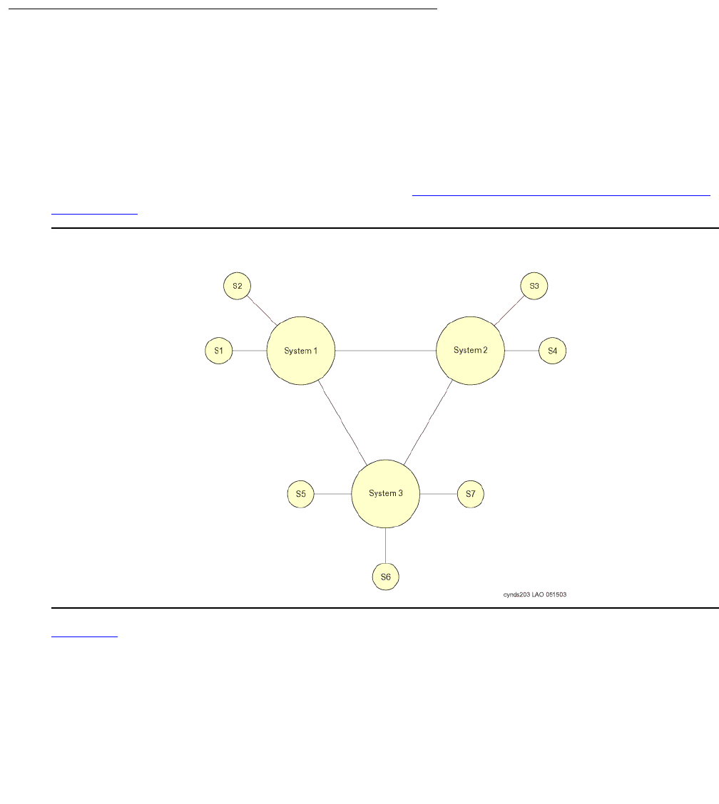
Call usage rates
Issue 4.3 February 2006 187
In general, one may choose to expand a COI matrix in any of several different possible ways,
depending upon the needs of the problem. In the preceding example, separating the endpoints
into IP, circuit-switched, and PSTN makes sense for the upcoming resource-sizing calculations,
as will be seen later in this document. In other examples, other sets of categories may be more
appropriate. Also, the number of categories per site is not limited to three.
COIs for multiple-site networks
The discussion of COIs up to this point has been limited to stand-alone Communication
Manager systems. It is also possible to network several Communication Manager systems
together. IP tie trunks serve as the most common mode of interconnectivity. However,
circuit-switched tie trunks are also supported.
To engineer a network of multiple Communication Manager systems, one must to know the
topology of sites within each of the individual systems, and the overall topology of the entire
configuration. Consider the network of systems that Figure 60: Network of Avaya systems and
system sites on page 187 shows.
Figure 60: Network of Avaya systems and system sites
Figure 60 shows three distinct Communication Manager systems, that are interconnected by IP
trunk groups. This network has a total of seven sites, which are labeled “S1” through “S7” in the
figure. Systems 1 and 2 each have two sites, and System 3 has three sites.

Traffic engineering
188 Avaya Application Solutions IP Telephony Deployment Guide
A seven-site COI matrix analogous to the three-site matrix in Table 14: 3-site standalone
community of interest (COI) matrix on page 174 can be constructed for the network shown in
Figure 60. A corresponding seven-site, expanded COI matrix, similar to the one in
Table 18: Expanded COI matrix for a three-site system on page 182, can also be constructed.
However, when multiple systems are networked together, the additional step of engineering the
tie trunk groups must be performed. To do this, the COI matrices are used to determine the
traffic flow between each pair of Avaya systems.
In the network that is shown in Figure 60, IP Trunk Group 1 carries calls between Sites 1 and 3,
Sites 1 and 4, Sites 2 and 3, and Sites 2 and 4, in addition to a presumably small amount of
overflow traffic that involves other sites. The traffic load that is associated with such calls is used
to size that trunk group. Tie trunk groups are typically sized at either P01 (1% blocking) or P03
(3% blocking). In a system such as the one in Figure 60, the traffic engineer must account for
overflow traffic. The traditional Wilkinson model is an effective tool for doing so. However, for
systems that have larger numbers of systems in the network, there can be many possible paths
between a given pair of systems. In such cases, determining the hierarchy of paths to consider
for calls between two systems is not always straightforward. The analysis involved in sizing the
tie trunk groups in topologies such as those can be quite complex.
Resource sizing
This section provides a description of the resources that have the potential to be bottlenecks,
and a discussion about how to engineer them. This is the final stage of the design process.
Overview
The primary Communication Manager resources that have the potential to be bottlenecks are:
●the TN799DP C-LAN (Control LAN) circuit packs
●the port network TDM bus pairs
●the TN2602AP IP Media Resource 320 and TN2302AP IP Media Processor circuit packs
●the TN2312BP IP server (IPSI) circuit packs
●the server’s processing capacity
●IP bandwidth.

Resource sizing
Issue 4.3 February 2006 189
Signaling resources
The TN799DP C-LAN and the TN2312BP (IPSI) circuit packs are the primary signaling traffic
bearing components residing within a port network. Both have finite internal resources such as
sockets and data-link connection identifiers (DLCIs) for assignment to and use by endpoints. In
addition, both components, being circuit packs, have firmware running on processors with finite
capacities to process signaling traffic. Therefore resource sizing the IPSI and the C-LAN
involves both tracking the sockets/DLCIs and the signaling traffic throughput.
The TN799DP C-LAN circuit pack provides the interface for a signaling channel between an IP
endpoint and a packet bus (which ultimately interfaces with the Avaya server). When an IP
endpoint, G250 MG, G350 MG, or G700 MG registers to a C-LAN circuit pack, it allocates a TCP
socket dedicated to that endpoint or gateway, for as long as it remains registered. C-LAN
sockets are also required for the support of certain adjuncts.
Each C-LAN circuit pack has a finite number of C-LAN sockets. The total number of C-LAN
circuit packs that are required to support a particular system depends on the total required
number of C-LAN sockets, which in turn depends on the total number of IP endpoints, G250/
G350/G700 MGs, and adjuncts. An individual C-LAN circuit pack can support endpoints in
different Network Regions, even those that are not administered to communicate with each
other.
Sizing the TN2312BP IPSI circuit packs is a fairly straightforward process. The number of IPSI
circuit packs that are required in the system depends on the total number of C-LAN sockets that
are required, and the number of ISDN D-channels in the system. Specifically, each IPSI circuit
pack supports up to a combined total of 2,480 C-LAN sockets and ISDN D-channels. This is a
system-wide constraint, as opposed to a site-by-site constraint. For an IP-Connect system,
each PN must house exactly one IPSI circuit pack, neglecting duplicated IPSI circuit packs for
enhanced reliability. Therefore, if the C-LAN sockets and the ISDN D-channels indicate a need
for more IPSI circuit packs than the required number of PNs to support the TDM usage, more
PNs are needed (note that placing two active IPSI circuit packs in a single PN is not permitted).
In other words, the number of PNs must be large enough to fulfill both the TDM and the IPSI
requirements.
In a system utilizing a circuit-switched center stage an IPSI circuit pack is not required in each
port network. However, there are restrictions pertaining to how many port networks can be
supported by a single IPSI circuit pack.
If the number of port networks needs to be increased to satisfy the IPSI requirements, then the
TDM and media processing engineering processes must be redone (since an increased
number of port networks implies an increase in inter-port-network traffic). This is an iterative
process.
In addition to counting sockets and DLCIs in allocating C-LANs and IPSIs, a separate,
independent traffic engineering process involves modeling the signaling message traffic through
them. The rate of message traffic depends primarily on the call traffic at the endpoints and MGs
signaling through the sockets/DLCIs. Each call generates a certain amount of messages
between the endpoints and the server. The exact number and sizes of the messages depends
on the protocols involved. Combining the messages per call with a call rate gives estimates of
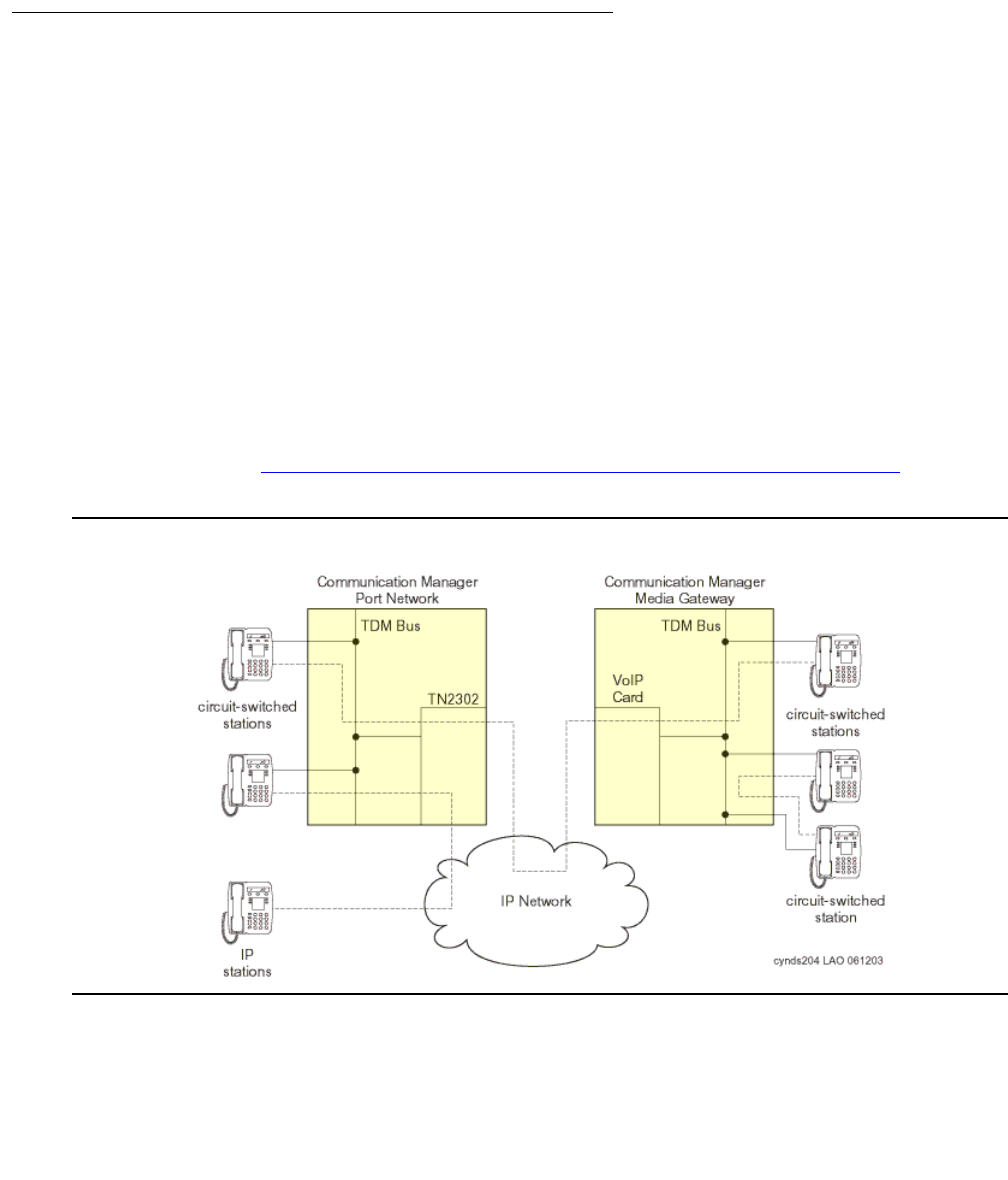
Traffic engineering
190 Avaya Application Solutions IP Telephony Deployment Guide
the message traffic through C-LANs and IPSIs. Optimal configurations allocate enough of both
to maintain traffic levels at or below known stable thresholds. Avaya configuration software tools
perform the requisite analysis and resulting resource sizing, as needed.
Media processing and TDM resources
The media processing resources on the TN2302AP IP Media Processor and/or TN2602AP IP
Media Resource 320 circuit packs on a PN or a G650 Media Gateway provide the gateway for
an audio channel between an IP endpoint and a circuit-switched TDM bus. On a G350 or G700
Media Gateway, the media processing resources reside on an on-board VoIP module. A G700
Media Gateway can accommodate an optional extra VoIP module as well. The media stream for
a call between a circuit-switched endpoint and an IP endpoint on a PN or MG traverses the PN’s
or MG’s TDM bus, a TN2302AP or TN2602AP media processing circuit pack or a VoIP module
(as applicable), and an IP network. The media stream for a call between two circuit-switched
endpoints on a single port network or Media Gateway uses that PN or Media Gateway’s TDM
bus, and does not require any media processing resources. However, the media stream for a
call between two circuit-switched endpoints that reside on different circuit-switched facilities
(that is, two different PNs, two different Media Gateways, or one PN and one Media Gateway)
traverses each circuit-switched facility’s TDM bus, a media processing resource on each
circuit-switched facility (a Media Processing circuit pack or VoIP Media Module, as applicable),
and an IP network. Figure 61: Examples of media streams between Avaya endpoints on
page 190 shows some examples of the various possible media streams.
Figure 61: Examples of media streams between Avaya endpoints

Resource sizing
Issue 4.3 February 2006 191
Although we stated that calls between two circuit-switched endpoints on different port networks
use an IP connection, the use of a circuit-switched center stage between the two PNs is also
supported. However, using circuit-switched facilities is not viable for interconnecting multiple
Media Gateways, or for interconnecting PNs and Media Gateways.
Figure 61 provides some insight into how a call between an IP endpoint and a circuit-switched
endpoint, as well as a call between two circuit-switched endpoints, utilizes media processing
and TDM resources. Calls between IP endpoints are addressed first.
Communication Manager supports three general modes of connectivity between IP endpoints:
IP-TDM-IP connectivity, hairpinning, and shuffling. Hairpinning can take one of two forms: deep
or shallow. These various modes of connectivity are described in more detail below.
IP-TDM-IP connectivity
A call that uses IP-TDM-IP connectivity between two IP endpoints requires one bidirectional
media processing “channel” for each IP endpoint involved, as well as a bidirectional TDM
resource on every PN (or Media Gateway) that is involved in the call. This option most often
applies in systems that use a circuit-switched center stage for interport network connectivity. In
such a system, IP-TDM-IP is required in order for two IP endpoints in network regions not
configured for connectivity (in the sense of the IRCM matrix) to talk to one another.
Hairpinning
Unlike the IP-TDM-IP connectivity option, hairpinning requires that all media processing
resources for a given call reside on a single TN2302AP or TN2602AP media processing circuit
pack or a single G350 or G700 Media Gateway VoIP Media Module. A hairpinned call is
originally set up as an IP-TDM-IP call, but once the set-up process is complete, no TDM
resources are required. However, resources on the Media Processing circuit pack or VoIP
Media Module are required for the duration of the call. A Media Processing circuit pack and a
VoIP Media Module each house an onboard Central Processing Unit (CPU) and Digital Signal
Processors (DSPs).
Shuffling
A shuffled call relinquishes all TDM and media processing resources after call setup. Therefore,
the media stream of a shuffled call traverses only an IP network. This is the most commonly
used mode of connectivity between two IP endpoints in the same system.
Figure 62: Connectivity modes between two IP endpoints on page 192 shows the various
modes of connectivity between two IP endpoints.
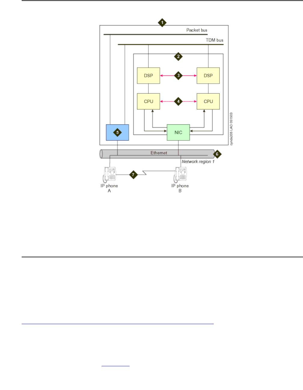
Traffic engineering
192 Avaya Application Solutions IP Telephony Deployment Guide
Figure 62: Connectivity modes between two IP endpoints
At this point, we can quantify the TDM and media processing requirements for various call
types. Throughout this discussion, calls between two IP stations are assumed to use shuffling.
That being the case, an intrasite call between two IP endpoints requires neither TDM nor media
processing resources, beyond the completion of the initial call set-up process. Each intrasite
call between an IP endpoint and a circuit-switched endpoint (including PSTN trunks) requires
one TDM resource and one media processing resource. Each of these resources is furnished
by the PN or the Media Gateway to which the circuit-switched endpoint is administered. See
Figure 61: Examples of media streams between Avaya endpoints on page 190 for an example.
The TDM and media processing resources that are required for each intrasite call between two
circuit-switched endpoints depends upon whether the call is intraport network or interport
network. Specifically, each intraport network call requires one TDM resource (on the port
network to which the two circuit-switched endpoints are administered), and no media
processing resources. See Figure 61 for an example. Also, assuming that IP interport network
Figure notes:
1. Avaya server
2. TN2302AP IP Media Processor or
TN2602AP IP Media Resource 320
(MedPro) circuit pack
3. Deep hairpinned audio connection
4. Shallow hairpinned audio connection
5. TN799DP Control LAN (C-LAN)
circuit pack
6. Customer LAN
7. Shuffled audio connection
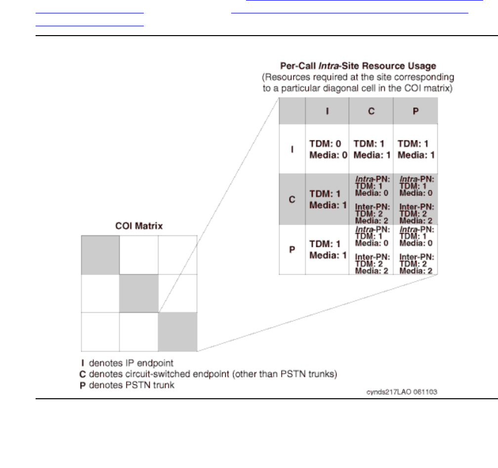
Resource sizing
Issue 4.3 February 2006 193
connectivity is being used (as opposed to a center stage), each interport network call requires
two TDM resources and two media processing resources. One of each of these resources is
supplied by each of the PNs that is involved in the call. In the preceding discussion, everything
that applies to a PN also applies to a Media Gateway.
In general, the TDM and media processing requirements for intersite calls are accounted for
somewhat differently than the requirements for intrasite calls. Throughout this discussion, we
assume that shuffling is implemented. When an IP endpoint is involved in an intersite call, it
induces no TDM or media processing usage in its own site beyond the resources that are
initially required for the call set-up process, regardless of the nature of the far-end party. On the
other hand, when a circuit-switched endpoint (including PSTN trunks) is involved in an intersite
call, one TDM resource and one media processing resource are required from the port network
or Media Gateway to which it is administered, regardless of the nature of the far-end party.
The preceding discussion is summarized in Figure 63: Intra-site TDM and Media Processing
resource requirements on page 193 and Figure 64: Inter-site TDM and Media Processing
resource requirements on page 194.
Figure 63: Intra-site TDM and Media Processing resource requirements

Traffic engineering
194 Avaya Application Solutions IP Telephony Deployment Guide
Figure 64: Inter-site TDM and Media Processing resource requirements
In Figure 64, the usages are presented on an endpoint-by-endpoint basis. For example,
according to Figure 64, an intersite call between an IP endpoint in Site 1 and a circuit-switched
endpoint in Site 2 requires no TDM or media processing resources in Site 1, but does require
one TDM resource and one media processing resource in Site 2.
The overall TDM usage and media processing usage for each site can be calculated from an
expanded COI matrix, along with the information from Figure 63 and Figure 64. To illustrate,
Example 4: Expanded COI matrices will be further expanded.
TDM: 0
Media: 0
I
P
C
COI
Matrix
Per-Call Inter-Site Resource Usage
(Resources required at both sites corresponding
to a particular off-diagonal cell in the COI matrix)
“I” denotes IP endpoint; “C” denotes circuit-switched endpoint
(other than PSTN trunks);
“P” denotes PSTN trunk
TDM: 1
Media: 1
TDM: 1
Media: 1

Resource sizing
Issue 4.3 February 2006 195
Example 5: TDM and media processing usage
Consider the COI matrix in Table 21: Completed COI matrix for Example 4: Expanded COI
matrices on page 186 in Example 4: Expanded COI matrices. A set of nine cells corresponds to
calls originated in Site 1 and terminated in Site 1 (that is, the upper left group of nine cells,
arranged in a three-by-three submatrix). The uppermost and leftmost cell of those nine cells
indicates that the IP-to-IP call usage for Site 1 intrasite calls is 12.7 Erlangs. The other four cells
of those nine cells which fall in a row or column that is labeled “I” indicate that the total call
usage between IP endpoints and circuit-switched endpoints (including PSTN trunks) within Site
1 is (7.5 + 30.9 + 7.5 + 30.9) = 76.8 Erlangs. The remaining four cells of those nine cells indicate
that the total call usage between two circuit-switched endpoints (including PSTN trunks) within
Site 1 is (4.4 + 18.1 + 18.1 + 0) = 40.6 Erlangs. Analogous numbers for intrasite usages that
correspond to the other two sites are similarly derived.
Next, consider the three-by-three submatrix that corresponds to calls from Site 1 to Site 2. The
total call usage from Site 1 to Site 2 which involves an IP endpoint in Site 1 can be determined
by adding the three cell values of those nine cells that correspond to IP endpoints in Site 1.
Specifically, the total is (5.2 + 2.3 + 0) = 7.5 Erlangs. The total call usage from Site 1 to Site 2
which involves a circuit-switched endpoint (including PSTN trunks) in Site 1 can be determined
by adding the remaining six cell values of those nine. Specifically, that total is (3.1 + 1.4 + 0 + 0
+ 0 + 0) = 4.5 Erlangs.
The total call usage from Site 1 to Site 2 which involves an IP endpoint in Site 2 can be
determined by adding the three cell values of those nine that correspond to IP endpoints in Site
2. Specifically, the total is (5.2 + 3.1 + 0) = 8.3 Erlangs. And finally, the total call usage from Site
1 to Site 2 which involves a circuit-switched endpoint (including PSTN trunks) in Site 2 can be
determined by adding the remaining six cell values of those nine. Specifically, that total is (2.3 +
1.4 + 0 + 0 + 0 + 0) = 3.7 Erlangs. Analogous numbers for the other five combinations of
intersite usages are similarly derived. The results are shown in Table 22: Re-categorization of
CURs from Table 21 on page 196.

Traffic engineering
196 Avaya Application Solutions IP Telephony Deployment Guide
Table 22 provides a summary of call usage rates, which can be mapped to a table of TDM
usage rates and media processing usage rates by using the information in Figure 63 and
Figure 64. We assume that there is only one PN in Site 1, one in Site 2, and two G350 Media
Gateways in Site 3. Under this assumption, which will be assessed shortly, all calls between
circuit-switched endpoints in Sites 1 and 2 are assumed to be intra-Port Network. A minimum of
two G350 Media Gateways is required to house the 36 analog telephones in Site 3. The results
of this exercise are shown in Table 23: TDM and Media Processing usages (Erlangs) for
Example 5: TDM and media processing usage on page 197.
Table 22: Re-categorization of CURs from Table 21
Endpoints Site 1
(Atlanta) Site 2
(Boston) Site 3
(Cleveland)
Intrasite: I, I 12.7 E 1.9 E 0.78 E
Intrasite: I, C or P 76.8 E 26.7 E 14.4 E
Intrasite: C or P, C or P 40.6 E 11.4 E 1.9 E
Calls from Site 1
to Site 2
I7.5 E 8.3 E 0
C or P 4.5 E 3.7 E 0
Calls from Site 2
to Site 1
I7.5 E 8.3 E 0
C or P 4.5 E 3.7 E 0
Calls from Site 1
to Site 3
I3.2 E 04.4 E
C or P 1.8 E 0 0.59 E
Calls from Site 3
to Site 1
I3.2 E 04.4 E
C or P 1.8 E 0 0.59 E
Calls from Site 2
to Site 3
I 0 1.4 E 1.7 E
C or P 0 0.61 E 0.23 E
Calls from Site 3
to Site 2
I 0 1.4 E 1.7 E
C or P 0 0.61 E 0.23 E

Resource sizing
Issue 4.3 February 2006 197
Table 23: TDM and Media Processing usages (Erlangs) for Example 5: TDM and
media processing usage
Endpoints Site 1
(Atlanta) Site 2
(Boston) Site 3
(Cleveland)
Intrasite: I, I TDM: 0
Media: 0 TDM: 0
Media: 0 TDM: 0
Media: 0
Intrasite: I, C or P TDM: 76.8
Media: 76.8 TDM: 26.7
Media: 26.7 TDM: 14.4
Media: 14.4
Intrasite: C or P, C or P TDM: 40.6
Media: 0 TDM: 11.4
Media: 0 TDM: 1.9
Media: 0
Calls from Site
1 to Site 2
ITDM: 0
Media: 0 TDM: 0
Media: 0 TDM: 0
Media: 0
C or
PTDM: 4.5
Media: 4.5 TDM: 3.7
Media: 3.7 TDM: 0
Media: 0
Calls from Site
2 to Site 1
ITDM: 0
Media: 0 TDM: 0
Media: 0 TDM: 0
Media: 0
C or
PTDM: 4.5
Media: 4.5 TDM: 3.7
Media: 3.7 TDM: 0
Media: 0
Calls from Site
1 to Site 3
ITDM: 0
Media: 0 TDM: 0
Media: 0 TDM: 0
Media: 0
C or
PTDM: 1.8
Media: 1.8 TDM: 0
Media: 0 TDM: 0.59
Media: 0.59
Calls from Site
3 to Site 1
ITDM: 0
Media: 0 TDM: 0
Media: 0 TDM: 0
Media: 0
C or
PTDM: 1.8
Media: 1.8 TDM: 0
Media: 0 TDM: 0.59
Media: 0.59
Calls from Site
2 to Site 3
ITDM: 0
Media: 0 TDM: 0
Media: 0 TDM: 0
Media: 0
C or
PTDM: 0
Media: 0 TDM: 0.61
Media: 0.61 TDM: 0.23
Media: 0.23
Calls from Site
3 to Site 2
ITDM: 0
Media: 0 TDM: 0
Media: 0 TDM: 0
Media: 0
C or
PTDM: 0
Media: 0 TDM: 0.61
Media: 0.61 TDM: 0.23
Media: 0.23
Totals TDM: 130.0
Media: 89.4 TDM: 46.7
Media: 35.3 TDM: 17.9
Media: 16.0

Traffic engineering
198 Avaya Application Solutions IP Telephony Deployment Guide
The TDM usage rates of 130.0 Erlangs for Site 1 and 46.7 Erlangs for Site 2 can both be easily
handled by the TDM facilities of a single PN, which is capable of carrying up to 200 Erlangs of
TDM traffic at a P001 GOS. Therefore, the assumption that all calls between two
circuit-switched endpoints is intra-Port Network is valid. If one PN was insufficient to support the
TDM usage in one of the sites, the calculations would have been repeated under the
assumption of two PNs. If a pair of PNs was still insufficient, the number would continually be
incremented until there were enough port networks to handle the TDM usage in that particular
site. Finally, the TDM resources on the two G350 Media Gateways are easily sufficient for
supporting the 17.9 Erlangs of TDM traffic in Site 3.
Note:
Note: The more PNs, the more inter-Port Network calls there are, and hence more TDM
usage, since each interport network call requires resources in each PN that is
involved in each call.
Next, the media processing resources must be considered. Since there are some fundamental
differences between the TN2302AP and the TN2602AP media processors, they will be
discussed separately, beginning with the TN2302AP.
Each TN2302AP IP Media Processor circuit pack (or Media Gateway VoIP Media Module) can
support only a finite number of simultaneous calls. However, the exact number that can be
supported varies according to the codecs of the calls to be supported. In general, compressed
calls (for example, G.729 codec) require twice as many media processing resources as
uncompressed calls (for example, G.711 codec). Also, calls utilizing AES media encryption
require approximately 25% more media processing resources than unencrypted calls.
A TN2302AP circuit pack (or a MG VoIP Media Module) can support both compressed and
uncompressed calls, as well as both encrypted and unencrypted calls, all simultaneously.
Therefore, the general model for sizing the media processing resources is very complex. The
model is a “batch arrival and service” model, and the details are beyond the scope of this
document.
In practice, a fairly common strategy is to use an uncompressed codec for intrasite calls, and a
compressed codec for intersite calls. This is due to the trade-off between bandwidth savings,
increased media processing costs, and voice quality for compressed calls. If a private LAN is
used for intrasite calls, bandwidth usage is of less concern than media processing cost and
voice quality. However, for intersite calls, especially over a public WAN, the bandwidth savings
offered by the use of compression outweighs the extra processing costs and slight degradation
of voice quality.
Recall that any usage that is expressed in Erlangs represents the average number of busy
servers at any given time. For the total media processing usages provided at the bottom of
Table 23, a “server” can be thought of as the set of media processing resources that is
necessary to support a single bidirectional media stream through a media processing circuit
pack. Consider the total of 89.4 Erlangs of media processing usage in Site 1. This usage
consists of 76.8 Erlangs of intrasite usage, and 12.6 Erlangs of intersite usage. Assume that an
uncompressed codec is used for the intrasite calls, and a compressed codec is used for the
intersite calls. Since each compressed call requires twice as many media processing resources
as each uncompressed call, the 12.6 Erlangs must be counted twice. Therefore, the media
processing load is actually 76.8 + (2 x 12.6) = 102.0 Erlangs. Similarly, the total media

Resource sizing
Issue 4.3 February 2006 199
processing loads in Sites 2 and 3 are 43.9 Erlangs and 17.6 Erlangs, respectively. Those
numbers are also based on the assumption that media encryption was not used.
Table 24: Number of TN2302AP IP Media Processors or G700 Media Gateway
VoIP Modules required for a given carried load
Carried
load
(Erlangs)
Required
number of
TN2302AP
circuit packs
Carried
load
(Erlangs)
Required
number of
TN2302AP
circuit packs
43 1 634 11
98 2695 12
155 3 756 13
213 4817 14
272 5 879 15
332 6940 16
392 7 1,001 17
452 81,063 18
512 9 1,125 19
573 10 1,187 20
Table 25: Number of G350 Media Gateway VoIP Modules required for a given
carried load
Carried
load
(Erlangs)
Required
number of
G700 MGs
Carried
load
(Erlangs)
Required
number of
G700 MGs
18 1 155 6
43 2184 7
70 3 213 8
98 4243 9
126 5 272 10

Traffic engineering
200 Avaya Application Solutions IP Telephony Deployment Guide
Table 24 implies that three TN2302AP IP Media Processor circuit packs should be used in Site
1 (Atlanta), and two should be used in Site 2 (Boston). Table 25 implies that the media
processing resources on the two G350 Media Gateways in Site 3 (Cleveland) are easily
sufficient. The required number of port networks, MGs, and media processing resources for
Example 5: TDM and media processing usage is summarized in Table 26: TDM and Media
Processing Requirements for Example 5: TDM and media processing usage on page 200.
TN2602AP IP Media Resource 320 differs from TN2302AP IP Media Processor both in capacity
and regarding the degree of sensitivity to compression and encryption. While the capacity of a
TN2302AP board is 64 simultaneous bidirectional, uncompressed, unencrypted connections, a
TN2602AP board can be administered to support either up to 80 or up to 320 simultaneous
bidirectional, uncompressed, unencrypted connections. Furthermore, while the capacity of a
TN2302AP board is decreased when compression and/or encryption is used, the capacity of a
TN2602AP board is not. Table 27 summarizes the media processing capacities of the
TN2302AP and TN2602AP circuit packs.
Table 26: TDM and Media Processing Requirements for Example 5: TDM and
media processing usage
Site TDM Requirement Media Processing Requirement
1 1 PN 3 TN2302AP boards
21 PN 2 TN2302AP boards
3 The 2 G350 MGs
are sufficient The on-board VoIP resources on
the 2 G350 MGs are sufficient
Table 27: Maximum number of simultaneous media processor connections
Connection Type
Supported by
Single
G250
Mother
board
Single
G350
Mother
board
Single G700
Motherboard
(DAF-1), or a
Single Extra
VoIP card for
G700 (MM760)
Single
TN2302AP
Board
Single
TN2602AP
with
Maximum
Licensed
Capacity of
80
Single
TN2602AP
with
Maximum
Licensed
Capacity of
320
Un-
encrypted
G.711 10 32164 64 80 320
G.729 10 16 32 32 80 320
G.723 10 16 32 32 NA NA
G.726 10 16 32 NA 80 288
1 of 2

Resource sizing
Issue 4.3 February 2006 201
Starting with release 3.1 of Communication Manager, the TN2602AP IP Media Resource 320
can be duplicated to provide critical bearer reliability for IP-connected port networks.
If more than one PN had been required in a particular site, intrasite calls between
circuit-switched endpoints in that site would have contributed toward media processing usage
because inter-Port Network calls between circuit-switched endpoints traverse an IP network.
Since only one PN is required in each site in this example, the media-processing usage for calls
between circuit-switched endpoints is zero in each site, as indicated in Table 23.
Processing occupancy
The Busy Hour Call Attempt (BHCA) rate of a system is the total number of calls that are
attempted within that system, during its busy hour. This is distinct from the Busy Hour Call
Completion (BHCC) rate of a system, which counts only those calls that have actually been
completed. The call capacity of a system refers to its BHCC rate.
In Communication Manager products, server occupancy (or processor occupancy, as
applicable) can be broken down into three categories: static occupancy, Call Processing (CP)
occupancy, and system management (SM) occupancy. The static component refers to
keep-alive processes, the CP component refers to processes that are required to set up and
tear down calls (as well as vectoring operations, in the case of call centers), and the SM
component refers to background maintenance operations and system audits. In theory, static
occupancy is a fixed overhead, and CP occupancy is directly proportional to the call rate. SM
Encrypted
G.711 10 24 48 48 80 320
G.729 10 12 24 24 80 320
G.723 10 12 24 24 NA NA
G.726 10 12 24 NA 80 288
T.38 Fax
or Modem over IP 10 8 16 16 80 320
1. 16 when transcoding G.711 to another codec.
Table 27: Maximum number of simultaneous media processor connections (continued)
Connection Type
Supported by
Single
G250
Mother
board
Single
G350
Mother
board
Single G700
Motherboard
(DAF-1), or a
Single Extra
VoIP card for
G700 (MM760)
Single
TN2302AP
Board
Single
TN2602AP
with
Maximum
Licensed
Capacity of
80
Single
TN2602AP
with
Maximum
Licensed
Capacity of
320
2 of 2

Traffic engineering
202 Avaya Application Solutions IP Telephony Deployment Guide
occupancy is allocated on an as-needed basis, such as for periodic maintenance functions.
However, if the overall server occupancy exceeds a particular threshold, SM operations are
postponed until a quieter traffic period.
Usually, the relationship between the sum of static and CP occupancy, as a function of BHCC, is
linear, with a positive y-intercept, as illustrated in Figure 65: Relationship Between Processing
Occupancy and BHCC Rate on page 202. The slope of the line corresponds to the average
processing cost per call, and the intercept corresponds to the idle (that is, no-load) occupancy.
The average processing cost per call depends on the mix of calls that is being handled by the
system, and how complex each type of call is. For general business calls, nearly all of the CP
occupancy is associated with setting up and tearing down calls. The call processing that is
required for maintaining the call once it has been established is negligible in comparison,
regardless of how long the call lasts. In a call center, the additional cost of processing vectoring
steps throughout the lifetime of a call must also be considered.
Figure 65: Relationship Between Processing Occupancy and BHCC Rate
To determine the anticipated processor occupancy that is associated with a particular
configuration, the average processing cost per call must be determined based on the
anticipated volume of each type of call, and the complexity of the various call types. This
average cost per call implies the slope of the line in relating static and CP occupancy to the
BHCC rate. The intercept of that line, which corresponds to the no-load occupancy, depends on
several factors, including which Communication Manager platform is being used, how many
endpoints are administered, and so on.
Communication Manager systems are designed to keep the sum of static and CP occupancy
below a particular threshold. This is done to allow a suitable amount of processing time for
system management functions.
So for a given configuration, the various types of calls to be supported are identified, and the
processing cost for each call type (based upon the complexity of the call) must be assessed.
That information can then be used to determine the average processing cost per call, based on
the anticipated relative frequencies of the various call types. The slope of the line relating the
sum of static and CP occupancy can then be determined from the average processing cost per
call. The intercept of that line is determined by information such as the Communication
Manager platform used, the number of endpoints administered, and so on.
Processing Occupanc
y
(CP + Static)
BHCC Rate
Idle (No-Load)
Occupancy

Resource sizing
Issue 4.3 February 2006 203
Therefore, for the given configuration, the specific linear model for the relationship between the
sum of static and CP occupancy, as a function of BHCC, has been derived. Using the
anticipated BHCC rate in that model yields the expected combined static and CP occupancy. If
that value exceeds the preset threshold, the configuration is unacceptable for the anticipated
call rate. In such a case, to support that call rate, either another platform must be considered, or
multiple platforms must be networked together.
SIP traffic engineering
Traffic engineering and resource sizing for SIP involve several unique considerations:
●Shuffling (or lack thereof between SIP and H.323 endpoints)
●SIP trunk provisioning and allocation
●SIP message traffic and its effect on message handling components
●Non-call related SIP traffic:
- Registration
- Subscription
- Instant messaging
●Special configurations:
-Bridging
- Conferencing
●SES processor occupancy
●Communication Manager processor occupancy
Direct media connect (shuffling)
SIP phones shuffle to "direct media connect" with other SIP phones, but not with H.323 IP
phones for releases up to Communication Manager 3.1 (status for later releases is pending).
On systems with mostly SIP phones and few IP phones, or vice versa, the VoIP media resource
traffic engineering is essentially similar to that of a system with only IP phones. Systems with
significant numbers of both SIP and H.323 IP phones will need additional media processing
resources to handle the added load from SIP-to-IP connections that do not shuffle.
Traffic engineering analysis starts with adding another separate type of endpoint, S (for SIP), to
the expanded COI matrix discussed previously. Media connections between endpoints S and
circuit-switched phones and trunks take up the same media processing resources as a call
between IP phones and circuit-switched points. Connections between S endpoints and IP
phones, however, take up media processing channels on both legs of a call.

Traffic engineering
204 Avaya Application Solutions IP Telephony Deployment Guide
C-LAN allocation and SIP trunks
The Communication Manager server communicates to the SES server over administered SIP
trunks, which are finite software entities similar to H.323 IP TIE trunks. Communication
Manager organizes SIP trunks into trunk groups just like other trunks of any type. Each SIP
trunk group signals through a C-LAN or PC-LAN socket as a single signaling group. A SIP trunk
group may contain up to 255 trunk members.
Each leg of a SIP call in progress takes up one SIP trunk member for the duration of the call.
Thus, a SIP-SIP call takes up two trunk members, although those trunk members
corresponding to the two SIP endpoints need not be in the same trunk group, C-LAN, or SES.
Provisioning SIP trunks is then a process similar to provisioning IP and PSTN trunks, a matter
of accounting for traffic load and application of the standard Erlang calculations outlined in
previous sections. Calls routing to (terminating at) SIP endpoints can go through any C-LANs
with SIP trunks administered to the endpoint’s home SES. But calls originated by a SIP
endpoint can only route to a specific C-LAN according to the administered routing table in the
home SES; if all trunk members on that C-LAN are in use, the SIP endpoint-originated call is
blocked. Therefore, the prudent but somewhat conservative way to allocate SIP trunks is to
treat each C-LAN as a distinct trunk resource for both SIP endpoint-originated and
endpoint-terminated calls. In other words, allocate enough trunk members on each C-LAN to
achieve the desired grade of service within each C-LAN, not treating all trunk members in all
C-LANs as a pool.
Systems that use C-LANs to provide the signaling sockets for SIP trunks require additional
traffic engineering. Each C-LAN and IPSI circuit pack has finite processing capacity, which
translates into a finite message handling throughput. Each SIP call, just like an H.323 or an
H.248 call, involves some amount of upstream (endpoint to server) and downstream (server to
endpoint) message traffic through intermediate components like C-LAN and IPSI. Therefore,
finite message throughput for IPSI and C-LAN means finite call volume signaled through those
components. Being a text based protocol, SIP signaling involves much larger messages
compared to binary protocols. Generally, each C-LAN can handle signaling for 4000 to 10,000
SIP calls per hour (a call between two SIP phones signaled through the same C-LAN counts as
two calls), depending on the complexity of the call. IPSI has 3 to 4 times the signaling
throughput capacity of C-LAN.
Combining both traffic considerations of trunk member allocation and signaling throughput,
C-LAN provisioning is thus an iterative process:
1. Allocate an initial guessed number of C-LANs.
Quick rule: 1000 to 4000 users per C-LAN, depending on assumed complexity of each SIP
call (more complex implies fewer users per C-LAN).
2. Assign SIP endpoints to C-LANs.
Can uniformly distribute or allocate according to user community, if such information exists.
3. Allocate enough trunk members to each C-LAN to achieve desired grade of service, based
on the known or assumed call traffic.
4. Check SIP message throughput based on the call traffic.

Resource sizing
Issue 4.3 February 2006 205
5. If SIP message traffic exceeds desirable threshold for any C-LAN, either add more C-LANs
or re-distribute users, if excess capacity exists in any C-LAN.
Return to Step 2. Otherwise, continue to Step 6.
6. Assign C-LANs to port networks and IPSIs.
Estimate IPSI loading; add more PN and IPSI, if necessary.
SIP specific features
SIP deals with much more than just traditional voice communication. Any traffic analysis must
incorporate considerations of the following essential SIP features:
Registration
When large numbers of endpoints start up nearly simultaneously, the system must handle the
resulting flood of registration traffic in a robust and timely manner. The requirements and issues
are similar to the case for H.323 endpoints, except that SIP deals with two servers: SES and the
Communication Manager server.
Subscription and notification
Endpoint subscriptions to events, such as presence, features, message indicator, and bridges,
can potentially generate a large signaling load from the resulting notification message traffic.
Consider that, if each SIP user has average of "S" subscriptions (other users) subscribing to its
presence, then "U" users averaging "P" presence changes (off-hook, on-hook, unavailable, etc.)
per hour generates "S x U x P" notifications per hour.
Instant messaging
The Avaya SIP SoftPhone supports instant messaging (IM) over SIP. Experience and data on
average usage patterns for IM (average session time, message size, frequency, etc.) is
currently somewhat sparse. This could be a minor part of SIP traffic, at least for near future
deployments. But judging by the proliferation and popularity of IM among the consumer public,
its future potential cannot be discounted.
These are just some of the SIP features not considered in the traditional call traffic models.
Given that SIP is a constantly evolving and expanding standard, more non-call related SIP
traffic can be expected in the future. Some traffic, such as registration and subscription/
notification, involve both the SES and Communication Manager servers, and thus affect load on
such message bearing components as C-LAN and IPSI. Others, such as IM, will only affect
SES. Therefore, a SIP traffic model must account for the various types of traffic, their respective
flow patterns, and resulting loads on components.

Traffic engineering
206 Avaya Application Solutions IP Telephony Deployment Guide
Communication Manager and SES server processor occupancy
SIP incurs Communication Manager server processing time (as discussed in a previous
section), just like any other type of Communication Manager call. Special care should go into
accounting for the SIP features present in an average call. Calls involving notifications because
of bridging or subscriptions can be significantly more CPU intensive than simple calls.
Since SES is an integral part of all SIP calls, its CPU resource requires proper accounting just
like Communication Manager servers. Additionally, SES is more than just a SIP proxy, routing a
SIP message, it is an all-in-one solution housing multiple additional servers and functions
defined in the SIP standard: presence, event, personal profile, etc. Therefore, the SES is much
more involved than the Communication Manager server in the processing of SIP messages,
especially those outside of traditional call setup and teardown. A comprehensive traffic model
for SES must account for both call and non-call related traffic load.
IP bandwidth and Call Admission Control
IP bandwidth analysis for media streams begins with determining the number of bidirectional
media streams that are associated with each type of call supported by the system. Throughout
this discussion, calls between two IP stations are assumed to use shuffling. That being the
case, Figure 62: Connectivity modes between two IP endpoints on page 192 indicates that an
intrasite call between two IP endpoints requires a single bidirectional media stream through the
LAN at that site. Figure 61: Examples of media streams between Avaya endpoints on page 190
indicates that each intrasite call between an IP endpoint and a circuit-switched endpoint
(including PSTN trunks) also requires a single bidirectional media stream through the LAN at
that site. In addition, Figure 61: Examples of media streams between Avaya endpoints on
page 190 indicates that each interport network intrasite call between two circuit-switched
endpoints (including PSTN trunks) also requires a single bidirectional media stream through the
LAN at that site (assuming that IP-Connect is used, as opposed to a circuit-switched center
stage). In fact, the only intrasite call that does not require a single bidirectional media stream
through the LAN at that site is an intraport network call between two circuit-switched endpoints
which requires no IP resources because the call is completed solely across the circuit-switched
TDM bus of the PN. Each intersite call requires exactly one bidirectional media stream through
each participating site’s LAN, as well as a single bidirectional media stream through the WAN
that connects the two sites.
The preceding discussion is summarized in Figure 66: Required number of bidirectional IP
media streams for intra-site calls on page 207 and Figure 67: Required number of bidirectional
IP media streams for inter-site calls on page 208.
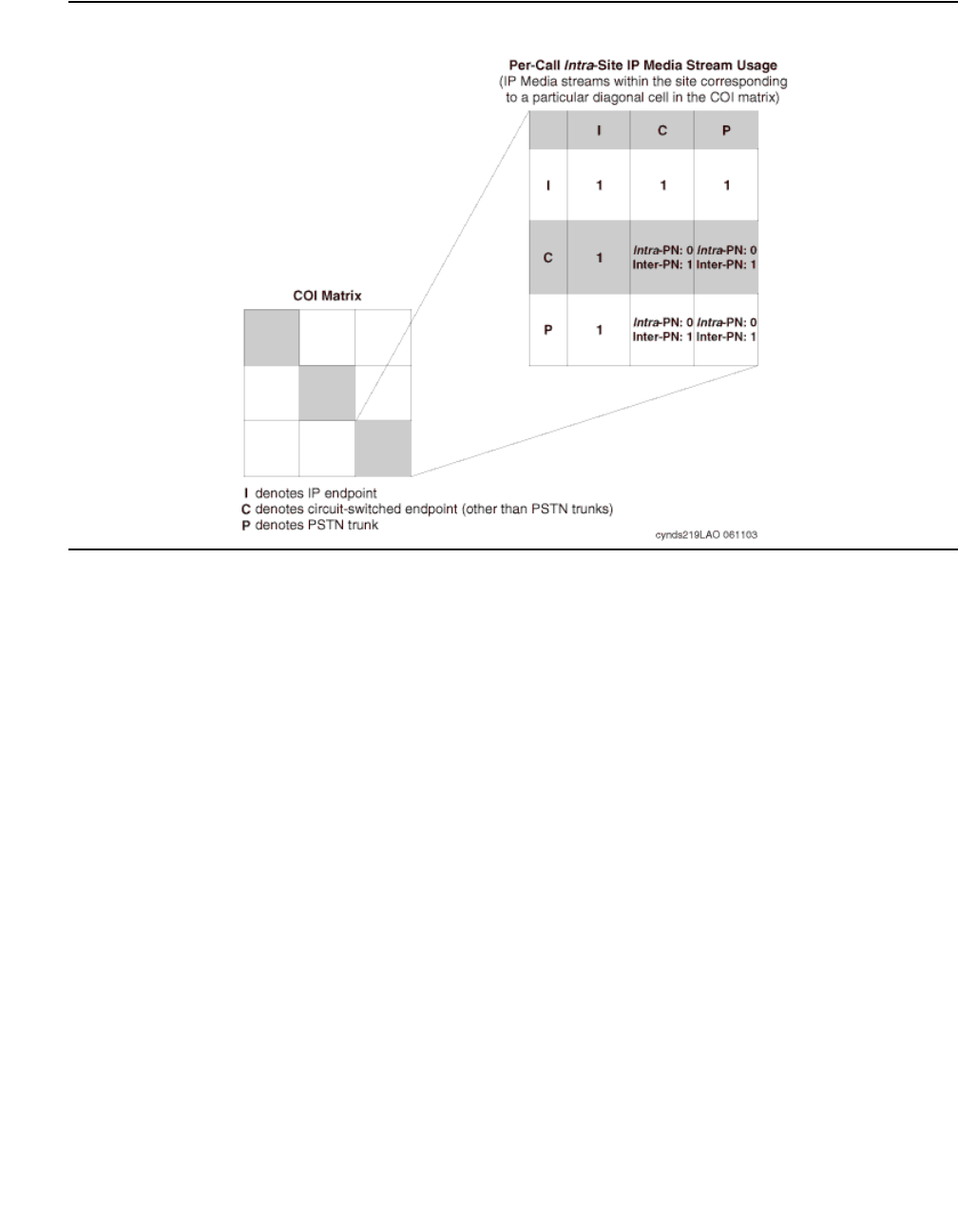
Resource sizing
Issue 4.3 February 2006 207
Figure 66: Required number of bidirectional IP media streams for intra-site calls

Traffic engineering
208 Avaya Application Solutions IP Telephony Deployment Guide
Figure 67: Required number of bidirectional IP media streams for inter-site calls
Figure 66 and Figure 67 provide information about the required number of bidirectional media
streams per call. This information can be combined with call usage information to provide IP
bandwidth usage estimates, as shown in Example 6: IP bandwidth considerations.
1
P
C
COI Matrix
Per-Call Inter-Site Resource Usage
(IP media streams within each participating site’s LAN,
as well as between the participating sites’ LANs)
“I” denotes IP endpoint; “C” denotes circuit-switched endpoint (other than PSTN trunks);
“P” denotes PSTN trunk
1
1
I

Resource sizing
Issue 4.3 February 2006 209
Example 6: IP bandwidth considerations
The information in Figure 66 and Figure 67 along with the information in Table 22 produces the
following tables of bandwidth usages that are associated with the configuration in Example 4:
Expanded COI matrices.
Table 28: IP LAN bandwidth usages (Erlangs) for Example 6: IP bandwidth
considerations
Endpoints Site 1
(Atlanta) Site 2
(Boston) Site 3
(Cleveland)
Intrasite: I, I 12.7 1.9 0.78
Intrasite: I, C or P 76.8 26.7 14.4
Intrasite: C or P, C or P 0 0 0
Calls from site 1 to site 2 12.0 12.0 0
Calls from site 2 to site 1 12.0 12.0 0
Calls from site 1 to site 3 5.0 05.0
Calls from site 3 to site 1 5.0 0 5.0
Calls from site 2 to site 3 02.0 2.0
Calls from site 3 to site 2 0 2.0 2.0
Totals 123.5 56.6 29.2
Table 29: IP WAN bandwidth usages (Erlangs) for Example 6: IP bandwidth
considerations
Endpoints WAN bandwidth
(Erlangs) between
Sites 1 and 2
WAN bandwidth
(Erlangs) between
Sites 1 and 3
WAN bandwidth
(Erlangs) between
Sites 2 and 3
Calls from site
1 to site 2 12.0 0 0
Calls from site
2 to site 1 12.0 0 0
Calls from site
1 to site 3 05.00
Calls from site
3 to site 1 05.0 0
1 of 2

Traffic engineering
210 Avaya Application Solutions IP Telephony Deployment Guide
Table 28 and Table 29 express bandwidth usages in Erlangs, because each such usage
actually represents the average number of simultaneous bidirectional media streams through
the IP network in question. To convert those usages into bandwidth requirements in units of
kilobits per second (kbps), one must know how many kbps each call requires. To answer that
question, a closer look at IP packet structure is necessary.
An IP packet consists of a payload and some amount of overhead. The payload consists of
actual sampled voice, and the overhead represents headers and trailers, which serve to
navigate the packet to its proper destination. The overhead due to IP, UDP, and RTP is 40
bytes, while the Ethernet overhead is between 18 and 22 bytes (18 is assumed in this example).
This represents a total overhead of 58 bytes (464 bits), regardless of the nature of the payload.
For this example, Layer 2 (Ethernet) overhead is included in that total. At every router boundary,
because Ethernet overhead is included in this example, our calculations are for bandwidth on a
LAN. Because WAN protocol (for example, PPP) Layer 2 headers are generally smaller than
Ethernet headers, WAN bandwidth is slightly less than LAN bandwidth.
The size of the payload depends on certain parameters that relate to the codec that is used.
The two most common codecs that are used with Avaya products are uncompressed G.711 and
compressed G.729. The transmission rates that are associated with those codecs are 64 kbps
for G.711 (this is the Nyquist sampling rate for human voice) and 8 kbps for G.729.
The packet “size” is sometimes expressed in units of time (specifically, in milliseconds). The
following formula yields the packet size, expressed in bits:
Calls from site
2 to site 3 002.0
Calls from site
3 to site 2 0 0 2.0
Totals 24.0 10.0 4.0
Table 29: IP WAN bandwidth usages (Erlangs) for Example 6: IP bandwidth
considerations (continued)
Endpoints WAN bandwidth
(Erlangs) between
Sites 1 and 2
WAN bandwidth
(Erlangs) between
Sites 1 and 3
WAN bandwidth
(Erlangs) between
Sites 2 and 3
2 of 2
Number of bits of
payload per packet
Transmission Rate
(kbps)
⎝⎠
⎛⎞
ms per Packet()×=

Resource sizing
Issue 4.3 February 2006 211
Table 30: Payload size per packet on page 211 is populated using this formula, and provides
the payload size per packet (expressed in bits) as a function of packet “size” (that is, ms per
packet) and codec.
Note that the number of bits of payload per packet depends on the packet “size,” but it is
independent of the “sizes” of the individual frames that are contained in that packet. For
example, a packet “size” of 60 ms could be referring to six 10-ms frames per packet, or three
20-ms frames per packet, or two 30-ms frames per packet, and so on. Presently, the most
commonly used packet “sizes” are 20 ms. Both G.711 and G.729 codecs typically use two
10-ms frames per packet.
As stated earlier, there is an overhead of 464 bits per packet. So, the bandwidth (expressed in
kbps) that is associated with a unidirectional media stream (assuming no Silence Suppression
is used) is augmented from 64 kbps and 8 kbps (for G.711 and G.729, respectively) to account
for this overhead. The results of this exercise are provided in Table 31: Bandwidth
requirements for media streams.
Note that the entries in Table 31 correspond with a single (unidirectional) media stream. As we
will see in the following example, the entries in Table 31 are not multiplied by the average
number of simultaneous streams, but rather by a much larger number that represents the 99.9th
percentile for the simultaneous number of streams.
Table 30: Payload size per packet
Packet
“size”
(ms)
G.711
(bits) G.729
(bits)
10 640 80
20 1280 160
30 1920 240
60 3840 480
Table 31: Bandwidth requirements for media streams
Packet “size” (ms) G.711 (kbps) G.729 (kbps)
10 110.4 54.4
20 87.2 31.2
30 79.5 23.5
60 71.7 15.7

Traffic engineering
212 Avaya Application Solutions IP Telephony Deployment Guide
Example 7: LAN bandwidth
In Example 6: IP bandwidth considerations, the total IP LAN bandwidth usage for each site was
calculated, and expressed in Erlangs at the bottom of Table 28. Specifically, the total LAN
bandwidth usage in Site 1 is 123.5 Erlangs, in Site 2 is 56.6 Erlangs, and in Site 3 is 29.2
Erlangs. This implies that the average number of bidirectional media streams that are
simultaneously in use at any given time in Site 1 is 123.5. Analogous statements can also be
made regarding Sites 2 and 3.
Every media stream across the IP LAN in any of the three sites is assumed to use the
uncompressed G.711 codec, since bandwidth is relatively inexpensive within a private LAN, as
opposed to a public WAN. Assume, for the sake of this example, a standard IP packet size of 20
ms. So for the G.711 codec, Table 31 indicates that each media stream consumes 87.2 kbps of
IP LAN bandwidth. It may be tempting at this point to simply multiply 87.2 kbps by 123.5
simultaneous bidirectional media streams, to arrive at the estimate for the overall LAN
bandwidth needed for Site 1. However, 123.5 is merely the average number of simultaneous
media streams, and approximately half of the time, there are at least 124 simultaneous media
streams in use.
In this example, suppose that the goal is to supply enough bandwidth to adequately support the
media streams at least 99.9% of the time. The standard infinite-server queueing model implies
that less than 0.1% of the time there are at least 159 simultaneous media streams in the Site 1
LAN. So, it is sufficient to engineer the LAN bandwidth to support 158 simultaneous media
streams. Therefore, the Site 1 LAN requires at least (158 simultaneous media streams) x (87.2
kbps per media stream) = 13.8 Mbps of bandwidth, in each direction. This result, along with the
analogous results for Sites 2 and 3, are provided in Table 32: IP LAN bandwidth requirements
in each direction, for Example 7: LAN bandwidth.
In Table 32, the number of simultaneous media streams for “P001” represents the 99.9th
percentile for the number of simultaneous unidirectional streams, as determined by applying the
standard infinite-server queueing model.
A slight variation of the procedure that was used to determine LAN bandwidth in Example 7:
LAN bandwidth can be used to determine WAN bandwidth. Using compressed RTP (cRTP) is a
means to conserve bandwidth. Specifically, the use of cRTP reduces the overhead due to IP,
UDP, and RTP from 40 bytes to between 2 and 4 bytes (4 bytes are assumed for this example).
Using the PPP overhead of 7 bytes (which would vary if ATM, HDLC, or Frame Relay were
used) implies a total overhead of 11 bytes (88 bits) in this example. This implies the following
Table 32: IP LAN bandwidth requirements in each direction, for Example 7: LAN
bandwidth
Resource Site 1
(Atlanta)
Site 2
(Boston)
Site 3
(Cleveland)
Simultaneous media streams for
“P001” 158 81 47
LAN bandwidth (Mbps) 13.8 7.1 4.1

Resource sizing
Issue 4.3 February 2006 213
table of WAN bandwidths, Table 33: IP WAN bandwidth requirements for media streams on
page 213, which assumes the use of cRTP:
This table can be used in the WAN bandwidth calculation for the system in Example 6: IP
bandwidth considerations.
Example 8: WAN bandwidth
In Example 6: IP bandwidth considerations, the total IP WAN bandwidth usage between each
pair of sites was calculated, and expressed in Erlangs at the bottom of Table 29. Specifically, the
total WAN bandwidth usage between Sites 1 and 2 is 24.0 Erlangs, between Sites 1 and 3 is
10.0 Erlangs, and between Sites 2 and 3 is 4.0 Erlangs. This implies that the average number of
media streams simultaneously in use at any given time between Sites 1 and 2 is 24. Analogous
statements can also be made regarding WAN traffic between each of the other two pairs of
sites.
Every media stream across the IP WAN, between any pair of sites, is assumed to use the
compressed G.729 codec, since bandwidth is relatively inexpensive within a private LAN, as
opposed to a public WAN. Assume, for the sake of this example, a standard IP packet size of 20
ms. For the G.729 codec, Table 33 indicates that each (unidirectional) media stream consumes
12.4 kbps of IP WAN bandwidth. Similar to the case in Example 7: LAN bandwidth, 24 is the
average number of simultaneous bidirectional media streams. As in Example 7: LAN bandwidth,
the bandwidth is sized to a “GOS” of P001 (“GOS” in this context is actually a pseudo-GOS; true
GOS is associated with a fixed number of channels, as is typical of circuit-switched systems).
The standard infinite-server queueing model implies that less than 0.1% of the time there is at
least 40 simultaneous media streams between Sites 1 and 2. So, it is sufficient to engineer the
WAN bandwidth between those two sites to support 39 simultaneous media streams. Therefore,
the WAN between Sites 1 and 2 requires at least (39 simultaneous media streams) x (12.4 kbps
per media stream) = 484 kbps of bandwidth. This result, along with the analogous results for the
WAN traffic between the other two pairs of sites, are provided in Table 34: IP WAN bandwidth
requirements in each direction, for Example 8: WAN bandwidth on page 214.
Table 33: IP WAN bandwidth requirements for media streams
Packet “size”
(ms) G.711 (kbps) G.729 (kbps)
10 72.8 16.8
20 68.4 12.4
30 66.9 10.9
60 65.5 9.5

Traffic engineering
214 Avaya Application Solutions IP Telephony Deployment Guide
In Table 34, the number of simultaneous media streams for “P001” represents the 99.9th
percentile for the number of simultaneous streams, as determined by applying the standard
infinite-server queueing model.
To this point, all the discussion regarding bandwidth relates only to bearer traffic (media
streams). Network packet traffic that is related to signaling is very different from the bearer
traffic because it tends to occur in bursts. For example, while the bearer traffic that is associated
with a particular call tends to involve a constant, steady stream of packets throughout the
duration of that call, the signaling traffic for that same call tends to occur in bursts during call
setup and teardown.
The bandwidth that is required for signaling is generally negligible in comparison to the
bandwidth that is required for bearer traffic. However, since Avaya products use Separation of
Bearer and Signaling (SBS), the bearer traffic and signaling traffic use distinct paths. Therefore,
signaling bandwidth must be given its due consideration, despite the fact that it is negligible in
comparison to bearer bandwidth.
Signaling traffic is more prone to bursts than bearer traffic because the former consists of
messages that are associated with call set-ups and tear-downs, as opposed to traffic that is
uniformly distributed throughout entire call durations. However, the “burst” effect is somewhat
assuaged for larger call volumes. Although the precise bandwidth requirement for a given
configuration depends on the nature of the endpoints involved, a reasonable approach is to
allocate an overhead of 50 bits per second (bps) for each IP endpoint in the network, as well as
the following (as applicable) for every 1000 calls:
●11 kbps for messaging between the S8700-series Media Server and an IPSI circuit pack
on a G650 Media Gateway
●8 kbps for the H.248 link between a C-LAN circuit pack and a G700 or G350 Media
Gateway
Note:
Note: The 11 kbps and 8 kbps associated with 1000 calls should not be amortized to
produce estimates for systems with very light traffic. For example, 11 bits per
second and 8 bits per second will not support an individual call.
Table 34: IP WAN bandwidth requirements in each direction, for Example 8: WAN
bandwidth
Requirement Between
sites 1 and 2
Between
sites 1 and 3
Between
sites 2 and 3
Simultaneous media streams for “P001” 39 20 10
LAN bandwidth (kbps) 484 248 124

Resource sizing
Issue 4.3 February 2006 215
Physical resource placement
As a default, resources should be balanced as uniformly as possible. For example, if 11 Media
Processors are required in a Network Region that has three PNs, two of the PNs should house
four Media Processors each, and the other PN should house the final three Media Processors.
This applies to signaling components C-LANs and IPSIs, also. The MGs usually generate much
more signaling traffic than IP endpoints, even though they each take up one only socket on the
C-LAN and one DLCI on the IPSI. Therefore it is advisable to practice even distribution for both
MGs and IP endpoints among available C-LANs, IPSIs, and the port networks they reside in.
Advanced users should be able to manually override the resource-placement defaults. For
example, there might be reasons beyond traffic engineering for specifying an unbalanced
system or an over-engineered resource pool, such as reliability, cost, security, physical
constraints, and so on.
Final checks and adjustments
The final step in the design process is to verify that the final configuration proposal meets the
following criteria:
●All endpoints and media gateways have been assigned to various Network Regions, sites,
and/or Communication Manager systems, according to customer specifications.
●The placement of resources adheres to the physical capacities of the proposed platform.
●The number of PNs and/or Media Gateways is sufficient to handle the TDM traffic, the
required number of IPSI circuit packs, and the required number of port circuit packs.
●The number of C-LAN circuit packs is sufficient to support the desired number of IP
endpoints, Media Gateways, and certain adjuncts.
●The number of media processing circuit packs is sufficient to handle both calls involving IP
endpoints, and interport network calls between circuit-switched endpoints, unless a
circuit-switched center stage is used instead of IP-Connect.
●The anticipated call volume can be handled by the server.
●There is sufficient bandwidth in all IP networks to support the anticipated media traffic.

Traffic engineering
216 Avaya Application Solutions IP Telephony Deployment Guide

Issue 4.3 February 2006 217
Security
This chapter discusses the security design and features for Avaya Communication Manager,
and how to operate Avaya systems securely.
Note:
Note: Because this information is valuable both to those who want to protect the system
and to those who seek to “hack” into those systems, the information in this
section is deliberately incomplete. For example, we discuss the use of one-time
passwords for user authentication, but not the mechanism of how this feature
works.
Earlier systems did not interface with the data network and were neither susceptible to the types
of attacks that are prevalent on those networks, nor provided a gateway into such networks
from which an attack might be launched. With the convergence of voice (IP Telephony) and
data over corporate enterprise networks, this is no longer true.
The main topics included in this chapter are:
●Your security policy
●Avaya Communication Manager and Media Servers
●IP Telephony circuit pack security
●Toll fraud
Your security policy
System security does not begin with the system itself, but with the people and the organizations
that operate or use the system. One of the most important tools for securing a system is to have
a written, published, and enforceable security policy. Your security policy should clearly address
these questions:
●What are you trying to protect?
●What are you protecting it from?
●How likely is a threat against these assets?

Security
218 Avaya Application Solutions IP Telephony Deployment Guide
What are you trying to protect?
The security policy usually attempts to protect information, whether the information is in the
form of data (files) or conversations (digitized voice packets). Customers should assess the
value of those assets that require protection, and compare the true costs of security to the value
of those assets.
What are you protecting it from?
Most often, criminals, who are also called “hackers,” pose a significant threat to secure
information. However, do not forget to look internally. A significant number of attacks come from
within an enterprise. Your security policy should include rules about behavior, the
consequences of bad behavior, a path of escalation, and a person to contact with regard to
security issues.
How likely is a threat against these assets?
Security is always a trade-off. The more security, the more inconvenience and the more cost.
To avoid the necessary inconvenience, some users are likely to subvert the security policy. For
example, if you make passwords so complex so that the passwords are difficult to remember,
people will write the passwords down. Users prefer easy access without security. Having to log
on is inconvenient. However, everyone must endure some level of inconvenience if the system
is going to be secure against attacks. The security policy must define this level of inconvenience
to ensure that the security polity is not circumvented. In addition, management must support the
policy, and establish clear rules for its enforcement, including the consequences for violating it.
A security policy that does not establish consequences for violations quickly becomes
irrelevant.
Recommendations for your security policy
Avaya recommends that you continuously review your security policy, and keep up with new
threats and to make improvements each time a weakness is found. To effectively support your
security policy, your company must allocate long-term resources to the development,
implementation, and reassessment of the policy.

Avaya Communication Manager and Media Servers
Issue 4.3 February 2006 219
Avaya Communication
Manager and Media Servers
This section discusses Avaya’s security designs:
●Built-in Linux security features
●One-time passwords
●Shell access
●Root access
●Remote access
●Secure access
●Monitoring and alarming
●Data encryption
Built-in Linux security features
Proprietary vs. open operating systems
Open operating systems such as Linux or a version of Microsoft Windows are often thought to
be less secure environments compared to proprietary systems. To some extent this is true, but
it is important to understand why Oryx-Pecos, Avaya’s proprietary operating system for its
legacy products, is more secure than an open operating system because it does not support the
types of network connections that converged voice and data network configurations demand.
So why not enhance Oryx-Pecos? Aside from the economic reasons, there is a security
paradox: to make an operating system secure, reveal its inner most secrets. When the
operating system software is publicly available and implemented in varying environments for a
wide range of applications, there are many more eyes looking for security holes. The expertise
of the entire technical community is brought to bear on the problem. Of the major operating
systems (Unix, Linux, Windows), one is not inherently more secure than another. Each has
inherent security flaws. All can be made secure through the application of a good security
policy, which includes proper administration and configuration, and diligent application of
vendor updates when security problems are discovered.
The Linux environment has a security advantage because
●Problems can be identified both by testing (hacking) and by reviewing the source code
itself.
●Security “holes” tend to be fixed more quickly compared to proprietary operating systems.

Security
220 Avaya Application Solutions IP Telephony Deployment Guide
Avaya capitalizes on Linux’ security advantage
The Avaya media servers run under the Linux operating system that has two important security
features:
●Built-in protection against certain types of Denial of Service (DOS) attack, such as SYN
floods, ping floods, malformed packets, oversized packets, sequence number spoofing,
ping/finger of death, etc. Attacks are recognized at the lower levels of the software and
their effect is blunted. (It is not possible for a target system to always provide service
during a DOS attack. Rather, the protection is to automatically resume service as soon as
the attack is removed.)
●The Linux kernel is compiled with a set of options to precisely tailor its operation to
maximize security consistent with required operation of the system. These include a
number of built-in firewall and filtering options. All file and directory permissions are set to
minimize access as much as possible consistent with proper system operation. The disk
drives of the S8700-series, S8500, and the S8300 Media Servers contain multiple
partitions, each of which is restricted according to the type of data that it contains. All
unneeded services are disabled either permanently or through administration for those
services. Disabled services and capabilities include NFS, SMB, X-windows, rcp, rlogin,
and rexec. The system administrator has additional control of which services are visible
from the multiple Ethernet interfaces that are connected to the enterprise LAN. Other
Ethernet interfaces are permanently configured to restrict services.
One-time passwords
Standard login accounts use static passwords that can be used multiple times to log in to a
system. Anyone who can monitor the login messages can also capture passwords, and use the
passwords to gain access. You can administer the Avaya media servers for one-time
passwords that have a fixed-user name but not a fixed password. In this case, users must
supply a unique, one-time password for each session, and even if the password is
compromised, it cannot be reused. When a system is covered by an Avaya service contract, all
logins that are accessed by Avaya Services technicians are protected by one-time passwords.
Shell access
Access to a “shell” from which arbitrary commands can be executed is not granted by default to
a login on an Avaya media server. When a login is created, the system administrator can
specify whether or not the account is permitted to have shell access. Accounts that are denied
shell access can either log in to an Avaya Communication Manager administration screen or a
Web page upon successful login. In both cases, the operations that these logins can perform
are restricted. Generally, only people who perform hardware maintenance or software
maintenance on the server need shell access permissions administered in their login accounts.

Avaya Communication Manager and Media Servers
Issue 4.3 February 2006 221
Root access
On a Linux system, the highest administrative-access level is called root. Direct logins to
root-level accounts are not permitted on Avaya media servers. Administrative access, which
requires root-level permissions, is handled through “proxy” programs that grant specific access
to specific accounts. The ability to obtain full, root-level access is granted only in very special
circumstances. By tightly restricting the root password, Avaya systems are less susceptible to
accidental or malicious system access.
Remote access
Avaya media servers have a modem port for remote maintenance access, and for sending
maintenance alarms calls. The server logins that establish this remote connection are separate
from other logins that allow administrative functions. One login account can establish a
connection, and once the link is established, a second login is necessary to administer the
system. The dial-in line can also be restricted to:
●Disallow all incoming calls.
●Allow only one incoming call.
●Allow all incoming calls.
When the interface is set to “allow one incoming call only,” the line is enabled to answer a single
call. As soon as a call arrives, the line is disabled, and must be re-enabled through
administration before another call will be accepted. This feature does not inhibit outgoing alarm
calls, which are needed for maintenance. Normally, the line is disabled for all calls. When a
maintenance activity is needed, the maintenance technician must contact the server
administrator and request that the line be activated. The server administrator must then log in to
the server, and enable the line for one call only. The maintenance technician then calls the
server, performs the necessary maintenance, and disconnects. At this point the line is
automatically disabled again. Enabling the data line for one call only is a good example of a
feature that illustrates the trade-off that is required between security and convenience. Having
the data line disabled provides better security, but during diagnostic activity, when multiple calls
must be made, the server administrator must be called to manually re-enable the line for each
call. In addition, Avaya employs Expert systems technology to contact systems automatically for
monitoring and diagnostics. Disabling the data line disables this technology, which results in
higher maintenance costs, and possibly longer times out of service when a failure does occur.

Security
222 Avaya Application Solutions IP Telephony Deployment Guide
Secure access
Typical server access methods include telnet, Web browser (HTTP), and FTP for file transfers.
Each of these mechanisms can support login authentication, but suffer a common weakness.
The password that you type during login is sent in clear text, which allows someone with a
network monitor/sniffer to capture the password and to gain access. These mechanisms also
transmit all the session information in clear text. Some of this information might contain data
such as account codes, authorization codes, or other data that might be useful to an attacker.
To overcome these problems, Avaya media servers support:
●Secure Shell Access (SSH) and Secure Copy (SCP). Provide an access mechanism for
terminal access and file copy that encrypt the entire session, including the login sequence,
and subsequent data transfer. SCP is the preferred method of transferring files.
●Secure WEB access using the Secure Sockets Layer (SSL) with HTTPS. All Web access
to an Avaya S8700 and S8300 servers is through a secure connection. Unencrypted Web
access is not supported. The Avaya servers also support one-time-passwords for logins
through these mechanisms, even though the exchange is already encrypted.
●FTP service that is disabled by default. Each time a file is to be transferred to the Avaya
server, an administrator must log in and enable the FTP server. The file is then transferred
using anonymous FTP, and the FTP server can then be disabled. Using anonymous FTP
in this manner avoids the problem of sending passwords in clear text.
Monitoring and alarming
Avaya media servers support the following security monitoring and alarming features:
●Sessions are automatically disconnected after a period of inactivity.
●Accounts are automatically locked out for a period of time as a consequence of
consecutive failed login attempts.
●Files and directories are monitored and audited by Tripwire, which maintains a
cryptographically encoded signature of the files on the system, and generates alarms if
any changes occur.
●All login sessions, whether successful or not, are logged.
●User activity logging.
●Security events are alarmable and reported by sending an SNMP trap to one or more
destinations.

Avaya Communication Manager and Media Servers
Issue 4.3 February 2006 223
Data encryption
Attacks against a system are not limited to attempts to find holes in the access structure.Avaya
media servers store backup copies of critical configuration information, including authentication
and account information, on external systems. If this information is stored in clear text, and the
file server on which it is stored is compromised, the servers also can be compromised. S8700
and S8300 servers can encrypt all backup data, and thus make use of the data impossible,
even if access to it is possible. The user is responsible for remembering the encryption key,
because Avaya cannot assist you if you forget it. Avaya also cryptographically signs all new
software or firmware media to prevent malicious modification in transit. If the system detects a
modification, the installation is aborted.
LAN isolation configurations
S8700 with Avaya MCC1 or
SCC1 Media Gateways
An Avaya S8700-series Media Server contains multiple Ethernet Network Interfaces (NICs):
●Each Avaya S8700-series Media Server with Avaya MCC1 or SCC1 Media Gateway has
five Ethernet interfaces (NICs), each dedicated to these specific functions:
- The two control LANs are only used to connect between the servers and the port
networks (PNs). These two LANs must be private LANs, and carry no other traffic.
- The duplication interface is a point-to-point LAN that is only used to send information
between the two servers.
- The laptop computer interface is a point-to-point LAN that is used only for local
administration and carries no other type of traffic.
- The enterprise LAN is used for administration and time synchronization. Telephony traffic
does not use this LAN. However, in this case, it is possible to subvert this security
measure by interconnecting the enterprise LAN NIC with one of the other LANs shown.
●PNs contain additional Ethernet interfaces.
Figure 68: Avaya S8700-series Media Server with an Avaya MCC1 or an SCC1 Media
Gateway on page 224 shows the different LANs that are possible on an S8700-series Media
Server that is configured with Avaya MCC1 or SCC1 Media Gateways along with some of the
common adjuncts. The enterprise LAN, adjunct LANs, and agent's LAN can all be connected
together to form one network. Or these LANs can be kept physically separate for either traffic
reasons or security reasons.
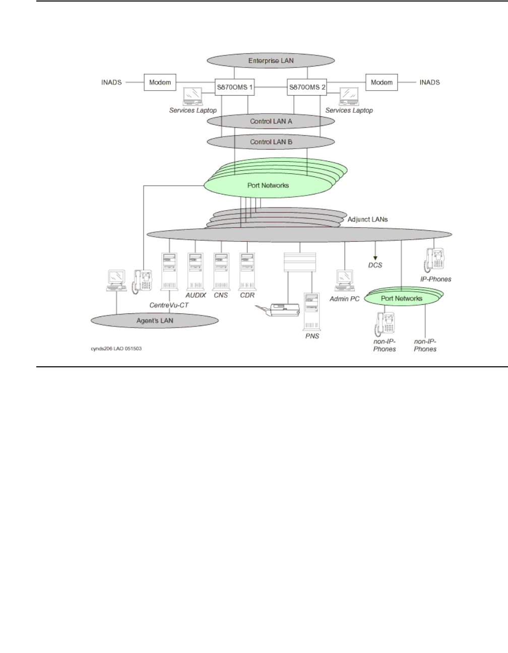
Security
224 Avaya Application Solutions IP Telephony Deployment Guide
Figure 68: Avaya S8700-series Media Server with an Avaya MCC1 or an SCC1 Media
Gateway
To provide the most secure environment that is possible for the system, network access should
be divided into separate zones of control. These zones are sometimes referred to as DMZs.
●One VLAN can be administered for administrative traffic, one for call signaling, another for
voice bearer traffic, and so on.
●Layer 3 boundary devices (routers, layer 3 switches, and firewalls) should be administered
to enforce the corporate security policy on traffic that is destined for the Avaya
S8700-series Media Server, its Avaya MCC1 or SCC1 Media Gateways, or adjuncts.
●Packet filters can permit administrative access only from an administrator's PC and to
deny access from the Avaya S8700-series Media Server or its gateways to the corporate
LAN while allowing call signaling and bearer traffic from all IP Telephones appropriate
access.
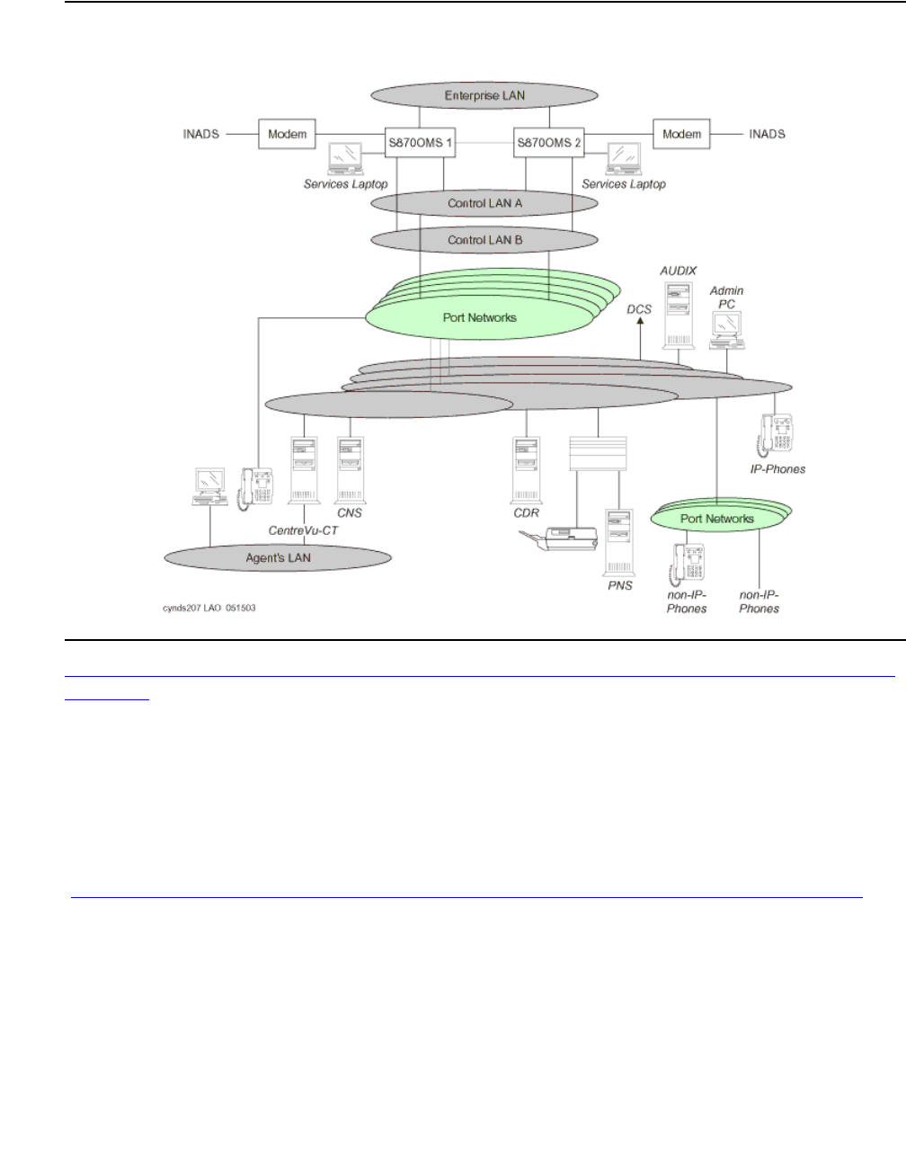
Avaya Communication Manager and Media Servers
Issue 4.3 February 2006 225
Figure 69: Isolated LANs (Avaya S8700-series Media Server with an MCC1 or an SCC1
Media Gateway)
Figure 69: Isolated LANs (Avaya S8700-series Media Server with an MCC1 or an SCC1 Media
Gateway) on page 225 shows how Communication Manager can be configured to allow only
certain types of access to specific LAN interfaces on its PNs. For example, even if you
connected an administration terminal to one of the other LANs, you cannot get administration
access.
S8700-series Media Server with Avaya G650 Media Gateways
The S8700-series Media Server with a G650 Media Gateway also have five interfaces each
(Figure 70: Isolated LANs (Avaya S8700-series Media Server with a G650 Media Gateway) on
page 226):
●The enterprise LAN and control LANs are connected together
●There is only one control LAN.
●There are two spare NICs that are not used.
The messages between the S8700-series Media Server and the G650 are encrypted.
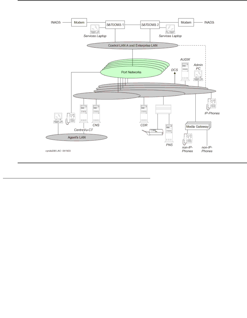
Security
226 Avaya Application Solutions IP Telephony Deployment Guide
Figure 70: Isolated LANs (Avaya S8700-series Media Server with a G650 Media Gateway)
Virus and worm protection
Viruses and worms are most often targeted at Microsoft Windows operating systems or such
commonly used applications as IIS, Exchange, Outlook, or Word. Because the Avaya S8300,
S8400, S8500, and S8700-series Media Servers are Linux-based and do not interface with
these Microsoft products, they have some degree of natural immunity. In addition, viruses and
worms are most commonly delivered by e-mail, by visiting infected Web sites, or by sharing disk
drives.
The media servers do not
●Support incoming email and, therefore, do not forward e-mail
●Contain the Internet Explorer Web browser
●Share drives
All file transfers to the Avaya media servers are restricted. Software and service pack files are
cryptographically signed to prevent introduction of unwanted software. In addition to this natural
immunity, the files and file systems of the Avaya media servers are monitored by Tripwire.

Avaya Communication Manager and Media Servers
Issue 4.3 February 2006 227
Testing
During the development of the S8300, S8500, and S8700-series Media Servers, or in
production of upgrades to its software, Avaya subjects the system to a variety of common
“attack tools” to find any overlooked or accidentally created security holes. The exact set of
tools that are used varies to keep up with the technology. Common tools include nmap and
nessus. Security problems found by these efforts are corrected before the product or the
service pack is released.
Environment
Avaya media servers are as secure as reasonably possible, consistent with the operational
needs of the product and business in which they are used. Security, however, does not end with
the servers. These servers are connected to one or more networks that are, in turn, connected
to other equipment in the enterprise.
Recommendations for network security
Avaya recommends that these servers be located behind a firewall. Where this firewall is
located with respect to other LAN components must be designed on a case-by-case basis.
Avaya Professional Services can assist owners in configuring their networks for both security
and optimal IP Telephony operation. Other vendors also specialize in this type of consulting.
Owners are advised to seek assistance if internal staff is not trained in these areas. Security
holes that arise from negligence, ignorance, or oversight or the pressures of schedule or budget
are all equally usable by hackers. Malicious activity is a moving target, and what is safe today
might not be safe tomorrow. Avaya is committed to providing appropriate secure solutions for its
products, and to continuously monitoring evolving security threats. Avaya S8700 and S8300
servers are appropriately secure against the known threats. Avaya responds quickly should
new threats appear. Consult these resources for the latest security information:
●Your Avaya account team
●The Avaya support Web site:
http://www.avaya.com/support
Click Security Advisory in the Technical Database list on the left side of the page.

Security
228 Avaya Application Solutions IP Telephony Deployment Guide
IP Telephony circuit pack security
Avaya circuit packs such as those in the G650 Media Gateways have a variety of security
measures that combine both voice and data security strategies in to a secure package.
The G650 use three different Ethernet interfaces to help isolate the traffic, and protect the
specific interfaces that must be secured:
●TN2312BP IP Server Interface (IPSI)
●TN2302AP and TN2602AP Media Processors (MedPro)
●TN799DP Control LAN (C-LAN)
TN2312BP IP Server Interface (IPSI)
Topics in this section include
●Telnet
●FTP
●DHCP
●Control link
Telnet
A telnet service is currently required on the IPSI for manual administration of the IPSI (IP
address, default gateway address, VLAN ID, QoS, and Ethernet settings). Telnet access to the
IPSI circuit pack is through
●Standard TCP port 23, but only for connections that are physically made through its
secondary services Ethernet port. When established, these Telnet accesses are directed
to a command menu that supports a variety of administration tasks.
●The OS-debugging shell over port 2312. This port is always available when accessed
through the local services port. Telnet access to this port on the control link is opened by a
Communication Manager command, and disabled immediately after a session has closed
the connection or after 5 minutes of inactivity (see also Control link).

IP Telephony circuit pack security
Issue 4.3 February 2006 229
FTP
An FTP service exists, but is disabled by default. Communication Manager must enable the
FTP service, and only does so for firmware downloads. Once the FTP service is started,
Communication Manager initiates the client-side of the FTP protocol, and then transfers a new
firmware file to the IPSI. Once the transfer is complete, the FTP service is automatically
disabled. A 5-minute time-out is enforced to guard against cases where the firmware download
is started but terminated prematurely. When time-out occurs, the FTP service is disabled until a
new command from Communication Manager enables it again.
DHCP
In S8700 fiber connect systems only, the IPSI has the ability to receive its IP address
information from the S8700-series Media Server through DHCP. This DHCP service only runs
on the control network, and does not connect to a customer's LAN. Avaya has also
implemented mechanisms for restricting this DHCP service, so that non-IPSIs do not receive an
IP address and IPSIs do not receive an address from a non-S8700-series Media Server.
Control link
In order to communicate with the S8700-series Media Server, the IPSI establishes a control
link. This link is encrypted through Triple-DES (3DES) by default, although AES is also
available. The control link is not open for communication to or from any other entity than the
S8700-series Media Server.
TN2302AP and TN2602AP Media Processors (MedPro)
The TN2302AP IP Media Processor and the TN2602AP IP Media Resource 320 circuit packs
are the interfaces to the audio gateway portion of IP Telephony. These circuit packs:
●Use isolated/proprietary operating systems, so they are not susceptible to known viruses.
●Run independently of administrator traffic in order to maintain an isolated security domain,
protecting against attacks that exploit trusted relationships.
●Establish audio connections and only respond to a connection when a corresponding
signaling connection is established.
●Successfully survive some Denial of Service (DoS) attacks, including SynFlood, and are
very resilient to flood-based attacks.
Because of the proprietary operating systems, limited number of open ports, and reliance on
UDP sessions, the TN2302AP and TN2602AP are very secure, and are difficult to take out of
service. Regardless, the TN2302AP and TN2602AP are completely independent of the
administration, maintenance, or reliability of the Avaya Media Gateways, so they cannot be
used “jumping points” to the Media Gateways.

Security
230 Avaya Application Solutions IP Telephony Deployment Guide
TN799DP Control LAN (C-LAN)
The C-LAN circuit pack interface not only supports signaling for IP Telephony applications, but
also supports asynchronous links to INTUITY AUDIX, Call Management System (CMS), and
other adjuncts. This interface
●Is independent of the Media Gateway.
●Has no IP link back to the central administration or maintenance processes of
Communication Manager.
●Successfully survives DoS attacks created by the SynFlood tools.
●Maintains the IP endpoint RAS authentication sequence, a safeguard against exploiting
toll services through IP endpoints.
For more information on the security of Avaya circuit packs, see:
http://support.avaya.com/elmodocs2/multivantage/95933.pdf
Toll fraud
This section contains information about Avaya’s design for preventing toll fraud, and includes
these topics:
●Avaya’s security design
●Hacking methods
●Your toll fraud responsibilities
●Toll fraud indemnification
●Additional toll fraud resources

Toll fraud
Issue 4.3 February 2006 231
Avaya’s security design
Telecommunications systems face significant and growing problems of theft of customer
services. Toll fraud, the unauthorized use of a system and its facilities by a third party, can result
in substantial additional charges for telecommunications services.
Avaya makes every effort to assist customers in their battle against “hackers” through the
technology that goes into every Avaya product. Avaya Communication Manager is designed
with security in mind, and offers many features and capabilities to help maintain security and
prevent toll fraud:
●Your company completely controls its communication facilities.
●Your company completely controls its communication’s security policy and features.
●Your company can make immediate changes at any time.
Each new release of Communication Manager addresses customer needs for even greater
security capabilities, including enhancements to support the recent changes in the North
American Numbering Plan.
Hacking methods
Hackers often facilitate toll fraud activity by gaining access to:
●A system's administration or maintenance port by randomly dialing thousands of telephone
numbers, and then attempt to log in using default passwords. Statistical sampling indicates
there is a high likelihood that customers still have one or more default passwords in place
on their telecommunications system. This allows hackers to completely modify the system
to allow toll fraud activity.
●A system’s remote access port, and then use the remote access feature.
●A voice messaging system, and then transfer their calls to outgoing facilities.
To aid in combating these crimes, Avaya continuously works with its customers and supporting
law enforcement officials to apprehend and prosecute those criminals.

Security
232 Avaya Application Solutions IP Telephony Deployment Guide
Your toll fraud responsibilities
No telecommunications system can be entirely free from risk of unauthorized use. But diligent
attention to system management and security can reduce that risk considerably. Often a
trade-off is required between reduced risk and flexibility. The user and the administrator of the
system are in the best position to determine how to tailor the system to meet their mutual needs,
while protecting the system from unauthorized use. Under applicable law, customers are
responsible for any toll fraud charges that occur. Because you have ultimate control over the
configuration and use of the Avaya products and services that you purchase, your company
bears the responsibility for fraudulent uses of those products and services. Not only can the
financial loss from these calls be substantial, but operational impacts such as reduced
productivity can also have an adverse effect.
Toll fraud indemnification
As part of Avaya's ongoing efforts to combat communications fraud and its threat to our
business customers, Avaya has introduced an enhancement to its Service Agreement.
Beginning January 1, 1996, Avaya indemnifies its customers for charges associated with fraud.
This indemnification is available to all customers who are covered by warranty and/or maintain
an Avaya Service Agreement for Avaya Communication Manager, INTUITY AUDIX voice
messaging, and Avaya Interactive Voice Response systems.
The indemnification enhancement is offered at no additional cost to your service agreement
during warranty, or as part of a multiyear Avaya Service Agreement. The only requirement is to
follow and maintain the sound security practices that every business should implement. A
complete list of these security practices can be obtained from your Avaya Account Team.
Additional toll fraud resources
In an effort to assist customers, Avaya has developed a variety of service offerings and provides
materials to assist in helping to identify and combat toll fraud. These offerings and materials
include:
●Security Audit Service
●Security Tune-up Service
●Toll Fraud Intervention Hotline
●Avaya Security Handbook

Toll fraud
Issue 4.3 February 2006 233
Security Audit Service
The Avaya Security Audit Service is a fee-based, consultation service that provides a security
evaluation of a customer's telecommunications system. The Security Audit is conducted by a
Avaya team of experts and includes:
1. Preliminary telephone interview
2. On-site or remote security audit of the equipment
3. Analysis of system vulnerability
4. Written recommendations for increasing security
Security Tune-up Service
The Security Tune-up Service is a fee-based, consultative service designed to provide an
expedient, online review of the toll-fraud potential in your system. This service is provided for
ACM systems and voice messaging systems. Customer support engineers who specialize in
security:
1. Remotely access your system.
2. Analyze the potential risks in the system.
3. Optionally implement agreed-upon changes to secure the system.
Toll Fraud Intervention Hotline
If you suspect you are being victimized by toll fraud or theft of services and need technical
support or assistance, call the Avaya Toll Fraud Intervention group toll free at
1-800-643-2353 (24 hours a day/7 days a week)
●Consultation charges may apply.
●There is no charge for intervention services performed on equipment that is covered by
warranty or service agreement.
Avaya Security Handbook
The Avaya Security Handbook summarizes the principal steps that a system administrator can
take to reduce the risk of toll fraud. This handbook complements specific documentation for
Avaya products and provides a system administrator with a complete, detailed reference for
planning and implementing security measures.

Security
234 Avaya Application Solutions IP Telephony Deployment Guide

Issue 4.3 February 2006 235
Voice quality network requirements
In addition to the influence of the telephone terminals at either end of a connection, there are
several network parameters that can affect voice quality. This chapter lists some of the more
important ones. The concept of voice quality has different aspects that need to be properly
understood and considered. IP Telephony quality can be engineered and administered to
several different levels to accommodate differing business needs and budget. Avaya therefore
provides network requirements options to allow the customer to choose which "voice quality"
level best suits their specific business needs.
This section covers the topics:
●Network delay
●Jitter
●Packet loss
●Echo
●Signal levels
●Codecs
●Silence suppression/VAD
●Transcoding/tandeming
Network delay
In IP networks, packet delay (latency) is the length of time for a packet to traverse the network.
Each element of the network, including switches, routers, WAN circuits, firewalls, and jitter
buffers, adds to packet delay.
Delay can have a noticeable effect on voice quality but can be controlled somewhat in a private
environment (LAN/WAN). For example, by managing the network infrastructure to minimize
delay or by agreeing on a Service Level Agreement (SLA) with a network provider. An
enterprise has less control over the delay when using the public network.
Previously, the ITU-T recommended 150 ms one-way delay (including endpoints) as a limit for
conversations. However, this value was largely misinterpreted as the only range to calculate a
network delay budget for connections.
One-way delays in excess of 250 ms can cause the well-known problem of "talk-over." This
occurs when both parties talk at the same time because the delay prevents them from realizing
that the other person has already started talking. However, in some applications, delays less
than 150 ms can impact the perceived quality, particularly in the presence of echo.

Voice quality network requirements
236 Avaya Application Solutions IP Telephony Deployment Guide
Long WAN transports must be considered as a major contributor to the network delay budget,
averaging approximately 10-20 ms per 1000 miles. Some transport mechanisms, such as
Frame Relay, can add additional delay. Thus, staying within 150 ms, end to end, may not be
possible for all types of connections.
Finally, one-way delay over 400 ms on signaling links between port networks and the
S8700-series Media Server can cause port network instability.
Avaya recommends a network assessment to measure latency, jitter, and packet loss. Also,
ensure that all values are within bounds before implementing IP Telephony.
Avaya suggests the following guidelines for one-way LAN/WAN delay between endpoints, not
including IP phones:
●80 ms (milliseconds) delay or less yields the best quality.
●80 ms to 180 ms delay can give Business Communication quality. This delay range is
much better than cell-phone quality and, in fact, is very well suited for the majority of
businesses.
●Delays exceeding 180 ms might still be quite acceptable depending on customer
expectations, analog trunks used, codec type, and so on.
Again, there is a trade-off between voice quality and the technical and monetary constraints
which businesses confront daily.
The Converged Network Analyzer (CNA) system is capable of providing ongoing
measurements of network delay (see The CNA Application Performance Rating on page 244).
CNA will also generate alarms when network delay rises to levels that are detrimental for voice
quality. For more information on CNA, see The Converged Network Analyzer on page 410.
Codec delay
Various codec algorithms also add some delay compared to G.711. The G.729 codec, for
example, adds:
●approximately 10 ms of algorithmic delay in each direction
●another 5 ms look ahead
●plus signal processing delays.
The compression algorithm in G.723.1 uses multiples of 30 ms samples per packet. This results
in increased latency over codecs configured to use 20 ms or less samples per packet.

Jitter
Issue 4.3 February 2006 237
Jitter
Jitter is thought of as the statistical average variance in arrival time between packets or
datagrams. To compensate for jitter, many vendors implement a de-jitter buffer in their VoIP
endpoints. The purpose of the jitter buffer is to hold incoming packets for a specified period of
time before forwarding them to the de-packetization (and decompression) process. A jitter
buffer is designed to smooth packet flow. In doing so, it will also add packet delay.
Excessive jitter will be experienced as either packet loss, if the jitter exceeds the jitter buffer
size, or as additional delay, if the jitter is less than or equal to the buffer size. Jitter may result in
packet discard creating audible voice-quality problems if the variation is greater than the jitter
buffer. Jitter buffers should be sized dynamically to give the best quality. If the buffer is sized
statically, it should generally be sized to twice the largest statistical variance between packet
arrivals. However, care needs to be taken in the design of the resizing algorithm of dynamic
buffers in order to avoid adverse effects. Dynamic jitter buffering can exacerbate problems in an
uncontrolled network.
The network topology can also affect jitter. The existence of multiple paths between endpoints
with load balancing enabled in routers can contribute significant amounts of jitter. The
Converged Network Analyzer (CNA) system is capable of providing ongoing measurements of
jitter (see The CNA Application Performance Rating on page 244). CNA can also generate
alarms when jitter rises to levels that are detrimental for voice quality. For more information on
CNA, see The Converged Network Analyzer on page 410.
The following Avaya products all have dynamic jitter buffers to minimize delay by automatically
adjusting the jitter buffer size:
●Avaya G350 and G700 Media Gateways and G650 Medial Gateways with the TN2302AP
circuit pack
●Avaya IP SoftPhone software
●Avaya 4600 Series IP Telephones
Packet loss
Packet loss occurs when packets are sent, but not received (or are received too late to be
processed) at the final destination due to some network problem. Packets discarded by the jitter
buffer of the receiving endpoint can also be considered lost from a user’s perspective.
Remember that too much delay or packet mis-order can be perceived as lost packets. It may
appear that the network is losing packets when in fact they have been discarded intentionally
because of late arrival at the endpoint. IP networks are characterized by unintentional packet
loss in the network as well as by discarded packets in the jitter buffers of the receiving
endpoints.

Voice quality network requirements
238 Avaya Application Solutions IP Telephony Deployment Guide
Qualifying problems caused by occasional packet loss are difficult to detect because each
codec has its own packet loss concealment method (PLC). Therefore, it is possible that voice
quality would be better using a compression codec (G.729A), which includes its own PLC,
compared to a full bandwidth G.711 codec without PLC.
The proper treatment of packet loss is dependent on several factors such as the following:
●Packet loss is more noticeable for tones (other than DTMF) than for voice. The human ear
is less able to detect packet loss during speech (variable-pitch), than during a tone
(consistent pitch).
●Packet loss is more noticeable for short, continuous packet loss than with random packet
loss over time. For example, losing ten contiguous packets is worse than losing ten
packets evenly spaced over an hour time span.
●Packet loss may be more noticeable for larger voice payloads per packet than for smaller
ones, because more voice is lost in a larger payload.
●Packet loss may be more tolerable for one codec over another.
●Even small amounts of packet loss can greatly affect a TTY/TDD device's (for
hearing-impaired people) ability to work properly.
●Packet loss for signaling traffic increases network traffic substantially when loss is greater
than 3%.
Network packet loss
Like packet delay, Avaya offers customers a tiered approach of recommendations to deal with
network packet loss to balance new network costs and limitations within business directives.
The maximum loss of IP packets (or frames) between endpoints should be:
●1% or less for best quality depending on many factors.
●3% or less for Business Communications quality. Again, this quality is much better than
cell-phone quality.
●More than 3% may be acceptable for voice but may negatively impact signaling. More
information on signaling bandwidth requirements can be found in white papers on the
Avaya Support website.
The Converged Network Analyzer (CNA) system is capable of providing ongoing
measurements of network packet loss (see The CNA Application Performance Rating on
page 244). CNA can also generate alarms when network packet loss rises to levels that are
detrimental for voice quality. For more information on CNA, see The Converged Network
Analyzer on page 410.
Note:
Note: Tools such as Avaya’s VoIP Monitoring Manager (VMM), the Agilent (HP)
Internet Advisor, Finisar's Surveyor Explorer, Radcom's Prism, NAI's Sniffer, and
others measure packet loss.

Echo
Issue 4.3 February 2006 239
Packet loss concealment (PLC)
Some packet loss can be dealt with by attempting to conceal the loss by generating packets to
take the place of the missing packets. ITU standards G.711 Annex I and the G.729 standard
define methods by which packet loss concealment can be provided. Excessive packet loss
cannot be disguised so, ultimately, PLC gives way to comfort noise generation (CNG) if too
many packets are lost in succession.
Ramping down to silence is a typical way that PLC is performed. Loss of six consecutive
packets is considered to be the maximum number of packets over which PLC can be sensibly
applied.
Echo
The two main types of talker echo are acoustic echo and electrical echo caused by hybrid
impedance mismatch.
Acoustic echo occurs when the talker’s voice traverses through the airpath from the receiver
back to the microphone of the remote terminal. This effect depends on the properties of the
remote room; for example, large room size, hard walls.
Electrical echo is due to an impedance mismatch between four-wire and two wire systems or in
the conversion between a headset and its adapter.
The user's perception of echo increases with delay. In practice, most echo received by the ear
within 30 ms is ignored. But if the level of the received echo signal is extremely high, even a
couple of milliseconds will cause echo perception. Echo received after 30 ms may be perceived
as an annoyance. Usually, only the speaker hears an echo but the receiver does not. Because
of the end-to-end latency in some IP Telephony implementations exceeds the latency in some
circuit-switched systems, the perception of echo can be greater in the IP Telephony system.
One strategy for dealing with echo is through the use of echo cancellers. Echo cancellers, which
have varying amounts of memory, store incoming voice streams in digital form in a buffer and
compare the received voice with the previously transmitted voice patterns stored in memory. If
the patterns match, the canceller removes the echo. Echo cancellers are not perfect, however.
There will be a residual level left even in optimal operating conditions. Echo cancellers operate
properly only if the one-way trip delay between the echo canceller and the echo source (for
example, the acoustic airpath at the telephone set or electrical hybrid) is larger than the echo
canceller can handle, the echo canceller will not find a pattern to cancel.
Avaya's G350 and G700 Medial Gateways, the Avaya TN2302AP IP Media Processor (in the
G650 Media Gateways), the Avaya IP SoftPhone, and the Avaya 4600 Series IP Telephone all
incorporate echo cancellers designed for IP Telephony to improve voice quality.

Voice quality network requirements
240 Avaya Application Solutions IP Telephony Deployment Guide
Signal levels
In order to provide more natural-sounding conversations, voice communication systems attempt
to emulate a typical communication scenario where the two parties are speaking directly and
are separated by one meter. To achieve these conditions, an acoustic loss of 10dB is added
between speaker and listener. Any significant differences from this loss level will be audible as a
signal level that is too soft or too loud and thus may result in some degree of listener discomfort.
In IP Telephony networks, the end-to-end loss of 10 dB is implemented as 8 dB in the speaker's
telephone, 0 dB in the IP network, and another 2 dB loss in the listener's telephone. To account
for personal preferences or the presence of background sound, listeners may adjust relative to
the 10 dB loss value by changing the volume control on their telephone.
The IP Telephony loss values are globally identical and specified in ITU-T Recommendations
and other regional local standards. Note that in principle, the telephone transmit and receive
loss values could have been implemented either as all transmit loss or as all receive loss. The
chosen implementation, where loss is split between speaker and listener, originates from the
circuit-switching history of telephony systems. See the subsection on Echo and Signal Levels
for more details.
In traditional circuit-switched networks the telephone transmit, receive, and inter-port line/trunk
losses are country-dependent. The end-to-end country-specified losses often also differs
somewhat from the 10dB loss value for historical reasons. The country-dependency of loss
values makes it more challenging to guarantee a proper received voice signal when the PSTN
is involved or when country borders are traversed.
IP Telephony gateways should provide proper signal level adjustments in the direction from the
IP network to the circuit-switched network and in the reverse direction, and also between
circuit-switched ports.
To allow for multi-country deployment of Avaya telephones and gateways, these devices
facilitate programmable loss values. In order to ensure that the signal levels are controlled
properly within the scope of the voice network consisting of Avaya systems, the appropriate
country-dependent loss plan should be administered.
Besides administering loss for two-party calls, Communication Manager also allows
country-dependent conference call loss administration. Loss is applied depending on the
number of parties involved in the conference.

Codecs
Issue 4.3 February 2006 241
Echo and Signal Levels
As mentioned before, in circuit-switched telephony, echo may be caused by acoustic reflection
in the remote party's environment, or by electrical reflection from 2-to-4 wire analog hybrid
impedance mismatches. Impedance mismatch can occur in analog telephones and analog line/
trunk cards, electrical cross-talk in circuitry, or in telephony wiring (particularly in low-cost
headsets). For this reason, in circuit-switched analog and digital phones, a relatively large
transmit loss is implemented in order to minimize the perceived echo due to electrical reflection
and cross-talk effects. In principle, the transmit loss of telephones could be made very large
followed by signal amplification in the receiving telephone. In practice however, the transmit
loss should be limited to prevent the electrical voice signal from dropping below electrical
background noise. This has resulted in the adoption of transmit loss and receive loss values
around 8 dB and 2 dB, respectively, although country-specific values may actually deviate quite
significantly from these values.
The loss plan administration provided by Avaya Communication Manager software is primarily
intended to control signal losses in telephones and gateways, and not to control echo. However,
in case of severe echo, the administered loss can be changed to a different plan. In principle, an
increase of the loss between two endpoints by a certain amount will increase the echo loss by
twice this amount. In general, it is not advised to use loss plan administration in this way without
consultation with Avaya Services personnel. It is better to reduce the echo by strategic
deployment of echo cancelers.
Tone Levels
The level of call progress and DTMF tones played out through telephones must also adhere to
specified levels in order to be satisfying for the average user. Again, respective standards are
country specific and can be set under administrative control. The volume of received call
progress tones can be adjusted by the telephone volume control.
Codecs
Codecs (Coder-Decoders) convert between analog voice signals and digital signals. Avaya
supports several different codecs offering varying bandwidth usage and voice quality, including
the following codecs:
●G.711 produces audio uncompressed at 64 kbps
●G.729 produces audio compressed at 8 kbps
●G.723.1 produces audio compressed at 5.3 or 6.3 kbps

Voice quality network requirements
242 Avaya Application Solutions IP Telephony Deployment Guide
Table 35 provides comparisons of several voice quality considerations associated with some of
the codecs supported by Avaya products.
Note:
Note: Toll-quality voice must achieve a MOS (Mean Opinion Score) of 4 or above. The
MOS scoring is a long-standing, subjective method of measuring voice quality.
Because it does not use compression, G.711 offers the highest level of voice quality.
Unfortunately, there is a trade-off with higher bandwidth usage. In situations where bandwidth is
scarce, such as across WAN links, G.729 offers a good compromise with lower bandwidth
usage, but still good fidelity audio.
Compression codecs use twice as many DSP (digital signal processor) resources than the
G.711 codec. One DSP resource is used for sampling and one for the compression. On the
TN2302AP (MedPro) circuit pack (and on the G700 VoIP engine) there are 64 DSP resources.
Thus, the number of calls supported by one MedPro or G700 is:
●64 G.711 calls
●32 compressed calls (for example, G.729)
●Some number in-between for a call mix.
The formula for calculating the number of calls one MedPro supports is
Generally, G.711 is used within LANs because bandwidth is abundant and inexpensive
whereas G.729 is used across WAN links because of the bandwidth savings and adequate
voice quality.
Table 35: Comparison of speech coding standards
(without IP / UDP / RTP overhead)
Standard Coding Type Bit Rate
(kbps) MOS-LQO1,2
1. As predicted. Measured according to ITU-IT Recommendation P.862
(PESQ). See draft Recommendation P.862.2, application guide for
PESQ.
2. Given MOS-LQO values for American English.
G.711 PCM 64 4.37
G.729 CS-ACELP 8 3.94
G.723.1 ACELPMP-MLQ 6.3
5.3 3.78
3.68
Number of uncompressed calls()2 Number of compressed calls()×64≤+

Silence suppression/VAD
Issue 4.3 February 2006 243
G.726 Codec and H.248 Media Gateways
As of Communication Manager release 3.1, media processing resources on H.248 Media
Gateways support the G.726 codec. The following table provides the corresponding capacities:
Silence suppression/VAD
Besides low bit rate, Voice Activity Detection (VAD) or silence suppression can also be used to
save bandwidth. During a conversation, because only one party is speaking at any given time,
more than 40% of the transmission is silence. Voice Activity Detection (VAD) in the IP telephone
monitors the locally produced voice signal for voice activity. When no activity is detected for the
configured period of time, the Avaya software informs the Packet Voice Protocol. This prevents
the encoder output from being transported across the network when there is silence, resulting in
bandwidth savings.
When silence suppression is enabled, the remote end is instructed to generate "comfort noise"
when no voice is present to make the call sound more natural to users. The trade-off with
silence suppression lies with the silence detection algorithm. If it is too aggressive, the
beginnings and ends of words can be "clipped." If not aggressive enough, no bandwidth is
saved.
Silence suppression is built into G.729B. It can be enabled for other codecs from within
Communication Manager. Because of voice quality concerns with respect to clipping, silence
suppression is generally not used (with the exception of G.729B).
The following Avaya products employ silence suppression to preserve bandwidth:
●Avaya Communication Manager software (for control)
●Avaya 4600 series IP Telephone
●Avaya IP SoftPhone
●Avaya Media Gateways
For procedures to administer QoS parameters, refer to Administration for Network Connectivity
for Avaya Communication Manager (555-233-504).
Table 36: Number of Simultaneous Bi-Directional Connections Supported
Codec G250 G350 G700
G.726A Unencrypted 10 16 32
G.726A with AEA Encryption 10 16 32
G.726A with AES Encryption 10 12 24

Voice quality network requirements
244 Avaya Application Solutions IP Telephony Deployment Guide
Transcoding/tandeming
Transcoding or tandeming describes a voice signal that has been passed through multiple
codecs, such as can be the case when call coverage is applied on a branch office system back
to a centralized voice mail system, the calls may experience multiple transcodings (this could
include G.729 across the WAN and G.723.1 into the voice mailbox). Each transcoding action
results in degradation of voice quality. These problems may be minimized by the use of the
Communication Manager feature called DCS with Rerouting (Path Replacement). This feature
detects that the call coming through the main switch has been routed from one tandem switch,
through the main, and back out to a third switch. In these cases, the system then re-routes the
call directly, thus replacing the path through the main system with a more direct connection.
Avaya products minimize transcoding while non-Avaya products may cause slight to excessive
transcoding. "Shuffling" and "Hairpinning" also reduce transcoding.
The CNA Application Performance Rating
Reporting on low level measurements, such as delay, jitter, and packet loss, is important and
helps debug networking related issues that are affecting an application. In addition to low level
measurements, the Converged Network Analyzer (CNA) provides an Application Performance
Rating (APR) that translates low level statistics in to a 0 to 5 metric that summarizes the effect
of all low level scores into one score. This APR score allows users, by looking at one number, to
determine whether their application performance is acceptable at any given time. CNA also
uses APR scores to derive network availability from the point of view of the application.
Translating low level statistics to an Application Performance
rating
The CNA assessment of application performance is based on application models, which
convert the raw delay, jitter, and loss measurements into an application performance rating that
ranges from 0 to 5. This rating is normalized across applications. Application models are
tailored to different applications and take into account the specific characteristics and
requirements of the various applications.
CNA Application Models follow a five-stage methodology, shown in Figure 71.
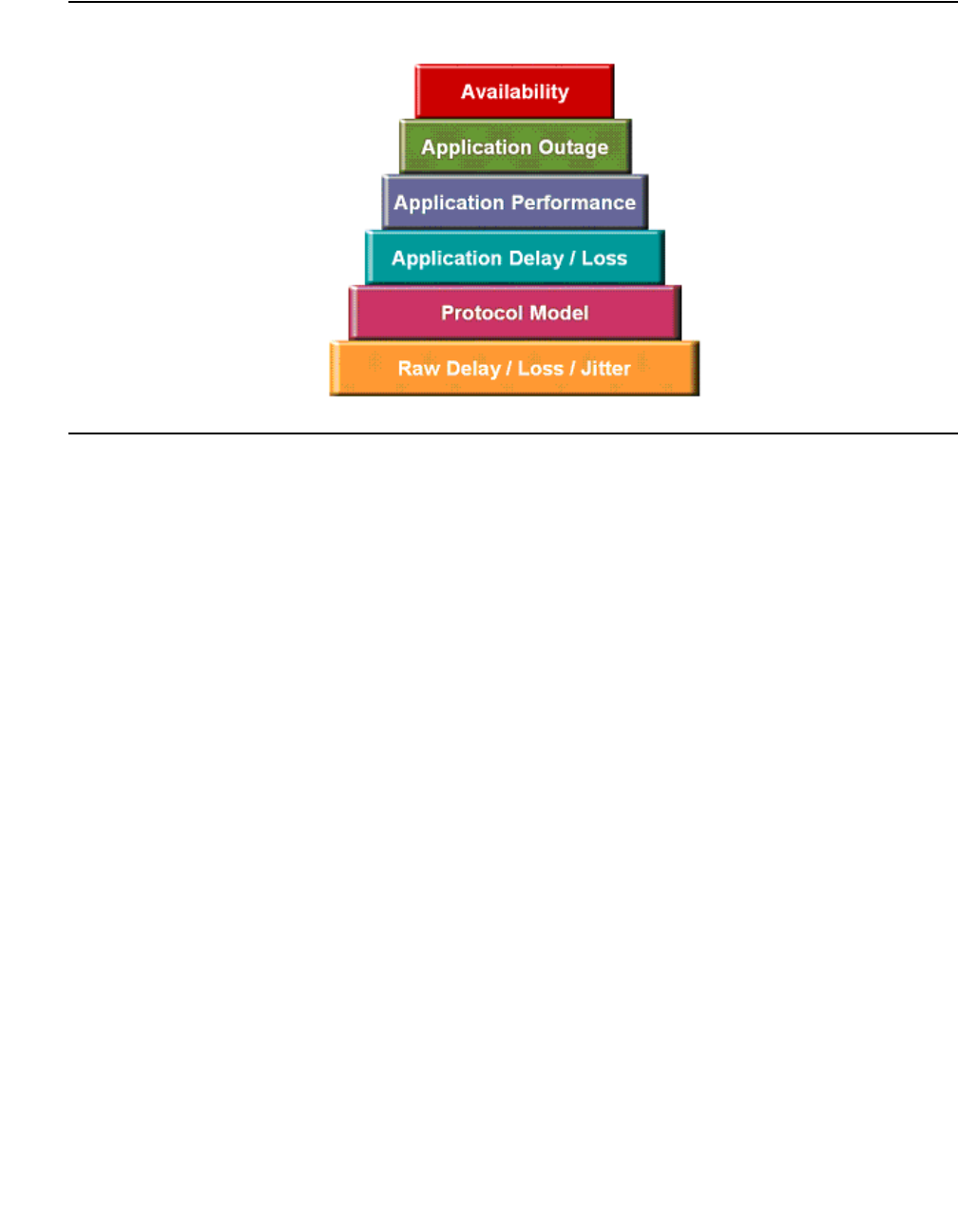
The CNA Application Performance Rating
Issue 4.3 February 2006 245
Figure 71: Converting raw statistics into an application performance rating
From the bottom, the five steps include:
●The measurement of low-level network quantities such as latency, loss, and jitter for each
available path between locations.
●The computation of transport delay from the raw scores; this takes into account the distinct
characteristics of TCP and UDP, and thus assesses the impact on applications in general,
not taking specific application sensitivities into consideration.
●The computation of application delay, specifically the transaction between the 2 end
points.
●The determination of an application performance rating, using a ranking from one to five
stars, similar to movie ratings.
●Finally, the time periods where the voice quality is determined to be unacceptable are
logged as “bad minutes” for that path. Adding up the bad minutes allows CNA to compute
the effect of network problems on application availability
The available application models are:
Voice
The voice model converts low level statistics (network delay, latency, and loss) into an APR
score that takes into account voice requirements. Given the sensitivity of voice to jitter, the voice
model is especially sensitive to jitter. This model is also very sensitive to sustained loss, which
effect can be detrimental to voice. This model is also sensitive to delay and loss. (See Section 3
for a detailed description of the effect of delay, jitter, and loss on voice quality).

Voice quality network requirements
246 Avaya Application Solutions IP Telephony Deployment Guide
Video conferencing
The video conferencing model converts low level statistics into an Application Performance
Rating (APR) score that takes into account Video Conferencing requirements. Given the
detrimental effects of loss on video conferencing, this model is very sensitive to loss. This model
is also sensitive to jitter and latency.
Enterprise model
The enterprise model takes into account the effect of low level network characteristics on short
TCP transactions. This model is very sensitive to network loss. On the other hand, this model is
not affected by jitter. Given that signaling traffic uses TCP and consists of short transactions,
The CNA application model that best captures the characteristics of signaling traffic is the
enterprise application model.
Web model
The web model is best suited for web applications. It converts latency and loss measures into
an APR score that best describes the user experience in the context of a typical web
transaction.
For more information on CNA, see The Converged Network Analyzer on page 410.

Issue 4.3 February 2006 247
Avaya Integrated Management
This chapter outlines Avaya’s system, network, and device management and monitoring
products, and some common third-party tools. It also discusses the distributed and centralized
management models, and describes how Avaya management products fit into those models.
The links in Table 37: Integrated Management Applications take you to the corresponding
product descriptions.
Table 37: Integrated Management Applications
Link to section Link to product
category Link to product
Avaya Integrated
Management products
System management
applications
Avaya MultiSite Administration
Avaya Integrated Management
Database
Avaya Fault and Performance
Manager
Avaya Proxy Agent
Avaya Site Administration
Avaya Voice Announcement Manager
Monitoring
management
applications
Avaya VoIP Monitoring Manager
Avaya Network
management
applications and
device managers
Avaya Network Management Console
and System View
Avaya Address Manager
Avaya Network Configuration Manager
Avaya QoS Manager
Avaya Secure Access Administration
Avaya SMON Manager
Avaya Software Update Manager
Avaya VLAN Manager
Avaya Provisioning and Installation
Manager
Avaya Device Managers

Avaya Integrated Management
248 Avaya Application Solutions IP Telephony Deployment Guide
The following links take you to the corresponding topics.
Third-party network management products
●Multi Router Traffic Grapher
●HP OpenView Network Node Manager
Network management models
●Distributed (component)
●Centralized (hybrid)
Avaya Integrated Management products
Avaya offers the following categories of management products:
●System management applications
●Monitoring management applications
●Avaya Network management applications and device managers
System management applications
Avaya’s system management products include:
●Avaya MultiSite Administration
●Avaya Integrated Management Database
●Avaya Fault and Performance Manager
●Avaya Proxy Agent
●Avaya Site Administration
●Avaya Voice Announcement Manager
Avaya MultiSite Administration
Avaya MultiSite Administration enables multiple administrators to access a network of multiple
voice communications systems including DEFINITY Release 9 and later and Linux-based
systems running all releases of Communication Manager. The Avaya MultiSite Administration
application provides a web based GUI client that runs in the supported browsers and allows
administrators access from any workstation on the network.

Avaya Integrated Management products
Issue 4.3 February 2006 249
The intuitive wizards allow you to quickly perform complex administrative tasks including:
●Add, move, and change individual stations and execute bulk moves
●Schedule routine tasks, multiyear maintenance, and system downloads
●Import and export data
●Enhanced number portability (ENP)
●Make global changes for most system objects
MultiSite Manager provides a single point of entry to distributed networks and campus
environments.
Avaya Integrated Management Database
The Avaya Integrated Management Database (IMD) stores device data (such as configurations
of voice systems, messaging systems, system adjuncts, and managed applications) and user
accounts. The IMD data is shared by the Integrated Management applications (for example,
Avaya MultiSite Administration, Avaya Fault and Performance Manager, and Avaya Proxy
Agent).
Avaya Fault and Performance Manager
Avaya Fault and Performance Manager is the next-generation product for fault and
performance management. Avaya Fault and Performance Manager:
●Runs on a Linux server and provides Web-based access from a universal client
●Integrates with your HP OpenView, running on either a Windows 2000/2003 server or
Solaris 9 server, to show the hierarchical view of devices and their status. (HP OpenView
is not included with this product.)
●Collects and stores data from the network devices, and lets you generate reports and view
that data in a text or table format on their screens and print reports.
●Uses the Simple Network Management Protocol (SNMP) to communicate with the
managed Avaya media servers and other supported devices.
Avaya Proxy Agent
Avaya Proxy Agent provides the interface between the Fault and Performance Manager and the
Avaya Media Servers that run Avaya Communication Manager. Avaya Proxy Agent:
●Runs on Linux, and acts as a protocol converter between the proprietary OSSI protocol
and Simple Network Management Protocol (SNMP)
●Sends and receives alarm traps, and can filter alarms by system, type, day, and hours.

Avaya Integrated Management
250 Avaya Application Solutions IP Telephony Deployment Guide
●Has a command line interface directly accesses Avaya media servers and non-IP
systems.
●Is required for customers who want to receive Communication Manager alarms through
SNMP.
Avaya Site Administration
Avaya Site Administration is a GUI-based administration product that runs on Windows 2000/
2003. Avaya Site Administration supports:
●IP and Non-IP systems
●Avaya media servers
●Avaya Communication Manager
●AUDIX messaging systems
You can launch the Avaya Site Administration from the Communication Manager Configuration
Manager to do the following:
●Move, add, and change information on stations and perform basic traffic analysis easily
●Execute the “Find and Replace” and “Import and Export” features to manage subscriber
data
Avaya Voice Announcement Manager
Avaya Voice Announcement Manager simplifies announcement administration by providing a
mechanism to transfer recorded announcements over the LAN. The announcements can be
transferred to both the voice announcement over LAN capability co-resident on the Avaya
G350/G700 Media Gateway and to the TN2501AP circuit packs located in voice systems.
Voice Announcement Manager enables storage of announcements in WAV files, which can be
sent to an Avaya G350/G700 Media Gateway or a TN2501AP without converting them. Voice
Announcement Manager also provides a repository to backup and restore announcement files,
the ability to broadcast .wav files to multiple voice announcement over LAN sources, and the
ability to schedule backup and broadcast tasks.
Monitoring management applications
Avaya’s monitoring management products include:
●Avaya VoIP Monitoring Manager

Avaya Integrated Management products
Issue 4.3 February 2006 251
Avaya VoIP Monitoring Manager
Avaya VoIP Monitoring Manager is a client/server Voice over IP (VoIP) monitoring application
that tracks the quality of voice transmissions over the network. Avaya VoIP Monitoring Manager
product runs on Windows 2000/2003, and offers these features:
●Receives quality of service (QoS) statistics from Avaya IP endpoints and displays this data
in graphs and reports.
●Isolates voice quality problems and send traps to any network management system (NMS)
when poor voice quality is detected. This product supports converged data and voice
products.
You can launch the Avaya VoIP Monitoring Manager from the Network Management Console
with VoIP SystemView or operate it as a standalone application.
Relationship between CNA and VMM: - Both the Converged Network Analyzer (CNA) and
VMM report on the performance of voice bearer applications. Both tools are complimentary:
●VMM reports on live calls. It provides information on the delay, jitter, and loss
characteristics of calls that have occurred.
●CNA, on the other hand, uses synthetic measurements to monitor all portions of the
network in a continuous fashion. CNA also summarizes the delay, jitter, and loss
information it gathers into an APR score.
CNA studies only the effect of the network on the application. Because VMM bases its reporting
on real calls, it captures effects outside the realm of the network (e.g., server problems). On the
other hand, VMM reporting is only current for paths on which live calls have taken place. CNA
reporting will be current for any section of the network CNA is configured to measure.
For more information on CNA, see The Converged Network Analyzer on page 410.
Avaya Network management applications and device managers
Network management is the practice of using specialized software tools to monitor and maintain
network components. Proper network management is a key component to the high availability
of data networks.
Avaya’s network management products include:
●Avaya Network Management Console and System View
●Avaya Address Manager
●Avaya Network Configuration Manager
●Avaya QoS Manager
●Avaya Secure Access Administration
●Avaya SMON Manager

Avaya Integrated Management
252 Avaya Application Solutions IP Telephony Deployment Guide
●Avaya Software Update Manager
●Avaya VLAN Manager
●Avaya Provisioning and Installation Manager
Avaya Network Management Console and System View
The Avaya Network Management Console "discovers" IP-enabled devices and provides fault
monitoring. Network Management Console supports SNMPv2 and SNMPv3 devices. Network
Management Console also provides a launch point for network management applications and
device managers, as well as other Avaya Integrated Management applications. Network
Management Console also provides a method to access an installed telnet client for access to
the command line interface of each device in the network.
The Avaya Network Management Console also provides System View, which is a view of the
customer’s network of Avaya converged products. System View provides a hierarchical view of
the components with device status, and also serves as a platform to launch device and element
managers for further analysis.
Avaya Address Manager
Avaya Address Manager automatically displays a centralized list of hosts discovered in the
network, and correlates between IP address, Media Access Control (MAC) address, and device
port connectivity. With Address Manager, you can generate predefined reports and
automatically discover duplicated IP addresses or port policy violations. Address Manager
supports the entire Avaya data product line.
Avaya Network Configuration Manager
The Avaya Network Configuration Manager provides the user with the ability to download or
upload device configuration files from or to devices. It is a network-wide application, able to deal
with multiple types of devices and perform multiple upload/download actions in parallel.
Avaya QoS Manager
The Avaya QoS Manager is the main tool for administration of access policy and QoS in Avaya
voice and wireless gateways and Avaya edge/core switches providing a complete coverage of
an Avaya-based network. QoS Manager provides QoS and Access Control List (ACL)
management for all Avaya rules-based QoS devices.

Avaya Integrated Management products
Issue 4.3 February 2006 253
Avaya Secure Access Administration
Avaya Secure Access Administration enables rapid deployment of user parameters to Avaya
network infrastructure products and gateways, replacing error prone manual configuration of
each device. This tool operates as a centralized console for defining CLI and SNMPv3 user’s
authentication and authorization parameters. It also provides the option to define user lists and
to deploy all users in a list to multiple devices in parallel and in one operation.
Secure Access Administration also hooks into the Avaya Network Manager and Network
Management Applications and defines entries in the Console database for validation of users to
the Console applications. The tool supports three pre-defined user roles: admin, read-write, and
read-only for the Avaya data device and gateway families. It also supplies internal API for NMC
applications for authenticating Avaya devices and gateways using SSH public keys.
Avaya SMON Manager
Avaya SMON Manager is a monitoring application that:
●Provides a complete view of all switched traffic in the network by using embedded agents
and leveraging special hardware capabilities.
●Monitors the network and displays a top-down view of all traffic that is traversing the entire
network of switches.
A license key is required to activate the SMON Manager.
Avaya Software Update Manager
Avaya Software Update Manager downloads software to managed Avaya data devices, in
addition to the Avaya G700 Media Gateway, and performs all necessary software maintenance
operations. Software Update Manager checks the software versions currently used versus the
latest versions available from the Avaya Web site and recommends updates when newer
versions are available. Software Update Manager can also be used as an inventory tool for
Avaya data and wireless gateway devices, providing a list of Avaya devices residing in the
network.
Avaya VLAN Manager
Avaya VLAN Manager is a graphical application for VLAN management that allows for
configuration and monitoring of VLAN usage. VLAN Manager also allows for maintaining and
assigning VLAN numbering and naming across all campus VLANs, as well as allowing the
network manager to track additions and changes to the network. VLAN Manager validates
VLAN name and tag values and number of VLANS in order to improve VLAN maintenance
tasks.

Avaya Integrated Management
254 Avaya Application Solutions IP Telephony Deployment Guide
Avaya Provisioning and Installation Manager
The Provisioning and Installation Manager (PIM) enables the centralized provisioning and
installation of a large number of gateways.
PIM capabilities include:
●Use of templates to make it easy to define and manage various types of configuration
parameters and to apply these parameters to devices.
●Bulk provisioning of multiple devices at a time.
●Importing data collected during the implementation process.
●Support for initial installation as well as ongoing provisioning of multiple gateways.
●Support for end customer use for gateway provisioning and services/business partners for
staged installations.
●Installed on the Enterprise Windows Server and co-resident with the other network
Management applications.
●Use of templates to support grouping of parameters and to form policies.
●Ability to apply templates to a single device or groups of devices (i.e. bulk provisioning).
●Ability to import and export device profiles and templates.
●Ability to import data to a device profile from an EPW.
●Configuration of G250, G250-BRI, G350, and W310 gateways.
●Configuration of device parameters.
Avaya Device Managers
Avaya Device Managers are applications that simplify the configuration, fault diagnosis, and
management of specific Avaya data products. Device managers provide an in-depth look at
network behavior, delivering the tools required for end-to-end device management. The device
managers provide a real-time graphical view of each device using color-coding to indicate
individual port and LAG status. Device Managers are either embedded or are available as an
application. Embedded Device Managers operate in the native operating system of the device
(for Standard Management Solutions) and are available through device web page.
Avaya’s Device Manager products include:
●C360 Manager
●G350 Manger
●P130 Manager
●P330/G700 Manager
●P580/P882 Manager
●W310 Mobility Manager
●Wireless AP 3/4/5/6 Manager

Third-party network management products
Issue 4.3 February 2006 255
Third-party network management products
This section describes some third-party monitoring tools that might provide benefit to
companies implementing IP Telephony. Avaya is not involved with the development of these
products. Inclusion on this list is not exhaustive, nor does it represent an endorsement from
Avaya. Products are listed here as a convenience for our customers:
●Multi Router Traffic Grapher
●HP OpenView Network Node Manager
Multi Router Traffic Grapher
The Multi Router Traffic Grapher (MRTG) monitors the traffic load on network links, and
generates HTML pages of graphic-displayed images that provide a live visual representation of
this traffic. MRTG is based on Perl and C, and works under UNIX and Windows NT. The Multi
Router Traffic Grapher:
●Uses SNMP to read the traffic counters of your routers, logs the traffic data, and creates
graphs that represent the traffic on the monitored network connection. These graphs are
embedded into Web pages. MRTG even allows you to accumulate two or more data
sources into a single graph.
●Creates visual representations of the traffic seen daily, during the last week, the last
month, and the last year. MRTG performs well enough to monitor 200 or more network
links from any reasonably-performing PC.
●Monitors any SNMP variable that you choose. You can even use an external program to
gather the data that MRTG should monitor, for example:
- System load
- Login sessions
- Modem availability
For more MRTG information, see:
●http://www.mrtg.org for the main MRTG Web site. Their product is available free of charge
under the terms of the GPL.
●http://www.ee.ethz.ch/stats/mrtg/ for an example.

Avaya Integrated Management
256 Avaya Application Solutions IP Telephony Deployment Guide
HP OpenView Network Node Manager
HP OpenView Network Node Manager (NNM) and Network Node Manager Extended Topology
together provide your management team with the capabilities that you need to address your key
business and network challenges:
●A new approach to root-cause analysis that includes a set of easy-to-use tools to help you
identify and resolve conditions before they become problems.
●ID for Networks delivers advanced capabilities for network event reduction, root-cause
analysis and a new management concept called State Analysis, which actively determines
the health of network protocols and complex network configurations.
●Includes out-of-the-box correlators for enhanced root-cause analysis and the new
Correlation Composer to easily tailor the out-of-the-box correlators that are shipped with
Network Node Manager to fit your particular needs.
●The NNM serves as a SNMP manager, trap collector, and connectivity tester. It also acts
as a framework for the attachment of other programs, such as Avaya Network
Management Console with VoIP SystemView.
●Topology discovery visually shows the interconnection of routers, switches, and endpoints.
Network management models
There are two basic network management models:
●Distributed. Specialized, nonintegrated tools (and sometimes organizations) to manage
discrete components
●Centralized. Integrating network management tools and organizations for a more coherent
management strategy.
This section contains information on the two main network management models:
●Distributed (component)
●Centralized (hybrid)
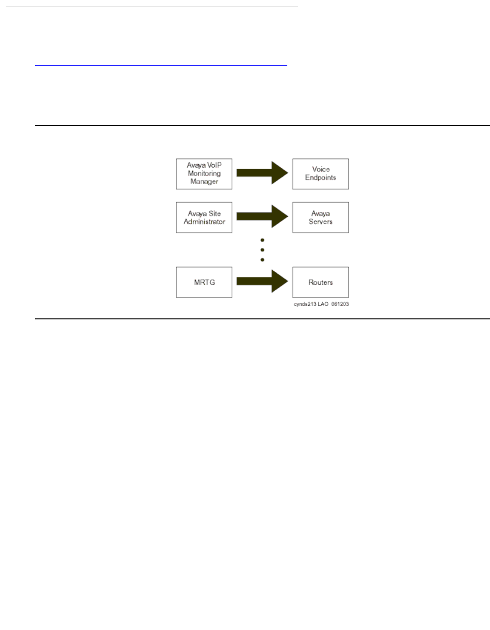
Network management models
Issue 4.3 February 2006 257
Distributed (component)
Distributed network management is the default management model for network equipment. As
Figure 72: Tools for distributed network management shows, each device is managed
separately, and can have its own management interface. There is no commonality between
these interfaces. Some might be CLI-based, Web-based, or GUI-based applications. In
addition, third-party tools such as MRTG complement integrated management interfaces to
provide additional functionality.
Figure 72: Tools for distributed network management
The advantage to this model is that the cost of tools is low compared to the centralized model.
Many of the tools are included with the purchase of networking equipment, and many are open
source. Also, many of these tools are more specialized on a specific platform or task than
centralized management tools. Most Avaya Integrated management products, including Avaya
VoIP Monitoring Manager, fall into this category.
There are numerous disadvantages to this model. First, this model requires more support
personnel than the centralized model. Next, there are numerous interfaces that support staff
must learn, which greatly increases training costs. Finally, the support person must check many
places to get the full status of the network, which adds time and the likelihood of missing critical
data. This model is appropriate in small to medium-sized enterprises with relatively few pieces
of network equipment. It is not appropriate for most large enterprises or enterprises with
complicated networks.
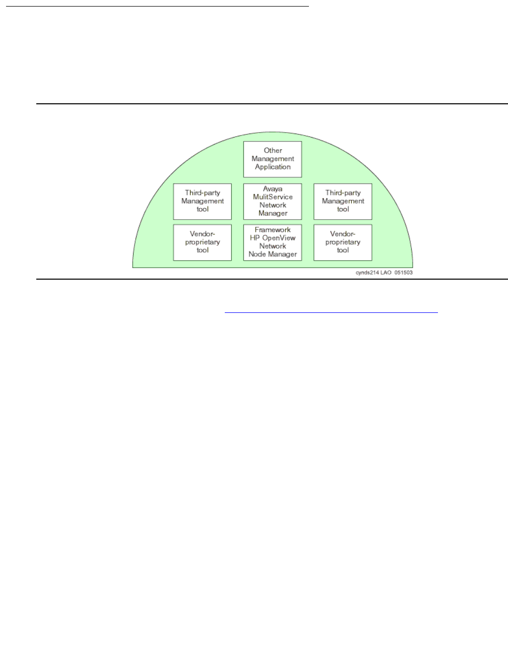
Avaya Integrated Management
258 Avaya Application Solutions IP Telephony Deployment Guide
Centralized (hybrid)
The centralized management model strives to make all network management available in a
central location. It generally begins with a framework product such as HP OpenView NNM. This
framework product serves as an SNMP trap receiver for alarm data sent by networking devices.
It also provides network topology discovery and availability testing.
Figure 73: Centralized management model
Additional management tools, such as Avaya Network Management Console with VoIP
SystemView, attach to the framework (Figure 73: Centralized management model). They can
be launched directly from the underlying application, and can share data with it. This allows a
network administrator to go to a central location for most network management and
configuration tasks. Client devices are configured to send alarm and event data to the
centralized manager, generally through SNMP. The management station also has the ability to
periodically poll the client for specific information. This can be used to graph performance, for
example. Polling can also be used for inventory management.
There are many advantages to this model:
●Because a centralized location is used, fewer administrators are required to manage a
network.
●Administrators are more likely to catch critical information because it is all in one place.
●Administrators need to learn fewer interfaces, which reduces training costs.
●More advanced centralized management products offer event correlation, which increases
the likelihood of proactively catching a problem before it adversely affects users.
The disadvantage to the centralized model is cost. Typically, centralized management tools
cost more than distributed tools. In addition, the implementation and integration can be
complex. Finally, the enterprise must adjust the manager as the network changes. If the
management server is not actively maintained, it quickly falls into disuse.

Network management models
Issue 4.3 February 2006 259
In practice, it is rare for an enterprise to completely embrace the centralized model. Some
applications may not “bolt on” to a particular framework, for example. Also, sometimes an
enterprise writes a “homegrown” application to cover an outage with the management server. In
addition, the distributed model is useful for times when the central management tool is
unavailable.
This resulting hybrid management model that combines elements of centralized management
with distributed management tools is most appropriate for large enterprises, or enterprises with
complex networks. It is also appropriate for smaller enterprises that can justify the cost of the
tools and have in-house expertise to keep the system running.

Avaya Integrated Management
260 Avaya Application Solutions IP Telephony Deployment Guide

Issue 4.3 February 2006 261
Reliability and Recovery
The purpose of this chapter is to provide the reader an overview of the subject of
communication-system “availability,” specific to Avaya Communication Manager and Avaya
Media Servers and Gateways. The discussion that follows demonstrates Avaya’s long-standing
commitment to high availability in hardware and software design and the architectural strength
of Avaya Application Solutions.
A brief description of availability and its significance to a communications system is provided.
Hardware-design considerations, software-design and recovery considerations, IP Telephone
and remote media gateway recovery, and overall maintenance strategy are also described. The
reliability tables specify the reliability performance of Avaya Application Solutions building
blocks.
This chapter contains information on these topics:
Reliability
●Reliability and availability
●High availability – general design considerations
Software and maintenance architecture recovery
●Software failure recovery levels
Avaya Linux servers
●Avaya S8700-series server complex
●Avaya S8500 Media Server
●Avaya S8300 Media Server with Media Gateways
●Avaya DEFINITY Server R
●Avaya DEFINITY Server CSI
Survivability solutions
●S8700-series Server Separation
●Enterprise survivable servers (ESS)
●ESS example configurations
●Connection preserving upgrades for duplex servers
●Inter Gateway Alternate Routing (IGAR)
Survivability for branch office media gateways
●G700/G350/G250 Media Gateway recovery via LSP
●Modem dial-up backup
●Auto fallback to primary Communication Manager for H.248 media gateways

Reliability and Recovery
262 Avaya Application Solutions IP Telephony Deployment Guide
●Connection preserving failover/failback for H.248 media gateways
●G250 Media Gateway standard local survivability function (SLS)
IP endpoint recovery
●IP endpoint recovery
●Recovery algorithm
Design for High Availability
●Assessment Methodology and Criteria
●Hardware Availability Assessment
●Software Availability Assessment
●Data network availability
●Example: A geographically distributed solution

Reliability
Issue 4.3 February 2006 263
Reliability
Customers need the full reliability of their traditional voice networks, including feature richness
and robustness, and they want the option of using converged voice and data infrastructures.
With the convergence of voice and data applications that run on common systems, a
communications failure could bring an entire business to a halt. Enterprises are looking to
vendors to help them design their converged infrastructure to meet their expected availability
level.
“High availability” communications require the system to work reliably with pre-existing transport
infrastructures, and to integrate with a wide variety of external connectivity options. As a result,
the underlying architecture should be designed to support reliable performance at every level.
Avaya Communication Manager running on the Avaya S8700 and the 8300 Media Servers
employs a variety of techniques to achieve this high reliability and availability.
Communication Manager is designed to automatically and continually assess performance, and
detect and correct errors as they occur. The software incorporates component and
subassembly self-tests, error detection and correction, system recovery, and alarm escalation
paths. Its maintenance subsystem manages hardware operation, software processes, and data
relationships.
Employing the TCP/IP packet-based transport architecture allows additional reliability
advantages. One example is the load-sharing and fail-over ability of the principal IP resources
found in the media gateways. The TCP/IP architecture also allows telephones to have a
recovery mechanism of their own, so they can connect to alternate controllers if the link to their
primary gatekeeper is broken.
For large systems, Avaya S8700-series Media Server Series provide server redundancy, with
call preserving fail-over, on the strength of a Linux operating system. With Enterprise Survivable
Servers farther enhancement is provided to ensure business continuity in the event of
connection failure or events leading to total failure of main server complex, such as natural
disaster.
The Avaya S8300 and S8500 Media Servers can further enhance redundancy by serving as
Local Survivable Processors (LSPs) for H.248 Media Gateways within networks. LSPs can take
over segments that have been disconnected from their primary call server, and provide those
segments with Avaya Communication Manger operation until the outage is resolved.

Reliability and Recovery
264 Avaya Application Solutions IP Telephony Deployment Guide
Reliability and availability
The reliability of maintained systems is often expressed in terms of availability, which is defined
as the percentage of time that the system is available to most of the users. The basic formula
for calculating availability is:
where
●Mean Time Between Outage (MTBO) measures length of time between outages.
●Mean Time To Recovery (MTTR) measures the time to recover from an outage.
Table 38: Expected range of typical availability shows the range of availability that is typically
expected of communications systems:
Table 38: Expected range of typical availability
Availability Downtime
per year Option
level Who might need this
99.95 4 ½ hours “Standard” Generally accepted as the minimum
standard of acceptable downtime for
business
99.99 53 minutes “High” Businesses or organizations that
highly depend on their
communication system
99.999+ 5 minutes
or less “Critical” Hospitals, emergency services,
high-performance call centers,
critical government agencies,
financial institutions
AMTBO MTTR–
MTBO
------------------------------------------
=

Reliability
Issue 4.3 February 2006 265
High availability – general design considerations
High availability requires dedicated design diligence at multiple layers and with several
overlapping objectives (Table 39: Measurements used for assessing availability expectations).
Failures at the device or subassembly level are infrequent and when a failure does occur, the
design itself helps in many ways to alleviate the impact of the failure. For example, the design
tests itself frequently to detect problems before they become customer affecting. The design
isolates subassemblies that are not functioning properly, and runs verification tests on them. If
necessary the circuits are taken out of service, and an alarm is automatically sent, prompting
the dispatch of a technician. Where necessary, the design incorporates redundancy at the
device or subassembly level to add reliability where it is most needed. As an example of the
level at which the maintenance architecture is thoroughly built in, consider that at least 30% of
the software code for Avaya Communication Manager is dedicated to the maintenance
subsystem. The firmware that runs the circuit packs, which also interacts with the maintenance
software, is similarly designed.
Hardware considerations
Table 40: Comparison of circuit packs and subassemblies failure rates on page 266 shows that
Avaya circuit packs and subassemblies are extraordinarily reliable relative to the industry in
general. This is not by accident. The heritage of “five 9s” (99.999%) availability results from
design, manufacture, and lifetime support based on an uncompromising focus on system
availability, and refined by tens of billions of hours of user experience.
Table 39: Measurements used for assessing availability expectations
Design element Measurement
Failures of each component and subsystem must be infrequent Mean Time between
Failures (MTBF)
System outages must be infrequent Mean Time between
Outages (MTBO)
When there is a failure or outage:
●The impact must be minimized and isolated.
●Recovery must be speedy.
Mean Time to
Recovery (MTTR)
The system collects its own performance statistics Various

Reliability and Recovery
266 Avaya Application Solutions IP Telephony Deployment Guide
Table 40 compares average failure rates of various Avaya components with industry averages
for similar components, demonstrating Avaya’s commitment to reliability.
The data in Table 40 show that in several cases Avaya’s subassemblies are so reliable that it
would take twice the number of industry-typical subassemblies to reach the same availability
level.
Table 40: Comparison of circuit packs and subassemblies failure rates1
1. All numbers assume 24 hours per day, 7 days per week usage.
Industry data Avaya system elements
Component Mean time
to failure Component Mean time
to failure
Logic boards2
2. Taken from Microsoft High Available Operations Guide.
3-20 years Media processor circuit
pack3
3. Based on numerous internal Avaya studies of millions of user-hours.
50 years
Disks21-50 years Protocol preprocessor
circuit pack (C-LAN) 50 years
ISP server class power
supply4
4. Based on an internal survey of reputable vendors.
20-25 years Digital line/trunk circuit
packs 72-77 years
Power (North America)25.2 months S8700-series Media Server
complex:
“duplex”/”high & critical”
9 / 90+ years
LAN23 weeks Power supplies 45 to 60 years
IP Server Interface (IPSI)
circuit pack 35 years
100+ years (duplicated)
Expansion Interface (EI)
circuit pack 20 years
(Industry) Power (North
America) 5.2 months
(Industry) LAN 3 weeks

Reliability
Issue 4.3 February 2006 267
Highly available components follow from highly effective knowledge and execution of “Design
for Manufacture, Installation, Reliability, and Serviceability”:
●Quality control that is executed thoroughly from electrical device vendor partnerships,
through every stage of the assembly process. The highest quality is pushed to the earliest
step of the process possible.
Note:
Note: Based on Deming’s “zero defects and zero errors,” this actually reduces overall
costs substantially. In his Leading the Revolution Gary Hamel speaks of the
importance of “getting different” rather than “getting better.” The “zero defects
and zero errors” passion fostered by the Quality giant, Dr. Deming, in the 1980s
was revolutionary. The prevailing conventional wisdom was that quality just
needed to be “good enough” (whatever that is), and that to increase quality
beyond “good enough” would be cost prohibitive . . . and provide diminishing
returns. The convention wisdom missed the concept that if “causes” of quality
problems are addressed, overall costs actually go down.
●Commonality that is leveraged at all levels
-Piece-parts. Many of the “workhorses” of the product are in their fifth to seventh
generation of silicon integration. This keeps us on the leading edge of technology curves.
-Subassemblies. Help customers in many ways, not the least of which is investment
protection. The subassemblies are also in their fifth to seventh level of renewal and
refinement.
-Shared designs. Even in cases where subassemblies cannot be directly reused,
common designs that have been “bullet-proofed” over years are reapplied in new
configurations as appropriate.
-Avaya Communication Manager. Avaya’s robust, feature-rich, “battle-hardened”
software for high-reliability enterprise systems, is common across Avaya IP solutions and
traditional solutions.
IP Bearer Duplication
Starting with release 3.1 of Communication Manager, the capabilities of the TN2602AP IP
Media Resource 320 have been expanded to provide duplicated bearer support. This enables
customers to administer IP-PNC with critical bearer reliability. A port network continues to
support a maximum of two TN2602AP circuit packs but they can now be administered for
duplication, in addition to the previously offered load balanced support. Duplicated TN2602AP
circuit packs will operate in an Active-Standby mode. State of health parameters exist between
the two boards to determine when it is appropriate to interchange duplicated TN2602AP circuit
packs. It is also possible to invoke an interchange manually via a software command.
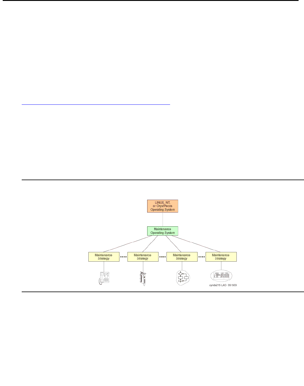
Reliability and Recovery
268 Avaya Application Solutions IP Telephony Deployment Guide
Software and maintenance architecture recovery
The Communication Manager maintenance architecture is designed to detect and correct errors
as they occur. This greatly reduces events that can cause a system outage. This also enables
quick identification (fault isolation) to a replaceable subassembly. This automatic assessment is
done constantly, in the background of normal operation, so errors can be addressed early and
proactively. Component self-testing, subassembly self-testing, error detection and correction,
and system reconfiguration and alarming escalation paths are all elements of this architecture.
The system software is designed to recover from intermittent failures, and to continue providing
service with a minimum of disruption. Firmware that runs each circuit pack does similar tasks at
the module level, working tightly with the system software.
Figure 74: Maintenance management architecture on page 268 shows the various levels of
maintenance strategies that are built into the communication system.
The maintenance subsystem manages three categories of maintenance objects:
●Hardware maintenance objects are tested, and where appropriate alarmed and
removed from service by the software. The error is reported to an operations center so
that the object can be replaced.
●If a software process encounters trouble, it is recovered or restarted.
●Data relationships are audited and corrected.
Figure 74: Maintenance management architecture
All systems are provided with remote diagnostics capability, which enables rapid
troubleshooting and maintenance, in the cases where the system cannot repair itself. Studies
have shown that most problems experienced by Avaya systems are self-corrected without
impact to the customer. Even with the highly reliable hardware components discussed
previously, this sophisticated maintenance management implementation is required to attain
the 99.99 – 99.999+% availability of Avaya systems.
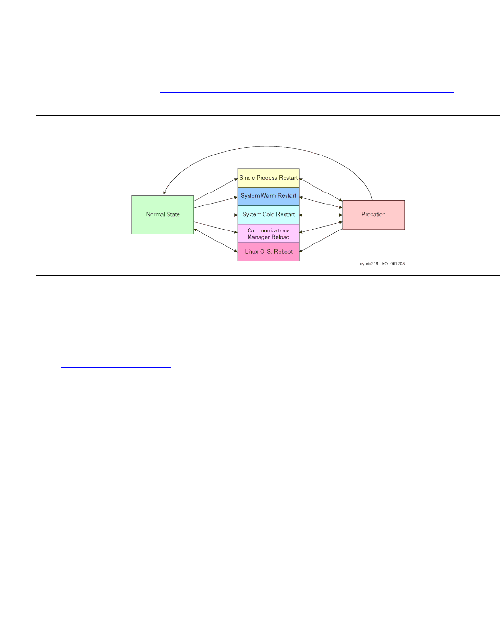
Software and maintenance architecture recovery
Issue 4.3 February 2006 269
Software failure recovery levels
One key to rapid self-recovery of software failures is the judicious use of the appropriate level of
recovery. With too little action, the attempted recovery becomes time wasting and ineffective,
when stronger action should be taken. Conversely, with too much action, the recovery is
unnecessarily prolonged. Figure 75: Avaya Communication Manager’s recovery levels shows
the 5 recovery levels of Communication Manager.
Figure 75: Avaya Communication Manager’s recovery levels
Restarts
These automatic recovery levels are listed from mildest to strongest, which is also from quickest
to slowest and more frequent to less frequent:
●Single process restarts
●System warm restarts
●System cold restarts
●Communication Manager reloads
●Linux operating system reboots on media servers
Single process restarts
Process sanity audits are performed routinely (approximately every 10 seconds) on many
dozens of key software processes. In the event of a process hang, that single process will be
restarted, and no call outage will result. If three single process restarts are needed within a
60-second probationary period, the third single process restart is deemed ineffective, and will
instead escalate to a system warm restart.

Reliability and Recovery
270 Avaya Application Solutions IP Telephony Deployment Guide
System warm restarts
This mechanism preserves all stable and held calls, as well as feature activity data, throughout
the brief recovery period. Processes are essentially started with the same data and stacks that
they were using prior to the warm restart. If three warm restarts are needed within a 15-minute
probationary period, the system warm restart is deemed ineffective, and will instead escalate to
a system cold restart.
System cold restarts
In this recovery mechanism, processes are still started with the same data and stacks that they
were using prior to the cold restart, but calls are dropped and port networks (PNs) are reset,
followed by a port board activation phase of recovery. If three cold restarts are needed within a
15-minute probationary period, the third system cold restart is deemed ineffective, and will
instead be escalated to a Communication Manager reload.
Communication Manager reloads
In this recovery mechanism, all calls are dropped, and all processes that are related to call
processing are stopped and restarted. PN configuration data known as “translations” is reread
from disk, and, as in system cold restarts, PNs are reset, and port boards are activated. If three
Communication Manager reloads are needed within a 10-minute probationary period, the reload
is deemed ineffective, and will instead be escalated to an operating system reboot.
Linux operating system reboots on media servers
In this recovery mechanism, all calls are dropped, all processes are killed, and the operating
system is completely rebooted. Processes are then read off disk and loaded into memory,
where recovery then proceeds exactly as it does in Communication Manager reloads. If the
reboot fails after a recent software upgrade, another reboot is attempted, but from a disk
partition containing the previous version of software.
For the S8700-series Media Server, this implementation is expected to result in a weighted
average of 2 minutes per year or less of call-affecting time out of service that can be attributed
to software.

Avaya Linux servers
Issue 4.3 February 2006 271
Avaya Linux servers
The high availability philosophy is scrupulously implemented in the Avaya S8700-series Media
Server complex:
●Linux is the operating system (OS) for many reasons:
- Provides access to full source for quicker bug-fix turnaround
- Allows easy system customization for high availability enhancements
- Exhibits fewer known security flaws than other OSs, and allows customization for added
security features
●Two servers with a memory shadowing link allow:
- One processor to take over when the other fails.
- Simple duplication of all other server components (for example, modem, disk, or
memory) to eliminate a single point of failure.
- Connection-preserving upgrades with insignificant time out of service.
●High availability enhancements:
- Software sanity is continuously evaluated. Any insanity (due to unexpected conditions) is
detected, and the offending software is forced to go through escalating levels of recovery
until finally the entire system can switch over to a standby processor.
- Disks are partitioned to keep most of the variable information away from the invariant,
and to allow for automatic recovery if newly loaded software fails.
- All event logs are proactively scanned for potential service-affecting items. If found,
alarms are generated. If necessary, a service dispatch is launched.
- Applications running on the OS are thoroughly pre-tested to assure proper performance.
This OS is closed to any applications other than those provided by the manufacturer to
avoid interference of operation. Alarms can be generated if any untested software is
loaded on the system.
- Customers and technicians (in most cases) can access the operating system shell
directly, providing protection from inadvertent adverse alterations to the system.
- Enhanced tools allow secure, remote, nonstop system debugging and unattended data
collection.

Reliability and Recovery
272 Avaya Application Solutions IP Telephony Deployment Guide
Avaya S8700-series server complex
While all businesses require solid performance from their communications systems, there are
increasing levels of “availability” performance needed. To meet that need, the Avaya Linux
servers and their associated gateways accommodate different reliability levels, as shown in
Table 41: S8700-series platforms.
The Avaya S8700-series Media Server also provides:
●Automatic restoration of the most recently saved versions of translations following a power
outage. Translations are automatically shadowed onto the standby server across a
high-speed fiber optic link for memory duplication.
Note:
Note: Translations can also be copied to S8300 Local Spare Processors (LSPs) in
G700, G350, and G250 Media Gateways for automatic recovery in the case of
network partitioning or complete central site failure.
●Scheduled backups of critical system information locally and/or at remote sites. In an
emergency, multiple copies of Communication Manager translations and server
configuration information are available. Saved information can be quickly restored.
Table 41: S8700-series platforms
Configuration Servers Control Network Bearer Network
CSS/ ATM
fiber connect Duplex
S8700-series
media servers
●Duplicated IPSI
(High)
●Single IPSI
(Standard)
●Duplicated ATM/CSS Port
Network Connectivity
(Critical)
●Single ATM/CSS PNC
(High and Standard)
●Duplicated IP Bearer PNC
IP connect Duplex
S8700-series
media servers
●Duplicated IPSI
(High)
●Single IPSI
(Standard)
●Single IP Bearer PNC
●Duplicated IP Bearer PNC
Combination of
IP connect and
fiber connect
Duplex
S8700-series
media servers
●Duplicated IPSI
(High)
●Single IPSI
(Standard)
●May combine High
Fiber-Connect and
Standard
IP-Connect,
●Duplicated ATM/CSS PNC
in Fiber Connect portion
●Single ATM/CSS PNC in
Fiber Connect portion
●Single IP Bearer PNC
●Duplicated IP Bearer PNC

Avaya Linux servers
Issue 4.3 February 2006 273
●Ability to recover from software failures through server interchanges. If the active server
needs to perform a non-call-preserving restart, the standby server can take over under a
slightly different operating system environment with nothing more than a call-preserving
warm restart. This ability is expected to enhance even traditional abilities, as it provides a
fail-safe mechanism to recover from obscure, intermittent “bugs.” (This is allowed by
processes duplicated on each server deliberately not running in lock-step
synchronization).
S8700-series system availability
Table 42: S8700-series system availability in 3 reliability configurations lists the fiber connect
hardware that is available in the three reliability configurations.
Note:
Note: This availability does not include availability of the customer’s data networks,
PSTN contributions, or contributions due to power outages. A conservative
MTTR of 4 hours in the event of hardware failure is assumed, which includes
travel and repair time.
Table 42: S8700-series system availability in 3 reliability configurations1
Standard (duplex) reliability High reliability Critical reliability
Sub-system Failures
per year MTBO
(years) Availability2
(%) Failures
per year MTBO
(years) Availability2
(%) Failures
per year MTBO
(years) Availabilit
y
(%)
S8700
Server
complex3
0.1095 9.1 99.995 /
99.998 <0.01095 >91.3 >99.9995 <0.01095 >91.3 >99.9995
SCC1.
MCC1,
G650 Media
Gateways4
0.153 6.5 99.993 /
99.997 0.0657 15.2 >99.9975 /
99.999 <0.01095 >91.3 >99.9995
CSS Intf 0.1095 9.1 99.995 /
99.998 0.0876 11.2 >99.996 /
99.998 <0.01095 >91.3 >99.9995
1. September 30, 2005 data.
2. The lower number is the equivalent availability for MTTR of 2 hours in the event of hardware failure, which is
attainable with technicians and spares on site. See also Reliability and availability.
3. For high and critical reliability, the S8700-series Media Server complex has duplicated servers, dedicated
Ethernet switches, and UPSs. The duplex reliability configuration consists of duplicated servers and a UPS for
each, with a single, dedicated Ethernet switch.
4. Standard reliability assumes a single IPSI per PN or shared IPSI across multiple PNs. High reliability assumes
duplicated IPSIs per carrier in each PN. Critical reliability assumes duplicated IPSIs per carrier and duplicated
bearer connectivity either through duplicated CSS/ATM PNC or through duplicated IP-bearer PNC.
5. Duplicated IPSIs help with two situations. First, a pair eliminates single point of failure for this module itself.
More significantly, a pair allows dual paths through a duplicated data network.

Reliability and Recovery
274 Avaya Application Solutions IP Telephony Deployment Guide
Avaya S8500 Media Server
The Avaya S8500 Media Server is a highly reliable server in a simplex mode. The server’s high
reliability is due to the following architecture:
●RAM DISK, which supports survivability from disk crashes, this allows the server to
provide call processing for up to 72 hours without administration capabilities.
●Co-resident Remote Maintenance Board, which provides the following functionality
regardless of the state of the server:
- Ability to report alarms to Avaya Services over the modem dial out
- Ability to report alarms over the LAN
- Ambient temperature, power supply voltage and fan monitoring, and administration
- Ability to report complete server failure
Such continuous monitoring and the alarming capability existing as part of the Media Server
helps to reduce the failure diagnostic period and as a result much shorter recovery time from
outages
.Table 43: S8500 reliability configurations
Configuration Server Control Network Bearer Network
Fiber Connect
(Direct) Simplex
S8500(B) Simplex IPSI Simplex PNC
IP Connect Simplex
S8500(B) Simplex IPSI Simplex IP PNC
Combination of
Fiber Connect
and IP-Connect
Simplex
S8500(B) Simplex IPSI Simplex PNC in
Fiber Connect and
Simplex IP PNC
Table 44: S8500 system availability in fiber connect and IP connect Configurations
Standard (duplex) reliability
Sub-system Failures/year MTBO (years) Availability
S8500 Simplex Server 0.12 8.1 99.994
S8500 Server Complex1
1. Server Complex includes S8500 server, Ethernet Switch (hardware MTBO = 16 years)
and UPS.
0.43 2.3 99.98
MCC1/SCC1 Media Gateways
(fiber connect) 0.15 6.5 99.993/
99.997
G650 Media Gateway
(IP connect) 0.05 20 99.998
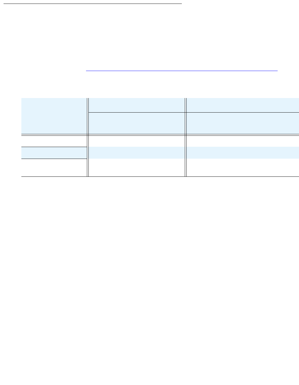
Avaya Linux servers
Issue 4.3 February 2006 275
Avaya S8300 Media Server with Media Gateways
The Avaya S8300 Media Server, like the Avaya S8700-series Media Server, accommodates
several levels of availability performance. In contrast to the S8700 that uses various levels of
duplication for processing and port network (PN) connectivity for bearer and signaling to add
heightened layers of availability, the S8300 is designed to use a Local Spare Processor (LSP).
LSP architecture provides added availability, and survivability to a network of small to
medium-sized offices. Table 45: S8300 system availability in two reliability configurations
shows the S8300/G700/G350 availability coverage:
Note:
Note: This availability does not include availability of the customer’s data networks,
PSTN contributions, or contributions due to power outages. A conservative
MTTR of 4 hours is assumed, which includes travel and repair time.
Table 45: S8300 system availability in two reliability configurations1
1. September 30, 2005 data. Based on engineering estimates and field performance.
Subsystem Standard reliability2
2. Standard Reliability:
S8300 — Single Internal Call Controller (ICC) equipped Media Gateway per site.
G700/G350 — Media Gateway interface to the call controller is supported by a non-redundant data
network.
High reliability3
3. High Reliability:
S8300 — Can failover to an LSP; N+1 media gateways at each site; each site has duplicate interfaces to
the data network: each IP endpoint is homed to at least 2 systems that are run by Communication Manager
(S8300, or otherwise). Avaya IP Telephones have multi-homing abilities, and can be configured to re-home
to any Communication Manager-run system. For example, in a configuration with S8700 at a main site and
G700 at remote site, the telephones at the remote site could re-homed to main S8700 through separate
Ethernet switches. This configuration could be said to provide 99.99% availability as well.
G700/G350 — Can failover to LSP upon a link failure; N+1 Media Gateways at each site with duplicate
interfaces to the data network. IP phones can home to an alternate gatekeeper (S8300, S8500, S8700, or
LSP).
Failures
per year MTBO
(years) Availability
(%) Failures
per year MTBO
(years) Availability
(%)
S8300 Media Server 0.22 4.6 99.99 0.1 9.1 99.995
G700 Media Gateway 1.1 4.6 99.99 0.219 9.1 99.995
G150, G250, G350
Media Gateways 1.1 4.6 99.99 0.219 9.1 99.995

Reliability and Recovery
276 Avaya Application Solutions IP Telephony Deployment Guide
Avaya DEFINITY Server R
Avaya DEFINITY Server CSI
Table 46: Avaya DEFINITY Server R system availability for 3 reliability configurations1
Sub-
system Standard reliability
(single processor complex) High reliability
(duplicated processor complex) Critical reliability
(duplicated port network
connectivity)
Failures
per year MTBO
(years) Availability2
(%) Failures
per year MTBO
(years) Availability2
(%) Failures
per year MTBO
(years) Availability
(%)
G3R
Processor
Complex
0.153 6.5 99.993 /
99.997 <0.01095 >91.3 >99.9995 <0.01095 >91.3 >99.9995
SCC1 or
MCC1
Media
Gateways
0.153 6.5 99.993 /
99.997 0.0657 15.2 0.99997 /
99.999 <0.01095 >91.3 >99.9995
CSS Intf 0.1095 9.1 99.995 /
99.998 0.0876 11.2 99.996 /
99.998 <0.01095 >91.3 >99.9995
1. Running Avaya Communication Manager (September 30, 2002 data).
2. The lower number is the equivalent availability for MTTR of 2 hours in the event of hardware failure, which is
attainable with technicians and spares on site. See also Reliability and availability.
Table 47: Avaya DEFINITY Server CSI system availability for 2reliability configurations1
1. Running Avaya Communication Manager (September 30, 2002 data).
Sub-
system Standard reliability
(single processor carrier) High reliability
Failures
per year MTBO
(years) Availability2
(%)
2. The lower number is the equivalent availability for MTTR of 2 hours in the event of hardware failure,
which is attainable with technicians and spares on site. See also Reliability and availability.
Failures
per year MTBO
(years) Availability2
(%)
SCC1 or MCC1
Media Gateways 0.153 6.5 99.993 /
99.997 0.0657 15.2 99.997

Survivability solutions
Issue 4.3 February 2006 277
Survivability solutions
Avaya Communication Manger release 3.0 introduces new features in support of enhancing
high availability and survivability. These features are in support of business continuity through
unscheduled outages such as network failure and congestion as well as scheduled outages
such as server upgrades.
General survivability features:
●S8700-series server separation
●Enterprise Survivable Server (ESS)
●Connection preserving upgrades for duplex servers
●Inter-Gateway Alternate Routing (IGAR)
Survivability for branch office media gateways:
●G700/G350 Media Gateway recovery via LSP
●Modem dial backup
●Auto fallback to primary Communication Manager for H.248 media gateways
●Connection-preserving failover for H.248 gateways
●G250 Media Gateway local survivability function (SLS)
Figure 76: Release 3.0 system example on page 278 summarizes these enhancements:
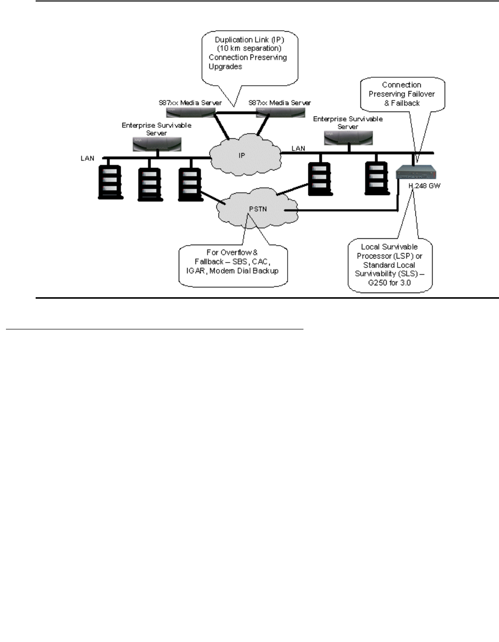
Reliability and Recovery
278 Avaya Application Solutions IP Telephony Deployment Guide
Figure 76: Release 3.0 system example
S8700-series Server Separation
S8700-series server separation allows the two servers in an S8700-series Media Server pair to
be geographically separated up to a maximum distance of 10 kilometers over a fiber-optic link.
Separating the servers offers an improved survivability option by allowing servers to reside in
two different buildings across a campus or small Metropolitan Area Network. This feature
capability is applicable to the S8700-series Media Servers in both fiber connect and IP connect
configurations.
The sever separation feature works best when each server is accompanied by its own Layer 2
Ethernet switch. For example, in a fiber connect system, each server would have an Ethernet
switch co-located with it. The two Ethernet switches would be connected using a 100base-FX or
Gigabit Ethernet link. For optimum results, the port networks should also be distributed with
respect to Ethernet switches.
Note:
Note: S8700-series Server Separation does not provide for separation of duplicated
center stage switch port network connectivity (CSS-PNC) in a critical reliability
configuration.

Survivability solutions
Issue 4.3 February 2006 279
Enterprise survivable servers (ESS)
The Enterprise Survivable Server (ESS) is a survivability option for S8700-series and S8500/
S8500(B) systems and is available with the Communication Manger release 3.0 and later. ESS
option provides survivability to an Avaya configuration by allowing backup servers to be placed
in various locations in the customer’s network. The backup servers (ESS servers) are given
administered values that are advertised to each IPSI in the configuration. The IPSI places the
ESS server on a priority list based on the administered values. If for any reason, the IPSI can no
longer communicate with the Main server, the IPSI request service from the next highest priority
ESS server on its list. The ESS server accepts the request and assumes control of the IPSI
controlled port network.
The IPSI request for ESS service will happen after an administered “No-Service” timer expires.
The value of the No-service timer determines the amount of time the IPSI will wait to request
service from an ESS server, after losing communication with the Main server or the controlling
ESS server. The value for the No-service timer is administrable from three to 15 minutes.
During No-Service timer interval stable calls remain up in the same state as they were before
the outage occurred. The stable calls do not have access to any features such as hold,
conference, etc. After the No-Service timer expires, shuffled IP to IP calls will stay up, but calls
on DCP or analog phones will terminate.
When service to main is restored, the IPSI(s) will return to the control of the main server in the
manner administered by the customer, which can be either manually or according to a
scheduled time.
In an ESS environment, there is one Main server. The Main server can be a S8500 (B) simplex
server or a pair of S8700-series servers. If the Main server is an S8500 Media Server, all ESS
servers in the configuration must also be S8500 Media Servers.
ESS provides a survivability option for port networks of the following platforms:
●S8700-series fiber-connect with ATM port network connectivity
●S8700-series fiber-connect with CSS port network connectivity
●S8700-series/S8500(B) IP connect systems
●System with combination of fiber-connect and IP-connect
Through careful planning and consideration, S8700-series and/or S8500 Media Servers are
placed in various locations in the customer’s network. Each ESS server is administered on the
Main server. The IPSIs in the configuration contain a list (called a priority list) of ESS servers.
The Main server is always the highest ranking server on an IPSI’s priority list.

Reliability and Recovery
280 Avaya Application Solutions IP Telephony Deployment Guide
ESS System Capacities
ESS can be administered as “local only” or as an “enterprise-wide” survivable server(s). When
administered as “Local only”, which indicates it will act as the survivable server for a community
or a subset of port networks, up to 63 ESS server clusters can be configured as ESS. This way
the customer may configure some ESSs to serve only a few port networks in order to enable
localization of failover where desired.
For enterprise-wide fail-over coverage, up to 7 ESS server clusters can be administered. The
ESS which acts as a main server is called System Preferred ESS, and it must have the same
capacity as the original main. For example when an S8500 Media Server is the System
Preferred ESS to S8700/S8710 main server, it will be configured to have the same capacities as
the S8700/S8710 Media Servers. This can be done based on its license files.
Depending on the type of failure and how the ESS servers are configured, an individual ESS
server may accept control of all port networks, several port networks, a single port network, or
no port networks. When a LAN or WAN failure occurs in configurations where port networks are
widely dispersed, multiple ESS servers may be required to collectively accept control with each
ESS server controlling some portion of the set of port networks.
When an ESS server accepts control, it communicates directly with each MCC1, CMC1, SCC1,
G600, or G650 Media Gateway through the gateway’s IPSI board. In ATM PNC configuration,
the ESS server can also control non-IPSI controlled port networks through an Expansion
Interface board. The ESS server communicates indirectly with each G250, G350, or G700
Media Gateway through CLAN connections in the port networks.
Stable calls remain up in the same state as they were before the outage occurred. The stable
calls do not have access to any features such as hold, conference, etc. The state of the stable
call cannot be changed.
ESS software and hardware requirements
Systems supported by ESS for survivability should comply with the configuration rules outlined
in this section.
ESS servers
Communication manager 3.0 (and later) Enterprise Edition ESS server can be an S8500(B) or
S8700-series Media Server or any combination except when the Main server is an S8500:
●Each ESS needs to be licensed to a unique reference IPSI
●IP Network must provide connectivity for all IPSIs, Main Server and ESS(s)
●IPSI and Media Processor are required in remote port networks that need to be survivable
●TN570D (EI Circuit Pack) minimum vintage for ESS with CSS
●TN2305B/TN2306B (ATM EI Circuit Pack) minimum vintage for ESS with ATM PNC
●Dual NIC card, when S8500(B) is an ESS server and supporting a High or Critical
Reliability configuration of S8700/S8710 Duplex Servers

Survivability solutions
Issue 4.3 February 2006 281
Although the S8500(B) is a simplex server, it can support duplicated IPSIs and duplicated
control networks when used as an ESS. Therefore, S8700-series Media Server as main servers
can have S8500(B) and S8700-series as ESS. In this case the S8500(B) ESS is configured with
a board with two additional Ethernet ports. When S8500/S8500(B) is the main server, the ESS
server can only be an S8500(B).
The following rules are platform specific.
ESS rules for S85xx or S87xx IP Connect
ESS does not introduce any new rules to IP Connect configurations.
ESS Configuration rules for S87xx Fiber-Connect with CSS
In this configuration CSS can only be controlled by the main server, thus ESS can not control
the CSS. For a CSS-connected port network to be survivable by an ESS, an IPSI and a Media
Processor is required in the port network. ESS can provide control to IPSI connected port
networks as in an IP Connect system. The port networks which do not have IPSI circuit pack
can not be controlled by an ESS. All IPSI connected port networks must have a TN570D
(minimum vintage) EI boards.
If the customer chooses not to populate IPSIs and Media Processors in every port network, the
non-IPSI connected port networks can not be survivable. If a CSS
connected port network only has an IPSI, it can be served by an ESS but can only complete
calls to other stations or trunks in the same port network. It could not complete calls to
endpoints in other port networks.
ESS configuration rules for S87xx Fiber-Connect with ATM-PNC
In the ATM-PNC environment, ESS can control the ATM connected port networks.
For example, in a distributed environment (building, campus, MAN or WAN network) there could
be multiple port networks controlled by a local ATM switch, while communicating with different
ESSs at each location. ATM EI circuit pack must be TN2305/TN2306 minimum vintage for this
configuration.
ESS configuration rules for Systems with Combined Fiber-Connect and
IP-Connect PNC
ESS does not introduce any new rules to the Mixed PNC configuration rules. In Mixed PNC
configuration rule is summarized as following. In the CSS or ATM and IP connect M-PNC
environment, at least one port network must have the ability to communicate over both CSS (or
ATM-PNC) and IP. That port network acts as a “gateway port network” and it must have at least
one EI or ATM EI circuit pack and one Media Processor (e.g., TN2602AP) circuit pack.
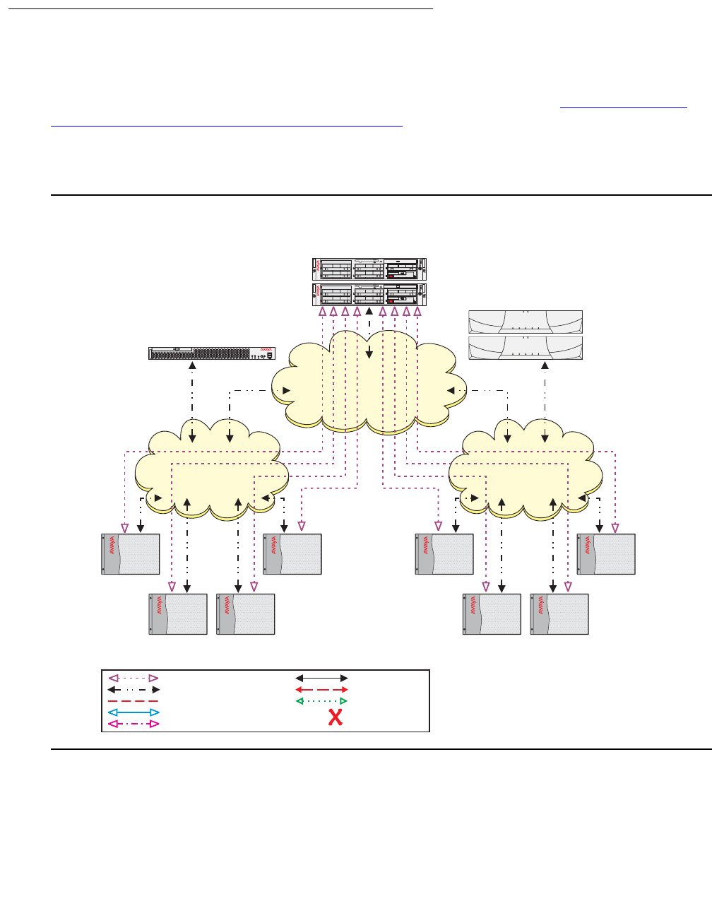
Reliability and Recovery
282 Avaya Application Solutions IP Telephony Deployment Guide
ESS example configurations
Example 1 - Main server failure in an S8700/S8710 IP-Connect platform
In this example the S8710 Media Server is acting as the Main server. See Figure 77: S8710
Media Server with ESS servers in normal operation on page 282. Two ESSs have been
positioned in the network. Through administration on the Main server, an S8700-series Media
Server pair has been selected as the primary backup to the Main server pair. A S8500 Media
Server will act as the alternative backup to the S8710 ESS.
Figure 77: S8710 Media Server with ESS servers in normal operation
UID
2
1
01
1
0
3
23
2
disc
COMPACT
5
45
4
SimplexDuplexch ch2
1
UID
2
1
01
1
0
3
23
2
disc
COMPACT
5
45
4
SimplexDuplexch ch2
1
S8710 Media Server
(Main Server)
cycmsrv3 KLC 031505
disc
S8500 ESS Server
(2nd Alternative)
PN #1 PN #5
PN #2 PN #6PN #3 PN #7
PN #4 PN #8
S8700 ESS Server
(1st Alternative)
Out of Service
CSS / EI (Fiber)
ATM / ATM-EI (Fiber)
Dup Link
Port Network Control Link (EAL)
IP Connection into Control Network
Server or Network Failure
VoIP Path
DSIC LInk

Survivability solutions
Issue 4.3 February 2006 283
A catastrophic failure occurs on the Main server (Figure 2). The IPSI’s in every IPSI controlled
port network can no longer communicate with the Main server. The No-Service countdown timer
activates. Based on the advertised weight of the ESS, the IPSIs have placed the S8700 ESS
higher on their priority list. When the No-Service countdown timer expires, the IPSI(s) request
service from the S8700 ESS (Figure 3). The S8700 ESS acknowledges the request and takes
control of the IPSI controlled port networks.
Example 2 - Recovering from a Network failure followed by a main server failure
Example 2 uses the same configuration used in Example 1. The S8710 Media Server is the
Main server, and a S8700 ESS is administered as the first priority ESS, and the S8500 ESS is
administered as the second priority ESS. Due to a catastrophic failure of the Main server, all
port networks are controlled by the S8700 ESS. Meanwhile the customer experiences a
network fragmentation failure. port networks 1– 4 can communicate with the S8500 ESS, but
can no longer communicate with the Main server or the S8700 ESS. port networks 5 through 8
can still communicate with the S8700 ESS but cannot communicate with the S8500 ESS.
Since the IPSIs in port networks 1 through 4 cannot communicate with the Main server or the
S8700 ESS, they adjust their priority list and move the S8500 ESS to the top of the list. The
IPSI’s in port networks 1– 4 request service from the S8500 ESS. The S8500 acknowledges the
request and assumes control of port network 1– 4. See Figure 78: Main server and network
failure — ESS recovery on page 284.
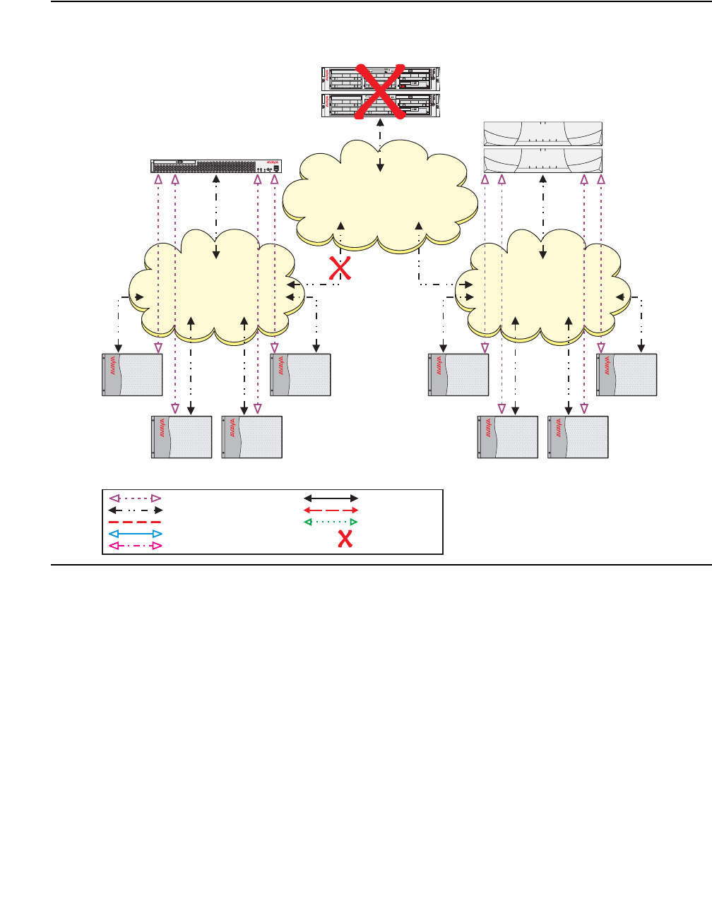
Reliability and Recovery
284 Avaya Application Solutions IP Telephony Deployment Guide
Figure 78: Main server and network failure — ESS recovery
When the network failure is fixed, the IPSIs in port network 1 through 4 can communicate with
the S8700 ESS. The IPSI priority list adjusts to reflect the S8700 ESS as the highest priority
ESS. Nevertheless, The port networks do not automatically return to the control of the S8700
ESS. Moving the port networks from the S8500 ESS to another ESS requires manual
intervention
When the Main server is restored, all IPSIs are able to communicate with the Main server and
each ESS. The Main server is always the highest priority on any IPSI
priority list. In this example the Main server is once again the highest priority followed by the
S8700 ESS. Even though the IPSIs can now communicate with the Main server they do not
automatically fail-back to the control of the Main server.
UID
2
1
01
1
0
3
23
2
disc
COMPACT
5
45
4
SimplexDuplexch ch2
1
UID
2
1
01
1
0
3
23
2
disc
COMPACT
5
45
4
SimplexDuplexch ch2
1
S8710 Media Server
(Main Server)
cycmerf2 KLC 031505
disc
S8500 ESS Server
(2nd Alternative)
PN #1 PN #5
PN #2 PN #6PN #3 PN #7
PN #4 PN #8
S8700 ESS Server
(1st Alternative)
Out of Service
CSS / EI (Fiber)
ATM / ATM-EI (Fiber)
Dup Link
Port Network Control Link (EAL)
IP Connection into Control Network
Server or Network Failure
VoIP Path
DSIC LInk

Survivability solutions
Issue 4.3 February 2006 285
Example 3 - ESS with Multiple Center Stage Switch (CSS) Nodes
When a Center Stage Switch system fails over to an ESS server, the port network connectivity
will transition to IP-Connect. In order to transition to IP, each port network must have an IPSI
and IP Media Processor board. Port networks that do not have an IPSI and IP Media Processor
board are not survivable.
In Example 3, there is a multiple node CSS controlled by the S8710 Main server. See
Figure 79: Ess with multiple CSS nodes on page 286.
Port network 2 is connected to the CSS node in port network 3. Port network 5 is connected to
the CSS node in port network 4. There is no IPSI in either port network 2 or port network 5. A
network outage occurs that stops communication from the Main server to port networks 4
through 6. The Main server continues to provide service to port networks 1 through 3. The no
service timer activates for port networks 4 and 6. After the no service timer expires, the IPSI in
port network 4 and port network 6 request, and receive service from the S8700 ESS server. The
ESS server cannot take control of the CSS node in port network 4. The CSS node in port
network 4 is not utilized. port network 5 is also not utilized as it does not have an IPSI and can
no longer communicate with the CSS node in port network 4. port networks 1, 2, and 3, are not
affected by the outage.
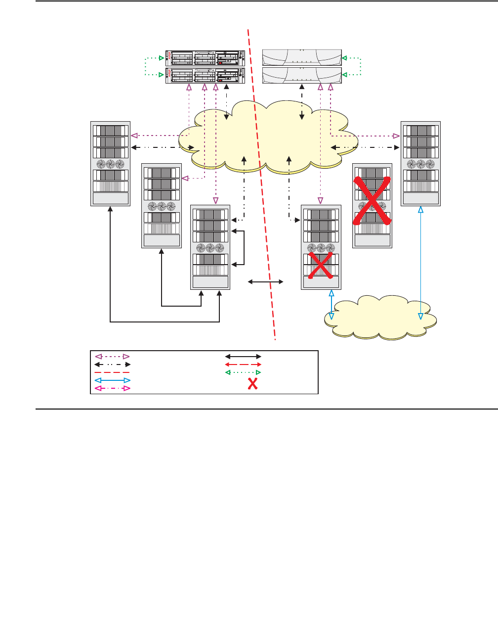
Reliability and Recovery
286 Avaya Application Solutions IP Telephony Deployment Guide
Figure 79: Ess with multiple CSS nodes
For port networks that do not have an IPSI but are controlled by the Main server(s) through ATM
connections, an ESS server similarly communicates indirectly through an IPSI controlled port
network, and then through an ATM connection (TN2305B or TN2306B ATM Expansion
Interface board). This configuration is shown in examples 4, 5, and 6.
LAN (IP PNC)
CSS CSS
UID
2
1
01
1
0
3
23
2
disc
COMPACT
5
45
4
SimplexDuplexch ch2
1
UID
2
1
01
1
0
3
23
2
disc
COMPACT
5
45
4
SimplexDuplexch ch2
1
S8710 Media Server
(Main Server)
PN #1
PN #2
PN #3
PN #6
PN #5
PN #4
S8700 ESS Server
(1st Alternative)
cycmcss6 KLC 031505
PN #2 remains in service
Out of Service
CSS / EI (Fiber)
ATM / ATM-EI (Fiber)
Dup Link
Port Network Control Link (EAL)
IP Connection into Control Network
Server or Network Failure
VoIP Path
DSIC LInk
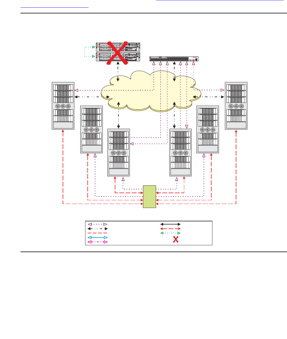
Survivability solutions
Issue 4.3 February 2006 287
Example 4 - Main Server Failure, Single ATM Node
In Example 4, there is a single ESS server in an ATM configuration. The S8710 is the Main
server and the S8500 Media Server is configured as the ESS server. IPSIs are installed in all
port networks except port networks 2 and 5. See Figure 80: Server failure in a single ATM with
single ESS configuration.
Figure 80: Server failure in a single ATM with single ESS configuration
A catastrophic failure occurs on the S8710 Media Servers. The IPSIs request service of the
S8500 Media Server after the no-service timer expires.
The S8500 Media Server assumes control of port network 1, 3, 4, and 6. Once the S8500 ESS
server assumes control of the port network, it attempts to take over all other port networks in the
system through the ATM Expansion Interface (EI) board (TN2305B or TN2306B).
Since no other servers are controlling port network 2 and port network 5, the attempt by the
S8500 ESS server to control it through ATM EI is successful.
UID
2
1
01
1
0
3
23
2
disc
COMPACT
5
45
4
SimplexDuplexch ch2
1
UID
2
1
01
1
0
3
23
2
disc
COMPACT
5
45
4
SimplexDuplexch ch2
1
S8710 Media Server
(Main Server)
PN #1 PN #6
PN #2 PN #5
PN #3 PN #4
cycmatm2 KLC 031605
disc
S8500 ESS Server
(1st Alternative)
ATM
PN #2 does not have
an IPSI but remains in
service via PN #3
PN #5 does not have
an IPSI but remains in
service via PN #4
Out of Service
CSS / EI (Fiber)
ATM / ATM-EI (Fiber)
Dup Link
Port Network Control Link (EAL)
IP Connection into Control Network
Server or Network Failure
VoIP Path
DSIC LInk
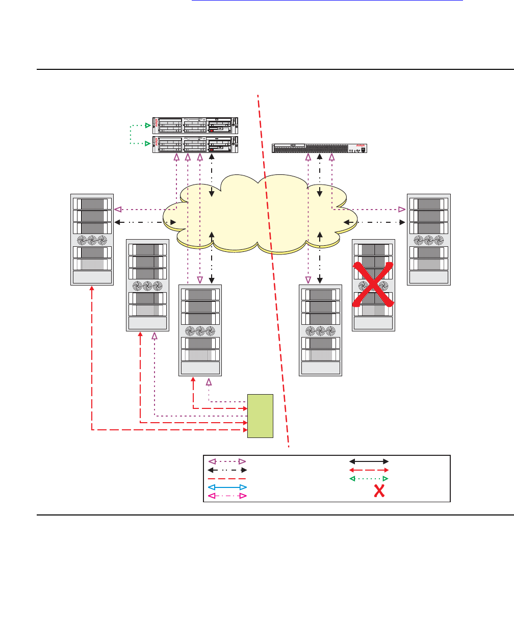
Reliability and Recovery
288 Avaya Application Solutions IP Telephony Deployment Guide
Example 5 - Network Failure, Single ATM Node
In this example, the configuration is the same as in Example 4 but a network failure occurs
instead of a server failure. See Figure 81: Network failure — single ATM configuration
Communication between the Main server and port networks 1 through 3 has not been affected
by the outage. The IPSIs in port network 4 and port network 5 can no longer communicate with
the Main server. The no service timer activates. When the no service timer expires the IPSIs in
port networks 4 and 5 request service from the S8500 ESS server.
Figure 81: Network failure — single ATM configuration
Once the ESS server controls a port network with an IPSI, the ESS server may then attempt to
communicate with, and possibly control, a non-IPSI PN through the ATM network. However, the
S8500 ESS server cannot communicate with the ATM switch and therefore cannot take control
of port network 5 through the ATM connection (EI board).
UID
2
1
01
1
0
3
23
2
disc
COMPACT
5
45
4
SimplexDuplexch ch2
1
UID
2
1
01
1
0
3
23
2
disc
COMPACT
5
45
4
SimplexDuplexch ch2
1
S8710 Media Server
(Main Server)
PN #1 PN #6
PN #2 PN #5
PN #3 PN #4
cycmatm5 KLC 031505
disc
S8500 ESS Server
(1st Alternative)
ATM
Out of Service
CSS / EI (Fiber)
ATM / ATM-EI (Fiber)
Dup Link
Port Network Control Link (EAL)
IP Connection into Control Network
Server or Network Failure
VoIP Path
DSIC LInk
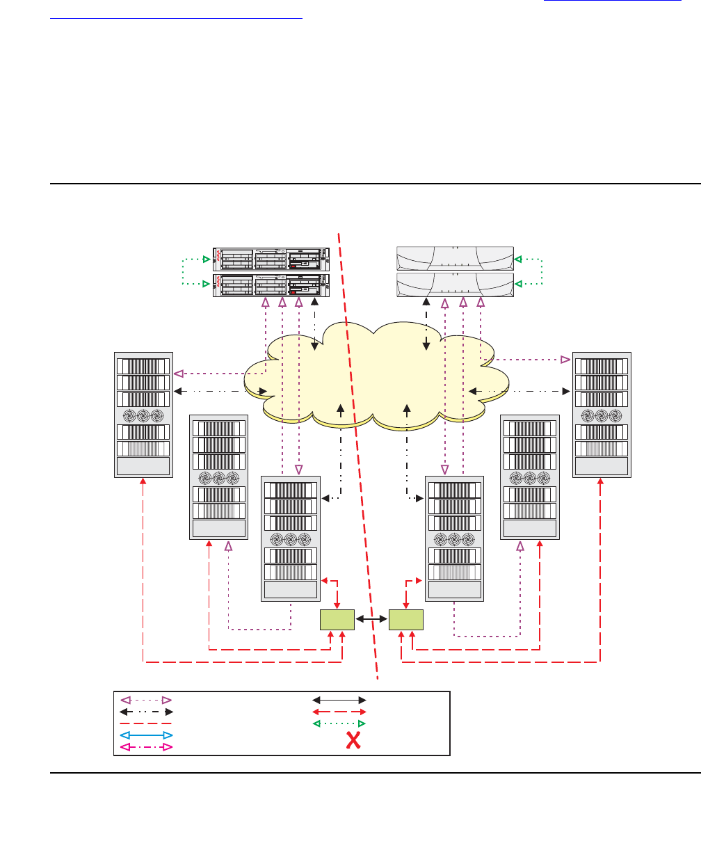
Survivability solutions
Issue 4.3 February 2006 289
Example 6 - Distributed ATM Switches
In example 6, there is a single ESS server with multiple ATM nodes. See Figure 82: Network
failure — multiple ATMs configuration on page 289. Port Network 2 connects to the ATM node
on the left side of the figure using an ATM Expansion Interface (EI) board and does not have an
IPSI. Port network 5 connects to the ATM node on the right side of the figure using an ATM EI
board and also does not have an IPSI.
A network outage occurs that fragments the two ATM and IP networks. The Main server
continues to provide service to port networks 1 through 3 with no service interruption. The IPSIs
in port network 4 and 6 requests service of the S8700 ESS server after the no-service timer
expires. The S8700 ESS server assumes control of port network 4 first. Once in control of port
network 4, the ESS server assumes control of port network 5 through the EI board.
Figure 82: Network failure — multiple ATMs configuration
ATM ATM
UID
2
1
01
1
0
3
23
2
disc
COMPACT
5
45
4
SimplexDuplexch ch2
1
UID
2
1
01
1
0
3
23
2
disc
COMPACT
5
45
4
SimplexDuplexch ch2
1
S8710 Media Server
(Main Server)
PN #1
PN #2
PN #3
PN #6
PN #5
PN #4
S8700 ESS Server
(1st Alternative)
cycmatm4 KLC 031505
Out of Service
CSS / EI (Fiber)
ATM / ATM-EI (Fiber)
Dup Link
Port Network Control Link (EAL)
IP Connection into Control Network
Server or Network Failure
VoIP Path
DSIC LInk
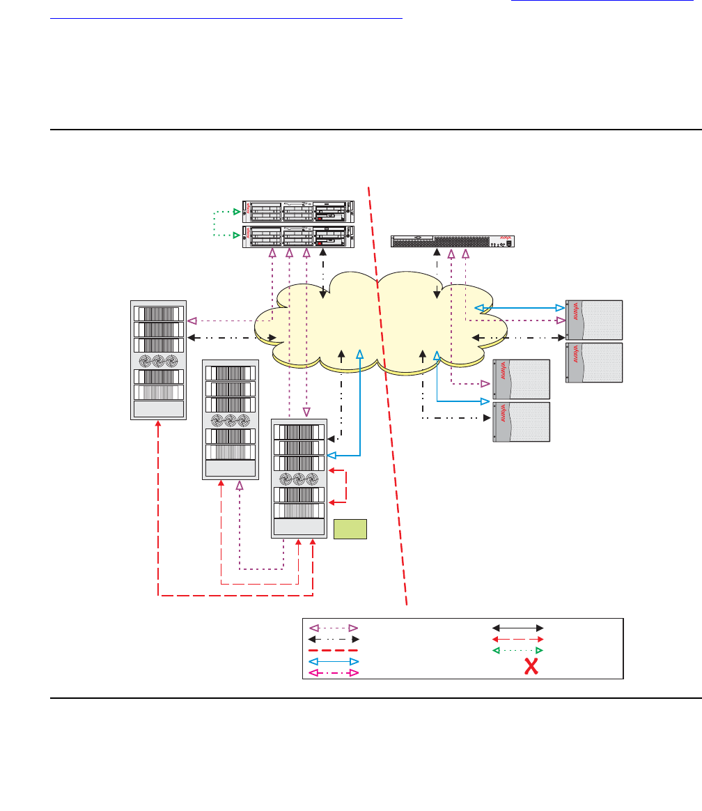
Reliability and Recovery
290 Avaya Application Solutions IP Telephony Deployment Guide
Example 7 - Combined IP connected port networks with CSS or ATM connected port networks
In this example, the configuration is a mixture of IP connect and fiber connect. Port network 1
through 3 are part of a Center Stage Switch connectivity. IPSIs are installed in port networks 1
and 3. Port network 2 connects to the Main server through port network 3. Port networks 4 and
5 both have IPSIs and use IP connect port network connectivity. See Figure 83: Network failure
— IP connect mixed with fiber connect configuration on page 290.
A WAN failure occurs. Port networks 4 and 5 can no longer communicate with the Main server
but can still communicate with the S8500 ESS server. After the no service timer expires, the
IPSIs in port networks 4 and 5 request service from the S8500 ESS server. The S8500 ESS
server assumes control of port networks 4 and 5. Port networks 1, 2, and 3 remain under the
control of the Main server and do not experience any service interruptions.
Figure 83: Network failure — IP connect mixed with fiber connect configuration
UID
2
1
01
1
0
3
23
2
disc
COMPACT
5
45
4
SimplexDuplexch ch2
1
UID
2
1
01
1
0
3
23
2
disc
COMPACT
5
45
4
SimplexDuplexch ch2
1
S8710 Media Server
(Main Server)
PN #1
PN #2
PN #3
cycmpnc2 KLC 031505
disc
S8500 ESS Server
(1st Alternative)
PN #4
PN #5
ATM
PN #2 remains in service
WAN Failure
Remote Site
Out of Service
CSS / EI (Fiber)
ATM / ATM-EI (Fiber)
Dup Link
Port Network Control Link (EAL)
IP Connection into Control Network
Server or Network Failure
VoIP Path
DSIC LInk

Survivability solutions
Issue 4.3 February 2006 291
ESS and H.248 Media Gateways
The H.248 G700/G350/G250/G150 Media Gateways are not directly supported by the ESS
feature. In the event of a failure they may re-register to ESS(s) through CLAN contained in port
network which has requested an ESS, or they have the option of re-registering to an LSP.
ESS and Adjunct Survivability
Most adjuncts register with CLAN, which in the event of failure will follow the port network IPSI
to an ESS. If the port network containing the CLAN cannot get service from an ESS, then the
adjunct will not be survivable. Having CLAN in IPSI connected port networks will give the
adjunct higher probability of survival.
Connection preserving upgrades for duplex servers
This feature is designed for preserving stable bearer connections for TDM end points and IP
stations during an upgrade of S8700/S8710 duplex servers. TDM and IP connection of H.248
Media Gateways, with the S8700/S8710 being the main call controller will also be preserved.
This feature is supported on all S8700 and S8710 Linux servers running Avaya Communication
Manager 3.0. It is supported on all H.248 Media Gateways and all port networks (including
G650 MG). It will apply on upgrade from Avaya CM 3.0 to a newer release, and does not apply
on upgrade to Avaya CM 3.0.
This feature is not call preserving and only preserves connection on stable calls. Connection
preservation will not apply to calls involving H.323 IP trunks; these are H.323 IP calls and SIP
calls. Connection preservation will not apply to IP trunks and ISDN-BRI stations and trunks
using H.248 Media gateways resources.
Inter Gateway Alternate Routing (IGAR)
This feature enables systems with distributed branch offices and distributed call centers an
alternate means of providing bearer connection between port networks and gateways when the
IP-WAN is incapable of carrying the bearer traffic. IGAR may request that bearer connections
be provided by the PSTN under the following conditions:
The number of calls allocated or bandwidth allocated via Call Admission Control – Bandwidth
Limits (CAC-BL) has been reached.
●VoIP RTP resource exhaustion in a MG/PN is encountered.
●A codec set is not specified between a network region pair.
●Forced redirection between a pair of network regions is configured.

Reliability and Recovery
292 Avaya Application Solutions IP Telephony Deployment Guide
●The number of calls allocated or bandwidth allocated via Call Admission Control –
Bandwidth
●Limits (CAC-BL) has been reached.
IGAR takes advantage of existing public and private-network facilities provisioned in a network
region.
Most trunks in use today can be used for IGAR. Examples of the better trunk facilities for use by
IGAR
would be:
●Public or Private ISDN PRI/BRI
●R2MFC
IGAR is the next logical step in providing Quality of Service (QoS) to large distributed
single-server configurations.
IGAR relies on Call Admission Control. When all VoIP RTP resources have been used the next
attempt to get a VoIP RTP resource results in denial of the VoIP connection. CM 3.0 will attempt
to use existing applications and features to redirect the call accordingly. Each IP audio stream
will require a VoIP RTP resource from either a TN2302AP IP Media Processor or a G700 media
gateway. Exactly how many audio streams can be supported by these resources depends on
the codec selection. Upon hitting the VoIP RTP resource limit, IGAR immediately attempts to
use an alternate path for a bearer connection to the network region of the called party using
PSTN facilities allocated for use by the IGAR feature.

Survivability for branch office media gateways
Issue 4.3 February 2006 293
Survivability for branch office media gateways
This section describes the survivability features for branch-office media gateways.
G700/G350/G250 Media Gateway recovery via LSP
If the link between the remote media gateway and the media gateway controller is broken, or
the controller is down, the local survivable processor (LSP) activates and assume call
processing for the media gateway. The media gateway controller can be the S8700, S8500, or
S8300. The strategy by which the media gateways change control from the primary to the LSP
controller is driven by the gateway using the media gateway controller list.
When the media gateway controller
is S8700-series or S8500 media server
Note:
Note: The following description applies to the S8500 as well as the S8700-series media
server.
In this configuration, the connectivity path between the remote Media Gateway and the S8700
Call Controller is as follows:
Media Gateway <=> IP network <=> C-LAN <=> PN back plane <=> IPSI <=> IP network <=> S8700
Link connectivity between the S8700 call controller and the G700 or G350 media gateway is
monitored through the exchange of keepalive messages between the two components. If the
link between the active call controller and the media gateway is severed, the gateway tries to
reestablish the link using its alternate gatekeeper list. The alternate gatekeeper list is divided
into primary and secondary addresses. All primary addresses receive priority weighting over the
secondary addresses. Normal practice is to designate all C-LANs for the primary controller as
primary gatekeeper addresses, and all the Local Survivable Processors (LSP) as secondary
addresses. This practice gives a media gateway the best possible chance of registering with its
primary call controller before registering with the LSP and entering into survivable mode.
In the event of a WAN failure, any IP telephone or media gateway that cannot reach the primary
controlling server can register with an LSP controller in survivable mode. In the S8700/G700/
G350 configuration, up to 50 LSPs are available and ready for the fail-over process. The LSP,
an S8300 or S8500 media server running Avaya Communication Manager software, is always
ready to acknowledge service requests from IP telephones and gateways that can no longer
communicate with their main controller. Once the phones and the gateway are registered, end
users at the remote site have full feature functionality. This failover process usually takes less
than 5 minutes. After failover, the remote system is stable and autonomous.
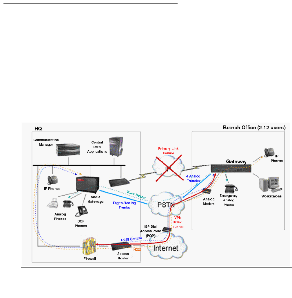
Reliability and Recovery
294 Avaya Application Solutions IP Telephony Deployment Guide
S8300/G700/G350 configuration
In this configuration, the connectivity path between the G700 or G350 Media Gateway and the
S8300 Media Server is:
Endpoint <=> IP Network <=> S8300 Server
The link failure discovery and recovery process is the same as above, except there are no
C-LAN addresses in the alternate gatekeeper list. In the S8300/G700/G350 configuration, up to
10 LSPs can back up the media gateways that are controlled by the S8300 Server.
Modem dial-up backup
Modem Dial-up Backup feature provides an alternative backup path to the Enterprise head
quarter, in order to maintain the control channel between the remote site and the Avaya
Communication Manager in the event of main WAN failure. This feature is defined as backup
interface for the primary interface for the WAN connectivity. During the switch over calls will not
drop.
This feature is supported in G250, G250-BRI and in G350 H.248 Media Gateways. The dial-up
back up feature and the remote router can be configured to re-establish connectivity to the main
Communication Manager before the gateway or the IP phones switch over to the LSP. This
feature supports dial-up to an ISP, in which case requires use of IPSec-VPN tunnel to the main
site.
Figure 84: Modem dialup backup

Survivability for branch office media gateways
Issue 4.3 February 2006 295
Auto fallback to primary Communication Manager for H.248 media
gateways
This feature allows an H.248 media gateway being served by a Local Survivable Processor
(LSP) to automatically return to its primary gatekeeper. This feature is connection preserving;
that is, stable bearer connections will not drop during this process.
The auto fallback process
While LSP is the acting call controller, the Media Gateway attempts to register with the primary
server every 30 seconds or whenever there are no active calls (this signaling also acts as
keep-alive messages to the primary server). The first registration request with the primary
server will set up encryption on TCP link for H.248 messages. The MG will keep LSP
registration until MG is accepted by primary server. Once registered with primary, Media
Gateway will drop LSP link. Once all Media Gateways have migrated form LSP, LSP will
un-register all IP end points, which automatically will re-register with primary server.
This automatic migration of H.248 to primary server can be administered to happen Immediately
(default), or when there is no active calls, or can be scheduled for a time of a day window.
Connection preserving failover/failback for H.248 media gateways
This feature allows existing stable calls to be preserved when the media gateway fails over to
another server, or LSP, or returns to its primary server. It is supported on all H.248 media
gateways. It applies to failover and fallback of media gateway to or from an LSP and to or from
an ESS.
During the failover/fallback process the bearer connection of stable calls are preserved. These
include, analog stations and trunks, DCP stations, digital trunks, IP stations using media
gateway resources, ISDN-PRI trunks, calls between gateways, IGAR, and previously
connection-preserved calls.

Reliability and Recovery
296 Avaya Application Solutions IP Telephony Deployment Guide
G250 Media Gateway standard local survivability function (SLS)
SLS is new survivable call processing engine that provides service to the media gateway when
the gateway cannot reach Avaya Communication Manager. This engine is resident in the media
gateway firmware and provides basic telephony functions at the branch without being registered
to Avaya Communication Manager.
The SLS features are:
●Local station and outbound PSTN calling
●Inbound calls over the trunks to be delivered to available stations
●Acts as an H.323 gatekeeper for local IP phones to register (maximum of 10 IP phones
can register)
●Call Detail Recording in a syslog format
During transition to survivability mode, only local IP-IP calls are preserved.
The link recovery process follows these steps:
1. While SLS is enabled and processing, the media gateway continues to seek an alternative
media gateway controller.
2. If Avaya Communication Manager accepts the registration then the active IP to IP calls that
shuffle are preserved.
3. The SLS application stops processing any new calls and goes to inactive mode.

IP endpoint recovery
Issue 4.3 February 2006 297
IP endpoint recovery
Avaya’s distributed IP-based systems can also enjoy increased availability by virtue of the
“alternate gatekeeper.” When IP Telephones register with Communication Manager, they are
given a list of “alternate gatekeepers” to which they can re-register in the event of a failure.
Thus, if a C-LAN fails or becomes unavailable, users that are registered to that C-LAN can
re-home to another C-LAN that is unaffected by the failure.
This section covers:
●IP endpoint recovery
●Recovery algorithm
IP endpoint recovery
The Avaya server is designed to have a scalable architecture with different server components.
These components provide processing and relay signaling information between Communication
Manager and the Avaya IP endpoints. The architecture is inherently distributed, thus allowing
the system to be scalable to handle large number of endpoints, and flexible to work in different
network configurations.
This distributed nature of the architecture introduces additional complexity in dealing with
endpoint recovery, since failure of any element in the end-to-end connectivity path between an
IP endpoint and the switch software can result in service failure at the endpoint.
The recovery algorithm that is outlined here deals with detection and recovery from the failure of
signaling channels for IP endpoints. Such failures are due to connectivity outages between the
server and the endpoint, which could be due to failure in the IP network or any other component
between the endpoint and the server.
In the S8500 and S8700-series configurations the connectivity path between the endpoint and
the server is:
Endpoint ⇔ IP network ⇔ C-LAN ⇔ PN backplane ⇔ IPSI ⇔ IP network ⇔ S8700
In this configuration, IP endpoints register to C-LAN on the PN. The DEFINITY platforms G3r,
G3si, and G3csi, which support Avaya Application Solutions features, also use C-LAN for
signaling connecting to IP endpoints.
A C-LAN provides two basic reliability functions:
●A C-LAN hides server interchanges from the IP endpoints. The signaling channels of the
endpoints remain intact during server interchanges, and do not have to be reestablished
with the new active server.
●A C-LAN terminates TCP keepalive messages from the endpoints, and thus frees the
server from handling frequent keepalive messages.

Reliability and Recovery
298 Avaya Application Solutions IP Telephony Deployment Guide
Recovery algorithm
The recovery algorithm is designed to minimize service disruption to an IP endpoint in the case
of a signaling channel failure. When connectivity to a gatekeeper is lost, the IP endpoint
progresses through three phases:
●Recognition of the loss of the gatekeeper
●Search for (discovery of) a new gatekeeper
●Re-registration
When the IP endpoint first registers with the C-LAN, the endpoint receives a list of alternate
gatekeeper addresses from the DHCP server. The telephone uses the list of addresses to
recover from a signaling link failure to the C-LAN/gatekeeper.
When the IP phone detects a failure with the signaling channel (H.225/Q.931), its recovery
algorithm depends on the call state of the endpoint:
●If the user of the phone is on a call and the phone loses its call signaling channel, the new
IP Robustness algorithm will allow the phone to reestablish the link with its gatekeeper
without dropping the call. As a result, the call is preserved. Call features are not available
during the time the phone is trying to reestablish the connection.
●If the user of the phone is not on a call, the phone closes its signaling channels and
searches for a gatekeeper using the algorithm defined below.
To reestablish the link, the phone tries to register with a C-LAN on its gatekeeper list. The new
C-LAN Load Balancing algorithm looks for the C-LAN on the list with the least number of
phones registered to it. As a result, the recovery time will be short, and there will be no
congestion due to too many phones trying to register to a single C-LAN board.
In the S8300/G700 or G350 configuration, the IP endpoint connects directly to the S8300
Server (there is no C-LAN.) The connectivity path between the endpoint and the server is:
Endpoint ⇔ IP network ⇔ S8300
To discover connectivity failure, keepalive messages are exchanged between the IP end point
and the server. When the endpoint discovers that it no longer has communication with its
primary gatekeeper, it looks at the next address on its list. If the next address is for an LSP, the
LSP accepts the registration and begins call processing.
While the LSP is not call preserving, the fail-over from primary gatekeeper to LSP is an
automatic process, and does not require human intervention. The fail-back from LSP to primary
gatekeeper, however, is not currently automatic, and requires a system reset on the LSP.
During the fail-back to the primary gatekeeper, all calls are dropped, with the exception of
IP-to-IP calls.

IP endpoint recovery
Issue 4.3 February 2006 299
Converged Network Analyzer for network optimization
The Converged Network Analyzer (CNA) is an offer from the Application Assurance Networking
line of products from Avaya. In conjunction with a network design that provides multiple diverse
paths, the CNA path optimization feature can be used to significantly enhance the reliability of
the voice communication system.
CNA can alleviate the effect of WAN problems on voice communication by ensuring that traffic
is always sent on the path that is experiencing the least amount of network related problems. In
the event of a network problem on a path that’s currently in use by the voice communication
system, CNA intervenes in real time to move the traffic to a path that experiences no such
problems.
This path optimization feature can be used to protect both the voice bearer traffic and the voice
signaling traffic. Studies have shown that enabling CNA path optimization can yield more than a
9 improvement in application availability. See Section 3 for more information on CNA.

Reliability and Recovery
300 Avaya Application Solutions IP Telephony Deployment Guide
Design for High Availability
As enterprises accelerate their migration from traditional circuit-switched telephony services to
IP Telephony solutions, the reliability of IP voice services versus that of their current
infrastructure is a major consideration. Indeed, in many call center environments, the potential
cost of downtime is often greater than the implied benefits of migrating to IP Telephony.
This section outlines an analytical approach to projecting the availability of an IP Telephony
solution by examining the characteristics of the critical components of the telephony system and
the traffic handled by different subsystems. The availability projection will assist with designing
a configuration that meets the reliability expectations of the enterprise.
Availability of a switching system is traditionally defined as the fraction of time that the system is
operational. This metric is generally calculated from the end-user's perspective and does not
necessarily reflect the frequency of individual component failures or the maintenance required.
Despite the fact that most people can empirically assess whether a device or service is
operational, the telecommunications industry entreats us to examine these availability issues
with a high degree of rigor, structure, and methodological comparison. This section walks
through several typical configurations to show where available redundancy options can be
implemented to improve availability. As the first step, the availability of the critical components
that comprise the enterprise's IP Telephony system, such as the supporting hardware, software
and the underlying data network infrastructure must be analyzed. Then, the full system
availability is calculated based on the estimated traffic generated at each site and by each
subsystem.
In addition to these parameters, there are other major contributors to failure of a telephony
system. These include outages due to user error, PSTN (Public Switch Telephony Network)
failure, and external power outages. The downtime experienced due to these types of outages
is not considered when projecting the system availability because they have an equal likelihood
of impacting all solutions. Outages as the result of "user error" and improper network design can
be significantly reduced with proper design and good networking practices.
Sometimes recommended components for mitigating power outages, including redundant
power supplies, backup generators, and Uninterruptible Power Sources (UPS) are simply
overlooked or not acted upon due to their cost. The Public Switched Telephony Network
(PSTN) in the United States is expected to meet 99.997% availability per year and, as such,
often serves as the de facto standard of availability for business applications involving voice
communication.
Note:
Note: D. Richard Kuhn, Sources of Failure in The Public Switched Telephone Network,
IEEE Computer Magazine, Vol. 30, April 1997, pp. 31-36. "For several decades,
AT&T has expected its switches to experience not more than two hours of failure
in 40 years, a failure rate of 5.7x10⁻⁶."

Design for High Availability
Issue 4.3 February 2006 301
This number can have varying impact on the availability of a telephony system relative to the
type of business of the enterprise. For example, for a contact center with 85% of its traffic being
outbound calls to PSTN trunks, the expected full system availability can never be greater than
that provided by its supporting PSTN.
Assessment Methodology and Criteria
The availability of a subsystem is described by the following equation:
where MTBF represents Mean Time Between Failures and MTTR represents Mean Time to
Recover/Repair. MTTR is the time to diagnose, respond, and resume service.
This equation is also sometimes presented in industry literature as the following:
where MTTF is defined as Mean Time to Failure, and equates to (MTBF - MTTR).
Using the above equation, the estimated average annual minutes of downtime experienced due
to a subsystem failure can be expressed as:
based on 365.25 × 24 × 60 = 525960 minutes per year.
To project the total system availability for an enterprise, the sum of annual downtime
contributed from all subsystems is calculated first. Then the system availability is estimated by
using the following sum:
Note that this formula will result in a crude approximation of availability. It does not account for
the groups of subsystems whose downtimes overlap.
Availability MTBF MTTR–()
MTBF
----------------------------------------------
=
Availability MTTF()
MTTF MTTR+()
----------------------------------------------
=
SubsystemAnnualDowntimeMinutes 1 Availability–()525960 minutes / year()×=
TotalSystemAvailability 1
ithSubsystemAnnualDowntimeMinutes[]
i
∑
⎝⎠
⎜⎟
⎛⎞
525960 minutes / year
--------------------------------------------------------------------------------------------------------------------------
–=

Reliability and Recovery
302 Avaya Application Solutions IP Telephony Deployment Guide
Definition of Critical Outages and Downtime
The industry recognized criteria used for defining failure, outages, and the downtime minutes
experienced are based on the Telecordia (Bellcore) GR-512 Reliability Model requirements for
telecommunications equipment.
The data required for predicting system availability are limited to unplanned outage frequency
and downtime experienced by service interruption. Potential outages are defined as follows:
●A Reportable Outage: "A reportable outage is an event that includes total loss of
origination and termination capability in all switch terminations for greater than 30 seconds
period (uninterrupted duration)."
●Outage Downtime Measure: "An outage downtime Performance Measure is the
expected long-term average sum, over one operating year, of the time durations of events
that prevent a user from requesting or receiving services. A failure that causes service
interruption contributes to the outage downtime of that service. Outage downtime is
usually expressed in terms of minutes of outage per year."
●Downtime Measure for Partial Outages: "The downtime measure for Partial Outage
Events is a Weighted Downtime Performance Measure. The actual time duration of a
partial outage is weighted by the fraction of switch terminations affected by the outage
condition."
The following criteria are also considered when assessing system availability:
●Only unplanned downtime count against availability of a system. For example, if software
upgrades require service interruption, the downtime associated with firmware and software
upgrades is considered to be "planned" and, by definition, do not count against the
availability of the system.
●IP data network outagages and the failure of non-Avaya products do not count against the
availability score for the Avaya-furnished product components.
●Downtime due to operator error will not count against system availability.
Hardware Availability Assessment
The hardware availability prediction is determined using the following steps:
1. Measure MTBF and FIT data
2. Use Markov State Modeling to measure failure rate for redundant components
3. Calculate individual sub-system availability and annual downtime minutes
4. Calculate total system availability
These steps are described in the following sections.
Design for High Availability
Issue 4.3 February 2006 303
MTBF and FIT data
The MTBF (Mean Time Between Failure) and FIT (Failure in Time Rate) data of individual
components are estimated based on Telecordia recommended "Part Count Method". This
process consists of summing the failure rates of all devices comprising the module.
Note:
Note: Telecordia (Bellcore) GR-512, Requirement R3-1, Hardware Reliability Modeling
Methods, Section 3.1, Method I of Reliability Prediction Procedure for Electronic
Equipment (RPP).
When extended field performance data of the module is available, typically based upon a review
of two (2) years of marketplace performance in a variety of settings for numerous enterprises, a
more accurate MTBF can be estimated.
Markov State Modeling for Redundant Components
For measuring the failure rate of the components that are working in parallel, either in active/
standby mode or active/active mode, the Markov Chain Model is used.
Note:
Note: This Model is also known as the State-Space Model.
The state-transition diagram of the Markov model displays the possible combinations of "up"
and "down" states for each component. Evaluation of the model along with the failure rates and
repair/recovery rate leads to the estimation of the individual steady-state probabilities and
failure rates.
Example: - Consider an Avaya solution that features duplex Avaya S8700-series Media
Servers, which are operating in an active/standby mode. The corresponding Markov
state-transition diagram is presented in Figure 85.
Figure 85: Markov State Transition Diagram for Duplicated Server
210
2λλ
μ2μ

Reliability and Recovery
304 Avaya Application Solutions IP Telephony Deployment Guide
In Figure 85, State 2 represents both servers operating while State 1 represents one server
operating and State 0 represents no operating servers. The parameter λ represents the average
failure rate expressed in failures per hour of individual server, and it is the reciprocal of MTBF (λ
= 1/MTBF). The parameter μ represents the average repair rate, expressed in repairs per hour
of an individual server, and it is the reciprocal of MTTR (μ = 1/MTTR). A critical outage occurs
only when both servers are down, and thus the failure arrival rate for the pair of servers as a
whole is the rate at which transition from "State 1" to "State 0" occurs. The failure rate is
calculated according to the following formula:
P1 is the probability of being in "State 1".
The following table shows the result of the calculation for duplex S8700-series Media Servers in
active/standby mode.
In the case that the redundant component is implemented in active/active mode such as the
power supplies in an Avaya G650 Media Gateway, the Markov state-transition model changes
slightly. In this scenario, upon failure of one component, the parallel component is compelled to
carry twice the original load, which means that the corresponding failure rate is estimated to
double. This increased failure rate is captured by substituting 2λ for the failure transition rate
from State 1 to State 0.
Table 48: Failure perceived by enterprise due to redundancy
in the S8700 Duplex Server Complex
Sub-System Mean Time Between Failure (MTBF) in Hours
Assuming a 4 Hour Mean Time To Repair1
1. Telecordia GR-512 Core: Equipment Service Restore Time assumption indicates a total of three
(3) hours of service restore time for attended sites (those with onsite technical resources), and
four (4) hours of service restore time for unattended sites (those sites to which technical
resources must be summoned). In many cases the hardware failure discovery and repair time
can be shorter due to the alarming and error logging capabilities implemented on all Avaya
products.
Single S8700-series Media
Server 52,815
Redundant S8700-series Media
Servers 3.487 × 108 ==> Availability = 99.9999+
FλP1
×=
P12μλ××
μ22μ×λ×()λ
2
++
---------------------------------------------------
=

Design for High Availability
Issue 4.3 February 2006 305
Individual sub-system availability and annual downtime minutes
The component's Mean Time Between Failure (MTBF) data together with its Mean Time to
Repair (MTTR) is used to accurately project individual sub-system availability. The result will
lead to calculating the annual downtime minutes experienced due to the sub-system failure.
The calculated downtime is prorated according to the percentage of the end-users of the
sub-system, or more accurately, the percentage of the total traffic generated in that sub-system.
For example, consider a configuration with a remote media gateway in a branch office that
generates approximately 10% of the total enterprise traffic. Upon failure of the Avaya Media
Gateway serving the branch office site, the contributed downtime of that gateway being off-line
to total system downtime is estimated to be
The prorating factor of 10% comes from assuming full service interruption of 10% of the total
system generated traffic. The prorating factor of 10% X 90% comes from assuming the portion
of enterprise traffic that terminates into the failed Media Gateway component will fail.
Total system availability
Total hardware availability is calculated by summing the estimated contributed downtime over
the subsystems.
.
Software Availability Assessment
To accurately predict the system availability, the overall contribution of software to downtime
must be considered. Unfortunately, at present, there are no universally accepted industry
standards covering the impact of software on system availability.
Note:
Note: See Telecordia (Bellcore) Generic Requirements for Software Reliability
Prediction GR2813-CORE.
ithSubsystemDowntime RemoteGatewayDowntime 10% 10% 90%×+[]×=
TotalSystemAvailability 1
ithSubsystemAnnualDowntimeMinutes
i
∑
525960 minutes / year
----------------------------------------------------------------------------------------------------------------
–=

Reliability and Recovery
306 Avaya Application Solutions IP Telephony Deployment Guide
To predict the software availability with an acceptable level of confidence, thousands of hours of
Avaya Communication Manager field performance data are collected from Avaya’s customers.
Software failure measurements and analyses are made possible by the event logs created by
Communication Manager, which capture software-induced outages. The sample pool used
includes different versions of Communication Manager software. The assessment of the data
collected is performed using timestamps from various outage-related software events.
The event logs include outages such as server switch reloads and restarts, which interrupt
service to all users, along with the corresponding recovery times. Port network and media
gateway reset logs and the time it takes to resume service are collected and prorated according
to the fraction of impacted users. The outcome of the data analysis puts the availability (uptime)
for the Avaya Communication Manager software application in the range of 99.999% to
99.9999%. For the purpose of projecting the full system software availability, Avaya uses the
average of the two numbers, 99.9995%.
Data network availability
The data network infrastructure is a critical component of an IP Telephony system. A highly
reliable data network involves properly designing the network topology and tuning network
protocols to provide scalability, performance, and fast convergence following a device or link
failure. The availability of IP Telephony services depends on the availability of the data network.
Local Area Network (LAN)
The LAN segments of an enterprise network are typically owned and controlled by the
enterprise. As such, the responsibility for LAN availability rests with the enterprise. With proper
engineering and redundancy planning efforts, Avaya proposes that an enterprise LAN has the
potential of meeting 99.99% to 99.999% availability. Such high availability depends on proper
network design following industry best practices, change control procedures to minimize
operator error, and proper network management techniques to quickly identify and repair
outages.
Wide Area Network (WAN)
A portion of the traffic in a geographically distributed IP Telephony system will traverse the Wide
Area Network (WAN). WAN link failures are one of the leading causes of network outages.
These failures can be due to cable failures, equipment failures, service provider errors,
administrator errors, or malicious activity such as Denial of Service attacks.
A single WAN link's availability is estimated to be no higher than 99% to 99.5%. To achieve the
desired IP Telephony availability, it is important to implement a strong network redundancy
strategy. This suggests the use of backup WAN links, preferably provided by different service
providers, along with network management techniques which assist with rapid detection of
network failures and identification of the failed component(s), and a fail over strategy to
enhance the availability of the WAN, potentially raising it up to 99.9 to 99.999%.

Design for High Availability
Issue 4.3 February 2006 307
Note:
Note: For desired higher availability, enterprises should negotiate a Service Level
Agreement (SLA) with their service provider guaranteeing 99.9% availability per
link. As a result, a fully redundant link can meet a better availability number. For
example, Sprint announced its new SLA structure availability of 99.9% at ITU
Telecom World 2003 in Geneva (Network World 10/20/03, page 31,
www.nwfusion.com)
When projecting the availability of an Avaya IP Telephony solution, the contributions of both
hardware failure and software downtime are considered. Then, the impact of network failure on
the potential overall downtime is estimated. The full system availability is assessed based on
the sum of the downtime minutes experienced due to a subsystems failure on the path from
point A to point B and the fraction of the traffic that traverses this path.
Note:
Note: For detailed information on network design processes and methodologies for
engineering highly reliable data networks, see Getting the IP network ready for
telephony. Other references for properly implementing Avaya IP Telephony
solutions include:
http://www1.avaya.com/services/whitepapers/planningdesign.html
http://www1.avaya.com/enterprise/news/docs/thought_leadership/
best_practices.html.
To prevent long service interruptions as a result of WAN link outages or frequent link flapping,
regional or remote offices local services can be resumed by Enterprise Survivable Server (ESS)
or Local Spare Processor (LSP). The following examples examine the contribution of such
solutions to the enhancement of full system availability.
Example: A geographically distributed solution
This example uses the configuration in Example 1: Station usage on page 171. Based on the
configuration data Table 12: Example 1 configuration data on page 171, and the estimated
traffic load, the configuration shown in Figure 86: Case Study I: Configuration of the Three
Sites on page 308 was recommended.
As shown in Figure 86, this S8700 IP-Connect System has a pair of S8700-series Media
Servers residing at the headquarters office in Atlanta, one port network (two G650 media
gateways) at headquarters, one port network (one or two G650 media gateways) in the Boston
branch office, and two G700 Media Gateways in the Cleveland branch office. The link between
servers and IPSIs residing on a port network (PN) at the headquarters site traverses the LAN.
The links between the media servers and the two remote sites cross the WAN.
For the purpose of assessing full system availability, the percentage of traffic generated at each
site serves as the prorating factor for the downtime expected as a result of a failure at that site.
The percentage of traffic generated at each site is calculated from the Communities of Interest
(COI) Matrix presented in Table 17: Intercom COI matrix for the Uniform Distribution model in
Example 2: Uniform Distribution model on page 179.
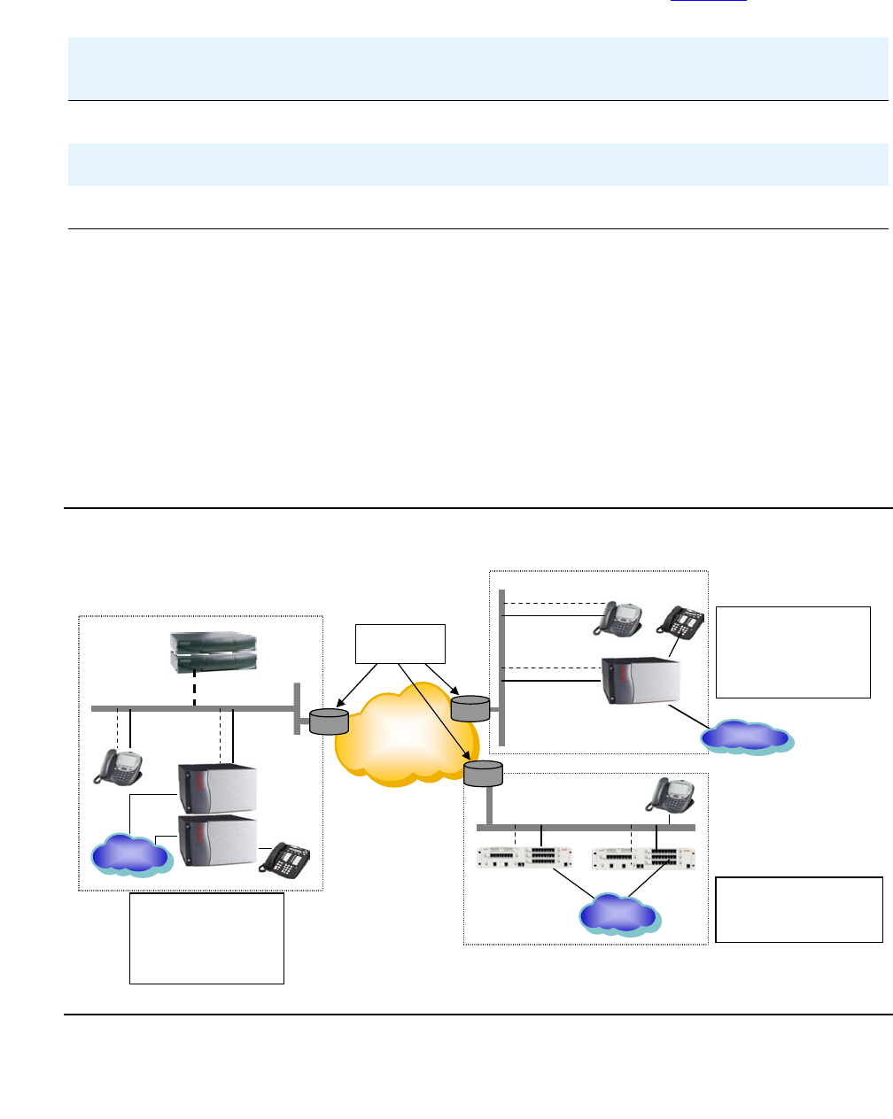
Reliability and Recovery
308 Avaya Application Solutions IP Telephony Deployment Guide
Case Study I: The Standard reliability configuration
●The call processing link from the S8700-series Media Servers to the G650 media
gateways in the headquarters is supported by a single LAN connection.
●The call processing link from the servers to each of the branch offices is over a single
WAN link.
●The quantity of C-LAN and Media Processor circuit packs or media modules follow the
recommendations in Section 2.1 for supporting the calculated traffic load, and have not
been engineered with N+1 reliability.
Figure 86: Case Study I: Configuration of the Three Sites
Table 49: Percentage of Traffic Generated by Each Site Based on Table 17 Traffic COI
Matrices. Total Traffic Generated by All Sites is 226 Erlangs.
Site Inbound &
outbound Atlanta Boston Cleveland
Atlanta 98E => 43.3% 32E => 14.2% 12E => 5.2% 5E => 2.2%
Boston 36E => 16% 12E => 5.2% 4E => 2% 2E=> 0.9%
Cleveland 16E => 7% 6E => 2.7% 2E => 0.9% 1E => 0.4%
Boston
Site 2: Branch Office
End Users: 648
IPSIs: 1
MedPros: 2
C-LANs: 2
Site 1: Headquarters
End Users: 1,755
IPSIs: 1
MedPros: 3
C-LANs: 5
PSTN
Atlanta S8700
G650
G650
Cleveland
Site 3: Branch Office
End Users: 270
2 G700 Media Gateways
WAN
G650
cydfcas1.pdf KLC 121103
PSTN
PSTN
WAN Edge
Routers

Design for High Availability
Issue 4.3 February 2006 309
The single WAN link is the weakest link in this configuration. Because WAN facilities are usually
leased and are not under the direct control of an enterprise, and because of the expense
involved in procuring WAN circuits, WAN availability has historically been in the range of 99% to
99.5%. However, some service providers guarantee 99.9% availability per WAN circuit. Call
control signaling traffic traverses the WAN link to give service to the phones in Boston and
Cleveland. As a result the availability of these two sites is no greater than the WAN link.
The following two tables show the result of the projected availability analysis for this
configuration.
The site availability values listed in the second column of Table 50: Case Study I: Standard
Configuration Availability and Impact of WAN Outages on Each Site on page 309 represent
Avaya Communication Manager solution availability values. The site availability values listed in
column 4 include the impact of the enterprise data network availability value on each site's
solution.
This combined value is assessed by considering the components involved to complete a call
from point A to point B. For example, for the calls generated in Boston the following components
are involved: Servers in Atlanta, Control signaling link over Atlanta LAN connection, WAN link
between Boston and Atlanta, Boston LAN connection, and the Media Gateway in Boston.
Table 51: Example Site Availability Calculation for Boston System. on page 310 shows the
resulting calculation.
Table 50: Case Study I: Standard Configuration Availability
and Impact of WAN Outages on Each Site
Avaya Product Enterprise’s Solutions including LAN
and WAN Link Availability
Site Availability Annual
Downtime
Minutes
Availability Per Site Annual
Downtime Minutes
Atlanta 99.99% 53 99.99% 53
Boston 99.95% 263 99% 5260 (88 hr)
Cleveland 99.95% 263 99% 5260 (88 hr)

Reliability and Recovery
310 Avaya Application Solutions IP Telephony Deployment Guide
:
A similar approach assesses the availability in Cleveland, and is shown in Table 52: System
Availability according to Generated Traffic on page 310.
Table 51: Example Site Availability Calculation for Boston System.
Component Availability Downtime minutes per year
S8700-series Media
Servers in Atlanta 99.9995%1
1. The duplex S8700 hardware calculation projects higher availability. The listed number is a
projected number for both hardware and Avaya CM software application supported by the
servers.
2.6
Data network between
Atlanta and Boston 99% – 99.5% 2630 to 5260
Boston Media Gateway 99.95% 262.98
Aggregated 98% – 99.4% 3155.76 (2.6 + 2630 + 262.98)
to 7863 (2.6 + 5260 +262.98)
Table 52: System Availability according to Generated Traffic
Full Solution Availability Projected Weighted Annual Downtime
minutes1.
1. Calculated according to percentage traffic affected by failure event.
Weighted annual downtime minutes = (% generated traffic) * (average system annual
downtime minutes due to failure)
% of traffic generated in Atlanta × Annual
downtime minutes in Atlanta (43.3% + 14.2%) × 53 = 30.5
% of traffic generated in Boston × Annual
downtime minutes in Boston (16% + 2%) × 5260 = 947
% of traffic between Atlanta and Boston ×
Annual downtime minutes due to failure in
Atlanta, WAN, and in Boston
(5.2% + 5.2%) × 5260 = 547
% of traffic generated in Cleveland × Annual
downtime minutes in Cleveland (7% + 0.4%) × 5260 = 390
% of traffic between Atlanta and Cleveland ×
Annual downtime minutes due to failure in
Atlanta, WAN, and in Cleveland
(2.7% + 2.2%) × 5260 = 258
% of traffic between Boston and Cleveland ×
Annual downtime minutes due to failure in
Boston, WAN, and in Cleveland
(0.9% + 0.9%) × 5260 = 95
Aggregated Downtime 2237.5 minutes
(30.5 + 947 + 547 + 390 + 258 + 95)
System Availability = 99.5%

Design for High Availability
Issue 4.3 February 2006 311
As reflected in Table 52, the main availability bottleneck in this configuration is the single WAN
link supporting the call control signaling between the headquarters and either of the branch
offices.
Case Study II (99.99% location availability and 99.9% system availability)
Case Study II demonstrates the effect of an Enterprise survivable server (ESS) and Local
Survivable Processor (LSP) on improving the local availability for the branch offices in Case
Study I.
The system availability at each location can be improved to 99.99% by implementing the
following survivability components in the configuration:
●N+1 IP resources in each site. This applies to the number of C-LAN circuit packs and
media processor circuit packs in Atlanta and Boston.
●In Cleveland, each G700 media gateway contains a resident VoIP resource, and each
media gateway has the capacity of housing an extra VoIP Media Module.
●Signaling and media traffic can take different routes across the network or signaling
packets can be tagged with priority.
●ESS in Boston as alternate gatekeeper and call controller for the G650 Media Gateway
and IP end points. This survivability option will allow service continuity at the location in the
event of any link failure to the main server.
●LSP in Cleveland branch office as the alternate gatekeeper and call controller for the G700
Media Gateway and IP end points. This survivability option will allow service continuity at
location in the event of any link failure to the main server.
See Figure 87: Case Study II: Three-site configuration with ESS and LSP on page 312.
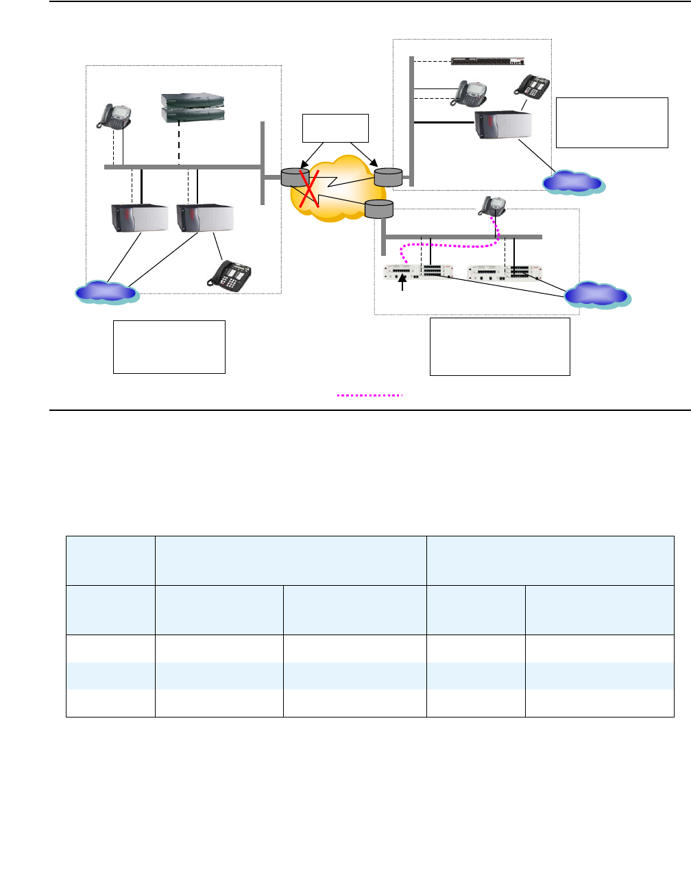
Reliability and Recovery
312 Avaya Application Solutions IP Telephony Deployment Guide
Figure 87: Case Study II: Three-site configuration with ESS and LSP
In this configuration, the simplex WAN link has the availability range of 99% to 99.5%. In the
headquarters in Atlanta, the N+1 IPSI and N+1 C-LAN guarantee sufficient IP resources in the
event of a C-LAN or IPSI failure.
Table 53: Local availability values are improved in the branch offices
with redundant connections
Avaya Product Enterprise Solution including LAN
and WAN link Availability1
1. The inter-site traffic reliability highly depends on the availability of the redundant WAN link
connections. With proper design, the redundancy enhances the link availability to the
range of 99.95% – 99.995%. The average (99.97%) is used in the calculations here.
Site Availability Annual Downtime
Minutes Availability Per Site Annual
Downtime Minutes
Atlanta 99.995% 26.3 99.995% 26.3
Boston 99.995% 26.3 99.995% 26.3
Cleveland 99.995% 26.3 99.99% 53
LSP
(
S8300
)
Site 1: Headquarters
End Users: 1755
IPSIs: 2
C-LANs: 6
Atlanta
Boston
Cleveland
Site 2: Branch Office
End Users: 648
IPSIs: 1
C-LANs: 2
Site 3: Branch Office
End Users: 306
2 G700 Media Gateways
LSP
S8700
LSP
(
S8300
)
PSTN
G650 G650
G650
Alternate Call Control signaling path to LSP cydfcas2.pdf LAO
052905
PSTN
WAN Edge
Routers
PSTN
S8500 ESS

Design for High Availability
Issue 4.3 February 2006 313
Case Study III (99.999% availability in Atlanta,
99.995% full system availability)
Avaya G650 Media Gateways can provide the optimum 99.999% availability using redundant
IPSI connections to the Avaya media servers. The G650 configuration supports two IPSI circuit
packs in active/standby mode. The call control link to the media gateways is fully redundant.
Upon any link or device failure, there will be a failover to the standby path.
When engineered with duplicated IPSI-2 and N+1 C-LAN and MedPro circuit packs, the G650
Media Gateway reliability assessment projects 99.9995% availability. The following
recommendations based upon our example case environment ensure the objective availability
value is attainable.
●G650 with redundant IPSIs in Atlanta and Boston Offices.
●ESS as the alternate gatekeeper and call controller in Boston.
●LSP as the alternate gatekeeper and call controller in Cleveland.
Table 54: Inter-site traffic availability is affected by low WAN link availability1
1. A single WAN connection has availability of 99% to 99.5%, which is equivalent to up to 5260 minutes (88
hours) of downtime per year. Local survivability at the location will improve site availability in this case.
Full Solution Availability Projected Weighted Downtime minutes
% of traffic generated in Atlanta × Annual downtime minutes in
Atlanta (43.3% + 14.2%) × 26.3 = 15
% of traffic generated in Boston × Annual downtime minutes in
Boston (16% + 2%) × 26.3 = 5
% of traffic between Atlanta and Boston × Annual downtime
minutes due to failure in Atlanta, WAN, and in Boston (5.2% + 5.2%) × 5260 = 547
% of traffic generated in Cleveland × Annual downtime minutes in
Cleveland (7% + 0.4%) × 53 = 3.9
% of traffic between Atlanta and Cleveland × Annual downtime
minutes due to failure in Atlanta, WAN and in Cleveland (2.7% + 2.2%) × 5260 = 258
% of traffic between Boston and Cleveland × Annual downtime
minutes due to failure in Boston, WAN and in Cleveland (0.9% + 0.9%) × 5260 = 95
Aggregated Downtime 923.9 minutes
(15 + 5 + 547+ 3.9 + 258 + 95)
System Availability ≥ 99.99%
System Availability including IP WAN network = 99.8%
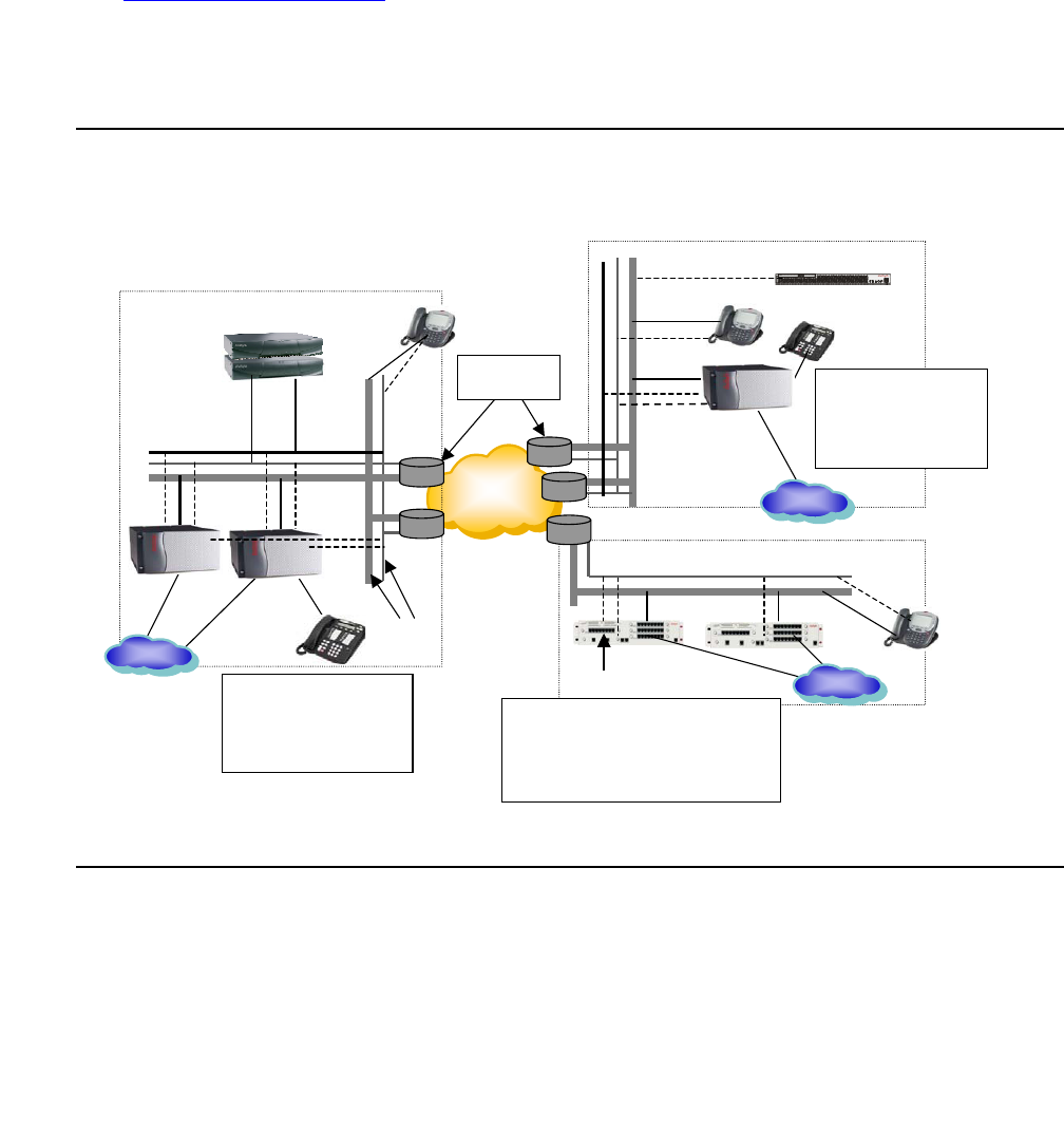
Reliability and Recovery
314 Avaya Application Solutions IP Telephony Deployment Guide
●A fully redundant data network. In order to fully take advantage of the duplicated link
connection between the media servers and media gateways, the WAN path (when
calculated using redundant circuits) should be 99.995% to 99.999% available. It is
expected that every link has sufficient bandwidth to handle the full load of converged
traffic.
●IP phones have at least three valid gatekeeper addresses that do not depend on the same
WAN link.
See Figure 88: Case Study III on page 314.
Note:
Note: For these calculations, the LAN between the servers and the IPSIs is assumed to
have been engineered to meet 99.999% availability.
Figure 88: Case Study III
WAN
Site 1: Head Quarter
End Users: 1755
IPSIs: 2 active, 2 standby
MedPros: 4
C-LANs: 6
Atlanta
Boston
Cleveland
Site 2: Branch Office
End Users: 648
IPSIs: 2 (active/standby)
MedPros: 3
C-LANs: 3
Site 3: Branch Office
End Users: 306
2 G700 Media Gateways
LSP
Additional VoIP MM installed
S8700
LSP
(
S8300
)
Customer LAN
G650
cydfcas4.pdf LAO 052905
PSTN
WAN Edge
Routers
PSTN
PSTN
G650
G650
S8500 ESS

Design for High Availability
Issue 4.3 February 2006 315
Table 55: Local Availability Improved to 99.999% availability for the Atlanta and
Boston Office with G650 and redundant server interface connections to the
S8700-series Media Servers
Enterprise Availability
including LAN and WAN link
availability
Complete Solution including
data network availability
Site Availability Annual
Downtime
Minutes
Availability Per Site
Annual
Downtime
Minutes
Atlanta 99.999% 5.3 99.999% 5.3
Boston 99.997% 15.8 99.995% 26
Cleveland 99.995% 26.3 99.994% 32
Table 56: Inter-site call Traffic Availability is Enhanced by Highly Available Data Network.
Percentage of traffic usage is listed in Table 49 and is according to the Communities of
Interest (COI) Matrix presented in Example 1: Station usage on page 171.
Full Solution Availability Projected Weighted Downtime min.
% of traffic generated in Atlanta × Annual downtime minutes
in Atlanta (43.3% + 14.2%) × 5.3 = 3
% of traffic generated in Boston × Annual downtime minutes
in Boston (16% + 2%) × 26 = 4.7
% of traffic between Atlanta and Boston × Annual downtime
minutes due to failure between Atlanta and Boston (5.2% + 5.2%) × 26.3 = 2.7
% of traffic generated in Cleveland × Annual downtime
minutes in Cleveland (7% + 0.4%) × 32 = 2.4
% of traffic between Atlanta and Cleveland × Annual
downtime minutes due to failure between Atlanta and
Cleveland
(2.7% + 2.2%) × 26.3 = 1.3
% of traffic between Boston and Cleveland × Annual
downtime minutes due to failure between Boston and
Cleveland
(0.9% + 0.9%) × 26.3 = 0.48
Aggregated Downtime 14.58
(3 + 4.7 + 2.7 + 2.4+ 1.3 +0.48))
System Availability = 99.997%

Reliability and Recovery
316 Avaya Application Solutions IP Telephony Deployment Guide
As reflected in the case studies presented in this section, an IP Telephony solution can be
configured to meet an enterprise's desired level of availability. The examples show that Avaya
IP Telephony solutions offer flexibility for designing a highly available system.
The optimum 99.999% availability within a site must include redundancy and optimized data
network design. For a geographically distributed system, a major bottleneck for high availability
is the WAN. For enterprises with high inter-site call traffic, redundant WAN links significantly
enhance the full system availability. Such redundancy should provide sufficient bandwidth to
support the extra traffic in the event of a failure. To take full advantage of link redundancy, the
network should be designed with failure detection, multiple paths, and failover capabilities.
For more details on network design and configuration, see Getting the IP network ready for
telephony.

Issue 4.3 February 2006 317
Section 3: Getting the IP network ready for
telephony

318 Avaya Application Solutions IP Telephony Deployment Guide

Overview
Issue 4.3 February 2006 319
IP Telephony network engineering overview
In the early days of local area networking, network designers used hubs to attach servers and
workstations, and routers to segment the network into manageable pieces. Because of the high
cost of router interfaces and the inherent limitations of shared-media hubs, network design was
generally well done. In recent years, with the rise of switches to segment networks, designers
were able to hide certain faults in their networks and still get good performance. As a result,
network design was often less than optimal. IP Telephony places new demands on the network.
Suboptimal design cannot cope with these demands. Even with switches installed, a company
must follow industry best practices to have a properly functioning voice network. Because most
users do not tolerate poor voice quality, administrators should implement a well-designed
network before they begin IP Telephony pilot programs or deployments.
This section contains network design recommendations in the following topics:
●Overview
●Voice quality
●Best practices
●Common issues
Overview
Industry best practices dictate that a network be designed with consideration of the following
factors:
●Reliability and redundancy
●Scalability
●Manageability
●Bandwidth
Voice mandates consideration of the following additional factors when designing a network:
●Delay
●Jitter
●Loss
●Duplex

IP Telephony network engineering overview
320 Avaya Application Solutions IP Telephony Deployment Guide
In general, these concerns dictate a hierarchical network that consists of at most three layers
(Table 57: Layers in a hierarchical network on page 320):
●Core
●Distribution
●Access
Some smaller networks can collapse the functions of several layers into one device.
For IP Telephony to work well, WAN links must be properly sized with sufficient bandwidth for
voice and data traffic. Each voice call uses between 6.3 Kbps and 80 Kbps, depending on the
desired codec, quality, and header compression used. G.729, which uses 24 Kbps of
bandwidth, is one of the most promising standards today. Traditional telephone metrics, such as
average call volume, peak volume, and average call length, can be used to size interoffice
bandwidth demands. See Traffic engineering for more information.
Quality of Service (QoS) also becomes increasingly important with WAN circuits. In this case,
QoS means the classification and the prioritization of voice traffic. Voice traffic must be given
absolute priority through the WAN. If links are not properly sized or queuing strategies are not
properly implemented, the quality and the timeliness of voice and data traffic will be less than
optimal.
Table 57: Layers in a hierarchical network
Layer Description
Core The core layer is the heart of the network. The purpose of the core
layer is to forward packets as quickly as possible. The core layer
must be designed with high availability in mind. Generally, these
high-availability features include redundant devices, redundant power
supplies, redundant processors, and redundant links. Today, core
interconnections increasingly use Gigabit Ethernet.
Distribution The distribution layer links the access layer with the core. The
distribution layer is where QoS feature and access lists are applied.
Generally, Gigabit Ethernet connects to the core, and either Gigabit
Ethernet or 100base-TX/FX links connect the access layer.
Redundancy is important at this layer, but not as important as in the
core.
Access The access layer connects servers and workstations. Switches at this
layer are smaller, usually 24 to 48 ports. Desktop computers and
workstations are usually connected at 10 Mbps (or 10 Mbps), and
servers are connected at 100 Mbps (or 1 Gbps). Limited redundancy
is used. Some QoS and security features can be implemented in the
access layer.

Voice quality
Issue 4.3 February 2006 321
Three WAN technologies are commonly used with IP Telephony:
●ATM
●Frame Relay
●Point-to-point (PPP) circuits
These technologies all have good throughput, low latency, and low jitter. ATM has the added
benefit of enhanced QoS. Frame Relay and PPP links are more economical, but lack some of
the traffic-shaping features of ATM.
Of the three technologies, Frame Relay is the most difficult WAN circuit to use with IP
Telephony. Congestion in Frame Relay networks can cause frame loss, which can significantly
degrade the quality of IP Telephony conversations. With Frame Relay, proper sizing of the
committed information rate (CIR) is critical. In a Frame Relay network, any traffic that exceeds
the CIR is marked as discard eligible, and is discarded at the option of the carrier if it
experiences congestion in its switches. Because voice packets must not be dropped, CIR must
be sized to maximum traffic usage. Also, Service Level Agreements (SLAs) must be established
with the carrier to define maximum levels of delay and frame loss, and remediation if the
agreed-to levels are not met.
Network management is another important area to consider when implementing IP Telephony.
Because of the stringent requirements imposed by IP Telephony, it is critical to have an
end-to-end view of the network, and ways to implement QoS policies globally. Products such as
HP OpenView Network Node Manager, Avaya Integrated Management, Concord NetHealth,
and MRTG help administrators maintain acceptable service. Outsource companies are also
available to assist other companies that do not have the resources to implement and maintain
network management.
Voice quality
Voice quality is always a subjective topic. Defining “good” voice quality varies with business
needs, cultural differences, customer expectations, and hardware and software. The
requirements set forth are based on the ITU-T and EIA/TIA guidelines and extensive testing at
Avaya Labs. Avaya requirements meet or exceed most customer expectations. However, the
final determination of acceptable voice quality lies with the customer’s definition of quality, and
the design, implementation, and monitoring of the end-to-end data network.
Quality is not one discrete value where the low side is good and the high side is bad. A trade-off
exists between real-world limits and acceptable voice quality. Lower delay, jitter, and packet
loss values can produce the best voice quality, but also can come with a cost to upgrade the
network infrastructure to get to the low values. Another real-world limit is the inherent WAN
delay over an IP trunk that links the west coast of the United States to India. This link could add
a fixed delay of 150 milliseconds (ms) into the overall delay budget.
Perfectly acceptable voice quality is attainable, but will not be “toll” quality. Therefore, Avaya
presents a tiered choice of elements that make up the requirements.

IP Telephony network engineering overview
322 Avaya Application Solutions IP Telephony Deployment Guide
The critical objective factors in assessing IP Telephony quality are delay, jitter, and packet loss.
To ensure good and consistent levels of voice quality, Table 58: Factors that affect voice
quality on page 322 lists Avaya’s suggested network requirements. These requirements are
true for both LAN only and for LAN and WAN connections.
Table 58: Factors that affect voice quality
Network factor Measurement1
1. All measurement values are between endpoints because this document assumes that IP Telephony is
not yet implemented. All values therefore reflect the performance of the network without endpoint
consideration.
Delay
(one-way between
endpoints)
●A delay of 80 ms or less can, but may not, yield the best
quality.
●A delay of 80 ms to 180 ms can yield
business-communication quality. Business-communication
quality is much better than cell-phone quality, and is
well-suited for the majority of businesses.2
●Delays that exceed 180 ms might still be quite acceptable
depending on customer expectations, analog trunks used,
codec type, and so on.
2. Also, “business-communication quality” is defined as less than toll quality, but much better than
cell-phone quality.
For more information see Voice quality network requirements.
The Converged Network Analyzer (CNA) can help you measure and report on network delay,
jitter, and packet loss. CNA can also provide you with a rating of voice quality using the 0-5
APR score (see The CNA Application Performance Rating on page 244).
With the optional Path Optimization feature, CNA can also help you optimize voice
performance, hence insure that voice quality is acceptable. For more information on CNA see
The Converged Network Analyzer on page 410.
Jitter
(variability of the delay
between endpoints)
●20 ms, or less than half the sample size, for the best quality.
Note:
Note: This value has some latitude, depending on the
type of service that the jitter buffer has in
relationship to other router buffers, the packet size
used, and so on.
Packet loss
(maximum packet/
frame loss between
endpoints)
●<1% can yield the best quality, depending on many factors.
●<3% should give business-communications quality, which is
much better than cell-phone quality.2
●>3% might be acceptable for voice, but might interfere with
signaling.

Best practices
Issue 4.3 February 2006 323
Best practices
To consistently ensure the highest quality voice, Avaya highly recommends consideration of the
following industry best practices when implementing IP Telephony. Note that these suggestions
are options, and might not fit individual business needs in all cases.
●QoS/CoS. QoS for voice packets is obtained only after a Class of Service (CoS)
mechanism tags voice packets as having priority over data packets. Networks with periods
of congestion can still provide excellent voice quality when using a QoS/CoS policy. The
recommendation for switched networks is to use IEEE 802.1p/Q. The recommendation for
routed networks is to use DiffServ Code Points (DSCP). The recommendation for mixed
networks is to use both. Port priority can also be used to enhance DiffServ and IEEE
802.1p/Q. Even networks with plentiful bandwidth should implement CoS/QoS to protect
voice communications from periods of unusual congestion, such as a computer virus might
cause. See Implementing Communication Manager on a data network for more
information.
●Switched network. A fully switched LAN network is a network that allows full duplex and
full endpoint bandwidth for every endpoint that exists on that LAN. Although IP Telephony
systems can work in a shared or hub-based LAN, Avaya recommends the consistently
high results that a switched network lends to IP Telephony.
●Network assessment. A Basic Network Readiness Assessment Offer from Avaya is vital
to a successful implementation of IP Telephony products and solutions. Contact an Avaya
representative or authorized dealer to review or certify your network. Network assessment
offer explains the options that are available with this offer.
●VLANs. Placing voice packets on a separate VLAN or subnetwork from data packets is a
generally accepted practice to reduce broadcast traffic. When data is on a shared LAN,
this practice also reduces contention for the same bandwidth as voice. Note that Avaya IP
Telephones provide excellent broadcast storm protection. Other benefits become
available when using VLANs, but there can be a substantial cost with initial administration
and maintenance. Section 3.2.1.2 Using VLANs explains this concept further.

IP Telephony network engineering overview
324 Avaya Application Solutions IP Telephony Deployment Guide
Common issues
Some common negative practices that can severely impact network performance, especially
when using IP Telephony, include:
●A flat, non-hierarchical network, for example, cascading small workgroup switches
together. This technique quickly results in bottlenecks, because all traffic must flow across
the uplinks at a maximum of 1Gbps, versus traversing switch fabric at speeds up to 256
Gbps. The greater the number of small switches or layers, the greater the number of
uplinks, and the lower the bandwidth for an individual connection. Under a network of this
type, voice performance can quickly degrade to an unacceptable level.
●Multiple subnets on a VLAN. A network of this type can have issues with broadcasts,
multicasts, and routing protocol updates. This practice can have a significant negative
impact on voice performance, and complicate troubleshooting.
●A hub-based network. Hubs in a network create some interesting challenges for
administrators. It is advisable not to link more than four 10baseT hubs or two 100baseT
hubs together. Also, the collision domain, the number of ports that are connected by hubs
without a switch or router in between, should be kept as low as possible. Finally, the
effective (half-duplex) bandwidth that is available on a shared collision domain is
approximately 35% of the total bandwidth that is available.
●Too many access lists. Access lists slow down a router. While access lists are
appropriate for voice networks, care must be taken not to apply them to unnecessary
interfaces. Traffic should be modeled beforehand, and access lists applied only to the
appropriate interface in the appropriate direction, not to all interfaces in all directions.
Avaya recommends caution when using the following:
●Network Address Translation (NAT). Most implementations that use IP Telephony
endpoints behind NAT fail because many H.323 messages (the protocol carrying the voice
information) contain multiple instances of the same IP address in a given message, but
NAT is unlikely to find and translate all of them. See NAT on page 353 for more information
on using NAT with IP Telephony. Avaya products work seamlessly with static NAT
implementation, even if that NAT is not H.323-aware.
●Analog dial-up. Be careful in using analog dial-up (56 K) to connect two locations.
Upstream bandwidth is limited to a maximum of 33.6 K, and in most cases is less. This
results in insufficient bandwidth to provide toll-quality voice. Some codecs and network
parameters provide connections that are acceptable, but consider each connection
individually.
●Virtual Private Network (VPN). Large delays are inherent in some VPN software
products due to encryption, decryption, and additional encapsulation. Some
hardware-based products, including Avaya VPN products, encrypt at near wire speed, and
can be used. In addition, if the VPN is run over the Internet, sufficient quality for voice
cannot be guaranteed unless delay, jitter, and packet loss are contained within the
parameters that are listed above. See VPN for more information.

Issue 4.3 February 2006 325
Network design
This section discusses the network design process for IP Telephony. This section focuses on:
●LAN issues
●IP addressing
●IP terminals deployment
●WAN
●VPN
●NAT
LAN issues
This section covers Local Area Network (LAN) issues, including speed and duplex, inline power,
hubs versus switches, and so on:
●General guidelines
●VLANs
General guidelines
Because of the time-sensitive nature of IP Telephony applications, IP Telephony should be
implemented on an entirely switched network. Ethernet collisions, which are a major contributor
to delay and jitter, are virtually eliminated on switched networks. Additionally, the C-LAN,
MedPro, and IP Telephones should be placed on a separate subnetwork or VLAN (that is,
separated from other non-IP Telephony hosts). This separation provides for a cleaner design
where IP Telephony hosts are not subjected to broadcasts from other hosts, and where
troubleshooting is simplified. This separation also provides a routed boundary between the IP
Telephony segments and the rest of the enterprise network, where restrictions can be placed to
prevent unwanted traffic from crossing the boundary. When personal computers are attached to
IP Telephones, the uplink to the Ethernet switch should be a 100-Mbps link, so that there is
more bandwidth to be shared between the telephone and the computer.

Network design
326 Avaya Application Solutions IP Telephony Deployment Guide
Sometimes enterprises are unable to follow these guidelines, and Avaya’s solutions can be
made to work in some less-than-ideal circumstances. If IP Telephones will share a subnetwork
with other hosts, the IP Telephones should be placed on a subnetwork of manageable size
(24-bit subnet mask or larger, with 254 hosts or less), with as low a rate of broadcasts as
possible. If the broadcast level is high, remember that 100-Mbps links are less likely to be
overwhelmed by broadcast traffic than 10-Mbps links. Perhaps a worst-case example is the
scenario where Avaya IP Telephones are deployed on a large subnetwork that is running IPX or
other broadcast-intensive protocol, with broadcasts approaching 500 per second. Although the
performance of the IP Telephones and the voice quality can be satisfactory in this environment,
this type of deployment is strongly discouraged.
This section covers:
●Ethernet switches
●Speed and duplex
Ethernet switches
The following recommendations apply to Ethernet switches to optimize operation with Avaya
endpoints. Theses recommendations are meant to provide the simplest configuration by
removing unnecessary features.
●Enable spanning tree fast start feature or disable spanning tree at the port level. The
Spanning Tree Protocol is a Layer 2 loop-avoidance protocol. When a device is first
connected (or reconnected) to a port that is running spanning tree, the port takes
approximately 50 seconds to cycle through the Listening, Learning, and Forwarding
states. This 50-second delay is neither necessary nor desired on ports that are connected
to IP endpoints. Instead, enable a fast start feature on these ports to put them into the
Forwarding state almost immediately. If this feature is not available, disabling spanning
tree on the port is an option that should be considered. Do not disable spanning tree on an
entire switch or VLAN.
●Disable Cisco features. Cisco features that are not required by Avaya endpoints include
channeling, cdp, and inline power. These features are nonstandard mechanisms that are
relevant only to Cisco devices, and can sometimes interfere with Avaya devices. The
CatOS command set port host <mod/port> automatically disables channeling and
trunking, and enables portfast. Execute this command first, and then manually disable cdp
and Cisco inline power. Then manually enable 802.1Q trunking as necessary.
●Properly configure 802.1Q trunking on Cisco switches. When trunking is required on a
Cisco CatOS switch that is connected to an Avaya IP Telephone, enable it for 802.1Q
encapsulation in the no-negotiate mode (set trunk <mod/port> nonegotiate
dot1q). This causes the port to become a plain 802.1Q trunk port with no Cisco
autonegotiation features. When trunking is not required, explicitly disable it, because the
default is to autonegotiate trunking.

LAN issues
Issue 4.3 February 2006 327
Speed and duplex
One major issue with Ethernet connectivity is proper configuration of speed and duplex. A
significant amount of misunderstanding exists in the industry as a whole with regard to the
autonegotiation standard. Table 59: Speed/duplex matrix on page 327 is a quick reference for
how speed and duplex settings are determined and typically configured. It is imperative that the
speed and duplex settings be configured properly.
A duplex mismatch condition results in a state where one side perceives a high number of
collisions, while the other side does not. This results in packet loss. Although it degrades
performance in all cases, this level of packet loss might go unnoticed in a data network because
protocols such as TCP retransmit lost packets. In voice networks, however, this level of packet
loss is unacceptable. Voice quality rapidly degrades in one direction. When voice quality
problems are experienced, duplex mismatches are the first thing to look for.
Table 59: Speed/duplex matrix
Device 1
configuration Device 2
configuration Result
Autonegotiate Autonegotiate 100/full expected and often achieved, but not
always stable. Suitable for user PC connections,
but not suitable for server connections or uplinks.
May be suitable for a single IP Telephony call,
such as with a Softphone. Not suitable for multiple
IP Telephony calls, such as through a MedPro
circuit pack.
Autonegotiate 100/half 100/half stable. Device 1 senses the speed, and
matches accordingly. Device 1 senses no duplex
negotiation, so it goes to half duplex.
Autonegotiate 10/half 10/half stable. Device 1 senses the speed and
matches accordingly. Device 1 senses no duplex
negotiation, so it goes to half duplex.
Autonegotiate 100/full Device 1 goes to 100/half, resulting in a duplex
mismatch, which is undesirable. Device 1 senses
the speed, and matches accordingly. Device 1
senses no duplex negotiation, so it goes to half
duplex.
100/full 100/full 100/full stable. Typical configuration for server
connections and uplinks.
10/half
100/half 10/half
100/half Stable at respective speed and duplex. Some
enterprises do this on user ports as a matter of
policy for various reasons.

Network design
328 Avaya Application Solutions IP Telephony Deployment Guide
VLANs
Virtual Local Area Networks (VLANs) are an often-misunderstood concept. This section begins
by defining VLANs, and then addresses configurations that require the Avaya IP Telephone to
connect to an Ethernet switch port that is configured for multiple VLANs. The IP Telephone is on
one VLAN, and a personal computer that is connected to the telephone is on a separate VLAN.
Four sets of configurations are given: Avaya Cajun P330 v3.2.8 and later, Avaya Cajun P330
pre-3.2, Cisco CatOS, and some Cisco IOS.
Topics include:
●VLAN defined
●The port or native VLAN
●Trunk configuration
●VLAN binding feature (P330 v3.2.8)
●Setting the priority without trunking or VLAN binding (single-VLAN scenario)
VLAN defined
With simple Ethernet switches, the entire switch is one Layer 2 broadcast domain that usually
contains one IP subnetwork (Layer 3 broadcast domain). Think of a single VLAN (on a
VLAN-capable Ethernet switch) as being equivalent to a simple Ethernet switch. A VLAN is a
logical Layer 2 broadcast domain that typically contains one IP subnetwork. Therefore, multiple
VLANs contain logically separated subnetworks. This arrangement is analogous to multiple
switches being physically separated subnetworks. A Layer 3 routing process is required to route
between VLANs, just as one is required to route between subnetworks. This routing process
can take place on a connected router or a router module within a Layer 2/Layer 3 Ethernet
switch. If no routing process is associated with a VLAN, devices on that VLAN can only
communicate with other devices on the same VLAN.
For more information, use the link below to see Avaya’s white paper, “LANs and VLANs: A
Simplified Tutorial.”
http://support.avaya.com/
The port or native VLAN
Port VLAN and native VLAN are synonymous terms. The IEEE 802.1Q standard and most
Avaya switches use the term port VLAN, but Cisco switches use the term native VLAN. Issue
the show trunk command on P330s and CatOS Catalysts to see which term is used in the
display output.

LAN issues
Issue 4.3 February 2006 329
Every port has a port VLAN or a native VLAN. Unless otherwise configured, it is VLAN 1 by
default. It can be configured on a per-port basis with the commands in Table 60.
All untagged Ethernet frames (with no 802.1Q tag, for example, from a personal computer) are
forwarded on the port VLAN or the native VLAN. This is true even if the Ethernet switch port is
configured as an 802.1Q trunk, or otherwise configured for multiple VLANs. For more
information, see VLAN binding feature (P330 v3.2.8).
Trunk configuration
A trunk port on an Ethernet switch is one that is capable of forwarding Ethernet frames on
multiple VLANs through the mechanism of VLAN tagging. IEEE 802.1Q specifies the standard
method for VLAN tagging. Cisco also uses a proprietary method called ISL. Avaya products do
not interoperate with ISL.
A trunk link is a connection between two devices across trunk ports. This connection can be
between a router and a switch, between two switches, or between a switch and an IP
Telephone. Some form of trunking or forwarding multiple VLANs must be enabled to permit the
IP Telephone and the attached personal computer to appear on separate VLANs. The
commands in Table 61 enable trunking.
Note that Cisco can remove VLANs from a trunk port. This is a highly desirable feature because
only two VLANs at most should appear on a trunk port that is connected to an IP Telephone.
That is, broadcasts from nonessential VLANs should not be permitted to bog down the link to
the IP Telephone. The pre-3.2 version of P330 code did not have the capability to clear off
unwanted VLANs. Enabling 802.1Q trunking enabled all the VLANs. Newer versions of P330
code can limit the VLANs on a trunk, but in doing so they alter the previous trunking behavior.
Table 60: Commands to configure a port VLAN or a native VLAN
Avaya P33xT v3.2.8 and later Cisco CatOS
set port vlan <id> <mod/port> set vlan <id> <mod/port>
Table 61: Administration commands for VLAN trunking
Avaya P33xT v3.2.8 and later Cisco CatOS
set trunk <mod/port> dot1q
By default, only the port VLAN or
the native VLAN is enabled on the
trunk port. Another set of
commands is required to specify
other allowed VLANs.
set trunk <mod/port> nonegotiate dot1q
By default, all VLANs (1 to1005) are enabled
on the trunk port. VLANs can be selectively
removed with the command clear trunk
<mod/port> <vid>.

Network design
330 Avaya Application Solutions IP Telephony Deployment Guide
VLAN binding feature (P330 v3.2.8)
With both Cisco and the pre-3.2 P330 code, the default behavior of trunking is to permit all
VLANs. With the new P330 code, the default behavior is to permit only the port VLAN or the
native VLAN, and to block all other VLANs. Additional VLANs are added to a port using the
VLAN binding feature. In addition, the port does not need to be a trunk at all to forward multiple
VLANs. For one application, connecting to an Avaya IP Telephone, the port must not be a trunk
(do not issue the set trunk command).
To enable VLAN binding:
1. Verify that the port is configured with the desired port VLAN or native VLAN.
2. Add additional VLANs with one of the following VLAN-binding-mode options:
Static option
a. Put the port in bind-to-static mode by typing set port vlan-binding-mode <mod/port>
static.
b. Statically add another VLAN in addition to the port VLAN or the native VLAN by typing
set port static-vlan <mod/port> <vid>.
Configured option
c. Add a VLAN to the configured VLAN list by typing set vlan <id>.
d. Type show vlan to see entire list.
e. Apply the configured VLANs to the port, and permit only those VLANs (bind-to-all permits
all VLANs and not just the configured) by typing set port vlan-binding-mode <mod/
port> bind-to-configured
3. For simplicity, Avaya recommends using the static option for IP Telephony. If the port is
connected to a router or to another switch, trunking must be enabled with the command set
trunk <mod/port> dot1q, which causes all egress frames to be tagged. However, if the
port is connected to an Avaya IP Telephone with an attached personal computer, trunking
must not be enabled so that none of the egress frames are tagged. This is necessary
because most personal computers cannot understand tagged frames.
Setting the priority without trunking
or VLAN binding (single-VLAN scenario)
With Avaya, it is possible to set the Layer 2 priority on the IP Telephone, even if the telephone is
not connected to a trunk or multi-VLAN port. That is, the Avaya switch does not need to be
explicitly configured to accept priority-tagged Ethernet frames on a port with only the port VLAN
or the native VLAN configured. This is useful if the telephone and the attached personal
computer are on the same VLAN (same IP subnetwork), but the telephone traffic requires
higher priority. Enable 802.1Q tagging on the IP phone, set the priorities as desired, and set the
VID to zero. Per the IEEE standard, a VID of zero assigns the Ethernet frame to the port VLAN
or the native VLAN.

LAN issues
Issue 4.3 February 2006 331
Cisco switches behave differently in this scenario, depending on the hardware platforms and
OS versions. Table 62: Cisco hardware characteristics on page 331 shows Avaya’s laboratory
test results with a sample of hardware platforms and OS versions.
Note:
Note: Setting a Layer 2 priority is only useful if QoS is enabled on the Ethernet switch.
Otherwise, the priority-tagged frames are treated no differently than clear frames.
See Multi-VLAN example for an example.
Table 62: Cisco hardware characteristics
Hardware platform /
operating system Laboratory test results
Catalyst 6509
with CatOS 6.1(2) Accepted VID zero for the native VLAN when 802.1Q
trunking was enabled on the port. In this case, all but the
native VLAN should be cleared off the trunk.
Catalyst 4000
with CatOS 6.3(3) Did not accept VID zero for the native VLAN. Opened a
case with Cisco TAC, and TAC engineer said it was a
hardware problem in the 4000. Bug ID is CSCdr06231.
Workaround is to enable 802.1Q trunking, and tag with
native VID instead of zero. Again, clear all but the native
VLAN off the trunk.
Catalyst 3500XL
with IOS
12.0(5)WC2
Accepted VID zero for the native VLAN when 802.1Q
trunking was disabled on the port.
Conclusion Note the hardware platform and the OS version, and consult
the Cisco documentation, or call TAC.

Network design
332 Avaya Application Solutions IP Telephony Deployment Guide
IP addressing
This section covers:
●Overview of IP addressing of IP addressing concepts, including classful addresses, RFC
1918, CIDR/VLSM
●DHCP
●Recommendations for IP Telephony
Overview of IP addressing
An IP (v4) address is a 32-bit network address (Layer 3 on the OSI model). An IP address is
usually written in dotted-quad notation. Dotted-quad notation consists of four integer fields that
range from 0 to 255, and are separated by periods.
An IP address consists of a network portion and a host portion. The boundary that separates
the network portion and the host portion of the address is defined by the subnet mask. The
subnet mask is another 32-bit address (again usually written in dotted-quad notation) with a
consecutive string of 1s followed by a consecutive string of 0s when written in binary. All bit
positions of the IP address that are covered by a 1 in the subnet mask are network address bits.
Bit positions that are covered by 0s represent the host address.
Some standard subnet masks have been assigned. For addresses that begin with 0 to 127, the
default subnet mask is 255.0.0.0, in which 8 bits are used for the network, and 24 bits are used
for the host. This is known as a Class A address. For addresses that begin with 128 to 191, the
default subnet mask is 255.255.0.0, in which 16 bits are used for the network, and 16 bits are
used for the host. This is known as a Class B address. Finally, for addresses that begin with 192
to 223, 24 bits are used for the network, and 8 bits are used for the host. This is known as a
Class C address.
In recent years, additional techniques, including Variable Length Subnet Masks (VLSM) and
Classless InterDomain Routing (CIDR), have extended subnetting techniques to make more
efficient use of address space. CIDR introduced the concept of supernets, which is a technique
for aggregating a range of older classful address blocks (for example, Class C) under a single
network mask. VLSM provides a technique for allocating subnets of varying size out of a
classful address block. Prior to this point, once a subnet mask was applied to a network, the
same mask had to be applied to all subnetworks.
Some addresses, defined by RFC 1918, are available for private use. Each address class range
includes one group of addresses. The available addresses are:
●Class A: 10.0.0.0 through 10.255.255.255 (mask 255.0.0.0)
●Class B: 172.16.0.0 through 172.31.255.255 (mask 255.240.0.0)
●Class C: 192.168.0.0 through 192.168.255.255 (mask 255.255.0.0)

IP addressing
Issue 4.3 February 2006 333
These addresses can be allocated by companies and individuals in any way. Be aware,
however, of the following caveats:
●These addresses are not routable across the Internet. If an organization that uses RFC
1918 addresses wants to connect to the Internet, that organization must use Network
Address Translation (NAT).
●If a company is connecting its network to another company, it must take care that their
RFC 1918 addresses do not overlap. Overlapping address ranges prohibit unimpeded
communication across affected networks.
DHCP
Dynamic Host Configuration Protocol (DHCP) is a tool that automates the assignment of IP
addresses. DHCP is a successor of BOOTP, the Bootstrap Protocol. Avaya IP Telephones can
use DHCP to learn their IP addresses, default gateways, call controller, tftp server, QoS
settings, and other parameters.
DHCP is a broadcast protocol. which means that request messages from DHCP clients such as
Avaya IP Telephones are seen by all devices on the local network, but are not forwarded to
additional subnetworks. If the DHCP server is present on a different network, DHCP forwarding
must be enabled on the router. DHCP forwarding converts the broadcast message into a
unicast message, and forwards the message to the configured DHCP server. DHCP forwarding
is offered on most routers and layer 3 switches, including those offered by Avaya and Cisco.
For more information, see DHCP / TFTP or the Avaya IP Telephone LAN Administrator Guide.
Recommendations for IP Telephony
Avaya recommends using a separate subnetwork for voice. Isolating voice traffic from data
traffic allows protection from viruses, excessive broadcast traffic, and security threats that are
caused by malicious users or external intruders. For most IP Telephony implementations, using
RFC 1918 (private) address space is acceptable. Generally, Voice over IP (VoIP) is not
deployed across the public Internet. Therefore, providing addresses in the private range saves
public IP addresses, and provides a layer of security protection by denying connections directly
in from the Internet. Should a public Internet connection prove necessary, Avaya recommends
setting up a C-LAN and a Media Processor card in a demilitarized zone (DMZ) off the firewall,
and using Communication Manager as a proxy server between the internal and external
networks.
Avaya also recommends using DHCP to configure IP Telephones. Using DHCP reduces
administration to a single point, and reduces the incidence of typographical errors that could
cause configuration problems. Avaya includes special configuration options for IP Telephones
in Option 176. Microsoft and ISC (Linux and Unix) DHCP servers support this option. Additional
methods exist for configuring IP Telephones if a particular DHCP server does not support
Option 176. Contact your Avaya representative for more information.

Network design
334 Avaya Application Solutions IP Telephony Deployment Guide
Avaya recommends using the Converged Network Analyzer (CNA) product to optimize voice
and bearer traffic and hence significantly improve the availability of the voice communications
system. Deploying VoIP across the WAN exposes users to network problems outside their
control (e.g., latency, jitter, loss and sustained outages). Using CNA provides insurance against
such problems, significantly increasing the availability of the voice communication system. For
more information on CNA, see The Converged Network Analyzer on page 410.
IP terminals deployment
In this section, the following topics are discussed:
●IP Telephone
●Telephone Basics
●An IP Telephone and an attached PC on different VLANs
●An IP Telephone and an attached PC on the same VLAN
●DHCP and TFTP
●Powering IP Telephones
IP Telephone
The sections to follow cover some general information regarding the IP Telephone. See the
following resources for more detailed information:
●4600 Series IP Telephone Installation Guide
●4600 Series IP Telephone LAN Administrator Guide
Both documents can be found at:
Link to 4600 Series IP Telephone documents (support.avaya.com)
The current GA firmware releases can be obtained at the Avaya Support Center
(support.avaya.com).
The information that is covered in this section may or may not be covered in the resources that
are listed above. It might also be necessary to read the “4600 Series…” guides above to fully
understand the information covered in this section.

IP terminals deployment
Issue 4.3 February 2006 335
Telephone Basics
Basic information on IP telephones is covered in the following sub-sections:
●Speed and duplex
●Sequence of operation
●Connecting a personal computer to an IP Telephone
Speed and duplex
Avaya IP Telephones contain a 10/100 Ethernet switch. This switch is set to speed and duplex
by default. The closest Ethernet switch to which the IP Telephone is attached should be set to
auto-negotiate, as well. Locking down the closest switch to full duplex without also “locking
down” the duplex of the phone will lead to packet loss, and thus result in problems with voice
quality.
Older Avaya IP Telephones such as the 4606, 4612, 4624, and 4630, contain a 10/100 hub. The
integrated hub in the IP Telephone operates at 10 mbps, or 100 mbps half duplex. When
connected to an Ethernet switch port that is configured to auto-negotiate, the Ethernet switch
port stabilizes at 100/half. The exception to this is if a personal computer is attached to the
telephone that is capable of only 10 mbps. In this case, all three devices stabilize at 10/half. If
no personal computer is to be attached to the telephone, or if the attached computer will always
be capable of 100 mbps operation, it is good practice to lock down the Ethernet switch to 100/
half. If a personal computer might be attached to the telephone, and there is a chance that the
computer might have a 10-mbps NIC, leave the Ethernet switch port in auto-negotiate mode.
These older telephones, however, cannot operate in full duplex mode.
Note:
Note: Dual-speed hubs and switches must inherently buffer and discard traffic because
of the inconsistent flows (one port receives at 100 mbps, but the other can only
send at 10 mbps). Avaya IP Telephones are designed with a single-speed bus in
the hub, and do not perform these functions. Instead, these functions are
transferred to the enterprise Ethernet switch.Although the IP Telephone can
accommodate a second user device (the telephone itself being the first), its
primary function is not that of an enterprise network device.

Network design
336 Avaya Application Solutions IP Telephony Deployment Guide
Sequence of operation
The following are key boot-up events, listed in order, that can help to verify proper operation of
the IP Telephone. This list includes only key events, and might not be comprehensive. Note also
that the telephone may go blank between events. In such cases, wait a few seconds or more for
an indication from the telephone as to what event is taking place.
1. Initial startup. At power-up or manual reset, the telephone goes through a short initial
startup procedure. The display shows Restarting… (if the telephone was intentionally
restarted with Hold RESET#), and then Loading… and Starting…
2. DHCP. The telephone queries the DHCP server for an IP address and other needed
information. The following packets are transmitted: DHCP Discover from telephone to
broadcast; DHCP Offer from server to broadcast, or relay agent to telephone; DHCP
Request from telephone to broadcast; and DHCP ACK from server to broadcast, or relay
agent to telephone. Note that this step is bypassed if the telephone is manually configured
with all the necessary information.
Also note that a protocol analyzer that is attached to the PC port of an Avaya IP Telephone
with a:
●Switch (for example, 4602SW, 4610SW, 4620SW), sees only broadcast packets.
●Hub (4606, 4612, 4624, 4630), sees all packets.
3. TFTP ping. The telephone pings the TFTP server for verification purposes.
4. Request file “46XXUPGRADE.SCR” (all caps) and others from TFTP server. This text script
file tells the telephone what boot code (“bbla0_##.bin”) and application code
(“def##r#_##.bin”) are needed. If the telephone does not have the current codes, it requests
them from the TFTP server. A brand new telephone makes all three requests, because
telephones come from the factory with no code, or outdated code. When captured using a
protocol analyzer, all three requests show up as intuitive TFTP messages that reveal the file
name that is being requested or transferred. Note that there is a loading period after each
code is received for the first time. Note also that the file names are case sensitive on some
servers (Unix), and not on others (Microsoft).
5. Ext and Password prompts. The telephone prompts for the extension and the password if
there are no previously stored values.
6. Registration. The telephone registers with a media controller after the codes are
successfully loaded. This registration happens very quickly, and does not show up on the
display. However, the following packets can be captured using a protocol analyzer:
RAS-Gatekeeper Request (GRQ) from the telephone to the media controller;
RAS-Gatekeeper Confirm (GCF) from the media controller to the telephone;
RAS-Registration Request (RRQ) from the telephone to the media controller (not
necessarily the same one that the GRQ was sent to); and RAS-Registration Confirm (RCF)
from the media controller to the telephone.
7. Telephone is operational. The administered display shows up on the telephone, and the
extension LED illuminates.

IP terminals deployment
Issue 4.3 February 2006 337
8. Keepalive messages. These messages are sent by each telephone to the media controller
at time intervals that are determined by Avaya Communication Manager, and based on the
number of registered sets. On a protocol analyzer, the keepalive message shows up as a
RAS-Registration Request (RRQ) message with the keepalive bit set in the RAS header.
Each request message is answered by the media controller with a RAS-Registration
Confirm (RCF) message.
9. Unregistration messages. If the Avaya Media Server intentionally unregisters a set, or if the
set intentionally unregisters itself, the message sent by either the media controller or the set
is a RAS-Unregistration Request (URQ). The acknowledgment message is
RAS-Unregistration Confirm (UCF). All unregistration requests should be confirmed. Future
releases will include various URQ types, whereas currently there is only one type.
Connecting a personal computer to an IP Telephone
On the back of the IP Telephone, the port with the icon that looks like a terminal is the user port.
(The port with the icon that looks like a network jack is the uplink port, which connects to the
Ethernet switch.) Use discretion when connecting a personal computer to the telephone, and
remember that its primary function is not that of an enterprise network device. For example, do
not connect an enterprise server to the telephone. Such high-traffic servers require their own
separate connections to the enterprise Ethernet switch. Also, do not connect a personal
computer to the telephone at 10 mbps if that computer routinely runs high-volume transactions.
The telephone itself operates well at 10 mbps, and the computer itself may also operate
adequately at 10 mbps. But the two combined can cause the computer to overwhelm the
10-mbps link at the expense of audio quality. Connecting a user computer to the telephone at
100 mbps works very well.
An IP Telephone and an attached PC on the same VLAN
Three variations exist for attaching a personal computer to the telephone. The first two involve
having both the telephone and the computer on the same VLAN, which is the port VLAN or the
native VLAN. Refer to the IP Telephony Implementation Guide for a primer on VLANs. In the
first scenario, traffic from both the telephone and the PC have no CoS tagging. In this case, no
special configurations are necessary. Just attach the telephone to an access port (one with only
the port VLAN or the native VLAN configured), and attach the computer to the telephone.
The second scenario is similar to the first, except that traffic from the telephone is tagged with
Layer 2/Layer 3 priority while remaining on the port VLAN or the native VLAN. The telephone
must be configured to tag its Ethernet frames and/or IP packets with the desired priority. This is
normally set by DHCP or TFTP by specifying the following parameters:
●802.1Q. On/off for 802.1Q tagging. Turn this on if Layer 2 priority tagging is desired.
Otherwise, turn this off.
●L2 audio. Layer 2 CoS tag for Ethernet frames that contain audio packets. Set this to a
value between 0 and 7. This value is sent to the telephone by Avaya Communication
Manager, as configured on the IP Network Region form.

Network design
338 Avaya Application Solutions IP Telephony Deployment Guide
●L2 signaling. Layer 2 CoS tag for Ethernet frames that contain signaling packets. Set this
to a value between 0 and 7. This value is sent to the telephone by Avaya Communication
Manager, as configured on the IP Network Region form.
●LAN ID. Must be set to zero (0) for this scenario. A VID of zero indicates that the Ethernet
frame belongs on the port VLAN or native VLAN. The VID has no effect when 802.1Q
tagging is disabled. Cajun switches require no special configuration for this scenario.
Cisco switches, however, behave differently for different hardware platforms and OS
versions. Table 62: Cisco hardware characteristics on page 331 shows Avaya laboratory
test results on a sample of hardware platforms and OS versions.
●L3 audio. Layer 3 DSCP for audio IP packets. Set this to a value between 0 and 63. This
value is sent to the telephone by Avaya Communication Manager, as configured on the IP
Network Region form.
●L3 signaling. Layer 3 DSCP for signaling IP packets. Set this to a value between 0 and 63.
This value is sent to the telephone by Avaya Communication Manager, as configured on
the IP Network Region form.
Remember that for the CoS tags to have any effect, the corresponding QoS configurations must
be implemented on the necessary network devices. Remember also that improperly enabling
Layer 2 and Layer 3 tagging can break processes that were working without tagging. Quality of
Service guidelines contains more information on CoS and QoS.
An IP Telephone and an attached PC on different VLANs
The third scenario for attaching a PC to the telephone (the first two were covered in the previous
subsection) is to have the telephone and the PC on separate VLANs. This requires a trunk port,
or some other multi-VLAN port, on the Ethernet switch. One of the VLANs is the port/native
VLAN, and the clear Ethernet frames (ones with no 802.1Q tag) from the PC reside on this
VLAN. The IP Telephone must tag its traffic with the ID of the VLAN to which it belongs. The
Hold QOS# options are exactly the same as described in the previous section, except that now
the VID must not be zero. The Layer 2 and Layer 3 priority options may or may not be
implemented. The IP Telephony Implementation Guide contains more detail about how to
implement this third scenario.

IP terminals deployment
Issue 4.3 February 2006 339
DHCP and TFTP
Dynamic Host Configuration Protocol (DHCP) provides a way to assign configuration
parameters to clients on a TCP/IP network automatically. This minimizes the maintenance of a
network of 4600 Series IP Telephones by removing the need to assign and maintain IP
addresses and other parameters for each IP Telephone on the network individually.
Trivial File Transfer Protocol (TFTP) provides a way to transfer files that does not require user
intervention. TFTP is used by Avaya IP Telephones to download their configuration files, and
the latest firmware.
The following sub-sections cover:
●Software checklist
●Required network information
Software checklist
Ensure that you own licenses to install and use the DHCP server software and the TFTP server
software.
!WARNING:
WARNING: The circuitry in the 4600 Series IP Telephones reserves IP addresses of the form
192.168.2.x for internal communications. The telephones do not properly use the
addresses you specify if the addresses are from that range.
Required network information
DHCP is the control point where an enterprise controls its IP Telephones. Before administering
DHCP and TFTP, complete the information that is outlined below to ensure that you have the
necessary information regarding your network. There can be more than one gateway, TFTP
server, subnet mask, and C-LAN in your configuration. You need a copy of this table for each
DHCP server.
Release 1.5 and later of the 4600 Series telephones supports the ability to specify a list of IP
addresses for a gateway/router, TFTP server, and one or more C-LAN circuit packs. Each list
can contain up to 127 total ASCII characters, with IP addresses that are separated by commas
with no intervening spaces. When you specify IP addresses for the TFTP server or call server,
you can use either dotted decimal format (“xxx.xxx.xxx.xxx”) or DNS names to identify the
addresses. If you use DNS, note that the system value DOMAIN is appended to the IP
addresses that you specify. If DOMAIN is null, the DNS names must be fully qualified, in
accordance with IETF RFCs 1034 and 1035. For more information about DNS, see DHCP /
TFTP and the IP Telephone LAN Administrator Guide.
You can install both the DHCP server and the TFTP server on the same machine.

Network design
340 Avaya Application Solutions IP Telephony Deployment Guide
Before installing each DHCP server, obtain the following required network information:
●Gateway/router IP addresses
●TFTP server IP addresses
●Subnet mask
●Media controller (C-LAN circuit pack) IP addresses
●Media controller (C-LAN circuit pack) port
●TFTP server path
●Telephone IP address range
-From:
-To:
●DNS server addresses
The TFTP server file path is the “root” directory that is used for all transfers by the server. This
is the default directory which all files will be uploaded to, or downloaded from. In configurations
where the upgrade script and the application files are in the default directory, TFTP server path
should not be used.
Avaya can use a special option, Option 176, to pass these values. Avaya has done significant
testing of and had good success with Option 176 on the Microsoft Windows 2000 DHCP server
and the ISC DHCP server (common on Linux and Unix platforms). Results from other DHCP
servers may vary. A typical Option 176 string looks like the following string:
“MCIPADD=#.#.#.#,MCPORT=1719,TFTPSRVR=#.#.#.#,L2Q=1,L2QVLAN=0”
where
●MCIPADD is the IP address of the C-LAN
●MCPORT is the UDP port that is used for telephone registration
●TFTPSRVR is the TFTP server that the telephone uses to look for firmware and
configuration upgrades
●L2Q is 802.1Q. 1 is on, 0 is off
●L2QVLAN is the VLAN that the telephone uses. Vlan ID 0 is a special vlan ID that tells the
next Layer 2 switch to replace the 0 tag with the native vlan ID on that ingress port.
See DHCP / TFTP for more information.

IP terminals deployment
Issue 4.3 February 2006 341
HTTP and TLS Firmware Downloads
Beginning with IP Telephone Release 2.2, Avaya IP telephones can download firmware from
web servers using the HTTP or TLS (HTTPS) protocols, in addition to TFTP. Preliminary lab
testing at Avaya indicates that HTTP servers can support more simultaneous downloads than
TFTP servers, suggesting that HTTP/TLS downloads should be better able to support large IP
telephony deployments than TFTP.
To specify TLS or HTTP firmware downloads, in Option 176 of the DHCP scope, add the
TLSSRVR (for TLS) or HTTPSRVR (for HTTP) parameter set to the IP address of the file
server. If TLSSRVR, HTTPSRVR, and TFTPSRVR are all set, the phone will attempt to
download firmware using TLS first on TCP port 411, then HTTP on TCP port 81, then HTTP on
TCP port 80, then TFTP on UDP port 69.
Note:
Note: Avaya IP telephones will only establish encrypted TLS connections with servers
using an Avaya-signed digital certificate (for example, an Avaya S8300 or S8500
Media Server).
Powering IP Telephones
The Avaya 4600 Series IP Telephones were designed to use flexible powering methods. Some
of these powering solutions require the use of special cables that are designed specifically for
the Avaya 4600 Series telephones.
The following subsections are discussed:
●Background
●Types of IP Telephone power
●Configuring the IP Telephones for power
Background
To meet the critical needs of the business, two generations, Gen-1 and Gen-2, of the 4606,
4612, and 4624 IP Telephones were developed. The second-generation IP Telephones, Gen-2,
added Power over Ethernet (PoE) to the capabilities of the original IP Telephone. Either local or
centralized power can be provided to the IP Telephones (4606, 4612, and 4624 models only) by
one of the following four methods:
●Power over Spare Pairs pins 4/5 (GRD) and 7/8 (-48 volts) of an RJ45 connector
●Power over Data/Signal Pairs pins 1/2 (-48 volts) and 3/6 (GRD) of an RJ45 connector
●Power over, Traditionally, pins 7 (-48 volts) and 8 (GRD) of an RJ45 connector
●Power through the barrel connector on the bottom of the telephone

Network design
342 Avaya Application Solutions IP Telephony Deployment Guide
Types of IP Telephone power
Centralized power
IEEE, the standards body that governs PoE, has not ratified a final position on PoE. However, a
working draft (Rev.3.0) of IEEE 802.3af has been in place to establish guidelines for this area
since November 2001, and was updated to Rev.3.2 in September, 2002. With PoE,
(IEEE Draft 802.3af standard), both power and data are carried over one CAT 5 Ethernet cable.
Deploying the IP Telephones using PoE eliminates the need for a local power supply, AC
adapter, and cables. Thus, power can be provided from the wiring closet or the switch room,
where it can be easily connected to a UPS system.
The key technical characteristics of the IEEE Draft 802.3af standard for PoE are:
●Power Sourcing Equipment (PSE) output voltage is 44 VDC to 57 VDC.
●Power Sourcing Equipment (PSE) output current is 350 mA, maximum.
●Power Sourcing Equipment (PSE) power is 15.4 watts, maximum.
●Powered Device (PD) power draw allowed is 12.95 watts, maximum.
●Powered Device (PD) is ready to accept power from either set of pairs:
- Spare Pairs (pins 4/5 and 7/8)
- Signal/Data Pairs (pins 1/2 and 3/6)
●The method of signature detection is the “Resistor” concept.
●Mid-Span supplies power on the Spare Pairs (pins 4/5 and 7/8).
●End-Span supplies power on either the Signal/Data Pairs (pins 1/2 and 3/6), or the Spare
Pairs (pins 4/5 and 7/8).
●The power detection and the power feed operate on the same set of pairs.
For more information on the IEEE Draft 802.3af standard (technically known as “DTE Power
through MDI Task Force”), see:
Link to IEEE Draft: “DTE Power through MDI Task Force
Local power
Local power is the power that is supplied at the immediate location of the telephone. Local
power requires a 120/240 VAC outlet that is located within 6 feet of the telephone. Power is
provided to the IP Telephone through a power supply with either a CAT 5 LAN cable or a barrel
connector or a special split cord. Each power supply has a different power range in which it can
operate.

IP terminals deployment
Issue 4.3 February 2006 343
Configuring the IP Telephones for power
The Avaya 4600 Series IP Telephones are comprised of the following models:
●4602 IP Telephone (no barrel connector, one RJ45 jack, no switch, no hub)
●4606 IP Telephone (barrel connector, two RJ45 jacks, built-in hub)
●4612 IP Telephone (barrel connector, two RJ45 jacks, built-in hub)
●4620 IP Telephone (no barrel connector, two RJ45 jacks, built-in switch)
●4624 IP Telephone (barrel connector, two RJ45 jacks, built-in hub)
●4630 IP Telephone/Screenphone (barrel connector, two RJ45 jacks, built-in hub)
Models 4602 and 4620 (also models 4601, 4602SW, 4610SW, 4620SW, and 4630SW)
The 4602 and the 4620 IP Telephones accept power only through the RJ45 Jack on the
telephone, using either of the following types of power supplies:
●Centralized power supply
- Avaya P333T-PWR switch
- 1152A1 Mid-Span Power Distribution Unit
●Local power supply
- 1151B1 “Desktop” Power Supply
- 1151B2 “Desktop” Power Supply with Battery Backup
Models 4606, 4612, and 4624
The following sections discusses the ways in which local or centralized power can be applied to
the IP 4606, 4612, and 4624 telephones:
Note:
Note: Legacy Power is the least preferred method for powering these telephones.
Centralized power - For centralized power (PoE), use either an Avaya P333T-PWR switch for
new or Greenfield installations, or an 1152A1 Mid-Span Power Distribution Unit for legacy
systems. The Avaya P333T-PWR switch with Power over LAN capability can use either the data
(pins 1/2 and 3/6) or spare (pins 4/5 and 7/8) pairs for power feeding. A Category 5 Ethernet
cable from an Ethernet LAN Switch carrying DATA is connected to the “data” port of the 1152A1
Mid-Span Power Distribution Unit (PDU). Power is then injected from the “data & power” port
over the spare pair (pins 4/5 and 7/8) on a Category 5 Ethernet cable that is connected to the IP
Telephone.
Local power - The 1151B1 and 1151B2 switching power supplies are the preferred global
solution for local power, and replace the 1151A1 and 1151A2 units, respectively. In addition to
being the preferred solution, the 1151B1 and 1151B2 local power supply units eliminate the
need for any special split cord.

Network design
344 Avaya Application Solutions IP Telephony Deployment Guide
Legacy power - Many existing IP Telephone installations within the United States and Canada
use the IP Phone Aux power supply with a barrel connector. This local power supply is also
known as a “leader” power supply or a wall power supply. Power is supplied through the barrel
connector to a jack on the bottom of the telephone. The 1151A1 or 1151A2 power supply
(commonly referred to as a brick transformer) is an alternative method of powering that requires
one or more special split cords. Many existing IP Telephone installations in international regions
use the 1151A1 or 1151A2 power supply with a required special split cord. If a 30A switch,
three-port switched hub is used with the 1151A1 or the 1151A2 local power supply, two special
cords are required (these cables are included with the 30A switch). The 30A switch is applicable
to the 4624 and 4612 models, but not the 4606 because of its small footprint (the 30A switch
does not fit in the base of 4606 model). The 1145B Bulk Power Supply is an existing
pre-standard solution (that is, the 1145B power supply was developed before the IEEE Draft
802.3af specifications) that provides centralized power over pins 7 and 8 using a special cord
with over-current protection, and alarm LEDs for each output. The 1145B uses a locking station
cord to guard against damage, compared to the signature detection method of the IEEE Draft
802.3af specifications.
Model 4630
The 4630 IP Telephone is popularly known as the IP Screenphone. Currently, the IP
Screenphone consumes more power than the IEEE limits, and therefore requires local power.
The IP Screenphone must be powered locally through the barrel connector on the bottom of the
telephone using the power supply that is provided with the unit. When using the 30A Switch with
the IP Screenphone, a special split cord is required.
WAN
Because of the high costs and lower bandwidths available, there are some fundamental
differences in running IP Telephony over a Wide Area Network (WAN) versus a LAN. Because
of the resource scarcity, it is important to consider network optimizations and proper network
design, because problems are more likely to manifest themselves in a WAN environment.
Topics covered include:
●Overview
●Frame Relay
Overview
The overview section covers:
●QoS
●Codec selection and compression
●Serialization delay
●Network design

WAN
Issue 4.3 February 2006 345
QoS
In particular, QoS becomes more important in a WAN environment than in a LAN. In many
cases, transitioning from the LAN to the WAN reduces bandwidth by approximately 99%.
Because of this severe bandwidth crunch, strong queuing, buffering, and packet loss
management techniques have been developed. These are covered in more detail in the Quality
of Service guidelines chapter.
Recommendations for QOS
In general, for the WAN, Avaya recommends tagging IP Telephony bearer and signaling
packets with DiffServ Code Point (DSCP) 46 (Expedited Forwarding). This tagging can be
administered in Avaya IP Telephones, Communication Manager, and circuit packs. At the
routers, Avaya recommends using strict priority queuing for voice packets, and weighted-fair
queuing for data packets. Voice packets should always get priority over non-network-control
data packets. This type of queuing is called Class-Based Queuing (CBQ) on Avaya data
networking products, or Low-Latency Queuing (LLQ) on Cisco routers.
Codec selection and compression
Because of the limited bandwidth that is available on the WAN, using a compressed codec
allows much more efficient use of resources without a significant decrease in voice quality.
Avaya recommends that IP Telephony implementations across a WAN use the G.729 codec
with 20-ms packets. This configuration uses 24 Kbps (excluding Layer 2 overhead), 30% of the
bandwidth of the G.711 uncompressed codec (80 Kbps). For more information on bandwidth,
see IP bandwidth and Call Admission Control on page 206.
To conserve even more bandwidth, RTP header compression (cRTP) can be used on
point-to-point links. cRTP reduces the IP/UDP/RTP overhead from 40 bytes to 4 bytes. With
20-ms packets, this translates to a savings of 14.4 Kbps, making the total bandwidth required
for G.729 approximately 9.6 Kbps. The trade-off for cRTP is higher CPU utilization on the router.
The processing power of the router determines the amount of compressed RTP traffic that the
router can handle. Avaya testing indicates that a typical small branch-office router can handle
768 Kbps of compressed traffic. Larger routers can handle greater amounts. cRTP is available
on Avaya and Cisco routers.
Serialization delay
Serialization delay refers to the delay that is associated with sending bits across a physical
medium. Serialization delay is important to IP Telephony because this delay can add significant
jitter to voice packets, and thus impair voice quality. See Layer 3 QoS on page 357 for
techniques to minimize serialization delay.

Network design
346 Avaya Application Solutions IP Telephony Deployment Guide
Network design
Routing protocols and convergence
When designing a IP Telephony network across a WAN, some care should be taken when
selecting a routing protocol or a dial-backup solution. Different routing protocols have different
convergence times, which is the time that it takes to detect a failure and route around it. While a
network is in the process of converging, all voice traffic is lost. Routing protocol convergence is
covered in more detail in section 3.5.
The selection of a routing protocol depends on several factors:
●If a network has a single path to other networks, static routes are sufficient.
●If multiple paths exist, is convergence time an issue? If so, EIGRP and OSPF are
appropriate.
●Are open standards-based protocols required? If so, OSPF and RIP are appropriate, but
not EIGRP or IGRP, which are Cisco proprietary.
In general, Avaya recommends the use of OSPF when routing protocols are required. OSPF
allows for relatively fast convergence, and does not rely on proprietary protocols.
In many organizations, because of the expense of dedicated WAN circuits, dial-on-demand
circuits are provisioned as backup if the primary link fails. The two principal technologies are
ISDN (BRI) and analog modem. ISDN dial-up takes approximately 2 seconds to connect, and
offers 64 Kbps to 128 Kbps of bandwidth. Analog modems take 60 seconds to connect, and
offer up to 56 Kbps of bandwidth. If G.729 is used as the codec, either technology can support
IP Telephony traffic. If G.711 is used as the codec, only ISDN is appropriate. Also, because of
the difference in connect times, ISDN is the preferred dial-on-demand technology for
implementing IP Telephony.
Multipath routing
Many routing protocols, such as OSPF, install multiple routes for a particular destination into a
routing table. Many routers attempt to load-balance across the two paths. There are two
methods for load balancing across multiple paths. The first method is per-packet load
balancing, where each packet is serviced round-robin fashion across the two links. The second
method is per-flow load balancing, where all packets in an identified “flow” (source and
destination addresses and ports) take the same path. IP Telephony does not operate well over
per-packet load-balanced paths. This type of setup often leads to “choppy” quality voice. Avaya
recommends that in situations with multiple active paths, per-flow load balancing is preferable to
per-packet load balancing. This behavior is enabled by default on Avaya products. On Cisco
routers, the command for this is “ip route-cache,” applied per interface.
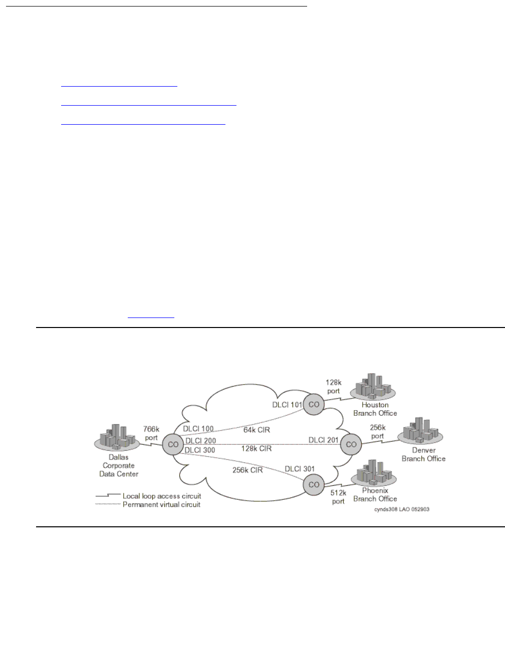
WAN
Issue 4.3 February 2006 347
Frame Relay
The nature of Frame Relay poses somewhat of a challenge for IP Telephony. This section
presents:
●Overview of frame relay
●A frame relay issue and alternatives
●Additional frame relay information
Overview of frame relay
Frame Relay service is composed of three elements: the physical access circuit, the Frame,
Relay port, and the virtual circuit. The physical access circuit is usually a T1 or fractional T1 and
is provided by the local exchange carrier (LEC) between the customer premise and the nearest
central office (CO). The Frame Relay port is the physical access into the Frame Relay network,
a port on the Frame Relay switch itself.
The access circuit rate and the Frame Relay port rate must match. The virtual circuit is a logical
connection between Frame Relay ports that can be provided by the LEC for intra-lata Frame
Relay, or by the inter-exchange carrier (IXC) for inter-lata Frame Relay. The most common
virtual circuit is a permanent virtual circuit (PVC), which is associated with a committed
information rate (CIR). The PVC is identified at each end by a separate data-link connection
identifier (DLCI) in Figure 89.
Figure 89: Data-link connection identifiers over an interexchange carrier Frame Relay
network
This hypothetical implementation shows the Dallas corporate office connected to three branch
offices in a common star topology (or hub and spoke). Each office connects to a LEC CO over a
fractional T1 circuit, which terminates onto a Frame Relay port at the CO, and onto a Frame
Relay capable router at the customer premise. The port rates and the access circuit rates
match. PVCs are provisioned within the Frame Relay network between Dallas and each branch
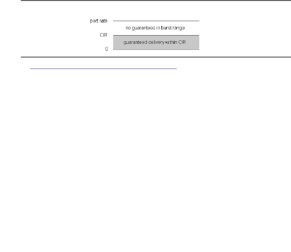
Network design
348 Avaya Application Solutions IP Telephony Deployment Guide
office. The CIR of each PVC is sized so that it is half the respective port rate, which is a
common implementation. Each branch office is guaranteed its respective CIR, but it is also
allowed to burst up to the port rate without any guarantees.
The port rate at Dallas is not quite double the aggregate CIR, but it does not need to be,
because the expectation is that not all three branch offices will burst up to the maximum at the
same time. In an implementation like this, the service is probably negotiated through a single
vendor. But it is likely that Dallas and Houston are serviced by the same LEC, and that the
Frame Relay is intra-lata, even if it was negotiated through an IXC, such as AT&T, WorldCom,
or Sprint. The service between Dallas and the other two branch offices, however, is most likely
inter-lata.
A frame relay issue and alternatives
The obstacle in running IP Telephony over Frame Relay involves the treatment of traffic within
the CIR and outside of CIR, commonly termed the “burst range.”
Figure 90: Committed information rate (burst range)
As Figure 90: Committed information rate (burst range) shows, traffic up to the CIR is
guaranteed, whereas traffic beyond the CIR usually is not. This is how Frame Relay is intended
to work. CIR is a committed and reliable rate, whereas burst is a bonus when network
conditions permit it without infringing upon the CIR of any user. For this reason, burst frames
are marked as discard eligible (DE), and are queued or discarded when network congestion
exists. Although experience has shown that customers can achieve significant burst throughput,
it is unreliable and unpredictable, and not suitable for real-time applications like IP Telephony.
Therefore, the objective is to prevent voice traffic from entering the burst range and being
marked DE. One way to accomplish this is to prohibit bursting by shaping the traffic to the CIR
and setting the excess burst size (Be – determines the burst range) to zero. However, this also
prevents data traffic from using the burst range.
Additional frame relay information
One interesting piece of knowledge is that most IXCs convert the long-haul delivery of Frame
Relay into ATM. That is, the Frame Relay PVC is converted to an ATM PVC at the first Frame
Relay switch after leaving the customer premise. It is not converted back to Frame Relay until
the last Frame Relay switch before entering the customer premise. This is significant because
ATM has built- in Class of Service (CoS). A customer can contract with a carrier to convert the
Frame Relay PVC into a constant bit rate (CBR) ATM PVC. ATM CBR cells are delivered with
lower latency and higher reliability.

VPN
Issue 4.3 February 2006 349
Finally, under the best circumstances, Frame Relay is still inherently more susceptible to delay
than ATM or TDM. Therefore, after applying the best possible queuing mechanism, one should
still expect more delay over Frame Relay than is present over ATM or TDM.
VPN
Many definitions exist for Virtual Private Networks (VPNs). VPNs refer to encrypted tunnels that
carry packetized data between remote sites. VPNs can use private lines, or use the Internet
through one or more Internet Service Providers (ISPs). VPNs are implemented in both
dedicated hardware and software, but can also be integrated as an application to existing
hardware and software packages. A common example of an integrated package is a firewall
product that can provide a barrier against unauthorized intrusion, as well as perform the security
features that are needed for a VPN session.
The encryption process can take from less than 1 millisecond (ms) to 1 second or more, at each
end. Obviously, VPNs can represent a significant source of delay, and therefore have a negative
affect on voice performance. Avaya VPN products encrypt traffic with less than 1ms of delay,
and thus are appropriate for IP Telephony. Also, because most VPN traffic runs over the Internet
and there is little control over QoS parameters for traffic crossing the Internet, voice quality may
suffer due to excessive packet loss, delay, and jitter. Users might be able to negotiate a
service-level agreement with the VPN provider to guarantee an acceptable level of service.
Before implementing IP Telephony with a VPN, users should test their VPN network over time to
ensure that it consistently meets the requirements that are specified in the Avaya IP Voice
Quality Network Requirements Document Summary.
For more information, see:
●IP Voice Quality Network Requirements Website
●IP Voice Quality Document (.PDF)
The following sections cover the topics:
●Convergence advantages
●Managing IP Telephony VPN issues
●Conclusion

Network design
350 Avaya Application Solutions IP Telephony Deployment Guide
Convergence advantages
For increasing numbers of enterprises, the VPN carries not only data, but voice
communications. Though voice communication over IP networks (IP Telephony) creates new
quality of service (QoS) and other challenges for network managers, there are compelling
reasons for moving forward with convergence over maintaining a traditional voice and data
infrastructure:
●A converged infrastructure makes it easier to deploy eBusiness applications, such as
customer care applications, that integrate voice, data, and video.
●Enterprises can reduce network costs by combining disparate network infrastructures, and
eliminating duplicate facilities.
●A converged infrastructure can increase the efficiencies of the IT organization.
●Long distance charges can be reduced by sending voice over IP networks.
Voice over IP VPN is emerging as a viable way to achieve these advantages. The emergence of
public and virtual private IP services promises to make it easier for customers, suppliers, and
businesses to use data networks to carry voice services. As with any powerful new technology,
however, VPNs require skilled management to achieve top performance. The highest network
performance becomes imperative when the VPN network must deliver high-quality voice
communication. Not all IP networks can meet these quality requirements today. For instance,
the public Internet is a transport option for voice communication only when reduced voice
performance is acceptable, and global reach has the highest priority. When high voice quality is
a requirement, ISPs and Network Service Providers (NSPs) can provide other VPN connections
that meet required Service Level Agreements (SLAs).
Managing IP Telephony VPN issues
This section provides information on:
●Communication security
●Firewall technologies
●Network management and outsourcing models
Communication security
The public nature of the Internet, its reach, and its shared infrastructure provide cost savings
when compared to leased lines and private network solutions. However, those factors also
contribute to make Internet access a security risk. To reduce these risks, network administrators
must use the appropriate security measures.
It is important to note that a managed service can be implemented either as a premises-based
solution or a network-based VPN service. A premises-based solution includes customer
premises equipment (CPE) that allows end-to-end security and Service Level Agreements
(SLAs) that include the local loop. These end-to-end guarantees of quality are key

VPN
Issue 4.3 February 2006 351
differentiators. A network-based VPN, on the other hand, is provisioned mainly by equipment at
the service provider’s point-of-presence (PoP), so it does not provide equivalent guarantees
over the last mile. For a secure VPN that delivers robust, end-to-end SLAs, an enterprise must
demand a premises-based solution that is built on an integrated family of secure VPN platforms.
The “private” in virtual private networking is also a matter of separating and insulating the traffic
of each customer traffic so that other parties cannot compromise the confidentiality or the
integrity of data. IPSec tunneling and data encryption achieves this insulation by essentially
carving private end-to-end pipes or “tunnels” out of the public bandwidth of the Internet, and
then encrypting the information within those tunnels to protect against someone else accessing
the information. In addition to IPSec, there are two standards for establishing tunnels at Layer 2.
These are the Point-to-Point Tunneling Protocol (PPTP) and Layer 2 Tunneling Protocol (L2TP),
neither of which includes the encryption capabilities of IPSec. The value of IPSec beyond these
solutions is that IPSec operates at IP Layer 3. It allows for native, end-to-end secure tunneling
and, as an IP-layer service, it also promises to be more scalable than the connection-oriented
Layer 2 mechanisms.
Also, note that IPSec can be used with either L2TP or PPTP, since IPSec encrypts the payload
that contains the L2TP/PPTP data. Indeed, IPSec provides a highly robust architecture for
secure wide-area VPN and remote dial-in services. It is fully complementary to any underlying
Layer 2 network architecture, and with its addition of security services that can protect the VPN
of a company, IPSec marks the clear transition from early tunneling to full-fledged Internet VPN
services.
An issue, however, is the fact that different implementations of IPSec confer varying degrees of
security services. Products must be compliant with the latest IPSec drafts, must support
high-performance encryption, and must scale to VPNs of industrial size.
Finally, a VPN platform should support a robust system for authentication of the identity of end
users, based on industry standard approaches and protocols.
Firewall technologies
To reduce security risks, appropriate network access policies should be defined as part of
business strategy. Firewalls can be used to enforce such policies. A firewall is a network
interconnection element that polices traffic the flows between internal (protected) networks and
external (public) networks such as the Internet. Firewalls can also be used to “segment” internal
networks.
The application of firewall technologies only represents a portion of an overall security strategy.
Firewall solutions do not guarantee 100% security by themselves. These technologies must be
complemented with other security measures, such as user authentication and encryption, to
achieve a complete solution.
The three technologies that are most commonly used in firewall products are packet filtering,
proxy servers, and hybrid. These technologies operate at different levels of detail, and thus they
provide varying degrees of network access protection. That means that these technologies are
not mutually exclusive. A firewall product may implement several of these technologies
simultaneously.

Network design
352 Avaya Application Solutions IP Telephony Deployment Guide
Network management and outsourcing models
While enterprises acknowledge the critical role that the Internet and IP VPNs can play in their
strategic eBusiness initiatives, they face a range of choices for implementing their VPNs. The
options range from enterprise-based or “do-it-yourself” VPNs that are fully built, owned, and
operated by the enterprise, to VPNs that are fully outsourced to a carrier or other partner. In the
near term, it is generally believed that enterprise-operated and managed VPN services will
hover around a 50/50 split, including hybrid approaches.
Increasingly, enterprises are assessing their VPN implementation options across a spectrum of
enterprise-based, carrier-based/outsourced, or hybrid models. Each approach offers a unique
business advantage.
●Enterprise based. This option operates over a public network facility (most commonly the
Internet) using equipment that is owned and operated by the enterprise. Its greatest
benefit to the enterprise is the degree of flexibility and control it offers over VPN
deployment, administration, and adaptability or change.
●Fully outsourced. This managed service could be implemented by a collection of
partners, including an ISP and a security integration partner. Its advantages include quick
deployment, easy global scalability, and freedom from overhead network management.
●Shared management. With this hybrid approach, a partner can take responsibility for
major elements of infrastructure deployment and management, but the enterprise retains
control over key aspects of policy definition and security management.
Conclusion
Moving to a multipurpose packet-based VPN that transports both voice and data with high
quality poses a number of significant management challenges. Managers must determine
whether to operate the network using an enterprise-based model, an outsourced or
carrier-based model, or a hybrid model. They must settle security issues that involve several
layers of the network. And they must ensure that they and their vendors can achieve the
required QoS levels across these complex networks. Yet the advantages of converged,
multipurpose VPNs remain a strong attraction. The opportunity to eliminate separate, duplicate
networks and costly dedicated facilities, avoid costly public network long distance charges, and
reduce administrative overhead provides a powerful incentive. Most important, by helping
integrate voice and data communication, multimedia messaging, supplier and customer
relationship management, corporate data stores, and other technologies and resources,
converged networks promise to become a key enabler for eBusiness initiatives.
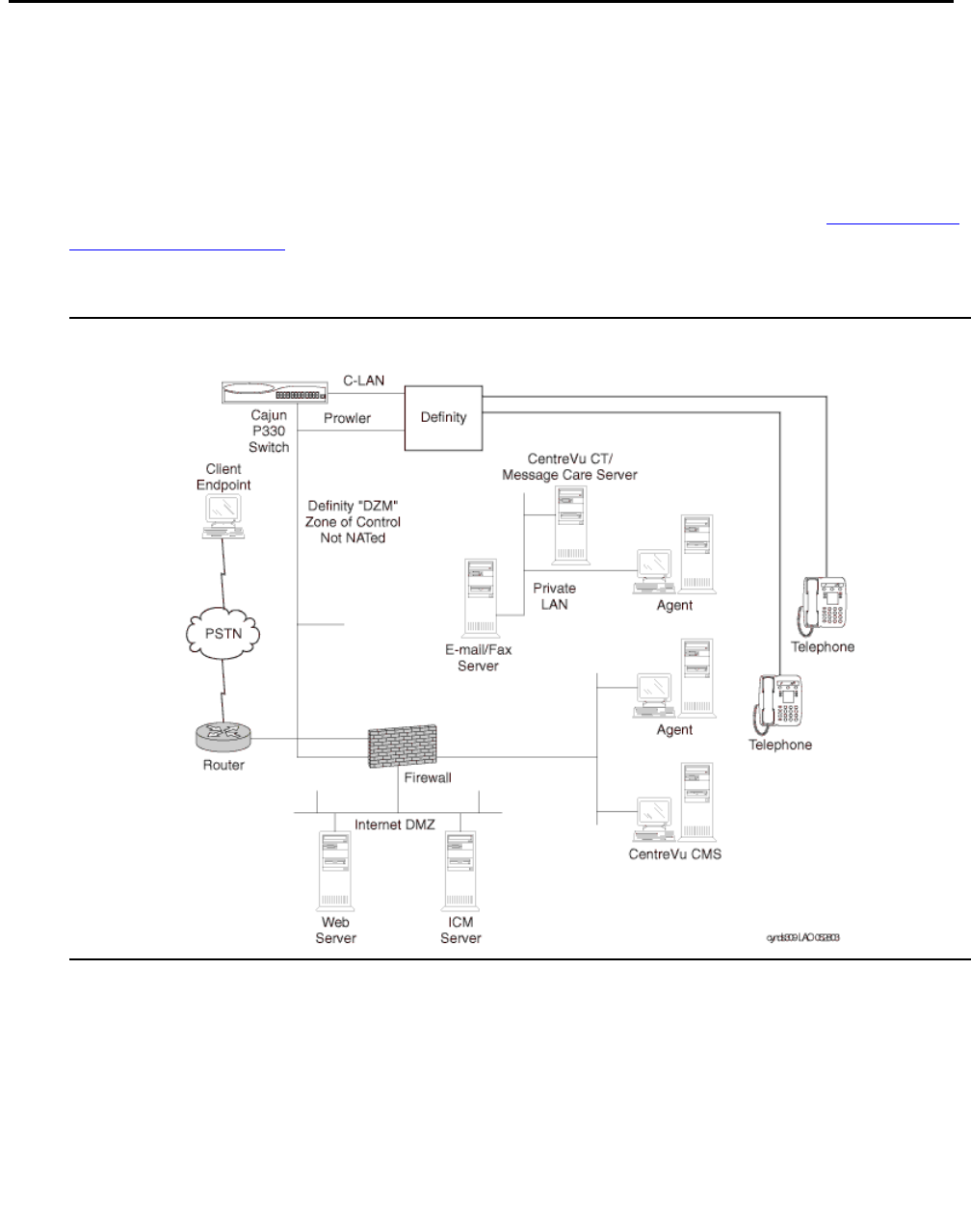
NAT
Issue 4.3 February 2006 353
NAT
IP Telephony does not work well with networks that use Network Address Translation (NAT)
because most NAT implementations do not support H.323 protocols. The destination IP address
is encapsulated in more than one header, including the Q.931, H.225, and IP headers. NAT
changes only the address in the IP header, which results in a mismatch that prohibits the control
of calls. Avaya suggests using a firewall to guard against intruders, but the firewall should not
provide NAT functions for IP Telephony packets unless it is Avaya Q.931 friendly. Figure 91: IP
Telephony without NAT on page 353 shows an approved sample implementation of a firewall
that uses selective NAT. With Avaya Communication Manager 1.3 and later, products work
seamlessly with many static NAT applications, even if they are not H.323 aware.
Figure 91: IP Telephony without NAT

Network design
354 Avaya Application Solutions IP Telephony Deployment Guide

Issue 4.3 February 2006 355
Quality of Service guidelines
This chapter contains guidelines for deploying Quality of Service (QoS) for an IP Telephony
network. This chapter begins with an overview of Class of Service (CoS) versus QoS.
Class of Service refers to mechanisms that tags traffic in such a way that the traffic can be
differentiated and segregated into various classes. Quality of Service refers to what the network
does to the tagged traffic to give higher priority to specific classes. If an endpoint tags its traffic
with Layer 2 802.1p priority 6 and Layer 3 Differentiated Services Code Point (DSCP) 46, for
example, the Ethernet switch must be configured to give priority to value 6, and the router must
be configured to give priority to DSCP 46. The fact that certain traffic is tagged with the intent to
give it higher priority does not necessarily mean it will receive higher priority. CoS tagging does
no good without the supporting QoS mechanisms in the network devices.
Topics covered in this section include:
●CoS
●Layer 2 QoS
●Layer 3 QoS
●IEEE 802.1 p/Q
●DiffServ
●RSVP
●Queuing methods
●Traffic shaping and policing
●Fragmentation
●RTP
●Examples of QoS implementation
CoS
IEEE 802.1p/Q at the Ethernet layer (Layer 2) and DSCP at the IP layer (Layer 3) are two
standards-based CoS mechanisms that are used by Avaya products. These mechanisms are
supported by the IP Telephone, the S8300 Media Server, and the C-LAN and MedPro circuit
packs. Although TCP/UDP source and destination ports are not CoS mechanisms, they can be
used to identify specific traffic, and can be used much like CoS tags. Other non-CoS methods to
identify specific traffic are to key in on source and destination IP addresses and specific
protocols, such as RTP. The MedPro circuit pack and IP Telephones use RTP to encapsulate
audio.

Quality of Service guidelines
356 Avaya Application Solutions IP Telephony Deployment Guide
Note that the 802.1Q tag changes the size and the format of the Ethernet frames. Because of
this, many switches must be explicitly configured to accept 802.1Q tagged frames. Otherwise,
these switches might reject the tagged frames. The two fields to be concerned with are the
Priority and Vlan ID (VID) fields. The Priority field is the “p” in 802.1p/Q, and ranges in value
from 0 to 7. (802.1p/Q is a common term that is used to indicate that the Priority field in the
802.1Q tag has significance. Prior to real-time applications, 802.1Q was used primarily for
VLAN trunking, and the Priority field was not important.) The VID field is used as it always has
been, to indicate the VLAN to which the Ethernet frame belongs.
The IP header with its 8-bit Type of Service (ToS) field, which was, and in some cases still is,
originally used. This original scheme was not widely used, and the IETF developed a new Layer
3 CoS tagging method for IP called Differentiated Services (DiffServ, RFC 2474/2475). DiffServ
uses the first 6 bits of the ToS field, and ranges in value from 0 to 63. Table 63: Comparison of
DSCP with original TOS on page 356 shows the original ToS scheme and DSCP in relation to
the 8 bits of the ToS field.
Ideally, any DSCP value should map directly to a precedence and traffic parameter combination
of the original scheme. This is not always the case, however, and it can cause problems on
some older devices.
On any device, new or old, having a nonzero value in the ToS field cannot hurt if the device is
not configured to examine the ToS field. The problems arise on some legacy devices when the
ToS field is examined, either by default or by enabling QoS. These legacy devices (network and
endpoint) might contain code that only implemented the precedence portion of the original ToS
scheme, with the remaining bits defaulted to zeros. This means that only DSCP values that are
divisible by 8 (XXX000) can map to the original ToS scheme. For example, if an endpoint is
tagging with DSCP 40, a legacy network device can be configured to look for precedence 5,
because both values show up as 10100000 in the ToS field. However, a DSCP of 46 (101110)
cannot be mapped to any precedence value alone. Another snag is if the existing code
implemented precedence with only one traffic parameter permitted to be set high. In this case, a
DSCP of 46 still does not work, because it requires 2 traffic parameter bits to be set high. When
these mismatches occur, the older device mighty reject the DSCP tagged IP packet, or exhibit
some other abnormal behavior. Most newer devices support both DSCP and the original ToS
scheme.
Table 63: Comparison of DSCP with original TOS
8-bit ToS field
IP precedence bits ToS bits 0
0 1 234567
DSCP bits 0 0

Layer 2 QoS
Issue 4.3 February 2006 357
Layer 2 QoS
On Avaya and Cisco switches, IP Telephony traffic can be assigned to higher priority queues.
The number and the sizes of queues and how the queues function are device dependent, and
beyond the scope of this document.
However, in general, a fixed number of queues exist, and the queues are usually not
configurable. If the queues are configurable, it is typically not recommended. Older or lower end
switches commonly have only two queues or none at all. Newer or higher-end switches
commonly have four or eight queues, with eight being the maximum because there are only
eight Layer 2 priority levels. When configured to do so, the Ethernet switch can identify the
high-priority traffic by the 802.1p/Q tag, and assign that traffic to a high-priority queue. On some
switches, a specific port can be designated as a high-priority port, which causes all traffic that
originates from that port to be assigned to a high-priority queue.
Layer 3 QoS
It is usually more complicated to implement QoS on a router than on an Ethernet switch. Unlike
Ethernet switches, routers do not just have a fixed number of queues. Instead, routers have
various queuing mechanisms. For example, Cisco routers have standard first-in first-out
queuing (FIFO), weighted fair queuing (WFQ), custom queuing (CQ), priority queuing (PQ), and
low-latency queuing (LLQ). LLQ is a combination of priority queuing and class-based weighted
fair queuing (CBWFQ), and it is Cisco’s recommended queuing mechanism for real-time
applications such as IP Telephony. Each queuing mechanism behaves differently, is configured
differently, and has its own set of queues.
First, the desired traffic must be identified using DSCP, IP address, TCP/UDP port, or protocol.
Then the traffic must be assigned to a queue in one of the queuing mechanisms. Then the
queuing mechanism must be applied to an interface.
The interface itself might also require additional modifications, independent of the queuing
mechanism, to make QoS work properly. For example, Cisco requires traffic shaping on Frame
Relay and ATM links to help ensure that voice traffic is allotted the committed or guaranteed
bandwidth. Cisco also recommends link fragmentation and interleaving (LFI) on WAN links
below 768 kbps, to reduce serialization delay. Serialization delay is the delay that is incurred in
encapsulating a packet and transmitting it out the serial interface. It increases with packet size,
but decreases with WAN link size. The concern is that large low-priority packets induce
additional delay and jitter, even with QoS enabled. This is overcome by fragmenting the large
low-priority packets and interleaving them with the small high-priority packets, thus reducing the
wait time for the high-priority packets. Table 64: Serialization delay matrix on page 358 lists

Quality of Service guidelines
358 Avaya Application Solutions IP Telephony Deployment Guide
serialization delay for a variety of packet sizes and line speeds. The formula for determining
serialization delay is:
Because of all these configuration variables, properly implementing QoS on a router is no trivial
task. However, QoS is needed most on the router where, because most WAN circuits terminate
on routers.
QoS guidelines
There is no all-inclusive rule regarding the implementation of QoS because all networks and
their traffic characteristics are unique. It is good practice to baseline the IP Telephony response
on a network without QoS, and then apply QoS as necessary. Avaya Network Consulting
Services can help with baselining services. Conversely, it is bad practice to enable multiple QoS
features simultaneously, not knowing what effects, if any, each feature is introducing.
Generally, for newer network equipment, best practices involve enabling Layer 3 (DiffServ) QoS
on WAN links traversed by voice. Tag voice and data with DiffServ Code Point 46 (Expedited
Forwarding), and set up a strict priority queue for voice. If voice quality is still not acceptable, or
if QoS is desired for contingencies such as unexpected traffic storms, QoS can then be
implemented on the LAN segments as necessary.
Table 64: Serialization delay matrix
WAN
line
speed
Packet size
64
bytes 128
bytes 256
bytes 512
bytes 1024
bytes 1500
bytes
56 kbps 9 ms 18 ms 36 ms 72 ms 144 ms 214 ms
64 kbps 8 ms 16 ms 32 ms 64 ms 128 ms 187 ms
128 kbps 4 ms 8 ms 16 ms 32 ms 64 ms 93 ms
256 kbps 2 ms 4 ms 8 ms 16 ms 32 ms 46 ms
512 kbps 1 ms 2 ms 4 ms 8 ms 16 ms 23 ms
768 kbps 640 µs 1.28 ms 2.56 ms 5.12 ms 10.24 ms 15 ms
Serialization delay Packet size (bits)
Line speed
-----------------------------------------
=

Layer 3 QoS
Issue 4.3 February 2006 359
There is one caution to keep in mind about QoS with regard to the processor load on network
devices. Simple routing and switching technologies have been around for many years and have
advanced significantly. Packet forwarding at Layer 2 and Layer 3 is commonly done in
hardware (Cisco calls this fast switching, with “switching” being used as a generic term here),
without heavy processor intervention. When selection criteria such as QoS and other policies
are added to the routing and switching process, it inherently requires more processing
resources from the network device. Many of the newer devices can handle this additional
processing in hardware, and maintain speed without a significant processor burden. However,
to implement QoS, some devices must take a hardware process and move it to software (Cisco
calls this process “switching”). Process switching not only reduces the speed of packet
forwarding, but it also adds a processor penalty that can be significant. This can result in an
overall performance degradation from the network device, and even device failure. Each
network device must be examined individually to determine if enabling QoS will reduce its
overall effectiveness by moving a hardware function to software, or for any other reason. Since
most QoS policies are implemented on WAN links, the following general points for Cisco routers
are offered to increase the level of confidence that QoS remains in hardware (consult Cisco to
be sure):
●Newer hardware platforms are required: 2600, 3600, 7200, and 7500
●Newer interface modules (WIC, VIP, and so on) are required. Consult Cisco to determine
which hardware revision is required for any given module.
●Sufficient memory is required: device dependent.
●Newer IOS is required: 12.0 or later.
Avaya Layer 3 switches and the X330 WAN module support both 802.1 p/Q and DiffServ QoS.
Several things should be examined whenever QoS is enabled on a network device. First, the
network administrator should examine the processor load on the device, and compare it to
levels before QoS was enabled. It is likely that the levels will have gone up, but the increase
should not be significant. If it is, then it is likely that the QoS process is being done by software.
Also, the processor load must remain at a manageable level (50% average, 80% peak). If the
processor load is manageable, then the IP Telephony response (for example, voice quality)
should be checked to verify that it has improved under stressed conditions (for example, high
congestion). If the IP Telephony response has improved, the other applications should be
checked to verify that their performances have not degraded to unacceptable levels.
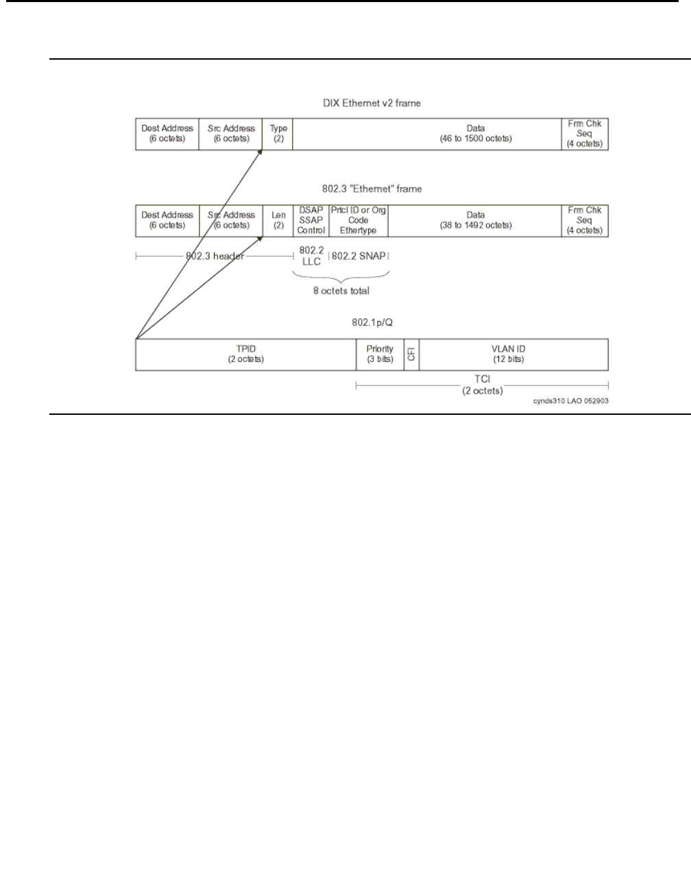
Quality of Service guidelines
360 Avaya Application Solutions IP Telephony Deployment Guide
IEEE 802.1 p/Q
Figure 92: 802.1Q tag
The IEEE 802.1Q standard is a Layer 2 tagging method that adds 4 bytes to the Layer 2
Ethernet header. IEEE 802.1Q defines the open standard for VLAN tagging. Two bytes house
12 bits that are used to tag each frame with a VLAN identification number. The IEEE 802.1p
standard uses 3 of the remaining bits in the 802.1Q header to assign one of 8 different classes
of service. Communication Manager users can add the 802.1Q bytes and set the priority bits as
desired. Avaya suggests that a priority of 6 be used for both voice and signaling. The Avaya line
of data switches can switch frames with or without these VLAN headers, with no configuration
time spent. IEEE 802.1p and IEEE 802.1Q are OSI layer 2 solutions, and work on frames.
Because 802.1Q is a Layer 2 (Ethernet) standard, it only applies to the Ethernet header. At
every Layer 3 boundary (router hop), the Layer 2 header, including CoS parameters, is stripped
and replaced with a new header for the next link. Thus, 802.1Q does not enable end-to-end
QoS.

DiffServ
Issue 4.3 February 2006 361
Recommendations for end-to-end QoS
When end-to-end QoS is desired, Avaya recommends using DiffServ, a Layer 3 CoS method.
Modern can map DiffServ Code Points (DSCP) to 802.1p priority values, so 802.1p tags can be
recreated on each Ethernet link. This functionality is supported in Avaya Layer 3 switches, and
the X330 WAN module.
IEEE 802.1p states a standard according to which these bits are used for CoS. The precedence
is listed in Table 65: IEEE 802.1 precedence and service mapping.
DiffServ
The Differentiated Services (DiffServ) prioritization scheme redefines the existing TOS byte in
the IP header (Figure 93: Differentiated Services (DiffServ) TOS byte on page 362) by
combining the first 6 bits into 64 possible combinations. This use of the TOS byte is still
evolving, but can be used now by Communication Manager, IP Telephones, and other network
elements such as routers and switches in the LAN and WAN.
Table 65: IEEE 802.1 precedence and service mapping
User priority Service mapping
000 Default, assumed to be best effort
001 Reserved, less than best effort
010 Reserved
011 Reserved
100 Delay sensitive, no bound
101 Delay sensitive, 100 ms bound
110 Delay sensitive, 10 ms bound
111 Network control
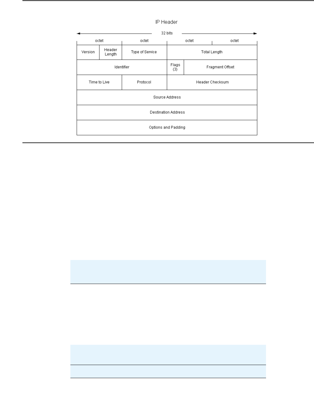
Quality of Service guidelines
362 Avaya Application Solutions IP Telephony Deployment Guide
Figure 93: Differentiated Services (DiffServ) TOS byte
A DiffServ Code Point (DSCP) of 46 (101110), referred to as expedited forwarding (EF), is
suggested for the proper treatment of voice and signaling packets. However, with
Communication Manager, one can set any DSCP value as desired to work with a company’s
QoS scheme. Some common DiffServ Code Points are defined in RFCs 2474 and 2475.
Although DSCPs are specified in IETF RFCs, the treatment of packets that are tagged with
DiffServe is implementation- dependent.
Note that older routers might require a DSCP setting of 40 (101000), which is backward
compatible to the original TOS byte definition of critical. But again, Avaya products and software
allows users to set any of the 64 possible DSCP values to work with your voice quality policy.
The TOS byte is an OSI model Layer 3 solution, and works on IP packets on the LAN and
possibly the WAN, depending upon the service provider.
Table 66: Original TOS specification
Bit
description Value Use
Bits 0-2IP
precedence
000
001
010
011
100
101
110
111
Routine
Priority
Immediate
Flash
Flash Override
CRITIC/ECP
Internetwork control
Network control
Bit 3
delay 0
1Normal
Low
1 of 2

RSVP
Issue 4.3 February 2006 363
RSVP
Resource Reservation Protocol (RSVP) is a protocol that hosts can use to request specific QoS
parameters through the network for a particular application data stream. A host can request
guaranteed service through a network. If all routers have RSVP support enabled, and if there
exists sufficient unreserved bandwidth, a reservation is established throughout the network. If
insufficient bandwidth exists, the reservation fails and notifies the hosts. At that point, hosts can
choose to send traffic without a reservation, or drop the connection.
RSVP is supported in Communication Manager beginning with Release 1.3. RSVP can be
enabled per network region on the network region form. If RSVP is enabled, endpoints including
IP Telephones and media processors attempt to establish a reservation for each call. If the
reservation fails, Avaya endpoints still try to place a call, but lower the DiffServ priority of the call
to the better-than-best-effort (BBE) DSCP that is defined on the network region form. By default,
this value is 43.
If RSVP is enabled on a network region, it is very important that it also be enabled on
associated routers. If not, all RSVP reservations fail, and all voice traffic in that region is marked
with the BBE DSCP, which will generally receive degraded service versus the EF (DSCP 46)
DiffServ Code Point.
Bit 4
Throughput 0
1Normal
High
Bit 5
reliability 0
1Normal
High
Bit 6
monetary cost 0
1Normal
Low
Bit 7
reserved Always set to 0
Table 66: Original TOS specification (continued)
Bit
description Value Use
2 of 2

Quality of Service guidelines
364 Avaya Application Solutions IP Telephony Deployment Guide
Queuing methods
This section discusses common queuing methods and their appropriateness for voice:
●WFQ
●PQ
●Round-robin
●CB-WFQ / LLQ / CBQ
●RED / WRED
WFQ
Weighted fair queuing (WFQ) is similar to first in, first out (FIFO) queuing, except that it grants a
higher weight to small flows, and flows that are marked with higher DiffServ or IP TOS priorities.
This queuing strategy does allow smaller (for example, telnet) and higher-priority (for example,
IP Telephony) protocols to squeeze in before high-flow (for example, ftp) packets, but does not
starve off any traffic. By itself, it is not appropriate for IP Telephony traffic because high-flow
traffic can still delay IP Telephony traffic, and cause unacceptable latency and jitter.
PQ
Strict priority queuing (PQ) divides traffic into different queues. These queues are usually high,
medium, normal, and low, based on traffic type. This form of queuing services the queues in
order of priority, from high to low. If there is a packet in the high-priority queue, it will always be
serviced before the queue manager services the lower-priority queues. With priority queuing,
however, it is possible to starve out lower-priority flows if sufficient traffic enters the
high-\priority queue. This mechanism works very well for IP Telephony traffic (where IP
Telephony bearer and signaling are inserted in the high-priority queue), but might work less well
for routine data traffic that is starved out if sufficient high-priority traffic arrives.

Queuing methods
Issue 4.3 February 2006 365
Round-robin
Round-robin (sometimes called custom) queuing sorts data into queues, and services each
queue in order. An administrator manually configures which type of traffic enters each queue,
the queue depth, and the amount of bandwidth to allocate to each queue.
Round-robin queuing is not particularly suited to IP Telephony. It does not ensure strict enough
priority to voice packets, so they may still wait behind other traffic flows in other queues.
Latency and jitter can be at unacceptable levels.
CB-WFQ / LLQ / CBQ
Class-Based Weighted Fair Queuing (CB-WFQ) with Low-Latency Queuing (LLQ), which is
sometimes called Class-Based Queuing (CBQ), combines the above-mentioned queuing
mechanisms. Generally, there is one strict-priority queue, several round-robin queues, and
weighted fair queuing for the remainder. This queuing mechanism works very well for
converged networks. IP Telephony bearer and signaling packets receive the priority they need,
while there remains an equitable mechanism for distributing remaining bandwidth. In addition,
limits can be set on the high-priority queue to prevent it from using more than a specified
amount of bandwidth. Bandwidth that is reserved for the high-priority queue will be given to
other queues if insufficient traffic enters the high-priority queue.
RED / WRED
Although they are not queuing methods per se, Random Early Detection (RED) and Weighted
Random Early Detection (WRED) are important queue management techniques. RED and
WRED work by randomly discarding packets from a queue. RED takes advantage of the
congestion control mechanism of TCP. By randomly dropping packets prior to periods of high
congestion, RED causes the packet source to decrease its transmission rate. Assuming that the
packet source is using TCP, it will decrease its transmission rate until all the packets reach their
destination, which indicates that the congestion is cleared. Some implementations of RED,
called Weighted Random Early Detection (WRED), combines the capabilities of the RED
algorithm with IP Precedence. This combination provides for preferential traffic handling for
higher-priority packets. It can selectively discard lower-priority traffic when the interface begins
to get congested, and provide differentiated performance characteristics for different classes of
service.
RED and WRED are useful tools for managing “data” traffic, but should not be used for “voice.”
Because IP Telephony traffic runs over UDP, because IP Telephony protocols do not retransmit
lost packets, and because IP Telephony transmits at a constant rate, the IP Telephony queue
should never be configured for WRED. WRED only adds unnecessary packet loss, and
consequently reduces voice quality.

Quality of Service guidelines
366 Avaya Application Solutions IP Telephony Deployment Guide
Traffic shaping and policing
Traffic shaping is a mechanism to reduce the rate at which data is transmitted over an interface.
When people discuss traffic shaping, they are usually referring to the related technology of
traffic policing. Policing works by either adjusting the priority of excess traffic to a lower queue,
or discarding it. As with RED, discarding TCP traffic has the effect of throttling the stream by
forcing window size to shrink, and decreasing its transmission rate. Because RTP is a
fixed-bandwidth application, discarding RTP packets reduces voice quality without altering the
transmission rate. Adjusting the priority of voice traffic removes the strict priority protection that
reduces latency and jitter, and offers the highest voice quality. Thus, in most cases, it is
beneficial to use the QoS mechanisms listed above, rather than traffic shaping and policing, to
offer the highest quality for voice.
Frame Relay traffic shaping
Traffic shaping is important in technologies that implement virtual circuits (VCs), such as Frame
Relay or ATM, where the Committed Information Rate (CIR) might be less than the physical
speed of the interface, the port speed. In such scenarios, it is possible for traffic to burst above
the CIR. Depending on the Service Level Agreement (SLA), a carrier might mark excess traffic
as Discard Eligible (DE), and either delay or discard it if congestion is detected within the
network of the carrier. This behavior is unacceptable for voice traffic, which must minimize delay
and jitter to achieve optimal voice quality. To solve this issue, Frame Relay traffic shaping gives
an administrator tools to limit the transmission rate on a Frame Relay virtual circuit to the CIR.
A popular misconception is that voice traffic can be confined to the CIR, while data traffic can be
allowed to burst. Unfortunately, that is not how Frame Relay works. There is not a QoS
mechanism for Frame Relay that is negotiated between service providers and customers.
Service providers view all traffic equally, and mark any packet that exceeds the CIR as DE,
even if the packet is high-priority voice. Thus, the only way to guarantee optimal performance
for voice traffic is to restrict the traffic rate to the CIR.
On a Cisco router, do the following to ensure proper handling for voice:
1. Disable Frame Relay adaptive shaping. This technique reduces the CIR in response to
backwards explicit congestion notification (BECN) messages from the service provider.
Because traffic is being transmitted at the CIR in the first place, it does not need to be
throttled.
2. Set cir and mincir to the negotiated CIR. If FRF.12 fragmentation is implemented, reduce
the cir and mincir values slightly to account for the fragment headers.
3. Set be, the excess burst rate, to 0
4. Set bc, the committed burst rate, to cir/100. This accounts for at most a 10-ms serialization
delay.
5. Apply this map class to an interface, subinterface, or VC.

Fragmentation
Issue 4.3 February 2006 367
Thus, the complete configuration for Frame Relay traffic shaping looks like:
map-class frame-relay NoBurst
no frame-relay adaptive shaping
frame-relay cir 384000! (for a 384K CIR)
frame-relay mincir 384000
frame-relay be 0
frame-relay bc 3840
interface serial 0
frame-relay class NoBurst
Fragmentation
One large cause of delay and jitter across WAN links is serialization delay, or the time that it
takes to put a packet on a wire. For example, a 1500-byte FTP packet takes approximately
214 ms to be fed onto a 56-Kbps circuit. For optimal voice performance, the maximum
serialization delay should be close to 10 ms. Thus, it can be problematic for a voice packet to
wait for a large data packet over a slow circuit. The solution to this problem is to fragment the
large data packet into smaller pieces for propagation. If a smaller voice packet comes in, it can
be squeezed between the data packet fragments and be transmitted within a short period of
time.
The sections that follow discuss some of the more common fragmentation techniques:
●MTU
●LFI
●FRF.12
MTU
The maximum transmission unit (MTU) is the longest packet (in bytes) that can be transmitted
by an interface without fragmentation. Reducing the MTU on an interface forces a router to
fragment the large packet at the IP level. This allows smaller voice packets to squeeze through
in a timelier manner.
The drawback to this method is that it increases overhead and processor occupancy. For every
fragment, a new IP header must be generated, which adds 20 bytes of data. If the MTU is
1,500 bytes, the overhead is approximately 1.3%. If the MTU is shortened to 200 bytes,
however, the overhead increases to 10%. In addition, shortening the MTU to force
fragmentation increases processor utilization on both the router and the end host that needs to
reassemble the packet.

Quality of Service guidelines
368 Avaya Application Solutions IP Telephony Deployment Guide
For these reasons, shortening the MTU is only recommended as a last resort. The techniques
described later in this section are more efficient, and should be used before changing the values
of the MTU. When changing the MTU, size it such that the serialization delay is less than or
equal to 10 ms. Thus, for a 384-kbps circuit, the MTU should be sized as follows: 384000 bps
*0.01 second (10 ms)/8 bits/byte = 480 bytes. As the circuit size diminishes, however, care
should be taken to never reduce the MTU below 200 bytes. Below that size, telephony signaling
and bearer (voice) packets can also be fragmented, which reduces the link efficiency and
degrades voice performance.
LFI
Link Fragmentation and Interleaving (LFI) is an enhancement to Multilink PPP (MLP) that
fragments packets at the Layer 2 (PPP) level. Fragmenting at the IP layer, as with MTU
reduction, forces the addition of a new 20-byte IP header and an 8-byte PPP header. However,
fragmenting at the data link (PPP) layer only forces generation of an 8-byte PPP header, which
greatly increases the efficiency of the link.
Avaya recommends use of LFI functionality instead of MTU manipulation when transmitting IP
Telephony packets over PPP links. As with MTU, Avaya recommends sizing packets so that the
serialization delay is approximately 10 ms or less.
FRF.12
FRF.12 is a Frame Relay standard for fragmentation. It works for Frame Relay in the same way
that LFI works for PPP, with similar increases in efficiency over MTU manipulation. When
implementing a Frame Relay network, Avaya recommends using FRF.12 for fragmentation, and
sizing the fragments so the serialization delay is no more than 10 ms.
RTP
RTP header compression is a mechanism that reduces the protocol overhead that is associated
with IP Telephony audio packets. It is a function of the network, and not a function of the IP
Telephony application. Along with the benefits of using RTP header compression, there are also
cautions.
This section discusses the following topics:
●Application perspective
●Network perspective
●The test
●Configuration

RTP
Issue 4.3 February 2006 369
Application perspective
Table 67: Anatomy of 20-ms G.729 audio packet on page 369 shows the anatomy of a 20-ms
G.729 audio packet, which is recommended for use across limited bandwidth WAN links. Notice
that two-thirds of the packet is consumed by overhead (IP, UDP, and RTP), and only one-third
is used by the actual audio.
It is important to understand that all 20-ms G.729 audio packets, regardless of the vendor, are
constructed like this. Not only is the structure of the packet the same, but the method of
encoding and decoding the audio itself is also the same. This sameness is what allows an
Avaya IP Telephone to communicate directly with a Cisco IP Telephone, or any other IP
Telephone, when using matching codecs. The packets from the application perspective are
identical.
Network perspective
RTP header compression is a mechanism that routers use to reduce the 40 bytes of protocol
overhead to approximately 2 to 4 bytes. Cisco routers use this mechanism, as does the Avaya
X330WAN router, which is a module for the P330 chassis. RTP header compression can
drastically reduce the IP Telephony bandwidth consumption on a WAN link when using 20-ms
G.729 audio. When the combined 40-byte header is reduced to 4 bytes, the total IP packet size
is reduced by 60% (from 60 bytes to 24 bytes). This equates to reducing the total IP Telephony
WAN bandwidth consumption by roughly half, and it applies to all 20-ms G.729 audio packets,
regardless of the vendor.
Recommendations for RTP header compression
Enterprises that deploy routers that are capable of this feature might be able to benefit from it.
However, Cisco recommends caution in using RTP header compression on its routers because
it can significantly tax the processor if the compression is done in software. Depending on the
processor load before compression, enabling RTP header compression can significantly slow
down the router, or cause the router to stop completely. For best results, use a hardware/IOS/
interface module combination that permits the compression to be done in hardware.
Table 67: Anatomy of 20-ms G.729 audio packet
IP header UDP header RTP header 20 ms of G.729 audio
20 B 8 B 12 B 20 B
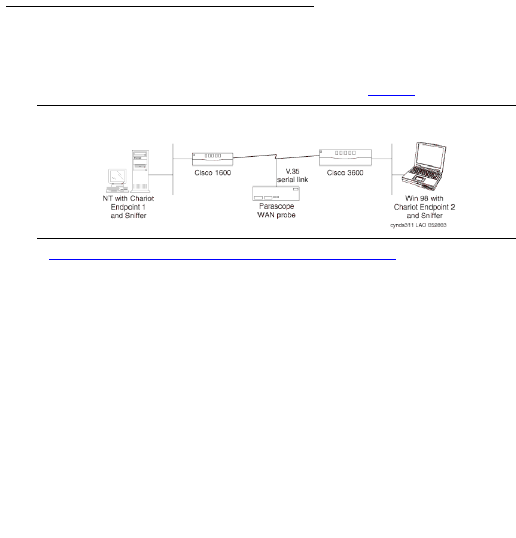
Quality of Service guidelines
370 Avaya Application Solutions IP Telephony Deployment Guide
RTP header compression has to function with exactness or it will disrupt audio. If for any reason
the compression at one end of the WAN link and decompression at the other end do not
function properly, the result can be intermittent loss of audio or one-way audio. This has been
very difficult to quantify, but there is some anecdotal evidence that cRTP sometimes leads to
voice-quality issues. One production site in particular experienced intermittent one-way audio,
the cause of which was garbled RTP audio samples inserted by the cRTP device. When, for
experimentation purposes, RTP header compression was disabled, the audio problems went
away.
The test
This section details the results of a simple RTP header compression test that was conducted in
a laboratory environment. Although this test was conducted using Cisco routers, the expected
behavior is the same for any router that performs this function as specified in RFC 2508. This
test was performed in the laboratory configuration that is shown in Figure 94.
Figure 94: Equipment configuration for RTP header compression test
In Figure 94: Equipment configuration for RTP header compression test on page 370:
●NetIQ Chariot v4.0 was used to simulate IP Telephony calls between the two endpoints.
Chariot v4.0 accurately simulates the characteristics of various codecs, and uses a
40-byte IP/UDP/RTP header.
●Sniffer Pro v3.50.02 was used to capture the sent and received packets.
●The Cisco 3600 had IOS v12.1(2)T, and the Cisco 1600 had IOS v12.0(12).
●The Frederick Engineering Parascope WAN probe was tapped into the V.35 serial link to
take bandwidth measurements.
●This test was performed using PPP encapsulation on the WAN link.
A single call was placed between the Chariot endpoints using various codecs, all sending
20-ms voice packets.
Table 68: Test call (20ms-packets) results on page 371 shows the results with and without RTP
header compression. Note that these are rough measurements.

RTP
Issue 4.3 February 2006 371
For each codec, there was an attempt to verify that the audio packets were received intact. This
was done by spot checking the audio packets before and after compression, using two Sniffer
protocol analyzers. For every codec except G.711, the RTP header and payload were identical
before and after compression. With G.711, however, the received packets had the PADDING
flag set in the RTP header, although the flag was not set when the packets were transmitted.
The PADDING flag indicates the presence of padding octets at the end of the RTP payload,
which cannot be true for G.711.
Configuration
To configure RTP header compression on a Cisco router:
1. Specify the number of RTP connections that can be compressed (cache allocation). In
interface configuration mode, the command is ip rtp compression-connections
<number>, where
●The default for <number> is 32, and each call requires two connections.
●The configurable range is 3 to 256 for PPP and HDLC using IOS v11.3 and later.
●The configurable range is 3 to 1000 for PPP and HDLC using IOS v12.0(7)T and later.
●For Frame Relay, the value is fixed at 256.
2. The command to turn on compression is ip rtp header-compression in interface
configuration mode. It must be implemented at both ends of the WAN link. When the
command was entered into the router, ip tcp header-compression was also installed
automatically. When either command was removed, the other was automatically removed.
Table 68: Test call (20ms-packets) results
Codec Payload
bytes
per packet
Packets
per
second
Avg WAN BW
consumption (kbps) %
reduction
without
compressi
on
with
compressi
on
G.711
(64 kbps) 160 50 84 68.5 ~18%
G.729A
(8 kbps) 20 50 27.5 13 ~53%
G.723.1
(5.3 kbps) 20 33 18 9 ~50%
G.723.1
(6.3 kbps) 24 33 19 10 ~47%

Quality of Service guidelines
372 Avaya Application Solutions IP Telephony Deployment Guide
See the Cisco documentation for more specific configurations on other types of WAN links (that
is, Frame Relay and ATM). Configuration for the X330WAN router is very similar to Cisco, and
is well documented in the X330WAN User Guides. For this documentation, see the P330
section at:
http://www.avaya.com/support
Examples of QoS implementation
This section contains sample commands for QoS implementation on Avaya products and Cisco
products.
Examples given include:
●Example 1: Cisco router configuration for point-to-point WAN links
●Example 2: C-LANS cannot tag their traffic
●Example 3: More restrictions on the traffic
●Converged infrastructure LAN switches
Example 1: Cisco router configuration for point-to-point WAN
links
There is a three-step process to turn on QoS on a Cisco router:
1. Set up a class map that defines “interesting traffic” to be prioritized.
2. Select a queuing strategy. In this case, use a policy map to set priority. Set up a route map
that sets the priority level (critical).
3. Apply the policy map to an interface.
In Figure 95: High-quality service across a congested WAN link on page 373, set priority-aware
Class-Based Weighted Fair Queuing (CB-WFQ) with Low Latency Queuing (LLQ). Although
there are more aggressive QoS strategies, they can have a severe impact on data
performance. Those other strategies, including Priority Queuing, Custom Queuing, and RSVP,
can be implemented at a later date, if conditions warrant. This is a good starting point.
Figure 95: High-quality service across a congested WAN link on page 373 is used as a
reference point. The objective is to assure high quality of service to IP Telephony applications
across the congested WAN link.
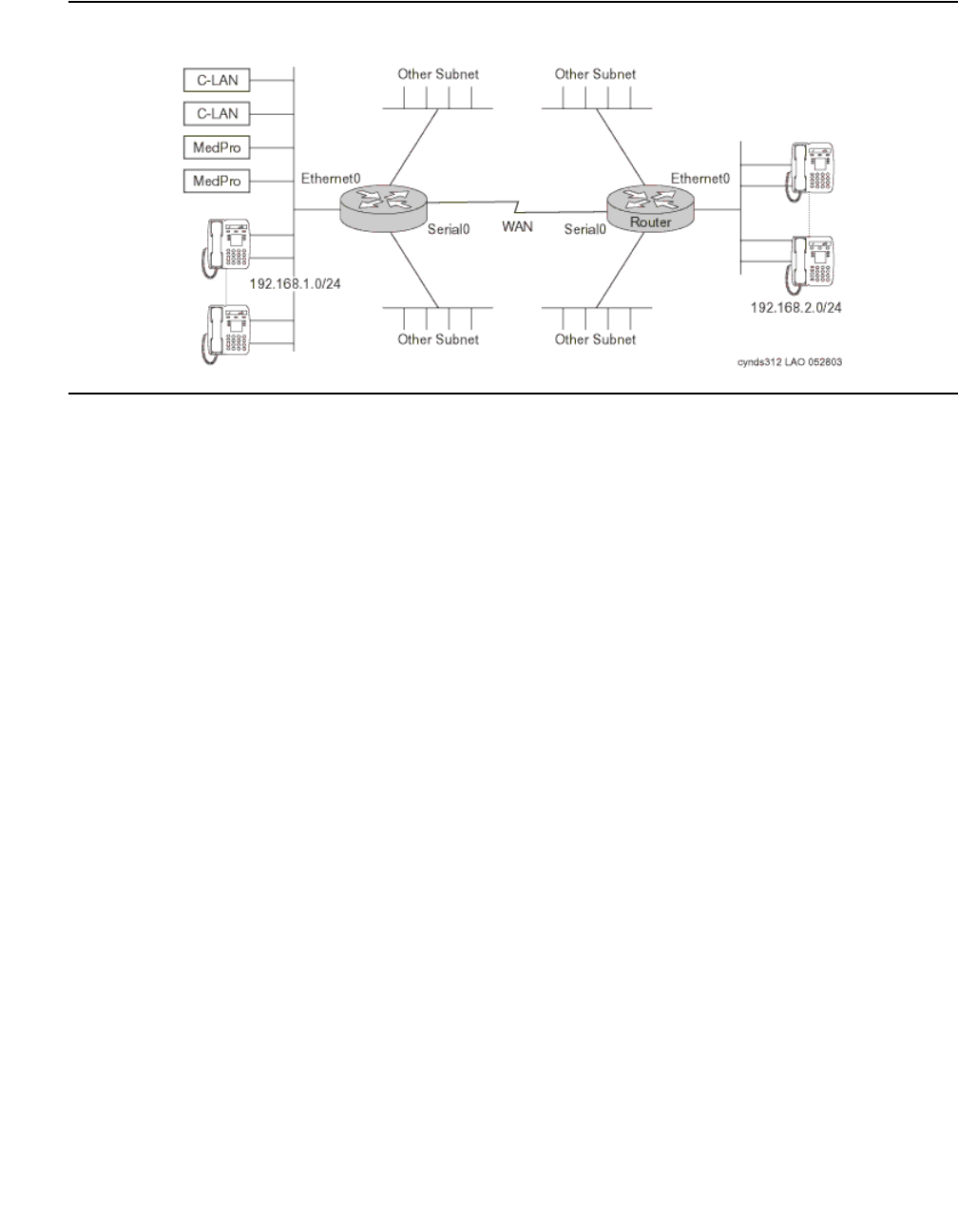
Examples of QoS implementation
Issue 4.3 February 2006 373
Figure 95: High-quality service across a congested WAN link
CB-WFQ/LLQ is a priority-aware queuing strategy that has a strict priority queue for voice
packets, and does round-robin queuing for other types of traffic. Non-prioritized traffic is still
forwarded, however, so this should not interfere with a customer’s data network. Use weighted
random early detect to manage the fair queue.
The actual router configuration used for this testing follows. First, set the endpoints to tag
interesting traffic as DSCP 46. Cisco routers support DiffServ in IOS 12.0 and later. Next, set up
a class map to match traffic that is marked with DSCP 46. Once traffic is defined by the class
map, set policies for it using a policy map. For the policy map to take effect, it has to be applied
to an interface. Queue packets on the outgoing interface. In the sample configuration, 768 K of
bandwidth is reserved for RTP. This value should be set at or above the maximum bandwidth to
be used for IP Telephony. In our case, 768 K supports 9 calls using G.711, or 31 calls using
G.729. This example should work well in most cases using Cisco routers with point-to-point
WAN links. Networks that use Frame Relay might need additional steps.
Assumptions for Example 1
Suppose all endpoints are capable of tagging with DSCP 46, which is the default for audio. This
would be true in a Communication Manager system with TN799DP C-LAN circuit packs running
firmware v5 or later. Previous firmware versions and the TN799C circuit pack cannot tag at
Layer 2 or Layer 3. A matching set of configurations is applied to both routers.

Quality of Service guidelines
374 Avaya Application Solutions IP Telephony Deployment Guide
Administration commands for Example 1
Example 2: C-LANS cannot tag their traffic
Assumptions for Example 2
●The C-LANs 192.168.1.10 and.11 cannot tag their traffic (TN-799C or earlier).
●The configuration commands in Table 70: Administration commands for Example 2 on
page 375 are applied only to the left router.
Table 69: Administration commands for Example 1
Command Meaning
1.class-map match-any VoIP Create a class map called “VoIP.”
2.match ip dscp 46 Any packet with DSCP 46 is in the class
“VoIP.”
3.policy-map voipQoS Create a policy map called “voipQoS.”
4.class VoIP priority 768 Give strict priority to packets in the class
“VoIP” on up to 768 k of this WAN link.
5.class class-default
fair-queue
Put everything else in the default class,
and transmit it out the default queue in a
fair queue fashion.
6.random-detect dscp-based If the default queue starts to get full,
randomly discard packets in this queue
based on DSCP. The lower values are
discarded first.
7.interface Serial0
description T1 ip address
172.16.0.1 service-policy
output voipQoS
Apply the “voipQoS policy” outbound on
this interface.

Examples of QoS implementation
Issue 4.3 February 2006 375
Administration commands for Example 2
Example 3: More restrictions on the traffic
Assumptions for Example 3
●DSCP 46 is used throughout to simplify the access list.
●A somewhat matching set of configurations is applied to both routers.
Table 70: Administration commands for Example 2
Command Meaning
1.access-list 101 permit
ip host 192.168.1.10
192.168.2.0 0.0.0.255
The command “access-list 101...” permits
any IP traffic from the 2 C-LANs to the
192.168.2.0/24 network. There is an
implicit “deny any” at the end of this access
list.
2.access-list 101 permit
ip host 192.168.1.11
192.168.2.0 0.0.0.255
3.class-map match-any
untaggedVoIP
Create a class map called “untaggedVoIP.”
4.match access-group 101 Packets that match access list 101 are in
the class that is “untaggedVoIP.”
5.policy-map setDSCP Create a policy map called “setDSCP.”
6.class untaggedVoIP set
ip dscp 46
For all packets in the class
“untaggedVoIP,” set the DSCP to 46.
7.interface Ethernet 0/0
service-policy input
setDSCP
Apply the “setDSCP” policy inbound on this
interface.

Quality of Service guidelines
376 Avaya Application Solutions IP Telephony Deployment Guide
Administration commands for Example 3
If any of the endpoints are incapable of tagging, the “dscp 46” can be removed from access list
101. Then any traffic between the two IP Telephony subnetworks, regardless of the tag, is in the
class “VoIP.”
Table 71: Administration commands for Example 3
Command Meaning
1.access-list 101 permit
ip 192.168.1.0
0.0.0.255
192.168.2.0 0.0.0.255
dscp 46
Left router
2.access-list 101 permit
ip 192.168.2.0
0.0.0.255 192.168.1.0
0.0.0.255 dscp 46
Right router
The “access list 101...” permits any IP traffic
that is tagged with DSCP 46 between the two
VoIP subnets. There is an implicit deny any
at the end of this access list
3.class-map match-any
VoIP
Create a class map called “VoIP.”
4.match access-group 101 Only packets matching access list 101 are in
the class VoIP; this is more restrictive than
matching any packet with DSCP 46 or 34.
5.policy-map voipQoS Create a class map called “VoIP.”
6.class VoIP priority
768
Give strict priority to packets in the class
“VoIP” on up to 768k of this WAN link.
7.class class-default
fair-queue
Put everything else in the default class and
transmit it out the default queue in a fair
queue fashion.
8.random-detect
dscp-based
If the default queue starts to get full,
randomly discard packets in this queue
based on DSCP (lower values get discarded
first).
9.interface Serial0
description T1 ip
address 172.16.0.1
service-policy output
voipQoS
Apply the “voipQoS” policy outbound on this
interface.

Examples of QoS implementation
Issue 4.3 February 2006 377
Converged infrastructure LAN switches
P330 family
By default, P330 LAN switches accept 802.1Q frames on all ports, and use the 802.1p priority
tags. There are two queues within the P330s. The high-priority queue represents 802.1p values
4 to7. The low-priority queue represents 802.1p values 0 to 3. In addition to accepting the
values tagged by an endpoint, tagging can be done per port with the command:
set port priority <high|low>
X330 WAN Module
The new X330WAN versions contain a predefined queue management strategy for IP
Telephony that is called CBQ. Use the following procedure to activate CBQ:
Table 72: X330 WAN Module administration commands
Command Meaning
1.set qos policy-source
local
Define DSCP-CoS mapping.
! no external policy source
2.ip access-list-name 100
voice
set up access-list 100 with name “voice”.
3.ip access-list-dscp
operation 100 34 fw7
The X330 WAN has four queues with eight
behaviors. fw6 and fw7 are different
behaviors within the top strict priority queue.
4.ip access-list-dscp
operation 100 46 fw6
In access-list 100, map DSCP 46 to the fw6
queue.
5.ip access-list-dscp
trust 100
trust-cos-dscp
Trust packet tagging.
6.interface
FabricFastEthernet 1
Activate the above mapping on ingress
traffic to the Fabric Fast Ethernet interface
7.ip access-group 100 in Apply the ACL to traffic that is arriving on
the FabricFastEthernet port.
8.exit
1 of 2

Quality of Service guidelines
378 Avaya Application Solutions IP Telephony Deployment Guide
9.interface Serial 1 Apply the following commands to Interface
Serial 1.
10.voip-queue Activate “VoIP queue management mode”
on the serial interface.
11.exit
12.interface Serial 1 Apply the following commands to Interface
Serial 1.
13.ip rtp
header-compression
Enable cRTP (optional).
Table 72: X330 WAN Module administration commands (continued)
Command Meaning
2 of 2

Issue 4.3 February 2006 379
Implementing Communication
Manager on a data network
This section presents several examples of implementing Communication Manager on a data
network. Topics covered include:
●S8700-series fiber connect
●S8700-series and S8500 IP connect
●S8700-series / S8500 / S8300 LSP
●S8300 / G700 / G350 / G250 (ICC)
●Sample fiber connect deployment
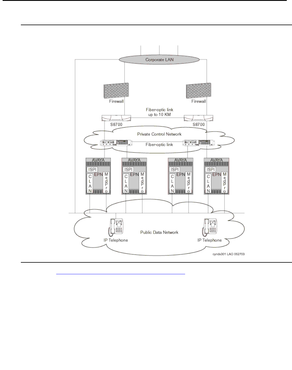
Implementing Communication Manager on a data network
380 Avaya Application Solutions IP Telephony Deployment Guide
S8700-series fiber connect
Figure 96: S8700-series fiber connect system
As shown in Figure 96: S8700-series fiber connect system on page 380, the S8700-series fiber
connect system is relatively straightforward to implement on the data network. It consists of an
S8700-series Media Server pair and some number of IPSIs, depending on the number of port
networks. The connection between the IPSIs and the S8700/S8710 pair is done on a private
LAN utilizing one (or more) switches. This is one of the simpler network configurations, as
control traffic is completely isolated from the production data network.

S8700-series fiber connect
Issue 4.3 February 2006 381
IPSI configuration
In a fiber connect system, IPSI configuration is automatic. Upon power-up, IPSIs send out a
DHCP request on the control network. The S8700s, then, provide DHCP addresses and server
configuration information to the IPSIs.
Server separation
The S8700-series servers can be separated by a maximum distance of 10 km. This limitation is
based on the fiber channel interface used for memory shadowing. When contemplating a 10 km
server separation, it is important to plan for the Ethernet separation, as well. Both servers’
arbitration link and control network links MUST be on the same IP subnet. Although the use of
media converters to convert the 10/100BaseTX Ethernet to 100BaseFX is an approved
configuration, it is not recommended. Media converters are not reliable and are difficult to
troubleshoot. As shown in Figure 96: S8700-series fiber connect system on page 380, the
recommended alternative is to use two C360 switches with 100BaseFX (or gigabit) interfaces.
Each server would connect to one switch, and the two switches would be linked by a fiber optic
connection. This solution is much more reliable and easier to troubleshoot.
Control Network on Customer LAN (CNOCL)
Prior to Avaya Communication Manager 2.0, the S8700-series fiber connect Control Network
was required to be implemented on a private, dedicated network. A private, dedicated Control
Network provides the much needed and desired system reliability and availability. The system is
isolated and hence much more secure, and less prone to security attacks from the likes of virus
attacks, Denial of Service (DoS) attacks, and broadcast storms. Thus, even though it is highly
recommended that customers with business-critical telephony applications implement the
Control Network on a private, dedicated network, Avaya Communication Manager 2.0 provides
the option of implementing the Control Network on existing enterprise LAN infrastructure. This
section provides implementation and installation recommendations when implementing the
Control Network of an S8700-series fiber connect system on an enterprise network.
Network Engineering Guidelines
The reliability of a fiber connect system can only be as good as the reliability of the control
network. Typically, enterprise LANs are approximately 99.9% reliable, while WANs reach
approximately 99% reliability. In order to approach 99.999% (five-9s) reliability for the fiber
connect system, the enterprise data network must take advantage of network design best
practices, failover mechanisms, and strict change control.

Implementing Communication Manager on a data network
382 Avaya Application Solutions IP Telephony Deployment Guide
The bandwidth required for control network traffic depends on the number of port networks
(PNs), the number of endpoints (both trunks and stations), and the number and complexity of
the calls being controlled. The network must be engineered to support the basic connectivity
and background activity on the port network, arriving call traffic, and periodic maintenance.
There will be cases where the control path traverses several network segments, each with
different configurations and sometimes carrying several signaling channels. In these cases,
each segment must be engineered for its specific needs. Table 73 lists the bandwidth required
on the control network.
The network bandwidth should be engineered to assure that the idle bandwidth (approximately
11kbps), plus the call volume bandwidth, plus additional bandwidth to assure a good grade of
service given the random nature of call events. Typically, 20kbps additional bandwidth is
sufficient to achieve acceptable latency on the connection.
End-to-end delay across the control network should be held below 100 ms. Above 100ms,
users may notice sluggishness in the user interface. Above 300ms, or with significant packet
loss, there will be excessive retransmission at the application layer that will bring the link down.
Delays, even momentary delays exceeding 300ms, may cause the interchange of control
networks or servers, and may generate alarms. Where a common path is used to reach IPSIs,
significant delays will cause a Port Network Warm (or COLD) restart.
Choose a routing protocol that is robust and will converge quickly when there are changes in
the network configuration. OSPF is a highly scalable, non-proprietary Interior Gateway (routing)
Protocol (IGP) that can achieve network convergence within 10 seconds. OSPF also supports
multipath routing, where parallel paths are used concurrently. When properly configured, OSPF
is an appropriate choice for a routing protocol across the control network.
Table 73: Control Network Bandwidth Requirements
Parameter Value Units Notes
Idle BW
(active IPSI) 10 Kbps This background sanity checking remains
constant, independent of load. Downlink
traffic is greater than uplink. Allow 10kbps
for good performance.
BW (standby
IPSI) 1Kbps This value is nearly constant. [To Be
Verified]
Incremental
traffic per call 2500 Octets With both endpoints controlled by the
same IPSI, less if only one endpoint is
controlled by the IPSI. This value will vary
depending on the complexity of the call.
21 Packets This typical value, associated with 2500
octets per call yields an average packet
size of 120 octets. This is useful for
calculating Overheads.

S8700-series fiber connect
Issue 4.3 February 2006 383
When tying the control network into the corporate network, strong access lists or firewalls
should be used to prevent Denial of Service (DoS) attacks and broadcast storms from
interfering with control network traffic. Appendix B identifies the ports that must be opened for
IPSI-controlled port networks.
A low latency queuing mechanism should be implemented on network elements in the control
network path. Control traffic should be tagged with DSCP 46 and 802.1p COS 6 Section 3
provides guidelines on setting up a LLQ or other suitable QoS design.
Security Concerns
The private control LAN has historically been a feature of the fiber connect configuration that
has added significant security and protection against network flooding attacks, viruses, and
unauthorized access. Naturally, with the control network and public network combined, this
protection is no longer inherently provided. Avaya recommends isolating the control network
from the enterprise network as much as possible.
Should an enterprise decide to combine the control and public networks, Avaya recommends
implementing firewalls or access control lists in order to protect the system from attacks and
unwanted traffic.
●Firewalls should be placed between the enterprise network and control network segments
to protect the server against network attacks.
●Firewalls should be implemented to prevent unauthorized access to the server from the
enterprise network in the case of a compromise of the enterprise network.
●Firewalls should be implemented to prevent unauthorized access to the enterprise network
from the server in the case of a server compromise.
●Firewalls should enforce protection rules that prevent the propagation of ANY traffic that is
not needed for VoIP communications. For a list of recommended settings in this area,
consult Appendix B: Access list.
Mixed Port Network Connectivity and Control Network C
With Communication Manager 3.0, Avaya extends “Control Network on Customer LAN”
functionality to simplify network configuration by allowing mixed Port Network Connectivity
(PNC), essentially blurring the line between IP connect and fiber connect offers. With mixed
PNC functionality, enterprises can attach IP-connected, ATM-connected, or
center-stage-connected Port Networks to their S8700, or S8710 media servers. To support
mixed PNC, Avaya allows enhanced IP network implementation flexibility to support Port
Network attachment. In addition to private Control Networks A and B, Avaya allows the
“Customer LAN” Ethernet interface to be used as a third, public control network, Control
Network C.

Implementing Communication Manager on a data network
384 Avaya Application Solutions IP Telephony Deployment Guide
Control Network C functionality is useful in situations where an enterprise is adding distributed
Port Networks at remote sites connected to a centralized S8700-series server. Using Control
Network C allows the enterprise to maintain the security and reliability of existing Port Networks
connected to private Control Networks A and B, while allowing new Port Networks to connect to
the media server without extending the control networks to remote sites or requiring static
routes on the S8700-series media servers.
From the S8700/S8710 Linux bash shell, use the commands:
●cnc on – to enable Control Network C
●cnc off – to disable Control Network C
●cnc status – to report whether or not cnc functionality is enabled
Avaya recommends that Port Networks be attached to private Control Networks A and B within
a building, but that remote Port Networks connect to the media servers through Control Network
C. This offers protection against network disruptions and Denial of Service (DoS) attacks to Port
Networks in the central site, while offering flexibility and reducing costs when attaching Port
Networks at remote sites.
Other IP interfaces
The C-LAN and Media Processor connect directly to the customer’s data network (that is, not
the control network). They must be reachable by IP Telephones on the network, so they should
be placed in the voice VLAN, should one exist, or should at least be reachable by all subnets
containing voice endpoints. The architecture of the system is such that traffic entering either the
C-LAN or MedPro cannot cross into the control network.
The IPSI connects to the control network and provide an interface between the S8700-series
Media Servers and the port network. It does not need to be reachable from the enterprise
network.
S8700-series and S8500 IP connect
Introduction
The IP-Connect configuration is intended for installation on a converged network infrastructure,
as opposed to the S8700-series fiber connect configuration, which must be installed on an
isolated control network. There are many ways to connect the pieces of the IP-Connect solution
to the network, each providing specific advantages and disadvantages. This section specifies
some of the more common recommended configurations for the IP-Connect solution.
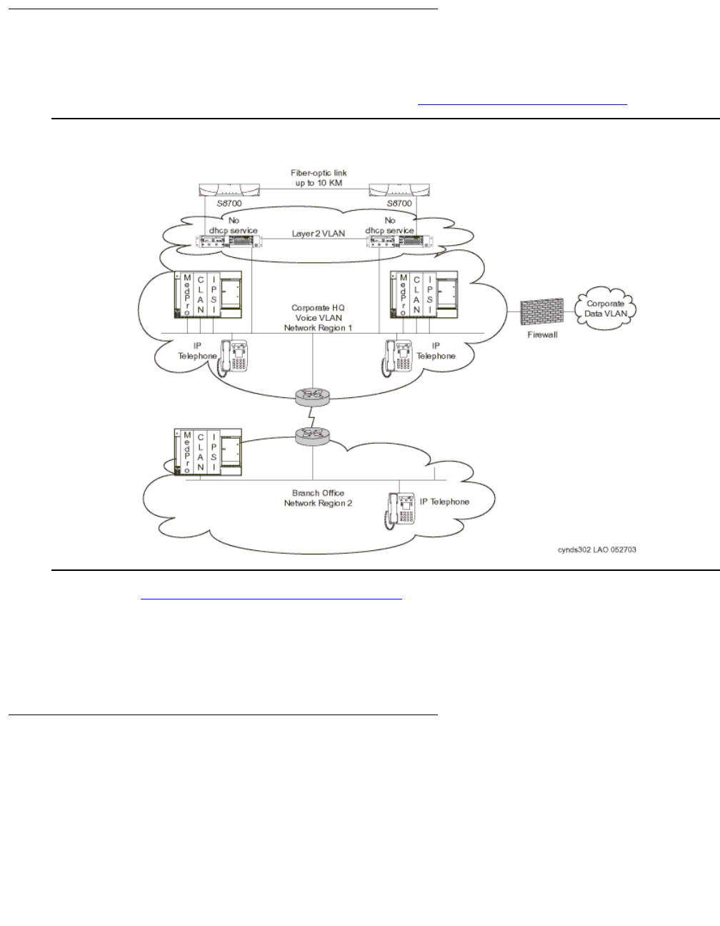
S8700-series and S8500 IP connect
Issue 4.3 February 2006 385
Network connectivity between Avaya media servers and port
networks
For more information on IP-Connect topologies, visit http://www.avaya.com/support.
Figure 97: S8700 IP-Connect system
As shown in Figure 97: S8700 IP-Connect system on page 385, the IP connect system also
consists of a pair of S8700-series servers (or a single S8500-series server) with IPSIs per port
network. The main difference between a fiber connect system and an IP connect system is that
in IP-Connect systems, control traffic is not isolated to a private control network, but traverses
the customer’s network, instead.
IPSI configuration
DHCP is not available in an IP-Connect system. IPSI cards must be administered manually
through the services ethernet interface on the front of the card.
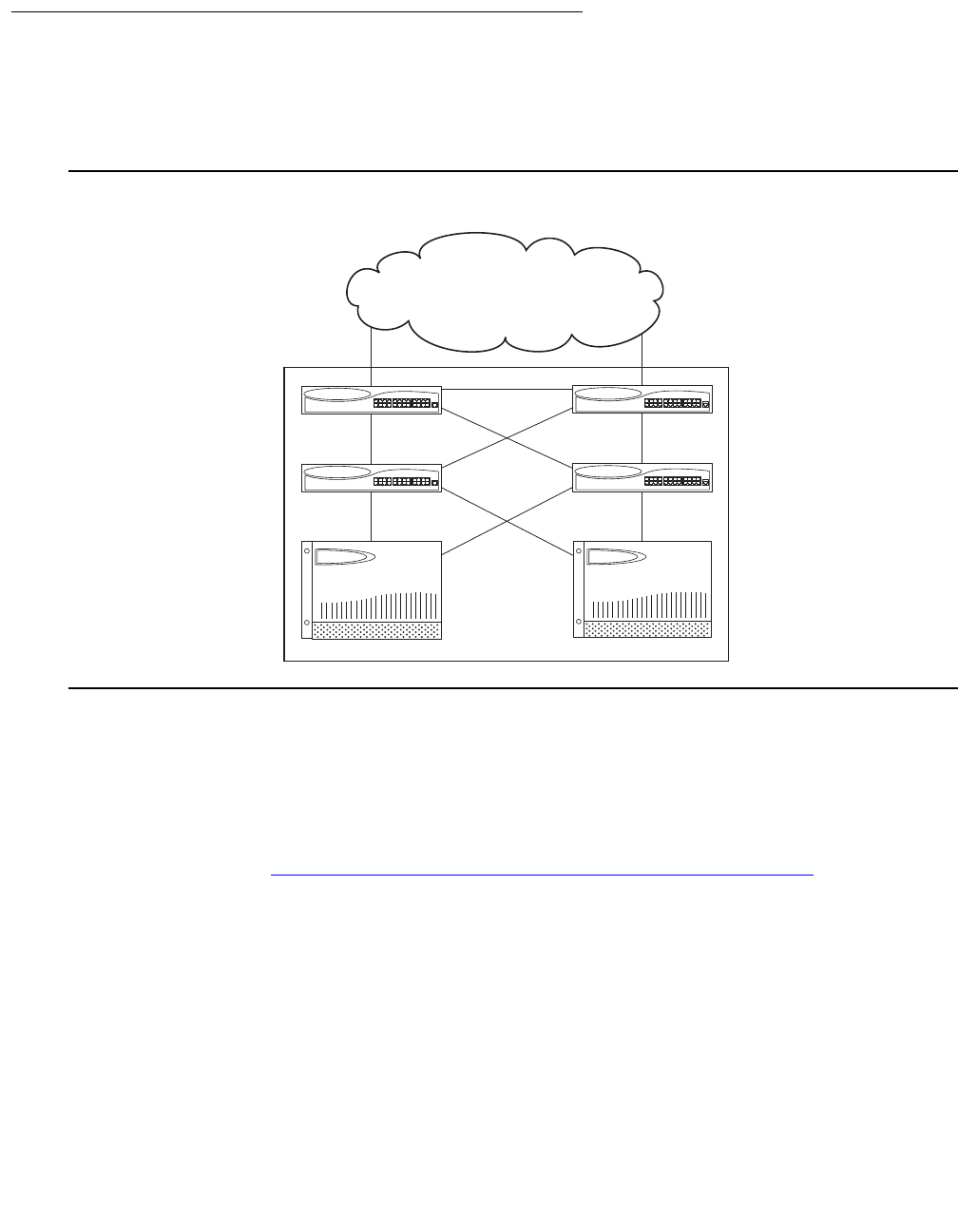
Implementing Communication Manager on a data network
386 Avaya Application Solutions IP Telephony Deployment Guide
Network design
Proper network design is very important in an IP-Connect system. Because port network control
traffic is flowing across a customer’s network, and not isolated on a control network, suboptimal
network design may lead to stability problems on the port networks.
Figure 98: Server farm placement in network configuration
In general, S8700-series Media Servers, S8500-series Media Servers, and G650 Media
Gateways should be treated as servers for the purpose of network placement. They should be
connected into a server farm utilizing redundant switches. If the network path between the
media servers and the G650 gateways is disrupted for more than a few seconds, the port
network could reset, disrupting calls to the PSTN. Because stability is a concern, G650s should
not be connected on the same subnet as user PCs. One such configuration of G650 media
gateways is shown in Figure 98: Server farm placement in network configuration on page 386.
cynds303 KLC 121103
Core
Layer 3 switches
Layer 2 switches
Server farm
1
13
12
24
CONSOLE
1
13
12
24
CONSOLE
1
13
12
24
CONSOLE
1
13
12
24
CONSOLE

S8700-series and S8500 IP connect
Issue 4.3 February 2006 387
Provisioning Network Regions
Network regions are Communication Manager constructs for selecting codecs and for grouping
resources by location or network topology. When determining MedPro resources, for example,
Communication Manager will try to select them in the same network region as the IP Telephone
attempting to use them. In addition, codec sets are negotiated by endpoints based on whether
they are in the same or different network regions. It is common to specify G.711 operation within
a network region and G.729 between regions. For voice quality reasons, then, it is advisable to
never have a network region extend across a WAN connection. Thus, when deploying an
IP-Connect system, it is common to have one network region for the central headquarters
location and separate network regions for each remote branch office. MedPros should be
configured for whichever network region in which they are physically located. This concept
applies to VoIP resources on the G700 media gateways, as well. The IP Telephony resources in
a G700 deployed in a branch office should be configured for the network region of the remote
branch office, and not the network region of the MedPros located in headquarters.
QoS
Because G650s can be separated from media servers by a WAN link, and because network
issues affect G650 stability, it is important to properly enable QoS, specifically DiffServ. QoS is
most important across WAN links, but may be important in LAN environments, as well. If a
network has already been configured for DiffServ, Avaya servers and gateways can utilize the
policy already existing on the network.
Recommendations for QoS DiffServ
If the network has not already been configured for DiffServ, Avaya recommends keeping the
policy simple: set the DiffServ Code Point (DSCP) to 46 (Expedited Forwarding, or EF) for
control, signaling, and voice bearer traffic. Use CBQ or strict priority queuing (with IP Telephony
traffic inserted into the highest priority queue) to offer the appropriate level of service.
Security
Because the media servers have modems for Avaya services access, it is advisable to use an
external firewall or router access-lists to filter traffic to and from the media servers. Appendix
B: Access list lists port ranges used by Avaya products, and can be used to harden a VoIP
system.

Implementing Communication Manager on a data network
388 Avaya Application Solutions IP Telephony Deployment Guide
Enterprise Survivable Servers (ESS)
In the media gateway architecture today, media gateways register with a primary call controller;
however, the IP interface through which the media gateway registers can either be on the call
controller directly in the case of the S8300 Media Server, or through a C-LAN interface in the
case where the call controller is an S8700-series or S8500-series Media Server.
The Enterprise Survivable Servers (ESS) option provides survivability to Port Networks by
allowing backup servers to be placed in various locations in the customer’s network. The
backup servers supply service to Port Networks in the case where the S8500-series media
server, or the S8700-series media server pair fails, or connectivity to the main Communication
Manager server(s) is lost. ESS servers can be either S8500-series or S8700-series media
servers, and offer full Avaya Communication Manager functionality when in survivable mode,
provided sufficient connectivity exists to other Avaya components (for example, endpoints,
gateways, and messaging servers). One exception is that an ESS cannot control a Center
Stage Switch. Enterprises desiring ESS survivable CSS-Connected Port Networks should install
an IPSI circuit pack and media processing resources in those Center Stage-Connected Port
Networks to ensure survivability in ESS mode.
When designing a network to support ESS servers, consider the following:
●ESS servers can only control Port Networks that they can reach over an IP network (or
Port Networks connected to IP-connected Port Networks by, for example, ATM).
That is, ESS servers connected on an enterprise’s public IP network will not be able to
control Port Networks connected to Control Network A or B, unless:
- ESS can control a remote Port Network that is connected through ATM to Port Networks
on Control Networks A or B, or
- Control Networks A or B are exposed to the public IP network through Control Network
on the Customer’s LAN (CNOCL).
●Multiple ESSs can be deployed in a network. In the case above, an enterprise could
deploy one or more ESSs on the public network, and an additional server on Control
Networks A and B to backup Port Networks attached to the respective networks.
However, when Port Networks associate with different ESS servers during network failures,
system fragmentation may occur. In that case, care should be taken to establish adequate
trunking and routing patterns to allow users at a particular location to be able to place calls
where needed.
●ESS servers register to the main server(s) through a C-LAN. The ESS-to-C-LAN link uses
UDP port 1719.
●In order to ensure up-to-date translations, an ESS must be able to communicate directly
over the IP network with the primary Media Server(s) using rsync. This communications
channel does not use a C-LAN.
- Main server sends translations to the ESS (Release 3.0 and above; also for LSP
translations)
- Main server sends translations to the LSP(s) (pre-Release 3.0)

S8700-series / S8500 / S8300 LSP
Issue 4.3 February 2006 389
For more information on ESS, see the Using the Avaya Enterprise Survivable Servers (ESS)
User Guide, 03-300428.
S8700-series / S8500 / S8300 LSP
The S8700-series server pair or the S8500 server can also be used to control a G700, G350, or
G250 Media Gateway. For survivability, an S8300 or S8500 media server running in Local
Survivable Processor (LSP) mode can take over control of up to 50 G700s, G350s, or G250
gateways and all associated endpoints in case of a network failure.
Security
Because both the S8700-series servers, the S8300 server, and the S8300 server can support
modems, it is important to consider using access-lists and firewalls to isolate servers and media
gateways from the rest of the data network. Appendix B has information necessary for
establishing access-lists or setting up a firewall policy. Avaya has worked on hardening Avaya
Application Solutions products against penetration and denial of service attacks. For more
information see Security on page 217.
G700/G350/G250/G150 connections to the C-LAN
A G700, G350, or G250 uses H.248 signaling with its controller. If the G700/G350/G250 is
homed off of an S8700-series Media Server pair, it must be able to reach a C-LAN for its
signaling connection. The G700, G350, or G250 gateway does not communicate directly with
an S8700. This restriction does not apply when controlled by an S8300 Media Server. The
G700, G350, or G250 would communicate directly with the S8300 server, and not a C-LAN, in
that case.
LSP-to-S8700 connection
In order to ensure up-to-date translations, an S8300 Media Server configured as an LSP must
be able to communicate directly over the IP network with the S8700-series server pair or S8500
server. Communication Manager uses rsync to synchronize translations between the
S8700-series or S8500 servers and their LSPs. This communications channel does not use a
C-LAN. The S8300 must communicate with a C-LAN circuit pack for keepalive traffic.

Implementing Communication Manager on a data network
390 Avaya Application Solutions IP Telephony Deployment Guide
S8300 / G700 / G350 / G250 (ICC)
The S8300 server, operating as primary controller, will control a G700, G350, or G250 Media
Gateway. It supports all of the same features as an S8700-series Media Server pair and is
inserted directly into the G700/G350. All H.248 signaling occurs across the Ethernet backplane
in the G700/G350.
Native NIC
The S8300 server supports C-LAN functionality natively within the server. IP Telephones, IP
trunks, and G700/G350 gateways can connect to the S8300 server interface directly for H.323
and H.248 signaling.
Stacking
The G700 can be stacked with other switches in the Avaya P330 family. It uses an 8-Gbps
stacking cable connecting the switches. As with other members of the P330 family, it can be
managed by the switch designated as the stack master, freeing customers from managing each
switch separately. It can take advantage of all of the features of P330 switches, including Layer
3 switching when stacked with a P330R switch. In addition, the G700 works with all of the X330
expansion modules, including gigabit Ethernet, IEEE 802.3af inline power, and 100BaseFX
Ethernet. It also supports the X330 WAN blade, allowing cost-effective routing of T-1/E-1 data
traffic.
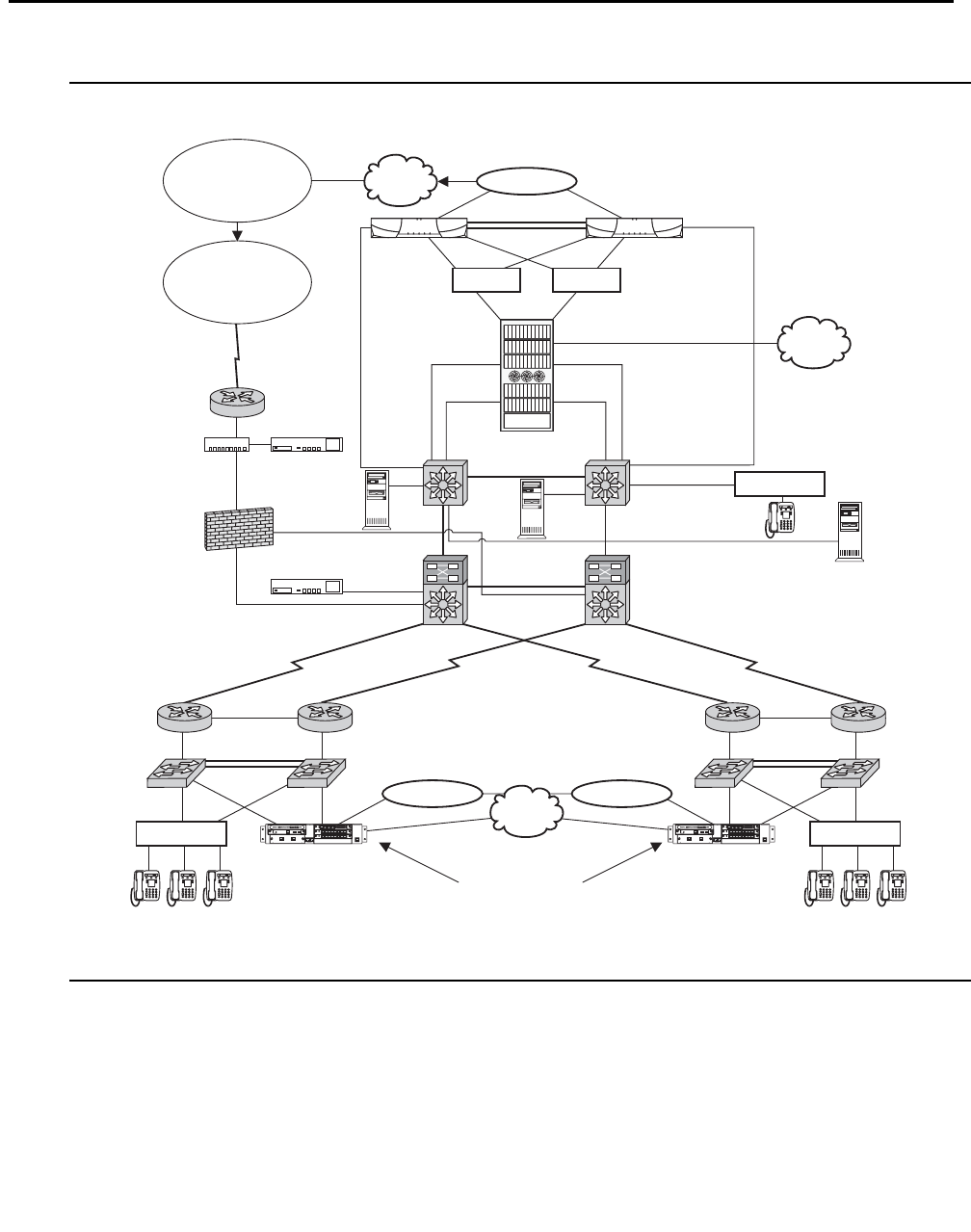
Sample fiber connect deployment
Issue 4.3 February 2006 391
Sample fiber connect deployment
Figure 99: fiber connect system (gateways deployed at remote offices)
cynds304 KLC 121003
Firewall
ALM
TST
ACT
ALM
TST
ACT
1 2 3 4 5 6 87
ALM
TST
ACT
ALM
TST
ACT
1 2 3 4 5 6 87
REMOVE
REMOVE
ALM
TST
ACT
OKTO
ALM
TST
ACT
OKTO
SHUTDOWN
SHUTDOWN
SERVICES
SERVICES
USB1
USB1
USB2
USB2
E1/T1
EIA 530A DCE
EIA 530A DCE
ALM
TST
ACT
SIG
ALM
TST
ACT
SIG
EI
EISO EMSM EOSI
PSTN
IDS
PSTN INADS
PSTN
INADSINADS
Midspan PoE
Avaya
G700/S8300LSP
Media Gateway
Phones
Ethernet
Switches
T1
Layer-2 Switches
Routers
Branch Office #1
2XT1/PR
TrunkI
2XT1/PR
TrunkI
ALM
TST
ACT
ALM
TST
ACT
1 2 3 4 5 6 87
ALM
TST
ACT
ALM
TST
ACT
1 2 3 4 5 6 87
REMOVE
REMOVE
ALM
TST
ACT
OKTO
ALM
TST
ACT
OKTO
SHUTDOWN
SHUTDOWN
SERVICES
USB1
USB1
USB2
USB2
E1/T1
EIA 530A DCE
EIA 530A DCE
ALM
TST
ACT
SIG
ALM
TST
ACT
SIG
EISO EMSM EOSI
Midspan PoE
Avaya
G350/S8300LSP
Media Gateway
Phones
Ethernet
Switches
Branch Office #2
T1 T1 T1
Optional cards
installed in G700s to
support analog trunks
for failover
Midspan PoE
Layer-2
Access
Switches
Layer-3 Switches
WAN Routers
Router
Hub/
Switch
Avaya MCC1
Gateway
Control BControl A
10/100
MedPro BMedPro A
port 3/3 port 3/3
port 3/2port 3/2
CLAN A CLAN B
2xT1/PRI for Backup
Avaya Private
Control Network
Segments
S8700 Ethernet 4
port 3/1
Voice
Messaging
GE
GE
port
1/2
port
1/2
port
1/2
port
1/2
port 1/1
dhcp1 port 1/1 port 1/1
dhcp2
port 1/1
IDS
Frame Relay
Remote
Management
S8700 Media Servers
S8700
Ethernet 4
port 3/1
Avaya Data NOC
11399 16th Ct. North
St. Petersburg, FL
33716
Avaya Voice NOC
18744 Lucent Blvd.
Highlands Ranch, CO
80129-2371
Authentication
Server

Implementing Communication Manager on a data network
392 Avaya Application Solutions IP Telephony Deployment Guide
Figure 99: fiber connect system (gateways deployed at remote offices) on page 391 illustrates
a typical fiber connect system with G700, G350, or G250 gateways deployed at two remote
offices. It demonstrates a number of the features previously discussed:
●The network as designed is highly resilient. There are redundant routers and switches at
every level. In addition, the routers and Layer 3 switches are running VRRP to offer
redundant default gateways to endpoints.
●The G700/G350/G250 gateways in the branch offices use LSPs for local survivability,
should connectivity to headquarters be disrupted.
●The phones are powered by midspan power units connected to UPSs, reducing the
likelihood of power outages to the phones.
●This network is very secure. Access-lists (set up in accordance with Appendix B) are
applied on the routers and Layer 3 switches. In addition, firewalls and intrusion detection
sensors have been deployed. The control networks are physically disconnected from the
building network, and only the C-LANs, MedPros, and S8700 administrative interfaces are
connected to the building network (through access-lists). This does provide sufficient
connectivity, however, for the G700/G350s to reach the C-LANs and the LSPs to reach the
S8700s.
●DiffServ (L3) QoS has been applied on the T-1 circuits. In this case, 75% of the bandwidth
has been reserved for voice and voice signaling (DSCP 46) and 25% has been left for
everything else. Should voice traffic not fill the voice queue, the excess bandwidth is
passed to the data queue. This level of queuing may not be appropriate for all networks,
but is often a good place to start.
●802.1Q has been enabled on the Ethernet segments. Voice and signaling traffic are both
tagged at 6, the value reserved for voice (and the second-highest level of Layer 2 QoS,
leaving the highest for network control). Because 802.1Q tags are stripped at every router
hop, they are regenerated at the far side of WAN links by mapping 802.1p tags based on
Layer 3 DiffServ tags.
●Three network regions have been set up: one for headquarters and one for each branch
office. The codec sets have been established such that intra-region traffic uses G.711,
while inter-region traffic uses G.729.

Other Sample configurations
Issue 4.3 February 2006 393
Other Sample configurations
Network connectivity between S8700-series servers and port
networks
The Avaya S8700 solution requires IP connectivity between S8700-series interfaces and Avaya
media gateways. IP-Connected port networks use IPSI cards in the Port Networks to
communicate with the Media Server. This connection will be referred to as the “Control
Connection”. There are many network options to provide this connectivity, and it is at the
enterprise’s discretion how this is best implemented in its environment.
If IP connectivity, including the control connection, between the server and Port Network is lost,
the server will be unable to provide call control, resulting in an unstable system. Although the
Avaya S8700-series media server interfaces provide for Denial of Service protection, they
cannot affect the ability of the network to successfully forward packets during a virus or worm
attack, or when the network becomes unstable due to network outages or administrative errors.
In hybrid environments (such as, IP and TDM endpoints and trunks), the incentive to minimize
disruption of the IP control connection is increased. By maintaining the control connection when
other network components have failed, TDM-connected endpoints will continue to function.
The following examples illustrate common methods for designing the control connection
between S8700-series servers and IP-connected Port Networks. They identify advantages and
disadvantages of each, so enterprises can select the appropriate solution for their environment.
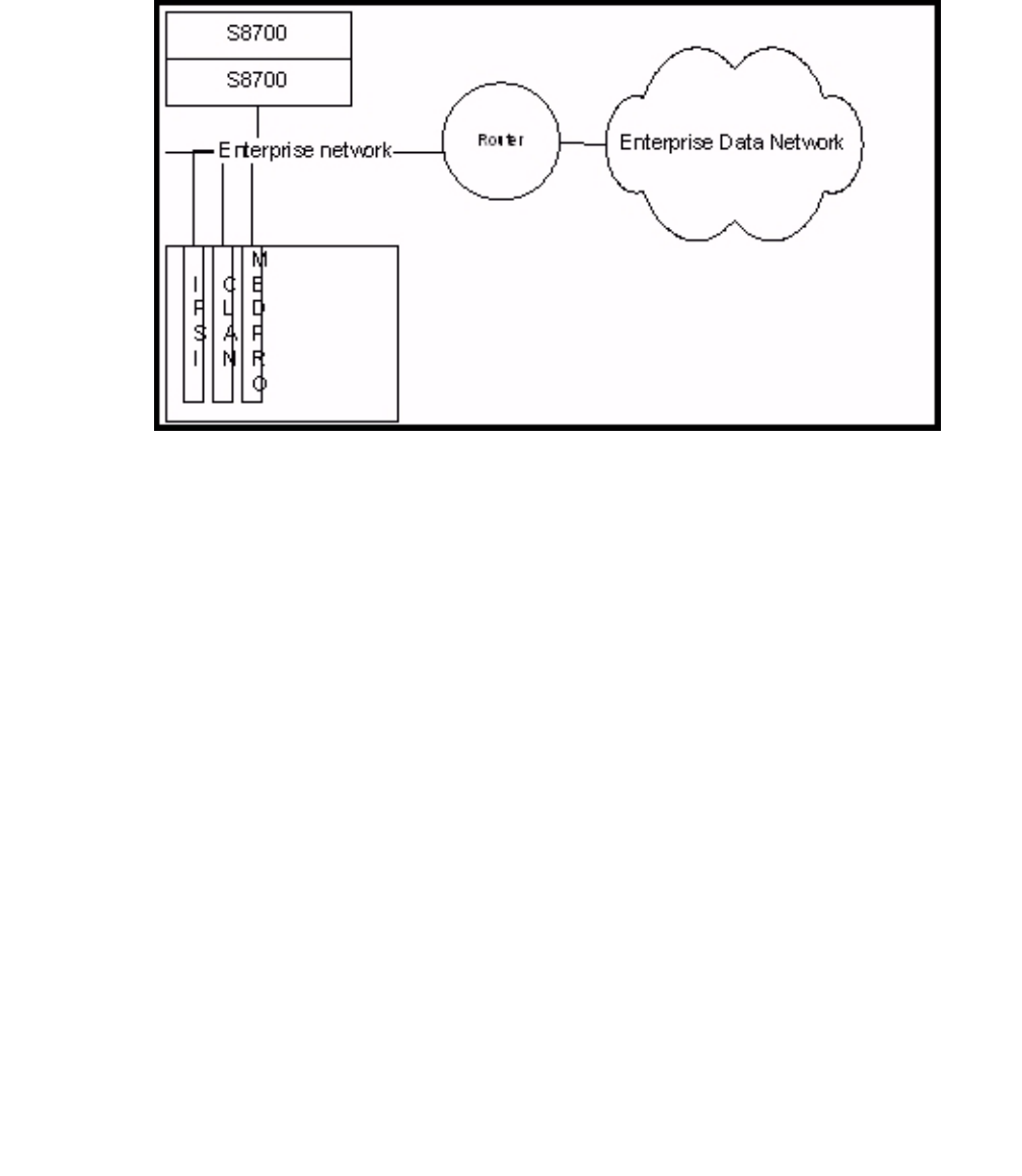
Implementing Communication Manager on a data network
394 Avaya Application Solutions IP Telephony Deployment Guide
Example 1: IP-Connect, single-site, single subnet
This design connects all Avaya server and gateway interfaces to a single VLAN. This solution is
used primarily in small sites of less than 500 users.
Advantages: - Simple; no host-based static routing required.
Disadvantages: - Provides no control point to protect the “control connection” from network
conditions that would not allow IP packets to reach their destinations. Because endpoints on the
enterprise data Network (even if given a separate “Voice VLAN”) must access C-LANs and
Media Processors using a large variety of ports, the control connection can be negatively
affected by DoS attacks, viruses, network convergence events, and so on.
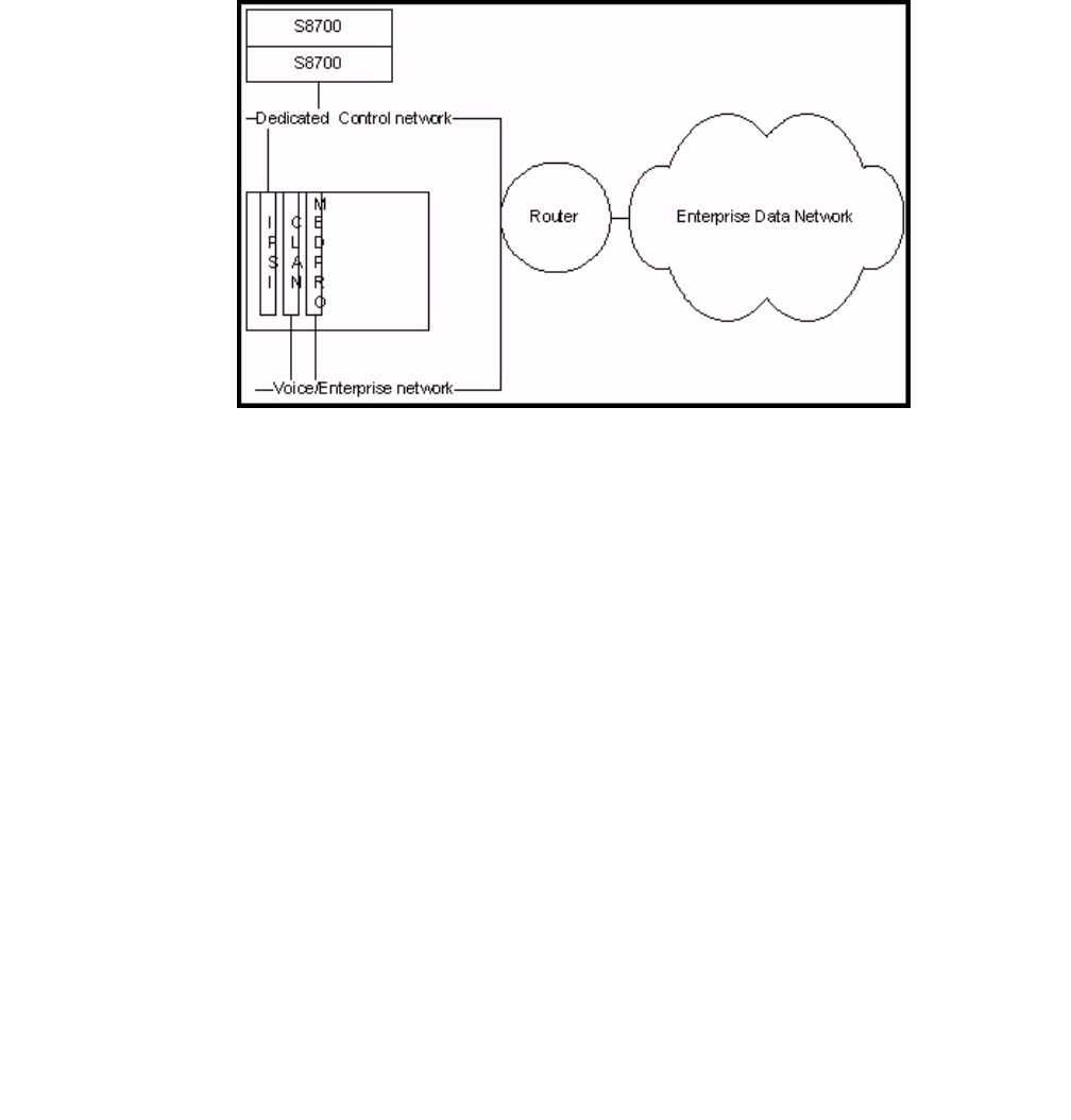
Other Sample configurations
Issue 4.3 February 2006 395
Example 2: IP-Connect, single-site, with a dedicated "control" network
This design connects all Avaya servers and IPSIs to a dedicated Control Network. C-LANS and
Media Processors are connected to a separate voice VLAN. Additional separation from the
infrastructure can be achieved by using a separate isolated switch for the dedicated control
network, providing resiliency from spanning tree calculations and DoS attacks that could
potentially disrupt a switch connected to the enterprise infrastructure. This design is typical in
large single site deployments. Firewalls are often used to provide additional security.
Advantages: - Provides a control point to limit traffic allowed on the control network. An
additional switch can provide protection against enterprise network failures. No host-based
static routing required.
Disadvantages: - Requires and additional VLAN or dedicated switch/router interface.
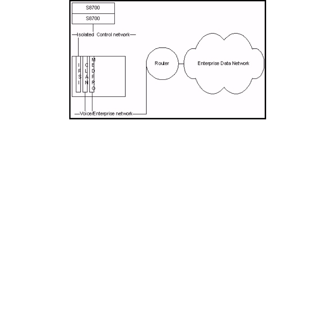
Implementing Communication Manager on a data network
396 Avaya Application Solutions IP Telephony Deployment Guide
Example 3: IP-Connect, single-site, with an isolated "control" network
An isolated control network provides little value if the isolation is through the use of VLANs only.
A switch not connected to any network infrastructure will provide full protection form external
attack. It is still possible to administer the Avaya Communication Manager server through a
properly configured C-LAN connected to the enterprise network. This design is not common, but
is used by some enterprises to provide total isolation of the control network.
Advantages: - Provides total isolation of the control network. No host-based static routing
required.
Disadvantages: - Requires an additional switch. The user cannot access the Web interface
from the enterprise network. The user must configure a C-LAN card to accept administration
connections.
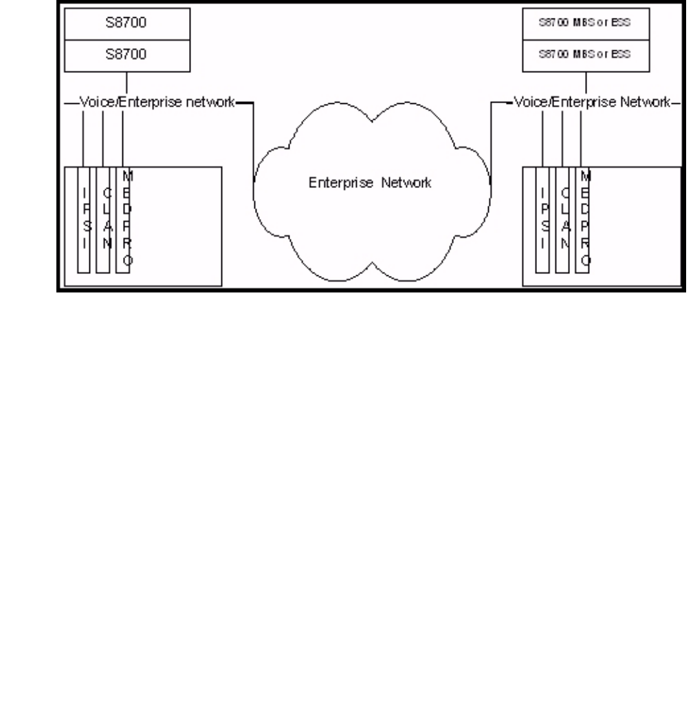
Other Sample configurations
Issue 4.3 February 2006 397
Example 4: IP-Connect, multi-site, single subnet, with a backup cluster/ESS
This design connects all Avaya server and gateway interfaces to a single VLAN per location. It
is important to note that for the primary cluster to control the Port Networks at the remote site,
the primary servers must have IP connectivity to the remote IPSIs. Also, for the backup cluster
to take control of the primary sites Port Networks, it must have IP connectivity to the primary site
IPSIs across the network. This design is not often used. Most large sites have chosen to
separate the control network for increased reliability.
Advantages: - Simple; no host-based static routing required.
Disadvantages: - Provides no control point to protect the “control connection” from network
conditions that would not allow IP packets to reach their destinations. Using this design, the
control connection can be negatively affected by DoS attacks, viruses, spanning tree
calculations, and so on. Any disruption in IP connectivity will also disrupt the TDM connections.
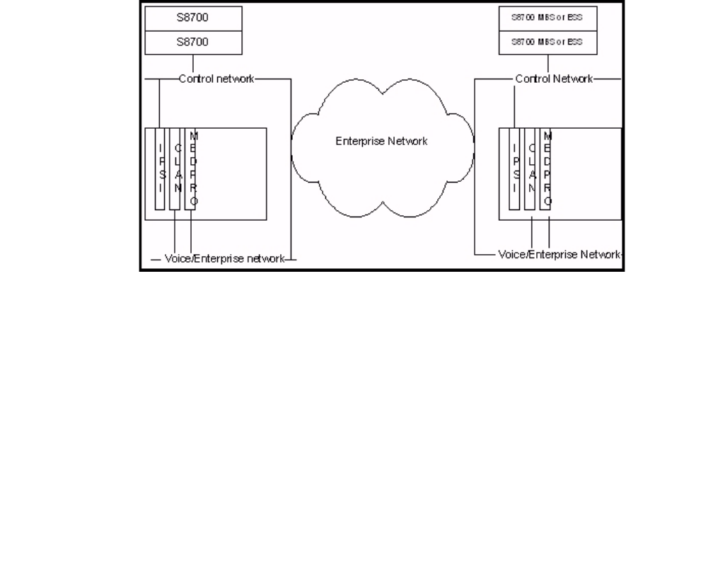
Implementing Communication Manager on a data network
398 Avaya Application Solutions IP Telephony Deployment Guide
Example 5: IP-Connect, multi-site, with a dedicated routed "control"
network
The above example shows two sites: the main site with the primary server cluster, and a remote
site with a backup cluster. To provide protection of the Server-to-IPSI link, Avaya recommends
the use of a dedicated control network. For backup cluster redundancy, it is a requirement that
each server pair be able to communicate across the enterprise network to control remote Port
Networks.
It is not a requirement, nor is it recommended that the voice (or data) networks be able to
communicate using the control networks. It is recommended that strong access lists or a firewall
separate the voice and data networks from the control network to limit traffic allowed from the
outside networks. Tight control of the rule set can then allow for specific stations to access the
web interface of the S8700-series Media Servers. Once again, the IP control connection must
be permitted through any access lists or firewalls. Control connectivity is required between each
server cluster and the IPSIs of any port network they wish to control. This is the most prevalent
design in large corporate infrastructures supporting the Avaya S8700 IP connect Solution.
Advantages: - Provides a control point to limit traffic allowed on the control network. With
additional Ethernet switches, it can provide protection against utilization failures and spanning
tree recalculations. This design can allow TDM connections to continue during specific network
failures. No host-based static routing required.
Disadvantages: - Requires additional VLANs and/or dedicated switches and router interfaces.
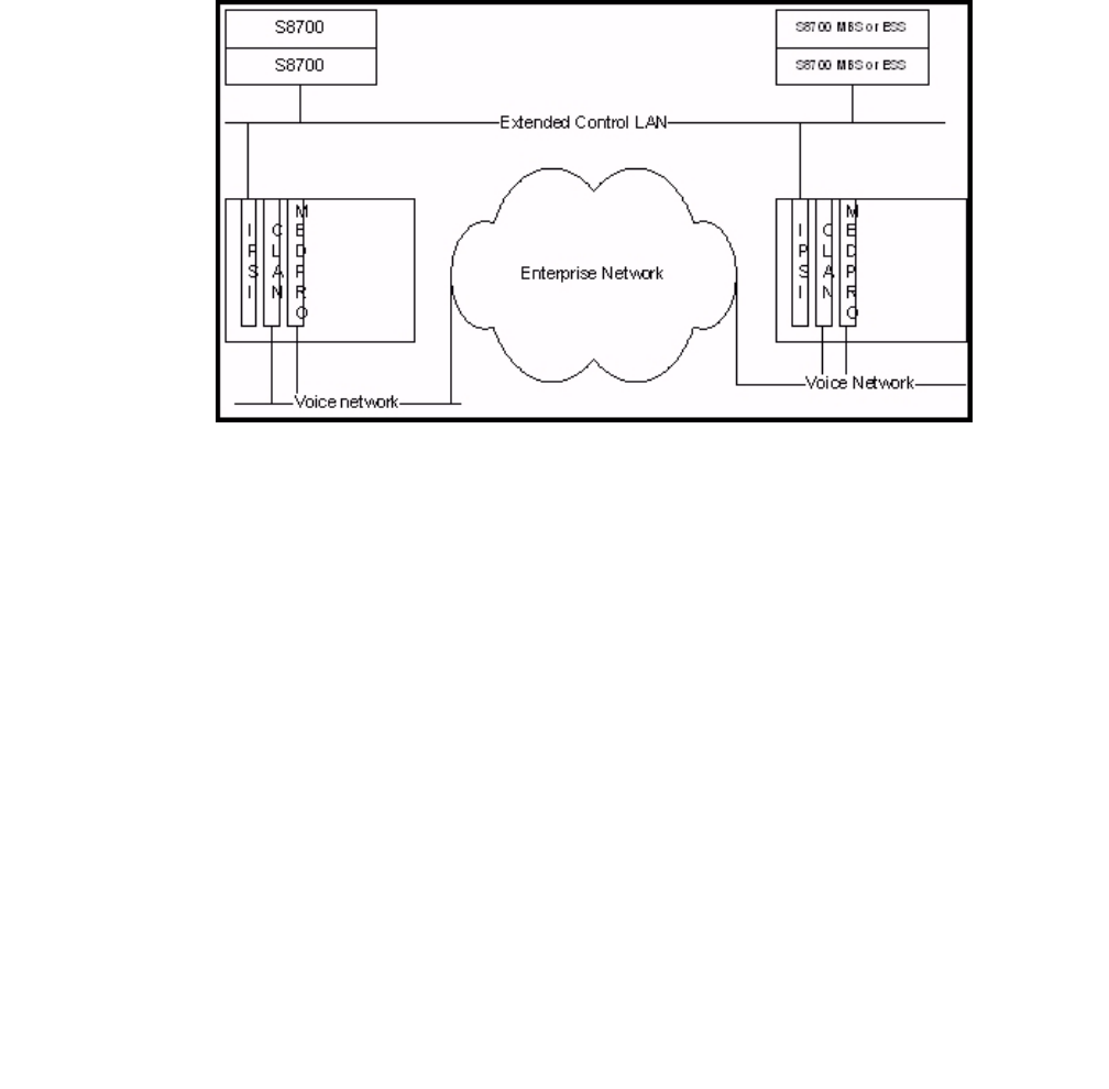
Other Sample configurations
Issue 4.3 February 2006 399
Example 6: Multi-site with a dedicated extended Layer 2 "control" network
This example shows the use of a single extended VLAN providing Layer 2 connectivity between
sites. This design provides all the benefits of design #7 and also address resiliency of the
enterprise network failing at Layer 3. It is at the enterprise’s discretion to route the traffic on the
extended control LAN to the enterprise network to provide access for administrative functions.
This design has been used successfully in several large Avaya IP-Connect deployments. It
provides excellent reliability, especially when used with redundant network equipment, but is
expensive and some times impossible due to fiber-optic cable availability and other network
design consideration between the sites.
Advantages: - Provides a control point to limit traffic allowed on the control network. With
additional switches, it can provide protection against switch failures and spanning tree
recalculations. This will allow TDM connections to continue during most network failures. No
host-based static routing required.
Disadvantages: - Requires additional dedicated switches, and a dedicated physical connection
infrastructure.
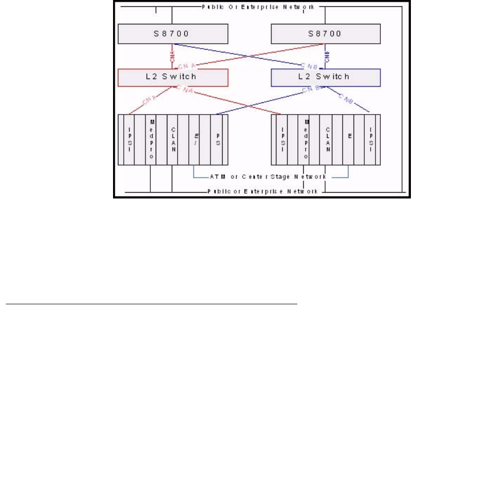
Implementing Communication Manager on a data network
400 Avaya Application Solutions IP Telephony Deployment Guide
Example 7: Single-site, fiber connect or IP connect, with redundant control
interfaces
The original fiber connect offer had several choices for reliability. Two offers provided redundant
servers and interfaces on two private control networks. Administrative control is provided by an
interface directly on the enterprise (“public”) network, or through properly administered C-LANs.
For the purposes of this document, public network refers to the routed enterprise network, and
not necessarily networks capable of being routed on the Internet.
Fiber connect configurations are distinguished by the existence of a non-IP bearer path
between Port Networks as shown in the figure.
Advantages: - Provides total isolation of the private control networks. This design allows TDM
connections to continue during any single control network component failure. No host-based
static routing is required.
Disadvantages: - Requires additional switches. It cannot extend across a routed infrastructure.
Control network on customer LAN (CNOCL)
Avaya Communication Manager 2.0 introduced the Control Network on Customer LAN option,
which allows the use of routed control networks. CNOCL removed many of the IP connectivity
differences between IP connect and fiber connect, and leaves the only true difference being the
existence of inter-Port Network bearer paths. CNOCL provides enterprises with several options
to create and extend control networks
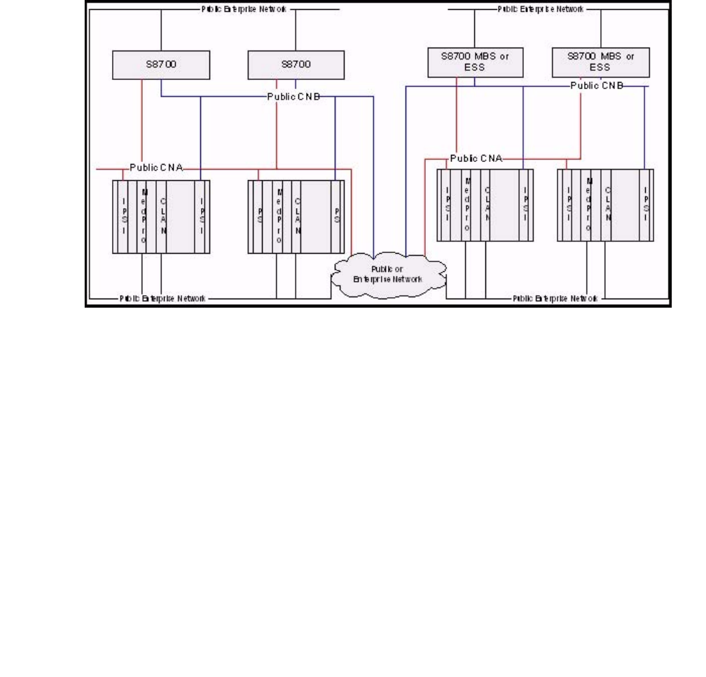
Other Sample configurations
Issue 4.3 February 2006 401
Example 8: Multi-site CNOCL using merged enterprise and control network
This example shows the connection of the two private control networks to the customers
enterprise network, making them public. They are designated public in this case because the IP
addressing of these control networks must be routable through the enterprise network.
This design has been used successfully in several Avaya deployments, but opens the control
networks to all network issues experienced in the enterprise. Firewalls or strong access lists
should be used to protect each site’s control network, but inter-site connectivity cannot truly be
protected. The use of the third interface connecting to the enterprise infrastructure for
management is no longer necessary, and can be collapsed on the one of the other two
networks.
Advantages: - Provides a control point to limit traffic allowed on the control network. Uses the
enterprise’s existing network infrastructure.
Disadvantages: - This will not allow TDM connections to continue during most network failures.
Static routing is required on both Main and MBS/ESS servers, and may become complex,
depending on the network architecture. Changes in network architecture will have to be
synchronized with changes in the static route table, and will be service-affecting.
Example 9: Multi-site CNOCL using extended private networks
This example shows the connection of the two private control networks using a dedicated
routed infrastructure. They are designated private in this case because the IP addressing of
these control networks is not routable through the enterprise network.
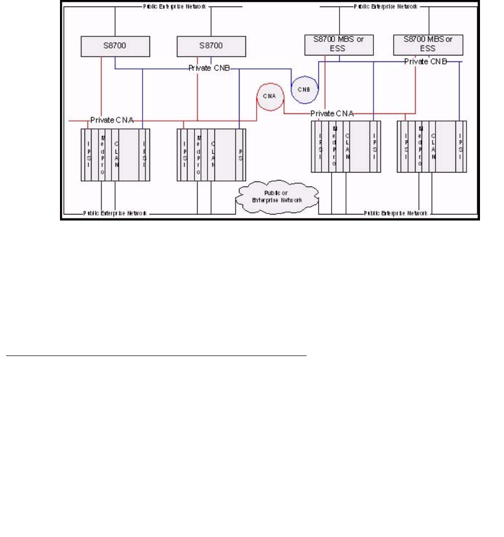
Implementing Communication Manager on a data network
402 Avaya Application Solutions IP Telephony Deployment Guide
This design provides for total protection of the control networks from any enterprise network
failures. With proper architecture, the static routing for CNA and CNB can be reduced to single
summary routes, rather than static routes per IPSI.
Example:
route 192.168.0.0 255.255.128.0 CNA
route 192.168.128.0 255.255.128.0 CNB
Advantages: - The dedicated Control network provides total isolation from outages in the
enterprise network, so all TDM communication can remain active during total enterprise
network failure. The use of simple summary routes instead of possibly complex static routing
provides for a more reliable system. The synchronization of network changes with
Communication Manager can be logistically difficult.
Disadvantages: - Requires a dedicated infrastructure.
Control network C
Control Network C is a new feature introduced in Avaya Communication Manager 3.0. It allows
control connectivity to be passed through what has been known as the customer interface. This
functionality is introduced to simplify the network design for enterprises with local private control
networks (CNA and CNB); who wish to use their corporate (public) network to support remote
IPSI-controlled Port Networks.
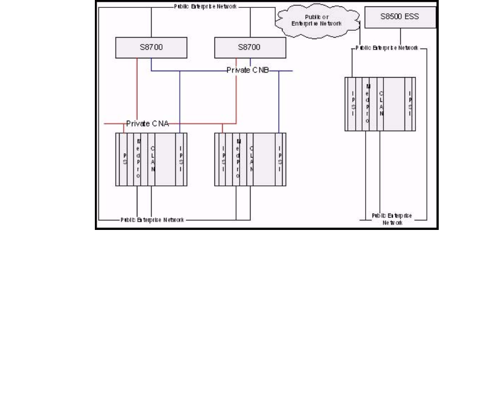
Other Sample configurations
Issue 4.3 February 2006 403
Example 10: Multi-site private CNA, CNB, with remote PNs on public LAN
This example shows the connection of local private control networks using the existing public
enterprise network to provide connectivity to a remote site with an IPSI-controlled Port Network
and an S8500 ESS server. The local Control Networks are designated as private in this case
because the IP addressing of these control networks will not be routable through the enterprise
network. The control network at the remote site is designated as public because it is fully
routable throughout the enterprise network. The Control connection from the S8700 to the
remote IPSI is established through the “Customer LAN”, or the third interface connected to the
enterprise network. This configuration is particularly appropriate for large main sites, which
require a fully redundant architecture, with smaller remote sites that do not require the same
level of redundancy.
This design provides for total protection of the local control networks from any enterprise
network failures; however, the remote site may be affected by enterprise network issues.
Configuration is simplified because the default route of the CNC interface allows the CNC
interface to communicate across the enterprise routed network infrastructure without requiring
static routes.
Advantages: - The dedicated Control Network provides total isolation from outages in the
enterprise network, so all local TDM communication at the main site can remain active during
total enterprise network failure. There are no static routes to maintain.
Disadvantages: - The remote site can be affected by public enterprise network issues. The
remote ESS server cannot control the Port Networks at the main site.

Implementing Communication Manager on a data network
404 Avaya Application Solutions IP Telephony Deployment Guide

Issue 4.3 February 2006 405
Network recovery
Conventional wisdom holds that network reliability is typically 3-9s (99.9%) on a LAN, and 2-9s
(99%) on a WAN. The leading causes of network failure are a WAN link failure, administrator
error, cable failure, issues that involve connecting new devices or services, and malicious
activity, including DoS attacks, worms, and viruses. Somewhere lower down on the list are
equipment failures. To achieve the highest levels of availability, it is important that a strong
change control policy and network management strategy be implemented.
There are numerous techniques for improving the reliability of data networks, including
spanning tree, self-healing routing protocols, network management, and change control. This
section discusses the following techniques:
●Change control
●Layer 2 mechanisms to increase reliability
●Layer 3 availability mechanisms
●Dial backup
●Convergence times
●The Converged Network Analyzer
Change control
Change control describes a process by which an organization can control non-emergency
network changes, and reduce the likelihood of administrator errors that cause network
disruption. It involves carefully planning for network changes (including back-out plans),
reviewing proposed changes, assessing risk, scheduling changes, notifying affected user
communities, and performing changes when they will be least disruptive. By implementing a
strict change control process, organizations can reduce the likelihood of administrator errors,
which are a major cause of network disruption, and increase the reliability of their networks.
Change control contains more information on change control.

Network recovery
406 Avaya Application Solutions IP Telephony Deployment Guide
Layer 2 mechanisms to increase reliability
Spanning tree
IEEE 802.1D spanning tree is an Ethernet loop avoidance protocol. It allows network managers
to connect redundant network links within their networks. Prior to the advent of spanning tree,
loops within a switched Ethernet network would forward traffic around the loop forever, which
saturated the network and prevented new traffic from getting through. Spanning tree selects one
switch as a root and creates a loop-free topology connecting to the root. If loops are discovered,
one switch blocks that port until its alternate path to the root is disrupted. Then the blocked port
is brought back into service. There are several drawbacks to spanning tree:
●By default, all switches have the same priority, which means that root bridge selection is
random. This can be suboptimal in a network.
●Spanning tree is slow to converge. It typically takes at least 50 seconds from link failure for
a backup link to become active. As Layer 2 complexity increases, so does convergence
time.
●Although there are mechanisms for speeding up spanning tree, most are proprietary.
●Traditional spanning tree is not VLAN aware. Thus, it will block links even if VLAN
provisioning would have prevented a loop.
To solve these issues, the IEEE has recently introduced 802.1s and 802.1w enhancements.
802.1w introduces rapid spanning tree protocol (RSTP). RSTP uses active handshaking to
speed up convergence times. 802.1s introduces multiple spanning trees (MST), which is a way
of grouping different VLANs into different spanning tree instances. These features might not be
present in data network switches yet, but look for them soon.
Link Aggregation Groups
Link Aggregation Groups (LAGs) are a mechanism for combining multiple real inter-switch links
(typically four, Avaya products are configurable from two to eight) into one point-to-point virtual
interswitch link. The advantage of this mechanism over spanning tree is that an organization
can have the redundant links in if a failure occurs in one of the LAG links, the two switches will
quickly discover it, and remove the failed link from the LAG., which reduces the convergence
time to nearly instantaneous. Not all implementations interoperate, so care must be taken when
the LAG connects switches from multiple vendors. Also, LAG links are a point-to-point
technology. They cannot be used to connect a backup switch in case the primary fails. When
available, this is a very good mechanism for improving the resiliency of LANs.

Layer 3 availability mechanisms
Issue 4.3 February 2006 407
Layer 3 availability mechanisms
Routing protocols
Routing protocols allow routers to dynamically learn the topology of the network. Should the
topology of the network change, routing protocols update their internal topology table, which
allows them to route around failure.
There are two types of routing protocol, distance vector and link state. Distance vector
protocols, including RIP and IGRP, exchange their entire routing table periodically. To each
route, they add their metric (for RIP, this is “hop count”) and insert it in the routing table. If
updates fail to arrive before the router’s timer expires, it purges the route and looks for another
path. These protocols are usually slow to converge. See Table 74: Sample convergence times
(single link failure) on page 409.
Link-state protocols, such as OSPF, take a more holistic view of the network. They compute the
entire topology of the network and insert the best path to a destination in the routing table. Link
state protocols exchange their routing tables only once, when routers first establish a
relationship. After that, they only send updates. They also send hello messages periodically to
ensure that the other routers are still present. Link state protocols converge much more quickly
than distance vector protocols, and thus are generally better suited to networks that require high
availability.
VRRP and HSRP
Virtual Router Redundancy Protocol (VRRP) and the related Cisco proprietary Hot Standby
Router Protocol (HSRP) provide a mechanism to deal with router failure without disrupting
endpoints on the network. In essence, these protocols work by assigning a virtual IP address
and MAC address for the routers. This address is given to endpoints as their default gateway.
The two routers send periodic hello messages marked with a priority value between each other.
The high-priority router assumes the virtual address, and traffic flows through it. If the primary
router fails or its capabilities become degraded (such as if a WAN link fails), the secondary
router takes over. This is a useful mechanism to protect endpoints from router failures, and
works with IP Telephony endpoints.

Network recovery
408 Avaya Application Solutions IP Telephony Deployment Guide
Multipath routing
Modern routers and Layer 3 switches allow multiple routes for a particular destination to be
installed in the routing table. Depending on the implementation, this can be as high as six
routes. Some implementations require that all routes that are inserted in the routing table have
the same metric, while others allow unequal metric routing. In cases where the metric for all
installed routes are the same, the router will load balance traffic evenly across each path. When
the metric for multiple routes vary, the traffic is load balanced in proportion to the metric (in other
words, if one path is “twice as good” as another, two-thirds of the traffic travels down the good
path, and one-third of the traffic selects the other one). Asymmetric routing is suboptimal for
voice, so route-caching (described earlier) should be considered in this environment.
In addition to using all (up to 6) active paths and optimally using available bandwidth, multipath
routing greatly improves convergence time. As soon as a router detects a path failure, it remove
it from the routing table, and sends all traffic over the remaining links. If this is a physical link
failure, the detection time is nearly instantaneous. Therefore, Avaya recommends the use of
multipath routing, where available, across multiple links to a particular location.
Dial backup
One cost-effective technique for installing backup WAN links is to use dial backup. This can be
done using either ISDN-BRI or analog lines. ISDN lines typically take 2 seconds to connect,
while 56-k analog modems take approximately 1 minute. While this strategy is effective for data
traffic, it is less effective for voice. First, the bandwidth may have been greatly reduced. If this is
the case, the number of voice channels that can be supported might have been reduced
proportionally. Also, if QoS is not properly applied to the backup interface, high packet loss and
jitter can adversely affect voice quality. Finally, the time that is required to establish the new link
can be up to 1 minute, which disrupts active calls. However, providing that these considerations
are taken into account, proper QoS is applied, and a compressed codec is chosen, dial backup
can be an effective solution for two to four users.

Convergence times
Issue 4.3 February 2006 409
Convergence times
Convergence is the time that it takes from the instant a failure occurs in the network until a new
path through the network is discovered, and all routers or switches are aware of the new path.
Convergence times vary, based on the complexity and size of a network. Table 74: Sample
convergence times (single link failure) on page 409 lists some sample convergence times that
are based on a single link failing in a relatively simple network. They reflect update and/or hello
timers expiring. Dialup “convergence” times reflect the time that it takes to dial, connect, and
authenticate a connection. These times do not take into account LAG, fast spanning tree, or
multipath routing, which speed up convergence. This table shows the importance of carefully
planning for fail-over in a network. For example, both OSPF and EIGRP (Layer 3) protocols
converge faster than spanning tree (Layer 2). When designing a highly available data network,
it is more advantageous to use Layer 3 protocols, especially link-state (OSPF) or hybrid
(EIGRP) protocols, than Layer 2 (spanning tree).
Table 74: Sample convergence times (single link failure)
Protocol Approximate convergence
time (seconds)
EIGRP (Cisco) 2
OSPF 6 to 46
RIP 210
IGRP (Cisco) 400
Spanning tree (Layer 2) 50+
ISDN dialup (connect +
authentication) 2
56-k dialup (connect +
authentication) 60

Network recovery
410 Avaya Application Solutions IP Telephony Deployment Guide
The Converged Network Analyzer
The Converged Network Analyzer (CNA) is an offer from the Avaya Application Assurance
Networking (AAN) line of products. It provides two principal value propositions:
●visibility
●path optimization.
Visibility is achieved through the use of real time measurements of the network infrastructure.
These measurements feed extensive reports and diagnostics tool, which give the user powerful
capabilities. On one end of the spectrum, CNA enables the user to monitor the general health of
their network and its ability to support demanding applications such as voice, video, and real
time TCP applications. On the other end of the spectrum, CNA enables the user to troubleshoot
the cause of a specific network problem.
Path optimization functions as follows: when two paths or more are available between two
measured end points, CNA can measure all of the available paths simultaneously. If any
problem is detected on one of the paths, CNA can intervene in real time and send route updates
to the edge routers, moving the traffic to a non-impaired path. The result is unaffected user
experience in the face of network outages.
CNA features a range of application models that assess network conditions. The models focus
on the specific characteristics and requirements of different applications:
●Voice
●Video Conferencing
●Video Streaming
●Web applications
●Enterprise TCP applications
Using these application models, CNA translates the performance characteristics of the network
path (e.g., latency, jitter, and loss) into Application Performance Ratings (APR). The APRs
provide a relative measure of performance if the application were run over this network fabric.
In addition, CNA automatically discovers applications running over the network and can
optionally measure load over various links in the network. A sophisticated policy language
allows the user to specify precise policies in terms of:
●What applications to optimize
●The performance level to maintain for these applications
●The preferred paths through which to send traffic for these applications
●Load thresholds not to exceed on specific paths.
The CNA package comprises servers that perform most of the analysis, provide the path
optimization functionality, and store the reports. CNA also comprises optional no cost test
agents that are embedded in an array of avaya phones, gateways, and Avaya partner products

The Converged Network Analyzer
Issue 4.3 February 2006 411
such as Extreme (http://www.extremenetworks.com/homepage.asp). Test agents are also
available in low cost devices that can be deployed standalone. Test agents help complement
server measurements in two ways: they allow end to end measurement to be performed
between specific points of interest (such as phones, gateways, or video conferencing end
points); and they provide a view of network impairments over a full mesh of paths between the
various sites of an enterprise.
The visibility and path optimization value propositions provided by CNA are instrumental to IP
Telephony. VoIP is a real time application with stringent requirements: delay, loss, and jitter
effects over the network can affect voice traffic and destroy the user experience. CNA can
provide both visibility into such network impairments and means to troubleshoot their cause.
Using the CNA Voice application model, network measurements can be translated into an
application score that describes the ability of the network fabric to support the IPT application.
The Application Score uses a 0 to 5 scale, and can easily be interpreted by IT experts and
executives alike. Using the CNA path optimization capabilities, the user can dramatically reduce
the effect of network impairments on the voice application running over the network; hence
significantly improve the voice communication experience. Finally, CNA can enable
IT personnel to specify precise policies that describe the preferred links for voice traffic to use,
thresholds on the quality of the voice experience, and load thresholds over given links that need
not be exceeded.
Using the embedded test agents in Avaya phones can significantly augment the value that can
be obtained from a CNA deployment. Embedded test agents in end points would allow those
end points to measure between each other, hence providing the CNA server with the specific
view of the network performance between them. The test agent is embedded in Avaya phones
and gateways today. The test agent is also embedded in Extreme products that are GA
today: the Summit X450, the BlackDiamond 8800, and the BlackDiamond 10808 switches
(http://www.extremenetworks.com/PRODUCTS/ModularSwitches.asp).
CNA path optimization can also be used to protect signaling traffic. In a typical enterprise, the
communication system comprises gateways deployed in a large portion of the enterprise’s sites
(including many of the small sites) and call controllers running Communications Manager (CM)
in the regional sites. Phones in the small sites register with the CLANs on the local gateways’
port networks; IPSIs on the port networks, in turn, communicate across the WAN with the call
controller through a IPSI connection over what is referred to as a control network. This IPSI
connection is critical, as it allows phones to communicate with the call controller, pass to it
critical stimuli such as depressed digits, access features offered by the call controller, and have
the call controller provide dial tone to the phone. An IPSI connection carries as many links as
there are active phone calls utilizing the connection. Given the critical nature of the IPSI, any
outage in the IPSI connection path can trigger an aggressive recovery mechanism which could
result in intermittent feature loss or dropped calls, depending on the severity of the outage. IPSI
connection loss can be prevented using CNA path optimization.
CNA path optimization requires path diversity, which is a key to WAN resiliency. Through the
provisioning of two or more diverse paths, the enterprise is not at the mercy of failures affecting
one of the paths. For example, consider Figure 100. Assume that the current connection
between the headquarter and the branch site is through Path A. Assuming that an outage
affects a portion of the path along Path A, then in principle, dynamic routing protocols should
detect the outage and propagate routing updates to the edge routers on the headquarters’ side
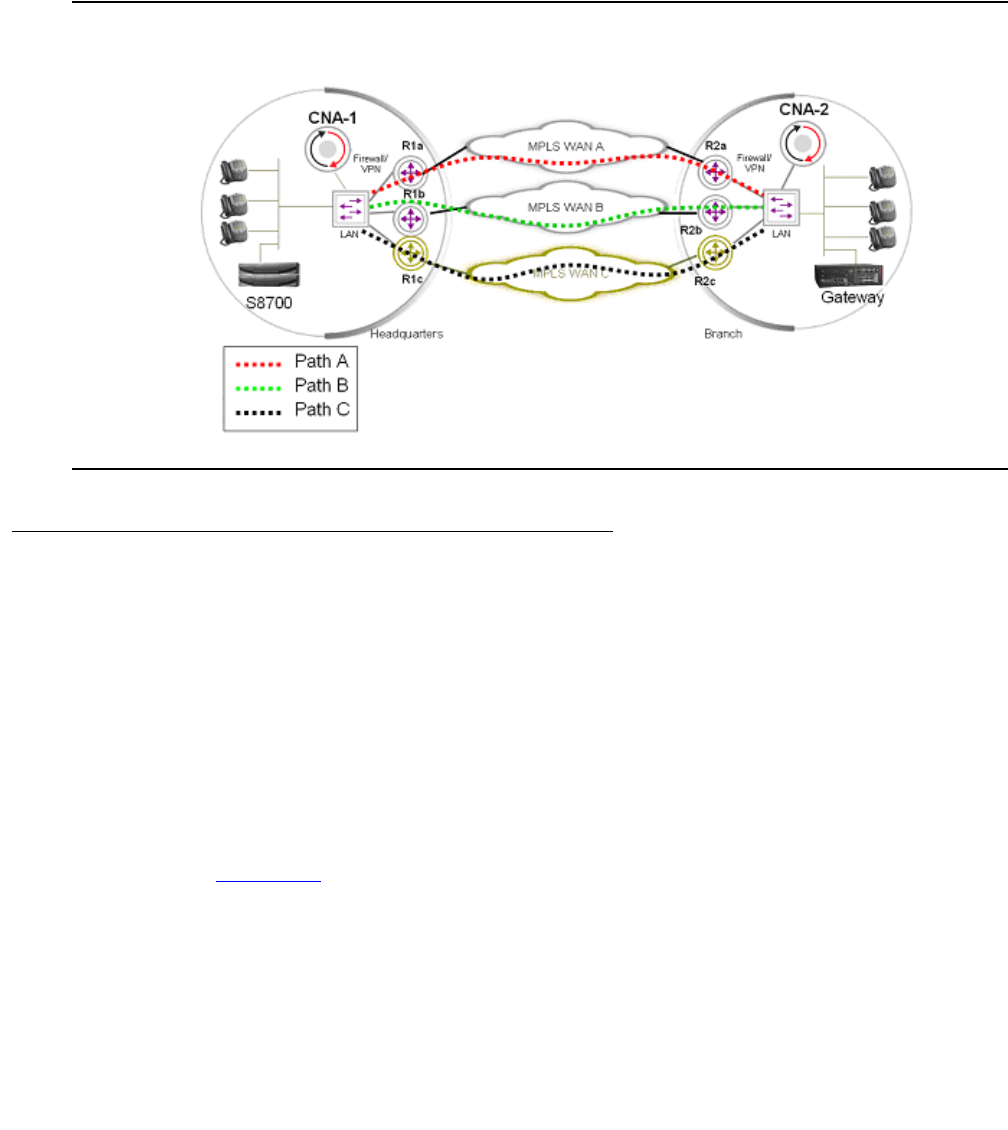
Network recovery
412 Avaya Application Solutions IP Telephony Deployment Guide
(Routers R1a, R1b, R1c), and on the branch side (R2a, R2b, and R2c); these routers would
then have been able move the traffic to Path B or Path C. In practice, however, some dynamic
routing protocols such as Border Gateway Protocols (BGP) are slow to propagate routes. In
other instances, network paths involve tunneling, and consequently, layered routing protocols.
Consequently, routing updates can take in the order of 30 seconds to reach the edge routers,
with negative effects on voice bearer and signaling traffic.
Figure 100: Enterprise example: headquarters and branch connected using 3 diverse
paths
CNA components
The Converged Network Analyzer software provides the layer of intelligence that alleviates the
problems described above. Through the use of continuous measurements of all available paths,
CNA can detect outages in real time. CNA can then send a BGP update to a router that it
controls, causing this router to move the traffic in real time. All in all, CNA can redirect an IPSI
connection away from an outaged path in less then one second.
CNA is a network appliance that provides the following capabilities:
●Measurements of targets at a rate of multiple packets a second.
●Ability to control routers through a BGP connection to the routers
As is shown in Figure 100, CNA is deployed out of line, in the vicinity of the edge routers. Figure
1 shows a scenario where two CNA systems are deployed, one on the headquarters side
(CNA-1) and one on the branch side (CNA-2). CNA-1 will simultaneously measure Paths A, B,
and C. If an outage affects a portion of the path along Path A, CNA-1 will detect the outage in
real time. As soon as the outage is detected, CNA-1 will send a route update to Routers R1a,
R1b, and R1c in real time. Similarly, CNA-2 will detect the outage and send a route update to
Routers R2a, R2b, and R2c. As a result, the traffic pertaining to the IPSI connection between
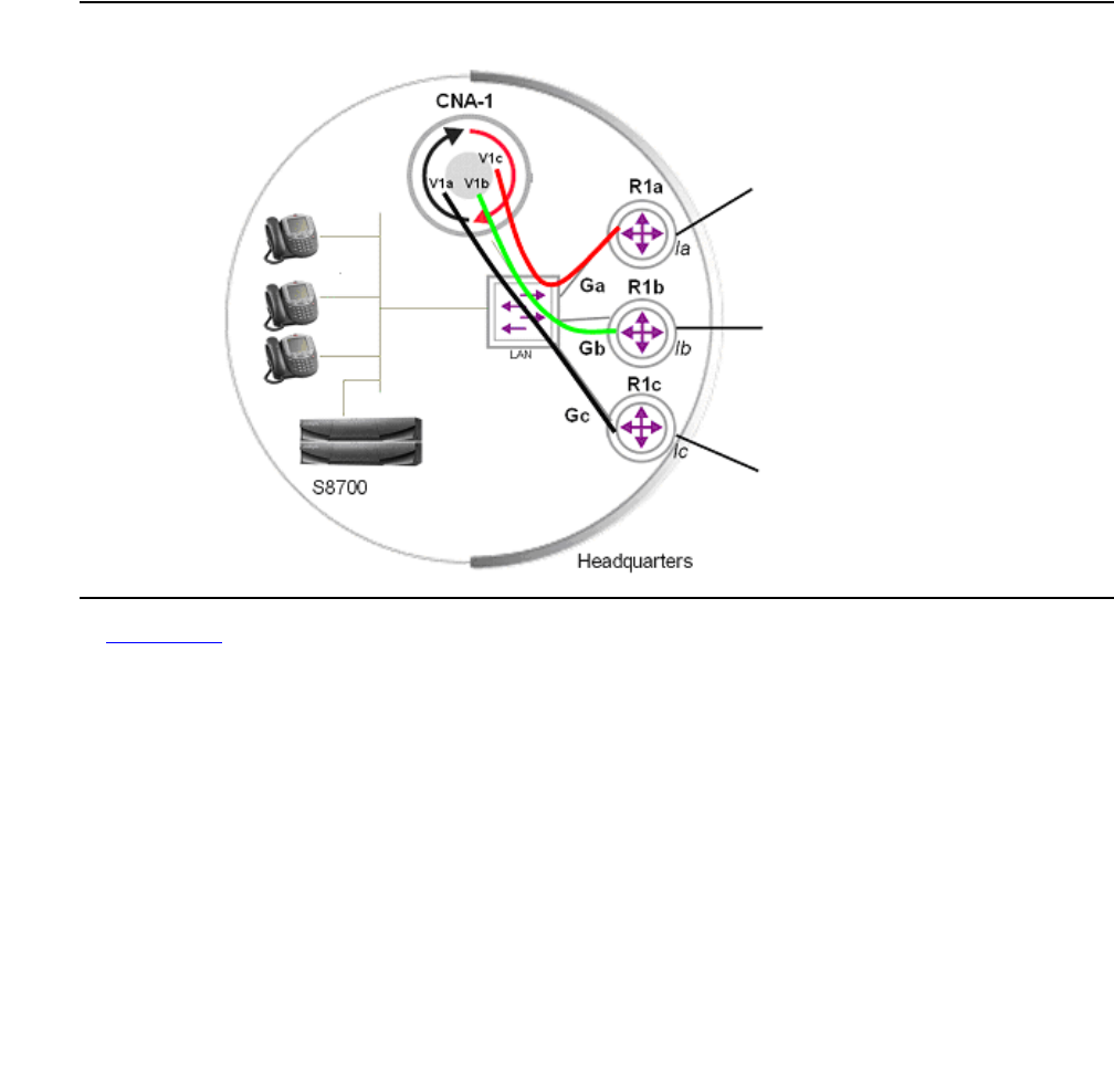
The Converged Network Analyzer
Issue 4.3 February 2006 413
Sites A and B will move away from the outage in less than a second, preventing unintelligibility
in the audio bearer, or outages in the voice signaling.
Simultaneous monitoring of all paths
The ability for CNA to measure all paths simultaneously is achieved by configuring Policy Based
Routing (PBR) functionality on the edge routers. Essentially, measurements through the various
links are sourced from different Virtual IP addresses (VIPs). The edge routers are then
configured to route the measurement packets to its different links according to the packets’
source address. PBR functionality exists in most routers, sometimes under a different name. In
Juniper devices, PBR functionality is called Filter-Based Forwarding (FBF).
Figure 101: Headquarters CNA deployment – Measurement plane
In Figure 101, three loopback addresses V1a, V1b, and V1c will be configured on CNA-1. Three
Generic Routing Ecapsulation (GRE) tunnels Ga, Gb, and Gc can be configured between the
CNA system and the edge routers R1a, R1b, and R1c. Measurement traffic pertaining to Paths
A, B, and C will be sourced from V1a, V1b, and V1c, and routed through Ga, Gb, and Gc,
respectively. The router will be configured to route traffic emerging from Ga, Gb, and Gc to
interfaces Ia, Ib, and Ic respectively.
The GRE tunnels allow the measurement traffic to emerge from their own virtual interfaces on
the routers. This way, PBR rules can be made to apply on those virtual interfaces only. This
setup presents advantages in some contexts, especially when the edge routers are unable to
perform line rate PBR. In such contexts, applying PBR rules to the measurement traffic only
helps prevent performance degradation. An alternative to building GRE tunnels is to configure
different VLANs for each of the measurement streams.

Network recovery
414 Avaya Application Solutions IP Telephony Deployment Guide
Controlling edge routers
CNA maintains a BGP peering with every edge device it needs to control. It is configured as a
route reflector to the edge devices, which allows it to (1) receive state of the routing table from
the edge devices, and (2) send BGP control messages to the edge routers pertaining to
destinations it needs to control. The edge routers need to be configured so that route updates
from CNA are given priority over other route updates regarding the same destinations. This is
accomplished by giving either a higher Weight or a higher LOCAL PREF to updates coming
from CNA. If given higher Weights, the route updates’ high priority status will only apply on the
edge routers themselves. If given higher LOCAL PREF, then the high priority status of these
route updates will apply across the entire Autonomous System.
Some router vendors, such as Juniper don’t support weight. For routers from those vendors,
LOCAL PREF is used to give high priority to routes updates sent by CNA.
In the scenario shown in Figure 101: Headquarters CNA deployment – Measurement plane on
page 413, CNA-1 and CNA-2 would be configured as route reflectors to Routers R1a, R1b, and
R1c respectively. Routers R1a, R1b and R1c would be configured to apply higher LOCAL PREF
to updates received from CNA-1 and CNA-2, respectively. When CNA-1 sends a route update
to R1a, the route update will win and traffic will be routed accordingly; similarly for when CNA-1
sends a route update to R1b.
Translating low level statistics to an Application Performance rating
See The CNA Application Performance Rating on page 244 for a description of the CNA
Application Performance rating (APR) based on application models.
Signaling traffic uses TCP and consists of short transactions. The CNA application model that
best captures the characteristics of signaling traffic is the enterprise application model. The
enterprise application model takes into account the impact of delay and loss on the TCP
transport protocol. It also assumes short transactions and uses transaction delay as the
measure of performance, which is translated into the 0-5 Application Performance rating.
Configuration and deployment details
Appendix E: CNA configuration and deployment on page 473 provides detailed procedures for
configuring CNA.

Issue 4.3 February 2006 415
Network assessment offer
Avaya Communication Solutions and Integration (CSI) supports a portfolio of consulting and
engineering offers to help plan and design
●IP Telephony
●Data Networking Services
●Network Security Services.
How to contact the CSI
●On the Web — http://csi.avaya.com
●E-Mail: bcsius@avaya.com
●Phone: +1 866-282-9266
Problems with data networks
Many customer IP infrastructures appear to be stable and perform at an acceptable levels but
have performance and stability issues that create problems for Avaya IP Telephony. While the
customer network appears to be ready for full-duplex IP Telephony, Avaya cannot assure
performance and quality without a Network Assessment.
Avaya network readiness assessment services
The Network Readiness Assessment Services for Avaya IP Telephony consist of 2 phases:
●Basic network readiness assessment service is a high-level LAN/WAN infrastructure
evaluation that determines the suitability of an existing network for IP Telephony.
The Basic Report includes detailed technical information about any problems that are
discovered in the customer infrastructure. It also includes performance predictions based
on network and system administration standards.
If the survey discovers significant network issues, these must be remedied before deploying
any Avaya IP Solution. Customers can resolve the problems independently and follow up
with another Basic Report (at an additional charge) or to move ahead with the Detailed
network readiness assessment service.
Note:
Note: The Basic Network Readiness Assessment Service is available in the U.S. and
Canada through direct and indirect channels.

Network assessment offer
416 Avaya Application Solutions IP Telephony Deployment Guide
●Detailed network readiness assessment service is typically the second phase in the
Network Assessment for IP Telephony solutions. The Detailed network readiness
assessment service takes information gathered from the Basic Report, performs problem
diagnosis and provides functional requirements for the network to implement Avaya IP
Telephony.
A Detailed network readiness assessment service is required when the Basic Report
indicates that the customer’s network as it is configured cannot support the proposed IP
Telephony application at the desired performance levels. Sometimes customers already
know that their existing network is not configured to support Avaya IP Telephony, and they
can order a Detailed network readiness assessment service without first completing a Basic
Report. The assessment requires that the customer complete a Basic-like analysis as the
first phase). Customers may also request a Detailed network readiness assessment service
to optimize their network.
Basic network readiness assessment service
The Basic Network Readiness Assessment Service is a scheduled remote network evaluation
that is valuable for all customers that are expanding of their communication capabilities.
The Basic service evaluates the customer’s current network environment by
●Maximizing the available resources.
●Identifying additional resources that are required to support the proposed IP Solution.
The outcome of the Basic service is a road map that identifies the gaps in the existing network
today, but it does not provide step-by-step configuration instructions on how to deploy the
solution. The Basic service is performed remotely and must be scheduled with the CSI team
2 weeks before implementing Avaya IP Telephony.
What if my network functions well today?
Even if your network appears to perform acceptably, IP Telephony taxes network resources and
performance because IP Telephony requires dedicated bandwidth and is more sensitive to
network problems than data applications. Table 75: Basic Network Readiness Assessment
Service components on page 417 shows the Basic service components and the depth of
Avaya’s network analyses.

Avaya network readiness assessment services
Issue 4.3 February 2006 417
Site Configuration Survey
The ECLIPS Site Configuration Survey (SCS) is an detailed customer-view of the their network.
This survey is required as part of the Customer Infrastructure Readiness Survey process. The
ECLIPS SCS questionnaire must be filled out as completely as possible, and can require the
Account Team's regional Sales Engineering resources to assist. In addition to the SCS the
customer must provide a topology map of their existing network (LAN/WAN and hardware/
software configuration listings). When the SCS is complete, the customer provides both the
SCS and Topology Maps with detailed descriptions of topology components (routers, Ethernet
switches, PSTN linked systems, firewalls, servers, E-mail systems, etc.). This information goes
to the CVDN Professional Service engineering team that reviews this information and prepares
for the Vital Agent Analysis, the second component of the Basic network readiness assessment
service.
Table 75: Basic Network Readiness Assessment Service components
Component Who does this? What does this do?
What are the results? What happens
with the results?
Network Topology
Report Customer Describes your
network configuration. Topology report
integrated with all
other Basic
service
components.
Site Configuration
Survey Customer Data for individual
customer site;
high-level health
check.1
1. If the network fails to meet the minimum criteria required for network throughput, configuration, or
additional resources are needed, Avaya recommends the more in-depth analysis of the Detailed
network readiness assessment service.
Professional
Service (PS)
engineer reviews
data and
recommends
where to deploy
Protocol Analysis
software.
Vital Agent
analysis Customer
downloads
application to
identified
desktops
Vital Agent collects
data about the
customer’s network
traffic.
PS Engineer
analyzes the
traffic data and
determines where
to deploy the
Performance
Analysis software.
Protocol Analysis Avaya Measures the data
exchange between the
local host and remote
resources and tests the
current load for
appropriate bandwidth.
Deeper data
analysis (CSI
engineer)

Network assessment offer
418 Avaya Application Solutions IP Telephony Deployment Guide
Vital Agent analysis
Vital Agent is a high-level analysis tool that passively monitors and reports throughput and
performance statistics and errors and reports any problems that the host computer encounters.
The customer must install and run the Vital Agent software on all desktops targeted for Avaya
IP Telephony.
If the customer has a somewhat standardized network infrastructure, Avaya can waive the need
to install this application on every desktop and instead to run this utility only on key desktops.
The Vital Agent software gathers data for up to 5 consecutive business days after which the
customer sends the data file to the CVDN Professional Service engineers for analysis. The
CVDN then determines if the proposed Avaya IP Telephony application can perform acceptably
over the customer’s network.
If a problem is uncovered as a result of the survey, the CVDN Professional Service engineering
team notifies the Account Team and includes detailed technical information regarding the
problem. The customer has two choices:
●Resolve the problems independently and then re-run the survey afterward;
●Hire Avaya to perform an on-site Detailed network readiness assessment service.
Detailed network readiness assessment service
The Detailed network readiness assessment service includes
●Scheduled on-site evaluations
●Traffic simulation
●Network testing
●Analysis of the results
●Recommendations to resolve any network throughput issues
In order to reap the benefits of IP Telephony, customers must either possess or acquire a keen
understanding of their network and its performance capabilities. This ensures that the transfer
of information between systems and processes is not compromised and that the network
infrastructure remains stable.
The Detailed service results are documented in a Network Assessment Report that identifies
the root cause of the network issues and provides the customer with recommendations on how
to resolve those issues to support the implementation of the IP Telephony solution. CVDN
Professional Services utilizes proven methodologies performed by a staff of highly-experienced,
certified network engineers. These engineers are capable of addressing the customer’s critical
business needs in complex, multimedia, and multivendor environments.

Avaya network readiness assessment services
Issue 4.3 February 2006 419
Use these links for more information about the Detailed network readiness assessment service
components:
●The Detailed network readiness assessment process
●Customer responsibilities
●Discovery
●Element monitoring
●Synthetic IP Telephony measurements
●Remote analysis
●Report generation
●Customer deliverables
The Detailed network readiness assessment process
To begin the Detailed network readiness assessment process, the customer must have
completed the:
●Basic network readiness assessment service. If a customer has already concluded that
their network is not ready for the implementation of Avaya IP Telephony, they can skip the
Basic service.
●Site Configuration Survey (SCS).
●Network topology map.
During a Detailed network readiness assessment service, data collection utilities and network
simulation tools are loaded onto a customer’s network at pre-determined endpoints. Traffic
with similar characteristics injected onto the network and monitored for performance under load
conditions. After the performance analysis, a comprehensive report documenting network
performance, problem areas, and suggested resolutions is given to the customer. The CVDN
Professional Services organization can also provide a separate proposal to assist the customer
in configuration and integration/administration engineering services to prepare the network for
the proposed Avaya IP Telephony application.
Table 76: Detailed network readiness assessment service components on page 420 shows the
Detailed network readiness assessment service components and the information exchange
between Avaya and the customer.

Network assessment offer
420 Avaya Application Solutions IP Telephony Deployment Guide
Table 76: Detailed network readiness assessment service components
Component Who does this? What does this do?
What are the results? What happens
with the results?
Network Topology
Report Customer (may
already be part of
Basic service)
Describes your
network configuration. Topology report
integrated with all
other Detailed
service
components.
Site Configuration
Survey Customer (can
already be part of
Basic service)
Data for individual
customer site;
high-level health
check.
Professional
Service (PS)
engineer reviews
data and
recommends
where to deploy
Protocol Analysis
software.
Traffic Injection
Monitoring
Data Collection
Avaya Determines endpoints
(with SNMP agents
installed) for data
collection.
Monitors each network
segment for busy hour
traffic
Data analyzed to
determine the
highest level
phone quality
(starting at
64Kbps) and
working through
lower quality
levels.
Additional tests Avaya Summary of Impact of
Delay
Packet Loss and Jitter
on Quality of Service
on Voice Quality
Summary of Quality
using Avaya’s
Specification for Delay,
Loss, and Jitter
Impact of Quality of
Service on Voice
Quality
Summary of Quality of
Real World Pilot Summarizes the
entire network
analysis.
Layer 3 Traffic Analysis

Avaya network readiness assessment services
Issue 4.3 February 2006 421
Customer responsibilities
In order to successfully complete a Detailed network readiness assessment the customer must:
●Provide technical resource personnel who are well-versed in the network infrastructure.
●Provide complete access to the network.
●Provide passwords for networking equipment.
●Provide access to personnel for interviews.
●Update or provide network topology maps.
●Identify a place on the network for test equipment.
●Define times to complete network testing.
Discovery
●Perform interviews with IT staff to determine application and network performance
expectations
●Locate and identify all SNMP enabled devices
●Identify hosts on each subnet
●Identify all routers, switches, and hubs
●Manual identification of all non-SNMP enabled devices
●Identify operating system of each Host found
●Map hosts to communication paths between hosts
●Generate Layer 3 topology map to compare with Basic service
●Install endpoints for testing
●Review WAN-specific circuits, bandwidths, DLCI/PVC configurations, and channeled T1
configurations
●Review the customer’s Layer 2 architecture
Element monitoring
●Monitor router status through SNMP (port utilization, MIB II errors)
●Capture all network device SNMP data real-time into database
●CPU utilization capturing per host being used for testing
●Monitor LAN switch utilization, MIB II errors

Network assessment offer
422 Avaya Application Solutions IP Telephony Deployment Guide
Synthetic IP Telephony measurements
●Inject busy hour IP Telephony call traffic simulation into live network segments
●Random CODECs and injection points between pre-defined end points/hosts
●Injections initially within single facilities, replicated across WAN end points as appropriate
●Capture of all test data into database real-time
Remote analysis
●Analysis of element/endpoint data by router, time period, and other performance variables
●Analysis of element/endpoint data by switch, time period, other performance variables
●Analysis of IP Telephony call data by IP endpoint pair, time period, and other performance
variables, then integrated with SNMP data
●Generation of graphs representing usage for all endpoint data
●“What if” analysis of IP Telephony codecs to determine best match for performance and
call quality
Report generation
●Summary of IT and Voice team’s interviews: perceived expectations and requirements as
related to proposed applications and network performance levels
●Physical topology map on all devices discovered and monitored on the network
●Analysis of WAN circuits: current status and recommendations for support of proposed
Avaya IP Telephony
●Traffic analysis reports, including archive on CD-ROM of all captured data for all segments
monitored and injected with simulated busy hour IP Telephony calls
●Recommendations of Avaya Engineering team to resolve infrastructure problems
discovered and/or make-ready for proposed Avaya IP Telephony
●Summary reports of segment utilization, errors, and dropped packets
●Summary E-Model calculations for different CODEC reports per segment/per layer
●Summary reports for the Level 3 QoS audits (if performed)
●Summary reports for different network layers’ performance

Avaya network readiness assessment services
Issue 4.3 February 2006 423
Customer deliverables
●Avaya networking experts perform discovery of the customer’s network and document
findings in a Detailed Network Readiness Assessment Report delivered to the customer.
●Accurate network topology
●Measurements of actual usability performance levels, throughput performance of the LAN,
and server utilization
●Results of traffic simulation on the network at projected volumes
●Define problem areas, causes, and functional requirement recommendations to be
implemented in the network design

Network assessment offer
424 Avaya Application Solutions IP Telephony Deployment Guide

Issue 4.3 February 2006 425
Appendixes
This section contains supplemental information related to several topics in this book. The
following appendixes are included in this section:
Appendix A: Change control
Appendix B: Access list
Appendix C: Multi-VLAN example
Appendix D: DHCP / TFTP
Appendix E: CNA configuration and deployment

Appendixes
426 Avaya Application Solutions IP Telephony Deployment Guide

Introduction
Issue 4.3 February 2006 427
Appendix A: Change control
This appendix contains an overview of the change control process, why it is important, and the
trade-offs that are associated with it.
Major topics covered include:
●Critical steps for creating a change management process
●High-Level process flow
●High-Level process flow for emergency change management
●Performance indicators for change management
Introduction
This section provides a template for change management that promotes high-availability
networks. Specifically, the template provides the critical steps for creating a change
management process, a high-level process flow for planned change management, an
emergency change process flow, and a general method to evaluate the success of your
process.
Critical steps for creating a change management process
Change management has two basic components
●Planning
●Managing

Change control
428 Avaya Application Solutions IP Telephony Deployment Guide
Planning
Change planning identifies the risk level that is associated with a change, and builds change
planning requirements to ensure a successful change. The main steps for change planning are
to:
●Assign all potential changes a risk level prior to scheduling the change.
●Document at least three risk levels for:
- Software and hardware upgrades
- Topology changes
- Routing changes
- Configuration changes
- New deployments
Assign higher risk levels to nonstandard adds, moves, or changes. The high-risk change
process that you document must include laboratory validation, vendor review, peer review,
and detailed configuration and design documentation.
●Create solution templates for deployments that affect multiple sites. Include information
about:
- Physical layout
- Logical design
- Configuration
- Software versions
- Acceptable hardware chassis and modules
- Deployment guidelines
●Document your network standards for:
- Configuration
- Software version
- Supported hardware
- Domain Name System (DNS)
- Device naming
-Design
- Supported services

Critical steps for creating a change management process
Issue 4.3 February 2006 429
Managing
Change management is the process that approves and schedules the change to ensure the
correct level of notification and minimal user impact. The main activities involved in change
management are to:
●Assign an individual to act as a change controller. This individual is responsible to:
- Receive and review change requests
- Manage change process improvements
- Moderate change management review meetings
- Act as liaison for user groups
●Hold periodic change review meetings. Include personnel from the following functional
areas:
- System administration
- Application development
- Network operations
- Facilities groups
- General users
●Document change input requirements, including:
- Change owner
- Business impact
- Risk level
- Reason for change
- Success factors
- Backout plan
- Testing requirements
●Document change output requirements, including updates to:
- DNS
-Network map
- Template
- IP addressing
- Circuit management
- Network management
●Define a change approval process that verifies validation steps for higher-risk change.
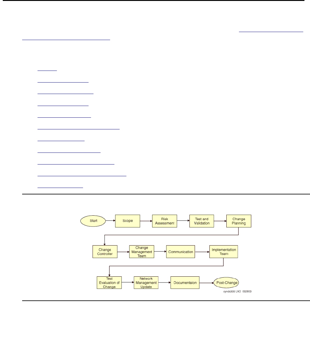
Change control
430 Avaya Application Solutions IP Telephony Deployment Guide
●Hold postmortem meetings for unsuccessful changes to determine the root cause of the
failure.
●Develop an emergency change procedure to ensure or restore an optimal solution.
High-Level process flow
The different steps to follow during a network change are represented in Figure 102: Process
flow during a network change on page 430. Each process (box) in the flowchart is discussed
below.
This section covers the topics:
●Scope
●Risk assessment
●Test and validation
●Change planning
●Change controller
●Change management team
●Communication
●Implementation team
●Test evaluation of change
●Network management update
●Documentation
Figure 102: Process flow during a network change

High-Level process flow
Issue 4.3 February 2006 431
Scope
Any proposed change should include a complete technical definition, and the intent or purpose
of the change. The change should also include information that describes what business units,
user groups, servers, and applications might be affected, both during the change period and
after deployment. Generally, most changes fall into one of the following categories:
●Network expansion
●Addition of LAN segments at existing sites
●Addition of new sites
●Connection to existing networks
●Connection to the Internet
●Corporate mergers and acquisitions
●Design and feature enhancements
●Software release upgrade
●Host software
●Distributed client software
●Configuration changes
●Support for additional protocol(s)
●Implementation of enhanced features
Risk assessment
Every network change has an associated risk level that can be assessed by modeling the
change in a laboratory environment or with a network modeling tool. It might be helpful to assign
one of the following risk categories to each change request:
●High risk. These network changes have the highest impact on user groups or particular
environments, and might affect an entire site. Backing out of the change can be time
consuming and difficult. Research high-risk changes using the available tools, and
implement the change in conjunction with Avaya Services personnel. Ensure that
management is aware of the change and its implications, and notify all users.
●Moderate-risk. These network changes can have a critical impact on user environments
or affect an entire site, but backing out of the change is a reasonably attainable scenario.
You should research moderate-risk changes the Avaya Support Centre Web site, and
possibly review the change with Avaya Services personnel. Avaya recommends notifying
all users of a moderate-risk change.

Change control
432 Avaya Application Solutions IP Telephony Deployment Guide
●Low-risk. These network changes have minor impact on user environments, and backing
out of the change is easy. Low-risk changes rarely require more than minimal
documentation. User notification is often unnecessary.
Additional risk levels night help identify the correct level of testing and validation prior to a
change. Table 77: Test and validation risk levels on page 432 defines five different risk levels
that might help identify testing and validation requirements.
Table 77: Test and validation risk levels
Risk level Definition
1 High potential impact to a large number of users (500+) or
business-critical service. Introducing a new product, software,
topology, or feature means network downtime.
2High potential impact to large number of users (500+) or
business-critical service. Large increases in traffic or users,
backbone changes, or routing changes might require network
downtime.
3 Medium potential impact to smaller number of users or business
service. Any nonstandard change, such as a new product, software,
topology, features, or the addition of new users, increased traffic, or
nonstandard topology may require some network downtime.
4 Low potential impact, including adding new standard template
network modules (building or server switches, IP Telephones,
trunks, or routers); bringing up new remote offices or additional
proven access services; and all risk level 3 changes that have been
tested in the production environment. Change might require some
network downtime.
5 No user or service impact, including adding individual users to the
network, and standard configuration changes such as password,
banner, Simple Network Management Protocol (SNMP), or other
standard configuration parameters. No expected network downtime.

High-Level process flow
Issue 4.3 February 2006 433
Test and validation
After the risk level of the potential change has been assessed, the appropriate amount of testing
and validation can be applied. Table 78: Testing and validation recommendations on page 433
demonstrates how testing and validation may be applied to the five-level risk model.
For changes with risk levels 1 through 3, two types of laboratory validation are important:
●Feature and functionality testing
●What-if analysis
Feature and functionality testing
Feature and functionality testing requires that you validate all configurations, modules, and
software with laboratory-generated traffic to ensure that the solution can handle the expected
traffic requirements. Create a test plan that validates configuration parameters, software
functionality, and hardware performance. Be sure to test behavior under real-world conditions,
including spanning-tree changes, default gateway changes, routing changes, interface flaps,
and link changes. Also validate the security and network management functions of the new
solution.
Table 78: Testing and validation recommendations
Risk level Recommendations
1 Requires laboratory validation of the new solution, including
documented testing, validation, and what-if analysis showing the
impact to existing infrastructure; completion of an operations support
document, backout plan, and implementation plan; and adherence to
the change process. Recommend solution pilots and a preliminary
design review prior to testing.
2Requires laboratory what-if analysis to determine the impact to the
existing environment with regard to capacity and performance; test
and review of all routing changes; backout plan, implementation plan,
and adherence to change process; and design review for major
routing changes or backbone changes.
3 Requires engineering analysis of the new solution, which may require
laboratory validation; implementation plan and adherence to change
process.
4Requires implementation plan and adherence to change process.
5 Optional adherence to change process.

Change control
434 Avaya Application Solutions IP Telephony Deployment Guide
What-if analysis
What-if analyses seek to understand the affect of the change on the existing environment. For
example, if you add a new feature to a media gateway, the what-if analysis should determine
the resource requirements of that feature on the media gateway. This type of testing is normally
required when adding additional features, users, or services to a network.
Change planning
Change planning is the process of planning a change, including identifying requirements,
ordering the required hardware and software parts, checking power budgets, identifying human
resources, creating change documentation, and reviewing technical aspects of the change and
change process. You should create change planning documentation such as maps, detailed
implementation procedures, testing procedures, and backout procedures. The level of planning
is usually directly proportional to the risk level of the change. A successful project should have
the following goals for change planning:
●Ensure all resources are identified and in place for the change.
●Ensure a clear goal has been set and met for the change.
●Ensure the change conforms to all organizational standards for design, configuration,
version, naming conventions, and management.
●Create a backout procedure.
●Define escalation paths.
●Define affected users and times when the network will be out of service for notification
purposes.
Change planning includes the generation of a change request, which should be sent to the
change controller.
Recommendations for change request information
Avaya recommends including the following information on the change request form:
●Name of person requesting change
●Date submitted
●Target date for implementing the change
●Change control number (supplied by the change controller)
●Help desk tracking number (if applicable)
●Risk level of the change
●Description of the change

High-Level process flow
Issue 4.3 February 2006 435
●Target system name and location
●User group contact (if available)
●Lab tested (yes or no)
●Description of how the change was tested
●Test plan
●Backout plan
●If successful, will the change migrate to other locations (yes or no)
●Prerequisites of other changes to make this change successful
The technical description of the change is an important aspect of the change request, and may
include the following: current topology and configuration, physical rack layouts, hardware and
hardware modules, software versions, software configuration, cabling requirements, logical
maps with device connectivity or VLAN connectivity, port assignments and addressing, device
naming and labeling, DNS update requirements, circuit identifiers and assignments, network
management update requirements, out-of-band management requirements, solution security,
and change procedures.
In addition, a change request should reference any standards within your organization that
apply to the change. This helps to ensure that the change conforms to current architecture or
engineering design guidelines or constraints. Standards can include the following: device and
interface naming conventions, DNS update requirements, IP addressing requirements, global
standard configuration files, labeling conventions, interface description conventions, design
guidelines, standard software versions, supported hardware and modules, network
management update requirements, out-of-band management requirements, and security
requirements.
Change controller
A key element to the change process is the change controller. The change controller is usually
an individual within your IT organization who acts as a coordinator for all change process
details. Normal job functions of the change controller include:
●Accepting and reviewing all change requests for completeness and accuracy
●Running periodic (weekly or biweekly) change review meetings with change review board
personnel
●Presenting complete change requests to the change review board for business impact,
priority, and change readiness review
●Preventing potential conflict by maintaining a change schedule or calendar

Change control
436 Avaya Application Solutions IP Telephony Deployment Guide
●Publishing change control meeting notes and helping communicate changes to
appropriate technology and user groups
●Helping ensure that only authorized changes are implemented, that changes are
implemented in an acceptable time frame in accordance with business requirements, that
changes are successful, and that no new incidents are created as a result of a change
In addition, the change controller should must metrics for the purpose of improving the change
management process. Metrics can cover any of the following:
●Volume of change processed per period, category, and risk level
●Average turnaround time of a change per period, category, and risk level
●Number of relative changes amended or rejected per period and category
●Number of relative change backouts by category
●Number of relative changes that generate new problem incidents
●Number of relative changes that do not produce the desired business results
●Number of emergency changes implemented
●Degree of client satisfaction
Change management team
You should create a change management team that includes representation from networking
operations, server operations, application support, and user groups within your organization.
The team should review all change requests and approve or deny each request based on
completeness, readiness, business impact, business need, and any other conflicts.
The team should first review each change to ensure that all associated documentation is
complete, based on the risk level. The team can then investigate the business impact issues
and business requirements. The final step is to schedule the change. Once a change has been
approved, the change management team is also responsible for communicating the change to
all affected parties. In some cases, user training might also be needed.
Note:
Note: The change management team does not investigate technical accuracy of the
change. Technical experts who better understand the scope and the technical
details should complete this phase of the change process.

High-Level process flow
Issue 4.3 February 2006 437
Communication
Once a change is approved, the next step is to communicate details of the change by setting
expectations, aligning support resources, communicating operational requirements, and
informing users. The risk level and potential impact to affected groups, as well as scheduled
network outages as a result of the change, should dictate the communication requirements.
Avaya recommends creating a matrix to help define who will be affected by a change, and what
the potential time out of service might be for each application, user group, or server. Remember
that different groups might require varying levels of detail about the change. For instance,
support groups might receive communication with more detailed aspects of the change, new
support requirements, and individual contacts, while user groups might receive only a notice of
the potential time that the network will be out of service, and a short message that describes the
business benefit.
Implementation team
You should create an implementation team that consists of individuals with the technical
expertise to expedite a change. The implementation team should also be involved in the
planning phase to contribute to the development of the project checkpoints, testing, backout
criteria, and backout time constraints. This team should guarantee adherence to organizational
standards, update DNS and network management tools, and maintain and enhance the tool set
that is used to test and validate the change.
Specifically, the implementation team should fully understand the following testing questions,
and should include them in the change documentation prior to approval by the change control
board:
●How thoroughly should we test the change?
●How will we roll out the test?
●How long will testing last, and at what point can we make the decision that the change is
implemented successfully?
The implementation team should also be fully aware of all backout criteria, time constraints, and
procedures. The team should answer the following questions as part of the change
documentation for high-risk change prior to approval by the change control board:
●How is the change to be removed?
●At what point is the decision made to back out of the change?
●What information should be gathered before backout occurs to determine why the change
needed to be backed out or why it affected the network adversely?
During the implementation of any change, it is crucial to follow the change management team
recommendations on how to make the change. If anything is performed on the network that
deviates from the recommendations, the implementation team should document and present
these steps to the change controller when the change is completed.

Change control
438 Avaya Application Solutions IP Telephony Deployment Guide
Test evaluation of change
Testing and verification can be critical to a successful change. You should identify testing steps
after defined change checkpoints and final change completion. In addition, allocate sufficient
time for testing, both during and following the implementation and backout, if necessary. In
some cases, you can do testing prior to the change when new service is involved, such as new
circuits or links that are not currently in production. The following additional testing and
verification procedures may be pertinent to a network change:
●Extended pings for connectivity and performance (may require many to many)
●Traceroutes
●End-user station network and application testing
●Test calls or traffic generation for performance-related changes
●Bit error rate tester (BERT) for new circuits
●Display errors
●Log file verification
●List trace verification
●Display or status command verification
●Network management station availability and verification
After achieving some level of comfort with the change, evaluate what was accomplished:
●Does the change make sense?
●Did the change address the network problem?
●What should be done differently the next time that a change is warranted?
Network management update
Operational readiness requires that you update all network management tools, device
configuration, and DNS to reflect the change. Your organization might also have tools for fault
management, configuration management, availability measurement, inventory management,
billing, and security that require updates. The following are some typical network management
update requirements following change:
●Removal of DNS entries and network management system (NMS) management for
devices that were removed from the network.
●Standard SNMP configuration entered on devices, including community string, location,
support contact, syslog server, trap server, and SNMP server host.
●Trap source, syslog source, and SNMP source configured for loopback.

High-Level process flow
Issue 4.3 February 2006 439
●Fault management tool update.
●Inventory management tool update.
●Circuit pack and media gateway addresses with DNS name (following naming standard)
Documentation
Possibly the most important requirement in any network environment is to have current and
accurate information about the network available at all times. During the process of changing
the network, it is critical to ensure that documentation is kept up to date. Network
documentation should include the following:
●Detailed physical layer drawing that displays all network devices that have a medium risk
(or higher) on the network. The drawing should include rack layouts, cable connections,
and devices.
●Detailed network layer drawing of all network devices that have a medium risk (or higher)
on the network. The drawing should include addresses, and IP subnetwork and VLAN
information.
●Out-of-band management access maps and documentation.
●Solution templates.
●Detailed numbering plans and assignments.
●Detailed dial plan and call routing information.
●VLAN numbering plans and assignments.
●Network Region assignments.
●Naming standards for all network devices.
●Software code and hardware types that are currently implemented and supported.
●Protocol filtering criteria and methodologies.
●Routing protocols standards and supported modifications from default settings.
●Global configuration standards.
●Inventory database for all physical connectivity and contact information.
In addition, Avaya recommends that you develop a matrix that contains information about user
groups, the applications they require, and the servers (addresses and locations) that host these
applications. This information is necessary to ensure that users continue to have the level of
access and performance they require during and after the change. In addition, previously used
test plans assist in simplifying future changes, and they may assist in troubleshooting problems
that occur because of a change.

Change control
440 Avaya Application Solutions IP Telephony Deployment Guide
High-Level process flow for emergency change
management
Unfortunately, not all situations that occur in a network environment are conducive to the
extensive research and planning described in the previous section. Sometimes you must make
more immediate changes to restore network connectivity following a network outage.
The procedures that you put in place to handle emergency changes should be flexible enough
to facilitate rapid resolution of the problem, including documentation of who is authorized to
make emergency changes to the network, and how to contact these individuals. You should
either have a sufficient number of people who can resolve network emergencies, or those
people should be easily accessible at all times to prevent a roadblock in the problem resolution
process.
It is critical to maintain both communication and the integrity of documentation through an
emergency change. This is the time when documentation is needed most, so documenting the
steps that are taken to resolve the problem is very important.
Finally, when considering changes, you should think about not only whether the change will
resolve the existing problem, but also whether the change will cause other network problems.
Steps that are critical for an emergency change process are shown in the process flow below.
In this section, the topics covered are:
●Issue determination
●Limited risk assessment
●Communication
●Documentation
●Implementation
●Test and evaluation
Issue determination
It is usually obvious when an emergency change is required. However, exactly what change is
required may not be obvious. For Avaya equipment, you should include the appropriate Avaya
Services personnel in the troubleshooting process. In many cases, problems with Avaya
equipment will be fixed by Avaya Services expert systems, or a technician will be dispatched
before users are aware of the problem.
When taking corrective action, it is imperative that you implement only one change at a time.
Otherwise, if the problem is resolved by multiple changes, it is impossible to pinpoint which
change actually fixed the problem. Or worse, if other problems are introduced, it is impossible to
determine which change was the cause of the new fault. Each change should go through the full
process outlined above before you begin on the next change. If a change is shown to have no
effect, you should back out of it before you begin the next change. The single exception is when
the initial change is a prerequisite to the next change that is under consideration.

High-Level process flow for emergency change management
Issue 4.3 February 2006 441
Limited risk assessment
In most cases, the amount of risk assessment done in an emergency situation is directly
proportional to the scope of the change, and inversely proportional to the effect of the network
outage. For example, the scope of changing a Communication Manager release is much
greater than that of changing a protocol address. Similarly, the same change would go through
increased scrutiny if a single user is unable to access the network rather than if an entire site
loses connectivity.
Ultimately, risk assessment is the responsibility of the support person who implements the
change. For this, the engineer should rely on personal experience, as well as that of associated
support personnel. Many of the ideas given in the section on Planned Change Management can
be adapted to the emergency change environment, but on a more limited scale. For instance,
you can use the Avaya Support Centre Web site (support.avaya.com/), or even use a limited
test bed simulation, depending on your situation.
Finally, as part of the limited risk assessment, you should determine which users might be
affected by the change.
Communication
Although it is not always be possible to notify all users of all changes (especially in emergency
situations), the users certainly appreciate any warning that you can provide. You should also
communicate the details of any emergency changes with the change manager, and allow the
change manager to maintain metrics on emergency changes and root causes. The information
may also affect the scheduling or the rollout of future changes.
Documentation
Updating documentation is critical to ensure valid, up to date information. During unplanned
changes, it can be easy to forget to make updates because of the frantic nature of emergencies.
However, undocumented change solutions often result in increased time out of service if the
solution is unsuccessful.
It helps to document changes before they are made in emergency situations from a central
location, perhaps at the change manager level. If a central support organization does not exist
to document changes before they occur, different individuals might make changes at the same
time, not knowing about each other’s activities. The following types of documentation often
require updates during a change: drawings, IP/VLAN database, engineering documents, dial
plan, troubleshooting procedures, and server/application/user matrices.

Change control
442 Avaya Application Solutions IP Telephony Deployment Guide
Implementation
If the process of assigning risk and documentation occurs before the implementation, the actual
implementation should be straightforward. Beware of the potential for changes to come from
multiple support personnel without their knowing about each other’s changes. This scenario can
lead to increased potential time out of service and misinterpretation of the problem.
Test and evaluation
In this phase, the person who initiated the change is responsible for ensuring that the
emergency change had the desired affect and if not, restarting the emergency change process.
Steps to take in the investigation of the change include the following:
●Observe and document the impact of the change on the problem.
●Observe and document any foreseen or unforeseen side effects of the change.
●Determine whether the problem is resolved, and if so, make sure all necessary
documentation and network management updates occur to properly reflect the change.
●If the change is unsuccessful, back out, and continue the emergency change process until
the problem is resolved or a workaround is in place.
Once the change is deemed successful, send all emergency change documentation to the
change controller for review and documentation by the change control team. The change
controller and change review team should perform a post-mortem on the problem to determine
potential improvements to prevent future emergency changes of this type. You should also send
the information to engineering or architecture groups for review, and allow them the opportunity
to change solution templates, standard software versions, or network designs to better meet the
goals or requirements of your organization.

Performance indicators for change management
Issue 4.3 February 2006 443
Performance indicators for change management
Performance indicators provide the mechanism for you to measure the success of your change
management process. We recommend that you review these indicators monthly to ensure that
change planning and change management are working well.
The topics are:
●Change management metrics by functional group
●Targeting change success
●Change history archive
●Change planning archive
●Periodic performance meeting
Change management metrics by functional group
Change management metrics by functional group include the percentage and quantity of
change success by functional group and risk level. Emergency changes should be identified
separately in the metrics by functional group, including the success rate for attempted fixes.
Functional groups include any IT teams making changes, possibly including telephony
administration, network administration, database groups, application teams, and facilities. Risk
level is important, because generally higher-risk changes fail or create incidents. You might
define change failure as any change that is backed out or causes a problem that results in time
out of service for the users.
Determining change-related incidents can be difficult. You should contact the user who is
identified on the change request form following the change to get an understanding of change
success. The change controller might also have a help-desk database available that includes
problems closed because of change-related issues.
Targeting change success
To target change success, you should start with a baseline of change management metrics.
The change controller can then identify potential issues and set overall goals. A reasonable
overall goal for change success in high-availability networks should be 99% across all functional
groups. If your organization is experiencing a higher rate of change failure, the rate should be
targeted for improvement.

Change control
444 Avaya Application Solutions IP Telephony Deployment Guide
Change history archive
The change controller is also responsible for archiving the change history. Creating a
spreadsheet with functional group success and failure columns and month rows is sufficient for
archival. Change history archives can help identify current issues that are based on past
change rates and available resources. The information can also be used to investigate change
rates in general for overall planning purposes.
Change planning archive
The change controller should archive change planning documentation, such as network
engineering documents, to create a reference of examples for future successful projects. If the
change controller notices change problems, the controller can refer to the change planning
document to investigate how well the particular issue was documented before the change. Over
time, the change controller might ask to have additional information added to future change
planning documents for higher-risk changes to help ensure success.
Periodic performance meeting
Each month, it is important to review the metrics that you collect, including the following:
●Change quantity and risk level
●Change failure quantity and post-mortems
●Emergency changes and post mortems
●Change management goals
●Undocumented changes
The functional manager should review the metrics, and report to the appropriate teams for
improvement.
Issue 4.3 February 2006 445
Appendix B: Access list
This appendix provides guidelines for configuring access lists to facilitate basic Avaya IP
Telephony functionality.
The ports used by the Avaya call server are fairly fixed and well known. The ports used by the
endpoints are more variable and random. As a result, it is simpler to tailor access lists based on
call server ports. Table 79: Access list guidelines to support IP Telephony on page 445 contains
access list guidelines for supporting IP Telephony.
Table 79: Access list guidelines to support IP Telephony
Action From TCP/UDP
port
or protocol
To TCP/UDP
port
or protocol
Notes
Permit Any C-LAN UDP 1719 Any endpoint UDP any The C-LAN uses UDP
port 1719 for endpoint
registration (RAS).
Permit Any endpoint UDP any Any C-LAN UDP 1719
Permit Any C-LAN TCP 1720 Any endpoint TCP any The C-LAN uses TCP
port 1720 for H.225
call signaling.
Permit Any endpoint TCP any Any C-LAN TCP 1720
Permit Near-end
C-LAN TCP 1720 Far-end
C-LAN TCP 1720 This is to facilitate IP
trunking between two
Avaya call servers,
and must be done for
each IP trunk.
Permit Far-end
C-LAN TCP 1720 Near-end
C-LAN TCP 1720
Permit Any MedPro UDP port
range
on IP
Network
Region form
Any endpoint UDP any This is one way to
facilitate audio
streams between
MedPros and
endpoints.
Permit Any endpoint UDP any Any MedPro UDP port
range
on IP
Network
Region form
1 of 3

Access list
446 Avaya Application Solutions IP Telephony Deployment Guide
Permit Any MedPro UDP port
range
on IP
Network
Region form
Any endpoint UDP any This is another way to
facilitate RTP/RTCP
audio streams
between MedPros and
endpoints.
Permit Any endpoint UDP any Any endpoint UDP any This is to facilitate
RTP/RTCP audio
streams between
direct IP-IP (shuffled)
endpoints.
Permit Any IP
Telephone UDP any DNS
server(s) UDP 53
(dns) These are all services
used by the IP
Telephone. TFTP is
difficult to isolate to a
port range. The GET
and PUT requests
from the client go to
the UDP port 69 on the
server, but all other
messages go between
random ports.
Permit DNS servers UDP 53
(dns) Any IP
Telephone UDP any
Permit Any IP
Telephone UDP 68
(bootpc) DHCP
server(s) UDP 67
(bootps)
Permit DHCP
servers UDP 67
(bootps) Any IP
Telephone UDP 68
(bootpc)
Permit Any IP
Telephone TFTP TFTP
server(s) --
Permit TFTP
servers TFTP Any IP
Telephone --
Permit SNMP
management
stations
UDP any Any IP
Telephone UDP 161
(snmp)
Permit Any IP
Telephone UDP 161
(snmp) SNMP
management
stations
UDP any
Table 79: Access list guidelines to support IP Telephony (continued)
Action From TCP/UDP
port
or protocol
To TCP/UDP
port
or protocol
Notes
2 of 3

Issue 4.3 February 2006 447
Table 80: Access list guidelines for Avaya S8300, S8500, S8700-series Media Servers on
page 448 contains access list guidelines that pertain to Communication Manager platforms,
including the S8700 and S8300 Media Servers. The S8700 enterprise interface, which is the
one that is connected to the enterprise network (versus the control network), is eth4 on fiber
connect systems and eth0 on IP connect systems.
Permit Any Avaya
device ICMP Echo Any -- Avaya devices ping
other devices for
various reasons. For
example, C-LANs ping
endpoints for
management
purposes; MedPros
ping C-LANs to gauge
network performance
across an IP trunk; IP
Telephones ping TFTP
servers for verification
purposes.
Permit Any ICMP Echo
Reply Any Avaya
device --
Table 79: Access list guidelines to support IP Telephony (continued)
Action From TCP/UDP
port
or protocol
To TCP/UDP
port
or protocol
Notes
3 of 3

Access list
448 Avaya Application Solutions IP Telephony Deployment Guide
Table 80: Access list guidelines for Avaya S8300, S8500, S8700-series Media Servers
Action From TCP/UDP
port
or protocol
To TCP/UDP
port
or protocol
Notes
Permit S8700
enterprise
interface
TCP any S8300 or
S8500 LSP TCP 514 Both S8700 and LSP
running pre-CM2.x:
This allows the S8700 to
synchronize translations
with the S8300 Local
Survivable Processor
(LSP). A TCP session is
initiated from the S8700 to
the S8300 TCP port 514. A
second session is then
initiated from the S8300 to
the S8700 TCP port range
512-1023. Network ports
TCP 512-1023 must be
open. See Table 81 below.
Permit S8300/S8500
LSP TCP 514 S8700
enterprise
interface
TCP any
Permit S8300/S8500
LSP TCP any S8700
enterprise
interface
TCP
512-1023
Permit S8700
enterprise
interface
TCP
512-1023 S8300/S8500
LSP TCP any
Permit Avaya Site
Administratio
n
workstation
TCP any S8300,
S8500, or
S8700
enterprise
interface
TCP 5023 This allows an administrator
to log in through Avaya Site
Administration to a call
server.
Permit S8300,
S8500, or
S8700
enterprise
interface
TCP 5023 Avaya Site
Administratio
n
workstation
TCP any
Permit Web admin
station TCP any S8300,
S8500, or
S8700
enterprise
interface
TCP 80 This allows secure and
insecure web access to a
call server. The call server
redirects insecure sessions
to https.
1 of 3

Issue 4.3 February 2006 449
Permit S8300,
S8500, or
S8700
enterprise
interface
TCP 80 Web admin
station(s) TCP any
Permit Web admin
station TCP any S8300,
S8500, or
S8700
enterprise
interface
TCP 443
Permit S8300,
S8500, or
S8700
enterprise
interface
TCP 443 Web admin
station(s) TCP any
Permit S8300,
S8500, or
S8700
enterprise
interface
UDP any DNS
server(s) UDP 53 (dns) Optional services used by
S8300, S8500, and S8700.
Permit DNS
server(s) UDP 53 (dns) S8300,
S8500, or
S8700
enterprise
interface
UDP any
Permit S8300,
S8500, or
S8700
enterprise
interface
UDP any NTP
server(s) UDP 123
(ntp)
Permit NTP
server(s) UDP 123
(ntp) S8300,
S8500, or
S8700
enterprise
interface
UDP any
Permit G700 or
G350 TCP any S8300 or
other
call server
TCP 2945 Unencrypted: H.248
signaling between G700 or
G350 Media Gateway and
S8300 or other call server.
G700/G350 initiates the
session.
Table 80: Access list guidelines for Avaya S8300, S8500, S8700-series Media Servers
Action From TCP/UDP
port
or protocol
To TCP/UDP
port
or protocol
Notes
2 of 3

Access list
450 Avaya Application Solutions IP Telephony Deployment Guide
Access list guidelines are dependent upon the release of Communication Manager running on
the Linux primary servers and LSPs, as described in Table 81: Port requirements for file
synchronization on page 450.
Permit S8300 or
other
call server
TCP 2945 G700 or
G350 TCP any
Permit G700 or
G350 TCP any S8300 or
other
call server
TCP 1039 Encrypted: H.248
signaling between G700 or
G350 Media Gateway and
S8300 or other call server.
G700/G350 initiates the
session.
Permit S8300 or
other
call server
TCP 1039 G700 or
G350 TCP any
Permit Call server IP any IPSI board IP any There are too many system
control messages and
services between the call
server and IPSI board to
filter each one individually.
Permit IPSI board IP any Call server IP any
Table 81: Port requirements for file synchronization
Primary Firewall Port Customer Network
Port(s) LSP Firewall Port
Both primary and LSP running pre-CM2.x:
TCP 514 TCP 512 - 1023 TCP 514
Both primary and LSP running CM2.x
TCP 21873 (opens
automatically; TCP 514
no longer needed)
TCP 21873 TCP 21873 (opens
automatically; TCP 514 no
longer needed)
Both primary and LSP running CM3.x
1 of 2
Table 80: Access list guidelines for Avaya S8300, S8500, S8700-series Media Servers
Action From TCP/UDP
port
or protocol
To TCP/UDP
port
or protocol
Notes
3 of 3

Issue 4.3 February 2006 451
TCP 21874 (opens
automatically) TCP 21874 TCP 21874 (opens
automatically)
Backward compatibility (CM1.3 primary; CM2.x LSP)
TCP 514 TCP 512 - 1023 TCP 21873 (opens
automatically)
Backward compatibility (CM2.x primary; CM3.x LSP)
TCP 21873 (opens
automatically) TCP 21873 TCP 21874 (opens
automatically)
Table 81: Port requirements for file synchronization (continued)
2 of 2

Access list
452 Avaya Application Solutions IP Telephony Deployment Guide
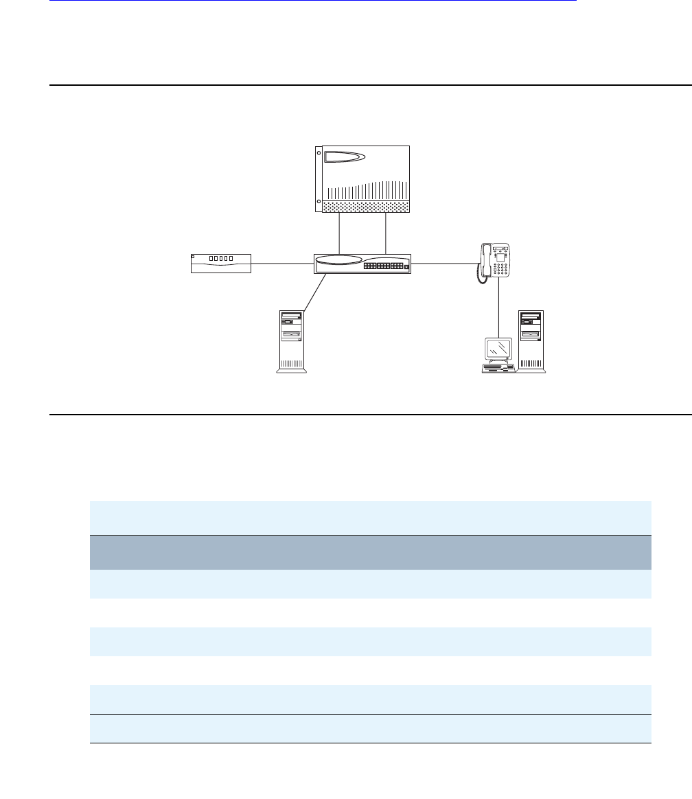
Issue 4.3 February 2006 453
Appendix C: Multi-VLAN example
Figure 103: Sample Multi-VLAN scenario for Cajun P330 code 3.2.8 and Cisco on page 453 is
a sample multi-VLAN scenario. Suppose there is a Cisco router that is connected to a P330
switch that contains two VLANs, one for the VoIP devices and one for the personal computers.
To conserve ports and cabling, the computers are connected to the telephones and the
telephones are connected to the P330 switch.
Figure 103: Sample Multi-VLAN scenario for Cajun P330 code 3.2.8 and Cisco
To configure the multi-VLAN example, proceed as follows:
Table 82: Command set and explanations for multi-VLAN example
Command Notes
Cisco router configuration
interface FastEthernet0/1
description 802.1Q trunk interface
!
interface FastEthernet0/1.1
encapsulation dot1q 1
1 of 5
cynds307 KLC 121003
AVAYA IP
Phone
PCDHCP Server
TFTP Server
Cisco Router
192.168.1.254
192.168.10.254
f0/1
Cajun P330
G600/G650
C-LAN
vlan 10
192.168.10.1
1/1 1/2 1/3 1/5
1/12
vlan 1
192.168.1.100
vlan 1
192.168.1.7
vlan 1
192.168.10.7
MedPro
vlan 10
192.168.10.2

Multi-VLAN example
454 Avaya Application Solutions IP Telephony Deployment Guide
ip address 192.168.1.254
255.255.255.0
!
interface FastEthernet0/1.10
encapsulation dot1q 10
ip address 192.168.10.254
255.255.255.0
ip helper-address 192.168.1.100 Forwards DHCP requests to the DHCP
server.
P330 configuration (bind-to-static option)1
set port vlan-binding-mode 1/1 static Port in static binding mode by default,
but command shown.
set port static-vlan 1/1 10 In addition to v1, v10 statically bound to
port.
set trunk 1/1 dot1q Port connected to Cisco router is an
802.1Q trunk port.
set port spantree disable 1/1
set port vlan 10 1/2 Port/native VLAN changed to 10 on this
port.
set port spantree disable 1/2
set port vlan 10 1/3
set port spantree disable 1/3
set port vlan-binding-mode 1/5 static Port in static binding mode by default,
but command shown.
set port static-vlan 1/5 10 In addition to v1, v10 statically bound to
port, but not a trunk port.
set port spantree disable 1/5 Port 1/12 for the DHCP/TFTP server
already has port/native VLAN 1.
Table 82: Command set and explanations for multi-VLAN example (continued)
Command Notes
2 of 5

Issue 4.3 February 2006 455
P330 configuration (bind-to-configured option)
set vlan 1 (VLAN 1 configured)
set vlan 10 (VLAN 10 configured)
set port vlan-binding-mode 1/1
bind-to-configured Port bound to configured VLANs 1 and
10.
set trunk 1/1 dot1q Port connected to Cisco router is an
802.1Q trunk port.
set port spantree disable 1/1
set port vlan 10 1/2 (port/native VLAN
changed to 10 on this port)
set port spantree disable 1/2
set port vlan 10 1/3
set port spantree disable 1/3
set port vlan-binding-mode 1/5
bind-to-configured Bound to configured VLANs but not a
trunk port.
set port spantree disable 1/5
If the P330 switch were a Cisco CatOS switch instead
First, invoke the set port host
command on all user ports, and then
proceed as follows.
set vlan 1005 1/1 Cisco switches do not tag the native
VLAN, but the router expects a tag on
VLAN 1, so the native VLAN is changed
to some unused VLAN.
set trunk 1/1 on dot1q Port connected to Cisco router is an
802.1Q trunk port.
clear trunk 1/1 2-9,11-1004 Unnecessary VLANs removed; 1, 10,
and 1005 remain.
set vlan 10 1/2 Port/native VLAN changed to 10 on this
port.
Table 82: Command set and explanations for multi-VLAN example (continued)
Command Notes
3 of 5

Multi-VLAN example
456 Avaya Application Solutions IP Telephony Deployment Guide
set vlan 10 1/3
set trunk 1/5 nonegotiate dot1q Plain 802.1Q trunk port with no Cisco
negotiation features.
clear trunk 1/5 2-9, 11-1005 Unnecessary VLANs removed; 1 and
10 remain.
Optional command using auxiliaryvlan on the telephone port instead of
explicit trunking
set port auxiliaryvlan 1/5 10 VLAN 10 is the auxiliaryvlan; only
VLANs 1 and 10 on this port; port is an
802.1Q trunk port, though not explicitly
configured.
If the P330 switch were a Cisco IOS switch instead
interface FastEthernet0/1
switchport trunk encapsulation dot1q Port connected to Cisco router is an
802.Q trunk port.
switchport trunk native vlan 1005 Cisco switches do not tag the native
VLAN, but the router expects a tag on
VLAN 1, so the native VLAN is changed
to some unused VLAN.
switchport trunk allowed vlan
1,10,1005 VLANs 1, 10, and 1005 allowed on
trunk.
switchport mode trunk
spanning-tree portfast
interface FastEthernet0/2
switchport access vlan 10 Port/native VLAN changed to 10 on this
port.
spanning-tree portfast
interface FastEthernet0/3
switchport access vlan 10
spanning-tree portfast
interface FastEthernet0/5
Table 82: Command set and explanations for multi-VLAN example (continued)
Command Notes
4 of 5

IP Telephone configuration
Issue 4.3 February 2006 457
IP Telephone configuration
This procedure applies regardless of the Ethernet switch that is being used. Initially placing the
IP Telephone on VLAN 10 requires two DHCP scopes, one for VLAN 1 and another for VLAN
10, with identical SSON 176 parameters.
To configure an IP telephone
1. Run the telephone through its normal boot-up sequence.
It will come up with an IP address on VLAN 1 - the port/native VLAN - assuming that the
DHCP scope is set up properly.
2. If IP600 R9.2 and IP Telephone R1.1, after the telephone is up and operational on VLAN 1
press Hold QOS #.
switchport trunk encapsulation
dot1q802.1Q trunk port
switchport trunk native vlan 1 Since most PCs do not understand the
tag, the Cisco native VLAN must be set
as the PC's VLAN. VLAN 1 is already
the native VLAN, but command is
shown.
switchport trunk allowed vlan 1,10 VLANs 1 and 10 allowed on trunk.
switchport mode trunk
spanning-tree portfast
Optional commands using the voice vlan on the telephone port.2
interface FastEthernet0/5
switchport trunk encapsulation dot1q
switchport trunk native vlan 1
switchport voice vlan 10 VLAN 10 is the voice vlan; unsure if this
removes all other VLANs from trunk or
not.
1. All ports have port/native VLAN 1 by default.
2. There really is no reason to do this unless a Cisco telephone will use this port. The
configuration is not simpler, as with the CatOS switch and auxiliaryvlan.
Table 82: Command set and explanations for multi-VLAN example (continued)
Command Notes
5 of 5

Multi-VLAN example
458 Avaya Application Solutions IP Telephony Deployment Guide
3. Enable 802.1Q, set the priorities as desired, set the VID to 10, and save the values.
4. Press Hold RESET #.
5. Answer No to resetting the values.
6. Answer Yes to restarting the telephone.
The telephone comes up with an IP address on VLAN 10, assuming DHCP is relayed and
set up properly. From then on the telephone will always come up on VLAN 10 without
further manual intervention until the stored values are manually reset. This is because all
manually entered values remain in the telephone's NVRAM until manually reset.
With IP600 R9.5 and IP Telephone R1.51, the Hold QOS# values that were set manually in the
previous IP Telephone release can be sent to the telephone by the DHCP server, using SSON
176. On the VLAN 1 DHCP scope, add L2Q=1 and L2QVLAN=10 to the existing SSON 176
comma-separated string. For example:
MCIPADD=#.#.#.#,MCPORT=1719,TFTPSRVR=#.#.#.#,L2Q=1,L2QVLAN=10
This causes the telephone to release the VLAN 1 address after the first DHCP sequence, and
then enter a second DHCP sequence with tagging enabled to obtain a VLAN 10 address.
Because the L2Q parameters are not manually set in this scenario, and thus are not stored in
NVRAM, the telephone requires the VLAN 1 DHCP scope every time it reboots. The L2Q
parameters should not be added to the VLAN 10 DHCP scope. This is so that in the event a
telephone is connected to a port that has VLAN 10 as the port/native VLAN, it will not receive
instructions from the DHCP scope to enable tagging. In such a case the telephone would not
require tagging to function on VLAN 10, and tagging could result in an incompatibility with the
Ethernet switch.
PC configuration
The PC can be statically addressed with a VLAN 1 address, or it can receive a VLAN 1 address
through DHCP. No special configurations are required.

Issue 4.3 February 2006 459
Appendix D: DHCP / TFTP
DHCP
This section provides information on possible DHCP servers and generic information on
administering a DHCP server.
Required information
Before installing a DHCP server you will need the following required network information:
●Router IP address
●TFTP server IP address
●Subnet mask
●C-LAN IP address(es)
●Communication Manager C-LAN port. Although this may be a value between 0 and 65535,
the default value is 1719 and should not be changed unless this conflicts with an existing
port assignment.
●TFTP server file path
●Telephone IP address range (both From and To)
●DNS Server addresses (if applicable)
Choosing a DHCP configuration
This section concentrates on the simplest case of the single LAN segment. Extrapolate the
information that is provided here for more complex LAN configurations.
!WARNING:
WARNING: Before you start, it is important that you understand your current network
configuration. An improper installation can cause network failures or reduce the
reliability and performance of your network. See Network assessment offer for
more information about Avaya’s comprehensive network performance
assessment.

DHCP / TFTP
460 Avaya Application Solutions IP Telephony Deployment Guide
DHCP software alternatives
Two DHCP software alternatives are common to Windows operating systems:
●Windows NT 4.0 DHCP Server
●Windows 2000 DHCP Server
Any other DHCP application might work.
It is the customer’s responsibility to install and configure the DHCP server correctly. This
appendix is limited to describing generic administration for Avaya IP Telephones.
DHCP generic setup
Set up of a DHCP server involves the following top-level tasks:
1. Install the DHCP server software according to vendor instructions.
2. Configure the DHCP server with the available IP addresses for the Avaya IP Telephones.
3. Administer the lease duration (“Infinite” is recommended).
4. Administer the gateway (router) IP addresses.
If more than one address is listed, the total list may contain up to 127 total ASCII characters,
with IP addresses separated by commas with no intervening spaces.
5. Configure the Subnet mask.
6. Administer Option 6 (DNS servers address list).
If more than one address is listed, the total list may contain up to 127 total ASCII characters,
with IP addresses separated by commas with no intervening spaces. At least one address
in Option 6 must be a valid, nonzero, dotted decimal address. Otherwise, DNS will fail.
7. Administer Option 15 (DNS Domain Name).
This string should contain the domain name to be used when DNS names in system
parameters are resolved into IP addresses. This domain name is appended to the DNS
name before the IP Telephone attempts to resolve the DNS address. Option 15 is
necessary if you want to use a DNS name for the TFTP server. Otherwise, you might
specify a DOMAIN as part of TFTP customization.

DHCP
Issue 4.3 February 2006 461
8. Administer Option 66 (TFTP Server Name).
Note:
Note: Microsoft DHCP servers support only dotted decimal format for TFTP addresses, not
symbolic names. Option 66 need not be used if the TFTP server is identified in the
Site Specific Option string (Option 176). However, to simplify configuration, we
recommend that you use Option 66. If you use both Option 66 and Option 176 to
identify TFTP servers, the values in Option 176 will override the values in Option 66.
9. Administer the IP Telephone-specific DHCP options specifying information, such as TFTP
server and DEFINITY C-LAN IP addresses. Use the site-specific option (SSON) at #176.
The value for this option should be set to either of the following strings:
MCIPADD=xxx.xxx.xxx.xxx,MCPORT=yyyy,TFTPSRVR=zzz.zzz.zzz.zzz,TFTPDIR=<
path>
or
MCIPADD={list of DNS names},MCPORT=yyyy,TFTPSRVR={list of DNS
names},TFTPDIR=<path>
Where xxx.xxx.xxx.xxx is one or more IP addresses for the C-LAN IP circuit pack, yyyy is
the C-LAN port (1719), zzz.zzz.zzz.zzz is one or more IP addresses for TFTP servers, and
<path> is the location of the location of the upgrade script and application files on the TFTP
server.
Each list can contain up to 127 total ASCII characters, with IP addresses separated by
commas with no intervening spaces, and with quotes on either end (see the example in the
NOTES below). If you use DNS, note that the system value DOMAIN is appended to the
hostname that you specify. If DOMAIN is null, the DNS names must be fully qualified. In
configurations where the upgrade script and application files are in the default directory, the
TFTPDIR=<path> should not be used. You do not have to use Option 176. For example, if
the DNS server is specified in Option 6, and the Domain Name is specified in Option 15,
you can use the configured names “AvayaTFTPServer” and “Avaya Call Server” for
TFTPSRVR and MCIPADD, respectively. The Call Server Name, TFTP Server Name, and
SMTP Server Name must each be no more than 32 characters in length. Examples of good
DNS administration include the following:
●Option 6: aaa.aaa.aaa.aaa
●Option 15: dnsexample.yourco.com
●Option 66: tftpserver.yourco.com,zzz.zzz.zzz.zzz
●Option 176: MCIPADD=xxxx.xxx.xxx.xxx
Depending on the DHCP application you choose, be aware of the fact that the application
most likely will not immediately recycle expired DHCP leases. An expired lease may remain
reserved for the original client for a day or more (for example, Windows NT DHCP reserves
expired leases for about 1 day). The intent of this reservation period is to protect a client’s
lease in case the client and the DHCP server are in two different time zones, the computers’
clocks are not in sync, or the client is not on the network when the lease expires.

DHCP / TFTP
462 Avaya Application Solutions IP Telephony Deployment Guide
The implication of this fact can be seen in the following example. Assume two IP addresses
(hence two possible DHCP leases) and three IP Telephones, two of which are using the two
available IP addresses. When the lease expires for the first two telephones, the third will not
be able to get a lease (even if the other two telephones have been removed from the
network), until the reservation period expires.
The IP Telephone sets the indicated system values to the values of the indicated fields of
the DHCPACK message (Table 83).
Windows NT 4.0 DHCP server
This section contains details on how to verify and configure the DHCP server included in the
Windows NT 4.0 server operating system.
Use Verifying the DHCP server installation below to verify whether the DHCP server is installed.
If it is not, install the DHCP server. If it is installed, then proceed with the Initial configuration and
the Creating a DHCP scope for the IP Telephones sections.
Verifying the DHCP server installation
Use the following procedure to verify whether the DHCP server is installed:
1. Select Start->Settings->Control Panel.
2. Double-click the Network icon.
3. Verify that Microsoft DHCP Server is listed as one of the Network Services on the Services
Tab.
4. If it is listed, continue with the Initial configuration section below. If it is not listed, install the
DHCP server.
Table 83: DHCP setting of system values
System value Set to
IPADD The yiaddr field
NETMASK Option #1 (if received)
GIPADD The first four octets of Option #3 (if
received)
TFTPSRVR The first four octets of the siaddr field

DHCP
Issue 4.3 February 2006 463
Initial configuration
The Windows NT 4.0 DHCP server configuration involves setting up a scope for the IP
Telephone. A DHCP scope is essentially a grouping of IP devices (in this case IP Telephones)
running the DHCP client service in a subnet. The scope is used to define parameters for each
subnet. Each scope has the following properties:
●A unique subnet mask used to determine the subnet related to a given IP address.
●A scope name assigned by the administrator when the scope is created.
●Lease duration values to be assigned to DHCP clients with dynamic addresses.
In addition, the DHCP server can assign configuration parameters to a client, and these can be
specified for each individual DHCP scope. Setting up of the Windows NT 4.0 DHCP server,
requires these steps:
1. Creating a DHCP scope for the IP Telephones
2. Editing custom options
3. Adding the DHCP option
4. Activating the leases
Creating a DHCP scope for the IP Telephones
Use the following procedure to create a DHCP scope for the IP Telephones:
1. Select Start->Programs->Admin Tools->DHCP Manager.
2. Expand Local Machine in the DHCP Servers window by double clicking on it until the +
sign changes to a - sign.
3. Select Scope->Create.
4. Define the range of IP addresses used by the IP Telephones.
●The Start Address should be the first IP address to be used for the IP Telephones.
●The End Address should be the last IP address to be used for the IP Telephones.
●Subnet Mask should be set to the value assigned by the network administrator.
5. Perform these steps to exclude any IP addresses that you do not want to be assigned to IP
Telephones within the range specified by the Start and End Addresses.
a. Enter the first IP address in the range that you would like to exclude in the Start Address
field under Exclusion Range.
b. Enter the last IP address in the range that you would like to exclude in the End Address
field under Exclusion Range.
c. Click the Add button.
d. Repeat steps a. through c. for each IP address range that you would like to exclude.

DHCP / TFTP
464 Avaya Application Solutions IP Telephony Deployment Guide
Example
Suppose the ranges of the IP addresses that are available for your IP Telephone network
are:
●135.254.76.7 to 135.254.76.80
●135.254.76.90 to 135.254.76.200
●135.254.76.225 to 135.254.76.230
Your start address and end address should then be 135.254.76.7 and 135.254.76.230,
respectively.
You should exclude the ranges 135.254.76.81 to 135.254.76.89 and 135.254.76.201 to
135.254.76.224.
Note:
Note: Avaya recommends that the IP Telephones be provisioned with sequential IP
addresses.
6. Under Lease Duration, select the Limited To option and set the lease duration to the
maximum.
7. Enter a sensible name for the Name field, such as “DEFINITY IP Telephones.”
8. Click OK.
A dialog box prompts you: ‘Activate the new scope now?’
9. Click No.
Editing custom options
Use the following procedure to edit custom options:
1. Select DHCP Options->Defaults.
2. Click New.
3. Enter “46XXOPTION” for your custom in the Add Option Type dialog.
4. Select Data Type of String, and enter 176 in the Identifier field.
5. Click OK.
The DHCP Options menu is displayed.
6. Select the Option Name for 176 and set the value string.
7. Click OK.
8. Select 003 Router from the list for the Option Name field.
9. Click Edit Array.
10. Enter the Gateway IP address for the New IP Address field.
11. Click Add, and then click OK.

DHCP
Issue 4.3 February 2006 465
Adding the DHCP option
Use the following procedure to add the DHCP option:
1. Highlight the scope that you just created.
2. Select Scope under DHCP OPTIONS.
3. Select the 176 option that you created from Unused Option List.
Avaya recommends that the IP Telephones be provisioned with sequential IP addresses.
You will activate the scope when all options have been set.
4. Click Add.
5. Select option 003 from the Unused Options List.
6. Click Add.
7. Click OK.
8. Chose the Global parameter under DHCP Comments.
9. Select the 176 option that you created from the Unused Option List.
10. Click Add.
11. Click OK.
Activating the leases
To activate the leases, click Activate under the Scope Menu, and the icon for the scope should
light.
Verifying your configuration
This section describes how to verify that the 46XXOPTIONs are correctly configured for the
Windows NT 4.0 DHCP server.
To verify the default option (176 46XXOPTION)
Use the following procedure to verify the default option:
1. Select Start>Programs>Admin Tools>DHCP Manager.
2. Expand Local Machine in the DHCP Servers window.
3. In the DHCP Servers frame, click the scope for the IP Telephone.
4. Select Defaults from the DHCP_Options menu.
5. In the Option Name list, select 176 46XXOPTION.
6. Verify that the Value String box contains the correct string.
7. If not, update the string, and click OK twice.

DHCP / TFTP
466 Avaya Application Solutions IP Telephony Deployment Guide
To verify the scope option, 176 46XXOPTION
Use the following procedure to verify the scope option:
1. Select Scope under DHCP OPTIONS.
2. In the Active Options scroll list, click on 176 46XXOPTION.
3. Click Value.
4. Verify that the Value String box contains the correct string from the DHCP generic setup
section.
If not, update the string and click OK.
To verify the global option, 176 46XXOPTION
1. Select Global under DHCP OPTIONS.
2. In the Active Options list, click 176 46XXOPTION.
3. Click Value.
4. Verify that the Value String box contains the correct value from the DHCP generic setup
section.
If not, update the string and click the OK button.
Windows 2000 DHCP server
This section describes the configuration of the DHCP server in Windows 2000.
Verifying the DHCP server installation (Windows 2000)
Use the following procedure to verify whether the DHCP server is installed (Windows 2000):
1. Select Start>Program>Administrative Tools>Computer Management.
2. Under Services and Applications in the Computer Management tree, find DHCP.
3. If DHCP is not installed, install the DHCP server. Otherwise skip directly to Creating and
configuring a DHCP Scope (Windows 2000) for instructions on server configuration.

DHCP
Issue 4.3 February 2006 467
Creating and configuring a DHCP Scope (Windows 2000)
Use the following procedure to create and configure a DHCP scope (Windows 2000):
1. Select Start >Programs >Administrative Tools>DHCP.
2. In the console tree, click the DHCP server to which you want to add the DHCP scope for the
IP Telephones. This is usually the name of your DHCP server.
3. Select Action>New Scope from the menu.
Windows displays the New Scope wizard to guide you through rest of the setup.
4. Click Next.
The Scope Name dialog box is displayed.
5. Enter a name for the scope in the Name field.
6. Enter a brief comment in the Description field.
7. Click Next when finished.
The IP Address Range dialog box is displayed.
8. Define the range of IP addresses used by the IP Telephones.
The Start IP Address should be the first IP address available to the IP Telephones. The End
IP Address should be the last IP address available to the IP Telephones.
9. Define the subnet mask in one of two ways:
●The number of bits of an IP address to use for the network/subnet IDs
●The subnet mask IP address in dotted-quad notation
Enter only one of these values.
10. Click Next when finished.
The Add Exclusions dialog box is displayed.
11. Exclude any IP addresses in the range specified in the previous step that you do not want to
be assigned to an IP Telephone.
a. Enter the first IP address in the range that you want to exclude in the Start Address field
under Exclusion Range.
b. Enter the last IP address in the range that you want like to exclude in the End Address
field under Exclusion Range.
c. Click the Add button.
d. Repeat steps a. through c. for each IP Address range that you want to exclude.

DHCP / TFTP
468 Avaya Application Solutions IP Telephony Deployment Guide
Example
Suppose the ranges of IP addresses available for your IP Telephone network are:
●135.254.76.7 to 135.254.76.80
●135.254.76.90 to 135.254.76.200
●135.254.76.225 to 135.254.76.230
Your Start IP Address and End IP Address entered on the IP Address Range dialog box
should then be 135.254.76.7 and 135.254.76.230, respectively.
On the Add Exclusions dialog box, you should exclude the following ranges:
●135.254.76.81 to 135.254.76.89
●135.254.76.201 to 135.254.76.224
12. Click Next when all the exclusions have been entered.
The Lease Duration dialog box is displayed.
13. Enter 30 days in the lease duration for all telephones that will receive their IP addresses
from the server. This is the duration after which the IP address for a device expires and
needs to be renewed by the device.
14. Click Next.
The Configure DHCP Options dialog box is displayed.
You can add additional exclusion ranges later by right clicking on the Address Pool under
the newly created scope and select the New Exclusion Range option.
15. Click No, I will activate this scope later.
The Router (Default Gateway) dialog box is displayed.
16. For each router or default gateway, enter the IP address and click Add.
17. When you are finished, click Next.
The Completing the New Scope Wizard dialog box is displayed.
18. Click Finish.
The new scope is added under the server in the DHCP tree. It is not yet active and will not
assign IP addresses.
19. Highlight the newly-created scope, and select Action->Properties from the menu.
20. Under Lease duration for DHCP clients, select Unlimited and then click OK.
!WARNING:
WARNING: IP Address leases are kept active for varying periods of time. To avoid having
calls terminated suddenly, make the lease duration unlimited.

DHCP
Issue 4.3 February 2006 469
Adding DHCP options (Windows 2000)
Use the following procedure to add DHCP options to the scope (Windows 2000):
1. On the DHCP window, right-click the Scope Options folder under the scope you created in
the last procedure.
A menu is displayed.
2. Click Configure Options.
The Scope Options dialog box is displayed.
3. In the General tab page, under the Available Options, select 066 Boot Server Host Name
Options.
The String Value dialog box is displayed.
4. Enter the TFTP Server addresses in the string value.
Use the same TFTPSRVR value format as discussed in the TFTP Generic Setup section.
For example, if you had a TFTP server at IP address zzz.zzz.zzz.zzz and a second TFTP
server at address tftpserver.yourco.com, in the string value field enter
“zzz.zzz.zzz.zzz,tftpserver.yourco.com”
5. Also under the Available Options, select 176 Site-Specific Options.
6. Click Add, and then click Edit Array.
The IP Address Array Editor dialog box is displayed.
7. Enter the IP Addresses for the TFTP Servers that support the IP Telephones.
8. Click OK.
The Predefined Options and Values dialog box is displayed.
9. Click OK.
The Predefined Options and Values dialog box is closed, leaving the DHCP dialog box
enabled.
10. Expand the newly created scope to reveal its Scope Options.
11. Click Scope Options, and select Action>Configure Options from the menu.
12. In the General tab page, under the Available Options, select 176 Site-Specific Options.
13. In the Data Entry box, enter the DHCP IP Telephone option string as described in the DHCP
generic setup section.
14. From the list in Available Options, select 003 Router.
15. Enter the gateway (router) IP address.
16. Click Add.
17. Click OK.

DHCP / TFTP
470 Avaya Application Solutions IP Telephony Deployment Guide
Activating the New Scope
Use the following procedure to activate the new scope:
1. In the DHCP console tree, click the IP Telephone Scope created.
2. From the Action menu, select Activate.
The small red down arrow over the scope icon disappears, indicating that the scope has
been activated.
Note:
Note: You can enter the text string directly on the right side of the Data Entry box under
the ASCII label.
TFTP
This section describes how to set up a TFTP server for downloading software updates to the
Avaya IP Telephones.
Note:
Note: The files defined by the TFTP server configuration must be accessible from all IP
Telephones. Ensure that the filenames match the names in the upgrade script,
including case, since some TFTP servers are case sensitive.
TFTP Generic Setup
The following top-level tasks are involved in setting up a TFTP server:
1. Install the TFTP server software.
The section below describes how to configure Avaya’s TFTP application.
2. Configure the file path parameter to the directory where the files are to be stored.
For increased security, it is also recommended that you disable the ability to upload to the
server. This option may be not available to all TFTP servers.
3. In addition, you may want to enable the transfer size option (tsize) if your TFTP server
supports it.
This allows the IP Telephone to display the progress of the transfer by displaying the total
number of data blocks.
4. Download the upgrade script file and application file from the Avaya Web site
(www.avaya.com/support) to the directory as specified by the file path.

TFTP
Issue 4.3 February 2006 471
Avaya TFTP (Suite Pro) configuration
Use the following procedure to configure the Avaya TFTP server:
1. Select Start->Programs->Avaya TFTP Server >TFTPServer32 to run the TFTP Suite Pro
server.
The TFTP server starts.
!WARNING:
WARNING: You must restart Avaya TFTP manually every time you reboot your TFTP server.
2. Select System->Setup.
On the Outbound tab (page 1) the Outbound path should be the TFTP file path.
3. Select Enable Path.
4. Under the Options tab, select No Incoming.
5. Under the Client Limits tab, Set the Maximum Simultaneous Clients to infinite by dragging
the slide bar all the way to the right.
6. Place the 46xxupgrade.scr file in the file path directory. (The filename 46xxupgrade.scr is
an example, not the filename you will use.)

DHCP / TFTP
472 Avaya Application Solutions IP Telephony Deployment Guide
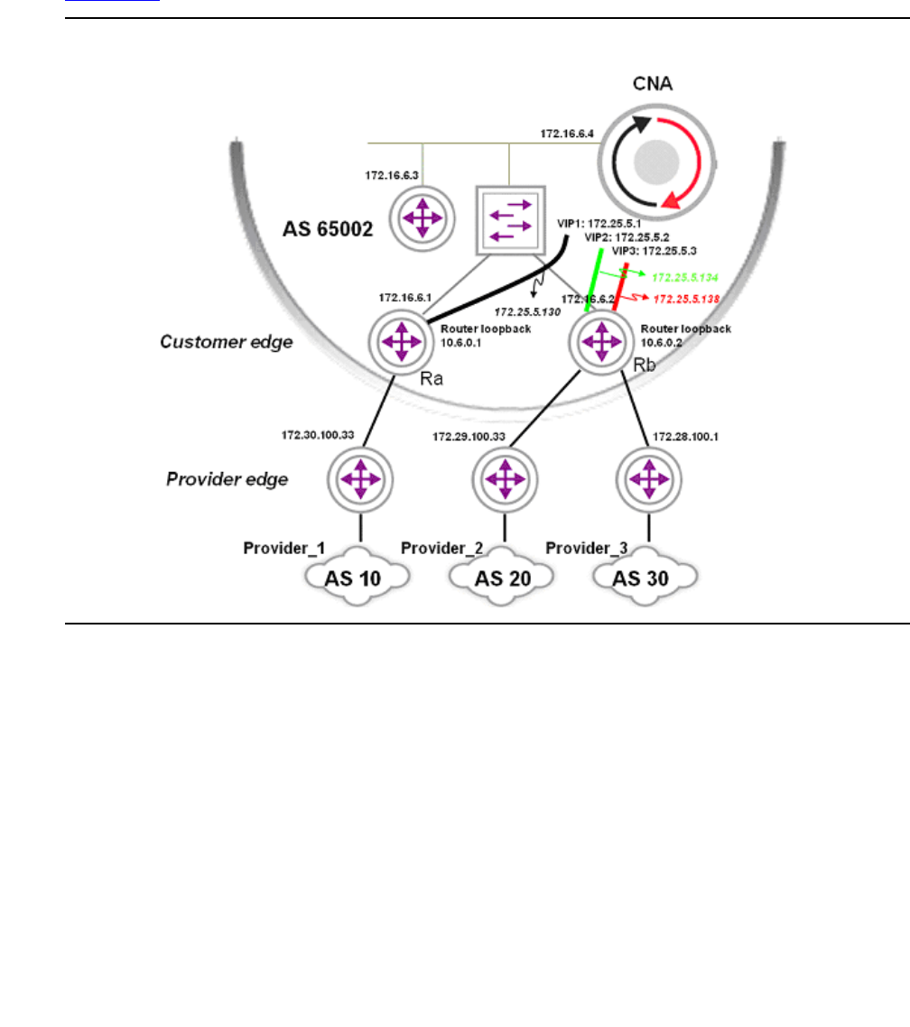

CNA configuration and deployment
474 Avaya Application Solutions IP Telephony Deployment Guide
Configuring CNA
Basic configuration
Configuring Virtual Module Interfaces
Avaya CNA Ethernet interfaces need to be associated with an Ethernet interface and a physical
connection to the network. Once the system has booted and all of its necessary ports are
connected to the network, a terminal or workstation can be connected to the serial console port
on the CNA system.
Using privileged-level access, the user should enter the configure terminal command.
Ethernet Interfaces on Modules
To create an interface, enter the interface command while in config mode. Enter
fastethernet as the type argument. The num argument is 0, while the port arguments
correspond with the labeled Ethernet ports on the system.
To assign an address to the interface, enter the ip address command with a valid IP address
and mask from your network address space. End the configuration of this interface with the end
command. E.g., for the management interface, enter the command to configure Ethernet 0.
Ustat modules will also have to be referred to inside the interface module. (Ustat modules will
be defined on Page 9).
interface fastethernet 0/0
ip address 176.16.6.4 255.255.255.224
module ustat provider_1
module ustat provider_2
module ustat provider_3
end
Default Gateway
A default route needs to be defined for the system so that it knows how to communicate with the
rest of the network:
ip route 0.0.0.0 0.0.0.0 172.16.6.3

Configuring CNA
Issue 4.3 February 2006 475
Service Provider Access Links
Each service provider that is to be managed or monitored by Avaya CNA needs a link object
defined. From config mode, enter engine configuration mode:
module engine
To associate a service provider with a link name, create the links using the link command.
link provider_1
provider-as 10 172.30.100.33
end
link provider_2
provider-as 20 172.29.100.33
end
link provider_3
provider-as 30 172.28.100.1
end
The name provider_1 will be used in the output of various CLI commands and web page
reports. The provider-as command associates the provider_1 link with both the Autonomous
System (AS) number of the corresponding service provider; and the IP address of the provider
edge the enterprise’s edge router is peering with.
BGP on the Engine Module
While still in config-engine mode, enter the bgp command, with the enterprise network’s AS
number as the as-num argument:
bgp 65002
neighbor 172.16.6.1 link provider_1
neighbor 172.16.6.1 remote-as 65002
neighbor 172.16.6.2 link provider_2
neighbor 172.16.6.2 link provider_3
neighbor 172.16.6.2 remote-as 65002
end
A neighbor link command needs to be entered once for each of the links. The command takes
address and name arguments, in the following form: The address argument is the IP address of
an interface on the edge router that connects the enterprise network to the service provider
identified by the name argument.
Also, in order to achieve IBGP peering, the router IP addresses need to be associated with the
enterprise’s AS numbers, using the neighbor remote-as command.

CNA configuration and deployment
476 Avaya Application Solutions IP Telephony Deployment Guide
Assigning USTATs to Providers
module ustat commands now need to be defined for each WAN link:
module ustat provider_1
link provider_1
vip 172.25.5.1
The ustat module specifies the association of the USTAT module to a specific WAN link and the
virtual IP (VIP) address to this WAN link.
USTAT GRE Tunnels
To configure GRE Tunnels for measurements, use the interface tunnel command, then assign
the tunnel to a ustat:
interface tunnel 1
ip address 172.25.5.130 255.255.255.252
tunnel destination 10.6.0.1
end
module ustat provider_1
ip route 10.6.0.1 255.255.255.255 172.16.6.1
ip route 0.0.0.0 0.0.0.0 tunnel1
end
Measurements
In this scenario, we’ll assume that CNA will only measure to and optimize signaling and bearer
targets. We create an address group that contains all signaling targets. We also create an
address group that contains all bearer targets. Then, we create within the engine module active
measurement groups for the signaling and bearer targets, respectively. The respective groups
of addresses are added to the list of targets within the measurement group. The measurement
type, rate, and loss timeout are also specified. It is recommended that high measurement rate of
5 per second, and an aggressive timeout (200 ms) are used, to insure sub-second rescue
times.
group signaling_targets
Prefix signaling_1/32
Prefix signaling_2/32
end
group bearer_targets

Configuring CNA
Issue 4.3 February 2006 477
Prefix bearer_1/32
Prefix bearer_2/32
end
module engine
active-measurement group AM_signaling_targets
type icmp
rate 5 per-second
timeout 200
target group bearer_targets
end
active-measurement group AM_bearer_targets
type icmp
rate 5 per-second
timeout 200
target group bearer_targets
end
end
Decision making
Decision making related commands include:
●turning route optimization on
●specifying a decision policy that includes policy preferences and the appropriate
application model
●applying the decision policy to the corresponding active measurement group
It is also recommended to insure that when no performance problems are detected, CNA
servers on both ends settle on a different link. To get this behavior, one must specify a priority
under the link command and disable “damped-mode” within the decision policy.
module engine
damped-mode disable
link provider_1
winner-set-priority prefer
end
route-assert-mode enable

CNA configuration and deployment
478 Avaya Application Solutions IP Telephony Deployment Guide
route-assert-filter force
decision-policy DP_signaling_targets
set-application-model enterprise
damped-mode disable
end
decision-policy DP_bearer_targets
set-application-model voice
damped-mode disable
end
set-decision-policy DM_signaling_targets active-measurement-group
AM_signaling_targets
set-decision-policy DM_bearer_targets active-measurement-group
AM_bearer_targets
end
Configuring the Routers
The following needs to be added to the enterprise edge routers:
●GRE tunnel interfaces that will connect to the USTAT modules
●route maps for policy routing on the tunnels
●outing between the edge routers and the CNA system, including iBGP peering and
●routing to the USTAT VIPs
For the purposes of describing the CNA configuration process using widely understood
terminology, this documentation assumes a simple, generic network that uses Cisco equipment
as its edge routers and Cisco IOS commands.
Edge Router GRE Tunnel Interfaces
Each CNA USTAT module needs to be associated with a different tunnel interface on the Cisco
router. Referring back to the example in Figure 104, three tunnels are needed. Since there are
three USTAT modules and only two edge routers, two of the tunnels—Tunnel1 and
Tunnel2—will be created on the one edge router, while the third tunnel—Tunnel3—will be
created on the other edge router.

Configuring the Routers
Issue 4.3 February 2006 479
These are the IOS commands needed to set up the GRE tunnel interface on Ra (see
Figure 104):
interface Tunnel1
description GRE to provider_1
ip address 172.25.5.129 255.255.255.252
ip policy route-map provider_1
tunnel source 172.16.6.1
tunnel destination 172.16.6.4
Specifically, here’s what the Cisco commands above do:
●the interface command identifies the tunnel to be created—Tunnel1
●the description command adds the text “GRE to provider_1” to the tunnel configuration
●the ip address command identifies the tunnel IP address as 172.25.5.129
255.255.255.252; this address should be in the same network as the tunnel IP address
specified on the CNA configuration—172.25.5.130 255.255.255.252
●the ip policy command identifies the route map to be used, which we have called
provider_1 (which will be created below, on Page 12); the route map will ensure that traffic
from a given USTAT will be directed to the correct WAN link
●the tunnel source command designates the address of the physical interface on the edge
router—172.16.6.1 (Cisco IOS syntax requires that it be explicitly specified; CNA syntax
has no such requirement—the address is implicitly set to the eth0 interface address of the
USTAT module)
●the tunnel destination command identifies the physical address on the USTAT module
These commands will have to be repeated for each GRE tunnel (one for each USTAT module).
In this example, the remaining two GRE tunnels will have to be configured on Router Rb. (See
Figure 104.)
Route Maps
The tunnel configuration in the previous section referred to a route map called provider_1,
which is created here, along an access list to restrict entry.
Specify the USTAT module’s VIP address in the access list:
ip access list 188 permit ip host 172.25.5.1 any
route-map provider_1 permit 10
match ip address 188
set ip next-hop 172.30.100.33
The USTAT module’s VIP address is specified in the access list. The name of the route map,
provider_1, must match exactly the name used in the ip policy command when the GRE tunnel
interface was created. The set ip next-hop command should point to the address used to
access the ISP being monitored by this USTAT (provider_1, as shown in Figure 104).

CNA configuration and deployment
480 Avaya Application Solutions IP Telephony Deployment Guide
These commands will have to be repeated for each USTAT module/ISP pair; at which point the
configuration would model the network shown in Figure 104.
Routing Configuration
Here, the routing to the USTAT VIPS are configured; the IBGP peering between the edge router
and the CNA system is also configured
VIP Routing:
USTAT modules do not support dynamic routing protocols, so static routes will be used. On
each edge router, you static routes are created to each of the CNA tunnels configured on that
router.
In global config mode on the edge router Ra, the following Cisco IOS command is used:
ip route 172.25.5.1 255.255.255.255 Tunnel1
On the edge router Rb, the following Cisco IOS command is used:
ip route 172.25.5.2 255.255.255.255 Tunnel2
ip route 172.25.5.3 255.255.255.255 Tunnel3
The addresses are the VIPs assigned to each USTAT. Tunnel1 and Tunnel2 coexist on one
edge router; Tunnel3 is alone on the other.
Note:
Note: Note: In order to accommodate asymmetric routing—a situation where a packet
destined for USTATa, which is configured for Tunnel1, arrives at router ER2,
which is configured for Tunnel2—static routes may need to be redistributed into
an interior routing protocol, or additional static routes will have to be placed on
each edge router.
IBGP
On the edge router, the router bgp command is used with the enterprise’s Autonomous
System Number:
router bgp 65002

Configuring the Routers
Issue 4.3 February 2006 481
Route Reflection
The CNA system must be a route reflector client to all of the edge routers that will operate within
the CNA system’s sphere of influence. When multiple edge routers are being configured for
route reflection, a BGP cluster ID is required. The number can be either a 32 bit integer or an IP
address; the same number must be used on each device on which routing tables are to be
placed under the direction of the CNA system.
bgp cluster-id 88
Now the parameters of the IBGP peering configuration from the edge router to the CNA system
need to be defined:
neighbor 172.16.6.4 remote-as 65002
neighbor 172.16.6.4 description IBGP to CNA
neighbor 172.16.6.4 route-reflector-client
neighbor 172.16.6.4 soft-reconfiguration inbound
neighbor 172.16.6.4 weight 200
The IP address used are the same configured on the CNA system. The remote-as command
identifies the peering as IBGP (because the remote AS number matches the AS number in the
bgp command). The description command adds some descriptive text to the configuration. The
route-reflector-client command designates the CNA system as a BGP route reflector client. The
soft-reconfiguration command allows the CNA system to make changes to the BGP
configuration without a session reset.
The weight command assigns a high value to the CNA system, which causes the edge router to
prefer the CNA system’s routing assertions over the natural BGP route selection. This
assignment is non-transitive, which means that the weighting is not communicated to other
IBGP or EBGP peers. The weight attribute is local to this router only. In the example, weight is
set to 200. The actual setting will be dependent on the local policies; the weight value should be
high enough to prevail over those policies.
Note:
Note: The CNA system has a built-in precaution that prevents its route assertions from
leaking beyond your edge router’s borders. The no-export attribute is always set
in all CNA BGP routing updates. This is not user configurable. This attribute
prohibits the router from passing routes that it has learned from the CNA system
to routers outside the local AS.

CNA configuration and deployment
482 Avaya Application Solutions IP Telephony Deployment Guide
Command summary
All of the CNA and router configuration commands described in this document are listed in this
section. For more information, please refer to the CNA administrative guide.
CNA commands
interface fastethernet 0/0
ip address 176.16.6.4 255.255.255.224
module ustat provider_1
module ustat provider_2
module ustat provider_3
end
interface tunnel 1
ip address 172.25.5.130 255.255.255.252
tunnel destination 10.6.0.1
end
interface tunnel 2
ip address 172.25.5.134 255.255.255.252
tunnel destination 10.6.0.2
end
interface tunnel 3
ip address 172.25.5.138 255.255.255.252
tunnel destination 10.6.0.2
end
ip route 0.0.0.0 0.0.0.0 172.16.6.3
group IPSI_targets
Prefix ISPI_1/32
Prefix IPSI_2/32
end
module engine
damped-mode disable
route-assert-mode enable

Command summary
Issue 4.3 February 2006 483
route-assert-filter force
link provider_1
provider-as 10 172.30.100.33
winner-set-priority prefer
end
link provider_2
provider-as 20 172.29.100.33
end
link provider_3
provider-as 30 172.28.100.1
end
bgp 65002
neighbor 172.16.6.1 link provider_1
neighbor 172.16.6.1 remote-as 65002
neighbor 172.16.6.2 link provider_2
neighbor 172.16.6.2 link provider_3
neighbor 172.16.6.2 remote-as 65002
end
active-measurement group AM_IPSI_targets
type icmp
rate 5 per-second
timeout 200
target group IPSI_targets
end
decision-policy DP_IPSI_targets
set-application-model enterprise
damped-mode disable
end
set-decision-policy DM_IPSI_targets active-measurement-group
AM_IPSI_targets
end
end
module ustat provider_1
link provider_1

CNA configuration and deployment
484 Avaya Application Solutions IP Telephony Deployment Guide
vip 172.25.5.1
ip route 10.6.0.1 255.255.255.255 172.16.6.1
ip route 0.0.0.0 0.0.0.0 tunnel1
end
module ustat provider_2
link provider_2
vip 172.25.5.2
ip route 10.6.0.2 255.255.255.255 172.16.6.2
ip route 0.0.0.0 0.0.0.0 tunnel2
end
module ustat provider_3
link provider_3
vip 172.25.5.3
ip route 10.6.0.2 255.255.255.255 172.16.6.2
ip route 0.0.0.0 0.0.0.0 tunnel3
end
Router Ra commands
interface Tunnel1
description GRE to provider_1
ip address 172.25.5.129 255.255.255.252
ip policy route-map provider_1
tunnel source 172.16.6.1
tunnel destination 172.16.6.4
ip access list 188 permit ip host 172.25.5.1 any
route-map provider_1 permit 10
match ip address 188
set ip next-hop 172.30.100.33
ip route 172.25.5.1 255.255.255.255 Tunnel1
router bgp 65002
bgp cluster-id 88
neighbor 172.16.6.4 remote-as 65002
neighbor 172.16.6.4 description IBGP to CNA

Command summary
Issue 4.3 February 2006 485
neighbor 172.16.6.4 route-reflector-client
neighbor 172.16.6.4 soft-reconfiguration inbound
neighbor 172.16.6.4 weight 200
Router Rb commands
interface Tunnel2
description GRE to provider_2
ip address 172.25.5.133 255.255.255.252
ip policy route-map provider_2
tunnel source 172.16.6.2
tunnel destination 172.16.6.4
interface Tunnel3
description GRE to provider_3
ip address 172.25.5.137 255.255.255.252
ip policy route-map provider_3
tunnel source 172.16.6.2
tunnel destination 172.16.6.4
ip access list 189 permit ip host 172.25.5.2 any route-map provider_2
permit 20
match ip address 189
set ip next-hop 172.29.100.33
ip access list 190 permit ip host 172.25.5.3 any route-map provider_3
permit 30
match ip address 190
set ip next-hop 172.28.100.1
ip route 172.25.5.2 255.255.255.255 Tunnel2
ip route 172.25.5.3 255.255.255.255 Tunnel3
router bgp 65002
bgp cluster-id 88
neighbor 172.16.6.4 remote-as 65002
neighbor 172.16.6.4 description IBGP to CNA
neighbor 172.16.6.4 route-reflector-client
neighbor 172.16.6.4 soft-reconfiguration inbound
neighbor 172.16.6.4 weight 200
This completes the CNA configuration for the scenario referenced in Figure 104: Detailed
configuration scenario on page 473.

CNA configuration and deployment
486 Avaya Application Solutions IP Telephony Deployment Guide

Issue 4.3 February 2006 487
Index
Index
Numerical
1152A1 Power Unit . . . . . . . . . . . . . . . . 143
A
API . . . . . . . . . . . . . . . . . . . . . . . . 134
ASB button
G250 . . . . . . . . . . . . . . . . . . . . . 53
Asynchronous Transfer Mode. . . . . . . . . . . . 77
ATM . . . . . . . . . . . . . . . . . . . . . . . 77
audio conferencing. . . . . . . . . . . . . . . . . 121
AUDIX . . . . . . . . . . . . . . . . . . . . . . 43
availability
S8700 series server complex . . . . . . . . . . 272
Avaya Application Solutions platforms . . . . . . . . 35
Avaya IP Office . . . . . . . . . . . . . . . . . 96
mid-market to large enterprise . . . . . . . . . . 65
small to mid-size . . . . . . . . . . . . . . . . 39
Avaya communication devices . . . . . . . . . . . 28
analog telephones . . . . . . . . . . . . . . . 28
DEFINITY Wireless DECT System. . . . . . . . 28
digital telephones . . . . . . . . . . . . . . . . 28
Extension to Cellular Application. . . . . . . . . 28
IP Agent . . . . . . . . . . . . . . . . . . . . 28
IP Softphone . . . . . . . . . . . . . . . . . . 28
IP Softphone for Pocket PC . . . . . . . . . . . 28
IP telephones. . . . . . . . . . . . . . . . . . 28
SIP IP telephones . . . . . . . . . . . . . . . 28
Wireless Telephone Solutions . . . . . . . . . . 28
Avaya Communication Manager . . . . . . . . . . 25
Avaya Integrated Management . . . . . . 27, 247, 251
Avaya IP Agent . . . . . . . . . . . . . . . . . . 149
Avaya IP Softphone . . . . . . . . . . . . . . . . 147
for Pocket PC . . . . . . . . . . . . . . . . . 150
Avaya Media Gateways . . . . . . . . . . . . . . 27
Avaya security designs
built-in Linux security features . . . . . . . . . . 219
data encryption . . . . . . . . . . . . . . . . . 223
LAN isolation configurations . . . . . . . . . . . 223
monitoring and alarming. . . . . . . . . . . . . 222
one-time passwords . . . . . . . . . . . . . . 220
remote access . . . . . . . . . . . . . . . . . 221
root access. . . . . . . . . . . . . . . . . . . 221
secure access . . . . . . . . . . . . . . . . . 222
shell access . . . . . . . . . . . . . . . . . . 220
virus and worm protection . . . . . . . . . . . . 226
Avaya servers
DEFINITY. . . . . . . . . . . . . . . . . . . . 26
Linux-based media servers . . . . . . . . . . . 25
Avaya Site Administration . . . . . . . . . . . . . 250
Avaya Softconsole . . . . . . . . . . . . . . . . 150
Avaya telephones . . . . . . . . . . . . . . . . 147
B
bandwidth
and Call Admission Control . . . . . . . . . . 206
IP . . . . . . . . . . . . . . . . . . . . . . 206
bearer and signaling separation . . . . . . . . . . 122
bearer duplication . . . . . . . . . . . . . . . . 267
BSR . . . . . . . . . . . . . . . . . . . . . . . 135
business continuity
S8700 server separation . . . . . . . . . . . . 278
Buttons
ASB (G250). . . . . . . . . . . . . . . . . . . 53
RST (G250). . . . . . . . . . . . . . . . . . . 53
C
C360 LAN switch . . . . . . . . . . . . . . . . . 137
Call Admission Control . . . . . . . . . . . . . . 206
Call Center. . . . . . . . . . . . . . . . . . . . . 28
call processing . . . . . . . . . . . . . . . . . . .117
alternate gatekeeper list . . . . . . . . . . . . .119
features. . . . . . . . . . . . . . . . . . . . .117
gatekeepers . . . . . . . . . . . . . . . . . .119
modem/FAX/TTY over IP . . . . . . . . . . . 123
multi-location . . . . . . . . . . . . . . . . . 123
RAS protocol . . . . . . . . . . . . . . . . . .119
registration . . . . . . . . . . . . . . . . . . .119
signaling . . . . . . . . . . . . . . . . . . . 120
call signaling . . . . . . . . . . . . . . . . . . . 120
call usage rates . . . . . . . . . . . . . . . . . 173
COIs for multiple-site networks . . . . . . . . . 187
communities of interest . . . . . . . . . . . . 173
expanded COI matrices . . . . . . . . . . . . 181
CCA port
G250 . . . . . . . . . . . . . . . . . . . . . . 53
Center Stage Switch . . . . . . . . . . . . . . . . 77
change control . . . . . . . . . . . . . . . . . . 427
emergency change management . . . . . . . . 440
high-level process flow. . . . . . . . . . . . . 430
managing . . . . . . . . . . . . . . . . . . . 429
performance indicators . . . . . . . . . . . . 443
planning . . . . . . . . . . . . . . . . . . . 428

488 Avaya Application Solutions IP Telephony Deployment Guide
Index
C-LAN . . . . . . . . . . . . . . . . . . . . . . 71
Class of Service (CoS) . . . . . . . . . . . . . . . 355
CMS . . . . . . . . . . . . . . . . . . . . . . . 133
CNOCL . . . . . . . . . . . . . . . . . . . . . . 400
codecs . . . . . . . . . . . . . . . . . . . . . . 241
communication applications . . . . . . . . . . . . 133
application programming interfaces . . . . . . . 134
Avaya Call Management System . . . . . . . . 133
best services routing . . . . . . . . . . . . . . 135
call center . . . . . . . . . . . . . . . . . . . 133
computer telephony integration . . . . . . . . . 134
meet-me conferencing . . . . . . . . . . . . . 135
Communication Manager . . . . . . . . . . . . . . 99
capabilities . . . . . . . . . . . . . . . . . . . 117
Compact Call Center . . . . . . . . . . . . . . . . 29
Computer Telephony Integration . . . . . . . . . . 29
Conferencing systems . . . . . . . . . . . . . . . 30
Console port
G250 . . . . . . . . . . . . . . . . . . . . . 53
Control LAN . . . . . . . . . . . . . . . . . . . . 71
control network C . . . . . . . . . . . . . . 383, 402
Control Network on Customer LAN . . . . . . . . . 400
CoS. . . . . . . . . . . . . . . . . . . . . . . . 355
critical reliability . . . . . . . . . . . . . . . . . . 267
CSS . . . . . . . . . . . . . . . . . . . . . . . 77
CTI . . . . . . . . . . . . . . . . . . . . . . 29, 134
D
data network implementation . . . . . . . . . . . . 379
S8300/G700/G350 (ICC) . . . . . . . . . . . . 390
S8700 IP connect. . . . . . . . . . . . . . . . 384
S8700 multi-connect . . . . . . . . . . . . . . 380
S8700/S8300 LSP . . . . . . . . . . . . . . . 389
sample multi-connect deployment . . . . . . . . 391
DHCP. . . . . . . . . . . . . . . . . . . . . . . 459
generic setup tasks . . . . . . . . . . . . . . . 460
required information. . . . . . . . . . . . . . . 459
simple configuration. . . . . . . . . . . . . . . 459
software alternatives . . . . . . . . . . . . . . 460
Windows 2000 . . . . . . . . . . . . . . . . . 466
Windows NT 4.0 . . . . . . . . . . . . . . . . 462
Differentiated Services (DiffServ) . . . . . . . . . . 361
DiffServ . . . . . . . . . . . . . . . . . . . . . . 361
disaster recovery
S8700 server separation . . . . . . . . . . . . 278
DTMF tone handling . . . . . . . . . . . . . . . . 121
duplicated bearer . . . . . . . . . . . . . . . . . 267
E
embedded messaging . . . . . . . . . . . . . . . 43
Emergency Transfer Relay, see ETR
enterprise survivable servers . . . . . . . . . . . 388
ESS . . . . . . . . . . . . . . . . . . . . . . . 388
ETH LAN POE ports, G250 . . . . . . . . . . . . . 53
ETH WAN port
G250 . . . . . . . . . . . . . . . . . . . . . . 53
ETR (Emergency Transfer Relay)
ports used (G250) . . . . . . . . . . . . . . . . 53
ports used (G350) . . . . . . . . . . . . . . . . 53
F
Fax over IP. . . . . . . . . . . . . . . . . . . . 123
Front panel
G250-BRI. . . . . . . . . . . . . . . . . . . . 52
G
G150
back panel . . . . . . . . . . . . . . . . . . . 59
G150 Media Gateway. . . . . . . . . . . . . . . . 55
G250 Media Gateway. . . . . . . . . . . . . . . . 45
configurations . . . . . . . . . . . . . . . . . . 52
G250-BRI
front panel . . . . . . . . . . . . . . . . . . . 52
physical description . . . . . . . . . . . . . . . 52
G350 Media Gateway. . . . . . . . . . . . . . 39, 45
configurations . . . . . . . . . . . . . . . . . . 48
front panel buttons. . . . . . . . . . . . . . . . 50
functions and capacities . . . . . . . . . . . . . 51
specifications . . . . . . . . . . . . . . . . . . 49
supported media modules . . . . . . . . . . . . 50
G700 Media Gateway. . . . . . . . . . . . . . . . 39
hardware architecture . . . . . . . . . . . . . . 40
processor . . . . . . . . . . . . . . . . . . . . 42
Greenfield deployment . . . . . . . . . . . . . . . 97
circuit packs. . . . . . . . . . . . . . . . . . 104
communication devices . . . . . . . . . . . . 107
Communication Manager . . . . . . . . . . . . 99
components. . . . . . . . . . . . . . . . . . . 97
configurations . . . . . . . . . . . . . . . . . 100
H.323 gatekeeper . . . . . . . . . . . . . . . . 98
media gateways. . . . . . . . . . . . . . . . . 99
medium-to-large enterprise . . . . . . . . . . 101
port networks . . . . . . . . . . . . . . . . . . 99
small-to-midsize enterprise. . . . . . . . . . . 100
H
H.323 messaging. . . . . . . . . . . . . . . . . . 43
hardware
back panel of G150 . . . . . . . . . . . . . . . 59
WAN interface cards. . . . . . . . . . . . . . . 59

Issue 4.3 February 2006 489
Index
high availability, design for . . . . . . . . . . . . . 300
assessment methodology . . . . . . . . . . . . 301
data network availability . . . . . . . . . . . . . 306
geographically distributed example. . . . . . . . 307
Case I Standard config. . . . . . . . . . . . 308
Case IV 99.999% full system . . . . . . . . . 313
hardware availability . . . . . . . . . . . . . . 302
software availability . . . . . . . . . . . . . . . 305
HP Openview Network Node Manager . . . . . . . 256
I
IA770 INTUITY AUDIX . . . . . . . . . . . . . . . 43
implementing Communication Manager . . . . . . . 379
S8300/G700/G350 (ICC) . . . . . . . . . . . . 390
S8700 IP connect. . . . . . . . . . . . . . . . 384
S8700 multi-connect . . . . . . . . . . . . . . 380
S8700/S8300 LSP . . . . . . . . . . . . . . . 389
sample multi-connect deployment . . . . . . . . 391
Integrated Management applications . . . . . 247, 248
monitoring management applications . . . . . . 250
network
Device Managers . . . . . . . . . . . . . . 254
Network Configuration Manager . . . . . . . 252
Network Management Console and
System View. . . . . . . . . . . . . . . . 252
Provisioning and Installation Manager (PIM). . 254
QoS Manager . . . . . . . . . . . . . . . . 252
Secure Access Administration . . . . . . . . 253
SMON Manager . . . . . . . . . . . . . . . 253
Software Update Manager . . . . . . . . . . 253
VLAN Manager . . . . . . . . . . . . . . . 253
system
Fault and Performance Manager . . . . . . . 249
Integrated Management Database . . . . . . 249
Proxy Agent. . . . . . . . . . . . . . . . . 249
Site Administration. . . . . . . . . . . . . . 250
Voice Administration Manager . . . . . . . . 250
INTUITY AUDIX . . . . . . . . . . . . . . . . . . 43
IP Agent. . . . . . . . . . . . . . . . . . . . . . 149
IP evolution . . . . . . . . . . . . . . . . . . . . 109
IP Media Processor . . . . . . . . . . . . . . . . 72
IP Server Interface . . . . . . . . . . . . . . . . . 71
IP signaling . . . . . . . . . . . . . . . . . . . . 70
IP softphone. . . . . . . . . . . . . . . . . . . . 147
IP Softphone for Pocket PC. . . . . . . . . . . . . 150
IP telephony circuit pack security . . . . . . . . . . 228
TN2302 Media Processor (MedPro) . . . . . . . 229
TN2312BP IP server interface (IPSI) . . . . . . . 228
TN799 Control LAN (C-LAN) . . . . . . . . . . 230
IP trunks . . . . . . . . . . . . . . . . . . . . . 125
signaling . . . . . . . . . . . . . . . . . . . 126
signaling group members . . . . . . . . . . . 126
SIP trunk capacities . . . . . . . . . . . . . . 126
tie trunks . . . . . . . . . . . . . . . . . . . 126
ISDN BRI TRUNK port . . . . . . . . . . . . . . . 53
L
LAN
ETH LAN POE ports (G250) . . . . . . . . . . . 53
LAN switches . . . . . . . . . . . . . . . . . . 137
C360 . . . . . . . . . . . . . . . . . . . . . 137
converged infrastructure . . . . . . . . . . 137, 377
LINE ports
G250 . . . . . . . . . . . . . . . . . . . . . . 53
Local Survivable Processor . . . . . . . . . . . . . 45
LSP
S8300 . . . . . . . . . . . . . . . . . . . . . 45
M
maintenance architecture
IP endpoint and remote media gateway recovery 297
software and recovery . . . . . . . . . . . . . 268
software failure recovery levels. . . . . . . . . 269
management applications
Device Managers . . . . . . . . . . . . . . . 254
Fault and Performance Manager (FPM). . . . . 249
HP OpenView Network Node Manager . . . . . 256
Integrated Management . . . . . . . . . . . . 248
Integrated Management Database (IMD) . . . . 249
monitoring management . . . . . . . . . . . . 250
Mutli Router Traffic Grapher . . . . . . . . . . 255
Network Configuration Manager . . . . . . . . 252
network management . . . . . . . . . . . . . 251
Network Management Console and System View 252
Provisioning and Installation (PIM) . . . . . . . 254
Proxy Agent. . . . . . . . . . . . . . . . . . 249
QoS Manager . . . . . . . . . . . . . . . . . 252
Secure Access Administration . . . . . . . . . 253
Site Administration . . . . . . . . . . . . . . 250
SMON Manager. . . . . . . . . . . . . . . . 253
Software Update Manager . . . . . . . . . . . 253
system management . . . . . . . . . . . . . 248
third-party. . . . . . . . . . . . . . . . . . . 255
VLAN Manager . . . . . . . . . . . . . . . . 253
Voice Administration Manager . . . . . . . . . 250
VoIP Monitoring Manager . . . . . . . . . . . 251
management models . . . . . . . . . . . . . . . 256
centralized (hybrid) . . . . . . . . . . . . . . 258
distributed (component) . . . . . . . . . . . . 257

490 Avaya Application Solutions IP Telephony Deployment Guide
Index
media gateway
G350 . . . . . . . . . . . . . . . . . . . . . 39
G700 . . . . . . . . . . . . . . . . . . . . . 39
Media Gateways. . . . . . . . . . . . . . . . . . 74
MCC1 . . . . . . . . . . . . . . . . . . . . . 74
non-IPSI connected. . . . . . . . . . . . . . . 76
remote G150 . . . . . . . . . . . . . . . . . . 77
remote G250 . . . . . . . . . . . . . . . . . . 77
remote G350 . . . . . . . . . . . . . . . . . . 77
remote G700 . . . . . . . . . . . . . . . . . . 77
remote MCC1/SCC1 . . . . . . . . . . . . . . 76
SCC1 . . . . . . . . . . . . . . . . . . . . . 75
media processing . . . . . . . . . . . . . . . . . 190
media processor capacities. . . . . . . . . . . . . 200
media server
S8300 . . . . . . . . . . . . . . . . . . . . . 39
media stream handling
audio conferencing . . . . . . . . . . . . . . . 121
DTMF tone handling . . . . . . . . . . . . . . 121
media processing . . . . . . . . . . . . . . . . 121
messaging . . . . . . . . . . . . . . . . . . . . 29
H.323 . . . . . . . . . . . . . . . . . . . . . 43
midspan power unit . . . . . . . . . . . . . . . . 143
mixed PNC
ESS support . . . . . . . . . . . . . . . . . . 95
mixed port network connectivity . . . . . . . . . . . 383
mobility . . . . . . . . . . . . . . . . . . . . . . 132
extension to cellular. . . . . . . . . . . . . . . 132
IP telephones or IP Softphones . . . . . . . . . 132
modem over IP . . . . . . . . . . . . . . . . . . 123
monitoring management applications
VoIP Monitoring Manager . . . . . . . . . . . . 251
Multi Router Traffic Grapher . . . . . . . . . . . . 255
multi-location call processing . . . . . . . . . . . . 123
multi-VLAN
example . . . . . . . . . . . . . . . . . . . . 453
IP telephone configuration. . . . . . . . . 453, 457
PC configuration . . . . . . . . . . . . . . . . 458
N
NAT. . . . . . . . . . . . . . . . . . . . . 324, 353
network address translation (NAT) . . . . . . 324, 353
network assessment . . . . . . . . . . . . . . . . 415
Network Configuration Manager . . . . . . . . . . 252
network design . . . . . . . . . . . . . . . . . . 325
IP addressing. . . . . . . . . . . . . . . . . . 332
IP terminals deployment. . . . . . . . . . . . . 334
LAN issues. . . . . . . . . . . . . . . . . . . 325
network address translation (NAT) . . . . . . . . 353
virtual private networks . . . . . . . . . . . . . 349
WAN. . . . . . . . . . . . . . . . . . . . . . 344
frame relay . . . . . . . . . . . . . . . . . 347
network engineering . . . . . . . . . . . . . . . 319
best practices . . . . . . . . . . . . . . . . . 323
common issues . . . . . . . . . . . . . . . . 324
access lists . . . . . . . . . . . . . . . . 324
analog dial-up . . . . . . . . . . . . . . . 324
hub-based network . . . . . . . . . . . . . 324
multiple subnets on VLAN . . . . . . . . . 324
network address translation (NAT) . . . . . 324
non-hierarchical network . . . . . . . . . . 324
virtual private network (VPN) . . . . . . . . 324
hierarchy . . . . . . . . . . . . . . . . . . . 320
management . . . . . . . . . . . . . . . . . 321
voice quality. . . . . . . . . . . . . . . . . . 321
WAN technologies. . . . . . . . . . . . . . . 321
network management applications . . . . . . . . . 251
Device Managers . . . . . . . . . . . . . . . 254
HP OpenView Network Node Manager . . . . . 256
Mutli Router Traffic Grapher . . . . . . . . . . 255
Network Configuration Manager . . . . . . . . 252
Network Management Console and System View 252
Provisioning and Installation Manager (PIM). . . 254
QoS Manager . . . . . . . . . . . . . . . . . 252
Secure Access Administration . . . . . . . . . 253
SMON Manager. . . . . . . . . . . . . . . . 253
Software Update Manager . . . . . . . . . . . 253
third-party. . . . . . . . . . . . . . . . . . . 255
VLAN Manager . . . . . . . . . . . . . . . . 253
Network Management Console and System View. . 252
network management models . . . . . . . . . . . 256
network readiness assessment . . . . . . . . . . 415
basic . . . . . . . . . . . . . . . . . . . 415, 416
detailed . . . . . . . . . . . . . . . . . . 416, 418
network recovery . . . . . . . . . . . . . . . . . 405
change control . . . . . . . . . . . . . . . . 405
convergence times . . . . . . . . . . . . . . 409
dial backup . . . . . . . . . . . . . . . . . . 408
layer 2 mechanisms . . . . . . . . . . . . . . 406
layer 3 mechanisms . . . . . . . . . . . . . . 407
networking . . . . . . . . . . . . . . . . . . . . .118
call routing . . . . . . . . . . . . . . . . . . .118
H.248 media gateway control . . . . . . . . . .118
IP connectivity . . . . . . . . . . . . . . . . .118
P
packet loss. . . . . . . . . . . . . . . . . . . . 237
network . . . . . . . . . . . . . . . . . . . . 238
packet loss concealment (PLC). . . . . . . . . 239
PDU . . . . . . . . . . . . . . . . . . . . . . . 143
Physical description
G250-BRI. . . . . . . . . . . . . . . . . . . . 52
PIM . . . . . . . . . . . . . . . . . . . . . . . 254
PLC . . . . . . . . . . . . . . . . . . . . . . . 237

Issue 4.3 February 2006 491
Index
POE . . . . . . . . . . . . . . . . . . . . . . . 143
POE switches . . . . . . . . . . . . . . . . . . . 141
C360. . . . . . . . . . . . . . . . . . . . . . 142
Ports
CCA (G250) . . . . . . . . . . . . . . . . . . 53
Console (G250) . . . . . . . . . . . . . . . . 53
ETH LAN POE (G250) . . . . . . . . . . . . . 53
ETH WAN (G250) . . . . . . . . . . . . . . . 53
ISDN BRI TRUNK (G250) . . . . . . . . . . . . 53
LINE (G250) . . . . . . . . . . . . . . . . . . 53
TRUNK (G250) . . . . . . . . . . . . . . . . . 53
USB (G250) . . . . . . . . . . . . . . . . . . 53
Power over Ethernet . . . . . . . . . . . . . . . . 144
fixed ports (G250) . . . . . . . . . . . . . . . 53
switches . . . . . . . . . . . . . . . . . . . . 144
processor ethernet applications . . . . . . . . . . . 96
Provisioning and Installation Manager (PIM) . . . . . 254
Proxy Agent (PA) . . . . . . . . . . . . . . . . . 249
Q
QoS. . . . . . . . . . . . . . . . . . . . . . . . 355
Qos Manager . . . . . . . . . . . . . . . . . . . 252
Quality of Service (QoS) . . . . . . . . . . . . . . 355
Class of Service (CoS) . . . . . . . . . . . . . 355
differentiated services (DiffServ) . . . . . . . . . 361
Examples . . . . . . . . . . . . . . . . . . . 372
fragmentation. . . . . . . . . . . . . . . . . . 367
FRF.12 . . . . . . . . . . . . . . . . . . . 368
LFI . . . . . . . . . . . . . . . . . . . . . 368
MTU . . . . . . . . . . . . . . . . . . . . 367
guidelines . . . . . . . . . . . . . . . . . . . 355
IEEE 802.1 p/Q. . . . . . . . . . . . . . . . . 360
layer 2 QoS . . . . . . . . . . . . . . . . . . 357
layer 3 QoS . . . . . . . . . . . . . . . . . . 357
queuing methods
CB-WFQ/LLQ/CBQ . . . . . . . . . . . . . 365
PQ . . . . . . . . . . . . . . . . . . . . . 364
RED/WRED. . . . . . . . . . . . . . . . . 365
round-robin . . . . . . . . . . . . . . . . . 365
WFQ . . . . . . . . . . . . . . . . . . . . 364
real time protocol (RTP) . . . . . . . . . . . . . 368
resource reservation protocol (RSVP) . . . . . . 363
traffic shaping and policing . . . . . . . . . . . 366
frame relay . . . . . . . . . . . . . . . . . 366
R
real time protocol (RTP) . . . . . . . . . . . . . . 368
reliability . . . . . . . . . . . . . . . . . . . . . 263
availability . . . . . . . . . . . . . . . . . . . 264
Avaya DEFINITY Server CSI . . . . . . . . . . 276
Avaya DEFINITY Server R . . . . . . . . . . . 276
Avaya Linux servers . . . . . . . . . . . . . . 271
reliability, (continued)
Avaya S8300 Media Server with G350 or
G700 Media Gateway . . . . . . . . . . . . 275
Avaya S8500 Media Server . . . . . . . . . . 274
Avaya S8700 Media Server complex
MCC1 and SCC1 multi-connect . . . . . . . 273
reliability configurations . . . . . . . . . . . . . . . 78
critical . . . . . . . . . . . . . . . . . . .82, 267
high . . . . . . . . . . . . . . . . . . . . . . 80
standard . . . . . . . . . . . . . . . . . . . . 78
resource reservation protocol (RSVP) . . . . . . . 363
restarts . . . . . . . . . . . . . . . . . . . . . 269
Communication Manager . . . . . . . . . . . 270
linux operating system . . . . . . . . . . . . . 270
single process. . . . . . . . . . . . . . . . . 269
system cold . . . . . . . . . . . . . . . . . . 270
system warm . . . . . . . . . . . . . . . . . 270
RST button
G250 . . . . . . . . . . . . . . . . . . . . . . 53
RSVP . . . . . . . . . . . . . . . . . . . . . . 363
RTP . . . . . . . . . . . . . . . . . . . . . . . 368
S
S8300 Media Server . . . . . . . . . . . . . . . . 39
S8300 primary controller architecture . . . . . . . . 44
S8400 Media Server . . . . . . . . . . . . . . . . 61
S8500 Media Server . . . . . . . . . . . . . . . . 65
capacities. . . . . . . . . . . . . . . . . . . . 65
S8700 Media Server, fiber connect configuration . . . 65
S8700-series Media Server . . . . . . . . . . . . . 66
control network . . . . . . . . . . . . . . . . . 69
external features . . . . . . . . . . . . . . . . 66
Fiber-Connect survivability . . . . . . . . . . . . 82
internal hardware elements . . . . . . . . . . . 67
IP-Connect configuration. . . . . . . . . . . 82, 87
other components . . . . . . . . . . . . . . . . 68
S8700-series Media Server IP-Connect configuration
main components . . . . . . . . . . . . . . . . 84
reliability . . . . . . . . . . . . . . . . . . . . 86
S8720 Media Server . . . . . . . . . . . . . . . . 95
SBS . . . . . . . . . . . . . . . . . . . . . . . 122
Secure Access Administration . . . . . . . . . . . 253
security . . . . . . . . . . . . . . . . . . . . . 217
Avaya security designs . . . . . . . . . . . . 219
IP telephony circuit pack . . . . . . . . . . . . 228
security policy. . . . . . . . . . . . . . . . . 217
toll fraud . . . . . . . . . . . . . . . . . . . 230
security gateways . . . . . . . . . . . . . . . . 144
separation of bearer and signaling . . . . . . . . . 122
SES . . . . . . . . . . . . . . . . . . . . . . . 128
shuffling . . . . . . . . . . . . . . . . . . . . . 203
signal levels . . . . . . . . . . . . . . . . . . . 240
echo and signal levels . . . . . . . . . . . . . 241
tone levels . . . . . . . . . . . . . . . . . . 241

492 Avaya Application Solutions IP Telephony Deployment Guide
Index
SIP . . . . . . . . . . . . . . . . . . . . . . . . 127
Enablement server . . . . . . . . . . . . . . . 128
SIP trunk capacities . . . . . . . . . . . . . . . . 126
Site Administration . . . . . . . . . . . . . . . . . 250
SMON Manager . . . . . . . . . . . . . . . . . . 253
Softconsole . . . . . . . . . . . . . . . . . . . . 150
Software Update Manager . . . . . . . . . . . . . 253
system management
applications . . . . . . . . . . . . . . . . . . 248
system management applications
Fault and Performance Manager. . . . . . . . . 249
Integrated Management Database . . . . . . . . 249
Proxy Agent . . . . . . . . . . . . . . . . . . 249
Site Administration . . . . . . . . . . . . . . . 250
Voice Administration Manager . . . . . . . . . . 250
T
telephones . . . . . . . . . . . . . . . . . . . . 147
Terminals
Avaya IP Softphone. . . . . . . . . . . . . . . 147
digital telephone . . . . . . . . . . . . . . . 149
instant messaging . . . . . . . . . . . . . . 149
IP telephone . . . . . . . . . . . . . . . . 148
road warrior . . . . . . . . . . . . . . . . . 148
telecommuter . . . . . . . . . . . . . . . . 148
terminals . . . . . . . . . . . . . . . . . . . . . 147
TFTP . . . . . . . . . . . . . . . . . . . . . . . 470
Avaya TFTP (Suite Pro) setup . . . . . . . . . . 471
generic setup tasks . . . . . . . . . . . . . . . 470
TN2302AP . . . . . . . . . . . . . . . . . . . . 72
TN2312AP . . . . . . . . . . . . . . . . . . . . 71
TN2602AP . . . . . . . . . . . . . . . . . . . . 72
TN799DP . . . . . . . . . . . . . . . . . . . . . 71
Toll fraud
Avaya security design. . . . . . . . . . . . . . 231
hacking methods . . . . . . . . . . . . . . . . 231
toll fraud. . . . . . . . . . . . . . . . . . . . . . 230
additional resources . . . . . . . . . . . . . . 232
indemnification . . . . . . . . . . . . . . . . . 232
your responsibilities. . . . . . . . . . . . . . . 232
traffic design inputs . . . . . . . . . . . . . . . . 168
endpoint specifications . . . . . . . . . . . . . 170
endpoint traffic usage . . . . . . . . . . . . . . 170
topology . . . . . . . . . . . . . . . . . . . . 168
traffic grapher . . . . . . . . . . . . . . . . . . . 255
traffic resource sizing. . . . . . . . . . . . . . . . 188
final checks and adjustments . . . . . . . . . . 215
IP bandwidth and call admission control . . . . . 206
media processing and TDM . . . . . . . . . . . 190
physical resource placement . . . . . . . . . . 215
processing occupancy . . . . . . . . . . . . . 201
signalling. . . . . . . . . . . . . . . . . . . . 189
TRUNK port
G250 . . . . . . . . . . . . . . . . . . . . . . 53
trunks
IP . . . . . . . . . . . . . . . . . . . . . . 125
IP tie . . . . . . . . . . . . . . . . . . . . . 126
SIP . . . . . . . . . . . . . . . . . . . . . . 126
TTY over IP . . . . . . . . . . . . . . . . . . . 123
U
Unified Communication Center . . . . . . . . . . . 30
USB port
G250 . . . . . . . . . . . . . . . . . . . . . . 53
V
VAL . . . . . . . . . . . . . . . . . . . . . . . . 43
virtual private network. . . . . . . . . . . . . . . 324
virtual private network (VPN) . . . . . . . . . . . 349
VLAN Manager. . . . . . . . . . . . . . . . . . 253
Voice Administration Manager. . . . . . . . . . . 250
Voice Announcement over the LAN . . . . . . . . . 43
voice quality . . . . . . . . . . . . . . . . . . . 235
codecs . . . . . . . . . . . . . . . . . . . . 241
delay . . . . . . . . . . . . . . . . . . . . . 235
echo . . . . . . . . . . . . . . . . . . . . . 239
jitter . . . . . . . . . . . . . . . . . . . . . 237
packet loss . . . . . . . . . . . . . . . . . . 237
signal levels. . . . . . . . . . . . . . . . . . 240
silence suppression/VAD . . . . . . . . . . . 243
transcoding/tandeming. . . . . . . . . . . . . 244
VoIP Monitoring Manager . . . . . . . . . . . . . 251
VPN . . . . . . . . . . . . . . . . . . . . . 324, 349
Client . . . . . . . . . . . . . . . . . . . . . 145
W
WAN
ETH WAN port (G250). . . . . . . . . . . . . . 53
wireless interoperability . . . . . . . . . . . . . . 144
X
X330 WAN module . . . . . . . . . . . . . . . . 377
