258_Introduction_to_Operating_System_ _Mod_1_Tape_Resident 258 Introduction To Operating System Mod 1 Tape Resident
258_Introduction_to_Operating_System_-_Mod_1_Tape_Resident 258_Introduction_to_Operating_System_-_Mod_1_Tape_Resident
User Manual: 258_Introduction_to_Operating_System_-_Mod_1_Tape_Resident
Open the PDF directly: View PDF ![]() .
.
Page Count: 88
HONEYWELL
EDP
GENERAL
SYSTEM:
SUBJECT:
SPECIAL
INSTRUCTIONS:
DATE:
August
29,
1966
9067
8766
Printed
in
U.
S.
A.
SOFTWARE MANUAL
SERIES
200
INTRODUCTION TO
SERIES
200jOPERATING
SYSTEM-
MOD I
(TAPE
RESIDENT)
SERIES
200/0PERATING
SYSTEM
-
MOD
1
General
Description
of
the
Series
200/Operating
System
-
Mod
1
(Tape
Resident).
This
software
manual
completely
supersedes
the
publication
entitled
Introduction
to
Series
200/
Operating
System
-
Mod
I,
Order
Number
258,
dated
March
30,
1966.
*
FILE
NO.:
123.
0005.
001C.
1-258
'~When
ordering
this
publication
please
specify
Title
and
Underscored
portion
of
File
Number.
Section
I
Section
II
Section
III
Section
IV
Copyright
1966
Honeywell
Inc.
Electronic
Data
Processing
Division
Wellesley
Hills,
Massachusetts
02181
TABLE
OF
CONTENTS
Introduc
tion
•.••.•.......•....•..•............••••••••••••
The
Evolution
and
Developrrlent
of
Operating
Systerrls
••.•..
Philosophy
of
an
Operating
System
.............•.•••.•...
The
Series
ZOO/Operating
System
-
Mod
1.
......•...........
Operating
Environrrlent
.•••........................•.•..
Mod
1
Operating
Systerrl
Philosophy
......•............•.
Sirrlplicity
••••.••.•.•.......•.......•....•..........
Efficiency
..•..•.••.•.........••...••....•.•.......•
Flexibility
.•....••.•.•.••.•••...•...•.•.....••.•.••
Processing
Structure
••••.•..•...•••.••••.••.•.•.••.•••
Components
of
the
Mod
1
Operating
System
••••••••••...•.
Prograrrl
Preparation
and
Maintenance
.••..••.••••••••...••
Language
Processing
....•.•.........•..•..•..••..••••••
Assembly
System
...•..•.••.•.........•..•..•.•.••••
Easycoder
Assembly
Language
.......•.••.•.....••
Library
Processor
....................•....•...•.
Easycoder
SYrrlbolic
Card
Formats
.............•
Easycoder
Assembler
................•............
Analyzer
.•......................•...............
COrrlpiler
Systems
..•...............................
The
COBOL
Compiler
System
....................
.
The
COBOL
Language
.....•.................•..
The
COBOL
COrrlpilers
.••......................
The
Fortran
Compiler
Systerrl
.•...................
The
Fortran
Language
........•.•...•..•.......
The
Fortran
Compilers
.......................•
Translators
.................................•......
Easytran
SYrrlbolic
Translators
...................
.
Easytran
Program
Modifier
......................
.
Easytran
Source
Program
Generator
..............
.
Utility
Programs
...............•.••.•...............•.
Data
Transcription
and
Editing
.•..••....•.•.......•..
Tape
Handling
.•..•....•.......•.••...........••.
Media
Conversion
...........•....•...••.........•
Data
Conversion
C
Routines
....••.........••...•
Sirrlultaneous
Media
Conversion
C
..............•
Report
Generation
..•...•.........................
Sorting
and
Collating
.••..............•.•........•.
Magnetic
Tape
.•..•..•••..•.......••...•.•.•..
•
Drum
Storage
..•.........••.........•.........
Matherrlatical
Processing
Functions
..................
.
Program
Editing
and
Maintenance
..........•............
SYrrlbolic
Programs
..•......•.......................
Machine-Language
Prograrrls
.•...............•....•..
Prograrrl
Execution
and
Control
..................•....•..••
Operation
Control.
.........................••..•.•.••.•
ii
Page
1-1
1-1
1-1
Z-1
Z-1
Z-1
Z-1
Z-1
Z-Z
Z-Z
Z-3
3-1
3-1
3-2
3-2
3-2
3-4
3-4
3-5
3-7
3-8
3-8
3-9
3-1Z
3-1Z
3-1Z
3-15
3-15
3-17
3-18
3-18
3-18
3-19
3-19
3-Z0
3-Z1
3-Z1
3-ZZ
3-ZZ
3-Z3
3-Z3
3-Z5

Section
IV
(cont)
Section
V
Section
VI
Appendix
A
Appendix
B
TABLE
OF
CONTENTS
(cont)
Loading
and
Monitoring
........•................•....
Loading
from
Tape
.•......•....•....••.•....•..•.
Loading
from
Cards
.........•.........•.••..•....
Loading
from
Drum
.•......•...•.....•....•......
Interrupt
Capabilities
....••....•....•....•....••.•..
Interrupt
Control
D
.........................•....
Foreground
Programs
.........•...•.•.......•.
Simultaneous
Sort
and
Print
..........•.......•....
List
Comments
C
...•.........................•....•
Input/Output
Control
.........•....•....••..•...•.•...•.
Magnetic
Tape
Input/Output
Control.
•...............•.
Magnetic
Tape
and
Terminal
Input/Output
Control
.....
.
Drum
Input/Output
Control
......•...............•...
Console
Input/Output
Control.
..............•.....•...
Communications
Input/Output
Control
.........•.•....•
Program
Test
Facilities
.•..............•..............
Automatic
Program
Checkout
.......................
.
Initializer
C
.•..................•......•..•......
List
Comments
C
•....•.....•...............•...•
Test
Data
Generator
C
............•......••....•.
Memory
Dump
Control
C
.•.••...•....•....•....•.
Memory
Dump
C
••.•••••••••.••••••••••••••••••••
Patch
C
•••••••••••••••••••••••••••••••.•••••••••
Tape
Dump
C
••••••.•••••••.•••••••••••••••••••••
Emergency
Memory
Dump
C
.••.•..........•...••.
Use
of
the
Program
Test
C
Utility
Programs
...••.....
Program
Searching
and
Loading
••••............•.......•..
Sample
Operating
Applications
................•....•.......
Application
I -
Easycoder
Program
Specialization,
Assembly,
and
Test
.•.......•....•.......••..•••.....
Run
Deck
Setup
....••....•..................•.......
Application
2 -
Preparing
and
Combining
Easycoder
and
COBOL
Programs
for
Testing
.•.......•...............
Run
Deck
Setup
....•..............•.........•••...•.
Application
3 -
Loading
by
Visibility
..............•....•.
Program
Termination
.............•............•....
Tape
Sort
C
Programs
...••.............•...........
Input
Run
Deck
.•...••..•.•.•...............•...••..
Formats
...............................................
.
Symbolic
Program
Tape
(SPT)
..........•...............
Binary
Run
Tape
(BRT)
...............................
.
Binary
Run
Decks
................•....................
Page
4-1
4-1
4-3
4-3
4-5
4-6
4-6
4-6
4-8
4-8
4-8
4-9
4-10
4-10
4-11
4-12
4-12
4-12
4-12
4-12
4-12
4-13
4-13
4-13
4-13
4-13
5-1
6
-1
6-1
6-1
6-4
6-4
6-8
6-9
6-9
6-13
A-I
A-I
A-I
A-2
Loader-Monitor
Communication
Area.......
........
...
..
A-5
Equipment
Configuration
Descriptor
(ECD)
Card
Format.
. .
A-6
ECD
Card.
. . . . . . . • . . . . . . . . . . . . . . . . . . . . . . . . . • . . . . . . .
A-6
Standard
ECD
Entries..
....
.. ..
...........
.
..
.......
A-7
Mod
1
Operating
System
Publications
......................
.
B-1
iii
Figure
2-1.
Figure
3-1.
Figure
3-2.
Figure
3-3.
Figure
3-4.
Figure
3-5.
Figure
3-6.
Figure
3-7.
Figure
3-8.
Figure
3-9.
Figure
3-10.
Figure
4-1.
Figure
6-1.
Figure
6-2.
Figure
6-3.
Figure
6-4.
Figure
6-5.
Figure
6-6.
Figure
6-7.
Figure
6-8.
Figure
6-9.
Figure
6-10.
Figure
6
-11.
Figure
A-I.
Figure
A-2.
Figure
A-3.
Figure
A-4.
Table
3-1.
Table
3-2.
Table
3-3.
Table
3-4.
Table
3-5.
Table
3-6.
Table
3-7.
Table
3-8.
Table
4-1.
Table
4-2.
Table
5-1.
Table
5-2.
Table
5-3.
Table
A-I.
Table
A-2.
LIST
OF
ILLUSTRATIONS
Series
200/0perating
Syste:m
-
Mod
1.
..........•.......•...
The
Library
Processor
•.•..•..•..•.•.•.••...•••..••••...•
Operating
Modes
of
Easycoder
Asse:mblers
C
and
D
•.•••.•..•
Analyzer
C
Setup
••••..•.•..•.••.•.••.•.•.•..•.•.••..•.•••
Exa:mple
of
the
COBOL
Source
Language
.•.•••.•.••••••..•••
COBOL
Compiler
System
.................................
.
Exa:mple
of
a
Fortran-Language
Arith:metic
State:ment
•••••...
The
Fortran
Co:mpiler
Syste:m
•.••.•••.•..•..••••..•••.••.•
The
Easytran
Sy:mbolic
Translator
Syste:m
..•••••••••.•..•..
Easytran
Progra:m
Modifier
C
•••..•..••....•.•.•.••••..•••
Mod
1
Operating
Syste:m:
Progra:m
Preparation
and
Maintenance
••...••.••••••••••.•.....•.•....•..•••..•..•
Multiprogra:m:ming
with
Interrupt
Control
D
.••..•••.•..•.••.
Application
1:
Run
Setup
••..•.•.••••..•.......•••••..•••..
Application
1:
Input
Run
Deck
•.•••••.•....•.•••••••.••••..
Application
2:
Run
Setup
••.•••••.••..••••••.••.•..••••••.•
Application
2:
Input
Run
Deck
••••.•....•..•.•.•••••.•••.••
Application
3:
Initializing
Progra:m
.•••.••.•.••••••••••••••
Application
3:
PROGCC
Ter:mination
Routine
...••..•••••••••
Application
3:
PROGDD
Initialization
Routine
••.•••..••••.••
Appl
ication
3:
PROGDD
Ter:mination
Routine
••.....•..••••.
Application
3:
PROGEE
Ter:mination
Routine
.•.••.•.•..••.•
Application
3:
Run
Ter:mination
Progra:m
••..••••••.••..•••.
Application
3:
Input
Run
Deck
..••.•..••...••.•••••••••.•.•
Sy:mbolic
Progra:m
Tape
(SPT)
For:mat
.•..••••.••••..••.•••
Sy:mbolic
Progra:m
Tape
(SPT)
For:mat:
Data
Record
Layout
..
Binary
Run
Tape
(BRT)
For:mat
••....•..•..•.••.•••••••.•••
Binary
Run
Deck
(BRD)
For:mat
•••.•.••••..••••.••.••••••••
LIST
OF
TABLES
Library
Processors
C
and
D:
Features
••••.•••••.•.••••••••
Easycoder
Asse:mblers
C
and
D:
Features
••..••••.••.••••••
COBOL
Co:mpilers
D
and
H:
Features
.....•.•.•••.•••.•.•.•
Fortran
Co:mpilers
D
and
H:
Features
••••.•••••••.•••••••••
Easytran
Sy:mbolic
Translators
C
and
D:
Features
••.•.•.•••.
Sort
and
Collate
Progra:ms:
Features
•..•••••••••••••••••••
Mathe:matical
Processing
Functions
••••••.•.••.•.••.••.•.••
Progra:m
Maintenance
and
Editing
Functions
•••••.••.••.•.•.•
Operation
Control:
Loading
and
Monitoring
Functions
••••.•••
Input/Output
Control
Functions
•••••..•....•..•.•.••.•.•••••
Progra:m
Searching
and
Loading
Para:meters
••••.•.••.••••••
Loader
-Monitor
Searching
Options
••••.••..••.•.•••••••••••
Methods
of
Entering
Search
Para:meters
••••.•••••••••••••••
Loader-Monitor
Co:m:munication
Area
(Basic
Fields)
•••••••••
Equip:ment
Configuration
Descriptor
(ECD)
Card
For:mat
••••••
iv
Page
2-5
3-3
3-6
3-7
3-8
3-11
3-12
3-14
3-16
3-18
3-27
4-7
6-2
6-3
6-5
6-6
6-9
6-10
6-11
6-11
6-12
6-13
6-13
A-2
A-3
A-3
A-4
3-4
3-5
3-10
3-14
3-16
3-23
3-24
3-26
4-4
4-11
5-1
5-2
5-2
A-5
A-7
SECTION
I
INTRODUC
TION
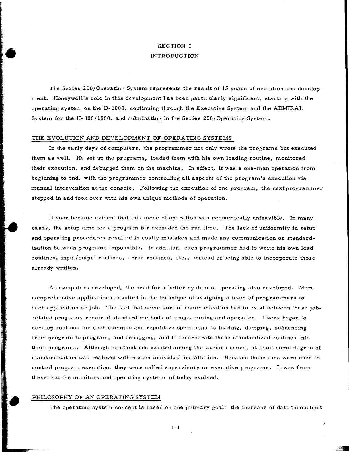
The
Series
ZOO/Operating
System
represents
the
result
of
15
years
of
evolution
and
develop-
ment.
Honeywell's
role
in
this
development
has
been
particularly
significant,
starting
with
the
operating
system
on
the
D-lOOO,
continuing
through
the
Executive
System
and
the
ADMIRAL
System
for
the
H-800/l800,
and
culminating
in
the
Series
ZOO/Operating
System.
THE
EVOLUTION
AND
DEVELOPMENT
OF
OPERATING
SYSTEMS
In
the
early
days
of
computers,
the
programmer
not
only
wrote
the
programs
but
executed
them
as
well.
He
set
up
the
programs,
loaded
them
with
his
own
loading
routine,
monitored
their
execution,
and
debugged
them
on
the
machine.
In
effect,
it
was
a
one-man
operation
from
beginning
to
end,
with
the
programmer
controlling
all
aspects
of
the
program's
execution
via
manual
intervention
at
the
console.
Following
the
execution
of
one
program,
the
next
programmer
stepped
in
and
took
over
with
his
own
unique
methods
of
operation.
It
soon
became
evident
that
this
mode
of
operation
was
economically
unfeasible.
In
many
cases,
the
setup
time
for
a
program
far
exceeded
the
run
time.
The
lack
of
uniformity
in
setup
and
operating
procedures
resulted
in
costly
mistakes
and
made
any
communication
or
standard-
ization
betwe.en
programs
impossible.
In
addition,
each
programmer
had
to
write
his
own
load
routines,
input/output
routines,
error
routines,
etc.,
instead
of
being
able
to
incorporate
those
already
written.
As
cemputers
developed,
the
need
for
a
better
system
of
operating
also
developed.
More
comprehensive
applications
resulted
in
the
technique
of
assigning
a
team
of
programmers
to
each
application
or
job.
The
fact
that
some
sort
of
communication
had
to
exist
between
these
job-
related
programs
required
standard
methods
of
programming
and
operation.
Users
began
to
develop
routines
for
such
common
and
repetitive
operations
as
loading,
dumping,
sequencing
from
program
to
program,
and
debugging,
and
to
incorporate
these
standardized
routines
into
their
programs.
Although
no
standards
existed
among
the
various
users,
at
least
some
degree
of
standardization
was
realized
within
each
individual
installation.
Because
these
aids
were
used
to
control
program
execution,
they
were
called
supervisory
or
executive
programs.
It
was
from
these
that
the
monitors
and
operating
systems
of
today
evolved.
PHILOSOPHY
OF
AN
OPERATING
SYSTEM
The
operating
system
concept
is
based
on
one
primary
goal:
the
increase
of
data
throughput
1-1
•
SECTION
1.
INTRODUCTION
by
assisting
the
user
in
utilizing
to
the
fullest
extent
the
hardware
and
software
available.
To
fulfill
this
goal,
an
operating
system
should:
1.
Be
simple
and
convenient
to
use.
2.
Relieve
the
operator
of
the
necessity
for
complex
procedures
and
constant
supervision.
3.
Eliminate
unnecessary
idle
time
spent
on
job
setup
and
last-minute
planning.
4.
Be
flexible
and
expandable
-
adaptable
to
the
operating
environment
in
terms
of
hardware
configurations,
software
complements,
and
operating
policies
of
the
user.
5.
Minimize
the
turnaround
time
between
the
submis
sion
of
a
job
and
the
return
of
the
results.
6.
Be
economical,
efficient,
and
easily
maintained.
To
the
extent
that
the
above
goals
have
been
achieved
in
the
design
of
an
operating
system,
the
operator
can
communicate
with
the
system
rather
than
with
the
individual
programs,
and
the
system
operating
procedures
become
standardized.
Likewise,
because
of
such
features
as
a
comprehensive
program
test
system,
the
programmer
can
direct
the
entire
testing
procedure
by
simply
preparing
the
control
deck
to
be
used.
Thus,
both
the
operator
and
the
programmer
are
removed
to
an
off-line
status
and
are
prevented
from
any
wasteful
contact
with
the
computer.
In
short,
an
operating
system
can
be
thought
of
as
a
framework
within
which
the
user's
data
processing
applications
can
be
written,
prepared,
and
executed.
To
this
end,
an
operating
system
consists
of
many
language
processing
and
service
routines
designed
to
aid
the
user
in
these
activities.
1-2
SECTION
II
THE
SERIES
200/0PERATING
SYSTEM
-
MOD
1
(TAPE
RESIDENT)
The
Series
200/Operating
System
-
Mod
1
provides
the
user
with
a
means
of
unleashing
the
full
power
of
any
Series
200
computer
system
having
a
minimum
of
12K
characters
of
mem-
ory
and
three
tape
units.
Designed
with
simplicity,
economy,
and
flexibility
in
mind,
the
Mod
1
Operating
System
offers
a
long
list
of
significant
features
molded
together
into
one
integrated
operating
framework.
OPERATING
ENVIRONMENT
The
Series
200/0perating
System
-
Mod
1
(Tape
Resident)
is
designed
for
all
Series
200
machine
configurations
having
12K
to
65K
characters
of
core
storage
and
from
three
to
six
tape
units.
In
addition,
the
versatility
of
the
system
enables
the
efficient
use
of
other
peripheral
devices
such
as
punched
cards,
drum
storage,
paper
tape,
communications,
and
mass
memory.
MOD
1
OPERATING
SYSTEM
PHILOSOPHY
Specifically
aimed
at
the
medium-scale,
tape-oriented,
Series
200
user,
the
basis
of
the
Mod
1
Operating
System
philosophy
can
be
found
in
the
three
outstanding
characteristics
of
the
system:
simplicity,
efficiency,
and
flexibility.
Simplicity
The
Mod
1
Operating
System
provides
a
comprehensive
collection
of
precoded
and
tested
systems
functions
and
programs
which
relieve
the
user
of
a
host
of
complex
programming
and
operating
tasks.
For
example,
tape
and
drum
storage
input/output
routines
are
provided
ready
for
specialization
and
insertion,
via
macro
calls,
into
the
user's
programs.
For
the
operator,
a
complete
program
test
package
allows
for
the
checkout
of
an
entire
series
of
programs
with
no
operator
intervention
from
the
initial
pressing
of
the
RUN
button
to
the
end
of
the
job.
Standard,
easily
learned
operating.
procedures
simplify
the
operator's
job.
The
same
maintenance
programs
and
standard
operating
procedures
are
used
to
maintain
and
execute
Honeywell
software
and
the
user's
own
object
programs.
Efficiency
One
of
the
most
important
objectives
in
the
design
of
the
Mod
1
Operating
System
is
the
efficient
and
economic
use
of
core
storage.
First,
since
the
system
is
completely
modular
in
design,
only
those
functions
required
for
any
given
operation
occupy
memory.
For
example,
2-1

•
SECTION
II.
THE
SERIES
200/0PERATING
SYSTEM
-
MOD
1
(TAPE
RESIDENT)
separate
loader
routines
are
provided
for
loading
programs
stored
on
punched
cards,
magnetic
tape,
or
drum.
Each
version
contains
only
those
functions
required
for
loading
from
the
particu-
lar
medium.
Secondly,
routines
(or
portions
of
routines) can
be
assembled
and
executed
in
either
two-,
three-,
or
four-character
addressing
mode.
Whenever
possible,
the
shortest
addressing
mode
may
be
used
to
conserve
core
requirements.
For
example,
the
three-character
address
mode
version
of
Floating
Tape
Loader-Monitor
C
occupies
approximately
520
to
550
fewer
core
locations
than
the
four-character
version.
One
proof
of
core
usage
efficiency
is
the
fact
that
Honeywell's
Series
200
COBOL
compilers
require
much
less
memory
than
any
competitive
com-
pilers
offering
similar
features.
Through
the
use
of
the
Mod
1
Operating
System,
the
user
realizes
savings
not
only
from
efficient
core
usage
but
also
from
the
reduction
of
setup
and
idle
time
and
from
the
elimination
of
operations
errors.
In
addition,
the
assembly,
sorting,
and
compiling
functions
offer
speeds
which
far
exceed
those
of
similarly
priced
competitive
equipment.
Flexibility
Flexibility
is
provided
both
by
the
number
and
variety
of
functions
offered
any
by
the
inherent
expansibility
of
the
system.
For
example,
the
user
has
a
choice
of
several
programming
languages
ranging
from
the
assembly-1eve11anguage
of
Easycoder
to
the
scientific
compiler-
1eve11anguage
of
Fortran.
Further,
he
can
choose
between
card,
tape,
or
drum
program
stor-
age
and
loading.
He
can
add
his
own
coded
macro
routines
to
the
macro
library
for
insertion
into
his
programs.
He
can
take
advantage
of
any
communication
devices
or
console
typewriters
included
as
part
of
his
computer
configuration.
He
can
use
any
core
memory
size
from
12K
up
to
262K_and
can
begin
with
as
few
as
three
tape
units.
One
of
the
major
benefits
derived
from
this
flexible
design
is
that
of
orderly
growth
poten-
tial
by
which
the
user
can
add
both
hardware
and
software
as
needed
and
still
maintain
an
inte-
grated
system.
Coupled
with
the
modular
design
of
the
Series
200
hardware
and
software,
the
Mod
1
Operating
System
assures
the
user
of
upward
program
compatibility
as
his
system
grows.
PROCESSING
STRUCTURE
Fundamental
to
the
design
of
the
Mod
1
Operating
System
is
its
functional
program
modu-
larity.
First,
although
the
concept
of
a
program
as
the
basic
logical
unit
is
still
retained,
a
pro-
gram
is
segmented
into
one
or
more
loading
units.
Each
loading
unit
consists
of
a
portion
of
the
code
for
a
particu1a·r
program
and
can
be
individually
searched
for
and
loaded
by
a
single
2-2
SECTION
II.
THE
SERIES
200/0PERATING
SYSTEM
-
MOD
1
(TAPE
RESIDENT)
call
to
the
Loader-Monitor.
This
concept
of
program
segmentation
provides
increased
opera-
tional
flexibility
plus
a
great
reduction
in
the
amount
of
memory
core
required
by
a
program.
Secondly,
related
programs
can
be
combined
into
job-oriented
groupings.
The
ability
to
store
not
only
several
"jobs"
but
also
several
versions
of
each
job
on
a
single
program
tape
allows
the
user
to
adopt
the
building-block
approach
in
the
implementation
of
these
jobs.
For
example,
a
program
tape
might
contain
all
of
the
current
production
programs
for
the
application,
checked-
out
programs
to
be
incorporated
in
the
future,
and
programs
yet
to
be
tested.
During
any
execu-
tion
of
the
job,
the
desired
programs
are
automatically
selected,
loaded,
and
executed
in
what-
ever
sequence
the
user
elects.
This
is
accomplished
through
the
common
interface
of
the
Mod
I
Operating
System
using
one
or
both
of
two
methods:
internal
control
via
coding
within
the
pro-
grams
themselves;
external
control
via
a
Console
Call
card
control
deck.
COMPONENTS
OF
THE
MOD
I
OPERATING
SYSTEM
The
Mod
1
Operating
System
contains
many
subsystems
and
routines
designed
to
eliminate
much
of
the
work
of
both
the
programmer
and
the
operator.
These
components
can
be
divided
into
three
types:
those
which
aid
in
the
preparation
of
source-language
programs
and
their
translation
into
machine
language;
those
which
perform
editing
and
maintenance
on
machine-
language
programs;
and
those
which
control
the
execution
of
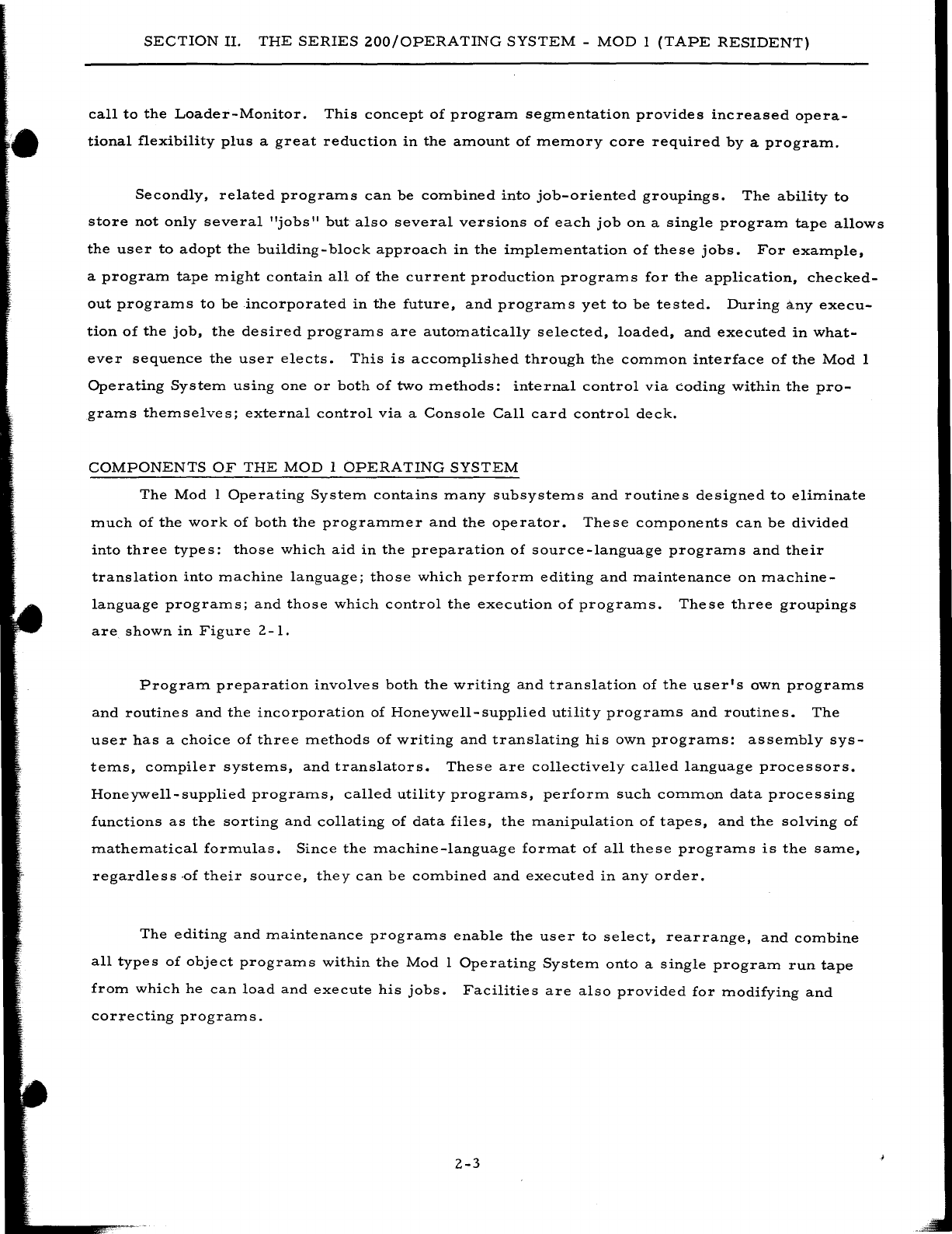
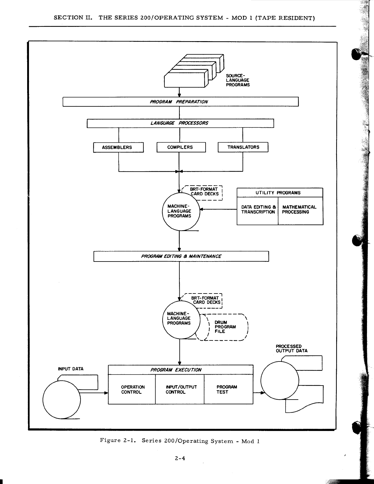
programs.
These
three
groupings
are
shown
in
Figure
2 -
1.
Program
preparation
involves
both
the
writing
and
translation
of
the
user's
own
programs
and
routines
and
the
incorporation
of
Honeywell-supplied
utility
programs
and
routines.
The
user
has
a
choice
of
three
methods
of
writing
and
translating
his
own
programs:
assembly
sys-
tems,
compiler
systems,
and
translators.
These
are
collectively
called
language
processors.
Honeywell-supplied
programs,
called
utility
programs,
perform
such
common
data
processing
functions
as
the
sorting
and
collating
of
data
files,
the
manipulation
of
tapes,
and
the
solving
of
mathematical
formulas.
Since
the
machine-language
format
of
all
these
programs
is
the
same,
regardless
-of
their
source,
they
can
be
combined
and
executed
in
any
order.
The
editing
and
maintenance
programs
enable
the
user
to
select,
rearrange,
and
combine
all
types
of
object
programs
within
the
Mod
1
Operating
System
onto
a
single
program
run
tape
from
which
he
can
load
and
execute
his
jobs.
Facilities
are
also
provided
for
modifying
and
correcting
program
s.
2-3
SECTION
II.
THE
SERIES
ZOO/OPERATING
SYSTEM
-
MOD
1
(TAPE
RESIDENT)
INPUT
DATA
PROGRAM PREPARATION
LANGUAGE PROCESSORS
SOURCE-
LANGUAGE
PROGRAMS
UTILITY
PROGRAMS
DATA
EDITING
a
MATHEMATICAL
TRANSCRIPTION
PROCESSING
PROGRAM
EDITING a MAINTENANCE
OPERATION
CONTROL
~---------
\
DRUM
\
\
PROGRAM
,
J FILE I
--r-~-'_L
_______
I
PROGRAM EXECUTION
INPUT/OUTPUT
CONTROL
PROGRAM
TEST
Figure
Z-1.
Series
ZOO/Operating
System.
-
Mod
1
Z-4
PROCESSED
OUTPUT
DATA
SECTION
II.
THE
SERIES
200/0PERATING
SYSTEM
-
MOD
I
(TAPE
RESIDENT)
In
the
area
of
program
execution,
the
Mod
1
Operating
System
offers
several
important
capabilities:
operation
control,
input/output
control,
and
program
test.
Operation
control
is
performed
by
some
version
of
the
loader-monitor
which
can
search
for
and
load
any
program
called
for
by
either
the
operator
or
the
current
progr-am.
It
can
also
execute
programs
on
a
job
basis
-
i.
e.,
automatically
search
for,
load,
and
execute
an
entire
series
of
programs
related
to
one
application
or
job.
An
associated
interrupt
control
routine
can
extend
these
capabilities
to
the
loading
and
executing
of
two
programs
at
the
same
time
by
utilizing
the
simultaneity
and
interrupt
capabilities
of
the
Series
200
hardware.
File
input
and
output
op-
erations
are
controlled
by
appropriate
input/output
routines
inserted
and
specialized
within
each
program
at
assembly
or
compilation
time
via
user-specified
macro
calls.
Automatic
program
test
and
checkout
procedures
are
provided
within
the
system
for
the
efficient
testing
and
debugging
of
a
single
program
or
a
whole
series
of
programs
immediately
following
assem-
bly,
compilation,
modification,
or
specialization
of
the
programs.
The
following
sections
present
these
various
components
in
detail.
2-5

•
SECTION
III
PROGRAM
PREPARATION
AND
MAINTENANCE
The
Mod
I
Operating
System
provides
the
user
with
a
comprehensive
language
processing
capability
in
the
form
of
assemblers,
compilers,
and
conversion
programs.
Utility
programs
complement
this
capability
by
offering
precoded
routines
which
perform
common
data
processing
functions
and
which
can
be
specialized
to
the
user's
individual
needs.
Editing
and
maintenance
programs
offer
a
means
of
creating
and
maintaining
symbolic
and
machine-language
program
files.
LANGUAGE
PROCESSING
Language
processing
programs
are
provided
to
translate
programs
written
in
several
different
source
languages
into
a
single
machine-language
format;
thus,
the
output
from
the
various
language
processors
can
be
combined
on
a
single
program
run
tape
and
executed
in
any
order.
In
writing
his
programs,
the
user
chooses
from
the
following
three
languages
the
one
best
suited
to
the
application
and
to
his
own
background
and
experience.
1.
Easycoder
- A
general-purpose
assembly-level
language
which
combines
ease
of
use
with
power
and
flexibility.
To
express
the
logic
of
his
pro-
gram,
the
user
employs
easily
remembered
mnemonic
op
codes
and
ref-
erences
memory
locations
by
either
absolute
decimal
numbers
or
sym-
bolic
tags.
The
Easycoder
system
includes
an
Easycoder
assembler
which
translates
the
source
language
to
machine
language,
a
library
processor
which
enables
the
user
to
incorporate
precoded
routines
into
his
program,
an
analyzer
program
which
prints
a
cross-reference
listing
of
all
symbolic
tags
used,
and
a
symbolic
program
maintenance
facility
which
permits
the
storage
and
updating
of
symbolic
programs
on
tape.
2.
COBOL
- A
business-oriented
compiler-level
language
which
offers
.
simplicity
of
format,
shorter
training
time
requirements,
and
com-
patibility
among
different
models
of
computers.
The
user
expresses
the
logic
of
his
program
as
a
series
of
English-language
statements
conforming
to
standardized
COBOL
conventions.
3.
Fortran
- A
science-oriented
compiler-level
language
which
allows
the
user
to
express
a
wide
variety
of
engineering,
scientific,
and
data
processing
problems
in
a
familiar
format.
Library
and
diag-
nostic
facilities
are
included
in
the
system.
If
the
user
has
already
written
his
programs
in
the
language
of
a
competitive
system,
he
can
easily
and
quickly
co~vert
these
programs
to
a
format
compatible
with
the
Series
200
sys-
tems.
As
a
result
of
the
Honeywell
Liberator
concept,
such
programs
can
be
translated
on
both
the
symbolic
and
machine-language
levels
without
the
aid
of
simulators.
For
example,
the
Easy-
tran
Symbolic
Translator
routines
translate
programs
written
in
Autocoder,
SPS,
or
mixed
3-1
I
SECTION
III.
PROGRAM
PREPARATION
AND
MAINTENANCE
SPS/
Autocoder
source
language
into
Easycoder
source
language.
An
important
facet
of
this
translation
is
that
all
programs
are
modified
to
take
advantage
of
the
superior
throughput
power
of
the
Series
200
hardware
and,
as
a
result,
usually
run
in
a
fraction
of
their
former
execution
time.
Assembly
System
The
Easycoder
Assembly
System
for
the
Mod
1
Operating
System
comprises
four
elements:
1.
A
symbolic
language,
2.
A
library
processor,
3.
An
assembler,
and
4.
An
analyzer.
EASYCODER
ASSEMBLY
LANGUAGE
The
Easycoder
Assembly
Language
is
a
general-purpose,
easy-to-use
language
designed
for
a.ll
types
of
applications.
It
provides
the
user
with
a
comprehensive
set
of
operation
codes
with
which
he
can
specify
the
following
types
of
operations:
1.
Arithmetic
-
Offer
the
user
a
choice
of
binary
or
decimal
arithmetic
functions.
In
addition,
Easycoder
Assembler
D
on
a
Series
200
com-
puter
with
the
Scientific
Unit
provides
the
user
with
floating-point
capabilities.
2.
Logic
-
Provide
the
user
with
the
functions
of
extracting,
half-
adding,
substituting,
comparing,
conditional
and
unconditional
branching,
etc.
3.
Control·
-
Enable
the
user
to
set
and
clear
punctuation,
halt
the
machine,
move
data,
enter
and
retrieve
data
from
control
memory,
and
change
addressing
and
sequencing
modes.
Easycoder
Assembler
D
also
allows
the
controlling
of
memory
barricades
with
the
Storage
Protect
Feature.
4.
Interrupt
Control
-
Enable
the
user
to
take
advantage
of
the
inter-
rupt
functions
of
the
Series
200
hardware.
5.
Editing
-
Permits
the
use
of
the
extensive
power
of
the
Edit
Feature
in
producing
financially
edited
fields
on
printed
reports.
6.
Input/Output
-
Provides
two
basic
instructions
which
allow
the
user
complete
control
over
all
data
transfers
between
the
central
pro-
cessor
and
all
peripheral
units
and
over
the
peripheral
units
them-
selves.
Also
included
in
the
Easycoder
symbolic
language
are
a
number
of
assembly
control
statements
which
permit
the
user
to
control
the
assembly
process
itself.
LIBRARY
PROCESSOR
To
relieve
the
programmer
of
the
burden
of
the
repetitive
and
complex
coding
of
commonly
used
routines
(e.
g.,
input/output
procedures),
the
Easycoder
Assembly
System
includes
library
3-2
SECTION
III.
PROGRAM
PREPARATION
AND
MAINTENANCE
facilities.
In
addition
to
the
basic
library
of
general-purpose
routines
supplied
by
Honeywell,
the
user
can
add
his
own
often
used
programs
and
routines
to
this
library.
These
routines
are
stored,
in
source-language
format,
on
a
library
source-program
tape.
By
writing
call
state-
ments
(macro
instructions)
within
his
source
coding
and
processing
his
program
through
a
library
processor
prior
to
assembly,
the
user
can
cause
these
routines
to
be
selected
from
the
library
source
-program
tape,
specialized
according
to
the
parameters
he
has
included
in
the
call
statements,
and
inserted
into
his
program.
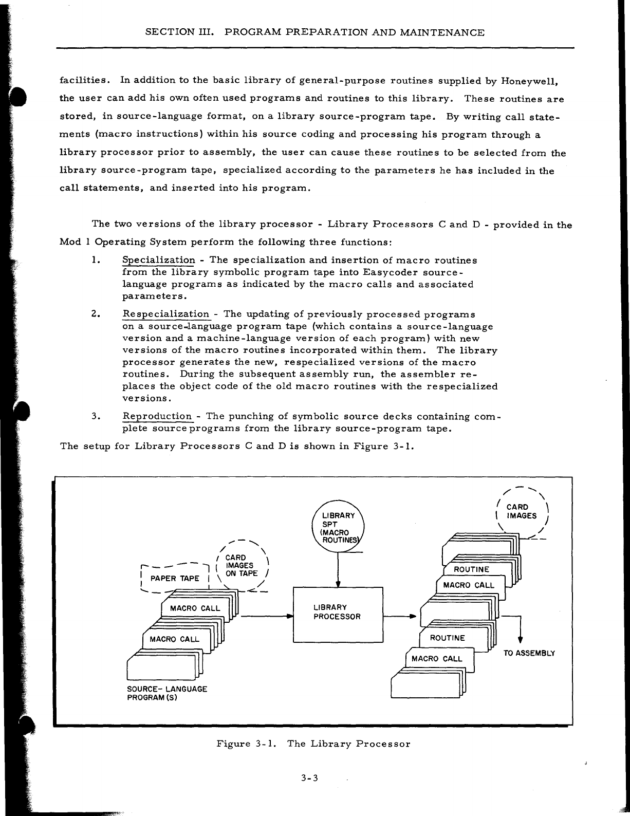
The
two
versions
of
the
library
processor
-
Library
Processors
C
and
D -
provided
in
the
Mod
I
Operating
System
perform
the
following
three
functions:
1.
Specialization
-
The
specialization
and
insertion
of
macro
routines
from
the
library
symbolic
program
tape
into
Easycoder
source-
language
programs
as
indicated
by
the
macro
calls
and
associated
parameters.
2.
Respecialization
-
The
updating
of
previously
processed
programs
on
a
source-language
program
tape
(which
contains
a
source
-language
version
and
a
machine-language
version
of
each
program)
with
new
versions
of
the
macro
routines
incorporated
within
them.
The
library
processor
generates
the
new,
respecialized
versions
of
the
macro
routines.
During
the
subsequent
assembly
run,
the
assembler
re-
places
the
object
code
of
the
old
macro
routines
with
the
respecialized
versions.
3.
Reproduction
-
The
punching
of
symbolic
source
decks
containing
com-
plete
source
programs
from
the
library
source-program
tape.
The
setup
for
Library
Processors
C
and
D
is
shown
in
Figure
3-1.
/'
-
........
,
I CARD \
I IMAGES J
~§§\~
/
.....
-"'"
/ \
I CARD \
r-
- - - - l I IMAGES
I PAPER TAPE I \
ON
TAPE J
I /
......
-
<::.-
SOURCE- LANGUAGE
PROGRAM (S)
LIBRARY
PROCESSOR
Figure
3-1.
The
Library
Processor
3-3
ROUTINE
TO
ASSEMBLY
SECTION
III.
PROGRAM
PREPARATION
AND
MAINTENANCE
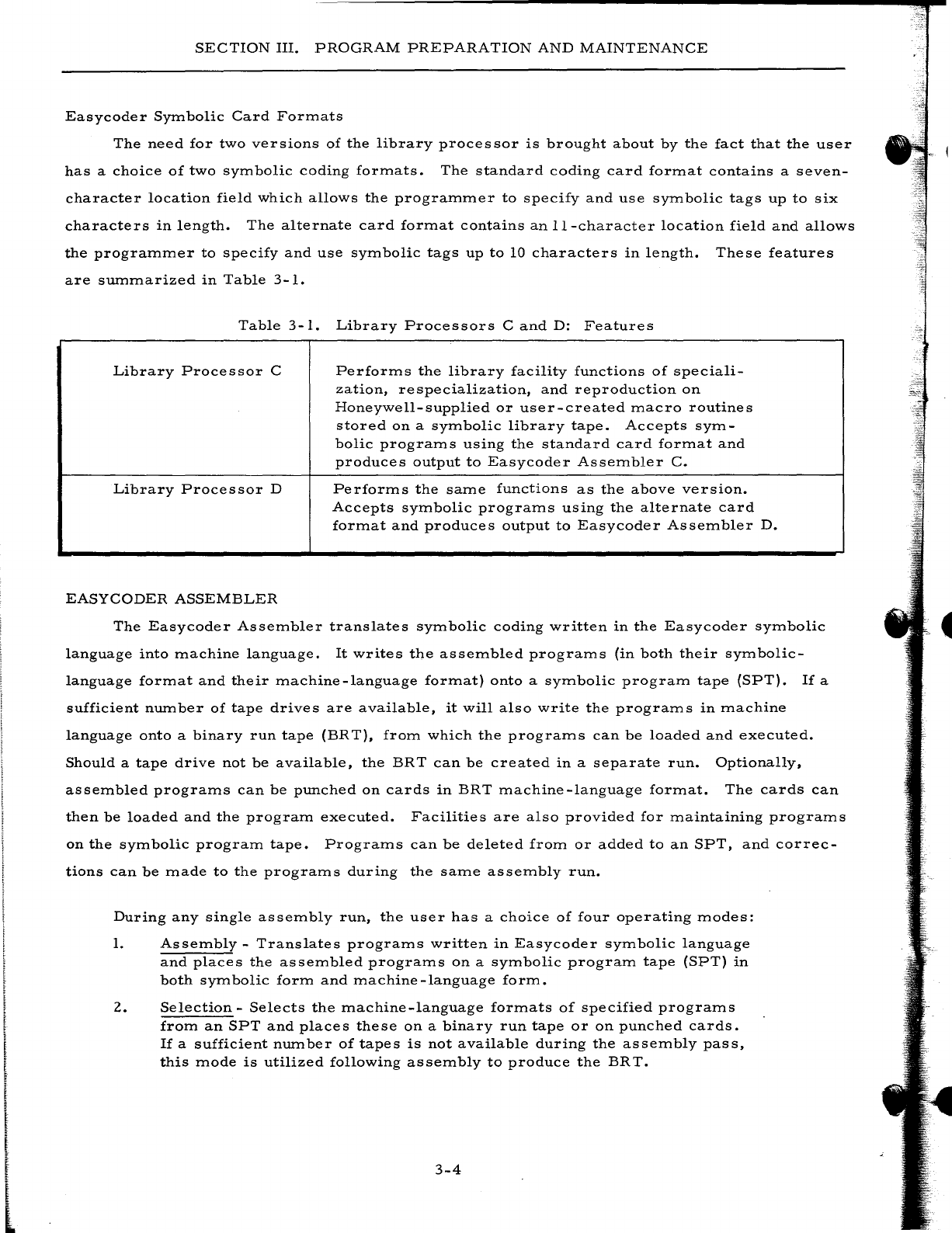
Easycoder
Symbolic
Card
Formats
The
need
for
two
versions
of
the
library
processor
is
brought
about
by
the
fact
that
the
user
has
a
choice
of
two
symbolic
coding
formats.
The
standard
coding
card
format
contains
a
seven-
character
location
field
which
allows
the
programmer
to
specify
and
use
symbolic
tags
up
to
six
characters
in
length.
The
alternate
card
format
contains
an
II-character
location
field
and
allows
the
programmer
to
specify
and
use
symbolic
tags
up
to
10
characters
in
length.
These
features
are
summarized
in
Table
3-1.
Table
3-1.
Library
Processors
C
and
D:
Features
Library
Processor
C
Performs
the
library
facility
functions
of
speciali-
zation,
respecialization,
and
reproduction
on
Honeywell-supplied
or
user-created
macro
routines
stored
on
a
symbolic
library
tape.
Accepts
sym-
bolic
programs
using
the
standard
card
format
and
produces
output
to
Easycoder
Assembler
C.
Library
Processor
D
EASYCODER
ASSEMBLER
Performs
the
same
functions
as
the
above
version.
Accepts
symbolic
programs
using
the
alternate
card
format
and
produces
output
to
Easycoder
Assembler
D.
The
Easycoder
Assembler
translates
symbolic
coding
written
in
the
Easycoder
symbolic
language
into
machine
language.
It
writes
the
assembled
programs
(in
both
their
symbolic-
language
format
and
their
machine-language
format)
onto
a
symbolic
program
tape
(SPT).
If
a
sufficient
number
of
tape
drives
are
available,
it
will
also
write
the
programs
in
machine
language
onto
a
binary
run
tape
(BR
T),
from
which
the
programs
can
be
loaded
and
executed.
Should
a
tape
drive
not
be
available,
the
BRT
can
be
created
in
a
separate
run.
Optionally,
assembled
programs
can
be
punched
on
cards
in
BRT
machine-language
format.
The
cards
can
then
be
loaded
and
the
program
executed.
Facilities
are
also
provided
for
maintaining
programs
on
the
symbolic
program
tape.
Programs
can
be
deleted
from
or
added
to
an
SPT,
and
correc-
tions
can
be
made
to
the
programs
during
the
same
assembly
run.
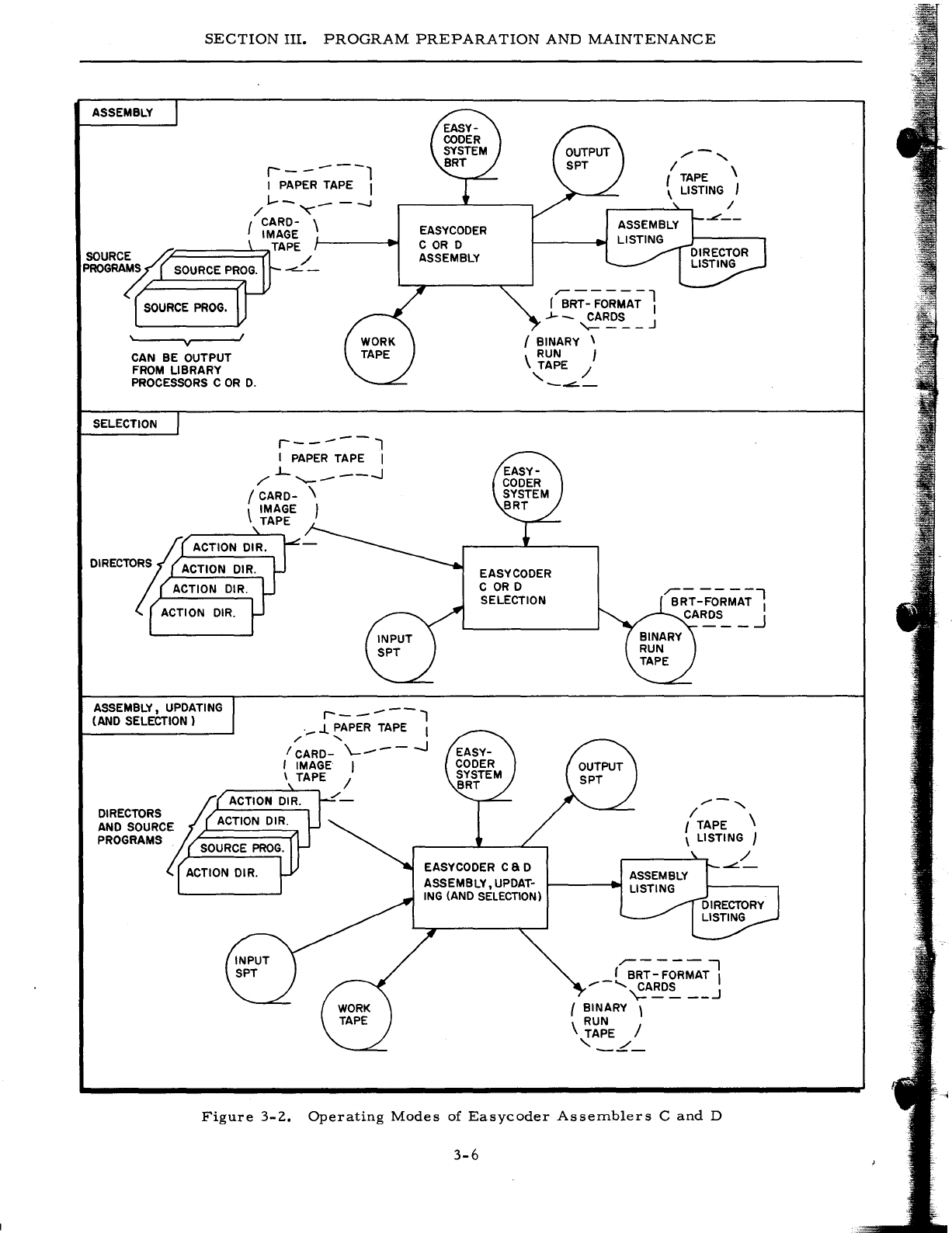
During
any
single
assembly
run,
the
user
has
a
choice
of
four
operating
modes:
1.
Assembly
-
Translates
programs
written
in
Easycoder
symbolic
language
and
places
the
assembled
programs
on
a
symbolic
program
tape
(SPT)
in
both
symbolic
form
and
machine-language
form.
2.
Selection
-
Selects
the
machine-language
formats
of
specified
programs
from
an
SPT
and
places
these
on
a
binary
run
tape
or
on
punched
cards.
If
a
sufficient
number
of
tapes
is
not
available
during
the
assembly
pass,
this
mode
is
utilized
following
as
sem
bly
to
produce
the
BR
T.
3-4
SECTION
III.
PROGRAM
PREPARATION
AND
MAINTENANCE
3.
Assembly
and
Updating
-
Maintains
and
updates
the
programs
on
an
SPT
in
both
their
symbolic
and
machine-language
formats
through
the
correc-
tion
of
individual
programs,
the
addition
of
new
programs,
and
the
deletion
of
unwanted
program
s.
4.
Assembly,
Updating,
and
Selection-
Performs
the
same
operations
as
the
assembly
and
updating
mode
with
the
added
ability
to
select
specified
programs
and
place
these
programs
on
tape
or
on
cards
in
executable
form.
The
mode
chosen
by
the
user
depends
upon
his
requirements
and
upon
the
number
of
tape
units
available.
The
setup
diagrams
for
the
various
modes
are
shown
in
Figure
3-2.
The
Mod
1
Operating
System
includes
two
versions
of
the
Easycoder
Assembler:
Easycoder
Assembler
C
and
Easycoder
Assembler
D.
The
features
provided
by
the
two
versions
are
summarized
in
Table
3-2.
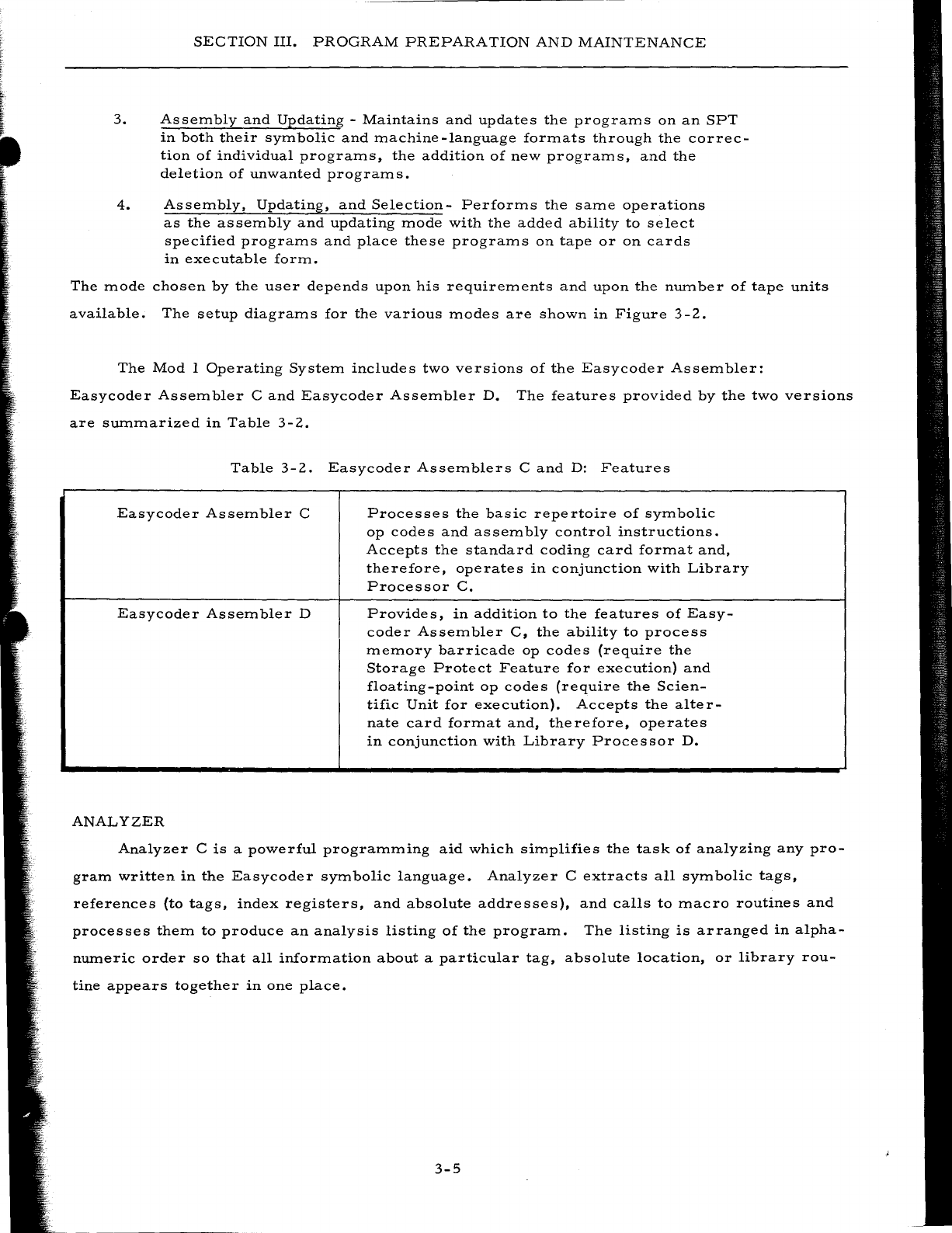
Table
3-2.
Easycoder
Assemblers
C
and
D:
Features
Easycoder
Assembler
C
Processes
the
basic
repertoire
of
symbolic
op
codes
and
assembly
control
instructions.
Accepts
the
standard
coding
card
format
and,
therefore,
operates
in
conjunction
with
Library
Processor
C.
Easycoder
Assembler
D
Provides,
in
addition
to
the
features
of
Easy-
coder
Assembler
C,
the
ability
to
process
memory
barricade
op
codes
(require
the
Storage
Protect
Feature
for
execution)
and
floating-point
op
codes
(require
the
Scien-
tific
Unit
for
execution).
Accepts
the
alter-
nate
card
format
and,
therefore,
operates
in
conjunction
with
Library
Processor
D.
ANALYZER
Analyzer
C
is
a
powerful
programming
aid
which
simplifies
the
task
of
analyzing
any
pro-
gram
written
in
the
Easycoder
symbolic
language.
Analyzer
C
extracts
all
symbolic
tags,
references
(to
tags,
index
registers,
and
absolute
addresses),
and
calls
to
macro
routines
and
processes
them
to
produce
an
analysis
listing
of
the
program.
The
listing
is
arranged
in
alpha-
numeric
order
so
that
all
information
about
a
particular
tag,
absolute
location,
or
library
rou-
tine
appears
together
in
one
place.
3-5
•
SECTION
III.
PROGRAM
PREPARATION
AND
MAINTENANCE
ASSEMBLY
r-
------1
I PAPER TAPE I
1--
_--...I
/
'"
{ CARD- \
IMAGE
,"-======~TAPE
SOURC~S~
/
PROGRA~
SOURCE
PROG.
....::...
-
SOURCE
PROG.
'------,v,..--...J
1
CAN BE OUTPUT
FROM
LIBRARY
PROCESSORS
COR
D.
SELECTION
r-----l
I
PAPER
TAPE I
/".L
'--_
---.1
I
CARD-
\
\ IMAGE I
TAPE
~
ACTION DIR.
DIRECTORS
ACTION DIR.
ACTION DIR.
ACTION
DIR.
EASYCODER
COR
D
ASSEMBLY
r";RT-
-;o-;;~;
1
.J-
_
CARDS
"'-
___
J
I BINARY \
RUN
J
'~APE
/
-~-
EASY
CODER
COR
D
SELECTION
ASSEMBLY, UPDATING
(AND SELECTION)
r-
----l
._
J. PAPER TAPE I
/"
"
I
CARD-
\..-
___
- - -.J
I IMAGE I
\ TAPE /
1/-'
I
TAPE
\
\ LISTING J
~
ACTION DIR.
DIRECTORS
AND
SOURCE ACTION DIR.
//-,
I TAPE \
\ LISTING J
PROGRAMS.
SOURCE
PROG.
ACTION DIR. EASY
CODER
CaD
ASSEMBLY, UPDAT-
ING
(AND
SELECTION)
,-----
-,
r BRT -FORMAT I
/-
.......
CARDS
\=
____
..J
{ BINARY \
RUN
\ TAPE /
'_L_
Figure
3-2.
Operating
Modes
of
Easycoder
Assemblers
C
and
D
3-6
/
~-
SECTION
III.
PROGRAM
PREPARATION
AND
MAINTENANCE
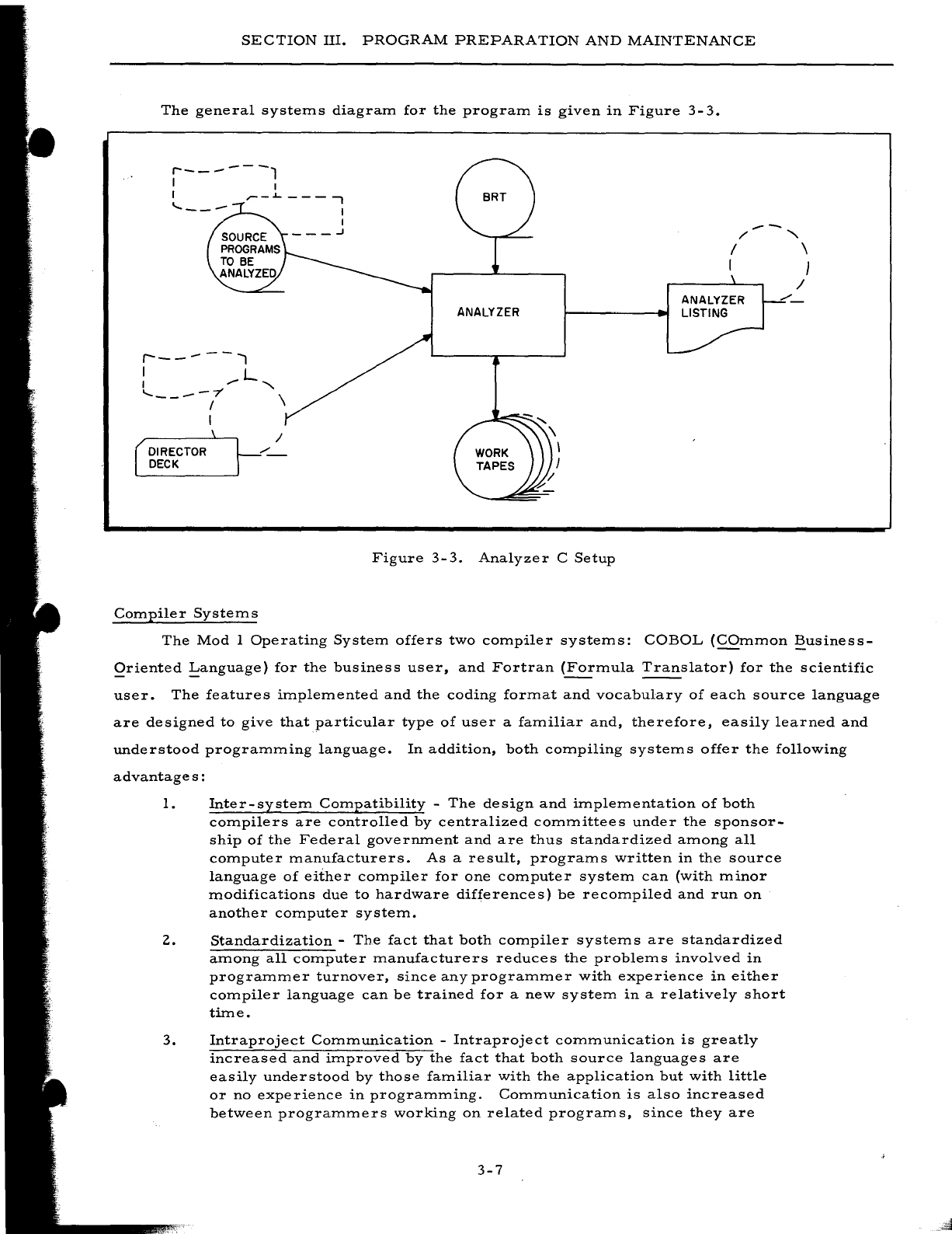
The
general
systems
diagram
for
the
program
is
given
in
Figure
3-
3.
r-------,
I I
I
.-
--
/'
'"
I \
I }
r------..,
I L
I
,.
'"
.....
----7' \
DIRECTOR
DECK
I
Compiler
Systems
/
ANALYZER
Figure
3-3.
Analyzer
C
Setup
The
Mod
I
Operating
System
offers
two
compiler
systems:
COBOL
(COmmon
~usiness
Qriented
!:anguage)
for
the
business
user,
and
Fortran
(Formula
Translator)
for
the
scientific
user.
The
features
implemented
and
the
coding
format
and
vocabulary
of
each
source
language
are
designed
to
give
that
particular
type
of
user
a
familiar
and,
therefore,
easily
learned
and
understood
programming
language.
In
addition,
both
compiling
systems
offer
the
following
advantage
s :
1.
Inter-system
Compatibility
-
The
design
and
implementation
of
both
compilers
are
controlled
by
centralized
committees
under
the
sponsor-
ship
of
the
Federal
government
and
are
thus
standardized
among
all
computer
manufacturers.
As
a
result,
programs
written
in
the
source
language
of
either
compiler
for
one
computer
system
can
(with
minor
modifications
due
to
hardware
differences)
be
recompiled
and
run
on
another
computer
system.
2.
Standardization
-
The
fact
that
both
compiler
systems
are
standardized
among
all
computer
manufacturers
reduces
the
problems
involved
in
programmer
turnover,
since
any
programmer
with
experience
in
either
compiler
language
can
be
trained
for
a
new
system
in
a
relatively
short
time.
3.
Intraproject
Communication
-
Intraproject
communication
is
greatly
increased
and
improved
by
the
fact
that
both
source
languages
are
easily
understood
by
those
familiar
with
the
application
but
with
little
or
no
experience
in
programming.
Communication
is
also
increased
between
programmers
working
on
related
programs,
since
they
are
3-7
•
SECTION
III.
PROGRAM
PREPARATION
AND
MAINTENANCE
all
using
the
same
coding
conventions,
symbolic
tags,
and
other
standardized
techniques.
4.
Fast
Program
Compilation
and
Testing
-
Both
systems
offer
com-
pilation
speeds
averaging
only
a
matter
of
a
few
minutes
per
source
program.
Both
compilers
offer
comprehensive
diagnostic
scans
for
clerical
errors
and
helpful
diagnostic
listings
of
all
errors
found.
As
a
result,
debugging
time
has
been
reduced
by
50%
or
more.
5.
Reduction
of
Programmer
Training
Time
-
Programmer
training
(or
retraining
in
the
case
of
a
changeover
to
a
new
computer)
is
drastically
reduced
by
the
use
of
these
easily
learned
source
lan-
guages.
Many
companies
have
found
that
programmers
trained
6.
in
a
compiler
language
reach
a
satisfactory
level
of
productivity
many
weeks
in
advance
of
those
trained
in
a
conventional
assembly
language.
Improved
Documentation
-
The
clear
and
comprehensive
listings
produced
by
both
compiler
systems
provide
a
clear
picture
of
the
program's
logic
and,
via
diagnostic
messages,
aid
the
programmer
in
achieving
his
goal
of
a
completely
checked-out
and
operable
pro-
gram.
This
documentation
is
especially
valuable
when
a
program-
mer
must
take
over
the
maintenance
of
a
program
written
by
another
programmer.
A
compiler
system
consists
of
two
elements:
1.
A
programming
language,
and
2.
A
translator,
called
a
compiler,
which
translates
the
programmer's
source-language
statements
or
formulas
into
machine
language.
THE
COBOL
COMPILER
SYSTEM
The
COBOL
Language
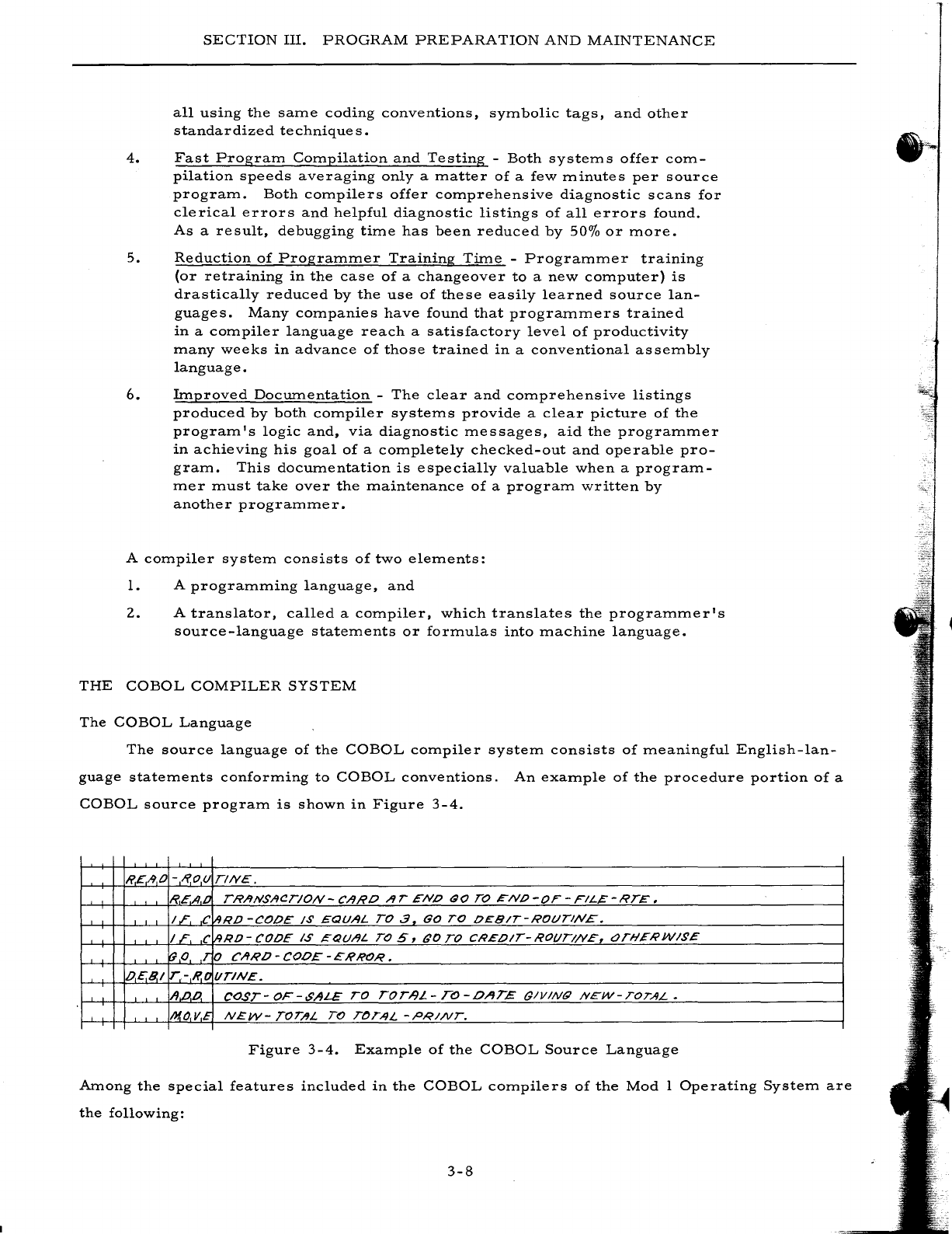
The
source
language
of
the
COBOL
compiler
system
consists
of
meaningful
English-lan-
guage
statements
conforming
to
COBOL
conventions.
An
example
of
the
procedure
portion
of
a
COBOL
source
program
is
shown
in
Figure
3-4.
R.£AO
-R.ou
TINE.
TRANSACTION-CARO
AT
ENO
GO
TO
'"NO-OF
-FIL~-RTE.
C
RD
-CODE
1$
EQUAL
TO.3
GO
TO
OEBIT-ROt)TlN£.
C
RO
-
CODE
IS
,=QUAL
TO
5,
GO
TO
CREOIT-
ROt/TI/VE,
t:Jn-lEI1'W/~£
o
CARO-COOE-ERROR.
t/TIN£.
CO,sT-
OF-$ALE
TO
rOT-9L
-
TO
-OAT£
tJlVINQ
NEW-TOTAL.
N£W-
TOT/IL
TO
TOTAL
-PRINT.
Figure
3-4.
Example
of
the
COBOL
Source
Language
Among
the
special
features
included
in
the
COBOL
compilers
of
the
Mod
1
Operating
System
are
the
following:
3-8
-"-',-
SECTION
III.
PROGRAM
PREPARATION
AND
MAINTENANCE
1.
Internal
and
Library
COpy
Functions
-
Allow
the
programmer
to
incor-
porate
within
his
source
-language
coding
complete
file
and
record
descriptions
from
either
some
other
portion
of
the
program
or
a
source-
language
library
tape.
2.
Tape
File
Handling
-
The
programmer
can
describe
and
process
five
types
of
tape
file
formats:
a.
Unblocked,
fixed-length
records,
b.
Unblocked,
variable
-length
records,
c.
Fixed-blocked,
fixed-length
records,
d.
Fixed-blocked,
variable-length
records,
or
e.
Variable
-
blocked,
fixed-
or
variable
-length
records.
The
compiler
can
also
generate
coding
to
handle
tapes
recorded
in
BCD
format
and/or
containing
120-character
labels.
3.
Two-level
Subscripting
-
Permits
the
programmer
to
set
up
and
use
two-
dimensional
tables.
4.
Editing
Features
-
Allow
the
user
to
express
a
wide
range
of
report
editing,
either
by
means
of
PICTURE
symbols
or
by
means
of
descrip-
tive
edit
clauses.
5.
PERFORM
Verb
Options
-
Four
options
of
the
PERFORM
verb
are
implemented
to
enable
the
programmer
to
direct
many
variations
of
out-of-sequence
processing.
6.
ADD,
SUBTRACT,
and
MOVE
CORRESPONDING
-
Permit
the
pro-
grammer
to
specify
in
one
statement
the
same
action
on
a
series
of
related
items,
rather
than
having
to
repeat
the
statement
for
each
item.
7.
USE
Procedures
-
Allow
the
programmer
to
control
the
processing
of
file
labels
and
to
specify
special
procedures
to
be
performed
in
the
case
of
input/output
errors.
The
COBOL
Compilers
Within
the
Mod
I
Operating
System,
COBOL
has
been
implemented
by
two
high-perfor-
mance,
syntax-directed
compilers:
COBOL
Compiler
D
and
COBOL
Compiler
H.
Both
possess
several
unique
operating
features:
1.
Operation
is
in
a
batch-compile,
load-and-go
mode.
An
entire
file
of
source
programs
can
be
compiled
under
the
control
of
the
Mod
I
Opera-
ting
System
without
operator
intervention.
2.
Source
-language
programs
can
be
maintained
on
a
library
tape
where
they
can
be
easily
modified
or
corrected
and
recompiled.
Portions
of
source-language
coding,
such
as
record
descriptions,
can
also
be
stored
on
this
tape
and
can
be
incorporated
into
any
program
through
use
of
the
COpy
verb.
3.
A
variety
of
program
testing
and
debugging
aids
such
as
memory
dumping,
English-language
diagnostics,
memory
mapping,
etc.,
are
included.
4.
The
addresses
of
peripheral
devices
can
be
changed
at
object
execution
3-9
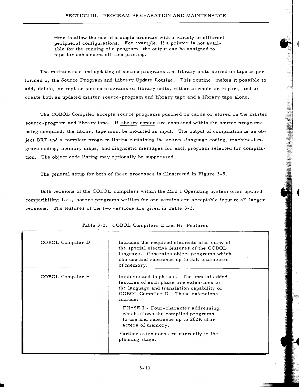
SECTION
III.
PROGRAM
PREPARATION
AND
MAINTENANCE
time
to
allow
the
use
of
a
single
program
with
a
variety
of
different
peripheral
configurations.
For
example,
if
a
printer
is
not
avail-
able
for
the
running
of
a
program,
the
output
can
be
assigned
to
tape
for
subsequent
off-line
printing.
The
maintenance
and
updating
of
source
programs
and
library
units
stored
on
tape
is
per-
formed
by
the
Source
Program
and
Library
Update
Routine.
This
routine
makes
it
possible
to
add,
delete,
or
replace
source
programs
or
library
units,
either
in
whole
or
in
part,
and
to
create
both
an
updated
master
source-program
and
library
tape
and
a
library
tape
alone.
The
COBOL
Compiler
accepts
source
programs
punched
on
cards
or
stored
on
the
master
source-program
and
library
tape.
If
library
copies
are
contained
within
the
source
programs
being
compiled,
the
library
tape
must
be
mounted
as
input.
The
output
of
compilation
is
an
ob-
ject
BRT
and
a
complete
program
listing
containing
the
source
-language
coding,
machine-lan-
guage
coding,
memory
maps,
and
diagnostic
messages
for
each
program
selected
for
compila-
tion.
The
object
code
listing
may
optionally
be
suppressed.
The
general
setup
for
both
of
these
processes
is
illustrated
in
Figure
3-5.
Both
versions
of
the
COBOL
compilers
within
the
Mod
1
Operating
System
offer
upward
compatibility;
i.
e.,
source
programs
written
for
one
version
are
acceptable
input
to
all
larger
versions.
The
features
of
the
two
versions
are
given
in
Table
3-3.
Table
3-3.
COBOL
Compilers
D
and
H:
Features
COBOL
Compiler
D
Includes
the
required
elements
plus
many
of
the
special
elective
features
of
the
COBOL
language.
Generates
object
programs
which
can
use
and
reference
up
to
32K
characters
of
memory.
COBOL
Compiler
H
Implemented
in
phases.
The
special
added
features
of
each
phase
are
extensions
to
the
language
and
translation
capability
of
COBOL
Compiler
D.
These
extensions
include:
PHASE
I -
Four-character
addressing,
which
allows
the
compiled
programs
to
use
and
reference
up
to
262K
char-
acters
of
memory.
Further
extensions
are
currently
in
the
planning
stage.
3-10

SECTION
III.
;'
.......
/OLD
MASTER \
SOURCE
PROG
I
SLiBRARY
I
\...
/
~-
DIRECTORS
AND
SOURCE
PROGRAMS
PROGRAM
PREPARATION
AND
MAINTENANCE
COBOL SOURCE
PROGRAM
AND
LIBRARY
UPDATE
r--
---,
I
LISTINGS
I
I I
,---'
I
;'
L-_/
r-----
---,
r
SELECTED
SOURCE PROGRAMS, PROGRAMS PUNCHED '
AND
LIBRARY
ON CARDS ,
UNITS
--.....
______
J
--,
LIBRARY UNITS
ONLY,
'
....
I
I
,
,
I
I
--I
r-----------------------------~
/~
I
,
,
I
I
I
I
.......
I
LIBRARY
TAPE
\ \
\ /
,~-
DIRECTORS AND
SOURCE PROGRAMS
COBOL
COMPILATION
Figure
3-5.
COBOL
COInpiler
SysteIn
3-11
TO
IMMEDIATE
--
..
EXECUTION
OR
INTEGRATION
WITH
OTHER
OBJECT
PROGRAMS
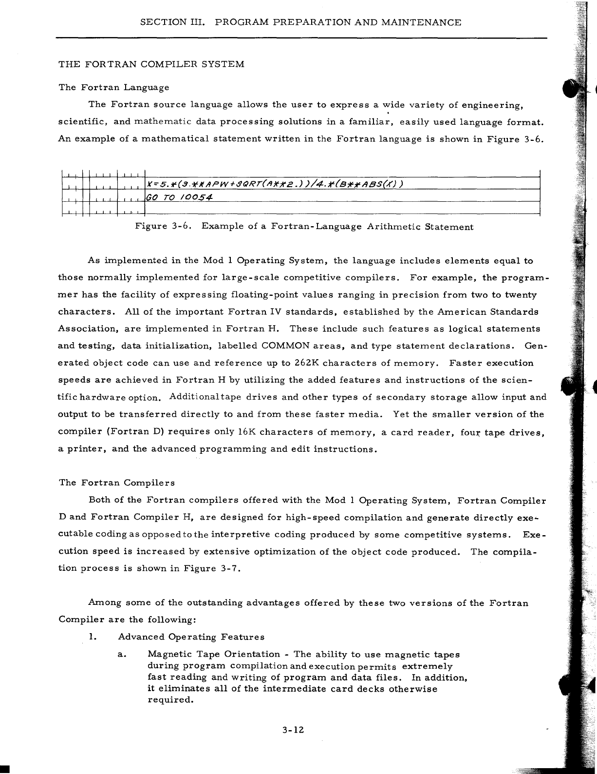
•
SECTION
III.
PROGRAM
PREPARATION
AND
MAINTENANCE
THE
FOR
TRAN
COMPILER
SYSTEM
The
Fortran
Language
The
Fortran
source
language
allows
the
user
to
express
a
wide
variety
of
engineering,
scientific,
and
ITlatheITlatic
data
processing
solutions
in
a
faITliliar,
easily
used
language
forITlat.
An
exaITlple
of
a
ITlatheITlatical
stateITlent
written
in
the
Fortran
language
is
shown
in
Figure
3-6.
GO
TO
/0054
Figure
3-6.
ExaITlple
of
a
Fortran-Language
ArithITletic
StateITlent
As
iITlpleITlented
in
the
Mod
1
Operating
SysteITl,
the
language
includes
eleITlents
equal
to
those
norITlally
iITlpleITlented
for
large-scale
cOITlpetitive
cOITlpilers.
For
exaITlple,
the
prograITl-
ITler
has
the
facility
of
expressing
floating-point
values
ranging
in
precision
froITl
two
to
twenty
characters.
All
of
the
iITlportant
Fortran
IV
standards,
established
by
the
AITlerican
Standards
Association,
are
iITlpleITlented
in
Fortran
H.
These
include
such
features
as
logical
stateITlents
and
testing,
data
initialization,
labelled
COMMON
areas,
and
type
stateITlent
declarations.
Gen-
erated
object
code
can
use
and
reference
up
to
262K
characters
of
ITleITlory.
Faster
execution
speeds
are
achieved
in
Fortran
H
by
utilizing
the
added
features
and
instructions
of
the
scien-
tific
hardware
option.
Additional
tape
drives
and
other
types
of
secondary
storage
allow
input
and
output
to
be
transferred
directly
to
and
froITl
these
faster
ITledia.
Yet
the
sITlaller
version
of
the
cOITlpiler
(Fortran
D)
requires
only
16K
characters
of
ITleITlory,
a
card
reader,
fou~
tape
drives,
a
printer,
and
the
advanced
prograITlITling
and
edit
instructions.
The
Fortran
COITlpilers
Both
of
the
Fortran
cOITlpilers
offered
with
the
Mod
1
Operating
SysteITl,
Fortran
COITlpiler
D
and
Fortran
COITlpiler
H,
are
designed
for
high-speed
cOITlpilation
and
generate
directly
exe-
cutable
coding
as
opposed
to
the
interpretive
coding
produced
by
SOITle
cOITlpetitive
systeITls.
Exe-
cution
speed
is
increased
by
extensive
optiITlization
of
the
object
code
produced.
The
cOITlpila-
tion
process
is
shown
in
Figure
3-7.
AITlong SOITle
of
the
outstanding
advantages
offered
by
these
two
versions
of
the
Fortran
COITlpiler
are
the
following:
1.
Advanced
Operating
Features
a.
Magnetic
Tape
Orientation
-
The
ability
to
use
ITlagnetic
tapes
during
prograITl
cOITlpilation
and
execution
perITlits
extreITlely
fast
reading
and
writing
of
prograITl
and
data
files.
In
addition,
it
eliITlinates
all
of
the
interITlediate
card
decks
otherwise
required.
3-12
SECTION
III.
PROGRAM
PREPARATION
AND
MAINTENANCE
b.
Subprogram
Modularity
- A
Fortran
program
can
consist
of
several
subprograms.
Once
a
subprogram
is
compiled,
it
can
be
punched
into
cards
or
added
to
a
stack
(library)
tape.
Later,
the
subprogram
can
be
combined
with
other
subpro-
grams
to
produce
an
executable
program
or
a
series
of
executable
programs
on
a
binary
run
tape
(BR
T).
The
abil-
ity
to
construct
such
programs
from
a
series
of
already-
compiled
subprograms
accelerates
program
completion
and
permits
more
efficient
organization
and
planning
of
the
work
to
be
aocomplished.
c.
Stack
(Library)
Tape
Usage
-
Permits
the
storage
of
a
user
subprogram
library
on
magnetic
tape.
During
creation
of
an
executable
program,
specific
subprograms
can
be
retrieved
from
this
tape
and
incorporated
into
the
user's
routine.
d.
Fortran/Easycoder
Integration
-
Easycoder
subprograms
are
written
according
to
simple
rules
and
assembled
by
the
Easy-
coder
Assembler.
A
binary
deck
or
tape
can
be
produced
as
output
during
the
assembly
process
and
subsequently
added
to
a
Fortran
program
deck
or
to
the
stack
tape.
e.
Variable
Format
Feature
-
Allows
the
user
to
execute
the
same
program
with
a
number
of
different
inputi
output
formats
without
having
to
recompile
the
program.
Thus,
a
program
need
only
be
compiled
once
regardless
of
the
number
of
data
formats
it
must
handle.
This
feature
allows
programs
to
be
written
and
compiled
independently
of
formatting
considera-
tions
and
eliminates
the
necessity
of
creating
and
maintaining
a
large
number
of
versions
of
the
same
logical
program
for
each
different
data
format.
f.
Load-and-Go
Operation
-
Under
the
direction
of
the
Mod
1
Operating
System
Loader-Monitor,
a
stack
of
separate
job
decks
(each
representing
a
problem)
are
processed
as
follows:
(l)
Job
1
is
compiled
(with
the
integration
of
sub-
programs
from
the
stack
(library)
tape
as
indicated),
and
a
binary
run
tape
is
created.
The
job
is
executed
and
the
results
listed
or
written
onto
tape.
(2)
Control
is
returned
to
the
monitor,
the
next
job
(Job
2)
is
brought
in,
and
the
cycle
is
auto-
matically
repeated.
(3)
This
cycle
continues
until
all
of
the
jobs
have
been
processed.
g.
Go-Later
Operation
- A
second
mode
of
operation
allows
the
user
to
compile
a
series
of
programs,
create
a
BRT,
and
dismount
it
for
use
at
a
later
date.
Another
alternative
is
to
create
a
program
from
a
series
of
subprograms
stored
on
a
stack
(library)
tape
and
execute
this
program
during
the
same
run.
h.
Chaining
-
Permits
the
execution
of
large
programs
within
a
relatively
small
amount
of
memory
by
dividing
such
programs
into
independent
segments
(chains)
which
can
be
loaded
and
executed
at
different
times.
Each
chain
is
overlaid
in
memory
3-13
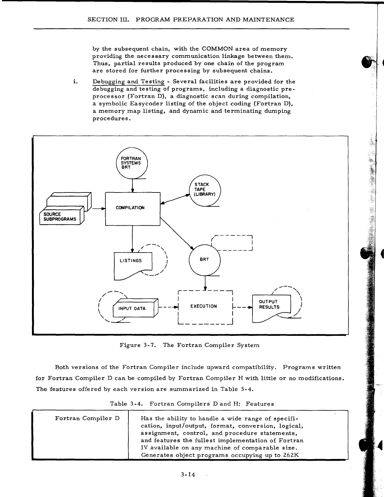
SECTION
III.
PROGRAM
PREPARATION
AND
MAINTENANCE
by
the
subsequent
chain,
with
the
COMMON
area
of
memory
providing
the
necessary
communication
linkage
between
them.
Thus,
partial
results
produced
by
one
chain
of
the
program
are
stored
for
further
processing
by
subsequent
chains.
i.
Debugging
and
Testing
-
Several
facilities
are
provided
for
the
debugging
and
testing
of
programs,
including
a
diagnostic
pre-
processor
(Fortran
D),
a
diagnostic
scan
during
compilation,
a
symbolic
Easycoder
listing
of
the
object
coding
(Fortran
D),
a
memory
map
listing,
and
dynamic
and
terminating
dumping
procedures.
COMPILATION
---
......
'"
"-
r---~~~~
\ \
LISTINGS
I
--_..-'
/
/
..-------,
( I
_____
..J
r---
---,
",---,,\
/--
.......
I
~:====71
I
, OUTPUT \
RESULTS I
I I
-
--.I
EXECUTION
I-
--
-L
I I
L _______
~
"-
'-""'---
Figure
3-7.
The
Fortran
Compiler
System
Both
versions
of
the
Fortran
Compiler
include
upward
compatibility.
Programs
written
for
Fortran
Compiler
D
can
be
compiled
by
Fortran
Compiler
H
with
little
or
no
modifications.
The
features
offered
by
each
version
are
summarized
in
Table
3-4.
Table
3-4.
Fortran
Compilers
D
and
H:
Features
Fortran
Compiler
D
Has
the
ability
to
handle
a
wide
range
of
specifi-
cation,
input/output,
format,
conversion,
logical,
assignment,
control,
and
procedure
statements,
and
features
the
fullest
implementation
of
Fortran
IV
available
on
any
machine
of
comparable
size.
Generates
object
programs
occupying
up
to
262K
3-14
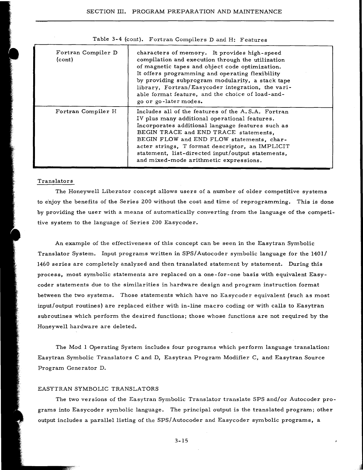
SECTION
III.
PROGRAM
PREPARATION
AND
MAINTENANCE
Table
3-4
(cont).
Fortran
Compilers
D
and
H:
Features
Fortran
Compiler
D
(cont)
Fortran
Compiler
H
Translators
characters
of
memory.
It
provides
high-speed
compilation
and
execution
through
the
utilization
of
magnetic
tapes
and
object
code
optimization.
It
offers
programming
and
operating
flexibility
by
providing
subprogram
modularity,
a
stack
tape
library,
Fortran/Easycoder
integration,
the
vari-
able
format
feature,
and
the
choice
of
load-and-
go
or
go-later
modes.
Includes
all
of
the
features
of
the
A.
S.A.
Fortran
IV
plus
many
additional
operational
features.
Incorporates
additional
language
features
such
as
BEGIN
TRACE
and
END
TRACE
statements,
BEGIN
FLOW
and
END
FLOW
statements,
char-
acter
strings,
T
format
descriptor,
an
IMPLICIT
statement,
list-directed
input/output
statements,
and
mixed-mode
arithmetic
expressions.
The
Honeywell
Liberator
concept
allows
users
of
a
number
of
older
competitive
systems
to
e"njoy
the
benefits
of
the
Series
200
without
the
cost
and
time
of
reprogramming.
This
is
done
by
providing
the
user
with
a
means
of
automatically
converting
from
the
language
of
the
competi-
tive
system
to
the
language
of
Series
200
Easycoder.
An
example
of
the
effectiveness
of
this
concept
can
be
seen
in
the
Easytran
Symbolic
Translator
System.
Input
programs
written
in
SPS/
Autocoder
symbolic
language
for
the
1401/
1460
series
are
completely
analyzed
and
then
translated
statement
by
statement.
During
this
process,
most
symbolic
statements
are
replaced
on
a
one-for-one
basis
with
equivalent
Easy-
coder
statements
due
to
the
similarities
in
hardware
design
and
program
instruction
format
between
the
two
systems.
Those
statements
which
have
no
Easycoder
equivalent
(such
as
most
input/
output
routines)
are
replaced
either
with
in-line
macro
coding
or
with
calls
to
Easytran
subroutines
which
perform
the
desired
functions;
those
whose
functions
are
not
required
by
the
Honeywell
hardware
are
deleted.
The
Mod
1
Operating
System
includes
four
programs
which
perform
language
translation:
Easytran
Symbolic
Translators
C
and
D,
Easytran
Program
Modifier
C,
and
Easytran
Source
Program
Generator
D.
EASYTRAN
SYMBOLIC
TRANSLATORS
The
two
versions
of
the
Easytran
Symbolic
Translator
translate
SPS
and/or
Autocoder
pro-
grams
into
Easycoder
symbolic
language.
The
principal
output
is
the
translated
program;
other
output
includes
a
parallel
listing
of
the
SPS/Autocoder
and
Easycoder
symbolic
programs,
a
3-15
· -
SECTION
III.
PROGRAM
PREPARATION
AND
MAINTENANCE
cross
-reference
listing
of
all
tags
used
in
the
input
program,
and
an
English-language
diagnos-
tic
listing
pointing
out
any
areas
where
modification
might
be
required.
If
the
source
program
contains
macro
calls
to
the
Autocoder
IOCS
functions,
these
are
replaced
with
equivalent
calls
to
the
lIZ-Inch
Tape
Input/Output
Package,
which
are
then
pro-
cessed
by
a
special
preassembly
routine
(Library
Processor
C).
Memory
requirements
for
the
translated
program
are
only
10%
more
than
those
of
the
original
program,
plus
additional
memory
for
the
Easytran
subroutines
and
for
double-buffering
of
tape
files.
Despite
this
additional
memory,
the
running
time
of
the
translated
program
is
usually
improved
due
to
the
faster
cycle
time
and
extensive
peripheral
simultaneity
of
the
Series
ZOO
processors.
The
general
systems
diagram
for
the
translators
is
shown
in
Figure
3-
8.
---~
TRANSLATION
AND/OR
UPDATE
----
'"
",/
'"
./
LIBRARY
~/0
OBJECT
AND
ASSEMBLY
EXECUTION
- - - -
-L
__
PR_O_C_E_S_S_OR
__
---'r -BRT - -
..
L.._P_R_O_G_R_A_M_---'
Figure
3-8.
The
Easytran
Symbolic
Translator
System
The
unique
features
of
each
of
the
versions
are
summarized
in
Table
3-5.
Table
3-5.
Easytran
Symbolic
Translators
C
and
D:
Features
Easytran
Symbolic
Translator
C
Will
accept
source
programs
written
in
SPS
or
Autocoder.
The
Autocoder
source
programs
may
contain
macro
calls.
Produces
an
Easycoder
C
sym-
bolic
source
deck,
a
parallel
source-
program
listing,
an
English-language
diagnostic
listing,
and
a
cross-refer-
ence
tag
listing.
The
symbolic
deck
must
be
processed
through
Library
Processor
C
and
Easycoder
Assembler
C
to
produce
an
executable
program.
3-16
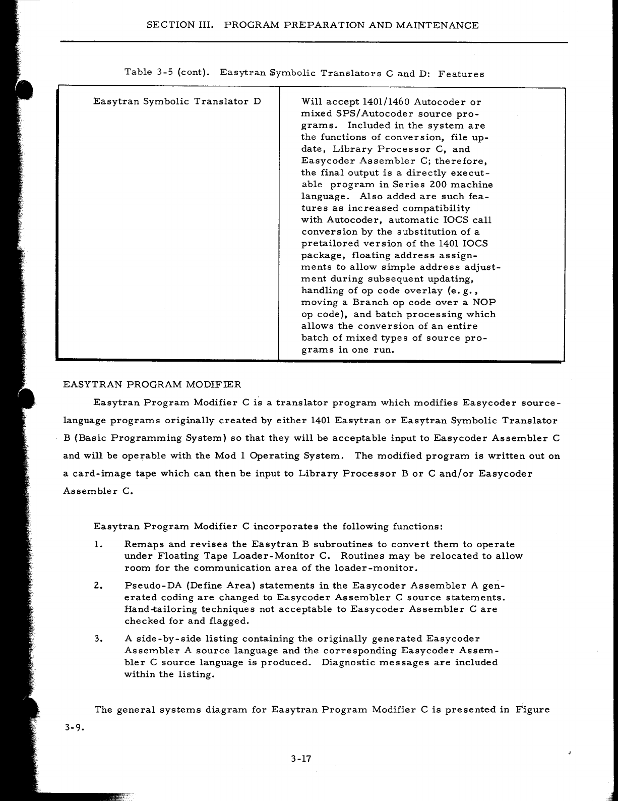
SECTION
III.
PROGRAM
PREPARATION
AND
MAINTENANCE
Table
3-5
(cont).
Easytran
SyITlbolic
Translators
C
and
D:
Features
Easytran
SYITlbolic
Translator
D
Will
accept
1401/1460
Autocoder
or
ITlixed
SPS/
Autocoder
source
pro-
graITls.
Included
in
the
systeITl
are
the
functions
of
conversion,
file
up-
date,
Library
Processor
C,
and
Easycoder
AsseITlbler
C;
therefore,
the
final
output
is
a
directly
execut-
able
prograITl
in
Series
200
ITlachine
language.
Also
added
are
such
fea-
tures
as
increased
cOITlpatibility
with
Autocoder,
autoITlatic
IOCS
call
conversion
by
the
substitution
of
a
pretailored
version
of
the
1401
IOCS
package,
floating
address
assign-
ITlents
to
allow
siITlple
address
adjust-
ITlent
during
subsequent
updating,
handling
of
op
code
overlay
(e.
g.
,
ITloving
a
Branch
op
code
over
a
NOP
op
code),
and
batch
processing
which
allows
the
conversion
of
an
entire
batch
of
ITlixed
types
of
source
pro-
graITls
in
one
run.
EASYTRAN
PROGRAM
MODIFIER
Easytran
PrograITl
Modifier
C
is
a
translator
prograITl
which
ITlodifies
Easycoder
source-
language
prograITls
originally
created
by
either
1401
Easytran
or
Easytran
SYITlbolic
Translator
B
(Basic
PrograITlITling
SysteITl)
so
that
they
will
be
acceptable
input
to
Easycoder
AsseITlbler
C
and
will
be
operable
with
the
Mod
1
Operating
SysteITl.
The
ITlodified
prograITl
is
written
out
on
a
card-iITlage
tape
which
can
then
be
input
to
Library
Processor
B
or
C
and/or
Easycoder
AsseITlbler
C.
3-9.
Easytran
PrograITl
Modifier
C
incorporates
the
following
functions:
1.
ReITlaps
and
revises
the
Easytran
B
subroutines
to
convert
theITl
to
operate
under
Floating
Tape
Loader-Monitor
C.
Routines
ITlay
be
relocated
to
allow
rOOITl
for
the
cOITlITlunication
area
of
the
loader
-ITlonitor.
2.
Pseudo-DA
(Define
Area)
stateITlents
in
the
Easycoder
AsseITlbler
A
gen-
erated
coding
are
changed
to
Easycoder
AsseITlbler
C
source
stateITlents.
Hand-tailoring
techniques
not
acceptable
to
Easycoder
AsseITlbler
Care
checked
for
and
flagged.
3.
A
side-by-side
listing
containing
the
originally
generated
Easycoder
AsseITlbler
A
source
language
and
the
corresponding
Easycoder
AsseITl-
bIer
C
source
language
is
produced.
Diagnostic
ITlessages
are
included
within
the
listing.
The
general
systeITls
diagraITl
for
Easytran
PrograITl
Modifier
C
is
presented
in
Figure
3-17
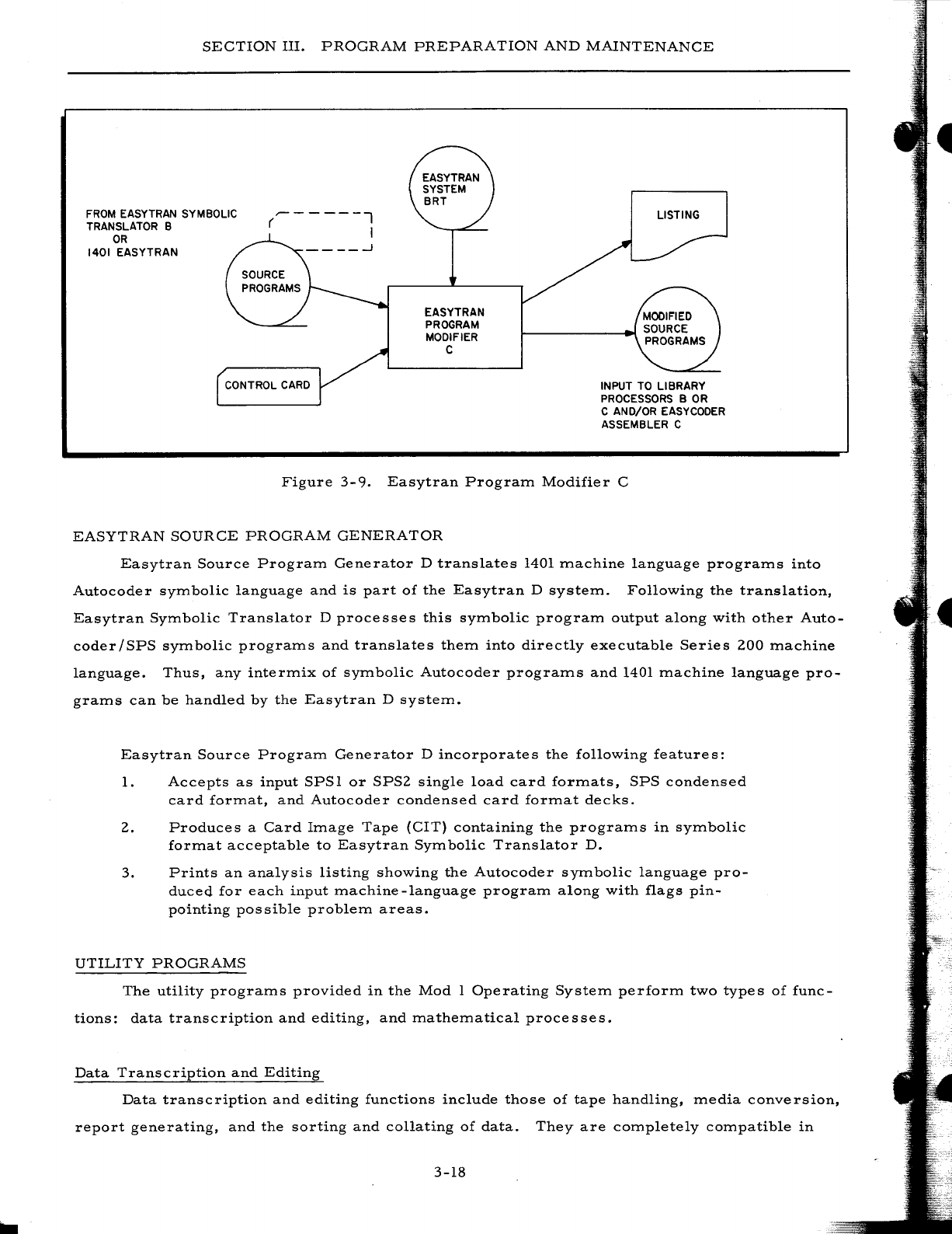
SECTION
III.
PROGRAM
PREPARATION
AND
MAINTENANCE
FROM
EASYTRAN SYMBOLIC
TRANSLATOR B
OR
1401
EASYTRAN
~-----l
( I
EASYTRAN
PROGRAM
MODIFIER
C
LISTING
CONTROL
CARD
INPUT TO LIBRARY
PROCESSORS B
OR
C AND/OR EASYCODER
ASSEMBLER C
Figure
3-9.
Easytran
Program
Modifier
C
EASYTRAN
SOURCE
PROGRAM
GENERATOR
Easytran
Source
Program
Generator
D
translates
1401
machine
language
programs
into
Autocoder
symbolic
language
and
is
part
of
the
Easytran
D
system.
Following
the
translation,
Easytran
Symbolic
Translator
D
processes
this
symbolic
program
output
along
with
other
Auto-
coder/SPS
symbolic
programs
and
translates
them
into
directly
executable
Series
200
machine
language.
Thus,
any
intermix
of
symbolic
Autocoder
programs
and
1401
machine
language
pro-
grams
can
be
handled
by
the
Easytran
D
system.
Easytran
Source
Program
Generator
D
incorporates
the
following
features:
1.
Accepts
as
input
SPSl
or
SPS2
single
load
card
formats,
SPS
condensed
card
format,
and
Autocoder
condensed
card
format
decks.
2.
Produces
a
Card
Image
Tape
(CIT)
containing
the
programs
in
symbolic
format
acceptable
to
Easytran
Symbolic
Translator
D.
3.
Prints
an
analysis
listing
showing
the
Autocoder
symbolic
language
pro-
duced
for
each
input
machine
-language
program
along
with
flags
pin-
pointing
possible
problem
areas.
UTILITY
PROGRAMS
The
utility
programs
provided
in
the
Mod
1
Operating
System
perform
two
types
of
func-
tions:
data
transcription
and
editing,
and
mathematical
processes.
Data
Transcription
and
Editing
Data
transcription
and
editing
functions
include
those
of
tape
handling,
media
conversion,
report
generating,
and
the
sorting
and
collating
of
data.
They
are
completely
compatible
in
3-18
SECTION
III.
PROGRAM
PREPARATION
AND
MAINTENANCE
operation
with
all
of
the
programs
written
for,
and
processed
by,
any
of
the
language
processors;
therefore,
they
can
be
intermixed
on
a
BRT
with
user-written
programs.
By
incorporating
these
functions
into
his
system,
the
user
not
only
saves
the
time
which
would
have
to
be
spent
in
writ-
ing
his
own
routines,
but
also
benefits
from
a
reduction
of
the
memory
space
and
exection
time
required.
T
APE
HANDLING
Tape
Handling
Routine
C
includes
a
set
of
general
tape-handling
and
correction
routines
for
use
with
liZ-inch
and
3/4-inch
magnetic
tapes.
Parameters
for
controlling
the
various
func-
tions
provided
can
be
entered
from
cards,
paper
tape,
or
the
control
panel.
Functions
which
operate
on
a
record-by-record
basis
(e.
g.,
copying)
can
be
directed
to
terminate
either
upon
the
processing
of
a
certain
number
of
records
or
upon
the
sensing
of
a
standard
label
or
file
identi-
fication
record.
The
functions
of
Tape
Handling
Routine
C
are
as
follows:
1.
Edit
-
Records
(or
portions
of
records)
can
be
edited
from
a
specified
tape
to
an
on-line
printer,
in
either
alphanumeric
or
octal
mode.
Z.
Rewind
-
One
or
more
magnetic
tapes
can
be
rewound
in
a
single
operation.
3.
Copy
- A
specified
number
of
records
can
be
copied
from
one
tape
to
another.
4.
Correct
and
Copy
- A
designated
record
is
copied
from
one
tape
to
another
with
specified
corrections.
5.
Forward
- A
tape
can
be
positioned
forward
a
specifed
number
of
records.
6.
Backspace
- A
tape
can
be
backspaced
a
specified
number
of
records.
7.
Compare
and
Print
- A
specified
number
of
records
from
each
of
two
tapes
are
compared
record-for-record.
Those
records
which
are
not
identical
are
printed
in
either
alphanumeric
or
octal
mode.
8.
Locate
-A
tape
is
searched
for
a
record
containing
a
specified
piece
of
information.
Upon
locating
such
a
record,
the
tape
is
backspaced
one
rec-
ord,
thus
permitting
another
operation
to
be
performed
on
the
located
record.
9.
Write
dummy
header
label
- A
dummy
header
label,
containing
a
phys~
ical
tape
reel
serial
number,
is
written
on
a
new
tape.
MEDIA
CONVERSION
Media
conversion
routines
transfer
data
from
one
medium
to
another.
This
might
be
done
for
one
of
several
reasons:
to
increase
the
speed
of
subsequent
processing
of
the
data
by
plac-
ing
it
on
a
faster
medium
(e.
g.,
converting
punched
cards
to
card
images
on
magnetic
tape),
to
permit
visual
examination
of
the
data
(e.
g.,
converting
print
images
on
tape
to
printed
output),
or
to
permit
physical
manipulation
of
the
data
(e.
g.,
converting
card
images
on
tape
to
punched
cards
).
3-19
•
SECTION
III.
PROGRAM
PREPARATION
AND
MAINTENANCE
Data
Conversion
C
Routines
Data
Conversion
C
routines
are
actually
macro
routines
which
can
be
adapted
to
process
any
file
format
and
to
operate
in
several
environments.
Three
generalized
conversion
routines
are
provided:
1.
Card-to-Tape
C,
which
converts
a
punched-card
file
to
a
card-image
file
on
magnetic
tape.
2.
Tape-to-Printer
C,
which
converts
a
print-image
file
on
magnetic
tape
to
printed
output.
3.
Tape
-to-Punch
C,
which
converts
a
card-image
file
on
magnetic
tape
to
a
punched-card
file.
These
three
routines
can
be
executed
in
any
of
three
operating
environments:
1.
As
independent
programs,
2.
As
coroutines
operating
together
under
Simultaneous
Media
Conversion
C,
or
3.
As
foreground
programs
operating
simultaneously
with
some
other
pro-
gram
under
Interrupt
Control
D.
As
independent
programs,
the
routines
can
be
executed
apart
from
any
controlling
program.
Running
under
the
control
of
the
Simultaneous
Media
Conversion
(SCOPE)
monitor,
two
(or
three)
of
the
routines
can
be
executed
simultaneously.
As
a
foreground
program,
anyone
of
the
rou-
tines
can
operate
in
the
interrupt
mode
under
Interrupt
Control
D.
Under
this
last
method,
the
conversion
routine
is
assigned
all
of
the
processor
cycles
until
it
initiates
a
Peripheral
Data
Transfer
(PDT)
instruction.
While
this
instruction
is
being
carried
out,
all
processing
cycles
are
allocated
to
a
background
program
which
consists
of
a
great
amount
of
internal
processing,
such
as
a
sort
or
an
assembly.
At
the
end
of
the
data
transfer
operation,
Interrupt
Control
D
receives
an
interrupt
signal
which
directs
that
control
be
reas
signed
to
the
conversion
routine.
All
three
routines
accept
as
input
or
generate
as
output
a
wide
variety
of
tape
file
formats
including
Honeywell
or
IBM
files
containing
fixed-length
or
variable-length
records,
blocked
or
unblocked.
Banner
and
print
control
characters
mayor
may
not
be
present.
Among
the
several
processing
advantages
offered
by
these
conversion
routines
are
the
following:
1.
Control
cards
-
The
specialization
of
Data
Conversion
C
routines
(through
Library
Processor
C)
establishes
the
operating
mode
and
general
file
type
to
be
handled.
However,
parameters
describing
the
file
structure
can
be
modified
at
execution
time
by
parameters
entered
via
a
control
card.
2.
Own-coding
option
-
All
routines
provide
exits
which
allow
data
to
be
edited
before
it
is
converted
to
the
output
mediwn.
3-20
SECTION
III.
PROGRAM
PREPARATION
AND
MAINTENANCE
3.
Card
count
-
Routines
handling
punched
cards
count
the
number
of
cards
converted.
4.
Variable
card
length
-
Routines
can
accept
or
generate
cards
or
card
images
of
less
than
80
columns
in
length.
s.
Item
print
bypass
-
Printing
of
specified
card-image
items
can
be
by-
passed
during
a
Tape-to-Printer
C
run.
6.
IBM
print
compatibility
-
Tape-to-Printer
C
may
be
specialized
to
include
coding
for
automatically
translating
special
IBM
print
charac-
ters
to
Honeywell
print
characters.
IBM
channel
skipping
can
also
be
simulated
in
Honeywell
Type
222
Printers.
7.
Sequence
checking
-
Card-to-
Tape
C
and
Tape
-to-Punch
C
can
perform
a
sequence
check
on
input
items
and
halt
when
an
item
is
out
of
sequence.
Simultaneous
Media
Conversion
C
Simultaneous
Media
Conversion
(SCOPE)
C
consists
of
a
group
of
independent
coroutines
which
can
operate
simultaneously
to
perform
conversion
of
data
from
one
medium
to
another.
Among
the
operations
performed
are:
1.
Punched
cards
to
magnetic
tape,
2.
Magnetic
tape
to
punched
cards,
3.
Magnetic
tape
to
printed
output,
4.
Paper
tape
to
magnetic
tape,
and
S.
Magnetic
tape
to
paper
tape.
Up
to
three
of
these
routines
can
be
combined
and
executed
simultaneously.
In
making
up
his
own
version
of
the
package,
the
user
selects
the
source-language
program
decks
for
each
of
the
operations
desired
plus
the
source
deck
for
the
monitor
(main
control
routine)
and
assembles
them
together
via
Easycoder
Assembler
C.
(NOTE:
The
paper
tape
conversion
routines
must
first
be
specialized
by
Library
Processor
C.)
During
execution,
the
monitor
acts
as
the
con-
trolling
routine
in
determining
the
allocation
of
machine
cycles
to
the
various
input/output
con-
version
routines
in
the
most
efficient
manner.
REPOR
T
GENERATION
Source-language
programs
which
simulate
and
expand
the
report
preparation
functions
of
an
E.
A.
M.
tabulating
machine
are
generated
by
a
report
generating
program.
Report
Generator
C
generates
programs
in
Easycoder
C
source
language
which,
when
assembled
by
Easycoder
Assembler
C,
produce
reports
from
card
or
tape
input
according
to
the
language
parameters
entered
during
generation
by
the
programmer.
The
output
reports
can
be
produced
in
the
form
of
printed
copy,
punched
cards,
and/or
magnetic
tape.
To
direct
the
generation
of
the
source-language
program,
the
user
punches
a
series
of
language
parameter
cards.
These
parameter
cards
are
compatible
with
those
of
the
1401
Report
3-21
SECTION
III.
PROGRAM
PREPARATION
AND
MAINTENANCE
Program
Generator.
The
parameter
cards
specify
to
Report
Generator
C
the
types
of
record
formats
present
in
the
input
file
(Input
cards),
the
fields
to
be
processed
and
any
simple
cal-
culations
to
be
performed
on
them
(Data
cards),
any
extensive
calculations
to
be
made
(Calcu-
lation
cards),
the
format
of
the
fields
and
lines
constituting
the
output
(Format
cards),
the
opera-
ting
environment
of
the
generated
program
(Control
card),
and
information
to
be
used
in
the
sim-
ulation
of
the
carriage
control
paper
tape
functions
on
the
tabulator
(Carriage
Control
card).
The
primary
purpose
of
Report
Generator
C
is
to
eliminate
the
need
for
the
user
to
devel-
op
and
code
a
separate
program
for
each
of
a
variety
of
reports.
Instead,
he
prepare
s
the
speci-
fication
cards
and
merges
them
with
the
Report
Generator
C
master
deck.
Report
Generator
C
then
produces
a
program
which
writes
the
report
in
accordance
with
the
specifications
stated
by
the
programmer.
SOR
TING
AND
COLLATING
A
number
of
sorting
and
collating
routines
are
available
in
the
Mod
1
Operating
System
to
process
data
stored
on
magnetic
tapes
or
on
drum
storage.
Magnetic
Tape
All
tape
sorting
routines
are
based
on
the
Honeywell-developed
polyphase
merge
technique,
which
uses
as
few
as
three
tape
drives
while
minimizing
the
number
of
passes
required
over
the
data.
Each
sort
operation
is
performed
in
two
stages:
the
presort
and
the
merge.
The
presort
arranges
the
input
data
in
ordered
strings,
the
number
and
length
of
which
depend
on
the
amount
of
core
storage
available
and
on
the
degree
of
preordering
which
exists
in
the
data.
The
merge
phase
produces
longer
ordered
strings
by
combining
strings
produced
during
the
presort.
This
continues
until
there
is
only
a
single
ordered
string
on
each
work
tape.
At
this
point,
the
last
pass
of
the
merge
combines
the
remaining
strings
to
form
an
ordered
file
on
the
output
tape.
The
collate
routines,
which
may
be
used
independently
or
in
conjunction
with
the
sorts,
combine
two
or
more
ordered
tape
files
to
form
a
single
ordered
tape
file.
Each
file
to
be
collated,
as
well
as
the
combined
output
file,
may
reside
on
one
or
more
reels
of
tape.
Routines
are
provided
for
sorting
and
collating
both
fixed-
and
variable-length
items,
blocked
or
unblocked.
Parameters,
entered
from
either
punched
cards
or
paper
tape
or
set
up
by
instructions
of
some
program
executed
prior
to
the
sort
or
collate
routine,
specify
the
item
and
record
lengths,
the
number
and
locations
of
the
key
fields
within
each
item,
the
desired
out-
put
sequence
(ascending
or
descending),
the
collating
sequence
to
be
used
(standard
Honeywell.or
other),
and
other
characteristics.
Both
routines
contain
provisions
for
own-coding,
which
the
user
can
prepare
in
Easycoder
source
language
if
desired.
3-22
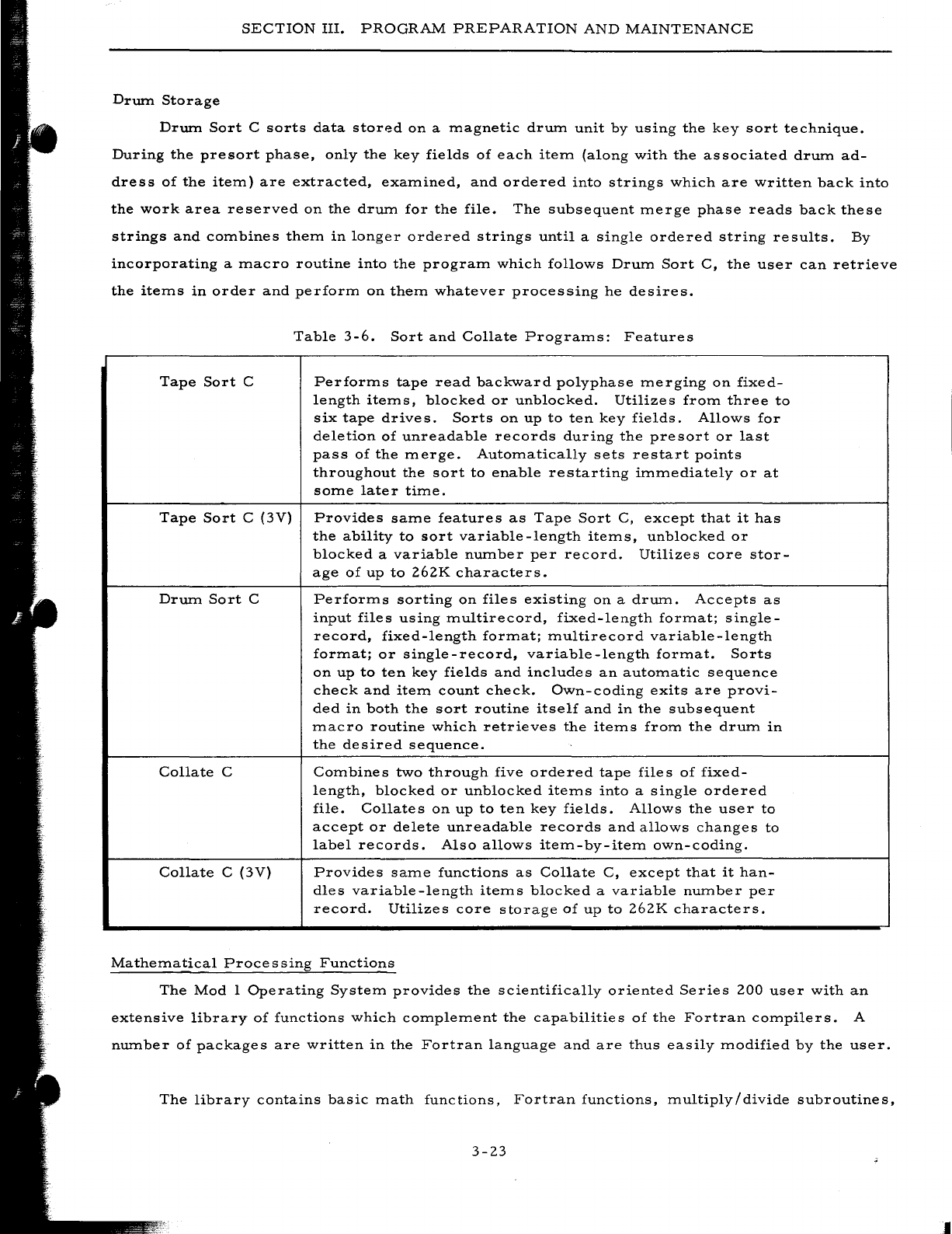
SECTION
III.
PROGRAM
PREPARATION
AND
MAINTENANCE
Drwn
Storage
Drwn
Sort
C
sorts
data
storp-d
on
a
magnetic
drwn
unit
by
using
the
key
sort
technique.
During
the
presort
phase,
only
the
key
fields
of
each
item
(along
with
the
associated
drum
ad-
dress
of
the
item)
are
extracted,
examined,
and
ordered
into
strings
which
are
written
back
into
the
work
area
reserved
on
the
drwn
for
the
file.
The
subsequent
merge
phase
reads
back
these
strings
and
combines
them
in
longer
ordered
strings
until
a
single
ordered
string
results.
By
incorporating
a
macro
routine
into
the
program
which
follows
Drum
Sort
C,
the
user
can
retrieve
the
items
in
order
and
perform
on
them
whatever
processing
he
desires.
Table
3-6.
Sort
and
Collate
Programs:
Features
Tape
Sort
C
Performs
tape
read
backward
polyphase
merging
on
fixed-
length
items,
blocked
or
unblocked.
Utilizes
from
three
to
six
tape
drive
s.
Sorts
on
up
to
ten
key
fields.
Allows
for
deletion
of
unreadable
records
during
the
presort
or
last
pass
of
the
merge.
Automatically
sets
restart
points
throughout
the
sort
to
enable
restarting
immediately
or
at
some
later
time.
Tape
Sort
C
(3V)
Provides
same
features
as
Tape
Sort
C,
except
that
it
has
the
ability
to
sort
variable-length
items,
unblocked
or
blocked
a
variable
nwnber
per
record.
Utilizes
core
stor-
age
of
up
to
262K
characters.
Drwn
Sort
C
Performs
sorting
on
files
existing
on
a
drwn.
Accepts
as
input
files
using
multirecord,
fixed-length
format;
single-
record,
fixed-length
format;
multirecord
variable-length
format;
or
single-record,
variable-length
format.
Sorts
on
up
to
ten
key
fields
and
includes
an
automatic
sequence
check
and
item
count
check.
Own-coding
exits
are
provi-
ded
in
both
the
sort
routine
itself
and
in
the
subsequent
macro
routine
which
retrieves
the
items
from
the
drum
in
the
desired
sequence.
Collate
C
Combines
two
through
five
ordered
tape
files
of
fixed-
length,
blocked
or
unblocked
items
into
a
single
ordered
file.
Collates
on
up
to
ten
key
fields.
Allows
the
user
to
accept
or
delete
unreadable
records
and
allows
changes
to
label
records.
Also
allows
item-by-item
own-coding.
Collate
C
(3V)
Provides
same
functions
as
Collate
C,
except
that
it
han-
dles
variable-length
items
blocked
a
variable
number
per
record.
Utilizes
core
storage
of
up
to
262K
characters.
Mathematical
Processing
Functions
The
Mod
I
Operating
System
provides
the
scientifically
oriented
Series
200
user
with
an
extensive
library
of
functions
which
complement
the
capabilities
of
the
Fortran
compilers.
A
nwnber
of
packages
are
written
in
the
Fortran
language
and
are
thus
easily
modified
by
the
user.
The
library
contains
basic
math
functions,
Fortran
functions,
multiply/divide
subroutines,
3-23
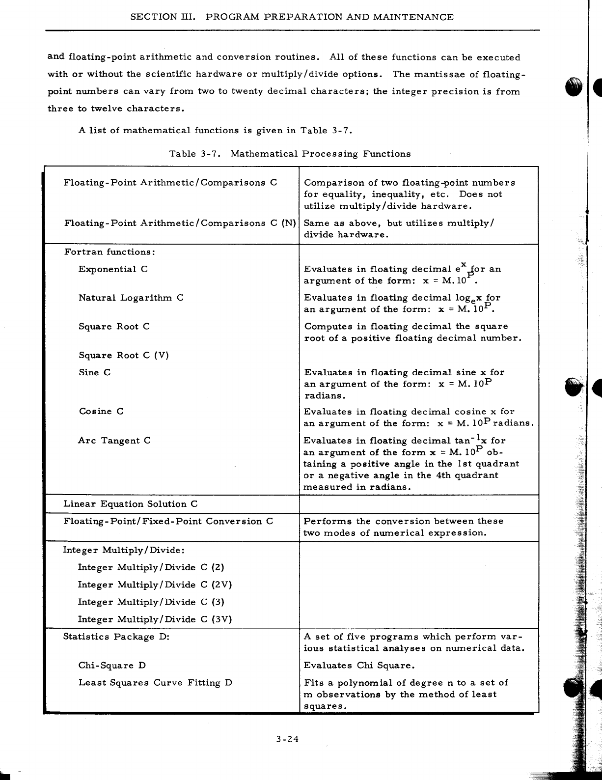
SECTION
III.
PROGRAM
PREPARATION
AND
MAINTENANCE
and
floating-point
arithmetic
and
conversion
routines.
All
of
these
functions
can
be
executed
with
or
without
the
scientific
hardware
or
multiply/divide
options.
The
mantissae
of
floating-
point
numbers
can
vary
from
two
to
twenty
decimal
characters;
the
integer
precision
is
from
three
to
twelve
characters.
A
list
of
mathematical
functions
is
given
in
Table
3-7.
Table
3-7.
Mathematical
Processing
Functions
Floating
-
Point
Arithmetic
/
Comparisons
C
Comparison
of
two
floating-point
numbers
for
equality,
inequality,
etc.
Does
not
utilize
multiply/divide
hardware.
Floating-Point
Arithmetic/Comparisons
C
(N)
Same
as
above,
but
utilizes
multiply/
divide
hardware.
Fortran
functions:
Exponential
C
Natural
Logarithm
C
Square
Root
C
Square
Root
C
(V)
Sine
C
Cosine
C
Arc
Tangent
C
Linear
Equation
Solution
C
Floating-Point/Fixed-Point
Conversion
C
Integer
Multiply/Divide:
Integer
Multiply/Divide
C
(2)
Integer
Multiply/Divide
C
(2V)
Integer
Multiply/Divide
C
(3)
Integer
Multiply/Divide
C
(3V)
Statistics
Package
D:
Chi-Square
D
Least
Squares
Curve
Fitting
D
3-24
Evaluates
in
floating
decimal
eX
~or
an
argument
of
the
form:
x =
M.IO
.
Evaluates
in
floating
decimal
logex
for
an
argument
of
the
form:
x =
M.
lOP.
Computes
in
floating
decimal
the
square
root
of
a
positive
floating
decimal
number.
Evaluates
in
floating
decimal
sine
x
for
an
argument
of
the
form:
x =
M.
lOP
radians.
Evaluates
in
floating
decimal
cosine
x
for
an
argum.ent
of
the
forIn:
x =
M.
lOP
radians.
Evaluates
in
floa.ting
decimal
tan-Ix
for
an
argument
of
the
form
x =
M.
lOP
ob-
taining
a
positive
angle
in
the
1st
quadrant
or
a
negative
angle
in
the
4th
quadrant
measured
in
ra.dians.
Performs
the
conversion
between
these
two
modes
of
numerical
expression.
A
set
of
five
programs
which
perform
var-
ious
statistical
analyses
on
numerical
data.
Evaluate
s
Chi
Square.
Fits
a
polynomial
of
degree
n
to
a
set
of
m
observations
by
the
method
of
least
squares.
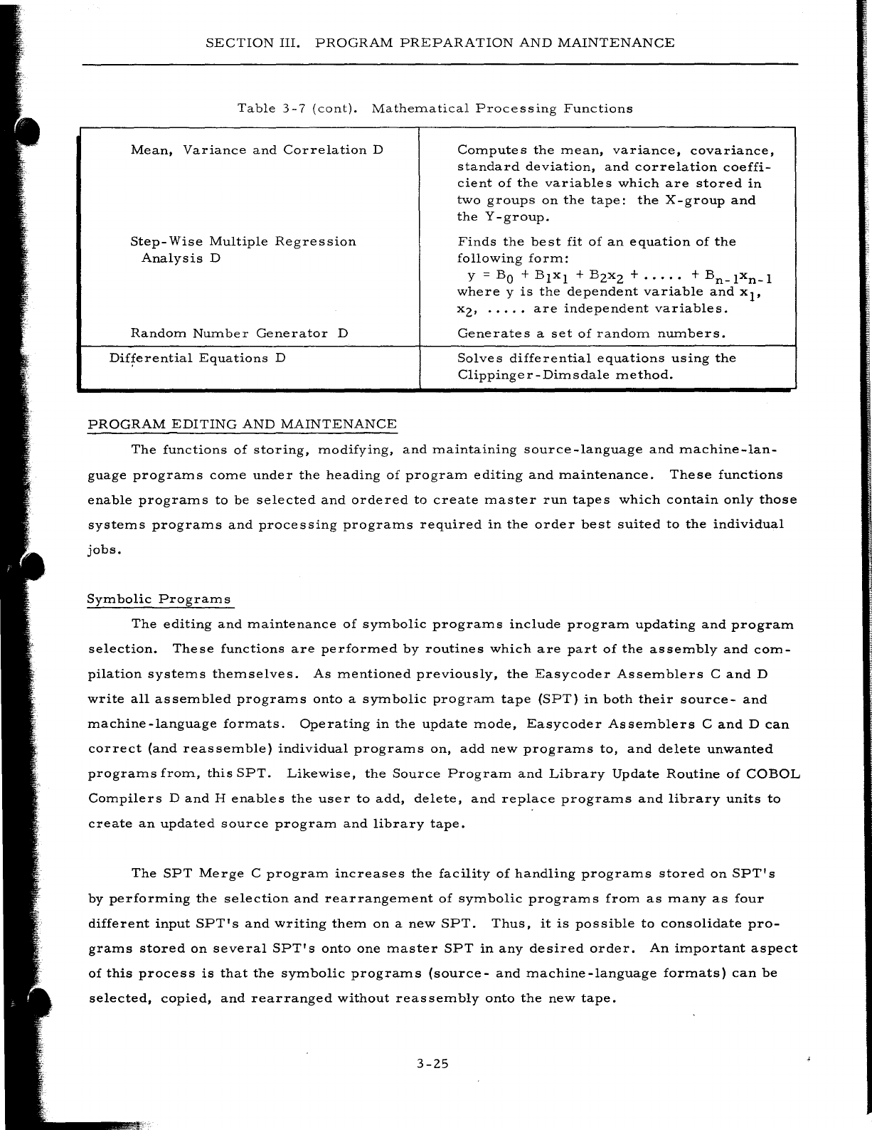
SECTION
III.
PROGRAM
PREPARATION
AND
MAINTENANCE
Table
3-7
(cont).
Mathematical
Processing
Functions
Mean,
Variance
and
Correlation
D
Step-
Wise
Multiple
Regression
Analysis
D
Random
Number
Generator
D
Differential
Equations
D
PROGRAM
EDITING
AND
MAINTENANCE
Compute
s
the
mean,
variance,
covariance,
standard
deviation,
and
correlation
coeffi-
cient
of
the
variables
which
are
stored
in
two
groups
on
the
tape:
the
X-group
and
the
Y
-group.
Finds
the
best
fit
of
an
equation
of
the
following
form:
y =
BO
+
Blxl
+
BZxZ
+
.....
+
Bn_lxn_l
where
y
is
the
dependent
variable
and
xl'
xz'
.....
are
independent
variables.
Generates
a
set
of
random
numbers.
Solves
differential
equations
using
the
Clippinger-Dimsdale
method.
The
functions
of
storing,
modifying,
and
maintaining
source
-language
and
machine-lan-
guage
programs
come
under
the
heading
of
program
editing
and
maintenance.
These
functions
enable
programs
to
be
selected
and
ordered
to
create
master
run
tapes
which
contain
only
those
systems
programs
and
processing
programs
required
in
the
order
best
suited
to
the
individual
jobs.
Symbolic
Programs
The
editing
and
maintenance
of
symbolic
programs
include
program
updating
and
program
selection.
These
functions
are
performed
by
routines
which
are
part
of
the
assembly
and
com-
pilation
systems
themselves.
As
mentioned
previously,
the
Easycoder
Assemblers
C
and
D
write
all
assembled
programs
onto
a
symbolic
program
tape
(SPT)
in
both
their
source-
and
machine-language
formats.
Operating
in
the
update
mode,
Easycoder
Assemblers
C
and
D
can
correct
(and
reassemble)
individual
programs
on,
add
new
programs
to,
and
delete
unwanted
programs
from,
this
SPT.
Likewise,
the
Source
Program
and
Library
Update
Routine
of
COBOL
Compilers
D
and
H
enables
the
user
to
add,
delete,
and
replace
programs
and
library
units
to
create
an
updated
source
program
and
library
tape.
The
SPT
Merge
C
program
increases
the
facility
of
handling
programs
stored
on
SPT's
by
performing
the
selection
and
rearrangement
of
symbolic
programs
from
as
many
as
four
different
input
SPT's
and
writing
them
on
a
new
SPT.
Thus,
it
is
possible
to
consolidate
pro-
grams
stored
on
several
SPT's
onto
one
master
SPT
in
any
desired
order.
An
important
aspect
of
this
process
is
that
the
symbolic
programs
(source-
and
machine-language
formats)
can
be
selected,
copied,
and
rearranged
without
reassembly
onto
the
new
tape.
3-Z5
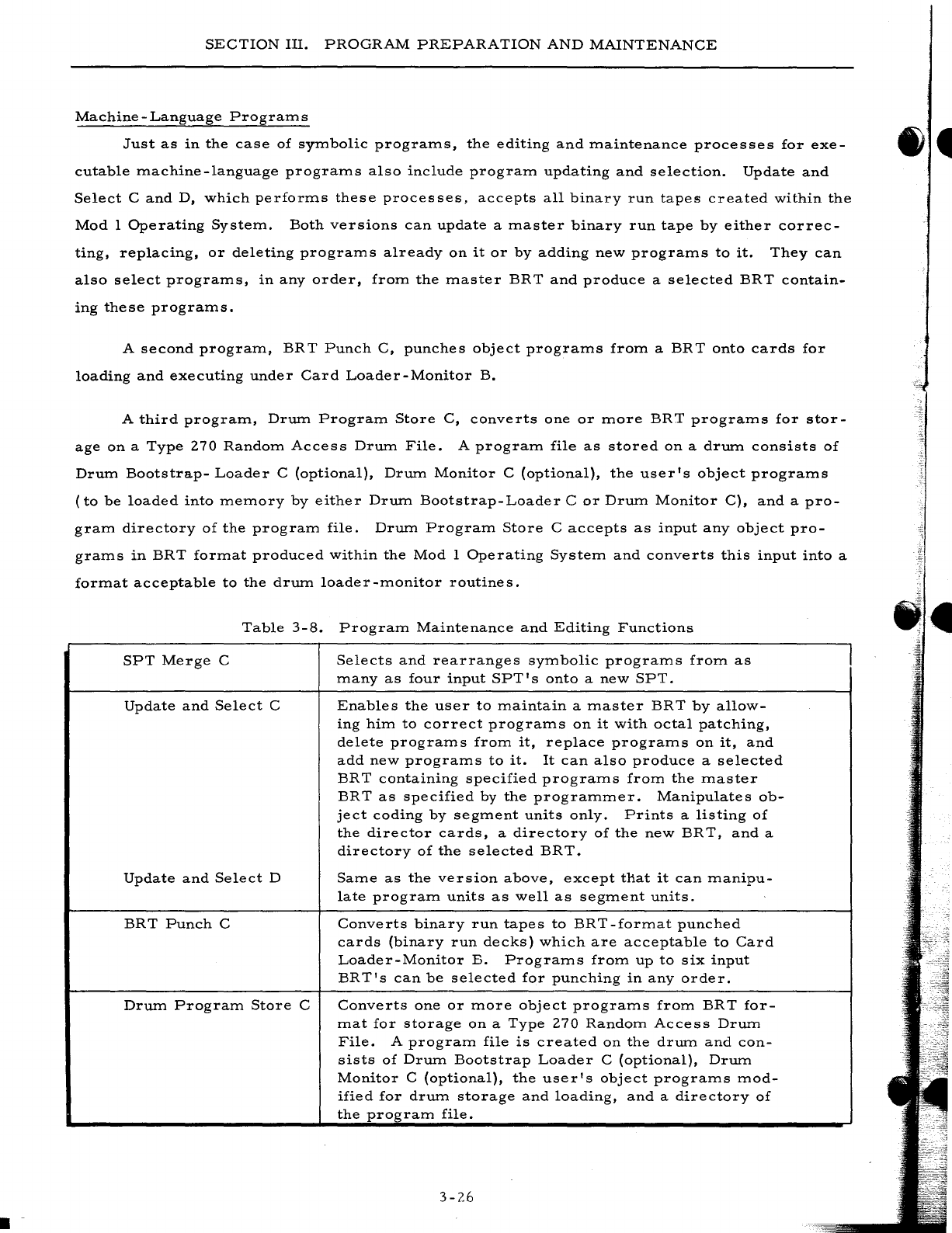
.-
SECTION
III.
PROGRAM
PREPARATION
AND
MAINTENANCE
Machine
-
Language
Program
s
Just
as
in
the
case
of
symbolic
programs,
the
editing
and
maintenance
processes
for
exe-
cutable
machine-language
programs
also
include
program
updating
and
selection.
Update
and
Select
C
and
D,
which
performs
these
processes,
accepts
all
binary
run
tapes
created
within
the
Mod
I
Operating
System.
Both
versions
can
update
a
master
binary
run
tape
by
either
correc-
ting,
replacing,
or
deleting
programs
already
on
it
or
by
adding
new
programs
to
it.
They
can
also
select
programs,
in
any
order,
from
the
master
BRT
and
produce
a
selected
BRT
contain-
ing
these
programs.
A
second
program,
BR
T
Punch
C,
punches
object
programs
from
a
BRT
onto
cards
for
loading
and
executing
under
Card
Loader-Monitor
B.
A
third
program,
Drum
Program
Store
C,
converts
one
or
more
BRT
programs
for
stor-
age
on
a
Type
270
Random
Access
Drum
File.
A
program
file
as
stored
on
a
drum
consists
of
Drum
Bootstrap-
Loader
C
(optional),
Drum
Monitor
C
(optional),
the
user's
object
programs
(to
be
loaded
into
memory
by
either
Drum
Bootstrap-Loader
C
or
Drum
Monitor
C),
and
a
pro-
gram
directory
of
the
program
file.
Drum
Program
Store
C
accepts
as
input
any
object
pro-
grams
in
BRT
format
produced
within
the
Mod
I
Operating
System
and
converts
this
input
into
a
format
acceptable
to
the
drum
loader-monitor
routines.
Table
3-8.
Program
Maintenance
and
Editing
Functions
SPT
Merge
C
Selects
and
rearranges
symbolic
programs
from
as
many
as
four
input
SPT'
s
onto
a
new
SPT.
Update
and
Select
C
Enables
the
user
to
maintain
a
master
BRT
by
allow-
ing
him
to
correct
programs
on
it
with
octal
patching,
delete
programs
from
it,
replace
programs
on
it,
and
add
new
programs
to
it.
It
can
also
produce
a
selected
BR
T
containing
specified
programs
from
the
master
BRT
as
specified
by
the
programmer.
Manipulates
ob-
ject
coding
by
segment
units
only.
Prints
a
listing
of
the
director
cards,
a
directory
of
the
new
BRT,
and
a
directory
of
the
selected
BRT.
Update
and
Select
D
Same
as
the
version
above,
except
that
it
can
manipu-
late
program
units
as
well
as
segment
units.
BRT
Punch
C
Converts
binary
run
tapes
to
BRT-format
punched
cards
(binary
run
decks)
which
are
acceptable
to
Card
Loader-Monitor
B.
Programs
from
up
to
six
input
BRT's
can
be
selected
for
punching
in
any
order.
Drum
Program
Store
C
Converts
one
or
more
object
programs
from
BRT
for-
mat
for
storage
on
a
Type
270
Random
Access
Drum
File.
A
program
file
is
created
on
the
drum
and
con-
sists
of
Drum
Bootstrap
Loader
C
(optional),
Drum
Monitor
C
(optional),
the
user's
object
programs
mod-
ified
for
drum
storage
and
loading,
and
a
directory
of
the
program
file.
3-26
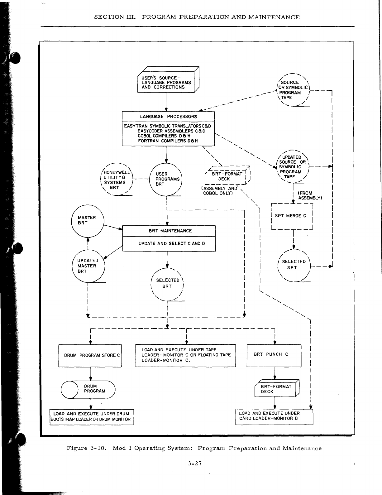
SECTION
III.
PROGRAM
PREPARATION
AND
MAINTENANCE
USER'S
SOURCE-
LANGUAGE PROGRAMS
AND
CORRECTIONS
LANGUAGE PROCESSORS
EASYTRAN
SYMBOLIC
TRANSLATORSCSD
EASYCODER
ASSEMBLERS
caD
COBOL
COMPILERS
D a H
FORTRAN COMPILERS DSH
--
--
---
/---..,
/sOURCE
\
JOR
SYMBOLIC'
..--
\ PROGRAM
r--i
--
\ TAPE / ,
,
/'
....
".
I
I
I
I
'-
,
" ,
,
, ,
/---..
I
, ' , I
UPDATED
"\
I
/---,
"
'-
f
SOURCE
OR
'-~----71
'-~
SYMBOLIC
1----,
(
IHONEYWEL~l
UTILITYS
_
(-BRr::
FoRMAT;
I \PROGRAM / I
L
DECK
.J.)
,T~E
...-/
I
\ SYSTEMS I
\.
BRT
/
'-
"./'
(ASSEMBLY
AND'~<
I'
COBOL ONLY) '- I (FROM I
-
---------l
BRT
MAINTENANCE
UPDATE AND SELECT C
AND
D
/'
--..
I "
f SELECTED \
\ BRT )
\ /
I '--r:::-
I I
t.
___________
,
___________
j
,
'-"
r - - i
~S~MlBLY)
,
'1
I I
I
'SPT
MERGE
C'
I
I I I I
I
L--T--J
I
, I I
I
'
,....--t-..
I
I " I
I I SELECTED \ I
I \
SPT
Ir--~
I
\,
./
,
------
l , , ,
'-
'-
,
'-
,----------1--,-----------,
'1
,
I
I
,
, , ,
DRUM
PROGRAM
STORE
C
LOAD
AND EXECUTE
UNDER
DRUM
BOOTSTRAP
LOADER
OR
DRUM
MONITOR
LOAD
AND
EXECUTE UNDER
TAPE
LOADER-
MONITOR C
OR
FLOATING
TAPE
LOADER-MONITOR C.
BRT PUNCH C ,
I
,
I
I
I
,
Figure
3-10.
Mod
1
Operating
System:
Program
Preparation
and
Maintenance
3-27

•
SECTION
IV
PROGRAM
EXECUTION
AND
CONTROL
The
program
execution
and
control
capabilities
of
the
Mod
I
Operating
System
are
divided
into
three
categorie
s:
1.
Operation
control,
2.
Input/output
control,
and
3.
Program
test.
OPERATION
CONTROL
Operation
control
encompasses
all
of
the
functions
involved
in
the
searching
for,
and
the
loading
and
monitoring
of,
object
programs.
The
Mod
I
Operating
System
extends
these
func-
tions
to
all
programs,
whether
stored
on
punched
cards,
magnetic
tape,
or
drum.
Also
included
is
interrupt
software
which
enables
the
user
to
take
advantage
of
the
interrupt
features
and
pe-
ripheral
simultaneity
of
the
Series
200
computers.
Lastly,
a
utility
program
reads
comments
cards
containing
instructions
to
the
operator,
report
headings,
etc.,
and
displays
them
on
the
console
typewriter
or
printer.
Loading
and
Monitoring
The
loading
and
monitoring
of
object
programs
are
accomplished
with
essentially
the
same
efficiency
regardlessofthe
program
storage
m.edhun.
Most
of
the
same
functional
characteristics
and
convenient
operational
features
are
also
retained.
LOADING
FROM
TAPE
Both
of
the
tape
loader-monitor
routines,
Tape
Loader-Monitor
C
and
Floating
Tape
Load-
er-Monitor
C,
search
for
and
load
program.s
stored
on
any
binary
run
tape
(BRT)
produced
within
the
Mod
1
Operating
System
envirorunent.
Object
programs,
as
assembled
or
compiled
and
stored
on
a
BRT,
are
composed
of
one
or
more
loading
units
or
segments.
Any
loading
unit
can
be
searched
for,
loaded,
and
executed
independently.
A
call
to
search
for
and
load
a
given
program
segment
can
originate
from
sev-
eral
sources:
1.
Current
program
-
The
programmer
may
include
programmed
instruc-
tions
which
set
up
the
required
search
parameters
in
the
loader
communi-
cations
area
and
then
branch
to
the
appropriate
loader
routine
to
initiate
the
searching
for
and
loading
of
the
next
segment
to
be
executed.
4-1
2.
3.
SECTION
IV.
PROGRAM
EXECUTION
AND
CONTROL
Operator
-
The
operator
can
enter
the
parameters
via
the
control
panel
or
console
typewriter
and
manually
branch
to
the
loader
routine.
Console
Call
card
-
Search
parameters
can
be
entered
through
the
card
reader
via
a
Console
Call
card.
The
reading
of
the
card
and
the
search
and
load
operation
can
be
initialized
either
manually
by
the
operator
or
automatically
by
programmed
instructions.
Basically,
the
search
parameters
specify
the
search
mode
to
be
used
and
the
program
name,
segment
name,
visibilities,
etc.
The
search
modes
include
the
following:
1.
Search
by
visibility
and
relative
position
-
Searching
in
the
specified
direction
(forward
or
backward)
on
the
BR
T,
load
the
nth
loading
unit
having
the
specified
visibility.
2.
Search
by
program
name
and
segment
name
-
Searching
in
the
speci-
fied
direction
(forward
or
backward)
on
the
BRT,
load
the
loading
unit
having
the
specified
program
name
and
segment
name
regardless
of
visibility.
3.
Search
by
segment
name
within
the
current
program
-
Searching
in
the
specified
direction,
load
the
loading
unit
having
the
specified
segment
name
within
the
current
program.
4.
Search
by
program
name,
segment
name,
and
visibility
-
Searching
in
the
specified
direction,
load
the
loading
unit
having
the
specified
pro-
gram
name,
segment
name,
and
visibility.
This
mode
allows
for
the
presence
of
several
versions
of
a
program
on
the
same
BRT
by
assign-
ing
a
different
visibility
to
each
of
the
versions.
5.
Search
by
segment
name
and
visibility
within
the
current
program
-
Searching
in
the
specified
direction,
load
the
loading
unit
having
the
specified
segment
name
and
visibility
within
the
current
program.
This
mode
allows
for
the
presence
of
several
versions
of
a
routine
within
a
program.
Other
parameters
which
may
be
specified
are
load
parameters
(relocation
augment,
etc.)
and
start
parameters
(branch
to
normal
start
location,
special
start
location,
etc.,
in
loaded
unit,
set
trapping
mode,
etc.).
Two
versions
of
the
tape
loader-monitor
are
provided:
Tape
Loader-Monitor
C
and
Float-
ing
Tape
Loader-Monitor
C.
Tape
Loader-Monitor
C
is
not
relocatable
and
occupies
1,276
loca-
tions
of
main
memory
(locations
64
through
I,
339).
Floating
Tape
Loader-Monitor
C
consists
of
two
segments.
Segment
1
occupies
memory
locations
2,
150
through
4,096
and
is
required
only
for
the
purpose
of
loading
Segment
2.
Segment
2
is
the
actual
tape
-loader-monitor
routine
and
can
be
reallocated
or
"floated"
into
any
memory
bank
above
memory
bank
0.
Once
Segment
2,
which
occupies
a
minimum
of
1,400
memory
locations,
is
loaded,
Segment
1
can
be
overlaid.
Thus,
user
programs
which
have
been
assembled
to
reside
in
memory
below
location
1339
need
not
be
modified
and
reassembled
as
would
be
required
with
the
use
of
Tape
Loader-Monitor
C.
Floating
Tape
Loader-Monitor
C,
which
provides
all
of
the
functions
of
Tape
Loader-Monitor
C
plus
several
additional
features,
is
a
macro
program
which
must
be
specialized
and
processed
by
Library
Processor
C
and
then
assembled.
By
filling
in
the
required
parameters
in
the
macro
4-2
I·
SECTION
IV.
PROGRAM
EXECUTION
AND
CONTROL
instruction,
the
user
can
specialize
the
loader-monitor
to
load
programs
in
any
portion
of
mem-
ory,
load
binary
run
decks,
provide
own-coding
exits,
and
utilize
a
console
typewriter
to
display
messages
and
to
receive
operator
responses.
As
explained
later,
Floating
Tape
Loader-Moni-
tor
C
must
be
present
in
memory
in
order
to
use
Interrupt
Control
D.
A
further
discussion
of
the
loader-monitor
routines
can
be
found
in
Section
V.
LOADING
FROM
CARDS
Object
programs
punched
on
binary
run
decks
(such
as
those
produced
by
Easycoder
Assemblers
C
and
D
or
BRT
Punch
C)
can
be
searched
for,
loaded,
and
initiated
by
Card
Loader-
Monitor
B.
The
functions
and
operational
characteristics
of
this
routine
are
compatible
with
those
of
the
tape
loader-monitors
in
many
ways:
1.
The
loader-monitor
communication
areas
of
both
are
identical.
2.
A
call
can
originate
from
the
same
three
sources:
the
current
program,
the
operator,
or
a
Console
Call
card.
3.
The
same
search
modes
are
provided.
Exceptions:
Card
Loader-Monitor
B
cannot,
of
course,
search
in
a
backward
direction
and
cannot
load
by
visibilities.
4.
The
same
loading
and
starting
parameter
options
are
applicable.
Card
Loader-Monitor
B
requires
936
memory
locations
(64
through
999)
and
has
a
fixed
allocation.
However,
if
this
allocation
is
not
desirable,
Floating
Tape
Loader-Monitor
C
can
be
specialized
to
load
from
cards.
LOADING
FROM
DR
UM
The
loading
and
monitoring
of
object
programs
which
are
part
of
a
drum
program
file
created
by
Drum
Program
Store
C
are
performed
by
two
routines:
Drum
Bootstrap-Loader
C
and
Drum
Monitor
C.
Drum
Bootstrap-Loader
C
is
the
simpler
of
the
two
and
is
designed
primarily
to
bring
Drum
Monitor
C
into
main
memory
from
the
drum
program
file;
however,
it
is
also
capable
of
searching
for
and
loading
any
object
program
on
the
drum.
Drum
Bootstrap-
Loader
C
is
the
only
program
in
the
drum
program
file
which
is
stored
in
condensed
card
images
(to
facilitate
bootstrapping)
instead
of
in
modified
BRT
format.
The
entire
routine
occupies
approximately
750
characters
and
can
exist
in
one
of
two
forms:
1.
As
a
bootstrap-loader
routine
which
can
be
manually
bootstrapped
from
the
drum
itself
into
a
fixed
memory
area
beginning
at
location
1,340,
or
2.
As
a
loader
routine
which
can
be
loaded
into
memory
by
Drum
Monitor
C,
or
by
some
other
loader-monitor
routine
(Card
Loader-Monitor
B,
Tape
Loader-Monitor
C,
etc.)
if
stored
on
some
other
device.
In
this
4-3
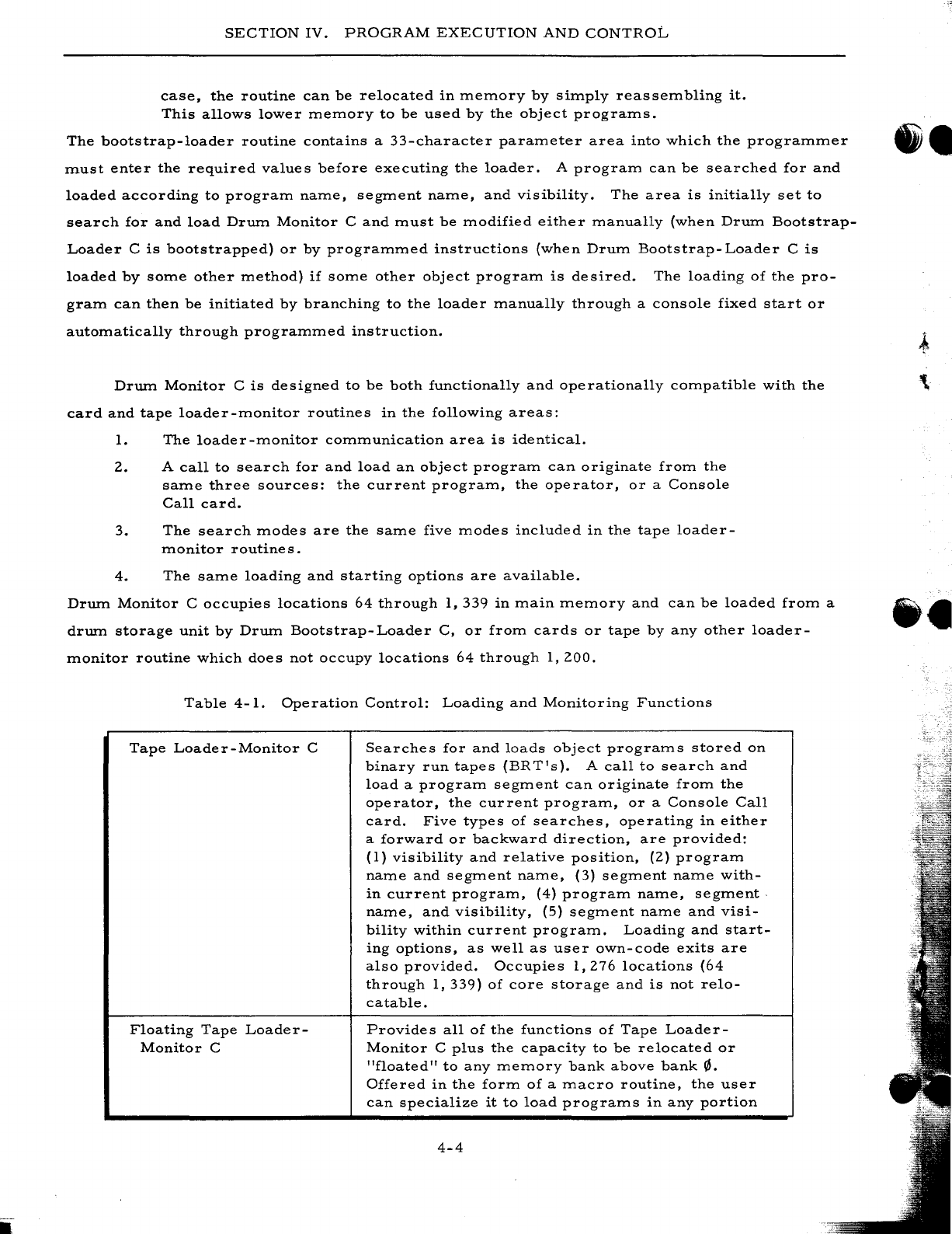
SECTION
IV.
PROGRAM
EXECUTION
AND
CONTROL
case,
the
routine
can
be
relocated
in
memory
by
simply
reassembling
it.
This
allows
lower
memory
to
be
used
by
the
object
programs.
The
bootstrap-loader
routine
contains
a
33-character
parameter
area
into
which
the
programmer
must
enter
the
required
values
before
executing
the
loader.
A
program
can
be
searched
for
and
loaded
according
to
program
name,
segment
name,
and
visibility.
The
area
is
initially
set
to
search
for
and
load
Drum
Monitor
C
and
must
be
modified
either
manually
(when
Drum
Bootstrap-
Loader
C
is
bootstrapped)
or
by
programmed
instructions
(when
Drum
Bootstrap-Loader
C
is
loaded
by
some
other
method)
if
some
other
object
program
is
desired.
The
loading
of
the
pro-
gram
can
then
be
initiated
by
branching
to
the
loader
manually
through
a
console
fixed
start
or
automatically
through
programmed
instruction.
Drum
Monitor
C
is
designed
to
be
both
functionally
and
operationally
compatible
with
the
card
and
tape
loader-monitor
routines
in
the
following
areas:
1.
The
loader-monitor
communication
area
is
identical.
2.
A
call
to
search
for
and
load
an
object
program
can
originate
from
the
same
three
sources:
the
current
program,
the
operator,
or
a
Console
Call
card.
3.
The
search
modes
are
the
same
five
modes
included
in
the
tape
loader-
monitor
routine
s.
4.
The
same
loading
and
starting
options
are
available.
Drum
Monitor
C
occupies
locations
64
through
1,339
in
main
memory
and
can
be
loaded
from
a
drum
storage
unit
by
Drum
Bootstrap-Loader
C,
or
from
cards
or
tape
by
any
other
loader-
monitor
routine
which
does
not
occupy
locations
64
through
1,200.
Table
4-1.
Operation
Control:
Loading
and
Monitoring
Functions
Tape
Loader-Monitor
C
Floating
Tape
Loader-
Monitor
C
Searches
for
and
loads
object
programs
stored
on
binary
run
tapes
(BRT's).
A
call
to
search
and
load
a
program
segment
can
originate
from
the
operator,
the
current
program,
or
a
Console
Call
card.
Five
types
of
searches,
operating
in
either
a
forward
or
backward
direction,
are
provided:
(1)
visibility
and
relative
position,
(2)
program
name
and
segment
name,
(3)
segment
name
with-
in
current
program,
(4)
program
name,
segment.
name,
and
visibility,
(5)
segment
name
and
visi-
bility
within
current
program.
Loading
and
start-
ing
options,
as
well
as
user
own-code
exits
are
also
provided.
Occupies
1,276
locations
(64
through
1,339)
of
core
storage
and
is
not
relo-
eatable.
Provides
all
of
the
functions
of
Tape
Loader-
Monitor
C
plus
the
capacity
to
be
relocated
or
"floated"
to
any
memory
bank
above
bank
0.
Offered
in
the
form
of
a
macro
routine,
the
user
can
specialize
it
to
load
programs
in
any
portion
4-4
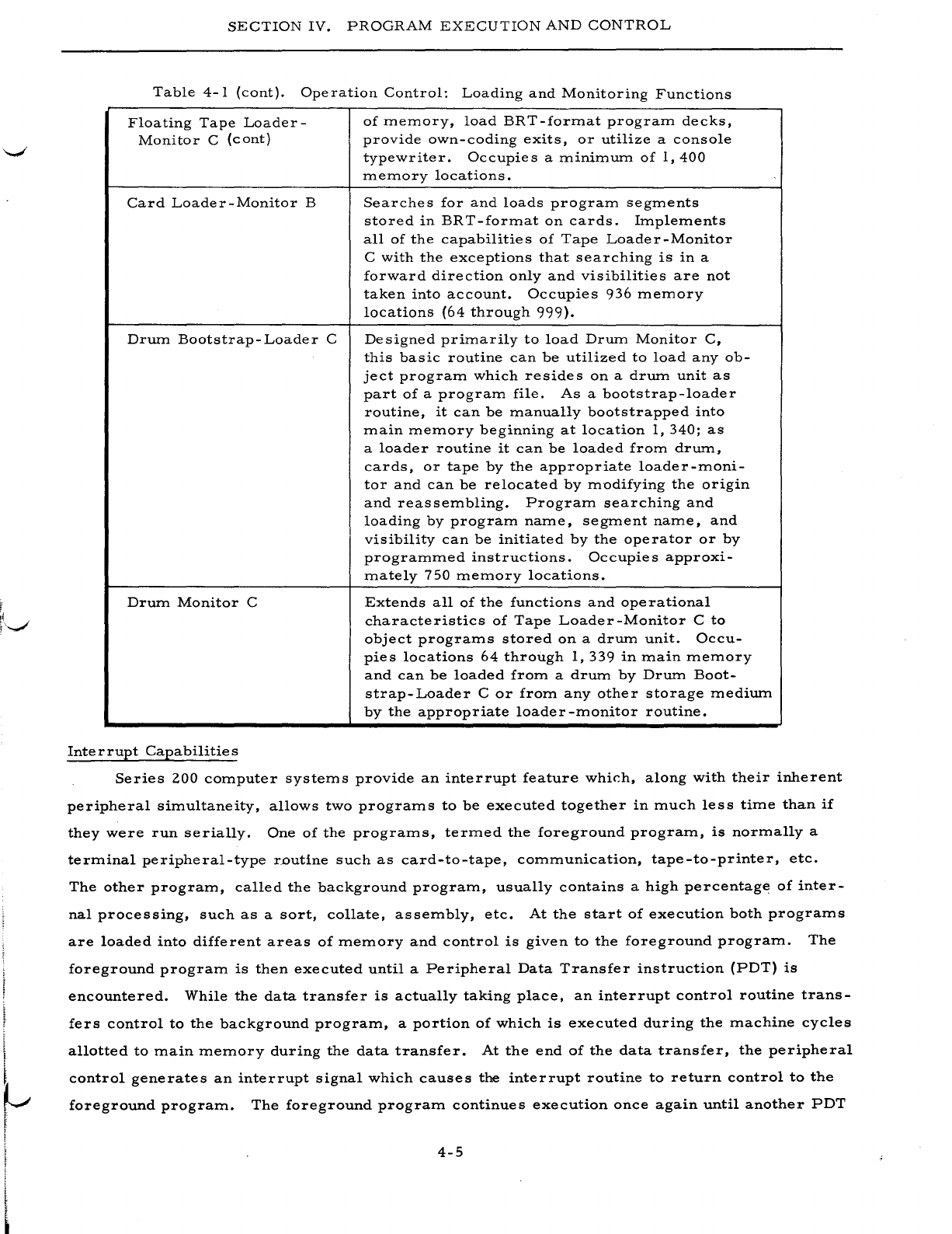
L
t
SECTION
IV.
PROGRAM
EXECUTION
AND
CONTROL
Table
4-1
(cont).
Operation
Control:
Loading
and
Monitoring
Functions
Floating
Tape
Loader-
Monitor
C
(cont)
Card
Loader-Monitor
B
Drum
Bootstrap-Loader
C
Drum
Monitor
C
Interrupt
Capabilities
of
memory,
load
BRT-format
program
decks,
provide
own-coding
exits,
or
utilize
a
console
typewriter.
Occupies
a
minimum
of
1,400
memory
locations.
Searches
for
and
loads
program
segments
stored
in
BRT-format
on
cards.
Implements
all
of
the
capabilities
of
Tape
Loader-Monitor
C
with
the
exceptions
that
searching
is
in
a
forward
direction
only
and
visibilities
are
not
taken
into
account.
Occupies
936
memory
locations
(64
through
999).
Designed
primarily
to
load
Drum
Monitor
C,
this
basic
routine
can
be
utilized
to
load
any
ob-
ject
program
which
resides
on
a
drum
unit
as
part
of
a
program
file.
As
a
bootstrap-loader
routine,
it
can
be
manually
bootstrapped
into
main
memory
beginning
at
location
1,
340;
as
a
loader
routine
it
can
be
loaded
from
drum,
cards,
or
tape
by
the
appropriate
loader-moni-
tor
and
can
be
relocated
by
modifying
the
origin
and
reassembling.
Program
searching
and
loading
by
program
name,
segment
name,
and
visibility
can
be
initiated
by
the
operator
or
by
programmed
instructions.
Occupies
approxi-
mately
750
memory
locations.
Extends
all
of
the
functions
and
operational
characteristics
of
Tape
Loader-Monitor
C
to
object
programs
stored
on
a
drum
unit.
Occu-
pies
locations
64
through
1,339
in
main
memory
and
can
be
loaded
from
a
drum
by
Drum
Boot-
strap-Loader
C
or
from
any
other
storage
medium
by
the
appropriate
loader-monitor
routine.
Series
200
computer
systems
provide
an
interrupt
feature
whir.h,
along
with
their
inherent
peripheral
simultaneity,
allows
two
programs
to
be
executed
together
in
much
less
time
than
if
they
were
run
serially.
One
of
the
programs,
termed
the
foreground
program,
is
normally
a
terminal
peripheral-type
routine
such
as
card-to-tape,
communication,
tape-to-printer,
etc.
The
other
program,
called
the
background
program,
usually
contains
a
high
percentage
of
inter-
nal
processing,
such
as
a
sort,
collate,
assembly,
etc.
At
the
start
of
execution
both
programs
are
loaded
into
different
areas
of
memory
and
control
is
given
to
the
foreground
program.
The
foreground
program
is
then
executed
until
a
Peripheral
Data
Transfer
instruction
(PDT)
is
encountered.
While
the
data
transfer
is
actually
taking
place,
an
interrupt
control
routine
trans-
fers
control
to
the
background
program,
a
portion
of
which
is
executed
during
the
machine
cycles
allotted
to
main
memory
during
the
data
transfer.
At
the
end
of
the
data
transfer,
the
peripheral
control
generates
an
interrupt
signal
which
causes
the
interrupt
routine
to
return
control
to
the
foreground
program.
The
foreground
program
continues
execution
once
again
until
another
PDT
4-5
SECTION
IV.
PROGRAM
EXECUTION
AND
CONTRa-L-
instruction
is
encountered,
at
which
tiITIe
the
control
is
given
to
the
background
prograITI
which
continues
where
it
left
off.
This
back-and-forth
operation
continues
until
both
prograITIs
reach
their
terITIination.
INTERR
UPT
CONTROL
D
Interrupt
Control
D
is
a
Honeywell-supplied
routine
designed
to
aid
the
user
in
taking
ad-
vantage
of
these
interrupt
capabilities.
It
runs
in
conjunction
with
Floating
Tape
Loader-Moni-
tor
C,
which
ITIust
be
resident
in
ITIeITIory
iITIITIediately
following
Interrupt
Control
D.
Interrupt
Control
D
is
a
generalized
ITIacro
prograITI
which
ITIust
be
specialized
,by
Library
Processor
C
or
D
before
being
asseITIbled
by
Easycoder
AsseITIbler
C
or
D.
Six
prespecialized
versions
are
provided
to
handle
three-
or
four-character
ITIode
operation,
the
presence
or
ab-
sence
of
an
external
INTERRUPT
button,
etc.
These
versions
require
500
to
625
locations
starting
at
location
200
plus
750
to
1,
150
locations
iITIITIediately
below
the
Floating
Tape
Loader-
Monitor
C
routine.
Interrupt
Control
D
perITIits
the
independent
sequencing
of
both
foreground
and
background
prograITIs
as
indicated
by
the
user.
Background
prograITIs
are
searched
for,
loaded,
a:nd
started
norITIally
under
control
of
Floating
Tape
Loader-Monitor
C.
Foreground
prograITIs,
however,
cannot
cOITIITIunicate
directly
with
the
loader-ITIonitor
and
ITIust
instead
terITIinate
with
a
ITIacro
call
to
Interrupt
Control
D.
If
the
user
has
previously
set
an
indicator
in
a
specified
ITIeITIory
location,
Interrupt
Control
D
loads
the
next
foreground
segITIent
and
con-
tinues
execution
of
the
new
segITIent
and
of
the
background
prograITI;
if
the
user
has
not
set
the
internal
indicator,
Interrupt
Control
D
allows
the
background
prograITI
to
continue
processing
to
cOITIpletion.
Foreground
PrograITIs
Currently,
Honeywell
offers
pre
specialized
foreground
prograITI8
to
perforITI
tape-to-printer,
tape-to-card,
and
card-to-tape
data
conversions.
These
three
routines
are
known
collectively
as
Data
Conversion
C
and
are
described
on
page
3-20.
If
the
user
writes
his
own
foreground
prograITI,
he
ITIust
follow
certain
prograITIITIing
considerations
and
ITIust
include
a
return
ITIacro
call
iITIITIediately
after
each
PDT
instruction.
This
causes
a
return
of
control
to
Interrupt
Con-
trol
D
which,
in
turn,
enters
the
background
prograITI.
At
the
end
of
the
foreground
pr02;raITI,
the
user
ITIust
include
an
exit
ITIacro
call
to
return
control
to
Interrupt
Control
D,
which
will
either
cause
the
next
foreground
segITIent
to
be
loaded
or
continue
the
processing
of
the
back-
ground
prograITI
to
cOITIpletion.
Figure
4-1
illustrates
these
functions.
SIMULTANEOUS
SORT
AND
PRINT
To
aid
the
user
in
cOITIbining
two
cOITIITIonly
used
functions,
Honeywell
has
ITIodified
the
Tape
Sort
C
prograITI
to
allow
printing
while
sorting.
The
print
prograITI
to
which
Tape
Sort
C
4-6
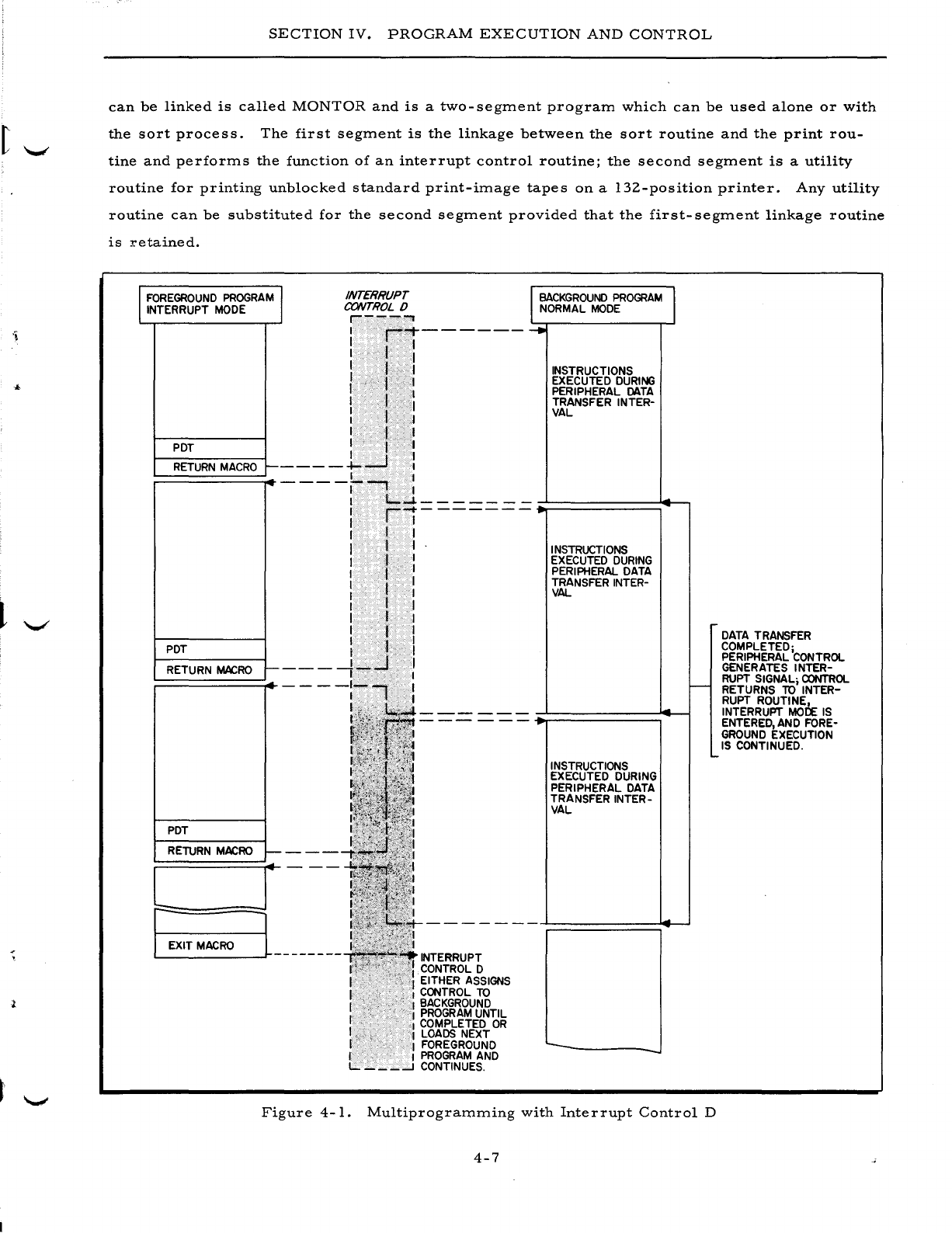
SECTION
IV.
PROGRAM
EXECUTION
AND
CONTROL
can
be
linked
is
called
MONTOR
and
is
a
two-segment
program
which
can
be
used
alone
or
with
the
sort
process.
The
first
segment
is
the
linkage
between
the
sort
routine
and
the
print
rou-
tine
and
performs
the
function
of
an
interrupt
control
routine;
the
second
segment
is
a
utility
routine
for
printing
unblocked
standard
print-image
tapes
on
a
132-position
printer.
Any
utility
routine
can
be
substituted
for
the
second
segment
provided
that
the
first-segment
linkage
routine
is
retained.
I
FOREGROUND
PROGRAM
I
INTERRUPT
MODE
INTERRUPT
CONTROL
0
,---'"
PDT
RETURN
MACRO
r---
I
r""1-------
I I I
: I 1
I t I
II
I
I I I
I . I
I f I
I·
I I
----l...-J
l
~
BACKGROUND
PROGRAM
I
NORMAL
MODE
......
INSTRUCTIONS
EXECUTED
DURING
PERIPHERAL
DATA
TRANSFER
INTER-
VAL
----/--,
:
I
t....-1---
__
--
PDT
RETURN
MACRO
I--
PDT
RETURN
MACRO
t-
..
:
ri-------
r I r
II
I
I I I
I f I
I I I
r
.,
I
I I
I I I
I I I
It
I
I . t I
___
-1-...J I
I I
----:-., :
!
L=J
r;:~_E_XI_T_M_AC_RO
___
l~L
______
--
INTERRUPT
CONTROL
0
EITHER
ASSIGNS
CONTROL
TO
I
BACKGROUND
I
PROGRAM
UNTIL
I
COMPLETED
OR
,'1
LOADS
NEXT
I
FOREGROUND
I I
PROGRAM
AND
L.
___
--l
CONTINUES.
INSTRUCTIONS
EXECUTED
DURING
PERIPHERAL
DATA
TRANSFER
INTER-
VAL
INSTRUCTIONS
EXECUTED
DURING
PERIPHERAL
DATA
TRANSFER
INTER-
VAL
'--
f--
....
Figure
4-1.
Multiprogramming
with
Interrupt
Control
D
4-7
DATA
TRANSFER
COMPLETED;
PERIPHERAL
CONTROL
GENERATES
INTER-
RUPT
SIGNAL;
CONTROL
RETURNS
TO
INTER-
RUPT
ROUTINE,
INTERRUPT
MOCf:
IS
ENTERED,
AND
FORE-
GROUND
EXECUTION
IS
CONTINUED
.
SECTION
IV.
PROGRAM
EXECUTION
AND
CONTROL
List
Comments
C
List
Comments
C
is
a
short
routine
which
reads
cards
containing
comments
such
as
opera-
tor
instructions,
report
headings,
etc.,
and
displays
them
on
either
the
printer
or
the
console
typewriter
as
directed.
Spacing
and
carriage
control
functions
are
included.
List
Comments
C
is
loaded
from
a
BRT
under
the
control
of
Tape
Loader-Monitor
C.
INPUT
/OUTPUT
CONTROL
Honeywell
provides
a
comprehensive
set
of
input/output
control
functions
in
the
form
of
macro
routines
which
can
be
specialized
and
incorporated
into
the
user's
programs.
These
functions
handle
all
of
the
standard
input/
output
devices
such
as
magnetic
tape
units,
card
read-
ers
and
punches,
printers,
drum
units,
and
consoles;
thus,
the
need
for
the
writing
of
detailed
and
exhaustive
input/output
coding
by
the
user
is
eliminated.
Moreover,
the
standardization
of
file
handling,
label
creation,
read/write
error
routines,
etc.,
creates
a
uniformity
in
both
data
format
and
operating
procedures.
Magnetic
Tape
Input/Output
Control
liZ-Inch
Tape
I/O
C
is
a
group
of
macro
routines
which
handle
data
files
of
either
fixed-
or
variable-length
records
stored
on
liZ-inch
magnetic
tape.
These
routines
are
capable
of
handling
Honeywell-created
tapes,
or
if
the
proper
hardware
compatibility
options
are
installed,
IBM-created
tapes.
The
user
incorporates
these
routines
into
his
Easycoder
source-language
program
by
means
of
file-definition
entries
and
macro
calls.
The
source
program
is
then
specialized
by
Library
Processor
C
or
D
before
being
assembled.
In
writing
his
program,
the
user
must
first
supply
a
definition
(Define
Communications
Area
-
DCA)
for
each
tape
file
to
be
processed.
He
includes
information
such
as
the
file
type
(input
or
output),
the
parity
(odd
or
even),
the
read/write
channel
to
be
used,
the
blocking
fac-
tor,
item
size,
locations
of
buffers
reserved
for
the
file,
etc.
Then,
in
writing
the
logic
for
the
program,
he
utilizes
the
appropriate
macro
calls
(@OPEN,
@GET,
@PUT,
@CLOSE,
@FEOR)
to
open
or
close
the
files,
read
or
write
records,
and
force
an
end
of
reel.
The
checking
and
creation
of
standard
labels,
the
blocking
and
unblocking
of
records,
and
the
detection
and
correc-
tion
of
read/write
errors
are
all
performed
automatically
by
the
macro
routines.
User's
own-
coding
exits
are
provided
for
additional
processing
of
header
and
trailer
labels
and
for
initiating
the
programmer's
own
end-of-file
procedure.
The
liZ-Inch
Tape
I/O
C
routines
are
written
and
assembled
in
three-
or
four-character
mode
and,
depending
upon
the
processes
called
for,
occupy
between
Z,
ZOO
and
3,500
core
mem-
ory
locations.
In
addition,
each
file
processed
requires
a
file
table
of
up
to
73
character
loca-
tions
and
the
necessary
buffer
areas.
4-8
I
SECTION
IV.
PROGRAM
EXECUTION
AND
CONTROL
Magnetic
Tape
and
Terminal
Input/Output
Control
l/Z-Inch
Tape
and
Terminal
I/O
C
is
a
more
comprehensive
input/output
control
package
'-'
consisting
of
a
series
of
routines
which
perform
the
standard
input/
output
procedures
for
mag-
netic
tape,
punched
card,
and
printer
operations.
Read/write
channel
tests
are
also
included
to
take
advantage
of
the
read/write
/
compute
simultaneity
of
the
Series
ZOO
systems.
Honeywell-
format
and
IBM-format
(if
required
hardware
options
are
present)
I
/Z-inch
magnetic
tape
files
are
acceptable
and
the
routines
are
functionally
compatible
with
those
of
the
IBM
1401
Input/Out-
put
Control
System
(IOCS).
The
programmer
must
supply
to
the
package
three
types
of
descriptive
entries:
1.
A
Descriptive
IOCS
(DIOCS)
entry
which
describes,
in
general,
all
the
files
to
be
processed
and
the
system
configuration
used,
Z. A
Define
the
File
(DTF)
entry
for
each
of
the
files
which
describes,
in
detail,
the
type,
format,
etc.,
of
a
specific
file,
and
3.
Carriage
control
entries
to
specify
punches
in
the
printer
carriage-
control
tape.
In
addition
to
a
number
of
extensions
to
the
macro
calls
provided
in
l/Z-Inch
Tape
I/O
C,
five
additional
macro
calls
have
been
added:
1.
RDLIN
-
Allows
the
label
information
specified
in
the
DTF
entry
for
the
file
to
be
changed
from
run
to
run;
e.
g.,
the
creation
date
constant
to
be
compared.
Z.
SPACE
-
Allows
the
programmer
to
control
the
spacing
of
printer
forms.
3.
SKIP
-
Allows
the
programmer
to
control
the
skipping
of
printer
forms.
4.
RELSE
-
Permits
the
programmer
to
skip
over
the
remaining
items
of
a
blocked
record
and
to
continue
processing
with
the
first
item
of
the
next
record.
5.
DCLOS
-
If,
in
one
or
more
DTF
entries,
the
programmer
has
specified
that
all
records
containing
parity
errors
are
to
be
written
on
an
error
tape,
this
macro
call
causes
the
deactivation
of
that
tape.
Additional
parameters
can
indicate
that
a
tape
mark
is
to
be
written
after
the
last
record
and
that
the
reel
is
to
be
rewound
and
unloaded.
As
in
l/Z-Inch
TapeI/O
C,
user's
own-coding
exits
are
provided
for
the
processing
of
nonstand-
ard
labels
or
the
additional
processing
of
standard
labels,
the
programmer's
own
end-of-reel
or
end-of-file
routines,
etc.
In
addition,
the
package
can
optionally
check
for
wrong-length
tape
records.
The
l/Z-Inch
Tape
and
Terminal
I/O
C
routines
can
be
assembled
in
either
three-
or
four-
character
mode
and
have
the
following
minimum
memory
requirements~
1.
DIOCS
table
-
800
locations
Z.
Each
tape
file
-
650
to
1,
ZOO
locations
3.
Each
card
file
-
Z50
to
400
locations
4.
Each
printer
file
-
1.900
locations
Memory
space
for
buffers
is
not
included
in
the
above
figures.
4-9
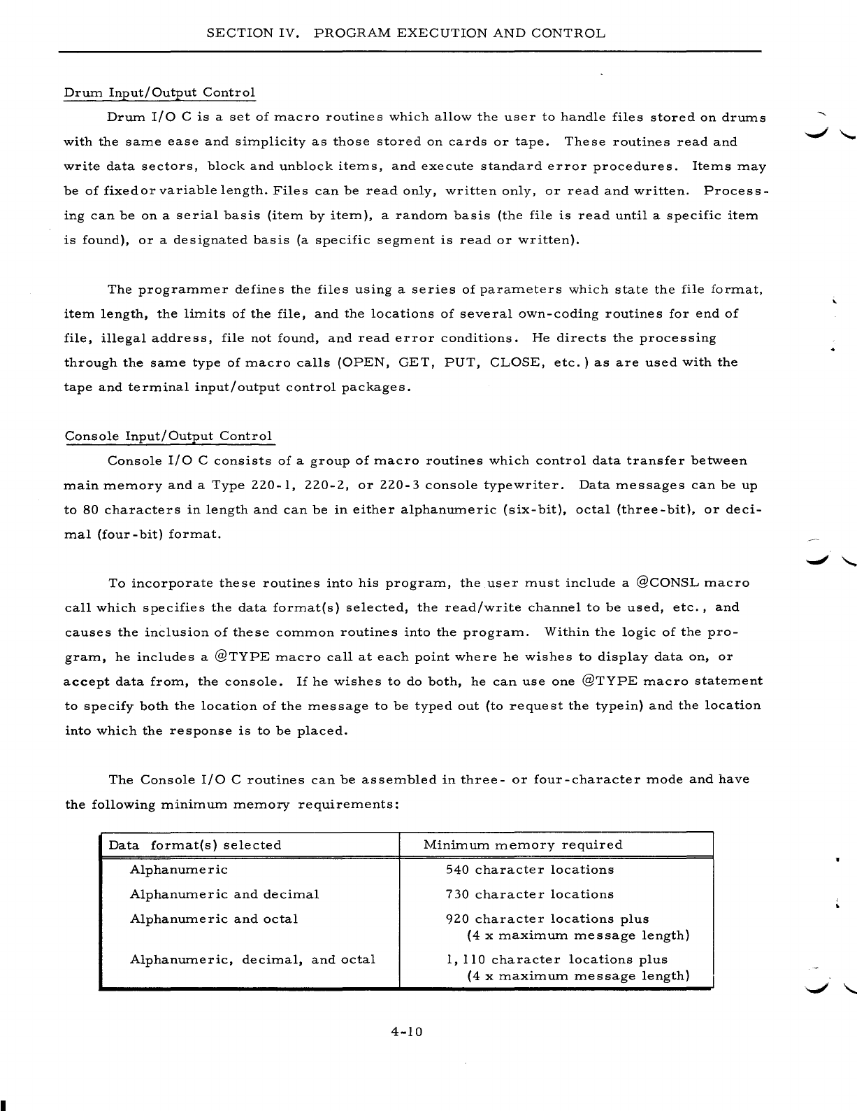
SECTION
IV.
PROGRAM
EXECUTION
AND
CONTROL
Drum
Input/Output
Control
Drum
I/O
C
is
a
set
of
macro
routines
which
allow
the
user
to
handle
files
stored
on
drums
with
the
same
ease
and
simplicity
as
those
stored
on
cards
or
tape.
These
routines
read
and
write
data
sectors,
block
and
unblock
items,
and
execute
standard
error
procedures.
Items
may
be
of
fixed
or
variable
length.
Files
can
be
read
only,
written
only,
or
read
and
written.
Process-
ing
can
be
on
a
serial
basis
(item
by
item),
a
random
basis
(the
file
is
read
until
a
specific
item
is
found),
or
a
designated
basis
(a
specific
segment
is
read
or
written).
The
programmer
defines
the
files
using
a
series
of
parameters
which
state
the
file
format,
item
length,
the
limits
of
the
file,
and
the
locations
of
several
own-coding
routines
for
end
of
file,
illegal
address,
file
not
found,
and
read
error
conditions.
He
directs
the
processing
through
the
same
type
of
macro
calls
(OPEN,
GET,
PUT,
CLOSE,
etc.)
as
are
used
with
the
tape
and
terminal
input/
output
control
packages.
Console
Input/
Output
Control
Console
I/O
C
consists
of
a
group
of
macro
routines
which
control
data
transfer
between
main
memory
and
a
Type
220-1,
220-2,
or
220-3
console
typewriter.
Data
messages
can
be
up
to
80
characters
in
length
and
can
be
in
either
alphanumeric
(six-bit),
octal
(three-bit),
or
deci-
mal
(four
-
bit)
format.
To
incorporate
these
routines
into
his
program,
the
user
must
include
a
@CONSL
macro
call
which
specifies
the
data
format{s)
selected,
the
read/write
channel
to
be
used,
etc.,
and
causes
the
inclusion
of
these
common
routines
into
the
program.
Within
the
logic
of
the
pro-
gram,
he
includes
a
@TYPE
macro
call
at
each
point
where
he
wishes
to
display
data
on,
or
accept
data
from,
the
console.
If
he
wishes
to
do
both,
he
can
use
one
@TYPE
macro
statement
to
specify
both
the
location
of
the
message
to
be
typed
out
(to
request
the
type
in)
and
the
location
into
which
the
response
is
to
be
placed.
The
Console
I/O
C
routines
can
be
assembled
in
three-
or
four-character
mode
and
have
the
following
minimum
memory
requirements:
Data
format{s)
selected
Minimum
memory
required
Alphanumeric
540
character
locations
Alphanumeric
and
decimal
730
characte
r
locations
Al
phanum
eric
and
octal
920
character
locations
plus
(4
x
maximum
message
length)
Alphanumeric,
decimal,
and
octal
1,
110
character
locations
plus
(4
x
maximum
message
length)
4-10
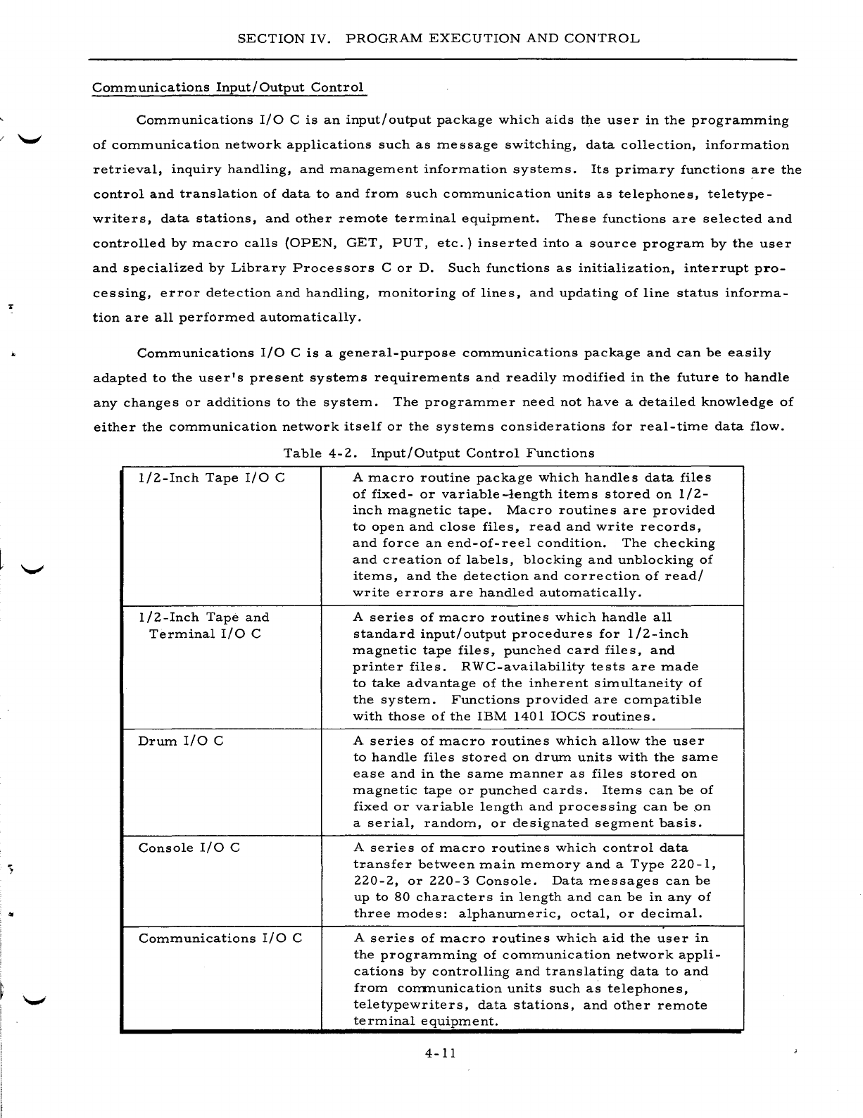
..
SECTION
IV.
PROGRAM
EXECUTION
AND
CONTROL
Communications
Input/Output
Control
Communications
I/O
C
is
an
input/output
package
which
aids
the
user
in
the
programming
of
communication
network
applications
such
as
message
switching,
data
collection,
information
retrieval,
inquiry
handling,
and
management
information
systems.
Its
primary
functions
are
the
control
and
translation
of
data
to
and
from
such
communication
units
as
telephones,
teletype-
writers,
data
stations,
and
other
remote
terminal
equipment.
These
functions
are
selected
and
controlled
by
macro
calls
(OPEN,
GET,
PUT,
etc.)
inserted
into
a
source
program
by
the
user
and
specialized
by
Library
Processors
C
or
D.
Such
functions
as
initialization,
interrupt
pro-
cessing,
error
detection
and
handling,
monitoring
of
lines,
and
updating
of
line
status
informa-
tion
are
all
performed
automatically.
Communications
I/O
C
is
a
general-purpose
communications
package
and
can
be
easily
adapted
to
the
user's
present
systems
requirements
and
readily
modified
in
the
future
to
handle
any
changes
or
additions
to
the
system.
The
programmer
need
not
have
a
detailed
knowledge
of
either
the
communication
network
itself
or
the
systems
considerations
for
real-time
data
flow.
Table
4-2.
Input/Output
Control
Functions
1/2-Inch
Tape
I/O
C
1/2-Inch
Tape
and
Terminal
I/O
C
Drum
I/O
C
Console
I/O
C
Communications
I/O
C
A
macro
routine
package
which
handles
data
files
of
fixed-
or
variable-length
items
stored
on
1/2-
inch
magnetic
tape.
Macro
routines
are
provided
to
open
and
close
files,
read
and
write
records,
and
force
an
end-of-reel
condition.
The
checking
and
creation
of
labels,
blocking
and
unblocking
of
items,
and
the
detection
and
correction
of
read/
write
errors
are
handled
automatically.
A
series
of
macro
routines
which
handle
all
standard
input/
output
procedures
for
1/2-inch
magnetic
tape
files,
punched
card
files,
and
printer
files.
RWC-availability
tests
are
made
to
take
advantage
of
the
inherent
simultaneity
of
the
system.
Functions
provided
are
compatible
with
those
of
the
IBM
1401
IOCS
routines.
A
series
of
macro
routines
which
allow
the
user
to
handle
files
stored
on
drum
units
with
the
same
ease
and
in
the
same
manner
as
files
stored
on
magnetic
tape
or
punched
cards.
Items
can
be
of
fixed
or
variable
length
and
processing
can
be
,on
a
serial,
random,
or
designated
segment
basis.
A
series
of
macro
routines
which
control
data
transfer
between
main
memory
and
a
Type
220-1,
220-2,
or
220-3
Console.
Data
messages
can
be
up
to
80
characters
in
length
and
can
be
in
any
of
three
modes:
alphanumeric,
octal,
or
decimal.
A
series
of
macro
routines
which
aid
the
user
in
the
programming
of
communication
network
appli-
cations
by
controlling
and
translating
data
to
and
from
corrrnunication
units
such
as
telephones,
teletypewriters,
data
stations,
and
other
remote
terminal
equipment.
4-11
SECTION
IV.
PROGRAM
EXECUTION
AND
CONTROL
PROGRAM
TEST
FACILITIES
An
important
part
of
the
program
execution
and
control
functions
in
the
Mod
1
Operating
System
is
the
program
te
st
facilitie
s.
Automatic
Program
Checkout
Program
Test
System
C
is
an
automatic,
open-ended
checkout
system
which
operates
under
Tape
Loader-Monitor
C
and
provides
automatic
run-to-run
sequencing,
test
data
genera-
tion,
program
patching,
program
checkout
diagnostics,
memory
dumping,
and
tape
dumping.
The
open-ended
design
allows
the
user
to
write
his
own
program
test
utility
routines
and
incor-
porate
them
within
the
test
system.
As
provided
by
Honeywell,
Program
Test
System
C
is
com-
posed
of
nine
utility
programs
stored
on
a
BRT.
These
are
Initializer
C,
List
Comments
C,
Test
Data
Generator
C,
Memory
Dump
Control
C,
Memory
Dump
C,
Patch
C,
Tape
Dump
C,
Emergency
Dump
C,
and
End
C.
INITIALIZER
C
Initializer
C
prepares
the
Program
Test
System
for
automatic
reading
of
Console
Call
cards
from
the
test
director
deck
and
the
loading
of
the
other
utility
programs
from
the
BRT.
It
sets
the
computer
to
the
nontrapping
mode,
rewinds
the
BRT,
and
suppresses
the
Tape
Loader-
Monitor
C
console
call
halt
to
enable
nonstop
sequencing
and
loading
of
the
pro
grams.
LIST
COMMENTS
C
List
Comments
C
reads
punched
cards
containing
operator
instructions,
report
heading
lines,
etc.,
and
prints
or
types
this
information
on
the
printer
or
the
console
typewriter.
This
utility
program
has
been
previously
described
under
Operation
Control
on
page
4-8.
TEST
DATA
GENERATOR
C
Test
Data
Generator
C
creates
test
data
on
liZ-inch
magnetic
tape
from
punched
cards
and
enables
the
programmer
to
test
his
programs
against
a
wide
range
of
possible
input
vari-
ables.
Tape
files
can
be
created
with
bannered
or
bannerless
records
of
blocked
or
unblocked,
fixed-
or
variable-length
items.
Header,
trailer,
and
tape
mark
records
are
created
as
direc-
ted
by
the
programmer.
MEMORY
DUMP
CONTROL
C
Memory
Dump
Control
C
facilitates
the
printing
out
of
core
storage
contents
by
loading
and
initiating
Memory
Dump
C
to
edit
and
print
these
contents.
Memory
dumping
can
be
called
for
by
either
or
both
of
two
methods:
programmed
instruction,
which
allows
for
the
taking
of
mem-
ory
dumps
by
use
of
symbolic
coding
within
the
program;
iteTIl-TIlark
trapping,
which
perTIlits
the
use
of
an
iteTIl
TIlark
over
the
operation
code
of
an
instruction
to
trigger
TIleTIlory
dUTIlping.
4-lZ
SECTION
IV.
PROGRAM
EXECUTION
AND
CONTROL
MEMOR
Y
DUMP
C
Memory
Dump
C
is
used
by
both
Memory
Dump
Control
C
and
Emergency
Dump
C
to
edit
and
print
the
contents
(data
and
punctuation)
of
core
storage.
It
must
be
loaded
by
one
of
these
two
programs
and
cannot
be
used
independently
within
the
Program
Test
System.
All
printouts
are
given
in
both
alphanumeric
and
octal
mode
with
any
punctuation
displayed
beneath
the
associ-
ated
character
positions.
PATCH
C
Patch
C
enables
the
programmer
to
make
octal
patches
to
his
program
in
main
memory
without
affecting
the
program
as
stored
on
the
BRT.
Thus,
on-the-spot
modifications
can
be
made
to
a
program
during
testing
to
tryout
different
variations
of
some
routine,
check
out
pro-
posed
corrections
to
the
program
before
making
a
permanent
change,
etc.
TAPE
DUMP
C
Tape
Dump
C
positions
1/2-inch
magnetic
tape
files
and
edits
and
prints
their
contents
as
directed
by
the
user.
Functions
include
rewinding,
positioning
(forward
or
backward),
and
edit-
ing
and
printing.
Editing
can
be
in
either
alphanumeric
or
octal
format.
Any
number
of
con-
secutive
functions
can
be
performed
with
a
single
loading
of
the
routine.
EMERGENCY
MEMORY
DUMP
C
Emergency
Memory
Dump
C
can
be
used
to
take
a
printout
of
core
storage
if
unexpected
difficulty
is
encountered
during
execution.
Memory
Dump
C
is
loaded
and
utilized
to
edit
and
print
the
contents.
In
the
three-character
addressing
mode,
Emergency
Memory
Dump
C
re-
quires
125
core
locations
and
Memory
Dump
C
requires
an
additional
625
core
locations.
The
operator
can
call
in
the
Emergency
Memory
Dump
C
program
by
entering
the
three
standard
call
parameters
(program
name,
segment
name,
and
tape
drive
number)
through
either
the
control
panel
(or
console)
or
the
card
reader.
Use
of
the
Program
Test
C
Utility
Programs
Under
the
Program
Test
System
C,
these
nine
utility
programs,
along
with
the
user's
pro-
grams
to
be
tested,
are
searched
for,
loaded,
and
executed
automatically
under
the
direction
of
the
test
director
deck.
This
deck
can
contain
Console
Call
cards,
data
cards
for
test
data
generation,
octal
corrections,
etc.
A
whole
series
of
runs
can
be
checked
out
with
little
or
no
operator
intervention
by
placing
Console
Call
cards
for
both
the
user's
object
programs
and
the
Program
Test
System
C
utility
programs
in
the
proper
order,
along
with
other
required
cards,
in
the
test
director
deck.
4-13

SECTION
IV.
PROGRAM
EXECUTION
AND
CONTROL
With
the
exception
of
the
separate
memory
dump
and
memory
dump
control
programs,
which
must
be
run
together
as
already
noted,
each
utility
program
making
up
Program
Te
st
System
C
can
be
run
separately
as
a
regular
BRT
program
without
executing
Initializer
C.
4-14
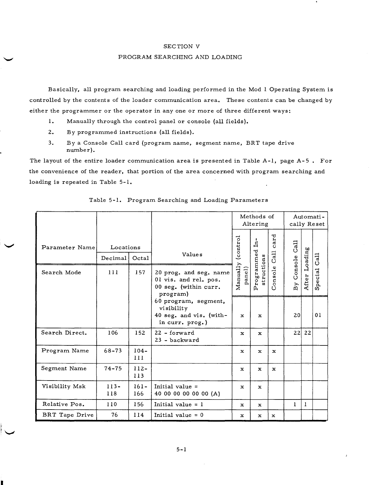
SECTION
V
PROGRAM
SEARCHING
AND
LOADING
Basically,
all
prograITl
searching
and
loading
perforITled
in
the
Mod
1
Operating
SysteITl
is
controlled
by
the
contents
of
the
loader
cOITlITlunication
area.
These
contents
can
be
changed
by
either
the
prograITlITler
or
the
operator
in
anyone
or
ITlore
of
three
different
ways:
1.
Manually
through
the
control
panel
or
console
(all
fields).
2.
By
prograITlITled
instructions
(all
fields).
3.
Bya
Console
Call
card
(prograITl
naITle,
segITlent
naITle,
BRT
tape
drive
nUITlber).
The
layout
of
the
entire
loader
cOITlITlunication
area
is
presented
in
Table
A-I,
page
A-
5
For
the
convenience
of
the
reader,
that
portion
of
the
area
concerned
with
prograITl
searching
and
loading
is
repeated
in
Table
5-1.
Table
5-1.
PrograITl
Searching
and
Loading
ParaITleters
ParaITleter
NaITle
Search
Mode
Search
Direct.
PrograITl
NaITle
SegITlent
NaITle
Visibility
Msk
Relative
POSe
BRT
Tape
Drive
Locations
DeciITlal
Octal
III
157
106
68-73
74-75
113-
118
110
76
152
104-
III
112-
113
161-
166
156
114
Values
20
prog.
and
seg.
naITle
01
vis.
and
reI.
pOSe
00
seg.
(within
curro
prograITl)
60
prograITl,
segITlent,
visibility
40
seg.
and
vis.
(with-
in
curro
prog.)
22
-
forward
23
-
backward
Initial
value
=
40
00
00
00 00 00
(A)
Initial
value
= 1
Initial
value
= 0
5-1
Methods
of
Altering
......
o
!-I
.....
s::
o
u
x
x
x
x
x
x
x
x
x
x
x
x
x
x
......
......
ro
U
Q)
......
o
Ul
s::
o
U
x
x
x
AutoITlati
-
cally
Reset
......
......
ro
U
Q)
......
o
Ul
s::
o
U
......
ro
.....
o
Q)
P-
en
20
01
22
22
1 1
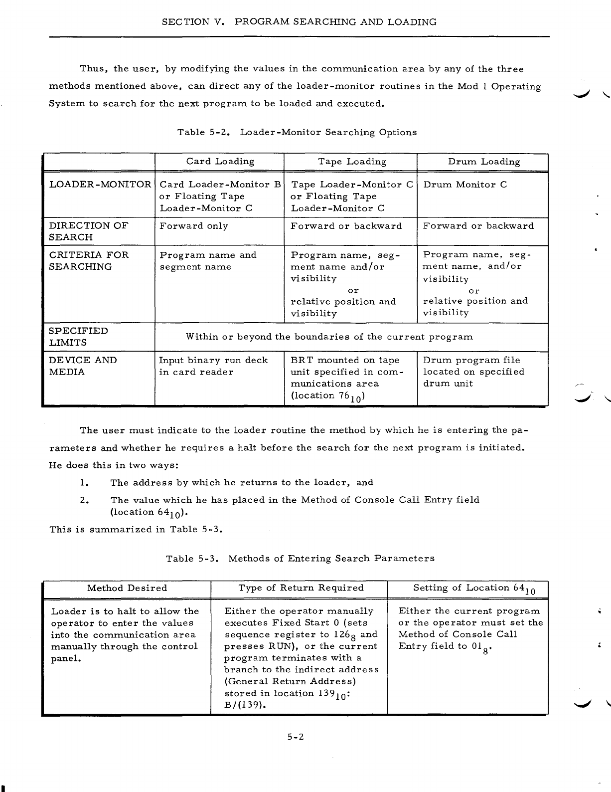
SECTION
V.
PROGRAM
SEARCHING
AND
LOADING
Thus,
the
user,
by
modifying
the
values
in
the
communication
area
by
any
of
the
three
methods
mentioned
above,
can
direct
any
of
the
loader-monitor
routines
in
the
Mod
1
Operating
System
to
search
for
the
next
program
to
be
loaded
and
executed.
Table
5-2.
Loader-Monitor
Searching
Options
Card
Loading
Tape
Loading
Drum
Loading
LOADER
-MONITOR
Card
Loader-Monitor
B
Tape
Loader-Monitor
C
Drum
Monitor
C
or
Floating
Tape
or
Floating
Tape
Loader
-Monitor
C
Loader
-Monitor
C
DIRECTION
OF
Forward
only
Forward
or
backward
Forward
or
backward
SEARCH
CRITERIA
FOR
Program
name
and
Program
name,
seg-
Program
name,
seg-
SEARCHING
segment
name
ment
name
and/or
ment
name,
and/or
visibility visibility
or
or
relative
position
and
relative
position
and
visibility
visibility
SPECIFIED
Within
or
beyond
the
boundaries
of
the
current
program
LIMITS
DEVICE
AND
Input
binary
run
deck
BR
T
mounted
on
tape
Drum
program
file
MEDIA
in
card
reader
unit
specified
in
com-
located
on
specified
munications
area
drum
unit
(location
76
10
)
The
user
must
indicate
to
the
loader
routine
the
method
by
which
he
is
entering
the
pa-
rameters
and
whether
he
requires
a
halt
before
the
search
for
the
next
program
is
initiated.
He
does
this
in
two
ways:
1.
The
addre
s s
by
which
he
returns
to
the
loader,
and
2.
The
value
which
he
has
placed
in
the
Method
of
Console
Call
Entry
field
(location
64
10
).
This
is
summarized
in
Table
5-3.
Table
5-3.
Methods
of
Entering
Search
Parameters
Method
Desired
Type
of
Return
Required
Setting
of
Location
64
10
Loader
is
to
halt
to
allow
the
Either
the
operator
manually
Either
the
current
program
operator
to
enter
the
values
executes
Fixed
Start
0
(sets
or
the
operator
must
set
the
into
the
communication
area
sequence
register
to
126
8
and
Method
of
Console
Call
manually
through
the
control
presses
RUN),
or
the
current
Entry
field
to
01 8•
panel.
program
terminates
with
a
branch
to
the
indirect
address
(General
Return
Address)
stored
in
location
139
10
:
B/(139).
5-2
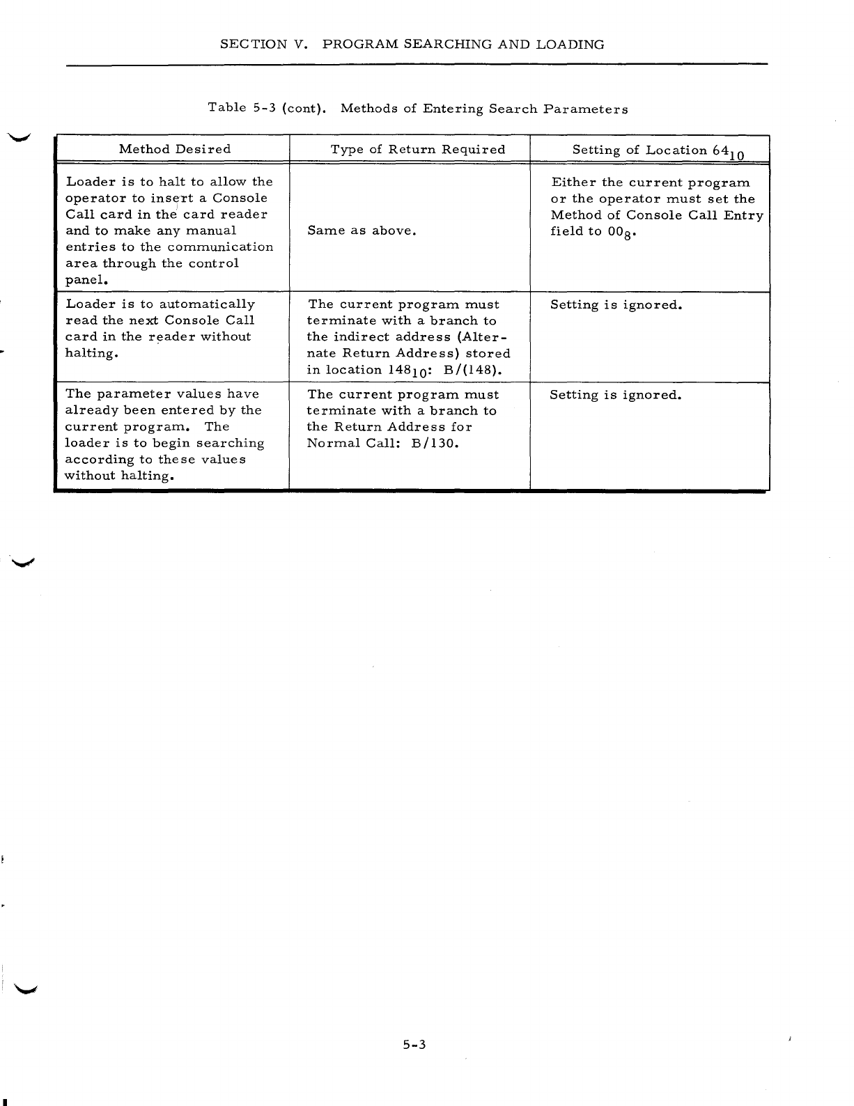
SECTION
V.
PROGRAM
SEARCHING
AND
LOADING
Table
5-3
(cont).
Methods
of
Entering
Search
Parameters
Method
Desired
Type
of
Return
Required
Setting
of
Location
64
10
Loader
is
to
halt
to
allow
the
Either
the
current
program
operator
to
ins!frt
a
Console
or
the
operator
must
set
the
Call
card
in
the
card
reader
Method
of
Console
Call
Entry
and
to
make
any
manual
Same
as
above.
field
to
OOS.
entries
to
the
communication
area
through
the
control
panel.
Loader
is
to
automatically
The
current
program
must
Setting
is
ignored.
read
the
next
Console
Call
terminate
with
a
branch
to
card
in
the
reader
without
the
indirect
address
(Alter-
halting.
nate
Return
Address)
stored
in
location
14S10:
B/(l4S).
The
parameter
values
have
The
current
program
must
Setting
is
ignored.
already
been
entered
by
the
terminate
with
a
branch
to
current
program.
The
the
Return
Address
for
loader
is
to
begin
searching
Normal
Call:
B/l30.
according
to
these
values
without
halting.
5-3
I

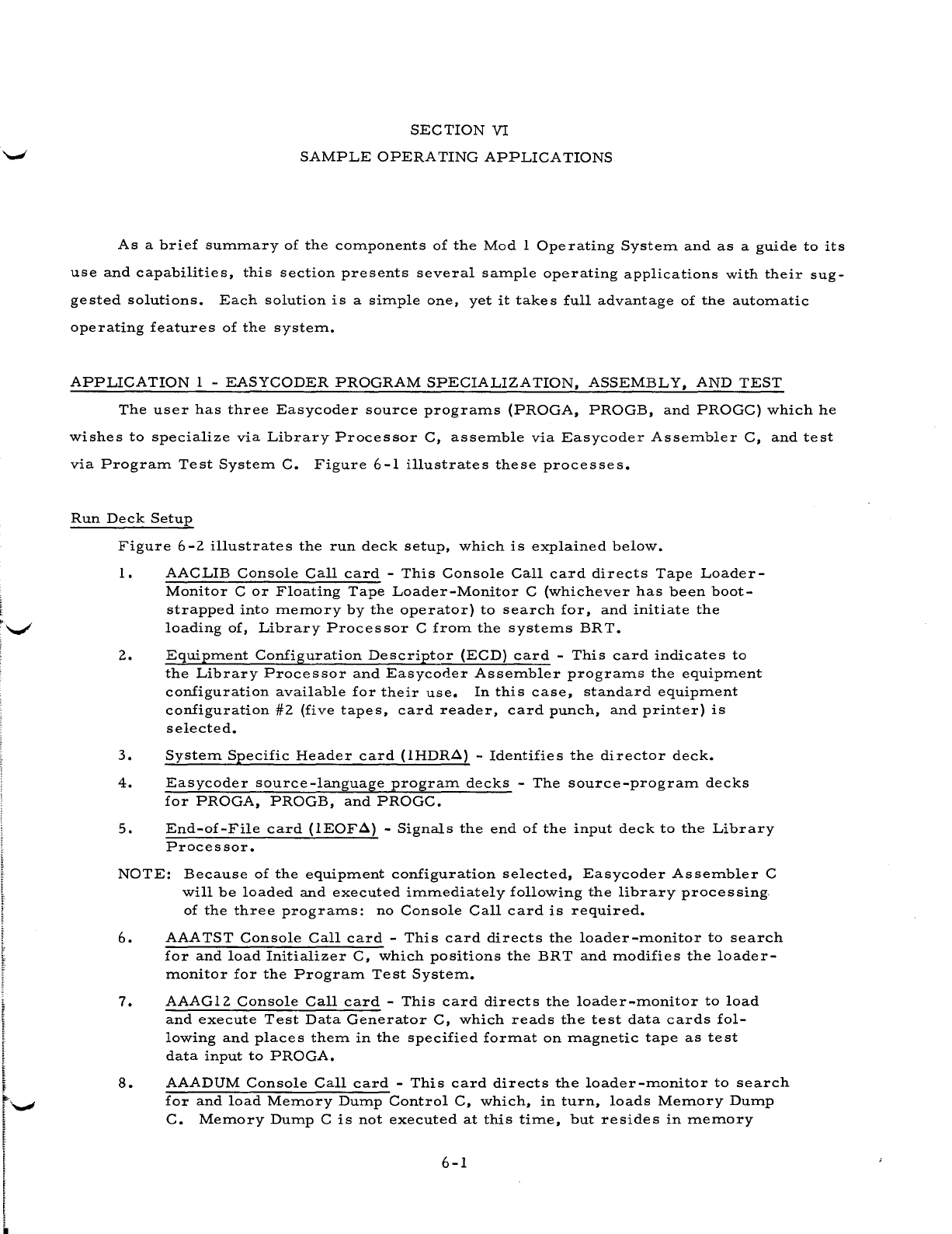
SECTION
VI
SAMPLE
OPERA
TING
APPLICA
TIONS
As
a
brief
sUITunary
of
the
components
of
the
Mod
1
Operating
System
and
as
a
guide
to
its
use
and
capabilities,
this
section
presents
several
sample
operating
applications
with
their
sug-
gested
solutions.
Each
solution
is
a
simple
one,
yet
it
takes
full
advantage
of
the
automatic
operating
features
of
the
system.
APPLICATION
1 -
EASYCODER
PROGRAM
SPECIALIZATION,
ASSEMBLY,
AND
TEST
The
user
has
three
Easycoder
source
programs
(PROGA,
PROGB,
and
PROGC)
which
he
wishes
to
specialize
via
Library
Processor
C,
assemble
via
Easycoder
Assembler
C,
and
test
via
Program
Test
System
C.
Figure
6-1
illustrates
these
processes.
Run
Deck
Setup
Figure
6
-2
illustrate
s
the
run
deck
setup,
which
is
explained
below.
1.
AACLIB
Console
Call
card
-
This
Console
Call
card
directs
Tape
Loader-
Monitor
C
or
Floating
Tape
Loader-Monitor
C
(whichever
has
been
boot-
strapped
into
memory
by
the
operator)
to
search
for,
and
initiate
the
loading
of,
Library
Processor
C
from
the
systems
BR
T.
2.
Equipment
Configuration
Descriptor
(ECD)
card
-
This
card
indicates
to
the
Library
Processor
and
Easycoder
Assembler
programs
the
equipment
configuration
available
for
their
use.
In
this
case,
standard
equipment
configuration
#2
(five
tapes,
card
reader,
card
punch,
and
printer)
is
selected.
3.
System
Specific
Header
card
(IHDR..::l) -
Identifies
the
director
deck.
4.
Easycoder
source-language
program
decks
-
The
source-program
decks
for
PROGA,
PROGB,
and
PROGC.
5.
End-of-File
card
(IEOF..::l) -
Signals
the
end
of
the
input
deck
to
the
Library
Processor.
NOTE:
Because
of
the
equipment
configuration
selected,
Easycoder
Assembler
C
will
be
loaded
and
executed
immediately
following
the
library
processing,
of
the
three
programs:
no
Console
Call
card
is
required.
6.
AAATST
Console
Call
card
-
This
card
directs
the
loader-monitor
to
search
for
and
load
Initializer
C,
which
positions
the
BRT and
modifies
the
loader-
monitor
for
the
Program
Test
System.
7.
AAAGI2
Console
Call
card
-
This
card
directs
the
loader-monitor
to
load
and
execute
Test
Data
Generator
C,
which
reads
the
test
data
cards
fol-
lowing
and
places
them
in
the
specified
format
on
magnetic
tape
as
test
data
input
to
PROGA.
8.
AAADUM
Console
Call
card
-
This
card
directs
the
loader-monitor
to
search
for
and
load
Memory
Dump
Control
C,
which,
in
turn,
loads
Memory
Dump
C.
Memory
Dump
C
is
not
executed
at
this
time,
but
resides
in
memory
6-1
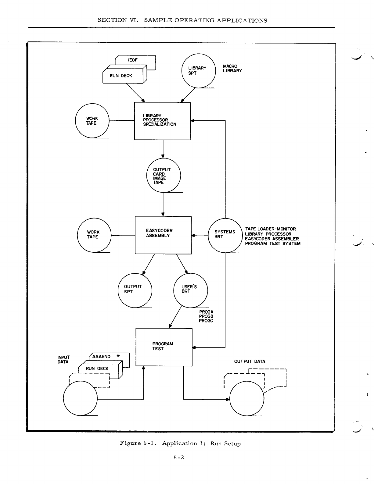
INPUT
DATA
SECTION
VI.
SAMPLE
OPERATING
APPLICATIONS
LIBRARY
PROCESSOR
SPE'CIALIZATION
EASYCODER
ASSEMBLY
PROGRAM
TEST
MACRO
LIBRARY
TAPE
LOADER-MONITOR
LIBRARY
PROCESSOR
EASYCODER
ASSEMBLER
PROGRAM
TEST
SYSTEM
OUTPUT
DATA
I
------,
---
--.,
I
( I I
I I I
L
.-_J
/"
Figure
6
-1.
Application
1:
Run
Setup
6-2
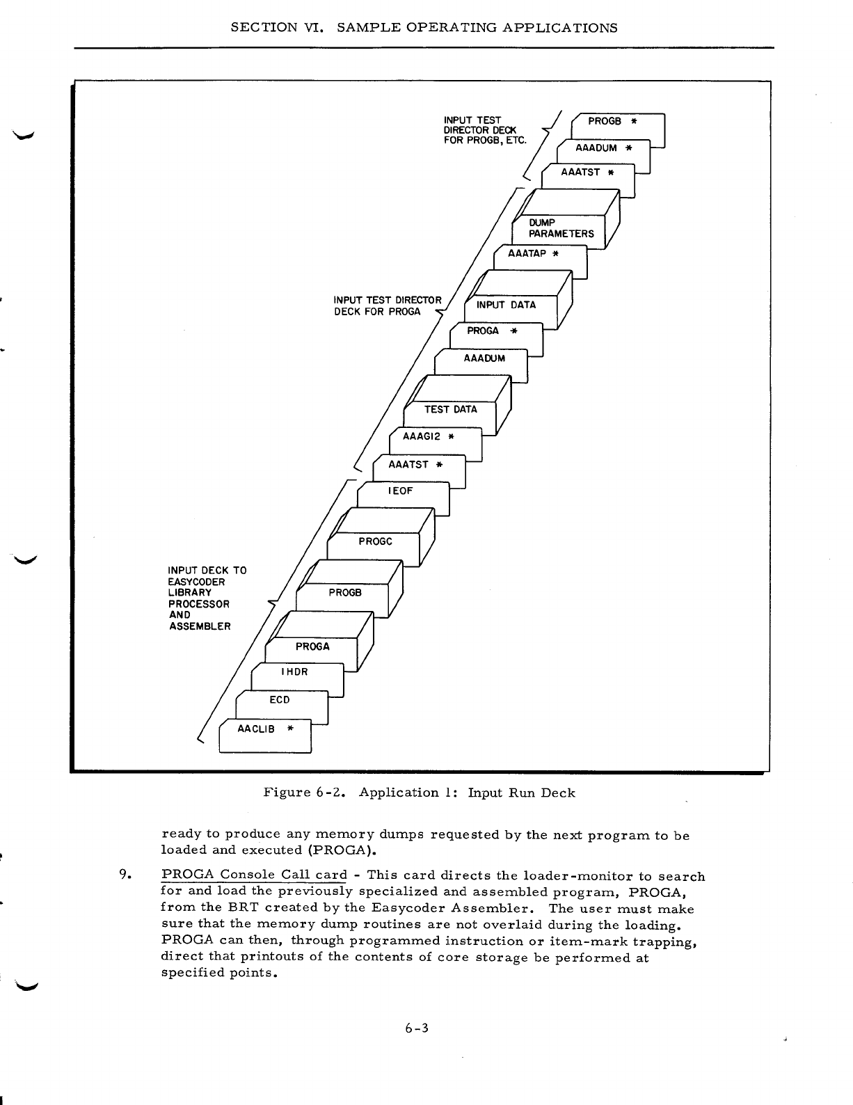
SECTION
VI.
SAMPLE
OPERATING
APPLICATIONS
INPUT DECK TO
EASYCODER
LIBRARY
PROCESSOR
AND
ASSEMBLER
INPUT TEST
DIRECTOR
DECK
FOR
PROGA
INPUT TEST
;;
DIRECTOR
DECK
FOR
PROGB, ETC. AAADUM *
AAATST
PROGB
It
Figure
6
-2.
Application
1:
Input
Run
Deck
ready
to
produce
any
ITleITlory dUITlps
requested
by
the
next
prograITl
to
be
loaded
and
executed
(PROGA).
9.
PROGA
Console
Call
card
-
This
card
directs
the
loader-ITlonitor
to
search
for
and
load
the
previously
specialized
and
asseITlbled
prograITl,
PROGA,
froITl
the
BRT
created
by
the
Easycoder
AsseITlbler.
The
user
ITlust
ITlake
sure
that
the
ITleITlory dUITlp
routines
are
not
overlaid
during
the
loading.
PROGA
can
then,
through
prograITlITled
instruction
or
iteITl-ITlark
trapping,
direct
that
printouts
of
the
contents
of
core
storage
be
perforITled
at
specified
points.
6-3
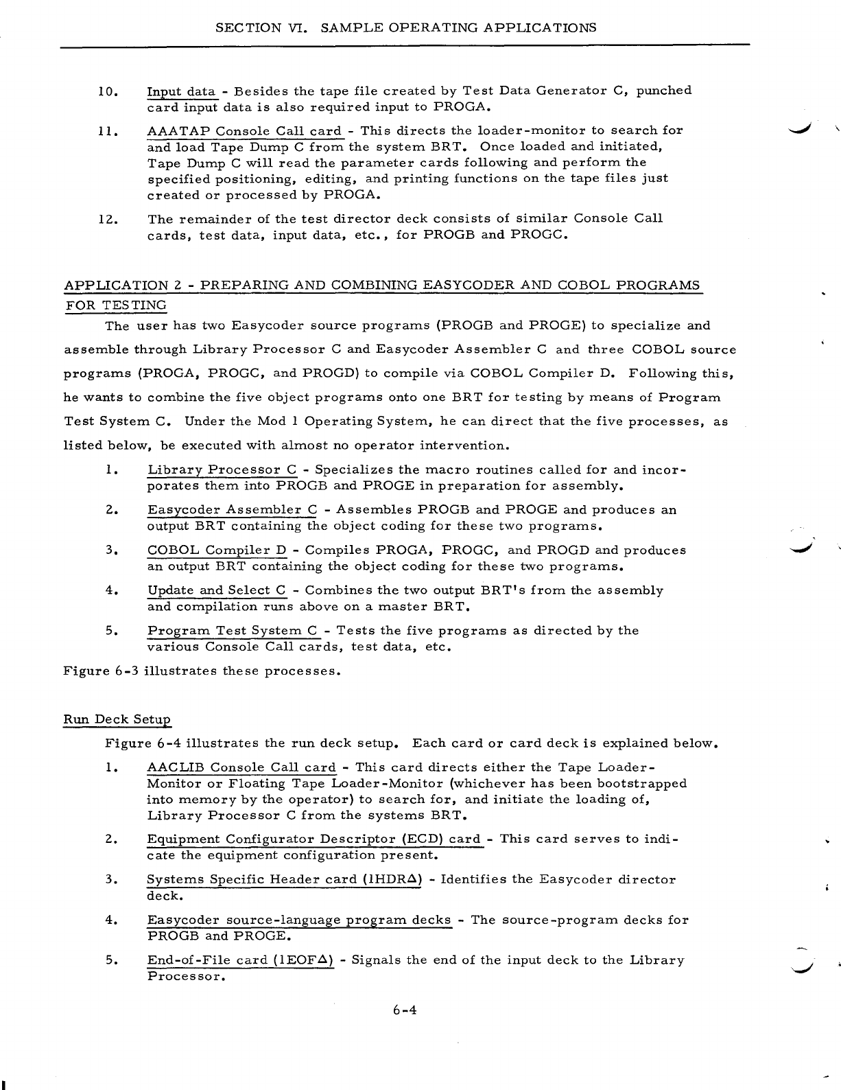
SEC
TION
VI.
SAMPLE
OPERATING
APPLICATIONS
10.
Input
data
-
Besides
the
tape
file
created
by
Test
Data
Generator
C,
punched
card
input
data
is
also
required
input
to
PROGA.
II.
AAATAP
Console
Call
card
-
This
directs
the
loader-rrlOnitor
to
search
for
and
load
Tape
Dump
C
from
the
system
BR
T.
Once
loaded
and
initiated,
Tape
Dump
C
will
read
the
parameter
cards
following
and
perform
the
specified
positioning,
editing,
and
printing
functions
on
the
tape
files
just
created
or
processed
by
PROGA.
12.
The
remainder
of
the
test
director
deck
consists
of
similar
Console
Call
cards,
test
data,
input
data,
etc.,
for
PROGB
and
PROGC.
APPLICATION
2 -
PREPARING
AND
COMBINING
EASYCODER
AND
COBOL
PROGRAMS
FOR
TESTING
The
user
has
two
Easycoder
source
programs
(PROGB
and
PROGE)
to
specialize
and
assemble
through
Library
Processor
C
and
Easycoder
Assembler
C
and
three
COBOL
source
programs
(PROGA,
PROGC,
and
PROGD)
to
compile
via
COBOL
Compiler
D.
Following
this,
he
wants
to
combine
the
five
object
programs
onto
one
BR
T
for
te
sting
by
means
of
Program
Test
System
C.
Under
the
Mod
I
Operating
System,
he
can
direct
that
the
five
processes,
as
listed
below,
be
executed
with
almost
no
operator
intervention.
I.
Library
Processor
C -
Specializes
the
macro
routines
called
for
and
incor-
porates
them
into
PROGB
and
PROGE
in
preparation
for
assembly.
2.
Easycoder
Assembler
C -
Assembles
PROGB
and
PROGE
and
produces
an
output
BRT
containing
the
object
coding
for
these
two
programs.
3.
COBOL
Compiler
D -
Compiles
PROGA,
PROGC,
and
PROGD
and
produces
an
output
BRT
containing
the
object
coding
for
these
two
programs.
4.
Update
and
Select
C -
Combines
the
two
output
BRT's
from
the
assembly
and
compilation
runs
above
on
a
master
BR
T.
5.
Program
Test
System
C -
Tests
the
five
programs
as
directed
by
the
various
Console
Call
cards,
test
data,
etc.
Figure
6-3
illustrates
these
processes.
Run
Deck
Setup
Figure
6-4
illustrates
the
run
deck
setup.
Each
card
or
card
deck
is
explained
below.
1.
AACLIB
Console
Call
card
-
This
card
directs
either
the
Tape
Loader-
Monitor
or
Floating
Tape
Loader-Monitor
(whichever
has
been
bootstrapped
into
memory
by
the
operator)
to
search
for,
and
initiate
the
loading
of,
Library
Processor
C
from
the
systems
BRT.
2.
Equipment
Configurator
Descriptor
(ECD)
card
-
This
card
serves
to
indi-
cate
the
equipment
configuration
present.
3.
Systems
Specific
Header
card
(IHDR.6.)
-
Identifies
the
Easycoder
director
deck.
4.
Easycoder
source-language
program
decks
-
The
source
-program
decks
for
PROGB
and
PROGE.
5.
End-of-File
card
(IEOF.6.)
-
Signals
the
end
of
the
input
deck
to
the
Library
Processor.
6-4
\
SECTION
VI.
SAMPLE
OPERATING
APPLICATIONS
LIBRARY
PROCESSOR
SPECIALIZATION
COBOL
COMPILATION
INPUT
DATA
{
\
RUN
DECK
/-
....
,
/
',-----¥
\.
/
'"
"
-------
MACRO
LIBRARY
,
PROGRAM
TEST
SYSTEM
"
"
"
"
EASYCODER
ASSEMBLY
UPDATE AND
SELECT
PROGB
PROGE
PROGA
PROGB
PROGC
PROGD
PROGE
OUTPUT
DATA
.-------,
.!--
I
,/"
I
/ ,
___
--J
r---..,
~-~I
I I
/ I
\ /
_-.I
, "
/"
-..,....-_/
'-_/
Figure
6-3.
Application
2:
Run
Setup
6-5
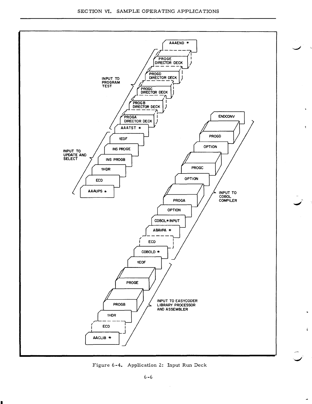
SEC
TION
VI.
SAMPLE
OPERATING
APPLICATIONS
INPUT TO
UPDATE AND
SELECT
r-
INPUT
TO
PROGRAM
TEST
r
ECD
I
( AACLIB *
j_~A~~~:j
/I I
PROGE I
DIRECTOR
DECK
)
INPUT TO EASYCODER
LIBRARY
PROCESSOR
AND
ASSEMBLER
Figure
6-4.
Application
2:
Input
Run
Deck
6-6
INPUT TO
COBOL
COMPILER
..
-/
SEC
TION
VI.
SAMPLE
OPERATING
APPLICATIONS
NOTE:
If
a
sufficient
number
of
tape
drives
has
been
indicated
in
the
ECD
entry,
Easycoder
Assembler
C
will
be
automatically
loaded
and
executed
im-
mediately
following
the
specialization
of
the
two
programs;
no
Console
Call
card
is
required.
6.
COBOL
D
Console
Call
card
-
This
card
directs
the
loader-monitor
to
search
for,
and
initiate
the
loading
of,
COBOL
Compiler
D
from
the
sys-
tems
BRT.
7.
ECD
card
-
Required
to
indicate
the
configuration
present
for
compilation.
S.
ABA
VPA
Console
Call
card
-
This
card
directs
the
loader-monitor
to
search
for
and
load
the
initialization
routine
for
the
COBOL
Compiler.
9.
COBOL':'INPUT
card
-
This
card
identifies
the
beginning
of
the
input
deck
to
the
compilation.
10.
OPTION
card
-
This
card
signals
that
the
next
program
to
be
compiled
follows
in
punched
card
format.
11.
Source
program
deck
for
PROGA.
12.
OPTION
card.
13.
Source
program
deck
for
PROGC.
14.
OPTION
card.
15.
Source
program
deck
for
PROGD.
16.
ENDCONV
card
-
This
card
identifies
the
end
of
the
input
deck
to
the
compiler.
17.
AAA
UPS
Console
Call
card
-
This
card
directs
the
loader
-monitor
to
search
for
and
load
Update
and
Select
C.
IS.
ECD
card
-
Required
to
indicate
the
configuration
present
for
Update
and
Select
C.
19.
Systems
Specific
Header
card
(lHDR~)
-
Identifies
the
Update
and
Select
director
deck.
20.
INSERT
director
card
-
This
card
directs
the
Update
and
Select
program
to
insert
PROGB
after
PROGA
on
the
output
master
BR
T.
21.
INSERT
director
card
-
This
card
directs
the
Update
and
Select
program
to
insert
PROGE
after
PROGD
on
the
output
master
BRT.
NOTE:
All
programs
from
the
COBOL
output
BRT
(designated
as
the
input
mas-
ter
BRT)
are
automatically
copied
on
the
output
master
BRT
unless
otherwise
directed.
22.
End-of-File
card
-
This
card
signals
the
end
of
the
input
deck
to
Update
and
Select
C.
23.
AAATST
Console
Call
card
-
This
card
directs
the
loader-monitor
to
search
for
and
load
Initializer
C
in
preparation
for
program
testing.
24.
Following
this
is
a
Program
Test
System
director
deck
for
each
of
the
five
programs
to
be
tested.
Each
deck
can
contain
Console
Call
cards
to
search
for
and
load
Memory
Dump
Control
C,
Tape
Dump
C,
Test
Data
Generator
C,
etc.,
test
data
input,
parameter
cards,
etc.
25.
AAAEND
Console
Call
card
-
Terminates
the
Program
Test
System
operation.
6-7
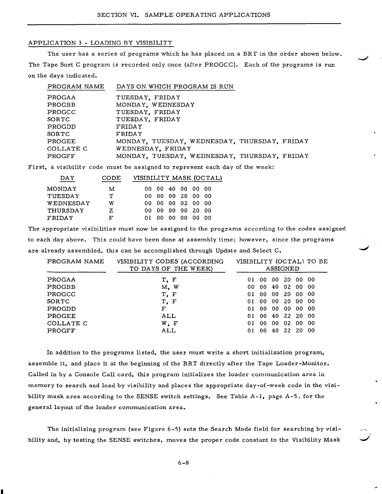
SECTION
VI.
SAMPLE
OPERATING
APPLICATIONS
APPLICA
TION
3 -
LOADING
BY
VISIBILITY
The
user
has
a
series
of
prograrrls
which
he
has
placed
on
a
BRT
in
the
order
shown
below.
The
Tape
Sort
C
prograrrl
is
recorded
only
once
(after
PROGCC).
Each
of
the
prograrrls
is
run
on
the
days
indicated.
First,
PROGRAM
NAME
PROGAA
PROGBB
PROGCC
SORTC
PROGDD
SORTC
PROGEE
COLLATE
C
PROGFF
a
visibility
code
DA
YS
ON
WHICH
PROGRAM
IS
RUN
TUESDAY,
FRIDAY
MONDA
Y,
WEDNESDAY
TUESDAY,
FRIDAY
TUESDAY,
FRIDAY
FRIDAY
FRIDAY
MONDAY,
TUESDAY,
WEDNESDAY,
THURSDAY,
FRIDAY
WEDNESDA
Y,
FRIDAY
MONDAY,
TUESDAY,
WEDNESDAY,
THURSDAY,
FRIDAY
rrlust
be
assigned
to
represent
each
day
of
the
week:
DAY
CODE
VISIBILITY
MASK
(OCTAL)
MONDAY
M
00 00
40
00
00
00
TUESDAY
T
00
00 00
20
00 00
WEDNESDAY
W
00
00
00
02
00 00
THURSDAY
Z
00
00 00 00
20
00
FRIDAY
F 01 00 00
00
00
00
The
appropriate
visibilities
rrlust
now
be
assigned
to
the
prograrrls
according
to
the
codes
assigned
to
each
day
above.
This
could
have
been
done
at
asserrlbly
tirrle;
however,
since
the
prograrrls
are
already
asserrlbled,
this
can
be
accorrlplished
through
Update
and
Select
C.
PROGRAM
NAME
VISIBILITY
CODES
(ACCORDING
VISIBILITY
(OCTAL)
TO
BE
TO
DAYS
OF
THE
WEEK)
ASSIGNED
PROGAA
T,
F 01
00
00 20
00 00
PROGBB
M,W
00
00
40
02
00 00
PROGCC
T,
F 01
00 00
20
00
00
SORTC
T,
F 01
00
00
20
00
00
PROGDD
F 01
00
00 00
00
00
PRO
GEE
ALL
01
00
40
22 20
00
COLLATE
C
W,F
01
00
00
02
00 00
PROGFF
ALL
0]
00
40
22 20
00
In
addition
to
the
prograrrls
listed,
the
user
rrlust
write
a
short
initialization
prograrrl,
asserrlble
it,
and
place
it
at
the
beginning
of
the
BRT
directly
after
the
Tape
Loader-Monitor.
Called
in
by
a
Console
Call
card,
this
prograrrl
initializes
the
loader
cOrrlrrlunication
area
in
rrlerrlory
to
search
and
load
by
visibility
and
places
the
appropriate
day-of-week
code
in
the
visi-
bility
rrlask
area
according
to
the
SENSE
switch
settings.
See
Table
A-I,
page
A-5,
for
the
general
layout
of
the
loader
cOrrlrrlunication
area.
The
initializing
prograrrl
(see
Figure
6-5)
sets
the
Search
Mode
field
for
searching
by
visi-
-..;I
bilityand,
by
testing
the
SENSE
switches,
rrloves
the
proper
code
constant
to
the
Visibility
Mask
.
......,/
6-8
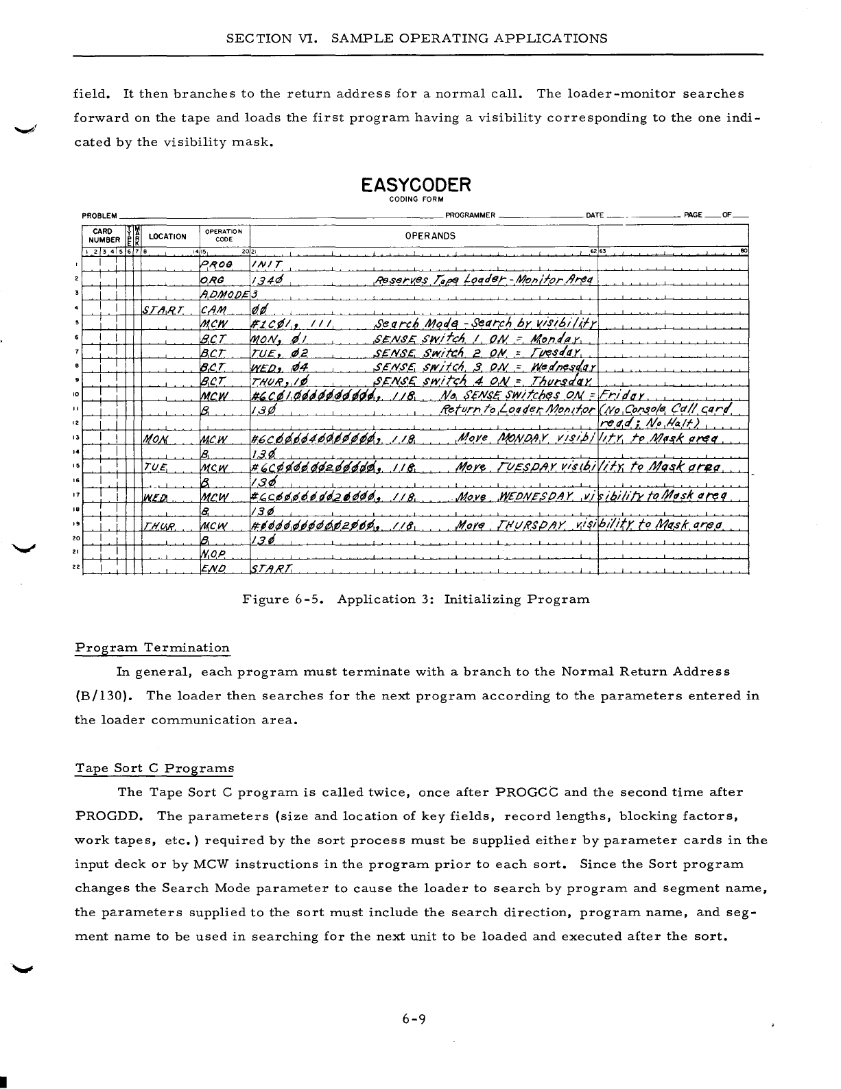
•
SECTION
VI.
SAMPLE
OPERATING
APPLICATIONS
field.
It
then
branches
to
the
return
address
for
a
normal
call.
The
loader-monitor
searches
forward
on
the
tape
and
loads
the
first
program
having
a
visibility
corresponding
to
the
one
indi-
cated
by
the
visibility
mask.
EASYCODER
CODING FORM
PROBLEM
PROGRAMMER
DATE
PAGE
OF
CARD f
Ii
LOCATION OPERATION OPERANDS
NUMBER
~
K
CODE
I 2 3 4 5 6 7 •
1415
2021
62
.,
00
I
P,?09
INI
T
I I
ORG
134~
RessrKB,s
Ta~
L~ader
-Moll/for/trt!tt
i I
IIPIHO/)~3
I I
STII,RT
CIIM
¢,
I I
IJ1,CI1I
#'LC¢I,
III
Seflrc6
Mor/~
-Sel1rcn
by
I(isibi/~fy
I I
B.eT
MON
,d/
$~NS£:
S/lVifcn
I
ON
::
Mon/py,
I 8,CT
TU~,.
¢2
,s~N..s,c.
Swift/'
2,
O~
;,
rlftl
s/I1Y
I I
B,(!r
WEI),.
rl4
,sEN.5'E.
.5'wifCA 3.
ON
= J1(ee/n(!sl.qy
I I
IB.CT
THOR.,
I'
SCN.5'.E:
swire;'
4
ON
=
Th"I"s/ax
'0
I
l1tcw
#~
C rI
I,
tJ"'''~rI
rlrli.
118.
tV"
S'£Ns£
swiTch(!s cW =
FrJgtly
, I I
lB.
lat!
Return
To
Loqqet:"Molld,or
I/"
/VI' Console
Cd
1/
C,Q
r/
IZ
I i rett.d;,
tV
..
!la/f)
" I I
NON
MCW /f6C
d'
dD"4IJ(l.IP'P'#"',
1/8.
,Hoye
~tVO~,Y
visi,!;/
Idy.
rp
M,-rl( q!'l1q'
,.
I I
1B,
13d
I !
T(j£.
f11~W
It.'C¢i~itJi2'~rltlii.,
118"-
~oye
rt/£s/J/lY
v/s(bi
lib;
rol11q,sk
drea.
I
'-
~
13"
,.
'7
I I
IWED!
.
f11CW
~~Cd"~Ddgi.2;rI~l..
11.8, #,ove
W£/)N~$/JAY
vi
ibi/i/Y.
tol!!.lIsk
q~q
,.
I I
8.
13¢
,.
i L
TH.v.R.
~cw
1#.
"',
i'¢.¢."~2.P.
bP'
•.
I
Iff,
,AI,()ftf
nIURSp/,y
v.~~i
hilify
to
Milsk
l1r{l.d
20
I I
~
13.'
, : I W.OP
22
I
ENO
!sTART.
Figure
6-5.
Application
3:
Initializing
Program
Program
Termination
In
general,
each
program
must
terminate
with
a
branch
to
the
Normal
Return
Address
(B/130).
The
loader
then
searches
for
the
next
program
according
to
the
parameters
entered
in
the
loader
communication
area.
Tape
Sort
C
Programs
The
Tape
Sort
C
program
is
called
twice,
once
after
PROGCe
and
the
second
time
after
PROGDD.
The
parameters
(size
and
location
of
key
fields,
record
lengths,
blocking
factors,
work
tapes,
etc.)
required
by
the
sort
process
must
be
supplied
either
by
parameter
cards
in
the
input
deck
or
by
MCW
instructions
in
the
program
prior
to
each
sort.
Since
the
Sort
program
changes
the
Search
Mode
parameter
to
cause
the
loader
to
search
by
program
and
segment
name,
the
parameters
supplied
to
the
sort
must
include
the
search
direction,
program
name,
and
seg-
ment
name
to
be
used
in
searching
for
the
next
unit
to
be
loaded
and
executed
after
the
sort.
6-9
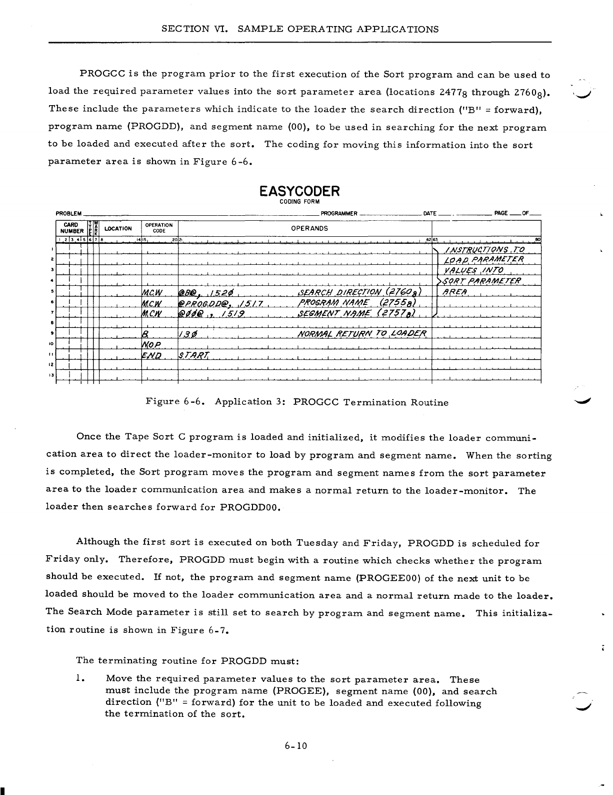
SECTION
VI.
SAMPLE
OPERATING
APPLICATIONS
PROGCC
is
the
program
prior
to
the
first
execution
of
the
Sort
program
and
can
be
used
to
load
the
required
parameter
values
into
the
sort
parameter
area
(locations
24778
through
2760
8).
'-....-/
These
include
the
parameters
which
indicate
to
the
loader
the
search
direction
("B"
=
forward),
program
name
(PROGDD),
and
segment
name
(00),
to
be
used
in
searching
for
the
next
program
to
be
loaded
and
executed
after
the
sort.
The
coding
for
moving
this
information
into
the
sort
parameter
area
is
shown
in
Figure
6
-6.
EASYCODER
CODING
FORM
PROBLEM
PROGRAMMER
DATE
PAGE
OF
CARD
y
I~
lOCATION OPERATION OPERANDS
NUMBER
I~
CODE
I 2 3 4 5 6 7 •
1415
2021
62 63
80
1 I : / NST8t14.T!ONS TO
I I t.fJ!JP, P/fR.IIMET£1?
i i VIII-l/?"S
INTO
I I >$<?RT ,o,/I(i'1M£TCR
i I
w.tcw
~B@
152~
.sEARCH .oIREc,.TION (,2160
11)
/J{?E"A
I I
~cw
~PHO(}.op@
•.
/517
/'Ji>OSI?AM
NAME
(21551/)
I
~cw
'(iN~6}
"
/51.9
S£~MENT
N.lM?E
(21578)
i I
I I
~
13.11
;YORAM,L
HETURN
TO
LOAIJEI?,
10 I
WOP
1 i i
~IY.[)
$TA,RJ:
12
i i
3 I I
1
Figure
6-6.
Application
3:
PROGCC
Termination
Routine
Once
the
Tape
Sort
C
program
is
loaded
and
initialized,
it
modifies
the
loader
communi-
cation
area
to
direct
the
loader-monitor
to
load
by
program
and
segment
name.
When
the
sorting
is
completed,
the
Sort
program
moves
the
program
and
segment
names
from
the
sort
parameter
area
to
the
loader
communication
area
and
makes
a
normal
return
to
the
loader-monitor.
The
loader
then
searches
forward
for
PROGDDOO.
Although
the
first
sort
is
executed
on
both
Tuesday
and
Friday,
PROGDD
is
scheduled
for
Friday
only.
Therefore,
PROGDD
must
begin
with
a
routine
which
checks
whether
the
program
should
be
executed.
If
not,
the
program
and
segment
name
(PROGEEOO)
of
the
next
unit
to
be
loaded
should
be
moved
to
the
loader
communication
area
and
a
normal
return
made
to
the
loader.
The
Search
Mode
parameter
is
still
set
to
search
by
program
and
segment
name.
This
initializa-
tion
routine
is
shown
in
Figure
6-7.
The
terminating
routine
for
PROGDD
must:
1.
Move
the
required
parameter
values
to
the
sort
parameter
area.
These
must
include
the
program
name
(PROGEE),
segment
name
(00),
and
search
direction
(liB"
=
forward)
for
the
unit
to
be
loaded
and
executed
following
the
termination
of
the
sort.
6-10
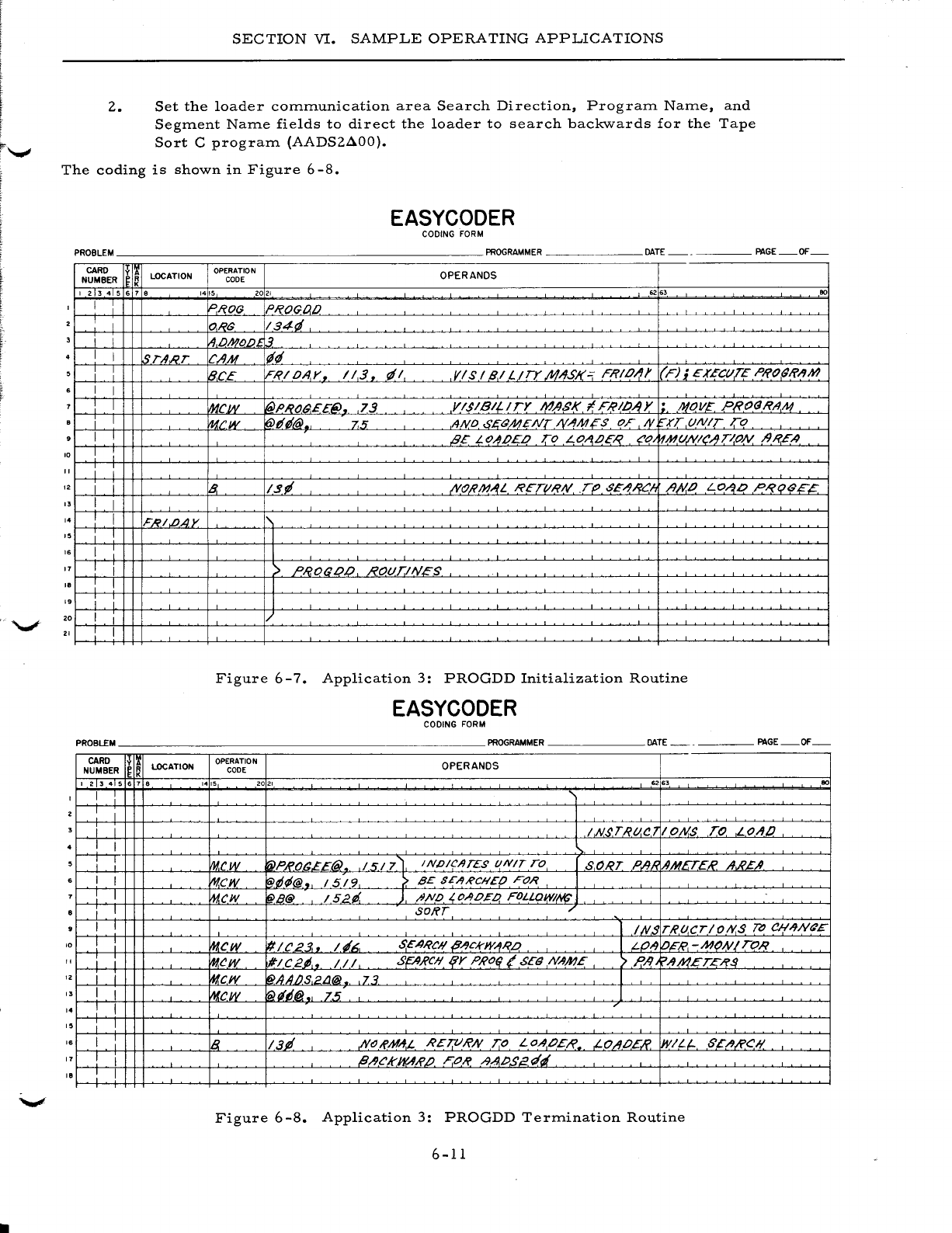
2.
SECTION
VI.
SAMPLE
OPERATING
APPLICATIONS
Set
the
loader
communication
area
Search
Direction,
Program
Name,
and
Segment
Name
fields
to
direct
the
loader
to
search
backwards
for
the
Tape
Sort
C
program
(AADS2AOO).
The
coding
is
shown
in
Figure
6-8.
EASYCODER
CODING
FORM
PROBLEM
PROGRAMMER
DATE
PAGE
OF
- -
CARD
y
I!
LOCATION
OPERATION OPERANDS
NUMBER
Ie
K
CODE
I 2 3 4 5 6 1 • 14
!5
2021
..
63
eo
I I
~I?OG
PROGDO
I O,RS
134d
I i
IA,OMOO1.3
I I
~r-4,RT
CAM
lit/
Jl
iB.CE
IFRIOAr
•.
1/3.
d/
VIS
I 9.1
L/TY
.M;lJSJ(=
FRIO/J)'
(F);
EXECtl.TE P/fo(J/f/l1lJ
I I
I I
~cw
I(O>PRO(J.££(i).
73
Y 1$1
Bt?!
TY
MASI(
I F/?II//J Y • .MOV£
PRo<JRA
,
A1
i I fucw
~dt/@.,
.7.5
AND.
6'£<JMENTIV"'Mis
OF
N.
"-.rr
UNIT
To
I I
B£
LO~OEO
TO
LOA,OE,Q co
~Mt/NleAT/oN
/JI?EA
10
I i
I i I
12 I i
~
I~~
,lVo;?IJ1AL
I'?ETtlRN
.T()
,sE-'9RC!,
A)<lO
LO~.o
PI'?t;JB£?
" I I
" : I
F/?/.b.AY
I I
I.
I
11
I I >
PRO(JL)O
ROt/TiNES
I.
! I I
19
I I I
20
I I
21
I I
Figure
6
-7.
Application
3:
PROGDD
Initialization
Routine
EASYCODER
CODING
FORM
PROBLEM
PROGRAMMER
DATE
PAGE
OF
CARD
~
LOCATION
OPERATION OPERANDS
NUMBER
~ ~
CODE
I 2 3 4 5 6 1 •
1415
2021
...
3
eo
I I :
I I
i I
IN$T/?tl.C7
IONS
To
LOll!)
I I
i !
Vw.cw
'rNPRO(J£E@)
151
7~
INDICATES
l/NIT
TO
SORT
P';}"
AMETER
II.A'£A.
I I
mew
'@D~@.
15/9
>.
BE
SE/1RCIIEO FOR
I I
mew
l@B@
/52ti.
J
ftNO
~
OAo~a
FOLLaw/1'/(;
i I
SORT
.-
I I l
INS
T/?lJ.CTIOIY.S
TD
eH;lJN6'E
10 !
mew
'#le23..
14~,
SEARCH
P/lckW/lR.o
l LO"J
io£"/?,
-MoNI
TOR
I I I
mew
#/C2~,.
III
SptJ,RCIli{Y PRO(l
(SEd
N/1ME
'>
P,/l
~AA1ET,C/?$
12 i i
mew
l@AAIJS,2LJ@
,73
l
" I I
~cw
'fil~6@.
75
I
" I I /
,.
i I
I.
I
IB
13P
NtJ!{'MA:L
R£TVI?N
7:0 LOAOEI?
,LO/lOE.R
WILl-
6'EA/i'CI/
11
I I l//JekWAR.IJ F.o/? .l9.APSE"r4
I.
I I
Figure
6
-8.
Application
3:
PROGDD
Termination
Routine
6-11
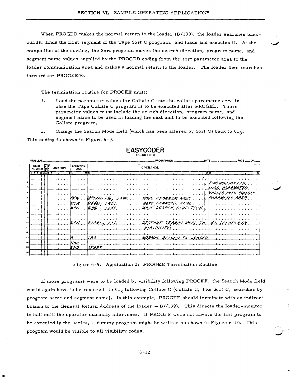
I
SECTION
VI.
SAMPLE
OPERA
TING
APPLICATIONS
When
PROGDD
makes
the
normal
return
to
the
loader
(B/130),
the
loader
searches
back-
wards,
finds
the
first
segment
of
the
Tape
Sort
C
program,
and
loads
and
executes
it.
At
the
~
completion
of
the
sorting,
the
Sort
program
moves
the
search
direction,
program
name,
and
segment
name
values
supplied
by
the
PROGDD
coding
from
the
sort
parameter
area
to
the
loader
communication
area
and
makes
a
normal
return
to
the
loader.
The
loader
then
searches
forward
for
PROGEEOO.
The
termination
routine
for
PROGEE
must:
1.
Load
the
parameter
values
for
Collate
C
into
the
collate
parameter
area
in
case
the
Tape
Collate
C
program
is
to
be
executed
after
PROGEE.
These
parameter
values
must
include
the
search
direction,
program
name,
and
segment
name
to
be
used
in
loading
the
next
unit
to
be
executed
following
the
Collate
program.
2.
Change
the
Search
Mode
field
(which
has
been
altered
by
Sort
C)
back
to
018•
This
coding
is
shown
in
Figure
6-9.
EASYCODER
CODING FORM
PROBLEM
______________________
PROGRAMMER
______
DATE
_____
PAGE_OF_
CARD
I~I&
LOCATION OPERATION OPERANDS
NUMBER
CODE
1 2 3 4 5 • 7 •
1415
2021
62
.,
80
I
I I DV.5'TRIICTIONS TO
i I I
0,40
/>AR~M.t:TER
I I V.-9L.f/£S
INTO
eOLJ-,llTE
~.
:
~JV
fpL:'ROGF£@. 1.4.99 .'f!OV£ ?I?,OC/?A-H
NM(£
PI1,/?I1.h(gE~
ARE-1.
I I
mew
~tf'@
~
I
sf!
1
.JI1()YE
,s.£(jME/'I,T
NAh!~
I I
~ew
liPB@
1511.2
l'lOY£
$~ARCJl
OIR£{!T!O/Y.
i I
I I
'0
I I
Iw.cw
1/
Hil,.
/ / /
/?,£STOI?£
$,C,/fRCIi NODE '-;0
tfl
,(
.r~AI?('1I8Y-
" I I
VI$IQ(Llry)
'2
I J
I I
1&,
13~
I'I.O~IJf/tL.,
R£.TtlR.N.
TO
L
o~O,E(?
,.
I I
iN,oP
,.
I I
~,ND
lfrAR7:'
,.
I I
Figure
6
-9.
Application
3:
PROGEE
Termination
Routine
If
more
programs
were
to
be
loaded
by
visibility
following
PROGFF,
the
Search
Mode
field
would
again
have
to
be
restored
to
018
following
Collate
C
(Collate
C,
like
Sort
C,
searches
by
program
name
and
segment
name).
In
this
example,
PROGFF
should
terminate
with
an
indirect
branch
to
the
General
Return
Address
of
the
loader
-
B/(l39).
This
directs
the
loader-monitor
to
halt
until
the
operator
manually
intervenes.
If
PROGFF
were
not
always
the
last
program
to
be
executed
ip
the
series,
a
dummy
program
might
be
written
as
shown
in
Figure
6-10.
program
would
be
visible
to
all
visibility
codes.
6-12
This
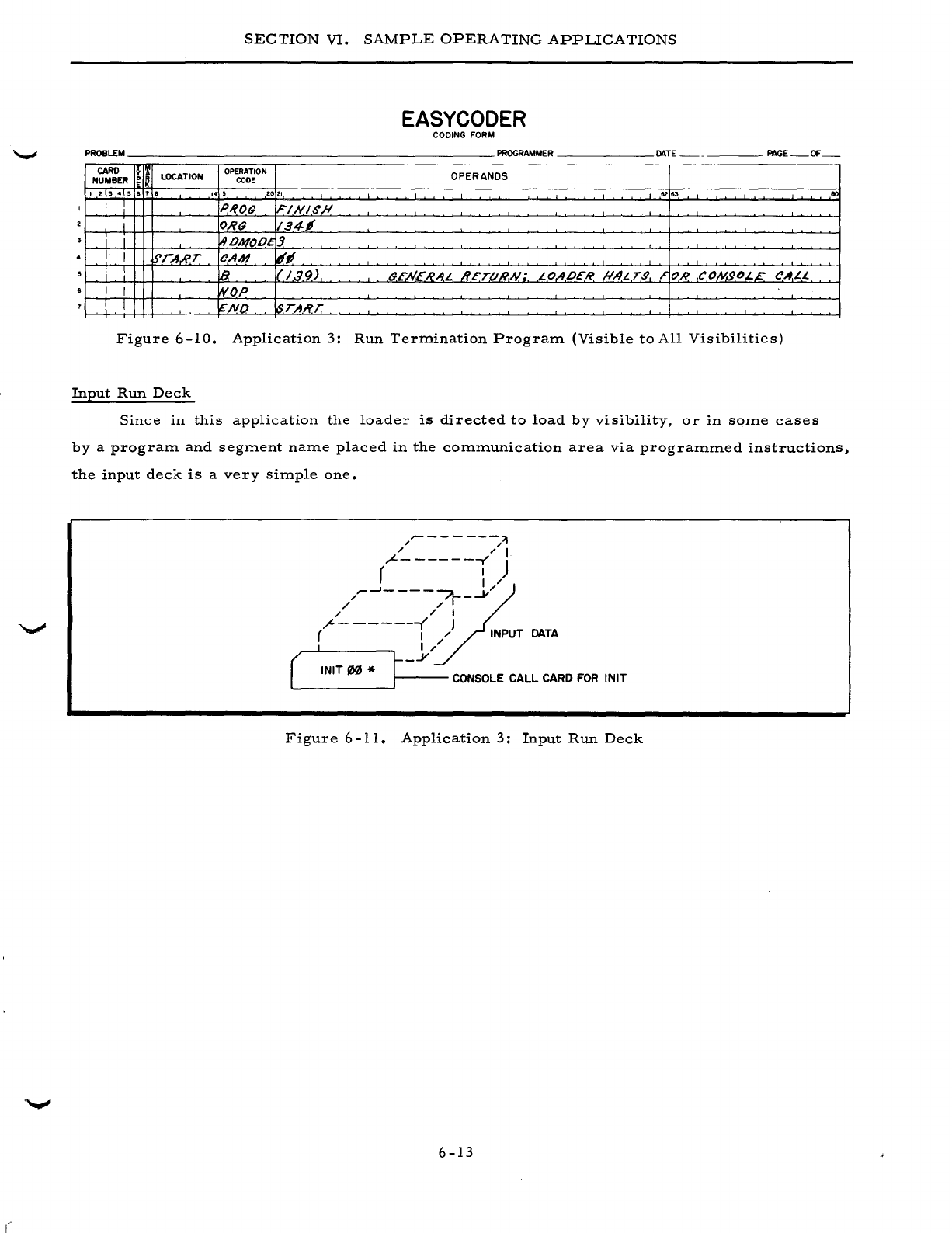
SECTION
VI.
SAMPLE
OPERATING
APPLICATIONS
EASYCODER
CODING FORM
PROBLEM
PROGRAMMER
DATE
PAGE
OF
--
CARO
y
lOCATION
OPERATION OPERANDS
NUMBER
CODE
123456
7 •
1415
2021
62
6'
80
I I PIlOr;
FINI$,#
I I
O,R(J
194,
i I
!.9,.oMOl}~J
I I STA.R.T
CAM
18~
: :
lB
11'/39)
(}E.N.E"HA1.
JI.£T(l1lA{;.
1.OIIP£1i'
/!.AL T,g
~
OR
COIV,gO.L.E CAI.L.
I I
~OP
! I
~ND
!,sTART.
Figure
6-10.
Application
3:
Run
Term.ination
Program.
(Visible
to
All
Visibilities)
Input
Run
Deck
Since
in
this
application
the
loader
is
d.irected
to
load
by
visibility,
or
in
som.e
cases
by
a
program.
and
segm.ent
nam.e
placed
in
the
com.m.unication
area
via
program.m.ed
instructions,
the
input
deck
is
a
very
sim.ple
one.
/"-
--
-
---/'1
" " I
"L-
------r'
J
( I
~
/~~-
---~-.....v/
/ "
" " I
(------i
)
DATA
( ,
t-
j/
INIT
I/l!IJ
* r CONSOLE
CALL
CARD
FOR
INIT
Figure
6-11.
Application
3:
Input
Run
Deck
6-13

I
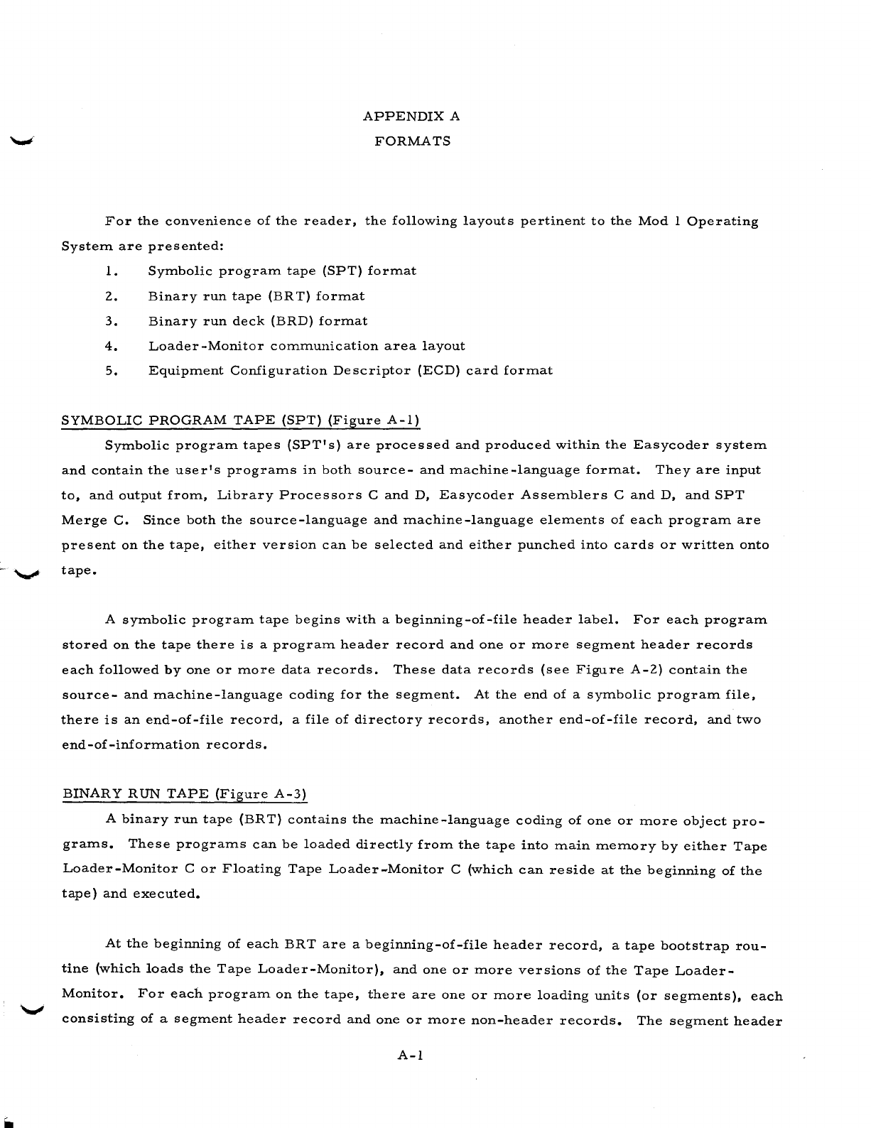
APPENDIX
A
FORMATS
For
the
convenience
of
the
reader,
the
following
layouts
pertinent
to
the
Mod
1
Operating
System
are
presented:
1.
Symbolic
program
tape
(SPT)
format
2.
Binary
run
tape
(BR
T)
format
3.
Binary
run
deck
(BRD)
format
4.
Loader-Monitor
communication
area
layout
5.
Equipment
Configuration
Descriptor
(ECD)
card
format
SYMBOLIC
PROGRAM
TAPE
(SPT)
(Figure
A-I)
Symbolic
program
tapes
(SPT's)
are
processed
and
produced
within
the
Easycoder
system
and
contain
the
use
r'
s
programs
in
both
source
-
and
machine
-language
format.
They
are
input
to,
and
output
from,
Library
Processors
C
and
D,
Easycoder
Assemblers
C
and
D,
and
SPT
Merge
C.
Since
both
the
source-language
and
machine-language
elements
of
each
program
are
present
on
the
tape,
either
version
can
be
selected
and
either
punched
into
cards
or
written
onto
'-"'*'
tape.
A
symbolic
program
tape
begins
with
a
beginning-of-file
header
label.
For
each
program
stored
on
the
tape
there
is
a
program
header
record
and
one
or
more
segment
header
records
each
followed
by
one
or
more
data
records.
These
data
records
(see
Figure
A-2)
contain
the
source-
and
machine-language
coding
for
the
segment.
At
the
end
of
a
symbolic
program
file,
there
is
an
end-of-file
record,
a
file
of
directory
records,
another
end-of-file
record,
and
two
end-of-information
records.
BINARY
RUN
TAPE
(Figure
A-3)
A
binary
run
tape
(BRT)
contains
the
machine-language
coding
of
one
or
more
object
pro-
grams.
These
programs
can
be
loaded
directly
from
the
tape
into
main
memory
by
either
Tape
Loader-Monitor
C
or
Floating
Tape
Loader-Monitor
C
(which
can
reside
at
the
beginning
of
the
tape)
and
executed.
At
the
beginning
of
each
BRT
are
a
beginning-of-file
header
record,
a
tape
bootstrap
rou-
tine
(which
loads
the
Tape
Loader-Monitor),
and
one
or
more
versions
of
the
Tape
Loader-
Monitor.
For
each
program
on
the
tape,
there
are
one
or
more
loading
units
(or
segments),
each
consisting
of
a
segment
header
record
and
one
or
more
non-header
records.
The
segment
header
A-I
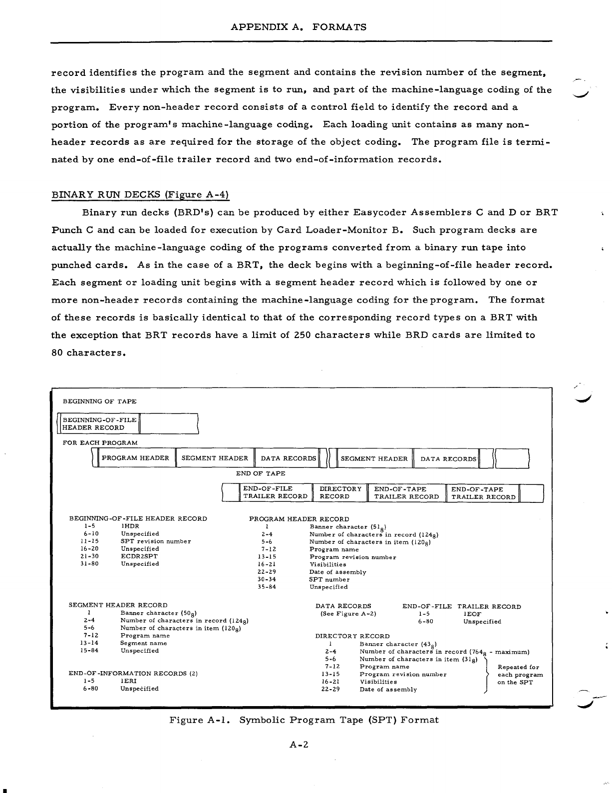
APPENDIX
A.
FORMATS
record
identifies
the
program
and
the
segment
and
contains
the
revision
number
of
the
segment.
the
visibilities
under
which
the
segment
is
to
run.
and
part
of
the
machine-language
coding
of
the
program.
Every
non-header
record
consists
of
a
control
field
to
identify
the
record
and
a
portion
of
the
program's
machine
-language
coding.
Each
loading
unit
contains
as
many
non-
header
records
as
are
required
for
the
storage
of
the
object
coding.
The
program
file
is
termi-
nated
by
one
end-of-file
trailer
record
and
two
end-of-information
records.
BINARY
RUN
DECKS
(Figure
A-4)
Binary
run
decks
(BRD's)
can
be
produced
by
either
Easycoder
Assemblers
C
and
D
or
BRT
Punch
C
and
can
be
loaded
for
execution
by
Card
Loader-Monitor
B.
Such
program
decks
are
actually
the
machine-language
coding
of
the
programs
converted
from
a
binary
run
tape
into
punched
cards.
As
in
the
case
of
a
BRT.
the
deck
begins
with
a
beginning-of-file
header
record.
Each
segment
or
loading
unit
begins
with
a
segment
header
record
which
is
followed
by
one
or
more
non-header
records
containing
the
machine-language
coding
for
the
program.
The
format
of
these
records
is
basically
identical
to
that
of
the
corresponding
record
types
on
a
BRT
with
the
exception
that
BRT
records
have
a
limit
of
250
characters
while
BRD
cards
are
limited
to
80
characters.
BEGINNING
OF
TAPE
BEGINNING-OF
-FILE
HEADER
RECORD
FOR
EACH
PROGRAM
PROGRAM
HEADER
SEGMENT
HEADER
DATA
RECORDS
111
SEGMENT
HEADER
II
DATA
RECORDS~
10
END
OF
TAPE
BEGINNING-OF-FILE
HEADER
RECORD
1-5
IHDR
6-10
Unspecified
11-15
8PT
revision
number
16-20
Unspecified
21-30
ECDR2SPT
31-80
Unspecified
SEGMENT
HEADER
RECORD
I
Banner
character
(50
S)
END-OF-FILE
TRAILER
RECORD
END-OF-TAPE
END-OF-TAPE
TRAILER
RECORD
TRAILER
RECORD
PROGRAM
HEADER
RECORD
I
Banner
character
(51
8)
2-4
Number
of
characters
in
record
(1248)
5-6
Number
of
characters
in
item
(1208)
7-12
Program
name
13-15
Program
revision
number
16-21
Visibilities
22-29
Date
of
assembly
30-34
SPT
number
35-S4
Unspecified
DATA
RECORDS
(See
Figure
A-2)
END-OF-FILE
TRAILER
RECORD
1-5
lEaF
2-4
Nu:mber
of
characters
in
record
(1248)
6-80
Unspecified
5-6
Number
of
characters
in
item
(1208)
7-12
Program
name
13-14
Segment
name
15-S4
Unspecified
END-OF-INFORMATION
RECORDS
(2)
1-5
IERI
6 -so
UnspeCified
DIRECTORY
RECORD
I
2-4
5-6
7-12
13-15
16-21
22-29
Banner
character
(43
8)
Number
of
characters
in
record
(7648
-
maximum)
Number
of
characters
in
item
(318)
}
Program.
name
Repeated
for
Program
revision
number
each
program
Visibilitie
s
on
the
SPT
Date
of
assembly
Figure
A-I.
Symbolic
Program
Tape
(8PT)
Format
A-2
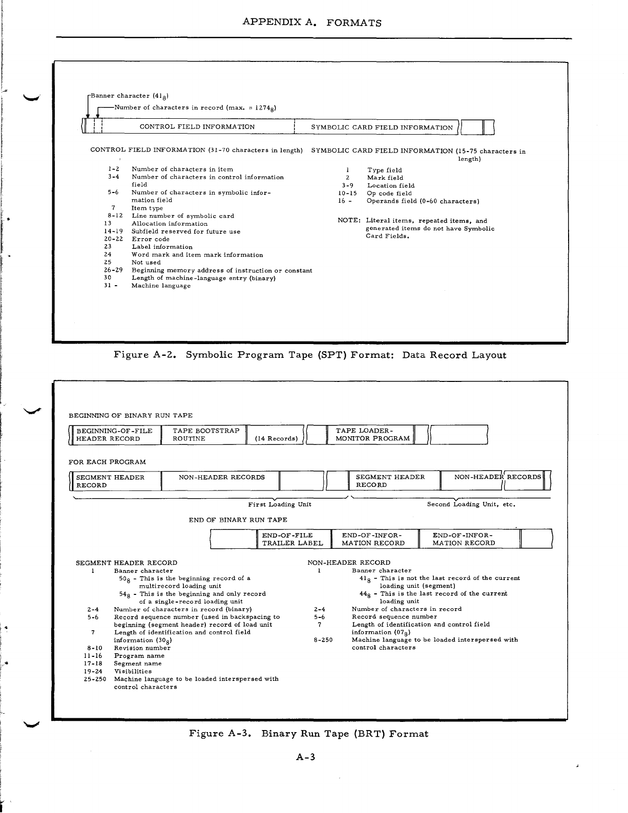
!
APPENDIX
A.
FORMATS
r
Banner
character
(41 8)
r-Nurnber
of
characters
in
record
(max.
::;
1274
8)
(II
CONTROL
FIELD
INFORMA
TION
SYMBOLIC
CARD
FIELD
INFORMATION
1,-1
__
,,-11--,1
CONTROL
FIELD
INFORMATION
(31-70
characters
in
length)
SYMBOLIC
CARD
FIELD
INFORMATION
(15-75
characters
in
length)
1-2
3-4
5-6
8-12
13
14-19
20-22
23
24
25
26-29
30
31
-
Num.ber
of
characters
in
itern
Number
of
characters
in
control
information
field
Number
of
characters
in
symbolic
infor-
m.ation
field
Item
type
Line
number
of
symbolic
card
Allocation
information
Subfield
re
served
for
future
use
Error
code
Label
information
Word
mark
and
item
mark
information
Not
used
Beginning
memory
address
of
instruction
or
constant
Length
of
machine
-language
entry
(binary)
Machine
language
I
2
3-9
10-15
16 -
Type
field
Mark
field
Location
field
Op
code
field
Operands
field
(0-60
characters)
NOTE:
Literal
items,
repeated
items,
and
generated
items
do
not
have
Symbolic
Card
Fields.
Figure
A-2.
Symbolic
Program
Tape
(SPT)
Format:
Data
Record
Layout
BEGINNING
OF
BINARY
RUN
TAPE
BEGINNING-OF-FILE
TAPE
BOOTSTRAP
TAPE
LOADER-
II
/I
ULH
__
E_A_D_E
__
R_R
__
E_C_o_R_D
____
~L__R
__
O_U_T_I_N_E
__________
"__
__________
~'--
__
-L
__
N1_0_NI
__
T_O
__
R
__
P_R_O_G_R
__
A_M~'__~ILI
____________
~
FOR
EACH
PROGRAM
SEGMENT
HEADER
RECORD
NON-HEADER
RECORDS
SEGMENT
HEADER
RECORD
NON
-HEADE7i
RECORDS
II
~--------------------------------~v~----------~
~--------------~v~--------------
First
Loading
Unit
END
OF
BINARY
RUN
TAPE
END-OF-FILE
TRAILER
LABEL
END-OF-INFOR-
MATION
RECORD
Second
Loading
Unit,
etc.
END-OF-INFOR-
MA
TION
RECORD
SEGMENT
HEADER
RECORD
NON-HEADER
RECORD
Banner
character
1
Banner
character
2-4
5-6
8-10
11-16
17-18
19-24
25-250
50
S -
This
is
the
beginning
record
of
a
rnultirecord
loading
unit
548
-
This
is
the
beginning
and
only
record
of
a
single-record
loading
unit
Number
of
characters
in
record
(binary)
Record
sequence
num.ber
(used
in
backspacing
to
beginning
(segrnent
header)
record
of
load
unit
Length
of
identification
and
control
field
information
(308)
Revision
number
Program
name
Segment
name
Visibilities
Machine
language
to
be
loaded
interspersed
with
control
characters
2-4
5-6
7
8-250
418
-
This
is
not
the
last
record
of
the
current
loading
unit
(segment)
448
-
This
is
the
last
record
of
the
current
loading
unit
Number
of
characters
in
record
Record
sequence
number
Length
of
identification
and
control
field
information
(078)
Machine
language
to
he
loaded
interspersed
with
control
characters
Figure
A-3.
Binary
Run
Tape
(BR
T)
Format
A-3
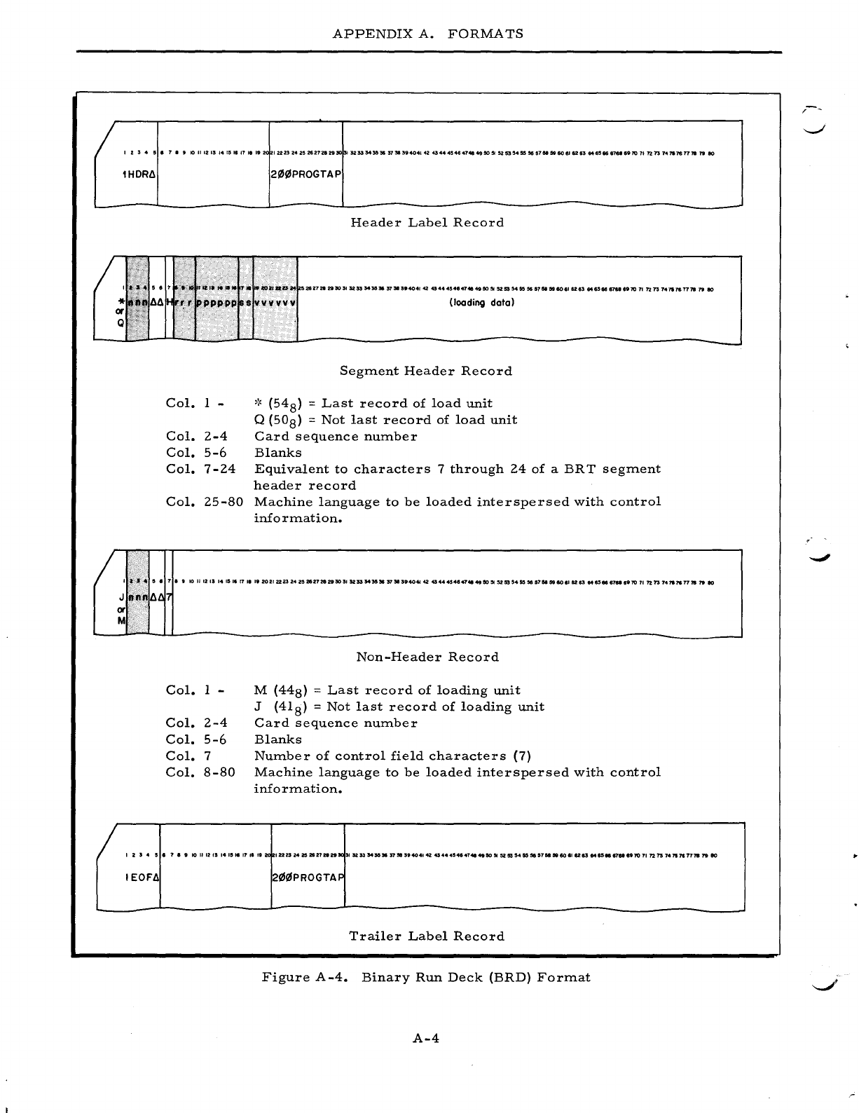
APPENDIX
A.
FORMATS
I
Z:5
..
5.7.9
101I12ISI4I'16'1111'2(
IU232421!1Z62728295Cl
13253543&~37S13'404142~44~4.47"49505I52"'4555657N5liI60.I$283M6SI681a6'107In73
74117$77181"180
lHDR~
Col.
1 -
Col.
2-4
Col.
5-6
Col.
7-24
Col.
25-S0
2I/J(i.lPROGTAP
Header
Label
Record
Segment
Header
Record
,~
(54
S) =
Last
record
of
load
unit
Q
(50S)
=
Not
last
record
of
load
unit
Card
sequence
number
Blanks
Equivalent
to
characters
7
through
24
of
a
BRT
segment
header
record
Machine
language
to
be
loaded
interspersed
with
control
info
rmation.
I
-."
..
5 • 7
••
10
II
12
13 14
15
'6
17
'I
I'
20
21
2223
24
20
21&27212930
,.
52
53
5435,.
37"
n4041
42
454
..
.,484748
49
50
51
52
55
54
55
3C5
a7N
59
80
6112
83
M&see
67a
.'70
71
?2
73
74'"
7$
7778
79
10
Col.
1 -
Col.
2-4
Col.
5-6
Col.
7
Col.
s-so
Non-Header
Record
M
(44S)
=
Last
record
of
loading
unit
J
(41S)
=
Not
last
record
of
loading
unit
Card
sequence
number
Blanks
Number
of
control
field
characters
(7)
Machine
language
to
be
loaded
interspersed
with
control
information.
123
..
!5'
.,.,
10111213141''''7,6''2(
1222l242S2827211nJ(315253S45G3In!l'.40414245444546474149505I525554555151I5lU8606'128384$5
..
..,."7071721574117177787910
IEOF~
2(i.1!6PROGTAF
Trailer
Label
Record
Figure
A-4.
Binary
Run
Deck
(BRD)
Format
A-4
-
--.;I'
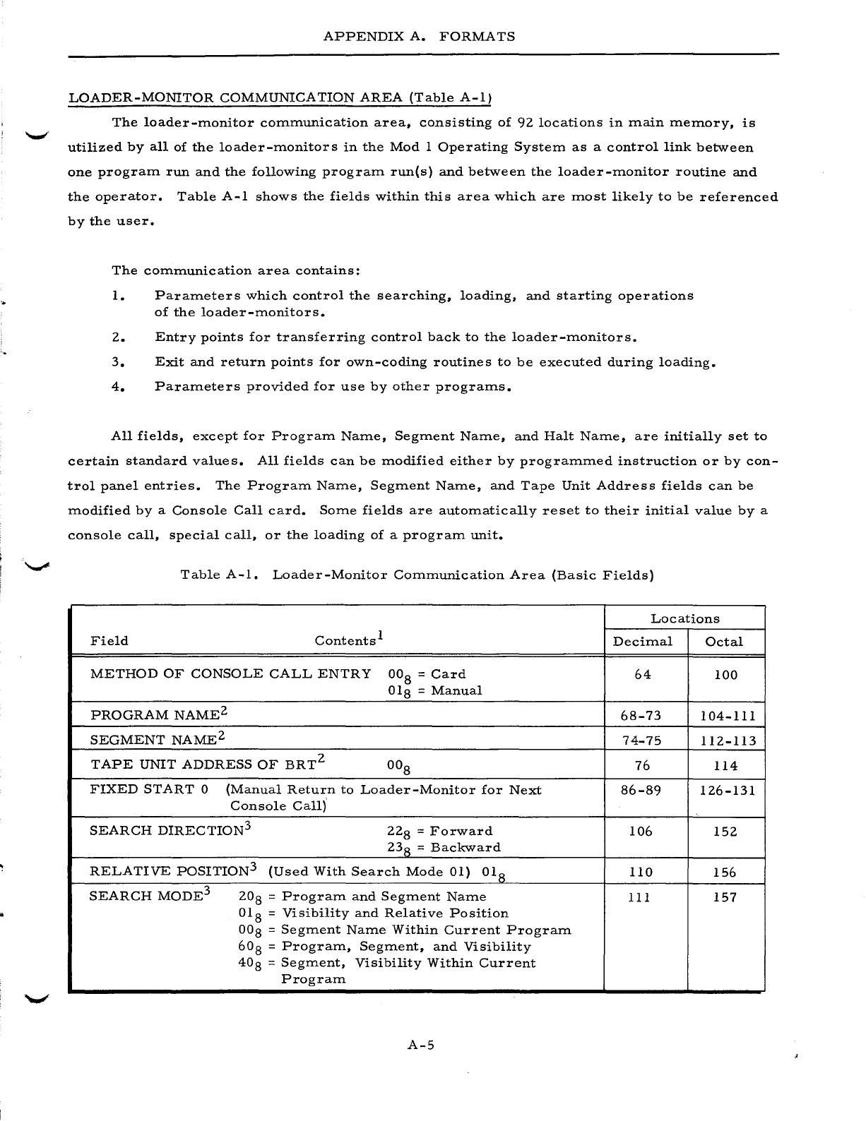
APPENDIX
A.
FORMATS
LOADER-MONITOR
COMMUNICATION
AREA
(Table
A-I)
The
loader-monitor
communication
area,
consisting
of
92
locations
in
main
memory,
is
utilized
by
all
of
the
loader-monitors
in
the
Mod
1
Operating
System
as
a
control
link
between
one
program
run
and
the
following
program
runes)
and
between
the
loader-monitor
routine
and
the
operator.
Table
A-I
shows
the
fields
within
this
area
which
are
most
likely
to
be
referenced
by
the
user.
The
communication
area
contains:
1.
Parameters
which
control
the
searching,
loading,
and
starting
operations
of
the
loader-monitors.
2.
Entry
points
for
transferring
control
back
to
the
loader-monitors.
3.
Exit
and
return
points
for
own-coding
routines
to
be
executed
during
loading.
4.
Parameters
provided
for
use
by
other
programs.
All
fields,
except
for
Program
Name,
Segment
Name,
and
Halt
Name,
are
initially
set
to
certain
standard
values.
All
fields
can
be
modified
either
by
programmed
instruction
or
by
con-
trol
panel
entries.
The
Program
Name,
Segment
Name,
and
Tape
Unit
Address
fields
can
be
modified
by
a
Console
Call
card.
Some
fields
are
automatically
reset
to
their
initial
value
by
a
console
call,
special
call,
or
the
loading
of
a
program
unit.
Table
A-I.
Loader-Monitor
Communication
Area
(Basic
Fields)
Locations
Field
Contents
1
Decimal
Octal
METHOD
OF
CONSOLE
CALL
ENTRY
OOS
=
Card
64
100
OlS
=
Manual
PROGRAM
NAME2
6S-73
104-111
SEGMENT
NAME2
74-75
112-113
TAPE
UNIT
ADDRESS
OF
BRT2
OOS
76
114
FIXED
START
0
(Manual
Return
to
Loader-Monitor
for
Next
S6-S9
126-131
Console
Call)
SEARCH
DIRECTION
3
22S
=
Forward
106
152
23
S =
Backward
RELATIVE
POSITION
3
(Used
With
Search
Mode
01)
OlS
110
156
SEARCH
MODE
3
20
S =
Program
and
Segment
Name
111
157
OlS
=
Visibility
and
Relative
Position
OOS
=
Segment
Name
Within
Current
Program
60
S =
Program,
Segment,
and
Visibility
40
S =
Segment,
Visibility
Within
Current
Program
A-5
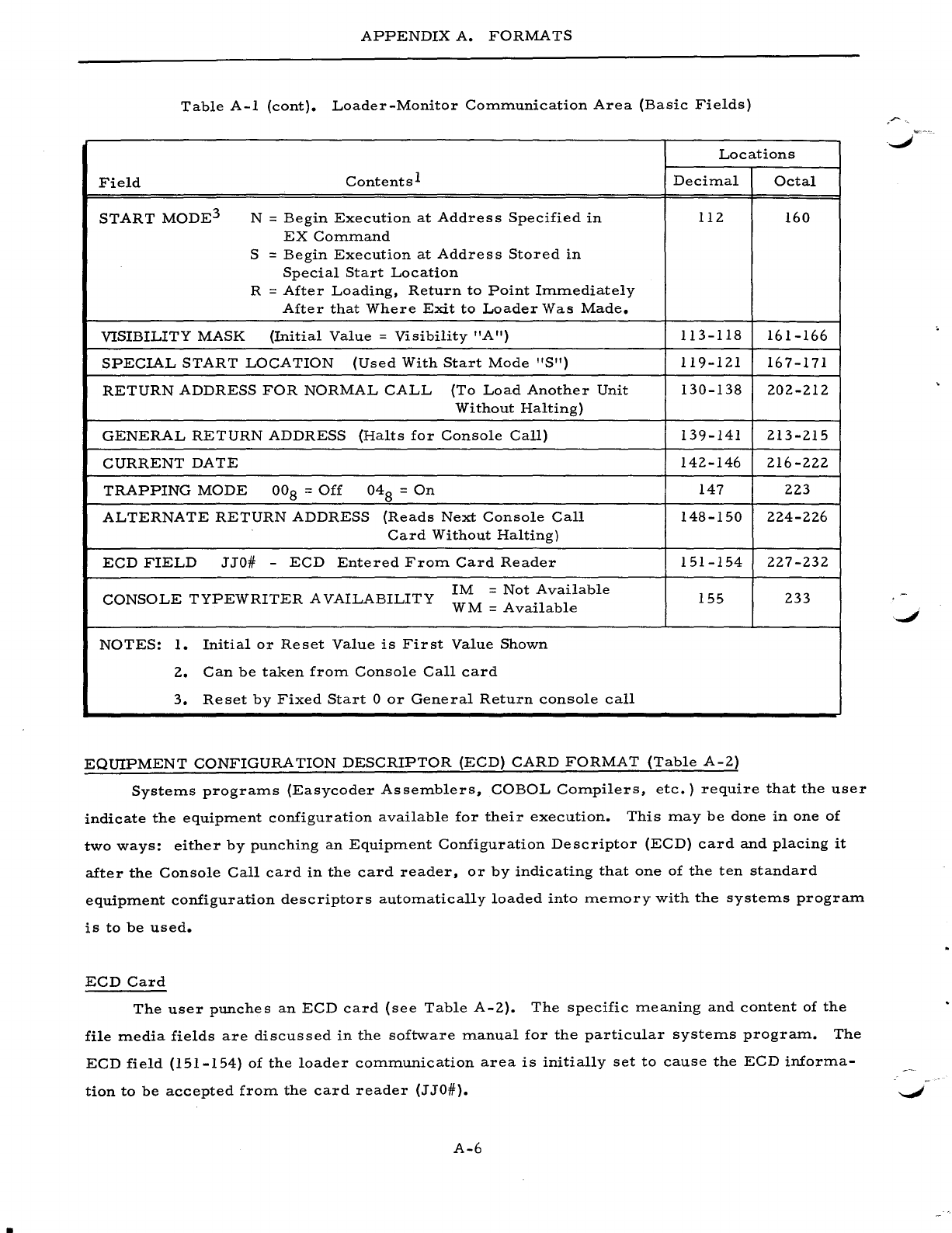
APPENDIX
A.
FORMATS
Table
A-I
(cont).
Loader-Monitor
Communication
Area
(Basic
Fields)
Locations
Field
Contents
1
Decimal
Octal
START
MODE3
N =
Begin
Execution
at
Address
Specified
in
112 160
EX
Command
S =
Begin
Execution
at
Address
Stored
in
Special
Start
Location
R =
After
Loading,
Return
to
Point
Immediately
After
that
Where
Exit
to
Loader
Was
Made.
VISIBILITY
MASK
(Initial
Value
=
Visibility
"A")
113-118
161-166
SPECIAL
START
LOCATION
(Used
With
Start
Mode
"S")
119-121
167-171
RETURN
ADDRESS
FOR
NORMAL
CALL
(To
Load
Another
Unit
130-138
202-212
Without
Halting)
GENERAL
RETURN
ADDRESS
(Halts
for
Console
Call)
139-141
213-215
CURRENT
DATE
142-146
216-222
TRAPPING
MODE
00
8 =
Off
048
=
On
147
223
ALTERNATE
RETURN
ADDRESS
(Reads
Next
Console
Call
148-150
224-226
Card
Without
Halting)
ECD
FIELD
JJO#
-
ECD
Entered
From
Card
Reader
151-154
227-232
CONSOLE
TYPEWRITER
AVAILABILITY
1M
=
Not
Available
155
233
WM
=
Available
NOTES:
1.
Initial
or
Reset
Value
is
First
Value
Shown
2.
Can
be
taken
from
Console
Call
card
3.
Reset
by
Fixed
Start
0
or
General
Return
console
call
EQUIPMENT
CONFIGURATION
DESCRIPTOR
(ECD)
CARD
FORMAT
(Table
A-2)
Systems
programs
(Easycoder
Assemblers,
COBOL
Compilers,
etc.)
require
that
the
user
indicate
the
equipment
configuration
available
for
their
execution.
This
may
be
done
in
one
of
two
ways:
either
by
punching
an
Equipment
Configuration
Descriptor
(ECD)
card
and
placing
it
after
the
Console
Call
card
in
the
card
reader,
or
by
indicating
that
one
of
the ten
standard
equipment
configuration
descriptors
automatically
loaded
into
memory
with
the
systems
program
is
to
be
used.
ECD
Card
The
user
punches
an
ECD
card
(see
Table
A-2).
The
specific
meaning
and
content
of
the
file
media
fields
are
discussed
in
the
software
manual
for
the
particular
systems
program.
The
ECD
field
(151-154)
of
the
loader
communication
area
is
initially
set
to
cause
the
ECD
informa-
tion
to
be
accepted
from
the
card
reader
(J
JO#).
A-6
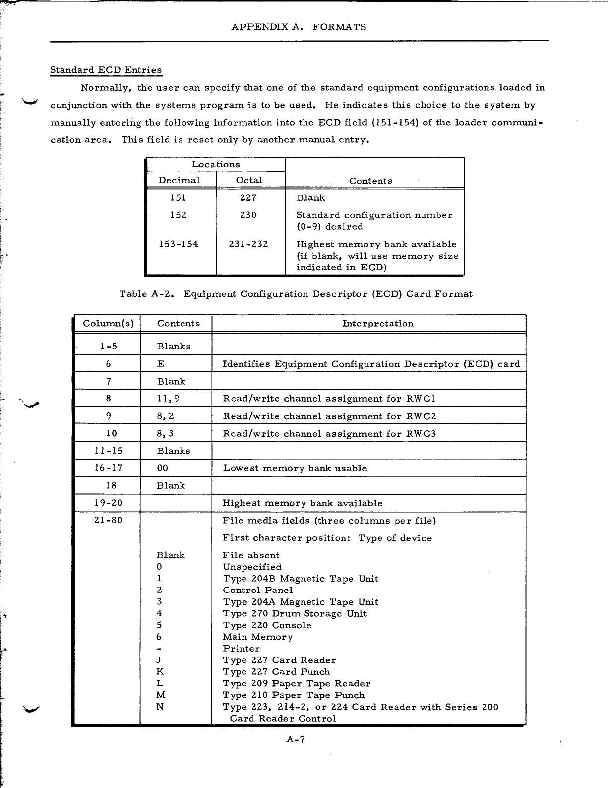
L
f:
l
APPENDIX
A.
FORMATS
Standard
ECD
Entries
Normally,
the
user
can
specify
that
one
of
the
standard
equipment
configurations
loaded
in
cc..njunction
with
the
systems
program
is
to
be
used.
He
indicates
this
choice
to
the
system
by
manually
entering
the
following
information
into
the
~CD
field
(151-154)
of
the
loader
communi-
cation
area.
This
field
is
reset
only
by
another
manual
entry.
Locations
Decimal
Octal
Contents
151
227
Blank
152
230
Standard
configuration
number
(0-9)
desired
153-154
231-232
Highest
memory
bank
available
(if
blank,
will
use
memory
size
indicated
in
ECD)
Table
A-2.
Equipment
Configuration
Descriptor
(ECD)
Card
Format
Column(s)
Contents
Interpretation
1-5
Blanks
6 E
Identifies
Equipment
Configuration
Descriptor
(ECD)
card
7
Blank
8
11,9
Read/write
channel
assignment
for
RWCl
9
8,2
Read/write
channel
assignment
for
RWC2
10
8,3
Read/write
channel
assignment
for
RWC3
11-15
Blanks
16-17
00
Lowe
st
memory
bank
usa.ble
18
Blank
19-20
Highest
memory
bank
available
21-80
File
media
fields
(three
columns
per
file)
First
character
position:
Type
of
device
Blank
File
absent
0
Unspecified
1
Type
204B
Magnetic
Tape
Unit
2
Control
Panel
3
Type
204A
Magnetic
Tape
Unit
4
Type
270
Drum
Storage
Unit
5
Type
220
Console
6
Main
Memory
-
Printer
J
Type
227
Card
Reader
K
Type
227
Card
Punch
L
Type
209
Paper
Tape
Reader
M
Type
210
Paper
Tape
Punch
N
Type
223,
214-2,
or
224
Card
Reader
with
Series
200
Card
Reader
Control
A-7
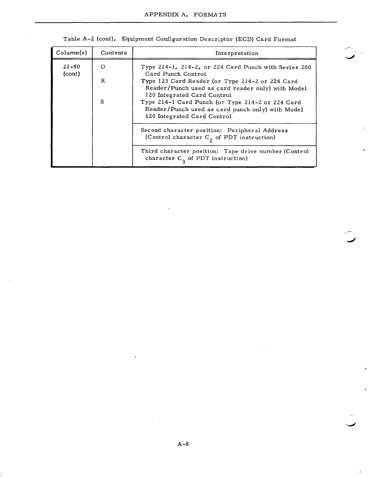
APPENDIX
A.
FORMATS
Table
A-2
(cont).
Equipment
Configuration
Descriptor
(ECD)
Card
Format
Colurnn(s)
Contents
Interpretation
21-80
0
Type
214-1,
214-2,
or
224
Card
Punch
with
Series
200
(cont)
Card
Punch
Control
R
Type
123
Card
Reader
(or
Type
214-2
or
224
Card
Reader
/Punch
used
as
card
reader
only)
with
Model
120
Integrated
Card
Control
S
Type
214-1
Card
Punch
(or
Type
214-2
or
224
Card
Reader/Punch
used
as
card
punch
only)
with
Model
120
Integrated
Card
Control
Second
character
position:
Peripheral
Address
(Control
character
C2
of
PDT
instruction)
Third
character
position:
Tape
drive
number
(Control
character
C3
of
PDT
instruction)
A-8
APPENDIX
B
MOD
1
OPERATING
.SYSTEM
PUBLICATIONS
This
appendix
contains
a
current
listing
of
the
Honeywell
publications
associated
with
the
Mod
1
Operating
System.
The
order
numbers
shown
in
parentheses
should
be
used
in
ordering
these
publications.
GENERAL
INTRODUCTION
Introduction
to
Series
200/0perating
System
-
Mod
1
(258)
OPERA
TING
PROCEDURES
Operating
System
-
Mod
1
Operating
Procedures
Summaries
(069)
LANGUAGE
PROCESSING
Honeywell
Series
200
(Model
120)
Programmers'
Reference
Manual
(141)
Honeywell
Series
200
(Models
200/1200/2200)
Programmers'
Reference
Manual
(139)
Library
Processors
C
and
D
(051)
Easycoder
Assemblers
C
and
D
(041)V'
Transition
to
Easycoder
- A
Programmer
Text
(238)
Programming
with
Easycoder
- A
Programmed
Text
(008)
Analyzer
C
(019)
COBOL
Compilers
D & H
(065)
COBOL
Compiler
D -
Volume
1 - A
Programmed
Text
(083)
COBOL
Compiler
D -
Volume
2 - A
Programmed
Text
(091)
COBOL
Compiler
D -
Volume
3 - A
Programmed
Text
(294)
Study
Guide:
COBOL
Programming
(A
three-volume
set)
(259,
260,
261)
Classroom
Workbook
-
COBOL
Programming
Fortran
Compiler
D
Reference
Handbook
(027)
Fortran
Compiler
D
Generated
Object
Code
(003)
Fortran
Conversion
Techniques
(002)
Fortran
D
Action
Session
(114)
Easytran
Symbolic
Translators
Band
C
(035)
Easytran
Symbolic
Translator
D
(220)
Easytran
Program
Modifier
C
(147)
UTILITY
PROGRAMS
Tape
Handling
Routine
B
(applicable
to
Tape
Handling
Routine
C)
(017)
Data
Conversion
A
and
C
(231)
Simultaneous
Media
Conversion
A
and
C
(021)
Report
Generator
A,
B,
and
C
(080)
Tape
Sort
C
and
Collate
C
(017)
Own
Coding
Routines
for
Tape
Sort
C
(026)
Sort
C
(V)
and
Collate
C (V)
(207)
Drum
Sort
C
(157)
Simultaneous
Sort
and
Print
(201)
B-1
..
APPENDIX
B.
MOD
1
OPERATING
SYSTEM
PUBLICATIONS
Statistics
Package
D
(159)
Linear
Program.m.ing
Package
D
(276)
PROGRAM
EDITING
AND
MAINTENANCE
SPT
Merge
C
(152)
Update
and
Select
C
and
D
(025)
BRT
Punch
C
(020)
Drum.
Program.
Store
C
(DSI-411)
OPERA
TION
CONTROL
Tape
Loader-Monitor
C
(221)
Floating
Tape
Loa_der-Monitor
C
and
Interrupt
Control
D
(005)
Card
Loader-Monitor
B
(154)
Drum.
Bootstrap-Loader
C
(DSI-415)
Drum.
Monitor
C
(DSI-408)
List
Com.m.ents
(DSI-353)
INPUT
/OUTPUT
CONTROL
1
/2-Inch
Tape
I/O
Band
C
(010)
1/2-Inch
Tape
and
Term.inal
I/O
C
(167)
Drum.
I/O
C
(DSI-405)
Console
I/O
C
(TYRO
2)
(DSI-413)
Com.m.unicatiol)s
I/O
C
(202)
PROGRAM
TEST
FACILITIES
Program.
Test
System.
C
(049)
Mem.ory
Dum.p
C
and
Tape
Dum.p
C
(469)
B-2
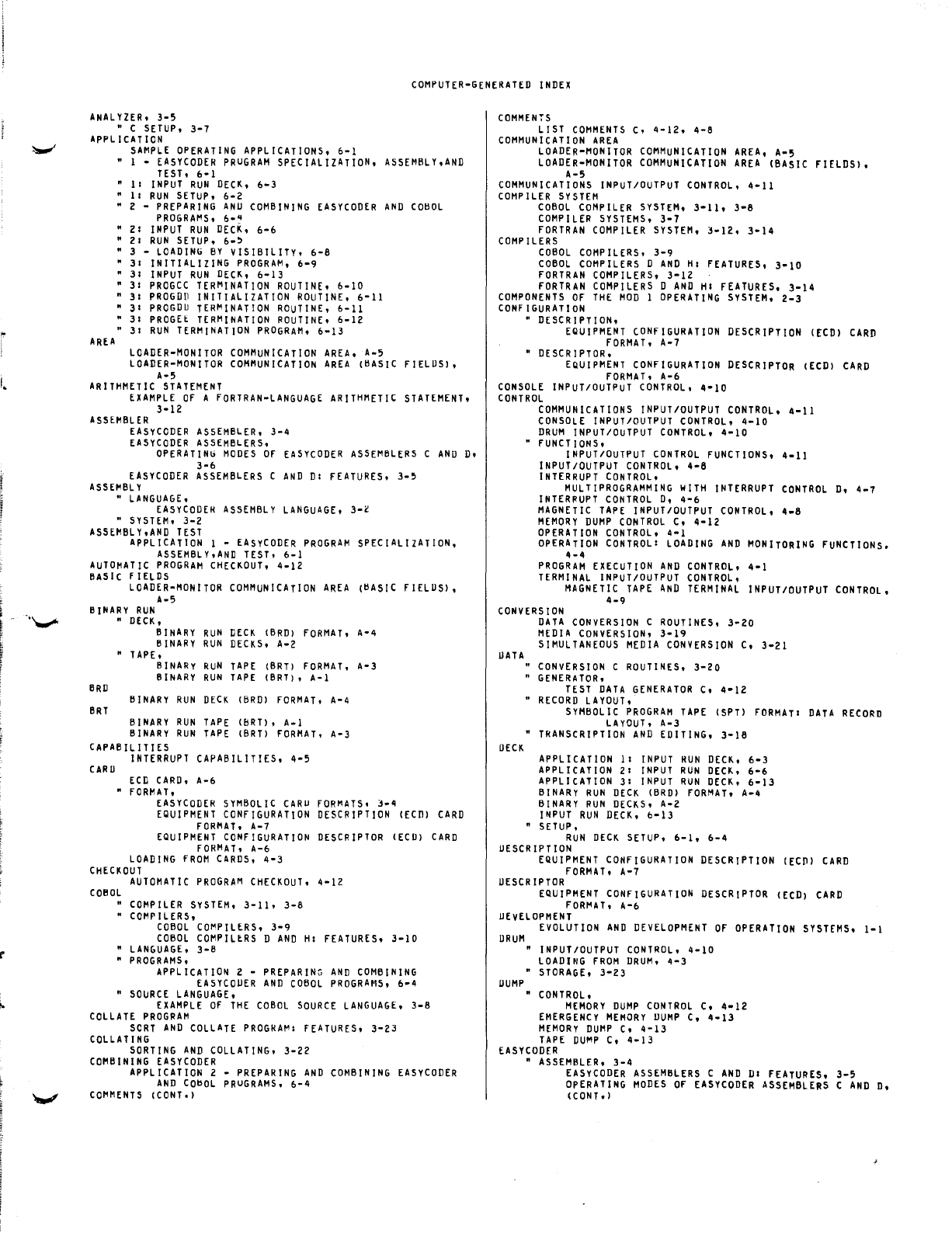
" -
I.
..
!
COMPUTER-GENERATED
INDEX
ANALYZER.
3-5
" C
SETUP.
3-7
APPLICATION
AREA
SAMPLE
OPERATING
APPLICATIONS.
6-1
I -
EASYCODER
PRUGRAM
SPECIALIZATION.
ASSEMBLY.AND
TEST.
6-1
11
I
NPUT
RUN
DECK.
6-3
II
RUN
SETUP.
6-2
2 -
PREPARING
ANU
COMBINING
EASYCODER
AND
COBOL
PROGRAt'lS.
6-"
21
INPUT
RUN
DECK.
6-6
21
RUN
SETUP.
6-'
3 -
LOADING
BY
VISIBILITY.
6-8
31
INITIALIZING
PROGRAt'l.
6-9
31
INPUT
RUN
DECK.
6-13
31
PROGCC
TERMINATION
ROUTINE.
6-10
"
31
PROGDD
INITIALIZATION
ROUTINE.
6-11
"
31
PROGDU
TER~INATION
ROUTINE.
6-11
"
31
PROGEt
TERMINATION
ROUTINE.
6-12
"
31
RUN
TERMINATION
PROGRAM.
6-13
LOADER-MONITOR
COMMUNICATION
AREA.
A-5
LOADER-MONITOR
COMMUNICATION
AREA
(BASIC
FIELUS).
A-5
ARITHMETIC
STATEMENT
EXAMPLE
OF
A
FORTRAN-LANGUAGE
ARITHMETIC
STATEMENT.
3-12
ASSEMBLER
EASYCODER
ASSEMBLER.
3-4
EASYCODER
ASSEMBLERS.
OPERATINb
MODES
OF
EASYCODER
ASSEMBLERS
C
AND
D.
3-6
EASYCODER
ASSEMBLERS
C
AND
DI
FEATURES.
3-5
ASSEMBLY
"
LANGUAGE.
EASYCODEH
ASSEMBLY
LANGUAGE.
3-l
"
SYSTEM.
3-2
ASSEMBLY.AND
TEST
APPLICATION
1 -
EASyCODER
PROGRAM
SPECIALiZATION.
ASSEMBLY.AND
TEST.
6-1
AUTOMATIC
PROGRAM
CHECKOUT.
4-12
BASiC
F I[LDS
LOADER-MONITOR
COMMUNICATION
AREA
(BASIC
FIELUS).
A-5
BINARY
RUN
BRD
eRT
"
DECK.
BINARY
RUN
DECK
(BRD)
FORMAT.
A-4
BINARY
RUN
DECKS.
A-2
"
TAPE.
BINARY
RUN
TAPE
(BRT)
FORMAT.
A-3
BINARY
RUN
TAPE
(BRT). A-I
BINARY
RUN
DECK
(BRD)
FORMAT.
A-4
BINARY
RUN
TAPE
(bRT). A-I
BINARY
RUN
TAPE
(BRT)
FORMAT.
A-3
CAPABILITIES
CARD
INTERRUPT
CAPABILITIES.
ECD
CARD.
A-6
"
FORMAT.
4-5
EASYCODER
SYMBOLIC
CARU
FORMATS.
3-4
EQUIPMENT
CONFIGURATION
DESCRIPTION
(ECD)
CARD
FORMAT.
A-7
EQUIPMENT
CONFIGURATION
DESCRIPTOR
(ECD)
CARD
FORMAT.
A-6
LOADING
FROM
CARDS.
4-3
CHECKOUT
AUTOMATIC
PROGRAM
CHECKOUT.
4-12
COBOL
"
COMPILER
SYSTEM.
3-11.
3-8
"
COMPILERS.
COBOL
COt'lPILERS.
3-9
COBOL
COMPILERS
D
AND
HI
FEATURES.
3-10
"
LANGUAGE.
3-8
"
PROGRAMS.
APPLICATION
2 -
PREPARING
AND
COMBINING
EASYCODER
AND
COBOL
PROGRAMS.
6-4
"
SOURCE
LANGUAGE.
EXAMPLE
OF
THE
COBOL
SOURCE
LANGUAGE.
3-8
COLLATE
PROGRAM
seRT
AND
COLLATE
PROGRAt'l1
FEATURES.
3-23
COLLATING
SORTING
AND
COLLATING.
3-22
COMBINING
EASYCODER
APPLICATION
2 -
PREPARING
AND
COMBINING
EASY
CODER
AND
CO~OL
PRUGRAMS.
6-4
COMMENTS
(CONT')
COMMENTS
LIST
COMMENTS
C.
4-12.
4-8
COMMUNICATION
AREA
LOADER-MONITOR
COMMUNICATION
AREA.
A-5
LOADER-MONITOR
COMMUNICATION
AREA
(BASIC
FIELDS).
A-5
COMMUNICATIONS
INPUT/OUTPUT
CONTROL.
4-11
COMPILER
SYSTEM
COBOL
COMPILER
SYSTEM.
3-11.
3-8
COMPILER
SYSTEMS.
3-7
FORTRAN
COMPILER
SYSTEM.
3-12.
3-14
COMPILERS
COBOL
COMPILERS.
3-9
COBOL
COMPILERS
D
AND
HI
FEATURES.
3-10
FORTRAN
COMPILERS.
3-12
FORTRAN
COMPILERS
D
AND
HI
FEATURES.
3-14
COMPONENTS
OF
THE
MOD
1
OPERATING
SYSTEM.
2-3
CONfiGURATION
" DESCRIPTION.
EQUIPMENT
CONFIGURATION
DESCRIPTION
(ECD)
CARO
FORMAT.
A-7
•
DESCRIPTOR.
EQUIPMENT
CONFIGURATION
DESCRIPTOR
(ECD)
CARD
fORMAT.
A-6
CONSOLE
INPUT/OUTPUT
CONTROL.
4-10
CONTROL
COMMUNICATIONS
INPUT/OUTPUT
CONTROL.
4-11
CONSOLE
INPUT/OUTPUT
CONTROL.
4-10
DRUM
INPUT/OUTPUT
CONTROL.
4-10
FUNCTIONS.
INPUT/OUTPUT
CONTROL
FUNCTIONS.
4-11
INPUT/OUTPUT
CONTROL.
4-6
INTERRUPT
CONTROL.
MULTIPROGRAMMING
WITH
INTERRUPT
CONTROL
D.
4-7
INTERRUPT
CONTROL
D.
4-6
MAGNETIC
TAPE
INPUT/OUTPUT
CONTROL.
4-8
MEMORY
DUMP
CONTROL
C.
4-12
OPERATION
CONTROL.
4-1
OPERATION
CONTROL
I
LOADING
AND
MONITORING
FUNCTIONS.
4-4
PROGRAM
EXECUTION
AND
CONTROL.
4-1
TERMINAL
INPUT/OUTPUT
CONTROL.
MAGNETIC
TAPE
AND
TERMINAL
INPUT/OUTPUT
CONTROL.
4-9
CONVERSION
UATA
DECK
DATA
CONVERSION
C
ROUTINES.
3-20
MEDIA
CONVERSION.
3-19
SIMULTANEOUS
MEDIA
CONVERSION
C.
3-21
"
CONVERSION
C
ROUTINES.
3-20
"
GENERATOR.
TEST
DATA
GENERATOR
C.
4-12
"
RECORD
LAYOUT.
SYMBOLIC
PROGRAM
TAPE
(SPT)
FORMATI
DATA
RECORD
LAYOUT.
A-3
•
TRANSCRIPTION
AND
EDITING.
3-16
APPLICATION
11
INPUT
RUN
DECK.
6-3
APPLICATION
21
INPUT
RUN
DECK.
6-6
APPLICATION
31
INPUT
RUN
DECK.
6-13
BINARY
RUN
DECK
(BRD)
FORMAT.
A-4
BINARY
RUN
DECKS.
A-2
INPUT
RUN
DECK.
0-13
"
SETUP.
RUN
DECK
SETUP.
6-1.
6-4
DESCRIPTION
EQUIPMENT
CONFIGURATION
DESCRIPTION
([CP)
CARD
FORMAT.
A-7
DESCRIPTOR
EQUIPMENT
CONFIGURATION
DESCRIPTOR
([CD)
CARD
fORt'lAT.
A-6
UEvELOPMENT
DRUM
DUMP
EVOLUTION
AND
DEVELoPMENT
OF
OPERATION
SYSTEMS.
1-1
"
INPUT/OUTPUT
CONTROL.
4-10
LOADING
FROM
DRUM.
4-3
"
STORAGE.
3-23
"
CONTROL.
MEMORY
DUMP
CONTROL
C.
4-12
EMERGENCY
MEMORY
DUMP
C.
4-13
MEMORy
DUMP
C.
4-13
TAPE
DUMP
C.
4-13
EASYCODER
"
ASSEMBLER.
3-4
EASYCODER
ASSEMBLERS
C
AND
DI
FEATURES.
3-5
OpERATING
MODES
Of
EASYCODER
ASSEMBLERS
C
AND
D.
(CONT.
)
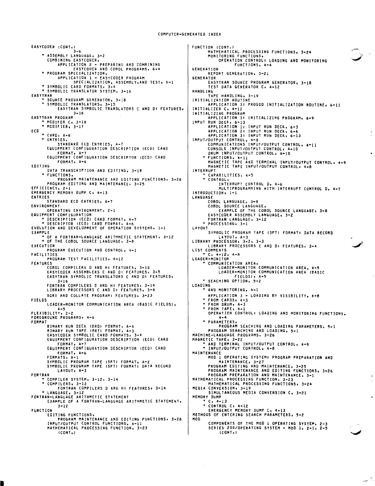
COMPUTER-GENERATED
INDEX
EASYCODER
(CONT.)
3-6
•
ASSEMBLY
LANGUAGt.
3-2
COMBINING
EASYCODER.
APPLICATION
2 -
PREPARING
AND
COMBINING
EASYCOUER
AND
COBOL
PROGRAMS.
6-4
•
PROGRAM
SPECIALIZATION.
APPLICATION
1 -
EASYCODER
PROGRAM
SPECIALIZATION.
ASSEMBLY.AND
TEST.
6-1
•
SYMBOLIC
CARD
FORMATS.
3-4
•
SYMBOLIC
TRANSLATOR
SYSTEM.
3-16
EASYTRAN
•
SOURCE
PROGRAM
GENERATOR.
3-18
"
SYMBOLIC
TRANSLATORS.
3-15
EA5YTRAN
SYMBOLIC
TRANSLATORS
C
AND
01
FEATURES,
3-16
EASYTRAN
PROGRAM
ECD
"
MODIFER
C,
3-18
•
MODIFIER,
3-17
•
CARD,
A-6
• ENTRIES,
STANDARD
ECD
ENTRIES.
A-7
EQUIPMENT
CONFIGURATION
DESCRIPTION
(ECU)
CARD
FORMAT,
A-7
EQUiPMENT
CONFIGURATION
DESCRIPTOR
(ECD)
CARD
FORMAT,
A-6
EDIT
ING
DATA
TRANSCRIPTION
AND
EDITING,
3-18
"
FUNCTIONS,
PROGRAM
MAINTENANCE
AND
EDITING
FUNCTIONS.
3-26
PROGRAM
EDITING
AND
MAINTENANCE,
3-25
EFF
ICIENCY,
2-1
EMERGENCY
MEMORY
DUMP
C,
4-13
ENTRIES
STANDARD
ECD
ENTRIES,
A-7
ENVIRONMENT
OPERATING
ENVIRONMENT,
2-1
EQUIPMENT
CONFIGURATION
•
DESCRIPTION
(ECC)
CARC
FORMAT.
A-7
•
DESCRIPTOR
(ECC)
CARD
fORMAT.
A-6
EVOLUTION
AND
DEVELOPMENT
OF
OPERATION
SYSTEMS.
1-1
EXAMPLE
•
OF
A
FORTRAN-LANGUAGE
ARITHMETIC
STATEMENT.
3-12
"
OF
THE
COBOL
SOURCE
LANGUAGE.
3-8
EHeUT
ION
PROGRAM
EXECUTION
AND
CONTROL,
4-1
FACILITIES
PROGRAM
TEST
FACILITIES,
4-12
FEATURES
fiELDS
COBOL
COMPILERS
D
AND
HI
FEATURES,
3-10
EASYCODER
ASSEMBLERS
C
AND
01
FEATURES.
3-5
EASYTRAN
SYMBOLIC
TRANSLATORS
C
AND
01
FEATURES.
3-16
FORTRAN
COMPILERS
0
AND
HI
FEATURES,
3-14
LIBRARY
PROCESSORS
C
AND
01
FEATURES.
3-4
SORT
AND
COLLATE
PROGRAM
I
FEATURES,
3-23
LOADER-MONITOR
COMMUNICATION
AREA
(BASIC
FIELDS),
A-5
fLEXIBILITY,
2-2
fOREGROUND
PROGRAMS,
4-6
fORMAT
BINARY
RUN
CECK
(eRC)
FORMAT,
A-4
BINARY
RUN
TAPE
(BRT)
FORMAT.
A-3
EASY
CODER
SYMBOLIC
CARD
FORMATS,
3-4
EQUIPMENT
CONfiGURATION
CESCRIPTION
(ECU)
CARD
FORMAT.
A-7
EQUIPMENT
CONFIGURATION
DESCHIPTOR
(ECD)
CARD
fORMAT,
A-6
fORMATS,
A-I
SYMBOLIC
PROGRAM
TAPE
(SPT)
FORMAT,
A-Z
SYMBOLIC
PROGRAM
TAPE
(SPT)
fORMAT
I
DATA
RECURD
LAYOUT,
A-3
fORTRAN
•
COMPILER
SYSTEM,
3-12.
3-14
•
COMPILERS,
3-12
fORTRAN
COMPILERS
D
ANu
HI
fEATURES,
3-14
"
LANGUAGE,
3-12
FORTRAN-LANGUAGE
ARITHMETIC
STATEMENT
EXAMPLE
OF
A
fORTRAN-LANGUAGE
ARITHMETIC
STATEME~T,
3-12
fUNCTION
EDITING
fUNCTIONS,
PROGRAM
MAINTENANCE
AND
EDITING
fUNCTIONS.
3-26
INPUT/OUTPUT
CONTROL
fUNCTIONS,
4-11
MATHEMATICAL
PROCESSING
fUNCTION.
3-23
(CONT.
)
fUNCTION
(CONT.)
MATHEMATICAL
PROCtSSING
FUNCTIONS,
3-24
MONITORING
fUNCTIONS,
OPERATION
CONTROL
I
LOADING
AND
MONITORING
fUNCTIONS,
4-4
GENERATION
REPORT
GENERATION,
3-21
GENERATOR
EASYTRAN
SOURCE
PROGRAM
GENERATOR,
3-18
TEST
DATA
GENERATOR
C,
4-12
HANDLING
TAPE
HANDLING,
3-19
INITIALIZATION
ROUTINE
APPLICATION
31
PROGDD
INITIALIZATION
ROUTINE,
6-11
INITIALIZER C,
4-12
INITIALIZING
PROGRAM
APPLICATION
31
INITIALIZING
PROGRAM,
6-9
INPUT
RUN
DECK,
6-13
APPLICATION
1:
INPUT
RUN
DECK,
6-3
APPLICATION
21
INPUT
RUN
DECK,
6-6
APPLICATION
31
INPUT
RUN
DECK,
6-13
INPUT/OUTPUT
CONTROL,
4-8
COMMUNICATIONS
INPUT/OUTPUT
CONTROL,
4-11
CONSOLE
INPUT/OUTPUT
CONTROL,
4-10
DRUM
INPUT/OUTPUT
CONTROL.
4-10
" fUNCTIONS,
4-11
MAGNETIC
TAPE
AND
TERMINAL
INPUT/OUTPUT
CONTROL,
4-9
MAGNETIC
TAPE
INPUT/OUTPUT
CONTROL.
4-8
INTERRUPT
" CAPABILITIES,
4-5
"
CONTROL.
INTERRUPT
CONTROL
D,
4-6
MULTIPROGRAMMING
wiTH
INTERRUPT
CONTROL
D,
4-7
INTRODUCTION,
1-1
LANGUAGE
COBOL
LANGUAGE,
3-8
COBOL
SOURCE
LANGUAGE,
EXAMPLE
OF
THE
COBOL
SOURCE
LANGUAGE,
3-8
EASYCODER
ASSEMBLY
LANGUAGE,
3-2
FORTRAN
LANGUAGE.
3-12
"
PROCESSING,
3-1
LAYOUT
SyMBOL
IC
PROGRAM
TAPE
(SPT)
fORMATI
DATA
RECORD
LAYOUT.
A-3
LIBRARY
PROCESSOR,
3-2,
3-3
LIBRARY
PROCESSORS
C
AND
DI
FEATURES,
3-4
LIST
COMMENTS
• C.
4-12.
4-8
LOADER-MONITOR
•
COMMUNICATION
AREA.
LOADER-MONITOR
COMMUNICATION
AREA,
A-5
LOADER-MONITOR
COMMUNICATION
AREA
(eASIC
FIELDS),
A-5
•
SEACHING
OPTION.
5-2
LOADING
"
AND
MONITORING,
4-1
APPLICATION
3 -
LOADING
BY
VISIBILITY,
6-8
•
FROM
CAPOS,
4-3
•
FROM
DRUM,
4-3
•
FROM
TAPE,
4-1
OPERATION
CONTROL
I
LOADING
AND
MONITORING
FUNCTIONS.
4-4
•
PARAMETERS,
PROGRAM
SEACHING
AND
LOADING
PARAMETERS,
5-1
PROGRAM
SEARCHI~G
AND
LOADING,
5-1
MACHINE-LANGUAGE
PROGRAMS,
3-26
MAGNETIC
TAPE,
3-22
"
AND
TERMINAL
INPUT/OUTPUT
CONTROL,
4-9
•
INPUT/OUTPUT
CONTROL,
4-8
MA
I
NTENANCE
MOD
1
OPERATING
SYSTEMI
PROGRAM
PREPARATION
AND
MAINTENANCE,
3-27
PROGRAM
EDITING
AND
MAINTENANCE,
3-25
PROGRAM
MAINTENANCE
AND
EDITING
fUNCTIONS,
3-26
PROGRAM
PREPARATION
AND
MAINTENANCE,
3-1
MATHEMATICAL
PROCESSING
FUNCTION,
3-23
MATHEMATICAL
PROCESSING
FUNCTIONS,
3-24
MEDIA
CONVERSION,
3-19
SIMULTANEOUS
MEDIA
CONVERSION
C,
3-21
MEMORY
DUMP
" C,
4-13
•
CONTROL
C,
4-12
EMERGENCY
MEMORY
DUMP
C.
4-13
METHODS
OF
ENTERING
SEARCH
PARAMETERS,
5-2
MOD
COMPONENTS
Of
THE
MOD
1
OPERATING
SYSTEM,
2-3
SERIES 200/0PERATING
SYSTEM
-
MOD
I,
2-1,
2-5
(cONT.)
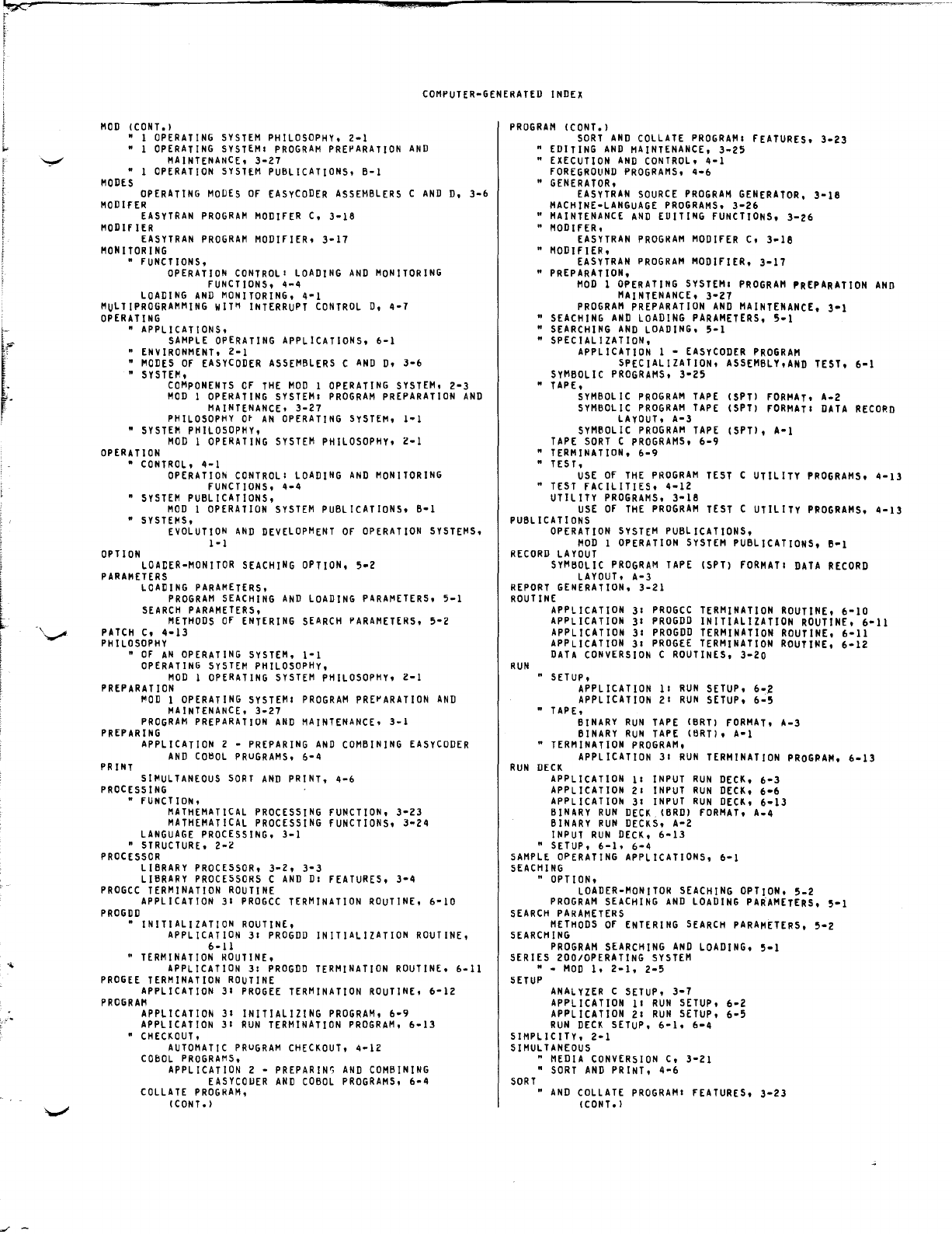
~
..
~
~
L·.
J
I
COMPUTER-GENERATED
INDEX
MOD
(CONT.)
• I
OPERATING
SYSTEM
PHILOSOPHY,
2-1
• 1
OPERATING
SYSTEMI
PROGRAM
PREPARATION
AND
MAINTENANCE,
3-27
• 1
OPERATION
SYSTEM
PUBLICATIONS,
B-1
MODES
OPERATING
MODES
OF
EASyCODER
ASSEMBLERS
C
AND
D,
3-6
MOD
IFER
EASYTRAN
PROGRAM
MODIFER
C,
3-18
MODifiER
EASYTRAN
PROGRAM
MODIFIER,
3-17
MONITORING
•
fUNCTIONS,
OPERATION
CONTROLI
LOADING
AND
MONITORING
FUNCTIONS,
4-4
LOADING
AND
MONITORING,
4-1
MULTIPROGRAMMING
WIT~
INTERRUPT
CONTROL
D,
4-7
OPERATING
• APPLICATIONS,
SAMPLE
OPERATING
APPLICATIONS,
6-1
•
ENVIRONMENT,
2-1
•
MODES
Of
EASyCODER
ASSEMBLERS
C
AND
D,
3-6
•
SYSTEM,
COMPONENTS
OF
THE
MOD
1
OPERATING
SYSTEM,
2-3
MOD
1
OPERATING
SYSTEMI
PROGRAM
PREPARATION
AND
MAINTENANCE,
3-27
PHILOSOPHY
O~
AN
OPERATING
SYSTEM,
I-I
•
SYSTEM
PHILOSOPHY,
MOD
I
OPERATING
SYSTEM
PHILOSOPHY,
Z-1
OPERATION
•
CONTROL,
4-1
OPERATION
CONTROL
I
LOADING
AND
MONITORING
FUNCTIONS,
4-4
"
SYSTEM
PUBLICATIONS,
MOD
1
OPERATION
SYSTEM
PUBLICATIONS,
B-1
"
SYSTEMS,
OPTION
EVOLUTION
AND
DEVELOPMENT
OF
OPERATION
SYSTEMS,
1-1
LOADER-MONITOR
SEACHING
OPTION,
5-2
PARAMETERS
LOADING
PARAMETERS,
PROGRAM
SEACHING
AND
LOADING
PARAMETERS,
5-1
SEARCH
PARAMETERS,
METHODS
OF
ENTERING
SEARCH
PARAMETERS,
5-2
PATCH
C,
4-13
PHILOSOPHY
•
OF
AN
OPERATING
SYSTEM,
I-I
OPERATING
SYSTEM
PHILOSOPHy,
MOD
I
OPERATING
SYSTEM
PHILOSOPHY,
2-1
PREPARATION
~OD
1
OPERATING
SYSTEMI
PROGRAM
PRE~ARATION
AND
MAINTENANCE,
3-27
PROGRAM
PREPARATION
AND
MAINTENANCE,
3-1
PREPARING
PRINT
APPLICATION
2 -
PREPARING
AND
COMBINING
EASYCODER
AND
CO~OL
PRuGRAMS,
6-4
SIMULTANEOUS
SORT
AND
PRINT,
4-6
PROCESSING
•
FUNCTION,
MATHEMATICAL
PROCESSING
FUNCTION,
3-23
MATHEMATICAL
PROCESSING
FUNCTIONS,
3-24
LANGUAGE
PROCESSING,
3-1
"
STRUCTURE,
2-Z
PROCESSOR
LIBRARY
PROCESSOR,
3-2,
3-3
LIBRARY
PROCESSORS
C
AND
DI
FEATURES,
3-4
PROGCC
TERMINATION
ROUTINE
APPLICATION
31
PROGCC
TERMINATION
ROUTINE,
6-10
PROGDD
• INITIALIZATION
ROUTINE,
APPLICATION
31
PROGDD
INITIALIZATION
ROUTINE,
6-11
•
TERMINATION
ROUTINE,
APPLICATION
3:
PROGDD
TERMINATION
ROUTINE,
6-11
PROGEE
TERMINATION
ROUTINE
APPLICATION
3:
PROGEE
TERMINATION
ROUTINE,
6-12
PROGRAM
APPLICATION
31
INITIALIZING
PROGRAM,
6-9
APPLICATION
31
RUN
TERMINATION
PROGRAM,
6-13
•
CHECKOUT,
AUTOMATIC
PRuGRAM
CHECKOUT,
4-12
COBOL
PROGRAMS,
APPLICATION
2 -
PREPARIN"
AND
COMBINING
EASYCOUER
AND
COBOL
PROGRAMS,
6-4
COLLATE
PROGRAM,
(CONT.)
PROGRAM
(CONT.)
SORT
AND
COLLATE
PROGRAM:
FEATURES,
3-Z3
•
EDITING
AND
MAINTENANCE,
3-25
•
EXECUTION
AND
CONTROL,
4-1
FOREGROUND
PROGRAMS,
4-6
•
GENERATOR,
EASYTRAN
SOURCE
PROGRAM
GENERATOR,
3-18
MACHINE-LANGUAGE
PROGRAMS,
3-Z6
"
MAINTENANCE
AND
EUITING
fUNCTIONS,
3-26
"
MODIFER,
EASYTRAN
PROGRAM
MODlfER
C,
3-18
• MODifiER,
EASYTRAN
PROGRAM
MODIFIER,
3-17
•
PREPARATION,
MOD
1
OPERATING
SYSTEM
I
PROGRAM
PREPARATION
AND
MAINTENANCE,
3-Z1
PROGRAM
PREPARATION
AND
MAINTENANCE,
3-1
•
SEACHING
AND
LOADING
PARAMETERS,
5-1
•
SEARCHING
AND
LOADING,
5-1
• SPECIALIZATION,
APPLICATION
1 -
EASYCODER
PROGRAM
SPECIALIZATION,
ASSEMBLY,AND
TEST,
6-1
SYMBOLIC
PROGRAMS,
3-25
•
TAPE,
SYMBOL
IC
PROGRAM
TAPE
(SPTl
FORMAT'
A-2
SYMBOLIC
PROGRAM
TAPE
(SPT)
fORMAT:
DATA
RECORD
LAyOUT,
A-3
SYMBOLIC
PROGRAM
TAPE
(SPT),
A-I
TAPE
SORT
C
PROGRAMS,
6-9
"
TERMINATION,
6-9
" TEST,
USE
Of
THE
PROGRAM
TEST
C UTILITY
PROGRAMS,
4-13
"
TEST
fACILITIES,
4-1Z
UTILITY
PROGRAMS.
3-18
USE
OF
THE
PROGRAM
TEST
C UTILITY
PROGRAMS,
4-13
PUBLICATIONS
OPERATION
SYSTEM
PUBLICATIONS,
MOD
1
OPERATION
SYSTEM
PUBLICATIONS, B-1
RECORD
LAYOUT
SYMBOLIC
PROGRAM
TAPE
(SPT)
fORMAT:
DATA
RECORD
LAYOUT,
A-3
REPORT
GENERATION,
3-21
ROUTINE
RUN
APPLICATION
31
PROGCC
TERMINATION
ROUTINE,
6-10
APPLICATION
31
PROGDD
INITIALIZATION
ROUTINE,
6-11
APPLICATION
31
PROGDD
TERMINATION
ROUTINE,
6-11
APPLICATION
3:
PROGEE
TERMINATION
ROUTINE,
6-1Z
DATA
CONVERSION
C
ROUTINES,
3-Z0
" SETUP,
APPLICATION
11
RUN
SETUP,
6-2
APPLICATION
21
RUN
SETUP,
6-5
•
TAPE,
BINARY
RUN
TAPE
(BRT)
fORMAT,
A-3
BINARY
RUN
TAPE
(BRT),
A-l
•
TERMINATION
PROGRAM,
APPLICATION
3:
RUN
TERMINATION
PROGRAM,
6-13
RUN
DECK
APPLICATION
11
INPUT
RUN
DECK,
6-3
APPLICATION
2:
INPUT
RUN
DECK,
6-6
APPLICATIO~
31
INPUT
RUN
DECK,
6-13
BINARY
RUN
DECK.
(BRD)
FORMAT,
A-4
BINARY
RUN
DECKS,
A-2
INPUT
RUN
DECK,
6-13
•
SETUP,
6-1,
6-4
SAMPLE
OPERATING
APPLICATIONS,
6-1
SEACHING
• OPTION,
LOADER-MONITOR
SEACHING
OPTION,
5-2
PROGRAM
SEACHING
AND
LOADING
PA~AMETERS,
5-1
SEARCH
PARAMETERS
METHODS
Of
ENTERING
SEARCH
PARAMETERS,
5-2
SEARCHING
PROGRAM
SEARCHING
AND
LOADING,
5-1
SERIES
ZOO/OPERATING
SYSTEM
• -
MOD
1,
Z-I,
Z-5
5ETUP
ANALYZER
C
SETUP,
3-7
APPLICATION
I:
RUN
SETUP,
6-Z
APPLICATION
2:
RUN
SETUP,
6-5
RUN
DECK
SETUP,
6-1,
6-4
SIMPLICITY, Z-1
S I
MUL
TANEOUS
SORT
"
MEDIA
CONVERSION
C,
3-21
"
SORT
AND
PRINT,
4-6
"
AND
COLLATE
PROGRAM:
FEATURES,
3-23
(CONT.)
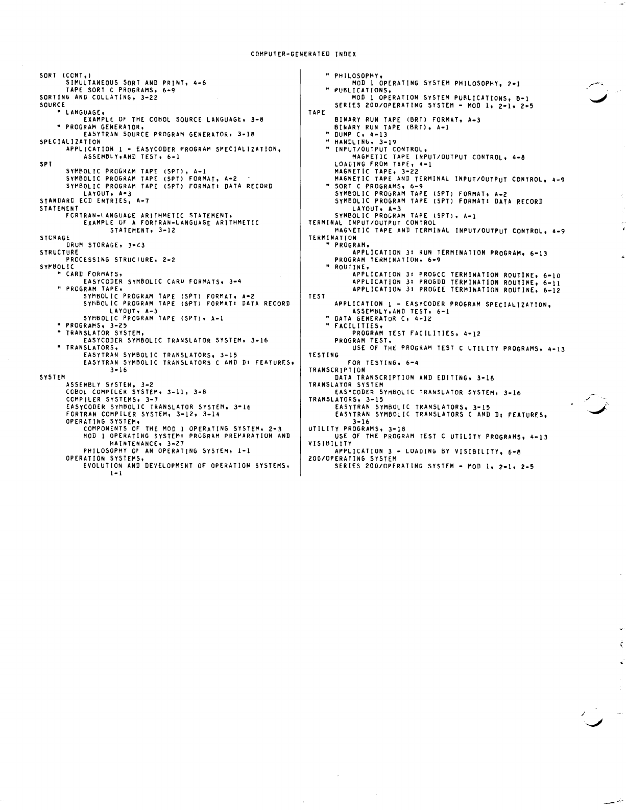
COMPUTER-GENERATED
INDEX
SORT
(CONT.)
SIMULTANEOUS
SORT
AND
PRINT.
4-6
TAPE
SORT
C
PROGRAMS.
6-9
SORTING
AND
COLLATING,
3-22
SOURCE
"
LANGUAGE,
EXAMPLE
Of
THE
COBOL
SOURCE
LANGUAGE,
3-8
"
PROGRAM
GENERATOR,
EA~YTRAN
SOURCE
PROGRAM
GENERATOR,
3-16
SPlCIALIZATION
SPT
APPLICATION
1 -
EASYCODER
PROGRA~
SPECIALIZATION,
ASSEMBLy,AND
TEST,
6-1
SYMBOL
IC
PROGRAM
TAPE
(SPT),
A-I
SYMBOLIC
PROGRAM
TAPE
(SPT)
fORMAT,
A-2
SYI'IBOLIC
PROGRAM
TAPE
(SPT)
fORMATI
DATA
RECORD
LAYOUT,
A-3
STANDARD
ECD
ENTRIES,
A-7
STATEMENT
fCRTRAN-LANGUAGE
ARITHMETIC
STATEMENT,
EXAMPLE
Of
A
fORTRAN-LANGUAGE
ARITHMETIC
STATEMENT,
3-12
STCRAGE
DRUM
STORAGE.
3-~3
STRUCTURE
PROCESSING
STRUCIURE,
2-2
SY~tlOLlC
"
CARD
fORMATS,
EASYCODER
SYMBOLIC
CARU
fORMATS,
3-4
"
PROGRAM
TAPE,
SYMBOLIC
PROGRAM
TAPE
(SPT)
FORMAT,
A-Z
SY~IBOL
IC
PROGRAM
TAPE
(Sf'T)
FORMATI
DATA
RECORD
LAYOUT,
A-)
SYMBOLIC
PROGRAM
TAPE
(SPT),
A-I
"
PROGRAMS.
3-Z5
•
TRANSLATOR
SYSTEM,
EASYCODER
SYMBOLIC
TRANSLATOR
SYSTEM,
3-16
n
TRANSLATORS,
S Y S
TEM
EASYTRAN
SyMBOLIC
TRANSLATORS.
3-15
EASYTRAN
SYMBOLIC
TRANSLATORS
C
AND
DI
FEATURf.S,
3-16
ASSEMBLY
SYSTEM.
3-2
COBOL
COMPILER
SYSTEM,
3-11,
3-8
COMPILER
SYSTEMS,
3-7
EASyCODER
SyMtlOLIC
TRANSLATOR
SYSTEM,
3-16
fORTRAN
COMPILER
SYSTEM,
3-12,
3-14
OPERATIhG
SYSTEM,
COMPONENTS
Of
THE
MOD
I
OPERATING
SYSTEM,
2-3
MOD
1
OPERATING
SYSTEMI
PROGRAM
PREPARATION
AND
MAINTENANCE,
3-27
PHILOSOPHY
Ot
AN
OPERATING
SYSTEM,
I-I
OPERATION
SYSTEMS.
EVOLUTION
AND
DEVELOPMENT
Of
OPERATION
SYSTEMS,
I-I
TAPE
"
PHILOSOPHY.
MOD
1
OPERATING
SYSTEM
PHILOSOPHY,
2-1
• PUBLICATIONS,
MOD
1
OPERATION
SYSTEM
PUBLICATIONS, B-1
SERIES
ZOO/OPERATING
SYSTEM
-
MOD
I,
2-1.
2-5
BINARY
RUN
TAPE
(BRT)
FORMAT.
A-3
BINARY
RUN
TAPE
(BRT), A-I
"
DUMP
C,
4-13
"
HANDLING.
3-19
"
INPUT/OUTPUT
CONTROL.
MAG~ETIC
TAPE
INPUT/OUTPUT
CONTROL.
4-8
LOADING
FROM
TAPE.
4-1
MAGNETIC
TAPE,
3-22
MAGNETIC
TAPE
AND
TERMINAL
INPUT/OUTPUT
CONTROL.
4-9
n
SORT
C
PROGRAMS.
6-9
SyMBOLIC
PROGRAM
TAPE
(SPT)
fORMAT.
A-Z
SyMBOLIC
PROGRAM
TAPE
(SPT)
fORMAT:
DATA
RECORD
LAYOUT.
A-3
SYMBOL
IC
PROGRAM
TAPE
(SPT).
A-I
TERMINAL
INPUT/OUTPUT
CONTROL
MAGNETIC
TAPE
AND
TERMINAL
INPUT/OUTPUT
CONTROL.
4-9
TERM
I
NAT
I
ON
TEST
"
PROGRAM.
APPLICATION
31
RUN
TERMINATION
PROGRAM.
6-13
PROGRAM
TERMINATION.
6-9
"
ROUTINE,
APPLICATION
31
PROGCC
TERMINATION
ROUTINE.
6-10
APPLICATION
31
PROGDD
TERMINATION
ROUTINE.
6-11
APPLICATION
31
PROGEE
TERMlhATION
ROUTINE.
6-12
APPLICATION
I -
EASYCODER
PROGRAM
SPECIALIZATION.
ASSEMtlLY.AND
TEST.
6-1
•
DATA
GENERATOR
C,
4-12
"
fACILITIES.
PROGRAM
TEST
fACILITIES.
4-12
PROGRAM
TEST.
USE
OF
THE
PROGRAM
TEST
C UTILITY
PPOGRAMS.
4-13
TESTING
fOR
TESTING.
6-4
TRANSCRIPTION
DATA
TRANSCRIPTION
AND
EDITING.
3-18
TRANSLATOR
SYSTEM
EASY
CODER
SYMBOLIC
TRANSLATOR
SYSTEM.
3-16
TRANSLATORS.
3-15
EASYTRAN
SYMBOLIC
TRANSLATORS.
3-15
EASYTRAN
SYMBOLIC
TRANSLATORS
C
AND
01
fEATURES.
3-16
UTILITY
PROGRAMS.
3-18
USE
Of
THE
PROGRAM
rEST
C UTILITY
PROGRAMS.
4-13
VISltllLlTY
APPLICATION
3 -
LOADING
BY
VISIBILITY. 6-B
ZOO/OPERATING
SYSTEM
SERIES 200/0PERATING
SYSTEM
-
MOD
I,
2-1.
2-5
/
HONEYWELL
EDP
TECHNICAL
PUBLICATIONS
USERS'
REMARKS
FORM
1
TITLE:
SERIES
200
INTRODUCTION
TO
SERIES
200/0PERATING
SYSTEM
-
MOD
1
(TAPE
RESIDENT)
SOFTWARE
MANUAL
DATED:
AUGUST,
1966
FILE
NO:
123.0005.
001C.
1-258
ERRORS
NOTED:
SUGGESTIONS
FOR
IMPROVEMENT:
Fold
FROM:
NAME
DATE
_____
__
COMPANY
_________________________________
___
TITLE
___________________
___
ADDRESS
__________________
__
1
Please
restrict
remarks
to
the
publication
itself.
Comments
concerning
hardware
/
software
difficulties
and
improvement
requests
should
be
submitted
through
the
channels
established
for
that
purpose.
•
---------------------------------------------------
············aUSINESSREPl
YMAlt<
.......
.
tto_stan,p
necessafY
if
m.J~tQi~
PQSTAGE
ATT'N: TECHNICAL COMMUNICATIONS DEPARTMENT
Honeywvell
ELECTRONIC
DATA
PROCESSING
FIRST CLASS
PERMIT NO.
39531
WELLESLEY HILLS
MASS.
