Edwards Signaling Data Sheet S85001 0632 Carbon Monoxide Detector 260 CO
User Manual: 260-CO Data Sheet 260-CO - GE Security
Open the PDF directly: View PDF ![]() .
.
Page Count: 4
Page 1 of 4 DATA SHEET S85001-0632
Not to be used for installation purposes. Issue 1
Edwards Signaling Catalog u Conventional Initiating Devices
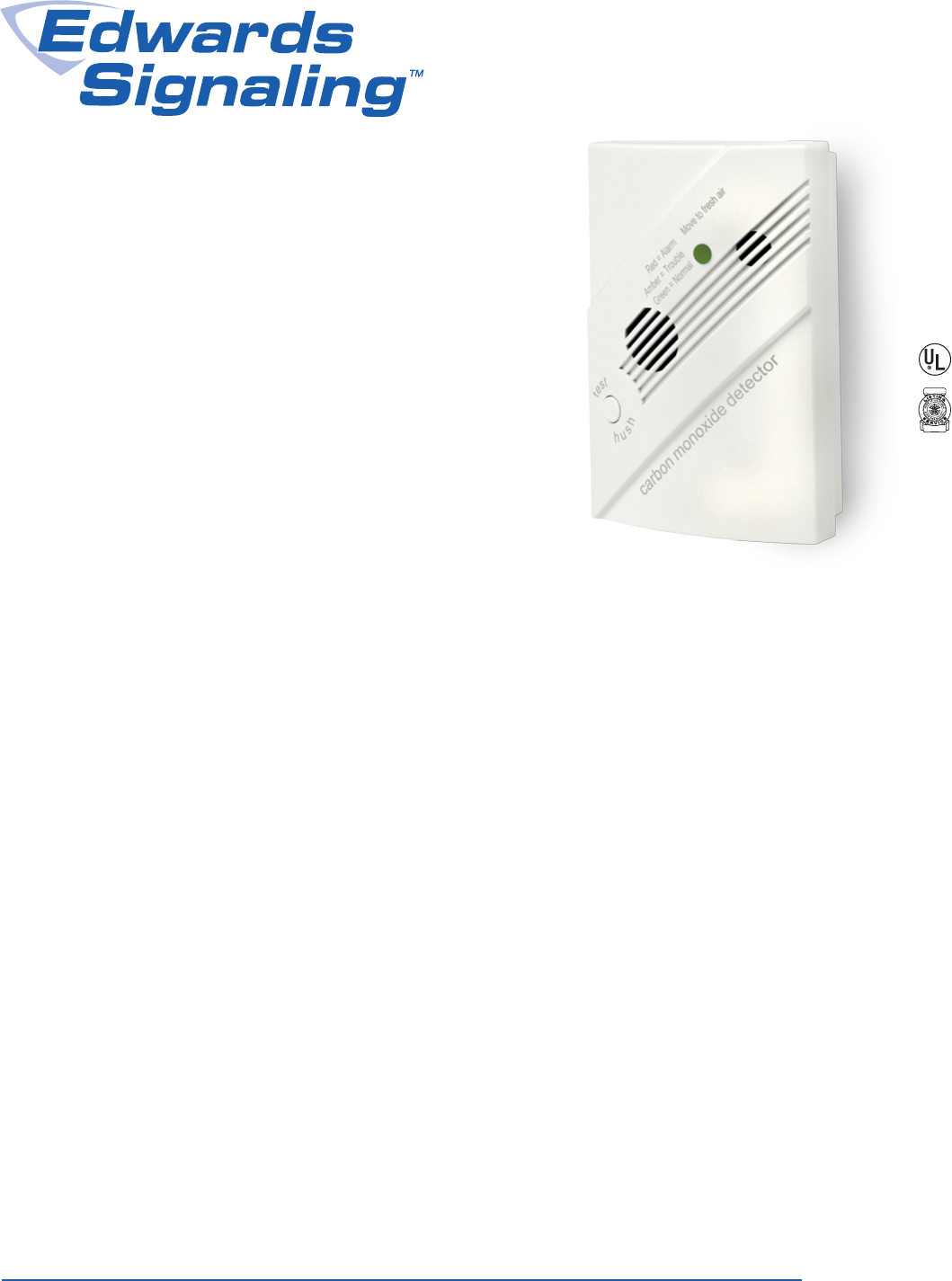
Overview
The 260-CO carbon monoxide (CO) detector is an accurate and
reliable means of alerting building occupants of potentially danger-
ous levels of CO in the protected area. The internal electro-chemi-
cal sensor communicates with a sophisticated on-board micropro-
cessor that accurately tracks CO levels over time.
This commercial-grade detection technology results in quick
response, reliable sensing, fast reset time, and superior false alarm
immunity. Its small size allows the 260-CO to blend inconspicu-
ously with any decor, and its smooth contoured design is compat-
ible with both residential and commercial environments.
Unaffected by normal indoor temperature variations, the 260-CO
automatically adjusts for environmental changes and operates
reliably under a wide variety of conditions. It also monitors its own
performance and compensates for sensitivity drift throughout the
course of its service life.
The 260-CO features the SafeTest™ functional test feature, which
facilitates testing with real CO gas. SafeTest meets the functional
test requirement in NFPA 720, 2009/2012 editions.
Like all CO detectors, the 260-CO has a limited service life. But
unlike most, which last only six years, the 260-CO’s advanced
sensor features a service life rated at 10 years. When it approach-
es this point, the 260-CO’s end-of-life timer automatically triggers
a warning that indicates the device must be serviced. This warning
annunciates at the detector, as well as at the control panel, and
optionally at a remote monitoring station.
An integrated temporal-4 sounder provides local signaling capability
for the 260-CO, and it easily interfaces with any intrusion or fire alarm
system by means of its output relay. Its low current draw results in
little additional demand on the system power supply.
Standard Features
• 10-year end-of-life signal
• SafeTest™ feature — functional test with spray of real CO gas
• Advanced electro-chemical sensing technology
• Wiring option activates sounders of all connected detectors
when any one of them goes into alarm
• Deep housing with plenty of room for wiring
• UL 2075 compliant
• Transmits sensor end-of-life to the supervising panel and cen-
tral station if the system is monitored
• CO sensitivity conforms to UL 2034 requirements
• Built-in trouble/power supervision relay
• Self-diagnostics keep the device operating optimally through-
out its service life
• 12 or 24VDC operation and 150mA Form C relay
• Large SEMS terminals ease wiring installation 14 to 22 AWG
• One-touch TEST/HUSH button simplifies local operation
• Integrated 85 dBa temporal-4 sounder for local notification
• On-board LED provides local alarm and trouble indication
• Inconspicuous footprint and attractively contoured design
• Adapter plate simplifies replacing 240-COe detectors
12/24VDC
Carbon Monoxide
Detector with SafeTest™
260-CO
Page 2 of 4 DATA SHEET S85001-0632
Not to be used for installation purposes. Issue 1
Application
The Edwards 260-CO Carbon Monoxide Detector is intended for
ordinary indoor-dwelling unit applications in both residential and
commercial occupancies, including single/multiple family residential
occupancies, hotel rooms, dorm rooms, and other areas approved
by the authority having jurisdiction (AHJ). The 260-CO detector
can connect to either UL 985 (Household Fire Warning) or UL 864
(Commercial Fire) control panels. It is not intended for use in indus-
trial applications such as gasoline refineries or parking garages,
which require different listings.
The 260-CO is a four-wire device that uses a Class 2 output from
a control panel. Nonetheless, the primary alarm notification de-
vice remains the 260-CO’s internal sounder with the control panel
secondary to these purposes. The 260-CO is not a substitute for life
safety devices, and should be only considered as an integral part of
a comprehensive safety program.
Selecting a suitable location is critical to the correct operation of
CO detectors. Install the 260-CO in accordance with NFPA 720
Standard for the Installation of Carbon Monoxide (CO) Detection
and Warning Equipment. Place wall-mounted detectors at least
5 ft. (1.5 m) up from the floor. For ceiling mounted applications,
place the detector at least 1 ft. (0.3 m) from any wall.
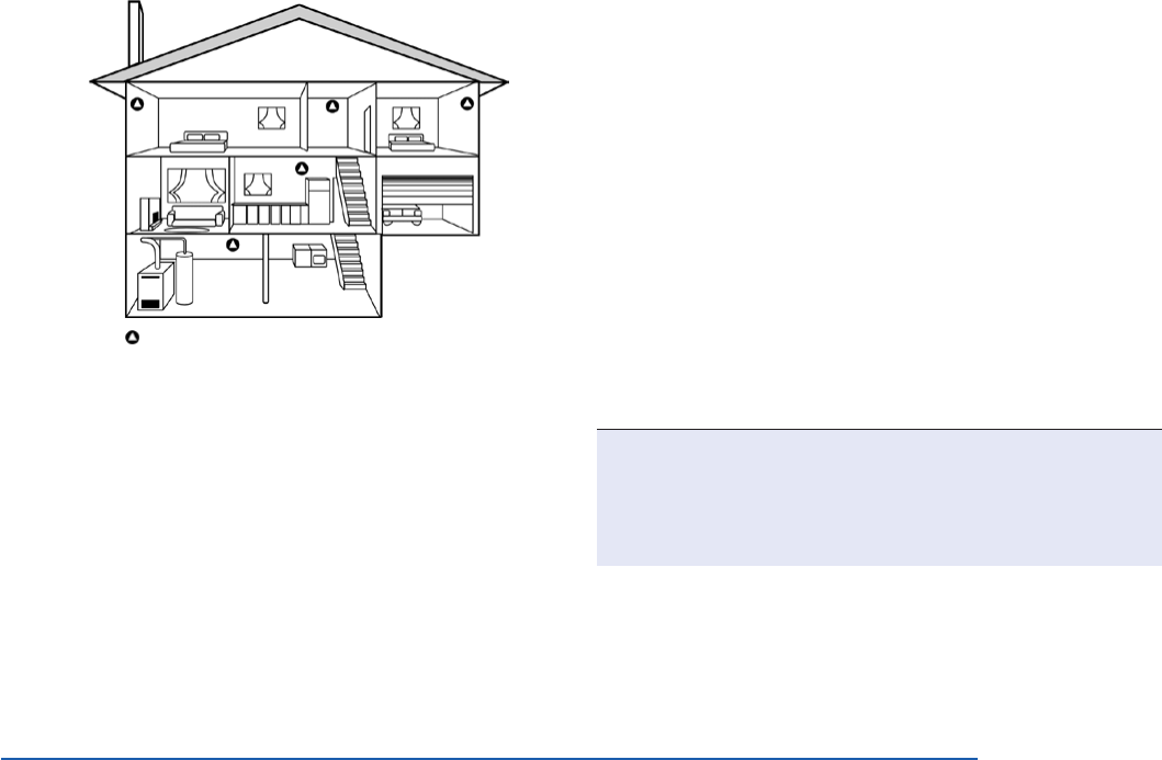
Recommended CO detector locations:
9Within 10 ft. (3 m) of all sleeping areas, including areas such
as hotel rooms and dorm rooms.
9In a suitable environment: areas with a temperature range
of 40 to 100 °F (4.4 to 37.8 °C) and with a relative humidity
range of 10 to 90% noncondensing.
9In residential dwellings, locate detectors in every bedroom
and on each level. At a minimum, place one detector outside
the sleeping areas.
Recommended locations for CO detectors
Always check with your local building codes,
legislation, and Authority Having Jurisdiction
for specific CO location requirements in your area
Recommended CO detector locations in commercial occupancies:
9Outside each separate sleeping area in the immediate vicinity
of the bedrooms (including areas such as hotel rooms and
dorm rooms)
9On every occupied level of a dwelling unit, including base-
ments, but excluding attics and crawl spaces
9Centrally located on every habitable level of the building and
in every HVAC zone based on an engineering evaluation con-
sidering potential sources and migration of carbon monoxide
9On the ceiling in the same room as permanently installed fuel-
burning appliances
9In any area required by local building codes, legislation, or the
authority having jurisdiction
9On a firm, permanent surface
Do not install the CO detector:
8Within 5 ft. (1.5 m) of any cooking appliance
8Within 10 ft. (3 m) of a fuel-burning appliance
8Near air conditioners, heating registers, and any other ventilation
source that may interfere with CO gas entering the detector
8Where furniture or draperies may obstruct the airflow
8In a recessed area
Operation
SafeTest functional test: This test facilitates the use of CO test
spray to verify the correct operation of the detector, which is man-
datory per NFPA 720. The SafeTest mode is activated by pressing
and holding the test/hush button for 5-10 seconds. While in Saf-
eTest mode, directing UL-classified CO testing spray at the sensor
port will result in the activation of the alarm relay, and the sounder
and red LED in a temporal-four pattern. Pressing and holding the
test/hush will exit SafeTest mode.
Distinct temporal-four sounder alarm: The 85 dB temporal-
four sounder provides a distinctive alarm notification that is easy
to differentiate from smoke alarm notification devices. The alarm
beeps four times, rests five seconds and then repeats the pattern.
Test/hush button: Use the test/hush button to test the alarm and
silence an activated alarm. Pushing the test/hush button silences
the integral sounder for five minutes. The red alarm light stays on
and if CO is still present after five minutes, the detector once again
sounds in the temporal-four pattern.
End of sensor life indicator: The detector uses both a flashing
green LED and intermittent sounder chirps to indicate that the de-
tector needs replacing. To silence the detector, push the test/hush
button. The detector also begins signaling a trouble when the CO
sensor is approaching end-of-life.
Common trouble relay: The trouble relay opens to indicate a
trouble condition upon lost power, CO sensor cell trouble, or cell
end-of-life. When connected to a listed control panel, the trouble
relay can report a trouble condition locally at the panel and option-
ally at the central station, if the system is monitored.
WARNINGS: Connect the CO detector only to a zone dedicat-
ed exclusively for CO detection and that is monitored 24 hours
a day. Do not connect to an initiating circuit with fire or security
devices. Failure to properly install, test, and maintain a CO
detector may cause it to fail, potentially resulting in loss of life.
Page 3 of 4 DATA SHEET S85001-0632
Not to be used for installation purposes. Issue 1
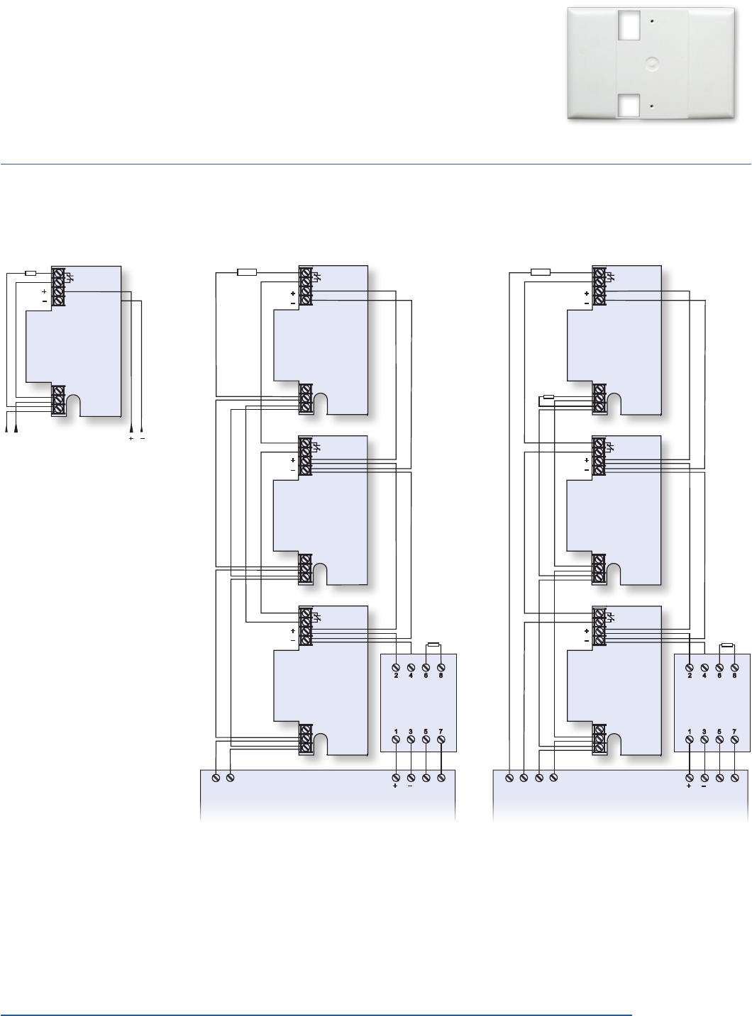
Wiring
Alarm
IDC
EOL device
Single device,
single zone
Power
Multiple devices,
single zone
C
NC
NC
NO
C
C
NC
NC
NO
C
C
NC
NC
NO
C
EOL device
EOL device
405
Polarity Reversal
Module
Alarm
IDC Control Panel Power NAC
Multiple devices,
separate alarm, trouble zone
C
NC
NC
NO
C
C
NC
NC
NO
C
C
NC
NC
NO
C
EOL device
EOL device
405
Polarity Reversal
Module
Alarm
IDC Control Panel
Power NAC
SUPV
IDC
Tandem Interconnect:
Use a Single Circuit Reversal
Module when wiring multiple
260-CO detectors for tandem
interconnect. On alarm, the
module disconnects the detec-
tor from its normal power supply
and applies reverse polarity from
the notification appliance circuit.
This causes the sounders to
activate on other 260-CO detec-
tors that are on the same loop.
Only the initiating detector will
sound and blink red. All others
in tandem mode will sound but
not blink red.
Installation
The 260-CO Carbon Monoxide Detector is a four-wire device
designed to use a Class 2 output from a control panel or auxiliary
power supply Listed to UL 985 or 864 standards.
All wiring must conform to the NFPA 70 National Electric Code, UL
2075, NFPA 720, and applicable codes. Use 14 to 22 AWG wire.
The 260-CO/240-COe
adapter plate
Use a 250-COPLT adaptor
plate when replacing a 240-
COe with a 260-CO to cover
any paint discoloration left
behind.
Page 4 of 4 DATA SHEET S85001-0632
Not to be used for installation purposes. Issue 1
Contact us...
Email: edwards.fire@fs.utc.com
Web: www.edwardssignaling.com
Edwards Signaling is
an EDWARDS brand.
3 Farm Glen Boulevard
Farmington, CT 06032
In Canada, contact Chubb Edwards...
Email: inquiries@chubbedwards.com
Web: www.chubbedwards.com
© 2013 UTC Fire & Security Americas
Corporation, Inc. All rights reserved.
Specifications subject to change
without notice. Edwards is part of UTC
Climate, Controls & Security, a unit of
United Technologies Corporation.
Specifications
Input voltage 12 or 24 VDC supplied by UL 985 or UL 864 listed control panel
or resettable auxiliary power supply
Current consumption
Normal
Alarm
20 mA
40 mA (75 mA in test)
Alarm relay
Type
UL rating
150 mA at 33 VDC
Form C
Zone
Common trouble relay
Type
UL rating
150 mA at 33 VDC
Normally opened held closed with power applied
Common
Sensor life 10 years from date of manufacture
Sounder 85 dB
Compatible control panel Listed to UL 985 or 864 standards
Compatible electrical box 2-1/2 in. (64 mm) single-gang
Wire size 14 to 22 AWG (0.25 to 2.0 mm²)
Dimensions (W × L × D)
Detector
Adapter plate
3.1 × 4.6 × 1.4 in. (7.8 × 11.7 × 3.6 cm)
4.5 × 6.5 × 0.2 in. (11.4 × 16.5 × 0.5 cm)
Color White
Operating environment
Temperature
Relative humidity
40 to 100 °F (4.4 to 37.8 °C)
10 to 90% noncondensing
CO sensitivity 70 ppm, 60 to 240 minutes
150 ppm, 10 to 50 minutes
400 ppm, 4 to 15 minutes
Ordering Information
Model Description
260-CO Carbon monoxide detector, alarm & trouble relays,
sounder, end-of life signal, 12/24VDC
250-COPLT-5PKG Adaptor plate for use when replacing the 240-COe CO detector
with a 260-CO
ESL 405-01 Polarity Reversal Module, 24 VDC
CO Gas Test Spray Functional CO gas test spray Solo C-6 from SDI
(www.sdifire.com) available through security distribution.
