GS3 2630 Display User Guide
User Manual: 2630
Open the PDF directly: View PDF ![]() .
.
Page Count: 88

User Guide
User Guide Delivery Instructions
GS3 2630 Display
GS3 2630 Display
1
Activations
Set date and time prior to entering Activation codes to ensure
the Activations will be acknowledged.
Data Transfer
Apex version 3.1 or newer is required to transfer data to the
GS3 2630 from a different John Deere Display model (i.e. GS2
1800, GS2 2600, GS3 CommandCenter).
Coverage and Swath Control Maps cannot be transferred from
a different John Deere Display model.
User Guide
This User Guide is intended to assist the operator with com-
mon operations. See the Operator Manual for detailed infor-
mation.
GS3 2630 Display.book Page 1 Thursday, May 12, 2011 7:45 AM

GS3 2630 Display
GS3 2630 Display
User Guide
User Guide Delivery Instructions
2
GS3 2630 Display.book Page 2 Thursday, May 12, 2011 7:45 AM
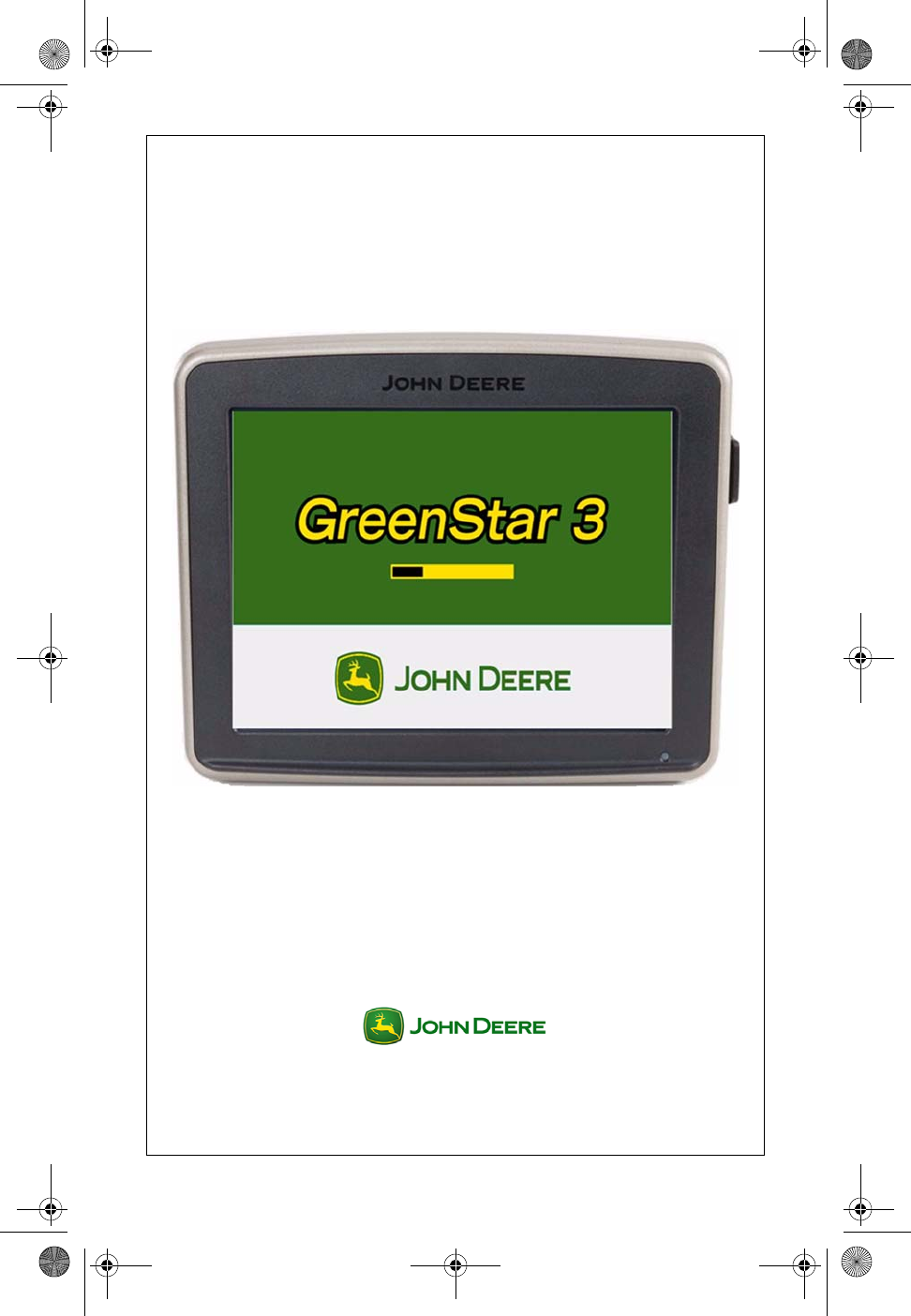
GreenStar™ 3
2630 Display
User Guide
PFP11104
GS3 2630 Display.book Page 1 Thursday, May 12, 2011 7:45 AM
Copyright © 2011 Deere & Company. All Rights Reserved. THIS MATERIAL IS THE
PROPERTY OF DEERE & COMPANY. ALL USE AND/OR REPRODUCTION NOT
SPECIFICALLY AUTHORIZED BY DEERE & COMPANY IS PROHIBITED. All information,
illustrations and specifications in this manual are based on the latest information available
at the time of publication. The right is reserved to make changes at any time without notice.
About This Document
This User Guide will help you learn how to perform common tasks with
your new display. It is a supplement to the display Operator Manual.
Read the Operator Manual for the following information:
• How to operate your display safely
• Theory of operation
• How to install the display and do initial setup
• Diagnostics
GS3 2630 Display.book Page 2 Thursday, May 12, 2011 7:45 AM

User Guide
User Guide Display General
GS3 2630 Display
GS3 2630 Display
1
Section Contents
TURNING THE DISPLAY ON/OFF ..........................................2
Turn ON the display.............................................................................. 2
Turn OFF the display............................................................................ 2
Putting the Display in Standby.............................................................. 2
Saving Settings and Data ..................................................................... 3
COMMON BUTTONS..................................................................3
DISPLAY SETTINGS...................................................................3
Brightness............................................................................................. 3
Day / Night Mode .................................................................................. 4
Volume ................................................................................................. 4
Language.............................................................................................. 4
Units ..................................................................................................... 5
HOME PAGE SETUP...................................................................5
USER ACCESS..............................................................................6
Lock or Unlock Functions ..................................................................... 6
VIDEO ............................................................................................7
Viewing Video (Option 1) ...................................................................... 7
Viewing Video (Option 2) ...................................................................... 7
Adjusting Video Image Quality ............................................................. 7
GS3 2630 Display.book Page 1 Thursday, May 12, 2011 7:45 AM
GS3 2630 Display
GS3 2630 Display
User Guide
User Guide Display General
2
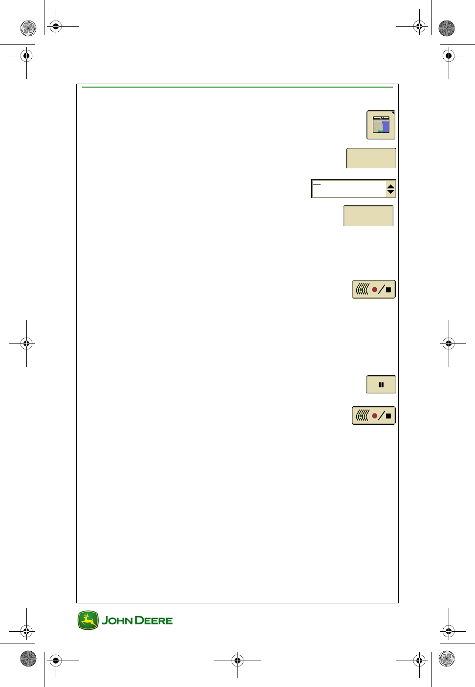
Turning the Display On/Off
The display will turn on and off with the vehicle key switch.
Turn ON the display
1. Turn vehicle key switch directly to the Run position.
IMPORTANT: Do NOT allow the display to boot up with the key
in Accessory Mode and then crank the engine.
NOTE: Implement controllers may take several minutes to load (if
connected).
Turn OFF the display
1. Turn vehicle key switch to shut down vehicle and wait for the
display to save settings.
IMPORTANT: Never pull the power plug without first turning
off the vehicle key switch. Data loss could occur.
NOTE: The display requires a constant power source, so that it can save
data and settings to permanent memory after the key is switched off. The
Status LED is amber while the display saves data and settings.
Putting the Display in Standby
Use Standby mode only when the display is not being used for any
operations. Standby mode will dim the display, mute tracking tones,
suppress GPS alerts, and signal some implements to go into Standby
mode.
1. Menu ............................................................................
2. Standby ..................................................................
NOTE: The Steer On button must be pressed after Standby has
been on to use AutoTrac.
GS3 2630 Display.book Page 2 Thursday, May 12, 2011 7:45 AM
User Guide
User Guide Display General
GS3 2630 Display
GS3 2630 Display
3
Saving Settings and Data
Documentation data is saved continuously to permanent memory as it is
recorded. Guidance lines are saved when the field setting is changed.
Map data and some settings are saved only when the display is powered
down or a data backup is performed.
Option 1. Turn the vehicle key switch to shut down vehicle and wait for the
Status LED to turn black.
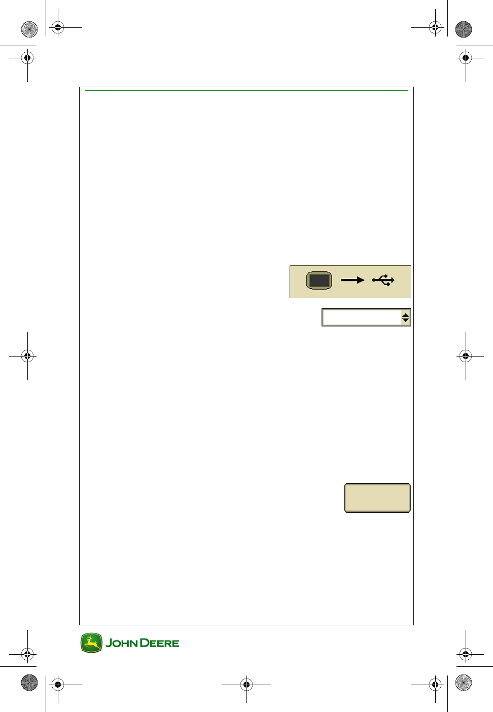
Option 2. Insert a USB and Backup data.
Common Buttons
Accept ..........................................................................................
Cancel .........................................................................................
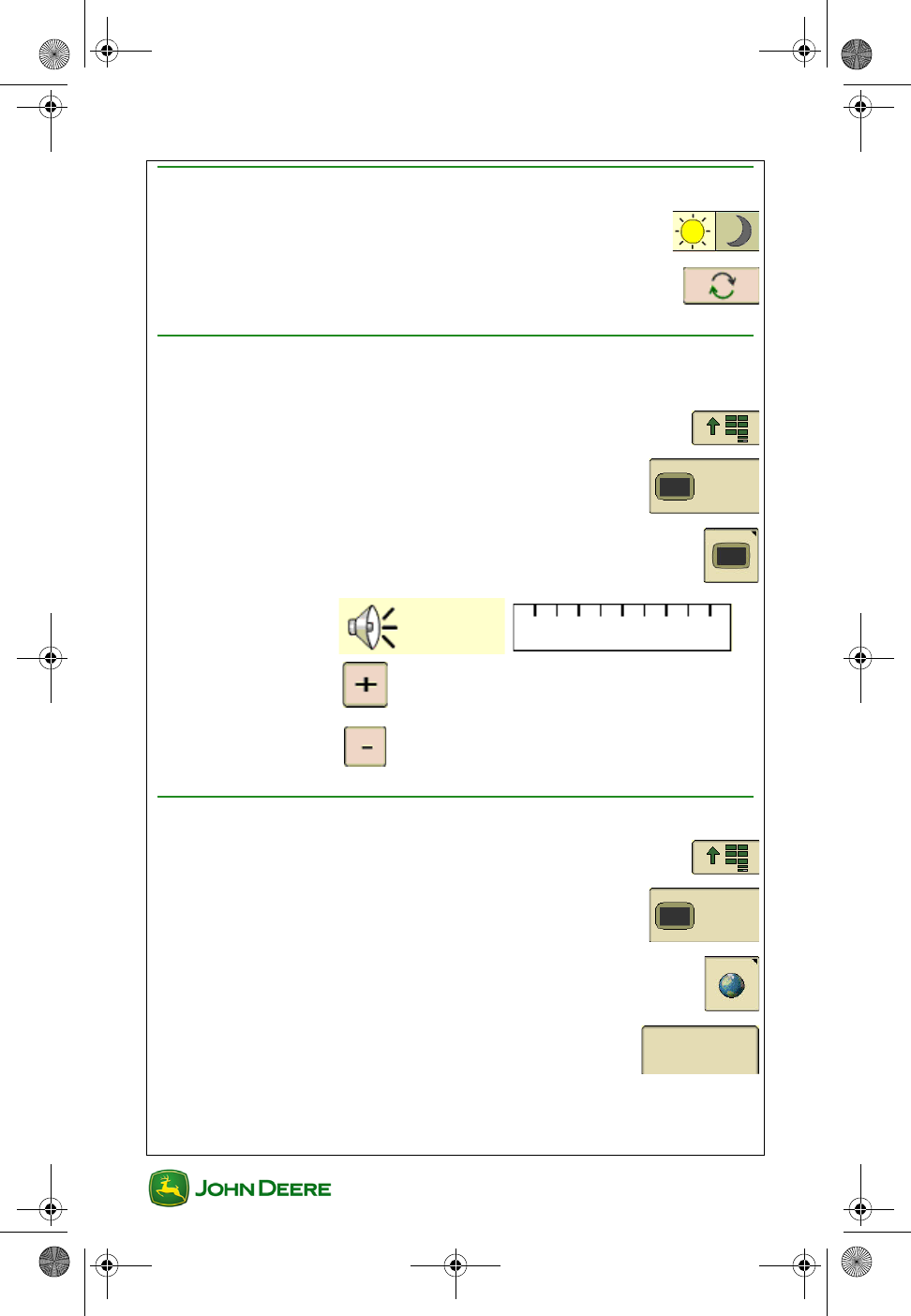
Display Settings
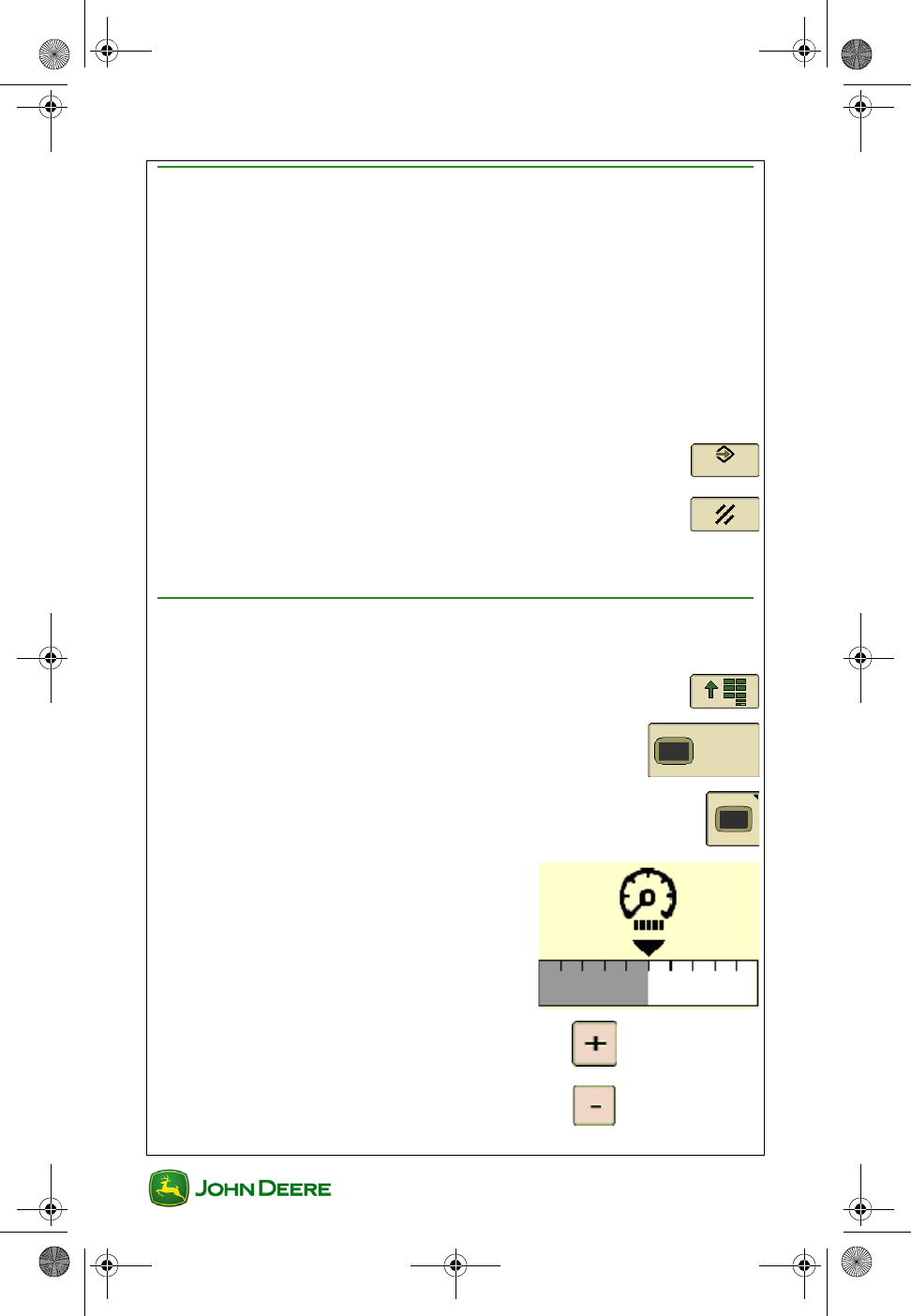
Brightness
This function allows the operator to adjust the brightness of the display.
1. Menu ............................................................................
2. Display Menu ........................................................
3. Display Softkey ...............................................................
4. Adjust the brightness ........................
to increase
to decrease
GS3 2630 Display.book Page 3 Thursday, May 12, 2011 7:45 AM
GS3 2630 Display
GS3 2630 Display
User Guide
User Guide Display General
4
Day / Night Mode
Allows operator to quickly change screen with one button
push.
Toggle to switch ........................................................................
Volume
This function allows the operator to adjust the volume of the display.
1. Menu ............................................................................
2. Display Menu ........................................................
3. Display Softkey ..............................................................
4. ............................
Language
1. Menu ............................................................................
2. Display Menu ........................................................
3. Global Settings .............................................................
4. Regional Tab ........................................................
5. Two ways to change language:
• Choose preferred country in the country drop box.
to increase
to decrease
Regional
GS3 2630 Display.book Page 4 Thursday, May 12, 2011 7:45 AM
User Guide
User Guide Display General
GS3 2630 Display
GS3 2630 Display
5
• Choose preferred language in the language drop box.
Units
1. Menu ............................................................................
2. Display Menu ........................................................
3. Global Settings .............................................................
4. Regional Tab ........................................................
5. Under the units drop box, choose one of the following:
•Metric
•Imperial
•US
Regional
GS3 2630 Display.book Page 5 Thursday, May 12, 2011 7:45 AM
GS3 2630 Display
GS3 2630 Display
User Guide
User Guide Display General
6
Home Page Setup
The Layout Manager allows the operator to create user-defined
Homepages.
1. Menu ............................................................................
2. Layout Manager ...................................................
3. Choose the preferred layout.
4. Press each section to configure:
•Enter if satisfied ........................................................
•Clear to start over ......................................................
5. Home to show configuration .........................................
NOTE: The Original GreenStar Display emulator is only available with
Options A and F. Advanced Performance Monitor is only available as a
full page.
GS3 2630 Display.book Page 6 Thursday, May 12, 2011 7:45 AM
User Guide
User Guide Display General
GS3 2630 Display
GS3 2630 Display
7
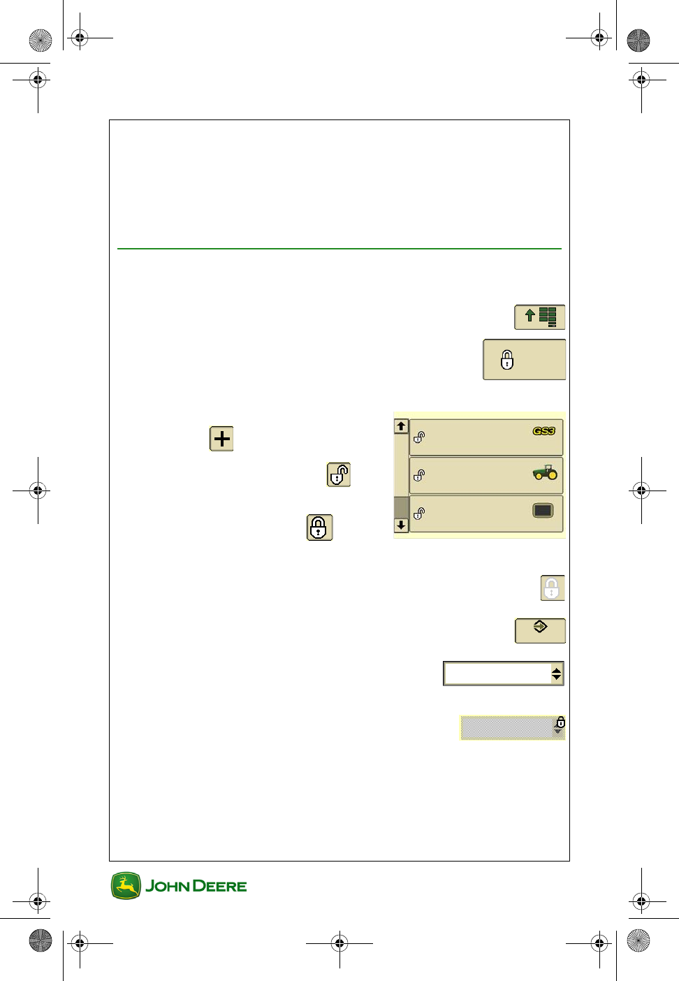
User Access
Almost all of the functions on the display can be locked for the operator to
simplify the user experience and reduce accidental settings changes.
Once functions are locked for “Operator Mode”, a password is required to
enter “Owner Mode” and access those functions. Read the Operator
Manual for password information.
Lock or Unlock Functions
NOTE: Must be in Owner Mode to lock or unlock functions.
1. Menu ............................................................................
2. Access Manager .................................................
3. Select functions to lock out in the list
4. Select “+” to expand a list
5. Select the “unlocked” icon to
lock a setting
6. Select the “locked” icon to
unlock a setting
NOTE: A gray lock means that only some of the sub-functions are
locked.
7. Select Accept to save changes.........................................
8. Select Operator Mode for functions to be
locked.
Locked functions will have a small lock appear
over them when in Operator Mode.
GS3 2630 Display.book Page 7 Thursday, May 12, 2011 7:45 AM
GS3 2630 Display
GS3 2630 Display
User Guide
User Guide Display General
8
Video
The display is capable of displaying video from one camera. Read the
display Operator Manual for more information.
CAUTION: Do not rely on a camera for collision avoidance or
bystander detection. To avoid possible injury or death to oper-
ator or others, always remain alert and aware of surroundings
when operating the machine. Read and understand AVOID
BACKOVER ACCIDENTS in the safety section of the Operator
Manual.
Viewing Video (Option 1)
1. Menu ............................................................................
2. Video .....................................................................
Viewing Video (Option 2)
1. Set up as a full page Homepage using Layout Manager.
Adjusting Video Image Quality
• Increase Contrast .............................................................
• Decrease Contrast .......................................................
• Mirror Image ...............................................................
Mirroring an image exchanges what is seen on the left and right sides of
the image like a rear view mirror. The camera or the display could mirror
the image. Check whether the image is mirrored before using the Video
feature.
IMPORTANT: Correctly understand whether the camera is
“mirrored” and whether the video application is mirrored.
GS3 2630 Display.book Page 8 Thursday, May 12, 2011 7:45 AM

User Guide
User Guide GreenStar General
GS3 2630 Display
GS3 2630 Display
1
Section Contents
GETTING STARTED...................................................................2
Access GreenStar Applications ............................................................ 2
GreenStar Activations........................................................................... 2
What Needs to Be Set Up .................................................................... 2
Summary of Setup Pages..................................................................... 3
Using the Setup Wizard ........................................................................ 4
CHANGE FIELD NAME .............................................................6
Selecting a Field Automatically............................................................. 6
Changing Fields Automatically ............................................................. 6
Selecting a Field Manually.................................................................... 7
Check Summary of Field Settings ........................................................ 7
Task Setting.......................................................................................... 7
MAPPING ......................................................................................8
Go to Mapping ...................................................................................... 8
Setup Map Layers ................................................................................ 8
Edit Map Legend .................................................................................. 9
Mapping (Recording) Diagnostics ........................................................ 9
RECORD A BOUNDARY ..........................................................10
DATA MANAGEMENT.............................................................12
Data Transfer Options ........................................................................ 12
Export Data from the Display.............................................................. 13
Importing Data to the Display ............................................................. 14
Importing Global or Shapefile Prescriptions ....................................... 15
Transferring Data between Two Displays........................................... 16
View Memory Remaining.................................................................... 16
Delete Documentation Data Only ....................................................... 16
Delete Coverage and Swath Control Maps ........................................ 17
Delete all Data and Setup Information................................................ 17
Delete Adaptive Curve Data ............................................................... 19
TROUBLESHOOTING..............................................................20
Coverage Maps .................................................................................. 20
This section applies to GreenStar™ set up and functions that are used by
most GreenStar applications.
GS3 2630 Display.book Page 1 Thursday, May 12, 2011 7:45 AM
GS3 2630 Display
GS3 2630 Display
User Guide
User Guide GreenStar General
2
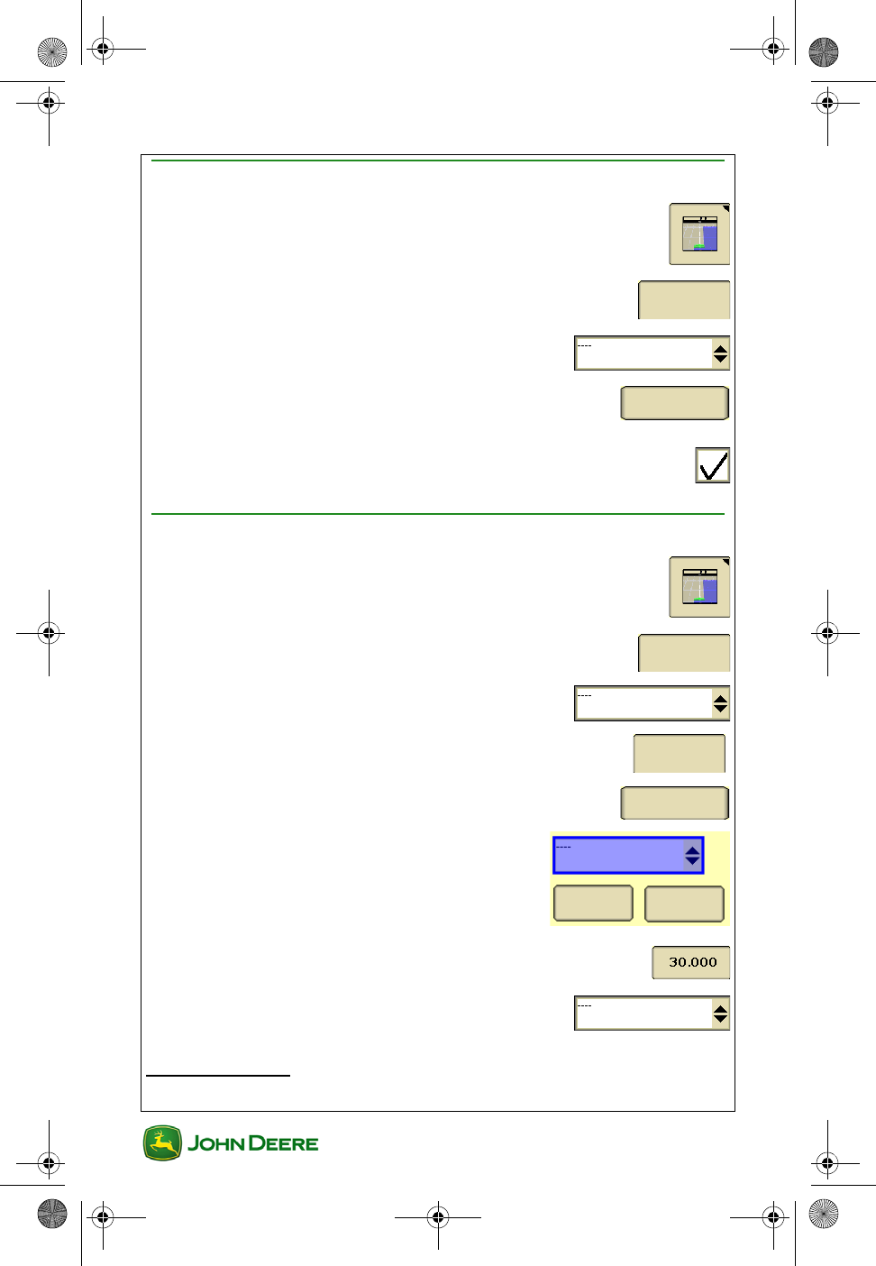
Getting Started
Access GreenStar Applications
All information and functionality related to GreenStar applications is
accessed with the GreenStar Softkey.
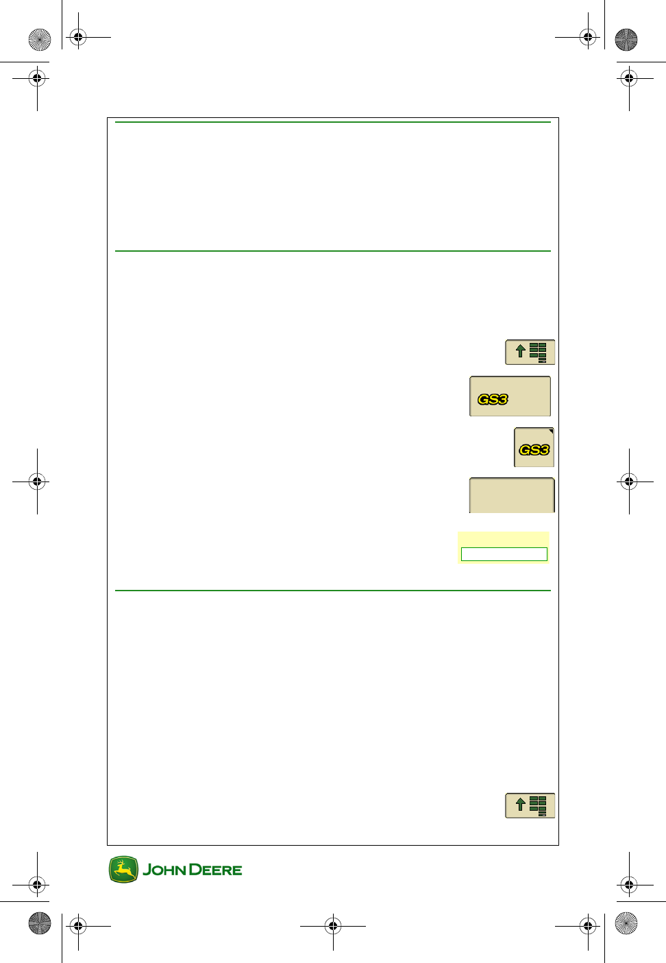
1. Menu ...........................................................................
2. GS3 ......................................................................
GreenStar Activations
Activations are required for GreenStar applications other than Manual
Guidance and Documentation. Check the Activations page to see if an
Application is Activated and checked ON.
1. Menu ............................................................................
2. GS3 ......................................................................
3. GreenStar Softkey ..........................................................
4. Activations Tab ...................................................
Easy Tip!! Uncheck demo activations that are not used to
hide buttons associated with those activations throughout the
display. The fewer buttons on each screen, the easier the
display is to use.
What Needs to Be Set Up
The amount of setup information that must be entered depends on the
operation and the amount of information to be documented. A Setup
Wizard is available to guide you through each setup page depending on
the operations you specify. GreenStar applications can also be set up by
accessing the setup pages individually.
Activations
GS3 2630 Display.book Page 2 Thursday, May 12, 2011 7:45 AM
User Guide
User Guide GreenStar General
GS3 2630 Display
GS3 2630 Display
3
Summary of Setup Pages
•Farm Resources and Conditions ................................
○Farm Resources Field Name – Setup is necessary to use
Documentation features (e.g., prescription maps, as-applied
maps, and yield maps) or to categorize guidance lines by
field. Field names must also be used with coverage mapping
and Swath Control if operating in fields more than 4.9 miles
apart.
○Conditions – Enter information about weather, crop, and
soil.
○Notes – Enter notes about the Task.
•Equipment .....................................................................
○Machine Tab
▪Machine Name – Machine information is saved by the
name.
▪Connection Type – Required for accurate mapping.
▪Machine Offsets – Often required to improve guid-
ance or mapping accuracy.
▪Recording Source – Select the trigger to turn map
and Documentation recording on / off.
○Implement 1 Tab
▪Implement Type Information
▪Implement Offsets – Required for accurate mapping,
Swath Control and Implement Guidance.
▪Implement Width – Required for mapping.
○Implement 2 and 3 Tabs – Available for operations with
additional implements such as an air cart.
GS3 2630 Display.book Page 3 Thursday, May 12, 2011 7:45 AM
GS3 2630 Display
GS3 2630 Display
User Guide
User Guide GreenStar General
4
•Documentation – Enter information to be documented
about operations such as planting, Product Application,
or Harvest. Also set up as-applied or yield mapping.
Using the Setup Wizard
The Setup Wizard guides the user to the setup pages that are required
based on the options that are checked. The Setup Tab only needs to be
used for this purpose.
1. Menu ............................................................................
2. GS3 ......................................................................
3. GS3 Softkey .....................................................................
4. Setup Tab
NOTE: To avoid extra setup, only check the Documentation option if you
know you want to Document.
Summary Activations Memory
What settings do you want to change?
Resources
Machine
Implement
Documentation
Guidance
Boundaries
iTEC Pro
Swath Control
Water Management
Setup
Implement
Guidance
GS3 2630 Display.book Page 4 Thursday, May 12, 2011 7:45 AM
User Guide
User Guide GreenStar General
GS3 2630 Display
GS3 2630 Display
5
5. Check the items that apply to your operation and
press Accept.
6. Fill out the necessary items on each setup page and
then press Next Page to continue.
NOTE: A red asterisk indicates items that must be filled out on each
page
GS3 2630 Display.book Page 5 Thursday, May 12, 2011 7:45 AM
GS3 2630 Display
GS3 2630 Display
User Guide
User Guide GreenStar General
6
Change Field Name
Client, Farm, and Field name can be selected manually or automatically.
Several types of setup data are tied to Field Names including Guidance
lines, maps, and Documentation data. If fields have external boundaries
saved in the display, the field settings can be selected automatically and
the operator will be alerted when the implement is completely out of the
field.
NOTE: Field Names can only be edited or deleted individually using Apex
or another type of desktop software.
Selecting a Field Automatically
1. Menu ............................................................................
2. GS3 ......................................................................
3. Resources / Conditions ................................................
4. Check the Field Locator ON / OFF checkbox.
5. Drive into a field that already has an external boundary defined
in the display.
6. Press Find Field button. A list of the closest fields will appear.
Changing Fields Automatically
1. After driving out of a field that has an external boundary saved
in the display, a “Field Exit Detected” message will appear on
the map.
2. Drive into the next field.
3. Press on the map. A list of the closest fields will appear.
4. Select a field and verify Guidance and Documentation settings.
GS3 2630 Display.book Page 6 Thursday, May 12, 2011 7:45 AM
User Guide
User Guide GreenStar General
GS3 2630 Display
GS3 2630 Display
7
Selecting a Field Manually
1. Menu ............................................................................
2. GS3 ......................................................................
3. Resources / Conditions ................................................
4. Select or create a new Client, Farm, and Field name. The
Client is the land owner in many cases.
Check Summary of Field Settings
Check the setup information entered for a field name after selecting a field.
1. Menu ............................................................................
2. GreenStar ............................................................
3. GreenStar Softkey ..........................................................
4. Summary Tab ......................................................
Task Setting
Task is ONLY used for Documentation. If NOT using Documentation
(e.g. rates, yield maps, Totals, etc.), select Documentation OFF to avoid
extra setup.
1. Menu ............................................................................
2. GreenStar ............................................................
3. Resources .....................................................................
Summary
GS3 2630 Display.book Page 7 Thursday, May 12, 2011 7:45 AM
GS3 2630 Display
GS3 2630 Display
User Guide
User Guide GreenStar General
8
4. Select Documentation OFF ........................
Mapping
Go to Mapping
1. Menu ............................................................................
2. GreenStar ............................................................
3. Mapping .........................................................................
Setup Map Layers
1. Map Settings tab ................................................
2. Select map to appear in the Background .....
• Examples: Prescription Map or Aerial Photo
• Background maps are loaded from Apex or another desktop soft-
ware
3. Select map to appear in the Foreground .......
• Examples: As-applied, Coverage, or Yield Map
Toggle between the Coverage Map and the As-
Applied map that is selected as the Foreground
Map Layer
NOTE: This button is only active when an Operation is setup for
Documentation.
Map Settings
GS3 2630 Display.book Page 8 Thursday, May 12, 2011 7:45 AM
User Guide
User Guide GreenStar General
GS3 2630 Display
GS3 2630 Display
9
Edit Map Legend
1. Mapping .........................................................................
2. Edit Legend ........................................................
NOTE: An As-applied or yield map must be setup in Documentation setup
and selected as the Foreground Layer in Map Settings.
3. Enter the preferred maximum and minimum values.
4. The legend will be divided into five colors automatically.
Mapping (Recording) Diagnostics
If recording will not start, go to Recording Diagnostics to determine
system status.
1. Menu ............................................................................
2. GS3 ......................................................................
3. GreenStar Diagnostics .................................................
4. Select Recording .........................................
GS3 2630 Display.book Page 9 Thursday, May 12, 2011 7:45 AM
GS3 2630 Display
GS3 2630 Display
User Guide
User Guide GreenStar General
10
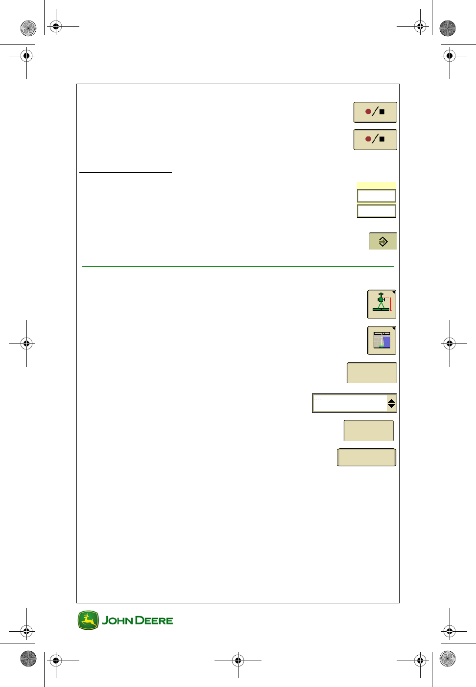
Record a Boundary
Boundaries are used for Swath Control, iTEC Pro, changing Field Names
automatically, and determining field area.
1. Menu ............................................................................
2. GreenStar ............................................................
3. Mapping .........................................................................
4. Boundary tab .......................................................
5. Select the Field Name for the boundary to
be saved
NOTE: Only one Exterior boundary may be saved per Field Name.
6. Select the Boundary Type...........................
•Exterior Boundary - perimeter of a field. Used for automatic
Field Name selection and Swath Control.
•Interior Passable Boundary - perimeter of an obstacle in a field
that can be crossed. Used for Swath Control and iTEC Pro™.
•Interior Impassable Boundary - perimeter of an obstacle in a
field that can NOT be crossed. Used for Swath Control and iTEC
Pro.
•Headland Boundary - delineates field headland. Used for Swath
Control and iTEC Pro. Recording Headland Boundaries is not
covered in this User Guide.
7. Enter the Boundary Offset distance. This is the
distance left and right of the GPS receiver to the
Boundary Recording Point.
Boundary
GS3 2630 Display.book Page 10 Thursday, May 12, 2011 7:45 AM
User Guide
User Guide GreenStar General
GS3 2630 Display
GS3 2630 Display
11
8. Toggle the Boundary Recording Point to the
desired corner of the machine / implement. The
location of this point in front and behind the machine is
determined by the values entered in machine and implement
offsets.
9. Drive to the edge of the field.
10. Select Start Boundary Recording ..........................
11. Drive around the perimeter of the field.
NOTE: AutoTrac and other applications can be operated during boundary
recording.
12. If desired, select Pause Boundary Recording to
snap a straight line between the points where
recording was paused and unpaused.
13. Select Stop Boundary Recording. A straight line
will be snapped between the first and last point of the
boundary.
GS3 2630 Display.book Page 11 Thursday, May 12, 2011 7:45 AM
GS3 2630 Display
GS3 2630 Display
User Guide
User Guide GreenStar General
12
Data Management
Data and setup information can be transferred to and from another GS3
2630 display or compatible desktop software using a USB flash drive.
Data and setup information are imported or exported as a Data Profile.
Only Prescription Maps can be imported individually. See Operator
Manual for Examples of managing your data properly.
Apex (v3.1 or newer) and several 3rd party desktop applications are
compatible with the display.
Data Transfer Options
Export Data from the display
Data Profile is copied to the USB flash drive. Use this option in the
following examples:
• Backup Documentation data to a USB flash drive,
• Transfer setup information and guidance lines to another display,
• Transfer setup information and guidance lines to compatible
desktop software, or
• Transfer screen shots and debug files to a USB flash drive.
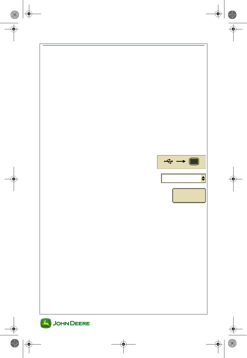
Import Data to the display
Data Profile is copied to the display. This option does NOT import global
prescriptions and shapefiles. Use this option in the following examples:
• Import Field Names, boundaries, and guidance lines from
another GS3 2630 display or compatible desktop software.
• Import coverage and swath control maps from another GS3 2630
display.
• Import field specific prescription (Rx) files from compatible desk-
top software.
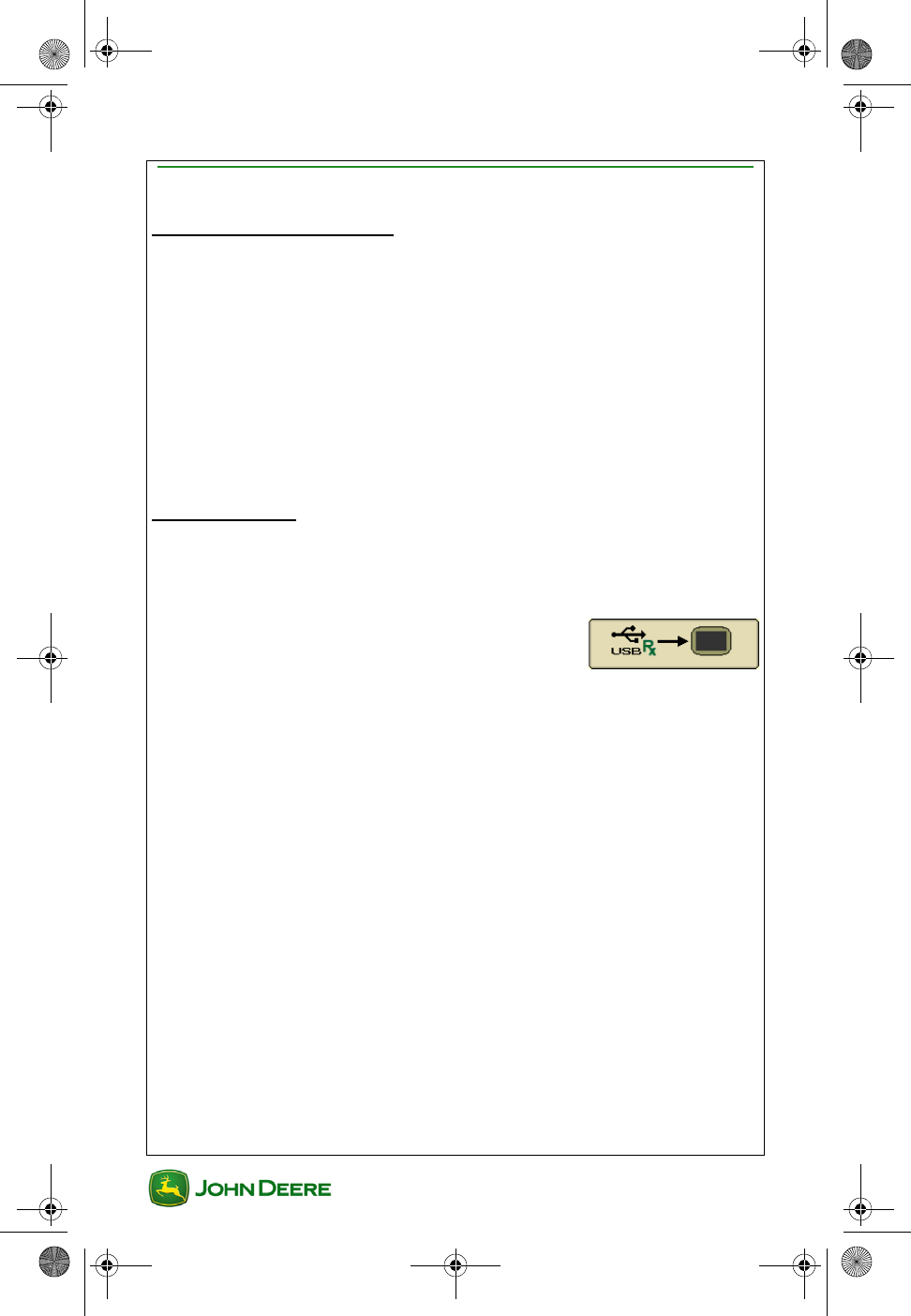
Import Global Prescriptions to the display
Only Global Prescription (GRx) files and shape files are imported into the
display.
GS3 2630 Display.book Page 12 Thursday, May 12, 2011 7:45 AM
User Guide
User Guide GreenStar General
GS3 2630 Display
GS3 2630 Display
13
Export Data from the Display
IMPORTANT: USB flash drive should have at least 1GB of free
memory. Large data sets may take several minutes to transfer.
Power loss or removing the USB during data transfer may
cause data loss.
1. Turn off all types of Recording and stop the vehicle.
2. Insert USB flash drive
3. A Data Transfer page will appear within about 10 seconds.
Troubleshooting Tips!!! If the USB flash drive is not recognized,
try the other USB port, format the USB flash drive (FAT or FAT32),
or try a different USB flash drive.
4. Export Data ......................................
5. Select or create a Profile Name where the
data will be stored on the USB
IMPORTANT: Exporting to an existing Profile will overwrite all
setup information and data in that Profile except for Documen-
tation files used by desktop software. See the Operator Man-
ual for more information.
Export takes less time when exporting repeatedly to the same Profile
because the Documentation files (e.g. As-applied and Yield map files)
that are already in the Profile on the USB are not exported again.
NOTE: Do not use of the following characters (\ / : * ? " < >) when creating
a Profile name. These will cause the profile to fail to load to a display or
Apex.
6. Begin Transfer ..................................................
7. When the data transfer is finished, a Data Transfer is
Complete message will appear.
Begin Transfer
GS3 2630 Display.book Page 13 Thursday, May 12, 2011 7:45 AM
GS3 2630 Display
GS3 2630 Display
User Guide
User Guide GreenStar General
14
Importing Data to the Display
IMPORTANT: Import Data will replace the setup information in
the internal memory of the display with the setup information
in the Data Profile that is selected from the USB drive. Only
Prescription files can be imported individually to the display.
See the Operator Manual for more information.
NOTE: Large data sets may take several minutes to transfer. Power loss
or removing the USB during data transfer may cause data loss.
1. Turn off all types of Recording and stop the vehicle.
2. Insert USB flash drive.
3. A Data Transfer page will appear within about 10 seconds.
Troubleshooting Tips!!! If the USB flash drive is not recognized,
try the other USB port, format the USB flash drive (FAT or FAT32),
or try a different USB flash drive.
4. Import data ..............................................
5. Select the Profile Name on the USB drive
to be imported
6. Begin Transfer ..................................................
7. When the data transfer is finished, Data Transfer is Complete
message will appear.
Begin Transfer
GS3 2630 Display.book Page 14 Thursday, May 12, 2011 7:45 AM
User Guide
User Guide GreenStar General
GS3 2630 Display
GS3 2630 Display
15
Importing Global or Shapefile Prescriptions
On a Desk top Computer
1. Insert a USB flash drive.
Global Prescriptions (GRx) files:
A. Create a folder named GRx in the root of the USB drive.
B. Copy the GRx files into this folder.
Shapefile Prescriptions:
A. Create a folder named Rx in the root of the USB drive.
B. Copy the shapefiles into this folder.
On the Display
1. Turn off all types of Recording and stop the vehicle.
2. Insert USB flash drive.
3. A Data Transfer page will appear within about 10 seconds.
4. Import Global Prescriptions and
Shapefile Data.
5. When the data transfer is finished, a Data
Transfer is Complete message will appear.
IMPORTANT: All Global and Shapefile Prescriptions on the
display will be deleted prior to importing.
GS3 2630 Display.book Page 15 Thursday, May 12, 2011 7:45 AM
GS3 2630 Display
GS3 2630 Display
User Guide
User Guide GreenStar General
16
Transferring Data between Two Displays
Apex or a compatible 3rd party desktop software is required for
transferring data and setup information between different John Deere
Display models (i.e. Original GreenStar Display, GS2 1800, GS2 2600,
and GS3 2630). Due to different file versions, data will not load when
transferred directly between different models.
View Memory Remaining
The Memory Used bar graph shows total memory used, including system
files. A message will appear when 90% of the memory is used. Data
should be deleted before memory used exceeds 90%.
1. Menu ............................................................................
2. GreenStar ............................................................
3. GS3 Softkey ....................................................................
4. Memory Tab .......................................................
5. Bar graph represents percent of memory used.
Delete Documentation Data Only
Documentation data includes the As-applied and yield maps used by
desktop software. The maps used by the display will remain on the
display. Examples for when to use this feature include:
• Deleting your planting rate maps after planting season, so that
there is less data on the display and data exports will take less
time during harvest.
• The internal memory is full.
1. Export Data to a USB flash drive if necessary, so it is not lost.
2. Remove the USB drive.
3. Menu ............................................................................
Memory
Memory Used
GS3 2630 Display.book Page 16 Thursday, May 12, 2011 7:45 AM
User Guide
User Guide GreenStar General
GS3 2630 Display
GS3 2630 Display
17
4. GreenStar ............................................................
5. Memory Tab .......................................................
6. Erase Data .........................................................
7. Documentation Data .........................................................
8. Begin Removal ..................................................
Delete Coverage and Swath Control Maps
Delete Coverage and Swath Control Maps to free up internal memory or
to create a new map with the same Field Name.
NOTE: Documentation data used by desktop software (i.e. As-Applied
(rate) maps and Yield maps) will NOT be deleted, but will no longer be
able to be viewed on the display. They can still be exported to a USB
drive.
1. Mapping .........................................................................
2. Map Settings ...................................................
3. Select option to Clear
•This Field Only - the map for the currently selected field
•All Farms and Fields - all coverage and swath control maps.
Delete all Data and Setup Information
All data and setup information will be deleted from the display. This option
is rarely used and may be used if you want to start over or think the setup
data may be causing a problem to occur on the display.
1. Export Data to a USB flash drive if necessary, so it is not lost.
2. Remove the USB drive.
Memory
Erase Data
Begin
Removal
Map Settings
GS3 2630 Display.book Page 17 Thursday, May 12, 2011 7:45 AM
GS3 2630 Display
GS3 2630 Display
User Guide
User Guide GreenStar General
18
3. Menu .............................................................................
4. GreenStar ............................................................
5. GS3 Softkey ...................................................................
6. Memory Tab .......................................................
7. Erase Data .........................................................
8. All Data ...............................................................
9. Begin Removal ..................................................
Memory
Erase Data
All Data
Begin
Removal
GS3 2630 Display.book Page 18 Thursday, May 12, 2011 7:45 AM
User Guide
User Guide GreenStar General
GS3 2630 Display
GS3 2630 Display
19
Delete Adaptive Curve Data
1. Guidance ......................................................................
2. Guidance Settings tab .......................................
3. Change Curve Track Settings ............................
4. Clear Data ..........................................................
Guidance
Settings
Change
Clear
Data
GS3 2630 Display.book Page 19 Thursday, May 12, 2011 7:45 AM
GS3 2630 Display
GS3 2630 Display
User Guide
User Guide GreenStar General
20
Troubleshooting
Coverage Maps
Symptom: Previously recorded Coverage map does NOT load
after startup.
Check: The display must shutdown properly with key switch for
maps to save. After the vehicle key is switched OFF the
Saving Settings screen should appear.
Symptom: Previously recorded Coverage map does NOT load
after selecting the Field Name.
Check: The settings for Implement Width and Number of
Sections must be the same as when the Coverage map was
recorded.
GS3 2630 Display.book Page 20 Thursday, May 12, 2011 7:45 AM

User Guide
User Guide Guidance
GS3 2630 Display
GS3 2630 Display
1
Section Contents
GUIDANCE INTRODUCTION...................................................2
Go to the Guidance Map Page ............................................................. 2
Guidance Map Page Symbols .............................................................. 2
Requirements for Guidance Operation ................................................. 3
AutoTrac Status Pie.............................................................................. 4
CHOOSE TRACKING MODE....................................................5
Straight Track Mode ............................................................................. 5
AB Curve Mode .................................................................................... 5
Adaptive Curve Mode ........................................................................... 5
Circle Track Mode ................................................................................ 6
Row Finder Mode ................................................................................. 6
GUIDANCE TRACK SETUP ......................................................7
Create a Straight Track AB Line ........................................................... 7
Create an AB Curve Track ................................................................... 9
Create an Adaptive Curve Track ........................................................ 10
Turn Repeat Mode ON / OFF ............................................................. 11
Create a Circle Track.......................................................................... 11
Row Finder Mode ............................................................................... 12
Change Track Spacing ....................................................................... 13
GUIDANCE SETTINGS.............................................................14
General Guidance Settings ................................................................ 14
Curve Track Settings .......................................................................... 14
Advanced AutoTrac Settings (if equipped) ......................................... 15
SHIFT TRACK SETTINGS.......................................................16
Turn Shift Track ON / OFF ................................................................. 16
Set Guidance Line Shift Distance....................................................... 16
Clear Guidance Line Shifts................................................................. 16
GS3 2630 Display.book Page 1 Thursday, May 12, 2011 7:45 AM
GS3 2630 Display
GS3 2630 Display
User Guide
User Guide Guidance
2
Guidance Introduction
This section includes basic functions for using Guidance.
Go to the Guidance Map Page
1. Menu ............................................................................
2. GS3 ......................................................................
3. Guidance softkey ...........................................................
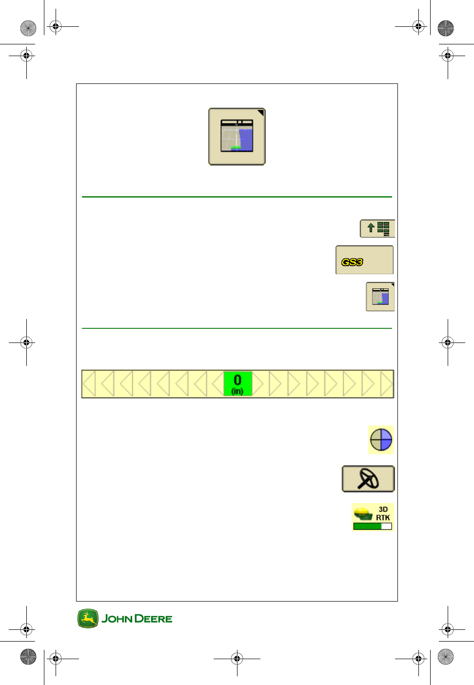
Guidance Map Page Symbols
• Pass Accuracy Indicator
• Variance off of “0” shows Off-track Error.
• AutoTrac Status Pie .........................................................
• Steering On / Off Button ..........................................
• GPS Accuracy Indicator .............................................
GS3 2630 Display.book Page 2 Thursday, May 12, 2011 7:45 AM
User Guide
User Guide Guidance
GS3 2630 Display
GS3 2630 Display
3
Requirements for Guidance Operation
• The following items are required for guidance to function:
• AB Lines
• GPS Signal
• Tracking Mode
• Track Spacing
• The following items are optional when operating guidance:
• Client, Farm and Field
• Coverage Map
• Documenting Field Operational Data
• Field Boundaries
•Flags
• Read the AutoTrac Status Pie section for AutoTrac require-
ments.
• Read and understand OPERATE GUIDANCE SYSTEMS
SAFELY section in the Safety Section of the Operators Manual.
GS3 2630 Display.book Page 3 Thursday, May 12, 2011 7:45 AM
GS3 2630 Display
GS3 2630 Display
User Guide
User Guide Guidance
4
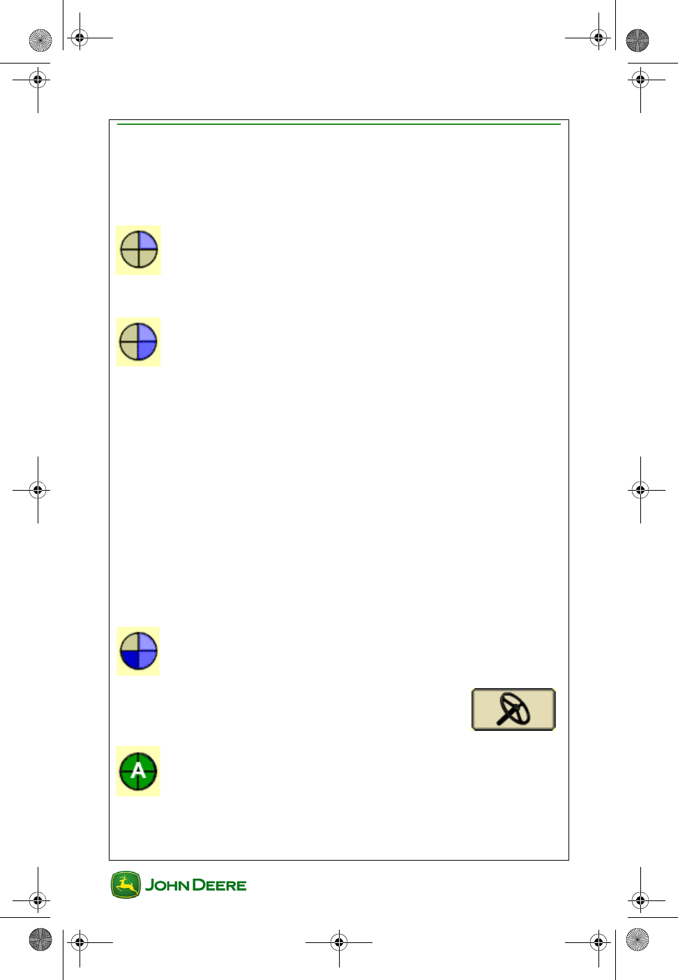
AutoTrac Status Pie
The AutoTrac Status Pie indicates what items are remaining to be set up
for AutoTrac to function.
Stage 1: Installed
• SSU is detected
Stage 2: Configured
• Tracking Mode has been selected
• Guidance AB Line has been defined
• AutoTrac Activation detected
• StarFire signal is present
• SSU has no active faults pertaining to the steering
function
• Hydraulic oil warmer than minimum temperature
• Speed is less than maximum
• TCM message is currently available and valid
• In proper operating gear
Stage 3: Enabled
• Select Steer ON
Stage 4: Activated
•Press Resume Switch on the Machine
GS3 2630 Display.book Page 4 Thursday, May 12, 2011 7:45 AM
User Guide
User Guide Guidance
GS3 2630 Display
GS3 2630 Display
5
Choose Tracking Mode
GreenStar guidance has several different tracking modes to suit almost
any field layout and operator preference.
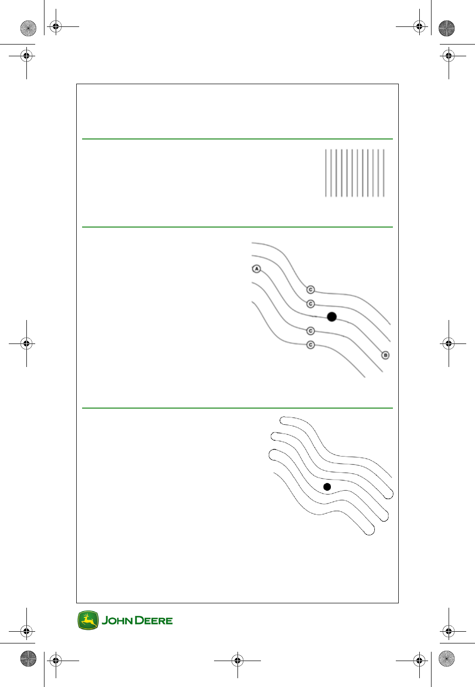
Straight Track Mode
Straight Track mode assists operator in driving
straight parallel paths by using display and audible
tones to alert operator when machine is off track.
AB Curve Mode
AB Curves allows an operator to
drive a curved line in the field with
end points at the ends of the field.
Parallel lines are generated from the
first pass.
A—Start Recording of AB Curve
B—Stop Recording of AB Curve
C—Paths Generated
Adaptive Curve Mode
Adaptive Curve Mode records a
guidance line the entire time while
operating in a field. The passes are not
identical copies of the original pass. Only
one Adaptive Curve track may be
generated per field.
GS3 2630 Display.book Page 5 Thursday, May 12, 2011 7:45 AM
GS3 2630 Display
GS3 2630 Display
User Guide
User Guide Guidance
6
Circle Track Mode
Used on center pivot irrigated fields. Requires a PivotPro activation.
Row Finder Mode
Row Finder Mode is intended for row crop applications where the rows
are not always equally spaced and can only be operated with manual
guidance. Row Finder will aid the operator in finding which set of rows to
enter back into the field on after setting a reference point when coming
out of the previous rows.
GS3 2630 Display.book Page 6 Thursday, May 12, 2011 7:45 AM
User Guide
User Guide Guidance
GS3 2630 Display
GS3 2630 Display
7
Guidance Track Setup
Minimal setup is required for basic guidance, as shown below. However, it
is recommended to read the operation specific sections of this user guide
and enter all machine and implement settings. Adjusting machine and
implement offsets may be required for guidance and mapping accuracy.
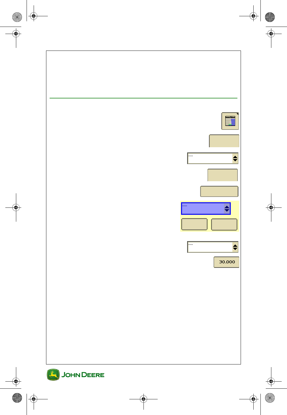
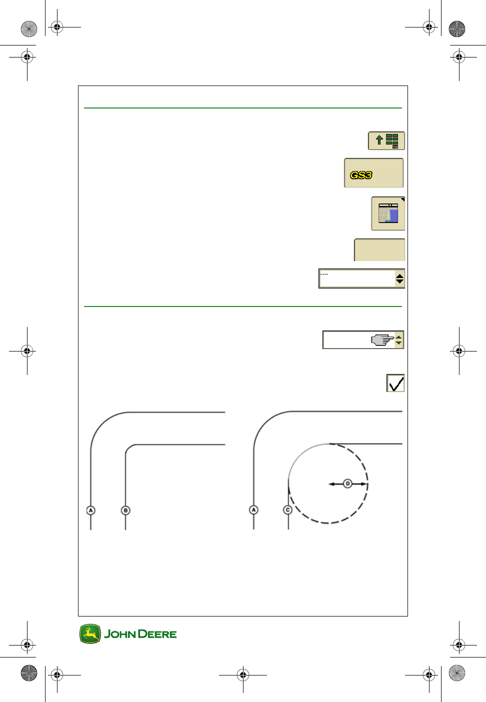
Create a Straight Track AB Line
1. Guidance ......................................................................
2. Guidance Settings tab ...........................................
3. Select Straight Track tracking mode ..........
4. View tab ..................................................................
5. Set Track 0 .........................................................
6. Select an existing track from the list or
select New
7. Select the Method to create the track ..........
8. Enter Track Spacing ..................................................
Guidance
S e t t i n g s
View
Set Track 0
New Remove
GS3 2630 Display.book Page 7 Thursday, May 12, 2011 7:45 AM
GS3 2630 Display
GS3 2630 Display
User Guide
User Guide Guidance
8
A + B Method
1. Drive to desired beginning of AB line and select
Set A
2. Select Set B Later ..............................................
3. Drive toward desired end of AB line and press
Set B
A + Heading Method
1. Drive to desired beginning of AB line and select
Set A
2. Enter desired Heading of the B point
Auto B Method
1. Drive to desired beginning of AB line and select
Set A
2. Drive toward desired end of AB line. The B point will
automatically set after 49 feet (15 meters).
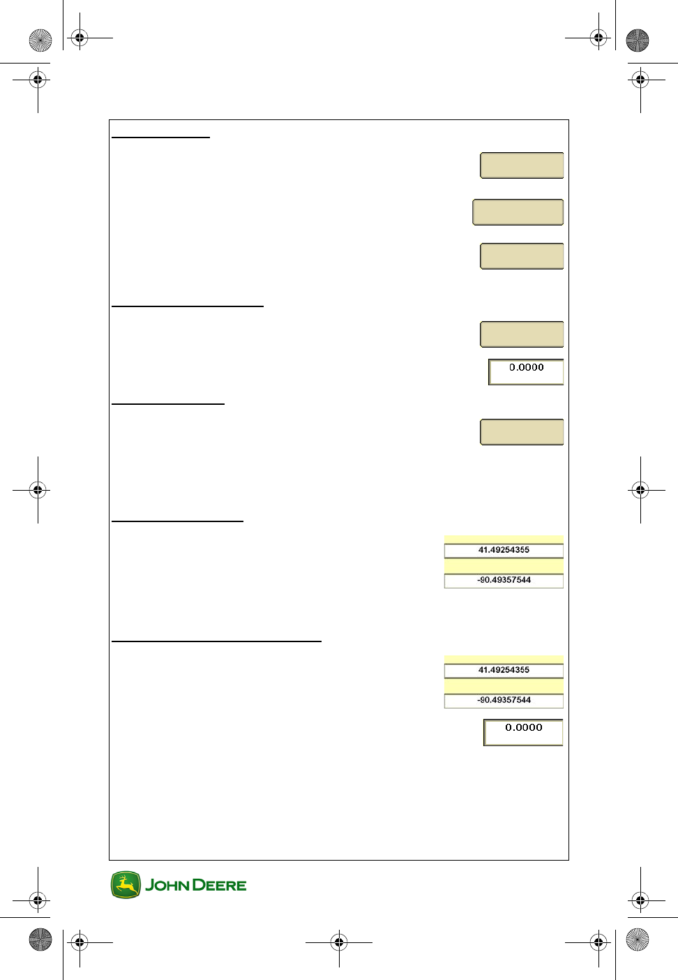
Lat / Long Method
1. Set A Point Latitude and Longitude
2. Set B Point Latitude and Longitude
Lat / Long + Heading Method
1. Enter in coordinates for A and B points .........
2. Enter in Desired Heading .......................................
Set A
Set B Later
Set B
Set A
Set A
Latitude
Longitude
Latitude
Longitude
GS3 2630 Display.book Page 8 Thursday, May 12, 2011 7:45 AM
User Guide
User Guide Guidance
GS3 2630 Display
GS3 2630 Display
9
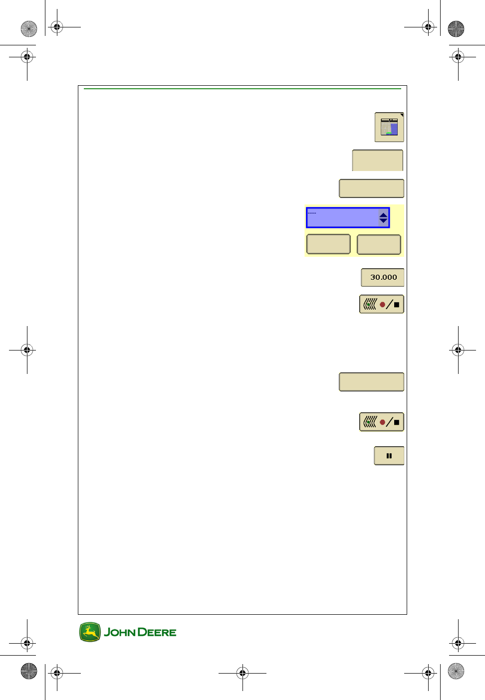
Create an AB Curve Track
1. Guidance ........................................................................
2. View tab ..................................................................
3. Set AB Curve ......................................................
4. Select an existing track from the list or
select New.
5. Enter Track Spacing..................................................
6. Drive to desired beginning of guidance line and
select Start Recording
IMPORTANT: Wait for adequate GPS signal before starting
recording (orange or green bar graph, depending on the oper-
ation).
7. End Track Later ..................................................
8. Drive the first guidance line
9. Stop Recording at the end of the guidance line .......
Use the Pause button to connect a straight line
between two points.
View
Set AB Curve
New Remove
End Track Later
GS3 2630 Display.book Page 9 Thursday, May 12, 2011 7:45 AM
GS3 2630 Display
GS3 2630 Display
User Guide
User Guide Guidance
10
Create an Adaptive Curve Track
1. Guidance .......................................................................
2. Guidance Settings tab ...........................................
3. Select Adaptive Curves tracking mode ......
4. View tab ..................................................................
NOTE: To record a new guidance line, Repeat Mode should be OFF
(unchecked). To follow an existing guidance line, Repeat Mode should be
ON (checked).
5. Drive to desired beginning of guidance line and
select Start Recording
The guidance line will record during operation until the field is
finished.
The next guidance line will generate each time the machine
turns around.
Use the Pause button to connect a straight line
between two points.
6. Stop Recording at the end of the field......................
IMPORTANT: Wait for adequate GPS signal before starting
recording (orange or green bar graph, depending on the oper-
ation).
IMPORTANT: Only one Adaptive curve may be recorded per
field. When changing fields, the Field Name setting must be
changed prior to starting recording to avoid connecting the
guidance line between the fields.
Guidance
S e t t i n g s
View
GS3 2630 Display.book Page 10 Thursday, May 12, 2011 7:45 AM
User Guide
User Guide Guidance
GS3 2630 Display
GS3 2630 Display
11
Turn Repeat Mode ON / OFF
1. Guidance ......................................................................
2. Guidance Settings tab ...........................................
3. Select Adaptive Curves tracking mode.......
4. Change Curve Track Settings ..............................
5. Check Repeat Mode to turn it ON. Uncheck it to turn it
OFF
Create a Circle Track
1. Guidance .....................................................................
2. Guidance Settings tab ...........................................
3. Select Circle Track tracking mode..............
4. View tab ..................................................................
5. Set Circle .............................................................
6. Select an existing track from the list or
select New.
7. Enter Track Spacing ..................................................
8. Select the Method to create the track ..........
Driving Method
Guidance
S e t t i n g s
Change
Guidance
S e t t i n g s
View
Set Circle
New Remove
GS3 2630 Display.book Page 11 Thursday, May 12, 2011 7:45 AM
GS3 2630 Display
GS3 2630 Display
User Guide
User Guide Guidance
12
1. Drive along an outer wheel track of the irrigation pivot.
2. Select Start Recording. The guidance line will be
generated after driving around 10% of the circle.
3. Select Stop Recording after End Circle text
appears.
Lat / Long Method
1. Enter the Latitude and Longitude of the center pivot.
2. Accept ..........................................................................
Row Finder Mode
1. First set Track Spacing in Equipment settings ..............
2. Guidance .......................................................................
3. Guidance Settings tab ...........................................
4. Select Row Finder tracking mode...............
5. View tab ..................................................................
6. Drive to the end of the first pass and select Set
Row before starting the turn. Guidance lines will
appear on the map for the next pass.
Center Point
Guidance
S e t t i n g s
View
Set Row
GS3 2630 Display.book Page 12 Thursday, May 12, 2011 7:45 AM
User Guide
User Guide Guidance
GS3 2630 Display
GS3 2630 Display
13
Change Track Spacing
1. Guidance .....................................................................
2. View tab ..................................................................
3. Set Track 0 or Set Curve ...............
4. Enter Track Spacing .................................................
•Implement Width - used to generate the onscreen map. If Imple-
ment Width is automatically detected, it can only be changed on
the implement controller setup.
•Track Spacing - sets the distance between the guidance lines on
each pass and defines the desired overlap.
•Physical Width - the width of the extents of the implement while
raised during field operation. Used for iTEC Pro only.
NOTE: If an overlap is desired, enter a Track Spacing smaller than the
Implement Width.
NOTE: Changing the Implement Width may prevent previously recorded
Coverage maps from being displayed.
View
Set Track 0
Set Curve
GS3 2630 Display.book Page 13 Thursday, May 12, 2011 7:45 AM
GS3 2630 Display
GS3 2630 Display
User Guide
User Guide Guidance
14
Guidance Settings
General Guidance Settings
1. Menu ............................................................................
2. GS3 ......................................................................
3. Guidance softkey ..........................................................
4. Guidance Settings tab ...........................................
5. Select Tracking Mode to access settings
specific to that mode
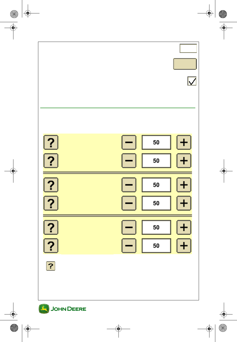
Curve Track Settings
• Choose Curve Track Recording source ......
• Smooth Tight Turns ON / OFF ..........................................
Guidance
S e t t i n g s
Smooth Tight Turns OFF Smooth Tight Turns ON
GS3 2630 Display.book Page 14 Thursday, May 12, 2011 7:45 AM
User Guide
User Guide Guidance
GS3 2630 Display
GS3 2630 Display
15
• Implement In-Ground Turn Radius ...............................
• Clear Adaptive Curves Data ....................................
• Repeat Mode ..................................................................
NOTE: When recording a new path, repeat mode should be unchecked or
off. To follow existing paths, repeat mode should be on or checked.
Advanced AutoTrac Settings (if equipped)
Use Advanced AutoTrac Settings to optimize AutoTrac performance.
AutoTrac Advanced settings are available only on some vehicle types.
Clear
Data
Describes each function
Line Sensitivity
Heading
Line Sensitivity
Tracking
Heading
Lead
Steering
Response Rate
Curve
Sensitivity
Acquire
Sensitivity
GS3 2630 Display.book Page 15 Thursday, May 12, 2011 7:45 AM
GS3 2630 Display
GS3 2630 Display
User Guide
User Guide Guidance
16
Shift Track Settings
1. Guidance softkey ...........................................................
2. Shift Track Settings Tab ........................................
Turn Shift Track ON / OFF
1. Check the box to turn Shifts OFF ........................................
Set Guidance Line Shift Distance
1. Choose Small Shifts or Large Shifts.
2. Set distance (inches/cm for small shifts).
Clear Guidance Line Shifts
1. Guidance softkey ..........................................................
2. Shift Track Settings Tab ........................................
3. Select Clear all shifts .................................
Shift Track
Settings
Shift Track
Settings
Clear all shifts
GS3 2630 Display.book Page 16 Thursday, May 12, 2011 7:45 AM

User Guide
User Guide Planting/Seeding
GS3 2630 Display
GS3 2630 Display
1
Section Contents
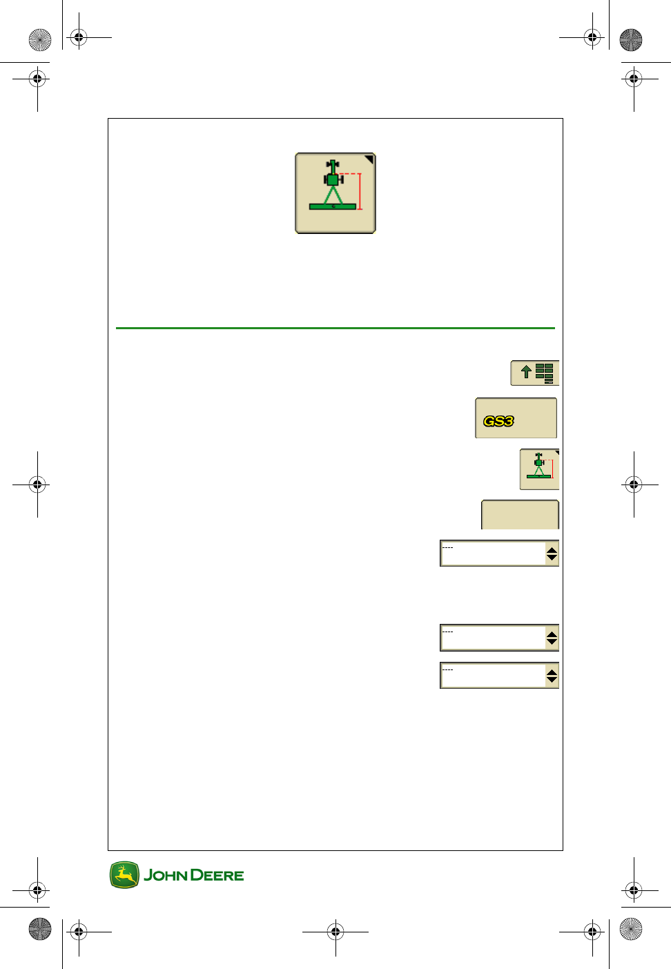
MACHINE AND IMPLEMENT SETUP....................................2
Machine Setup in GreenStar ................................................................ 2
Implement Setup in GreenStar ............................................................. 3
DOCUMENTATION SETUP.......................................................5
Task Setup ........................................................................................... 5
Turn Documentation Off ....................................................................... 6
Weather, Soil, and Crop Conditions ..................................................... 6
Operation Setup ................................................................................... 6
Prescription Setup ................................................................................ 7
Recording Diagnostics.......................................................................... 8
SWATH CONTROL .....................................................................9
Requirements for Swath Control Operation.......................................... 9
Go to Swath Control Map and Settings .............................................. 10
Turn Swath Control ON / OFF ............................................................ 10
Turn Headland Control ON / OFF....................................................... 10
Swath Control Overlap Settings ......................................................... 10
Swath Control Turn ON / OFF Settings .............................................. 11
Swath Control Diagnostics ................................................................. 11
This section applies to GreenStar applications associated with Planting
and Seeding.
GS3 2630 Display.book Page 1 Thursday, May 12, 2011 7:45 AM
GS3 2630 Display
GS3 2630 Display
User Guide
User Guide Planting/Seeding
2
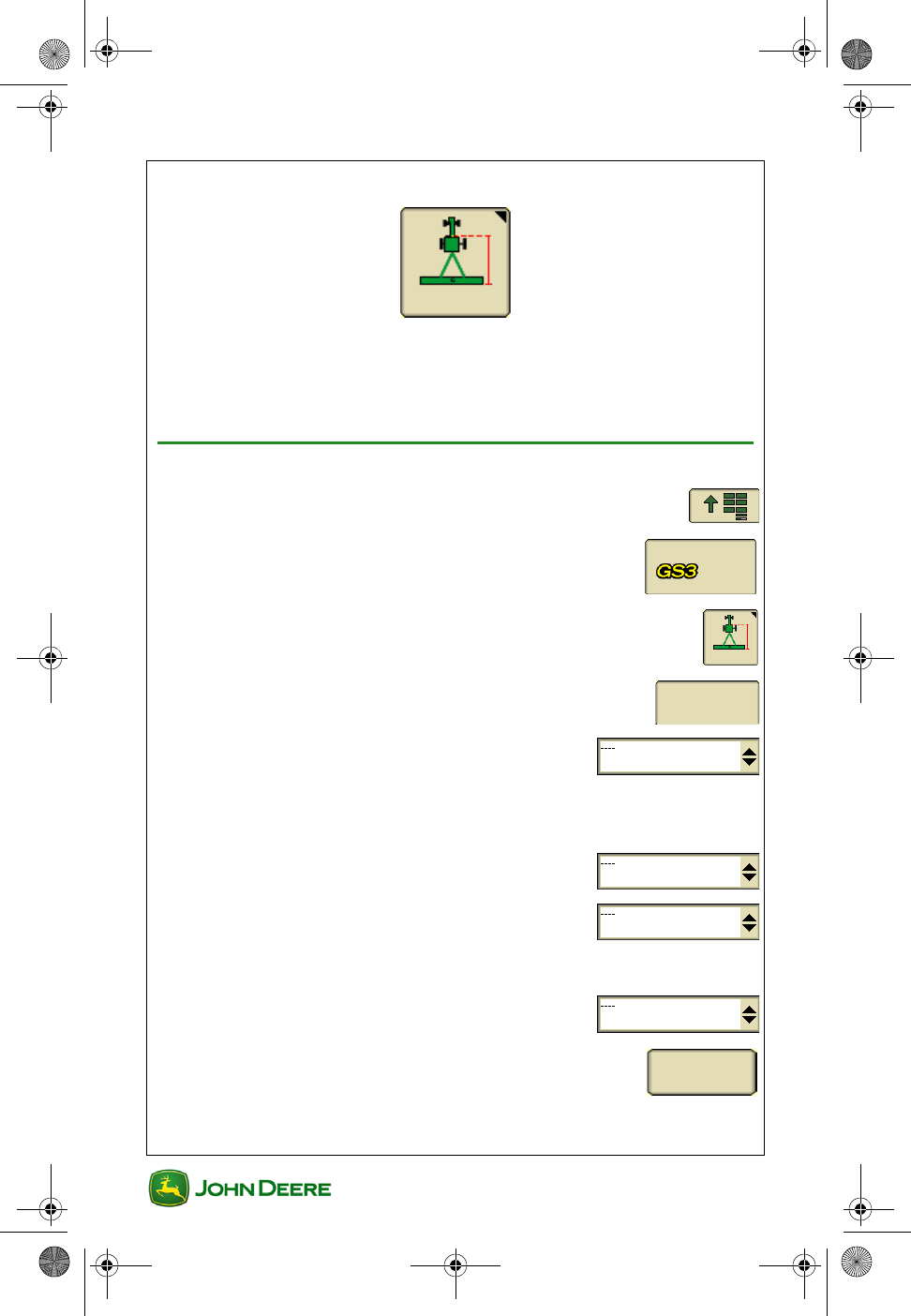
Machine and Implement Setup
Machine and Implement setup is required when moving the display
between machines or changing implements. Accuracy of guidance,
mapping and Swath Control relies on accurate settings. Settings that are
automatically detected will be grayed out.
Machine Setup in GreenStar
1. Menu ............................................................................
2. GS3 ......................................................................
3. Equipment softkey .........................................................
4. Machine tab ...........................................................
5. Select Machine Type ...................................
NOTE: This setting will determine which options are displayed on the
Implement tab.
6. Select Model (Optional) ................................
7. Select or create a Machine Name ...............
NOTE: Machine settings will be saved under the current machine name.
8. Select Connection Type ..............................
9. Select Change Offsets to verify and change
them as needed.
Machine
Change
Offsets
GS3 2630 Display.book Page 2 Thursday, May 12, 2011 7:45 AM
User Guide
User Guide Planting/Seeding
GS3 2630 Display
GS3 2630 Display
3
NOTE: Preloaded offsets often need to be adjusted on an individual
machine basis. Accuracy of guidance, mapping and Swath Control relies
on accurate offsets.
NOTE: Offsets are provided by some Deere tractors. Some boxes may be
grayed out when the machine is automatically recognized.
10. Select Recording Source. This turns
mapping and Documentation ON / OFF.
NOTE: If selection box is grayed out, the Recording Source has been
auto-detected and can be adjusted through the implement controller
software.
Machine Turn Radius is only needed for curve track and
iTEC Pro.
Turn Sensitivity is only needed for iTec Pro.
Implement Setup in GreenStar
1. Menu ............................................................................
2. GS3 ......................................................................
3. Equipment softkey .........................................................
4. Implement tab ........................................................
5. Select Implement Type ................................
NOTE: Changing an implement Type that is automatically detected may
require turning off and restarting the machine.
6. Select Model (Optional) ................................
7. Select or create an Implement Name ..........
NOTE: Implement settings will be saved under the current implement
name.
AUTO
Implement
GS3 2630 Display.book Page 3 Thursday, May 12, 2011 7:45 AM
GS3 2630 Display
GS3 2630 Display
User Guide
User Guide Planting/Seeding
4
8. Select Change Offsets to verify and change
them as needed.
NOTE: Offsets are provided by some ISO implements.
Some boxes may be grayed out when the implement is automatically
recognized.
9. Select Change Widths to set the Implement Width and Track
Spacing.
•Implement Width - used to generate the on screen map. This is
the planting width. If Implement Width is automatically detected, it
can only be changed on the implement controller setup (e.g.
SeedStar).
•Track Spacing - sets the distance between the guidance lines on
each pass and defines the desired overlap.
•Physical Width - the width of the extents of the implement while
raised during field operation. Used for iTEC Pro only.
NOTE: If an overlap is desired, enter a Track Spacing smaller than the
Implement Width.
NOTE: Changing the Implement Width may prevent previously recorded
Coverage maps from being displayed.
Change
Offsets
GS3 2630 Display.book Page 4 Thursday, May 12, 2011 7:45 AM

User Guide
User Guide Planting/Seeding
GS3 2630 Display
GS3 2630 Display
5
Documentation Setup
Set up Documentation ONLY if you want to:
• Document information about the operation such as Varieties and
rates,
• View Totals of seed rates and amount applied,
• View colored maps of applied rates (As-Applied Maps), or
• Use Prescriptions (Rx).
IMPORTANT: Planter or seeder controller must be connected
and setup prior to setting up Documentation.
Task Setup
Client, Farm, Field, and Task selections are required for Documentation.
1. Menu ............................................................................
2. GS3 ......................................................................
3. Resources .....................................................................
4. Select or create a Task .................................
NOTE: If selecting a new Task for a Field Name that has a previously
recorded Coverage map, go to Map Settings and clear the Coverage map
to record a new Coverage map.
Optional
GS3 2630 Display.book Page 5 Thursday, May 12, 2011 7:45 AM
GS3 2630 Display
GS3 2630 Display
User Guide
User Guide Planting/Seeding
6
Turn Documentation Off
If Documentation is not needed, turn it OFF to avoid extra setup.
1. Resources .....................................................................
2. Select Documentation OFF in the Task
selection box
Weather, Soil, and Crop Conditions
Notes about weather, crop, and soil condition can be entered on the
Conditions tab.
1. Resources ....................................................................
2. Conditions tab ......................................................
NOTE: If entering Conditions information, remember to change the
information every field or as conditions change.
Operation Setup
1. Menu ............................................................................
2. GS3 ......................................................................
3. Documentation softkey .................................................
NOTE: If a John Deere SeedStar planter or air cart is connected, a
Planting/Seeding tab is automatically created
4. Select New tab .......................................................
5. Select Planting / Seeding ..................................
Conditions
New
Planting / Seeding
GS3 2630 Display.book Page 6 Thursday, May 12, 2011 7:45 AM
User Guide
User Guide Planting/Seeding
GS3 2630 Display
GS3 2630 Display
7
IMPORTANT: Remove any operation tabs that are not cur-
rently in use. Old Operation tabs may prevent Recording.
NOTE: Change the Field Name setting, in Resources, prior to removing
an Operation tab or disconnecting the implement controller. Otherwise the
last map recorded with that Operation will no longer be able to be viewed
on the display.
6. Planting / Seed tab ............................................
7. Select Seed Type .........................................
8. Add Variety ..........................................................
NOTE: Settings with an asterisk are required.
9. Accept ............................................................................
NOTE: Enable Disable operation: Operations that are automatically
created when an implement is connected and detected, will have the
possibility to be disabled. Any disabled operation will not be documented
Prescription Setup
NOTE: If applying multiple prescriptions, operator must choose a
prescription for each operation. If applying the same product in 2 or more
tanks, operator needs a prescription for each tank.
1. Documentation softkey ................................................
2. Planting / Seeding .......................................
3. Prescription ..............................................................
4. Select Prescription Name ...........................
NOTE: If the selection box does not have any prescriptions in it, check
that the correct Field Name is selected in Resources.
Planting / Seeding
Add Variety
GS3 2630 Display.book Page 7 Thursday, May 12, 2011 7:45 AM
GS3 2630 Display
GS3 2630 Display
User Guide
User Guide Planting/Seeding
8
5. Enter Look Ahead time if needed. Enter a value
between 0 and 4 seconds.
NOTE: Look Ahead is an adjustment to compensate for the delay
between the control unit making the rate change and the implement
responding.
6. Enter Prescription Multiplier (%) if needed.
Example - a Prescription Multiplier of 115% will
increase all rates in the Prescription by 15%.
7. Accept ............................................................................
NOTE: “Prescription cannot be applied” will be displayed and the Accept
button will become inactive when prescription base units do not match.
Correcting the base unit measurement mismatch will allow the
prescription to be applied.
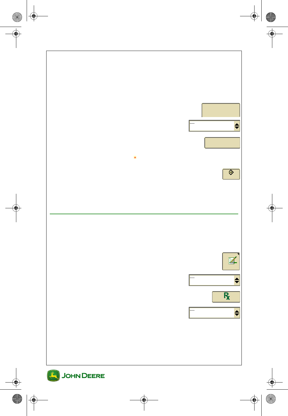
Recording Diagnostics
If Documentation or map Recording is not functioning properly, check this
page.
1. Menu ............................................................................
2. GS3 ......................................................................
3. GreenStar Diagnostics .................................................
4. Select Recording .........................................
0
GS3 2630 Display.book Page 8 Thursday, May 12, 2011 7:45 AM
User Guide
User Guide Planting/Seeding
GS3 2630 Display
GS3 2630 Display
9
Swath Control
Swath Control automatically turns sections ON and OFF when crossing:
• A previously covered area
• Interior boundaries
• Exterior and Exterior Headland boundaries
Requirements for Swath Control Operation
NOTE: The Swath Control softkey will not appear on the display if some
of these conditions are not met.*
• Swath Control activation on display *
• Swath capable controller is detected *
• Implement must be lowered into the ground
• Master switch is ON
• Section switch is in the ON position
• Swath Control check box is checked
• GPS signal status is valid
• Speed above 0 km/h or 0 mph for all planting and seeding opera-
tions
• Vehicle is within 7.64 kilometers (4.75 miles) of the field reference
point.
GS3 2630 Display.book Page 9 Thursday, May 12, 2011 7:45 AM
GS3 2630 Display
GS3 2630 Display
User Guide
User Guide Planting/Seeding
10
Go to Swath Control Map and Settings
1. Menu ............................................................................
2. GS3 ......................................................................
3. Swath Control softkey ...................................................
Turn Swath Control ON / OFF
1. Swath Control softkey ...................................................
NOTE: This softkey is only available when a Swath Control capable
implement is connected and a valid Swath Control activation is entered
into the display.
2. Settings tab ............................................................
3. Check the box for Swath Control Operations to turn
them on.
4. Check the box for Swath Control Master to turn it on.......
Turn Headland Control ON / OFF
1. Swath Control softkey ...................................................
2. Settings tab ............................................................
3. Check the box for Headland Control to turn it on .............
Swath Control Overlap Settings
Use Swath Control settings to adjust for desired skips and overlaps.
Settings
Settings
GS3 2630 Display.book Page 10 Thursday, May 12, 2011 7:45 AM
User Guide
User Guide Planting/Seeding
GS3 2630 Display
GS3 2630 Display
11
1. Swath Control softkey ...................................................
2. Settings tab ............................................................
3. Overlap Settings ...............................................
4. Set Overlap desired when crossing boundaries and previously
covered areas.
Swath Control Turn ON / OFF Settings
1. Swath Control softkey ...................................................
2. Settings tab ............................................................
3. Turn On / Off Settings ...............................
4. Set Turn ON / Turn OFF times for each operation
NOTE: Turn ON / Turn OFF times adjust for the physical
delays of the implement.
IMPORTANT: A map recorded with poor GPS signal may give
the appearance the Turn ON / Turn OFF times are incorrect.
• Range: 0.3–15 seconds
• Default Turn ON time: 1.0 s
• Default Turn OFF time: 0.6 s
NOTE: Driving 6 mph (9.7 kph), the machine will move 8.8 feet (2.7 m) in
1 second and 10.5 inches (0.27 m) in 0.1 second.
Swath Control Diagnostics
If Swath Control is not functioning properly, check this page.
1. Menu ............................................................................
2. GS3 ......................................................................
Settings
Settings
Turn On/Off Settings
GS3 2630 Display.book Page 11 Thursday, May 12, 2011 7:45 AM
GS3 2630 Display
GS3 2630 Display
User Guide
User Guide Planting/Seeding
12
3. GreenStar Diagnostics .................................................
4. Select Swath Control ..................................
GS3 2630 Display.book Page 12 Thursday, May 12, 2011 7:45 AM
User Guide
User Guide Product Application
GS3 2630 Display
GS3 2630 Display
1
Section Contents
MACHINE AND IMPLEMENT SETUP....................................2
Machine Setup in GreenStar ................................................................ 2
Implement Setup in GreenStar ............................................................. 3
DOCUMENTATION SETUP.......................................................5
Task Setup ........................................................................................... 5
Task Setup ........................................................................................... 6
Turn Documentation OFF ..................................................................... 6
Weather, Soil, and Crop Conditions ..................................................... 6
Operation Setup ................................................................................... 7
Prescription Setup ................................................................................ 8
Recording Diagnostics.......................................................................... 9
SWATH CONTROL ...................................................................10
Requirements for Swath Control ........................................................ 10
Go to Swath Control Map and Settings .............................................. 11
Turn Swath Control ON / OFF ............................................................ 11
Turn Headland Control ON / OFF....................................................... 11
Swath Control Overlap Settings ......................................................... 11
Swath Control Turn ON / OFF Settings .............................................. 12
Swath Control Diagnostics ................................................................. 12
SET UP SWATH CONTROL ON JOHN DEERE SPRAYERS
(EUROPE ONLY)........................................................................14
700i and 800i John Deere Pulled-Type Sprayers ............................... 14
5430i John Deere Self-Propelled Sprayers ........................................ 14
This section applies to GreenStar applications associated with Product
Application, including:
• Spraying
• Spreading
GS3 2630 Display.book Page 1 Thursday, May 12, 2011 7:45 AM
GS3 2630 Display
GS3 2630 Display
User Guide
User Guide Product Application
2
Machine and Implement Setup
Machine and Implement setup is required when moving the display
between machines or changing implements. Accuracy of guidance,
mapping and Swath Control relies on accurate settings. Settings that are
automatically detected will be grayed out.
Machine Setup in GreenStar
1. Menu ............................................................................
2. GS3 ......................................................................
3. Equipment softkey .........................................................
4. Machine tab ..........................................................
5. Select Machine Type ..................................
NOTE: This setting will determine which options are displayed on the
Implement tab. Select Tractor for sprayers with front mounted booms.
6. Select Model (Optional) ...............................
7. Select or create a Machine Name .............
NOTE: Machine settings will be saved under the current machine name.
Machine
GS3 2630 Display.book Page 2 Thursday, May 12, 2011 7:45 AM
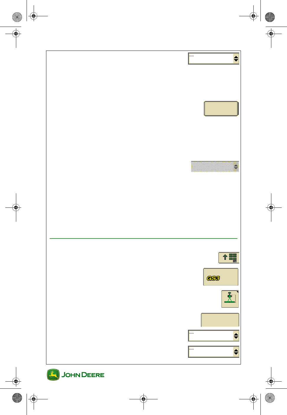
User Guide
User Guide Product Application
GS3 2630 Display
GS3 2630 Display
3
8. Select Connection Type ............................
• Rear-mounted boom / spreader: Rear Rigid 3-pt
• Front-mounted boom: Front Rigid 3-pt
• Pull-behind sprayer / spreader: Rear Pivot Drawbar
9. Select Change Offsets to verify and change
them as needed.
NOTE: Preloaded offsets often need to be adjusted on an
individual machine basis. Accuracy of guidance, mapping and Swath
Control relies on accurate offsets.
NOTE: Offsets are provided by some Deere tractors. Some boxes may be
grayed out when the machine is automatically recognized.
10. Select Recording Source. This turns
mapping and Documentation ON / OFF.
NOTE: If selection box is grayed out, the Recording Source has been
auto-detected and can be adjusted through the implement controller
software.
Machine Turn Radius is only needed for curve track or iTEC
Pro
Turn Sensitivity is only needed for iTEC Pro.
Implement Setup in GreenStar
1. Menu ............................................................................
2. GS3 ......................................................................
3. Equipment softkey .........................................................
4. Boom tab ............................................................
5. Select Implement Type ................................
6. Select Model (Optional) ................................
Change
Offsets
AUTO
Boom
GS3 2630 Display.book Page 3 Thursday, May 12, 2011 7:45 AM
GS3 2630 Display
GS3 2630 Display
User Guide
User Guide Product Application
4
7. Select or create an Implement Name .........
NOTE:Implement settings will be saved under the current implement
name.
8. Select Change Offsets to verify and change
them as needed.
NOTE: Preloaded offsets often need to be adjusted on an
individual machine basis. Accuracy of guidance, mapping and Swath
Control relies on accurate offsets.
NOTE: When Machine Type is set to Sprayer, these offsets are entered
on the Machine tab.
NOTE: Offsets are provided by some ISO implements. Some boxes may
be grayed out when the implement is automatically recognized.
9. Select Change Widths to set the Implement
Width and Track Spacing.
•Implement Width – used to generate the on screen map. This is
the distance between outside spray nozzles or the throw distance
of a spreader. If Implement Width is automatically detected, it can
only be changed on the implement controller setup (e.g. Spray-
Star).
•Track Spacing - sets the distance between the guidance lines on
each pass and defines the desired overlap.
•Physical Width - the width of the extents of the implement while
raised during field operation. Used for iTEC Pro only.
NOTE:If an overlap is desired, enter a Track Spacing smaller than the
Implement Width.
NOTE:Changing the Implement Width may prevent previously recorded
Coverage maps from being displayed.
Change
Offsets
Change
Widths
GS3 2630 Display.book Page 4 Thursday, May 12, 2011 7:45 AM
User Guide
User Guide Product Application
GS3 2630 Display
GS3 2630 Display
5
Documentation Setup
Setup Documentation if you want to:
• Document information about the operation such as Products
applied and rates,
• View Totals of seed rates and amount applied,
• View colored maps of applied rates (As-Applied Maps), or
• Use Prescriptions (Rx).
IMPORTANT: Sprayer or spreader controller must be con-
nected and setup prior to setting up Documentation.
Task Setup
Client, Farm, Field and Task selections are required for Documentation.
1. Menu ............................................................................
2. GS3 ......................................................................
3. Resources .....................................................................
4. Select or create a Task .................................
NOTE: If selecting a new Task for a Field Name that has a previously
recorded Coverage map, go to Map Settings and clear the Coverage map
to record a new Coverage map.
Optional
GS3 2630 Display.book Page 5 Thursday, May 12, 2011 7:45 AM
GS3 2630 Display
GS3 2630 Display
User Guide
User Guide Product Application
6
Task Setup
Client, Farm, Field, and Task selections are required for Documentation.
1. Menu ............................................................................
2. GS3 ......................................................................
3. Resources .....................................................................
4. Select or create a Task .................................
NOTE: If selecting a new Task for a Field Name that has a previously
recorded Coverage map, go to Map Settings and clear the Coverage map
to record a new Coverage map.
Turn Documentation OFF
If Documentation is not needed, turn it OFF to avoid extra setup.
1. Resources .....................................................................
2. Select or create a Task ................................
Weather, Soil, and Crop Conditions
Optional inputs that are set manually.
1. Resources .....................................................................
2. Conditions tab ........................................................
NOTE: If entering Conditions information, remember to change the
information every field or as conditions change.
Conditions
GS3 2630 Display.book Page 6 Thursday, May 12, 2011 7:45 AM
User Guide
User Guide Product Application
GS3 2630 Display
GS3 2630 Display
7
Operation Setup
1. Menu ............................................................................
2. GS3 ......................................................................
3. Documentation softkey .................................................
NOTE: If a John Deere sprayer or sprayer is connected, Product
Application tabs may be automatically created. There should be a tab for
each bin or tank.
4. Select New tab ........................................................
5. Select Product Application ........................
IMPORTANT: Remove any operation tabs that are not cur-
rently in use. Old Operation tabs may prevent Recording.
NOTE: Change the Field Name setting, in Resources, prior to removing
an Operation tab or disconnecting the implement controller. Otherwise the
last map recorded with that Operation will no longer be able to be viewed
on the display.
6. Product Application tab .........................................
7. Select Single Product or Tank Mix ............
NOTE: Tank Mixes created in desktop software should appear in the
Tank Mix Name list. One tank mix may be created on the display.
8. Add Carrier for a Tank Mix ........................................
9. Add Product(s) ................................................
NOTE: Settings with an asterisk are required.
New
Product Application
Product
Application
Add
Carrier
Add Product
GS3 2630 Display.book Page 7 Thursday, May 12, 2011 7:45 AM
GS3 2630 Display
GS3 2630 Display
User Guide
User Guide Product Application
8
10. Accept ............................................................................
11. Enter Target Rate .........................................................
12. Use Advanced Settings to enter Application Method and
Height / Depth if desired.
NOTE: Enable Disable operation: Operations that are automatically
created when an implement is connected and detected, will have the
possibility to be disabled. Any disabled operation will not be documented.
Prescription Setup
NOTE: If applying multiple prescriptions, operator must choose a
prescription for each operation. If applying the same product in 2 or more
tanks, operator needs a prescription for each tank.
1. Documentation softkey .................................................
2. Product Application tab .........................................
3. Prescription ..............................................................
4. Select Prescription Name ..........................
• Prescription Map
• GreenSeeker Sensor
• Yara N Sensor (Europe Only)
NOTE: If the selection box does not have any prescriptions in it, check
that the correct Field Name is selected in Resources.
5. Enter Look Ahead time if needed. Enter a value
between 0 and 4 seconds.
NOTE: Look Ahead is an adjustment to compensate for the delay
between the control unit making the rate change and the implement
responding.
6. Enter Prescription Multiplier (%) if needed.
Example – a Prescription Multiplier of 115% will
increase all rates in the Prescription by 15%.
Product
Application
0
15%
GS3 2630 Display.book Page 8 Thursday, May 12, 2011 7:45 AM

User Guide
User Guide Product Application
GS3 2630 Display
GS3 2630 Display
9
7. Accept .............................................................................
NOTE: “Prescription cannot be applied” will be displayed and the Accept
button will become inactive when prescription base units do not match.
Correcting the base unit measurement mismatch will allow the
prescription to be applied.
Recording Diagnostics
If Documentation or map Recording is not functioning properly, check this
page.
1. Menu ............................................................................
2. GS3 ......................................................................
3. GreenStar Diagnostics .................................................
4. Select Recording .........................................
GS3 2630 Display.book Page 9 Thursday, May 12, 2011 7:45 AM

GS3 2630 Display
GS3 2630 Display
User Guide
User Guide Product Application
10
Swath Control
Swath Control automatically turns sections ON and OFF when crossing
• A previously covered area
• Interior boundaries
• Exterior and Exterior Headland boundaries
Requirements for Swath Control
NOTE: The Swath Control softkey will not appear on the display if some
of these conditions are not met. *
• Swath Control activation on display *
• Swath capable controller is detected *
• Master spray switch is ON
• Section switch is in the ON position
• Swath Control check box is checked
• GPS signal status is valid
• Speed above 0.8 km/h or 0.5 mph
• Vehicle is within 7.64 kilometers (4.75 miles) of the field reference
point
• ISO Sprayers Only (700i and 800i) — Task Controller Enabled
GS3 2630 Display.book Page 10 Thursday, May 12, 2011 7:45 AM
User Guide
User Guide Product Application
GS3 2630 Display
GS3 2630 Display
11
Go to Swath Control Map and Settings
1. Menu ............................................................................
2. GS3 ......................................................................
3. Swath Control softkey ...................................................
Turn Swath Control ON / OFF
1. Swath Control softkey ...................................................
NOTE: This softkey is only available when a Swath Control capable
implement is connected and a valid Swath Control activation is entered
into the display.
2. Settings tab ............................................................
3. Check the box for Swath Control Operations to turn
them on.
4. Check the box for Swath Control Master to turn it on.......
Turn Headland Control ON / OFF
1. Swath Control softkey ...................................................
2. Settings tab ............................................................
3. Check the box for Headland Control to turn it on .............
Swath Control Overlap Settings
Use Swath Control settings to adjust for desired skips and overlaps.
Settings
Settings
GS3 2630 Display.book Page 11 Thursday, May 12, 2011 7:45 AM
GS3 2630 Display
GS3 2630 Display
User Guide
User Guide Product Application
12
1. Swath Control softkey ...................................................
2. Settings tab ............................................................
3. Overlap Settings ...............................................
4. Set Overlap desired when crossing boundaries and previously
covered areas.
Swath Control Turn ON / OFF Settings
1. Swath Control softkey ...................................................
2. Settings tab ............................................................
3. Turn On / Off Settings ...............................
4. Set Turn ON / Turn OFF times for each operation
NOTE: Turn ON / Turn OFF times adjust for the physical delays
of the implement.
IMPORTANT: A map recorded with poor GPS signal may give
the appearance the Turn ON / Turn OFF times are incorrect.
• Range: 0.3–15 seconds
• Default Turn ON time: 1.0 s
• Default Turn OFF time: 0.6 s
NOTE: Driving 16 mph (25.7 kph), the machine will move 23.5 feet (7.2
m) in 1 second.
Swath Control Diagnostics
If Swath Control is not functioning properly, check this page.
1. Menu ............................................................................
2. GS3 ......................................................................
Settings
Settings
Turn On/Off Settings
GS3 2630 Display.book Page 12 Thursday, May 12, 2011 7:45 AM

User Guide
User Guide Product Application
GS3 2630 Display
GS3 2630 Display
13
3. GreenStar Diagnostics .................................................
4. Select Swath Control ..................................
GS3 2630 Display.book Page 13 Thursday, May 12, 2011 7:45 AM
GS3 2630 Display
GS3 2630 Display
User Guide
User Guide Product Application
14
Set up Swath Control on John Deere Sprayers
(Europe only)
700i and 800i John Deere Pulled-Type Sprayers
1. Menu ............................................................................
2. Sprayer ................................................................
3. Job Settings ..................................................................
4. Select Control & Doc from the Task
Controller drop-down list to enable
Documentation, Coverage Mapping, and
Section Control.
5. Select Control from the Task Controller
drop-down list to enable only Section
Control.
5430i John Deere Self-Propelled Sprayers
There are no specific setup requirements to enable Sprayer Pro™ in the
5430i Sprayer menu. As soon as the Swath Control checkbox is active the
system is enabled.
1. Menu ............................................................................
2. GS3 ......................................................................
3. Swath Control softkey ..................................................
4. Summary tab .........................................................
5. Check box for Swath Control ...........................................
Control & Doc
Control
Summary
GS3 2630 Display.book Page 14 Thursday, May 12, 2011 7:45 AM
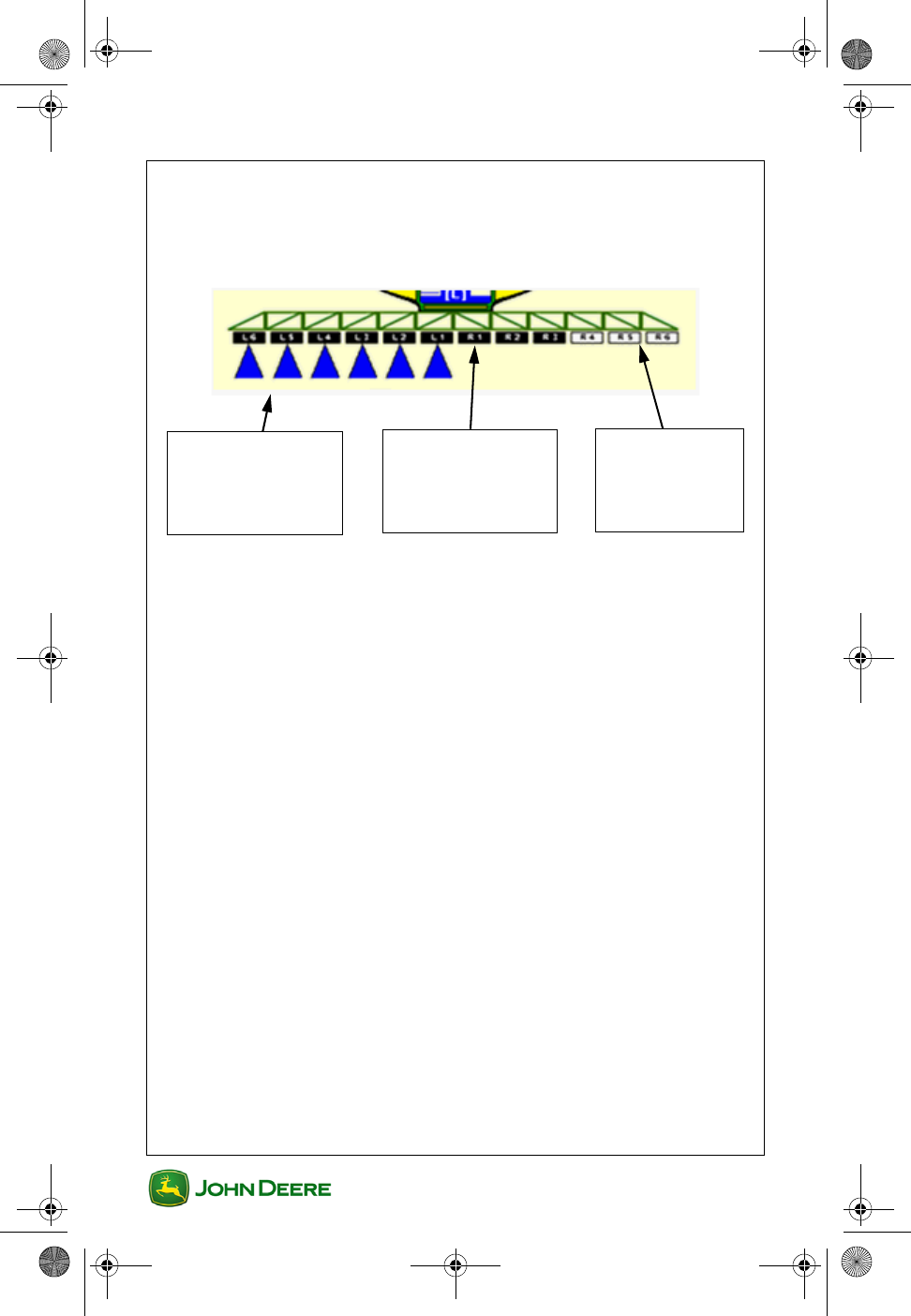
User Guide
User Guide Product Application
GS3 2630 Display
GS3 2630 Display
15
NOTE: If the master switch is in ON position, all sections are enabled
except those that have been disabled manually. Enabled sections are
marked with a black background color. Only those sections can be
controlled by Swath Control.
Sections enabled
and inside the
boundary or
spraying area
Section NOT
enabled — has
been disabled
manually.
Sections enabled
but outside the
boundary or
spraying area
GS3 2630 Display.book Page 15 Thursday, May 12, 2011 7:45 AM

GS3 2630 Display
GS3 2630 Display
User Guide
User Guide Product Application
16
NOTES
GS3 2630 Display.book Page 16 Thursday, May 12, 2011 7:45 AM

User Guide
User Guide Harvest
GS3 2630 Display
GS3 2630 Display
1
Section Contents
MACHINE AND HEADER SETUP............................................2
Machine Setup in GreenStar ................................................................ 2
Header Setup in GreenStar .................................................................. 3
Cut Width Adjustment........................................................................... 4
DOCUMENTATION SETUP.......................................................5
Task Setup ........................................................................................... 5
Turn Documentation OFF ..................................................................... 5
Operation Setup ................................................................................... 6
Turn Variety Locator ON / OFF ............................................................ 6
This section applies to GreenStar applications associated with Harvesting
Machines, including:
• Combines
• Cotton Pickers
• Cotton Strippers
• Self-Propelled Forage Harvesters
GS3 2630 Display.book Page 1 Thursday, May 12, 2011 7:45 AM
GS3 2630 Display
GS3 2630 Display
User Guide
User Guide Harvest
2
Machine and Header Setup
Machine and Header setup is required when moving the display between
machines or changing Headers. Accuracy of guidance, mapping and
Overlap Control relies on accurate settings. Settings that are
automatically detected will be grayed out.
Machine Setup in GreenStar
1. Menu ............................................................................
2. GS3 ......................................................................
3. Equipment softkey .........................................................
4. Machine tab ........................................................
5. Select Machine Type ...................................
NOTE:This setting will determine which options are displayed on the
Implement tab.
6. Select Model (Optional)................................
7. Select or create a Machine Name ...............
NOTE: Machine and Implement settings will be saved under the current
machine or implement name.
8. Verify Connection Type is set to Front
Rigid 3-pt.
Machine
GS3 2630 Display.book Page 2 Thursday, May 12, 2011 7:45 AM
User Guide
User Guide Harvest
GS3 2630 Display
GS3 2630 Display
3
9. Select Change Offsets to verify and change
them as
needed.
NOTE: Preloaded offsets often need to be adjusted on an individual
machine basis. Accuracy of guidance and mapping relies on accurate
offsets.
10. Select Recording Source. This turns
mapping and Documentation ON / OFF.
NOTE: If selection box is grayed out, the Recording Source has been
auto-detected can be adjusted through the implement controller software.
Machine Turn Radius is only needed for curve track or iTEC
Pro
Turn Sensitivity normally is only needed for iTEC Pro.
Header Setup in GreenStar
1. Menu ............................................................................
2. GS3 ......................................................................
3. Equipment softkey .........................................................
4. Header tab ...........................................................
5. Select Implement Type...............................
6. Select Model (Optional)...............................
7. Select or create Implement Name...............
NOTE: Implement settings will be saved under the current implement
name.
8. Select Change Offsets to verify and change
them as needed.
Change
Offsets
AUTO
Header
Change
Offsets
GS3 2630 Display.book Page 3 Thursday, May 12, 2011 7:45 AM
GS3 2630 Display
GS3 2630 Display
User Guide
User Guide Harvest
4
NOTE: Preloaded offsets often need to be adjusted on an individual
machine basis. Accuracy of guidance, mapping and Swath Control relies
on accurate offsets.
NOTE: When Machine Type is set to Sprayer, these offsets are entered
on the Machine tab.
9. Select Change Widths to set the Implement
Width and Track Spacing.
•Implement Width - used to generate the onscreen map. This is
the width of the Header. If Implement Width is automatically
detected, it can only be changed in the Harvester machine setup.
•Track Spacing - sets the distance between the guidance lines on
each pass and defines the desired overlap.
NOTE: If an overlap is desired, enter a Track Spacing smaller than the
Implement Width.
NOTE: Changing the Implement Width may prevent previously recorded
Coverage maps from being displayed.
10. Turn Overlap Control ON to map only a partial Header
width when the Header is overlapping previously
harvested areas (Overlap Control improves Totals accuracy).
Cut Width Adjustment
1. Equipment softkey .........................................................
2. Header tab ...........................................................
3. Use the Arrows to start and stop mapping for each
Header section manually.
Change
Widths
Header
GS3 2630 Display.book Page 4 Thursday, May 12, 2011 7:45 AM
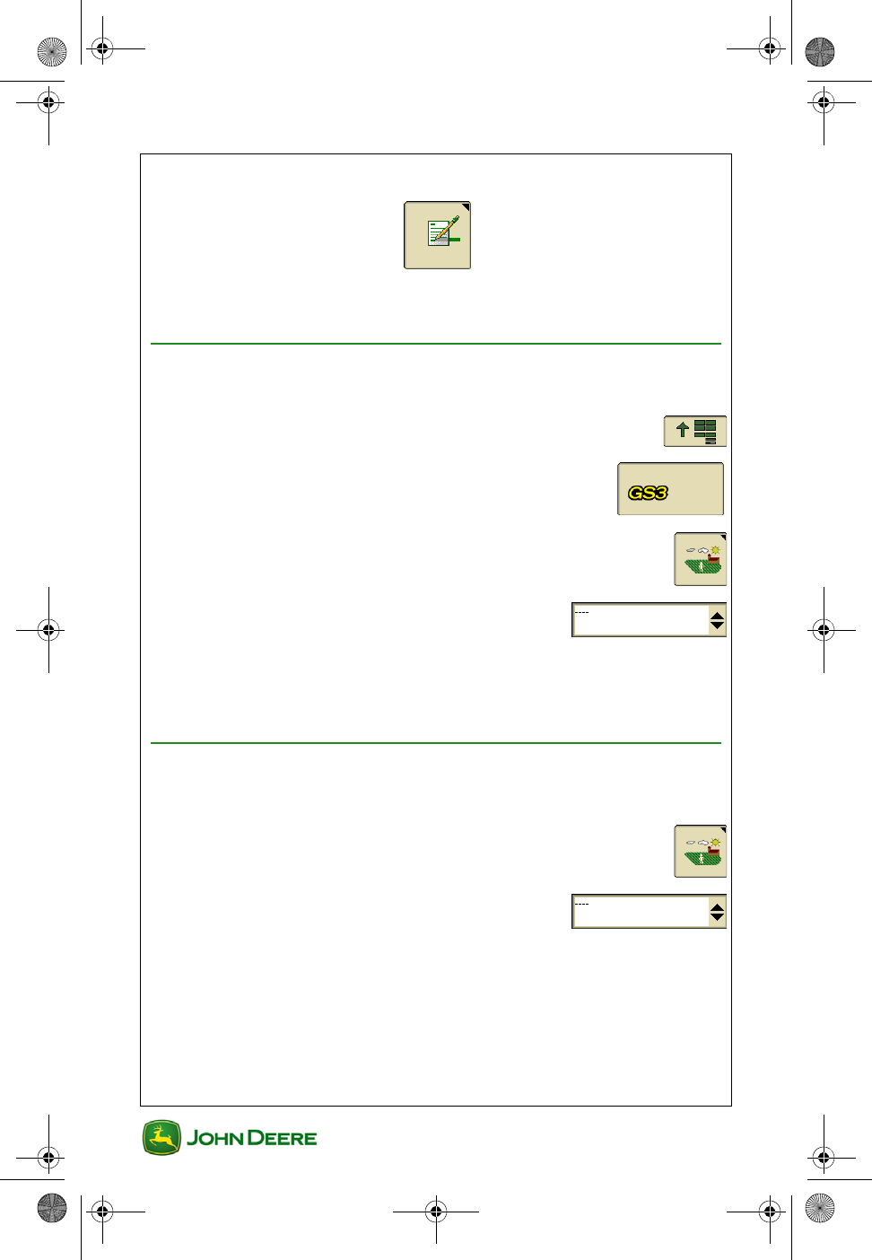
User Guide
User Guide Harvest
GS3 2630 Display
GS3 2630 Display
5
Documentation Setup
Setup Documentation when it is desired to calculate Harvest Totals and
map yield or moisture.
Task Setup
Client, Farm, Field and Task selections are required for Documentation.
1. Menu ............................................................................
2. GS3 ......................................................................
3. Resources .....................................................................
4. Select or create a Task.................................
NOTE: If selecting a new Task for a Field Name that has a previously
recorded Coverage map, go to Map Settings and clear the Coverage map
to record a new Coverage map.
Turn Documentation OFF
If Documentation is not needed, turn it OFF to avoid extra setup.
1. Resources ....................................................................
2. Select Documentation OFF in the Task
selection box
Optional
GS3 2630 Display.book Page 5 Thursday, May 12, 2011 7:45 AM
GS3 2630 Display
GS3 2630 Display
User Guide
User Guide Harvest
6
Operation Setup
1. Harvest tab ..........................................................
2. Enter Crop Type ..........................................
3. Enter Variety ...............................................
NOTE: Only settings with an asterisk are required.
Turn Variety Locator ON / OFF
1. Harvest tab ..........................................................
2. Change Harvest Settings .....................
3. Check box for Variety Locator ..........................................
NOTE: Variety Locator requires a variety map loaded from Apex desktop
software.
Harvest
Harvest
Change Harvest Settings
GS3 2630 Display.book Page 6 Thursday, May 12, 2011 7:45 AM

User Guide
User Guide Performance Monitor
GS3 2630 Display
GS3 2630 Display
1
Section Contents
MONITOR MACHINE PERFORMANCE ................................2
View in Performance Monitor ............................................................... 2
View on Homepages ............................................................................ 2
PERFORMANCE MONITOR SETUP.......................................3
Setup Area Counter.............................................................................. 3
PERFORMANCE MONITOR TOTALS....................................4
Acre Counter Manual Start and Stop.................................................... 4
Resetting Performance Monitor Totals ................................................. 5
GS3 2630 Display.book Page 1 Thursday, May 12, 2011 7:45 AM
GS3 2630 Display
GS3 2630 Display
User Guide
User Guide Performance Monitor
2
Monitor Machine Performance
Performance Monitor provides productivity information such as vehicle
speeds, acre counters, and fuel efficiency data. The information available
to be displayed depends on the vehicle on which the display is installed.
View in Performance Monitor
1. Menu ............................................................................
2. Performance Monitor ..........................................
3. Performance Monitor Main ..........................................
4. Performance Monitor Totals ........................................
View on Homepages
1. Use Layout Manager to add a Performance Monitor screen for
any region of any Homepage.
GS3 2630 Display.book Page 2 Thursday, May 12, 2011 7:45 AM
User Guide
User Guide Performance Monitor
GS3 2630 Display
GS3 2630 Display
3
Performance Monitor Setup
Setup Area Counter
1. Menu ............................................................................
2. Performance Monitor ..........................................
3. Setup ..............................................................................
4. Enter Implement Width .................................................
5. Select a control source to start and stop the Area Counter. The
available options depend on the vehicle configuration.
• Synchronize with GreenStar Map Recording
Source (Recommended)
• Implement Whisker Switch .........................................
• Use source from John Deere implement ...
• Manual...........................................................................
• Front Hitch
• Rear Hitch
GreenStar
AUTO
GS3 2630 Display.book Page 3 Thursday, May 12, 2011 7:45 AM
GS3 2630 Display
GS3 2630 Display
User Guide
User Guide Performance Monitor
4
Performance Monitor Totals
Performance Monitor calculates a running total of several values
including acres and distance.
NOTE: Total acres are calculated separately from GreenStar Totals and
therefore the total acres may not align. Performance Monitor does not
utilize Overlap Control for acre calculations. Starting, stopping, and
resetting the Performance Monitor acre counter does not affect
GreenStar Acre Totals.
Acre Counter Manual Start and Stop
NOTE: Manually starting and stopping the Area Counter is not necessary
when the Area Counter control source is set to an option other than
Manual.
1. Menu ............................................................................
2. Performance Monitor ..........................................
3. Performance Monitor Main ..........................................
4. Acre Counter Start / Stop .............................................
ON OFF
GS3 2630 Display.book Page 4 Thursday, May 12, 2011 7:45 AM
User Guide
User Guide Performance Monitor
GS3 2630 Display
GS3 2630 Display
5
Resetting Performance Monitor Totals
5. Menu ............................................................................
6. Performance Monitor ..........................................
7. Totals .............................................................................
8. Reset Distance .......................................................
9. Reset Acres ...................................................................
There are two reset buttons on the page. Each is displayed within the
group of values that it resets.
GS3 2630 Display.book Page 5 Thursday, May 12, 2011 7:45 AM

GS3 2630 Display
GS3 2630 Display
User Guide
User Guide Performance Monitor
6
NOTES
GS3 2630 Display.book Page 6 Thursday, May 12, 2011 7:45 AM
