0master 2638A Hydra Series III Data Acquisition System Digital Multimeter User Manual Brochure
User Manual: 2638A-Hydra-Series-III-Data-Acquisition-System-Digital-Multimeter-User-Manual-Brochure
Open the PDF directly: View PDF ![]() .
.
Page Count: 58
- 2638A Calibration Manual
- Introduction
- Contact Fluke
- Safety Information
- General Specifications
- Measurement Specifications
- 2638A-100 Universal Input Module
- General Maintenance
- Firmware Update
- Required Equipment
- Test Considerations
- Performance Tests
- Calibration Adjustment
- Remote Commands for Calibration
- User-Replaceable Parts and Accessories

August 2014 Rev. 1, 5/16
© 2014-2016 Fluke Corporation. All rights reserved. Specifications are subject to change without notice.
All product names are trademarks of their respective companies.
2638A
HYDRA Series III Data Acquisition Unit
Calibration Manual
LIMITED WARRANTY AND LIMITATION OF LIABILITY
Each Fluke product is warranted to be free from defects in material and workmanship under normal use and
service. The warranty period is one year and begins on the date of shipment. Parts, product repairs, and
services are warranted for 90 days. This warranty extends only to the original buyer or end-user customer of
a Fluke authorized reseller, and does not apply to fuses, disposable batteries, or to any product which, in
Fluke's opinion, has been misused, altered, neglected, contaminated, or damaged by accident or abnormal
conditions of operation or handling. Fluke warrants that software will operate substantially in accordance
with its functional specifications for 90 days and that it has been properly recorded on non-defective media.
Fluke does not warrant that software will be error free or operate without interruption.
Fluke authorized resellers shall extend this warranty on new and unused products to end-user customers
only but have no authority to extend a greater or different warranty on behalf of Fluke. Warranty support is
available only if product is purchased through a Fluke authorized sales outlet or Buyer has paid the
applicable international price. Fluke reserves the right to invoice Buyer for importation costs of
repair/replacement parts when product purchased in one country is submitted for repair in another country.
Fluke's warranty obligation is limited, at Fluke's option, to refund of the purchase price, free of charge repair,
or replacement of a defective product which is returned to a Fluke authorized service center within the
warranty period.
To obtain warranty service, contact your nearest Fluke authorized service center to obtain return
authorization information, then send the product to that service center, with a description of the difficulty,
postage and insurance prepaid (FOB Destination). Fluke assumes no risk for damage in transit. Following
warranty repair, the product will be returned to Buyer, transportation prepaid (FOB Destination). If Fluke
determines that failure was caused by neglect, misuse, contamination, alteration, accident, or abnormal
condition of operation or handling, including overvoltage failures caused by use outside the product’s
specified rating, or normal wear and tear of mechanical components, Fluke will provide an estimate of repair
costs and obtain authorization before commencing the work. Following repair, the product will be returned to
the Buyer transportation prepaid and the Buyer will be billed for the repair and return transportation charges
(FOB Shipping Point).
THIS WARRANTY IS BUYER'S SOLE AND EXCLUSIVE REMEDY AND IS IN LIEU OF ALL OTHER
WARRANTIES, EXPRESS OR IMPLIED, INCLUDING BUT NOT LIMITED TO ANY IMPLIED WARRANTY
OF MERCHANTABILITY OR FITNESS FOR A PARTICULAR PURPOSE. FLUKE SHALL NOT BE LIABLE
FOR ANY SPECIAL, INDIRECT, INCIDENTAL, OR CONSEQUENTIAL DAMAGES OR LOSSES,
INCLUDING LOSS OF DATA, ARISING FROM ANY CAUSE OR THEORY.
Since some countries or states do not allow limitation of the term of an implied warranty, or exclusion or
limitation of incidental or consequential damages, the limitations and exclusions of this warranty may not
apply to every buyer. If any provision of this Warranty is held invalid or unenforceable by a court or other
decision-maker of competent jurisdiction, such holding will not affect the validity or enforceability of any other
provision.
Fluke Corporation
P.O. Box 9090
Everett, WA 98206-9090
U.S.A.
Fluke Europe B.V.
P.O. Box 1186
5602 BD Eindhoven
The Netherlands
11/99
i
Table of Contents
Title Page
Introduction ............................................................................................ 1
Contact Fluke ........................................................................................ 1
Safety Information ................................................................................. 2
General Specifications .......................................................................... 5
Measurement Specifications ................................................................. 6
DC Voltage ........................................................................................ 6
DC Voltage Input Characteristics .................................................. 6
DC Voltage Accuracy .................................................................... 7
DC Voltage Additional Errors ......................................................... 7
AC Voltage ........................................................................................ 7
AC Voltage Input Characteristics ................................................... 8
AC Voltage Accuracy ..................................................................... 8
Additional Low Frequency Errors ...................................................... 8
DC Current ........................................................................................ 8
DC Current Input Characteristics ................................................... 9
DC Current Accuracy ..................................................................... 9
DC Current Additional Errors ......................................................... 9
AC Current ......................................................................................... 9
AC Current Input Characteristics ................................................... 9
AC Current Accuracy ..................................................................... 10
Additional Low Frequency Errors ...................................................... 10
Frequency .......................................................................................... 10
Resistance ......................................................................................... 10
Resistance Input Characteristics ................................................... 11
Resistance Accuracy ..................................................................... 11
Resistance Additional Errors ......................................................... 11
RTD ................................................................................................... 11
RTD Temperature Accuracy .......................................................... 12
RTD Measurement Characteristics ............................................... 12
Thermistor ......................................................................................... 12
Thermistor Temperature Accuracy ................................................ 12
Thermistor Measurement Characteristics ...................................... 13
Thermocouple .................................................................................... 13
Thermocouple Temperature Accuracy .......................................... 13
Thermocouple Measurement Characteristics ................................ 14
Digital I/O ........................................................................................... 14

2638A
Calibration Manual
ii
Totalizer ............................................................................................. 14
Trigger ............................................................................................... 15
Alarm Output ..................................................................................... 15
2638A-100 Universal Input Module ....................................................... 15
General Maintenance ............................................................................ 16
If the Product Does Not Turn On ....................................................... 16
Clean the Product .............................................................................. 16
Replace the Line Power Fuse ........................................................... 16
Battery Replacement ......................................................................... 17
Memory and Factory Reset ............................................................... 18
Required Equipment .............................................................................. 19
Test Considerations .............................................................................. 21
Performance Tests ................................................................................ 21
Front Panel Test ................................................................................ 22
DC Volts Verification .......................................................................... 22
Volts AC and Frequency Verification ................................................. 24
4-Wire Ohms Verification ................................................................... 26
PRT Verification Steps ...................................................................... 27
Configure Resistance Display ........................................................... 27
Thermistor Verification Steps ............................................................ 28
Configure Resistance Display ........................................................... 28
DC Current Verification ...................................................................... 29
AC Current Verification Steps ............................................................ 31
2638A-100 Module Verification ......................................................... 32
Calibration Adjustment .......................................................................... 33
Unlock the Product ............................................................................ 33
Unlock the Product with a Remote Interface ..................................... 33
Reset the Admin Password ............................................................... 34
Disassembly ...................................................................................... 35
Change the Calibration Date Remotely ............................................. 37
“Mainframe” Adjustment Process ...................................................... 37
Remote Commands for Calibration ....................................................... 43
Remote Programming Examples ....................................................... 44
Start a Full Calibration ....................................................................... 44
Calibrate 1 V DC Range only ............................................................ 45
Write Calibration Date to a Module .................................................... 45
Command References ....................................................................... 46
User-Replaceable Parts and Accessories ............................................. 51

1
Introduction
The Fluke 2638A HYDRA Series III Data Acquisition Unit (the Product or
Instrument) is a 67 analog channel bench-top data logger that measures and
records dc volts, ac volts, dc current, ac current, resistance, frequency, and
temperature. See the Specifications section for information on the types and
ranges of the measurement inputs the Product can accept.
Contact Fluke
To contact Fluke, call one of the following telephone numbers:
• Technical Support USA: 1-800-44-FLUKE (1-800-443-5853)
• Calibration/Repair USA: 1-888-99-FLUKE (1-888-993-5853)
• Canada: 1-800-36-FLUKE (1-800-363-5853)
• Europe: +31 402-675-200
• Japan: +81-3-6714-3114
• Singapore: +65-6799-5566
• Anywhere in the world: +1-425-446-5500
Or, visit Fluke's website at www.fluke.com.
To register your product, visit http://register.fluke.com.
To view, print, or download the latest manual supplement, visit
http://us.fluke.com/usen/support/manuals.

2638A
Calibration Manual
2
Safety Information
A Warning identifies conditions and procedures that are dangerous to the user.
A Caution identifies conditions and procedures that can cause damage to the
Product or the equipment under test.
See Table 1 for a list of symbols used in this manual and on the Product.
Table 1. Symbols
Symbol Description Symbol Description
W Risk of Danger. Important
information. See Manual. DC (Direct Current)
X Hazardous voltage. Voltage
>30 V dc or ac peak might be
present.
AC or DC (Alternating or Direct Current)
Earth ground. Digital signal
or
AC or DC (Alternating or Direct
Current) T Double insulated
Recycle. + Power ON / OFF
à Conforms to relevant South
Korean EMC Standards. P Conforms to European Union directives.
Measurement Category II is applicable to test and measuring circuits connected directly to
utilization points (socket outlets and similar points) of the low-voltage MAINS installation.
Measurement Category III is applicable to test and measuring circuits connected to the
distribution part of the building’s low-voltage MAINS installation.
Measurement Category IV is applicable to test and measuring circuits connected at the
source of the building’s low-voltage MAINS installation.
~
This product complies with the WEEE Directive marking requirements. The affixed label
indicates that you must not discard this electrical/electronic product in domestic household
waste. Product Category: With reference to the equipment types in the WEEE Directive
Annex I, this product is classed as category 9 "Monitoring and Control Instrumentation”
product. Do not dispose of this product as unsorted municipal waste.

HYDRA Series III Data Acquisition Unit
Safety Information
3
WXWarning
To prevent possible electrical shock, fire, or personal injury:
• Read all safety information before you use the Product.
• Carefully read all instructions.
• Use the Product only as specified, or the protection supplied
by the Product can be compromised.
• Examine the case before you use the Product. Look for cracks
or missing plastic. Carefully look at the insulation around the
terminals.
• Do not use the Product if it operates incorrectly.
• Do not use the Product if it is damaged.
• Disable the Product if it is damaged.
• Use only the mains power cord and connector approved for
the voltage and plug configuration in your country and rated
for the Product.
• Replace the mains power cord if the insulation is damaged or
if the insulation shows signs of wear.
• Make sure the ground conductor in the mains power cord is
connected to a protective earth ground. Disruption of the
protective earth could put voltage on the chassis that could
cause death.
• Do not put the Product where access to the mains power cord
is blocked.
• Use only correct measurement category (CAT), voltage, and
amperage rated probes, test leads, and adapters for the
measurement.
• Use only cables with correct voltage ratings.
• Do not use test leads if they are damaged. Examine the test
leads for damaged insulation and measure a known voltage.
• Do not exceed the Measurement Category (CAT) rating of the
lowest rated individual component of a Product, probe, or
accessory.
• Keep fingers behind the finger guards on the probes.
• Do not apply more than the rated voltage, between the
terminals or between each terminal and earth ground.
• Do not touch voltages >30 V ac rms, 42 V ac peak, or 60 V dc.
• Limit operation to the specified measurement category,
voltage, or amperage ratings.
• Measure a known voltage first to make sure that the Product
operates correctly.

2638A
Calibration Manual
4
• Consider all accessible channels to be hazardous live and an
electric shock hazard if any channel is connected to a
hazardous voltage source.
• Do not remove, touch, or change the internal wiring of
hazardous inputs until the input source is turned off.
• Remove inputs from hazardous voltage sources before an
input module is opened.
• Use the correct terminals, function, and range for
measurements.
• Use this Product indoors only.
• Do not use the Product around explosive gas, vapor, or in
damp or wet environments.

HYDRA Series III Data Acquisition Unit
General Specifications
5
General Specifications
Mains Voltage
100 V Setting ...................................................... 90 V to 110 V
120 V Setting ...................................................... 108 V to 132 V
220 V Setting ...................................................... 198 V to 242 V
240 V Setting ...................................................... 216 V to 264 V
Frequency .............................................................. 47 Hz to 440 Hz
Power Consumption ............................................. 36 VA peak (24 W average)
Environment Temperature
Operating ............................................................ 0 °C to 50 °C
Full accuracy ....................................................... 18 °C to 28 °C
Storage ............................................................... -20 °C to 70 °C
Warm-up ............................................................. 1 hour to full accuracy specifications
Relative Humidity (non-condensing)
Operating ............................................................ 0 °C to 28 °C <90 %
28 °C to 40 °C <75 %
40 °C to 50 °C <45 %
Storage ............................................................... -20 °C to 70 °C <95 %
Altitude
Operating ............................................................ 2,000 m
Storage ............................................................... 12,000 m
Channel Capacity
Total analog channels ........................................ 67
Voltage/resistance channels ............................... 61
Current channels ................................................ 7
Digital I/O ............................................................ 8 bits
Totalizer .............................................................. 1
Alarm outputs...................................................... 6
Trigger input ........................................................ 1
Channel Capacity: 2638A/05
Total analog channels ......................................... 23
Voltage/resistance channels ............................... 21
Current channels ................................................ 2
Safety Protection
Mains Input ......................................................... IEC 61010-1, Overvoltage Category II, Pollution Degree 2
Measurement Front Panel .................................. IEC 61010-2-030: CAT II 300 V
Measurement Rear Panel ................................... IEC 61010-2-030: CAT II 150 V CAT II, 250 V rms with maximum
transient voltage of 1000 V peak. These terminals are not intended for
connection to mains voltage above 150 V without external transient
suppression. The maximum input that can be applied between rear-
module terminals or between any rear-module terminal and earth
ground is 250 V dc or ac rms.
Electromagnetic Compatibility (EMC)
International ........................................................ IEC 61326-1: Basic Electromagnetic Environment
CISPR 11: Group 1, Class A
Group 1: Equipment has intentionally generated and/or uses
conductively-coupled radio frequency energy that is necessary for
the internal function of the equipment itself.
Class A: Equipment is suitable for use in all establishments other
than domestic and those directly connected to a low-voltage power
supply network that supplies buildings used for domestic purposes.
There may be potential difficulties in ensuring electromagnetic
compatibility in other environments due to conducted and radiated
disturbances.
Emissions that exceed the levels required by CISPR 11 can occur
when the equipment is connected to a test object.

2638A
Calibration Manual
6
Korea (KCC) ....................................................... Class A Equipment (Industrial Broadcasting & Communication
Equipment)
Class A: Equipment meets requirements for industrial
electromagnetic wave equipment and the seller or user should take
notice of it. This equipment is intended for use in business
environments and not to be used in homes.
USA (FCC) .......................................................... 47 CFR 15 subpart B. This product is considered an exempt device per
clause 15.103.
Math Channels
Number of channels............................................ 20
Operations .......................................................... sum, difference, multiply, divide, polynomial, power, square root,
reciprocal, exponential, logarithm, absolute value, average, maximum,
minimum
Triggers .................................................................. interval, external (trigger input), alarm, remote (bus), manual
Battery life ............................................................. 5 years
Memory
Scan data RAM................................................... 75,000 readings with timestamp
Data/Setup flash memory ................................... 20 MB
Non-volatile memory life ..................................... 5 years
USB Host Port
Standard ............................................................. 2.0, full speed
Connector type ................................................... Type A
Function .............................................................. Memory
File system .......................................................... FAT32
Memory capacity................................................. 32 GB
USB Device Port
Connector type ................................................... Type B
Class ................................................................... Instrument
Function .............................................................. Control and data transfer
Command protocol ............................................. SCPI
LAN
Function .............................................................. Control and data transfer
Network protocols ............................................... Ethernet 10/100, TCP/IP
Command protocol ............................................. SCPI
Dimensions
Height ................................................................. 150 mm
Width ................................................................... 245 mm
Depth .................................................................. 385 mm
Weight ................................................................. 6 kg (typical configuration)
Shipping Weight.................................................. 9.5 kg (typical configuration)
Conformity ............................................................. CE, CSA, IEC 61010 3rd ed.
Measurement Specifications
Accuracy specifications generally are valid for 6 ½ digit resolution mode (unless otherwise noted) for front panel input
(Channel 001), after a minimum of 1-hour warm-up, and within an environment temperature range of 18 °C to 28 °C.
24-hour specifications are relative to calibration standards and assume a controlled electromagnetic environment per EN
61326. The confidence level for accuracy specifications is 99 % within 1 year of calibration (unless otherwise noted).
Scan rate (typical, depending on function and range)
Fast ..................................................................... 46 channels per second max (0.02 seconds per channel)
Medium ............................................................... 10 channels per second (0.1 seconds per channel)
Slow .................................................................... 2 channels per second (0.5 seconds per channel)
Display Resolution ................................................ 4 ½ to 6 ½ digits, depending on Sample Rate or NPLC
DC Voltage
Maximum Input ...................................................... 300 V on any range
Common Mode Rejection ..................................... 140 dB at 50 Hz or 60 Hz (1 kΩ unbalance for NPLC of 1 or greater,
±500 V peak maximum in the low lead)
Normal Mode Rejection ........................................ 55 dB for NPLC of 1 or greater and power-line frequency ±0.1 %,
±20 % of range peak maximum
Measurement Method ........................................... Multi-ramp A/D
A/D Linearity .......................................................... 2 ppm of measurement + 1 ppm off range

HYDRA Series III Data Acquisition Unit
Measurement Specifications
7
Input Bias Current ................................................. <30 pA at 25 °C
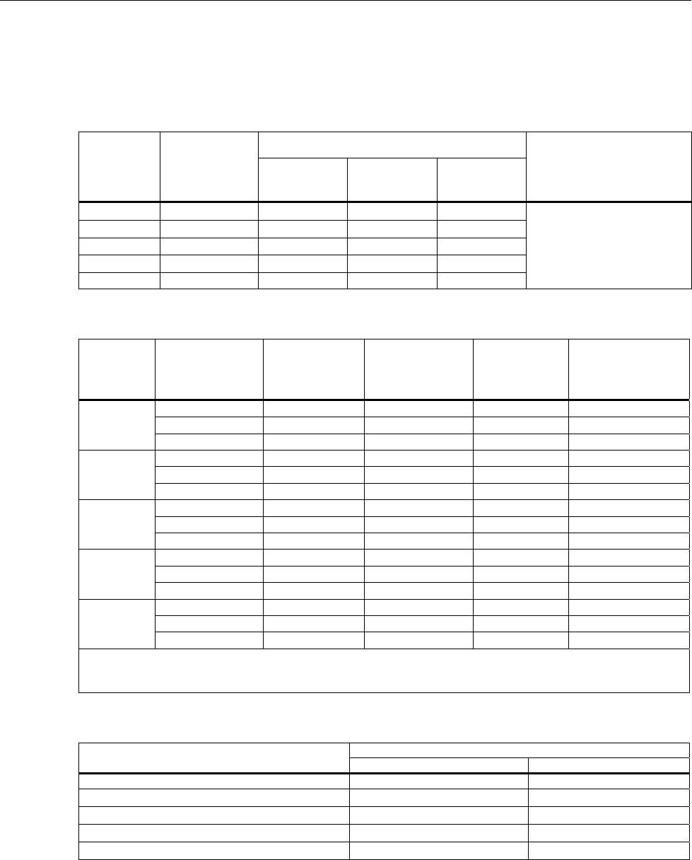
DC Voltage Input Characteristics
Range Resolution Resolution Input Impedance
Fast
4½ Digits Medium
5 ½ Digits Slow
6 ½ Digits
100 mV 100.0000 mV 10 μV 1 μV 0.1 μV 10 MΩ or >10 GΩ [1]
1 V 1.000000 V 100 μV 10 μV 1 μV 10 MΩ or >10 GΩ [1]
10 V 10.00000 V 1 mV 100 μV 10 μV 10 MΩ or >10 GΩ [1]
100 V 100.0000 V 10 mV 1 mV 100 μV 10 MΩ ±1 %
300 V 300.000 V 100 mV 10 mV 1 mV 10 MΩ ±1 %
Note:
Input beyond ±12 V is clamped. The clamp current is up to 3 mA. 10 MΩ is default input impedance.
DC Voltage Accuracy
Accuracy is given as ± (% measurement + % of range).
Range 24 Hour
(23 ±1 °C) 90 Days
(23 ±5 °C) 1 Year
(23 ±5 °C)
T.C./ °C
Outside
18 °C to 28 °C
100 mV 0.0025 % + 0.003 % 0.0025 % + 0.0035 % 0.0037 % + 0.0035 % 0.0005 % + 0.0005 %
1 V 0.0018 % + 0.0006 % 0.0018 % + 0.0007 % 0.0025 % + 0.0007 % 0.0005 % + 0.0001 %
10 V 0.0013 % + 0.0004 % 0.0018 % + 0.0005 % 0.0024 % + 0.0005 % 0.0005 % + 0.0001 %
100 V 0.0018 % + 0.0006 % 0.0027 % + 0.0006 % 0.0038 % + 0.0006 % 0.0005 % + 0.0001 %
300 V 0.0018 % + 0.002 % 0.0031 % + 0.002 % 0.0041 % + 0.002 % 0.0005 % + 0.0003 %
Notes:
• For conducted disturbances on mains input >1 V from 10 MHz to 20 MHz, add 0.02 % of range. For disturbances
>3 V, accuracy is unspecified.
• For radiated disturbances >1V/m from 450 MHz to 550 MHz, add 0.02 % of range. For disturbances > 3 V/m,
accuracy is unspecified.
DC Voltage Additional Errors
Digits NPLC Ch. x01 – x20 Additional NPLC Noise
Error
6 ½ 200 add 2 μV -
6 ½ 100 add 2 μV -
6 ½ 10 (Slow) add 2 μV -
5 ½ 1 (Medium) add 2 μV add 0.0008 % of range
4 ½ 0.2 (Fast) - add 0.002 % of range + 12 μV
4 ½ 0.02 - add 0.014 % of range + 17 μV
AC Voltage
AC voltage specifications are for ac sine wave signals >5 % of range. For inputs from 1 % to 5 % of range and <50 kHz,
add an additional error of 0.1 % of range. For 50 kHz to 100 kHz, add 0.13 % of range.
Maximum Input ...................................................... 300 V rms or 425 V peak or 3 × 10⁷ volts-Hertz product (whichever is
less) for any range.
Measurement Method ........................................... AC-coupled true-rms. Measures the ac component of input with up to
300 V dc bias on any range.
AC Filter Bandwidth:
Slow .................................................................... 20 Hz
Fast ..................................................................... 200 Hz
Maximum Crest Factor ......................................... 5:1 at full scale
2638A
Calibration Manual
8
Additional Crest Factor Errors ............................ Crest factor 1-2, 0.05 % of full scale
Crest factor 2-3, 0.2 % of full scale
Crest factor 3-4, 0.4 % of full scale
Crest factor 4-5, 0.5 % of full scale
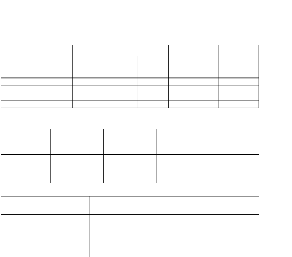
AC Voltage Input Characteristics
Range Resolution
Resolution
Input Impedance
4 ½
Digits 5 ½
Digits 6 ½
Digits
100 mV 100.0000 mV 10 μV 1 μV 0.1 μV
1 MΩ ±2 % shunted by 150 pF
1 V 1.000000 V 100 μV 10 μV 1 μV
10 V 10.00000 V 1 mV 100 µV 10 μV
100 V 100.0000 V 10 mV 1 mV 100 μV
300 V 300.000 V 100 mV 10 mV 1 mV
AC Voltage Accuracy
Accuracy is given as ± (% measurement + % of range).
Range Frequency 24 Hour
(23 ±1 °C) 90 Days
(23 ±5 °C) 1 Year
(23 ±5 °C)
T.C./ °C
Outside
18 °C to 28 °C
100 mV
20 Hz to 20 kHz 0.1 % + 0.05 % 0.11 % + 0.05 % 0.11 % + 0.05 % 0.01 % + 0.005 %
20 kHz to 50 kHz 0.2 % + 0.05 % 0.22 % + 0.05 % 0.22 % + 0.05 % 0.01 % + 0.005 %
50 kHz to 100 kHz 0.55 % + 0.08 % 0.6 % + 0.08 % 0.6 % + 0.08 % 0.05 % + 0.01 %
1 V
20 Hz to 20 kHz 0.1 % + 0.05 % 0.11 % + 0.05 % 0.11 % + 0.05 % 0.01 % + 0.005 %
20 kHz to 50 kHz 0.2 % + 0.05 % 0.22 % + 0.05 % 0.22 % + 0.05 % 0.01 % + 0.005 %
50 kHz to 100 kHz 0.55 % + 0.08 % 0.6 % + 0.08 % 0.6 % + 0.08 % 0.05 % + 0.01 %
10 V
20 Hz to 20 kHz 0.1 % + 0.05 % 0.11 % + 0.05 % 0.11 % + 0.05 % 0.01 % + 0.005 %
20 kHz to 50 kHz 0.2 % + 0.05 % 0.22 % + 0.05 % 0.22 % + 0.05 % 0.01 % + 0.005 %
50 kHz to 100 kHz 0.55 % + 0.08 % 0.6 % + 0.08 % 0.6 % + 0.08 % 0.05 % + 0.01 %
100 V
20 Hz to 20 kHz 0.1 % + 0.05 % 0.11 % + 0.05 % 0.11 % + 0.05 % 0.01 % + 0.005 %
20 kHz to 50 kHz 0.2 % + 0.05 % 0.22 % + 0.05 % 0.22 % + 0.05 % 0.01 % + 0.005 %
50 kHz to 100 kHz 0.55 % + 0.08 % 0.6 % + 0.08 % 0.6 % + 0.08 % 0.05 % + 0.01 %
300 V
20 Hz to 20 kHz 0.1 % + 0.05 % 0.11 % + 0.05 % 0.11 % + 0.05 % 0.01 % + 0.005 %
20 kHz to 50 kHz 0.2 % + 0.05 % 0.22 % + 0.05 % 0.22 % + 0.05 % 0.01 % + 0.005 %
50 kHz to 100 kHz 0.55 % + 0.27 % 0.6 % + 0.27 % 0.6 % + 0.27 % 0.05 % + 0.03 %
Note:
For conducted disturbances on mains input >1 V from 10 MHz to 40 MHz, add 0.02 % of range. For disturbances >3 V,
accuracy is unspecified.
Additional Low Frequency Errors
Error is stated as % of reading.
Frequency AC Filte
r
20 Hz 200 Hz
20 Hz to 40 Hz 0 % −
40 Hz to 100 Hz 0 % 0.55 %
100 Hz to 200 Hz 0 % 0.2 %
200 Hz to 1 kHz 0 % 0.02 %
>1 kHz 0 % 0 %
HYDRA Series III Data Acquisition Unit
Measurement Specifications
9
DC Current
Input Protection .................................................... 0.15 A / 600 V Resettable PTC
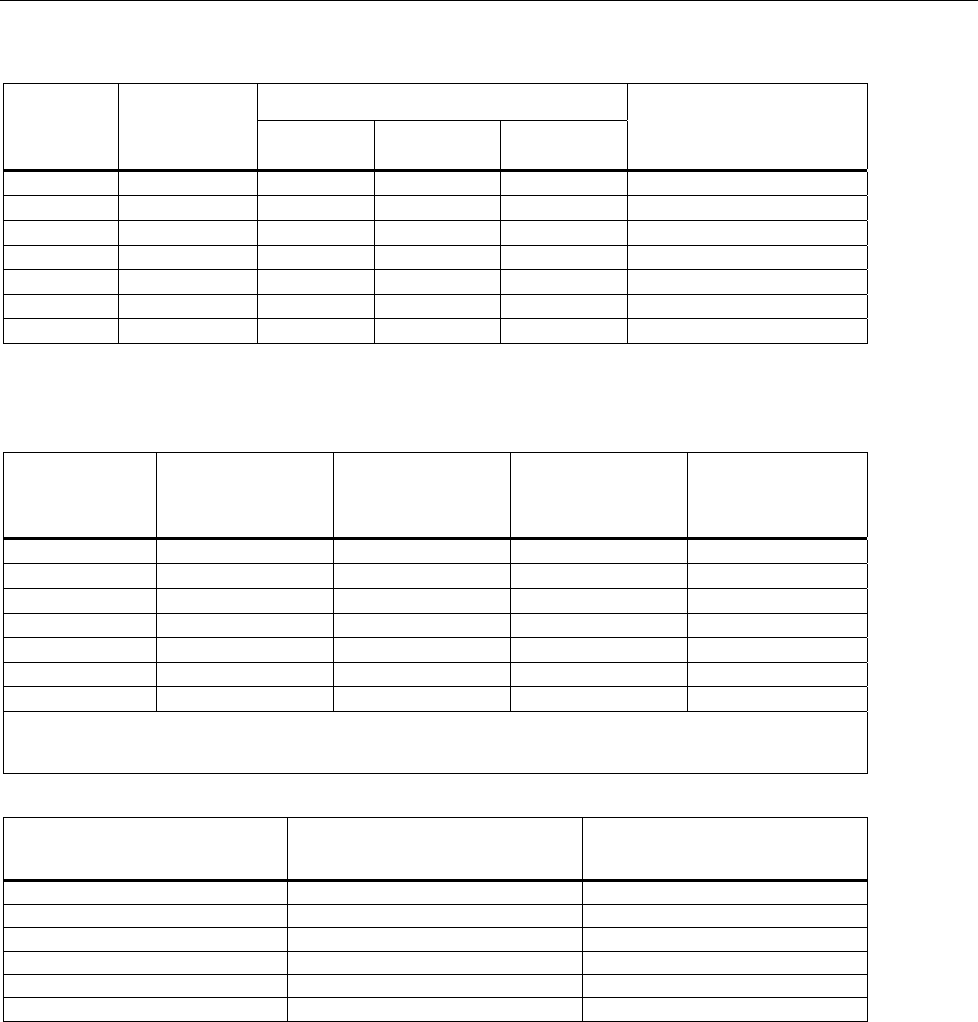
DC Current Input Characteristics
Range Resolution
Resolution Reference
Resistance
(Ohms)
Burden
Voltage
Fast
4½
Digits
Medium
5 ½
Digits
Slow
6 ½
Digits
100 μA 100.0000 µA 10 nA 1 nA 0.1 nA 1k Ω <1 mV
1 mA 1.000000 mA 100 nA 10 nA 1 nA 1k Ω <1 mV
10 mA 10.00000 mA 1 μA 100 nA 10 nA 10 Ω <1 mV
100 mA 100.0000 mA 10 μA 1 μA 100 nA 10 Ω <1 mV
DC Current Accuracy
Accuracy is given as ± (% measurement + % of range).
Range 24 Hour
(23 ±1 °C) 90 Days
(23 ±5 °C) 1 Year
(23 ±5 °C)
T.C./ °C
Outside
18 °C to 28 °C
100 μA 0.005 % + 0.003 % 0.015 % + 0.0035 % 0.015 % + 0.0035 % 0.002 % + 0.001 %
1 mA 0.005 % + 0.001 % 0.015 % + 0.0011 % 0.015 % + 0.0011 % 0.002 % + 0.001 %
10 mA 0.005 % + 0.003 % 0.015 % + 0.0035 % 0.015 % + 0.0035 % 0.002 % + 0.001 %
100 mA 0.005 % + 0.001 % 0.015 % + 0.0035 % 0.015 % + 0.0035 % 0.002 % + 0.001 %
DC Current Additional Errors
Digits NPLC
Additional NPLC Noise Error
for 10 mA, 100 mA Additional NPLC Noise
Error for 100 µA, 1 mA
6 ½ 200 - -
6 ½ 100 - -
6 ½ 10 (Slow) - -
5 ½ 1 (Medium) 0.0008 % of range 0.0008 % of range
4 ½ 0.2 (Fast) 0.002 % of range + 1.2 µA 0.002 % of range + 12 nA
4 ½ 0.02 0.014 % of range + 1.7 µA 0.014 % of range + 17 nA
AC Current
Input Protection .................................................... 0.15 A / 600 V resettable PTC
Measurement Method ........................................... AC-coupled true-rms, dc-coupled to the shunt (no blocking capacitor).
AC Filter Bandwidth:
Slow .................................................................... 20 Hz
Fast ..................................................................... 200 Hz
Maximum Crest Factor ......................................... 5:1 at full scale
Additional Crest Factor Errors ............................ Crest factor 1-2, 0.05 % of full scale
Crest factor 2-3, 0.2 % of full scale
Crest factor 3-4, 0.4 % of full scale
Crest factor 4-5, 0.5 % of full scale

2638A
Calibration Manual
10
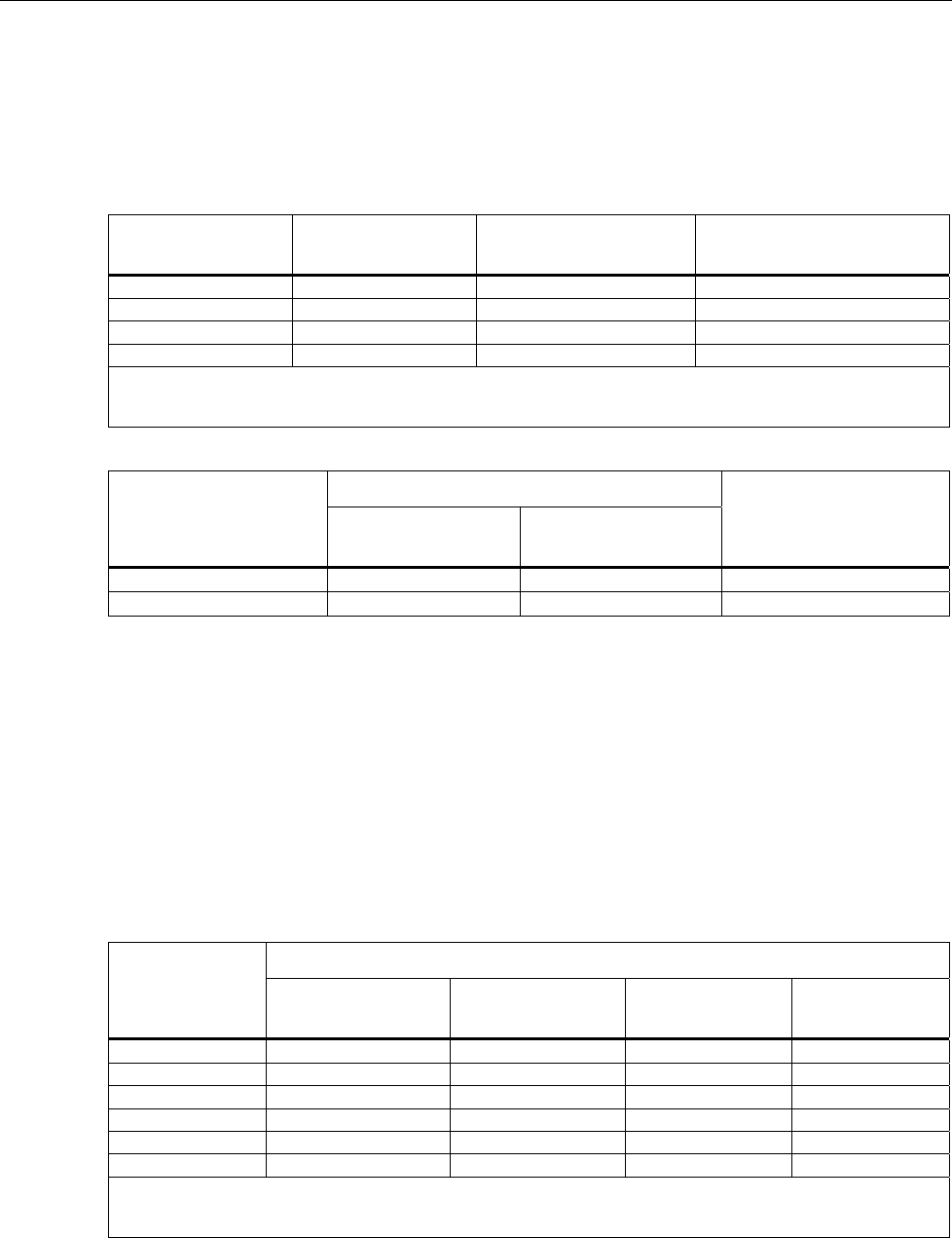
AC Current Input Characteristics
Range Resolution
Resolution Reference
Resistance Burden
Voltage
4 ½
Digits 5 ½
Digits 6 ½
Digits
100 μA 100.0000 µA 10 nA 1 nA 0.1 nA 1 kΩ <10 mV (RMS)
1 mA 1.000000 mA 100 nA 10 nA 1 nA 1 kΩ <10 mV (RMS)
10 mA 10.00000 mA 1 μA 100 nA 10 nA 10 Ω <20 mV (RMS)
100 mA 100.0000 mA 10 μA 1 μA 100 nA 10 Ω <50 mV (RMS)
AC Current Accuracy
Accuracy is given as ± (% measurement + % of range). Basic accuracy specification is for a sinusoidal signal with
amplitude greater than 5 % of range. For input signals between 1 % to 5 % of range, add 0.1 % of range.
Range Frequency 24 Hour
(23 ±1 °C) 90 Days
(23 ±5 °C) 1 Year
(23 ±5 °C) T.C./ °C Outside
18 °C to 28 °C
100 μA 20 Hz to 2 kHz 0.2 % + 0.06 % 0.25 % + 0.06 % 0.3 % + 0.06 % 0.015 % + 0.005 %
1 mA 20 Hz to 2 kHz 0.2 % + 0.06 % 0.25 % + 0.06 % 0.3 % + 0.06 % 0.015 % + 0.005 %
10 mA 20 Hz to 2 kHz 0.2 % + 0.06 % 0.25 % + 0.06 % 0.3 % + 0.06 % 0.015 % + 0.005 %
100 mA 20 Hz to 2 kHz 0.2 % + 0.06 % 0.25 % + 0.06 % 0.3 % + 0.06 % 0.015 % + 0.005 %
Additional Low Frequency Errors
Error is stated as % of reading.
Frequency AC Filte
r
20 Hz 200 Hz
20 Hz to 40 Hz 0 % −
40 Hz to 100 Hz 0 % 0.55 %
100 Hz to 200 Hz 0 % 0.2 %
200 Hz to 1 kHz 0 % 0.02 %
>1 kHz 0 % 0 %
Frequency
Gate Times ............................................................. 100 milliseconds to 1 second.
Measurement Method ........................................... Flexible counting technique. AC-coupled input using the ac voltage
measurement function.
Settling Considerations........................................ When measuring frequency after a dc offset voltage change, errors
may occur. For the most accurate measurement, wait up to 1 second
for the input blocking capacitor to settle.
Measurement Considerations.............................. To minimize measurement errors, shield inputs from external noise
when measuring low-voltage, low-frequency signals.
Frequency Accuracy
Accuracy is given as ± % of measurement.
Range Frequency 24 Hour
(23 ±1 °C) 90 Days
(23 ±5 °C) 1 Year
(23 ±5 °C)
T.C./ °C
Outside 18
°C to 28 °C
100 mV to
300 V [1] [2]
20 Hz to 40 Hz 0.03 % 0.03 % 0.03 % 0.001 %
40 Hz to 1 MHz 0.006 % 0.01 % 0.01 % 0.001 %
[1] Input >100 mV. For 10 mV to 100 mV, multiply percent measurement error by 10.
[2] Limited to 3 x 10⁷ volt-Hertz
Resistance
Measurement Method ........................................... Current source referenced to LO input.
Max. Lead Resistance (4-wire ohms) .................. 10 Ω per lead for 100 Ω, 1 kΩ ranges. 1 kΩ per lead on all other
ranges.
Input Protection .................................................... 300 V on all ranges.
HYDRA Series III Data Acquisition Unit
Measurement Specifications
11
Resistance Input Characteristics
Range Resolution Resolution Source Current
Fast
4½ Digits Medium
5 ½ Digits Slow
6 ½ Digits
100 Ω 100.0000 Ω 10 mΩ 1 mΩ 0.1 mΩ 1 mA / 4 V
1 kΩ 1.000000 kΩ 100 mΩ 10 mΩ 1 mΩ 1 mA / 4 V
10 kΩ 10.00000 kΩ 1 Ω 100 mΩ 10 mΩ 100 µA / 6 V
100 kΩ 100.0000 kΩ 10 Ω 1 Ω 100 mΩ 100 µA / 12 V
1 MΩ 1.000000 MΩ 100 Ω 10 Ω 1 Ω 10 µA / 12 V
10 MΩ 10.00000 MΩ 1 kΩ 100 Ω 10 Ω 1 µA / 12 V
100 MΩ 100.0000 MΩ 10 kΩ 1 kΩ 100 Ω 0.1 µA / 12 V
Resistance Accuracy
Accuracy is given as ± (% measurement + % of range). Basic accuracy specification is for 4-wire resistance. For 2-wire
resistance add 0.02 Ω internal resistance if using Channel 1 or 1.5 Ω if using channels x01 through x20, and add external
lead wire resistance.
Range 24 Hour
(23 ±1 °C) 90 Days
(23 ±5 °C) 1 Year
(23 ±5 °C)
T.C./ °C
Outside 18 °C
to 28 °C
100 Ω 0.003 % + 0.003 % 0.008 % + 0.004 % 0.01 % + 0.004 % 0.0006 % + 0.0005 %
1 kΩ 0.002 % + 0.0005 % 0.008 % + 0.001 % 0.01 % + 0.001 % 0.0006 % + 0.0001 %
10 kΩ 0.002 % + 0.0005 % 0.008 % + 0.001 % 0.01 % + 0.001 % 0.0006 % + 0.0001 %
100 kΩ 0.002 % + 0.0005 % 0.008 % + 0.001 % 0.01 % + 0.001 % 0.0006 % + 0.0001 %
1 MΩ 0.002 % + 0.001 % 0.008 % + 0.001 % 0.01 % + 0.001 % 0.001 % + 0.0002 %
10 MΩ 0.015 % + 0.001 % 0.02 % + 0.001 % 0.04 % + 0.001 % 0.003 % + 0.0004 %
100 MΩ 0.3 % + 0.01 % 0.8 % + 0.01 % 0.8 % + 0.01 % 0.05 % + 0.002 %
Note:
For conducted disturbances on mains input >1 V from 10 MHz to 40 MHz, add 0.6 % of range. For disturbances >3 V,
accuracy is unspecified.
Resistance Additional Errors
Digits NPLC Additional NPLC Noise Error
6 ½ 200 0 % of range
6 ½ 100 0 % of range
6 ½ 10 (Slow) 0 % of range
5 ½ 1 (Medium) 0.0008 % of range
4 ½ 0.2 (Fast)(only for 2-wire) 0.002 % of range + 12 mΩ
4 ½ 0.02 (only for 2-wire) 0.01 % of range + 17 mΩ
RTD
Temperature Range .............................................. -200 °C to 1200 °C (depending on the sensor)
Resistance Range ................................................. 0 Ω to 4 kΩ
Maximum Lead Resistance (4-wire Ω) ................ 2.5 % of range per lead for 400 Ω and 4 kΩ ranges
Sample Rate
Slow .................................................................... 10 PLC
Medium ............................................................... 2 PLC
Fast ..................................................................... 1 PLC
2638A
Calibration Manual
12
RTD Temperature Accuracy
Accuracy is for 4-wire 100 Ω nominal RTD, using the slow sample rate. With 3-wire PRT/RTD add 0.015 °C if using
Channel 1, or add 0.15 °C internal resistance mismatch to the accuracy specification if using channels x01 through x20,
and add external lead wire resistance mismatch. When using medium or fast sample rate (NPLC <10), add the number
given in the table to the accuracy specification. If the environment temperature is outside the specified range, multiply the
Temperature Coefficient number by the temperature deviation and add to the accuracy specification. Linear interpolation
may be used between points in the table. Specifications do not include sensor accuracy. The practical range of
temperature measurement depends on the sensor and characterization.
Temperature Accuracy Medium/Fast Sample
Rate (NPLC <10) T.C./ °C Outside
18 °C to 28 °C
-200 °C 0.016 °C add 0.02 °C 0.0026 °C
0 °C 0.038 °C add 0.02 °C 0.0041 °C
300 °C 0.073 °C add 0.03 °C 0.0063 °C
600 °C 0.113 °C add 0.03 °C 0.0089 °C
Note:
For conducted disturbances on mains input >1 V from 10 MHz to 40 MHz, add 0.2 Celsius. For disturbances >3 V,
accuracy is unspecified.
RTD Measurement Characteristics
Range
Temperature Display Resolution
Source Current
Slow
Sample Rate Medium/Fast
Sample Rate
0 Ω to 400 Ω 0.001 °C 0.01 °C 1 mA
400 Ω to 4 kΩ 0.001 °C 0.01 °C 0.1 mA
Thermistor
Temperature Range .............................................. -200 °C to 400 °C (depending on the sensor)
Resistance Range ................................................. 0 Ω to 1 MΩ
Sample Rate
Slow .................................................................... 10 PLC
Medium ............................................................... 2 PLC
Fast ..................................................................... 1 PLC
Thermistor Temperature Accuracy
Accuracy specifications are for a 4-wire thermistor using medium or slow sample rate. With 2-wire thermistor add the
number given in the table to the accuracy specification for internal resistance. When using fast sample rate (NPLC <10),
multiply the accuracy specification by 3. If the environment temperature is outside the specified range, increase the
accuracy specification by 25 % for every 1 °C outside the specified environment temperature range. Specifications do not
include sensor accuracy. The practical range of temperature measurement depends on the sensor.
Temperature
Accuracy
2.2 kΩ
thermistor 5 kΩ
thermistor 10 kΩ
thermistor 2-wire
-40 °C 0.002 °C 0.007 °C 0.007 °C add 0.002 °C
0 °C 0.005 °C 0.004 °C 0.003 °C add 0.004 °C
25 °C 0.013 °C 0.007 °C 0.005 °C add 0.016 °C
50 °C 0.019 °C 0.01 °C 0.011 °C add 0.05 °C
100 °C 0.116 °C 0.054 °C 0.026 °C add 0.34 °C
150 °C 0.527 °C 0.239 °C 0.1 °C add 1.7 °C
Note:
For conducted disturbances on mains input >1 V from 10 MHz to 40 MHz, add 0.2 Celsius. For disturbances >3 V,
accuracy is unspecified.

HYDRA Series III Data Acquisition Unit
Measurement Specifications
13
Thermistor Measurement Characteristics
Range
Temperature Display Resolution
Source Current
Slow
Sample Rate Medium/Fast
Sample Rate
0 Ω to 98 kΩ 0.001 °C 0.01 °C 10 μA
95 kΩ to 1 MΩ 0.001 °C 0.01 °C 1 μA
Thermocouple
Temperature Range .............................................. -270 °C to 2315 °C (depending on the sensor)
Voltage Range ....................................................... -15 mV to 100 mV
Sample Rate
Slow .................................................................... 10 PLC
Medium ............................................................... 2 PLC
Fast ..................................................................... 1 PLC
Thermocouple Temperature Accuracy
Accuracy specifications apply using a slow sample rate. When using a medium or fast sample rate (NPLC < 10), increase
the accuracy specification by 25 %. If the environment temperature is outside the specified range, increase the accuracy
specification by 12 % for every 1 °C outside the specified environment temperature range. Accuracy with fixed/external
CJC does not include the accuracy of the reference junction temperature. Linear interpolation may be used between
points in the table. Specifications do not include sensor accuracy. The practical range of temperature measurement
depends on the sensor.
Type
(Range) Temperature
Accuracy
Fixed / External CJC Internal CJC
Channel 1 Ch. x01 – x20 Ch. x01 – x20
K
-270 °C to 1372 °C
-200 °C
0 °C
1000 °C
0.28 °C
0.10 °C
0.14 °C
0.41 °C
0.15 °C
0.20 °C
1.60 °C
0.62 °C
0.64 °C
T
-270 °C to 400 °C
-200 °C
0 °C
200 °C
400 °C
0.27 °C
0.10 °C
0.08 °C
0.08 °C
0.40 °C
0.15 °C
0.12 °C
0.11 °C
1.60 °C
0.65 °C
0.47 °C
0.41 °C
R
-50 °C to 1768 °C
0 °C
300 °C
1200 °C
1600 °C
0.76 °C
0.42 °C
0.33 °C
0.34 °C
1.13 °C
0.63 °C
0.47 °C
0.49 °C
1.28 °C
0.71 °C
0.52 °C
0.54 °C
S
-50 °C to 1768 °C
0 °C
300 °C
1200 °C
1600 °C
0.74 °C
0.45 °C
0.37 °C
0.39 °C
1.11 °C
0.67 °C
0.54 °C
0.56 °C
1.26 °C
0.76 °C
0.60 °C
0.63 °C
J
-210 °C to 1200 °C
-200 °C
0 °C
1000 °C
0.20 °C
0.08 °C
0.11 °C
0.29 °C
0.12 °C
0.14 °C
1.41 °C
0.61 °C
0.53 °C
N
-270 °C to 1300 °C
-200 °C
0 °C
500 °C
1000 °C
0.42 °C
0.15 °C
0.12 °C
0.14 °C
0.62 °C
0.23 °C
0.17 °C
0.19 °C
1.69 °C
0.64 °C
0.44 °C
0.45 °C
E
-270 °C to 1000 °C
-200 °C
0 °C
300 °C
700 °C
0.17 °C
0.07 °C
0.06 °C
0.08 °C
0.25 °C
0.10 °C
0.09 °C
0.10 °C
1.42 °C
0.61 °C
0.46 °C
0.45 °C

2638A
Calibration Manual
14
B
100 °C to 1820 °C
300 °C
600 °C
1200 °C
1600 °C
1.32 °C
0.68 °C
0.41 °C
0.38 °C
1.97 °C
1.02 °C
0.60 °C
0.55 °C
1.97 °C
1.02 °C
0.60 °C
0.55 °C
C
0 °C to 2315 °C
600 °C
1200 °C
2000 °C
0.23 °C
0.28 °C
0.44 °C
0.33 °C
0.40 °C
0.60 °C
0.54 °C
0.63 °C
0.91 °C
D
0 °C to 2315 °C
600 °C
1200 °C
2000 °C
0.22 °C
0.26 °C
0.39 °C
0.32 °C
0.36 °C
0.53 °C
0.44 °C
0.49 °C
0.69 °C
G
0 °C to 2315 °C
600 °C
1200 °C
2000 °C
0.24 °C
0.22 °C
0.33 °C
0.36 °C
0.32 °C
0.46 °C
0.36 °C
0.33 °C
0.46 °C
L
-200 °C to 900 °C
-200 °C
0 °C
800 °C
0.13 °C
0.08 °C
0.09 °C
0.19 °C
0.12 °C
0.12 °C
0.99 °C
0.62 °C
0.48 °C
M
-50 °C to 1410 °C
0 °C
500 °C
1000 °C
0.11 °C
0.10 °C
0.10 °C
0.16 °C
0.15 °C
0.14 °C
0.64 °C
0.51 °C
0.41 °C
U
-200 °C to 600 °C
-200 °C
0 °C
400 °C
0.25 °C
0.10 °C
0.08 °C
0.37 °C
0.15 °C
0.11 °C
1.48 °C
0.63 °C
0.40 °C
W
0 °C to 2315 °C
600 °C
1200 °C
2000 °C
0.24 °C
0.22 °C
0.33 °C
0.36 °C
0.32 °C
0.46 °C
0.36 °C
0.33 °C
0.46 °C
Thermocouple Measurement Characteristics
Range
Temperature Display Resolution
Slow
Sample Rate Medium/Fast
Sample Rate
-270 °C to 2315 °C 0.01 °C 0.1 °C
Digital I/O
Absolute Voltage Range ......................................... -4 V to 30 V
Input Minimum Logic High ...................................... 2.0 V
Input Maximum Logic Low ...................................... 0.7 V
Output Type ............................................................ open drain active low
Output Logic Low (<1 mA) ...................................... 0 V to 0.7 V
Maximum Sink Current ........................................... 50 mA
Output Resistance .................................................. 47 Ω
Totalizer
Absolute Voltage Range ......................................... -4 V to 30 V
Minimum Logic High ............................................... 2.0 V
Maximum Logic Low ............................................... 0.7 V
Minimum Pulse Width ............................................. 50 μs
Maximum Frequency .............................................. 10 kHz
Debounce Time ....................................................... 1.7 ms
Maximum Count ...................................................... 1048575 (20 bits)
Trigger
Absolute Voltage Range ......................................... -4 V to 30 V
Minimum Logic High ............................................... 2.0 V

HYDRA Series III Data Acquisition Unit
2638A-100 Universal Input Module
15
Maximum Logic Low ............................................... 0.7 V
Minimum Pulse Width ............................................. 50 μs
Maximum Latency ................................................... 100 ms
Alarm Output
Absolute Voltage Range ......................................... -4 V to 30 V
Output Type ............................................................ open drain active low
Output Logic Low (<1 mA) ...................................... 0 V to 0.7 V
Maximum Sink Current ........................................... 50 mA
Output Resistance ................................................. 47 Ω
2638A-100 Universal Input Module
General
Measurement .......................................................... IEC 61010-2-030: CAT II 150 V, on any range. 250 V Max. (see safety
notice in this manual under input protection)
Offset Voltage ......................................................... <2 μV
3-Wire Internal Resistance Mismatch ..................... <50 mΩ
Basic CJC Accuracy ............................................... 0.6 °C

2638A
Calibration Manual
16
General Maintenance
This section supplies information on how to clean the Product, reset the memory,
and replace the fuse in the rear of the Product.
If the Product Does Not Turn On
To help solve problems encountered when turning on the Product:
1. Verify that the power switch is in the “On” position.
2. Make sure that the mains power cord is firmly plugged into the power module
on the rear of the Product.
3. Make sure the power source that the Product is plugged into is energized.
4. Verify that the line power fuse is good. See “Replace the Line Power Fuse”.
If these steps do not solve the problem, then contact Fluke. See the “Contact
Fluke”.
Clean the Product
To clean the Product, wipe the instrument with a cloth that is lightly dampened
with water or mild detergent. Do not use aromatic hydrocarbons, chlorinated
solvents, or methanol based fluids.
WCaution
To prevent possible damage to the Product, do not use
solvents or abrasive cleansers.
WCaution
For safe operation and maintenance of the product:
• Have an approved technician repair the Product.
• Do not allow water to get inside the Product.
Replace the Line Power Fuse
The Product has a fuse that protects from overcurrent. Each voltage selection
requires a specific fuse. See Table 2 for the correct fuse for each of the four line-
voltage selections. This fuse is located on the rear panel.
XWWarning
To prevent possible electrical shock, fire, or personal injury,
use only specified replacement parts.
Table 2. Fuses
Voltage Selector Fuse Fluke Part Number
100 V 0.25 A, 250 V (slow blow) 166306
120 V 0.25 A, 250 V (slow blow) 166306
220 V 0.160 A, 250 V (slow blow) 4394437
240 V 0.160 A, 250 V (slow blow) 4394437
HYDRA Series III Data Acquisition Unit
General Maintenance
17
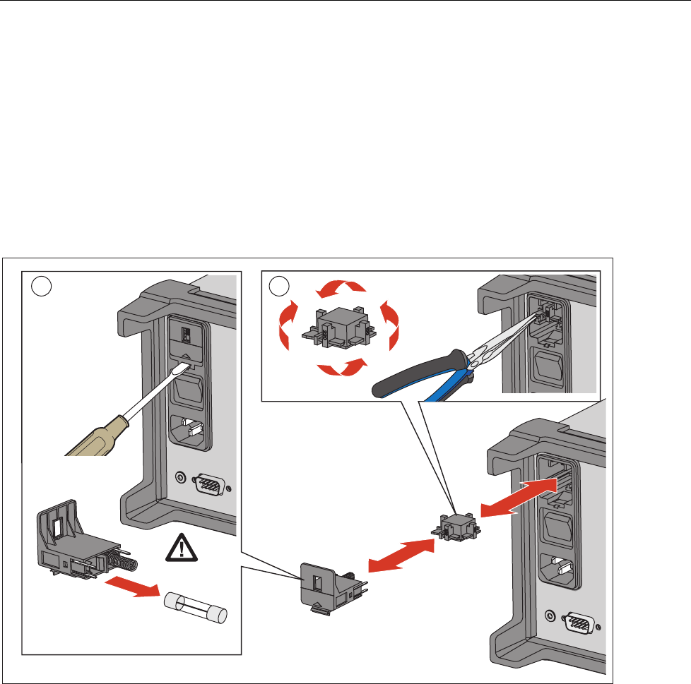
To replace the fuses, see Figure 1:
1. Remove any high-capacity modules or test leads from the Product where
hazardous voltage may be present.
2. Disconnect the mains-power cord from the power-entry module.
3. Insert a small, flat screwdriver blade into the narrow recess to the left of the
fuse holder and pry to the right until the holder pops out. The Product is
shipped with a replacement fuse of the same rating as the fuse installed in
the fuse block.
4. Replace the fuse with the replacements as listed in Table 2.
5. Slide the fuse holder back into the Product until it locks into place.
1 2
hcn027.eps
Figure 1. Fuse Replacement
Battery Replacement
The battery in the Product is used for Product memory (menu settings, readings,
or other functions).
To replace the battery:
1. Disassemble the Product as described in the Disassembly section.
2. Remove the battery (see Figure 9) and replace with one rated appropriately
for the selected voltage button battery.
3. Reassemble the Product.

2638A
Calibration Manual
18
Memory and Factory Reset
The Product has two memory reset functions to remove data from the memory
and reset the Product:
• Clear all Files
• Factory Reset
See Table 3 for a comparison of these functions.
Note
All memory reset functions require the Admin password.
Table 3. Memory Clear Functions
Task Clear All Files Factory Reset
Deletes Test Setup files, DMM Data files, and Scan
Data files from the internal memory. [1] •
Clears the configuration of the Channel Setup, Test
Setup, and Instrument Setup [2] •
[1] Does not remove data from the USB drive.
[2] Does not reset the MAC address, the serial number, calibration, clock time, or the Admin or User passwords.
To clear all files:
1. Push .
2. Push twice.
3. Enter the Admin password.
4. Push .
5. Push to confirm.
To reset the Product to factory settings:
1. Push .
2. Push .
3. Enter the Admin password, then push .

HYDRA Series III Data Acquisition Unit
Firmware Update
19
Firmware Update
For Products with a firmware version 1.03 or higher, firmware may be updated by
the product administrator with the front-panel USB port. New firmware versions
are available from the Fluke Calibration web page for the Product under the
Knowledge and Information tab.
For Products that have firmware versions below 1.03, contact Fluke Calibration
Service to schedule a firmware update as these versions do not support the USB
firmware update process.
Update instructions for Products that use version 1.03 and above:
WCaution
• Do not cycle the power or remove the USB device while the
firmware update is in process. These actions will cause an
instrument failure during the update process and require a
return to a Fluke Service center to correct.
• The Product automatically re-boots when the update
process is complete. Updates can take several minutes to
complete and the display screen will not illuminate until the
re-boot.
Note
Fluke Calibration recommends that you move all internal data files
and setup files from the Product to a USB device before the update
of the firmware.
Before the update process starts, verify that the current firmware is version 1.03
or above by viewing Firmware under . If your firmware version is below
1.03, do not continue the update process. You must return the Product to Fluke
Calibration Service for the firmware update.
Firmware update steps:
1. Download and extract the firmware update files (AuxInfo.txt and mtv.flt) to
your computer from the Fluke Calibration website.
2. Create a new folder firmware on a USB flash drive (1 GB or greater), and
then copy these files into this folder. To prevent file corruption, use the
Windows utility to safely eject your USB flash drive from your computer.
3. Plug the USB flash drive into the Product and wait for the red light on the
USB port to illuminate and show that the drive is recognized.
Note
Some USB flash drives may not be recognized by the Product. Test
the USB flash drive prior to starting this update process to ensure it
is recognized.
4. Push to enter the Setup menu.
5. Push the Up/Down arrow button to select Firmware then push to enter
the firmware menu.
6. Push and enter the administrator password and then push to start
the update process.
7. WAIT until the Product automatically re-boots. There will be no screen display
for several minutes during this time. Do not cycle the power or remove the
USB device while the firmware update is in process.

2638A
Calibration Manual
20
8. After the automatic re-boot, push to verify that the update was
successful. Verify the firmware version that you have installed is displayed on
the screen.
Required Equipment
Table 4 lists the equipment required for performance tests and calibration
adjustment of the Product.
Table 4. Required Test Equipment
Function Instrument Type Model Comments
Volts DC
Standard Fluke 5720A
8½ digit meter Fluke 8508A Used to characterized the
5522A
4-wire short Fluke low thermal 4-wire
short or equivalent Fluke PN 2653346
Alternate standard[1] Fluke 5522A Must be characterized with
8508A
Volts ac
Standard Fluke 5720A
8½ digit meter Fluke 8508A Used to characterized the
5522A
4-wire short Fluke low thermal 4-wire
short or equivalent Fluke PN 2653346
Alternate standard [1] Fluke 5522A Must be characterized with
8508A
Frequency
Standard Fluke 5522A
Alternate standard Function generator
Specifications include
0.075 % frequency
accuracy from 20 Hz to
40 Hz and 0.0025 %
accuracy for frequencies
up to 1 MHz
Ohms
Standard Fluke 5720A
4-wire short Fluke low thermal 4-wire
short or equivalent Fluke PN 2653346
Alternate standard The standard resistors
which have equivalent
spec with Fluke 5720A.

HYDRA Series III Data Acquisition Unit
Required Equipment
21
Table 4. Required Test Equipment (cont.)
Function Instrument Type Model Comments
PRT
Standard
Fluke 5522A
(for 1 kΩ value)
Standard resistors of
25 Ω, 100 Ω, 200 Ω, and
400 Ω
Resistance accuracy
specification (k = 2) should
be or better than:
40 ppm (for 25 Ω)
20 ppm (for 100 Ω, 200 Ω
and 400 Ω)
4-wire short Fluke low thermal 4-wire
short or equivalent Fluke PN 2653346
Alternate standard The standard resistors
which have equivalent
specification.
Thermistor
Standard Fluke 5522A Must be characterized with
8508A
8½ digit meter Fluke 8508A Used to characterized the
5522A
4-wire short Fluke low thermal 4-wire
short or equivalent Fluke PN 2653346
Alternate standard[1] Fluke 5720A
Current DC
Standard Fluke 5522A Must be characterized with
8508A
8½ digit meter Fluke 8508A Used to characterized the
5522A
Alternate standard[1] Fluke 5720A
Current ac
Standard
Fluke 5522A
Fluke 5720A (for 10 μA
adjustment)
Fluke 5522A must be
characterized with 8508A
8½ digit meter Fluke 8508A Used to characterized the
5522A
Alternate standard Fluke 5720A
2638A-100
Module
Metrology Drywell Fluke 9171 with insert
block
Reference thermistor
probe Fluke 5610-9 Accuracy 0.013 °C or
better at 25 °C
Reference
thermometer Fluke 1586A Only for CJC verification
E-type
thermocouples Omega TT-E-24-SLE
Must be calibrated.
Accuracy 0.026 °C or
better at 25 °C
Cables
To reduce the possibility of inducing errors with ac signals picked up by the test
leads, use short, shielded twisted-pair PTFE-insulated test cables between the test
equipment and the Meter. Fluke makes a 2 foot (PN 738716) and 4 foot (PN
738724) PTFE insulated test cable for this purpose
[1] Other alternate standards beside those listed can be used as long as they provide sufficient traceable [Test
uncertaintity Ratios (TURs)] at each calibration and verification point.

2638A
Calibration Manual
22
Test Considerations
For optimum performance, all test procedures should comply with these
recommendations:
• Assure the calibration ambient temperature (Tcal) is stable and between 18 °C
and 28 °C. Ideally, the calibration should be done at 23 °C ±2 °C.
• Assure ambient relative humidity is <80%.
• Allow a 60-minute warm-up period.
• Use shielded twisted-pair PTFE-insulated cables to reduce settling and noise
errors.
• Keep all input cables as short as possible.
• Ensure that the calibration standards and test procedures used do not
introduce additional errors.
Note
Ideally, the standards used to verify and adjust the Product should
be four times more accurate than each full-scale error specification
of the Product.
• User the Fluke low-thermal 4-Wire short for all voltages and Ohm shorts. See
Table 4 for Fluke part number.
Performance Tests
This section provides performance tests to verify that the Product operates within
published specifications as well as a complete calibration procedure. The
performance test and, if necessary, the calibration adjustment procedure can be
done both periodically and after service or repair.
The performance tests can be used as an acceptance test upon receipt of the
Product. Use the 90-day specifications when an acceptance test is done after the
Product is calibrated.
Fluke provides these performance tests to ensure that the Product is in proper
operating condition. If the Product fails any of the performance tests, calibration
adjustment and/or repair are needed. The performance test works best if done in
the sequence shown in Table 5.
Each of the measurements listed in the following tests assumes the Product is
being tested after a one-hour warm-up in an environment with an ambient
temperature of 18 °C to 28 °C and a relative humidity of <80 %.
Note
All instrument settings for verification use power up conditions
except as noted by the verification step.
HYDRA Series III Data Acquisition Unit
Performance Tests
23
Front Panel Test
To test the keypad and LEDs on the front panel:
1. Push Instrument Setup.
2. Push and hold for 3 seconds to enter keypad diagnostic.
3. Push every key. The key name should be shown correctly on the screen.
4. Push , , , and again, to check the LED.
5. Push to exit the keypad diagnostic program.
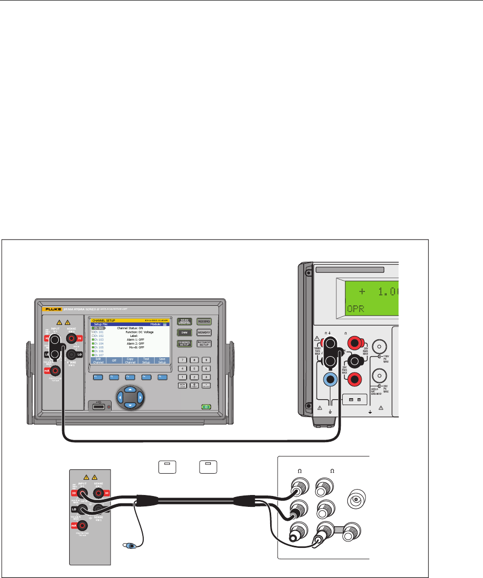
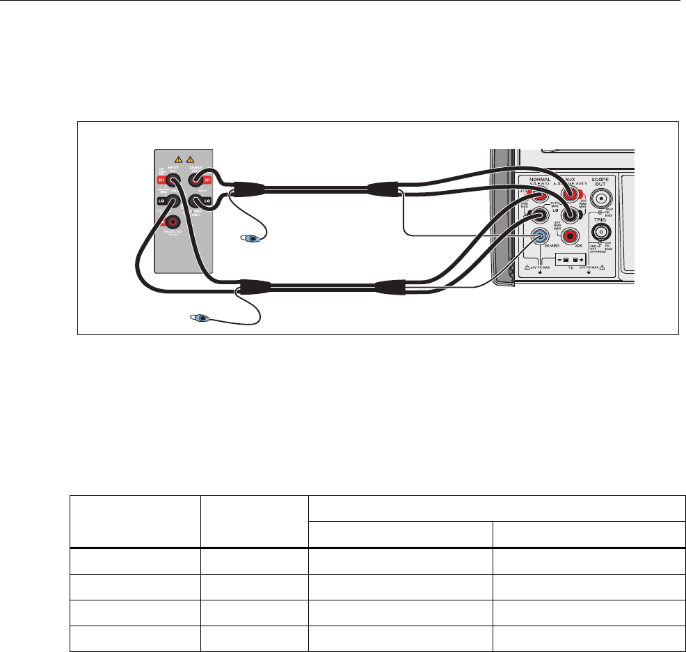
DC Volts Verification
Connect the Product to the test equipment as shown in Figure 2 and apply the
voltages listed in Table 5.
Note
For the 0 V tests, use the 4-wire short to short the Hi/Lo and Sense
inputs.
X
5520A CALIBRATOR
HI
LO
TRIG
GUARD
TC
20A
NORMAL AUX SCOPE
OUT
V, , ,RTD A, -SENSE, AUX V
20V PK MAX
20V PK MAX
FUSED
2638A HYDRA Series
HI HI
LO LO
HI
OUTPUT
V A
SENSE
V
AUX
CURRENT
GUARD GROUND
WIDEBAND
NC
5720A Calibrator
5522A Calibrator
UUT A.
EX SNS
: OFF
EX GRD
: OFF
hcn105.eps
Figure 2. DC Voltage Test Connections

2638A
Calibration Manual
24
Table 5. DC Volts Verification Steps
Nominal
Input(V) Range 90-Day Test Limits 1-Year Test Limits
High Low High Low
0 0.1 3.5 μV -3.5 μV 3.5 μV -3.5 μV
0.04[1] 0.1 40.0045 mV 39.9955 mV 40.005 mV 39.995 mV
0.1[1] 0.1 100.006 mV 99.994 mV 100.0072 mV 99.9928 mV
-0.04[1] 0.1 -39.9955 mV -40.0045 mV -39.995 mV -40.005 mV
-0.1[1] 0.1 -99.994 mV -100.006 mV -99.9928 mV -100.0072 mV
0 1 7.0 μV -7.0 μV 7.0 μV -7.0 μV
1[1] 1 1.000025 V 0.999975 V 1.000032 V 0.999968 V
-1[1] 1 -0.999975 V -1.000025 V -0.999968 V -1.000032 V
0 10 50.0 μV -50.0 μV 50.0 μV -50.0 μV
10[1] 10 10.00023 V 9.99977 V 10.00029 V 9.99971 V
-10[1] 10 -9.99977 V -10.00023 V -9.99971 V -10.00029 V
0 100 600.0 μV -600.0 μV 600.0 μV -600.0 μV
100[1] 100 100.0033 V 99.9967 V 100.0044 V 99.9956 V
-100[1] 100 -99.9967 V -100.0033 V -99.9956 V -100.0044 V
0 300 6.0 mV -6.0 mV 6.0 mV -6.0 mV
300[1] 300 300.0153 V 299.9847 V 300.0183 V 299.9817 V
-300[1] 300 -299.9847 V -300.0153 V -299.9817 V -300.0183 V
[1] 5522A must be used with 8508A to obtain suitable test uncertainty ratio.
HYDRA Series III Data Acquisition Unit
Performance Tests
25
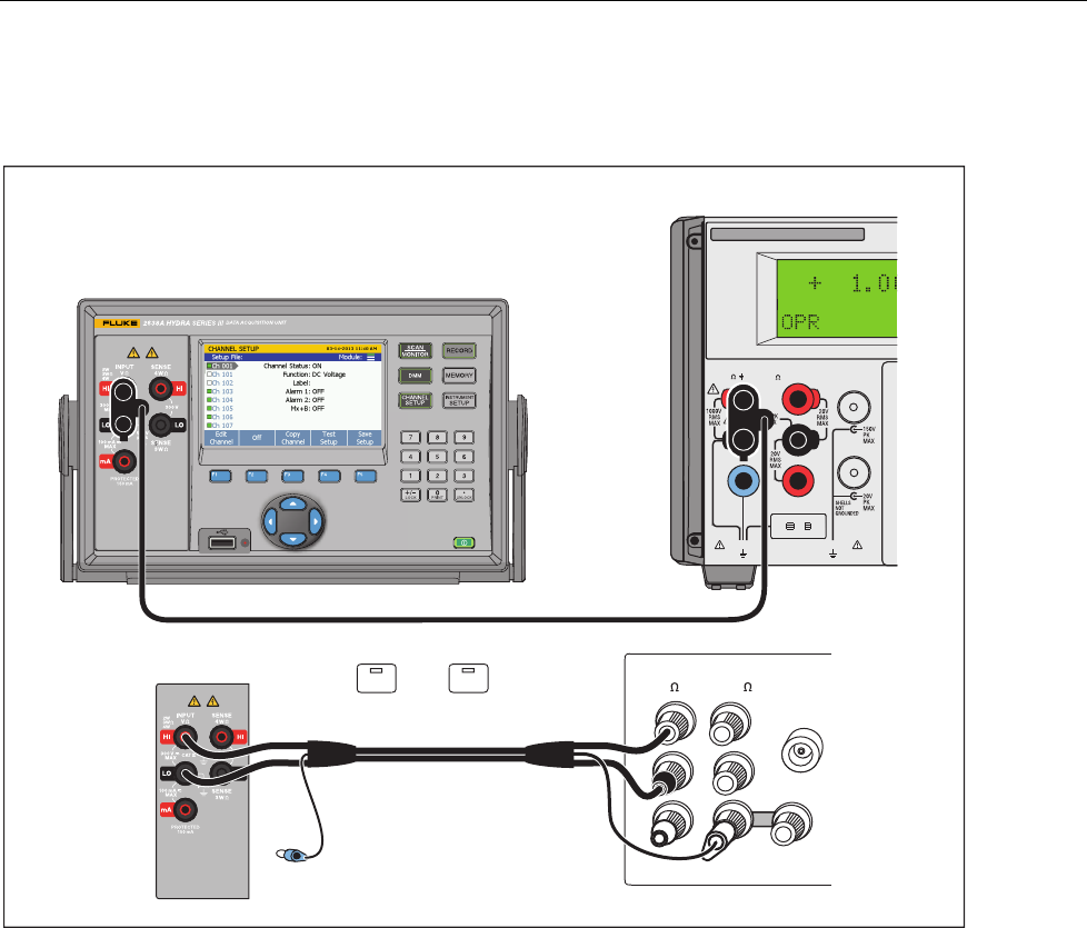
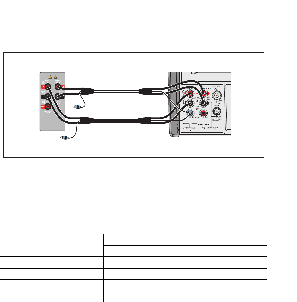
Volts AC and Frequency Verification
Connect the Product to the test equipment as shown in Figure 3 and apply the
voltages listed in Table 6 and Table 7.
X
5520A
CALIBRATOR
HI
LO
TRIG
GUARD
TC
20A
NORMAL AUX SCOPE
OUT
V, , ,RTD A, -SENSE, AUX V
20V PK MAX
20V PK MAX
FUSED
2638A HYDRA Series
HI HI
LO LO
HI
OUTPUT
V A
SENSE
V
AUX
CURRENT
GUARD GROUND
WIDEBAND
NC
5720A Calibrator
5522A Calibrator
UUT A.
EX SNS: OFF EX GRD : OFF
hcn105.eps
Figure 3. AC Volts Verification Connections

2638A
Calibration Manual
26
Table 6. AC Volts Verification Steps
Nominal Input Range 90-Day Test Limits 1-Year Test Limits
Ampl. Freq. High Low High Low
100.0 mV 20 Hz 0.1 100.16 mV 99.84 mV 100.16 mV 99.84 mV
100.0 mV 20 kHz 0.1 100.16 mV 99.84 mV 100.16 mV 99.84 mV
100.0 mV 50 kHz 0.1 100.27 mV 99.73 mV 100.27 mV 99.73 mV
100.0 mV 100 kHz 0.1 100.68 mV 99.32 mV 100.68 mV 99.32 mV
1 V 20 Hz 1 1.0016 V 0.9984 V 1.0016 V 0.9984 V
1 V 20 kHz 1 1.0016 V 0.9984 V 1.0016 V 0.9984 V
1 V 50 kHz 1 1.0027 V 0.9973 V 1.0027 V 0.9973 V
1 V 100 kHz 1 1.0068 V 0.9932 V 1.0068 V 0.9932 V
10 V 20 Hz 10 10.016 V 9.984 V 10.016 V 9.984 V
10 V 20 kHz 10 10.016 V 9.984 V 10.016 V 9.984 V
10 V 50 kHz 10 10.027 V 9.973 V 10.027 V 9.973 V
10 V 100 kHz 10 10.068 V 9.932 V 10.068 V 9.973 V
30 V 20 Hz 100 30.083 V 29.917 V 30.083 V 29.917 V
100 V 20 kHz 100 100.16 V 99.84 V 100.16 V 99.84 V
100 V 50 kHz 100 100.27 V 99.73 V 100.27 V 99.73 V
100 V[1] 100 kHz 100 100.68 V 99.32 V 100.68 V 99.32 V
30 V 20 Hz 300 30.183 V 29.817 V 30.183 V 29.817 V
300 V 20 kHz 300 300.48 V 299.52 V 300.48 V 299.52 V
300 V 50 kHz 300 300.81 V 299.19 V 300.81 V 299.19 V
300 V 100 kHz 300 302.61 V 297.39 V 302.61 V 297.39 V
[1] 5522A must be used with 8508A to obtain suitable test uncertainty ratio.
Table 7. AC Volts Frequency Verification Steps
Nominal Input 90-day Test Limits 1-year Test Limits
Ampl. Frequency High Low High Low
1 V 20 Hz 20.006 Hz 19.994 Hz 20.006 Hz 19.994 Hz
1 V 40 Hz 40.012 Hz 39.988 Hz 40.012 Hz 39.988 Hz
100 mV 300 kHz 300.03 kHz 299.97 kHz 300.03 kHz 299.97 kHz
100 mV 1 MHz 1.0001 MHz 999.9 kHz 1.0001 MHz 999.9 kHz
HYDRA Series III Data Acquisition Unit
Performance Tests
27
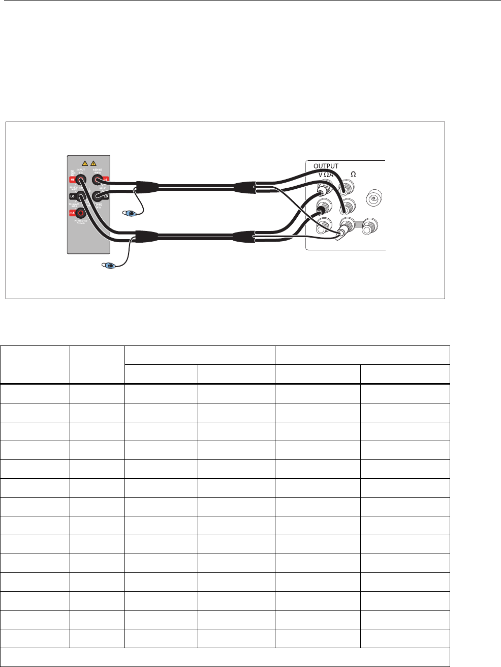
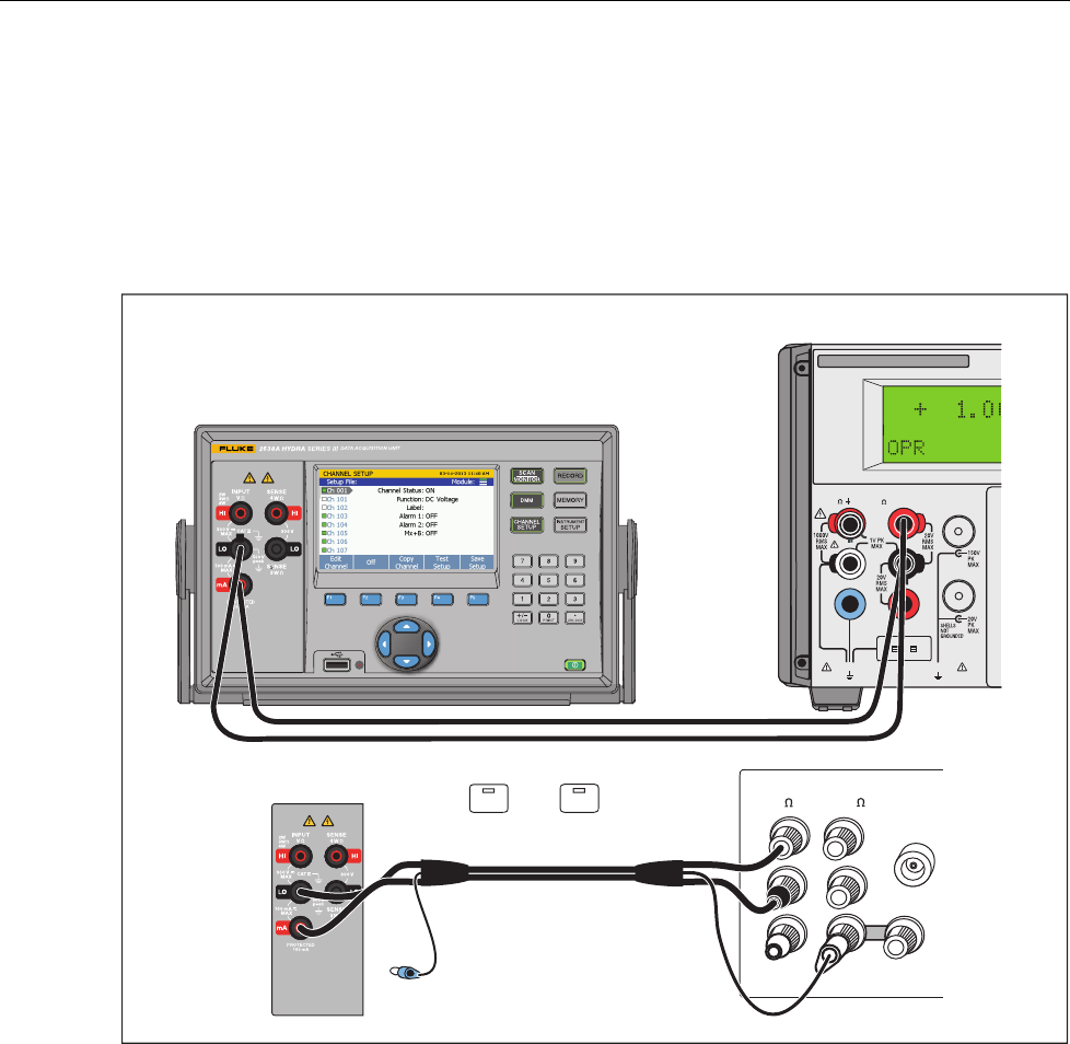
4-Wire Ohms Verification
Connect the Product to the test equipment as shown in Figure 4 and apply the
resistance listed in Table 8.
Note
For the 0
Ω
tests, use the 4-wire short to short the Hi/Lo and Sense
inputs.
5720A Calibrator
UUT
NC
NC
HI HI
LO LO
HI
SENSE
V
AUX
CURRENT
GUARD GROUND
WIDEBAND
hcn305.eps
Figure 4. 4-Wire Ohms Test Equipment Setup
Table 8. 4-Wire Ohms Verification Steps
Nominal
Input Range 90-Day Test Limits 1-Year Test Limits
High Low High Low
0 Ω 100 0.004 Ω -0.004 Ω 0.004 Ω -0.004 Ω
100 Ω 100 100.012 Ω 99.988 Ω 100.014 Ω 99.986 Ω
0 Ω 1 k 0.00001 kΩ -0.00001 kΩ 0.00001 kΩ -0.00001 kΩ
1 k Ω 1 k 1.00009 kΩ 0.99991 kΩ 1.00011 kΩ 0.99989 kΩ
0 Ω 10 k 0.0001 kΩ -0.0001 kΩ 0.0001 kΩ -0.0001 kΩ
10 k Ω 10 k 10.0009 kΩ 9.9991 kΩ 10.0011 kΩ 9.9989 kΩ
0 Ω 100 k 0.001 kΩ -0.001 kΩ 0.001 kΩ -0.001 kΩ
100 k Ω 100 k 100.009 kΩ 99.991 kΩ 100.011 kΩ 99.989 kΩ
0 Ω 1 M 0.00001 MΩ -0.00001 MΩ 0.00001 MΩ -0.00001 MΩ
1 M Ω 1 M 1.00009 MΩ 0.99991 MΩ 1.00011 MΩ 0.99989 MΩ
0 Ω 10 M 0.0001 MΩ -0.0001 MΩ 0.0001 MΩ -0.0001 MΩ
10 M Ω 10 M 10.0021 MΩ 9.9979 MΩ 10.0041 kΩ 9.9959 MΩ
0 Ω [1] 100 M 0.01 MΩ -0.01 MΩ 0.01 MΩ -0.01 MΩ
100 M Ω [1] 100 M 100.81 MΩ 99.19 MΩ 100.81 MΩ 99.19 MΩ
[1] 2-Wire
2638A
Calibration Manual
28
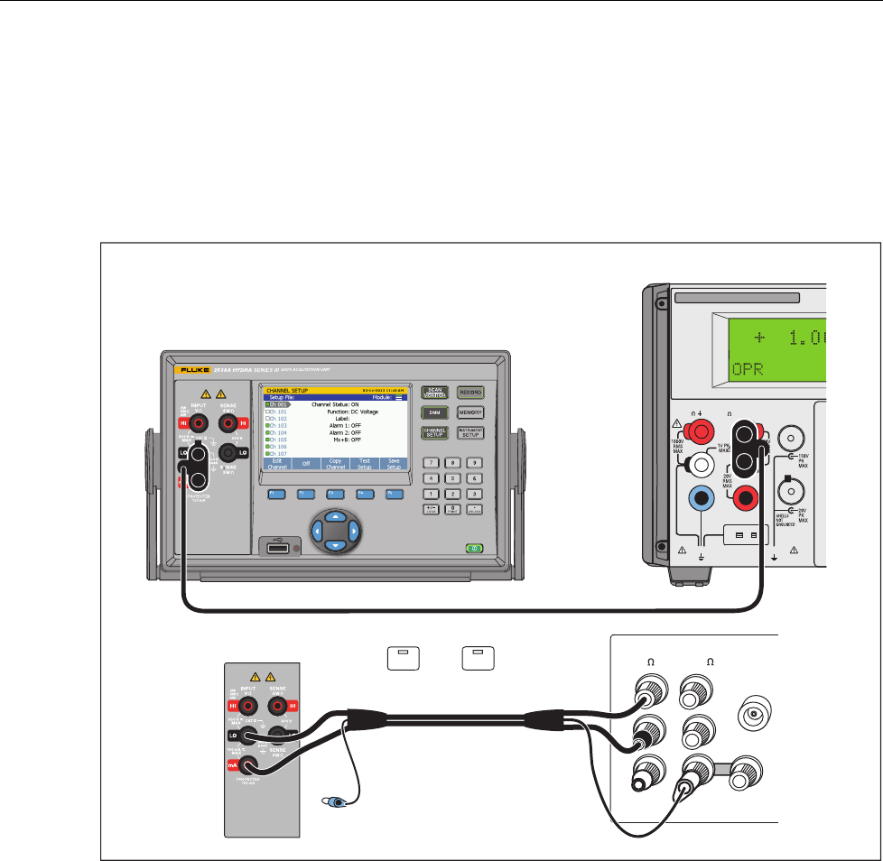
PRT Verification Steps
Connect the Product as in Figure 5 for the 1 kΩ value listed in Table 9. For all
other values in the table, use standard resistors. Configure the Ch001 as 4-wire
PRT function with resistance display.
NC
5522A Calibrator
1 ke
NC
UUT
hcn312.eps
Figure 5. PRT Verification Connection
Configure Resistance Display
After configuring the channel Ch001 to 4-wire PRT function, send the following
command through the remote interface to configure the resistance display:
TEMP:FPRT:CALC:RES ON,(@1)
Table 9. PRT Verification Steps
Nominal
Input Range 1-Year Test Limits
High Low
0 Ω 100 0.005 Ω -0.005 Ω
25 Ω 100 25.0075 Ω 24.9925 Ω
100 Ω 100 100.015 Ω 99.985 Ω
1k Ω 1 k 1.0002 kΩ 0.9998 kΩ
HYDRA Series III Data Acquisition Unit
Performance Tests
29
Thermistor Verification Steps
Connect the Product to the test equipment as shown in Figure 6 and apply the
resistance listed in Table 10. Configure Ch001 as a 4-wire thermistor function
with resistance display.
5522A Calibrator
UUT
NC
NC
hcn304.eps
Figure 6. Thermistor Test Equipment Setup
Configure Resistance Display
After configuring the channel Ch001 to 4-wire thermistor function, send this
command through the remote interface to configure the resistance display. Apply
the values in Table 10:
TEMP:FTH:CALC:RES ON, (@1)
Table 10. Thermistor Verification Steps
Nominal
Input Range 1-Year Test Limits
High Low
0 Ω 2.2 k 0.5 Ω -0.5 Ω
2 kΩ 2.2 k 2000.7 Ω 1999.3 Ω
90 kΩ 98 k 90010 Ω 89990 Ω
900 kΩ 1 M 900370 Ω 899630 Ω
2638A
Calibration Manual
30
DC Current Verification
Connect the Product to the test equipment as shown in Figure 7 and apply the
resistance listed in Table 11.
Note
When the 5720A/5522A is used as source, connect Hi (source) to Lo
(Product) and Lo (source) to mA (Product). For the 0 A tests, open
Lo inputs.
X
5520A CALIBR ATO R
HI
LO
TRIG
GUAR D
TC
20A
NORMAL AUX SCOPE
OUT
V, , , RTD A, -SENSE, AUX V
20V PK MAX
20V PK MAX
FUSED
2638A HYDRA Series
5522A Calibrator
UUT
HI HI
LO LO
HI
OUTPUT
V A
SENSE
V
AUX
CURRENT
GUARD GROUND
WIDEBAND
5720A Calibrator
NC
A.
EX SNS
: OFF
EX GRD
: OFF
hcn308.eps
Figure 7. mA DC Current Equipment Setup

HYDRA Series III Data Acquisition Unit
Performance Tests
31
Table 11. DC Current Verification Steps
Nominal
Input
(mA)
Range
90-Day Test Limits 1-Year Test Limits
High Low High Low
0 0.1 3.5 nA -3.5 nA 3.5 nA -3.5 nA
0.1[1] 0.1 100.0185 μA 99.9815 μA 100.0185 μA 99.9815 μA
-0.1[1] 0.1 -99.9815 μA -100.0185 μA -99.9815 μA -100.0185 μA
0 1 11.0 nA -11.0 nA 11.0 nA -11.0 nA
1[1] 1 1.000161 mA 0.999839 mA 1.000161 mA 0.999839 mA
-1[1] 1 -0.999839 mA -1.000161 mA -0.999839 mA -1.000161 mA
0 10 0.35 μA -0.35 μA 0.35 μA -0.35 μA
10[1] 10 10.00185 mA 9.99815 mA 10.00185 mA 9.99815 mA
-10[1] 10 -9.99815 mA -10.00185 mA -9.99815 mA -10.00185 mA
0 100 3.5 μA -3.5 μA 3.5 μA -3.5 μA
100[1] 100 100.0185 mA 99.9815 mA 100.0185 mA 99.9815 mA
-100[1] 100 -99.9815 mA -100.0185 mA -99.9815 mA -100.0185 mA
[1] 5720A or 5522A must be used with 8508A to obtain suitable test uncertainty ratio.
2638A
Calibration Manual
32
AC Current Verification Steps
Connect the Meter to the test equipment as shown in Figure 8 and, depending on
which meter you are calibrating, apply the resistance listed in Table 12.
Note
When use 5720A/5522A as source, connect Hi (source) to Lo
(meter) and Lo (source) to mA (meter). For the zero (0) A tests, open
Lo inputs.
X
5520A CALIBR ATO R
HI
LO
TRIG
GUAR D
TC
20A
NORMAL AUX SCOPE
OUT
V, , , RTD A, -SENSE, AUX V
20V PK MAX
20V PK MAX
FUSED
2638A HYDRA Series
5522A Calibrator
UUT
HI HI
LO LO
HI
OUTPUT
V A
SENSE
V
AUX
CURRENT
GUARD GROUND
WIDEBAND
5720A Calibrator
NC
A.
EX SNS
: OFF
EX GRD
: OFF
hcn311.eps
Figure 8. mA AC Current Equipment Setup

HYDRA Series III Data Acquisition Unit
Performance Tests
33
Table 12. AC Current Verification Steps
Nominal Input Range 90-day Test Limits 1-year Test Limits
Ampl. Frequency High Low High Low
100.0 μA[1] 20 Hz 0.1 100.31 µA 99.69 µA 100.36 µA 99.64 µA
100.0 μA[1] 2 kHz 0.1 100.31 µA 99.69 µA 100.36 µA 99.64 µA
1.0 mA[1] 20 Hz 1 1.0031 mA 0.9969 mA 1.0036 mA 0.9964 mA
1.0 mA[1] 2 kHz 1 1.0031 mA 0.9969 mA 1.0036 mA 0.9964 mA
10.0 mA[1] 20 Hz 10 10.031 mA 9.969 mA 10.036 mA 9.964 mA
10.0 mA[1] 2 kHz 10 10.031 mA 9.969 mA 10.036 mA 9.964 mA
100.0 mA[1] 20 Hz 100 100.31 mA 99.69 mA 100.36 mA 99.64 mA
100.0 mA[1] 2 kHz 100 100.31 mA 99.69 mA 100.36 mA 99.64 mA
[1] 5522A must be used with 8508A to obtain suitable test uncertainty ratio.
2638A-100 Module Verification
1. Connect the calibrated E-type thermocouples to channel 10 on the Product.
2. Insert the thermocouples into a drywell calibrator which is set and stabilized
at 25 °C.
3. Configure the channels of the Product for an E-thermocouple.
4. Insert the reference thermistor probe into the drywell to measure the actual
temperature.
5. Use the reference thermometer with the reference thermistor probe and the
thermocouples on the Product to measure the drywell temperature until all
readings are stable.
6. Compare the thermocouple readings and reference thermometer reading.
The difference should be <0.6 °C.

2638A
Calibration Manual
34
Calibration Adjustment
Calibration adjustment should be done at the specified interval, or whenever a
verification test indicates that a Product function is out of tolerance. Product
accuracy stays within specifications only if the adjustment procedure is done at
regular intervals. A one-year interval is adequate for most applications. Product
accuracy specifications are not valid beyond the one-year interval.
Adjustments are accessed through both the remote interface and front panel with
a series of adjustment steps. The remote program directs the test equipment to
apply a series of shorts, opens, voltages, currents, and resistances to the
Product. At each step, the Product internally makes the necessary adjustment to
bring the Product into specification. No internal mechanical adjustments are
necessary.
With an automated, computer-controlled procedure, the calibration and
verification procedures can be done in under an hour. A simple adjustment
program is listed in the Sample Adjustment Program section. A MetCal program
is available at www.fluke.com to adjust the Product.
Adjustments are password protected to prevent accidental or unauthorized
adjustments. The admin password must be entered through the front panel or
remote interface.
Unlock the Product
To unlock the Product for adjustments from the front panel:
1. Push Instrument Setup.
2. Push Calibrate.
3. Use the numeric keypad to enter the 4-digit admin password.
4. Push OK to enter the password and continue the adjustments procedure.
The Product is shipped from the factory with the password set to 2638.
Unlock the Product with a Remote Interface
To unlock the Product with a remote interface, send the command:
CAL:SEC:STAT OFF,“2638”
To relock the Product, send the command:
CAL:SEC:STAT ON
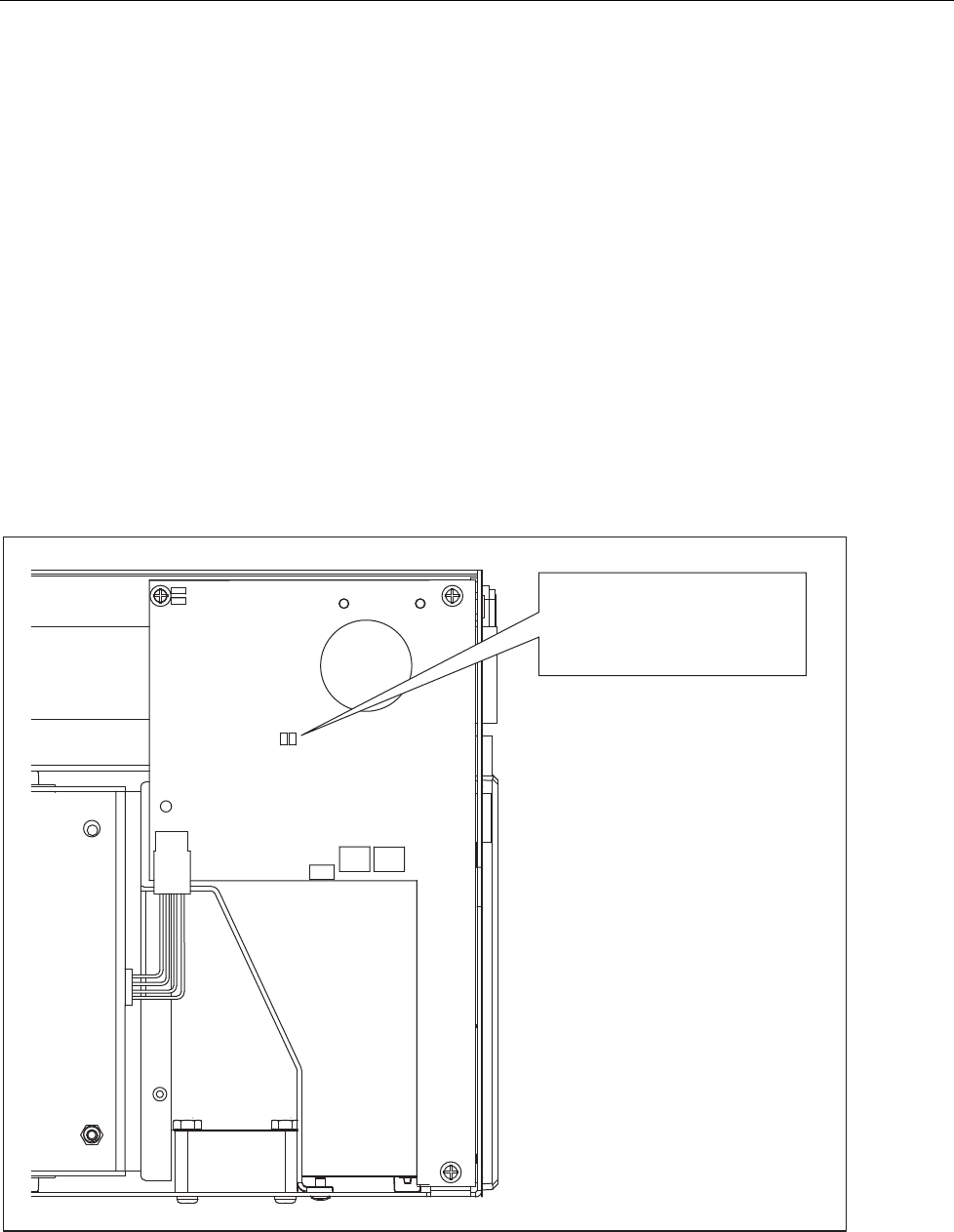
HYDRA Series III Data Acquisition Unit
Calibration Adjustment
35
Reset the Admin Password
If the admin password is lost or forgotten, the password can be reset to 2638 with
these steps:
Note
Before doing these steps, try to use the factory default password:
2638.
1. Do the general disassembly steps in the “Disassembly” section.
2. Connect a jumper across J8, as shown in Figure 9.
3. Reconnect the mains power cable between the Product and a power outlet.
4. Turn the Product on.
5. When the Product is started, the password will automatically be reset to
2638.
6. Turn the Product off and disconnect the mains power cable.
7. Remove the jumper connected in step 2.
8. Reassemble the Product by doing the reverse procedure in “Disassembly”.
J8
RST PSW
Fan
Battery
Display
Cable
InGuard
Shield
A6
PCB
Assembly
Short J8, then turn on the power.
After the instrument is successfully
started, the admin password is
reset to 2638.
hcn103.eps
Figure 9. Password Reset Jumper

2638A
Calibration Manual
36
Disassembly
XWWarning
To prevent possible electrical shock or personal injury,
disconnect the mains power cord before you remove the
Product covers.
Only disassemble the Product to reset the password or replace the battery. See
Figure 10.
A 2# Phillips screwdriver and small crescent wrench are required to disassemble
the Product.
1. Remove all high-capacity modules and test leads from the Product.
2. Turn off the mains power at the rear of the Product and remove the mains
power cord. The front panel power key only puts the Product into a power-
save mode and does not remove mains power.
3. Remove the boots by pulling from a corner and stretching the bumpers off
the Product.
4. Remove the bail by rotating the handle upright to a 90 ° angle from the top
of the Product and pulling the bail out from the sides.
5. Remove the top cover by removing the two screws on the sides of the
chassis, and slide the cover towards the back of the Product .
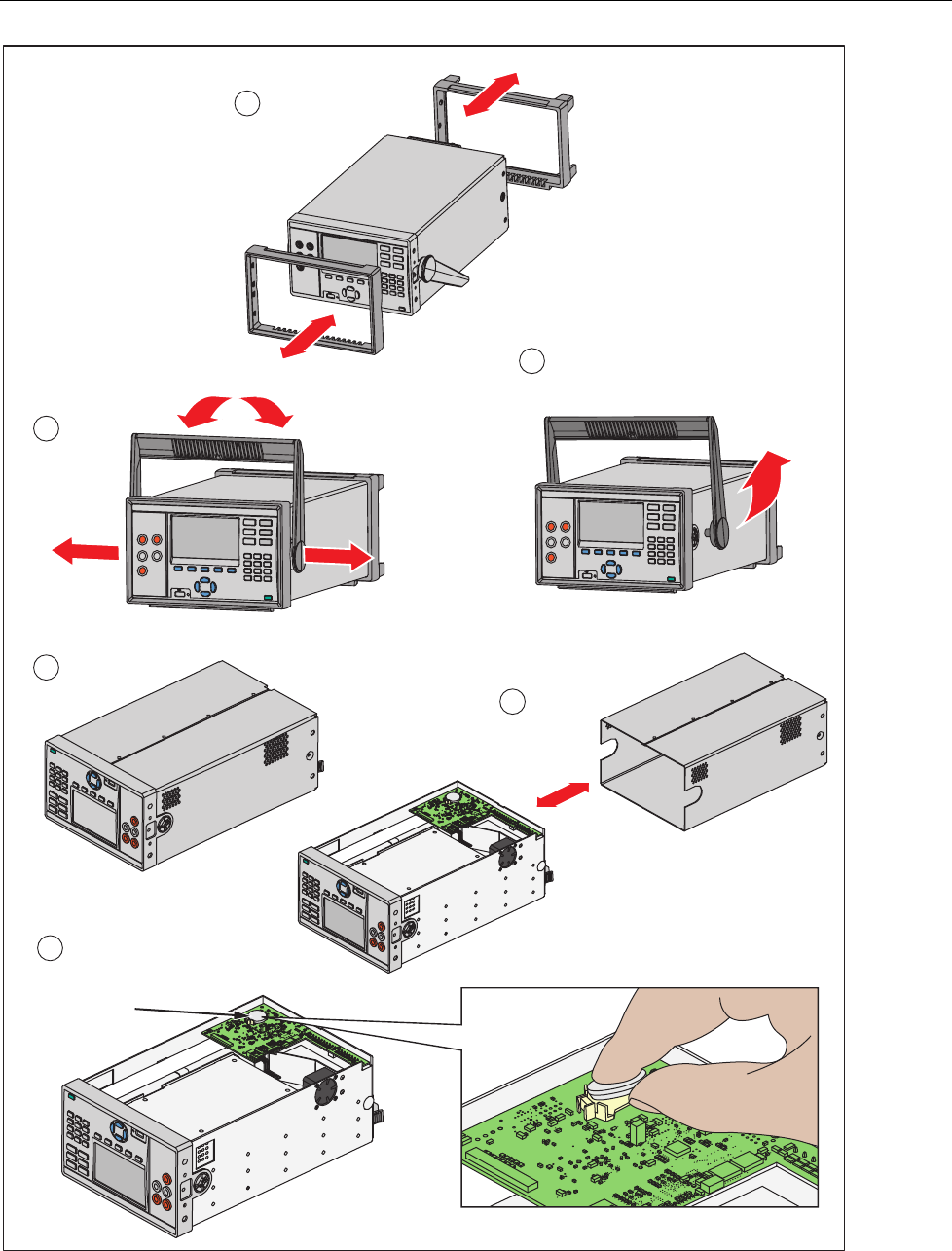
HYDRA Series III Data Acquisition Unit
Calibration Adjustment
37
To Remove, Pull End From Unit
3
Boot Removal
1
Battery
4
5
2
6
hcn309.eps
Figure 10. Disassembly
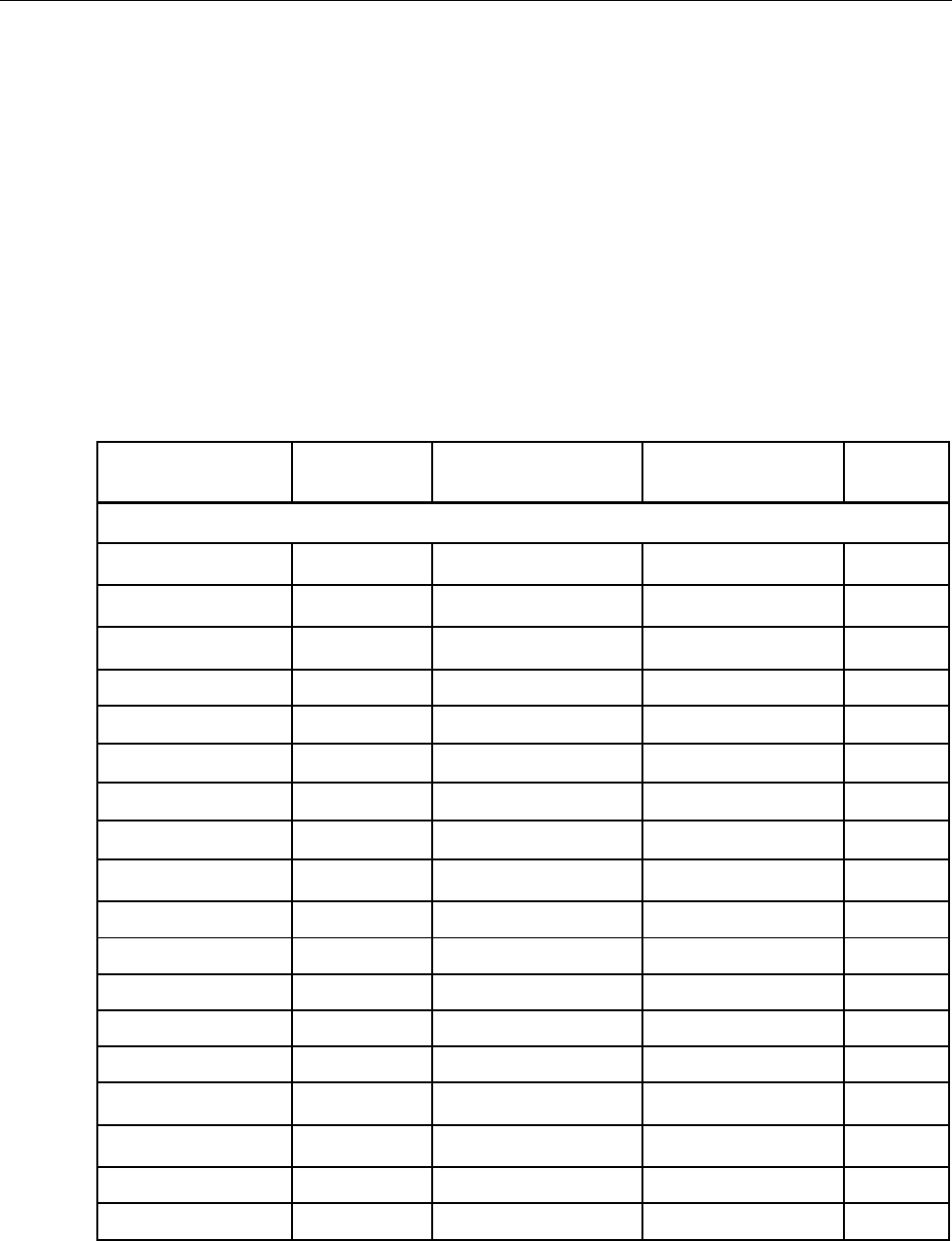
2638A
Calibration Manual
38
Change the Calibration Date Remotely
The calibration date is automatically updated when the “CALibrate:STORe”
command is sent.
“Mainframe” Adjustment Process
Table 13 lists:
• Steps
• Description of the adjustment
• Measurement adjustment type (open, zero, or gain adjustment)
• Product value or range that is to be adjusted
• Amplitude of the adjustment signal
• The frequency of the adjustment signal (if necessary)
Table 13. Adjustment Steps
Step Value
Range Input Signal Description Entry
Point
MAIN
A2D open ADC self-calibration Y
ACV
AC100MV 0.1 Start calibration of
ac 100 mV range Y
AC_100MV_1 100.0 mV, 1 kHz N
AC_50MV_1 50.0 mV, 1 kHz N
AC_25MV_1 25.0 mV, 1 kHz N
AC_5MV_1 5.0 mV, 1 kHz N
AC_0V_1 0.0 V N
AC1V 1.0 Start calibration of
ac 1 V range Y
AC_1V_2 1.0 V, 1 kHz N
AC_0_5V_2 0.5 V, 1 kHz N
AC_0_25V_2 0.25 V, 1 kHz N
AC_0_05V_2 0.05 V, 1 kHz N
AC_0V_2 0.0 V N
AC_1V_LF 1 V, 20 Hz AC LF
compensation N
AC10V 10.0 Start calibration of
ac 10 V range Y
AC_10V_3 1.0 V, 1 kHz N
AC_5V_3 5.0 V, 1 kHz N

HYDRA Series III Data Acquisition Unit
Calibration Adjustment
39
Table 13. Adjustment Steps (cont.)
Step Value
Range Input Signal Description Entry
Point
AC_2_5V_3 2.5 V, 1 kHz N
AC_0_5V_3 0.5 V, 1 kHz N
AC_0V_3 0.0 V N
AC100V 100.0 Start calibration of ac
100 V range Y
AC_100V_4 100.0 V, 1 kHz N
AC_50V_4 50.0 V , 1 kHz N
AC_25V_4 25.0 V, 1 kHz N
AC_5V_4 5.0 V, 1 kHz N
AC_0V_4 0.0 V N
AC300V 300.0 Start calibration of ac
300 V range Y
AC_300V_5 300.0 V, 1 kHz N
AC_200V_5 200.0 V, 1 kHz N
AC_100V_5 100.0 V, 1 kHz N
AC_50V_5 50.0 V, 1 kHz N
AC_0V_5 0.0 V N
DCV
DC100MV 0.1 Start calibration of dc
100 mV range Y
DC_P100MV_1 100.0 mV N
DC_0V_1 0.0 V N
DC_N100MV_1 -100.0 mV N
DC1V 1.0 Start calibration of dc 1 V
range Y
DC_P1V_2 1.0 V N
DC_0V_2 0.0 V N
DC_N1V_2 -1.0 V N
DC10V 10.0 Start calibration of dc
10 V range Y
DC_P10V_3 10.0 V N
DC_0V_3 0.0 V N

2638A
Calibration Manual
40
Table 13. Adjustment Steps (cont.)
Step Value Range Input
Signal Description Entry
Point
DC_N10V_3 -10.0 V N
DC100V 100.0
Start calibration of dc 100 V
range Y
DC_P100V_4 100.0 V N
DC_0V_4 0.0 V N
DC_N100V_4 -100.0 V N
DC300V 300.0
Start calibration of dc 300 V
range Y
DC_P300V_5 300.0 V N
DC_0V_5 0.0 V N
DC_N300V_5 -300.0 V N
OHM
R100 100.0
Start calibration of FRES
100 Ω range Y
R_100_1 100.0 Ω N
R_19_1 19.0 Ω N
R_0_1 0.0 Ω N
R1K 1.0E+3
Start calibration of FRES
1 kΩ range Y
R_1K_2 1.0 kΩ N
R_190_2 190.0 Ω N
R_0_2 0.0 Ω N
R10K 10.0E+3
Start calibration of FRES
10 kΩ range Y
R_10K_3 10.0 kΩ N
R_1_9K_3 1.9 kΩ N
R_0_3 0.0 Ω N
R100K 100.0E+3
Start calibration of FRES
100 kΩ range Y
R_100K_4 100.0 kΩ N
R_19K_4 19.0 kΩ N

HYDRA Series III Data Acquisition Unit
Calibration Adjustment
41
Table 13. Adjustment Steps (cont.)
Step Value Range Input
Signal Description Entry
Point
R_0_4 0.0 Ω N
R1M 1.0E+6
Start calibration of FRES
1 MΩ range Y
R_1M_5 1.0 MΩ N
R_190K_5 190.0 kΩ N
R_100K_5 100.0 kΩ N
R_0_5 0.0 Ω N
R10M 10.0E+6
Start calibration of RES
10 MΩ range Y
R_10M_6 10.0 MΩ N
R_1_9M_6 1.9 MΩ N
R_1_0M_6 1.0 MΩ N
R_0_6 0.0 Ω N
R100M 100.0E+6
Start calibration of RES
100 MΩ range Y
R_100M_7 100.0 MΩ N
R_19M_7 19.0 MΩ N
R_0_7 0.0 Ω N
THERM
T2K 2.2E+3
Start calibration of FTH
2 kΩ range Y
T_1_9K_1 1.9 kΩ N
T_1_0K_1 1.0 kΩ N
T_190_1 190.0 Ω N
T_0_1 0.0 Ω N
T90K 90.0E+3
Start calibration of FTH
90 kΩ range Y
T_100K_2 100.0 kΩ N
T_19K_2 19.0 kΩ N
T_10K_2 10.0 kΩ N
T_0_2 0.0 Ω N
T1M 90.0E+3
Start calibration of FTH
1 MΩ range Y

2638A
Calibration Manual
42
Table 13. Adjustment Steps (cont.)
Step Value Range Input
Signal Description Entry
Point
T_1M_3 1.0 MΩ N
T_190K_3 190.0 kΩ N
T_100K_3 100.0 kΩ N
T_0_3 0.0 Ω N
HZ
HZ1K
Start calibration of
frequency Y
HERTZ 1000.0 Hz,
1 V N
ACI
AC100UA 100.0E-6 Start calibration of ac
100 μA range Y
AC_100UA_1 100.0 μA,
500 Hz N
AC_50UA_1 50.0 μA,
500 Hz N
AC_25UA_1 25.0 μA,
500 Hz N
AC_10UA_1 10.0 μA,
500 Hz N
AC_0A_1 Open N
AC1MA 1.0E-3 Start calibration of ac 1 mA
range Y
AC_1MA_2 1.0 mA,
500 Hz N
AC_0_5MA_2 0.5 mA,
500 Hz N
AC_0_25MA_2 0.25 mA,
500 Hz N
AC_0_05MA_2 0.05 mA,
500 Hz N
AC_0A_2 Open N
AC10MA 10.0E-3 Start calibration of ac
10 mA range Y
AC_10MA_3 10.0 mA,
500 Hz N

HYDRA Series III Data Acquisition Unit
Calibration Adjustment
43
Table 13. Adjustment Steps (cont.)
Step Value Range Input Signal Description Entry
Point
AC_5MA_3 5.0 mA, 500 Hz N
AC_2_5MA_3 2.5 mA, 500 Hz N
AC_0_5MA_3 0.5 mA, 500 Hz N
AC_0A_3 Open N
AC100MA 100.0E-3 Start calibration of ac
100 mA range Y
AC_100MA_1 100.0 mA,
500 Hz N
AC_50MA_1 50.0 mA, 500 Hz N
AC_25MA_1 25.0 mA, 500 Hz N
AC_5MA_1 5.0 mA, 500 Hz N
AC_0A_1 Open N
DCI
DC100UA 100.0E-6 Start calibration of dc
100 μA range Y
DC_P100UA_1 100.0 μA N
DC_0A_1 Open N
DC_N100UA_1 -100.0 μA N
DC1MA 1.0E-3 Start calibration of dc
1 mA range Y
DC_P1_0MA_2 1.0 mA N
DC_0A_2 Open N
DC_N1_0MA_2 -1.0 mA N
DC10MA 10.0E-3 Start calibration of dc
10 mA range Y
DC_P10MA_3 10.0 mA N
DC_0A_3 Open N
DC_N10MA_3 -10.0 mA N
DC100MA 100.0E-3 Start calibration of dc
100 mA range Y
DC_P100MA_4 100.0 mA N
DC_0A_4 Open N
DC_N100MA_4 -100.0 mA N

2638A
Calibration Manual
44
Remote Commands for Calibration
Table 14 alphabetically lists the command set for calibration.
Table 14. List of Commands
Remote Command Meaning
CALibrate:ABORt Instruct unit to abort calibration procedure after
present step.
CALibrate:BACKup Backup to previous entry point in calibration
procedure.
CALibrate:CONSt? Retrieve the value in use of the given calibration
constant.
CALibrate:DATE? Return a CAL date associated with stored
calibration constants.
CALibrate:INFO? Return message or instructions associated with
running step.
CALibrate:MOD:DATE
<slot>,<year>,<month>,<day> Set CAL date of module in specified slot.
CALibrate:NEXT [<reference>] Continue a calibration procedure if it is waiting.
CALibrate:REF? Return nominal value expected for reference entry.
CALibrate:SECure:STATe
<boolean>,<admin_password> Instruct unit to enable calibration.
CALibrate:SECTion Skip to next section of calibration procedure.
CALibrate:SKIP Skip to next entry point in calibration procedure.
CALibrate:STARt <procedure>[,<step>] Start a calibration procedure.
CALibrate:STATe? Return state of calibration.
CALibrate:STEP? Return name of step currently running.
CALibrate:STORe Store new calibration constants.
CALibrate:MODule:DATE
<slot>,<year>,<month>,<day> Set module CAL date.

HYDRA Series III Data Acquisition Unit
Remote Commands for Calibration
45
Remote Programming Examples
This section gives examples of command sequences for several likely scenarios.
Start a Full Calibration
Table 15 shows an example to run a full calibration.
Table 15. Full Calibration Example
Command Action
CAL:SEC:STAT OFF,”2638” Disable the security for calibration.
CAL:STAR MAIN Start MAIN calibration procedure, and show instruction of MAIN
calibration procedure.
CAL:NEXT Continue to show instruction of ACV calibration.
CAL:NEXT
Continue to perform ACV calibration.
After it is completed, show instruction to connect the calibrator to
the instrument for ACV calibration.
CAL:NEXT Show instruction to ask for 100 mV/1 kHz signal input, and the
reference value.
CAL:NEXT 0.1
Continue to perform measurements for this point, after it is
completed, show instruction to ask for 50 mV/1 kHz signal input
and the reference value.
CAL:NEXT 0.05
Continue to perform measurements for this point, after it is
completed, show instruction to ask for 25 mV/1 kHz signal input
and the reference value.
CAL:NEXT 0.025
Continue to perform measurements for this point, after it is
completed, show instruction to ask for 5 mV/1 kHz signal input
and the reference value.
CAL:NEXT 0.005
Continue to perform measurements for this point, after it is
completed, show instruction to ask for 0V signal input and the
reference value.
CAL:NEXT 0.0
Continue to perform measurements for this point, after it is
completed, calculate the calibration constants for ac 100 mV
range, then show instruction to ask for 1 V/1 kHz signal input and
the reference value (the first calibration point of next ac 1 V
range.
… …
CAL:STOR Store the calibration constants.
CAL:ABOR Abort the calibration procedure.

2638A
Calibration Manual
46
Calibrate 1 V DC Range only
Table 16 shows an example to run a calibration for 1 V dc.
Table 16. 1 V DC Calibration Example
Command Action
CAL:SEC:STAT OFF,”2638” Disable the security for calibration.
CAL:STAR MAIN,DC1V
Start MAIN calibration procedure, and jump to 1 V dc range
directly, it will show ask for 1 V signal input, and the reference
value.
CAL:NEXT 1
Continue to perform measurements for this point, after it is
completed, show instruction to ask for 0 V signal input and the
reference value.
CAL:NEXT 0
Continue to perform measurements for this point, after it is
completed, show instruction to ask for -1 V signal input and the
reference value.
CAL:NEXT -1
Continue to perform measurements for this point, after it is
completed, calculate the calibration constants for DC 1V range,
then show instruction to ask for 10 V signal input and the
reference value (the first calibration point of next 10 V dc range.
CAL:STOR Store the calibration constants.
CAL:ABOR Abort the calibration procedure.
Write Calibration Date to a Module
Table 17 shows an example to write the calibration date into a module after the
CJC accuracy is validated.
Table 17. Write Calibration Date to a Module Example
Command Action
CAL:SEC:STAT OFF,”2638” Disable the security for calibration.
CAL:MOD:DATE 1,2014,11,1 Write “2014/11/1” as new calibration date into module in slot 1.

HYDRA Series III Data Acquisition Unit
Remote Commands for Calibration
47
Command References
CALibrate:ABORt
Description: Instruct unit to abort calibration procedure after present
step.
Example: CAL:ABOR
Related Commands:
CALibrate:STATe?
CALibrate:BACKup
Description: Backup to previous entry point in calibration procedure.
Example: CAL:BACK
Related Commands:
CALibrate:SKIP
CALibrate:SECTion
CALibrate:CONSt? “<cco_name>”
Description: Retrieves the value in use of the given calibration constant.
Example: CAL:CONS? “DC100MV_A1”
Response: -1.401686110719e-04
Related Commands:
CALibrate:SECure:STATe
CALibrate:STORe
CALibrate:DATE?
Description: Return a CAL date associated with stored calibration
constants.
Example: CAL:DATE?
Response: 2013,11,1
Related Commands:
CALibrate:MODule:DATE?

2638A
Calibration Manual
48
CALibrate:INFOrmation?
Description: Return message or instructions associated with
running step.
Example: CAL:INFO?
Response: “Connect calibrator to Volt terminals”
Related Commands:
CALibrate:STATe?
CALibrate:STEP?
CALibrate:MODule:DATE <slot>,<year>,<month>,<day>
CALibrate:MODule:DATE? <slot>
Description: Set and query module calibration date.
Example: CAL:MOD:DATE 1,2013,11,1
CAL:MOD:DATE? 1
Response: 2013,11,1
Related Commands:
CALibrate:SECure:STATe
CALibrate:NEXT [<reference>]
Description: Continue a calibration procedure if it is waiting. An
optional parameter reference value (used if it's waiting
for a reference), If the reference value has no unit, the
unit is assumed to be that returned by the CAL_REF?
command.
Example: CAL_NEXT
CAL_NEXT 2.999987
CAL_NEXT 100 mV
Related Commands:
CALibrate:REFerence?
CALibrate:BACKup
CALibrate:SKIP

HYDRA Series III Data Acquisition Unit
Remote Commands for Calibration
49
CALibrate:REFerence?
Description: Return nominal value expected for reference entry.
Example: CAL:REF?
Response: 3.000000e+00
Related Commands:
CALibrate:NEXT
CALibrate:STATe?
CALibrate:INFOrmation?
CALibrate:STEP?
CALibrate:SECure:STATe <boolean>, <admin_password>
Description: Instruct unit to enable calibration.
Example: CAL:SEC:STATE OFF,”1586”
Related Commands:
CALibrate:SECure:STATe?
CALibrate:SECure:STATe?
Description: Query calibration enable state.
Example: CAL:SEC:STAT?
Response: 1
Related Commands:
CALibrate:SECure:STATe
CALibrate:SECTion
Description: Skip to next section of calibration procedure.
Example: CAL:SECT
Related Commands:
CALibrate:BACKup
CALibrate:SKIP
CALibrate:SKIP
Description: Skip to next entry point in calibration procedure.
Example: CAL:SKIP
Related Commands:
CALibrate:BACKup
CALibrate:SECTion

2638A
Calibration Manual
50
CALibrate:STARt <procedure>[,<step>]
Description: Start a calibration procedure. As parameter, the name
of procedure should be provided (MAIN is the
procedure for full instrument calibration), an optional
parameter <step> can be provided to start from, if it is
omitted, it starts at the beginning. Before any
calibration procedure can be started, the calibration
secure state should be disabled.
Example: CAL_START MAIN
CAL_START MAIN,DC1V
Related Commands:
CALibrate:SECure:STATe
CALibrate:STATe?
Description: Return state of calibration.
Example: CAL:STAT?
Response: RUN - running a calibration step
REF - waiting for a CAL_NEXT with reference
(measurement) value
INS - instruction available, waiting for a CAL_NEXT
NOT - not in a calibration procedure (or at end of one)
Related Commands:
CALibrate:STEP?
CALibrate:REFerence?
CALibrate:INFOrmation?

HYDRA Series III Data Acquisition Unit
Remote Commands for Calibration
51
CALibrate:STEP?
Description: Return name of step currently running.
Example: CAL:STEP?
Response: DC1V
Related Commands:
CALibrate:STATe?
CALibrate:REFerence?
CALibrate:INFOrmation?
CALibrate:STORe
CALibrate:STORe?
Description: Store new calibration constants or query whether a
cal store is needed.
Example: CAL:STOR
CAL:STOR?
Response: 1 is yes, 0 if no
Related Commands:
CALibrate:SECure:STATe
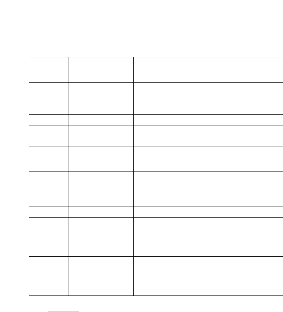
2638A
Calibration Manual
52
User-Replaceable Parts and Accessories
Table 18 lists the part numbers of each user-replaceable part or accessory for
the Product, see Figure 11.
Table 18. User-Replaceable Parts and Accessories
Item Fluke
Part
Number Qty Description
4281998 1 FLUKE-1586A-2010, 2638A HANDLE
4281980 1 FLUKE-1586A-2009, 2638A FRONT PANEL BOOT
4281971 1 FLUKE-1586A-2008, 2638A REAR PANEL BOOT
4396173 1 FLUKE 1586A-2586 RELAY CARD
4374731 1 FLUKE-1586A-2586, 2638A, PROTECTIVE SLOT COVER
4338362 1 FLUKE-2638A, REAR SLOT FRAME
4357143 6
SCREW,4-40 X 0.375
IN.,FLAT,PHILLIPS,SS,PASSIVATED,LOCK
PATCH,ROHS COMPLIANT
Contact
Fluke 1 FLUKE 1586A-2586 HI-CAPACITY MODULE
Not Shown 1588940 1 BATTERY,PRIMARY,LI-
MNO2,3V,560MAH,COIN,CR2450,24X5MM,BULK
Not Shown 4410441 1 Transit Case
Not Shown 4121552 1 884X-4GB,USB MEMORY, 4GB
Not Shown 4298499 1 CABLE, USB MALE A TO MALE B, 2M
Not Shown 884X-
ETH 1 884X-ETH, ETHERNET INTERFACE CABLE, 1m
Not Shown Variable
[3] 1 Test lead set [3]
Not Shown 4394437 1 WFUSE,0.16A,250V,SLOW,0.5 I2T,6X32MM,CERAMIC [2]
Not Shown 166306 1 W Fuse 0.25A, 250V (slow blow) [2]
[1] Quantity of items listed can vary based on kit or model ordered.
[2] Only use exact replacements.
[3] See www.fluke.com for more information about the test leads for your region.
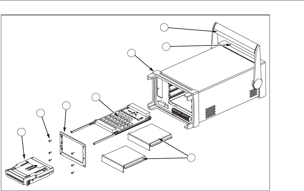
HYDRA Series III Data Acquisition Unit
User-Replaceable Parts and Accessories
53
1
2
3
4
6
5
7
8
hcn310.eps
Figure 11. Replaceable Parts

2638A
Calibration Manual
54
