USA102682993 2682993_Accounting_Machine_Data_Indicator_Jul54 2682993 Accounting Machine Data Indicator Jul54
2682993_Accounting_Machine_Data_Indicator_Jul54 2682993_Accounting_Machine_Data_Indicator_Jul54
User Manual: 2682993_Accounting_Machine_Data_Indicator_Jul54
Open the PDF directly: View PDF ![]() .
.
Page Count: 30
~
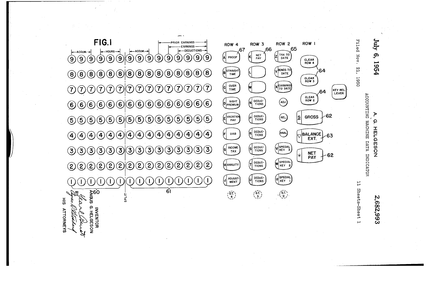
· FIG.I
hPRIOR
EARNINGS==:!
®®®®®®1®®®®4~~~®
,
®®®®®®I®®®®®®®®®
,
000000100000
0000
,
®®®®®®I®®®®,®®®®®
,
®®®®®®I®®®®®®®®®
®®®®®®i®®®®@)@)@)@)@)
®®®®®®I®®®®®®®®®
®®®®®®i®®®®®®®®®
02
CD
CDyCDCD
CJ)I'02
CD
CD
CD
cp
CD CD
CDCJ)
~
~60
I-
61
~
~
~
:1~
~Z
~
-l
~<
-l
111111
o
rz
::0
~-l
Z
1110
~
~::o
C/) I Z
ROW
4
8
67
A
PROOF
G
G:Ul3
IG~'\
\
....
~/
ROW
3
@
66
K
NET
PAY
o
o
{
....
G~T>I
, 3 I
'-'
ROW
I
64
64
8
e
[GRO~62
8
~-62
~
,--
__
{.;T.~
-j
"'l
1-"
I-'
<D
Po
Z
o
<:
N
I-'
I-'
(!J
(Jl
o
I-'
I-'
UJ
::r
<D
<D
c+
rn
I
UJ
::r
<D
<D
c+
I-'
:»
o
o
g
c....
~
$1l
~
(J:)
en
.;:..
Z
0-'1
H
Z »
0,
.
is:
G'l
:»
.
§2
:r
H
(T1
Eii
r
o
G'l
~
(T1
0-'1
Ul
:»
0
!;l
Z
o
H
o
~
o
:;0
N
0')
<Xl
N
10
(J:)
w
July
6,
1954
A.
G.
HELGESON
2,682,993
ACCOUNTING
MACHINE
DATA
INDICATOR
Filed
Nov.
21, 1950 11
Sheets-Sheet
2
171
FIG.2
NET PAY
"-
HOURS
BASE OVERTIME
AOB
WITHHOLDING
;;;-;,
OTHER
UNION
INSURANCE
HOSPIT:C
PAY PAY
TAX
DEDUCTIONS
DUES
JOHN
C.
DOE
236
$1.291/2
2
2.59
.
.03
2.56
1.06
.46 .46
4
5.18
.05 5.13
3.63
3.03
3.03
6
7.77
.08
7.69
6.19
5.59
1.44
8 10.36 .10 10.26
8.76
8.16
4.01
10 12.95 .13 12.82 11.32 10.72
6.57
12
15.54 .16 15.38 13.88
13.28
9.13
14 18.13 .18 17.95 16.45
15.85
11.70
16
20.72
.21
20.51 19.01 18.41 14.26
18
23.31
.23
23.08
21.58
20.98
16.83
20
25.90
.26
25.64
24.14
23.54
19.39
22
28.49
.28
.40
27.81 26.31 25.71
21.56
24
31.08
.31
.90
29.87
28.37
27.77 23.62
26
33.67
.34
1.20 32.13
30.63
30.03
25.88
28
36.26
.36
1.60
34.30
32.80
32.20
28.05
30
38.85
.39 1.90
36.56
35.06 34.46
30.31
32
41.44
.41
2.40
38.63
37.13
36.53
32.38
34
44.03
.44
2.80
40.79
39.29
38.69
34.54
36
46.62
.47
3.10
43.05
41.55
40.95
36.80
38
49.21 .49
3.60
45.12
43.62
43.02
38.87
40
51.80
.52
3.90
47.38
45.88
45.28
41.13
42
54.39
1.30
.56
4.50
50.63
49.13
48.53 44.38
44
56.98
2.59
.60
5.10
53.87
52.37
51.77
47.62
46
59.57
3.89
.63
5.60
57.23 55.73
55.13
50.98
48
62.16
5.18
.67
6.20
60.47
,58.97
58.37
54.22
39.9
51.77
.52
3.90
47.35
45.85
45.25
41.10
39.8
51.54
.52
3.90
47.12
45.62
45.02
40.87
39.7
51.41
.51
3.90
47.00
45.50 44.90
40.75
39.6
51.28
.51
3.90
46.87
45.37
44.77
40.62
39.5
51.15
.51
3.90
46.74
45.24
44.64
40.49
.00
1.50
2.10
6.25
.00
.13
.26
.39 .52 .65 .78
.91
1.04
1.17 FRACTIONAL EARNINGS
.00
.13
.26
.39
.41
.54
.67
.80
.93
1.06 BALANCE FACTOR
1.30
1.43 1.56 1.69 1.82 1.95
2.08
2.21
2.34
2.47
EARNINGS
1.19 1.32 1.34 1.47 1.60 1.73 1.86 1.99 2.12 2.25 BALANCE FACTOR
1.0
.1
.2
.3
.4
.5 .6 .7 .8 .9 HOURS
INVENTOR
ANGUS
G.
HELGESON
B~~
~
ATTOR
EYS
July
6,
1954
Filed
Nov. 21, 1950
172
BASE
HOURS
PAY
40
51.80
20
25.90
39-3/4
51.48
39-1/2
51.15
39-114
50.83
48
62.16·
28
36.26
47-3/4
61.84
47-1/2
61.51
47-1/4
61.19
36
46.62
16
20.72
15-3/4
20.40
15-1/2
20.07
15-
114
19.75
44
56.98
24
31.10
23-3/4
30.76
.
23-1/2
30.43
23-1/4
30.11
32
41.44
12
15.54
31-3/4
41.12
31-1/2
40.79
31-114
40.47
8
10.36
4
5.18
JOHN
A.
G.
HELGESON
ACCOUNTING
MACHINE
DATA
INDICATOR
2,682,993
FIG.3
OVERTIME A 0 B
WITHHOLDING
/No
OTHER
PAY
. . .
TAX
DEDUCTIONS
.52
3.90
47.38
.26
25.64
.51
3.90
47.07
.51
3.90
46.74
.51
3.70
46.62
5.18 .67
6.20
60.47
.36 1.60
34.30
5.02
.67
6.20
59.99
4.86.
.66
6.20
59.51
4.69 .66
5.90
59.32
.47 3.10
43.05
.21
20.51
20
20.20
.20 19.87
20
19.55
2.59
.60
5.10
53.87
.31
.90
29.87
.31
.70
29.75
.30 .70
29.43
.30 .70
29.11
.41
2.40
38.63
.16 15.38
.41
2.40
38.31
.41
2.20
38.18
.40
2.20
37.87
.10
10.26
.05
5.13
C.
DOE
236
$1.29!4
11
Sheets-Sheet
3
NET"PAY
UNION
DUES
45.88
24.14
45.57
45.24
45.12
58.97
32.80
58.49
58.01
57.82
41.55
19.01
18.70
18.37
18.05
52.37
28.37
28.25
27.93
27.61
37.13
13.88
36.81
36.68
36.37
8.76
3.63
""'-
INSURANCE HOSPITAL
45.28
41.13
23.54
19.39
44.97 40.82
44.64 40.49
44.52
40.37
58.37
54.22
32.20
28.05
57.89
53.74
57.41
53.26
57.22
53.07
40.95
36.80
18.41
14.26
18.10 13.95
17.77 13.62
17.45
13.30
51.77
47.62
27.77
23.62
27.65
23.50
27.33 23.18
27.01
22.86
36.53
32.38
13.28· 9.13
36.21
32.06
36.08
31.93
35.77 31.62
8.16
4.01
3.03
3.03
INVENTOR
ANGUS
G.
HELGESON
~~
BY
.
(J.R:f~
~
HIS ATTORNEYS
July
6,
1954
Filed
Nov. 21, 1950
150
A. G.
HELGESON
ACCOUNTING
MACHINE
DATA
INDICATOR
2,682,993
11
Sheets-Sheet
4
FIG.5
74
INVENTOR
ANGUS
G.
HELGESON
Byg~~
rlf,~
HIS ATTORNEYS
July
6,
1954
Filed
Nov.
21, 1950
FIG.
6
~
~
~
~
234
~
228-
2
22-
~
2
42-
\
A. G.
HELGESON
2,682,993
ACCOUNTING
MACHINE
DATA
INDICATOR
G
-
TRANSLUCENT
OPAQUE
COVER~
1fi
1
r-
~-
~
i ;
i',
i
-
3-
~
11
Sheets-Sheet
5
~
G
G
1-----
192
G
185
186
G
.....
187
~
18
8
.G
189
t-
192
_1-
180
--179
INVENTOR
ANGUS
G_HELGESON
~~
BY
t?lWlf.~-I
HIS
ATTORNEYS
July
6,
1954
Filed
Nov. 21, 1950
180
217
216 215
A G.
HELGESON
ACCOUNTING
MACHINE
DATA
INDICATOR
FIG.7
FIG.8
212
219
238
232
226
220
\ \
2,682,993
II
Sheets-Sheet
6
192
11=;;;;:.~/'193
135
INVENTOR
ANGUS
G.
HELGESON
BY~~
a;~
$.;2:1.2241/-1
{/
HIS
ATTORNEYS
July
6, 1954
Filed
Nov. 21. 1950
185
A.
G.
HELGESON
ACCOUNTING
MACHINE
DATA
INDICATOR
FIG.9
179
2,682,993
11
Sheets-Sheet
7
INVENTOR
~NGUS
G.
HELGESON
~~
BY
.
~If.~
7/
HIS ATTORNEYS
HRS.
2
10
14
20
24
28
30
34
38
40
44
39.9
39.7
39.5
FIG.
10
312""'-}<
IliII>-jII'
361
t~
:ltt
-l~
trTIrii
-l
r z
o
(i)-l
~
mO
rTI
0:0
c:i
Z
·320
356
355
.408
152
I SKIP BUTTON
•
~409
"H'I'~
410
245
(
~LOCK
CARD
[1
-
-
~~~---
---------
---------
---------
---------
---------
---------
---------
---------
---------
---------
---------
---------
---------
---------
---------
--
-- --
---
346
"l
,....
f--'
(1)
P.
Z
o
<:
N
f--'
f--'
lO
U1
o
f--'
f--'o
Ul
:T
(1)
(1)
c+
ill
I
Ul
:T
(1)
(1)
c+
co
~
o
o
o
~
c...
c:
q'
~
.....
(0
en
~
H
a
~
s::
G)
~
.
~
:c
H
III
~
r
CJ
G)
~
III
>-'l
(J)
~ 0
!i Z
CJ
H
~
.0
:;0
!"
0)
00
N
10
(0
w
July
6,
1954
".
A.
G.
HELGESON
2,682,993
ACCOUNTING
MACI-lINE
DATA
INDICATOR
Filed
Nov. 21, 1950 11
Sheets-Sheet
9
44
6,,\~
448
-r--:.,
44
0.......)
425-
442~
4J6
4H--{!
FIG
•
II
7
a
4~j455
/460/
447
/449
lid-'
0"
I@i
u .
r---440
0 0 0 0
~--~----~--~----_o----~0
~425
o )424..--
___
--.:
.....
(4_2_2_
424
D
427
423
427)
II
/
/423
/Jrr-
o 1--442
:---438
~426
In
J
o
o
o
T
/
/
Q INVENTOR
ANGUS G. HELGESON
~~
Br41.:'~s
July
6,
1954
Filed
Nov. 21, 1950
FIG.
12
A.
G.
HELGESON
ACCOUNTING
MACHINE
DATA
INDICATOR
421
2,682,993
11
Sheets-Sheet
10
FIG.
13
INVENTOR
ANGUS G. HELGESON
~~~
B~ifa!~
HIS ATTORNEYS
July
6,
1954
Filed
Nov. 21, 1950
.---
I
A. G.
HELGESON
ACCOUNTING
MACHINE
DATA
INDICATOR
FIG.
14
o o
2,682,993
11
Sheets-Sheet
11
1--465
INVENTOR
ANGUS
G.
HELGESON
if~~
L-----------B~R.~
~
if
HIS ATTORNEYS
Patented
July
6, 1954
2,682,993
UNITED STATES
PATENT
OFFICE
2,682,993
ACCOUNTING
MACHINE
DATA
INDICATOR
Angus
G.
Helgeson,
Birmingham,
Mich.,
assignor
to
The
National
Cash
Register
Company,
Day-
ton,
Ohio,
a
corporation
of
Maryland
Application
November
21, 1950,
Serial
No. 196,906
13
Claims.
WI.
235-23)
1 2
This
invention
relates
to
accounting
machines
and
similar
bUsiness
machines
and
is
directed
par-
ticularly
to
means
for speeding
up
the
recording
of payroll
data
and
the
consequent
printing
of
the
payroll checks,
and
to
control
various
mechanisms
5
in
the
machine
in
this
connection.
This
invention
is especially
adapted
to
be
used
in
machines
of
the
payroll type,
shown
and
de-
scribed
in
the
United
states
Patent
No.
2,467,704,
issued April 19, 1949,
to
Pascal
Spurlino,
Rudolph
10
J.
Moser, Alfred G. Kibler,
Marvin
D.
Frost,
and
Walter
J.
Kreider,
and
for
illustrative purposes is
embodied
in
a
machine
of
the
type
shown
in
said
patent.
This
invention
is also embodied
in
machines
of
15
the
general
type
shown
in
the
following
United
states
Letters
Patent
and
reference
may
be
had
to
them
and
to
the
above-mentioned
patent
·for a
complete showing
and
description of
standard
mechanism
not
fully disclosed
herein:
United
20
states
Patents
Nos. 1,619,796; 1,747,397; 1,761,542;
and
1,916,535, issued
March
1, 1927;
February
18,
1930;
June
3, 1930;
and
July
4, 1933, respectively,
to
Bernis
M.
Shipley; No. 2,175,346, issued
Octo-
ber
10, 1939,
to
Maximilian
M. Goldberg; No.
25
2,141,332, issued December 27, 1938,
to
Charles
H.
Arnold; No. 1,693,279, issued November 27, 1928,
to
Walter
J.
Kreider;
No. 2,305,000, issued
De-
cember 15, 1942, to Mayo
A.
Goodbar;
No. 2,361-
662, issued October
31,
1944, to
Pascal
Spurlino
30
and
Konrad
Rauch;
No.
2,345,839, issued April
4, 1944,
to
Pascal
Spurlino, Mayo
A.
Goodbar,
and
Marvin
D.
Frost;
and
No. 2,351,541, issued
June
13, 1944,
to
Everett
H. Placke.
The
specific
machine
shown
in
the
above-men-
35
tioned
Patent
No.
2,467,704, embodying
the
pres-
ent
invention,
and
as now constructed, is well
adapted
for
use by
any
organization
where a
large
number
of payroll checks
are
to
be issued
period-
ically
and
particularly
where
such
organizations
40
wish to keep
accurate
records of
totals
of
amounts
paid
to
their
employees, ·and also a
record
of
var-
ious deductions
which
nowadays
are
common
practice.
As
is well known,
such
deductions
in-
clude social security
payments,
group
insurance
45
payments,
income
tax
withholdings
and
union
dues,
:md
many
other
types
of
deductions,
which
various
organizations
permit
their
employes
to
make
against
gross
earnings
for
a definite period.
Accurate records of
each
of
the
various types
50
of individual deductions
are
accumulated
in
the
machine,
with
the
result
that
the
company
may
at
any
time
definitely
ascertain,
by
means
of
printed
records,
the
various
totals
of
such
.de-
Quctions,
and
also
the
totals
of
the
net
earnings
.55
of
the
employees,
the
gross
earnings
of
the
employees,
and
other
records
relative
to
the
em-
ployees.
Other
records,
such
as
the
total
number
of
reg-
ular
hours
worked
and
the
total
number
of over-
time
hours
worked,
are
also
accumulated
in
the
machine,
so
that
the
company
may
at
any
time
definitely
ascertain
by
means
of
printed
records
the
number
of
regular
hours
paid
for
and
also
the
number
of overtime
hours
paid
for.
The
machine
is also
adapted
to
print
a
pay-
roll check,
upon
the
main
portion
of
which
are
shown
the
consecutive
number,
thedate,and
the
net
amount
of
the
check
printed
in
two places;
and
on
the
stub
portion
of
the
check,
which
is
to
be
torn
oft'
and
retained
by
the
employee before
he
cashes
the
check,
are
shown
the
number
of
regular
hours
he
worked,
the
gross
earnings
for
those
regular
hours,
the
number
of overtime hours,
the
gross
earnings
for
the
overtime hours, a
total
of
the
gross regUlar-hour
and
overtime-hour
earn-
ings, a
list
of
all
deductions, showing
the
amount
of
each, a symbol
for
each
deduction,
and
the
net
pay.
The
net
pay
printed
on
the
stub
portion
of
the
check is
identical
with
the
net
amount
which
is
printed
in
two places
on
the
main
portion
of
the
check.
The
machine
in
which
the
present
invention
is embodied is also
adapted
to
print
upon
the
payroll
summary
sheet,
which,
for
example,
may
be
used
for
the
departmental
summary
of
the
em-
ployees
in
anyone
or
more
departments.
If
the
departments
'are too large,
the
payroll
summary
may
be
allotted
to
various
jobs
of
the
depart-
ments.
An individual employee's
earnings
record
card
may
also
be
printed
by
the
machine
in
which
this
present
invention
is embodied.
Upon
this
earn-
ings
card,
which is divided
into
columns,
there
may
be
printed
the
number
of
regular
hours
the
employee works
and
the
number
of overtime
hours
he
works; also
the
gross
amount
of
earn-
ings for
regular
hours
and
the
gross
amount
of
earnings
for
overtime
hours
may
be
recorded.
The
deductions
against
each
employee
are
also
printed
and
recorded
on
this
particular
earnings
card
record
for
the
individual employee.
In
the
last
column
on
the
card
there
is
a
space
for
a
balance
forward,
which
is picked
up
from
a
former
earnings
record,
set
up
on
the
keyboard,
and
printed
in
this
column,
when
a
new
card
is
begun
for
the
employee
when
his
old
card
is
filled.
On
the
top
of
the
machine
there
is provided a
time
card
box,
which
carries
the
time
cards
for
2,682,993
each
individual employee.
On
these
time
cards
there
is various
data
relating
particularly
to
the
number
of
regular
hours
and
the
number
of
over-
time
hours
which
the
employee
has
worked.
On
this
card
there
are
also various types of deductions
which
have
been
previously
mentioned
and
which
are
recorded
thereon
by
the
clerk.
These
time
cards
are
adapted
to
be
ej ected
from
the
stack
upon
operation
of
the
Net
Pay
key.
Mounted
on
top
of
the
machine
and
alongside
the
time
card
box is also
what
will be
referred
to
hereinafter
as a
pattern
card
box.
This
pattern
card,
there
being one
for
each
individual
em-
ployee,
has
printed
on
it
certain
constant
figures
which
relate
to
the
printing
of
the
payroll check
for
this
particular
employee.
This
employee's
time
clock
card
and
his
pattern
card
are
side by
side, one
in
the
time
card
box
and
one
in
tIlel
pattern
card
box,
and
other
employees'
time
cards
and
pattern
cards
are
stacked
successivelY,
so
that,
each
time
a
time
clock
card
is ejected,
the
corresponding
pattern
card
for
the
same
employee will be ejected.
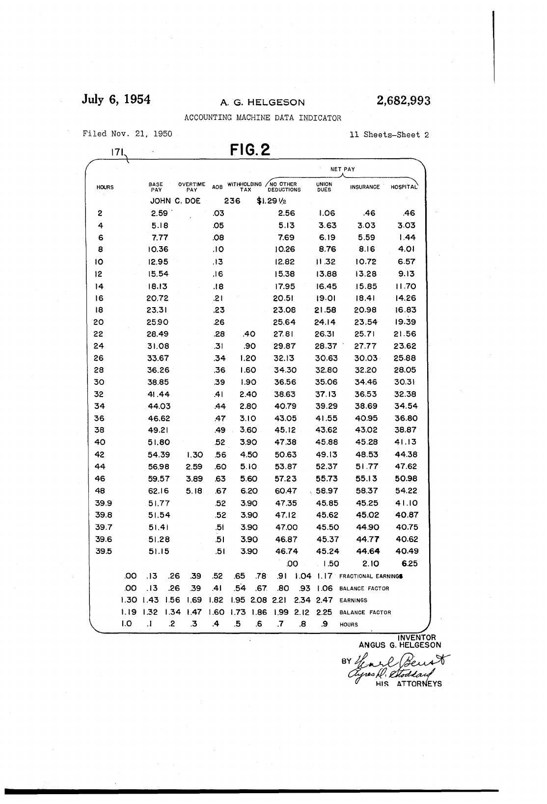
This
pattern
card
on
the
left
shows
the
number
of
hours
worked,
in
the
next
column
the
base
pay
for
that
number
of hours,
which
base
pay
has
been
figured according
to
the
rate
which
the
employee gets
per
hour.
Near
the
bottom
of
the
card
the
employee's
name
and
check
number
are
shown
and,
in
addition, his
hourly
rate,
which
in
the
example
and
illustration
given
herein
is
$1.29%
per
hour.
The
same
employee's
name
is
on
his
time
clock
card.
In
the
third
column
from
the
left
there
are
figures
which
show
the
overtime
pay.
The
next
column
shows
the
OAB
deductions
at
the
rate
of 1 %.
The
next
column
shows
the
withholding
tax
to
be
deducted.
4
of
the
differential
mechanism
of
the
hourly
banks, so
that,
through
the
combination
of
the
moving of
the
face
of
the
box
and
the
selection
of
the
propel' light,
anyone
of
the
four
lines of
5
::\,
group of
data
may
be selected
after
the
particu-
la,r group
has
been
selected by
the
depression of
the
hours
keys.
This
will all be described
in
detail
later
on
..
Generally,
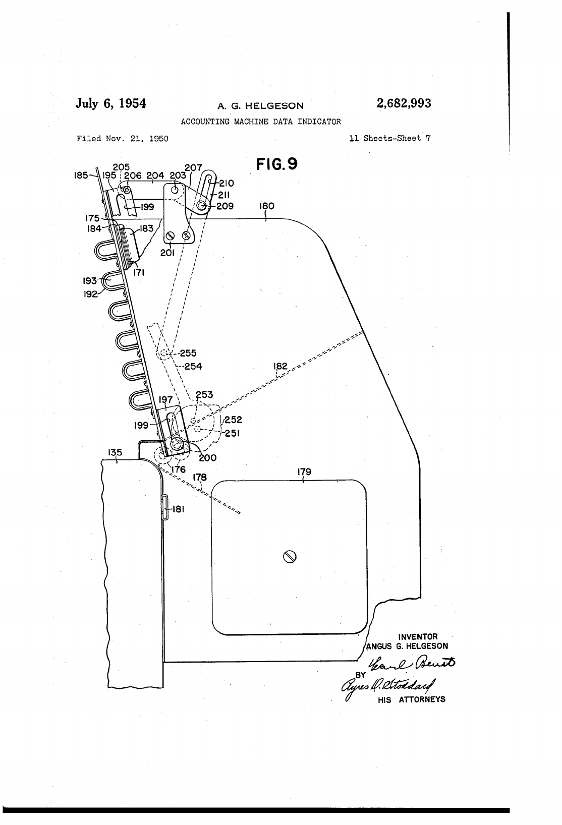
the
movable
face
is
constructed
in
10
such
a
manner
that,
through
the
use of solenoids,
the
said
movable face
can
be lowered
four
addi-
tional
positions,
making
five
in
all, so
that,
through
a
combination
of
the
moving of
the
face
of
the
box
and
the
selection of
the
proper
light
15
to
be illuminated,
anyone
of
thirty
lines
can
be
selected
on
each
card.
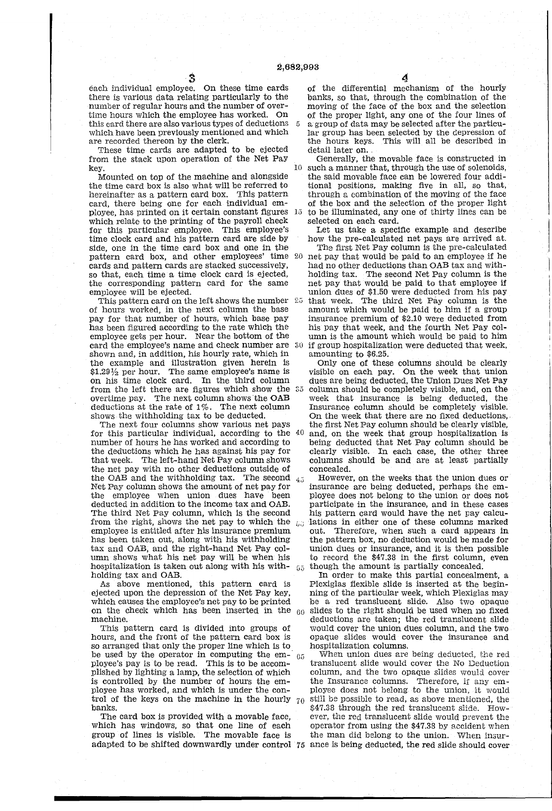
Let
us
take
a speCific
example
and
describe
how
the
pre-calculated
net
pays
are
arrived
at.
The
first
Net
Pay
column is
the
pre-calculated
20
net
pay
that
would
be
paid
to
an
employee
if
he
had
no
other
deductions
than
OAB
tax
and
with-
holding
tax.
The
second Net
Pay
column
is
the
net
pay
that
would
be
paid
to
that
employee
if
union
dues of $1.50 were
deducted
from
his
pay
2"
that
week.
The
third
Net
Pay
column
is
the
amount
which
would be
paid
to
him
if
a
group
insurance
premium
of $2.10 were deducted
from
his
pay
that
week,
and
the
fourth
Net
Pay
col-
umn
is
the
amount
which
would be
paid
to
him
30
if
group hospitalization were
deducted
that
week,
amounting
to
$6.25.
Only one
of
these
columns
should
be clearly
visible
on
each
pay.
On
the
week
that
union
dues
are
being deducted,
the
Union
Dues
Net
Pay
35
column
should
be completely visible,
and,
on
the
week
that
insurance
is being deducted, t.he
Insurance
column
should
be completely visible.
On
the
week
that
there
are
no
fixed deductions,.
the
first
Net
Pay
column
should
be clearly visible,
The
next
foul' columns show various
net
pays
for
this
particular
individual, according
to
the
number
of
hours
he
has
worked
and
according
to
the
deductions whiCh
he
has
against
his
pay
for
that
week.
The
left-hand
Net
Pay
column shows
the
net
pay
with
no
other
deductions outside of
the
OAB
and
the
withholding
tax.
The
second
4';
Net
Pay
column shows
the
amount
of
net
pay
for
the
employee
when
union
dues
have
been
deducted
in
addition
to
the
income
tax
and
OAB.
The
third
Net
pay
column, which is
the
second
from
tl1e
right,
shows
the
net
pay
to
which
the
employee is
entitled
after
his
insurance
premium
has
been
taken
out, along
with
his
withholding
tax
and
OAB,
and
the
right-hand
Net
Pay
col-
umn
shows
what
his
net
pay
will be
when
his
hospitalization
is
taken
out
along
with
his
with-
holding
tax
and
OAB.
40
and,
on
the
week
that
group
hospitalization
is
being deducted
that
Net
Pay
colunm
should
be
clearly visible.
In
each
case,
the
other
thr~e
columns
should
be
and
are
at
least
partially
concealed.
However,
on
the
weeks
that
the
union
dues
or
insurance
are
being deducted,
perhaps
the
em-
ployee does
not
belong
to
the
union
or
does
not
participate
in
the
insurance,
and
in
these
cases
his
pattern
card
would
have
the
net
pay
calcu-
i);;
lations
in
either
one of
these
columns
marked
out. Therefore,
when
such
a
card
appears
in
the
pattern
box,
no
deduction
would be
made
for
union
dues
or
insurance,
and
it
is
then
possible
to record
the
$47.38
in
the
first column, even
G5
though
the
amount
is
partially
concealed.
In
order
to
make
this
partial
concealment, a
Plexiglas fiexible slide is
inserted
p,t
the
begin-
ning
of
the
particular
week, which Plexiglas
may
be a
red
translucent
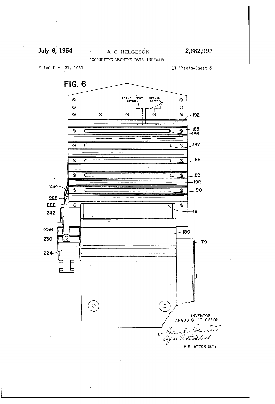
slide. Also two opaque
As
above
mentioned,
this
pattern
card
is
ejected
upon
the
depression of
the
Net
Pay
key,
which
causes
the
employee's
net
pay
to
be
printed
on
the
check which
has
been
inserted
in
the
machine.
This
pattern
card
is divided
into
groups of
hours,
and
the
front
of
the
pattern
card
box is
so
arranged
that
only
the
proper
line
which
is
to
GO
slides to
the
right
should
be
used
when
no fixed
deductions
are
taken;
the
red
translucent
slide
would cover
the
union
dues column,
and
the
two
opaque
slides would cover
the
insurance
and
hospitalization
columns.
be used by
the
operator
in
computing
the
em-·
Oli
ployee's
pay
is to be read.
This
is
to
be
accom-
plished by
lighting
a lamp,
the
selection of which
When
union
dues
are
being deducted,
the
red
translucent
slide would cover
the
No
Deduction
column,
and
the
two opaque slides would covel'
the
Insurance
columns. Therefore, if
any
em-
ployee does
not
belong
to
the
union,
it
would
is controlled by
the
number
of
hours
the
em-
ployee
has
worked,
and
which
is
under
the
con-
trol
of
the
keys
on
the
machine
in
the
hourly
banks.
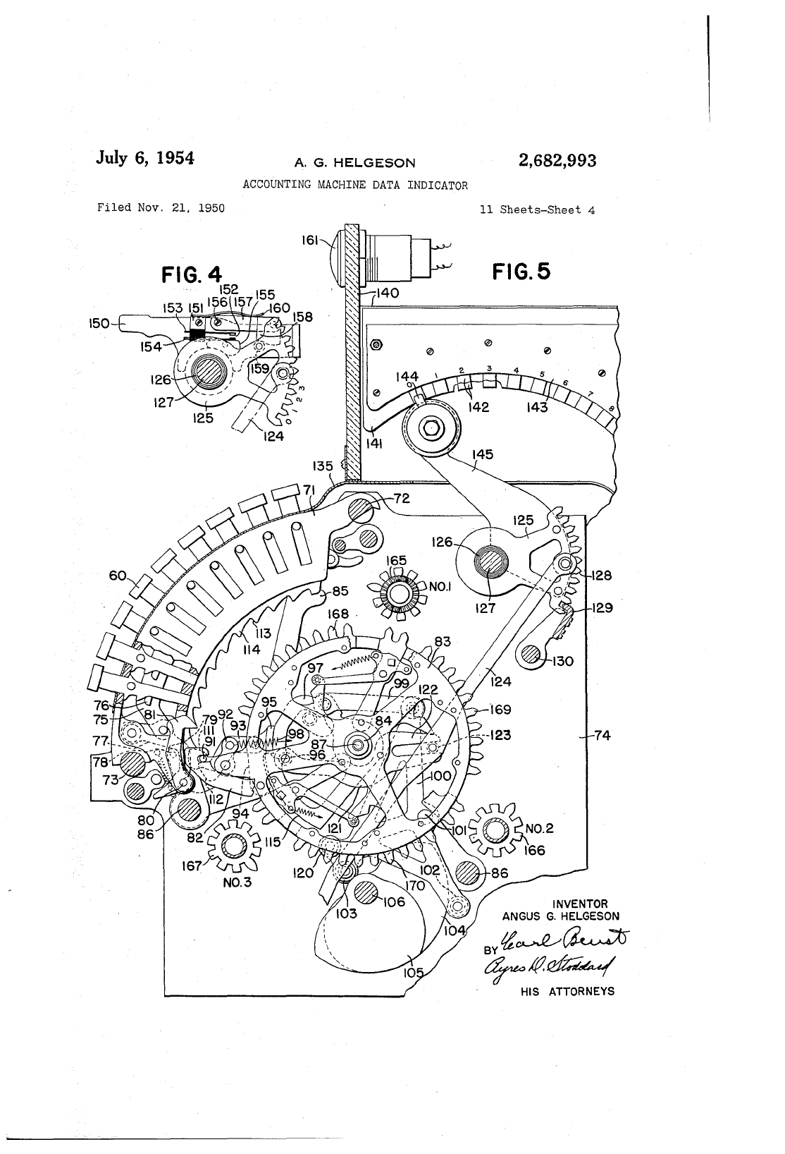
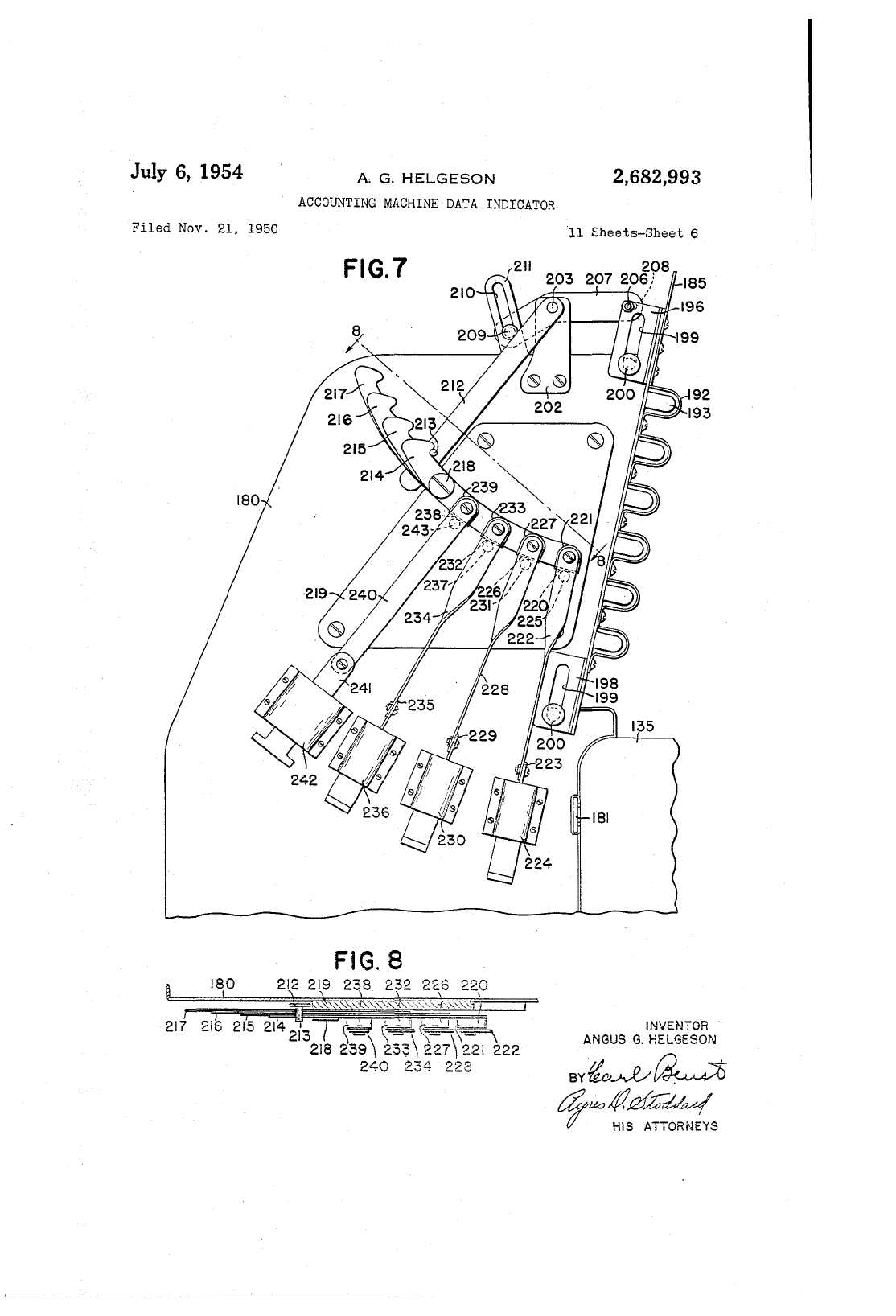
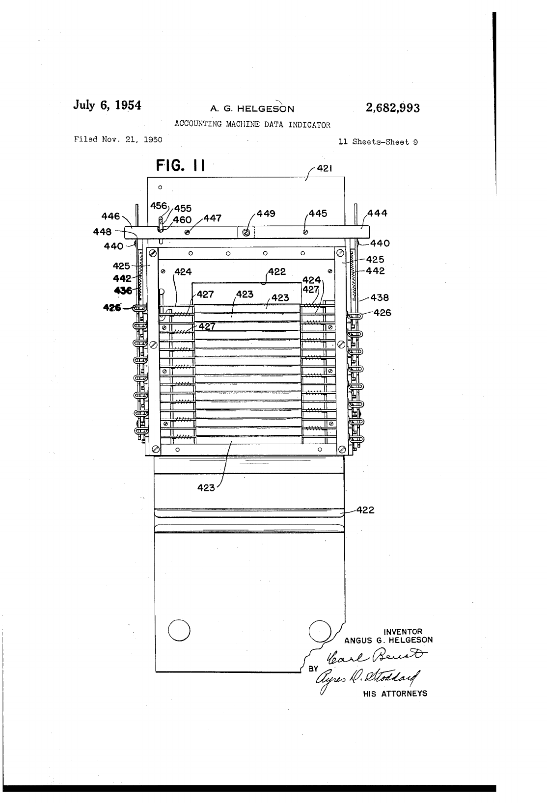
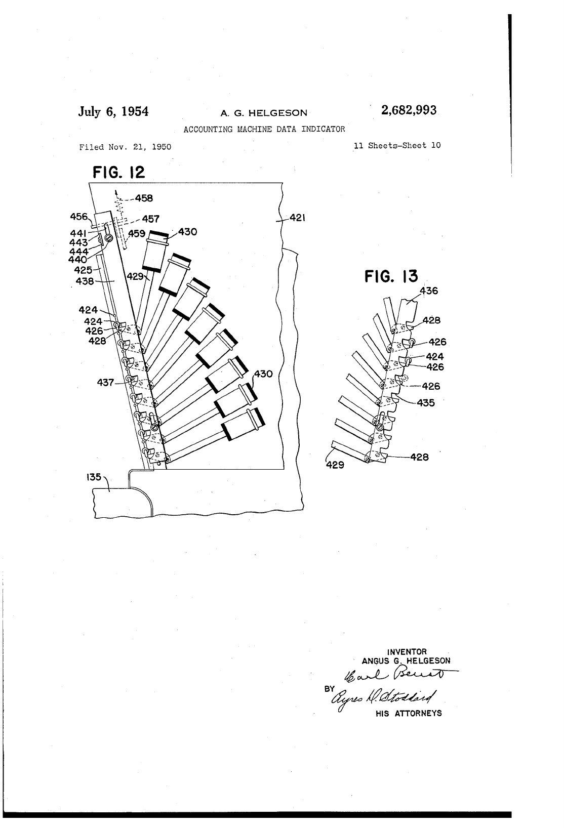
The
card
box is provided
with
a movable face,
which
has
windows, so
that
one line of
each
group
of lines is visible.
The
movable face is
adapted
to
be
shifted
downwardly
under
control
70
still be possible to read, as above mentioned,
the
$47.38
through
the
red
translucent
slide. How-
ever,
the
red
tmnslucent
slide would
prevent
the
operator
from
using
the
$47.38 by
accident
when
the
man
did belong to
the
union.
When
insur-
75
ance
is being deducted,
the
red
slide
should
cover
2,682,993
5
the
No
Deduction
column,
and
one
opaque
slide
should
be
moved over
to
cover
the
Union
Dues
column,
and
the
other
opaque
slide
to
cover
the
Hospitalization
column.
At
this
point
it
might
be well to describe briefly
the
sequence of a
normal
operation
of
the
machine.
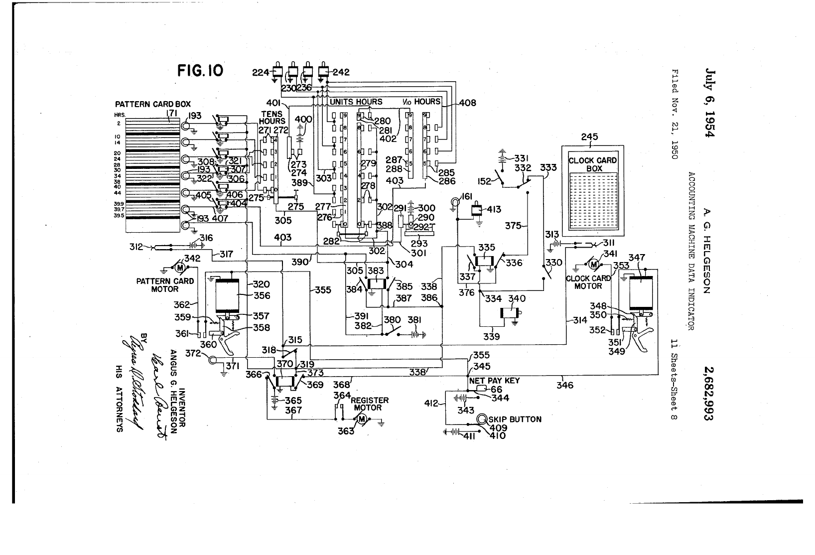
First,
a
group
of clock
cards
for
a
particular
department
is
inserted
in
the
clock
card
box,
which
is located,
as
above
mentioned,
on
the
top
of
the
machine.
Then
a
corresponding
number
of
pattern
cards
for
these
same
employees is
inserted
in
the
pattern
card
box,
which
is nol'-
mally
located
on
top
of
the
machine,
just
to
the
left
of
the
clock
card
box.
This
pattern
card
box
is
provided
with
the
same
type
of feeler
mechanism
that
the
clock
card
box is provided
with,
which
will
assure
the
operator
that
a.
pat-
tern
card
goes
out
of
the
pattern
mud
box every
time
the
clock
card
mechanism
is operalLed
to
eject
a clock
card.
If
a
card
does
not
go dovm,
6
pattern
box.
Thus,
as
a
result
of
the
movement
of
the
light
switches,
under
control
of
the
hours
keys,
which
was
brought
about
by
the
setting.
of
the
proper
hours
on
those
hours
keys,
the
pat-
5
tern
box
mechanism
selects
and
illuminates
the
proper
line
on
the
face
of
the
card,
according
to
the
hours
recorded.
Reading
from
that
illuminated
line
on
the
pat-
tern
card,
the
operator
will
then
record
the
total
I
()
amount
of
the
base
pay
and
the
total
overtime
hours
and
earnings
(if
there
are
any),
the
total
amount
of
the
OAE
tax,
the
withholding
tax,
and
whatever
fixed
deduction
is
being
deducted
that
week, provided
this
employee
has
such
a
1
[j
deduction
to
be
made.
The
net
amount,
de-
pending
upon
the
fixed
deduction
applicable
to
this
employee,
appears
in
one
of
the
Net
Pay
columns
and
should
be visible
at
all
times.
The
operator
then
records
whichever
net
pay
is
20
visible,
either
the
one
for
the
fixed
deduction
factor
being
deducted
that
week
or
one
without
any
fixed deduction,
depending
on
whether
01'
not
that
type
of
deduction
is applicable to
that
a
light
is
lighted
on
the
face of
the
pattern
card
box,
and
the
current
from
the
machine
is
shut
ot!.
Thus,
when
the
current
is at!,
the
operator
can
tell
from
whichever
light
goes
on
as
to
which
25
box failed
to
eject
the
card.
Therefore,
by
prov-
ing,
through
the
light
system,
that
a
card
goes
down
in
each
box
each
operation,
it
insures
that
particular
employee whose check is being
written.
The
"K"
key,
which
is used
to
record
the
amount
of
the
net
pay
in
this
case, causes
such
amount
to
be
recorded
to
be
deducted
from
the
crossfooter
and
causes
that
amount
to
be
printed
on
the
main
portion
:3,nd
on
the
stub
of
the
a
proper
sequence of
cards
will be
maintained
between
the
two
stacks
of cards, so
that
the
clock
card
and
the
pattern
card
for
the
same
em-
ployee will always
be
the
front
card
in
each
of
their
respective boxes.
As
above
mentioned,
the
name
of
the
employee
and
his
clock
number
are
on
the
clock
card
and
are
visible
to
the
oper-
ator;
also
the
name
of
the
employee is
on
the
pattern
card,
and
also
the
rate
per
hour
shows
on
the
pattern
card.
Having
placed
the
two
sets
of
cards
in
the
two
boxes-that
is,
the
clock
card
box
and
the
pat-
tern
card
box-the
operator
first
will pick
up
30
check
as
"veIl
as
on
the
journal
sheet,
thus
com-
pleting
the
check
and
ejecting
the
same,
as
well
as
actuating
both
the
clock
card
box
and
the
pattern
card
box,
causing
the
clock
card
and
the
pattern
card
to
be
ejected, so
as
to
bring
to
view
35
the
clock
wrd
anel
the
pattern
card
for
the
next
employee whose check is
to
be
written.
The
routine
of
the
sequence of
operations
on
the
payroll
machines
of
the
type
shown
in
the
above-mentioned
Patent
No. 2/Hl7,704 calls for
40
the
use of
the
withholding
tax
pickup key
fll"St
on
every check,
and
it,
therefore,
requires
the
operator
to
preBS
the
key
regardless
of
whether
or
not
there
is
any
withholding
tax
to
pick up.
This
withholding
tax
key
then
serves
the
purpose
all
of
the
old
balances
appearing
on
the
earnings
card
for
this particular
employee,
which
earn-
ings
card
is
taken
from
the
regular
payroll
file.
She
will
first
pick
up
the
balance
of
the
with-
holding
tax
and,
at
the
same
time
she
is
making
these
pickups, will
insert
the
check
into
the
checl{
chute,
ready
to
be
printed
on
at
the
propel' time.
The
last
pickup
should
be
the
earnings·-to-date
pickup,
and
at
this
time
she
should
record
the
total
hours
on
the
left
side of
the
keyboard.
Just
before
the
operation
of
the
machine,
she
will
insert
the
earnings
card
in
the
machine
on
the
printing
table,
and
therefore
the
total
hours
will be
printed
on
the
earnings
card
and
on
the
55
check
in
this
operation.·
45
of signalling
the
operator
as
to
whether
01'
not
the
previous check
written
VIe,s
wTitten correctly.
If
the
operator
is able
to
piCk
up
the
amount
of
the
withholding
tax
with
that
pickup
key,
then
she
knows
that
the
previous
check
was completed
50
correctly.
If
the
withholding
tax
key is locked
on
this
operation,
that
means
that
there
was
still
some
amount
remaining
in
the
crossfooter,
thus
giving evidence of
the
fact
that
the
previous
check
was
not
correctly
written.
Should
such
a
thing
occur,
the
operator
would
then
remove
the
last
check
from
the
check
com-
partment
underneath
the
machine,
place
it
in
the
check
chute
upside down,
and
hit
the
Net
Fay
key,
which
would
cause
the
machine
to
clear
the
At
the
same
time,
the
regular
differential
mechanism
in
the
machine
for
the
three
banks
of
hour
l~eys
will
control
three
wipe switches
and
move
them
into
pOSition,
which
will
set
up
the
right
type
of
an
electrical
circuit
to
cause
the
proper
line
to
be
selected
on
the
pattern
box,
moving
the
face
of
the
box
to
the
right
position,
and
illuminate
the
proper
light
in
order
that
the
correct
line is selected.
The
total
hours
are
ac-
cumulated
on
this
operation,
together
with
a
total
of
the
earnings-to-date,
in
their
respective
totalizers.
The
total
number
of
hours
accumulated
in
the
machine
for
e:3,ch
payroll
division is
later
checked
against
a
prelisted
accumulation
of
hours
from
the
clock
cards
in
order
to
prove
that
the
right
hour
keys were selected,
and,
therefore,
prov-
ing
that
the
correct
line
was
selected
on
the
60
amount
of
the
difference
out
of
the
crossfooter
and
print
that
amount,
which
is
the
net
amount
of
the
error,
on
the
back
of
the
check.
The
oper-
ator
would
then
lay
aside
this
check
for
correction
at
a
later
time,
and
the
machine,
together
with
65
the
crossfooter, would
be
automatically
adjusted
back
to
zero;
thus
the
withholding-
tax
key would
be
unlocked.
If
any
condition
should
leave
the
crossfooter
at
zero
and
locked up,
as
a
result
of
being
on
the
subtract
side, provision is
made
to
70
release
this
lock
on
the
next
pickup
operation
of
the
withholding
tax
key.
Thus
far
the
operation
has
been
described
in
connection
with
a
pattern
card,
which
has
27
patterns
of
hours,
providing
for
every
full
day
75
up
to
six
days
and
every
half
day
within
each
one of
those
six
days,
and
also providing
for
patterns
for
five of
the
days, showing
fractional
hours
by
quarters
in
order
to
take
care
of
time
lates
in
quarter
fractional
hours.
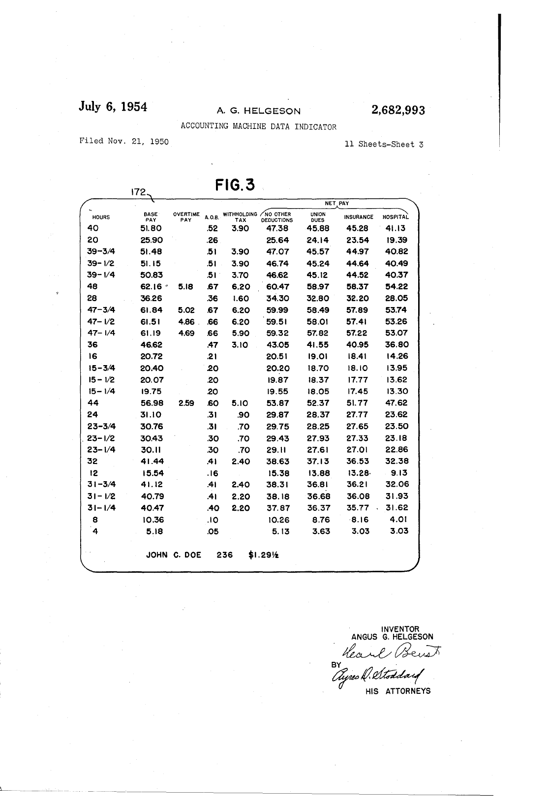
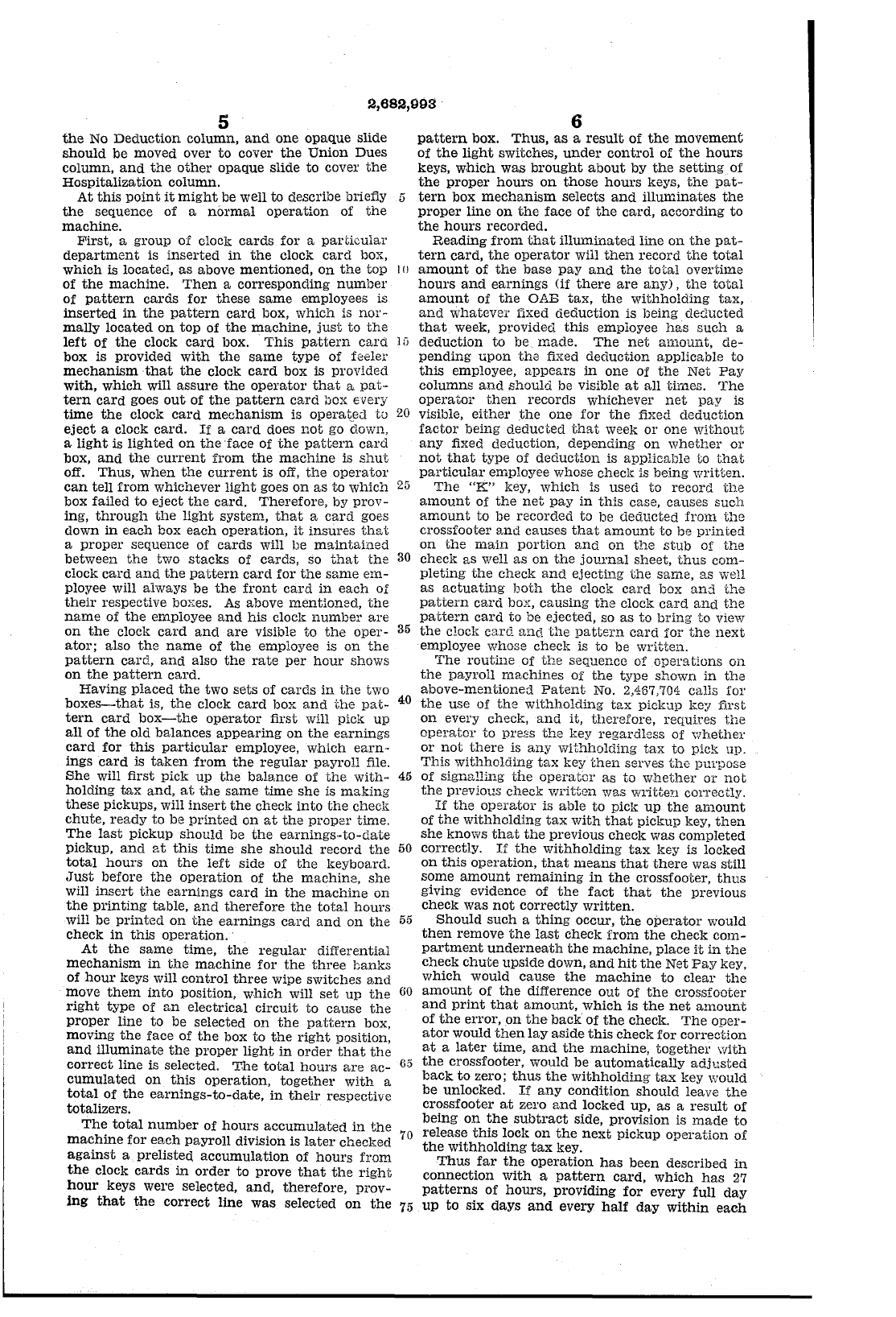
There
is also
shown
in
connection
with
this
application
a
pattern
card
which
provides five
fixed
patterns
for
39.9, 39.8, 39.7, 39.6,
and
39.5
hours.
This
chart
provides six
patterns
for every
even
hour
from
0
up
to
48
hours.
In
addition
to
that,
it
provides a special
pattern
chart
at
the
bottom,
showing
earnings
patterns
for
each
.1
hour
from
0
up
to
2
hours.
In
addition
to
providing
the
earnings
for
these
various
hours,
it
also provides a
chart
of
proof
factors
for
the
same
units
of
hours.
It
is
this
additional
section
of
the
pattern
card,
together
with
the
proper
set-up
on
the
machine,
which
makes
the
additional
spread
of
500
patterns
possible.
The
machine
is
constructed
to
provide
an
oper-
ating
key, speciallcey
No.1,
which
will
cause
any
amount
recorded
on
the
keyboard
to
accumulate
in
its
own
total,
and
which
non-prints
an
amounts
and
non
-spaces all of
the
records.
Another
speeial key,
named
special
key
No.2,
8
Therefore,
when
she
records
the
OAB
tax,
in-
stead
of
recording
44
cents,
she
will
record
45
cents,
and
the
withholding
tax,
instead
of
record-
ing
$2.80,
which
appears
on
the
line
for
the
34-
5
hour
premium,
she
will
record
$2.90,
which
is
the
$2.80
plus
the
extra
ten
cents.
The
operator
will
then
read
the
proper
net
pay
figure
appearing
on
the
pattern
card
for
34
hours.
In
this
case
it
would be $40.79.
She
will
record
that
amount
on
10
the
keyboard
and
press
the
speCial key
No.1,
which
will
accumulate
such
amount.
She
will
then
read
from
the
special
chart
at
the
bottom
ax
the
pattern
card
the
amount
of
the
balancing
factor
for
the
adjustment.
In
this
case
that
15
amount
is
67
cents.
Having
recorded
this
amount
also
through
the
speCial key
No.1,
she
will press
the
special key No;
2,
followed by
the
"K"
Net
Pay
key.
This
"K"
Net
Pay
key
functions
as
it
normally
20
does,
causing
the
amount
to
be
printed
on
the
check
for
the
total
amount
in
the
accumulator
of speCial key No. 1.
That
amount
will
be
trans-
felTed
into
the
totalizer
associated
with
the
"K"
key,
subtracted
from
the
crossfooter,
and
printed
23
on
all records,
and
the
amount
so
printed
will
be
$41.46. is a
non-operating
key, which,
when
depressed
together
with
any
operating
key
on
the
machine,
allows
that
operating
key
to
function,
as
it
nor-
mally
does,
but
also causes
the
amount
previously
accumulated
in
total
key No. 1
to
transfer
auto-
:::0
maticalJ.y
into
the
accumulator
controlled
by
the
operating
key
and
print
on
all
of
the
records
as
determined
by
the
operating
key.
This
again
causes
the
check
to
be
ejected
and
stacked,
and
the
operator
then
proceeds
to
the
next
check.
During
the
writing
of
the
above check
for
34.6
hours, $44.03
and
78
cents
making
a
total
of $44.81
were
added
into
the
crossfooter.
The
OAB of
45
cents,
the
withholding
tax
of $2.90,
the
net
pay
of $40.79 for
34
hours
and
the
net
pay
of
67
cents
Such
mechanism
for
controlling
the
selection
and
operation
of
the
totals
and
the
transfer
of
totals
is fully
illustrated
and
described
in
the
above-mentioned
patents.
W~henever
an
operator
sets
up
the
hours
on
the
left
side of
the
keyboard
and
the
e:wnings
on
the
right
side of
the
keyboard,
and
no
line is selected
or
illuminated
on
the
pattern
box,
she
then
knows
that
she
does
not
have
that
pattern
as
an
active
pattern
on
the
card.
Now
let
us
assume, for example,
that
the
num-
ber
of
hours
recorded were 34.6 hours.
No
line
will
be
illuminated,
and
therefore
the
operator
will
press
a special key
No.3,
which
will
not
retain
but
will select
and
illuminate
the
line for
the
34-hour
pattern,
and
it
will also
illuminate
a
special
light
for
the
lower
chart.
Thus,
there
will be two
lights
i.lluminated
on
the
pattern
box
at
the
same
time,
the
lower
light
illuminating
the
speCial
chart
at
the
bottom,
and
the
upper
will
illuminate
the
line
for
the
34
hours
worked.
The
operator
then
will
set
up
$44.03
in
the
speci.al key
No.1,
which
amount
will
be
accumu-
lated
into
that
total.
She
will
then
read
from
her
special
chart
at
the
bottom
of
the
pattern
card,
which
amount
appeared
in
the
position
for
.0
hour,
which is
the
difference
between
34
hours
and
34.6
hours.
This
amount
is
78
cents,
which
she
will
record
on
the
keyboard,
then
she
will
press
the
speCial key No. 1.
The
operator
then
presses special key No. 2 fIrst,
and,
immediately
after,
she
will
press
the
proper
earnings
key,
which
in
this
case will be
the
key
marked
"Straight
Time."
That
would be
$44.81,~
which
is
the
amount
accumulated
in
the
special
total
No.
2
to
print
as
s,
regular
earnings
entry
on
all
records
and
accumulate
in
the
earnings
total
and
add
the
earnings
to
the
crossfooter.
The
operator
then
records
the
OAB
tax,
but
she
will see
from
the
po;:;ition of
the
78
cents
on
the
chart
that
she
is supposed
to
add. one
cent
to
the
OAB:
tax
and
ten
cents
to
the
withholding
tax.
:;.j
for.6
hour
making
a
total
of $44.81 were
all
sub-
tracted
from
the
gross
pay
of $44.81,
thus
leaving
the
crossfooter
at
zero
which
proves
that
all
com-
putations
have
been
made
correctly,
and
there-
fore,
the
operator
may
proceed
with
the
writing
40
of
the
next
check.
If
an
error
had
been
made
during
the
printing
of
the
above
check
the
machine
would
have
been
locl~ed
by
mechanism,
well
known
in
the
art,
under
control
of
the
crossfooter
when
the
latter
't.)
~~
~~~w~
i~r~he
~~~:1~:1
J
~f
~~~e~
~~~n~~
2,417,563.
The
machine
is also provided
with
an
electrical
contact
switch,
which
feels
the
pOSition
of
the
50
differential
mechanism
associated
with
the
thou-
sand-dollar
bank
of keys.
When
the
thousand-
dollar
banl~
is
in
the
zero pOSition,
or
in
the
No.
1
or
No. 2 position of
the
bank,
the
differential
will
cause
the
switch
to
remain
open,
thus
pre-
56
venting
any
contact
from
taking
place.
However,
when
the
differential
for
that
bank
is
in
the
pOSition
to
record
$3,000.00
or
more,
the
differential causes
the
switch
to
close,
thus
send-
ing
an
electrical
signal
to
a
red
lamp
located
60
on
the
top
of
the
machine,
and,
when
this
light
is
illuminated
on
the
clearing
of
the
earnings
to
date
total,
the
operator
of
the
machine
will know
that
the
particular
employee
has
just
completed
earnings
of
$3,.000.00
or
more.
Thus,
she
will
65
split
the
amount
of
the
OAB
tax
on
that
particu-
lar
check.
Vlhen
the
operator
comes
to
record
the
amount
of
the
split
OAB
tax
in
a case of
this
kind,
she
will look
at
the
dials
which
show
the
total
and
read
the
amount
in
excess of $3,000.00.
70
For
example,
let
us
say
that
we
are
writing
a
check,
in
which
the
earnings
of
the
employee for
this
particular
week were $100.00,
and
the
pre-
vious
earnings
to
date
picked
up
was $2,970.00.
Therefore,
when
the
new
balance
of
the
earnings
7(5
to
date
is
extended,
a
red
light
is
illuminated,
2,682,993
9
and
the
operator
will see
by
the
total
indicator
dials $3,070.00,
indicating
that
$70.00 of
the
earn-
ings were
not
taxable
for
OAB purposes.
The
operator,
therefore,
records
70
cents
in
special
key
No.1
totalizer,
which
will
non-print
5
all
of
the
records
and
accumulate
a
total
of
that
70
cents,
and
then
she
will
record
30
cents,
which
was
to
be collected
as
a
tax,
through
the
regular
OAB
tax
key,
in
this
particular
case key No. 22,
and
marked
"F."
She
will
then
continue
on
with
10
the
balance
of
her
checks.
Let
us
assume,
for
example,
that
there
is
no
withholding
tax
on
this
particular
check,
and
normally,
if
OAB
tax
were
to
be
deducted,
the
net
check,
as
indicated
by
the
pattern
card,
calls
for
$99.00
net
pay.
When
it
is
15
time
to
record
the
net
pay,
the
operator
will
record
the
$99.00,
in
this
case
not
through
the
"K"
key
but
through
the
special
key
No. 1.
She
will
then
press
the
special key
No.2,
followed
with
depression
of
the
UK"
key.
That
will
cause
the
20
accumulation
of special
key
No.' 1
to
be
printed
on
the
check
and
all
of
the
records
and
subtract
it
from
the
crossfooter,
and
complete
the
check
for
$99.70,
which
is
the
correct
amount
of
the
net
pay.
In
this
case
the
machine
has
again
proved
25
the
accuracy
of
the
computation.
Through
the
use
of
the
line
lock proof,
the
machine
here
proves
that
each
one
of
the
amounts
of
earnings,
de-
ductions, etc.,
was
correctly
entered,
and
also
proves
that
the
operator
made
the
correct
split
30
in
the
OAB
tax,
because
she
read
the
first
amount
from
the
total
reading
dial
in
the
machine
and
the
second
amount,
which
was
a
mental
calcula-
tion
of
the
difference,
must
be
correct
in
order
to
make
the
machine
balance.
Therefore,
the
35
machine
provides 100%
accuracy,
even
though
there
are
mental
calculations
involved
in
an
operation
of
this
type.
Whenever
the
red
signal
is lit,
warning
of a
spli:t OAB
tax
of
this
type,'
the
same
electrical
40
impulse is
used
to
actuate
a
type
wheel
in
the
journal
sheet
section
of
the
machine,
which
prints
a
clearly
visible symbol,
which
will
stand
out
so
that
it
can
be
seen
at
a glance.
The
purpose
of
this
symbol
is
to
assist
the
balancing
clerk
in
45
her
audit.
When
she
secures
the
journal
sheet
from
the
payroll of
the
machine
operator,
to-
gether
with
the
pattern
card
and
other
records,
she
will
glance
down .the
sheet,
providing
that
it·
is
the
right
time
of
year
to
expect
employees
to
50
go over
the
$3,000.00
earnings
point,
and
she
will
be
able
to
audit
the
sheet
quickly
in
order
to
de-
termine
if
any
special signals
appear
on
the
jour-
nal
sheet.
Whenever
she
finds
such
a special
printed
signal
55
appearing
on
the
journal
sheet,
she
will look
for,
the
pattern
card
for
that
particular
employee
and
see
to
it
that
said.
card
is
turned
around,
so
that
the
back
of
the
pattern
card
faces
the
front,
be-
cause
the
back
of
the
pattern
card
has
the
same
60
calculations
which
appear
on
the
front,
with
the
exclusion of
the
OAB
calculation.
The
electrical
hook-up
in
this particular
case
on
the
$3,000.00
mechanism
is
made
in
such
a
manner
that
it
takes
into
consideration
the
earn-
65
ings
to
date
pickup
key
on
the
machine
as
well
as
the
clearing
key
for
the
earnings
to
date.
In
other
words,
if
the
$3,000.00
in
the
machine
comes
about
as
a
result
of
adding
sufficient
earnings
to
the
earnings-to-date
pickup
to
make
$3,000.00,
70
then
a
light
is
illuminated
indicating
this
condi-
tion
to
the
operator.
However,
if
the
pickup
of
the
earnings
to
date
is $3,000.00
or
more,
then
this
mechanism
also causes
the
machine
to
lock
75
10
the
.cAB key, so
that
it
will
be
impossible
to
record
any
OAB
tax
on
such
check.
This
electrical
hookup
also
actuates
a
relay
when
the
$3,000.00
amount
is
secured
on
the
pick-
up
key,
and
no
red
light
will
be
lit
on
the
machine
in
such
a condition.
The
mechanism
of
the
pattern
card
box also
provides
for
holding
the
electrical selection,
which
was
made
on
the
pickup of
the
earnings-
to-date,
throughout
the
entire
writing
of
the
check,
eliminating
any
possibility of
interference
which
might
occur
from
any
source.
For
ex-
ample,
the
hours
keys will
be
used
again
on
the
recording
of
the
overtime
hours,
in
which
case a
movement
would
be
given
to
the
wipe switches,
setting
up
a new selection.
'However,
an
electrical
hookup
is provided
in
order
that
there
will
be
no
interference
with
the
previous selection
at
th;;
time
the
total
hours
are
recorded. A
relay
is used
in
the
circuit
to
diS-
connect
the
previously-selected
hookup
at
the
time
the
clocl~
card
boxes
are
actuated.
In
other
words,
when
either
one of
the
Net
Pay
keys is
used
and
the
electrical
impulse
is given
to
the
pattern
card
box
and
to
the
clock
card
box,
these
same
impulses
are
used
to
actuate
a
rela¥
which
cuts
off
all
the
power
which
was locking
the
elec-
trical
selection, so
that
the
line
selection will
be
completely wiped
out
on
the
net
pay
operation,
and
the
face
of
the
pattern
card
box is hooked
up
with
the
mechanism
which
pushes
the
pat-
tern
card
down, so
that,
when
the
pattern
card
box is
actuated,
the
mechanism
in
this
box
will
restore
the
face
of
the
pattern
card
box
to
its
home
position
from
whatever
position
it
has
been
previously selected.
In
connection
with
payroll
operations,
there
are
certain
conditions
where
unusual
deductions
or
earnings
adjustments
are
made,
for
which
there
has
been
no
previous
pattern
set
up.
For
example,
many
employees
might
be
affected by
a
Community
Chest
deduction
on
a payroll,
which
would
make
it
impossible
to
complete
the
pat-
tern
and
use
anyone
of
the
net
pay
figures.
In
order
to
efficiently accomplish
this
type
of
set-
up, provision is
made
on
the
machine
tocoDstruct
one
of
the
totalizing
keys
in
the
total
row
to
func-
tion
as
an
indicating
balance
key.
In
other
words,
when
that
key
is pressed,
it
will
sub-
total
the
crossfooter
without
printing
on
any
of
the
records
or
spacing
any
of
the
records
and
only
indicating
the
amount
of
the
net
pay
in
the
visible
total
dials
in
the
front
of
the
machine.
Then,
the
operator
of
the
machine
completes
the
writing
of
the
check
from
the
pattern
c9,rd
up
to
the
point
of
inserting
the
amo:.1nt of
the
special
deduction
or
addition,
and,
just
prior
to
recording
that
amount
on
the
machine,
the
op-
erator
will press
the
indicating
balance
key
and
then
will
check
the
amount
which
appears
on
the
visible
total
dials
with
the
amount
of
the
cor-
rect
net
pay
visible
on
the
pattern
card.
Thus.
she
will prove visually
that
the
payroll
has
been.
written
correctly
up
to
that
point.
She
will
re-
cord
the
amount
of
the
special
deduction
adjust-
ment
in
one of
the
special
deduction
or
addition
. keys
on
the
machine
and
complete
the
check by
pressing
the
Net
Pay
l\:ey,
which
clears
the
cross-
footer
and
prints
the
amount
of
the
net
pay
on
all
of
the
records-namely,
the
check,
the
stub
of.
the
chec1"
and
the
cheCk
register-and
eject
and
stack
the
check
as
on
the
normal
payroll
ma-
chine
operation
of
the
type
of
machine
shown
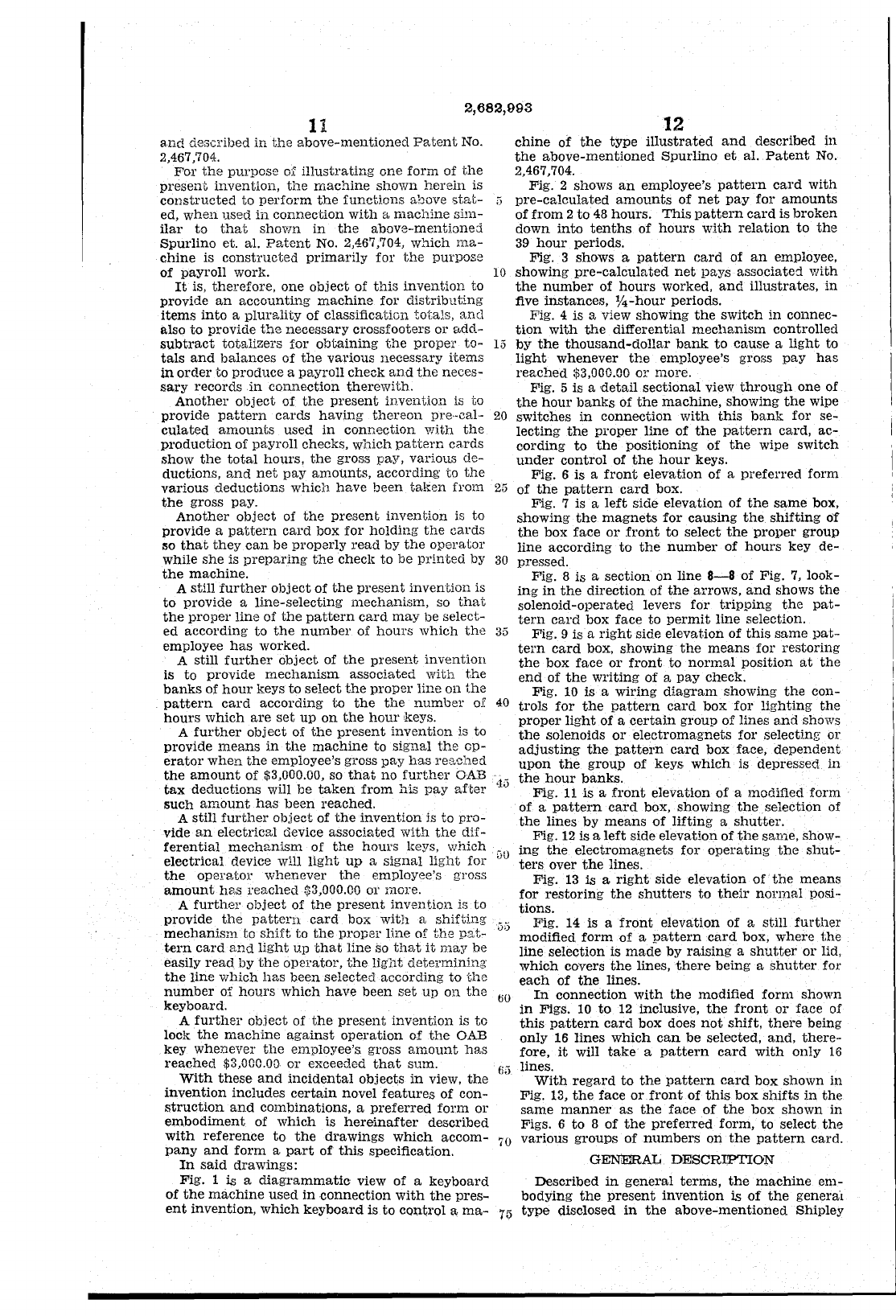
2,682,003
11
and
described
in
j;he
above-mentioned
Patent
No.
2,467,704.
For
the
purpose
of
illustrating
one
form
of
the
present
invention,
the
machine
shown
herein
is
constructed
to
perform
the
functions
ahove
5tE.t-
ed,
when
used
in
connection
with
a
machine
sim-
ilar
to
that
shown
in
the
above··mentioned
Spurlino
ct. al.
Patent
No. 2,467,704,
which
ma-
chine
is
constructed
primarily
for
the
purpose
of
payroll
worle
It
is,
therefore,
one
object
of
this
invention
to
provide
an
accounting
machine
for
distributing
items
into
a
plurality
of
classification
totals,
and
also
to
provide
the
necessary
crossfooters
or
adcl-
subtract
totalizers
for
obtaining
the
propel'
to-
tals
and
balances
of
the
various
necessary
items
in
order
to
produce
a
payroll
check
and
the
neces-
sary
records
in
connection
therewith.
Another
object
of
the
present
invention
is to
provide
pattern
cards
having
thereon
pre,·cal,·
culated
amounts
used
in
connection
with
the
production
of
payroll
checks,
which
pattern
cards
show
the
total
hours,
the
gross
pay,
vari.ous de-
ductions,
and
net
pay
amounts,
according
to
the
various
deductions
which
have
been
taken
from
the
gross
pay.
Another
object
of
the
present
invention
is
to
provide
a
pattern
card
box
for
holding
the
cards
:50
that
they
can
be
properly
read
by
the
operator
while
she
is
preparing
the
checl,
to
be
printed
by
the
machine.
A
still
further
object
of
the
present
invention
is
to
provide
a line·'selecting
mechanism,
so
that
the
propel'
line
of
the
pattern
card
may
be
select-
12
chine
of
the
type
illustrated
and
described
in
the
above-mentioned
Spurlino
et
al.
Patent
No.
2,467,704.
Fig.
2
shows
an
employee's
pattern
card
with
"
pre-calculated
amounts
of
net
pay
for
amounts
of
from
2
to
48
hours.
This
pattern
card
is
broken
down
into
tenths
of
hours
with
relation
to
the
39
hour
periods.
Fig. 3
shows
a
pattern
card
of
an
employee,
10
showing
pre-calculated
net
pays
associated
with
the
number
of
hours
worked,
and
illustrates,
in
five
instances,
%-hour
periods.
Fig. 4
is
a view
showing
the
switch
in
connec-
tion
with
the
differential
mecllanism
controlled
15
by
the
thousand-dollar
bank
to
cause
a
light
to
light
whenever
the
employee'S gross
pay
has
reached
$3,000.00
or
more.
Fig. 5
is
a
detail
sectional
view
through
one
of
the
hour
banks
of
the
machine,
showing
the
wipe
20
switches
in
connection
with
this
bank
for
se-
lecting
the
propel'
line
of
the
pattern
card,
ac-
cording
to
the
positioning
of
the
wipe
switch
under
control
of
the
hour
keys.
Fig. 6
is
a
front
elevation
of a
preferred
form
25
of
the
pattern
card
box.
Fig. 7 is a
left
side
elevation
of
the
same
box,
showing
the
magnets
for
causing
the
shifting
of
the
box
face
or
front
to
select
the
propel'
group
line
according
to
the
number
of
hours
key
de-
30 pressed.
Fig.
8
is
a
section
on
line
8-8
of
Fig.
7, look-
ing
in
the
direction
of
the
arrows,
and
shows
the
solenoid-operated
levers
for
tripping
the
pat-
tern
card
box
face
to
permit
line
selection.
ed
according
to
the
number
of
hours
which
the
35
employee
has
worked.
Fig.
9 is a
right
side
elevat.ion
of
this
same
pat-
tern
card
box,
showing
the
means
for
restoring
the
box
face
or
front
to
normal
position
at
the
end
of
the
writing
of
a
pay
check.
A still
further
object
of
the
present
invention
is
to
provide
mechanism
associated
with
the
banks
of
hour
keys
to
select
the
proper
line
on
the
pattern
card
according
to
the the
number
oK
hours
which
are
set
up
on
the
hour
keys.
A
further
object
of
the
present
invention
is
to
provide
means
in
the
machine
to
signal
the
op-
erator
when
the
employee's gross
pay
has
reached
the
amount
of
$3,000.00, so
that
no
further
OAB
tax
deductions
will
be
taken
from
hIs
pay
after
such
amount
has
been
reached.
A
still
further
object
of
the
invention
is
to
pro-
vide
an
electrical
device associr,ted
with
the
dif-
ferential
mechanism
of
the
hours
keys,
which
electrical
device
will
light
up
a
signal
light
for
the
operator
whenever
the
employee's gross
amount
h8,S
reached
$3,000.00 01' more.
A
further
object
of
the
present
invention
is
to
provide
the
pattern
card
box
with
a
shifting
mechanism
to
shift
to
the
proper
Hne
of
the
pat-
tern
card
and
light
up
that
line
so
that
it
may
be
easily
read
by
the
oP2rator,
the
Ug11t
detel'minin;s
the
line
which
has
been
selected
accord:lng
to
the
number
of
hours
which
have
been
set
up
on
the
keyboard.
A
further
object
of
the
present
invention
is
to
lock
the
machine
against
operation
of
the
OAB
key
whenever
the
employee's
gross
amount
has
reached
$3,000.00
or
exceeded
that
sum.
With
these
and
incidental
objects
in
view,
the
invention
includes
certain
novel
features
of
con-
struction
and
combinations,
a
preferred
form
or
embodiment
of
which
is
hereinafter
described
with
reference
to
the
drawings
which
accom-
pany
and
form
a
part
of
this
specification.
In
said
drawings:
Fig.
1 is a
diagrammatic
view
of
a
keyboard
of
the
machine
used
in
connection
with
the
pres-
ent
invention,
which
keyboard
is
to
control
a
ma-
Fig.
10
is
a
wiring
diagram
showing
the
COl1-
40 troIs
for
the
pattern
card
box
for
lighting
the
proper
light
of
a
certain
group
of
lines
and
shows
the
solenoids
or
electromagnets
for
selecti.ng
or
adjusting
the
pattern
card
box
face,
dependent
upon
the
group
of
keys
which
is
depressed
in
4.)
the
hour
banks.
Fig.
11
is
a
front
elevation
of
a modified
form
of
a
pattern
card
box,
showing
the
selection
of
the
lines
by
means
of
lifting
a
shutter.
Fig.
12
is
a
left
side
elevation
of
the
same,
show-
GO
ing
the
electromagnets
for
operating
the
shut-
ters
over
the
lines.
Fig.
13
is
a
right
side
elevation
of
the
means
for
restoring
the
shutters
to
their
normal
posi,·
tions.
35
Fig.
14 is a
front
elevation
of a st.ill
further
modified
form
of
a
pattern
card
box,
where
the
line
selection
is
made
by
raising
a
shutter
or
lid,
which
covers
the
lines,
there
being
a
shutter
for
each
of
the
lines.
60
In
connection
with
the
modified
form
shown
in
Figs. 10
to
12 inclusive,
the
front
or
face
of
this
pattern
card
box
does
not
shift,
there
being
only
16
lines
which
can
be
selected,
and,
there-
fore,
it
will
take
a
pattern
card
with
only
16
fjii lines.
With
regard
to
the
pattern
card
box
shown
in
Fig. 13,
the
face
or
front
of
this
box
shifts
in
the
same
manner
as
the
face
of
the
box
shown
in
Figs. 6
to
8
of
the
preferred
form,
to
select
the
70
various
groups
of
numbers
on
the
pattern
card.
GENERAL DESCRI.'PTION
Described
in
general
terms,
the
machine
em-
bodying
the
present
invention
is
of
the
genera'l
75
type
disclosed
in
the
above-mentioned
Shipley
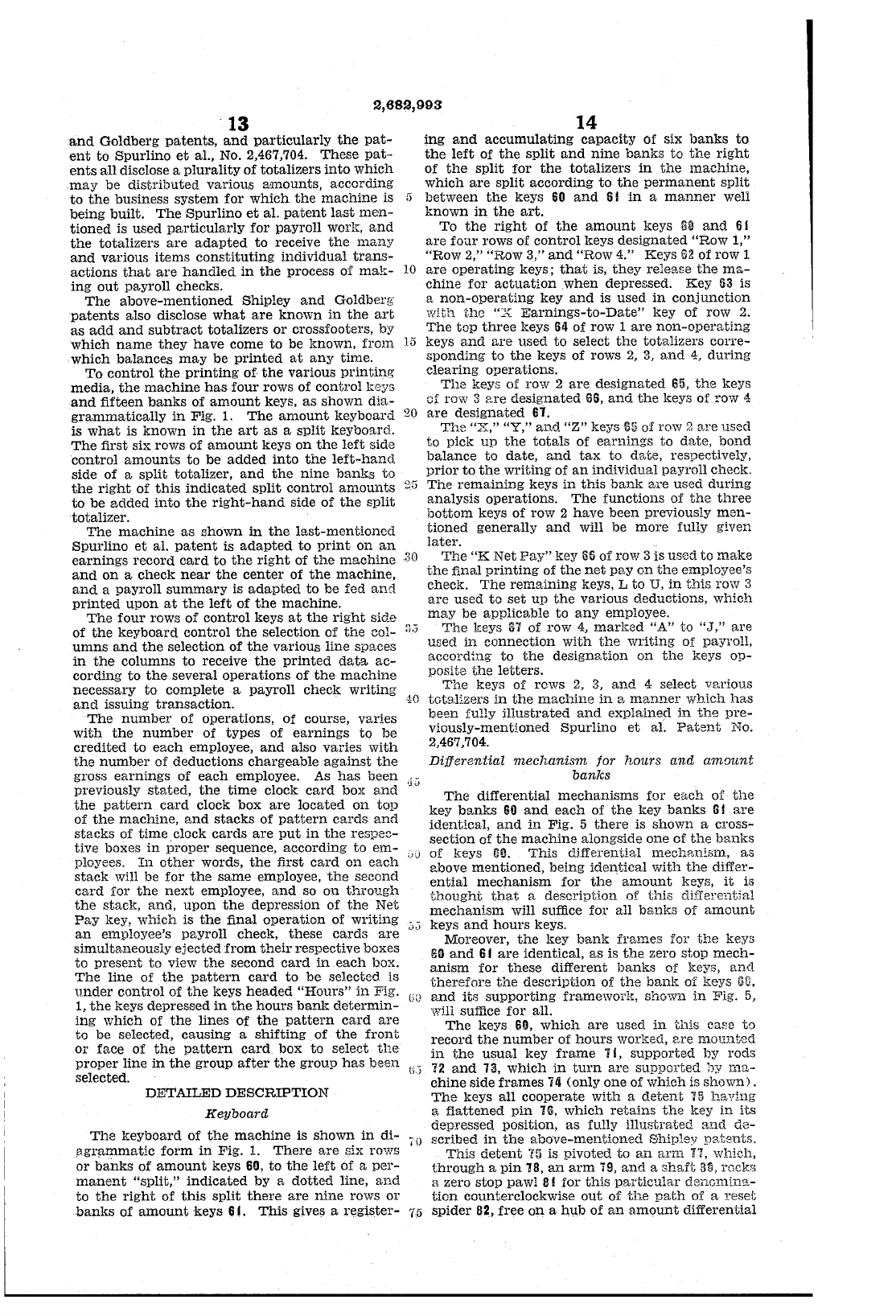
2,682,993
13
and
Goldberg
patents,
and
particularly
the
pat-
ent
to
Spurlino
et
al., No. 2,467,704.
These
pat··
ents
all
disclose a
plurality
of
totalizers
into
which
.may
be
distributed
various
amounts,
according
to
the
business
system
for
which
the
machine
is 5
being built.
The
Spurlino
et
al.
patent
last
men-
tioned
is
used
particularly
for
payroll work,
and
the
totalizers
are
adapted
to
receive
the
many
and
various
items
constituting
individual
trans-
actions
that
are
handled
in
the
process of
mak-
10
ing
out
payroll checks.
The
above-mentioned
Shipley
and
Goldberg
patents
also disclose
what
are
known
in
the
art
as
add
and
subtract
totalizers
or
crossfootel's, by
which
name
they
have
come
to
be
known,
from
15
which
balances
may
be
printed
at
any
time.
To
control
the
printing'
of
the
various
printing
media,
the
machine
has
four
rows of
controllceys
and
fifteen
banks
of
amount
keys,
as
shown
dia-
grammatically
in
Fig. 1.
The
amount
keyboard
20
is
what
is
known
in
the
art
as
a
split
keyboard.
The
first
six
rows of
amount
keys
on
the
left
side
control
amounts
to
be
added
into
the
left-hand.
side of a
split
totalizer,
and
the
nine
banks
to
the
right
of
this
indicated
split
control
amounts
2G
to
be
added
into
the
right-hand
side
of
the
split
totalizer.
The
machine
as
shown
in
the
last-mentioned
Spurlino
et
al.
patent
is
adapted
to
print
on
an
earnings
record
card
to
the
right
of
the
machine
30
and
on
a
check
near
the
center
of
the
machine,
and
a
payroll
summary
is
adapted
to
be
fed
and
printed
upon
at
the
left
of
the
machine.
'The
four
rows
of
control
keys
at
the
right
side
of
the
keyboard
control
the
selection of
the
col-
.'.J
umns
and
the
selection
of
the
various line spaces
in
the
columns
to
receive
the
printed
data
ac-
cording
to
the
several
operations
of
the
machine
necessary
to
complete a
payroll
check
writing
and
issuing
transaction.
40
The
number
of
operations,
of course,
varies
with
the
number
of
types
of
earnings
to
be
credited
to
each
employee,
and
also
varies
with
the
number
of
deductions
chargeable
against
the
gross
earnings
of
each
employee.
As
has
been
<jj
previously
stated,
the
time
clocl~
card
box
and
the
pattern
card
clock
box
are
located
on
top
of
the
machine,
and
stacks
of
pattern
cards
and
stacks
of
time.
clock
cards
are
put
in
the
respec-
tive boxes
in
proper
sequence,
according
to
em-
,.oj
ployees.
In
other
words,
the
first c(l,rd
on
each
stack
will be for
the
same
employee,
the
second
card
for
the
next
employee,
and
so
on
through
the
stacl{,
and,
upon
the
depression of
the
Net
Pay
l{ey,
whIch is
the
final
operation
of
writing
an
employee's payroll check,
these
cards
are
vcl
simultaneously
ejected
from
their
respective boxes
to
present
to
view
the
second
card
in
each
box.
The
line
of
the
pattern
card
to
be
selected is
under
control
of
the
keys
headed
"Hours"
in
Fig.
(jJ
1,
the
keys depressed
in
the
hours
banl~
determin-
ing
which
of
the
lines
of
the
pattern
card
are
to
be
selected,
causing
a
shifting
of
the
front
or
face
of
the
pattern
card
box
to
select
the
proper
line
in
the
group
after
the
group
has
been
selected.
(;)
DETAILED
DESCRIPTION
Keyboard
14
ing
and
accumulating
capacity
of six
banks
to
the
left
of
the
split
and
nine
banks
to
the
right
of
the
split
for
the
totalizers
in
the
machine,
which
are
split
according
to
the
permanent
split
between
the
keys
60
and
61
in
a
manner
well
known
in
the
art.
To
the
right
of
the
amount
keys
!lI!
and
61
are
four
rows of
control
keys
designated
"Row
1,"
"Row
2,"
"Row
3,"
and
"Row
4." Keys
62
of row 1
are
operating
keys;
that
is,
they
release
the
ma-
chine
for
actuation
.when depressed. Key
63
is
a
non-operating
key
and
is used
in
conjunction
with
the
"X
Earnings-to-Date"
key of row
2.
The
top
three
keys
64
of row 1
are
non-operating
keys
and
are
used
to
select
the
totalizers
corre-
sponding
to
the
keys of rows
2,
3,
and
4,
during
clearing
operations.
The
keys of row 2
are
deSignated
65,
the
keys
of row 3
p.re
designated
G6,
and
the
keys of row
4:
are
designated
In.
The
"X,"
"Y,"
and
"ZH
keys
S~
of
ro\v 2
are
used
to
pick
up
the
totals
of
earnings
to
date,
bond
balance
to
date,
and
tax
to
date,
respectively,
prior
to
the
writing
of
an
individual
payroll check.
The
remaining
keys
in
this
bank
are
used
during
analysis
operations.
The
functions
of
the
three
bottom
keys of row 2
have
been
previously
men-
tioned
generally
and
will
be
more
fully given
later.
The
"K
Net
Pay"
key
65
of row 3 is
used
to
make
the
final
printing
of
the
net
pay
on
the
employee's
check.
The
remaining
keys, L
to
U,
in
thi.s row 3
are
used
to
set
up
the
various
deductions,
which
may
be
applicable
to
any
employee.
The
keys
31
of row
4,
marked
"A"
to
"J,"
are
used
in
connection
with
the
writing
of payroll,
according
to
the
design3.tion
on
the
keys
op-
posite
the
letters.
The
keys of rows
2,
3,
and
4 select
v[',riOHS
totalizers
in
the
machine
in
a
manner
whIch
has
be~m
fully
illustrated
and
explained
in
the
pre-
viously-mentioned
Spurlino
et
al.
Patent
No.
2,467,704.
Differential
mechanism
jor
hours
and
amount
banks
The
differential
mechanisms
for
each
of
the
key b::mks
60
and
each
of
the
key
banks
G I
are
identical,
and
in
Fig. 5
there
is
shown
a C1'OSS-
section of
the
machine
alongside one of
the
banks
of
keys !ill.
This
di.fferential mechp,nism,
as
above
mentioned,
being
identical
with
the
differ-
ential
mechanism
for
the·
amount
keys,
it
is
thought
that
a
description
of
this
differel"ltial
mechanism
will suffice for all
banks
of
amount
keys
and
hours
keys.
Moreover,
the
key
bank
fnunes
for
the
keys
!HI
and
61
are
identical,
as
is
the
zero
ston
mech-
anism
for
these
different
banks
of
keys,
and
therefore
the
description
of
the
banl{ of keys
Sf.),
and
its
supporting
framewori~,
shown
in
Fig. 5,
will suffice
for
all.
The
keys
60,
which
are
used
in
this
case
to
record
the
number
of
hours
worked, [',re
mounted
in
the
usual
key
frame
7!,
supported
by
rods
72
and
13,
which
in
turn
are
supported
hy mct-
chine
side
frames
7Ii
(only one of
which
is
shown).
The
keys
all
cooperate
with
a
detent
15
having
a
fiattened
pin
16,
which
retains
the
key
in
its
depressed position,
as
fully
illustrated
and
de-
The
keyboard
of
the
machine
is
shown
in
di-
;Jgr;:tmmatic
form
in
Fig.
1.
There
are
six rows
or
banks
of
amount
keys
60,
to
the
left
of a
per-
manent
"split,"
indicated
by a
dotted
line,
and
to
the
right
of
this
split
there
are
nine
rows
or
banks
of
amount
keys
61.
This
give!)
a
register-
,0
scribed
in
the
above-mentIoned
Shipley
patents.
This
detent
Ifl
is pivoted
to
an
arm
n,
whic.h,
through
a
pin
18,
an
arm
19,
and
a
shaft
1Hl,
rock'5
a zero
stop
pawl
III
for
this
particular
denomina-
tion
counterclockwise
out
of
the
path
of a
reset
7.5
spider
82,
free
on
a httb
of
an
amount
differential
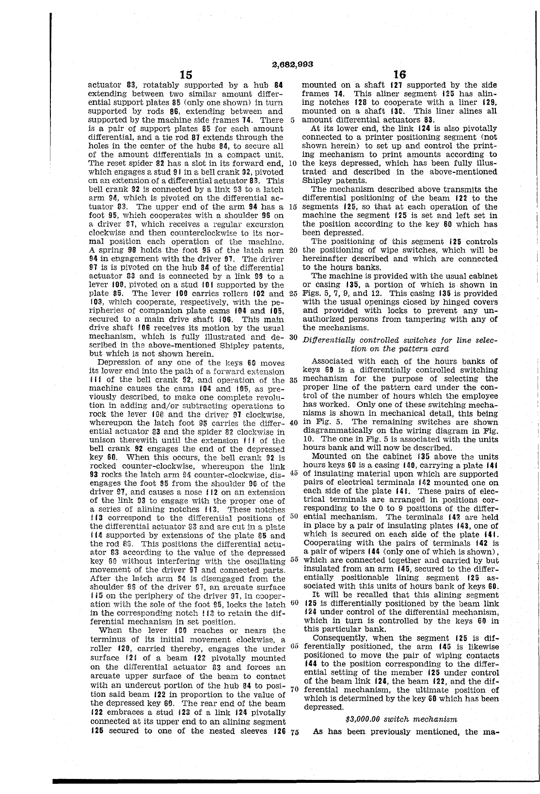
2,682,993
15
actuator
83,
rotatably
supported
by
a
hub
84
extending
between
two
similar
amount
differ-
ential
support
plates
85
(only
one
shown)
in
turn
supported
by
rods
86,
extending
between
and
supported
by
the
machine
side
frames
14.
There
5
is a
pair
of
support
plates
85
for
each
amount
differential,
and
a
tie
rod
81
extends
through
the
holes
in
the
center
of
the
hubs
84,
to
secure
all
of
the
amount
differentials
in
a
compact
unit.
The
reset
spider
82
has
a
slot
in
its
forward
end,
10
which
engages a
stud
91
in
a bell
crank
92,
pivoted
on
an
extension
of
a
differential
actuator
83.
This
bell
crank
92
is
connected
by
a lin];:
93
to
8.
latch
arm
9",
which
is
pivoted
on
the
differential
ac-
tuator
83.
The
upper
end
of
the
arm
94
has
a
15
foot
95,
which
cooperates
with
a
shoulder
95
on
a
driver
97,
which
receives a
regular
excursion
clockwise
and
then
counterclockwise
to
its
nor-
mal
position
each
operation
of
the
machine.
A
spring
98
holds
the
foot
95
of
the
latch
arm
20
94
in
engagement
with
the
driver
91.
The
driver
91
is is
pivoted
on
the
hub
84
of
the
differential
actuator
33
and
is
connected
by
a
link
99
to
a
lever
lOll,
pivoted
on
a
stud
101
supported
by
the
plate
85.
The
lever
100
carries
rollers
102
and
25
103,
which
cooperate, respectively,
with
the
pe-
ripheries
of
companion
plate
cams
104
and
105,
secured
to
a
main
drive
shaft
106.
This
main
drive
shaft
!
06
receives
its
motion
by
the
usual
mechanism,
which
is fully
illustrated
and
de-
30
scribed
in
the
above-mentioned
Shipley
patents,
but
which
is
not
shown
herein.
Depression
of
anyone
of
the
keys
60
moves
its
lower
end
into
the
path
of
a
forward
extension
1"
of
the
bell cran!c
92,
and
operation
of
the
35
machine
causes
the
cams
104
and
105,
as
pre-
viously described,
to
make
one
complete
revolu-
tion
in
adding
and/or
subtracting
operations
to
rock
the
lever
IOil
and
the
drivel'
91
cloclewise,
whereupon
the
latch
foot
95
carries
the
c1iffer-
40
ential
actuator
!la
and
the
spider
82
clockv'lj.se
in
unison
therewith
until
the
extension
f
j!
of
the
bell
crank
92
engages
the
end
of
the
depressed
key
60.
When
this
occurs,
the
bell
crank
92
is
rocked
counter-clocJI:wise,
whereupon
the
link
93
rocks
the
latch
arm
(HI
counter-clockwise,
dis-
45
engages
the
foot
95
from
the
shoulder
96
of
the
driver
!H,
and
causes
a nose f
12
on
an
extension
of
the
linl~
03
to
engage
with
the
proper
one
of
a series
of
alining
notches
!!
3.
These
notches
113
correspond
to
the
differential
positions of
50
the
differential
actuator
83
and
are
cut
in
a
plate
114
supported
by
extensions
of
the
plate
85
and
the
rod
1l8.
This
positions
the
differential
actu-
ator
S3
according
to
the
value
of
the
depressed
key
60
without
interfering
with
the
oscillating
55
movement
of
the
driver
91
and
connected
parts.
After
the
ls,tch
arm
!l4
is disengaged
from
the
shoulder
95
of
the
driver
IH, I:m
arcuate
surface
I i 5
on
the
periphery
of
the
driver
97,
in
cooper-
ation
with
the
sole
of
the
foot
95,
locks
the
latch
60
in
the
corresponding
notch!
13
to
retain
the
dif-
ferential
mechanism
in
set
position.
When
the
lever
(lHI
reaches
or
nears
the
terminus
of
its
initial
movement
clockwise, a
roller
120,
carried
thereby,
engages
the
under
Go
surface
121
of
a
beam
122
pivotally
mounted
on
the
differential
actuator
33
and
forces
an
arcuate
upper
surface
of
the
beam
to
contact
with
an
undercut
portion
of
the
hub
a4
to
posi-
70
tion
said
beam
122
in
proportion
to
the
value
of
the
depressed
key
60.
The
rear
end
of
the
beam
122
embraces
a
stud
j
23
of
a linle j
24
pivotally
connected
at
its
upper
end
to
an
alining
segment
125
secured
to
one
of
the
nested
sleeves
126
75
16
mounted
on
a
shaft
121
supported
by
the
side
frames
14.
This
aliner
segment
125
has
alin-
ing
notches
128
to
cooperate
with
a
liner
129,
mounted
on
a
shaft
131l.
This
liner
alines
all
amount
differential
actuators
83.
At
its
lower
end,
the
link
124
is also pivotally
connected
to
a
printer
pOSitioning
segment
(not
shown
herein)
to
set
up
and
control
the
print-
ing
mechanism
to
print
amounts
according
to
the
keys depressed,
which
has
been
fully
illus-
trated
and
described
in
the
above-mentioned
Shipley
patents.
The
mechanism
described above
transmits
the
differential
positioning
of
the
beam
122
to
the
segments
125, so
that
at
each
operation
of
the
machine
the
segment
125
is
set
and
left
set
in
the
pOSition
according
to
the
key
60
which
has
been
depressed.
The
positioning
of
this
segment
125
controls
the
positioning
of
wipe switches,
which
will be
hereinafter
described
and
which
are
connected
to
the
hours
banks.
The
machine
is
provided
with
the
usual
cabinet
or
casing
135,
a
portion
of
which
is
shown
in
Figs. 5, 7,
9,
and
12.
This
casing
135
is
provided
with
the
usual
openings
closed by
hinged
covers
and
provided
with
locks
to
prevent
any
un-
authorized
persons
from
tampering
with
any
of
the
mechanisms.
Differentially
controlled
switches
for
line
selec-
tion
on
the
pattern
card
Associated
with
each
of
the
hours
banks
of
keys
60
is a dift'erentially
controlled
switching
mechanism
for
the
purpose
of
selecting
the
proper
line
of
the
pattern
card
under
the
con-
trol
of
the
number
of
hours
which
the
employee
has
worked.
Only
one
of
these
switching
mecha-
nisms
is
shown
in
mechanical
detail,
this
being
in
Fig.
5.
The
remaining
switches
are
shown
diagrammatically
on
the
wiring
diagram
in
Fig.
10.
The
one
in
Fig. 5 is
associated
with
the
units
hours
bank
and
will
now
be described.
Mounted
on
the
cabinet
135
above
the
units
hours
keys
60
is a
casing
140,
carrying
a
plate
141
of
insulating
material
upon
which
are
supported
pairs
of
electrical
terminals
1112
mounted
one
on
each
side
of
the
plate
14
L
These
pairs
of
elec-
trical
terminals
are
arranged
in
pOSitions
cor-
responding
to
the
0
to
9 pOSitions of
the
differ-
ential
mechanism.
The
terminals
141,
are
held
in
place
by a
pair
of
insulating
plates
143,
one
of
which
is
secured
on
each
side
of
the
nlate
141.
Cooperating
with
the
pairs
of
terminals
142
is
a
pair
of
wipers
144
(only
one
of
which
is
shown),
which
are
connected
together
and
carried
by
but
insulated
from
an
arm
145,
secured
to
the
differ-
entially
positionable
lining
segment
125
as-
sociated
with
this
units
of
hours
bank
of
keys 60.
It
will
be
recalled
that
this
alining
segment
125
is
differentially
positioned
by
the
heam
link
124
under
control
of
the
differential
mechanism,
which
in
turn
is
controlled
by
the
keys
60
in
this
particular
bank.
Consequently,
when
the
segment
125
is
dif-
ferentially
positioned,
the
arm
145
is
likewise
positioned
to
move
the
pair
of wiping
contacts
144
to
the
pOSition
corresponding
to
the
differ-
ential
setting
of
the
member
125
under
control
of
the
beam
link
124,
the
beam
122,
and
the
dif-
ferential
mechanism,
the
ultimate
position
of
which
is
determined
by
the
key
GO
which
has
been
depressed.
$3,000.00
switch
mechanism
As
has
been
previously
mentioned,
the
ma-
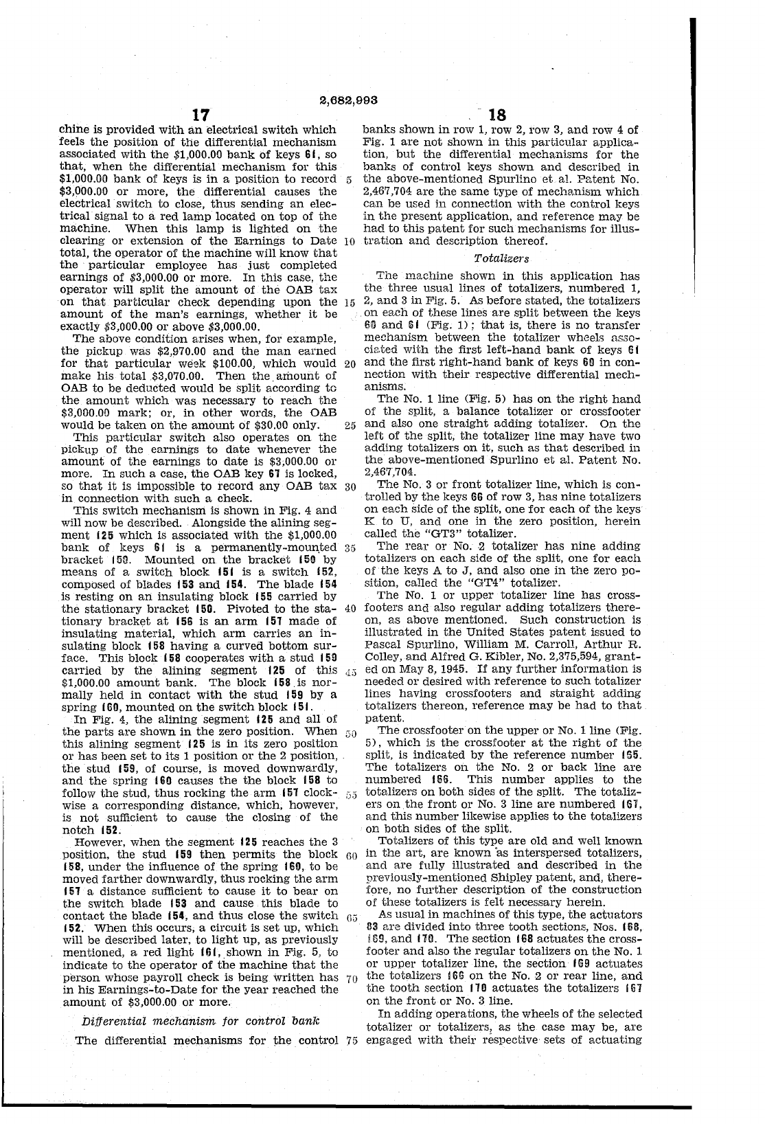
2,682,993
17
chine
is
provided
with
an
electrical
switch
which
feels
the
position
of
the
differential
mechanism
associated
with
the
$1,000.00
bank
of
keys 61, so
that,
when
the
differential
mechanism
for
this
$1,000.00
bank
of
keys is
in
a
position
to
record
5
$3,000.00
or
more,
the
differential
causes
the
electrical·
switch
to
close,
thus
sending
an
elec-
trical
signal
to
a
red
lamp
located
on
top
of
the
machine.
When
this
lamp
is
lighted
on
the
clearing
or
extension
of
the
Earnings
to
Date
10
total,
the
operator
of
the
machine
will
know
that
the
particular
employee
has
just
completed
earnings
of
$3,000.00
or
more.
In
this
case,
the
operator
will
split
the
amount
of
the
OAB
tax
on
that
particular
check
depending
upon
the
15
amount
of
the
man's
earnings,
whether
it
be
exactly
$3,000.00
or
above $3,000.00.
The
above
condition
arises
when,
for
example,
the
pickup
was $2,970.00
and
the
man
earned
for
that
particular
weell:
$100.00,
which
would
20
make
his
total.$3,070.00.
Then
the
amount
of
OAB
to
be
deducted
would be
split
according
to
18
banks
shown
in
row 1,
row
2,
row 3,
and
row 4 of
Fig. 1
are
not
shown
in
this
particular
applica-
tion,
but
the
differential
mechanisms
for
the
banks
of
control
keys
shown
and
described
in
the
above-mentioned
Spurlino
et
al.
Pr,tent
No.
2,467,704
are
the
same
tYpe
of
mechs.nism
which
can
be
used
in
connection
with
the
control
keys
in
the
present
application,
and
reference
may
be
had
to
this
patent
for
such
mechanisms
for
illus-
tration
and
description
thereof.
Totalize1"s
The
machine
shown
in
this
application
has
the
three
usual
lines
of
totalizers,
numbered
1,
2,
and
3
in
Fig.
5.
As
before
stated,
the
tdtalizers
on
each
of
these
lines
are
split
between
the
keys
S[J
and
Ii
I (Fig.
1);
that
is,
there
is
no
transfer
mechanism
between
the
totalizer
wheels
asso-
ciated
with
the
first
left-hand
bank
of
keys
61
and
the
first
right-hand
bank
of keys
60
in
con-
nection
with
their
respective
differential
mech-
anisms.
The
No.1
line
(Fig. 5)
has
on
the
right
hand
of
the
split, a
balance
totalizer
or
crossfooter
the
amount
which
was
necessary
to
reach
the
$3,000.00
mark;
or,
in
other
words,
the
OAB
would be
taken
on
the
amount
of
$30.00 only.
This
particular
switch
also
operates
on
the
pickup
of
the
earnings
to
date
whenever
the
amount
of
the
earnings
to
date
is $3,000.00
or
more.
In
such
a case,
the
OAB key
61
is
locked,
25
and
also
one
straight
adding
totalizer.
On
the
left
of
the
split,
the
totalizer
line
may
have
two
adding
totalizers
on
it,
such
as
that
described
in
the
above-mentioned
Spurlino
et
a1.
Patent
No.
so
that
it
is impossible
to
record
any
OAB
tax
30
in
connection
with
such
a check.
This
switch
mechanism
is
shown
in
Fig. 4
and
will now be described. Alongside
the
alining
seg-
ment
125
which
is
associated
with
the
$1,000.00
bank
of
keys 6(
is
a
permanently-moun.ted
35
bracket
151!.
Mounted
on
the
bracket
IS!!
by
means
of
a switCh
block
(51 is a
switch
152,
composed
of
blades
153
and
154.
The
blade
154
is
resting
on
an
insulating
block 155
carried
by
the
stationary
bracket
150.
Pivoted
to
the
sta-
40
tionary
bracket
at
156
is
an
arm
151
made
of
insulating
material,
which
arm
carries
an
in-
sulating
block
158
having
a
curved
bottom
sur-
face.
This
block (58 coopera,tes
with
a
stud
159
carried
by
the
alining
segment
125
of
this
,1;3
$1,000.00
amount
bank.
The
block 158. is
nor-
mally
held
in
contact
with
the
stud
159
by
a
spring
I
GO,
mounted
on
the
switch
block
151.
In
Fig.
4,
the
alining
segment
125
and
all
of
the
parts
are
shown
in
the
zero
position.
When
30
this
alining
segment
125 is
in
its
zero
position
or
has
been
set
to
its
1 position
or
the
2 position,
the
stud
159,
of
course, is
moved
downwardly,
and
the
spring
160 causes
the
the
block 158
to
follow
the
stud,
thus
rocking
the
arm
151 clock-
:j.)
wise a
corresponding
distance,
which,
however,
is
not
sufficient
to
cause
the
closing
of
the
notch
152.
However,
when
the
segment
125
reaches
the
3
position,
the
stud
159
then
permits
the
block
60
158,
under
the
infiuence
of
the
spring
160,
to
be
moved
farther
downwardly,
thus
rocking
the
arm
151 a
distance
sufficient
to
cause
it
to
bear
on
the
switch
blade
153
and
cause
this
blade
to
contact
the
blade
154,
and
thus
close
the
switch
fiG
152.
When
this
occurs, a
circuit
is
set
up,
which
will
be
described
later,
to
light
up,
as
previously
mentioned,
a
red
light
161,
shown
in
Fig.
5,
to
indicate
to
the
operator
of
the
machine
that
the
person
whose
payroll
check
is
being
written
has
70
in
his
Earnings-to-Date
for
the
year
reached
the
amount
of
$3,000.00
or
more.
Differential
mechanism
for
control
bank
The
differential
mechanisms
for
the
control
75
2,467,704.
The
No.3
or
front
totalizer
line,
which
is
con-
trolled
by
the
keys
66
of
row
3,
has
nine
totalizers
on
each
side
of
the
split,
one
for
each
of
the
l{eys
K
to
U,
and
one
in
the
zero position,
herein
called
the
"GT3"
totalizer.
The
rear
or
No.
·2
totalizer
has
nine
adding
totalizers
on
each
side
of
the
split,
one
for
each
of
the
keys A
to
J,
and
also
one
in
the
zero
po-
sition,
called
the
"GT4"
totalizer.
The
No. 1
or
upper
totalizer
line
has
cross-
footers
and
also
regular
adding
totalizers
there-
on,
as
above
mentioned.
Such
construction
is
illustrated
in
the
United
States
patent
issued
to
Pascal
Spurlino,
William
M. Carroll,
Arthur
R.
Colley,
and
Alfred G. Kibler, No. 2,375,594,
grant-
ed
on
May
8,
1945.
If
any
further
information
is
needed
or
desired
with
reference
to
such
totalizer
lines
having
crossfooters
and
straight
adding
totalizers
thereon,
reference
may
be
had
to
that
patent.
The
crossfooter
on
the
upper
or
No. 1
line
(Fig.
5),
which
is
the
crossfooter
at
the
right
of
the
split, is
indicated
by
the
reference
number
! 55.
The
totalizers
on
the
No. 2
or
back
line
are
numbered
166.
This
number
applies
to
the
totalizers
on
both
sides
of
the
split.
The
totaliz-
ers
on
.the
front
or
No.3
line
are
numbered
157,
and
this
number
likewise applies
to
the
totalizers
on
both
sides
of
the
split.
Totalizers
of
this
type
are
old
and
well
known
in
the
art,
are
known
"as
interspersed
totalizers,
and
are
fully
illustrated
and
described
in
the
previously-mentioned
Shipley
patent,
and,
there-
fore,
no
further
description
of
the
construction
of
these
totalizers
is
felt
necessary
herein.
As
usual
in
machines
of
this
type,
the
actuators
33
are
divided
into
three
tooth
sections, Nos. 168,
!
69,
and
11
o.
The
section
16
8
actuates
the
cross-
footer
and
also
the
regular
totalizers
on
the
No.1
or
upper
totalizer
line,
the
section
I Ii 9
actuates
the
totalizers
!
66
on
the
No.
·2
or
rear
line,
and
the
tooth
section
170
actuates
the
totalizers
'Ill
on
the
front
or
No.3
line.
In
adding
operations,
the
wheels
of
the
selected
totalizer
or
totalizers,
as
the
case
may
be,
are
engaged
with
their
respective
sets
of
actuating
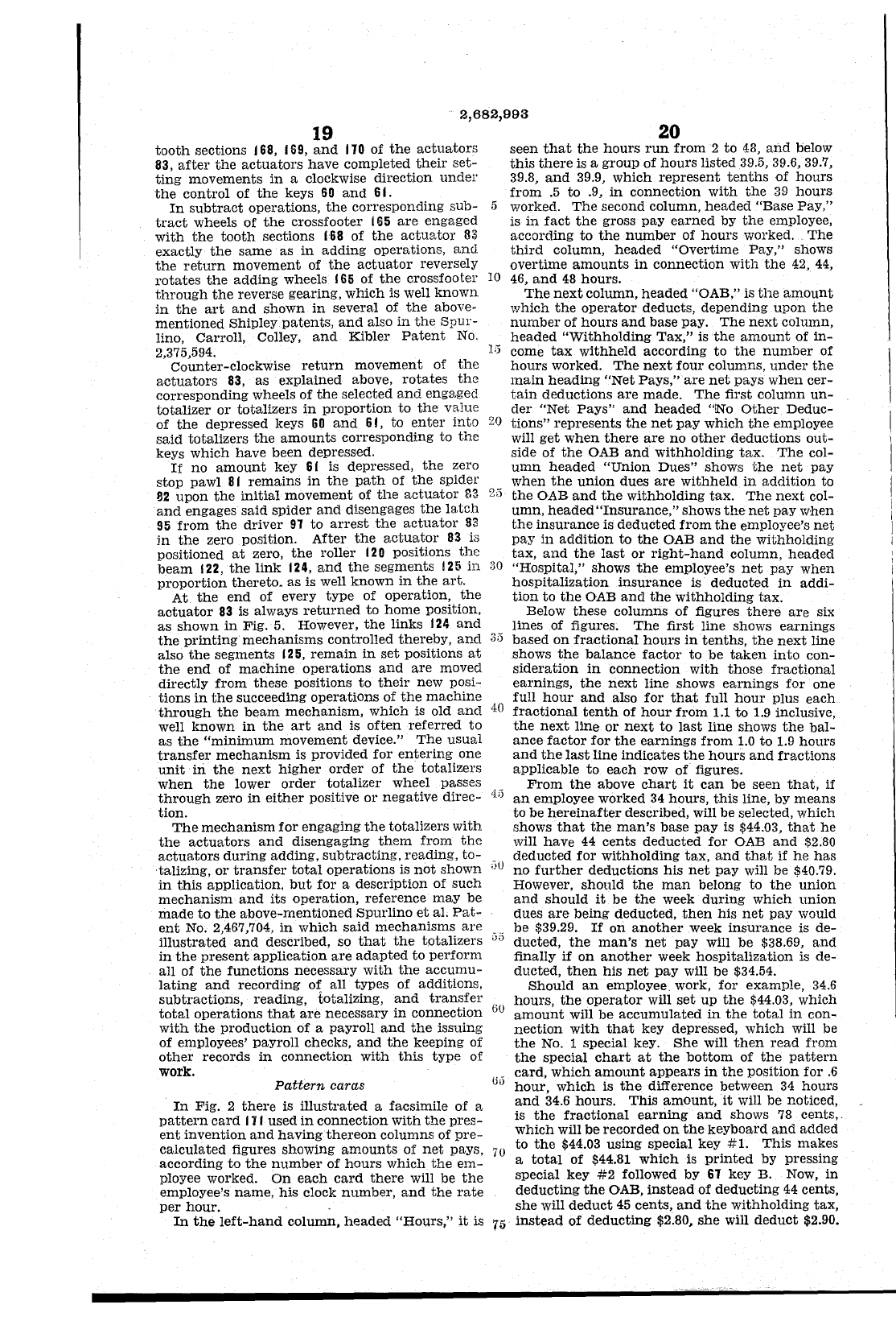
2,682,993
19
tooth
sections 168, 159,
and
110
of
the
actuators
83,
after
the
actuators
have
completed
their
set-
ting
movements
in
a clockwise
direction
under
the
control
of
the
keys
60
and
6
l-
In
subtract
operations,
the
corresponding
sub-
tract
wheels of
the
cross footer
165
are
engaged
with
the
tooth
sections
168
of
the
actuator
83
exactly
the
same
as
in
adding
operations,
and
the
return
movement
of
the
actuator
reversely
rotates
the
adding
wheels
165
of
the
crossfooter
through
the
reverse gearing,
which
is well
known
in
the
art
and
shown
in
several of
the
above-
mentioned
Shipley
patents,
and
also
in
the
Spur-
lino, Carroll, Colley,
and
Kibler
Patent
No,
2,375,594.
Counter-clockwise
return
movement
of
the
actuators
83,
as
explained
above,
rotates
the
corresponding
wheels
of
the
selected
and
engs,ged
totalizer
or
totalizers
in
proportion
to
the
value
of
the
depressed keys
60
and
61,
to
enter
into
said
totalizers
the
amounts
corresponding
to
the
keys
which
have
been
depressed.
If
no
amount
key
6 I is depressed,
the
zero
stop
pawl
8 I
remains
in
the
path
of
the
spidel'
82
upon
the
initial
movement
of
the
actuator
&3
and
engages
said
spider
and
disengages
the
latch
95
from
the
driver
91
to
arrest
the
actuator
83
in
the
zero position.
After
the
actuator
83
is
positioned
at
zero,
the
roller
120
positions
the
beam
122,
the
link
124,
and
the
segments
125
in
proportion
thereto.
as
is well
known
in
the
art.
At
the
end
of every
type
of
operation,
the
actuator
83
is always
returned
to
home
position,
as
shown
in
Fig. 5. However,
the
links
124
and
the
printing
mechanisms
controlled
thereby,
and
also
the
segments
125,
remain
in
set
positions
at
the
end
of
machine
operations
and
are
moved
directly
from
these
positions
to
their
new posi-
tions
in
the
succeeding
operations
of
the
machine
through
the
beam
mechanism,
which
is old
and
well
known
in
the
art
and
is
often
referred
to
as
the
"minimum
movement
device."
The
usual
transfer
mechanism
is provided
for
entering
one
unit
ill
the
next
higher
order
of
the
totalizers
when
the
lower
order
totalizer
wheel passes
through
zero
in
either
positive
or
negative
direc-
tion.
The
mechanism
for
engaging
the
totalizers
with
the
actuators
and
disengaging
them
from
the
actuators
during
adding,
subtracting,
reading,
to-
'talizing,
or
transfer
total
operations
is
not
shown
in
this
application,
but
for
a
description
of
such
mechanism
and
its
operation,
reference
may
be
made
to
the
above-mentioned
Spurlino
et
al.
Pat-
ent
No. 2,467,704,
in
which
said
mechanisms
are
illustrated
and
described, so
that
the
totalizers
in
the
present
application
are
adapted
to
perform
all
of
the
functions
necessary
with
the
accumu-
lating
and
recording
of
all
types
of additions,
subtractions,
reading,
totalizing,
and
transfer
total
operations
that
are
necessary
in
connection
with
the
production
of
a payroll
and
the
issuing
of employees'
payroll
checks,
and
the
keeping of
other
records
in
connection
with
this
type
of
work. Pattern caras
In
Fig. 2
there
is
illustrated
a facsimile of a
pattern
card
III
used
in
connection
with
the
pres-
ent
invention
and
having
thereon
columns of
pre-
calculated
figures showing
amounts
of
net
pays,
according
to
the
number
of
hours
which
the
em-
ployee worked.
On
each
card
there
will be
the
employee's
name,
his
clock
number,
and
the
rate
per
hour.
In
the
left-hand
column.
headed
"Hours,"
it
is
20
seen
that
the
hours
run
from
2
to
48,
and
below
this
there
is a
group
of
hours
listed
39.5, 39.6, 39.7,
39.8,
and
39.9,
which
represent
tenths
of
hours
from
.5
to
.9,
in
connection
with
the
39
hours
5
worl;;:ed.
The
second column,
headed
"Base
Pay,"
is
in
fact
the
gross
pay
earned
by
the
employee,
according
to
the
number
of
hours
worked.
The
third
column,
headed
"Overtime
Pay,"
shows
overtime
amounts
in
connection
with
the
42,
44,
10
46,
and
48
hours.
The
next
column,
headed
"OAB," is
the
amount
which
the
operator
deducts,
depending
upon
the
number
of
hours
and
base pay.
The
next
column,
headed
"Withholding
Tax,"
is
the
amount
of
in-
I,) come
tax
withheld
according
to
the
number
of
hours
worked.
The
next
four
columns,
under
the
main
heading
"Net
Pays,"
are
net
pays
when
cer-
tain
deductions
are
made.
The
first
column
un-
der
"Net
Pays"
and
headed
"1N0
Other
Deduc-
20
tions"
represents
the
net
pay
which
the
employee
will
get
when
there
are
no
other
deductions
out-
side
of
the
OAB
and
withholding
tax.
The
col-
umn
headed
"Union
Dues"
shows
the
net
pay
when
the
union
dues
are
withheld
in
addition
to
25
the
OAB
and
the
withholding
tax.
The
next
col-
umn,
headed
"Insurance,"
shows
the
net
pay
when
the
insurance
is
deducted
from
the
employee's
net
pay
in
addition
to
the
OAB
and
the
withholding
tax,
and
the
last
or
right-hand
column,
headed
:)0
"Hospital,"
shows
the
employee's
net
pay
when
hospitalization
insurance
is
deducted
in
addi-
tion
to
the
OAB
and
the
withholding
tax.
Below
these
columns
of
figures
there
are
six
lines of figures.
The
first
line shows
earnings
3;3
based
on
fractional
hours
in
tenths,
the
next
line
shows
the
balance
factor
to
be
taken
into
con-
sideration
in
connection
with
those
fractional
earnings,
the
next
line
shows
earnings
for
one
full
hour
and
also
for
that
full
hour
plus
each
40
fractional
tenth
of
hour
from
1.1
to
1.9
inclusive,
the
next
line
or
next
to
last
line shows
the
bal-
ance
factor
for
the
earnings
from
1.0
to
1.9
hours
and
the
last
line
indicates
the
hours
and
fractions
applicable
to
each
row of figures.
From
the
above
chart
it
can
be
seen
that,
if
4;)
an
employee worked
34
hours,
this
line, by
means
to
be
hereinafter
described, will be selected, which
shows
that
the
man's
base
pay
is $44.03,
that
he
will
have
44
cents
deducted
for
OAB
and
$2.80
deducted
for
withholding
tax,
and
tha,t if
he
has
;)0
no
further
deductions his
net
pay
will be $40.79.
However,
should
the
man
belong
to
the
union
and
should
it
be
the
week
during
which
union
dues
are
being
deducted,
then
his
net
pay
would
be
$39.29.
If
on
another
week
insurance
is
de-
;)5
ducted,
the
man's
net
pay
will
be
$38.69,
and
finally
if
on
another
week
hospitalization
is de-
ducted,
then
his
net
pay
will
be
$34.54.
Should
an
employee work,
for
example,
34.6
60
hours,
the
operator
will
set
up
the
$44.03, which
amount
will
be
accumulated
in
the
total
in
con-
nection
with
that
key depressed,
which
will be
the
No.1
special key.
She
will
then
read
from
the
special
chart
at
the
bottom
of
the
pattern
66
~~~~,
w:~~~
a~o~~t
~&:r~~c~n
~~::e~~t~of
~~~~.~
and
34.6
hours.
This
amount,
it
will be noticed,
is
the
fractional
earning
and
shows
78
cents"
which
will
be
recorded
on
the
keyboard
and
added
to
the
$44.03
using
special key
#1.
This
makes
70
a
total
of $44.81
which
is
printed
by pressing
special key
#2
followed by
61
key B. Now,
in
deducting
the
OAB,
instead
of
deducting
44 cents,
she
will
deduct
45
cents,
and
the
withholding
tax,
75
instead
of
deducting
$2.80,
she
will
deduct
$2.90.
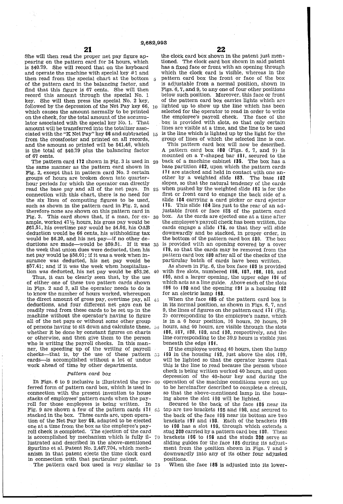
2,682,993
21
She
will
then
read
the
proper
net
pay
figure
ap-
pearing
on
the
pattern
card
for
34
hours,
which
is $40.79.
She
will
record
that
on
the
keyboard
and
operate
the
machine
with
special
key
#1
and
then
read
from
the
special
chart
at
the
bottom
of
the
pattetn
card
in
the
balancing
factor,
and
find
that
this
figure is
67
cents.
She
will
then
record
this
amount
through
the
special
No. 1
key.
She
will
then
press
the
special
No.2
key,
followed
by
the
depression
of
the
Net
Pay
key 66,
which
causes
the
amount
normally
to
be
printed
on
the
check,
for
the
total
amount.
of
the
accumu-
lator
associated
with
the
special
key No.
1.
That
amount
will be
transferred
into
the
totalizer
asso-
ciated
with
the
"K
Net
Pay"
key
6S
and
subtracted
from
the
crossfooter
and
printed
on
all
records,
and
the
amount
so
printed
will
be
$41.46,
which
is
the
total
of
$40.79 plus
the
balancing
factor
of
67
cents.
The
pattern
card
112
shown
in
Fig. 3 is
used
in
the
same
manner
as
the
pattern
card
shown
in
Fig.
2,
except
that
in
pattern
card
No.3
certain
groups
of
hours
are
broken
down
into
quarter-
hour
periods
for
which
the
operator
can
directly
read
the
base
pay
and
all
of
the
net
pays.
In
connection
with
this
chart,
there
is
no
need
for
the
six
lines
of
computing
figures
to
be used,
such
as
shown
in
the
pattern
card
in
Fig.
2,
and
therefore
none
are
shown
on
this
pattern
card
in
Fig.
3.
This
card
shows
that,
if
a
man,
for
ex-
ample,
worked
47
Y2
hours,
his
gross
pay
would be
$61.51,
his
overtime
pay
would
be
$4.86,
his
OAB
deduction
would
be
66
cents,
his
withholding
tax
would
be
$6.20,
and
his
net
pay-if
no
other
de-
ductions
are
made-would
be
$59.51.
If
it
was
the
week
that
union
dues were
deducted,
then
his
net
pay
would
be
$58.01;
if
it
was a week
when
in-
surance
was
deducted,
his
net
pay
would
be
$57.41;
and
if
it
was
the
week
when
hospitaliza··
tion
was
deducted,
his
net
pay
would
be
$53.26.
Thus,
it
can
be
clearly
seen
that,
by
the
use
of
either
one
of
these
two
pattern
cards
shown
in
Figs. 2
and
3,
all
the
operator
needs
to
do
is
22
the
clock
card
box
shown
in
the
patent
just
men-
tioned.
The
clock
card
box
shown
in
said
patent
has
a fixed
face
or
front
with
an
opening
through
which
the
clock
card
is visible,
whereas
in
the
5
pattern
card
box
the
front
or
face
of
the
box
is
adjustable
from
a
normal
position,
shown
in
Figs.
6,
7,
and
9,
to
anyone
of
four
other
positions
below
such
position. Moreover,
this
face
or
front
of
the
pattern
card
box
carries
lights
which
are
10
lighted
up
to
show
up
the
line
which
has
been
selected
for
the
operator
to
read
in
order
to
write
the
employee's
payroll
cheCk.
The
face
of
the
box is provided
with
slots, so
that
only
certain
lines
are
visible
at
a
time,
and
the
line
to
be
used
15
is
the
line
which
is
lighted
up
by
the
light
for
the
group
of
lines
of
which
the
selected
line
is one.
This
pattern
card
box will
now
be
described.
A
pattern
card
box
180
(Figs. 6, 7,
and
9)
is
mounted
on
aT-shaped
bar
j a
I,
secured
to
the
20
bacl(
of
a
machine
cabinet
135.
The
box
has
a
base
partition
1'112,
upon
which
the
pattern
cards
17
I
are
stacked
and
held
in
contact
with
one
an-
other
by
a
weighted
slide
1113.
The
base
182
slopes, so
that
the
natural
tendency
of
the
cards
25
when
pushed
by
the
weighted
slide 183 is
for
the
first
01'
front
card
to
engage
the
back
side
of
a
slide
1114
carrying
a
card
picker
or
card
ejector
I
Hi.
This
slide
184
lies
just
to
the
rear
of
an
ad-
justable
front
or
face
185
of
the
pattern
card
30
box.
As
the
cards
are
ejected
one
at
a
time
after
the
employee's
payroll
cheCk
has
been
written,
the
cards
engage
a slide
118,
so
that
they
win slide
downwardly
and
be
stacked,
in
proper
order,
in
the
bottom
of
the
pattern
card
box
180.
The
box
35
is
provided
with
an
opening
covered
by
a
cover
119,
so
that
the
cards
may
be
removed
from
the
pattern
card
box
I
1l0after
all
of
the
checks
of
the
particular
batch
of
cards
have
been
written.
As
shown
in
Fig.
6,
the
box
face
185
is
provided
40
with
five slots,
numbered
III'S,
187,
1'88,
189,
and
'SO,
and
a
larger
opening,
the
upper
edge
j 9 f
of
which
acts
as
a
line
guide. Above
each
of
the
slots
!
86
to
190
and
the
opening
19! is a
housing
!
92
to
know
the
number
of
hours
worked,
whereupon
the
direct
amount
of
gross pay,
overtime
pay,
all
4;:;
deductions,
and
four
different
net
pays
can
be
readily
read
from
these
cards
to
be
set
up
in
the
machine
without
the
operator's
having
to
figure
for
an
electric
lamp
193.
When
the
face
185
of
the
pattern
card
box
is
in
its
normal
pOSition,
as
shown
in
Figs. 6, 7,
and
9,
the
lines
of
figures
on
the
pattern
card
111
(Fig.
2)
corresponding
to
the
employee's
name,
which
is
ina
0
hour
position,
10
hours,
20
hours,
30
all
of
the
net
pays
or
without
some
other
group
of
persons
having
to
sit
down
and
calculate
these,
whether
it
be
done
by
constant
figures
on
charts
or
otherwise,
and
then
give
them
to
the
person
who
is
writing
the
payroll
checks.
In
this
man-
ner,
the
speeding
up
of
the
vvriting
of
payroll
checks-that
is,
by
the
use
of
these
pattern
cards-is
accomplished
without
a
lot
of
undue
work
ahead
of
time
by
other
departments.
Pattern
card
box
In
Figs. 6
to
9 inclusive is
illustrated
the
pre-
ferred
form
of
pattern
card
box,
which
is
used
in
connection
with
the
present
invention
to
house
stacks
of
employees'
pattern
cards
when
the
pay-
roll
for
those
employees is
being
written.
In
Fig. 9
are
shown
a few
of
the
pattern
cards
111
stacked
in
the
box.
These
cards
are,
upon
opera-
tion
of
the
Net
Pay
lcey
56,
adapted
to
be
ejected
one
at
a
time
from
the
box
as
the
employee's
pay-
roll
check
is completed.
The
ejection
of
the
card
is
accomplished
by
mechanism
which
is fully
il-
lustrated
and
described
in
the
above-mentioned
Spurlino
et
al.
Patent
No. 2,467,704,
which
mech-
anism
in
that
patent
ejects
the
time
clock
card
in
connection
with
that
particular
patent.
GU
hours,
and
40
hours,
are
visible
through
the
slots
186, ill1, 188,
Ill!!,
and
1911,
respectively,
and
the
line
corresponding
to
the
39.9
hours
is visible
just
beneath
the
edge I 9 I.
If
the
employee worked
40
hours,
then
the
lamp
c,:;
i
&3
in
the
housing
Hl2,
just
above
the
slot
UW,
will
be
lighted
so
that
the
operator
knows
that
tIllS is
the
line
to
,read
because
the
person
whose
check
is
being
written
worked
40
hours,
and
upon
depreSSion
of
the
40-hour
key
and
during
the
GO
operation
of
the
machine
conditions
were
set
up
to
be
hereinafter
described
to
complete
a circuit,
so
that
the
above-mentioned
lamp
in
the
hous-
ing
above
the
slot
190
will
be
lighted.
Secured
to
the
back
of
the
face
1115
near
its
G;';
top
are
two
brackets
195
and
196,
and
secured
to
the
back
of
the
face
185
near
its
bottom
are
two
brackets
i
91
and
193.
Each
of
the
brackets
I
!Hi
to
I
SIl
has
a
slot
HIS,
tl1rough
which
extends
a
stUd
200
carried
by
a
pattern
card
box 130.
These
70
brackets
I
Sii
to
I
SB
and
the
studs
200
serve
as
sliding guides
for
the
face
185
during
its
adJust-
ment
from
the
position
shown
in
Figs. 'I
and
[)
downwardly
into
any
of
its
other
four
adjusted
positions.
The
pattern
card
box
used
is
very
similar
to
75
When
the
face
185
is
adjusted
into
its
lower-
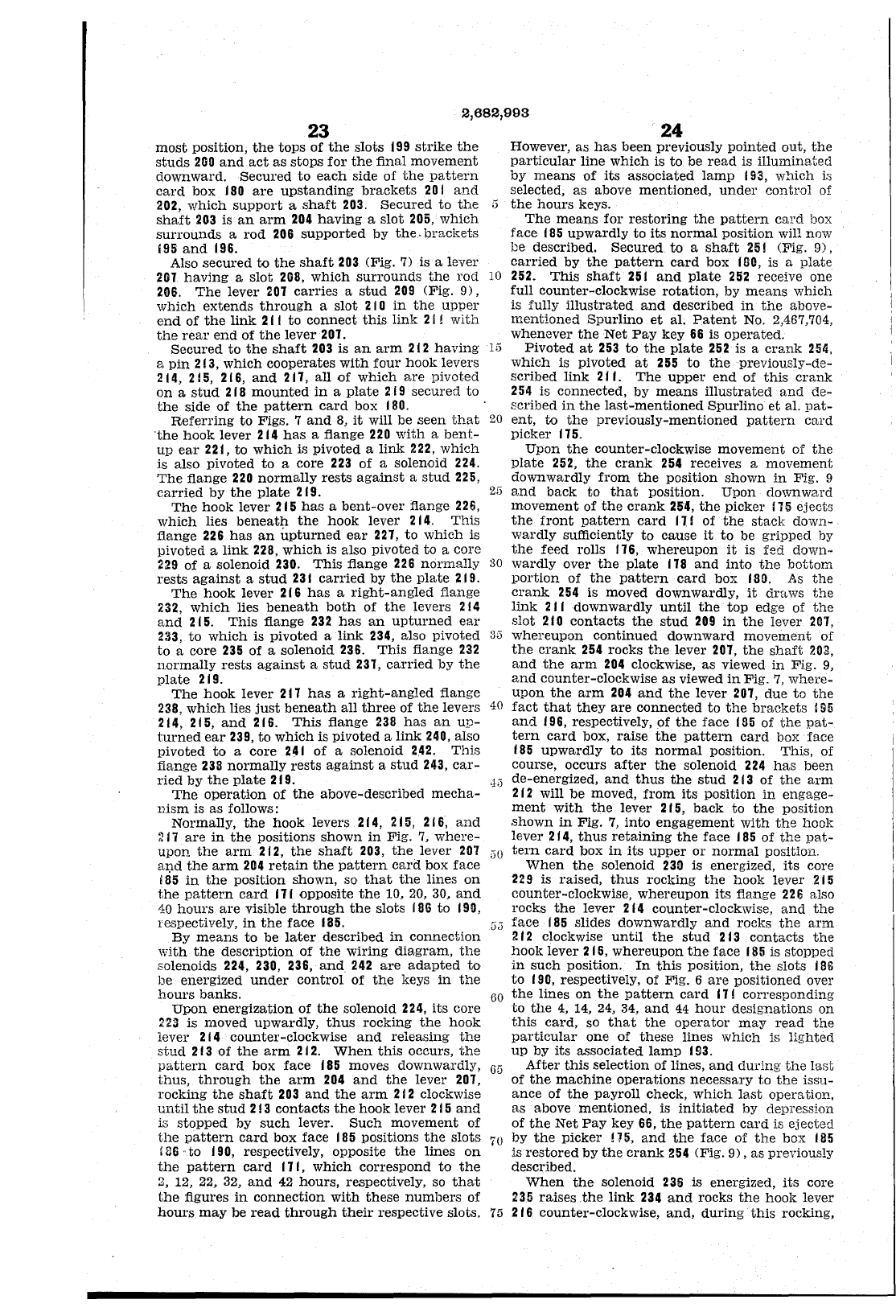
2,682,993
23
most
position,
the
tops
of
the
slots
199
strike
the
studs
200
and
act
as
stops
for
the
final
movement
downward.
Secured
to
each
side
of
the
pattern
card
box I
SO
are
upstanding
brackets
20
I
and
202,
which
support
a
shaft
203.
Secured
to
the
:3
shaft
203
is
an
arm
204
having
a
slot
205,
which
surrounds
a
rod
206
supported
by
the.
brackets
i9S
and
196.
Also
secured
to
the
shaft
203
(Fig. 7) is a
lever
207
having
a
slot
208,
which
surrounds
the
rod
10
206.
The
lever
201
carries
a
stud
209
(Fig.
9),
which
extends
through
a
slot
2
lOin
the
upper
end
of
the
link
211
to
connect
this
link
2 i I
with
the
rear
end
of
the
lever
201.
Secured
to
the
shaft
203
is
an
arm
212
having
1:3
a
pin
213,
which
cooperates
with
four
hook
levers
214,
215, 216,
and
211,
all
of
which
s,re
pivoted
on
a
stud
218
mounted
in
a
plate
219
secured
to
the
side
of
the
pattern
card
box
180.
Referring
to
Figs. 7
and
8,
it
will be
seen
that
20
·the
hook
lever
214
has
a flange
220
with
a
bent-
up
ear
221,
to
which
is
pivoted
a
link
222,
which
24
However,
as
has
been
previously
pointed
out,
the
particular
line
which
is
to
be
read
is
illuminated
by
means
of
its
associated
lamp
193,
which
is
selected,
as
above
mentioned,
under
control
of
the
hours
keys.
The
means
for
restoring
the
pattern
card
box
face
f
85
upwardly
to
its
normal
position
will now
be
described.
Secured
to
a
shaft
25!
(Fig.
9),
carried
by
the
pattern
card
box
1110,
is a
plate
252.
This
shaft
251
and
plate
252
receive one
full
counter-clockwise
rotation,
by
means
which
is fully
illustrated
and
described
in
the
above-
mentioned
Spurlino
et
al.
Patent
No. 2,467,704,
whenever
the
Net
Pay
key
66
is
operated.
Pivoted
at
253
to
the
plate
252
is a
crank
254,
which
is
pivoted
at
255
to
the
previously-de-
scribed
link
211.
The
upper
end
of
this
crank
254
is
connected,
by
means
illustrated
and
de-
scribed
in
the
last-mentioned
Spurlino
et
al.
pat-
ent,
to
the
previously-mentioned
pattern
card
picker
115.
Upon
the
counter-clockwise
movement
of
the
plate
252,
the
crank
254
receives a
movement
downwardly
from
the
position
shown
in
Fig. 9
is
also
pivoted
to
a
core
223
of
a solenoid
224.
The
flange
220
normally
rests
against
a
stud
225,
carried
by
the
plate
2
19.
2:3
and
back
to
that
pOSition.
Upon
downward
movement
of
the
crank
254,
the
picker
115
ejects
the
front
pattern
card
11.1
of
the
stack
down-
wardly
sufficiently
to
cause
it
to
be
gripped
by
The
hook
lever
215
has
a
bent-over
flange
226,
which
lies
beneath
the
hook
lever
214.
This
flange
226
has
an
upturned
ear
221,
to
which
is
pivoted
a
link
228,
which
is also pivoted
to
a core
229
of
a solenoid 230.
This
flange
226
normally
30
rests
against
a
stud
231
carried
by
the
plate
219.
The
hook
lever
216
has
a
right-angled
fiange
232,
which
lies
beneath
both
of
the
levers
214
and
215.
This
flange
232
has
an
upturned
ear
233,
to
which
is
pivoted
a
link
234, also
pivoted
3:3
to
a core
235
of
a solenoid 236.
This
flange
232
normally
rests
against
a
stud
231,
carried
by
the
plate
219.
the
feed rolls
116,
whereupon
it
is
fed
down-
wardly
over
the
plate
118
and
into
the
bottom
portion
of
the
pattern
card
box
I
SO.
As
the
crank
254
is moved
downwardly,
it
draws
the
link
211
downwardly
until
the
top
edge of
the
slot
210
contacts
the
stud
209
in
the
lever
201,
whereupon
continued
downward
movement
of
the
crank
254
rocks
the
lever
201,
the
shaft
203,
and
the
arm
204
clockwise,
as
viewed
in
Fig. 9,
and
counter-clockwise
as
viewed
in
Fig.
7,
where-
upon
the
arm
204
and
the
lever
201,
due
to
the
fact
that
they
are
connected
to
the
brackets
195
and
196,
respectively,
of
the
face
185
of
the
pat-
tern
card
box,
raise
the
pattern
card
box face
185
upwardly
to
its
normal
pOSition.
This,
of
course, occurs
after
the
solenoid
224
has
been
The
hook
lever
211
has
a
right-angled
flange
238,
which
lies
just
beneath
all
three
of
the
levers
40
214, 215,
and
216.
This
flange
238
has
an
up-
turned
ear
239,
to
which
is
pivoted
a
link
240, also
pivoted
to
a core
241
of
a solenoid
2.42.
This
fiange
238
normally
rests
against
a
stud
243,
car-
ried
by
the
plate
219.
,hi
de-energized,
and
thus
the
stud
213
of
the
arm
2
12
will
be
moved,
from
its
position
in
engage-
ment
with
the
lever
215,
back
to
the
position
shown
in
Fig.
7,
into
engagement
with
the
hook
The
operation
of
the
above-described
mecha-
nism
is
as
follows:
Normally,
the
hook
levers
214, 215, 216,
and
217
are
in
the
positions
shown
in
Fig.
7,
where-
upon
the
arm
212,
the
shaft
203,
the
lever
207
60
and
the
arm
204
retain
the
pattern
card
box
face
i
65
in
the
position
shown, so
that
the
lines
on
the
pattern
card
111
OPPOSite
the
10,
20,
30,
and
lever
214,
thus
retaining
the
face
185
of
the
pat-
tern
card
box
in
its
upper
or
normal
position.
When
the
solenoid
230
is energized,
its
core
229
is
raised,
thus
rocking
the
hook
lever
2 I 5
counter-clockwise,
whereupon
its
flange
2213
also
rocks
the
lever
214
counter-clockwise,
and
the
10
hours
are
visible
through
the
slots
fOG
to
1911,
respectively,
in
the
face
185.
By
means
to
be
later
described
in
connection
\'lith
the
description
of
the
wiring
diagram,
the
solenoids 224, 230, 236,
and
242
are
adapted
to
be
energized
under
control
of
the
keys
in
the
hours
banks.
[i;i
face
185
slides
downwardly
and
rocks
the
arm
212
clockwise
until
the
stud
213
contacts
the
hook
lever
215,
whereupon
the
face
185
is
stopped
in
such
position.
In
this
position,
the
slots
186
to
190,
respectively, of Fig. 6
are
positioned
over
60
the
lines
on
the
pattern
card
171
corresponding
to
the
4,
14,
24,
34,
and
44
hour
designations
on
this
card,
so
that
the
operator
may
read
the
particular
one
of
these
lines
which
is
lighted
Upon
energization
of
the
solenoid 224,
its
core
223
is
moved
upwardly,
thus
rocking
the
hook
lever
214
counter-clockwise
and
releasing
the
stud
213
of
the
arm
212.
When
this
occurs,
the
pattern
card
box
face
185
moves downwardly,
6G
thus,
through
the
arm
204
and
the
lever
201,
rocking
the
shaft
203
and
the
arm
212
clockwise
until
the
stud
213
contacts
the
hook
lever
215
and
is
stopped
by
such
lever.
Such
movement
of
the
pattern
card
box
face
185
positions
the
slots
70
'86
..
to
190,
respectively, opposite
the
lines
on
the
pattern
card
111,
which
correspond
to
the
2,
12, 22, 32,
and
42
hours,
respectively, so
that
the
figures
in
connection
with
these
numbers
of
hours
may
be
read
through
their
respective slots.
75
up
by
its
associated
lamp
1f)3.
After
this
selection
of
lines,
and
dming
the
last
of
the
machine
operations
necessary
to
the
issu-
ance
of
the
payroll
check,
which
last
operation,
as
above
mentioned,
is
initiated
by depression
of
the
Net
Pay
key 56,
the
pattern
card
is
ejected
by
the
picker
115,
and
the
face
of
the
box
185
is
restored
by
the
crank
254
(Fig.
9),
as
previously
described.
When
the
solenoid
236
is energized,
its
core
235
raises
.the
link
234
and
rocks
the
hook
lever
216
counter-clockwise,
and,
during
this
rocking,
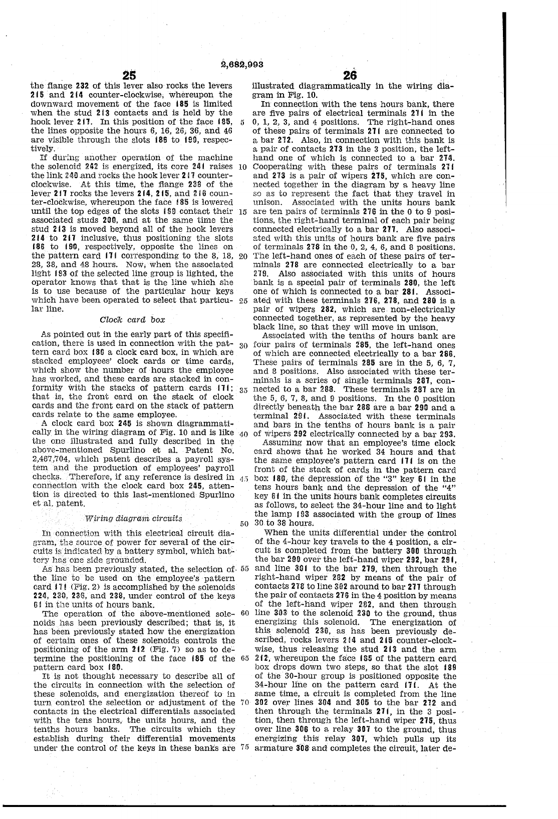
2,682,993
25
the
flange
232
of
this
lever
also
rocks
the
levers
2
15
and
2
III
counter-clockwise;
whereupon
the
downward
movement
of
the
face
185
is
limited
when
the
stud
213
contacts
and
is
held
by
the
hook
level' 217.
In
this
position
of
the
face
185, 5
the
lines
opposite
the
hours
6,
16,
26,
36,
and
46
are
visible
through
the
slots 186
to
1M,
respec-
tively.
If
during
another
operation
of
the
machine
the
solenoid 242 is energized,
its
core
241
raises
10
the
link
24!]
.and rocks
the
hook
lever
217
counter-
clockwise.
At
this
time,
the
flange
2311
of
the
lever
2 n rocks
the
levers 214, 2
Hi,
and
2
Hi
coun-
ter-clockwise,
whereupon
the
face
! 85 is lowered
until
the
top
edges of
the
slots I
sa
contact
their
15
associated
studs
200,
and
at
the
same
time
the
stud
2
13
is moved
beyond
all
of
the
hook
levers
2
14
to
2
11
inclusive,
thus
positioning
the
slots
186
to
190, respectively, opposite
the
lines
on
the
pattern
card
111
corresponding
to
the
8,
18,
20
28, 38,
and
48
hours.
Now;
when
the
associated
light
I
S3
of
the
selected
line
group
is
lighted,
the
operator
knows
that that
is
the
line
which
she
is
to
use
because
of
the
particular
hour
keys
which
have
been
operated
to
select
that
particu-
25
lar
line.
Clock
careL
box
26
illustrated
diagrammatically
in
the
wiring
dia-
gram
in
Fig. 10.
In
connection
with
the
tens
hours
bank,
there
are
five
pairs
of
electrical
terniinals
2"11
in
the
0,
1, 2,
3,
and
4 positions.
The
right-hand
ones
of
these
pairs
of
terminals
211
are
connected
to
a
bar
212. Also,
in
connection
with
thi.s
bank
is
a
pair
of
contacts
213
in
the
3 position,
the
left-
hand
one
of
which
is
connected
to
a
bar
214.
Cooperating
with
these
pairs
of
terminals
211
and
2"13
is a
pair
of
wipers 215,
which
are
con-
nected
together
in
the
diagram
by
a
heavy
line
so
as
to
represent
the
fact
that
they
travel
in
unison.
Associated
with
the
units
hours
bank
are
ten
pairs
of
terminals
276
in
the
0
to
9 posi-
tions,
the
right~hand
terminal
of
each
pair
being
connected
electrically
to
a
bar
271. Also associ-
sted
with
this
units
of
hours
banl{
are
five
pairs
of
terminals
278
in
the
0,
2,
4,
6,
and
8 positions.
The
left-hand
ones
of
each
of
these
pairs
of
ter-
minals
218
are
connected
electrically
to
a
bar
219. Also
associated
with
this
units
of
hours
bank
is a
special
pair
of
terminals
280,
the
left
one
of
which
is
connected
to
a
bar
281. Associ-
ated
with
these
terminals
276, 218,
and
280 is a
pair
of
wipers
282,
which
are
non-electrically
connected
together,
as
represented
by
the
heavy
black
line, so
that
they
will move
in
unison.
ASSOCiated
with
the
tenths
of
hours
bank
are
As
pointed
out
in
the
early
part
of
this
specifi-
cation,
there
is
used
in
connection
"'lith
the
pat-
tern
card
box
181l
a clock
card
box,
in
which
are
stacked
employees' clock
cards
or
time
cards,
which
show
the
number
of
hours
the
employee
has
worked,
and
these
cards
are
stacked
in
con-
formity
With
the
stacks
of
pattern
cards
111;
that
is,
the
front
card
on
the
stack
of
clock
cards
and
the
front
card
on
the
stack
of
pattern
cards
relate
to
the
same
employee.
30
four
pairs
of
terminals
:i85,
the
left-hand
ones
of
which
are
connected
electrically
to
a
bar
266.
These
pa.irs
of
terminals
285
are
in
the
5,
6,
7,
and
8 positions. Also
associated
with
these
ter-
minals
is
a series
of
single
terminals
287,
con-
A clock
card
box
245
is
shown
diagrammati-
cally
in
the
wiring
diagram
of
Fig.
10
and
is like
the
one
illustrated
and
fully
described
in
the
above-mentioned
Spurlino
et
al.
Patent
No.
2,467,704,
which
patent
describes a
payroll
sys-
tem
and
the
production
of employees'
payroll
chec:jm.
Therefore,
if
any
reference
is
desired
in
connection
with
the
clock
card
box
245,
atten-
tion
is
directed
to
this
last-mentioned
Spurlino
et
al.
patent.
35
nected
to
a
bar
288.
These
terminals
281
are
in
the
5,
6, 7,
8,
and
9 positions.
In
the
0
position
directly
beneath
the
bar
2811
are
a
bar
290
and
a
terminal
2!l
L Associated
with
these
terminals
and
bars
in
the
tenths
of
hours
bank
is a
pair
40
of
wipers
292
electrically
connected
by
a
bar
293.
Assuming
now
that
an
employee's
time
clock
card
shows
that
he
worked
34
hours
and
that
the
sanie
employee's
pattern
card
171
is
on
the
front
of
the
stack
of
cards
in
the
pattern
card
Wiring
diagram
circuits
·1')
box
181l,
the
depression
of
the
"3"
key
61
in
the
tens
hours
bank
and
the
depression
of
the
"4"
key
Ii
I
in
the
units
hours
banl{
completes
circuits
as
follows,
to
select
the
34-hour
line
and
to
light
the
lamp
193
associated
with
the
group
of
lines
50
30
to
38
hours.
In
connection
with
this
elect.rical
circuit
dia-
BTam,
th3
source
of
power
for
several
of
the
cir-
cuits
is
indicated
by
a
battery
symbol,
which
bat-
tery
hn·s
one
side
grounded.
As
has
been
previously
stated,
the
selection
of-
55
the
line
to
be
used
on
the
employee's
pattern
card
11!
(Fig. 2) is
accomplished
by
the
solenoids
224, 230,
23(3,
and
238,
under
control
of
the
keys
ll!
in
the
units
of
hours
bank.
The
operation
of
the
above-mentioned
sole-
60
noids
has
been
previously described;
that
is,
it
has
been
previously
stated
how
the
energization
of
certain
ones
of
these
solenoids
controls
the
positioning
of
the
arm
212
(Pig. 7) so
as
to
de-
termine
the
positioning
of
the
face
185
of
the
65
pattern
card
box 180.
It
is
not
thought
necessary
to
describe
all
of
the
circuits
in
connection
with
the
selection of
these
solenoids,
and
energization
thereof
to
in
turn
control
the
selection
or
adjustment
of
the
70
contacts
in
the
electrical
differentials
associated
with
the
tens
hours,
the
units
hours,
and
the
tenths
hours
banks.
The
circuits
which
they
establish
during
their
differential
movements
under
the
control
of
the
keys
in
these
banks
are
75
When
the
units
differential
under
the
control
of
the
4-hour
key
travels
to
the
4 position, a
cir-
cuit
is
completed
from
the
battery
3DD
through
the
bar
:1
90
over
the
left-hand
wiper 292,
bar
29
I ,
and
line
30
j
to
the
bar
279,
then
through
the
right-hand
wiper
282
by
means
of
the
pair
of
contacts
218
to
line
302
around
to
bar
217
through
the
pair
of
contacts
216
in
the
4
position
by
means
of
the
left-hand
wiper 282,
and
then
through
line
303
to
the
solenoid
230
to
the
ground,
thus
energizing
this
solenoid.
The
energization
of
this
solenoid 230,
as
has
been
previously
de-
scribed,
rocks
levers
:2!
4
and
215
counter-clock-
wise,
thus
releasing
the
stud
213
and
the
arm
212,
whereupon
the
face
185
of
the
pattern
card
box
drops
down
two
steps,
so
that
the
slot
189
of
the
30-hour
group
is
positioned
opposite
the
34-hour
line
on
the
pattern
card
171.
At
the
same
time,
a
circuit
is
completed
from
the
line
302
over
lines
304
and
305
to
the
bar
212
and
then
through
the
terminals
271,
in
the
3 posi-
tion,
then
through
the
left-hand
wiper
275,
thus
over
line
306
to
a
relay
307
to
the
ground,
thus
energizing
this
relay
301,
which
pulls
up
its
armature
308
and
completes
the
circuit,
later
de-
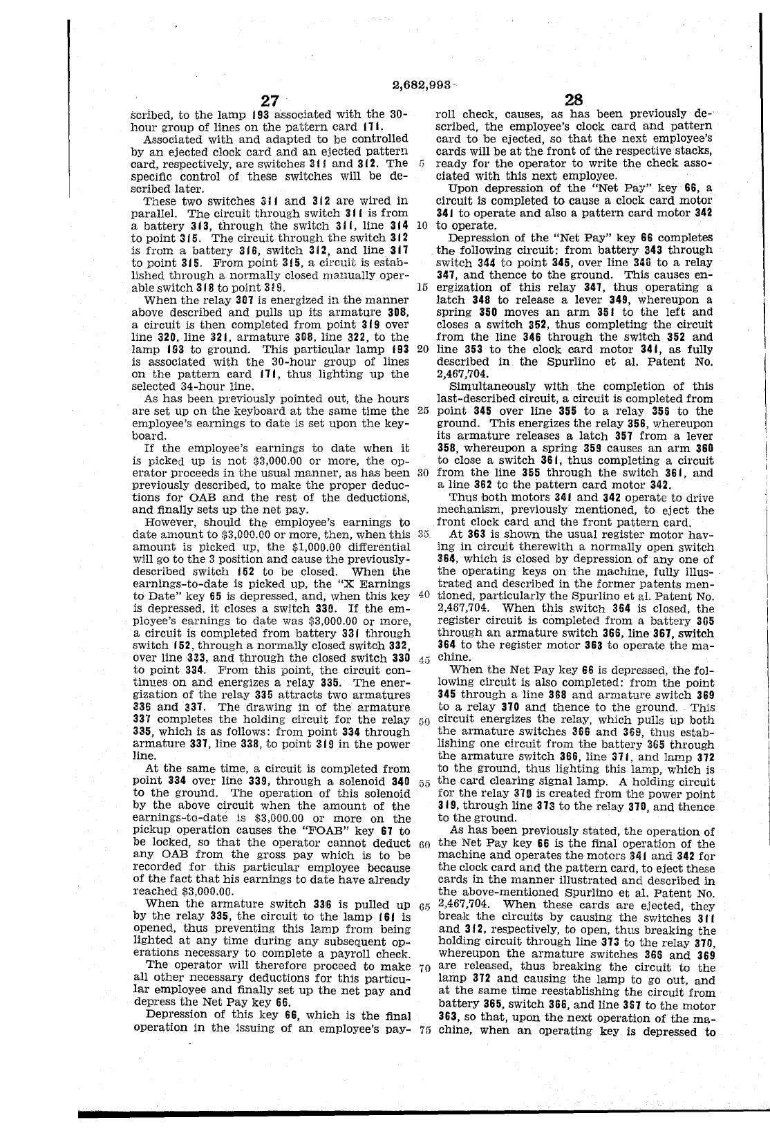
2,682,993
27
scribed,
to
the
lamp
193 associated
with
the
30-
hour
group
of lines
on
the
pattern
card
11
L
Associated
with
and
adapted
to
be
controlled
by
an
ejected
clock
card
and
an
ejected
pattern
card,
respectively,
are
switches
31
j
and
312.
The
G
specific
control
of
these
switches will be
de-
scribed
later.
These
two switches
311
and
3 i 2
are
wired
in
parallel.
The
circuit
through
switch
311
is
from
a
battery
313,
through
the
switch
31
i,
line 314 10
to
point
315.
The
circuit
through
the
switch
312
is
from
a
battery
316,
switch
312,
and
line 311
28
roll check, causes,
as
has
been
previously de-
scribed,
the
employee's clock
card
and
pattern
card
to
be
ejected, so
that
the
next
employee's
cards
will be
at
the
front
of
the
respective stacks,
ready
for
the
operator
to
write
the
check
asso-
ciated
with
this
next
employee.
Upon
depression of
the
"Net
Pay"
key 66, a
circuit
is completed
to
cause
a clock
card
motor
341
to
operate
and
also a
pattern
card
motor
342
to
operate.
Depression of
the
"Net
Pay"
key 66 completes
the
following
circuit:
from
battery
343
through
switch
344
to
point
345, over line 346
to
a relay
347,
and
thence
to
the
ground.
This
causes
en-
to
point
315.
From
point
315, a
circlli"(;
is
estab-
lished
through
a
normally
closed
manually
oper-
able
switch
3 f 8
to
point
3 !
9.
When
the
relay
307 is energized
in
the
manner
above described
and
pulls
up
its
armature
308,
15
ergization
of
this
relay
341,
thus
operating
a
latch
348
to
release a lever 349,
whereupon
a
spring
350 moves
an
arm
351
to
the
left
and
closes a
switch
352,
thus
completing
the
circuit
a
circuit
is
then
completed
from
point
319 over
line 320,
line
321,
armature
308,
line
322,
to
the
lamp
193
to
ground.
This
particular
lamp
193 20
is
associated
with
the
30-hour
group of lines
on
the
pattern
card
171,
thus
lighting
up
the
selected
34-hour
line.
As
has
been
previously
pointed
out,
the
hours
are
set
up
on
the
keyboard
at
the
same
time
the
25
employee's
earnings
to
date
is
set
upon
the
key-
board.
If
the
employee's
earnings
to
date
when
it
is picked
up
is
not
$3,000.00
or
more,
the
op-
erator
proceeds
in
the
usual
manner,
as
has
been
30
previously described,
to
make
the
proper
deduc-
tions
for
OAB
and
the
rest
of
the
deductioml,
and
finally
sets
up
the
net
pay.
However,
should
the
employee's
earnings
to
date
arnount
to
$3,000.00
or
more,
then,
when
this
35
amount
is picked up,
the
$1,000.00 differential
will go
to
the
3 position
and
cause
the
previously··
described
switch
152
to
be closed.
When
the
earnings-to-date
is picked up,
the
"X
Earnings
to
Date"
key 65 is depressed,
and,
when
this
key 40
is depressed,
it
closes a
switch
330.
If
the
em-
ployee's
earnings
to
date
was $3,000.00
or
more,
a
circuit
is completed
from
battery
331
through
switch
152,
through
a
normally
closed
switch
332,
over line 333,
and
through
the
closed
switch
330 'Ii)
to
point
334. F'rom
this
point,
the
circuit
con-
tinu.es
on
and
energizes a
relay
335.
The
ener-
gization of
the
relay
335
attracts
two
armatures
335
and
331.
The
drawing
in
of
the
armature
331 completes
the
holding
circuit
for
the
relay
50
335,
which
is
as
follows:
from
point
334
through
armature
331, line 338,
to
point
31!l
in
the
power
line.
At
the
same
time, a
circuit
is completed
from
point
334 over line
339,
through
a solenoid 340
55
to
the
ground.
The
operation
of
this
solenoid
by
the
above
circuit
when
the
amount
of
the
earnings-to-date
is $3,000.00
or
more
on
the
pickup
operation
causes
the
"FOAB"
key
67
to
be locked, so
that
the
operator
cannot
deduct
60
any
OAB
from
the
gross
pay
which
is
to
be
recorded
for
this particular
employee because
of
the
fact
that
his
earnings
to
date
have
already
reached
$3,000.00.
When
the
armature
switch
33r6
is
pulled
UP
65
by
the
relay
335,
the
circuit
to
the
lamp
161
is
opened,
thus
preventing
this
lamp
from
being
lighted
at
any
time
during
any
subsequent
op-
erations
necessary
to
complete a
payroll
check.
The
operator
will
therefore
proceed
to
make
70
all
other
necessary
deductions
for
this
particu-
lar
employee
and
finally
set
up
the
net
pay
and
depress
the
Net
Pay
key 66.
Depression of
this
key 66,
which
is
the
final
operation
in
the
issuing of
an
employee's
pay-
75
from
the
line 346
through
the
switch
352
and
line
353
to
the
clock
card
motor
341,
as
fully
described
in
the
Spurlino
et
a1.
Patent
No.
2,467,704.
Simultaneously
with
the
completion
of
this
last-described
circuit, a
circuit
is completed from
point
345 over
line
355
to
a
relay
355
to
the
ground.
This
energizes
the
relay
356, whereupon
its
armature
releases a latCh 357
from
a lever
358,
whereupon
a
spring
359 causes
an
arm
360
to
close a
switch
361,
thus
completing a
circuit
from
the
line
355
through
the
switch
361,
and
a
line
362
to
the
pattern
card
motor
342.
Thus
both
motors
341
and
342
operate
to
drive
mechanism,
previously
mentioned,
to
eject
the
front
clock
card
and
the
front
pattern
card.
At
363 is
shown
the
usual
register
motor
hav-
ing
in
circuit
therewith
a
normally
open
switch
364,
which
is closed by depression of
anyone
of
the
operating
keys
on
the
machine,
fully illus-
trated
and
described
in
the
former
patents
men-
tioned,
particularly
the
Spurlino
et
sJ.
Patent
No.
2,487,704.
When
this
switCh 364 is closed,
the
register
circuit
is completed
from
a
battery
365
through
an
armature
switch
366,
line
361,
switch
364
to
the
register
motor
363
to
operate
the
ma-
chine.
When
the
Net
Pay
key 66 is depressed,
the
fol-
lowing
circuit
is also completed:
from
the
point
345
through
a
line
368
and
armature
switch
369
to
a
relay
310
and
thence
to
the
ground.
This
circuit
energizes
the
relay,
which
pulls
up
both
the
armature
switches
366
and
369,
thus
estab-
lishing
one
circuit
from
the
battery
365
through
the
armature
switch 366, line 371,
and
lamp
312
to
the
ground,
thus
lighting
this
lamp,
which
is
the
card
clearing
Signal lamp. A
holding
circuit
for
the
relay
310
is
created
from
the
power
point
319,
through
line
313
to
the
relay
310,
and
thence
to
the
ground.
As
has
been
previously
stated,
the
operation
of
the
Net
Pay
key
66 is
the
final
operation
of
the
machine
and
operates
the
motors
341
and
342 for
the
clock
card
and
the
pattern
card,
to
eject
these
cards
in
the
manner
illustrated
and
described
in
the
above-mentioned
Spurlino
el;
aI.
Patent
No.
2,467,704.
When
these
cards
are
ejected,they
break
the
circuits
by
causing
the
switches
311
and
312, respectively,
to
open,
thus
breaking
the
holding
circuit
through
line
313
to
the
relay
310,
whereupon
the
armature
switches 365
and
369
are
released,
thus
breaking
the
circuit
to
the
lamp
372
and
causing
the
lamp
to
go out,
and
at
the
same
time
reestablishing
the
cirCuit
from
battery
365,
switch
366,
and
line 361
to
the
motor
363, so
that,
upon
the
next
operation
of
the
ma-
chine,
when
an
operating
key is depressed to
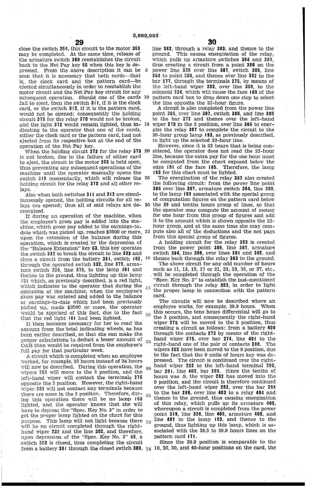
2,682,993
29
close
the
switch
3S~,
this
circuit
to
the
motor
363
may
be
completed.
At
the
same
time,
release
of
the
armature
switch
369
reestablishes
the
circuit
back
to
the
Net
Pay
key
66
when
this
key
is
de-
pressed.
From
the
above
description
it
can
be
5
seen
that
it
is
necessary
that
both
cards-that
is,
the
clock
card
and
the
pattern
card-be
ejected
simultaneously
in
order
to
reestablish
the
motor
circuit
and
the
Net
Pay
key
circuit
for
any
subsequent
operation.
Should
one
of
the
cards
10
fail
to
eject,
then
the
switch
3 I I,
if
it
is
the
clock
card,
or
the
switch
312,
if
it
is
the
pattern
card,
would
not
be opened;
consequently
the
holding
circuit
373
for
the
relay
310 would
not
be
broken,
and
the
light
372
would
remain
lighted,
thus
in-
15
dicating
to
the
operator
that
one
of
the
cards,
either
the
clock
card
or
the
pattern
card,
had
not
ejected
from
its
respective
box
at
the
end
of
the
operation
of
the
Net
Pay
key.
When
the
holding
circuit
373
for
the
relay
370
20
is
not
broken,
due
to
the
failure
of
either
card
to
eject,
the
circuit
to
the
motor
363
is
held
open,
thus
preventing
any
subsequent
operations
of
the
machine
until
the
operator
ma.nually opens
the
switch
313
momentarily,
which
will
release
the
25
holding
circuit
for
the
relay
310
and
all
other
re-
lays.
Also
when
both
switches
31
I
and
312
are
simUl-
taneously
opened,
the
holding
circuits
for
all
re-
lays
are
opened;
thus
all
of
said
relays
are
de-
30
energized.
If
during
an
operation
of
the
machine,
when
the
employee's gross
pay
is
added
into
the
ma-
chine,
which
gross
pay
added
to
the
earnings-to-
date
which
was
picked
up,
reaches
$3000
or
more,
35
upon
the
extension
of
the
balance
during
this
operation,
which
is
created
by
the
depression
of
the
"Balance
Extension"
key
63,
this
key
operates
the
switch
332
to
break
the
circuit
to
line 333
and
clC!2e
a
circuit
from
the
battery
33
I,
switch
152,
40
through
the
operr,ted
switch
332, line 375,
anna-
ture
switch
336,
line
315,
to
the
lamp
161
and
thence
to
the
ground,
thus
lighting
up
this
lamp
! 3! which,
as
previously described, is a
red
light,
which
indicates
to
the
operator.
that
during
the
4:;
opcl'ation
of
the
machine,
when
the
employee'S
groEs
pay
was
entered
and
added
to
the
balance
or
earnings-to-date
which
had
been
previously
picked
up, Ina,de $3000 .01'. more,
the
operator
viould
be
apprised
of
this
fact,
due
to
the
fact
50
that
the
red
light
j
61
had
been
lighted.
It
then
becomes
necessary
for
her
to
read
the
amount
from
the
total
indicating
wheels,
as
has
been
earlier
described, so
that
she
can
make
the
proper
cr,}cuJ.a;tions
to
deduct
a lesser
amount
of
55
01.13 th::m would be
required
from
the
employee's
full
pay
for
that
particular
week.
A
cireuit
which
is
completed
when
an
employee
worked,
for
example,
33
hours
instead
of
34
hours
will now be described.
During
this
operation,
the
60
,vipers
282
will move
to
the
3 position,
and
the
left-hand
wiper
will
contact
the
terminals
2iG
opposite
the
:3
position. However,
the
right-hand
wiper
232
will
not
contact
any
terminals
because
there
[Ire nanG
in
the
3 position.
Therefore,
dur-
G5
ing
this
operation
there
will
be
no
lamp
i
93
lighted,
and
the
operator
knows
that
she
will
have
to
depress
the
"Spec.
Key
NO.3"
in
order
to
get
the
proper
lamp
lighted
on
the
chart
for
this
pmpose.
This
lamp
will
not
light
because
there
70
will
be
no
circuit
completed
through
the
right-
hand
wiper
2S2
and
the
line
302,
and
therefore,
upon
depression
of
the
"Spec.
Key
NO.3"
65,
a
switch
Mil
is closed,
thus
completing
the
circuit
from
a
battery
38
I
through
the
closed
switch
380,
75
30
line
382,
through
a
relay
383,
and
thence
to
the
ground.
This
causes
energization
of
the
relay,
which
pulls
up
armature
switches
384
and
385,
thus
creating
a
circuit
from
a
point
386
on
the
power
line
338 over
line
381,
switch
385,
line
304
to
point
::l8S,
and
thence
over
line
302
to
the
bar
271,
through
the
terminals
216,
by
means
of
the
left-hand
wiper
282, over
line
31l9,
to
the
solenoid 224,
which
will
cause
the
face
185
of
the
pattern
card
box
to
drop
down
one
step
to
select
the
line
opposite
the
32-hour
figure.
A
circuit
is also
completed
from
the
power
line
point
385,
over
line
387,
switch
385,
and
line
305
to
the
bar
212
and
thence
over
the
left-hand
wiper
275
in
the
3 position,
over
line
306
to
ener-
gize
the
relay
301
to
complete
the
circuit
to
the
30-hour
group
lamp
193,
as
previously described,
to
light
up
the
selected
32-hour
line.
However,
since
it
is
33
hours
that
is
being
con-
sidered,
the
operator
does
not
read
the
32-hour
line,
because
the
extra
pay
for
the
one
hour
must
be
computed
from
the
chart
exposed below
the
edge
19
I
of
the
face
185.
Therefore,
the
lamp
193
for
this
chart
must
be
lighted.
The
energization
of
the
relay
383 also
created
the
following
circuit:
from
the
power
line
point
386
over
line
387,
armature
switch
384,
line
3911,
to
the
lamp
193
associated
with
the
special
group
of
computation
figures
on
the
pattern
card
below
the
39
and
tenths
hours
group
of
lines, so
that
the
operator
may
compute
the
amount
of
money
for
one
hour
from
this
group
of
figures
and
add
it
to
the
amount
which
is
shown
opposite
the
32-
hour
group,
and
at
the
same
time
she
may
com-
pute
also
all
of
the
deductions
and
.the
net
pays
from
this
special
group
of
figures.
A
holding
circuit
for
the
relay
383
is
created
from
the
power
point
386,
line
381,
armature
switch
384,
line
390, over
lines
39 I
and
382,
and
thence
back
through
the
relay
383
to
the
ground.
The
above
circuit
for
any
odd
number
of
hours
such
as
11, 13, 15,
17
or
21, 23, 33, 35,
or
37, etc.,
will be
completed
through
the
operation
of
the
"Spec.
Key
No.3"
to
establish
the
last-mentioned
circuit
through
the
relay
383,
in
order
to
light
the
proper
lamp
in
connection
with
the
pattern
card.
The
'circuits will now
be
described
where
an
employee
worl{S,
for
example,
39.9
hours.
When
this
occurs,
the
tens
hours
differential
will go
to
the
3 position,
and
consequently
the
right-hand
wiper
275
will
be
moved
to
the
3 position,
thus
creating
a
circuit
as
follows:
from
a
battery
400
through
the
contacts
213
by
means
of
the
right-
hand
wiper
215, over
bar
214,
line
401
to
the
right-hand
one
of
the
pail' of
contacts
280.
The
wipers
282
have
been
moved
to
the
9 position,
due
to
the
fact
that
the
9
units
of
hours
key was
de-
pressed.
The
circuit
is
continued
over
the
right-
hand
wiper
2B2
to
the
left-hand
terminal
280,
bar
281,
line
402,
bar
288.
Since
the
tenths
of
hours
was
.9,
the
wiper
292
has
moved
into
the
9 position,
and
the
circuit
is
therefore
continued
over
the
left-hand
wiper
292, over
the
bar
293
to
the
bar
286,
over
line
403
to
a
relay
404
and
thence
to
the
ground,
thus
causing
energization
of
this
relay,
which
pulls
up
its
armature
~05,
whereupon
a
circuit
is
completed
from
the
power
point
319,
line
320,
line
406,
armature
405,
and
line
401
to
the
lamp
I
!l3,
and
thence
to
the
ground,
thus
lighting
up
this
lamp,
which
is
as-
sociated
with
the
39.5
to
39.9
hours
lines
on
the
pattern
card.
I 1 I .
Since
the
39.9
position
is
comparable
to
the
10, 20, 30,
and
40-hour
positions
on
the
card,
the
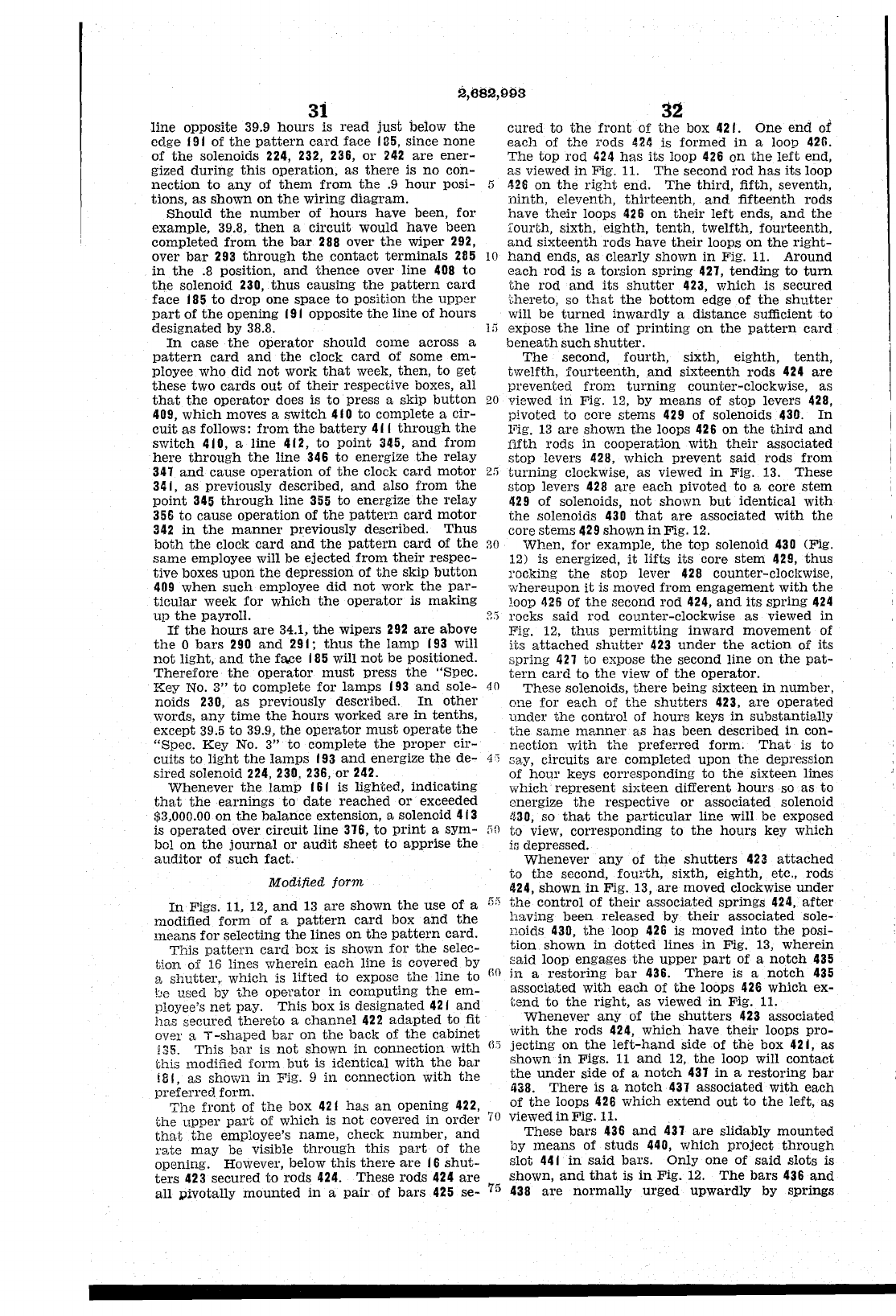
2,682,993
31
line
opposite 39.9
hours
is
read
just
below
the
edge
191
of
the
pattern
card
face
135,
since
none
of
the
solenoids 224,
232,
236,
or
242
are
ener-
gized
during
this
operation,
as
there
is
no
con-
nection
to
any
of
them
from
the
.9
hour
posi- 5
tions,
as
shown
on
the
wiring
diagram.
32
cured
to
the
front
of
the
box 421.
One
end
of
each
of
the
rods
4211
is
formed
in
a loop 426.
The
top
rod
424
has
its loop
426
on
the
left
end,
as
viewed
in
Fig.
11.
The
second
rod
has
its
loop
426
on
the
right
end.
The
third,
fifth, seventh,
ninth,
eleventh,
thirteenth,
and
fifteenth
rods
have
their
loops
426
on
their
left
ends,
and
the
fourth,
sixth,
eighth,
tenth,
twelfth,
fourteenth,
and
sixteenth
rods
have
their
loops
on
the
right-
hand
ends,
as
clearly
shown
in
Fig.
11.
Around
each
rod
is a
torsion
spring
427,
tending
to
tum
the
rod
and
its
shutter
423,
which
is
secured
(,hereto, so
that
the
bottom
edge
of
the
shutter
will
be
turned
inwardly
a
distance
sufficient
to
ShoUld
the
number
of
hours
have
been,
for
example,
39.8,
then
a
circuit
would
have
been
completed
from
the
bar
288
over
the
wiper
292,
over
bar
293
through
the
contact
terminals
285
10
in
the
.8
position,
and
thence
over
line
408
to
the
solenoid 230,
thus
causing
the
pattern
card
face
185
to
drop
one
space
to
position
the
upper
part
of
the
opening
191
opposite
the
line
of
hours
deSignated
by
38.8.
In
case
the
operator
should
come
across
a
pattern
card
and
the
clock
card
of
some
em-
ployee
who
did
not
work
that
week,
then,
to
get
these
two
cards
out
of
their
respective boxes, all
that
the
operator
does is
to
press
a
skip
button
20
409,
which
moves a
switch
410
to
complete
a
cir-
cuit
as
follows:
from
the
battery
41
I
through
the
switch
410, a
line
412,
to
point
345,
and
from
here
through
the
line
346
to
energize
the
relay
347
and
cause
operation
of
the
clock
card
motor
2"
341,
as
previously described,
and
also
from
the
point
345
through
line
355
to
energize
the
relay
356
to
cause
operation
of
the
pattern
card
motor
342
in
the
manner
previously described.
Thus
both
the
clock
card
and
the
pattern
card
of
the
30
same
employee will be
ejected
from
their
respec-
tive
boxes
upon
the
depression
of
the
skip
button
409
when
such
employee
did
not
work
the
par-
ticular
week
for
which
the
operator
is
making
1;)
expose
the
line
of
printing
on
the
pattern
card
beneath
such
shutter.
up
the
payroll.
The
second,
fourth,
sixth,
eighth,
tenth,
twelfth,
fourteenth,
.and
sixteenth
rods
424
are
prevented
from
turning
counter-clockwise, as
viewed
in
Fig. 12, by
means
of
stop
levers
428,
pivoted
to
core
stems
429
of
solenoids 430.
In
l"ig.
13
are
shown
the
loops
426
on
the
third
and
fifth
rods
in
cooperation
with
their
associated
stop
levers 428,
which
prevent
said
rods
from
turning
clockwise,
as
viewed
in
Fig.
13.
These
stop
levers
428
are
each
pivoted
to
a core
stem
429
of
solenoids,
not
shown
but
identical
with
the
solenoids
430
that
are
associated
with
the
core
stems
429
shown
in
Fig.
12.
When,
for
example,
the
top
solenoid
430
(Fig.
12) is energized,
it
lifts
its
core
stem
429,
thus
l'ocking
the
stop
lever
428
counter-clockwise,
whereupon
it
is moved
from
engagement
with
the
loop
425
of
the
second
rod
424,
and
its
spring
424
~:5
rocks
said
rod
counter-clockwise
as
viewed
in
Fig. 12,
thus
permitting
inward
movement
of
its
attached
shutter
423
under
the
action
of
its
spring
427
to
expose
the
second
line
on
the
pat-
If
the
hours
are
34.1,
the
wipers
292
are
above
the
0
bars
290
and
291;
thus
the
lamp
193
will
not
light,
and
the
face
185
will
not
be positioned.
Therefore
the
operator
must
press
the
"Spec.
Key
NO.3"
to
complete
for
lamps
193
and
sole-
40
noids
230,
as
previously described.
In
other
words,
any
time
the
hours
worked
are
in
tenths,
except
39.5
to
39.9,
the
operator
must
operate
the
"Spec.
Key
No.3"
to
complete
the
proper
cir-
cuits
to
light
the
lamps
193
and
energize
the
de-
4,
sired
solenoid 224, 230, 236,
or
242.
tern
card
to
the
view of
the
operator.
These
solenoids,
there
being
sixteen
in
number,
one
for
each
of
the
shutters
423,
are
operated
Lmder
the
control
of
hours
keys
in
substantially
the
same
manner
as
has
been
described
in
con-
nection
with
the
preferred
form.
That
is
to
Gay,
circuits
are
completed
upon
the
depression
of
hour
keys
corresponding
to
the
sixteen
lines
Whenever
the
lamp
161
is
lighted,
indicating
that
the
earnings
to
date
reached
or
exceeded
$3,000.00
on
the
balance
extension, a solenoid
413
is
operated
over
circuit
line
376,
to
print
a
sym-
[i0
bol
on
the
journal
or
audit
sheet
to
apprise
the
auditor
of
such
fact.
which·
represent
sixteen
different
hours
so
as
to
energize
the
respective
or
associated
solenoid
430, so
that
the
particular
line
will
be
exposed
to
View,
corresponding
to
the
hours
key
which
i~
depressed.
Whenever
any
of
the
shutters
423
attached
to
the
second,
fow'th,·
sixth,
eighth,
etc., rods
424,
shown
in
Fig. 13,
are
moved clockwise
under
Modified
form
In
Figs. 11, 12,
and
13
are
shown
the
use
of
a
modified
form
of
a
pattern
card
box
and
the
means
for
selecting
the
lines
on
the
pattern
card.
This
pattern
card
box is
shown
for
the
selec-
tion
of
16
lines
wherein
each
line
is covered
by
8,
shutter,.
which
is
lifted
to
expose
the
line
to
be used by
the
operator
in
computing
the
em-
ployee's
net
pay.
This
box
is
designated
421
and
has
secured
thereto
a
channel
422
adapted
to
fit
over a
T-shaped
bar
on
the
back
of
the
cabinet
!
35.
This
bar
is
not
shown
in
connection
with
this
modified
form
but
is
identical
with
the
bar
! 81,
as
shown
in
Fig. 9
in
connection
with
the
preferred
form.
The
front
of
the
box
421
has
an
opening
422,
the
upper
part
of
which
is
not
covered
in
order
that
the
employee's
name,
check
number,
and
rate
may
be visible
through
this
part
of
the
opening. However, below
this
there
are
16
shut-
ters
423
secured
to
rods
424.
These
rods
424
are
all
pivotally
mounted
in
a
pair
of
bars
425
se-
fir,
the
control
of
their
associated
springs
424,
after
having
been
released
by
their
associated
sole-
noids
430,
the
loop
426
is moved
into
the
posi-
tion
shown
in
dotted
lines
in
Fig.
13,
wherein
said
loop
engages
the
upper
part
of a
notch
435
nO
in
a
restoring
bar
436.
There
is a
notch
435
associated
with
each
of
the
loops
426
which
ex-
tend
to
the
right,
as
viewed
in
Fig.
11.
Whenever
any
of
the
shutters
423
associated
with
the
rods
424,
which
have
their
loops
pro-
w;
jecting
on
the
left-hand
side of
the
box
421, as
shown
in
Figs.
11
and
12,
the
loop will
contact
the
under
side
of
a
notch
437
in
a
restoring
bar
438.
There
is a
notch
437
associated
with
each
of
the
loops
426
which
extend
out
to
the
left,
as
70
viewed
in
Fig. 11.
These
bars
436
and
437
are
slidably
mounted
by
means
of
studs
440,
which
project
through
slot
441
in
said
bars.
Only
one
of
said
slots
is
shown,
and
that
is
in
Fig.
12.
The
bars
436
and
75
438
are
normally
urged
upwardly
by
springs
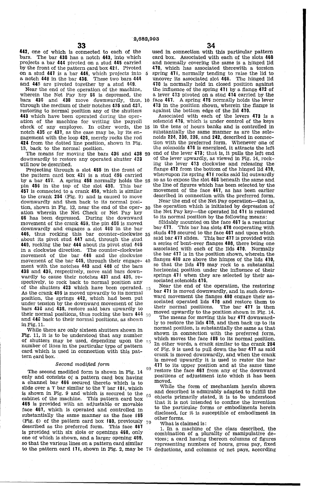
·2,682,993
33
442,
one of
which
is
connected
to
each
of
the
bars.
The
bar
43B
has
a
notch
443,
into
which
projects
a
bar
444
pivoted
on
a
stud
445
carried
by
the
front
of
the
pattern
card
box
421.
Pivoted
on
a
stud
447 is a
bar
446,
which
projects
into
5
a
notch
448
in
the
bar
436.
These
two
bars
444
and
448
are
pivoted
together
by a
stud
4tiS.
Near
the
end
of
the
operation
of
the
machine,
wherein
the
Net
Pay
key
66
is depressed,
the
bars
436
and
438
move downwardly,
thus,
10
through
the
mrdium
of
their
notches
435
and
431,
restoring
to
normal
position
any
of
the
shutters
443
which
have
been
operated
during
the
oper-
ation
of
the
machine
for
writing
the
payroll
check
of
any
employee.
In
other
words,
the
15
notch
435
or
437,
as
the
case
may
be, by
its
en-
gagement
with
the
loop 426,
merely
rocks
the
rod
424
from
the
dotted
line position,
shown
in
Fig.
13,
back
to
the
normal
position.
The
means
for
moving
the
bars
436
and
438
20
downwardly
to
restore
any
operated
shutter
423
will
now
be
described.
34
used
in
connection
with
this
particular
pattern
card
box.
ASSOCiated
with
each
of
the
slots
468
and
normally
covering
the
same
is a
hinged
lid
410,
which
has
associated
therewith
a
torsion
spring
47 I,
normally
tending
to
raise
the
lid
to
uncover
its
associated
slot
468.
The
hinged
lid
470 is
normally
held
in
closed
position
against
the
influence
of
the
spring
411
by a flange 472
of
a lever
473
pivoted
on
a
stud
474
carried
by
the
face
461. A
spring
475
normally
holds
the
lever
413
in
the
position shown,
wherein
the
flange
is
against
the
bottom
edge
of
the
lid
410.
Associated
with
each
of
the
levers
413
is a
solenoid
476,
which
is
under
control
of
the
keys
in
the
tens
of
hours
banks
and
is
controlled
in
substantially
the
same
manner
as
are
the
sole-
noids
2211,
230, 236,
and
242,
described
in
connec-
tion
with
the
prefelTed form.
Whenever
one
of
the
solenoids
416
is energized,
it
attracts
the
left
end
of
the
lever
473;
that
is,
it
pulls
the
left
end
of
the
lever
upwardly,
as
viewed
in
Fig. 14,
rock-
ing
the
lever
473
clockwise
and
releasing
the
flange
472
from
the
bottom
of
the
hinged
lid
47£1,
whereupon
its
spring
471 rocks
said
lid
outwardly
Projecting
through
a
slot
455
in
the
front
of
the
pattern
card
box
421
is a
stud
1158
carried
by a
bar
451.
A
spring
458
normally
holds
the
pin
456
in
the
top
of
the
slot
455.
This
bar
457
is
connected
to
a
crank
459,
which
is
similar
25
so
as
to
expose
the
slot
4GB
beneath
the
same
and
the
line
of
figures
which
has
been
selected
by
the
movement
of
the
face 467,
as
has
been
earlier
described
in
connection
with
the
preferred
form.
to
the
crank
254
(Fig. 9)
and
is caused
to
move
downwardly
and
then
back
to
its
normal
posi-
tion,
shown
in
Fig.
12,
near
the
end
of
the
oper-
30
ation
wherein
the
Net
Check
or
Net
Pay
key
66
has
been
depressed.
During
the
downward
movement
of
the
crank
459,
the
pin
465
is moved
downwardly
and
engages a
slot
liB!!
in
the
bar
446,
thus
rocking
this
bar
counter-clockwise
35
about
its
pivot
stud
441
and,
through
the
stud
449,
rocking
the
bar
444
about
its
pivot
stud
4115
in
a clockwise direction.
The
counter-clockwise
movement
of
the
bar
446
and
the
clockwise
movement
of
the
bar
445,
through
their
engage-
40
ment
with
the
notches
443
and
448
of
the
bars
43B
and
435,
respectively, move
said
bars
down-
wardly
to
cause
their
notches
43"1
and
435,
re-
spectively,
to
rock
back
to
normal
position
any
of
the
shutters
423
which
have
been
operated
.
.15
As
the
crank
459
is moved
upwardly
to
its
normal
position,
the
springs
442,
which
had
been
put
under
tension
by
the
downward
movement
of
the
bars
436
and
438,
restore
said
bars
upwardly
to
their
normal
positions,
thus
rocking
the
bars
Uti
,,0
and
446
back
to
their
normal
positions,
as
shown
in
Fig.
11.
While
there.
are
only
sixteen
shutters
shown
in
Fig. 11,
it
is
to
be
understood
that
any
number
of
shutters
may
be used,
depending
upon
the
~)
number
of lines
in
the
particular
type
of
pattern
card
which
is used
in
connection
with
this
pat-
tern
card
box.
Second
modified
form
Near
the
end
of
the
Net
Pay
operation-that
is,
the
operation
which
is
initiated
by
depression
of
the
Net
Pay
key-the
operated
lid
471
is
restored
to
its
normal
pOSition by
the
following
means:
Slidably
mounted
on
the
face
467
is a
restoring
bar
477.
This
bar
has
slots
418
cooperating
with
studs
419
secured
to
the
face
467
and
upon
which
said
bar
477
slides.
This
bar
477
is
provided
with
a series
of
bent-over
flanges
480,
there
being
one
associated
with
each
of
the
lids
470.
Normally
the
bar
lin
is
in
the
position
shown,
wherein
the
flanges
480
are
above
the
hinges
of
the
lids 470,
so
that
the
lids
470
may
rock
to
a
substantial
horizontal
position
under
the
influence
of
their
springs
411
when
they
are
selected
by
their
as-
sociated
solenoids
U6.
Near
the
end
of
the
operation,
the
restoring
bar
411
is moved downwardly,
and
in
such
down-
ward
movement
the
flanges
480
engage
their
as-
sociated
operated
lids
470
and
restore
them
to
their
normal
positions.
The
bar
477
is
then
moved
upwardly
to
the
position
shown
in
Fig. 14.
The
means
for moving
this
bar
417
downward-
ly
to
restore
the
lids 410,
and
then
back
up
to
its
normal
pOSition, is
substantially
the
same
as
that
shown
in
connection
with
the
preferred
form,
The
second
modified
form
is
shown
in
Fig.
14
only
and
consists
Of
a
pattern
card
box
having
a
channel
bar
466
secured
thereto
which
is
to
slide over a T
bar
similar
to
the
T
bar
181,
which
which
moves
the
face
185
to
its
normal
position.
In
other
words, a
crank
similar
to
the
crank
254
of Pig. 9 is
used
to
pull
down
the
bar
477
as
said
crank
is moved downwardly,
and
when
the
crank
is moved
upwardly
it
is used
to
restor
the
bar
411
to
its
upper
position
and
at
the
same
time
GO
restore
the
face
467
from
any
of
the
downward
positions
of
adjustment
into
which
it
has
been
moved.
While
the
form
of
mechanism
herein
shown
and
described is
admirably
adapted
to
fulfill
the
05
objects
primarily
stated,
it
is
to
be
understood
that
it
is
not
intended
to
confine
the
invention
to
the
particular
forms
or
embodiments
herein
disclosed, for
it
is susceptible of
embodiment
in
is
shown
in
Fig. 9
and
which
is
secured
to
the
cabinet
of
the
machine.
This
pattern
card
box
465
is
provided
with
an
adjustable
or
movable
face
467,
which
is
operated
and
controlled
in
substantially
the
same
manner
as
the
face
185
(Fig.
6)
of
the
pattern
card
box 180, previously
70
described
as
the
preferred
form.
This
face
461
is provided
with
six
slots
or
openings
468,
only
one
of
which
is shown,
and
a
larger
opening
469,
so
that
the
various
lines
on
a
pattern
card
similar
to
the
pattern
card
171,
shown
in
Fig.
2,
may
be
other
forms.
What
is
claimed
is:
1.
In
a
machine
of
the
class described,
the
combination
of
a
plurality
of
manipulative
de-
vices; a
card
having
thereon
columns
of
figures
representing
numbers
of
hours,
gross
pay,
fixed
75
deductions,
and
columns of
net
pays,
according
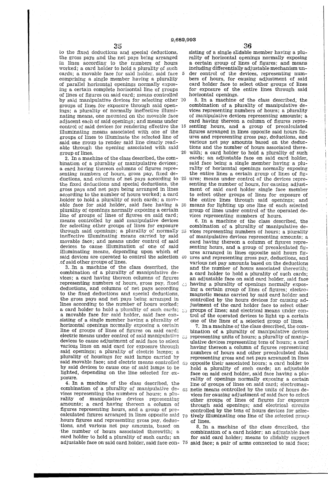
2,682,993
35
to
the
fixed
deductions
and
special deductions,
the
gross
pays
and
the
net
pays
being
arranged
in
lines
according
to
the
numbers
of
hours
worked; a
card
holder
to
hold
a
plurality
of
such
cards;
a movable
face
lor
said
holder,
said
face 5
comprising
a single
member
having
a
plurality
of
parallel
horizontal
openings
normally
expos-
ing
a
certain
complete
horizontal
line
of
groups
of
lines
of
figures
on
said
card;
means
controlled
by
said
manipulative
devices
for
selecting
other
10
groups
of lines·
for
exposure
through
said
open-
ings;
a
plurality
of
normally
ineffective
illumi-
nating
means,
one
mounted
on
the
movable
face
adjacent
each
of
said
openings;
and
means
under
control
of
said
devices
for
rendering
effective
the
15
illuminating
means
associated
with
one
of
the
groups
of
lines
to
illuminate
the
selected
line
of
said
one
group
to
render
said
line
clearly
read-
able
through
the
opening
associated
with
said
group
of
lines.
20
2.
In
8,
machine
of
the
class described,
the
com-
bination
of
a
plurality
of
manipulative
devices;
a
card
having
thereon
columns
of
figures
repre-
senting
numbers
of
hours,
gross pay, fixed
de-
ductions,
and
columns
of
net
pays
according
to
25
the
fixed
deductions
and
special
deductions,
the
gross
pays
and
net
pays
being
arranged
in
lines
according
to
the
number
of
hours
worked;
a
card
holder
to
hold
a
plurality
of
such
cards;
a
mov-
able
face
for
said
holder,
said
face
having
a
30
plUrality of openings
normally
exposing a
certain
line
of
groups
of
lines
·of figures
on
said
card;
means
controlled
by.said
manipulative
devices
for
selecting
other
groups
of
lines
for
exposure
through
said
openings;
a
plurality
01'
normally
33
ineffective
illuminating
means
carried
by
said
movable
face;
and
means
under
control
of
said
devices
to
cause
illumination
of
one
of
said
illuminating
meanS,depending
upon
which
of
said
devices
are
operated
to
control
the
selection
40
.of
said
other
groups
of
lines.
3
..
In
a
machine
of
the
class described,
the
combination
of
a
plurality
of
manipulative
de-
vices; a
card
having
thereon
columns
of
figures
representing
numbers
of
hours,
gross pay, fixed "."J
deductions,
gnd
columns
of
net
pays
according
to
the
fixed
deductions
and
speCial deductions,
the
gross
pays
and
net
pays
being
arranged
in
lines
according
to
the
number
of
hours
worked;
a
card
holder
to
hold
g
plurality
of
such
C8,r0.S;
ij;)
a movable
face
for
sgid
holder,
said
face
con-
sisting
of
a
single
member
h<wing a
plurality
of
horizontal
openings
normally
exposing a
certain
line
of
groups
of
lines
of
figures
on
said
card;
electric
means
under
control
of
said
manipulative
u,)
devices
to
cause
adjustment
of
SElJd
face
to
select
various
lines
on
said
card
for
exposure
through
said
openings;
a
plurality
of
electric
lamps;
a
plurality
of
housings
for
said
lamps
carried
by
said
movable
face;
and
electric
means
contl'olled
G:J
by
said
devices
to
cause
one
of
said
lamps
to
be
lighted,
depending
on
the
line
selected
for
ex-
posure.
4.
In
a
machine
of
the
class described,
the
combination
of
a
plurality
of
manipulatj.ve
de-
G6
vices
representing
the
numbers
of
hours;
a
plu-
rality
of
manipulative
devices
representing
amounts;
a
card
having
thereon
a
column
of
figures
representing
hours,
a,nd a
group
of
pI'e-
calculated
figures
arranged
in
lines
opposite
s8,id
70
hours
figures
and
representing
gross pay,
deduc-
tions,
and
various
net
pay
amounts,
based
on
the
number
of
hours
associated
therewith;
a
card
holder
to
hold
a
plurality
of
such
cards;
an
adjustable
face
on
said
card
holder.
said
face
con-
75
36
sisting
of
a
single
slidable
member
having
a
plu-
rality
of
horizontal
openings
normally
exposing
a
certain
group
of
lines
of
figures;
and
means
including
differentially
adjustable
mechanism
un-
der
control
of
the
devices,
representing
num-
bers
of
hours,
for
causing
adjustment
of
said
card
holder
face
to
select
other
groups
of
lines
for
exposure
of
the
entire
lines
through
said
horizontal
openings.
5.
In
a
machine
of
the
class described,
the
combination
of
a
plurality
of
manipulative
de-
vices
representing
numbers
of
hours;
a
plurality
of
manipulative
devices
representing
amounts;
a
card
having
thereon
a
column
of
figures
repre-
senting
hours,
and
a
group
of
precalculated
figures
arranged
in
lines
opposite
said
hours
fig-
ures
and
representing
gross pay, deductions,
and
various
net
pay
amounts
based
on
the
deduc-
tions
and
the
number
of
hours
associated
there-
with;
a
card
holder
to
hold
a
plurality
of
such
cards;
an
adjustable
face
on
said
card
holder,
said
face
being
a
single
member
having
a
plu-
rality
of
horizontal
openings
normally
exposing
the
entire
lines
a
certain
group
of
lines
of
fig-
ures;
means
under
control
of
the
devices
repre-
senting
the
number
of
hours,
for
causing
adjust-
ment
of
said
card
holder
single
face
member
to
select
other
groups
of lines
for
exposure
of
the
entire
lines
through
said
openings;
and
means
for
lighting
up
one
line
of
each
selected
group
of
lines
under
control
of·
the
operated
de-
vices
representing
numbers
of
hours.
6.
In
a
machine
of
the
class described,
the
combination
of
a
plurality
of
manipulative
de-
vices
representing
numbers
of
hours;
a
plurality
of
manipulative
devices
representing
amounts;
a
card
having
thereon
a
column
of
figures
repre-
senting
hours,
and
a
group
of
precalculated
fig-
ures
arranged
in
lines opposite
said
hours
fig-
ures
and
representing
gross pay, deductions,
and
various
net
pay
amounts
based
on
the
deductions
and
the
number
of
hours
associated
therewith;
a
card
holder
to
hold
a
plurality
of
such
cards;
an
adjustable
face
on
said
card
holder,
said
face
having
a
plurality
of
openings
normally
expos-
ing
a
certain
group
of
lines
of
figures;
electro-
magnetic
means
carried
by
said
card
holder
and
controlled
by
the
hours
devices
for
causing
ad-
justment
of
the
card
holder
face
to
select
other
groups
of
lines;
and
electrical
means
under
con-
trol
of
the
operated
devices
to
light
up
a
certain
one
of
the
lines
of
a selected
group
of
lines.
7.
In
a
machine
of
the
class described,
the
COffi-
binationof
a
plurality
of
manipulative
devices
representing
units
of
hours;
a
plurality
of
manip-
ulative
devices
representing
tens
of
hours;
a
card
having
thereon
a
column
of
figures
representing
numbers
of
hours
and
other
precalculated
data
representing
gross
and
net
pays
arranged
in
Hnes
opposite
their
associated
hours;
a
card
holder
to
hold
a
plurality
of
such
cards;
an
adjustable
face
on
said
card
holder,
said
face
having. a
plu-
rality
of
openings
normally
exposing a
certain
line
of
groups
of
lines
on
said
card;
electromag-
netic
means
controlled
by
the
units
of
hours
de-
vices
for
causing
adjustment
of
said
face
to
select
other
groups
of
lines
of
figures
for
exposure
through
said
openings;
and
electrical
circuits
controlled
by
the
tens
of
hours
devices
for
selec-
tively
illuminating
one
line
of
the
selected
group
of
lines.
8.
In
a
machine
of
the
class described,
the
combination
of
a
card
holder;
an
adju.stable
face
for
said
card
holder;
means
to
Blidably
support
said
t'ace; a pail'
of
arms
connected
to
said
face;
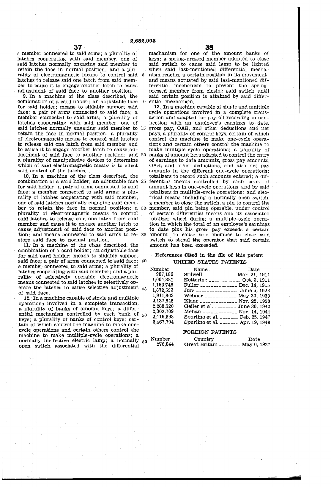
2,682,993
37
a
member
connected
to
said
arms;
a
plurality
of
latches
cooperating
with
said
member,
one
of
said
latches
normally
engaging
said
member
to
retain
the
face
in
normal
position;
and
a
plu-
rality
of
electromagnetic
means
to
control
said
latches
to
release
said
one
latch
from
said
mem-
ber
to
cause
it
to
engage
another
latch
to' cause
adjustment
of
said·
face
to
another
position.
9.
In
a
machine
of
the
class described,
the
combination
of
a
card
holder;
an
adjustable
face
for
said
holder;
means
to
slidably
support
said
face; a
pair
of
arms
connected
to
said
face; a
member
connected
to
said
arms;
a
plurality
of
latches
cooperating
with
said
member,
one
of
said
latches
normally
engaging
said
member
to
retain
the
face
in
normal
position; a
plurality
of
electromagnetic
means
to
control
said
latches
to
release
said
one
latch
from
said
member
and
to
cause
it
to
engage
another
latch
to cause
ad-
justment
of
said
face
to
another
position;
and
a
plurality
of
manipulative
devices
to
determine
which
of
said
electromagnetic
means
is to effect
said
control
of
the
latches.
10.
In
a
machine
of
the
class described,
the
combination
of a
card
holder;
an
adjusts,bIe face
for
said
holder; a
pair
of
arms
connected
to
said
face; a
member
connected
to
said
arms;
a
plu-
rality
of
latches
cooperating
with
said
member,
one of
said
latches
normally
engaging
said
mem-
ber
to
retain
the
face
in
normal
position; a
plurality
of electromagnetic
means
to
control
said
latches
to
release
said
one
latch
from
said
member
and
cause
it
to
engage
another
latch
to
cause
adjustment
of
said
face
to
another
posi-
tion;
and
means
connected
to
said
arms
to
re-
store
said
face
to
normal
position.
38
mechanism
for
one
of
the
amount
banks
of
keys; a
spring-pressed
member
adapted
to close
said
switch
to
cause
said
lamp
to
be
lighted
when
said
last-mentioned
differential
mecha-
5
nism
reaches
a
certain
position
in
its
movement;
and
means
actuat.ed by
said
last-mentioned
dif-
ferential
mechanism
to
prevent
the
spring-
pressed
member
from
closing
said
switch
until
said
certain
position is
attained
by saId differ-
10
ential
mechanism.
13.
In
a
machine
capable of single
and
multiple
cycle
operations
involved
in
a complete
trans-
action
and
adapted
for
payroll
recording
in
con-
nection
with
an
employee's
earnings
to
date,
15
gross pay, OAB,
and
other
deductions
and
net
pays, a
plurality
of
control
keys,
certain
of
which
control
the
machine
to
make
one-cycle
opera-
tions
and
certain
others
control
the
machine
to
make
multiple-cycle
operations;
a
plurality
of
20
banks
of
amount
keys
adapted
to
control
the
entry
of
earnings
to
date
amounts,
gross
pay
amounts,
OAB,
and
other
deductions,
and
also
net
pay
amounts
in
the
different one-cycle
operations;
totalizers
to
record
such
amounts
entered;
a dif-
25
ferential
means
controlled by
each
bank
of
amount
keys
in
one-cycle operations,
and
by
said
totalizers
in
multiple-cycle
operations;
and
elec-
trical
means
including a
normally
open
switch,
a
member
to
close
the
switch, a
pin
to
control
the
30
member,
said
pin
being operable,
under
control
of
certain
differential
means
and
its
associated
totalizer
wheel
during
a multiple-cycle
opera-
tion
in
which
the
total
of
an
employee's
earnings
to
date
plus
his
gross
pay
exceeds a
certain
35
amount,
to
cause
said
member
to
close
said
switch
to
signal
the
operator
that
said
certain
amount
has
been
exceeded. 11.
In
a
machine
of
the
class described,
the
combination
of
a
card
holder;
an
adjustable
face
for
said
card
holder;
means
to
slidably
support
said
face; a
pair
of
arms
connected
to
said
face;
40
a
member
connected
to
said
arms;
a
plurality
of
latches
cooperating
with
said
member;
and
a
plu-
rality
of selectively operable electromagnetic
means
connected
to
said
latches
to
selectively
op-
erate
the
latches
to
cause
selective
adjustment
45
of
said
face.
References
Cited
in
the
file
of
t.his pat.ent
UNITED STATES PATENTS
Number
987,186
1,004,8,81
1,163,748
1,672,533
1,911,863
2,137,845
2,288,520
2,362,709
2,416,598
2,467,704
Name
Date
Stilwell ____________
Mar.
21,
1911
Kettering
____________ Oct. 3,
1911
Fuller
______________ Dec.
14,
1915
Jurs
________________
June
5,
1928
Webner
____________
May
30,
1933
12.
In
a
machine
capable
of
single
and
multiple
operations
involved
in
a complete
transaction,
a
plurality
of
banks
of
amount
keys; a differ-
ential
mechanism
controlled
by
each
bank
of
50
keys; a
plurality
of
banks
of
control
keys;
cer-
tain
of
which
control
the
machine
to
make
one-
cycle
operations'
and
certain
others
control
the
machine
to
make
multiple-cycle
operations;
a
normally
ineffective electric
lamp;
a
normally
open
switch
associated
with
the
differential
55
Nuniber
270,044
Klaar
______________ Nov. 22, 1938
Geller
et
al. ________
June
30, 1942
Mehan
_____________ Nov.
14,
1944
Spurlino
et
al. _______ Feb.
25,
1947
Spurlino
et
al. _______ Apr.
19,
1949
FOREIGN
PATENTS
Country
Date
Great
Brit.ain ________
May
6,
1927
