Parallax PAM 7Q GPS Module (#28509) 28509 Product Guide V10 1
User Manual: parallax -
Open the PDF directly: View PDF ![]() .
.
Page Count: 6

Web Site: www.parallax.com
Forums: forums.parallax.com
Sales: sales@parallax.com
Technical: support@parallax.com
Office: (916) 624-8333
Fax: (916) 624-8003
Sales: (888) 512-1024
Tech Support: (888) 997-8267
PAM-7Q GPS Module (#28509)
Parallax’s PAM-7Q GPS Module embeds the very capable uBlox
PAM-7Q GPS device in a project-friendly module.
The PAM-7Q GPS device gives your project the ability to
understand its position anywhere on the earth, as long as it
has a clear view of the sky. It does this by using a Global
Navigation Satellite System (GNSS), such as GPS. Its default
settings provide all the capabilities you would expect from a
GPS receiver – location fix, speed, heading, altitude
measurements, and atomic date and time. Advanced users
can reconfigure these settings for specific needs.
Parallax’s module makes the PAM-7Q device even more user-
friendly by providing a breadboard-friendly 5-pin header and
mounting holes for quick, solder-free integration into your
project. An onboard voltage regulator and buffer circuitry
provides bidirectional signal conditioning for ready use with 5
V microcontrollers. A dual-purpose power/satellite lock LED
lets you know when your GPS module is powered on and
receiving data. As a final touch, an onboard super-cap
preserves the GPS device’s almanac data for up to 30 minutes
if power is disconnected temporarily, such as when changing
your project’s batteries. Whether your project needs positional
accuracy, high speed movement estimations, high altitude
measurements, fast update rates, or just plain ease of use,
the PAM-7Q GPS Module has you covered.
PAM-7Q Features
NMEA 0183 v2.3 standard protocol
56 separate tracking channels
Up to 10 Hz max navigation update rate
<2.0 meter horizontal position accuracy
(2.5 m worst case)
Configurable time pulse signal (0.25 Hz
to 1 kHz)
Buffered UART serial communication
(3.3 V/5V safe)
50 km (~31 mi) maximum altitude
(upper stratosphere)
Super-capacitor aided start battery
backup
Key Specifications
Power requirements: 3.3 V – 5 V, 55 mA
max (typically 35 mA)
Communication: TTL Asynchronous
Serial (UART), Optional I2C
Operating temperature range: -40 to
+185 °F (-40° to +85° C)
Dimensions: 1.0 x 1.5 x 0.5 in
(25.4 x 38.1 x 12.7 mm)
Application Ideas
Robo-Magellan projects
Fleet tracking
Heading and speed measurements
Weather balloon tracking
Electronic pet tracking collar
Copyright © Parallax Inc. PAM-7Q GPS Module (#28509) v1.0 8/7/2014 Page 1 of 6
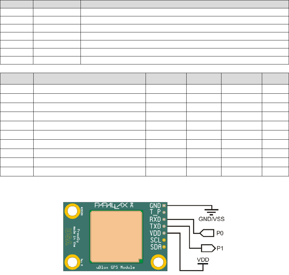
Pin Definitions and Ratings
Pin
Name
Function
1
GND
Ground Reference (VSS) -> 0 V
2
T_P
Time Pulse
3
RXD
Device UART Receive
4
TXD
Device UART Transmit
5
VDD
Voltage Input (3.3 V – 5.0 V)
6
SCL
Optional I2C Serial Clock
7
SDA
Optional I2C Serial Data
Symbol Quantity Minimum Typical Maximum Units
VDD
Supply Voltage
3.0
3.3
5.2
V
GND Ground reference connection 0 V
I
DD
(Ave) Average active supply current 35 mA
I
DD
(Pk) Peak instantaneous current 55 mA
VOH
Signal high transmit (TXD, T_P)
VDD × 0.9
VDD
VDD + 0.5
V
VOL
Signal low transmit (TXD, T_P)
GND - 0.3
GND
VDD × 0.15
V
VIH
Signal high receive (RXD)
1.5
VDD
40
V
VIL
Signal low receive (RXD)
- 0.3
GND
0.7
V
VSCL
I2C Clock Signal
0
3.3
V
VSDA
I2C Data Signal
0
3.3
V
Quick Start Circuit
The PAM-7Q GPS Module can be interfaced with many common microcontrollers or computers, including
the Propeller, BASIC Stamp, Arduino, PIC, Raspberry Pi, Beaglebone, and more. At minimum, you can
begin receiving data from the module by connecting the power pins, VDD and GND, and by making a
connection with the module’s transmit pin, TXD. If you want to change any of the module’s settings, you
will need to connect a signaling pin from your device to the module’s receive pin, RXD.
Voltage Supply and Signaling Levels
You can power the module at common TTL voltage levels, between 3.3 V and 5.0 V. The module’s
voltage supply and communication voltage level is provided by the VDD pin. The module’s onboard
regulator and buffer circuitry appropriately condition incoming and outgoing communication signals. So,
output signals will be matched to VDD’s voltage, and input signals will be conditioned to 3.3 V so as not
to damage the uBlox GPS device. Note that the optional SCL and SDA lines are not conditioned; see the
Other Features and Precautions section, page 5.
Copyright © Parallax Inc. PAM-7Q GPS Module (#28509) v1.0 8/7/2014 Page 2 of 6

Default Settings
The device comes preconfigured with these default settings. See the sections that follow for details about
these defaults. Full information about configurable options can be found in the PAM-7Q manufacturer’s
datasheet.
Output Data: 0183 NMEA standard sentences
o RMC
o VTG
o GGA
o GSA
o GSV
o GLL
Update Rate: 1 Hz fix update rate
Navigation Mode: Continuous
Time Pulse Output: 1 Hz time pulse output on T_P pin, 10% duty cycle
Communication Protocol: 9,600 baud TTL Asynchronous Serial (UART) communication
o True mode (active high)
o 1 start bit
o 8 data bits
o 1 stop bit
o No parity
Output Data
By default, the PAM-7Q GPS Module outputs NMEA 0183 v2.3 protocol standard sentences. As soon as
the module is powered, a series of ASCII strings are sent from the module’s TXD pin, representing fix
information.
The module will output the following NMEA strings by default:
RMC: Recommended minimum data for GPS
VTG: Vector track and speed over the ground
GGA: Fix information
GSA: Overall satellite data
GSV: Detailed satellite data
GLL: Latitude/Longitude data
These NMEA sentences and others can be turned on or off optionally by issuing special UBX commands to
the module. See the Communication Protocol section and uBlox’s Receiver Description Protocol
Specification document for more information.
At initial power-on, the PAM-7Q GPS module also transmits a set of special messages that describe the
GPS device hardware. These messages carry a non-NMEA-standard “TXT” prefix, yet follow the same
checksum rules defined by the standard. If your application demands verification of the module, you can
parse this information as needed. These strings contain no relevant fix information.
This is an example of the module’s power-on hardware summary:
$GPTXT,01,01,02,u-blox ag - www.u-blox.com*50
$GPTXT,01,01,02,HW UBX-G70xx 00070000 EFFFFFFFo*1B
$GPTXT,01,01,02,ROM CORE 1.00 (59842) Jun 27 2012 17:43:52*59
$GPTXT,01,01,02,PROTVER 14.00*1E
$GPTXT,01,01,02,ANTSUPERV=AC SD PDoS SR*20
$GPTXT,01,01,02,ANTSTATUS=DONTKNOW*33
Copyright © Parallax Inc. PAM-7Q GPS Module (#28509) v1.0 8/7/2014 Page 3 of 6

$GPTXT,01,01,02,LLC FFFFFFFF-FFFFFFED-FFFFFFFF-FFFFFFFF-FFFFFF79*21
$GPTXT,01,01,02,ANTSTATUS=INIT*25
$GPTXT,01,01,02,ANTSTATUS=OK*3B
This is a set of initial empty NMEA sentences before a fix has been established, just after the module has
been powered on:
$GPRMC,,V,,,,,,,,,,N*53
$GPVTG,,,,,,,,,N*30
$GPGGA,,,,,,0,00,99.99,,,,,,*48
$GPGSA,A,1,,,,,,,,,,,,,99.99,99.99,99.99*30
$GPGLL,,,,,,V,N*64
A valid position fix will have NMEA sentences that look something like this:
$GPRMC,041845.00,A,3846.50323,N,12115.39233,W,0.264,,040814,,,A*67
$GPVTG,,T,,M,0.264,N,0.488,K,A*27
$GPGGA,041845.00,3846.50323,N,12115.39233,W,1,03,7.16,72.5,M,-26.8,M,,*50
$GPGSA,A,2,18,21,15,,,,,,,,,,7.23,7.16,1.00*0A
$GPGSV,4,1,14,14,18,184,,15,33,055,15,16,19,263,,18,78,009,28*75
$GPGSV,4,2,14,19,11,320,,21,68,067,29,22,53,256,,24,05,105,*74
$GPGSV,4,3,14,26,05,033,,27,38,308,14,29,17,156,09,46,36,147,*79
$GPGSV,4,4,14,48,43,198,,51,43,158,*78
$GPGLL,3846.50323,N,12115.39233,W,041845.00,A,A*77
Your application can parse these sentences for GPS fix information as needed. Parallax provides some
sample programs that parse these NMEA sentences and makes the data available to your application.
See the Resources and Downloads section for more information. For more information about NMEA
sentences and what information is contained in the fields, check out this website:
http://www.gpsinformation.org/dale/nmea.htm
Update Rate
By default, the most up-to-date GPS fix information is transmitted from the module at a rate of 1 Hz, that
is, once per second. This rate can be increased up to 10 Hz; see the manufacturer’s datasheet for more
information.
Navigation Mode
There are two navigation modes, continuous navigation and static hold. In the default continuous
navigation mode, the PAM-7Q module uses its position acquisition system to constantly download
updated almanac information and track satellites. With this information, the module transmits the most
up-to-date fix information to your connected device. Continuous navigation mode is enabled by default
so your application will receive constant fix updates, regardless of the speed or distance traveled. When
the module is stationary, you may see very minute changes in reported speed.
Atmospheric anomalies cause the precise timing signals received by the module to drift ever so slightly,
causing the module’s reported location to minimally vary. Tall buildings, trees, and overhead
obstructions also contribute to slight shifts in timing measurements from the satellites. Static Hold mode
is used to filter out this “noise” while the module is not in motion. Thus, the module will not report
position changes unless it has moved several meters. This feature is commonly used in automobile GPS
navigation systems.
Copyright © Parallax Inc. PAM-7Q GPS Module (#28509) v1.0 8/7/2014 Page 4 of 6

Time Pulse and Satellite Lock LED
The Time Pulse pin on the PAM-7Q GPS module outputs a pulse that is synchronized with the GPS
device’s “epoch.” By default, the PAM-7Q GPS device’s epoch is set to a 1 second period and it is
synchronized with the time base received from the network of GPS satellites in orbit. By default, this
active high pulse has a 10% duty cycle, or 100 ms. The time pulse is only active at the top of each
second and only occurs once the module has acquired a GPS satellite lock. If your application requires it,
this signal can serve as an interrupt request.
The blue satellite lock LED on the underside of the module also makes use of this time pulse signal to
give you a visual indication of when the GPS module has locked onto a GPS signal. This LED also doubles
as a power indicator to the module. As soon as power is applied, the LED will light indicating the
presence of power. Once at least one satellite is being tracked, the LED will begin to blink with the
module’s time pulse.
Communication Protocol
The PAM-7Q GPS Module supports multiple physical communication protocols. The module was designed
to communicate primarily through a TTL UART – with the TXD transmit pin and RXD receive pin. This
UART operates at a default baud rate of 9,600 bits per second (BPS), eight data bits, one start bit, one
stop bit, and no parity (8N1). However, the baud rate and character framing settings can be changed to
other standard configurations, up to a maximum of 115,200 baud. If 10 Hz navigation update is
required, it is recommended that you change the module’s baud rate to a higher setting. This is because
at 9,600 baud, there is not enough time to send a full set of NMEA sentences in a 100 ms period.
For convenience, advanced users can take advantage of the optional I2C slave port. As you would
expect, this communication will take place on the SCL and SDA pins. Note that the pins have not been
populated – this is to prevent damage to the module as the signals are not pre-conditioned. See the
Precautions section below for more information.
The PAM-7Q GPS module also supports multiple structured data protocols. By default, the module is set
to output NMEA sentences automatically. The module will also respond to other data protocols. uBlox
has created two proprietary protocols called PUBX and UBX. The PUBX protocol is similar to the NMEA
protocol in that data is communicated in ASCII format. For more compact data transmissions, the UBX
protocol exchanges data in a binary format. Most users will not need to configure the module with these
protocols, but it is good to be aware of their existence.
Additional information about how to communicate with the module via these special protocols or with I2C
can be found in uBlox’s “Receiver Description Protocol Specification” document.
Other Features and Precautions
Battery Backup Aided Start Feature
The module is designed with a 30 mF super-cap that acts as a rechargeable battery backup. This allows
the GPS module to retain almanac data for more than 30 minutes which aids in quicker Time To Fix
(TTF). With this aided start, the module can acquire a valid location fix in as little as 5 seconds.
SCL and SDA Line Precautions
Communication with the PAM-7Q GPS module is intended to happen via the TXD and RXD lines. For
advanced users, I2C communication signals are provided as an option. However, there is no signal
conditioning present on these lines. Only signal the SCL and SDA lines at 3.3 V. Additionally, the I2C
lines are not externally pulled up. If you do decide to communicate via I2C, make sure that the SDA and
SCL lines are pulled up to 3.3 V in order to comply with the I2C standard.
Copyright © Parallax Inc. PAM-7Q GPS Module (#28509) v1.0 8/7/2014 Page 5 of 6
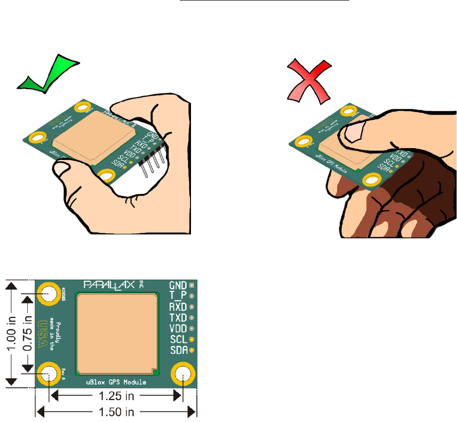
Handling Precautions
When handling the PAM-7Q GPS module, handle the module from the edges only. Take special care not
to put undue pressure on the GPS antenna from the top-side of the module. As part of the
manufacturing process, we have applied epoxy to the GPS antenna to make the module resistant to
stress, but excess force could still damage the module.
Module Dimensions
Pin spacing is standard 0.1” for a breadboard friendly design. Mounting holes are spaced by 1.25” and
0.75” center-to-center, with a .125” diameter, and accepts #4-40 screws.
Resources and Downloads
Check for example programs on Parallax’s PAM-7Q product page. Just search for the product
number: 28509. Additionally, uBlox publishes detailed datasheets and other technical descriptions on
their website. If you want to gain full use of all of the GPS receiver’s special features, take a look at
uBlox’s “Receiver Description Protocol Specification” document. This document is very complete and
describes every setting of the PAM-7Q module you can change, as well as the communication protocols
the module supports.
Copyright © Parallax Inc. PAM-7Q GPS Module (#28509) v1.0 8/7/2014 Page 6 of 6
