MN 29758_TH SK III_0515 Alto Shaam Inc. Oven 300 TH/III 28f9059e E881 498d 83d3 9d3576db197b
User Manual: Alto-Shaam Inc. Oven 300-TH/III
Open the PDF directly: View PDF ![]() .
.
Page Count: 59
MN-29758 (r e v . 6) • 05/15
p r i n t e d i n u.s.a.
W164 N9221 Water Street • P.O. Box 450
Menomonee Falls, Wisconsin 53052-0450 U.S.A.
PHONE: 262.251.3800 • 800.558.8744 U.S.A. / CANADA
FAX: 262.251.7067 • 800.329.8744 U.S.A. ONLY
www.alto-shaam.com
Consult instructions
for operation and use.
Cook, Hold, Smoke Oven
Deluxe Control
Model:
300-TH/III
500-TH/III
750-TH/III
1000-TH/III
1200-TH/III
767-SK/III
1767-SK/III
1000-SK/III
1200-SK/III
1200-TH/III
1767-SK/III
750-TH/III
300-TH/III
1000-SK/III
500-TH/III

MN-29758 (Rev. 6) 05/15 • TH/III-SK/III Series Cook, Hold, Smoke • Index
Delivery ...................................... 1
Unpacking .................................... 1
Safety Procedures and Precautions ................. 2
Installation
Installation Requirements ...................... 3
Clearance Requirements ....................... 3
Dimension Drawings, weights & capacities ........4-8
Options and Accessories ...................... 9
Stacking Configurations ...................... 10
Leveling .................................. 11
Restraint Requirements - Mobile Equipment ....... 11
Drip Tray Installation ......................... 12
Electrical Specifications ....................13-14
Operating Instructions
User Safety Information. . . . . . . . . . . . . . . . . . . . . . . 15
Start-up Operation .......................... 15
Audible Signals ............................. 15
Control Features ............................ 16
Cook/Hold/Smoke Instructions ................. 17
Operating Features & Functions ..............18-19
Smoking Instructions ........................ 20
User Options ............................... 21
HACCP ................................... 22
General Holding Guidelines .................... 23
Care and Cleaning
Protecting Stainless Steel Surfaces .............. 24
Cleaning Agents ............................ 24
Cleaning Materials .......................... 24
Equipment Care ............................ 25
Clean Daily ................................ 25
Clean the Door Vents ........................ 26
Check Overall Condition of Oven ............... 26
Daily Prong Cleaning ......................... 26
Sanitation
Sanitation/Food Safety ....................... 27
Internal Food Product Temperatures ............. 27
Service
Trouble Shooting - Error Codes. . . . . . . . . . . . . . . . . 28
Trouble Shooting Electrical Components ......... 29
Exterior Service View & Parts ................30-39
Electronic Components View & Parts ..........40-43
HACCP Data Logger Service Parts (option) ........ 44
Cable Heating Kits .......................... 44
Wire Diagrams
Always refer to the wire diagram(s) included with the unit
for most current version.
Warranty
Transportation Damage and Claims ...... Back Cover
Limited Warranty ..................... Back Cover

MN-29758 (Rev. 6) 05/15 • TH/III-SK/III Series Cook, Hold, Smoke • 1
This Alto-Shaam appliance has been thoroughly
tested and inspected to ensure only the highest
quality unit is provided. Upon receipt, check for any
possible shipping damage and report it at once to the
delivering carrier. See Transportation Damage and
Claims section located in this manual.
This appliance, complete with unattached items and
accessories, may have been delivered in one or more
packages. Check to ensure that all standard items
and options have been received with each model as
ordered.
Save all the information and instructions packed with
the appliance. Complete and return the warranty
card to the factory as soon as possible to ensure
prompt service in the event of a warranty parts and
labor claim.
This manual must be read and understood by all
people using or installing the equipment model.
Contact the Alto-Shaam Tech Team Service
Department if you have any questions concerning
installation, operation, or maintenance.
All claims for warranty must include the
full model number and serial number of the
unit.
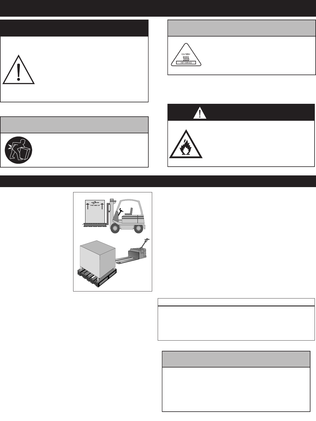
• Carefully remove the appliance
from the carton or crate.
Do not discard the
carton and other
packaging material
until you have
inspected the unit for
hidden damage and
tested it for proper operation.
• Read all instructions in this manual carefully before
initiating the installation of this appliance, using
the appliance or performing routine maintenance.
Following procedures other than those indicated
in this guide to use and clean the appliance is
considered inappropriate and may cause damage,
injury or fatal accidents, in addition to invalidating
the guarantee and relieving Alto-Shaam of all
liability.
• DO NOT DISCARD THIS MANUAL.
This manual is considered to be part of the
appliance and is to be provided to the owner
or manager of the business or to the person
responsible for training operators. Additional
manuals are available from the Alto-Shaam Tech
Team Service Department.
• Remove all protective plastic film, packaging
materials, and accessories from the appliance
before connecting electrical power. Store any
accessories in a convenient place for future use.
®
®
MN-29758 (Rev. 6) 05/15 • TH/III-SK/III Series Cook, Hold, Smoke • 2
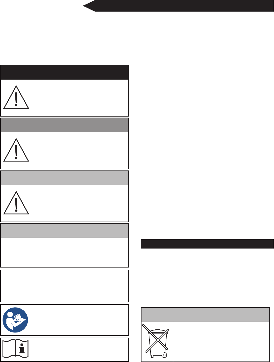
Used to indicate the presence of a hazard that
can or will cause minor personal injury, property
damage, or a potential unsafe practice if the
warning included with this symbol is ignored.
Used to indicate the presence of a
hazard that can or will cause minor or
moderate personal injury or property
damage if the warning included with
this symbol is ignored.
Used to indicate the presence of
a hazard that WILL cause severe
personal injury, death, or substantial
property damage if the warning
included with this symbol is ignored.
Used to indicate the presence of
a hazard that CAN cause personal
injury, possible death, or major
property damage if the warning
included with this symbol is ignored.
• This appliance is intended to cook, hold or process
foods for the purpose of human consumption. No
other use for this appliance is authorized and is
therefore considered dangerous. The appliance
must not be used to cook food containing flammable
materials (such as food with alcohol). Substances
with a low flash point can ignite spontaneously and
become a fire risk.
• This appliance is intended for use in commercial
establishments where all operators are familiar
with the purpose, limitations, and associated
hazards of this appliance. Operating instructions
and warnings must be read and understood by
all operators and users. We recommend regular
training of your staff to avoid the risk of accident
or damage to the unit. Operators must also receive
regular safety instructions.
• Any troubleshooting guides, component views, and
parts lists included in this manual are for general
reference only and are intended for use by qualified
and trained technicians.
•
This manual should be considered a permanent part
of this appliance. This manual and all supplied
instructions, diagrams, schematics, parts lists,
notices, and labels must remain with the appliance
if the item is sold or moved to another location.
Used to notify personnel of
installation, operation, or
maintenance information that is
important but not hazard related.
Knowledge of proper procedures is essential to the
safe operation of electrically and/or gas energized
equipment. In accordance with generally accepted
product safety labeling guidelines for potential
hazards, the following signal words and symbols
may be used throughout this manual.
Used to indicate that referral to
operating instructions is a mandatory
action. If not followed the operator
could suffer personal injury.
Used to indicate that referral to
operating instructions is recommended
to understand operation of equipment.
For equipment delivered for use
in any location regulated by the
following directive:
DO NOT DISPOSE OF ELECTRICAL
OR ELECTRONIC EQUIPMENT WITH
OTHER MUNICIPAL WASTE.
• Operational Environmental Conditions
• Unit must acclimate to room temperature in the
environment it is placed. 24 hours is recommended.
• Ambient temperature range of 50° to 110°F (10° to 43°C).
• Relative humidity of less than 95% non-condensation.
• Atmospheric pressure range of 50KPa to 106KPa.
MN-29758 (Rev. 6) 05/15 • TH/III-SK/III Series Cook, Hold, Smoke • 3
The Alto-Shaam Cook
& Hold oven must be
installed in a location
that will permit the
oven to function
for its intended
purpose and to allow
adequate clearance
for ventilation,
proper cleaning, and
maintenance access.
1. The oven must be installed on a stable and
level surface.
2. DO NOT install this appliance in any area
where it may be affected by any adverse
conditions such as steam, grease, dripping
water, high temperatures, or any other severely
adverse conditions.
3. DO NOT store or use any flammable liquids or
allow flammable vapors in the vicinity of this
oven or any other appliance.
4. This appliance must be kept free and clear of
any combustible materials.
5. This appliance must be kept free and clear
of any obstructions blocking access for
maintenance or service.
®
Emissions testing conducted by Underwriters
Laboratories, Inc.® was found to be in compliance
with the applicable requirements of NFPA96:
2004 Edition, Par. 4.1.1.2. U.L emissions
sampling of grease laden vapor resulted in a total
of 0.55 milligrams per cubic meter with no visible
smoke and is considered representative of all
oven models in the line. Based on these results,
hood installation and/or outside venting should
not be a requirement in most areas. Verify local
codes for locations where more restrictive codes
are applicable.
Improper installation, alteration,
adjustment, service, cleaning, or
maintenance could result in property
damage, severe injury, or death.
Read the installation, operating and
maintenance instructions thoroughly
before installing, servicing, or
operating this equipment.
Appliance and accessories may be
heavy. To prevent personal injury, use
caution when moving or leveling this
appliance or handling accessories.
Metal parts of this equipment
become extremely hot when in
operation. To avoid burns, always
use hand protection when operating
this appliance.
DO NOT store or use gasoline or
other flammable vapors or liquids
in the vicinity of this or any other
appliance. Failure to observe this
precaution may result in a fire,
explosion or personal injury.
If the appliance has been unplugged for an
extended period of time, the Real Time Clock
may require recharging. Turn main breaker to the
unit off for 10 seconds and then restore power.
For more information, see Error Code E-60 in the
Troubleshooting section of this manual.
C
18" (457mm) minimum clearance at the back from heat
producing equipment. To protect the electronic control,
maintain sufficient side clearance to prevent the control area
from reaching any temperature at or above 140°F (60°C).
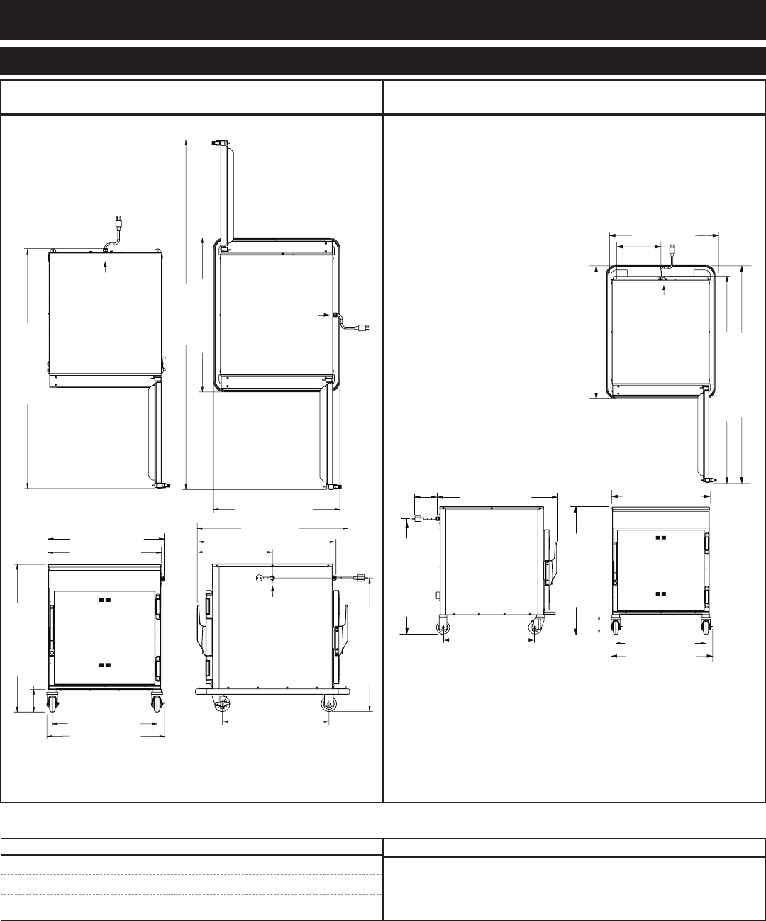
MN-29758 (Rev. 6) 05/15 • TH/III-SK/III Series Cook, Hold, Smoke • 4
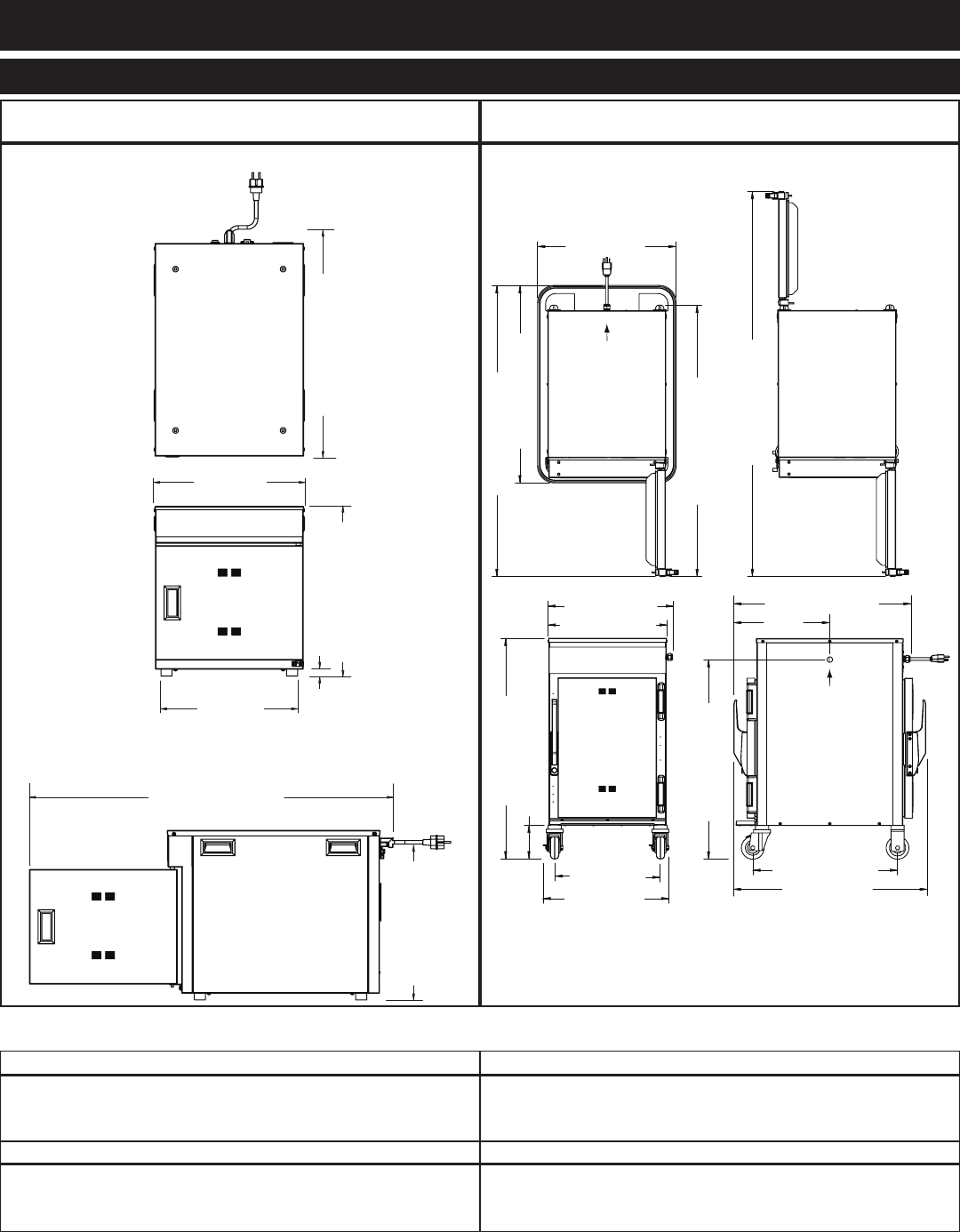
300-th3 2011 lit
25-3/16" (643mm)
Cord Length:
5 ft. (1524mm)
16-13/16"
(426mm)
18-15/16" (480mm)
3/4" (19mm)
15-1/4"
(387mm)
40-5/8" (1031mm)
17-5/8" (447mm)
500-TH/III300-TH/III
300-th3 2011 lit
25-3/16" (643mm)
Cord Length:
5 ft. (1524mm)
16-13/16"
(426mm)
18-15/16" (480mm)
3/4" (19mm)
15-1/4"
(387mm)
40-5/8" (1031mm)
17-5/8" (447mm)
net: 69 lb (31 kg)
ship: contact factory
- 300-TH/III
36 lb (16 kg) maximum
volume maximum: 22.5 quarts (28,5 liters)
- 500-TH/III
40 lb (18 kg) maximum
voluMe MaxiMuM: 30 quarts (38 liters)
net: 140 lb (64 kg)
ship: 180 lb (82 kg)
21" (532mm)
Shown with
optional bumper
29-7/8" (758mm)
41-1/16" (1043mm)
Electrical
Connection
44-1/16" (1118mm)
58-1/4" (1479mm)
14-1/2"
(368mm)
30-3/16" (767mm)
21-7/8" (556mm)
16" (406mm)
33-3/8" (848mm)
5-1/8" (130mm)
18-1/16" (458mm)
Pass-Through
Option
Pass-Through
Option
19" (483mm)
Electrical
Connection
26-9/16" (675mm)
29" (737mm)
*31-11/16" (804mm) - with optional 2-1/2" casters
*35-5/16" (897mm) - with optional 5" casters
*33-7/8" (860mm) - with optional 6" legs
Cord Length
120V - 5 ft. (1524mm)
208-240V - 5 ft. (1524mm)
230V - 8 ft. (2438mm)
19-1/8" (486mm)
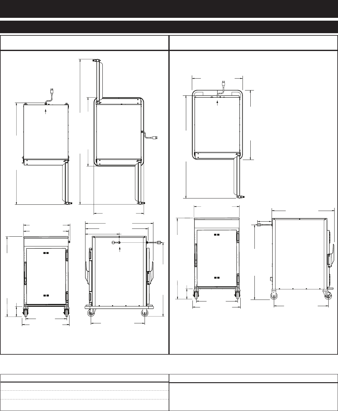
MN-29758 (Rev. 6) 05/15 • TH/III-SK/III Series Cook, Hold, Smoke • 5
767-SK/III750-TH/III
100 lb (45 kg) maximum
volume maximum: 53 quarts (67 liters)
MODeL net WeiGht ship WeiGht
750-TH/III 192 lb (87 kg) 260 lb (118 kg)
767-SK/III 196 lb (89 kg) 275 lb (125 kg)
Shown with
optional bumper
Electrical
Connection
Pass-Through
Option
Electrical
Connection
Pass-Through
Option
Electrical
Connection
Shown with
optional bumper
25-3/4" (651mm)
54-1/8" (1373mm)
33-3/8" (848mm)
with 3" (76mm) casters*
5-1/8" (130mm)
23-5/8" (600mm)
26-5/8" (676mm)
30-3/16" (767mm)
24-1/8" (612mm)
17" (432mm)
Elec. Connection
34" (864mm)
31-5/8" (802mm)
28-9/16" (726mm)
79" (2006mm)
34-7/8" (886mm)
*32-1/2" (826mm) - with optional 2-1/2" casters
*35-1/4" (894mm) - with optional 5" casters
*33-3/4" (857mm) - with optional 6" legs
26-3/4" (679mm)
Cord Length
120V - 5 ft. (1524mm)
208-240V - 5 ft. (1524mm)
230V - 8 ft. (2438mm)
26-5/8" (676mm)
25-11/16" (651mm)
*31-11/16" (804mm) - with optional 2-1/2" casters
*35-1/16" (890mm) - with optional 5" casters
*33-13/16" (858mm) - with optional 6" legs
33-3/8" (848mm)
with 3-1/2" casters*
28-5/8" (726mm)
Shown with
optional bumper
34-7/8" (886mm)
56-3/4" (1441mm)
Electrical
Connection
54-1/16" (1373mm)
11-5/8"
(295mm)
31-5/8" (802mm)
30-3/16" (767mm)
(electrical connection)
24-1/8" (612mm) 23-5/8" (600mm)
5-1/8" (130mm)
Cord Length
230V - 8 ft. (2438mm)
208-240V - 6 ft. (1829mm)
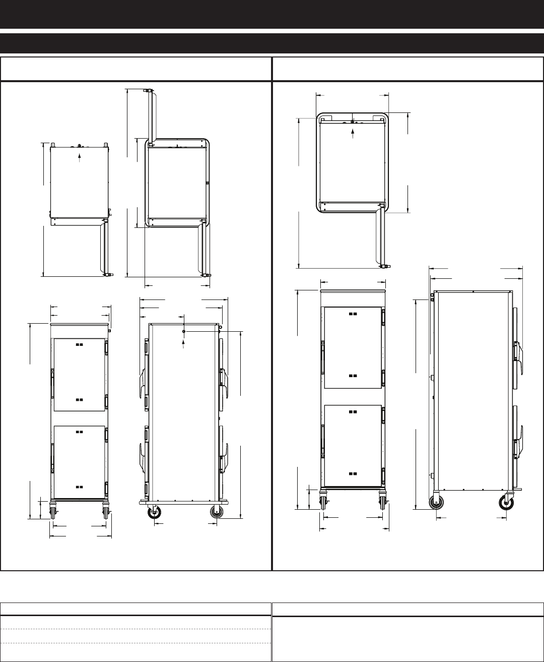
MN-29758 (Rev. 6) 05/15 • TH/III-SK/III Series Cook, Hold, Smoke • 6
1000-SK/III1000-TH/III
34" (864mm)
25-1/16" (636mm)
23-5/8" (600mm)
17" (432mm)
51" (1294mm)
72-3/4" (1847mm)
5-1/8" (130mm)
40-3/16" (1021mm)
with 3-1/2 (89mm) casters
37" (940mm)
34-1/2" (876mm)
*38-5/8" (981mm) - with optional 2-1/2" casters
*42" (1067mm) - with optional 5" casters
*41-7/8" (1063mm) - with optional 6" legs
Electrical
Connection
Pass-Through
Option
Electrical
Connection
20-1/2"
(521mm)
23-1/2" (597mm)
31-5/8" (802mm)
26-7/8" (683mm)
Cord Length
208-240V - 5 ft. (1524mm)
230V - 8 ft. (2438mm)
22-1/2" (572mm)
Shown with
optional bumper
Pass-Through
Option
22-1/2" (572mm)
5-1/8" (130mm)
40-3/16" (1021mm)
with 3-1/2 (89mm) casters
*38-5/8" (981mm) - with optional 2-1/2" casters
*42" (1067mm) - with optional 5" casters
*41-7/8" (1063mm) - with optional 6" legs
20-1/2"
(521mm)
23-1/2" (597mm)
51" (1294mm)
34-1/2" (876mm)
25-1/16" (636mm)
26-7/8" (683mm)
37" (940mm)
31-5/8" (802mm)
Cord Length
230V - 8 ft. (2438mm)
208-240V - no cord or plug
Shown with
optional bumper
Electrical
Connection
120 lb (54 kg) maximum
voluMe MaxiMuM: 60 quarts (76 liters)
MODeL net WeiGht ship WeiGht
1000-TH/III 230 lb (104 kg) est. 275 lb (125 kg)
1000-SK/III 203 lb (92 kg) est. 282 lb (128 kg)
MN-29758 (Rev. 6) 05/15 • TH/III-SK/III Series Cook, Hold, Smoke • 7
1200-SK/III1200-TH/III
25-1/16" (636mm)
51" (1294mm)
72-3/4" (1847mm)
34-1/2" (876mm)
Electrical
Connection
Pass-Through
Option
Shown with
optional bumper
17" (432mm)
34" (864mm)
20-1/2"
(521mm)
23-15/16"
(608mm)
Pass-Through
Option
Electrical
Connection
75-5/8" (1920mm) with 5 (127mm) casters*
6-13/16" (172mm)
24-1/4" (613mm)
72-1/4" (1835mm)
31-5/8" (802mm)
*73-7/8" (1877mm) - with optional 3-1/2" casters
*74-11/16" (1897mm) - with optional 6" legs
23-5/8" (600mm)
22-1/2" (572mm)
22-1/2" (572mm)
20-1/2"
(521mm)
23-15/16" (608mm)
75-5/8" (1920mm) with 5 (127mm) casters*
6-13/16" (172mm)
*73-7/8" (1877mm) - with optional 3-1/2" casters
*74-11/16" (1897mm) - with optional 6" legs
25-1/16" (636mm)
34-1/2" (876mm)
51" (1294mm)
72-1/4" (1835mm)
31-5/8" (802mm)
32-1/4" (819mm)
24-1/4" (613mm)
Shown with
optional bumper
Electrical
Connection
(per compartment)
120 lb (54 kg) maximum
voluMe MaxiMuM: 60 quarts (76 liters)
MODeL net WeiGht ship WeiGht
1200-TH/III 345 lb (156 kg) 435 lb (197 kg)
1200-SK/III 390 lb (177 kg) est. 465 lb (211 kg)
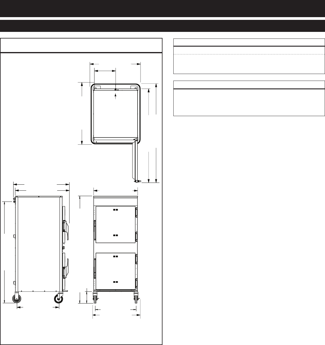
MN-29758 (Rev. 6) 05/15 • TH/III-SK/III Series Cook, Hold, Smoke • 8
1767-SK/III
27-1/16" (686mm)
25-11/16" (651mm)
23-5/8" (600mm)
Shown with
optional bumper
Electrical
Connection
28-5/8" (726mm)
34-7/8" (886mm)
56-3/4" (1441mm)
54-1/16" (1373mm)
11-5/8"
(295mm)
31-3/4" (807mm)
24-1/8" (613mm)
58-9/16" (1487mm)
Electrical Connection
61-15/16" (1572mm) with 5" (127mm) casters*
6-13/16" (172mm)
*60-11/16" (1540mm) - with optional 3-1/2" (89mm) casters
*62-1/8" (1577mm) - with optional 6" (152mm) legs
32-3/4" (832mm)
(per compartment)
100 lb (45 kg) maximum
volume maximum: 53 quarts (67 liters)
MODeL net WeiGht ship WeiGht
1767-SK/III 359 lb (163 kg) est 450 lb (204 kg)

MN-29758 (Rev. 6) 05/15 • TH/III-SK/III Series Cook, Hold, Smoke • 9
767-SK/III 1767-SK/III 1000-SK/III 1200-SK/III
Bumper, Full Perimeter (Not available with 2-1/2" casters)5010371 5010371 5009767 5009767
Carving Holder
prime rib
steamship (cafeteria) round
HL-2635
4459
HL-2635
4459
HL-2635
4459
HL-2635
4459
Casters - 2 rigid, 2 swivel w/brake
5" (127mm)
3-1/2" (89mm)
2-1/2" (64mm)
5004862
standard
5008022
standard
5008017
––
5004862
standard
5008022
standard
5008017
––
Door Lock with Key LK-22567 LK-22567 LK-22567 LK-22567
Drip Pan
with drain
without drain
extra deep
14831
—
—
14831
11906
—
5005616
11906
15929
5005616
11906
15929
HACCP Data Logger (factory installed)5015563 5015563 5015563 5015563
Legs, 6" (152mm), Stemmed (set of four)5011149 5011149 5011149 5011149
Pan Grid, Wire - 18" x 26" paN iNsert PN-2115 PN-2115 PN-2115 PN-2115
Security Panel with key lock 5013936 5013936 5013934 5013934
Shelf, Stainless Steel
flat wire, reach-in
rib rack
SH-2324
SH-2743
SH-2324
SH-2743
SH-2325
SH-29474
SH-2325
SH-29474
Stacking Hardware 5004864 –– 5004864 ––
Wood Chips, bulk pack, 20 lb (9 kg)
Apple
Cherry
Hickory
Maple
WC-22543
WC-22541
WC-2829
WC-22545
WC-22543
WC-22541
WC-2829
WC-22545
WC-22543
WC-22541
WC-2829
WC-22545
WC-22543
WC-22541
WC-2829
WC-22545
300-TH/III 500-TH/III 750-TH/III 1000-TH/III 1200-TH/III
Bumper, Full Perimeter
(Not available with 2-1/2" casters)—5011161 5010371 5009767 5009767
Carving Holder
prime rib
steamship (cafeteria) round
HL-2635
—
HL-2635
4459
HL-2635
4459
HL-2635
4459
HL-2635
4459
Casters - 2 rigid, 2 swivel w/brake
5" (127mm)
3-1/2" (89mm)
3" (76mm)
2-1/2" (64mm)
—
—
5015323
—
5004862
standard
—
5008022
5004862
standard
—
5008022
5004862
standard
—
5008022
5004862
standard
—
—
Door Lock with Key —LK-22567 LK-22567 LK-22567 LK-22567
Drip Pan
with drain
without drain
extra deep
—
—
PN-2122
14813
11898
—
14831
11906
—
5005616
11906
15929
5005616
11906
15929
HACCP Data Logger (factory installed)5015563 5015563 5015563 5015563 5015563
Legs, 6" (152mm), Stemmed (set of four)—5011149 5011149 5011149 5011149
Pan Grid, Wire - 18" x 26" paN iNsert — — PN-2115 PN-2115 PN-2115
Security Panel with key lock —5013939 5013936 5013934 5013934
Shelf, Stainless Steel
flat wire, reach-in
flat wire, pass-through
rib rack
SH-2107
—
—
SH-2326
SH-2326
—
SH-2324
SH-2327
SH-2743
SH-2325
SH-2346
SH-29474
SH-2325
SH-2346
SH-29474
Stacking Hardware —5004864 5004864 5004864 —
MN-29758 (Rev. 6) 05/15 • TH/III-SK/III Series Cook, Hold, Smoke • 10
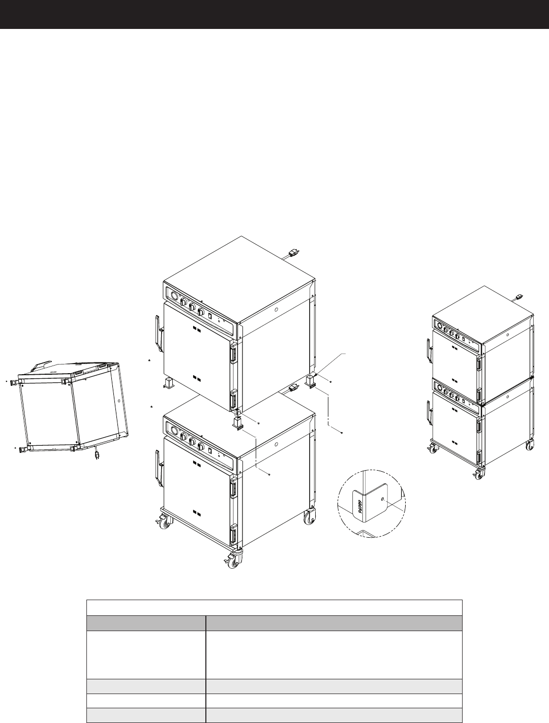
1) If the two appliances were shipped together from the factory, the top unit will have the casters
If casters need to be removed, lay the unit on its back, and using a rubber or non-marring hammer, tap on the top and
underside of the caster, alternating sides, until the caster slides out.
upper unit. Secure the stacking posts using one screw and two fl at washers that come with the
stacking kit. Use template 68696 to locate set screw hole. Drill with #30 Bit and Tap 8-32.
The fl ange on the stacking posts must face the outside of the unit.
A
DETAIL A
STACKING KIT 5004864
CASTER SET SCREW
TOP MOUNTING SCREW
Stacking Configurations
Model Can be stacked with
300-TH/III 300-TH/III or 300-S
No Stacking Hardware needed. Align dimples at top
and bottom of units. It is recommended that the legs
be removed from the top unit before stacking.
500-TH/III 500-TH/III, 500-TH-II or 500-S
750-TH/III or 767-SK/III 750-TH/III, 750-TH-II, 750-S, 767-SK or 767-SK/III
1000-TH/III or 1000-SK/III 1000-TH/III, 1000-SK/III, 1000-SK/II or 1000-S
MN-29758 (Rev. 6) 05/15 • TH/III-SK/III Series Cook, Hold, Smoke • 11
A number of adjustments are associated with
initial installation and start-up. It is important
that these adjustments be conducted by a qualified
service technician. Installation and start-up
adjustments are the responsibility of the dealer
or user. These adjustments include but are not
limited to thermostat calibration, door adjustment,
leveling, electrical hook-up and installation of
optional casters or legs.
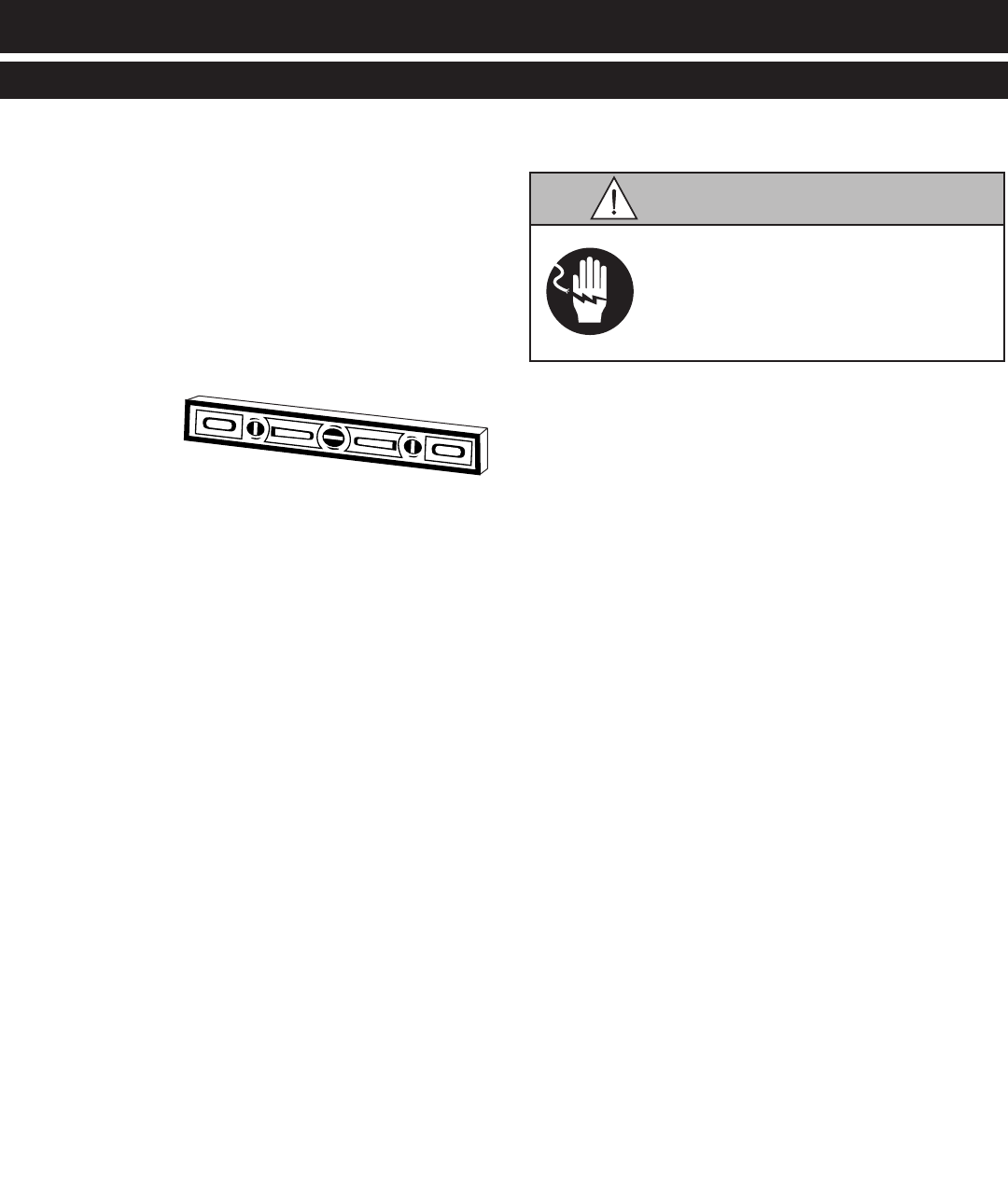
Level the oven
from side-to-side and
front-to-back with the use of a spirit level.
For ovens installed with casters, it is important
that the installation surface be level due to the
probability of frequent oven repositioning.
We recommend checking the level of the oven
periodically to make certain the floor has not
shifted nor the oven moved.
Failure to properly level this oven can
cause improper function and will result
in the uneven baking with products
consisting of semi-liquid batter.
Any appliance that is not furnished with a power
supply cord but that includes a set of casters
must be installed with a tether. Adequate means
must be provided to limit the movement of this
appliance without depending on or transmitting
stress to the electrical conduit. The following
requirements apply:
1. Maximum height of casters is 6" (152mm).
2. Two of the casters must of be the locking type.
3. Such mobile appliances or appliances on mobile
stands must be installed with the use of a flexible
connector secured to the building structure.
A mounting connector for a restraining device is
located on the upper back flange of the appliance.
A flexible connector is not supplied by nor is it
available from the factory.
Appliance must be secured to building
structure. Failure to observe this
precaution may result in damage to the
equipment and severe personal injury.
MN-29758 (Rev. 6) 05/15 • TH/III-SK/III Series Cook, Hold, Smoke • 12
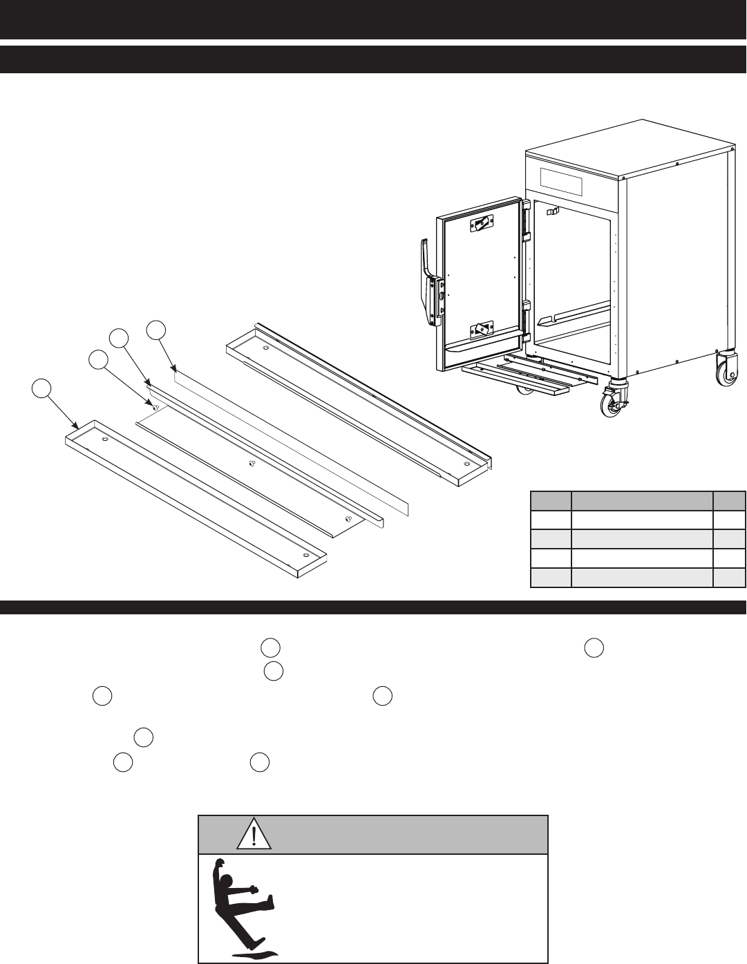
Failure to properly install the
drip tray can or will cause major
equipment damage and will
result in a leakage hazard that
can cause personal injury.
1. Poke holes through double-sided tape 1 which is attached to the back of drip tray holder 2.
2. Remove backing on double-sided tape 1.
3. Put screws 3 through holes and attach drip tray holder 2 to unit.
4. Optional, but strongly recommended - apply a line of food-grade silicone caulk along top edge
of drip tray holder 2 to seal.
5. Place drip tray 4 in drip tray holder 2.
Item Description Qty
1Double-Sided Tape 1
2Drip Tray Holder 1
38-32 x 1/4” Phil Screw 3
4Drip Tray 1
1
2
3
4
MN-29758 (Rev. 6) 05/15 • TH/III-SK/III Series Cook, Hold, Smoke • 13
The appliance must be installed by a qualified
service technician. The oven must be properly
grounded in accordance with the National
Electrical Code and applicable local codes.
Plug the unit into a properly grounded receptacle
ONLY, positioning the unit so that the plug is
easily accessible in case of an emergency. Arcing
will occur when connecting or disconnecting the
unit unless all controls are in the “OFF” position.
Proper receptacle or outlet configuration or
permanent wiring for this unit must be installed
by a licensed electrician in accordance with
applicable local electrical codes.
REGARDING INTERNATIONAL STANDARD UNITS:
If the unit is not equipped with flexible cord and
plug, an all-pole country approved disconnection
device which has a contact separation of at least
3mm in all poles must be incorporated in the fixed
wiring for disconnection. When using a cord
without a plug, the green/yellow conductor shall
be connected to the terminal which is marked with
the ground symbol. If a plug is used, the socket
outlet must be easily accessible. If the power cord
needs replacement, use a similar one obtained
from the distributor.
Ensure power source matches
voltage identified on appliance rating
tag. The rating tag provides essential
technical information required for any
appliance installation, maintenance
or repairs. Do not remove, damage or
modify the rating tag.
This appliance MUST be adequately
grounded in accordance with local
electrical codes or, in the absence
of local codes, with the current
edition of the National Electrical
Code ANSI/NFPA No. 70. In Canada,
all electrical connections are to be
made in accordance with CSA C22.1,
Canadian Electrical Code Part 1 or
local codes.
Failure to observe this precaution
may damage the appliance,
result in electrical shock, fire or
personal injury.
: Where local codes and CE regulatory
requirements apply, appliances must be
connected to an electrical circuit that is
protected by an external GFCI outlet.
Hard wired models:
Hard wired models must be equipped with a country
certified external allpole disconnection switch with
sufficient contact separation.
If a power cord is used for the connection of the product an
oil resistant cord like H05RN or H07RN or equivalent must
be used.
Appliances with no cord provided
by factory must be equipped with a
cord of sufficient length to permit the
appliance to be moved for cleaning.
Electrical connections must be made
by a qualified service technician in
accordance with applicable electrical
codes. Use the correct AWG wire size
based on the electrical requirements
for the appliance.
Failure to observe this precaution
may result in electrical shock,
damage to the appliance, fire,
property damage or personal injury.
For CE approved units:
To prevent an electrical
shock hazard between the appliance and other
appliances or metal parts in close vicinity,
an equalization-bonding stud is provided. An
equalization bonding lead must be connected to
this stud and the other appliances/metal parts
to provide sufficient protection against potential
difference. The terminal is marked with
the following symbol.
MN-29758 (Rev. 6) 05/15 • TH/III-SK/III Series Cook, Hold, Smoke • 14
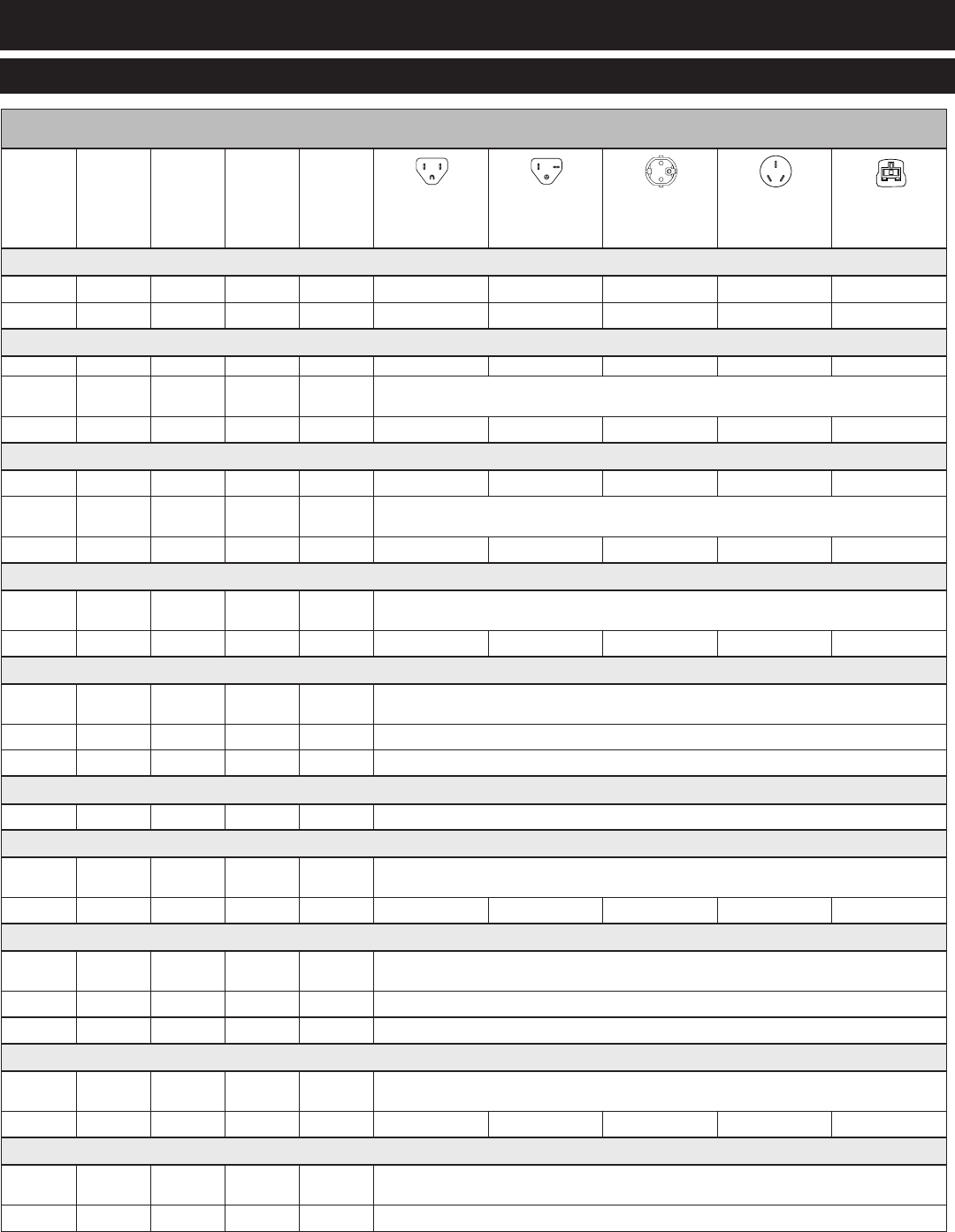
(Wire diagrams are located inside the bonnet of the unit)
Voltage Phase Hz Amps kW nema 5-15p
15a-125v plug
nema 5-20p
20a-125v plug
cee 7/7
plug rated 250v
ch2-16p
plug rated 250v
bs1363
plug rated 250v
(u.K. only)
300-TH/III
120V 1 60 6.7 .80
230V 1 50/60 2.7 .62
500-TH/III
120V 1 60 16.0 1.9
208V
240V 1 60 11.2
12.5
2.7
3.0 CORD, NO PLUG
230V 1 50/60 12.0 2.8
750-TH/III
120V 1 60 14.2 1.7
208V
240V 1 60 14.0
16.0
2.9
3.9 CORD, NO PLUG
230V 1 50/60 12.2 2.8
1000-TH/III
208V
240V 1 60 14.0
16.0
2.9
3.9 CORD, NO PLUG
230V 1 50/60 12.2 2.8
1200-TH/III
208V
240V 1 60 29.0
33.3
6.1
8.0 NO CORD OR PLUG
230V 1 50/60 28.7 6.6 NO CORD OR PLUG
380-415V 3 50/60 16.5 6.0 NO CORD OR PLUG
1200-TH/III (u.k. only)
230V 1 50/60 21.5 4.9 NO CORD OR PLUG
767-SK/III
208V
240V 1 60 16.0
18.5
3.9
4.4 CORD, NO PLUG
230V 1 50/60 14.0 3.1
1767-SK/III
208V
240V 1 60 32.0
36.3
7.7
8.7 NO CORD OR PLUG
230V 1 50/60 30.0 6.2 NO CORD OR PLUG
380-415V 3 50/60 17.2 6.4 NO CORD OR PLUG
1000-SK/III
208V
240V 1 60 16.0
18.3
3.3
4.4 CORD, NO PLUG
230V 1 50/60 14.0 3.1
1200-SK/III
208V
240V 1 60 32.0
36.3
7.7
8.7 NO CORD OR PLUG
230V 1 50/60 31.5 7.2 NO CORD OR PLUG
MN-29758 (Rev. 6) 05/15 • TH/III-SK/III Series Cook, Hold, Smoke • 15
The Alto-Shaam cook and hold oven is intended
for use in commercial establishments by qualified
operating personnel where all operators are
familiar with the purpose, limitations, and
associated hazards of this appliance. Operating
instructions and warnings must be read and
understood by all operators and users.
Interior oven surfaces must be heated to remove
surface oils and the accompanying odor produced
during the first use of the oven.
1. Wipe all wire shelves, side racks and the full oven
interior with a clean, damp cloth. Install the oven
side racks, oven shelves, and external drip tray.
Shelves are installed with the curved edge toward
the back of the oven. Insert the drip pan on the
interior bottom surface of the oven.
2. • Close the oven doors
• Press and release control oN/off key.
• Press the COOK key.
• Press the up and down arrows to set the cooking
temperature to 300°F (149°C).
3. • Press the TIME key.
• Press the up and down arrows to set the
cooking time to approximately 2 hours.
• Allow the oven to cycle for approximately
2 hours or until no odor is detected.
Metal parts of this equipment
become extremely hot when in
operation. To avoid burns, always
use hand protection when operating
this appliance.
At no time should the interior or
exterior be steam cleaned, hosed
down, or flooded with water or
liquid solution of any kind. Do not
use water jet to clean.
Severe damage or electrical
hazard could result. Failure to
observe this precaution will void
the warranty.
Disconnect unit from power source
before cleaning or servicing. Failure
to observe this precaution can cause
electrical shock and personal injury.
OVEN BEEPING indicates a response, mode changes, and error conditions.
One brief beep - response to a key being pressed.
Two brief beeps - informative beep that indicates that something has been changed, such
as the user entering a volume change, entering a temperature scale
change, etc.
Three brief beeps - indicates the oven is done preheating, the probe has exceeded
set-point in cold smoking, the door has been open too long, or the
control is unlocked.
Four brief beeps - indicates an error. Refer to the Trouble Shooting section of this manual.
MN-29758 (Rev. 6) 05/15 • TH/III-SK/III Series Cook, Hold, Smoke • 16
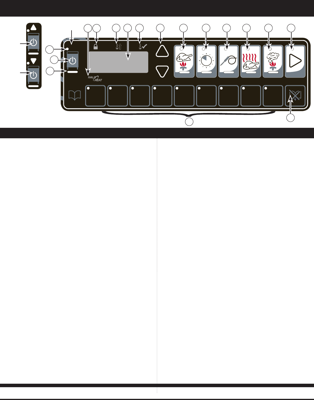
A B C D E F G H I
A B C D E F G H I
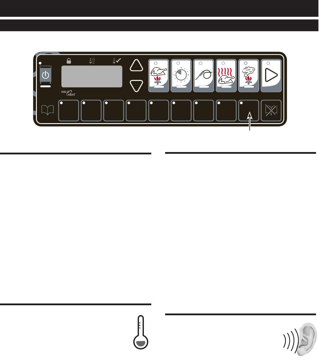
1. ON/OFF Key
The ON/OFF control system key operates the
functions of the control panel. If there is any power
loss during operation, the on/off indicator light will
flash. To clear, push key and release.
2. COOK Key — Temperature range 200 ° to 325°F
(93° to 162°C)
Used to select cooking mode and to review the cook
temperature setting.
3. TIME Key — Maximum time 24 hours
Used to select cook time and to review set time.
4. PROBE Key — Temperature range 50° to 195°F
(10° to 91°C)
Used to select internal product probe temperature
mode, review probe temperature setting, enable Probe
Hold mode, and edit probe holding temperature.
5. HOLD Key — Temperature range 60° to 205°F
(15° to 96°C)
Used to select food holding mode and to review set
holding temperature.
6. SMOKER Key — Time range 0 to 4 hours
Used to select warm smoke or cold smoke and to
review the smoke time remaining.
7. Lock Indicator
When illuminated, this symbol indicates settings
used in the cooking sequence are locked and cannot
be changed.
8. Halo Heat Indicator
When the oven is preheating, the Halo Heat indicator
will illuminate during preheating and remain steady
until the oven reaches the set cooking temperature.
When the temperature has stabilized, the indicator will
illuminate periodically as the oven calls for heat.
9. Oven Preheat Light
Illuminates until the oven is preheated or in ready mode.
10. LED Display
Indicates interior oven air temperature, internal
product probe temperature, time, or when used in
conjunction with other keys, will review
original cooking, holding and probe temperature
settings. The display will also indicate various
programming and diagnostic information.
11. Ready Indicator Light
Illuminates when the oven has finished preheating.
12. UP and DOWN ARROWS
Used to increase or decrease set time, including
cooking, holding and probe temperature settings.
13. START Key
Used to initiate a selected mode sequence when pressed
and released. You may stop any mode of operation by
pressing and holding the START Key until you hear a
2-second beep.
14. Green Indicator Lights
Located within each function key, the green light
functions as an operator prompt indicating additional
operator action is required and also identifies current
mode of operation.
15. Amber Indicator Lights
Located below the COOK, TIME, PROBE and HOLD
Keys, these indicators will illuminate to identify the
current mode of operation and allows the operator
to identify the information currently shown in the
LED display.
16. Preset Program Keys
Provides memory storage and operation of up to eight
operator set cooking programs for specific products
(A thru H). I enables locking abilities.
17. CANCEL Key
Used to erase a program from memory storage.
IMPORTANT
Do not use the oven if the controls are not properly functioning. Refer to the Troubleshooting
Guide located in this manual or call an authorized service technician.
Power ON
Indicator
A B C D E F G H I
A B C D E F G H I
Double
Compartment
Control
Lower
Cavity
ON/OFF
Upper
Cavity
ON/OFF
1
2 3 4 5 6
78 9 10 11 12 13
14
15
16 17

MN-29758 (Rev. 6) 05/15 • TH/III-SK/III Series Cook, Hold, Smoke • 17
Cook/Hold/Smoke Instructions
Press and release control ON/OFF key. The oven will beep for one second and power to the unit will be
indicated by an illuminated green indicator light located in the upper left corner of the ON/OFF key. The
oven will begin operating in the hold mode. The amber hold indicator will be illuminated and the last set
hold temperature will be displayed.
Set cook temperature — Press COOK Key. Oven preheat indicator will illuminate and the last set cooking
temperature will displayed. Press the UP or DOWN ARROW Keys to change the cook temperature.
If cooking by time — Press the TIME Key. The green time indicator will illuminate and the last set
cooking time will be displayed. Press the UP or DOWN ARROW Keys to change the set time. The
display will alternate between the set temperature and the elapsed time.
If cooking by probe — Press the PROBE Key. The green probe indicator will illuminate and the last set
internal product temperature will be displayed. Press the UP or DOWN ARROW Keys to change the
set temperature. The display will alternate between the set temperature, the elapsed time, and the probe
temperature.
Set hold temperature — Press the HOLD Key. The green cook indicator light will remain illuminated.
Press the UP or DOWN ARROW Keys to change set hold temperature. The display will alternate between
the set hold temperature and the amount of time the product has been in the hold mode. Oven will remain
in the hold mode until the ON/OFF Key is pressed.
To enable Probe Hold mode (optional when cooking by probe) — Press the PROBE Key. The probe
cooking temperature will be displayed. Press the PROBE key again to toggle to the Probe Hold temperature.
The yellow LEDs below the PROBE and HOLD keys will alternate, signaling the Probe Hold mode. Press
the UP or DOWN ARROW Keys to set probe holding temperature.
Set Smoke time if desired (hot smoke) — Press SMOKE Key. Press the UP or DOWN ARROW Keys to
set the smoke time desired. The last set time will be displayed.
To save program to a preset — Select desired PRESET key (A-H) for the product programmed by the
previous steps. Press and hold the selected PRESET Key for two seconds. When the preset has been saved,
you will hear a one second beep and the preset light will illuminate.
Note: Only one preset can be programmed at a time. If programming an additional preset is desired, the unit must be
started and stopped either by cycling the power to the cavity or by pressing the START/STOP key. The last PRESET
Key used will be the oven cooking run sequence for the next product to be programmed. Settings can be manually
changed for the next product and an alternate pre-programmed letter key selected.
Start cooking cycle - Press START Key.
Press desired PRESET Key (A through H). PRESET Keys with stored cooking programs will have
green indicator illuminated. The oven will automatically enter preheat mode. Oven will beep
periodically when it has reached a preheat ready state, and both the Ready and Start indicator lights
will flash.
Start cooking cycle - Press START Key.
To Erase a Preset — Oven must be in either the power-up hold mode or in the preheat mode. The oven
cannot be running a PRESET Menu program.
When the oven is in the power-up hold mode or in the preheat mode, press and hold the CANCEL Key and
then the appropriate letter PRESET Key to be erased for two seconds. When the preset has been erased the
oven will beep for one second.
- After programming a specific product into memory in a programmable preset
key, it is very important to make a written permanent record of the product and the program
letter assigned. Menu card (PE-23384) is provided for this purpose.

MN-29758 (Rev. 6) 05/15 • TH/III-SK/III Series Cook, Hold, Smoke • 18
To stop an operation at any time :
Press and hold the start Key until the control beeps
for two seconds, indicating the operation has been
cancelled. The oven will remain in a power-on
state.
To turn oven control panel off:
Press and hold the oN/off Key until the oven
beeps. The ON/Off indicator light will go out.
Door open indicator:
Display will flash “door” and a triple beep will alert
the user. Press ON/Off key to acknowledge error
and disable triple beep.
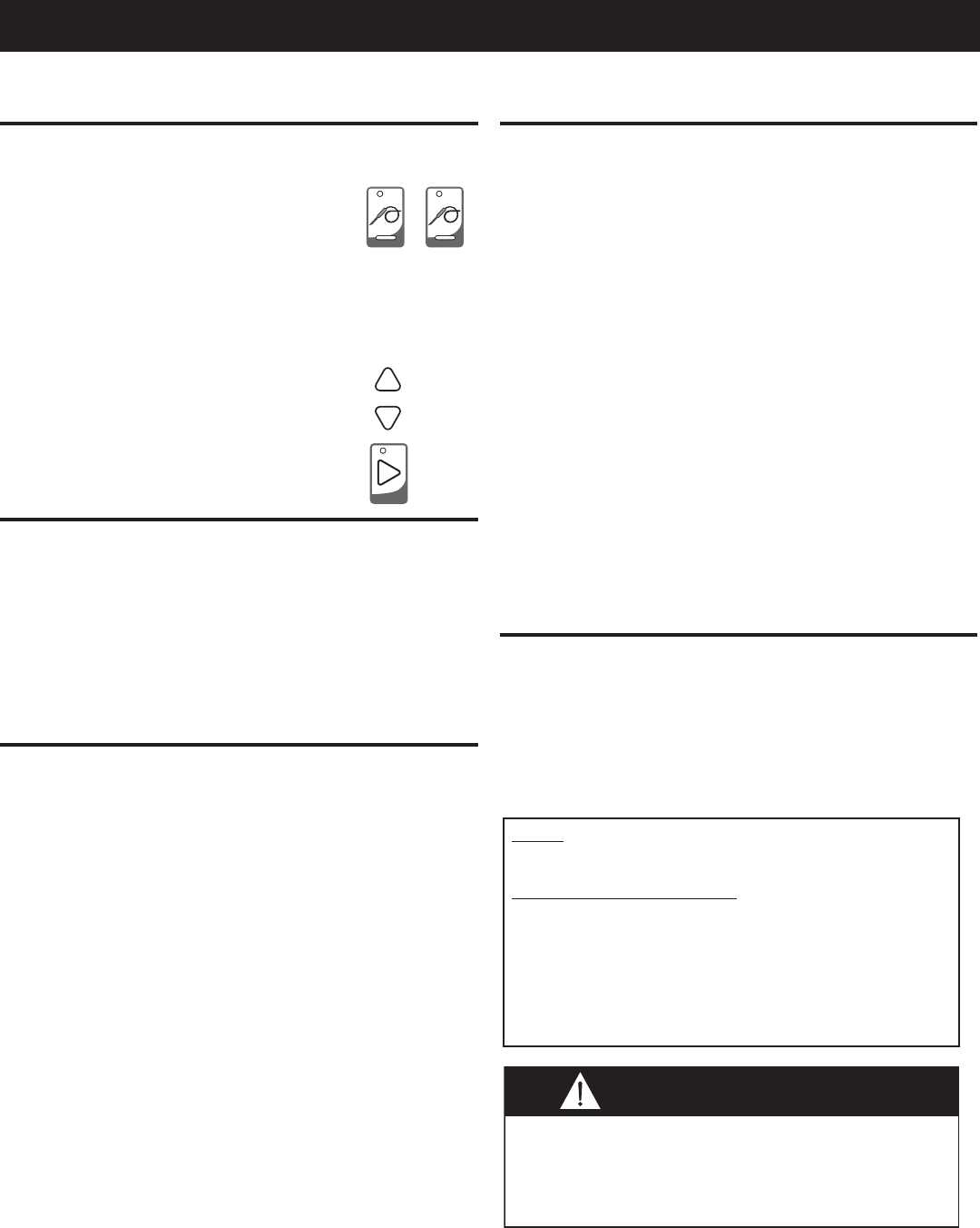
Arrow Keys:
Cook, Hold and Probe Temperature, and the Time
setting can be adjusted by pressing the Arrow keys.
Pressing and releasing the Arrow key will change
settings in increments of one. To change a setting
more rapidly, press and hold the Arrow key. Once
the setting reaches a number divisible by 10, it will
begin to increase in increments of 10.
Green and Amber Indicators:
Each program key includes a green
light which indicates a requirement
for additional programming by the
operator or the current operational
state of the oven.
The cook, tiMe, prob e, and hold keys include an
amber indicator light to identify the information
being displayed.
Power Fail Detect:
If the power were to fail for any reason while
heating, the control will retain, in memory, the
programmed operating conditions. When power
is restored, the control will resume operating from
the point where it was interrupted and the ON/Off
indicator light will flash, indicating that such an
event did occur. The operator can acknowledge the
power failure by pressing the ON/Off key. Pressing
the key will display the amount of time that the
power has been off. The control will stop counting
the amount of time the power has been off when it
has been off for more than 24 hours.
NOTE: If such an event has occurred, it is strongly
recommended that you ensure the food is safe for
consumption according to local health regulations.
To set date and time:
All oven cavities must be turned OFF.
To set Time (HH:mm) - press and hold “A” Key for
three seconds. Press UP/Down Arrow Key to set
Time.
To set Year - press and hold “B” Key for three
seconds. Press UP/Down Arrow Key to set Year.
To set month and day (MM.dd) = press “C” Key for
three seconds. Press UP/Down Arrow Key to set
Month and Day.
Amber
Green
MN-29758 (Rev. 6) 05/15 • TH/III-SK/III Series Cook, Hold, Smoke • 19
To Enable Probe Hold
(optional when cooking by Probe)
• Press the Probe key to see the probe
cooking temperature.
• Press the Probe key again to toggle to
the probe hold temperature.
Note: The yellow LEDs below the Probe
and Hold keys will alternate,
signaling the Probe Hold mode.
• Press the Up/Down Arrow keys to set
desired probe holding temperature.
• Press Start key to begin cooking cycle.
Display High/Low Probe Temperatures:
To observe the recorded maximum or minimum
probe temperature when cooking by probe, press
the following keys while the probe remains in the
product:
Highest Temperature: Press probe Key and up
arrow Key at same time.
Lowest Temperature: Press probe Key and down
arrow Key at same time.
Probe Calibration:
1. To verify product probe calibration, place the
probe in a glass of ice water.
2. After allowing the temperature to settle, press the
probe key for five (5) seconds. Compare reading
against 32°F (0°C).
3. If calibration is required, the unit must be in the
power up hold mode. From the off state turn
the unit on. The unit will begin to operate in
the power up hold mode, press the probe key for
eight (8) seconds until the unit beeps twice and a
temperature is displayed. Adjust the probe offset
temperature by pressing the up or down arrows to
increase or decrease the temperature. Repeat step
2 to verify.
4. Repeat steps 1 and 2 to verify the probe calibration
as necessary.
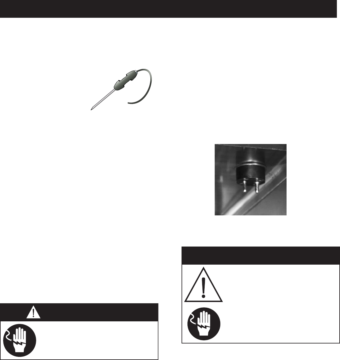
Probe Usage:
When the oven probe remains inserted in the probe
bracket, the LED temperature display will indicate
the ambient air temperature inside the oven. To use
the probe for cooking remove it from the bracket
and wipe the full length of the metal probe with a
disposable alcohol pad to clean and sanitize before
using.
Only the tip of the probe senses the internal
product temperature; therefore, it is important the
tip be placed correctly in the product for internal
temperature accuracy. Push the probe tip halfway
into the product, positioning the tip at the center of
the food mass. When inserting the probe into solid
foods such as meat roast or poultry breasts, push the
probe in from a straight downward position or in
from the side to the center position. If placing into a
semi-liquid or liquid product, the probe cable must
be secured to keep the probe positioned properly.
Do not let the probe tip touch the edges, bottom or
side of a container. Tape the probe cable to the lip
or edge of the container.
Sous Vide Cooking:
With the oven in a preheat mode, press and hold the
probe button. After 5 seconds, it will display “SouS”
if in sous-vide mode, or “ rE9” if in a regular probe
mode. If changes are desired, continue holding the
probe button for an addition three seconds which
will toggle the option.
NOTE: When cooking by probe, insert the probe into
the raw product after the oven has been preheated.
WAIT ONE FULL MINUTE to allow the probe
temperature to decrease to the internal temperature
of the product. Press the start button to begin
the cooking process after this probe temperature
adjustment period. A false probe reading of the
internal product temperature will cause the oven to
default to a holding temperature.
To maintain safe temperature levels, cold food
for rethermalization or reheating must never
be added to the oven while hot foods are
being held.

MN-29758 (Rev. 6) 05/15 • TH/III-SK/III Series Cook, Hold, Smoke • 20
Adjust the inside door vents per the individual cooking
procedure selected. Always keep door vents closed
when cooking with the smoking function. Insert drip
pan on the bottom of the oven cavity.
Wood Chips
Soak one full tray of wood chips in water for 5 to 10
minutes. Shake off excess water, and place the
moistened chips in the wood chip tray of the
smoker oven. Replace the container in the oven.
Press and release power switch ON/OFF
Control Key.
Press and set COOK thermostat to required
cooking temperature.
Press and set TIME or PROBE.
Press and set HOLD thermostat to required
holding temperature.
Enable and set PROBE HOLD mode if
desired.
The Oven is automatically programmed to
preheat to the set cooking temperature. The
oven will produce an audible signal when
fully preheated.
Prepare product for cooking.
Load product on shelves.
To Set Smoking Time
Press the SMOKER key.
Press the UP and DOWN ARROW keys to
select the smoke time in minutes.
Press START.
Note: The smoking timer activates the heating
element located within the wood chip
container when in either a cook or hold
mode. The smoke element will not turn
on during preheat or ready modes.
A full wood chip container will produce
smoke for a period of approximately 1
hour, even though the timer can go past
one hour.
Press and release power switch ON/OFF
Control Key.
Press and hold the SMOKER key for a period
of 3 seconds.
To Set Cold Smoke Holding Temperature
The temperature will default to the last
smoke holding temperature set by the user.
The holding temperature range is
14°F to 205°F (-10°C to 96°C).
To increase this default temperature, press
the HOLD Key and press the UP ARROW to
set a higher default temperature.
Temperature (if desired)
Press the PROBE Key
Press the UP and DOWN ARROW keys
to select the verication temperature. The probe
range is 14°F to 195°F (-10°C to 91°C).
This will incorporate the probe into the cold-
smoking process and the control will alarm if the
temperature exceeds the probe set point.
To Set Smoking Time
Press the SMOKER key.
Press the UP and DOWN ARROW keys to
select the smoke time in minutes.
Prepare product for smoking.
Place stainless steel tray filled with ice on
shelf above the smoker tray.
Load product on shelves.
Press START.
Taste preference Minimum Smoking time
Light Smoke Flavor 10 min.
Medium Smoke Flavor 30 min.
Heavy Smoke Flavor 40 min.
Very Heavy Smoke Flavor 60 min.
Extra Heavy Smoke Flavor 80 min.
These instructions are basic operational guidelines only.
For complete instructions, see the HALO HEAT
Guide to Low Temperature Cooking and Holding
provided with the oven.
For maximum product tenderizing and to reduce labor
during peak preparation hours, products can be
cooked and held overnight.
The use of improper materials for the smoking
function could result in damage, hazard, equipment
failure or could reduce the overall life of the oven.
Do not use sawdust for smoking. Do not use wood
chips smaller than thumbnail size.
I
o
MN-29758 (Rev. 6) 05/15 • TH/III-SK/III Series Cook, Hold, Smoke • 21
Preset
PRESET Keys A through H can be locked in order to
prevent storing, altering or erasing a program.
To lock the PRESET keys, press and hold the “I”
Key until the oven beeps. Release the “I” key.
The green indicator on the “I” key will illuminate.
Oven PRESET Keys A through H are now locked.
Note: Only the oven PRESET keys A through H are
affected by this lock-out in order to also allow
the oven to be used with the unprogrammed
Cook, Probe, or Hold modes.
To unlock the PRESET keys, press and hold the
CANCEL Key along with the “I” Key for
two seconds until the “I” key light no longer
illuminates. Release all keys. The oven preset keys
are now unlocked.
With the control in the off mode,
press and hold the UP ARROW Key until the
display shows the current selection. Press
the up or down buttons to toggle between
the two options. After each change the
button must be released. The display must clear
before the procedure can be repeated.
The control panel can be locked at any time in order to
prevent inadvertent or accidental setting changes.
To lock the control panel, press and hold the
up arrow Key and then press the ON/OFF Key.
You will hear a brief beep and the panel lock
indicator will illuminate. Release all keys.
The oven’s control panel is now locked.
Note: The control panel is now fully locked with the
exception of the ON/OFF Key and ARROW keys.
You will be unable to turn the oven control off at
this point.
To unlock the control panel, press and hold the DOWN
ARROW Key and then press the ON/OFF Key. You
will hear three beeps and the panel lock indicator will
extinguish. Release all keys. The panel is now unlocked
and ready for normal use.
With the control in the off mode,
press and hold the DOWN ARROW Key
until the display shows the current control
volume. Press the UP or DOWN ARROW
Key to cycle through the four options
(0 = Off, 1 = Low, 2 = Mid, 3 = High).
A B C D E F G H I
A B C D E F G H I
Preset
Lock
MN-29758 (Rev. 6) 05/15 • TH/III-SK/III Series Cook, Hold, Smoke • 22
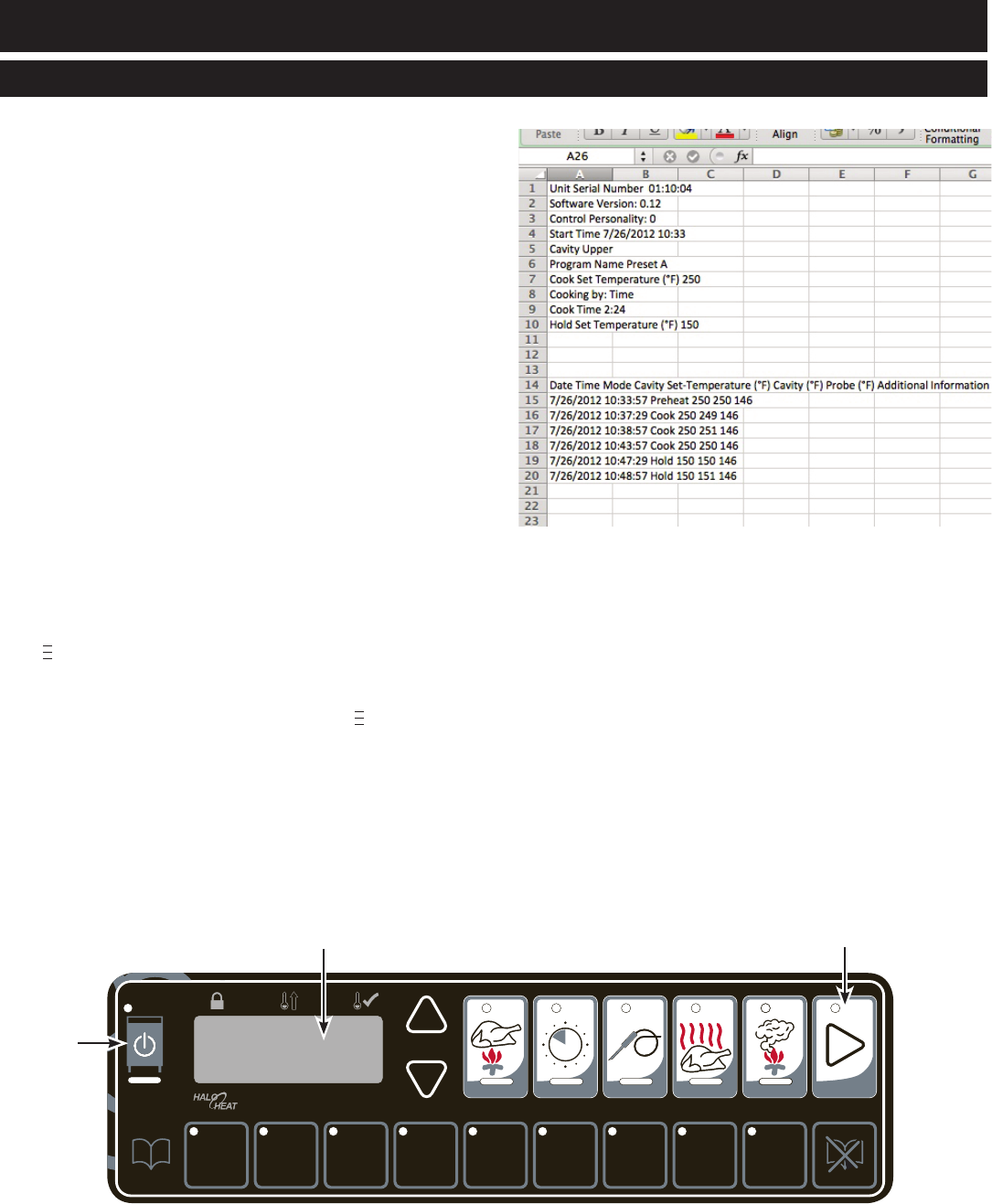
HACCP Documentation, Data Logger - Optional
This oven meets the requirements of established
HACCP criteria by providing automated sampling,
record keeping, set-point validation, recipe used,
dates and time. This data is retained for the last 30
days. This information can be viewed on screen or
downloaded to a USB drive and then copied to your
computer. The file format is a comma-separated
variable (*.csv), that is easily opened using a
spreadsheet package.
To download the data collected:
1. All oven cavities must be turned OFF.
2. It is recommended that a completely empty USB
flash drive is used. Remove the cap of the USB port
located on the right side of the control panel and
insert the USB flash drive. Display will show
“Usb”. If display does not show “Usb”, try again
with another flash drive device or call
Alto-Shaam Service.
3. Press and hold the START Key until display shows
“ XYZ”. The number at the far right is the
percentage of the download completed. The START
Key indicator light will flash while the download
is in process. When display shows “ 100”, the
download is complete.
4. Remove the USB flash drive and replace the cap on
the USB port. When the USB is removed, the oven
will beep for 1-second, acknowledging the removal.
HACCP Data Sample
A B C D E F G H I
A B C D E F G H I
Start Key
ON/OFF
Key
LCD Display
MN-29758 (Rev. 6) 05/15 • TH/III-SK/III Series Cook, Hold, Smoke • 23
Chefs, cooks and other specialized food service
personnel employ varied methods of cooking. Proper
holding temperatures for a specific food product
must be based on the moisture content of the
product, product density, volume, and proper serving
temperatures. Safe holding temperatures must also
be correlated with palatability in determining the
length of holding time for a specific product.
Halo Heat maintains the maximum amount of
product moisture content without the addition of
water, water vapor, or steam. Maintaining maximum
natural product moisture preserves the natural
flavor of the product and provides a more genuine
taste. In addition to product moisture retention, the
gentle properties of Halo Heat maintain a consistent
temperature throughout the cabinet without
the necessity of a heat distribution fan, thereby
preventing further moisture loss due to evaporation
or dehydration.
When product is removed from a high temperature
cooking environment for immediate transfer into
equipment with the lower temperature required
for hot food holding, condensation can form on the
outside of the product and on the inside of plastic
containers used in self-service applications. Allowing
the product to release the initial steam and heat
produced by high temperature cooking can alleviate
this condition. To preserve the safety and quality of
freshly cooked foods, however, a maximum of 1 to 2
minutes must be the only time period allowed for the
initial heat to be released from the product.
Most Halo Heat Holding Equipment is provided with
a thermostat control between 60° and 200°F
(16° to 93°C). If the unit is equipped with vents, close
the vents for moist holding and open the vents for
crisp holding.
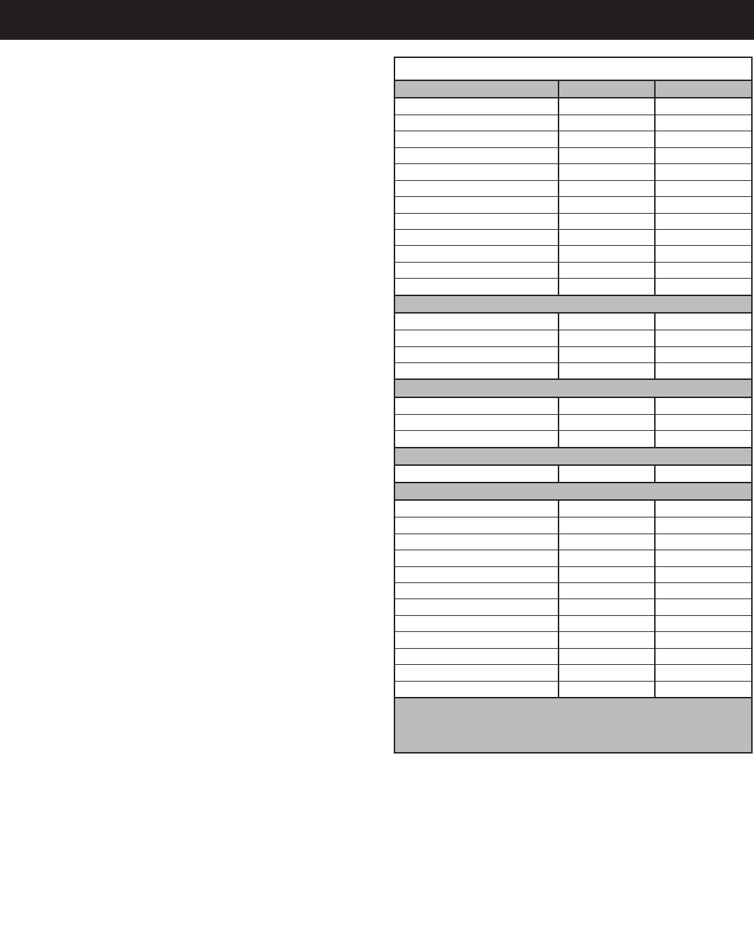
BEEF ROAST — Rare 130°F 54°C
BEEF ROAST — Med/Well Done 155°F 68°C
BEEF BRISKET 160° — 175°F 71° — 79°C
CORN BEEF 160° — 175°F 71° — 79°C
PASTRAMI 160° — 175°F 71° — 79°C
PRIME RIB — Rare 130°F 54°C
STEAKS — Broiled/Fried 140° — 160°F 60° — 71°C
RIBS — Beef or Pork 160°F 71°C
VEAL 160° — 175°F 71° — 79°C
HAM 160° — 175°F 71° — 79°C
PORK 160° — 175°F 71° — 79°C
LAMB 160° — 175°F 71° — 79°C
CHICKEN — Fried/Baked 160° — 175°F 71° — 79°C
DUCK 160° — 175°F 71° — 79°C
TURKEY 160° — 175°F 71° — 79°C
GENERAL 160° — 175°F 71° — 79°C
FISH — Baked/Fried 160° — 175°F 71° — 79°C
LOBSTER 160° — 175°F 71° — 79°C
SHRIMP — Fried 160° — 175°F 71° — 79°C
BREADS/ROLLS 120° — 140°F 49° — 60°C
CASSEROLES 160° — 175°F 71° — 79°C
DOUGH — Proofing 80° — 100°F 27° — 38°C
EGGS —Fried 150° — 160°F 66° — 71°C
FROZEN ENTREES 160° — 175°F 71° — 79°C
HORS D'OEUVRES 160° — 180°F 71° — 82°C
PASTA 160° — 180°F 71° — 82°C
PIZZA 160° — 180°F 71° — 82°C
POTATOES 180°F 82°C
PLATED MEALS 140° — 165°F 60°— 74°C
SAUCES 140° — 200°F 60° — 93°C
SOUP 140° — 200°F 60° — 93°C
VEGETABLES 160° — 175°F 71° — 79°C
THE HOLDING TEMPERATURES LISTED ARE SUGGESTED GUIDELINES ONLY . ALL
FOOD HOLDING SHOULD BE BASED ON INTERNAL PRODUCT TEMPERATURES.
ALWAYS FOLLOW LOCAL HEALTH (HYGIENE) REGULATIONS FOR ALL INTERNAL
TEMPERATURE REQUIREMENTS.
MN-29758 (Rev. 6) 05/15 • TH/III-SK/III Series Cook, Hold, Smoke • 24
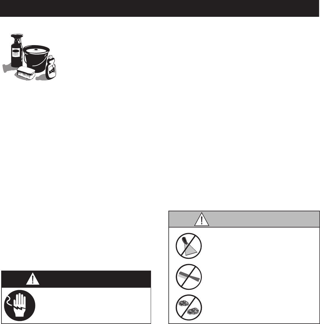
It is important to guard against corrosion
in the care of stainless steel
surfaces. Harsh, corrosive,
or inappropriate chemicals
can completely destroy the
protective surface layer
of stainless steel. Abrasive
pads, steel wool, or metal implements will abrade
surfaces causing damage to this protective coating
and will eventually result in areas of corrosion.
Even water, particularly hard water that contains
high to moderate concentrations of chloride, will
cause oxidation and pitting that result in rust
and corrosion. In addition, many acidic foods
spilled and left to remain on metal surfaces are
contributing factors that will corrode surfaces.
Proper cleaning agents, materials, and
methods are vital to maintaining the appearance
and life of this appliance. Spilled foods should be
removed and the area wiped as soon as possible
but at the very least, a minimum of once a day.
Always thoroughly rinse surfaces after using a
cleaning agent and wipe standing water as quickly
as possible after rinsing.
Use non-abrasive cleaning products designed for
use on stainless steel surfaces. Cleaning agents
must be chloride-free compounds and must not
contain quaternary salts. Never use hydrochloric
acid (muriatic acid) on stainless steel surfaces.
Always use the proper cleaning agent at the
manufacturer's recommended strength.
Contact your local cleaning supplier for
product recommendations.
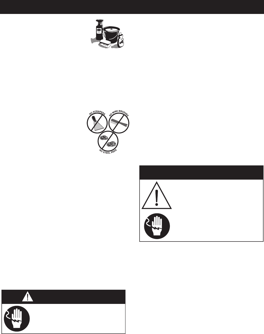
The cleaning function can usually be accomplished
with the proper cleaning agent and a soft, clean
cloth. When more aggressive methods must be
employed, use a non-abrasive scouring pad on
difficult areas and make certain to scrub with the
visible grain of surface metal to avoid surface
scratches. Never use wire brushes, metal scouring
pads, or scrapers to remove food residue.
To protect stainless steel
surfaces, completely avoid
the use of abrasive cleaning
compounds, chloride based
cleaners, or cleaners containing
quaternary salts. Never use
hydrochloric acid (muriatic acid)
on stainless steel. Never use
wire brushes, metal scouring
pads or scrapers.
N
O
W
I
R
E
B
R
U
S
H
E
S
N
O
S
T
E
E
L
P
A
D
S
N
O
S
C
R
A
P
E
R
S
Disconnect unit from power source
before cleaning or servicing. Failure
to observe this precaution can cause
electrical shock and personal injury.
MN-29758 (Rev. 6) 05/15 • TH/III-SK/III Series Cook, Hold, Smoke • 25
Under normal circumstances, this
oven should provide you with long
and trouble free service. There is no
preventative maintenance required,
however, the following Equipment Care Guide
will maximize the potential life and trouble free
operation of this oven.
The cleanliness and appearance of this equipment
will contribute considerably to operating efficiency
and savory, appetizing food. Good equipment that
is kept clean works better and lasts longer.
1. Disconnect unit from power
source, and let cool.
2. Remove all detachable items
such as wire shelves, side
racks, and drip pans. Clean
these items separately.
3. Wipe the interior metal surfaces
of the oven with a paper towel to
remove loose food debris.
4. Clean the interior metal surfaces of the cabinet
with a damp clean cloth or sponge and any good
commercial detergent.
Avoid the use of abrasive cleaning
compounds, chloride based cleaners, or
cleaners containing quaternary salts. Never
use hydrochloric acid (muriatic acid) on
stainless steel.
5. Spray heavily soiled areas with a water soluble
degreaser and let stand for 10 minutes, then
remove soil with a plastic scouring pad.
6. Wipe control panel, door vents, door handles,
and door gaskets thoroughly since these areas
harbor food debris.
7. Rinse surfaces by wiping with sponge and clean
warm water.
8. Remove excess water with sponge and wipe dry
with a clean cloth or air dry. Leave doors open
until interior is completely dry. Replace side
racks and shelves.
9. Wipe door gaskets and control panel dry with a
clean, soft cloth.
10. Interior can be wiped with a sanitizing solution
after cleaning and rinsing. This solution must
be approved for use on stainless steel food
contact surfaces.
11. To help maintain the protective film coating
on polished stainless steel, clean the exterior
of the cabinet with a cleaner recommended
for stainless steel surfaces. Spray the cleaning
agent on a clean cloth and wipe with the grain
of the stainless steel.
12. Clean any glass with a window cleaner.
Always follow appropriate state or local health
(hygiene) regulations regarding all applicable
cleaning and sanitation requirements for equipment.
Disconnect unit from power source
before cleaning or servicing. Failure
to observe this precaution can cause
electrical shock and personal injury.
At no time should the interior or
exterior be steam cleaned, hosed
down, or flooded with water or
liquid solution of any kind. Do not
use water jet to clean.
Severe damage or electrical
hazard could result. Failure to
observe this precaution will void
the warranty.
MN-29758 (Rev. 6) 05/15 • TH/III-SK/III Series Cook, Hold, Smoke • 26
Door vents need to be inspected and cleaned
as required.
Remove all food soil from
probes. Wipe entire probe
and cable assembly with
warm detergent solution
and a clean cloth. Remove
detergent by wiping each
probe and cable with clean
rinse water and a cloth.
Wipe probes, and probe brackets with disposable
alcohol pad or sanitizing solution recommended for
food contact surfaces. Allow probe and cable to air
dry in probe holding bracket.
While the oven is warm, check that the cooling fan
in the oven control area is functioning. The fan is
located at the back of the unit, toward the top.
Check the oven once a month for physical damage
and loose screws. Correct any problems before they
begin to interfere with the operation of the oven.
Refer to the Trouble Shooting Guide located in this
manual or call an authorized service technician.
To ensure accurate internal product temperature
readings the prongs on the removable probe must be
cleaned daily.
1. Remove all food debris from prongs at the end
of each production shift. Wipe the entire prong
casing, and between each prong with a clean
cloth and warm detergent solution.
2. Remove detergent by wiping with a cloth and
clean rinse water.
3. Allow prongs to air dry before replacing
detachable probe.
Disconnect unit from power source
before cleaning or servicing. Failure
to observe this precaution can cause
electrical shock and personal injury.
At no time should the interior or
exterior be steam cleaned, hosed
down, or flooded with water or
liquid solution of any kind. Do not
use water jet to clean.
Severe damage or electrical
hazard could result. Failure to
observe this precaution will void
the warranty.
MN-29758 (Rev. 6) 05/15 • TH/III-SK/III Series Cook, Hold, Smoke • 27
Food fl avor and aroma are usually so closely related
that it is diffi cult, if not impossible, to separate them.
There is also an important, inseparable relationship
between cleanliness and food fl avor. Cleanliness, top
operating effi ciency, and appearance of equipment
contribute considerably to savory, appetizing foods. Good
equipment that is kept clean, works be er and lasts longer.
Most food imparts its own particular aroma and many
foods also absorb existing odors. Unfortunately, during
this absorption there is not distinction between GOOD
and BAD odors. The majority of objectionable fl avors
and odors troubling food service operations are caused by
bacteria growth. Sourness, rancidity, mustiness, stale or
other OFF fl avors are usually the result of germ activity.
The easiest way to insure full, natural food fl avor is
through comprehensive cleanliness. This means good
control of both visible soil (dirt) and invisible soil
(germs). A through approach to sanitation will provide
essential cleanliness. It will assure an a ractive
appearance of equipment, along with maximum effi ciency
and utility. More importantly, a good sanitation program
provides one of the key elements in the prevention of
food-borne illnesses.
A controlled holding environment for prepared foods is
just one of the important factors involved in the prevention
of food-borne illnesses. Temperature monitoring and
control during receiving, storage, preparation, and the
service of foods are of equal importance.
The most accurate method of measuring safe temperatures
of both hot and cold foods is by internal product
temperature. A quality thermometer is an eff ective tool for
this purpose, and should be routinely used on all products
that require holding at a specifi c temperature.
A comprehensive sanitation program should focus on
the training of staff in basic sanitation procedures. This
includes personal hygiene, proper handling of raw foods,
cooking to a safe internal product temperature, and
the routine monitoring of internal temperatures from
receiving through service.
Most food-borne illnesses can be prevented through
proper temperature control and a comprehensive
program of sanitation. Both these factors are important
to build quality service as the foundation of customer
satisfaction. Safe food handling practices to prevent
food-borne illness is of critical importance to the health
and safety of your customers.
HACCP, an acronym for Hazard Analysis (at) Critical
Control Points, is a quality control program of operating
procedures to assure food integrity, quality, and safety.
Taking steps necessary to augment food safety practices
is both cost eff ective and relatively simple. While HACCP
guidelines go far beyond the scope of this manual,
additional information is available by contacting:
CENTER FOR FOOD SAFETY AND APPLIED
NUTRITION FOOD AND DRUG ADMINISTRATION
1-888-SAFEFOOD
HOT FOODS
DANGER ZONE 40° TO 140°F (4° TO 60°C)
CRITICAL ZONE 70° TO 120°F (21° TO 49°C)
SAFE ZONE 140° TO 165°F (60° TO 74°C)
COLD FOODS
DANGER ZONE ABOVE 40°F (ABOVE 4°C)
SAFE ZONE 36° TO 40°F (2° TO 4°C)
FROZEN FOODS
DANGER ZONE ABOVE 32°F (ABOVE 0°C)
CRITICAL ZONE 0° TO 32°F (-18° TO 0°C)
SAFE ZONE 0°F or below (-18°C or below)

MN-29758 (Rev. 6) 05/15 • TH/III-SK/III Series Cook, Hold, Smoke • 28
Code Description
Cavity air sensor shorted Cavity air sensor reading < 5°F (-15°C). Verify sensor integrity.
See sensor test instructions below.
Cavity air sensor open Cavity air sensor reading > 517°F (269°C). Verify sensor integrity.
See sensor test instructions below.
Oven will cook in time only
Product probe reading < 5°F (-15°C). Verify sensor integrity.
See sensor test instructions below.
Oven will cook in time only
Product Probe reading > 517°F (269°C). Verify sensor integrity.
See sensor test instructions below.
Under temperature Unit has not reached (set-point - 25°F (4°C)) for more than 90 minutes.
Over temperature
Unit has been higher than 60°F (16°C) above the maximum cavity set-point
for more than 3 minutes. Note: Holding Cabinets with this error code are
more than 145°F (63°C) higher than the maximum set-point.
Safety switch open
Contact factory.
Internal software error Contact factory.
Sensor error Contact factory.
Temp. measurement error Contact factory.
Temp. measurement error Contact factory.
Data set to factory default. Ensure that date and time are correct if applicable.
Contact factory.
Clock is not oscillating Contact factory.
Configuration connector
Refer to wiring diagram for the particular model and ensure dip switches on
the control match the settings called out on the WD. If the dip switch settings
are correct according to the print replace the control.
Voltage below 90 VAC on a 125 VAC unit, or below 190 VAC on a
208-240 VAC unit. Correct voltage.
Voltage over 135 VAC on a 125 VAC unit, or over 250 VAC on a
208-240 VAC unit. Correct voltage.
Ensure that all temperatures and times are properly set.
Contact factory if problem persists.
Contact factory.
Contact factory.
Contact factory.
All timers, if previously on, are now off. Possible bad EEPROM.
Stored HACCP memory corrupted. HACCP Address reset to 1. Possible bad
EEPROM. Contact factory if problem persists.
Stored offsets corrupted. Offsets reset to 0. Control may need a recalibration.
Possible bad EEPROM. Contact factory if problem persists.
All timer set-points are reset to 1 minute. Timers, if previously on, are now
off. Possible bad EEPROM.
Button stuck A button has been held down for > 60 seconds. Adjust control. Error will
reset when the problem has been resolved.
Input failure Contact factory.
Datakey error Datakey digital signature incompatible. Cycle power, and install compatible
Datakey if error persists.
Datakey error Datakey incompatible with control. Install compatible Datakey.
Datakey unplugged Install Datakey and cycle power to control to clear error.
Datalogger has timed out Cycle power. Contact factory if error persists.
Micro SD card not plugged in Plug in SD card and cycle power. Contact factory if error persists.
Note: If in doubt, always cycle the power to the control and contact factory if the problem persists.
Tes t probe and air sensor by placing sensor in ice water bath and using an ohmmeter set on the ohm scale. The
reading should be 100 ohms resistance. If it is more than 2 ohms higher or lower, sensor needs to be replaced.
MN-29758 (Rev. 6) 05/15 • TH/III-SK/III Series Cook, Hold, Smoke • 29
Disconnect unit from power source
before cleaning or servicing. Failure
to observe this precaution can cause
electrical shock and personal injury.
If the appliance has been unplugged for an
extended period of time, the Real Time Clock
may require recharging. Turn main breaker to the
unit off for 10 seconds and then restore power.
For more information, see Error Code E-60 in the
Troubleshooting section of this manual.
This section is provided for the assistance
of qualified and trained service technicians
only and is not intended for use by untrained
or unauthorized service personnel. Failure to
observe this precaution may void the warranty.
1. Verify that power is available at the outlet or junction box.
2. Verify that the circuit breaker switch on the back of the unit is turned on.
3. Verify that the power cord is not open. Check continuity with a VOM meter.
4. If the problem persists, call a qualified Alto-Shaam service technician at 1-800-558-8744.
Check to verify that the high limit switch located at the rear of the unit top has not been
tripped. If it has been tripped, reset by pressing in the hi-limit reset button at the rear
of the oven.
After resetting, the cause of the high limit trip must be corrected. If the high limit switch
will not reset, the high limit switch is defective and must be replaced. This is a safety
device and must not be bypassed or removed from the circuit.
C. To test air sensor:
Test air sensor by placing sensor in ice water bath and using an ohmmeter set on the ohm scale.
The reading should be 100 ohms resistance. If it is more than 2 ohms higher or lower, sensor
needs to be replaced.
Test food probe by placing in ice water bath and using an ohmmeter set on the ohm scale.
The reading should be 100 ohms resistance.
Lock-out or post breaker panel
until service work until service
work has been completed.
This section is provided for the assistance of qualified technicians only and is not intended for use by untrained
or unauthorized service personnel. If your Alto-Shaam® unit is not operating properly, check the following before
calling your Authorized Alto-Shaam Service Agent:
☛ Check main power circuit breaker to the unit and verify that the circuit breaker on the back of the unit is turned
on, if applicable.
Do not attempt to repair or service the unit beyond this point. Contact Alto-Shaam for the nearest authorized
service agent. Repairs made by any other service agents without prior authorization by Alto-Shaam® will
void the warranty on the unit.
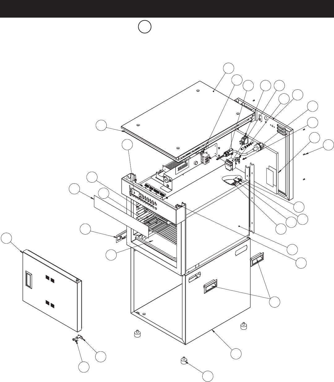
MN-29758 (Rev. 6) 05/15 • TH/III-SK/III Series Cook, Hold, Smoke • 30
- 300-TH/III
11
7
10
6
8
1
29
16
25
18
23
21
22
20
19
26
15
9
5
4
3
2
28
13
14
12
17
24
27
18
Part numbers and drawings are subject to change without notice.

MN-29758 (Rev. 6) 05/15 • TH/III-SK/III Series Cook, Hold, Smoke • 31
1BONNET TOP COVER 1012831 1
2FAN BOX, 120V FA-3973 1
FAN BOX, 230V FA-34524 1
3BUSHING, STRAIGHT, STRAIN RELIEF, 230V BU-34898 1
BUSHING, STRAIGHT, STRAIN RELIEF, 120V BU-3964 1
4SWITCH, ROCKER, 125-277V, 20A SW-34769 1
5HI-LIMIT THERMOSTAT TT-33476 1
6HI-LIMIT PROTECTION COVER 1003936 1
7REAR TRIM 5014525 1
8CORDSET, 230V CD-3922 1
CORDSET, 120V CD-3232 1
9SCREWS, M4-0.7 X 6mm PHIL SC-22271 2
10 INSULATION IN-2003 1
11 RIVET, BLIND, #44, S/S RI-2100 16
12 GUARD SENSOR 1493 1
13 SCREW, 6-32 X 1/2, NC PHIL, FLAT SC-2254 2
14 BLOCK, SENSOR BK-29605 1
15 SENSOR SN-33541 1
16 INSULATION IN-22364 1
17 PRODUCT PROBE 15892R 1
18 HANDLE, PULL, RECESSED HD-28789 4
19 OUTER CASING SPOT 5014538 1
20 FEET, 3-1/2” (89mm) RIGID FE-29203 4
21 HINGE PLATE, BOTTOM right 1012999 1
left*1014661 1
22 SCREW, M6 X 1.0 X 10 PAN SC-27078 2
23 DOOR ASSEMBLY 5014458 1
DOOR GASKET GS-35092 1
24 DRIP PAN PN-2122 1
25 PANEL, OVERLAY PE-35086 1
26 SHELF, WIRE SH-2107 2
27 SIDE RACK 1012872 2
28 CONTROL CC-34194 1
29 GASKET, ADHESIVE,.125X.375 [lin ft] GS-23622 1
30* PROBE WIRE HOLDER 13239 1
31* NUT, THREADED INSERT, M6 NU-22770 1
32* NUT, 8-32 UNC FEPS ZP NU-26526 4
33* SCREW, 8-32 X 2 SLOT PAN HEAD 18-8 S/S SC-23154 2
34* SCREW, HHCS M6 X 20, W/NO MARKING SC-22924 1
35* SCREW, 8-32 X 1/4" TRH PHH SC-2459 12
36* FOIL PAD HEATER, 230V EL-29740 1
FOIL PAD HEATER, 120V EL-35173 1
* not Shown
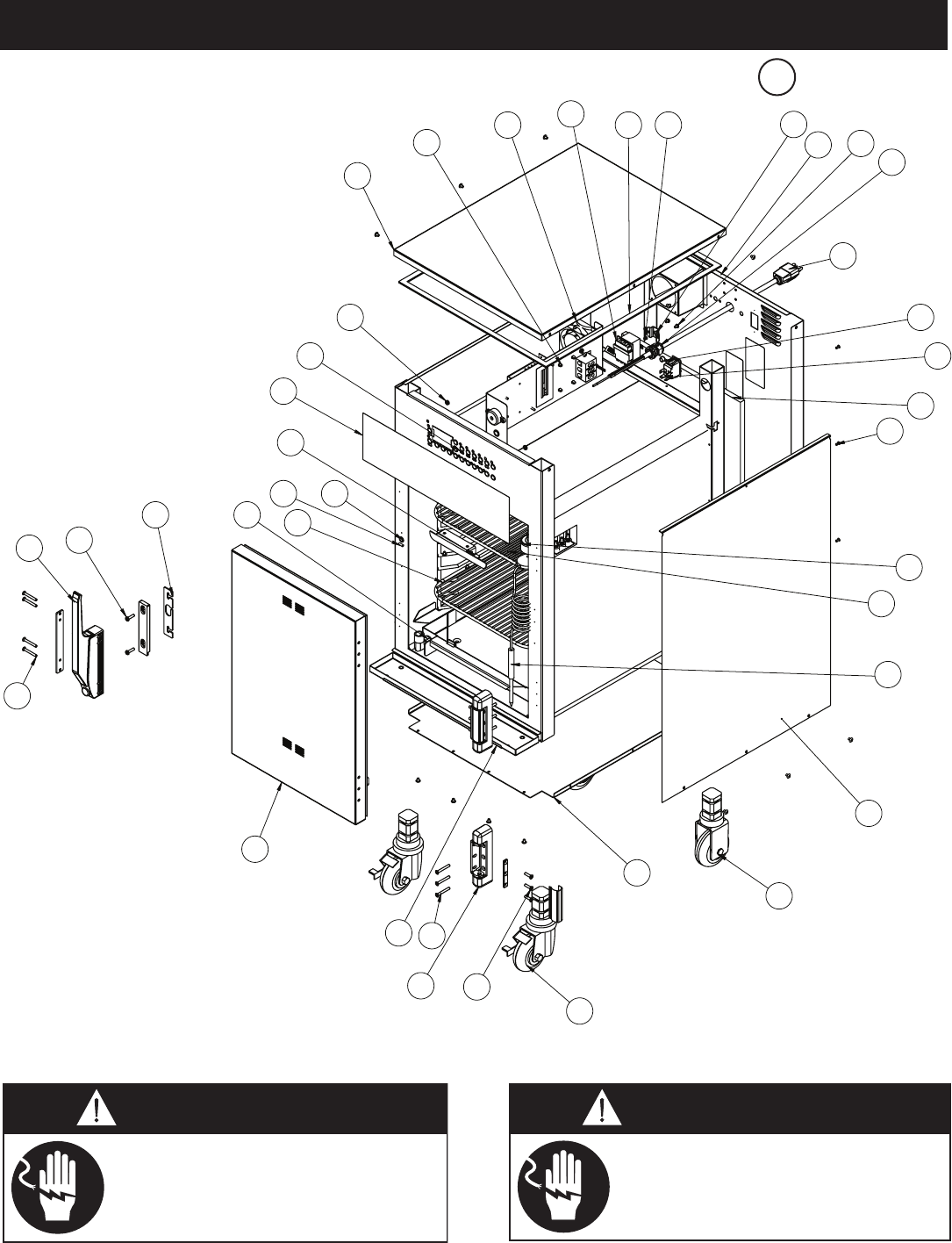
MN-29758 (Rev. 6) 05/15 • TH/III-SK/III Series Cook, Hold, Smoke • 32
35
34
36
37
1
23 4
56
7
9
10
11
12
13
14
15
17A
18
19
17B
22
20
27
23
25
21
26
24
28
29
31
30
32
33
16
8
21
500-TH/III Shown
Part numbers and drawings are subject to change without notice.
Disconnect unit from power source
before cleaning or servicing. Failure
to observe this precaution can cause
electrical shock and personal injury.
Lock-out or post breaker panel
until service work until service
work has been completed.
B

MN-29758 (Rev. 6) 05/15 • TH/III-SK/III Series Cook, Hold, Smoke • 33
500-TH/III 750-TH/III 1000-TH/III
1THERMOSTAT, HI LIMIT TT-33476 1 TT-33476 1 TT-33476 1
2GASKET ADHESIVE 0.125 X 0.375 [LIN FT] GS-23622 1 GS-23622 1 GS-23622 1
3 PLUG, DOME, .187" HOLE PG-28439 4 PG-28439 4 PG-28439 4
4HIGH LIMIT PROTECTION COVER 1003936 1 1003936 1 1003936 1
5REAR TRIM, SPOT 5014004 1 5014081 1 5014172 1
6SCREW, M4-0.7 X 6mm PHIL SC-22271 2 SC-22271 2 SC-22271 2
7BUSHING, STRAIN RELIEF BU-3964 1 BU-3964 1 BU-3964 1
8CORDSET 120V CD-3397 1 CD-3397 1 — —
208-240V CD-3607 1 CD-3607 1 CD-3607 1
230V (CEE 7/7) CD-3922 1 CD-3922 1 CD-3922 1
230V (CH2-16P) CD-36231 1 CD-36231 1 CD-36231 1
230V (BS 1363) CD-33925 1 CD-33925 1 CD-33925 1
9 PLUG, 3/8" HOLE PG-25574 1 PG-25574 1 PG-25574 1
10 SWITCH,ROCKER, 125-277V, 20A SW-34769 1 SW-34769 1 SW-34769 1
11 INSULATION IN-2003 1 IN-2003 1 IN-2003 1
12 RIVET, BLIND, #44 STAINLESS RI-2100 6 RI-2100 6 RI-2100 6
13 PROBE RECEPTACLE PR-34705 1 PR-34705 1 PR-34705 1
14 SHELF, STAINLESS STEEL SH-2326 2 SH-2324 3 SH-2325 3
15 PROBE, PRODUCT PR-36065 1 PR-36065 1 PR-36065 1
PROBE, PRODUCT (UK 230V ONLY) — — — — PR-34298 1
16 PANEL, SIDE 5015081 2 5015083 2 5015088 2
17 CASTER PACKAGE 5014422 1 5014422 1 5014422 1
17A - CASTER, 3-1/2" (89mm) RIGID CS-25674 2 CS-25674 2 CS-25674 2
17B - CASTER, 3-1/2" (89mm) SWIVEL W/ BRAKE CS-25675 2 CS-25675 2 CS-25675 2
17C* - SHIM 1012735 4 1012735 4 1012735 4
18 BOTTOM PANEL 1010774 1 1010394 1 1009941 1
19 SCREW, 10-32 X 3/4", NF PHIL SC-2072 6 SC-2072 6 SC-2072 6
20 HINGE HG-22338 1 HG-22338 1 HG-22338 1
21 SCREW,10-32 X 1-1/2", NF, PHIL SC-2073 10 SC-2073 10 SC-2073 10
22 DRIP TRAY KIT 5010736 1 5010391 1 5009716 1
- DRIP TRAY HOLDER 1010782 1 1010584 1 1010188 1
- DRIP TRAY 1010783 1 1010585 1 1010189 1
23 DOOR ASSEMBLY, SLAB, RH 5010828 1 5010946 1 5010081 1
*DOOR ASSEMBLY, WINDOW, RH 5010830 1 5010948 1 5010082 1
*DOOR ASSEMBLY, SLAB, LH 5010824 1 5010947 1 5010071 1
*DOOR ASSEMBLY, WINDOW, LH 5010829 1 5010949 1 5010076 1
*DOOR GASKET GS-22950 1 GS-22951 1 GS-22952 1
24 HANDLE, OFFSET MAG. LATCH HD-27080 1 HD-27080 1 HD-27080 1
25 SCREW, 3/4" PAN HD SC-2071 2 SC-2071 2 SC-2071 2
26 SHIM, HANDLE 13947 1 13947 1 13947 1
27 DRIP PAN WELD 14813 1 14831 1 5005616 1
28 SIDE RACK, CHROME SR-28403 2 SR-28405 2 SR-2266 2
PAN SLIDES, 230V ONLY 1010880 2 1010813 2 — —
29 REED SWITCH, DOOR (qty per door)SW-33559 1 SW-33559 1 SW-33559 1
30 BUSHING, 3/8" BLACK HOLE BU-3419 1 BU-3419 1 BU-3419 1
31 PROBE WIRE HOLDER 13239 1 13239 1 13239 1
32 PANEL OVERLAY PE-26710 1 PE-26839 1 PE-26713 1
33 CONTROL CC-34194 1 CC-34194 1 CC-34194 1
34 NUT, #8-32 UNC KEPS ZP NU-26526 4 NU-26526 4 NU-26526 4
35 TOP COVER 1011946 1 1011872 1 1011534 1
36 SCREW, 8-32 X 2 SLOT PAN HEAD 18-8 S.S. SC-23154 2 SC-23154 2 SC-23154 2
37 FAN, BOX - 120V ONLY FA-3973 1 FA-3973 1 FA-3973 1
FAN, BOX FA-34524 1 FA-34524 1 FA-34524 1
38* SENSOR GUARD 1493 1 1493 1 1493 1
39* PROBE COVER 5009712 1 5009712 1 5009712 1
40* SENSOR MOUNTING BLOCK BK-29605 1 BK-29605 1 BK-29605 1
41* SCREW, 6-32 X 1/2", NC PHIL, FLAT SC-2254 2 SC-2254 2 SC-2254 2
42* SCREW, 8-32 X 1/4" PHIL SC-2459 18 SC-2459 20 SC-2459 26
43* SCREW, 8-32 X 1/2” PHIL, S/S SC-2425 6 SC-2425 6 SC-2425 6
44* SENSOR, OVEN TEMPERATURE SN-33541 1 SN-33541 1 SN-33541 1
46* WASHER, FLAT, M6 DIN 125 WS-22297 2 WS-22297 2 WS-22297 2
47* WASHER, M6 SPLIT LOCK S/S 18-8 WS-22302 2 WS-22302 2 WS-22302 2
* not Shown
B
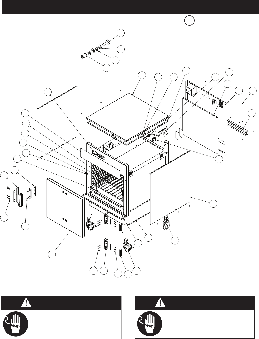
MN-29758 (Rev. 6) 05/15 • TH/III-SK/III Series Cook, Hold, Smoke • 34
Lock-out or post breaker panel
until service work until service
work has been completed.
Disconnect unit from power source
before cleaning or servicing. Failure
to observe this precaution can cause
electrical shock and personal injury.
A
8
7
9
1
4
12
11
30
29
28
27
24
15
14
13A
13B
18
17
19
20
23
22
21
19
5
6
23
26
25
10
A
32
33
34
35
16
767-SK/III 230V Shown
Part numbers and drawings are subject to change without notice.
** Shown with electrical chassis prior to 5/1/13
C

MN-29758 (Rev. 6) 05/15 • TH/III-SK/III Series Cook, Hold, Smoke • 35
*not Shown
767-SK/III 1000-SK/III
1TOP COVER 1011872 1 1011534 1
2THERMOSTAT, HI-LIMIT TT-33476 1 TT-33476 1
3HI-LIMIT PROTECTION COVER 1003936 1 1003936 1
4GASKETS, ADHESIVE, 0.125X 0.375 [linear ft] GS-23622 1 GS-23622 1
5BUSHING, STRAIGHT, STRAIN RELIEF BU-3964 1 BU-3964 1
6CORDSET 208-240V CD-3607 1 CD-3607 1
230V (CEE 7/7) CD-3922 1 CD-3922 1
230V (CH2-16P) CD-36231 1 CD-36231 1
230V (BS 1363) CD-33925 1 CD-33925 1
7 INSULATION IN-2003 1 IN-2003 1
8REAR TRIM, SPOT 5014137 1 5014204 1
9RIVET, BLIND, #44, STAINLES STEEL RI-2100 6 RI-2100 6
10 ELEMENT COVER 1010409 1 1011813 1
11 SWITCH, ROCKER, 20A SW-34769 1 SW-34769 1
12 SIDE PANEL 5015083 2 5015088 2
13 CASTER PACKAGE 5014422 1 5014422 1
13A - CASTER, 1.5" STEM, RIGID 5" (127mm) CS-24874 2 CS-24874 2
13B - CASTER, 1.5" STEM, 5" (127mm) SWIVEL W/ BRAKE CS-24875 2 CS-24875 2
13C* - SHIM 1012735 4 1012735 4
14 BOTTOM PANEL 1010394 1 1009941 1
15 DRIP TRAY KIT 5010391 15009716 1
— DRIP TRAY 1010584 11010188 1
— DRIP TRAY HOLDER 1010585 11010189 1
16 HINGE COVER CV-22171 2 CV-22171 2
17 SCREW, M5 X 0.8 X 20mm FLAT SC-23868 6 SC-23868 6
18 HINGE, 1-3/8" OFFSET, PAIR, CHROME HG-22338 1 HG-22338 1
19 SCREW, MS X 0.8 X 30mm FLAT SC-22853 10 SC-22853 10
20 DOOR ASSEMBLY, RH 5011828 1 5012859 1
*DOOR ASSEMBLY, LH 5011829 1 5012861 1
*DOOR GASKET GS-22951 1 GS-22952 1
21 SCREW, M5 X 0.8 X 20mm PAN SC-22779 2 SC-22779 2
22 HANDLE, OFFSET MAGNETIC LATCH HD-27080 1 HD-27080 1
23 SHIM, HANDLE 13947 1 13947 1
24 DRIP PAN WELD 14831 1 5005616 1
25 REED SWITCH, DOOR SW-33559 1 SW-33559 1
26 BUSHING, 3/8" BLACK HOLE BU-3419 1 BU-3419 1
27 SHELF, WIRE S/S SH-2324 2 SH-2325 2
*SHELF, RIB RACK SH-2743 2 SH-29474 1
28 SIDE RACKS SR-28405 2 SR-2266 2
PAN SLIDES (230V ONLY) 1010813 2 — —
29 PANEL OVERLAY PE-27178 1 PE-29385 1
30 CONTROL CC-34194 1 CC-34194 1
31 SCREW, HHCS, M6 X 20mm SC-22924 1 SC-22924 1
32 WASHER, FLAT, M6, DIN 125 WS-22297 2 WS-22297 2
33 WASHER, M6 SPLIT LOCK S/S 18-8 WS-22302 2 WS-22302 2
34 NUT, #8-32 UNC KEPS ZP NU-26526 4 NU-26526 4
35* SENSOR BLOCK, TERMINAL, PORCELAIN BK-33546 1 BK-33546 1
36* SENSOR MOUNTING BLOCK BK-24427 1 BK-24427 1
37* BRACKET, CHIP TRAY BT-29217 1 BT-29217 1
38* BUSHING, 5/8" SNAP, BLACK BU-3611 2 BU-3611 2
39* CHIP TRAY WELD 4652R 1 4652R 1
40* SMOKE ELEMENT - 208-240V, 230V EL-35022 1 EL-35022 1
SMOKE ELEMENT - 120V EL-35023 1 EL-35023 1
41* FAN, BOX, 120V FA-3973 1 FA-3973 1
FAN BOX FA-34524 1 FA-34524 1
NUT, THREADED INSERT, M6 NU-22770 1 NU-22770 1
42* NUT, 1/4-20 HEX S/S NU-2437 2 NU-2437 2
43* PLUG, DOME, .187" HOLE PG-28439 4 PG-28439 4
44* PROBE ASSEMBLY, PRODUCT PR-36065 1 PR-36065 1
45* PROBE COVER 5009712 1 5009712 1
46* PROBE WIRE HOLDER 13239 1 13239 1
47* PROBE RECEPTICAL, PRODUCT PR-34705 1 PR-34705 1
48* SCREW, 6-32 X 1/2, NC PHIL, FLAT SC-2239 2 SC-2239 2
49* SCREW, M4-0.7 X 6mm PHIL SC-22271 2 SC-22271 2
50* SCREW, M3 X 0.5 X 16mm PAN SC-22270 6 SC-22270 6
51* SCREW, 8-32 X 2 SLOT PAN HEAD 18-8 S/S SC-23154 2 SC-23154 2
52* SENSOR, CAVITY SN-33541 1 SN-33541 1
53* SENSOR GUARD 1493 1 1493 1
54* SMOKE HEATER PLATE WELD 5003782 15003782 1
C
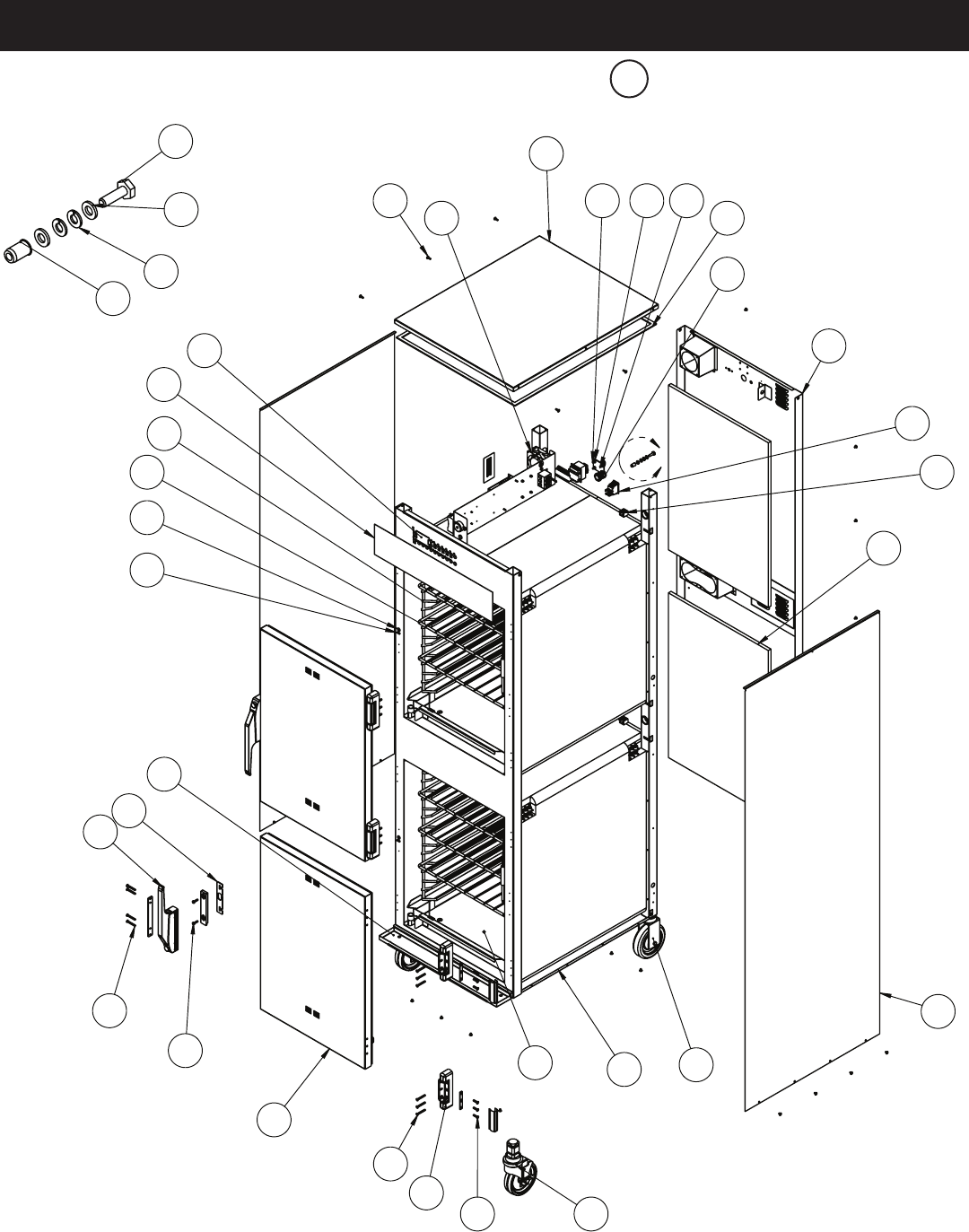
MN-29758 (Rev. 6) 05/15 • TH/III-SK/III Series Cook, Hold, Smoke • 36
- 1200-TH/III
A
7
10
1
5
11
8
28
27
24
26
25
22
12B
12A
16
15
17
18
21
20
19
17
9
13
432
23
30
29
6
A
31
32
33
34
14
Part numbers and drawings are subject to change without notice.
** Shown with electrical chassis prior to 5/1/13
D
MN-29758 (Rev. 6) 05/15 • TH/III-SK/III Series Cook, Hold, Smoke • 37
- 1200-TH/III
* not Shown
Disconnect unit from power source
before cleaning or servicing. Failure
to observe this precaution can cause
electrical shock and personal injury.
Lock-out or post breaker panel
until service work until service
work has been completed.
1TOP COVER 1011534 1 - DRIP TRAY 1010189 1
2SCREW, 10-32 X 1/2, NF PHIL, FLAT SC-23670 4 23 SWITCH, REED (qty per door)SW-33559 1
3 NUT, 10-32 UNF HEX MS, 18-8 SST NU-2215 4 24 BUSHING, 3/8" BLACK HOLE BU-3419 1
4BRACKET, TETHER BT-26884 1 25 SHELF, STAINLESS STEEL SH-2325 6
5GASKET ADHESIVE 0.125 X 0.375 GS-23622 1 26 SIDE RACK, CHROME SR-2266 4
6BUSHING, STRAIN RELIEF BU-3964 1 27 PANEL OVERLAY PE-26714 1
7REAR TRIM, SPOT 5014268 1 28 CONTROL CC-34194 1
8SWITCH, ROCKER,125-277V, 20A SW-34769 1 29 SCREW, 8-32 X 1/2" PHIL SCREW SC-2425 6
9SENSOR MOUNTING BLOCK BK-29605 1 30 FAN, BOX FA-34524 2
10 INSULATION IN-2003 2 31 SCREW, HHCS, M6 X 20 SC-22924 1
11 PANEL, SIDE 5015105 2 32 WASHER, FLAT, M6 DIN 125 WS-22297 2
12 CASter pACKAge 5014421 1 33 WASHER, M6 SPLIT LOCK S/S 18-8 WS-22302 2
12A - CASTER, 3-1/2" (89mm) rigid CS-24874 2 34 NUT, THREADED INSERT NU-22770 1
12B - CASTER, 3-1/2" (89mm) Swivel w/ brAKe CS-24875 2 35* SENSOR GUARD 1493 1
12C* - SHIM 1012735 4 36* PROBE WIRE HOLDER 13239 1
13 BOTTOM PANEL 1009941 1 37* HIGH LIMIT PROTECTION COVER 1003936 1
14 DRIP PAN WELD 5005616 2 38* PROBE COVER 5009712 1
15 SCREW,10-32 X 3/4", NF PHIL SC-2072 12 39* TERMINAL BLOCK BK-33546 2
16 HINGE HG-22338 2 40* BUSHING, 1-1/8" SNAP BUSHING BU-3378 8
HINGE COVER CV-22171 4 41* NUT, #8-32 UNC KEPS ZP NU-26526 4
17 SCREW,10-32 X 1-1/2", NF, PHIL SC-2073 20 42* PROBE, PRODUCT PR-36065 1
18 DOOR ASSEMBLY, RH 5010081 2 PROBE, PRODUCT (UK 230V ONLY) PR-34298 1
*DOOR ASSEMBLY, WIDOW, RH 5010082 2 43* PROBE RECEPTACLE, 2200mm WIRE PR-34704 1
*DOOR ASSEMBLY, LH 5010071 2 44* PROBE RECEPTACLE, 600mm WIRE PR-34705 1
*DOOR ASSEMBLY, WINDOW, LH 5010076 2 45* SCREW, M4-0.7 X 6mm PHIL SC-22271 4
*DOOR GASKET GS-22952 2 46* SCREW, 6-32 X 1/2", NC PHIL, FLAT SC-2254 4
19 SCREW, 3/4" PAN HD SC-2071 4 47* 8-32 X 2 SLOT PAN HEAD 18-8 S.S. SC-23154 4
20 HANDLE, OFFSET MAG. LATCH HD-27080 2 48* SCREW, 8-32 X 1/4" PHIL SC-2459 22
21 SHIM, HANDLE 13947 1 49* SENSOR, OVEN TEMPERATURE SN-33541 2
22 DRIP TRAY KIT 5009716 1 50* THERMOSTAT, HI LIMIT TT-33476 2
- DRIP TRAY HOLDER 1010188 1
D
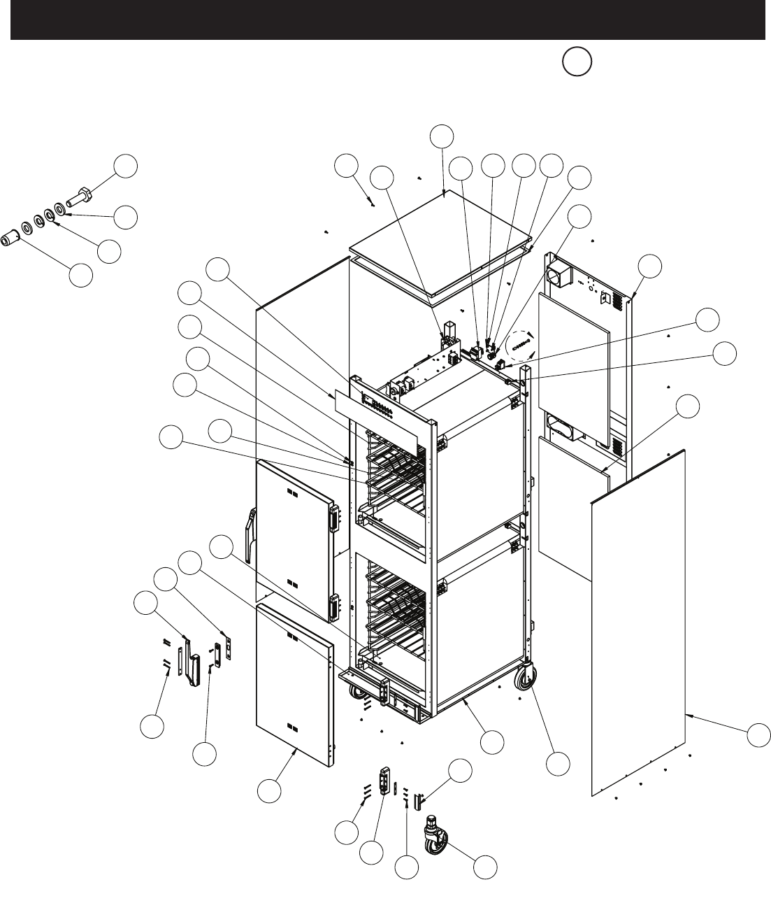
MN-29758 (Rev. 6) 05/15 • TH/III-SK/III Series Cook, Hold, Smoke • 38
A
8
11
1
6
12
9
31
30
28
29
25
23
14
13A
17
16
18
19
22
21
20
18
10
13B
543
27
33
32
7
A
34
35
36
37
2
15
24
26
1200-SK/III Shown
Part numbers and drawings are subject to change without notice.
** Shown with electrical chassis prior to 5/1/13

MN-29758 (Rev. 6) 05/15 • TH/III-SK/III Series Cook, Hold, Smoke • 39
*not Shown
1767-SK/III 1200-SK/III
1TOP COVER 1011872 1 1011534 1
2THERMOSTAT, HI-LIMIT TT-33476 2 TT-33476 2
3SCREW, M5X0.8X16mm FLAT SC-22281 4 SC-22281 4
4NUT, CT, M5-0.8 HEX, 18-8 NU-22289 4 NU-22289 4
5HI-LIMIT PROTECTION COVER 1003936 2 1003936 2
6GASKET, ADHESIVE, 0.125 X 0.375 [linear ft] GS-23622 1 GS-23622 1
7BRACKET, TETHER BT-26884 1 BT-26884 1
8REAR TRIM, SPOT 5014223 1 5014293 1
9SWITCH, ROCKER, 20A SW-34769 1 SW-34769 1
10 SENSOR BLOCK, TERMINAL, PORCELAIN BK-33546 2 BK-33546 2
11 INSULATION IN-2003 2 IN-2003 2
12 SIDE PANEL 5015102 2 5015103 2
13 CASTER PACKAGE 5014421 1 5014421 1
13A - CASTER, 1.5" STEM, RIGID 5" (127mm) CS-24874 2 CS-24874 2
13B - CASTER, 1.5" STEM, 5" (127mm) SWIVEL W/ BRAKE CS-24875 2 CS-24875 2
13C* - SHIM 1012735 4 1012735 4
14 BOTTOM PANEL 1010394 1 1009941 1
15 HINGE COVER CV-22171 4 CV-22171 4
16 SCREW, M5X0.8X20mm FLAT SC-23868 12 SC-23868 12
17 HINGE, 1-3/8" OFFSET, PAIR, CHROME HG-22338 2 HG-22338 2
18 SCREW, MSX0.8X30mm FLAT SC-22853 20 SC-22853 20
19 DOOR ASSEMBLY, RH 5011828 2 5012859 2
*DOOR ASSEMBLY, LH 5011829 2 5012861 2
*DOOR GASKET GS-22951 2 GS-22952 2
20 SCREW, M5X0.8X20mm PAN SC-22779 4 SC-22779 4
21 HANDLE, OFFSET MAGNETIC LATCH HD-27080 2 HD-27080 2
22 SHIM, HANDLE 13947 2 13947 2
23 DRIP TRAY KIT 5010391 15009716 1
- DRIP TRAY 1010584 11010188 1
- DRIP TRAY HOLDER 1010585 11010189 1
24 DRIP PAN WELD 14831 2 5005616 2
25 SHELF, WIRE S/S SH-2324 4 SH-2325 4
26 SHELF, RIB RACK SH-2743 2 SH-29474 2
27 REED SWITCH, DOOR SW-33559 2 SW-33559 2
28 BUSHING, 3/8" BLACK HOLE BU-3419 2 BU-3419 2
29 SIDE RACKS SR-28405 4 SR-2266 4
PAN SLIDES (230V ONLY) 1010813 4 — —
30 PANEL OVERLAY PE-27181 1 PE-29386 1
31 CONTROL CC-34194 1 CC-34194 1
32 RIVET, BLIND, #44, STNLS RI-2100 12 RI-2100 12
33 FAN BOX FA-34524 2 FA-34524 2
34 SCREW, HHCS, M6 X 20 SC-22924 1 SC-22924 1
35 WASHER, FLAT, M6, DIN 125 WS-22297 2 WS-22297 2
36 WASHER, M6 SPLIT LOCK S/S 18-8 WS-22302 2 WS-22302 2
37 NUT, THREADED INSERT, M6 NU-22770 1 NU-22770 1
38* BRACKET, CHIP TRAY BT-29217 2 BT-29217 2
39* BUSHING, 5/8" SNAP, BLACK BU-3611 4 BU-3611 4
40* CHIP TRAY WELD 4652R 2 4652R 2
41* SMOKER ELEMENT EL-35002 2 EL-35002 2
42* ELEMENT COVER 1010409 2 1011813 2
43* NUT, 1/4-20 HEX S/S NU-2437 4 NU-2437 4
44* NUT, #8-32 UNC KEPS ZP NU-26526 4 NU-26526 4
45* PLUG, DOME, .187" HOLE PG-28439 4 PG-28439 4
46* PROBE ASSEMBLY, PRODUCT PR-36065 2 PR-36065 2
47* PROBE COVER 5009712 2 5009712 2
48* PROBE WIRE HOLDER 13239 2 13239 2
49* PROBE RECEPTICAL, PRODUCT PR-34705 1 PR-34705 1
50* SCREW, 6-32 X 1/2, NC PHIL, FLAT SC-2239 4 SC-2239 4
51* SCREW, M4-0.7 X 6mm PHIL SC-22271 4 SC-22271 4
52* SCREW, 8-32 X 2 SLOT PAN HEAD 18-8 S/S SC-23154 4 SC-23154 4
53* SCREW, M3X0.5X16mm PAN SC-22270 6 SC-22270 6
54* SENSOR, CAVITY SN-33541 2 SN-33541 2
55* SENSOR GUARD 1493 1 1493 1
56* SENSOR MOUNTING BLOCK BK-24427 2 BK-24427 2
57* SMOKE HEATER PLATE WELD 5003782 25003782 2
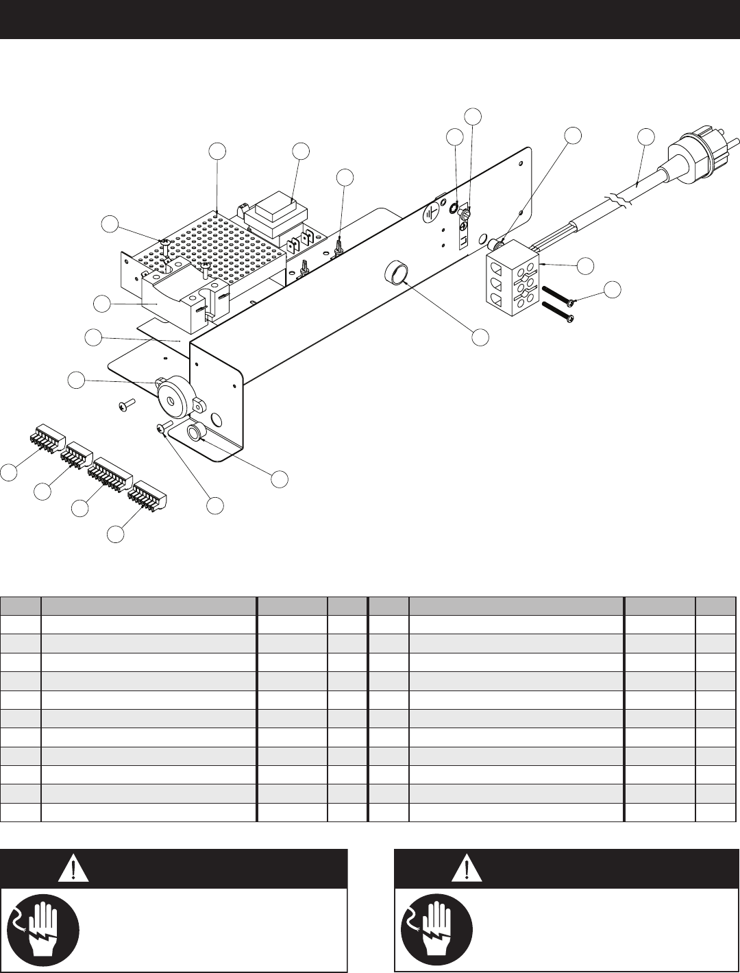
MN-29758 (Rev. 6) 05/15 • TH/III-SK/III Series Cook, Hold, Smoke • 40
4
3
1
2
7
5
6
19
1817
15
16
9
14
8
13
12
11
10
9
230V Shown
Part numbers and drawings are subject to change without notice.
1 WASHER, STAR LOCK WS-2467 1 9 SCREW, 6-32 X 1/2” NC PHIL TRUSS SC-2472 6
2 SCREW, 10-32 X 1/4" PAN HD GROUND SC-2190 1 10 CONNECTOR, 6 PIN CR-33719 1
3 BUSHING, 3/8" BLACK HOLE BU-3419 1 11 CONNECTOR, 10 PIN CR-33717 1
4CORDSET 120V CD-3397 1 12 CONNECTOR, 7 PIN CR-33762 1
230V (CEE 7/7) CD-3922 1 13 CONNECTOR, 8 PIN CR-33761 1
230V (CH2-16P) CD-36231 1 14 BEEPER BP-3567 1
230V (BS1363) CD-33925 1 15 HEATSINK HE-33926 1
5 T-BLOCK BK-3019 1 16 RELAY RL-33829 1
6 SCREW, 6-32 X 1-1/4" ROUND HD SC-2365 2 17 BOARD, POWER SUPPLY BA-36144 1
7 BUSHING, HOLE, 3/4” BU-3008 1 18 BOARD, VOLTAGE MONITOR BA-33764 1
8 BUSHING, HOLE, 1/2" BU-3006 1 19 SPACER, LOCK MOUNT SP-33832 4
Disconnect unit from power source
before cleaning or servicing. Failure
to observe this precaution can cause
electrical shock and personal injury.
Lock-out or post breaker panel
until service work until service
work has been completed.
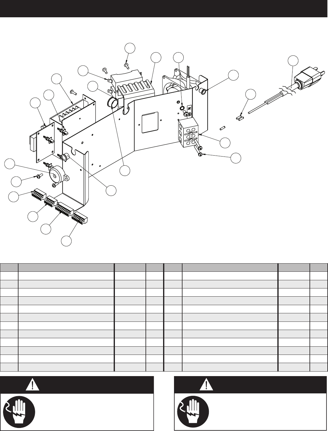
MN-29758 (Rev. 6) 05/15 • TH/III-SK/III Series Cook, Hold, Smoke • 41
- 500-TH/III
Part numbers and drawings are subject to change without notice.
1 BUSHING, 3/8" BLACK HOLE BU-3419 1 10 CONNECTOR, 7 PIN CR-33762 1
2 CONNECTOR, #12 FERRULE CR-34830 3 11 CONNECTOR, 8 PIN CR-33761 1
3CORDSET 120V CD-3397 1 12 SCREW, 6-32 X 1/2" NC PHIL TRUSS SC-2472 6
230V (CEE 7/7) CD-3922 1 13 BEEPER BP-3567 1
230V (CH2-16P) CD-36231 1 14 BOARD, VOLTAGE MONITOR BA-33764 1
230V (BS1363) CD-33925 1 15 SPACER, LOCK MOUNT SP-33832 4
4 T-BLOCSSK BK-3019 1 16 BOARD, POWER SUPPLY BA-36144 1
5 SCREW, 6-32 X 1-1/4" ROUND HD SC-2365 2 17 HEATSINK HE-33926 1
6 BUSHING, 3/4" HOLE BU-3008 1 18 RELAY RL-33829 1
7 BUSHING, 1/2" HOLE BU-3006 1 19 HEATSINK, BASE 1014450 1
8 CONNECTOR, 6 PIN CR-33719 1 20 STAR LOCK WASHER WS-2467 1
9 CONNECTOR, 10 PIN CR-33717 1
Disconnect unit from power source
before cleaning or servicing. Failure
to observe this precaution can cause
electrical shock and personal injury.
Lock-out or post breaker panel
until service work until service
work has been completed.
3
2
4
1
5
20
15
14
16
18
13
17
13
11
10
9
7
8
6
19
12
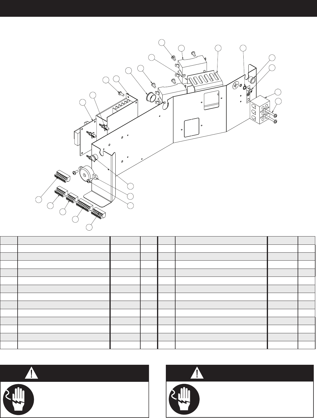
MN-29758 (Rev. 6) 05/15 • TH/III-SK/III Series Cook, Hold, Smoke • 42
750, 1000, 1200-TH/III
hown
3
1
19
13
12
14
16
17
11
10
9
8
7
1
5
15
4
2
6
18
6
6
6
Part numbers and drawings are subject to change without notice.
1 BUSHING, 1/2" HOLE BU-3006 1 14 BOARD, POWER SUPPLY BA-36144 1
2 SCREW, M5X 0.8 X 10mm PAN SC-22766 1 15 BUSHING, 3/4" WHITE SNAP BU-3008 1
3 T-BLOCK BK-3019 1 16 HEATSINK PAD HE-33926 1**
4 SCREW, M4 X 0.7 X 30mm PAN SC-29276 2 17 RELAY RL-33829 1**
5BEEPER BP-3567 1 18 HEAT SINK, SSR BASE 1014450 1**
6SCREW, M4 X 0.7 X 10mm PAN SC-22273 8 19 STAR LOCK WASHER WS-2467 1
7 CONNECTOR, 6 PIN CR-33719 1 21* CORDSET 120V (NEMA 5-20) CD-3397 1
8 CONNECTOR, 10 PIN CR-33717 1 230V (CEE 7/7) CD-3922 1
9 CONNECTOR, 7 PIN CR-33762 1 230V (CH2-16P) CD-36231 1
10 CONNECTOR, 8 PIN CR-33761 1 230V (BS1363) CD-33925 1
11 CONNECTOR, 9 PIN, 1200-TH/III ONLY CR-33718 1 22* CONNECTOR, #12 FERRULE CR-34830 3
12 BOARD, VOLTAGE MONITOR BA-33764 1 23* SERVICE KIT - 1 COMPARTMENT TH/III 5016623 1
13 SPACER, LOCK MOUNT SP-33832 4 SERVICE KIT - 2 COMPARTMENT TH/III 5016625 1
**per CompArtment * not Shown
Disconnect unit from power source
before cleaning or servicing. Failure
to observe this precaution can cause
electrical shock and personal injury.
Lock-out or post breaker panel
until service work until service
work has been completed.
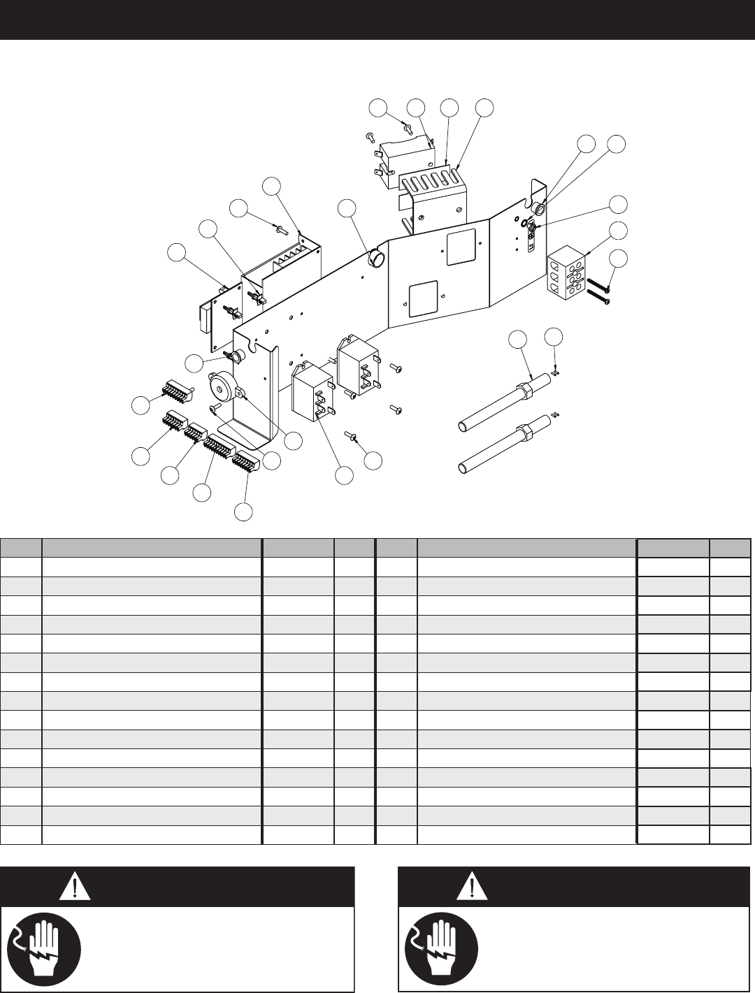
MN-29758 (Rev. 6) 05/15 • TH/III-SK/III Series Cook, Hold, Smoke • 43
4
5
1
3
2
17
16
18
8
2120
15
14
13
12
8
11
1
9
8
76
19
22
10
8
Part numbers and drawings are subject to change without notice.
1 BUSHING, 1/2" HOLE BU-3006 1 15 CONNECTOR, 9 PIN CR-33718 1
2 STAR LOCK WASHER WS-2467 1 16 BOARD, VOLTAGE MONITOR BA-33764 1
3 SCREW, 10-32 X 1/4" PAN HD GROUND SC-2190 1 17 SPACER, LOCK MOUNT SP-33832 4
4 T-BLOCK BK-3019 1 18 BOARD, POWER SUPPLY BA-36144 1
5 SCREW, 6-32 X 1-1/4" ROUND HD SC-2365 2 19 BUSHING, 3/8" WHITE SNAP BU-3008 1
6 CONNECTOR, FERRULE #18 CR-34827 2** 20 RELAY,SPST 30A @ 277 VAC 12VDC RL-33558 1**
7 SMOKER ELEMENT, 208-240V, 230V EL-35022 1** 21 HEATSINK PAD, RELAY HE-33926 1**
SMOKER ELEMENT, 120V EL-25023 1** 22 HEAT SINK, SSR BASE 1014450 1**
8 SCREW, 6-32 X 1/2, PHIL TRUSS SC-2472 12 23* CORDSET 120V (NEMA 5-20) CD-3397 1
9 RELAY, 230V, 25A RL-33829 1** 230V (CEE 7/7) CD-3922 1
10 BEEPER BP-3567 1 230V (CH2-16P) CD-36231 1
11 CONNECTOR, 6 PIN CR-33719 1 230V (BS1363) CD-33925 1
12 CONNECTOR, 10 PIN CR-33717 1 24* CONNECTOR, #12 FERRULE CD-34830 3
13 CONNECTOR, 7 PIN CR-33762 1 25* SERVICE KIT - 1 COMPARTMENT SK/III 5016624 1
14 CONNECTOR, 8 PIN CR-33761 1 SERVICE KIT - 2 COMPARTMENT SK/III 5016626 1
Disconnect unit from power source
before cleaning or servicing. Failure
to observe this precaution can cause
electrical shock and personal injury.
Lock-out or post breaker panel
until service work until service
work has been completed.
767, 1000, 1200, 1767-SK/III
Shown
**per CompArtment * not Shown
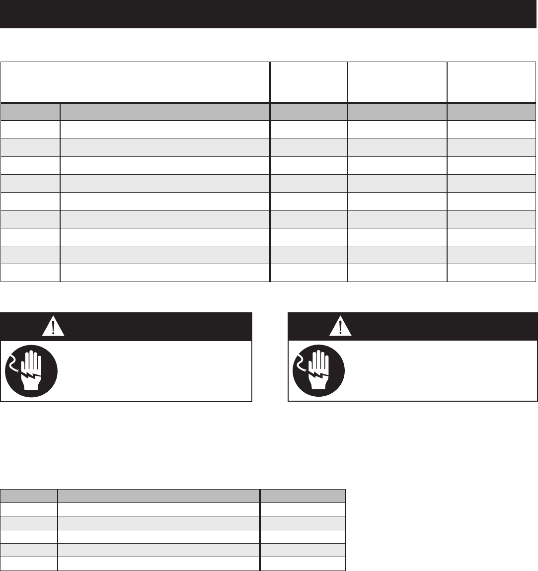
MN-29758 (Rev. 6) 05/15 • TH/III-SK/III Series Cook, Hold, Smoke • 44
(ONE KIT REQUIRED PER CAVITY)
(500)
(750, 1000, 1200, 1767)
UK ONLY
(1200) 4900W
CB-3045 CABLE HEATING ELEMENT 134 ft. 210 ft. 134 ft.
CR-3226 RING CONNECTOR 4 12 4
IN-3488 INSULATION CORNER 1 ft. 1 ft. 1 ft.
BU-3105 SHOULDER BUSHING 4 12 4
BU-3106 CUP BUSHING 4 12 4
ST-2439 STUD 4 12 4
NU-2215 HEX NUT 8 24 8
SL-3063 INSULATING SLEEVE 4 12 4
TA-3540 ELECTRICAL TAPE 1 ROLL 1 ROLL 1 ROLL
Disconnect unit from power source
before cleaning or servicing. Failure
to observe this precaution can cause
electrical shock and personal injury.
Lock-out or post breaker panel
until service work until service
work has been completed.
5015562 HACCP DATA LOGGER, RETRO-FIT KIT 1
CC-37264 — HACCP DATA LOGGER* 1
5014750 HACCP PACKAGE WITH USB PORT 1
CB-34893 — CAP, WATERPROOF USB SHIELDED 1
CB-34894 — CABLE USB WATERPROOF SHIELDED 1
( o P t i o n )
* CC-37264 may be ordered as a separate item for units that already have the Data Logger Kit installed.
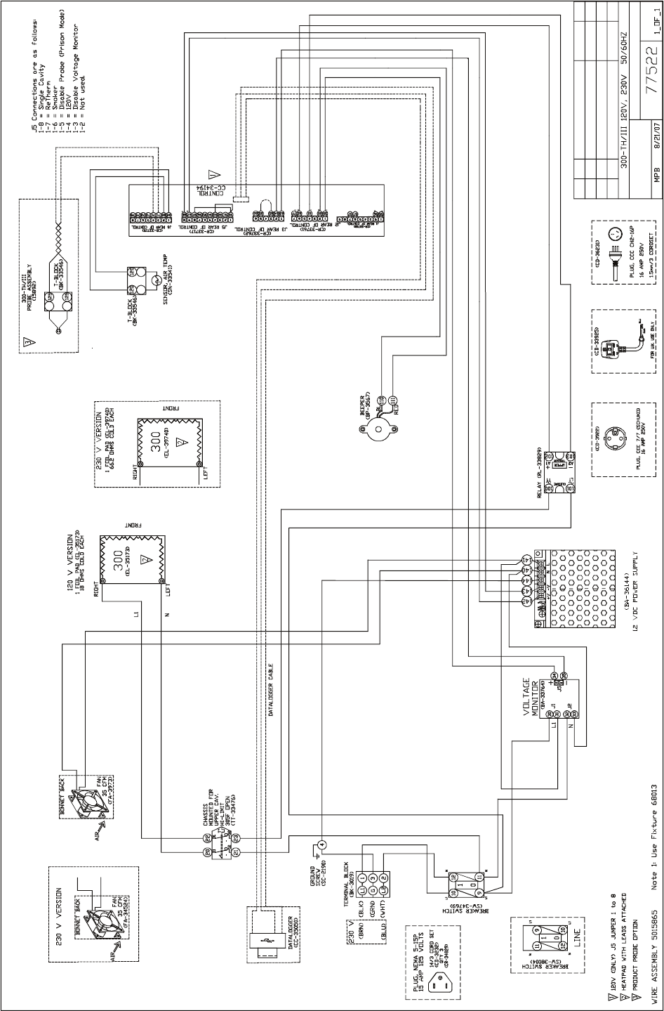
MN-29758 (Rev. 6) 05/15 • TH/III-SK/III Series Cook, Hold, Smoke • 45
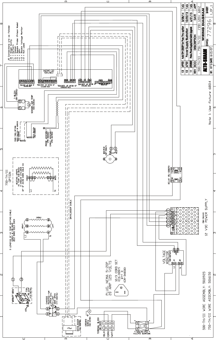
MN-29758 (Rev. 6) 05/15 • TH/III-SK/III Series Cook, Hold, Smoke • 46
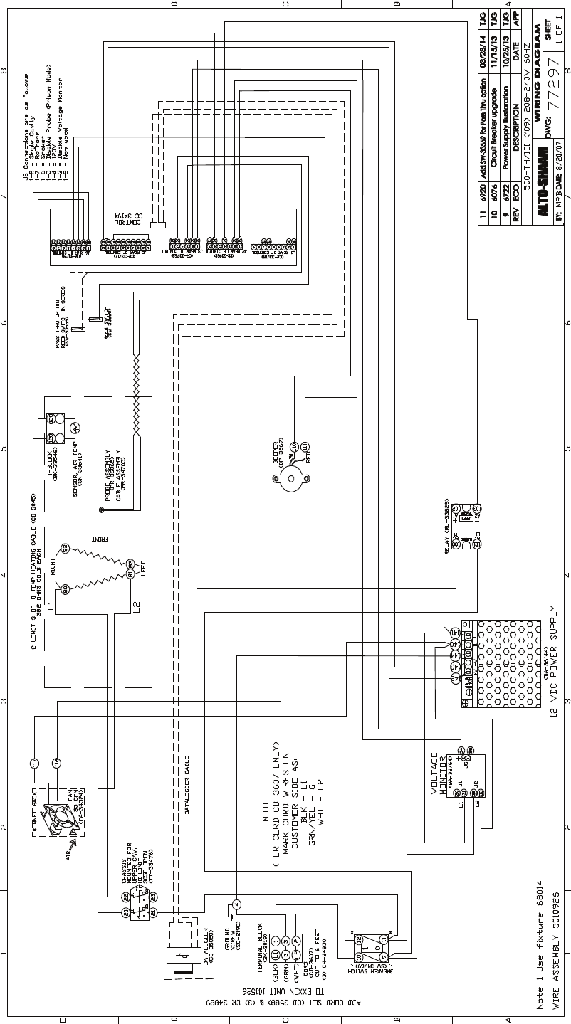
MN-29758 (Rev. 6) 05/15 • TH/III-SK/III Series Cook, Hold, Smoke • 47
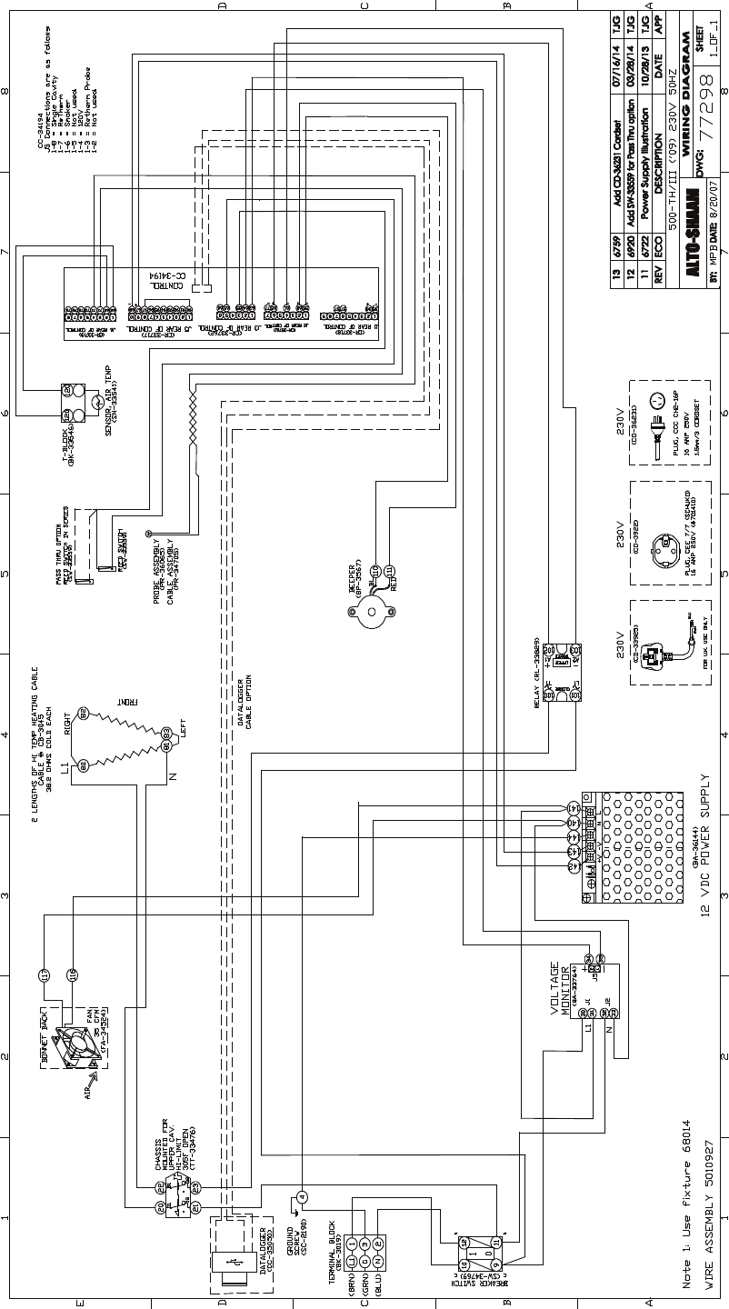
MN-29758 (Rev. 6) 05/15 • TH/III-SK/III Series Cook, Hold, Smoke • 48
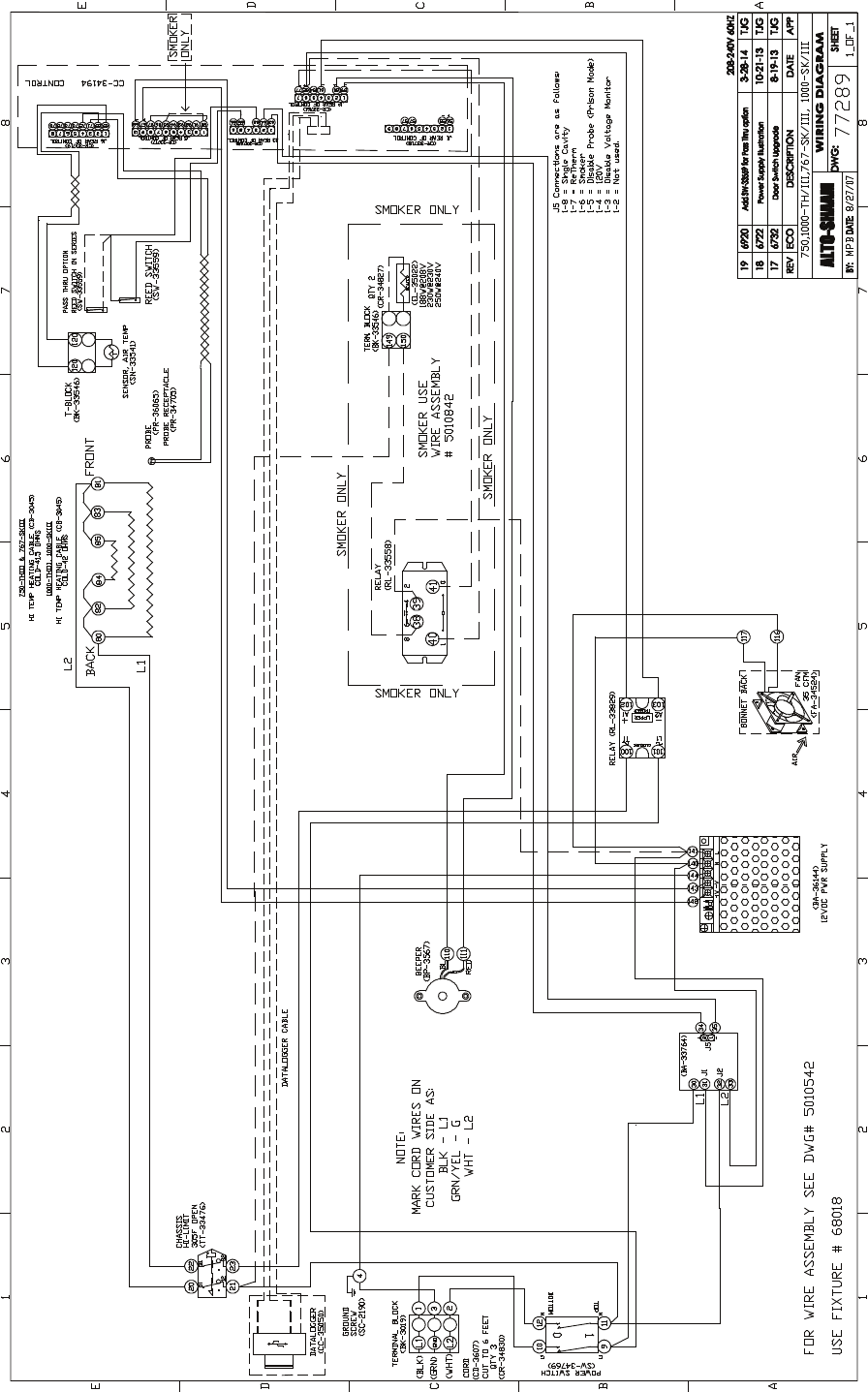
MN-29758 (Rev. 6) 05/15 • TH/III-SK/III Series Cook, Hold, Smoke • 49

MN-29758 (Rev. 6) 05/15 • TH/III-SK/III Series Cook, Hold, Smoke • 50
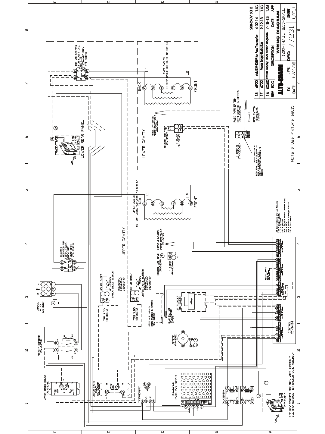
MN-29758 (Rev. 6) 05/15 • TH/III-SK/III Series Cook, Hold, Smoke • 51
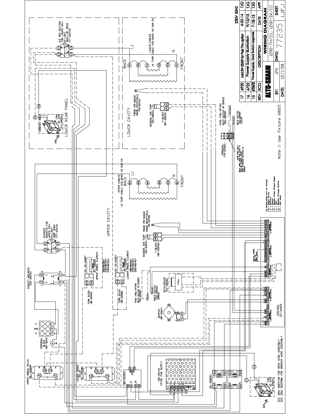
MN-29758 (Rev. 6) 05/15 • TH/III-SK/III Series Cook, Hold, Smoke • 52
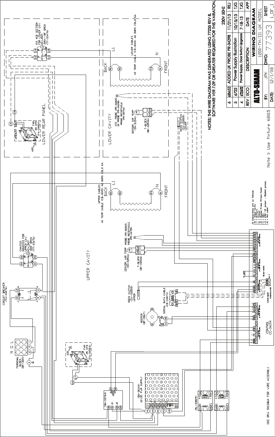
MN-29758 (Rev. 6) 05/15 • TH/III-SK/III Series Cook, Hold, Smoke • 53
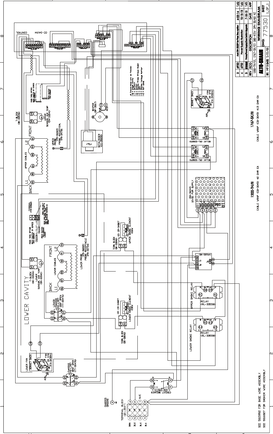
MN-29758 (Rev. 6) 05/15 • TH/III-SK/III Series Cook, Hold, Smoke • 54
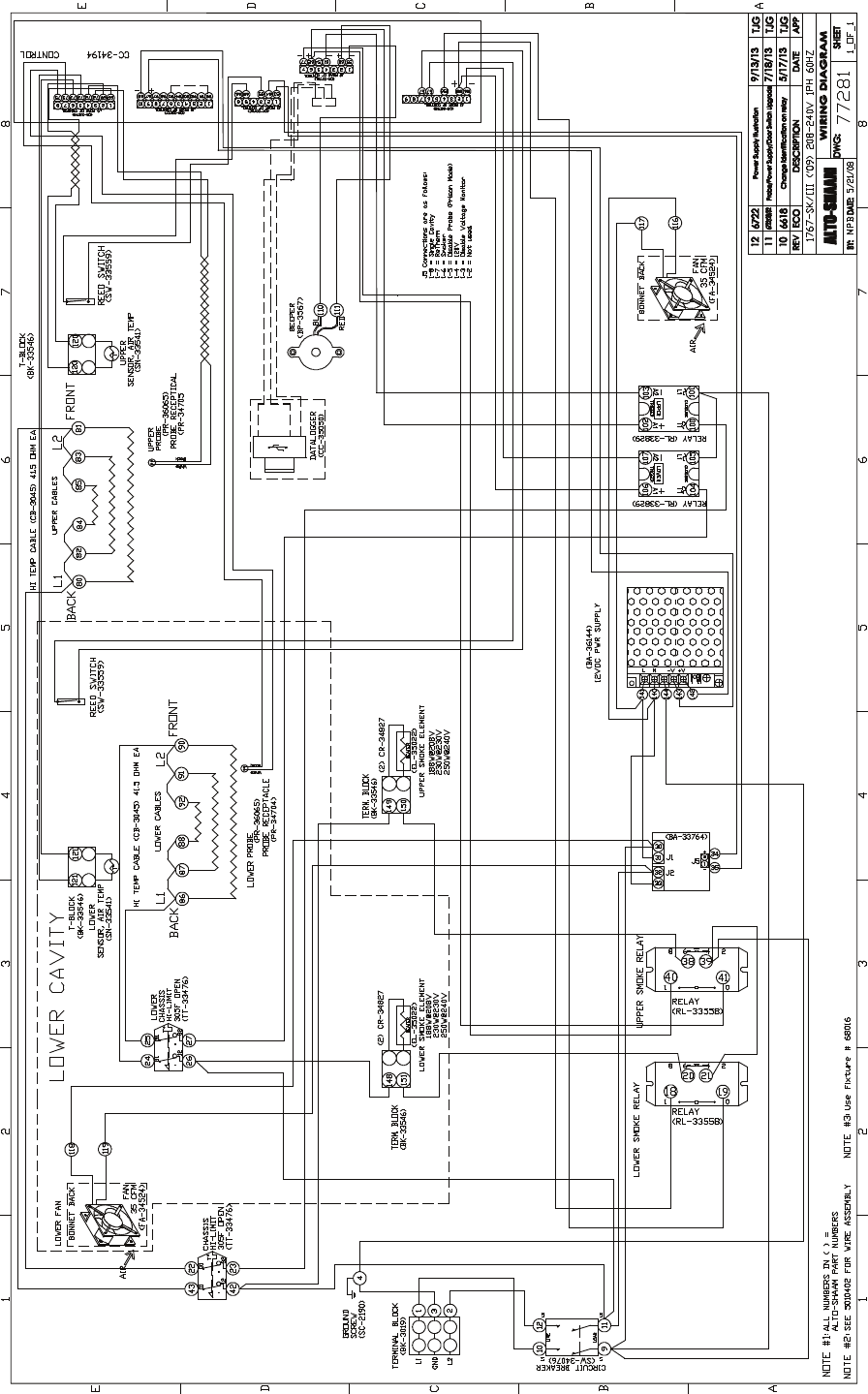
MN-29758 (Rev. 6) 05/15 • TH/III-SK/III Series Cook, Hold, Smoke • 55
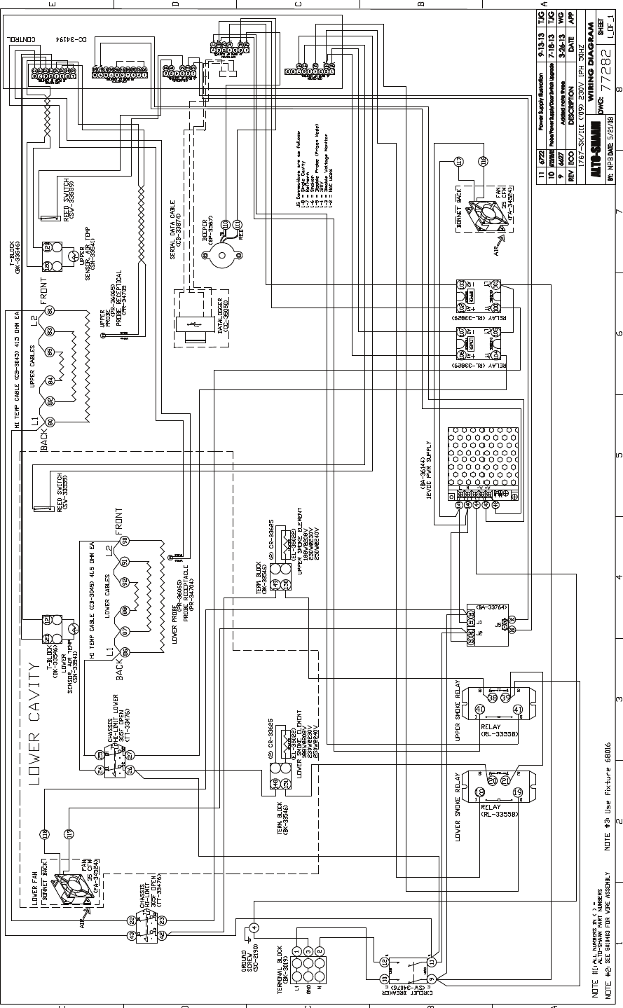
MN-29758 (Rev. 6) 05/15 • TH/III-SK/III Series Cook, Hold, Smoke • 56

TRANSPORTATION DAMAGE and CLAIMS
All Alto-Shaam equipment is sold F.O.B. shipping point, and when accepted by the carrier, such shipments
become the property of the consignee.
Should damage occur in shipment, it is a matter between the carrier and the consignee. In such cases,
the carrier is assumed to be responsible for the safe delivery of the merchandise, unless negligence can be
established on the part of the shipper.
1. Make an immediate inspection while the equipment is still in the truck or immediately after it is moved to the receiving area.
Do not wait until after the material is moved to a storage area.
2. Do not sign a delivery receipt or a freight bill until you have made a proper count and inspection of all merchandise received.
3. Note all damage to packages directly on the carrier’s delivery receipt.
4. Make certain the driver signs this receipt. If he refuses to sign, make a notation of this refusal on the receipt.
5. If the driver refuses to allow inspection, write the following on the delivery receipt:
Driver refuses to allow inspection of containers for visible damage.
6. Telephone the carrier’s office immediately upon finding damage, and request an inspection. Mail a written confirmation of the
time, date, and the person called.
7. Save any packages and packing material for further inspection by the carrier.
8. Promptly file a written claim with the carrier and attach copies of all supporting paperwork.
We will continue our policy of assisting our customers in collecting claims which have been properly filed and actively pursued.
We cannot, however, file any damage claims for you, assume the responsibility of any claims, or accept deductions in payment
for such claims.
LIMITED WARRANTY
Alto-Shaam, Inc. warrants to the original purchaser only that any original part that is found to be defective in material or workmanship will, at
Alto-Shaam's option, subject to provisions hereinafter stated, be replaced with a new or rebuilt part.
The original parts warranty period is as follows:
For the refrigeration compressor on Alto-Shaam Quickchillers™, five (5) years from the date of installation of appliance.
For the heating element on Halo Heat® cooking and holding ovens, as long as the original purchaser owns the oven. This
excludes holding only equipment.
For all other original parts, one (1) year from the date of installation of appliance or fifteen (15) months from the shipping date, whichever
occurs first.
The labor warranty period is one (1) year from the date of installation or fifteen (15) months from the shipping date, whichever occurs first.
Alto-Shaam will bear normal labor charges performed during standard business hours, excluding overtime, holiday rates or any
additional fees.
To be valid, a warranty claim must be asserted during the applicable warranty period. This warranty is not transferable.
THIS WARRANTY DOES NOT APPLY TO:
1. Calibration.
2. Replacement of light bulbs, door gaskets, and/or the replacement of glass due to damage of any kind.
3. Equipment damage caused by accident, shipping, improper installation or alteration.
4. Equipment used under conditions of abuse, misuse, carelessness or abnormal conditions, including but not limited to, equipment
subjected to harsh or inappropriate chemicals, including but not limited to, compounds containing chloride or quaternary salts, poor water
quality, or equipment with missing or altered serial numbers.
5. Damage incurred as a direct result of poor water quality, inadequate maintenance of steam generators and/or surfaces affected by water
quality. Water quality and required maintenance of steam generating equipment is the responsibility of the owner/operator.
6. Damage caused by use of any cleaning agent other than Alto-Shaam's Combitherm® Cleaner, including but not limited to damage due to
chlorine or other harmful chemicals. Use of Alto-Shaam's Combitherm® Cleaner on Combitherm® ovens is highly recommended.
7. Any losses or damage resulting from malfunction, including loss of product, food product, revenue, or consequential or incidental
damages of any kind.
8. Equipment modified in any manner from original model, substitution of parts other than factory authorized parts, removal of any parts
including legs, or addition of any parts.
This warranty is exclusive and is in lieu of all other warranties, express or implied, including the implied
warranties of merchantability and fitness for a particular purpose. In no event shall Alto-Shaam be liable for
loss of use, loss of revenue or profit, or loss of product, or for any indirect, special, incidental, or consequential
damages. No person except an officer of Alto-Shaam, Inc. is authorized to modify this warranty or to incur on
behalf of Alto-Shaam any other obligation or liability in connection with Alto-Shaam equipment.
RECORD THE MODEL AND SERIAL NUMBER OF THE APPLIANCE FOR EASY REFERENCE.
ALWAYS REFER TO BOTH MODEL AND SERIAL NUMBER IN ANY CONTACT WITH ALTO-SHAAM REGARDING THIS APPLIANCE.
Model: ______________________________________________ Date Installed: ______________________________________________________
Voltage: ______________________________________________ Purchased From: ___________________________________________
Serial Number: _____________________________________________________________________________________________________________
W164 N9221 Water Street ● P.O. Box 450 ● Menomonee Falls, Wisconsin 53052-0450 ● U.S.A.
PHONE: 262.251.3800 • 800.558-8744
USA/CANADA
FAX: 262.251.7067 • 800.329.8744
U.S.A. ONLY
www.alto-shaam.com
PRINTED I N U.S.A.
Effective November 1, 2012
