2. Chapter 1 General Information
User Manual: manual pdf -FilePursuit
Open the PDF directly: View PDF ![]() .
.
Page Count: 19

Chapter 1. General information
The IBM®BladeCenter E Type 8677 unit is a high-density, high-performance
rack-mounted system developed for medium-to-large businesses. It supports up to
14 blade servers, making it ideally suited for networking environments that require a
large number of high-performance servers in a small amount of space. The
BladeCenter system provides common resources that are shared by the blade
servers, such as power, cooling, system management, network connections, and
input/output (I/O) ports (diskette drive, optical drive, ports for USB, keyboard, video,
mouse, and network interfaces). The use of common resources enables small blade
server size, minimizes the cabling required in a working configuration, and
eliminates resources sitting idle.
Performance, ease of use, reliability, and expansion capabilities were key
considerations during the design of your BladeCenter system. These design
features make it possible for you to customize the system hardware to meet your
needs today, while providing flexible expansion capabilities for the future.
Notes:
1. Current BladeCenter E models do not have a diskette drive in the media tray.
Older BladeCenter E models do have a diskette drive in the media tray. In this
document, this difference is noted, when necessary, to describe differences that
exist between current and older model offerings.
2. The illustrations in this document might differ slightly from your actual hardware:
the illustrations do not depict a particular model offering unless noted in text.
3. Throughout this document, the terms I/O module and switch module are used to
refer to switch modules and all other types of I/O module.
This Hardware Maintenance Manual and Troubleshooting Guide provides
information to troubleshoot your BladeCenter unit and replace damaged parts.
This Hardware Maintenance Manual and Troubleshooting Guide and other
publications that provide detailed information about your BladeCenter unit are
provided in Portable Document Format (PDF) on the IBM BladeCenter
Documentation CD.
The latest version of this publication is available from the IBM support Web site at
http://www.ibm.com/systems/support.
If you have access to the World Wide Web, you can obtain up-to-date information
about your BladeCenter model and other IBM server products at
http://www.ibm.com/eserver/xseries/ on the World Wide Web.
You can register the BladeCenter unit and blade servers on the World Wide Web.
To register, go to http://www.ibm.com/support/mysupport/ on the World Wide Web.
© Copyright IBM Corp. 2009 1
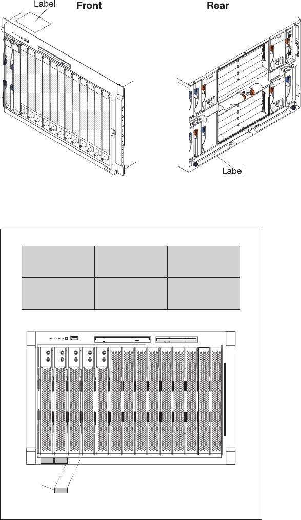
The serial number and model number are on labels on the top, front, and rear of
the chassis, as shown in the following illustration.
Note: The illustrations in this document might differ slightly from your hardware.
A set of user labels comes with each blade server. Write whatever identifying
information you want on a label, and place it on the BladeCenter bezel just below
the blade server, as shown in the following illustration.
User
label
Important: Do not place the label on the blade server itself or in any way block the
ventilation holes on the blade server.
2BladeCenter E Type 8677: Hardware Maintenance Manual and Troubleshooting Guide

The IBM Documentation CD
Use the IBM Documentation CD to access the blade server documentation in PDF
format.
You can run the IBM Documentation CD on any personal computer that meets the
hardware and software requirements.
The IBM Documentation CD contains documentation for your blade server in
Portable Document Format (PDF) and includes the IBM Documentation Browser to
help you find information quickly.
Hardware and software requirements
Use this information to determine the minimum hardware and software requirements
for the blade server.
The IBM Documentation CD requires the following minimum hardware and
software:
vMicrosoft®Windows®XP, Windows 2000, or Red Hat Enterprise Linux®5 Server
v100 MHz microprocessor
v32 MB of RAM
vAdobe®Acrobat Reader 3.0 (or later) or xpdf, which comes with Linux operating
systems
Using the Documentation Browser
Use these instructions to start the Documentation Browser.
Use the Documentation Browser to browse the contents of the CD, read brief
descriptions of the documents, and view documents, using Adobe Acrobat Reader
or xpdf. The Documentation Browser automatically detects the regional settings in
use in your system and displays the documents in the language for that region (if
available). If a document is not available in the language for that region, the
English-language version is displayed.
Use one of the following procedures to start the Documentation Browser:
vIf Autostart is enabled, insert the CD into the CD drive. The Documentation
Browser starts automatically.
vIf Autostart is disabled or is not enabled for all users, use one of the following
procedures:
– If you are using a Windows operating system, insert the CD into the CD or
DVD drive and click Start →Run.IntheOpen field, type
e:\win32.bat
where eis the drive letter of the CD or DVD drive, and click OK.
– If you are using Red Hat Linux, insert the CD into the CD or DVD drive; then,
run the following command from the /mnt/cdrom directory:
sh runlinux.sh
Select your blade server from the Product menu. The Available Topics list
displays all the documents for your blade server. Some documents might be in
folders. A plus sign (+) indicates each folder or document that has additional
documents under it. Click the plus sign to display the additional documents.
Chapter 1. General information 3

When you select a document, a description of the document is displayed under
Topic Description. To select more than one document, press and hold the Ctrl key
while you select the documents. Click View Book to view the selected document or
documents in Acrobat Reader or xpdf. If you selected more than one document, all
the selected documents are opened in Acrobat Reader or xpdf.
To search all the documents, type a word or word string in the Search field and
click Search. The documents in which the word or word string appears are listed in
order of the most occurrences. Click a document to view it, and press Crtl+F to use
the Acrobat search function, or press Alt+F to use the xpdf search function within
the document.
Click Help for detailed information about using the Documentation Browser.
Related publications
This Hardware Maintenance Manual and Troubleshooting Guide is provided in
Portable Document Format (PDF). It contains information to help you solve the
problem yourself or to provide helpful information to a service technician.
In addition to this Hardware Maintenance Manual and Troubleshooting Guide, the
following IBM BladeCenter Type 8677 Documentation is provided with the unit:
vSafety Information: This document contains translated caution and danger
statements. Each caution and danger statement that appears in the
documentation has a number that you can use to locate the corresponding
statement in your language in the Safety Information book.
vBladeCenter Type 8677 Rack Installation Instructions: This document contains
instructions for installing the BladeCenter unit in a rack.
vBladeCenter Management Module Installation Guide: This document contains
instructions for installing the management module in a BladeCenter unit and
creating the initial configuration. There is a unique Installation Guide for each
management module type.
vBladeCenter Management Module User’s Guide: This document provides general
information about the management module for your BladeCenter unit, including
information about features, how to configure the management module, and how
to get help. There is a unique User's Guide for each management module type.
vBladeCenter Management Module Command-Line Interface Reference Guide:
This document explains how to use the management-module command-line
interface to directly access BladeCenter management functions as an alternative
to using the Web-based user interface. The command-line interface also provides
access to the text-console command prompt on each blade server through a
serial over LAN (SOL) connection. There is a unique Command-Line Interface
Reference Guide for each management module type.
Additional publications might be included on the IBM BladeCenter E Type 8677
Documentation CD.
4BladeCenter E Type 8677: Hardware Maintenance Manual and Troubleshooting Guide

Notices and statements used in this book
The caution and danger statements used in this book also appear in the multilingual
Safety Information book provided on the IBM BladeCenter Documentation CD. Each
caution and danger statement is numbered for easy reference to the corresponding
statements in the safety book.
The following types of notices and statements are used in this book:
vNote: These notices provide important tips, guidance, or advice.
vImportant: These notices provide information or advice that might help you avoid
inconvenient or problem situations.
vAttention: These notices indicate possible damage to programs, devices, or
data. An attention notice is placed just before the instruction or situation in which
damage could occur.
vCaution: These statements indicate situations that can be potentially hazardous
to you. A caution statement is placed just before the description of a potentially
hazardous procedure step or situation.
vDanger: These statements indicate situations that can be potentially lethal or
extremely hazardous to you. A danger statement is placed just before the
description of a potentially lethal or extremely hazardous procedure step or
situation.
Features and specifications
Current BladeCenter E models do not have a diskette drive in the media tray. Older
BladeCenter E models do have a diskette drive in the media tray. A separate
features and specifications table is provided for each of these model types.
Notes:
1. For information about which types of I/O modules can be installed in which
I/O-module bays, see “I/O (switch) modules” on page 34.
2. The operating system in the blade server must provide USB support for the
blade server to recognize and use the keyboard, mouse, and optical drive. The
BladeCenter unit uses USB for internal communication with these devices.
Chapter 1. General information 5

The following table provides a summary of the features and specifications for a
BladeCenter unit that does not have a diskette drive bay in the media tray.
Media tray (on front):
vSATA CD/DVD drive
vUSB v2.0 port
vFront system LED panel
Module bays (on rear):
vFour hot-swap power-module bays
vTwo hot-swap management-module
bays
vFour hot-swap I/O-module bays
vTwo hot-swap blower bays
Blade-server bays (on front):
14 hot-swap blade-server bays
Redundant cooling:
Two variable-speed hot-swap blowers
Power modules:
vMinimum: Two 2000-watt or greater
hot-swap power modules
– Both power modules supply power
to all modules and to blade-server
bays 1 through 6.
– Both power modules provide
redundancy to each other.
vMaximum: Four
– Power modules 1 and 2 supply
power to all modules and to
blade-server bays 1 through 6.
– Power modules 3 and 4 supply
power to blade-server bays 7
through 14.
– Power modules 1 and 2 provide
redundancy to each other.
– Power modules 3 and 4 provide
redundancy to each other.
I/O modules:
vMinimum: One
vMaximum: Four
Management module:
vMinimum: One hot-swap advanced
management module providing the
following features:
– System-management functions for
the BladeCenter unit
– Video port (analog)
– Two USB ports for keyboard and
mouse
– Serial management connection
– 10/100 Mb Ethernet remote
management connection
vMaximum: Two hot-swap advanced
management modules: one active, one
redundant
Upgradeable microcode:
vManagement-module firmware
vI/O-module firmware (some I/O module
types)
vBlade-server firmware
Security features:
vLogin password for remote connection.
vSecure Socket Layer (SSL) security for
Web interface access, Secure Shell
(SSH) for remote command-line access,
and Lightweight Directory Access
Protocol (LDAP) and role-based security
for user authentication and
authorization.
Size (7 U):
vHeight: 304.2 mm (12 in. or 7 U)
vDepth: 711.2 mm (28 in.)
vWidth: 444 mm (17.5 in.)
vWeight:
– Fully configured with modules and
blade servers: Approximately 102 kg
(225 lb)
– Fully configured without modules and
blade servers: Approximately 38.6 kg
(85 lb)
Acoustical noise emissions:
vWithout acoustic attenuation module: Sound
power, operating, and idle: 7.4 bels
vWith acoustic attenuation module: Sound
power, idle, and operating: 6.9 bels
Environment:
vAir temperature:
– On:
- Altitude: 0 to 914 m (3000 ft) - 10° to
35°C (50° to 95°F)
- Altitude: 914 m to 2134 m (3000 ft to
7000 ft) - 10° to 32°C (50° to 89.6°F)
– Off: -40° to 60°C (-40° to 140°F).
vHumidity: 8% to 80%
Electrical input:
vSine-wave input (50-60 Hz single-phase)
required
vInput voltage:
– Minimum: 200 V ac
– Maximum: 240 V ac
Heat output:
Approximate heat output in British thermal
units (Btu) per hour:
vMinimum configuration: 1365 Btu/hour (400
watts)
vMaximum configuration: Varies depending
on the type of power modules installed.
– Four 2000-watt power modules: 20 094
Btu/hour (5889 watts)
– Four 2320-watt power modules: 23 672
Btu/hour (6938 watts)
6BladeCenter E Type 8677: Hardware Maintenance Manual and Troubleshooting Guide

The following table provides a summary of the features and specifications for a
BladeCenter unit that has a diskette drive bay in the media tray.
Media tray (on front):
vDiskette drive: 1.44 MB
vIDE CD or DVD
vUSB v1.1 port
vFront system LED panel
Module bays (on rear):
vFour hot-swap power-module bays
vTwo hot-swap management-module
bays
vFour hot-swap I/O-module bays
vTwo hot-swap blower bays
Blade-server bays (on front):
14 hot-swap blade-server bays
Redundant cooling:
Two variable-speed hot-swap blowers
Power modules:
vMinimum: Two hot-swap power
modules
– Both power modules supply power
to all modules and to blade-server
bays 1 through 6.
– Both power modules provide
redundancy to each other.
vMaximum: Four
– Power modules 1 and 2 supply
power to all modules and to
blade-server bays 1 through 6.
– Power modules 3 and 4 supply
power to blade-server bays 7
through 14.
– Power modules 1 and 2 provide
redundancy to each other.
– Power modules 3 and 4 provide
redundancy to each other.
I/O modules:
vMinimum: One
vMaximum: Four
Management module:
vMinimum: One hot-swap management
module providing the following features:
– System-management functions for
the BladeCenter unit
– Video port (analog)
– Keyboard connection (PS/2 port or
USB port depending on the
management module-type)
– Mouse connection (PS/2 port or USB
port depending on the management
module type)
– Serial management connection
(advanced management module
only)
– 10/100 Mb Ethernet remote
management connection
vMaximum: Two hot-swap management
modules: one active, one redundant
Upgradeable microcode:
vManagement-module firmware
vI/O-module firmware (some I/O module
types)
vBlade-server firmware
Security features:
vLogin password for remote connection.
vSecure Socket Layer (SSL) security for
Web interface access, Secure Shell
(SSH) for remote command-line access,
and Lightweight Directory Access
Protocol (LDAP) and role-based security
for user authentication and
authorization.
Size (7 U):
vHeight: 304.2 mm (12 in. or 7 U)
vDepth: 711.2 mm (28 in.)
vWidth: 444 mm (17.5 in.)
vWeight:
– Fully configured with modules and
blade servers: Approximately 102 kg
(225 lb)
– Fully configured without modules and
blade servers: Approximately 38.6 kg
(85 lb)
Acoustical noise emissions:
vWithout acoustic attenuation module: Sound
power, operating, and idle: 7.4 bels
vWith acoustic attenuation module: Sound
power, idle, and operating: 6.9 bels
Environment:
vAir temperature:
– On:
- Altitude: 0 to 914 m (3000 ft) - 10° to
35°C (50° to 95°F)
- Altitude: 914 m to 2134 m (3000 ft to
7000 ft) - 10° to 32°C (50° to 89.6°F)
– Off: -40° to 60°C (-40° to 140°F).
vHumidity: 8% to 80%
Electrical input:
vSine-wave input (50-60 Hz single-phase)
required
vInput voltage:
– Minimum: 200 V ac
– Maximum: 240 V ac
Heat output:
Approximate heat output in British thermal
units (Btu) per hour:
vMinimum configuration: 1365 Btu/hour (400
watts)
vMaximum configuration: Varies depending
on the type of power modules installed.
– Four 1200-watt power modules: 9622
Btu/hour (2820 watts)
– Four 1400-watt power modules: 11 111
Btu/hour (3256 watts)
– Four 1800-watt power modules: 13 650
Btu/hour (4000 watts)
– Four 2000-watt power modules (for use
with a Gigabit Ethernet expansion card):
18 425 Btu/hour (5400 watts)
Chapter 1. General information 7
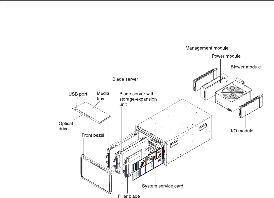
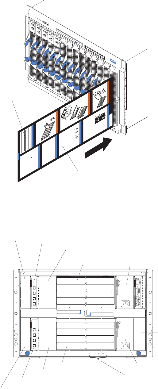
Major components of the BladeCenter Type 8677 unit
The following illustration shows the locations of major components in your
BladeCenter unit.
Note: The illustrations in this document might differ slightly from your hardware.
Attention: To maintain proper system cooling, each module bay must contain
either a module or a filler module; each blade bay must contain either a blade
server or a filler blade.
8BladeCenter E Type 8677: Hardware Maintenance Manual and Troubleshooting Guide

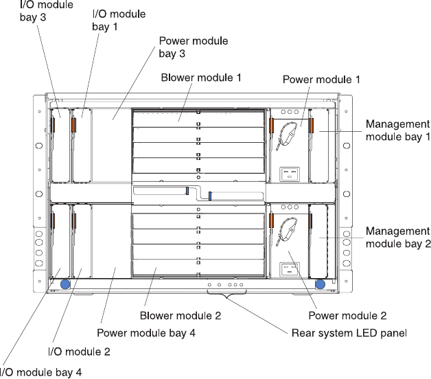
Rear view
The following illustration shows the locations of components and indicators on the
rear of the BladeCenter Type 8677 unit.
See “BladeCenter components, controls, and LEDs” on page 13 for details about
these components and indicators.
10 BladeCenter E Type 8677: Hardware Maintenance Manual and Troubleshooting Guide

BladeCenter unit power, controls, and indicators
This section describes the controls and light-emitting diodes (LEDs) and how to
start and shut down the BladeCenter unit.
Notes:
1. The removable media drives, keyboard, and mouse in the BladeCenter unit are
viewed as USB devices by the blade server operating system.
2. Local media tray support can be turned off preventing the blade servers from
accessing the removable media drives.
3. Local KVM switching support can be turned off preventing the blade servers
form accessing the keyboard, video, and mouse.
Press keyboard keys in the following sequence to switch KVM control between
blade servers:
NumLock <blade server number> Enter
Where <blade server number> is the two-digit number for the blade bay in which
the blade server is installed.
You will need to press the Shift key to switch KVM control when using the 28L3644
(37L0888) keyboard. If pressing the Shift key does not switch KVM control,
complete the following steps:
1. Press and hold the Shift key.
2. Press keyboard keys in the following sequence:
NumLock <blade server number> Enter
3. Release the Shift key.
Starting the BladeCenter unit
Important: For the LEDs on each system LED panel to function correctly, be sure
to install the management module before turning on the BladeCenter unit. See
Chapter 4, “Installing options,” on page 31 for instructions for installing the
management module.
To start the BladeCenter unit, plug one end of each power cord into a power
module on the rear of the BladeCenter unit and the other end of each power cord
into a 220-volt power distribution unit (PDU) that is plugged into an appropriate
electrical outlet.
After you start the BladeCenter unit, it has dc power. The blade servers in the
BladeCenter unit are connected to dc power but are not turned on. Press the
power-control button on the front of each blade server to obtain full power for the
blade server and start its operating system (see the documentation that comes with
your blade server for information about turning on the blade server).
Note: If a power failure occurs, the BladeCenter unit restarts automatically when
power is restored.
Chapter 1. General information 11
Shutting down the BladeCenter unit
You can shut down the BladeCenter unit by turning off the blade servers and
disconnecting the BladeCenter unit from the power source.
Complete the following steps to shut down the BladeCenter unit:
1. Refer to your blade server operating-system documentation for the proper
procedure to shut down the operating system in the blade servers; then, shut
down each operating system.
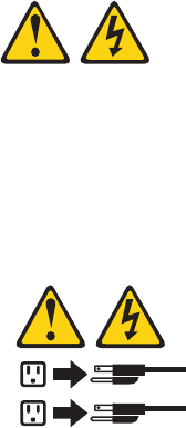
Statement 5:
CAUTION:
The power control button on the device and the power switch on the
power supply do not turn off the electrical current supplied to the device.
The device also might have more than one power cord. To remove all
electrical current from the device, ensure that all power cords are
disconnected from the power source.
1
2
2. Press the power-control button on the front of each blade server. Wait at least
30 seconds for the blade server drives to stop spinning.
3. Disconnect all power cords on the BladeCenter unit from all the power modules.
Note: After you disconnect the BladeCenter unit from power, wait at least 5
seconds before you connect the BladeCenter unit to power again.
12 BladeCenter E Type 8677: Hardware Maintenance Manual and Troubleshooting Guide
BladeCenter components, controls, and LEDs
This section identifies the components, controls, and LEDs on the front and rear of
your BladeCenter unit.
Note: The illustrations in this document might differ slightly from your hardware.
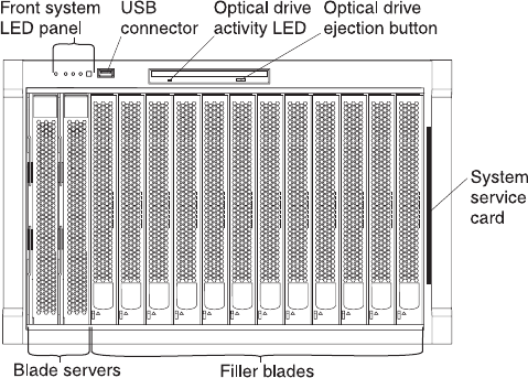
Front view
This section identifies the components, controls, and LEDs on the front of your
BladeCenter unit.
Front system LED panel: The LEDs on this panel provide status information for
your BladeCenter unit. See “System LED panel” on page 17 for more information.
USB port: Use this port to attach an external USB device.
Optical-drive activity LED: When this LED is lit, it indicates that the optical drive is
in use.
Optical-drive eject button: Press this button to release a CD or DVD from the
optical drive.
Diskette-drive activity LED (not shown in illustration):For media trays that have a
diskette drive, when this LED is lit, it indicates that the diskette drive is in use.
Diskette-drive eject button (not shown in illustration):For media trays that have a
diskette drive, press this button to release a diskette from the drive.
Blade control panel: This panel contains indicators and controls for the blade
server. See the documentation that comes with your blade server for information
about the blade control panel.
System service card: This card contains system service instructions and a writable
area for your use.
Chapter 1. General information 13
Chassis Service Information
Processor Blade Operator Panel
Hot-Plug Processor Blade
Hot-Plug Media Tray
Operator Panel
Common Chassis FRUs
Hot-Swap Hard Disk Drives
Customer Information
CD
For More Information
Download files, hints & tips, create custom
profiles, and frequently asked questions
http://www.ibm.com/pc/support
http://www.ibm.com/pc/us/compat/
Compatibility information
http://www.ibm.com/pc/ww/eserver/
xseries/serverguide
IBM ServerGuide home page
http://www.ibm.com/servers
IBM Server home page
http://www.ibm.com/eserver/xseries
IBMserver xSeries home page
Power-on
Location
Over-temperature
Information
System error
System service card
Writeable
area
Rear view
This section identifies the components and indicators on the rear of your
BladeCenter unit.
AC
AC
DC
DC
Switch module
bay 3 Switch module 1
Switch module bay 4
Switch module 2
Power module
bay 3
Power module 1
Power module bay 4
Power module 2
Management
module
Reserved
Blower module 1
Blower module 2
Rear system LED panel
14 BladeCenter E Type 8677: Hardware Maintenance Manual and Troubleshooting Guide
Rear system LED panel:The LEDs on this panel provide status information for
your BladeCenter unit. These LEDs duplicate the LEDs in the front system LED
panel, see “System LED panel” on page 17 for more information about these LEDs.
Blower module:
Blower error
LEDs
Important: If the ambient temperature is 72° F or below, the BladeCenter blowers
will run at 30% of their maximum rotational speed, increasing their speed as
required to control internal BladeCenter temperature. If ambient temperature is
above 72° F, the blowers will run at 80% of their maximum rotational speed
increasing their speed as required to control internal BladeCenter temperature.
Blower error LEDs: The amber LED on each blower is lit and stays lit when an
error has been detected in the blower. The system-error LED on the BladeCenter
system LED panels is also lit. For additional information, see “Identifying problems
using the Light Path Diagnostics feature” on page 29.
I/O (switch) module:See the documentation that comes with each I/O module for
a description of the LEDs on the I/O module.
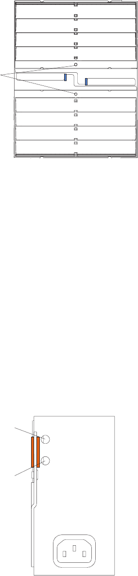
Power module:Several types of power module, with different wattage ratings, can
be used in the BladeCenter E unit.
The following illustration shows the rear view for older power modules.
Note: The illustrations might differ slightly from your hardware.
AC
DC
AC power
DC power
Chapter 1. General information 15
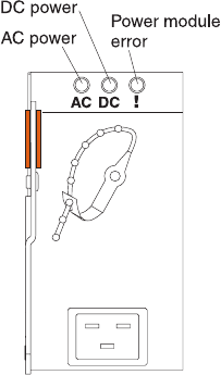
The following illustration shows the rear view for the currently available power
modules.
Power module LEDs: These LEDs indicate the condition of the power module. For
additional information, see “Identifying problems using the Light Path Diagnostics
feature” on page 29.
vAC power: When this green LED is lit, ac input to the power module is present
and within specifications. During typical operation, both the ac and dc power
LEDs are lit. For any other combination of LEDs, see “Identifying problems using
the Light Path Diagnostics feature” on page 29.
vDC power: When this green LED is lit, the dc output from the power module to
the other components and blade servers is present and within specifications.
During typical operation, both the ac and dc power LEDs are lit. For any other
combination of LEDs, see “Identifying problems using the Light Path Diagnostics
feature” on page 29.
vPower module error LED (2320-watt power modules only): When this amber
LED is lit, it indicates that an error has been detected in the power module.
When this LED is lit, the BladeCenter unit system error LED is also lit.
Management module:The type of management module that is installed in your
BladeCenter unit depends on the BladeCenter unit model and devices that are
installed.
vA BladeCenter unit that has a media tray with a diskette drive can use either a
management module or an advanced management module, depending on which
devices are installed in the BladeCenter unit.
vA BladeCenter unit that has a media tray without a diskette drive must use an
advanced management module.
vIf 2320-watt power modules are installed in the BladeCenter unit, you must use
an advanced management module.
vSee the documentation that comes with your BladeCenter device to determine if
a specific management module type is required to support the device.
See the documentation for your management module for additional information and
instructions.
16 BladeCenter E Type 8677: Hardware Maintenance Manual and Troubleshooting Guide
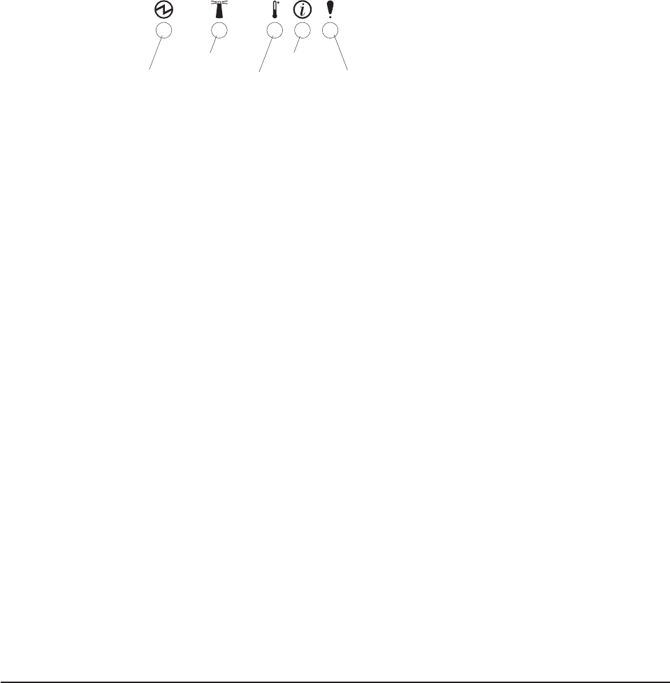
System LED panel
The following illustration shows the status LEDs on the system LED panels on the
front and rear of the BladeCenter unit.
Power-on
Location
Over-temperature
Information
System error
Attention: If the power-on LED is off, it does not mean there is no electrical
current present in the BladeCenter unit. The LED might be burned out. To remove
all electrical current from the BladeCenter unit, you must unplug all power cords
from all power modules.
Note: You can turn off the location LED and the information LED through the Web
interface or the IBM Director console.
Power-on: When this green LED is lit, power is present in the BladeCenter unit.
When this LED is off, the power subsystem, the ac power, or the LED has
failed, or the management module is not present or not functioning.
Location: When this blue LED is lit or flashing, it has been turned on by the
system administrator to aid in visually locating the BladeCenter unit. If a blade
server requires attention, the location LED on the blade server usually will also
be lit. After the BladeCenter unit has been located, you can have the system
administrator turn off the location LED.
Over-temperature: When this amber LED is lit, the temperature in the
BladeCenter unit exceeds the temperature limits, or a blade server has reported
an over-temperature condition. The BladeCenter unit might have already taken
corrective action, such as increasing the blower speed. This LED turns off
automatically when there is no longer an over-temperature condition.
Information: When this amber LED is lit, a noncritical event has occurred that
requires attention, such as the wrong I/O module inserted in a bay or power
demands that exceed the capacity of power modules currently installed. The
event is recorded in the event log. Check the LEDs on the BladeCenter unit and
the blade servers to isolate the component. After the situation is handled, have
the system administrator turn off the information LED.
Note: The information LED will also light if the system error log is 75% full.
System-error: When this amber LED is lit, it indicates that a system error has
occurred, such as a failed module or a system error in a blade server. An LED
on one of the components or on a blade server is also lit to further isolate the
error. (For more information, see “Identifying problems using the Light Path
Diagnostics feature” on page 29.)
Setting up the BladeCenter unit
This section briefly discusses considerations for the setup of your BladeCenter unit.
vBlade bays must be occupied at all times.
To help ensure proper cooling, performance, and system reliability, make sure
that each of the blade bays on the front of the BladeCenter unit has a blade
server, expansion unit, or filler blade installed.
Important: When replacing a blade server or installing an expansion option, do
not operate the BladeCenter unit for more than one minute without either a blade
server, an expansion option, or a filler blade installed in each blade bay.
Chapter 1. General information 17
vModule bays must be occupied at all times.
To help ensure proper cooling, performance, and system reliability, make sure
that each of the module bays on the rear of the BladeCenter unit has a module
or filler module installed.
Important: When replacing a module, do not operate the BladeCenter unit for
more than one minute without either a module or a filler module installed in each
module bay.
vThere is no power switch on the BladeCenter unit.
The BladeCenter unit does not have a power switch. Plugging the power cords
into the power modules and a 220 V ac power source (rack-mounted 220-volt
PDU) starts the BladeCenter unit (the management module, I/O modules, and
blowers start running).
Each blade server in the BladeCenter unit has an individual power-control button
behind the control-panel door on the blade front that turns on or turns off the
blade server. Be sure to shut down the operating system before turning off the
blade server, to avoid damaging the hard disk drives.
Notes:
1. The blade server power button turns on or turns off the blade server if local
power control has not been disabled through the management module.
2. The blade server power button turns on the blade server only if the green
power light on the blade server is flashing slowly. If the light flashes rapidly,
the blade server has not yet synchronized with the management module, and
the power button will have no effect.
See the IBM BladeCenter Type 8677 Installation and User’s Guide for more
information about the BladeCenter unit. See the Installation and User’s Guide for
your blade server for more information about the blade server power controls and
turning on or turning off the blade server.
vThe removable media drives are detected as a Universal Serial Bus (USB)
device
The removable media drives in the BladeCenter unit are viewed as a USB
devices by the operating system in the blade server. Make sure that your
operating system provides USB support.
vHot-swap capabilities
The front bays on the BladeCenter unit are hot-swap blade bays; the rear bays
on the BladeCenter unit are hot-swap module bays. You can add, remove, or
replace blade servers or management, I/O, power, or blower modules in
hot-swap bays without removing power from the BladeCenter unit.
Attention: To maintain proper system cooling, each unoccupied bay must
contain a filler blade and an expansion or filler module. When replacing a blade
server or installing an expansion option, do not operate the BladeCenter unit for
more than one minute without either a blade server, an expansion option, or a
filler blade installed in each blade bay or without a module or filler installed in
each rear bay.
18 BladeCenter E Type 8677: Hardware Maintenance Manual and Troubleshooting Guide
Connecting to the default IP address on a new BladeCenter
A newly-installed (out-of-the-box) BladeCenter unit tries to locate a DHCP server on
the network before it will default to the factory-configured static IP address in the
management module. This is the initial configuration setting. When there is no
DHCP server on the network the BladeCenter unit is connected to, it can take
several minutes before the management module uses the default (static) IP
address. When the DHCP search times out and the management module uses the
static IP address, you can change the management module configuration so that it
will not attempt to locate a DHCP server.
See the Installation Guide and User's Guide or Command-Line Interface Reference
Guide for your management module type for information about connecting to and
configuring the BladeCenter management module.
Registering and profiling the BladeCenter products
You can register and profile the BladeCenter unit and blade servers on the World
Wide Web.
vTo register, go to: http://www.ibm.com/support/mysupport/
vTo profile, go to: http://www.ibm.com/systems/support/
Important:
1. Do not switch control of a shared removable media drive to another blade
server until the activity lights on the drive is off, indicating that no read or write
operations are in progress. Before you remove a hot-swap blade server from
the BladeCenter unit, you must shut down the operating system and turn off the
blade server. You do not have to shut down the BladeCenter unit itself.
2. It can take approximately 20 seconds for the operating system in the
switched-to blade server to recognize the removable media drives and USB port
or the keyboard, video, and mouse.
a. The system-error LED might light, and a KVM allocation error might be
logged if the change in ownership for the removable media drives and USB
port or the keyboard, video, and mouse takes more than 8 seconds. The
system-error LED will go off after the ownership change is complete.
b. It can take up to 48 seconds after a blade server is initially turned on before
you can attempt to switch KVM control to that blade server.
Chapter 1. General information 19
