30 0045 & 0140 _2008_ !!
Preview ! 30-0045 Country Lawn Mower Manuals - Lawn Mower Manuals – The Best Lawn Mower Manuals Collection
User Manual: !! Country Lawn Mower Manuals - Lawn Mower Manuals – The Best Lawn Mower Manuals Collection
Open the PDF directly: View PDF ![]() .
.
Page Count: 20
1701 38TH AVE W
PO BOX 257
SPENCER, IA 51301
PHONE: 712-262-4191
FAX: 712-262-0248
SERVICE: 800-841-2222
E-MAIL: ccac@cyclecountry.com
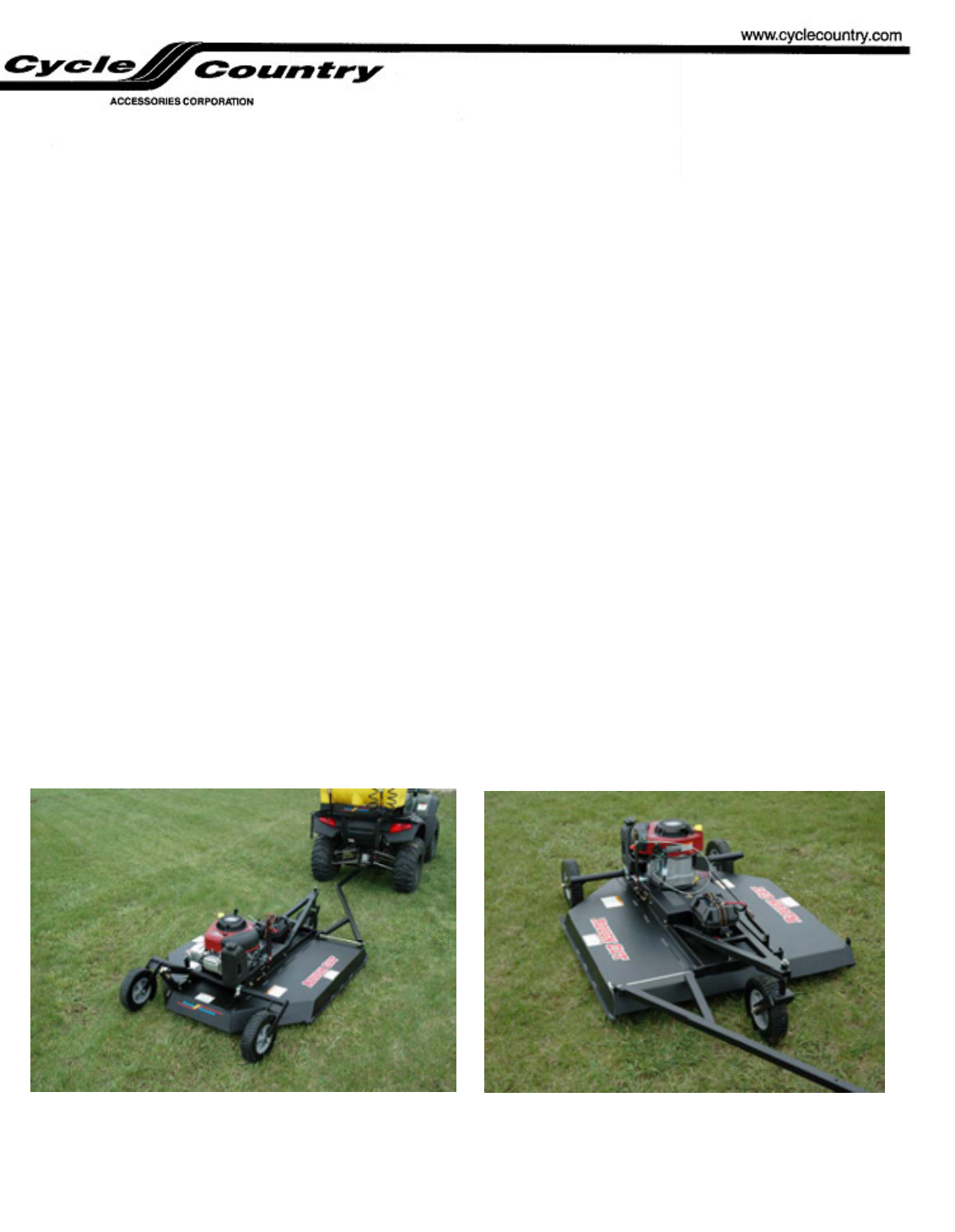
ROUGH CUT
LAWN MOWER
OWNER’S AND OPERATORS MANUAL
MODEL NUMBER:
30-0045 (BRIGGS & STRATTON)
30-0140 (HONDA)
CUSTOMER MUST RECEIVE A COPY OF THIS
OWNER’S MANUAL AT TIME OF SALE
© 2004 Cycle Country Accessories Corp.
Rev. 1
3/27/08

ONE YEAR LIMITED WARRANTY
For the period of one year from the purchase date Cycle Country Accessories
Corporation will replace for the original purchaser, free of charge, any part or parts, when
found, upon examination by Cycle Country Accessories Corporation, to be defective in
material, workmanship, or both.
All transportation cost incurred by the purchaser in submitting the material to
Cycle Country Accessories Corporation for replacement under this warranty must be
borne by the purchaser. If Cycle Country Accessories Corporation determines that the
product must be returned to the factory for credit please call 1-800-841-2222 for an RMA
number and shipping instructions.
The warranty does not apply to parts that have been damaged by accident,
alteration, abuse, improper lubrication, normal wear, or other causes beyond Cycle
Country Accessories Corporation’s control. Products such as engines, electric motors,
and actuators may carry an original manufacturer’s warranty. Please call Cycle Country
Accessories Corporation for information.
1701 38TH AVE W
PO BOX 257
SPENCER, IA 51301
PHONE: 712-262-4191
FAX: 712-262-0248
SERVICE: 800-841-2222
E-MAIL: ccac
@
c
y
clecountr
y
.com
2

The ROUGH CUT MOWER is a powerful cutting machine and is capable of
amputating hands and feet and can also throw materials that can cause damage to
you or your property.
PLEASE READ ALL INSTRUCTIONS IN THIS MANUAL VERY CAREFULLY
IF YOU HAVE ANY QUESTIONS, PLEASE CONSULT YOUR DEALER OR
CYCLE COUNTRY DIRECTLY AT 1-800-841-2222
IMPORTANT PRECAUTIONS:
DO NOT ALLOW children to ride on the ATV or lawn mower at any time.
DO NOT ALLOW children to operate the lawn mower.
Be familiar with the lawn mower controls, safety switch, and all cautions and warnings before operation
of mower.
Only responsible persons with mature judgment should be allowed to operate the lawn mower.
Wear appropriate protective clothing when mowing such as gloves, head and eye protection, long pants
and footwear.
Never operate under the influence of DRUGS or ALCOHOL.
Know how to stop the blade and engine quickly in preparation for emergencies. Always have the kill
switch and kill switch tether properly installed. SEE PARAGRAPH 2-3.
Keep all people and pets at a safe distance from lawn mower.
All shields, safety/kill switch, throttle control and other devices must be in proper positions and
functional before using the lawn mower.
Clear the area to be mowed of all wire, rocks, and other objects that could cause injury if thrown by the
blades.
Shut off the engine before leaving the ATV. Remove the key when leaving the ATV and mower
unattended.
DO NOT attempt to operate the lawn mower unless properly seated on the ATV.
Stop the engine and disconnect the spark plug wire and wait for blade to stop before attempting to
unclog grass or leaves from the mower.
DO NOT operate with the belt covers removed for any reason.
Service the lawn mower and make adjustments only when the engine is stopped.
Tighten all bolts, nuts, and screws frequently and check, adjust or replace worn or broken parts as
needed.
Handle gasoline with care!!! Never remove cap while engine is running. Fill the fuel tank outdoors
only with the engine stopped and cool.
3
ASSEMBLY INSTRUCTIONS:
Note: You will need to purchase a battery. Recommended battery is a
Garden Tractor/Utility Battery
BCI Group: U1
1. Remove mower from shipping crate.
Refer to the Deck Sub Assembly for Instruction #2.
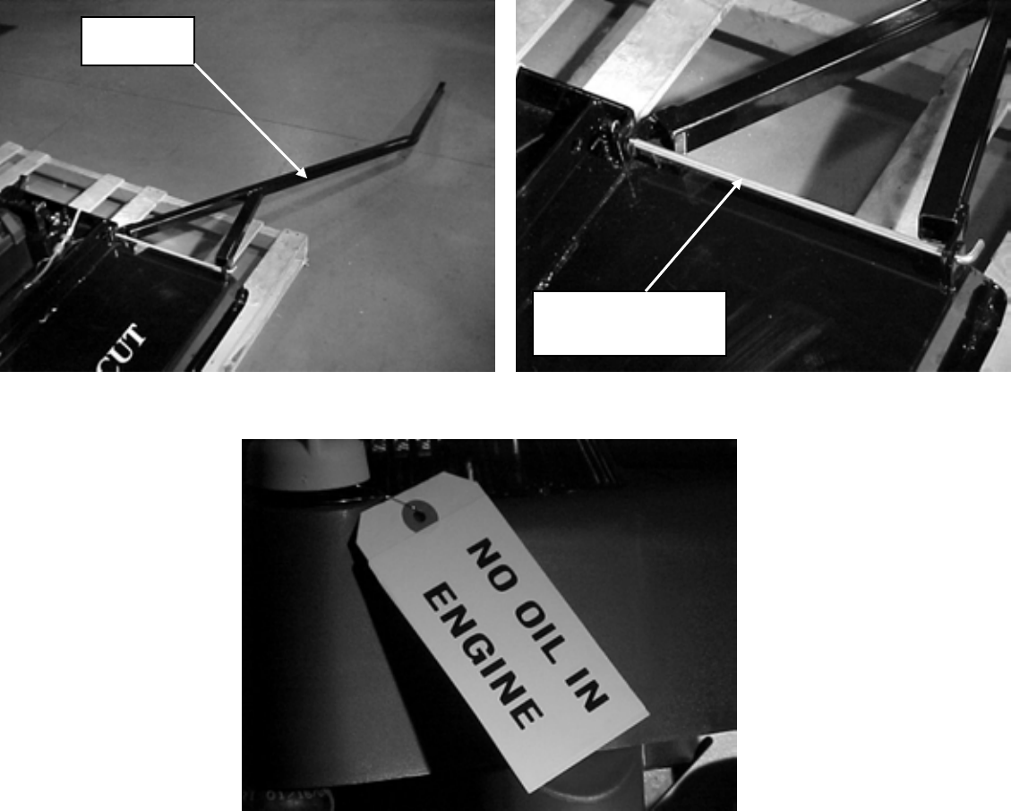
2. Use the hitch attachment rod to attach the tow bar to the deck. The tow bar can be
switched to the opposite side of the mower. It can also be flipped over to tow
directly behind the ATV.
Tow Bar
Hitch Attachment
Rod
3. Add engine oil before startup.
Prepare the engine according to the ENGINE OWNER’S MANUAL.
4
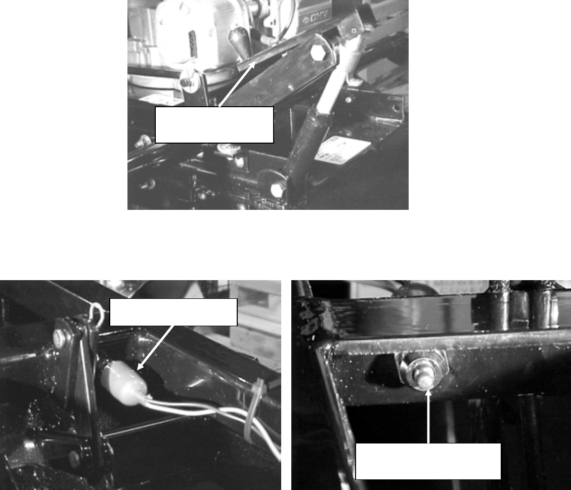
4. To increase or decrease the height of the cut, use the height adjustment crank
handle on the rear axle sub assembly to raise and lower the height of the deck.
Height Adjustment
Crank
5. Attach the rubber stopper and safety/kill switch tether found in your parts bag as
shown below. Install the tether cord support through the hole found on the tow
bar. Secure with the hairpin provided.
Front of kill switch. Place
Tether Cord Stopper here.
Rear of Kill Switch
5
OPERATING INSTRUCTIONS
***Before operating your new LAWN MOWER – PLEASE READ and FOLLOW all the operating
instructions and assembly instructions contained in this manual.***
CAUTION: When transporting the lawn mower, be sure to crank the deck all the way down to
prevent any movement during transport.
WARNING: The lawn mower is a powerful machine and is capable of amputating hands and feet, can
throw materials that can cause injury and damage to you and your property. PLEASE READ ALL
INSTRUCTIONS IN THIS MANUAL CAREFULLY.
STARTING AND STOPPING
1-1 PRE-START CHECK LIST
1. Check over your ATV to insure that it is in good working order.
2. Check over the lawn mower. All guards and covers must be in proper position.
3. Check the exterior surfaces of the lawn mower. Clean up any accumulation of grass, oil, or gas,
especially around air intakes and cooling fins on the engine.
4. Check the engine oil and add as needed. (SEE ENGINE OWNER’S MANUAL.)
5. Fill the fuel tank outdoors where fumes will dissipate.
6. Check the spark plug for tightness and then connect spark plug wire.
1-2 STARTING –STOPPING
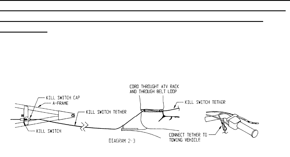
1. Before starting engine, be sure the safety/kill switch is in place and the safety/kill switch tether is
laced through the rear rack of the ATV and draped over the handlebars so it is easily accessible
to string through the drivers belt loop once the lawn mowers engine is started. Make sure the kill
switch tether does not become tangled in any moving parts of the lawn mower, ATV or garden
tractor.
2. To start engine, move throttle control to the CHOKE position, unless engine is warm. If engine
is warm, move the throttle control to slow position. Turn the key to start engine. When engine is
running, move the throttle control to the desired speed. WARNING: automatic clutch will
engage blade drive system IMMEDIATELY. KEEP FEET AND HANDS CLEAR OF DECK
EDGES.
3. As soon as lawn mower engine starting has been achieved and engine speed has been adjusted,
mount the ATV/garden tractor and immediately string the safety/kill switch tether through
operators belt loop (or equivalent) then around the ATV handle bars (as shown in Diagram 2-3).
6
4. The engine is stopped by moving the throttle control down to the STOP position, turning the key
to OFF position or by pulling the safety/kill switch tether.
WARNING! THE ONLY WAY TO INSURE THAT THE BLADES ARE
STOPPED IS TO SHUT OFF THE ENGINE! DO NOT RELY ON THE
CLUTCH TO DISENGAGE THE BLADES WITH THE ENGINE
RUNNING!
1-3 EMERGENCY SHUTDOWN PROCEDURES
To shutdown the engine and blade quickly, in the event of an emergency, pull the safety/kill switch
tether. This will stop the engine immediately. The blade still will be spinning however, so use
CAUTION when approaching the mower. If lawn mower blade should strike a hard object or become
tangled in some debris, immediately pull the safety/kill switch tether, wait for the blade to come to a
complete stop and remove the spark plug wire. Then, inspect blade for damage or untangle blade before
continuing. Install the safety/kill switch tether cord holder onto the rear hitch tube. String the tether
cord through the holder when stringing from the A-Frame to the belt loop.
1-4 MOWING SPEED SPECIFICATION
Mower is to be used at low speeds. When mowing, do not exceed 5 MPH. When towing mower,
have engine off and blade stopped, and do not exceed 10 MPH. If mower cuttings are uneven, slow
the mowing speed.
1-5 HEIGHT ADJUSTMENT
Height adjustment is controlled by a single screw adjustment at the rear of the mower. Height
adjustment changes must be done with engine off. Turn crank handle clockwise to raise the mower,
and counter clockwise to lower the mower. Level cutting is recommended and is adjusted by
position of the 1/2” nuts on the lift rod.
7
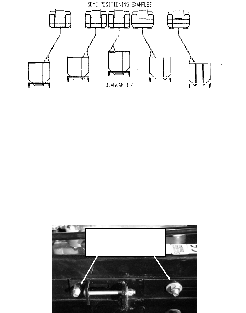
1-6 HITCH POSITION
SEE DIA. 1-4 Engine must be stopped when setting new hitch position. Hitch positioning can be
one of 3 primary positions, plus, extension of the hitch to 3 different lengths allows different
amounts of offsetting positions relative to the ATV or garden tractor. The mower may be towed
directly behind the ATV/garden tractor, slightly offset to the right or left, or fully offset right or left
of the ATV/garden tractor. With each hitch position change, the safety/kill switch tether cord length
must be changed.
MAINTENANCE
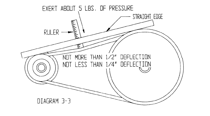
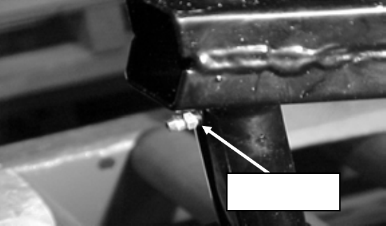
2-1 BELT REPLACEMENT AND TENSION SETTING
Remove the belt guard and loosen the front and rear carriage bolt locknuts of the belt tensioner on
each side of the mower (see picture below). Loosen the 3” carriage bolts. Remove old belt if
necessary. Thread new belt around the pulleys. Tighten the 3” carriage bolts until proper belt
tension is achieved. SEE DIAGRAM 3-3. Retighten the carriage bolt locknuts fully. Reinstall the
belt guard.
Note: Check Belt Tension after the first 1/2 hour of use at the beginning of the season and
daily thereafter.
Loosen two front and rear
nylock nuts on each side of
mower.
8
2-2 CUTTING BLADE SERVICE
1. Before doing any work on blade, disconnect the spark plug wire and secure it away from the plug
to prevent unintentional starting. Remove safety/kill switch cap. Have blade sharpened if it
becomes dull from extended use. Have blade and blade support replaced if they become bent or
chipped from impacting solid objects. Grease spindle at each blade change.
2. Check blade, spindle nuts and bolts at frequent intervals to make sure blade and spindle remains
tight.
2-3 SPINDLE BEARING REPLACEMENT
Refer to the Parts List for Part #’s on Instructions 1-4
1. Remove the belt guard.
2. Remove the blade and blade support.
3. Remove the pulley from the spindle shaft.
4. Remove the spindle from the center deck.
Refer to Spindle Parts List for Part #’s on Instructions 5-10
5. Remove the bolt, lockwasher, flatwasher and cotter pin.
6. Remove the spindle nut.
7. Pull spindle shaft out of the spindle casting.
8. Remove the spindle seals, these will have to be replaced with new ones.
9. Remove the spindle bearings.
10. Remove the spindle outer bearing cups. Using new spindle bearings, spindle outer bearing cups
and spindle seals, put spindle back together in the opposite order it was taken apart (Instruction
10 thru 5). Then, grease the spindle until grease is discharged through either the top or bottom
spindle seal. (Wipe off excess grease and put the spindle back on the mower using instructions 4
thru 1). Set belt tension using SECTION 2-1.
9
2-4 PERIODIC MAINTENANCE
Check these items before each use unless otherwise specified.
1. Check V-belt tension after the first 1/2 hour of use at the beginning of the season and daily
thereafter. SEE SECTION 2-1.
2. Engine oil level, daily. Blade condition, daily.
3. Bolts, nuts, cotter keys and retaining pins before and after each use, and at each refueling.
4. Lubrication of mower parts weekly.
5. Follow engine manual recommendations for engine servicing.
6. Check for dull or nicked blades that may require sharpening or replacing.
7. Replace all damaged or missing fasteners immediately, before any operation of the mower.
8. Grease or lightly oil between moving parts.
9. Grease spindle whenever blade is replaced or at beginning of new season. Apply grease until a
small amount is discharged from either upper or lower spindle seal. Wipe off excess grease and
oil. Prevent or remove lubricants from contact with belt or pulley grooves.
10. Change oil according to engine manufacturer’s owners manual.
11. Inspect mower parts and decals at each refueling.
12. Repair or replace all damage, worn or missing mower parts before using.
13. Replace all damaged or missing warning or instruction decals as soon as possible.
14. Located on the A-frame is the grease zerk. This zerk has already been greased for you but it is
important for you to re-grease it at the beginning of each mowing season and at each oil change.
Grease Zerk
15. Periodically check all nuts and bolts for tightness.
16. Check exterior surfaces and clean up any accumulation of grass, oil, dirt or gas especially around
air intakes and cooling fins on engine. Failure to keep clean will make the engine overheat,
causing severe damage.
17. Check engine oil and add as needed. (SEE ENGINE OWNER’S MANUAL.)
10
7
9
8
10
A
B
19
12
14
18
13
11
17
16
Belt Tensioner
20
21
15
2
5
4
6
3
7
Detail A
Detail B
11

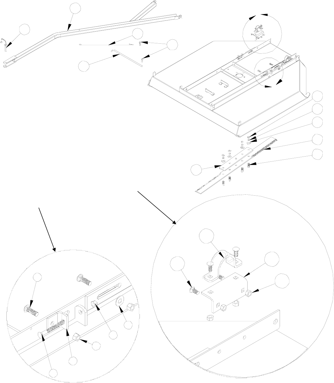
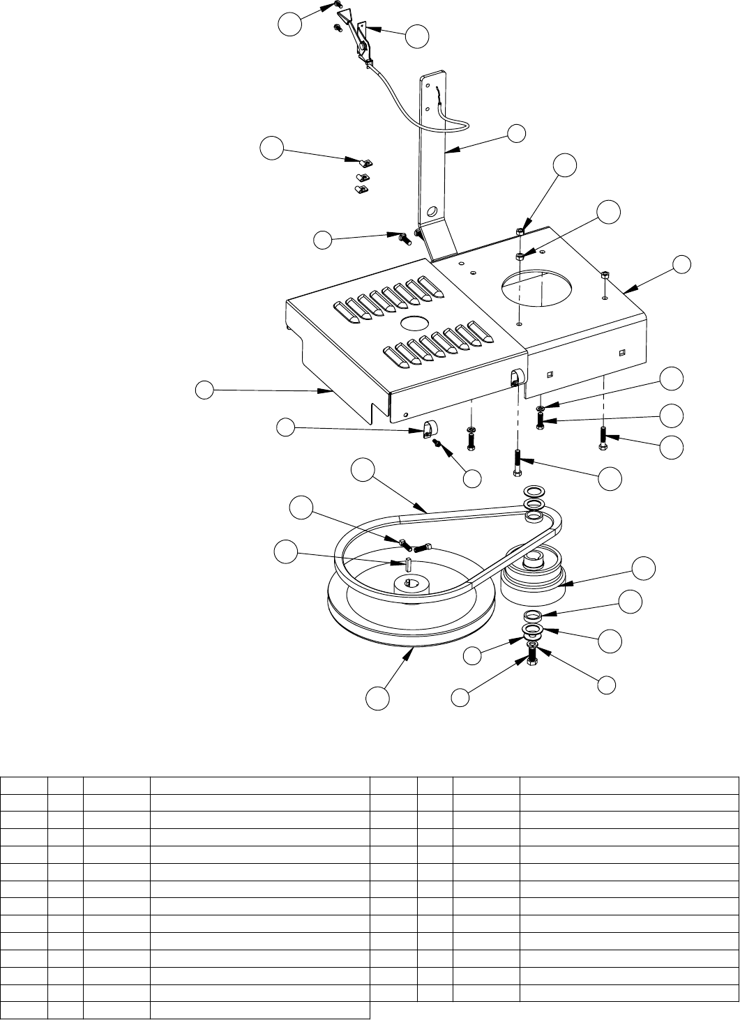
Rough Cut Mower
Deck Sub Assembly
30-0045
30-0140
Parts List
ITEM NO. QTY. PART NO. DESCRIPTION
1 1 CYC1535 Deck
2 4 PUR1187 Carriage Bolt 3/8" x 1-1/4"
3 2 CYC2233 Belt Tension Bracket
4 2 PUR0250 3/8" Flatwasher
5 4 PUR1272 Nut 3/8" Nylock
6 2 PUR1201 Carriage Bolt 5/16" x 3"
7 10 PUR1275 Locknut 5/16" Nylock
8 8 PUR1202 Carriage Bolt 5/16" x 3/4"
9 2 CYC1579 Rear Axle Mount Bracket
10 2 CYC1580 Rear Axle U-Bracket
11 4 PUR1110 1/2" x 1-1/2" Bolt
12 1 PUR1574 Blade
13 1 PUR1575 Blade Support
14 4 PUR1233 1/2" Flatwasher
15 4 PUR1288 1/2" Lockwasher
16 1 CYC4862 Tow Bar
17 1 CYC1569 Hitch Attachment Rod
18 4 PUR1260 Lock Nut 1/2" Yellow
19 2 PUR1249 # 3 Hair Pin
20 1 PUR1587 Tether Cord Support
21 1 PUR1286 Lock Pin 3/8" x 2.5"
12
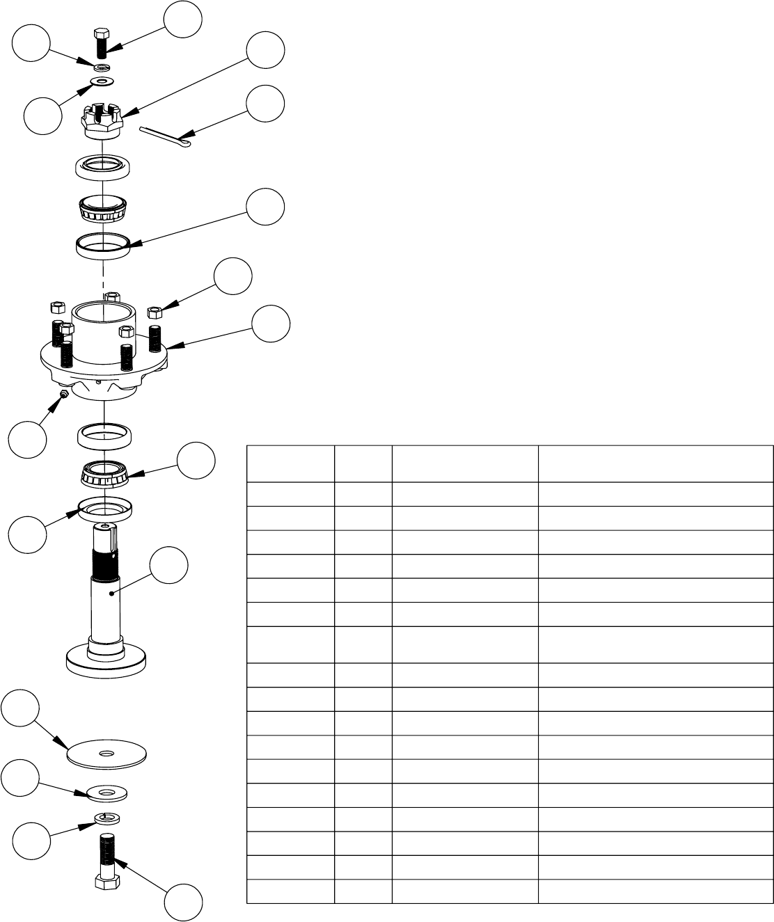
Rough Cut Mower
Spindle Assembly
30-0045
30-0140
Parts List
ITEM NO. QTY. PART NUMBER DESCRIPTION
1.7 1 PUR1565 Rough Cut Spindle
1.1 1 PUR1566 Spindle Casting
1.2 1 PUR1567 Spindle Shaft
1.3 1 PUR1568 Spindle Nut
1.4 1 PUR1573 Cotter Pin
1.5 1 PUR1572 Spindle Zerk
1.6 2 PUR1571 Spindle Outer Bearing Cup
1.7 2 PUR1570 Spindle Bearing
1.8 2 PUR1569 Spindle Seal
21PUR1140 3/8" x 1" Bolt
31PUR1292 3/8" Lockwasher
41PUR0250 3/8" Flatwasher
51PUR1168 5/8" x 2" Bolt
61PUR1294 5/8" Lockwasher
71PUR1245 5/8" Flatwasher
8 1 PUR1585 Blade Clutch Pad
9 5 PUR1262 Nut 3/8" Fine Thread
5
6
7
8
1.7
9
4
1.6
1.2
1.3
1.4
3
1.8
1.5
1.1
2
13
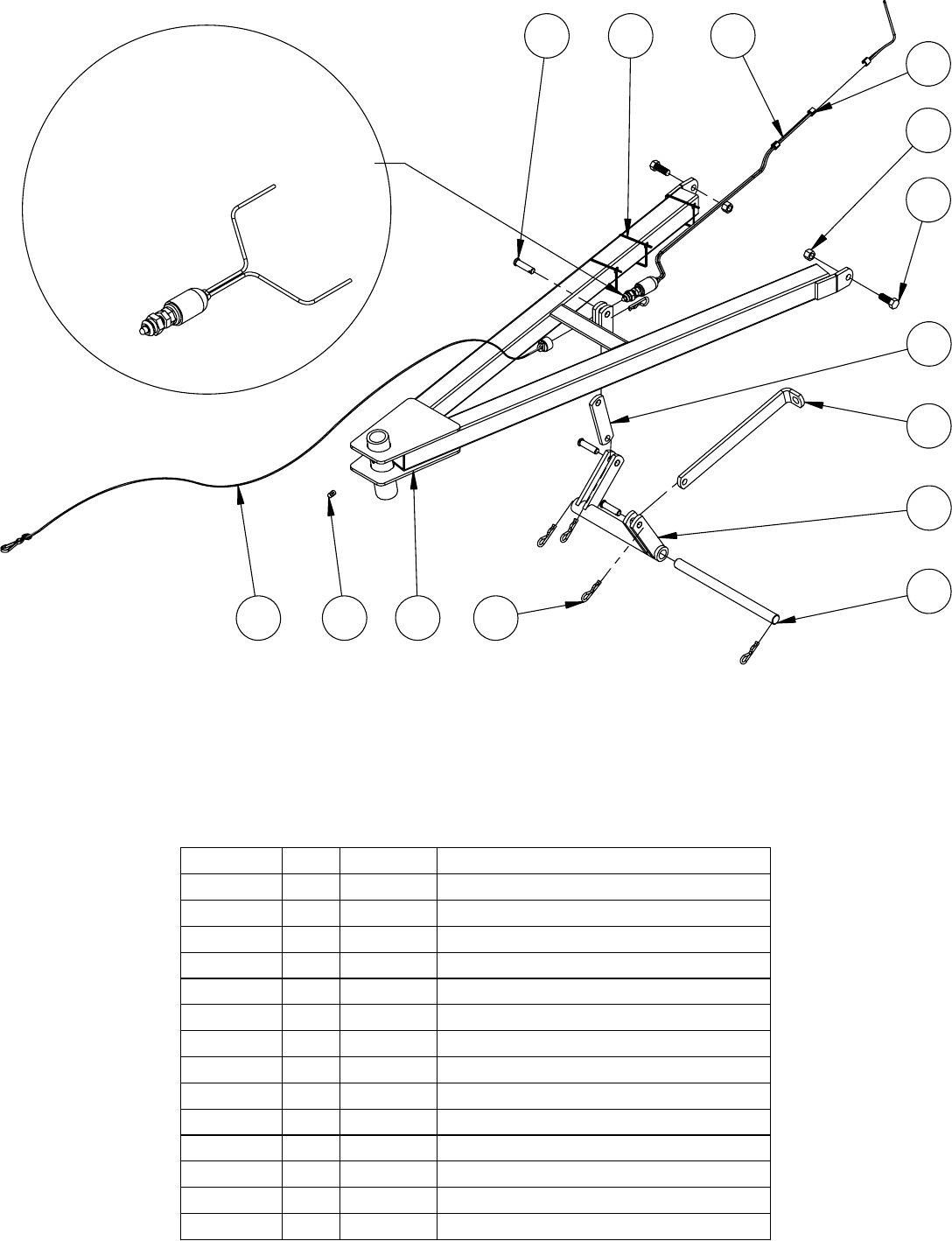
Rough Cut Mower
A-Frame Sub Assembly
30-0045
30-0140
Parts List
13
12
914
11
7
2
5
6
3
4
10 8 1
Switch PUR1584 is
separate from the wiring harness
on Honda Mowers
ITEM NO. QTY. PART NO. DESCRIPTION
1 1 CYC0100 A-Frame Weldment
2 1 CYC1567 Toggle Plate
3 1 CYC1557 Bell Crank Assembly
4 1 CYC1560 Pivot Rod
5 1 CYC1568 Lift Rod Adjuster
6 5 PUR1249 #3 Hair Pin
7 3 PUR1209 Clevis Pin .375 x 1.375 Yellow Zinc
8 1 PUR1603 Grease Zerk
9 1 CYC5372 Safety Switch & Components (Briggs)
10 1 CYC5371 Safety Switch Cap/ Tether/ Hook
11 2 PUR1140 3/8" x 1" Bolt
12 2 PUR1272 Locknut 3/8" Nylock
13 3 PUR1593 Rubber Grommet
14 3 PUR1947 Cable Tie 14"
4
1
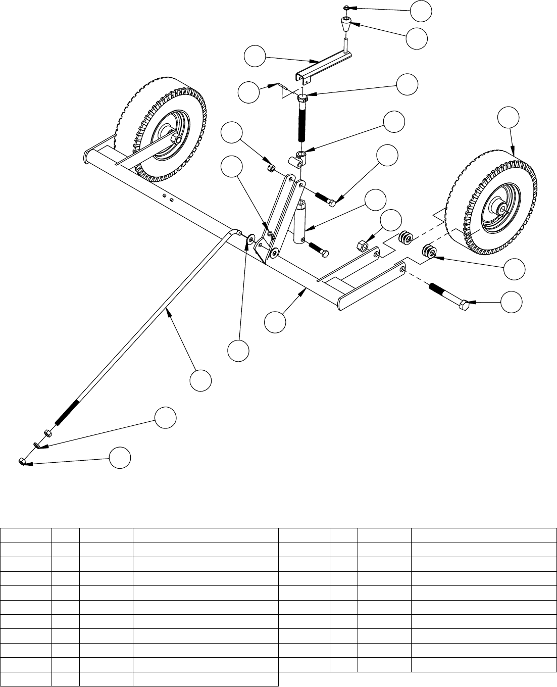
Rough Cut Mower
Rear Axle Sub Assembly
30-0045
30-0140
Parts List
78
6
4
5
9
11
10
12
19
15
1
14
13
17
16
2
3
18
ITEM NO. QTY. PART NO. DESCRIPTION
1 1 CYC0111 Rear Axle Weldment
2 2 PUR1139 3/4" x 5-1/2" Bolt
3 2 PUR1268 Lock Nut 3/4"
4 1 PUR1353 3/8" Push Nut
5 1 PUR1590 Knob
6 1 CYC1582 Height Adjustment Crank
7 1 PUR1363 3/16" x 1-1/2" Roll Pin
8 1 PUR1564 Height Adjustment Bolt
9 1 CYC1587 T-Sleeve
10 2 PUR1112 1/2" x 2-1/2" Bolt
ITEM NO. QTY. PART NO. DESCRIPTION
11 2 PUR1260 Lock Nut 1/2" Yellow
12 1 CYC1586 Height Adjustment Nut
13 1 CYC1230 Lift Rod
14 2 PUR1233 1/2" Flatwasher
15 1 PUR1249 # 3 Hair Pin
16 2 PUR1332 Nut 1/2"
17 1 PUR1288 1/2" Lockwasher
18 2 PUR2179 Pneumatic Wheel
19 12 PUR1240 14 Gauge Machine Bushing
15
6
1
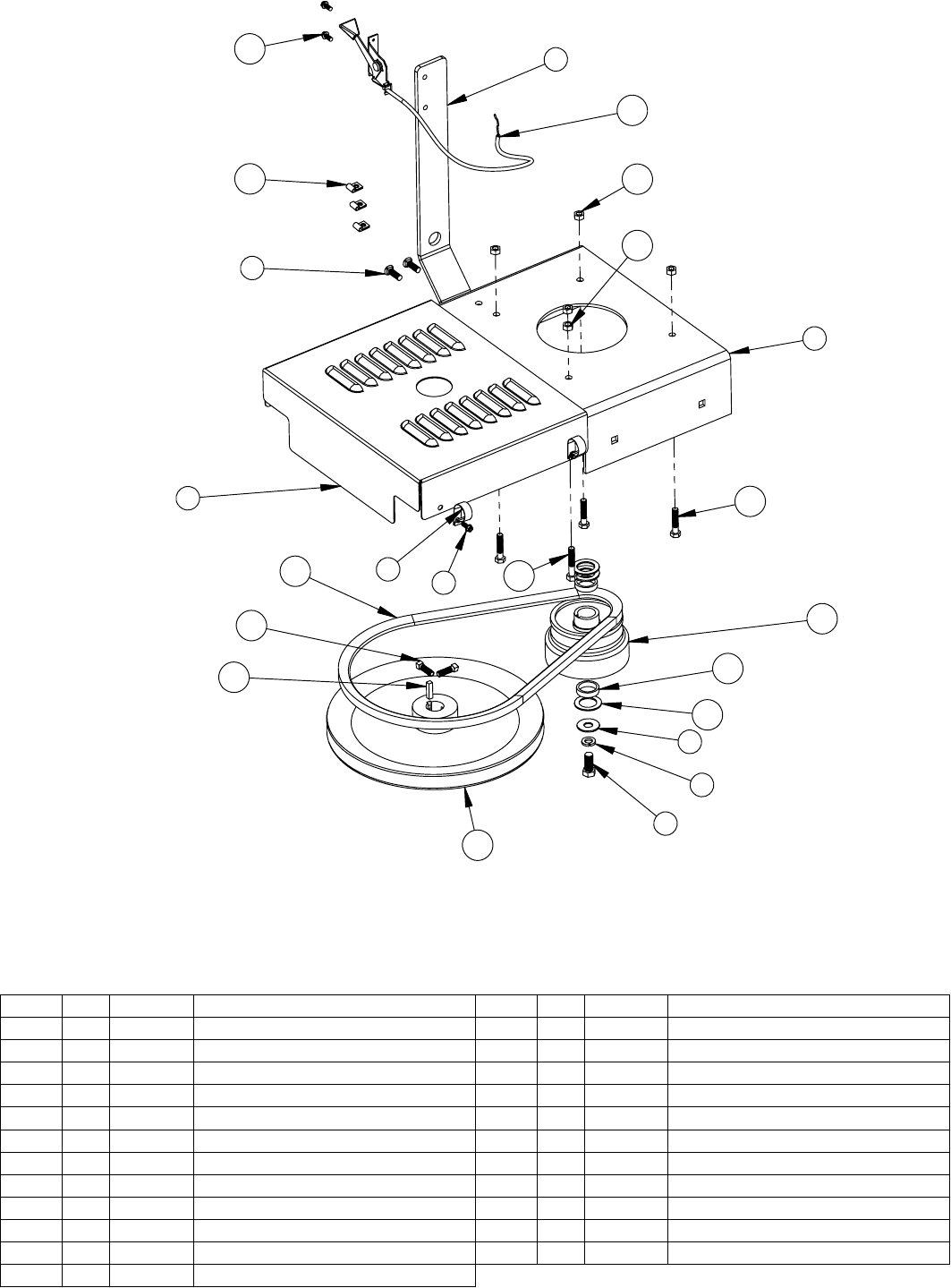
Rough Cut Mower
Pulley Sub Assembly
30-0045
Briggs
Parts List
22 5
21
19
20
1
34
17
18
15 12
10
9
8
7
13
16
14
2
6
23
11
ITEM NO. QTY. PART NO. DESCRIPTION
1 1 CYC2235 Motor Mount
2 1 CYC2234 Belt Guard Shield
3 2 PUR1609 Clamp 3/4" Vinyl Coated
4 4 PUR1395 12 x 1/2" Hex Washer Head Tapping Screw
5 1 CYC2934 Bracket for throttle and starter switch
6 2 PUR1189 Carriage Bolt 5/16" x 1"
7 1 PUR1229 7/16" x 1" Fine Thread Bolt
8 1 PUR1295 7/16" Lockwasher
9 1 PUR1248 7/16" Flatwasher
10 3 PUR1301 1" x 1-1/2" Machine Bushing
11 2 CYC5443 Bushing Mower Clutch RC Mower
12 1 PUR0678 Engine Drive Clutch
ITEM NO. QTY. PART NO. DESCRIPTION
13 1 PUR1578 Pulley
14 1 PUR1595 1/4" x 1" Keystock
15 2 PUR1384 5/16" x 1" Square Head Set Screw
16 1 PUR1586 Belt
17 3 PUR1156 5/16" x 1-1/2" Bolt
18 1 PUR1159 5/16" x 1-3/4" Bolt
19 6 PUR1275 Locknut 5/16" Nylock
20 1 PUR1278 Flange Nut 5/16" Serrated
21 1 PUR1563 Throttle Cable
22 2 PUR1392 10 x 1/2" Slotted Tapping Screw
23 3 PUR1562 Throttle Cable Clamp
Rough Cut Mower
Pulley Sub Assembly
30-0140
Honda
Parts List
24 23
25 5
22
21
1
220
19
18
3
417
14 12
11
10
8
7
9
13
16
15
6
ITEM NO. QTY. PART NO. DESCRIPTION
1 1 CYC2235 Motor Mount
2 1 CYC2234 Belt Guard Shield
3 2 PUR1609 Clamp 3/4" Vinyl Coated
4 4 PUR1395 12 x 1/2" Hex Washer Head Tapping Screw
5 1 CYC2934 Bracket for throttle and starter switch
6 2 PUR1189 Carriage Bolt 5/16" x 1"
7 1 PUR1229 7/16" x 1" Fine Thread Bolt
8 1 PUR1295 7/16" Lockwasher
9 1 PUR1248 7/16" Flatwasher
10 3 PUR1301 1" x 1-1/2" Machine Bushing
11 2 CYC5443 Bushing Mower Clutch RC Mower
12 1 PUR0678 Engine Drive Clutch
17
13 1 PUR1578 Pulley
ITEM NO. QTY. PART NO. DESCRIPTION
14 1 PUR1595 1/4" x 1" Keystock
15 2 PUR1384 5/16" x 1" Square Head Set Screw
16 1 PUR1586 Belt
17 1 PUR1159 5/16" x 1-3/4" Bolt
18 1 PUR1156 5/16" x 1-1/2" Bolt
19 2 PUR1932 5/16" x 1" Fine Thread Bolt
20 2 PUR1293 5/16" Lockwasher
21 1 PUR1278 Flange Nut 5/16" Serrated
22 4 PUR1275 Locknut 5/16" Nylock
23 1 PUR1563 Throttle Cable
24 2 PUR1392 10 x 1/2" Slotted Tapping Screw
25 3 PUR1562 Throttle Cable Clamp
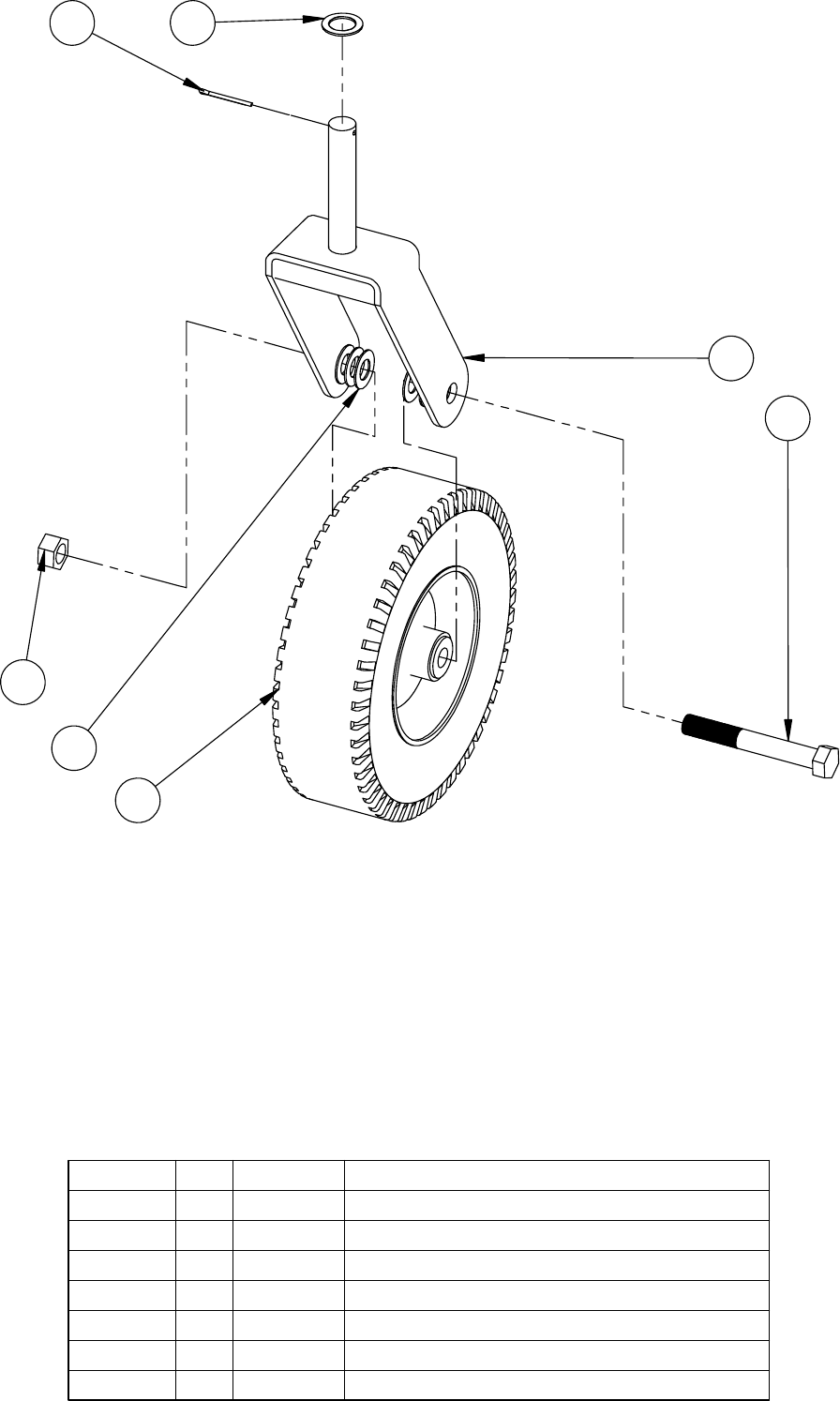
Rough Cut Mower
Wheel Caster Sub Assembly
30-045
30-0140
Parts List
4
3
2
71
5
6
ITEM NO. QTY. PART NO. DESCRIPTION
1 1 PUR1205 5/32" x 1-1/2" Cotter Pin
2 1 CYC0107 Front Fork Weldment
3 1 PUR2179 Pneumatic Wheel
4 1 PUR1139 3/4" x 5-1/2" Bolt
5 1 PUR1268 Lock Nut 3/4"
6 6 PUR1240 14 Gauge Machine Bushing
7 1 PUR1301 1" x 1-1/2" Machine Bushing (MB112-1)
8
1
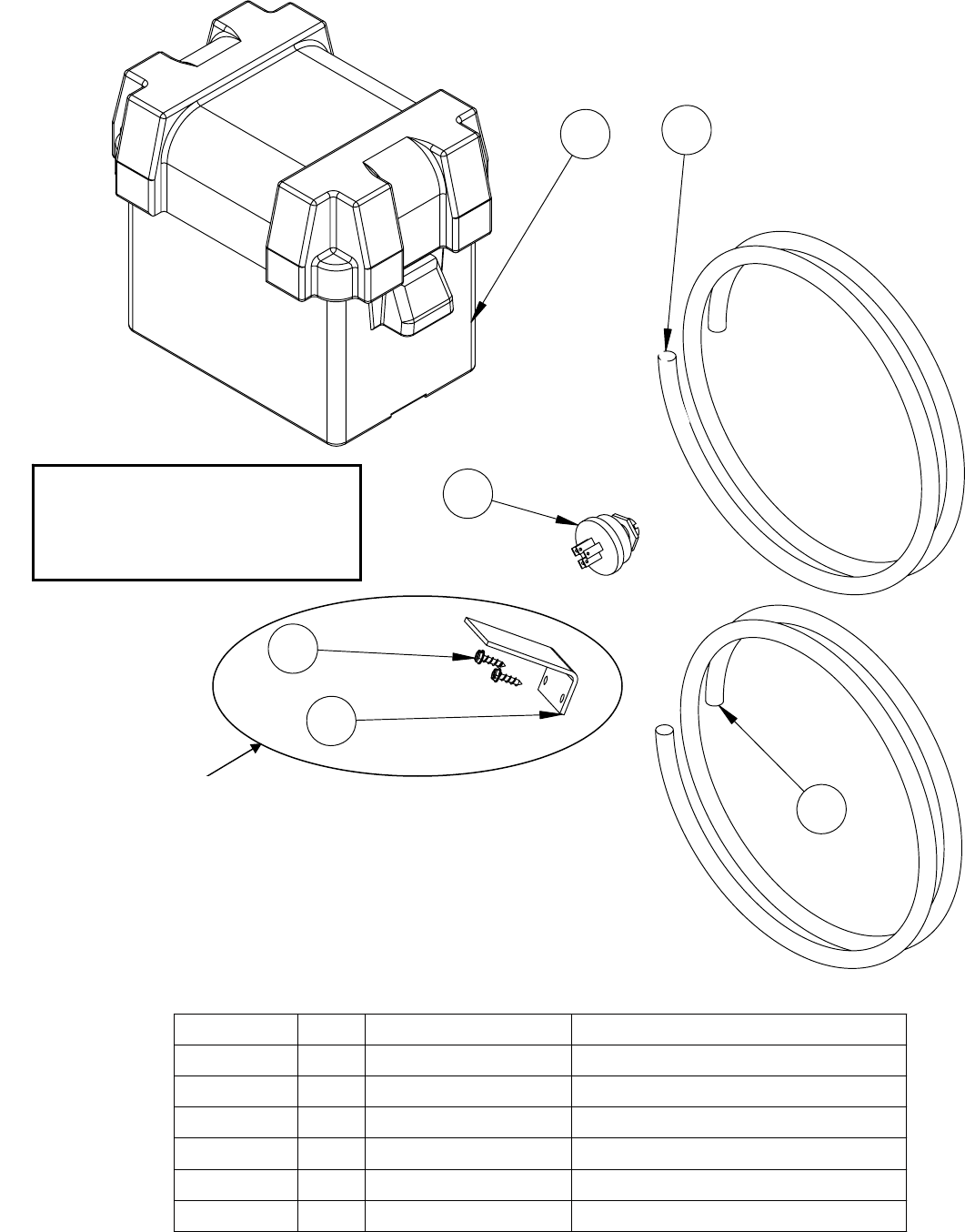
Rough Cut Mower
Electric Start Wiring
Parts List
12
4
5
3
6
ITEM NO. QTY. PART NO. DESCRIPTION
1 1 PUR1540 Battery Box
2 1 CYC5572 Wiring Harness - Briggs RC
3 1 CYC5573 Wiring Harness - Honda RC
4 1 PUR1600 Ignition Switch
5 1 PUR1550 Solenoid Cover
6 2 PUR1407 Hex Tapping Screw 1/4" x 3/4"
Recommended Battery:
Garden Tractor, Utility Battery
BCI Group: U1
(
Not Included
)
Used only when Briggs Engine is
being used.
19

Cycle Country Accessories Corporation has been a world-renowned manufacturer of quality
ATV products since 1981 and we hope you will enjoy your new Cycle Country accessory.
We’re the Industry Snow Blade leader:
42”, 48”, 54”, 60” & 72” Straight Blades
52” & 60” State Plows
Power ‘V’ Blade
If a winch is what you must have, then you’ve come to the right place:
1500lb, 2500lb and 3000lb Winches
We also have an extensive line of winch mounts for both Cycle Country and Warn winches
If you need to haul more gear on your quad, check out our baskets:
Front Basket
Rear Basket
Rear Drop Basket
If you need to mow the trail before you go riding one of these will help:
Our 54” finish cut Quick Silver54 can be mounted in front or towed behind your ATV
The 48” Rough Cut will handle your toughest mowing jobs
The Rough Cut 44 provides an economical way to handle all your mowing needs
If you are into deer hunting and want to make a food plot, you will love our 3 Point
Hitch & Implements:
Rear Blade Moldboard Plow Spreader
Furrower Rake
Cultivator Disk Harrow
And many more accessories to help you Work Hard and Play Hard:
For more information call us at 1-800-841-2222, or on the web at www.cyclecountry.com
20
