L301PDP_0 301SIE_E 301SIE E
301sie_e 301sie_e
User Manual: 301SIE_E
Open the PDF directly: View PDF ![]() .
.
Page Count: 42
- Suggestions for the user
- Quality and support
- Safety regulations
- Standards
- 1 AS511 - Driver
- 1.1 First commissioning
- 1.1.1 Loading of the AS511 firmware into the LCA
- 1.1.2 Connection of the LCA to the PLC
- 1.1.3 Trouble-shooting
- 1.1.4 Diagnosis
- 1.2. PLC-Handling software
- 1.2.1 General description of the AS511 protocol
- 1.2.2 AS511 and LCA
- 1.2.3 Transfer times/response times
- 1.2.4 Multiple use of AS 511
- 1.2.5 Configuration of the address reference
- 1.2.6 Driving of the LCA
- 1.3 Cables
- 2 Lauer - Driver
- 2.1 First commissioning
- 2.1.1 Lauer driver variables
- 2.1.2 Procedure
- 2.1.3 Trouble-shooting
- 2.2 PCS 810 Handling FB
- 2.2.1 Addressing
- 2.2.2 Selection of the slot
- 2.2.3 Handling software
- 2.2.4 Parameterization of the FB 203
- 2.2.5 Operation of the PLC with EPROM
- 2.2.6 Implementation of the handling FB
- 2.2.7 Program integration
- 2.3 PCS 810 technical data
- 2.4 Communication
- 2.4.1 Current loop power supply
- 2.4.2 PCS 736 Adapter cable
- 2.4.3 PCS 733 programming cable
- 2.4.4 LCA/PCS 810 data transfer
- 2.4.5 PCS 810/S5 Bus data transfer
- 2.4.6 Software
- 2.4.7 PROJEKT 1: P81019ST.S5D
- Index

Reg 10226/1099Reg 10226/1099
Reg 10226/1099Reg 10226/1099
Reg 10226/1099
VV
VV
Version 2/10.99ersion 2/10.99
ersion 2/10.99ersion 2/10.99
ersion 2/10.99
© Systeme © Systeme
© Systeme © Systeme
© Systeme LauerLauer
LauerLauer
Lauer GmbH & Co KG GmbH & Co KG
GmbH & Co KG GmbH & Co KG
GmbH & Co KG
LCA 301.SIE
Siemens Manual
LCA 301
Appendix to the manual ofAppendix to the manual of
Appendix to the manual ofAppendix to the manual of
Appendix to the manual of
the LCA 300/320the LCA 300/320
the LCA 300/320the LCA 300/320
the LCA 300/320

© Systeme Lauer GmbH & Co KG Kelterstr.59 72669 Unterensingen Tel. (07022) 96 60-0 Fax (07022) 96 60-103
0-2
Systeme Lauer GmbH & Co KG
Postfach 1465
D-72604 Nürtingen
Operator reference manual: LCA 301.SIE
Version: 19. Oktober 1999
Person responsible: Lackenbauer
Operating manuals, reference manuals, and software are protected by
copyright. All rights remain reserved. The copying, duplication, trans-
lation, conversion in the whole or into parts are not permitted. An excep-
tion applies to making a copy of the software for the own use.
We reserve the right to make changes to the reference manual with-
out prior notice.
We can not guarantee the accuracy of the programs and data stored
on the diskette and the fault-free state of this information.
Since diskettes represent manipulatable data media, we can only
guarantee the physical completeness. The responsibility is limited
to a replacement.
At any time, we welcome suggestions for improvements and remarks
on errors.
The agreement also applies to the special appendices to this refer-
ence manual.
Microsoft, MS, MS DOS, Windows, Windows 95, Windows NT and the
Windows logo are either registered trademark or trademarks of the Micro-
soft Corporation in the USA and/or other countries.
SIMATIC and STEP are registered trademarks of the Siemens AG.
The remaining designations in this document can be brand names whos
use by third parties for their purposes can violate the rights of the owners.
© Systeme Lauer GmbH & Co KG Kelterstr.59 72669 Unterensingen Tel. (07022) 96 60-0 Fax (07022) 96 60-103 0-3
Suggestions for the userSuggestions for the user
Suggestions for the userSuggestions for the user
Suggestions for the user
Please read the reference manual before applying the unit first and store
the manual at a safe location for later use.
Target group The reference manual is written for users with previous knowledge in
PC and automation technology.
Representation conventions [KEY] Key inputs of the user are represented in square
brackets, e.g. [CTRL] or [DEL]
Courier Display outputs are printed in the Courier font, e.g.
C: \>
Courier boldCourier bold
Courier boldCourier bold
Courier bold Keyboard input to be made by the user are given in
Courier bold, e.g. C:\>DIRDIR
DIRDIR
DIR
Kursiv Names of buttons to be selected, menus or other
screen elements and product names are printed in
Italics.
Symbols The following symbols in the reference manual are used to
mark certain text sections:
Danger!
Possibly dangerous situation.
Injury to persons can be the result.
Attention!
Possibly dangerous situation.
Property damages can be the result.
Tips and supplementary notes

© Systeme Lauer GmbH & Co KG Kelterstr.59 72669 Unterensingen Tel. (07022) 96 60-0 Fax (07022) 96 60-103
0-4
TT
TT
Table of contensable of contens
able of contensable of contens
able of contens
Suggestions for the userSuggestions for the user
Suggestions for the userSuggestions for the user
Suggestions for the user 0-30-3
0-30-3
0-3
Quality and supportQuality and support
Quality and supportQuality and support
Quality and support 0-50-5
0-50-5
0-5
Safety regulationsSafety regulations
Safety regulationsSafety regulations
Safety regulations 0-60-6
0-60-6
0-6
StandardsStandards
StandardsStandards
Standards 0-70-7
0-70-7
0-7
11
11
1AS511 - DriverAS511 - Driver
AS511 - DriverAS511 - Driver
AS511 - Driver 1-11-1
1-11-1
1-1
1.1 First commissioning ......................................................... 1-1
1.1.1 Loading of the AS511 firmware into the LCA................... 1-2
1.1.2 Connection of the LCA to the PLC ................................... 1-2
1.1.3 Trouble-shooting ............................................................. 1-3
1.1.4 Diagnosis ......................................................................... 1-4
1.2. PLC-Handling software .................................................... 1-5
1.2.1 General description of the AS511 protocol ...................... 1-5
1.2.2 AS511 and LCA ............................................................... 1-5
1.2.3 Transfer times/response times .......................................... 1-6
1.2.4 Multiple use of AS 511 .................................................... 1-6
1.2.5 Configuration of the address reference ............................ 1-6
1.2.6 Driving of the LCA ........................................................... 1-7
1.3 Cables ............................................................................. 1-8
22
22
2Lauer - DriverLauer - Driver
Lauer - DriverLauer - Driver
Lauer - Driver 2-12-1
2-12-1
2-1
2.1 First commissioning ......................................................... 2-1
2.1.1 Lauer driver variables ....................................................... 2-2
2.1.2 Procedure ........................................................................ 2-3
2.1.3 Trouble-shooting ............................................................. 2-4
2.2 PCS 810 Handling FB ...................................................... 2-6
2.2.1 Addressing....................................................................... 2-6
2.2.2 Selection of the slot ......................................................... 2-6
2.2.3 Handling software ........................................................... 2-8
2.2.4 Parameterization of the FB 203 ....................................... 2-9
2.2.5 Operation of the PLC with EPROM ................................ 2-11
2.2.6 Implementation of the handling FB ............................... 2-12
2.2.7 Program integration ...................................................... 2-12
2.3 PCS 810 technical data ................................................. 2-13
2.4 Communication ............................................................ 2-14
2.4.1 Current loop power supply ............................................ 2-14
2.4.2 PCS 736 Adapter cable .................................................. 2-15
2.4.3 PCS 733 programming cable......................................... 2-16
2.4.4 LCA/PCS 810 data transfer ............................................ 2-16
2.4.5 PCS 810/S5 Bus data transfer ........................................ 2-17
2.4.6 Software ........................................................................ 2-18
2.4.7 PROJEKT 1: P81019ST.S5D ............................................ 2-20
IndexIndex
IndexIndex
Index i-1i-1
i-1i-1
i-1
© Systeme Lauer GmbH & Co KG Kelterstr.59 72669 Unterensingen Tel. (07022) 96 60-0 Fax (07022) 96 60-103 0-5
Quality and supportQuality and support
Quality and supportQuality and support
Quality and support
In our company, quality comes first. From the electronics component
up to the finished device, the quality assurance tests competently and
comprehensively.
National and international test standards (ISO, TÜV, Germanischer Lloyd)
are the basis.
Within 48 hours, every device passes a 100% check and continuous test
under worst case conditions at changing temperatures (0... 50°C) and
test voltages.
A guarantee for maximum quality.
Our products not only feature a maximum economic efficiency and
reliability but also a comprehensive complete service.
You not only receive demo devices but we rather make specialists available
who support you in person with your first application.
Qualified user consultation by competent sales engineers is obvious for
us.
Our support is for you for the side with advice and deed every day.
We set up training programs and technical training for you in our mo-
dern training center or alternatively also in your house.
Request the current training catalog.
From the consultation up to the user support, from the hotline up to
the service, from the reference manual up to the training an all covering
and individual service for the entire product line is waiting for you.
Whenever you need us, we are there for you:
dynamically, creatively and enormously efficiently. With the entire
experience of a world-wide successful enterprise.
Telephone 07022/9660 -222, -132, -231, -230
eMail: support@systeme-lauer.de
Web site: www.systeme-lauer.de
Systeme Lauer Active Area
(Download of Software, driver, manuals, Forum ...)
© Systeme Lauer GmbH & Co KG Kelterstr.59 72669 Unterensingen Tel. (07022) 96 60-0 Fax (07022) 96 60-103
0-6
Safety regulationsSafety regulations
Safety regulationsSafety regulations
Safety regulations
This reference manual contains the most important remarks in order to
safely operate the device.
This operators guide, particularly the safety remarks are to be noted
by all persons working with the device.
Furthermore, the rules and regulations for the accident prevention
applying to the application location are to be observed.
Use as directed. The device is designed for the application in the
industrial area.
The device is manufactured to the state of the art and the official
safeguarding regulations. Nevertheless, due to the application,
dangers or impairments can result to the machine or to material
assets.
The device meets the requirements of the EMC guidelines and
harmonized European standards. Any hardware-related modification
of the system can influence the EMC behavior.
The device may not be used without special protective measures in
the hazardous area and in plants requiring a special monitoring.
Do not heat up the buffer batteries. Danger of explosion. Serious
burnings can be the result.
The installation and operation may only be performed by trained
personnel.
The operating voltage of the device may only be in the specified
ranges.
You find information on this on the type plate and in the specific-
ations of this reference manual.

© Systeme Lauer GmbH & Co KG Kelterstr.59 72669 Unterensingen Tel. (07022) 96 60-0 Fax (07022) 96 60-103 0-7
StandardsStandards
StandardsStandards
Standards
The PCS is manufactured to the state of the art and meets the require-
ments of following guidelines and standards:
EMC guideline 89/336/ EEC
EMC specialist basic standard EN50081 part 2 Noise Emission in
The Industrial Area
EMC specialist basic standard EN50082 part 2 Interference Resistance
in The Industrial Area
European Extra Low Voltage Guideline 73/23/EEC
The mounting and connection instructions described in this documen-
tation are to be observed.
The conformity is confirmed by attaching the CE sign.
The EC conformity declarations can be asked for at:
Systeme Lauer GmbH & Co KG
P.O. Box 1465
D-72604 Nürtingen

© Systeme Lauer GmbH & Co KG Kelterstr.59 72669 Unterensingen Tel. (07022) 96 60-0 Fax (07022) 96 60-103
0-8
© Systeme Lauer GmbH & Co KG Kelterstr.59 72669 Unterensingen Tel. (07022) 96 60-0 Fax (07022) 96 60-103 1-1
11
11
1AS511 - DriverAS511 - Driver
AS511 - DriverAS511 - Driver
AS511 - Driver
11
11
1AS511 - DriverAS511 - Driver
AS511 - DriverAS511 - Driver
AS511 - Driver
1.11.1
1.11.1
1.1 First commissioningFirst commissioning
First commissioningFirst commissioning
First commissioning
Delimitation
Warning!
Use only the LCAPRO software for the configuration. Other software
packages can cause malfunctions in the LCA and programmable
controller.
The successful parameterization of the LCA as described in the LCA and/
or LCAPRO manual is assumed. This appendix is exclusively concerned
with the application of the LCA together with the SIEMENS S5 90U to
135U programmable controller series. This controller is called program-
mable controller in the following. The SIEMENS-specific terminology
and the programming of the programmable controller using the software
is assumed to be known. The LCA 300 mentioned in the following
represents also the LCA 320. Functionally, both text displays are identical.
Required devices and accessories The following products (from the System Lauer company) are required
to operate a programmable controller with an already parameterized
LCA 300/320:
1. The LCA text display (already parameterized).
2. The LCA 716 connecting cable for the connection of the LCA to the
programmable controller via the TTY interface.
3. This manual.
4. The LCAPRO diskette with the L300AS08.FRM, L300AS16.FRM, and
L300AS20.FRM firmware modules.
5. LCA 300 or LCA 320.
6. Possibly a PG-MUX 809 for CPUs with one port.
Also required are (from SIEMENS):
7. One 155U,(CPU 928), 135U (CPU 928), 115U (CPU 941 and high-
er), 100U (CPU 100, CPU 102 or CPU 103), 95U or 90U program-
mable controller
8. One corresponding rack or bus module for the programmable con-
troller.
9. One PG 635, PG 675, PG 685, PG 710, PG 730, or PG 750 program-
ming unit.
10. Power supply for all components.

© Systeme Lauer GmbH & Co KG Kelterstr.59 72669 Unterensingen Tel. (07022) 96 60-0 Fax (07022) 96 60-103
1-2
11
11
1AS511 - DriverAS511 - Driver
AS511 - DriverAS511 - Driver
AS511 - Driver
1.1.11.1.1
1.1.11.1.1
1.1.1Loading of the AS511 firmware into the LCALoading of the AS511 firmware into the LCA
Loading of the AS511 firmware into the LCALoading of the AS511 firmware into the LCA
Loading of the AS511 firmware into the LCA
The LCA firmware and one or two binary records are transferred during
the configuration. The modules have the .FRM extension and are
associated to the CPUs as followed:
L300AS08.DRV for all programmable controllers of the 95U, 100U,
102U, 103U series (all CPUs), 115U for the CPU 941 up to and
including the CPU 944.
L300AS20.DRV for the 945 programmable controller.
L300AS16.DRV for the 135U and 155U series (all CPUs besides CPU
921)
All parameters and settings which affect the linkage are taken from the
1st record. These are:
1. [Y001] variable: time-out time
The time-out time determines the maximum admissible time (in
milliseconds) between the sending of a request and the arriving of
the programmable controller response. Since a repeat is started
after the first missing reception data, the message may appear only
after the twice the time. By default, this time is preset to 400 milli-
seconds. Admissible values are between 0 (no time monitoring)
and 30000 (30 sec.).
2. ADDRESS REFERENCES are also retrieved from the first record. If
references are specified in the second record which are not contained
in the first record (e.g. variables) then these values remain at 0 and
are never read. The preset value addresses are also taken from the
1st record.
1.1.21.1.2
1.1.21.1.2
1.1.2Connection of the LCA to the PLCConnection of the LCA to the PLC
Connection of the LCA to the PLCConnection of the LCA to the PLC
Connection of the LCA to the PLC
Warning!
Check the function of the LCA and programmable controller after
parameterization and/or a firmware transfer. All parameterized functions
must be checked.
1. Create possibly required DBs in the programmable controller.
2. Apply operating voltage (24V DC 20%) to the LCA. The red ERR
LED must now be activated.
3. Connect the programming interface of the programmable controller
to the LCA using the LCA 716 cable.
4. The ERR LED on the LCA must be deactivated after approx. 1 se-
cond.
5. A communication time-out has to be waited for when exchanging
the connected programmable controller CPU in the RUN state! This
applies specially for changing byte-oriented CPUs against word-
oriented CPUs and conversely.
© Systeme Lauer GmbH & Co KG Kelterstr.59 72669 Unterensingen Tel. (07022) 96 60-0 Fax (07022) 96 60-103 1-3
11
11
1AS511 - DriverAS511 - Driver
AS511 - DriverAS511 - Driver
AS511 - Driver
1.1.31.1.3
1.1.31.1.3
1.1.3TT
TT
Trouble-shootingrouble-shooting
rouble-shootingrouble-shooting
rouble-shooting
Here, the most frequent faults are listed which appear during the first
commissioning and in continuous operation:
1. Wrong firmware loaded. In this case, the LCA signals the fault in
plain text. This applies to all known CPUs having the production
date November 1994.
2. Faulty cable. This results in no error message since a time overflow
is evaluated as fault first after the link has already been started.
However, the ERR LED lights permanently.
3. DB in the programmable controller not created or too short. In this
case, the LCA signals the fault when it tries to access the missing
data element. The following information are shown in the display:
the corresponding LCA address, the required DB/DX number, and
the required byte number (DL/DR).
4. First, communications starts normally (LCA ERR LED is deactivated)
but after a short time, the following message appears on the topmost
display line of the LCA:
»COMMUNICATION-ERROR«
The following faults can appear on the second line:
TIMEOUTTIMEOUT
TIMEOUTTIMEOUT
TIMEOUT::
::
:
This fault appears possibly when using the MUX PCS 809. When
using this device, the variable [Y001] is to be parameterized accor-
ding to the time to be bridged. Usually, 2000 milliseconds are suffi-
cient. Without MUX, 200 milliseconds are sufficient.
PROTOCOL VIOLAPROTOCOL VIOLA
PROTOCOL VIOLAPROTOCOL VIOLA
PROTOCOL VIOLATION:TION:
TION:TION:
TION:
Sequencing fault in the AS511 protocol. In this case, the LCA to
programmable controller interface cabling is routed in a heavy inter-
ference-loaded environment, the cable is too long, or the grounding
is insufficient.
TOO MANY REPETITIONS:TOO MANY REPETITIONS:
TOO MANY REPETITIONS:TOO MANY REPETITIONS:
TOO MANY REPETITIONS:
A re-synchronization and a repetition is performed after unexpected
characters have been received. Interferences, defective screens or
bad grounding situations can be the source of the problem if unex-
pected character are received again.
ERROR CODE:ERROR CODE:
ERROR CODE:ERROR CODE:
ERROR CODE:
xx: This error message could appear with new revisions and new
CPUs. We can perform a more detailed analysis if we are informed
about the shown code.
Warning!
Check the reaction/action of the programmable controller! The desired
reaction/action of the programmable controller is to be checked to avoid
malfunctions after the restart of the pro- grammable controller following
a communication loss.
© Systeme Lauer GmbH & Co KG Kelterstr.59 72669 Unterensingen Tel. (07022) 96 60-0 Fax (07022) 96 60-103
1-4
11
11
1AS511 - DriverAS511 - Driver
AS511 - DriverAS511 - Driver
AS511 - Driver
1.1.41.1.4
1.1.41.1.4
1.1.4DiagnosisDiagnosis
DiagnosisDiagnosis
Diagnosis
Beside the normal operation, the LCA also allows the diagnosis operation.
This mode is activated by pressing an arbitrary key during the powering
up. Subsequently, values read from the programmable controller can
be displayed in the KH format. The addresses are selected using the
ARROW UP and ARROW DOWN keys. The read value is continuously
displayed. The keys are only treated internally. The key status and key
event are always transferred as 0 to the programmable controller.
This mode is terminated be powering the LCA down and up again.
Notes for the connection of the LCA to a programmable controller:
Connect the cable screening to the central common point in the
swiching cabinet!
Provide for good common connections between the LCA on the
one, and to the programmable controller bus board on the other
hand! Remember that a copper grounding strip based on its large
surfacearea has a somewhat better RF conductivity than normal
flexible wire.
Avoid as far as possible the creation of high frequency interferences
since these are very difficult to dampen. Using photocouplers, there
is a potential separation between the programmable controller and
the LCA. But this galvanic isolation is nearly without effect for fast
transients since photocouplers also have (even though minor)a
coupling capacity.
Provide for clear reference points for the supply voltage.To facilitate
this, the power supply is potential-free!
The use of an own power supply for the LCA (24 volt, 10 VA) is
recommended where the supply voltage is subject to high noise
levels. The power supply should have a corresponding noise filter.
Then, 0 volt can be directly connected to the LCA with the protective
conductor.
The LCA and the communication cable should have a minimum
distance of 200 mm from noise sources. This applies especially to
inductivities and frequency converters.
Take care that the serial data lines are covered as completely as
possible by the screening. Use metal-covered connector hoods on
both the LCA as well as on the programmable controller side. The-
se hoods should have a low impedance connection to the cable
screen. With grounding at both sides is to be noted however that
possibly (because of ground potential shifts) a potential compen-
sation wire is required having at least 10 times the screen cross
section. This applies particularly if LCA and programmable controller
are not connected to the same common point. This is for example
valid where the LCA and programmable controller are not housed
in the same switching cabinet!
Reason: Avoidance of compensation currents on the cable screen!
Warning!
The text display writes data
cyclically into the programmable
controller. The programmable
controller may in no case be
compressed using the second
interface if a DW is the target!
This results in an uncontrollable
malfunction of the programma-
ble controller!

© Systeme Lauer GmbH & Co KG Kelterstr.59 72669 Unterensingen Tel. (07022) 96 60-0 Fax (07022) 96 60-103 1-5
11
11
1AS511 - DriverAS511 - Driver
AS511 - DriverAS511 - Driver
AS511 - Driver
1.2.1.2.
1.2.1.2.
1.2. PLC-Handling softwarePLC-Handling software
PLC-Handling softwarePLC-Handling software
PLC-Handling software
1.2.11.2.1
1.2.11.2.1
1.2.1General description of the AS511 protocolGeneral description of the AS511 protocol
General description of the AS511 protocolGeneral description of the AS511 protocol
General description of the AS511 protocol
The AS511 protocol is a pure programming protocol and anticipates
only a few possibilities for the fault detection. Its advantage is the quick
asynchronous access to programmable controller data. Thereby, the scan
time load remains under 2 ms and is thus approximately just as large as
the scan time variation of a programmable controller without commu-
nication. Data is asynchronously accessed byte-by-byte as much as possi-
ble.
The protocol does not support any block check. It performs only a chara-
cter test via the parity.
1.2.21.2.2
1.2.21.2.2
1.2.2AS511 and LCAAS511 and LCA
AS511 and LCAAS511 and LCA
AS511 and LCA
The transfer exchanges the following data:
Key bits and life bit (cyclically, direction LCA R PLC)
Key code and the internal bit (after a change, direction LCA R PLC)
LCA addresses, byte 4 up to the last used variable address (cyclically
in blocks, direction PLC R LCA)
For this, the entire byte field (byte 4 up to the last used variable address)
to read is split into individual blocks. With larger blocks sizes, fewer
transfer cycles are required for a complete data interchange. The parame-
terization of the cross-references determines this block size most extensi-
vely. Therefore, it is recommended that in the programmable controller,
the data field is only split for important reasons. LCAPRO optimizes the
individual cross-references by functionally summarizing these into indivi-
dual blocks.
The basic communication sequence is as follows:
1. Write the key status (byte 1)
2. Write the key code (byte 3) if a key has been pressed.
3. Write a preset value if ENTER was used in the edit mode.
4. Read the next block
5. Repeat starting with 1.
No programmable controller program is required for transferring the en-
tire field. For the preset value transfer, AS511 directly accesses the byte or
word for writing. A logical 1 is transferred in bit 0 for each writing of byte
1 so the programmable controller program can recognize the connected
text display.

© Systeme Lauer GmbH & Co KG Kelterstr.59 72669 Unterensingen Tel. (07022) 96 60-0 Fax (07022) 96 60-103
1-6
11
11
1AS511 - DriverAS511 - Driver
AS511 - DriverAS511 - Driver
AS511 - Driver
1.2.31.2.3
1.2.31.2.3
1.2.3TT
TT
Transfer times/response timesransfer times/response times
ransfer times/response timesransfer times/response times
ransfer times/response times
The response of the protocol for transferring the entire field to read
depends on one hand on the splitting of the read area and on the other
hand on the highest used data byte address. With linear addressing, a
standard time of 150 milliseconds + 1.2 milliseconds per byte can be
assumed. The key transfer is delayed by a maximum of 100 milliseconds
+ 2 programmable controller scan cycles.
1.2.41.2.4
1.2.41.2.4
1.2.4Multiple use of AS 511Multiple use of AS 511
Multiple use of AS 511Multiple use of AS 511
Multiple use of AS 511
A parallel operation of 2 LCA or an LCA and a PU/PC which are connected
to the programmable controller is either possible via two interfaces on
the CPU or by means of an AUTOMUX PCS 809.
A parallel operation of 2 LCA is possible starting with a time-out time >
200 msec. However, the bytes 1 and 3 must be setup for different
addresses.
1.2.51.2.5
1.2.51.2.5
1.2.5Configuration of the address referenceConfiguration of the address reference
Configuration of the address referenceConfiguration of the address reference
Configuration of the address reference
Based on the above described peculiarities of the AS511 protocol, the
following limitations emerge which are to be considered during the
configuration:
In the programmable controller of the 135U series, the access to
data words (DB and DX) is only possible word-by-word. Thus, bytes
1 and 3 must be distributed across various DWs. When writing preset
values back into DBs and DXs these data can likewise only be written
word-by-word. Thus, only DL are basically sensible for word varia-
bles. Separate DWs must be configured for all byte variables. If word
variables start at DR, then framing bytes are set to 0 on writing
back. The same applies to byte variables where the non-required
byte is also set to zero. This limitation is not valid for EB, AB, and
MB.
Preset values should only be written by the programmable controller
if it is ensured, that they are not simultaneously edited in the LCA.
Preset values must never be continuously written! An indicator for
the operating mode is bit 7 of byte 3 (see manual).
Bit variables which are used as preset values may not be set up
along with continuously written present values within a byte. When
writing, the text display uses the bits of the entire byte which have
been last read. Then, it combines these with the preset value bit
and writes the entire byte back (AS511 offers no bit transfer). Bits
outside of the preset value which are used by the programmable
controller for other purposes can thereby be overwritten.

© Systeme Lauer GmbH & Co KG Kelterstr.59 72669 Unterensingen Tel. (07022) 96 60-0 Fax (07022) 96 60-103 1-7
11
11
1AS511 - DriverAS511 - Driver
AS511 - DriverAS511 - Driver
AS511 - Driver
Sufficient time must be elapsed between the 2 ENTER actions if
several preset value bits are located within a byte. It must be ensured
that the first written value is read in again into the text display
before ENTER is used to complete the second variable (otherwise,
the preset value bit would be combined with the old not yet valid
but finally read bits in the byte and thus the first edited bit would
be lost. This monitoring is possible e.g. by means of a simultaneously
visible present value.
There is no monitoring if the programmable controller program is
executed. Writing of the key bits and the preset values is also possible
in the stop mode of the programmable controller.
1.2.61.2.6
1.2.61.2.6
1.2.6Driving of the LCADriving of the LCA
Driving of the LCADriving of the LCA
Driving of the LCA
Besides the application-specific programmable controller program no
further program is necessary to operate the LCA 300/320 text displays.
The following points should be considered when writing the programm-
able controller program.
Evaluation of the life identification If a function to monitor the regular work of the entire system is desired
in the programmable controller then this can be realized as follows:
If bit 0 of byte 1 = 1 then it is zeroed and a time delay of approx.
300msec is triggered. If this time has elapsed then it can be assumed
that a non-temporary interference has appeared. In this case, all key
bits should be zeroed by the programmable controller.
Key status Byte 1 (key status) is written during each transfer cycle. The edge
detection must be performed in the programmable controller for the
evaluation of the key bits. Without edge detection it has to be considered
that a loss during a key activity can result in the key bit not being reset
anymore. This situation can be avoided however with the above-men-
tioned programmable controller program.
Key code In bits 0 to 2 of byte 3, a key code of 1..7 (ARROW LEFT = 1, HELP = 7)
is signaled in addtional to the Internal flag (bit 7). This byte is assumed
to be zero at the restart. It is sent ONCE with every pressing of a key. Bits
0, 1 and 2 must be zeroed by the programmable controller after proces-
sing the key code.
THERE IS NO REACTION IN BYTE 3 WHEN RELEASING THE KEY!
The Internal bit is made available in bit 7. Byte 1 is also transferred once
if the status in the LCA changes. On power-up, both devices assume an
equal state if this byte is NOT located in the non-volatile area.
Message bits At a restart, the message memory of the text display is erased. Further-
more, a zeroed message bit field is assumed. It is recommendable NOT
to locate the counterpart in the programmable controller in the non-
volatile area since then both devices assume the same initial state. Thus,
each rising edge results in a new entry in the message memory. Each
negative edge will remove the message from the message memory.
© Systeme Lauer GmbH & Co KG Kelterstr.59 72669 Unterensingen Tel. (07022) 96 60-0 Fax (07022) 96 60-103
1-8
11
11
1AS511 - DriverAS511 - Driver
AS511 - DriverAS511 - Driver
AS511 - Driver
1.31.3
1.31.3
1.3 CablesCables
CablesCables
Cables
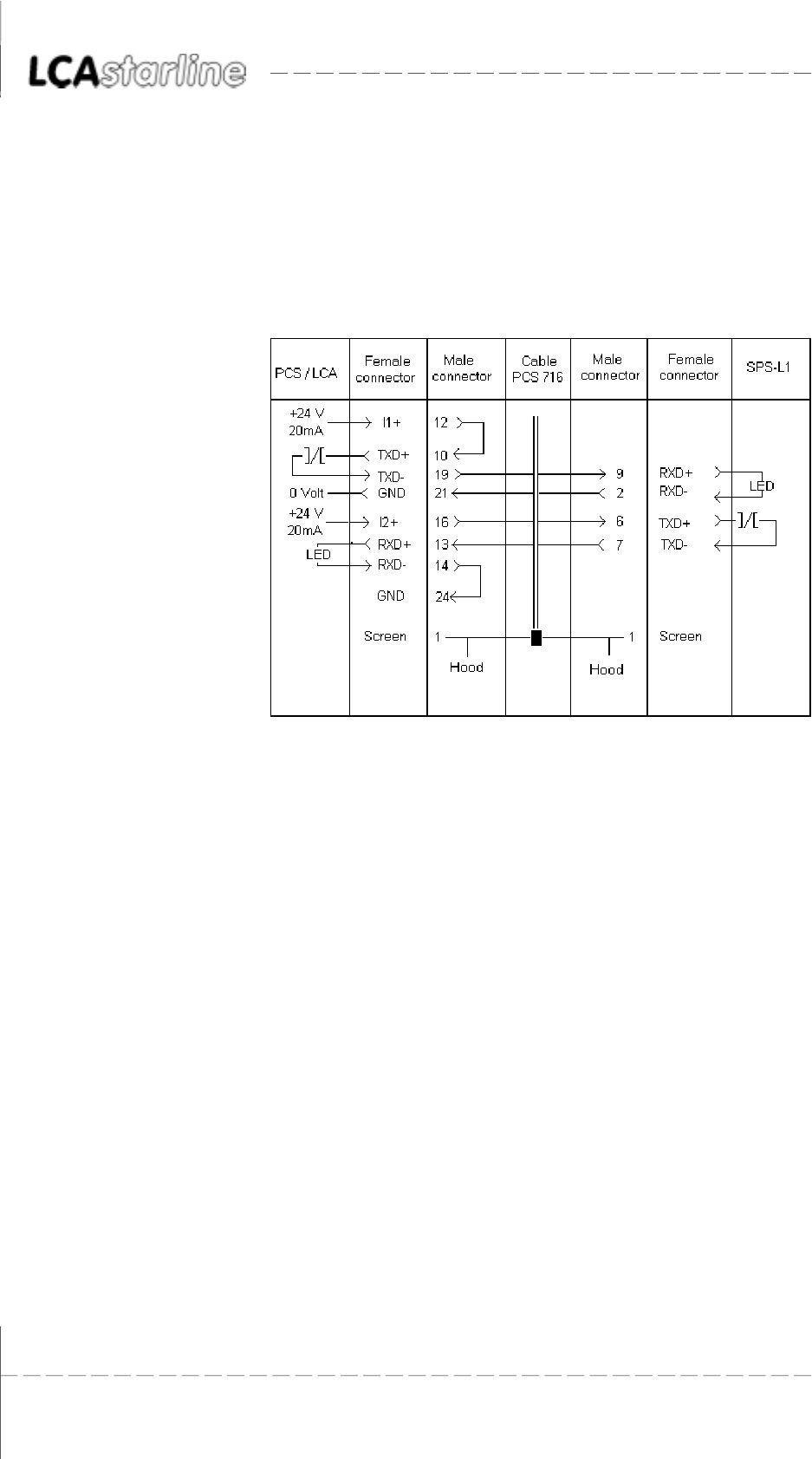
PCS 716 Adapter cable LCA to programmable controller connection
The connection is made via the TTY interface. The current loop is powered
by the LCA. Thus, there is a strict potential separation to the programm-
able controller.
Shielded standard cable (4 * 0.14, not twisted) results in a recommended
maximum length of 20 meters.
When using low-capacity data cables twisted in pairs, the length can be
extended by a factor of 10!
Recommended cable: 2 * 2 * 0.2 stranded in pairs, with single screening
in foil design for pairs of wires (e.g. Belden cable no. 8723)
Screening The screen should be connected on both sides to a metal coated
connector hood. In addition, the screen can also be connected to pin 1.
With grounding at both sides is to be noted however that possibly
(because of ground potential shifts) a potential compensation wire is
required having at least 10 times the screen cross section (reason:
compensation currents should not flow through the cable screen if
possible!). This applies particularly if LCA and programmable controller
are not connected to the same grounding point. This is for example
valid where the LCA and programmable controller are not housed in
the same switching cabinet!
© Systeme Lauer GmbH & Co KG Kelterstr.59 72669 Unterensingen Tel. (07022) 96 60-0 Fax (07022) 96 60-103 1-9
11
11
1AS511 - DriverAS511 - Driver
AS511 - DriverAS511 - Driver
AS511 - Driver
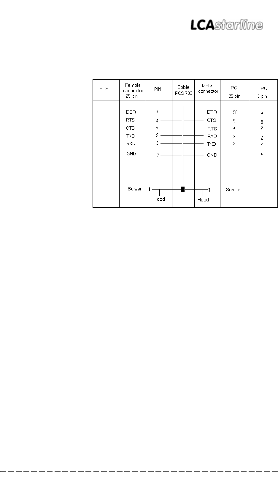
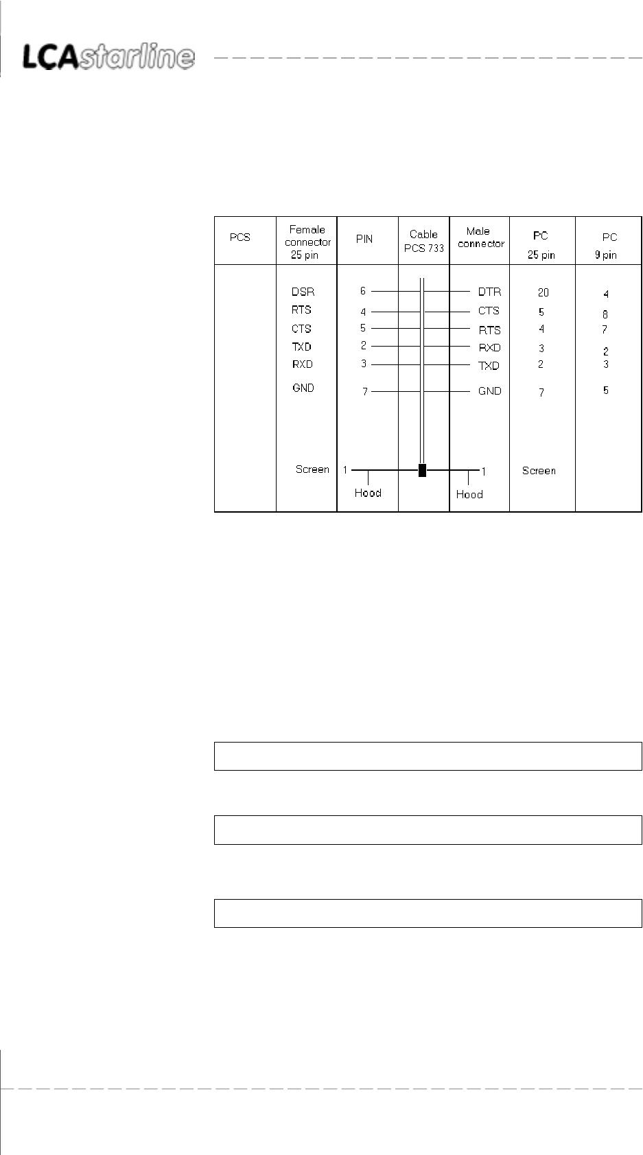
PCS 733 Programming cable PC/PG 730 and 750 to LCA connection
The transfer is only possibly when of all above listed handshake signal
lines are connected. Since DTR to PC (20) R DSR to LCA (6) is only
connected in a direction, the cable ends may not be exchanged. The
programming mode is initiated on the LCA side by setting DSR to a
high level.

© Systeme Lauer GmbH & Co KG Kelterstr.59 72669 Unterensingen Tel. (07022) 96 60-0 Fax (07022) 96 60-103
1-10
11
11
1AS511 - DriverAS511 - Driver
AS511 - DriverAS511 - Driver
AS511 - Driver

© Systeme Lauer GmbH & Co KG Kelterstr.59 72669 Unterensingen Tel. (07022) 96 60-0 Fax (07022) 96 60-103 2-1
22
22
2Lauer - DriverLauer - Driver
Lauer - DriverLauer - Driver
Lauer - Driver
22
22
2Lauer - DriverLauer - Driver
Lauer - DriverLauer - Driver
Lauer - Driver
2.12.1
2.12.1
2.1 First commissioningFirst commissioning
First commissioningFirst commissioning
First commissioning
Delimitation The successful parameterization of the LCA as described in the LCA 300/
320 manual is assumed. This appendix is exclusively concerned with the
application of the LCA together with the PCS 810 communication board
and a Siemens S5 controller.
Required devices and accessories The following products are required (System Lauer company) to operate
a programmable controller with an already parameterized LCA:
1. The LCA text display (already parameterized).
2. The PCS 736 connecting cable for the connection of the LCA to the
programmable controller via the TTY interface.
3. The (LCA 301.SIE) appendix.
4. LCA 301.SIE/PCS 91.SIE floppy disk with handling blocks and
example.
Also required are (from Siemens):
5. 115U (CPU 941 upwards) programmable controller
6. one input board
7. one output board
8. one CR 700.x rack
9. A PG 675, PG 685, PG 710, PG 730 or PG 750 programming unit.
Note for the PG 675: floppy disks are needed separately (quote
project number when ordering).
...as well as the power supply for all components.
Alternatively, the corresponding boards of the 135U,150U and 155U
series can be used.
© Systeme Lauer GmbH & Co KG Kelterstr.59 72669 Unterensingen Tel. (07022) 96 60-0 Fax (07022) 96 60-103
2-2
22
22
2Lauer - DriverLauer - Driver
Lauer - DriverLauer - Driver
Lauer - Driver
2.1.12.1.1
2.1.12.1.1
2.1.1Lauer driver variablesLauer driver variables
Lauer driver variablesLauer driver variables
Lauer driver variables
During configuration of the LCA, both the application program with
data and a selected driver are transferred. The following variables are to
be set for the Lauer driver:
FunctionFunction
FunctionFunction
Function default valuedefault value
default valuedefault value
default value value inputvalue input
value inputvalue input
value input max. valuemax. value
max. valuemax. value
max. value
min.min.
min.min.
min.
Time-out 400ms 0ms 30000ms
Number of repetitions 4 0 254
TT
TT
Time-out (see also B3.5)ime-out (see also B3.5)
ime-out (see also B3.5)ime-out (see also B3.5)
ime-out (see also B3.5)
A continual interchange of data takes place during communication
between the LCA and the PCS 810. The time-out time is the moni-
toring time between the data packages.
In case of an error, COMMUNICATION ERROR: TIME-OUT appears
on the LCA.
Number of repetitionsNumber of repetitions
Number of repetitionsNumber of repetitions
Number of repetitions
A repeat request is sent when receiving a wrong data package. The
setting = 0 corresponds to a repeat command. Counting continues
after a correct package is received. COMMUNICATION ERROR:
CONNECT is displayed when the maximum number of repetitions
has been exceeded.
Baud rate settingsBaud rate settings
Baud rate settingsBaud rate settings
Baud rate settings
Setting Baud rate Interface
1 1200 TTY
2 4800 TTY
3 9600 TTY
4 19200 TTY*)
5 1200 RS232
6 48600 RS232
7 9600 RS232
8 19200 RS232
*) Remark: The default parameters are loaded if no other parameters are
specified in the LCAPRO software.
© Systeme Lauer GmbH & Co KG Kelterstr.59 72669 Unterensingen Tel. (07022) 96 60-0 Fax (07022) 96 60-103 2-3
22
22
2Lauer - DriverLauer - Driver
Lauer - DriverLauer - Driver
Lauer - Driver
2.1.22.1.2
2.1.22.1.2
2.1.2ProcedureProcedure
ProcedureProcedure
Procedure
Since you can select one of several drivers for the LCA, you should load
the enclosed example program, together with the LAUER driver into the
LCA. Thereby, pay attention to the port parameter assignment for the
desired interface setting.
1. Set the LCA interface with the LCAPRO to 19200 baud and TTY.
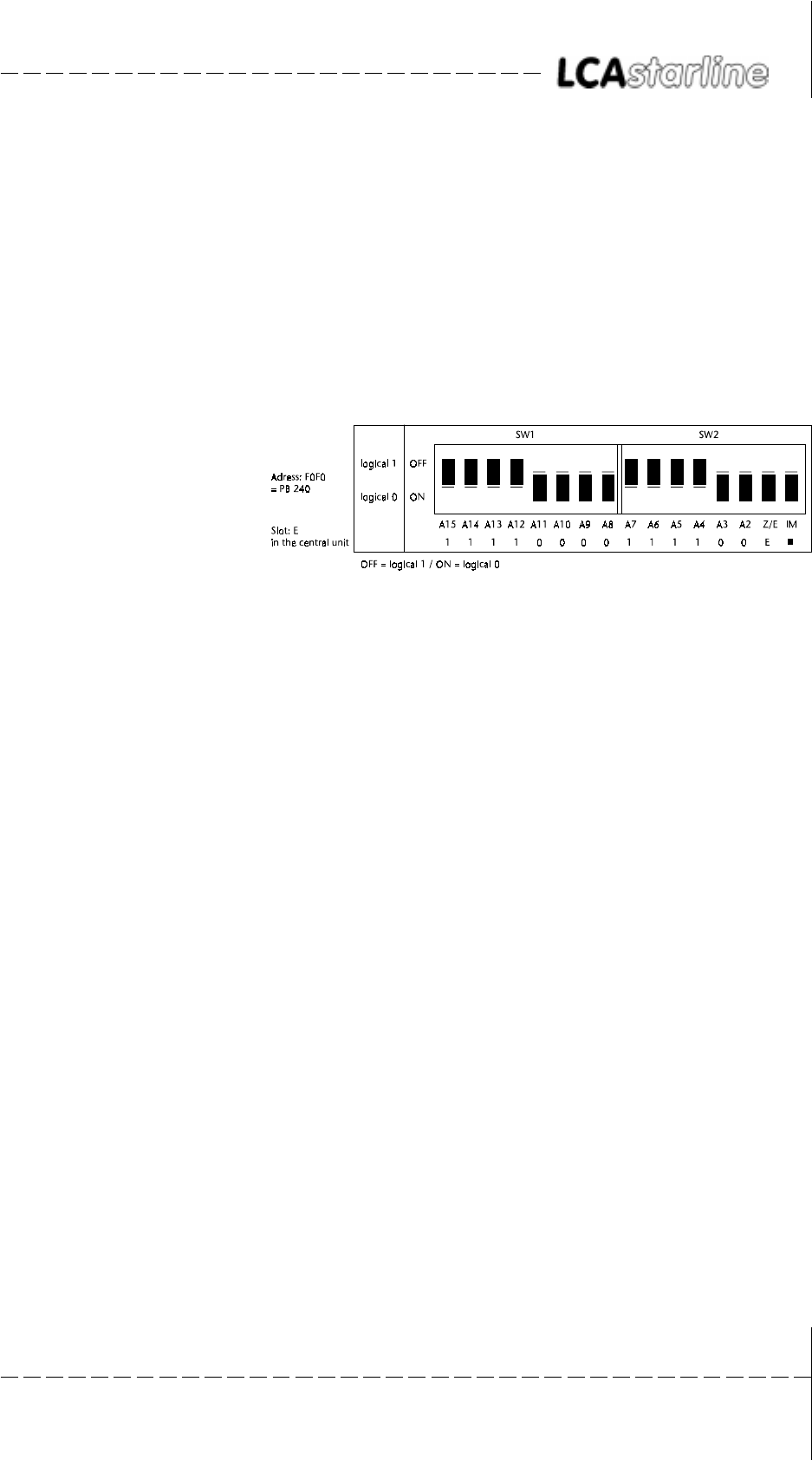
2. Check the DIL-switch position on the PCS 810.1 board:
This switch position corresponds to address F0F0, address decoding
as intelligent peripheral board with the simulation of the terminator
connector.
3. Plug the board (first of all without adaptor) into the last slot on the
right (when using the adaptor, the last seating guide on the rack
must be unscrewed beforehand).
4. Plug in an input board as 1st board and an output board as 2nd
board.
5. Connect the PCS 810 board to the LCA with the PCS 736 cable.
Take note of the labeling at the cable ends.
6. Switch the programmable controller to STOP and supply operating
voltage to the programmable controller and the LCA. The following
display must now appear on the LCA:
LCA 320 machine runs
Test 14.10.94 correctly
AUTO HAND MENU END PRESET ACTUAL SET UP
7. Check the pre-setting mask in the programming unit when using
the PG 675 (also with some older PG 685 versions). >>YES<< must
be preset for the >>SYSTEM COMMAND<< item beforehand.
8. Transfer the FBs 201, 202, 203, and the OBs 1, 21 and 22 from the
floppy disk into the programmable controller. The transfer DB (DB
50) is generated at the restart. In addition, starting with the 135U
programmable controller, OB 20, OB 23, OB 29 and DB 50 (is not
generated!) must be inserted. Remove the STS commands in FB201
and FB202.
© Systeme Lauer GmbH & Co KG Kelterstr.59 72669 Unterensingen Tel. (07022) 96 60-0 Fax (07022) 96 60-103
2-4
22
22
2Lauer - DriverLauer - Driver
Lauer - DriverLauer - Driver
Lauer - Driver
9. Switch the programmable controller from STOP to RUN. Now, the
RUN LED must light at the programmable controller. The ERR LED
at the LCA is deactivated. Output 4.0 should not be active!
Attention!
A fault analysis(section 2.1.3) must be performed if one of the above
points is not correct.
At the programmable controller, LCA driving can now be simulated by
writing and reading the corresponding DWs in DB 50. Output O 4.0 is
activated if the connection is interrupted. The communication can be
restarted by a momentary switch connected to input I 0.0.
All texts, various variables, all message texts, and HELP texts are now
prepared in the LCA. Thus, all functions can be tested (manually via
CONTROL VARIABLE at the programming unit).
2.1.32.1.3
2.1.32.1.3
2.1.3TT
TT
Trouble-shootingrouble-shooting
rouble-shootingrouble-shooting
rouble-shooting
Here, the most frequent faults are listed which occur during the first
commissioning:
1. The jumper below the RS-232C connector is set to PROG. If set,
then after powering-up, the LCA enters a diagnosis routine which
is only required for test purposes. Remedy: move the jumper to
AUTO and restart the LCA (by cycling power to the text display).
2. The PCS 736 cable ends are exchanged, the baud rate was incorrectly
assigned.
3. The programmable controller enters the STOP mode after starting.
Diagnosis: the IM DIL-switch on the PCS 810 board is not set to
ON. The switch does not simulate the terminator connector on the
last slot.
4. The programmable controller enters the STOP mode although the
DIL-switches are correctly set. If DB50 was created manually, check
its length. DW 255 must still be displayed at the programming
unit. The variable for the idle text 0 is taken from this address when
communication is started.
5. The programmable controller enters of course the RUN mode but
the ERR LED at the LCA is not deactivated. The PCS 810 to LCA
connection has to be examined (in this case the PCS 810 transmitting
line) if after a 2nd attempt this LED is not deactivated. If the ERR
LED flashes at the LCA, then the LCA transmitting line is faulty (the
communication was started by the programmable controller, the
LCA 810 however got no answer).
6. In DW3, a fault is signaled with a value > KH 0000. In this case
search for a fault in the PCS 810 to LCA connection. Either the
cable ends are exchanged, or the cable is defective.
7. First, communications starts normally (LCA ERR LED is deactivated)
but after a short time the following message appears on the topmost
display line of the LCA:
COMMUNICATION ERROR

© Systeme Lauer GmbH & Co KG Kelterstr.59 72669 Unterensingen Tel. (07022) 96 60-0 Fax (07022) 96 60-103 2-5
22
22
2Lauer - DriverLauer - Driver
Lauer - DriverLauer - Driver
Lauer - Driver
Mostly, addresses intersecting with counters or analog boards are
the reason for this fault.
8. Noise on the communication line originated in electric and magnetic
interferences causes mostly a communication loss over long periods
of time. Frequency converters are a common source of those
interferences.
Remedy possibilities Connect the cable screening on both ends of the communications
cable to a metal coated connector case, and in addition to pin 1.
Ground the LCA as well as the programmable controller bus board
using a cable with at least the 10-fold screen cross-section.
Provide for good common connections between the LCA on the
one, and to the programmable controller bus board on the other
hand! Remember that a copper grounding strip based on its large
surface area has a somewhat better RF conductivity than normal
flexible wire.
Avoid as far as possible the creation of high frequency interferences
since these are very difficult to dampen. Using photocouplers, there
is a potential separation between the programmable controller and
the LCA. But this galvanic isolation is nearly without effect for fast
transients since photocouplers also have (even though minor)a
coupling capacity.
Provide for clear reference points for the supply voltage. To facilitate
this, the power supply is potential-free!
The use of an own power supply for the LCA (24 volt, 10 VA) is
recommended where the supply voltage is subject to high noise
levels. The power supply should have a corresponding noise filter.
Then, 0 volt can be directly connected to the PCS with the protective
conductor.
The LCA and the communication cable should have a minimum
distance of 200 mm from noise sources. This applies especially to
inductivities and frequency converters.
Short-term noise can possibly be cured by multiple repeat requests.
The number of repeats can be programmed with the AB driver va-
riables and calling up FB 203 (WDHA parameter).
Only if none of these measures provides the desired result, then a
reduction of the baud rate should be taken into account. This must
be specified as a parameter for FB203. In addition, the baud rate
must be correspondingly adjusted via the LCAPRO programming
software.
Potential coupling is created by the programming cable that is
connected to the programming unit since 0 volt of the (RS232)
interface is connected to the protective conductor. Therefore, a
decrease in noise immunity has to be considered during
communication. Recommendation: disconnect the programming
unit when the link is no longer needed.
© Systeme Lauer GmbH & Co KG Kelterstr.59 72669 Unterensingen Tel. (07022) 96 60-0 Fax (07022) 96 60-103
2-6
22
22
2Lauer - DriverLauer - Driver
Lauer - DriverLauer - Driver
Lauer - Driver
2.22.2
2.22.2
2.2 PCS 810 Handling FBPCS 810 Handling FB
PCS 810 Handling FBPCS 810 Handling FB
PCS 810 Handling FB
The PCS 810 board is independent of the slot and suitable for the 115U,
135U, 150U and 155U programmable controllers. It uses four S5
addresses and can be freely addressed in steps of 4 via DIL-switch settings.
It is to be noted that the set address does not intersect with already used
addresses!
Project 1 (P81019ST.S5D) relates to the 115 U programmable controller.
Project 2 (P81029ST.S5D) relates to 135 U programmable controller
and higher. This project is only to be found on the floppy disk!
2.2.12.2.1
2.2.12.2.1
2.2.1AddressingAddressing
AddressingAddressing
Addressing
The area F080 to F0FF is reserved for intelligent peripheral boards in all
programmable controllers. The I/O boards are located in the F000 to
F07F area. This area should not be used since it is scanned for plugged
in boards by some programmable controllers during the restart (refer to
the programmable controller manual: Memory assignment).
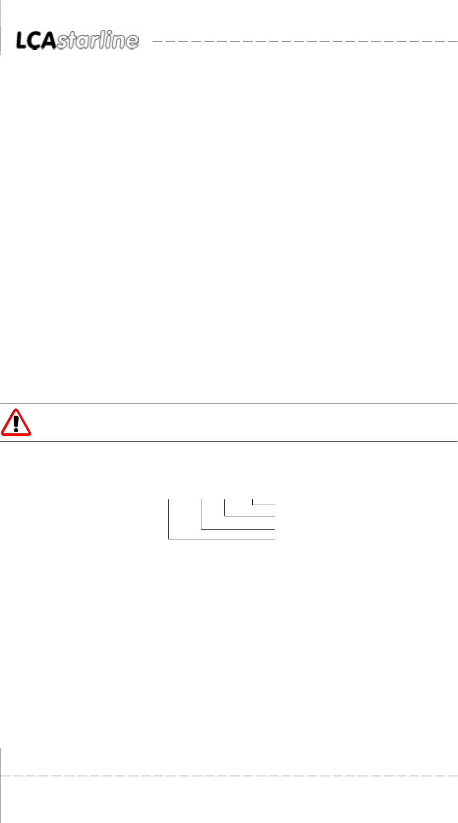
EXAMPLE:
2.2.22.2.2
2.2.22.2.2
2.2.2Selection of the slotSelection of the slot
Selection of the slotSelection of the slot
Selection of the slot
The board can be plugged into each slot which has a 48-pin connector
strip. The lower connector strip is not required. The usual limitations
with CP boards are not valid since the LCA 300/320 provides both line
current sources.
Exceptions
11, 163 in the 135U programmable controller
27, 35, 43, 51, 59, 155, 163 in the 150U programmable controller
11, 19, 27 in the 155U programmable controller
PCS 810.1 operation in these slots is not possible!
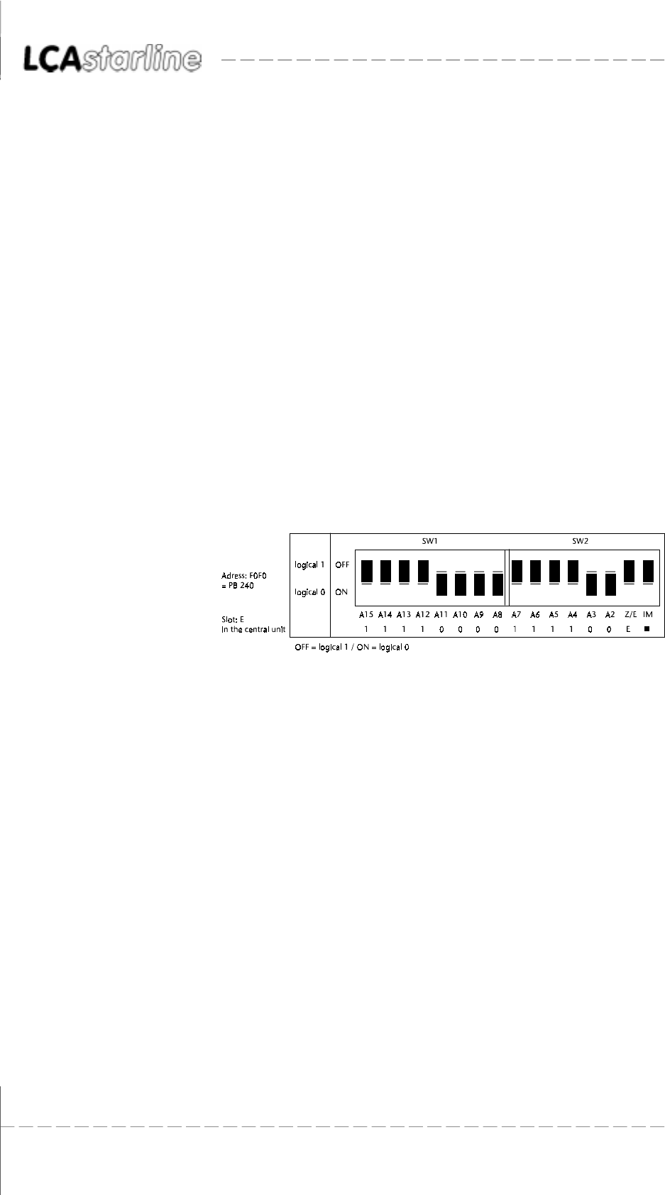
EG set to ON allows the usage in the EU or on the EU slot completely to
the right of the CU. In this case, the SW 2 position is irrelevant since the
PESP signal is evaluated instead of the higher significant address byte.
Thus, only the lower 8 address lines are decoded. In this case an address
between F080 and F0FC (intelligent peripheral devices area) is to be
selected for the FB.
© Systeme Lauer GmbH & Co KG Kelterstr.59 72669 Unterensingen Tel. (07022) 96 60-0 Fax (07022) 96 60-103 2-7
22
22
2Lauer - DriverLauer - Driver
Lauer - DriverLauer - Driver
Lauer - Driver
EU set to OFF means, that all address lines are decoded. This is the
correct position for all slots in the central unit, excluding the last slot on
the right.
Attention!
The IM and EG switches must be set to on if the board is plugged into
the last slot on the right (EU activated)!
Explanation!
Since the A12 to A15 address lines on the interfacing slot are not always
available, the PESP signal must be evaluated instead of the address lines.
In this case it only makes sense to set the F080..F0FC addresses.
Addressing outside of F080-F0FFAddressing outside of F080-F0FF
Addressing outside of F080-F0FFAddressing outside of F080-F0FF
Addressing outside of F080-F0FF
With the 115U series, the addresses above F100 (to F2FF) can also
be set.
These addresses can also be set if the 135U interfacing area is not
used further. Then, this area may not be entered in DB 1!
Starting with the 135 U programmable controller, the FB 203 hand-
ling block from project 1 (115U) must be used when specifying
addresses outside of the peripheral area since the handling block
for project 2 directly accesses the peripheral bytes.
TT
TT
Testing of the addressingesting of the addressing
esting of the addressingesting of the addressing
esting of the addressing
In the stop mode, the correct addressing can be checked at the
programming unit with >>OUTPUT ADDRESSES TEST STATUS<<.
Without the LCA 300/320 being connected, FFC0 FFC0 appears
under the selected address at the first scan after powering up. Unused
addresses in the F080..F0FF area are always displayed as FF.
Attention!
Take note:
1. When using the 928CPU, a reliable operation is only possible with
release 5 and higher since older versions transact faulty bus accesses!
2. With the S processor (135U), the F100..F1FF and F000..F0FF address
ranges are mirrored, i.e. the I/O boards from F000 to F07F appear
also at F100..F17F!

© Systeme Lauer GmbH & Co KG Kelterstr.59 72669 Unterensingen Tel. (07022) 96 60-0 Fax (07022) 96 60-103
2-8
22
22
2Lauer - DriverLauer - Driver
Lauer - DriverLauer - Driver
Lauer - Driver
2.2.32.2.3
2.2.32.2.3
2.2.3Handling softwareHandling software
Handling softwareHandling software
Handling software
The enclosed FB 203 determines the data traffic between a transfer DB
and a PCS 810.1. This FB needs no adjustment and is suited for all LCA
operating units which can be operated together with the PCS 810.1. All
device-specific presettings can be entered in separate FBs (customer-
specific). The block number for this presetting FB is parameterizable.
The block in project 1 (P8101ST.S5D) is language independent and suited
for all programmable controllers except the 155U. The P81039ST.S5D
project must be used for the CPU 945, S5 115 series.
FB 203 in project 2 (P81029ST.S5D) is considered for the programmable
controllers 135U, 150U and 155U (language area B). It differs by the
PADR address specification (see Chapter 2.2.4 PARAMETERIZATION).
Take note!
Important for all programmable controllers!
1. In the first project (for the 115U) MBs 250 to 255 and in the second
project 2 (starting with 135U) MBs 239 to 255 are used as temporary
flags. Writing to these MWs does not disturb the FB as long as this
does not occur within the interrupt program. If these MWs are read
by other FBs, then the contents must be newly written at the
entrance and saved at the exit. A separate temporary flag area is
recommended in interrupt programs anyhow!
2. With project 1 the FB accesses data by means of the TNB command
and with project 2 by means of L PBxx/T PBxx. When using the PG
675 or the older PG 685 for transferring data into the controller,
>>WITH SYSTEM COMMANDS<< must nearly always be selected
during presetting.
3. The transfer DB may not be set in the programmable controller
program EPROM! It should be created in the start OBs (unfortunately,
this is not feasible via a formal operand in all programmable control-
lers. Thus, the creation is not part of the handling FB).
4. FB 203 consists of a single network. Since interrupt processing occurs
only at the network end in some programmable controllers, it must
be modified perhaps if time-critical interrupt programs are used in
such programmable controllers (highly theoretical case!).
The implementation limits itself (excluding the FB 203 cyclical call)
to reading and writing the DWs in the transfer DB. The presence of
the (selectable) transfer DB is not checked. It must be available in
the programmable controller with the necessary net length
(dynamically). Otherwise, the programmable controller shows a
TRAF error (initially at the 1st call of a present value). A summary
error bit (EROR) enables the communication status to be evaluated
via a ladder diagram program. If this error bit = 1, then the data
transfer has been stopped. It can be restarted by setting a flag (RSET).
In addition, a further flag is required for the restart. This is set after
the first successful execution of the handling FB. It must be reset in
OB 20 (only for the 135U and higher), 21 and 22!

© Systeme Lauer GmbH & Co KG Kelterstr.59 72669 Unterensingen Tel. (07022) 96 60-0 Fax (07022) 96 60-103 2-9
22
22
2Lauer - DriverLauer - Driver
Lauer - DriverLauer - Driver
Lauer - Driver
2.2.42.2.4
2.2.42.2.4
2.2.4Parameterization of the FB 203Parameterization of the FB 203
Parameterization of the FB 203Parameterization of the FB 203
Parameterization of the FB 203
UBDBUBDB
UBDBUBDB
UBDB
Here, the DB number of the transfer DB is to be specified (e.g. DB
50). If the DB should not be available, then >>TRAF error<< is shown.
RSETRSET
RSETRSET
RSET
Reset: as soon as this flag is = 1, the PCS 810 hardware is reset and
a restart is initiated (FB 201 is called). This flag is subsequently set
to zero again. It should be set by a positive edge of a momentary
pushbutton. If this remains set, then restarts are constantly initiated.
Thus, no more correct communication would be possible.
EROREROR
EROREROR
EROR
This is a global error message that is set to logical 1 as soon as co-
mmunication is irrevocably lost. A more exact fault analysis is possi-
ble through the evaluation of DW3. EROR is reset automatically as
soon as the first correct package is received.
RFLMRFLM
RFLMRFLM
RFLM
This is the flag for the first cycle. It must be reset in OB21 and
OB22, and after the first successful execution it is set by FB 203 to
logical 1. After that, it may only be indirectly reset by RSET! If it
remains reset, then restarts are constantly initiated. Thus, no more
correct communication would be possible.
PP
PP
PADRADR
ADRADR
ADR
Here, the base address is of course, to be specified in KH for project
1, and in KF for project 2 (peripherals byte address) of the PCS 810
board.
BAUDBAUD
BAUDBAUD
BAUD
Here, one of the following baud rates can be selected: KF+0 = 1200
baud, KF+1 = 4800 baud, KF+2 = 9600 baud, KF+3 = 19200 baud.
INITINIT
INITINIT
INIT
Here, the FB to be selected at a new start and RSET = 1 must be
indicated. This is FB 201 on the floppy disk. This FB must be modified
for the customer specific presetting of preset values.
COFFCOFF
COFFCOFF
COFF
The FB that is immediately executed on a COMMUNICATION ERROR
must likewise be indicated here. In other words, this FB should at
least set the DW4 key word to zero. This is FB 202 on the floppy
disk.
WDHAWDHA
WDHAWDHA
WDHA
The number of additional permitted repeat requests by the user on
behalf of PCS 810 must be indicated there. A repeat request is sent
if a faulty data package is received by the LCA. If the value 0 is
shown, then a maximum of one repeat request is allowed. A remedy
for short-term RF interferences can possibly be created by increasing
this number.

© Systeme Lauer GmbH & Co KG Kelterstr.59 72669 Unterensingen Tel. (07022) 96 60-0 Fax (07022) 96 60-103
2-10
22
22
2Lauer - DriverLauer - Driver
Lauer - DriverLauer - Driver
Lauer - Driver
MAFBMAFB
MAFBMAFB
MAFB
This parameter is only present in project 1, that means available for
the 115U programmable controller. If FB 0 is shown here, then the
handling block is processed via normal step 5 commands (as in the
example).
Assembler blocks exist for the CPU 941, CPU 942, and CPU 943
which considerably shorten the FB 203 execution times (approx. 3
times).
GenerallyGenerally
GenerallyGenerally
Generally, the following is valid:, the following is valid:
, the following is valid:, the following is valid:
, the following is valid:
Additional FBs are available on the floppy disk. The numbering
corresponds to the CPU types:
CPU 941 = FB 141, CPU 942 = FB 142, CPU 943, 94xB = FB 143.
The corresponding FB must be transferred into the controller and be
passed on as parameter when FB 203 is called up. The FB 141, FB 142
and FB 143 function blocks cannot be read nor changed by the progra-
mming unit.
The FB is designed in such a way, that in case of each fault, the commu-
nication is interrupted and the fault is signaled to the outside. Then, the
communication must be consciously restarted using an input (RSET para-
meter). This of course, does not affect the faults reparable by repeating.
These are processed internally in the PCS 810.
SPECIAL CASE 135U, 150U PROGRAMMABLE CONTROLLERS (projectSPECIAL CASE 135U, 150U PROGRAMMABLE CONTROLLERS (project
SPECIAL CASE 135U, 150U PROGRAMMABLE CONTROLLERS (projectSPECIAL CASE 135U, 150U PROGRAMMABLE CONTROLLERS (project
SPECIAL CASE 135U, 150U PROGRAMMABLE CONTROLLERS (project
2)2)
2)2)
2)
This function block does not realize the data transfer through TNB com-
mands but by means of L / T PBxx operations. Although it would be
operational on programmable controllers of the 115U series, execution
would be slower. If it is parameterized, the PADR address must be specified
as PY (relatively):
F080 KF+128
F0FC KF+252
Here, only the P area starting at F080 can be used! If no more space is
available in the P area, then FB 203 of project 1 can also be used for the
135U and 150U programmable controllers.
Advantage:
free addressing possibilities
Disadvantage:
In some CPUs, the PESP signal is not activated by the TNB instruction
in the peripheral area. This means for instance, that a PCS 810
which is operated remotely in the expansion unit, is not selected.
Clearly: PCS 810 in the EU 183 of a 150U programmable controller.
CU and EU are connected via the EG-AS 301 and ZG-AS 310
interfaces.

© Systeme Lauer GmbH & Co KG Kelterstr.59 72669 Unterensingen Tel. (07022) 96 60-0 Fax (07022) 96 60-103 2-11
22
22
2Lauer - DriverLauer - Driver
Lauer - DriverLauer - Driver
Lauer - Driver
2.2.52.2.5
2.2.52.2.5
2.2.5Operation of the PLC with EPROMOperation of the PLC with EPROM
Operation of the PLC with EPROMOperation of the PLC with EPROM
Operation of the PLC with EPROM
115U programmable controller115U programmable controller
115U programmable controller115U programmable controller
115U programmable controller
The transfer DB should be automatically created by the following
commands in OB 21 and OB 22:
L KF +255 (length of the DB in words - 1)
E DB xx (xx = DB number)
135U programmable controller and higher135U programmable controller and higher
135U programmable controller and higher135U programmable controller and higher
135U programmable controller and higher
Here, a function block should be called by OB 20, OB 21 and OB
22. The function block should check again whether the
corresponding DB is already available. If not, then it is created. This
can be done with the 135U programmable controller (CPU 922
928) by executing the following programming sequence:
L KY 1,50 (1 = data block, 50 = block number)
SPA OB 181 this OB tests the presence of DB 50
SPB = M001 -->--> M001, if DB not present!
SPA = M002
M001:
L KF +256 (length of the DB in words)
EDB xx
M002:.....
The DB should only then be located in EPROM if the programmable
controller copies it into the internal RAM of the CPU at a restart.
The DB cannot be integrated into the handling FB since the
automatic creation of a DB by a formal operand is only possible via
self-modifying program code. Project 1 on the floppy disk however,
contains restart OBs which generate the DB 50. For project 2, the
data block (P81029ST.S5D) is to be found on the floppy disk
(attention: do not copy into the EPROM!).

© Systeme Lauer GmbH & Co KG Kelterstr.59 72669 Unterensingen Tel. (07022) 96 60-0 Fax (07022) 96 60-103
2-12
22
22
2Lauer - DriverLauer - Driver
Lauer - DriverLauer - Driver
Lauer - Driver
2.2.62.2.6
2.2.62.2.6
2.2.6Implementation of the handling FBImplementation of the handling FB
Implementation of the handling FBImplementation of the handling FB
Implementation of the handling FB
1. Power-down the programmable controller.
2. Determine the PCS 810 address with DIL-switches.
3. Plug in the board.
4. Switch the programmable controller to stop and supply voltage.
5. Create (with KH0000 preset) and insert the transfer DB in OB 21
and 22 (starting with the 135U programmable controller also in
OB 20).
6. Reset the RFLM flag in OB 21 and 22 (for 135U programmable
controllers and higher also in OB 20).
7. load the handling FB.
8. Cyclically select and parameterize FB 203.
9. Select the momentary reset pushbutton and set RSET with the po-
sitive edge.
10. Power-up the programmable controller and switch to RUN.
If the KH 2000 fault appears in DW3 (time-out, when the LCA is not
connected) and the RFLM and EROR flags are both at logical 1, then the
implementation is successfully completed.
An example (OB1) is contained on the floppy disk which signals faults
on output 4.0, expects a momentary reset pushbutton on I 0.0, uses the
20.0 / 20.2 flags and accesses the PCS 810 board at F0F0. 19200 baud
are selected as baud rate. The logic (following the FB 203 call-up) prevents
a multiple manual RESET (can be omitted also).
2.2.72.2.7
2.2.72.2.7
2.2.7Program integrationProgram integration
Program integrationProgram integration
Program integration
The LCA makes the following assumption after a restart:
0 is selected as idle text0 is selected as idle text
0 is selected as idle text0 is selected as idle text
0 is selected as idle text
Take note of this run-up behavior when presetting the transfer DB .
© Systeme Lauer GmbH & Co KG Kelterstr.59 72669 Unterensingen Tel. (07022) 96 60-0 Fax (07022) 96 60-103 2-13
22
22
2Lauer - DriverLauer - Driver
Lauer - DriverLauer - Driver
Lauer - Driver
2.32.3
2.32.3
2.3 PCS 810 technical dataPCS 810 technical data
PCS 810 technical dataPCS 810 technical data
PCS 810 technical data
Mechanical design Board with 2 * 48-pin DIN 48612 F connector terminal strips
Height 1 1 / 3 standard installation locations (SEP)
Power supply via S5 PCB bus: 5 V ± 5%
Current requirement 360 mA
Address allocation 4 successive addresses, freely settable in the entire address range
Interfaces 1 x TTY
TTY current supply internally / externally selectable; not required however for LCA
Potential separation yes, photocouplers HP 4100 / 4200
Dimensions 243 * 196 * 20 mm
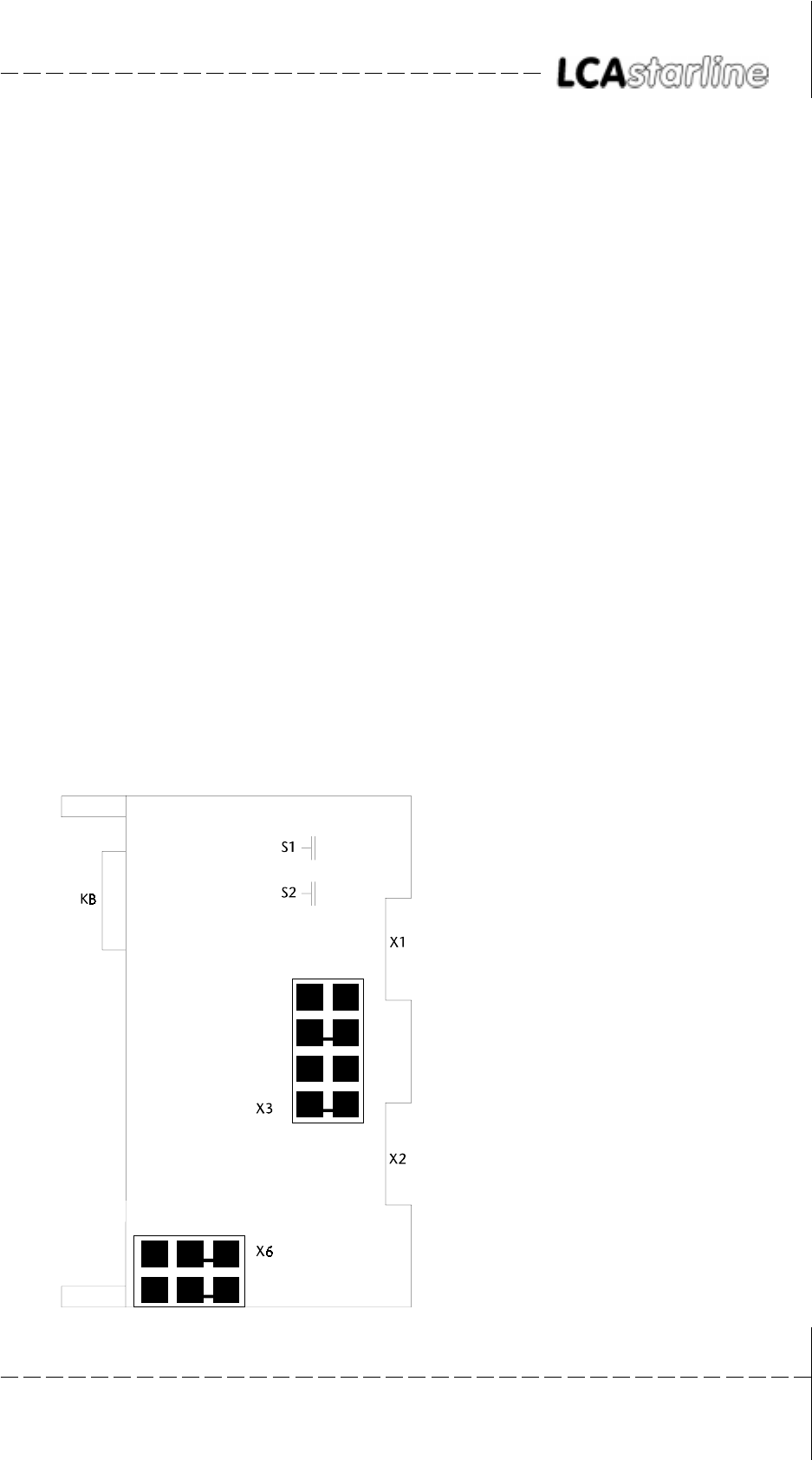
X6 current loop power supply
drawn: internal supply
S1 address switch A15 ... A8
S2 IM, EU and address switch A7 ... A2
X3 line current selection X1/X2
drawn: X1
KBS of communication selection (25-pin)
© Systeme Lauer GmbH & Co KG Kelterstr.59 72669 Unterensingen Tel. (07022) 96 60-0 Fax (07022) 96 60-103
2-14
22
22
2Lauer - DriverLauer - Driver
Lauer - DriverLauer - Driver
Lauer - Driver
2.42.4
2.42.4
2.4 CommunicationCommunication
CommunicationCommunication
Communication
2.4.12.4.1
2.4.12.4.1
2.4.1Current loop power supplyCurrent loop power supply
Current loop power supplyCurrent loop power supply
Current loop power supply
The current loop current sources can be powered either internally or
externally. To avoid capacitive coupling, It is recommended to always
activate both current loop current sources (for receiver and transmitter)
only on one side of the device.
SUPPLSUPPL
SUPPLSUPPL
SUPPLY BY THE LCAY BY THE LCA
Y BY THE LCAY BY THE LCA
Y BY THE LCA
The cable assignment can be seen in the following section. Thereby, the
setting of X3 and X6 is not important. The PCS 736 cable polarity is
decisive: it must be made according to the corresponding labeling.
SUPPLSUPPL
SUPPLSUPPL
SUPPLY BY THE PCS 810Y BY THE PCS 810
Y BY THE PCS 810Y BY THE PCS 810
Y BY THE PCS 810
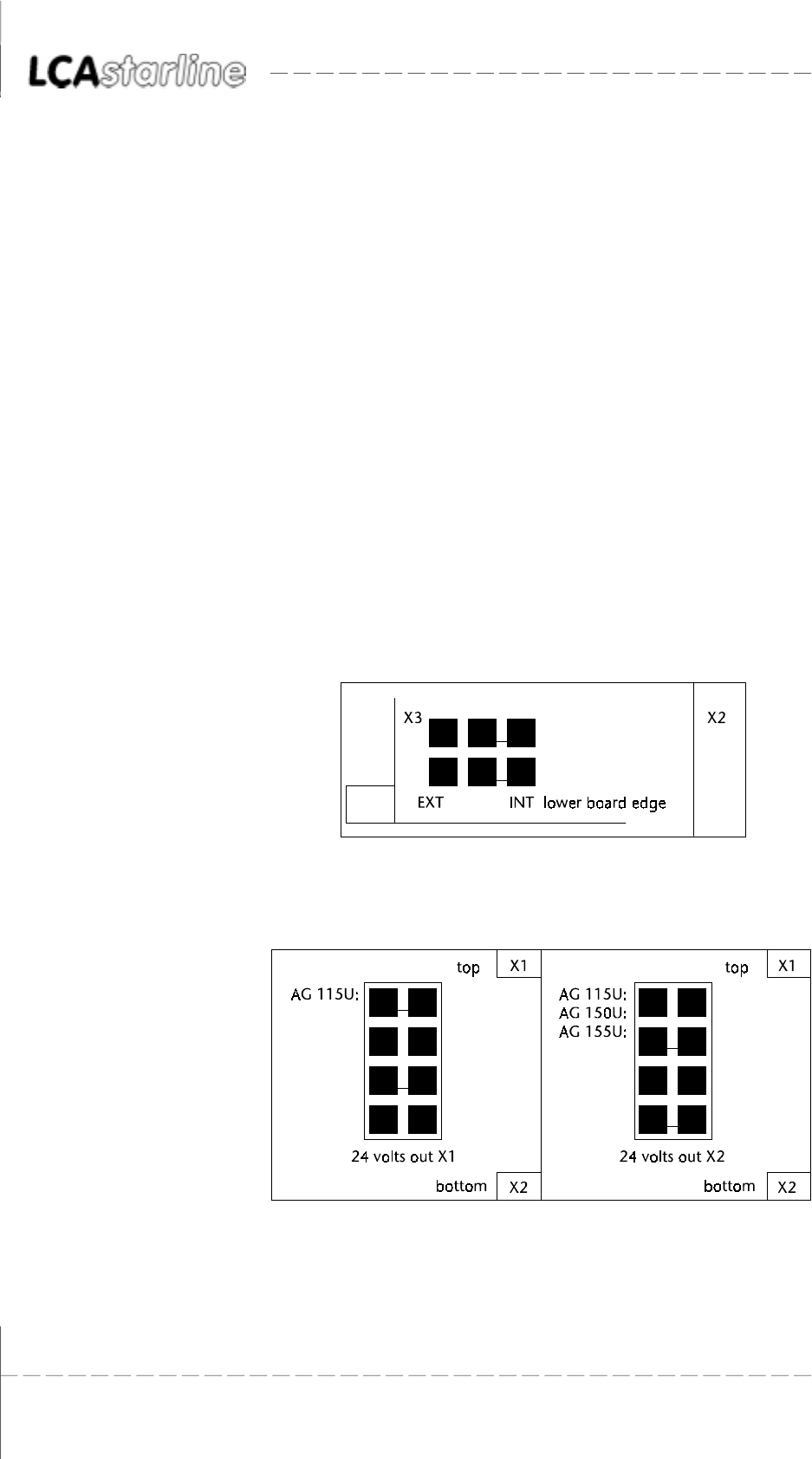
The current loop supply for communication is taken from the PCS 810.
The connector assignment of the interface connectors on the PCS 810
and the LCA are identical. If the PCS 736 cable is used, then exchange
the cable ends and set the jumper on the PCS 810 correspondingly:
Jumper X6 selects the source for the TTY current sources. It is drawn
here for internal supply:
The X3 jumper selects the connector for the internal TTY power supply:
X1 connector (top) or X2 connector (bottom).
© Systeme Lauer GmbH & Co KG Kelterstr.59 72669 Unterensingen Tel. (07022) 96 60-0 Fax (07022) 96 60-103 2-15
22
22
2Lauer - DriverLauer - Driver
Lauer - DriverLauer - Driver
Lauer - Driver
2.4.22.4.2
2.4.22.4.2
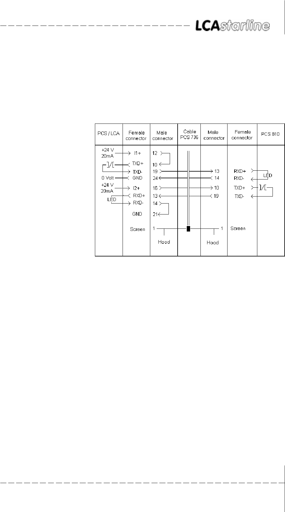
2.4.2PCS 736 Adapter cablePCS 736 Adapter cable
PCS 736 Adapter cablePCS 736 Adapter cable
PCS 736 Adapter cable
Communication cable between PCS 810 and LCA.Communication cable between PCS 810 and LCA.
Communication cable between PCS 810 and LCA.Communication cable between PCS 810 and LCA.
Communication cable between PCS 810 and LCA.
The connection is made via 2 TTY channels. The LCA supplies current
for the current loops of both channels. The positions of the jumpers on
the PCS 810 board is thus irrelevant. There is a strict potential separation
from the programmable controller since the LCA supplies the current.
Maximum lengths The following recommended maximum lengths emerge when using
standard shielded cable (4 * 0.14, not twisted in pairs),:
19200 baud 10 meters
9600 baud 20 meters
4800 baud 40 meters
1200 baud 160 meters
10 times the lengths can be used when using pairs of twisted and mutually
shielded data cable!
Recommended cable: 2 * 2 * 0.2 stranded in pairs, with single screening
in foil design for pairs of cable (e.g. Belden cable no. 8723)
Screening The screen should be connected on both sides to a metal coated connect-
or case. The screen can also be connected to pin 1 when using non-
metal coated connector cases. However, this is not recommended for
error-technical reasons. There, the data lines should be covered as
completely as possible by the screen! With grounding at both sides is to
be noted however that possibly (because of ground potential shifts) a
potential compensation wire is required having at least 10 times the
screen cross section (reason: compensation currents should not flow
through the cable screen if possible!). This applies particularly if LCA
and programmable controller are not connected to the same earthing
point. This is for example valid where the LCA and programmable con-
troller are not housed in one switching cabinet!
© Systeme Lauer GmbH & Co KG Kelterstr.59 72669 Unterensingen Tel. (07022) 96 60-0 Fax (07022) 96 60-103
2-16
22
22
2Lauer - DriverLauer - Driver
Lauer - DriverLauer - Driver
Lauer - Driver
2.4.32.4.3
2.4.32.4.3
2.4.3PCS 733 programming cablePCS 733 programming cable
PCS 733 programming cablePCS 733 programming cable
PCS 733 programming cable
PC/PU 750 - LCA connection
2.4.42.4.4
2.4.42.4.4
2.4.4LCA/PCS 810 data transferLCA/PCS 810 data transfer
LCA/PCS 810 data transferLCA/PCS 810 data transfer
LCA/PCS 810 data transfer
The data traffic with the control is performed in packages. Each package
has a checksum and its contents are checked for possible faults in the
PCS 810. At the minimum, each package consists of one sub-package
which performs a clearly defined task.
SET-UPSET-UP
SET-UPSET-UP
SET-UP
During running communication, the LCA issues commands in the
following format to the programmable controller:
COMMAND (DATA) COMMAND (DATA).... CHECK SUM TERMINATOR
In principle, the programmable controller answer is set up as follows:
ALL DATA.... CHECK SUM TERMINATOR
TT
TT
Timely sequence of the data transferimely sequence of the data transfer
imely sequence of the data transferimely sequence of the data transfer
imely sequence of the data transfer
1111 2222222222222222 33 44444 55555 6666666666666666 (1111)
11111111
11111111
1111
The LCA assembles a new package. The required time totals 2.5 milli-
seconds.

© Systeme Lauer GmbH & Co KG Kelterstr.59 72669 Unterensingen Tel. (07022) 96 60-0 Fax (07022) 96 60-103 2-17
22
22
2Lauer - DriverLauer - Driver
Lauer - DriverLauer - Driver
Lauer - Driver
22222222222222222222222222222222222222
22222222222222222222222222222222222222
2222222222222222222
The package is transferred. The required time depends on the package
length and the baud rate. Since the package length is not constant, this
time can not be determined in principle.
3333
3333
33
The PCS 810 examines the package for plausibility and signals the readi-
ness for data interchange to the handling FB.
4444444444
4444444444
44444
Waiting time until the handling FB is processed.
5555555555
5555555555
55555
The handling FB performs the data interchange in both directions. The
required times are to be taken from the handling FB description.
66666666666666666666666666666666666666
66666666666666666666666666666666666666
6666666666666666666
The answer package is transferred. The length of this package is also
variable. A new package is assembled as described in 1 as soon as the
package is completely received in the LCA.
2.4.52.4.5
2.4.52.4.5
2.4.5PCS 810/S5 Bus data transferPCS 810/S5 Bus data transfer
PCS 810/S5 Bus data transferPCS 810/S5 Bus data transfer
PCS 810/S5 Bus data transfer
The PCS 810 uses 4 addresses on the S5 bus. These addresses have the
following meanings (only for diagnosis purposes):
COMMAND CHANNELCOMMAND CHANNEL
COMMAND CHANNELCOMMAND CHANNEL
COMMAND CHANNEL
ADDRESS: base address +0
DIRECTION: writing
Code 00H send a new package
Code x1H restart with 1200 baud
Code x2H restart with 4800 baud
Code x3H restart with 9600 baud
Code x4H restart with 19200 baud
Code 05..0FH software reset: waiting for the signaling of a baud
rate.
Note: x... number of additional repeat requests (0H..FH)
DIRECTION: reading
the internal RAM of the PCS 810 is used here for
diagnosis.
COMMAND STCOMMAND ST
COMMAND STCOMMAND ST
COMMAND STAA
AA
ATUSTUS
TUSTUS
TUS
ADDRESS: base address +1
DIRECTION: reading only
BIT 7 = 1 ready for instruction
Bit 7 = 0 wait, board is not ready!
DADA
DADA
DATT
TT
TA CHANNELA CHANNEL
A CHANNELA CHANNEL
A CHANNEL
ADDRESS: base address +2
DIRECTION: bi-directional
COMMANDS LCA R PROGRAMMABLE CONTROLLER
DATA LCA ´ PROGRAMMABLE CONTROLLER
© Systeme Lauer GmbH & Co KG Kelterstr.59 72669 Unterensingen Tel. (07022) 96 60-0 Fax (07022) 96 60-103
2-18
22
22
2Lauer - DriverLauer - Driver
Lauer - DriverLauer - Driver
Lauer - Driver
DADA
DADA
DATT
TT
TA STA ST
A STA ST
A STAA
AA
ATUSTUS
TUSTUS
TUS
ADDRESS: Base address +3
DIRECTION: reading only
Bit 5 = 1 further sub-packages are waiting
Bit 5 = 0 finished!
The data transfer is managed by the enclosed FB (FB203), thus relieving
the user from evaluation. The indicated meanings (above) are relevant
only for diagnosis purposes. The >>TEST ADDRESSES<< programming
unit function may not be carried out while the handling FB is running,.
In >>AG STOP<< however, the correct addressing can be checked with
>>TEST ADDRESSES<<. The KH C0 value (handshake signal) appears at
base address + 1 while non-used addresses reply with KH FF. Different
data appear on the base address (command channel) because internal
RAM values are generated here for diagnosis purposes.
2.4.62.4.6
2.4.62.4.6
2.4.6SoftwareSoftware
SoftwareSoftware
Software
You receive the floppy disk in MS-DOS format. On demand, you can
also receive a floppy disk in the PG 675 format. Since two project files
are contained on the PG 685 / 750 floppy disk, the project number
must also be indicated when ordering the PG 675 floppy disk!
Attention!
Test the handling software function. This will avoid LCA and program-
mable controller malfunctions.
The project number has the following assignment coding:
P 811 1 1 ST.S5D
Version/revision number
Project and/or floppy disk number
Project number 811
Product line PCS
The following projects are currently to be found on the floppy disk:
PCS 810.1PCS 810.1
PCS 810.1PCS 810.1
PCS 810.1
Project 1: P81019ST.S5D Handling software for the 115U program-
mable controller
Project 2: P81029ST.S5D Handling software starting with the 135U
programmable controller
Project 3: P81039ST.S5D Handling software for the 115U program-
mable controller with CPU 945
Projekt 4: P81049ST.S5D Handling software for the 135U program-
mable controller with CPU 948
© Systeme Lauer GmbH & Co KG Kelterstr.59 72669 Unterensingen Tel. (07022) 96 60-0 Fax (07022) 96 60-103 2-19
22
22
2Lauer - DriverLauer - Driver
Lauer - DriverLauer - Driver
Lauer - Driver
PCS 810.3PCS 810.3
PCS 810.3PCS 810.3
PCS 810.3
Project 1: P81111ST.S5D Handling software for the 115U program-
mable controller
Project 2: P81121ST.S5D Handling software starting with the 135U
programmable controller
Project 3: P81131ST.S5D Handling software for the 115U program-
mable controller with CPU 945
Projekt 4: P81141ST.S5D Handling software for the 135U program-
mable controller with CPU 948
PCS 840PCS 840
PCS 840PCS 840
PCS 840
Project 1: P84113ST.S5D Handling software for the 115U program-
mable controller
Project 2: P84123ST.S5D Handling software starting with the 135U/
155U programmable controller
Project 3: P84133ST.S5D Handling software for the 115U program-
mable controller with CPU 945
Project changes are listed in the README.TXT file on the commissioning
disk.
*) The floppy disk(s) is(are) located in the respective PCS manuals.

© Systeme Lauer GmbH & Co KG Kelterstr.59 72669 Unterensingen Tel. (07022) 96 60-0 Fax (07022) 96 60-103
2-20
22
22
2Lauer - DriverLauer - Driver
Lauer - DriverLauer - Driver
Lauer - Driver
2.4.72.4.7
2.4.72.4.7
2.4.7PROJEKT 1: P81019STPROJEKT 1: P81019ST
PROJEKT 1: P81019STPROJEKT 1: P81019ST
PROJEKT 1: P81019ST.S5D.S5D
.S5D.S5D
.S5D
FB 201 C:P81019ST.S5D
NETZWERK 1 0000
NAME :INIT
0005 : STS EXAMPLE PCS 900!!!!!!!!!
0006 : TYPICAL PRESETS
0007 : L KH 0000
0008 : T DW 4
0009 : T DW 5
000A : T DW 6
000B : T DW 9
000C : T DW 39
000D : L KH 0080
000E : T DW 38
000F : L KH 00FF
0010 : T DW 37
0011 : L KH 1F00
0012 : T DW 36
0013 :
0014 : EXAMPLE PCS 090/095 !!!!!!!!!!!
0015 : TYPICAL PRESETS
0016 : L KH 0000
0017 : T DW 4
0018 : T DW 5
0019 : L KH 0FC8
001A : T DW 13
001B : L KH 0080
001C : T DW 14
001D :BE
FB 202 C:P81019ST.S5D
NETZWERK 1 0000
NAME :COFF
0005 : STS EXAMPLE PCS 900 !!!!!!!!!!!!!!!
0006 : PRESETS EMERGENCY CASE
0007 : L KH 0000
0008 : T DW 4
0009 : T DW 5
000A : T DW 6
000B : T DW 9
000C : IF USED,
000D : CLEAR ADDITIONAL KEYS
000E :
000F : EXAMPLE PCS 090/095 !!!!!!!!!!!
0010 : PRESETS EMERGENCY CASE
0011 : L KH 0000
0012 : T DW 4
0013 : T DW 5
0014 : IF USED,
0015 : CLEAR ADDITIONAL KEYS
0016 :BE

© Systeme Lauer GmbH & Co KG Kelterstr.59 72669 Unterensingen Tel. (07022) 96 60-0 Fax (07022) 96 60-103 2-21
22
22
2Lauer - DriverLauer - Driver
Lauer - DriverLauer - Driver
Lauer - Driver
OB 1 C:P81019ST.S5D
NETZWERK 1 0000
0000 : SPA FB 203
0001 NAME : HANT.PCS
0002 UBDB : DB 50 COMMUNICATION DB = DB 50
0003 RSET : M 20.1 DEFINE RESET WITH M 20.1=1
0004 EROR : A 4.0 DEFINE ERROR-FLAG AT A 4.0
0005 RFLM : M 20.0 DEFINE RESET-FLAG-MARK FOR
1.CYCLE M 20.0
0006 PADR : KH F0F0 BASIC ADDRESS PCS810(MOD.8)
0007 BAUD : KF +3 BAUD RATE (POSSIBLE KF 0..+3)
0008 INIT : FB 201 INITIALISATION ACTIONS FB
0009 COFF : FB 202 ERROR ACTIONS FB
000A WDHA : KF +0 EXTRA WDHA (POSSIBLE: KF 0..+15)
000B MAFB : FB 0 FB FOR CPU 141/142/143 0=ALL
000C :U E 0.0 RESET KEY
000D :UN M 20.2 FLAG FOR RESET-EDGE
000E :S M 20.1 IF POSITIVE-EDGE R RESET
000F :S M 20.2 (SLOPE FLAG FOR KEY)
0010 :UN E 0.0 NEGATIVE EDGE NOT USED
0011 :R M 20.2
0012 :BE
OB 21 C:P81019ST.S5D
NETZWERK 1 0000
0000 :U M 20.0
0001 :R M 20.0
0002 :L KF +255
0004 :E DB 50
0006 :BE
OB 22 C:P81019ST.S5D
NETZWERK 1 0000
0000 :U M 20.0
0001 :R M 20.0
0002 :L KF +255
0004 :E DB 50
0006 :BE

© Systeme Lauer GmbH & Co KG Kelterstr.59 72669 Unterensingen Tel. (07022) 96 60-0 Fax (07022) 96 60-103
2-22
22
22
2Lauer - DriverLauer - Driver
Lauer - DriverLauer - Driver
Lauer - Driver

IndexIndex
IndexIndex
Index
© Systeme Lauer GmbH & Co KG Kelterstr.59 72669 Unterensingen Tel. (07022) 96 60-0 Fax (07022) 96 60-103 i-1
IndexIndex
IndexIndex
Index
AA
AA
A
Accessories ................................................1-1, 2-1
Adapter cable ..........................................1-8, 2-15
Address allocation .......................................... 2-13
Address reference .............................................. 1-6
ADDRESS REFERENCES ......................................1-2
Addressing ................................................2-6, 2-7
AS 511 ..............................................................1-6
AS511 ...............................................................1-5
AS511 protocol .........................................1-3, 1-5
AUTOMUX ........................................................1-6
BB
BB
B
BAUD ................................................................2-9
Baud rate ..........................................................2-2
CC
CC
C
COFF .................................................................2-9
COMMAND CHANNEL .................................. 2-17
COMMAND STATUS ...................................... 2-17
COMMUNICATION ERROR ...............................2-9
Configuration....................................................1-6
Connection of the LCA......................................1-2
Current loop .................................................. 2-14
Current requirement ...................................... 2-13
DD
DD
D
DATA CHANNEL ............................................. 2-17
DATA STATUS ................................................. 2-18
Data transfer ........................................ 2-16, 2-17
Delimitation ..............................................1-1, 2-1
Diagnosis ..........................................................1-4
Dimensions .................................................... 2-13
Driving ..............................................................1-7
EE
EE
E
EROR .................................................................2-9
Evaluation .........................................................1-7
FF
FF
F
F080 .............................................................. 2-10
F0FC .............................................................. 2-10
FB 203 ..............................................................2-8
HH
HH
H
Handling software .............................................2-8
Height ............................................................ 2-13
II
II
I
Implementation ............................................. 2-12
INIT ...................................................................2-9
Interfaces ....................................................... 2-13
KK
KK
K
Key code ...........................................................1-7
Key status .......................................................... 1-7
LL
LL
L
Lauer driver .......................................................2-2
Life identification .............................................. 1-7
Loading firmware ..............................................1-2
MM
MM
M
MAFB ............................................................. 2-10
Maximum lengths .......................................... 2-15
Mechanical design ......................................... 2-13
Message bits .....................................................1-7
MUX PCS 809 ...................................................1-3
NN
NN
N
Number of repetitions ....................................... 2-2
OO
OO
O
Operation of the PLC ..................................... 2-11
PP
PP
P
P81019ST.S5D ..................................................2-6
P81029ST.S5D ..................................................2-6
PADR .................................................................2-9
Parameterization ...............................................2-9
PCS 716 ............................................................1-8
PCS 733 ..................................................1-9, 2-16
PCS 736 ......................................................... 2-15

IndexIndex
IndexIndex
Index
© Systeme Lauer GmbH & Co KG Kelterstr.59 72669 Unterensingen Tel. (07022) 96 60-0 Fax (07022) 96 60-103
i-2
PCS 810.1 ...................................................... 2-18
PCS 810.3 ...................................................... 2-19
PCS 840 ......................................................... 2-19
PESP signal ..................................................... 2-10
Potential separation ....................................... 2-13
Power supply ................................................. 2-13
Procedure .........................................................2-3
Program integration ....................................... 2-12
Programming cable...........................................1-9
programming cable ....................................... 2-16
Project 1 ........................................................... 2-6
Project 2 ........................................................... 2-6
PROJEKT 1: P81019ST.S5D ............................. 2-20
PROTOCOL VIOLATION ....................................1-3
RR
RR
R
Remedy possibilities ..........................................2-5
Required devices .......................................1-1, 2-1
Response time ................................................... 1-6
RFLM .................................................................2-9
RSET ..................................................................2-9
SS
SS
S
Screening ................................................1-8, 2-15
SET-UP ........................................................... 2-16
Slot selection .....................................................2-6
Software......................................................... 2-18
TT
TT
T
Testing of the addressing ..................................2-7
Time-out ........................................................... 2-2
Time-out time ...................................................1-2
TIMEOUT ..........................................................1-3
TO MANY REPETITIONS ....................................1-3
TRAF error .........................................................2-9
Transfer time .....................................................1-6
Trouble-shooting .......................................1-3, 2-4
TTY current supply ......................................... 2-13
UU
UU
U
UBDB ................................................................2-9
VV
VV
V
variable .............................................................2-2
WW
WW
W
WDHA ...............................................................2-9
