320009
User Manual: 320009
Open the PDF directly: View PDF ![]() .
.
Page Count: 40
1
PRINTED 0311 320009-001
KEEP THIS MANUAL IN THE POCKET ON HEATER FOR FUTURE REFERENCE
WHENEVER MAINTENANCE ADJUSTMENT OR SERVICE IS REQUIRED.
ALL TECHNICAL AND WARRANTY QUESTIONS: SHOULD BE DIRECTED TO THE LOCAL DEALER FROM WHOM THE WATER HEATER WAS
PURCHASED. IF YOU ARE UNSUCCESSFUL, PLEASE WRITE TO THE COMPANY LISTED ON THE RATING PLATE ON THE WATER HEATER.
Instruction Manual
RESIDENTIAL SOLAR WATER HEATING SYSTEMS
STANDARD SYSTEMS
WITH DOUBLE WALL HEAT EXCHANGER
FOR POTABLE WATER HEATING ONLY
Solar Water Heater
C US
LISTED
Solar Collector
SRCC OG-100
™
Solar Water Heating System
SRCC OG-300
™
http://waterheatertimer.org/Should-you-buy-solar-water-heater.html
2
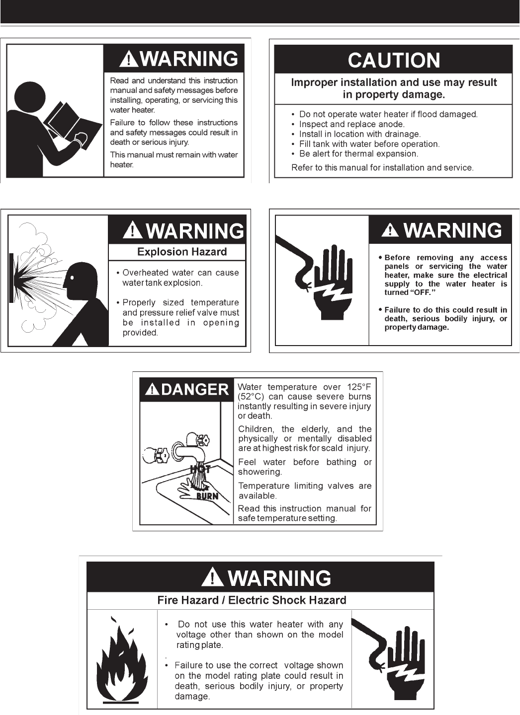
All safety messages will generally tell you about the type of hazard, what can happen if you do not follow the safety
message, and how to avoid the risk of injury.
The California Safe Drinking Water and Toxic Enforcement Act requires the Governor of California to publish a list of
substances known to the State of California to cause cancer, birth defects, or other reproductive harm, and requires
businesses to warn of potential exposure to such substances.
WARNING: This product contains a chemical known to the State of California to cause cancer, birth defects, or other
reproductive harm.
This appliance can cause low-level exposure to some of the substances listed in the act.
Hydrogen gas can be produced in a hot water system that has not been used for a long period of time (generally two
weeks or more). Hydrogen gas is extremely flammable and can ignite when exposed to a spark or flame. To prevent
the possibility of injury under these conditions, we recommend the hot water faucet be opened for several minutes at
the kitchen sink before using any electrical appliance which is connected to the hot water system. If hydrogen is pres-
ent, there will probably be an unusual sound such as air escaping through the faucet as water begins to flow. Do not
smoke or have any open flame near the faucet at the time it is open.
IMPORTANT DEFINITIONS
• Qualified Installer: A qualified installer must have ability equivalent to a licensed tradesman in the fields of
plumbing and electrical installation of these appliances. This would include a thorough understanding of the
requirements of the National Electrical Code and applicable local electrical and plumbing codes (and tools
necessary to confirm proper installation and operation of the water heater) as they relate to the installation
of electric water heaters. The qualified installer must have a thorough understanding of the water heater
Instruction Manual.
• Service Agency: A service agency also must have ability equivalent to a licensed tradesman in the fields of
plumbing and electrical installation of these appliances. This would include a thorough understanding of the
requirements of the National Electrical Code and applicable local electrical and plumbing codes (and tools
necessary to confirm proper installation and operation of the water heater) as they relate to the installation
of electric water heaters. The service agency must have a thorough understanding of the water heater
Instruction Manual.
SAFE INSTALLATION, USE AND SERVICE
Your safety and the safety of others is extremely important in the installation, use, and servicing of this water
heater.
Many safety-related messages and instructions have been provided in this manual and on your own water heater to
warn you and others of a potential injury hazard. Read and obey all safety messages and instructions throughout this
manual. It is very important that the meaning of each safety message is understood by you and others who install,
use, or service this water heater.
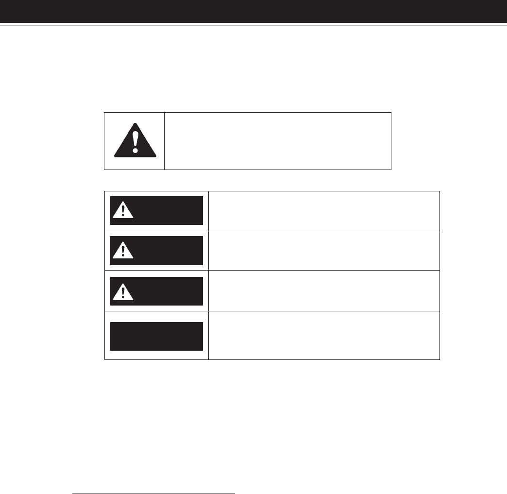
This is the safety alert symbol. It is used to
alert you to potential personal injury hazards.
Obey all safety messages that follow this
symbol to avoid possible injury or death.
DANGER
WARNING
CAUTION
DANGER indicates an imminently hazardous
situation which, if not avoided, will result in death
or injury.
WARNING indicates a potentially hazardous
situation which, if not avoided, could result in
death or injury.
CAUTION indicates a potentially hazardous
situation which, if not avoided, could result in
minor or moderate injury.
CAUTION used without the safety alert symbol
indicates a potentially hazardous situation
which, if not avoided, could result in property
damage.
CAUTION
3
GENERAL SAFETY

4
Thank You for purchasing this water heating system.
Properly installed and maintained, it should give you years
of trouble free service.
Abbreviations Found In This Instruction Manual:
• ANSI - American National Standards Institute
• ASME - American Society of Mechanical Engineers
• GAMA - Gas Appliance Manufacturers Association
• NEC - National Electrical Code
• NFPA - National Fire Protection Association
• UL - Underwriters Laboratories Inc.
• SRCC - Solar Rating and Certification Corp.
SYSTEM DESCRIPTION
This Solar Water Heating System consists of four main
parts — the solar collectors, the solar pump station, the
solar storage tank, and the plumbing for the heat transfer
uid.
The solar pump station uses a pump to circulate a heat-
transfer uid through the “collector loop”. This collector
loop includes the solar collectors, the uid lines or “line-
set” and a heat exchanger. The collector loop is a “closed
loop”, meaning there is no contact of the heat transfer uid
with your potable water or with the atmosphere. The collec-
tor loop contains only a small volume of heat-transfer uid
which is non-toxic and freeze-protected to -30°F (Freeze
tolerance limits are based upon an assumed set of environ-
mental conditions). Though freeze protection may not be
necessary in all areas, the heat-transfer uid also contains
corrosion inhibitors which protect the system components,
has an elevated boiling point, and is suitable throughout
North America.
When exposed to sunlight, the solar collectors get hot.
As the heat-transfer uid passes through the collectors,
it absorbs the heat and then travels down the line-set to
the tank. The hot uid passes through the heat exchanger
and heat is transferred to the potable water. After giving up
its heat to the potable water, the cool heat-transfer uid is
pumped back to the solar collectors to be heated again.
Hot potable water is stored in the solar storage tank.
The auxiliary or back-up electric-heating guarantees hot
water even under poor solar conditions (at night or when
very cloudy). The minimum acceptable temperature set-
point is specied in local plumbing codes.
You can save the most money on your water-heating bills
by using the backup heater on your system as little as pos-
sible. If the sun shines brightly between 10 am and 3 pm,
enough heat will normally be generated to keep the water
hot throughout the rest of the day and night.
However, on days when the sky is cloudy or when large
quantities of hot water are being used, we recommend
leaving the backup heater turned on and set to 120° F to
provide adequate hot water.
PREPARING FOR THE INSTALLATION
1. Read the “General Safety” section of this manual first and
then the entire manual carefully. If you don’t follow the
safety rules, the water heater will not operate properly. It
could cause DEATH, SERIOUS BODILY INJURY, AND/
OR PROPERTY DAMAGE.
This manual contains instructions for the installation,
operation, and maintenance of the solar water heater.
It also contains warnings throughout the manual that
you must read and understand. All warnings and all
instructions are essential to the proper operation of
the water heater and your safety. READ THE ENTIRE
MANUAL BEFORE ATTEMPTING TO INSTALL OR
OPERATE THE WATER HEATER.
2. The installation must conform with these instructions
and the local code authority having jurisdiction and the
requirements of the power company. In the absence of
local code requirements follow NFPA-70, the National
Electrical Code (current edition), which may be
ordered from: National Fire Protection Association, 1
Batterymarch Park, Quincy, MA 02169.
3. If after reading this manual you have any questions or
do not understand any portion of the instructions, call the
local utility or the manufacturer whose name appears on
the rating plate.
4. Carefully plan your intended placement of the water heater
and collectors. INSTALLATION OR SERVICE OF THIS
WATER HEATER REQUIRES ABILITY EQUIVALENT
TO THAT OF A LICENSED TRADESMAN IN THE FIELD
INVOLVED. PLUMBING AND ELECTRICAL WORK ARE
REQUIRED.
Examine the location to ensure the water heater complies
with the “Facts to Consider About the Location” section
in this manual.
5. For California installation this water heater must be
braced, anchored, or strapped to avoid falling or moving
during an earthquake. See instructions for correct
installation procedures. Instructions may be obtained
from California Office of the State Architect, 400 P Street,
Sacramento, CA 95814.
6. Massachusetts Code requires this water heater to be
installed in accordance with Massachusetts 248-CMR
2.00: State Plumbing Code and 248-CMR 5.00.
7. The solar energy system described by this manual, when
properly installed and maintained, meets the minimum
standards established by the SRCC. This certification
does not imply endorsement or warranty of this product
by SRCC.
INTRODUCTION

5
TABLE OF CONTENTS
SAFE INSTALLATION, USE AND SERVICE............................. 2
Important Denitions .................................................. 2
GENERAL SAFETY .................................................................. 3
INTRODUCTION ...................................................................... 4
System Description .................................................... 4
Preparing for Installation ............................................. 4
TABLE OF CONTENTS ............................................................ 5
SYSTEM DIAGRAM/TYPICAL INSTALLATION ....................... 6
SYSTEM COMPONENT PART ................................................ 7
STORAGE TANK INSTALLATION ............................................ 7
Local Codes ............................................................... 7
Temperature-Pressure Relief Valve ........................7-8
Closed System/Thermal Expansion ............................ 8
Locating the Solar Water Heater ................................ 8
Water Piping ............................................................8-9
Installation in Residential Garages.............................. 9
Filling the Solar Water Heater with Water ................... 9
Wiring of Element ..................................................... 10
Thermostat ............................................................... 10
Temperature Regulation ...................................... 10-11
Temperature Settings ............................................... 11
Temperature Adjustment .......................................... 11
Tank Sensor ............................................................. 11
Draining ............................................................... 11-12
Element .................................................................... 12
Element Replacement .............................................. 12
Anode ....................................................................... 12
Water Heater Sounds ............................................... 12
SOLAR COLLECTOR INSTALLATION .................................. 13
Collector Location .................................................... 13
General Considerations ........................................... 13
Collector Orientation ...........................................13-14
Spanner Mounting ...............................................15-17
Attaching Collector to Mounting Brackets ................ 18
Collector Piping ........................................................ 19
Collector Piping Detail .............................................. 20
Sensor Wiring at Collector ....................................... 20
Sensor Mounting at Collector ................................... 20
Piping Through the Roof .......................................... 20
Piping Insulation ....................................................... 20
PUMP STATION INSTALLATION ........................................... 21
Pump Station ............................................................ 21
Safety Instructions .................................................... 21
Safety Equipment ..................................................... 22
Wall Mounting the Solar Pump Station .................... 22
Plumbing Conguration ............................................ 23
Function ................................................................... 23
Flowmeter ................................................................ 23
Start-up and Operation of the Solar Pump Station ... 24
Leak Detection ......................................................... 24
Flushing .................................................................... 24
Filling ........................................................................ 24
Preparation of the Heat Transfer Fluid ..................... 24
Filling the Solar Loop ...........................................24-25
Draining ..................................................................... 25
PUMP STATION CONTROL INSTRUCTIONS ....................... 26
Control Instructions .................................................. 26
System Description .............................................26-33
TROUBLESHOOTING ......................................................34-36
SYSTEM MAINTENANCE ...................................................... 37
REPAIR PARTS ...................................................................... 38
HEAT TRANSFER FLUID PROPERTIES .............................. 39
SOLAR RATING / MODELS / WARRANTY.......INSERT SHEET
6
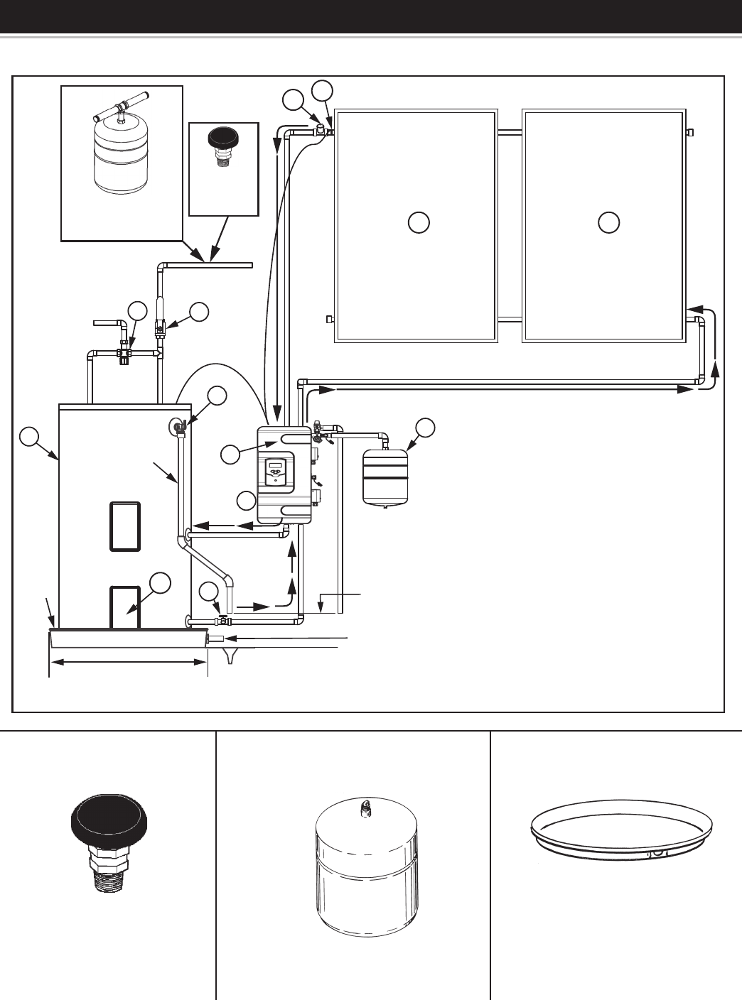
SYSTEM DIAGRAM/TYPICAL INSTALLATION
Figure 1.
INSTALL VACUUM
RELIEF IN COLD
WATER INLET LINE AS
REQUIRED BY LOCAL
CODES.
INSTALL SUITABLE METAL DRAIN
PANS UNDER HEATERS TO PREVENT
DAMAGE DUE TO LEAKAGE. REFER
TO WATER HEATER LOCATION, SEE
“LOCATING THE SOLAR WATER
HEATER” SECTION.
INSTALL THERMAL EXPANSION
TANK OR DEVICE IF WATER HEATER
IS INSTALLED IN A CLOSED WATER
SYSTEM.
6” Maximum Air Gap
Piped To An
Adequate Drain
At Least 2” Greater Than The
Diameter Of The Water Heater.
Metal
Drain
Pan
Discharge Pipe
(DO NOT CAP
OR PLUG)
Flow Direction
1 1
610
9
4
7
3
10
8
5
2
11
VACUUM RELIEF
VALVE
INSTALL PER
LOCAL CODES
INSTALL THERMAL EXPANSION
TANK IF WATER HEATER IS
INSTALLED IN A CLOSED
WATER SYSTEM
7
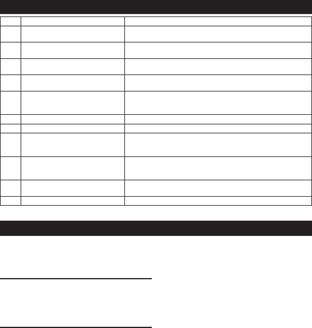
Item Component Function
1 Solar collector Absorbs the sun’s heat energy and transfers this to the heat transfer
uid circulating through the collector.
2 Solar storage tank Stores potable water heated by solar generated heat or installed
back-up electric resistance element.
3 Double Wall Heat exchanger (inside
Solar pump station)
Transfers the heat from the collector loop to the potable water in the
solar storage tank.
4 Solar Loop Expansion tank Allows for the expansion and contraction of the heat transfer uid as
it heat and cools.
5 Temperature and Pressure relief
valve
Required by plumbing code to automatically open and dump water if
the storage tank exceeds 150 PSI of pressure or 210° F in tempera-
ture.
6 Air vent Purges air from the collector loop uid during the installation.
7 Drain valve Used to drain the heat transfer uid from the collector loop.
8 Mixing valve Used to temper hot water from the solar storage tank with cold inlet
water to maintain appropriate temperature hot water delivered from
the system.
9 Solar pump station Controls the ow of heat transfer uid from the collectors to the tank
through the heat exchanger. For a detailed description of the solar
pump station see page 20.
10 Temperature sensor Tank and collector sensor work together to turn the circulating
pump(s) on and off at preset temperature differentials.
11 Cold Water Cut-Off Valve Isolates the tank from incoming water supply.
SYSTEM COMPONENT PART
STORAGE TANK INSTALLATION
Never operate the electrical heating element without being
certain the solar water heater is completely filled with water.
If any air is left in the top of the tank, the heating element
will burn out.
LOCAL CODES
The installation of this solar water heater must be in
accordance with these instructions and all applicable local
codes and electric utility requirements. In the absence of
local codes, install in accordance with the latest edition of the
National Electrical Code (NFPA-70).
TEMPERATURE-PRESSURE RELIEF VALVE
For protection against excessive pressures and temperatures
in this water heater, install temperature-pressure protective
equipment required by local codes, but not less than a
combination temperature-pressure relief valve certified by
a nationally recognized testing laboratory that maintains
periodic inspection of production of listed equipment or
materials, as meeting the requirements for Relief Valves for
Hot Water Supply Systems, the latest edition of ANSI Z21.22.
This valve must be marked with a maximum set pressure not
to exceed the marked hydrostatic working pressure of the
water heater (150 lbs./sq. in.).
Install the temperature-pressure relief valve directly into the
fitting of the water heater. Position the valve downward and
provide a discharge pipe that must terminate a maximum
of six inches above a oor drain or external to the building.
In cold climates, it is recommended that the discharge pipe
be terminated at an adequate drain inside the building. Be
certain that no contact is made with any live electrical part.
The discharge opening must not be blocked or reduced in size
under any circumstances. Excessive length, over 15 feet, or
use of more than two elbows can cause restriction and reduce
the discharge capacity of the valve.
No valve or other obstruction is to be placed between the
temperature-pressure relief valve and the tank. Do not
connect tubing directly to discharge drain unless a 6” air
gap is provided. To prevent bodily injury, hazard to life
or damage to property, the temperature-pressure relief
valve must be allowed to discharge water in quantities
should circumstances demand. If the discharge pipe is not
connected to a drain or other suitable means, the water flow
may cause property damage.
The Discharge Pipe:
• Shall not be smaller in size than the outlet pipe size of the
temperature-pressure relief valve, or have any reducing
couplings or other restrictions.
• Shall not be plugged or blocked.
• Shall be of material listed for hot water distribution.
• Shall be installed so as to allow complete drainage of both the
temperature-pressure relief valve, and the discharge pipe.
• Must terminate a maximum of six inches above a floor drain
8
or external to the building. In cold climates, it is recommended
that the discharge pipe be terminated at an adequate drain
inside the building.
• Shall not have any valve between the relief valve and tank.
When installing the temperature-pressure relief valve, use
two or three turns of Teflon® tape or other suitable thread
sealer around the threaded end of the valve.
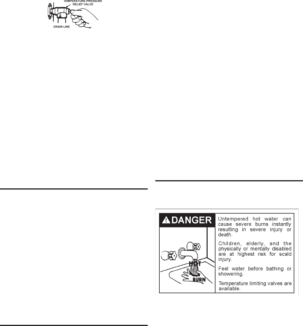
Figure 2.
The temperature-pressure relief valve should be manually
opened once a year. Caution should be taken to ensure that
(1) no one is in front of or around the outlet of the
temperature-pressure relief valve discharge line, and (2)
the water manually discharged will not cause any bodily
injury or property damage because the water may be
extremely hot.
If after manually operating the valve, it fails to completely
reset and continues to release water, immediately close
the cold water inlet to the water heater, follow the draining
instructions, and replace the temperature-pressure relief
valve with a new one.
If the temperature-pressure relief valve on the appliance
weeps this may be due to thermal expansion. The water
supply serving this solar water heater may have a check
valve installed. Contact the water supplier or local plumbing
contractor on how to control this situation. Do not plug the
temperature-pressure relief valve.
CLOSED SYSTEM/THERMAL EXPANSION
As water is heated, it expands (thermal expansion). In a
closed system, the volume of water will grow. As the volume
of water grows, there will be a corresponding increase
in water pressure due to thermal expansion. Thermal
expansion can cause premature tank failure (leakage). This
type of failure is not covered under the limited warranty.
Thermal expansion can also cause intermittent temperature-
pressure relief valve operation: water discharged from the
valve due to excessive pressure build up. The temperature-
pressure relief valve is not intended for the constant relief
of thermal expansion. This condition is not covered under
the limited warranty.
A properly-sized thermal expansion tank should be installed
on all closed systems to control the harmful effects of
thermal expansion. Contact a plumbing service agency or
your retail supplier regarding the installation of a thermal
expansion tank..
LOCATING THE SOLAR WATER HEATER
If you have a choice of where to install the solar water heater,
these ideas may help you decide.
1. Put the solar water heater indoors as close as possible
to where you use the most hot water. This water heater
is not intended for outdoor installation.
2. It is handy to have a floor drain, tub or sink nearby.
That will make it easy to drain water from the water
heater. It is also a good place to end the drain line of
the temperature-pressure relief (T & P) valve.
3. The solar water heater or the pipes and the connections
may, in time, leak. Put the solar water heater in a place
where a water leak will not damage anything.
4. You must not put the water heater in an area where
it might freeze You must turn off the electricity to the
water heater before you drain it, to protect the heating
elements.
5. Make sure that you are able to reach the drain valve
and all access panels when the water heater is in place.
This will make it easy to service the water heater.
6. The water heater must be level before you begin the
piping.
WATER HEATERS EVENTUALLY LEAK. The installation
of the water heater must be accomplished in such a manner
that if the tank or any connections should leak, the flow
of water will not cause damage to the area adjoining the
water heater or to lower floors of the structure. When such
locations can’t be avoided, a suitable metal drain pan should
be installed under the water heater. Such a pan should be
no greater than 1 1/2 inches deep, have a minimum length
and width of at least two inches greater than the heater
dimensions and must be piped to an adequate drain.
This solar water heater, as all water heaters, will eventually
leak. Do not install without adequate drainage provisions
where water flow will cause damage. Note: normal
condensation from a solar water heater may appear to be
a leaking tank.
WATER PIPING
This solar water heater is design certified to be used with a
potable water system. When connecting water piping with
solder joints use only lead free solder.
This solar water heater shall not be connected to any
heating systems or component(s) previously used with a
non-potable water heating appliance.
If this solar water heater is also used for space heating
applications, all piping and components connected to the
solar water heater shall be suitable for use with potable
water.
This appliance has been design certified as a solar water
heater complying with Standards for Safety - UL174 for
the U.S. and can/csa-c22.2 No 110 F379.1 and F379.2
9
for Canada. The particular application of this appliance
described (above paragraph) may be subject to review and
approval by local code officials.
Toxic chemicals such as used for treatment of boilers or non-
potable water heating appliances shall never be introduced
into a potable water space heating system.
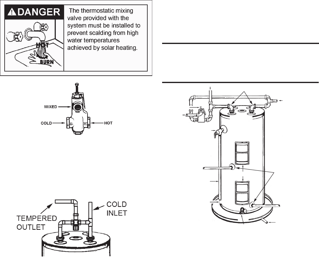
Figure 3.
The solar water heater will work better if you keep the hot
water runs short. You will also get hot water faster and with
less heat loss.
The illustration shows the correct valves and fittings that you
will need to install the solar water heater. Threaded (3/4”)
water connections are supplied through the tank top.
Figure 4.
1. Buy the fittings that you need to connect the pipes.
Remember that you have to connect both the hot and
cold water pipes.
2. Apply a light covering of pipe joint compound to each
outside thread before making connection.
3. Connect the cold water supply pipe to the cold water inlet
of your solar water heater as follows:
a. Look at the top cover of the solar water heater. The
hot and cold connections are marked there.
b. A non-metallic dip tube is supplied to carry cold water
from the tank top to the bottom. Be sure that it is in
the cold water inlet.
c. If using copper tubing, solder tubing to an adapter
BEFORE you attach the adapter to the cold water
inlet. DO NOT solder the cold water supply pipe
directly to the cold water inlet connection. It might
harm the dip tube.
d. The cold water supply line must have a shut-off valve
and union.
4. Use a union to connect the hot water supply pipe to the
solar water heater’s hot water outlet.
Operating an empty or partially filled solar water heater will
result in damage to the tank.
If a solar water heater is installed in a closed water system;
such as one having a back flow preventer, check valve or
water meter with check valve in the cold water supply line,
means shall be provided to control thermal expansion.
Contact the water supplier or local plumbing contractor on
how to control this situation.
INSTALLATION IN RESIDENTIAL GARAGES
The solar water heater must be located and/or protected
so it is not subject to physical damage by a moving vehicle.
FILLING THE SOLAR WATER
HEATER WITH WATER
MIXING VALVE
HOT WATER OUTLET
SIDE SOLAR
WATER LOOP
CONNECTIONS
TOP SOLAR WATER
LOOP CONNECTIONS
TEMPERATURE-PRESSURE
RELIEF VALVE
TO SUITABLE
DRAIN
DRAIN VALVE
6” AIR GAP
DRAIN LINE
ACCESS COVER
COLD WATER
INLET
TEMPERED
WATER
OTLET
Figure 5.
Before lling the solar water heater with water, the pump
station storage tank loop must be connected to the water
heater. See “Filling The Storage Tank Loop” section of the
manual.
The solar water heater is equipped with top and side pump
station water loop connections. Cap or plug the connections
that are not used in your application.
1. Close the solar water heater drain valve. The drain
valve is on the lower front of the solar water heater.
2. Open the cold water supply to the solar water heater.
NOTE: THIS VALVE MUST BE LEFT OPEN WHEN
THE SOLAR WATER HEATER IS IN USE.
3. Fill the solar water heater until a constant flow of water
runs out an opened hot water faucet. This will let out
air in the solar water heater and the piping. Close the
faucet and solar loop air vent after all air has been
purged and the water comes out with constant flow.
You must not turn the electricity on until the solar water
heater is full of water. IF ANY AIR IS LEFT IN THE TOP
OF THE SOLAR WATER HEATER OR IN THE PUMP
STATION STORAGE TANK LOOP THE HEATING
ELEMENT WILL BURN OUT IMMEDIATELY.
4. Check all the new water piping for leaks. Fix as needed.
10
WIRING OF ELEMENT
Determine voltage and wattage from the rating plate
attached to the solar water heater. All external wiring,
connection, and overcurrent protective devices must be
provided and installed in accordance with the latest edition
of the National Electrical Code, local codes, and local utility
requirements. The solar water heater must be electrically
“grounded” by the installer. A green ground screw has been
provided on the solar water heater’s junction box.
The grounding electrode conductor shall be of copper,
aluminum, or copper clad aluminum. The material shall
be resistant to corrosion, and shall be of one continuous
length without a splice or joint.
Rigid metal conduit, intermediate metal conduit, or electrical
metallic tubing may be used for the grounding means
if conduit or tubing is terminated in fittings approved for
grounding.
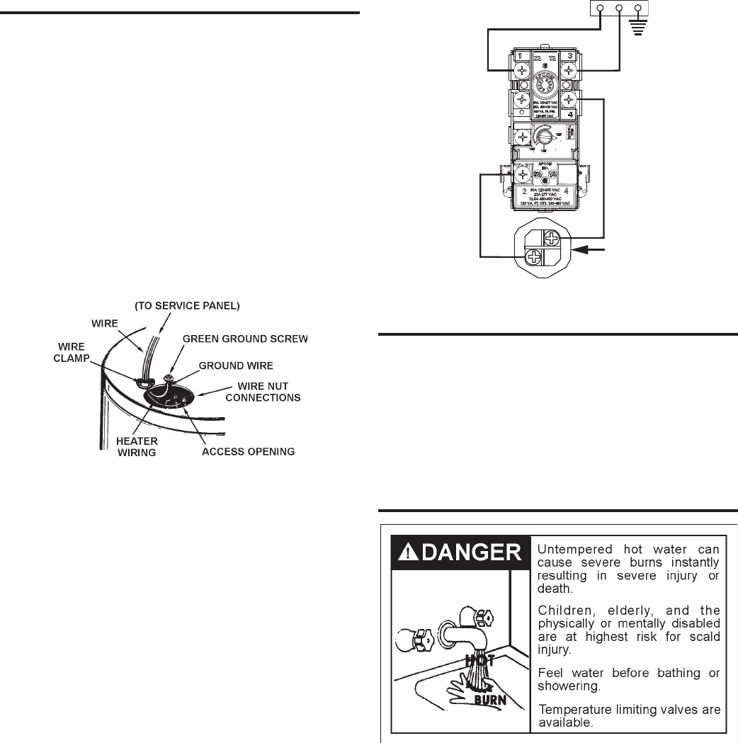
Figure 6.
Flexible metal conduit or flexible metallic tubing shall be
permitted for grounding if all the following conditions are
met:
1. The length in any ground return path does not exceed
6 feet.
2. The circuit conductors contained therein are protected
by overcurrent devices rated at 20 amperes or less.
3. The conduit or tubing is terminated in fittings approved
for grounding.
Never use this solar water heater unless it is completely
full of water.
SOLAR WATER HEATERS EQUIPPED FOR ONE TYPE
VOLTAGE ONLY. This solar water heater is equipped
for one type of voltage only. Check the rating plate near
the bottom access panel for the correct voltage. DO NOT
USE THIS SOLAR WATER HEATER WITH ANY VOLTAGE
OTHER THAN THE ONE SHOWN ON THE MODEL
RATING PLATE. Failure to use the correct voltage can
cause problems which can result in DEATH, SERIOUS
BODILY INJURY OR PROPERTY DAMAGE. If you have
any questions or doubts consult your electric company.
If wiring from the fuse box or circuit breaker box was alumi-
num for the old tank, replace it with copper wire. If you wish
to reuse the existing aluminum wire, have the connection
at the solar water heater made by a competent electrician.
Contact your local utility to arrange for a professional elec-
trician.
BLACK
RED
BLACK
ELEMENT
RED
F
C)(66 F(60 C)
F
C)(49
Figure 7.
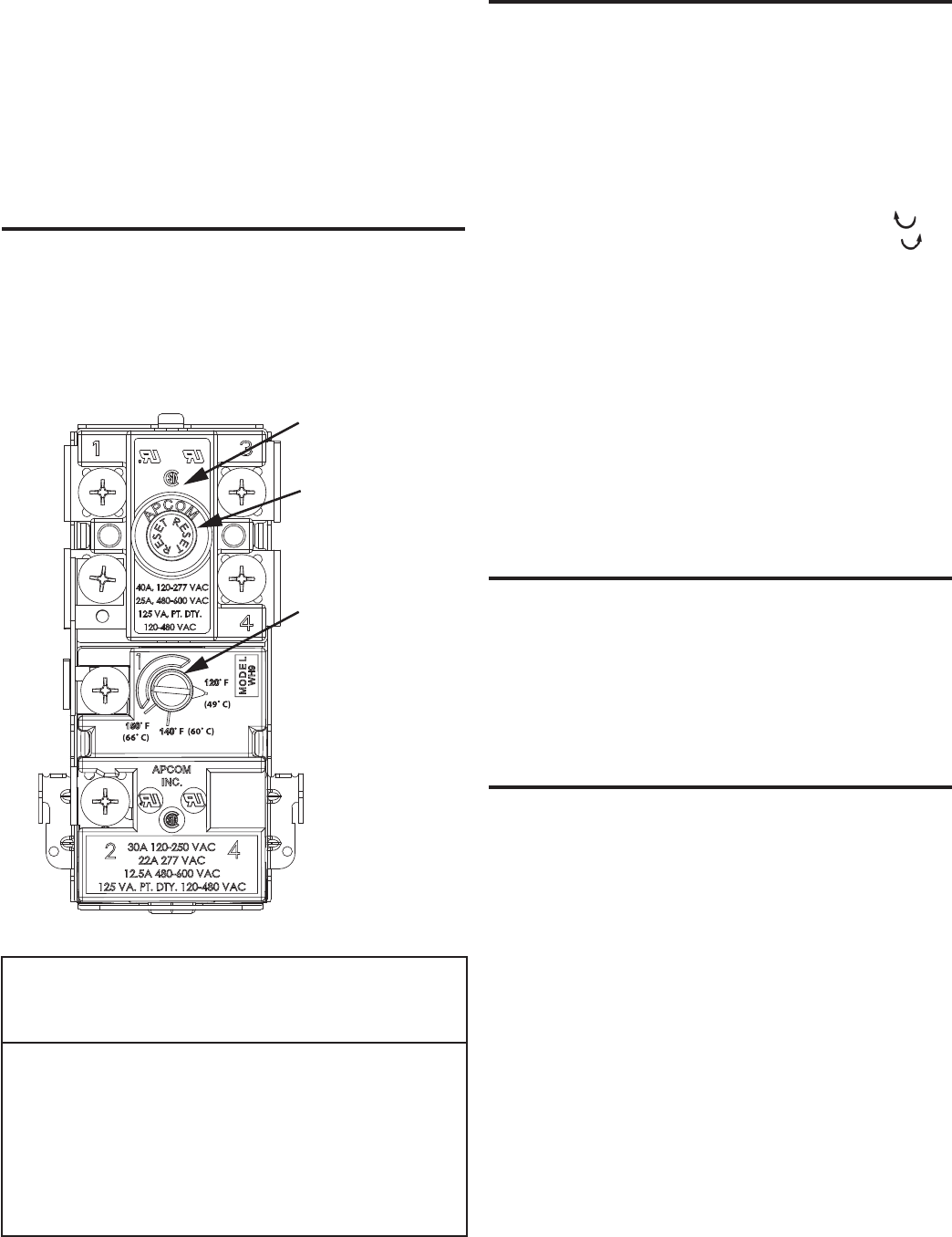
THERMOSTAT
Each thermostat is factory preset at 120°F to reduce the
risk of scald injury. This setting has proven by experience
to be most satisfactory from the standpoint of operational
costs and household needs.
Solar water heaters installed in Florida require the
thermostat(s) to be set at 125°F. If you wish to adjust the
settings, see the “Temperature Adjustment” section of this
installation manual on page 11.
TEMPERATURE REGULATION
HOTTER WATER CAN SCALD: Solar water heaters are
intended to produce hot water. Water heated to a temperature
which will satisfy clothes washing, dish washing, and other
sanitizing needs can cause scalds resulting in serious
personal injury and/or death. Some people are more likely
to be permanently injured by hot water than others. These
include the elderly, children, the infirmed, or physically
handicapped. If anyone using hot water in your home fits
into one of these groups or if there is a local code or state
law requiring a certain temperature water at the hot water
tap, then you must take special precautions. Please see
Figure 8 and Table 2 for information regarding thermostat
settings. In addition to using the lowest possible temperature
setting that satisfies your hot water needs, some type of
mixing device, such as a mixing valve should be used at the
11
hot water taps used by these people or at the solar water
heater. Mixing valves are available at plumbing supply or
hardware stores. Follow manufacturers instructions for
installation of the valves. Before changing the factory
setting of the thermostat, read the Temperature Adjustment
section. KEEPING THE THERMOSTAT SETTING AT 120°F
WILL REDUCE THE RISK OF SCALDS. Never allow
small children to use a hot water tap, or to draw their own
bath water. Never leave a child or handicapped person
unattended in a bathtub or shower.
TEMPERATURE SETTINGS
NOTE: This residential solar water heater will not supply
sanitizing hot water for dishwashers.
The thermostat is factory set at its lowest position which
approximates 120°F and is adjustable if a different water
temperature is desired. For best system savings this
temperature should not be changed. Read all warnings in
this manual and on the solar water heater before proceeding.
ADJUSTABLE
THERMOSTAT
WITH
HIGH LIMIT
HIGH LIMIT
CONTROL
RESET
BUTTON
Figure 8.
Water
Temperature °F
Time for 1st Degree
Burn
(Less Severe Burns)
Time for Perma-
nent Burns 2nd &
3rd Degree (Most
Severe Burns)
110
116
116
122
131
140
149
154
(normal shower temp.)
(pain threshold)
35 minutes
1 minute
5 seconds
2 seconds
1 second
instantaneous
45 minutes
5 minutes
25 seconds
5 seconds
2 seconds
1 seconds
(U.S. Government Memorandum, C.P.S.C., Peter L. Armstrong, Sept. 15,1978)
Table 2.
TEMPERATURE ADJUSTMENT
To adjust the temperature setting:
1. Turn “OFF” the electrical power to the water heater, at
the junction box.
HAZARD OF ELECTRICAL SHOCK! Failure to turn
“OFF” electric power to the solar water heater will result
in the possibility of DEATH, SERIOUS BODILY INJURY
OR PROPERTY DAMAGE.
2. Take off the access panel and fold away the insulation.
3. Turn the water temperature dial clockwise ( ) to
increase the temperature, or counterclockwise ( ) to
decrease the temperature.
4. Fold the insulation back in place and replace the access
panel.
5. Turn “ON” the power supply.
A non-adjustable high temperature limit control operates
before steam temperatures are reached. The high limit is
in the same area as the upper thermostat and must be reset
manually when it activates. BECAUSE THE HIGH LIMIT
ACTIVATES ONLY WHEN ABNORMALLY HIGH WATER
TEMPERATURES ARE PRESENT, IT IS IMPORTANT
THAT A QUALIFIED SERVICE AGENT BE CONTACTED
TO DETERMINE THE REASON FOR OPERATION
BEFORE RESETTING.
TANK SENSOR
The surface mount tank sensor should be attached to the
sensor stud behind the lower door by placing the hole in
the sensor over the stud provided and securing in place
with a nut. The end of the tank sensor shall be connected
to the red wires in the opening with wire nuts (with no
regard for polarity). The other ends of the red temperature
sensor extension extend from the top of the tank and shall
be connected to the controller in the tank sensor position.
DRAINING
It is recommended that the storage tank be drained and
ushed every 6 months to remove sediment which may
build up during operation. The water heater should be
drained if being shut down during freezing temperatures.
To drain the tank, perform the following steps:
1. Turn off power to the water heater.
2. Open a nearby hot water faucet until the water is no
longer hot.
3. Close the cold water inlet valve.
4. Connect a hose to the drain valve and terminate it to
an adequate drain or external to the building.
5. Open the water heater drain valve and allow all of the
water to drain from the tank. Flush the tank with water
as needed to remove sediment.
6. Close the drain valve, rell the tank, and restart the
heater as directed in this manual.
If the water heater is going to be shut down for an extend-
ed period, the drain valve should be left open.
IMPORTANT: Condensation may occur when relling the
tank and should not be confused with a tank leak.
If the solar water heater is to be shut off and exposed to
12
freezing temperatures, it must be drained. Water, if left in
the tank and allowed to freeze, will expand and damage
the solar water heater.
1. Turn “OFF” the electrical supply to the solar water heater.
Make sure the electrical supply to the solar water heater
is turned OFF. Failure to heed this will result in the
possibility of DEATH, SERIOUS BODILY INJURY OR
PROPERTY DAMAGE.
2. Open a nearby hot water faucet until the water is no
longer hot, then turn off the cold water supply and open
the drain valve, leaving the hot water faucet open.
3. The drain valve must be left open during the shut-down
period. Once the solar water heater is drained close the
hot water faucet.
ELEMENT
In some water areas, scale or mineral deposits will build up
on heating elements. This build up may cause a rumbling
noise. Follow the element replacement directions to remove
the elements from the tank. Soaking in vinegar and scraping
will remove the mineral deposit. Be careful not to bend the
element.
ELEMENT REPLACEMENT
Replacement elements must (1) be the same voltage and
(2) no greater wattage than listed on the model and rating
plate afxed to the solar water heater.
1. Turn OFF the electrical supply to the solar water heater.
Make sure the electrical supply to the solar water heater
is turned OFF. Failure to heed this will result in the
possibility of DEATH, SERIOUS BODILY INJURY OR
PROPERTY DAMAGE.
2. Drain the solar water heater. Follow the directions for
draining.
3. Take off the access panel and take off the access panel
and remove the insulation. Disconnect the wires from the
heating element terminals.
4. Use an element wrench to remove the element and gasket.
You should always use a new gasket when you replace the
element.
5. Install new element.
6. Reconnect the wires as they were.
7. Fill the tank , following the filling directions on page 9. Fill
the tank completely with water, BEFORE you turn on the
electric supply.
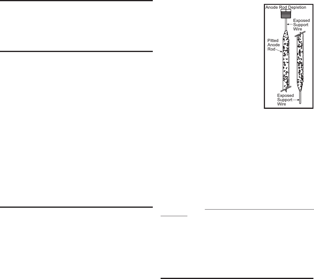
ANODE
Each water heater contains at least one anode rod, which
will slowly deplete (due to electrolysis) prolonging the life
of the water heater by protecting the glass-lined tank from
corrosion. Adverse water quality, hotter water temperatures,
high hot water usage, hydronic heating devices, and water
softening methods can increase the rate of anode rod
depletion. Once the anode rod is depleted, the tank will
start to corrode, eventually developing a leak.
Certain water conditions will cause a reaction between the
anode rod and the water. The most common complaint
associated with the anode rod is a “rotten egg smell”
produced from the presence of hydrogen sulfide gas
dissolved in the water. IMPORTANT: Do not remove this rod
permanently as it may void any warranties. A special anode
rod may be available if water odor or discoloration occurs.
NOTE: This rod may reduce but not eliminate water odor
problems. The water supply system may require special
filtration equipment from a water conditioning company to
successfully eliminate all water odor problems.
Artificially softened water is exceedingly corrosive because
the process substitutes sodium ions for magnesium and
calcium ions. The use of a water softener may decrease
the life of the water heater tank.
The anode rod should be inspected after a maximum of
three years and annually thereafter until the condition of
the anode rod dictates its replacement. NOTE: artificially
softened water requires the anode rod to be inspected
annually.
The following are typical (but not all) signs of a depleted
anode rod:
• The majority of the rod’s diameter is less than 3/8”.
• Significant sections of the support wire (approx. 1/3 or
more of the anode rod’s length) are visible.
If the anode rod shows signs of either
or both it should be replaced. NOTE:
Whether re-installing or replacing the
anode rod, check for any leaks and
immediately correct if found.
In replacing the anode:
1. Turn off power supply to the water
heater.
2. Shut off the water supply and
open a nearby hot water faucet to
depressurize the water tank.
3. Drain approximately 5 gallons
of water from tank. (Refer to
“Draining and Flushing” for proper
procedures). Close drain valve.
4. Remove old anode rod.
5. Use Teflon® tape or approved pipe sealant on threads
and install new anode rod.
6. Turn on water supply and open a nearby hot water
faucet to purge air from water system. Check for any
leaks and immediately correct any if found.
7. Restart the water heater as directed in this manual.
See the Storage Tank Repair Parts section for anode
rod location.
TEFLON® is a registered trademark of E.I. Du Pont De
Nemours and Company.
Hydrogen gas can be produced in a hot water system that
has not been used for a long period of time (generally two
weeks or more). Hydrogen gas is extremely flammable and
explosive. To prevent the possibility of bodily injury under
these conditions, open the hot water faucet for several
minutes at the kitchen sink before any electrical appliances
which are connected to the hot water system are used (such
as a dishwasher or washing machine). If hydrogen gas is
present, there will probably be an unusual sound similar
to air escaping through the pipe as the hot water faucet is
opened. There must be no smoking or open flame near
the faucet at the time it is opened.
WATER HEATER SOUNDS
1. The solar water heater is equipped with an immersion
heating element for fastest recovery. If the solar water
heater occasionally makes noises this is not a defect or a
safety hazard.
2. Lime or scale has accumulated on the heating element
causing a hissing sound. Element scale removal can be
accomplished by using vinegar or by scraping.
Figure 9.
13
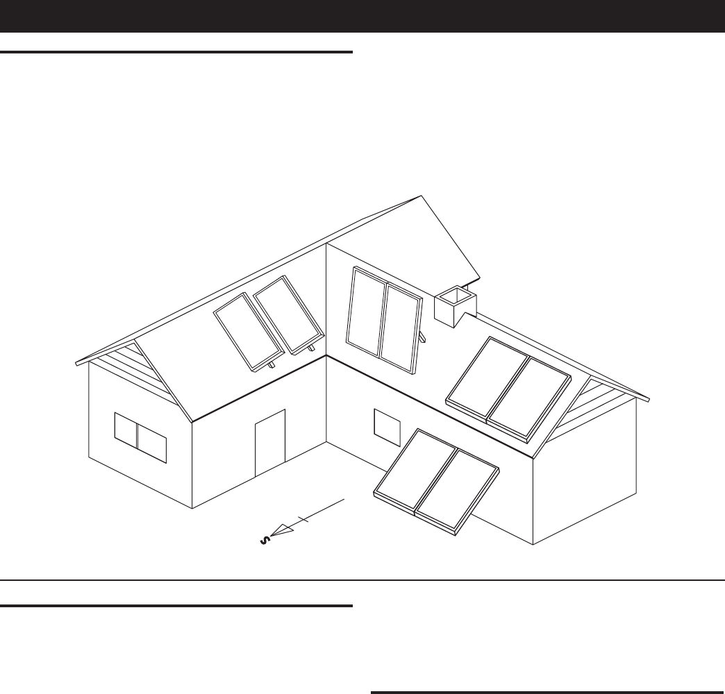
Figure 10.
COLLECTOR LOCATION
Proper location and orientation of the solar collectors is
important for maximum system efciency. The collectors
should be unshaded from 10:00 am through 3:00 pm each
day in every month of the year and should be located as
close to the storage tank as possible to minimize heat loss
in the piping runs. The best orientation is achieved when
the collectors are facing due south +/- 45° and tilted at
an angle from the horizontal equal to the latitude of the
SOLAR COLLECTOR INSTALLATION
location + 15°. A steeper angle provides better winter per-
formance as the sun is lower in the sky. The collectors
will also shed snow more effectively at the steeper angle.
Figure 10 below shows many alternatives for collector
mounting. Placing the collectors as close as possible to
the peak of the roof will make installation easier by provid-
ing increased attic access.
GENERAL CONSIDERATIONS
The contractor shall obtain all required permits and
approvals.
The installation shall conform to all federal, state and local
regulations, codes, ordinances and standards governing
solar water heating system installations and the contractor
shall adhere to sound building safety and trade practices.
Special consideration must be given to building code
requirements for the penetration of structural members
and re rated assemblies.
Ensure the mounting surface is solid and able to with-
stand in excess of 330lbs / 150kg of pull force that
may be encountered during high winds. Consult a
structural engineer if in doubt.
The solar collector must be located in a structurally sound
area of the roof that will be unshaded for the majority of the
day all year round. Adjacent buildings and trees should be
checked for possible winter shading. An instrument such
as the Solar Pathnder (www.solarpathnder.com) can be
used for solar site analysis.
Before the installation the contractor shall inspect the con-
dition of the roof and notify the homeowner of any existing
roof damage or necessary repairs.
COLLECTOR ORIENTATION
Proper tilt angle for solar collectors is latitude plus 15°.
This 15° additional tilt improves performance in the
winter, when the sun is weaker and at a lower angle.
The cost in performance in the summer when the sun is
high is overcome by the hours of sunlight and strength
of irradiation that occurs in the summer. Tilt mounting
accessory kits are available to set the proper collector
angle. Please call your local dealer for more information.
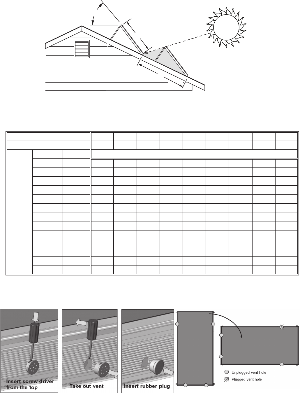
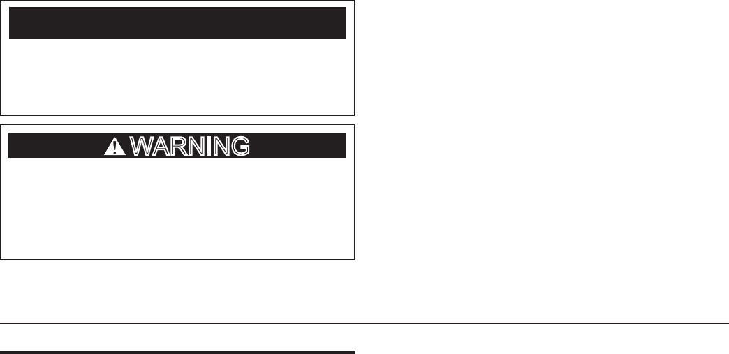
When the collectors are mounted one behind the other,
they should be spaced sufciently apart so that when the
sun is at its lowest altitude, the collectors will not shade
each other and cause efciency loss. See Figure 11 and
Table 3. If a collector must be installed horizontally, replace
the upper vent with a rubber plug in order to prevent rain
penetration. See Figures 12 & 13.
14
A”
48”
COLLECTOR TILT
Figure 11.
Figure 12. Figure 13.
LATITUDE 25° N 30° N 35° N 40° N 45° N 50° N 55° N 60° N 65° N
COLLECTOR TILT 35° 40° 45° 50° 55° 60° 65° 70° 75°
ROOF
ANGLE
&
PITCH
ANGLE PITCH A” SPACING IN INCHES
0° FLAT 87 103 127 159 213 260 330 446 661
5° 1/12 76 87 103 122 151 174 204 244 295
9° 2/12 69 78 90 104 123 139 157 180 205
14° 3/12 63 69 78 88 101 111 123 136 149
18° 4/12 59 64 71 78 88 96 105 115 123
23° 5/12 54 59 64 70 77 83 89 96 102
27° 6/12 52 55 59 64 70 75 80 86 90
30° 7/12 50 53 57 61 66 70 75 79 83
34° 8/12 48 51 54 57 61 65 69 72 75
37° 9/12 N/A 49 52 55 59 62 65 68 70
40° 10/12 N/A 48 50 53 56 59 62 65 66
43° 11/12 N/A N/A 49 51 54 56 59 62 63
45° 12/12 N/A N/A 48 50 53 55 57 60 61
Table 3. (For All Horizontally Mounted Collectors)
15
CAUTION
ALL PERSONS WORKING ON ROOFS SHOULD
HAVE SUCCESSFULLY COMPLETED A FALL SAFETY
COURSE AND SHOULD BE PROPERLY EQUIPPED
WITH THE APPROPRIATE SAFETY EQUIPMENT
AFTER COMPLETION OF THE COLLECTOR
MOUNTING AND PRIOR TO SYSTEM CHARGING THE
COLLECTORS MUST BE COVERED BY A BLANKET OR
OTHER MEANS TO AVOID SOLAR RADIATION FROM
HEATING THE COLLECTORS. THE SURFACES OF THE
COLLECTOR CAN BECOME EXTREMELY HOT AND
COULD POSE A BURN HAZARD.
WARNING
The most important structural consideration is to securely
anchor the solar collector and the mounting hardware to the
structural members of the roof with the stainless steel hardware
provided. The solar collector must be attached to the mounting
hardware as detailed in Figure 17.
Preserving the integrity of the roof membrane is the
most important roong consideration. Ensure that all roof
penetrations required to plumb and mount the solar collector
are properly ashed and sealed in accordance with standard
roong practices.
If the region is subject to hurricane conditions, additional
steps may be required to secure the collector and mounting
hardware to the structural members. In certain areas of the
country, local building codes may require collector wind load
testing or prescribe specic mounting procedures. Consult
your local building department.
Install the collectors as described in the Spanner Mounting
instructions.
SPANNER MOUNTING
Although there are other installation methods for mounting
solar collectors, it has been determined that the spanner
mounting method is the most suitable for this application.
Consult with your installer if other mounting means are
required for your installation.
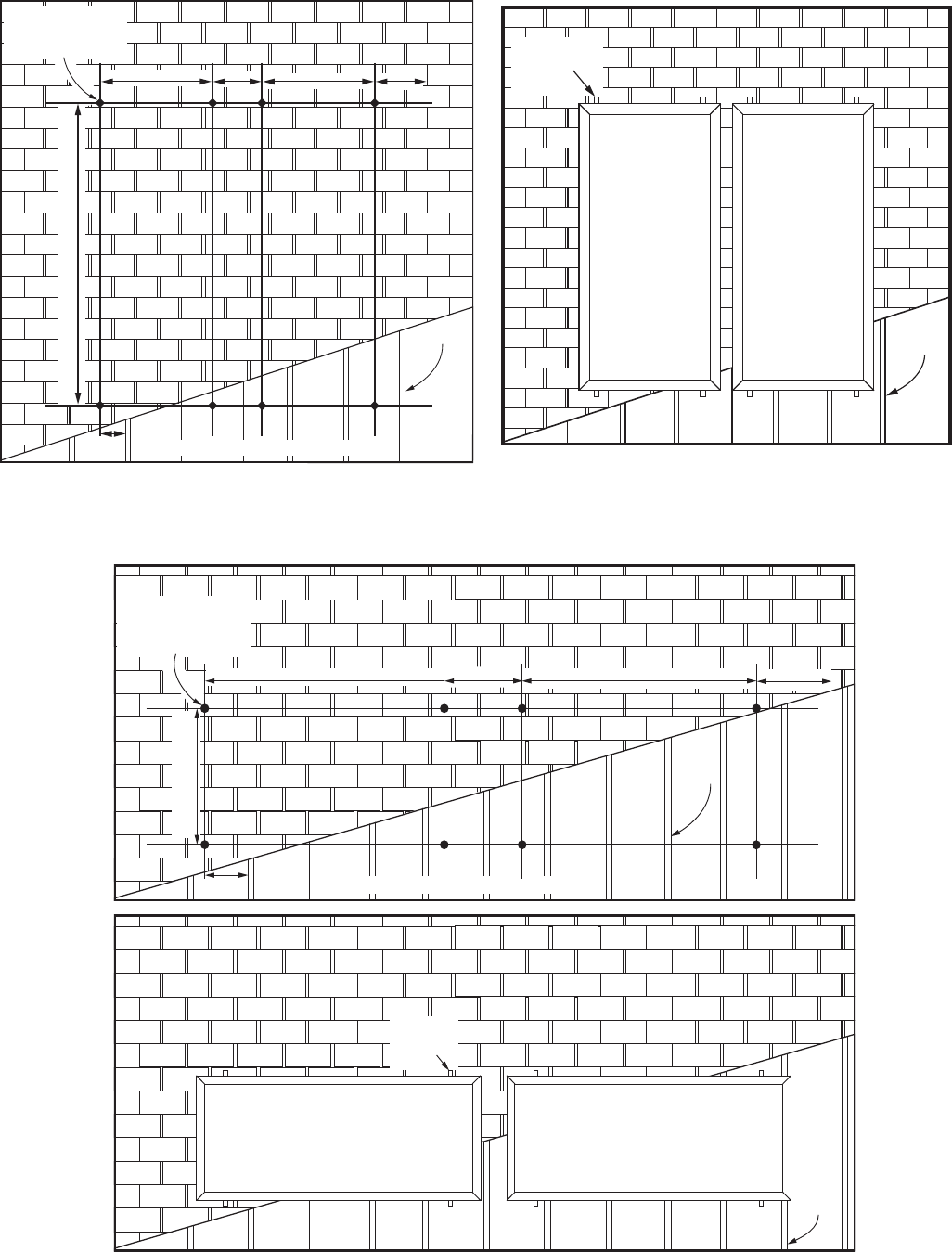
1. After locating the mounting points from Figure 14 for
vertical collector mounting, Figure 15 for horizontal
collector mounting, and Table 4, layout the roof as
specified and drill 5/16” holes between the rafters
where indicated.
2. A 12” length of stainless steel 5/16” all-thread is then
inserted through the hole and a stainless steel nut, lock
washer, and flat washer secures the all-thread to the
mounting bracket. The all-thread should extend about
4” below the roof rafters.
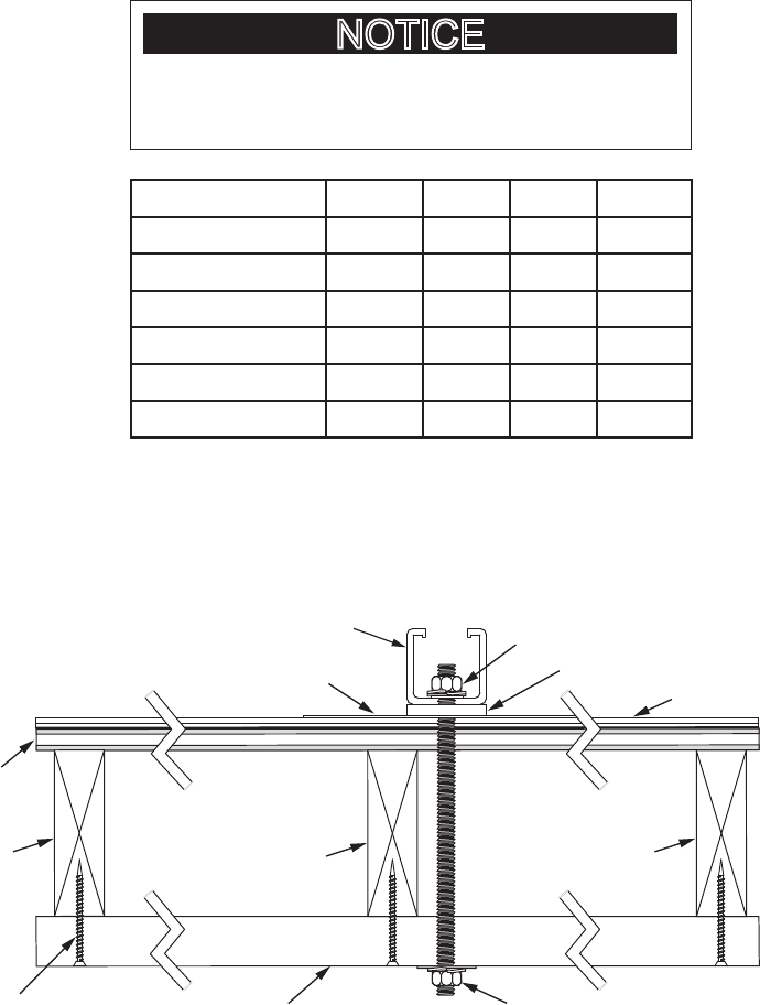
3. Fabricate spanners, one for each mounting bracket,
using a 2” x 4” or similar lumber. Spanners must be
long enough to span at least two rafters. In the attic or
crawl space drill a 5/16” hole through each spanner and
insert the all-thread through it. Secure each spanner to
the rafters with decking or wood screws. See Figure 16.
4. Fabricate spacer blocks, one for each mounting bracket,
using a 2” x 4” or similar lumber the same width of the
rafter next to each all-thread. Place spacer blocks next
to the all-thread between the spanner and roof. Secure
each spacer block to the spanners with decking or
wood screws. Spacer blocks are necessary to avoid
deformation of the roof. See Figure 16.
5. With a stainless steel nut, lock washer and fender
washer secure the all-thread to each spanner. Tighten
down until the mounting bracket is tightly secured to
the roof (approx. 97 inch pounds). Be careful not to
overtighten and dish out the roof tiles underneath the
mounting bracket.
Repeat steps 2-5 for the remainder of the mounting
bracket locations.
16
MOUNTING
BRACKETS
RAFTER
VERTICAL MOUNTING
HORIZONTAL MOUNTING
RAFTER
MOUNTING
BRACKET
RAFTER
Figure 14.
Figure 15.
B” B”C” C”
A”
DRILL POINTS
(CLEARANCE HOLE
for 5/16” BOLT)
RAFTER
D” BASED ON 16” CENTER RAFTERS
B” B”C” C”
A”
DRILL POINTS
(CLEARANCE HOLE
for 5/16” BOLT)
RAFTER
D” BASED ON 16” CENTER RAFTERS
17
4” MOUNTING BRACKET
ROOF
RAFTER
WOOD SPANNER
(2” x 4” or 2” x 6” LUMBER)
SHINGLES
PLYWOOD
SHEETING
FLASHING
STAINLESS STEEL NUT, ALL THREAD ROD
LOCK WASHER, & EPDM BONDED WASHER
CP COMPRESSION
BRACKET WASHER
DECKING/WOOD
SCREWS
FENDER WASHER
LOCK WASHER
NUT
ROOF
RAFTER
SPACER
BLOCK
Figure 16.
Table 4.
* IF MOUNTING WITH AN OPTIONAL TILT MOUNT
KIT, FOR OPTIMAL COLLECTOR ANGLE REFER TO
ITS INSTRUCTION SHEET FOR THE APPLICABLE “A”
DIMENSION.
NOTICE
COLLECTOR A B C D
Vert. 3.5’ X 7’ 86* 32 14 7-1/4
Vert. 4’ X 8’ 97* 35 16 11-3/4
Vert. 4’ X 10’ 121* 35 16 11-3/4
Horiz. 3.5’ X 7’ 42.25* 62 28 13-1/2
Horiz. 4’ X 8’ 47* 72 28 12
Horiz. 4’ X 10’ 47* 94 30 9
18
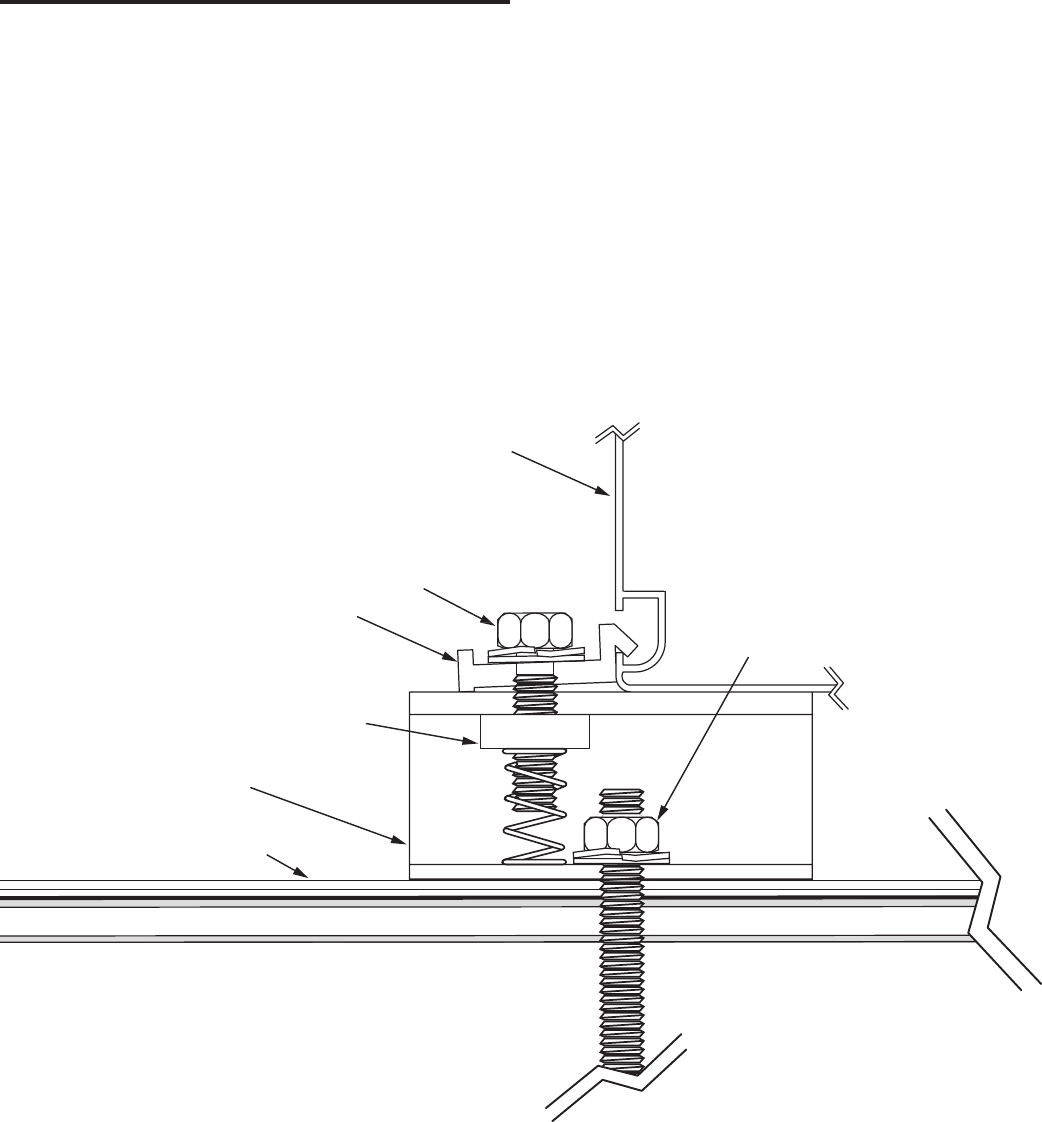
Figure 17.
ATTACHING COLLECTOR TO MOUNTING BRACKETS
Once all of the mounting brackets have been secured to
the roof the solar collector(s) can be installed. Refer to
Figure 17 for these instructions.
1. Insert the stainless steel channel nut w/spring inside
of the mounting bracket.
2. Fasten the solar collector mounting clip to the channel
nut with the stainless steel bolt, lock-washer, and at
washer as shown. Do not tighten. Repeat step for the
other mounting bracket locations.
3. The solar collector can now be set on the mount-
ing brackets. To aid in handling the collectors on the
roof the mounting clips may be tightened to the lower
mounting brackets prior to raising the collectors. The
collector can then be set on the lower mounting brack-
ets while the top clips are fastened over the lip on the
collector frame.
4. After the solar collector is in position, locate the upper
mounting clip so that its lip over-hangs the lip of the
solar collector frame as shown. Tighten the mounting
clip to the solar collector frame securely. Repeat for
the other upper mounting clips.
5. Once the upper mounting clips are secured, the bot-
tom mounting clips can be loosened and retightened
over the collector lip as directed in step 4.
6. Repeat steps as needed for other solar collectors.
SOLAR COLLECTOR FRAME
MOUNTING CLIP
STAINLESS STEEL BOLT,
LOCK WASHER,
& FLAT WASHER
CHANNEL NUT with SPRING
(One Piece Part)
ROOF
MOUNTING
BRACKET
STAINLESS STEEL
NUT, ALL THREAD ROD
with LOCK WASHER, &
FLAT WASHER
19
COLLECTOR PIPING
The piping of the system should be considered before a nal
decision is made on how the collectors are mounted. Piping
should be made of copper tube of the type meeting local
codes, insulated with Armacell UT Solaex or equivalent.
The maximum total piping length allowed in this system is
200 equivalent ft.
Use only lead-free solder. Use of 50/50 lead solder is
expressly prohibited. Use only type “L” or “M” copper
tubing in the collector loop plumbing. Use of galvanized
steel, CPVC, PVC, PEX or any other type of plastic pipe
is prohibited.
Care should be taken in the spacing of collectors as
attachment of piping is easiest with properly aligned
collectors. The connection between the collector panels is
made with copper unions or couplings. To aid in installation
the collector array layout should be planned on the ground
and the unions or couplings soldered to the adjoining
headers prior to lifting the collectors to the roof. Similarly
the top and bottom outside header that will not be used
for the inlet or outlet (should be on opposite sides) should
be capped with the 1” copper cap provided while on the
ground. See Figure 18.
VERTICAL MOUNT
OUTLET
INLET
1” COPPER
CAPS
HORIZONTAL MOUNT
OUTLET
INLET
1” COPPER
CAPS
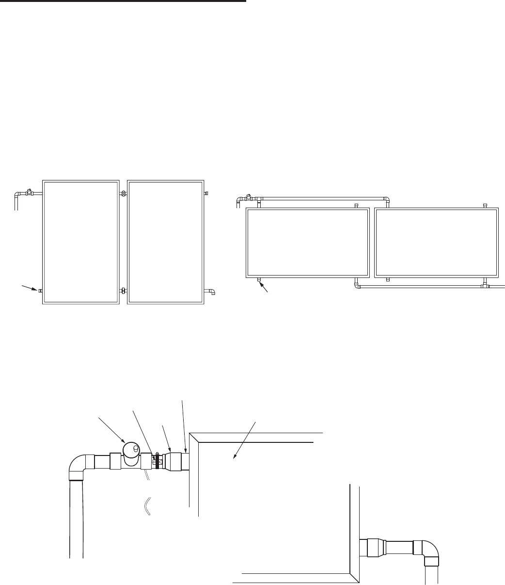
Figure 18.
SOLAR COLLECTOR
AIR VENT
1” COPPER
PIPE
HEADER
PIPE
ADAPTER
COLLECTOR
(OUTLET)
COLLECTOR
(INLET)
TEMPERATURE
SENSOR
Figure 19.
20
COLLECTOR PIPING DETAIL
The outlets of the collector are 1” copper pipe nipples. See
Figure 19. They should be piped as shown with provisions
for an air vent. The air vent must be oriented vertically as
this must be the highest point in the system in order for air
to escape. This will prevent air lock and subsequent loss of
system efciency. Teflon® tape or high temperature, high
quality pipe sealant should be used when making threaded
connections.
The collector inlets should be piped similarly but without
the air vent.
SENSOR WIRING AT COLLECTOR
The wiring used to connect the sensors to the controller
should be a minimum 18 AWG. The wiring should be two-
conductor, PVC UV resistant suitable for outdoor use. Use
Belden Wire No. 7409A or equivalent.
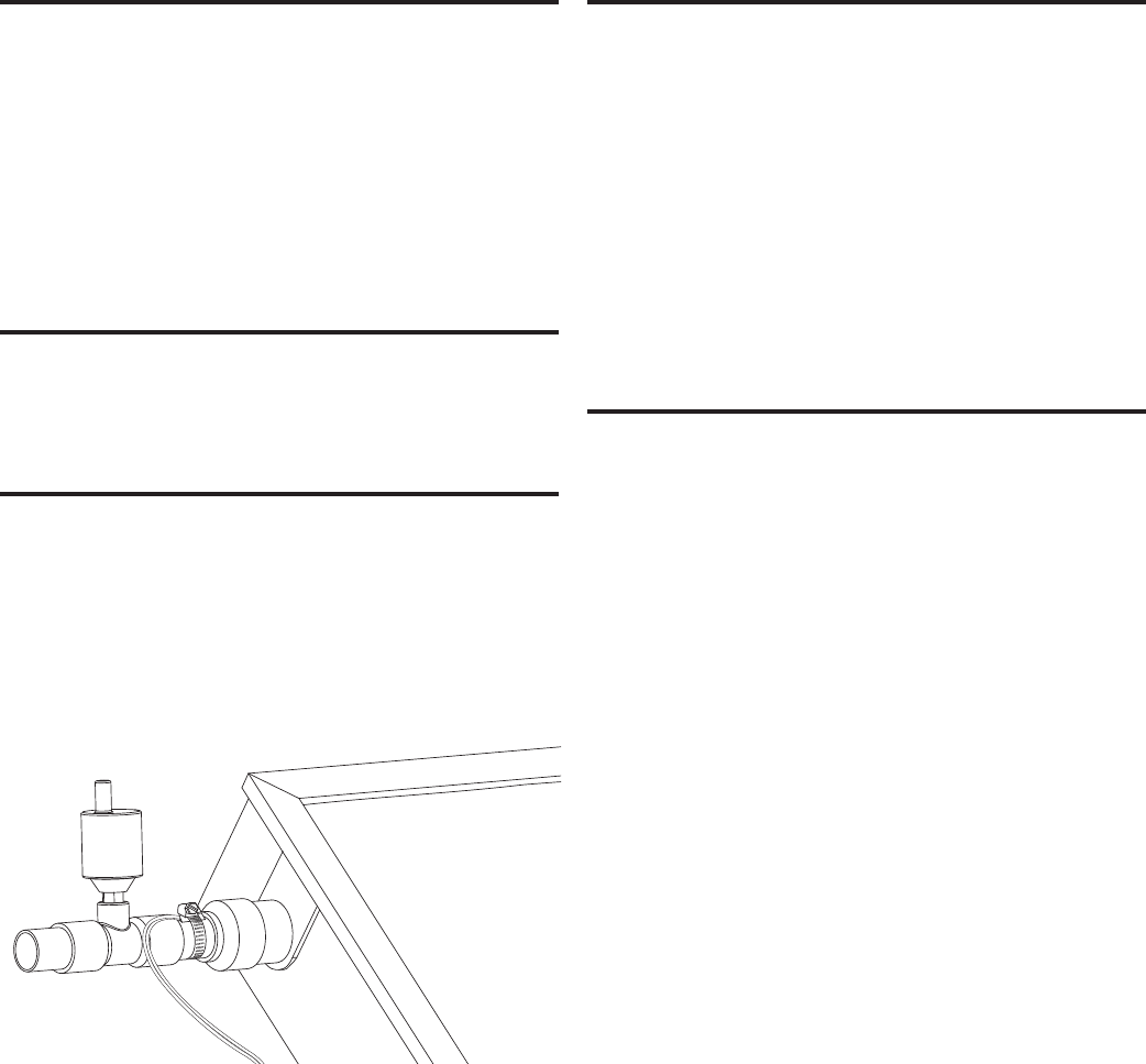
SENSOR MOUNTING AT COLLECTOR
The angled collector heat sensor is mounted to the outlet of
the collector. See Figure 20. The stainless steel screw clamp
should be used. The entire sensor should be wrapped
thoroughly with insulating stretch tape such as MOCAP
Silicone X-Treme Tape® so that the sensor is isolated from
the outside air. If possible route the sensor wire through the
roof with the collector piping and connect the sensor wire
to the sensor extension wire with wire nuts.
Figure 20.
PIPING THROUGH THE ROOF
Preserving the integrity of the roof membrane is the
most important roong consideration. Ensure that all roof
penetrations required to plumb and mount the solar collector
are properly ashed and sealed in accordance with standard
roong practices.
The return and supply lines should be supported under the
roof to prevent undue stress on the piping assemblies at
the collector. Hangers shall provide adequate support and
correct pitch of pipes. Hangers or supports for insulated
pipes or components shall avoid compressing or damaging
the insulation material. Piping should be sloped toward drain
ports with a drainage slope of no less than 2 cm vertical
drop for each meter of horizontal length (1/4 inch per foot).
PIPE INSULATION
The collector loop piping (exterior and interior) must be
well insulated with a high quality exible EPDM closed
cell insulation to minimize heat loss. The wall thickness
of the pipe insulation should not be less than ¾”. A 1” wall
thickness is required in all areas prone to annual hard
freeze conditions. When it comes to pipe insulation the
rule is simple: thicker is better. The specied insulation
material is Armacell UT Solaex or equivalent. As part of
the insulation requirements the nal 5 ft of the cold water
inlet to the storage tank must be insulated.
To the extent possible, slide the insulation material over
the pipe without cutting or taping. All butt joints must be
sealed with high temperature contact adhesive. The use
of rigid polyethylene pipe insulation is prohibited. All
outdoor insulation should be protected from moisture and
Ultraviolet deterioration by either paint or foil tape.
21
PUMP STATION
The following instructions describe the installation, start-
up, function and operation of the solar pump station. The
solar pump station may only be used in the collector circuit
of a solar thermal installation. The technical data specied
in these instructions must be observed. Improper usage
excludes any liability claims.
The wrapping materials that form the outer shell of the
pump station are made of recyclable materials and can be
disposed of with recyclable materials.
The solar station is a premounted valves and ttings group
checked for leakage used to circulate the solar uid in the
solar circuit.
SAFETY INSTRUCTIONS
The installation and start-up of the solar station as well as
the connection of electrical components require technical
knowledge commensurate with a recognized vocational
qualication such as a tter for plumbing, heating and air
conditioning technology, or a profession requiring a com-
parable level of knowledge [specialist]. The following must
be observed during installation and start-up:
• Relevant local and national codes
• Accident prevention regulations of the professional
association
• Instructions and safety instructions mentioned in this
manual
PUMP STATION INSTALLATION
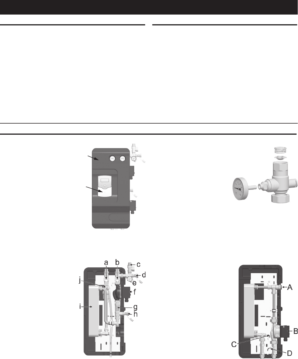
Figure 21.
a
b
With cover on:
a. Front Cover
b. Differential temperature
controller
Primary (solar) loop with cover
removed:
a. Ball valve with integrated
temperature gauge and
check valve, solar supply
b. Ball valve with integrated
temperature gauge and
check valve, solar return
c. Pressure relief valve for
avoiding over-pressure
condition
d. Fill valve
e. Pressure gauge and
connection for expansion
tank
f. Solar loop circulation pump
g. Flow meter to display the flow
rate
h. Drain valve
i. Double wall heat exchanger
j. Air scoop
SOLEX PUMP STATION COMPONENTS
Secondary (storage tank) loop
with cover removed:
A. Storage tank loop air vent
B. Water heater circulation pump
C. Temperature sensor supply
D. Temperature sensor return
The solar ball valves (a and
b) are equipped with spring-
charged check valves to prevent
gravity circulation.
22
SAFETY EQUIPMENT
For protection against excessive pressures in the collector
loop a pressure relief valve is integrated into the solar
pump station. Drain tubing must be installed in the valve
outlet so that any discharge will exit only within 6 inches
above, or at any distance below the structural oor. Be
certain that no contact is made with any live electrical part.
The discharge opening must not be blocked or reduced in
size under any circumstances. Excessive length, over 15
feet, or use of more than two elbows can cause restriction
and reduce the discharge capacity of the valve.
Do not connect tubing directly to discharge drain unless a
6” air gap is provided. To prevent bodily injury, hazard to
life, or damage to property, the relief valve must be allowed
to discharge uid in quantities should circumstances
demand. If the discharge pipe is not connected to a drain
or other suitable means, the uid may cause property
damage.
ATTENTION: TO PREVENT DAMAGE TO PROPERTY,
THE LOCATION OF INSTALLATION MUST BE DRY,
LOAD-CARRYING AND FROST-PROOF TO PREVENT
MATERIAL DAMAGE TO THE INSTALLATION.
When following the ‘PUMP STATION INSTALLATION’ see
Figure 21.
WALL MOUNTING THE SOLAR PUMP STATION
1. Choose the position to install the solar pump station
next to the storage tank .
2. Mark the location of the hanging holes on the wall (15”
apart vertically)
CAUTION
DUE TO THE WEIGHT OF THE SOLEX PUMP STATION THE
HANGAR ANCHORS MUST BE ATTACHED TO A STRUCTURAL
SUPPORT LIKE A STUD
3. Pre-drill holes and insert the enclosed 4.5” hanging
screws so that about 1” of each screw still stick out..
4. Remove the front cover of the solar station and hang
the station onto the screws then tighten the screws.
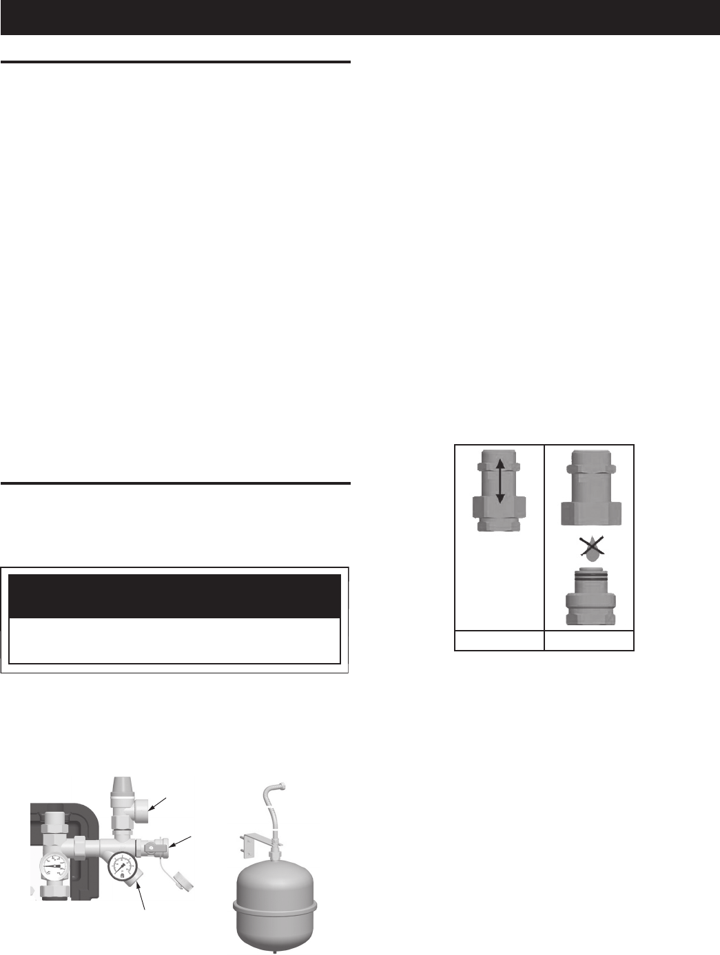
5. Mount the solar safety group to the connection above
the return ball valve.
CONNECTION FOR
EXPANSION TANK
CONNECTION FOR
DISCHARGE LINE
DRAIN
VALVE
CONNECTION SET
WITH EXPANSION TANK
Figure 22.
6. Connect a discharge line to the pressure relief valve
in the solar circuit
7. Connect the stainless steel corrugated hose to the
safety group. Do not forget to insert the seal.
8. Choose the position for the expansion tank bracket
on the wall beside the solar pump station. Fasten the
bracket to the wall with the enclosed hardware (masonry
or drywall).
9. Unscrew the tank connector to separate the two halves.
The top half should be pushed onto the mounting
bracket and the lock ring tightened. The bottom half
should be attached to the ¾” threads on the expansion
tank.
NOTE: The tank connector allows you to isolate the
expansion tank from the solar circuit. See Figure 23. When
the nut is unscrewed the valves in each half of the tank
connector are automatically closed tightly by the integrated
springs. Each side remains closed until the two halves are
screwed back together and the valves are forced open. Do
not forget to insert the seal.
The expansion tank should not be connected to the system
until it has been flushed and charged.
FLOW CLOSED
Figure 23.
10. Check and set the pressure of the air bladder in the
expansion tank to 25 psi. If the pressure is higher bleed
pressure out until it is correct. If the pressure is too low
add air by use of a compressor or bicycle pump until
the pressure is correct.
11. Plumb the solar pump station to the storage tank
and to the collector: The tank connections should
use ¾” copper pipe and can be connected using
the threaded adaptors provided. The collector
connections should use ½” copper pipe and can be
connected with the compression fittings provided.
The total piping run in the solar loop should not exceed
200 equivalent feet. Failure to limit the line length may
cause poor system performance and lead to premature
pump failure.
12. Install a discharge pipe to the pump station relief valve
that must terminate a maximum of six inches above a
floor drain or external to the building.
PUMP STATION INSTALLATION
23
Installing the ½” copper to and from the collector using
the compression fittings.
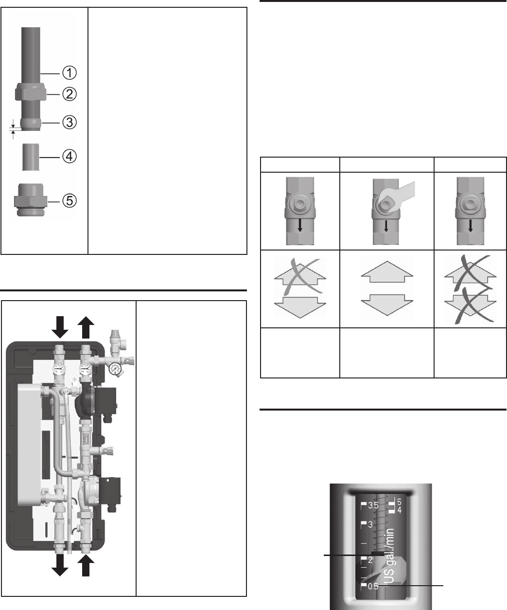
1. Push the union nut and
the cutting ring onto the
copper pipe . The pipe
must protrude at least 3/8”
(3 mm) from the cutting ring
in order to ensure the force
transmission and the sealing.
2. Insert the support sleeve into
the copper pipe.
3. Insert the copper pipe with the
plugged-on individual parts (,
and ) all the way into the
housing of the compression
fitting .
4. First screw the union nut
manually.
5. Tighten the union nut by
rotating one full turn. Hold the
housing of the compression
fitting to avoid rotation in order
to avoid damaging the sealing
ring.
Figure 24.
PLUMBING CONFIGURATION
1 2
3 4
1. ½” copper tube - from
the collector outlet
(top) to the collector
return compression
fitting.
2. ½” copper tube –
from the collector
inlet (bottom) to
the collector supply
compression fitting.
3. ¾” copper tube –
from the upper tank
inlet marked “from
collector” to the tank
supply threaded fitting.
4. ¾” copper tube – from
the lower tank outlet
marked “to pump”
to the tank return
threaded fitting.
Figure 25.
FUNCTION
Check valves
The solar station is equipped with check valves in the supply
and the return ball valve (J, Q).
For filling, venting and flushing of the installation the check
valves must be turned to the correct position. To set the
proper position for the check valves take off the temperature
gauges (C, E), remove the top cover (D) and turn the ball
valves into the proper position using a wrench. See Figure
26. In the 45° position the balls in the ball valves push the
check valves open.
During operation the ball valves must be in 0° position.
0° 45° 90°
Check valve is
operating, flow
only in flow
direction
Check valve is not
operating, flow in
both directions.
Ball valve
closed,
no flow.
Figure 26.
FLOWMETER
The flowmeter serves to measure and display flow volume
of the system in a range of 0.5-5.0 US gpm.
In order to guarantee the flawless function of the measuring
device the installation must be flushed and free from foreign
substances.
The flowmeter must be mounted vertically.
LEFT SCALE:
0.5 - 3.5 GAL/MIN
READING EDGE =
TOP EDGE OF THE
TURBINE
EXAMPLE:
ABOUT 2 GAL/MIN
RIGHT SCALE:
4 - 5 GAL/MIN
READING EDGE =
BOTTOM EDGE OF
THE TURBINE
Figure 27.
24
START-UP AND OPERATION OF THE SOLAR
PUMP STATION
Observe the following safety instructions when starting up
the solar thermal installation:
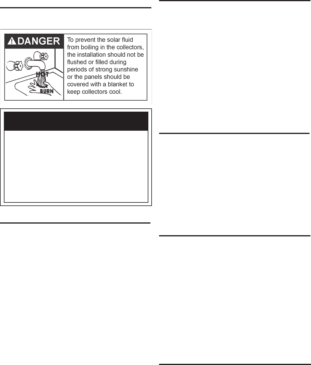
CAUTION
Solar thermal installations cannot be completely
emptied after flushing. There is a danger of frost
damage if water is used for flushing. Only use
water to flush the system when the outside
temperature is above 32° F, otherwise use the
solar fluid to flush making sure to filter any
debris before final filling.
Use a water / propylene glycol mixture as a solar
fluid (maximum 50% propylene glycol).
LEAK DETECTION
1. Disconnect the expansion tank from the solar system by
unscrewing the nut on the tank connector. This prevents
the access of dirt particles present in the pipes from
entering the expansion tank.
2. Remove the front cover of the solar station and the
temperature gauges from the ball valves (a, b)
3. Turn the two isolation ball valves (a,b) to 45° using an
appropriate wrench to allow flow in both directions.
4. Close the drain valve (h).
5. Be sure the air vent at the collector array is closed.
6. Connect an air pressure hose to the fill valve (d) above
the pressure gauge (e) and open this valve.
7. Using an air compressor or pressurized air tank fill the
system with pressurized air until the pressure gauge
(e) reads 40 psi then close the fill valve (d).
8. The pressure should hold steady for 15 minutes. If
the pressure falls it is an indication of a leak. Find and
repair the leak then repeat steps 6 and 7 watching
for the pressure to hold at least 15 minutes. After the
pressure test slowly open the drain valve (h) to release
the air pressure on the system.
FLUSHING
9. Disconnect the air pressure hose from the fill valve (d)
10. Connect a water hose from a water source with at least
40 PSI supply pressure to the fill valve (d).
11. Connect a discharge hose to the drain valve (h) and
open this valve. Place the other end of the discharge
hose into an appropriate drain.
12. Turn the supply ball valve (b) to 90° (horizontal) so that
the valve is closed.
13. Turn on the supply water and open the fill valve (d)
then leave running for 15 minutes to flush debris out
of the solar loop
14. After the 15 minute flush turn off the supply water at the
source and allow the system to drain. When water stops
flowing out of the discharge hose close the fill valve (d)
15. Close the drain and fill valves (d & h) on the pump
station and disconnect the water source hose.
FILLING
The storage tank loop is filled with potable water by means
of the valves and fittings of the storage tank.
16. Fill the storage tank following the procedures in the tank
section of this manual.
17. Vent the storage tank loop by opening a nearby hot
water faucet and the storage tank loop ball valve (A)
to avoid trapped air in the storage tank loop of the
pump station and burn out of the water heater heating
element.
18. Close the faucet and solar loop air vent (A) after all
air has been purged and the water comes out with
constant flow.
PREPARATION OF THE HEAT TRANSFER FLUID
19. Pour 100% Propylene Glycol into a large clean bucket.
Add an equivalent amount of distilled or de-mineralized
water for a 50/50 solution by volume.
The use of regular tap water as a mixing agent is
prohibited. Distilled or de-mineralized water is often
available from grocery stores and drugstores. This
solution provides freeze protection down to -30° F and
burst protection down to -60° F.
Use of heat-transfer uid other than a maximum 50/50
mix by volume of Propylene Glycol and distilled or de-
mineralized water is not permitted. Use of any heat-
transfer uid other than that specied by the appliance
manufacturer will void warranty, and may result in poor
performance, equipment damage, or risk to health and
safety.
FILLING THE SOLAR LOOP
20. Connect a discharge hose to the drain valve (h) and
place the discharge end of the hose into the glycol
solution container.
21. Turn the return ball valve (a) to 0° (vertical) so that flow
is only allowed in the proper direction.
22. Connect a fill hose from the glycol container to a 1/2
25
HP transfer pump and another hose from the transfer
pump to the fill valve (d) then open this valve.
23. Turn on the transfer pump to fill the system with the
glycol solution and allow to circulate for 15 minutes in
order to flush as much air as possible from the system.
24. Open the air vent at the top of the collector array until
all of the air has been dispersed then close the air vent.
25. Open the vent on the air scoop (j) with a flat head
screwdriver. This will release air that has been captured
by the system during circulation. Cover small outlet
port with a rag as fluid will be ejected after the air is
evacuated.
26. Turn the supply ball valve (b) to 0° (vertical) so that flow
is only allow in the proper direction.
27. With the transfer pump still running close the drain valve
(h) and allow the system to rise to an operating pressure
of 30 psi on the pressure gauge then close the fill valve
and turn off the pump. If the pressure has exceeded
30 psi after the pump is off the slowly open the drain
valve (h) and relieve pressure until the pressure gauge
reads 30 psi. then close the drain valve.
28. Connect the expansion tank and verify the system
pressure. If it has dropped open the fill valve (d) and
turn on the transfer pump. Repeat system pressure
setting in step 27.
29. Remove the fill and drain hoses and close the fill and
drain valves (d, h) with the caps provided. The caps
only serve to protect the valves against dirt. They are
not designed to withstand high system pressures, the
valves must be closed.
Figure 28.
30. Plug in the solar pump station to a 115V outlet and
turn the pump on using the manual mode (see control
operation section).
31. Switch on the pumps using the manual mode.
32. Adjust the solar pump speed using the pump speed
selector on the side of the pump (f). Set the speed to
the lowest level possible to achieve the recommended
system flow rate. See Table 5.
NUMBER OF COLLECTORS
1234
COLLECTOR
SIZE
3.5’ x 7’ 0.7 1.4 2.1 2.8
4’ x 8’ 1.0 2.0 3.0 4.0
4’ x 10’ 1.3 2.6 3.8 5.0
FLOW RATE IN GPM
Table 5.
Adjust the storage tank pump speed using the pump
speed selector on the side of the pump (B). Set the speed
to be one level lower than that of the solar pump.
Cycle the pumps on and off in manual mode to check
whether the starting torque is sufficient with the pump
speed selected. If flow does not start properly a higher
speed may need to be selected. Again check the
installation for leaks and ensure both ball valves are
open completely.
33. Re-insert the temperature gauges and replace the
front cover.
34. Set both pumps on the controller to operate in automatic
mode. See control operation section.
35. After the system has been running for several days
open the air vent at the top of the collector array until
all of the air has been dispersed then close the air vent.
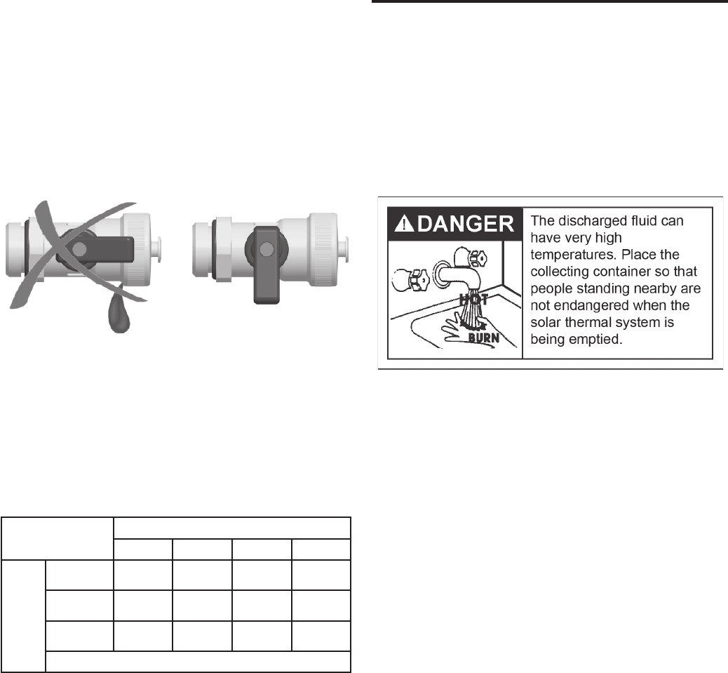
DRAINING
1. Switch off the controller by unplugging the power supply
from the outlet.
2. Open the check valves in the supply and the return ball
valves (a,b) by turning the ball valves to position 45°
with an appropriate wrench
3. Place a temperature-resistant container under the drain
valve (h)
4. Connect a temperature resistant hose to the drain
valve (h) with the discharge end placed in the collection
container
5. Open the drain valve.
6. Open the air vent at the top of the collector array. This
will serve as a vacuum break to aid in draining.
7. Dispose of the solar fluid observing any local codes.
ATTENTION: Upon completion of the pump station
installation and prior to the pump station start-up the
included pump station valve diagram label must be attached
to the pump station piping so that it is in plain view.
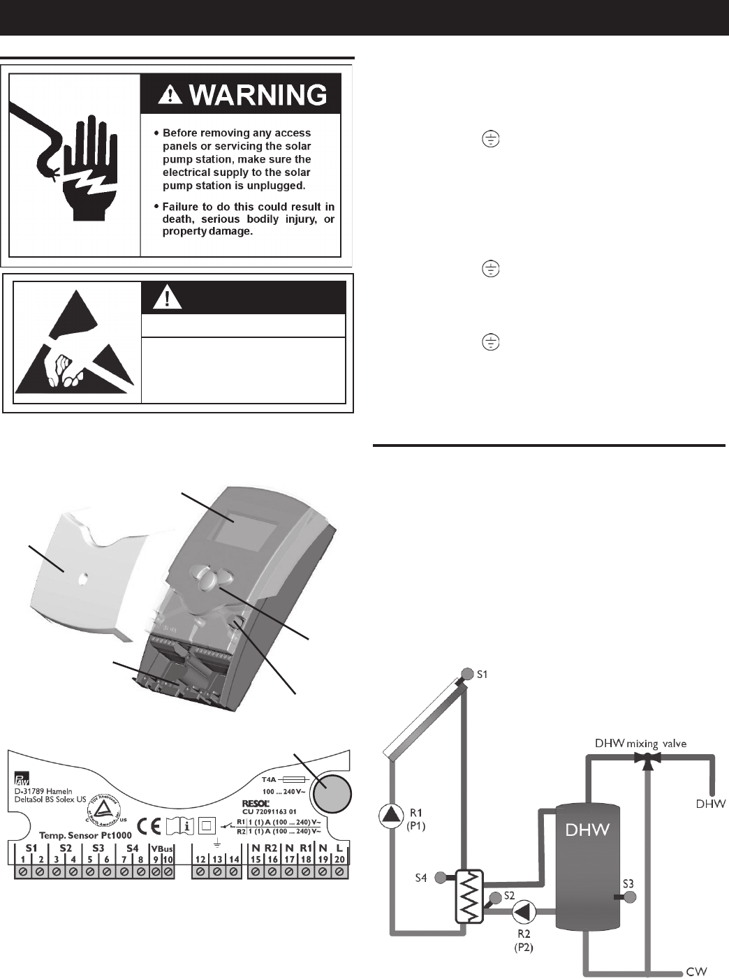
26
PUMP STATION CONTROL INSTRUCTIONS
CONTROL INSTRUCTIONS
WARNING
ESD SENSITIVE
Electrostatic discharge can lead to
damage of electronic components.
Prior to operation of the control on the solar pump station
the collector and tank temperature sensors must be prop-
erly connected. Remove the control cover and connect
the sensors to the proper terminals.
COVER
CABLE CONDUITS
WITH STRAIN RELIEF
DISPLAY
PUSHBUTTONS
CAN FUSE 4A
Figure 29.
FUSE
Figure 30.
The temperature sensors should be connected to the
following terminals with no dependence on polarity:
1 / 2 = sensor 1 (collector outlet)
3 / 4 = sensor 2 (lower heat exchanger sensor - pre-installed)
5 / 6 = sensor 3 (tank sensor)
7 / 8 = sensor 4 (upper heat exchanger sensor - pre-installed)
9/10 = VBus (see VBus note)
The power supply is connected to the following terminals:
19 = Neutral - N
20 = Line power - L
12 = Ground
The control is equipped with two relays, one for the solar
loop pump (upper - primary) and one for the water loop
pump (lower - secondary)
• Relay 1 (primary pump)
18 = Line power - R1
17 = Neutral - N
13 = Ground
• Relay 2 (secondary pump)
16 = Line power - R2
15 = Neutral - N
14 = Ground
The controller is equipped with a VBus® for data transfer
with an energy supply to external modules (not included).
The connection is carried out at the terminals marked “VBus”
and is not polarity dependent.
SYSTEM DESCRIPTION
The DeltaSol® BS Solex US controller is used in solar thermal
systems with an external heat exchanger which separates
the solar loop from the domestic hot water loop.
The controller calculates the temperature difference between
the collector sensor S1 and the tank temperature sensor
S3. If this temperature difference reaches the switch-on
temperature difference, the primary loop pump is switched
on. If the temperature difference falls below the switch-off
difference the pump is switched off.
If the switch-on temperature difference between the upper
heat exchanger sensor S4 and the tank temperature sensor
S3 is reached, the secondary loop pump will be switched on.
Figure 31.
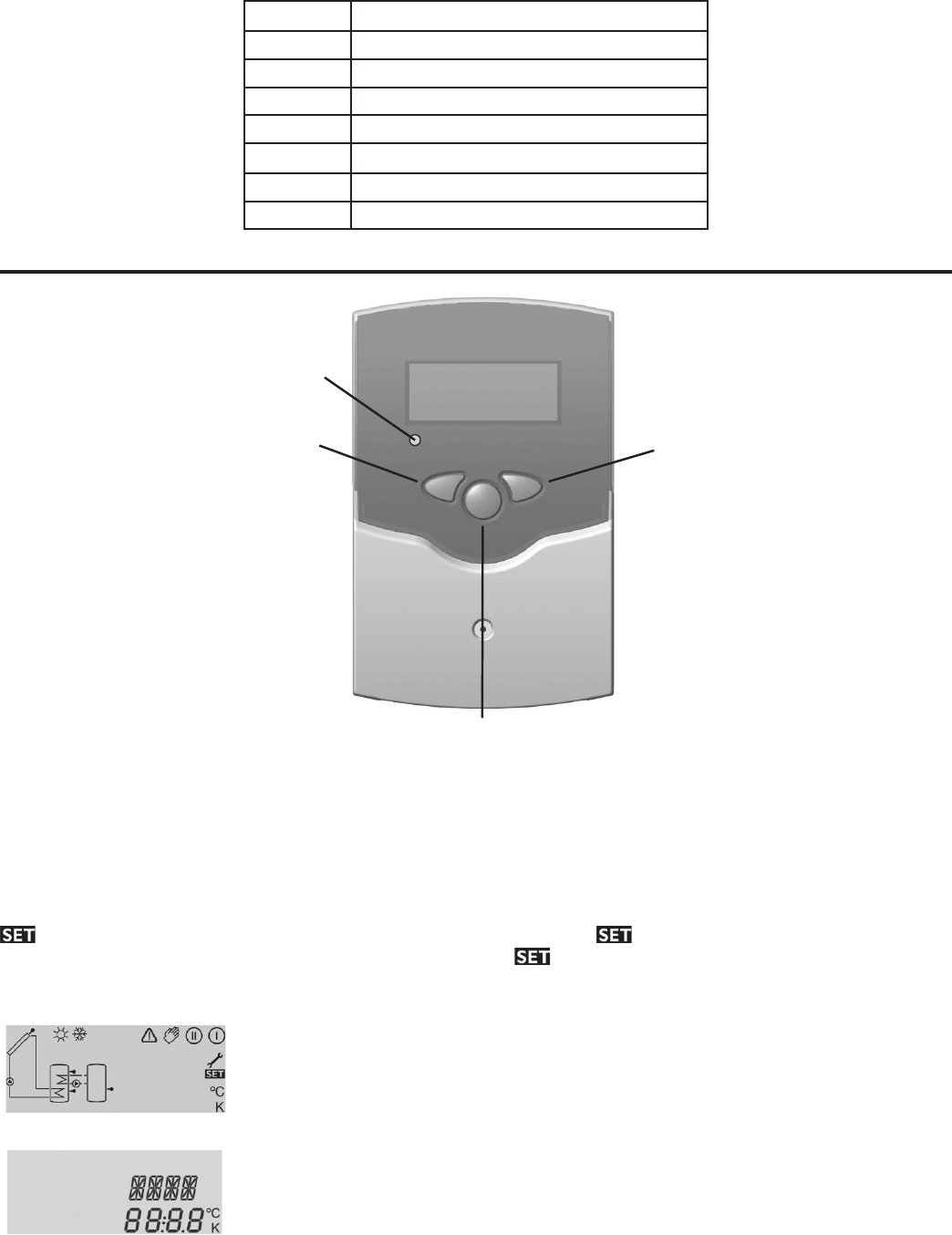
27
SENSOR DESCRIPTION
S1 Collector sensor
S2 Secondary loop heat exchanger sensor
S3 Tank sensor
S4 Primary loop heat exchanger sensor
RELAYS DESCRIPTION
R1 Primary loop pump
R2 Secondary loop pump
OPERATION AND FUNCTION
12 3
OPERATION
CONTROL LAMP
BACKWARDS FORWARDS
SET
(SELECTION / ADJUSTMENT MODE)
Figure 32.
The controller is operated by 3 push buttons below the display. The forward key (1) is used for scrolling forward through
the indication menu or to increase the adjustment values. The backwards key (2) is used for scrolling backward through
the indication menu or to decrease the adjustment values.
For system settings adjustment press the forward key to reach the last display channel. Then hold the forward button
down for 2 seconds and the system setting screens can then be shown. If an adjustable value is shown on the display
is indicated. To change the set value press the Set button (3) so that flashes. Adjust the value using button 1
or 2 until the desired value is shown then press button 3 so that permanently appears. The adjusted value is now
saved.
System Monitoring Display
System screen with toolbar
Channel display
The system monitoring display consists of 3 blocks: channel indication, the toolbar, and
system screen.
The channel indication consists of two lines. The upper line is an alphanumeric 16
segment indication in which the channel name or menu item is shown. The lower 7
segment indication shows the channel value and the adjustment parameters are
indicated.
Temperatures are indicated in °F / °C, Temperature differences are indicated in °F / K
The symbols in the toolbar indicate the current system status:
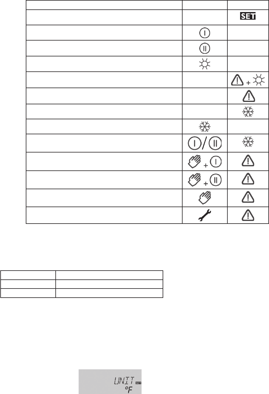
28
STATUS STANDARD FLASHING
An adjustment value is being changed - SET MODE
Relay 1 active
Relay 2 active
Maximum tank temperature reached
Tank Emergency shutdown active
Collector emergency shutdown active
Collector minimum limitation active
Antifreeze function activated
Antifreeze function active
Manual operation relay 1 ON
Manual operation relay 2 ON
Manual operation relay 1 / 2 OFF
Sensor error
Blinking control symbols
• Pump is blinking while running
• Sensors are blinking if the respective sensor indication channel is selected
• Sensors are quickly blinking if there is a sensor error
Operation control lamp indication
Constantly green: system operation normal
Red/green blinking: initialization phase / manual operation
Red blinking: sensor error
STARTUP / SYSTEM SETTINGS
The AC power cord should be plugged in to an appropriate 115V outlet. The controller will enter an initialization phase
in which the operating control lamp will flash red and green
When the controller is commissioned for the first time or after a system reset, it will run a commissioning menu. The
commissioning menu leads the user through the most important adjustment channels for operating the system.
Commissioning Menu:
Unit:
Adjust the unit in which the
temperatures and temperature
difference shall be displayed
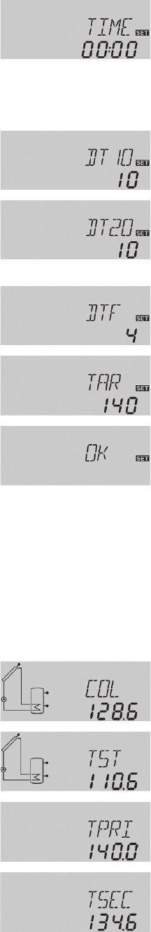
29
Time:
Adjust the current time for the
real time clock.
The hours and minutes have
to be adjusted separately, rst
the hours, then the minutes.
Time format is 24 hours, e.g.
15:00h = 3 pm
Switch-on difference of
primary loop
Adjust the switch-on differ-
ence
Switch-on difference of
secondary loop
Adjust the switch-on differ-
ence
Switch-off difference
Adjust the switch-off differ-
ence
Target temperature
Adjust the target temperature
Completing the commis-
sioning menu
After the last channel of the
commissioning menu has
been adjusted and conrmed,
the controller asks for conr-
mation of the adjustments.
To conrm the adjustments
made in the commissioning
menu, press button 3
The controller is now ready for operation with typical settings to suit the system layout
The settings made in the commissioning menu can be changed later on in the corresponding adjustment channels. Ad-
ditional functions and options can be individually set by accessing the system adjustment channels.
Display Channels:
COL:
Collector Temperature
Display range: -40 to +482 °F
Shows the current collector temperature.
TST:
Tank temperature
Display range: -40 to +500 °F
Shows the current tank temperature (from tank bottom sensor).
TPRI:
Flow temperature of the pri-
mary loop
Display range -40 to +500 °F
Indicates the current ow temperature of the primary loop in
the Solex station.
TSEC:
Flow temperature of the sec-
ondary loop
Display range -40 to +500 °F
Indicates the current ow temperature of the secondary loop in
the Solex station.
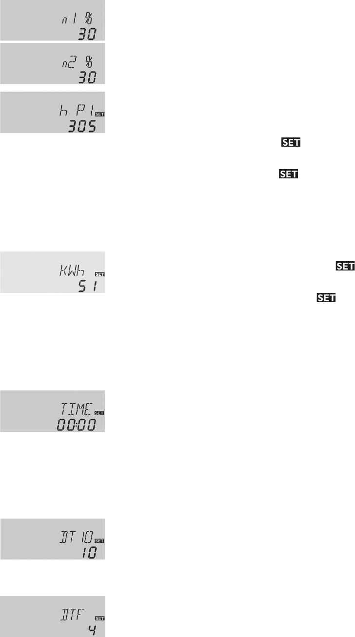
30
n1%, n2%:
Current pump speed
Display range 30 to 100%
Indicates the current pump speed of the corresponding pump:
- n1%: current pump speed pump 1 – primary loop
- n2%: current pump speed pump 2 – secondary loop
h P1, h P2
Operating hours counter
Display channel
The operating hours counter adds up the solar operating hours
of the respective relay (h P1, h P2). Full hours are shown on
the display.
The total operating hours can be reset. When the operating
hours channel is selected the symbol is permanently
shown in the display. The set button (3) must be pressed for
approximately 2 seconds in order to go into the reset mode
for the counter. The display symbol will be ashing
and the operating hours will be set to 0. In order to nish the
reset procedure the set button (3) must be pressed in order to
conrm.
In order to interrupt the reset procedure no button should be
pressed for about 5 seconds. The controller will automatically
return to the indication mode with the previous total.
kWh/MWh:
Heat quantity value shown
in the kWh and MWh display
channels. The sum of both
channels form the total heat
output.
The total heat quantity value can be reset. When one of the
heat quantity display channels is selected the symbol is
permanently shown in the display. The set button (3) must be
pressed for approximately 2 seconds in order to go into the
reset mode for the counter. The display symbol will be
ashing and the value for heat quantity will be set to 0. In order
to nish the reset procedure the set button (3) must be pressed
in order to conrm.
In order to interrupt the reset procedure no button should be
pressed for about 5 seconds. The controller will automatically
return to the indication mode with the previous total.
TIME:
Current time based on 24
hour clock, e.g. 15:00 = 3 pm
To set the current time:
Press button 3 for two seconds to adjust the hours
Set the hours by pressing buttons 1 and 2
Press button 3 again to set the minutes
Set the minutes by pressing buttons 1 and 2
Press button 3 in order to save the adjustments
Once the nal display channel is reached the remaining system setting channels may only be accessed by holding the
forward (2) button down for approximately 2 seconds. The following setting channels will then be shown:
Adjustment channels:
DT1O / DT20:
Switch-on temperature diff.
Adjustment range
2.0 to 40.0 °F
Recommended setting: 10.0
The controller works as a standard differential controller. It
calculates the temperature difference between the collector
sensor S1 and the tank temperature sensor S3. If this
temperature difference reaches the switch-on temperature
difference DT1O, the primary loop pump is switched on. If
the temperature difference falls below the switch-off difference
DTF, the pump is switched off.
DT F:
Switch-off temperature diff.
Adjustment range
1.0 to 39.0 °F
Recommended setting: 4.0
If the switch-on temperature difference between the upper heat
exchanger sensor S4 and the tank temperature sensor S3 is
reached (DT2O), the secondary loop pump will be switched on.
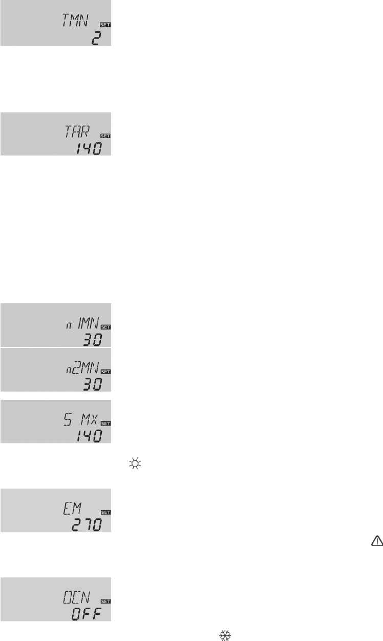
31
TMN:
Minimum runtime
Adjustment range
1 to 10 min
Recommended setting: 2
min
Solar loading will be carried out for the adjustable minimum
runtime TMN during which the switch-off condition will be ig-
nored to stabilize the system.
If the temperature difference between the upper heat exchang-
er sensor S4 and the lower heat exchanger temperature sen-
sor S2 falls below the switch-off temperature difference DTF
both loops will be switched off.
Note: The switch-on temperature difference must be at least 1°
higher than the switch-off temperature difference.
TAR:
Pump speed control target
temperature
Adjustment range
70 to 210 °F in steps of 2 °F
Recommended setting: 140
°F
The primary and secondary pump speeds are controlled based
on the target temperature of the upper heat exchanger sensor
S4.
The primary and secondary loop pumps will run at minimum
speed until the target temperature at S4 is reached. If the tar-
get temperature is exceeded by 5°, the speed of the primary
loop pump will increase by one step (10%). This state will be
held for 2 min even if the sensor temperature decreases. If,
during this time, the S4 temperature increases by more than
5°, the pump speed of the secondary pump will also increase
by 1 step.
This state will be held for 2 min each time the pumps increase
a step unless the temperature increases further by 5° and the
speed is increased another step. If the temperature decreases
the secondary pump will decrease by 1 step followed by the
primary pump.
n1MN, n2MN:
Minimum pump speed
Adjustment range
30 to 100%
Recommended setting: 30%
A relative minimum pump speed that can be allocated to the
outputs R1 (primary pump) and R2 (secondary pump) via the
adjustment channels n1MN and n2MN.
S MX:
Maximum tank temperature
Adjustment range:
100 to 160 °F
Recommended setting: 160
°F
If the maximum tank temperature is reached the control will
prevent the pump from operating and heating the tank any fur-
ther. A xed hysteresis of 4 °F is set for the maximum tank
temperature.
When the maximum tank temperature setting is reached the
symbol will be shown on the display.
EM:
Collector temperature limit
Adjustment range:
170 to 390 °F
Recommended setting: 270
°F
If the collector temperature limit is reached the solar pump (R1)
is deactivated in order to avoid damaging overheating of the
solar components (collector emergency shutdown). A hyster-
esis of 20 °F is set for the collector temperature limit.
If the collector temperature limit setting is exceeded the
symbol will be shown ashing on the display.
OCN:
Minimum collector limit
Adjustment: OFF / ON
Recommended setting: OFF
The minimum collector temperature is a minimum switching
temperature, which must be exceeded before the solar pump
(R1) is switched on. The minimum temperature will avoid short
cycling of the solar pump at low collector temperatures. If the
collector temperature is lower than the minimum collector tem-
perature set point the symbol will be shown ashing on the
display.
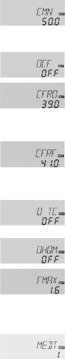
32
CMN:
Minimum collector temp.
Adjustment range:
50 to 195 °F
Recommended setting: 50 °F
Channel only available when
OCN is active
This function is unnecessary if the system backup heating ele-
ment has a set point maintained at 120 °F.
OCF:
Antifreeze function
Adjustment: OFF / ON
Recommended setting: OFF
This function is used to transfer heat from the storage tank to
the collector in order to avoid freezing of the heat transfer me-
dium in some system types.
Note: Since this function uses the limited heat quantity of the
tank, the antifreeze function should only be used in regions
with a few days of temperature around the freezing point. The
antifreeze function will be suppressed if the tank temperature
falls below 40 °F in order to protect the tank from frost damage.
If the system uses a 50/50 solution of propylene glycol and
water it is freeze resistant to -30 °F; therefore, this function is
not necessary.
There is an automatic antifreeze function for the heat exchanger
that activates R2 (100%) if the heat exchanger temperature
falls below 40 °F.
CFRO:
Antifreeze temperature on
Adjustment range:
38 to 48 °F
Recommended setting: 39
°F
Channel only available when
OCF is active
CFRF:
Antifreeze temperature off
Adjustment range:
40 to 50 °F
Recommended setting: 41
°F
Channel only available when
OCF is active
O TC:
Tube collector function
Adjustment: OFF / ON
Recommended setting: OFF
The tube collector function is only needed for systems that use
vacuum tube solar collectors.
This function is not necessary for this system.
OHQM:
Heat quantity measurement
Adjustment: OFF / ON
Recommended setting: OFF
If enabled a heat quantity measurement is possible for this
system in conjunction with the ow meter.
FMAX:
Volume ow in gal/min
Adjustment range:
0.0 to 5.0 gal/min in steps of
0.2 gal/min
Recommended setting: pump
station ow meter reading.
Channel only available when
OHQM is active
For OHQM to give an accurate reading the volume ow readable
at the owmeter (l/min) must be adjusted in the channel FMAX.
MEDT:
Type of antifreeze
Adjustment range: 0 to 3
Recommended setting: 1
Channel only available when
OHQM is active.
For OHQM to give an accurate reading the type of heat transfer
uid type(antifreeze) must be set in the channel MEDT:
0: water
1: propylene glycol
2: ethylene glycol
3: Tyfocor ® LS / G – LS
Caution: for this system type only type 1: propylene glycol
should be selected. Use of any other type of heat transfer uid
in this system may cause damage to the system or present a
health hazard
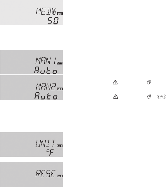
33
MED%:
Concentration of antifreeze by
volume %
Adjustment range: 20 to 70%
Recommended setting: 50
Channel only available when
OHQM is active.
The antifreeze concentration by % volume should be entered in
this channel for OHQM to give an accurate reading.
Standard system concentration should be a 50% propylene
glycol and 50% distilled or de-mineralized water.
MAN1:
Operating mode R1
Adjustment range:
OFF / AUTO / ON / n1LO
MAN2:
Operating mode R2
Adjustment range:
OFF / AUTO / ON / n2LO
For system setup and service work the operating mode of the
pump can be manually adjusted by selecting the adjustment
value for MAN1, MAN2 as follows:
Operating mode:
OFF: relay off (ashing) +
AUTO: relay in automatic operation
ON: relay on (ashing) + +
n1(2)LO: minimum speed
Note: Always adjust the operating mode back to “Auto” when
the control and service work is completed. Normal operation is
not possible in manual mode.
UNIT:
Temperature units
Adjustment: FAH, CEL
Recommended setting: FAH
The temperature unit can be adjusted in this channel:
FAH: °Fahrenheit
CEL: °Celsius
RESE:
System reset
If the reset is selected, the controller will revert back to the fac-
tory settings and the commissioning assistant will be displayed
for new start-up.
The nal channel indicates the current version number for the controller. To exit out of the system setting mode press
the backward button (2) repeatedly until you reach the rst display channel (COL).
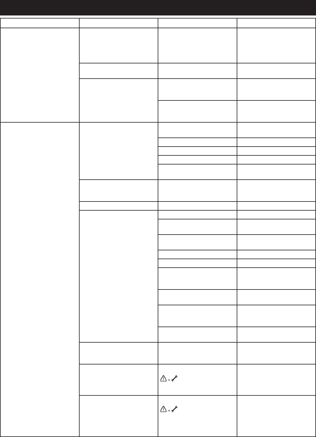
34
TROUBLESHOOTING
PROBLEM CHECK THIS POSSIBLE CAUSE CORRECTIVE ACTION
No hot water Storage water heater No power to auxiliary back-up
heating element
Check high temperature
protection and push reset
button on the heater
thermostat. (Use caution when
dealing with electricity.)
Storage water heater
thermostat
Thermostat defective Replace
Thermostatic mixing valve Improper adjustment Check water temperature at
house faucet and adjust valve
setting
Valve defective Replace. System must not
be run without thermostatic
mixing valve due to scald risk.
Not enough hot water Storage water heater Undersized for hot water
demand load
Replace
Thermostat set too low Increase set point temperature
Element failure Replace element
Thermostat failure Replace thermostat
Element disconnected Reconnect element and set
thermostat to 120°F
Check valve Heat loss due to defective
check valve in solar pump
station
Inspect valve and repair or
replace
Cold water supply dip tube Missing or defective Replace dip tube
Collectors Absorber coating degradation Replace collector
Collector panel area
undersized
Increase collector area
Excessive condensation Inspect and clean weep holes
and vents at bottom.
Glazing dirty Clean as required
Leaks Repair
Orientation Check orientation. Face
collector within 45° of due
South
Shaded by tree(s) or other
obstructions
Remove obstacle and shading
or relocate collectors
Improper tilt Check tilt for geographic area.
Ensure tilt is equal to latitude
plus 15°
Improperly plumbed Compare with system
schematic and correct.
Differential Controller Improper operation (cycling,
late turn on)
Check sensor placement
and insulation from ambient
conditions
Faulty sensor
is shown and control
reads 888.8 instead of
temperature
Sensor line break. Check the
line and repair or replace
Faulty sensor
is shown and control
reads -88.8 instead of
temperature
Short circuit. Check the line
for breaks, metal contact,
water exposure and corrosion.

35
PROBLEM CHECK THIS POSSIBLE CAUSE CORRECTIVE ACTION
Not enough hot water (cont.) Differential Controller Improper wiring or loose
connections)
Compare with system
schematic. Check for proper
connections. Seal all splices
against moisture
Isolation valves Closed Open
Thermostatic mixing valve Improper adjustment Check water temperature at
house faucet and adjust valve
setting
Valve defective Replace. System must not
be run without thermostatic
mixing valve due to scald risk.
Piping Insufcient Insulation Add insulation where required
High heat losses Check insulation for splits,
deterioration, absence
Nighttime thermosyphoning Check for pump operation at
night
Improperly plumbed Compare with system
schematic. Check ow
direction
Flow blockage Flush system. Check efuent
for debris.
Low system pressure Check pressure gauge. Set
system pressure to correct
setting, check for leaks.
Pump No power Check breaker, pump cord,
and controller fuse. Repair or
replace
Flow rated too high or too low Adjust ow rate
Faulty pump Listen for irregular noises
in pump operation. Feel
collector feed and return line
for temperature difference.
Ensure all air is purged from
system.
Runs continuously Check sensors for shorts
No hot water in the morning Storage water heater Circuit breaker shut off Turn breaker on
Differential controller Sensor wires reversed Ensure the collector and
tanks sensors are wired to
the correct position on the
controller
Water too hot Thermostatic mixing valve Improper adjustment Check water temperature at
house faucet and adjust valve
setting
Valve defective Replace. System must not
be run without thermostatic
mixing valve due to scald risk.
No water Cold-water supply valve Valve closed Open valve
Pump does not start Differential controller Controller set to “off” position Set system operation to
“Auto”
Unplugged Return power to controller
On and/or off temperature
differential set points too high
Reset on and off
differentials according to
recommendations
Loose contacts Clean contacts and tighten
connections or replace
Blown fuse Replace fuse

36
PROBLEM CHECK THIS POSSIBLE CAUSE CORRECTIVE ACTION
Pump does not start Electrical power supply Controller plug disconnected Reconnect control plug to
power outlet
Blown fuse or breaker tripped
on overload
Determine cause and replace
fuse or reset breaker
Pump Motor failure Replace pump
Sensors Defective sensors, sensor
error
Check wiring continuity.
Repair or replace
Pump starts, but cycles
continuously
Differential controller On and/or off temperature
differential set points too low
Reset on and off
differentials according to
recommendations
Piping Reversed connections to
collectors
Compare with system
schematic and reconnect
properly
Sensors Improper location Compare with system
schematic and reconnect
properly
Pump cycles after dark Differential controller Recooling function active
and max temperature setting
exceeded
Controller operating properly.
No fault.
Sensors Defective sensors, sensor
error
Check wiring continuity.
Repair or replace
Pump runs continuously Differential controller Off temperature differential set
too low
Reset off differential according
to recommendation
Controller set to “on” position Set system operation to
“Auto”
Pump operated but no uid
ows from collectors
Air Scoop System air-locked Purge air from air scoop in
solar pump station by opening
valve slowly. Caution: after air
is evacuated uid will ow out
in a small stream and may be
hot. Cover port with a rag to
catch any uid.
Air vent System air-locked Open air vent on the top of the
system and purge excess air.
Close after purging.
Fluid Loss of uid from system Locate leak and repair
Isolation valves Valves in closed position Open valves
Piping Clogged or damaged piping Unblock piping or repair
damaged piping
Pump Broken impeller shaft Replace shaft
Not vented properly Install in correct orientation
Undersized System piping run too long.
Refer to maximum piping
lengths and adjust
Noisy system Air vents Air trapped in system Open air vent and purge air
scoop in solar pump station
by opening the valve slowly.
Caution: after air is evacuated
uid will ow out in a small
stream and may be hot.
Cover port with a rag to catch
any uid.
Pump Bearings are dry or have
excessive wear
Lubricate or replace
Impeller loose Tighten or replace impeller
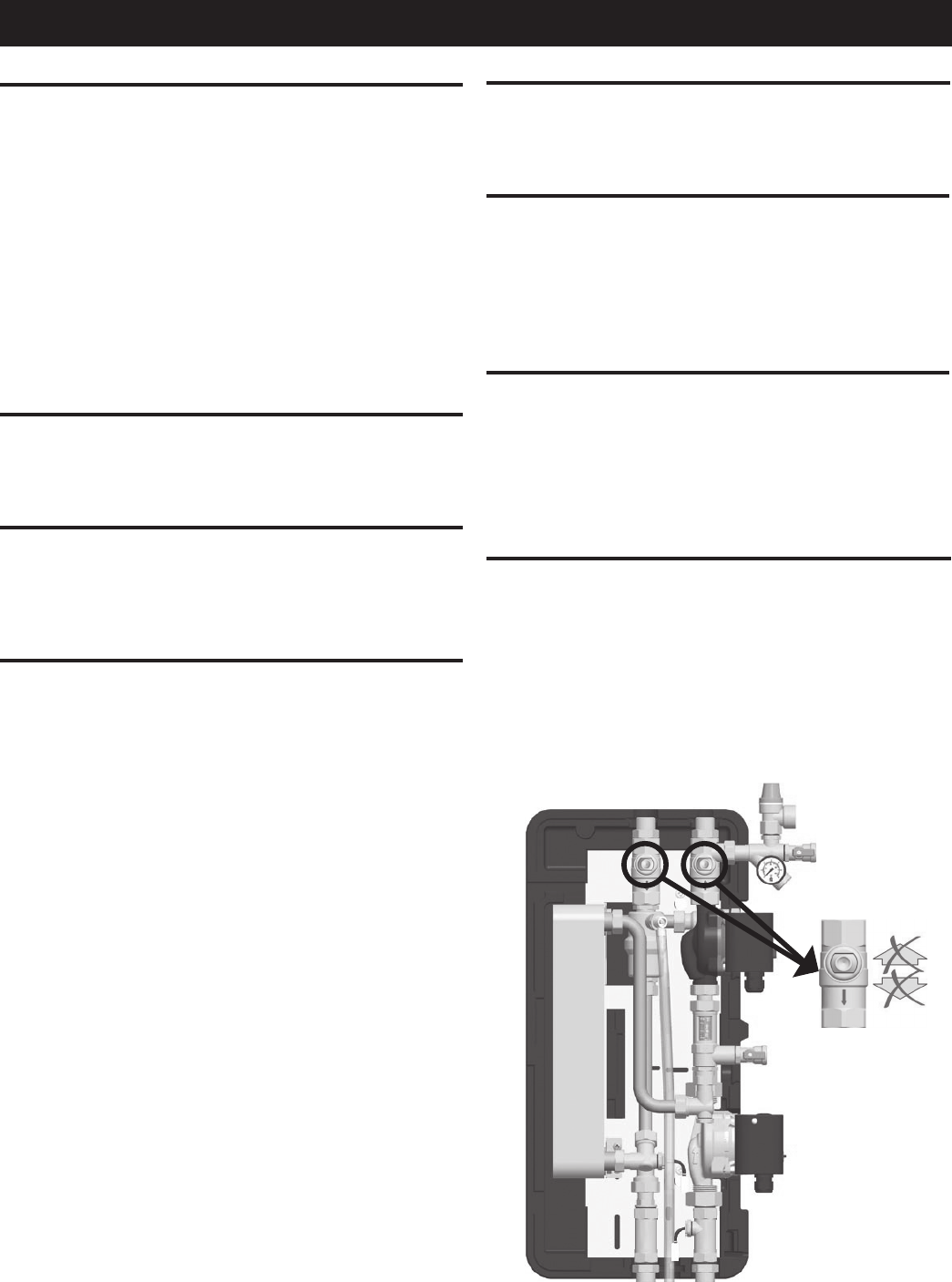
37
SYSTEM MAINTENANCE
HEAT TRANSFER FLUID (HTF) QUALITY
The chemical composition of the HTF may change over
time. The HTF quality should be monitored on a periodic
basis – at least annually. After summer and before any
chance of the first freeze is an ideal time. A drop in ph can
indicate the system has been stagnating frequently. The
cause should be determined and corrected.
To test the pH level, use a digital ph tester or tight range
litmus paper. Remove a small sample of the fluid from the
air scoop on the pump station. The pH should be between
8.1 and 12.0. Fluid with pH between 7.5 and 8.1 can be
conditioned by your contractor using an inhibitor boost. Fluid
with pH above 12.0 or that is dark, dirty or has an acidic
smell should be replaced.
PIPING AND EXTERNAL INSULATION
On an annual basis, all piping should be checked for leakage
at joints, and unions. Any damaged external insulation
should be repaired or replaced.
WIRING AND CONNECTIONS
On an annual basis, check wiring and connections, including
sensor wiring and splices. Look for signs of overheating,
discoloration, corrosion or loose connections. Any damaged
wiring should be repaired or replaced.
FLUID LEAKS
If you detect a glycol or water leak, or the glycol loop
pressure drops unexpectedly, contact your installation
contractor immediately to diagnose the problem and
recharge the system.
SOLAR PANEL CLARITY
If you live in a dusty climate, once a month wash off dirt that
settles on the solar panel glass. Clean glass allows the solar
panel to maintain a high level of thermal performance.
EXPANSION TANK
Annually check condition of the solar expansion tank. Check
to see if it is waterlogged by quickly pressing Schrader valve
stem at bottom of the tank. You should get a quick burst of
air. If fluid is discharged, the tank may be waterlogged and
need replacement. Contact a qualified solar installer if the
tank needs replacement.
VACATION
For extended periods with no hot water usage such as
vacation it is recommend that the power to the pump station
be disconnected and that the solar collectors are covered
with a blanket or other means to prevent heat gain from
the sun to prevent system overheating and breakdown of
the glycol solution.
EMERGENCY SHUTDOWN
For a Emergency system shut down both the power to the
unit and the pump station shall be disconnected. In addition
the pump station has two ball valves located as shown below
that must be turned to the 90° position to shut off the flow
through the collector per loop. See Figure 33. The inlet water
shut-off to the unit itself shall also be closed. This will isolate
any electricity or fluids from entering the unit.
Figure 33.
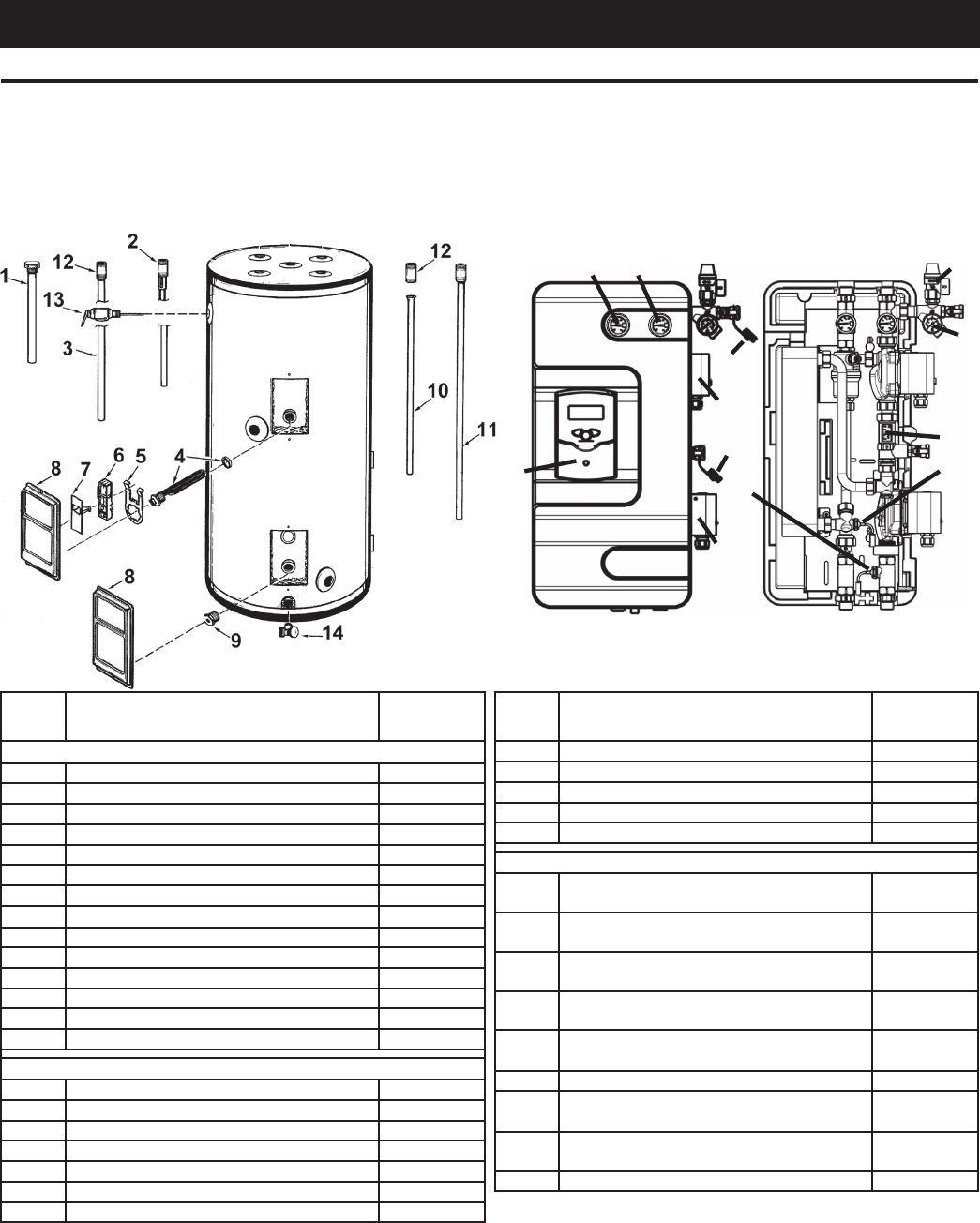
38
REPAIR PARTS
REPAIR PARTS SCHEDULE
ORDERING REPAIR PARTS
The following parts may be ordered through the store or dealer from whom you purchased the solar water heater, or direct
from the factory listed on the model & rating plate located on the lower front of the solar water heater and by phone at
1-800-433-2545. Selling prices will be furnished on request or parts will be shipped at prevailing prices and you will be
billed accordingly. When ordering repair parts always give the following information: (1) Part description, (2) Model serial
number, (3) Element wattage, (4) Voltage, (5) Part number.
15
18
21
20
25
25
16
22
17
19
24
23
ITEM PART DESCRIPTION SERVICE
PART #
WATER HEATER SERVICE PARTS
1Primary Anode 9003892005
2 Anode Outlet 9006827005
3Primary Dip Tube 9002549005
4 Element w/Gasket 9003950115
5 Thermostat Bracket 9003898215
6 Thermostat w/High Limit 9007623015
7 Terminal Cover 9003914015
8Access Panel 9003900005
9 Sensor Mounting Plug 9007309005
10 Solar Loop Dip Tube 9006789005
11 Solar Loop Dip Tube w/Nipple 9006790005
12 Plastisert Nipple 9003976015
13 T&P Valve 9000728015
14 Drain Valve 9003906015
SOLEX DWHX PUMP STATION SERVICE PARTS
15 Temperature Gauge-Supply (Red) 9007789005
16 Temperature Gauge-Return (Blue) 9007788005
17 Pressure Gauge 9007454005
18 Resol BS Solex US Controller 9007785005
19 Solex Flowmeter 9007782005
20 Wilo Star S 21U-15 Primary Pump 9007783005
21 Wilo Star S 21BU Secondary Pump 9007784005
ITEM PART DESCRIPTION SERVICE
PART #
22 Pressure Relief Valve 9007460005
23 Temperature Sensor (Plug-In) 9007786015
24 Temperature Sensor (Screw-In) 9007787015
25 Sealing Cap 9007792015
26 Solex Gasket Kit (Not Pictured) 9007793015
MISCELLANEOUS SYSTEM SERVICE PARTS
27 Chromagen CR110 AP Solar Collector
(Not Pictured) 9007447005
28 Chromagen CR130 AP Solar Collector
(Not Pictured) 9007712005
29 Chromagen CR140 AP Solar Collector
(Not Pictured) 9007724005
30 Water Tempering (Mixing) Valve (Not
Pictured) 9007448005
31 Propylene Glycol HTF (DOWFROST)
5 Gallon (Not Pictured) 9007645005
32 Air Vent (Not Pictured) 9007451005
33 Solar Loop Expansion Tank (Not Pic-
tured) 9007456005
34 Collector Temperature Sensor (Not
Pictured) 9007461015
35 Tank Temperature Sensor (Not Pictured) 9007462015
39
DOWFROST HEAT TRANSFER FLUID PROPERTIES
Potential Health Effects
Eye Contact: May cause slight temporary eye irritation. Corneal injury is unlikely.
Skin Contact: Prolonged contact is essentially nonirritating to skin. Repeated contact may cause aking and softening of skin.
Skin Absorption: Prolonged skin contact is unlikely to result in absorption of harmful amounts.
Inhalation: At room temperature, exposure to vapor is minimal due to low volatility. Mist may cause irritation of upper respiratory tract (nose and throat).
Ingestion: Very low toxicity if swallowed. Harmful effects not anticipated from swallowing small amounts.
Effects of Repeated Exposure: In rare cases, repeated excessive exposure to propylene glycol may cause central nervous system effects.
Component CAS # Amount
Propylene glycol 57-55-6 > 95.0 %
Dipotassium hydrogen phosphate 7758-11-4 < 3.0 %
Deionized water 7732-18-5 < 3.0 %
First-aid measures
Eye Contact: Flush eyes thoroughly with water for several minutes. Remove contact lenses after the initial 1-2 minutes and continue ushing for several additional min-
utes. If effects occur, consult a physician, preferably an ophthalmologist.
Skin Contact: Wash skin with plenty of water.
Inhalation: Move person to fresh air; if effects occur, consult a physician.
Ingestion: No emergency medical treatment necessary.
Notes to Physician: No specic antidote. Treatment of exposure should be directed at the control of symptoms and the clinical condition of the patient.
Accidental Release Measures
Steps to be Taken if Material is Released or Spilled: Small spills: Absorb with materials such as: Cat litter. Sawdust. Vermiculite. Zorb-all®. Collect in suitable and prop-
erly labeled containers. Large spills: Dike area to contain spill. Recover spilled material if possible.
Handling and Storage
Handling
General Handling: No special precautions required. Keep container closed. Spills of these organic materials on hot brous insulations may lead to lowering of the autoig-
nition temperatures possibly resulting in spontaneous combustion.
Storage
Do not store in: Galvanized steel. Opened or unlabeled containers. Store in original unopened container.
Exposure Controls / Personal Protection
Exposure Limits
Component List Type Value
Propylene glycol
Personal Protection
Eye/Face Protection: Use safety glasses.
Skin Protection: Wear clean, body-covering clothing.
Hand protection: Use gloves chemically resistant to this material when prolonged or frequently repeated contact could occur. Examples of preferred glove barrier materi-
als include: Butyl rubber. Natural rubber ("latex"). Neoprene. Nitrile/butadiene rubber ("nitrile" or "NBR").
Respiratory Protection: Respiratory protection should be worn when there is a potential to exceed the exposure limit requirements or guidelines. If there are no appli-
cable exposure limit requirements or guidelines, wear respiratory protection when adverse effects, such as respiratory irritation or discomfort have been experienced, or
where indicated by your risk assessment process.
Physical and Chemical Properties
Physical State Liquid
Color Colorless
Odor Characteristic
Flash Point - Closed Cup 104 °C (219 °F) Pensky-Martens Closed Cup ASTM D 93 (based on major component), Propylene glycol
Flammable Limits In Air Lower: 2.6 %(V) Literature Propylene glycol
Upper: 12.5 %(V) Literature Propylene glycol
Autoignition Temperature 371 °C (700 °F) Literature Propylene glycol
Vapor Pressure 2.2 mmHg Literature
Boiling Point (760 mmHg) 152 °C (306 °F) Literature .
Vapor Density (air = 1) >1.0 Literature
Specic Gravity (H2O = 1) 1.05 20 °C/20 °C Literature
Freezing Point supercools
Melting Point Not applicable to liquids
Solubility in Water (by weight)
100 % Literature
pH 10.0 Literature
Kinematic Viscosity 43.4 cSt @ 20 °C Literature
Disposal Considerations
DO NOT DUMP INTO ANY SEWERS, ON THE GROUND, OR INTO ANY BODY OF WATER. All disposal practices must be in compliance with all Federal, State/Provin-
cial and local laws and regulations. Regulations may vary in different locations. Waste characterizations and compliance with applicable laws are the responsibility solely
of the waste generator.
Regulatory Information
OSHA Hazard Communication Standard
This product is not a "Hazardous Chemical" as dened by the OSHA Hazard Communication Standard, 29
CFR 1910.1200.
Superfund Amendments and Reauthorization Act of 1986 Title III (Emergency Planning and Community Right-to-Know Act of 1986) Sections 311 and 312
Immediate (Acute) Health Hazard No
Delayed (Chronic) Health Hazard No
Fire Hazard No
Reactive Hazard No
Sudden Release of Pressure Hazard No

40
