Getting Started With The PropScope USB Oscilloscope 32220gettingstartedv10
User Manual: parallax -
Open the PDF directly: View PDF ![]() .
.
Page Count: 6
Web Site: www.parallax.com
Forums: forums.parallax.com
Sales: sales@parallax.com
Technical: support@parallax.com
Office: (916) 624-8333
Fax: (916) 624-8003
Sales: (888) 512-1024
Tech Support: (888) 997-8267
Getting Started
with the
USB Oscilloscope, Function Generator,
Logic Analyzer and Spectrum Analyzer
Copyright © Parallax Inc. PropScope USB Oscilloscope v1.0 12/3/2009 Page 1 of 6
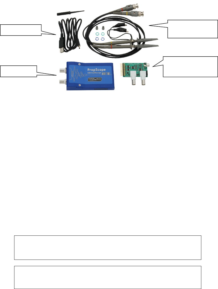
Your PropScope includes
PropScope Specifications
•2 input channels
•25 Msps maximum sample rate
•20 Vpp maximum input range (-10 V to +10 V when DC-coupled)
•10-bit input resolution over either the entire 20 Vpp range, or selectable 10, 2,
and 1 Vpp ranges.
•1x/10x selectable probes for 200 Vpp maximum input range (-100 V to +100 V
when DC-coupled)
PropScope DAC card specifications
•8-bit 25 Msps DAC, up to 25Msps with -1.5 to 1.5 and 0 to 5 volt ranges
•External trigger input configurable from -10 to 10 volts
•Four-bit logic analyzer, up to 25 Msps
•Four-bit NTSC/PAL output
Note
The card must be plugged in before starting the PropScope software. When
using the DAC, logic analyzer, or NTSC/PAL outputs, channel 2 will be disabled.
Warning
Do not apply more than +200 or less than -200 VDC to the input of the
PropScope, otherwise permanent damage may occur.
Copyright © Parallax Inc PropScope USB Oscilloscope v1.0 12/3/2009 Page 2 of 6
Two 1x/10x BNC
probes
PropScope
PropScope DAC card
for DAC/LSA/Trigger
USB Cable
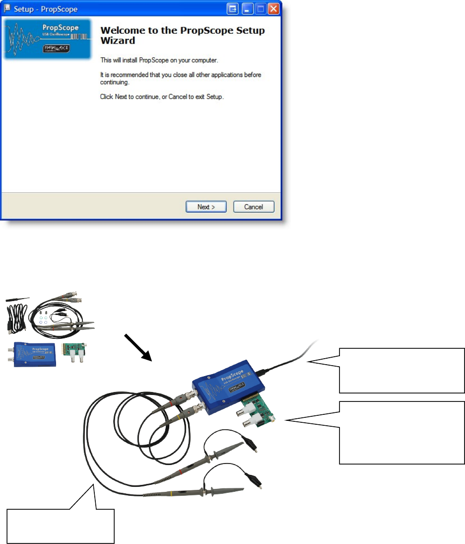
Step 1: Install Software
Download your PropScope software from: http://www.parallax.com/go/propscope and
follow the instructions to install the USB driver and PropScope software.
Step 2: Connect your PropScope
Copyright © Parallax Inc PropScope USB Oscilloscope v1.0 12/3/2009 Page 3 of 6
Connect the Probes
to your PropScope
Connect the USB cable
to the PropScope and to
your PC
Connect the PropScope
DAC card to use the
Function Generator,
External Trigger or LSA
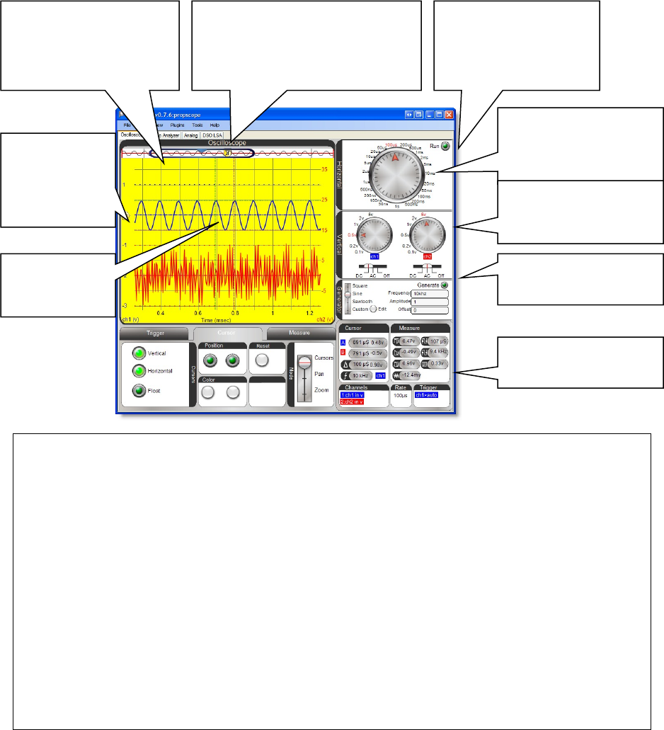
Step 3: Measure
Start the PropScope software by clicking on PropScope shortcut on your desktop.
PropScope will start in the Oscilloscope view and show measurements taken by the two
probes- see the next pages for detail on the other views.
Copyright © Parallax Inc PropScope USB Oscilloscope v1.0 12/3/2009 Page 4 of 6
Control the function
generator
Click to Start and Stop
Measurements
Adjust the horizontal
timescale to suit the
speed of your signal
Tips:
-Select the right timescale
Digital oscilloscopes sample the input signal at configurable rates. (The PropScope
samples up to 25 Million times/second) Sampling a signal too slowly will yield artifacts-
so always look at a new signal with a faster timescale first.
-Use a trigger
Click the Trigger tab to configure the trigger to stabilize the signal. You can adjust the
horizontal slider on top of the graph to show data before or after the trigger fired
-Use AC/DC mode
If you are not interested in the DC offset of your signal, switch to AC coupling.
-Make sure the probe’s 1X/10X switch is correct
Your PropScope comes with two 1X/10X probes. Switch the probe to 10X and select 10X
in the “Tools/Probe” dialog of the PropScope software to measure larger signals.
-Get Help when you’re stuck
For more information about the PropScope software controls, choose “Help” from the
menu in the PropScope software.
Adjust the horizontal
trigger and slider to see
the signal before and
after the trigger
Switch between different views:
oscilloscope, logic analyzer,
analog, and DSO-LSA
Set coupling and
vertical coupling
resolution
Click in the left
margin to set
the trigger
mode and
level
Drag traces up
and down or
left and right
View automatic
measurements
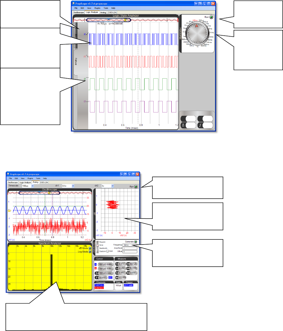
Logic Analyzer
Use the Logic Analyzer with the IO Expander to measure multiple logic signals.
Analog View
Use the Analog View to view your signal in XY mode and with the Spectrum Analyzer.
Copyright © Parallax Inc PropScope USB Oscilloscope v1.0 12/3/2009 Page 5 of 6
In Bit mode, click
on a trace label to
select rising or
falling edge trigger
for that bit
In Pattern mode,
click on any
combination of
trace labels to
select between
rise, fall, high, or
low for each bit
Explore relationships
between your signals
with the x-y graph
Control the function
generator with these
controls
Explore the frequency component of your signal
with the spectrum analyzer. Adjust the timescale
to control the frequencies graphed.
Select between Bit
and Pattern trigger
modes.
Click to Start
and Stop
Measurements
Adjust the
horizontal
timescale to
suit the speed
of your signal
Click to Start and Stop
Measurements
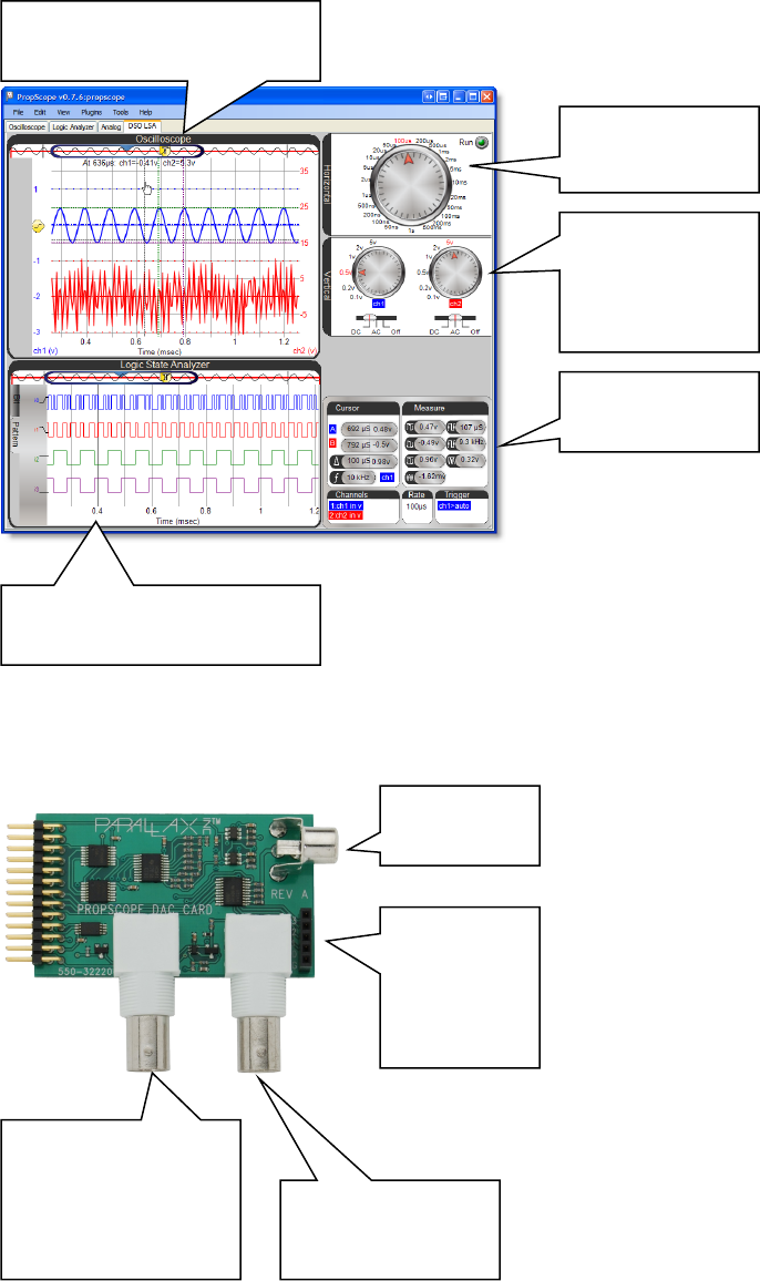
DSO LSA View
Use the DSO LSA View to control both the oscilloscope and logic state analyzer on one
screen.
PropScope DAC Card Details
Copyright © Parallax Inc PropScope USB Oscilloscope v1.0 12/3/2009 Page 6 of 6
Adjust timescale
of both graphs
Set Vertical
resolution and
coupling
View
measurements
Logic Analyzer view of digital
signals
Oscilloscope view of analog
signals
RCA output
for TV
External trigger
input configurable
from –10 to +10V
Function generator
outputs configurable
waveforms between
-1.5 to 1.5V and 0 to
5V
Four-bit
logic input,
labeled 3
through 0
and ground
