Workshop Manual GALANT Mitsubishi Rear Suspension 34
User Manual: Mitsubishi Galant Workshop Rear Suspension Manual Troubleshoot Mitsubishi Galant Workshop Rear Suspension |
Open the PDF directly: View PDF ![]() .
.
Page Count: 18
34-1
REAR
SUSPENSION
CONTENTS 34109000145
GENERAL INFORMATION 2..................
SERVICE SPECIFICATIONS 3.................
SPECIAL TOOLS 3..........................
ON-VEHICLE SERVICE 4.....................
Wheel Alignment Check and Adjustment 4.......
Ball Joint Dust Cover Check 4..................
REAR SUSPENSION ASSEMBLY 5...........
UPPER ARM ASSEMBLY 7...................
TRAILING ARM ASSEMBLY 9................
LOWER ARM AND TOE CONTROL ARM
ASSEMBLIES 10............................
SHOCK ABSORBER ASSEMBLY 13.........
STABILIZER BAR 16........................
REAR SUSPENSION - General Information
34-2
GENERAL INFORMATION 34100010192
The rear suspension is a multi-link suspension,
which has been used for the previous models. The
layout of each arm and the rigidity balance of each
bushing have been rationalized to provide both
excellent steering stability and riding comfort.
COIL SPRING
Items Sedan Wagon
Wire diameter ´average diameter ´
free length mm
9¢62 - 102 ¢397,
9¢94 - 102 ¢330*1,
9-10¢63 - 103 ¢386*2
9-10¢63 - 103 ¢405,
10 ¢95 - 103 ¢321*1,
10 - 11 ¢64 - 104 ¢383*2
NOTE
*1: Self-leveling shock absorber
*2: Heavy-duty suspension
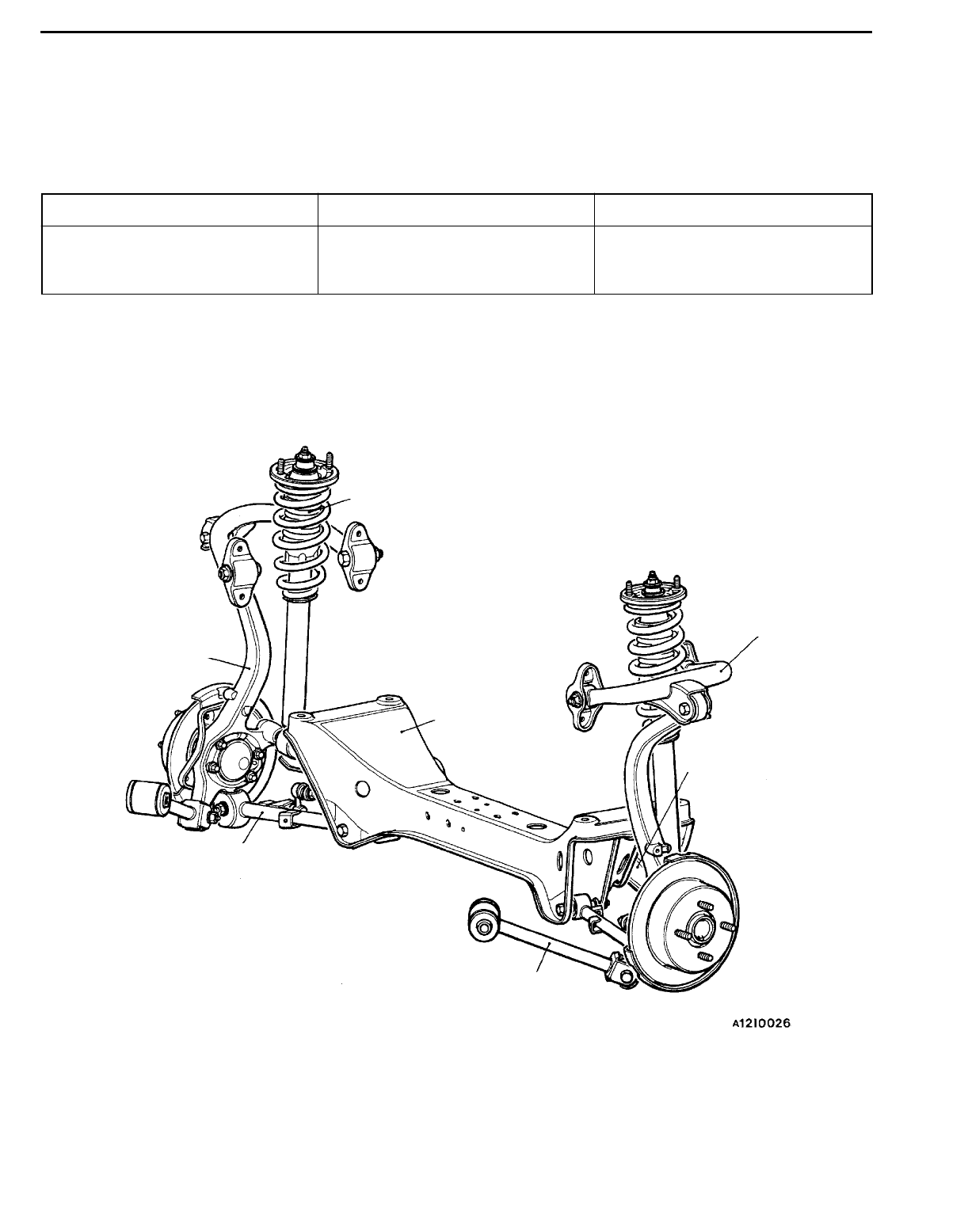
CONSTRUCTION DIAGRAM
Shock absorber
Knuckle
Crossmember
Upper arm
Toe control arm
Lower arm
Trailing arm
REAR SUSPENSION - Service Specifications/Special Tools 34-3
SERVICE SPECIFICATIONS 34100030174
Items Specifications
Toe-in At the centre of tyre tread mm 3±3
Toe-angle (per wheel) 0_09’ ±09’
Camber -1_00’ ±30’
Dimension for positioning upper arm bracket mm 37.2 ±2
Toe control arm ball joint turning torque Nm 1.0 - 2.6
Stabilizer link ball joint turning torque Nm 0.5 - 1.5
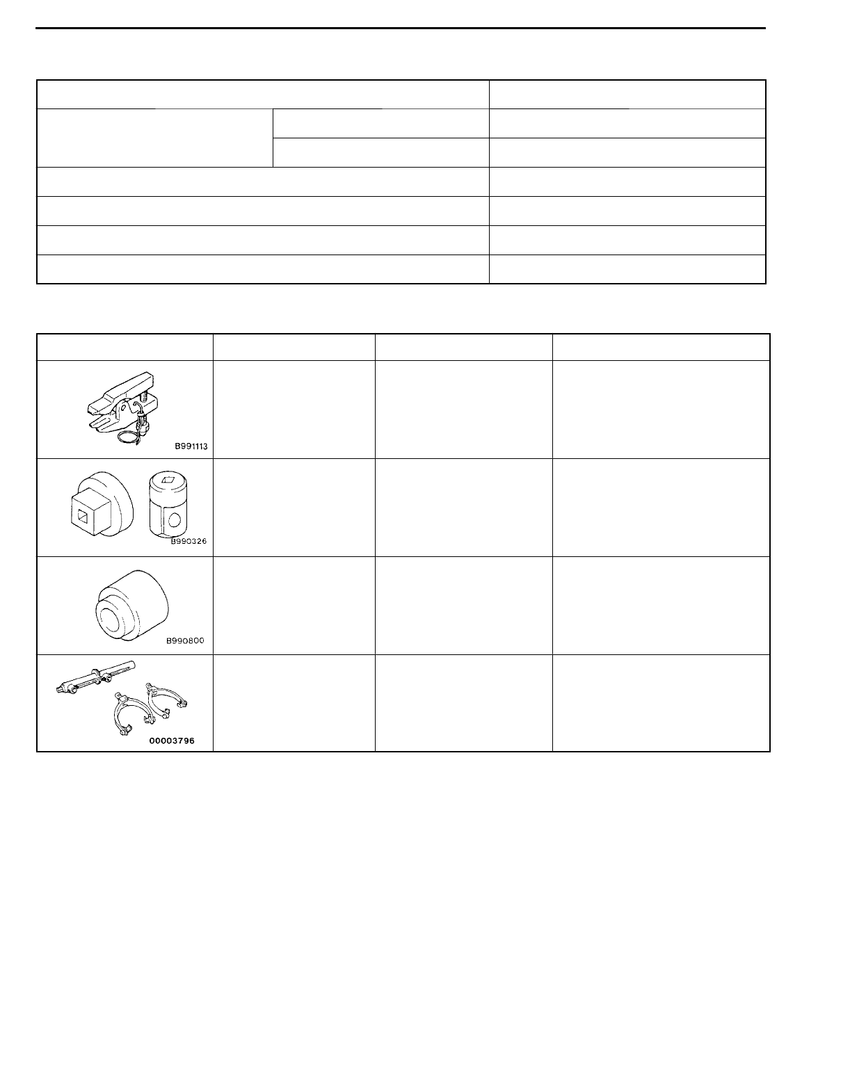
SPECIAL TOOLS 34100060159
Tool Number Name Use
MB990635,
MB991113 or
MB991406
Steering linkage puller Ball joint and knuckle disconnec-
tion
MB990326 Preload socket Ball joint continuous rotating
check
MB990800 Ball joint remover and
installer
Ball joint dust cover installation
A
B
A: MB991237
B: MB991239
A: Spring compressor
body
B: Arm set
Coil spring compression
REAR SUSPENSION - On-vehicle Service
34-4
ON-VEHICLE SERVICE 33100100106
WHEEL ALIGNMENT CHECK AND
ADJUSTMENT
TOE-IN
Standard value:
At the centre of tyre tread 3 ±3mm
Toe angle (per wheel) 0_09’±09’
Turn the toe control arm mounting bolts of the left and right
toe control arms by equal amounts to adjust.
LH: Clockwise viewed from the rear ®Toe-out
RH: Clockwise viewed from the rear ®Toe-in
Furthermore, toe adjustment can be mode at graduations
of approximately 2.5 mm
CAMBER
Standard value: -1_00’ ±30’
NOTE
1. Camber is preset at the factory and can not be adjusted.
2. If camber is not within the standard value, check and
replace bent or damaged parts.
BALL JOINT DUST COVER CHECK 34101280011
1. Check the dust cover for cracks or damage by pushing
it with finger.
2. If the dust cover is cracked or damaged, replace the
toe control arm assembly or stabilizer link.
NOTE
Cracks or damage of the dust cover may cause damage
of the ball joint.
Crossmember
REAR SUSPENSION - Rear Suspension Assembly 34-5
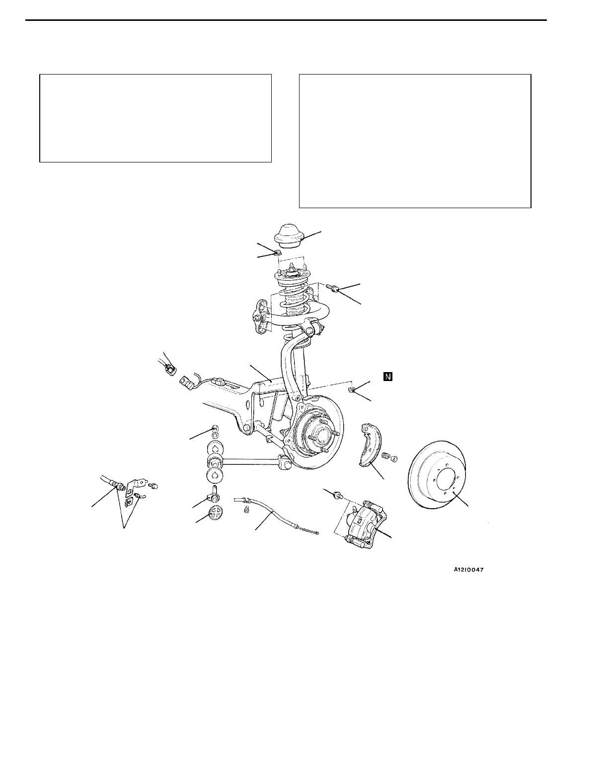
REAR SUSPENSION ASSEMBLY 34100330113
REMOVAL AND INSTALLATION
Pre-removal Operation
DBrake Fluid Draining <Vehicles with drum brake>
DRear Seat Removal <Sedan>
(Refer to GROUP 52A.)
DRetractor Trim Removal <Wagon>
(Refer to GROUP 52A.)
DCenter Exhaust Pipe Removal
(Refer to GROUP 15.)
Post-installation Operation
DCenter Exhaust Pipe Installation
(Refer to GROUP 15.)
DRetractor Trim Installation <Wagon>
(Refer to GROUP 52A.)
DRear Seat Installation <Sedan>
(Refer to GROUP 52A.)
DParking Brake Lever Stroke Check
(Refer to GROUP 36 - On-vehicle Service.)
DBrake Line bleeding <Vehicles with drum brake>
(Refer to GROUP 35A - On-vehicle Service.)
DWheel Alignment Check and Adjustment
(Refer to P.34-4.)
1
2
3
4
5
6
7
8
9
10
11
12 13
44 Nm
39 Nm
137 - 157 Nm*
15 Nm
100 Nm
88 Nm
Removal steps
1. Cap
2. Shock absorber mounting nuts
AA"3. Brake caliper assembly
4. Brake disc or brake dram
5. Shoe and lining assembly (Refer to
GROUP 36 - Parking Brake
Drum.)
6. Parking brake cable connection
(Refer to GROUP 36.)
7. Brake hose connection <Vehicles
with drum brake>
8. Upper arm mounting bolts
9. Grommet
10. Trailing arm mounting bolt
AB"11. Crossmember mounting nuts
12. Rear wheel speed sensor connec-
tor connection <Vehicles with ABS>
13. Rear suspension assembly
Caution
*: Indicates parts which should be temporarily
tightened, and then fully tightened with the
vehicles on the ground in the unladen condition.
REAR SUSPENSION - Rear Suspension Assembly
34-6
REMOVAL SERVICE POINT
AA"BRAKE CALIPER ASSEMBLY REMOVAL
Secure the removed caliper assembly with wire, so that it
does not fall.
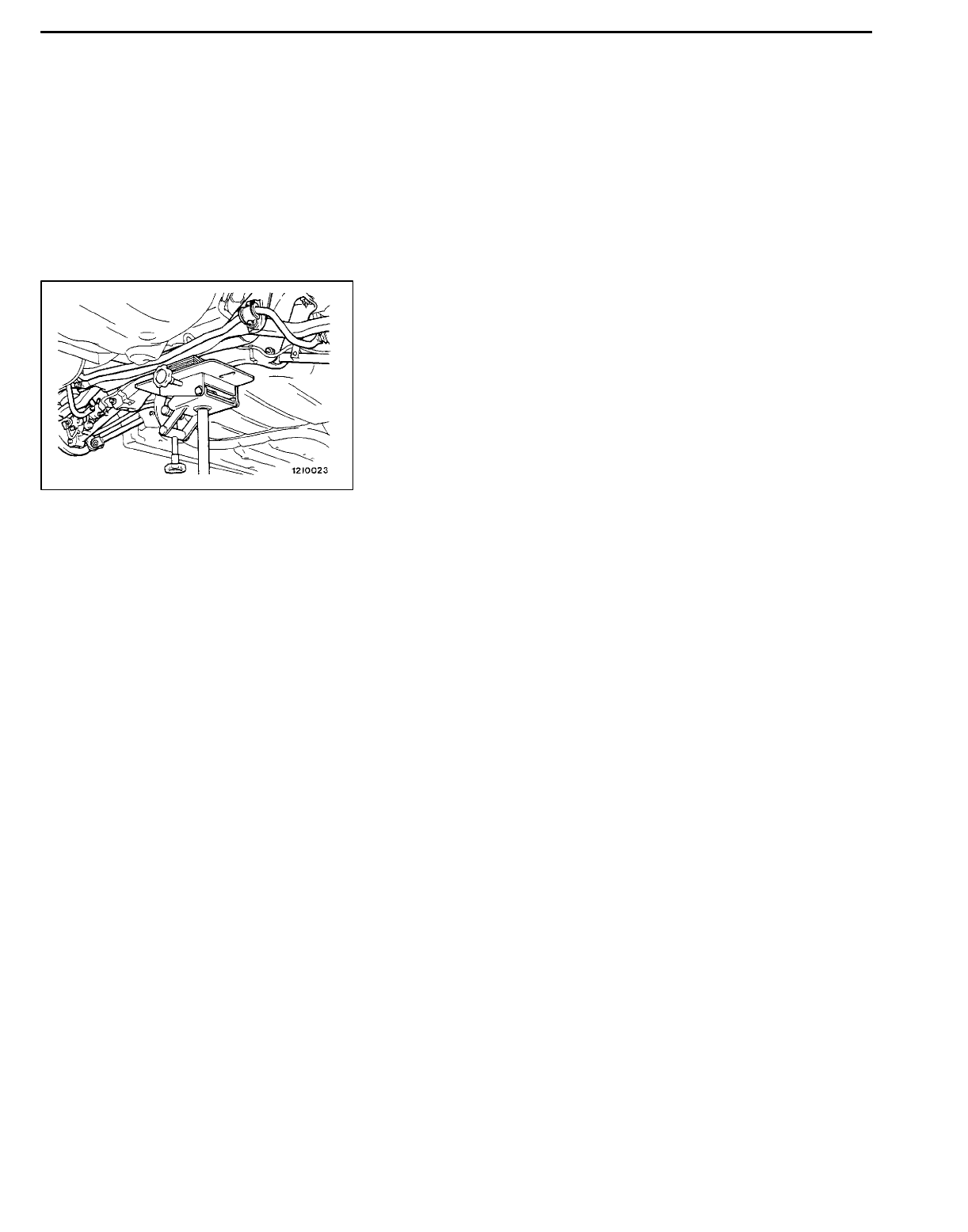
AB"CROSSMEMBER MOUNTING NUT REMOVAL
Hold the crossmember with a garage jack or transmission
jack to remove a crossmember mounting nut.
REAR SUSPENSION - Upper Arm Assembly 34-7
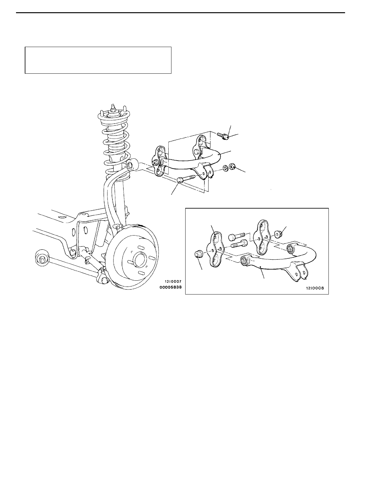
UPPER ARM ASSEMBLY 34100360082
REMOVAL AND INSTALLATION
Post-installation Operation
Wheel Alignment Check and Adjustment
(Refer to P.34-4.)
39 Nm
98 Nm*
57 Nm
57 Nm
1
2
3
4
5
Removal steps
1. Upper arm and knuckle connecting
bolt
2. Upper arm assembly mounting
bolts
3. Upper arm assembly
"AA4. Upper arm bracket
5. Upper arm
Caution
*: Indicates parts which should be temporarily
tightened, and then fully tightened with the
vehicles on the ground in the unladen condition.
REAR SUSPENSION - Upper Arm Assembly
34-8
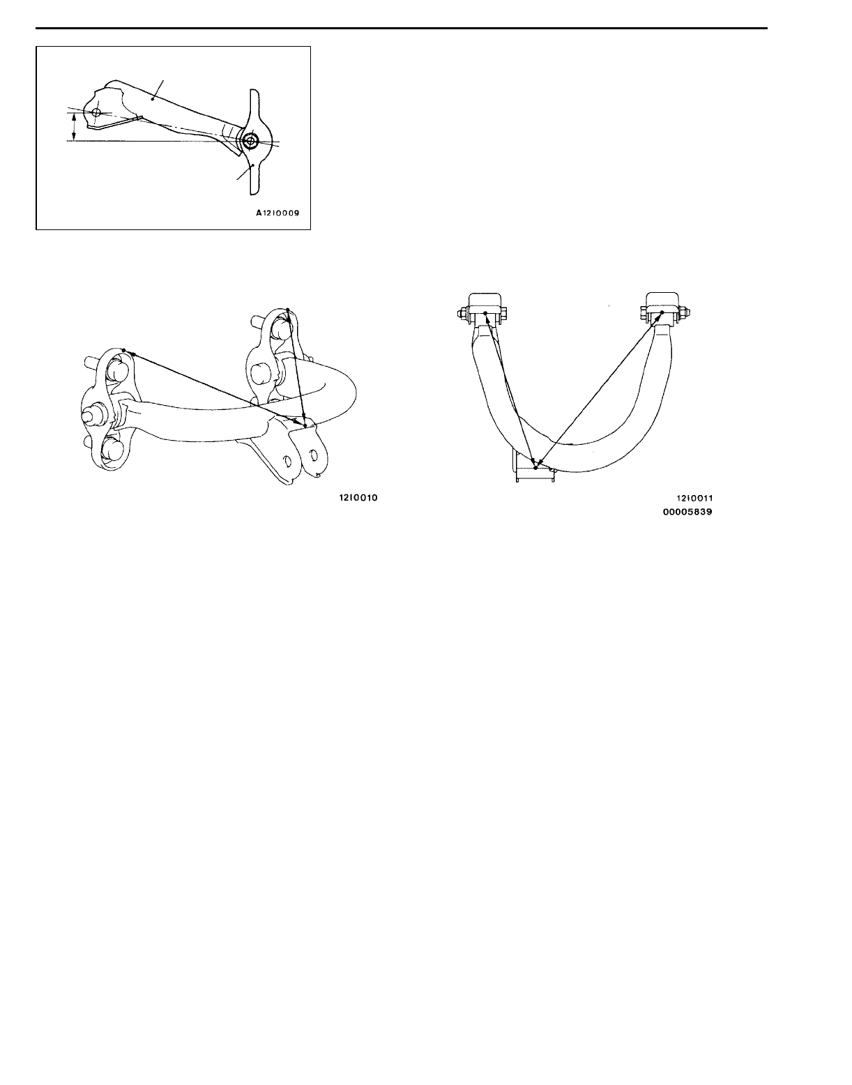
INSTALLATION SERVICE POINT
"AAUPPER ARM BRACKET INSTALLATION
Install the upper arm bracket that the dimension shown in
the illustration is at the standard value.
Standard value (A): 37.2 ±2mm
NOTE
Refer to distances B and C shown in the illustration to check
the installation angle of the upper arm bracket.
BCB
C
B: 220.1 mm
C: 274.4 mm
Upper arm
Upper arm bracket
A
REAR SUSPENSION - Trailing Arm Assembly 34-9
TRAILING ARM ASSEMBLY 34100420162
REMOVAL AND INSTALLATION
Post-installation Operation
Wheel Alignment Check and Adjustment
(Refer to P.34-4.)
137 - 157 Nm*
1
2
345
118 - 137 Nm*
Removal steps
1. Knuckle and trailing arm assembly
connecting bolt
2. Grommet
3. Trailing arm assembly mounting
bolt
4. Stopper
5. Trailing arm assembly
Caution
*: Indicates parts which should be temporarily
tightened, and then fully tightened with the
vehicles on the ground in the unladen condition.
REAR SUSPENSION - Lower Arm and Toe Control Arm Assemblies
34-10
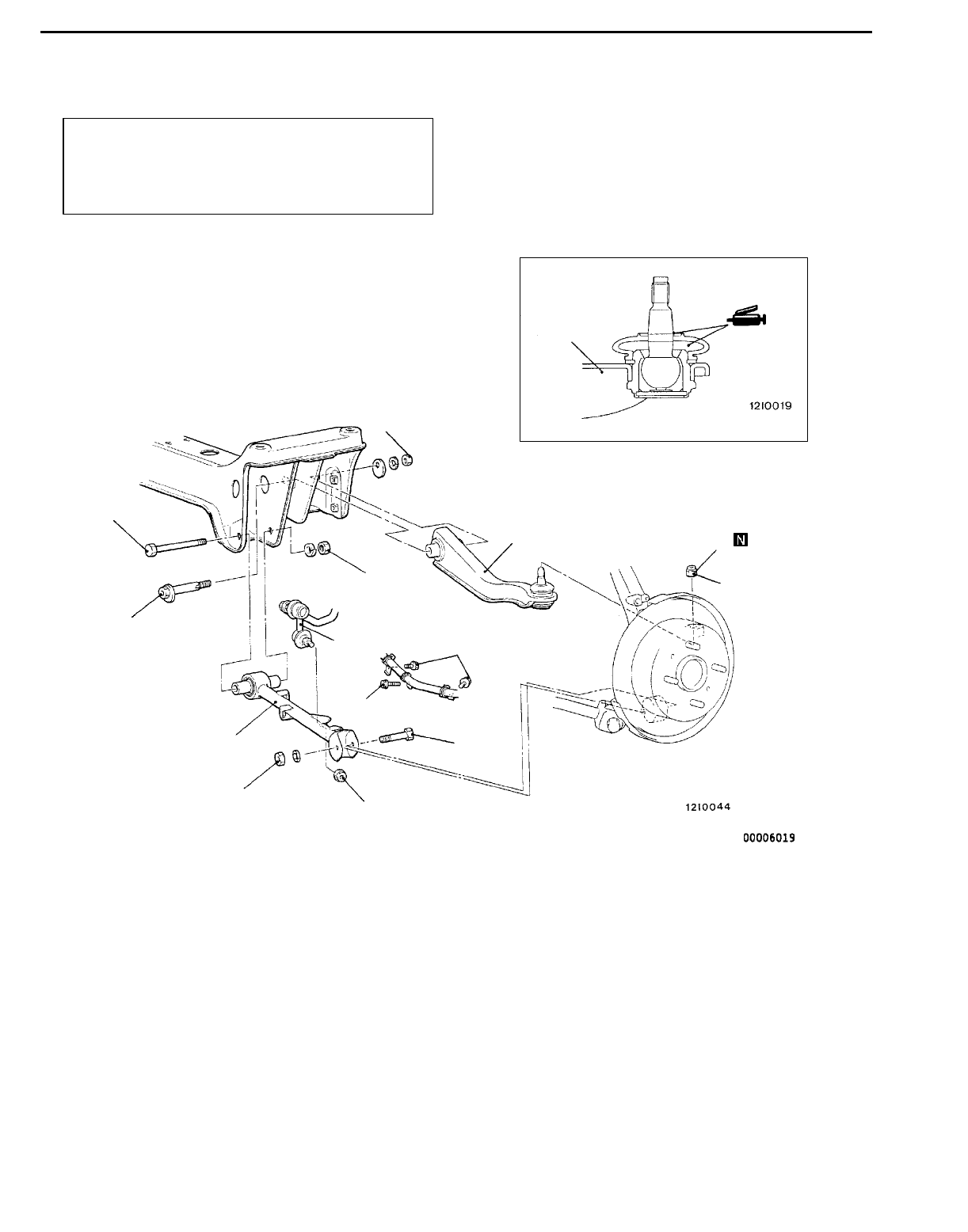
LOWER ARM AND TOE CONTROL ARM ASSEMBLIES 34100450086
REMOVAL AND INSTALLATION
Post-installation Operation
DCheck the Dust Cover for Cracks or Damage by
Pushing it with Finger
DWheel Alignment Check and Adjustment
(Refer to P.34-4.)
67 - 98 Nm*
98 Nm* 28 Nm
39 Nm
12
3
4
5
6
7
8
98 Nm*
8
2
Lower arm assembly removal steps
1. Stabilizer link connection
2. Wheel speed sensor mounting
bolts
3. Lower arm assembly and knuckle
connecting bolt
4. Lower arm assembly mounting bolt
5. Lower arm assembly
Toe control arm assembly removal
steps
AA"6. Toe control arm and knuckle con-
nection
AB"7. Toe control arm assembly mounting
bolt
8. Toe control arm assembly
Caution
*: Indicates parts which should be temporarily
tightened, and then fully tightened with the
vehicles on the ground in the unladen condition.
REAR SUSPENSION - Lower Arm and Toe Control Arm Assemblies 34-11
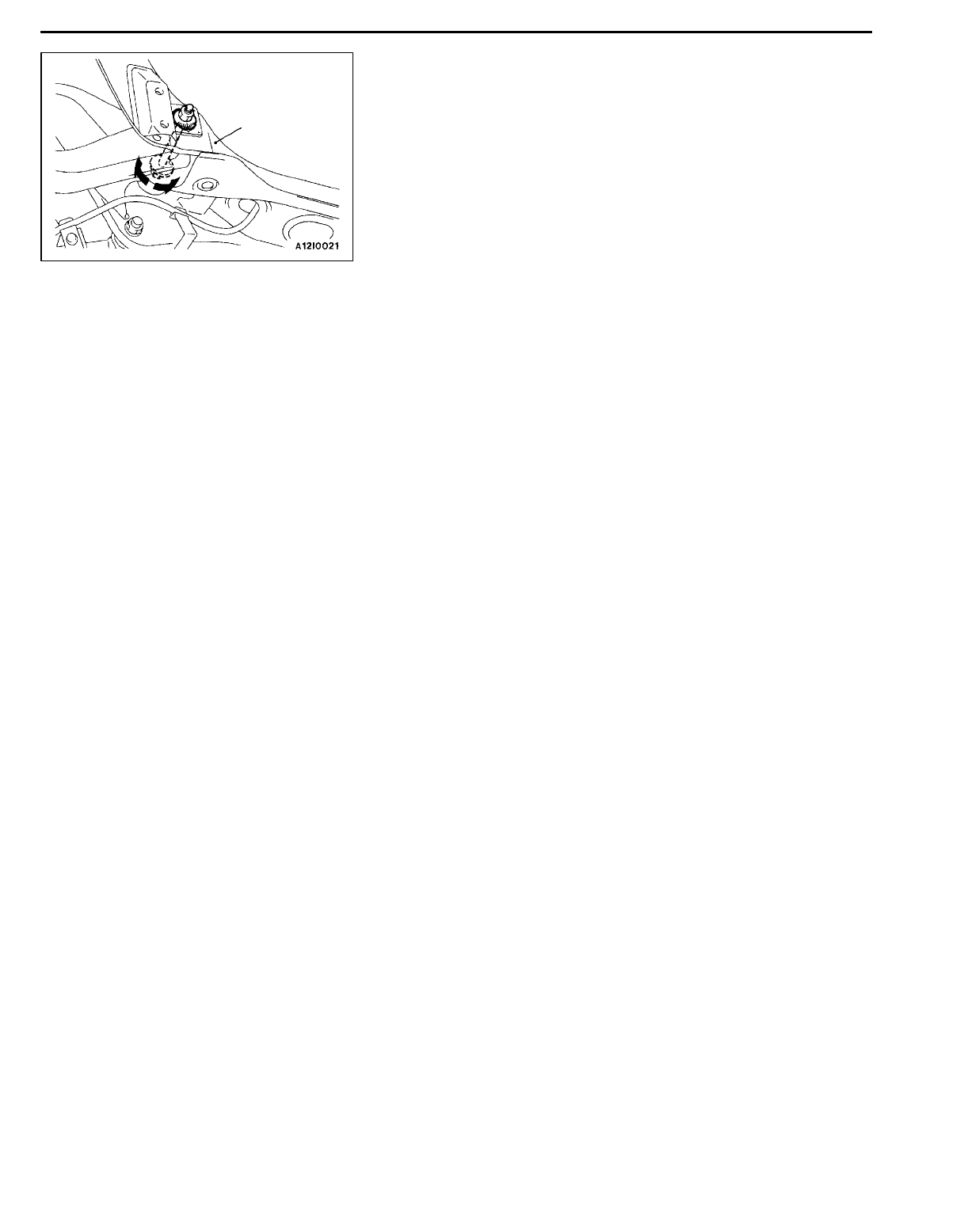
REMOVAL SERVICE POINTS
AA"TOE CONTROL ARM AND KNUCKLE
DISCONNECTION
Caution
1. Use the special tool to loosen the nut only; do not
removal it from the ball joint.
2. Tie the special tool with a cord not to let it fall off.
AB"TOE CONTROL ARM ASSEMBLY MOUNTING
BOLT REMOVAL
Place mating marks on the crossmember and the plate before
removing the bolt.
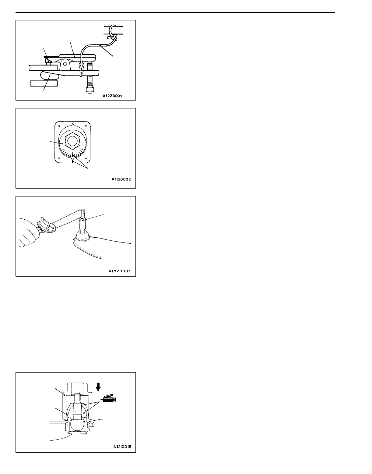
INSPECTION 34100460096
TOE CONTROL ARM BALL JOINT TURNING TORQUE
CHECK
1. After shaking the ball joint stud several times, install the
nut to the stud and use the special tool to measure the
turning torque of the ball joint.
Standard value: 1.0 - 2.6 Nm
2. When the measured value exceeds the standard value,
replace the toe control arm assembly.
3. When the measured value is lower than the standard
value, check that the ball joint turns smoothly without
excessive play. If so, it is possible to use that ball joint.
TOE CONTROL ARM BALL JOINT DUST
COVER CHECK 34101290014
1. Check the dust cover for cracks or damage by pushing
it with finger.
2. If the dust cover is cracked or damaged, replace the
toe control arm assembly.
NOTE
Cracks or damage of the dust cover may cause damaged
of the ball joint. When it is damaged during service work,
replace the dust cover.
MB990635,
MB991113 or
MB991406
Nut
Cord
Ball joint
Plate
Mating marks
MB990326
MB990800
Dust cover
Snap ring

REAR SUSPENSION - Lower Arm and Toe Control Arm Assemblies
34-12
TOE CONTROL ARM BALL JOINT DUST
COVER REPLACEMENT 34101080062
Only when the dust cover is damaged accidentally during
service work, replace the dust cover as follows:
1. Remove the dust cover.
2. Apply multipurpose grease to inside and lip of the dust
cover.
3. Using the special tool, press the dust cover until it contacts
the snap ring.
4. Check the dust cover for cracks or damage by pushing
it with finger.
REAR SUSPENSION - Shock Absorber Assembly 34-13
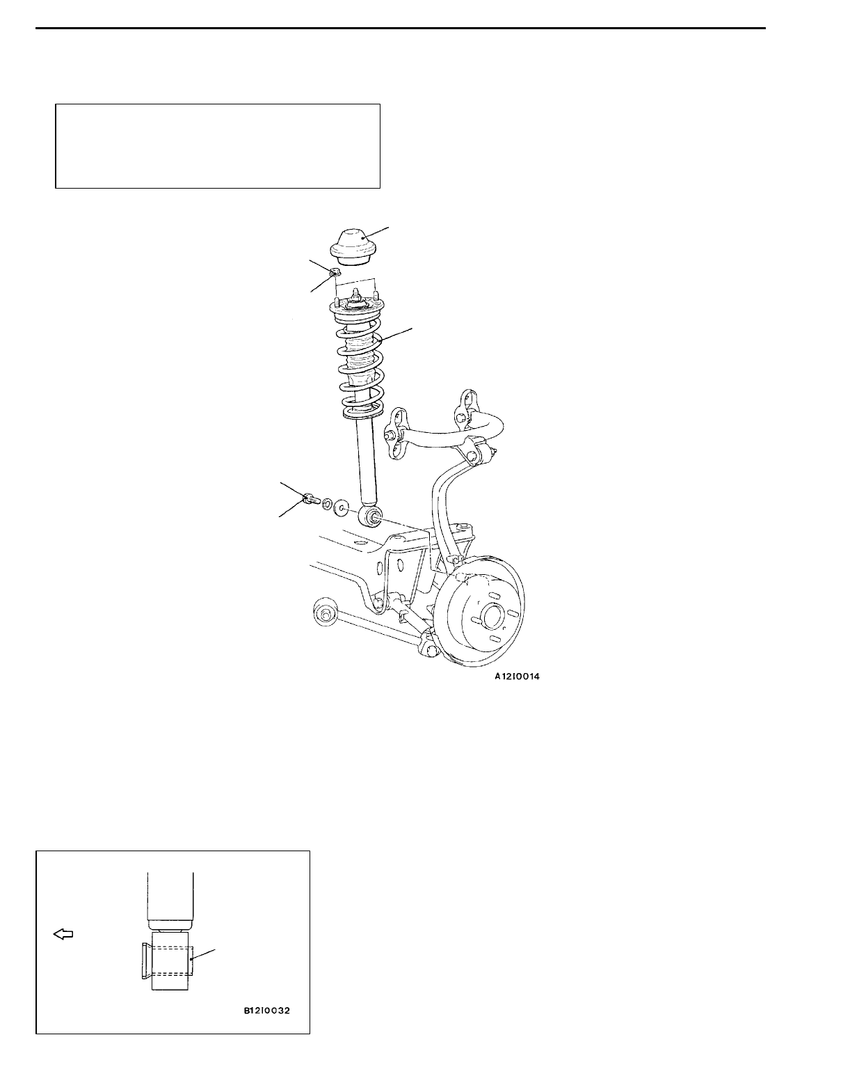
SHOCK ABSORBER ASSEMBLY 34100510159
REMOVAL AND INSTALLATION
Pre-removal and Post-installation Operation
DRear Seat Removal and Installation <Sedan>
(Refer to GROUP 52A.)
DRetractor Trim Removal and Installation <Wagon>
(Refer to GROUP 52A.)
44 Nm
98 Nm
1
2
3
4
Removal steps
1. Cap
2. Shock absorber mounting nuts
3. Bolt
"AA4. Shock absorber assembly
INSTALLATION SERVICE POINT
"AASHOCK ABSORBER ASSEMBLY INSTALLATION
Install the shock absorber so that the larger diameter side
of the lower bushing inner pipe faces toward the outside
of the vehicle.
Outside of
the body
Lower bushing
inner pipe
REAR SUSPENSION - Shock Absorber Assembly
34-14
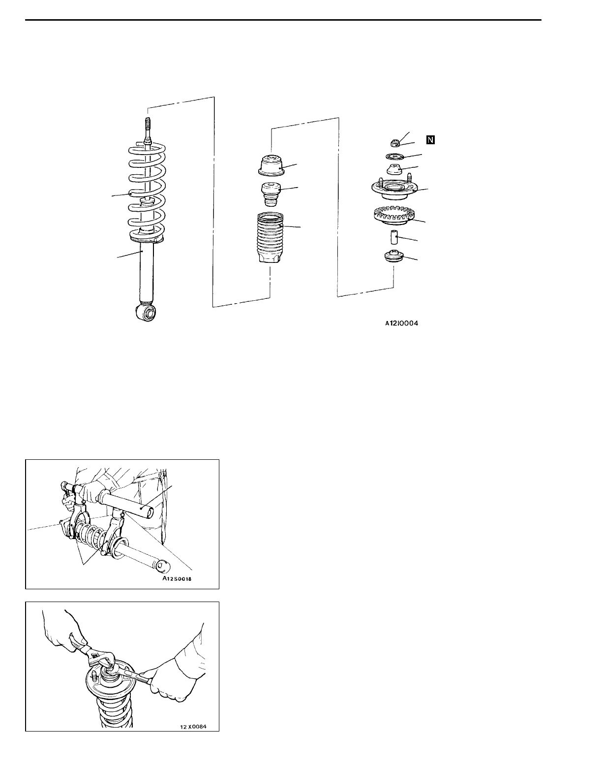
DISASSEMBLY AND REASSEMBLY 34100530117
23 Nm
12
3
4
5
8
6
7
9
11
10
12
Disassembly steps
AA""
CA1. Self-locking nut
2. Washer
3. Upper bushing A
"BA4. Upper bracket assembly
5. Upper spring pad
6. Collar
7. Upper bushing B
8. Cup assembly
9. Bump rubber
10. Dust cover
"AA11. Coil spring
12. Shock absorber assembly
DISASSEMBLY SERVICE POINT
AA"SELF-LOCKING NUT REMOVAL
1. Use the special tools to compress the coil spring.
Caution
(1) Install the special tools evenly, and so that the
maximum length will be attained within the
installation range.
(2) Do not use an impact wrench to tighten the special
tool bolt.
2. While holding the piston rod, remove the self-locking nut.
Caution
Do not use an impact wrench.
MB991239
MB991237
REAR SUSPENSION - Shock Absorber Assembly 34-15
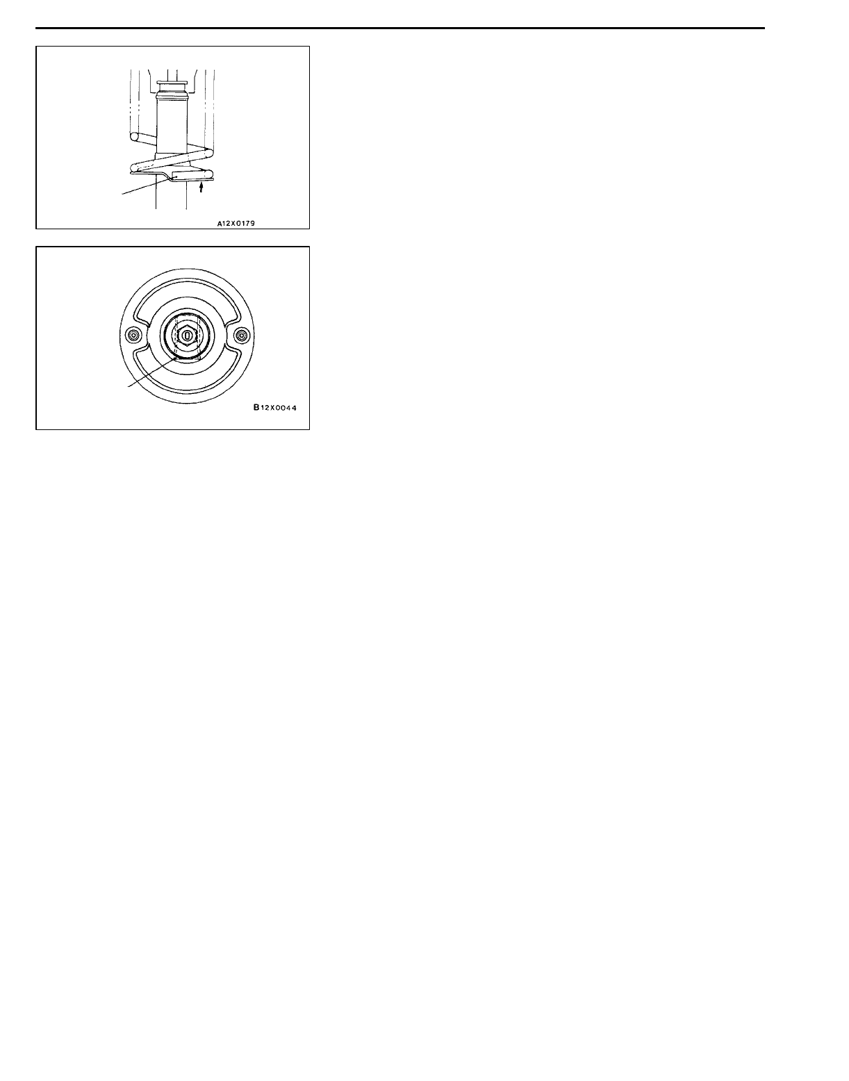
REASSEMBLY SERVICE POINTS
"AACOIL SPRING INSTALLATION
1. Install the special tool in the same manner as for removal,
and compress the coil spring to install the shock absorber.
Caution
Do not use an impact wrench to tighten the special
tool bolt.
2. Align the edge of the coil spring to the stepped part of
the shock absorber spring seat.
"BAUPPER BRACKET ASSEMBLY INSTALLATION
Install the upper bracket assembly so that the lower bushing
inner pipe of the shock absorber is at the shown position.
"CASELF-LOCKING NUT INSTALLATION
1. Temporarily tighten the self-locking nut.
2. Remove the special tools (MB991237, MB991239), and
tighten the self-locking nut to the specified torque.
Caution
Do not use an impact wrench.
Coil spring
edge
Spring seat
Lower bushing
inner pipe
REAR SUSPENSION - Stabilizer Bar
34-16
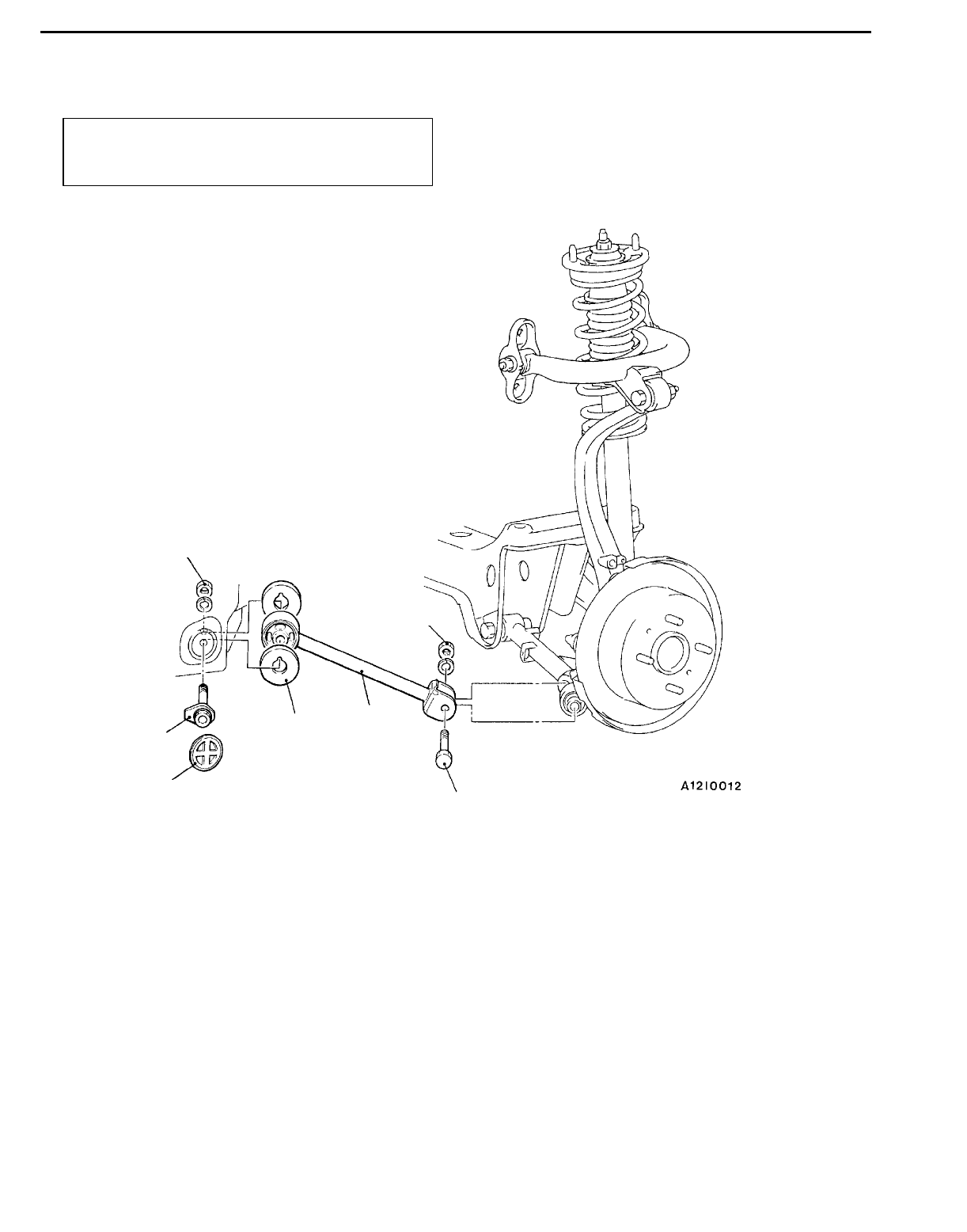
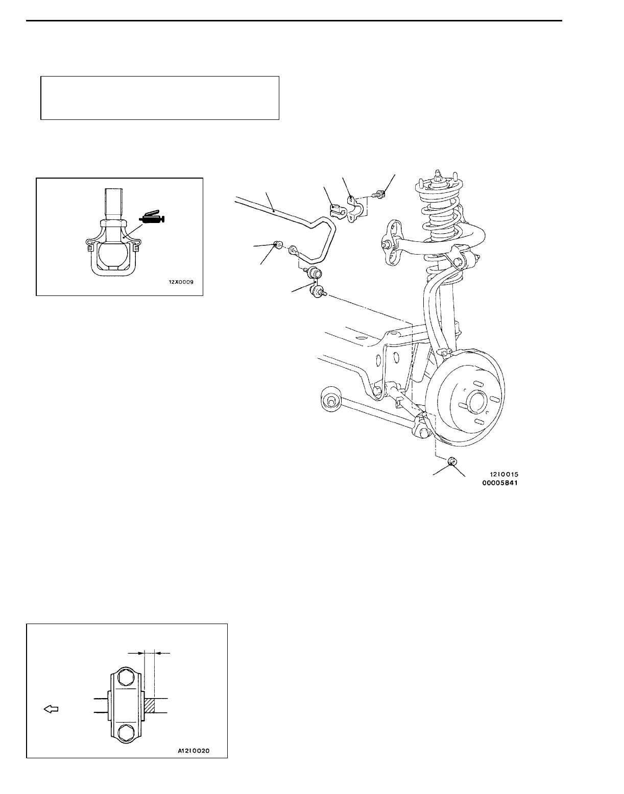
STABILIZER BAR 34100560109
REMOVAL AND INSTALLATION
Post-installation Operation
Check the Dust Cover for Cracks or Damage by Pushing
it with Finger.
39 Nm
39 Nm
44 Nm
1
2
3
4
5
1
Removal steps
1. Stabilizer link mounting nuts
2. Stabilizer link
"AA3. Stabilizer bar bracket
"AA4. Bushing
"AA5. Stabilizer bar
INSTALLATION SERVICE POINT
"AASTABILIZER BAR/BUSHING/STABILIZER BAR
BRACKET INSTALLATION
Position the stabilizer bar identification mark to the left side.
Adjust the identification mark position as shown in the figure,
and tighten the stabilizer bar bracket mounting bolt.
Approx. 20 mm
Outside of
the body
REAR SUSPENSION - Stabilizer Bar 34-17
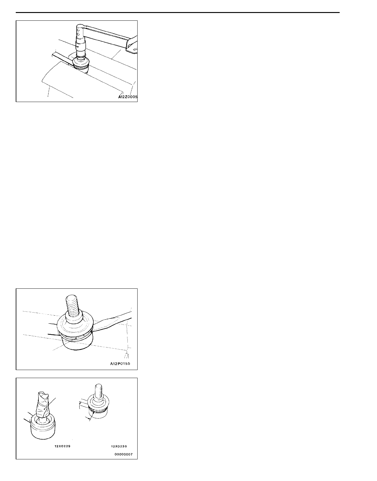
INSPECTION 34100570119
STABILIZER LINK BALL JOINT TURNING TORQUE
CHECK
1. After shaking the ball joint stud several times, install the
nut to the stud and use the special tool to measure the
turning torque of the ball joint.
Standard value: 0.5 - 1.5 Nm
2. When the measured value exceeds the standard value,
replace the stabilizer link.
3. When the measured value is lower than the standard
value, check that the ball joint turns smoothly without
excessive play. If so, it is possible to use that ball joint.
STABILIZER LINK BALL JOINT DUST COVER CHECK
34101300014
1. Check the dust cover for cracks or damage by pushing
it with finger.
2. If the dust cover is cracked or damaged, replace the
stabilizer link.
NOTE
Cracks or damage of the dust cover may cause damage
of the ball joint. When it is damaged during service work,
replace the dust cover.
STABILIZER LINK BALL JOINT DUST COVER
REPLACEMENT 34101090089
Only when the dust cover is damaged accidentally during
service work, replace the dust cover as follows:
1. Remove the clip ring and the dust cover.
2. Apply multipurpose grease to the lip and inside of the
dust cover.
3. Use plastic tape on the stabilizer link threads as shown
in the illustration, and then install the dust cover to the
stabilizer link.
4. Secure the dust cover with the clip ring.
When installing the clip ring, align the ends at a 90_
angle from the axis of the stabilizer link.
5. Check the dust cover for cracks or damage by pushing
it with finger.
MB990326
Clip ring
Plastic tape
Approx. 90_
Clip ring ends (180_on
opposite side also possible)

NOTES
