HP 34401A User's Guide
User Manual:
Open the PDF directly: View PDF ![]() .
.
Page Count: 32

HP 34401A
Multimeter
User’s Guide
Part Number 34401-90004
February 1996
For Safety information, Warranties, and Regulatory information,
see the pages behind the Index.
© Copyright Hewlett-Packard Company 1991, 1996
All Rights Reserved.

4
Remote Interface
Reference
4

Remote Interface Reference
•Command Summary, starting on page 105
•Simplified Programming Overview, starting on page 112
•The MEASure? and CONFigure Commands, starting on page 117
•Measurement Configuration Commands, starting on page 121
•Math Operation Commands, starting on page 124
•Triggering, starting on page 127
•Triggering Commands, starting on page 130
•System-Related Commands, starting on page 132
•The SCPI Status Model, starting on page 134
•Status Reporting Commands, starting on page 144
•Calibration Commands, on page 146
•RS-232 Interface Configuration, starting on page 148
•RS-232 Interface Commands, on page 153
•An Introduction to the SCPI Language, starting on page 154
•Output Data Formats, on page 159
•Using Device Clear to Halt Measurements, on page 160
•TALK ONLY for Printers, on page 160
•To Set the HP-IB Address, on page 161
•To Select the Remote Interface, on page 162
•To Set the Baud Rate, on page 163
•To Set the Parity, on page 164
•To Select the Programming Language, on page 165
•Alternate Programming Language Compatibility, starting on page 166
•SCPI Compliance Information, on page 168
•IEEE-488 Compliance Information, on page 169
If you are a first-time user of the SCPI language, you may want to refer to these sections
to become familiar with the language before attempting to program the multimeter.
104
Command Summary
This section summarizes the SCPI (Standard Commands for
Programmable Instruments) commands available to program the
multimeter. Refer to the later sections in this chapter for more complete
details on each command.
Throughout this manual, the following conventions are used for
SCPI command syntax. Square brackets ( [ ] ) indicate optional
keywords or parameters. Braces ( { } ) enclose parameters within a
command string. Triangle brackets ( < > ) indicate that you must
substitute a value for the enclosed parameter.
First-time
SCPI users,
see page 154.
The MEASure? and CONFigure Commands
(see page 117 for more information)
MEASure
:VOLTage:DC? {<range>|MIN|MAX|DEF},{<resolution>|MIN|MAX|DEF}
:VOLTage:DC:RATio? {<range>|MIN|MAX|DEF},{<resolution>|MIN|MAX|DEF}
:VOLTage:AC? {<range>|MIN|MAX|DEF},{<resolution>|MIN|MAX|DEF}
:CURRent:DC? {<range>|MIN|MAX|DEF},{<resolution>|MIN|MAX|DEF}
:CURRent:AC? {<range>|MIN|MAX|DEF},{<resolution>|MIN|MAX|DEF}
:RESistance? {<range>|MIN|MAX|DEF},{<resolution>|MIN|MAX|DEF}
:FRESistance? {<range>|MIN|MAX|DEF},{<resolution>|MIN|MAX|DEF}
:FREQuency? {<range>|MIN|MAX|DEF},{<resolution>|MIN|MAX|DEF}
:PERiod? {<range>|MIN|MAX|DEF},{<resolution>|MIN|MAX|DEF}
:CONTinuity?
:DIODe?
CONFigure
:VOLTage:DC {<range>|MIN|MAX|DEF},{<resolution>|MIN|MAX|DEF}
:VOLTage:DC:RATio {<range>|MIN|MAX|DEF},{<resolution>|MIN|MAX|DEF}
:VOLTage:AC {<range>|MIN|MAX|DEF},{<resolution>|MIN|MAX|DEF}
:CURRent:DC {<range>|MIN|MAX|DEF},{<resolution>|MIN|MAX|DEF}
:CURRent:AC {<range>|MIN|MAX|DEF},{<resolution>|MIN|MAX|DEF}
:RESistance {<range>|MIN|MAX|DEF},{<resolution>|MIN|MAX|DEF}
:FRESistance {<range>|MIN|MAX|DEF},{<resolution>|MIN|MAX|DEF}
:FREQuency {<range>|MIN|MAX|DEF},{<resolution>|MIN|MAX|DEF}
:PERiod {<range>|MIN|MAX|DEF},{<resolution>|MIN|MAX|DEF}
:CONTinuity
:DIODe
CONFigure?
4
Chapter 4 Remote Interface Reference
Command Summary
105

Default parameters are shown in bold.
Measurement Configuration Commands
(see page 121 for more information)
[SENSe:]
FUNCtion "VOLTage:DC"
FUNCtion "VOLTage:DC:RATio"
FUNCtion "VOLTage:AC"
FUNCtion "CURRent:DC"
FUNCtion "CURRent:AC"
FUNCtion "RESistance" (2-wire ohms)
FUNCtion "FRESistance" (4-wire ohms)
FUNCtion "FREQuency"
FUNCtion "PERiod"
FUNCtion "CONTinuity"
FUNCtion "DIODe"
FUNCtion?
[SENSe:]
VOLTage:DC:RANGe {<range>|MINimum|MAXimum}
VOLTage:DC:RANGe? [MINimum|MAXimum]
VOLTage:AC:RANGe {<range>|MINimum|MAXimum}
VOLTage:AC:RANGe? [MINimum|MAXimum]
CURRent:DC:RANGe {<range>|MINimum|MAXimum}
CURRent:DC:RANGe? [MINimum|MAXimum]
CURRent:AC:RANGe {<range>|MINimum|MAXimum}
CURRent:AC:RANGe? [MINimum|MAXimum]
RESistance:RANGe {<range>|MINimum|MAXimum}
RESistance:RANGe? [MINimum|MAXimum]
FRESistance:RANGe {<range>|MINimum|MAXimum}
FRESistance:RANGe? [MINimum|MAXimum]
FREQuency:VOLTage:RANGe {<range>|MINimum|MAXimum}
FREQuency:VOLTage:RANGe? [MINimum|MAXimum]
PERiod:VOLTage:RANGe {<range>|MINimum|MAXimum}
PERiod:VOLTage:RANGe? [MINimum|MAXimum]
[SENSe:]
VOLTage:DC:RANGe:AUTO {OFF|ON}
VOLTage:DC:RANGe:AUTO?
VOLTage:AC:RANGe:AUTO {OFF|ON}
VOLTage:AC:RANGe:AUTO?
CURRent:DC:RANGe:AUTO {OFF|ON}
CURRent:DC:RANGe:AUTO?
CURRent:AC:RANGe:AUTO {OFF|ON}
CURRent:AC:RANGe:AUTO?
RESistance:RANGe:AUTO {OFF|ON}
RESistance:RANGe:AUTO?
FRESistance:RANGe:AUTO {OFF|ON}
FRESistance:RANGe:AUTO?
FREQuency:VOLTage:RANGe:AUTO {OFF|ON}
FREQuency:VOLTage:RANGe:AUTO?
PERiod:VOLTage:RANGe:AUTO {OFF|ON}
PERiod:VOLTage:RANGe:AUTO?
Chapter 4 Remote Interface Reference
Command Summary
106

Measurement Configuration Commands
(continued)
[SENSe:]
VOLTage:DC:RESolution {<resolution>|MINimum|MAXimum}
VOLTage:DC:RESolution? [MINimum|MAXimum]
VOLTage:AC:RESolution {<resolution>|MINimum|MAXimum}
VOLTage:AC:RESolution? [MINimum|MAXimum]
CURRent:DC:RESolution {<resolution>|MINimum|MAXimum}
CURRent:DC:RESolution? [MINimum|MAXimum]
CURRent:AC:RESolution {<resolution>|MINimum|MAXimum}
CURRent:AC:RESolution? [MINimum|MAXimum]
RESistance:RESolution {<resolution>|MINimum|MAXimum}
RESistance:RESolution? [MINimum|MAXimum]
FRESistance:RESolution {<resolution>|MINimum|MAXimum}
FRESistance:RESolution? [MINimum|MAXimum]
[SENSe:]
VOLTage:DC:NPLCycles {0.02|0.2|1|10|100|MINimum|MAXimum}
VOLTage:DC:NPLCycles? [MINimum|MAXimum]
CURRent:DC:NPLCycles {0.02|0.2|1|10|100|MINimum|MAXimum}
CURRent:DC:NPLCycles? [MINimum|MAXimum]
RESistance:NPLCycles {0.02|0.2|1|10|100|MINimum|MAXimum}
RESistance:NPLCycles? [MINimum|MAXimum]
FRESistance:NPLCycles {0.02|0.2|1|10|100|MINimum|MAXimum}
FRESistance:NPLCycles? [MINimum|MAXimum]
[SENSe:]
FREQuency:APERture {0.01|0.1|1|MINimum|MAXimum}
FREQuency:APERture? [MINimum|MAXimum]
PERiod:APERture {0.01|0.1|1|MINimum|MAXimum}
PERiod:APERture? [MINimum|MAXimum]
[SENSe:]
DETector:BANDwidth {3|20|200|MINimum|MAXimum}
DETector:BANDwidth? [MINimum|MAXimum]
[SENSe:]
ZERO:AUTO {OFF|ONCE|ON}
ZERO:AUTO?
INPut
:IMPedance:AUTO {OFF|ON}
:IMPedance:AUTO?
ROUTe:TERMinals?
Default parameters are shown in bold.
4
Chapter 4 Remote Interface Reference
Command Summary
107

Math Operation Commands
(see page 124 for more information)
CALCulate
:FUNCtion {NULL|DB|DBM|AVERage|LIMit}
:FUNCtion?
:STATe {OFF|ON}
:STATe?
CALCulate
:AVERage:MINimum?
:AVERage:MAXimum?
:AVERage:AVERage?
:AVERage:COUNt?
CALCulate
:NULL:OFFSet {<value>|MINimum|MAXimum}
:NULL:OFFSet? [MINimum|MAXimum]
CALCulate
:DB:REFerence {<value>|MINimum|MAXimum}
:DB:REFerence? [MINimum|MAXimum]
CALCulate
:DBM:REFerence {<value>|MINimum|MAXimum}
:DBM:REFerence? [MINimum|MAXimum]
CALCulate
:LIMit:LOWer {<value>|MINimum|MAXimum}
:LIMit:LOWer? [MINimum|MAXimum]
:LIMit:UPPer {<value>|MINimum|MAXimum}
:LIMit:UPPer? [MINimum|MAXimum]
DATA:FEED RDG_STORE, {"CALCulate"|""}
DATA:FEED?
Chapter 4 Remote Interface Reference
Command Summary
108

Triggering Commands
(see page 127 for more information)
INITiate
READ?
TRIGger
:SOURce {BUS|IMMediate|EXTernal}
:SOURce?
TRIGger
:DELay {<seconds>|MINimum|MAXimum}
:DELay? [MINimum|MAXimum]
TRIGger
:DELay:AUTO {OFF|ON}
:DELay:AUTO?
SAMPle
:COUNt {<value>|MINimum|MAXimum}
:COUNt? [MINimum|MAXimum]
TRIGger
:COUNt {<value>|MINimum|MAXimum|INFinite}
:COUNt? [MINimum|MAXimum]
System-Related Commands
(see page 132 for more information)
FETCh?
READ?
DISPlay {OFF|ON}
DISPlay?
DISPlay
:TEXT <quoted string>
:TEXT?
:TEXT:CLEar
SYSTem
:BEEPer
:BEEPer:STATe {OFF|ON}
:BEEPer:STATe?
Default parameters are shown in bold.
SYSTem:ERRor?
SYSTem:VERSion?
DATA:POINts?
*RST
*TST?
*IDN?
L1
L2
L3
4
Chapter 4 Remote Interface Reference
Command Summary
109
Default parameters are shown in bold.
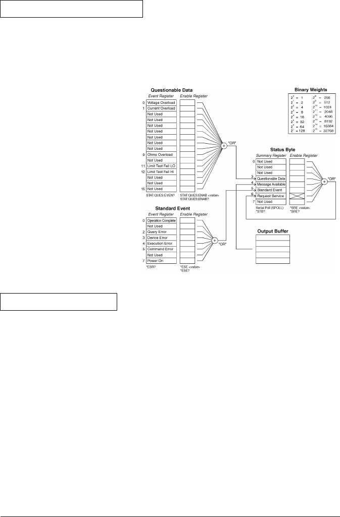
Status Reporting Commands
(see page 144 for more information)
SYSTem:ERRor?
STATus
:QUEStionable:ENABle <enable value>
:QUEStionable:ENABle?
:QUEStionable:EVENt?
STATus:PRESet
*CLS
*ESE <enable value>
*ESE?
*ESR?
*OPC
*OPC?
*PSC {0|1}
*PSC?
*SRE <enable value>
*SRE?
*STB?
Calibration Commands
(see page 146 for more information)
CALibration?
CALibration:COUNt?
CALibration
:SECure:CODE <new code>
:SECure:STATe {OFF|ON},<code>
:SECure:STATe?
CALibration
:STRing <quoted string>
:STRing?
CALibration
:VALue <value>
:VALue?
Chapter 4 Remote Interface Reference
Command Summary
110

RS-232 Interface Commands
(see page 148 for more information)
SYSTem:LOCal
SYSTem:REMote
SYSTem:RWLock
IEEE-488.2 Common Commands
(see page 169 for more information)
*CLS
*ESE <enable value>
*ESE?
*ESR?
*IDN?
*OPC
*OPC?
*PSC {0|1}
*PSC?
*RST
*SRE <enable value>
*SRE?
*STB?
*TRG
*TST?
Default parameters are shown in bold.
4
Chapter 4 Remote Interface Reference
Command Summary
111

Simplified Programming Overview
You can program the multimeter to take measurements from the remote
interface using the following simple seven-step sequence.
1. Place the multimeter in a known state (often the reset state).
2. Change the multimeter’s settings to achieve the desired configuration.
3. Set-up the triggering conditions.
4. Initiate or arm the multimeter for a measurement.
5. Trigger the multimeter to make a measurement.
6. Retrieve the readings from the output buffer or internal memory.
7. Read the measured data into your bus controller.
The MEASure? and CONFigure commands provide the most straight-
forward method to program the multimeter for measurements. You can
select the measurement function, range, and resolution all in one
command. The multimeter automatically presets other measurement
parameters (ac filter, autozero, trigger count, etc.) to default values as
shown below.
First-time
SCPI users,
see page 154.
Command
AC Filter (DET:BAND)
Autozero (ZERO:AUTO)
Input Resistance (INP:IMP:AUTO)
Samples per Trigger (SAMP:COUN)
Trigger Count (TRIG:COUN)
Trigger Delay (TRIG:DEL)
Trigger Source (TRIG:SOUR)
Math Function (CALCulate subsystem)
MEASure? and CONFigure Setting
20 Hz (medium filter)
OFF if resolution setting results in NPLC < 1;
ON if resolution setting results in NPLC ≥ 1
OFF (fixed at 10 MΩ for all dc voltage ranges)
1 sample
1 trigger
Automatic delay
Immediate
OFF
MEASure? and CONFigure Preset States
Chapter 4 Remote Interface Reference
Simplified Programming Overview
112

Using the MEASure? Command
The easiest way to program the multimeter for measurements is by
using the MEASure? command. However, this command does not offer
much flexibility. When you execute the command, the multimeter
presets the best settings for the requested configuration and
immediately performs the measurement. You cannot change any
settings (other than function, range, and resolution) before the
measurement is taken. The results are sent to the output buffer.
Sending the MEASure? command is the same as sending a CONFigure
command followed immediately by a READ? command.
Using the CONFigure Command
For a little more programming flexibility, use the CONFigure command.
When you execute the command, the multimeter presets the best
settings for the requested configuration (like the MEASure? command).
However, the measurement is not automatically started and you can
change measurement parameters before making measurements. This
allows you to “incrementally” change the multimeter’s configuration
from the preset conditions. The multimeter offers a variety of low-level
commands in the INPut, SENSe, CALCulate, and TRIGger
subsystems. (You can use the SENSe:FUNCtion command to change the
measurement function without using MEASure? or CONFigure.)
Use the INITiate or READ? command to initiate the measurement.
4
Chapter 4 Remote Interface Reference
Simplified Programming Overview
113

Using the range and resolution Parameters
With the MEASure? and CONFigure commands, you can select the
measurement function, range, and resolution all in one command.
Use the range parameter to specify the expected value of the input
signal. The multimeter then selects the correct measurement range.
For frequency and period measurements, the multimeter uses one
“range” for all inputs between 3 Hz and 300 kHz. The range parameter
is required only to specify the resolution. Therefore, it is not necessary
to send a new command for each new frequency to be measured.
Use the resolution parameter to specify the desired resolution for
the measurement. Specify the resolution in the same units as the
measurement function, not in number of digits. For example, for
dc volts, specify the resolution in volts. For frequency, specify the
resolution in hertz.
You must specify a range to use the resolution parameter.
Using the READ? Command
The READ? command changes the state of the trigger system from the
“idle” state to the “wait-for-trigger” state. Measurements will begin
when the specified trigger conditions are satisfied following the receipt
of the READ? command. Readings are sent immediately to the output
buffer. You must enter the reading data into your bus controller or the
multimeter will stop making measurements when the output buffer
fills. Readings are not stored in the multimeter’s internal memory when
using the READ? command.
Sending the READ? command is like sending the INITiate command
followed immediately by the FETCh? command, except readings are not
buffered internally.
Chapter 4 Remote Interface Reference
Simplified Programming Overview
114

Caution If you send two query commands without reading the response from the
first, and then attempt to read the second response, you may receive some
data from the first response followed by the complete second response.
To avoid this, do not send a query command without reading the
response. When you cannot avoid this situation, send a device clear
before sending the second query command.
Using the INITiate and FETCh? Commands
The INITiate and FETCh? commands provide the lowest level of
control (with the most flexibility) of measurement triggering and
reading retrieval. Use the INITiate command after you have
configured the multimeter for the measurement. This changes the state
of the triggering system from the “idle” state to the “wait-for-trigger”
state. Measurements will begin when the specified trigger conditions
are satisfied after the INITiate command is received. The readings are
placed in the multimeter’s internal memory (up to 512 readings can be
stored). Readings are stored in memory until you are able to retrieve them.
Use the FETCh? command to transfer the readings from the
multimeter’s internal memory to the multimeter’s output buffer where
you can read them into your bus controller.
MEASure?
Example
The following program segment shows how to use the MEASure?
command to make a measurement. This example configures the
multimeter for dc voltage measurements, automatically places the
multimeter in the “wait-for-trigger” state, internally triggers the
multimeter to take one reading, and then sends the reading to the
output buffer.
MEAS:VOLT:DC? 10,0.003
bus enter statement
This is the simplest way to take a reading. However, you do not have
any flexibility with MEASure? to set the trigger count, sample count,
trigger delay, etc. All measurement parameters except function, range,
and resolution are preset for you automatically (see the table on page 112).
4
Chapter 4 Remote Interface Reference
Simplified Programming Overview
115

CONFigure
Example
The following program segment shows how to use the READ? command
with CONFigure to make an externally-triggered measurement.
The program configures the multimeter for dc voltage measurements.
CONFigure does not place the multimeter in the “wait-for-trigger” state.
The READ? command places the multimeter in the “wait-for-trigger”
state, takes a reading when the Ext Trig terminal is pulsed, and sends
the reading to the output buffer.
CONF:VOLT:DC 10, 0.003
TRIG:SOUR EXT
READ?
bus enter statement
CONFigure
Example
The following program segment is similar to the program above but it
uses INITiate to place the multimeter in the “wait-for-trigger” state.
The INITiate command places the multimeter in the “wait-for-trigger”
state, takes a reading when the Ext Trig terminal is pulsed, and sends
the reading to the multimeter’s internal memory. The FETCh? command
transfers the reading from internal memory to the output buffer.
CONF:VOLT:DC 10, 0.003
TRIG:SOUR EXT
INIT
FETC?
bus enter statement
Storing readings in memory using the INITiate command is faster
than sending readings to the output buffer using the READ? command.
The multimeter can store up to 512 readings in internal memory. If you
configure the multimeter to take more than 512 readings (using the
sample count and trigger count), and then send INITiate, a memory
error is generated.
After you execute an INITiate command, no further commands are
accepted until the measurement sequence is completed. However, if you
select TRIGger:SOURce BUS, the multimeter will accept the *TRG
command (bus trigger) or an IEEE-488 Group Execute Trigger message.
Chapter 4 Remote Interface Reference
Simplified Programming Overview
116

The MEASure? and CONFigure Commands
See also “Measurement Configuration,” starting on page 51 in chapter 3.
•For the range parameter, MIN selects the lowest range for the
selected function; MAX selects the highest range; DEF selects
autoranging.
•For the resolution parameter, specify the resolution in the same units
as the measurement function, not in number of digits. MIN selects the
smallest value accepted, which gives the best resolution; MAX selects
the largest value accepted, which gives the least resolution;
DEF selects the default resolution which is 51⁄2 digits slow (10 PLC).
Note: You must specify a range to use the resolution parameter.
MEASure:VOLTage:DC? {<range
>|
MIN|MAX|DEF},{<resolution>|MIN|MAX|DEF}
Preset and make a dc voltage measurement with the specified range
and resolution. The reading is sent to the output buffer.
MEASure:VOLTage:DC:RATio? {<range>|MIN|MAX|DEF},{<resolution>|MIN|MAX|DEF}
Preset and make a dc:dc ratio measurement with the specified range
and resolution. The reading is sent to the output buffer. For ratio
measurements, the specified range applies to the signal connected to the
Input terminals. Autoranging is automatically selected for reference
voltage measurements on the Sense terminals.
MEASure:VOLTage:AC? {<range>|MIN|MAX|DEF},{<resolution>|MIN|MAX|DEF}
Preset and make an ac voltage measurement with the specified range
and resolution. The reading is sent to the output buffer. For ac
measurements, resolution is actually fixed at 61⁄2 digits. The resolution
parameter only affects the front-panel display.
MEASure:CURRent:DC? {<range>|MIN|MAX|DEF},{<resolution>|MIN|MAX|DEF}
Preset and make a dc current measurement with the specified range
and resolution. The reading is sent to the output buffer.
4
Chapter 4 Remote Interface Reference
The MEASure? and CONFigure Commands
117

MEASure:CURRent:AC? {<range>|MIN|MAX|DEF},{<resolution>|MIN|MAX|DEF}
Preset and make an ac current measurement with the specified range
and resolution. The reading is sent to the output buffer. For ac
measurements, resolution is actually fixed at 61⁄2 digits. The resolution
parameter only affects the front-panel display.
MEASure:RESistance? {<range>|MIN|MAX|DEF},{<resolution>|MIN|MAX|DEF}
Preset and make a 2-wire ohms measurement with the specified range
and resolution. The reading is sent to the output buffer.
MEASure:FRESistance? {<range>|MIN|MAX|DEF},{<resolution>|MIN|MAX|DEF}
Preset and make a 4-wire ohms measurement with the specified range
and resolution. The reading is sent to the output buffer.
MEASure:FREQuency? {<range>|MIN|MAX|DEF},{<resolution>|MIN|MAX|DEF}
Preset and make a frequency measurement with the specified range and
resolution. The reading is sent to the output buffer. For frequency
measurements, the multimeter uses one “range” for all inputs between
3 Hz and 300 kHz. With no input signal applied, frequency measurements
return “0”.
MEASure:PERiod? {<range>|MIN|MAX|DEF},{<resolution>|MIN|MAX|DEF}
Preset and make a period measurement with the specified range and
resolution. The reading is sent to the output buffer. For period
measurements, the multimeter uses one “range” for all inputs between
0.33 seconds and 3.3 µsec. With no input signal applied, period
measurements return “0”.
MEASure:CONTinuity?
Preset and make a continuity measurement. The reading is sent to the
output buffer. The range and resolution are fixed for continuity tests
(1 kΩ range and 51⁄2 digits).
MEASure:DIODe?
Preset and make a diode measurement. The reading is sent to the
output buffer. The range and resolution are fixed for diode tests
(1 Vdc range with 1 mA current source output and 51⁄2 digits).
Chapter 4 Remote Interface Reference
The MEASure? and CONFigure Commands
118

CONFigure:VOLTage:DC {<range>|MIN|MAX|DEF},{<resolution>|MIN|MAX|DEF}
Preset and configure the multimeter for dc voltage measurements with
the specified range and resolution. This command does not initiate the
measurement.
CONFigure:VOLTage:DC:RATio {<range>|MIN|MAX|DEF},{<resolution>|MIN|MAX|DEF}
Preset and configure the multimeter for dc:dc ratio measurements with
the specified range and resolution. This command does not initiate the
measurement. For ratio measurements, the specified range applies to
the signal connected to the Input terminals. Autoranging is automatically
selected for reference voltage measurements on the Sense terminals.
CONFigure:VOLTage:AC {<range>|MIN|MAX|DEF},{<resolution>|MIN|MAX|DEF}
Preset and configure the multimeter for ac voltage measurements with
the specified range and resolution. This command does not initiate the
measurement. For ac measurements, resolution is actually fixed at
61⁄2 digits. The resolution parameter only affects the front-panel display.
CONFigure:CURRent:DC {<range
>
|MIN|MAX|DEF},{<resolution>|MIN|MAX|DEF}
Preset and configure the multimeter for dc current measurements with
the specified range and resolution. This command does not initiate the
measurement.
CONFigure:CURRent:AC {<range>|MIN|MAX|DEF},{<resolution>|MIN|MAX|DEF}
Preset and configure the multimeter for ac current measurements with
the specified range and resolution. This command does not initiate the
measurement. For ac measurements, resolution is actually fixed at
61⁄2 digits. The resolution parameter only affects the front-panel display.
CONFigure:RESistance {<range>|MIN|MAX|DEF},{<resolution>|MIN|MAX|DEF}
Preset and configure the multimeter for 2-wire ohms measurements
with the specified range and resolution. This command does not initiate
the measurement.
CONFigure:FRESistance {<range>|MIN|MAX|DEF},{<resolution>|MIN|MAX|DEF}
Preset and configure the multimeter for 4-wire ohms measurements
with the specified range and resolution. This command does not initiate
the measurement.
4
Chapter 4 Remote Interface Reference
The MEASure? and CONFigure Commands
119

CONFigure:FREQuency {<range>|MIN|MAX|DEF},{<resolution>|MIN|MAX|DEF}
Preset and configure a frequency measurement with the specified range
and resolution. This command does not initiate the measurement.
For frequency measurements, the multimeter uses one “range” for all
inputs between 3 Hz and 300 kHz. With no input signal applied,
frequency measurements return “0”.
CONFigure:PERiod {<range>|MIN|MAX|DEF},{<resolution>|MIN|MAX|DEF}
Preset and configure a period measurement with the specified range
and resolution. This command does not initiate the measurement.
For period measurements, the multimeter uses one “range” for all
inputs between 0.33 seconds and 3.3 µsec. With no input signal applied,
period measurements return “0”.
CONFigure:CONTinuity
Preset and configure the multimeter for continuity measurements.
This command does not initiate the measurement. The range and
resolution are fixed for continuity tests (1 kΩ range and 51⁄2 digits).
CONFigure:DIODe
Preset and configure the multimeter for diode measurements.
This command does not initiate the measurement. The range and
resolution are fixed for diode tests (1 Vdc range with 1 mA current
source output and 51⁄2 digits).
CONFigure?
Query the multimeter’s present configuration and return a quoted string.
Chapter 4 Remote Interface Reference
The MEASure? and CONFigure Commands
120
Measurement Configuration Commands
See also “Measurement Configuration,” starting on page 51 in chapter 3.
FUNCtion "<function>"
Select a measurement function. The function must be enclosed in quotes
in the command string (FUNC "VOLT:DC"). Specify one of the following
strings.
FUNCtion?
Query the measurement function and return a quoted string.
<function>:RANGe {<range>|MINimum|MAXimum}
Select the range for the selected function. For frequency and period
measurements, ranging applies to the signal’s input voltage, not its
frequency (use FREQuency:VOLTage or PERiod:VOLTage). MIN selects
the lowest range for the selected function. MAX selects the highest
range. [Stored in volatile memory]
<function>:RANGe? [MINimum|MAXimum]
Query the range for the selected function.
<function>:RANGe:AUTO {OFF|ON}
Disable or enable autoranging for the selected function. For frequency and
period, use FREQuency:VOLTage or PERiod:VOLTage. Autorange thresholds:
Down range at <10% of range; Up range at >120% of range. [Stored in volatile
memory]
<function>:RANGe:AUTO?
Query the autorange setting. Returns “0” (OFF) or “1” (ON).
VOLTage:DC
VOLTage:DC:RATio
VOLTage:AC
CURRent:DC
CURRent:AC
RESistance (
2-wire ohms
)
FRESistance (
4-wire ohms
)
FREQuency
PERiod
CONTinuity
DIODe
4
Chapter 4 Remote Interface Reference
Measurement Configuration Commands
121

<function>:RESolution {<resolution>|MINimum|MAXimum}
Select the resolution for the specified function (not valid for frequency, period, or
ratio). Specify the resolution in the same units as the measurement function, not
in number of digits. MIN selects the smallest value accepted, which gives
the most resolution. MAX selects the largest value accepted which gives
the least resolution. [Stored in volatile memory]
<function>:RESolution? [MINimum|MAXimum]
Query the resolution for the selected function. For frequency or period
measurements, the multimeter returns a resolution setting based upon a 3 Hz
input frequency.
<function>:NPLCycles {0.02|0.2|1|10|100|MINimum|MAXimum}
Select the integration time in number of power line cycles for the present
function (the default is 10 PLC). This command is valid only for dc volts,
ratio, dc current, 2-wire ohms, and 4-wire ohms. MIN = 0.02. MAX =
100. [Stored in volatile memory]
<function>:NPLCycles? [MINimum|MAXimum]
Query the integration time for the selected function.
FREQuency:APERture {0.01|0.1|1|MINimum|MAXimum}
Select the aperture time (or gate time) for frequency measurements (the default
is 0.1 seconds). Specify 10 ms (41⁄2 digits), 100 ms (default; 51⁄2 digits), or
1 second (61⁄2 digits). MIN = 0.01 seconds. MAX = 1 second.
[Stored in volatile memory]
FREQuency:APERture? [MINimum|MAXimum]
Query the aperture time for frequency measurements.
PERiod:APERture {0.01|0.1|1|MINimum|MAXimum}
Select the aperture time (or gate time) for period measurements
(the default is 0.1 seconds). Specify 10 ms (41⁄2 digits), 100 ms (default;
51⁄2 digits), or 1 second (61⁄2 digits). MIN = 0.01 seconds. MAX = 1 second.
[Stored in volatile memory]
PERiod:APERture? [MINimum|MAXimum]
Query the aperture time for period measurements.
Chapter 4 Remote Interface Reference
Measurement Configuration Commands
122

[SENSe:]DETector:BANDwidth {3|20|200|MINimum|MAXimum}
Specify the lowest frequency expected in the input signal. The multimeter
selects the slow, medium (default), or fast ac filter based on the frequency
you specify. MIN = 3 Hz. MAX = 200 Hz. [Stored in volatile memory]
[SENSe:]DETector:BANDwidth? [MINimum|MAXimum]
Query the ac filter. Returns “3”, “20”, or “200”.
[SENSe:]ZERO:AUTO {OFF|ONCE|ON}
Disable or enable (default) the autozero mode. The OFF and ONCE
parameters have a similar effect. Autozero OFF does not issue a new
zero measurement until the next time the multimeter goes to the
“wait-for-trigger” state. Autozero ONCE issues an immediate zero
measurement. [Stored in volatile memory]
[SENSe:]ZERO:AUTO?
Query the autozero mode. Returns “0” (OFF or ONCE) or “1” (ON).
INPut:IMPedance:AUTO {OFF|ON}
Disable or enable the automatic input resistance mode for dc voltage
measurements. With AUTO OFF (default), the input resistance is fixed
at 10 MΩ for all ranges. With AUTO ON, the resistance is set to >10 GΩ
for the 100 mV, 1 V, and 10 V ranges. [Stored in volatile memory]
INPut:IMPedance:AUTO?
Query the input resistance mode. Returns “0” (OFF) or “1” (ON).
ROUTe:TERMinals?
Query the multimeter to determine if the front or rear input terminals
are selected. Returns “FRON” or “REAR”.
4
Chapter 4 Remote Interface Reference
Measurement Configuration Commands
123

Math Operation Commands
See also “Math Operations,” starting on page 63 in chapter 3.
There are five math operations available, only one of which can be
enabled at a time. Each math operation performs a mathematical
operation on each reading or stores data on a series of readings.
The selected math operation remains in effect until you disable it,
change functions, turn off the power, or perform a remote interface
reset. The math operations use one or more internal registers. You can
preset the values in some of the registers, while others hold the results
of the math operation.
The following table shows the math/measurement function combinations
allowed. Each “X” indicates an allowable combination. If you choose a
math operation that is not allowed with the present measurement
function, math is turned off. If you select a valid math operation and
then change to one that is invalid, a “Settings conflict” error is
generated over the remote interface. For null and dB measurements, you
must turn on the math operation before writing to their math registers.
CALCulate:FUNCtion {NULL|DB|DBM|AVERage|LIMit}
Select the math function. Only one function can be enabled at a time.
The default function is null. [Stored in volatile memory]
CALCulate:FUNCtion?
Query the present math function. Returns NULL, DB, DBM, AVER, or LIM.
CALCulate:STATe {OFF|ON}
Disable or enable the selected math function. [Stored in volatile memory]
CALCulate:STATe?
Query the state of the math function. Returns “0” (OFF) or “1” (ON).
Null
Min-Max
dB
dBm
Limit
DC V
X
X
X
X
X
AC V
X
X
X
X
X
DC I
X
X
X
AC I
X
X
X
Ω 2W
X
X
X
Ω 4W
X
X
X
Freq
X
X
X
Per
X
X
X
Cont Diode Ratio
X
X
Chapter 4 Remote Interface Reference
Math Operation Commands
124

CALCulate:AVERage:MINimum?
Read the minimum value found during a min-max operation. The
multimeter clears the value when min-max is turned on, when power
has been off, or after a remote interface reset. [Stored in volatile memory]
CALCulate:AVERage:MAXimum?
Read the maximum value found during a min-max operation. The
multimeter clears the value when min-max is turned on, when power
has been off, or after a remote interface reset. [Stored in volatile memory]
CALCulate:AVERage:AVERage?
Read the average of all readings taken since min-max was enabled.
The multimeter clears the value when min-max is turned on, when
power has been off, or after a remote interface reset. [Stored in volatile
memory]
CALCulate:AVERage:COUNt?
Read the number of readings taken since min-max was enabled. The
multimeter clears the value when min-max is turned on, when power
has been off, or after a remote interface reset. [Stored in volatile
memory]
CALCulate:NULL:OFFSet {<value>|MINimum|MAXimum}
Store a null value in the multimeter’s Null Register. You must turn on the math
operation before writing to the math register. You can set the null value to any
number between 0 and ±120% of the highest range, for the present
function. MIN = –120% of the highest range. MAX = 120% of the highest
range. [Stored in volatile memory]
CALCulate:NULL:OFFSet? [MINimum|MAXimum]
Query the null value.
CALCulate:DB:REFerence {<value
>|MINimum|MAXimum}
Store a relative value in the dB Relative Register. You must turn on the math
operation before writing to the math register. You can set the relative value to
any number between 0 dBm and ±200 dBm.
MIN = –200.00 dBm. MAX = 200.00 dBm. [Stored in volatile memory]
CALCulate:DB:REFerence? [MINimum|MAXimum]
Query the dB relative value.
4
Chapter 4 Remote Interface Reference
Math Operation Commands
125

CALCulate:DBM:REFerence {<value>|MINimum|MAXimum}
Select the dBm reference value. Choose from: 50, 75, 93, 110, 124, 125, 135,
150, 250, 300, 500, 600, 800, 900, 1000, 1200, or 8000 ohms.
MIN = 50 Ω. MAX = 8000 Ω. [Stored in non-volatile memory]
CALCulate:DBM:REFerence? [MINimum|MAXimum]
Query the dBm reference resistance.
CALCulate:LIMit:LOWer {<value
>|MINimum|MAXimum}
Set the lower limit for limit testing. You can set the value to any number
between 0 and ±120% of the highest range, for the present function.
MIN = –120% of the highest range. MAX = 120% of the highest range.
[Stored in volatile memory]
CALCulate:LIMit:LOWer? [MINimum|MAXimum]
Query the lower limit.
CALCulate:LIMit:UPPer {<value
>|MINimum|MAXimum}
Set the lower limit for limit testing. You can set the value to any number
between 0 and ±120% of the highest range, for the present function.
MIN = –120% of the highest range. MAX = 120% of the highest range.
[Stored in volatile memory]
CALCulate:LIMit:UPPer? [MINimum|MAXimum]
Query the upper limit.
DATA:FEED RDG_STORE, {"CALCulate"|""}
Selects whether readings taken using the INITiate command are
stored in the multimeter’s internal memory (default) or not stored at all.
In the default state (DATA:FEED RDG_STORE, "CALC"), up to
512 readings are stored in memory when INITiate is executed.
The MEASure? and CONFigure commands automatically select "CALC".
With memory disabled (DATA:FEED RDG_STORE, ""), readings taken
using INITiate are not stored. This may be useful with the min-max
operation since it allows you to determine an average of the readings
without storing the individual values. An error will be generated if you
attempt to transfer readings to the output buffer using the FETCh? command.
DATA:FEED?
Query the reading memory state. Returns "CALC" or "".
Chapter 4 Remote Interface Reference
Math Operation Commands
126

Triggering
See also “Triggering,” starting on page 71 in chapter 3.
The multimeter’s triggering system allows you to generate triggers
either manually or automatically, take multiple readings per trigger,
and insert a delay before each reading. Normally, the multimeter will
take one reading each time it receives a trigger, but you can specify
multiple readings (up to 50,000) per trigger.
Triggering the multimeter from the remote interface is a multi-step
process that offers triggering flexibility.
•First, you must configure the multimeter for the measurement by
selecting the function, range, resolution, etc.
•Then, you must specify the source from which the multimeter will
accept the trigger. The multimeter will accept a software (bus) trigger
from the remote interface, a hardware trigger from the rear-panel
Ext Trig (external trigger) terminal, or an immediate internal trigger.
•Then, you must make sure that the multimeter is ready to accept
a trigger from the specified trigger source (this is called the wait-for-
trigger state).
The diagram on the next page shows the multimeter’s triggering system.
First-time
SCPI users,
see page 154.
4
Chapter 4 Remote Interface Reference
Triggering
127
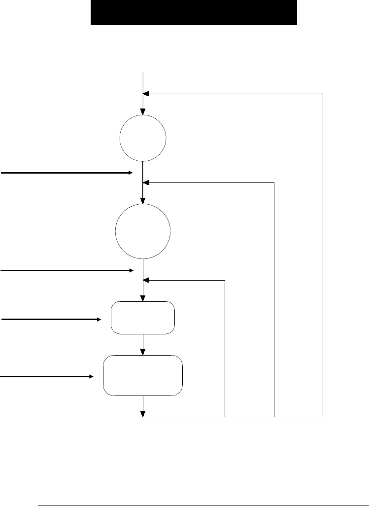
HP 34401A Triggering System
Delay
Idle
State
Wait-for-
Trigger
State
Measurement
Sample Sample
Count ≠ 1 Trigger
Count ≠ 1
Initiate Triggering
MEASure?
READ?
INITiate
Trigger Source
TRIGger:SOURce IMMediate
TRIGger:SOURce EXTernal
TRIGger:SOURce BUS
Front-panel “Single” key
Trigger Delay
TRIGger:DELay
Sample ( * )
Annunciator
Chapter 4 Remote Interface Reference
Triggering
128

The Wait-for-Trigger State
After you have configured the multimeter and selected a trigger source,
you must place the multimeter in the wait-for-trigger state. A trigger
will not be accepted until the multimeter is in this state. If a trigger
signal is present, and if multimeter is in the “wait-for-trigger” state,
the measurement sequence begins and readings are taken.
The “wait-for-trigger” state is a term used primarily for remote interface
operation. From the front panel, the multimeter is always in the “wait-
for-trigger” state and will accept triggers at any time, unless a
measurement is already in progress.
You can place the multimeter in “wait-for-trigger” state by executing
any of the following commands from the remote interface.
MEASure?
READ?
INITiate
The multimeter requires approximately 20 ms of set-up time after you
send a command to change to the “wait-for-trigger” state. Any external
triggers that occur during this set-up time are ignored.
4
Chapter 4 Remote Interface Reference
Triggering
129

Triggering Commands
See also “Triggering,” starting on page 71 in chapter 3.
INITiate
Change the state of the triggering system from the “idle” state to the
“wait-for-trigger” state. Measurements will begin when the specified
trigger conditions are satisfied after the INITiate command is
received. The readings are placed in the multimeter’s internal memory
(up to 512 readings can be stored). Readings are stored in memory until
you are able to retrieve them. Use the FETCh? command to retrieve
reading results.
A new command is available starting with firmware Revision 2 which
allows you to take readings using INITiate without storing them in
internal memory. This command may be useful with the min-max
operation since it allows you to determine the average of a series of
readings without storing the individual values.
DATA:FEED RDG_STORE, "" do not store readings
DATA:FEED RDG_STORE, "CALCulate" store readings (default)
See page 126 for more information on using the DATA:FEED command.
READ?
Change the state of the trigger system from the “idle” state to the
“wait-for-trigger” state. Measurements will begin when the specified
trigger conditions are satisfied following the receipt of the READ?
command. Readings are sent immediately to the output buffer.
TRIGger:SOURce {BUS|IMMediate|EXTernal}
Select the source from which the multimeter will accept a trigger.
The multimeter will accept a software (bus) trigger, an immediate
internal trigger (this is the default source), or a hardware trigger from the
rear-panel Ext Trig (external trigger) terminal. [Stored in volatile memory]
TRIGger:SOURce?
Query the present trigger source. Returns “BUS”, “IMM”, or “EXT”.
Chapter 4 Remote Interface Reference
Triggering Commands
130

TRIGger:DELay {<seconds>|MINimum|MAXimum}
Insert a trigger delay between the trigger signal and each sample that follows.
If you do not specify a trigger delay, the multimeter automatically selects a
delay for you. Select from 0 to 3600 seconds. MIN = 0 seconds. MAX = 3600
seconds. [Stored in volatile memory]
TRIGger:DELay? [MINimum|MAXimum]
Query the trigger delay.
TRIGger:DELay:AUTO {OFF|ON}
Disable or enable an automatic trigger delay. The delay is determined
by function, range, integration time, and ac filter setting. Selecting a
specific trigger delay value automatically turns off the automatic trigger
delay. [Stored in volatile memory]
TRIGger:DELay:AUTO?
Query the automatic trigger delay setting. Returns “0” (OFF) or “1” (ON).
SAMPle:COUNt {<value>|MINimum|MAXimum}
Set the number of readings (samples) the multimeter takes per trigger. Select
from 1 to 50,000 readings per trigger. MIN = 1. MAX = 50,000. [Stored in
volatile memory]
SAMPle:COUNt? [MINimum|MAXimum]
Query the sample count.
TRIGger:COUNt {<value>|MINimum|MAXimum|INFinite}
Set the number of triggers the multimeter will accept before returning to the
“idle” state. Select from 1 to 50,000 triggers. The INFinite parameter instructs
the multimeter to continuously accept triggers (you must send a device clear to
return to the “idle” state). Trigger count is ignored while in local operation.
MIN = 1. MAX = 50,000. [Stored in volatile memory]
TRIGger:COUNt? [MINimum|MAXimum]
Query the trigger count. If you specify an infinite trigger count,
the query command returns “9.90000000E+37”.
4
Chapter 4 Remote Interface Reference
Triggering Commands
131

System-Related Commands
See also “System-Related Operations,” starting on page 84 in chapter 3.
FETCh?
Transfer readings stored in the multimeter’s internal memory by the
INITiate command to the multimeter’s output buffer where you can
read them into your bus controller.
READ?
Change the state of the trigger system from the “idle” state to the
“wait-for-trigger” state. Measurements will begin when the specified
trigger conditions are satisfied following the receipt of the READ?
command. Readings are sent immediately to the output buffer.
DISPlay {OFF|ON}
Turn the front-panel display off or on. [Stored in volatile memory]
DISPlay?
Query the front-panel display setting. Returns “0” (OFF) or “1” (ON).
DISPlay:TEXT <quoted string
>
Display a message on the front panel. The multimeter will display up to 12
characters in a message; any additional characters are truncated.
[Stored in volatile memory]
DISPlay:TEXT?
Query the message sent to the front panel and return a quoted string.
DISPlay:TEXT:CLEar
Clear the message displayed on the front panel.
Chapter 4 Remote Interface Reference
System-Related Commands
132

SYSTem:BEEPer
Issue a single beep immediately.
SYSTem:BEEPer:STATe {OFF|ON}
Disable or enable the front-panel beeper. [Stored in non-volatile memory]
When you disable the beeper, the multimeter will not emit a tone when:
1) a new minimum or maximum is found in a min–max test.
2) a stable reading is captured in reading hold.
3) a limit is exceeded in a limit test.
4) a forward-biased diode is measured in the diode test function.
SYSTem:BEEPer:STATe?
Query the state of the front-panel beeper. Returns “0” (OFF) or “1” (ON).
SYSTem:ERRor?
Query the multimeter’s error queue. Up to 20 errors can be stored in the
queue. Errors are retrieved in first-in-first out (FIFO) order. Each error
string may contain up to 80 characters.
SYSTem:VERSion?
Query the multimeter to determine the present SCPI version.
DATA:POINts?
Query the number of readings stored in the multimeter’s internal memory.
*RST
Reset the multimeter to its power-on configuration.
*TST?
Perform a complete self-test of the multimeter. Returns “0” if the
self-test is successful, or “1” if it test fails.
*IDN?
Read the multimeter’s identification string (be sure to dimension a
string variable with at least 35 characters).
4
Chapter 4 Remote Interface Reference
System-Related Commands
133
