COMSPHERE 3600 Series Data Service Units S 3610 And 3611 Time Division Multiplexer, Multichannel, Multipoint, Digital B A2 GB48 70
3610-A2-GB48-70 3610-A2-GB48-70
User Manual: 3610-A2-GB48-70
Open the PDF directly: View PDF ![]() .
.
Page Count: 74

COMSPHERE
3600 SERIES
DATA SERVICE UNITS
MODELS 3610 AND 3611
TIME DIVISION MULTIPLEXER,
MULTICHANNEL MULTIPOINT, AND
DIGITAL BRIDGE OPTIONS SUPPLEMENT
Document No. 3610-A2-GB48-70
March 1999

COMSPHERE 3600 Series Data Service Units
AMarch 1999 3610-A2-GB48-70
COMSPHERE
3600 Series Data Service Units
Models 3610 and 3611
Time Division Multiplexer, Multichannel Multipoint, and Digital Bridge Options
Supplement
3610-A2-GB48-70
8th Edition (March 1999)
Changes and enhancements to the product and to the information herein will be documented and issued as a new release.
Warranty, Sales, Service, and Training Information
Contact your local sales representative, service representative, or distributor directly for any help needed. For additional information
concerning warranty, sales, service, repair, installation, documentation, training, distributor locations, or Paradyne worldwide office
locations, use one of the following methods:
•Internet: Visit the Paradyne World Wide Web site at www.paradyne.com. (Be sure to register your warranty there. Select
Service & Support → Warranty Registration.)
•Telephone: Call our automated system to receive current information by fax or to speak with a company representative.
— Within the U.S.A., call 1-800-870-2221
— Outside the U.S.A., call 1-727-530-2340
Document Feedback
We welcome your comments and suggestions about this document. Please mail them to Technical Publications, Paradyne Corporation,
8545 126th Ave. N., Largo, FL 33773, or send e-mail to userdoc@paradyne.com. Include the number and title of this document in
your correspondence. Please include your name and phone number if you are willing to provide additional clarification.
Trademarks
All products and services mentioned herein are the trademarks, service marks, registered trademarks or registered service marks of their
respective owners.
COPYRIGHT 1999 Paradyne Corporation. All rights reserved.
This publication is protected by federal copyright law. No part of this publication may be copied or distributed, transmitted, transcribed, stored in a retrieval system,
or translated into any human or computer language in any form or by any means, electronic, mechanical, magnetic, manual or otherwise, or disclosed to third parties
without the express written permission of Paradyne Corporation, 8545 126th Avenue North, P.O. Box 2826, Largo, Florida 33779-2826.
Paradyne Corporation makes no representation or warranties with respect to the contents hereof and specifically disclaims any implied warranties of merchantability
or fitness for a particular purpose. Further, Paradyne Corporation reserves the right to revise this publication and to make changes from time to time in the contents
hereof without obligation of Paradyne Corporation to notify any person of such revision or changes.
Printed on recycled paper

i3610-A2-GB48-70 March 1999
Table of Contents
Preface
About This Supplement iii. . . . . . . . . . . . . . . . . . . . . . . . . . . . . . . . . . .
How to Use This Supplement iii. . . . . . . . . . . . . . . . . . . . . . . . . . . . . .
Product-Related Documents iii. . . . . . . . . . . . . . . . . . . . . . . . . . . . . . .
1. Product Introduction
TDM/MCMP Common Capabilities 1-1. . . . . . . . . . . . . . . . . . . . . . . . .
TDM Capability 1-2. . . . . . . . . . . . . . . . . . . . . . . . . . . . . . . . . . . . . . . . .
MCMP Capability 1-3. . . . . . . . . . . . . . . . . . . . . . . . . . . . . . . . . . . . . . .
DSU with Digital Bridge Capability 1-3. . . . . . . . . . . . . . . . . . . . . . . . .
LPDA-2 with TDM or MCMP 1-3. . . . . . . . . . . . . . . . . . . . . . . . . . . . .
2. TDM/MCMP Installation and Setup
Before You Begin 2-1. . . . . . . . . . . . . . . . . . . . . . . . . . . . . . . . . . . . . . . .
Installing the DSU 2-1. . . . . . . . . . . . . . . . . . . . . . . . . . . . . . . . . . . . . . .
Hardware Settings 2-1. . . . . . . . . . . . . . . . . . . . . . . . . . . . . . . . . . . . . . .
Opening the DSU 2-2. . . . . . . . . . . . . . . . . . . . . . . . . . . . . . . . . . . . . . . .
Separating the DSU from the TDM or MCMP 2-3. . . . . . . . . . . . . . .
Changing the DSD Option Card Setting 2-4. . . . . . . . . . . . . . . . . . . .
Reassembling the DSU 2-4. . . . . . . . . . . . . . . . . . . . . . . . . . . . . . . . .
Powering Up the DSU 2-4. . . . . . . . . . . . . . . . . . . . . . . . . . . . . . . . . . . .
Power-Up Routine 2-5. . . . . . . . . . . . . . . . . . . . . . . . . . . . . . . . . . . . .
DTE Connections 2-5. . . . . . . . . . . . . . . . . . . . . . . . . . . . . . . . . . . . . . . .
Reconfiguring Ports 2-5. . . . . . . . . . . . . . . . . . . . . . . . . . . . . . . . . . .
Network Verification Testing 2-6. . . . . . . . . . . . . . . . . . . . . . . . . . . . . . .

COMSPHERE 3600 Series Data Service Units
ii March 1999 3610-A2-GB48-70
3. Front Panel Operation
Overview 3-1. . . . . . . . . . . . . . . . . . . . . . . . . . . . . . . . . . . . . . . . . . . . . .
Front Panels 3-2. . . . . . . . . . . . . . . . . . . . . . . . . . . . . . . . . . . . . . . . . . . .
Status Indicators 3-2. . . . . . . . . . . . . . . . . . . . . . . . . . . . . . . . . . . . . . . . .
Menu Structure 3-3. . . . . . . . . . . . . . . . . . . . . . . . . . . . . . . . . . . . . . . . . .
Menus and Modes of Operation 3-3. . . . . . . . . . . . . . . . . . . . . . . . . .
Local/Remote Branch Menus 3-3. . . . . . . . . . . . . . . . . . . . . . . . . . . .
Status Branch 3-4. . . . . . . . . . . . . . . . . . . . . . . . . . . . . . . . . . . . . . . . . . .
Health and Status 3-4. . . . . . . . . . . . . . . . . . . . . . . . . . . . . . . . . . . . . .
DTE Status 3-4. . . . . . . . . . . . . . . . . . . . . . . . . . . . . . . . . . . . . . . . . .
Circuit Quality 3-5. . . . . . . . . . . . . . . . . . . . . . . . . . . . . . . . . . . . . . . .
Identity 3-5. . . . . . . . . . . . . . . . . . . . . . . . . . . . . . . . . . . . . . . . . . . . .
Terminal Power 3-5. . . . . . . . . . . . . . . . . . . . . . . . . . . . . . . . . . . . . . .
Backup Branch 3-5. . . . . . . . . . . . . . . . . . . . . . . . . . . . . . . . . . . . . . . . . .
Digital Bridging 3-5. . . . . . . . . . . . . . . . . . . . . . . . . . . . . . . . . . . . . .
Test Branch 3-6. . . . . . . . . . . . . . . . . . . . . . . . . . . . . . . . . . . . . . . . . . . .
Abort 3-6. . . . . . . . . . . . . . . . . . . . . . . . . . . . . . . . . . . . . . . . . . . . . . .
Device Test 3-7. . . . . . . . . . . . . . . . . . . . . . . . . . . . . . . . . . . . . . . . . .
Loopbacks 3-7. . . . . . . . . . . . . . . . . . . . . . . . . . . . . . . . . . . . . . . . . . .
Digital Test 3-8. . . . . . . . . . . . . . . . . . . . . . . . . . . . . . . . . . . . . . . . . .
End-to-End Test 3-8. . . . . . . . . . . . . . . . . . . . . . . . . . . . . . . . . . . . . .
Bit Error Rate Test 3-8. . . . . . . . . . . . . . . . . . . . . . . . . . . . . . . . . . . .
Dial Tone Test 3-8. . . . . . . . . . . . . . . . . . . . . . . . . . . . . . . . . . . . . . . .
Configuration Branch 3-8. . . . . . . . . . . . . . . . . . . . . . . . . . . . . . . . . . . . .
Options 3-9. . . . . . . . . . . . . . . . . . . . . . . . . . . . . . . . . . . . . . . . . . . . .
Poll List 3-9. . . . . . . . . . . . . . . . . . . . . . . . . . . . . . . . . . . . . . . . . . . . .
Menu 3-9. . . . . . . . . . . . . . . . . . . . . . . . . . . . . . . . . . . . . . . . . . . . . . .
Control Branch 3-10. . . . . . . . . . . . . . . . . . . . . . . . . . . . . . . . . . . . . . . . . .
Transmitter Control 3-10. . . . . . . . . . . . . . . . . . . . . . . . . . . . . . . . . . . .
LEDs 3-10. . . . . . . . . . . . . . . . . . . . . . . . . . . . . . . . . . . . . . . . . . . . . . .
External Leads 3-10. . . . . . . . . . . . . . . . . . . . . . . . . . . . . . . . . . . . . . . .
Reset 3-10. . . . . . . . . . . . . . . . . . . . . . . . . . . . . . . . . . . . . . . . . . . . . . .
Remote Mode 3-10. . . . . . . . . . . . . . . . . . . . . . . . . . . . . . . . . . . . . . . . . . .
4. Configuration Option Tables
Overview 4-1. . . . . . . . . . . . . . . . . . . . . . . . . . . . . . . . . . . . . . . . . . . . . .
Configuration Option Tables 4-1. . . . . . . . . . . . . . . . . . . . . . . . . . . . . . .
Configuration Option Tables Format 4-2. . . . . . . . . . . . . . . . . . . . . .
TDM Mode 4-2. . . . . . . . . . . . . . . . . . . . . . . . . . . . . . . . . . . . . . . . . .
Appendices
A. Data Service Unit Menu A-1. . . . . . . . . . . . . . . . . . . . . . . . . . . . . . .
B. Configuration Worksheets B-1. . . . . . . . . . . . . . . . . . . . . . . . . . . . .
C. Configuration Examples C-1. . . . . . . . . . . . . . . . . . . . . . . . . . . . . .
D. Troubleshooting and Front Panel Messages D-1. . . . . . . . . . . . . . .
E. Technical Specifications E-1. . . . . . . . . . . . . . . . . . . . . . . . . . . . . .
Index

iii3610-A2-GB48-70 March 1999
Preface
About This Supplement
This supplement provides basic information to get you
started using your COMSPHERE 3600 Series Data
Service Unit (DSU) with a Time Division
Multiplexer (TDM) or Multichannel Multipoint (MCMP)
option installed. The supplement also provides a summary
of TDM and MCMP capabilities, along with the unit’s
capabilities when it operates as a digital bridge.
It is assumed that you are familiar with the functional
operation of data communications equipment.
How to Use This Supplement
Chapter 1 provides a general overview of the TDM,
MCMP, and digital bridge capabilities for the
3600 Series DSU.
Chapter 2 explains the set up of your Model 3610 DSU
with TDM or MCMP circuit card. To install a Model 3611
DSU with TDM or MCMP, refer to the COMSPHERE
3000 Series Carrier, Installation Manual.
Chapter 3 provides an overview of the front panel with
TDM or MCMP and the DSU’s status indicators.
Chapter 4 provides the basics of setting or changing
configuration options for TDM, MCMP, and digital
bridging. The configuration option tables supplement the
DSU tables in the User’s Guide and the DBM tables in the
DBM Options Supplement.
Appendix A provides MUX factory default
configuration options and the DSU’s menu structure.
Refer to the menu tree as you proceed through the menu
from the front panel or SDCP if you have a Model 3611
DSU.
Appendix B provides MUX configuration worksheets
to use during planning.
Appendix C contains TDM, MCMP, and digital bridge
sample configurations.
Appendix D provides troubleshooting and a list of
MUX configuration error messages that may appear on
the front panel.
Appendix E contains technical specifications.
Refer to the User’s Guide for an extensive Glossary
and list of acronyms.
Product-Related Documents
For additional 3600 Series features, refer to the:
•COMSPHERE 3600 Series Data Service Units,
Models 3610 and 3611, User’s Guide, for basic
Data Service Unit (DSU) information and a
product-related documentation table: Document
No. 3610-A2-GB46.
•COMSPHERE 3600 Series Data Service Units,
Models 3610 and 3611, Dial Backup Module
Options Supplement for the DBM features:
Document No. 3610-A2-GB49.
•COMSPHERE 3000 Series Carrier, Installation
Manual: Document No. 3000-A2-GA31.
Contact your sales or service representative to order
additional product documentation.
Paradyne documents are also available on the World
Wide Web at www.paradyne.com. Select Library →
Technical Manuals.

COMSPHERE 3600 Series Data Service Units
iv March 1999 3610-A2-GB48-70
This page intentionally left blank.

1-13610-A2-GB48-70 March 1999
Product Introduction
TDM/MCMP Common Capabilities 1-1. . . . . . . . . . . . . . . . . . . . . . . . . . . . . . . . . . . . . . . . . . . . . . . . . . . . .
TDM Capability 1-2. . . . . . . . . . . . . . . . . . . . . . . . . . . . . . . . . . . . . . . . . . . . . . . . . . . . . . . . . . . . . . . . . . . .
MCMP Capability 1-3. . . . . . . . . . . . . . . . . . . . . . . . . . . . . . . . . . . . . . . . . . . . . . . . . . . . . . . . . . . . . . . . . . .
DSU with Digital Bridge Capability 1-3. . . . . . . . . . . . . . . . . . . . . . . . . . . . . . . . . . . . . . . . . . . . . . . . . . . . .
LPDA-2 with TDM or MCMP 1-3. . . . . . . . . . . . . . . . . . . . . . . . . . . . . . . . . . . . . . . . . . . . . . . . . . . . . . . . .
TDM/MCMP Common
Capabilities
The TDM/MCMP option is an additional circuit card.
TDM capability allows up to six independent ports to
share one standard digital point-to-point facility. MCMP
capability allows up to six ports to share one standard
56 kbps multipoint facility.
The TDM option can be software-defined to provide
one of the following:
•TDM
•Digital bridge capability
The MCMP option can be software-defined to provide
one of the following:
•MCMP
•TDM
•Digital bridge capability
Common features are:
•Async/Sync conversion: Provides point-to-point
and multipoint asynchronous-to-synchronous data
conversion for DTE ports for both EIA-232 and
V.35. The DSU can send asynchronous data over a
synchronous network.
•FEP port sharing: Provides a method of
connecting a front-end processor (FEP) to two
consecutive ports to broadcast the same message
over the network and the shared ports. Up to three
separate FEP port-sharing groups can be selected.
Each group consists of two adjacent ports (1 and 2,
3 and 4, 5 and 6).
•Elastic store per port: Provides a transmit elastic
store buffer for each port to support extended
circuits. Supports both digital and analog
extensions.
•Switched-carrier emulation: Provides optional
switched-carrier emulation for each port for both
inbound (toward the control DSU) and outbound
(toward the tributary DSU) directions.
1

COMSPHERE 3600 Series Data Service Units
1-2 March 1999 3610-A2-GB48-70
TDM Capability
TDM capability allows up to six independent ports to
share one standard digital point-to-point facility.
Additional TDM capability includes the following
features:
•Flex option: There are two versions of the
TDM/Flex standalone model:
— 2-port TDM/Flex
— 6-port TDM/Flex
With either flex option installed, each port can be
set independently as either an EIA-232 or V.35
interface.
•Port capacity: Model 3610 provides:
— Up to six EIA-232 or V.35 ports with DSD or
Flex models
— An EIA-232 or V.35 Port 1 option and five
EIA-232 ports for the Standard model
Model 3611 uses the Standard model and a six-port
DTE connector module. The connector module
includes six 25-pin DTE connectors and a 26-pin
high-density connector for the V.35 alternate Port 1
option. Model 3611 does not have V.35 for
Ports 2–6.
•Port speeds: Individual TDM ports (1 through 6)
can be set to a variety of speeds. The sum of the
port speeds cannot exceed the DSU data rate.
•Digital sharing: Allows two groups of consecutive
ports to share the same TDM channel. All ports in a
digital-sharing group operate at the same speed and
receive the same data.
•Data rates: Operates up to 64 kbps full-duplex.
•Primary network interface: The alternate Port 1
on the DSU provides an internal aggregate data
stream. When the Network Interface configuration
option is set to forced on, the unused V.35 or
EIA-232 interface functions as an external TDM. A
connection can be made to any multiplexer or
DSU/CSU.
When the DSU powers up, data automatically
switches to the alternate Port 1. No DDS
connection is required. Any cluster controller
requiring subrate can be supported at a remote site.
Using the alternate Port 1 for the network interface
supports:
— DBM, TDM, and MCMP options
— Disruptive and Nondisruptive diagnostics
— Rate Adaption and In-Band Framing
— Aggregate data rates of 64, 56, 19.2, 9.6, 4.8,
and 2.4 kbps
•Digital bridge: Performs digital bridge functions
and supports many applications, including
dedicated multipoint dial backup and multipoint
LADS operation.
•Flexible device control: Provides the same
diagnostic capabilities as a point-to-point
3600 Series DSU without the TDM option. Allows
control of the TDM option from the front panel, an
async terminal, or a 6700 or 6800 Series NMS.
•Point-to-point backup: Allows a DSU with TDM
to have a DBM installed for point-to-point dial
backup. If backup is at a different port speed than
the DSU’s port speed, TDM operation
automatically changes to a second predefined port
speed to support dial backup operation at a lower
port speed.

Product Introduction
1-33610-A2-GB48-70 March 1999
MCMP Capability
MCMP capability allows up to six independent
application programs to share one standard 56 kbps
multipoint facility. MCMP capability provides the
following features:
•Channel capacity: Provides up to eight channels,
which can be matched to all enabled ports.
•Flex option: There are two versions of the
MCMP/Flex standalone model:
— 2-port MCMP/Flex
— 6-port MCMP/Flex
With either flex option installed, each port can be
set independently as either an EIA-232 or
V.35 interface.
•Port capacity: Model 3610 provides:
— Up to six EIA-232 or V.35 ports with DSD or
Flex models
— An EIA-232 or V.35 Port 1 option and five
EIA-232 ports for the Standard model
Model 3611 uses the Standard model and a six-port
DTE connector module. The connector module
includes six 25-pin DTE connectors and a 26-pin
high-density connector for the V.35 alternate Port 1
option and up to five EIA-232 ports. Model 3611
does not have V.35 for Ports 2–6.
•Digital sharing: Allows up to three digital-sharing
devices at each tributary by assigning channels to
more than one port. All ports operate at the same
speed and receive the same data.
MCMP capability allows digital sharing and
multiplexing simultaneously at any tributary site.
•Number of addressable devices: Supports up to
40 tributary DSUs or 20 tributary DSUs with
DBMs, each equipped with an MCMP circuit card.
•Channel speeds: Speeds of the individual channels
can be set to a variety of speeds. The sum of the
channel speeds cannot exceed 48 kbps.
•Multipoint dial backup: Provides multipoint
service restoration. When Network Interface
configuration option is set to AggSw, the DSU
provides an internal aggregate data stream for
diagnostics and framing on alternate Port 1. The
alternate Port 1 can be connected to an extended
bridge.
DSU with Digital Bridge
Capability
Digital bridging is used primarily for dedicated
multipoint dial backup. A digital data service (DDS)
multipoint network can be backed up with:
•V.32 analog DBM
•Switched 56 kbps calls between the central-site and
remote-site DBMs that are connected by the digital
bridge
•ISDN (Integrated Services Digital Network)
The digital bridge capability is dedicated to a single
DSU. The DTE connected to the DSU is usually the
controlling DTE of a multipoint network. Configure either
the TDM or MCMP option to provide the digital bridge
capability.
The digital bridge capability, when used to support
dedicated multipoint dial backup, includes the following
features:
•Number of tributaries: Provides dedicated
multipoint dial backup for up to 20 tributary DSUs.
Four additional DSUs with TDMs are required for
each configured extended bridge (EBrdg).
•Partial and full backup: Provides multipoint dial
backup for both partial and full backup on DDS
multipoint circuits, depending on configuration.
•Security: DBMs provide multiple levels of call
setup security.
•Restoration: When the DSU rate equals the DBM
rate, preconfigured tributary DSUs can
automatically drop the backup connection and
switch back to the DDS facility when the DDS
network is restored.
LPDA-2 with TDM or MCMP
The SNA Diagnostic Interface uses the Release 2 Link
Problem Determination Aid (LPDA-2) protocol. The
LPDA-2 protocol is installed on the DSU circuit card.
When enabled:
•With TDM or MCMP, LPDA-2 is only supported
on Port 1.
•For digital sharing, all ports are supported.

COMSPHERE 3600 Series Data Service Units
1-4 March 1999 3610-A2-GB48-70
This page intentionally left blank.

2-13610-A2-GB48-70 March 1999
TDM/MCMP Installation and Setup
Before You Begin 2-1. . . . . . . . . . . . . . . . . . . . . . . . . . . . . . . . . . . . . . . . . . . . . . . . . . . . . . . . . . . . . . . . . . .
Installing the DSU 2-1. . . . . . . . . . . . . . . . . . . . . . . . . . . . . . . . . . . . . . . . . . . . . . . . . . . . . . . . . . . . . . . . . . .
Hardware Settings 2-1. . . . . . . . . . . . . . . . . . . . . . . . . . . . . . . . . . . . . . . . . . . . . . . . . . . . . . . . . . . . . . . . . . .
Opening the DSU 2-2. . . . . . . . . . . . . . . . . . . . . . . . . . . . . . . . . . . . . . . . . . . . . . . . . . . . . . . . . . . . . . . . . . .
Separating the DSU from the TDM or MCMP 2-3. . . . . . . . . . . . . . . . . . . . . . . . . . . . . . . . . . . . . . . . . .
Changing the DSD Option Card Setting 2-4. . . . . . . . . . . . . . . . . . . . . . . . . . . . . . . . . . . . . . . . . . . . . . .
Reassembling the DSU 2-4. . . . . . . . . . . . . . . . . . . . . . . . . . . . . . . . . . . . . . . . . . . . . . . . . . . . . . . . . . . .
Powering Up the DSU 2-4. . . . . . . . . . . . . . . . . . . . . . . . . . . . . . . . . . . . . . . . . . . . . . . . . . . . . . . . . . . . . . .
Power-Up Routine 2-5. . . . . . . . . . . . . . . . . . . . . . . . . . . . . . . . . . . . . . . . . . . . . . . . . . . . . . . . . . . . . . . .
DTE Connections 2-5. . . . . . . . . . . . . . . . . . . . . . . . . . . . . . . . . . . . . . . . . . . . . . . . . . . . . . . . . . . . . . . . . . .
Reconfiguring Ports 2-5. . . . . . . . . . . . . . . . . . . . . . . . . . . . . . . . . . . . . . . . . . . . . . . . . . . . . . . . . . . . . . .
Network Verification Testing 2-6. . . . . . . . . . . . . . . . . . . . . . . . . . . . . . . . . . . . . . . . . . . . . . . . . . . . . . . . . .
Before You Begin
The Model 3610 DSU with the TDM or MCMP option
is delivered with default hardware settings, factory default
configuration option settings, and factory-installed
software.
Please note the following:
•Port 1 of the DSU is preconfigured to operate with
the TDM or MCMP capability enabled. The DSU
includes the factory default configuration option
settings for FacT with some defaults based on
hardware. Refer to Table A-1 for MUX
configuration option default settings.
•For the Model 3610, all additional ports are
disabled and preconfigured for EIA-232 port
interface operation. Each port configured for V.35
needs an adapter (feature number 3000-F1-510).
•Once a DSD model is powered up, you can verify
the port interface switch setting through the right
side of the back panel.
— If set for EIA-232, you will see a green light.
— If set for V.35, you will see a yellow light.
Installing the DSU
The Model 3610 DSU is designed for desktop
operation.
•Place the DSU in the planned location.
•Allow 1 to 2 feet of clearance for cable
connections, space for the ventilation slots on the
sides, and clearance at the rear for the cable
connections.
Hardware Settings
HANDLING PRECAUTIONS
FOR
STATIC-SENSITIVE DEVICES
This product is designed to
protect sensitive components
from damage due to electrostatic
discharge (ESD) during normal
operation. When performing
installation procedures, however,
take proper static control
precautions to prevent damage to
equipment. If you are not sure of
the proper static control
precautions, contact your nearest
sales or service representative.
2
COMSPHERE 3600 Series Data Service Units
2-2 March 1999 3610-A2-GB48-70
TDM/Flex and MCMP/Flex models are available with
two or six ports. When your firmware version is 6.33 or
greater, each port can be set individually for either
EIA-232 or V.35 using the front panel, an async terminal,
or an NMS.
Based on your model, you may need to perform one of
following procedures. Use ID from the Status branch to
obtain the firmware version.
If your
model is a
6-port . . .
And the
EIA232
setting . . . Then . . .
TDM/Flex or
MCMP/Flex
Is correct Go to the
Powering Up the
DSU
section, page 2-4.
MCMP/Flex
with firmware
6.33 or
greater
Needs to be
changed Go to the
Powering Up the
DSU
section, page 2-4
and the
Reconfiguring
Ports
section, page 2-5.
TDM/Flex or
Is correct Go to the
Powering Up the
DSU
section, page 2-4.
TDM/Flex
or
MCMP/Flex
with firmware
less than
6.33
Needs to be
changed Change the S1 switch
setting on the TDM/Flex or
MCMP/Flex circuit card to
ON for V.35 or Off for
EIA-232.
Is correct Go to the
Powering Up the
DSU
section, page 2-4.
TDM/DSD or
MCMP/DSD Needs to be
changed Change the option card to
set all six ports; start with
next section,
Opening the
DSU
.
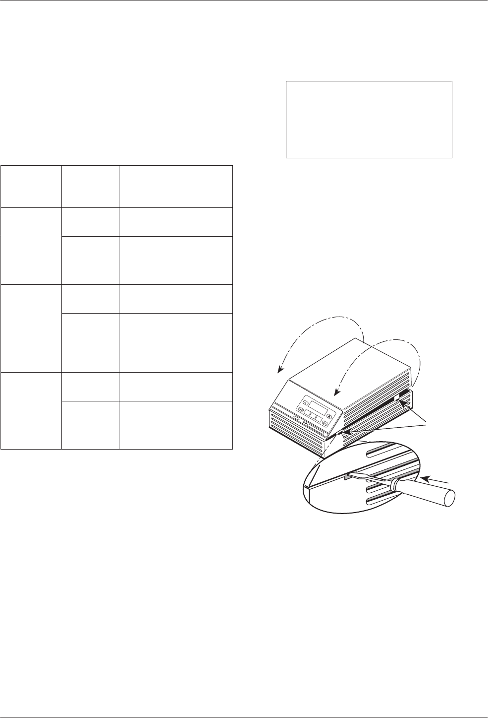
Opening the DSU
NOTE
If the unit is already installed,
disconnect all cables, including
the power source, before
opening the DSU.
Follow this section to change a TDM/DSD or
MCMP/DSD model from:
•EIA-232 interface to V.35 interface, or
•V.35 interface to EIA-232 interface
Use a small flat-head screwdriver to release the four
snap tabs holding the base in place. Remove the cover. Do
not allow any cables to pull free from the inside front
panel connectors.
496-14707-01
With TDM
or MCMP
Snap Tabs
COMSPHERE 3610
TDM/MCMP Installation and Setup
2-33610-A2-GB48-70 March 1999
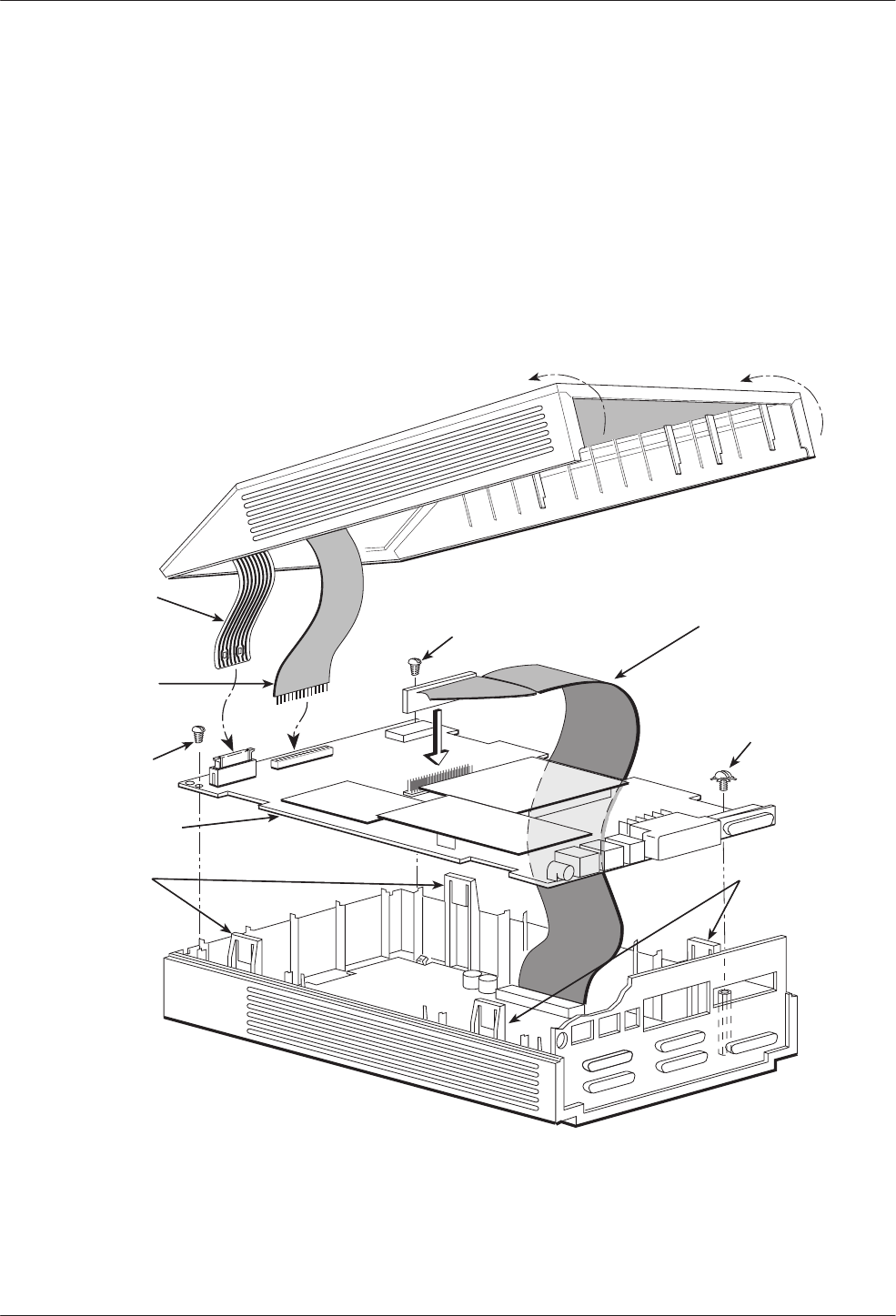
Separating the DSU from the TDM or MCMP
Follow this procedure to separate the DSU circuit card
from the TDM or MCMP (refer to Figure 2-1).
"Procedure
1. Disconnect the keypad flat cable from the DSU
circuit card by squeezing the latches on each side
of the cable connection and pulling up on the
keypad flat cable.
2. Disconnect the LCD flat cable by working the
cable free of the connector.
3. Disconnect the TDM or MCMP flat cable.
4. Unscrew the three screws holding the DSU circuit
card in place.
5. Lift the DSU circuit card from the base and set
aside.
LCD
Flat
Cable
Keypad
Flat
Cable
DSU
Circuit Card
Expanded
Base
Snap
Tabs
TDM or MCMP
Flat Cable
Screw
495-13846c
Snap
Tabs
Screw
Screw
Figure 2-1. Disassembling a TDM or MCMP DSU
COMSPHERE 3600 Series Data Service Units
2-4 March 1999 3610-A2-GB48-70
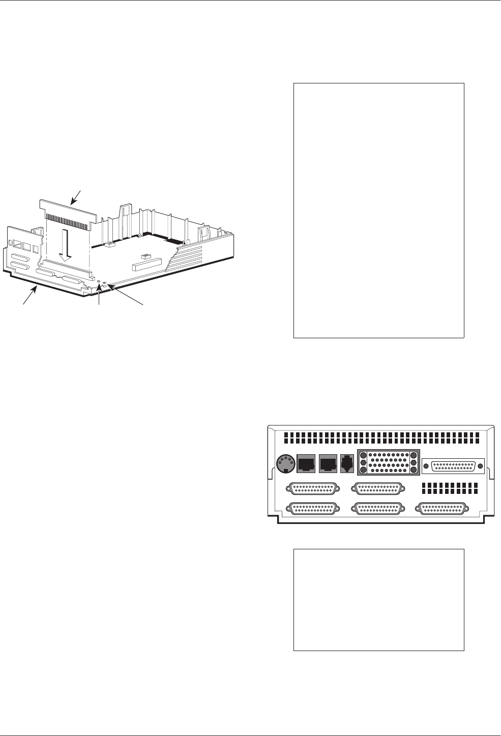
Changing the DSD Option Card Setting
For the TDM/DSD or MCMP/DSD model, use the
following procedure to change the setting from EIA-232
to V.35 or from V.35 to EIA-232.
"Procedure
1. Work the option card free of its connector.
Option
Card
Rear
Panel LED 2
(Yellow
V.35)
LED 1
(Green
EIA-232)
496-13845-03
THIS SIDE FACES REAR FOR V.35
S1
S2
2. Turn the card around and re-insert. In the example
above, the card reads THIS SIDE FACES REAR
FOR V.35.
3. Continue with next section, Reassembling the
DSU.
Reassembling the DSU
"Procedure
1. Reinstall the DSU circuit card, using the three
screws.
2. Reconnect the three flat cables:
— TDM/MCMP
— Keypad
— LCD
3. Align the rear panel and four snap tabs. Replace
the cover over the expanded base, allowing the
four tabs to snap into place.
Powering Up the DSU
CAUTION
The power cord contains a
3-wire grounding-type plug
which has a grounding pin.
This is a safety feature.
Grounding of the unit is vital
to ensure safe operation. Do
not defeat the purpose of the
grounding plug by modifying
it or by using an adapter.
Prior to installation, use an
outlet tester or voltmeter to
check the ac receptacle for
earth ground. If the power
source does not provide a
ground connection, consult
an electrician to determine
another method of grounding
the unit before proceeding
with the installation.
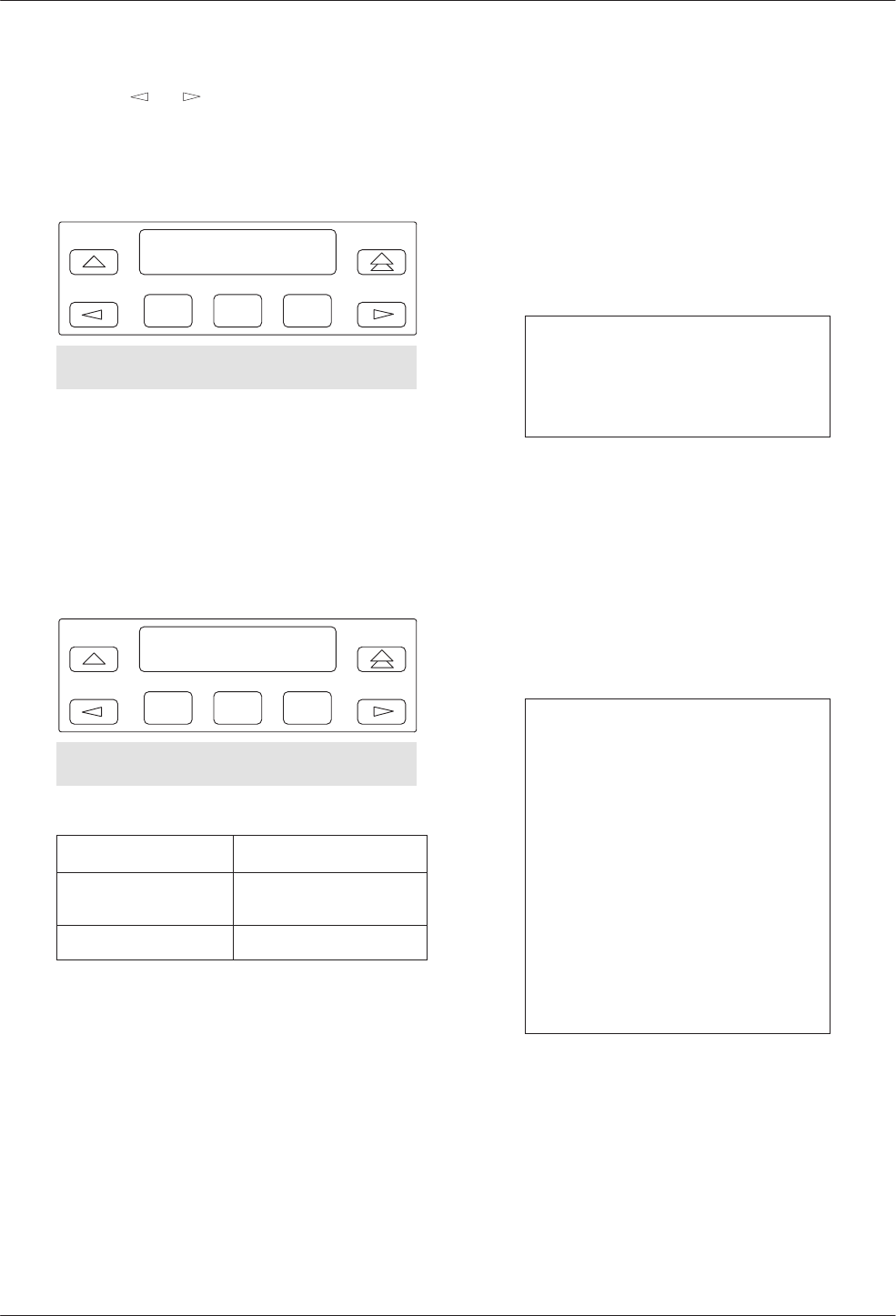
"Procedure
1. At the rear of the DSU, insert the small end of the
power cable into the receptacle labeled POWER.
495-14710
PORT 5 PORT 3
PORT 6 PORT 4 PORT 2
POWER LINE BACKUP CC/DC EIA 232
V.35
CAUTION
Only use the power
transformer designed for the
Model 3610 DSU. Using other
transformers may result in
personal injury or damage to
the equipment.
2. Connect the 3-prong plug at the other end of the
cable to an ac outlet.

TDM/MCMP Installation and Setup
2-53610-A2-GB48-70 March 1999
Power-Up Routine
When you apply power the first time, the DSU
performs a power-up routine and:
•Determines what hardware options are installed.
This may include MUX to represent TDM or
MCMP.
•Automatically runs a Device Test on the DSU and
each installed hardware option. All front panel
lights flash on and off.
•If a TDM or MCMP is installed, MUX appears as
Pass or Fail on the LCD.
Refer to your User’s Guide for power-up messages and
steps for saving and changing configuration options. Refer
to Table D-1 for Configuration Error messages.
If a Fail message appears or an installed hardware
option does not appear, see Appendix D, Troubleshooting
and Front Panel Messages. Refer to Document No.
3610-A2-GB46 for DSU troubleshooting and Document
No. 3610-A2-GB49 for DBM troubleshooting.
DTE Connections
Make the DTE connections as described in the User’s
Guide, Document No. 3610-A2-GB46.
In a TDM or MCMP application, all ports default to
EIA-232 port interface operation. For MCMP/TDM Flex,
Ports 1 through 6 can be set individually to EIA-232 or
V.35 by using the MUX port configuration options.
For an EIA-232 connection with distances greater than
50 feet or data rates higher than 19.2 kbps, use short, high
quality cable with low capacitance and a DTE capable of
supporting the distance and data rate.
When Port 1 requires a speed higher than 19.2 kbps, it
is recommended that the port interface be set to V.35. An
adapter is required for every port (2 through 6) that is set
to V.35 interface.
Reconfiguring Ports
If you have a MCMP/TDM Flex with a firmware
version 6.33 or greater, you can configure each port for
either EIA-232 or V.35 interface compatibility from the
front panel, an async terminal, or an NMS.
To set a port for EIA-232 or V.35 operation:
"Procedure
1. From the Home screen, select Local (F1). The
following screen appears on the LCD.
F1
Local Mode:
Stat Bckup Test
F2 F3
Confg Ctrl
2. Press the key until Confg appears.
3. Select Confg (Configuration branch). The
Configure screen appears.
4. Select Opts. The Load from screen appears.
5. Select Activ (F1). The Edit/Save screen appears.
F1
Edit/Save:
SAVE DSU Diag
F2 F3
DBM Gen Bkup MUX PrtSp
LPDA
COMSPHERE 3600 Series Data Service Units
2-6 March 1999 3610-A2-GB48-70
6. Press the or key to scroll the MUX option
set into view.
7. Press the function key directly below MUX. The
Change MUX Opts screen appears.
F1
Change MUX Opts:
Copy Setup Prt1
F2 F3
Prt2 Prt3 Prt4 Prt5 Prt6
8. Select a port:
•Any of the installed ports, Prt1 through Prt6,
for a 6-port MCMP/TDM Flex
•Prt1 or Prt2 for a 2-port MCMP/TDM Flex
9. Press Next or Prev and select EIA232 or V.35.
F1
DTE Port: EIA232
Next EIA232 V.35
F2 F3
Prev
If you are . . . Then return to . . .
Selecting another port Change MUX Opts,
Step 7.
Finished The Edit/Save screen.
10. Select SAVE.
Network Verification Testing
Perform verification testing after any installation.
"Procedure
1. Request a device Identity report from each
tributary to ensure that the DSU is addressed
properly (ID from the Status branch).
NOTE
The Model 3610 is delivered
with its network address set to
254.
2. Perform a Digital Test on the DDS circuit to
ensure that the network is functioning (DT from
the Test branch).
Perform a Digital Test on each:
— Active port when MUX Funct is set to TDM
— Tributary DSU when MUX Funct is set to
MCMP
NOTE
A
control DSU
can originate a
Digital Test in a point-to-point or
multipoint network. Use Position
in the Diagnostic General
configuration option table to set
a unit to Cntrl.
A
tributary DSU
can originate a
Digital Test in a point-to-point
network only, provided the
configuration option Respond to
Remote Digital Loopback
(RespondRDL) is enabled in the
control.
For additional verification steps, refer to Appendix D,
Troubleshooting and Front Panel Messages.

3-13610-A2-GB48-70 March 1999
Front Panel Operation
Overview 3-1. . . . . . . . . . . . . . . . . . . . . . . . . . . . . . . . . . . . . . . . . . . . . . . . . . . . . . . . . . . . . . . . . . . . . . . . . .
Front Panels 3-2. . . . . . . . . . . . . . . . . . . . . . . . . . . . . . . . . . . . . . . . . . . . . . . . . . . . . . . . . . . . . . . . . . . . . . .
Status Indicators 3-2. . . . . . . . . . . . . . . . . . . . . . . . . . . . . . . . . . . . . . . . . . . . . . . . . . . . . . . . . . . . . . . . . . . .
Menu Structure 3-3. . . . . . . . . . . . . . . . . . . . . . . . . . . . . . . . . . . . . . . . . . . . . . . . . . . . . . . . . . . . . . . . . . . . .
Menus and Modes of Operation 3-3. . . . . . . . . . . . . . . . . . . . . . . . . . . . . . . . . . . . . . . . . . . . . . . . . . . . .
Local/Remote Branch Menus 3-3. . . . . . . . . . . . . . . . . . . . . . . . . . . . . . . . . . . . . . . . . . . . . . . . . . . . . . .
Status Branch 3-4. . . . . . . . . . . . . . . . . . . . . . . . . . . . . . . . . . . . . . . . . . . . . . . . . . . . . . . . . . . . . . . . . . . . . .
Health and Status 3-4. . . . . . . . . . . . . . . . . . . . . . . . . . . . . . . . . . . . . . . . . . . . . . . . . . . . . . . . . . . . . . . . .
Device Health and Status 3-4. . . . . . . . . . . . . . . . . . . . . . . . . . . . . . . . . . . . . . . . . . . . . . . . . . . . . . . .
DTE Status 3-4. . . . . . . . . . . . . . . . . . . . . . . . . . . . . . . . . . . . . . . . . . . . . . . . . . . . . . . . . . . . . . . . . . . . . .
Circuit Quality 3-5. . . . . . . . . . . . . . . . . . . . . . . . . . . . . . . . . . . . . . . . . . . . . . . . . . . . . . . . . . . . . . . . . . .
Identity 3-5. . . . . . . . . . . . . . . . . . . . . . . . . . . . . . . . . . . . . . . . . . . . . . . . . . . . . . . . . . . . . . . . . . . . . . . . .
Terminal Power 3-5. . . . . . . . . . . . . . . . . . . . . . . . . . . . . . . . . . . . . . . . . . . . . . . . . . . . . . . . . . . . . . . . . .
Backup Branch 3-5. . . . . . . . . . . . . . . . . . . . . . . . . . . . . . . . . . . . . . . . . . . . . . . . . . . . . . . . . . . . . . . . . . . . .
Digital Bridging 3-5. . . . . . . . . . . . . . . . . . . . . . . . . . . . . . . . . . . . . . . . . . . . . . . . . . . . . . . . . . . . . . . . . .
Central-Site Bridge 3-5. . . . . . . . . . . . . . . . . . . . . . . . . . . . . . . . . . . . . . . . . . . . . . . . . . . . . . . . . . . . .
Extended Bridge 3-6. . . . . . . . . . . . . . . . . . . . . . . . . . . . . . . . . . . . . . . . . . . . . . . . . . . . . . . . . . . . . . .
Test Branch 3-6. . . . . . . . . . . . . . . . . . . . . . . . . . . . . . . . . . . . . . . . . . . . . . . . . . . . . . . . . . . . . . . . . . . . . . . .
Abort 3-6. . . . . . . . . . . . . . . . . . . . . . . . . . . . . . . . . . . . . . . . . . . . . . . . . . . . . . . . . . . . . . . . . . . . . . . . . .
Device Test 3-7. . . . . . . . . . . . . . . . . . . . . . . . . . . . . . . . . . . . . . . . . . . . . . . . . . . . . . . . . . . . . . . . . . . . .
Loopbacks 3-7. . . . . . . . . . . . . . . . . . . . . . . . . . . . . . . . . . . . . . . . . . . . . . . . . . . . . . . . . . . . . . . . . . . . . .
Local Loopback 3-7. . . . . . . . . . . . . . . . . . . . . . . . . . . . . . . . . . . . . . . . . . . . . . . . . . . . . . . . . . . . . . .
DTE Loopback 3-7. . . . . . . . . . . . . . . . . . . . . . . . . . . . . . . . . . . . . . . . . . . . . . . . . . . . . . . . . . . . . . . .
Digital Loopback 3-7. . . . . . . . . . . . . . . . . . . . . . . . . . . . . . . . . . . . . . . . . . . . . . . . . . . . . . . . . . . . . .
Remote Digital Loopback 3-7. . . . . . . . . . . . . . . . . . . . . . . . . . . . . . . . . . . . . . . . . . . . . . . . . . . . . . .
Digital Test 3-8. . . . . . . . . . . . . . . . . . . . . . . . . . . . . . . . . . . . . . . . . . . . . . . . . . . . . . . . . . . . . . . . . . . . . .
End-to-End Test 3-8. . . . . . . . . . . . . . . . . . . . . . . . . . . . . . . . . . . . . . . . . . . . . . . . . . . . . . . . . . . . . . . . . .
Bit Error Rate Test 3-8. . . . . . . . . . . . . . . . . . . . . . . . . . . . . . . . . . . . . . . . . . . . . . . . . . . . . . . . . . . . . . . .
Dial Tone Test 3-8. . . . . . . . . . . . . . . . . . . . . . . . . . . . . . . . . . . . . . . . . . . . . . . . . . . . . . . . . . . . . . . . . . .
Configuration Branch 3-8. . . . . . . . . . . . . . . . . . . . . . . . . . . . . . . . . . . . . . . . . . . . . . . . . . . . . . . . . . . . . . . .
Options 3-9. . . . . . . . . . . . . . . . . . . . . . . . . . . . . . . . . . . . . . . . . . . . . . . . . . . . . . . . . . . . . . . . . . . . . . . . .
Poll List 3-9. . . . . . . . . . . . . . . . . . . . . . . . . . . . . . . . . . . . . . . . . . . . . . . . . . . . . . . . . . . . . . . . . . . . . . . .
Menu 3-9. . . . . . . . . . . . . . . . . . . . . . . . . . . . . . . . . . . . . . . . . . . . . . . . . . . . . . . . . . . . . . . . . . . . . . . . . .
Control Branch 3-10. . . . . . . . . . . . . . . . . . . . . . . . . . . . . . . . . . . . . . . . . . . . . . . . . . . . . . . . . . . . . . . . . . . . .
Transmitter Control 3-10. . . . . . . . . . . . . . . . . . . . . . . . . . . . . . . . . . . . . . . . . . . . . . . . . . . . . . . . . . . . . . .
LEDs 3-10. . . . . . . . . . . . . . . . . . . . . . . . . . . . . . . . . . . . . . . . . . . . . . . . . . . . . . . . . . . . . . . . . . . . . . . . . .
External Leads 3-10. . . . . . . . . . . . . . . . . . . . . . . . . . . . . . . . . . . . . . . . . . . . . . . . . . . . . . . . . . . . . . . . . . .
Reset 3-10. . . . . . . . . . . . . . . . . . . . . . . . . . . . . . . . . . . . . . . . . . . . . . . . . . . . . . . . . . . . . . . . . . . . . . . . . .
Remote Mode 3-10. . . . . . . . . . . . . . . . . . . . . . . . . . . . . . . . . . . . . . . . . . . . . . . . . . . . . . . . . . . . . . . . . . . . . .
Overview
You can manage a 3600 Series DSU from:
•The front panel
•An async terminal
•A 6700 or 6800 Series NMS
The front panel menus are organized as a branching
hierarchy or menu tree. Refer to these reference materials
as you proceed through the DSU’s menus.
•Appendix A contains this menu tree.
•Chapter 4 presents configuration option tables.
•Appendix B contains Configuration Worksheets.
3
COMSPHERE 3600 Series Data Service Units
3-2 March 1999 3610-A2-GB48-70
Front Panels
The front panel is the user interface to the DSU. There
are two types of front panels:
•Front panel on the Model 3610 DSU (see
Figure 3-1).
•SDCP (shared diagnostic control panel) used with
the Model 3611 DSU (see Figure 3-2) in a
COMSPHERE 3000 Series Carrier.
F1 F2 F3
OK Alrm Test Dial TXD RXD
107
RTS CTS DTR LSDDSR
COMSPHERE 3610
105 106 108 109104103
DTE Status
Indicators
Dial
Backup
Test
Mode
Network/Device
Alarm
LCD
496-12347b-06
Figure 3-1. Model 3610 Front Panel
Front panel operation does not vary with the addition
of DSU options (DBM, TDM, MCMP, or SNA Diagnostic
Interface). However, menu or selection displays may vary
based on installed options. Refer to the User’s Guide for
basic front panel, display, keypad, and menu function
information.
A Model 3611 DBM with Primary Core set to Yes does
not function as a DSU and is labeled with an alpha code:
DBM-D, DBM-I, DBM-S, and DBM-V. A DBM-X is a
Model 3611 DBM-D, DBM-I, DBM-S, or DBM-V. Refer
to Document No. 3610-A2-GB49 for DBM details. Any
MUX function is operational with a DBM-X.
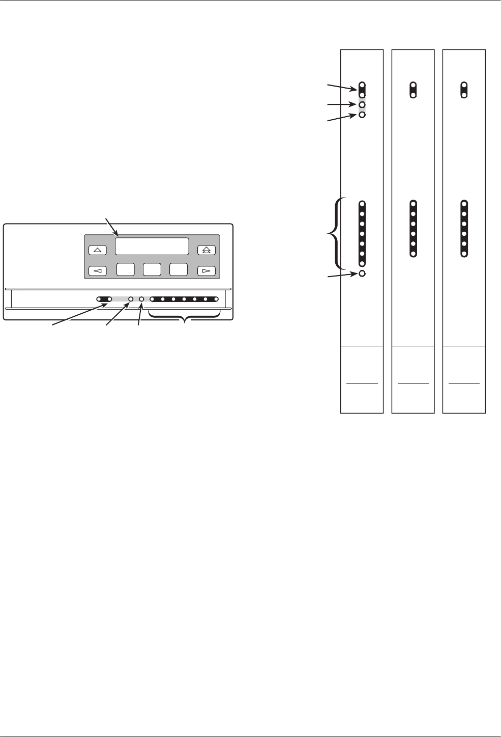
Network/
Device Alarm
DSU
3611
Multirate
TXD
RXD
RTS
CTS
DSR
DTR
LSD
Ok
Alrm
Test
Dial
Status
Front Panel
Spkr
103
104
105
106
107
108
109
Test Mode
Dial Backup
DTE
Status
Indicators
SDCP
Indicator
(Front Panel)
496-14720-01
TDM
3600
1
2
3
4
5
6
Ok
Alrm
Status
Port
Spkr
MCMP
3600
1
2
3
4
5
6
Ok
Alrm
Status
Port
Spkr
Figure 3-2. Model 3611 DSU,
TDM and MCMP Faceplates
Status Indicators
The status indicators on the Model 3610 DSU’s front
panel and on the Model 3611 DSU’s faceplate
continuously provide information on the current operating
condition of the DSU.
Refer to the COMSPHERE 3000 Series Carrier
Installation Manual for SDCP status indicator tables;
these are unchanged by the presence of a TDM or MCMP
circuit card.
Front Panel Operation
3-33610-A2-GB48-70 March 1999
The status indicators of the carrier-mounted
Model 3611 DSU are spread across the SDCP, DSU,
TDM, or MCMP faceplates. Refer to Table 3-1 for TDM
and MCMP status indicators and descriptions.
Table 3-1
Model 3611 TDM and MCMP Status Indicators
LED Color Description
OK Green Health and status indicator: TDM or
MCMP operation is normal. Indicator
flashes two times per second if a
message is present.
Alrm Red Health and status indicator: There is
an alarm in the TDM or MCMP
hardware, firmware, or a corrupted
configuration.
A voltage spike on the power line or
momentary loss of power may cause
an alarm. The DSU automatically
reloads the active set of TDM or
MCMP configuration options. When
the reload has completed, the Alrm
LED goes Off and the TDM or MCMP
OK LED comes ON.
Port 1,
2, 3, 4,
5, or 6
Green TDM or MCMP mode: Shows ports
currently being monitored. The status
of the port’s leads is displayed on the
faceplate of the associated DSU.
One of the six ports can be monitored
at any given time; the port to be
monitored is selected at the SDCP.
When Network Interface is set to
aggregate switch (AggSw), all ports
are monitored and all LEDs will be
ON.
Bridge mode: The port LEDs perform
differently. The LEDs indicate which
ports had RTS ON during the last
second.
When the port is connected to a DCE
device, the port RTS becomes the
received LSD signal of the DCE
device. The LEDs indicate which ports
had upstream activity during the last
second.
Menu Structure
A 3600 Series DSU comes factory-loaded with default
configuration settings:
•Model 3610 DSU is configured as a tributary
(FacT)
•Model 3611 DSU is configured as a control (FacC)
•DSU with MCMP/TDM comes configured as a
TDM
Menus and Modes of Operation
A DSU without TDM or MCMP operates in Basic
mode. A DSU equipped with TDM or MCMP can operate
in one of several modes. The mode of operation affects
which menus appear and the selections available within
the menus. Use the MUX Function configuration option
to set the mode of operation (Table 4-1).
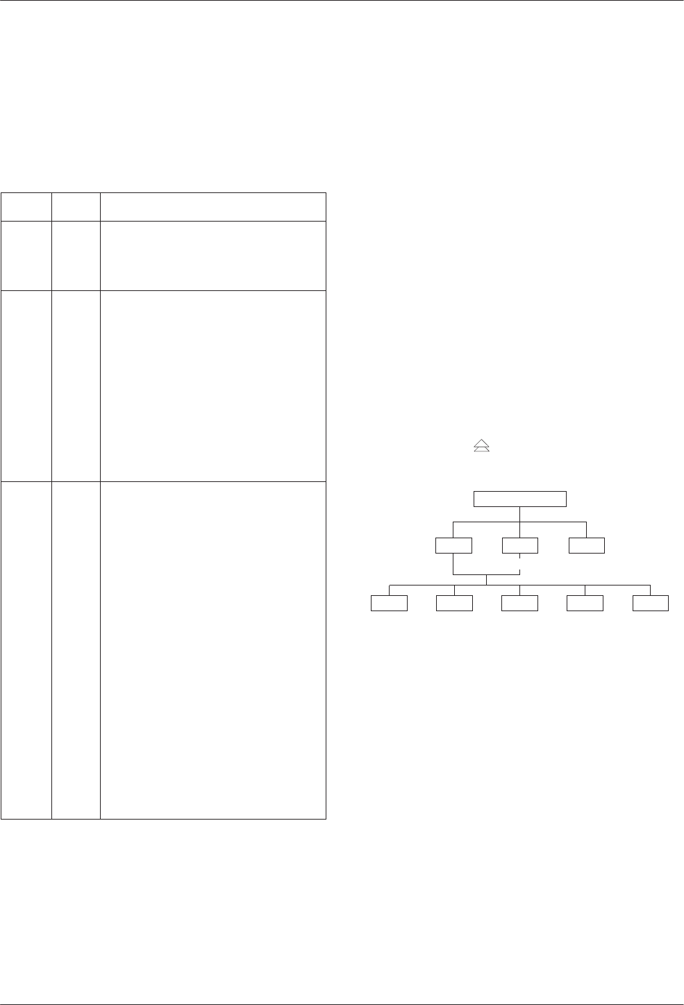
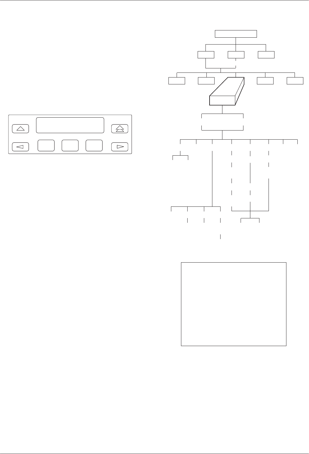
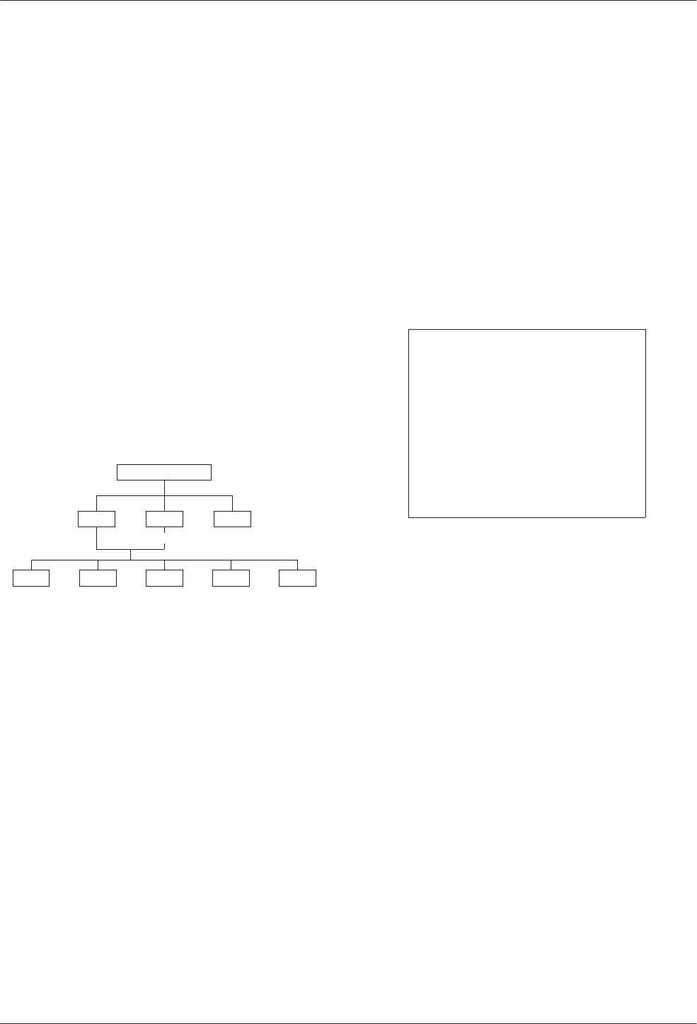
Access to all network management tasks from the front
panel begins at the top-level menu, the head of the menu
hierarchy. Press the key from anywhere in the menu
to return to the top-level menu.
495-12970b
TOP-LEVEL MENU
Local Remot
Bckup Test Ctrl
Msgs
Address
Confg
Stat
Local/Remote Branch Menus
The Local branch menu has five branches; the Remote
branch has four (Bckup is not available):
•Status (Stat) branch
•Backup (Bckup) branch
•Test branch
•Configuration (Confg) branch
•Control (Ctrl) branch
COMSPHERE 3600 Series Data Service Units
3-4 March 1999 3610-A2-GB48-70
Each selection leads to submenus. Factors determining
which selections or options are available are:
•DSU is in Display mode and operating in DSU
mode
•DSU has Full mode disabled
•DSU is a control or tributary
•Selecting the Local or Remote branch
•DBM is installed
•TDM/MCMP is installed
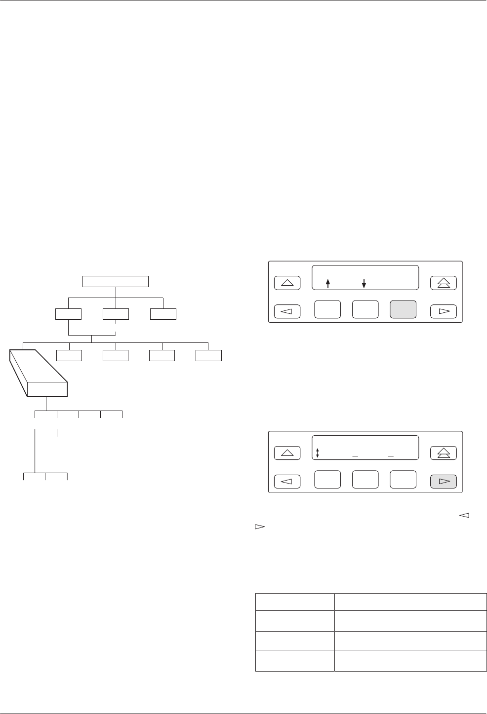
Status Branch
The Status (Stat) branch includes reports on the health
and status of the DSU, TDM, MCMP, and DBM.
496-12970-02
TOP-LEVEL MENU
Local Remot
Bckup Test Ctrl
Msgs
Address
Confg
Stat
H/S DTE CircQ ID TPwr
Port
Select
Devic Expan Subn
Health and Status
Health and Status (H/S) displays the health and status
of the DSU, and DBM, TDM or MCMP, if installed. DSU
and line conditions are automatically scanned for normal
limits. Refer to the User’s Guide for Health and Status
messages.
Device Health and Status
Device Health and Status (Devic) reports health and
status information for a selected DSU.
For a DSU with TDM or MCMP, the Device Health
and Status report displays:
•The health and status of both the DSU and TDM or
MCMP circuit cards.
•Any test or alarm involving the TDM or MCMP
that also affects the DSU.
•Any test or alarm that appears on the DSU’s Device
Health and Status report.
DTE Status
DTE status is a snapshot display of the local or remote
DSU/DBM’s external DTE interface status. For TDM,
MCMP, or Bridge mode, an additional port number screen
appears.
F1
Port Number: 1
Displ
F2 F3
Use F1 and F2 to change the port number and F3 to
display the status.
The following external DTE interface data appears for
the selected DSU with TDM or MCMP. The display may
differ from the DSU’s LED indicators which reflect the
internal states of the interface circuits.
F1
Prt01 DTE Stats:
TXD RXD DSR
F2 F3
The DTE interface leads appear in sets. Use the or
key to scroll and view the next set of DTE leads.
Table 3-2 translates the status codes.
Table 3-2
DTE Lead Status Codes
Code Lead Status
–ON/SPACE (line above text line)
_Off/MARK (line below text line)
↑↓ In transition between Off and ON
Front Panel Operation
3-53610-A2-GB48-70 March 1999
Circuit Quality
Circuit Quality (CircQ) is a display of the DDS
Receive Signal Loss and analog DBM measurements.
Circuit Quality does not display when MUX Function is
set for EBrdg. Refer to Document No. 3610-A2-GB46 for
more information.
Identity
Identity (ID) displays a report showing a DSU’s
model number, serial number, software/firmware version,
network address, DDS rate, DBM rate, and the DBM type
installed. For a DSU with TDM or MCMP, the TDM or
MCMP circuit card’s model, application, and firmware
version also appear. Refer to Table 3-3 in your User’s
Guide for Identity Descriptions.
Terminal Power
Terminal Power (TPwr) is a display showing the status
of the connected DTE’s EIA-232 and V.35 interface. For a
DSU with TDM or MCMP, Terminal Power displays the
RTS lead status for the DTE connected to the DSU for
Port 1. The front panel displays On when the voltage is
less than –3V or greater than +3V.
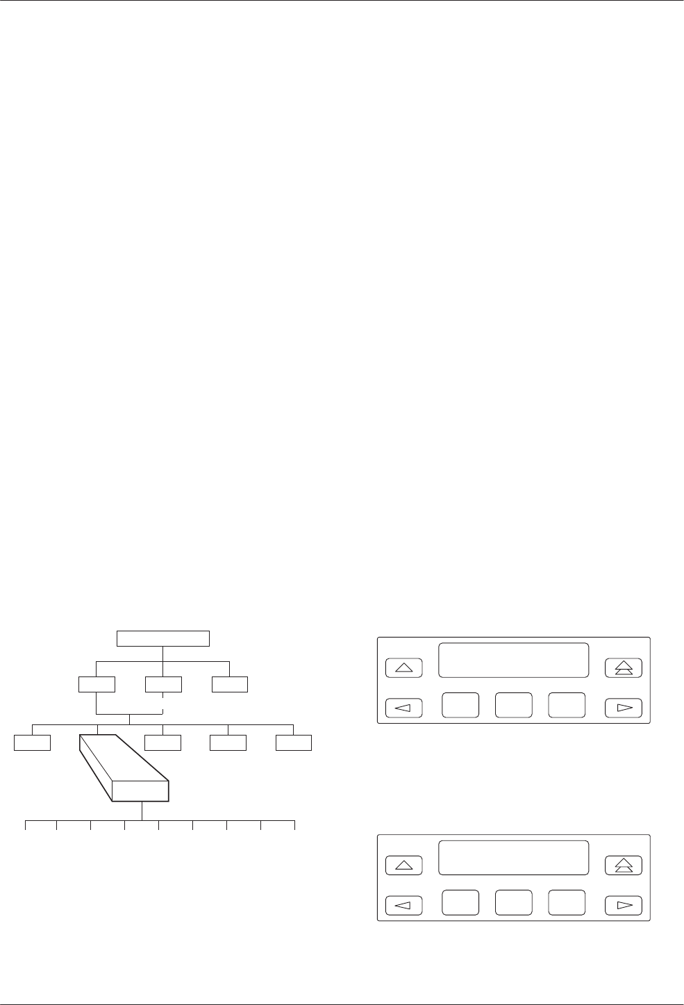
Backup Branch
The Backup (Bckup) branch controls operation of
digital bridging when a DSU with TDM or MCMP has
MUX Funct set to CBrdg or EBrdg.
496-12971-06
TOP-LEVEL MENU
Local Remot
Test Ctrl
Stat
Msgs
Address
Confg
Bckup
Abort Bkup Dial DrBU Disc →Dial →DDS AggSw →NetI
For additional use of the Backup branch, refer to
Document No. 3610-A2-GB46 for network interface
aggregate switching and Document No. 3610-A2-GB49
for DBM information.
Digital Bridging
Use the Backup branch to configure a digital bridge.
Refer to Appendix C for configuration examples.
Central-Site Bridge
For a DSU configured as a central-site bridge (CBrdg),
the backup options available are Bkup and DrBU. Refer
to Table 4-2 for Digital Bridge Setup Configuration
Options.
•Bkup (backup) is used to:
— Activate the bridge
— Disconnect DDS line from bridge
— Switch to the timing source specified by the
Bridge Timing configuration option
Do not initiate the Bkup option for a partial
multipoint backup.
•DrBU (drop backup) is used to:
— Deactivate the bridge
— Connect the DDS line to bridge
— Switch to the DDS line using timing specified
by the DSU TxClkSource configuration option
For a DSU configured as a central-site bridge with the
Bridge Rate configuration option set to =DSU, the
following is an example of the display for partial backup
of a CBrdg.
F1
Brdg with DDS
Bkup
F2 F3
For a DSU configured as a central-site bridge with the
Bridge Rate configuration option set to a data rate, the
following screen appears. The DDS and backup data rates
can be different.
F1
Inactiv Brdg
Bkup
F2 F3
COMSPHERE 3600 Series Data Service Units
3-6 March 1999 3610-A2-GB48-70
Extended Bridge
For a DSU configured as an extended bridge (EBrdg):
•DSU/DBM is always in Dial Backup mode and no
Backup menu options appear
•DBM circuit card should not be installed. If
installed, the DBM must be disabled
When in full backup, the following screen appears.
F1
Brdg w/o DDS
DrBU
F2 F3
Test Branch
The Test branch provides extensive testing capabilities
for the DSU, DDS circuit, DBM, and backup circuit.
While performing a multiplexing function for a DSU,
tests can be requested on individual ports or on the
aggregate data path. Multiplexing functions include:
•TDM or MCMP
•Nondisruptive diagnostics
•Rate adaption
On the aggregate data path, Local Loopback (LL) and
End-to-End (EE) tests can be run.
Performing tests on the aggregate data stream tests the
entire bandwidth, and in-band transport communication is
lost. For tests such as aggregate Digital Loopback (DL),
the control DSU reports a No Response or a TribTimOut
alarm for downstream devices.
When the tributary DSU receives a test request from
the control DSU, any locally initiated test in progress is
aborted.
496-12972-03
TOP-LEVEL MENU
Local Remot
Bckup Ctrl
Stat
Msgs
Address
Confg
Test
DSU DBM
Abort Devic Lpbk Lamp
LL DTE DL RL
Start Start Start
Port
Select Port
Select Port
Select
Port
Select
Address
Address Address
Run
Tim # Blocks
Displ Clr
EE DT BERT
Port
Select
Subn Selective
DTone
NOTE
Running a test can affect your
application data or may cause
your application session to be
dropped depending upon the
protocol, front-end processor, or
time-out parameters. No data or
acknowledgment messages will
be transmitted while the test is in
progress.
Abort
Abort allows you to stop a test currently running. The
DSU is not allowed to run any other test until the test in
progress completes or is aborted.
Front Panel Operation
3-73610-A2-GB48-70 March 1999
Device Test
The Device (Devic) Test is an internal self-test. If
TDM or MCMP is present, the Device Test will test the
MUX circuit card also.
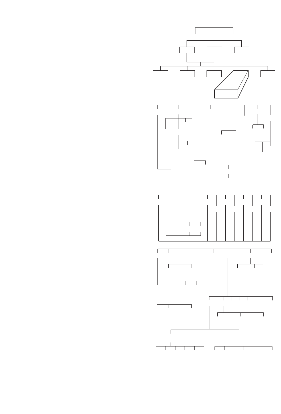
Loopbacks
Loopback (Lpbk) provides four loopback tests.
Figure 3-3 shows the direction of each loopback on the
circuit. Refer to Document No. 3610-A2-GB46 for
additional loopback information.
Local Loopback
Local Loopback (LL) is session-disruptive; performing
the test disrupts data. The DTE may run a test to
determine if the DTE to DSU connection and the DSU
itself are functioning properly.
•The DSU must be connected to the DTE.
•Network connection to the DSU is not required.
•For TDM, MCMP, or Bridge mode, the entire data
stream is looped back and all six ports are in Local
Loopback.
DTE Loopback
DTE Loopback (DTE) loops back the data path at the
DTE/DCE interface on a per-port basis without affecting
the operation of the remaining ports. The DSU with TDM
or MCMP permits one active test at a time.
Digital Loopback
Digital Loopback (DL) allows manual testing with the
remote end of the circuit. DL can be initiated from a
control or a point-to-point tributary.
Selecting one port or all active ports (Aggr) loops back
the user-transmitted data and the in-band secondary
channel transport data when nondisruptive diagnostics are
in effect. This disrupts in-band data transport
communications.
In Bridge mode, a Basic mode loopback occurs without
port selection. For MCMP mode, using the NetIntf
selection to perform a Digital Loopback is not a valid
command.
Remote Digital Loopback
Remote Digital Loopback (RL) supports testing by an
external device, such as a test pattern generator connected
to the local DSU’s DTE interface. This tests the local
DSU and the DDS circuit.
•In TDM or MCMP mode, asserting power to Pin 21
on Port 1 initiates a V.54 aggregate loopback. This
loopback is performed on the DDS circuit unless a
dial backup session is active.
•In MCMP mode, the port selected is not
automatically the port placed in loopback at the
remote location. If a channel assigned to Port 2
locally is assigned to Port 3 remotely, Port 3 at the
remote location is placed in loopback.
To abort a Remote Digital Loopback, issue an Abort
command to the control DSU.
496-15049
Control
DSU
DTE
DL on a
Port LL
COMSPHERE 3610
DTE
NETWORK
RL on
Aggregate RL on a
Port
COMSPHERE 3610
Tributary
DSU
DL on
Aggregate
Figure 3-3. Loopbacks Example
COMSPHERE 3600 Series Data Service Units
3-8 March 1999 3610-A2-GB48-70
Digital Test
The Digital Test (DT) verifies operation of a pair of
DSUs and the data circuit between them. When a Digital
Test is performed on a specific port, data transmission is
not affected on the other ports.
For a DSU operating in single-port mode and having
either nondisruptive diagnostics or rate adaption in effect,
an additional selection for Aggr or Prt1 appears.
Selecting Aggr tests the looped data path; in-band
communication transport data is not allowed.
End-to-End Test
The End-to-End (EE) test analyzes a control and a
tributary DSU or DBM and the network circuit between
them in both directions independently. Refer to Document
No. 3610-A2-GB46 for additional information.
Bit Error Rate Test
The Bit Error Rate Test (BERT) is session-disruptive
and transmits a test pattern to analyze the network circuit.
Refer to Document No. 3610-A2-GB46 for additional
information.
Dial Tone Test
The Dial Tone test (DTone) allows a DBM to test for
dial tone. This selection does not appear in the DSU’s Test
branch.
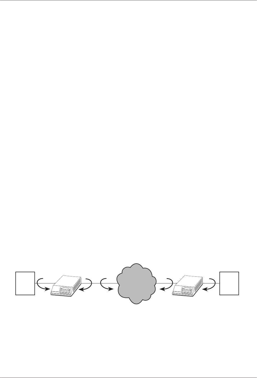
Configuration Branch
The Configuration (Confg) branch allows you to
configure or customize the DSU and its options.
The Configuration branch menu varies with the options
being configured. With TDM or MCMP installed, the
MUX and PrtSp (Port Speed) option sets appear.
Refer to the configuration option tables in Chapter 4,
the menu tree in Appendix A, and the configuration
worksheets in Appendix B for additional configuration
details. Additional Configuration branch menu details are
in Document No.:
•3610-A2-GB46 for DSU information
•3610-A2-GB49 for DBM information
496-12973-07
TOP-LEVEL MENU
Local Remot
Bckup Test Ctrl
Stat
Confg
Msgs
Opts PList Dir Phone
Addr
ChgMd
Displ Chang
Add
Acq
Activ Delet
Chang Clr
Save
DPII
ADp
Remt
Address
Activ Usr1 Usr2 Usr3
Activ Usr1
Usr2
Usr3
FacC
FacT
FacB
Load
SAVE DSU DBM Gen Bkup MUX PrtSp LPDA
Copy Setup Prt1 Prt2 Prt3 Prt4 Prt5 Prt6
Remt Usr1 Usr2 Usr3
Address
Activ Usr1 Usr2 Usr3
TDM MCMP CBrdg EBrdg None
DSU DBM Chan
Skip
Clr
Diag
All Prt1 Prt2 Prt3 Prt4 Prt5 Prt6
Copy
To
Activ
Address
DSU DBM Gen
Prt1 Prt2 Prt3 Prt4 Prt5 Prt6
Copy
From
Term
Enab Pswrd CIDDisab
Pswrd
SPID
Menu
FB1
Chang Clr
SaveEnabDisab
MPTC
MPTT

Front Panel Operation
3-93610-A2-GB48-70 March 1999
Options
Options (Opts) allows you to save, copy, and/or
change DSU, Diagnostic, DBM, General, Backup, MUX,
port speeds, and LPDA-2 configuration options.
When changing configuration options, always set the
mode first (MUX Funct) in the MUX option set
(Table 4-1).
•For a DSU with TDM or MCMP, you can set the
DSU’s MUX operating mode to TDM, MCMP,
Bridge, or None. Selecting None disables the
MCMP/TDM card and the DSU operates in Basic
mode. No MUX configuration options appear.
F1
MUX Funct: MCMP
Next TDM MCMP
F2 F3
CBrdg EBrdg None Prev
•When a MCMP/TDM is installed, the CBrdg and
EBrdg selections are also available to place the
DSU in Bridge mode.
— CBrdg operates as a central-site bridge.
— EBrdg operates as an extended bridge.
When a bridge configuration consists of a
central-site bridge with one or more extended
bridges, digital bridge options must be set for each
DSU in the bridge.
•For TDM, MCMP, or Bridge mode, a port number
(6-port version or 2-port version) must be specified
before issuing some commands. The results sent
back from the DSU may vary depending upon the
operating mode (MUX Funct) and port selected.
Refer to Table D-1 for configuration error messages
that may appear after pressing SAVE.
Poll List
Poll List (PList) maintains or changes a DSU’s poll list
and interfaces with an active internal NMS. A poll list
identifies all DSUs or DBMs one level downstream. PList
is available for point-to-point tributary DSUs, or
tributaries configured for MCMP mode and nondisruptive
diagnostics.
•When a DSU is configured for MCMP mode and
nondisruptive diagnostics, both tributary DSU and
DBM addresses are included in the DSU’s poll list.
•When configured for MCMP mode and disruptive
diagnostics, only tributary DSU addresses are
included in the DSU’s poll list (DBM address is
omitted).
•Using the Acquire (Acq) command is an efficient
alternative to the Add command.
When MUX Funct is set to MCMP:
•The Acq command must be used to successfully
initiate transmissions.
•When adding tributaries to a working network:
— From a control, use the Acq command.
— From a tributary, use the Add command.
Command Complete appears when the poll list is
completed. When NMS is polling a control unit or a
control unit is polling a tributary, an asterisk (*) appears
in the Health and Status display on the right side of the
front panel.
Menu
Menu (Menu) allows you to disable Full mode. Full
mode displays all menu selections based on installed
configuration options and those set by the user. When
disabled, an abbreviated set of selections appears. The
configuration options that do not display when in Full
mode are indicated by row with a A symbol in
Appendix B, Configuration Worksheets.
COMSPHERE 3600 Series Data Service Units
3-10 March 1999 3610-A2-GB48-70
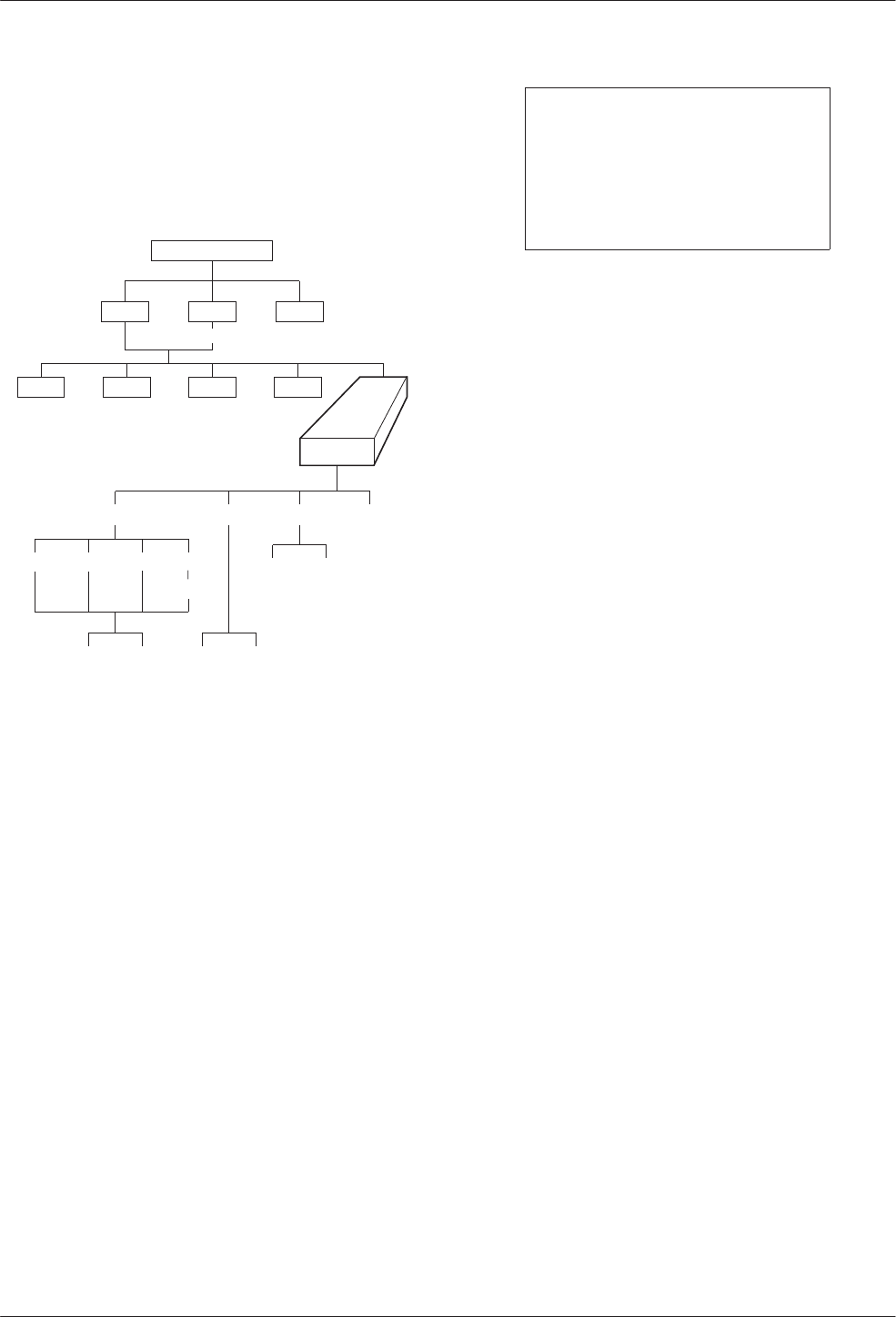
Control Branch
The Control (Ctrl) branch allows you to enable or
disable the DSU’s transmitter, as well as the DBM’s, and
to display/change the status of the general purpose
external DTE leads.
496-12974-02
TOP-LEVEL MENU
Local Remot
Bckup Test
Stat
Msgs
Address
Confg
Ctrl
TxCtl LEDs ExtL
DSU DBM Ports
Load Save
Displ Chang
Enab Disab
Devic
Port Select
Reset
Transmitter Control
Transmitter Control (TxCtl) allows you to:
•Enable or disable the DSU’s transmitter
(DDS core).
•Enable or disable individual ports in TDM or
MCMP mode.
•Select the port that will have its circuit leads
monitored.
NOTE
If the DSU core is disabled,
enabling all ports in TDM or
MCMP mode will not enable the
DSU core. You must also enable
the DSU core separately.
LEDs
The LEDs selection is available from the Local branch.
This selection allows you to monitor any of the TDM or
MCMP ports at any given time. The LEDs on the TDM or
MCMP circuit card show which ports are being monitored
when the TDM or MCMP mode is in operation. You can
also choose to monitor the aggregate data stream.
External Leads
External Leads (ExtL) allows display of the state of
four general-purpose leads on the EIA-232/V.24 Port 1
interface. Refer to Document No. 3610-A2-GB46 for
additional information.
Reset
Selecting Reset will reset all connections and start a
power-up routine. Refer to Document No. 3610-A2-GB46
for additional information.
Remote Mode
Remote mode is not available for a multipoint
tributary. Refer to Document No. 3610-A2-GB46 for
additional information.
4-13610-A2-GB48-70 March 1999
Configuration Option Tables
Overview 4-1. . . . . . . . . . . . . . . . . . . . . . . . . . . . . . . . . . . . . . . . . . . . . . . . . . . . . . . . . . . . . . . . . . . . . . . . . .
Configuration Option Tables 4-1. . . . . . . . . . . . . . . . . . . . . . . . . . . . . . . . . . . . . . . . . . . . . . . . . . . . . . . . . . .
Configuration Option Tables Format 4-2. . . . . . . . . . . . . . . . . . . . . . . . . . . . . . . . . . . . . . . . . . . . . . . . . .
TDM Mode 4-2. . . . . . . . . . . . . . . . . . . . . . . . . . . . . . . . . . . . . . . . . . . . . . . . . . . . . . . . . . . . . . . . . . . . .
Overview
After the DSU is installed, set the software
configuration options by accessing the Configuration
(Config) branch of the menu. Refer to the menu tree in
Appendix A and worksheets in Appendix B while
planning configurations.
495-12970b
TOP-LEVEL MENU
Local Remot
Bckup Test Ctrl
Msgs
Address
Confg
Stat
Configuration Option Tables
This section contains a configuration table for each
functional group or option set within the Configuration
branch of the menu that applies to TDM, MCMP, and
digital bridge applications.
Load and save a set of factory defaults before
changing any configuration options. For additional
details, refer to:
•Saving and Changing Configuration Options in
Chapter 2 of the User’s Guide.
•Table A-1, Factory Default MUX Configuration
Options.
•Table D-1, Configuration Error Messages, for
messages that may appear after pressing SAVE.
NOTE
With TDM or MCMP, always set
the MUX Setup
option first. The
mode of operation (MUX Funct =
TDM, MCMP, CBrdg, EBrdg, or
None) results in different
configuration options and
selections. MUX Funct set to
None results in Basic mode and
no MUX options appear.
The tables included here are:
MUX Setup Options (from same Confg menu option):
•MCMP/TDM Setup Configuration Options
(Table 4-1)
•Digital Bridge Setup Configuration Options
(Table 4-2). The setting after each configuration
option name is the FacB default setting.
MUX Portn Options (from same Confg menu option):
•MCMP/TDM Port Configuration Options
(Table 4-3)
•Digital Bridge Port Configuration Options
(Table 4-4)
Port Speed DSU Options (from same Confg menu
option):
•DSU Port Speed Configuration Options for
MCMP/TDM (Table 4-5)
•Port Speed Channel-to-Port Assignment
Configuration Options for MCMP (Table 4-6)
4

COMSPHERE 3600 Series Data Service Units
4-2 March 1999 3610-A2-GB48-70
Configuration Option Tables Format
The tables are formatted to show the following
configuration option information:
•Name of configuration option followed by a
colon (:) and the factory default setting.
•All selectable options.
•Description of the configuration option.
•Description of each selectable setting.
Factory default options for the MUX tables in this
chapter are located in Table A-1. Configuration options
appear or are filtered based on settings in effect and
additional installed hardware features.
•For basic DSU operations, refer to Document
No. 3610-A2-GB46.
•Options supporting DBMs are in Document
No. 3610-A2-GB49.
TDM Mode
Any Model 3610-A4-xxx or Model 3611-B4-xxx with
a MUX card has TDM and MCMP combined. The new
model is shipped from the factory with MUX Function set
to TDM. When factory defaults are loaded and saved, the
MCMP mode is in effect. To change the MUX circuit card
from MCMP mode to TDM mode, change the following
settings for FacC and/or FacT:
Configuration
Branch Configuration
Option FacC or
FacT
MUX Setup MUX Funct TDM
DSU Rate(Kbps) Auto
Diag Gen Link Config Pt-Pt
Gen RTS Cntrl DTE
DBM (with ISDN
DBM installed)
Rate(Kbps) 64
DBM installed) Fallback One
Table 4-1
(1 of 4)
MCMP/TDM Setup Configuration Options
MUX Funct: MCMP
Next TDM MCMP CBrdg EBrdg None Prev
MUX Function. Mode of operation for the MCMP/TDM circuit card.
TDM – TDM mode for point-to-point multiplexing, tributary multipoint DSD, or digital-sharing configuration.
MCMP – MCMP mode for multichannel multipoint operation and digital-sharing configuration. Multichannel multipoint
circuitry is activated on the MCMP circuit card.
CBrdg – Bridge mode for a central-site bridge configuration (see Table 4-2). An installed DBM must be disabled.
EBrdg – Bridge mode for a extended bridge configuration (see Table 4-2). An installed DBM must be disabled.
None – Basic mode configuration; disables the MUX circuit card. None of the following options appear.
Share DevA: Disab
Next Enab Disab Prev
Sharing Device A. Enabling this configuration option allows you to create one of two digital-sharing groups for TDM
backup of MCMP or digital bridging. Used with configuration option MCMP Backup at the end of this table. This
configuration option may be used with an LPDA-2 configuration.
The following rules apply:
•All ports in a group must have the same port speed.
•All ports must be adjacent.
•A contention group can have from 2 to 6 ports with a total of 2 ports when a 2-port MCMP/TDM Flex is installed.
•In MCMP mode, a digital-sharing group is set up by assigning multiple ports to the same channel.
Enab – Enables digital-sharing.
Disab – Disables digital-sharing.

Configuration Option Tables
4-33610-A2-GB48-70 March 1999
Table 4-1
(2 of 4)
MCMP/TDM Setup Configuration Options
Lowest Port#: 1
Next 1 2 3 4 5 Prev
Lowest Port Number. Select the lowest port number to be included in the digital-sharing group. This configuration option
appears when Sharing Device A is enabled and does not appear when a 2-port MCMP/TDM Flex is installed.
NOTE: Enabling Sharing Device A and accepting the defaults for configuration options Lowest Port Number and
Number of Ports in Group places Ports 1 and 2 in the digital-sharing group.
1 to 5 – Selects the lowest port number.
#Ports in Gp: 2
Next 2 3 4 5 6 Prev
Number of Ports in Group. Select total number of ports to be included in the first digital-sharing group. This configuration
option appears if Sharing Device A is enabled and does not appear when a 2-port MCMP/TDM Flex is installed.
NOTE: Individual ports in a digital-sharing group can be configured for streaming terminal. If streaming terminal
detection is enabled on a port and RTS (Request to Send) for that port is ON longer than the value selected,
the port’s leads are clamped until RTS is turned Off. (See RTS Cntrl in Table 4-3.)
2 to 6 – Selects the number of ports.
Port Cntrl: Host
Next Host DSD Prev
Port Control. Specifies how to handle contention between the ports in the first digital-sharing group. This configuration
option appears if Sharing Device A is enabled. Only two digital-sharing groups can have DSD contention.
Host – No port contention. Causes CTS (Clear to Send) to turn ON for any port that has RTS turned ON, even if another
port is active (RTS ON). The host protocol must enforce the order of transmission to avoid collisions.
DSD – Digital-Sharing Device (port contention). Controls CTS to ensure that only one port is active at a time. All ports
must be configured with RTS Control set to DTE. A subsequent DTE that has RTS turned ON does not have its CTS
turned ON until the first DTE has RTS Off. Selection of the next port to transmit when more than one port has raised
RTS is based upon the port number; the lowest-numbered port has the highest priority.
Share DevB: Disab
Next Enab Disab Prev
Sharing Device B. Enabling this configuration option allows you to create a second digital-sharing group. Use Sharing
Device A with LPDA-2 enabled. This configuration option does not appear when a 2-port MCMP/TDM Flex is installed.
The following rules apply:
•All ports in a group must have the same port speed.
•All ports must be adjacent.
•A digital-sharing group can have from 2 to 6 ports.
•In MCMP mode, a digital-sharing group is set up by assigning multiple ports to the same channel.
Enab – Enables digital-sharing.
Disab – Disables digital-sharing.
Lowest Port#: 3
Next 1 2 3 4 5 Prev
Lowest Port Number. Select the lowest port number to be included in the second digital-sharing group. This configuration
option appears when Sharing Device B is enabled and and does not appear when a 2-port MCMP/TDM Flex is installed.
NOTE: Enabling Sharing Device B and accepting the defaults for configuration options Lowest Port Number and
Number of Ports in Group places Ports 3 and 4 in the digital-sharing group.
1 to 5 – Selects the lowest port number for the digital-sharing group.

COMSPHERE 3600 Series Data Service Units
4-4 March 1999 3610-A2-GB48-70
Table 4-1
(3 of 4)
MCMP/TDM Setup Configuration Options
#Ports in Gp: 2
Next 2 3 4 5 6 Prev
Number of Ports in Group. Select total number of ports to be included in the second digital-sharing group. This
configuration option appears when Sharing Device B is enabled and a 6-port MCMP/TDM Flex is installed.
NOTE: Individual ports in a digital-sharing group can be configured for streaming terminal. If streaming terminal
detection is enabled on a port and RTS for that port is ON longer than the value selected, the port’s leads are
clamped until RTS is turned Off. (See RTS Cntrl in Table 4-3.)
2 to 6 – Selects the number of ports for digital-sharing.
Port Cntrl: Host
Next Host DSD Prev
Port Control. Specifies how to handle contention between the ports in the second digital-sharing group. This
configuration option appears if Sharing Device B is enabled and does not appear when a 2-port MCMP/TDM Flex is
installed. Only two digital-sharing groups can have DSD contention.
Host – No port contention. Causes CTS to turn ON for any port that has RTS turned ON, even if another port is active
(RTS ON). The host protocol must enforce the order of transmission to avoid collisions; the MCMP or TDM does not
provide port contention.
DSD – Digital-Sharing Device (port contention). Controls CTS to ensure that only one port is active at a time. All ports
must be configured with RTS Control set to DTE. A subsequent DTE that has RTS turned ON does not have its CTS
turned ON until the first DTE has RTS Off. Selection of the next port to transmit when more than one port has raised
RTS is based upon the port number; the lowest-numbered port has the highest priority.
P1/2 FEPSh: Disab
Next Enab Disab Prev
Ports 1 and 2 Front-End Processor Port Sharing. Creates an FEP port-sharing group consisting of Ports 1 and 2.
Enab 1 – FEP transmissions and controls pass through Port 1 to be broadcast onto the aggregate data stream and to
Port 2. Data to be received by the FEP comes from both the aggregate data stream and Port 2.
Disab – Disables the FEP port-sharing feature for Ports 1 and 2.
P3/4 FEPSh: Disab
Next Enab Disab Prev
Ports 3 and 4 FEP Port Sharing. Creates an FEP port-sharing group consisting of Ports 3 and 4. This configuration
option will not appear if a 2-port MCMP/TDM Flex is installed.
Enab 1 – FEP transmissions and controls pass through Port 3 to be broadcast onto the aggregate data stream and to
Port 4. Data to be received by the FEP comes from both the aggregate data stream and Port 4.
Disab – Disables the FEP port-sharing feature for Ports 3 and 4.
P5/6 FEPSh: Disab
Next Enab Disab Prev
Ports 5 and 6 FEP Port Sharing. Creates an FEP port-sharing group consisting of Ports 5 and 6. This configuration
option will not appear if a 2-port MCMP/TDM Flex is installed.
Enab 1 – FEP transmissions and controls pass through Port 5 to be broadcast onto the aggregate data stream and to
Port 6. Data to be received by to the FEP comes from both the aggregate data stream and Port 6.
Disab – Disables FEP port-sharing feature for Ports 5 and 6.
1 When enabled, the CTS lead is forced ON (high) for the odd-numbered port in the FEP port-sharing group.

Configuration Option Tables
4-53610-A2-GB48-70 March 1999
Table 4-1
(4 of 4)
MCMP/TDM Setup Configuration Options
MCMP Bckup: MCMP
Next MCMP TDM Prev
MCMP Backup. Determines the mode for backup with MCMP installed. Valid only when an ISDN or a Switched 56 DBM
is installed.
MCMP – Enables backup in MCMP mode.
TDM – Enables backup in TDM mode. Results in FEP port sharing at the control; no aggregate switch with EBrdg. The
V.32 analog DBM is forced to TDM.
Table 4-2
(1 of 2)
Digital Bridge Setup Configuration Options
MUX Funct: CBrdg
Next TDM MCMP CBrdg EBrdg None Prev
MUX Function. MCMP/TDM Circuit Card Function with either CBrdg or EBrdg mode selected. Initiates Bridge mode for a
central-site bridge or an extended bridge configuration.
TDM – TDM mode for multiplexing or digital-sharing configuration.
MCMP – MCMP mode for multichannel multipoint operation or digital-sharing configuration.
CBrdg – Bridge mode for a central-site bridge configuration; an installed DBM must be disabled.
EBrdg – Bridge mode for an extended bridge configuration; an installed DBM must be disabled.
None – Basic mode configuration; disables MCMP/TDM circuit card. None of the following configuration options appear.
Bridge Rate: =DSU
Next =DSU 64 56 28.8 24.0 19.2 16.8 14.4 12.0 9.6 4.8 2.4 Prev
Bridge Rate. Data rate in kbps on the digital bridge.
=DSU – Choose this configuration value for a CBrdg when the digital bridge operates at the same speed as the DSU.
Not valid for EBrdg. This configuration value causes the DSU to connect the controlling DTE to the aggregate data path
of the digital bridge, and to connect to the DCE port on the digital bridge to the DDS core. Select this value for:
•Multipoint LADS operation.
•Multipoint dial backup where partial backup is possible.
64 to 2.4 kbps – For multipoint dial backup, if the DSU’s speed is higher than the highest possible speed of an analog
DBM, configure the digital bridge to operate at a speed that maximizes data throughput. Only full backup is possible, and
is set manually from the front panel or initiated by an NMS. When full backup goes into effect, the DSU switches the data
path from DTE/DSU to DTE/digital bridge, and enables internal timing at the selected Bridge Rate.
Brdg Timing: Int
Next Int Auto Prt Prt2 Prt3 Prt4 Prt5 Prt6 Prev
Bridge Timing. In CBrdg mode, this timing is used when in full backup where the backup is initiated from the Backup
branch. In EBrdg mode, the Bridge Timing selected is always used.
Int – Timing taken internally from the unit; primarily used for analog backup.
Auto – Timing taken from any of the ports that have DTR high; primarily used for switched 56 kbps backup.
Prt1 to Prt6 – Timing is taken from the specified port. Ports 3 through 6 do not appear with a 2-port MCMP/TDM Flex.

COMSPHERE 3600 Series Data Service Units
4-6 March 1999 3610-A2-GB48-70
Table 4-2
(2 of 2)
Digital Bridge Setup Configuration Options
Share DevA: Enab
Next Enab Prev
Sharing Device A. This configuration option creates a digital-sharing group to configure for contention. This configuration
option can be used with an LPDA-2 configuration.
Enab – This configuration option is Forced On (enabled) in Bridge mode.
Lowest Port#: DCE
Next DCE 2 3 4 5 Prev
Lowest Port Number. Allows you to specify the number of active ports on the digital bridge. This configuration option
displays when Sharing Device A is enabled and does not appear when a 2-port MCMP/TDM Flex is installed.
NOTE: Accepting the defaults for configuration options Lowest Port Number and Number of Ports in Group places
Ports DCE and 2 in this digital-sharing group.
DCE – Select for multipoint LADS operation or multipoint dial backup where partial backup is possible. Bridge Rate is set
to =DSU in this table.
2 to 5 – Selects the number of ports for multipoint dial backup where only full backup is possible [Rate(Kbps) 19.2 kbps
or greater].
#Ports in Gp: 6
Next 2 3 4 5 6 Prev
Number of Ports in Group. Allows you to specify the number of active ports on the digital bridge. This configuration
option displays when Sharing Device A is enabled and does not appear when a 2-port MCMP/TDM Flex is installed.
Ports from the digital bridge can be added or dropped by changing number of ports in the port-sharing group.
2 to 6 – Selects the number of ports to be included in the digital-sharing group.
Port Cntrl: Host
Next Host DSD Prev
Port Control. Specifies how to handle contention between the ports in the ports in a port-sharing group. This
configuration option is only displayed if Sharing Device A is enabled.
In multipoint dial backup, ports are not automatically dropped from the digital bridge if the backup call is lost. A DBM that
has dropped a backup call will no longer be raising RTS at the digital bridge port and is effectively isolated from the
digital bridge. If the backup call was dropped due to a network problem and a new call is successful, the DBM is able to
raise RTS and again work with the digital bridge.
Host – No port contention. Causes CTS to turn ON for any port that has RTS turned ON, even if another port is active
(RTS ON). The host protocol must enforce the order of transmission to avoid collisions. The connected DBM-D, DBM-I,
DBM-S, or DBM-V is not required to have V.13 switched-carrier emulation.
NOTE: In CBrdg mode, Host is the only available setting if Diag Type is set to NonD. In EBrdg mode, Host
should be used if the extended bridge is connected to an MCMP control or a nondisruptive CBrdg.
DSD – Digital-Sharing Device (port contention). Controls CTS to ensure that only one port is active at a time. All ports
must be configured with RTS Control set to DTE. A subsequent DTE that has RTS turned ON does not have its CTS
turned ON until the first DTE has lowered its RTS. Selection of the next port to transmit when more than one port has
raised RTS is based upon the port; the lowest-numbered port has the highest priority.
Share DevB: Disab
Next Disab Prev
Sharing Device B. This configuration option creates a digital-sharing group to configure for contention.
Disab – This configuration option is Forced Off (disabled) in Bridge mode.

Configuration Option Tables
4-73610-A2-GB48-70 March 1999
Table 4-3
(1 of 4)
MCMP/TDM Port Configuration Options*
Async→Sync: Disab
Next Enab Disab Prev
Asynchronous-to-Synchronous Conversion. Sets each port for asynchronous or synchronous operation. The DSU
verifies that an asynchronous setting is not underspeed if the sum of the port speeds equals the aggregate speed.
Enab – Configures the port as asynchronous (asynchronous-to-synchronous conversion takes place).
Disab – Configures the port as synchronous.
Async Rate: =Sync
Next =Sync 1800 1200 600 300 150 Prev
Asynchronous Rate in bps. Specifies the rate of an asynchronous port. The asynchronous rate must be less than or
equal to the synchronous port speed. Use the DSU PrtSp(Kbps) configuration option to set the synchronous port speed.
This configuration option appears if the Async→Sync configuration option is enabled.
NOTE: When 1800 bps is selected, the DSU verifies that the synchronous port speed is 2400 bps or greater. If only
one stop bit is used, the asynchronous rate cannot be equal to half the synchronous rate.
=Sync – Asynchronous rate is the same as the synchronous rate.
1800 to 150 – Select the rate in bps of the asynchronous port.
AsyncBit/Char: 8
Next 6 7 8 9 10 Prev
Asynchronous Bits per Character. Specifies the length of a character, including the parity bit but excluding the start and
stop bits. This configuration option appears if the Async→Sync configuration option is enabled.
6 to 10 – Select the asynchronous bits per character.
Stop Bits: 1
Next 1 2 Prev
Stop Bits. Specifies the number of stop bits in an asynchronous character. This configuration option appears if the
Async→Sync configuration option is enabled and the AsyncBit/Char configuration option is not set to 10. If the
AsyncBit/Char configuration option is set to 10, stop bits is set to 1.
1 to 2 – Select the number of stop bits to be used.
Overspeed: 2.50
Next 1.25 2.50 Prev
Overspeed. Selects the overspeed percentage range of the asynchronous-to-synchronous converter. This configuration
option displays when MUX Funct is set to TDM and does not display with a MUX SW version less than 5.xx.
1.25 – Selects the basic overspeed range. Basic range provides 1.25% overspeed in the DTE asynchronous data rate.
2.50 – Selects the overspeed percentage for extended range. Extended range provides 2.5% overspeed in the DTE
asynchronous data rate.
RTS Cntrl: DTE
Next FrcOn DTE Prev
Request-to-Send Control. Controls the internal RTS lead operation.
NOTE: Refer to next configuration option, Transmitter Carrier Select, for a description of constant-carrier and
switched-carrier operation.
FrcOn – DSU keeps the internal RTS ON continuously. Any data appearing on the transmitted data (TXD) lead from the
DTE is transmitted immediately. Choose this configuration value for constant-carrier operation.
DTE – DSU turns RTS ON when the external RTS is turned ON. CTS is turned ON or Off by the external control signal
RTS. Choose this configuration value for switched-carrier operation.
* The menu paths for Port 1 through Port 6 are identical; each port is set separately.

COMSPHERE 3600 Series Data Service Units
4-8 March 1999 3610-A2-GB48-70
Table 4-3
(2 of 4)
MCMP/TDM Port Configuration Options*
TxCarrSel: Const
Next Const Cntrl Prev
Transmitter Carrier Select. Enables the TDM transmitter circuitry to simulate switched-carrier operation using the
V.13 codes on an individual channel. The simulated switched-carrier operation is also referred to as pseudo-controlled
carrier (PCC) mode. Required for applications where the receiving DTE expects a raised LSD lead prior to receiving
data. For MCMP mode, this configuration option is ignored except during dial backup when the MCMP Backup
configuration option is set to TDM (Table 4-1) or a V.32 DBM is installed.
NOTE: A port can be configured for switched-carrier operation in one direction and constant-carrier operation in the
other direction.
Const – Transmit Constant Carrier (constant-carrier operation). The V.13 codes are not sent. The corresponding remote
TDM or MCMP port must be configured for Receiver Constant Carrier or Mark (RxCarrSel set to Const or Mark).
Configure each port in a digital-sharing group for Constant Carrier operation (TxCarrSel set to Const).
Cntrl – Transmit Controlled Carrier (switched-carrier operation, PCC mode). The DSU transmits the V.13 codes over the
DDS line when the port RTS changes state. When RTS is turned ON, the DSU transmits a code that turns ON LSD at
the remote TDM or MCMP port before CTS is turned ON at the local TDM or MCMP port. When RTS is dropped, the
DSU sends a code that turns Off LSD at the remote TDM or MCMP port. The corresponding remote TDM or MCMP port
must be configured for Receiver Controlled Carrier (RxCarrSel set to Cntrl). This selection is not valid if the DSU is part
of a Digital-Sharing Device (DSD) group. See the Mark setting in the next configuration option, RxCarrSel.
RxCarrSel: Const
Next Const Cntrl Mark Prev
Receiver Carrier Select. Enables the TDM receiver circuitry to simulate switched-carrier operation using the V.13 codes
on an individual channel. Configuration values Const and Cntrl for Receiver Carrier Select are both valid choices for a
port belonging to a digital-sharing group. Not valid for MCMP mode.
Const – Receiver Constant Carrier (constant-carrier operation). The receiving DSU does not look for V.13 codes used
by the V.13 protocol and does not toggle LSD.
Cntrl – Receiver Controlled Carrier for switched-carrier operation in PCC mode (see PCC Buffer, next configuration
option). The receiving DSU looks for V.13 codes used by the V.13 protocol that indicate the transition of RTS at the
remote TDM port; the receiving DSU toggles LSD as appropriate.
Mark – If 30 consecutive marks are received, received Line Signal Detect (LSD) goes Off at the port. Received LSD
goes ON again just before the first space. TxCarrSel must be set to Const at the remote unit. This configuration option is
used primarily when the remote DSU has a DSD group.
PCC Buffer: Disab
Next Enab Disab Prev
Pseudo-Controlled Carrier Buffer. Intercepts the V.13 codes used by the V.13 protocol so they do not pass to the
receiving DTE. This configuration option is only valid when RxCarrSel is set to Cntrl. Not valid for MCMP.
For an asynchronous port configured for switched-carrier operation, set PCC Buffer to Enab.
For a synchronous port configured for switched-carrier operation, PCC Buffer can be disabled or enabled, depending on
whether the V.13 codes disrupt communication at the receiving DTE.
NOTE: Enabling this configuration option can corrupt the end-of-message for some synchronous protocols.
Enab – Enables PCC Buffer to intercept V.13 codes.
Disab – Disables PCC Buffer.
* The menu paths for Port 1 through Port 6 are identical; each port is set separately.

Configuration Option Tables
4-93610-A2-GB48-70 March 1999
Table 4-3
(3 of 4)
MCMP/TDM Port Configuration Options*
Elast Stor: Disab
Next Enab Disab Prev
Elastic Store. Elastic Store hardware consists of a transmit buffer (register). Serial data from the extended circuit is
clocked into the DSU elastic store using a clock (on EIA-232 Pin 24 or V.35 Pins U and W) provided by the extended
circuit received clock lead (on Pin 17). The DSU uses its own system timing to clock data out of the buffer.
Elastic Store is reset on power-up, overflow, or after the RTS lead makes an Off-to-ON transition. After reset, the elastic
store can drift by ±5 bits in TDM mode and ±3 bits in MCMP mode before overflow occurs.
Enab – Use Enable if you have an extended network.
Disab – Use Disable if you do not have an extended network.
RTS/CTS Del: 0
Next Chang Prev
Request-To-Send to Clear-To-Send Delay. Allows for an additional delay between the time that RTS is turned ON and
CTS is turned ON. A delay is sometimes required for multiplexed applications operating in switched-carrier operation
with primary channel extended circuits. This configuration option must provide enough delay so that the last DSU in the
circuit has time to train and be ready to accept data before CTS is turned ON.
Chang – Set the RTS-to-CTS delay to the desired value, from 0 to 1040 milliseconds in 8 milliseconds increments.
Port speeds of 38.4 and higher can only use delays of up to 504 milliseconds.
DTR Alarm: Disab
Next Enab Disab Prev
Data Terminal Ready Alarm. Causes the DSU to report an alarm for the port if the port’s DTR lead is Off for more than
30 seconds. The front panel or async terminal displays DTR Alarm and reports the alarm to NMS.
Enab – If the port’s DTR lead turns Off for 30 seconds, the DSU reports an alarm.
Disab – Regardless how long the port’s DTR lead is Off, no alarm is reported.
AntiStream: Disab
Next Chang Prev
AntiStreaming. Specifies if the port is monitored for streaming terminal alarms. The purpose of Antistreaming is to
provide network protection against a streaming DTE (a defective DTE that has its RTS lead constantly turned ON) by
disabling the DTE.
If the DTE turns ON RTS longer than the time specified for the AntiStreaming configuration option, the tributary DSU
turns ON its alarm indicator and clamps the port’s leads until RTS is turned Off. Although the DTE port is not allowed to
send, it is capable of being tested or disabled. A test resets the streaming terminal timer. When the test is completed, the
timer starts again.
Upon detecting that RTS is no longer turned ON, the DSU turns Off its alarm and resets the streaming timer, and allows
the DTE port to send data once again.
At tributary locations, this configuration option is generally used for digital-sharing operation and for MCMP operation.
This configuration option has an effect only at a port configured with RTS Control set to DTE. It is not allowed when RTS
Control is set to FrcOn (set in this table).
Chang – Set timer to any value from 1 to 100 seconds in increments of 1, or Disab. When the timer reaches 100, adding
to the timer disables this configuration option. With an async terminal, entering 0 (zero) disables this configuration
option.
* The menu paths for Port 1 through Port 6 are identical; each port is set separately.

COMSPHERE 3600 Series Data Service Units
4-10 March 1999 3610-A2-GB48-70
Table 4-3
(4 of 4)
MCMP/TDM Port Configuration Options*
DSR FrcOn: Enab
Next Enab Disab Prev
Data Set Ready Forced On. Overrides any other configuration options controlling the Data Set Ready lead.
Enab – DSR remains ON as long as the DSU is working, regardless of tests and network alarms.
Disab – DSR functions as an active lead reflecting various test and alarm conditions and other configuration options.
DSR on Tst: Enab
Next Enab Disab Prev
Data Set Ready On in Test. Controls the DSR lead during testing.
Enab – DSR is ON continuously during testing, allowing a DTE that relies on DSR being ON to send test messages to
the DSU.
Disab – Use to set DSR to Off during testing.
Extend Chan: No
Next Yes No Prev
Extend Main Channel. Specifies whether an extended network has main channel connectivity between the DTE port of
the tributary DSU and the DTE port of the extended DSU during a test condition.
NOTE: This configuration option is not displayed for a single-port multipoint tributary DSU or a tributary with
DBM Diag Type set to Disr or None.
Yes – This configuration option extends main channel connectivity between the DTE ports of the tributary and extended
DSU in an extended network.
No – Use No if you do not have an extended network.
Upstrm Port:Prt1
Next Prt1 Prt2 Prt3 Prt4 Prt5 Prt6 Prev
Upstream Port. If an extended control DSU has its main (primary) channel connected to a tributary DSU and the
tributary’s Extend Channel configuration option is set to Yes, set this configuration option to the upstream port number.
Select Prt1 if the tributary DSU is operating in single port mode. Ports 3 through 6 do not appear when a 2-port
MCMP/TDM Flex is installed.
Prt1 to Prt6 – Selects the upstream port number.
DTE Port: EIA232
Next EIA232 V.35 Prev
DTE Port. Selects the alternate Port 1 or the Port 2 through port 6 interface for data transmission. For MCMP/TDM Flex
models, each port is set separately. See the
Reconfiguring Ports
section in Chapter 2.
EIA232 – Selects EIA-232 interface connector operation for the port.
V.35 – Selects V.35 interface connector operation for the port.
DCE Type: Analg
Next Analg Digtl Prev
DCE Type. Appears when FEP Port Sharing is enabled (Table 4-1). Applies to even numbered ports only. When backup
initiated, this configuration option specifies what timing source will automatically be in effect.
Analg – Select for analog connection; includes V.32 DBM.
Digtl – Select for digital connection; includes Switched 56 and ISDN DBMs.
* The menu paths for Port 1 through Port 6 are identical; each port is set separately.

Configuration Option Tables
4-113610-A2-GB48-70 March 1999
Table 4-4
(1 of 3)
Digital Bridge Port Configuration Options*
RTS Cntrl: FrcOn
Next FrcOn DTE Prev
Request-to-Send Control. Controls the response of the internal RTS lead.
FrcOn – This configuration option is available for CBrdg; not valid for EBrdg.
DTE – DSU turns ON RTS when the external RTS is turned ON. CTS is turned ON or Off by the external control signal
RTS. Choose this configuration value for Bridge mode.
TxCarrSel: Const
Next Const Cntrl Prev
Transmitter Carrier Select. This configuration option is ignored in Bridge mode.
RxCarrSel: Const
Next Const Cntrl Mark Prev
Receiver Carrier Select. This configuration option is ignored in Bridge mode.
PCC Buffer: Disab
Next Enab Disab Prev
Pseudo-Controlled Carrier Buffer. This configuration option is ignored in Bridge mode.
Elast Stor: Disab
Next Enab Disab Prev
Elastic Store. Elastic Store hardware consists of a transmit buffer (register). Serial data from the extended circuit is
clocked into the DSU elastic store using a clock (on EIA-232 Pin 24 or V.35 Pins U and W) provided by the extended
circuit received clock lead (on Pin 17). The DSU uses its own system timing to clock data out of the buffer.
Elastic Store is reset on power-up, overflow, or after the RTS lead makes an Off-to-ON transition. After reset, the elastic
store can drift by ±8 bits before overflow occurs.
Enab – Use Enable if you have an extended network.
Disab – Use Disable if you do not have an extended network.
RTS/CTS Del: 0
Next Chang Prev
Request-To-Send to Clear-To-Send Delay. Allows for an additional delay between the time that RTS is turned ON and
CTS is turned ON. This is useful for multiplexed applications operating in switched-carrier operation with primary channel
extended circuits. This configuration option must provide enough delay so that the last modem in the circuit has time to
train and is ready to accept data before CTS is turned ON.
Chang – Set the RTS-to-CTS delay to the desired value (from 0 to 1040 milliseconds in 8 millisecond increments).
* The menu paths for Port 1 through Port 6 are identical; each port is set separately.

COMSPHERE 3600 Series Data Service Units
4-12 March 1999 3610-A2-GB48-70
Table 4-4
(2 of 3)
Digital Bridge Port Configuration Options*
DTR Alarm: Disab
Next Enab Disab Prev
Data Terminal Ready Alarm. Causes the DSU to report an alarm for the port if the port’s DTR lead is Off for more than
30 seconds. The front panel or async terminal displays DTR Alarm and reports the alarm to NMS. The ability to report
DTR as an alarm is independent of port speed; the alarm is reported even if the speed of the port is set to 0 bps.
Enab – If the port’s DTR lead turns Off for 30 seconds, the DSU reports an alarm.
Disab – Regardless how long the port’s DTR lead is Off, no alarm is reported.
AntiStream: Disab
Next Chang Prev6
AntiStreaming. Specifies if the port is monitored for streaming terminal alarms. The purpose of Antistreaming is to
provide network protection against a streaming DTE (a defective DTE that has its RTS lead constantly turned ON) by
disabling the DTE.
If the DTE turns ON RTS longer than the time specified for the AntiStreaming configuration option, the tributary DSU
turns ON its alarm indicator and clamps the port’s leads until RTS is turned Off. Although the DTE port is not allowed to
send, it is capable of being tested or disabled. A test resets the streaming terminal timer. When the test is completed, the
timer starts again.
Upon detecting that RTS is no longer turned ON, the DSU turns Off its alarm and resets the streaming timer, and allows
the DTE port to send data once again.
This configuration option has an effect only at a port configured with RTS Control set to DTE. It is disabled when RTS
Control is set to FrcOn.
Chang – Set timer to any value from 1 to 100 seconds in increments of 1, or Disab. Incrementing the value when it
reaches 100 disables this configuration option. With an async terminal, enter 0 (zero) to disable this configuration option.
DSR FrcOn: Disab
Next Enab Disab Prev
Data Set Ready Forced On. Overrides any other configuration options controlling the Data Set Ready lead.
Enab – DSR remains ON as long as the DSU is working, regardless of tests and network alarms.
Disab – DSR functions as an active lead reflecting various test and alarm conditions and other configuration options.
DSR on Tst: Disab
Next Enab Disab Prev
Data Set Ready On in Test. Controls the activity of the DSR lead during testing.
Enab – DSR is ON continuously during testing, allowing a DTE that relies on DSR being ON to send test messages to
the DSU.
Disab – DSR is Off during testing.
* The menu paths for Port 1 through Port 6 are identical; each port is set separately.

Configuration Option Tables
4-133610-A2-GB48-70 March 1999
Table 4-4
(3 of 3)
Digital Bridge Port Configuration Options*
Extend Chan: No
Next Yes No Prev
Extend Channel. Specifies whether an extended network has main channel connectivity between the DTE port of the
tributary DSU and the DTE port of the extended DSU during a test condition.
NOTE: This configuration option is not displayed for a single-port multipoint tributary DSU or a tributary with
DBM Diag Type set to Disr or None.
Yes – Set this configuration option to Yes to extend main channel connectivity between the DTE ports of the tributary
and extended DSU in an extended network.
No – Use No if you do not have an extended network.
Upstrm Port:Prt1
Next Prt1 Prt2 Prt3 Prt4 Prt5 Prt6 Prev
Upstream Port. If an extended control DSU has its main (primary) channel connected to a tributary DSU and the
tributary’s Extend Channel configuration option is set to Yes, set this configuration option at the control DSU to the
upstream DSU’s port number. Select Prt1 if the tributary DSU is operating in single-port mode.
NOTE: This configuration option is not displayed for a single-port multipoint tributary DSU or a tributary with
DBM Diag Type set to Disr or None.
Prt1 to Prt6 – Selects the upstream port number.
DTE Port: EIA232
Next EIA232 V.35 Prev
DTE Port. Selects the alternate Port 1 or the Port 2 through Port 6 interface for data transmission. For TDM/Flex or
MCMP/Flex models, each port is set separately. See the
Reconfiguring Ports
section in Chapter 2.
EIA232 – Selects EIA-232 interface connector operation for the port.
V.35 – Selects V.35 interface connector operation for the port.
* The menu paths for Port 1 through Port 6 are identical; each port is set separately.

COMSPHERE 3600 Series Data Service Units
4-14 March 1999 3610-A2-GB48-70
Table 4-5
DSU Port Speed Configuration Options for MCMP/TDM
Prt1(9.6): 9.6
Next 64 56 48 38.4 32 28.8 24.0 19.2 18.8 18.0 16.8 14.4
12.0 9.6 9.2 8.4 7.2 4.8 4.4 4.0 2.4 2.0 1.2 Disab Prev
Port 1 Speed. Primary DSU port speed in kbps on Port 1. Must be set to the same value in the remote DSU.
Choose a port speed for Port 1, then press Next to bring up the speed selection menu for Port 2. Continue selecting port
speeds for each enabled port until you enter a port speed for all ports. The default for Ports 2 through 6 is Disab. Ports 3
through 6 do not appear when a 2-port MCMP/TDM Flex is installed.
NOTE: In MCMP mode, the DSU verifies that the sum of the individual port speeds does not exceed 48 kbps. The data
rate, set via the DSU’s Rate(Kbps) configuration option, must be set to 56 kbps. Port speeds in DSD and FEP
port-sharing groups are counted once per group when calculating used bandwidth.
In MCMP mode, the following port speeds do not appear:
64, 56, 32, 28.8, 24.0, 18.8, 18.0, 9.2, 8.4, 4.4, 4.0, and 2.0 kbps.
NOTE: In TDM mode, both ports in an FEP port-sharing group must be configured to operate at the same port speed
when using the 18.8, 9.2, and 4.4 kbps. For all ports, the DSU verifies that the sum of the individual port speeds
does not exceed the data rate set in the DSU’s Rate(Kbps) configuration option. If the sum of the port speeds
equals the aggregate data rate, an underspeed port selection is required. Port speeds in DSD and FEP
port-sharing groups are only counted once per group when calculating used bandwidth.
In TDM Mode with the Async→Sync configuration option is enabled, the following port speeds will not appear:
32, 24.0, 18.8, 18.0, 9.2, 8.4, 4.4, 4.0, and 2.0 kbps.
64 to 1.2 kbps – Sets the port speed.
Disab – Sets port speed to 0 (zero) bps.
Underspeed: Disab
Next Disab Prt1 Prt2 Prt3 Prt4 Prt5 Prt6 Prev
Underspeed Port. Selects which port is run underspeed to allow for in-band framing, if used. One port must run
underspeed if the sum of the port speeds equals the aggregate data rate [Rate(Kbps)]. A port used for asynchronous
operation cannot be set for underspeed. Ports 3 through 6 do not appear when a 2-port TDM/Flex is installed.
NOTE: This configuration option is available in TDM mode. Underspeed cannot be used with 18.8, 9.2, or 4.4 kbps port
speeds. The DSU verifies that an underspeed port is selected if the sum of the port speeds equals the primary
data rate.
Disab – No port runs underspeed during primary operation.
Prt1 to Prt6 – Selected port runs underspeed during primary operation.
Table 4-6
Port Speed Channel-to-Port Assignment Configuration Options for MCMP
AssgmntPrt1: A
Next A B C D E F G H None Prev
Channel Assignment to Port 1. At the control site, any of the channels (A through H) can be assigned to any of the six
ports (e.g., channel F→Port 1). Assign only one channel to one port. With FEP port sharing, the same channel is
assigned to both ports in the group. At one or more tributary sites with Port Control set to Host, a channel can be
assigned to as many ports as wanted to establish the virtual multiport circuit for that channel. This configuration option is
available when MUX Funct is set to MCMP. Ports 3 through 6 do not appear when a 2-port MCMP/Flex is installed.
Choose a channel assignment for Port 1, then press Next to bring up the channel selection menu for Port 2. Continue
selecting channel assignments until channels have been assigned to all ports. The default for Ports 2 through 6 is None.
A to H – Assigns one channel to one port.
None – Assigns no channel to Port 1.

A-13610-A2-GB48-70 March 1999
Data Service Unit Menu
DSU Menu Tree A-1. . . . . . . . . . . . . . . . . . . . . . . . . . . . . . . . . . . . . . . . . . . . . . . . . . . . . . . . . . . . . . . . . . . .
Top-Level Menu A-1. . . . . . . . . . . . . . . . . . . . . . . . . . . . . . . . . . . . . . . . . . . . . . . . . . . . . . . . . . . . . . . . .
Factory Default Settings A-1. . . . . . . . . . . . . . . . . . . . . . . . . . . . . . . . . . . . . . . . . . . . . . . . . . . . . . . . . . . . . .
DSU Menu Tree
The menu tree and all possible configuration options
are presented on the next two pages. Configuration
options appear or are filtered based on settings in effect
and additional installed hardware features.
Top-Level Menu
The DSU operation is presented as menu selections
that branch downward from the top-level of the menu tree.
Factory Default Settings
Table A-1 presents all MUX factory default
configuration options in effect when the factory defaults
are loaded and saved into active. The unit is shipped with
TDM as the default. Refer to Chapter 4 for details
regarding MUX configuration options.
For additional factory default configuration options,
refer to Document No.:
•3610-A2-GB46 for DSUs
•3610-A2-GB49 for DBMs
Table A-1
(1 of 2, continued on page A-4)
Factory Default MUX Configuration Options
MUX FacC
Control FacT
Tributary FacB
Digital Bridge MPTC Multipoint
Control MPTT Multipoint
Tributary
MUX Function MCMP MCMP CBridge MCMP MCMP
Bridge Rate =DSU =DSU =DSU =DSU =DSU
Bridge Timing Internal Internal Auto Internal Internal
Share DevA Disable Disable Enable Disable Disable
Lowest Port# 1 1 DCE 1 1
# Ports in Group 2 2 6 2 2
Port Control Host Host Host Host Host
Share DevB Disable Disable Disable Disable Disable
Lowest Port# 3 3 3 3 3
# Ports in Group 2 2 2 2 2
Port Control Host Host Host Host Host
Port1/2 FEPSh Disable Disable Disable Disable Disable
Port3/4 FEPSh Disable Disable Disable Disable Disable
Port5/6 FEPSh Disable Disable Disable Disable Disable
MCMP Backup* MCMP MCMP MCMP MCMP MCMP
*MCMP Backup defaults to TDM when a V.32 analog DBM is installed.
A
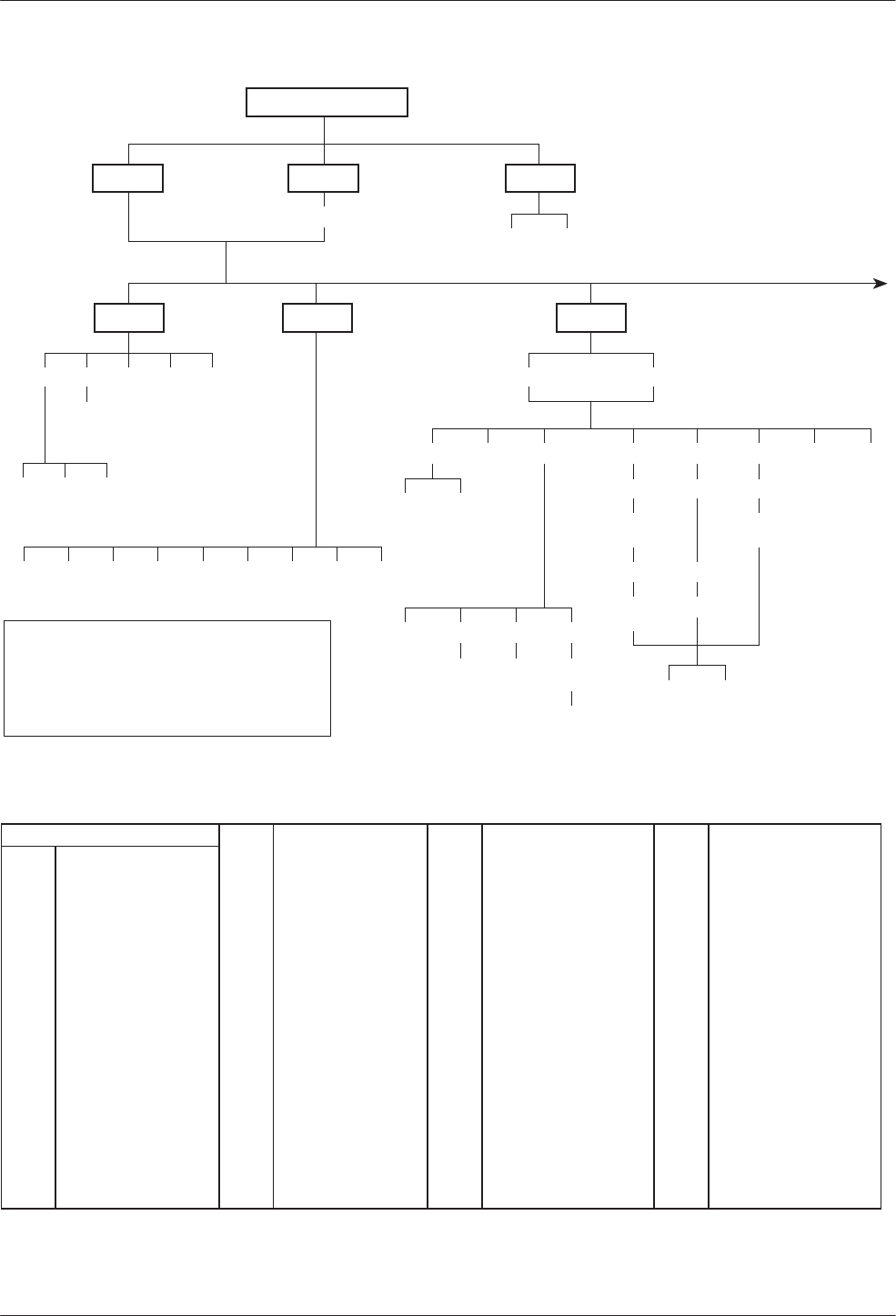
COMSPHERE 3600 Series Data Service Units
A-2 March 1999 3610-A2-GB48-70
Local Remot
Stat Bckup Test
TOP-LEVEL MENU
H/S DTE CircQ ID TPwr
Port
Select
DSU DBM
Abort Devic Lpbk Lamp
LL DTE DL RL
Start Start Start
Port
Select Port
Select Port
Select
Port
Select
Address
Address Address
Run
Tim # Blocks
Displ Clr
EE
Devic Expan Subn
BERT
Port
Select
Subn Selective
Msgs
Address Read Clear
DT
496-14331a-04
Abort Bkup Dial DrBU Disc →Dial →DDS AggSw
DTone
→Net
I
NOTE
For additional details refer to Chapter 4,
Configuration Option Tables
, and
Appendix B,
Configuration Worksheets
.
ABBREVIATIONS DBM Dial Backup Module EBrdg Extended Bridge MPTC Multipoint Control
→ DDS Switch to DDS Path DDD Direct Distance Dialing Enab Enable MPTT Multipoint Tributary
→ Dial Switch to DDD Path DDS Digital Data Service Expan Expanded Health and Service MUX Multiplexer
Acq Acquire Devic Device ExtL External Leads NetINetwork Interface
Addr Address Diag Diagnostic FacB Factory Bridge Opts Configuration Options
ADp Advanced Diagnostic protocol Dir Directory FacC Factory Control PList Poll List
AggSw Aggregate Switch Disab Disable FacT Factory Tributary PrtSp Port Speed
Bckup Backup Disc Disconnect FB1 Fallback 1 Pswrd Password
BERT Bit Error Rate Test Displ Display Gen General Remot Remote Mode
CBrdg Central-Site Bridge DL Digital Loopback H/S Health and Status Remt Remote
Chan Channel to Port DPII DATAPHONE II ID Identity RL Remote Digital Loopback
ChgMd Change Mode DrBU Drop Backup LEDs Light Emitting Diodes SPID Service Profile Identifier
CID Customer Identifier DSU Data Service Unit LL Local Loopback Subn Subnetwork Health and Status
CircQ Circuit Quality DT Digital Test Lpbk Loopback TDM Time Division Multiplexer
Clr Clear DTE Data Terminal Equipment LPDA Link Problem Determination Aid Term Async Terminal
Confg Configure DTone Dial Tone MCMP Multichannel Multipoint TPwr Terminal Power
Ctrl Control EE End-to-End Test Msgs Messages TxCtl Transmitter Control
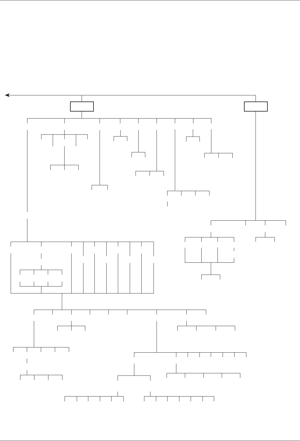
Data Service Unit Menu
A-33610-A2-GB48-70 March 1999
Confg Ctrl
Opts PList Addr ChgMd
Displ Chang Add Acq
Activ Delet Save DPII ADp
Remt
Address
Activ Usr1 Usr2 Usr3
Activ Usr1
Usr2
Usr3
FacC
FacT
FacB
Load
SAVE DSU DBM Gen Bkup MUX LPDA
Copy Setup Prt1 Prt2 Prt3 Prt4 Prt5 Prt6
Remt Usr1 Usr2 Usr3
Address
Activ Usr1 Usr2 Usr3 TDM MCMP
DSU DBM
TxCtl LEDs ExtL
DSU DBM Ports Displ Chang
Enab Disab
Skip
Clr
Diag
Prt1 Prt2 Prt3 Prt4 Prt5 Prt6
Copy
From
Devic
Activ
Port Select
Dir Phone
Chang Clr
496-14331b-05
DSU DBM Gen Chan
CBrdg EBrdg None
PrtSp
All Prt1 Prt2 Prt3 Prt4 Prt5 Prt6
Copy
To
Term
Enab Disab Pswrd CID
Pswrd
MenuSPID
Chang Clr
Save Enab Disab
FB1
Chang Clr
Chang Clr
MPTC
MPTT
Reset

COMSPHERE 3600 Series Data Service Units
A-4 March 1999 3610-A2-GB48-70
Table A-1
(2 of 2)
Factory Default MUX Configuration Options
MUX Port
n
FacC
Control FacT
Tributary FacB
Digital Bridge MPTC Multipoint
Control MPTT Multipoint
Tributary
Async–>Sync Disable Disable Disable Disable Disable
AsyncRate =Sync =Sync =Sync =Sync =Sync
AsyncBit/Char 8 8 8 8 8
Stop Bits 1 1 1 1 1
Overspeed 2.50 2.50 2.50 2.50 2.50
RTS Control DTE DTE DTE DTE DTE
TxCarrierSelect Constant Constant Constant Constant Constant
RxCarrierSelect Constant Constant Constant Constant Constant
PCC Buffer Disable Disable Disable Disable Disable
Elastic Store Disable Disable Enable Disable Disable
RTS/CTS Delay 0 0 0 0 0
DTR Alarm Disable Disable Disable Disable Disable
AntiStream Disable Disable Disable Disable Disable
DSR FrcOn Enable Enable Disable Enable Enable
DSR on Test Enable Enable Disable Enable Enable
Extend Channel No No No No No
Upstream Port Port 1 Port 1 Port 1 Port 1 Port 1
DTE Port EIA232 EIA232 EIA232 EIA232 EIA232
DCE Type Analog Analog Analog Analog Analog
DSU Port Speed FacC FacT FacB MPTC MPTT
Port 1 9.6 kbps 9.6 kbps 9.6 kbps 9.6 kbps 9.6 kbps
Port 2 — Port 6 Disable Disable 9.6 kbps Disable Disable
Underspeed Disable Disable Disable Disable Disable
MCMP Channel FacC FacT FacB MPTC MPTT
Assignment Port 1 A A A A A
Assignment Port 2 B B B B B
Assignment Port 3 C C C C C
Assignment Port 4 D D D D D
Assignment Port 5 E E E E E
Assignment Port 6 F F F F F

B-13610-A2-GB48-70 March 1999
Configuration Worksheets
Overview B-1. . . . . . . . . . . . . . . . . . . . . . . . . . . . . . . . . . . . . . . . . . . . . . . . . . . . . . . . . . . . . . . . . . . . . . . . . .
Overview
This section contains worksheets for:
•MCMP mode
•TDM mode
•Digital Bridge mode
Each set of worksheets includes the option sets with
configuration options and values applicable for the
selected MUX mode.
Use the worksheets for:
•Reference
•Recording changes to options
•Planning changes to default settings
Use the worksheets along with Chapter 4,
Configuration Option Tables, and Appendix A,
Data Service Unit Menu.
B

COMSPHERE 3600 Series Data Service Units
B-2 March 1999 3610-A2-GB48-70
This page intentionally left blank.

Configuration Worksheet for MCMP Mode (1 of 3)
Date:________________________________________________ Location:_____________________________________________ Local Phone Number: ( )____________________________
Device:______________________________________________ Local Address:_________________________________________ DBM Installed
Serial Number:________________________________________ Tributary Network Address:_______________________________ SNA Diagnostic Interface (LPDA-2) Enabled
MUX Setup
Configuration Options Value
MUX Funct TDM, MCMP, CBrdg, EBrdg, None
Share DevA Enab, Disab
Lowest Port# 1, 2, 3, 4, 5
#Ports in Gp 2, 3, 4, 5, 6
Port Cntrl Host, DSD
Share DevB Enab, Disab
Lowest Port# 1, 2, 3, 4, 5
#Ports in Gp 2, 3, 4, 5, 6
Port Cntrl Host, DSD
P1/2 FEPSh Enab, Disab
P3/4 FEPSh Enab, Disab
P5/6 FEPSh Enab, Disab
MCMP Bckup MCMP, TDM
ISDN and Switched 56 kbps Digital DBMs only
Ports 3–6 are not available for 2-port MCMP/TDM Flex models
Available for MCMP/Flex with DSU firmware version 6.33 or greater
Configuration options that do not appear when Full mode is disabled
using Menu from the Configuration branch
Prt3
Configuration Options Value
Async→Sync Enab, Disab
Async Rate =Sync, 1800, 1200, 600, 300, 150
AsyncBit/Char 6, 7, 8, 9, 10
Stop Bits 1, 2
RTS Cntrl FrcOn, DTE
TxCarrSel Const, Cntrl
RxCarrSel Const, Cntrl, Mark
PCC Buffer Enab, Disab
Elast Stor Enab, Disab
RTS/CTS Del 0–1040 ms (8 ms increments)
DTR Alarm Enab, Disab
AntiStream Disab, 1–100 sec (async terminal = 0–100)
DSR FrcOn Enab, Disab
DSR on Tst Enab, Disab
Extend Chan Yes, No
Upstrm Port Prt1, Prt2, Prt3, Prt4, Prt5, Prt6
DTE Port EIA232, V.35
DCE Type Analg, Digtl
Prt1
Configuration Options Value
Async→Sync Enab, Disab
Async Rate =Sync, 1800, 1200, 600, 300, 150
AsyncBit/Char 6, 7, 8, 9, 10
Stop Bits 1, 2
RTS Cntrl FrcOn, DTE
TxCarrSel Const, Cntrl
RxCarrSel Const, Cntrl, Mark
PCC Buffer Enab, Disab
Elast Stor Enab, Disab
RTS/CTS Del 0–1040 ms (8 ms increments)
DTR Alarm Enab, Disab
AntiStream Disab, 1–100 sec (async terminal = 0–100)
DSR FrcOn Enab, Disab
DSR on Tst Enab, Disab
Extend Chan Yes, No
Upstrm Port Prt1, Prt2, Prt3, Prt4, Prt5, Prt6
DTE Port EIA232, V.35
DCE Type Analg, Digtl
Prt4
Configuration Options Value
Async→Sync Enab, Disab
Async Rate =Sync, 1800, 1200, 600, 300, 150
AsyncBit/Char 6, 7, 8, 9, 10
Stop Bits 1, 2
RTS Cntrl FrcOn, DTE
TxCarrSel Const, Cntrl
RxCarrSel Const, Cntrl, Mark
PCC Buffer Enab, Disab
Elast Stor Enab, Disab
RTS/CTS Del 0–1040 ms (8 ms increments)
DTR Alarm Enab, Disab
AntiStream Disab, 1–100 sec (async terminal = 0–100)
DSR FrcOn Enab, Disab
DSR on Tst Enab, Disab
Extend Chan Yes, No
Upstrm Port Prt1, Prt2, Prt3, Prt4, Prt5, Prt6
DTE Port EIA232, V.35
DCE Type Analg, Digtl
Prt2
Configuration Options Value
Async→Sync Enab, Disab
Async Rate =Sync, 1800, 1200, 600, 300, 150
AsyncBit/Char 6, 7, 8, 9, 10
Stop Bits 1, 2
RTS Cntrl FrcOn, DTE
TxCarrSel Const, Cntrl
RxCarrSel Const, Cntrl, Mark
PCC Buffer Enab, Disab
Elast Stor Enab, Disab
RTS/CTS Del 0–1040 ms (8 ms increments)
DTR Alarm Enab, Disab
AntiStream Disab, 1–100 sec (async terminal = 0–100)
DSR FrcOn Enab, Disab
DSR on Tst Enab, Disab
Extend Chan Yes, No
Upstrm Port Prt1, Prt2, Prt3, Prt4, Prt5, Prt6
DTE Port EIA232, V.35
DCE Type Analg, Digtl
Prt5
Configuration Options Value
Async→Sync Enab, Disab
Async Rate =Sync, 1800, 1200, 600, 300, 150
AsyncBit/Char 6, 7, 8, 9, 10
Stop Bits 1, 2
RTS Cntrl FrcOn, DTE
TxCarrSel Const, Cntrl
RxCarrSel Const, Cntrl, Mark
PCC Buffer Enab, Disab
Elast Stor Enab, Disab
RTS/CTS Del 0–1040 ms (8 ms increments)
DTR Alarm Enab, Disab
AntiStream Disab, 1–100 sec (async terminal = 0–100)
DSR FrcOn Enab, Disab
DSR on Tst Enab, Disab
Extend Chan Yes, No
Upstrm Port Prt1, Prt2, Prt3, Prt4, Prt5, Prt6
DTE Port EIA232, V.35
DCE Type Analg, Digtl

Configuration Worksheet for MCMP Mode (2 of 3)
Prt6
Configuration Options Value
Async→Sync Enab, Disab
Async Rate =Sync, 1800, 1200, 600, 300, 150
AsyncBit/Char 6, 7, 8, 9, 10
Stop Bits 1, 2
RTS Cntrl FrcOn, DTE
TxCarrSel AConst, Cntrl
RxCarrSel AConst, Cntrl, Mark
PCC Buffer Enab, Disab
Elast Stor AEnab, Disab
RTS/CTS Del A0–1040 ms (8 ms increments)
DTR Alarm AEnab, Disab
AntiStream ADisab, 1–100 sec (async term = 0–100)
DSR FrcOn AEnab, Disab
DSR on Tst AEnab, Disab
Extend Chan AYes, No
Upstrm Port }} APrt1, Prt2, Prt3, Prt4, Prt5, Prt6
DTE Port :EIA232, V.35
DCE Type Analg, Digtl
DSU
Configuration Options Value
Rate(Kbps) 56
TxClkSource Int, RXC, DDS
Msg Clamp AEnab, Disab
TxElasStor Enab, Disab
RxElasStor AEnab, Disab
19.2 PowrLvl DD A+6, 0, –10
64KScrambling AOn, Off
64KLatchLpbk AOn, Off
NetIntf AAggSw, Forc, Disab
NetI Timing AInt, NetI
V.54 Lpbk AEnab, Disab
Diagnostic DSU
Configuration Options Value
Diag Type NonD, Disr, None
2nd Ch(bps) A100, 400, 800, 1200, 1600
Disr Type 3600s, 3600e, Br56
Diagnostic DBM
Configuration Options Value
Diag Type NonD, Disr, None
2nd Ch(bps) A100, 400, 800, 1200, 1600
RemoteDiag AV.54, Enhan, 2500
FB DiagTyp1 LNonD, Disr, Mixed, None
FB 2nd Ch1 LA100, 400, 800, 1200, 1600
Diagnostic General
Configuration Options Value
Position Cntrl, Trib
LinkConfig Pt-Pt, M-Pt
Resp Period A1, 2, 10
Trib TimOut Amin and sec (5 sec. to 10 min.)
Diag Conn CC, DC
Link Delay A0s, 1s, 2s, 5s, 10s, 20s, 50s
Network Delay A0s, 1s, 2s, 5s, 10s, 20s, 50s
Packet Delay A0s, 1s, 2s, 5s
Fast Sel AEnab, Disab
DSU MCMP PrtSp
Configuration Options Value
Prt
n
(SS.S) }} 48, 38.4, 19.2, 16.8, 14.4, 12.0, 9.6, 7.2, 4.8,
2.4, 1.2, Disab
Prt1 Prt2 Prt3 Prt4 Prt5 Prt6
DBM PrtSp
Configuration Options Value
Prt
n
(SS.S) }} D*48, 38.4, 32, 28.8, 19.2, 18.0, 16.8, 14.4,
12.0, 9.6, 8.4
,
7.2, 4.8, 4.0, 2.4, 2.0, 1.2,
Disab
Underspeed }} Disab, Prt1, Prt2, Prt3, Prt4, Prt5, Prt6
Prt1 Prt2 Prt3 Prt4 Prt5 Prt6
DBM Fallback1 PrtSp
Configuration Options Value
Prt
n
(SS.S) LD}} 48, 38.4, 32, 28.8, 19.2, 18.0, 16.8, 14.4,
12.0, 9.6, 8.4, 7.2, 4.8, 4.0, 2.4, 2.0, 1.2,
Disab
Underspeed }} Disab, Prt1, Prt2, Prt3, Prt4, Prt5, Prt6
Prt1 Prt2 Prt3 Prt4 Prt5 Prt6
:Appears with MCMP/TDM Flex with DSU firmware version
6.33 or greater
LISDN DBM only
}} Ports 3–6 are not available for 2-port MCMP/TDM Flex
models.
DWhen the Async→Sync configuration option is enabled
using the MUX Port
n
branch, the following DBM PrtSp
settings will not appear: 32, 18.0, 8.4, 4.0, and 2.0 kbps
DD 19.2 Power Level defaults to +6 dB when App Module ID
displays XLOOP
n
= Port number
SS.S = Aggregate rate
AConfiguration options that do not appear when Full mode
is disabled using Menu from the Configuration branch.

Configuration Worksheet for MCMP Mode (3 of 3)
DBM
Configuration Options Value
Rate(Kbps) }56, 28.8, 24.0, 19.2, 16.8, 14.4, 12.0, 9.6,
7.2, 4.8, 2.4
TxClkSourceLL}} Int, RXC, DSU, Prt1, Prt2, Prt3, Prt4,
Prt5, Prt6
CarrLossDisc LL AYes, No
Auto Retrain LL AYes, No
Single Rate LL Yes, No
Fallback LNone, All, One
AutoAnswer AEnab, Disab
TxElasStor Enab, Disab
RxElasStor AEnab, Disab
Call Setup None, Pswrd, Clbk, Alarm
RxPwd (10 characters)
TxPwd (10 characters)
V.13 Signl Enab, Disab
Dial Test AEnab, Disab
Primary Core AYes, No
DtrCallCon Orig z, Ansr, Disab
EchoCancel HAEnab, Disab
Remote DBM DDD A2-wire, 4-wire
Wait Answer zz A90 ms, 300 ms, 500 ms, 1s, 2s, 3s, 4s, 5s
Bkup Timer Disab, 15s, 30s, 1m, 2m, 3m
SwitchTyp LNI-1, NI-2, AT&T, DMS100
FBR1(Kbps) L56
Channel to Port
Configuration Options Value
AssgmntPrt1 A, B, C, D, E, F, G, H, None
AssgmntPrt2 A, B, C, D, E, F, G, H, None
AssgmntPrt3 }} A, B, C, D, E, F, G, H, None
AssgmntPrt4 }} A, B, C, D, E, F, G, H, None
AssgmntPrt5 }} A, B, C, D, E, F, G, H, None
AssgmntPrt6 }} A, B, C, D, E, F, G, H, None
Backup
Configuration Options Value
Auto Bckup zEnab, Disab
Backup Dir 1–10
FAOnCMI zAEnab, Disab
AutoRestor Enab, Disab
NtwkTimOut z min and sec (1 sec to 30 min)
RestorTimOut z min (1 min to 60 min)
TriesTimeOut zA min (1 min to 60 min)
MultiCall zAEnab, Disab
General
Configuration Options Value
DTE Port :: EIA232, V.35
RTS Cntrl FrcOn, DTE
CTS Cntrl Std, =RTS
LSD Lead ASTD, Delay, FrcOn
CTS Lead ASTD, Delay, FrcOn
SystemStat AEnab, Disab
Circ Assur AEnab, Disab
Tst Pattern AAT&T, Std
RespondRDL AEnab, Disab
LL by DTE AEnab, Disab
RL by DTE AEnab, Disab
Bilat Lpbk AEnab, Disab
Ext Leads AExtLd, Rate, RPowr
CCN by EL AEnab, Disab
SW Vers A3.24, 4.43, 6.66, Normal
AnswExtBU AEnab, Disab
RLSD in MCMP HAYes, No
PowerOnTst Enab, Disab
LPDA-2
Configuration Options Value
LPDA-2 Enab, Disab
LPDA Address 1–256
SNA Backup Enab, Disab
Code 1 (6 digits)
Code 2 (7 digits)
Backup Directory Dial String
1
2
3
4
5
6
7
8
9
10
S1 Hardware Settings Value
DBM Interface LL Permissive (ON), Programmable (OFF)
Frame Ground/
Signal Ground Connected (ON), Disconnected (OFF)
EIA-232 Test Mode Enable (ON), Disable (OFF)
V.35 Test Mode Enable (ON), Disable (OFF)
ChgMd
Configuration Options Value
Protocol Mode DPII, ADp
LISDN DBM only
LL V.32 Analog DBM only
DDD ISDN and 2-wire Switched 56 DBMs only
}Not available for Switched 56 DBMs; defaults to 56 kbps.
}} Ports 3–6 are not available for 2-port Flex MUX models.
zNot available for a DBM-
X
or a DSU with Primary core set
to Yes; the DSU is Disabled
zz 4-wire Switched 56 DBM only
HISDN and Switched 56 Digital DBMs
:: Appears when non-Flex MCMP/TDM is installed or 6-port
MCMP/TDM Flex is installed with firmware version less
than 6.33
AConfiguration options that do not appear when Full mode
is disabled using Menu from the Configuration branch.

Configuration Worksheet for TDM Mode (1 of 3)
Date:________________________________________________ Location:_____________________________________________ Local Phone Number: ( )__________________________
Device:______________________________________________ Local Address:________________________________________ j DBM Installed
Serial Number:_________________________________________ Tributary Network Address:______________________________ j SNA Diagnostic Interface (LPDA-2) Installed
MUX Setup
Configuration Options Value Options
MUX Funct TDM, MCMPa, CBrdg, EBrdg, None
Share DevA Enab, Disab
Lowest Port# 1, 2, 3, 4, 5
#Ports in Gp 2, 3, 4, 5, 6
Port Cntrl Host, DSD
Share DevB Enab, Disab
Lowest Port# 1, 2, 3, 4, 5
#Ports in Gp 2, 3, 4, 5, 6
Port Cntrl Host, DSD
P1/2 FEPSh Enab, Disab
P3/4 FEPSh Enab, Disab
P5/6 FEPSh Enab, Disab
aMCMP option only
}} Ports 3–6 not available for 2-port MCMP/TDM Flex models
:Appears with MCMP/TDM Flex with DSU firmware version 6.33
or greater
AConfiguration options that do not appear when Full mode is
disabled using Menu from the Configuration branch.
Prt3
Configuration Options Value
Async→Sync Enab, Disab
Async Rate =Sync, 1800, 1200, 600, 300, 150
AsyncBit/Char 6, 7, 8, 9, 10
Stop Bits 1, 2
Overspeed 1.25, 2.50
RTS Cntrl FrcOn, DTE
TxCarrSel AConst, Cntrl
RxCarrSel AConst, Cntrl, Mark
PCC Buffer Enab, Disab
Elast Stor AEnab, Disab
RTS/CTS Del A0–1040 ms (8 ms increments)
DTR Alarm AEnab, Disab
AntiStream ADisab, 1–100 sec (async terminal = 0–100)
DSR FrcOn AEnab, Disab
DSR on Tst AEnab, Disab
Extend Chan AYes, No
Upstrm Port }} APrt1, Prt2, Prt3, Prt4, Prt5, Prt6
DTE Port :EIA232, V.35
DCE Type Analg, Digtl
Prt1
Configuration Options Value
Async→Sync Enab, Disab
Async Rate =Sync, 1800, 1200, 600, 300, 150
AsyncBit/Char 6, 7, 8, 9, 10
Stop Bits 1, 2
Overspeed 1.25, 2.50
RTS Cntrl FrcOn, DTE
TxCarrSel AConst, Cntrl
RxCarrSel AConst, Cntrl, Mark
PCC Buffer Enab, Disab
Elast Stor AEnab, Disab
RTS/CTS Del A0–1040 ms (8 ms increments)
DTR Alarm AEnab, Disab
AntiStream ADisab, 1–100 sec (async terminal = 0–100)
DSR FrcOn AEnab, Disab
DSR on Tst AEnab, Disab
Extend Chan AYes, No
Upstrm Port }} APrt1, Prt2, Prt3, Prt4, Prt5, Prt6
DTE Port :EIA232, V.35
DCE Type Analg, Digtl
Prt4
Configuration Options Value
Async→Sync Enab, Disab
Async Rate =Sync, 1800, 1200, 600, 300, 150
AsyncBit/Char 6, 7, 8, 9, 10
Stop Bits 1, 2
Overspeed 1.25, 2.50
RTS Cntrl FrcOn, DTE
TxCarrSel AConst, Cntrl
RxCarrSel AConst, Cntrl, Mark
PCC Buffer Enab, Disab
Elast Stor AEnab, Disab
RTS/CTS Del A0–1040 ms (8 ms increments)
DTR Alarm AEnab, Disab
AntiStream ADisab, 1–100 sec (async terminal = 0–100)
DSR FrcOn AEnab, Disab
DSR on Tst AEnab, Disab
Extend Chan AYes, No
Upstrm Port }} APrt1, Prt2, Prt3, Prt4, Prt5, Prt6
DTE Port :EIA232, V.35
DCE Type Analg, Digtl
Prt2
Configuration Options Value
Async→Sync Enab, Disab
Async Rate =Sync, 1800, 1200, 600, 300, 150
AsyncBit/Char 6, 7, 8, 9, 10
Stop Bits 1, 2
Overspeed 1.25, 2.50
RTS Cntrl FrcOn, DTE
TxCarrSel AConst, Cntrl
RxCarrSel AConst, Cntrl, Mark
PCC Buffer Enab, Disab
Elast Stor AEnab, Disab
RTS/CTS Del A0–1040 ms (8 ms increments)
DTR Alarm AEnab, Disab
AntiStream ADisab, 1–100 sec (async terminal = 0–100)
DSR FrcOn AEnab, Disab
DSR on Tst AEnab, Disab
Extend Chan AYes, No
Upstrm Port }} APrt1, Prt2, Prt3, Prt4, Prt5, Prt6
DTE Port :EIA232, V.35
DCE Type Analg, Digtl
Prt5
Configuration Options Value
Async→Sync Enab, Disab
Async Rate =Sync, 1800, 1200, 600, 300, 150
AsyncBit/Char 6, 7, 8, 9, 10
Stop Bits 1, 2
Overspeed 1.25, 2.50
RTS Cntrl FrcOn, DTE
TxCarrSel AConst, Cntrl
RxCarrSel AConst, Cntrl, Mark
PCC Buffer Enab, Disab
Elast Stor AEnab, Disab
RTS/CTS Del A0–1040 ms (8 ms increments)
DTR Alarm AEnab, Disab
AntiStream ADisab, 1–100 sec (async terminal = 0–100)
DSR FrcOn AEnab, Disab
DSR on Tst AEnab, Disab
Extend Chan AYes, No
Upstrm Port }} APrt1, Prt2, Prt3, Prt4, Prt5, Prt6
DTE Port :EIA232, V.35
DCE Type Analg, Digtl

Configuration Worksheet for TDM Mode (2 of 3)
Prt6
Configuration Options Value
Async→Sync Enab, Disab
Async Rate =Sync, 1800, 1200, 600, 300, 150
AsyncBit/Char 6, 7, 8, 9, 10
Stop Bits 1, 2
Overspeed 1.25, 2.50
RTS Cntrl FrcOn, DTE
TxCarrSel AConst, Cntrl
RxCarrSel AConst, Cntrl, Mark
PCC Buffer Enab, Disab
Elast Stor AEnab, Disab
RTS/CTS Del A0–1040 ms (8 ms increments)
DTR Alarm AEnab, Disab
AntiStream ADisab, 1–100 sec (async terminal = 0–100)
DSR FrcOn AEnab, Disab
DSR on Tst AEnab, Disab
Extend Chan AYes, No
Upstrm Port }} APrt1, Prt2, Prt3, Prt4, Prt5, Prt6
DTE Port :EIA232, V.35
DCE Type Analg, Digtl
DSU
Configuration
Options Value
Rate(Kbps) Auto, 64CC, 64L, 56, 38.4, 19.2, 9.6, 4.8, 2.4
TxClkSource }} Int, RXC, DDS, Prt1, Prt2, Prt3, Prt4, Prt5,
Prt6
Msg Clamp AEnab, Disab
TxElasStor Enab, Disab
RxElasStor AEnab, Disab
19.2 PowrLvl DD A+6, 0, –10
64KScrambling AOn, Off
64KLatchLpbk AOn, Off
NetIntf AAggSw, Forc, Disab
NetI Timing }} AInt, NetI, Prt1, Prt2, Prt3, Prt4, Prt5, Prt6
V.54 Lpbk AEnab, Disab
Diagnostic DSU
Configuration
Options Value
Diag Type NonD, Disr, Mixed, None
2nd Ch(bps) A100, 400, 800, 1200, 1600
Disr Type 2500, 2600, 3600s, 3600e, Br56
Diagnostic DBM
Configuration
Options Value
Diag Type NonD, Disr, Mixed, None
2nd Ch(bps) A100, 400, 800, 1200, 1600
RemoteDiag AV.54, Enhan, 2500
FBDiagTyp1 LNonD, Disr, Mixed, None
FB 2nd Ch1 LA100, 400, 800, 1200, 1600
Diagnostic General
Configuration
Options Value
Position Cntrl, Trib, G2Trb
LinkConfig Pt-Pt, M-Pt
Resp Period A1, 2, 10
Trib TimOut Amin and sec (5 sec. to 10 min.)
Diag Conn CC, DC
Link Delay A0s, 1s, 2s, 5s, 10s, 20s, 50s
Network Delay A0s, 1s, 2s, 5s, 10s, 20s, 50s
Packet Delay A0s, 1s, 2s, 5s
M-PtSymPrt AEnab, Disab
Fast Sel AEnab, Disab
DSU TDM PrtSp
Configuration
Options Value
Prt
n
(SS.S) D }} 64, 56, 48, 38.4, 32, 28.8, 24.0, 19.2, 18.8,
18.0, 16.8, 14.4, 12.0, 9.6, 9.2, 8.4, 7.2, 4.8,
4.4, 4.0, 2.4, 2.0, 1.2, Disab
Underspeed }} Disab, Prt1, Prt2, Prt3, Prt4, Prt5, Prt6
Prt1 Prt2 Prt3 Prt4 Prt5 Prt6
DBM PrtSp
Configuration Options Value
Prt
n
(SS.S) D}} 64, 56, 48, 38.4, 32, 28.8, 24.0, 19.2, 18.8,
18.0, 16.8, 14.4, 12.0, 9.6, 9.2, 8.4, 7.2, 4.8,
4.4, 4.0, 2.4, 2.0, 1.2, Disab
Underspeed }} Disab, Prt1, Prt2, Prt3, Prt4, Prt5, Prt6
Prt1 Prt2 Prt3 Prt4 Prt5 Prt6
DBM Fallback1 PrtSp
Configuration Options Value
Prt
n
(SS.S) LD}} 56, 48, 38.4, 32, 28.8, 24.0, 19.2, 18.8, 18.0,
16.8, 14.4, 12.0, 9.6, 9.2, 8.4, 7.2, 4.8, 4.4,
4.0, 2.4, 2.0, 1.2, Disab
Underspeed }} Disab, Prt1, Prt2, Prt3, Prt4, Prt5, Prt6
Prt1 Prt2 Prt3 Prt4 Prt5 Prt6
LISDN DBM only
}} Ports 3–6 not available for 2-port MCMP/TDM Flex models
:Appears with MCMP/TDM Flex with DSU firmware version
6.33 or greater
DWhen the Async→Sync configuration option is enabled
using MUX Port
n
, the following PrtSp settings will not
appear:
32, 24.0, 18.8, 18.0, 9.2, 8.4, 4.4, 4.0, and 2.0 kbps.
DD 19.2 Power Level defaults to +6 dB when ID App Module
displays XLOOP
n
= Port number
SS.S = Aggregate rate
AConfiguration options that do not appear when Full mode
is disabled using Menu from the Configuration branch.8

Configuration Worksheet for TDM Mode (3 of 3)
DBM
Configuration
Options Value
Rate(Kbps) }64, 56, 28.8, 24.0, 19.2, 16.8, 14.4, 12.0,
9.6, 7.2, 4.8, 2.4
TxClkSource LL}} Int, RXC, DSU, Prt1, Prt2, Prt3, Prt4,
Prt5, Prt6
CarrLossDisc LL AYes, No
Auto Retrain LL AYes, No
Single Rate LL Yes, No
Fallback LNone, All, One
AutoAnswer AEnab, Disab
TxElasStor Enab, Disab
RxElasStor AEnab, Disab
Call Setup None, Pswrd, Clbk, Alarm
RxPwd (10 characters)
TxPwd (10 characters)
V.13 Signl Enab, Disab
Dial Test AEnab, Disab
Primary Core AYes, No
DtrCallCon Orig z, Ansr, Disab
EchoCancel HAEnab, Disab
Remote DBM DDDA2-wire, 4-wire
Wait Answer zz A90 ms, 300 ms, 500 ms, 1s, 2s, 3s, 4s, 5s
Bkup Timer Disab, 15s, 30s, 1m, 2m, 3m
SwitchTyp LNI-1, NI-2, AT&T, DMS100
FBR1(Kbps) L56
LPDA-2
Configuration
Options Value
LPDA-2 Enab, Disab
LPDA Address 1–256
SNA Backup Enab, Disab
Code 1 (6 digits)
Code 2 (7 digits)
Backup
Configuration
Options Value
Auto Bckup zEnab, Disab
Backup Dir 1–10
FAOnCMI zAEnab, Disab
AutoRestor Enab, Disab
NtwkTimOutz min and sec (1 sec to 30 min)
RestorTimOut z min (1 min to 60 min)
TriesTimeOut zA min (1 min to 60 min)
MultiCall zAEnab, Disab
General
Configuration
Options Value
DTE Port :: EIA232, V.35
RTS Cntrl FrcOn, DTE
CTS Cntrl Std, =RTS
LSD Lead ASTD, Delay, FrcOn
CTS Lead ASTD, Delay, FrcOn
SystemStat AEnab, Disab
Circ Assur AEnab, Disab
Tst Pattern AAT&T, Std
RespondRDL AEnab, Disab
LL by DTE AEnab, Disab
RL by DTE AEnab, Disab
Bilat Lpbk AEnab, Disab
Ext Leads AExtLd, Rate, RPowr
CCN by EL AEnab, Disab
SW Vers A3.24, 4.43, 6.66, Normal
AnswExtBU AEnab, Disab
RLSD in MCMP HAYes, No
PowerOnTst Enab, Disab
ChgMd
Configuration
Options Value
Protocol Mode DPII, ADp
Backup Directory Dial String
1
3
4
5
6
7
8
9
10
S1 Hardware
Settings Value
DBM Interface LL Permissive (ON), Programmable (OFF)
Frame Ground/
Signal Ground Connected (ON), Disconnected (OFF)
EIA-232 Test Mode Enable (ON), Disable (OFF)
V.35 Test Mode Enable (ON), Disable (OFF)
}Not available for Switched 56 DBM; Defaults to 56 kbps
}} Ports 3–6 not available for 2-port Flex MUX models
HISDN and Switched 56 Digital DBMs only
LISDN DBM only
LL V.32 Analog DBM only
DDD ISDN and 2-wire Switched 56 DBMs only
:: Appears with Non-Flex MCMP/TDM or 6-port TDM/Flex
with firmware version less than 6.33
zNot available for a DBM-
X
or a DSU with Primary Core set
to Yes; the DSU is disabled
zz 4-wire Switched 56 DBM only
AConfiguration options that do not appear when Full mode is
disabled using Menu from the Configuration branch.

Configuration Worksheet for Bridge Mode (1 of 2)
Date:________________________________________________ Location:_____________________________________________ Local Phone Number: ( j)___________________________
Device:______________________________________________ Local Address:_________________________________________ j DBM Installed
Serial Number:_________________________________________ Tributary Network Address:_______________________________ j SNA Diagnostic Interface (LPDA-2) Enabled
MUX Setup
Configuration
Options Value
MUX Funct:
(CBrdg or EBrdg)
TDM, MCMP, CBrdg, EBrdg, None
Bridge Rate =DSU z, 64, 56, 28.8, 24.0, 19.2, 16.8,
14.4, 12.0, 9.6, 4.8, 2.4
Brdg Timing }} Int, Auto, Prt1, Prt2, Prt3, Prt4, Prt5,
Prt6
Share DevA: Enab
Lowest Port# DCE, 2, 3, 4, 5
#Ports in Gp: 2, 3, 4, 5, 6
Port Cntrl: Host, DSD
Share DevB: Disab
zDoes not appear for EBrdg
}} Ports 3–6 not available for 2-port MCMP/TDM Flex models
:Appears with MCMP/TDM Flex with DSU firmware version
6.33 or greater
AConfiguration options that do not appear when Full mode is
disabled using Menu from the configuration branch.
Prt4
Configuration
Options Value
RTS Cntrl FrcOn, DTE
TxCarrSel AConst, Cntrl
RxCarrSel AConst, Cntrl, Mark
PCC Buffer Enab, Disab
Elast Stor AEnab, Disab
RTS/CTS Del A0–1040 ms (8 ms increments)
DTR Alarm AEnab, Disab
AntiStream ADisab, 1–100 sec (async term = 0–100)
DSR FrcOn AEnab, Disab
DSR on Tst AEnab, Disab
Extend Chan AYes, No
Upstrm Port }} APrt1, Prt2, Prt3, Prt4, Prt5, Prt6
DTE Port :EIA232, V.35
Prt2
Configuration
Options Value
RTS Cntrl FrcOn, DTE
TxCarrSel AConst, Cntrl
RxCarrSel AConst, Cntrl, Mark
PCC Buffer Enab, Disab
Elast Stor AEnab, Disab
RTS/CTS Del A0–1040 ms (8 ms increments)
DTR Alarm AEnab, Disab
AntiStream ADisab, 1–100 sec (async term = 0–100)
DSR FrcOn AEnab, Disab
DSR on Tst AEnab, Disab
Extend Chan AYes, No
Upstrm Port }} APrt1, Prt2, Prt3, Prt4, Prt5, Prt6
DTE Port :EIA232, V.35
Prt5
Configuration
Options Value
RTS Cntrl FrcOn, DTE
TxCarrSel AConst, Cntrl
RxCarrSel AConst, Cntrl, Mark
PCC Buffer Enab, Disab
Elast Stor AEnab, Disab
RTS/CTS Del A0–1040 ms (8 ms increments)
DTR Alarm AEnab, Disab
AntiStream ADisab, 1–100 sec (async term = 0–100)
DSR FrcOn AEnab, Disab
DSR on Tst AEnab, Disab
Extend Chan AYes, No
Upstrm Port }} APrt1, Prt2, Prt3, Prt4, Prt5, Prt6
DTE Port :EIA232, V.35
Prt3
Configuration
Options Value
RTS Cntrl FrcOn, DTE
TxCarrSel AConst, Cntrl
RxCarrSel AConst, Cntrl, Mark
PCC Buffer Enab, Disab
Elast Stor AEnab, Disab
RTS/CTS Del A0–1040 ms (8 ms increments)
DTR Alarm AEnab, Disab
AntiStream ADisab, 1–100 sec (async term = 0–100)
DSR FrcOn AEnab, Disab
DSR on Tst AEnab, Disab
Extend Chan AYes, No
Upstrm Port }} APrt1, Prt2, Prt3, Prt4, Prt5, Prt6
DTE Port :EIA232, V.35
Prt6
Configuration
Options Value
RTS Cntrl FrcOn, DTE
TxCarrSel AConst, Cntrl
RxCarrSel AConst, Cntrl, Mark
PCC Buffer Enab, Disab
Elast Stor AEnab, Disab
RTS/CTS Del A0–1040 ms (8 ms increments)
DTR Alarm AEnab, Disab
AntiStream ADisab, 1–100 sec (async term = 0–100)
DSR FrcOn AEnab, Disab
DSR on Tst AEnab, Disab
Extend Chan AYes, No
Upstrm Port }} APrt1, Prt2, Prt3, Prt4, Prt5, Prt6
DTE Port :EIA232, V.35

Configuration Worksheet for Bridge Mode (2 of 2)
DSU
Configuration
Options Value
Rate(Kbps) zAuto, 64CC, 64L, 56, 38.4, 19.2, 9.6, 4.8,
2.4
TxClkSource zInt, RXC, DDS, Prt1
Msg Clamp zAEnab, Disab
TxElasStor Enab, Disab
RxElasStor
zAEnab, Disab
19.2 PowrLvl FF A+6, 0, –10
64KScrambling AOn, Off
64KLatchLpbk AOn, Off
NetI Timing z}} AInt, NetI, Prt1, Prt2, Prt3, Prt4, Prt5, Prt6
V.54 Lpbk AEnab, Disab
Diagnostic DSU
Configuration
Options Value
Diag Type NonD z, Disr, Mixed z, None
2nd Ch(bps) zA100, 400, 800, 1200, 1600
Disr Type 3600s z, 3600e, Br56
Diagnostic General
Configuration
Options Value
Position Cntrl
LinkConfig Pt-Pt, M-Pt
Resp Period A1, 2, 10
Trib TimOut Amin and sec (5 sec to 10 min)
Diag Conn CC, DC
Link Delay A0s, 1s, 2s, 5s, 10s, 20s, 50s
Network Delay A0s, 1s, 2s, 5s, 10s, 20s, 50s
Packet Delay A0s, 1s, 2s, 5s
M-PtSymPrt HAEnab, Disab
Fast Sel AEnab, Disab
General
Configuration
Options Value
DTE Port :: EIA232, V.35
RTS Cntrl FrcOn
CTS Cntrl Std, =RTS
LSD Lead ASTD, Delay, FrcOn
CTS Lead ASTD, Delay, FrcOn
SystemStat AEnab, Disab
Circ Assur AEnab, Disab
Tst Pattern AAT&T, Std
RespondRDL AEnab, Disab
LL by DTE AEnab, Disab
RL by DTE AEnab, Disab
Bilat Lpbk AEnab, Disab
Ext Leads AExtLd, Rate, RPowr
CCN by EL AEnab, Disab
DTR Alarm AEnab, Disab
SW Vers A3.24, 4.43, 6.66, Normal
AnswExtBU AEnab, Disab
Async→Sync zEnab, Disab
AsyncBit/Char z6, 7, 8, 9, 10
Stop Bits z1, 2
Overspeed z1.0, 2.3
PowerOnTst Enab, Disab
ChgMd
Configuration
Options Value
Protocol Mode DPII, ADp
LPDA-2
Configuration
Options Value
LPDA-2 Enab, Disab
LPDA Address 1–256
SNA Backup Enab, Disab
Code 1 (6 digits)
Code 2 (7 digits)
S1 Hardware
Settings Value
DBM Interface LL Permissive (ON), Programmable (OFF)
Frame Ground/
Signal Ground Connected (ON), Disconnected (OFF)
EIA-232 Test Mode Enable (ON), Disable (OFF)
V.35 Test Mode Enable (ON), Disable (OFF)
zDoes not appear for EBrdg
FF 19.2 Power Level defaults to +6 dB when ID App Module
displays XLOOP
}} Ports 3–6 not available for 2-port Flex MUX models
HTDM option only
:: Appears with non-Flex MCMP/TDM or 6-port MCMP/TDM
Flex with DSU firmware version less than 6.33
LLV.32 Analog DBM only
AConfiguration options that do not appear when Full mode is
disabled using Menu from the Configuration branch.

C-13610-A2-GB48-70 March 1999
Configuration Examples
Overview C-1. . . . . . . . . . . . . . . . . . . . . . . . . . . . . . . . . . . . . . . . . . . . . . . . . . . . . . . . . . . . . . . . . . . . . . . . . .
MCMP Mode C-1. . . . . . . . . . . . . . . . . . . . . . . . . . . . . . . . . . . . . . . . . . . . . . . . . . . . . . . . . . . . . . . . . . . . . .
TDM Mode C-2. . . . . . . . . . . . . . . . . . . . . . . . . . . . . . . . . . . . . . . . . . . . . . . . . . . . . . . . . . . . . . . . . . . . . . . .
Bridge Mode C-4. . . . . . . . . . . . . . . . . . . . . . . . . . . . . . . . . . . . . . . . . . . . . . . . . . . . . . . . . . . . . . . . . . . . . . .
LADS Environment C-6. . . . . . . . . . . . . . . . . . . . . . . . . . . . . . . . . . . . . . . . . . . . . . . . . . . . . . . . . . . . . . .
Overview
The MUX Setup configuration options are set using
the Configuration branch. When an MCMP/TDM circuit
card is installed, the following functions are available:
•MCMP mode
•TDM mode
•Digital Bridge mode
•CBrdg
•EBrdg
•Basic mode (MUX = None)
MCMP Mode
When the MUX function is set to MCMP,
multichannel multipoint circuitry is activated. All six
ports are available for multiplexing, digital-sharing, or a
combination of both.
Using a management channel, the control DSU is in
constant communication with each tributary DSU. The
management channel is included in the MCMP circuitry
and transmits data without disrupting user-transmitted
data. In Figure C-1, the DDS multipoint circuit is
transmitting to three tributaries.
The management channel is also used for framing and
an underspeed channel is not required. MCMP can
support up to forty addressable tributary devices
(40 DSUs or 20 DSUs with DBMs). With multichannel
multipoint and digital sharing, up to three digital-sharing
groups can be formed at each tributary site.
NOTE
The figures in this appendix use
Customer Provided Equipment
(CPE) to represent any DTE,
LAN, FEP, DDS backup, MUX,
or mainframe.
C
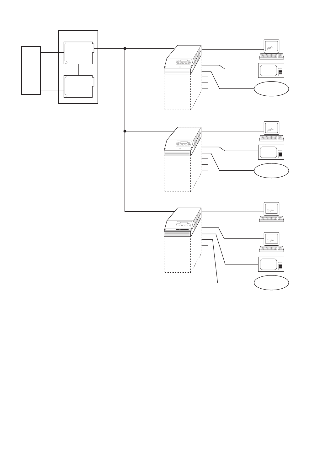
COMSPHERE 3600 Series Data Service Units
C-2 March 1999 3610-A2-GB48-70
496-12997-02
CPE
DSU
MCMP
2
3
MCMP
1
B
C
AA
1
Branch
Site 1
Control
DDS 56 kbps
ATM
Security
Teller
B
C
2.4 kbps
Branch
Site 2
Branch
Site 3
19.2 kbps
4.8 kbps
CPE = Customer Provided Equipment
CARRIER
DSU
2
3
4
5
6
MCMP
A
1
ATM
Security
Teller
B
C
2.4 kbps
19.2 kbps
4.8 kbps
DSU
2
3
4
5
6
MCMP
A
1
ATM
Security
Teller
B
C
2.4 kbps
19.2 kbps
4.8 kbps
DSU
2
3
4
5
6
Teller
A
19.2 kbps
Figure C-1. Applications Combined on One DDS Multipoint Circuit with MCMP
TDM Mode
When MUX Funct is set to TDM, the equivalent of up
to six point-to-point circuits are available between the
DSU and TDM to increase the port capacity of the DSU
to six ports. All six ports can be configured for
multiplexing, digital-sharing, or a combination of both.
A variety of configurations are available and include
point-to-point multiplexing, FEP port-sharing, digital
sharing, and multiplexing with digital sharing. Refer to
Figures C-2 and C-3 for two TDM configuration
examples.
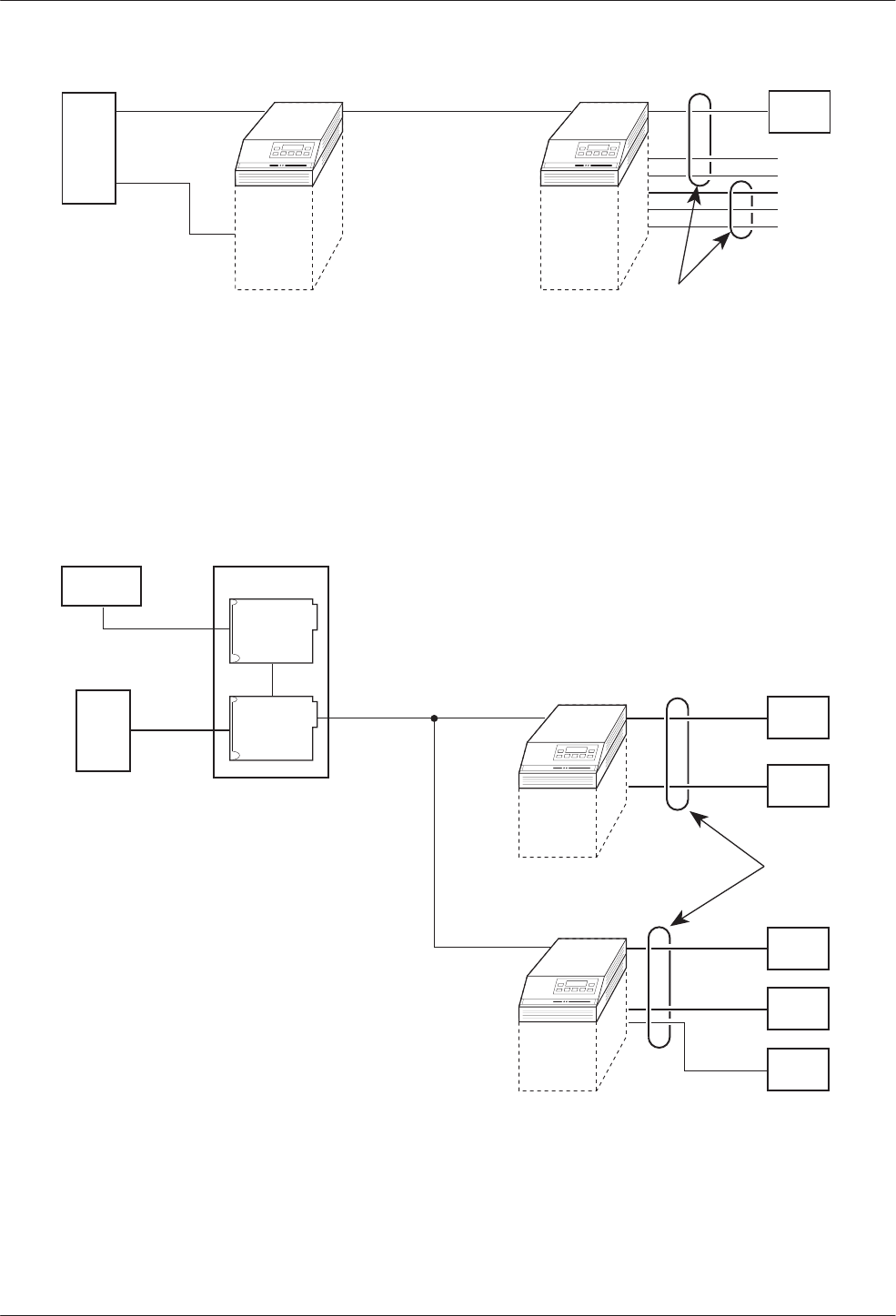
Configuration Examples
C-33610-A2-GB48-70 March 1999
CPE
CPE
CPE
CPE
CPE
CPE
CPE
A
B
DSU
TDM
2
3
4
5
6
2-Port
TDM/
Flex
DSU A
B
496-12992a-03
Digital-
Sharing
Group
= Digital-Sharing Group A
= Digital-Sharing Group B
= Customer Provided Equipment
A
B
CPE
DDS
Figure C-2. Point-to-Point Multiplexing with TDM and Tributary Digital Sharing
496-12993a-03
CARRIER
SDU
CPE DSU
NMS
Digital-
Sharing
Group
CPE
CPE
CPE
CPE
CPE
CPE = Customer Provided Equipment
DDS
DSU
TDM
DSU
TDM
Figure C-3. Digital Sharing in a Multipoint Circuit
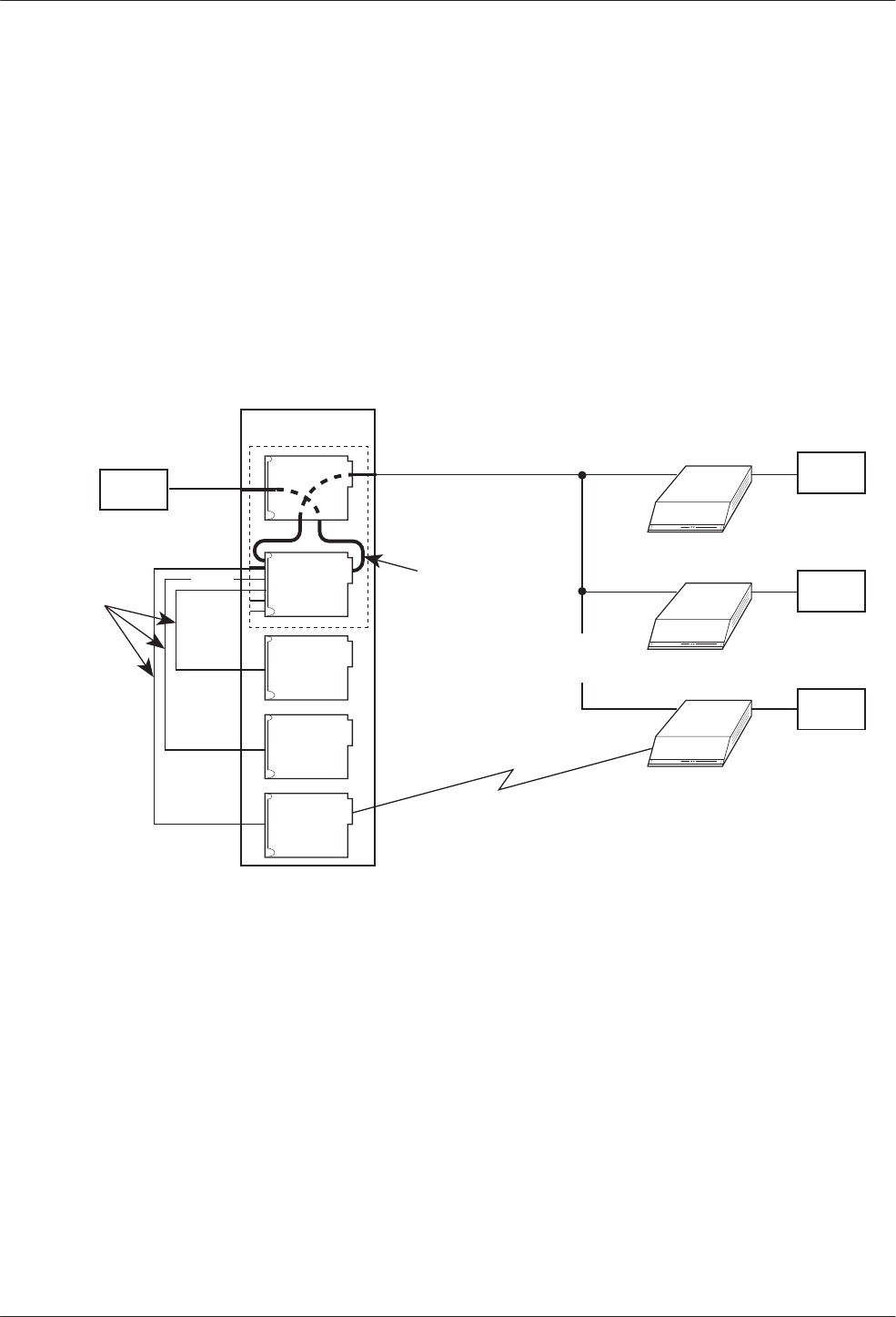
COMSPHERE 3600 Series Data Service Units
C-4 March 1999 3610-A2-GB48-70
Bridge Mode
In Bridge mode, all ports are assigned to one
digital-sharing group. When the MCMP/TDM circuit
card is configured as a digital bridge, the control DSU
can support dedicated multipoint dial backup, expanded
digital-sharing, or multipoint LADS operation.
When the digital bridge is set for automatic backup,
partial or full backup occurs as needed. In Figures C-4
and C-5, a DDS multipoint network is operating with
three central-site V.32 DBMs dedicated to the control
DSU and connected to the CBrdg.
If a failure occurs on the DDS line, each of the
affected DSUs switches data through the digital bridge to
the dedicated DBM. If automatic restoral is enabled, the
active DBMs switch back to the DSUs automatically
when the DDS network is restored.
496-15120
CARRIER
DSU DSU
DBM
CPE
DDS 9.6 kbps
X
X
Dial Line
9.6 kbps
Aggregate
Data Path
Customer Provided Equipment
Central-Site Bridge; Bridge Rate: =DSU
Port 1
DBM-V
DBM-V
DBM-V
DSU
DBM
DSU
DBM
CPE
CPE
CPE
Port 2
Port 4
Port 3
CPE =
CBrdg =
CBrdg
Failure
Crossover
Cables
Figure C-4. Digital Bridging (CBrdg) in Partial Backup
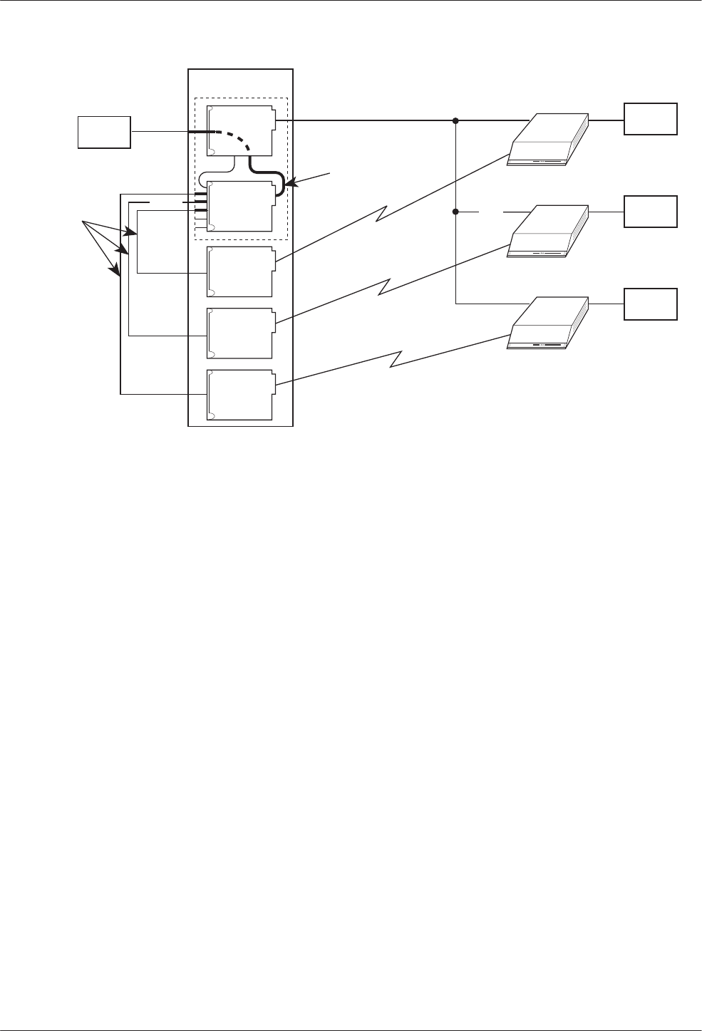
Configuration Examples
C-53610-A2-GB48-70 March 1999
496-15121
CARRIER
DSU DSU
DBM
CPE
DDS 56 kbps
XX
14.4 kbps
Aggregate
Data Path
Customer Provided Equipment
Central-Site Bridge; Bridge Rate: 14.4 kbps
Port 1
DBM-V
DBM-V
DBM-V
DSU
DBM
DSU
DBM
CPE
CPE
CPE
Port 2
Port 4
Port 3
CPE =
CBrdg =
CBrdg
Failure
14.4 kbps
14.4 kbps
Crossover
Cables
Figure C-5. Digital Bridging (CBrdg) in Full Backup
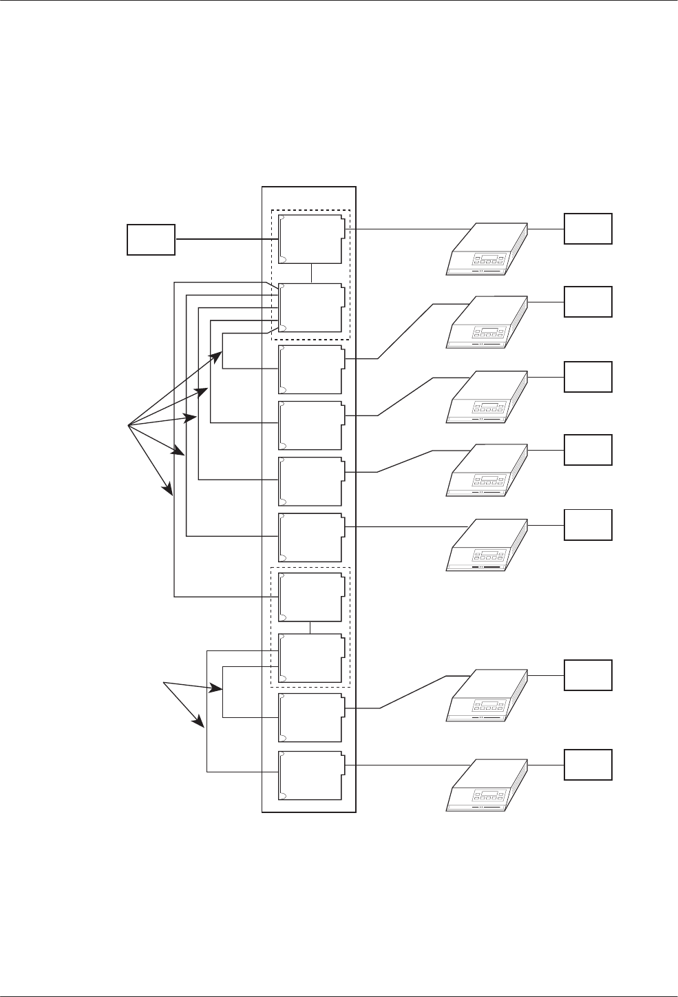
COMSPHERE 3600 Series Data Service Units
C-6 March 1999 3610-A2-GB48-70
LADS Environment
In the LADS environment, a point-to-point link is
established between two devices with a direct 4-wire
connection.
A bridged LADS configuration can be used to provide
a multipoint function. Digital bridge crossover interface
cables are required as shown in Figure C-6. Both the
CBrdg and EBrdg include a DSU circuit card attached to
a MUX circuit card.
496-12847-06
CARRIER
DSU
56 kbps
Port 1
Crossover
Cables
Port 2
Port 3
Port 4
Port 5
Port 6
Port 2
Port 3
Customer Provided Equipment
Central-Site Bridge
Extended Bridge
Crossover
Cables
CPE =
CBrdg =
EBrdg =
Port 1
DSU
DSU
CPE
DSU
CPE
DSU
CPE
DSU
CPE
DSU
CPE
DSU
CPE
DSU
CPE
DSU
DSU
DSU
DSU
DSU
DSU
CPE
CBrdg
EBrdg
Figure C-6. Central-Site and Extended Digital Bridges in LADS Environment

D-13610-A2-GB48-70 March 1999
Troubleshooting and
Front Panel Messages
Troubleshooting D-1. . . . . . . . . . . . . . . . . . . . . . . . . . . . . . . . . . . . . . . . . . . . . . . . . . . . . . . . . . . . . . . . . . . .
Messages D-1. . . . . . . . . . . . . . . . . . . . . . . . . . . . . . . . . . . . . . . . . . . . . . . . . . . . . . . . . . . . . . . . . . . . . . . . . .
Troubleshooting
Confirm the configuration option settings for the items
listed below that apply to your configuration.
•Verify the network, NMS, and DDS connections.
Refer to your User’s Guide, Chapter 2.
•For an Out of Frame Thresh message and facility
alarm, verify that the control and tributary:
— DSU rates [Rate(Kbps)] are set to match the
DDS circuit rate.
— Diag Type, Port Speed, and 2nd Ch(bps) are set
the same.
•Diagnostic type affects the control and tributary
interaction. Verify that all DSUs are set to the same
Diag Type. Mixed mode is not valid for MCMP.
•For multipoint rate adaption, enabling the
M-PtSymPrt configuration option is not required.
With Diag Type of NonD, the default is enable. The
control and all tributaries must be set the same.
•For MCMP mode, verify poll list acquire (Acq) is
completed. To add a tributary, use Add or Acq from
the tributary.
•To verify the network, request a remote ID and
ensure that you receive all addresses.
•Initiate a Digital Test (DT) and an End-to-End Test
(EE) to verify error free communications.
•Confirm the CTS Lead, RTS Cntrl, TxCarrSel, and
DSR FrcOn configuration option settings.
Messages
This section describes the progress or error messages
that may appear on the front panel of the 3600 Series
DSU with a TDM or MCMP installed when:
•Executing a command
•An error condition prevents execution
The messages listed here do not include menus, data
entry displays, or specific test results; they do give the
condition and any action to perform.
Table D-1 lists the configuration error messages that
may appear after pressing SAVE and the verification
routine runs.
For command, progress, health and status, and
additional configuration error messages, refer to
Document No. 3610-A2-GB46.
For configuration error, progress, and health and status
messages supporting DBMs, refer to Document No.
3610-A2-GB49.
D

COMSPHERE 3600 Series Data Service Units
D-2 March 1999 3610-A2-GB48-70
Table D-1
(1 of 4)
Configuration Error Messages
Message Condition Action
AgSw&BRDG Incmpt Bridge Mode is incompatible with Network
Interface set to AggSw or forced on. Refer to configuration option NetIntf.
Asy Not= forChan MCMP mode: all ports in a sharing group must all
be the same, either asynchronous or
synchronous. When asynchronous, all ports must
be the set the same for asynchronous rate,
bits/char, and number of stop bits.
Use configuration option Async→Sync to set
all ports. If set to Async, also set the
configuration options Async Rate,
AsyncBit/Char, and Stop Bits for each port.
BRDG&SymP
Incmpt Multipoint symmetric enabled is incompatible with
Bridge mode and NonDisruptive diagnostics. Disable configuration option M-PtSymPrt.
BRG&Bilat Incmpt Bilateral Loopback enabled is incompatible with
Bridge mode. Disable configuration option Bilat Lpbk.
Chan >1 in FEPGrp MCMP mode: both ports in a FEP port-sharing
group must be assigned to the same channel. Assign the same channel to both ports in a
FEP port-sharing group using the PrtSp
configuration submenu to access Chan.
Chan >1 in ShrGrp MCMP mode: all ports in a digital-sharing group
are not assigned to the same channel. Use the PrtSp configuration submenu to
access Chan. For the ports, use configuration
options Share DevA or Share DevB with
Lowest Port # and #Ports in Gp.
Ctrl Type Requir Bridge mode: a DSU configured as a tributary
cannot be in Bridge mode. Set the configuration option Position to Cntrl
for digital bridging.
CTS delay > 1024 TDM mode:
•If the port speed is equal to or greater than
38.4 kbps, the RTS to CTS delay should be
504 ms or less.
•DBM port speed is set to 32 kbps and RTS
delay is more than 1280 ms.
•Port speed is set to 32 kbps and RTS delay is
greater 1280 ms.
•Set the delay with configuration option
RTS/CTS Del.
•Change the configuration option RTS/CTS
Del to 1280 ms or less or change DBM
PrtSp(Kbps).
•Change the configuration option RTS/CTS
Del to 1280 ms or less.
DDS must be 56k MCMP mode: the DDS data rate is not set to
56 kbps for MCMP. Set the DSU configuration option Rate(Kbps)
to 56 kbps.
DSD Async Diff •TDM mode: all ports in a port-sharing group
must be the same, either asynchronous or
synchronous. If asynchronous, all async
options must be the same.
•Bridge mode: only Port 1 can be
asynchronous. All other ports must be
synchronous.
Use configuration option Async→Sync to set
all ports. If set to Async, also set the
configuration options Async Rate,
AsyncBit/Char, and Stop Bits for each port.
DSD Wrong RTS TDM or MCMP multipoint mode: one or more
ports in a digital-sharing group with DSD port
control do not have RTS Control set to DTE.
Set the configuration option RTS Cntrl to DTE
for all ports in the digital-sharing group.
DSU Agg Exceeded •TDM mode: the sum of the port speeds
exceeds the DDS speed.
•MCMP mode: the sum of the port speeds
exceeds 48 kbps.
Set configuration option Rate(Kbps) to a
higher speed or lower one or more port
speeds with configuration option PrtSp(Kbps).

Troubleshooting and Front Panel Messages
D-33610-A2-GB48-70 March 1999
Table D-1
(2 of 4)
Configuration Error Messages
Message ActionCondition
DSU ShareGp Spds DSU port speeds in a sharing group do not
match. Use configuration option PrtSp(Kbps) to set
both ports to the same port speed.
DSU Undersp Reqd TDM mode: the sum of the ports is equal to the
DDS speed and either:
•There is more than one port active that is not in
the same sharing group, or
•Diagnostics set to NonDisruptive with no
underspeed port.
•Select an underspeed port.
•Change configuration option Diag Type to
Disr, Mixed or None or use the PrtSp
configuration submenu to select an
underspeed port and configuration option
2nd Ch(bps) for the diagnostic speed.
Elast Not Valid Bridge mode: an attempt was made to configure
a DSU as an extended bridge with:
•Receive elastic store turned ON at one or
more of the active bridge ports, or
•The Bridge Rate is not set to
=DSU.
•Disable configuration option RxElasStor for
each of the active bridge ports.
•Configuration option Bridge Rate must be
set to =DSU when TxElasStor is enabled.
FEP Async diff Two ports with FEP port-sharing must have both
ports set either to asynchronous or synchronous. Use configuration option Async→Sync to set
the ports.
FEP Prt Underspd One of two ports in an FEP port-sharing group
was chosen for the underspeed port. Select an underspeed port that is not in an
FEP port-sharing group.
FEP&ShrDv Incmpt TDM or MCMP mode: an attempt was made to
place a port into both a digital-sharing group and
an FEP port-sharing group.
Select which of the groups is to have the port
included. Use MCMP Setup configuration
options to set Share DevA or P
n
/
n
FEP Sh.
FEP Speeds diff TDM or MCMP mode: two ports in the FEP
port-sharing group are assigned different speeds. Set all ports in the port-sharing group to the
same speed by using the configuration option
PrtSp(Kbps) for the DSU or DBM.
G2Trib Inv MCMP Diagnostic general configuration option Position
is set to G2Trib which is invalid with MCMP. Set configuration option Position to Cntrl or
Trib.
Incmpt Diag Mode Mixed diagnostics is incompatible with EBrdg or
MCMP mode. Use configuration option Diag Type to change
diagnostic setting.
Inval BridgeRate Bridge mode: MUX function set to EBrdg with
Bridge rate set to =DSU. Change configuration option Bridge Rate to a
valid data rate or set MUX Funct to CBrdg.
Inval DSU Timing •Port timing from a TDM port without TDM.
•Bridge timing from a port that is not installed
•DDS timing from a port that is not installed.
•TDM mode and timing is external.
•MCMP mode with timing from a port.
•Network interface timing from a non-installed
port.
Use configuration option:
•MUX Funct to enable TDM.
•Brdg Timing to select a valid port.
•TxClkSource to select a valid port.
•TxClkSource to select Port 1.
•TxClkSource to select a valid timing source.
•NetI Timing to select a valid timing source.

COMSPHERE 3600 Series Data Service Units
D-4 March 1999 3610-A2-GB48-70
Table D-1
(3 of 4)
Configuration Error Messages
Message ActionCondition
Inval lowest Prt TDM or MCMP mode:
•Sharing group is enabled with DCE as the
lowest port number and port control from DSD
but not in Bridge mode.
•A two-port Flex MUX has sharing group B
enabled.
•The first port in one sharing group is already in
another sharing group.
•When configuration option Share DevA is
enabled, the Lowest Port# is 1 for TDM or
MCMP. DCE is only valid in Bridge mode.
•A two-port TDM/Flex or MCMP/Flex can
only have Share DevA enabled.
•Use configuration options Lowest Port #
and #Ports in Gp to assign ports.
Inval M-Pt Confg TDM mode:
•Multipoint configuration with NonDisruptive
diagnostics and Secondary Channel speed of
100 bps.
•Multipoint configuration with rate adaption must
have NonDisruptive diagnostics with
symmetric mode enabled and all ports in a
digital-sharing group.
•Change configuration option Diag Type, or
use 2nd Ch(bps) to increase speed.
•Set configuration option Diag Type to NonD,
enable M-PtSymPrt, and enable Share
DevA.
Inval Port Cntrl Bridge mode: NonDisruptive diagnostics not valid
with port control set to DSD. Change configuration option Diag Type, or set
configuration option Port Cntrl to Host.
Invalid Async TDM mode in asynchronous mode cannot run:
•1.2 kbps port speed with async rate of 600 bps
and only 1 stop bit, or
•2.4 kbps port speed with async rate of
1.2 kbps and only 1 stop bit.
When configuration option Async→Sync is
enabled for asynchronous mode and Stop Bits
is set to 1, the Async Rate cannot be equal to
half the synchronous rate. Change the
configuration option Async Rate, or change
the number of Stop Bits.
Invalid Port Spd 1. MCMP mode: invalid port speed.
2. MCMP mode: a DBM port is configured for
56 or 64 kbps with MCMP.
3. TDM mode: a port is set to a port speed of
4.4, 9.2, or 18.8 kbps and set for underspeed.
Underspeed is not valid with a port speed of
4.4, 9.2, or 18.8 kbps.
4. TDM mode: one of two ports in a sharing
group is set for underspeed.
1. Use configuration option DSU/MCMP Port
Speed to select a valid MCMP port speed.
2. Use configuration option DBM Port Speed
to select a valid MCMP port speed.
3. Use configuration option DSU/TDM Port
Speed to select a valid TDM port speed,
or change the Underspeed selection to
another port.
4. Set both ports in a sharing group to
underspeed.
Invalid Underspeed
Port TDM mode: A port with port speed of 4.4, 9.2 or
18.8 kbps is set for underspeed. •Use configuration option DSU/TDM Port
Speed to select a valid TDM port speed, or
•Change Underspeed port selection to
another port.
No Ext Timing CBrdg mode: an attempt was made to configure
a DSU as a central-site bridge using external
timing on Prt1, and Bridge Rate is not set to
=DSU.
For a central-site bridge configuration, set the
configuration option:
•Bridge Rate to =DSU, or
•TxClkSource to Int, RXC, or DDS.
PCC/Async Conflc TDM mode: an async port’s Receiver Carrier
Select and PCC Buffer are not both enabled. When configuration option RxCarrSel is set to
Cntrl for an asynchronous port, PCC Buffer
must be Enab for the same port.

Troubleshooting and Front Panel Messages
D-53610-A2-GB48-70 March 1999
Table D-1
(4 of 4)
Configuration Error Messages
Message ActionCondition
Port Off Undersp TDM mode: a port that is disabled (0 bps) is set
for underspeed port. Use the DSU or DBM PrtSp configuration
option to assign a speed to the port or set
another port to Underspeed.
Prts>2: FEP Chan MCMP mode: a channel assigned to both ports
of a FEP port-sharing group is also assigned to
one or more other ports.
Use the MCMP AssgmntPrt1 to assign the
channel only to the two ports of the FEP
port-sharing group.
RTS/AnStr Conflc AntiStreaming disabled and RTS Control forced
on are incompatible for the same port. Disable configuration option AntiStream or set
RTS Control to DTE.
RTS FrcOn Requir Bridge Mode: DDS RTS control must be forced
on. Set configuration option RTS Cntrl to FrcOn.
RTS/TxCrr Conflc TDM mode: a port’s Transmitter Carrier Select
and RTS Control settings are incompatible. Set configuration option TxCarrSel to Cntrl
and RTS Cntrl to DTE, or set TxCarrSel to
Const and RTS Cntrl to FrcOn for each port.
Share DevA Reqd Bridge Mode: sharing group A disabled. Enable configuration option Share DevA.
Share DevB Inval Bridge Mode: sharing group B enabled. Disable configuration option Share DevB.
Spd Not=forChan MCMP mode: a channel is assigned to two or
more ports that are not operating at the same
port speed.
Use the DSU/MCMP Port Speed configuration
option to assign the same port speed to each
port in the channel.
Sync >Async Req TDM mode: the async rate setting for the port
must be less than or equal to the synchronous
data rate of the port.
Change configuration option Async Rate or
use the DSU/TDM Port Speed to change the
port speed.
Too Many Ports TDM or MCMP mode: either a sharing group has
more ports assigned than exist on the card or
one port is assigned to more than one
digital-sharing group.
Use the configuration options Lowest Port#
and #Ports in Gp to specify the ports in a
digital-sharing group.
V.13&MCMP Bckup DBM V.13 Signaling enabled with MUX function
set to MCMP and MCMP backup set to MCMP. The configuration option MUX Funct set to
MCMP is not valid with V.13 Signaling
enabled. Disable V.13 Signaling.

COMSPHERE 3600 Series Data Service Units
D-6 March 1999 3610-A2-GB48-70
This page intentionally left blank.

E-13610-A2-GB48-70 March 1999
Technical Specifications
Technical Specifications E-1. . . . . . . . . . . . . . . . . . . . . . . . . . . . . . . . . . . . . . . . . . . . . . . . . . . . . . . . . . . . . .
Technical Specifications
•Table E-1 lists MCMP technical specifications.
•Table E-2 lists TDM technical specifications.
•Table E-3 lists digital bridge technical
specifications.
Refer to the COMSPHERE 3600 Series Data Service
Units, Models 3610 and 3611, User’s Guide for the
general technical specifications for the 3600 Series DSU
and the COMSPHERE 3600 Series Data Service Units,
Models 3610 and 3611, Dial Backup Module Options
Supplement for DBMs.
E

COMSPHERE 3600 Series Data Service Units
E-2 March 1999 3610-A2-GB48-70
Table E-1
MCMP Technical Specifications
Specifications Criteria
APPLICATION
Multichannel multipoint
Digital sharing
FEP port sharing
Allows up to two or six independent application programs to share one
standard multipoint digital facility, depending upon the version, 2-port or
6-port.
Allows up to three digital-sharing groups (two ports each) at each
tributary site, or a maximum of six ports per group.
Provides up to three separate FEP port-sharing groups.
NUMBER OF TRIBUTARIES Supports up to 40 addressable tributary devices (40 DSUs or 20 DSUs
and DBMs).
LINE SPEEDS 56 kbps (maximum usable data rate is 48 kbps)
CHANNEL SYNCHRONOUS RATES
Primary (DSU) 1.2, 2.4, 4.8, 7.2, 9.6, 12.0, 14.4, 16.8, 19.2, 38.4, and 48 kbps
CHANNEL ASYNCHRONOUS RATES 150, 300, 600, 1200, and 1800 bps plus all primary (DSU) rates
PORT DTE INTERFACE
3610 DSU (2-port MCMP/Flex)
3610 DSU (6-port MCMP/Flex)
3611 DSU (modular)
3610 DSU (MCMP/DSD)
3611 DSU (non-modular)
Provides an additional 25-pin D-subminiature connector, for a total of
two EIA-232 or V.35 interfaces that can be set independently of each
other when you have DSU firmware Release 6.33 or greater.
Provides five additional 25-pin D-subminiature connectors, for a total of
six EIA-232 or V.35 interfaces that can be set independently of each
other when you have DSU firmware Release 6.33 or greater.
Provides a 6-port connector module that provides a total of six 25-pin
D-subminiature EIA-232 connections (including the DSU); in addition, a
26-pin high-density D-type connector that provides a V.35 interface
through an adapter cable for Port 1.
Provides five additional 25-pin D-subminiature connectors that can be
optioned for EIA-232 or V.35, for a total of six EIA-232 or six V.35
interfaces.
Provides one 60-pin high-density D-type connector that provides five
additional EIA-232 interfaces through an adapter cable.
NMS SUPPORT MCMP capability is fully supported by the COMSPHERE 6700 or
6800 Series NMS, Release 4.0 or greater for the 6700 Series NMS and
Release 4.1.5 or greater for the 6800 Series NMS software in ADp and
DATAPHONE II modes.

Technical Specifications
E-33610-A2-GB48-70 March 1999
Table E-2
TDM Technical Specifications
Specifications1Criteria
APPLICATION
Multiplexing
Digital sharing
FEP port sharing
Digital bridge
Provides time division multiplexing of up to two or six independent
ports, depending upon the version, 2-port or 6-port.
Allows two groups of consecutive ports to share the same TDM
channel.
Provides up to three separate FEP port-sharing groups.
Configured to perform a 5-port digital bridge capability.
PORT SYNCHRONOUS RATES 1.2, 2.0, 2.4, 4.0, 4.4, 4.8, 7.2, 8.4, 9.2, 9.6, 12.0, 14.4, 16.8, 18.0, 18.8,
19.2, 28.8, 32, 38.4, 48, 56, and 64 kbps
PORT ASYNCHRONOUS RATES 150, 300, 600, 1200, and 1800 bps plus all primary (DSU) rates.
Asynchronous rates support +2.3, –2.5 percent overspeed/underspeed
compensation.
PORT DTE INTERFACE
3610 DSU (2-port TDM/Flex)
3610 DSU (6-port TDM/Flex)
3611 DSU (modular)
3610 DSU (TDM/DSD)
3611 DSU (non-modular)
Provides an additional 25-pin D-subminiature connector, for a total of
two EIA-232 or V.35 interfaces that can be set independently of each
other when you have DSU firmware Release 6.28 or greater.
Provides five additional 25-pin D-subminiature connectors, for a total of
six EIA-232 or V.35 interfaces that can be set independently of each
other when you have DSU firmware Release 6.28 or greater.
Provides a 6-port connector module that provides a total of six 25-pin
D-subminiature EIA-232 connections (including the DSU). In addition, a
26-pin high-density D-type connector provides a V.35 interface through
an adapter cable.
Provides five additional 25-pin D-subminiature connectors that can be
optioned for EIA-232 or V.35, for a total of six EIA-232 or six V.35
interfaces.
Provides one 60-pin high-density D-type connector that provides five
additional EIA-232 interfaces through an adapter cable.
NMS SUPPORT TDM capability is fully supported by the COMSPHERE 6700 or
6800 Series NMS, Release 4.0 or greater for the 6700 Series NMS and
Release 4.1.5 or greater for the 6800 Series NMS software in ADp and
DATAPHONE II modes.
1TDM and MCMP circuit cards can be configured to provide TDM capability.

COMSPHERE 3600 Series Data Service Units
E-4 March 1999 3610-A2-GB48-70
Table E-3
Digital Bridge Technical Specifications
Specifications2Criteria
APPLICATION
Digital Bridge Provides 5-port digital bridging for various applications. Used primarily
for multipoint dial backup, which can be configured as a central-site
bridge or an extended bridge.
PORT SYNCHRONOUS RATES
Primary (DSU) and Backup (DBM) 2.4, 4.4, 4.8, 9.2, 9.6, 12.0, 14.4, 18.8, 19.2, 38.4, 56 and 64 kbps
DIAGNOSTIC SUPPORT Supports nondisruptive diagnostics (NonD), mixed, and disruptive (Disr)
diagnostic types. The Disruptive Type configuration option must be set
to either 3600e or Br56.
PORT DTE INTERFACE
3610 DSU (2-port TDM/Flex or MCMP/Flex)
3610 DSU (6-port TDM/Flex or MCMP/Flex)
3611 DSU (modular)
3610 DSU (TDM/DSD or MCMP/DSD)
3611 DSU (non-modular)
Provides an additional 25-pin D-subminiature connector, for a total of
two EIA-232 or V.35 interfaces that can be set independently of each
other when you have DSU firmware Release 6.33 or greater.
Provides five additional 25-pin D-subminiature connectors, for a total of
six EIA-232 or V.35 interfaces that can be set independently of each
other when you have DSU firmware Release 6.33 or greater.
Provides a 6-port connector module that provides a total of six 25-pin
D-subminiature EIA-232 connections (including the DSU). In addition, a
26-pin high-density D-type connector provides a V.35 interface through
an adapter cable.
Provides five additional 25-pin D-subminiature connectors that can be
optioned for EIA-232 or V.35, for a total of six EIA-232 or six V.35
interfaces.
Provides one 60-pin high-density D-type connector that provides five
additional EIA-232 interfaces through an adapter cable.
NMS SUPPORT Digital bridging capability is fully supported by the COMSPHERE 6700
or 6800 Series NMS, Release 4.0 or greater for the 6700 Series NMS
and Release 4.1.5 or greater for the 6800 Series NMS software in ADp
and DATAPHONE II modes.
2TDM and MCMP circuit cards can both be configured to provide digital bridge capability.

Index-13610-A2-GB48-70 March 1999
Index
Symbols
# Ports in Gp
for digital bridging, 4-6
for MCMP Setup, 4-3, 4-4
Aabbreviations, for menu tree, A-2
Acq, poll list, 3-9
adapter
V.35 interface, 2-1
AgSw&BRDG Incmpt, D-2
alternate Port 1, 1-2–1-3
AntiStream
for digital bridging, 4-12
for TDM/MCMP, 4-9
AssgmntPrt1, MCMP channel, 4-14
Asy Not= forChan message, D-2
Async Rate, 4-7
Async–>Sync, 4-7
data conversion, 1-1
AsyncBit/Char, 4-7
BBackup (Bckup) branch, 3-5
central-site bridge, 3-5
Digital Bridging, 3-5
extended bridge, 3-6
bit error rate test (BERT), 3-8
BrdgTiming, 4-5
Bridge Rate, 4-5
Bridge timing, 3-5
bridging. See digital bridging
Ccapability
digital bridging, 1-3
MCMP, 1-3
TDM, 1-2
CBrdg, configuration example, C-4
central-site bridge, 3-5
Chan
>1 in FEPGrp message, D-2
>1 in ShrGrp message, D-2
Spd Not=for message, D-5
channel, MCMP port assignment, 4-14
circuit quality, 3-5
configuration
error messages, D-2–D-5
examples
digital bridging, C-4–C-6
LADS, C-6
MCMP, C-1–C-2
TDM, C-2–C-3
option worksheets, B-1–B-10
options, factory defaults, A-1–A-4
Configuration (Confg) branch
Menu, 3-9
Options (Opts), 3-8–3-9
Poll List (PList), 3-9
Control branch, 3-10
external leads (ExtL), 3-10
LEDs, 3-10
Reset, 3-10
Transmitter Control (TxCd), 3-10
CTS delay > 1024 message, D-2
DDBM operation. See 3610-A2-GB49
DCE Type, 4-10
DDS, must be 56k message, D-2
dial tone test (DTone), 3-8
digital bridging
configuration, 3-5
features, 1-3
port configuration options, 4-11–4-13
setup configuration options, 4-5–4-6
technical specifications, E-4
worksheets, B-1–B-10
digital sharing, 1-2–1-3
digital test (DT), 3-8
DrBU, Backup menu, 3-5

COMSPHERE 3600 Series Data Service Units
Index-2 March 1999 3610-A2-GB48-70
DSD
Async Diff message, D-2
verify port interface, 2-1
Wrong RTS message, D-2
DSR FrcOn
for digital bridging, 4-12
for TDM/MCMP, 4-10
DSR on Tst
for digital bridging, 4-12
for TDM/MCMP, 4-10
DSU
Agg Exceeded message, D-2
DTE connections, 2-5
front panels, 3-2
how to open, 2-2
power-up routine, 2-5
reassembling, 2-4
separating from TDM or MCMP, 2-3
status indicators, 3-2
Undersp Reqd message, D-3
with digital bridge capability, 1-3
with LPDA-2 Interoperability, 1-3
with MCMP capability, 1-3
with TDM capability, 1-2
DSU operation. See 3610-A2-GB46
DTE connections, 2-5
DTE Port
for digital bridging, 4-13
for TDM/MCMP, 4-10
DTR Alarm, 4-12
for TDM/MCMP, 4-9
EEBrdg, configuration example, C-6
EIA-232 interface, changing to V.35, 2-2, 2-4–2-6
Elast Stor
for digital bridging, 4-11
for TDM/MCMP, 4-9
Not Valid message, D-3
Elastic Store, 1-1
End-to-End test (EE), 3-8
ExtendChan
for digital bridging, 4-13
for TDM/MCMP, 4-10
extended bridge, 3-6
EBrdg, 1-2–1-3
external leads, 3-10
FFac, factory default settings, A-1–A-4
faceplate, 3-2
factory defaults, A-1–A-4
See also 3610A2–GB46 & 3610-A2-GB49
features
common, 1-1
MCMP specific, 1-3
TDM specific, 1-2
FEP
&ShrDv Incmpt message, D-3
Async Diff message, D-3
port sharing, 1-1
Prt Underspd message, D-3
Speeds diff message, D-3
flat cables, 2-3
front panels, 3-2
GG2Trib Inv MCMP, message, D-3
IIdentity, 3-5
in-band framing, 1-2
Incmpt Diag Mode, message, D-3
indicators, status, 3-2
installation procedures
changing hardware straps, 2-1
how to open the DSU, 2-2
installing the DSU, 2-1
installing the power cable, 2-4
pre-installation notes, 2-1
Inval
BridgeRate message, D-3
DSU Timing message, D-3
lowest Prt message, D-4
M-Pt Confg message, D-4
Port Cntrl message, D-4
Invalid
Async message, D-4
Port Spd message, D-4
Underspeed Port message, D-4
LLEDs, 3-10
Link Problem Determination Aid. See LPDA-2
Local branch, 3-3
loopbacks, 3-7
digital, 3-7
remote digital, 3-7
Lowest Port#
for digital bridging, 4-6
for MCMP/TDM Setup, 4-3
LPDA-2, configuration example, C-6
LPDA-2, with TDM or MCMP, 1-3

Index
Index-33610-A2-GB48-70 March 1999
MMCMP
capability, 1-1, 1-3
changing DSD V.35 interface setting, 2-2, 2-4
changing the Flex interface, 2-2
channel-to-port assignment, 4-14
features, 1-3
front panel, 3-2
mode, 4-2
port configuration options, 4-7–4-11
separating from DSU, 2-3
setup configuration options, 4-2–4-5
status indicators, 3-2–3-3
worksheets, B-1–B-5
MCMP Bckup, 4-5
MCMP/Flex, reconfiguring interface, 2-5
Menu, Full mode, 3-9
menu
and modes of operation, 3-3
structure, 3-3
tree, A-1–A-3
tree abbreviations, A-2
message
AgSw&BRDGIncmpt, D-2
Asy Not= forChan, D-2
BRDG&SymP Incmpt, D-2
BRG&Bilat Incmpt, D-2
Chan >1 in FEPGrp, D-2
Chan >1 in ShrGrp, D-2
Ctrl Type Requir, D-2
CTS delay > 1024, D-2
DDS must be 56k, D-2
DSD Async Diff, D-2
DSD Wrong RTS, D-2
DSU, ShareGp Spds, D-3
DSU Agg Exceeded, D-2
DSU Undersp Reqd, D-3
Elast Not Valid, D-3
FEP Async Diff, D-3
FEP Prt Underspd, D-3
FEP Speeds diff, D-3
FEP&ShrDv Incmpt, D-3
G2Trib Inv MCMP, D-3
Incmpt Diag Mode, D-3
Inval BridgeRate, D-3
Inval DSU Timing, D-3
Inval lowest Prt, D-4
Inval M-Pt Confg, D-4
Inval Port Cntrl, D-4
Invalid Async, D-4
Invalid Port Spd, D-4
Invalid Underspeed Port, D-4
No Ext Timing, D-4
PCC/Async Conflc, D-4
Port Off Undersp, D-5
Prts>2: FEP Chan, D-5
RTS FrcOn Requir, D-5
RTS/AnStr Conflc, D-5
RTS/TxCrr Conflc, D-5
Share DevA Reqd, D-5
Share DevB Inval, D-5
Spd Not=forChan, D-5
Sync to Async Req, D-5
Too Many Ports, D-5
V.13&MCMP Bckup, D-5
messages
See also 3610-A2-GB46 & 3610-A2-GB49
configuration error, D-2–D-5
error, D-1–D-5
mode
full, 3-9
on worksheets, B-1–B-10
of operation, 3-3, 4-2
model 3611, carrier. See 3000-A2-GA31
MPTC or MPTT, factory default settings, A-1–A-4
multichannel multipoint. See MCMP
MUX Funct, 4-1
configuration examples, C-1–C-6
configuration options, factory defaults, A-1–A-4
for digital bridging, 4-5
for MCMP/TDM Setup, 4-2
MUX Portn Options, 4-1
for digital bridge, 4-11–4-13
for TDM & MCMP, 4-7–4-11
MUX Setup Options, 4-1
digital bridge, 4-5–4-6
MCMP/TDM, 4-2–4-5
Nnetwork interface, 1-2
No Ext Timing, message, D-4
OOpts
configuration options, 3-8–3-9
configuration tables, 4-1
configuration worksheets, B-1–B-10
Overspeed, 4-7
PPCC Buffer
for digital bridging, 4-11
for TDM/MCMP, 4-8
PCC/Async Conflc, message, D-4
PList, 3-9
Pn/n FEPSh, for MCMP Setup, 4-4–4-5
poll list, 3-9, D-1
port, interface operation, 2-1
Port Cntrl
for digital bridging, 4-6
for MCMP/TDM Setup, 4-3–4-4
Port Off Undersp, message, D-5
Port Speed Options, 4-1
MCMP channel-to-port assignment, 4-14
MCMP/TDM, 4-14
power-up routine, 2-5
Prts>2: FEP Chan, message, D-5

COMSPHERE 3600 Series Data Service Units
Index-4 March 1999 3610-A2-GB48-70
Rrate adaption, D-1
reconfiguring ports, changing interface for Flex models,
2-5
Remote branch, 3-3
reset, Control branch, 3-10
RTS
AnStr Conflc message, D-5
FrcOn Requir message, D-5
TxCrr Conflc message, D-5
RTS Cntrl
for digital bridging, 4-11
for TDM/MCMP, 4-7
RTS/CTS Del
for digital bridging, 4-11
for TDM/MCMP, 4-9
RxCarrSel
for digital bridging, 4-11
for TDM/MCMP, 4-8
SShare DevA
for digital bridging, 4-6
for MCMP Setup, 4-2
Reqd message, D-5
Share DevB
for digital bridging, 4-6
for MCMP Setup, 4-3
Inval message, D-5
SNA Diagnostic Interface. See LPDA–2
Status (Stat) branch, 3-4
Circuit Quality (CircQ), 3-5
DTE status, 3-4
Health and Status (H/S), 3-4
Identity (ID), 3-5
Terminal Power (TPwr), 3-5
status indicators, 3-2
Stop Bits, 4-7
switched-carrier emulation, 1-1
Sync to Async, Req message, D-5
TTDM
capability, 1-1–1-2
changing DSD V.35 interface setting, 2-2, 2-4
changing the Flex interface, 2-2
features, 1-2
front panel, 3-2
mode, 4-2
port configuration options, 4-7–4-11
separating from DSU, 2-3
status indicators, 3-2–3-3
worksheets, B-1–B-8
TDM/Flex, reconfiguring interface, 2-5, 2-6
technical specifications, E-1–E-4
TDM, E-3
terminal power, status, 3-5
Test branch, 3-6
Abort, 3-6
Device Test (Devic), 3-7
Loopback (Lpbk), 3-7
testing, network verification, 2-6
tests
bit error rate test (BERT), 3-8
device, 3-7
dial tone (DTone), 3-8
digital, 3-8
end-to-end (EE), 3-8
loopback, 3-7
time division multiplexer. See TDM
Too Many Ports, message, D-5
top-level menu, 3-3, A-1–A-3
troubleshooting, D-1
TxCarrSel
for digital bridging, 4-11
for TDM/MCMP, 4-8
UUnderspeed, 4-14
UpstrmPort
for digital bridging, 4-13
for TDM/MCMP, 4-10
VV.13&MCMP Bckup, message, D-5
V.35 interface
adapter, 2-1
changing to EIA-232, 2-2, 2-4–2-6
verification, testing network, 2-6
Wworksheets, configuration options, B-1–B-10
