COMSPHERE 3600 Series Data Service Units S 3610 & 3611 A2 GL11 10
3610-A2-GL11-10 3610-A2-GL11-10
User Manual: 3610-A2-GL11-10
Open the PDF directly: View PDF ![]() .
.
Page Count: 28

COMSPHEREr
3600 SERIES
DATA SERVICE UNITS
MODELS 3610 & 3611
QUICK REFERENCE
Document No. 3610-A2-GL11-10
Copyright E 2000 Paradyne Corporation.
All rights reserved.
Printed in U.S.A.
Notice
This publication is protected by federal copyright law. No part of this publication may be
copied or distributed, transmitted, transcribed, stored in a retrieval system, or translated
into any human or computer language in any form or by any means, electronic,
mechanical, magnetic, manual or otherwise, or disclosed to third parties without the
express written permission of Paradyne Corporation, 8545 126th Ave. N., Largo,
FL 33773.
Paradyne Corporation makes no representation or warranties with respect to the
contents hereof and specifically disclaims any implied warranties of merchantability or
fitness for a particular purpose. Further, Paradyne Corporation reserves the right to
revise this publication and to make changes from time to time in the contents hereof
without obligation of Paradyne Corporation to notify any person of such revision or
changes.
Changes and enhancements to the product and to the information herein will be
documented and issued as a new release to this manual.
Warranty, Sales, Service, and Training Information
Contact your local sales representative, service representative, or distributor directly for
any help needed. For additional information concerning warranty, sales, service, repair,
installation, documentation, training, distributor locations, or Paradyne worldwide office
locations, use one of the following methods:
HInternet: Visit the Paradyne World Wide Web site at www.paradyne.com. (Be
sure to register your warranty at www.paradyne.com/warranty.)
HTelephone: Call our automated system to receive current information by fax or to
speak with a company representative.
— Within the U.S.A., call 1-800-870-2221
— Outside the U.S.A, call 1-727-530-2340
Document Feedback
We welcome your comments and suggestions about this document. Please mail them
to Technical Publications, Paradyne Corporation, 8545 126th Ave. N., Largo, FL 33773,
or send e-mail to userdoc@paradyne.com. Include the number and title of this
document in your correspondence. Please include your name and phone number if you
are willing to provide additional clarification.
Trademarks
COMSPHERE is a registered trademark of Paradyne Corporation. All other products
and services mentioned are the trademarks, service marks, registered trademarks, or
registered service marks of their respective owners.

1
COMSPHEREr 3600 Series Data Service Units
Models 3610 & 3611
Quick Reference
Document Number 3610-A2-GL11-10
February 2000
Product Documentation on the World Wide Web
We provide complete product documentation online. This lets you search the
documentation for specific topics and print only what you need, reducing the waste of
surplus printing. It also helps us maintain competitive prices for our products.
Complete documentation for this product is available at www.paradyne.com.
Select Library → Technical Manuals →Subrate Digital Access Devices.
Select the following document:
3610-A2-GB46
COMSPHERE 3600 Series Data Service Units,
Models 3610 and 3611, User’s Guide
To request a paper copy of a Paradyne document:
HWithin the U.S.A., call 1-800-PARADYNE (1-800-727-2396)
HOutside the U.S.A., call 1-727-530-8623
Model 3610 Installation
To install the COMSPHEREr Model 3610 DSU, perform these steps:
HRead the Important Safety Instructions on page 23.
HIf you are installing new hardware into an existing system, verify that software and
firmware levels are compatible. See Software and Firmware Version Control on
page 22.
HVerify the S1 switch settings.
HPower up the DSU.
HConnect to the DDS Network.
HPerform network verification testing.
HConnect to the DTE.
2
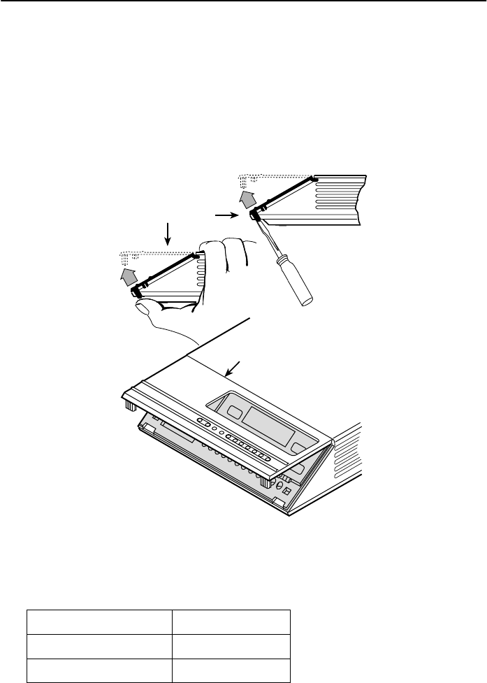
Model 3610: Verifying the S1 Switch Settings
The Model 3610 DSU has a switch located under the front panel. To verify or change
the S1 switch settings, remove the front bezel:
"Procedure
1. Place a small screwdriver or your thumbs under the two tabs on the outside edges
of the front bezel. Firmly press upward to separate the bezel from the tabs.
496-14701-01
Front Bezel
COMSPHERE 3610
Front Bezel
or
2. Swing the front bezel up and set aside.
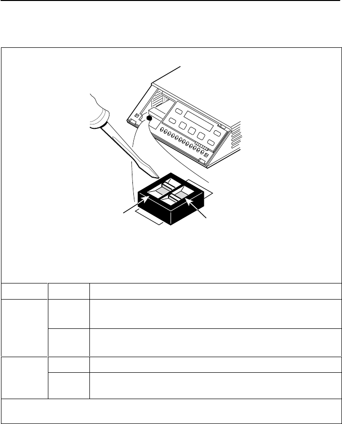
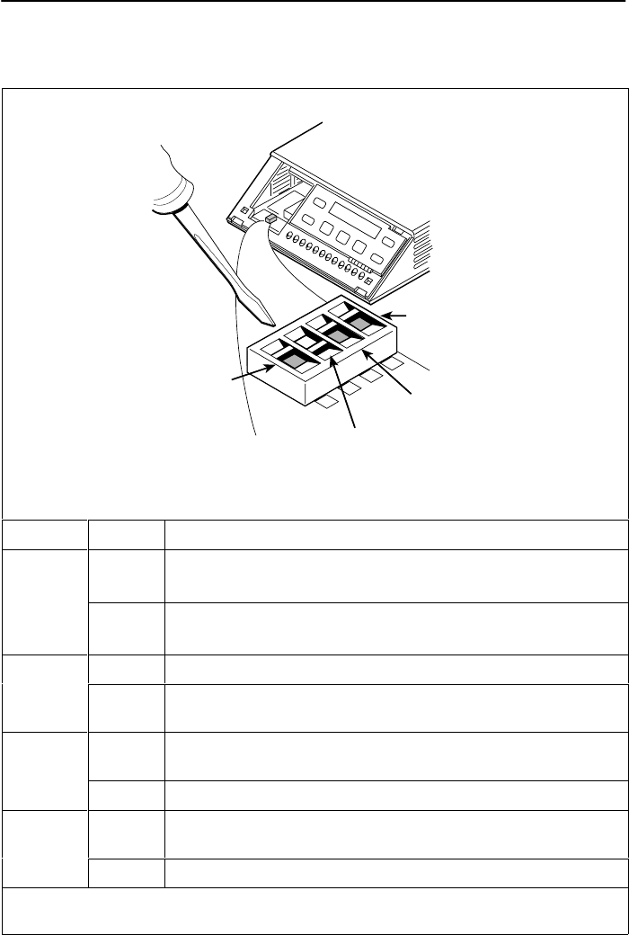
3. Change the switch settings if necessary. Use a small instrument. Do not use a
pencil.
If the DSU has . . . Then use . . .
Two switches Figure A.
Four switches Figure B.
4. Reinsert the front bezel’s hinge tabs into position at the top and swing the bezel
down. Snap the bezel back into place.
3
Figure A
496-14702-01
S1
ON
2
ON
l
Switch 1
V.32
Analog
DBM
Interface
(S1-1)
Frame Ground/
Signal Ground
(S1-2)
Switch Setting Function
S1-1
V32
ON
(default) Permissive transmit output level of –9 dBm
V.32
Analog
DBM only
OFF Programmable transmit output level between –12 dBm and
0 dBm
ON Frame ground (FG) connected to signal ground (SG)
S1-2 OFF
(default) FG connected to SG through 100-ohm resistor
ON is to the rear as you face the front of the DSU.
OFF is to the front.
4
Figure B
496-14719-02
Switch 1
V.35
Test Mode
(S1-4)
EIA-232
Test Mode
(S1-3)
V.32
Analog
DBM
Interface
(S1-1) Frame Ground/
Signal Ground
(S1-2)
S1
1
ON
234
1234
Switch Setting Function
S1-1
V32
ON
(default) Permissive transmit output level of –9 dBm
V.32
Analog
DBM only
OFF Programmable transmit output level between –12 dBm and
0 dBm
ON Frame ground (FG) connected to signal ground (SG)
S1-2 OFF
(default) FG connected to SG through 100-ohm resistor
S1-3
ON
(default) Enables EIA-232 Test mode; Pin 25 controlled by the DSU
S1-3
OFF Disables EIA-232 Test mode
S1-4
ON
(default) Enables V.35 Test mode; V.35 lead NN controlled by the DSU
S1-4
OFF Disables V.35 Test mode
ON is to the left as you face the front of the DSU.
OFF is to the right.
5
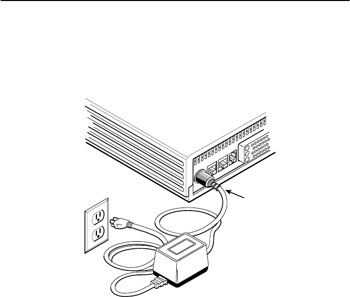
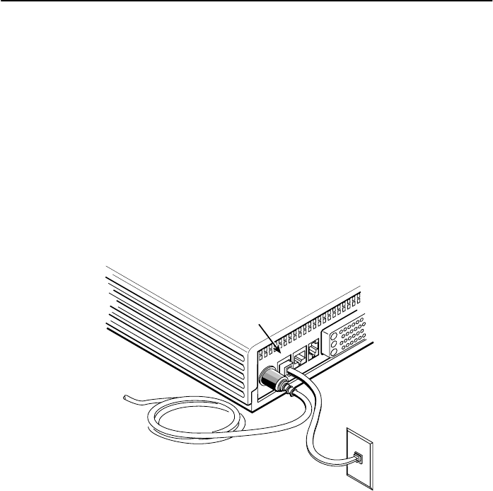
Model 3610: Powering Up the DSU
"Procedure
1. At the rear of the DSU, insert the round end of the power cable into the receptacle
labeled POWER.
Low
Voltage
AC Power
In
495-14703
Table-Top
AC
Transformer
POWER LINE BACKUP CC/DC V.35
3-Prong
Grounded
AC
Wall Outlet
2. Connect the 3-prong plug at the other end of the cable to an ac outlet.
6
Model 3610: DDS Network Connection
To connect the DSU to the DDS network:
"Procedure
1. For countries other than Canada, use an 8-pin to 8-pin network cable (Feature
Number 3600-F3-501 or 3600-F3-502). Plug either end into the wall jack.
For Canada, ensure that approved primary protectors have been installed on the
circuit in accordance with Article 800 of the National Electric Code, NFPA 70, in the
United States and Section 60 of the Canadian Electric Code, Part 1, in Canada.
Plug the 6-pin cable end (Feature Number 3600-F1-006) into the wall jack.
2. Plug the other end of the cable into the DSU jack labeled LINE.
495-14578-02
DDS Network
Connection
Line
POWERLINEBACKUPCC/DCV.35
RJ48S
Wall Jack
If a remote DSU is also connected to the network and there are no other facility alarms,
the:
HDSU’s green OK LED lights.
HAlrm indicator is no longer lit.
HHealth and Status screen no longer displays a No Signal message. The DDS data
rate displays Auto while detecting a rate. Change the Rate(Kbps) to a set rate
when the data rate has been detected.
If connecting the DSU to a LADS network, set the data rate. There are distance
limitations that govern the use of DSUs on the network.
7
Model 3610: DTE Connections
The distance between the DSU and the DTE must be within the EIA-232 or V.35
interface limits.
To install the Model 3610 DTE connection:
"Procedure
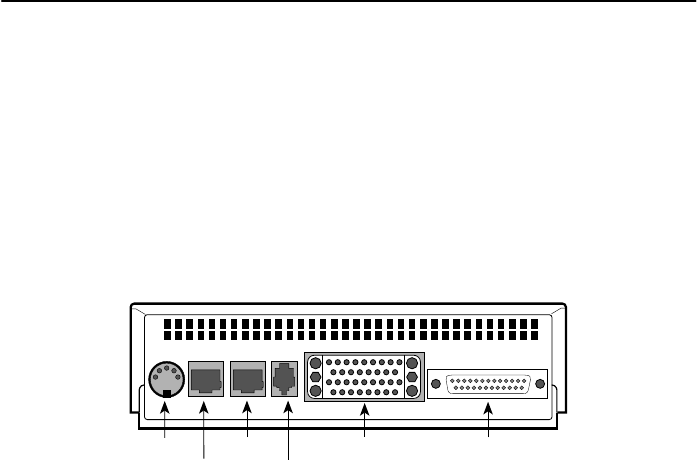
1. Connect the plug end of the DTE cable to the proper port on the back panel of the
DSU (EIA232 or V.35). Tighten the two holding screws, if present, to secure the
connector.
POWER LINE BACKUP CC/DC EIA 232
V.35
495-14704
Power
Line
Backup
CC/DC
EIA 232V.35
NOTE:
If connecting the DTE to the V.35 connector, set the DTE Port in General
Configuration Options to V.35 so the DSU can communicate with the DTE. The
default for this configuration option is EIA232.
2. Connect the other end of the cable to the appropriate port on the DTE. Tighten the
two holding screws, if present.
3. Perform Local Loopback (LL) and DTE Loopback tests.

8
Model 3610: Network Diagnostic Connection
A hubbing device and a 6-position modular cable (Feature Number 4400-F1-510,
4400-F1-511, or 4400-F1-512) are needed to connect the control DSU to a 6700 or
6800 Series NMS. The hubbing device provides two 8-pin modular jacks for diagnostic
channel (DC) and control channel (CC) connections.
To install the hubbing device:
"Procedure
1. Plug the 4-pin modular plug of the hubbing device into the modular jack labeled
CC/DC located on the rear of the DSU.
2. Plug one end of the 6-position cable into the hubbing device jack labeled CC IN/DC
OUT.
3. Plug the opposite end of the cable into the appropriate 6700 or 6800 Series NMS
jack.
Refer to your COMSPHERE 6700 or 6800 Series NMS documentation to control and
configure the DSU from the NMS.
Model 3610: SNA Diagnostic Interface Verification
"Procedure
1. Enable the LPDA option.
2. Send a DSU/CSU and Line Status test from the IBM NetView console to the
control DSU and each tributary.
3. As the status for each DSU is returned to NetView, check the network address. If
the address is correct, the verification procedure is complete.
Model 3610: Async Terminal Connection
Use a CC-to-DB25 cable to connect an async terminal to a DSU. This feature is
available for the Model 3610 standalone unit only.
"Procedure
1. Plug the 4-pin modular plug of the DSU CC-to-DB25 cable (Feature
Number 3600-F3-504) into the DSU jack labeled CC/DC.
2. Connect the EIA-232 (DB25) end of the cable to the async terminal. Tighten the
holding screws.

9
Model 3611 Installation
To install the COMSPHERE Model 3611 DSU, perform these steps:
HRead the Important Safety Instructions on page 23.
HIf you are installing new hardware into an existing system, verify that software and
firmware levels are compatible. See Software and Firmware Version Control on
page 22.
HInstall the appropriate Network Interface Module (NIM) on the COMSPHERE 3000
Series Carrier.
HAttach the connector plate (for single-slot DSUs) or connector module (for DSUs
with a mux card attached) to the carrier.
HInstall the 3611 circuit card.
HConnect the DTE and network cables.
The procedures for installation are contained in the COMSPHERE 3000 Series Carrier
Installation Manual, Document No. 3000-A2-GA31. If ferrite chokes are included with
your DSU, install them according to the following procedure.
Model 3611: Ferrite Choke Installation
One ferrite choke is provided with every Model 3611 DSU with a Dial Backup Module
(DBM). Attach the ferrite choke to the DTE cable. Six ferrite chokes are provided with
every Model 3611 MUX circuit card. Attach one ferrite choke to each DTE cable. All
ferrite chokes that are supplied must be installed following these instructions to
ensure compliance with FCC Part 15 Rules.
To install the ferrite choke on the DTE interface:
"Procedure
1. Pull up on the latch to open the ferrite choke.
2. Place the ferrite choke around the cable as close to the cable connector as
possible.
3. Close the two halves around the cable and snap the ferrite choke shut.
496-14820-01
Ferrite Choke
Tie
Wrap
Plastic
Latch
4. Press down on the plastic latch to secure the ferrite choke in place around the
cable.
10
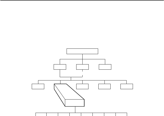
Menu Structure
You access the menu tree, a representation of the DSU’s menu structure, via the front
panel. The menus that appear depend upon the DSU’s function within the network (i.e.,
control or tributary) and the hardware options that are installed (e.g., a DBM or MUX).
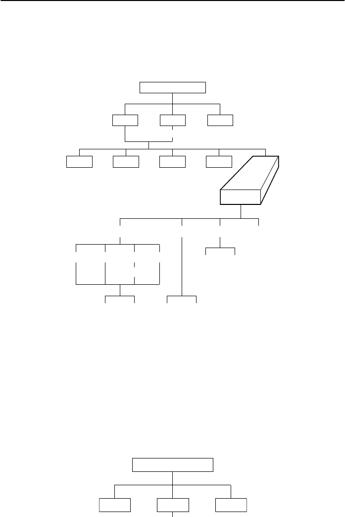
Access to all network management tasks begins at the top-level menu, the head of the
menu hierarchy.
495-12970a
TOP-LEVEL MENU
Local Remot Msgs
Address
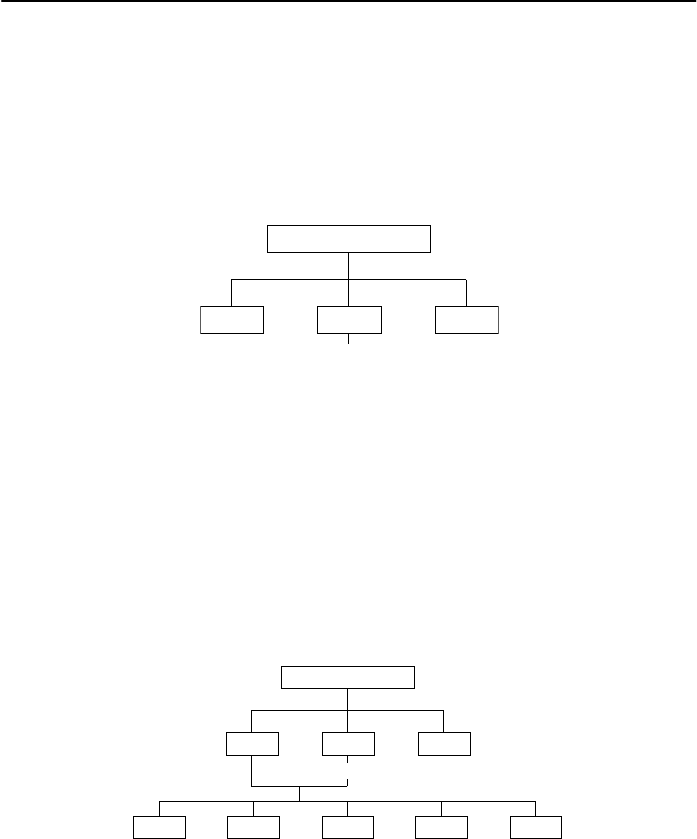
The top-level menu contains the:
HLocal selection: For a control DSU.
HRemote (Remot) selection: Used for control of a remote DSU.
HMessages (Msgs) selection: Appears when an NMS message has been received
and not cleared. The OK LED flashes. Once the NMS messages are cleared, the
Msgs selection disappears and the OK LED no longer flashes.
Local/Remote Menu Branches
495-12970b
TOP-LEVEL MENU
Local Remot
Bckup Test Ctrl
Msgs
Address
Confg
Stat
The Local menu has five branches; the Remote menu has four (Bckup is not available).
Each selection leads to submenus.
HStatus (Stat) branch
HBackup (Bckup) branch
HTest branch: The Test branch does not appear when the DSU is in Display mode.
HConfiguration (Confg) branch
HControl (Ctrl) branch
11
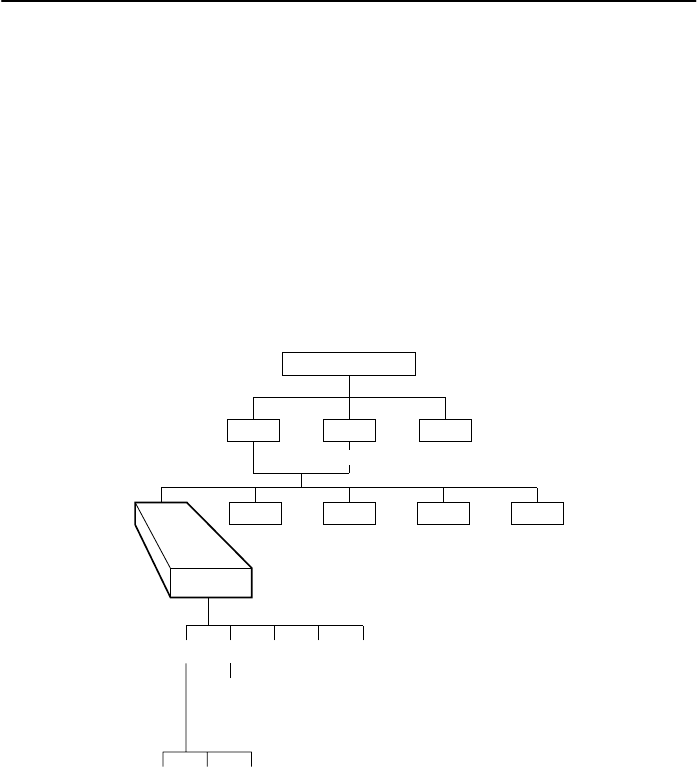
Status Branch
The Status (Stat) branch reports on the:
HHealth and status of the DSU and DBM
HDTE interface
HCircuit quality:
—For an analog DBM connection, Network Signal Level and Quality
—For a DSU with App Module ID displaying XLOOP, DDS Signal Quality
HIdentity of the DSU
HTerminal’s power – status of voltage on the DTE’s RTS lead
496-12970-02
TOP-LEVEL MENU
Local Remot
Bckup Test Ctrl
Msgs
Address
Confg
Stat
H/S DTE CircQ ID TPwr
Port
Select
Devic Expan Subn
12
Backup Branch
The Backup (Bckup) branch appears when the configuration option Network Interface
(NetIntf) is set to AggSw or Forc or a DBM is installed. The DSU provides an internal
aggregate data stream for diagnostics, standby mode, and framing on the alternate
V.35 or EIA-232 interface of Port 1. The aggregate port can be connected to an external
dial backup unit (DBU).
496-12971-06
TOP-LEVEL MENU
Local Remot
Test Ctrl
Stat
Msgs
Address
Confg
Bckup
Abort Bkup Dial DrBU Disc →Dial →DDS AggSw →NetI
For additional use of the Backup branch, refer to the TDM/MCMP/Digital Bridge Options
Supplement, Document No. 3610-A2-GB48, and the DBM Options Supplement,
Document No. 3610-A2-GB49.
13
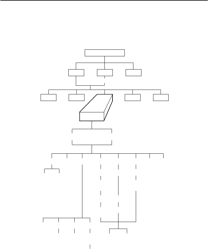
Test Branch
The Test branch provides extensive testing capabilities for the DSU, the DDS circuit,
the DBM, and the backup circuit. When the tributary DSU receives a test request from
the control DSU, the DSU aborts any locally initiated test in progress.
496-12972-03
TOP-LEVEL MENU
Local Remot
Bckup Ctrl
Stat
Msgs
Address
Confg
Test
DSU DBM
Abort Devic Lpbk Lamp
LL DTE DL RL
Start Start Start
Port
Select Port
Select Port
Select
Port
Select
Address
Address Address
Run
Tim # Blocks
Displ Clr
EE DT BERT
Port
Select
Subn Selective
DTone
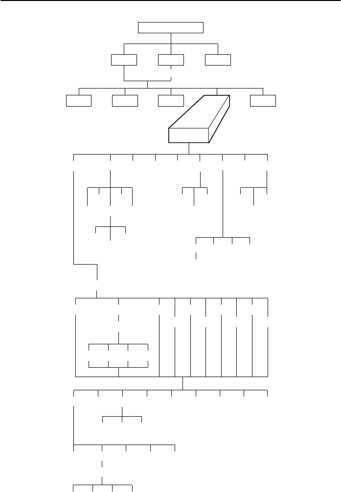
Configuration Branch
The Configuration (Confg) branch allows you to configure or customize the DSU and its
options to:
HFit site requirements.
HEnter and change telephone numbers (if a DBM is installed).
HSpecify the protocol used by a connected NMS.
14
496-12973b
TOP-LEVEL MENU
Local Remot
Bckup Test Ctrl
Stat
Confg
Msgs
Opts PList Dir Phone Addr ChgMd
Displ Chang
Add
Acq
Activ Delet
Save
DPII
ADp
Remt
Address
Activ Usr1 Usr2 Usr3
Activ Usr1
Usr2
Usr3
FacC
FacT
FacB
Load
SAVE DSU DBM Gen Bkup MUX PrtSp LPDA
Remt Usr1 Usr2 Usr3
Address
Activ Usr1 Usr2 Usr3
Skip
Clr
Diag
Activ
Address
DSU DBM Gen
Term
Enab Pswrd CIDDisab
Pswrd
SPID Menu
SaveEnabDisab
MPTC
MPTT
15
Saving and Changing Configuration Options
For Model 3610 and Model 3611 DSUs, change configurations options from:
HA front panel, or
HA 6700 or 6800 Series NMS, or
HAn async terminal (Model 3610 standalone only)
Configuration options supporting TDM, MCMP, and digital bridging are in Document
No. 3610-A2-GB48. Configuration options supporting DBMs are in Document
No. 3610-A2-GB49.
The DSU preconfigured at the factory for FacT with default settings for a tributary,
point-to-point circuit, and a data rate of Auto. Set the data rate to match the service
provider’s rate.
If you have a point-to-point configuration, enable one unit as the control and the other
unit as the tributary.
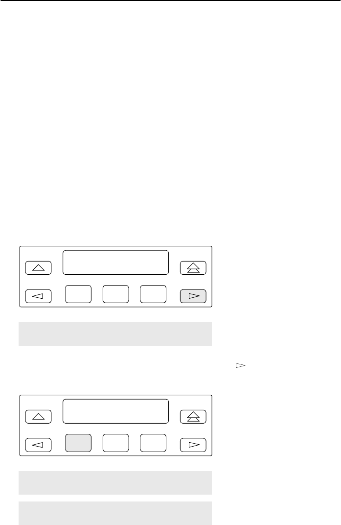
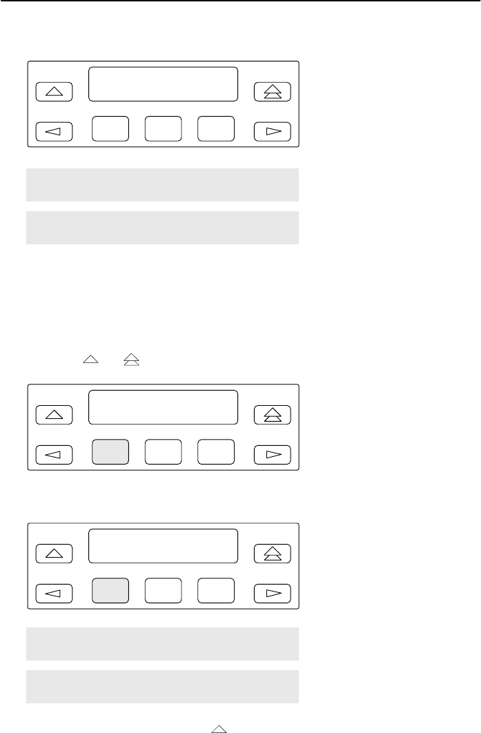
1. From the Home screen select Local (F1). The following screen appears on the
LCD.
F1
Local Mode:
Stat Bckup Test
F2 F3
Confg Ctrl
2. To access the Configuration (Confg) branch, press the key until Confg
appears. Press the function key below Confg. The following screen appears.
F1
Configure:
Opts PList Dir
F2 F3
Phone Addr ChgMd Term SPID
Menu
16
3. Select Opts (for Configuration Options). The following screen appears.
F1
Load from:
Activ Remt Usr1
F2 F3
Usr2 Usr3 FacC FacT FacB
MPTC MPTT
4. The selections on the screen are configuration option sets stored in the DSU’s
memory. Table 1 lists the Load from menu selections and their source.
From the Load from menu, any selection except Remote loads a complete set of
configuration option values into a working buffer.
5. After changing and not saving configuration options, the following prompt appears
when the or key is pressed.
F1
Save Options?
Yes No
F2 F3
6. If you press F1 for Yes, the Save to screen appears.
F1
Save to:
Activ Remt Usr1
F2 F3
Usr2 Usr3 FacC FacT FacB
MPTC MPTT
If Save to is not displayed, press until the prompt appears.
When you press a function key from the Save to screen, the DSU performs a
verification routine to ensure that the configuration options chosen are compatible.

17
Default Configuration Option Sets
Load
from Source of
Configuration Options
Activ Active: Currently active configuration options for the addressed DSU;
use to change and save configuration options.
Remt Remote: Configuration options that can be retrieved from a selected
tributary DSU; these will be from the tributary’s Active set and appear
based on local hardware. They are filtered when the front panel is
locked.
The selected option set can then be displayed, edited, and saved back
to the same tributary, another tributary, or the control DSU. The five
factory default option sets do not appear when in Remote mode.
Remote is filtered for a multipoint tributary or a unit with Diag Type of
None.
Usr1 User 1: User-defined option sets.
Usr2 User 2: User-defined option sets.
Usr3*User 3: User-defined option sets, and factory default settings for a
DBM-X (Model 3611 DBM-D, DBM-I, DBM-S, and DBM-V; does not
function as a DSU).
FacC Factory Control: Control DSU factory default settings.
FacT Factory Tributary: Tributary DSU factory default settings.
FacB Factory Digital Bridge: Central-site digital bridge factory default settings.
FacB is filtered when MUX CCA is not installed.
MPTC Multipoint Control: Multipoint Control DSU factory default settings. MPTC
is filtered when TDM CCA is installed.
MPTT Multipoint Tributary: Multipoint Tributary DSU factory default settings.
*When configuring a DBM-X, do not SAVE to Usr3.
7. Select SAVE for changes to take effect.

18
Configuration Options
Configuration options are accessed from the Configuration branch of the front panel
menu.
In the following tables, FacT (Factory Tributary) defaults are shown in boldface. If
different from the FacT defaults, FacC (Factory Control) defaults are shown in italics.
Key to symbols:
DWhen the Async→Sync configuration option is enabled using the General
branch, the following PrtSp(Kbps) settings do not appear:
32, 24.0, 18.8, 18.0, 9.2, 8.4, 4.4, 4.0, and 2.0 kbps
DD 19.2 Power Level defaults to +6 dB when App Module ID displays XLOOP
LL V.32 Analog DBM only
AThese configuration options do not appear when Full mode is disabled using
Menu from the Configuration branch.
DSU
Configuration Options Value
Rate(Kbps) Auto, 64CC, 64L, 56, 38.4, 19.2, 9.6, 4.8, 2.4
PrtSp(Kbps) D64, 56, 48, 38.4, 32, 28.8, 24.0, 19.2, 18.8, 18.0, 16.8, 14.4, 12.0,
9.6, 9.2, 8.4, 7.2, 4.8, 4.4, 4.0, 2.4, 2.0, 1.2, Disab
TxClkSource Int, RXC, Ext, DDS, Prt1, Prt2, Prt3, Prt4, Prt5, Prt6
Msg Clamp AEnab, Disab
TxElasStor Enab, Disab
RxElasStor AEnab, Disab
19.2 PowrLvl DD A+6, 0, –10
64KScramblng AOn, Off
64KLatchLpbk AOn, Off
NetIntf AAggSw, Forc, Disab
Net ITiming AInt, NetI, Prt1, Prt2, Prt3, Prt4, Prt5, Prt6
V.54 Lpbk AEnab, Disab
Diagnostic DSU
Configuration Options Value
Diag Type NonD, Disr, Mixed, None
2nd Ch(bps) A100, 400, 800, 1200, 1600
Disr Type 2500, 2600, 3600s, 3600e, Br56

19
Diagnostic General
Configuration Options Value
Position Cntrl, Trib, G2Trb
LinkConfg Pt-Pt, M-Pt
Resp Period A1, 2, 10
TribTimOut A0:10 (5 sec to 10 min)
Diag Conn CC, DC
Link Delay A0s, 1s, 2s, 5s, 10s, 20s, 50s
Network Delay A0s, 1s, 2s, 5s, 10s, 20s, 50s
Packet Delay A0s, 1s, 2s, 5s
Extend Chan AYes, No
Upstrm Port APrt1, Prt2, Prt3, Prt4, Prt5, Prt6
M-PtSymPrt AEnab, Disab
Fast Sel AEnab, Disab
LPDA-2
Configuration Options Value
LPDA-2 Enab, Disab
LPDA Address 1 (1 – 256)
SNA Backup Enab, Disab
Code 1 582210 (Model 3610) 582218 (Model 3611)
Code 2 5822101 (Model 3610) 5822181 (Model 3611)
ChgMd
Configuration Settings Value
Protocol Mode DPII, ADp
S1 Hardware
Settings Value
DBM Interface LL Permissive (ON), Programmable (OFF)
Frame Ground/
Signal Ground Connected (ON), Disconnected (OFF)
EIA-232 Test Mode Enable (ON), Disable (OFF)
V.35 Test Mode Enable (ON), Disable (OFF)

20
General
Configuration
Options Value
DTE Port EIA232, V.35
RTS Cntrl FrcOn, DTE
CTS Cntrl Std, =RTS
AntiStream ADisab, 1–100 sec (async term = 0–100)
LSD Lead AStd, Delay, FrcOn
CTS Lead AStd, Delay, FrcOn
DSR FrcOn AEnab, Disab
SystemStat AEnab, Disab
DSR on Tst AEnab, Disab
Circ Assur AEnab, Disab
Tst Pattern AAT&T, Std
RespondRDL AEnab, Disab
LL by DTE AEnab, Disab
RL by DTE AEnab, Disab
Bilat Lpbk AEnab, Disab
Ext Leads AExtLd, Rate, RPowr
CCN by EL AEnab, Disab
DTR Alarm AEnab, Disab
SW Vers A3.24, 4.43, 6.66, Normal
AnswExtBU AEnab, Disab
Async→Sync Enab, Disab
AsyncBit/Char 6, 7, 8, 9, 10
Stop Bits 1, 2
Overspeed 1.0, 2.3
PowerOnTst Enab, Disab
21
Control Branch
The Control (Ctrl) branch allows you to enable or disable the DSU’s transmitter, as well
as the DBM’s, and to display/change the status of the general purpose external DTE
leads.
496-12974-02
TOP-LEVEL MENU
Local Remot
Bckup Test
Stat
Msgs
Address
Confg
Ctrl
TxCtl LEDs ExtL
DSU DBM Ports
Load Save
Displ Chang
Enab Disab
Devic
Port Select
Reset
Remote Branch
The Remote (Remot) branch allows front panel access to remote units.
HPoint-to-point configuration: access DSU at the other end.
HMultipoint configuration: enter DSU remote addresses and access each unit.
When the Remote branch is accessed, the front panel displays the local menu tree with
the remote unit’s data.
495-12970a
TOP-LEVEL MENU
Local Remot Msgs
Address

22
Software and Firmware Version Control
Verify that the control and tributary DSUs have the same firmware version or that the
control has the highest firmware version. If the control DSU software version is less
than 7.24 but greater than 1.10, changes are required to the DSU tributary firmware
version in the General configuration options.
If Control DSU is: If Tributary DSU is: Set Tributary Su
pp
orted Su
pp
orted
Release FW
Version Release FW
Version
Set
Trib
u
tary
DSU’s SW
Version to:
S
u
pported
by 6700
Release
S
u
pported
by 6800
Release
2 3.xx 3 4.xx 3.20 3.0/1.0 3.0
2 3.xx 3.1 5.xx 3.21 3.0/1.0 3.1
2 3.xx 3.2 or 3.3 6.xx 3.22 4.0.0/1.2 4.1
2 3.xx 3.4 7.xx 3.23 4.0.5/1.2.1 4.2.7
2 3.xx 3.5 8.xx 3.24 4.0.7/1.3 4.2.9
3 4.xx 3.1 5.xx 4.40 3.0/1.0 3.1
3 4.xx 3.2 or 3.3 6.xx 4.41 4.0.0/1.2 4.2.6
3 4.xx 3.4 7.xx 4.42 4.0.5/1.2.1 4.2.7
3 4.xx 3.5 8.xx 4.43 4.0.7/1.3 4.2.9
3.1 5.xx 3.1 5.xx Normal 3.0/1.0 3.1
3.1 5.xx 3.2 or 3.3 6.xx Normal 4.0.0/1.2 4.2.6
3.1 5.xx 3.4 7.xx 6.65 4.0.5/1.2.1 4.2.7
3.1 5.xx 3.5 8.xx 6.66 4.0.7/1.3 4.2.9
3.2 6.2x 3.2 6.2x Normal 3.0.10/1.1 4.1.6
3.2 6.2x 3.3 6.33–6.99 Normal 4.0.0/1.2 4.2.6
3.2 6.2x 3.4 7.xx 6.65 4.0.5/1.2.1 4.2.7
3.2 6.2x 3.5 8.xx 6.66 4.0.7/1.3 4.2.9
3.3 6.33–6.99 3.3 6.33–6.99 Normal 4.0.0/1.2 4.2.6
3.3 6.33–6.99 3.4 7.xx 6.65 4.0.5/1.2.1 4.2.7
3.3 6.33–6.99 3.5 8.xx 6.66 4.0.7/1.3 4.2.9
3.4 7.xx 3.4 7.xx Normal 4.0.5/1.2.1 4.2.7
3.4 7.xx 3.5 8.xx Normal 4.0.7/1.3 4.2.9
3.5 8.xx 3.5 8.xx Normal 4.0.7/1.3 4.2.9

23
!Important Safety Instructions
1. Read and follow all warning notices and instructions marked on the product or
included in the manual.
2. This product is intended to be used with a three-wire grounding type plug – a plug
which has a grounding pin. This is a safety feature. Equipment grounding is vital to
ensure safe operation. Do not defeat the purpose of the grounding type plug by
modifying the plug or using an adapter.
Prior to installation, use an outlet tester or a voltmeter to check the ac receptacle
for the presence of earth ground. If the receptacle is not properly grounded, the
installation must not continue until a qualified electrician has corrected the problem.
If a three-wire grounding type power source is not available, consult a qualified
electrician to determine another method of grounding the equipment.
3. Slots and openings in the cabinet are provided for ventilation. To ensure reliable
operation of the product and to protect it from overheating, these slots and
openings must not be blocked or covered.
4. Do not allow anything to rest on the power cord and do not locate the product
where persons will walk on the power cord.
5. Do not attempt to service this product yourself, as opening or removing covers may
expose you to dangerous high voltage points or other risks. Refer all servicing to
qualified service personnel.
6. General purpose cables are provided with this product. Special cables, which may
be required by the regulatory inspection authority for the installation site, are the
responsibility of the customer.
7. When installed in the final configuration, the product must comply with the
applicable Safety Standards and regulatory requirements of the country in which it
is installed. If necessary, consult with the appropriate regulatory agencies and
inspection authorities to ensure compliance.
8. A rare phenomenon can create a voltage potential between the earth grounds of
two or more buildings. If products installed in separate buildings are
interconnected, the voltage potential may cause a hazardous condition. Consult a
qualified electrical consultant to determine whether or not this phenomenon exists
and, if necessary, implement corrective action prior to interconnecting the products.
9. In addition, if the equipment is to be used with telecommunications circuits, take the
following precautions:
— Never install telephone wiring during a lightning storm.
— Never install telephone jacks in wet locations unless the jack is specifically
designed for wet locations.
— Never touch uninsulated telephone wires or terminals unless the telephone line
has been disconnected at the network interface.
— Use caution when installing or modifying telephone lines.
— Avoid using a telephone (other than a cordless type) during an electrical storm.
There may be a remote risk of electric shock from lightning.
— Do not use the telephone to report a gas leak in the vicinity of the leak.

24
Notices
!WARNING:
THIS EQUIPMENT HAS BEEN TESTED AND FOUND TO COMPLY WITH THE LIMITS
FOR A CLASS A DIGITAL DEVICE, PURSUANT TO PART 15 OF THE FCC RULES.
THESE LIMITS ARE DESIGNED TO PROVIDE REASONABLE PROTECTION AGAINST
HARMFUL INTERFERENCE WHEN THE EQUIPMENT IS OPERATED IN A COMMERCIAL
ENVIRONMENT. THIS EQUIPMENT GENERATES, USES, AND CAN RADIATE RADIO
FREQUENCY ENERGY AND, IF NOT INSTALLED AND USED IN ACCORDANCE WITH
THE INSTRUCTION MANUAL, MAY CAUSE HARMFUL INTERFERENCE TO RADIO
COMMUNICATIONS. OPERATION OF THIS EQUIPMENT IN A RESIDENTIAL AREA IS
LIKELY TO CAUSE HARMFUL INTERFERENCE IN WHICH CASE THE USER WILL BE
REQUIRED TO CORRECT THE INTERFERENCE AT HIS OWN EXPENSE. THE
AUTHORITY TO OPERATE THIS EQUIPMENT IS CONDITIONED BY THE
REQUIREMENTS THAT NO MODIFICATIONS WILL BE MADE TO THE EQUIPMENT
UNLESS THE CHANGES OR MODIFICATIONS ARE EXPRESSLY APPROVED BY
PARADYNE.
!WARNING:
TO USERS OF DIGITAL APPARATUS IN CANADA: THIS CLASS A DIGITAL APPARATUS
MEETS ALL REQUIREMENTS OF THE CANADIAN INTERFERENCEĆCAUSING
EQUIPMENT REGULATIONS.
CET APPAREIL NUMÉRIQUE DE LA CLASSE A RESPECTE TOUTES LES EXIGENCES
DU RÈGLEMENT SUR LE MATÉRIEL BROUILLEUR DU CANADA.
Government Requirements
Certain governments require that instructions pertaining to connection to the telephone
network be included in the installation and operation manual. Specific instructions are
listed in the following sections.
United States – Notice to Users of the Telephone Network
This equipment complies with Part 68 of the FCC rules. On the bottom of the equipment
is a label or silk-screened text that contains, among other information, the FCC
registration number and Ringer Equivalence Number (REN) for this equipment. If
requested, please provide this information to your telephone company.
The REN is useful to determine the quantity of devices you may connect to your
telephone line and still have all of those devices ring when your number is called. In
most areas, the sum of the RENs of all devices should not exceed 5. Call your local
telephone company to ascertain the maximum REN for your calling area.
If your Model 3610 or 3611 DSU with DBM causes harm to the telephone network, the
telephone company may discontinue your service temporarily. If possible, they will
notify you in advance. But if advance notice is not practical, you will be notified as soon
as possible. You will be advised of your right to file a complaint with the FCC.

25
Your telephone company may make changes in facilities, equipment, operations, or
procedures that could affect the proper operation of your equipment. If so, you will be
given advance notice so as to give you an opportunity to maintain uninterrupted
service.
The DBM cannot be used on public coin-operated telephone service provided by the
telephone company. Connection to party-line service is subject to state tariffs. Contact
the state public utility commission, public service commission, or corporation
commission for information.
No repairs may be performed by the user. Should you experience difficulty with this
equipment, refer to Warranty, Sales, Service, and Training inside the cover of this
document.
For Digital Data Service (DDS) installations, inform the local telephone company of the
appropriate facility interface code for the service you desire.
DDS Facility
Interface Code Data Rate (bps) Interface Code Data Rate (bps)
04DU5-24 2400 04DU5-38 38,400
04DU5-48 4800 04DU5-56 56,000
04DU5-96 9600 04DU5-64 64,000
04DU5-19 19,200
For DBM installations, the proper service and jack must be ordered from the telephone
company. Refer to the following table for this information.
DBM Jack Installation Requirements
DBM Type USOC Jack
(Standalone) USOC Jack
(Carrier)
Canadian
Jack
(Standalone)
Canadian
Jack
(Carrier)
12.0 or
14.4 kbps
V.32bis
DBM
RJ11C
Permissive
RJ45C
Programmable
RJ21X
Permissive
RJ27X
Programmable
CA11A
Permissive
CA27A
Programmable
CA21A
Permissive
CA27A
Programmable
2-Wire
Switched
56 DBM
SJA48 SJA48 (uses
an adapter
cable)
CA11
(metallic
channel)
CA21A
(metallic
channel)
4-Wire
Switched
56 DBM
SJA56 SJA57 Not available
in Canada Not available
in Canada
ISDN BRI
DBM RJ49C RJ49C (uses
an adapter
cable)
CA-A11 CA-A11 (uses
an adapter
cable)

26
After the telephone company has installed the requested service and jack, you can
connect the DSU with the cable provided. An FCC-compliant telephone cord and
modular plug are provided with this equipment. This equipment is designed to be
connected to the telephone network or premises wiring using a compatible modular jack
that is Part 68 compliant.
Canada – Notice to Users of the Canadian Telephone Network
The Canadian Department of Communications has certified that this equipment meets
certain telecommunications network protective, operational, and safety requirements.
The Department does not guarantee that the equipment will operate to the user’s
satisfaction.
Before installation, verify connectivity of this equipment to the local telecommunications
company’s facilities. The equipment must be connected by an acceptable method. In
some cases, the telecommunications company’s inside wiring associated with
single-line individual service may be extended with a certified connector assembly
(telephone connection cord). The customer should be aware that compliance with the
above conditions may not prevent degradation of service in some situations.
If you experience difficulty with this equipment and require service, refer to Warranty,
Sales, Service, and Training Information in the front of this document.
Repairs to certified equipment should be made by an authorized Canadian
maintenance facility. Any repairs or alterations made by the user to this equipment, or
equipment malfunctions, may cause the telecommunications company to ask you to
disconnect the equipment.
Users should ensure that the electrical ground connections of the power utility,
telephone lines and internal metallic water pipe system, if present, are connected
together for protection. This precaution may be particularly important in rural areas.
CAUTION:
Users should not attempt to make such connections themselves, but should
contact the appropriate electric inspection authority, or an electrician, as
appropriate.
The load number (LN) is labeled on the equipment. The LN denotes the percentage of
the total load to be connected to a telephone loop used by this equipment. To prevent
an overload, the total of the LNs of all devices attached to the loop may not exceed 100.
The LN also specifies the appropriate ringing type (A or B), if applicable. For example,
LN = 20A designates a load number of 20 and an A type ringer.
If you experience trouble with this equipment, please contact your sales or service
representative (as appropriate) for repair or warranty information. If the trouble is
causing harm to the telephone network, the telephone company may request that you
remove the equipment from the network until the problem is resolved.
*3610-A2-GL11-10*
*3610–A2–GL11–10*
