3660 MDC.ib.Rev0 MDC_ib_Rev0 MDC Ib Rev0
User Manual: 3660-MDC_ib_Rev0
Open the PDF directly: View PDF ![]() .
.
Page Count: 12

3660-mdc.ib.rev0.doc Page 1 of 9 17/10/2007
IRT Eurocard
Type MDC-3660
2 Mb/s (E1) G.703 / ASI
Network Interface Adapter
Designed and manufactured in Australia
IRT can be found on the Internet at:
http://www.irtelectronics.com
I R T Electronics Pty Ltd A.B.N. 35 000 832 575
26 Hotham Parade, ARTARMON N.S.W. 2064 AUSTRALIA
National: Phone: (02) 9439 3744 Fax: (02) 9439 7439
International: +61 2 9439 3744 +61 2 9439 7439
Email: sales@irtelectronics.com
Web: www.irtelectronics.com

3660-mdc.ib.rev0.doc Page 2 of 9 17/10/2007
IRT Eurocard
Type MDC-3660
2 Mb/s (E1) G.703 / ASI
Network Interface Adapter
Instruction Book
Table of Contents
Section Page
Operational Safety 2
General Description 3
Technical Specifications 4
Installation 5
Front and rear layouts 6
Operation 7
Front Panel Indicators 7
Alarm Relays 7
Maintenance & Storage 8
Warranty & Service 8
Equipment return 8
Drawing List Index 9
This instruction book applies to units later than S/N 0305001.
Operational Safety:
WARNING
Operation of electronic equipment involves the use of voltages and currents that
may be dangerous to human life. Note that under certain conditions dangerous
potentials may exist in some circuits when power controls are in the OFF position.
Maintenance personnel should observe all safety regulations.
Do not make any adjustments inside equipment with power ON unless proper
precautions are observed. All internal adjustments should only be made by suitably
qualified personnel. All operational adjustments are available externally without the
need for removing covers or use of extender cards.
3660-mdc.ib.rev0.doc Page 3 of 9 17/10/2007
IRT Eurocard
Type MDC-3660
2 Mb/s (E1) G.703 / ASI
Network Interface Adapter
General Description
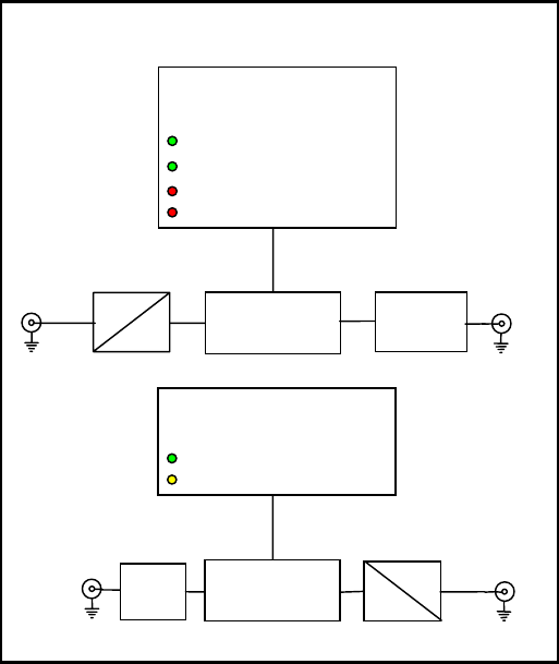
The MDC-3660 takes a 2048 kb/s G.703 (E1) signal and packs it into an RS encoded DVB compliant, 204 byte,
ASI transport stream. This allows it to pass through ASI style of circuits such IRT’s ASI Mux/DeMux and fibre
modules.
The MDC-3660 will also simultaneously decode an appropriate ASI input into 2048 kb/s G.703 (E1).
The MDC-3660 finds particular use for transmission of framed or unframed E1 signals down an ASI link such as a
fibre optic link.
In the absence of an ASI input, the G.703 output is AIS (Alarm Indication Signal). In the absence of a valid G.703
input, AIS is packed into an RS encoded 204 byte ASI transport stream.
For the G.703 input, front panel LEDs indicate if a G.703 input is present and if it is AIS. For the ASI input, front
panel LEDs indicate if the ASI is present, if the ASI is at the correct input rate, if there is a sync error, or the input
signal is a 188 byte packet, as the unit expects a 204 byte packet signal.
External relay contact alarms also are available on the rear connector assembly.
The MDC-3660 is suitable for mounting in all IRT’s standard 1RU and 3RU frames.
Standard features:
• 2 Mb/s (E1) G.703 input to ASI output.
• ASI input to 2 Mb/s (E1) G.703 output.
• AIS signal generated when no input is present.
MDC-3660
E1
Alarms & indications
INPUT
AIS
10B
8B
E1
G.703
Input
Signal
Processing
ASI
Output
(270 Mb/s) coax
ASI
Alarms & indications
INPUT
RATE
SYNC ERROR
188 BYTE
10B
8B
E1
G.703
Out
p
ut
Signal
Processing
ASI
Input
(270 Mb/s) coax
3660-mdc.ib.rev0.doc Page 4 of 9 17/10/2007
Technical Specifications
IRT Eurocard module
Type MDC-3660
Input 1:
Type 1 x G.703.
Electrical characteristics HDB3 encoded.
Data rate 2048 kb/s (E1).
Output 1:
Type 1 x ASI-C, 75 Ω, 204 Byte RS encoded.
Data Rate 3.072 Mb/s (nominal).
Impedance 75Ω.
Level 800 mVp-p.
Input 2:
Type 1 x ASI-C, 75 Ω, 204 Byte RS encoded.
Data rate 3.072 Mb/s (nominal).
Return Loss >15 dB 5 MHz to 270 MHz.
Equalisation Automatic, better than 250 metres at 270 Mb/s for Belden 8281 or equivalent
cable.
Output 2:
Type 1 x G.703.
Electrical characteristics HDB3 encoding.
Data Rate 2048 kb/s (E1).
Alarms:
2 x general alarm - Relay 1 releases on ASI Sync loss, incorrect ASI rate, or power loss.
- Relay 2 releases on G.703 input loss, or power loss.
2 set relay contacts - N/O1, N/C1, N/O2, N/C2, Com.
5 pin phoenix style connector.
Power Requirements 28 Vac CT (14-0-14) or ± 16 Vdc.
Power consumption <4 VA.
Other:
Temperature range 0 - 50° C ambient
Mechanical Suitable for mounting in IRT 19” rack chassis with input, output and power
connections on the rear panel.
Finish: Front panel Grey background, silk-screened black lettering & red IRT logo
Rear assembly Detachable silk-screened PCB with direct mount connectors to Eurocard and
external signals
Dimensions 6 HP x 3 U x 220 mm IRT Eurocard
Supplied accessories Rear connector assembly including matching connector for alarm output.
Optional accessories TME-6 module extender card.
Due to our policy of continuing development, these specifications are subject to change without notice.
3660-mdc.ib.rev0.doc Page 5 of 9 17/10/2007
Installation
Pre-installation:
Handling:
This equipment may contain or be connected to static sensitive devices and proper static free handling precautions
should be observed.
Where individual circuit cards are stored, they should be placed in antistatic bags. Proper antistatic procedures
should be followed when inserting or removing cards from these bags.
Power:
AC mains supply: Ensure that operating voltage of unit and local supply voltage match and that correct rating
fuse is installed for local supply.
DC supply: Ensure that the correct polarity is observed and that DC supply voltage is maintained within
the operating range specified.
Earthing:
The earth path is dependent on the type of frame selected. In every case particular care should be taken to ensure
that the frame is connected to earth for safety reasons. See frame manual for details.
Signal earth: For safety reasons a connection is made between signal earth and chassis earth. No attempt should be
made to break this connection.
Installation in frame or chassis:
See details in separate manual for selected frame type.
ASI and G.703 Inputs and Outputs:
ASI and G.703 Inputs and Outputs are by BNC connectors on the rear of the connector unit.
Note that the MDC-3660 is made up of a 2 Mb/s G.703 to ASI encoder and a completely separate ASI to 2 Mb/s
G.703 decoder. Therefore the 2 Mb/s (E1) G.703 input pairs with the ASI output, and the ASI input pairs with the
2 Mb/s (E1) G.703 output.
Alarm Relays:
As well as front panel LEDs indicating signal status, there are two relay alarm outputs sharing a 5 pin connector,
PL3, on the rear connector unit.
Relay 1 releases on releases on ASI Sync loss, incorrect ASI rate, or power loss.
Relay 2 releases on G.703 input loss, or power loss.
Pin 1 – Common
Pin 2 – Relay 2 Normally Open (N/O2)
Pin 3 – Relay 1 Normally Open (N/O1)
Pin 4 – Relay 2 Normally Closed (N/C2)
Pin 5 – Relay 1 Normally Closed (N/C1)
3660-mdc.ib.rev0.doc Page 6 of 9 17/10/2007
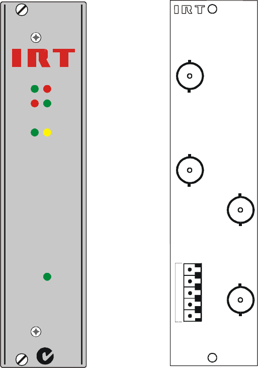
Front & rear panel connector diagrams
The following front panel and rear assembly drawings are not to scale and are intended to show connection order
and approximate layout only.
INPUT AIS
E1
SYNC RATE
188INPUT
ASI
DC
MDC-3660
N140
ASI
INPUT
1
2
3
4
1–COM
2–N/O2
3–N/O1
4–N/C2
5–N/C1
5
G.703
OUTPUT
ASI
OUTPUT
G.703
INPUT
PL3

3660-mdc.ib.rev0.doc Page 7 of 9 17/10/2007
Operation
The MDC-3660 is made up of a 2 Mb/s G.703 to ASI encoder and a completely separate ASI to 2 Mb/s G.703
decoder. Therefore the 2 Mb/s (E1) G.703 input pairs with the ASI output, and the ASI input pairs with the 2 Mb/s
(E1) G.703 output.
There are no operational or set-up controls for this module. Setting up only consists of connecting the input and its
corresponding output. Once this is done the front panel indicators should react and the output should present the
correct format signal.
Any change in signal will be indicated by the front panel LEDs and/or alarm output as outlined below.
Front Panel Indicators:
ASI:
Input indicator:
This LED lights Green when a valid encoded ASI signal is present.
Sync loss alarm:
This LED lights Red upon loss of TS (Transport Stream) sync.
188 byte indicator:
This LED lights Red when a 188 byte TS is present. The MDC-3660 expects to see a 204 byte signal.
Rate indicator:
This LED lights Green when the input ASI signal is at the correct expected rate of 3.072 Mb/s.
E1:
Input indicator:
This LED lights Green when a valid 2 Mb/s (E1) G.703 signal is present.
AIS indicator:
This LED lights Yellow when G.703 input is AIS (Alarm Indication Signal).
Alarm Relays:
As already mentioned in the Installation section of this manual, as well as front panel LEDs indicating signal status,
there are two relay alarm outputs sharing a 5 pin connector, PL3, on the rear connector unit.
Relay 1 releases on releases on ASI Sync loss, incorrect ASI rate, or power loss.
Relay 2 releases on G.703 input loss, or power loss.
Pin 1 – Common
Pin 2 – Relay 2 Normally Open (N/O2)
Pin 3 – Relay 1 Normally Open (N/O1)
Pin 4 – Relay 2 Normally Closed (N/C2)
Pin 5 – Relay 1 Normally Closed (N/C1)
A
SI
E1
INPUT
SYNC
188
RATE
INPUT AIS
3660-mdc.ib.rev0.doc Page 8 of 9 17/10/2007
Maintenance & storage
Maintenance:
No regular maintenance is required.
Care however should be taken to ensure that all connectors are kept clean and free from contamination of any kind.
This is especially important in fibre optic equipment where cleanliness of optical connections is critical to
performance.
Storage:
If the equipment is not to be used for an extended period, it is recommended the whole unit be placed in a sealed
plastic bag to prevent dust contamination. In areas of high humidity a suitably sized bag of silica gel should be
included to deter corrosion.
Where individual circuit cards are stored, they should be placed in antistatic bags. Proper antistatic procedures
should be followed when inserting or removing cards from these bags.
Warranty & Service
Equipment is covered by a limited warranty period of three years from date of first delivery unless contrary
conditions apply under a particular contract of supply. For situations when “No Fault Found” for repairs, a
minimum charge of 1 hour’s labour, at IRT’s current labour charge rate, will apply, whether the equipment is within
the warranty period or not.
Equipment warranty is limited to faults attributable to defects in original design or manufacture. Warranty on
components shall be extended by IRT only to the extent obtainable from the component supplier.
Equipment return:
Before arranging service, ensure that the fault is in the unit to be serviced and not in associated equipment. If
possible, confirm this by substitution.
Before returning equipment contact should be made with IRT or your local agent to determine whether the
equipment can be serviced in the field or should be returned for repair.
The equipment should be properly packed for return observing antistatic procedures.
The following information should accompany the unit to be returned:
1. A fault report should be included indicating the nature of the fault
2. The operating conditions under which the fault initially occurred.
3. Any additional information, which may be of assistance in fault location and remedy.
4. A contact name and telephone and fax numbers.
5. Details of payment method for items not covered by warranty.
6. Full return address.
7. For situations when “No Fault Found” for repairs, a minimum charge of 1 hour’s labour will apply,
whether the equipment is within the warranty period or not. Contact IRT for current hourly rate.
Please note that all freight charges are the responsibility of the customer.
The equipment should be returned to the agent who originally supplied the equipment or, where this is not
possible, to IRT direct as follows.
Equipment Service
IRT Electronics Pty Ltd
26 Hotham Parade
ARTARMON
N.S.W. 2064
AUSTRALIA
Phone: 61 2 9439 3744 Fax: 61 2 9439 7439
Email: service@irtelectronics.com
3660-mdc.ib.rev0.doc Page 9 of 9 17/10/2007
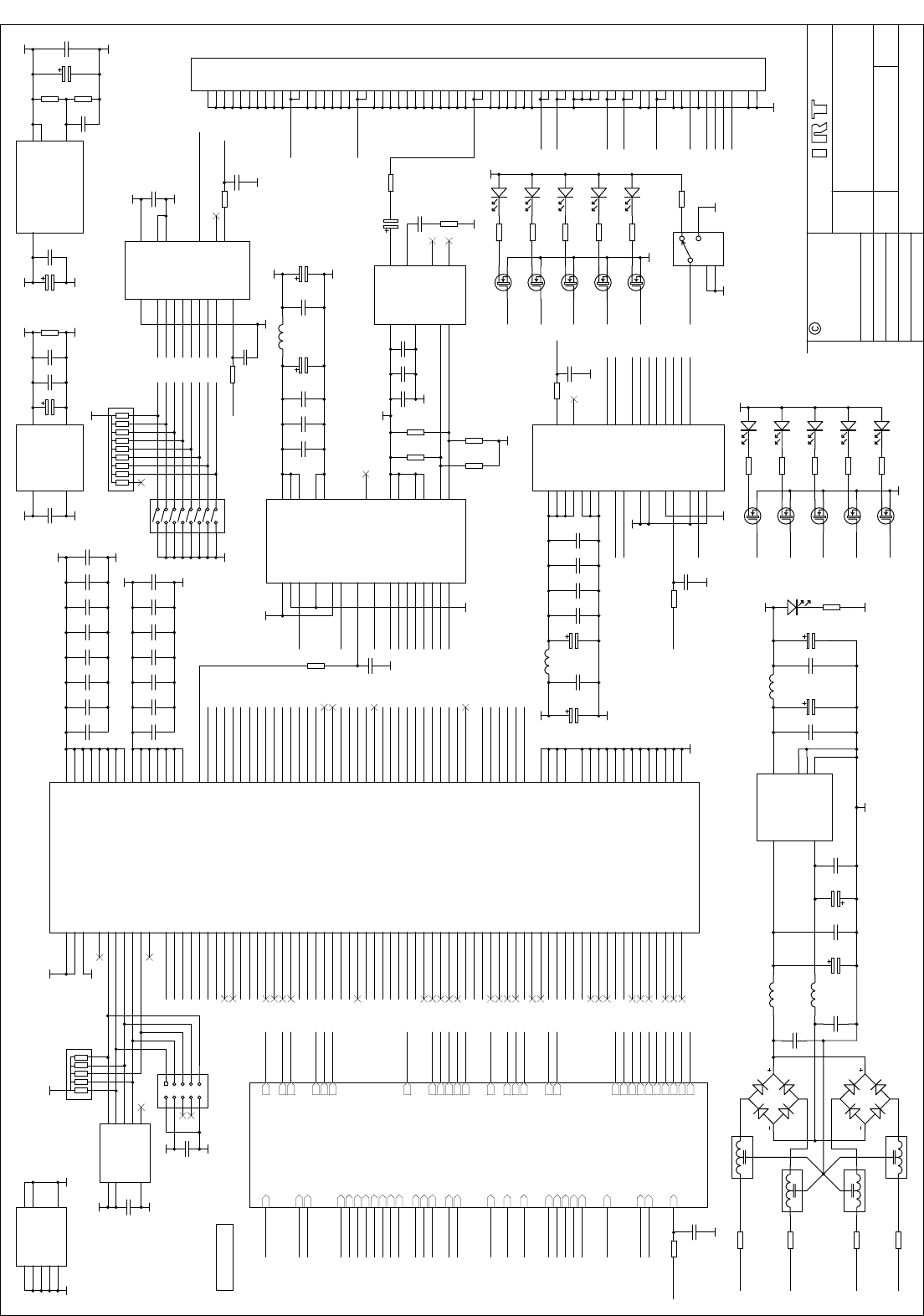
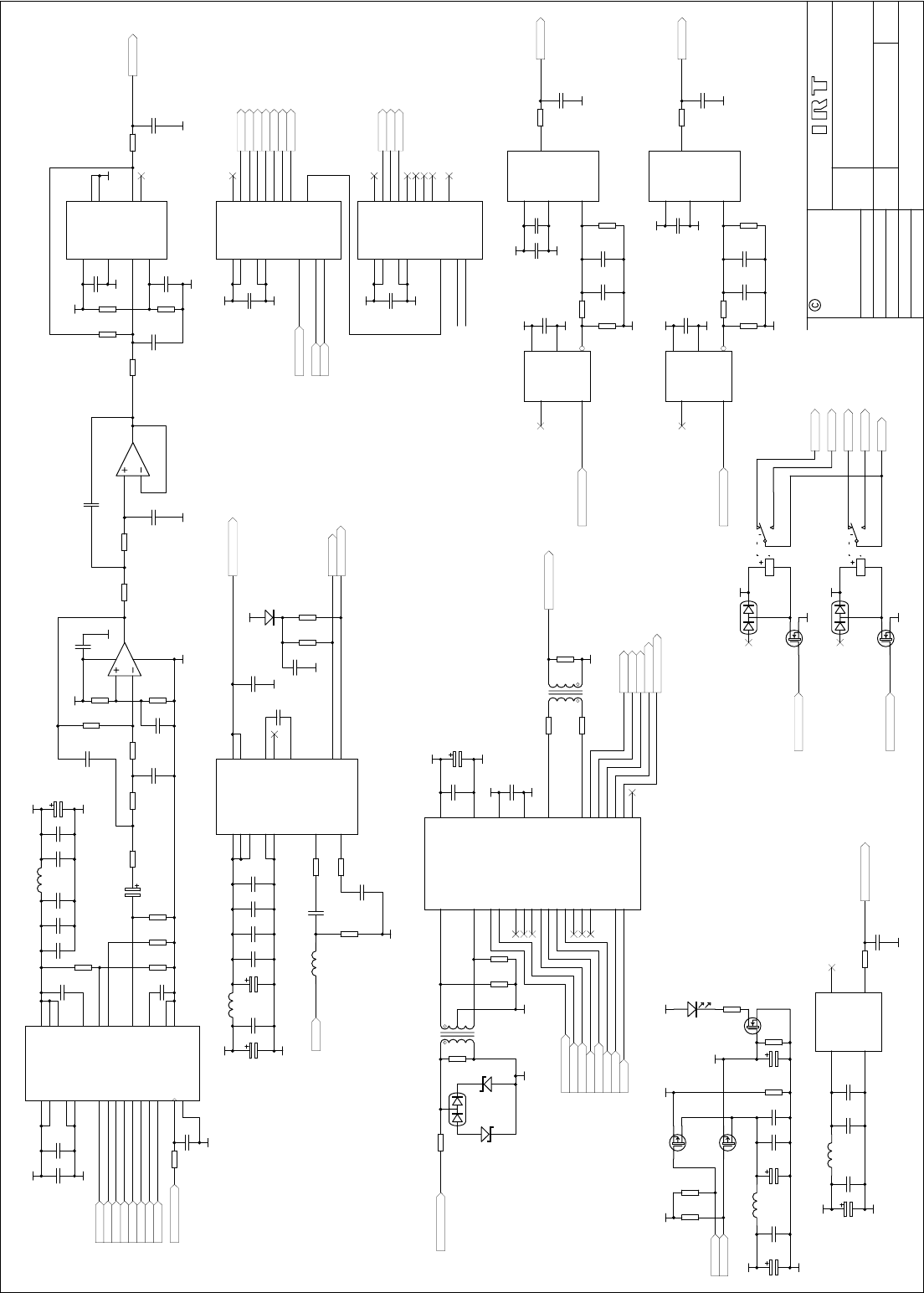
Drawing List Index
Drawing # Sheet # Description
804645 1 2 Mb/s (E1) G.703/ASI Network Interface Adapter circuit diagram – sheet 1
804645 2 2 Mb/s (E1) G.703/ASI Network Interface Adapter circuit diagram – sheet 2
804645 3 2 Mb/s (E1) G.703/ASI Network Interface Adapter circuit diagram – sheet 3
Title
SCALE
SIZE
Sheet
DRAWN
CHECKED
ENG. APP.
Revision:
DO NOT COPY NOR
DISCLOSE TO ANY
THIRD PARTY
WITHOUT WRITTEN
CONSENT
of1
IRT Electronics Pty. Ltd.
Drawing No.
COPYRIGHT
ARTARMON NSW AUSTRALIA 2064
A3
N.T.S. 3
MDC-3660
804645
Date:
1
14-Jan-2004
GND
V1+
V1-
V2+
V2-
1A
1B
2A
2B
3A
3B
4A
4B
5A
5B
6A
6B
7A
7B
8A
8B
9A
9B
10A
10B
11A
11B
12A
12B
13A
13B
14A
14B
15A
15B
16A
16B
17A
17B
18A
18B
19A
19B
20A
20B
21A
21B
22A
22B
23A
23B
24A
24B
25A
25B
26A
26B
27A
27B
28A
28B
29A
29B
30A
30B
31A
31B
32A
32B
M1
M2
PL2
DIN64M
TR9
BSS123
TR10
BSS123
R12
820R
R7
820R
LEDA
LEDB
LD5
LEDR
LD6
LEDG
POWER ON INDICATOR
VCC
SVS
10
BISTENn
5
MODE
7
GND 6
VCCN 4
OUTC+ 3
OUTC- 2
OUTB- 1
VCCQ 9
RP 8
D7
11
D6
12
D5
13
D4
14
SC
19
GND 20
D3
15
D2
16
D1
17
D0
18
CKW
21
VCCQ 22
ENA
23 ENN
24
FOTO
25
OUTA- 26
OUTA+ 27
OUTB+ 28
IC15
CY7B923
12 34 56 78 910
PL1
CON5X2
C22
100n
GND
VCC
C11
100n
GND
VCC
GND
VCC
C80
100n
C59
100n
C67
100n
C63
100n
C81
100n
3V3
GND
nCONFIG
D0
DCLK
nSTATUS
CONF_DONE
DATA 1
DCLK 2
OE 3
nCS 4
GND
5nCASC 6
VCC
7VCC
8IC7
EPC1441
C73
100n
RN2
RN-1k
TXD0
TXD1
TXD2
TXD3
TXD4
TXD5
TXD6
TXD7
TXD0
TXD1
TXD2
TXD3
TXD4
TXD5
TXD6
TXD7
CON3
CON1
TXDA
TXDJ
TXDJ
TXDA
TXENA
RXRF
DOUT
DOUTn
DIN CARRIER
VCO1
VCONT2
DAC0
DAC1
DAC2
DAC3
DAC4
DAC5
DAC6
DAC7
DACCLK PCLK
VCO2
N/O1
ASICLK
VCONT1
REG2 N/C1
COM
G703OUT
XRCLK
XRDATA
XVIO
XLOS
RELAY1
G703IN
XTDATA
XTCLK
XALMT
XRBC
XBCLK
XTBC
XSD
HDB3
XLOC
REG1
ODATA
SC1
SL1
LEDA
LEDB
LEDC
LEDD
LEDE
LEDF
LEDG
LEDH
LEDI
LEDJ
N/C2
N/O2
RELAY2
EQUALISER
804645i1s2.SCH
DIN CARRIER
DOUT
DOUTn
C103
10n
C97
10n
C101
10n
C116
100n
C117
10u C115
10u
L9
470nH
VCC
GND
VCC
R56
120R R60
120R
C112
100n
VCC
8
VEE
5
IN+
7IN-
6Q1n 4
Q1 3
Q0n 2
Q0 1
IC18
CLC007
C114
100p
C113
10n
R61
180R R55
180R
GND
GND
VCONT2
VCO1
COM
N/O1
N/C1
C12
10u
VCC
3V3
C75
100n
C60
100n
C61
100n
C77
100n
C78
100n
C88
100n
C58
100n
C89
100n
C87
100n
2V5
GND
C13
100n
GND R14
820R
C19
100n
C23
100n
C21
10u
R15
820R
VIN
1
GND
2
VOUT 3
CASE
IC5
LM3940
C17
100n
C18
100n
C14
47u
3V3
GNDGND
2V5
GND
C122
4u7
R66
150R
R67
75R
ODATA
TXENA
DIN
RXD0
RXD1
RXD2
RXD3
RXD4
RXD5
RXD6
RXD7
RXDA
RXDJ
CARRIER
RXREF
TXCLK
VCONT1
C20
10n
VTX
DAC0
DAC1
DAC2
DAC3
DAC4
DAC5
DAC6
DAC7
DACCLK PCLK DAC0
DAC1
DAC2
DAC3
DAC4
DAC5
DAC6
DAC7
DACCLK
CON4
GND
RELAY1
SWITCH1
VIN
3VOUT 2
ADJ 1
CASE 0
IC6
LM317TO
GCLK1 55
DI1 54
GND 6
DATA0
108
DCLK
107
nCE 106
TDI
105
GND 25
VCCINT 85
MSEL0 77
MSEL1 76
GND 52
nCONFIG
74
GCLK2 125
DI3 124
VCCINT 75
GND 129
VCCCKLK 53
GND 104
DI2 56
nSTATUS
35
TMS
34
GND 93
TDO
4
nCEO
3
CONF_DONE
2
TCK
1
GND 139
DI4 126
GND 123
VCCIO 5
VCCIO 24
VCCIO 61
VCCIO 45
VCCIO 71
VCCIO 94
VCCIO 115
VCCIO 134
VCCINT 127
GND 40
GND 15
VCCINT 50
GND 66
VCCINT 16
GND 58
GNDCKLK 57
GND 84
VCCINT 103
7
7
8
8
9
9
10
10
11
11
12
12
13
13
17
17
18
18
19
19
20
20
21
21
22
22
23
23
26
26
27
27
28
28
29
29
30
30
31
31
32
32
33
33
36
36
37
37
38
38
39
39
41
41
LOCK
42
43
43
44
44
46
46
47
47
48
48
49
49
51
51
59
59
60
60
62
62
63
63
64
64
65
65
67
67
68
68
69
69
70
70
72
72
73
73
78
78
79
79
80
80
81
81
82
82
83
83
86
86
87
87
88
88
89
89
90
90
91
91
92
92
95
95
96
96
97 97
98 98
99 99
100 100
101 101
102 102
109 109
110 110
111 111
112 112
113 113
114 114
116 116
117 117
118 118
119 119
120 120
121 121
122 122
128 128
130 130
131 131
132 132
133 133
135 135
136 136
137 137
138 138
140 140
141 141
142 142
143 143
144 144
14
14
IC12
EP1K30TC144
GND
TR6
BSS123
TR7
BSS123
R6
820R
R11
820R
GND
LEDC
LEDD
LD10
LEDG
LD11
LEDR
C120
10n
FL4
FL3
FL2
FL1
~
~
DB1
DB106
~
~DB2
DB106
F3
4R7
F4
4R7
F2
4R7
F1
4R7
V1-
V1+
V2-
V2+
C8
1500u C9
1500u
C15
100n
C16
100n
C2
100n
C3
100n
C1
220u C4
220u
VCC
VIN+
1
VIN-
2
VOUT+ 5
VOUT- 3
CASE G1
CASE G2
IC1
PBBA-2405B
L1
22u LD1
R1
820R
GND
C27
100n
C25
100n
L3
L2
GCON1
CON2
GND
SCLK
DMK
R48
22R
C86
56p
GND
VTX
ASI1
VCC
SLATCH
SDATA
RVS/Qj 10
RF
5
RDYn 7
GND
6
BISTENn
4
A/Bn
3
INA+
2
INA-
1
VCCN
9
GND
8
Q7 11
Q6 12
Q5 13
Q4 14
SC/Qa 19
GND
20
Q3 15
Q2 16
Q1 17
Q0 18
VCCQ
21
CKR 22
SO
23
VCCQ
24
REFCLK
25 MODE
26
INB-
27 INB+
28
IC13
CY7B933
RXD0
RXD1
RXD2
RXD3
RXD4
RXD5
RXD6
RXD7
RXRF
RXREF
RXCLK
RXDA
RXDJ
C85
10n
C71
10n
C74
10n
C76
100n
C70
100n
DOUT
DOUTn
C79
10u
C65
10u
L6
470nH
VCC
GND
VREC
VREC
GND
C66
56p
R45
22R
GND
R44
22R C72
56p
GND
VCC
GND
GCON2
VCO2
ASICLK
VCONT1
REG2
XLOC
XLOS
XRCLK
XRDATA
XVIO
N/O1
N/C1
COM
G703OUT
RELAY1
G703IN
XTDATA
XTCLK
XALMT
XRBC
XBCLK
XTBC
XSD
HDB3
CON1
XLOC
XLOS
XSD
XTBC
XBCLK
XTDATA
XVIO
XTCLK
XALMT
XRBC
XRDATA
XRCLK
HDB3
REG2
VCONT2
G703OUT
G703IN
GND 8
G
5
nQ 7
H
6
F
4E
3
CLOCK
2
nLOAD 1
Q9
SA
10
A
11
B
12
C
13
D
14
CLKINH 15
VCC 16
IC4
74HC165
1
2
3
4
5
6
7
89
10
11
12
13
14
15
16 SW2
8SPST
9
8
7
6
5
4
3
2
10
RN1
RN-10k
R33
22R C49
56p
GND
SCLK
C5
100n
VCC
GND
C10
56p
R13
22R
GND
SLATCH
SDATA
TR8
N/C
TR4
BSS123
R9
820R
R8
N/C
LEDE
LEDF
LD4
N/C
LD8
LEDY
VCC
TR5
N/C
R10
N/C
LEDG
LD9
N/C
GND
SL1
34
2
GND
1GND
5
SW1
N/C
SWITCH1
GND GND
R2
N/C
REG1
REG1
LEDA
LEDB
LEDC
LEDD
LEDE
LEDF
LEDG
LEDH
LEDI
LEDJ
ODATA
SC1
SL1
TR3
BSS123
R5
820R
LEDH
LD3
LEDG
TR2
N/C
R4
N/C
LEDI
LD7
N/C
TR1
N/C
R3
N/C
LEDJ
LD2
N/C
R32
22R
C48
56p
GND
SWA
SWB
SWC
SWD
SWE
SWF
SWG
SWH
SWA
SWB
SWC
SWD
SWE
SWF
SWG
SWH
SC1
GND GND
DATA
1
DCLK
2
OE
3
nCS
4
GND 5
nCASC
6
VCC 7
VCC 8
SPARE
REAR ASSEMBLY
804645i1s3.SCH
N/O2
N/C2
N/O2
N/C2
RELAY2
RELAY2
PCLK
GCON1
CON2
VCO2
VCO1
GND
R16
820R
CON4
GCON2
CON3
RXCLK
ASICLK
2MBPS ASI/G.703 INTERFACE
Title
SCALE
SIZE
Sheet
DRAWN
CHECKED
ENG. APP.
Revision:
DO NOT COPY NOR
DISCLOSE TO ANY
THIRD PARTY
WITHOUT WRITTEN
CONSENT
of2
IRT Electronics Pty. Ltd.
Drawing No.
COPYRIGHT
ARTARMON NSW AUSTRALIA 2064
A3
N.T.S. 3
MDC-3660
804645
Date:
1
14-Jan-2004
2MBPS ASI/G.703 INTERFACE
DMK
C30
N/C
C56
N/C
C39
N/C
C38
N/C
VCC
GND
R25
N/C
C40
N/C
C41
N/C
C35
N/C
C45
N/C
R37
N/C
R27
N/C
R26
N/C
VCC
GND
GND
DAC0
DAC1
DAC2
DAC3
DAC4
DAC5
DAC6
DAC7
DACCLK
IN+
1
IN-
2
SHDN 3
LE 4
GND
5
Q6
Qn 7
VCC
8
IC11
N/C
C55
N/C
VCC
GND
R36
N/C
R39
N/C
GND
GND
FDBCK
PCLK
R35
N/C
C54
N/C
2
31
84
IC9A
N/C
5
67
IC9B
N/C
R34
N/C
C52
N/C
GND
C51
N/C
GND
FOUT
D4
5
D5
6
DVDD
23
AVDD 22
DVDD
24
IOUT1 20
IOUT2 21
DVSS
13
AVSS 14
IREF 15
VG 17
AVDD 18
D3
4
AVDD 19
VREF 16
D7
8
D1
2
CLK
12
BLNK
9
DVSS
10
D6
7
D0
1
D2
3
VB 11
IC10
N/C
R30
N/C
R24
N/C R18
N/C
C50
N/C
R31
N/C
RELAY CONTACTS SHOWN
IN "NOT-ENERGISED"
POSITION
5
1
10
3
8
RELAY1
RELAY-SPCO
VCC
TR13
BSS123 GND
RELAY2
D1
BAV99
N/C2
N/O2
COM
L5
N/C C28
N/C
C29
N/C
RELAY2
N/O2
N/C2
C53
N/C
R40
N/C
R22
N/C
R20
N/C
C36
N/C
VCC
C34
N/C
R21
N/C
C47
N/C
5th order Butterworth filter
Cutoff frequency = 7MHz.
(s^2+0.618s+1)(s^2+1.618s+1)(s+1)
C37
N/C
R41
N/C C57
N/C
GND
R42
N/C
PCLK
C62
N/C
GND
VCC
1
VCC
2
VEE
11
VEE
10 OEM 3
VCC
4CD 5
AEC+ 6
AEC- 7
DI
8
DIn
9
MUTEn 12
D0 13
DOn 14
IC17
CLC014AJE
GND
C111
100n
C118
100p
R65
120R
R64
100R
R70
75R C119
10n
C121
10n
C109
10n
C110
10n
C106
10n
C104
100n
C102
10u
C99
10u
L8
470nH
C96
100n
L10
15nH
GND
GND
D3
LS4148
VCC
C100
10n
CARRIER
GND
R53
75R R54
75R
VCC
CARRIER
DOUT
DOUTn
DIN
N/C 1
FOUT 8
VCC
14
GND
7
XO3
XO
ASICLK
R47
22R C82
56p
GND
C84
100n
C83
10n
VCC
GND
C92
10u
L7
470nH
GND
CONTROL
1
FOUT 8
VCC
14
GND
7
XO2
VCXO
C95
100nF
R50
220k
GND
C93
100nF
C94
100n
GND
5VREG2
NC
1
IN
2
GND 3
OUT 4
VCC 5
IC14
74HCT1G04
C68
56p
R46
22R
GND
VCO2
VCONT2
5VREG2
C98
10n
C91
100n
VCONT2
ASICLK
VCO2
GND
8
G6
RESET
10
H7
F5
E4
CLOCK
11 LATCH
12 SDO 9
SDI
14
A15
B1
C2
D3
OUTEN
13
VCC
16
IC2
74HC595
GND
8
G6
RESET
10
H7
F5
E4
CLOCK
11 LATCH
12 SDO 9
SDI
14
A15
B1
C2
D3
OUTEN
13
VCC
16
IC3
74HC595
ODATA
C24
100n
C33
10n
C26
10u
VCC
GND
C32
100n
L4
470nH
5VREG2
TR11
NDS336P
C31
10u
5VREG1
TR12
NDS336P
R17
33k R19
33k
VCC
REG1
REG2
LD12
N/C
R52
N/C
5VREG1
GND
CONTROL
1
FOUT 8
VCC
14
GND
7
XO1
XO
C43
N/C
R28
N/C
GND
C42
N/C
C44
100n
GND
5VREG1
NC
1
IN
2
GND 3
OUT 4
VCC 5
IC8
N/C
C64
56p
R43
22R
GND
VCO1
VCONT1
C46
10n
12288kHz
VCONT1
VCO1
LEDB
LEDA
LEDE
LEDD
LEDC
LEDG
LEDF
LEDH
LEDI
LEDJ
C7
100n
C6
100n
VCC
GND
VCC
GND
SL1
SC1
SL1
SC1
SL1
SC1
VCC
R59
N/C
TR15
N/C
ODATA
5
1
10
3
8
RELAY2
RELAY-SPCO
VCC
TR14
BSS123 GND
RELAY1
D2
BAV99
N/C1
N/O1
RELAY1
N/O1
N/C1
COM
C90
100n
C69
47u
R51
33k
R23
N/C R38
N/C
R49
10M
R29
N/C
XTCLK
XTDATA
C107
100n
C105
100n
R62
15R
R57
15R
VCC
GNDVCC
GND
XTBC
C108
10u
T1
R1
XBCLK LOSn 1
LOCn 2
HDB3
3VIO 4
RCLK 5
RDATA 6
TCLK
7TDATA
8
LP1n
9
LP2n
10
LP3n
11
ALMTn
12
RBC
13
TBC
14 BCLK
15
SRn/DR
16
FLM
17
N/C 18
DGND 19
R2 20
DVDD 21
T2 22
ZS
23
AVDD 24
AGND 25
SD
26
R1
27
T1
28
IC16
XR-T7288
G703OUT
1 6
1:2
43
T2
T4-6
R68
270R
GND
R58
270R R63
270R
XRCLK
XVIO
XLOC
XLOS
XRDATA
XRBC
XALMT
XSD
HDB3
GND
R69
10R R71
220R
GND
G703IN
D6
BAV99
D5
BZX84
D4
BZX84
1 6
5
1:2
43 T1
T4-6T
XLOS
XRCLK
XVIO
XRDATA
XLOC
G703OUT
XTDATA
XTCLK
XALMT
XRBC
XBCLK
XTBC
HDB3
XSD
G703IN
Title
SCALE
SIZE
Sheet
DRAWN
CHECKED
ENG. APP.
Revision:
DO NOT COPY NOR
DISCLOSE TO ANY
THIRD PARTY
WITHOUT WRITTEN
CONSENT
of3
IRT Electronics Pty. Ltd.
Drawing No.
COPYRIGHT
ARTARMON NSW AUSTRALIA 2064
A3
N.T.S. 3
MDC-3660
804645
Date:
1
14-Jan-2004
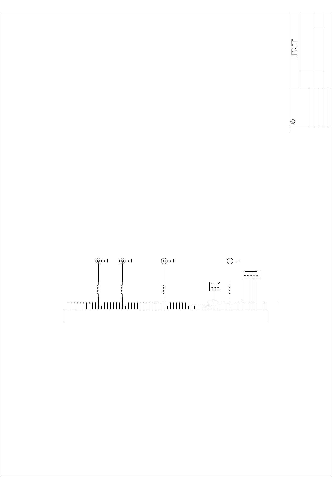
1A
1B
2A
2B
3A
3B
4A
4B
5A
5B
6A
6B
7A
7B
8A
8B
9A
9B
10A
10B
11A
11B
12A
12B
13A
13B
14A
14B
15A
15B
16A
16B
17A
17B
18A
18B
19A
19B
20A
20B
21A
21B
22A
22B
23A
23B
24A
24B
25A
25B
26A
26B
27A
27B
28A
28B
29A
29B
30A
30B
31A
31B
32A
32B
M2
M1
SK3
DIN64F
GNDR
SK4
GNDR
1
2
3
J1
CON3X1
SK1
GNDR
SK5
GNDR
RAL3
15nH
RAL4
22nH
RAL2
15nH
DMK
SK2
GNDR
RAL1
15nH
COM
N/O1
N/C1
G703IN
G703OUT
ASIOUT
ASIIN
1
2
3
4
5
PL3
CON5X1
N/O2
N/C2
2MBPS ASI/G.703 INTERFACE
