Archived CAN 372139B 01
User Manual: CAN 372139B-01
Open the PDF directly: View PDF ![]() .
.
Page Count: 301 [warning: Documents this large are best viewed by clicking the View PDF Link!]
- Automotive Diagnostic Command Set User Manual
- Support
- Important Information
- Compliance
- Contents
- About This Manual
- Chapter 1 Introduction
- Chapter 2 Installation and Configuration
- Chapter 3 Application Development
- Chapter 4 Using the Automotive Diagnostic Command Set
- Chapter 5 Automotive Diagnostic Command Set API for LabVIEW
- Section Headings
- List of VIs
- General Functions
- KWP2000 Services
- ClearDiagnosticInformation.vi
- ControlDTCSetting.vi
- DisableNormalMessageTransmission.vi
- ECUReset.vi
- EnableNormalMessageTransmission.vi
- InputOutputControlByLocalIdentifier.vi
- ReadDataByLocalIdentifier.vi
- ReadDTCByStatus.vi
- ReadECUIdentification.vi
- ReadMemoryByAddress.vi
- ReadStatusOfDTC.vi
- RequestRoutineResultsByLocalIdentifier.vi
- RequestSeed.vi
- SendKey.vi
- StartDiagnosticSession.vi
- StartRoutineByLocalIdentifier.vi
- StopDiagnosticSession.vi
- StopRoutineByLocalIdentifier.vi
- TesterPresent.vi
- WriteDataByLocalIdentifier.vi
- WriteMemoryByAddress.vi
- UDS (DiagOnCAN) Services
- UDS ClearDiagnosticInformation.vi
- UDS CommunicationControl.vi
- UDS ControlDTCSetting.vi
- UDS DiagnosticSessionControl.vi
- UDS ECUReset.vi
- UDS InputOutputControlByIdentifier.vi
- UDS ReadDataByIdentifier.vi
- UDS ReadMemoryByAddress.vi
- UDS ReportDTCBySeverityMaskRecord.vi
- UDS ReportDTCByStatusMask.vi
- UDS ReportSeverityInformationOfDTC.vi
- UDS ReportSupportedDTCs.vi
- UDS RequestSeed.vi
- UDS RoutineControl.vi
- UDS SendKey.vi
- UDS TesterPresent.vi
- UDS WriteDataByIdentifier.vi
- UDS WriteMemoryByAddress.vi
- OBD (On-Board Diagnostics) Services
- OBD Clear Emission Related Diagnostic Information.vi
- OBD Request Control Of On-Board Device.vi
- OBD Request Current Powertrain Diagnostic Data.vi
- OBD Request Emission Related DTCs.vi
- OBD Request Emission Related DTCs During Current Drive Cycle.vi
- OBD Request On-Board Monitoring Test Results.vi
- OBD Request Powertrain Freeze Frame Data.vi
- OBD Request Supported PIDs.vi
- OBD Request Vehicle Information.vi
- Chapter 6 Automotive Diagnostic Command Set API for C
- Section Headings
- List of Data Types
- List of Functions
- General Functions
- KWP2000 Services
- ndClearDiagnosticInformation
- ndControlDTCSetting
- ndDisableNormalMessageTransmission
- ndECUReset
- ndEnableNormalMessageTransmission
- ndInputOutputControlByLocalIdentifier
- ndReadDataByLocalIdentifier
- ndReadDTCByStatus
- ndReadECUIdentification
- ndReadMemoryByAddress
- ndReadStatusOfDTC
- ndRequestRoutineResultsByLocalIdentifier
- ndRequestSeed
- ndSendKey
- ndStartDiagnosticSession
- ndStartRoutineByLocalIdentifier
- ndStopDiagnosticSession
- ndStopRoutineByLocalIdentifier
- ndTesterPresent
- ndWriteDataByLocalIdentifier
- ndWriteMemoryByAddress
- UDS (DiagOnCAN) Services
- ndUDSClearDiagnosticInformation
- ndUDSCommunicationControl
- ndUDSControlDTCSetting
- ndUDSDiagnosticSessionControl
- ndUDSECUReset
- ndUDSInputOutputControlByIdentifier
- ndUDSReadDataByIdentifier
- ndUDSReadMemoryByAddress
- ndUDSReportDTCBySeverityMaskRecord
- ndUDSReportDTCByStatusMask
- ndUDSReportSeverityInformationOfDTC
- ndUDSReportSupportedDTCs
- ndUDSRequestSeed
- ndUDSRoutineControl
- ndUDSSendKey
- ndUDSTesterPresent
- ndUDSWriteDataByIdentifier
- ndUDSWriteMemoryByAddress
- OBD (On-Board Diagnostics) Services
- ndOBDClearEmissionRelatedDiagnosticInformation
- ndOBDRequestControlOfOnBoardDevice
- ndOBDRequestCurrentPowertrainDiagnosticData
- ndOBDRequestEmissionRelatedDTCs
- ndOBDRequestEmissionRelatedDTCsDuringCurrentDriveCycle
- ndOBDRequestOnBoardMonitoringTestResults
- ndOBDRequestPowertrainFreezeFrameData
- ndOBDRequestVehicleInformation
- Appendix A Technical Support and Professional Services
- Index

CAN
Automotive Diagnostic Command Set User Manual
Automotive Diagnostic Command Set User Manual
December 2007
372139B-01
Support
Worldwide Technical Support and Product Information
ni.com
National Instruments Corporate Headquarters
11500 North Mopac Expressway Austin, Texas 78759-3504 USA Tel: 512 683 0100
Worldwide Offices
Australia 1800 300 800, Austria 43 662 457990-0, Belgium 32 (0) 2 757 0020, Brazil 55 11 3262 3599,
Canada 800 433 3488, China 86 21 5050 9800, Czech Republic 420 224 235 774, Denmark 45 45 76 26 00,
Finland 358 (0) 9 725 72511, France 01 57 66 24 24, Germany 49 89 7413130, India 91 80 41190000,
Israel 972 3 6393737, Italy 39 02 41309277, Japan 0120-527196, Korea 82 02 3451 3400,
Lebanon 961 (0) 1 33 28 28, Malaysia 1800 887710, Mexico 01 800 010 0793, Netherlands 31 (0) 348 433 466,
New Zealand 0800 553 322, Norway 47 (0) 66 90 76 60, Poland 48 22 3390150, Portugal 351 210 311 210,
Russia 7 495 783 6851, Singapore 1800 226 5886, Slovenia 386 3 425 42 00, South Africa 27 0 11 805 8197,
Spain 34 91 640 0085, Sweden 46 (0) 8 587 895 00, Switzerland 41 56 2005151, Taiwan 886 02 2377 2222,
Thailand 662 278 6777, Turkey 90 212 279 3031, United Kingdom 44 (0) 1635 523545
For further support information, refer to the Technical Support and Professional Services appendix. To comment
on National Instruments documentation, refer to the National Instruments Web site at ni.com/info and enter
the info code feedback.
© 2007 National Instruments Corporation. All rights reserved.

Important Information
Warranty
The media on which you receive National Instruments software are warranted not to fail to execute programming instructions, due to defects in
materials and workmanship, for a period of 90 days from date of shipment, as evidenced by receipts or other documentation. National Instruments
will, at its option, repair or replace software media that do not execute programming instructions if National Instruments receives notice of such defects
during the warranty period. National Instruments does not warrant that the operation of the software shall be uninterrupted or error free.
A Return Material Authorization (RMA) number must be obtained from the factory and clearly marked on the outside of the package before any
equipment will be accepted for warranty work. National Instruments will pay the shipping costs of returning to the owner parts which are covered by
warranty.
National Instruments believes that the information in this document is accurate. The document has been carefully reviewed for technical accuracy. In
the event that technical or typographical errors exist, National Instruments reserves the right to make changes to subsequent editions of this document
without prior notice to holders of this edition. The reader should consult National Instruments if errors are suspected. In no event shall National
Instruments be liable for any damages arising out of or related to this document or the information contained in it.
EXCEPT AS SPECIFIED HEREIN, NATIONAL INSTRUMENTS MAKES NO WARRANTIES, EXPRESS OR IMPLIED, AND SPECIFICALLY DISCLAIMS ANY WARRANTY OF
MERCHANTABILITY OR FITNESS FOR A PARTICULAR PURPOSE. CUSTOMER’S RIGHT TO RECOVER DAMAGES CAUSED BY FAULT OR NEGLIGENCE ON THE PART OF NATIONAL
INSTRUMENTS SHALL BE LIMITED TO THE AMOUNT THERETOFORE PAID BY THE CUSTOMER. NATIONAL INSTRUMENTS WILL NOT BE LIABLE FOR DAMAGES RESULTING
FROM LOSS OF DATA, PROFITS, USE OF PRODUCTS, OR INCIDENTAL OR CONSEQUENTIAL DAMAGES, EVEN IF ADVISED OF THE POSSIBILITY THEREOF. This limitation of
the liability of National Instruments will apply regardless of the form of action, whether in contract or tort, including negligence. Any action against
National Instruments must be brought within one year after the cause of action accrues. National Instruments shall not be liable for any delay in
performance due to causes beyond its reasonable control. The warranty provided herein does not cover damages, defects, malfunctions, or service
failures caused by owner’s failure to follow the National Instruments installation, operation, or maintenance instructions; owner’s modification of the
product; owner’s abuse, misuse, or negligent acts; and power failure or surges, fire, flood, accident, actions of third parties, or other events outside
reasonable control.
Copyright
Under the copyright laws, this publication may not be reproduced or transmitted in any form, electronic or mechanical, including photocopying,
recording, storing in an information retrieval system, or translating, in whole or in part, without the prior written consent of National
Instruments Corporation.
National Instruments respects the intellectual property of others, and we ask our users to do the same. NI software is protected by copyright and other
intellectual property laws. Where NI software may be used to reproduce software or other materials belonging to others, you may use NI software only
to reproduce materials that you may reproduce in accordance with the terms of any applicable license or other legal restriction.
Trademarks
National Instruments, NI, ni.com, and LabVIEW are trademarks of National Instruments Corporation. Refer to the Terms of Use section
on ni.com/legal for more information about National Instruments trademarks.
Other product and company names mentioned herein are trademarks or trade names of their respective companies.
Members of the National Instruments Alliance Partner Program are business entities independent from National Instruments and have no agency,
partnership, or joint-venture relationship with National Instruments.
Patents
For patents covering National Instruments products, refer to the appropriate location: Help»Patents in your software, the patents.txt file
on your CD, or ni.com/patents.
WARNING REGARDING USE OF NATIONAL INSTRUMENTS PRODUCTS
(1) NATIONAL INSTRUMENTS PRODUCTS ARE NOT DESIGNED WITH COMPONENTS AND TESTING FOR A LEVEL OF
RELIABILITY SUITABLE FOR USE IN OR IN CONNECTION WITH SURGICAL IMPLANTS OR AS CRITICAL COMPONENTS IN
ANY LIFE SUPPORT SYSTEMS WHOSE FAILURE TO PERFORM CAN REASONABLY BE EXPECTED TO CAUSE SIGNIFICANT
INJURY TO A HUMAN.
(2) IN ANY APPLICATION, INCLUDING THE ABOVE, RELIABILITY OF OPERATION OF THE SOFTWARE PRODUCTS CAN BE
IMPAIRED BY ADVERSE FACTORS, INCLUDING BUT NOT LIMITED TO FLUCTUATIONS IN ELECTRICAL POWER SUPPLY,
COMPUTER HARDWARE MALFUNCTIONS, COMPUTER OPERATING SYSTEM SOFTWARE FITNESS, FITNESS OF COMPILERS
AND DEVELOPMENT SOFTWARE USED TO DEVELOP AN APPLICATION, INSTALLATION ERRORS, SOFTWARE AND HARDWARE
COMPATIBILITY PROBLEMS, MALFUNCTIONS OR FAILURES OF ELECTRONIC MONITORING OR CONTROL DEVICES,
TRANSIENT FAILURES OF ELECTRONIC SYSTEMS (HARDWARE AND/OR SOFTWARE), UNANTICIPATED USES OR MISUSES, OR
ERRORS ON THE PART OF THE USER OR APPLICATIONS DESIGNER (ADVERSE FACTORS SUCH AS THESE ARE HEREAFTER
COLLECTIVELY TERMED “SYSTEM FAILURES”). ANY APPLICATION WHERE A SYSTEM FAILURE WOULD CREATE A RISK OF
HARM TO PROPERTY OR PERSONS (INCLUDING THE RISK OF BODILY INJURY AND DEATH) SHOULD NOT BE RELIANT SOLELY
UPON ONE FORM OF ELECTRONIC SYSTEM DUE TO THE RISK OF SYSTEM FAILURE. TO AVOID DAMAGE, INJURY, OR DEATH,
THE USER OR APPLICATION DESIGNER MUST TAKE REASONABLY PRUDENT STEPS TO PROTECT AGAINST SYSTEM FAILURES,
INCLUDING BUT NOT LIMITED TO BACK-UP OR SHUT DOWN MECHANISMS. BECAUSE EACH END-USER SYSTEM IS
CUSTOMIZED AND DIFFERS FROM NATIONAL INSTRUMENTS' TESTING PLATFORMS AND BECAUSE A USER OR APPLICATION
DESIGNER MAY USE NATIONAL INSTRUMENTS PRODUCTS IN COMBINATION WITH OTHER PRODUCTS IN A MANNER NOT
EVALUATED OR CONTEMPLATED BY NATIONAL INSTRUMENTS, THE USER OR APPLICATION DESIGNER IS ULTIMATELY
RESPONSIBLE FOR VERIFYING AND VALIDATING THE SUITABILITY OF NATIONAL INSTRUMENTS PRODUCTS WHENEVER
NATIONAL INSTRUMENTS PRODUCTS ARE INCORPORATED IN A SYSTEM OR APPLICATION, INCLUDING, WITHOUT
LIMITATION, THE APPROPRIATE DESIGN, PROCESS AND SAFETY LEVEL OF SUCH SYSTEM OR APPLICATION.

Compliance
Compliance with FCC/Canada Radio Frequency Interference
Regulations
Determining FCC Class
The Federal Communications Commission (FCC) has rules to protect wireless communications from interference. The FCC
places digital electronics into two classes. These classes are known as Class A (for use in industrial-commercial locations only)
or Class B (for use in residential or commercial locations). All National Instruments (NI) products are FCC Class A products.
Depending on where it is operated, this Class A product could be subject to restrictions in the FCC rules. (In Canada, the
Department of Communications (DOC), of Industry Canada, regulates wireless interference in much the same way.) Digital
electronics emit weak signals during normal operation that can affect radio, television, or other wireless products.
All Class A products display a simple warning statement of one paragraph in length regarding interference and undesired
operation. The FCC rules have restrictions regarding the locations where FCC Class A products can be operated.
Consult the FCC Web site at www.fcc.gov for more information.
FCC/DOC Warnings
This equipment generates and uses radio frequency energy and, if not installed and used in strict accordance with the instructions
in this manual and the CE marking Declaration of Conformity*, may cause interference to radio and television reception.
Classification requirements are the same for the Federal Communications Commission (FCC) and the Canadian Department
of Communications (DOC).
Changes or modifications not expressly approved by NI could void the user’s authority to operate the equipment under the
FCC Rules.
Class A
Federal Communications Commission
This equipment has been tested and found to comply with the limits for a Class A digital device, pursuant to part 15 of the FCC
Rules. These limits are designed to provide reasonable protection against harmful interference when the equipment is operated
in a commercial environment. This equipment generates, uses, and can radiate radio frequency energy and, if not installed and
used in accordance with the instruction manual, may cause harmful interference to radio communications. Operation of this
equipment in a residential area is likely to cause harmful interference in which case the user is required to correct the interference
at their own expense.
Canadian Department of Communications
This Class A digital apparatus meets all requirements of the Canadian Interference-Causing Equipment Regulations.
Cet appareil numérique de la classe A respecte toutes les exigences du Règlement sur le matériel brouilleur du Canada.
Compliance with EU Directives
Users in the European Union (EU) should refer to the Declaration of Conformity (DoC) for information* pertaining to the
CE marking. Refer to the Declaration of Conformity (DoC) for this product for any additional regulatory compliance
information. To obtain the DoC for this product, visit ni.com/certification, search by model number or product line,
and click the appropriate link in the Certification column.
* The CE marking Declaration of Conformity contains important supplementary information and instructions for the user or
installer.

© National Instruments Corporation v Automotive Diagnostic Command Set User Manual
Contents
About This Manual
Conventions ...................................................................................................................xi
Related Documentation..................................................................................................xii
Chapter 1
Introduction
KWP2000 (Key Word Protocol 2000)...........................................................................1-1
Transport Protocol ...........................................................................................1-2
Diagnostic Services .........................................................................................1-2
Diagnostic Service Format ..............................................................................1-2
Connect/Disconnect.........................................................................................1-3
GetSeed/Unlock...............................................................................................1-3
Read/Write Memory........................................................................................1-3
Measurements..................................................................................................1-4
Diagnostic Trouble Codes ...............................................................................1-4
Input/Output Control .......................................................................................1-4
Remote Activation of a Routine ......................................................................1-4
External References.........................................................................................1-4
UDS (Unified Diagnostic Services)...............................................................................1-5
Diagnostic Services .........................................................................................1-5
Diagnostic Service Format ..............................................................................1-5
External References.........................................................................................1-6
OBD (On-Board Diagnostic) .........................................................................................1-6
Chapter 2
Installation and Configuration
Installation .....................................................................................................................2-1
LabVIEW Real-Time (RT) Configuration ....................................................................2-2
Hardware and Software Requirements ..........................................................................2-2
Chapter 3
Application Development
Choosing the Programming Language ..........................................................................3-1
LabVIEW ........................................................................................................3-1
LabWindows/CVI............................................................................................3-1
Contents
Automotive Diagnostic Command Set User Manual vi ni.com
Visual C++ 6 ................................................................................................... 3-2
Other Programming Languages ...................................................................... 3-2
Debugging an Application............................................................................................. 3-3
Chapter 4
Using the Automotive Diagnostic Command Set
Structure of the Automotive Diagnostic Command Set................................................ 4-1
Automotive Diagnostic Command Set API Structure................................................... 4-2
General Programming Model ........................................................................................ 4-3
Available Diagnostic Services....................................................................................... 4-4
Tweaking the Transport Protocol .................................................................................. 4-4
Chapter 5
Automotive Diagnostic Command Set API for LabVIEW
Section Headings ........................................................................................................... 5-1
Purpose............................................................................................................ 5-1
Format ............................................................................................................. 5-1
Input and Output ............................................................................................. 5-1
Description ...................................................................................................... 5-1
List of VIs...................................................................................................................... 5-2
General Functions.......................................................................................................... 5-8
Close Diagnostic.vi ......................................................................................... 5-8
Convert from Phys.vi ...................................................................................... 5-10
Convert to Phys.vi........................................................................................... 5-12
Create Extended CAN IDs.vi.......................................................................... 5-14
Diag Get Property.vi ....................................................................................... 5-15
Diag Set Property.vi........................................................................................ 5-17
Diagnostic Service.vi ...................................................................................... 5-19
DTC to String.vi.............................................................................................. 5-21
OBD Open.vi .................................................................................................. 5-22
Open Diagnostic.vi.......................................................................................... 5-24
VWTP Connect.vi........................................................................................... 5-26
VWTP Connection Test.vi.............................................................................. 5-28
VWTP Disconnect.vi ...................................................................................... 5-30
KWP2000 Services........................................................................................................ 5-32
ClearDiagnosticInformation.vi ....................................................................... 5-32
ControlDTCSetting.vi ..................................................................................... 5-35
DisableNormalMessageTransmission.vi......................................................... 5-38
ECUReset.vi.................................................................................................... 5-40
EnableNormalMessageTransmission.vi.......................................................... 5-42
InputOutputControlByLocalIdentifier.vi ........................................................ 5-44
ReadDataByLocalIdentifier.vi ........................................................................ 5-46
Contents
© National Instruments Corporation vii Automotive Diagnostic Command Set User Manual
ReadDTCByStatus.vi ......................................................................................5-48
ReadECUIdentification.vi ...............................................................................5-51
ReadMemoryByAddress.vi .............................................................................5-53
ReadStatusOfDTC.vi.......................................................................................5-55
RequestRoutineResultsByLocalIdentifier.vi ...................................................5-58
RequestSeed.vi ................................................................................................5-60
SendKey.vi ......................................................................................................5-62
StartDiagnosticSession.vi................................................................................5-64
StartRoutineByLocalIdentifier.vi ....................................................................5-66
StopDiagnosticSession.vi ................................................................................5-68
StopRoutineByLocalIdentifier.vi ....................................................................5-70
TesterPresent.vi ...............................................................................................5-72
WriteDataByLocalIdentifier.vi........................................................................5-74
WriteMemoryByAddress.vi ............................................................................5-76
UDS (DiagOnCAN) Services ........................................................................................5-78
UDS ClearDiagnosticInformation.vi...............................................................5-78
UDS CommunicationControl.vi ......................................................................5-81
UDS ControlDTCSetting.vi ............................................................................5-83
UDS DiagnosticSessionControl.vi ..................................................................5-85
UDS ECUReset.vi ...........................................................................................5-87
UDS InputOutputControlByIdentifier.vi.........................................................5-89
UDS ReadDataByIdentifier.vi.........................................................................5-91
UDS ReadMemoryByAddress.vi ....................................................................5-93
UDS ReportDTCBySeverityMaskRecord.vi...................................................5-95
UDS ReportDTCByStatusMask.vi..................................................................5-98
UDS ReportSeverityInformationOfDTC.vi ....................................................5-101
UDS ReportSupportedDTCs.vi .......................................................................5-104
UDS RequestSeed.vi .......................................................................................5-107
UDS RoutineControl.vi ...................................................................................5-109
UDS SendKey.vi .............................................................................................5-111
UDS TesterPresent.vi ......................................................................................5-113
UDS WriteDataByIdentifier.vi........................................................................5-115
UDS WriteMemoryByAddress.vi ...................................................................5-117
OBD (On-Board Diagnostics) Services .........................................................................5-119
OBD Clear Emission Related Diagnostic Information.vi ...............................5-119
OBD Request Control Of On-Board Device.vi...............................................5-121
OBD Request Current Powertrain Diagnostic Data.vi....................................5-123
OBD Request Emission Related DTCs.vi.......................................................5-125
OBD Request Emission Related DTCs During Current Drive Cycle.vi .........5-128
OBD Request On-Board Monitoring Test Results.vi......................................5-131
OBD Request Powertrain Freeze Frame Data.vi.............................................5-133
OBD Request Supported PIDs.vi ....................................................................5-135
OBD Request Vehicle Information.vi .............................................................5-137
Contents
Automotive Diagnostic Command Set User Manual viii ni.com
Chapter 6
Automotive Diagnostic Command Set API for C
Section Headings ........................................................................................................... 6-1
Purpose............................................................................................................ 6-1
Format ............................................................................................................. 6-1
Input and Output ............................................................................................. 6-1
Description ...................................................................................................... 6-1
List of Data Types ......................................................................................................... 6-2
List of Functions............................................................................................................ 6-3
General Functions.......................................................................................................... 6-12
ndCloseDiagnostic .......................................................................................... 6-12
ndConvertFromPhys ....................................................................................... 6-13
ndConvertToPhys............................................................................................ 6-15
ndCreateExtendedCANIds.............................................................................. 6-17
ndDiagnosticService ....................................................................................... 6-19
ndDTCToString .............................................................................................. 6-21
ndGetProperty ................................................................................................. 6-22
ndOBDOpen.................................................................................................... 6-24
ndOpenDiagnostic........................................................................................... 6-26
ndSetProperty.................................................................................................. 6-28
ndStatusToString............................................................................................. 6-30
ndVWTPConnect ............................................................................................ 6-32
ndVWTPConnectionTest ................................................................................ 6-34
ndVWTPDisconnect ....................................................................................... 6-35
KWP2000 Services........................................................................................................ 6-36
ndClearDiagnosticInformation........................................................................ 6-36
ndControlDTCSetting ..................................................................................... 6-38
ndDisableNormalMessageTransmission......................................................... 6-40
ndECUReset.................................................................................................... 6-41
ndEnableNormalMessageTransmission.......................................................... 6-43
ndInputOutputControlByLocalIdentifier ........................................................ 6-44
ndReadDataByLocalIdentifier ........................................................................ 6-46
ndReadDTCByStatus ...................................................................................... 6-48
ndReadECUIdentification............................................................................... 6-51
ndReadMemoryByAddress............................................................................. 6-53
ndReadStatusOfDTC ...................................................................................... 6-55
ndRequestRoutineResultsByLocalIdentifier................................................... 6-58
ndRequestSeed ................................................................................................ 6-60
ndSendKey ...................................................................................................... 6-62
ndStartDiagnosticSession................................................................................ 6-64
ndStartRoutineByLocalIdentifier.................................................................... 6-66
ndStopDiagnosticSession................................................................................ 6-68
ndStopRoutineByLocalIdentifier .................................................................... 6-69
Contents
© National Instruments Corporation ix Automotive Diagnostic Command Set User Manual
ndTesterPresent ...............................................................................................6-71
ndWriteDataByLocalIdentifier........................................................................6-73
ndWriteMemoryByAddress ............................................................................6-75
UDS (DiagOnCAN) Services ........................................................................................6-77
ndUDSClearDiagnosticInformation ................................................................6-77
ndUDSCommunicationControl .......................................................................6-79
ndUDSControlDTCSetting..............................................................................6-81
ndUDSDiagnosticSessionControl ...................................................................6-82
ndUDSECUReset ............................................................................................6-83
ndUDSInputOutputControlByIdentifier..........................................................6-85
ndUDSReadDataByIdentifier..........................................................................6-87
ndUDSReadMemoryByAddress .....................................................................6-89
ndUDSReportDTCBySeverityMaskRecord....................................................6-91
ndUDSReportDTCByStatusMask...................................................................6-94
ndUDSReportSeverityInformationOfDTC......................................................6-97
ndUDSReportSupportedDTCs ........................................................................6-100
ndUDSRequestSeed ........................................................................................6-103
ndUDSRoutineControl ....................................................................................6-105
ndUDSSendKey ..............................................................................................6-107
ndUDSTesterPresent .......................................................................................6-109
ndUDSWriteDataByIdentifier.........................................................................6-111
ndUDSWriteMemoryByAddress ....................................................................6-113
OBD (On-Board Diagnostics) Services .........................................................................6-115
ndOBDClearEmissionRelatedDiagnosticInformation ....................................6-115
ndOBDRequestControlOfOnBoardDevice .....................................................6-116
ndOBDRequestCurrentPowertrainDiagnosticData .........................................6-118
ndOBDRequestEmissionRelatedDTCs ...........................................................6-120
ndOBDRequestEmissionRelatedDTCsDuringCurrentDriveCycle .................6-122
ndOBDRequestOnBoardMonitoringTestResults ............................................6-124
ndOBDRequestPowertrainFreezeFrameData..................................................6-126
ndOBDRequestVehicleInformation ................................................................6-128
Appendix A
Technical Support and Professional Services
Index

© National Instruments Corporation xi Automotive Diagnostic Command Set User Manual
About This Manual
This manual provides instructions for using the Automotive Diagnostic
Command Set. It contains information about installation, configuration,
and troubleshooting, and also contains Automotive Diagnostic Command
Set function reference for LabVIEW-based and C-based APIs.
Conventions
The following conventions appear in this manual:
»The » symbol leads you through nested menu items and dialog box options
to a final action. The sequence File»Page Setup»Options directs you to
pull down the File menu, select the Page Setup item, and select Options
from the last dialog box.
This icon denotes a tip, which alerts you to advisory information.
This icon denotes a note, which alerts you to important information.
bold Bold text denotes items that you must select or click in the software, such
as menu items and dialog box options. Bold text also denotes parameter
names.
italic Italic text denotes variables, emphasis, a cross-reference, or an introduction
to a key concept. Italic text also denotes text that is a placeholder for a word
or value that you must supply.
monospace Text in this font denotes text or characters that you should enter from the
keyboard, sections of code, programming examples, and syntax examples.
This font is also used for the proper names of disk drives, paths, directories,
programs, subprograms, subroutines, device names, functions, operations,
variables, filenames, and extensions.
monospace italic
Italic text in this font denotes text that is a placeholder for a word or value
that you must supply.

About This Manual
Automotive Diagnostic Command Set User Manual xii ni.com
Related Documentation
The following documents contain information that you might find helpful
as you read this manual:
• ANSI/ISO Standard 11898-1993, Road Vehicles—Interchange of
Digital Information—Controller Area Network (CAN) for High-Speed
Communication
•CAN Specification Version 2.0, 1991, Robert Bosch GmbH.,
Postfach 106050, D-70049 Stuttgart 1
•CiA Draft Standard 102, Version 2.0, CAN Physical Layer for
Industrial Applications
• ISO 14229:1998(E), Road Vehicles, Diagnostic Systems, Diagnostic
Services Specification
• ISO 14230-1:1999(E), Road Vehicles, Diagnostic Systems, Keyword
Protocol 2000, Part 1: Physical Layer
•ISO 14230-2:1999(E), Road Vehicles, Diagnostic Systems, Keyword
Protocol 2000, Part 2: Data Link Layer
• ISO 14230-3:1999(E), Road Vehicles, Diagnostic Systems, Keyword
Protocol 2000, Part 3: Application Layer
• ISO 15765-1:2004(E), Road Vehicles, Diagnostics on Controller Area
Networks (CAN), Part 1: General Information
• ISO 15765-2:2004(E), Road Vehicles, Diagnostics on Controller Area
Networks (CAN), Part 2: Network Layer Services
• ISO 15765-3:2004(E), Road Vehicles, Diagnostics on Controller Area
Networks (CAN), Part 3: Implementation of Unified Diagnostic
Services (UDS on CAN)
• NI-CAN Hardware and Software Manual

© National Instruments Corporation 1-1 Automotive Diagnostic Command Set User Manual
1
Introduction
Diagnostics involve remote execution of routines, or services, on ECUs. To
execute a routine, you send a byte string as a request to an ECU, and the
ECU usually answers with a response byte string. Several diagnostic
protocols such as KWP2000 and UDS standardize the format of the
services to be executed, but those standards leave a large amount of room
for manufacturer-specific extensions. A newer trend is the emission-related
legislated OnBoard Diagnostics (OBD), which is manufacturer
independent and standardized in SAE J1979 and ISO 15031-5. This
standard adds another set of services that follow the same scheme.
Because diagnostics were traditionally executed on serial communication
links, the byte string length is not limited. For newer, CAN-based
diagnostics, this involves using a transport protocol that segments the
arbitrarily long byte strings into pieces that can be transferred over the CAN
bus, and reassembles them on the receiver side. Several transport protocols
accomplish this task. The Automotive Diagnostic Command Set
implements the ISO TP (standardized in ISO 15765-2) and the
manufacturer-specific VW TP 2.0.
Note The Automotive Diagnostic Command Set is designed for CAN-based diagnostics
only. Diagnostics on serial lines (K-line and L-line) are not in the scope of the Automotive
Diagnostic Command Set.
KWP2000 (Key Word Protocol 2000)
The KWP2000 protocol has become a de facto standard in automotive
diagnostic applications. It is standardized as ISO 14230-3. KWP2000
describes the implementation of various diagnostic services you can access
through the protocol. You can run KWP2000 on several transport layers
such as K-line (serial) or CAN.

Chapter 1 Introduction
Automotive Diagnostic Command Set User Manual 1-2 ni.com
Transport Protocol
As KWP2000 uses messages of variable byte lengths, a transport protocol
is necessary on layers with only a well defined (short) message length, such
as CAN. The transport protocol splits a long KWP2000 message into pieces
that can be transferred over the network and reassembles those pieces to
recover the original message.
KWP2000 runs on CAN on various transport protocols such as ISO TP
(ISO 15765-2), TP 1.6, TP 2.0 (Volkswagen), and SAE J1939-21.
Note For KWP2000, the Automotive Diagnostic Command Set supports only the ISO TP
(standardized in ISO 15765-2) and manufacturer-specific VW TP 2.0 transport protocols.
Diagnostic Services
The diagnostic services available in KWP2000 are grouped in functional
units and identified by a one-byte code (ServiceId). The standard does not
define all codes; for some codes, the standard refers to other SAE or ISO
standards, and some are reserved for manufacturer-specific extensions. The
Automotive Diagnostic Command Set supports the following services:
• Diagnostic Management
• Data Transmission
• Stored Data Transmission (Diagnostic Trouble Codes)
• Input/Output Control
• Remote Activation of Routine
Note Upload/Download and Extended services are not part of the Automotive Diagnostic
Command Set.
Diagnostic Service Format
Diagnostic services have a common message format. Each service defines
a Request Message, Positive Response Message, and Negative Response
Message.
The Request Message has the ServiceId as first byte, plus additional
service-defined parameters. The Positive Response Message has an echo of
the ServiceId with bit 6 set as first byte, plus the service-defined response
parameters.
The Negative Response Message is usually a three-byte message: it has the
Negative Response ServiceId as first byte, an echo of the original ServiceId
Chapter 1 Introduction
© National Instruments Corporation 1-3 Automotive Diagnostic Command Set User Manual
as second byte, and a ResponseCode as third byte. The only exception to
this format is the negative response to an EscapeCode service; here, the
third byte is an echo of the user-defined service code, and the fourth byte
is the ResponseCode. The KWP2000 standard partly defines the
ResponseCodes, but there is room left for manufacturer-specific
extensions. For some of the ResponseCodes, KWP2000 defines an error
handling procedure. Because both positive and negative responses have an
echo of the requested service, you can always assign the responses to their
corresponding request.
Connect/Disconnect
KWP2000 expects a diagnostic session to be started with
StartDiagnosticSession and terminated with StopDiagnosticSession.
However, StartDiagnosticSession has a DiagnosticMode parameter that
determines the diagnostic session type. Depending on this type, the ECU
may or may not support other diagnostic services, or operate in a restricted
mode where not all ECU functions are available. The DiagnosticMode
parameter values are manufacturer specific and not defined in the standard.
For a diagnostic session to remain active, it must execute the TesterPresent
service periodically if no other service is executed. If the TesterPresent
service is missing for a certain period of time, the diagnostic session is
terminated, and the ECU returns to normal operation mode.
GetSeed/Unlock
A GetSeed/Unlock mechanism may protect some diagnostic services.
However, the applicable services are left to the manufacturer and not
defined by the standard.
You can execute the GetSeed/Unlock mechanism through the
SecurityAccess service. This defines several levels of security, but the
manufacturer assigns these levels to certain services.
Read/Write Memory
Use the Read/WriteMemoryByAddress services to upload/download data
to certain memory addresses on an ECU. The address is a three-byte
quantity in KWP2000 and a five-byte quantity (four-byte address and
one-byte extension) in the calibration protocols.
The Upload/Download functional unit services are highly manufacturer
specific and not well defined in the standard, so they are not a good way to
provide a general upload/download mechanism.

Chapter 1 Introduction
Automotive Diagnostic Command Set User Manual 1-4 ni.com
Measurements
Use the ReadDataByLocal/CommonIdentifier services to access ECU data
in a way similar to a DAQ list. A Local/CommonIdentifier describes a list
of ECU quantities that are then transferred from the ECU to the tester. The
transfer can be either single value or periodic, with a slow, medium, or fast
transfer rate. The transfer rates are manufacturer specific; you can use the
SetDataRates service to set them, but this setting is manufacturer specific.
Note The Automotive Diagnostic Command Set supports single-point measurements.
Diagnostic Trouble Codes
A major diagnostic feature is the readout of Diagnostic Trouble Codes
(DTCs). KWP2000 defines several services that access DTCs based on
their group or status.
Input/Output Control
KWP2000 defines services to modify internal or external ECU signals. One
example is redirecting ECU sensor inputs to stimulated signals. The control
parameters of these commands are manufacturer specific and not defined
in the standard.
Remote Activation of a Routine
These services are similar to the ActionService and DiagService
functions of CCP. You can invoke an ECU internal routine identified by a
Local/CommonIdentifier or a memory address. Contrary to the CCP case,
execution of this routine can be asynchronous; that is, there are separate
Start, Stop, and RequestResult services.
The control parameters of these commands are manufacturer specific and
not defined in the standard.
External References
For more information about the KWP2000 Standard, refer to the
ISO 14230-3 standard.

Chapter 1 Introduction
© National Instruments Corporation 1-5 Automotive Diagnostic Command Set User Manual
UDS (Unified Diagnostic Services)
The UDS protocol has become a de facto standard in automotive diagnostic
applications. It is standardized as ISO 15765-3. UDS describes the
implementation of various diagnostic services you can access through the
protocol.
As UDS uses messages of variable byte lengths, a transport protocol is
necessary on layers with only a well defined (short) message length, such
as CAN. The transport protocol splits a long UDS message into pieces that
can be transferred over the network and reassembles those pieces to recover
the original message.
UDS runs on CAN on various transport protocols.
Note The Automotive Diagnostic Command Set supports only the ISO TP (standardized
in ISO 15765-2) and manufacturer-specific VW TP 2.0 transport protocols.
Diagnostic Services
The diagnostic services available in UDS are grouped in functional units
and identified by a one-byte code (ServiceId). Not all codes are defined in
the standard; for some codes, the standard refers to other standards, and
some are reserved for manufacturer-specific extensions. The Automotive
Diagnostic Command Set supports the following services:
• Diagnostic Management
• Data Transmission
• Stored Data Transmission (Diagnostic Trouble Codes)
• Input/Output Control
• Remote Activation of Routine
Diagnostic Service Format
Diagnostic services have a common message format. Each service defines
a Request Message, a Positive Response Message, and a Negative
Response Message. The general format of the diagnostic services complies
with the KWP2000 definition; most of the Service Ids also comply with
KWP2000. The Request Message has the ServiceId as first byte, plus
additional service-defined parameters. The Positive Response Message has
an echo of the ServiceId with bit 6 set as first byte, plus the service-defined
response parameters.

Chapter 1 Introduction
Automotive Diagnostic Command Set User Manual 1-6 ni.com
Note Some parameters to both the Request and Positive Response Messages are optional.
Each service defines these parameters. Also, the standard does not define all parameters.
The Negative Response Message is usually a three-byte message: it has the
Negative Response ServiceId (0x7F) as first byte, an echo of the original
ServiceId as second byte, and a ResponseCode as third byte. The UDS
standard partly defines the ResponseCodes, but there is room left for
manufacturer-specific extensions. For some of the ResponseCodes, UDS
defines an error handling procedure.
Because both positive and negative responses have an echo of the requested
service, you always can assign the responses to their corresponding request.
External References
For more information about the UDS Standard, refer to the ISO 15765-3
standard.
OBD (On-Board Diagnostic)
On-Board Diagnostic (OBD) systems are present in most cars and light
trucks on the road today. On-Board Diagnostics refer to the vehicle’s
self-diagnostic and reporting capability, which the vehicle owner or a
repair technician can use to query status information for various vehicle
subsystems.
The amount of diagnostic information available via OBD has increased
since the introduction of on-board vehicle computers in the early 1980s.
Modern OBD implementations use a CAN communication port to provide
real-time data and a standardized series of diagnostic trouble codes
(DTCs), which identify and remedy malfunctions within the vehicle. In the
1970s and early 1980s, manufacturers began using electronic means to
control engine functions and diagnose engine problems. This was primarily
to meet EPA emission standards. Through the years, on-board diagnostic
systems have become more sophisticated. OBD-II, a new standard
introduced in the mid 1990s, provides almost complete engine control and
also monitors parts of the chassis, body, and accessory devices, as well as
the car’s diagnostic control network.
The On-Board Diagnostic (OBD) standard defines a minimum set of
diagnostic information for passenger cars and light and medium-duty
trucks, which must be exchanged with any off-board test equipment.

© National Instruments Corporation 2-1 Automotive Diagnostic Command Set User Manual
2
Installation and Configuration
This chapter explains how to install and configure the Automotive
Diagnostic Command Set.
Installation
This section discusses the Automotive Diagnostic Command Set
installation for Microsoft Windows.
Note You need administrator rights to install the Automotive Diagnostic Command Set on
your computer.
Follow these steps to install the Automotive Diagnostic Command Set
software:
1. Insert the Automotive Diagnostic Command Set CD into the CD-ROM
drive.
2. Open Windows Explorer.
3. Access the CD-ROM drive.
4. Double-click on autorun.exe to launch the software interface.
5. Start the installation. The installation program guides you through the
rest of the installation process.
6. If you have not already installed NI-CAN, the Automotive Diagnostic
Command Set installer automatically installs the NI-CAN driver on
your computer.
Within the Devices & Interfaces branch of the MAX Configuration
tree, NI CAN hardware is listed along with other hardware in the local
computer system. If the CAN hardware is not listed here, MAX is not
configured to search for new devices on startup. To search for the new
hardware, press <F5>. To verify installation of the CAN hardware,
right-click the CAN device, then select Self-test. If the self-test passes,
the card icon shows a checkmark. If the self-test fails, the card icon
shows an X mark, and the Test Status in the right pane describes the
problem.

Chapter 2 Installation and Configuration
Automotive Diagnostic Command Set User Manual 2-2 ni.com
Refer to Appendix A, Troubleshooting and Common Questions, of the
NI-CAN User Manual for information about resolving hardware
installation problems.
When installation is complete, you can access the Automotive Diagnostic
Command Set functions in your application development environment.
LabVIEW Real-Time (RT) Configuration
LabVIEW Real-Time (RT) combines easy-to-use LabVIEW programming
with the power of real-time systems. When you use a National Instruments
PXI controller as a LabVIEW RT system, you can install a PXI CAN card
and use the NI-CAN APIs to develop real-time applications. As with any
NI software library for LabVIEW RT, you must install the Automotive
Diagnostic Command Set software to the LabVIEW RT target using the
Remote Systems branch in MAX. For more information, refer to the
LabVIEW RT documentation.
After you install the PXI CAN cards and download the Automotive
Diagnostic Command Set software to the LabVIEW RT system, you must
verify the installation.
Hardware and Software Requirements
The Automotive Diagnostic Command Set requires National Instruments
NI-CAN hardware Series 1 or 2 or USB-CAN and the NI-CAN driver
software version 2.4 or later installed.

© National Instruments Corporation 3-1 Automotive Diagnostic Command Set User Manual
3
Application Development
This chapter explains how to develop an application using the Automotive
Diagnostic Command Set API.
Choosing the Programming Language
The programming language you use for application development
determines how to access the Automotive Diagnostic Command Set APIs.
LabVIEW
Automotive Diagnostic Command Set functions and controls are in the
LabVIEW palettes. In LabVIEW, the Automotive Diagnostic Command
Set palette is in the top-level NI Measurements palette.
Chapter 5, Automotive Diagnostic Command Set API for LabVIEW,
describes each LabVIEW VI for the Automotive Diagnostic Command Set
API.
To access the VI reference from within LabVIEW, press <Ctrl-H> to open
the Help window, click the appropriate Automotive Diagnostic Command
Set VI, and follow the link. The Automotive Diagnostic Command Set
software includes a full set of LabVIEW examples. These examples teach
programming basics as well as advanced topics. The example help
describes each example and includes a link you can use to open the VI.
LabWindows/CVI
Within LabWindows™/CVI™, the Automotive Diagnostic Command Set
function panel is in Libraries»Automotive Diagnostic Command Set. As
with other LabWindows/CVI function panels, the Automotive Diagnostic
Command Set function panel provides help for each function and the
ability to generate code. Chapter 6, Automotive Diagnostic Command Set
API for C, describes each Automotive Diagnostic Command Set API
function. You can access the reference for each function directly from
within the function panel. The Automotive Diagnostic Command Set API
header file is nidiagcs.h. The Automotive Diagnostic Command Set
API library is nidiagcs.lib. The toolkit software includes a full set of
Chapter 3 Application Development
Automotive Diagnostic Command Set User Manual 3-2 ni.com
LabWindows/CVI examples. The examples are in the LabWindows/CVI
\samples\Automotive Diagnostic Command Set directory. Each
example includes a complete LabWindows/CVI project (.prj file). The
example description is in comments at the top of the .c file.
Visual C++ 6
The Automotive Diagnostic Command Set software supports Microsoft
Visual C/C++ 6. The header file and library for Visual C/C++ 6 are
in the \ProgramFiles\National Instruments\Automotive
Diagnostic Command Set\MS Visual C folder. To use the
Automotive Diagnostic Command Set API, include the nidiagcs.h
header file in the code, then link with the nidiagcs.lib library file. For
C applications (files with a .c extension), include the header file by adding
a #include to the beginning of the code, as follows:
#include "nidiagcs.h"
For C++ applications (files with a .cpp extension), define _cplusplus
before including the header, as follows:
#define _cplusplus
#include "nidiagcs.h"
The _cplusplus define enables the transition from C++ to the C language
functions.
Chapter 6, Automotive Diagnostic Command Set API for C, describes each
function. The C examples are in the Automotive Diagnostic Command
Set\MS Visual C folder. Each example is in a separate folder. The
example description is in comments at the top of the .c file. At the
command prompt, after setting MSVC environment variables (such as
with MS vcvars32.bat), you can build each example using a command
such as:
cl /I..
GetDTCs.c
..\nidiagcs.lib
Other Programming Languages
The Automotive Diagnostic Command Set software does not provide
formal support for programming languages other than those described in
the preceding sections. If the programming language includes a mechanism
to call a Dynamic Link Library (DLL), you can create code to call
Automotive Diagnostic Command Set functions. All functions for the
Automotive Diagnostic Command Set API are in nidiagcs.dll. If the
programming language supports the Microsoft Win32 APIs, you can load

Chapter 3 Application Development
© National Instruments Corporation 3-3 Automotive Diagnostic Command Set User Manual
pointers to Automotive Diagnostic Command Set functions in the
application. The following section describes how to use the Win32
functions for C/C++ environments other than Visual C/C++ 6. For more
detailed information, refer to Microsoft documentation.
The following C language code fragment shows how to call Win32
LoadLibrary to load the Automotive Diagnostic Command Set API DLL:
#include <windows.h>
#include "nidiagcs.h"
HINSTANCE NiDiagCSLib = NULL;
NiMcLib = LoadLibrary("nidiagcs.dll");
Next, the application must call the Win32 GetProcAddress function to
obtain a pointer to each Automotive Diagnostic Command Set function the
application uses. For each function, you must declare a pointer variable
using the prototype of the function. For the Automotive Diagnostic
Command Set function prototypes, refer to Chapter 6, Automotive
Diagnostic Command Set API for C. Before exiting the application, you
must unload the Automotive Diagnostic Command Set DLL as follows:
FreeLibrary (NiDiagCSLib);
Debugging an Application
To debug your diagnostic application, use the LabVIEW example
Diagnostic Monitor.vi. This example monitors the CAN traffic the
diagnostic protocols generate on the level of individual CAN messages. It
works with all other Automotive Diagnostic Command Set examples and
diagnostic applications using the Automotive Diagnostic Command Set.
To launch this tool, open the LabVIEW Example Finder and search for
Diagnostic Monitor.vi under Hardware Input and Output/CAN/
Automotive Diagnostic Command Set/Diagnostic Monitor.
© National Instruments Corporation 4-1 Automotive Diagnostic Command Set User Manual
4
Using the Automotive
Diagnostic Command Set
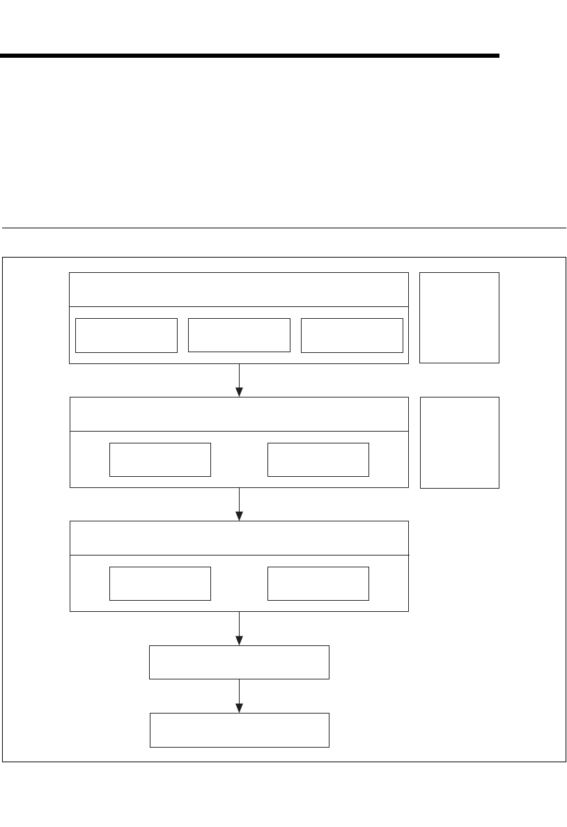
Structure of the Automotive Diagnostic Command Set
Diagnostic Services Layer
KWP2000
Services
UDS (DiagOnCAN)
Services
OBD(OnBoard
Diag) Services
Auxiliary
Routines
Diagnostic Transport Layer
Connection
Management
Service
Execution
Auxiliary
Routines
Transport Protocols
ISO TP
(ISO 15765-2) VW TP 2.0
CAN Layer (C++ DLL)
NI-CAN 2.3.3 (or Higher)

Chapter 4 Using the Automotive Diagnostic Command Set
Automotive Diagnostic Command Set User Manual 4-2 ni.com
The Automotive Diagnostic Command Set is structured into three layers of
functionality:
• The top layer implements three sets of diagnostic services for the
diagnostic protocols KWP2000, UDS (DiagOnCAN), and OBD
(On-Board Diagnostics).
• The second layer implements general routines involving opening and
closing diagnostic communication connections, connecting and
disconnecting to/from an ECU, and executing a diagnostic service on
byte level. The latter routine is the one the top layer uses heavily.
• The third layer implements the transport protocols needed for
diagnostic communication to an ECU. The second layer uses these
routines to communicate to an ECU.
All three top layers are fully implemented in LabVIEW.
The transport protocols then execute CAN Read/Write operations through
a specialized DLL for streamlining the CAN data flow, especially in higher
busload situations.
Automotive Diagnostic Command Set API Structure
The top two layer routines are available as API functions. Each diagnostic
service for KWP2000, UDS, and OBD is available as one routine. Also
available on the top level are auxiliary routines for converting scaled
physical data values to and from their binary representations used in the
diagnostic services.
On the second layer are more general routines for opening and closing
diagnostic communication channels and executing a diagnostic service.
Auxiliary routines create the diagnostic CAN identifiers from the logical
ECU address.
Chapter 4 Using the Automotive Diagnostic Command Set
© National Instruments Corporation 4-3 Automotive Diagnostic Command Set User Manual
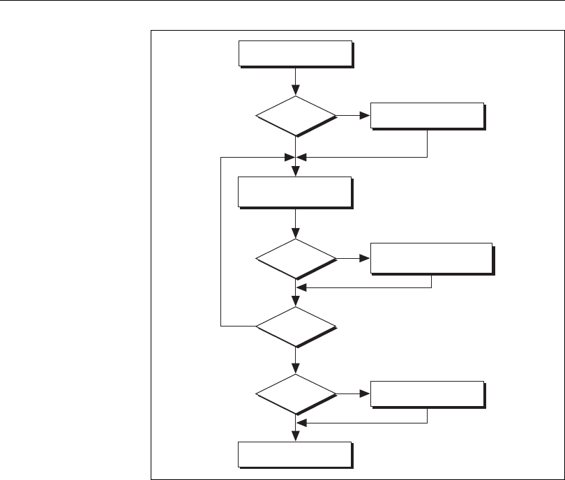
General Programming Model
First, you must open a diagnostic communication link. This involves
initializing the CAN port and defining communication parameters such as
the baud rate and CAN identifiers on which the diagnostic communication
takes place. No actual communication to the ECU takes place at this stage.
For the VW TP 2.0, you then must establish a communication channel to
the ECU using the VWTP Connect routine. The communication channel
properties are negotiated between the host and ECU.
After these steps, the diagnostic communication is established, and you can
execute diagnostic services of your choice. Note that for the VW TP 2.0,
you must execute the VWTP ConnectionTest routine periodically (once per
second) to keep the communication channel open.
VW TP?
VW TP?
Done?
VW TP?
Ye s
No
Ye s
Ye s
No
No
No
Ye s
Open Diagnostic
VWTP Connect
Execute a
Diagnostic Service
Periodically Execute
VWTP ConnectionTest
VWTP Disconnect
Close Diagnostic

Chapter 4 Using the Automotive Diagnostic Command Set
Automotive Diagnostic Command Set User Manual 4-4 ni.com
When you finish your diagnostic services, you must close the diagnostic
communication link. This finally closes the CAN port. For the VW TP 2.0,
you should disconnect the communication channel established before
closing.
Available Diagnostic Services
The standards on automotive diagnostic define many different services for
many purposes. Unfortunately, most services leave a large amount of room
for manufacturer-specific variants and extensions. National Instruments
implemented the most used variants while trying not to overload them with
optional parameters.
However, all services are implemented in LabVIEW and open to the user.
If you are missing a service or variant of an existing service, you can easily
add or modify it on your own.
In the C API, you can also implement your own diagnostic services using
the ndDiagnosticService routine. However, the templates from the existing
services are not available.
Tweaking the Transport Protocol
A set of global constants controls transport protocol behavior. These
constants default to maximum performance. To check the properties of an
implementation of a transport protocol in an ECU, for example, you may
want to change the constants to nonstandard values using the Get/Set
Property routines.
The transport protocols also are fully implemented in LabVIEW and open
to the user. In LabVIEW, you can even modify the protocol behavior (for
example, you can send undefined responses to check the behavior of an
implementation).
However, be sure to save the original routine versions to restore the original
behavior.
In the C API, changing the global constants is the only way to modify the
transport protocol.

© National Instruments Corporation 5-1 Automotive Diagnostic Command Set User Manual
5
Automotive Diagnostic
Command Set API for LabVIEW
This chapter lists the LabVIEW VIs for the Automotive Diagnostic Command Set API and
describes the format, purpose, and parameters for each VI. The VIs are listed alphabetically
in four categories: general functions, KWP2000 services, UDS (DiagOnCAN) services, and
OBD (On-Board Diagnostics) services.
Section Headings
The following are section headings found in the Automotive Diagnostic Command Set API
for LabVIEW VIs.
Purpose
Each VI description briefly describes the VI purpose.
Format
The format section describes the VI format.
Input and Output
The input and output sections list the VI parameters.
Description
The description section gives details about the VI purpose and effect.

Chapter 5 Automotive Diagnostic Command Set API for LabVIEW
Automotive Diagnostic Command Set User Manual 5-2 ni.com
List of VIs
The following table is an alphabetical list of the Automotive Diagnostic Command Set VIs.
Table 5-1. Automotive Diagnostic Command Set API VIs for LabVIEW
Function Purpose
ClearDiagnosticInformation.vi Executes the ClearDiagnosticInformation
service and clears selected Diagnostic
Trouble Codes (DTCs).
Close Diagnostic.vi Closes a diagnostic session.
ControlDTCSetting.vi Executes the ControlDTCSetting service and
modifies the generation behavior of selected
Diagnostic Trouble Codes (DTCs).
Convert from Phys.vi Converts a physical data value into a binary
representation using a type descriptor.
Convert to Phys.vi Converts a binary representation of a value
into its physical value using a type
descriptor.
Create Extended CAN IDs.vi Creates diagnostic CAN IDs according to
ISO 15765-2.
Diag Get Property.vi Gets a diagnostic global internal parameter.
Diag Set Property.vi Sets a diagnostic global internal parameter.
Diagnostic Service.vi Executes a generic diagnostic service. If a
special service is not available through the
KWP2000, UDS, or OBD service functions,
you can build it using this VI.
DisableNormalMessageTransmission.vi Executes the
DisableNormalMessageTransmission
service. The ECU no longer transmits its
regular communication messages (usually
CAN messages).
DTC to String.vi Returns a string representation (such as
P1234) for a 2-byte Diagnostic Trouble
Code (DTC).
ECUReset.vi Executes the ECUReset service and resets
the ECU.

Chapter 5 Automotive Diagnostic Command Set API for LabVIEW
© National Instruments Corporation 5-3 Automotive Diagnostic Command Set User Manual
EnableNormalMessageTransmission.vi Executes the
EnableNormalMessageTransmission
service. The ECU starts transmitting its
regular communication messages (usually
CAN messages).
InputOutputControlByLocalIdentifier.vi Executes the
InputOutputControlByLocalIdentifier
service. Modifies the ECU I/O port behavior.
OBD Clear Emission Related Diagnostic
Information.vi
Executes the OBD Clear Emission Related
Diagnostic Information service. Clears
emission-related Diagnostic Trouble Codes
(DTCs) in the ECU.
OBD Open.vi Opens an OBD-II diagnostic session on a
CAN port.
OBD Request Control Of On-Board Device.vi Executes the OBD Request Control Of
On-Board Device service. Use this VI to
modify ECU I/O port behavior.
OBD Request Current Powertrain Diagnostic
Data.vi
Executes the OBD Request Current
Powertrain Diagnostic Data service. Reads a
data record from the ECU.
OBD Request Emission Related DTCs.vi Executes the OBD Request Emission
Related DTCs service. Reads all
emission-related Diagnostic Trouble Codes
(DTCs).
OBD Request Emission Related DTCs During
Current Drive Cycle.vi
Executes the OBD Request Emission
Related DTCs During Current Drive Cycle
service. Reads the emission-related
Diagnostic Trouble Codes (DTCs) that
occurred during the current (or last
completed) drive cycle.
OBD Request On-Board Monitoring Test
Results.vi
Executes the OBD Request On-Board
Monitoring Test Results service. Reads a test
data record from the ECU.
Table 5-1. Automotive Diagnostic Command Set API VIs for LabVIEW (Continued)
Function Purpose

Chapter 5 Automotive Diagnostic Command Set API for LabVIEW
Automotive Diagnostic Command Set User Manual 5-4 ni.com
OBD Request Powertrain Freeze Frame Data.vi Executes the OBD Request Powertrain
Freeze Frame Data service. Reads a data
record from the ECU that has been stored
while a Diagnostic Trouble Code occurred.
OBD Request Supported PIDs.vi Executes the OBD Request Current
Powertrain Diagnostic Data service to
retrieve the valid PID values for this service.
OBD Request Vehicle Information.vi Executes the OBD Request Vehicle
Information service. Reads a set of
information data from the ECU.
Open Diagnostic.vi Opens a diagnostic session on a CAN port.
Communication to the ECU is not yet
started.
ReadDataByLocalIdentifier.vi Executes the ReadDataByLocalIdentifier
service. Reads a data record from the ECU.
ReadDTCByStatus.vi Executes the
ReadDiagnosticTroubleCodesByStatus
service. Reads selected Diagnostic Trouble
Codes (DTCs).
ReadECUIdentification.vi Executes the ReadECUIdentification
service. Returns ECU identification data
from the ECU.
ReadMemoryByAddress.vi Executes the ReadMemoryByAddress
service. Reads data from the ECU memory.
ReadStatusOfDTC.vi Executes the
ReadStatusOfDiagnosticTroubleCodes
service. Reads selected Diagnostic Trouble
Codes (DTCs).
RequestRoutineResultsByLocalIdentifier.vi Executes the
RequestRoutineResultsByLocalIdentifier
service. Returns results from a routine on the
ECU.
RequestSeed.vi Executes the SecurityAccess service to
retrieve a seed from the ECU.
Table 5-1. Automotive Diagnostic Command Set API VIs for LabVIEW (Continued)
Function Purpose

Chapter 5 Automotive Diagnostic Command Set API for LabVIEW
© National Instruments Corporation 5-5 Automotive Diagnostic Command Set User Manual
SendKey.vi Executes the SecurityAccess service to send
a key to the ECU.
StartDiagnosticSession.vi Executes the StartDiagnosticSession service.
Sets up the ECU in a specific diagnostic
mode.
StartRoutineByLocalIdentifier.vi Executes the StartRoutineByLocalIdentifier
service. Executes a routine on the ECU.
StopDiagnosticSession.vi Executes the StopDiagnosticSession service.
Brings the ECU back in normal mode.
StopRoutineByLocalIdentifier.vi Executes the StopRoutineByLocalIdentifier
service. Stops a routine on the ECU.
TesterPresent.vi Executes the TesterPresent service. Keeps
the ECU in diagnostic mode.
UDS ClearDiagnosticInformation.vi Executes the UDS
ClearDiagnosticInformation service. Clears
selected Diagnostic Trouble Codes (DTCs).
UDS CommunicationControl.vi Executes the UDS CommunicationControl
service. Use this VI to switch on or off
transmission and/or reception of the normal
communication messages (usually CAN
messages).
UDS ControlDTCSetting.vi Executes the UDS ControlDTCSetting
service. Modifies Diagnostic Trouble Code
(DTC) generation behavior.
UDS DiagnosticSessionControl.vi Executes the UDS
DiagnosticSessionControl service. Sets up
the ECU in a specific diagnostic mode.
UDS ECUReset.vi Executes the UDS ECUReset service. Resets
the ECU.
UDS InputOutputControlByIdentifier.vi Executes the UDS
InputOutputControlByIdentifier service.
Use this VI to modify ECU I/O port
behavior.
Table 5-1. Automotive Diagnostic Command Set API VIs for LabVIEW (Continued)
Function Purpose

Chapter 5 Automotive Diagnostic Command Set API for LabVIEW
Automotive Diagnostic Command Set User Manual 5-6 ni.com
UDS ReadDataByIdentifier.vi Executes the UDS ReadDataByIdentifier
service. Reads a data record from the ECU.
UDS ReadMemoryByAddress.vi Executes the UDS ReadMemoryByAddress
service. Reads data from the ECU memory.
UDS ReportDTCBySeverityMaskRecord.vi Executes the
ReportDTCBySeverityMaskRecord
subfunction of the UDS
ReadDiagnosticTroubleCodeInformation
service. Reads selected Diagnostic Trouble
Codes (DTCs).
UDS ReportDTCByStatusMask.vi Executes the ReportDTCByStatusMask
subfunction of the UDS
ReadDiagnosticTroubleCodeInformation
service. Reads selected Diagnostic Trouble
Codes (DTCs).
UDS ReportSeverityInformationOfDTC.vi Executes the
ReportSeverityInformationOfDTC
subfunction of the UDS
ReadDiagnosticTroubleCodeInformation
service. Reads selected Diagnostic Trouble
Codes (DTCs).
UDS ReportSupportedDTCs.vi Executes the ReportSupportedDTCs
subfunction of the UDS
ReadDiagnosticTroubleCodeInformation
service. Reads all supported Diagnostic
Trouble Codes (DTCs).
UDS RequestSeed.vi Executes the UDS SecurityAccess service to
retrieve a seed from the ECU.
UDS RoutineControl.vi Executes the UDS RoutineControl service.
Executes a routine on the ECU.
UDS SendKey.vi Executes the SecurityAccess service to send
a key to the ECU.
UDS TesterPresent.vi Executes the UDS TesterPresent service.
Keeps the ECU in diagnostic mode.
Table 5-1. Automotive Diagnostic Command Set API VIs for LabVIEW (Continued)
Function Purpose

Chapter 5 Automotive Diagnostic Command Set API for LabVIEW
© National Instruments Corporation 5-7 Automotive Diagnostic Command Set User Manual
UDS WriteDataByIdentifier.vi Executes the UDS WriteDataByIdentifier
service. Writes a data record to the ECU.
UDS WriteMemoryByAddress.vi Executes the UDS WriteMemoryByAddress
service. Writes data to the ECU memory.
VWTP Connect.vi Establishes a connection channel to an ECU
using the VW TP 2.0.
VWTP Connection Test.vi Maintains a connection channel to an ECU
using the VW TP 2.0.
VWTP Disconnect.vi Terminates a connection channel to an ECU
using the VW TP 2.0.
WriteDataByLocalIdentifier.vi Executes the WriteDataByLocalIdentifier
service. Writes a data record to the ECU.
WriteMemoryByAddress.vi Executes the WriteMemoryByAddress
service. Writes data to the ECU memory.
Table 5-1. Automotive Diagnostic Command Set API VIs for LabVIEW (Continued)
Function Purpose
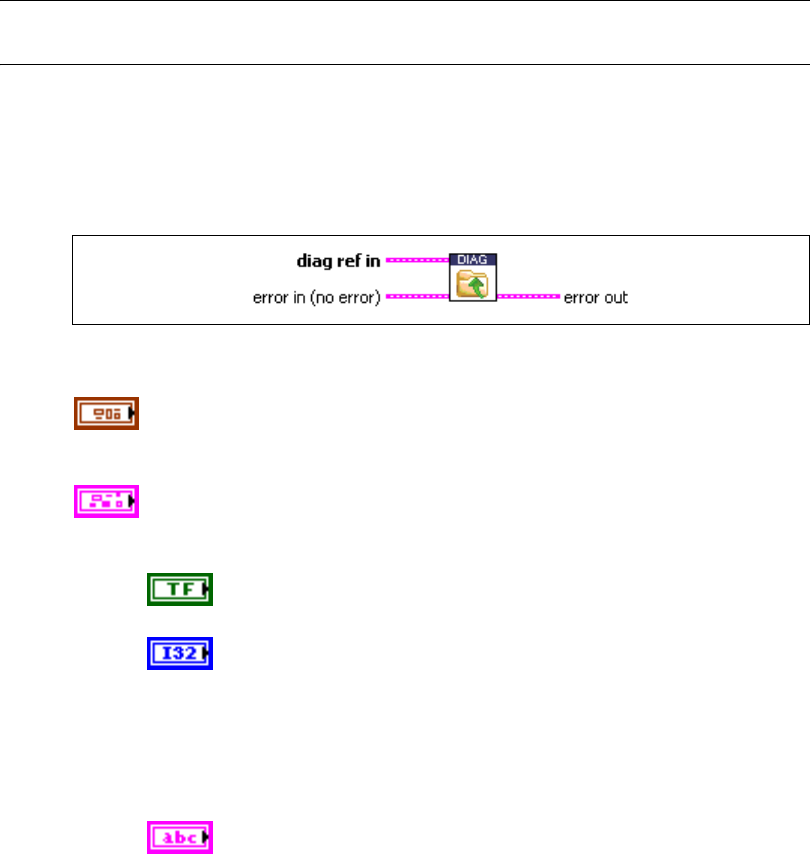
Chapter 5 Automotive Diagnostic Command Set API for LabVIEW
Automotive Diagnostic Command Set User Manual 5-8 ni.com
General Functions
Close Diagnostic.vi
Purpose
Closes a diagnostic session.
Format
Input
diag ref in specifies the diagnostic session handle, obtained from Open
Diagnostic.vi and wired through subsequent diagnostic VIs. Normally, it is
not necessary to manually manipulate the elements of this cluster.
error in is a cluster that describes error conditions occurring before the VI
executes. If an error has already occurred, the VI returns the value of the
error in cluster to error out.
status is TRUE if an error occurred. This VI is not executed when
status is TRUE.
code is the error code number identifying an error. A value of 0
means success. A negative value means error: the VI did not
execute the intended operation. A positive value means warning:
the VI executed intended operation, but an informational warning
is returned. For a description of the code, wire the error cluster to
a LabVIEW error-handling VI, such as the Simple Error
Handler.
source identifies the VI where the error occurred.
Chapter 5 Automotive Diagnostic Command Set API for LabVIEW
© National Instruments Corporation 5-9 Automotive Diagnostic Command Set User Manual
Output
error out describes error conditions. If the error in cluster indicated an
error, the error out cluster contains the same information. Otherwise,
error out describes the error status of this VI.
status is TRUE if an error occurred.
code is the error code number identifying an error. A value of 0
means success. A negative value means error: the VI did not
execute the intended operation. A positive value means warning:
the VI executed intended operation, but an informational warning
is returned. For a description of the code, wire the error cluster to
a LabVIEW error-handling VI, such as the Simple Error
Handler.
source identifies the VI where the error occurred.
Description
The diagnostic session specified by diag ref in is closed, and you can no longer use it for
communication to an ECU. Note that this command does not communicate the closing to the
ECU before terminating; if this is necessary, you must manually do so (for example, by
calling StopDiagnosticSession.vi) before calling Close Diagnostic.vi.
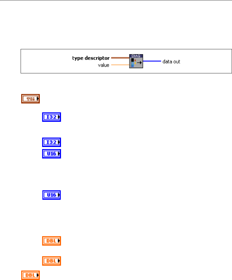
Chapter 5 Automotive Diagnostic Command Set API for LabVIEW
Automotive Diagnostic Command Set User Manual 5-10 ni.com
Convert from Phys.vi
Purpose
Converts a physical data value into a binary representation using a type descriptor.
Format
Input
type descriptor is a cluster that specifies the conversion of the physical
value to its binary representation:
Start Byte gives the start byte of the binary representation. For
Convert from Phys.vi, this value is ignored and always assumed
to be 0.
Byte Length is the binary representation byte length.
Byte Order is the byte ordering of the data in the binary
representation:
0: MSB_FIRST (Motorola)
1: LSB_FIRST (Intel)
Data Type is the binary representation format:
0: Unsigned. Only byte lengths of 1–4 are allowed.
1: Signed. Only byte lengths of 1–4 are allowed.
2: Float. Only byte lengths of 4 or 8 are allowed.
Scale Factor defines the physical value scaling:
Phys = (Scale Factor) * (binary representation) + (Scale Offset)
Scale Offset (refer to Scale Factor)
value is the physical value to be converted.

Chapter 5 Automotive Diagnostic Command Set API for LabVIEW
© National Instruments Corporation 5-11 Automotive Diagnostic Command Set User Manual
Output
data out is the binary representation of the physical value. If you build a
record of multiple values, you can concatenate the outputs of several
instances of Convert from Phys.vi.
Description
Data input to diagnostic services (for example, WriteDataByLocalIdentifier.vi) is usually a
byte stream of binary data. If you have a description of the data input (for example, byte 3 and
4 are engine RPM scaled as .25 *
×
RPM in Motorola representation), you can use Convert
from Phys.vi to convert the physical value to the byte stream by filling an appropriate type
descriptor cluster.
Convert from Phys.vi converts only the portion specified by one type descriptor to a binary
representation. If your data input consists of several values, you can use Convert from
Phys.vi multiple times and concatenate their outputs.
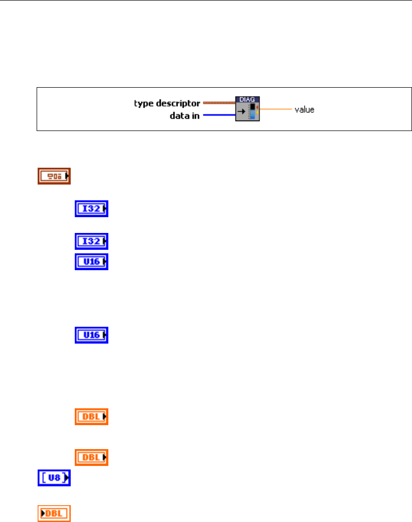
Chapter 5 Automotive Diagnostic Command Set API for LabVIEW
Automotive Diagnostic Command Set User Manual 5-12 ni.com
Convert to Phys.vi
Purpose
Converts a binary representation of a value into its physical value using a type descriptor.
Format
Input
type descriptor is a cluster that specifies the conversion of the binary
representation to its physical value:
Start Byte gives the binary representation start byte in the data in
record.
Byte Length is the binary representation byte length.
Byte Order is the byte ordering of the data in the binary
representation:
0: MSB_FIRST (Motorola)
1: LSB_FIRST (Intel)
Data Type is the binary representation format:
0: Unsigned. Only byte lengths of 1–4 are allowed.
1: Signed. Only byte lengths of 1–4 are allowed.
2: Float. Only byte lengths of 4 or 8 are allowed.
Scale Factor defines the physical value scaling:
Phys = (Scale Factor) * (binary representation) + (Scale Offset)
Scale Offset (refer to Scale Factor)
data in is the data record from which physical values are to be extracted.
Output
value is the physical value extracted from the record.
Chapter 5 Automotive Diagnostic Command Set API for LabVIEW
© National Instruments Corporation 5-13 Automotive Diagnostic Command Set User Manual
Description
Data output from diagnostic services (for example, ReadDataByLocalIdentifier.vi) is
usually a byte stream of binary data. If you have a description of the data output (for example,
byte 3 and 4 are engine RPM scaled as .25 *
×
RPM in Motorola representation), you can
use Convert to Phys.vi to extract the physical value from the byte stream by filling an
appropriate type descriptor cluster.
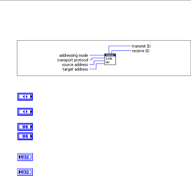
Chapter 5 Automotive Diagnostic Command Set API for LabVIEW
Automotive Diagnostic Command Set User Manual 5-14 ni.com
Create Extended CAN IDs.vi
Purpose
Creates diagnostic CAN IDs according to ISO 15765-2.
Format
Input
addressing mode specifies whether the ECU is physically or functionally
addressed.
transport protocol specifies whether normal or mixed mode addressing is
used.
source address is the logical address of the host (diagnostic tester).
target address is the ECU logical address.
Output
transmit ID is the generated CAN identifier for sending diagnostic request
messages from the host to the ECU.
receive ID is the generated CAN identifier for sending diagnostic response
messages from the ECU to the host.
Description
ISO 15765-2 specifies a method (extended/29 bit) of creating CAN identifiers for diagnostic
applications given the addressing mode (physical/functional), the transport protocol
(normal/mixed), and the 8-bit source and target addresses. This VI implements the
construction of these CAN identifiers. You can use them directly in Open Diagnostic.vi.
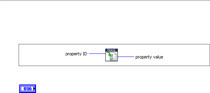
Chapter 5 Automotive Diagnostic Command Set API for LabVIEW
© National Instruments Corporation 5-15 Automotive Diagnostic Command Set User Manual
Diag Get Property.vi
Purpose
Gets a diagnostic global internal parameter.
Format
Input
property ID defines the parameter whose value is to be retrieved. You can
create the values using an Enum control.
0Timeout Diag Command is the timeout in milliseconds the master
waits for the response to a diagnostic request message. The default is
1000 ms.
1Timeout FC (Bs) is the timeout in milliseconds the master waits for
a Flow Control frame after sending a First Frame or the last
Consecutive Frame of a block. The default is 250 ms.
2Timeout CF (Cr) is the timeout in milliseconds the master waits for
a Consecutive Frame in a multiframe response. The default is
250 ms.
3Receive Block Size (BS) is the number of Consecutive Frames the
slave sends in one block before waiting for the next Flow Control
frame. A value of 0 (default) means all Consecutive Frames are sent
in one run without interruption.
4Wait Time CF (STmin) defines the minimum time for the slave to
wait between sending two Consecutive Frames of a block. Values
from 0 to 127 are wait times in milliseconds. Values 241 to 249
(Hex F1 to F9) mean wait times of 100 µs to 900 µs, respectively. All
other values are reserved. The default is 5 ms.
5Max Wait Frames (N_WFTmax) is the maximum number of WAIT
frames the master accepts before terminating the connection. The
default is 10.

Chapter 5 Automotive Diagnostic Command Set API for LabVIEW
Automotive Diagnostic Command Set User Manual 5-16 ni.com
6Wait Frames to Send (N_WAIT) is the number of WAIT frames the
master sends every time before a CTS frame is sent. If this value is
set to a negative number (for example, 0xFFFFFFFF = –1), the
master sends an OVERLOAD frame instead of a WAIT, and
reception is aborted. The default is 0 for maximum speed.
7Time between Waits (T_W) is the number of milliseconds the
master waits after sending a WAIT frame. The default is 25.
8Fill CAN Frames returns whether a CAN frame is transmitted with
8 bytes or less.
0: Short CAN frames are sent with DLC < 8 (default).
1: Short CAN frames are filled to 8 bytes with Fill Byte (necessary
for OBD, for example).
9Fill Byte returns the CAN frame content if filled with defined data or
random data bytes.
0–255: Byte is used optionally to fill short CAN frames.
256: Short CAN frames are filled optionally with random bytes.
10 Invalid Response as Error returns how the toolkit handles an
invalid ECU response.
0: Invalid response is indicated by success? = FALSE only (default).
1: Invalid response is returned as an error in addition.
Output
property value is the requested property value.
Description
Use this VI to request several internal diagnostic parameters, such as timeouts for the
transport protocol. Use Diag Set Property.vi to modify them.
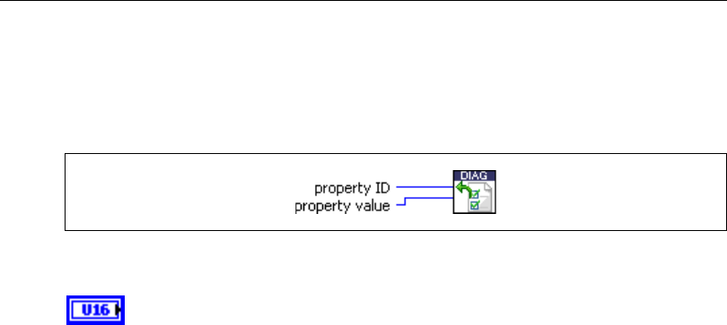
Chapter 5 Automotive Diagnostic Command Set API for LabVIEW
© National Instruments Corporation 5-17 Automotive Diagnostic Command Set User Manual
Diag Set Property.vi
Purpose
Sets a diagnostic global internal parameter.
Format
Input
property ID defines the parameter whose value is to be retrieved. You can
create the values using an Enum control.
0Timeout Diag Command is the timeout in milliseconds the master
waits for the response to a diagnostic request message. The default is
1000 ms.
1Timeout FC (Bs) is the timeout in milliseconds the master waits for
a Flow Control frame after sending a First Frame or the last
Consecutive Frame of a block. The default is 250 ms.
2Timeout CF (Cr) is the timeout in milliseconds the master waits for
a Consecutive Frame in a multiframe response. The default is
250 ms.
3Receive Block Size (BS) is the number of Consecutive Frames the
slave sends in one block before waiting for the next Flow Control
frame. A value of 0 (default) means all Consecutive Frames are sent
in one run without interruption.
4Wait Time CF (STmin) defines the minimum time for the slave to
wait between sending two Consecutive Frames of a block. Values
from 0 to 127 are wait times in milliseconds. Values 241 to 249
(Hex F1 to F9) mean wait times of 100 µs to 900 µs, respectively. All
other values are reserved. The default is 5 ms.
5Max Wait Frames (N_WFTmax) is the maximum number of WAIT
frames the master accepts before terminating the connection. The
default is 10.

Chapter 5 Automotive Diagnostic Command Set API for LabVIEW
Automotive Diagnostic Command Set User Manual 5-18 ni.com
6Wait Frames to Send (N_WAIT) is the number of WAIT frames the
master sends every time before a CTS frame is sent. If this value is
set to a negative number (for example, 0xFFFFFFFF = –1), the
master sends an OVERLOAD frame instead of a WAIT, and
reception is aborted. The default is 0 for maximum speed.
7Time between Waits (T_W) is the number of milliseconds the
master waits after sending a WAIT frame. The default is 25.
8Fill CAN Frames specifies whether a CAN frame is transmitted with
8 bytes or less.
0: Short CAN frames are sent with DLC < 8 (default).
1: Short CAN frames are filled to 8 bytes with Fill Byte (necessary
for OBD, for example).
9Fill Byte specifies the CAN frame content, filled with defined data or
random data.
0–255: Byte is used optionally to fill short CAN frames.
256: Short CAN frames are filled optionally with random bytes.
10 Invalid Response as Error specifies how the toolkit handles an
invalid ECU response.
0: Invalid response is indicated by success? = FALSE only (default).
1: Invalid response is returned as an error in addition.
property value is the value of the property to be set.
Output
None.
Description
Use this VI to set several internal diagnostic parameters such as timeouts for the transport
protocol. Use Diag Get Property.vi to read them out.
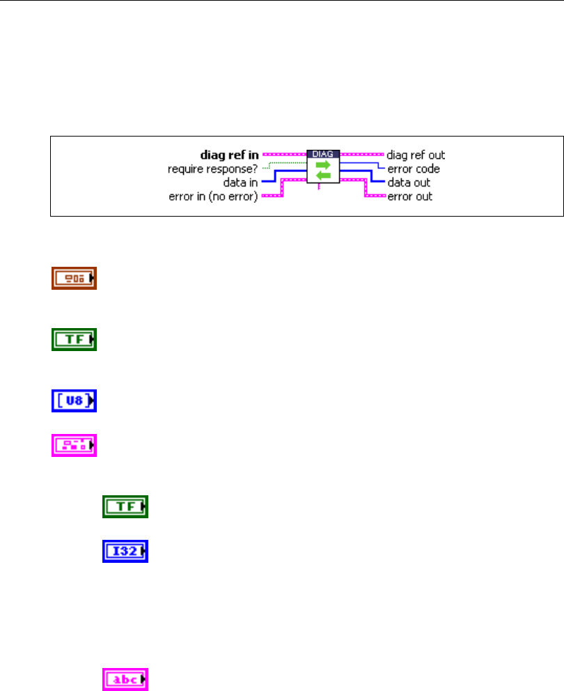
Chapter 5 Automotive Diagnostic Command Set API for LabVIEW
© National Instruments Corporation 5-19 Automotive Diagnostic Command Set User Manual
Diagnostic Service.vi
Purpose
Executes a generic diagnostic service. If a special service is not available through the
KWP2000, UDS, or OBD service functions, you can build it using this VI.
Format
Input
diag ref in specifies the diagnostic session handle, obtained from Open
Diagnostic.vi and wired through subsequent diagnostic VIs. Normally, it is
not necessary to manually manipulate the elements of this cluster.
require response? indicates whether a diagnostic service expects a
response (TRUE) or not (FALSE). In the latter case, error code is returned
as 0, and data out as an empty array.
data in defines the diagnostic service request message sent to the ECU as
a stream of bytes.
error in is a cluster that describes error conditions occurring before the VI
executes. If an error has already occurred, the VI returns the value of the
error in cluster to error out.
status is TRUE if an error occurred. This VI is not executed when
status is TRUE.
code is the error code number identifying an error. A value of 0
means success. A negative value means error: the VI did not
execute the intended operation. A positive value means warning:
the VI executed intended operation, but an informational warning
is returned. For a description of the code, wire the error cluster to
a LabVIEW error-handling VI, such as the Simple Error
Handler.
source identifies the VI where the error occurred.
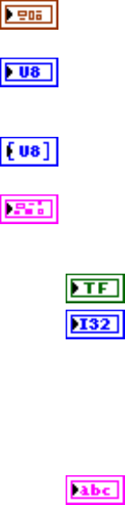
Chapter 5 Automotive Diagnostic Command Set API for LabVIEW
Automotive Diagnostic Command Set User Manual 5-20 ni.com
Output
diag ref out is a copy of diag ref in. You can wire it to subsequent
diagnostic VIs.
error code is the error code sent with a negative response message. In
addition, the error cluster indicates an error and gives a more detailed
description. If no negative response message occurred, 0 is returned.
data out returns the diagnostic service response message (positive or
negative) the ECU sends as a stream of bytes.
error out describes error conditions. If the error in cluster indicated an
error, the error out cluster contains the same information. Otherwise,
error out describes the error status of this VI.
status is TRUE if an error occurred.
code is the error code number identifying an error. A value of 0
means success. A negative value means error: the VI did not
execute the intended operation. A positive value means warning:
the VI executed intended operation, but an informational warning
is returned. For a description of the code, wire the error cluster to
a LabVIEW error-handling VI, such as the Simple Error
Handler.
source identifies the VI where the error occurred.
Description
Diagnostic Service.vi is a generic routine to execute any diagnostic service. The request and
response messages are fed unmodified to the data in input and retrieved from the data out
output, respectively. No interpretation of the contents is done, with one exception: the error
number is retrieved from a negative response, if one occurs. In this case, an error also is
communicated through the error out cluster.
All specialized diagnostic services call Diagnostic Service.vi internally.
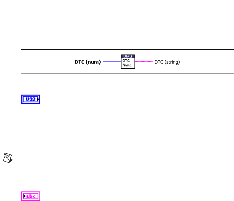
Chapter 5 Automotive Diagnostic Command Set API for LabVIEW
© National Instruments Corporation 5-21 Automotive Diagnostic Command Set User Manual
DTC to String.vi
Purpose
Returns a string representation (such as P1234) for a 2-byte Diagnostic Trouble Code (DTC).
Format
Input
DTC (num) is the DTC number as returned in the clusters of
ReadDTCByStatus.vi, ReadStatusOfDTC.vi,
UDS ReportDTCBySeverityMaskRecord.vi,
UDS ReportDTCByStatusMask.vi,
UDS ReportSeverityInformationOfDTC.vi,
UDS ReportSupportedDTCs.vi, OBD Request Emission Related
DTCs.vi, or OBD Request Emission Related DTCs During Current
Drive Cycle.vi.
Note This VI converts only 2-byte DTCs. If you feed in larger numbers, the VI returns
garbage.
Output
DTC (string) is the DTC string representation.
Description
The SAE J2012 standard specifies a naming scheme for 2-byte DTCs consisting of one letter
and four digits. Use DTC to String.vi to convert a DTC numerical representation to this
name.
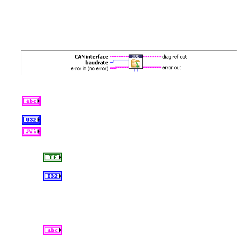
Chapter 5 Automotive Diagnostic Command Set API for LabVIEW
Automotive Diagnostic Command Set User Manual 5-22 ni.com
OBD Open.vi
Purpose
Opens an OBD-II diagnostic session on a CAN port.
Format
Input
CAN interface specifies the CAN interface on which the diagnostic
communication should take place. The values are CAN0, CAN1, and so on.
baudrate is the diagnostic communication baud rate.
error in is a cluster that describes error conditions occurring before the VI
executes. If an error has already occurred, the VI returns the value of the
error in cluster to error out.
status is TRUE if an error occurred. This VI is not executed when
status is TRUE.
code is the error code number identifying an error. A value of 0
means success. A negative value means error: the VI did not
execute the intended operation. A positive value means warning:
the VI executed intended operation, but an informational warning
is returned. For a description of the code, wire the error cluster
to a LabVIEW error-handling VI, such as the Simple Error
Handler.
source identifies the VI where the error occurred.
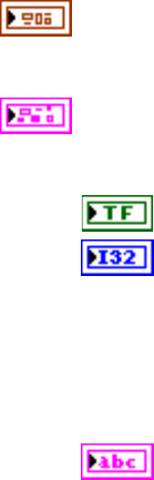
Chapter 5 Automotive Diagnostic Command Set API for LabVIEW
© National Instruments Corporation 5-23 Automotive Diagnostic Command Set User Manual
Output
diag ref out is a cluster containing all necessary diagnostic session
information. Wire this cluster as a handle to all subsequent diagnostic
VIs and close it using Close Diagnostic.vi.
error out describes error conditions. If the error in cluster indicated an
error, the error out cluster contains the same information. Otherwise,
error out describes the error status of this VI.
status is TRUE if an error occurred.
code is the error code number identifying an error. A value of 0
means success. A negative value means error: the VI did not
execute the intended operation. A positive value means warning:
the VI executed intended operation, but an informational warning
is returned. For a description of the code, wire the error cluster
to a LabVIEW error-handling VI, such as the Simple Error
Handler.
source identifies the VI where the error occurred.
Description
Use this VI to open a diagnostic communication channel to an ECU for OBD-II. The CAN
port specified as input is initialized, and a handle to it is stored (among other internal data) in
the diag ref out cluster, which serves as reference for further diagnostic functions.
First, communication to the ECU is tried on the default 11-bit OBD CAN identifiers; if that
fails, the default 29-bit OBD CAN identifiers are tried. If that also fails, the VI returns an
error.
You can overwrite the default OBD CAN identifiers optionally with any other identifiers.
In general, it is not necessary to manipulate the diag ref out cluster contents.
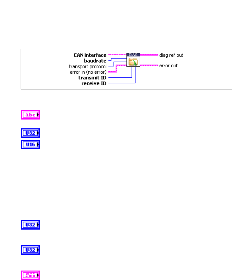
Chapter 5 Automotive Diagnostic Command Set API for LabVIEW
Automotive Diagnostic Command Set User Manual 5-24 ni.com
Open Diagnostic.vi
Purpose
Opens a diagnostic session on a CAN port. Communication to the ECU is not yet started.
Format
Input
CAN interface specifies the CAN interface on which the diagnostic
communication should take place. The values are CAN0, CAN1, and so on.
baudrate is the diagnostic communication baud rate.
transport protocol specifies the transport protocol for transferring the
diagnostic service messages over the CAN network. The following values
are valid and can be obtained through an enum control:
0ISO TP—Normal Mode: The ISO TP as specified in ISO 15765-2
is used; all eight data bytes of the CAN messages are used for data
transfer.
1ISO TP—Mixed Mode: The ISO TP as specified in ISO 15765-2 is
used; the first data byte is used as address extension.
2 VW TP 2.0
transmit ID is the CAN identifier for sending diagnostic request messages
from the host to the ECU. To specify an extended (29-bit) ID, OR the value
with 0x20000000.
receive ID is the CAN identifier or sending diagnostic response messages
from the ECU to the host. To specify an extended (29-bit) ID, OR the value
with 0x20000000.
error in is a cluster that describes error conditions occurring before the VI
executes. If an error has already occurred, the VI returns the value of the
error in cluster to error out.
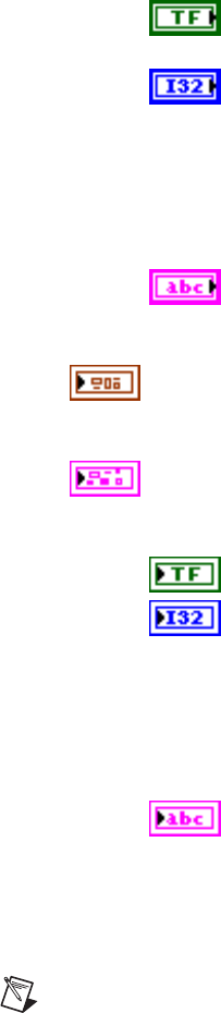
Chapter 5 Automotive Diagnostic Command Set API for LabVIEW
© National Instruments Corporation 5-25 Automotive Diagnostic Command Set User Manual
status is TRUE if an error occurred. This VI is not executed when
status is TRUE.
code is the error code number identifying an error. A value of 0
means success. A negative value means error: the VI did not
execute the intended operation. A positive value means warning:
the VI executed intended operation, but an informational warning
is returned. For a description of the code, wire the error cluster to
a LabVIEW error-handling VI, such as the Simple Error
Handler.
source identifies the VI where the error occurred.
Output
diag ref out is a cluster containing all necessary diagnostic session
information. Wire this cluster as a handle to all subsequent diagnostic VIs
and close it using Close Diagnostic.vi.
error out describes error conditions. If the error in cluster indicated an
error, the error out cluster contains the same information. Otherwise,
error out describes the error status of this VI.
status is TRUE if an error occurred.
code is the error code number identifying an error. A value of 0
means success. A negative value means error: the VI did not
execute the intended operation. A positive value means warning:
the VI executed intended operation, but an informational warning
is returned. For a description of the code, wire the error cluster to
a LabVIEW error-handling VI, such as the Simple Error
Handler.
source identifies the VI where the error occurred.
Description
Open Diagnostic.vi opens a diagnostic communication channel to an ECU. The CAN port
specified as input is initialized, and a handle to it is stored (among other internal data) in the
diag ref out cluster, which serves as reference for further diagnostic functions.
Note No communication to the ECU takes place at this point. To open a diagnostic session
on the ECU, call StartDiagnosticSession.vi or UDS DiagnosticSessionControl.vi.
In general, it is not necessary to manipulate the diag ref out cluster contents, with one notable
exception: If you use the ISO TP—Mixed Mode transport protocol, you must store the
address extensions for transmit and receive in the appropriate cluster members.
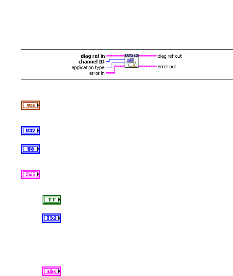
Chapter 5 Automotive Diagnostic Command Set API for LabVIEW
Automotive Diagnostic Command Set User Manual 5-26 ni.com
VWTP Connect.vi
Purpose
Establishes a connection channel to an ECU using the VW TP 2.0.
Format
Input
diag ref in specifies the diagnostic session handle, obtained from Open
Diagnostic.vi and wired through subsequent diagnostic VIs. Normally, it is
not necessary to manually manipulate the elements of this cluster.
channel ID defines the CAN identifier on which the ECU responds for this
connection. The ECU defines the ID on which the host transmits.
application type specifies the type of communication that takes place on
the communication channel. For diagnostic applications, specify
KWP2000 (1). The other values are for manufacturer-specific purposes.
error in is a cluster that describes error conditions occurring before the VI
executes. If an error has already occurred, the VI returns the value of the
error in cluster to error out.
status is TRUE if an error occurred. This VI is not executed when
status is TRUE.
code is the error code number identifying an error. A value of 0
means success. A negative value means error: the VI did not
execute the intended operation. A positive value means warning:
the VI executed intended operation, but an informational warning
is returned. For a description of the code, wire the error cluster to
a LabVIEW error-handling VI, such as the Simple Error
Handler.
source identifies the VI where the error occurred.
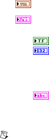
Chapter 5 Automotive Diagnostic Command Set API for LabVIEW
© National Instruments Corporation 5-27 Automotive Diagnostic Command Set User Manual
Output
diag ref out is a copy of diag ref in. You can wire it to subsequent
diagnostic VIs.
error out describes error conditions. If the error in cluster indicated an
error, the error out cluster contains the same information. Otherwise,
error out describes the error status of this VI.
status is TRUE if an error occurred.
code is the error code number identifying an error. A value of 0
means success. A negative value means error: the VI did not
execute the intended operation. A positive value means warning:
the VI executed intended operation, but an informational warning
is returned. For a description of the code, wire the error cluster to
a LabVIEW error-handling VI, such as the Simple Error
Handler.
source identifies the VI where the error occurred.
Description
For the VW TP 2.0, you must establish a connection to the ECU before any diagnostic
communication can occur. This VI sets up a unique communication channel to an ECU for
subsequent diagnostic service requests.
Note You must maintain the communication link you created by periodically (at least once
a second) calling VWTP Connection Test.vi.
There is no equivalent for the ISO TP (ISO 15765-2), as the ISO TP does not use a special
communication link.
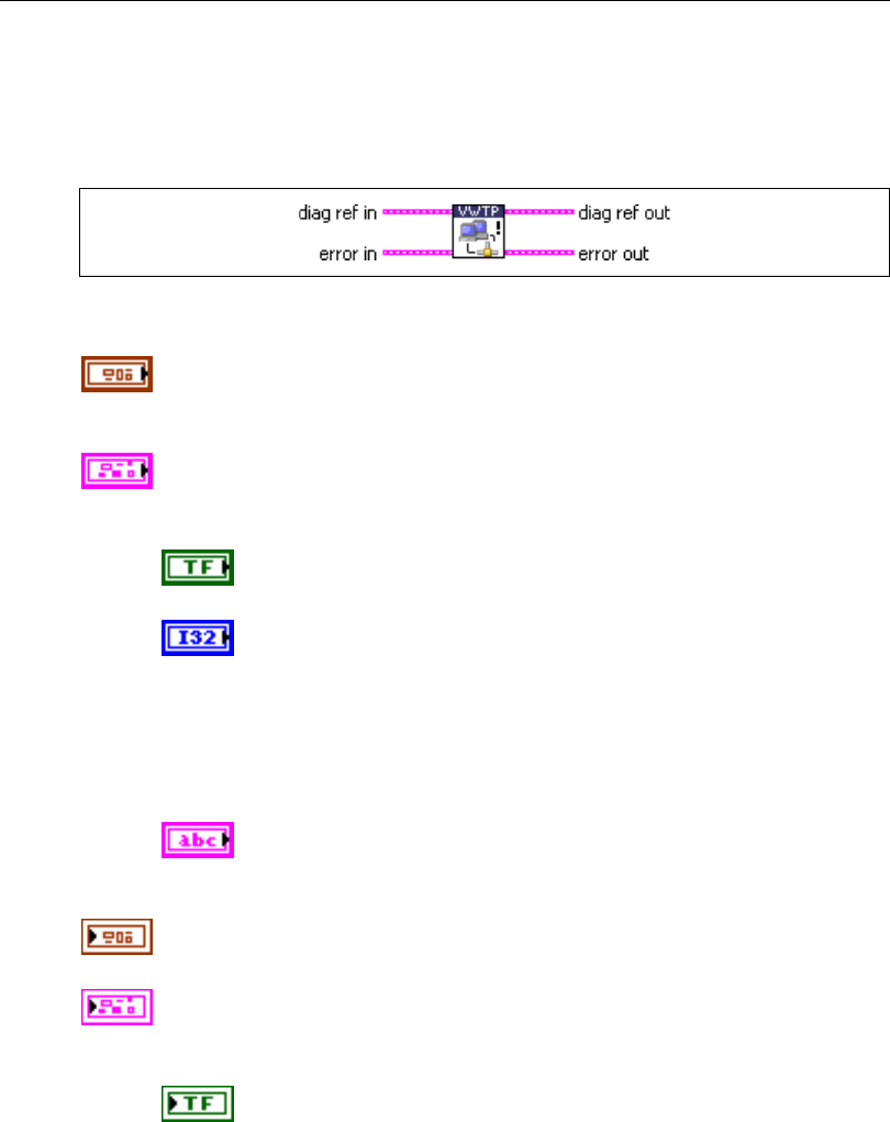
Chapter 5 Automotive Diagnostic Command Set API for LabVIEW
Automotive Diagnostic Command Set User Manual 5-28 ni.com
VWTP Connection Test.vi
Purpose
Maintains a connection channel to an ECU using the VW TP 2.0.
Format
Input
diag ref in specifies the diagnostic session handle, obtained from Open
Diagnostic.vi and wired through subsequent diagnostic VIs. Normally, it is
not necessary to manually manipulate the elements of this cluster.
error in is a cluster that describes error conditions occurring before the VI
executes. If an error has already occurred, the VI returns the value of the
error in cluster to error out.
status is TRUE if an error occurred. This VI is not executed when
status is TRUE.
code is the error code number identifying an error. A value of 0
means success. A negative value means error: the VI did not
execute the intended operation. A positive value means warning:
the VI executed intended operation, but an informational warning
is returned. For a description of the code, wire the error cluster to
a LabVIEW error-handling VI, such as the Simple Error
Handler.
source identifies the VI where the error occurred.
Output
diag ref out is a copy of diag ref in. You can wire it to subsequent
diagnostic VIs.
error out describes error conditions. If the error in cluster indicated an
error, the error out cluster contains the same information. Otherwise,
error out describes the error status of this VI.
status is TRUE if an error occurred.

Chapter 5 Automotive Diagnostic Command Set API for LabVIEW
© National Instruments Corporation 5-29 Automotive Diagnostic Command Set User Manual
code is the error code number identifying an error. A value of 0
means success. A negative value means error: the VI did not
execute the intended operation. A positive value means warning:
the VI executed intended operation, but an informational warning
is returned. For a description of the code, wire the error cluster to
a LabVIEW error-handling VI, such as the Simple Error
Handler.
source identifies the VI where the error occurred.
Description
For the VW TP 2.0, you must periodically maintain the connection link to the ECU so that
the ECU does not terminate it.
This VI sends a Connection Test message to the ECU and evaluates its response, performing
the steps necessary to maintain the connection.
There is no equivalent for the ISO TP (ISO 15765-2), as the ISO TP does not use a special
communication link.
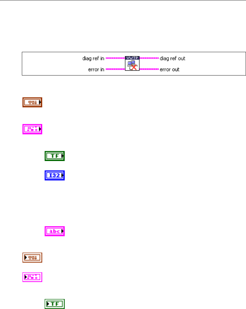
Chapter 5 Automotive Diagnostic Command Set API for LabVIEW
Automotive Diagnostic Command Set User Manual 5-30 ni.com
VWTP Disconnect.vi
Purpose
Terminates a connection channel to an ECU using the VW TP 2.0.
Format
Input
diag ref in specifies the diagnostic session handle, obtained from Open
Diagnostic.vi and wired through subsequent diagnostic VIs. Normally, it is
not necessary to manually manipulate the elements of this cluster.
error in is a cluster that describes error conditions occurring before the VI
executes. If an error has already occurred, the VI returns the value of the
error in cluster to error out.
status is TRUE if an error occurred. This VI is not executed when
status is TRUE.
code is the error code number identifying an error. A value of 0
means success. A negative value means error: the VI did not
execute the intended operation. A positive value means warning:
the VI executed intended operation, but an informational warning
is returned. For a description of the code, wire the error cluster to
a LabVIEW error-handling VI, such as the Simple Error
Handler.
source identifies the VI where the error occurred.
Output
diag ref out is a copy of diag ref in. You can wire it to subsequent
diagnostic VIs.
error out describes error conditions. If the error in cluster indicated an
error, the error out cluster contains the same information. Otherwise,
error out describes the error status of this VI.
status is TRUE if an error occurred.

Chapter 5 Automotive Diagnostic Command Set API for LabVIEW
© National Instruments Corporation 5-31 Automotive Diagnostic Command Set User Manual
code is the error code number identifying an error. A value of 0
means success. A negative value means error: the VI did not
execute the intended operation. A positive value means warning:
the VI executed intended operation, but an informational warning
is returned. For a description of the code, wire the error cluster to
a LabVIEW error-handling VI, such as the Simple Error
Handler.
source identifies the VI where the error occurred.
Description
For the VW TP 2.0, you must disconnect the connection link to the ECU to properly terminate
communication to the ECU. This VI sends the proper disconnect messages and unlinks the
communication.
You can create a new connection to the same ECU using VWTP Connect.vi again.
There is no equivalent for the ISO TP (ISO 15765-2), as the ISO TP does not use a special
communication link.

Chapter 5 Automotive Diagnostic Command Set API for LabVIEW
Automotive Diagnostic Command Set User Manual 5-32 ni.com
KWP2000 Services
ClearDiagnosticInformation.vi
Purpose
Executes the ClearDiagnosticInformation service and clears selected Diagnostic Trouble
Codes (DTCs).
Format
Input
DTC descriptor is a cluster that describes the DTC records the ECU
delivers:
DTC Byte Length indicates the number of bytes the ECU sends
for each DTC. The default is 2.
Status Byte Length indicates the number of bytes the ECU sends
for each DTC’s status. The default is 1.
Add Data Byte Length indicates the number of bytes the ECU
sends for each DTC’s additional data. Usually, there is no
additional data, so the default is 0.
Byte Order indicates the byte ordering for multibyte items:
0: MSB_FIRST (Motorola) (default)
1: LSB_FIRST (Intel)
The DTC descriptor is given here as a parameter basically to convert the
group of DTC parameter to a binary representation according to DTC
Byte Length and Byte Order.
diag ref in specifies the diagnostic session handle, obtained from Open
Diagnostic.vi and wired through subsequent diagnostic VIs. Normally, it is
not necessary to manually manipulate the elements of this cluster.

Chapter 5 Automotive Diagnostic Command Set API for LabVIEW
© National Instruments Corporation 5-33 Automotive Diagnostic Command Set User Manual
group of DTC specifies the group of Diagnostic Trouble Codes to be
cleared. The following values have a special meaning, and you can specify
them through a ring control:
0x0000 All powertrain DTCs
0x4000 All chassis DTCs
0x8000 All body DTCs
0xC000 All network-related DTCs
0xFF00 All DTCs
error in is a cluster that describes error conditions occurring before the VI
executes. If an error has already occurred, the VI returns the value of the
error in cluster to error out.
status is TRUE if an error occurred. This VI is not executed when
status is TRUE.
code is the error code number identifying an error. A value of 0
means success. A negative value means error: the VI did not
execute the intended operation. A positive value means warning:
the VI executed intended operation, but an informational warning
is returned. For a description of the code, wire the error cluster to
a LabVIEW error-handling VI, such as the Simple Error
Handler.
source identifies the VI where the error occurred.
Output
diag ref out is a copy of diag ref in. You can wire it to subsequent
diagnostic VIs.
success? indicates successful receipt of a positive response message for
this diagnostic service.
error out describes error conditions. If the error in cluster indicated an
error, the error out cluster contains the same information. Otherwise,
error out describes the error status of this VI.
status is TRUE if an error occurred.

Chapter 5 Automotive Diagnostic Command Set API for LabVIEW
Automotive Diagnostic Command Set User Manual 5-34 ni.com
code is the error code number identifying an error. A value of 0
means success. A negative value means error: the VI did not
execute the intended operation. A positive value means warning:
the VI executed intended operation, but an informational warning
is returned. For a description of the code, wire the error cluster to
a LabVIEW error-handling VI, such as the Simple Error
Handler.
source identifies the VI where the error occurred.
Description
This VI clears the diagnostic information on the ECU memory. If the group of DTC
parameter is present, the ECU is requested to clear all memory including the DTCs.
For further details about this service, refer to the ISO 14230-3 standard.

Chapter 5 Automotive Diagnostic Command Set API for LabVIEW
© National Instruments Corporation 5-35 Automotive Diagnostic Command Set User Manual
ControlDTCSetting.vi
Purpose
Executes the ControlDTCSetting service and modifies the generation behavior of selected
Diagnostic Trouble Codes (DTCs).
Format
Input
DTC descriptor is a cluster that describes the DTC records the ECU
delivers:
DTC Byte Length indicates the number of bytes the ECU sends
for each DTC. The default is 2.
Status Byte Length indicates the number of bytes the ECU sends
for each DTC’s status. The default is 1.
Add Data Byte Length indicates the number of bytes the ECU
sends for each DTC’s additional data. Usually, there is no
additional data, so the default is 0.
Byte Order indicates the byte ordering for multibyte items:
0: MSB_FIRST (Motorola) (default)
1: LSB_FIRST (Intel)
The DTC descriptor is given here as a parameter basically to convert the
group of DTC parameter to a binary representation according to DTC
Byte Length and Byte Order.
diag ref in specifies the diagnostic session handle, obtained from Open
Diagnostic.vi and wired through subsequent diagnostic VIs. Normally, it is
not necessary to manually manipulate the elements of this cluster.
data in specifies application-specific data that control DTC generation.
Chapter 5 Automotive Diagnostic Command Set API for LabVIEW
Automotive Diagnostic Command Set User Manual 5-36 ni.com
group of DTC specifies the group of Diagnostic Trouble Codes to be
controlled. The following values have a special meaning, and you can
specify them through a ring control:
0x0000 All powertrain DTCs
0x4000 All chassis DTCs
0x8000 All body DTCs
0xC000 All network-related DTCs
0xFF00 All DTCs
error in is a cluster that describes error conditions occurring before the VI
executes. If an error has already occurred, the VI returns the value of the
error in cluster to error out.
status is TRUE if an error occurred. This VI is not executed when
status is TRUE.
code is the error code number identifying an error. A value of 0
means success. A negative value means error: the VI did not
execute the intended operation. A positive value means warning:
the VI executed intended operation, but an informational warning
is returned. For a description of the code, wire the error cluster to
a LabVIEW error-handling VI, such as the Simple Error
Handler.
source identifies the VI where the error occurred.
Output
diag ref out is a copy of diag ref in. You can wire it to subsequent
diagnostic VIs.
success? indicates successful receipt of a positive response message for
this diagnostic service.
error out describes error conditions. If the error in cluster indicated an
error, the error out cluster contains the same information. Otherwise,
error out describes the error status of this VI.
status is TRUE if an error occurred.

Chapter 5 Automotive Diagnostic Command Set API for LabVIEW
© National Instruments Corporation 5-37 Automotive Diagnostic Command Set User Manual
code is the error code number identifying an error. A value of 0
means success. A negative value means error: the VI did not
execute the intended operation. A positive value means warning:
the VI executed intended operation, but an informational warning
is returned. For a description of the code, wire the error cluster to
a LabVIEW error-handling VI, such as the Simple Error
Handler.
source identifies the VI where the error occurred.
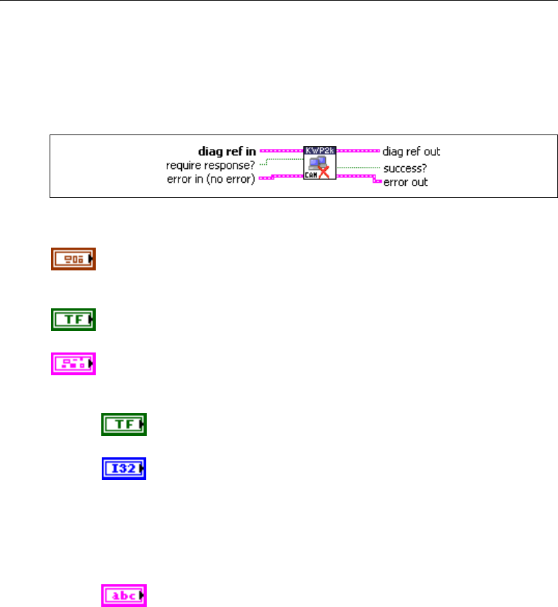
Chapter 5 Automotive Diagnostic Command Set API for LabVIEW
Automotive Diagnostic Command Set User Manual 5-38 ni.com
DisableNormalMessageTransmission.vi
Purpose
Executes the DisableNormalMessageTransmission service. The ECU no longer transmits its
regular communication messages (usually CAN messages).
Format
Input
diag ref in specifies the diagnostic session handle, obtained from Open
Diagnostic.vi and wired through subsequent diagnostic VIs. Normally, it is
not necessary to manually manipulate the elements of this cluster.
response required? indicates whether the ECU answers this service
(TRUE, default) or not (FALSE). In the latter case, success? is TRUE.
error in is a cluster that describes error conditions occurring before the VI
executes. If an error has already occurred, the VI returns the value of the
error in cluster to error out.
status is TRUE if an error occurred. This VI is not executed when
status is TRUE.
code is the error code number identifying an error. A value of 0
means success. A negative value means error: the VI did not
execute the intended operation. A positive value means warning:
the VI executed intended operation, but an informational warning
is returned. For a description of the code, wire the error cluster to
a LabVIEW error-handling VI, such as the Simple Error
Handler.
source identifies the VI where the error occurred.

Chapter 5 Automotive Diagnostic Command Set API for LabVIEW
© National Instruments Corporation 5-39 Automotive Diagnostic Command Set User Manual
Output
diag ref out is a copy of diag ref in. You can wire it to subsequent
diagnostic VIs.
success? indicates successful receipt of a positive response message for
this diagnostic service.
error out describes error conditions. If the error in cluster indicated an
error, the error out cluster contains the same information. Otherwise,
error out describes the error status of this VI.
status is TRUE if an error occurred.
code is the error code number identifying an error. A value of 0
means success. A negative value means error: the VI did not
execute the intended operation. A positive value means warning:
the VI executed intended operation, but an informational warning
is returned. For a description of the code, wire the error cluster to
a LabVIEW error-handling VI, such as the Simple Error
Handler.
source identifies the VI where the error occurred.
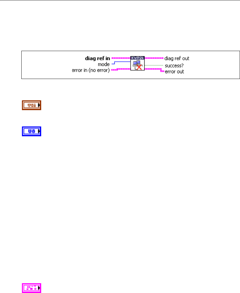
Chapter 5 Automotive Diagnostic Command Set API for LabVIEW
Automotive Diagnostic Command Set User Manual 5-40 ni.com
ECUReset.vi
Purpose
Executes the ECUReset service. Resets the ECU.
Format
Input
diag ref in specifies the diagnostic session handle, obtained from Open
Diagnostic.vi and wired through subsequent diagnostic VIs. Normally, it is
not necessary to manually manipulate the elements of this cluster.
mode indicates the reset mode:
Hex Description
01 PowerOn
This value identifies the PowerOn ResetMode, a simulated
PowerOn reset that most ECUs perform after the ignition
OFF/ON cycle. When the ECU performs the reset, the client
(tester) re-establishes communication.
02 PowerOnWhileMaintainingCommunication
This value identifies the PowerOn ResetMode, a simulated
PowerOn reset that most ECUs perform after the ignition
OFF/ON cycle. When the ECU performs the reset, the server
(ECU) maintains communication with the client (tester).
03–7F Reserved
80–FF ManufacturerSpecific
This range of values is reserved for vehicle manufacturer-specific
use.
error in is a cluster that describes error conditions occurring before the VI
executes. If an error has already occurred, the VI returns the value of the
error in cluster to error out.
Chapter 5 Automotive Diagnostic Command Set API for LabVIEW
© National Instruments Corporation 5-41 Automotive Diagnostic Command Set User Manual
status is TRUE if an error occurred. This VI is not executed when
status is TRUE.
code is the error code number identifying an error. A value of 0
means success. A negative value means error: the VI did not
execute the intended operation. A positive value means warning:
the VI executed intended operation, but an informational warning
is returned. For a description of the code, wire the error cluster to
a LabVIEW error-handling VI, such as the Simple Error
Handler.
source identifies the VI where the error occurred.
Output
diag ref out is a copy of diag ref in. You can wire it to subsequent
diagnostic VIs.
success? indicates successful receipt of a positive response message for
this diagnostic service.
error out describes error conditions. If the error in cluster indicated an
error, the error out cluster contains the same information. Otherwise,
error out describes the error status of this VI.
status is TRUE if an error occurred.
code is the error code number identifying an error. A value of 0
means success. A negative value means error: the VI did not
execute the intended operation. A positive value means warning:
the VI executed intended operation, but an informational warning
is returned. For a description of the code, wire the error cluster to
a LabVIEW error-handling VI, such as the Simple Error
Handler.
source identifies the VI where the error occurred.
Description
This VI requests the ECU to perform an ECU reset effectively based on the mode parameter
value content. The vehicle manufacturer determines when the positive response message is
sent.
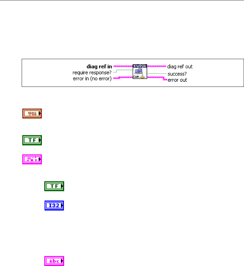
Chapter 5 Automotive Diagnostic Command Set API for LabVIEW
Automotive Diagnostic Command Set User Manual 5-42 ni.com
EnableNormalMessageTransmission.vi
Purpose
Executes the EnableNormalMessageTransmission service. The ECU starts transmitting its
regular communication messages (usually CAN messages).
Format
Input
diag ref in specifies the diagnostic session handle, obtained from Open
Diagnostic.vi and wired through subsequent diagnostic VIs. Normally, it is
not necessary to manually manipulate the elements of this cluster.
response required? indicates whether the ECU answers this service
(TRUE, default) or not (FALSE). In the latter case, success? is TRUE.
error in is a cluster that describes error conditions occurring before the VI
executes. If an error has already occurred, the VI returns the value of the
error in cluster to error out.
status is TRUE if an error occurred. This VI is not executed when
status is TRUE.
code is the error code number identifying an error. A value of 0
means success. A negative value means error: the VI did not
execute the intended operation. A positive value means warning:
the VI executed intended operation, but an informational warning
is returned. For a description of the code, wire the error cluster to
a LabVIEW error-handling VI, such as the Simple Error
Handler.
source identifies the VI where the error occurred.

Chapter 5 Automotive Diagnostic Command Set API for LabVIEW
© National Instruments Corporation 5-43 Automotive Diagnostic Command Set User Manual
Output
diag ref out is a copy of diag ref in. You can wire it to subsequent
diagnostic VIs.
success? indicates successful receipt of a positive response message for
this diagnostic service.
error out describes error conditions. If the error in cluster indicated an
error, the error out cluster contains the same information. Otherwise,
error out describes the error status of this VI.
status is TRUE if an error occurred.
code is the error code number identifying an error. A value of 0
means success. A negative value means error: the VI did not
execute the intended operation. A positive value means warning:
the VI executed intended operation, but an informational warning
is returned. For a description of the code, wire the error cluster to
a LabVIEW error-handling VI, such as the Simple Error
Handler.
source identifies the VI where the error occurred.
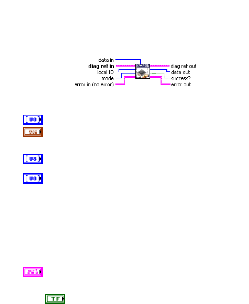
Chapter 5 Automotive Diagnostic Command Set API for LabVIEW
Automotive Diagnostic Command Set User Manual 5-44 ni.com
InputOutputControlByLocalIdentifier.vi
Purpose
Executes the InputOutputControlByLocalIdentifier service. Modifies ECU I/O port behavior.
Format
Input
data in defines application-specific data for this service.
diag ref in specifies the diagnostic session handle, obtained from Open
Diagnostic.vi and wired through subsequent diagnostic VIs. Normally, it is
not necessary to manually manipulate the elements of this cluster.
local ID defines the local identifier of the I/O to be manipulated. The values
are application specific.
mode defines the type of I/O control. The values are application specific.
The usual values are:
0: ReturnControlToECU
1: ReportCurrentState
4: ResetToDefault
5: FreezeCurrentState
7: ShortTermAdjustment
8: LongTermAdjustment
error in is a cluster that describes error conditions occurring before the VI
executes. If an error has already occurred, the VI returns the value of the
error in cluster to error out.
status is TRUE if an error occurred. This VI is not executed when
status is TRUE.
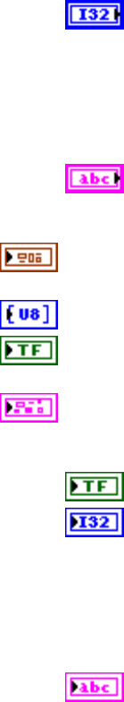
Chapter 5 Automotive Diagnostic Command Set API for LabVIEW
© National Instruments Corporation 5-45 Automotive Diagnostic Command Set User Manual
code is the error code number identifying an error. A value of 0
means success. A negative value means error: the VI did not
execute the intended operation. A positive value means warning:
the VI executed intended operation, but an informational warning
is returned. For a description of the code, wire the error cluster to
a LabVIEW error-handling VI, such as the Simple Error
Handler.
source identifies the VI where the error occurred.
Output
diag ref out is a copy of diag ref in. You can wire it to subsequent
diagnostic VIs.
data out returns application-specific data for this service.
success? indicates successful receipt of a positive response message for
this diagnostic service.
error out describes error conditions. If the error in cluster indicated an
error, the error out cluster contains the same information. Otherwise,
error out describes the error status of this VI.
status is TRUE if an error occurred.
code is the error code number identifying an error. A value of 0
means success. A negative value means error: the VI did not
execute the intended operation. A positive value means warning:
the VI executed intended operation, but an informational warning
is returned. For a description of the code, wire the error cluster to
a LabVIEW error-handling VI, such as the Simple Error
Handler.
source identifies the VI where the error occurred.
Description
This VI substitutes a value for an input signal or internal ECU function. It also controls an
output (actuator) of an electronic system referenced by the local ID parameter.
For further details about this service, refer to the ISO 14230-3 standard.
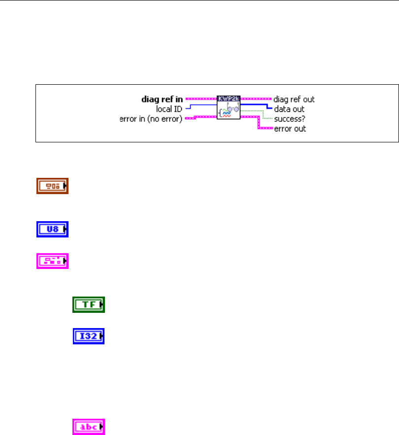
Chapter 5 Automotive Diagnostic Command Set API for LabVIEW
Automotive Diagnostic Command Set User Manual 5-46 ni.com
ReadDataByLocalIdentifier.vi
Purpose
Executes the ReadDataByLocalIdentifier service. Reads a data record from the ECU.
Format
Input
diag ref in specifies the diagnostic session handle, obtained from Open
Diagnostic.vi and wired through subsequent diagnostic VIs. Normally, it is
not necessary to manually manipulate the elements of this cluster.
local ID defines the local identifier of the data to be read. The values are
application specific.
error in is a cluster that describes error conditions occurring before the VI
executes. If an error has already occurred, the VI returns the value of the
error in cluster to error out.
status is TRUE if an error occurred. This VI is not executed when
status is TRUE.
code is the error code number identifying an error. A value of 0
means success. A negative value means error: the VI did not
execute the intended operation. A positive value means warning:
the VI executed intended operation, but an informational warning
is returned. For a description of the code, wire the error cluster to
a LabVIEW error-handling VI, such as the Simple Error
Handler.
source identifies the VI where the error occurred.
Chapter 5 Automotive Diagnostic Command Set API for LabVIEW
© National Instruments Corporation 5-47 Automotive Diagnostic Command Set User Manual
Output
diag ref out is a copy of diag ref in. You can wire it to subsequent
diagnostic VIs.
data out returns the data record from the ECU. If you know the record data
description, you can interpret this record using Convert from Phys.vi.
success? indicates successful receipt of a positive response message for
this diagnostic service.
error out describes error conditions. If the error in cluster indicated an
error, the error out cluster contains the same information. Otherwise,
error out describes the error status of this VI.
status is TRUE if an error occurred.
code is the error code number identifying an error. A value of 0
means success. A negative value means error: the VI did not
execute the intended operation. A positive value means warning:
the VI executed intended operation, but an informational warning
is returned. For a description of the code, wire the error cluster to
a LabVIEW error-handling VI, such as the Simple Error
Handler.
source identifies the VI where the error occurred.
Description
This VI requests data record values from the ECU identified by the local ID parameter.
For further details about this service, refer to the ISO 14230-3 standard.

Chapter 5 Automotive Diagnostic Command Set API for LabVIEW
Automotive Diagnostic Command Set User Manual 5-48 ni.com
ReadDTCByStatus.vi
Purpose
Executes the ReadDiagnosticTroubleCodesByStatus service. Reads selected Diagnostic
Trouble Codes (DTCs).
Format
Input
DTC descriptor is a cluster that describes the DTC records the ECU
delivers:
DTC Byte Length indicates the number of bytes the ECU sends
for each DTC. The default is 2.
Status Byte Length indicates the number of bytes the ECU sends
for each DTC’s status. The default is 1.
Add Data Byte Length indicates the number of bytes the ECU
sends for each DTC’s additional data. Usually, there is no
additional data, so the default is 0.
Byte Order indicates the byte ordering for multibyte items:
0: MSB_FIRST (Motorola) (default)
1: LSB_FIRST (Intel)
This VI interprets the response byte stream according to this description
and returns the resulting DTC records in the DTCs cluster array.
diag ref in specifies the diagnostic session handle, obtained from Open
Diagnostic.vi and wired through subsequent diagnostic VIs. Normally, it is
not necessary to manually manipulate the elements of this cluster.
Chapter 5 Automotive Diagnostic Command Set API for LabVIEW
© National Instruments Corporation 5-49 Automotive Diagnostic Command Set User Manual
mode defines the type of DTCs to be read. The values are application
specific. The usual values are:
2: AllIdentified
3: AllSupported
group of DTC specifies the group of Diagnostic Trouble Codes to be read.
The following values have a special meaning, and you can specify them
through a ring control:
0x0000 All powertrain DTCs
0x4000 All chassis DTCs
0x8000 All body DTCs
0xC000 All network-related DTCs
0xFF00 All DTCs
error in is a cluster that describes error conditions occurring before the VI
executes. If an error has already occurred, the VI returns the value of the
error in cluster to error out.
status is TRUE if an error occurred. This VI is not executed when
status is TRUE.
code is the error code number identifying an error. A value of 0
means success. A negative value means error: the VI did not
execute the intended operation. A positive value means warning:
the VI executed intended operation, but an informational warning
is returned. For a description of the code, wire the error cluster to
a LabVIEW error-handling VI, such as the Simple Error
Handler.
source identifies the VI where the error occurred.
Output
diag ref out is a copy of diag ref in. You can wire it to subsequent
diagnostic VIs.
DTCs returns the resulting DTCs as an array of clusters:
DTC is the resulting Diagnostic Trouble Code. For the default
2-byte DTCs, you can use DTC to String.vi to convert this to
readable format as defined by SAE J2012.

Chapter 5 Automotive Diagnostic Command Set API for LabVIEW
Automotive Diagnostic Command Set User Manual 5-50 ni.com
Status is the DTC status. Usually, this is a bit field with the
following meaning:
Bit Meaning
0 testFailed
1 testFailedThisMonitoringCycle
2 pendingDTC
3 confirmedDTC
4 testNotCompletedSinceLastClear
5 testFailedSinceLastClear
6 testNotCompletedThisMonitoringCycle
7 warningIndicatorRequested
Add Data contains optional additional data for this DTC. Usually,
this does not contain valid information (refer to DTC descriptor)
success? indicates successful receipt of a positive response message for
this diagnostic service.
error out describes error conditions. If the error in cluster indicated an
error, the error out cluster contains the same information. Otherwise,
error out describes the error status of this VI.
status is TRUE if an error occurred.
code is the error code number identifying an error. A value of 0
means success. A negative value means error: the VI did not
execute the intended operation. A positive value means warning:
the VI executed intended operation, but an informational warning
is returned. For a description of the code, wire the error cluster to
a LabVIEW error-handling VI, such as the Simple Error
Handler.
source identifies the VI where the error occurred.
Description
This VI reads DTCs by status from the ECU memory. If you use the optional group of DTC
parameter, the ECU reports DTCs only with status information based on the functional group
selected by group of DTC.
For further details about this service, refer to the ISO 14230-3 standard.

Chapter 5 Automotive Diagnostic Command Set API for LabVIEW
© National Instruments Corporation 5-51 Automotive Diagnostic Command Set User Manual
ReadECUIdentification.vi
Purpose
Executes the ReadECUIdentification service. Returns ECU identification data.
Format
Input
diag ref in specifies the diagnostic session handle, obtained from Open
Diagnostic.vi and wired through subsequent diagnostic VIs. Normally, it is
not necessary to manually manipulate the elements of this cluster.
mode indicates the type of identification information to be returned. The
values are application specific.
error in is a cluster that describes error conditions occurring before the VI
executes. If an error has already occurred, the VI returns the value of the
error in cluster to error out.
status is TRUE if an error occurred. This VI is not executed when
status is TRUE.
code is the error code number identifying an error. A value of 0
means success. A negative value means error: the VI did not
execute the intended operation. A positive value means warning:
the VI executed intended operation, but an informational warning
is returned. For a description of the code, wire the error cluster to
a LabVIEW error-handling VI, such as the Simple Error
Handler.
source identifies the VI where the error occurred.
Output
diag ref out is a copy of diag ref in. You can wire it to subsequent
diagnostic VIs.
data out returns the ECU identification data.
Chapter 5 Automotive Diagnostic Command Set API for LabVIEW
Automotive Diagnostic Command Set User Manual 5-52 ni.com
success? indicates successful receipt of a positive response message for
this diagnostic service.
error out describes error conditions. If the error in cluster indicated an
error, the error out cluster contains the same information. Otherwise,
error out describes the error status of this VI.
status is TRUE if an error occurred.
code is the error code number identifying an error. A value of 0
means success. A negative value means error: the VI did not
execute the intended operation. A positive value means warning:
the VI executed intended operation, but an informational warning
is returned. For a description of the code, wire the error cluster to
a LabVIEW error-handling VI, such as the Simple Error
Handler.
source identifies the VI where the error occurred.
Description
This VI requests identification data from the ECU. The mode parameter identifies the type of
identification data requested. The ECU returns identification data that the data out parameter
can access. The data out format and definition are vehicle manufacturer specific.
For further details about this service, refer to the ISO 14230-3 standard.
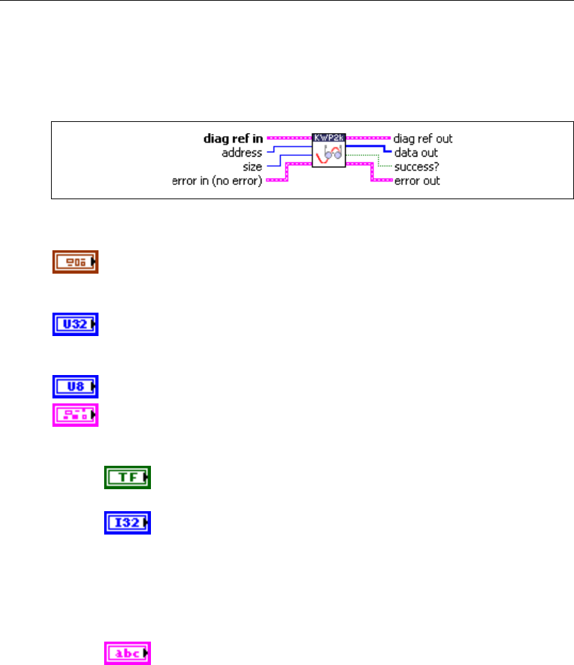
Chapter 5 Automotive Diagnostic Command Set API for LabVIEW
© National Instruments Corporation 5-53 Automotive Diagnostic Command Set User Manual
ReadMemoryByAddress.vi
Purpose
Executes the ReadMemoryByAddress service. Reads data from the ECU memory.
Format
Input
diag ref in specifies the diagnostic session handle, obtained from Open
Diagnostic.vi and wired through subsequent diagnostic VIs. Normally, it is
not necessary to manually manipulate the elements of this cluster.
address defines the memory address from which data are to be read. Notice
that only three bytes are sent to the ECU, so the address must be in the range
0–FFFFFF (hex).
size defines the length of the memory block to be read.
error in is a cluster that describes error conditions occurring before the VI
executes. If an error has already occurred, the VI returns the value of the
error in cluster to error out.
status is TRUE if an error occurred. This VI is not executed when
status is TRUE.
code is the error code number identifying an error. A value of 0
means success. A negative value means error: the VI did not
execute the intended operation. A positive value means warning:
the VI executed intended operation, but an informational warning
is returned. For a description of the code, wire the error cluster to
a LabVIEW error-handling VI, such as the Simple Error
Handler.
source identifies the VI where the error occurred.

Chapter 5 Automotive Diagnostic Command Set API for LabVIEW
Automotive Diagnostic Command Set User Manual 5-54 ni.com
Output
diag ref out is a copy of diag ref in. You can wire it to subsequent
diagnostic VIs.
Data out returns the memory data from the ECU.
success? indicates successful receipt of a positive response message for
this diagnostic service.
error out describes error conditions. If the error in cluster indicated an
error, the error out cluster contains the same information. Otherwise,
error out describes the error status of this VI.
status is TRUE if an error occurred.
code is the error code number identifying an error. A value of 0
means success. A negative value means error: the VI did not
execute the intended operation. A positive value means warning:
the VI executed intended operation, but an informational warning
is returned. For a description of the code, wire the error cluster to
a LabVIEW error-handling VI, such as the Simple Error
Handler.
source identifies the VI where the error occurred.
Description
This VI requests memory data from the ECU identified by the address and size parameters.
The data out format and definition are vehicle manufacturer specific. data out includes
analog input and output signals, digital input and output signals, internal data, and system
status information if the ECU supports them.
For further details about this service, refer to the ISO 14230-3 standard.
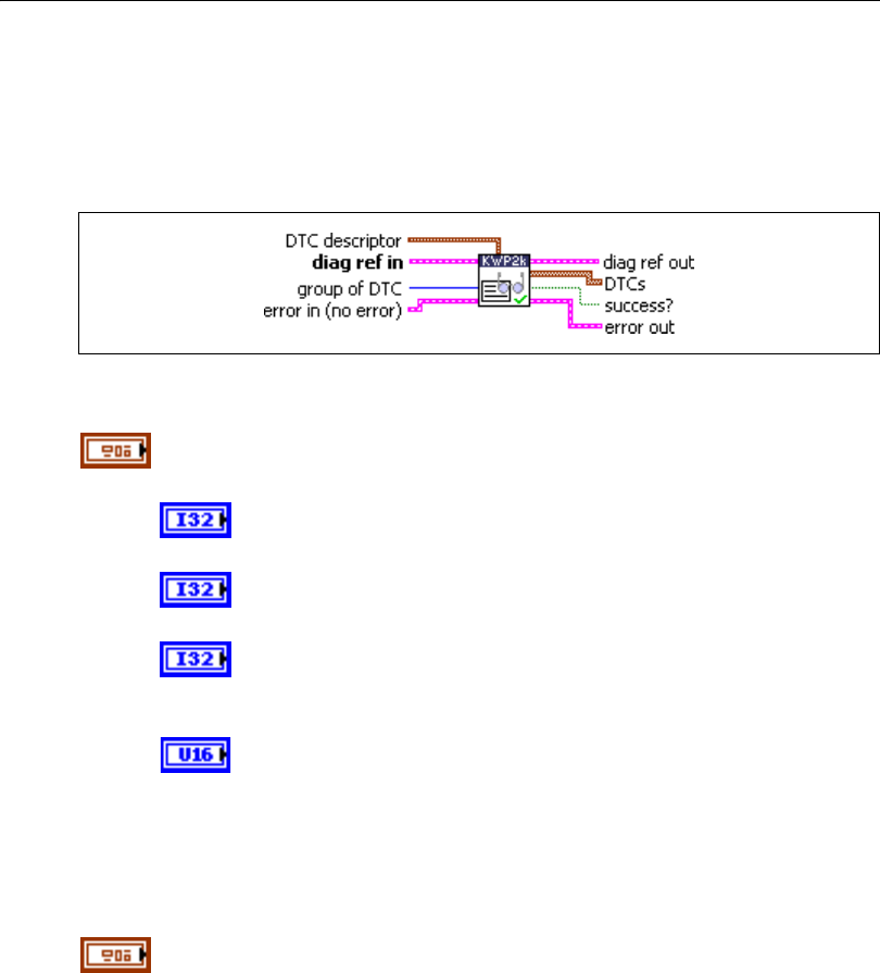
Chapter 5 Automotive Diagnostic Command Set API for LabVIEW
© National Instruments Corporation 5-55 Automotive Diagnostic Command Set User Manual
ReadStatusOfDTC.vi
Purpose
Executes the ReadStatusOfDiagnosticTroubleCodes service. Reads selected Diagnostic
Trouble Codes (DTCs).
Format
Input
DTC descriptor is a cluster that describes the DTC records the ECU
delivers:
DTC Byte Length indicates the number of bytes the ECU sends
for each DTC. The default is 2.
Status Byte Length indicates the number of bytes the ECU sends
for each DTC’s status. The default is 1.
Add Data Byte Length indicates the number of bytes the ECU
sends for each DTC’s additional data. Usually, there is no
additional data, so the default is 0.
Byte Order indicates the byte ordering for multibyte items:
0: MSB_FIRST (Motorola) (default)
1: LSB_FIRST (Intel)
This VI interprets the response byte stream according to this description
and returns the resulting DTC records in the DTCs cluster array.
diag ref in specifies the diagnostic session handle, obtained from Open
Diagnostic.vi and wired through subsequent diagnostic VIs. Normally, it is
not necessary to manually manipulate the elements of this cluster.
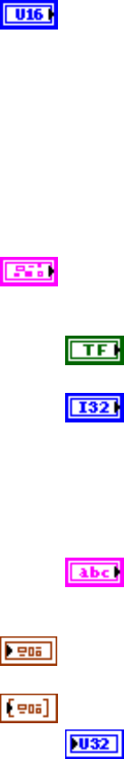
Chapter 5 Automotive Diagnostic Command Set API for LabVIEW
Automotive Diagnostic Command Set User Manual 5-56 ni.com
group of DTC specifies the group of Diagnostic Trouble Codes to be read.
The following values have a special meaning, and you can specify them
through a ring control:
0x0000 All powertrain DTCs
0x4000 All chassis DTCs
0x8000 All body DTCs
0xC000 All network-related DTCs
0xFF00 All DTCs
error in is a cluster that describes error conditions occurring before the VI
executes. If an error has already occurred, the VI returns the value of the
error in cluster to error out.
status is TRUE if an error occurred. This VI is not executed when
status is TRUE.
code is the error code number identifying an error. A value of 0
means success. A negative value means error: the VI did not
execute the intended operation. A positive value means warning:
the VI executed intended operation, but an informational warning
is returned. For a description of the code, wire the error cluster to
a LabVIEW error-handling VI, such as the Simple Error
Handler.
source identifies the VI where the error occurred.
Output
diag ref out is a copy of diag ref in. You can wire it to subsequent
diagnostic VIs.
DTCs returns the resulting DTCs as an array of clusters:
DTC is the resulting Diagnostic Trouble Code. For the default
2-byte DTCs, you can use DTC to String.vi to convert this to
readable format as defined by SAE J2012.
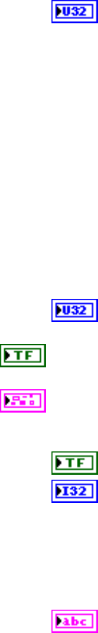
Chapter 5 Automotive Diagnostic Command Set API for LabVIEW
© National Instruments Corporation 5-57 Automotive Diagnostic Command Set User Manual
Status is the DTC status. Usually, this is a bit field with the
following meaning:
Bit Meaning
0 testFailed
1 testFailedThisMonitoringCycle
2 pendingDTC
3 confirmedDTC
4 testNotCompletedSinceLastClear
5 testFailedSinceLastClear
6 testNotCompletedThisMonitoringCycle
7 warningIndicatorRequested
Add Data contains optional additional data for this DTC. Usually,
this does not contain valid information (refer to DTC descriptor)
success? indicates successful receipt of a positive response message for
this diagnostic service.
error out describes error conditions. If the error in cluster indicated an
error, the error out cluster contains the same information. Otherwise,
error out describes the error status of this VI.
status is TRUE if an error occurred.
code is the error code number identifying an error. A value of 0
means success. A negative value means error: the VI did not
execute the intended operation. A positive value means warning:
the VI executed intended operation, but an informational warning
is returned. For a description of the code, wire the error cluster to
a LabVIEW error-handling VI, such as the Simple Error
Handler.
source identifies the VI where the error occurred.
Description
This VI reads diagnostic trouble codes from the ECU memory. If you use the optional group
of DTC parameter, the ECU reports DTCs based only on the functional group selected by
group of DTC.
For further details about this service, refer to the ISO 14230-3 standard.
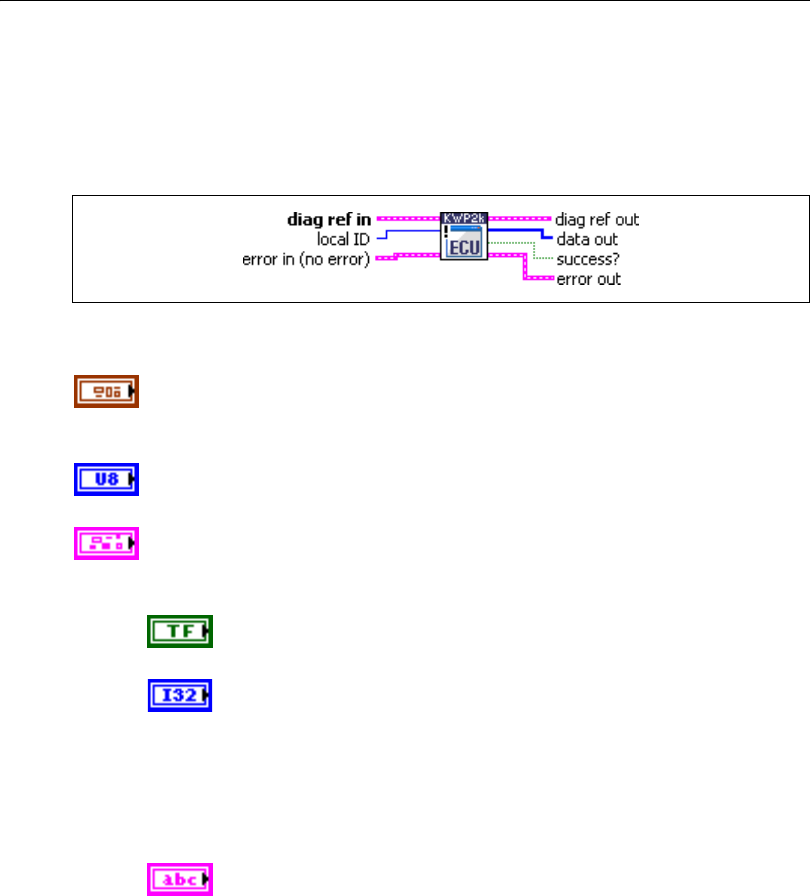
Chapter 5 Automotive Diagnostic Command Set API for LabVIEW
Automotive Diagnostic Command Set User Manual 5-58 ni.com
RequestRoutineResultsByLocalIdentifier.vi
Purpose
Executes the RequestRoutineResultsByLocalIdentifier service. Returns results from a routine
on the ECU.
Format
Input
diag ref in specifies the diagnostic session handle, obtained from Open
Diagnostic.vi and wired through subsequent diagnostic VIs. Normally, it is
not necessary to manually manipulate the elements of this cluster.
local ID defines the local identifier of the routine from which this VI
retrieves results. The values are application specific.
error in is a cluster that describes error conditions occurring before the VI
executes. If an error has already occurred, the VI returns the value of the
error in cluster to error out.
status is TRUE if an error occurred. This VI is not executed when
status is TRUE.
code is the error code number identifying an error. A value of 0
means success. A negative value means error: the VI did not
execute the intended operation. A positive value means warning:
the VI executed intended operation, but an informational warning
is returned. For a description of the code, wire the error cluster to
a LabVIEW error-handling VI, such as the Simple Error
Handler.
source identifies the VI where the error occurred.

Chapter 5 Automotive Diagnostic Command Set API for LabVIEW
© National Instruments Corporation 5-59 Automotive Diagnostic Command Set User Manual
Output
diag ref out is a copy of diag ref in. You can wire it to subsequent
diagnostic VIs.
data out returns application-specific output parameters from the routine.
success? indicates successful receipt of a positive response message for
this diagnostic service.
error out describes error conditions. If the error in cluster indicated an
error, the error out cluster contains the same information. Otherwise,
error out describes the error status of this VI.
status is TRUE if an error occurred.
code is the error code number identifying an error. A value of 0
means success. A negative value means error: the VI did not
execute the intended operation. A positive value means warning:
the VI executed intended operation, but an informational warning
is returned. For a description of the code, wire the error cluster to
a LabVIEW error-handling VI, such as the Simple Error
Handler.
source identifies the VI where the error occurred.
Description
This VI requests results (for example, exit status information) referenced by local ID and
generated by the routine executed in the ECU memory.
For further details about this service, refer to the ISO 14230-3 standard.
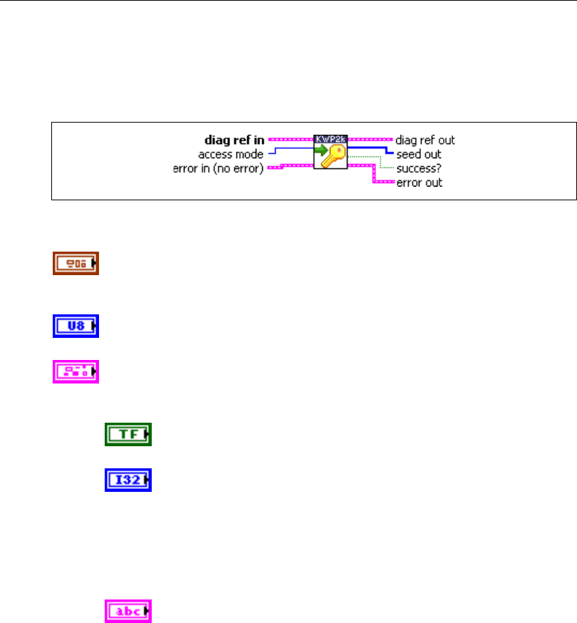
Chapter 5 Automotive Diagnostic Command Set API for LabVIEW
Automotive Diagnostic Command Set User Manual 5-60 ni.com
RequestSeed.vi
Purpose
Executes the SecurityAccess service to retrieve a seed from the ECU.
Format
Input
diag ref in specifies the diagnostic session handle, obtained from Open
Diagnostic.vi and wired through subsequent diagnostic VIs. Normally, it is
not necessary to manually manipulate the elements of this cluster.
access mode indicates the security level to be granted. The values are
application specific. This is an odd number, usually 1.
error in is a cluster that describes error conditions occurring before the VI
executes. If an error has already occurred, the VI returns the value of the
error in cluster to error out.
status is TRUE if an error occurred. This VI is not executed when
status is TRUE.
code is the error code number identifying an error. A value of 0
means success. A negative value means error: the VI did not
execute the intended operation. A positive value means warning:
the VI executed intended operation, but an informational warning
is returned. For a description of the code, wire the error cluster to
a LabVIEW error-handling VI, such as the Simple Error
Handler.
source identifies the VI where the error occurred.

Chapter 5 Automotive Diagnostic Command Set API for LabVIEW
© National Instruments Corporation 5-61 Automotive Diagnostic Command Set User Manual
Output
diag ref out is a copy of diag ref in. You can wire it to subsequent
diagnostic VIs.
seed out returns the seed from the ECU.
success? indicates successful receipt of a positive response message for
this diagnostic service.
error out describes error conditions. If the error in cluster indicated an
error, the error out cluster contains the same information. Otherwise,
error out describes the error status of this VI.
status is TRUE if an error occurred.
code is the error code number identifying an error. A value of 0
means success. A negative value means error: the VI did not
execute the intended operation. A positive value means warning:
the VI executed intended operation, but an informational warning
is returned. For a description of the code, wire the error cluster to
a LabVIEW error-handling VI, such as the Simple Error
Handler.
source identifies the VI where the error occurred.
Description
The usual procedure for getting a security access to the ECU is as follows:
1. Request a seed from the ECU using RequestSeed.vi with access mode = n.
2. From the seed, compute a key for the ECU on the host.
3. Send the key to the ECU using SendKey.vi with access mode = n + 1.
4. The security access is granted if the ECU validates the key sent. Otherwise, an error is
returned.
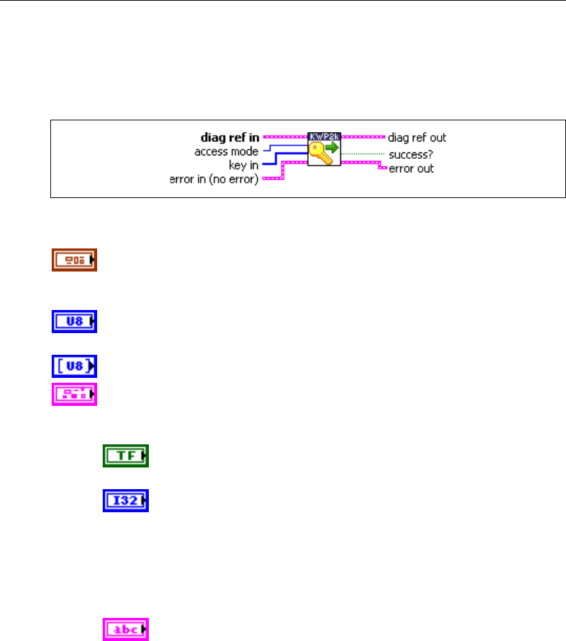
Chapter 5 Automotive Diagnostic Command Set API for LabVIEW
Automotive Diagnostic Command Set User Manual 5-62 ni.com
SendKey.vi
Purpose
Executes the SecurityAccess service to send a key to the ECU.
Format
Input
diag ref in specifies the diagnostic session handle, obtained from Open
Diagnostic.vi and wired through subsequent diagnostic VIs. Normally, it is
not necessary to manually manipulate the elements of this cluster.
access mode indicates the security level to be granted. The values are
application specific. This is an even number, usually 2.
key in defines the key data to be sent to the ECU.
error in is a cluster that describes error conditions occurring before the VI
executes. If an error has already occurred, the VI returns the value of the
error in cluster to error out.
status is TRUE if an error occurred. This VI is not executed when
status is TRUE.
code is the error code number identifying an error. A value of 0
means success. A negative value means error: the VI did not
execute the intended operation. A positive value means warning:
the VI executed intended operation, but an informational warning
is returned. For a description of the code, wire the error cluster to
a LabVIEW error-handling VI, such as the Simple Error
Handler.
source identifies the VI where the error occurred.

Chapter 5 Automotive Diagnostic Command Set API for LabVIEW
© National Instruments Corporation 5-63 Automotive Diagnostic Command Set User Manual
Output
diag ref out is a copy of diag ref in. You can wire it to subsequent
diagnostic VIs.
success? indicates successful receipt of a positive response message for
this diagnostic service.
error out describes error conditions. If the error in cluster indicated an
error, the error out cluster contains the same information. Otherwise,
error out describes the error status of this VI.
status is TRUE if an error occurred.
code is the error code number identifying an error. A value of 0
means success. A negative value means error: the VI did not
execute the intended operation. A positive value means warning:
the VI executed intended operation, but an informational warning
is returned. For a description of the code, wire the error cluster to
a LabVIEW error-handling VI, such as the Simple Error
Handler.
source identifies the VI where the error occurred.
Description
The usual procedure for getting a security access to the ECU is as follows:
1. Request a seed from the ECU using RequestSeed.vi with access mode = n.
2. From the seed, compute a key for the ECU on the host.
3. Send the key to the ECU using SendKey.vi with access mode = n + 1.
4. The security access is granted if the ECU validates the key sent. Otherwise, an error is
returned.
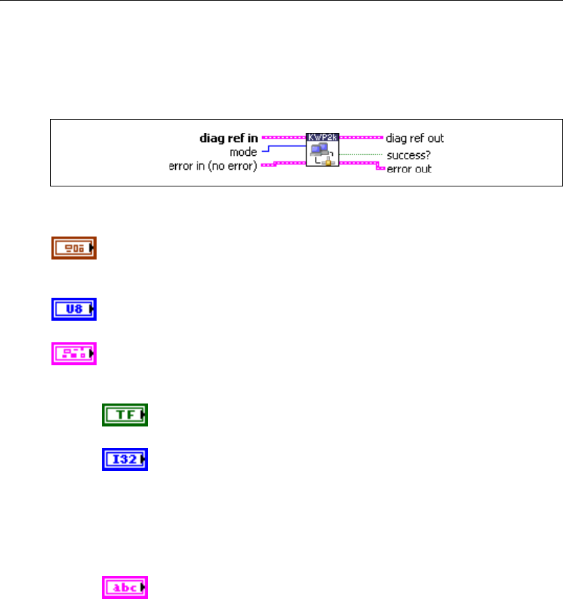
Chapter 5 Automotive Diagnostic Command Set API for LabVIEW
Automotive Diagnostic Command Set User Manual 5-64 ni.com
StartDiagnosticSession.vi
Purpose
Executes the StartDiagnosticSession service. Sets up the ECU in a specific diagnostic mode.
Format
Input
diag ref in specifies the diagnostic session handle, obtained from Open
Diagnostic.vi and wired through subsequent diagnostic VIs. Normally, it is
not necessary to manually manipulate the elements of this cluster.
mode indicates the diagnostic mode into which the ECU is brought. The
values are application specific.
error in is a cluster that describes error conditions occurring before the VI
executes. If an error has already occurred, the VI returns the value of the
error in cluster to error out.
status is TRUE if an error occurred. This VI is not executed when
status is TRUE.
code is the error code number identifying an error. A value of 0
means success. A negative value means error: the VI did not
execute the intended operation. A positive value means warning:
the VI executed intended operation, but an informational warning
is returned. For a description of the code, wire the error cluster to
a LabVIEW error-handling VI, such as the Simple Error
Handler.
source identifies the VI where the error occurred.

Chapter 5 Automotive Diagnostic Command Set API for LabVIEW
© National Instruments Corporation 5-65 Automotive Diagnostic Command Set User Manual
Output
diag ref out is a copy of diag ref in. You can wire it to subsequent
diagnostic VIs.
success? indicates successful receipt of a positive response message for
this diagnostic service.
error out describes error conditions. If the error in cluster indicated an
error, the error out cluster contains the same information. Otherwise,
error out describes the error status of this VI.
status is TRUE if an error occurred.
code is the error code number identifying an error. A value of 0
means success. A negative value means error: the VI did not
execute the intended operation. A positive value means warning:
the VI executed intended operation, but an informational warning
is returned. For a description of the code, wire the error cluster to
a LabVIEW error-handling VI, such as the Simple Error
Handler.
source identifies the VI where the error occurred.
Description
This VI enables different diagnostic modes in the ECU. The possible diagnostic modes are
not defined in the ISO 14230 standard and are application specific. A diagnostic session starts
only if communication with the ECU is established. For more details about starting
communication, refer to the ISO 14230-2 standard. If no diagnostic session has been
requested after Open Diagnostic.vi, a default session is automatically enabled in the ECU.
The default session supports at least the following services:
• The StopCommunication service (refer to Close Diagnostic.vi and the ISO 14230-2
standard).
• The TesterPresent service (refer to TesterPresent.vi and the ISO 14230-3 standard).
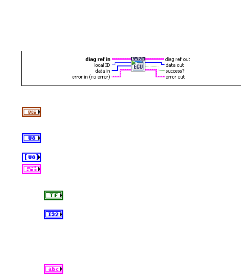
Chapter 5 Automotive Diagnostic Command Set API for LabVIEW
Automotive Diagnostic Command Set User Manual 5-66 ni.com
StartRoutineByLocalIdentifier.vi
Purpose
Executes the StartRoutineByLocalIdentifier service. Executes a routine on the ECU.
Format
Input
diag ref in specifies the diagnostic session handle, obtained from Open
Diagnostic.vi and wired through subsequent diagnostic VIs. Normally, it is
not necessary to manually manipulate the elements of this cluster.
local ID defines the local identifier of the routine to be started. The values
are application specific.
data in defines application-specific input parameters for the routine.
error in is a cluster that describes error conditions occurring before the VI
executes. If an error has already occurred, the VI returns the value of the
error in cluster to error out.
status is TRUE if an error occurred. This VI is not executed when
status is TRUE.
code is the error code number identifying an error. A value of 0
means success. A negative value means error: the VI did not
execute the intended operation. A positive value means warning:
the VI executed intended operation, but an informational warning
is returned. For a description of the code, wire the error cluster to
a LabVIEW error-handling VI, such as the Simple Error
Handler.
source identifies the VI where the error occurred.

Chapter 5 Automotive Diagnostic Command Set API for LabVIEW
© National Instruments Corporation 5-67 Automotive Diagnostic Command Set User Manual
Output
diag ref out is a copy of diag ref in. You can wire it to subsequent
diagnostic VIs.
data out returns application-specific output parameters from the routine.
success? indicates successful receipt of a positive response message for
this diagnostic service.
error out describes error conditions. If the error in cluster indicated an
error, the error out cluster contains the same information. Otherwise,
error out describes the error status of this VI.
status is TRUE if an error occurred.
code is the error code number identifying an error. A value of 0
means success. A negative value means error: the VI did not
execute the intended operation. A positive value means warning:
the VI executed intended operation, but an informational warning
is returned. For a description of the code, wire the error cluster to
a LabVIEW error-handling VI, such as the Simple Error
Handler.
source identifies the VI where the error occurred.
Description
This VI starts a routine in the ECU memory. The routine in the ECU starts after the positive
response message is sent. The routine stops until StopRoutineByLocalIdentifier.vi is
issued. The routines could be either tests run instead of normal operating code or routines
enabled and executed with the normal operating code running. In the first case, you may need
to switch the ECU to a specific diagnostic mode using StartDiagnosticSession.vi or unlock
the ECU using the SecurityAccess service prior to using StartRoutineByLocalIdentifier.vi.
For further details about this service, refer to the ISO 14230-3 standard.
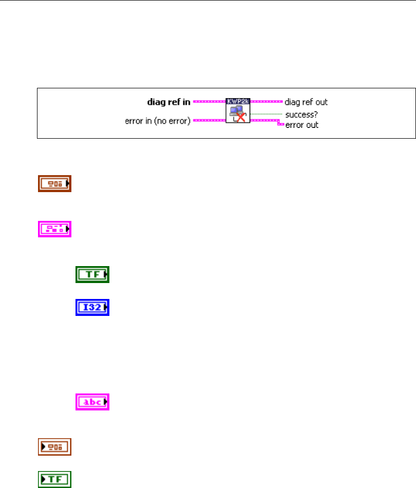
Chapter 5 Automotive Diagnostic Command Set API for LabVIEW
Automotive Diagnostic Command Set User Manual 5-68 ni.com
StopDiagnosticSession.vi
Purpose
Executes the StopDiagnosticSession service. Returns the ECU to normal mode.
Format
Input
diag ref in specifies the diagnostic session handle, obtained from Open
Diagnostic.vi and wired through subsequent diagnostic VIs. Normally, it is
not necessary to manually manipulate the elements of this cluster.
error in is a cluster that describes error conditions occurring before the VI
executes. If an error has already occurred, the VI returns the value of the
error in cluster to error out.
status is TRUE if an error occurred. This VI is not executed when
status is TRUE.
code is the error code number identifying an error. A value of 0
means success. A negative value means error: the VI did not
execute the intended operation. A positive value means warning:
the VI executed intended operation, but an informational warning
is returned. For a description of the code, wire the error cluster to
a LabVIEW error-handling VI, such as the Simple Error
Handler.
source identifies the VI where the error occurred.
Output
diag ref out is a copy of diag ref in. You can wire it to subsequent
diagnostic VIs.
success? indicates successful receipt of a positive response message for
this diagnostic service.

Chapter 5 Automotive Diagnostic Command Set API for LabVIEW
© National Instruments Corporation 5-69 Automotive Diagnostic Command Set User Manual
error out describes error conditions. If the error in cluster indicated an
error, the error out cluster contains the same information. Otherwise,
error out describes the error status of this VI.
status is TRUE if an error occurred.
code is the error code number identifying an error. A value of 0
means success. A negative value means error: the VI did not
execute the intended operation. A positive value means warning:
the VI executed intended operation, but an informational warning
is returned. For a description of the code, wire the error cluster to
a LabVIEW error-handling VI, such as the Simple Error
Handler.
source identifies the VI where the error occurred.
Description
This VI disables the current ECU diagnostic mode. A diagnostic session stops only if
communication is established with the ECU and a diagnostic session is running. If no
diagnostic session is running, the default session is active. StopDiagnosticSession.vi cannot
disable the default session. If the ECU has stopped the current diagnostic session, it performs
the necessary action to restore its normal operating conditions. Restoring the normal
operating conditions of the ECU may include resetting all controlled actuators if they were
activated during the diagnostic session being stopped, and resuming all normal ECU
algorithms. You should call StopDiagnosticSession.vi before disabling communication with
Close Diagnostic.vi, but only if you previously used StartDiagnosticSession.vi.

Chapter 5 Automotive Diagnostic Command Set API for LabVIEW
Automotive Diagnostic Command Set User Manual 5-70 ni.com
StopRoutineByLocalIdentifier.vi
Purpose
Executes the StopRoutineByLocalIdentifier service. Stops a routine on the ECU.
Format
Input
diag ref in specifies the diagnostic session handle, obtained from Open
Diagnostic.vi and wired through subsequent diagnostic VIs. Normally, it is
not necessary to manually manipulate the elements of this cluster.
local ID defines the local identifier of the routine to be stopped. The values
are application specific.
data in defines application-specific input parameters for the routine.
error in is a cluster that describes error conditions occurring before the VI
executes. If an error has already occurred, the VI returns the value of the
error in cluster to error out.
status is TRUE if an error occurred. This VI is not executed when
status is TRUE.
code is the error code number identifying an error. A value of 0
means success. A negative value means error: the VI did not
execute the intended operation. A positive value means warning:
the VI executed intended operation, but an informational warning
is returned. For a description of the code, wire the error cluster to
a LabVIEW error-handling VI, such as the Simple Error
Handler.
source identifies the VI where the error occurred.
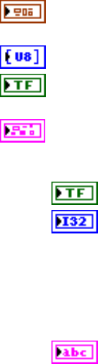
Chapter 5 Automotive Diagnostic Command Set API for LabVIEW
© National Instruments Corporation 5-71 Automotive Diagnostic Command Set User Manual
Output
diag ref out is a copy of diag ref in. You can wire it to subsequent
diagnostic VIs.
data out returns application-specific output parameters from the routine.
success? indicates successful receipt of a positive response message for
this diagnostic service.
error out describes error conditions. If the error in cluster indicated an
error, the error out cluster contains the same information. Otherwise,
error out describes the error status of this VI.
status is TRUE if an error occurred.
code is the error code number identifying an error. A value of 0
means success. A negative value means error: the VI did not
execute the intended operation. A positive value means warning:
the VI executed intended operation, but an informational warning
is returned. For a description of the code, wire the error cluster to
a LabVIEW error-handling VI, such as the Simple Error
Handler.
source identifies the VI where the error occurred.
Description
This VI stops a routine in the ECU memory referenced by the local ID parameter.
For further details about this service, refer to the ISO 14230-3 standard.
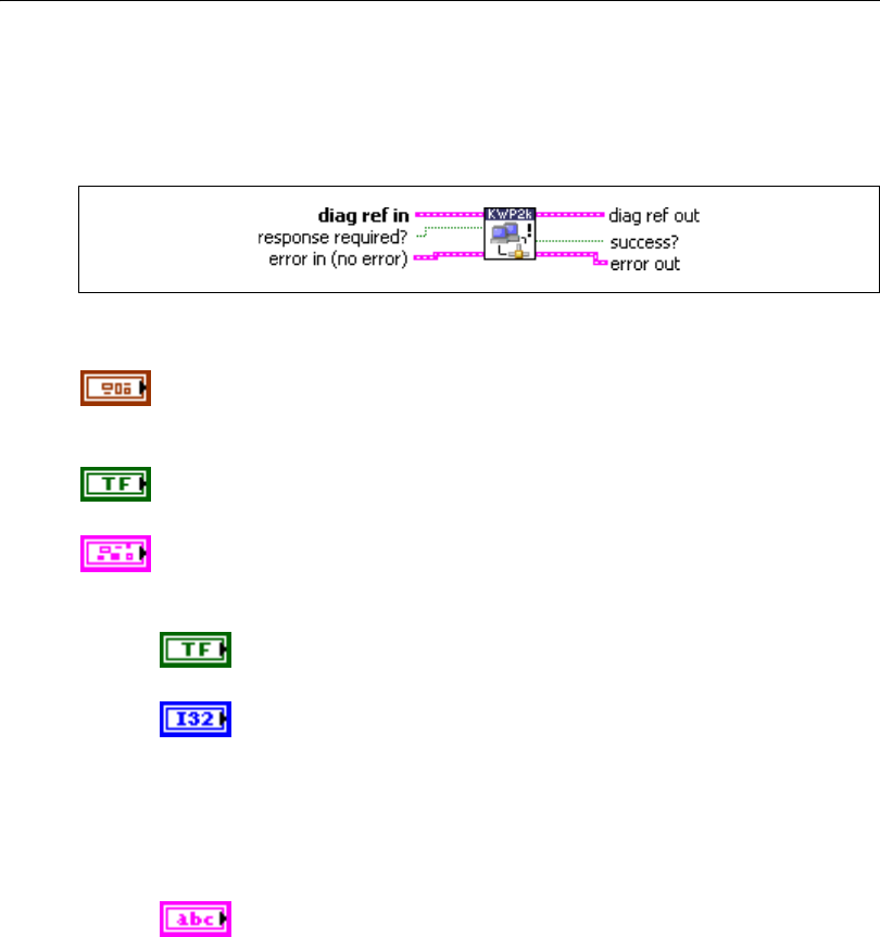
Chapter 5 Automotive Diagnostic Command Set API for LabVIEW
Automotive Diagnostic Command Set User Manual 5-72 ni.com
TesterPresent.vi
Purpose
Executes the TesterPresent service. Keeps the ECU in diagnostic mode.
Format
Input
diag ref in specifies the diagnostic session handle, obtained from Open
Diagnostic.vi and wired through subsequent diagnostic VIs. Normally, it is
not necessary to manually manipulate the elements of this cluster.
response required? indicates whether the ECU answers this service
(TRUE, default) or not (FALSE). In the latter case, success? is TRUE.
error in is a cluster that describes error conditions occurring before the VI
executes. If an error has already occurred, the VI returns the value of the
error in cluster to error out.
status is TRUE if an error occurred. This VI is not executed when
status is TRUE.
code is the error code number identifying an error. A value of 0
means success. A negative value means error: the VI did not
execute the intended operation. A positive value means warning:
the VI executed intended operation, but an informational warning
is returned. For a description of the code, wire the error cluster to
a LabVIEW error-handling VI, such as the Simple Error
Handler.
source identifies the VI where the error occurred.

Chapter 5 Automotive Diagnostic Command Set API for LabVIEW
© National Instruments Corporation 5-73 Automotive Diagnostic Command Set User Manual
Output
diag ref out is a copy of diag ref in. You can wire it to subsequent
diagnostic VIs.
success? indicates successful receipt of a positive response message for
this diagnostic service.
error out describes error conditions. If the error in cluster indicated an
error, the error out cluster contains the same information. Otherwise,
error out describes the error status of this VI.
status is TRUE if an error occurred.
code is the error code number identifying an error. A value of 0
means success. A negative value means error: the VI did not
execute the intended operation. A positive value means warning:
the VI executed intended operation, but an informational warning
is returned. For a description of the code, wire the error cluster to
a LabVIEW error-handling VI, such as the Simple Error
Handler.
source identifies the VI where the error occurred.
Description
To ensure proper ECU operation, you may need to keep the ECU informed that a diagnostic
session is still in progress. If you do not send this information (for example, because the
communication is broken), the ECU returns to normal mode from diagnostic mode after a
while.
The TesterPresent service is this “keep alive” signal. It does not affect any other ECU
operation.
Keep calling TesterPresent.vi within the ECU timeout period if no other service is executed.
Chapter 5 Automotive Diagnostic Command Set API for LabVIEW
Automotive Diagnostic Command Set User Manual 5-74 ni.com
WriteDataByLocalIdentifier.vi
Purpose
Executes the WriteDataByLocalIdentifier service. Writes a data record to the ECU.
Format
Input
data in defines the data record written to the ECU. If you know the record
data description, you can use Convert from Phys.vi to generate this
record.
diag ref in specifies the diagnostic session handle, obtained from Open
Diagnostic.vi and wired through subsequent diagnostic VIs. Normally, it is
not necessary to manually manipulate the elements of this cluster.
local ID defines the local identifier of the data to be written. The values are
application specific.
error in is a cluster that describes error conditions occurring before the VI
executes. If an error has already occurred, the VI returns the value of the
error in cluster to error out.
status is TRUE if an error occurred. This VI is not executed when
status is TRUE.
code is the error code number identifying an error. A value of 0
means success. A negative value means error: the VI did not
execute the intended operation. A positive value means warning:
the VI executed intended operation, but an informational warning
is returned. For a description of the code, wire the error cluster to
a LabVIEW error-handling VI, such as the Simple Error
Handler.
source identifies the VI where the error occurred.
Chapter 5 Automotive Diagnostic Command Set API for LabVIEW
© National Instruments Corporation 5-75 Automotive Diagnostic Command Set User Manual
Output
diag ref out is a copy of diag ref in. You can wire it to subsequent
diagnostic VIs.
success? indicates successful receipt of a positive response message for
this diagnostic service.
error out describes error conditions. If the error in cluster indicated an
error, the error out cluster contains the same information. Otherwise,
error out describes the error status of this VI.
status is TRUE if an error occurred.
code is the error code number identifying an error. A value of 0
means success. A negative value means error: the VI did not
execute the intended operation. A positive value means warning:
the VI executed intended operation, but an informational warning
is returned. For a description of the code, wire the error cluster to
a LabVIEW error-handling VI, such as the Simple Error
Handler.
source identifies the VI where the error occurred.
Description
This VI performs the KWP2000 WriteDataByLocalIdentifier service and writes
RecordValues (data values) to the ECU. data in identifies the data. The vehicle manufacturer
must ensure the ECU conditions are met when performing this service. Typical use cases are
clearing nonvolatile memory, resetting learned values, setting option content, setting the
Vehicle Identification Number, or changing calibration values.
For further details about this service, refer to the ISO 14230-3 standard.

Chapter 5 Automotive Diagnostic Command Set API for LabVIEW
Automotive Diagnostic Command Set User Manual 5-76 ni.com
WriteMemoryByAddress.vi
Purpose
Executes the WriteMemoryByAddress service. Writes data to the ECU memory.
Format
Input
data in defines the memory block to be written to the ECU.
diag ref in specifies the diagnostic session handle, obtained from Open
Diagnostic.vi and wired through subsequent diagnostic VIs. Normally, it is
not necessary to manually manipulate the elements of this cluster.
address defines the memory address to which data are written. Notice that
only three bytes are sent to the ECU, so the address must be in the range
0–FFFFFF (hex).
size defines the length of the memory block to be written.
error in is a cluster that describes error conditions occurring before the VI
executes. If an error has already occurred, the VI returns the value of the
error in cluster to error out.
status is TRUE if an error occurred. This VI is not executed when
status is TRUE.
code is the error code number identifying an error. A value of 0
means success. A negative value means error: the VI did not
execute the intended operation. A positive value means warning:
the VI executed intended operation, but an informational warning
is returned. For a description of the code, wire the error cluster to
a LabVIEW error-handling VI, such as the Simple Error
Handler.
source identifies the VI where the error occurred.

Chapter 5 Automotive Diagnostic Command Set API for LabVIEW
© National Instruments Corporation 5-77 Automotive Diagnostic Command Set User Manual
Output
diag ref out is a copy of diag ref in. You can wire it to subsequent
diagnostic VIs.
success? indicates successful receipt of a positive response message for
this diagnostic service.
error out describes error conditions. If the error in cluster indicated an
error, the error out cluster contains the same information. Otherwise,
error out describes the error status of this VI.
status is TRUE if an error occurred.
code is the error code number identifying an error. A value of 0
means success. A negative value means error: the VI did not
execute the intended operation. A positive value means warning:
the VI executed intended operation, but an informational warning
is returned. For a description of the code, wire the error cluster to
a LabVIEW error-handling VI, such as the Simple Error
Handler.
source identifies the VI where the error occurred.
Description
This VI performs the KWP2000 WriteDataByAddress service and writes RecordValues (data
values) to the ECU. address and size identify the data. The vehicle manufacturer must ensure
the ECU conditions are met when performing this service. Typical use cases are clearing
nonvolatile memory, resetting learned values, setting option content, setting the Vehicle
Identification Number, or changing calibration values.
For further details about this service, refer to the ISO 14230-3 standard.
Chapter 5 Automotive Diagnostic Command Set API for LabVIEW
Automotive Diagnostic Command Set User Manual 5-78 ni.com
UDS (DiagOnCAN) Services
UDS ClearDiagnosticInformation.vi
Purpose
Executes the UDS ClearDiagnosticInformation service. Clears selected Diagnostic Trouble
Codes (DTCs).
Format
Input
DTC descriptor is a cluster that describes the DTC records the ECU
delivers:
DTC Byte Length indicates the number of bytes the ECU sends
for each DTC. The default is 2.
Status Byte Length indicates the number of bytes the ECU sends
for each DTC’s status. The default is 1.
Add Data Byte Length indicates the number of bytes the ECU
sends for each DTC’s additional data. Usually, there is no
additional data, so the default is 0.
Byte Order indicates the byte ordering for multibyte items:
0: MSB_FIRST (Motorola) (default)
1: LSB_FIRST (Intel)
The DTC descriptor is given here as a parameter basically to convert the
group of DTC parameter to a binary representation according to DTC
Byte Length and Byte Order.
diag ref in specifies the diagnostic session handle, obtained from Open
Diagnostic.vi and wired through subsequent diagnostic VIs. Normally, it is
not necessary to manually manipulate the elements of this cluster.
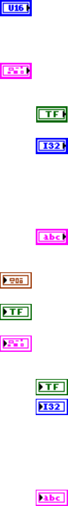
Chapter 5 Automotive Diagnostic Command Set API for LabVIEW
© National Instruments Corporation 5-79 Automotive Diagnostic Command Set User Manual
group of DTC specifies the group of Diagnostic Trouble Codes to be
cleared. The values are application specific. The following value has a
special meaning, and you can specify it through a ring control:
0xFFFFFF All DTCs
error in is a cluster that describes error conditions occurring before the VI
executes. If an error has already occurred, the VI returns the value of the
error in cluster to error out.
status is TRUE if an error occurred. This VI is not executed when
status is TRUE.
code is the error code number identifying an error. A value of 0
means success. A negative value means error: the VI did not
execute the intended operation. A positive value means warning:
the VI executed intended operation, but an informational warning
is returned. For a description of the code, wire the error cluster to
a LabVIEW error-handling VI, such as the Simple Error
Handler.
source identifies the VI where the error occurred.
Output
diag ref out is a copy of diag ref in. You can wire it to subsequent
diagnostic VIs.
success? indicates successful receipt of a positive response message for
this diagnostic service.
error out describes error conditions. If the error in cluster indicated an
error, the error out cluster contains the same information. Otherwise,
error out describes the error status of this VI.
status is TRUE if an error occurred.
code is the error code number identifying an error. A value of 0
means success. A negative value means error: the VI did not
execute the intended operation. A positive value means warning:
the VI executed intended operation, but an informational warning
is returned. For a description of the code, wire the error cluster to
a LabVIEW error-handling VI, such as the Simple Error
Handler.
source identifies the VI where the error occurred.
Chapter 5 Automotive Diagnostic Command Set API for LabVIEW
Automotive Diagnostic Command Set User Manual 5-80 ni.com
Description
This VI clears the diagnostic information on the ECU memory. If the group of DTC
parameter is present, the ECU is requested to clear all memory including the DTCs.
For further details about this service, refer to the ISO 15765-3 standard.
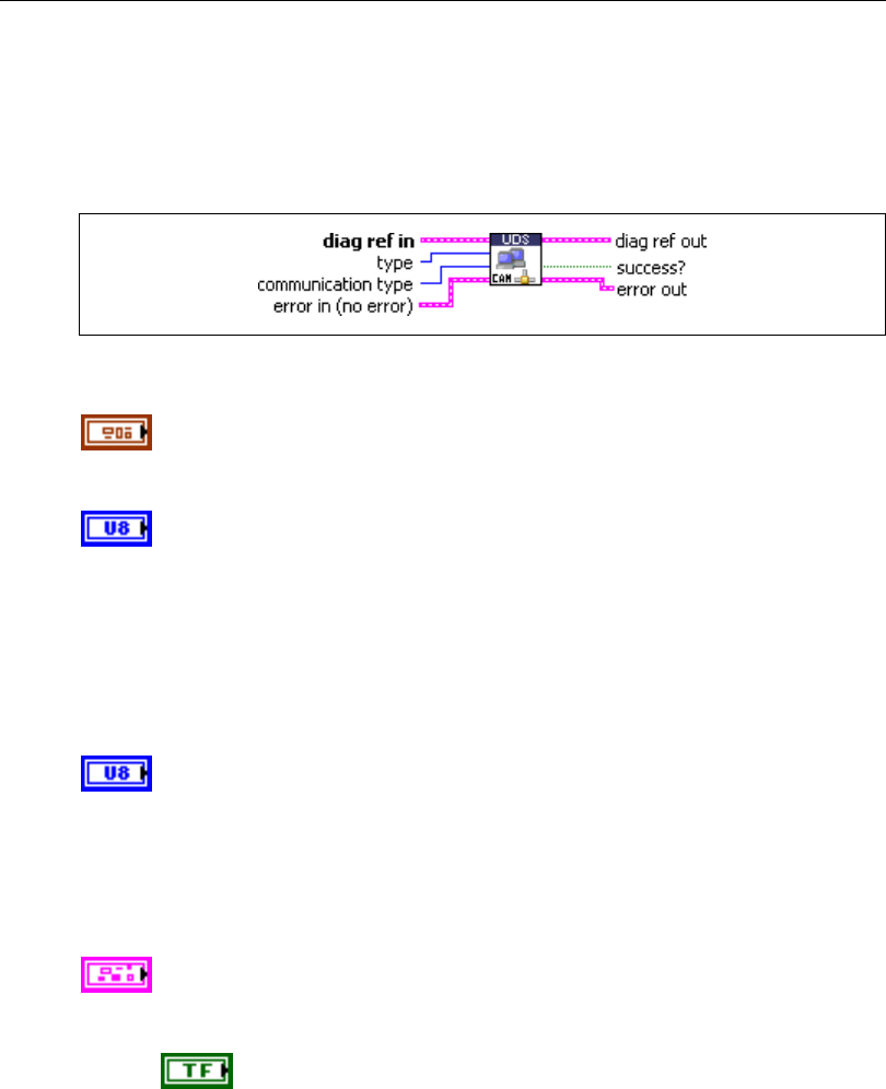
Chapter 5 Automotive Diagnostic Command Set API for LabVIEW
© National Instruments Corporation 5-81 Automotive Diagnostic Command Set User Manual
UDS CommunicationControl.vi
Purpose
Executes the UDS CommunicationControl service. Use this VI to switch transmission and/or
reception of the normal communication messages (usually CAN messages) on or off.
Format
Input
diag ref in specifies the diagnostic session handle, obtained from Open
Diagnostic.vi and wired through subsequent diagnostic VIs. Normally, it is
not necessary to manually manipulate the elements of this cluster.
type indicates whether transmission/reception is to be switched on/off.
The usual values are:
00: enableRxAndTx
01: enableRxAndDisableTx
02: disableRxAndEnableTx
03: disableRxAndTx
communication type is a bitfield indicating the application level to
change. The usual values are:
01: application
02: networkManagement
You can change more than one level at a time.
error in is a cluster that describes error conditions occurring before the VI
executes. If an error has already occurred, the VI returns the value of the
error in cluster to error out.
status is TRUE if an error occurred. This VI is not executed when
status is TRUE.
Chapter 5 Automotive Diagnostic Command Set API for LabVIEW
Automotive Diagnostic Command Set User Manual 5-82 ni.com
code is the error code number identifying an error. A value of 0
means success. A negative value means error: the VI did not
execute the intended operation. A positive value means warning:
the VI executed intended operation, but an informational warning
is returned. For a description of the code, wire the error cluster to
a LabVIEW error-handling VI, such as the Simple Error
Handler.
source identifies the VI where the error occurred.
Output
diag ref out is a copy of diag ref in. You can wire it to subsequent
diagnostic VIs.
success? indicates successful receipt of a positive response message for
this diagnostic service.
error out describes error conditions. If the error in cluster indicated an
error, the error out cluster contains the same information. Otherwise,
error out describes the error status of this VI.
status is TRUE if an error occurred.
code is the error code number identifying an error. A value of 0
means success. A negative value means error: the VI did not
execute the intended operation. A positive value means warning:
the VI executed intended operation, but an informational warning
is returned. For a description of the code, wire the error cluster to
a LabVIEW error-handling VI, such as the Simple Error
Handler.
source identifies the VI where the error occurred.
Description
This VI executes the UDS CommunicationControl service and switches transmission and/or
reception of the normal communication messages (usually CAN messages) on or off. The
type and communication type parameters are vehicle manufacturer specific (one OEM may
disable the transmission only, while another OEM may disable the transmission and the
reception based on vehicle manufacturer specific needs). The request is either transmitted
functionally addressed to all ECUs with a single request message, or transmitted physically
addressed to each ECU in a separate request message.
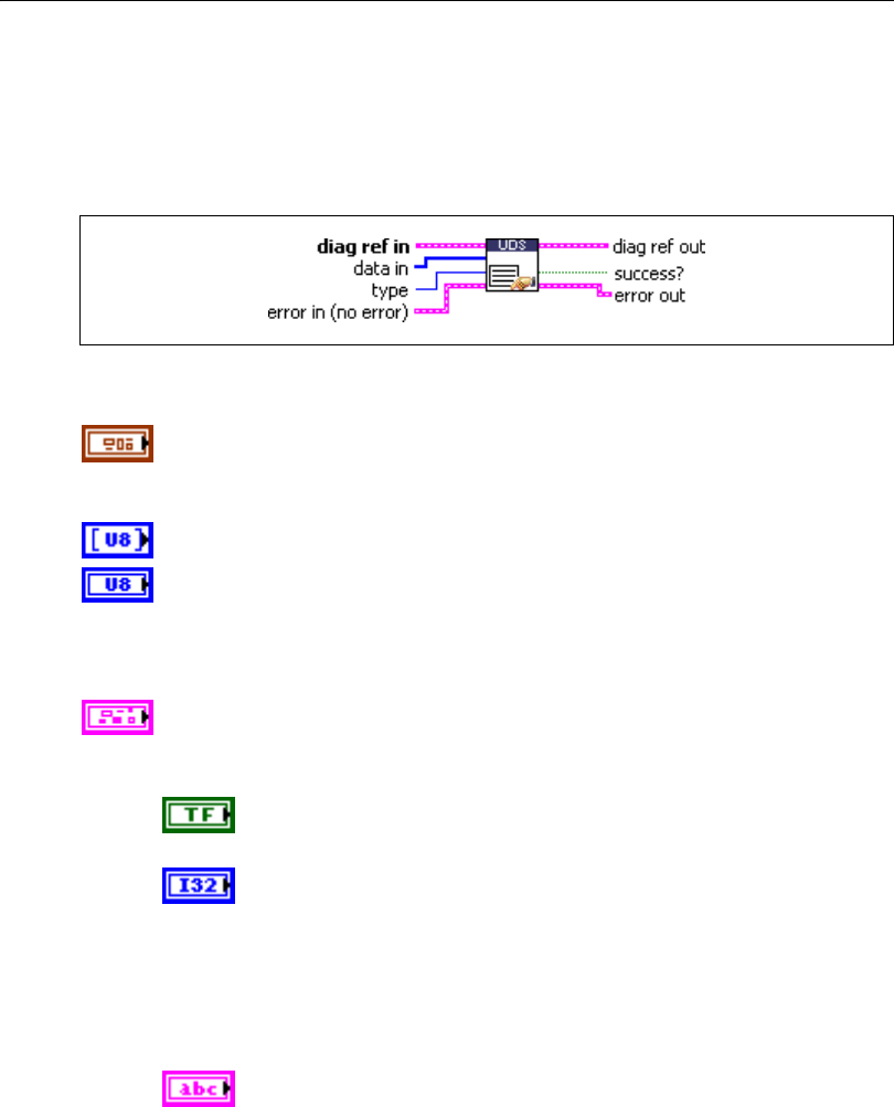
Chapter 5 Automotive Diagnostic Command Set API for LabVIEW
© National Instruments Corporation 5-83 Automotive Diagnostic Command Set User Manual
UDS ControlDTCSetting.vi
Purpose
Executes the UDS ControlDTCSetting service. Modifies Diagnostic Trouble Code (DTC)
generation behavior.
Format
Input
diag ref in specifies the diagnostic session handle, obtained from Open
Diagnostic.vi and wired through subsequent diagnostic VIs. Normally, it is
not necessary to manually manipulate the elements of this cluster.
data in specifies application-specific data that control DTC generation.
type specifies the control mode:
1: on
2: off
error in is a cluster that describes error conditions occurring before the VI
executes. If an error has already occurred, the VI returns the value of the
error in cluster to error out.
status is TRUE if an error occurred. This VI is not executed when
status is TRUE.
code is the error code number identifying an error. A value of 0
means success. A negative value means error: the VI did not
execute the intended operation. A positive value means warning:
the VI executed intended operation, but an informational warning
is returned. For a description of the code, wire the error cluster to
a LabVIEW error-handling VI, such as the Simple Error
Handler.
source identifies the VI where the error occurred.

Chapter 5 Automotive Diagnostic Command Set API for LabVIEW
Automotive Diagnostic Command Set User Manual 5-84 ni.com
Output
diag ref out is a copy of diag ref in. You can wire it to subsequent
diagnostic VIs.
success? indicates successful receipt of a positive response message for
this diagnostic service.
error out describes error conditions. If the error in cluster indicated an
error, the error out cluster contains the same information. Otherwise,
error out describes the error status of this VI.
status is TRUE if an error occurred.
code is the error code number identifying an error. A value of 0
means success. A negative value means error: the VI did not
execute the intended operation. A positive value means warning:
the VI executed intended operation, but an informational warning
is returned. For a description of the code, wire the error cluster to
a LabVIEW error-handling VI, such as the Simple Error
Handler.
source identifies the VI where the error occurred.
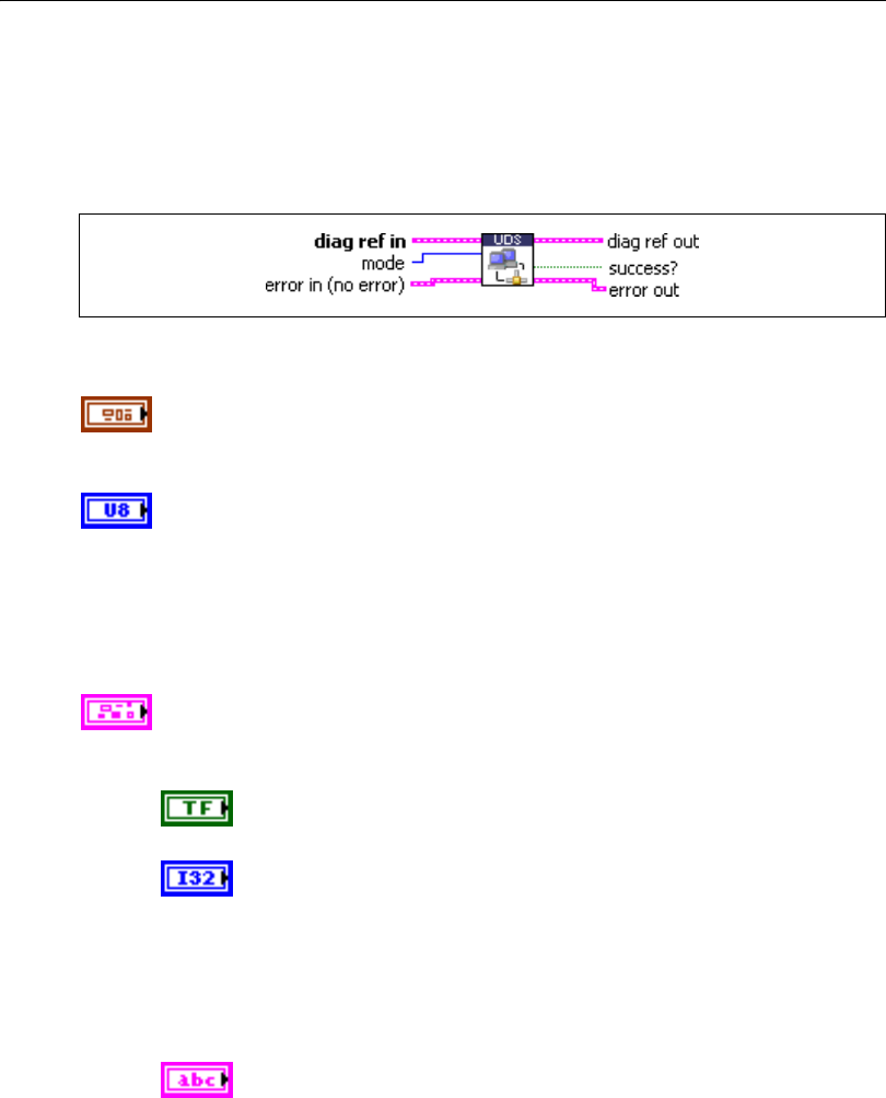
Chapter 5 Automotive Diagnostic Command Set API for LabVIEW
© National Instruments Corporation 5-85 Automotive Diagnostic Command Set User Manual
UDS DiagnosticSessionControl.vi
Purpose
Executes the UDS DiagnosticSessionControl service. Sets up the ECU in a specific diagnostic
mode.
Format
Input
diag ref in specifies the diagnostic session handle, obtained from Open
Diagnostic.vi and wired through subsequent diagnostic VIs. Normally, it is
not necessary to manually manipulate the elements of this cluster.
mode indicates the diagnostic mode into which the ECU is brought. The
values are application specific. The usual values are:
01: defaultSession
02: ECUProgrammingSession
03: ECUExtendedDiagnosticSession
error in is a cluster that describes error conditions occurring before the VI
executes. If an error has already occurred, the VI returns the value of the
error in cluster to error out.
status is TRUE if an error occurred. This VI is not executed when
status is TRUE.
code is the error code number identifying an error. A value of 0
means success. A negative value means error: the VI did not
execute the intended operation. A positive value means warning:
the VI executed intended operation, but an informational warning
is returned. For a description of the code, wire the error cluster to
a LabVIEW error-handling VI, such as the Simple Error
Handler.
source identifies the VI where the error occurred.

Chapter 5 Automotive Diagnostic Command Set API for LabVIEW
Automotive Diagnostic Command Set User Manual 5-86 ni.com
Output
diag ref out is a copy of diag ref in. You can wire it to subsequent
diagnostic VIs.
success? indicates successful receipt of a positive response message for
this diagnostic service.
error out describes error conditions. If the error in cluster indicated an
error, the error out cluster contains the same information. Otherwise,
error out describes the error status of this VI.
status is TRUE if an error occurred.
code is the error code number identifying an error. A value of 0
means success. A negative value means error: the VI did not
execute the intended operation. A positive value means warning:
the VI executed intended operation, but an informational warning
is returned. For a description of the code, wire the error cluster to
a LabVIEW error-handling VI, such as the Simple Error
Handler.
source identifies the VI where the error occurred.
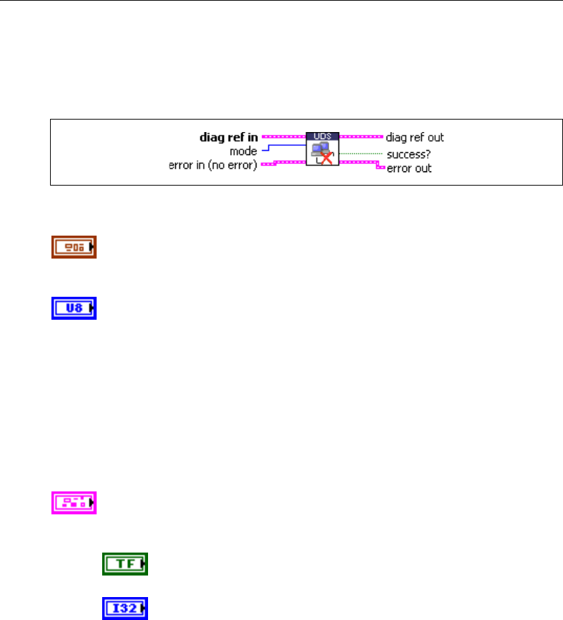
Chapter 5 Automotive Diagnostic Command Set API for LabVIEW
© National Instruments Corporation 5-87 Automotive Diagnostic Command Set User Manual
UDS ECUReset.vi
Purpose
Executes the UDS ECUReset service. Resets the ECU.
Format
Input
diag ref in specifies the diagnostic session handle, obtained from Open
Diagnostic.vi and wired through subsequent diagnostic VIs. Normally, it is
not necessary to manually manipulate the elements of this cluster.
mode indicates the reset mode:
Hex Description
01 hardReset
02 keyOffOnReset
03 softReset
04 enableRapidPowerShutDown
05 disableRapidPowerShutDown
error in is a cluster that describes error conditions occurring before the VI
executes. If an error has already occurred, the VI returns the value of the
error in cluster to error out.
status is TRUE if an error occurred. This VI is not executed when
status is TRUE.
code is the error code number identifying an error. A value of 0
means success. A negative value means error: the VI did not
execute the intended operation. A positive value means warning:
the VI executed intended operation, but an informational warning
is returned. For a description of the code, wire the error cluster to
a LabVIEW error-handling VI, such as the Simple Error
Handler.
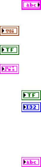
Chapter 5 Automotive Diagnostic Command Set API for LabVIEW
Automotive Diagnostic Command Set User Manual 5-88 ni.com
source identifies the VI where the error occurred.
Output
diag ref out is a copy of diag ref in. You can wire it to subsequent
diagnostic VIs.
success? indicates successful receipt of a positive response message for
this diagnostic service.
error out describes error conditions. If the error in cluster indicated an
error, the error out cluster contains the same information. Otherwise,
error out describes the error status of this VI.
status is TRUE if an error occurred.
code is the error code number identifying an error. A value of 0
means success. A negative value means error: the VI did not
execute the intended operation. A positive value means warning:
the VI executed intended operation, but an informational warning
is returned. For a description of the code, wire the error cluster to
a LabVIEW error-handling VI, such as the Simple Error
Handler.
source identifies the VI where the error occurred.
Description
This VI requests the ECU to perform an ECU reset effectively based on the mode parameter
value content. The vehicle manufacturer determines when the positive response message is
sent.
For further details about this service, refer to the ISO 15765-3 standard.
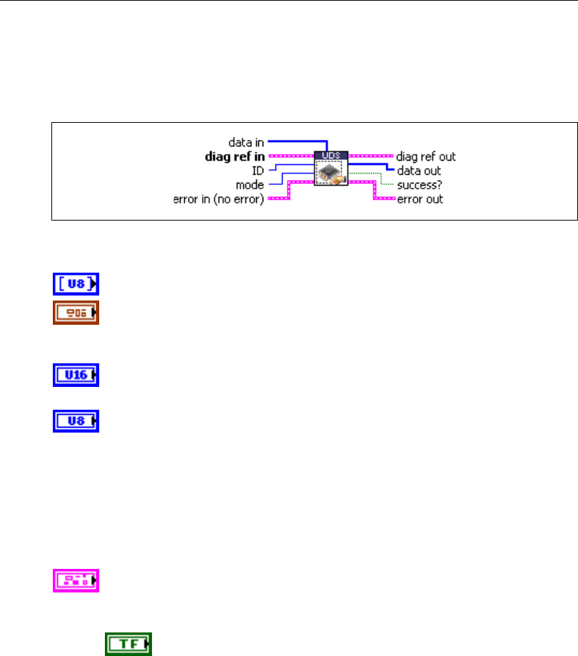
Chapter 5 Automotive Diagnostic Command Set API for LabVIEW
© National Instruments Corporation 5-89 Automotive Diagnostic Command Set User Manual
UDS InputOutputControlByIdentifier.vi
Purpose
Executes the UDS InputOutputControlByIdentifier service. Modifies ECU I/O port behavior.
Format
Input
data in defines application specific data for this service.
diag ref in specifies the diagnostic session handle, obtained from Open
Diagnostic.vi and wired through subsequent diagnostic VIs. Normally, it is
not necessary to manually manipulate the elements of this cluster.
ID defines the identifier of the I/O to be manipulated. The values are
application specific.
mode defines the I/O control type. The values are application specific. The
usual values are:
0: ReturnControlToECU
1: ResetToDefault
2: FreezeCurrentState
3: ShortTermAdjustment
error in is a cluster that describes error conditions occurring before the VI
executes. If an error has already occurred, the VI returns the value of the
error in cluster to error out.
status is TRUE if an error occurred. This VI is not executed when
status is TRUE.

Chapter 5 Automotive Diagnostic Command Set API for LabVIEW
Automotive Diagnostic Command Set User Manual 5-90 ni.com
code is the error code number identifying an error. A value of 0
means success. A negative value means error: the VI did not
execute the intended operation. A positive value means warning:
the VI executed intended operation, but an informational warning
is returned. For a description of the code, wire the error cluster to
a LabVIEW error-handling VI, such as the Simple Error
Handler.
source identifies the VI where the error occurred.
Output
diag ref out is a copy of diag ref in. You can wire it to subsequent
diagnostic VIs.
data out returns application-specific data for this service.
success? indicates successful receipt of a positive response message for
this diagnostic service.
error out describes error conditions. If the error in cluster indicated an
error, the error out cluster contains the same information. Otherwise,
error out describes the error status of this VI.
status is TRUE if an error occurred.
code is the error code number identifying an error. A value of 0
means success. A negative value means error: the VI did not
execute the intended operation. A positive value means warning:
the VI executed intended operation, but an informational warning
is returned. For a description of the code, wire the error cluster to
a LabVIEW error-handling VI, such as the Simple Error
Handler.
source identifies the VI where the error occurred.
Description
This VI substitutes a value for an input signal or internal ECU function. It also controls an
output (actuator) of an electronic system referenced by the local ID parameter.
For further details about this service, refer to the ISO 15765-3 standard.
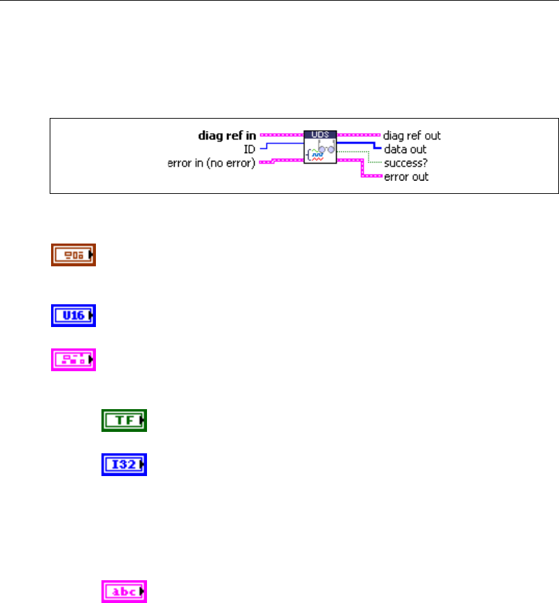
Chapter 5 Automotive Diagnostic Command Set API for LabVIEW
© National Instruments Corporation 5-91 Automotive Diagnostic Command Set User Manual
UDS ReadDataByIdentifier.vi
Purpose
Executes the UDS ReadDataByIdentifier service. Reads a data record from the ECU.
Format
Input
diag ref in specifies the diagnostic session handle, obtained from Open
Diagnostic.vi and wired through subsequent diagnostic VIs. Normally, it is
not necessary to manually manipulate the elements of this cluster.
ID defines the identifier of the data to be read. The values are application
specific.
error in is a cluster that describes error conditions occurring before the VI
executes. If an error has already occurred, the VI returns the value of the
error in cluster to error out.
status is TRUE if an error occurred. This VI is not executed when
status is TRUE.
code is the error code number identifying an error. A value of 0
means success. A negative value means error: the VI did not
execute the intended operation. A positive value means warning:
the VI executed intended operation, but an informational warning
is returned. For a description of the code, wire the error cluster to
a LabVIEW error-handling VI, such as the Simple Error
Handler.
source identifies the VI where the error occurred.

Chapter 5 Automotive Diagnostic Command Set API for LabVIEW
Automotive Diagnostic Command Set User Manual 5-92 ni.com
Output
diag ref out is a copy of diag ref in. You can wire it to subsequent
diagnostic VIs.
data out returns the data record from the ECU. If you know the record data
description, you can use Convert to Phys.vi to interpret this record.
success? indicates successful receipt of a positive response message for
this diagnostic service.
error out describes error conditions. If the error in cluster indicated an
error, the error out cluster contains the same information. Otherwise,
error out describes the error status of this VI.
status is TRUE if an error occurred.
code is the error code number identifying an error. A value of 0
means success. A negative value means error: the VI did not
execute the intended operation. A positive value means warning:
the VI executed intended operation, but an informational warning
is returned. For a description of the code, wire the error cluster to
a LabVIEW error-handling VI, such as the Simple Error
Handler.
source identifies the VI where the error occurred.
Description
This VI requests data record values from the ECU identified by the ID parameter.
For further details about this service, refer to the ISO 15765-3 standard.
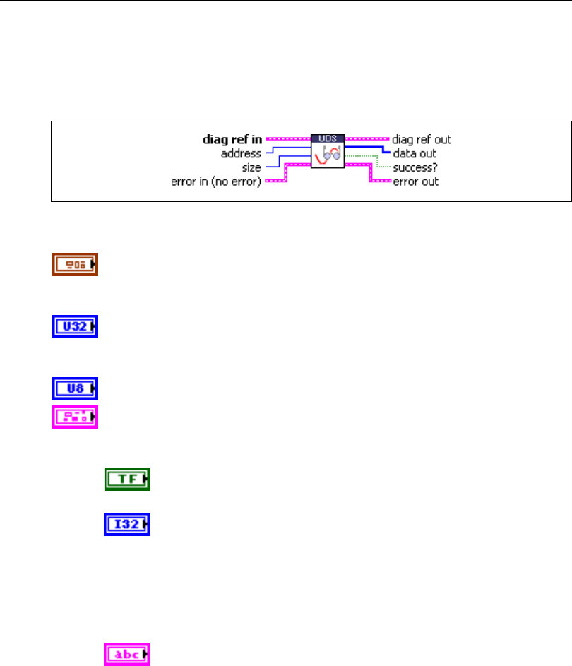
Chapter 5 Automotive Diagnostic Command Set API for LabVIEW
© National Instruments Corporation 5-93 Automotive Diagnostic Command Set User Manual
UDS ReadMemoryByAddress.vi
Purpose
Executes the UDS ReadMemoryByAddress service. Reads data from the ECU memory.
Format
Input
diag ref in specifies the diagnostic session handle, obtained from Open
Diagnostic.vi and wired through subsequent diagnostic VIs. Normally, it is
not necessary to manually manipulate the elements of this cluster.
address defines the memory address from which data are to be read. Only
three bytes are sent to the ECU, so the address must be in the range
0–FFFFFF (hex).
size defines the length of the memory block to be read.
error in is a cluster that describes error conditions occurring before the VI
executes. If an error has already occurred, the VI returns the value of the
error in cluster to error out.
status is TRUE if an error occurred. This VI is not executed when
status is TRUE.
code is the error code number identifying an error. A value of 0
means success. A negative value means error: the VI did not
execute the intended operation. A positive value means warning:
the VI executed intended operation, but an informational warning
is returned. For a description of the code, wire the error cluster to
a LabVIEW error-handling VI, such as the Simple Error
Handler.
source identifies the VI where the error occurred.

Chapter 5 Automotive Diagnostic Command Set API for LabVIEW
Automotive Diagnostic Command Set User Manual 5-94 ni.com
Output
diag ref out is a copy of diag ref in. You can wire it to subsequent
diagnostic VIs.
data out returns the ECU memory data.
success? indicates successful receipt of a positive response message for
this diagnostic service.
error out describes error conditions. If the error in cluster indicated an
error, the error out cluster contains the same information. Otherwise,
error out describes the error status of this VI.
status is TRUE if an error occurred.
code is the error code number identifying an error. A value of 0
means success. A negative value means error: the VI did not
execute the intended operation. A positive value means warning:
the VI executed intended operation, but an informational warning
is returned. For a description of the code, wire the error cluster to
a LabVIEW error-handling VI, such as the Simple Error
Handler.
source identifies the VI where the error occurred.
Description
This VI requests ECU memory data identified by the address and size parameters. The data
out format and definition are vehicle manufacturer specific. data out includes analog input
and output signals, digital input and output signals, internal data, and system status
information if the ECU supports them.
For further details about this service, refer to the ISO 15765-3 standard.
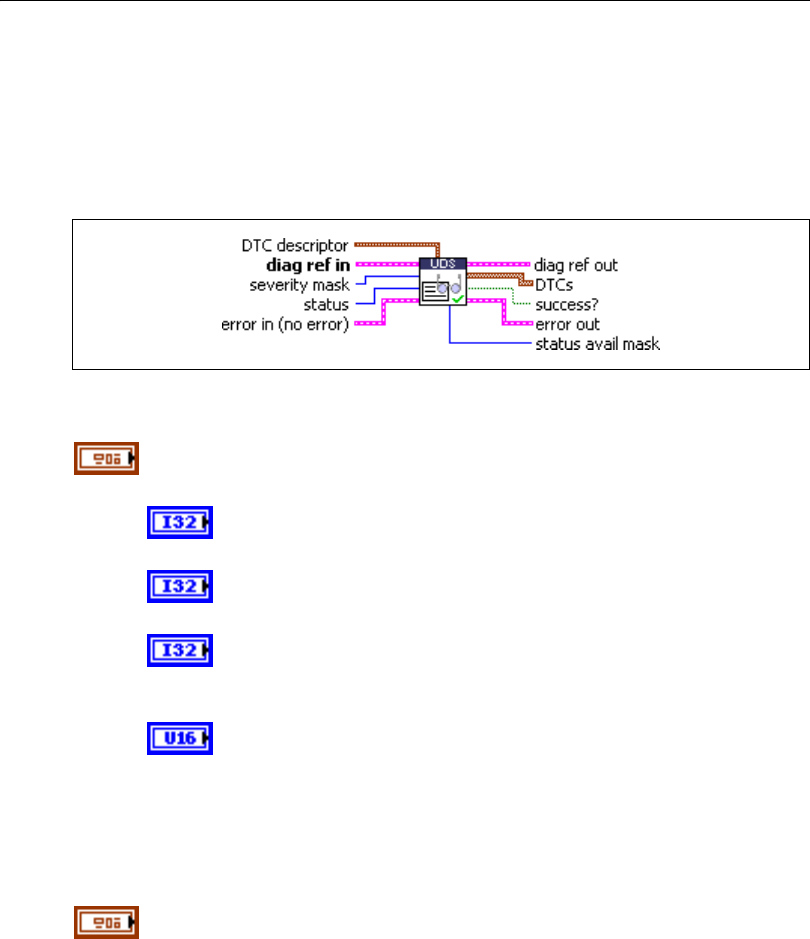
Chapter 5 Automotive Diagnostic Command Set API for LabVIEW
© National Instruments Corporation 5-95 Automotive Diagnostic Command Set User Manual
UDS ReportDTCBySeverityMaskRecord.vi
Purpose
Executes the ReportDTCBySeverityMaskRecord subfunction of the UDS
ReadDiagnosticTroubleCodeInformation service. Reads selected Diagnostic Trouble Codes
(DTCs).
Format
Input
DTC descriptor is a cluster that describes the DTC records the ECU
delivers:
DTC Byte Length indicates the number of bytes the ECU sends
for each DTC. The default is 3 for UDS.
Status Byte Length indicates the number of bytes the ECU sends
for each DTC’s status. The default is 1.
Add Data Byte Length indicates the number of bytes the ECU
sends for each DTC’s additional data. For this subfunction, the
default is 2.
Byte Order indicates the byte ordering for multibyte items:
0: MSB_FIRST (Motorola) (default)
1: LSB_FIRST (Intel)
This VI interprets the response byte stream according to this description
and returns the resulting DTC records in the DTCs cluster array.
diag ref in specifies the diagnostic session handle, obtained from Open
Diagnostic.vi and wired through subsequent diagnostic VIs. Normally, it is
not necessary to manually manipulate the elements of this cluster.
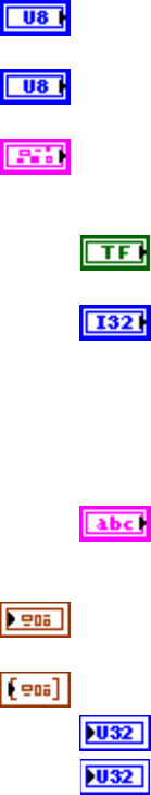
Chapter 5 Automotive Diagnostic Command Set API for LabVIEW
Automotive Diagnostic Command Set User Manual 5-96 ni.com
severity mask defines the status of DTCs to be read. The values are
application specific.
status defines the status of DTCs to be read. The values are application
specific.
error in is a cluster that describes error conditions occurring before the VI
executes. If an error has already occurred, the VI returns the value of the
error in cluster to error out.
status is TRUE if an error occurred. This VI is not executed when
status is TRUE.
code is the error code number identifying an error. A value of 0
means success. A negative value means error: the VI did not
execute the intended operation. A positive value means warning:
the VI executed intended operation, but an informational warning
is returned. For a description of the code, wire the error cluster to
a LabVIEW error-handling VI, such as the Simple Error
Handler.
source identifies the VI where the error occurred.
Output
diag ref out is a copy of diag ref in. You can wire it to subsequent
diagnostic VIs.
DTCs returns the resulting DTCs as an array of clusters:
DTC is the resulting Diagnostic Trouble Code.
Status is the DTC status. Usually, this is a bit field with following
meaning:
Bit Meaning
0 testFailed
1 testFailedThisMonitoringCycle
2 pendingDTC
3 confirmedDTC
4 testNotCompletedSinceLastClear
5 testFailedSinceLastClear
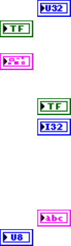
Chapter 5 Automotive Diagnostic Command Set API for LabVIEW
© National Instruments Corporation 5-97 Automotive Diagnostic Command Set User Manual
6 testNotCompletedThisMonitoringCycle
7 warningIndicatorRequested
Add Data contains optional additional data for this DTC.
success? indicates successful receipt of a positive response message for
this diagnostic service.
error out describes error conditions. If the error in cluster indicated an
error, the error out cluster contains the same information. Otherwise,
error out describes the error status of this VI.
status is TRUE if an error occurred.
code is the error code number identifying an error. A value of 0
means success. A negative value means error: the VI did not
execute the intended operation. A positive value means warning:
the VI executed intended operation, but an informational warning
is returned. For a description of the code, wire the error cluster to
a LabVIEW error-handling VI, such as the Simple Error
Handler.
source identifies the VI where the error occurred.
status avail mask is an application-specific value returned for all DTCs.
Description
This VI executes the ReportDTCBySeverityMaskRecord subfunction of the UDS
ReadDiagnosticTroubleCodeInformation service and reads the selected DTCs.
For further details about this service, refer to the ISO 15765-3 standard.
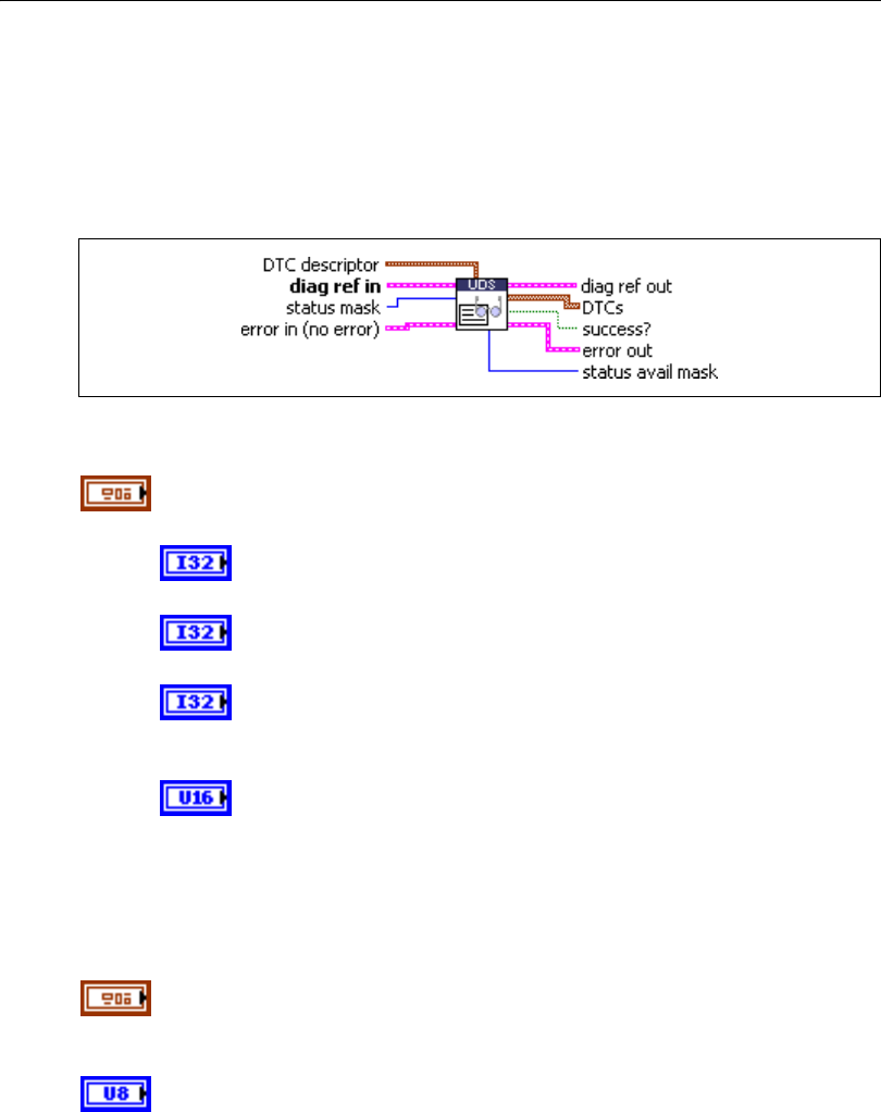
Chapter 5 Automotive Diagnostic Command Set API for LabVIEW
Automotive Diagnostic Command Set User Manual 5-98 ni.com
UDS ReportDTCByStatusMask.vi
Purpose
Executes the ReportDTCByStatusMask subfunction of the UDS
ReadDiagnosticTroubleCodeInformation service. Reads selected Diagnostic Trouble Codes
(DTCs).
Format
Input
DTC descriptor is a cluster that describes the DTC records the ECU
delivers:
DTC Byte Length indicates the number of bytes the ECU sends
for each DTC. The default is 3 for UDS.
Status Byte Length indicates the number of bytes the ECU sends
for each DTC’s status. The default is 1.
Add Data Byte Length indicates the number of bytes the ECU
sends for each DTC’s additional data. Usually, there is no
additional data, so the default is 0.
Byte Order indicates the byte ordering for multibyte items:
0: MSB_FIRST (Motorola) (default)
1: LSB_FIRST (Intel)
This VI interprets the response byte stream according to this description
and returns the resulting DTC records in the DTCs cluster array.
diag ref in specifies the diagnostic session handle, obtained from Open
Diagnostic.vi and wired through subsequent diagnostic VIs. Normally, it is
not necessary to manually manipulate the elements of this cluster.
status mask defines the status of DTCs to be read. The values are
application specific.
Chapter 5 Automotive Diagnostic Command Set API for LabVIEW
© National Instruments Corporation 5-99 Automotive Diagnostic Command Set User Manual
error in is a cluster that describes error conditions occurring before the VI
executes. If an error has already occurred, the VI returns the value of the
error in cluster to error out.
status is TRUE if an error occurred. This VI is not executed when
status is TRUE.
code is the error code number identifying an error. A value of 0
means success. A negative value means error: the VI did not
execute the intended operation. A positive value means warning:
the VI executed intended operation, but an informational warning
is returned. For a description of the code, wire the error cluster to
a LabVIEW error-handling VI, such as the Simple Error
Handler.
source identifies the VI where the error occurred.
Output
diag ref out is a copy of diag ref in. You can wire it to subsequent
diagnostic VIs.
DTCs returns the resulting DTCs as an array of clusters:
DTC is the resulting Diagnostic Trouble Code.
Status is the DTC status. Usually, this is a bit field with following
meaning:
Bit Meaning
0 testFailed
1 testFailedThisMonitoringCycle
2 pendingDTC
3 confirmedDTC
4 testNotCompletedSinceLastClear
5 testFailedSinceLastClear
6 testNotCompletedThisMonitoringCycle
7 warningIndicatorRequested
Add Data contains optional additional data for this DTC. Usually,
this does not contain valid information (refer to DTC descriptor).
Chapter 5 Automotive Diagnostic Command Set API for LabVIEW
Automotive Diagnostic Command Set User Manual 5-100 ni.com
success? indicates successful receipt of a positive response message for
this diagnostic service.
error out describes error conditions. If the error in cluster indicated an
error, the error out cluster contains the same information. Otherwise,
error out describes the error status of this VI.
status is TRUE if an error occurred.
code is the error code number identifying an error. A value of 0
means success. A negative value means error: the VI did not
execute the intended operation. A positive value means warning:
the VI executed intended operation, but an informational warning
is returned. For a description of the code, wire the error cluster to
a LabVIEW error-handling VI, such as the Simple Error
Handler.
source identifies the VI where the error occurred.
status avail mask is an application-specific value returned for all DTCs.
Description
This VI executes the ReportDTCByStatusMask subfunction of the UDS
ReadDiagnosticTroubleCodeInformation service and reads the selected DTCs from the ECU.
For further details about this service, refer to the ISO 15765-3 standard.
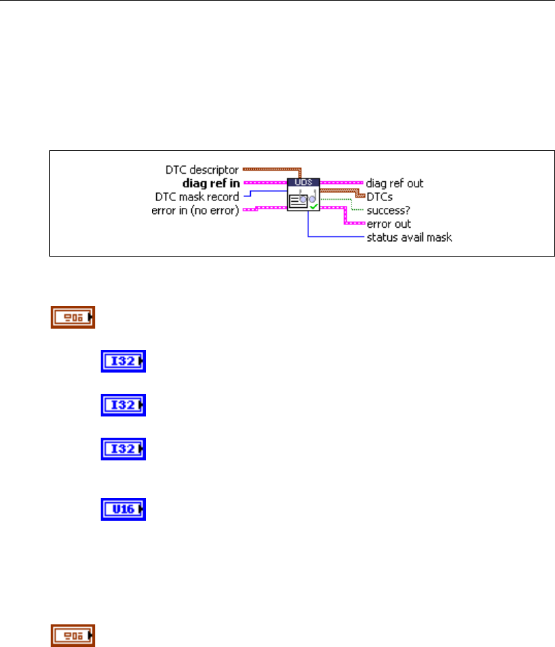
Chapter 5 Automotive Diagnostic Command Set API for LabVIEW
© National Instruments Corporation 5-101 Automotive Diagnostic Command Set User Manual
UDS ReportSeverityInformationOfDTC.vi
Purpose
Executes the ReportSeverityInformationOfDTC subfunction of the UDS
ReadDiagnosticTroubleCodeInformation service. Reads selected Diagnostic Trouble Codes
(DTCs).
Format
Input
DTC descriptor is a cluster that describes the DTC records the ECU
delivers:
DTC Byte Length indicates the number of bytes the ECU sends
for each DTC. The default is 3 for UDS.
Status Byte Length indicates the number of bytes the ECU sends
for each DTC’s status. The default is 1.
Add Data Byte Length indicates the number of bytes the ECU
sends for each DTC’s additional data. For this subfunction, the
default is 2.
Byte Order indicates the byte ordering for multibyte items:
0: MSB_FIRST (Motorola) (default)
1: LSB_FIRST (Intel)
This VI interprets the response byte stream according to this description
and returns the resulting DTC records in the DTCs cluster array.
diag ref in specifies the diagnostic session handle, obtained from Open
Diagnostic.vi and wired through subsequent diagnostic VIs. Normally, it is
not necessary to manually manipulate the elements of this cluster.
Chapter 5 Automotive Diagnostic Command Set API for LabVIEW
Automotive Diagnostic Command Set User Manual 5-102 ni.com
DTC mask record defines the status of DTCs to be read. The values are
application specific.
error in is a cluster that describes error conditions occurring before the VI
executes. If an error has already occurred, the VI returns the value of the
error in cluster to error out.
status is TRUE if an error occurred. This VI is not executed when
status is TRUE.
code is the error code number identifying an error. A value of 0
means success. A negative value means error: the VI did not
execute the intended operation. A positive value means warning:
the VI executed intended operation, but an informational warning
is returned. For a description of the code, wire the error cluster to
a LabVIEW error-handling VI, such as the Simple Error
Handler.
source identifies the VI where the error occurred.
Output
diag ref out is a copy of diag ref in. You can wire it to subsequent
diagnostic VIs.
DTCs returns the resulting DTCs as an array of clusters:
DTC is the resulting Diagnostic Trouble Code.
Status is the DTC status. Usually, this is a bit field with following
meaning:
Bit Meaning
0 testFailed
1 testFailedThisMonitoringCycle
2 pendingDTC
3 confirmedDTC
4 testNotCompletedSinceLastClear
5 testFailedSinceLastClear
6 testNotCompletedThisMonitoringCycle
7 warningIndicatorRequested
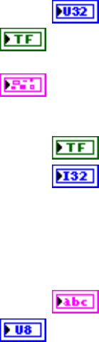
Chapter 5 Automotive Diagnostic Command Set API for LabVIEW
© National Instruments Corporation 5-103 Automotive Diagnostic Command Set User Manual
Add Data contains optional additional data for this DTC.
success? indicates successful receipt of a positive response message for
this diagnostic service.
error out describes error conditions. If the error in cluster indicated an
error, the error out cluster contains the same information. Otherwise,
error out describes the error status of this VI.
status is TRUE if an error occurred.
code is the error code number identifying an error. A value of 0
means success. A negative value means error: the VI did not
execute the intended operation. A positive value means warning:
the VI executed intended operation, but an informational warning
is returned. For a description of the code, wire the error cluster to
a LabVIEW error-handling VI, such as the Simple Error
Handler.
source identifies the VI where the error occurred.
status avail mask is an application-specific value returned for all DTCs.
Description
This VI executes the ReportSeverityInformationOfDTC subfunction of the UDS
ReadDiagnosticTroubleCodeInformation service and reads the selected DTCs from the ECU
memory.
For further details about this service, refer to the ISO 15765-3 standard.
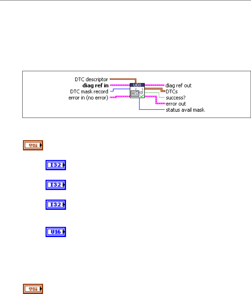
Chapter 5 Automotive Diagnostic Command Set API for LabVIEW
Automotive Diagnostic Command Set User Manual 5-104 ni.com
UDS ReportSupportedDTCs.vi
Purpose
Executes the ReportSupportedDTCs subfunction of the UDS
ReadDiagnosticTroubleCodeInformation service. Reads all supported
Diagnostic Trouble Codes (DTCs).
Format
Input
DTC descriptor is a cluster that describes the DTC records the ECU
delivers:
DTC Byte Length indicates the number of bytes the ECU sends
for each DTC. The default is 3 for UDS.
Status Byte Length indicates the number of bytes the ECU sends
for each DTC’s status. The default is 1.
Add Data Byte Length indicates the number of bytes the ECU
sends for each DTC’s additional data. Usually, there is no
additional data, so the default is 0.
Byte Order indicates the byte ordering for multibyte items:
0: MSB_FIRST (Motorola) (default)
1: LSB_FIRST (Intel)
This VI interprets the response byte stream according to this description
and returns the resulting DTC records in the DTCs cluster array.
diag ref in specifies the diagnostic session handle, obtained from Open
Diagnostic.vi and wired through subsequent diagnostic VIs. Normally, it is
not necessary to manually manipulate the elements of this cluster.

Chapter 5 Automotive Diagnostic Command Set API for LabVIEW
© National Instruments Corporation 5-105 Automotive Diagnostic Command Set User Manual
error in is a cluster that describes error conditions occurring before the VI
executes. If an error has already occurred, the VI returns the value of the
error in cluster to error out.
status is TRUE if an error occurred. This VI is not executed when
status is TRUE.
code is the error code number identifying an error. A value of 0
means success. A negative value means error: the VI did not
execute the intended operation. A positive value means warning:
the VI executed intended operation, but an informational warning
is returned. For a description of the code, wire the error cluster to
a LabVIEW error-handling VI, such as the Simple Error
Handler.
source identifies the VI where the error occurred.
Output
diag ref out is a copy of diag ref in. You can wire it to subsequent
diagnostic VIs.
DTCs returns the resulting DTCs as an array of clusters:
DTC is the resulting Diagnostic Trouble Code.
Status is the DTC status. Usually, this is a bit field with following
meaning:
Bit Meaning
0 testFailed
1 testFailedThisMonitoringCycle
2 pendingDTC
3 confirmedDTC
4 testNotCompletedSinceLastClear
5 testFailedSinceLastClear
6 testNotCompletedThisMonitoringCycle
7 warningIndicatorRequested
Add Data contains optional additional data for this DTC. Usually,
this does not contain valid information (refer to DTC descriptor).
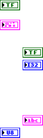
Chapter 5 Automotive Diagnostic Command Set API for LabVIEW
Automotive Diagnostic Command Set User Manual 5-106 ni.com
success? indicates successful receipt of a positive response message for
this diagnostic service.
error out describes error conditions. If the error in cluster indicated an
error, the error out cluster contains the same information. Otherwise,
error out describes the error status of this VI.
status is TRUE if an error occurred.
code is the error code number identifying an error. A value of 0
means success. A negative value means error: the VI did not
execute the intended operation. A positive value means warning:
the VI executed intended operation, but an informational warning
is returned. For a description of the code, wire the error cluster to
a LabVIEW error-handling VI, such as the Simple Error
Handler.
source identifies the VI where the error occurred.
status avail mask is an application-specific value returned for all DTCs.
Description
This VI executes the ReportSupportedDTCs subfunction of the UDS
ReadDiagnosticTroubleCodeInformation service and reads all supported DTCs from the
ECU memory.
For further details about this service, refer to the ISO 15765-3 standard.
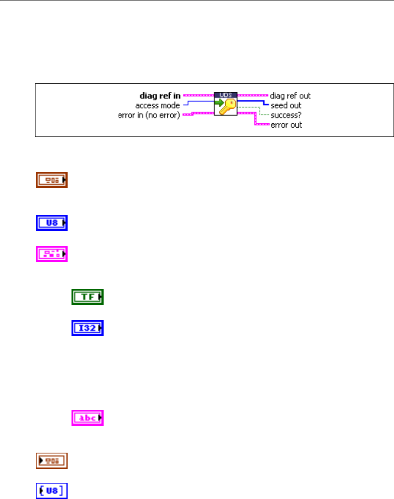
Chapter 5 Automotive Diagnostic Command Set API for LabVIEW
© National Instruments Corporation 5-107 Automotive Diagnostic Command Set User Manual
UDS RequestSeed.vi
Purpose
Executes the UDS SecurityAccess service to retrieve a seed from the ECU.
Format
Input
diag ref in specifies the diagnostic session handle, obtained from Open
Diagnostic.vi and wired through subsequent diagnostic VIs. Normally, it is
not necessary to manually manipulate the elements of this cluster.
access mode indicates the security level to be granted. The values are
application specific. This is an odd number, usually 1.
error in is a cluster that describes error conditions occurring before the VI
executes. If an error has already occurred, the VI returns the value of the
error in cluster to error out.
status is TRUE if an error occurred. This VI is not executed when
status is TRUE.
code is the error code number identifying an error. A value of 0
means success. A negative value means error: the VI did not
execute the intended operation. A positive value means warning:
the VI executed intended operation, but an informational warning
is returned. For a description of the code, wire the error cluster to
a LabVIEW error-handling VI, such as the Simple Error
Handler.
source identifies the VI where the error occurred.
Output
diag ref out is a copy of diag ref in. You can wire it to subsequent
diagnostic VIs.
seed out returns the seed from the ECU.

Chapter 5 Automotive Diagnostic Command Set API for LabVIEW
Automotive Diagnostic Command Set User Manual 5-108 ni.com
success? indicates successful receipt of a positive response message for
this diagnostic service.
error out describes error conditions. If the error in cluster indicated an
error, the error out cluster contains the same information. Otherwise,
error out describes the error status of this VI.
status is TRUE if an error occurred.
code is the error code number identifying an error. A value of 0
means success. A negative value means error: the VI did not
execute the intended operation. A positive value means warning:
the VI executed intended operation, but an informational warning
is returned. For a description of the code, wire the error cluster to
a LabVIEW error-handling VI, such as the Simple Error
Handler.
source identifies the VI where the error occurred.
Description
The usual procedure for getting a security access to the ECU is as follows:
1. Request a seed from the ECU using UDS RequestSeed.vi with access mode = n.
2. From the seed, compute a key for the ECU on the host.
3. Send the key to the ECU using UDS SendKey.vi with access mode = n + 1.
4. The security access is granted if the ECU validates the key sent. Otherwise, an error is
returned.
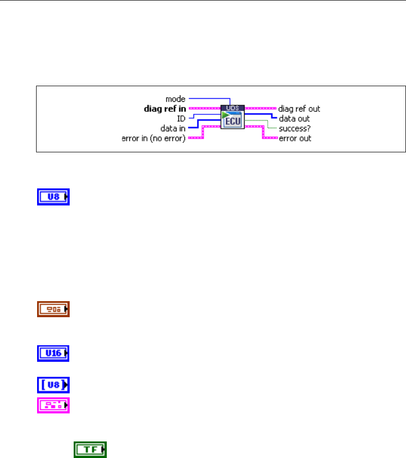
Chapter 5 Automotive Diagnostic Command Set API for LabVIEW
© National Instruments Corporation 5-109 Automotive Diagnostic Command Set User Manual
UDS RoutineControl.vi
Purpose
Executes the UDS RoutineControl service. Executes a routine on the ECU.
Format
Input
mode defines the service operation mode. You can obtain the values from
a ring control:
1: Start Routine
2: Stop Routine
3: Request Routine Results
Other values are application specific.
diag ref in specifies the diagnostic session handle, obtained from Open
Diagnostic.vi and wired through subsequent diagnostic VIs. Normally, it is
not necessary to manually manipulate the elements of this cluster.
ID defines the identifier of the routine to be started. The values are
application specific.
data in defines application-specific input parameters for the routine.
error in is a cluster that describes error conditions occurring before the VI
executes. If an error has already occurred, the VI returns the value of the
error in cluster to error out.
status is TRUE if an error occurred. This VI is not executed when
status is TRUE.

Chapter 5 Automotive Diagnostic Command Set API for LabVIEW
Automotive Diagnostic Command Set User Manual 5-110 ni.com
code is the error code number identifying an error. A value of 0
means success. A negative value means error: the VI did not
execute the intended operation. A positive value means warning:
the VI executed intended operation, but an informational warning
is returned. For a description of the code, wire the error cluster to
a LabVIEW error-handling VI, such as the Simple Error
Handler.
source identifies the VI where the error occurred.
Output
diag ref out is a copy of diag ref in. You can wire it to subsequent
diagnostic VIs.
data out returns application-specific output parameters from the routine.
success? indicates successful receipt of a positive response message for
this diagnostic service.
error out describes error conditions. If the error in cluster indicated an
error, the error out cluster contains the same information. Otherwise,
error out describes the error status of this VI.
status is TRUE if an error occurred.
code is the error code number identifying an error. A value of 0
means success. A negative value means error: the VI did not
execute the intended operation. A positive value means warning:
the VI executed intended operation, but an informational warning
is returned. For a description of the code, wire the error cluster to
a LabVIEW error-handling VI, such as the Simple Error
Handler.
source identifies the VI where the error occurred.
Description
This VI executes the UDS RoutineControl service and launches an ECU routine, stops an
ECU routine, or requests ECU routine results from the ECU.
For further details about this service, refer to the ISO 15765-3 standard.

Chapter 5 Automotive Diagnostic Command Set API for LabVIEW
© National Instruments Corporation 5-111 Automotive Diagnostic Command Set User Manual
UDS SendKey.vi
Purpose
Executes the SecurityAccess service to send a key to the ECU.
Format
Input
diag ref in specifies the diagnostic session handle, obtained from Open
Diagnostic.vi and wired through subsequent diagnostic VIs. Normally, it is
not necessary to manually manipulate the elements of this cluster.
access mode indicates the security level to be granted. The values are
application specific. This is an even number, usually 2.
key in defines the key data to be sent to the ECU.
error in is a cluster that describes error conditions occurring before the VI
executes. If an error has already occurred, the VI returns the value of the
error in cluster to error out.
status is TRUE if an error occurred. This VI is not executed when
status is TRUE.
code is the error code number identifying an error. A value of 0
means success. A negative value means error: the VI did not
execute the intended operation. A positive value means warning:
the VI executed intended operation, but an informational warning
is returned. For a description of the code, wire the error cluster to
a LabVIEW error-handling VI, such as the Simple Error
Handler.
source identifies the VI where the error occurred.

Chapter 5 Automotive Diagnostic Command Set API for LabVIEW
Automotive Diagnostic Command Set User Manual 5-112 ni.com
Output
diag ref out is a copy of diag ref in. You can wire it to subsequent
diagnostic VIs.
success? indicates successful receipt of a positive response message for
this diagnostic service.
error out describes error conditions. If the error in cluster indicated an
error, the error out cluster contains the same information. Otherwise,
error out describes the error status of this VI.
status is TRUE if an error occurred.
code is the error code number identifying an error. A value of 0
means success. A negative value means error: the VI did not
execute the intended operation. A positive value means warning:
the VI executed intended operation, but an informational warning
is returned. For a description of the code, wire the error cluster to
a LabVIEW error-handling VI, such as the Simple Error
Handler.
source identifies the VI where the error occurred.
Description
The usual procedure for getting a security access to the ECU is as follows:
1. Request a seed from the ECU using UDS RequestSeed.vi with access mode = n.
2. From the seed, compute a key for the ECU on the host.
3. Send the key to the ECU using UDS SendKey.vi with access mode = n + 1.
4. The security access is granted if the ECU validates the key sent. Otherwise, an error is
returned.
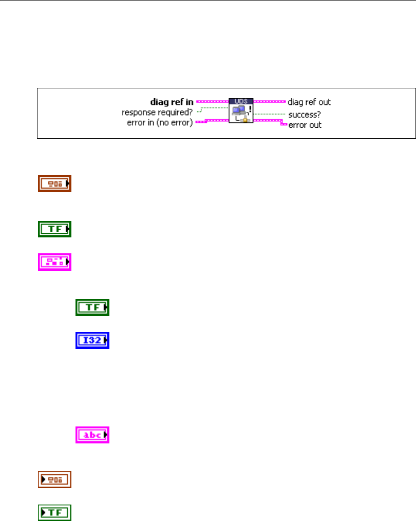
Chapter 5 Automotive Diagnostic Command Set API for LabVIEW
© National Instruments Corporation 5-113 Automotive Diagnostic Command Set User Manual
UDS TesterPresent.vi
Purpose
Executes the UDS TesterPresent service. Keeps the ECU in diagnostic mode.
Format
Input
diag ref in specifies the diagnostic session handle, obtained from Open
Diagnostic.vi and wired through subsequent diagnostic VIs. Normally, it is
not necessary to manually manipulate the elements of this cluster.
response required? indicates whether the ECU answers this service
(TRUE, default) or not (FALSE). In the latter case, success? is TRUE.
error in is a cluster that describes error conditions occurring before the VI
executes. If an error has already occurred, the VI returns the value of the
error in cluster to error out.
status is TRUE if an error occurred. This VI is not executed when
status is TRUE.
code is the error code number identifying an error. A value of 0
means success. A negative value means error: the VI did not
execute the intended operation. A positive value means warning:
the VI executed intended operation, but an informational warning
is returned. For a description of the code, wire the error cluster to
a LabVIEW error-handling VI, such as the Simple Error
Handler.
source identifies the VI where the error occurred.
Output
diag ref out is a copy of diag ref in. You can wire it to subsequent
diagnostic VIs.
success? indicates successful receipt of a positive response message for
this diagnostic service.

Chapter 5 Automotive Diagnostic Command Set API for LabVIEW
Automotive Diagnostic Command Set User Manual 5-114 ni.com
error out describes error conditions. If the error in cluster indicated an
error, the error out cluster contains the same information. Otherwise,
error out describes the error status of this VI.
status is TRUE if an error occurred.
code is the error code number identifying an error. A value of 0
means success. A negative value means error: the VI did not
execute the intended operation. A positive value means warning:
the VI executed intended operation, but an informational warning
is returned. For a description of the code, wire the error cluster to
a LabVIEW error-handling VI, such as the Simple Error
Handler.
source identifies the VI where the error occurred.
Description
To ensure proper ECU operation, you may need to keep the ECU informed that a diagnostic
session is still in progress. If you do not send this information (for example, because the
communication is broken), the ECU returns to normal mode from diagnostic mode after a
while.
The TesterPresent service is this “keep alive” signal. It does not affect any other ECU
operation.
Keep calling UDS TesterPresent.vi within the ECU timeout period if no other service is
executed.
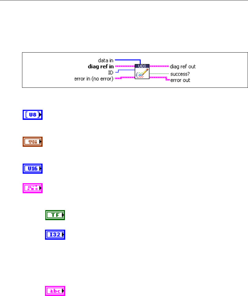
Chapter 5 Automotive Diagnostic Command Set API for LabVIEW
© National Instruments Corporation 5-115 Automotive Diagnostic Command Set User Manual
UDS WriteDataByIdentifier.vi
Purpose
Executes the UDS WriteDataByIdentifier service. Writes a data record to the ECU.
Format
Input
data in defines the data record to be written to the ECU. If you know the
the data description record, you can use Convert from Phys.vi to generate
this record.
diag ref in specifies the diagnostic session handle, obtained from Open
Diagnostic.vi and wired through subsequent diagnostic VIs. Normally, it is
not necessary to manually manipulate the elements of this cluster.
ID defines the identifier of the data to be written. The values are application
specific.
error in is a cluster that describes error conditions occurring before the VI
executes. If an error has already occurred, the VI returns the value of the
error in cluster to error out.
status is TRUE if an error occurred. This VI is not executed when
status is TRUE.
code is the error code number identifying an error. A value of 0
means success. A negative value means error: the VI did not
execute the intended operation. A positive value means warning:
the VI executed intended operation, but an informational warning
is returned. For a description of the code, wire the error cluster to
a LabVIEW error-handling VI, such as the Simple Error
Handler.
source identifies the VI where the error occurred.

Chapter 5 Automotive Diagnostic Command Set API for LabVIEW
Automotive Diagnostic Command Set User Manual 5-116 ni.com
Output
diag ref out is a copy of diag ref in. You can wire it to subsequent
diagnostic VIs.
success? indicates successful receipt of a positive response message for
this diagnostic service.
error out describes error conditions. If the error in cluster indicated an
error, the error out cluster contains the same information. Otherwise,
error out describes the error status of this VI.
status is TRUE if an error occurred.
code is the error code number identifying an error. A value of 0
means success. A negative value means error: the VI did not
execute the intended operation. A positive value means warning:
the VI executed intended operation, but an informational warning
is returned. For a description of the code, wire the error cluster to
a LabVIEW error-handling VI, such as the Simple Error
Handler.
source identifies the VI where the error occurred.
Description
This VI performs the UDS service WriteDataByIdentifier and writes RecordValues (data
values) to the ECU. data in identifies the data. The vehicle manufacturer must ensure the
ECU conditions are met when performing this service. Typical use cases are clearing
nonvolatile memory, resetting learned values, setting option content, setting the Vehicle
Identification Number, or changing calibration values.
For further details about this service, refer to the 15765-3 standard.
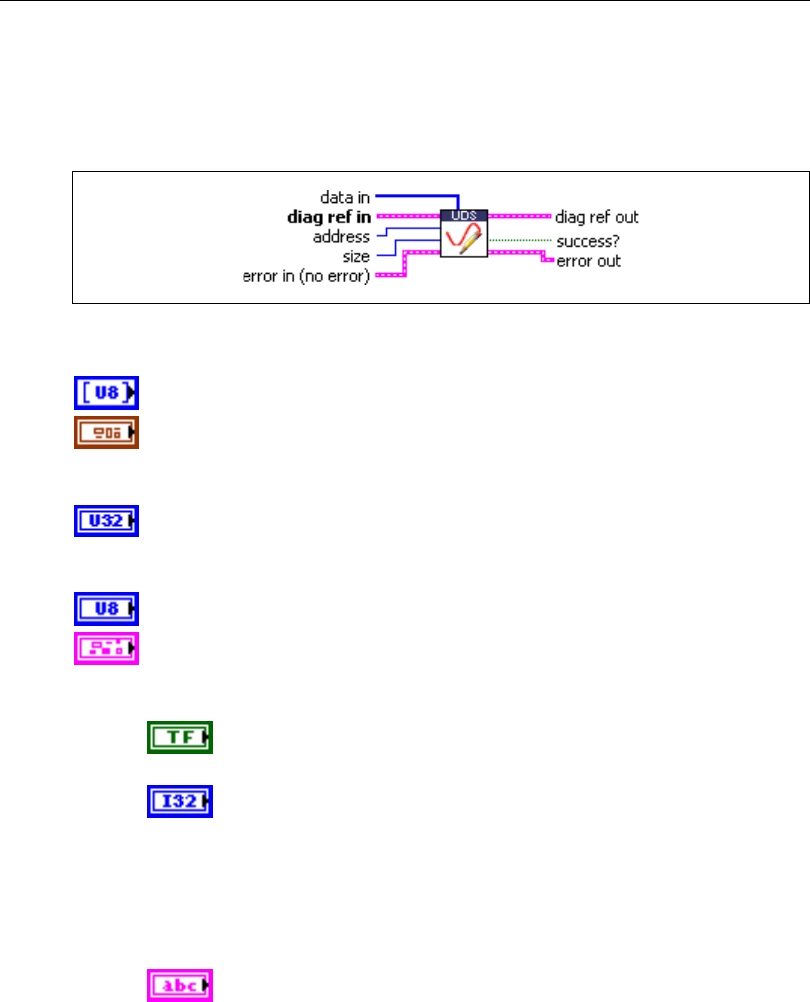
Chapter 5 Automotive Diagnostic Command Set API for LabVIEW
© National Instruments Corporation 5-117 Automotive Diagnostic Command Set User Manual
UDS WriteMemoryByAddress.vi
Purpose
Executes the UDS WriteMemoryByAddress service. Writes data to the ECU memory.
Format
Input
data in defines the memory block to be written to the ECU.
diag ref in specifies the diagnostic session handle, obtained from Open
Diagnostic.vi and wired through subsequent diagnostic VIs. Normally, it is
not necessary to manually manipulate the elements of this cluster.
address defines the memory address to which data are to be written. Only
three bytes are sent to the ECU, so the address must be in the range
0–FFFFFF (hex).
size defines the length of the memory block to be written.
error in is a cluster that describes error conditions occurring before the VI
executes. If an error has already occurred, the VI returns the value of the
error in cluster to error out.
status is TRUE if an error occurred. This VI is not executed when
status is TRUE.
code is the error code number identifying an error. A value of 0
means success. A negative value means error: the VI did not
execute the intended operation. A positive value means warning:
the VI executed intended operation, but an informational warning
is returned. For a description of the code, wire the error cluster to
a LabVIEW error-handling VI, such as the Simple Error
Handler.
source identifies the VI where the error occurred.

Chapter 5 Automotive Diagnostic Command Set API for LabVIEW
Automotive Diagnostic Command Set User Manual 5-118 ni.com
Output
diag ref out is a copy of diag ref in. You can wire it to subsequent
diagnostic VIs.
success? indicates successful receipt of a positive response message for
this diagnostic service.
error out describes error conditions. If the error in cluster indicated an
error, the error out cluster contains the same information. Otherwise,
error out describes the error status of this VI.
status is TRUE if an error occurred.
code is the error code number identifying an error. A value of 0
means success. A negative value means error: the VI did not
execute the intended operation. A positive value means warning:
the VI executed intended operation, but an informational warning
is returned. For a description of the code, wire the error cluster to
a LabVIEW error-handling VI, such as the Simple Error
Handler.
source identifies the VI where the error occurred.
Description
This VI performs the UDS service WriteMemoryByAddress and writes RecordValues (data
values) to the ECU. address and size identify the data. The vehicle manufacturer must ensure
the ECU conditions are met when performing this service. Typical use cases are clearing
nonvolatile memory, resetting learned values, setting option content, setting the Vehicle
Identification Number, or changing calibration values.
For further details about this service, refer to the ISO 15765-3 standard.
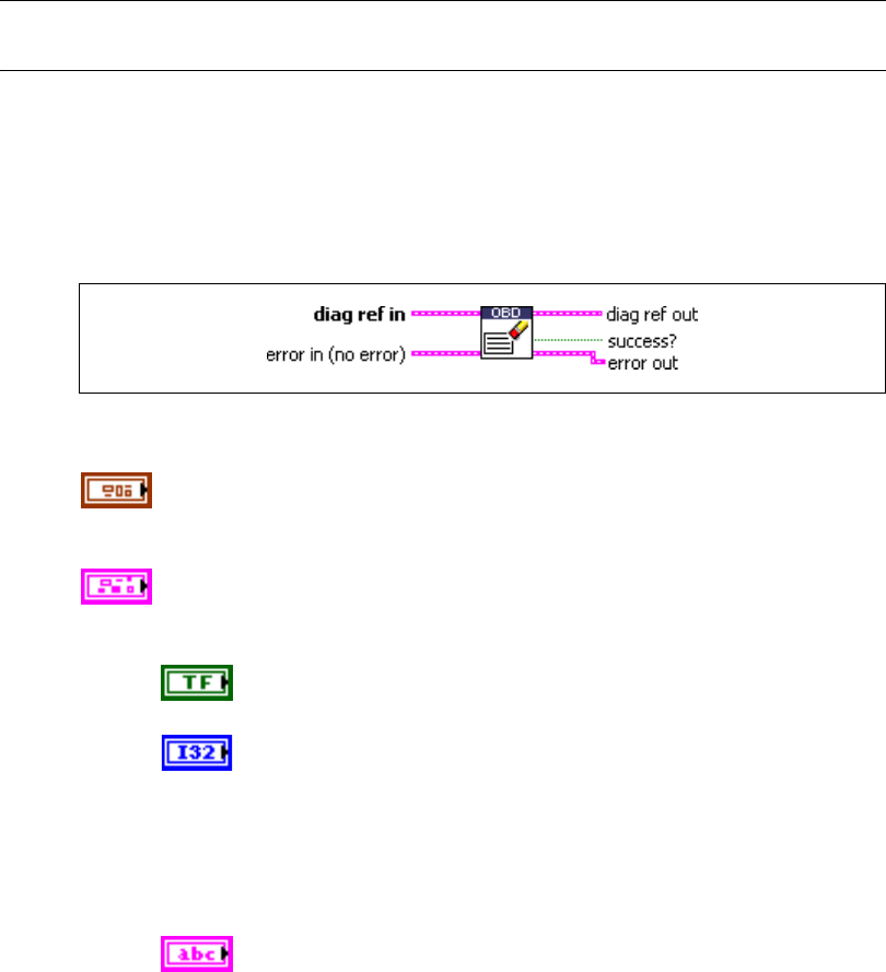
Chapter 5 Automotive Diagnostic Command Set API for LabVIEW
© National Instruments Corporation 5-119 Automotive Diagnostic Command Set User Manual
OBD (On-Board Diagnostics) Services
OBD Clear Emission Related Diagnostic Information.vi
Purpose
Executes the OBD Clear Emission Related Diagnostic Information service. Clears
emission-related Diagnostic Trouble Codes (DTCs) in the ECU.
Format
Input
diag ref in specifies the diagnostic session handle, obtained from Open
Diagnostic.vi and wired through subsequent diagnostic VIs. Normally, it is
not necessary to manually manipulate the elements of this cluster.
error in is a cluster that describes error conditions occurring before the VI
executes. If an error has already occurred, the VI returns the value of the
error in cluster to error out.
status is TRUE if an error occurred. This VI is not executed when
status is TRUE.
code is the error code number identifying an error. A value of 0
means success. A negative value means error: the VI did not
execute the intended operation. A positive value means warning:
the VI executed intended operation, but an informational warning
is returned. For a description of the code, wire the error cluster to
a LabVIEW error-handling VI, such as the Simple Error
Handler.
source identifies the VI where the error occurred.

Chapter 5 Automotive Diagnostic Command Set API for LabVIEW
Automotive Diagnostic Command Set User Manual 5-120 ni.com
Output
diag ref out is a copy of diag ref in. You can wire it to subsequent
diagnostic VIs.
success? indicates successful receipt of a positive response message for
this diagnostic service.
error out describes error conditions. If the error in cluster indicated an
error, the error out cluster contains the same information. Otherwise,
error out describes the error status of this VI.
status is TRUE if an error occurred.
code is the error code number identifying an error. A value of 0
means success. A negative value means error: the VI did not
execute the intended operation. A positive value means warning:
the VI executed intended operation, but an informational warning
is returned. For a description of the code, wire the error cluster to
a LabVIEW error-handling VI, such as the Simple Error
Handler.
source identifies the VI where the error occurred.
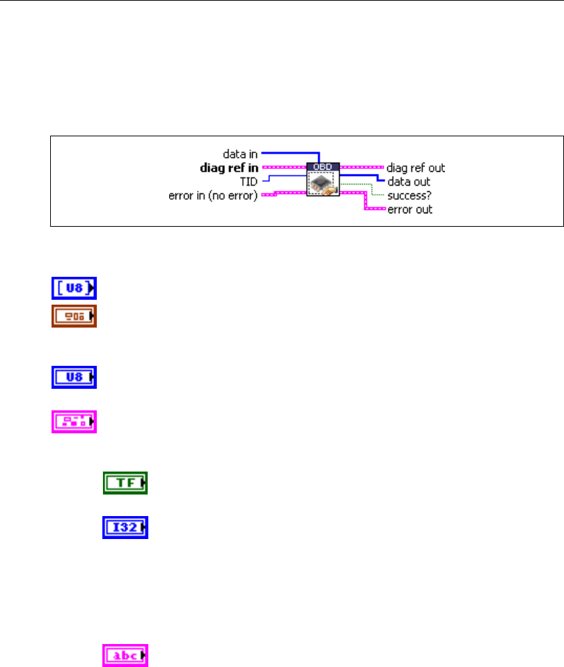
Chapter 5 Automotive Diagnostic Command Set API for LabVIEW
© National Instruments Corporation 5-121 Automotive Diagnostic Command Set User Manual
OBD Request Control Of On-Board Device.vi
Purpose
Executes the OBD Request Control Of On-Board Device service. Modifies ECU I/O port
behavior.
Format
Input
data in defines application-specific data for this service.
diag ref in specifies the diagnostic session handle, obtained from Open
Diagnostic.vi and wired through subsequent diagnostic VIs. Normally, it is
not necessary to manually manipulate the elements of this cluster.
TID defines the test identifier of the I/O to be manipulated. The values are
application specific.
error in is a cluster that describes error conditions occurring before the VI
executes. If an error has already occurred, the VI returns the value of the
error in cluster to error out.
status is TRUE if an error occurred. This VI is not executed when
status is TRUE.
code is the error code number identifying an error. A value of 0
means success. A negative value means error: the VI did not
execute the intended operation. A positive value means warning:
the VI executed intended operation, but an informational warning
is returned. For a description of the code, wire the error cluster to
a LabVIEW error-handling VI, such as the Simple Error
Handler.
source identifies the VI where the error occurred.

Chapter 5 Automotive Diagnostic Command Set API for LabVIEW
Automotive Diagnostic Command Set User Manual 5-122 ni.com
Output
diag ref out is a copy of diag ref in. You can wire it to subsequent
diagnostic VIs.
data out returns application-specific data for this service.
success? indicates successful receipt of a positive response message for
this diagnostic service.
error out describes error conditions. If the error in cluster indicated an
error, the error out cluster contains the same information. Otherwise,
error out describes the error status of this VI.
status is TRUE if an error occurred.
code is the error code number identifying an error. A value of 0
means success. A negative value means error: the VI did not
execute the intended operation. A positive value means warning:
the VI executed intended operation, but an informational warning
is returned. For a description of the code, wire the error cluster to
a LabVIEW error-handling VI, such as the Simple Error
Handler.
source identifies the VI where the error occurred.
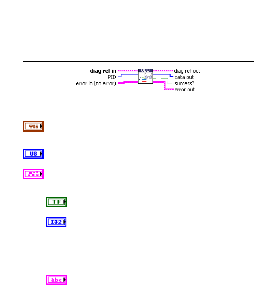
Chapter 5 Automotive Diagnostic Command Set API for LabVIEW
© National Instruments Corporation 5-123 Automotive Diagnostic Command Set User Manual
OBD Request Current Powertrain Diagnostic Data.vi
Purpose
Executes the OBD Request Current Powertrain Diagnostic Data service. Reads a data record
from the ECU.
Format
Input
diag ref in specifies the diagnostic session handle, obtained from Open
Diagnostic.vi and wired through subsequent diagnostic VIs. Normally, it is
not necessary to manually manipulate the elements of this cluster.
PID defines the parameter identifier of the data to be read. The SAE J1979
standard defines the values.
error in is a cluster that describes error conditions occurring before the VI
executes. If an error has already occurred, the VI returns the value of the
error in cluster to error out.
status is TRUE if an error occurred. This VI is not executed when
status is TRUE.
code is the error code number identifying an error. A value of 0
means success. A negative value means error: the VI did not
execute the intended operation. A positive value means warning:
the VI executed intended operation, but an informational warning
is returned. For a description of the code, wire the error cluster to
a LabVIEW error-handling VI, such as the Simple Error
Handler.
source identifies the VI where the error occurred.
Chapter 5 Automotive Diagnostic Command Set API for LabVIEW
Automotive Diagnostic Command Set User Manual 5-124 ni.com
Output
diag ref out is a copy of diag ref in. You can wire it to subsequent
diagnostic VIs.
data out returns the ECU data record. If you know the record data
description, you can use Convert from Phys.vi to interpret this record. You
can obtain the description from the SAE J1979 standard.
success? indicates successful receipt of a positive response message for
this diagnostic service.
error out describes error conditions. If the error in cluster indicated an
error, the error out cluster contains the same information. Otherwise,
error out describes the error status of this VI.
status is TRUE if an error occurred.
code is the error code number identifying an error. A value of 0
means success. A negative value means error: the VI did not
execute the intended operation. A positive value means warning:
the VI executed intended operation, but an informational warning
is returned. For a description of the code, wire the error cluster to
a LabVIEW error-handling VI, such as the Simple Error
Handler.
source identifies the VI where the error occurred.

Chapter 5 Automotive Diagnostic Command Set API for LabVIEW
© National Instruments Corporation 5-125 Automotive Diagnostic Command Set User Manual
OBD Request Emission Related DTCs.vi
Purpose
Executes the OBD Request Emission Related DTCs service. Reads all emission-related
Diagnostic Trouble Codes (DTCs).
Format
Input
DTC descriptor is a cluster that describes the DTC records the ECU
delivers:
DTC Byte Length indicates the number of bytes the ECU sends
for each DTC. The default is 2.
Status Byte Length indicates the number of bytes the ECU sends
for each DTC’s status. The default is 0 for OBD.
Add Data Byte Length indicates the number of bytes the ECU
sends for each DTC’s additional data. Usually, there is no
additional data, so the default is 0.
Byte Order indicates the byte ordering for multibyte items:
0: MSB_FIRST (Motorola) (default)
1: LSB_FIRST (Intel)
This VI interprets the response byte stream according to this description
and returns the resulting DTC records in the DTCs cluster array.
diag ref in specifies the diagnostic session handle, obtained from Open
Diagnostic.vi and wired through subsequent diagnostic VIs. Normally, it is
not necessary to manually manipulate the elements of this cluster.
error in is a cluster that describes error conditions occurring before the VI
executes. If an error has already occurred, the VI returns the value of the
error in cluster to error out.
Chapter 5 Automotive Diagnostic Command Set API for LabVIEW
Automotive Diagnostic Command Set User Manual 5-126 ni.com
status is TRUE if an error occurred. This VI is not executed when
status is TRUE.
code is the error code number identifying an error. A value of 0
means success. A negative value means error: the VI did not
execute the intended operation. A positive value means warning:
the VI executed intended operation, but an informational warning
is returned. For a description of the code, wire the error cluster to
a LabVIEW error-handling VI, such as the Simple Error
Handler.
source identifies the VI where the error occurred.
Output
diag ref out is a copy of diag ref in. You can wire it to subsequent
diagnostic VIs.
DTCs returns the resulting DTCs as an array of clusters:
DTC is the resulting Diagnostic Trouble Code. For the default
2-byte DTCs, you can use DTC to String.vi to convert this to
readable format as defined by SAE J2012.
Status is the DTC status. Usually, this is a bit field with the
following meaning:
Bit Meaning
0 testFailed
1 testFailedThisMonitoringCycle
2 pendingDTC
3 confirmedDTC
4 testNotCompletedSinceLastClear
5 testFailedSinceLastClear
6 testNotCompletedThisMonitoringCycle
7 warningIndicatorRequested
For OBD, this field usually does not contain valid information.
Add Data contains optional additional data for this DTC. Usually,
this does not contain valid information (refer to DTC descriptor).

Chapter 5 Automotive Diagnostic Command Set API for LabVIEW
© National Instruments Corporation 5-127 Automotive Diagnostic Command Set User Manual
success? indicates successful receipt of a positive response message for
this diagnostic service.
error out describes error conditions. If the error in cluster indicated an
error, the error out cluster contains the same information. Otherwise,
error out describes the error status of this VI.
status is TRUE if an error occurred.
code is the error code number identifying an error. A value of 0
means success. A negative value means error: the VI did not
execute the intended operation. A positive value means warning:
the VI executed intended operation, but an informational warning
is returned. For a description of the code, wire the error cluster to
a LabVIEW error-handling VI, such as the Simple Error
Handler.
source identifies the VI where the error occurred.
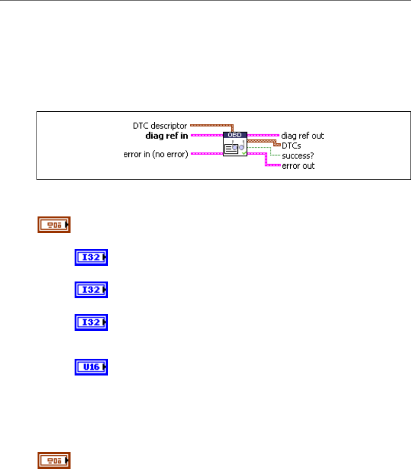
Chapter 5 Automotive Diagnostic Command Set API for LabVIEW
Automotive Diagnostic Command Set User Manual 5-128 ni.com
OBD Request Emission Related DTCs During Current Drive Cycle.vi
Purpose
Executes the OBD Request Emission Related DTCs During Current Drive Cycle service.
Reads the emission-related Diagnostic Trouble Codes (DTCs) that occurred during the
current (or last completed) drive cycle.
Format
Input
DTC descriptor is a cluster that describes the DTC records the ECU
delivers:
DTC Byte Length indicates the number of bytes the ECU sends
for each DTC. The default is 2.
Status Byte Length indicates the number of bytes the ECU sends
for each DTC’s status. The default is 0 for OBD.
Add Data Byte Length indicates the number of bytes the ECU
sends for each DTC’s additional data. Usually, there is no
additional data, so the default is 0.
Byte Order indicates the byte ordering for multibyte items:
0: MSB_FIRST (Motorola) (default)
1: LSB_FIRST (Intel)
This VI interprets the response byte stream according to this description
and returns the resulting DTC records in the DTCs cluster array.
diag ref in specifies the diagnostic session handle, obtained from Open
Diagnostic.vi and wired through subsequent diagnostic VIs. Normally, it is
not necessary to manually manipulate the elements of this cluster.
Chapter 5 Automotive Diagnostic Command Set API for LabVIEW
© National Instruments Corporation 5-129 Automotive Diagnostic Command Set User Manual
error in is a cluster that describes error conditions occurring before the VI
executes. If an error has already occurred, the VI returns the value of the
error in cluster to error out.
status is TRUE if an error occurred. This VI is not executed when
status is TRUE.
code is the error code number identifying an error. A value of 0
means success. A negative value means error: the VI did not
execute the intended operation. A positive value means warning:
the VI executed intended operation, but an informational warning
is returned. For a description of the code, wire the error cluster to
a LabVIEW error-handling VI, such as the Simple Error
Handler.
source identifies the VI where the error occurred.
Output
diag ref out is a copy of diag ref in. You can wire it to subsequent
diagnostic VIs.
DTCs returns the resulting DTCs as an array of clusters:
DTC is the resulting Diagnostic Trouble Code. For the default
2-byte DTCs, you can use DTC to String.vi to convert this to
readable format as defined by SAE J2012.
Status is the DTC status. Usually, this is a bit field with the
following meaning:
Bit Meaning
0 testFailed
1 testFailedThisMonitoringCycle
2 pendingDTC
3 confirmedDTC
4 testNotCompletedSinceLastClear
5 testFailedSinceLastClear
6 testNotCompletedThisMonitoringCycle
7 warningIndicatorRequested
Chapter 5 Automotive Diagnostic Command Set API for LabVIEW
Automotive Diagnostic Command Set User Manual 5-130 ni.com
For OBD, this field usually does not contain valid information.
Add Data contains optional additional data for this DTC. Usually,
this does not contain valid information (refer to DTC descriptor).
success? indicates successful receipt of a positive response message for
this diagnostic service.
error out describes error conditions. If the error in cluster indicated an
error, the error out cluster contains the same information. Otherwise,
error out describes the error status of this VI.
status is TRUE if an error occurred.
code is the error code number identifying an error. A value of 0
means success. A negative value means error: the VI did not
execute the intended operation. A positive value means warning:
the VI executed intended operation, but an informational warning
is returned. For a description of the code, wire the error cluster to
a LabVIEW error-handling VI, such as the Simple Error
Handler.
source identifies the VI where the error occurred.
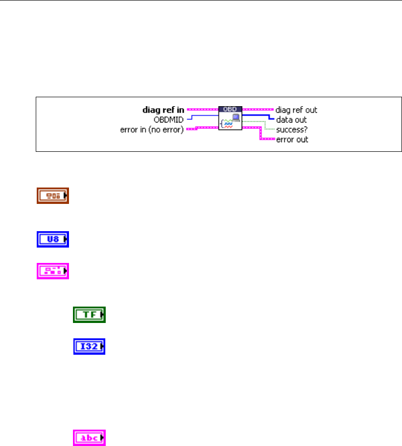
Chapter 5 Automotive Diagnostic Command Set API for LabVIEW
© National Instruments Corporation 5-131 Automotive Diagnostic Command Set User Manual
OBD Request On-Board Monitoring Test Results.vi
Purpose
Executes the OBD Request On-Board Monitoring Test Results service. Reads a test data
record from the ECU.
Format
Input
diag ref in specifies the diagnostic session handle, obtained from Open
Diagnostic.vi and wired through subsequent diagnostic VIs. Normally, it is
not necessary to manually manipulate the elements of this cluster.
OBDMID defines the parameter identifier of the data to be read. The
SAE J1979 standard defines the values.
error in is a cluster that describes error conditions occurring before the VI
executes. If an error has already occurred, the VI returns the value of the
error in cluster to error out.
status is TRUE if an error occurred. This VI is not executed when
status is TRUE.
code is the error code number identifying an error. A value of 0
means success. A negative value means error: the VI did not
execute the intended operation. A positive value means warning:
the VI executed intended operation, but an informational warning
is returned. For a description of the code, wire the error cluster to
a LabVIEW error-handling VI, such as the Simple Error
Handler.
source identifies the VI where the error occurred.

Chapter 5 Automotive Diagnostic Command Set API for LabVIEW
Automotive Diagnostic Command Set User Manual 5-132 ni.com
Output
diag ref out is a copy of diag ref in. You can wire it to subsequent
diagnostic VIs.
data out returns the ECU data record. If you know the record data
description, you can use Convert from Phys.vi to interpret this record. You
can obtain the description from the SAE J1979 standard.
success? indicates successful receipt of a positive response message for
this diagnostic service.
error out describes error conditions. If the error in cluster indicated an
error, the error out cluster contains the same information. Otherwise,
error out describes the error status of this VI.
status is TRUE if an error occurred.
code is the error code number identifying an error. A value of 0
means success. A negative value means error: the VI did not
execute the intended operation. A positive value means warning:
the VI executed intended operation, but an informational warning
is returned. For a description of the code, wire the error cluster to
a LabVIEW error-handling VI, such as the Simple Error
Handler.
source identifies the VI where the error occurred.
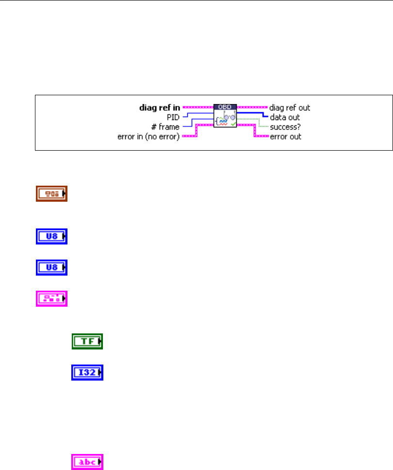
Chapter 5 Automotive Diagnostic Command Set API for LabVIEW
© National Instruments Corporation 5-133 Automotive Diagnostic Command Set User Manual
OBD Request Powertrain Freeze Frame Data.vi
Purpose
Executes the OBD Request Powertrain Freeze Frame Data service. Reads an ECU data record
stored while a Diagnostic Trouble Code occurred.
Format
Input
diag ref in specifies the diagnostic session handle, obtained from Open
Diagnostic.vi and wired through subsequent diagnostic VIs. Normally, it is
not necessary to manually manipulate the elements of this cluster.
PID defines the parameter identifier of the data to be read. The SAE J1979
standard defines the values.
# frame is the number of the freeze frame from which the data are to be
retrieved.
error in is a cluster that describes error conditions occurring before the VI
executes. If an error has already occurred, the VI returns the value of the
error in cluster to error out.
status is TRUE if an error occurred. This VI is not executed when
status is TRUE.
code is the error code number identifying an error. A value of 0
means success. A negative value means error: the VI did not
execute the intended operation. A positive value means warning:
the VI executed intended operation, but an informational warning
is returned. For a description of the code, wire the error cluster to
a LabVIEW error-handling VI, such as the Simple Error
Handler.
source identifies the VI where the error occurred.

Chapter 5 Automotive Diagnostic Command Set API for LabVIEW
Automotive Diagnostic Command Set User Manual 5-134 ni.com
Output
diag ref out is a copy of diag ref in. You can wire it to subsequent
diagnostic VIs.
data out returns the ECU data record. If you know the record data
description, you can use Convert from Phys.vi to interpret this record. You
can obtain the description from the SAE J1979 standard.
success? indicates successful receipt of a positive response message for
this diagnostic service.
error out describes error conditions. If the error in cluster indicated an
error, the error out cluster contains the same information. Otherwise,
error out describes the error status of this VI.
status is TRUE if an error occurred.
code is the error code number identifying an error. A value of 0
means success. A negative value means error: the VI did not
execute the intended operation. A positive value means warning:
the VI executed intended operation, but an informational warning
is returned. For a description of the code, wire the error cluster to
a LabVIEW error-handling VI, such as the Simple Error
Handler.
source identifies the VI where the error occurred.
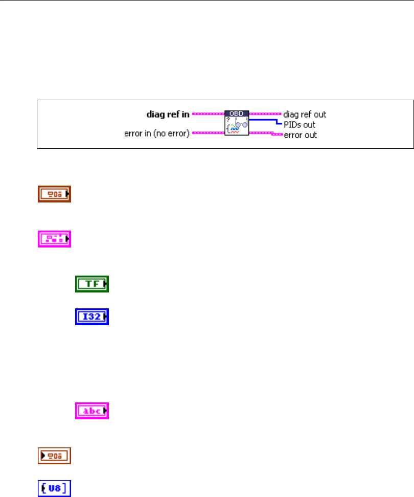
Chapter 5 Automotive Diagnostic Command Set API for LabVIEW
© National Instruments Corporation 5-135 Automotive Diagnostic Command Set User Manual
OBD Request Supported PIDs.vi
Purpose
Executes the OBD Request Current Powertrain Diagnostic Data service to retrieve the valid
PID values for this service.
Format
Input
diag ref in specifies the diagnostic session handle, obtained from Open
Diagnostic.vi and wired through subsequent diagnostic VIs. Normally, it is
not necessary to manually manipulate the elements of this cluster.
error in is a cluster that describes error conditions occurring before the VI
executes. If an error has already occurred, the VI returns the value of the
error in cluster to error out.
status is TRUE if an error occurred. This VI is not executed when
status is TRUE.
code is the error code number identifying an error. A value of 0
means success. A negative value means error: the VI did not
execute the intended operation. A positive value means warning:
the VI executed intended operation, but an informational warning
is returned. For a description of the code, wire the error cluster to
a LabVIEW error-handling VI, such as the Simple Error
Handler.
source identifies the VI where the error occurred.
Output
diag ref out is a copy of diag ref in. You can wire it to subsequent
diagnostic VIs.
PIDs out returns an array of valid PIDs for the OBD Request Current
Powertrain Diagnostic Data service.

Chapter 5 Automotive Diagnostic Command Set API for LabVIEW
Automotive Diagnostic Command Set User Manual 5-136 ni.com
error out describes error conditions. If the error in cluster indicated an
error, the error out cluster contains the same information. Otherwise,
error out describes the error status of this VI.
status is TRUE if an error occurred.
code is the error code number identifying an error. A value of 0
means success. A negative value means error: the VI did not
execute the intended operation. A positive value means warning:
the VI executed intended operation, but an informational warning
is returned. For a description of the code, wire the error cluster to
a LabVIEW error-handling VI, such as the Simple Error
Handler.
source identifies the VI where the error occurred.
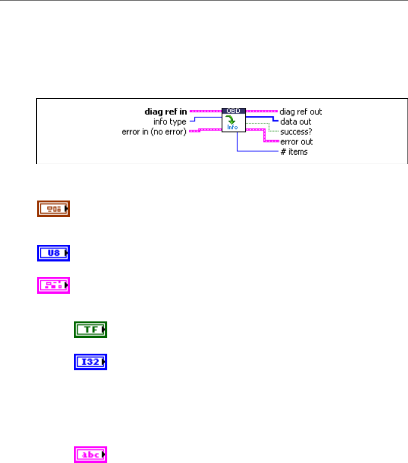
Chapter 5 Automotive Diagnostic Command Set API for LabVIEW
© National Instruments Corporation 5-137 Automotive Diagnostic Command Set User Manual
OBD Request Vehicle Information.vi
Purpose
Executes the OBD Request Vehicle Information service. Reads a set of information data from
the ECU.
Format
Input
diag ref in specifies the diagnostic session handle, obtained from Open
Diagnostic.vi and wired through subsequent diagnostic VIs. Normally, it is
not necessary to manually manipulate the elements of this cluster.
info type defines the type of information to be read. The values are defined
in the SAE J1979 standard.
error in is a cluster that describes error conditions occurring before the VI
executes. If an error has already occurred, the VI returns the value of the
error in cluster to error out.
status is TRUE if an error occurred. This VI is not executed when
status is TRUE.
code is the error code number identifying an error. A value of 0
means success. A negative value means error: the VI did not
execute the intended operation. A positive value means warning:
the VI executed intended operation, but an informational warning
is returned. For a description of the code, wire the error cluster to
a LabVIEW error-handling VI, such as the Simple Error
Handler.
source identifies the VI where the error occurred.
Chapter 5 Automotive Diagnostic Command Set API for LabVIEW
Automotive Diagnostic Command Set User Manual 5-138 ni.com
Output
diag ref out is a copy of diag ref in. You can wire it to subsequent
diagnostic VIs.
data out returns the vehicle information from the ECU. You can obtain the
description from the SAE J1979 standard.
success? indicates successful receipt of a positive response message for
this diagnostic service.
error out describes error conditions. If the error in cluster indicated an
error, the error out cluster contains the same information. Otherwise,
error out describes the error status of this VI.
status is TRUE if an error occurred.
code is the error code number identifying an error. A value of 0
means success. A negative value means error: the VI did not
execute the intended operation. A positive value means warning:
the VI executed intended operation, but an informational warning
is returned. For a description of the code, wire the error cluster to
a LabVIEW error-handling VI, such as the Simple Error
Handler.
source identifies the VI where the error occurred.
# items is the number of data items (not bytes) this service returns.

© National Instruments Corporation 6-1 Automotive Diagnostic Command Set User Manual
6
Automotive Diagnostic
Command Set API for C
This chapter lists the Automotive Diagnostic Command Set API functions and describes their
format, purpose, and parameters. Unless otherwise stated, each Automotive Diagnostic
Command Set function suspends execution of the calling thread until it completes. The
functions are listed alphabetically in four categories: general functions, KWP2000 services,
UDS (DiagOnCAN) services, and OBD (On-Board Diagnostics) services.
Section Headings
The following are section headings found in the Automotive Diagnostic Command Set for C
functions.
Purpose
Each function description includes a brief statement of the function purpose.
Format
The format section describes the function format for the C programming language.
Input and Output
The input and output sections list the function parameters.
Description
The description section gives details about the function purpose and effect.

Chapter 6 Automotive Diagnostic Command Set API for C
Automotive Diagnostic Command Set User Manual 6-2 ni.com
List of Data Types
The following data types are used with the Automotive Diagnostic Command Set API for C
functions.
Table 6-1. Data Types for the Automotive Diagnostic Command Set for C
Data Type Purpose
i8 8-bit signed integer
i16 16-bit signed integer
i32 32-bit signed integer
u8 8-bit unsigned integer
u16 16-bit unsigned integer
u32 32-bit unsigned integer
f32 32-bit floating-point number
f64 64-bit floating-point number
str ASCII string represented as an array of characters terminated by null
character ('\0'). This type is used with output strings. str is typically
used in the Automotive Diagnostic Command Set API as a pointer to a
string, as char*.
cstr ASCII string represented as an array of characters terminated by null
character ('\0'). This type is used with input strings. cstr is typically
used in the Automotive Diagnostic Command Set as a pointer to a string,
as const char*.

Chapter 6 Automotive Diagnostic Command Set API for C
© National Instruments Corporation 6-3 Automotive Diagnostic Command Set User Manual
List of Functions
The following table contains an alphabetical list of the Automotive Diagnostic Command Set
API functions.
Table 6-2. Functions for the Automotive Diagnostic Command Set for C
Function Purpose
ndClearDiagnosticInformation Executes the
ClearDiagnostic
Information service.
Clears selected Diagnostic
Trouble Codes (DTCs).
ndCloseDiagnostic Closes a diagnostic
session.
ndControlDTCSetting Executes the
ControlDTCSetting
service. Modifies the
generation behavior of
selected Diagnostic
Trouble Codes (DTCs).
ndConvertFromPhys Converts a physical data
value into a binary
representation using a
type descriptor.
ndConvertToPhys Converts a binary
representation of a value
into its physical value
using a type descriptor.
ndCreateExtendedCANIds Creates diagnostic CAN
identifiers according to
ISO 15765-2.
ndDiagnosticService Executes a generic
diagnostic service. If a
special service is not
available through the
KWP2000, UDS, or OBD
service functions, you can
build it using this function.

Chapter 6 Automotive Diagnostic Command Set API for C
Automotive Diagnostic Command Set User Manual 6-4 ni.com
ndDisableNormalMessageTransmission Executes the
DisableNormalMessage
Transmission service. The
ECU no longer transmits
its regular communication
messages (usually CAN
messages).
ndDTCToString Returns a string
representation (such as
P1234) for a 2-byte
diagnostic trouble code
(DTC).
ndECUReset Executes the ECUReset
service. Resets the ECU.
ndEnableNormalMessageTransmission Executes the
EnableNormalMessage
Transmission service. The
ECU starts transmitting its
regular communication
messages (usually CAN
messages).
ndGetProperty Get a diagnostic global
internal parameter.
ndInputOutputControlByLocalIdentifier Executes the
InputOutputControlBy
LocalIdentifier service.
Modifies the ECU I/O port
behavior.
ndOBDClearEmissionRelatedDiagnosticInformation Executes the OBD Clear
Emission Related
Diagnostic Information
service. Clears
emission-related
diagnostic trouble codes
(DTCs) in the ECU.
Table 6-2. Functions for the Automotive Diagnostic Command Set for C (Continued)
Function Purpose

Chapter 6 Automotive Diagnostic Command Set API for C
© National Instruments Corporation 6-5 Automotive Diagnostic Command Set User Manual
ndOBDOpen Opens a diagnostic
session on a CAN port for
OBD-II.
ndOBDRequestControlOfOnBoardDevice Executes the OBD
Request Control Of
On-Board Device service.
Modifies ECU I/O port
behavior.
ndOBDRequestCurrentPowertrainDiagnosticData Executes the OBD
Request Current
Powertrain Diagnostic
Data service. Reads an
ECU data record.
ndOBDRequestEmissionRelatedDTCs Executes the OBD
Request Emission Related
DTCs service. Reads all
emission-related
Diagnostic Trouble Codes
(DTCs).
ndOBDRequestEmissionRelatedDTCsDuringCurrent
DriveCycle
Executes the OBD
Request Emission Related
DTCs During Current
Drive Cycle service.
Reads the
emission-related
Diagnostic Trouble Codes
(DTCs) that occurred
during the current (or last
completed) drive cycle.
ndOBDRequestOnBoardMonitoringTestResults Executes the OBD
Request On-Board
Monitoring Test Results
service. Reads an ECU
test data record.
Table 6-2. Functions for the Automotive Diagnostic Command Set for C (Continued)
Function Purpose

Chapter 6 Automotive Diagnostic Command Set API for C
Automotive Diagnostic Command Set User Manual 6-6 ni.com
ndOBDRequestPowertrainFreezeFrameData Executes the OBD
Request Powertrain
Freeze Frame Data
service. Reads an ECU
data record stored while a
diagnostic trouble code
occurred.
ndOBDRequestVehicleInformation Executes the OBD
Request Vehicle
Information service.
Reads a set of information
data from the ECU.
ndOpenDiagnostic Opens a diagnostic
session on a CAN port.
Communication to the
ECU is not yet started.
ndReadDataByLocalIdentifier Executes the
ReadDataByLocal
Identifier service. Reads
an ECU data record.
ndReadDTCByStatus Executes the
ReadDiagnosticTrouble
CodesByStatus service.
Reads selected Diagnostic
Trouble Codes (DTCs).
ndReadECUIdentification Executes the
ReadECUIdentification
service. Returns ECU
identification data from
the ECU.
ndReadMemoryByAddress Executes the
ReadMemoryByAddress
service. Reads data from
the ECU memory.
Table 6-2. Functions for the Automotive Diagnostic Command Set for C (Continued)
Function Purpose

Chapter 6 Automotive Diagnostic Command Set API for C
© National Instruments Corporation 6-7 Automotive Diagnostic Command Set User Manual
ndReadStatusOfDTC Executes the
ReadStatusOfDiagnostic
TroubleCodes service.
Reads selected Diagnostic
Trouble Codes (DTCs).
ndRequestRoutineResultsByLocalIdentifier Executes the
RequestRoutineResultsBy
LocalIdentifier service.
Returns results from an
ECU routine.
ndRequestSeed Executes the
SecurityAccess service
to retrieve a seed from
the ECU.
ndSendKey Executes the
SecurityAccess service to
send a key to the ECU.
ndSetProperty Set a diagnostic global
internal parameter.
ndStartDiagnosticSession Executes the
StartDiagnosticSession
service. The ECU is set up
in a specific diagnostic
mode.
ndStartRoutineByLocalIdentifier Executes the
StartRoutineByLocal
Identifier service.
Executes a routine on
the ECU.
ndStatusToString Returns a description for
an error code.
ndStopDiagnosticSession Executes the
StopDiagnosticSession
service. Returns the ECU
to normal mode.
Table 6-2. Functions for the Automotive Diagnostic Command Set for C (Continued)
Function Purpose

Chapter 6 Automotive Diagnostic Command Set API for C
Automotive Diagnostic Command Set User Manual 6-8 ni.com
ndStopRoutineByLocalIdentifier Executes the
StopRoutineByLocal
Identifier service. Stops a
routine on the ECU.
ndTesterPresent Executes the
TesterPresent service.
Keeps the ECU in
diagnostic mode.
ndUDSClearDiagnosticInformation Executes the UDS
ClearDiagnostic
Information service.
Clears selected Diagnostic
Trouble Codes (DTCs).
ndUDSCommunicationControl Executes the UDS
CommunicationControl
service. Switches
transmission and/or
reception of the normal
communication messages
(usually CAN messages)
on or off.
ndUDSControlDTCSetting Executes the UDS
ControlDTCSetting
service. Modifies
Diagnostic Trouble Code
(DTC) behavior.
ndUDSDiagnosticSessionControl Executes the UDS
DiagnosticSessionControl
service. The ECU is set up
in a specific diagnostic
mode.
ndUDSECUReset Executes the UDS
ECUReset service. Resets
the ECU.
Table 6-2. Functions for the Automotive Diagnostic Command Set for C (Continued)
Function Purpose

Chapter 6 Automotive Diagnostic Command Set API for C
© National Instruments Corporation 6-9 Automotive Diagnostic Command Set User Manual
ndUDSInputOutputControlByIdentifier Executes the UDS
InputOutputControlBy
Identifier service.
Modifies ECU I/O port
behavior.
ndUDSReadDataByIdentifier Executes the UDS
ReadDataByIdentifier
service. Reads an ECU
data record.
ndUDSReadMemoryByAddress Executes the UDS
ReadMemoryByAddress
service. Reads data from
the ECU memory.
ndUDSReportDTCBySeverityMaskRecord Executes the
ReportDTCBySeverity
MaskRecord subfunction
of the UDS
ReadDiagnosticTrouble
CodeInformation service.
Reads selected Diagnostic
Trouble Codes (DTCs).
ndUDSReportDTCByStatusMask Executes the
ReportDTCByStatus
Mask subfunction
of the UDS
ReadDiagnosticTrouble
CodeInformation service.
Reads selected Diagnostic
Trouble Codes (DTCs).
Table 6-2. Functions for the Automotive Diagnostic Command Set for C (Continued)
Function Purpose

Chapter 6 Automotive Diagnostic Command Set API for C
Automotive Diagnostic Command Set User Manual 6-10 ni.com
ndUDSReportSeverityInformationOfDTC Executes the
ReportSeverity
InformationOfDTC
subfunction of the UDS
ReadDiagnosticTrouble
CodeInformation service.
Reads selected Diagnostic
Trouble Codes (DTCs) are
read.
ndUDSReportSupportedDTCs Executes the
ReportSupportedDTCs
subfunction of the UDS
ReadDiagnosticTrouble
CodeInformation service.
Reads all supported
Diagnostic Trouble Codes
(DTCs).
ndUDSRequestSeed Executes the UDS
SecurityAccess service
to retrieve a seed from
the ECU.
ndUDSRoutineControl Executes the UDS
RoutineControl service.
Executes a routine on
the ECU.
ndUDSSendKey Executes the UDS
SecurityAccess service to
send a key to the ECU.
ndUDSTesterPresent Executes the UDS
TesterPresent service.
Keeps the ECU in
diagnostic mode.
ndUDSWriteDataByIdentifier Executes the UDS
WriteDataByIdentifier
service. Writes a data
record to the ECU.
Table 6-2. Functions for the Automotive Diagnostic Command Set for C (Continued)
Function Purpose

Chapter 6 Automotive Diagnostic Command Set API for C
© National Instruments Corporation 6-11 Automotive Diagnostic Command Set User Manual
ndUDSWriteMemoryByAddress Executes the UDS
WriteMemoryByAddress
service. Writes data to the
ECU memory.
ndVWTPConnect Establishes a connection
channel to an ECU using
the VW TP 2.0.
ndVWTPConnectionTest Maintains a connection
channel to an ECU using
the VW TP 2.0.
ndVWTPDisconnect Terminates a connection
channel to an ECU using
the VW TP 2.0.
ndWriteDataByLocalIdentifier Executes the
WriteDataByLocal
Identifier service. Writes a
data record to the ECU.
ndWriteMemoryByAddress Executes the
WriteMemoryByAddress
service. Writes data to the
ECU memory.
Table 6-2. Functions for the Automotive Diagnostic Command Set for C (Continued)
Function Purpose

Chapter 6 Automotive Diagnostic Command Set API for C
Automotive Diagnostic Command Set User Manual 6-12 ni.com
General Functions
ndCloseDiagnostic
Purpose
Closes a diagnostic session.
Format
long ndCloseDiagnostic(
TD1 *diagRefIn);
Input
diagRefIn
Specifies the diagnostic session handle, obtained from ndOpenDiagnostic and passed
to subsequent diagnostic functions. Normally, it is not necessary to manually manipulate
the elements of this struct.
Output
Return Value
The return value indicates the function call status as a signed 32-bit integer. Zero means the
function executed successfully. A negative value specifies an error, which means the function
did not perform the expected behavior. A positive value specifies a warning, which means the
function performed as expected, but a condition arose that may require attention.
Use the ndStatusToString function to obtain a descriptive string for the return value.
Description
The diagnostic session diagRefIn specifies is closed, and you can no longer use it for
communication to an ECU. This command does not communicate the closing to the ECU
before terminating; if this is necessary, you must manually do so (for example, by calling
ndStopDiagnosticSession) before calling ndCloseDiagnostic.

Chapter 6 Automotive Diagnostic Command Set API for C
© National Instruments Corporation 6-13 Automotive Diagnostic Command Set User Manual
ndConvertFromPhys
Purpose
Converts a physical data value into a binary representation using a type descriptor.
Format
void ndConvertFromPhys(
TD2 *typeDescriptor,
double value,
unsigned char dataOut[],
long *len);
Input
typeDescriptor
A struct that specifies the conversion of the physical value to its binary representation:
typedef struct {
long StartByte;
long ByteLength;
unsigned short ByteOrder;
unsigned short DataType;
double ScaleFactor;
double ScaleOffset;
} TD2;
StartByte is ignored by ndConvertFromPhys.
ByteLength is the number of bytes in the binary representation.
ByteOrder defines the byte order for multibyte representations. The values are:
0: MSB_FIRST (Motorola)
1: LSB_FIRST (Intel)
DataType is the binary representation format:
0: Unsigned. Only byte lengths of 1–4 are allowed.
1: Signed. Only byte lengths of 1–4 are allowed.
2: Float. Only byte lengths 4 or 8 are allowed.
ScaleFactor defines the physical value scaling:
Phys = (ScaleFactor) * (binary representation) + (ScaleOffset)
ScaleOffset (refer to ScaleFactor)
value
The physical value to be converted to a binary representation.
Chapter 6 Automotive Diagnostic Command Set API for C
Automotive Diagnostic Command Set User Manual 6-14 ni.com
Output
dataOut
Points to the byte array to be filled with the binary representation of value.
len
On input, len must contain the dataOut array length. On return, it contains the number
of valid data bytes in the dataOut array.
Description
Data input to diagnostic services (for example, ndWriteDataByLocalIdentifier) is
usually a byte array of binary data. If you have the data input description (for example, byte
3 and 4 are engine RPM scaled as .25 *
×
RPM in Motorola representation), you can use
ndConvertFromPhys to convert the physical value to the byte stream by filling an
appropriate typeDescriptor struct.
ndConvertFromPhys converts only the portion specified by one type descriptor to a binary
representation. If your data input consists of several values, you can use
ndConvertFromPhys multiple times on different parts of the byte array.

Chapter 6 Automotive Diagnostic Command Set API for C
© National Instruments Corporation 6-15 Automotive Diagnostic Command Set User Manual
ndConvertToPhys
Purpose
Converts a binary representation of a value into its physical value using a type descriptor.
Format
void ndConvertToPhys(
TD2 *typeDescriptor,
unsigned char dataIn[],
long len,
double *value);
Input
typeDescriptor
A struct that specifies the conversion of the physical value to its binary representation:
typedef struct {
long StartByte;
long ByteLength;
unsigned short ByteOrder;
unsigned short DataType;
double ScaleFactor;
double ScaleOffset;
} TD2;
StartByte gives the start byte of the binary representation in the dataIn record.
ByteLength is the number of bytes in the binary representation.
ByteOrder defines the byte order for multibyte representations. The values are:
0: MSB_FIRST (Motorola)
1: LSB_FIRST (Intel)
DataType is the binary representation format:
0: Unsigned. Only byte lengths of 1–4 are allowed.
1: Signed. Only byte lengths of 1–4 are allowed.
2: Float. Only byte lengths 4 or 8 are allowed.
ScaleFactor defines the physical value scaling:
Phys = (ScaleFactor) * (binary representation) + (ScaleOffset)
ScaleOffset (refer to ScaleFactor)
Chapter 6 Automotive Diagnostic Command Set API for C
Automotive Diagnostic Command Set User Manual 6-16 ni.com
dataIn
Points to the byte array that contains the binary representation of value.
len
Must contain the dataIn array length.
Output
value
The physical value converted from the binary representation.
Description
Data output from diagnostic services (for example, ndReadDataByLocalIdentifier) is
usually a byte stream of binary data. If you have a description of the data output (for example,
byte 3 and 4 are engine RPM scaled as .25 *
×
RPM in Motorola representation), you can
use ndConvertToPhys to extract the physical value from the byte stream by filling an
appropriate typeDescriptor struct.

Chapter 6 Automotive Diagnostic Command Set API for C
© National Instruments Corporation 6-17 Automotive Diagnostic Command Set User Manual
ndCreateExtendedCANIds
Purpose
Creates diagnostic CAN identifiers according to ISO 15765-2.
Format
void ndCreateExtendedCANIds (
unsigned short addressingMode,
unsigned short transportProtocol,
unsigned char sourceAddress,
unsigned char targetAddress,
unsigned long *transmitID,
unsigned long *receiveID);
Input
addressingMode
Specifies whether the ECU is physically or functionally addressed:
0: physical addressing
1: functional addressing
transportProtocol
Specifies whether normal or mixed mode addressing is used. The following values are
valid:
0ISO TP—Normal Mode. The ISO TP as specified in ISO 15765-2 is used;
all eight data bytes of the CAN messages are used for data transfer.
1ISO TP—Mixed Mode. The ISO TP as specified in ISO 15765-2 is used;
the first data byte is used as address extension.
sourceAddress
The host (diagnostic tester) logical address.
targetAddress
The ECU logical address.
Chapter 6 Automotive Diagnostic Command Set API for C
Automotive Diagnostic Command Set User Manual 6-18 ni.com
Output
transmitID
The generated CAN identifier for sending diagnostic request messages from the host to
the ECU.
receiveID
The generated CAN identifier for sending diagnostic response messages from the ECU
to the host.
Description
ISO 15765-2 specifies a method for creating (extended/29 bit) CAN identifiers for diagnostic
applications given the addressing mode (physical/functional), the transport protocol
(normal/mixed), and the 8-bit source and target addresses. This function implements the
construction of these CAN identifiers. You can use them directly in the ndOpenDiagnostic
function.

Chapter 6 Automotive Diagnostic Command Set API for C
© National Instruments Corporation 6-19 Automotive Diagnostic Command Set User Manual
ndDiagnosticService
Purpose
Executes a generic diagnostic service. If a special service is not available through the
KWP2000, UDS, or OBD service functions, you can build it using this function.
Format
long ndDiagnosticService(
TD1 *diagRef,
LVBoolean *requireResponse,
unsigned char dataIn[],
long len,
unsigned char dataOut[],
long *len2);
Input
diagRef
Specifies the diagnostic session handle, obtained from ndOpenDiagnostic and passed
to subsequent diagnostic functions. Normally, it is not necessary to manually manipulate
the elements of this struct.
requireResponse
Indicates whether a response to this service is required. If *requireResponse is
FALSE, dataOut returns no values, and len2 returns 0. This parameter is passed by
reference.
dataIn
Contains the request message byte sequence for the diagnostic service sent to the ECU.
len
Must contain the number of valid data bytes in dataIn.
Output
dataOut
Contains the response message byte sequence of the diagnostic service returned from the
ECU.
len2
On input, len2 must contain the number of bytes provided for the dataOut buffer.
On output, it returns the number of valid data bytes in dataOut.
Chapter 6 Automotive Diagnostic Command Set API for C
Automotive Diagnostic Command Set User Manual 6-20 ni.com
Return Value
The return value indicates the function call status as a signed 32-bit integer. Zero means the
function executed successfully. A negative value specifies an error, which means the function
did not perform the expected behavior. A positive value specifies a warning, which means the
function performed as expected, but a condition arose that may require attention.
Use the ndStatusToString function to obtain a descriptive string for the return value.
Description
ndDiagnosticService is a generic routine to execute any diagnostic service. The request
and response messages are fed unmodified to the dataIn input and retrieved from the
dataOut output, respectively. No interpretation of the contents is done, with one exception:
The error number is retrieved from a negative response, if one occurs. In this case, an error is
communicated through the return value.
All specialized diagnostic services call ndDiagnosticService internally.

Chapter 6 Automotive Diagnostic Command Set API for C
© National Instruments Corporation 6-21 Automotive Diagnostic Command Set User Manual
ndDTCToString
Purpose
Returns a string representation (such as P1234) for a 2-byte diagnostic trouble code (DTC).
Format
void ndDTCToString(
unsigned long DTCNum,
char DTCString[],
long *len);
Input
DTCNum
The DTC number as returned in the DTCs structs of ndReadDTCByStatus,
ndReadStatusOfDTC, ndUDSReportDTCBySeverityMaskRecord,
ndUDSReportDTCByStatusMask, ndUDSReportSeverityInformationOfDTC,
ndUDSReportSupportedDTCs, ndOBDRequestEmissionRelatedDTCs, or
ndOBDRequestEmissionRelatedDTCsDuringCurrentDriveCycle.
Note This function converts only 2-byte DTCs. If you feed in larger numbers, the function
returns garbage.
Output
DTCString
The DTC string representation.
len
On input, len must contain the DTCString array length (at least 6). On return, it
contains the number of valid data bytes in the DTCString array.
Description
The SAE J2012 standard specifies a naming scheme for 2-byte DTCs consisting of one letter
and four digits. Use ndDTCToString to convert the DTC numerical representation to this
name.

Chapter 6 Automotive Diagnostic Command Set API for C
Automotive Diagnostic Command Set User Manual 6-22 ni.com
ndGetProperty
Purpose
Gets a diagnostic global internal parameter.
Format
void ndGetProperty(
unsigned short propertyID,
unsigned long *propertyValue);
Input
propertyID
Defines the parameter whose value is to be retrieved:
0Timeout Diag Command is the timeout in milliseconds the master waits for the
response to a diagnostic request message. The default is 1000 ms.
1Timeout FC (Bs) is the timeout in milliseconds the master waits for a Flow
Control frame after sending a First Frame or the last Consecutive Frame of a
block. The default is 250 ms.
2Timeout CF (Cr) is the timeout in milliseconds the master waits for a
Consecutive Frame in a multiframe response. The default is 250 ms.
3Receive Block Size (BS) is the number of Consecutive Frames the slave sends
in one block before waiting for the next Flow Control frame. A value of 0
(default) means all Consecutive Frames are sent in one run without interruption.
4Wait Time CF (STmin) defines the minimum time for the slave to wait
between sending two Consecutive Frames of a block. Values from 0 to 127 are
wait times in milliseconds. Values 241 to 249 (Hex F1 to F9) mean wait times
of 100 μs to 900 μs, respectively. All other values are reserved. The default is
5ms.
5Max Wait Frames (N_WFTmax) is the maximum number of WAIT frames
the master accepts before terminating the connection. The default is 10.
6Wait Frames to Send (N_WAIT) is the number of WAIT frames the master
sends every time before a CTS frame is sent. If you set this value to a negative
number (for example, 0xFFFFFFFF = –1), the master sends an OVERLOAD
frame instead of a WAIT, and reception is aborted. The default is 0 for maximum
speed.
7Time between Waits (T_W) is the number of milliseconds the master waits
after sending a WAIT frame. The default is 25.
Chapter 6 Automotive Diagnostic Command Set API for C
© National Instruments Corporation 6-23 Automotive Diagnostic Command Set User Manual
8Fill CAN Frames returns whether a CAN frame is transmitted with 8 bytes or
less.
0: Short CAN frames are sent with DLC < 8 (default).
1: Short CAN frames are filled to 8 bytes with Fill Byte (necessary for OBD,
for example).
9Fill Byte returns the CAN frame content if filled with defined data or random
data bytes.
0–255: Byte is used optionally to fill short CAN frames.
256: Short CAN frames are filled optionally with random bytes.
10 Invalid Response as Error returns how the toolkit handles an invalid ECU
response.
0: Invalid response is indicated by success = FALSE only (default).
1: Invalid response is returned as an error in addition.
Output
propertyValue
The requested property value.
Description
Use this function to request several internal diagnostic parameters, such as timeouts for the
transport protocol. Use ndSetProperty to modify the parameters.

Chapter 6 Automotive Diagnostic Command Set API for C
Automotive Diagnostic Command Set User Manual 6-24 ni.com
ndOBDOpen
Purpose
Opens a diagnostic session on a CAN port for OBD-II.
Format
long ndOBDOpen (
char CANInterface[],
unsigned long baudrate,
unsigned long transmitID,
unsigned long receiveID,
TD1 *diagRefOut);
Input
CANInterface
Specifies the CAN interface on which the diagnostic communication should take place.
The values are CAN0, CAN1, and so on.
baudrate
The diagnostic communication baud rate.
transmitID
The CAN identifier for sending diagnostic request messages from the host to the ECU.
Set to –1 (0xFFFFFFFF) for the default OBD CAN identifier.
receiveID
The CAN identifier for sending diagnostic response messages from the ECU to the host.
Set to –1 (0xFFFFFFFF) for the default OBD CAN identifier.
Output
diagRefOut
A struct containing all necessary information about the diagnostic session. This is
passed as a handle to all subsequent diagnostic functions, and you must close it using
ndCloseDiagnostic.
Return Value
The return value indicates the function call status as a signed 32-bit integer. Zero means the
function executed successfully. A negative value specifies an error, which means the function
did not perform the expected behavior. A positive value specifies a warning, which means the
function performed as expected, but a condition arose that may require attention.
Use the ndStatusToString function to obtain a descriptive string for the return value.
Chapter 6 Automotive Diagnostic Command Set API for C
© National Instruments Corporation 6-25 Automotive Diagnostic Command Set User Manual
Description
ndOBDOpen opens a diagnostic communication channel to an ECU for OBD-II. The CAN
port specified as input is initialized, and a handle to it is stored (among other internal data)
into the diagRefOut struct, which serves as reference for further diagnostic functions.
If the transmitID and receiveID parameters are set to –1, communication is first tried on
the default 11-bit OBD CAN identifiers; if that fails, the default 29-bit OBD CAN identifiers
are tried. If that also fails, an error is returned.
If valid transmitID or receiveID parameters (11-bit or 29-bit with bit 29 set) are given,
communication is tried on these identifiers. If that fails, an error is returned.
In general, it is not necessary to manipulate the diagRefOut struct contents.

Chapter 6 Automotive Diagnostic Command Set API for C
Automotive Diagnostic Command Set User Manual 6-26 ni.com
ndOpenDiagnostic
Purpose
Opens a diagnostic session on a CAN port. Communication to the ECU is not yet started.
Format
long ndOpenDiagnostic(
char CANInterface[],
unsigned long baudrate,
unsigned short transportProtocol,
unsigned long transmitID,
unsigned long receiveID,
TD1 *diagRefOut);
Input
CANInterface
Specifies the CAN interface on which the diagnostic communication should take place.
The values are CAN0, CAN1, and so on.
baudrate
The diagnostic communication baud rate.
transportProtocol
Specifies the transport protocol for transferring the diagnostic service messages over the
CAN network. The following values are valid:
0ISO TP—Normal Mode. The ISO TP as specified in ISO 15765-2 is used;
all eight data bytes of the CAN messages are used for data transfer.
1ISO TP—Mixed Mode. The ISO TP as specified in ISO 15765-2 is used;
the first data byte is used as address extension.
2VW TP 2.0.
transmitID
The CAN identifier for sending diagnostic request messages from the host to the ECU.
receiveID
The CAN identifier for sending diagnostic response messages from the ECU to the host.
Chapter 6 Automotive Diagnostic Command Set API for C
© National Instruments Corporation 6-27 Automotive Diagnostic Command Set User Manual
Output
diagRefOut
A struct containing all necessary information about the diagnostic session. This is passed
as a handle to all subsequent diagnostic functions, and you must close it using
ndCloseDiagnostic.
Return Value
The return value indicates the function call status as a signed 32-bit integer. Zero means the
function executed successfully. A negative value specifies an error, which means the function
did not perform the expected behavior. A positive value specifies a warning, which means the
function performed as expected, but a condition arose that may require attention.
Use the ndStatusToString function to obtain a descriptive string for the return value.
Description
ndOpenDiagnostic opens a diagnostic communication channel to an ECU. This function
initializes the CAN port specified as input and stores a handle to it (among other internal data)
into diagRefOut, which serves as reference for further diagnostic functions.
No communication to the ECU takes place at this point. To open a diagnostic session on the
ECU, call ndStartDiagnosticSession or ndUDSDiagnosticSessionControl.
In general, you do not need to manipulate the diagRefOut struct contents, except if you use
the ISO TP—Mixed Mode transport protocol, in which case you must store the address
extensions for transmit and receive in the appropriate members of that struct.

Chapter 6 Automotive Diagnostic Command Set API for C
Automotive Diagnostic Command Set User Manual 6-28 ni.com
ndSetProperty
Purpose
Sets a diagnostic global internal parameter.
Format
void ndSetProperty(
unsigned short propertyID,
unsigned long propertyValue);
Input
propertyID
Defines the parameter whose value is to be modified:
0Timeout Diag Command is the timeout in milliseconds the master waits for the
response to a diagnostic request message. The default is 1000 ms.
1Timeout FC (Bs) is the timeout in milliseconds the master waits for a Flow
Control frame after sending a First Frame or the last Consecutive Frame of a
block. The default is 250 ms.
2Timeout CF (Cr) is the timeout in milliseconds the master waits for a
Consecutive Frame in a multiframe response. The default is 250 ms.
3Receive Block Size (BS) is the number of Consecutive Frames the slave sends
in one block before waiting for the next Flow Control frame. A value of 0
(default) means all Consecutive Frames are sent in one run without interruption.
4Wait Time CF (STmin) defines the minimum time for the slave to wait
between sending two Consecutive Frames of a block. Values from 0 to 127 are
wait times in milliseconds. Values 241 to 249 (Hex F1 to F9) mean wait times
of 100 μs to 900 μs, respectively. All other values are reserved. The default is
5ms.
5Max Wait Frames (N_WFTmax) is the maximum number of WAIT frames
the master accepts before terminating the connection. The default is 10.
6Wait Frames to Send (N_WAIT) is the number of WAIT frames the master
sends every time before a CTS frame is sent. If you set this value to a negative
number (for example, 0xFFFFFFFF = –1), the master sends an OVERLOAD
frame instead of a WAIT, and reception is aborted. The default is 0 for maximum
speed.
7Time between Waits (T_W) is the number of milliseconds the master waits
after sending a WAIT frame. The default is 25.
Chapter 6 Automotive Diagnostic Command Set API for C
© National Instruments Corporation 6-29 Automotive Diagnostic Command Set User Manual
8Fill CAN Frames specifies whether a CAN frame is transmitted with 8 bytes or
less.
0: Short CAN frames are sent with DLC < 8 (default).
1: Short CAN frames are filled to 8 bytes with Fill Byte (necessary for OBD,
for example).
9Fill Byte specifies the CAN frame content, filled with defined data or random
data.
0–255: Byte is used optionally to fill short CAN frames.
256: Short CAN frames are filled optionally with random bytes.
10 Invalid Response as Error specifies how the toolkit handles an invalid ECU
response.
0: Invalid response is indicated by success = FALSE only (default).
1: Invalid response is returned as an error in addition.
propertyValue
The requested property value.
Output
None.
Description
Use this function to set several internal diagnostic parameters, such as timeouts for the
transport protocol. Use ndGetProperty to read them out.

Chapter 6 Automotive Diagnostic Command Set API for C
Automotive Diagnostic Command Set User Manual 6-30 ni.com
ndStatusToString
Purpose
Returns a description for an error code.
Format
void ndStatusToString(
long errorCode,
char message[],
long *len);
Input
errorCode
The status code (return value) of any other diagnostic functions.
Output
message
Returns a descriptive string for the error code.
len
On input, len must contain the message array length. On return, it contains the number
of valid data bytes in the message array.
Description
When the status code returned from an Automotive Diagnostic Command Set function is
nonzero, an error or warning is indicated. This function obtains an error/warning description
for debugging purposes.
The return code is passed into the errorCode parameter. The len parameter indicates the
number of bytes available in the string for the description. The description is truncated to size
len if needed, but a size of 1024 characters is large enough to hold any description. The text
returned in message is null-terminated, so you can use it with ANSI C functions such as
printf. For C or C++ applications, each Automotive Diagnostic Command Set function
returns a status code as a signed 32-bit integer. The following table summarizes the
Automotive Diagnostic Command Set use of this status.

Chapter 6 Automotive Diagnostic Command Set API for C
© National Instruments Corporation 6-31 Automotive Diagnostic Command Set User Manual
Status Code Use
The application code should check the status returned from every Automotive Diagnostic
Command Set function. If an error is detected, close all Automotive Diagnostic Command Set
handles and exit the application. If a warning is detected, you can display a message for
debugging purposes or simply ignore the warning.
The following code shows an example of handling Automotive Diagnostic Command Set
status during application debugging.
Status = ndOpenDiagnostic ("CAN0", 500000, 0, 0x7E0, 0x7E8,
&MyDiagHandle);
PrintStat (status, "ndOpenDiagnostic");
where the function PrintStat has been defined at the top of the program as:
void PrintStat(mcTypeStatus status, char *source)
{
char statusString[1024];
long len = sizeof(statusString);
if (status != 0)
{
ndStatusToString(status, statusString, &len);
printf("\n%s\nSource = %s\n", statusString, source);
if (status < 0)
{
ndCloseDiagnostic(&MyDiagHandle);
exit(1);
}
}
}
Status Code Definition
Negative Error—Function did not perform the expected behavior.
Positive Warning—Function performed as expected, but a condition arose that
may require attention.
Zero Success—Function completed successfully.

Chapter 6 Automotive Diagnostic Command Set API for C
Automotive Diagnostic Command Set User Manual 6-32 ni.com
ndVWTPConnect
Purpose
Establishes a connection channel to an ECU using the VW TP 2.0.
Format
long ndVWTPConnect(
TD1 *diagRef,
unsigned long channelID,
unsigned char applicationType);
Input
diagRef
Specifies the diagnostic session handle, obtained from ndOpenDiagnostic and passed
to subsequent diagnostic functions. Normally, it is not necessary to manually manipulate
the elements of this struct.
channelID
Defines the CAN identifier on which the ECU responds for this connection. The ECU
defines the ID on which the host transmits.
applicationType
Specifies the communication type that takes place on the communication channel. For
diagnostic applications, specify KWP2000 (1). The other values are for
manufacturer-specific purposes.
Output
Return Value
The return value indicates the function call status as a signed 32-bit integer. Zero means the
function executed successfully. A negative value specifies an error, which means the function
did not perform the expected behavior. A positive value specifies a warning, which means the
function performed as expected, but a condition arose that may require attention.
Use the ndStatusToString function to obtain a descriptive string for the return value.
Chapter 6 Automotive Diagnostic Command Set API for C
© National Instruments Corporation 6-33 Automotive Diagnostic Command Set User Manual
Description
For the VW TP 2.0, you must establish a connection to the ECU before any diagnostic
communication can occur. This function sets up a unique communication channel to an ECU
that you can use in subsequent diagnostic service requests.
You must maintain the communication link thus created by periodically (at least once a
second) calling ndVWTPConnectionTest.
No equivalent exists for the ISO TP (ISO 15765-2), as the ISO TP does not use a special
communication link.

Chapter 6 Automotive Diagnostic Command Set API for C
Automotive Diagnostic Command Set User Manual 6-34 ni.com
ndVWTPConnectionTest
Purpose
Maintains a connection channel to an ECU using the VW TP 2.0.
Format
long ndVWTPConnectionTest(
TD1 *diagRef);
Input
diagRef
Specifies the diagnostic session handle, obtained from ndOpenDiagnostic and passed
to subsequent diagnostic functions. Normally, it is not necessary to manually manipulate
the elements of this struct.
Output
Return Value
The return value indicates the function call status as a signed 32-bit integer. Zero means the
function executed successfully. A negative value specifies an error, which means the function
did not perform the expected behavior. A positive value specifies a warning, which means the
function performed as expected, but a condition arose that may require attention.
Use the ndStatusToString function to obtain a descriptive string for the return value.
Description
For the VW TP 2.0, you must periodically maintain the connection link to the ECU, so that
the ECU does not terminate it. You must execute this periodic refresh at least once per second.
This function sends a Connection Test message to the ECU and evaluates its response,
performing the necessary steps to maintain the connection.
There is no equivalent for the ISO TP (ISO 15765-2), as the ISO TP does not use a special
communication link.

Chapter 6 Automotive Diagnostic Command Set API for C
© National Instruments Corporation 6-35 Automotive Diagnostic Command Set User Manual
ndVWTPDisconnect
Purpose
Terminates a connection channel to an ECU using the VW TP 2.0.
Format
long ndVWTPDisconnect(
TD1 *diagRef);
Input
diagRef
Specifies the diagnostic session handle, obtained from ndOpenDiagnostic and passed
to subsequent diagnostic functions. Normally, it is not necessary to manually manipulate
the elements of this struct.
Output
Return Value
The return value indicates the function call status as a signed 32-bit integer. Zero means the
function executed successfully. A negative value specifies an error, which means the function
did not perform the expected behavior. A positive value specifies a warning, which means the
function performed as expected, but a condition arose that may require attention.
Use the ndStatusToString function to obtain a descriptive string for the return value.
Description
For the VW TP 2.0, you must disconnect the ECU connection link to properly terminate
communication to the ECU. This function sends the proper disconnect messages and unlinks
the communication.
Use ndVWTPConnect the create a new connection to the same ECU.
There is no equivalent for the ISO TP (ISO 15765-2), as the ISO TP does not use a special
communication link.

Chapter 6 Automotive Diagnostic Command Set API for C
Automotive Diagnostic Command Set User Manual 6-36 ni.com
KWP2000 Services
ndClearDiagnosticInformation
Purpose
Executes the ClearDiagnosticInformation service. Clears selected Diagnostic Trouble Codes
(DTCs).
Format
long ndClearDiagnosticInformation(
TD1 *diagRef,
unsigned short groupOfDTC,
LVBoolean *success);
Input
diagRef
Specifies the diagnostic session handle, obtained from ndOpenDiagnostic and passed
to subsequent diagnostic functions. Normally, it is not necessary to manually manipulate
the elements of this struct.
groupOfDTC
Specifies the group of diagnostic trouble codes to be cleared. The following values have
a special meaning:
0x0000 All powertrain DTCs
0x4000 All chassis DTCs
0x8000 All body DTCs
0xC000 All network related DTCs
0xFF00 All DTCs
Output
success
Indicates successful receipt of a positive response message for this diagnostic service.
Return Value
The return value indicates the function call status as a signed 32-bit integer. Zero means the
function executed successfully. A negative value specifies an error, which means the function
did not perform the expected behavior. A positive value specifies a warning, which means the
function performed as expected, but a condition arose that may require attention.
Use the ndStatusToString function to obtain a descriptive string for the return value.
Chapter 6 Automotive Diagnostic Command Set API for C
© National Instruments Corporation 6-37 Automotive Diagnostic Command Set User Manual
Description
This function clears the diagnostic information on the ECU memory. groupOfDTC specifies
the type of diagnostic trouble codes to be cleared on the ECU memory.
For further details about this service, refer to the ISO 14230-3 standard.

Chapter 6 Automotive Diagnostic Command Set API for C
Automotive Diagnostic Command Set User Manual 6-38 ni.com
ndControlDTCSetting
Purpose
Executes the ControlDTCSetting service. Modifies the generation behavior of selected
Diagnostic Trouble Codes (DTCs).
Format
long ndControlDTCSetting(
TD1 *diagRef,
unsigned short groupOfDTC,
unsigned char dataIn[],
long len,
LVBoolean *success);
Input
diagRef
Specifies the diagnostic session handle, obtained from ndOpenDiagnostic and passed
to subsequent diagnostic functions. Normally, it is not necessary to manually manipulate
the elements of this struct.
groupOfDTC
Specifies the group of diagnostic trouble codes to be cleared. The following values have
a special meaning:
0x0000 All powertrain DTCs
0x4000 All chassis DTCs
0x8000 All body DTCs
0xC000 All network related DTCs
0xFF00 All DTCs
dataIn
Specifies application-specific data that control DTC generation.
len
Must contain the number of valid data bytes in dataIn.
Chapter 6 Automotive Diagnostic Command Set API for C
© National Instruments Corporation 6-39 Automotive Diagnostic Command Set User Manual
Output
success
Indicates successful receipt of a positive response message for this diagnostic service.
Return Value
The return value indicates the function call status as a signed 32-bit integer. Zero means the
function executed successfully. A negative value specifies an error, which means the function
did not perform the expected behavior. A positive value specifies a warning, which means the
function performed as expected, but a condition arose that may require attention.
Use the ndStatusToString function to obtain a descriptive string for the return value.

Chapter 6 Automotive Diagnostic Command Set API for C
Automotive Diagnostic Command Set User Manual 6-40 ni.com
ndDisableNormalMessageTransmission
Purpose
Executes the DisableNormalMessageTransmission service. The ECU no longer transmits its
regular communication messages (usually CAN messages).
Format
long ndDisableNormalMessageTransmission(
TD1 *diagRef,
LVBoolean *requireResponse,
LVBoolean *success);
Input
diagRef
Specifies the diagnostic session handle, obtained from ndOpenDiagnostic and passed
to subsequent diagnostic functions. Normally, it is not necessary to manually manipulate
the elements of this struct.
requireResponse
Indicates whether a response to this service is required. If *requireResponse is
FALSE, no response is evaluated, and success is always returned TRUE. This
parameter is passed by reference.
Output
success
Indicates successful receipt of a positive response message for this diagnostic service.
Return Value
The return value indicates the function call status as a signed 32-bit integer. Zero means the
function executed successfully. A negative value specifies an error, which means the function
did not perform the expected behavior. A positive value specifies a warning, which means the
function performed as expected, but a condition arose that may require attention.
Use the ndStatusToString function to obtain a descriptive string for the return value.

Chapter 6 Automotive Diagnostic Command Set API for C
© National Instruments Corporation 6-41 Automotive Diagnostic Command Set User Manual
ndECUReset
Purpose
Executes the ECUReset service. Resets the ECU.
Format
long ndECUReset(
TD1 *diagRef,
unsigned char mode,
LVBoolean *success);
Input
diagRef
Specifies the diagnostic session handle, obtained from ndOpenDiagnostic and passed
to subsequent diagnostic functions. Normally, it is not necessary to manually manipulate
the elements of this struct.
mode
Indicates the reset mode:
Hex Description
01 PowerOn
This value identifies the PowerOn ResetMode, a simulated PowerOn reset that
most ECUs perform after the ignition OFF/ON cycle. When the ECU performs
the reset, the client (tester) re-establishes communication.
02 PowerOnWhileMaintainingCommunication
This value identifies the PowerOn ResetMode, a simulated PowerOn reset that
most ECUs perform after the ignition OFF/ON cycle. When the ECU performs
the reset, the server (ECU) maintains communication with the client (tester).
03–7F Reserved
80–FF ManufacturerSpecific
This range of values is reserved for vehicle manufacturer-specific use.
Chapter 6 Automotive Diagnostic Command Set API for C
Automotive Diagnostic Command Set User Manual 6-42 ni.com
Output
success
Indicates successful receipt of a positive response message for this diagnostic service.
Return Value
The return value indicates the function call status as a signed 32-bit integer. Zero means the
function executed successfully. A negative value specifies an error, which means the function
did not perform the expected behavior. A positive value specifies a warning, which means the
function performed as expected, but a condition arose that may require attention.
Use the ndStatusToString function to obtain a descriptive string for the return value.
Description
This function requests the ECU to perform an ECU reset effectively based on the mode value
content. The vehicle manufacturer determines when the positive response message is sent.

Chapter 6 Automotive Diagnostic Command Set API for C
© National Instruments Corporation 6-43 Automotive Diagnostic Command Set User Manual
ndEnableNormalMessageTransmission
Purpose
Executes the EnableNormalMessageTransmission service. The ECU starts transmitting its
regular communication messages (usually CAN messages).
Format
long ndEnableNormalMessageTransmission(
TD1 *diagRef,
LVBoolean *requireResponse,
LVBoolean *success);
Input
diagRef
Specifies the diagnostic session handle, obtained from ndOpenDiagnostic and passed
to subsequent diagnostic functions. Normally, it is not necessary to manually manipulate
the elements of this struct.
requireResponse
Indicates whether a response to this service is required. If *requireResponse is
FALSE, no response is evaluated, and success is always returned TRUE. This
parameter is passed by reference.
Output
success
Indicates successful receipt of a positive response message for this diagnostic service.
Return Value
The return value indicates the function call status as a signed 32-bit integer. Zero means the
function executed successfully. A negative value specifies an error, which means the function
did not perform the expected behavior. A positive value specifies a warning, which means the
function performed as expected, but a condition arose that may require attention.
Use the ndStatusToString function to obtain a descriptive string for the return value.

Chapter 6 Automotive Diagnostic Command Set API for C
Automotive Diagnostic Command Set User Manual 6-44 ni.com
ndInputOutputControlByLocalIdentifier
Purpose
Executes the InputOutputControlByLocalIdentifier service. Modifies the ECU I/O port
behavior.
Format
long ndInputOutputControlByLocalIdentifier(
TD1 *diagRef,
unsigned char localID,
unsigned char mode,
unsigned char dataIn[],
long len,
unsigned char dataOut[],
long *len2,
LVBoolean *success);
Input
diagRef
Specifies the diagnostic session handle, obtained from ndOpenDiagnostic and passed
to subsequent diagnostic functions. Normally, it is not necessary to manually manipulate
the elements of this struct.
localID
Defines the local identifier of the I/O to be manipulated. The values are application
specific.
mode
Defines the I/O control type. The values are application specific. The usual values are:
0: ReturnControlToECU
1: ReportCurrentState
4: ResetToDefault
5: FreezeCurrentState
7: ShortTermAdjustment
8: LongTermAdjustment
dataIn
Defines application-specific data for this service.
len
Must contain the number of valid data bytes in dataIn.
Chapter 6 Automotive Diagnostic Command Set API for C
© National Instruments Corporation 6-45 Automotive Diagnostic Command Set User Manual
Output
dataOut
Returns application-specific data for this service.
len2
On input, len2 must contain the dataOut array length. On return, it contains the number
of valid data bytes in the dataOut array.
success
Indicates successful receipt of a positive response message for this diagnostic service.
Return Value
The return value indicates the function call status as a signed 32-bit integer. Zero means the
function executed successfully. A negative value specifies an error, which means the function
did not perform the expected behavior. A positive value specifies a warning, which means the
function performed as expected, but a condition arose that may require attention.
Use the ndStatusToString function to obtain a descriptive string for the return value.
Description
This function substitutes a value for an input signal or internal ECU function. It also controls
an output (actuator) of an electronic system referenced by localID.
For further details about this service, refer to the ISO 14230-3 standard.

Chapter 6 Automotive Diagnostic Command Set API for C
Automotive Diagnostic Command Set User Manual 6-46 ni.com
ndReadDataByLocalIdentifier
Purpose
Executes the ReadDataByLocalIdentifier service. Reads an ECU data record.
Format
long ndReadDataByLocalIdentifier(
TD1 *diagRef,
unsigned char localID,
unsigned char dataOut[],
long *len,
LVBoolean *success);
Input
diagRef
Specifies the diagnostic session handle, obtained from ndOpenDiagnostic and passed
to subsequent diagnostic functions. Normally, it is not necessary to manually manipulate
the elements of this struct.
localID
Defines the local identifier of the data to be read. The values are application specific.
Output
dataOut
Returns the data record from the ECU. If you know the record data description, you can
use the ndConvertToPhys function to interpret it.
len
On input, len must contain the dataOut array length. On return, it contains the number
of valid data bytes in the dataOut array.
success
Indicates successful receipt of a positive response message for this diagnostic service.
Return Value
The return value indicates the function call status as a signed 32-bit integer. Zero means the
function executed successfully. A negative value specifies an error, which means the function
did not perform the expected behavior. A positive value specifies a warning, which means the
function performed as expected, but a condition arose that may require attention.
Use the ndStatusToString function to obtain a descriptive string for the return value.
Chapter 6 Automotive Diagnostic Command Set API for C
© National Instruments Corporation 6-47 Automotive Diagnostic Command Set User Manual
Description
This function requests data record values from the ECU identified by the localID parameter.
For further details about this service, refer to the ISO 14230-3 standard.

Chapter 6 Automotive Diagnostic Command Set API for C
Automotive Diagnostic Command Set User Manual 6-48 ni.com
ndReadDTCByStatus
Purpose
Executes the ReadDiagnosticTroubleCodesByStatus service. Reads selected Diagnostic
Trouble Codes (DTCs).
Format
long ndReadDTCByStatus(
TD1 *diagRef,
unsigned char mode,
unsigned short groupOfDTC,
TD3 *DTCDescriptor,
TD4 DTCs[],
long *len,
LVBoolean *success);
Input
diagRef
Specifies the diagnostic session handle, obtained from ndOpenDiagnostic and passed
to subsequent diagnostic functions. Normally, it is not necessary to manually manipulate
the elements of this struct.
mode
Defines the type of DTCs to be read. The values are application specific. The usual values
are:
2: AllIdentified
3: AllSupported
groupOfDTC
Specifies the group of diagnostic trouble codes to be cleared. The following values have
a special meaning:
0x0000 All powertrain DTCs
0x4000 All chassis DTCs
0x8000 All body DTCs
0xC000 All network related DTCs
0xFF00 All DTCs
Chapter 6 Automotive Diagnostic Command Set API for C
© National Instruments Corporation 6-49 Automotive Diagnostic Command Set User Manual
DTCDescriptor
A struct that describes the DTC records the ECU delivers:
typedef struct {
long DTCByteLength;
long StatusByteLength;
long AddDataByteLength;
unsigned short ByteOrder;
} TD3;
DTCByteLength indicates the number of bytes the ECU sends for each DTC. The
default is 2.
StatusByteLength indicates the number of bytes the ECU sends for each DTC’s
status. The default is 1.
AddDataByteLength indicates the number of bytes the ECU sends for each DTC’s
additional data. Usually, there are no additional data, so the default is 0.
ByteOrder indicates the byte ordering for multibyte items:
0: MSB_FIRST (Motorola) , default
1: LSB_FIRST (Intel)
This function interprets the response byte stream according to this description and
returns the resulting DTC records in the DTCs struct array.
Output
DTCs
Returns the resulting DTCs as an array of structs:
typedef struct {
unsigned long DTC;
unsigned long Status;
unsigned long AddData;
} TD4;
DTC is the resulting Diagnostic Trouble Code. For the default 2-byte DTCs, use
ndDTCToString to convert this code to readable format as defined by SAE J2012.
Status is the DTC status. Usually, this is a bit field with following meaning:
Bit Meaning
0 testFailed
1 testFailedThisMonitoringCycle
2 pendingDTC
3 confirmedDTC
4 testNotCompletedSinceLastClear
5 testFailedSinceLastClear
Chapter 6 Automotive Diagnostic Command Set API for C
Automotive Diagnostic Command Set User Manual 6-50 ni.com
6 testNotCompletedThisMonitoringCycle
7 warningIndicatorRequested
AddData contains optional additional data for this DTC. Usually, this does not
contain valid information (refer to DTCDescriptor).
len
On input, len must contain the DTCs array length in elements. On return, it contains the
number of valid elements in the DTCs array.
success
Indicates successful receipt of a positive response message for this diagnostic service.
Return Value
The return value indicates the function call status as a signed 32-bit integer. Zero means the
function executed successfully. A negative value specifies an error, which means the function
did not perform the expected behavior. A positive value specifies a warning, which means the
function performed as expected, but a condition arose that may require attention.
Use the ndStatusToString function to obtain a descriptive string for the return value.
Description
This function reads diagnostic trouble codes by status from the ECU memory. If you set the
optional groupOfDTC parameter to the above specified codes, the ECU reports DTCs only
with status information based on the functional group selected by groupOfDTC.
For further details about this service, refer to the ISO 14230-3 standard.

Chapter 6 Automotive Diagnostic Command Set API for C
© National Instruments Corporation 6-51 Automotive Diagnostic Command Set User Manual
ndReadECUIdentification
Purpose
Executes the ReadECUIdentification service. Returns ECU identification data.
Format
long ndReadECUIdentification(
TD1 *diagRef,
unsigned char mode,
unsigned char dataOut[],
long *len,
LVBoolean *success);
Input
diagRef
Specifies the diagnostic session handle, obtained from ndOpenDiagnostic and passed
to subsequent diagnostic functions. Normally, it is not necessary to manually manipulate
the elements of this struct.
mode
Indicates the type of identification information to be returned. The values are application
specific.
Output
dataOut
Returns the ECU identification data.
len
On input, len must contain the dataOut array length. On return, it contains the number
of valid data bytes in the dataOut array.
success
Indicates successful receipt of a positive response message for this diagnostic service.
Return Value
The return value indicates the function call status as a signed 32-bit integer. Zero means the
function executed successfully. A negative value specifies an error, which means the function
did not perform the expected behavior. A positive value specifies a warning, which means the
function performed as expected, but a condition arose that may require attention.
Use the ndStatusToString function to obtain a descriptive string for the return value.
Chapter 6 Automotive Diagnostic Command Set API for C
Automotive Diagnostic Command Set User Manual 6-52 ni.com
Description
This function requests identification data from the ECU. mode identifies the type of
identification data requested. The ECU returns identification data that dataOut can access.
The dataOut format and definition are vehicle manufacturer specific.
For further details about this service, refer to the ISO 14230-3 standard.

Chapter 6 Automotive Diagnostic Command Set API for C
© National Instruments Corporation 6-53 Automotive Diagnostic Command Set User Manual
ndReadMemoryByAddress
Purpose
Executes the ReadMemoryByAddress service. Reads data from the ECU memory.
Format
long ndReadMemoryByAddress(
TD1 *diagRef,
unsigned long address,
unsigned char size,
unsigned char dataOut[],
long *len,
LVBoolean *success);
Input
diagRef
Specifies the diagnostic session handle, obtained from ndOpenDiagnostic and passed
to subsequent diagnostic functions. Normally, it is not necessary to manually manipulate
the elements of this struct.
address
Defines the memory address from which data are read. Only three bytes are sent to the
ECU, so the address must be in the range 0–FFFFFF (hex).
size
Defines the length of the memory block to be read.
Output
dataOut
Returns the ECU memory data.
len
On input, len must contain the dataOut array length. On return, it contains the number
of valid data bytes in the dataOut array.
success
Indicates successful receipt of a positive response message for this diagnostic service.
Chapter 6 Automotive Diagnostic Command Set API for C
Automotive Diagnostic Command Set User Manual 6-54 ni.com
Return Value
The return value indicates the function call status as a signed 32-bit integer. Zero means the
function executed successfully. A negative value specifies an error, which means the function
did not perform the expected behavior. A positive value specifies a warning, which means the
function performed as expected, but a condition arose that may require attention.
Use the ndStatusToString function to obtain a descriptive string for the return value.
Description
This function requests ECU memory data identified by the address and size parameters.
The dataOut format and definition are vehicle manufacturer specific. dataOut includes
analog input and output signals, digital input and output signals, internal data, and system
status information if the ECU supports them.
For further details about this service, refer to the ISO 14230-3 standard.

Chapter 6 Automotive Diagnostic Command Set API for C
© National Instruments Corporation 6-55 Automotive Diagnostic Command Set User Manual
ndReadStatusOfDTC
Purpose
Executes the ReadStatusOfDiagnosticTroubleCodes service. Reads selected Diagnostic
Trouble Codes (DTCs).
Format
long ndReadStatusOfDTC(
TD1 *diagRef,
unsigned short groupOfDTC,
TD3 *DTCDescriptor,
TD4 DTCs[],
long *len,
LVBoolean *success);
Input
diagRef
Specifies the diagnostic session handle, obtained from ndOpenDiagnostic and passed
to subsequent diagnostic functions. Normally, it is not necessary to manually manipulate
the elements of this struct.
groupOfDTC
Specifies the group of diagnostic trouble codes to be cleared. The following values have
a special meaning:
0x0000 All powertrain DTCs
0x4000 All chassis DTCs
0x8000 All body DTCs
0xC000 All network related DTCs
0xFF00 All DTCs
DTCDescriptor
A struct that describes the DTC records the ECU delivers:
typedef struct {
long DTCByteLength;
long StatusByteLength;
long AddDataByteLength;
unsigned short ByteOrder;
} TD3;
DTCByteLength indicates the number of bytes the ECU sends for each DTC. The
default is 2.
Chapter 6 Automotive Diagnostic Command Set API for C
Automotive Diagnostic Command Set User Manual 6-56 ni.com
StatusByteLength indicates the number of bytes the ECU sends for each DTC’s
status. The default is 1.
AddDataByteLength indicates the number of bytes the ECU sends for each DTC’s
additional data. Usually, there are no additional data, so the default is 0.
ByteOrder indicates the byte ordering for multibyte items:
0: MSB_FIRST (Motorola), default
1: LSB_FIRST (Intel)
This function interprets the response byte stream according to this description and
returns the resulting DTC records in the DTCs struct array.
Output
DTCs
Returns the resulting DTCs as an array of structs:
typedef struct {
unsigned long DTC;
unsigned long Status;
unsigned long AddData;
} TD4;
DTC is the resulting Diagnostic Trouble Code. For the default 2-byte DTCs, use
ndDTCToString to convert this code to readable format as defined by SAE J2012.
Status is the DTC status. Usually, this is a bit field with following meaning:
Bit Meaning
0 testFailed
1 testFailedThisMonitoringCycle
2 pendingDTC
3 confirmedDTC
4 testNotCompletedSinceLastClear
5 testFailedSinceLastClear
6 testNotCompletedThisMonitoringCycle
7 warningIndicatorRequested
AddData contains optional additional data for this DTC. Usually, this does not
contain valid information (refer to DTCDescriptor).
Chapter 6 Automotive Diagnostic Command Set API for C
© National Instruments Corporation 6-57 Automotive Diagnostic Command Set User Manual
len
On input, len must contain the DTCs array length in elements. On return, it contains the
number of valid elements in the DTCs array.
success
Indicates successful receipt of a positive response message for this diagnostic service.
Return Value
The return value indicates the function call status as a signed 32-bit integer. Zero means the
function executed successfully. A negative value specifies an error, which means the function
did not perform the expected behavior. A positive value specifies a warning, which means the
function performed as expected, but a condition arose that may require attention.
Use the ndStatusToString function to obtain a descriptive string for the return value.
Description
This function reads diagnostic trouble codes from the ECU memory. If you specify
groupOfDTC, the ECU reports DTCs based only on the functional group selected by
groupOfDTC.
For further details about this service, refer to the ISO 14230-3 standard.

Chapter 6 Automotive Diagnostic Command Set API for C
Automotive Diagnostic Command Set User Manual 6-58 ni.com
ndRequestRoutineResultsByLocalIdentifier
Purpose
Executes the RequestRoutineResultsByLocalIdentifier service. Returns results from an ECU
routine.
Format
long ndRequestRoutineResultsByLocalIdentifier(
TD1 *diagRef,
unsigned char localID,
unsigned char dataOut[],
long *len,
LVBoolean *success);
Input
diagRef
Specifies the diagnostic session handle, obtained from ndOpenDiagnostic and passed
to subsequent diagnostic functions. Normally, it is not necessary to manually manipulate
the elements of this struct.
localID
Defines the local identifier of the routine from which this function retrieves results. The
values are application specific.
Output
dataOut
Returns application-specific output parameters from the routine.
len
On input, len must contain the dataOut array length. On return, it contains the number
of valid data bytes in the dataOut array.
success
Indicates successful receipt of a positive response message for this diagnostic service.
Return Value
The return value indicates the function call status as a signed 32-bit integer. Zero means the
function executed successfully. A negative value specifies an error, which means the function
did not perform the expected behavior. A positive value specifies a warning, which means the
function performed as expected, but a condition arose that may require attention.
Use the ndStatusToString function to obtain a descriptive string for the return value.
Chapter 6 Automotive Diagnostic Command Set API for C
© National Instruments Corporation 6-59 Automotive Diagnostic Command Set User Manual
Description
This function requests results (for example, exit status information) referenced by localID
and generated by the routine executed in the ECU memory.
For further details about this service, refer to the ISO 14230-3 standard.

Chapter 6 Automotive Diagnostic Command Set API for C
Automotive Diagnostic Command Set User Manual 6-60 ni.com
ndRequestSeed
Purpose
Executes the SecurityAccess service to retrieve a seed from the ECU.
Format
long ndRequestSeed(
TD1 *diagRef,
unsigned char accessMode,
unsigned char seedOut[],
long *len,
LVBoolean *success);
Input
diagRef
Specifies the diagnostic session handle, obtained from ndOpenDiagnostic and passed
to subsequent diagnostic functions. Normally, it is not necessary to manually manipulate
the elements of this struct.
accessMode
Indicates the security level to be granted. The values are application specific. This is an
odd number, usually 1.
Output
seedOut
Returns the seed from the ECU.
len
On input, len must contain the seedOut array length. On return, it contains the number
of valid data bytes in the seedOut array.
success
Indicates successful receipt of a positive response message for this diagnostic service.
Return Value
The return value indicates the function call status as a signed 32-bit integer. Zero means the
function executed successfully. A negative value specifies an error, which means the function
did not perform the expected behavior. A positive value specifies a warning, which means the
function performed as expected, but a condition arose that may require attention.
Use the ndStatusToString function to obtain a descriptive string for the return value.
Chapter 6 Automotive Diagnostic Command Set API for C
© National Instruments Corporation 6-61 Automotive Diagnostic Command Set User Manual
Description
The usual procedure for getting a security access to the ECU is as follows:
1. Request a seed from the ECU using ndRequestSeed with access mode = n.
2. From the seed, compute a key for the ECU on the host.
3. Send the key to the ECU using ndSendKey with access mode = n + 1.
4. The security access is granted if the ECU validates the key sent. Otherwise, an error is
returned.

Chapter 6 Automotive Diagnostic Command Set API for C
Automotive Diagnostic Command Set User Manual 6-62 ni.com
ndSendKey
Purpose
Executes the SecurityAccess service to send a key to the ECU.
Format
long ndSendKey(
TD1 *diagRef,
unsigned char accessMode,
unsigned char keyIn[],
long len,
LVBoolean *success);
Input
diagRef
Specifies the diagnostic session handle, obtained from ndOpenDiagnostic and passed
to subsequent diagnostic functions. Normally, it is not necessary to manually manipulate
the elements of this struct.
accessMode
Indicates the security level to be granted. The values are application specific. This is an
even number, usually 2.
keyIn
Defines the key data to be sent to the ECU.
len
Must contain the number of valid data bytes in keyIn.
Output
success
Indicates successful receipt of a positive response message for this diagnostic service.
Return Value
The return value indicates the function call status as a signed 32-bit integer. Zero means the
function executed successfully. A negative value specifies an error, which means the function
did not perform the expected behavior. A positive value specifies a warning, which means the
function performed as expected, but a condition arose that may require attention.
Use the ndStatusToString function to obtain a descriptive string for the return value.
Chapter 6 Automotive Diagnostic Command Set API for C
© National Instruments Corporation 6-63 Automotive Diagnostic Command Set User Manual
Description
The usual procedure for getting a security access to the ECU is as follows:
1. Request a seed from the ECU using ndRequestSeed with access mode = n.
2. From the seed, compute a key for the ECU on the host.
3. Send the key to the ECU using ndSendKey with access mode = n + 1.
4. The security access is granted if the ECU validates the key sent. Otherwise, an error is
returned.

Chapter 6 Automotive Diagnostic Command Set API for C
Automotive Diagnostic Command Set User Manual 6-64 ni.com
ndStartDiagnosticSession
Purpose
Executes the StartDiagnosticSession service. The ECU is set up in a specific diagnostic mode.
Format
long ndStartDiagnosticSession(
TD1 *diagRef,
unsigned char mode,
LVBoolean *success);
Input
diagRef
Specifies the diagnostic session handle, obtained from ndOpenDiagnostic and passed
to subsequent diagnostic functions. Normally, it is not necessary to manually manipulate
the elements of this struct.
mode
Indicates the diagnostic mode into which the ECU is brought. The values are application
specific.
Output
success
Indicates successful receipt of a positive response message for this diagnostic service.
Return Value
The return value indicates the function call status as a signed 32-bit integer. Zero means the
function executed successfully. A negative value specifies an error, which means the function
did not perform the expected behavior. A positive value specifies a warning, which means the
function performed as expected, but a condition arose that may require attention.
Use the ndStatusToString function to obtain a descriptive string for the return value.
Chapter 6 Automotive Diagnostic Command Set API for C
© National Instruments Corporation 6-65 Automotive Diagnostic Command Set User Manual
Description
This function enables different ECU diagnostic modes. The possible diagnostic modes are not
defined in ISO 14230 and are application specific. A diagnostic session starts only if
communication with the ECU is established. For more details about starting communication,
refer to ISO 14230-2. If no diagnostic session is requested after ndOpenDiagnostic, a
default session is enabled automatically in the ECU. The default session supports at least the
following services:
• The StopCommunication service (refer to ndCloseDiagnostic and the ISO 14230-2
standard).
• The TesterPresent service (refer to ndTesterPresent and the ISO 14230-3 standard).

Chapter 6 Automotive Diagnostic Command Set API for C
Automotive Diagnostic Command Set User Manual 6-66 ni.com
ndStartRoutineByLocalIdentifier
Purpose
Executes the StartRoutineByLocalIdentifier service. Executes a routine on the ECU.
Format
long ndStartRoutineByLocalIdentifier(
TD1 *diagRef,
unsigned char localID,
unsigned char dataIn[],
long len,
unsigned char dataOut[],
long *len2,
LVBoolean *success);
Input
diagRef
Specifies the diagnostic session handle, obtained from ndOpenDiagnostic and passed
to subsequent diagnostic functions. Normally, it is not necessary to manually manipulate
the elements of this struct.
localID
Defines the local identifier of the routine to be started. The values are application
specific.
dataIn
Defines application-specific input parameters for the routine.
len
Must contain the number of valid data bytes in dataIn.
Output
dataOut
Returns application-specific output parameters from the routine.
len2
On input, len2 must contain the dataOut array length. On return, it contains the number
of valid data bytes in the dataOut array.
success
Indicates successful receipt of a positive response message for this diagnostic service.
Chapter 6 Automotive Diagnostic Command Set API for C
© National Instruments Corporation 6-67 Automotive Diagnostic Command Set User Manual
Return Value
The return value indicates the function call status as a signed 32-bit integer. Zero means the
function executed successfully. A negative value specifies an error, which means the function
did not perform the expected behavior. A positive value specifies a warning, which means the
function performed as expected, but a condition arose that may require attention.
Use the ndStatusToString function to obtain a descriptive string for the return value.
Description
This function starts a routine in the ECU memory. The ECU routine starts after the positive
response message is sent. The routine stops until the ndStopRoutineByLocalIdentifier
function and corresponding service are issued. The routines could be either tests that run
instead of normal operating code or routines enabled and executed with the normal operating
code running. In the first case, you may need to switch the ECU to a specific diagnostic mode
using ndOpenDiagnostic or unlock the ECU using the SecurityAccess service prior to
using ndStartRoutineByLocalIdentifier.
For further details about this service, refer to the ISO 14230-3 standard.

Chapter 6 Automotive Diagnostic Command Set API for C
Automotive Diagnostic Command Set User Manual 6-68 ni.com
ndStopDiagnosticSession
Purpose
Executes the StopDiagnosticSession service. Returns the ECU to normal mode.
Format
long ndStopDiagnosticSession(
TD1 *diagRef,
LVBoolean *success);
Input
diagRef
Specifies the diagnostic session handle, obtained from ndOpenDiagnostic and passed
to subsequent diagnostic functions. Normally, it is not necessary to manually manipulate
the elements of this struct.
Output
success
Indicates successful receipt of a positive response message for this diagnostic service.
Return Value
The return value indicates the function call status as a signed 32-bit integer. Zero means the
function executed successfully. A negative value specifies an error, which means the function
did not perform the expected behavior. A positive value specifies a warning, which means the
function performed as expected, but a condition arose that may require attention.
Use the ndStatusToString function to obtain a descriptive string for the return value.
Description
This function disables the current ECU diagnostic mode. A diagnostic session stops only if
communication with the ECU is established and a diagnostic session is running. If no
diagnostic session is running, the default session is active. ndStopDiagnosticSession
cannot disable the default session. If the ECU stops the current diagnostic session, it performs
the necessary action to restore its normal operating conditions. Restoring the normal ECU
operating conditions may include resetting all controlled actuators activated during the
diagnostic session being stopped, and resuming all normal ECU algorithms. You
should call ndStopDiagnosticSession before disabling communication with
ndCloseDiagnostic, but only if you previously used ndStartDiagnosticSession.

Chapter 6 Automotive Diagnostic Command Set API for C
© National Instruments Corporation 6-69 Automotive Diagnostic Command Set User Manual
ndStopRoutineByLocalIdentifier
Purpose
Executes the StopRoutineByLocalIdentifier service. Stops a routine on the ECU.
Format
long ndStopRoutineByLocalIdentifier(
TD1 *diagRef,
unsigned char localID,
unsigned char dataIn[],
long len,
unsigned char dataOut[],
long *len2,
LVBoolean *success);
Input
diagRef
Specifies the diagnostic session handle, obtained from ndOpenDiagnostic and passed
to subsequent diagnostic functions. Normally, it is not necessary to manually manipulate
the elements of this struct.
localID
Defines the local identifier of the routine to be stopped. The values are application
specific.
dataIn
Defines application-specific input parameters for the routine.
len
Must contain the number of valid data bytes in dataIn.
Output
dataOut
Returns application-specific output parameters from the routine.
len2
On input, len2 must contain the dataOut array length. On return, it contains the number
of valid data bytes in the dataOut array.
success
Indicates successful receipt of a positive response message for this diagnostic service.
Chapter 6 Automotive Diagnostic Command Set API for C
Automotive Diagnostic Command Set User Manual 6-70 ni.com
Return Value
The return value indicates the function call status as a signed 32-bit integer. Zero means the
function executed successfully. A negative value specifies an error, which means the function
did not perform the expected behavior. A positive value specifies a warning, which means the
function performed as expected, but a condition arose that may require attention.
Use the ndStatusToString function to obtain a descriptive string for the return value.
Description
This function stops a routine in the ECU memory referenced by localID.
For further details about this service, refer to the ISO 14230-3 standard.

Chapter 6 Automotive Diagnostic Command Set API for C
© National Instruments Corporation 6-71 Automotive Diagnostic Command Set User Manual
ndTesterPresent
Purpose
Executes the TesterPresent service. Keeps the ECU in diagnostic mode.
Format
long ndTesterPresent(
TD1 *diagRef,
LVBoolean *requireResponse,
LVBoolean *success);
Input
diagRef
Specifies the diagnostic session handle, obtained from ndOpenDiagnostic and passed
to subsequent diagnostic functions. Normally, it is not necessary to manually manipulate
the elements of this struct.
requireResponse
Indicates whether a response to this service is required. If *requireResponse is
FALSE, no response is evaluated, and success is always returned TRUE. This
parameter is passed by reference.
Output
success
Indicates successful receipt of a positive response message for this diagnostic service.
Return Value
The return value indicates the function call status as a signed 32-bit integer. Zero means the
function executed successfully. A negative value specifies an error, which means the function
did not perform the expected behavior. A positive value specifies a warning, which means the
function performed as expected, but a condition arose that may require attention.
Use the ndStatusToString function to obtain a descriptive string for the return value.
Description
To ensure proper ECU operation, you may need to keep the ECU informed that a diagnostic
session is still in progress. If you do not send this information (for example, because the
communication is broken), the ECU returns to normal mode from diagnostic mode after a
while.

Chapter 6 Automotive Diagnostic Command Set API for C
© National Instruments Corporation 6-73 Automotive Diagnostic Command Set User Manual
ndWriteDataByLocalIdentifier
Purpose
Executes the WriteDataByLocalIdentifier service. Writes a data record to the ECU.
Format
long ndWriteDataByLocalIdentifier(
TD1 *diagRef,
unsigned char localID,
unsigned char dataIn[],
long len,
LVBoolean *success);
Input
diagRef
Specifies the diagnostic session handle, obtained from ndOpenDiagnostic and passed
to subsequent diagnostic functions. Normally, it is not necessary to manually manipulate
the elements of this struct.
localID
Defines the local identifier of the data to be read. The values are application specific.
dataIn
Defines the data record to be written to the ECU. If you know the record data description,
use ndConvertFromPhys to generate this record.
len
Must contain the number of valid data bytes in dataIn.
Output
success
Indicates successful receipt of a positive response message for this diagnostic service.
Return Value
The return value indicates the function call status as a signed 32-bit integer. Zero means the
function executed successfully. A negative value specifies an error, which means the function
did not perform the expected behavior. A positive value specifies a warning, which means the
function performed as expected, but a condition arose that may require attention.
Use the ndStatusToString function to obtain a descriptive string for the return value.
Chapter 6 Automotive Diagnostic Command Set API for C
Automotive Diagnostic Command Set User Manual 6-74 ni.com
Description
This function performs the WriteDataByLocalIdentifier service and writes RecordValues
(data values) to the ECU. dataIn identifies the data values to be transmitted. The vehicle
manufacturer must ensure the ECU conditions are met when performing this service. Typical
use cases are clearing nonvolatile memory, resetting learned values, setting option content,
setting the Vehicle Identification Number, or changing calibration values.
For further details about this service, refer to the ISO 14230-3 standard.

Chapter 6 Automotive Diagnostic Command Set API for C
© National Instruments Corporation 6-75 Automotive Diagnostic Command Set User Manual
ndWriteMemoryByAddress
Purpose
Executes the WriteMemoryByAddress service. Writes data to the ECU memory.
Format
long ndWriteMemoryByAddress(
TD1 *diagRef,
unsigned long address,
unsigned char size,
unsigned char dataIn[],
long len,
LVBoolean *success);
Input
diagRef
Specifies the diagnostic session handle, obtained from ndOpenDiagnostic and passed
to subsequent diagnostic functions. Normally, it is not necessary to manually manipulate
the elements of this struct.
address
Defines the memory address to which data are written. Only three bytes are sent to the
ECU, so the address must be in the range 0–FFFFFF (hex).
size
Defines the length of the memory block to be written.
dataIn
Defines the memory block to be written to the ECU.
len
Must contain the number of valid data bytes in dataIn.
Output
success
Indicates successful receipt of a positive response message for this diagnostic service.
Return Value
The return value indicates the function call status as a signed 32-bit integer. Zero means the
function executed successfully. A negative value specifies an error, which means the function
Chapter 6 Automotive Diagnostic Command Set API for C
Automotive Diagnostic Command Set User Manual 6-76 ni.com
did not perform the expected behavior. A positive value specifies a warning, which means the
function performed as expected, but a condition arose that may require attention.
Use the ndStatusToString function to obtain a descriptive string for the return value.
Description
This VI performs the KWP2000 WriteDataByAddress service and writes RecordValues (data
values) to the ECU. address and size identify the data. The vehicle manufacturer must
ensure the ECU conditions are met when performing this service. Typical use cases are
clearing nonvolatile memory, resetting learned values, setting option content, setting the
Vehicle Identification Number, or changing calibration values.
For further details about this service, refer to the ISO 14230-3 standard.

Chapter 6 Automotive Diagnostic Command Set API for C
© National Instruments Corporation 6-77 Automotive Diagnostic Command Set User Manual
UDS (DiagOnCAN) Services
ndUDSClearDiagnosticInformation
Purpose
Executes the UDS ClearDiagnosticInformation service. Clears selected Diagnostic Trouble
Codes (DTCs).
Format
long ndUDSClearDiagnosticInformation(
TD1 *diagRef,
unsigned long groupOfDTC,
LVBoolean *success);
Input
diagRef
Specifies the diagnostic session handle, obtained from ndOpenDiagnostic and passed
to subsequent diagnostic functions. Normally, it is not necessary to manually manipulate
the elements of this struct.
groupOfDTC
Specifies the group of diagnostic trouble codes to be cleared. The values are application
specific. The following value has a special meaning:
0xFFFFFF All DTCs
Output
success
Indicates successful receipt of a positive response message for this diagnostic service.
Return Value
The return value indicates the function call status as a signed 32-bit integer. Zero means the
function executed successfully. A negative value specifies an error, which means the function
did not perform the expected behavior. A positive value specifies a warning, which means the
function performed as expected, but a condition arose that may require attention.
Use the ndStatusToString function to obtain a descriptive string for the return value.
Chapter 6 Automotive Diagnostic Command Set API for C
Automotive Diagnostic Command Set User Manual 6-78 ni.com
Description
This function clears the diagnostic information on the ECU memory. Depending on the value
of groupOfDTC, the ECU is requested to clear the corresponding DTCs. The groupOfDTC
values are application specific.
For further details about this service, refer to the ISO 15765-3 standard.

Chapter 6 Automotive Diagnostic Command Set API for C
© National Instruments Corporation 6-79 Automotive Diagnostic Command Set User Manual
ndUDSCommunicationControl
Purpose
Executes the UDS CommunicationControl service. Switches transmission and/or reception of
the normal communication messages (usually CAN messages) on or off.
Format
long ndUDSCommunicationControl(
TD1 *diagRef,
unsigned char type,
unsigned char communicationType,
LVBoolean *success);
Input
diagRef
Specifies the diagnostic session handle, obtained from ndOpenDiagnostic and passed
to subsequent diagnostic functions. Normally, it is not necessary to manually manipulate
the elements of this struct.
type
Indicates whether transmission/reception is to be switched on/off. The usual values are:
00: enableRxAndTx
01: enableRxAndDisableTx
02: disableRxAndEnableTx
03: disableRxAndTx
communicationType
A bitfield indicating which application level is to be changed. The usual values are:
01: application
02: networkManagement
You can change more than one level at a time.
Output
success
Indicates successful receipt of a positive response message for this diagnostic service.
Return Value
The return value indicates the function call status as a signed 32-bit integer. Zero means the
function executed successfully. A negative value specifies an error, which means the function
Chapter 6 Automotive Diagnostic Command Set API for C
Automotive Diagnostic Command Set User Manual 6-80 ni.com
did not perform the expected behavior. A positive value specifies a warning, which means the
function performed as expected, but a condition arose that may require attention.
Use the ndStatusToString function to obtain a descriptive string for the return value.
Description
This function executes the UDS CommunicationControl service and switches transmission
and/or reception of the normal communication messages (usually CAN messages) on or off.
The type and communication type parameters are vehicle manufacturer specific (one
OEM may disable the transmission only, while another OEM may disable the transmission
and reception based on vehicle manufacturer specific needs). The request is either transmitted
functionally addressed to all ECUs with a single request message, or transmitted physically
addressed to each ECU in a separate request message.

Chapter 6 Automotive Diagnostic Command Set API for C
© National Instruments Corporation 6-81 Automotive Diagnostic Command Set User Manual
ndUDSControlDTCSetting
Purpose
Executes the UDS ControlDTCSetting service. Modifies Diagnostic Trouble Code (DTC)
behavior.
Format
long ndUDSControlDTCSetting(
TD1 *diagRef,
unsigned char type,
unsigned char dataIn[],
long len,
LVBoolean *success);
Input
diagRef
Specifies the diagnostic session handle, obtained from ndOpenDiagnostic and passed
to subsequent diagnostic functions. Normally, it is not necessary to manually manipulate
the elements of this struct.
type
Specifies the control mode:
1: on
2: off
dataIn
Specifies application-specific data that control DTC generation.
len
Must contain the number of valid data bytes in dataIn.
Output
success
Indicates successful receipt of a positive response message for this diagnostic service.
Return Value
The return value indicates the function call status as a signed 32-bit integer. Zero means the
function executed successfully. A negative value specifies an error, which means the function
did not perform the expected behavior. A positive value specifies a warning, which means the
function performed as expected, but a condition arose that may require attention.
Use the ndStatusToString function to obtain a descriptive string for the return value.

Chapter 6 Automotive Diagnostic Command Set API for C
Automotive Diagnostic Command Set User Manual 6-82 ni.com
ndUDSDiagnosticSessionControl
Purpose
Executes the UDS DiagnosticSessionControl service. The ECU is set up in a specific
diagnostic mode.
Format
long ndUDSDiagnosticSessionControl(
TD1 *diagRef,
unsigned char mode,
LVBoolean *success);
Input
diagRef
Specifies the diagnostic session handle, obtained from ndOpenDiagnostic and passed
to subsequent diagnostic functions. Normally, it is not necessary to manually manipulate
the elements of this struct.
mode
Indicates the diagnostic mode into which the ECU is brought. The values are application
specific. The usual values are:
01: defaultSession
02: ECUProgrammingSession
03: ECUExtendedDiagnosticSession
Output
success
Indicates successful receipt of a positive response message for this diagnostic service.
Return Value
The return value indicates the function call status as a signed 32-bit integer. Zero means the
function executed successfully. A negative value specifies an error, which means the function
did not perform the expected behavior. A positive value specifies a warning, which means the
function performed as expected, but a condition arose that may require attention.
Use the ndStatusToString function to obtain a descriptive string for the return value.

Chapter 6 Automotive Diagnostic Command Set API for C
© National Instruments Corporation 6-83 Automotive Diagnostic Command Set User Manual
ndUDSECUReset
Purpose
Executes the UDS ECUReset service. Resets the ECU.
Format
long ndUDSECUReset(
TD1 *diagRef,
unsigned char mode,
LVBoolean *success);
Input
diagRef
Specifies the diagnostic session handle, obtained from ndOpenDiagnostic and passed
to subsequent diagnostic functions. Normally, it is not necessary to manually manipulate
the elements of this struct.
mode
Indicates the reset mode:
Hex Description
01 hardReset
02 keyOffOnReset
03 softReset
04 enableRapidPowerShutDown
05 disableRapidPowerShutDown
Output
success
Indicates successful receipt of a positive response message for this diagnostic service.
Return Value
The return value indicates the function call status as a signed 32-bit integer. Zero means the
function executed successfully. A negative value specifies an error, which means the function
did not perform the expected behavior. A positive value specifies a warning, which means the
function performed as expected, but a condition arose that may require attention.
Use the ndStatusToString function to obtain a descriptive string for the return value.
Chapter 6 Automotive Diagnostic Command Set API for C
Automotive Diagnostic Command Set User Manual 6-84 ni.com
Description
This function requests the ECU to perform an ECU reset effectively based on the mode
parameter value content. The vehicle manufacturer determines when the positive response
message is sent. Depending the value of mode, the corresponding ECU reset event is executed
as a hard reset, key off/on reset, soft reset, or other reset.
For further details about this service, refer to the ISO 15765-3 standard.

Chapter 6 Automotive Diagnostic Command Set API for C
© National Instruments Corporation 6-85 Automotive Diagnostic Command Set User Manual
ndUDSInputOutputControlByIdentifier
Purpose
Executes the UDS InputOutputControlByIdentifier service. Modifies ECU I/O port behavior.
Format
long ndUDSInputOutputControlByIdentifier(
TD1 *diagRef,
unsigned short ID,
unsigned char mode,
unsigned char dataIn[],
long len,
unsigned char dataOut[],
long *len2,
LVBoolean *success);
Input
diagRef
Specifies the diagnostic session handle, obtained from ndOpenDiagnostic and passed
to subsequent diagnostic functions. Normally, it is not necessary to manually manipulate
the elements of this struct.
ID
Defines the identifier of the I/O to be manipulated. The values are application specific.
mode
Defines the I/O control type. The values are application specific. The usual values are:
0: ReturnControlToECU
1: ResetToDefault
2: FreezeCurrentState
3: ShortTermAdjustment
dataIn
Defines application-specific data for this service.
len
Must contain the number of valid data bytes in dataIn.
Chapter 6 Automotive Diagnostic Command Set API for C
Automotive Diagnostic Command Set User Manual 6-86 ni.com
Output
dataOut
Returns application-specific data for this service.
len2
On input, len2 must contain the dataOut array length. On return, it contains the number
of valid data bytes in the dataOut array.
success
Indicates successful receipt of a positive response message for this diagnostic service.
Return Value
The return value indicates the function call status as a signed 32-bit integer. Zero means the
function executed successfully. A negative value specifies an error, which means the function
did not perform the expected behavior. A positive value specifies a warning, which means the
function performed as expected, but a condition arose that may require attention.
Use the ndStatusToString function to obtain a descriptive string for the return value.
Description
This function substitutes a value for an input signal or internal ECU function. It also controls
an output (actuator) of an electronic system referenced by the ID parameter.
For further details about this service, refer to the ISO 15765-3 standard.

Chapter 6 Automotive Diagnostic Command Set API for C
© National Instruments Corporation 6-87 Automotive Diagnostic Command Set User Manual
ndUDSReadDataByIdentifier
Purpose
Executes the UDS ReadDataByIdentifier service. Reads an ECU data record.
Format
long ndUDSReadDataByIdentifier(
TD1 *diagRef,
unsigned short ID,
unsigned char dataOut[],
long *len,
LVBoolean *success);
Input
diagRef
Specifies the diagnostic session handle, obtained from ndOpenDiagnostic and passed
to subsequent diagnostic functions. Normally, it is not necessary to manually manipulate
the elements of this struct.
ID
Defines the identifier of the data to be read. The values are application specific.
Output
dataOut
Returns the ECU data record. If you know the record data description, use
ndConvertToPhys to interpret this record.
len
On input, len must contain the dataOut array length. On return, it contains the number
of valid data bytes in the dataOut array.
success
Indicates successful receipt of a positive response message for this diagnostic service.
Return Value
The return value indicates the function call status as a signed 32-bit integer. Zero means the
function executed successfully. A negative value specifies an error, which means the function
did not perform the expected behavior. A positive value specifies a warning, which means the
function performed as expected, but a condition arose that may require attention.
Use the ndStatusToString function to obtain a descriptive string for the return value.

Chapter 6 Automotive Diagnostic Command Set API for C
© National Instruments Corporation 6-89 Automotive Diagnostic Command Set User Manual
ndUDSReadMemoryByAddress
Purpose
Executes the UDS ReadMemoryByAddress service. Reads data from the ECU memory.
Format
long ndUDSReadMemoryByAddress(
TD1 *diagRef,
unsigned long address,
unsigned char size,
unsigned char dataOut[],
long *len,
LVBoolean *success);
Input
diagRef
Specifies the diagnostic session handle, obtained from ndOpenDiagnostic and passed
to subsequent diagnostic functions. Normally, it is not necessary to manually manipulate
the elements of this struct.
address
Defines the memory address from which data are read. Only three bytes are sent to the
ECU, so the address must be in the range 0–FFFFFF (hex).
size
Defines the length of the memory block to be read.
Output
dataOut
Returns the ECU memory data.
len
On input, len must contain the dataOut array length. On return, it contains the number
of valid data bytes in the dataOut array.
success
Indicates successful receipt of a positive response message for this diagnostic service.
Chapter 6 Automotive Diagnostic Command Set API for C
Automotive Diagnostic Command Set User Manual 6-90 ni.com
Return Value
The return value indicates the function call status as a signed 32-bit integer. Zero means the
function executed successfully. A negative value specifies an error, which means the function
did not perform the expected behavior. A positive value specifies a warning, which means the
function performed as expected, but a condition arose that may require attention.
Use the ndStatusToString function to obtain a descriptive string for the return value.
Description
This function requests memory data from the ECU identified by the address and size
parameters. The dataOut format and definition are vehicle manufacturer specific. dataOut
includes analog input and output signals, digital input and output signals, internal data, and
system status information if the ECU supports them.
For further details about this service, refer to the ISO 15765-3 standard.

Chapter 6 Automotive Diagnostic Command Set API for C
© National Instruments Corporation 6-91 Automotive Diagnostic Command Set User Manual
ndUDSReportDTCBySeverityMaskRecord
Purpose
Executes the ReportDTCBySeverityMaskRecord subfunction of the UDS
ReadDiagnosticTroubleCodeInformation service. Reads selected Diagnostic Trouble Codes
(DTCs).
Format
long ndUDSReportDTCBySeverityMaskRecord(
TD1 *diagRef,
unsigned char severityMask,
unsigned char status,
TD3 *DTCDescriptor,
unsigned char *statusAvailMask,
TD4 DTCs[],
long *len,
LVBoolean *success);
Input
diagRef
Specifies the diagnostic session handle, obtained from ndOpenDiagnostic and passed
to subsequent diagnostic functions. Normally, it is not necessary to manually manipulate
the elements of this struct.
severityMask
Defines the status of DTCs to be read. The values are application specific.
status
Defines the status of DTCs to be read. The values are application specific.
DTCDescriptor
A struct that describes the DTC records the ECU delivers:
typedef struct {
long DTCByteLength;
long StatusByteLength;
long AddDataByteLength;
unsigned short ByteOrder;
} TD3;
DTCByteLength indicates the number of bytes the ECU sends for each DTC. The
default is 3 for UDS.
StatusByteLength indicates the number of bytes the ECU sends for each DTC’s
status. The default is 1.
Chapter 6 Automotive Diagnostic Command Set API for C
Automotive Diagnostic Command Set User Manual 6-92 ni.com
AddDataByteLength indicates the number of bytes the ECU sends for each DTC’s
additional data. For this subfunction, the default is 2.
ByteOrder indicates the byte ordering for multibyte items:
0: MSB_FIRST (Motorola), default
1: LSB_FIRST (Intel)
This function interprets the response byte stream according to this description and
returns the resulting DTC records in the DTCs struct array.
Output
statusAvailMask
An application-specific value returned for all DTCs.
DTCs
Returns the resulting DTCs as an array of structs:
typedef struct {
unsigned long DTC;
unsigned long Status;
unsigned long AddData;
} TD4;
DTC is the resulting Diagnostic Trouble Code. For the default 2-byte DTCs, use
ndDTCToString to convert this code to readable format as defined by SAE J2012.
Status is the DTC status. Usually, this is a bit field with following meaning:
Bit Meaning
0 testFailed
1 testFailedThisMonitoringCycle
2 pendingDTC
3 confirmedDTC
4 testNotCompletedSinceLastClear
5 testFailedSinceLastClear
6 testNotCompletedThisMonitoringCycle
7 warningIndicatorRequested
AddData contains optional additional data for this DTC.
Chapter 6 Automotive Diagnostic Command Set API for C
© National Instruments Corporation 6-93 Automotive Diagnostic Command Set User Manual
len
On input, len must contain the DTCs array length in elements. On return, it contains the
number of valid elements in the DTCs array.
success
Indicates successful receipt of a positive response message for this diagnostic service.
Return Value
The return value indicates the function call status as a signed 32-bit integer. Zero means the
function executed successfully. A negative value specifies an error, which means the function
did not perform the expected behavior. A positive value specifies a warning, which means the
function performed as expected, but a condition arose that may require attention.
Use the ndStatusToString function to obtain a descriptive string for the return value.
Description
This function executes the ReportDTCBySeverityMaskRecord subfunction of the UDS
ReadDiagnosticTroubleCodeInformation service and reads the selected DTCs.
For further details about this service, refer to the ISO 15765-3 standard.

Chapter 6 Automotive Diagnostic Command Set API for C
Automotive Diagnostic Command Set User Manual 6-94 ni.com
ndUDSReportDTCByStatusMask
Purpose
Executes the ReportDTCByStatusMask subfunction of the UDS
ReadDiagnosticTroubleCodeInformation service. Reads selected Diagnostic Trouble Codes
(DTCs).
Format
long ndUDSReportDTCByStatusMask(
TD1 *diagRef,
unsigned char statusMask,
TD3 *DTCDescriptor,
unsigned char *statusAvailMask,
TD4 DTCs[],
long *len,
LVBoolean *success);
Input
diagRef
Specifies the diagnostic session handle, obtained from ndOpenDiagnostic and passed
to subsequent diagnostic functions. Normally, it is not necessary to manually manipulate
the elements of this struct.
statusMask
Defines the status of DTCs to be read. The values are application specific.
DTCDescriptor
A struct that describes the DTC records the ECU delivers:
typedef struct {
long DTCByteLength;
long StatusByteLength;
long AddDataByteLength;
unsigned short ByteOrder;
} TD3;
DTCByteLength indicates the number of bytes the ECU sends for each DTC. The
default is 3 for UDS.
StatusByteLength indicates the number of bytes the ECU sends for each DTC’s
status. The default is 1.
AddDataByteLength indicates the number of bytes the ECU sends for each DTC’s
additional data. Usually, there are no additional data, so the default is 0.
Chapter 6 Automotive Diagnostic Command Set API for C
© National Instruments Corporation 6-95 Automotive Diagnostic Command Set User Manual
ByteOrder indicates the byte ordering for multibyte items:
0: MSB_FIRST (Motorola), default
1: LSB_FIRST (Intel)
This function interprets the response byte stream according to this description and
returns the resulting DTC records in the DTCs struct array.
Output
statusAvailMask
An application-specific value returned for all DTCs.
DTCs
Returns the resulting DTCs as an array of structs:
typedef struct {
unsigned long DTC;
unsigned long Status;
unsigned long AddData;
} TD4;
DTC is the resulting Diagnostic Trouble Code. For the default 2-byte DTCs, use
ndDTCToString to convert this code to readable format as defined by SAE J2012.
Status is the DTC status. Usually, this is a bit field with following meaning:
Bit Meaning
0 testFailed
1 testFailedThisMonitoringCycle
2 pendingDTC
3 confirmedDTC
4 testNotCompletedSinceLastClear
5 testFailedSinceLastClear
6 testNotCompletedThisMonitoringCycle
7 warningIndicatorRequested
AddData contains optional additional data for this DTC. Usually, this does not
contain valid information (refer to DTCDescriptor).
len
On input, len must contain the DTCs array length in elements. On return, it contains the
number of valid elements in the DTCs array.
success
Indicates successful receipt of a positive response message for this diagnostic service.
Chapter 6 Automotive Diagnostic Command Set API for C
Automotive Diagnostic Command Set User Manual 6-96 ni.com
Return Value
The return value indicates the function call status as a signed 32-bit integer. Zero means the
function executed successfully. A negative value specifies an error, which means the function
did not perform the expected behavior. A positive value specifies a warning, which means the
function performed as expected, but a condition arose that may require attention.
Use the ndStatusToString function to obtain a descriptive string for the return value.
Description
This function executes the ReportDTCByStatusMask subfunction of the UDS
ReadDiagnosticTroubleCodeInformation service and reads the selected DTCs from the ECU.
For further details about this service, refer to the ISO 15765-3 standard.

Chapter 6 Automotive Diagnostic Command Set API for C
© National Instruments Corporation 6-97 Automotive Diagnostic Command Set User Manual
ndUDSReportSeverityInformationOfDTC
Purpose
Executes the ReportSeverityInformationOfDTC subfunction of the UDS
ReadDiagnosticTroubleCodeInformation service. Reads selected Diagnostic Trouble Codes
(DTCs) are read.
Format
long ndUDSReportSeverityInformationOfDTC(
TD1 *diagRef,
unsigned long DTCMaskRecord,
TD3 *DTCDescriptor,
unsigned char *statusAvailMask,
TD4 DTCs[],
long *len,
LVBoolean *success);
Input
diagRef
Specifies the diagnostic session handle, obtained from ndOpenDiagnostic and passed
to subsequent diagnostic functions. Normally, it is not necessary to manually manipulate
the elements of this struct.
DTCMaskRecord
Defines the status of DTCs to be read. The values are application specific.
DTCDescriptor
A struct that describes the DTC records the ECU delivers:
typedef struct {
long DTCByteLength;
long StatusByteLength;
long AddDataByteLength;
unsigned short ByteOrder;
} TD3;
DTCByteLength indicates the number of bytes the ECU sends for each DTC. The
default is 3 for UDS.
StatusByteLength indicates the number of bytes the ECU sends for each DTC’s
status. The default is 1.
AddDataByteLength indicates the number of bytes the ECU sends for each DTC’s
additional data. For this subfunction, the default is 2.
Chapter 6 Automotive Diagnostic Command Set API for C
Automotive Diagnostic Command Set User Manual 6-98 ni.com
ByteOrder indicates the byte ordering for multibyte items:
0: MSB_FIRST (Motorola), default
1: LSB_FIRST (Intel)
This function interprets the response byte stream according to this description and
returns the resulting DTC records in the DTCs struct array.
Output
statusAvailMask
An application-specific value returned for all DTCs.
DTCs
Returns the resulting DTCs as an array of structs:
typedef struct {
unsigned long DTC;
unsigned long Status;
unsigned long AddData;
} TD4;
DTC is the resulting Diagnostic Trouble Code. For the default 2-byte DTCs, use
ndDTCToString to convert this code to readable format as defined by SAE J2012.
Status is the DTC status. Usually, this is a bit field with following meaning:
Bit Meaning
0 testFailed
1 testFailedThisMonitoringCycle
2 pendingDTC
3 confirmedDTC
4 testNotCompletedSinceLastClear
5 testFailedSinceLastClear
6 testNotCompletedThisMonitoringCycle
7 warningIndicatorRequested
AddData contains optional additional data for this DTC.
len
On input, len must contain the DTCs array length in elements. On return, it contains the
number of valid elements in the DTCs array.
success
Indicates successful receipt of a positive response message for this diagnostic service.
Chapter 6 Automotive Diagnostic Command Set API for C
© National Instruments Corporation 6-99 Automotive Diagnostic Command Set User Manual
Return Value
The return value indicates the function call status as a signed 32-bit integer. Zero means the
function executed successfully. A negative value specifies an error, which means the function
did not perform the expected behavior. A positive value specifies a warning, which means the
function performed as expected, but a condition arose that may require attention.
Use the ndStatusToString function to obtain a descriptive string for the return value.
Description
This function executes the ReportSeverityInformationOfDTC subfunction of the UDS
ReadDiagnosticTroubleCodeInformation service and reads the selected DTCs from the ECU
memory.
For further details about this service, refer to the ISO 15765-3 standard.

Chapter 6 Automotive Diagnostic Command Set API for C
Automotive Diagnostic Command Set User Manual 6-100 ni.com
ndUDSReportSupportedDTCs
Purpose
Executes the ReportSupportedDTCs subfunction of the UDS
ReadDiagnosticTroubleCodeInformation service. Reads all supported Diagnostic Trouble
Codes (DTCs).
Format
long ndUDSReportSupportedDTCs(
TD1 *diagRef,
TD3 *DTCDescriptor,
unsigned char *statusAvailMask,
TD4 DTCs[],
long *len,
LVBoolean *success);
Input
diagRef
Specifies the diagnostic session handle, obtained from ndOpenDiagnostic and passed
to subsequent diagnostic functions. Normally, it is not necessary to manually manipulate
the elements of this struct.
DTCDescriptor
A struct that describes the DTC records the ECU delivers:
typedef struct {
long DTCByteLength;
long StatusByteLength;
long AddDataByteLength;
unsigned short ByteOrder;
} TD3;
DTCByteLength indicates the number of bytes the ECU sends for each DTC. The
default is 3 for UDS.
StatusByteLength indicates the number of bytes the ECU sends for each DTC’s
status. The default is 1.
AddDataByteLength indicates the number of bytes the ECU sends for each DTC’s
additional data. Usually, there are no additional data, so the default is 0.
Chapter 6 Automotive Diagnostic Command Set API for C
© National Instruments Corporation 6-101 Automotive Diagnostic Command Set User Manual
ByteOrder indicates the byte ordering for multibyte items:
0: MSB_FIRST (Motorola), default
1: LSB_FIRST (Intel)
This function interprets the response byte stream according to this description and
returns the resulting DTC records in the DTCs struct array.
Output
statusAvailMask
An application-specific value returned for all DTCs.
DTCs
Returns the resulting DTCs as an array of structs:
typedef struct {
unsigned long DTC;
unsigned long Status;
unsigned long AddData;
} TD4;
DTC is the resulting Diagnostic Trouble Code. For the default 2-byte DTCs, use
ndDTCToString to convert this code to readable format as defined by SAE J2012.
Status is the DTC status. Usually, this is a bit field with following meaning:
Bit Meaning
0 testFailed
1 testFailedThisMonitoringCycle
2 pendingDTC
3 confirmedDTC
4 testNotCompletedSinceLastClear
5 testFailedSinceLastClear
6 testNotCompletedThisMonitoringCycle
7 warningIndicatorRequested
AddData contains optional additional data for this DTC. Usually, this does not
contain valid information (refer to DTCDescriptor).
len
On input, len must contain the DTCs array length in elements. On return, it contains the
number of valid elements in the DTCs array.
success
Indicates successful receipt of a positive response message for this diagnostic service.
Chapter 6 Automotive Diagnostic Command Set API for C
Automotive Diagnostic Command Set User Manual 6-102 ni.com
Return Value
The return value indicates the function call status as a signed 32-bit integer. Zero means the
function executed successfully. A negative value specifies an error, which means the function
did not perform the expected behavior. A positive value specifies a warning, which means the
function performed as expected, but a condition arose that may require attention.
Use the ndStatusToString function to obtain a descriptive string for the return value.
Description
This function executes the ReportSupportedDTCs subfunction of the UDS
ReadDiagnosticTroubleCodeInformation service and reads all supported DTCs from the
ECU memory.
For further details about this service, refer to the ISO 15765-3 standard.

Chapter 6 Automotive Diagnostic Command Set API for C
© National Instruments Corporation 6-103 Automotive Diagnostic Command Set User Manual
ndUDSRequestSeed
Purpose
Executes the UDS SecurityAccess service to retrieve a seed from the ECU.
Format
long ndUDSRequestSeed(
TD1 *diagRef,
unsigned char accessMode,
unsigned char seedOut[],
long *len,
LVBoolean *success);
Input
diagRef
Specifies the diagnostic session handle, obtained from ndOpenDiagnostic and passed
to subsequent diagnostic functions. Normally, it is not necessary to manually manipulate
the elements of this struct.
accessMode
Indicates the security level to be granted. The values are application specific. This is an
odd number, usually 1.
Output
seedOut
Returns the seed from the ECU.
len
On input, len must contain the seedOut array length. On return, it contains the number
of valid data bytes in the seedOut array.
success
Indicates successful receipt of a positive response message for this diagnostic service.
Return Value
The return value indicates the function call status as a signed 32-bit integer. Zero means the
function executed successfully. A negative value specifies an error, which means the function
did not perform the expected behavior. A positive value specifies a warning, which means the
function performed as expected, but a condition arose that may require attention.
Use the ndStatusToString function to obtain a descriptive string for the return value.
Chapter 6 Automotive Diagnostic Command Set API for C
Automotive Diagnostic Command Set User Manual 6-104 ni.com
Description
The usual procedure for getting a security access to the ECU is as follows:
1. Request a seed from the ECU using ndUDSRequestSeed with access mode = n.
2. From the seed, compute a key for the ECU on the host.
3. Send the key to the ECU using ndUDSSendKey with access mode = n + 1.
4. The security access is granted if the ECU validates the key sent. Otherwise, an error is
returned.

Chapter 6 Automotive Diagnostic Command Set API for C
© National Instruments Corporation 6-105 Automotive Diagnostic Command Set User Manual
ndUDSRoutineControl
Purpose
Executes the UDS RoutineControl service. Executes a routine on the ECU.
Format
long ndUDSRoutineControl(
TD1 *diagRef,
unsigned short ID,
unsigned char mode,
unsigned char dataIn[],
long len,
unsigned char dataOut[],
long *len2,
LVBoolean *success);
Input
diagRef
Specifies the diagnostic session handle, obtained from ndOpenDiagnostic and passed
to subsequent diagnostic functions. Normally, it is not necessary to manually manipulate
the elements of this struct.
ID
Defines the identifier of the routine to be started. The values are application specific.
mode
Defines the operation mode for this service:
1: Start Routine
2: Stop Routine
3: Request Routine Results
Other values are application specific.
dataIn
Defines application-specific input parameters for the routine.
len
Must contain the number of valid data bytes in dataIn.
Chapter 6 Automotive Diagnostic Command Set API for C
Automotive Diagnostic Command Set User Manual 6-106 ni.com
Output
dataOut
Returns application-specific output parameters from the routine.
len2
On input, len2 must contain the dataOut array length. On return, it contains the number
of valid data bytes in the dataOut array.
success
Indicates successful receipt of a positive response message for this diagnostic service.
Return Value
The return value indicates the function call status as a signed 32-bit integer. Zero means the
function executed successfully. A negative value specifies an error, which means the function
did not perform the expected behavior. A positive value specifies a warning, which means the
function performed as expected, but a condition arose that may require attention.
Use the ndStatusToString function to obtain a descriptive string for the return value.
Description
This function executes the UDS RoutineControl service and launches an ECU routine, stops
an ECU routine, or requests ECU routine results from the ECU.
For further details about this service, refer to the ISO 15765-3 standard.

Chapter 6 Automotive Diagnostic Command Set API for C
© National Instruments Corporation 6-107 Automotive Diagnostic Command Set User Manual
ndUDSSendKey
Purpose
Executes the UDS SecurityAccess service to send a key to the ECU.
Format
long ndUDSSendKey(
TD1 *diagRef,
unsigned char accessMode,
unsigned char keyIn[],
long len,
LVBoolean *success);
Input
diagRef
Specifies the diagnostic session handle, obtained from ndOpenDiagnostic and passed
to subsequent diagnostic functions. Normally, it is not necessary to manually manipulate
the elements of this struct.
accessMode
Indicates the security level to be granted. The values are application specific. This is an
even number, usually 2.
keyIn
Defines the key data to be sent to the ECU.
len
Must contain the number of valid data bytes in keyIn.
Output
success
Indicates successful receipt of a positive response message for this diagnostic service.
Return Value
The return value indicates the function call status as a signed 32-bit integer. Zero means the
function executed successfully. A negative value specifies an error, which means the function
did not perform the expected behavior. A positive value specifies a warning, which means the
function performed as expected, but a condition arose that may require attention.
Use the ndStatusToString function to obtain a descriptive string for the return value.
Chapter 6 Automotive Diagnostic Command Set API for C
Automotive Diagnostic Command Set User Manual 6-108 ni.com
Description
The usual procedure for getting a security access to the ECU is as follows:
1. Request a seed from the ECU using ndUDSRequestSeed with access mode = n.
2. From the seed, compute a key for the ECU on the host.
3. Send the key to the ECU using ndUDSSendKey with access mode = n + 1.
4. The security access is granted if the ECU validates the key sent. Otherwise, an error is
returned.

Chapter 6 Automotive Diagnostic Command Set API for C
© National Instruments Corporation 6-109 Automotive Diagnostic Command Set User Manual
ndUDSTesterPresent
Purpose
Executes the UDS TesterPresent service. Keeps the ECU in diagnostic mode.
Format
long ndUDSTesterPresent(
TD1 *diagRef,
LVBoolean *requireResponse,
LVBoolean *success);
Input
diagRef
Specifies the diagnostic session handle, obtained from ndOpenDiagnostic and passed
to subsequent diagnostic functions. Normally, it is not necessary to manually manipulate
the elements of this struct.
requireResponse
Indicates whether a response to this service is required. If *requireResponse is
FALSE, no response is evaluated, and success is always returned TRUE. This
parameter is passed by reference.
Output
success
Indicates successful receipt of a positive response message for this diagnostic service.
Return Value
The return value indicates the function call status as a signed 32-bit integer. Zero means the
function executed successfully. A negative value specifies an error, which means the function
did not perform the expected behavior. A positive value specifies a warning, which means the
function performed as expected, but a condition arose that may require attention.
Use the ndStatusToString function to obtain a descriptive string for the return value.
Description
To ensure proper ECU operation, you may need to keep the ECU informed that a diagnostic
session is still in progress. If you do not send this information (for example, because the
communication is broken), the ECU returns to normal mode from diagnostic mode after a
while.
Chapter 6 Automotive Diagnostic Command Set API for C
Automotive Diagnostic Command Set User Manual 6-110 ni.com
The TesterPresent service is this “keep alive” signal. It does not affect any other ECU
operation.
Keep calling ndUDSTesterPresent within the ECU timeout period if no other service is
executed.

Chapter 6 Automotive Diagnostic Command Set API for C
© National Instruments Corporation 6-111 Automotive Diagnostic Command Set User Manual
ndUDSWriteDataByIdentifier
Purpose
Executes the UDS WriteDataByIdentifier service. Writes a data record to the ECU.
Format
long ndUDSWriteDataByIdentifier(
TD1 *diagRef,
unsigned short ID,
unsigned char dataIn[],
long len,
LVBoolean *success);
Input
diagRef
Specifies the diagnostic session handle, obtained from ndOpenDiagnostic and passed
to subsequent diagnostic functions. Normally, it is not necessary to manually manipulate
the elements of this struct.
ID
Defines the identifier of the data to be read. The values are application specific.
dataIn
Defines the data record written to the ECU. If you know the record data description, use
ndConvertFromPhys to generate this record.
len
Must contain the number of valid data bytes in dataIn.
Output
success
Indicates successful receipt of a positive response message for this diagnostic service.
Return Value
The return value indicates the function call status as a signed 32-bit integer. Zero means the
function executed successfully. A negative value specifies an error, which means the function
did not perform the expected behavior. A positive value specifies a warning, which means the
function performed as expected, but a condition arose that may require attention.
Use the ndStatusToString function to obtain a descriptive string for the return value.
Chapter 6 Automotive Diagnostic Command Set API for C
Automotive Diagnostic Command Set User Manual 6-112 ni.com
Description
This function performs the UDS service WriteDataByIdentifier and writes RecordValues
(data values) into the ECU. dataIn identifies the data. The vehicle manufacturer must ensure
the ECU conditions are met when performing this service. Typical use cases are clearing
nonvolatile memory, resetting learned values, setting option content, setting the Vehicle
Identification Number, or changing calibration values.
For further details about this service, refer to the ISO 15765-3 standard.

Chapter 6 Automotive Diagnostic Command Set API for C
© National Instruments Corporation 6-113 Automotive Diagnostic Command Set User Manual
ndUDSWriteMemoryByAddress
Purpose
Executes the UDS WriteMemoryByAddress service. Writes data to the ECU memory.
Format
long ndUDSWriteMemoryByAddress(
TD1 *diagRef,
unsigned long address,
unsigned char size,
unsigned char dataIn[],
long len,
LVBoolean *success);
Input
diagRef
Specifies the diagnostic session handle, obtained from ndOpenDiagnostic and passed
to subsequent diagnostic functions. Normally, it is not necessary to manually manipulate
the elements of this struct.
address
Defines the memory address to which data are written. Only three bytes are sent to the
ECU, so the address must be in the range 0–FFFFFF (hex).
size
Defines the length of the memory block to be written.
dataIn
Defines the memory block to be written to the ECU.
len
Must contain the number of valid data bytes in dataIn.
Output
success
Indicates successful receipt of a positive response message for this diagnostic service.
Return Value
The return value indicates the function call status as a signed 32-bit integer. Zero means the
function executed successfully. A negative value specifies an error, which means the function
Chapter 6 Automotive Diagnostic Command Set API for C
Automotive Diagnostic Command Set User Manual 6-114 ni.com
did not perform the expected behavior. A positive value specifies a warning, which means the
function performed as expected, but a condition arose that may require attention.
Use the ndStatusToString function to obtain a descriptive string for the return value.
Description
This function performs the UDS service WriteMemoryByAddress and writes RecordValues
(data values) into the ECU. address and size identify the data. The vehicle manufacturer
must ensure the ECU conditions are met when performing this service. Typical use cases are
clearing nonvolatile memory, resetting learned values, setting option content, setting the
Vehicle Identification Number, or changing calibration values.
For further details about this service, refer to the ISO 15765-3 standard.

Chapter 6 Automotive Diagnostic Command Set API for C
© National Instruments Corporation 6-115 Automotive Diagnostic Command Set User Manual
OBD (On-Board Diagnostics) Services
ndOBDClearEmissionRelatedDiagnosticInformation
Purpose
Executes the OBD Clear Emission Related Diagnostic Information service. Clears
emission-related diagnostic trouble codes (DTCs) in the ECU.
Format
long ndOBDClearEmissionRelatedDiagnosticInformation(
TD1 *diagRef,
LVBoolean *success);
Input
diagRef
Specifies the diagnostic session handle, obtained from ndOpenDiagnostic and passed
to subsequent diagnostic functions. Normally, it is not necessary to manually manipulate
the elements of this struct.
Output
success
Indicates successful receipt of a positive response message for this diagnostic service.
Return Value
The return value indicates the function call status as a signed 32-bit integer. Zero means the
function executed successfully. A negative value specifies an error, which means the function
did not perform the expected behavior. A positive value specifies a warning, which means the
function performed as expected, but a condition arose that may require attention.
Use the ndStatusToString function to obtain a descriptive string for the return value.

Chapter 6 Automotive Diagnostic Command Set API for C
Automotive Diagnostic Command Set User Manual 6-116 ni.com
ndOBDRequestControlOfOnBoardDevice
Purpose
Executes the OBD Request Control Of On-Board Device service. Modifies ECU I/O port
behavior.
Format
long ndOBDRequestControlOfOnBoardDevice(
TD1 *diagRef,
unsigned char TID,
unsigned char dataIn[],
long len,
unsigned char dataOut[],
long *len2,
LVBoolean *success);
Input
diagRef
Specifies the diagnostic session handle, obtained from ndOpenDiagnostic and passed
to subsequent diagnostic functions. Normally, it is not necessary to manually manipulate
the elements of this struct.
TID
Defines the test identifier of the I/O to be manipulated. The values are application
specific.
dataIn
Defines application-specific data for this service.
len
Must contain the number of valid data bytes in dataIn.
Output
dataOut
Returns application-specific data for this service.
len2
On input, len2 must contain the dataOut array length. On return, it contains the number
of valid data bytes in the dataOut array.
success
Indicates successful receipt of a positive response message for this diagnostic service.
Chapter 6 Automotive Diagnostic Command Set API for C
© National Instruments Corporation 6-117 Automotive Diagnostic Command Set User Manual
Return Value
The return value indicates the function call status as a signed 32-bit integer. Zero means the
function executed successfully. A negative value specifies an error, which means the function
did not perform the expected behavior. A positive value specifies a warning, which means the
function performed as expected, but a condition arose that may require attention.
Use the ndStatusToString function to obtain a descriptive string for the return value.

Chapter 6 Automotive Diagnostic Command Set API for C
Automotive Diagnostic Command Set User Manual 6-118 ni.com
ndOBDRequestCurrentPowertrainDiagnosticData
Purpose
Executes the OBD Request Current Powertrain Diagnostic Data service. Reads an ECU data
record.
Format
long ndOBDRequestCurrentPowertrainDiagnosticData(
TD1 *diagRef,
unsigned char PID,
unsigned char dataOut[],
long *len,
LVBoolean *success);
Input
diagRef
Specifies the diagnostic session handle, obtained from ndOpenDiagnostic and passed
to subsequent diagnostic functions. Normally, it is not necessary to manually manipulate
the elements of this struct.
PID
Defines the parameter identifier of the data to be read. The SAE J1979 standard defines
the values.
Output
dataOut
Returns the ECU data record. If you know the record data description, use
ndConvertToPhys to interpret this record. You can obtain the description from the
SAE J1979 standard.
len
On input, len must contain the dataOut array length. On return, it contains the number
of valid data bytes in the dataOut array.
success
Indicates successful receipt of a positive response message for this diagnostic service.
Chapter 6 Automotive Diagnostic Command Set API for C
© National Instruments Corporation 6-119 Automotive Diagnostic Command Set User Manual
Return Value
The return value indicates the function call status as a signed 32-bit integer. Zero means the
function executed successfully. A negative value specifies an error, which means the function
did not perform the expected behavior. A positive value specifies a warning, which means the
function performed as expected, but a condition arose that may require attention.
Use the ndStatusToString function to obtain a descriptive string for the return value.

Chapter 6 Automotive Diagnostic Command Set API for C
Automotive Diagnostic Command Set User Manual 6-120 ni.com
ndOBDRequestEmissionRelatedDTCs
Purpose
Executes the OBD Request Emission Related DTCs service. Reads all emission-related
Diagnostic Trouble Codes (DTCs).
Format
long ndOBDRequestEmissionRelatedDTCs(
TD1 *diagRef,
TD3 *DTCDescriptor,
TD4 DTCs[],
long *len,
LVBoolean *success);
Input
diagRef
Specifies the diagnostic session handle, obtained from ndOpenDiagnostic and passed
to subsequent diagnostic functions. Normally, it is not necessary to manually manipulate
the elements of this struct.
DTCDescriptor
A struct that describes the DTC records the ECU delivers:
typedef struct {
long DTCByteLength;
long StatusByteLength;
long AddDataByteLength;
unsigned short ByteOrder;
} TD3;
DTCByteLength indicates the number of bytes the ECU sends for each DTC. The
default is 2.
StatusByteLength indicates the number of bytes the ECU sends for each DTC’s
status. The default is 0 for OBD.
AddDataByteLength indicates the number of bytes the ECU sends for each DTC’s
additional data. Usually, there are no additional data, so the default is 0.
ByteOrder indicates the byte ordering for multibyte items:
0: MSB_FIRST (Motorola), default
1: LSB_FIRST (Intel)
This function interprets the response byte stream according to this description and
returns the resulting DTC records in the DTCs struct array.
Chapter 6 Automotive Diagnostic Command Set API for C
© National Instruments Corporation 6-121 Automotive Diagnostic Command Set User Manual
Output
DTCs
Returns the resulting DTCs as an array of structs:
typedef struct {
unsigned long DTC;
unsigned long Status;
unsigned long AddData;
} TD4;
DTC is the resulting Diagnostic Trouble Code. For the default 2-byte DTCs, use
ndDTCToString to convert this code to readable format as defined by SAE J2012.
Status is the DTC status. Usually, this is a bit field with following meaning:
Bit Meaning
0 testFailed
1 testFailedThisMonitoringCycle
2 pendingDTC
3 confirmedDTC
4 testNotCompletedSinceLastClear
5 testFailedSinceLastClear
6 testNotCompletedThisMonitoringCycle
7 warningIndicatorRequested
For OBD, this field usually does not contain valid information.
AddData contains optional additional data for this DTC. Usually, this does not
contain valid information (refer to DTCDescriptor).
len
On input, len must contain the DTCs array length in elements. On return, it contains the
number of valid elements in the DTCs array.
success
Indicates successful receipt of a positive response message for this diagnostic service.
Return Value
The return value indicates the function call status as a signed 32-bit integer. Zero means the
function executed successfully. A negative value specifies an error, which means the function
did not perform the expected behavior. A positive value specifies a warning, which means the
function performed as expected, but a condition arose that may require attention.
Use the ndStatusToString function to obtain a descriptive string for the return value.

Chapter 6 Automotive Diagnostic Command Set API for C
Automotive Diagnostic Command Set User Manual 6-122 ni.com
ndOBDRequestEmissionRelatedDTCsDuringCurrentDriveCycle
Purpose
Executes the OBD Request Emission Related DTCs During Current Drive Cycle service.
Reads the emission-related Diagnostic Trouble Codes (DTCs) that occurred during the
current (or last completed) drive cycle.
Format
long ndOBDRequestEmissionRelatedDTCsDuringCurrentDriveCycle(
TD1 *diagRef,
TD3 *DTCDescriptor,
TD4 DTCs[],
long *len,
LVBoolean *success);
Input
diagRef
Specifies the diagnostic session handle, obtained from ndOpenDiagnostic and passed
to subsequent diagnostic functions. Normally, it is not necessary to manually manipulate
the elements of this struct.
DTCDescriptor
A struct that describes the DTC records the ECU delivers:
typedef struct {
long DTCByteLength;
long StatusByteLength;
long AddDataByteLength;
unsigned short ByteOrder;
} TD3;
DTCByteLength indicates the number of bytes the ECU sends for each DTC. The
default is 2.
StatusByteLength indicates the number of bytes the ECU sends for each DTC’s
status. The default is 0 for OBD.
AddDataByteLength indicates the number of bytes the ECU sends for each DTC’s
additional data. Usually, there are no additional data, so the default is 0.
ByteOrder indicates the byte ordering for multibyte items:
0: MSB_FIRST (Motorola), default
1: LSB_FIRST (Intel)
This function interprets the response byte stream according to this description and
returns the resulting DTC records in the DTCs struct array.
Chapter 6 Automotive Diagnostic Command Set API for C
© National Instruments Corporation 6-123 Automotive Diagnostic Command Set User Manual
Output
DTCs
Returns the resulting DTCs as an array of structs:
typedef struct {
unsigned long DTC;
unsigned long Status;
unsigned long AddData;
} TD4;
DTC is the resulting Diagnostic Trouble Code. For the default 2-byte DTCs, use
ndDTCToString to convert this code to readable format as defined by SAE J2012.
Status is the DTC status. Usually, this is a bit field with following meaning:
Bit Meaning
0 testFailed
1 testFailedThisMonitoringCycle
2 pendingDTC
3 confirmedDTC
4 testNotCompletedSinceLastClear
5 testFailedSinceLastClear
6 testNotCompletedThisMonitoringCycle
7 warningIndicatorRequested
For OBD, this field usually does not contain valid information.
AddData contains optional additional data for this DTC. Usually, this does not
contain valid information (refer to DTCDescriptor).
len
On input, len must contain the DTCs array length in elements. On return, it contains the
number of valid elements in the DTCs array.
success
Indicates successful receipt of a positive response message for this diagnostic service.
Return Value
The return value indicates the function call status as a signed 32-bit integer. Zero means the
function executed successfully. A negative value specifies an error, which means the function
did not perform the expected behavior. A positive value specifies a warning, which means the
function performed as expected, but a condition arose that may require attention.
Use the ndStatusToString function to obtain a descriptive string for the return value.

Chapter 6 Automotive Diagnostic Command Set API for C
Automotive Diagnostic Command Set User Manual 6-124 ni.com
ndOBDRequestOnBoardMonitoringTestResults
Purpose
Executes the OBD Request On-Board Monitoring Test Results service. Reads an ECU test
data record.
Format
long ndOBDRequestOnBoardMonitoringTestResults(
TD1 *diagRef,
unsigned char OBDMID,
unsigned char dataOut[],
long *len,
LVBoolean *success);
Input
diagRef
Specifies the diagnostic session handle, obtained from ndOpenDiagnostic and passed
to subsequent diagnostic functions. Normally, it is not necessary to manually manipulate
the elements of this struct.
OBDMID
Defines the parameter identifier of the data to be read. The SAE J1979 standard defines
the values.
Output
dataOut
Returns the ECU test data record. If you know the record data description, use
ndConvertToPhys to interpret this record. You can obtain the description from the
SAE J1979 standard.
len
On input, len must contain the dataOut array length. On return, it contains the number
of valid data bytes in the dataOut array.
success
Indicates successful receipt of a positive response message for this diagnostic service.
Chapter 6 Automotive Diagnostic Command Set API for C
© National Instruments Corporation 6-125 Automotive Diagnostic Command Set User Manual
Return Value
The return value indicates the function call status as a signed 32-bit integer. Zero means the
function executed successfully. A negative value specifies an error, which means the function
did not perform the expected behavior. A positive value specifies a warning, which means the
function performed as expected, but a condition arose that may require attention.
Use the ndStatusToString function to obtain a descriptive string for the return value.

Chapter 6 Automotive Diagnostic Command Set API for C
Automotive Diagnostic Command Set User Manual 6-126 ni.com
ndOBDRequestPowertrainFreezeFrameData
Purpose
Executes the OBD Request Powertrain Freeze Frame Data service. Reads an ECU data record
stored while a diagnostic trouble code occurred.
Format
long ndOBDRequestPowertrainFreezeFrameData(
TD1 *diagRef,
unsigned char PID,
unsigned char nFrame,
unsigned char dataOut[],
long *len,
LVBoolean *success);
Input
diagRef
Specifies the diagnostic session handle, obtained from ndOpenDiagnostic and passed
to subsequent diagnostic functions. Normally, it is not necessary to manually manipulate
the elements of this struct.
PID
Defines the parameter identifier of the data to be read. The SAE J1979 standard defines
the values.
nFrame
The number of the freeze frame from which the data are to be retrieved.
Output
dataOut
Returns the ECU data record. If you know the record data description, use
ndConvertToPhys to interpret this record. You can obtain the description from the
SAE J1979 standard.
len
On input, len must contain the dataOut array length. On return, it contains the number
of valid data bytes in the dataOut array.
success
Indicates successful receipt of a positive response message for this diagnostic service.
Chapter 6 Automotive Diagnostic Command Set API for C
© National Instruments Corporation 6-127 Automotive Diagnostic Command Set User Manual
Return Value
The return value indicates the function call status as a signed 32-bit integer. Zero means the
function executed successfully. A negative value specifies an error, which means the function
did not perform the expected behavior. A positive value specifies a warning, which means the
function performed as expected, but a condition arose that may require attention.
Use the ndStatusToString function to obtain a descriptive string for the return value.

Chapter 6 Automotive Diagnostic Command Set API for C
Automotive Diagnostic Command Set User Manual 6-128 ni.com
ndOBDRequestVehicleInformation
Purpose
Executes the OBD Request Vehicle Information service. Reads a set of information data from
the ECU.
Format
long ndOBDRequestVehicleInformation(
TD1 *diagRef,
unsigned char infoType,
unsigned char *nItems,
unsigned char dataOut[],
long *len,
LVBoolean *success);
Input
diagRef
Specifies the diagnostic session handle, obtained from ndOpenDiagnostic and passed
to subsequent diagnostic functions. Normally, it is not necessary to manually manipulate
the elements of this struct.
infoType
Defines the type of information to be read. The SAE J1979 standard defines the values.
Output
nItems
The number of data items (not bytes) this service returns.
dataOut
Returns the ECU vehicle information. You can obtain the description from the
SAE J1979 standard.
len
On input, len must contain the dataOut array length. On return, it contains the number
of valid data bytes in the dataOut array.
success
Indicates successful receipt of a positive response message for this diagnostic service.
Chapter 6 Automotive Diagnostic Command Set API for C
© National Instruments Corporation 6-129 Automotive Diagnostic Command Set User Manual
Return Value
The return value indicates the function call status as a signed 32-bit integer. Zero means the
function executed successfully. A negative value specifies an error, which means the function
did not perform the expected behavior. A positive value specifies a warning, which means the
function performed as expected, but a condition arose that may require attention.
Use the ndStatusToString function to obtain a descriptive string for the return value.

© National Instruments Corporation A-1 Automotive Diagnostic Command Set User Manual
A
Technical Support and
Professional Services
Visit the following sections of the National Instruments Web site at
ni.com for technical support and professional services:
•Support—Online technical support resources at ni.com/support
include the following:
–Self-Help Resources—For answers and solutions, visit the
award-winning National Instruments Web site for software drivers
and updates, a searchable KnowledgeBase, product manuals,
step-by-step troubleshooting wizards, thousands of example
programs, tutorials, application notes, instrument drivers, and
so on.
–Free Technical Support—All registered users receive free Basic
Service, which includes access to hundreds of Application
Engineers worldwide in the NI Discussion Forums at
ni.com/forums. National Instruments Application Engineers
make sure every question receives an answer.
For information about other technical support options in your
area, visit ni.com/services or contact your local office at
ni.com/contact.
•Training and Certification—Visit ni.com/training for
self-paced training, eLearning virtual classrooms, interactive CDs,
and Certification program information. You also can register for
instructor-led, hands-on courses at locations around the world.
•System Integration—If you have time constraints, limited in-house
technical resources, or other project challenges, National Instruments
Alliance Partner members can help. To learn more, call your local
NI office or visit ni.com/alliance.
If you searched ni.com and could not find the answers you need, contact
your local office or NI corporate headquarters. Phone numbers for our
worldwide offices are listed at the front of this manual. You also can visit
the Worldwide Offices section of ni.com/niglobal to access the branch
office Web sites, which provide up-to-date contact information, support
phone numbers, email addresses, and current events.

© National Instruments Corporation I-1 Automotive Diagnostic Command Set User Manual
Index
A
application debugging, 3-3
application development, 3-1
Automotive Diagnostic Command Set
API
C, 6-1
LabVIEW, 5-1
API structure, 4-2
application development, 3-1
available diagnostic services, 4-4
choosing a programming language, 3-1
configuration, 2-1
debugging an application, 3-3
general programming model (figure), 4-3
hardware requirements, 2-2
installation, 2-1
introduction, 1-1
KWP2000, 1-1
connect/disconnect, 1-3
diagnostic service format, 1-2
diagnostic services, 1-2
Diagnostic Trouble Codes, 1-4
external references, 1-4
GetSeed/Unlock, 1-3
input/output control, 1-4
measurements, 1-4
read/write memory, 1-3
remote activation of a routine, 1-4
transport protocol, 1-2
LabVIEW RT configuration, 2-2
OBD, 1-6
software requirements, 2-2
structure (figure), 4-1
tweaking the transport protocol, 4-4
UDS, 1-5
diagnostic service format, 1-5
diagnostic services, 1-5
external references, 1-6
using, 4-1
using with LabVIEW, 3-1
using with LabWindows/CVI, 3-1
using with other programming
languages, 3-2
using with Visual C++ 6, 3-2
available diagnostic services, 4-4
C
C API
general functions, 6-12
KWP2000 services, 6-36
list of data types, 6-2
list of functions, 6-3
ndClearDiagnosticInformation, 6-36
ndCloseDiagnostic, 6-12
ndControlDTCSetting, 6-38
ndConvertFromPhys, 6-13
ndConvertToPhys, 6-15
ndCreateExtendedCANIds, 6-17
ndDiagnosticService, 6-19
ndDisableNormalMessageTransmission,
6-40
ndDTCToString, 6-21
ndECUReset, 6-41
ndEnableNormalMessageTransmission,
6-43
ndGetProperty, 6-22
ndInputOutputControlByLocalIdentifier,
6-44
ndOBDClearEmissionRelatedDiagnostic
Information, 6-115
ndOBDOpen, 6-24
Index
Automotive Diagnostic Command Set User Manual I-2 ni.com
ndOBDRequestControlOfOnBoard
Device, 6-116
ndOBDRequestCurrentPowertrain
DiagnosticData, 6-118
ndOBDRequestEmissionRelatedDTCs,
6-120
ndOBDRequestEmissionRelatedDTCs
DuringCurrentDriveCycle, 6-122
ndOBDRequestOnBoardMonitoringTest
Results, 6-124
ndOBDRequestPowertrainFreezeFrame
Data, 6-126
ndOBDRequestVehicleInformation,
6-128
ndOpenDiagnostic, 6-26
ndReadDataByLocalIdentifier, 6-46
ndReadDTCByStatus, 6-48
ndReadECUIdentification, 6-51
ndReadMemoryByAddress, 6-53
ndReadStatusOfDTC, 6-55
ndRequestRoutineResultsByLocal
Identifier, 6-58
ndRequestSeed, 6-60
ndSendKey, 6-62
ndSetProperty, 6-28
ndStartDiagnosticSession, 6-64
ndStartRoutineByLocalIdentifier, 6-66
ndStatusToString, 6-30
ndStopDiagnosticSession, 6-68
ndStopRoutineByLocalIdentifier, 6-69
ndTesterPresent, 6-71
ndUDSClearDiagnosticInformation, 6-77
ndUDSCommunicationControl, 6-79
ndUDSControlDTCSetting, 6-81
ndUDSDiagnosticSessionControl, 6-82
ndUDSECUReset, 6-83
ndUDSInputOutputControlByIdentifier,
6-85
ndUDSReadDataByIdentifier, 6-87
ndUDSReadMemoryByAddress, 6-89
ndUDSReportDTCBySeverityMask
Record, 6-91
ndUDSReportDTCByStatusMask, 6-94
ndUDSReportSeverityInformationOf
DTC, 6-97
ndUDSReportSupportedDTCs, 6-100
ndUDSRequestSeed, 6-103
ndUDSRoutineControl, 6-105
ndUDSSendKey, 6-107
ndUDSTesterPresent, 6-109
ndUDSWriteDataByIdentifier, 6-111
ndUDSWriteMemoryByAddress, 6-113
ndVWTPConnect, 6-32
ndVWTPConnectionTest, 6-34
ndVWTPDisconnect, 6-35
ndWriteDataByLocalIdentifier, 6-73
ndWriteMemoryByAddress, 6-75
OBD (On-Board Diagnostics)
services, 6-115
UDS (DiagOnCAN) services, 6-77
ClearDiagnosticInformation.vi, 5-32
Close Diagnostic.vi, 5-8
configuration, 2-1
connect/disconnect, KWP2000, 1-3
ControlDTCSetting.vi, 5-35
conventions used in the manual, xi
Convert from Phys.vi, 5-10
Convert to Phys.vi, 5-12
Create Extended CAN IDs.vi, 5-14
D
debugging an application, 3-3
Diag Get Property.vi, 5-15
Diag Set Property.vi, 5-17
diagnostic service format
KWP2000, 1-2
UDS, 1-5
Diagnostic Service.vi, 5-19
Index
© National Instruments Corporation I-3 Automotive Diagnostic Command Set User Manual
diagnostic services
KWP2000, 1-2
UDS, 1-5
diagnostic services available, 4-4
diagnostic tools (NI resources), A-1
Diagnostic Trouble Codes
KWP2000, 1-4
DisableNormalMessageTransmission.vi, 5-38
documentation
conventions used in manual, xi
NI resources, A-1
related documentation, xii
drivers (NI resources), A-1
DTC to String.vi, 5-21
E
ECUReset.vi, 5-40
EnableNormalMessageTransmission.vi, 5-42
examples (NI resources), A-1
external references
KWP2000, 1-4
UDS, 1-6
G
general functions
C API, 6-12
LabVIEW API, 5-8
general programming model (figure), 4-3
GetSeed/Unlock, 1-3
H
hardware requirements, 2-2
help, technical support, A-1
I
input/output control, 1-4
InputOutputControlByLocalIdentifier.vi, 5-44
installation, 2-1
instrument drivers (NI resources), A-1
introduction, 1-1
K
Key Word Protocol 2000, 1-1
KnowledgeBase, A-1
KWP2000
connect/disconnect, 1-3
definition, 1-1
diagnostic service format, 1-2
diagnostic services, 1-2
Diagnostic Trouble Codes, 1-4
external references, 1-4
GetSeed/Unlock, 1-3
input/output control, 1-4
measurements, 1-4
read/write memory, 1-3
remote activation of a routine, 1-4
transport protocol, 1-2
KWP2000 services
C API, 6-36
LabVIEW API, 5-32
L
LabVIEW
using with Automotive Diagnostic
Command Set, 3-1
LabVIEW API
ClearDiagnosticInformation.vi, 5-32
Close Diagnostic.vi, 5-8
ControlDTCSetting.vi, 5-35
Convert from Phys.vi, 5-10
Convert to Phys.vi, 5-12
Create Extended CAN IDs.vi, 5-14
Diag Get Property.vi, 5-15
Diag Set Property.vi, 5-17
Diagnostic Service.vi, 5-19
Index
Automotive Diagnostic Command Set User Manual I-4 ni.com
DisableNormalMessageTransmission.vi,
5-38
DTC to String.vi, 5-21
ECUReset.vi, 5-40
EnableNormalMessageTransmission.vi,
5-42
general functions, 5-8
InputOutputControlByLocalIdentifier.vi,
5-44
KWP2000 services, 5-32
list of VIs, 5-2
OBD (On-Board Diagnostics)
services, 5-119
OBD Clear Emission Related Diagnostic
Information.vi, 5-119
OBD Open.vi, 5-22
OBD Request Control Of On-Board
Device.vi, 5-121
OBD Request Current Powertrain
Diagnostic Data.vi, 5-123
OBD Request Emission Related DTCs
During Current Drive Cycle.vi, 5-128
OBD Request Emission Related DTCs.vi,
5-125
OBD Request On-Board Monitoring Test
Results.vi, 5-131
OBD Request Powertrain Freeze Frame
Data.vi, 5-133
OBD Request Supported PIDs.vi, 5-135
Open Diagnostic.vi, 5-24
ReadDataByLocalIdentifier.vi, 5-46
ReadDTCByStatus.vi, 5-48
ReadECUIdentification.vi, 5-51
ReadMemoryByAddress.vi, 5-53
ReadStatusOfDTC.vi, 5-55
RequestRoutineResultsByLocal
Identifier.vi, 5-58
RequestSeed.vi, 5-60
SendKey.vi, 5-62
StartDiagnosticSession.vi, 5-64
StartRoutineByLocalIdentifier.vi, 5-66
StopDiagnosticSession.vi, 5-68
StopRoutineByLocalIdentifier.vi, 5-70
TesterPresent.vi, 5-72
UDS (DiagOnCAN) services, 5-78
UDS ClearDiagnosticInformation.vi,
5-78
UDS CommunicationControl.vi, 5-81
UDS ControlDTCSetting.vi, 5-83
UDS DiagnosticSessionControl.vi, 5-85
UDS ECUReset.vi, 5-87
UDS InputOutputControlByIdentifier.vi,
5-89
UDS ReadDataByIdentifier.vi, 5-91
UDS ReadMemoryByAddress.vi, 5-93
UDS
ReportDTCBySeverityMaskRecord.vi,
5-95
UDS ReportDTCByStatusMask.vi, 5-98
UDS
ReportSeverityInformationOfDTC.vi,
5-101
UDS ReportSupportedDTCs.vi, 5-104
UDS RequestSeed.vi, 5-107
UDS RoutineControl.vi, 5-109
UDS SendKey.vi, 5-111
UDS TesterPresent.vi, 5-113
UDS WriteDataByIdentifier.vi, 5-115
UDS WriteMemoryByAddress.vi, 5-117
VWTP Connect.vi, 5-26
VWTP Connection Test.vi, 5-28
VWTP Disconnect.vi, 5-30
WriteDataByLocalIdentifier.vi, 5-74
WriteMemoryByAddress.vi, 5-76
LabVIEW RT configuration, 2-2
LabWindows/CVI
using with Automotive Diagnostic
Command Set, 3-1
list of C functions, 6-3
list of data types, 6-2
list of LabVIEW VIs, 5-2
Index
© National Instruments Corporation I-5 Automotive Diagnostic Command Set User Manual
N
National Instruments support and
services, A-1
ndClearDiagnosticInformation, 6-36
ndCloseDiagnostic, 6-12
ndControlDTCSetting, 6-38
ndConvertFromPhys, 6-13
ndConvertToPhys, 6-15
ndCreateExtendedCANIds, 6-17
ndDiagnosticService, 6-19
ndDisableNormalMessageTransmission, 6-40
ndDTCToString, 6-21
ndECUReset, 6-41
ndEnableNormalMessageTransmission, 6-43
ndGetProperty, 6-22
ndInputOutputControlByLocalIdentifier, 6-44
ndOBDClearEmissionRelatedDiagnostic
Information, 6-115
ndOBDOpen, 6-24
ndOBDRequestControlOfOnBoardDevice,
6-116
ndOBDRequestCurrentPowertrainDiagnostic
Data, 6-118
ndOBDRequestEmissionRelatedDTCs, 6-120
ndOBDRequestEmissionRelatedDTCsDuring
CurrentDriveCycle, 6-122
ndOBDRequestOnBoardMonitoringTest
Results, 6-124
ndOBDRequestPowertrainFreezeFrameData,
6-126
ndOBDRequestVehicleInformation, 6-128
ndOpenDiagnostic, 6-26
ndReadDataByLocalIdentifier, 6-46
ndReadDTCByStatus, 6-48
ndReadECUIdentification, 6-51
ndReadMemoryByAddress, 6-53
ndReadStatusOfDTC, 6-55
ndRequestRoutineResultsByLocalIdentifier,
6-58
ndRequestSeed, 6-60
ndSendKey, 6-62
ndSetProperty, 6-28
ndStartDiagnosticSession, 6-64
ndStartRoutineByLocalIdentifier, 6-66
ndStatusToString, 6-30
ndStopDiagnosticSession, 6-68
ndStopRoutineByLocalIdentifier, 6-69
ndTesterPresent, 6-71
ndUDSClearDiagnosticInformation, 6-77
ndUDSCommunicationControl, 6-79
ndUDSControlDTCSetting, 6-81
ndUDSDiagnosticSessionControl, 6-82
ndUDSECUReset, 6-83
ndUDSInputOutputControlByIdentifier, 6-85
ndUDSReadDataByIdentifier, 6-87
ndUDSReadMemoryByAddress, 6-89
ndUDSReportDTCBySeverityMaskRecord,
6-91
ndUDSReportDTCByStatusMask, 6-94
ndUDSReportSeverityInformationOfDTC,
6-97
ndUDSReportSupportedDTCs, 6-100
ndUDSRequestSeed, 6-103
ndUDSRoutineControl, 6-105
ndUDSSendKey, 6-107
ndUDSTesterPresent, 6-109
ndUDSWriteDataByIdentifier, 6-111
ndUDSWriteMemoryByAddress, 6-113
ndVWTPConnect, 6-32
ndVWTPConnectionTest, 6-34
ndVWTPDisconnect, 6-35
ndWriteDataByLocalIdentifier, 6-73
ndWriteMemoryByAddress, 6-75
NI support and services, A-1
O
OBD, 1-6
OBD (On-Board Diagnostics) services
C API, 6-115
LabVIEW API, 5-119
Index
Automotive Diagnostic Command Set User Manual I-6 ni.com
OBD Clear Emission Related Diagnostic
Information.vi, 5-119
OBD Open.vi, 5-22
OBD Request Control Of On-Board
Device.vi, 5-121
OBD Request Current Powertrain Diagnostic
Data.vi, 5-123
OBD Request Emission Related DTCs During
Current Drive Cycle.vi, 5-128
OBD Request Emission Related DTCs.vi,
5-125
OBD Request On-Board Monitoring Test
Results.vi, 5-131
OBD Request Powertrain Freeze Frame
Data.vi, 5-133
OBD Request Supported PIDs.vi, 5-135
On-Board Diagnostic, 1-6
Open Diagnostic.vi, 5-24
other programming languages, using with
Automotive Diagnostic Command Set, 3-2
P
programming examples (NI resources), A-1
programming language, choosing, 3-1
R
read/write memory, 1-3
ReadDataByLocalIdentifier.vi, 5-46
ReadDTCByStatus.vi, 5-48
ReadECUIdentification.vi, 5-51
ReadMemoryByAddress.vi, 5-53
ReadStatusOfDTC.vi, 5-55
related documentation, xii
remote action of a routine, KWP2000, 1-4
RequestRoutineResultsByLocalIdentifier.vi,
5-58
RequestSeed.vi, 5-60
S
SendKey.vi, 5-62
software (NI resources), A-1
software requirements, 2-2
StartDiagnosticSession.vi, 5-64
StartRoutineByLocalIdentifier.vi, 5-66
StopDiagnosticSession.vi, 5-68
StopRoutineByLocalIdentifier.vi, 5-70
support, technical, A-1
T
technical support, A-1
TesterPresent.vi, 5-72
training and certification (NI resources), A-1
transport protocol
KWP2000, 1-2
tweaking, 4-4
troubleshooting (NI resources), A-1
tweaking the transport protocol, 4-4
U
UDS, 1-5
diagnostic service format, 1-5
diagnostic services, 1-5
external references, 1-6
UDS (DiagOnCAN) services
C API, 6-77
LabVIEW API, 5-78
UDS ClearDiagnosticInformation.vi, 5-78
UDS CommunicationControl.vi, 5-81
UDS ControlDTCSetting.vi, 5-83
UDS DiagnosticSessionControl.vi, 5-85
UDS ECUReset.vi, 5-87
UDS InputOutputControlByIdentifier.vi, 5-89
UDS ReadDataByIdentifier.vi, 5-91
UDS ReadMemoryByAddress.vi, 5-93
Index
© National Instruments Corporation I-7 Automotive Diagnostic Command Set User Manual
UDS ReportDTCBySeverityMaskRecord.vi,
5-95
UDS ReportDTCByStatusMask.vi, 5-98
UDS ReportSeverityInformationOfDTC.vi,
5-101
UDS ReportSupportedDTCs.vi, 5-104
UDS RequestSeed.vi, 5-107
UDS RoutineControl.vi, 5-109
UDS SendKey.vi, 5-111
UDS TesterPresent.vi, 5-113
UDS WriteDataByIdentifier.vi, 5-115
UDS WriteMemoryByAddress.vi, 5-117
Unified Diagnostic Services, 1-5
V
Visual C++ 6, using with Automotive
Diagnostic Command Set, 3-2
VWTP Connect.vi, 5-26
VWTP Connection Test.vi, 5-28
VWTP Disconnect.vi, 5-30
W
Web resources, A-1
WriteDataByLocalIdentifier.vi, 5-74
WriteMemoryByAddress.vi, 5-76
