VXI MXI Express Series User Manual National Instruments 373683a
User Manual: VXI-MXI-Express Series
Open the PDF directly: View PDF ![]() .
.
Page Count: 87
- VXI-MXI-Express Series User Manual
- Support
- Important Information
- Electromagnetic Compatibility Guidelines
- Contents
- About This Manual
- Chapter 1 Introduction
- Chapter 2 Installation and Configuration
- Chapter 3 Developing Your Application
- Appendix A Specifications
- Appendix B Advanced Hardware Configuration Settings
- Figure B-1. VXI-MXI-Express Factory Default Jumper Settings
- Figure B-2. Slot 0 Detection through the J2 Jumper
- Figure B-3. CLK10 Routing Options
- Table B-1. NI VXI-8360T/LT Slot O CLK10 Routing Options and Jumper Configurations
- Table B-2. NI VXI-8360T/LT Non Slot O CLK10 Routing Options and Jumper Configurations
- Figure B-4. Inverting the CLK10 Signal through MAX
- Figure B-5. Power-on Self Configuration Status
- Appendix C Using the Trigger Ports on the NI VXI-8360T
- Appendix D Using the Trigger Ports on the NI VXI-8360LT
- Appendix E How to Fix an Invalid EEPROM Configuration
- Appendix F VMEbus Capability Codes
- Appendix G Common Questions
- Appendix H Technical Support and Professional Services
- Glossary
- Index

VXI-MXITM-Express
VXI-MXI-Express Series User Manual
NI VXI-8360T
NI VXI-8360LT
VXI-MXI-Express Series User Manual
April 2012
373683A-01
Support
Worldwide Technical Support and Product Information
ni.com
Worldwide Offices
Visit ni.com/niglobal to access the branch office Web sites, which provide up-to-date contact information,
support phone numbers, email addresses, and current events.
National Instruments Corporate Headquarters
11500 North Mopac Expressway Austin, Texas 78759-3504 USA Tel: 512 683 0100
For further support information, refer to the Technical Support and Professional Services appendix. To comment
on National Instruments documentation, refer to the National Instruments Web site at ni.com/info and enter
the Info Code feedback.
© 2012 National Instruments. All rights reserved.

Important Information
Warranty
The NI VXI-8360T and NI VXI-8360LT controllers are warranted against defects in materials and workmanship for a period of one year from
the date of shipment, as evidenced by receipts or other documentation. National Instruments will, at its option, repair or replace equipment that
proves to be defective during the warranty period. This warranty includes parts and labor.
The media on which you receive National Instruments software are warranted not to fail to execute programming instructions, due to defects in
materials and workmanship, for a period of 90 days from date of shipment, as evidenced by receipts or other documentation. National Instruments
will, at its option, repair or replace software media that do not execute programming instructions if National Instruments receives notice of such defects
during the warranty period. National Instruments does not warrant that the operation of the software shall be uninterrupted or error free.
A Return Material Authorization (RMA) number must be obtained from the factory and clearly marked on the outside of the package before any
equipment will be accepted for warranty work. National Instruments will pay the shipping costs of returning to the owner parts which are covered by
warranty.
National Instruments believes that the information in this document is accurate. The document has been carefully reviewed for technical accuracy. In
the event that technical or typographical errors exist, National Instruments reserves the right to make changes to subsequent editions of this document
without prior notice to holders of this edition. The reader should consult National Instruments if errors are suspected. In no event shall National
Instruments be liable for any damages arising out of or related to this document or the information contained in it.
EXCEPT AS SPECIFIED HEREIN, NATIONAL INSTRUMENTS MAKES NO WARRANTIES, EXPRESS OR IMPLIED, AND SPECIFICALLY DISCLAIMS ANY WARRANTY OF
MERCHANTABILITY OR FITNESS FOR A PARTICULAR PURPOSE. CUSTOMER’S RIGHT TO RECOVER DAMAGES CAUSED BY FAULT OR NEGLIGENCE ON THE PART OF NATIONAL
INSTRUMENTS SHALL BE LIMITED TO THE AMOUNT THERETOFORE PAID BY THE CUSTOMER. NATIONAL I NSTRUMENTS WILL NOT BE LIABLE FOR DAMAGES RESULTING FROM
LOSS OF DATA, PROFITS, USE OF PRODUCTS, OR INCIDENTAL OR CONSEQUENTIAL DAMAGES, EVEN IF ADVISED OF THE POSSIBILITY THEREOF. This limitation of the
liability of National Instruments will apply regardless of the form of action, whether in contract or tort, including negligence. Any action against
National Instruments must be brought within one year after the cause of action accrues. National Instruments shall not be liable for any delay in
performance due to causes beyond its reasonable control. The warranty provided herein does not cover damages, defects, malfunctions, or service
failures caused by owner’s failure to follow the National Instruments installation, operation, or maintenance instructions; owner’s modification of the
product; owner’s abuse, misuse, or negligent acts; and power failure or surges, fire, flood, accident, actions of third parties, or other events outside
reasonable control.
Copyright
Under the copyright laws, this publication may not be reproduced or transmitted in any form, electronic or mechanical, including photocopying,
recording, storing in an information retrieval system, or translating, in whole or in part, without the prior written consent of National
Instruments Corporation.
National Instruments respects the intellectual property of others, and we ask our users to do the same. NI software is protected by copyright and other
intellectual property laws. Where NI software may be used to reproduce software or other materials belonging to others, you may use NI software only
to reproduce materials that you may reproduce in accordance with the terms of any applicable license or other legal restriction.
End-User License Agreements and Third-Party Legal Notices
You can find end-user license agreements (EULAs) and third-party legal notices in the following locations:
• Notices are located in the <National Instruments>\_Legal Information and <National Instruments> directories.
• EULAs are located in the <National Instruments>\Shared\MDF\EULAs directory.
•Review
<National Instruments>\_Legal Information.txt for more information on including legal information in installers built with
NI products.
Trademarks
CVI, LabVIEW, National Instruments, NI, ni.com, the National Instruments corporate logo, and the Eagle logo are trademarks of National
Instruments Corporation. Refer to the Trademark Information at ni.com/trademarks for other National Instruments trademarks.
The ExpressCard™ word mark and logos are owned by PCMCIA and any use of such marks by National Instruments is under license. The mark
LabWindows is used under a license from Microsoft Corporation. Windows is a registered trademark of Microsoft Corporation in the United States
and other countries. Other product and company names mentioned herein are trademarks or trade names of their respective companies.
Members of the National Instruments Alliance Partner Program are business entities independent from National Instruments and have no agency,
partnership, or joint-venture relationship with National Instruments.
Patents
For patents covering National Instruments products/technology, refer to the appropriate location: Help»Patents in your software,
the patents.txt file on your media, or the National Instruments Patent Notice at ni.com/patents.
Export Compliance Information
Refer to the Export Compliance Information at ni.com/legal/export-compliance for the National Instruments global trade compliance
policy and how to obtain relevant HTS codes, ECCNs, and other import/export data.
WARNING REGARDING USE OF NATIONAL INSTRUMENTS PRODUCTS
(1) NATIONAL INSTRUMENTS PRODUCTS ARE NOT DESIGNED WITH COMPONENTS AND TESTING FOR A LEVEL OF
RELIABILITY SUITABLE FOR USE IN OR IN CONNECTION WITH SURGICAL IMPLANTS OR AS CRITICAL COMPONENTS IN
ANY LIFE SUPPORT SYSTEMS WHOSE FAILURE TO PERFORM CAN REASONABLY BE EXPECTED TO CAUSE SIGNIFICANT
INJURY TO A HUMAN.
(2) IN ANY APPLICATION, INCLUDING THE ABOVE, RELIABILITY OF OPERATION OF THE SOFTWARE PRODUCTS CAN BE
IMPAIRED BY ADVERSE FACTORS, INCLUDING BUT NOT LIMITED TO FLUCTUATIONS IN ELECTRICAL POWER SUPPLY,
COMPUTER HARDWARE MALFUNCTIONS, COMPUTER OPERATING SYSTEM SOFTWARE FITNESS, FITNESS OF COMPILERS
AND DEVELOPMENT SOFTWARE USED TO DEVELOP AN APPLICATION, INSTALLATION ERRORS, SOFTWARE AND HARDWARE
COMPATIBILITY PROBLEMS, MALFUNCTIONS OR FAILURES OF ELECTRONIC MONITORING OR CONTROL DEVICES,
TRANSIENT FAILURES OF ELECTRONIC SYSTEMS (HARDWARE AND/OR SOFTWARE), UNANTICIPATED USES OR MISUSES, OR
ERRORS ON THE PART OF THE USER OR APPLICATIONS DESIGNER (ADVERSE FACTORS SUCH AS THESE ARE HEREAFTER
COLLECTIVELY TERMED “SYSTEM FAILURES”). ANY APPLICATION WHERE A SYSTEM FAILURE WOULD CREATE A RISK OF
HARM TO PROPERTY OR PERSONS (INCLUDING THE RISK OF BODILY INJURY AND DEATH) SHOULD NOT BE RELIANT SOLELY
UPON ONE FORM OF ELECTRONIC SYSTEM DUE TO THE RISK OF SYSTEM FAILURE. TO AVOID DAMAGE, INJURY, OR DEATH,
THE USER OR APPLICATION DESIGNER MUST TAKE REASONABLY PRUDENT STEPS TO PROTECT AGAINST SYSTEM FAILURES,
INCLUDING BUT NOT LIMITED TO BACK-UP OR SHUT DOWN MECHANISMS. BECAUSE EACH END-USER SYSTEM IS
CUSTOMIZED AND DIFFERS FROM NATIONAL INSTRUMENTS' TESTING PLATFORMS AND BECAUSE A USER OR APPLICATION
DESIGNER MAY USE NATIONAL INSTRUMENTS PRODUCTS IN COMBINATION WITH OTHER PRODUCTS IN A MANNER NOT
EVALUATED OR CONTEMPLATED BY NATIONAL INSTRUMENTS, THE USER OR APPLICATION DESIGNER IS ULTIMATELY
RESPONSIBLE FOR VERIFYING AND VALIDATING THE SUITABILITY OF NATIONAL INSTRUMENTS PRODUCTS WHENEVER
NATIONAL INSTRUMENTS PRODUCTS ARE INCORPORATED IN A SYSTEM OR APPLICATION, INCLUDING, WITHOUT
LIMITATION, THE APPROPRIATE DESIGN, PROCESS AND SAFETY LEVEL OF SUCH SYSTEM OR APPLICATION.
Electromagnetic Compatibility Guidelines
This product was tested and complies with the regulatory requirements and limits for electromagnetic
compatibility (EMC) as stated in the product specifications. These requirements and limits are designed to provide
reasonable protection against harmful interference when the product is operated in its intended operational
electromagnetic environment.
This product is intended for use in industrial locations. There is no guarantee that harmful interference will not
occur in a particular installation, when the product is connected to a test object, or if the product is used in
residential areas. To minimize the potential for the product to cause interference to radio and television reception
or to experience unacceptable performance degradation, install and use this product in strict accordance with the
instructions in the product documentation.
Furthermore, any changes or modifications to the product not expressly approved by National Instruments could
void your authority to operate it under your local regulatory rules.
Caution To ensure the specified EMC performance, operate this product only with shielded cables and
accessories.

© National Instruments vii VXI-MXI-Express Series User Manual
Contents
About This Manual
Products Covered...........................................................................................................ix
Conventions ...................................................................................................................ix
Related Documentation..................................................................................................x
Chapter 1
Introduction
Description and Features ...............................................................................................1-1
NI VXI-8360T Front Panel Features...............................................................1-3
NI VXI-8360LT Front Panel Features ............................................................1-4
Functional Block Diagrams.............................................................................1-5
MXI-Express x1 Functional Overview..........................................................................1-6
Basic MXI-Express x1 Systems ......................................................................1-7
Larger MXI-Express x1 Systems ....................................................................1-8
Chapter 2
Installation and Configuration
Equipment Needed.........................................................................................................2-1
Unpacking......................................................................................................................2-2
Software Installation ......................................................................................................2-2
Hardware Installation and Configuration ......................................................................2-3
Installing Your NI VXI-8360T/LT Controller ................................................2-3
Installing Your MXI-Express x1 Host Adapter or Peripheral.........................2-4
Connecting Cables...........................................................................................2-4
Powering On/Off the MXI-Express System....................................................2-4
Software Configuration..................................................................................................2-5
Default Software Settings................................................................................2-7
Chapter 3
Developing Your Application
National Instruments Application Software ..................................................................3-1
NI-VXI, NI-VISA, and Related Terms..........................................................................3-2
Programming for VXI....................................................................................................3-3
Optimizing Large VXIbus Transfers...............................................................3-4
NI-VXI API Notes...........................................................................................3-5
Compiler Symbols.............................................................................3-5
Compatibility Layer Options ............................................................3-5
Contents
VXI-MXI-Express Series User Manual viii ni.com
Device Interaction and Debugging Tools...................................................................... 3-6
NI I/O Trace .................................................................................................... 3-6
VISA Interactive Control (VISAIC) ............................................................... 3-7
VXI Interactive Control (VIC)........................................................................ 3-9
Appendix A
Specifications
Appendix B
Advanced Hardware Configuration Settings
Appendix C
Using the Trigger Ports on the NI VXI-8360T
Appendix D
Using the Trigger Ports on the NI VXI-8360LT
Appendix E
How to Fix an Invalid EEPROM Configuration
Appendix F
VMEbus Capability Codes
Appendix G
Common Questions
Appendix H
Technical Support and Professional Services
Glossary
Index
© National Instruments ix VXI-MXI-Express Series User Manual
About This Manual
This manual contains instructions for installing and configuring the
NI VXI-8360T/LT controller interface kit. It also discusses how to start
developing your VXI/VME application.
Products Covered
Note The model numbers listed below are followed by their specific NI assembly numbers
in parentheses. x denotes all letter revisions of the assembly. Ensure the specifications of
interest match the NI assembly number that is printed on either the front or back side of the
board.
•NI VXI-8360T (198399x-02)
•NI VXI-8360LT (152725x-01)
Conventions
The following conventions appear in this manual:
»The » symbol leads you through nested menu items and dialog box options
to a final action. The sequence File»Page Setup»Options directs you to
pull down the File menu, select the Page Setup item, and select Options
from the last dialog box.
This icon denotes a note, which alerts you to important information.
This icon denotes a caution, which advises you of precautions to take to
avoid injury, data loss, or a system crash. When this symbol is marked on a
product, refer to the Safety section in Appendix A, Specifications, for
information about precautions to take.
bold Bold text denotes items that you must select or click in the software, such
as menu items and dialog box options. Bold text also denotes parameter
names.
italic Italic text denotes variables, emphasis, a cross-reference, or an introduction
to a key concept. Italic text also denotes text that is a placeholder for a word
or value that you must supply.

About This Manual
VXI-MXI-Express Series User Manual x ni.com
monospace Text in this font denotes text or characters that you should enter from the
keyboard, sections of code, programming examples, and syntax examples.
This font is also used for the proper names of disk drives, paths, directories,
programs, subprograms, subroutines, device names, functions, operations,
variables, filenames, and extensions.
VXI-MXI-Express This term refers to the NI VXI-8360T or NI VXI-8360LT.
Series controller
MXI-Express x1 This term refers to the NI PCIe-8361, NI PCIe-8362,
host adapter NI ExpressCard-8360, and MXI-Express x1 host adapters.
Related Documentation
The following documents contain information that you might find helpful
as you read this manual:
• Your computer and/or chassis documentation
• ANSI/IEEE Standard 1014-1987, IEEE Standard for a Versatile
Backplane Bus: VMEbus
• ANSI/IEEE Standard 1155-1998, IEEE VMEbus Extensions for
Instrumentation: VXIbus
• ANSI/VITA 1-1994, VME64
• VXI-6, VXIbus Mainframe Extender Specification, Rev. 2.0, VXIbus
Consortium
•NI-VISA Help
•NI-VXI Help
•Measurement & Automation Explorer Help for NI-VISA/NI-VXI
•Set Up Your MXI-Express x1 System
•MXI-Express x1 Series User Manual
•PCI Specification, Revision 3.0
•PCI-PCI Bridge Architecture Specification, Revision 1.2
•PCI Express Specification, Revision 1.0a
•PICMG CompactPCI 2.0 R3.0 specification
•PICMG EXP.0 CompactPCI Express Specification R1.0
•PCMCIA ExpressCard Standard, Revision 1.0
•PCI Express Base Specification, Revision 1.1

© National Instruments 1-1 VXI-MXI-Express Series User Manual
Introduction
Description and Features
The NI VXI-8360T/LT controller is a C-size, VXIbus, Slot 0-capable
device that can reside in any C-size or D-size VXI mainframe.
Note
D-size VXI mainframes have connections for a P3 connector. The NI VXI-8360T/LT
controller, however, does not have this connector and cannot provide the necessary control
for VXI devices that need P3 support.
The NI VXI-8360T/LT controller links a PCI Express-based host computer
to the VXIbus using the National Instruments MXI-Express x1 interface.
The MXI-Express x1 link enables your computer to perform as though it
were plugged directly into the VXI backplane, giving it the capabilities of
an embedded computer.
With MXI-Express x1, you can do the following:
• Control a VXI backplane with a PCI Express or ExpressCard-based
PC or laptop/mobile host adapter.
• Physically separate the measurement or automation system from
a host PC or laptop.
• Combine VXI, PCI Express, CompactPCI, CompactPCI Express, PXI,
PXI Express, and CompactRIO devices into the same system.
Several different MXI-Express x1 interfaces are compatible with the
NI VXI-8360T/LT controller. Refer to the Set Up Your MXI-Express x1
System Guide included in this kit for information about connectivity
support.
The NI VXI-8360T incorporates functionality allowing the extension of the
8 TTL backplane triggers and CLK10 between multiple chassis through
convenient front panel connectors. Refer to Appendix C, Using the Trigger
Ports on the NI VXI-8360T, for more information about using the
TRIG/CLK ports on the NI VXI-8360T.
Chapter 1 Introduction
VXI-MXI-Express Series User Manual 1-2 ni.com
The NI VXI-8360LT allows the extension of the 8 TTL backplane triggers
to two M-LVDS front panel trigger bus connectors that are mechanically
and electrically compatible with the LXI-wired trigger bus specification
when configured in a specific way. Refer to Appendix D, Using the Trigger
Ports on the NI VXI-8360LT, for more information about using the trigger
bus ports on the NI VXI-8360T.
Kits that include a MXI-Express interface board also include a 3 m
MXI-Express x1 cable. 1 m and 7 m cables are also available and can be
purchased separately.
The kits also include the NI-VXI/NI-VISA CD, which installs the
VXI device drivers, NI-VISA, MAX, Resman, and other useful utilities.
This software also enables additional features of the NI VXI-8360T/LT,
such as Variable Power On (VPO) support, that are not covered in this
manual. Refer to the respective software release notes for more
information.
Chapter 1 Introduction
© National Instruments 1-3 VXI-MXI-Express Series User Manual
NI VXI-8360T Front Panel Features
Front Panel Features
• Eight front panel status LEDs
–FAILED—Indicates the NI VXI-8360T failed power on
diagnostics.
–SYSFAIL—Indicates the VMEbus SYSFAIL line has been
asserted by a device on the backplane.
–ONLINE—Indicates the board is detected by the
NI-VXI/VISA driver.
–ACCESS—Indicates a VXI bus master is accessing the
NI VXI-8360T.
–CB—Indicates the circuit breaker has tripped from an over
current condition on the +5.0 VDC rail of the NI VXI-8360T.
–ACT—Indicates bus activity on the MXI-Express link.
–PWRGD—Indicates the on board power supplies are in
regulation.
–LINK—Indicates the MXI-Express link connecting the host
computer to the NI VXI-8360T has been established.
•TRIG/CLK PORT A(B)—These ports allow the user to
daisy-chain the 8 TTL triggers and/or CLK10 between multiple
chassis.
• CABLE STATUS LED—Indicates if the cable connections to
the TRG/CLK ports are correct.
–Off—Indicates no cables are connected to the TRIG/CLK
PORT A(B) ports.
–Blinking Red—Indicates incorrect trigger cable connection.
–Solid Green—Indicates correct trigger cable connection.
• Three front panel SMB connectors for:
– Trigger input
– Trigger output
–CLK10 I/O
• One MXI-Express x1 connector
Chapter 1 Introduction
VXI-MXI-Express Series User Manual 1-4 ni.com
NI VXI-8360LT Front Panel Features
Front Panel Features
• Eight front panel status LEDs
–FAILED—Indicates the NI VXI-8360LT failed power on
diagnostics.
–SYSFAIL—Indicates the VMEbus SYSFAIL line has been
asserted by a device on the backplane.
–ONLINE—Indicates the board is detected by the
NI-VXI/VISA driver.
–ACCESS—Indicates a VXI bus master is accessing the
NI VXI-8360LT.
–CB—Indicates the circuit breaker has tripped from an over
current condition on the +5.0 VDC rail of the
NI VXI-8360LT.
–ACT—Indicates bus activity on the MXI-Express link.
–PWRGD—Indicates the on board power supplies are in
regulation.
–LINK—Indicates the MXI-Express link connecting the host
computer to the NI VXI-8360LT has been established.
•Two Trigger Bus Ports—These ports allow the user to daisy
chain the 8 M-LVDS backplane triggers and/or CLK10 between
multiple chassis.
• Three front panel SMB connectors for:
– Trigger input
– Trigger output
–CLK10 I/O
• One MXI-Express x1 connector
Chapter 1 Introduction
© National Instruments 1-5 VXI-MXI-Express Series User Manual
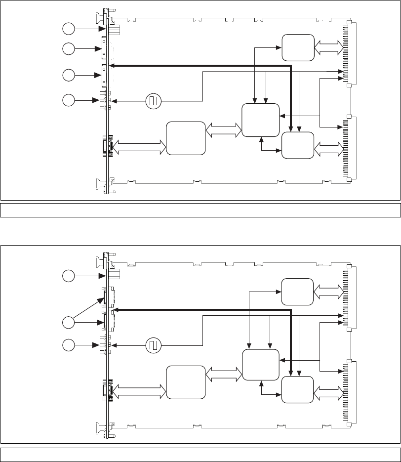
Functional Block Diagrams
Figure 1-1. NI VXI-8360T (198399x-02) Functional Block Diagram
Figure 1-2. NI VXI-8360LT (152725x-01) Functional Block Diagram
1 Status LEDs 2TRG/CLK Port A 3 TRG/CLK Port B 4 SMB I/O
1 Status LEDs 2 Trigger Bus Ports 3 SMB I/O
MXI-Express x1
Copper
P1 ConnectorP2 Connector
PCIe Gen 1 x1
PCIe-to
PCI Bridge
PXI/PCI
MITE
ASIC
P2
MANTIS
ASIC
P1
MANTIS
ASIC
CLK10/
Backplane Triggers
Wired VXI Backplane Trigger and CLK10 Bus
1
2
3
4
MXI-Express x1
Copper
1
3
P1 ConnectorP2 Connector
PCIe Gen 1 x1
PCIe-to
PCI Bridge
PXI/PCI
MITE
ASIC
P2
MANTIS
ASIC
P1
MANTIS
ASIC
CLK10/
Backplane Triggers
Wired VXI Backplane Trigger Bus
2

Chapter 1 Introduction
VXI-MXI-Express Series User Manual 1-6 ni.com
The NI VXI-8360T/LT is, by factory default, hardware configured to
automatically detect if it is in Slot 0, and will supply a CLK10 sourced from
an onboard oscillator. Refer to Appendix B, Advanced Hardware
Configuration Settings, for additional hardware configuration options.
MXI-Express x1 Functional Overview
The NI VXI-8360T/LT controllers enable control of a VXI mainframe with
a host computer using MXI-Express x1 technology.
MXI-Express x1 is based on PCI Express technology. A MXI-Express x1
kit may use a combination of PCI Express switches or PCI Express-to-PCI
bridges to enable control of a VXI chassis from a PC with an available
PCI Express or ExpressCard slot.
The link between the PC and the chassis is a x1 cabled MXI-Express link.
This link is a dual-simplex communication channel comprised of a
low-voltage, differentially driven signal pair. The link can transmit at a rate
of 2.5 Gbps in each direction simultaneously. This port is not compatible
with the cabled PCI Express specification developed by the PCI-SIG.
The BIOS of some host machines may not support the extension of the
PCI-Express fabric or PCI bus. Since this is the primary function of
MXI-Express x1 products, those systems may not boot or function
correctly. To address this issue, certain MXI-Express x1 products have
additional functionality intended to hide all PCI or PCI-Express resources
that are connected to the host machine allowing NI MXI-Express BIOS
Compatibility Software to handle the enumeration process of these
resources.
In the cases where this software is required, there may be a dip switch on
the MXI-Express x1 host adapter that needs to be toggled as instructed by
the documentation for the software.
Chapter 1 Introduction
© National Instruments 1-7 VXI-MXI-Express Series User Manual
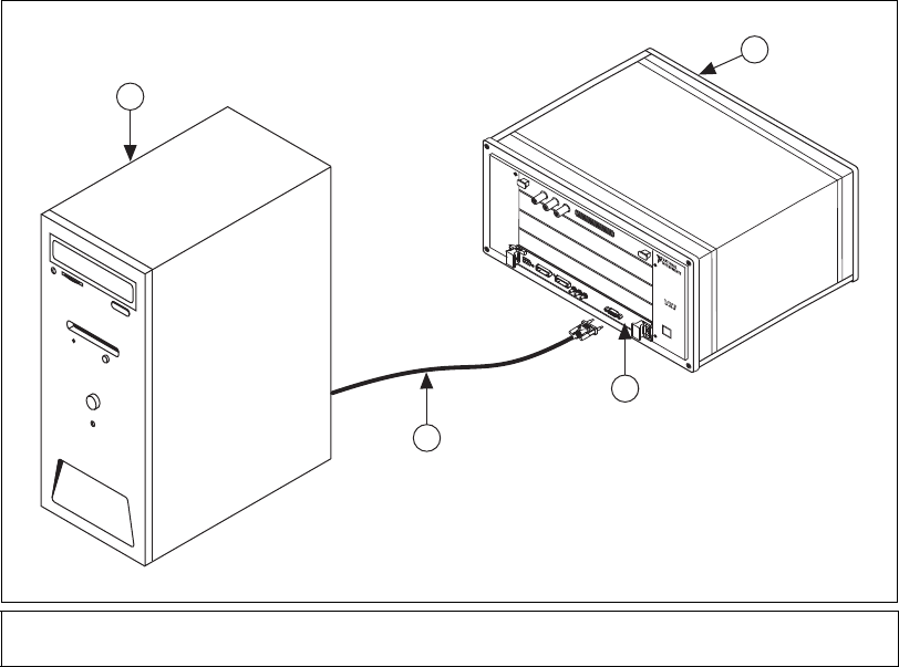
Basic MXI-Express x1 Systems
Figure 1-3 is an example of a basic VXI system being controlled by a
PCI-Express based host computer via a MXI-Express x1 link.
Figure 1-3. Host System with NI VXI-8360T/LT Controller
Refer to the MXI-Express x1 Series User Manual or the Set Up Your
MXI-Express x1 System guide included in your kit for more information
about MXI-Express x1 connectivity support for the NI VXI-8360T/LT
controller.
1 Host Computer
2 VXI Mainframe
3 NI VXI-8360T/LT Controller in Slot 0
4 MXI-Express x1 Cable
bus
1
3
2
4
Chapter 1 Introduction
VXI-MXI-Express Series User Manual 1-8 ni.com
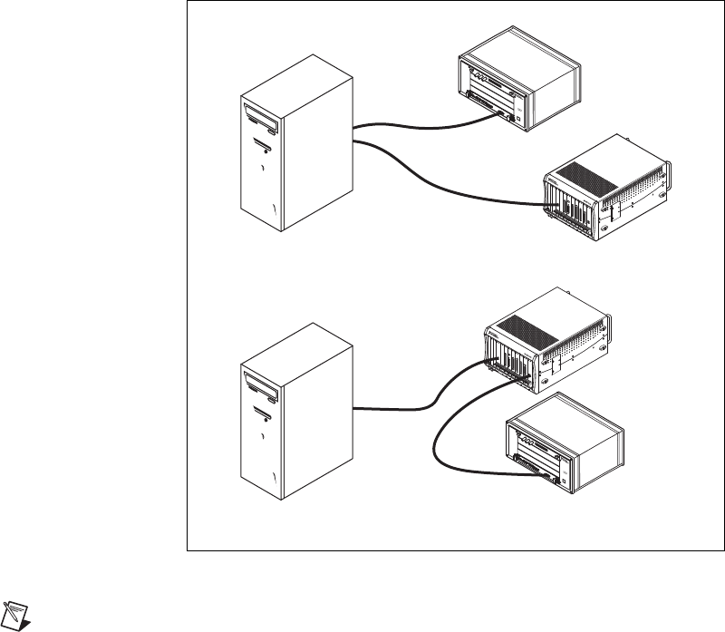
Larger MXI-Express x1 Systems
By leveraging the PCI Express technology used in MXI-Express x1
products, you can connect more than a single chassis to a host controller.
The NI PCIe-8362, for example, has two MXI-Express x1 ports. This
allows for connecting two targets simultaneously, also known as a star
configuration or star topology. Also, if multiple PCI or PCI Express slots
are available in the host PC, additional chassis can be connected by
installing additional NI MXI-Express x1 host boards to achieve the same
star topology.
You can also daisy-chain from a PXI or PXI Express chassis that is already
controlled by an embedded controller, host PC, or laptop to a VXI
mainframe using MXI-Express x1 products.
Figure 1-4. Example MXI-Express x1 System Expansion Topologies
Note The NI VXI-8360T/LT controller cannot be used to daisy-chain the MXI-Express
x1 link from one VXI mainframe to another VXI mainframe.
Star Topology
Daisy-Chain Topology
bus
bus

© National Instruments 2-1 VXI-MXI-Express Series User Manual
Installation and Configuration
Equipment Needed
❑A host computer with an available PCI Express slot1.
❑A MXI-Express x1 host board that is appropriate for the host system
slot.
Refer to the connectivity tables in the Set Up Your MXI-Express x1
System guide to determine which MXI-Express x1 products are
compatible with the NI VXI-8360T and NI VXI-8360LT.
❑A VXIbus mainframe
❑A NI VXI-8360T/LT controller
❑MXI-Express x1 copper cable
❑National Instruments NI-VXI driver software CD
1 Some x16 slots may not work correctly with MXI-Express adapters.

Chapter 2 Installation and Configuration
VXI-MXI-Express Series User Manual 2-2 ni.com
Unpacking
Your MXI-Express x1 boards are shipped in antistatic packages to prevent
electrostatic discharge (ESD) to the devices. ESD can damage several
components on the device.
Caution Never touch the exposed pins of connectors. Doing so may damage the device.
To avoid such damage in handling the device, take the following
precautions:
• Ground yourself using a grounding strap or by holding a grounded
object.
• Touch the antistatic package to a metal part of the computer chassis
before removing the device from the package.
Remove the device from the package and inspect the device for loose
components or any sign of damage. Notify NI if the device appears
damaged in any way. Do not install a damaged device into a computer,
laptop, PXI/CompactPCI, PXI Express/CompactPCI Express,
CompactRIO, or VXI chassis.
Store the device in the antistatic envelope when not in use.
Software Installation
Run setup.exe on the NI-VXI/VISA software CD included with your kit
to install the software and for installation instructions. The CD will install
the driver for the product as well as NI-VISA by default.
With NI-VISA installed on your computer, you can run any VXI
plug&play
software that is compatible with the WINNT/GWINNT framework. This
includes instrument drivers and executable soft front panel software included
with VXI
plug&play
-compatible instruments from a variety of vendors.
Caution To keep the manufacturer/model name tables or the VME device configuration
from a previous installation, be sure to back them up before starting Setup. They are in the
TBL subdirectory of your NI-VXI directory, usually Program Files\National
Instruments\VXI.
When the installation process completes, reboot the system for the changes
to take effect. If you backed up the manufacturer and model name files,

Chapter 2 Installation and Configuration
© National Instruments 2-3 VXI-MXI-Express Series User Manual
restore them to the TBL subdirectory of your NI-VXI directory before
running MAX.
Note If you save and restore the TBL files from an older version of NI-VXI, the software
will use TBL files that do not have the latest updates from National Instruments and may
not include recent hardware releases. If you added additional manufacturer or model names
to your TBL files, we recommend merging those changes with the latest updates included
with this version of NI-VXI, so that all your devices are properly identified.
For more information about the NI-VXI API, refer to Chapter 3,
Developing Your Application.
Hardware Installation and Configuration
Prior to installation of the NI VXI-8360T/LT controller, determine if any
onboard jumper settings need to be changed. The NI VXI-8360T/LT
controllers’ default configuration of onboard jumpers should be acceptable
for most systems. Refer to Appendix B, Default Jumper Settings, only if
your system uses the front-panel CLK10 and trigger SMB connectors.
Caution To guard against electrostatic discharge, touch the antistatic plastic packages to a
metal part of your computer or chassis before removing the boards from their packages.
Your computer or chassis should be plugged in but powered off.
Caution The protection provided by the NI VXI-8360T/LT device can be impaired if it is
used in a manner not described in this document.
Installing Your NI VXI-8360T/LT Controller
1. Power off the chassis.
2. Verify that the backplane connector is intact and that there are no bent
or missing pins on the controller.
3. Insert the NI VXI-8360T/LT controller into the chassis in Slot 0, as
shown in Figure 1-3.
4. Firmly press the NI VXI-8360T/LT controller into the mating
connectors to ensure the module is fully inserted and seated in the
connector.
5. Tighten the two ejector handle screws.

Chapter 2 Installation and Configuration
VXI-MXI-Express Series User Manual 2-4 ni.com
6. Verify that any other VXI devices with system controller capability
that are in the same chassis are not configured as system controller.
7. Ensure that no other VXI devices in your system are manually
configured for the same logical address as your controller.
Note Although the NI VXI-8360T/LT controllers are typically installed in Slot 0 of the
VXI chassis, they may operate in other slots of the chassis. If you choose to install the
controller in a slot other than Slot 0, the automatic detection circuitry on the controller will
detect the slot and configure the controller appropriately, as long as the J2 jumper is set to
Auto-detect.
Caution Having more than one device configured as system controller can damage the
VXI system. For VXI systems that include VME devices, ensure that the VME devices are
not configured in the upper 16 KB (starting from 0xC000) of the A16 address space. This
region is reserved for VXI device configuration registers, which are used for initializing,
configuring, and interacting with VXI devices. The NI VXI-8360T/LT controller also uses
this region for this purpose.
Installing Your MXI-Express x1 Host Adapter or Peripheral
Refer to the Setup Your MXI-Express x1 System guide included in the kit
for hardware installation instructions.
Connecting Cables
Connect the NI VXI-8360T/LT controller to the MXI-Express x1 host
adapter in the host computer, using the MXI-Express x1 cable as shown in
Figure 1-3, Host System with NI VXI-8360T/LT Controller.
For information about connecting trigger cables for the NI VXI-8360T,
refer to Appendix C, Using the Trigger Ports on the NI VXI-8360T.
For information about connecting trigger cables for the NI VXI-8360LT,
refer to Appendix D, Using the Trigger Ports on the NI VXI-8360LT.
For more information about MAX, refer to its online help by selecting the
Help»Help Topics menu.
Powering On/Off the MXI-Express System
For instructions, refer to the Powering On the MXI-Express x1 System
section and Powering Off the MXI-Express x1 System section of the Setup
Your MXI-Express x1 System guide.

Chapter 2 Installation and Configuration
© National Instruments 2-5 VXI-MXI-Express Series User Manual
If using Variable Power On (VPO) refer to the NI-VXI Release Notes for
more information about powering up/down the system.
Software Configuration
The configuration utilities in your software kit are Resource Manager
(Resman) and Measurement & Automation Explorer (MAX).
Resman configures all devices on the VXI backplane for operation and
allocates memory for devices that request it. Resman must be executed
every time the chassis or computer power is cycled, so that your application
can access devices in the VXI chassis.
Note You can also configure MAX to run Resman automatically at every computer startup
by selecting the Run Auto VXI Resource Manager at Startup checkbox from the Tools»
NI-VXI»VXI Options menu.
MAX presents a graphical display of your entire test and measurement
system to help you configure and check the status of various components,
including the NI VXI-8360T/LT controller.
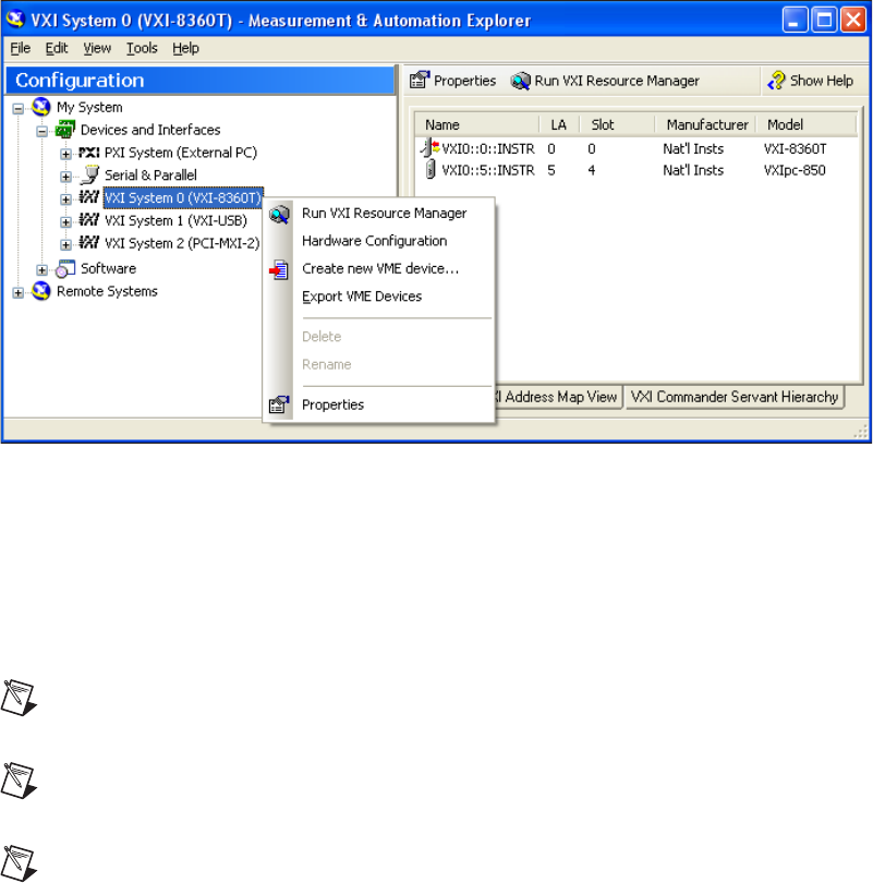
Complete the following steps to configure the VXI System.
1. Open MAX.
2. Select the VXI system that is controlled by the NI VXI-8360T/LT
controller listed under Devices and Interfaces.
Chapter 2 Installation and Configuration
VXI-MXI-Express Series User Manual 2-6 ni.com
3. Verify the configuration of your VXI system by right-clicking the
device in the configuration tree, and selecting Properties or
Hardware Configuration, as shown in Figure 2-1.
Figure 2-1. Right-Clicking on a VXI System in MAX
4. Run Resman by either clicking the Run VXI Resource Manager button
in the toolbar or right-clicking on the VXI system, as shown in
Figure 2-1.
If Resman encounters any issues during configuration, it will report
errors in Max under the system listing.
Note If you change any configuration settings, you will need to run Resman to apply the
changes.
Note You can also run Resman for all VXI systems at once in MAX by selecting Tools»
NI-VXI»VXI Resource Manager.
Note If you are using extenders such as MXI-2 to create a multichassis system, you may
need to run Resman before configuring some of your devices.
5. Verify the configuration, as needed, through the interactive control
utility, VISAIC (Start»Programs» National Instruments»VISA»
VISA Interactive Control), as described in Chapter 3, Developing
Your Application.

Chapter 2 Installation and Configuration
© National Instruments 2-7 VXI-MXI-Express Series User Manual
Default Software Settings
The following tables list the default software settings in Measurement &
Automation Explorer (MAX) for the NI VXI-8360T/LT controller.
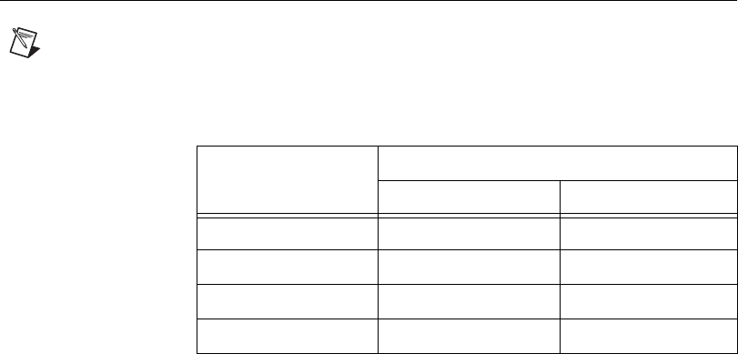
Table 2-1. MAX Device Tab Default Settings
Editor Field Default Setting
Device class Message-based
Number of handlers 1
Table 2-2. MAX Shared Memory Tab Default Settings
Editor Field Default Setting
Don’t share memory —
A24/A32 write posting Enabled
Table 2-3. MAX VXI Bus Tab Default Settings
Editor Field Default Setting
Bus timeout value 500 μs
VXI retry generation Enabled
Automatic retries Enabled
VXI transfer limit 256
A24/A32 write posting Enabled
Requester mode Release on Request
Request level 3
Operate as fair requester Enabled
Bus arbitration mode Prioritized
Arbiter timeout Disabled

Chapter 2 Installation and Configuration
VXI-MXI-Express Series User Manual 2-8 ni.com
Table 2-4. MAX PCI Tab Default Settings
Editor Field Default Setting
Low-level register access
API support
Enabled
User window size 512 KB
DMA setting Enable DMA on this controller
Table 2-5. MAX SMB Tab Default Settings
Editor Field Default Setting
CLK10 50 Ω termination Disabled
Invert CLK10 polarity Enabled
TRIG IN 50 Ω termination Disabled

© National Instruments 3-1 VXI-MXI-Express Series User Manual
Developing Your Application
This chapter discusses the software utilities you can use to start developing
applications that use NI-VXI. Be sure to check the release notes for the
latest application development notes and changes.
Your software features several system development utilities including
MAX, Resman, NI I/O Trace, VISA Interactive Control (VISAIC), and
optionally VXI Interactive Control (VIC). You can also access online
help and a variety of examples to learn how to use NI-VXI for certain
tasks. Each component assists you with one of four development steps:
configuration, device interaction, programming, and debugging.
You can access the utilities, help files, and release notes through the
Windows Start menu by opening the National Instruments»VXI or
National Instruments»VISA program groups.
National Instruments Application Software
In addition to the NI-VISA/NI-VXI software, you can use the National
Instruments LabVIEW, Measurement Studio, and LabWindows™/CVI™
application programs and instrument drivers to ease your programming
task. These standardized programs match the modular virtual instrument
capability of VXI and can reduce your VXI/VME software development
time. These programs are fully VXIplug&play compliant and feature
extensive libraries of VXI instrument drivers written to take full
advantage of direct VXI control. LabVIEW, Measurement Studio, and
LabWindows/CVI include all the tools needed for instrument control, data
acquisition, analysis, and presentation.
LabVIEW is an easy-to-use, graphical programming environment you can
use to acquire data from thousands of different instruments, including
IEEE 488.2 devices, VXI devices, serial devices, PLCs, and plug-in data
acquisition boards. After you have acquired raw data, you can convert
it into meaningful results using the powerful data analysis routines in
LabVIEW. LabVIEW also comes with hundreds of instrument drivers,
which dramatically reduce software development time, because you do not
need to spend time programming the low-level control of each instrument.

Chapter 3 Developing Your Application
VXI-MXI-Express Series User Manual 3-2 ni.com
Measurement Studio allows you to choose from standard environments
such as Microsoft Visual Basic, Visual C++, and Visual Studio .NET to
create your application, using tools specific for each language. With
Measurement Studio, you can write programs quickly and easily and
modify them as your needs change.
LabWindows/CVI is an interactive ANSI C programming environment
designed for building virtual instrument applications. LabWindows/CVI
delivers a drag-and-drop editor for building user interfaces, a complete
ANSI C environment for building your test program logic, and a collection
of automated code generation tools, as well as utilities for building
automated test systems, monitoring applications, or laboratory
experiments.
To use any of these application programs, install them before installing
the NI-VISA/NI-VXI software. LabVIEW, Measurement Studio, and
LabWindows/CVI integrate the VXI and VISA libraries required to support
your NI VXI-8360T/LT controller. You also get hundreds of complete
instrument drivers, which are modular, source-code programs that handle
the communication with your instrument to speed your application
development.
NI-VXI, NI-VISA, and Related Terms
Before you develop your application, it is important to understand the
difference between NI-VXI, NI-VISA, and similar terms.
•NI-VXI/NI-VISA CD is the software package that ships with National
Instruments VXI and VME controllers. This software CD includes
Measurement & Automation Explorer (MAX), NI-VISA, NI I/O
Trace, Resource Manager (Resman), VXI device drivers, and other
utilities for configuring and controlling your VXI or VME system.
•NI-VISA is the native API for communicating with VXI/VME devices.
NI-VISA is the National Instruments implementation of the VISA I/O
standard, which is a common interface to many types of instruments
(such as VXI, GPIB, PXI, Serial, TCP/IP, and so on). NI-VXI is
optimized for use through NI-VISA, and NI recommends using
NI-VISA to develop all new VXI/VME applications.
•The NI-VXI API is an optional development environment that was
developed before NI-VISA. Although NI-VXI still supports the
NI-VXI API, NI recommends using NI-VISA for all new VXI/VME
applications. Refer to the NI-VXI API Notes section for more
information regarding the NI-VXI API.

Chapter 3 Developing Your Application
© National Instruments 3-3 VXI-MXI-Express Series User Manual
•The NI-VXI compatibility layer allows older programs that use the
NI-VXI API to communicate with VXI devices through VISA. Using
this compatibility layer, older programs can run in NI-VXI 3.0 or later
without being rewritten to use the VISA interface. This layer installs
with NI-VXI by default. It should be completely transparent and
provide a high level of performance; however, there may be some
slight changes in behavior for certain applications.
Programming for VXI
NI-VISA and the NI-VXI API are the two National Instruments
programming interfaces for accessing your VXI/VME instruments. With
NI-VXI 3.0 or later, NI-VISA is the native API for communicating with a
VXI or VME system, and NI recommends using it for all new applications.
Older programs that use the NI-VXI API now use the NI-VXI-to-NI-VISA
compatibility layer to communicate with the VXI devices.
Both NI-VISA and the NI-VXI API include functions for register-level
access to VXI instruments and messaging capability to message-based
devices. You can also use either interface to service asynchronous events
such as triggers, signals, and interrupts, and also assert them. Compatibility
with the NI-VXI API is included for legacy applications only—
NI recommends that you write all new VXI/VME applications in VISA.
The best way to learn NI-VISA programming is by reviewing the example
programs your software includes. The examples directory contains working
VISA programs that illustrate many different types of applications. You can
find these examples in the Windows Start menu under Programs»
National Instruments»VISA»Examples.
If you are just getting started, you should learn how to access registers
with high-level calls and send messages with word-serial functions. The
NI-VISA examples for these tasks are HighReg.c and RdWrt.c. Refer
to the other examples as you try more advanced techniques. Consult the
NI-VISA online help for additional information about these topics.
Table 3-1 summarizes the topics the example programs address. All
NI-VISA files are found through the Windows Start menu under
Programs»National Instruments»VISA»Examples, in the
subdirectories listed below.
Chapter 3 Developing Your Application
VXI-MXI-Express Series User Manual 3-4 ni.com
Note MAX includes configuration options that affect low-level functions and shared
memory, as well as trigger mappings and other attributes of your VXI system. Refer to
the MAX online help for information regarding these options.
Optimizing Large VXIbus Transfers
For best performance, keep the following in mind when using viMove()
or VXImove():
• Make sure your buffers are 32-bit aligned.
• Transfer 32-bit data whenever possible.
• Use VXI block access privileges to significantly improve performance
to devices that can accept block transfers, and likewise use D64 access
privileges for devices that can accept the VME64 64-bit data transfer
protocol.
• To optimize move performance on virtual memory systems such as the
Windows operating system, lock the user buffer in memory yourself so
the move operation does not need to lock the buffer.
• To optimize move performance on paged memory systems such as
the Windows operating system, use a contiguous buffer so the move
operation does not need to build a scatter-gather list for the user buffer.
Note viMemAlloc() or VXImemAlloc() returns 32-bit aligned, page-locked,
continuous buffers that work efficiently with the move operations.
Table 3-1. NI-VISA/NI-VXI Examples
Coverage NI-VISA Example
NI-VXI
Example
(Optional)
Message-Based Access C\General\RdWrt.c VXIws.c
High-Level Register Access C\VXI-VME\HighReg.c VXIhigh.c
Low-Level Register Access C\VXI-VME\LowReg.c VXIlow.c
Interrupt Handling C\VXI-VME\AsyncIntr.c and WaitIntr.c VXIint.c
Trigger Handling C\VXI-VME\WaitTrig.c VXItrig.c

Chapter 3 Developing Your Application
© National Instruments 3-5 VXI-MXI-Express Series User Manual
NI-VXI API Notes
The following notes apply only if you are using the NI-VXI API.
National Instruments recommends that all new VXI/VME applications use
the NI-VISA API, but you can still develop with the older NI-VXI API for
compatibility with legacy code.
Compiler Symbols
You may need to define certain compiler symbols so that the NI-VXI
library can work properly with your program. The required symbol
indicates your operating system platform; for example, VXINT designates
the application as a Windows 2000/NT/XP/Me/98 application.
Note LabWindows/CVI automatically defines the correct symbol. You do not need to
define VXINT when using LabWindows/CVI.
The additional symbol BINARY_COMPATIBLE is optional. It ensures
that the resulting application is binary compatible with other National
Instruments VXI controllers using the same operating system. This symbol
may cause a slight performance degradation when you use low-level
VXIbus access functions on some controllers.
You can define these symbols using #define statements in your source
code or using the appropriate option in your compiler (typically either –D
or /D). If you use #define statements, they must appear in your code
before the line that includes the NI-VXI API header nivxi.h.
Compatibility Layer Options
Although NI-VXI supports multiple VXI controllers through NI-VISA, the
NI-VXI API supports only a single controller. To specify which controller
the emulation layer should use, run MAX. Select Tools»NI-VXI»
VXI Options. Select the VXI system that will support the emulation layer.
In NI-VXI 3.0 or later, when you enable for triggers or interrupts, only
the local controller is enabled. In the NI-VXI API functions for enabling
triggers and interrupts, the controller parameter is ignored. If you need
to enable a remote controller for triggers, use the MAX frame resource to
map the trigger back to the local controller. Refer to the NI-VISA Help for
additional information.
The interrupt and trigger routing in the NI-VXI 3.0 or later low-level
drivers is somewhat different from the default routing in previous versions
of NI-VXI. Therefore, the compatibility layer may behave differently than

Chapter 3 Developing Your Application
VXI-MXI-Express Series User Manual 3-6 ni.com
the original NI-VXI API with regard to these settings. In particular, if you
are receiving triggers on an external controller, you may need to modify the
trigger configuration on your extender module using MAX. Consult the
manual for your extender module for details. In general, interrupts are
routed automatically based on the interrupt configuration the resource
manager detects. Whether the changed routing behavior affects your
program is application dependent.
Because VISA is an instrument-centric API, certain functions from the
more controller-centric NI-VXI API do not match perfectly with a VISA
counterpart. When an application enables an event with the NI-VXI API
compatibility layer, each logical address is enabled for that event
separately. For example, if the application enables an interrupt level, VISA
will enable the interrupt on each logical address, one at a time, until all the
devices are enabled. This means that some interrupts could be lost from
devices with higher numbered logical addresses. MAX provides an
option for users to pick which logical address is enabled first. Select Tools»
NI-VXI»VXI Options. Set Prioritized Signal LA to the logical address of
the device that generates the events. This prevents possible loss of events
from that device.
Device Interaction and Debugging Tools
NI I/O Trace and VISAIC are useful utilities for identifying the causes of
problems in your application, and are installed by default with your NI-VXI
installation.
NI I/O Trace
NI I/O Trace tracks the calls your application makes to National Instruments
drivers, including NI-VISA, NI-VXI, and NI-488. NI I/O Trace highlights
functions that return errors, so during development you can quickly spot
which functions failed during a program’s execution. NI I/O Trace can log
the calls your program makes to these drivers so you can check them for
errors at your convenience, or use the NI I/O Trace log as a reference when
discussing the problem with National Instruments technical support.
Figure 3-1 shows an example of an error returned from a call to
viMemAllocEx
.
Chapter 3 Developing Your Application
© National Instruments 3-7 VXI-MXI-Express Series User Manual
Figure 3-1. NI I/O Trace
VISA Interactive Control (VISAIC)
You can interact with your VXI/VME devices using the VISA Interactive
Control (VISAIC) utility. VISAIC allows you to control your VXI/VME
devices without using LabVIEW, Measurement Studio, LabWindows/CVI,
or another programming language. You can also control your devices in
MAX by right-clicking a device name and selecting Open VISA Session.
Try the following in VISAIC: In the tree view, navigate using your mouse
to the VISA resource for your controller—probably VXI0::0::INSTR,
representing the VXI system 0, logical address 0 instrument resource,
as shown in Figure 3-2.
Chapter 3 Developing Your Application
VXI-MXI-Express Series User Manual 3-8 ni.com
Figure 3-2. Select Your Controller in VISAIC
Open the selected resource and navigate to Input/Output and select the
In tab. In this tab, you can read registers on your device, such as the VXI
device configuration registers. Execute the In operation with Width set to
16-bits and other parameters set to default values. The In Value field shows
the I/O operation result, such as 0x8ff6. The Return Data field shows the
function status, such as No Error for VI_SUCCESS, as shown in
Figure 3-3.
Chapter 3 Developing Your Application
© National Instruments 3-9 VXI-MXI-Express Series User Manual
Figure 3-3. Successful In Access in the VISAIC Input/Output Tab
(This Window May Look Slightly Different for LabVIEW Users)
If the data value ends in FF6, you have successfully read the National
Instruments manufacturer ID from your VXI/VME controller’s ID register.
You may now want to read the configuration registers from other VXI
devices in your system by opening the devices in VISAIC. Try reading a
register from each device listed in the MAX view of your VXI system. This
way, you can verify that your VXI controller can access each device in your
VXI system successfully. You can also access VXI and VME devices
configured in A16, A24, or A32 space by opening the VXI MEMACC
resource, which is VISA’s representation of VXI memory. For more
information about VISAIC operations and commands, refer to the online
help in the Help menu and the context-sensitive help (such as What’s
This?), available by clicking Help and mousing over any panel.
VXI Interactive Control (VIC)
You can also use VXI Interactive Control Program (VIC) to control your
VXI/VME devices and develop and debug VXI application programs. You
can launch VISAIC (or VIC) from the Tools menu in MAX or from the
VISA or VXI subgroups in Start»Programs»National Instruments.

© National Instruments A-1 VXI-MXI-Express Series User Manual
Specifications
This appendix lists the system specifications for the following products
only:
•NI VXI-8360T (198399x-02)
•NI VXI-8360LT (152725x-01)
Note The model numbers listed above are followed by their specific NI assembly numbers
in parentheses. x denotes all letter revisions of the assembly. Ensure the specifications of
interest match the NI assembly number that is printed on either the front or back side of the
board.
For specifications on other MXI-Express x1 products that can connect to
the NI VXI-8360T and NI VXI-8360LT, refer to the MXI-Express x1 Series
User Manual.
Appendix A Specifications
VXI-MXI-Express Series User Manual A-2 ni.com
NI VXI-8360T (198399x-02)
Note These specifications are typical at 25 °C, unless otherwise stated, and are subject to
change without notice.
Power Requirements
Physical
Size .........................................................C size, C-1
Dimensions ............................................. 23.3 × 34.0 cm (9.2 × 13.4 in.)
Weight ....................................................1.3 kg (46.8 oz)
Slot requirements....................................Single VXI C-size slot
Compatibility ..........................................Fully compatible with VXI
specification
VXI keying class ....................................Class 1 TTL
MTBF .....................................................Contact factory
Volt age
Current
Typical (DC) Dynamic
+5 V 1.600 A 1.600 A
+12 V 0.020 A 0.020 A
–5.2 V 0.177 A 0.125 A
–2 V 0.060 A 0.125 A

Appendix A Specifications
© National Instruments A-3 VXI-MXI-Express Series User Manual
Front Panel I/O Connectors
EXT CLK SMB Connector
Output drive ........................................... 50 Ω source terminated
output driver
Voltage level ................................................... 0.1 to 4.9 V into open circuit (typical)
0.1 to 2.5 V into 50 Ω (typical)
Absolute maximum DC current ............. ±50 mA
Output coupling...................................... DC
TRIG IN SMB Connector
Input buffer ............................................ TTL compatible
Input coupling ........................................ DC
TRIG OUT SMB Connector
Output drive ........................................... 50 Ω line driver
Voltage level............................................... 2.0 V minimum into 50 Ω (typical)
Output coupling...................................... DC
Figure A-1. Front Panel SMB Connectors
12
TRIG IN
12
12
TRIG OUT
EXT CLK (CLK10)
Appendix A Specifications
VXI-MXI-Express Series User Manual A-4 ni.com
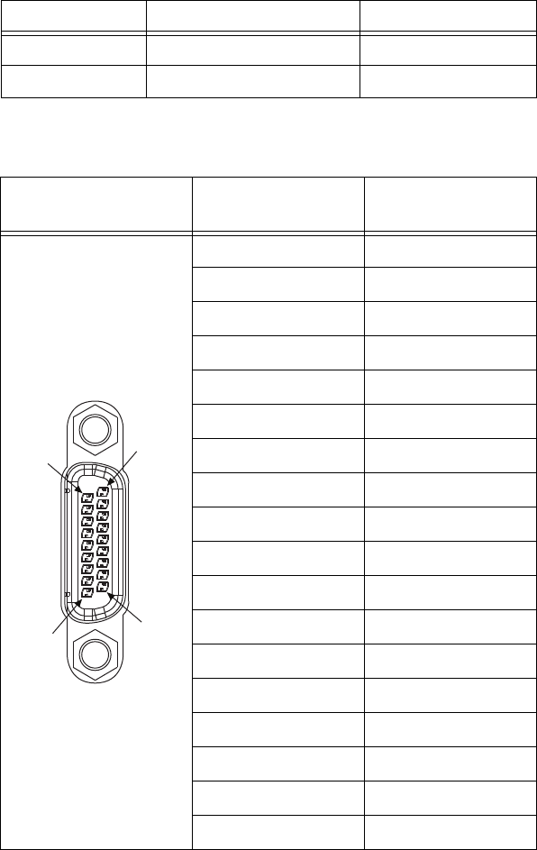
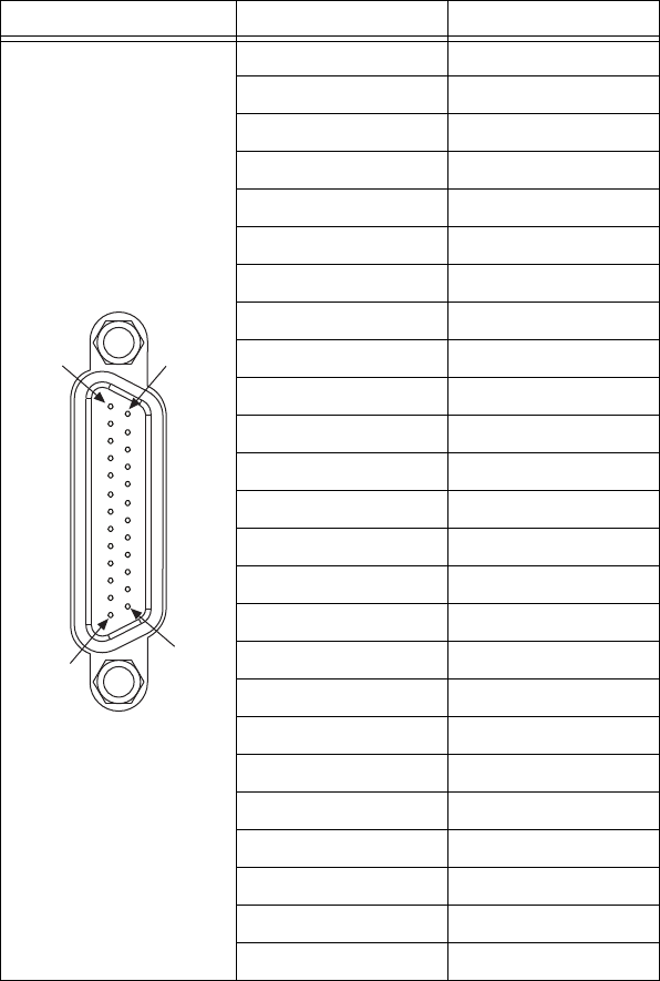
MXI-Express x1 Connector
Table A-1. SMB Connector Pinout
Pin Signal Name Signal Description
1SIGNALCONDUCTOR Trigger/CLK
2 (Shield) GND Ground
MXI-Express x1
Connector Pin Number Signal Description
A1 PERn0
A2 PERp0
A3 RSVD
A4 SB_RTN
A5 CREFCLK–
A6 CREFCLK+
A7 PWR_RTN
A8 CPERST#
A9 GND
B1 GND
B2 RSVD
B3 CWAKE#
B4 CPRSNT#
B5 GND
B6 PWR
B7 CPWRON
B8 PETn0
B9 PETp0
A9
A1
B1
B9

Appendix A Specifications
© National Instruments A-5 VXI-MXI-Express Series User Manual
Two TRIG/CLK PORTs
Connector type ....................................... Cabled MXI-Express x41
Maximum trigger bus length.................. 19 m of cables
Maximum number of devices on bus..... 62
Environmental
Maximum altitude .................................. 2,000 m
Pollution Degree .................................... 2
Indoor use only.
Operating Environment
Ambient temperature range.................... 0 to 55 °C
(Tested in accordance with
IEC-60068-2-1 and
IEC-60068-2-2: meets
MIL-PRF-28800F Class 3 low
temperature limit and
MIL-PRF-28800F Class 2 high
temperature limit.)
Relative humidity range ......................... 10% to 90%
(Tested in accordance with
IEC-60068-2-56.)
Storage Environment
Ambient temperature range.................... –40 to 85 °C
(Tested in accordance with
IEC-60068-2-1 and
IEC-60068-2-2; meets
MIL-PRF-28800F Class 3 limits.)
Relative humidity range ......................... 5% to 95%
(Tested in accordance with
IEC-60068-2-56.)
EMI ........................................................ FCC Class A verified, EC verified
1 Not to be used for MXI-Express communication.
2 Additional devices sharing the bus may function, but is not supported by National Instruments.

Appendix A Specifications
VXI-MXI-Express Series User Manual A-6 ni.com
Shock and Vibration
Operational shock ...................................30 g peak, half-sine, 11 ms pulse
(Tested in accordance with
IEC-60068-2-27; meets
MIL-PRF-28800F Class 2 limits.)
Random vibration
Operating .........................................5 to 500 Hz, 0.3 grms
Nonoperating ...................................5 to 500 Hz, 2.4 grms
(Tested in accordance with
IEC-60068-2-64. Nonoperating
test profile exceeds the
requirements of
MIL-PRF-28800F, Class 3.)
Safety
This product meets the requirements of the following standards of safety
for electrical equipment for measurement, control, and laboratory use:
• IEC 61010-1, EN 61010-1
• UL 61010-1, CSA 61010-1
Note For UL and other safety certifications, refer to the product label or the Online
Product Certification section.
Electromagnetic Compatibility
This product meets the requirements of the following EMC standards for
electrical equipment for measurement, control, and laboratory use:
• EN 61326-1 (IEC 61326-1): Class A emissions; Basic immunity
• EN 55011 (CISPR 11): Group 1, Class A emissions
• AS/NZS CISPR 11: Group 1, Class A emissions
• FCC 47 CFR Part 15B: Class A emissions
• ICES-001: Class A emissions
Note In the United States (per FCC 47 CFR), Class A equipment is intended for use in
commercial, light-industrial, and heavy-industrial locations. In Europe, Canada, Australia
and New Zealand (per CISPR 11) Class A equipment is intended for use only in
heavy-industrial locations.

Appendix A Specifications
© National Instruments A-7 VXI-MXI-Express Series User Manual
Note Group 1 equipment (per CISPR 11) is any industrial, scientific, or medical
equipment that does not intentionally generates radio frequency energy for the treatment
of material or inspection/analysis purposes..
Note For EMC declarations and certifications, and additional information, refer to the
Online Product Certification section.
CE Compliance
This product meets the essential requirements of applicable European
Directives as follows:
• 2006/95/EC; Low-Voltage Directive (safety)
• 2004/108/EC; Electromagnetic Compatibility Directive (EMC)
Online Product Certification
To obtain product certifications and the Declaration of Conformity (DoC)
for this product, visit ni.com/certification, search by model number
or product line, and click the appropriate link in the Certification column.
Environmental Management
NI is committed to designing and manufacturing products in an
environmentally responsible manner. NI recognizes that eliminating certain
hazardous substances from our products is beneficial to the environment
and to NI customers.
For additional environmental information, refer to the NI and the
Environment Web page at ni.com/environment. This page contains the
environmental regulations and directives with which NI complies, as well
as other environmental information not included in this document.

Appendix A Specifications
VXI-MXI-Express Series User Manual A-8 ni.com
Waste Electrical and Electronic Equipment (WEEE)
EU Customers At the end of the product life cycle, all products must be sent to a WEEE
recycling center. For more information about WEEE recycling centers, National
Instruments WEEE initiatives, and compliance with WEEE Directive 2002/96/EC on
Waste Electrical and Electronic Equipment, visit ni.com/environment/weee.
Cleaning
If you need to clean the module, use a soft, nonmetallic brush. Make sure
that the module is completely dry and free from contaminants before
returning it to service.
⬉ᄤֵᙃѻક∵ᶧࠊㅵ⧚ࡲ⊩ ˄Ё
RoHS
˅
Ёᅶ᠋ National Instruments ヺড়Ё⬉ᄤֵᙃѻકЁ䰤ࠊՓ⫼ᶤѯ᳝ᆇ⠽䋼ᣛҸ (RoHS)DŽ
݇Ѣ National Instruments Ё RoHS ড়㾘ᗻֵᙃˈ䇋ⱏᔩ ni.com/environment/rohs_chinaDŽ
(For information about China RoHS compliance, go to ni.com/environment/rohs_china.)
Appendix A Specifications
© National Instruments A-9 VXI-MXI-Express Series User Manual
NI VXI-8360LT (152725x-01)
Note These specifications are typical at 25 °C, unless otherwise stated, and are subject to
change without notice.
Power Requirements
Physical
Size......................................................... C size, C-1
Dimensions............................................. 23.3 × 34.0 cm (9.2 × 13.4 in.)
Weight.................................................... 1.3 kg (47.2 oz)
Slot requirements ................................... Single VXI C-size slot
Compatibility ......................................... Fully compatible with VXI
specification
VXI keying class.................................... Class 1 TTL
MTBF..................................................... 322,638 hours
Volt a ge
Current
Typical (DC)
+5 V 1.750 A1
+12 V 0.020 A
–5.2 V 0.177 A
–2 V 0.060 A
1 An additional 0.079 A may be drawn when a combined 100 mA is sourced from the
3.3 V pins of the trigger bus port connectors.

Appendix A Specifications
VXI-MXI-Express Series User Manual A-10 ni.com
Front Panel I/O Connectors
EXT CLK SMB Connector
Output drive............................................50 Ω source terminated
output driver
Voltage level.................................................... 0.1 to 4.9 V into open circuit (typical)
0.1 to 2.5 V into 50 Ω (typical)
Absolute maximum DC current..............±50 mA
Output coupling ......................................DC
TRIG IN SMB Connector
Input buffer .............................................TTL compatible
Input coupling.........................................DC
TRIG OUT SMB Connector
Output drive............................................50 Ω line driver
Voltage level................................................2.0 V minimum into 50 Ω (typical)
Output coupling ......................................DC
Figure A-2. Front Panel SMB Connectors
12
TRIG IN
12
12
TRIG OUT
EXT CLK (CLK10)
Appendix A Specifications
© National Instruments A-11 VXI-MXI-Express Series User Manual
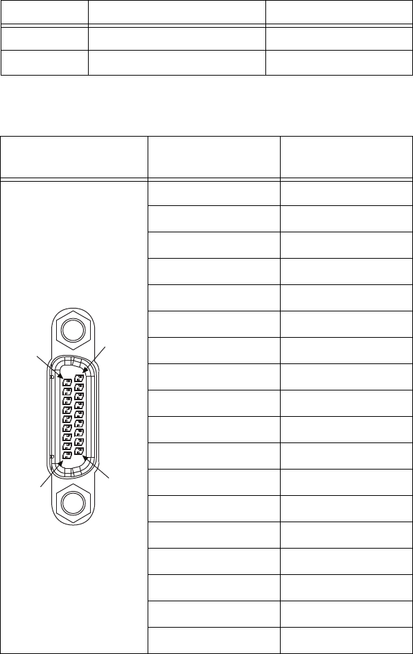
MXI-Express x1 Connector
Table A-2. SMB Connector Pinout
Pin Signal Name Signal Description
1SIGNALCONDUCTOR Trigger/CLK
2 (Shield) GND Ground
MXI-Express x1
Connector Pin Number Signal Description
A1 PERn0
A2 PERp0
A3 RSVD
A4 SB_RTN
A5 CREFCLK–
A6 CREFCLK+
A7 PWR_RTN
A8 CPERST#
A9 GND
B1 GND
B2 RSVD
B3 CWAKE#
B4 CPRSNT#
B5 GND
B6 PWR
B7 CPWRON
B8 PETn0
B9 PETp0
A9
A1
B1
B9

Appendix A Specifications
VXI-MXI-Express Series User Manual A-12 ni.com
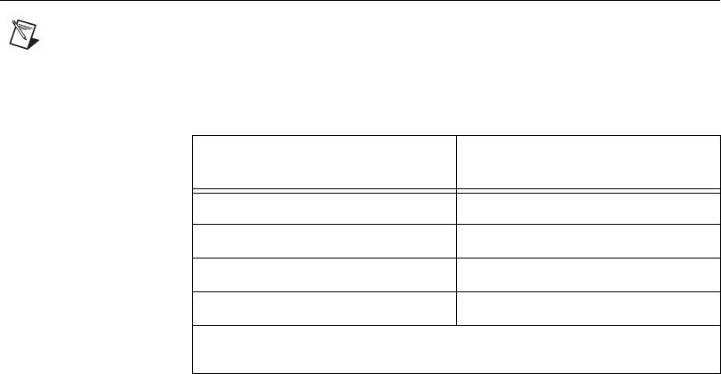
Two Trigger Bus Ports
Physical interface......................................TIA/EIA899 M-LVDS compatible
Bus transceiver...............................................Texas Instruments SN65MLVD080
Maximum trigger bus length ..................20 m of cables
Maximum number of devices on bus .....61
1 Additional devices sharing the bus may function, but is not supported by National Instruments.
Appendix A Specifications
© National Instruments A-13 VXI-MXI-Express Series User Manual
Environmental
Maximum altitude .................................. 2,000 m
Pollution Degree .................................... 2
Indoor use only.
Trigger Bus Port Pin Number Signal Description
1+3.3 V
2+3.3 V Return
3LXI1p
4LXI1n
5GND
6LXI3p
7LXI3n
8GND
9LXI5p
10 LXI5n
11 RSVD
12 LXI7p
13 LXI7n
14 LXI0p
15 LXI0n
16 RSVD
17 LXI2p
18 LXI2n
19 GND
20 LXI4p
21 LXI4n
22 GND
23 LXI6p
24 LXI6n
25 RSVD
1
14
1325
Appendix A Specifications
VXI-MXI-Express Series User Manual A-14 ni.com
Operating Environment
Ambient temperature range ....................0 to 55 °C
(Tested in accordance with
IEC-60068-2-1 and
IEC-60068-2-2: meets
MIL-PRF-28800F Class 3 low
temperature limit and
MIL-PRF-28800F Class 2 high
temperature limit.)
Relative humidity range..........................10% to 90%
(Tested in accordance with
IEC-60068-2-56.)
Storage Environment
Ambient temperature range ....................–40 to 85 °C
(Tested in accordance with
IEC-60068-2-1 and
IEC-60068-2-2; meets
MIL-PRF-28800F Class 3 limits.)
Relative humidity range..........................5% to 95%
(Tested in accordance with
IEC-60068-2-56.)
EMI.........................................................FCC Class A verified, EC verified
Shock and Vibration
Operational shock ...................................30 g peak, half-sine, 11 ms pulse
(Tested in accordance with
IEC-60068-2-27; meets
MIL-PRF-28800F Class 2 limits.)
Random vibration
Operating .........................................5 to 500 Hz, 0.3 grms
Nonoperating ...................................5 to 500 Hz, 2.4 grms
(Tested in accordance with
IEC-60068-2-64. Nonoperating
test profile exceeds the
requirements of
MIL-PRF-28800F, Class 3.)

Appendix A Specifications
© National Instruments A-15 VXI-MXI-Express Series User Manual
Safety
This product meets the requirements of the following standards of safety
for electrical equipment for measurement, control, and laboratory use:
• IEC 61010-1, EN 61010-1
• UL 61010-1, CSA 61010-1
Note For UL and other safety certifications, refer to the product label or the Online
Product Certification section.
Electromagnetic Compatibility
This product meets the requirements of the following EMC standards for
electrical equipment for measurement, control, and laboratory use:
• EN 61326-1 (IEC 61326-1): Class A emissions; Basic immunity
• EN 55011 (CISPR 11): Group 1, Class A emissions
• AS/NZS CISPR 11: Group 1, Class A emissions
• FCC 47 CFR Part 15B: Class A emissions
• ICES-001: Class A emissions
Note In the United States (per FCC 47 CFR), Class A equipment is intended for use in
commercial, light-industrial, and heavy-industrial locations. In Europe, Canada, Australia
and New Zealand (per CISPR 11) Class A equipment is intended for use only in
heavy-industrial locations.
Note Group 1 equipment (per CISPR 11) is any industrial, scientific, or medical
equipment that does not intentionally generates radio frequency energy for the treatment
of material or inspection/analysis purposes..
Note For EMC declarations and certifications, and additional information, refer to the
Online Product Certification section.
Appendix A Specifications
VXI-MXI-Express Series User Manual A-16 ni.com
CE Compliance
This product meets the essential requirements of applicable European
Directives as follows:
• 2006/95/EC; Low-Voltage Directive (safety)
• 2004/108/EC; Electromagnetic Compatibility Directive (EMC)
Online Product Certification
To obtain product certifications and the Declaration of Conformity (DoC)
for this product, visit ni.com/certification, search by model number
or product line, and click the appropriate link in the Certification column.
Environmental Management
NI is committed to designing and manufacturing products in an
environmentally responsible manner. NI recognizes that eliminating certain
hazardous substances from our products is beneficial to the environment
and to NI customers.
For additional environmental information, refer to the NI and the
Environment Web page at ni.com/environment. This page contains the
environmental regulations and directives with which NI complies, as well
as other environmental information not included in this document.
Waste Electrical and Electronic Equipment (WEEE)
EU Customers At the end of the product life cycle, all products must be sent to a WEEE
recycling center. For more information about WEEE recycling centers, National
Instruments WEEE initiatives, and compliance with WEEE Directive 2002/96/EC on
Waste Electrical and Electronic Equipment, visit ni.com/environment/weee.
Cleaning
If you need to clean the module, use a soft, nonmetallic brush. Make sure
that the module is completely dry and free from contaminants before
returning it to service.
⬉ᄤֵᙃѻક∵ᶧࠊㅵ⧚ࡲ⊩ ˄Ё
RoHS
˅
Ёᅶ᠋ National Instruments ヺড়Ё⬉ᄤֵᙃѻકЁ䰤ࠊՓ⫼ᶤѯ᳝ᆇ⠽䋼ᣛҸ (RoHS)DŽ
݇Ѣ National Instruments Ё RoHS ড়㾘ᗻֵᙃˈ䇋ⱏᔩ ni.com/environment/rohs_chinaDŽ
(For information about China RoHS compliance, go to ni.com/environment/rohs_china.)

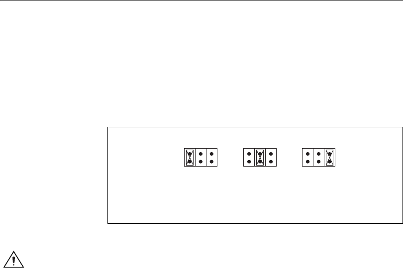
© National Instruments B-1 VXI-MXI-Express Series User Manual
Advanced Hardware
Configuration Settings
This appendix describes the alternate hardware configuration settings for
the NI VXI-8360T/LT controller. The board is set at the factory for the most
commonly used configuration. This information is intended for more
advanced users. Do not attempt to reconfigure any jumpers unless you are
familiar with its purpose.
The following hardware configuration settings are user configurable.
• Slot 0 detection
• VXIbus CLK10 routing
• SMB Trigger I/O
• Backplane trigger I/O
For the jumper locations and default settings, see Figure B-1, Default
Jumper Settings.
Note To gain access to the jumpers, remove the side panel cover that is fastened with
screws.
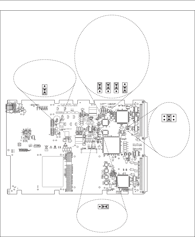
Appendix B Advanced Hardware Configuration Settings
VXI-MXI-Express Series User Manual B-2 ni.com
Default Jumper Settings
Figure B-1. VXI-MXI-Express Factory Default Jumper Settings
W7—TRIG CARD CLK10 DIR
1-2—OUT
2-3—IN (DEFAULT)
W2—SMB CLK10 DIR
1-2—IN (DEFAULT)
2-3—OUT
W3—EXT. SOURCE SELECT
1-2—SMB (DEFAULT)
2-3—TRIGGER CARD
W4—CLK10 SOURCE SELECT
1-2—INTERNAL OSC (DEFAULT)
2-3—EXTERNAL SOURCE
W5—MITE CONFIGURATION
1-2—FACTORY
2-3—USER (DEFAULT)
W8—MITE SELF CONFIG
1-2—DISABLE
2-3—ENABLE (DEFAULT)
J2—SLOT 0 DETECT
1-2—NON-SLOT 0
3-4—AUTO DETECT
(DEFAULT)
5-6—SLOT 0
1
2
3
W7 1
2
3
W5
1
2
3
W2
1
2
3
W3
1
2
3
W4
W8
123
246
135
J2
Appendix B Advanced Hardware Configuration Settings
© National Instruments B-3 VXI-MXI-Express Series User Manual
Slot 0 Detection
The NI VXI-8360T/LT controller is configured at the factory to
automatically detect if it is installed in Slot 0 of a VXI mainframe. With
automatic System Controller slot detection the NI VXI-8360T/LT
controller can be installed in any VXIbus slot.
The NI VXI-8360T/LT controller can be manually configured for either
System Controller or Non-System Controller operation. Use the three
position jumper J2 as shown in Figure B-2 to select between automatic
detection, System Controller, or Non-System Controller.
Figure B-2. Slot 0 Detection through the J2 Jumper
Caution Do not install a device configured as the System Controller in any slot other
than Slot 0. When installing into a slot other than Slot 0, first reconfigure it as either a
Non-System Controller or for automatic detection. Failing to do so may result in damage
to the NI VXI-8360T/LT controller and/or the backplane.
When the NI VXI-8360T/LT controller is installed in Slot 0 of a VXI
system it becomes the VXIbus System Controller. As the System Controller
the NI VXI-8360T/LT controller has VXIbus Data Transfer Arbiter
circuitry that accepts bus requests on all four VXIbus request levels,
prioritizes the requests, and grants the bus to the highest priority requester.
As the VXIbus System Controller the NI VXI-8360T/LT controller also
drives the 16 MHz VXIbus system clock via an onboard 16 MHz oscillator.
As required by the specification, when installed in Slot 0, the
NI VXI-8360T/LT controller drives CLK10, a differential ECL output, to
the VXIbus backplane. When the system is not installed in Slot 0 it will
only receive the CLK10 signal.
c. Slot 0/
System
Controller
a. Non-Slot 0/
Non-System
Controller
b. Auto Detect
(Default)
135
246
J2
135
246
J2
135
246
J2

Appendix B Advanced Hardware Configuration Settings
VXI-MXI-Express Series User Manual B-4 ni.com
VXIbus CLK10 Routing
When the NI VXI-8360T/LT controller is installed in Slot 0 of your
mainframe, it supplies the VXIbus CLK10 signal. Three different sources
for CLK10 are available with the NI VXI-8360T/LT controller:
• The internal 10 MHz ±100 ppm CLK10 oscillator. This is the default
CLK10 source.
• The front panel EXT CLK SMB connector. When configured as an
input the front panel SMB allows an external source to be used as the
source for the VXIbus CLK10 signal.
•(NI VXI-8360T Only) The front panel TRIG/CLK PORT A(B). CLK10
can be routed into the NI VXI-8360T from another NI VXI-8360T
through the TRIG/CLK PORT A(B) on the front panel. Onboard
jumpers are used to set this configuration.
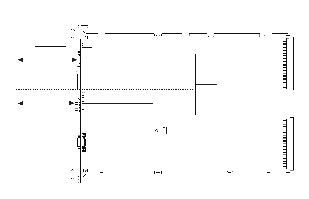
Appendix B Advanced Hardware Configuration Settings
© National Instruments B-5 VXI-MXI-Express Series User Manual
CLK10 Routing Options
Figure B-3. CLK10 Routing Options
To/From
Backplane
W4
W3External
Internal
10 MHz Oscillator
±100 ppm
To/From TRG/CLK PORT
To/From SMB
W7
W2
SMB CLK Dir
Trig Card CLK 10 Dir
CLK 10
Source Select
NI VXI-8360T Only
External CLK 10
Source Select

Appendix B Advanced Hardware Configuration Settings
VXI-MXI-Express Series User Manual B-6 ni.com
Table B-1. NI VXI-8360T/LT Slot O CLK10 Routing Options and Jumper Configurations
Product CLK10 Source
EXT CLK
Front Panel SMB
TRG/CLK
Ports W7 W2 W3 W4
NI VXI-8360T
Internal
Oscillator
Off
CLK10 Out Out In X Internal
NI VXI-8360T/LT Off In In X Internal
NI VXI-8360T
CLK10 Out
CLK10 Out Out Out X Internal
NI VXI-8360T/LT Off In Out X Internal
NI VXI-8360T
EXT CLK SMB Input for CLK10
CLK10 Out Out XSMB External
NI VXI-8360T/LT Off In XSMB External
NI VXI-8360T
Trigger Port
Off Input for
CLK10
Out In Trigger Card External
NI VXI-8360T CLK10 Out Out Out Trigger Card External
NI VXI-8360T Not recommended. Undefined operation. In XTrigger Card External
Table B-2. NI VXI-8360T/LT Non Slot O CLK10 Routing Options and Jumper Configurations
Product CLK10 Source
EXT CLK
Front Panel SMB
TRG/CLK
Ports W7 W2 W3 W4
NI VXI-8360T/LT
Backplane
(from Slot 0
controller)
CLK10 Out Off In Out X X
NI VXI-8360T/LT Off Off In In X X
NI VXI-8360T CLK10 Out CLK10 Out Out Out X X
NI VXI-8360T Off CLK10 Out Out In X X
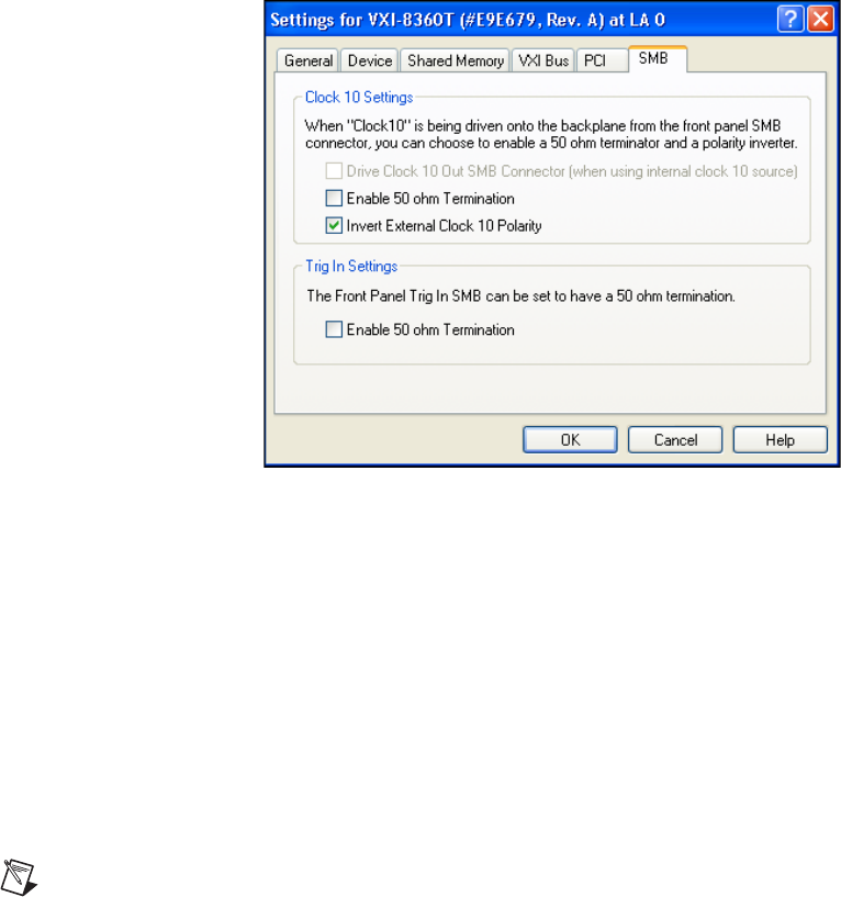
Appendix B Advanced Hardware Configuration Settings
© National Instruments B-7 VXI-MXI-Express Series User Manual
Inverting CLK10
If the front panel SMB connector EXT CLK is configured as an output this
software setting provides the capability to invert the clock output. This
setting can be found in the hardware configuration panels in MAX as
shown in Figure B-4.
Figure B-4. Inverting the CLK10 Signal through MAX
CLK10 Termination
If the front panel SMB connector EXT CLK is configured as an input
this software setting can enable 50 Ω parallel termination. This setting
can be found in the hardware configuration panels in MAX, as shown in
Figure B-4.
Front Panel/SMB Trigger Input Termination
Optional software enabled 50 Ω parallel termination is available for the
front panel trigger input. This setting can be found in the hardware
configuration panels in MAX, as shown in Figure B-4.
Note Parallel termination is not necessary when the signal is driven by a 50 Ω source,
such as a NI VXI-8360T/LT controller.
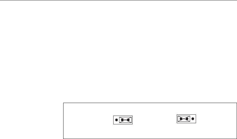
Appendix B Advanced Hardware Configuration Settings
VXI-MXI-Express Series User Manual B-8 ni.com
Power-On Self Configuration
The NI VXI-8360T/LT controller has an onboard EEPROM, which stores
default register values for the VXI circuitry. These values are loaded when
you power up the computer. The values read from the EEPROM program
the PCI interface and the VXIbus registers so that the VXI interface is ready
to respond to Resource Manager accesses within the required 5 seconds of
SYSRST# deasserting.
You can disable this power-on self-configuration (POSC) circuit by
changing switch W8. Although this makes the VXI circuitry unusable,
it is sometimes helpful in debugging address and interrupt conflicts
with add-in boards. In general, however, you should leave W8 in its
factory-default setting. Figure B-5 shows the possible configurations
for W8.
Figure B-5. Power-on Self Configuration Status
a. Enable (default) b. Disable
W8
231
W8
231
© National Instruments C-1 VXI-MXI-Express Series User Manual
Using the Trigger Ports on the
NI VXI-8360T
The NI VXI-8360T allows you to extend the 8 VXI backplane triggers and
CLK10 through convenient front panel connectors. Each trigger and the
CLK are independently configurable as either inputs to the frame or outputs
from the frame. The wired VXI backplane trigger and CLK10 bus is
connected in a daisy chain topology and can support up to 6 devices with a
total of 19 m of cables.
Cautions The wired VXI backplane trigger and CLK10 bus uses MXI-Express x4 cables
and connectors, however these are not MXI-Express x4 ports. Do not connect the trigger
ports to a MXI-Express x4 or PCI Express x4 device.
The trigger bus may be able to support more devices and/or greater cable lengths, but these
configurations have not been validated by National Instruments and are not currently
supported.
Connecting the Trigger Port Cables
When connecting the cables between two devices on the wired VXI
backplane trigger and CLK10 bus, always ensure you connect TRIG/CLK
PORT A of one device to TRIG/CLK PORT B of the second device, or
TRIG/CLK PORT B of one device to TRIG/CLK PORT A of the second
device, as shown in Figure C-1.
If the cables are not connected correctly, the Cable Status LED will blink
red, and the trigger drivers in that system will be disabled.
Note Trigger bus cables may be removed and inserted while power is on.
End of bus termination is also required for proper operation. The
VXI-8360T automatically detects its position on the wired VXI backplane
trigger and CLK10 bus and it will enable its termination if it detects it is at
the end of the bus
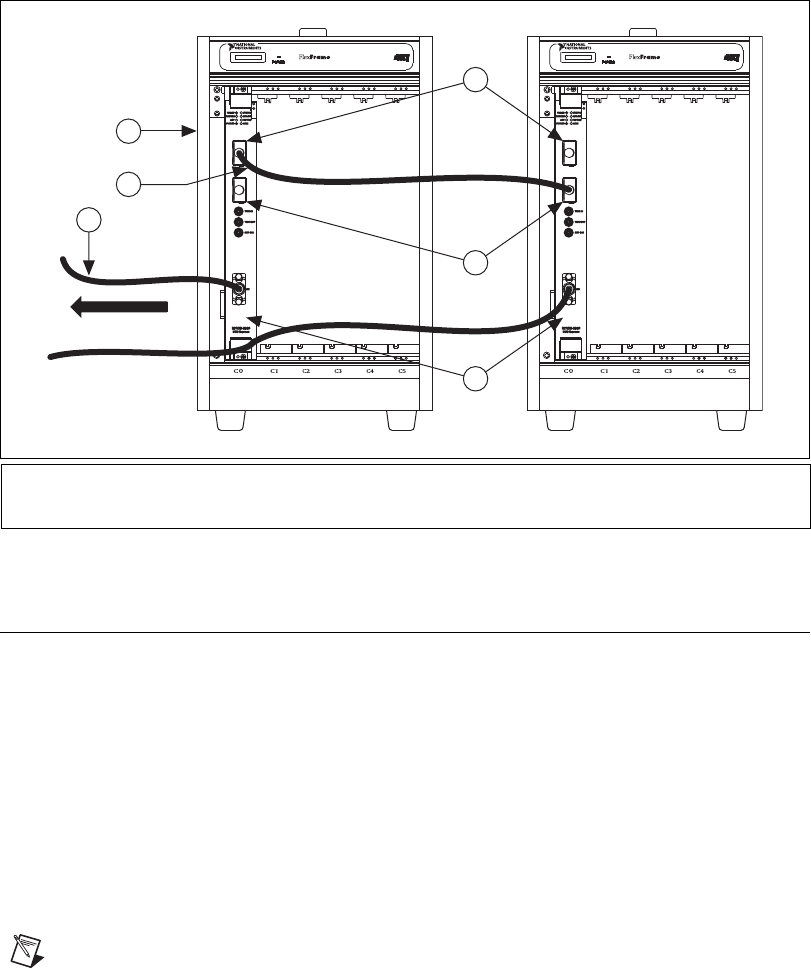
Appendix C Using the Trigger Ports on the NI VXI-8360T
VXI-MXI-Express Series User Manual C-2 ni.com
Figure C-1. NI VXI-8360T Trigger Cabling
Software Configuration
Triggers are mapped into and out of your NI VXI-8360T through software
using the following steps.
1. Open MAX.
2. Find your device under Devices and Interfaces.
3. Right click on your device and select Properties.
4. Click on the Signal Mappings Tab.
5. From each TTL Trigger select Into the Frame, Out of the Frame,
or None.
6. Click OK and re-run the Resman for the changes to take effect.
Note Do not map the same trigger out of the frame on more than one device on the trigger
bus. This will cause the bus to be driven by more than one device. Protection circuitry
prevents this from causing physical damage, however your setup will not function properly.
1 TRIG/CLK PORT A
2 TRIG/CLK PORT B
3 NI VXI-8360T Controller in Slot 0
4 MXI-Express x1 cable
5 Trigger Cable
6 VXI Mainframe
To host controller
6
1
2
5
3
4

Appendix C Using the Trigger Ports on the NI VXI-8360T
© National Instruments C-3 VXI-MXI-Express Series User Manual
Configuring the Wired Trigger and Clock Bus
Each of the 8 physical trigger channels is independently configurable and
designed to be used in a point-to-multipoint topology where one device acts
as the trigger driver and the remaining devices are listeners.
To map a trigger from the VXI backplane to multiple chassis, configure the
trigger to be mapped as Out of the Frame in MAX. This configures the
trigger as a driver. The remaining devices on the wired VXI backplane
trigger and CLK10 bus need to be configured as listeners by configuring
their respective triggers as In to the Frame.
To map CLK10 Out of the Frame set jumper W7 to connect pins 1-2. To
map CLK10 In to the Frame set jumper W7 to connect pins 2-3. Refer to
Appendix B, Advanced Hardware Configuration Settings, for more
information about setting the hardware jumper.

© National Instruments D-1 VXI-MXI-Express Series User Manual
Using the Trigger Ports on the
NI VXI-8360LT
The NI VXI-8360LT allows you to extend the 8 TTL backplane triggers
over a wired VXI backplane trigger bus through convenient front panel
connectors. The wired VXI backplane trigger bus allows a simple way to
have an event in one system trigger events in other VXI systems.
The wired trigger bus physical interface is based off of the TIA/EIA-899
Multi-Point Low Voltage Differential Signaling (M-LVDS) standard. The
physical interface allows the construction of large multi-drop systems and
reliable triggering over long distance. Topologies up to 6 devices over 20 m
of cable are supported. The wired VXI backplane trigger bus may be
capable of supporting more devices over greater cable lengths but, these
configurations have not been validated by National Instruments.
The 8 triggers on the wired VXI backplane trigger bus correspond to the
8 TTL triggers on the VXI backplane (e.g., TTLTRG0* on the VXI
backplane corresponds to Trigger Number 0 on the wired VXI backplane
trigger bus). Each of the 8 physical trigger channels are independently
configurable and can be used in one of two topologies: point-to-multipoint
or multipoint-to-multipoint.
Driven Mode Operation
This is a point-to-multipoint configuration where one device on the trigger
channel is configured as a driver and the remaining devices are configured
as listeners. The device configured as the driver sets the state of the trigger
channel and the other devices receive that state. If two or more devices are
configured to drive the trigger channel the behavior of the bus is undefined.
Wired-OR Mode Operation
This is a multipoint-to-multipoint topology where multiple devices can
assert a trigger channel to multiple listeners. For this topology, the trigger
channel behaves in a wired-OR manner with all drivers tri-stated. A bias
device is used to pull the trigger to a known, unasserted state and then the
triggering device(s) drive(s) the bus to its asserted state.

Appendix D Using the Trigger Ports on the NI VXI-8360LT
VXI-MXI-Express Series User Manual D-2 ni.com
LXI Compatibility
The physical and electrical interface of the wired VXI backplane trigger
bus is compatible with the LXI wired trigger bus. The physical interface
uses the standardized 25-pin micro-D type connector. The electrical
interface uses the LXI-wired Trigger Bus cable and Terminator 2.0
specified Texas Instruments (SN65MLVD080) bus transceiver.
The LXI wired trigger bus has a much broader triggering definition and can
be considered as a superset of the VXI-8360LT’s wired VXI backplane
trigger bus. The two trigger domains are compatible with a few constraints:
1. All LXI devices that share the wired VXI backplane trigger bus must
be configured for active high assertion of triggers whether in Driven
mode or Wired-OR mode.
2. The LXI specification states that each trigger channel shall be
individually configurable as an input or output (or both). The NI VXI
driver software allows a trigger be mapped In to the Frame (input) or
Out of the Frame (output) but not both. This constrains a single
trigger to be either a driver or a receiver.
Connecting the Trigger Port Cables
The physical pinout for the two trigger ports is identical so there are no
special cable connection requirements between the ports.
Note Trigger bus cables may be removed and inserted while power is on.
End of bus termination is required for proper operation. Use two 50 Ω
resistors in series across each trigger differential pair with the center tap
decoupled to ground with a capacitor. Commercially available terminators
are recommended.
Configuring the Wired Trigger Bus
The 8 triggers in the wired VXI backplane trigger bus are configured via
hardware and software. Hardware switches located on the top edge of the
NI VXI-8360LT control the operating mode of the trigger. The factory
default switch settings for all 8 triggers are displayed in Figure D-1,
Trigger Configuration Sticker (Located on the Side of the NI VXI-8360LT).
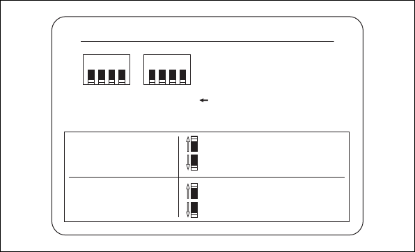
Appendix D Using the Trigger Ports on the NI VXI-8360LT
© National Instruments D-3 VXI-MXI-Express Series User Manual
Figure D-1. Trigger Configuration Sticker
(Located on the Side of the NI VXI-8360LT)
Software controls whether the trigger is routed In to the Frame or Out of
the Frame.
Triggers are mapped into and out of your NI VXI-8360LT though software
using the following steps.
1. Open MAX.
2. Find your device under Devices and Interfaces.
3. Right click on your device and select Properties.
4. Click on the Signal Mappings Tab.
5. For each TTL Trigger select Into the Frame, Out of the Frame,
or None.
6. Click OK and re-run the Resman for the changes to take effect.
HARDWARESOFTWARE
Trigger set to:
Into the frame
Trigger set to:
Out of the frame
Receiver
Receiver w/ Bias Device
Wired-Or
Driven
TRIGGER CONFIGURATION
0 1 2 3 4 5 6 7 Trigger Number
Switches shown in
Receiver / Wired-Or
position.
12341234

Appendix D Using the Trigger Ports on the NI VXI-8360LT
VXI-MXI-Express Series User Manual D-4 ni.com
For Driven Mode Triggers
Complete the following steps to map a trigger from the VXI backplane to
the wired VXI backplane trigger bus:
Driving Device
1. In MAX configure the trigger to be mapped as Out of the Frame.
2. Set the trigger’s hardware switch to Driven.
Listening Device
1. In MAX configure the respective trigger lines as Into the Frame.
2. Set the trigger’s hardware switch to Receiver.
Note Do not select Receiver w/Bias Device in Driven mode. Doing so will produce
undefined results.
For Wired-Or Mode Triggers
Complete the following steps to map a trigger from the VXI backplane to
the wired VXI backplane trigger bus:
Driving Device
1. In MAX configure the trigger to be mapped as Out of the Frame.
2. Set the trigger’s hardware switch to configure it as a Wired-OR.
Listening Device
1. In MAX configure the trigger to be mapped as In to Frame.
2. Set the trigger’s hardware switch to select the type of receiver needed.
If the device is going to bias the wired VXI backplane trigger bus, set
the trigger’s hardware switch for Receiver w/BIAS Device.
3. If the device is going to be a receiver, set the trigger hardware switch
to Receiver.
Note Ensure only one receiving device is configured as the Receiver w/BIAS Device.
Having more than one bias device on a trigger channel will produce undefined results.

© National Instruments E-1 VXI-MXI-Express Series User Manual
How to Fix an Invalid EEPROM
Configuration
The NI VXI-8360T/LT controller uses an EEPROM to store configuration
settings required at power on. Certain EEPROM configurations could cause
your computer to lock up while booting. Generally, the size and location of
memory windows will cause this issue.
Many PCI-based computers will not boot if a board in the system is
requesting more memory space than the computer can allocate. If you
encounter this situation you should reduce the size of the
NI VXI-8360T/LT controller user memory window.
The EEPROM can also become corrupt if the NI VXI-8360T/LT controller
loses power while software is updating the EEPROM.
To aid in EEPROM recovery the EEPROM is divided into two halves—one
half is factory configured and the other half is user configurable. By default
the VXI-MXI-Express boots from the user half of the EEPROM. Should
the EEPROM become corrupt complete the following steps to restore the
EEPROM to its factory settings:
1. Power off your computer.
Caution To protect both yourself and the mainframe from electrical hazards,
the mainframe should remain off until you finish changing the settings on the NI
VXI-8360T/LT controller.
2. Change jumper W5 to the position shown in Figure E-1 to restore the
factory configuration. Refer to Figure B-1, VXI-MXI-Express Factory
Default Jumper Settings, of Appendix B, Advanced Hardware
Configuration Settings, for jumper locations.
Figure E-1 shows the configuration settings for EEPROM operation. Use
jumper W5 to control whether the NI VXI-8360T/LT controller boots off
the factory-configured EEPROM settings or the user-modified settings.

Appendix E How to Fix an Invalid EEPROM Configuration
VXI-MXI-Express Series User Manual E-2 ni.com
Figure E-1. EEPROM Configuration
3. Power on the computer. The computer should boot this time because
the factory-default configuration is being used to initialize the
NI VXI-8360T/LT controller.
4. Right-click on the VXI system in MAX and select the Hardware
Configuration utility.
5. A dialog box will appear explaining that the Factory Override switch
has been set, and the NI VXI-8360T/LT controller is running using
factory default settings. Click OK to continue.
6. In the General tab under Quick Configuration select Default
Configuration.
7. Click Yes in the pop up box if you are sure you want to restore the
factory defaults.
8. Click OK in the hardware configuration panel to save the settings.
9. After saving the configuration, exit Windows and power off the
computer.
10. Change jumper W5 back to the default position, as shown in
Figure E-1.
11. Power on the computer. If the computer does not boot with this
configuration, you will need to repeat these steps, modifying your
configuration until a final configuration is reached.
a. Boot from User
Configuration (Default)
b. Boot from Write Protected
Factory Configuration
W5 W5
2
3
1
2
3
1
© National Instruments F-1 VXI-MXI-Express Series User Manual
VMEbus Capability Codes
Table F-1. VMEbus Capability Codes
Capability Code Description
A32, A24, A16 (master) VMEbus master A32, A24, and A16 addressing
A32, A24, A16 (slave) VMEbus slave A32, A24, and A16 addressing
D32, D16, D08(EO) (master) VMEbus master D32, D16, and D08 data sizes
D32, D16, D08(EO) (slave) VMEbus slave D32, D16, and D08 data sizes
BLT, MBLT (master) VMEbus master block and D64 transfers
BLT, MBLT (slave) VMEbus slave block and D64 transfers
RMW (master) VMEbus master read/modify/write transfers
RMW (slave) VMEbus slave read/modify/write transfers
RETRY (master) VMEbus master retry support
RETRY (slave) VMEbus slave retry support
FSD First slot detector
SCON VMEbus System Controller
PRI, RRS Prioritized or Round Robin Select arbiter
ROR, FAIR Release on Request and FAIR bus requester
IH(7–1) Interrupt handler for levels 7–1
I(7–1) Interrupt requester for levels 7–1
D32, D16, D08(O) (Interrupt Handler) VMEbus D32, D16, D08(O) interrupt handler
D32, D16, D08(O) (Interrupter) VMEbus D32, D16, D08(O) interrupter
ROAK, RORA Release on Acknowledge or Register Access interrupter
BTO(x) VMEbus bus timer (programmable limit)

© National Instruments G-1 VXI-MXI-Express Series User Manual
Common Questions
What is the maximum length of the NI VXI-8360T/LT controller
MXI-Express x1 copper cable?
The maximum length for the NI VXI-8360T/LT controller MXI-Express x1
copper cable is 7 m. National Instruments offers 1 m, 3 m, and 7 m copper
cables.
I need more devices than can fit in one chassis. How can I expand my
NI VXI-8360T/LT controller system?
Many applications can be easily extended to multiple chassis by adding
additional NI VXI-8360T/LT controllers to the host computer
and using the trigger and clock sharing features of the NI VXI-8360T to
synchronize events between chassis. In the event that VXI or VME bus
mastering devices must communicate to devices in other chassis directly,
National Instruments recommends that you use a VXI-MXI-2 interface,
which implements the VXI-6 specification for mainframe extension. This
extends full VXI functionality across multiple mainframes, including a
common device address space, interframe triggering, interrupts, and bus
mastering. Place a VXI-MXI-2 in the same mainframe with the Slot 0
NI VXI-8360T/LT controller, and another VXI-MXI-2 in Slot 0 of the next
mainframe. You can then fill up this mainframe with additional devices.
Refer to the MXI-2 Configuration Reference Manual available at ni.com
for additional configuration instructions.
How can I determine the serial number of the NI VXI-8360T/LT
controller?
This information is displayed in the title bar of the Hardware Configuration
window in MAX. The serial number can also be found on the sticker
applied to the side of the controller.
Appendix G Common Questions
VXI-MXI-Express Series User Manual G-2 ni.com
What is Resman?
Resman is the utility that performs the duties of a VXI Resource Manager
as discussed in the VXIbus specification.
When do I need to run Resman?
Run Resman whenever you need to configure your VXI instruments (for
example, when you power cycle either the host computer or the chassis).
When you set a National Instruments controller to Logical Address 0, you
will at some point need to run Resman to configure your VXI instruments.
If your controller uses a different (nonzero) logical address and is a
message-based device, you need to start Resman before running it on the
Logical Address 0 computer.
Which NI-VXI utility program must I use to configure the
NI VXI-8360T/LT controller?
Use Measurement & Automation Explorer (MAX) to configure the
NI VXI-8360T/LT controller. MAX is in the National Instruments
program group folder, and a shortcut is on your desktop.
How do I handle VME devices?
Although there is no way to automatically detect VME devices in a system,
you can add them easily through the Add Device Wizard in MAX. Through
this procedure, you can reserve resources for each of your VME devices
and configure MAX to show VME devices on the screen with all your other
devices.
Which NI-VXI utility program must I use to perform startup Resource
Manager operations?
Use the Resman program to perform startup Resource Manager operations
in Start»Programs»National Instruments»VXI. Resman uses the
settings configured in MAX. It initializes your VXI/VMEbus system and
makes the information it collects accessible through MAX. You can also
run Resource Manager operations from MAX. Through MAX, you can also
configure Resman to run automatically at Windows startup.
Appendix G Common Questions
© National Instruments G-3 VXI-MXI-Express Series User Manual
What can I do to make sure that my system is up and running?
The fastest method for testing the system is to run Resman. This program
attempts to access memory in the upper A16 address space of each device
in the system. If Resman does not report any problems, the
NI VXI-8360T/LT controller communication system is operational. To test
individual devices, you can use the VIC or VISAIC program to
interactively issue NI-VXI functions or NI-VISA operations, respectively.
You can use viIn() and viOut() with the NI-VISA API (or VXIin() or
VXIinReg() and VXIout() or VXIoutReg() with the NI-VXI API) to
test register-based devices by programming their registers. If you have
any message-based devices, you can send and receive messages with the
viRead() and viWrite() operations in the NI-VISA API (or WSrd()
and WSwrt() functions in the NI-VXI API). Notice that VXIinReg() and
VXIoutReg() are for VXI devices only, but you can use VXIin() and
VXIout() for both VXI and VME. Finally, if you are using LabVIEW or
LabWindows/CVI and you have instrument drivers for the devices in your
chassis, you can use the interactive features of these programs to quickly
test the functionality of the devices.
What is the accuracy of the CLK10 signal?
The CLK10 generated by the NI VXI-8360T/LT controller is ±100 ppm per
the VXI specification. To use a more accurate reference for CLK10,
connect the signal to the controller through the EXT CLK SMB input on
the front panel.

© National Instruments H-1 VXI-MXI-Express Series User Manual
Technical Support and
Professional Services
Log in to your National Instruments ni.com User Profile to get
personalized access to your services. Visit the following sections of
ni.com for technical support and professional services:
•Support—Technical support at ni.com/support includes the
following resources:
–Self-Help Technical Resources—For answers and solutions,
visit ni.com/support for software drivers and updates,
a searchable KnowledgeBase, product manuals, step-by-step
troubleshooting wizards, thousands of example programs,
tutorials, application notes, instrument drivers, and so on.
Registered users also receive access to the NI Discussion Forums
at ni.com/forums. NI Applications Engineers make sure every
question submitted online receives an answer.
–Standard Service Program Membership—This program
entitles members to direct access to NI Applications Engineers
via phone and email for one-to-one technical support, as well as
exclusive access to eLearning training modules at ni.com/
elearning. All customers automatically receive a one-year
membership in the Standard Service Program (SSP) with the
purchase of most software products and bundles including
NI Developer Suite. NI also offers flexible extended contract
options that guarantee your SSP benefits are available without
interruption for as long as you need them. Visit ni.com/ssp for
more information.
For information about other technical support options in your
area, visit ni.com/services, or contact your local office at
ni.com/contact.
•Training and Certification—Visit ni.com/training for training
and certification program information. You can also register for
instructor-led, hands-on courses at locations around the world.
•System Integration—If you have time constraints, limited in-house
technical resources, or other project challenges, National Instruments
Appendix H Technical Support and Professional Services
VXI-MXI-Express Series User Manual H-2 ni.com
Alliance Partner members can help. To learn more, call your local
NI office or visit ni.com/alliance.
•Declaration of Conformity (DoC)—A DoC is our claim of
compliance with the Council of the European Communities using
the manufacturer’s declaration of conformity. This system affords
the user protection for electromagnetic compatibility (EMC) and
product safety. You can obtain the DoC for your product by visiting
ni.com/certification.
•Calibration Certificate—If your product supports calibration,
you can obtain the calibration certificate for your product at
ni.com/calibration.
You also can visit the Worldwide Offices section of ni.com/niglobal
to access the branch office Web sites, which provide up-to-date contact
information, support phone numbers, email addresses, and current events.
© National Instruments Glossary-1 VXI-MXI-Express Series User Manual
Glossary
Symbol Prefix Value
ppico10
–12
nnano10
–9
μmicro 10–6
m milli 10–3
k kilo 103
Mmega10
6
Ggiga10
9
Ttera10
12
Symbols
°degrees
Ωohms
A
Aamperes
address Character code that identifies a specific location (or series of locations) in
memory. In VISA, it identifies a resource.
address modifier One of six signals in the VMEbus specification used by VMEbus masters
to indicate the address space in which a data transfer is to take place.
address space
A set of 2
n
memory locations differentiated from other such sets in
VXI/VMEbus systems by six addressing lines known as address modifiers.
n
is the number of address lines required to uniquely specify a byte location
in a given space. Valid numbers for
n
are 16, 24, 32, and 64. In VME/VXI,
because there are six address modifiers, there are 64 possible address spaces.
ANSI American National Standards Institute
Glossary
VXI-MXI-Express Series User Manual Glossary-2 ni.com
API Application Programming Interface—the direct interface that an end user
sees when creating an application.
arbitration A process in which a potential bus master gains control over a particular
bus.
B
B Byte—eight related bits of data, an 8-bit binary number. Also used to
denote the amount of memory required to store one byte of data.
backplane An assembly, typically a printed circuit board, with 96-pin connectors and
signal paths that bus the connector pins. A C-size VXIbus system will have
two sets of bused connectors called J1 and J2. A D-size VXIbus system will
have three sets of bused connectors called J1, J2, and J3.
BERR* bus error signal
BIOS Basic Input/Output System. BIOS functions are the fundamental level
of any PC or compatible computer. BIOS functions embody the basic
operations needed for successful use of the computer’s hardware resources.
block-mode transfer An uninterrupted transfer of data elements in which the master sources only
the first address at the beginning of the cycle. The slave is then responsible
for incrementing the address on subsequent transfers so that the next
element is transferred to or from the proper storage location. A VME
data transfer may have no more than 256 elements.
bus The group of conductors that interconnect individual circuitry in a
computer. Typically, a bus is the expansion vehicle to which I/O or other
devices are connected. Examples of buses include the ISA bus, PCI bus,
VXI bus, and VME bus.
bus error An error that signals failed access to an address. Bus errors occur with
low-level accesses to memory and usually involve hardware with bus
mapping capabilities. For example, nonexistent memory, a nonexistent
register, or an incorrect device access can cause a bus error.
Glossary
© National Instruments Glossary-3 VXI-MXI-Express Series User Manual
bus master A device that is capable of requesting the Data Transfer Bus (DTB) for the
purpose of accessing a slave device.
byte order How bytes are arranged within a word or how words are arranged within
a longword. Motorola ordering stores the most significant byte (MSB)
or word first, followed by the least significant byte (LSB) or word. Intel
ordering stores the LSB or word first, followed by the MSB or word.
C
CCelsius
CLK10 A 10 MHz, ±100 ppm, individually buffered (to each module slot),
differential ECL system clock that is sourced from Slot 0 of a VXIbus
mainframe and distributed to Slots 1 through 12 on P2. It is distributed to
each slot as a single-source, single-destination signal with a matched delay
of under 8 ns.
Commander A message-based device that is also a bus master and can control one or
more Servants.
configuration registers
A set of registers through which the system can identify a module
device type, model, manufacturer, address space, and memory requirements.
To support automatic system and memory configuration, the VXI
specification requires that all VXIbus devices have a set of such registers.
D
Data Transfer Bus DTB; one of four buses on the VMEbus backplane. The DTB is used by a
bus master to transfer binary data between itself and a slave device.
DMA Direct Memory Access—a method by which data is transferred between
devices and internal memory without intervention of the central processing
unit. DMA is the fastest method of transferring data to/from computer
memory.
DRAM Dynamic RAM (Random Access Memory)—storage that the computer
must refresh at frequent intervals.
Glossary
VXI-MXI-Express Series User Manual Glossary-4 ni.com
dynamic
configuration
A method of automatically assigning logical addresses to VXIbus devices
at system startup or other configuration times.
dynamically
configured device
A device that has its logical address assigned by the Resource Manager.
A VXI device initially responds at Logical Address 255 when its MODID
line is asserted. The Resource Manager subsequently assigns it a new
logical address, to which the device responds until powered down.
E
ECL Emitter-Coupled Logic
EEPROM Electronically Erasable Programmable Read Only Memory—ROM that
can be erased with an electrical signal and reprogrammed.
embedded controller An intelligent CPU (controller) interface plugged directly into the VXI
backplane, giving it direct access to the VXIbus. It must have all of its
required VXI interface capabilities built in.
EMC electromagnetic compliance
EMI electromagnetic interference
external trigger A voltage pulse from an external source that triggers an event.
F
fair requester A VXIbus device that will not arbitrate for the VXIbus after releasing
it until it detects the bus request signal inactive. This ensures that all
requesting devices will be granted use of the bus.
firmware Software embedded in the NI VXI-8360T/LT controller, contained on
EEPROM and flash memory that can be updated with a special utility (part
of MAX). In combination with the hardware, the firmware enables the NI
VXI-8360T/LT controller to act as a translator between USB and VXI
protocols.
Glossary
© National Instruments Glossary-5 VXI-MXI-Express Series User Manual
G
g (1) grams
(2) a measure of acceleration equal to 9.8 m/s2
GPIB General Purpose Interface Bus (IEEE 488)
gRMS A measure of random vibration. The root mean square of acceleration
levels in a random vibration test profile.
H
hex Hexadecimal—the numbering system with base 16, using the digits 0 to 9
and letters A to F.
Hz hertz; cycles per second
I
I/O Input/output—the techniques, media, and devices used to achieve
communication between machines and users.
IEC International Electrotechnical Commission. The IEC publishes
internationally recognized standards. IEC 60068 contains information
on environmental testing procedures and severities.
IEEE Institute of Electrical and Electronics Engineers
in. inches
instrument driver A set of routines designed to control a specific instrument or family of
instruments, and any necessary related files for LabWindows/CVI or
LabVIEW.
interrupt A means for a device to request service from another device; a computer
signal indicating that the CPU should suspend its current task to service a
designated activity.
interrupt handler A VMEbus functional module that detects interrupt requests generated by
interrupters and responds to those requests by requesting status and identify
information.
Glossary
VXI-MXI-Express Series User Manual Glossary-6 ni.com
interrupt level The relative priority at which a device can interrupt.
IRQ* interrupt signal
K
K kilo—the prefix for 1,024, or 210, used with B (byte) in quantifying data or
computer memory.
k kilo—the standard metric prefix for 1,000, or 103, used with units of
measure such as volts, hertz, and meters.
L
logical address An 8-bit number that uniquely identifies each VXIbus device in a system.
It defines the A16 register address of a device, and indicates Commander
and Servant relationships.
M
m meters
M mega—(1) the standard metric prefix for 1 million or 106, when used with
units of measure such as volts and hertz; (2) the prefix for 1,048,576, or 220,
when used with B (byte) to quantify data or computer memory.
master A functional part of a VME/VXIbus device that initiates data transfers on
the backplane. A transfer can be either a read or a write.
message-based
device
An intelligent device that implements the defined VXIbus registers and
communication protocols. These devices are able to use Word Serial
Protocol to communicate with one another through communication
registers.
MODID Module ID lines—used in VXI to geographically locate boards and to
dynamically configure boards.
MTBF Mean Time Between Failure
Glossary
© National Instruments Glossary-7 VXI-MXI-Express Series User Manual
MXI-3 A PCI Master/Slave system implementing the PCI-to-PCI Bridge register
set. It couples two physically separate PCI buses with either a copper or
fiber optic data link capable of 1.5 Gbits/s serial data rates.
MXI-Express An extension of MXI based upon PCI Express. MXI-Express provides
bandwidth of up to 110 MB/s.
N
NI-488.2 or
NI-488.2M
The National Instruments industry-standard software for controlling
GPIB instruments.
NI-DAQ The National Instruments industry-standard software for data acquisition
instruments.
NI-VISA The National Instruments implementation of the VISA standard; an
interface-independent software that provides a unified programming
interface for VXI, GPIB, and serial instruments.
NI-VXI The National Instruments bus interface software for VME/VXIbus
systems.
Non-Slot 0 device A device configured for installation in any slot in a VXIbus mainframe
other than Slot 0. Installing such a device into Slot 0 can damage the device,
the VXIbus backplane, or both.
P
PCI Peripheral Component Interconnect. The PCI bus is a high-performance
32-bit or 64-bit bus with multiplexed address and data lines.
PCI Express A serialized, highly scalable I/O interconnect standard that leverages
existing PCI technology such as the software model and the load-store
architecture.
Glossary
VXI-MXI-Express Series User Manual Glossary-8 ni.com
R
register-based device A Servant-only device that supports VXIbus configuration registers.
Register-based devices are typically controlled by message-based devices
via device-dependent register reads and writes.
Resman The name of the National Instruments Resource Manager in NI-VXI bus
interface software. See also Resource Manager.
Resource Manager A message-based Commander located at Logical Address 0, which
provides configuration management services such as address map
configuration, Commander and Servant mappings, and self-test and
diagnostic management.
retry An acknowledge by a destination that signifies that the cycle did not
complete and should be repeated.
RMS Root mean squared. See also gRMS.
S
s seconds
slave A functional part of a VME/VXIbus device that detects data transfer cycles
initiated by a VMEbus master and responds to the transfers when the
address specifies one of the device’s registers.
Slot 0 device A device configured for installation in Slot 0 of a VXIbus mainframe. This
device is unique in the VXIbus system in that it performs the VXI/VMEbus
System Controller functions, including clock sourcing and arbitration for
data transfers across the backplane. Installing such a device into any other
slot can damage the device, the VXIbus backplane, or both.
SMB Sub Miniature Type B connector that features a snap coupling for fast
connection.
statically configured
device
A device whose logical address cannot be set through software; that is, it is
not dynamically configurable.
SYSFAIL A VMEbus signal that is used by a device to indicate an internal failure.
A failed device asserts this line. In VXI, a device that fails also clears its
PASSed bit in its Status register.
Glossary
© National Instruments Glossary-9 VXI-MXI-Express Series User Manual
T
trigger Either TTL or ECL lines used for intermodule communication.
TTL Transistor-Transistor Logic
U
USB Universal Serial Bus—a serial bus for connecting computers to keyboards,
printers, and other peripheral devices.
V
V volts
VIC VXI Interactive Control program, a part of the NI-VXI bus interface
software. Used to program VXI devices and develop and debug
VXI application programs.
VISA Virtual Instrument Software Architecture. This is the general name given
to VISA and its associated architecture.
VISAIC VISA Interactive Control program, a part of the NI-VISA software.
Used to program devices and develop and debug application programs.
VITA VMEbus International Trade Association
VME Versa Module Eurocard or IEEE 1014
VMEbus System
Controller
A device configured for installation in Slot 0 or a VXIbus mainframe or the
first slot in a VMEbus chassis. This device is unique in the VMEbus system
in that it performs the VMEbus System Controller functions, including
clock sourcing and arbitration for data transfers across the backplane.
Installing such a device into any other slot can damage the device, the
VMEbus/VXIbus backplane, or both.
VXIbus VMEbus Extensions for Instrumentation
Glossary
VXI-MXI-Express Series User Manual Glossary-10 ni.com
W
Wwatts
Word Serial Protocol The simplest required communication protocol supported by
message-based devices in a VXIbus system. It utilizes the A16
communication registers to transfer data using a simple polling handshake
method.
write posting A mechanism that signifies that a device will immediately give a successful
acknowledge to a write transfer and place the transfer in a local buffer. The
device can then independently complete the write cycle to the destination.

© National Instruments I-1 VXI-MXI-Express Series User Manual
Index
A
advanced hardware configuration settings, B-1
application development, 3-1
debugging, 3-6
NI-VXI API notes, 3-5
optimizing large VXIbus transfers, 3-4
programming for VXI, 3-3
B
basic, MXI-Express x1 systems, 1-7
block diagrams, 1-5
C
cables, connecting, 2-4
cabling triggers between two controllers
(figure), C-2
calibration certificate (NI resources), H-2
CE compliance, specifications, A-7, A-16
cleaning specifications, A-8, A-16
CLK10 routing, VXI bus, B-6
optional settings
inverting CLK10, B-9
inverting CLK10 (figure), B-9
termination, B-9
CLK10 signal
accuracy, G-3
inverting (figure), B-9
common questions, G-1
compatibility layer options, 3-5
compiler symbols, 3-5
configuration, 2-1
additional, star (figure), 1-8
advanced hardware settings, B-1
advanced options, B-1
NI VXI-8360T trigger ports, C-1, D-1
slot 0 detection, B-5
slot 0 detection (figure), B-5
connecting cables, 2-4
conventions used in the manual, ix
D
debugging tools, 3-6
Declaration of Conformity (NI resources), H-2
default settings
jumper, B-2
software, 2-7
developing applications, 3-1
device tab default settings (table), 2-7
diagnostic tools (NI resources), H-1
documentation
conventions used in manual, ix
NI resources, H-1
related documentation, x
drivers (NI resources), H-1
E
EEPROM, B-10
configuration, E-1
fixing an invalid configuration, E-1
electromagnetic compatibility, A-6, A-15
environmental management,
specifications, A-7, A-16
WEEE information, A-8, A-16
environmental specifications, A-5, A-13
examples (NI resources), H-1
EXT CLK specifications, A-3, A-10
F
front panel features, 1-3, 1-4
Index
VXI-MXI-Express Series User Manual I-2 ni.com
G
getting started, 2-1
H
hardware
advanced configuration settings, B-1
configuration, 2-3
default settings, B-2
description, 1-1
determining serial number, G-1
installation, 2-3
NI VXI-8360T trigger port
settings, C-1, D-1
help, technical support, H-1
host system with NI VXI-8360T/LT controller
(figure), 1-7
I
installation, 2-1
host adapter, 2-4
peripheral, 2-4
software, 2-2
instrument drivers (NI resources), H-1
introduction, 1-1
inverting the CLK10 signal (figure), B-9
K
KnowledgeBase, H-1
L
LabVIEW, 3-1
LabWindows/CVI, 3-2
larger MXI-Express x1 systems, 1-8
M
Measurement & Automation Explorer
device tab default settings (table), 2-7
PCI tab default settings (table), 2-8
shared memory tab default settings
(table), 2-7
SMB tab default settings (table), 2-8
VXI bus tab default settings (table), 2-7
Measurement Studio, 3-2
MITE EEPROM, power on self configuration,
B-10
MXI-Express x1
basic system, 1-7
block diagrams, 1-5
larger systems, 1-8
unpacking, 2-2
MXI-Express x1 system expansion topologies
(figure), 1-8
N
National Instruments
application software, 3-1
support and services, H-1
NI I/O Trace, figure, 3-7
NI support and services, H-1
NI-VISA, 3-2
examples (table), 3-4
NI-VXI, 3-2
compatibility layer, 3-3
examples (table), 3-4
utility programs
using to configure NI VXI-8360T/LT
controller, G-2
using to perform startup Resource
Manager operations, G-2
NI-VXI API, 3-2
compatibility layer options, 3-5
compiler symbols, 3-5
notes, 3-5
Index
© National Instruments I-3 VXI-MXI-Express Series User Manual
O
operating environment
specifications, A-5, A-14
optimizing large VXIbus transfers, 3-4
overview, functional, PCI/PCIe/PXI/PXIe, 1-6
P
PCI tab default settings (table), 2-8
physical specifications, A-2, A-9
POSC (power-on self-configuration), B-10
power requirement specifications, A-2, A-9
power-on self-configuration (POSC), B-10
programming examples (NI resources), H-1
programming for VXI, 3-3
R
recycling hardware, A-8, A-16
Register I/O tab, successful viIn access in
(figure), 3-9
related documentation, x
Resman, G-2
running (figure), 2-6
using to ensure system is up and
running, G-3
when to run, G-2
S
safety, specifications, A-6, A-15
selecting controller in VISAIC (figure), 3-8
serial number, determining, G-1
shared memory tab default settings (table), 2-7
shock and vibration specifications, A-6, A-14
slot 0 detection
configuration, B-5
J2 jumper (figure), B-5
SMB tab default settings (table), 2-8
software
configuration, 2-5
installation, 2-2
verification, 2-5
software (NI resources), H-1
specifications
CE compliance, A-7, A-16
cleaning, A-8, A-16
electromagnetic compatibility, A-6, A-15
environmental, A-5, A-13
operating environment, A-5, A-14
shock and vibration, A-6, A-14
storage environment, A-5, A-14
environmental management, A-7, A-16
WEEE information, A-8, A-16
EXT CLK, A-3, A-10
online product certification, A-7, A-16
physical, A-2, A-9
power requirement, A-2, A-9
safety, A-6, A-15
TRIG IN, A-3, A-10
TRIG OUT, A-3, A-10
storage environment specifications, A-5, A-14
support, technical, H-1
T
technical support, H-1
termination resistance for CLK10, B-9
training and certification (NI resources), H-1
TRIG IN specifications, A-3, A-10
TRIG OUT specifications, A-3, A-10
trigger ports
cabling, C-1, D-2
cabling (figure), C-2
connector
signals (table), A-4, A-11
software configuration, C-2
troubleshooting (NI resources), H-1
Index
VXI-MXI-Express Series User Manual I-4 ni.com
U
unpacking, 2-2
user-configurable settings, B-1
using, NI VXI-8360T trigger ports, C-1, D-1
V
VISAIC
selecting controller in (figure), 3-8
successful viIn access in Register I/O tab
(figure), 3-9
VME devices, handling, G-2
VXI bus tab default settings (table), 2-7
VXI, programming for, 3-3
VXI-8360T trigger ports, C-1, D-1
VXIbus transfers, optimizing, 3-4
VXIbus, CLK10 routing, B-6
optional settings
inverting CLK10, B-9
figure, B-9
termination, B-9
VXI-MXI-Express series controller
application development, 3-1
common questions, G-1
configuration, 2-1
copper cable lengths, G-1
default software settings, 2-7
determining serial number, G-1
determining which NI-VXI utility to use
with, G-2
ensuring that system is up and
running, G-3
equipment, 2-1
expanding system, G-1
front panel features, 1-3, 1-4
hardware, description, 1-1
installation, 2-1, 2-3
introduction, 1-1
software
configuration and verification, 2-5
installation, 2-2
specifications, A-1
W
Web resources, H-1
WEEE information, A-8, A-16
