Hardware Management Console For PSeries Maintenance Guide 6578 380603
User Manual: 6578
Open the PDF directly: View PDF ![]() .
.
Page Count: 164 [warning: Documents this large are best viewed by clicking the View PDF Link!]
- Contents
- Safety Notices
- Data Integrity and Verification
- About This Book
- Chapter 1. Reference Information
- Chapter 2. Diagnostics Overview
- Chapter 3. HMC Software Support
- Chapter 4. Maintenance Analysis Procedures
- Chapter 5. Error Code to FRU Index
- Chapter 6. Removal and Replacement Procedures
- Chapter 7. Hardware Management Console Parts
- Parts Listing for a 6578-KLU
- Parts Listing for a 7040 (FC 7316) and 7315-C01
- Parts Listing for a 7315-C02
- Parts Listing for a 7310-CR2 and a 7315-CR2
- Parts Listing for a 7310-CR3 and a 7315-CR3
- Parts Listing for a 7310-C03 and a 7315-C03
- Parts Listing for a 7310-C04 and a 7315-C04
- HMC modem cable part numbers
- Power Cords
- Appendix A. Service Focal Point
- Getting Started
- Testing Error Reporting
- Service Focal Point Settings
- Working With Serviceable Events
- Viewing Serviceable Events
- Viewing Serviceable Event Details
- Saving and Managing Extended Error Data
- Viewing and Adding Serviceable Event Comments
- Closing a Serviceable Event
- Updating Field Replaceable Unit (FRU) Information
- Replacing an Existing FRU
- Adding a New FRU
- Viewing Serviceable Event Partition Information
- Hardware Service Functions
- Appendix B. Environmental Notices
- Appendix C. Notices
- Index
- Readers’ Comments — We'd Like to Hear from You

Hardware Management Console for pSeries
Maintenance Guide
SA38-0603-05
ERserver
Hardware Management Console for pSeries
Maintenance Guide
SA38-0603-05
ER s e r v e r
Sixth Edition (February 2005)
Before using this information and the product it supports, read the information in “Safety Notices” on page v,
Appendix B, “Environmental Notices,” on page 139, and .
A reader’s comment form is provided at the back of this publication. If the form has been removed, address
comments to Publications Department, Internal Zip 905-6C006, 11501 Burnet Road, Austin, Texas 78758-3493. To
send comments electronically, use this commercial internet address: aix6kpub@austin.ibm.com. Any information that
you supply may be used without incurring any obligation to you.
©International Business Machines Corporation, 2001, 2005. All rights reserved. Note to U.S. Government Users
- Documentation related to restricted rights - Use, duplication, or disclosure is subject to the restrictions set forth in
the GSA ADP Schedule Contract with IBM Corp.

Contents
Safety Notices . . . . . . . . . . . . . . . . . . . . . . . . . . . . . . . . . .v
Electrical Safety . . . . . . . . . . . . . . . . . . . . . . . . . . . . . . . . .v
Laser Safety Information . . . . . . . . . . . . . . . . . . . . . . . . . . . . . .v
Laser Compliance . . . . . . . . . . . . . . . . . . . . . . . . . . . . . . . .v
Data Integrity and Verification . . . . . . . . . . . . . . . . . . . . . . . . . . . vii
About This Book . . . . . . . . . . . . . . . . . . . . . . . . . . . . . . . .ix
ISO 9000 . . . . . . . . . . . . . . . . . . . . . . . . . . . . . . . . . . . .ix
Highlighting . . . . . . . . . . . . . . . . . . . . . . . . . . . . . . . . . . .x
Accessing Information . . . . . . . . . . . . . . . . . . . . . . . . . . . . . . .x
Related Publications . . . . . . . . . . . . . . . . . . . . . . . . . . . . . . . .x
Trademarks . . . . . . . . . . . . . . . . . . . . . . . . . . . . . . . . . . .xi
Chapter 1. Reference Information . . . . . . . . . . . . . . . . . . . . . . . . . .1
Hardware Management Console Overview . . . . . . . . . . . . . . . . . . . . . . . .1
Managed System Operation . . . . . . . . . . . . . . . . . . . . . . . . . . . .2
HMC to Managed System Cabling . . . . . . . . . . . . . . . . . . . . . . . . . .2
Powering On and Off . . . . . . . . . . . . . . . . . . . . . . . . . . . . . .4
Power-On Self-Test . . . . . . . . . . . . . . . . . . . . . . . . . . . . . . .4
Specifications and System Unit Locations . . . . . . . . . . . . . . . . . . . . . . . .4
External AC Power Cable . . . . . . . . . . . . . . . . . . . . . . . . . . . . . .6
Service Inspection Guide . . . . . . . . . . . . . . . . . . . . . . . . . . . . . .6
Chapter 2. Diagnostics Overview . . . . . . . . . . . . . . . . . . . . . . . . . .9
MAPs . . . . . . . . . . . . . . . . . . . . . . . . . . . . . . . . . . . . .9
Diagnostics, Test, and Recovery . . . . . . . . . . . . . . . . . . . . . . . . . . .9
PC-Doctor . . . . . . . . . . . . . . . . . . . . . . . . . . . . . . . . . . .9
Running PC-Doctor on a Desktop HMC . . . . . . . . . . . . . . . . . . . . . . . .9
Running PC-Doctor on a Rack-Mounted HMC . . . . . . . . . . . . . . . . . . . . .10
Chapter 3. HMC Software Support . . . . . . . . . . . . . . . . . . . . . . . . .11
Viewing the HMC Console Logs . . . . . . . . . . . . . . . . . . . . . . . . . . .11
How to Create a Service Shell or View a HMC Log . . . . . . . . . . . . . . . . . . .11
Chapter 4. Maintenance Analysis Procedures . . . . . . . . . . . . . . . . . . . . .13
Entry MAP . . . . . . . . . . . . . . . . . . . . . . . . . . . . . . . . . . .14
MAP 1020 Problem Determination . . . . . . . . . . . . . . . . . . . . . . . . . .15
MAP 1520 Power . . . . . . . . . . . . . . . . . . . . . . . . . . . . . . . .17
MAP 1530: Testing the HMC . . . . . . . . . . . . . . . . . . . . . . . . . . . .17
Diagnostic Procedures . . . . . . . . . . . . . . . . . . . . . . . . . . . . .17
System Unit Testing . . . . . . . . . . . . . . . . . . . . . . . . . . . . . .18
Managed System Connection . . . . . . . . . . . . . . . . . . . . . . . . . . .19
Modem MAP . . . . . . . . . . . . . . . . . . . . . . . . . . . . . . . . .21
Ethernet MAP . . . . . . . . . . . . . . . . . . . . . . . . . . . . . . . . .24
Disk Drive MAP . . . . . . . . . . . . . . . . . . . . . . . . . . . . . . . .25
DVD RAM MAP . . . . . . . . . . . . . . . . . . . . . . . . . . . . . . . .26
Diskette Drive MAP . . . . . . . . . . . . . . . . . . . . . . . . . . . . . . .28
Display Problems . . . . . . . . . . . . . . . . . . . . . . . . . . . . . . .29
Chapter 5. Error Code to FRU Index . . . . . . . . . . . . . . . . . . . . . . . . .31
Symptom to Action . . . . . . . . . . . . . . . . . . . . . . . . . . . . . . . .31
Error Messages and Recovery Information . . . . . . . . . . . . . . . . . . . . . .31
iii
Chapter 6. Removal and Replacement Procedures . . . . . . . . . . . . . . . . . . .95
Service Procedures . . . . . . . . . . . . . . . . . . . . . . . . . . . . . . . .95
General Information . . . . . . . . . . . . . . . . . . . . . . . . . . . . . .95
Restoring the HMC Image . . . . . . . . . . . . . . . . . . . . . . . . . . . .96
Removals and Replacements . . . . . . . . . . . . . . . . . . . . . . . . . . . .98
Installing or Removing the 8-Port ASYNC Adapter . . . . . . . . . . . . . . . . . . .98
Installing or Removing the 128-Port ASYNC Adapter . . . . . . . . . . . . . . . . . . 101
Removing an Adapter . . . . . . . . . . . . . . . . . . . . . . . . . . . . . 102
Exchanging a Disk Drive . . . . . . . . . . . . . . . . . . . . . . . . . . . . 102
Replacing the Planar and Performing the Flash (BIOS/VPD) update procedure . . . . . . . . 103
Chapter 7. Hardware Management Console Parts . . . . . . . . . . . . . . . . . . . 105
Parts Listing for a 6578-KLU . . . . . . . . . . . . . . . . . . . . . . . . . . . . 106
Parts Listing for a 7040 (FC 7316) and 7315-C01 . . . . . . . . . . . . . . . . . . . . 109
Parts Listing for a 7315-C02 . . . . . . . . . . . . . . . . . . . . . . . . . . . .113
Parts Listing for a 7310-CR2 and a 7315-CR2 . . . . . . . . . . . . . . . . . . . . .116
Parts Listing for a 7310-CR3 and a 7315-CR3 . . . . . . . . . . . . . . . . . . . . . 120
Parts Listing for a 7310-C03 and a 7315-C03 . . . . . . . . . . . . . . . . . . . . . . 124
Parts Listing for a 7310-C04 and a 7315-C04 . . . . . . . . . . . . . . . . . . . . . . 127
HMC modem cable part numbers . . . . . . . . . . . . . . . . . . . . . . . . . . 130
Telephone Cable Information . . . . . . . . . . . . . . . . . . . . . . . . . . . 130
External Modems - Multitech II MT5600BA . . . . . . . . . . . . . . . . . . . . . . 130
Internal Modem . . . . . . . . . . . . . . . . . . . . . . . . . . . . . . . . 130
Power Cords . . . . . . . . . . . . . . . . . . . . . . . . . . . . . . . . . . 130
Appendix A. Service Focal Point . . . . . . . . . . . . . . . . . . . . . . . . . . 133
Getting Started . . . . . . . . . . . . . . . . . . . . . . . . . . . . . . . . . 133
Testing Error Reporting . . . . . . . . . . . . . . . . . . . . . . . . . . . . . . 133
Service Focal Point Settings . . . . . . . . . . . . . . . . . . . . . . . . . . . . 134
Automatic Call-Home Feature . . . . . . . . . . . . . . . . . . . . . . . . . . 134
Setting Up Surveillance . . . . . . . . . . . . . . . . . . . . . . . . . . . . . 134
Enabling Surveillance Notifications . . . . . . . . . . . . . . . . . . . . . . . . . 135
Working With Serviceable Events . . . . . . . . . . . . . . . . . . . . . . . . . . 135
Viewing Serviceable Events . . . . . . . . . . . . . . . . . . . . . . . . . . . 135
Viewing Serviceable Event Details . . . . . . . . . . . . . . . . . . . . . . . . . 136
Saving and Managing Extended Error Data . . . . . . . . . . . . . . . . . . . . . 136
Viewing and Adding Serviceable Event Comments . . . . . . . . . . . . . . . . . . . 136
Closing a Serviceable Event . . . . . . . . . . . . . . . . . . . . . . . . . . . 137
Updating Field Replaceable Unit (FRU) Information . . . . . . . . . . . . . . . . . . 137
Replacing an Existing FRU . . . . . . . . . . . . . . . . . . . . . . . . . . . 137
Adding a New FRU . . . . . . . . . . . . . . . . . . . . . . . . . . . . . . 138
Viewing Serviceable Event Partition Information . . . . . . . . . . . . . . . . . . . . 138
Hardware Service Functions . . . . . . . . . . . . . . . . . . . . . . . . . . . . 138
Activating and Deactivating FRU Identity LEDs . . . . . . . . . . . . . . . . . . . . 138
Appendix B. Environmental Notices . . . . . . . . . . . . . . . . . . . . . . . . 139
Product Recycling and Disposal . . . . . . . . . . . . . . . . . . . . . . . . . . . 139
Environmental Design . . . . . . . . . . . . . . . . . . . . . . . . . . . . . . 139
Acoustical Noise Emissions . . . . . . . . . . . . . . . . . . . . . . . . . . . . 139
Appendix C. Notices . . . . . . . . . . . . . . . . . . . . . . . . . . . . . . 141
Product Recycling and Disposal . . . . . . . . . . . . . . . . . . . . . . . . . . . 141
Battery Return Program . . . . . . . . . . . . . . . . . . . . . . . . . . . . . . 142
Index . . . . . . . . . . . . . . . . . . . . . . . . . . . . . . . . . . . . 143
iv Hardware Management Console for pSeries Maintenance Guide

Safety Notices
A danger notice indicates the presence of a hazard that has the potential of causing death or serious
personal injury.
Danger notices appear on the following pages:
v v
A caution notice indicates the presence of a hazard that has the potential of causing moderate or minor
personal injury.
Caution notices appear on the following pages:
v v
Note: For a translation of these notices, see the System Unit Safety Information manual, order number
SA23-2652.
Electrical Safety
Observe the following safety instructions any time you are connecting or disconnecting devices attached to
the system.
CAUTION:
This product is equipped with a three-wire power cable and plug for the user’s safety. Use this
power cable with a properly grounded electrical outlet to avoid electrical shock.
C01
Laser Safety Information
CAUTION:
This product may contain a CD-ROM, DVD-ROM, or laser module on a PCI card, which are class 1
laser products.
C30
Laser Compliance
All lasers are certified in the U.S. to conform to the requirements of DHHS 21 CFR Subchapter J for class
1 laser products. Outside the U.S., they are certified to be in compliance with the IEC 825 (first edition
1984) as a class 1 laser product. Consult the label on each part for laser certification numbers and
approval information.
CAUTION:
All IBM laser modules are designed so that there is never any human access to laser radiation
above a class 1 level during normal operation, user maintenance, or prescribed service conditions.
Data processing environments can contain equipment transmitting on system links with laser
modules that operate at greater than class 1 power levels. For this reason, never look into the end
of an optical fiber cable or open receptacle. Only trained service personnel should perform the
inspection or repair of optical fiber cable assemblies and receptacles.
C25, C26
v
vi Hardware Management Console for pSeries Maintenance Guide

Data Integrity and Verification
IBM computer systems contain mechanisms designed to reduce the possibility of undetected data corruption
or loss. This risk, however, cannot be eliminated. Users who experience unplanned outages, system failures,
power fluctuations or outages, or component failures must verify the accuracy of operations performed and
data saved or transmitted by the system at or near the time of the outage or failure. In addition, users must
establish procedures to ensure that there is independent data verification before relying on such data in
sensitive or critical operations. Users should periodically check the IBM support websites for updated
information and fixes applicable to the system and related software.
vii
viii Hardware Management Console for pSeries Maintenance Guide

About This Book
This book is used by the service representative to help repair hardware management console (HMC)
hardware failures. This book assumes that the service representative is trained to service the HMC system
hardware and the managed systems that are supported by the HMC.
This book provides maintenance information to help diagnose and repair problems that may occur on the
HMC. The HMC consists of a personal computer that runs software that is used to manage the
configurations of one or more other systems. Managed system is the term used in the book to refer to
systems that are managed by the HMC.
The HMC is connected to one or more managed system through a serial port. The managed systems are
capable of running logically partitioned configurations (LPAR) or symmetric multi-processor configurations.
The HMC provides the tools and interfaces to enable system administrators and service representatives to
perform installation, configuration, problem determination, and service tasks on the managed system.
Because the HMC can be connected to multiple managed systems, only one console is needed to perform
these tasks on numerous managed systems.
This book refers to other service documentation that is available for the HMC. The system-hardware part
of the HMC is based on the following personal computers:
pSeries HMC Machine Type and
Model Number
Personal Computer Machine Type
and Model Number
Supporting Hardware Maintenance
Manual Part Number
7040 (FC 7315) 6578 Model KLU 06P1504
7040 (FC 7316) 6792 Model 31U 24P2934
7310 Model CR2 8676 Model 22X 48P9908
7310 Model CR3 8737 Model 22U 25K8109
7310 Model C03 8187 Model F4U 74P2661
7310 Model C04 8141 Model 31U 19R0486
7315 Model C01 (FC 7316) 6792 Model 31U 24P2934
7315 Model C02 8305 Model 41U 24P2969
7315 Model C03 8187 Model F4U
(without POV)
74P2661
7315 Model C04 8141 Model 31U 19R0486
7315 Model CR2 8676 Model 22X 48P9908
7315 Model CR3 8837 Model 22U 25K8109
The maintenance documentation for the personal computers listed above is used to service the system as
a standalone system.
This book provides maintenance information for specific configurations of the HMC, including adapters and
devices that have been added to the configuration to provide communication between the HMC and the
managed system.
This book should be used if you have been directed to perform HMC tasks from the managed system’s
service documentation.
ISO 9000
ISO 9000 registered quality systems were used in the development and manufacturing of this product.
ix

Highlighting
The following highlighting conventions are used in this book:
Bold Identifies commands, subroutines, keywords, files, structures, directories, and other items
whose names are predefined by the system. Also identifies graphical objects such as buttons,
labels, and icons that the user selects.
Italics Identifies parameters whose actual names or values are to be supplied by the user.
Monospace Identifies examples of specific data values, examples of text similar to what you might see
displayed, examples of portions of program code similar to what you might write as a
programmer, messages from the system, or information you should actually type.
Accessing Information
IBM Eserver pSeries hardware publications are available online. To access the online hardware
publications, see the IBM Eserver pSeries and AIX Information Center at
http://publib16.boulder.ibm.com/pseries/index.htm. Click hardware documentation
Documentation for the AIX operating system is available at the IBM Eserver pSeries and AIX Information
Center at http://publib16.boulder.ibm.com/pseries/index.htm. Click AIX documentation. The AIX
Documentation CD contains the base set of publications for the operating system, including
system-management and end-user documentation.
Related Publications
The following publications provide additional information about the system:
Note: Each PC hardware maintenance manual, listed below, may reference more than one machine type
in the actual title of the publication. The title given in this section identifies only the PC machine
types and models crossed referenced in the following table:
pSeries HMC Machine Type and
Model Number
Personal Computer Machine Type
and Model Number
Supporting Hardware Maintenance
Manual Part Number
7040 (FC 7315) 6578 Model KLU 06P1504
7040 (FC 7316) 6792 Model 31U 24P2934
7310 Model CR2 8676 Model 22X 48P9908
7310 Model CR3 8737 Model 22U 25K8109
7310 Model C03 8187 Model F4U 74P2661
7310 Model C04 8141 Model 31U 19R0486
7315 Model C01 (FC 7316) 6792 Model 31U 24P2934
7315 Model C02 8305 Model 41U 24P2969
7315 Model C03 8187 Model F4U
(without POV)
74P2661
7315 Model C04 8141 Model 31U 19R0486
7315 Model CR2 8676 Model 22X 48P9908
7315 Model CR3 8837 Model 22U 25K8109
v The IBM Hardware Management Console for pSeries Installation and Operations Guide, order number
SA38-0590, contains information to help users to operate the HMC and manage partitions on the
attached host systems.
x Hardware Management Console for pSeries Maintenance Guide

v The managed system’s service guide contains information about the system that is connected to the
HMC. The managed system’s service guide directs the service representative to this book in the event
that the HMC and the managed system cannot communicate because of a problem with the HMC or the
cabling between the two systems.
v The Diagnostic Information for Multiple Bus Systems, order number SA38-0509, contains common
diagnostic procedures, error codes, service request numbers, and failing function codes for a managed
system. This manual is intended for trained service representatives. If a problem is related to the
Hardware Management Console, the Diagnostic Information for Multiple Bus Systems book directs the
service representative to the appropriate book for the HMC.
v The Hardware Maintenance Manual for IBM NetVista Computer types 6578 (available through
http://www.pc.ibm.com), part number 06P1504, contains information about servicing the HMC personal
computer.
v The Hardware Maintenance Manual for IBM NetVista Computer types 6792 (available through
http://www.pc.ibm.com), part number 24P2934, contains information about servicing the HMC personal
computer.
v The Hardware Maintenance Manual for IBM NetVista Computer types 8676 (available through
http://www.pc.ibm.com), part number 48P9908, contains information about servicing the HMC personal
computer.
v The Hardware Maintenance Manual for IBM NetVista Computer types 8305 (available through
http://www.pc.ibm.com), part number 24P2969, contains information about servicing the HMC personal
computer.
v The Site and Hardware Planning Information, order number SA38-0508, contains information to help
you plan your installation.
v The Electronic Service Agent for RS/6000 User’s Guide, contains information for use by the service
representative to help set up and use the Electronic Service Agent. The book is available on the CD
that is delivered with the HMC.
v The System Unit Safety Information, order number SA23-2652, contains translations of safety
information used in this book.
Trademarks
The following terms are trademarks of the International Business Machines Corporation in the United
States, other countries, or both:
v AIX
v Electronic Service Agent
v Eserver
v IBM
v NetVista
v pSeries
Other company, product, and service names may be trademarks or service marks of others.
About This Book xi
xii Hardware Management Console for pSeries Maintenance Guide

Chapter 1. Reference Information
This chapter provides reference information for the HMC.
Hardware Management Console Overview
The hardware management console (HMC) system is delivered with its software preinstalled on the disk
drive. After the system is installed and connected to a managed system, system management tasks can
begin.
Note: The 7315 Model CR3 requires a minimum HMC microcode level of Version 4 Release 4.0 to be
installed in the HMC.
The HMC uses its serial connection to one or more managed systems to perform various functions. The
HMC’s main functions include the following:
v Providing a console for system administrators and service representatives to manage system hardware
v Creating and maintaining a multiple partitioned environment on a managed system
v Detecting, reporting, and storing changes in hardware conditions.
v Acting as a service focal point for service representatives to determine an appropriate service strategy
(Ethernet connection required)
v Displaying a virtual operating system session terminal for each partition
The HMC software does not have provisions for loading or running additional applications that are not
related to hardware management. All the tasks you need to maintain the managed system, the underlying
operating system, and the HMC’s application code are available by using the HMC’s management
applications.
1
Managed System Operation
The HMC’s graphical user interface provides the functions needed to create and maintain a partitioned
environment on a managed system. Using the interface allows for direct manipulation of HMC-defined
objects and increased information regarding detected changes in hardware conditions.
The managed system can be run as a partitioned system, sometimes referred to as logically partitioned
(LPAR). This means that the managed system can run multiple operating systems simultaneously. The
system can also run as a large single partition, also referred to as a Full System Partition.
Partitioning provides users with the ability to divide a single managed system into several systems. Each
of these systems, running in a partition, is capable of running applications in multiple, independent
environments simultaneously. Logical partitioning makes it possible for a user to run a single application
using different sets of data on separate partitions, as if that application were running independently on
separate physical systems. By creating partitions, for example, a company can test its program in one
partition while developing the same program in another, at the same time, all using the same system. This
″same system″ partitioning method is more cost-effective, potentially eliminating the need for a separate
test system.
The Full System Partition is no different from the traditional way of using a system. The single system
uses all of its resources as one system.
HMC to Managed System Cabling
To connect your HMC to a managed system, connect the serial cable into serial port 1 located on the back
of the HMC. Connect the other end of the serial cable into the HMC 1 connector located on the primary
I/O book of the managed system.
The managed system has two HMC ports that support connection of one HMC each. Two HMCs can be
connected to the same managed system for redundancy and convenience.
2 Hardware Management Console for pSeries Maintenance Guide
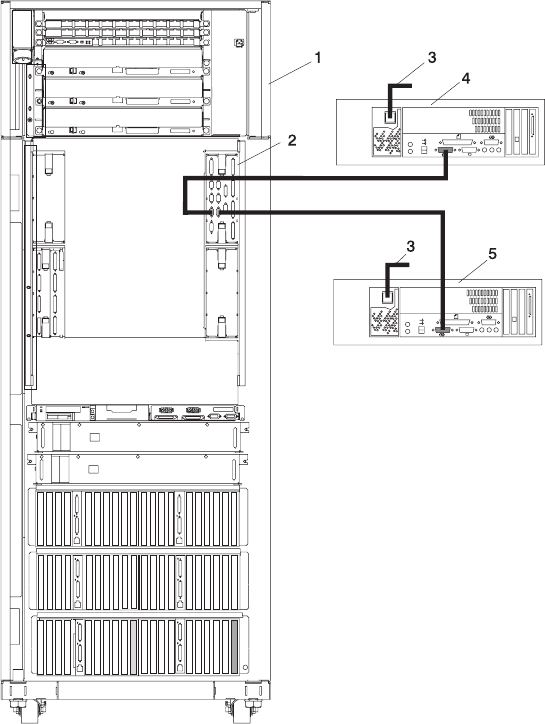
The following illustration shows the location of the serial ports on the back of the HMC and the HMC
connectors located on the system I/O book. As shown in this example, two HMCs are connected.
1 Primary Rack 2 Primary I/O Book
3 Power Plug to External Power Source (wall
plug)
4 Primary HMC Connected to the Primary I/O
Book
5 Optional Second HMC Connected to the
Primary I/O Book
Chapter 1. Reference Information 3

Powering On and Off
During the process of powering on, the HMC checks to see which managed systems are available and
communicating with the console. To ensure that each managed system is available before you power on
the HMC, managed systems must be in ″standby mode″ or actively operating. Standby mode is indicated
by the OK shown in the operator panel after the managed system has the power connected and the initial
tests are complete.
Note: If the managed system is in an emergency power off (EPOW) condition, the managed system must
be brought to ″standby mode″ before the HMC can be used to power on the system.
To power on the HMC, do the following:
1. Press the Power button once to turn on the power.
2. When the system has finished the power-on self-test (POST), log in to the HMC by using your service
representative name and password.
To power off the HMC, do the following:
1. Log in to the HMC and select Power Off.
2. The HMC shuts down any applications that are running, and then turns off the HMC.
Note: If the HMC fails to respond and will not shut down and turn off the power, call for HMC software
support.
Power-On Self-Test
After power is turned on and before the operating system is loaded, the system does a power-on self-test
(POST). This test performs checks to ensure that the hardware is functioning correctly before the
operating system is loaded. During the POST, codes indicating the progress of the POST might appear on
the display. After the POST is complete, the HMC operating software loads and a login prompt appears.
Specifications and System Unit Locations
Your HMC system is based on one of the following listed PC machine types and models. Use the follwing
table when cross referencing between a PC and pSeries HMC Machine Type and Model Number.
pSeries HMC Machine Type and
Model Number
Personal Computer Machine Type
and Model Number
Supporting Hardware Maintenance
Manual Part Number
7040 (FC 7315) 6578 Model KLU 06P1504
7040 (FC 7316) 6792 Model 31U 24P2934
7310 Model CR2 8676 Model 22X 48P9908
7310 Model CR3 8737 Model 22U 25K8109
7310 Model C03 8187 Model F4U 74P2661
7310 Model C04 8141 Model 31U 19R0486
7315 Model C01 (FC 7316) 6792 Model 31U 24P2934
7315 Model C02 8305 Model 41U 24P2969
7315 Model C03 8187 Model F4U
(without POV)
74P2661
7315 Model C04 8141 Model 31U 19R0486
7315 Model CR2 8676 Model 22X 48P9908
7315 Model CR3 8837 Model 22U 25K8109
4 Hardware Management Console for pSeries Maintenance Guide

External AC Power Cable
To avoid electrical shock, a power cable with a grounded attachment plug is provided. Use only properly
grounded outlets.
Power cables used in the United States and Canada are listed by Underwriter’s Laboratories (UL) and
certified by the Canadian Standards Association (CSA). These power cords consist of the following:
v Electrical cables, type ST
v Attachment plugs complying with National Electrical Manufacturers Association (NEMA) L6-30P
v Appliance couplers complying with International Electrotechnical Commission (IEC) Standard 320, Sheet
C13 and C14
Power cables used in other countries consist of the following:
v Electrical cables, type HD21 or HD22
v Attachment plugs approved by the appropriate testing organization for the specific countries where they
are used
v Appliance couplers complying with the International Electrotechnical Commission (IEC) Standard 320,
Sheet C13 and C14
Service Inspection Guide
Perform a service inspection on the server when the following are true:
v The server is inspected for a maintenance agreement.
v Service is requested and service has not recently been performed.
v An alterations and attachments review is performed.
v Changes have been made to the equipment that may affect the safe operation of the equipment.
v External devices with their own power cables have those cables attached.
If the inspection indicates an unacceptable safety condition, the condition must be corrected before anyone
can service the machine.
Note: The owner of the server is responsible to correct any unsafe condition.
Perform the following checks:
1. Check the covers for sharp edges and for damage or alterations that expose the internal parts of the
server unit.
2. Check the covers for proper fit to the server unit. They should be in place and secure.
3. Perform the appropriate power-off procedures.
4. Open the covers.
5. Check for alterations or attachments. If there are any, check for obvious safety hazards, such as
broken wires, sharp edges, or broken insulation.
6. Check the internal cables for damage.
7. Check for dirt, water, and any other contamination within the server unit.
8. Check the voltage label on the back of the server unit to ensure that it matches the voltage at the
outlet.
9. Check the external power cable for damage.
10. With the external power cable connected to the server unit, check for 0.1 ohm or less resistance
between the ground lug on the external power cable plug and the metal frame.
6 Hardware Management Console for pSeries Maintenance Guide
11. Perform the following checks on each device that has its own power cables:
a. Check for damage to the power cord.
b. Check for the correct grounded power cable.
c. With the external power cable connected to the device, check for 0.1 ohm or less resistance
between the ground lug on the external power cable plug and the metal frame of the device.
12. Close the doors.
13. Perform the appropriate power-on procedures.
Chapter 1. Reference Information 7
8 Hardware Management Console for pSeries Maintenance Guide

Chapter 2. Diagnostics Overview
The first step to service a managed system and the attached HMC (HMC) is to begin in the Diagnostic
Information for Multiple Bus Systems maintenance analysis procedures (MAPs). The Diagnostic
Information for Multiple Bus Systems, order number SA38-0509 directs the service representative to the
appropriate documentation depending on the type of problem that is to be isolated and repaired.
If a problem is determined to be in the HMC, see “Entry MAP” on page 14 for information about
diagnosing and repairing the HMC.
MAPs
The MAPs for the HMC are the starting point for diagnosing and repairing the HMC. The MAPs guide the
service representative to a specific repair action. There are occasions where the MAPs direct the service
representative directly to the service documentation for the personal computer. When this occurs, the
service documentation for the personal computer is used to complete the repair action.
Diagnostics, Test, and Recovery
The following tools are available to help identify and resolve hardware-related problems:
v Power-on self-test (POST)
– POST beep codes
– Error code format
v
PC Doctor
When you are referred to the PC service documentation, refer to “Related Publications” on page x for a
listing of PC hardware maintenance manuals. The publications are available through the following web
site:
http://www.pc.ibm.com
Note: Use the table located at the beginning of the related publications section to cross reference the PC
machine type and model number to the HMC machine type and model number.
PC-Doctor
PC-Doctor is a set of diagnostic and system information tools shipped with the HMC. In rack-mounted
HMC models, PC-Doctor is pre-loaded on the system. In desktop HMC models, PC-Doctor is included on
the HMC Recovery CDs for Release 3 Version 3.0 or later.
Running PC-Doctor on a Desktop HMC
Before accessing the PC-Doctor application on the desktop HMC models, you will need to create a
bootable diskette (referred to as the PC-Doctor diskette in the remainder of this section).
To create the diskette:
1. On a machine running Windows, insert a High Density Floppy Diskette in your diskette drive.
2. Insert volume 2 of HMC Recovery CD into the CD-ROM drive.
3. Select Start—>My Computer.
4. Open the CD-ROM and go to the pc_diag directory.
5. Open the README file and follow the instructions for creating the PC-Doctor diskette using the
pc_diag.exe tool.
9
To run PC-Doctor:
1. Power off the HMC.
2. Insert the PC-Doctor diskette you created.
3. Power on the HMC,
If the HMC does not read the PC-Doctor diskette upon startup, it may be due to the startup sequence. To
make the PC-Doctor diskette the primary startup media, do the following:
1. Turn off the power to the HMC.
2. Turn the power to the HMC back on and press F1 when the Setup Utility prompts during startup.
3. Select the Startup tab.
4. Highlight Startup Sequence and press Enter.
5. Under Primary Startup Sequence, make sure the first startup device is set to Removable. Then
follow the remainder of the instructions on the screen to complete the procedure.
Running PC-Doctor on a Rack-Mounted HMC
To run PC-Doctor on a rack-mounted HMC:
1. Turn off the power to the HMC.
2. Turn the power to the HMC back on and press F2 when the Setup Utility prompts during startup.
3. Select Diagnostics and follow the instructions on the screen.
10 Hardware Management Console for pSeries Maintenance Guide

Chapter 3. HMC Software Support
The software support organization uses the Problem Determination application to look at the HMC’s
internal code and determine how to fix a software problem.
Only a service representative or support representative can access this feature. When the hscpe user
selects the Microcode Maintenance feature, the system prompts the service representative for a password.
The service representative must contact software support to obtain this password.
Viewing the HMC Console Logs
The console logs display error and information messages that the console has logged while running
commands. The service representative can use this information to learn more about what caused an error
and how to resolve it. The HMC classifies log entries as either an informational message or an error
message. Log entries are identified with an I or E, respectively. The HMC lists these log entries
chronologically, with the most recent shown at the top of the list.
Use the HMC Console Log to view a record of HMC system events. System events are activities that
indicate when processes begin and end. These events also indicate whether the attempted action was
successful.
How to Create a Service Shell or View a HMC Log
To open a service shell and view the HMC log, do the following:
1. Contact HMC support and obtain the PE password for the HMC.
2. Log onto the HMC using hscpe user id. The customer must first create this account.
3. Open the restricted shell by doing one of the following:
v To open the restricted shell when working from a HMC console: right click on the desktop and select
Terminals then select rshterm.
v To open the restricted shell when working from a remote console: ssh to the HMC.
4. Use the pesh command to access a service shell. (To access a service shell, see “How to Create a
Service Shell or View a HMC Log.”) From the service shell command line type pesh then the HMC
serial number. (pesh serial number)
Note: The HMC serial number should be entered in uppercase.
When prompted , enter the password that was received from HMC support.
5. Run the showLog command.
The log includes the following information:
v The event’s unique ID code
v The date the event occurred
v The time the event occurred
v The log’s type
v The name of the attempted action
v The log’s reference code
v The status of the log
To view a particular event, do the following:
1. Select an event by clicking once on it.
2. Press Enter to get to a summary of the log you selected. From here, you must select a Block ID to
display. The blocks are listed next to the buttons and include the following options:
11
v Standard Data Block
v Secondary Data Block
v Microcode Reason / ID Error Information
3. Select the data block you want to view.
4. Press Enter. The extended information shown for the data block you selected includes the following:
v Program name
v Current process ID
v Parent process ID
v Current thread priority
v Current thread ID
v Screen group
v Subscreen group
v Current foreground screen process group
v Current background screen process group
For information about error messages displayed and recovery for these messages, see “Error Messages
and Recovery Information” on page 31.
12 Hardware Management Console for pSeries Maintenance Guide

Chapter 4. Maintenance Analysis Procedures
Use the information in this chapter to diagnose and repair problems that are related to the hardware
management console (HMC). You should use these maintenance analysis procedures (MAPs) when
directed from the managed system’s service documentation, or when a problem with the HMC is
suspected.
Note: If you are looking for procedures that are related to servicing the HMC, see the following for:
v Diagnostic information and service tips, go to Chapter 2, “Diagnostics Overview,” on page 9.
v Removing and and replacing parts, go to Chapter 6, “Removal and Replacement Procedures,” on
page 95.
v Backing up disk drive information on the HMC, refer to the IBM Hardware Management Console
for pSeries Installation and Operations Guide, form number SA38-0590, for backup procedures.
v Restoring disk drive information on the HMC, refer to the IBM Hardware Management Console
for pSeries Installation and Operations Guide, form number SA38-0590, for backup procedures.
v Checking modem settings. Refer to the IBM Hardware Management Console for pSeries
Installation and Operations Guide, form number SA38-0590.
v For additional PC maintenance information, refer to “Related Publications” on page x for a listing
of PC hardware maintenance manuals. The publications are available through the following web
site:
http://www.pc.ibm.com
13

Entry MAP
To start, find the symptom in the Symptom column of the following table. Then, perform the action
described in the Action column.
Symptom Action
Operator reported that the HMC did not start, but no
other problems were reported.
Go to “MAP 1020 Problem Determination” on page 15.
Operator reported “Communication not active” on the
HMC.
Go to “Managed System Connection” on page 19.
Operator reported communication problems with a
remotely connected HMC or a managed system.
Go to “Managed System Connection” on page 19.
Power Problems Go to “MAP 1520 Power” on page 17.
HMC Boot Problems Go to “MAP 1020 Problem Determination” on page 15.
Display problem Go to “Display Problems” on page 29.
DVD-RAM drive problem Go to “DVD RAM MAP” on page 26.
Disk drive problem Go to “Disk Drive MAP” on page 25.
Diskette drive problem Go to “Diskette Drive MAP” on page 28.
Ethernet LAN problem Go to “Ethernet MAP” on page 24.
You need to test the system to verify a problem with any
of the following:
v display
v diskette drive
v DVD-RAM Drive
v disk drive
v Ethernet LAN
Go to “System Unit Testing” on page 18.
Eight character error code begining with HMC received
when using the HMC graphical user interface.
Go to Chapter 5, “Error Code to FRU Index,” on page 31.
HMC does not communicate through the modem. Go to “Modem MAP” on page 21.
PC Doctor diagnostic tests detected an error. Refer to “Related Publications” on page x for a listing of
PC hardware maintenance manuals. The publications are
available through the following web site:
http://www.pc.ibm.com
If a part is called out for replacement, see Chapter 7,
“Hardware Management Console Parts,” on page 105 for
parts that are not included in the personal computer
service documentation.
Problems understanding the usage of the HMC. Go to IBM Hardware Management Console for pSeries
Installation and Operations Guide.
All other problems (for example: HMC graphical user
interface unresponsive, parity errors, power, POST
codes, blank display, mouse, or keyboard).
Go to “MAP 1020 Problem Determination” on page 15.
Symptoms not in this list. Go to “MAP 1020 Problem Determination” on page 15.
14 Hardware Management Console for pSeries Maintenance Guide

MAP 1020 Problem Determination
Use this MAP to determine if there is a problem with the HMC hardware. This MAP might direct you to
procedures in different sections of this book or to other books.
Step 1020-1
Note: If the HMC is running, shut down the console by exiting the graphical user interface, the PC should
turn off the power automatically. If the PC cannot turn off the power, then turn the power switch off.
1. Turn on the HMC power.
2. Watch the console and allow enough time for the system to complete the POST and load the HMC
software.
3. Watch and listen for the following failing symptoms during power-on:
v POST error condition.
v A series of beeps that indicate an error condition.
v The HMC login screen and user interface fails to start.
v A reference code or any other error information is displayed.
Do you have any of the failing symptoms during power on?
No Go to “Step 1020-2.”
Yes Go to the “General Checkout” section of the hardware maintenance manual for your machine type,
refer to “Related Publications” on page x for a listing of hardware maintenance manuals. The
hardware maintenance manuals can be accessed at the following web site:
http://www.pc.ibm.com
Step 1020-2
Follow the procedures in “System Unit Testing” on page 18 to run the PC diagnostic software (PC Doctor).
Does the PC Doctor diagnostics diskette boot and allow tests to be run on the PC system unit?
No Go to “MAP 1520 Power” on page 17.
Yes Go to “Step 1020-3.”
Step 1020-3
Follow the procedures in “System Unit Testing” on page 18 to test the PC hardware for the HMC. Select
System Unit problem area and run the test for Run All Selected.
Did the system unit tests detect any errors?
No Go to “Step 1020-4” on page 16.
Yes Go to “Step 1020-5” on page 16.
Chapter 4. Maintenance Analysis Procedures 15
Step 1020-4
Attention: This step requires software support assistance. Contact software support before continuing.
You might need to reload the HMC from the recovery DVD and reload the customer’s backup profile and
configuration data (see “Reloading the Hardware Management Console Image” on page 98 for more
information).
After reloading the software from the recovery DVD, does the HMC start correctly?
No Call your support representative.
Yes This ends the procedure. Go to MAP 0410 in the Diagnostic Information for Multiple Bus Systems.
Step 1020-5
Use the PC Doctor diagnostics and the maintenance procedures for the type of PC that you are working
on to isolate the failure and exchange FRUs. Refer to “Related Publications” on page x for a listing of PC
hardware maintenance manuals. The publications are available through the following web site:
http://www.pc.ibm.com
When the problem is repaired, or if the problem cannot be isolated, continue with “Step 1020-6.”
Step 1020-6
Note: If you reach this step and you have not been able to isolate a failure, call your next level of support
for assistance.
Reinstall all FRUs that did not fix the problem.
You must have performed a repair action to continue. If you have not already done so, verify the repair.
For instructions, see “System Unit Testing” on page 18.
Did the system unit tests run without errors?
No Return to “System Unit Testing” on page 18 to troubleshoot the error. Return here and continue
when the problem is resolved. Continue with “Step 1020-7.”
Yes Go to “Step 1020-7.”
Step 1020-7
Does the HMC communicate with all connected managed systems?
No Go to “Managed System Connection” on page 19.
Yes Go to “Step 1020-8” on page 17.
16 Hardware Management Console for pSeries Maintenance Guide

Step 1020-8
Did you exchange the system board or the system board battery?
No This ends the procedure.
Yes Go to “Step 1020-9”
Step 1020-9
If you have not already done so, configure the system board. Refer to “Configuring the System” on page
96.
This ends the procedure.
MAP 1520 Power
To troubleshoot a power problem on the PC, refer to the service documentation for the PC, refer to
“Related Publications” on page x for a listing of PC hardware maintenance manuals. The publications are
available through the following web site:
http://www.pc.ibm.com
MAP 1530: Testing the HMC
This MAP tests each of the base parts of the HMC. If a failure is detected, you will be instructed to fix the
failing part and then close out the service call.
This section describes diagnostics tests for the HMC. Use the information in this section when you are
directed to test the HMC to isolate a problem or verify a repair.
To help identify adapters, use “Specifications and System Unit Locations” on page 4.
Diagnostic Procedures
You should have been directed here to test a specific part of the HMC. See “System Unit Testing” on page
18. for the following problem areas:
v Display
v Keyboard
v Mouse
v Floppy Drive
v DVD-RAM
v DASD (disk drive)
v Memory
v Power
v Run All Selected
v SCSI
v Serial Port/Modem
v 16/4 Port Serial
v Ethernet
Chapter 4. Maintenance Analysis Procedures 17
System Unit Testing
This section provides information to help you use the PC Doctor diagnostic diskette to test the PC
hardware parts of the HMC. The PC Doctor diagnostic diskette is bootable.
Note: Performing procedures other than those specified in the following procedures may cause errors.
1. If you know which device is failing or you were sent here by another procedure, do the following:
a. Shut down the HMC, and ensure that the PC power is off.
b. Insert the PC Doctor diagnostic diskette into drive A.
c. Power on the PC.
d. Wait until a diagnostic selection menu is displayed.
2. Select either Diagnostics or Interactive Tests for a list of devices to test.
v Devices that require manual intervention (keyboard, video, mouse, diskette, CD-ROM) may be
selected from the Interactive Tests task bar.
v Devices that do not require manual intervention (processor, system board, I/O ports, fixed disks,
memory) and predefined test sequences (Run Normal/Quick Test) can be selected from the
Diagnostic task bar.
Select the task containing the device(s) or test(s) and follow the instructions. If you were instructed to
Run All Selected, continue with that selection.
3. If the diagnostics report a failure on the PC hardware, refer to “Related Publications” on page x for a
listing of PC hardware maintenance manuals. The publications are available through the following web
site:
http://www.pc.ibm.com
4. If the diagnostics do not report a failure, the HMC PC hardware is functioning correctly. If you still have
a problem, go to “MAP 1020 Problem Determination” on page 15.
18 Hardware Management Console for pSeries Maintenance Guide
Managed System Connection
Use this procedure to test the modem connection to the PC for the HMC.
1. Is the managed system currently communicating with the HMC?
No Go to step 2.
Yes This procedure is complete.
2. Is the managed system attached to serial (COM) port 2 on the HMC?
No Go to step 4.
Yes Go to step 3.
3. The HMC’s serial port 2 is reserved for modem use only. Move the serial cable from the HMC’s serial
port 2 to another HMC serial port. Go to step 1.
4. Is the managed system attached to serial (COM) port 1 on the HMC?
No Go to step 5.
Yes Go to step 7 on page 20.
5. Do the following:
a. Move the serial cable to serial port 1 (HMC1) of the HMC to aid in debugging. (The assumption is
that this cable is on a multi-port serial adapter. Note the position of the port that the cable was
moved from, for reinstallation after debugging.)
b. Reinitialize the HMC to have it attempt communication with the managed system.
Is the managed system communicating with the HMC?
No Go to step 7 on page 20.
Yes Go to step 6.
6. Do the following:
a. Replace the multi-port serial adapter card and its cable.
b. Return the serial cable to its original location.
(If the replacement hardware is delayed, use another, vacant serial connector port on the adapter
card as an attempt to restore HMC-managed system communication until the replacement hardware
arrives.) Go to step 1.
Chapter 4. Maintenance Analysis Procedures 19
7. Do the following:
a. Place a loopback plug on the far end of the serial port connector that is attached to the managed
system.
b. Insert the PC Doctor diskette into the HMC’s drive A: (floppy drive).
c. Reboot the HMC and wait until the PC Doctor main menu appears.
d. Click Diagnostics > Serial Ports to open the serial port diagnostics screen.
e. On the serial port diagnostics screen, select only the following tests for COM 1:
v Register and Interrupts
v Internal Loopback
v External Loopback
Note: Do not select External Loopback if loopback plug is not used.
v FIFO Buffers (16550A)
Did all the COM 1 tests pass?
No Go to step 8.
Yes Go to step 11.
8. Did the external loopback test fail?
No Go to step 10.
Yes Go to step 9.
9. Replace the serial port cable. Go to step 1 on page 19.
10. The problem appears to be in the serial port 1 of the HMC. Replace the hardware (system board) that
contains this port. Go to step 1 on page 19.
11. The problem appears to be with the serial port in the managed system. Refer to the MAPs for the
managed system.
20 Hardware Management Console for pSeries Maintenance Guide
Modem MAP
Use this procedure to test the modem connection to the PC for the HMC.
1. Verify that the modem and phone line are functioning properly.
To verify, do the following:
a. On the HMC console, open the Service Agent application.
b. Select Test Tools.
c. Initiate a Test PMR.
d. Monitor the call log to verify that the call is completed successfully. If the call is completed
successfully, the modem is functioning correctly.
Is the installed modem currently functioning on the HMC?
No Go to step 2.
Yes The problem is not in the modem. This is the end of this procedure.
2. Are the HMC configurations, relating to the modem operation, correct?
No Go to step 3.
Yes Go to step 4.
3. Correct the HMC configuration arguments. Go to step 1.
4. Is the modem powered on? (Are any indicators lit?)
No Go to step 5.
Yes Go to step 6.
5. Ensure the modem is powered on.
Go to step 1.
6. Is the serial cable, between the HMC’s serial (COM) port connector (HMC2) and the modem,
attached?
No Go to step 7.
Yes Go to step 8.
7. Attach the serial cable (as indicated by the preceding step).
Go to step1.
8. Install the PC Doctor diskette into the HMC’s drive A: (floppy drive). Reboot the HMC and wait until
the PC Doctor main menu appears. Click Diagnostics > Other Devices > Modem to perform the
modem diagnostic test.
Did the diagnostic pass?
No Go to step 9 on page 22.
Yes Go to step 17 on page 23.
Chapter 4. Maintenance Analysis Procedures 21
9. Is the modem properly connected to a working telephone line (or equivalent)?
Note: This can be checked by connecting a known good telephone to the line in place of the modem
and making a phone call.
No Go to step 18 on page 23.
Yes Locate a serial port loopback plug for the next step. Go to step 10.
10. Do the following:
a. Place a loopback plug on the end of the serial port connector that is attached to the modem.
b. Return to PC Doctor main menu.
c. Click Diagnostics > Serial Ports to access the serial port diagnostics screen.
d. On the serial port diagnostics screen, select only the following tests for COM 2:
v Register and Interrupts
v Internal Loopback
v External Loopback
Note: Do not select External Loopback if loopback plug is not used.
v FIFO Buffers (16550A)
Did all the COM 2 tests pass?
No Go to step 11.
Yes Go to step 14 on page 23.
11. Did the external loopback test fail?
No Go to step 12.
Yes Go to step 13.
12. The COM 2 port is defective. Replace the HMC hardware for COM 2 on your HMC.
Go to step 1 on page 21.
13. Replace the serial port cable. Go to step 1 on page 21.
22 Hardware Management Console for pSeries Maintenance Guide

14. The fault appears to be within the modem operation.
Are the modem’s internal settings (for example, switches) correct?
Note: If you are using a 7852-400 modem to enable communications, for proper operation, the dual
inline package (DIP) switches must be set according to the following table:
Switch Position Function
1 Up Force DTR
2 Up Flow Control &E4
3 Down Result Codes Enabled
4 Down Modem Emulation Disabled
5 Down* Auto Answer Enabled
6 Up Maximum Throughput Enabled
7 Up RTS Normal Functions
8 Down Enable Command Mode
9 Down Remote Digital Loopback Test Enabled
10 Up Dial-Up Line Enabled
11 Down AT Responses Enabled (Extended Responses Disabled)
12 Down* Asynchronous Operation
13 Up 28.8KB Line Speed
14 Up
15 Up CD and DSR Normal Functions
16 Up 2-Wire Leased Line Enabled
* Only switches 5 and 12 are changed from the factory default settings.
No Go to step 15.
Yes Go to step 16.
15. Correct the modem’s internal settings. Go to step 1 on page 21.
16. The modem appears to be faulty. Replace the modem. Go to step 1 on page 21.
17. Is the modem properly connected to a working telephone line (or equivalent)?
Note: This can be checked by connecting a known good telephone to the line in place of the modem
and making a telephone call.
No Go to step 18.
Yes Go to step 19.
18. Properly connect the telephone line (or equivalent) to the modem. Go to step 1 on page 21.
19. The failure mode is undetermined. Call service support.
Note: If you are servicing a MultiTech Modem
II
and more information is needed to complete the service
call, go to one of the following sites:
v CORE (Service personnel only): If you are servicing a MT5600BA-V92, go to the 7310/7315
folder and access the MultiTech MultiModem
II
documentation. If you are servicing a 7852-400
modem or a MultiTech Model 2834 MultiModem
II
, go to the 7852-400 folder and access the
MultiTech documentation.
Note: Use the MultiTech Model 2834 MultiModem documentation when installing or servicing the
7852-400 or the MultiTech Model 2834 MultiModem
II
modems.
v MultiTech web site: http://www.multitech.com/documents/families/multimodemII/manuals.asp
Chapter 4. Maintenance Analysis Procedures 23
Ethernet MAP
Use this procedure to test the Ethernet adapter in the PC for the HMC.
1. Is the Ethernet port currently functioning though normal operation of the HMC?
No Go to step 2.
Yes This is the end of the procedure.
2. Are the Ethernet configuration values set correctly? (IP address, Subnet Mask, and so on.)
No Go to step 3.
Yes Go to step 4.
3. Set the Ethernet configuration values to their proper settings. Go to step 1.
4. Can the HMC’s IP address be ’pinged’ by another system that should be able to ’see’ the HMC
on the customer’s network?
No Go to step 5.
Yes Go to step 13.
5. Is the Ethernet cable properly attached to the HMC and the customer’s network?
No Go to step 6.
Yes Go to step 7.
6. Attach the HMC to the customer’s network using an Ethernet cable with the correct pinout. Go to step
1.
7. Is the Ethernet cable the proper pinout? (There are two types of Ethernet cables in use, which
are distinguished by different pinouts. The customer’s network will determine which version of
cable to use.)
No Go to step 8.
Yes Go to step 9.
8. Replace the Ethernet cable with the correct version. Go to step 1.
9. Install the PC Doctor diskette into the HMC’s drive A: (floppy drive). Reboot the HMC and wait until
the PC Doctor main menu appears.
Click Diagnostics > Other Devices > Intel Ethernet to run the Ethernet diagnostic.
Did the diagnostic pass?
No Go to step 10.
Yes Go to step 13.
10. Refer to the Ethernet hardware’s hardware maintenance manual to determine if there are any internal
settings/jumpers that may disable the Ethernet port.
Are there any internal settings/jumpers?
No Go to step 11.
Yes Go to step 12.
11. Replace the Ethernet hardware in the HMC. (This may be a PCI card or system board replacement,
depending on the HMC hardware.) Go to step 1.
12. Set the internal settings/jumpers to enable the HMC’s Ethernet port. Go to step 1.
13. The failure appears not to be in the HMC.
24 Hardware Management Console for pSeries Maintenance Guide
Disk Drive MAP
Use this procedure to test the disk drive in the PC for the HMC.
1. Use the information in “System Unit Testing” on page 18 to test the PC. Select Hard Disk Drive
problem area.
Return here when the test is complete.
2. Did the disk drive test fail?
No Go to step 6.
Yes Continue with the next step.
3. Exchange the FRUs called by the diagnostics one at a time. For FRU removal and replacement
instructions, refer to the “Related Publications” on page x for a listing of PC hardware maintenance
manuals. The publications are available through the following web site:
http://www.pc.ibm.com
When each FRU is exchanged, test the repair using the information in “System Unit Testing” on page
18. Select Hard Disk Drive problem area.
Did the disk drive test fail?
No Continue with the next step.
Yes Call for assistance.
4. If you exchanged the disk drive and there are jumpers or tab settings on the new disk drive, ensure
they are set the same as the old drive. If there is a SCSI cable-terminating resistor device, ensure it is
secured to the cable and (if necessary) reattached to its original location on the PC.
Go to ″Hard Disk Jumper Settings″ in the PC hardware maintenance manual. Refer to “Related
Publications” on page x for a listing of PC hardware maintenance manuals. The publications are
available through the following web site:
http://www.pc.ibm.com
Continue with the next step.
5. If you exchanged the disk drive, restore the HMC image to the new disk drive. Refer to “Reloading the
Hardware Management Console Image” on page 98.
6. Use the information in “System Unit Testing” on page 18 to test the PC. Select Run All Selected
problem area.
v If the tests fail, go to “MAP 1020 Problem Determination” on page 15 to isolate the problem.
v If the tests run without errors, turn off the PC power and then turn on the power. Ensure that the
system boots and the HMC screen displays.
This ends the procedure. Go to MAP 0410 in the Diagnostic Information for Multiple Bus Systems.
Chapter 4. Maintenance Analysis Procedures 25
DVD RAM MAP
Use this procedure to test the DVD drive in the PC for the HMC.
1. Determine the media in the DVD RAM drive:
v Compact Disk Recordable (CD-R) similar to a CD
v DVD-RAM media cartridge
Is the media a CD-R?
No Go to step 4.
Yes Continue with the next step.
2. Clean the compact disk as follows:
v Hold the disk by its edges. Do not touch the surface.
v Remove dust and fingerprints from the surface by wiping from the center to the outside using a dry,
soft cloth.
Reinstall the CD, with the label-side facing up.
Continue with the next step.
3. Retry the failing task using the original media.
Does the failure occur again?
No Continue with the next step.
Yes Go to step 5.
This ends the procedure. Go to MAP 0410 in the Diagnostic Information for Multiple Bus Systems.
4. Ensure the write protect tab is in the ″disabled″ (down) position.
Was the write protect tab in the ″disabled″ (down) position?
No Go to step 3.
Yes Continue with the next step.
5. Leave the original media in the drive.
v If you are attempting a restore procedure, turn off the PC power.
v For any other operation, shut down the HMC, and then turn off the PC power.
Note: For shutdown procedures, see “Powering On and Off” on page 4.
Turn on the PC power and test the DVD-RAM drive using the information in “System Unit Testing” on
page 18. Select DVD-RAM Drive problem area.
When the test is complete, return here and continue with the next step.
6. Did the DVD-RAM test fail while testing with the original media?
No Go to step 11 on page 27.
Yes Continue with the next step.
26 Hardware Management Console for pSeries Maintenance Guide
7. Exchange the original media with a new one.
Note: If you are replacing DVD-RAM media, the new cartridge must be formatted. If possible, use
another HMC to format the new cartridge.
Turn off the PC power.
Turn on the PC power, and test the DVD-RAM drive with the new media. Use the information in
“System Unit Testing” on page 18 to test the PC. Select DVD-RAM Drive problem area.
8. Did the DVD-RAM test fail while testing with the new media?
No The original media was defective. This ends the procedure. Go to MAP 0410 in the
Diagnostic Information for Multiple Bus Systems.
Yes Continue with the next step.
9. Verify the following:
v All DVD-RAM drive data and power cables are secure.
v The DVD-RAM drive is jumpered as ″Master″ and is cabled to the Secondary IDE Bus.
If the diagnostics continue to fail, exchange the DVD-RAM drive. When complete, run the DVD-RAM
test again.
Note: If there are any jumpers or tab settings on the new drive, ensure they have the same settings
as the old drive.
Did the DVD-RAM Drive test continue to fail?
No The original DVD-RAM drive was defective. This ends the procedure. Go to MAP 0410 in the
Diagnostic Information for Multiple Bus Systems.
Yes Continue with the next step.
10. Continue exchanging FRUs from the FRU list and running the DVD-RAM drive tests.
v If the FRUs fix the problem, this ends the procedure. Go to MAP 0410 in the Diagnostic
Information for Multiple Bus Systems.
v If you cannot isolate the problem, call your next level of support for assistance.
11. The PC resources (for example: interrupt, I/O address) may be configured incorrectly. Verify the PC
resources are correctly configured, using the procedure in “PC Configuration” on page 98.
Select System Unit for the configuration area, and verify configuration for the system unit and all
adapters.
When you complete the verification, retry the failing procedure and continue with the next step.
12. Does the failing procedure continue to fail?
No The resource settings were incorrect. This ends the procedure. Go to MAP 0410 in the
Diagnostic Information for Multiple Bus Systems.
Yes If you cannot isolate the problem, call your next level of support for assistance.
This ends the procedure. Go to MAP 0410 in the Diagnostic Information for Multiple Bus Systems.
Chapter 4. Maintenance Analysis Procedures 27
Diskette Drive MAP
Use this procedure to test the diskette drive in the PC for the HMC.
1. Turn on the PC power and test the diskette drive using the information in “System Unit Testing” on
page 18. Select System Unit problem area and the test of Diskette Drive.
Note: Do not test with the diskette on which the errors occurred. Use a new diskette.
When the test is complete, continue with the next step.
2. Did the diskette test fail while testing with a new diskette?
Note: Answer ″Yes″ if you were not able to run the test because of the diskette errors.
No Go to step 5.
Yes Continue with the next step.
3. Exchange the diskette drive.
When complete, run the diskette test again.
Did the diskette test fail again?
No The original diskette drive was failing. This ends the procedure. Go to MAP 0410 in the
Diagnostic Information for Multiple Bus Systems.
Yes Continue with the next step.
4. Continue exchanging FRUs from the FRU list and running tests. If the FRUs fix the problem, this ends
the procedure. Go to MAP 0410 in the Diagnostic Information for Multiple Bus Systems.
If you cannot resolve the problem, call your next level of support for assistance.
5. Did the original failure occur while writing to a diskette?
No Go to step 7.
Yes Continue with the next step.
6. Retry the original task using a new diskette.
v If the failure occurs again, go to step 8.
v If no failures occur, the original diskette was failing. This ends the procedure. Go to MAP 0410 in
the Diagnostic Information for Multiple Bus Systems.
7. Re-create the information on the diskette, or get a new diskette with the information.
Retry the original task.
v If the failure occurs again, continue with the next step.
v If no failures occur, the original diskette was failing, this ends the procedure. Go to MAP 0410 in the
Diagnostic Information for Multiple Bus Systems.
8. Test the diskette drive, using the information in “System Unit Testing” on page 18. Select System Unit
problem area and the test of Diskette Drive.
v If the tests fail, isolate the problem using the procedures found in the PC hardware maintenance
manual. Refer to “Related Publications” on page x for a listing of PC related hardware maintenance
manuals. The publications are available through the following web site:
http://www.pc.ibm.com
When complete, go to MAP 0410 in the Diagnostic Information for Multiple Bus Systems.
v If the tests do not or if you cannot isolate the problem, call your next level of support for assistance.
28 Hardware Management Console for pSeries Maintenance Guide
Display Problems
Use this procedure when the customer reports a display problem.
1. Is the display type a 95xx (17P, 17X, 21P)?
No Continue with the next step.
Yes 95xx-xxx repairs may require replacing internal display FRUs.
Repair and test the display using the procedures in Monitor Hardware Maintenance Manual Vol
2, S41G-3317.
2. Is the display type a 65xx (P70, P200)?
No Continue with the next step.
Yes 65xx-xxx repairs may require replacing the entire display. There are no internal display FRUs.
Repair and test the display using the procedures in Monitor Hardware Maintenance Manual Vol
3, P and G series, S52H-3679.
When the test and repair are complete, continue with step 5.
3. Is the display type a 65xx (P72, P202)?
No Continue with the next step.
Yes 65xx-xxx repairs may require replacing the entire display. There are no internal display FRUs.
Repair and test the display using the procedures in Color Monitor Operating Instructions.
When the test and repair are complete, continue with step 5.
4. Repair and test the display using the documentation shipped with the display.
When the test and repair are complete, continue with step 6.
5. Verify the repair using the information in “System Unit Testing” on page 18. Select System Unit for the
problem area and the Test for Display.
When the test and repair are complete, return to step 6.
6. Close out the service call.
Chapter 4. Maintenance Analysis Procedures 29
30 Hardware Management Console for pSeries Maintenance Guide

Chapter 5. Error Code to FRU Index
Symptom to Action
Error Messages and Recovery Information
The following tables contain information about error messages that can be displayed by the HMC during
system configuration and operations.
Use this appendix to learn more about a specific error or information message. The table also includes
recovery information (if applicable) to help you determine a recovery strategy.
Console Events
Error Codes
Message Recovery Action
HSCE2066 A scheduled backup of critical console data
failed with a return code of {0}.
The possible return code values are:
v 4 - A return code of 4 indicates the
removable media could not be mounted.
Recovery Action - Verify that the media is
inserted properly in the drive and try the
operation again.
v 5 - A return code of 5 indicates that the
removable media is write protected.
Recovery Action - Remove the write
protection and try the operation again.
v Any value except 4 or 5 is an Internal
HMC Error
Recovery Action:
1. Perform Backup Critical Data task.
2. Call for HMC software support.
Inventory Scout
Error Codes
Message Recovery Action
HSCI0100 No managed systems were detected that are
attached to this system console.
None
HSCI0101 No partitions have been defined for this
managed system.
None
HSCI0102 A blank or invalid entry was entered in the
partition password field.
Enter a valid password value.
HSCI0103 A blank or invalid entry was entered in the
listening port field.
Enter a valid port value.
HSCI0104 A blank or invalid entry was entered in the IP
address field.
Enter a valid IP address value.
HSCI0110 The Inventory Scout command completed
successfully.
None
HSCI0111 The Inventory Scout command request failed 1. Verify that the removable media is
properly inserted in the drive and try the
operation again.
2. Try the operation with different media.
3. Run PC Doctor to determine if there is a
problem with the hardware.
4. Call for HMC software support.
31

Inventory Scout
Error Codes
Message Recovery Action
HSCI0112 The removable media cannot be mounted.
Please make sure the media is inserted
properly in the drive and retry the operation
1. Verify that the removable media is
properly inserted in the drive and try the
operation again.
2. Try the operation with different media.
3. Run PC Doctor to determine if there is a
problem with the hardware.
4. Call for HMC software support.
HSCI0113 The media specified is write protected.
Please adjust the media and retry.
Remove the write protection and try the
operation again.
HSCI0114 The Inventory Scout request failed. Ensure
the removable media is properly inserted in
the drive.
1. Verify that the removable media is
properly inserted in the drive and try the
operation again.
2. Try the operation with different media.
3. Run PC Doctor to determine if there is a
problem with the hardware.
4. Call for HMC software support.
HSCI0115 An error occurred while copying the Inventory
Scout data. Verify that a blank formatted
diskette is inserted properly in the drive and
retry the operation.
1. Verify that the removable media is
properly inserted in the drive and try the
operation again.
2. Try the operation with different media.
3. Run PC Doctor to determine if there is a
problem with the hardware.
4. Call for HMC software support.
HSCI0116 An error occurred while compressing the
Inventory Scout data. Please retry the
operation.
1. Verify that the removable media is
properly inserted in the drive and try the
operation again.
2. Try the operation with different media.
3. Run PC Doctor to determine if there is a
problem with the hardware.
4. Call for HMC software support.
HSCI0117 An error occurred while trying to unmount the
media.
1. Verify that the removable media is
properly inserted in the drive and try the
operation again.
2. Try the operation with different media.
3. Run PC Doctor to determine if there is a
problem with the hardware.
4. Call for HMC software support.
HSCI0118 The Inventory Scout daemon was restarted
successfully.
None
HSCI0119 The Inventory Scout daemon could not be
restarted.
1. Verify that the removable media is
properly inserted in the drive and try the
operation again.
2. Try the operation with different media.
3. Run PC Doctor to determine if there is a
problem with the hardware to determine if
there is a hardware problem.
4. Call for HMC software support.
32 Hardware Management Console for pSeries Maintenance Guide

Inventory Scout
Error Codes
Message Recovery Action
HSCI0120 The internal managed system name is
malformed. Please exit this task and retry the
operation.
1. Verify that the removable media is
properly inserted in the drive and try the
operation again.
2. Try the operation with different media.
3. Run PC Doctor to determine if there is a
problem with the hardware.
4. Call for HMC software support.
HSCI0121 The Inventory Scout request failed. An error
occurred while copying data to removable
media.
1. Verify that the removable media is
properly inserted in the drive and try the
operation again.
2. Try the operation with different media.
3. Run PC Doctor to determine if there is a
problem with the hardware.
4. Call for HMC software support.
After collecting all necessary data for L3
support, try the following steps to fix the
problem:
1. Reboot the HMC. If the reboot does not
correct the problem, continue with the
next step.
2. Perform these steps:
a. /usr/sbin/rsct/bin/rmcctrl -z ctrmc -
b. rm /var/ct/IW/registry/local_tree
c. rm /var/ct/IW/register/SfpCl
d. Reboot HMC again.
Chapter 5. Error Code to FRU Index 33

Inventory Scout
Error Codes
Message Recovery Action
HSCI0122 The system partition(s) did not respond to
query attempts.
1. Check that the HMC host name and the
host name of the partition are fully
qualified domain name (not a short host
name). If they are not, this must be
corrected for remote security to work.
2. Verify the network routing is set up so the
HMC can use ping to reach the partition
and vice versa. If one or both cannot be
reached from the other, correct the
routing.
3. Check to make sure /var is not full on the
partition, which would prevent certain
processes from running correctly.
4. Verify that the following filesets have been
installed properly on the AIX partitions:
v rsct.core
v csm.client
v devices.chrp.base.ServiceRM
5. Log in to one of the partitions and issue
the following command: lssrc -s ctcas .
If the output shows ctcasd is inoperative,
run an ls -l command on the /var/ct/cfg/
directory. If the files ct_has.pkf and
ct_has.qkf are zero-length, there was an
(AIX) installation configuration problem.
These zero-length files should be
removed and then issue the command
startsrc -s ctcas. If the startsrc -s
ctcas command does not work, the AIX
lpp may not have been installed.
6. If the output is still blank, reboot the HMC.
After the reboot occurs, wait at least 10
minutes before trying again, to make sure
all the partitions have resynchronized their
information with the HMC.
7. If the problem persists, contact your
software service support representative.
Profile Data Error
Codes
Message Recovery Action
HSCL0001 There is no more space for a new profile
name. Reuse profile names being used by
other profiles or remove the profiles that are
no longer needed.
No more space for a new profile name is
available. Reuse the profile names that are
already used by other profiles, or remove the
profiles that are no longer needed. This is a
customer action.
HSCL0002 Too many drawers are being used in profiles.
Remove the drawers that no longer exist or
are not needed.
Remove the drawers that no longer exist or
are no longer needed. This is a customer
action.
HSCL0003 The profile data save area is full. Remove
any profiles that are no longer needed.
Remove the profiles that are no longer
needed. This is a customer action.
34 Hardware Management Console for pSeries Maintenance Guide

Profile Data Error
Codes
Message Recovery Action
HSCL0004 A profile with name {0} already exists in the
partition with ID {1} in profile data of the
managed system. Provide another name for
this profile.
Rename the profile to names that are not
already in use in this partition. This is a
customer action.
HSCL0005 Cannot find information regarding profile data
of the managed system. Execute a rebuild
managed system operation.
1. Perform a rebuild managed system
operation.
2. If the problem persists, contact your
software service support representative.
HSCL0006 The managed system’s profile data has been
corrupted. You must either restore or
reinitialize the profile data.
You must either restore or initialize the profile
data. This is a customer action.
HSCL0007 The profile data of the managed system
cannot be accessed or modified. Execute a
rebuild managed system operation
1. Perform a rebuild managed system
operation.
2. If the problem persists, contact your
software service support representative.
HSCL0008 Could not construct or initialize profile data.
Perform a Rebuild Managed System
operation.
If the customer has not done so, perform a
Rebuild Managed System operation. Follow
the procedures in “Rebuild is Indicated for
Managed System” on page 89 to perform this
action. If the problem persists, check the
state of the system and perform the
procedures in “Operating States” on page 85
to return the managed system to ready state.
HSCL0009 Could not construct or initialize the profile
data from the backup file, {0}. Repeat the
operation.
Repeat the operation. Direct customers to
follow the procedures in their IBM Hardware
Management Console for pSeries Installation
and Operations Guide. If the problem
persists, call for HMC software support.
HSCL000B Could not get the activated LPAR profile from
the profile data. Perform a Rebuild Managed
System operation.
If the customer has not done so, perform a
Rebuild Managed System operation. Follow
the procedures in “Rebuild is Indicated for
Managed System” on page 89 to perform this
action. If the problem persists, check the
state of the system and perform the
procedures in “Operating States” on page 85
to return the managed system to ready state.
HSCL000C Could not get the activated system profile
from the profile data. Perform a Rebuild
Managed System operation.
If the customer has not done so, perform a
Rebuild Managed System operation. Follow
the procedures in “Rebuild is Indicated for
Managed System” on page 89 to perform this
action. If the problem persists, check the
state of the system and perform the
procedures in “Operating States” on page 85
to return the managed system to ready state.
HSCL000D Could not get all the system profiles from the
profile data. Perform a Rebuild Managed
System operation.
If the customer has not done so, perform a
Rebuild Managed System operation. Follow
the procedures in “Rebuild is Indicated for
Managed System” on page 89 to perform this
action. If the problem persists, check the
state of the system and perform the
procedures in “Operating States” on page 85
to return the managed system to ready state.
Chapter 5. Error Code to FRU Index 35

Profile Data Error
Codes
Message Recovery Action
HSCL000E Could not get the default LPAR profile from
the profile data. Perform a Rebuild Managed
System operation.
If the customer has not done so, perform a
Rebuild Managed System operation. Follow
the procedures in “Rebuild is Indicated for
Managed System” on page 89 to perform this
action. If the problem persists, check the
state of the system and perform the
procedures in “Operating States” on page 85
to return the managed system to ready state.
HSCL000F Could not get the default system profile from
the profile data. Perform a Rebuild Managed
System operation.
If the customer has not done so, perform a
Rebuild Managed System operation. Follow
the procedures in “Rebuild is Indicated for
Managed System” on page 89 to perform this
action. If the problem persists, check the
state of the system and perform the
procedures in “Operating States” on page 85
to return the managed system to ready state.
HSCL0010 Could not get the LPAR profiles for the
partition from the profile data. Perform a
Rebuild Managed System operation.
If the customer has not done so, perform a
Rebuild Managed System operation. Follow
the procedures in “Rebuild is Indicated for
Managed System” on page 89 to perform this
action. If the problem persists, check the
state of the system and perform the
procedures in “Operating States” on page 85
to return the managed system to ready state.
HSCL0011 Could not get the LPAR profiles at this
partition from the profile data. Perform a
Rebuild Managed System operation.
If the customer has not done so, perform a
Rebuild Managed System operation. Follow
the procedures in “Rebuild is Indicated for
Managed System” on page 89 to perform this
action. If the problem persists, check the
state of the system and perform the
procedures in “Operating States” on page 85
to return the managed system to ready state.
HSCL0012 Could not get the system profile from the
profile data. Perform a Rebuild Managed
System operation.
If the customer has not done so, perform a
Rebuild Managed System operation. Follow
the procedures in “Rebuild is Indicated for
Managed System” on page 89 to perform this
action. If the problem persists, check the
state of the system and perform the
procedures in “Operating States” on page 85
to return the managed system to ready state.
HSCL0013 Could not remove the LPAR profile from the
profile data. Perform a Rebuild Managed
System operation.
If the customer has not done so, perform a
Rebuild Managed System operation. Follow
the procedures in “Rebuild is Indicated for
Managed System” on page 89 to perform this
action. If the problem persists, check the
state of the system and perform the
procedures in “Operating States” on page 85
to return the managed system to ready state.
36 Hardware Management Console for pSeries Maintenance Guide

Profile Data Error
Codes
Message Recovery Action
HSCL0014 Could not remove the system profile from the
profile data. Perform a Rebuild Managed
System operation.
If the customer has not done so, perform a
Rebuild Managed System operation. Follow
the procedures in “Rebuild is Indicated for
Managed System” on page 89 to perform this
action. If the problem persists, check the
state of the system and perform the
procedures in “Operating States” on page 85
to return the managed system to ready state.
HSCL0015 Could not save the LPAR profile to the profile
data. Perform a Rebuild Managed System
operation.
If the customer has not done so, perform a
Rebuild Managed System operation. Follow
the procedures in “Rebuild is Indicated for
Managed System” on page 89 to perform this
action. If the problem persists, check the
state of the system and perform the
procedures in “Operating States” on page 85
to return the managed system to ready state.
HSCL0016 Could not save the system profile to the
profile data. Perform a Rebuild Managed
System operation.
If the customer has not done so, perform a
Rebuild Managed System operation. Follow
the procedures in “Rebuild is Indicated for
Managed System” on page 89 to perform this
action. If the problem persists, check the
state of the system and perform the
procedures in “Operating States” on page 85
to return the managed system to ready state.
HSCL0017 Could not create the LPAR profile in the
profile data. Perform a Rebuild Managed
System operation.
If the customer has not done so, perform a
Rebuild Managed System operation. Follow
the procedures in “Rebuild is Indicated for
Managed System” on page 89 to perform this
action. If the problem persists, check the
state of the system and perform the
procedures in “Operating States” on page 85
to return the managed system to ready state.
HSCL0018 Could not create the system profile in the
profile data. Perform a Rebuild Managed
System operation.
If the customer has not done so, perform a
Rebuild Managed System operation. Follow
the procedures in “Rebuild is Indicated for
Managed System” on page 89 to perform this
action. If the problem persists, check the
state of the system and perform the
procedures in “Operating States” on page 85
to return the managed system to ready state.
HSCL0019 Could not set the activated LPAR profile in
the profile data. Perform a Rebuild Managed
System operation.
If the customer has not done so, perform a
Rebuild Managed System operation. Follow
the procedures in “Rebuild is Indicated for
Managed System” on page 89 to perform this
action. If the problem persists, check the
state of the system and perform the
procedures in “Operating States” on page 85
to return the managed system to ready state.
Chapter 5. Error Code to FRU Index 37

Profile Data Error
Codes
Message Recovery Action
HSCL001A Could not set the activated system profile in
the profile data. Perform a Rebuild Managed
System operation.
If the customer has not done so, perform a
Rebuild Managed System operation. Follow
the procedures in “Rebuild is Indicated for
Managed System” on page 89 to perform this
action. If the problem persists, check the
state of the system and perform the
procedures in “Operating States” on page 85
to return the managed system to ready state.
HSCL001B Could not set the default LPAR profile in the
profile data. Perform a Rebuild Managed
System operation.
If the customer has not done so, perform a
Rebuild Managed System operation. Follow
the procedures in “Rebuild is Indicated for
Managed System” on page 89 to perform this
action. If the problem persists, check the
state of the system and perform the
procedures in “Operating States” on page 85
to return the managed system to ready state.
HSCL001C Could not set the default system profile in the
profile data. Perform a Rebuild Managed
System operation.
If the customer has not done so, perform a
Rebuild Managed System operation. Follow
the procedures in “Rebuild is Indicated for
Managed System” on page 89 to perform this
action. If the problem persists, check the
state of the system and perform the
procedures in “Operating States” on page 85
to return the managed system to ready state.
HSCL001D Could not clean up the profile data. Perform
a Rebuild Managed System operation.
If the customer has not done so, perform a
Rebuild Managed System operation. Follow
the procedures in “Rebuild is Indicated for
Managed System” on page 89 to perform this
action. If the problem persists, check the
state of the system and perform the
procedures in “Operating States” on page 85
to return the managed system to ready state.
HSCL001E Could not update the profile data cache.
Perform a Rebuild Managed System
operation.
If the customer has not done so, perform a
Rebuild Managed System operation. Follow
the procedures in “Rebuild is Indicated for
Managed System” on page 89 to perform this
action. If the problem persists, check the
state of the system and perform the
procedures in “Operating States” on page 85
to return the managed system to ready state.
HSCL001F Could not check for duplicate LPAR name.
Perform a Rebuild Managed System
operation.
If the customer has not done so, perform a
Rebuild Managed System operation. Follow
the procedures in “Rebuild is Indicated for
Managed System” on page 89 to perform this
action. If the problem persists, check the
state of the system and perform the
procedures in “Operating States” on page 85
to return the managed system to ready state.
38 Hardware Management Console for pSeries Maintenance Guide

Profile Data Error
Codes
Message Recovery Action
HSCL0020 Could not remove the LPAR profile from the
system profile content in the profile data.
Perform a Rebuild Managed System
operation.
If the customer has not done so, perform a
Rebuild Managed System operation. Follow
the procedures in “Rebuild is Indicated for
Managed System” on page 89 to perform this
action. If the problem persists, check the
state of the system and perform the
procedures in “Operating States” on page 85
to return the managed system to ready state.
HSCL0021 Could not add the LPAR profile to the system
profile in the profile data. Perform a Rebuild
Managed System operation.
If the customer has not done so, perform a
Rebuild Managed System operation. Follow
the procedures in “Rebuild is Indicated for
Managed System” on page 89 to perform this
action. If the problem persists, check the
state of the system and perform the
procedures in “Operating States” on page 85
to return the managed system to ready state.
HSCL0022 Could not get the partition name from the
profile data. Perform a Rebuild Managed
System operation.
If the customer has not done so, perform a
Rebuild Managed System operation. Follow
the procedures in “Rebuild is Indicated for
Managed System” on page 89 to perform this
action. If the problem persists, check the
state of the system and perform the
procedures in “Operating States” on page 85
to return the managed system to ready state.
HSCL0023 Could not get all the partition names from the
profile data. Perform a Rebuild Managed
System operation.
If the customer has not done so, perform a
Rebuild Managed System operation. Follow
the procedures in “Rebuild is Indicated for
Managed System” on page 89 to perform this
action. If the problem persists, check the
state of the system and perform the
procedures in “Operating States” on page 85
to return the managed system to ready state.
HSCL0024 Could not set the partition name in the profile
data. Perform a Rebuild Managed System
operation.
If the customer has not done so, perform a
Rebuild Managed System operation. Follow
the procedures in “Rebuild is Indicated for
Managed System” on page 89 to perform this
action. If the problem persists, check the
state of the system and perform the
procedures in “Operating States” on page 85
to return the managed system to ready state.
HSCL0025 Could not build the profile data from the local
file, {0}. Perform a Rebuild Managed System
operation.
If the customer has not done so, perform a
Rebuild Managed System operation. Follow
the procedures in “Rebuild is Indicated for
Managed System” on page 89 to perform this
action. If the problem persists, check the
state of the system and perform the
procedures in “Operating States” on page 85
to return the managed system to ready state.
Chapter 5. Error Code to FRU Index 39

Profile Data Error
Codes
Message Recovery Action
HSCL0026 Could not write the data to the managed
system. Perform a Rebuild Managed System
operation.
If the customer has not done so, perform a
Rebuild Managed System operation. Follow
the procedures in “Rebuild is Indicated for
Managed System” on page 89 to perform this
action. If the problem persists, check the
state of the system and perform the
procedures in “Operating States” on page 85
to return the managed system to ready state.
HSCL0027 Could not backup the profile data to a file.
Perform a Rebuild Managed System
operation.
If the customer has not done so, perform a
Rebuild Managed System operation. Follow
the procedures in “Rebuild is Indicated for
Managed System” on page 89 to perform this
action. If the problem persists, check the
state of the system and perform the
procedures in “Operating States” on page 85
to return the managed system to ready state.
HSCL0028 Could not read profile data from the managed
system. Perform a Rebuild Managed System
operation.
If the customer has not done so, perform a
Rebuild Managed System operation. Follow
the procedures in “Rebuild is Indicated for
Managed System” on page 89 to perform this
action. If the problem persists, check the
state of the system and perform the
procedures in “Operating States” on page 85
to return the managed system to ready state.
HSCL0029 Could not delete profiles at the partition with
ID of {0} in the profile data. Perform a
Rebuild Managed System operation.
If the customer has not done so, perform a
Rebuild Managed System operation. Follow
the procedures in “Rebuild is Indicated for
Managed System” on page 89 to perform this
action. If the problem persists, check the
state of the system and perform the
procedures in “Operating States” on page 85
to return the managed system to ready state.
HSCL002A Could not modify the system profiles
containing the LPAR slot ID of {0} in the
profile data. Perform a Rebuild Managed
System operation.
If the customer has not done so, perform a
Rebuild Managed System operation. Follow
the procedures in “Rebuild is Indicated for
Managed System” on page 89 to perform this
action. If the problem persists, check the
state of the system and perform the
procedures in “Operating States” on page 85
to return the managed system to ready state.
HSCL002B Could not do a priority restore on the profile
data. Perform a Rebuild Managed System
operation.
If the customer has not done so, perform a
Rebuild Managed System operation. Follow
the procedures in “Rebuild is Indicated for
Managed System” on page 89 to perform this
action. If the problem persists, check the
state of the system and perform the
procedures in “Operating States” on page 85
to return the managed system to ready state.
40 Hardware Management Console for pSeries Maintenance Guide

Profile Data Error
Codes
Message Recovery Action
HSCL002C Could not merge the profile information in
profile data. Perform a Rebuild Managed
System operation.
If the customer has not done so, perform a
Rebuild Managed System operation. Follow
the procedures in “Rebuild is Indicated for
Managed System” on page 89 to perform this
action. If the problem persists, check the
state of the system and perform the
procedures in “Operating States” on page 85
to return the managed system to ready state.
HSCL002D Could not merge partition name data in the
profile data. Perform a Rebuild Managed
System operation.
If the customer has not done so, perform a
Rebuild Managed System operation. Follow
the procedures in “Rebuild is Indicated for
Managed System” on page 89 to perform this
action. If the problem persists, check the
state of the system and perform the
procedures in “Operating States” on page 85
to return the managed system to ready state.
HSCL002E Could not merge default and activated list
data in profile data. Perform a Rebuild
Managed System operation.
If the customer has not done so, perform a
Rebuild Managed System operation. Follow
the procedures in “Rebuild is Indicated for
Managed System” on page 89 to perform this
action. If the problem persists, check the
state of the system and perform the
procedures in “Operating States” on page 85
to return the managed system to ready state.
HSCL002F Could not merge drawer and profile
information data in profile data. Perform a
Rebuild Managed System operation.
If the customer has not done so, perform a
Rebuild Managed System operation. Follow
the procedures in “Rebuild is Indicated for
Managed System” on page 89 to perform this
action. If the problem persists, check the
state of the system and perform the
procedures in “Operating States” on page 85
to return the managed system to ready state.
HSCL0030 Unable to initialize the profile data. Perform a
Rebuild Managed System operation.
If the customer has not done so, perform a
Rebuild Managed System operation. Follow
the procedures in “Rebuild is Indicated for
Managed System” on page 89 to perform this
action. If the problem persists, check the
state of the system and perform the
procedures in “Operating States” on page 85
to return the managed system to ready state.
HSCL0031 The profile data has been cleared. Either
restore or reinitialize the profile data save
area.
Perform restore profile data task or reinitialize
the profile data. Refer to the IBM Hardware
Management Console for pSeries Installation
and Operations Guide, order number
SA38-0590 for these procedures.
HSCL0032 Could not set the system profile’s user
defined name to the profile data. Perform a
Rebuild Managed System operation.
If the customer has not done so, perform a
Rebuild Managed System operation. Follow
the procedures in “Rebuild is Indicated for
Managed System” on page 89 to perform this
action. If the problem persists, check the
state of the system and perform the
procedures in “Operating States” on page 85
to return the managed system to ready state.
Chapter 5. Error Code to FRU Index 41

Profile Data Error
Codes
Message Recovery Action
HSCL0033 This managed system version, {0}, is
unknown to HMC. Update to an HMC release
that can handle this version of managed
system.
1. Perform the rebuild managed system
operation.
2. If the same error occurs, update to an
HMC release that can handle this version
of managed system.
3. If you are not sure what version to use,
contact software support.
HSCL0034 The levels of managed system and profile
data area are not matching up. Managed
system version: {0}, profile data area version:
{1}. Upgrade the managed system version ″to
proper level.″
1. Perform the rebuild managed system
operation.
2. If the same error occurs, please update
the managed system to a proper version.
3. If you are not sure what version to use,
contact software support.
HSCL0035 Cannot restore profile data with 2 different
versions of profile save data.
1. Perform the operation again.
2. If the same error occurs, restore using
another profile data file.
HSCL0036 Migrate profile data failed. 1. Perform the operation again.
2. If the problem persists, contact your
software service support representative.
HSCL0037 This level of profile data, {0}, is unknown to
this HMC. Please update to an HMC version
that can handle this level of profile data.
1. Perform the operation again.
2. If the problem persists, update to an HMC
version that can handle this level of
profile data.
3. If you are not sure what version to use,
contact software support.
HSCL0038 Creation of affinity logical partition profiles
failed in profile data save area.
1. Perform the rebuild managed system
operation.
2. Retry the operation again.
3. If the problem persists, contact your
software service support representative.
HSCL0039 Deletion of affinity logical partitions failed in
profile data save area.
1. Perform the rebuild managed system
operation.
2. Retry the operation again.
3. If the problem persists, contact your
software service support representative.
HSCL003A Removal system profiles failed at profile data
save area.
1. Perform the rebuild managed system
operation.
2. Retry the operation again.
3. If the problem persists, contact your
software service support representative.
HSCL003B Setting of partition information failed in profile
data save area.
1. Perform the rebuild managed system
operation.
2. Retry the operation again.
3. If the problem persists, contact your
software service support representative.
42 Hardware Management Console for pSeries Maintenance Guide

Profile Data Error
Codes
Message Recovery Action
HSCL003C Retrieval of all affinity logical partition
information failed in profile data save area.
1. Perform the rebuild managed system
operation.
2. Retry the operation again.
3. If the problem persists, contact your
software service support representative.
HSCL003D Retrieval of partition information failed in
profile data save area.
1. Perform the rebuild managed system
operation.
2. Retry the operation again.
3. If the problem persists, call for HMC
software support.
HSCL003E Cannot build LPAR information from profile
data save area when the managed system is
not LPAR capable.
The capabilities of your managed system are
listed on the Machine tab of the property
panel.
HSCL003F Cannot build affinity logical partition
information from profile data save area when
the managed system is not Affinity LPAR
capable.
The capabilities of your managed system are
listed on the Machine tab of the property
panel.
HSCL0040 No more space for physical location code in
the profile data save area.
1. Perform the rebuild managed system
operation
2. Retry the operation again.
3. If the problem persists, call for HMC
software support.
HSCL0041 Migration of partition information failed in
profile data save area
1. Perform the rebuild managed system
operation.
2. If the problem persists, call for HMC
software support.
HSCL0042 Migration of profile names failed in profile
data save area
1. Perform the rebuild managed system
operation.
2. If the problem persists, call for HMC
software support.
HSCL0043 Migration of default profile list failed in profile
data save area
1. Perform the rebuild managed system
operation.
2. If the problem persists, call for HMC
software support.
HSCL0044 Migration of activated profile list failed in
profile data save area
1. Perform the rebuild managed system
operation.
2. If the problem persists, call for HMC
software support.
HSCL0045 Migration of physical location code
information failed in profile data save area
1. Perform the rebuild managed system
operation.
2. If the problem persists, call for HMC
software support.
HSCL0046 Migration of drawer and profile information
failed in profile data save area
1. Perform the rebuild managed system
operation.
2. If the problem persists, call for HMC
software support.
Chapter 5. Error Code to FRU Index 43

Profile Data Error
Codes
Message Recovery Action
HSCL0047 Migration of time stamps of profile data save
area failed
1. Perform the rebuild managed system
operation.
2. If the problem persists, call for HMC
software support.
HSCL0048 Migration of checksums of profile data save
area failed
1. Perform the rebuild managed system
operation.
2. If the problem persists, call for HMC
software support.
Managed System
Error Codes
Message Recovery Action
HSCL01F5 Unable to lock the Service Processor.
Perform one of the following steps: (1) Check
serial cable connection; (2) Check if another
Console is communicating with the Service
Processor; (3) Perform the Release Lock
task; (4) Perform Rebuild task to re-establish
the connection.
1. Wait for three minutes and retry the task.
2. If the problem persists, make sure other
HMCs and remote login sessions of the
HMCs are not performing any task. Then
perform the Release HMC Lock task to
unlock the service processor, and then try
the task again.
3. Rebuild the managed system. Follow the
procedures in “Rebuild is Indicated for
Managed System” on page 89 to perform
this action.
This is a customer action.
HSCL01F6 Unable to unlock the managed system lock.
Perform the Release Hardware Management
Console Lock to unlock the managed system.
1. Perform the Release HMC lock to unlock
the service processor, and try the task
again.
2. If the task still fails and a redundant HMC
is present, turn off the redundant HMC
power and try the task again.
This is a customer action. If the problem
persists, refer to “Managed System States for
the HMC” on page 90 and check the state of
the managed system. Perform the appropriate
actions to recover.
HSCL01F7 Unable to get the current time from the
managed system.
1. Try the task again.
2. Perform a Rebuild Managed System
operation. Follow the procedures in
“Rebuild is Indicated for Managed
System” on page 89 to perform this
action.
If the problem persists, refer to “Managed
System States for the HMC” on page 90 and
check the state of the managed system.
Perform the appropriate actions to recover.
HSCL01F8 This property cannot be altered. None.
44 Hardware Management Console for pSeries Maintenance Guide

Managed System
Error Codes
Message Recovery Action
HSCL01F9 Unable to create managed system instance
in object manager.
1. Try the task again.
2. Shut down and restart the HMC.
3. Try the task again.
This is a customer action.
HSCL01FA The managed system is already powered off. None.
HSCL01FC The parameter specified is not valid. Specify
a different value.
None.
HSCL01FD Power on failed. Try again. Retry the Power On task. This is a customer
action.
HSCL01FE The managed system is already powered on. None.
HSCL01FF Could not rebuild. Shut down and restart the
Hardware Management Console.
1. Before rebooting, try the task again.
2. Reboot the HMC.
3. Refer to “Managed System States for the
HMC” on page 90 and check the state of
the managed system. Perform the
appropriate actions to recover.
4. Try the task again.
This is a customer action. Verify the customer
has performed the appropriate recovery
action, If the problem persists, call for HMC
software support.
HSCL0200 Unable to communicate with Service
Processor. Check serial cable connection.
1. Check the serial cable connection from
the HMC to the managed system.
2. Refer to “Managed System States for the
HMC” on page 90 and check the state of
the managed system. Perform the
appropriate actions to put the managed
system in the correct state.
HSCL0201 Service Processor Command failed after {0}
attempts: Invalid Response.
Wait several minutes and try the task again.
HSCL0202 Service Processor Socket is corrupted. 1. Wait two minutes and retry the command
2. If the command still fails, wait an
additional two minutes and try again.
3. If both tries fail, rebuild the managed
system to re-establish the socket
connection. Follow the procedures in
“Rebuild is Indicated for Managed
System” on page 89 to perform this
action, then try the task again.
HSCL0203 Command sent to Service Processor failed.
Error Response {0}
1. Try the task again.
2. Refer to “Managed System States for the
HMC” on page 90 and check the state of
the managed system. Perform the
appropriate actions to put the managed
system in the correct state.
Chapter 5. Error Code to FRU Index 45

Managed System
Error Codes
Message Recovery Action
HSCL0204 Command failed. Unknown error. 1. Try the task again.
2. Refer to “Managed System States for the
HMC” on page 90 and check the state of
the managed system. Perform the
appropriate actions to put the managed
system in the correct state.
HSCL0205 The Managed System is in the Error State
and is unable to continue with the Recover
Partition Data Task.
The recovery partition data task cannot be
run until the managed system is no longer in
error state.
1. Record the error message.
2. Refer to the recovery procedures for the
managed system.
HSCL0206 Failed to Power On the managed system in
Partition Standby mode. Unable to continue
with the Recover Partition Data task.
1. Check the operator panel value of the
managed system to verify it is in the no
power state and that the managed system
is not in the error state.
2. Verify that no other task is being
performed while executing this task, then
retry the task.
3. If problem persists, call HMC software
support.
HSCL0207 Failed to Power Off the Managed System.
Unable to continue with the Recover Partition
Data Task.
1. Check the operator panel value of the
managed system to verify it is powered
on and that the managed system is not in
the error state.
2. Verify that no other task is being
performed while executing this task, then
retry the task
3. If problem persists, call HMC software
support.
HSCL0208 Failed to Power On the Managed System.
Unable to continue with the Power On Task
1. Check the operator panel value of the
managed system to verify it is in the no
power state and that the managed system
is not in the error state.
2. Verify that no other task is being
performed while executing this task, then
retry the task.
3. If problem persists, call HMC software
support.
HSCL0209 Remote virtual terminal sessions are not
allowed. Please check the remote virtual
terminal settings.
Virtual terminal cannot open remotely at this
point. If open virtual terminal remotely is
needed, enable your remote virtual terminal
setting. Use the Enable/Disable Remote
Virtual Terminal task in the System
Configuration menu to enable remote
connections.
HSCL020A The power on system profile operation timed
out. Activate the system profile manually
once the managed system is powered on.
Activate the system profile manually after the
managed system is powered on.
46 Hardware Management Console for pSeries Maintenance Guide

Managed System
Error Codes
Message Recovery Action
HSCL020B The CUoD activation code you entered is
incorrect. Please check the activation code
and retry.
Make sure the key is correct, and enter it
again. If it still fails, contact your service
representative.
HSCL020C The managed system does not allow
Activation Codes for CUoD operations.
None
HSCL020D The command you issued contained incorrect
data.
Internal use only. Contact your next level of
software support.
HSCL020E The sequence number of this activation code
indicates it has been used before. Please
enter in a newer activation code.
Make sure the key is correct, and enter it
again. If it still fails, contact your service
representative.
HSCL020F The activation code was not entered
correctly. Re-enter your activation code.
Make sure the key is correct, and enter it
again. If it still fails, contact your service
representative.
HSCL0210 The managed system cannot currently
process an activation code. This condition is
temporary, please retry this operation.
The system is processing another CUoD
function. Retry the operation.
HSCL0211 The requested function is currently disabled. Power off the managed system, and power it
back up.
HSCL0212 The managed system is not CUoD capable
at the present time.
Make sure that the managed system is
powered on. If it is powered on, check the
managed system’s properties panel to verify
that the system is not CUoD capable. Contact
your local representative for more information
about this feature.
HSCL0213 The managed system does not support
CUoD upgrades for processors.
Contact your local representative for more
information about this feature.
HSCL0214 The managed system does not support
CUoD upgrades for memory.
Contact your local representative for more
information about this feature.
HSCL0215 There was an error trying to save processor
order information to a diskette. Verify the
diskette is writable, and retry the operation. If
the error persists, contact your service
representative.
Verify the diskette is writable, and retry the
operation again. If the error persists, contact
your service representative.
HSCL0216 There was an error trying to send processor
order information to the remote system.
Verify the network connection to the remote
system and that the user has access to the
remote system and directory where the file
will be copied. If the problem persists,
contact your software support representative.
Verify the network connection to the remote
system and that user has access to the
remote system and directory where the file
will be copied. If the problem persists, contact
your software support representative.
HSCL0217 The managed system cannot process the
CUoD task at this time. The function has
been disabled. You must power off and then
power on the managed system to enable this
task.
To enable the CUoD task, power off and then
power on the managed system.
HSCL021F The number of processors to activate
immediate is greater than the number
currently allowed.
Choose a number of processors that is fewer
than the number allowed. Retry the operation.
Chapter 5. Error Code to FRU Index 47

Managed System
Error Codes
Message Recovery Action
HSCL0220 The Managed System cannot proceed with
the CUoD Activate operation since another
CUoD activation operation is being
performed. Please make sure no other CUoD
operation is taking place and then retry this
operation
Ensure that no other CUoD operation is
taking place and then retry this operation.
HSCL0221 The amount of memory to activate immediate
is greater than the number currently allowed.
Choose an amount of memory that is less
than the number allowed. Retry the operation.
HSCL3302 Partition {0} cannot be activated with SNI
adapter {1} because {2} windows were
requested, and only {3} windows are
available on adapter {1}. Please remove this
SNI adapter from your profile configuration,
and retry the operation.
Remove this SNI adapter from your profile
configuration and retry the operation.
HSCL305D An error occurred while setting the frame
number through the frame interface. Retry
the operation.
Retry the operation.
HSCL305E Unable to set the frame number for the
following : {0}
Retry the operation. If the problem persists,
make sure the serial connection to the frame
is configured properly and then retry the
operation again.
HSCL3303 The partition cannot be activated because
the SMA adapter pair {0} was bad.
Retry the operation. If the problem persists,
call for hardware support.
HSCL3304 Adapters should be sent down in pairs. Retry the operation, sending down two
adapters (or an even number of adapters). If
the problem persists, call for HMC software
support.
HSCL3305 The partition cannot be activated because
because the SMA adapter pair {0} is not
installed or has been removed.
Retry the operation with other installed SMA
adapters. If there are no other adapters to
select, delete the profile and recreate it. If this
SMA adapter pair is installed, call for
hardware support.
Managed System
Resource Error
Codes
Message Recovery Action
HSCL03EA There is an insufficient number of processors:
Obtained - {0},
Required - {1}. Check that there are enough
processors available to activate the partition.
If not, create a new profile or modify the
existing profile with the available resources,
then activate the partition. If the partition must
be activated with the specified number of
processors, deactivate any active partitions
using the resource, then activate the partition.
1. Check the managed system properties
panel to make sure that enough
processors are available to activate the
partition.
2. If there are not enough processors
available, create a new profile or modify
the existing profile with the available
resources. Then, activate the partition.
3. If the partition must be activated at any
cost, deactivate any running partition that
is using the resource and then activate
the partition.
This is a customer action.
48 Hardware Management Console for pSeries Maintenance Guide

Managed System
Resource Error
Codes
Message Recovery Action
HSCL03EB Unable to allocate the I/O slot for activation in
{0}. Check that the specified I/O is available
to activate the partition. If not, create a new
profile or modify the existing profile with the
available resources, then activate the
partition. If the partition must be activated
with these resources, deactivate any running
partition(s) using the resource then activate
this partition.
1. Check the managed system properties
panel to make sure that enough I/O slots
are available to activate the partition.
2. If there are not enough I/O slots available,
then create a new profile or modify the
existing profile with the available
resources. Then activate the partition.
3. If the partition must be activated at any
cost, deactivate any running partition that
is using the resource and then activate
the partition.
Note: If you have tried to recover using the
above actions and you are not successful,
and you must activate the partition, edit the
profile for the partition you are activating and
remove all slots that are associated with the
identified slot’s PHB. See the PCI Adapter
Placement Reference, order number
SA38-0538 for information on PHB slot
associations. This is a customer action.
HSCL03EC There is not enough memory: Obtained - {0},
Required - {1}. Check that there is enough
memory available to activate the partition. If
not, create a new profile or modify the
existing profile with the available resources,
then activate the partition. If the partition must
be activated with these resources, deactivate
any running partition(s) using the resource
then activate this partition.
1. Check the managed system properties
panel to make sure that enough memory
is available to activate the partition.
2. If there is not enough available memory,
create a new profile or modify the existing
profile with the available resources and
then activate the partition.
3. Check the Memory Planning section of
the Hardware Management Console’s
IBM Hardware Management Console for
pSeries Installation and Operations Guide
order number, SA38-0590.
4. If the partition must be activated at any
cost, deactivate any running partition
using the resource and activate the
partition.
This is a customer action.
HSCL03ED The I/O Drawer specified by this ID cannot be
found and may have been deleted from the
managed system. Modify the profile.
The I/O drawer defined in the profile may
have been removed from the server. Check
to verify that the I/O drawers defined in the
profile are installed. Then, modify the profile
to match the server configuration. This is a
customer action.
HSCL03EE The specified slot number cannot be found.
Make sure the profile is not using I/O drawer
slots that do not exist in the managed
system.
An I/O slot defined in the profile may have
been removed from the server. Verify that the
I/O slots defined in the profile are installed.
Then, modify the profile to match the server
configuration. This is a customer action.
Chapter 5. Error Code to FRU Index 49

Managed System
Resource Error
Codes
Message Recovery Action
HSCL03EF The number of drawers, slots, and I/O
required/desired information stored in the
properties do not match. The profile may be
corrupted. Perform the Restore Profile Data
task.
1. The profile may be corrupted. Perform the
Restore Profile Data task.
2. If problem persists, delete the profile and
create a new profile.
This is a customer action. If the problem
persists, refer to “Managed System States for
the HMC” on page 90 and check the state of
the managed system. Perform the
appropriate actions to recover.
HSCL03F0 Unable to allocate the I/O slot for activation in
I/O drawer {0}. Slot {1} is currently being
used by another partition. Perform one of the
following three actions 1) remove this I/O slot
from the profile or 2) change the I/O slot from
Required to Desired in the profile or 3)
remove the I/O slot from the other partition.
Perform one of the following actions:
v Remove this I/O slot from the profile.
v Change the I/O slot from Required to
Desired in the profile.
v Remove the I/O slot from the other
partition.
HSCL03F1 Unable to allocate one or more I/O slots. The
following slots are in error state: {0} slot {1}.
Please complete one of the following actions:
Remove this I/O slot from the profile, or
change the I/O slot from required to desired
in the profile, or reboot the managed system
to restore the PCI slots in error to normal
state.
Perform one of the following options:
v Remove this I/O slot from the profile.
v Change the I/O slot from required to
desired in the profile.
v Reboot the managed system to restore the
PCI slots in error to normal state.
v Consult hardware manuals for the
managed system to determine the cause
of the error state.
HSCL03F2 Unable to allocate the I/O slot for activation in
I/O drawer {0}. Slot {1} is not present.
Remove this I/O slot from the profile or
change the I/O slot from Required to Desired
in the profile.
Remove this I/O slot from the profile or
change the I/O slot from Required to Desired
in the profile.
HSCL03F3 Unable to allocate the I/O slot for activation in
I/O drawer {0}. Slot {1} is system
deconfigured. Remove this I/O slot from the
profile or change the I/O slot from Required
to Desired in the profile.
Remove this I/O slot from the profile or
change the I/O slot from Required to Desired
in the profile.
Partition Error Codes Message Recovery Action
HSCL0591 Cannot activate logical partition when an
affinity logical partition has already been
activated since powering on
Activation of logical partitions is not allowed
at this point. To activate this partition, do the
following:
1. Power off the managed system.
2. Power on the managed system to
partition standby.
3. Try the activation operation again.
50 Hardware Management Console for pSeries Maintenance Guide

Partition Error Codes Message Recovery Action
HSCL0592 Cannot activate a 8-processor affinity logical
partition when a logical partition or other type
of affinity logical partition has already been
activated since powering on
Activation of an 8-way affinity logical
partition is not allowed at this point. To
activate this partition, do the following:
1. Power off the managed system.
2. Power on the managed system to
partition standby.
3. Try the activation operation again.
HSCL0593 Cannot activate a 4-processor affinity logical
partition when a logical partition or other type
of affinity logical partition has already been
activated since powering on
Activation of a 4-way affinity logical partition
is not allowed at this point. If you need to
activate this partition, do the following
1. Power off the managed system.
2. Power on the managed system to
partition standby.
3. Retry the activation operation.
HSCL0594 Managed system is not capable of activating a
4-processor affinity logical partition
The capabilities of your managed system
are listed on the Machine tab of the property
panel.
HSCL0595 Managed system is not capable of activating a
8-processor affinity logical partition
The capabilities of your managed system
are listed on the Machine tab of the property
panel.
HSCL0596 Cannot activate a Full Machine Partition in a
non-SMP capable managed system
The capabilities of your managed system
are listed on the Machine tab of the property
panel.
HSCL0597 Cannot activate a logical partition in a
non-LPAR capable managed system
The capabilities of your managed system
are listed on the Machine tab of the property
panel.
HSCL0598 Cannot activate an affinity logical partition in a
non-Affinity-LPAR capable managed system
The capabilities of your managed system
are listed on the Machine tab of the property
panel.
HSCL059A Cannot activate the partition. The profile’s
maximum memory amount exceeds the
managed system’s memory limit. Please
change the profile’s maximum memory
amount.
Change the profile’s maximum memory
amount, and retry the operation.
HSCL05DD Unable to get partition state. Repeat the
operation.
Repeat the operation. If the problem
persists, refer to “Managed System States
for the HMC” on page 90 and check the
state of the managed system. Perform the
appropriate actions to recover.
HSCL05DE A partition in the managed system already
uses the name {0}. Provide another name for
this partition.
Rename the partition to another name that
is not yet used by other partitions in the
same managed system. This is a customer
action.
HSCL05DF The partition is not in a state under which this
operation can be performed. Check the state
of the partition.
Verify that the operation is allowable under
this partition state. This is a customer action.
Chapter 5. Error Code to FRU Index 51

Partition Error Codes Message Recovery Action
HSCL05E0 The partition {0} is in an undefined state.
Rebuild the managed system.
If the customer has not done so, perform a
Rebuild Managed System operation. Follow
the procedures in “Rebuild is Indicated for
Managed System” on page 89 to perform
this action. If the problem persists, check
the state of the system and perform the
procedures in “Operating States” on page
85 to return the managed system to ready
state.
HSCL05E1 Only 16 partitions per managed system can be
allocated. There are no more unallocated
partitions available. Delete unused or
unwanted partitions for this managed system
and retry the operation. Partitions in the ready
state are currently not in use.
Delete unused or unwanted partitions.
Partitions in the ready state are currently not
in use. This is a customer action.
HSCL05E4 Unable to delete a full system partition. You do
not have the necessary permission to delete a
full system partition.
You do not have the necessary permission
to delete a full system partition. Contact
your user administrator to give you proper
access.This is a customer action.
HSCL05E5 Unable to create partition when the managed
system is in {0} state. Make sure that the
managed system is in the ready state and was
powered on with Partition Standby.
Verify the managed system is in the ready
state and in Partition Standby. This is a
customer action. If the problem persists,
refer to “Managed System States for the
HMC” on page 90 and check the state of
the managed system. Perform the
appropriate actions to recover.
HSCL05E6 Partition {0} delete failed. Cannot delete a
partition when its state is in {1}. If the partition
is not in the ready error state, perform a hard
reset operation then delete the partition.
Verify the partition is not in running or
booting state. If the state is ready or error
state, perform a Rebuild Managed System
operation. Follow the procedures in “Rebuild
is Indicated for Managed System” on page
89 to perform this action, then try the task
again. This is a customer action.
HSCL05E7 The profile you tried to activate does not
belong to the partition {0} you specified. Select
the correct LPAR profile.
Verify that you selected the correct LPAR
profile to activate.
HSCL05E8 Cannot delete partition {0}. A partition cannot
be deleted when the managed system is at
the {1} state. Delete the LPAR when the
managed system is in the Ready state and in
Partition Standby.
If the managed system is in the Ready state
and Partition Standby, rebuild the managed
system. Follow the procedures in “Rebuild is
Indicated for Managed System” on page 89
to perform this action, and then try the task
again. Also refer to partition error message
HSCL05H6. This is a customer action.Verify
the customer has performed the appropriate
recovery actions, If the problem persists, call
for HMC software support. If the problem
persists, refer to “Managed System States
for the HMC” on page 90 and check the
state of the managed system. Perform the
appropriate actions to recover.
HSCL05E9 Could not activate the partition. Make sure that
the partition is not already activated and that
the managed system is running.
Verify that the partition is not already
activated, and the state and power-on
condition of the managed system are
correct, try the operation again.
52 Hardware Management Console for pSeries Maintenance Guide

Partition Error Codes Message Recovery Action
HSCL05EA Cannot activate the partition when it is in state
{0}. Make sure the partition is not running,
booting or in the open firmware state.
Verify the LPAR is not in the running,
booting, or open firmware state. This is a
customer action.
HSCL05EB Could not create partition. Make sure that all
requirements are met for creating a logical
partition.
Cannot create a partition. To verify that all
the requirements for creating a logical
partition are met, refer to Create Partitions,
in Partition Management Tasks, in the IBM
Hardware Management Console for pSeries
Installation and Operations Guide, order
number SA38-0590. If all requirements are
met, do a rebuild of the managed system,
follow the procedures in “Rebuild is
Indicated for Managed System” on page 89
to perform this action, and try the task
again. If the failure still occurs, call for HMC
software support.
HSCL05EC Could not delete partition {0}. Make sure that
all requirements are met for deleting a logical
partition.
Cannot delete a partition. Verify that all the
requirements for deleting a partition are met,
refer to “Deleting Partitions”, in “Partition
Management Tasks”, in the IBM Hardware
Management Console for pSeries
Installation and Operations Guide, order
number SA38-0590. If all requirements are
met, rebuild of the managed system Follow
the procedures in “Rebuild is Indicated for
Managed System” on page 89 to perform
this action, and try the task again.
HSCL05ED Could not set the properties for partition {0}.
Try again
Repeat the operation. If the operation still
fails, call for HMC software support. If the
problem persists, refer to “Managed System
States for the HMC” on page 90 and check
the state of the managed system. Perform
the appropriate actions to recover.
HSCL05EE Could not get the managed system’s service
processor log entry. Try again
Repeat the operation. If the problem
persists, refer to “Managed System States
for the HMC” on page 90 and check the
state of the managed system. Perform the
appropriate actions to recover.
HSCL05EF This new partition does not have a user
defined name. Specify a name for the
partition.
Set the user defined name for this partition.
This is a customer action.
HSCL05F0 Cannot create the partition when the managed
system was powered on with {0}. Make sure
the managed system is powered on with
Partition Standby.
Verify that the managed system is in
Partition Standby. This is a customer action.
HSCL05F1 Could not delete partition {0}. A partition
cannot be deleted when the managed system
was power on with {1}. Make sure that the
managed system was powered on with
Partition Standby.
Verify that the managed system is in running
in Partition Standby. This is a customer
action.
Chapter 5. Error Code to FRU Index 53

Partition Error Codes Message Recovery Action
HSCL05F2 No port or session number information for
opening a virtual terminal partition on {0} with
id {1}. Try again.
1. Wait for two minutes and then try the
task again.
2. If the problem persists, refer to
“Managed System States for the HMC”
on page 90 to check the state of the
managed system. Perform the
appropriate actions to recover.
3. If the operation still fails, call for HMC
software support.
HSCL05F3 Could not display the OS reset dialog for
partition {0}. Try again.
1. Log off and then log back on to the HMC
and try the operation again.
2. If this does not correct the problem, call
for HMC software support.
HSCL05F4 Could not display the partition activate dialog
for partition {0}. Try again.
1. Log off and then log back on to the HMC
and try the operation again.
2. If this does not correct the problem, call
for HMC software support.
HSCL05F5 Could not display the create partition dialog for
the managed system: {0}. Try again.
1. Log off and then log back on to the HMC
and try the operation again.
2. If this does not correct the problem, call
for HMC software support.
HSCL05F6 Could not create the partition on the managed
system {0} with partition name {1}. Refresh the
interface and check whether the operation was
performed. If not, try the operation again.
Verify the newly created partition displays on
the graphical user interface. If not, retry the
create partition task and check the graphical
user interface again. If the task still fails, log
off and log back on to the HMC, and try the
task again.
HSCL05F7 Could not open the virtual terminal for partition
{0} with ID {1}.
1. Refresh the interface and check whether
the operation was performed.
2. Reboot the HMC, and try the task again.
Verify that the customer has performed the
appropriate recovery actions.
HSCL05F8 Could not perform the OS reset {0} reset on
partition {1} with ID {2}.
1. Refresh the interface and check whether
the operation was performed. If not, try
the operation again.
2. If the partition has been reset. (If you
performed a soft reset, check to see if
the partition rebooted. If you performed
a hard reset, verify that the partition
state changed to ready.)
3. Retry the OS reset operation.
4. If a hard reset was performed, rebuild
the managed system see “Rebuild is
Indicated for Managed System” on page
89 and check the state, see“Managed
System States for the HMC” on page 90.
Verify the customer has performed the
appropriate recovery actions.
54 Hardware Management Console for pSeries Maintenance Guide

Partition Error Codes Message Recovery Action
HSCL05F9 Could not delete partition {0}. Refresh the
interface and check whether the operation was
performed. If not, try the operation again.
1. Verify that the partition displays on the
graphical user interface.
2. Retry the delete partition and check the
graphical user interface to see if it is
updated appropriately.
3. Log off and log back on to the HMC.
Verify that the customer has performed the
appropriate recovery actions.
HSCL058A Could not activate the partition on partition {0}
with ID {1}. Refresh the interface and check
whether the operation was performed. If not,
try the operation again.
1. Refresh the graphical user interface.
2. Perform a rebuild of the managed
system, following the procedures in
“Rebuild is Indicated for Managed
System” on page 89 to perform this
action
3. Try the task again.
4. Call for HMC software support.
Verify that the customer has performed the
appropriate recovery actions.
HSCL058B Could not read the boot error value task on
partition {0} with ID {1}. Refresh the interface
and check whether the operation was
performed. If not, try the operation again.
1. Try the task again.
2. Perform a Rebuild Managed System
operation. Follow the procedures in
“Rebuild is Indicated for Managed
System” on page 89 to perform this
action, then try the task again.
Profile Error Codes Message Recovery Action
HSCL07D1 This partition profile is currently active in its
logical partition and cannot be modified or
deleted. To make the profile inactive, perform
a hard operating system reset on the
partition to bring it to the Ready state, then
repeat the operation.
Partition Profiles that are active in a Logical
Partition cannot be modified or deleted.
Perform a Hard Operating System Reset on
the Partition to bring it to the Ready state, at
which time the profile will no longer be active.
This is a customer action.
HSCL07D2 This partition profile is the logical partition’s
default profile and cannot be deleted. If you
still want to delete it, change the default
profile for this logical partition or, if
necessary, create another partition profile to
be the default profile.
All Logical Partitions must have at least one
Partition Profile, which is designated as the
Default Profile because it is the Profile
implicitly used when the Partition is activated
with no Profile specified. If you still wish to
delete it, change the Default Profile for this
Logical Partition (create another Partition
Profile if necessary). This is a customer
action.
HSCL07D3 The partition profile could not be found in the
Hardware Management Console save area.
The Hardware Management Console is
either out of sync with the console save area
or the console save area has been
corrupted. Rebuild this partition profile’s
managed system.
1. The HMC is out of sync with the profile
data.
2. The profile data has been corrupted. This
might cause the loss of the Partition
Profile.
3. Rebuild the Partition Profiles for the
managed system.
This is a customer action.
Chapter 5. Error Code to FRU Index 55

Profile Error Codes Message Recovery Action
HSCL07D4 A profile named {0} already exists for this
partition in the Hardware Management
Console save area. Choose a different name
for the new system profile.
All Partition Profiles for a logical partition
must have unique names. Choose a different
name for the new profile. This is a customer
action.
HSCL07D5 Creation of partition profiles for the full
system partition is not allowed. You must use
one of the predefined partition profiles for the
full system partition.
You must use one of the predefined partition
profiles for the Full System Partition. This is a
customer action.
HSCL07D6 You cannot delete full system partition
profiles.
HSCL07D7 You cannot modify the full system partition
profile’s properties.
None
HSCL07D8 Deleting default profile associations within
the current context is not allowed.
You can delete the Default partition Profile
Association only by:
1. Deleting the Partition CIMInstance to
which the Association connects. This will
also delete the Partition Profile
CIMInstance to which the Association
connects the Partition.
2. Use createInstance to change the
DefaultLparProfile Association to overwrite
the previous Association you intended to
delete.
This is a customer action.
HSCL07D9 Setting a default profile association is only
allowed during create.
You can alter the DefaultLparProfile
Association only through createInstance,
which overwrites the previous association.
This is a customer action.
HSCL07DA The partition profile used for the operation
cannot be found in the profile data.
Verify that you enter the correct information.
This is a customer action.
HSCL07DB An attempt to create a profile failed. Try the task again.
HSCL07DC An attempt to modify a profile failed. Try the task again.
System Profile Error
Codes
Message Recovery Action
HSCL09C6 Could not find the system profile in memory.
It may be corrupted. Restore the profile data.
The System Profile may be corrupted.
1. Perform the Restore Profile Data task.
2. If problem persists, delete and re-create a
new system profile.
This is a customer action.
HSCL09C7 A system profile named {0} already exists for
this managed system in the Hardware
Management Console save area. Choose a
different name for the new system profile.
Every system profile created for an individual
managed system must have a unique name.
Choose a different name for the new System
Profile. This is a customer action. If the
problem persists, refer to “Managed System
States for the HMC” on page 90 and check
the state of the managed system. Perform
the appropriate actions to recover.
56 Hardware Management Console for pSeries Maintenance Guide

System Profile Error
Codes
Message Recovery Action
HSCL09C8 Could not open the Copy System Profile
dialog. Try again.
1. Try the task again.
2. Log off the HMC, and log back on.
3. Try the task again.
This is a customer action. Verify that the
customer has performed the appropriate
recovery actions.
HSCL09C9 Could not copy the system profile {0}. Try
again.
1. Try the task again.
2. Log off the HMC, and log back on.
3. Try the task again.
This is a customer action. Verify that the
customer has performed the appropriate
recovery actions.
HSCL09CA Could not delete the system profile. Try
again.
1. Try the task again.
2. Log off the HMC, and log back on.
3. Try the task again.
This is a customer action. Verify that the
customer has performed the appropriate
recovery actions.
HSCL09CC Cannot activate a Full System Partition profile
when the managed system is powered on
with Partition Standby.
Check the status of the Managed System
from the properties panel and verify that the
system was powered on as Full System
Partition. If not in Full System Partition,
switch the managed system from Partition
Standby to Full System Partition. To switch
these power-on options, turn off the power for
the managed system. Then, turn on the
power on and select Full System Partition
during the power-on process.
HSCL09CD Cannot activate user defined partition profiles
when the managed system is powered on
with Full System Partition.
Check the status of the Managed System
from the properties panel and verify that the
system was powered-on as Partition Standby.
If not in Partition Standby, switch the
managed system from Full System partition
to Partition Standby. To switch these
power-on options, turn off the power to the
managed system. Then, turn on the power
and select Partition Standby during the
power-on process.
HSCL09CE You cannot have LPAR and affinity LPAR
profiles in the same System Profile.
Ensure the System Profile contains only
profiles that belong to the same partition
type. To determine the partition type, select
the logical partition and view its properties.
HSCL09CF Validation of system profile failed. Retry the
operation.
Retry the operation. If the problem persists,
contact HMC software support.
HSCL09D0 Cannot validate system profile if the
managed system is not in ready state.
Retry the operation with the managed system
in the Ready state.
HSCL09D1 Cannot validate system when the managed
system is powered-on with the Full System
Partition
None
Chapter 5. Error Code to FRU Index 57

Operating System
Reset Error Codes
Message Recovery Action
HSCL0DAE The Hardware Management Console was
unable to successfully issue an Operating
System Reset request to the managed
system or Logical Partition
1. Try the task again.
2. Perform a Rebuild Managed System
operation. Follow the procedures in
“Rebuild is Indicated for Managed
System” on page 89 to perform this
action, then try the task again.
HSCL0DAF A Hard Operating System Reset can be
issued only on a logical partition, not on the
managed system.
None
HSCL0DB0 A Soft Operating System Reset can be
issued for the managed system when it is in
the Ready state only if it was powered on in
Full System Partition.
If the managed system was not powered on
in Full System Partition, turn off the power to
the managed system, and then turn on the
power in Full System Partition. If the
managed system is in the No-Power state,
perform just the power-on operation. The
managed system should transition to the
Initializing state, then to the Ready state.
If the managed system is in the Error state,
or No-Communication state, refer to
“Managed System States for the HMC” on
page 90 and check the state of the managed
system. Perform the appropriate actions to
recover.
HSCL0DB1 A Soft Operating System Reset can be
issued for the managed system only if it is in
the Initializing or Ready state.
If the managed system is in the No-Power
state, apply power to the system. The
managed system should transition to the
Initializing state then to the Ready state.
If the managed system is in an Error state or
No-Communication state, refer to “Managed
System States for the HMC” on page 90 and
check the state of the managed system.
Perform the appropriate actions to recover.
HSCL0DB2 An Operating System Reset can be issued
for a logical partition only if the partition is in
the Running or Starting state.
1. Refresh the graphical user interface.
2. Try the task again.
3. Perform a Rebuild Managed System
operation. Follow the procedures in
“Rebuild is Indicated for Managed
System” on page 89 to perform this
action, then try the task again.
This is a customer action.
58 Hardware Management Console for pSeries Maintenance Guide

Virtual Terminal Error
Codes
Message Recovery Action
HSCL0FA1 The managed system’s service processor
could not open a virtual terminal session.
1. Verify that the managed system is
connected and has power.
2. Try the task again.
3. Perform a Rebuild Managed System
operation. Follow the procedures in
“Rebuild is Indicated for Managed
System” on page 89 to perform this
action, then try the task again.
4. If the problem persists, call for HMC
software support. This is a customer
action.
HSCL0FA2 All available virtual terminal sessions have
been opened and are in use. To force a new
open session, perform a Close Terminal
Session operation which frees up the
session.
No Virtual Terminal Sessions are available.
Perform a Close Terminal Session to
forcefully close an open session and free it
up to be opened. This is a customer action.
HSCL0FA3 Unable to close the virtual terminal session.
Issue a Close Virtual Terminal Connection
operation.
1. Perform Backup Critical Data task.
2. Call for HMC software support.
HSCL0FA4 There is no virtual terminal session with
session number {0} open.
None
Backup and Restore
Error Codes
Message Recovery Action
HSCL1195 Unable to back up the profile data to the
backup file. Try again.
1. Try the task again.
2. Reboot the HMC, and then try the task
again.
3. If the operation still fails, call for HMC
software support.
Verify that the customer has performed the
appropriate recovery actions.
HSCL1196 You do not have read access permission on
the backup file, {0}. Try the operation again.
1. Try the task again.
Verify that the customer has performed the
appropriate recovery actions.
HSCL1197 Unable to read the profile data’s backup file,
{0}. Try the operation again.
1. Try the task again.
2. Reboot the HMC, and then try the task
again.
Verify that the customer has performed the
appropriate recovery actions.
HSCL1198 Cannot find backup file, {0}, for profile data.
Select a valid, existing backup file.
1. Try the task again.
Verify that the customer has performed the
appropriate recovery actions.
HSCL1199 A full restore is not permitted when there are
logical partitions in the {0} state. A full restore
can only be issued when the managed
system was powered on with Partition
Standby and there are no partitions running,
booting, or in the open firmware state.
1. Verify the managed system was
powered-on to run in Partition Standby.
2. Try the task again.
Verify that the customer has performed the
appropriate recovery actions.
Chapter 5. Error Code to FRU Index 59

Backup and Restore
Error Codes
Message Recovery Action
HSCL119A There was an I/O error while backing up the
profile data. Try again.
1. Try the task again.
2. Reboot the HMC, and then try the task
again.
Verify that the customer has performed the
appropriate recovery actions.
HSCL119B The restore profile data operation failed. Try
again.
1. Try the task again.
2. Reboot theHMC, and then try the task
again.
Verify that the customer has performed the
appropriate recovery actions.
HSCL119C Cannot initialize profile data when a partition
is in the {0} state and when the managed
system is not powered on with Partition
Standby, or when there are partitions running,
booting, or in the open firmware state.
Cannot initialize the profile data when
managed system is not running logical
partitions and in the ready state. Also , there
should be no partition in running, booting, or
open firmware state. This is a customer
action.
HSCL119D Cannot restore the profile data if the
managed system is in the {0} state.
1. Verify the managed system is in ready
state and running logical partitions or
Partition Standby.
2. Try the task again.
This is a customer action.
HSCL119E Cannot initialize the profile data if the
managed system is in the {0} state.
1. Verify the managed system is in ready
state and running logical partitions or
partition standby.
2. Try the task again.
This is a customer action.
HSCL119F The backup file {0} used to restore the profile
data is not valid. Its file size ({1}) is not
correct. Select a valid backup file.
The backup file selected is not valid. The File
may be corrupted.
1. Try the task again.
2. Select another backup file and try the
task again.
3. If the problem persists, call for HMC
software support
HSCL11A0 Cannot restore the profile data if the
managed system is in the {0} state. The
managed system must be in the Ready state
and powered on with Partition Standby.
1. Verify the managed system is in ready
state and running logical partitions or
Partition Standby.
2. Try the task again.
This is a customer action.
HSCL11A1 Cannot initialize the profile data if the
managed system is in the {0} state. The
managed system must be in the Ready state
and powered on with Partition Standby.
1. Verify the managed system is in ready
state and running logical partitions or
partition standby.
2. Try the task again.
This is a customer action.
60 Hardware Management Console for pSeries Maintenance Guide

Backup and Restore
Error Codes
Message Recovery Action
HSCL11A2 Could not display the backup dialog for the
managed system: {0}. Try again.
1. Try the task again.
2. Log off the HMC, then log back on.
3. Try the task again.
This is a customer action. Verify that the
customer has performed the appropriate
recovery actions.
HSCL11A3 Could not back up the profile data for the
managed system: {0} to file: {1}.
1. Refresh the graphical user interface.
2. Try the task again.
3. Reboot the HMC, then try the task again.
4. If the problem persists, call for HMC
software support.
HSCL11A4 Cannot back up profile data to the default
backup file name: {0}.
Cannot back up the profile data to the default
backup file. Choose a different backup file
name. This is a customer action.
HSCL11A5 Could not display the remove backup dialog
for the managed system: {0}. Try again.
1. Try the task again.
2. Log off the HMC, and log back on.
3. Try the task again.
This is a customer action. Verify that the
customer has performed the appropriate
recovery actions.
HSCL11A6 Could not remove the backup file {0} from the
managed system {1}.
1. Refresh the graphical user interface.
2. Try the task again.
3. Reboot the HMC, then try the task again.
4. If the problem persists, call for HMC
software support.
HSCL11A7 No backup file has been selected for the
operation. Select a backup file.
This is a customer action.
HSCL11A8 Could not display the restore profile data
dialog for the managed system: {0}. Try
again.
1. Try the task again.
2. Log off the HMC, then log back on.
3. Try the task again.
This is a customer action. Verify that the
customer has performed the appropriate
recovery actions.
HSCL11A9 Could not initialize the profile data task on
the managed system {0}. Refresh the
interface and check whether the operation
was performed. If not, try the operation again.
Refresh the graphical user interface. Check
whether the operation has been performed
and displays on the graphical user interface.
If not, repeat the operation. If the problem
persists, refer to “Managed System States for
the HMC” on page 90 and check the state of
the managed system. Perform the
appropriate actions to recover.
Chapter 5. Error Code to FRU Index 61

Backup and Restore
Error Codes
Message Recovery Action
HSCL11AA Could not restore the profile data task on the
managed system {0} with backup file {1} of
{2} option. Refresh the interface and check
whether the operation was performed. If not,
try the operation again.
1. Refresh the graphical user interface.
2. Try the task again.
3. Perform a Rebuild Managed System
operation. Follow the procedures in
“Rebuild is Indicated for Managed
System” on page 89 to perform this
action, then try the task again.
4. If the problem persists, call for HMC
software support.
HSCL11AB Could not display the recover partition data
dialog for the managed system {0}.
1. Try the task again.
2. Log off the HMC, then log back on.
3. Try the task again.
This is a customer action. Verify that the
customer has performed the appropriate
recovery actions.
HSCL11AC Could not perform the recover partition data
task on the managed system {0}.
1. Refresh the graphical user interface.
2. Try the task again.
3. Perform a Rebuild Managed System
operation. Follow the procedures in
“Rebuild is Indicated for Managed
System” on page 89 to perform this
action, then try the task again.
4. If the problem persists, call for HMC
software support.
HSCL11AD Could not display the Rebuild the Managed
System dialog for the managed system {0}.
None
HSCL11AE The backup profile data name must start with
a numeric or alphabetic character.
Specify the name correctly.
HSCL11AF The backup profile data name must not
contain
/ \ ’ or ″ characters.
Specify the name correctly.
Utility Class Error
Codes
Message Recovery Action
HSCL138A Unable to a get the socket connection to the
managed system. Shut down and restart the
Hardware Management Console.
Shut down and restart the HMC. This is a
customer action.
HSCL138C Unable to find the machine type, model,
serial number of this HMC.
Reboot the HMC. This is a customer action.
HSCL138D Could not release the management
framework socket.
Reboot the HMC.This is a customer action.
HSCL138F Unable to get the Hardware Management
Console host name. Check the network
settings within the system configuration.
Check the network setting under system
configuration, then try the task again. This is
a customer action.
HSCL1390 The managed system is not registered in the
management framework. Shut down and
restart the Hardware Management Console.
Shut down and restart the HMC. This is a
customer action.
62 Hardware Management Console for pSeries Maintenance Guide

Utility Class Error
Codes
Message Recovery Action
HSCL1391 The management framework socket is not
registered. Make sure to not attempt any
operations while the delete, rebuild, or
restore profile data tasks are being
performed. Perform the Rebuild Managed
System task.
1. Make sure not to perform any operation
while the Delete, Rebuild and Restore
Profile Data tasks are performed.
2. Perform the Rebuild Managed System
task.
This is a customer action.
HSCL1392 The management framework socket is either
deleted or changed. Do not perform any
operations while the delete, rebuild, or
restore profile data tasks are being
performed. Perform the Rebuild Managed
System task.
Make sure not to perform any operation while
the Delete, Rebuild, and Restore Profile Data
tasks are performed. This is a customer
action.
HSCL1393 Unable to load the list of IBM PC product
names.
1. Reboot the HMC.
2. If the problem persists, call for HMC
software support.
HSCL1395 Unable to launch the confirmation dialog. Try
again.
1. Refresh the graphical user interface.
2. Try the task again.
3. Perform a Rebuild Managed System
operation. Follow the procedures in
“Rebuild is Indicated for Managed
System” on page 89 to perform this
action, then try the task again.
4. If the problem persists, call for HMC
software support.
HSCL1396 Unable to initialize the HMC-CSP Version
compatibility table.
Retry the operation. If it fails, contact HMC
Software Support.
HSCL1397 Unable to determine what version of firmware
is loaded on the service processor.
Try the operation again. If it fails, contact
HMC Software Support.
HSCL1398 Unable to determine what versions of service
processor firmware is compatible with this
version of the Hardware Management
Console.
Retry the operation. If the error persists,
contact HMC software support.
CIMOM Error Codes Message Recovery Action
HSCL157F Cannot find an instance of the object
specified.
1. Perform a Rebuild Managed System
operation. Follow the procedures in
“Rebuild is Indicated for Managed
System” on page 89 to perform this
action, then try the task again.
2. If the problem persists, call for HMC
software support.
HSCL1584 You do not have the proper authorization or
permission to perform this task. Log in as the
proper user and try again.
Log in with appropriate permissions to
perform the task. This is a customer action.
HSCL1585 There was an unknown error while querying
the object manager database.
1. Try the task again.
2. Reboot the HMC.
3. If the problem persists, call for HMC
software support.
Chapter 5. Error Code to FRU Index 63

CIMOM Error Codes Message Recovery Action
HSCL1586 Cannot find an Instance with object manager
of {0}.
1. Perform a Rebuild Managed System
operation. Follow the procedures in
“Rebuild is Indicated for Managed
System” on page 89 to perform this
action, then try the task again.
2. If the problem persists, call for HMC
software support.
HMC Console Error
Codes
Message Recovery Action
HSCL1771 Unable to create console information and set
it with the managed system. Perform the
Rebuild Managed System operation.
If the customer has not done so, perform a
Rebuild Managed System operation. Follow
the procedures in “Rebuild is Indicated for
Managed System” on page 89 to perform this
action. If the problem persists, check the
state of the system and perform the
procedures in “Operating States” on page 85
to return the managed system to ready state.
HSCL1772 Could not set Hardware Management
Console information. Perform the Rebuild
Managed System operation.
If the customer has not done so, perform a
Rebuild Managed System operation. Follow
the procedures in “Rebuild is Indicated for
Managed System” on page 89 to perform this
action. If the problem persists, check the
state of the system and perform the
procedures in “Operating States” on page 85
to return the managed system to ready state.
HSCL1773 Invocation of the Hardware Management
Console information method failed. Perform
the Rebuild Managed System operation.
If the customer has not done so, perform a
Rebuild Managed System operation. Follow
the procedures in “Rebuild is Indicated for
Managed System” on page 89 to perform this
action. If the problem persists, check the
state of the system and perform the
procedures in “Operating States” on page 85
to return the managed system to ready state.
HSCL1774 Unable to get the defined slot number for
Hardware Management Console information
slots. Perform the Rebuild Managed System
operation.
If the customer has not done so, perform a
Rebuild Managed System operation. Follow
the procedures in “Rebuild is Indicated for
Managed System” on page 89 to perform this
action. If the problem persists, check the
state of the system and perform the
procedures in “Operating States” on page 85
to return the managed system to ready state.
HSCL1775 Could not get host Hardware Management
Console information slot ID. Perform the
Rebuild Managed System operation.
If the customer has not done so, perform a
Rebuild Managed System operation. Follow
the procedures in “Rebuild is Indicated for
Managed System” on page 89 to perform this
action. If the problem persists, check the
state of the system and perform the
procedures in “Operating States” on page 85
to return the managed system to ready state.
64 Hardware Management Console for pSeries Maintenance Guide

HMC Console Error
Codes
Message Recovery Action
HSCL1776 Could not get the Hardware Management
Console information. Perform the Rebuild
Managed System operation.
If the customer has not done so, perform a
Rebuild Managed System operation. Follow
the procedures in “Rebuild is Indicated for
Managed System” on page 89 to perform this
action. If the problem persists, check the
state of the system and perform the
procedures in “Operating States” on page 85
to return the managed system to ready state.
HSCL1777 Failed to construct the Hardware
Management Console information string.
Perform the Rebuild Managed System
operation.
If the customer has not done so, perform a
Rebuild Managed System operation. Follow
the procedures in “Rebuild is Indicated for
Managed System” on page 89 to perform this
action. If the problem persists, check the
state of the system and perform the
procedures in “Operating States” on page 85
to return the managed system to ready state.
HSCL177F Could not delete the Hardware Management
Console instance.
1. Perform a Rebuild Managed System
operation. Follow the procedures in
“Rebuild is Indicated for Managed
System” on page 89 to perform this
action, then try the task again.
2. Reboot the HMC and then try the task
again.
3. If the problem persists, call for HMC
software support.
WEBSM/AUIML Error
Codes
Message Recovery Action
HSCL1965 Unable to determine the Hardware
Management Console server’s host name.
Check the Hardware Management Console
network settings under System Configuration
and verify that they are correct.
Check the HMC Network Settings under
System Configuration and verify the settings
are correct, and that you have a valid host
name for the HMC. Contact your
System/Network Administrator for network
settings help. This is a customer action.
HSCL1966 You must select one profile for powering on
the Full System Partition or select Cancel.
Select a profile from the Power-on panel or
select Cancel to close the panel. This is a
customer action.
HSCL1967 You must select one system profile to power
on with or select Cancel.
Select a system profile from the panel or
select Cancel to close the panel. This is a
customer action.
HSCL1968 You must select a power on option or select
Cancel.
Select either Full System Partition or Partition
Standby to turn on the power or select
Cancel to close the panel. This is a customer
action.
HSCL1969 Could not retrieve information from the GUI
server. Check your network configuration and
connection.
Check the HMC network settings under
System Configuration and verify the settings
are correct. This is a customer action.
HSCL196A Choose a new default profile from the list or
select Cancel.
None
Chapter 5. Error Code to FRU Index 65

WEBSM/AUIML Error
Codes
Message Recovery Action
HSCL196B The object is not found in the data area.
Please refresh the interface.
1. Perform the refresh task.
2. If the problem persists, call for HMC
software support.
HSCL196C Problem obtaining object information. Please
refresh the interface
1. Perform the refresh task.
2. If the same error occurs, perform the
rebuild managed system operation.
3. If the problem persists, call for HMC
software support.
User Management
Error Codes
Message Recovery Action
HSCL2329 The following characters cannot be used in
the login name: space , : ( ) [ ] ’’ | & ; $ \
DOUBLE QUOTE.
Specify a login name using valid characters.
This is a customer action.
HSCL232A The user name already exists or may be a
user name reserved by the Hardware
Management Console. Choose another user
name.
User names must be unique. Choose a
different user name. This is a customer
action.
HSCL232B The user login name cannot be longer than
32 characters. Choose another login name
with less than 32 characters.
Choose a new login name that uses less
than 32 characters. This is a customer action.
HSCL232C The user must have a role. Select a role from
the list.
User must have a role assigned. Choose a
role from the menu list. This is a customer
action.
HSCL232D Could not modify user’s property. 1. Try the task again.
2. If the problem persists, call for HMC
software support.
This is a customer action.
HSCL232E Could not create user. Check to see the create command in debug
print. This is a customer action.
HSCL232F The Hardware Management Console user
cannot be deleted.
None
HSCL2330 The new password and confirmation
password do not match. Try again.
New password and confirmation password
must match. Enter the new password again.
HSCL2331 Change user password failed. 1. Try the task again.
2. If the problem persists, call for HMC
software support.
This is a customer action.
HSCL2332 The Hardware Management Console user
properties cannot be changed.
Cannot change the HMC special user
properties. This is a customer action.
HSCL2333 Multiple roles are not allowed. Select only
one role from the role list.
Select only one role from the role list. This is
a customer action.
66 Hardware Management Console for pSeries Maintenance Guide

User Management
Error Codes
Message Recovery Action
HSCL2334 Cannot create or modify the user due to the
following reasons:
1. May not be able to locate the file
’rmcadduser’ in /opt/hsc/bin directory.
2. May not be able to locate the file
’’ctrmc.acls’’ file in /var/ct/cfg directory.
3. Service Focal Point functionality may not
be installed.
This is a customer action.
HSCL2336 The user name is not valid. The user name
should not start with 0 1 2 3 4 5 6 7 8 9 ! @
# $ % ^ & * - + = / | { } [ ] : ; ’’ , < > . ? ~ ` _ \
DOUBLE QUOTE.
Specify a user name that contains valid
characters. This is a customer action.
HSCL2337 Cannot delete the user due to the following
reasons:
1. May not be able to locate the file
’rmcremoveuser’ in /opt/hsc/bin directory.
2. May not be able to locate the file
’ctrmc.acls’ in /var/ct/cfg directory.
3. Service Focal Point functionality may not
be installed.
This is a customer action.
HSCL2338 User name is required. Specify a user name and try the task again. If
the problem persists, call for HMC software
support.
HSCL2339 Password cannot be empty. Specify a non-empty password and try the
task again. If the problem persists, call for
HMC software support.
HSCL233A Could not find the file /usr/bin/expect. Try the task again. If the problem persists,
call for HMC software support.
HSCL233B The old password specified for the user was
incorrect.
Enter the old password correctly and try the
task again. If the problem persists, call for
HMC software support.
HSCL251E Failed to set the ’enable remote virtual
terminal’ option
1. Retry the operation again.
2. If the problem persists, call for HMC
software support.
HSCL251F The following error was encountered:
\n{0}\n. Retry the operation.
1. Wait 5-7 minutes.
2. Retry the operation again.
3. Reboot the HMC.
4. If the problem persists, call for HMC
software support.
Chapter 5. Error Code to FRU Index 67

User Management
Error Codes
Message Recovery Action
HSCL2726 An affinity LPAR configuration already exists.
You must remove this configuration before
setting up a new affinity LPAR configuration.
1. Verify that affinity LPARs display on the
graphical user interface. If no affinity
LPARs can be seen, refresh the console.
If the affinity LPARs do not display,
rebuild the managed system.
2. Make sure that no affinity logical partitions
are in the Running or Initializing state.
3. Remove the existing affinity LPAR
configuration.
4. Retry the operation.
5. If problem persists, contact HMC software
support.
HSCL2727 The operation failed. It is possible that
another user is in the process of creating or
updating affinity logical partitions. If this is not
the case, restore profile data and retry the
operation.
1. Make sure that another user is not in the
process of creating or updating affinity
LPARs.
2. If another user is not creating affinity
LPARs, restore the profile data. Choose
the Managed System Priority option, and
restore from the file labeled backupFile.
3. Retry the operation.
HSCL2728 Your partition names are not all unique. No
partitions have been created. Make sure that
all partition names are different from each
other and those of already created partitions.
Try setting up an affinity LPAR configuration
again, using unique names for every partition,
both LPAR and affinity LPAR.
HSCL2729 Affinity LPAR creation failed. Retry the
operation.
1. Ensure affinity partitions do not already
exist.
2. Retry the operation.
HSCL272A An error occurred in partition creation. Default
profiles and the system profile may have to
be created manually. First, rebuild the
managed system, and then create items if
needed.
1. Rebuild the managed system.
2. You may have to manually create missing
items (default profiles, system profile).
HSCL272B An error occurred in default profile creation.
Default profiles and the system profile will
have to be created manually. First rebuild the
managed system, and then create the
needed items.
1. Rebuild the managed system.
2. Create the missing affinity LPAR default
profiles manually. Create a system profile
that includes each affinity partition’s
default profile.
HSCL272D An error occurred in default profile creation.
The system profile will have to be created
manually. First rebuild the managed system,
and then create the missing system profile.
1. Rebuild the managed system.
2. Create a system profile that includes
each affinity partition’s default profile.
HSCL272E An unknown error occurred during partition
creation.
1. Retry the operation
2. If the problem persists, contact HMC
software support.
HSCL272F An error occurred in partition creation. Affinity
partitions have been created, but default
profiles and the system profile may have to
be created manually. First, recover partition
data, and then create items if needed.
1. Recover partition data - choose the
Restore option.
2. Manually create any missing affinity
LPAR items
68 Hardware Management Console for pSeries Maintenance Guide

User Management
Error Codes
Message Recovery Action
HSCL2730 Unable to get the resources of the partition
since it is not an affinity logical partition
1. Retry the task.
2. Rebuild the managed system.
HSCL2731 The addition of affinity logical partitions
exceeds the maximum limit. Delete other
partitions and retry the task.
Delete enough logical partitions and then
retry the task.
HSCL2734 Cannot create only one affinity logical
partition.
The user must create as many affinity LPAR
partitions as resources will allow at the same
time. To create an affinity LPAR configuration,
use the Affinity Partition option.
HSCL2735 Cannot delete only one affinity logical
partition.
The user must delete all affinity LPAR
partitions at the same time. To delete an
affinity LPAR configuration, use the Affinity
Partition option.
HSCL2736 The update operation cannot be performed
since there are no affinity logical partitions
1. Refresh the interface and check if affinity
logical partitions exist. If so, retry the
operation.
2. If the problem persists, call HMC software
support.
HSCL2737 The operation failed since the update
parameter is invalid.
1. Retry the task.
2. If the problem persists, call HMC software
support.
HSCL2738 The operation failed since the cluster size
parameter is invalid.
1. Retry the task.
2. If the problem persists, call HMC software
support.
HSCL2739 The update operation failed since the
hardware resources have not changed.
1. If the hardware resources (processor and
memory) have changed, retry the task.
2. If the problem persists, call the HMC
software support.
HSCL273A The managed system is not affinity LPAR
capable.
None. If you are certain that the managed
system is or should be affinity LPAR-capable,
contact software support.
HSCL273B The managed system cannot handle the
creation of partitions with the specified cluster
size.
None. If you are certain that the managed
system supports partitions of the specified
cluster size, contact software support.
HSCL273C Affinity LPAR deletion failed. Rebuild the
managed system and retry the operation.
1. Rebuild the managed system.
2. Retry the operation.
3. If problem persists, contact software
support.
HSCL273D Deletion of affinity logical partitions failed.
Recover partition data and retry the
operation.
1. Recover partition data - choose the
Restore option.
2. Retry the operation.
3. If problem persists, contact HMC software
support.
HSCL273E Deletion of partition {0} failed. The partition
cannot be deleted in the Running or
Initializing state. Stop the partition and retry
the task.
1. Make sure that all partitions are stopped.
2. Retry the deletion operation.
Chapter 5. Error Code to FRU Index 69

User Management
Error Codes
Message Recovery Action
HSCL2901 This partition is not capable of adding,
removing, or moving processors dynamically.
If you know that this partition is capable of
processor DLPAR operations, make sure the
managed system is powered on, wait and
retry the task. If this does not work, rebuild
the managed system, or reboot the HMC if
necessary. Contact your local representative
for more information about this feature.
HSCL2902 The destination partition is not capable of
adding, removing, or moving processors
dynamically.
If you know that this partition is capable of
processor DLPAR operations, make sure the
managed system is powered on, wait and
retry the task. If this does not work, rebuild
the managed system, or reboot the HMC if
necessary. Contact your local representative
for more information about this feature.
HSCL2903 Your processor request goes below the
profile’s Required processor limit. You can
remove or move {0} or fewer processors.
Retry the operation.
Retry the operation, entering a smaller
number of processors.
HSCL2904 Your processor request exceeds the profile’s
Maximum processor limit. You can add or
move up to {0} processors. Retry the
operation.
Retry the operation, entering a smaller
number of processors.
HSCL2905 This partition is not capable of adding,
removing, or moving memory dynamically.
If you know that this partition is capable of
DLPAR memory operations, make sure the
managed system is powered on, wait and
retry the task. If this does not work, rebuild
the managed system, or reboot the HMC if
necessary. Contact your local representative
for more information about this feature.
HSCL2906 The destination partition is not capable of
adding, removing, or moving memory
dynamically.
If you know that this partition is capable of
DLPAR memory operations, make sure the
managed system is powered on, wait and
retry the task. If this does not work, rebuild
the managed system, or reboot the HMC if
necessary. Contact your local representative
for more information about this feature.
HSCL2907 Your memory request exceeds the profile’s
Maximum memory limit. You can add or
move up to {0} MBs of memory. Retry the
operation.
1. Retry the task and request a smaller
memory amount.
2. Reset the partition, then reactivate the
partition and then retry the operation.
3. If problem persists, contact your software
support representative.
HSCL2908 Your memory request goes below the the
profile’s Minimum memory limit. You can
remove or move up to {0} MB of memory.
Retry the operation.
1. Retry the task and request a smaller
memory amount.
2. Reset the partition, then reactivate the
partition and then retry the operation.
3. If problem persists, contact your software
support representative.
70 Hardware Management Console for pSeries Maintenance Guide

User Management
Error Codes
Message Recovery Action
HSCL2909 Your memory request exceeds the total
available memory of the managed system.
You can add up to {0} MB of memory. Retry
the operation.
1. Check the available memory of the
managed system, retry the task and
request a smaller memory amount.
2. Reset the partition, then reactivate the
partition and then retry the operation.
3. If problem persists, contact your software
support representative.
HSCL290B This partition is not capable of adding,
removing, or moving I/O slots dynamically.
If you know that this partition is capable of
DLPAR memory operations, make sure the
managed system is powered on, wait and
retry the task. If this does not work, rebuild
the managed system, or reboot the HMC if
necessary. Contact your local representative
for more information about this feature.
HSCL290C The destination partition is not capable of
adding, removing, or moving I/O slots
dynamically.
If you know that this partition is capable of
DLPAR memory operations, make sure the
managed system is powered on, wait and
retry the task. If this does not work, rebuild
the managed system, or reboot the HMC if
necessary. Contact your local representative
for more information about this feature.
HSCL290D Since the managed system is not capable of
dynamic logical partitioning, you cannot
unassign resources.
None
HSCL290E Since the managed system is not capable of
dynamic logical partitioning, you cannot
correct requested memory values.
None
HSCL290F The partition cannot be activated because
there are not enough free processors to
satisfy the partition’s requirements. However,
there are stopped processors available which
are still assigned to running partitions that
you may unassign.
Attempt to restore lost processors. For more
information, see “Restoring Processor
Resources” on page 87. When you are
finished, try to activate partition again.
HSCL2907 Your memory request exceeds the profile’s
Maximum memory limit. You can add or
move up to {0} MB’s of memory. Retry the
operation.
1. Retry the task with the lesser memory.
2. Reset the partition and reactivate the
partition and then retry the task.
3. If problem persists, call software support.
HSCL2908 Your memory request goes below the the
profile’s Minimum memory limit. You can
remove or move up to {0} MB of memory.
Retry the operation.
1. Retry the task with the lesser memory.
2. Reset the partition and reactivate the
partition and then retry the task.
3. If problem persists, call software support.
HSCL2909 Your memory request exceeds the total
available memory of the managed system.
You can add up to {0} MB of memory. Retry
the operation.
1. Check the available memory of the
managed system and retry the task with
lesser memory.
2. Reset the partition and reactivate the
partition and then retry the task.
3. If problem persists, call software support.
Chapter 5. Error Code to FRU Index 71

User Management
Error Codes
Message Recovery Action
HSCL2910 The partition cannot be activated because
there are not enough free adapters to satisfy
the partition’s requirements. However, there
are stopped adapters available which are still
assigned to running partitions that you may
unassign.
Attempt to restore lost adapters. For more
information, see “Restoring Adapter
Resources” on page 88. When you are
finished, activate partition again.
HSCL2911 The partition cannot be activated because
there is not enough available system memory
to satisfy the profile’s required amount.
However, there is some memory available
which was requested by running partitions
but is not being used that you may unassign.
Correct the requested memory value. For
more information see “Restoring Memory
Resources” on page 88. When you are
finished, activate the partition again.
HSCL3001 LED operations are not supported with this
CSP version. For LED operations, please
upgrade to CSP version 3.0 or greater.
To upgrade to a higher version of CSP,
contact your service representative.
HSCL3002 The LED operation failed. Retry the operation. If the problem persists,
contact hardware support.
HSCL3051 An error occurred during frame initialization.
Not all I/O may have been powered on. Retry
the operation.
Retry the operation. If the problem persists,
contact HMC software support.
HSCL3052 An error occurred during frame initialization.
Not all managed systems could be powered
on. Retry the operation.
Retry the operation. If the problem persists,
contact HMC software support
HSCL3053 An unknown error occurred during frame
initialization. Retry the operation.
Retry the operation. If the problem persists,
contact HMC software support.
HSCL3054 An error occurred during frame initialization.
Retry the operation.
Retry the operation. If the problem persists,
contact HMC software support.
HSCL3055 An error occurred while deactivating CSPs.
Retry the operation.
Retry the operation. If the problem persists,
contact HMC software support.
HSCL3056 An error occurred during the pinhole reset.
Retry the operation.
Retry the operation. If the problem persists,
contact HMC software support.
HSCL3057 An error occurred while deactivating I/O
drawers. Retry the operation.
Retry the operation. If the problem persists,
contact HMC software support.
HSCL3058 Frame information retrieval failed. Retry the
operation.
Retry the operation. If the problem persists,
contact HMC software support.
HSCL3059 The refresh operation failed. Retry the
operation.
Retry the operation. If the problem persists,
contact HMC software support.
HSCL305A The wrong number of cages was received.
The I/O cages must be specified in pairs.
Retry the operation.
Retry the operation, specifying the adapter
drawers in pairs. There should be an even
number of drawers specified. If the problem
persists, contact HMC software support.
HSCL305B The list of I/O drawers to deactivate was not
sent correctly. Please send the cage numbers
of the I/O drawers in pairs.
Retry the operation, sending the cage
numbers of the adapter drawers in pairs.
HSCL3200 Unknown lock error. Contact HMC software support.
HSCL3201 Invalid lock type. Contact HMC software support.
HSCL3202 Failed to acquire lock because of timeout. Retry the operation. If the problem persists,
contact HMC software support.
HSCL3203 Illegal nested lock type requested. Contact HMC software support.
72 Hardware Management Console for pSeries Maintenance Guide

User Management
Error Codes
Message Recovery Action
HSCL3204 Lock not held. Contact HMC software support.
Platform
Management Error
Codes
Message Recovery Action
HSCP0001 The Backup Critical Data request completed
successfully.
None
HSCP0002 Ensure the media is inserted correctly into
the drive and try the operation again.
Verify that the media is inserted correctly in
the drive and try the operation again.
HSCP0003 The Backup Critical Data request failed. Internal HMC Error.
1. Perform Backup Critical Data task.
2. Call for HMC software support.
HSCP0004 The media is write protected. Remove the
write protection and try the operation again.
Remove the write protection and try the
operation again.
HSCP0005 The Backup Critical Data request is in
progress. Please wait.
None
HSCP0010 The Format Removable Media request
completed successfully.
None
HSCP0011 Ensure the media is inserted correctly into
the drive and try the operation again.
None
HSCP0012 The media is write protected. Remove the
write protection and try the operation again.
None
HSCP0013 An unknown error occurred. Replace the
media and try the operation again.
Replace the media and try the operation
again. If the error persists, call for HMC
software support.
HSCP0014 The Format Removable Media request failed. 1. Verify that the removable media is
properly inserted in the drive and try the
operation again.
2. Try the operation with different media.
3. Run PC Doctor to determine if there is a
problem with the hardware.
4. If the error persists, call for HMC software
support.
HSCP0015 Please wait while the media is being
formatted.
None
HSCP0020 The Save Upgrade Data request completed
successfully.
None
HSCP0021 The Save Upgrade Data request failed. 1. Verify that the removable media is
properly inserted in the drive and try the
operation again.
2. Try the operation with different media.
3. Run PC Doctor to determine if there is a
problem with the hardware.
4. If the problem persists, call for HMC
software support.
Chapter 5. Error Code to FRU Index 73

Platform
Management Error
Codes
Message Recovery Action
HSCP0022 The Save Upgrade Data request failed.
Ensure the removable media is inserted
correctly into the drive.
Verify the removable media is properly
inserted in the drive and try the operation
again. If the error persists, call for HMC
software support.
HSCP0023 The media is write protected. Remove the
write protection and try the operation again.
None
HSCP0024 An error occurred while copying the upgrade
data. Ensure the removable media is inserted
correctly into the drive and retry the
operation.
Verify the removable media is properly
inserted in the drive and try the operation
again. If the error persists, call for HMC
software support.
HSCP0025 An error occurred while saving the upgrade
data. Try the operation again. If the problem
continues, contact your service
representative.
1. Verify that the removable media is
properly inserted in the drive and try the
operation again.
2. Try the operation with different media.
3. Run PC Doctor to determine if there is a
problem with the hardware.
4. If the problem persists, call for HMC
software support.
HSCP0026 An error occurred while trying to mount the
media. Ensure the removable media is
inserted correctly and try the operation again.
1. Verify that the removable media is
properly inserted in the drive and try the
operation again.
2. Try the operation with different media.
3. Run PC Doctor to determine if there is a
problem with the hardware.
4. If the problem persists, call for HMC
software support.
HSCP0027 An error occurred while trying to unmount the
media. Ensure the media is not being shared.
1. Verify that the removable media is
properly inserted in the drive and try the
operation again.
2. Try the operation with different media.
3. Run PC Doctor to determine if there is a
problem with the hardware.
4. If the problem persists, call for HMC
software support.
HSCP0028 An non-recoverable error occurred. Refer to
the HMC console log for detailed information.
1. Verify that the removable media is
properly inserted in the drive and try the
operation again.
2. Try the operation with different media.
3. Run PC Doctor to determine if there is a
problem with the hardware.
4. If the problem persists, call for HMC
software support.
74 Hardware Management Console for pSeries Maintenance Guide

Platform
Management Error
Codes
Message Recovery Action
HSCP0029 An error occurred while instantiating the save
upgrade data target class.
1. Verify that the removable media is
properly inserted in the drive and try the
operation again.
2. Try the operation with different media.
3. Run PC Doctor to determine if there is a
problem with the hardware.
4. If the problem persists, call for HMC
software support.
HSCP0030 An error occurred creating the file that
processes the save upgrade data on the next
reboot. Try the operation again.
1. Verify that the removable media is
properly inserted in the drive and try the
operation again.
2. Try the operation with different media.
3. Run PC Doctor to determine if there is a
problem with the hardware.
4. If the problem persists, call for HMC
software support.
HSCP0040 The corrective service file was successfully
downloaded to this system console. Press
OK to continue and install this update.
None
HSCP0041 The corrective service file was successfully
applied. Wait until all tasks complete and
reboot the HMC for the changes to take
effect.
None
HSCP0042 An unrecoverable error occurred during the
corrective service file download. Try the
operation again. If the problem continues,
contact your service representative.
Try the operation again. If the error persists,
call for HMC software support.
HSCP0043 An unrecoverable error occurred during the
corrective service installation. Try the
operation again. If the problem continues,
contact your service representative.
Try the operation again. If the error persists,
call for HMC software support.
HSCP0044 The removable media cannot be mounted.
Ensure the media is inserted correctly into
the drive and try the operation again.
1. Verify that the removable media is
properly inserted in the drive and try the
operation again.
2. Try the operation with different media.
3. Run PC Doctor to determine if there is a
problem with the hardware.
4. If the error persists, call software support.
HSCP0045 The corrective service data is corrupt. Ensure
the media is inserted correctly into the drive
and try the operation again.
Verify the removable media is properly
inserted in the drive and try the operation
again. If the error persists, call for HMC
software support.
HSCP0046 An error occurred while attempting to
remotely connect to the server. Try the
operation again. If the problem continues,
contact your service representative.
Verify that the remote site is operational and
try the operation again. If the error persists,
call for HMC software support.
Chapter 5. Error Code to FRU Index 75

Platform
Management Error
Codes
Message Recovery Action
HSCP0047 An unspecified error occurred while
downloading the corrective service file. Try
the operation again. If the problem continues,
contact your service representative.
Verify that the remote site is operational and
try the operation again. If the error persists,
call for HMC software support.
HSCP0048 An unknown error occurred. Try the operation
again. If the problem continues, contact your
service representative.
Try the operation again. If the error persists,
call for HMC software support.
HSCP0049 The Install Corrective Service request is in
progress. Please wait.
None
HSCP0051 The corrective service file download was
unsuccessful.
Read the text on the error message window.
HSCP0052 Successfully downloaded file. Installing,
please wait.
N/A
HSCP0053 Corrective service installation was successful. N/A
HSCP0054 Corrective service installation has failed. Read the text on the error message window.
HSCP0055 View the console log for details. N/A
HSCP0056 Halting service installation. N/A
HSCP0057 Corrective service file download in progress... N/A
HSCP0058 The corrective service file downloaded
successfully, continuing...
N/A
HSCP0060 The Customize Date/Time request completed
successfully.
None
HSCP0061 The Customize Date/Time request failed. 1. Verify that the removable media is
properly inserted in the drive and try the
operation again.
2. Try the operation with different media.
3. Run PC Doctor to determine if there is a
problem with the hardware.
4. If the problem persists, call for HMC
software support.
HSCP0070 Enter an integer value between 1 and 99. None
HSCP0071 You cannot schedule an event in the past.
Set the date and time to schedule the event
in the future.
Select a date and time that is after the
present time.
HSCP0080 There are no system events. None
HSCP0081 Unable to display the log data. 1. Verify that the removable media is
properly inserted in the drive and try the
operation again.
2. Try the operation with different media.
3. Run PC Doctor to determine if there is a
problem with the hardware.
4. If the problem persists, call for HMC
software support.
76 Hardware Management Console for pSeries Maintenance Guide

Platform
Management Error
Codes
Message Recovery Action
HSCP0082 Unable to retrieve log data. 1. Verify that the removable media is
properly inserted in the drive and try the
operation again.
2. Try the operation with different media.
3. Run PC Doctor to determine if there is a
problem with the hardware.
4. If the problem persists, call for HMC
software support.
HSCP0083 An error occurred while processing the exit
request.
1. Verify that the removable media is
properly inserted in the drive and try the
operation again.
2. Try the operation with different media.
3. Run PC Doctor to determine if there is a
problem with the hardware.
4. If the problem persists, call for HMC
software support.
HSCP0090 Cannot check both the ’Export default
gateway’ and ’Silent’ options for ’routed’.
Select either ’Export default gateway’ or
’Silent’ for the Routed option.
HSCP0091 You may need to reboot for all Network
Settings changes to take effect.
Restart the HMC.
HSCP0092 Unable to save your Network Settings
updates to the system configuration files.
Try the operation again. Reboot the HMC If
the error persists, call for HMC software
support.
HSCP0093 Ethernet driver {1} cannot be set to {0}. 1. Select a valid speed for the adapter
2. Select Auto-negotiate speed
3. Reboot the HMC
HSCP0100 No CECs were detected that are attached to
this system console.
1. If you have a managed system attached,
reboot the HMC.
2. If the problem persists, contact your
service service representative.
HSCP0101 No partitions have been defined for this CEC. 1. Check to ensure that Service Focal Point
is communicating correctly with the
managed system.
2. Reboot the HMC.
3. If the error persists, call for HMC software
support.
HSCP0102 A blank or incorrect entry was entered in the
partition password field.
Re-enter a valid password in the entry field
and try the operation again.
HSCP0103 A blank or incorrect entry was entered in the
listening port field.
Re-enter a valid listening port and try the
operation again.
HSCP0104 A blank or incorrect entry was entered in the
IP address field.
Re-enter the IP address and try the operation
again.
HSCP0110 The Inventory Scout command completed
successfully.
N/A
HSCP0111 The Inventory Scout command request failed. Try the operation again. Reboot the HMC If
the error persists, call for HMC software
support.
Chapter 5. Error Code to FRU Index 77

Platform
Management Error
Codes
Message Recovery Action
HSCP0112 The removable media cannot be mounted.
Ensure the media is inserted correctly into
the drive and try the operation again.
1. Insert a properly formatted diskette into
the drive.
2. Try using an alternate diskette
3. If the error persists, call for HMC software
support.
HSCP0113 The media is write protected. Remove the
write protection and try the operation again.
Remove write protection on the media and
retry the operation.
HSCP0114 The Inventory Scout request failed. Ensure
the removable media is inserted correctly into
the drive.
1. Insert the properly formatted diskette into
the drive
2. Try using an alternate diskette
3. If the error persists, call for HMC software
support.
HSCP0115 An error occurred while copying the Inventory
Scout data. Verify that a blank formatted
diskette is inserted correctly in the drive and
retry the operation.
1. Ensure that there is enough free space
on the media.
2. Try using an alternate diskette and retry
the operation.
3. If the error persists, call for HMC software
support.
HSCP0117 An error occurred while trying to unmount the
media.
N/A
HSCP0118 The Inventory Scout daemon was restarted
successfully.
N/A
HSCP0119 The Inventory Scout daemon cannot be
restarted. Reboot the HMC and try the
operation again.
Try the operation again. Reboot the HMC. If
the error persists, call for HMC software
support.
HSCP0120 The CEC name is malformed Reboot the HMC. If the error persists, call for
HMC software support.
HSCP0121 The Inventory Scout request failed. An error
occurred while copying data to removable
media.
1. Retry the operation.
2. Restart the invscout daemon
3. If the error persists, call for HMC software
support.
HSCP0122 The system partition(s) did not respond to
query attempts.
1. Check to ensure that Service Focal Point
is communicating correctly with the
managed system.
2. Reboot the HMC.
3. If the error persists, call for HMC software
support.
HSCP0123 Unable to start the terminal session using
available error data. Return to Service
Management interface and attempt to start
the TTY session from there.
1. Return to the Service Management
interface and attempt to start the virtual
terminal session.
2. If the problem persists, contact your
service representative.
HSCP0124 Unrecoverable error attempting to start a TTY
session. Return to Service Management
interface and attempt to start the TTY session
from there.
1. Return to the Service Management
interface and attempt to start the virtual
terminal session.
2. If the problem persists, contact your
service representative.
78 Hardware Management Console for pSeries Maintenance Guide

Platform
Management Error
Codes
Message Recovery Action
HSCP0125 An incorrect user ID and password
combination was entered. Specify a valid
user ID and password and try the operation
again.
1. Specify a valid user ID and password and
retry the operation.
2. Ensure that the remote service (ftp) site is
operational.
3. If the problem persists, contact your
service representative.
HSCP0126 The corrective service file was not found on
the server. Ensure the correct fully qualified
path and filename has been specified for the
’Patch file’ field and retry the operation.
1. Specify a valid user ID and password and
retry the operation.
2. Ensure that the remote service (ftp) site is
operational.
3. If the problem persists, contact your
service representative.
HSCP0127 An error occurred while unpacking the
corrective service file. The file may be
corrupt, or the HMC may have run out of disk
space. Try the operation again. If the problem
continues, contact your service
representative.
Reboot the HMC. If the error persists, call for
HMC software support.
HSCP0128 A required file is missing from the service
package. Contact your service representative.
Contact your service representative.
HSCP0129 An attempt was made to apply incorrect
service to this version of HMC software.
Ensure the correct service filename has been
specified and retry the operation.
1. Ensure that the correct service file name
has been entered and try the operation
again.
2. If the problem persists, contact your
service representative.
HSCP0130 The target directory for service file extraction
does not exist. Contact your service
representative.
Reboot the HMC. If the error persists, call for
HMC software support.
HSCP0131 A fatal error occurred during service file
installation. The system may be unstable.
Contact your service representative
Reboot the HMC. If the error persists, call for
HMC software support.
HSCP0135 Error {0} processing data on removable
media.
1. Attempt to download and apply the
service file again.
2. Perform the Save Upgrade Data task to
preserve configuration data and then
reinstall the HMC from recovery CD as if
an upgrade
3. If the problem persists, contact your
service representative.
HSCP0136 The corrective service file was successfully
copied to the HMC. Select the Frame ’Install
Corrective Service’ task to apply this update.
Select the Frame Install Corrective Service
task to apply this update.
HSCP0137 The corrective service file was successfully
downloaded to the HMC. Select the Frame
’Install Corrective Service’ task to apply this
update.
Select the Frame Install Corrective Service
task to apply this update.
Chapter 5. Error Code to FRU Index 79

Platform
Management Error
Codes
Message Recovery Action
HSCP0138 An internal error occurred during Save
Upgrade Data processing. Refer to the HMC
console log for detailed information and
recovery actions.
Refer to the HMC console log for detailed
information and recovery actions.
Service Focal Point
Error Codes
Message Recovery Action
HSCS0001 Unable to access RMC to obtain Serviceable
Events.
The HMC could not retrieve the Serviceable
Events. Wait and try the previous function
again. If error continues, shut down and
restart the HMC. If error persists, call for
HMC software support.
HSCS0002 Unable to process request. The HMC could not process your request.
Wait and try the previous function again. If
error continues, shut down and restart the
HMC. If error persists, call for HMC software
support.
HSCS0003 Unable to update the attribute on the
Serviceable Event.
The HMC could not process your request to
make changes to the Serviceable Event. Wait
and try the previous function again. If error
continues, shut down and restart the HMC. If
error persists, call for HMC software support.
HSCS0004 Unable to locate Serviceable Event to
update.
The HMC could not locate the Serviceable
Event you are trying to view or update. It may
have expired or otherwise been closed. Exit
the Select Serviceable Event dialog and retry.
HSCS0005 Function Failed: Error occurred attempting to
display a Serviceable Event panel.
The HMC was unable to locate or launch a
panel you have requested. This is an internal
HMC error.
1. Perform Backup Critical Data task.
2. Call for HMC software support.
HSCS0006 This Serviceable Event may contain more
information that this version of the HMC can
display. You may wish to upgrade your HMC
to the latest version.
In order to see Serviceable Event data made
available in more recent HMC versions,
upgrade this HMC to the most recent version
or switch to an HMC that has already been
upgraded.
HSCS0008 Function Failed: An error occurred when
retrieving machine names.
Not all functions may be operating. Wait and
try the previous function again. If error
continues, shut down and restart the HMC. If
error persists, call for HMC software support.
HSCS0020 Function Failed: An error occurred when
launching the Service Focal Point Settings
panel.
Not all functions may be operating. Wait and
try the previous function again. If error
continues, shut down and restart the HMC. If
error persists, call for HMC software support.
HSCS0021 Function Failed: Error occurred getting
information to display the Service Focal Point
settings.
Not all functions may be operating. Wait and
try the previous function again. If error
continues, shut down and restart the HMC. If
error persists, call for HMC software support.
80 Hardware Management Console for pSeries Maintenance Guide

Service Focal Point
Error Codes
Message Recovery Action
HSCS0022 Function Failed: An error occurred when
updating Service Focal Point settings.
Not all functions may be operating. Wait and
try the previous function again. If error
continues, shut down and restart the HMC. If
error persists, call for HMC software support.
HSCS0023 Function Failed: Error occurred processing
button for the Service Focal Point Settings
Panel.
Not all functions may be operating. Wait and
try the previous function again. If error
continues, shut down and restart the HMC. If
error persists, call for HMC software support.
HSCS0024 Function Failed: Error occurred processing
sort for the Service Focal Point Settings
Panel.
Not all functions may be operating. Wait and
try the previous function again. If error
continues, shut down and restart the HMC. If
error persists, call for HMC software support.
HSCS0025 Function Failed: Error occurred processing
Double Click for the Service Focal Point
Settings Panel.
Not all functions may be operating. Wait and
try the previous function again. If error
continues, shut down and restart the HMC. If
error persists, call for HMC software support.
HSCS0026 Service Focal Point settings have been saved
successfully.
None.
HSCS0040 New FRU Location Code and Part Number
must be entered.
Enter the requested Location Code and Part
Number.
HSCS0041 A New FRU Part Number must be entered. Enter the requested Part Number.
HSCS0042 There was nothing to apply. There were no changes to the FRU list to be
added to the Serviceable Event.
HSCS0043 The No FRUs to Update box was checked
but there are updated FRUs in the in the
pending table. If there are no FRUs to
update, remove the ones from the pending
table. If you want to update the FRUs from
the pending table, uncheck the check box.
None
HSCS0044 The No FRUs to Update box was unchecked
and there are no updated FRUs in the in the
pending table. If there are no FRUs to
update, check the check box to indicate this.
None
HSCS0045 Function Failed: An error occurred when
updating FRU information for the Serviceable
Event.
Not all functions may be operating. Wait and
try the previous function again. If error
continues, shut down and restart the HMC. If
error persists, call for HMC software support.
HSCS0046 Function Failed: An error occurred when
attempting to remove an item from the list.
Not all functions may be operating. Wait and
try the previous function again. If error
continues, shut down and restart the HMC. If
error persists, call for HMC software support.
HSCS0047 Function Failed: An error occurred when
attempting to Close the Serviceable Event
Not all functions may be operating. Wait and
try the previous function again. If error
continues, shut down and restart the HMC. If
error persists, call for HMC software support.
HSCS0048 Function Failed: An error occurred when
adding FRU information for the Serviceable
Event.
Not all functions may be operating. Wait and
try the previous function again. If error
continues, shut down and restart the HMC. If
error persists, call for HMC software support.
Chapter 5. Error Code to FRU Index 81

Service Focal Point
Error Codes
Message Recovery Action
HSCS0049 Function Failed: An error occurred when
processing the panel.
Not all functions may be operating. Wait and
try the previous function again. If error
continues, shut down and restart the HMC. If
error persists, call for HMC software support.
HSCS0050 Function Failed: An error occurred when
launching panel.
Not all functions may be operating. Wait and
try the previous function again. If error
continues, shut down and restart the HMC. If
error persists, call for HMC software support.
HSCS0060 Cannot change state from Unknown for
machine
The requested machine state is not allowed
at this time. Close and then restart the
Enable/Disable panels for updated machine
information.
HSCS0061 Insert scratch diskette number {0} of {1}. Insert a scratch diskette and select the
appropriate button.
HSCS0062 Insert DVD cartridge and press the {0}
button.
Insert a formatted DVD cartridge and push
the appropriate button.
HSCS0064 No extended error data available. Select a serviceable event that has extended
error data associated with it.
HSCS0065 Error writing to diskette: {0} Make sure there is a diskette in the diskette
drive. Try the operation again.
HSCS0066 Error writing to DVD cartridge: {0} Make sure there is a formatted DVD cartridge
in the DVD drive. Try the operation again.
HSCS0067 Error reading extended error data: {0} Not all functions may be operating. Wait and
try the previous function again. If error
continues, shut down and restart the HMC. If
error persists, call for HMC software support.
HSCS0068 Error creating temporary file: {0} 1. Verify that the removable media is
properly inserted in the drive and try the
operation again.
2. Try the operation with different media.
3. Run PC Doctor to determine if there is a
problem with the hardware.
4. If the problem persists, call for HMC
software support.
HSCS0069 Error writing to temporary file: {0} 1. Verify that the removable media is
properly inserted in the drive and try the
operation again.
2. Try the operation with different media.
3. Run PC Doctor to determine if there is a
problem with the hardware.
4. If the problem persists, call for HMC
software support.
HSCS0070 Error formatting diskette: {0} Make sure there is a diskette in the diskette
drive. Try the operation again.
HSCS0071 Extended error data has been saved
successfully.
None
HSCS0072 The saving of extended error data has been
cancelled.
No action. The operation was cancelled as a
result of your request.
82 Hardware Management Console for pSeries Maintenance Guide

Service Focal Point
Error Codes
Message Recovery Action
HSCS0080 Error encountered while getting the partition
information.
Not all functions may be operating. Wait and
try the previous function again. If error
continues, shut down and restart the HMC. If
error persists, call for HMC software support.
HSCS0081 Error encountered while reading the partition
information.
Not all functions may be operating. Wait and
try the previous function again. If error
continues, shut down and restart the HMC. If
error persists, call for HMC software support.
HSCS0082 Error encountered while getting the extended
error data.
Not all functions may be operating. Wait and
try the previous function again. If error
continues, shut down and restart the HMC. If
error persists, call for HMC software support.
HSCS0083 Unexpected error encountered while saving
the extended error data.
1. Verify that the removable media is
properly inserted in the drive and try the
operation again.
2. Try the operation with different media.
3. Run PC Doctor to determine if there is a
problem with the hardware.
4. If the problem persists, call for HMC
software support.
HSCS0084 Error encountered while attempting to call
home with the extended error information.
Not all functions may be operating. Wait and
try the previous function again. If error
continues, shut down and restart the HMC. If
error persists, call for HMC software support.
HSCS0085 Error encountered while attempting to call
home with the extended error information.
The call program returned a value of {0}.
Not all functions may be operating. Wait and
try the previous function again. If error
continues, shut down and restart the HMC. If
error persists, call for HMC software support.
HSCS0086 Request to call home the extended error
information has been successfully submitted.
See the Service Agent application to monitor
the progress of the request.
The operation was successful. Use the
Service Agent application to monitor the
progress of the request.
HSCS0087 Error encountered while attempting to call
home the Serviceable Event.
Not all functions may be operating. Wait and
try the previous function again. If error
continues, shut down and restart the HMC. If
error persists, call for HMC software support.
HSCS0088 Error encountered while attempting to call
home the Serviceable Event. The callsa
program returned a value of {0}.
Not all functions may be operating. Wait and
try the previous function again. If error
continues, shut down and restart the HMC. If
error persists, call for HMC software support.
HSCS0089 Request to call home the Serviceable Event
has been successfully submitted. See the
Service Agent application to monitor the
progress of the request.
Not all functions may be operating. Wait and
try the previous function again. If error
continues, shut down and restart the HMC. If
error persists, call for HMC software support.
HSCS0090 Unexpected return code encountered while
creating a temporary packaging file: {0}
Not all functions may be operating. Wait and
try the previous function again. If error
continues, shut down and restart the HMC. If
error persists, call for HMC software support.
HSCS0096 No items selected when button was pressed. Not all functions may be operating. Wait and
try the previous function again. If error
continues, shut down and restart the HMC. If
error persists, call for HMC software support.
Chapter 5. Error Code to FRU Index 83

Service Focal Point
Error Codes
Message Recovery Action
HSCS0100 Please wait while the extended error data is
being saved.
The extended error data is being saved to
the appropriate removable media.
HSCS0101 Error writing to DVD cartridge. Ensure there is a formatted DVD cartridge in
the DVD drive. Try the operation again.
HSCS0102 Error unmounting DVD cartridge after writing
data successfully.
Ensure there is a formatted DVD cartridge in
the DVD drive. Try the operation again.
HSCS0103 DVD drive is already mounted. None
HSCS0104 The LED request did not complete
successfully.
1. Retry the task.
2. Log out and then back in to the HMC
interface.
3. Reboot the HMC.
4. If the problem persists, call HMC software
support.
HSCS0105 The LED request completed successfully. None.
HSCS0106 Function failed: An error occurred attempting
to display the LED Management panel.
1. Retry the task.
2. Log out and then back in to the HMC
interface.
3. Reboot the HMC.
4. If the problem persists, call HMC software
support.
HSCS0122 Function failed: An error occurred attempting
to display the Hardware Services panel.
1. Retry the task.
2. Log out and then back in to the HMC
interface.
3. Reboot the HMC.
4. If the problem persists, call HMC software
support.
HSCS0123 The System Attention LED for the selected
machine is not supported. The system LED
will not be activated
None.
HSCS0124 The Identify LED for the selected FRU is not
supported. The FRU LED will not be
activated.
None.
Virtual Terminal Errors
When using a virtual terminal (VTERM), you might see an error code displayed in the bottom-left corner of
the VTERM window. The following table lists the error codes and the recovery actions for each.
Virtual Terminal
(VTERM) Error
Codes
Message Recovery Action
Comm 654 The virtual terminal server is unable to
process this type of request.
An unknown error occurred during virtual
terminal device-type negotiations.
If the error persists, contact the system
administrator for help.
Comm 655 The socket connection to the Virtual Terminal
server has been established and the session
is waiting for negotiation to finish.
If the error persists, contact the system
administrator for help.
84 Hardware Management Console for pSeries Maintenance Guide

Virtual Terminal
(VTERM) Error
Codes
Message Recovery Action
Comm 657 The session is in the process of establishing
the TCP/IP connection to the virtual terminal
server.
When you close a session that displays
COMM 657, there may be some delay before
it closes.
The delay varies. You can close the browser.
Comm 658 The session is initializing the TCP/IP
connection to the HMC.
If the error persists, contact the system
administrator for help.
Comm 659 The Virtual Terminal TCP connection to the
session has not succeeded or has failed.
v The TCP/IP connection to the virtual
terminal server could not be established.
v You clicked Disconnect on the
Communication menu.
v The virtual terminal server closed the
TCP/IP connection either by application
control or because it detected an error.
Operating States
In the Contents area, an operating state is listed next to your managed system. Read the next section to
learn more about what each of these states mean, and the actions you should take to recover.
Managed System Operating States: The following operating states apply to the managed system itself.
State Description Recovery Action
Initializing The managed system is powered on and is
initializing.
Wait for initialization to complete. Initialization
can take up to an hour, depending on the
managed system’s hardware and boot
configuration.
Ready The managed system is powered on and
functioning normally.
None
No Power The managed system is powered off. None
Error The managed system’s operating system or
hardware is experiencing errors.
If the managed system is set up to run as a
Full System Partition, the system will also
indicate an Error state. Read the managed
system operator panel.
Incomplete The HMC cannot gather complete partition,
profile, and resource information from the
managed system.
In the Contents area, highlight the managed
system icon and select Rebuild the
Managed System from the menu.
No Connection HMC cannot contact the managed system. 1. Delete the managed system from the
Navigation area by highlighting the
managed system icon and selecting
Delete from the menu.
2. Follow the instructions to delete the
managed system from the Navigation
area.
3. Reconnect to the managed system by
checking that the cable connections are
secure.
Chapter 5. Error Code to FRU Index 85

State Description Recovery Action
Recovery The partition and profile data stored in the
managed system is corrupted.
In the Contents area, select the managed
system icon and choose Recover Partition
Data from the menu.
v For the data to be restored, the managed
system must be powered on using the
Partition Standby power on option. If your
system is not currently powered on in
Partition Standby, it will be powered off first
before powering on to Partition Standby
mode. In this case, restoring data can take
up to an hour.
OR
v If you do not want to restore data from a
backup source, select Initialize from the
menu.
Note: Powering on using the Partition
Standby option will require that you power off
the managed system if the system is currently
using the Full System Partition.
Version Mismatch Your managed system’s service processor
level is higher than your HMC’s code level.
Contact your service representative to
upgrade your HMC’s level so that the levels
match.
CUoD CTA You must accept the CUoD license. To accept the license, do any of the following:
v When you boot the HMC and managed
system, click the Accept button on the
License Agreement panel.
v If you have already booted the HMC and
managed system, select the managed
system in the Contents area. Select CUoD
—> Accept License. Click the Accept
button.
v Power off the managed system, remove all
CUoD resources from the managed
system, and then power your managed
system back on again.
Partition Operating States: The following operating states describe the logical partition you have
created.
State Description Recovery Action
Ready The partition is not yet active but is ready for
activation.
None
Starting The partition is activated and is going through
its booting routines.
None
Running The partition has finished its booting routines.
The operating system can be performing its
booting routines or is in its normal running
state.
None
Error Activation of this partition failed due to a
hardware or operating system error.
Select the partition and choose the Read
Boot Error Value task from the menu to see
the reasons for the activation failure.“Boot
Error Values” on page 91 You can also try to
activate the partition again.
86 Hardware Management Console for pSeries Maintenance Guide

State Description Recovery Action
Not Available This partition is not available for use.
Reasons can include:
v The managed system is powered off.
v The Full System Partition is not available
when the managed system is powered on
with the Partition Standby power-on option.
v Logical partitions are not available when
the managed system is powered on with
the Full System Partition power-on option.
v Affinity partitions are not available when
the managed system is powered on and
non-affinity partitions are activated first.
v Non-affinity partitions are not available
when the managed system is powered on
and affinity partitions are powered on first.
Turn on the power to the managed system
and select either Full System Partition or
Partition Standby during the power-on
process.
Open Firmware The partition was activated by a profile that
specified an OPEN_FIRMWARE boot mode.
None
Restoring Partition Resources
The following section has procedures to help you restore partition resources that are stopped but are still
assigned to a partition as a result of a failed dynamic logical partitioning operation. These resources are
lost, or are unusable by any other partition until they have been unassigned.
Restoring Processor Resources: When you are dynamically adding processor resources to a partition,
the HMC determines if there are any stopped processors in a running partition. If the HMC finds stopped,
unused processors, a Processor Information button appears on the panel. When you click this button,
the Processor Recovery window opens. This window displays each stopped processor’s states, statuses,
and the partitions to which they are currently assigned.
If no partition is performing a dynamic logical partitioning processor operations, you can unassign stopped
processors from their partitions and free them for system use.
Note: If another user is in the middle of performing a dynamic logical partitioning processor operation on
any partition, and you unassign stopped processors from that partition, you will cause the user’s
dynamic logical partitioning operation to fail.
To unassign stopped processors, do the following:
1. Log in to the HMC using either the System Administrator or Advanced Operator roles.
2. In the Navigation area, click the console’s icon to expand the tree.
3. In the Navigation area, click the Server and Partition folder.
4. In the Contents area, click the Server Management icon.
5. In the Contents area, click the managed system’s icon to expand the tree.
6. Select the partition to which you want to add the processors.
7. From the Selected menu, select Dynamic Logical Partitioning.
8. Select Processors.
9. The Dynamic Logical Partitioning window opens. Click Add resources to this partition.
10. If the Processor Information button appears underneath the Number of CPUs to add field, the
HMC has discovered stopped processors on running partitions that you might be able to unassign, or
free for system use. If the Processor Information button appears, click it. If it does not, you do not
have processor resources to restore.
Chapter 5. Error Code to FRU Index 87
11. The Restore Processors window opens. This window displays each lost processor, along with the
processor’s state, status, and partition assignment. Select the processor you want to free and click
Unassign. The processors you selected are then unassigned and freed for other partitions to use.
Restoring Adapter Resources: When you are dynamically adding adapter resources to a partition, the
HMC determines if there are any stopped adapters in any running partition. If the HMC finds stopped,
unused adapters, an Adapter Information button appears on the panel. When you click this button, the
Restore Adapters window opens. This window displays each stopped adapter’s state, status, and the
partition to which it is assigned. If another user is not performing a dynamic logical partition operation, you
can unassign stopped adapters from their partitions and free them for system use.
Note: If another user is in the middle of performing a dynamic logical partitioning adapter operation on
any partition, and you unassign stopped adapters from that partition, you will cause the user’s
dynamic logical partitioning operation to fail.
To unassign stopped adapters from a running partition, do the following:
1. Log in to the HMC using either the System Administrator or Advanced Operator roles.
2. In the Navigation area, click the console’s icon to expand the tree.
3. In the Navigation area, click the Server and Partition folder.
4. In the Contents area, click the Server Management icon.
5. In the Contents area, click the managed system’s icon to expand the tree.
6. Select the partition to which you want to add the processors.
7. From the Selected menu, select Dynamic Logical Partitioning.
8. Select Adapters.
9. The Dynamic Logical Partitioning window opens. Click Add resources to this partition.
10. If the Adapter Information button appears underneath the Adapters to add field, the HMC has
discovered stopped processors on running partitions that you might be able to unassign, or free for
system use. If the Adapter Information button appears, click it. If it does not, you do not have
adapter resources to restore.
11. The Adapter Recovery window opens. This window displays each lost adapter, along with the
adapter’s drawer, slot, type, state, and partition assignment. If you are sure that another user is not
currently performing a dynamic logical partitioning operation, select the adapter you want to free and
click Unassign. The adapters you selected are then unassigned and freed for system use.
Restoring Memory Resources: When you are dynamically adding, removing, or moving memory
resources to a partition, the HMC determines if there is an inconsistency between the amount of memory
being used by the partition and the amount of memory requested by the partition for pending memory
changes.
If these amounts are not equal, a Memory Information button appears on the window. When you click
this button, the Restore Memory window opens. This window displays each running partition’s amount of
memory in use, requested memory amount, the maximum and minimum profile memory values, and the
total available system memory. If another user is not performing any dynamic logical partitioning memory
operations, you can correct a partition’s requested memory value amount so that it is equal to the memory
amount currently in use. If the requested memory value is greater than the amount of memory actually in
use, a correction of the requested memory amount will result in some memory being freed for other
partitions to use. If another user is in the middle of performing a dynamic logical partitioning memory
operation on a partition, and you correct the requested memory amount for that partition, you will cause
the other user’s dynamic logical partitioning operation to fail.
To correct requested memory amounts, do the following:
1. Log in to the HMC using either the System Administrator or Advanced Operator roles.
2. In the Navigation area, click the console’s icon to expand the tree.
88 Hardware Management Console for pSeries Maintenance Guide
3. In the Navigation area, click the Server and Partition folder.
4. In the Contents area, click the Server Management icon.
5. In the Contents area, click the managed system’s icon to expand the tree.
6. Select the partition to which you want to add the processors.
7. From the Selected menu, select Dynamic Logical Partitioning.
8. Select Memory.
9. The Dynamic Logical Partitioning window opens. Click Add resources to this partition.
10. If the Memory Information button appears underneath the Destination Partition Details field, the
HMC has discovered memory inconsistencies. If the Memory Information button appears, click it. If it
does not appear, you do not have memory resources to restore.
11. The Restore Memory window opens. This window displays the name of the partition that has the
inconsistency, the amount of memory in use by this partition, the requested memory amount, this
partition’s minimum and maximum memory amounts, and the amount of free (system available)
memory. Select the partition or partitions you want to correct, and click Correct Requested Value.
The memory amount is then corrected and the Dynamic Memory Configuration window is updated
with the new values.
Error Recovery Actions
The recovery action for many error messages is to perform a rebuild managed system operation. This
section has procedures to help rebuild a managed system. References to this procedure are indicated
throughout the error message tables as appropriate.
Rebuild is Indicated for Managed System: For messages that indicate that a rebuild managed system
operation is needed, do the following to be sure that the operation is necessary:
1. Verify you have the correct authority to perform the task.
v If you do not, log in with the correct user authority and try the task again.
v If you do have the correct authority, retry the task. If it still fails, continue with step 2.
2. Perform the Rebuild Managed System task (see “Steps to Rebuild a Managed System”) then retry the
failing task. If the task still fails, continue with step 3.
3. Reboot the HMC, then verify that the managed system is in Ready state.
v If the managed system is in Ready state, retry the failing task. If the task still fails, call for HMC
software support.
v If the managed system is in any state other than Ready, (for example, not in Connection state, Error
state, or another state) refer to “Managed System States for the HMC” on page 90 for the recovery
procedure for the current state.
Steps to Rebuild a Managed System: To rebuild a managed system, do the following:
1. In the HMC contents area, select the managed system that you want to rebuild.
2. Select Rebuild Managed System from the Select menu or by clicking the right mouse button in the
content area.
3. A confirmation window displays a message asking you to confirm whether you want to perform this
task.
While this task is running, you cannot perform any other HMC functions. This task can take up to
several minutes to complete.
Steps for Rebooting the HMC: To reboot the HMC, do the following:
1. From the Select menu, select Console.
2. Select Exit.
3. When you exit from your HMC session, you can choose to shut down, reboot, or log off from your
session. Using the pull-down bar, select reboot.
4. Select Exit. The HMC reboots.
Chapter 5. Error Code to FRU Index 89
Performing a File System Check on HMC Reboot: In the event of an unexpected power loss or if the
white reset button on the HMC is pressed, the system runs a file system check (fsck) on the next system
reboot. If the automatic file system check fails, the HMC prompts the user to enter the HMC’s root
password so that it can perform a file system maintenance manually. If the following message displays:
Enter the root password or hit Control-D to reboot., do the following to recover the HMC:
1. Type the following root password: passw0rd
2. To run a file-system check, type fsck file system where file system is the name of the file system that
fails the file system check, such as / and /var in the field. When the checking is completed, a prompt
window opens.
3. Type reboot.
OR
Press Ctrl-D to reboot the HMC interface.
Changing a Partition Host Name Manually
If you need to change the host name of the partition manually, before changing the host name of the
partition, do the following:
1. Run the following command (Skip this step if the AIX level is earlier than AIX 5.1 with 5100-02
Recommended Maintenance Package.):
/usr/sbin/rsct/bin/runact -c IBM.ManagementServer SetRTASPollingInterval Seconds=0
2. Run the following command:
/usr/sbin/rsct/bin/lsrsrc IBM.ManagementServer Hostname
The output displayed will be similar to the following: (If the partition is managed by multiple HMCs,
there may be multiple entries, because each HMC has its own entry.)
resource 1: Hostname = "hmc1.mydomain.mycompany.com"
3. For each entry, remove the resource using the host name shown. For example, type the following:
/usr/sbin/rsct/bin/rmrsrc -s’Hostname = "hmc1.mydomain.mycompany.com"’ IBM.ManagementServer
. You can verify that all entries have been removed by performing Step 2 again.
4. Run the following command:
/usr/sbin/rsct/bin/rmcctrl -z
5. Change the host name of the partition.
6. Once the host name has been changed, run the following command: /usr/sbin/rsct/bin/rmcctrl -A
Managed System States for the HMC
This section describes the states for a managed system that display on the HMC. Follow the procedures in
this section to attempt to restore management of a system in one of the listed states.
No Connection State: In the No Connection state, the HMC has lost contact with the managed system,
or power to the service processor has been removed. Do the following:
1. Check the operator panel on the managed system to verify that the power is on.
a. If the power light indicates that there is no power on the managed system operator panel, refer
your system’s user’s guide for problem-determination procedures.
b. After power is restored, wait 5 minutes for the service processor to re-IPL and the HMC to
re-establish contact. If the HMC can access partitions using a virtual terminal (VTERM) but the
state is still No Connection, call for HMC support.
2. If the power indicator is on, wait 5 minutes for the HMC to attempt to reestablish contact. The service
processor in the managed system may be in the process of turning power on. If partitions no longer
respond, the system power is off.
3. From a telnet session from another system, attempt to ping or contact active partitions on this
managed system.
If the partitions are active, do the following:
90 Hardware Management Console for pSeries Maintenance Guide

a. Verify that the serial cable on the HMC is firmly connected and that it is not damaged.
b. Reboot the HMC.
c. Reset the Service Processor.
4. If the managed system is running and restarting the HMC did not resolve the problem, call for HMC
software support.
Incomplete State: In the Incomplete state, the HMC is unable to collect information required to build a
complete representation of the managed system. Do the following:
1. Select Rebuild Managed System from the Managed System Task list. If the state goes to Recovery,
see “Recovery State.” If the state does not go to Recovery, continue with the next step.
Note: This operation performed in the next step may take up to ten minutes to complete.
2. Reboot the HMC. If the state goes to Recovery, see “Recovery State.”
If the state remains Incomplete, verify whether there is a redundant HMC and verify that no one is
entering commands from the alternate HMC.
Repeat step 1. If it still fails, go to the next step.
3. Restore the profile data (see task list). The profile-data restore task is a full restore from a backup
copy.
4. Verify that the HMC serial cable is securely attached to the HMC and that it is not damaged.
5. Reset the service processor.
6. If the problem persists, call for service.
Recovery State: In the Recovery state, profile data stored in the managed system has been cleared or
corrupted. Do the following:
1. Select Recover partition data from the managed system task list to restore or initialize profile data.
2. If the state changes to Incomplete, see “Incomplete State” for recovery procedures.
3. If the state changes to No Connection, see “No Connection State” on page 90 for recovery procedures.
4. If the restore fails, reset the service processor.
5. Clear NVRAM (nonvolatile memory), and repeat steps 1 through 4.
6. If the problem persists, call for HMC software support.
Error State: The Error state automatically generates a call to the service support center if the function is
enabled. If the function is not enabled, call for HMC software support.
Open Firmware State: In the Open Firmware state, the partition has been activated. You can open a
virtual terminal window to the partition and enter open firmware commands.
Boot Error Values
If a problem occurs during the boot process and initial loading of the console software, the following table
contains the boot error values and messages that might display on the HMC.
Boot Error Values Message
0x0A NOT_ENOUGH_PARTITION_LICENSED_MEMORY
0x00 NO_ERROR
0x01 NO_GLOBAL_SERVER
0x02 NO_CONTIGUOUS_PAGE_TABLE_MEMORY
0x03 NO_CONTIGUOUS_REAL_MODE_MEMORY
0x04 NOT_ENOUGH_PARTITION_LOGICAL_MEMORY
0x05 ALL_ASSIGNED_PROCESORS_ARE_NOT_WORKING
Chapter 5. Error Code to FRU Index 91

Boot Error Values Message
0x06 NO_PROCESSORS_ASSIGNED
0x07 INVALID_PROCESSOR_ASSIGNED_FOR_ALPAR_PARTITION
0x08 NO_MEMORY_AVAILABLE_FOR_ALPAR_PARTITIONS
0x60 ANOTHER_SERVICE_AUTHORITY_PARTITION_IS_ACTIVE
0x7F FAIL_TO_BOOT
0x80 I/O_SLOT_ASSIGNMENT_ERROR
0xAC AIX_OS_TERM_WITH_CRASH_CODE
92 Hardware Management Console for pSeries Maintenance Guide
HMC Recovery Procedure
If attempts to recover the HMC were not successful, use this procedure:
1. Verify that the serial cable is securely attached to the managed system and is not damaged.
2. There are two dedicated HMC serial ports on the managed system. Move the cable to the second port.
If does not resolve problem, continue with the next step.
3. Back up the customer profile data.
4. Shut down the HMC.
5. Run hardware diagnostics (PC Doctor). If an error is detected, repair the HMC.
6. Move serial cable on the HMC PC to the alternate serial port.
7. Turn on the Power to the HMC.
8. If there is still no connection and the managed system is still running, review the HMC logs for errors.
Save the logs and core files.
a. Call HMC software support.
b. Use PE mode.
Releasing an HMC Lock on the Managed System
If you have two HMCs connected to your managed system, one HMC temporarily locks the other out while
it is performing operations. This action prevents the other HMC from operating on the managed system
because simultaneous operations could cause conflicting results. If the interface is locked, most console
operations automatically wait for the lock to release.
However, in the rare event that an HMC has a problem that prevents the lock from being properly
released, you may need to manually unlock the connection to the managed system. Typically, if one HMC
has locked the connection, you must unlock it from the other HMC, which then allows other HMCs to
communicate with the managed system and run further commands.
To release a lock on a managed system, you must be a member of one of the following roles:
v System Administrator
v Advanced Operator
To release an HMC lock, do the following:
1. In the Contents area, select the managed system.
2. In the menu, click Selected.
3. Select Release Console Lock.
Chapter 5. Error Code to FRU Index 93
94 Hardware Management Console for pSeries Maintenance Guide

Chapter 6. Removal and Replacement Procedures
This chapter contains service procedures and procedures to help remove and replace parts that are part of
the HMC.
Depending on the system configuration, when you are directed to exchange FRUs, run tests, or change
configuration data, the customer’s interface to the managed system may not be available. Before starting
any of these tasks, notify the customer.
When you exchange a system board, battery, or adapter, follow the configuration procedures in this
manual to ensure correct operation.
Attention: Removing power from a HMC may cause loss of data on the disk drives. If power must be
removed, select Power Off from the HMC user interface. This action shuts down the operating system and
turns off the power to the HMC. See “Powering On and Off” on page 4.
Service Procedures
The service procedures in this section help in performing maintenance tasks and installing updates to the
HMC.
General Information
Attention: The system board, adapters, memory modules, and processor modules can be damaged by
electrostatic discharge. If you are directed to exchange FRUs in a HMC, refer to the “Handling
Electro-Static Discharge (ESD) Sensitive Devices” in the 6578, 6792, 8305 or 8187 maintenance
information manuals.
When you are referred to the hardware maintenance manual for the personal computer, use the hardware
maintenance manual for the appropriate personal computer machine type.
Depending on the system configuration, when you are directed to exchange FRUs, run tests, or change
configuration data, the customer’s interface to the system hardware may not be available. Berfore starting
any of these tasks, notify the customer.
When you exchange a system board, battery, or adapter, follow the configuration procedures in this
manual to ensure correct operation.
When you exchange a disk drive, ensure the licensed internal code is loaded on the new drive. Use the
“Restore the Hard Disk” procedures in the hardware maintenance manual for the personal computer
machine type.
Removing power from the HMC may cause loss of data on the disk drive. If power must be removed, shut
down the HMC. See “Powering On and Off” on page 4.
95

Restoring the HMC Image
Attention: This procedure will restore the HMC image onto the disk drive in the HMC PC. Before
performing this procedure, contact HMC software support and also ensure that the customer has backups
for all critical console data.
Refer to the IBM Hardware Management Console for pSeries Installation and Operations Guide, order
number SA38-0590 when performing the following procedures:
1. Correct any error conditions on the HMC hardware.
2. Reload the HMC system image, as follows:
a. Turn on the HMC power.
b. Locate the HMC system image DVD and insert it into the DVD drive on the HMC personal
computer.
c. Turn the HMC power off and then on, and allow the system to boot from the DVD.
d. When the boot stops, follow the instructions on the screen to install the HMC system image.
3. Restore the customer’s critical console data.
4. Reboot the HMC.
Backup Profiles
Refer to the IBM Hardware Management Console for pSeries Installation and Operations Guide, form
number SA38-0590.
System Board Configuration
Your HMC system is based on one of the following listed PC machine types and models. Use the follwing
table when cross referencing between a PC and pSeries HMC Machine Type and Model Number.
pSeries HMC Machine Type and
Model Number
Personal Computer Machine Type
and Model Number
Supporting Hardware Maintenance
Manual Part Number
7040 (FC 7315) 6578 Model KLU 06P1504
7040 (FC 7316) 6792 Model 31U 24P2934
7310 Model CR2 8676 Model 22X 48P9908
7310 Model CR3 8737 Model 22U 25K8109
7310 Model C03 8187 Model F4U 74P2661
7310 Model C04 8141 Model 31U 19R0486
7315 Model C01 (FC 7316) 6792 Model 31U 24P2934
7315 Model C02 8305 Model 41U 24P2969
7315 Model C03 8187 Model F4U
(without POV)
74P2661
7315 Model C04 8141 Model 31U 19R0486
7315 Model CR2 8676 Model 22X 48P9908
7315 Model CR3 8837 Model 22U 25K8109
For information about system board specifications, refer to “Related Publications” on page x for a listing of
PC hardware maintenance manuals. The publications are available through the following web site:
http://www.pc.ibm.com
Configuring the System
Refer to the IBM Hardware Management Console for pSeries Installation and Operations Guide, form
number SA38-0590, when performing the following procedures.
96 Hardware Management Console for pSeries Maintenance Guide
Update Device Microcode
Refer to the IBM Hardware Management Console for pSeries Installation and Operations Guide, form
number SA38-0590, when performing the following procedures.
Chapter 6. Removal and Replacement Procedures 97

Updating HMC Code
Refer to the IBM Hardware Management Console for pSeries Installation and Operations Guide, form
number SA38-0590. If there are upgrades to the HMC hardware, ensure that the hardware updates are
performed first.
Obtaining HMC Image: Refer to the IBM Hardware Management Console for pSeries Installation and
Operations Guide, form number SA38-0590.
Reloading the Hardware Management Console Image:
1. Locate the Hardware Management Console Backup CD. The customer should have this CD stored in a
safe place in the event it is needed to recover the HMC.
2. Insert the CD into the DVD-RAM, and close the drive.
3. If the power is on, exit the HMC, and turn off the console power.
4. Turn on the HMC power. When the system loads from the Hardware Management Console Backup
CD, the HMC automatically loads itself onto the disk drive of the HMC.
Note: If the HMC does not load the HMC Backup CD, it may be because the DVD-RAM drive is not
set to be a boot device. Use the Setup Utility program to make the DVD-RAM a boot device, as
follows:
a. Turn off the power to the HMC and watch the in-use lights until they go off.
b. Turn on the power to the HMC.
c. When the Setup Utility prompt displays on the screen during start-up, press F1. The Setup
Utility menu displays.
d. Follow the instructions on the screen to change the Start Options to make the DVD-RAM
the boot device. Additional information about the Setup Utility Program can be found in the
PC hardware maintenance manual. Refer to “Related Publications” on page x for a listing of
PC hardware maintenance manuals. The publications are available through the following
web site:
http://www.pc.ibm.com
When you complete this procedure, if you changed the boot device list, be sure to reset the
boot device list to enable the system to boot from the disk drive.
5. When the installation is complete, remove the CD from the DVD-RAM drive and reboot the system.
6. Instruct the customer to restore their console data from their backup copies. The customer can find the
procedure under “Restoring Console Data” in the IBM Hardware Management Console for pSeries
Installation and Operations Guide, order number SA38-0590.
PC Configuration
Refer to the IBM Hardware Management Console for pSeries Installation and Operations Guide, form
number SA38-0590, when performing the following procedures.
Removals and Replacements
For removal and replacement procedures that are not described here, refer to “Related Publications” on
page x for a listing of PC hardware maintenance manuals. The publications are available through the
following web site:
http://www.pc.ibm.com
Installing or Removing the 8-Port ASYNC Adapter
When an 8-Port ASYNC Adapter is installed in the HMC, the adapter must be configured using the
following procedure.
98 Hardware Management Console for pSeries Maintenance Guide
Configuring a Serial Adapter
You can use your HMC to configure adapters that are installed in your HMC. When performing this task,
all serial adapters in the system must be configured at the same time. When adding an additional adapter,
the original adapter must also be reconfigured. If you do not reconfigure the original adapter, its original
definition will be lost.
To configure serial adapters, do the following:
1. In the Navigation area, click the HMC Maintenance icon.
2. In the Contents area, double-click the System Configuration icon.
3. In the Contents area, click Configure Serial Adapter.
4. The Working window opens. Type 1 to select Configure Serial Adapter(s)
5. The configuration utility guides you through a series of questions.
For an 8-port adapter, you must provide the following questions with the following answers:
a. Question: How many boards would you like to install? Answer: Type the total number of 8-Port
and/or 128-Port async adapters in the system.
b. Question: Board #1. What type of board is this? ( L for list) Answer: Board type 15
c. Question: Do you want to set Altpin on this board? ( y or n ) Answer: No
If two 8-port adapters are installed in the system, the HMC asks the following questions:
a. Question: Board #2. What type of board is this? ( L for list) Answer: Board type 15
b. Question: Do you want to set Altpin on this board? ( y or n ) Answer: No
For a 128-port adapter, you must provide the following questions with the following answers:
a. Question: How many boards would you like to install? Answer: The total number of 8-Port and/or
128-Port async adapters that are installed in the HMC PC.
b. Question: Board #1. What type of board is this? ( L for list) Answer: Board type 16 (IBM 128-Port
async PCI)
c. Question: How many ports does this digiBoard have? Possible values:
1) 8 5) 40 9) 72 13) 104
2) 16 6) 48 10) 80 14) 112
3) 24 7) 56 11) 88 15) 120
4) 32 8) 64 12) 96 16) 128
Board #1 How many ports? (1-16) Answer: Count the total number of Enhanced RANs you are
attaching to the 128-Port async adapter and multiply by 2. Type the selection number 4), for 32 in
this example, at the prompt.
Chapter 6. Removal and Replacement Procedures 99
d. Question: Do you want to set Altpin on this board? ( y or n ) Answer: No
If two 128-Port async adapters are installed in the system, the utility repeats the previous sequence of
questions for each. The configuration utility guides you through a series of questions.
Note: The term C/CON is synonymous with Enhanced RAN or RAN.
a. Question: How many C/X cards do you have? Answer: Type the total number of 128-Port async
adapters installed in the HMC PC.
b. Question: How many C/CONs (RANs) are connected to card 1 line 1? Answer: Type the total
number of RANs on line 1. For this example, two concentrators (RANs) are connected to line 1.
c. Question: What type of wiring scheme are you going to use for card 1, line 1? Answer: A
d. Enter the type of communication mode to use on line 1. (Type L for a list) Answer: 14
e. Question: How many ports does this C/CON (RAN) support? (conc #1) Answer: 16
f. Question: How many C/CONs (RANs) are connected to card 1, line 2? Answer: Type the number of
RANs connected to line 2.
Reboot your HMC to load the adapter device driver.
Configuring RS422 Ports on an 8-Port Adapter: This task allows you to switch a port from RS232 to
RS422. Use this task for ports that are connected to a frame’s power supply.
Note: Managed systems should continue to use the default RS232 port type.
To configure RS422 ports on an 8-Port adapter connected to the HMC, do the following:
1. In the Navigation area, click the HMC Maintenance icon.
2. In the Contents area, double-click the System Configuration icon.
3. In the Contents area, click Configure Serial Adapter.
4. The Working window opens. Select Configure RS422 ports on an 8-port Adapter.
5. From the menu, select the 8-port adapter you want to configure.
6. From the menu, select the port change.
Removing the 8-Port ASYNC Adapter: To remove an 8-port ASYNC adapter, do the following:
1. Obtain the root password from the customer.
2. Log in with the ID hscpe and open a service shell. To open a service shell, go to “How to Create a
Service Shell or View a HMC Log” on page 11.
3. Type su -, then log in with the root password.
4. At the command prompt, type /usr/sbin/digiConf
5. When prompted, set the configuration to the correct number of adapters in the HMC.
100 Hardware Management Console for pSeries Maintenance Guide
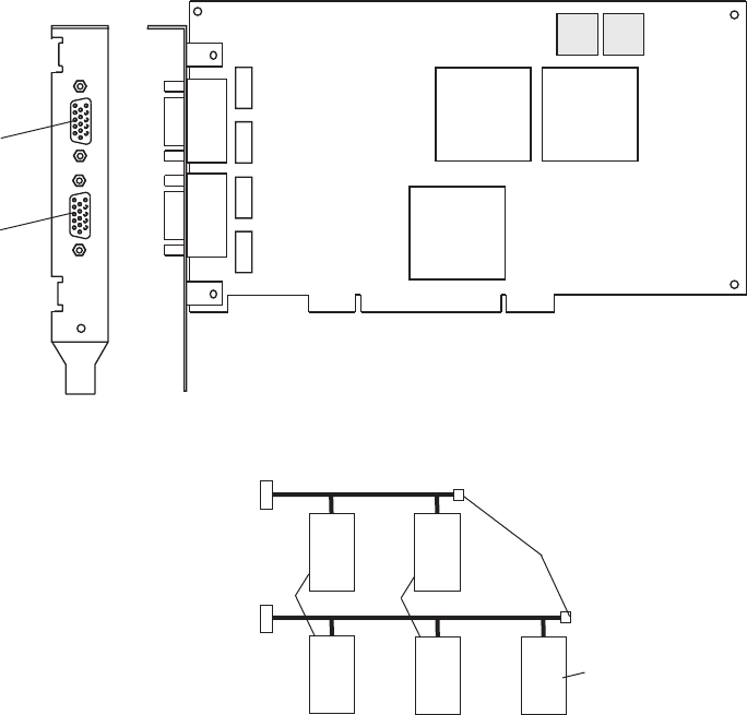
Installing or Removing the 128-Port ASYNC Adapter
The 128-Port ASYNC adapter is an option for the HMC. It must be configured by the service
representative when the HMC is installed. The 128-Port ASYNC adapter software is installed in the HMC
base software installation package.
128-Port ASYNC Adapter Connector
The HMC 128-Port ASYNC adapter installation differs from the installation in AIX. The 128-Port ASYNC
adapter has two 15-pin D-shell connectors on it. The connector that is closest to the edge connector that
plugs into the HMC PC is line 1. The remote access nodes (RANs) are cabled in a daisy chain and are
terminated using a line terminator. The following figure shows the adapter.
1
2
3-C
The following figure shows an example of a typical RAN configuration. RANs are connected to both line 1
and line 2 of the adapter in this example.
Adapter Line 1
Adapter Line 2
1
1
1
2
3
2
23
4
Node
Node
Node
Node
Node
1 RAN Nodes
2 RAN Nodes
3 RAN Node
4 Terminators
v Up to eight RANS can be attached to one adapter. If four are attached to line one, only four more can
be attached to line 2.
v RANs must be numbered in ascending order. The RAN closest to the adapter is assigned as node 1.
No gaps in the numbering should occur. Example, numbering RANs as 1, 3, 4 in a line will cause
configuration problems.
Chapter 6. Removal and Replacement Procedures 101

Setting a RAN Node Number
The AIX Asynchronous Communications Guide provides information about configuring and running
diagnostics on the 128-Port ASYNC Adapter and associated RANs. To access the AIX Asynchronous
Communications Guide, see the IBM eServer pSeries Information Center at
http://publib16.boulder.ibm.com/pseries/en_US/infocenter/base. Click AIX documentation. The 128-Port
ASYNC adapter identifies RANs by their node numbers. Each RAN in a daisy chain must have a unique
node number (1n-4n), which must be set during installation. The node numbers must be assigned in
ascending order with the lowest number assigned to the RAN closest to the 128-Port ASYNC adapter. The
following figure shows the front panel of a RAN.
CCITT 103 104 105 106 107 109 108 125CCITT 103 104 105 106 107 109 108 125
TD RD RTS CTS DSR CD DTR RI OFC IFCTD RD RTS CTS DSR CD DTR RI OFC IFC
0% 100%0% 100%
AC
To set the RAN node number, do the following:
1. Turn the RAN on and wait for the power-on self-test (POST) to complete.
2. When P1 is displayed on the front panel seven-segment LED display, press the Left Arrow button once.
The current node number is displayed, for example, 1n for node 1.
3. Press the Right Arrow button to advance the node number through the eight possible settings (1n-8n).
4. When the desired node number is displayed, press the Left Arrow button again to select the number.
The display should now read Pn (indicating a pass condition). If there was an error, the display reads
En.
In the case of duplicate node numbers, the RAN farthest from the host adapter displays En, instead of
AC, when the system is started.
Removing an Adapter
After you remove a 128-Port ASYNC adapter, do the following:
1. Obtain the root password from the customer.
2. Log in with the ID hscpe and open a service shell. To open a service shell, see “How to Create a
Service Shell or View a HMC Log” on page 11.
3. Type su -, then login with the root password.
4. At the command prompt, type /usr/sbin/digiConf.
5. When prompted, set the configuration to the correct number of adapters in the HMC.
Exchanging a Disk Drive
When you exchange a disk drive, ensure that the licensed internal code is installed on the new drive. Use
the ″Restore Hard Disk″ procedures, refer to “Related Publications” on page x for a listing of PC hardware
maintenance manuals. The publications are available through the following web site:
http://www.pc.ibm.com
102 Hardware Management Console for pSeries Maintenance Guide
Replacing the Planar and Performing the Flash (BIOS/VPD) update
procedure
After replacing the system planar, you should perform the flash BIOS/VPD update.
Attention: Refer to the information label located inside the system unit cover for any model-specific
information.
To perform the flash (BIOS/VPD) update procedure, do the folowing:
1. Power off the computer.
2. Insert the flash update diskette into drive A.
3. Power on the computer.
4. When the Update Utility window opens, select the country/keyboard, then press Enter.
5. If the computer serial number was previously recorded, the number is displayed with an option to
update it. Press Y to update the serial number.
6. Type the 7-digit serial number of the computer you are servicing, then press Enter.
7. Follow the instructions on the screen to complete the flash (BIOS/VPD) update procedure.
Chapter 6. Removal and Replacement Procedures 103
104 Hardware Management Console for pSeries Maintenance Guide

Chapter 7. Hardware Management Console Parts
This section contains part number information for parts that are added to the base personal computer.
These additional parts when added to one of the following listed personal computers makeup your HMC.
For personal computer parts information not listed, refer to the hardware maintenance manual for the
personal computer on which you are servicing. To access the personal computer hardware maintenance
manuals, go to the following web address:
http://www.pc.ibm.com
The following table contains a cross reference equivilant of the HMC machine type and model number to
the personal computer machine type and model number.
pSeries HMC Machine Type and
Model Number
Personal Computer Machine Type
and Model Number
Supporting Hardware Maintenance
Manual Part Number
7040 (FC 7315) 6578 Model KLU 06P1504
7040 (FC 7316) 6792 Model 31U 24P2934
7310 Model CR2 8676 Model 22X 48P9908
7310 Model CR3 8837 Model 22U 25K8109
7310 Model C03 8187 Model F4U 74P2661
7310 Model C04 8141 Model 31U 19R0486
7315 Model C01 (FC 7316) 6792 Model 31U 24P2934
7315 Model C02 8305 Model 41U 24P2969
7315 Model C03 8187 Model F4U
(without POV)
74P2661
7315 Model C04 8141 Model 31U 19R0486
7315 Model CR2 8676 Model 22X 48P9908
7315 Model CR3 8837 Model 22U 25K8109
105
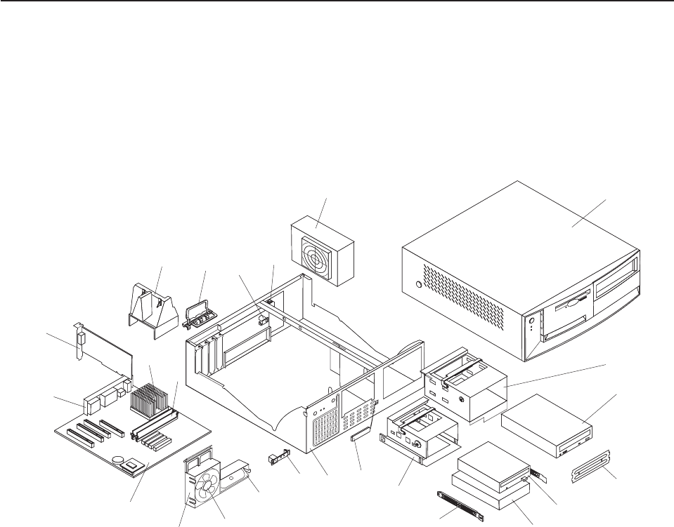
Parts Listing for a 6578-KLU
Feature code 7315 was released as HMC machine type 7040 and used the PC machine type 6578-KLU
for its base configuration. If necessary, to cross reference to the original PC hardware maintenance
manuals, go to “Related Publications” on page x.
Note: Each PC hardware maintenance manual may reference more than one machine type in the title of
the pub. The title given in the Related Publications section of this publication only identifies the PC
machine types cross referenced in the following table. Use the part number to reference the correct
manual.
22
20
19
4
2
1
24
21 23
17
5
6
7
3
15
16
18
13
14
12
11 10 9
8
106 Hardware Management Console for pSeries Maintenance Guide

Parts Listing for a 6578-KLU
Index Description Units Part Numbers
1 Top cover assembly stealth black 1 49P4367
2 DASD Bracket 09N5746
3 DVD-RAM Drive (Black) 24P3615
DVD-RAM Drive (White) 19K1537
4 Bezel Kit 09N5732
5 FDD 3.5″ 1.44MB (w/o bezel) 75H9550
Diskette Drive (Japan) 75H9552
6 HDD 40GB 7200RPM 19K1568
HDD 30GB 7200RPM 19K1567
IDE: Hard Drive Cable 37L4525
7 DASD Rail Kit 19K5331
8 3.5 DASD Bracket 06P2734
9 RFID Antenna 03K9654
10 Chassis assembly 49P4369
11 Control panel assembly 37L5092
12 Speaker assembly 01K4909
00N5151
13 Fan assembly 33L2594
14 Fan Sink 1 06P2458
12-14 Fan/Speaker/Power Switch Assembly 01K4909
15 Planar (Spartan-G 10/100/1000 POV) 1 02R4085
16 Planar EMC shield 09N5770
17 PCI: nVidia Vanta (16MB) 25P4058
18 Processor P4 2.4 GHz 1 48P7684
59P1991
02R4517
19 Memory 256MB NP SDRAM 33L3305
20 Air Baffle Duct 06P2733
21 I/O cam bracket 09N5734
22 Keylock Assembly 09K9829
23 C2 Switch Assembly 09K9827
24 Power Supply 00N7685
Power Supply (Japan) 00N7687
Power Supply (China) 00N7689
Power Supply (China) 24P6883
Power Supply (China) 24P6885
Chapter 7. Hardware Management Console Parts 107

The following table contains part descriptions and part numbers for parts not shown in the 6578 Model
KLU illustration.
Description Units Part Numbers
5.25 locking handle 09N5747
5.25 EMC Shield 19K5548
3.5 locking handle 09N5748
PS/2 2 Button Mouse (black) 24P0383
Bezel kit (black) 49P4371
50-foot 9-9 pin serial cable, connects HMC to system 44P0206
10/100 Ethernet Adapter (FC 4962) 09P5023
Token Ring Adapter Cable (9 Pin D-Shell to STP) 6339098
PCI: 16/4 Token Ring Mngt 34L5009
Battery 33F8354
COM Port to Modem Async Cable 21L4322
PC Doctor Diagnostic Diskette 21H4251
US Power Cord 93F2364
Mouse, Three-Button USB 09N5532
Mouse, Three-Button USB (ScrollPoint-white) 12J4546
Mouse, Three-Button USB (ScrollPoint-black) 28L1865
128 port async adapter 93H6545
Wrap plug 43G0928
Terminator 43G0926
9-25 pin serial cable connects from fanout cable to system HMC
1
31L7196
8 port async adapter 93H6541
Fanout cable 07L9822
Wrap plug 6298964
Bracket 03K8992
9-25 pin serial cable connects from fanout cable to system HMC
1
31L7196
108 Hardware Management Console for pSeries Maintenance Guide
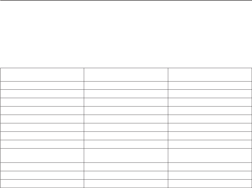
Parts Listing for a 7040 (FC 7316) and 7315-C01
HMC machine type 7315 Model C01 or HMC machine type 7040 feature code 7316 uses the PC machine
type 6792 Model 31U for its base configuration. If necessary, to cross reference to the original PC
hardware maintenance manuals, go to “Related Publications” on page x.
Note: Each PC hardware maintenance manual may reference more than one machine type in the title of
the pub. The title given in the Related Publications section of this publication only identifies the PC
machine types cross referenced in the following table. Use the part number to reference the correct
manual.
pSeries HMC Machine Type and
Model Number
Personal Computer Machine Type
and Model Number
Supporting Hardware Maintenance
Manual Part Number
7040 (FC 7315) 6578 Model KLU 06P1504
7040 (FC 7316) 6792 Model 31U 24P2934
7310 Model CR2 8676 Model 22X 48P9908
7310 Model CR3 8737 Model 22U 25K8109
7310 Model C03 8187 Model F4U 74P2661
7310 Model C04 8141 Model 31U 19R0486
7315 Model C01 (FC 7316) 6792 Model 31U 24P2934
7315 Model C02 8305 Model 41U 24P2969
7315 Model C03 8187 Model F4U
(without POV)
74P2661
7315 Model C04 8141 Model 31U 19R0486
7315 Model CR2 8676 Model 22X 48P9908
7315 Model CR3 8837 Model 22U 25K8109
Chapter 7. Hardware Management Console Parts 109
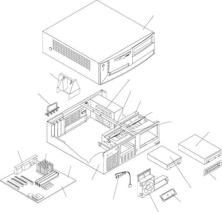
Parts Listing for a 7040 (FC 7316) and 7315-C01
6793
2
3
4
5
6
7
10
11
12
19
1
8
9
13
14
18
15
16
17
1
2
3
4
5
6
7
8
9
10
11
12
13
14
15
16
17
18
19
110 Hardware Management Console for pSeries Maintenance Guide

Parts Listing for a 7040 (FC 7316) and 7315-C01
Index Description Units Part Numbers
1 Top cover assembly stealth black 1 49P4367
2 185W Power Supply 24P6883
49P2127
2 Power Supply (China) 24P6885
3 DASD Bracket 06P2734
4 DASD Bracket 09N5746
5 5.25 Locking Handle 09N5747
6 3.5 Locking Handle 09N5748
7 DVD-RAM Drive (Black)DVD-RAM Drive
(Black)CD-ROM Drive
24P3615
33P3309
33P3243
DVD-RAM Drive cable 37L5098
DVD Cable 19P0484 (1)
DVD Media (Blank) 19P0862 (5 pack)
8 Shield 5.25 EMC 19K5548
9 Diskette Drive 75H9550
Diskette Drive (Japan) 75H9552
Diskette Cable 33L2596
10 Speaker assembly 01K4909
00N5151
11 92mm Fan w/Grommets 33L2594
12 Control Panel Power switch 37L5092
13 Chassis assembly 49P4369
14 Planar: 10/100 EtherNet 25P5090
73P0546
15 Processor P4 2.0 GHzFan sink 1 73P0570
48P7205
32P4004
16 Memory 512MB DIMM, EDO ECC 33L3307
10K0049
17 I/O cam bracket 09N5734
19 Air Baffle Duct 06P2733
32P4707
Chapter 7. Hardware Management Console Parts 111

The following table contains part descriptions and part numbers for parts not shown in the 7315 Model
C01 illustration.
Description Units Part Numbers
Planar (Spartan-G 10/100/1000 POV) 1 02R4085
Bezel kit stealth black 49P4371
Mouse PS/2 2 button stealth black 24P0383
Battery 33F8354
COM2 Port to Modem Async Cable 21L4322
PC Doctor Diagnostic Diskette 21H4251
PCI: nVidia Vanta (16MB) 25P4058
ASYNC 8 Way Adapter 93H6541
ASYNC 128 Way Adapter 93H6545
10/100 Ethernet Adapter 09P5023
Mouse 24P0507
HDD 40GB 7200RPM 19K1568
IDE: Hard Drive Cable 37L4525
7852 Modem 1 01K1263
112 Hardware Management Console for pSeries Maintenance Guide

Parts Listing for a 7315-C02
Machine type 7315-C02 uses a personal computer machine type of 8305 Model 41U for its base
configuration. If necessary, to cross reference to the original PC hardware maintenance manuals, go to
“Related Publications” on page x.
Note: Each PC hardware maintenance manual may reference more than one machine type in the title of
the pub. The title given in the Related Publications section of this publication only identifies the PC
machine types cross referenced in the following table. Use the part number to reference the correct
manual.
pSeries HMC Machine Type and
Model Number
Personal Computer Machine Type
and Model Number
Supporting Hardware Maintenance
Manual Part Number
7040 (FC 7315) 6578 Model KLU 06P1504
7040 (FC 7316) 6792 Model 31U 24P2934
7310 Model CR2 8676 Model 22X 48P9908
7310 Model CR3 8737 Model 22U 25K8109
7310 Model C03 8187 Model F4U 74P2661
7310 Model C04 8141 Model 31U 19R0486
7315 Model C01 (FC 7316) 6792 Model 31U 24P2934
7315 Model C02 8305 Model 41U 24P2969
7315 Model C03 8187 Model F4U
(without POV)
74P2661
7315 Model C04 8141 Model 31U 19R0486
7315 Model CR2 8676 Model 22X 48P9908
7315 Model CR3 8837 Model 22U 25K8109
Chapter 7. Hardware Management Console Parts 113
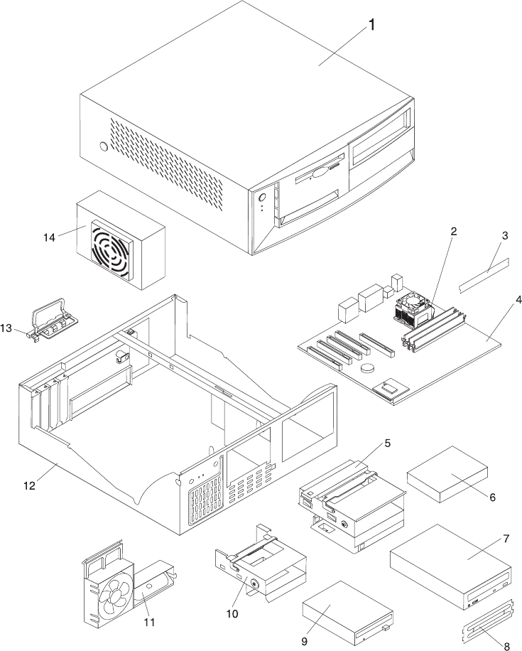
Parts Listing for a 7315-C02
114 Hardware Management Console for pSeries Maintenance Guide

Parts Listing for a 7315-C02
Index Description Units Part Numbers
1 Top cover assembly stealth black 1 49P4367
2 Processor P4 2.4 GHz 1 73P0576
48P7684
Fan Sink 1 32P4004
3 Memory 512MB SDRAM, NP 33L3307
4 Planar (10/100/1000 ) 1 02R4086
49P1602
5 5.25 locking handle 09N5747
6 HDD 40GB 7200RPM 19K1568
7 DVD RAM Drive (Black)DVD RAM Drive
(Black)CD-ROM Drive
24P3615
33P3309
33P3243
DVD-RAM Drive cable 37L5098
CD-ROM/DVD Cable 19P0484
DVD R/W Media (blank) 19P0862 (5 pack)
8 Shield 5.25 EMC 19K5548
9 Diskette Drive 75H9550
Diskette Drive (Japan) 75H9549
Diskette Cable 49P4764
10 3.5 locking handle 09N5748
11 Speaker assembly 01K4909
00N5151
12 Power SupplyPower Supply (China) 24P6883
49P2127
24P6885
13 Chassis assembly 49P4369
14 I/O cam bracket 09N5734
The following table contains part descriptions and part numbers for parts not shown in the 7315 Model
C02 illustration.
Description Units Part Numbers
Mouse PS/2 2 button stealth black 24P0383
Bezel kit stealth black 49P4371
Battery 33F8354
PC Doctor Diagnostic Diskette 21H4251
System Board 49P1602
COM2 Port to Modem Async Cable 21L4322
ASYNC 8 Way Adapter 93H6541
ASYNC 128 Way Adapter 93H6545
10/100 Ethernet Adapter 09P5023
Mouse (USB) 24P0507
Chapter 7. Hardware Management Console Parts 115

Parts Listing for a 7310-CR2 and a 7315-CR2
Machine type 7315-CR2 uses a personal computer machine type of 8676 Model 22X for its base
configuration. If necessary, to cross reference to the original PC hardware maintenance manuals, go to
“Related Publications” on page x.
Note: Each PC hardware maintenance manual may reference more than one machine type in the title of
the pub. The title given in the Related Publications section of this publication only identifies the PC
machine types cross referenced in the following table. Use the part number to reference the correct
manual.
pSeries HMC Machine Type and
Model Number
Personal Computer Machine Type
and Model Number
Supporting Hardware Maintenance
Manual Part Number
7040 (FC 7315) 6578 Model KLU 06P1504
7040 (FC 7316) 6792 Model 31U 24P2934
7310 Model CR2 8676 Model 22X 48P9908
7310 Model CR3 8737 Model 22U 25K8109
7310 Model C03 8187 Model F4U 74P2661
7310 Model C04 8141 Model 31U 19R0486
7315 Model C01 (FC 7316) 6792 Model 31U 24P2934
7315 Model C02 8305 Model 41U 24P2969
7315 Model C03 8187 Model F4U
(without POV)
74P2661
7315 Model C04 8141 Model 31U 19R0486
7315 Model CR2 8676 Model 22X 48P9908
7315 Model CR3 8837 Model 22U 25K8109
116 Hardware Management Console for pSeries Maintenance Guide
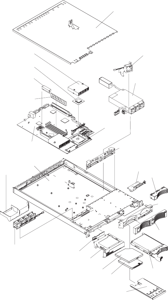
1
2
3
4
5
6
7
8
9
10
11
12
13
14
15
16
17
17a
18
19
20
21
22
Chapter 7. Hardware Management Console Parts 117

Parts Listing for a 7315-CR2
Index Description Units Part Numbers
1 Top cover assembly 1 24P0708
2 Fan, DASD 1 00N6991
3 Power Supply (332W) 49P2090
4 Heatsink Retention Module 1 24P0836
5 Hot-Swap SCSI Backplane 32P1932
6 Operator Information Card 48P9086
7 Bezel Filler 06P6245
8 Bezel, Hot Swap Trim 24P0720
9 Bezel, Non-Hot Swap Trim 24P0723
10 40GB IDE Drive (7200
RPM)
19K1568
11 USB Tray 32P0580
12 12.7, 3 MODE Diskette
Drive
36L8645
13 24X CD-ROM drive
(primary)
06P5263
13 24X CD-ROM drive 33P3231
13 DVD-RAM 33P3307
14 Bracket, CD-ROM
Drive/Diskette Drive
32P1925
15 Interposer Card 48P9028
16 Microprocessor Fan 24P1118
17 Baffle 24P0742
17a Chassis 32P1924
18 System Board 25R3039
19 256 PC2100 ECC Memory
DIMM
09N4306
19 512 MB Memory DIMM 09N4307
19 1 GB Memory DIMM 09N4308
20 9.0 1U/13A VRM Card, 74P4407
21 533/3.06-0K L3
Microprocessor
02R8908
22 533 Heatsink 24P0891
118 Hardware Management Console for pSeries Maintenance Guide

The following table contains part descriptions and part numbers for parts not shown in the 7315 Model
CR2 illustration.
Description Units Part Numbers
3.0V Battery 33F8354
Mouse 24P0507
Mouse Cable 00N6954
C2T Cable (FC 4271) 0.26 m, HMC to HMC,
(Keyboard/Video/Mouse)
00N7003
C2T Cable (FC 4272) 2 m, HMC to HMC,
(Keyboard/Video/Mouse)
00N7006
PC Doctor Diagnostic Diskette 21H4251
-48V Connector 01R1199
40x20 Fan Assembly Duct 24P0892
1U Tool-less Rail Kit 24P1121
Service Label 33P2339
Eserver xSeries Nameplate 33P2205
Non-Hot Swap Hard Disk Drive Rail Kit 32P1928
3.5V Riser Assembly 25P3359
Jumper Cord 36L8886
CD-ROM Drive Power Cable 24P0867
CD-ROM Signal Cable 24P0851
Hard Disk Drive Power Fixed 2-Drop Cable 24P0865
Cable, switch and USB 24P0853
Cable, diskette drive signal 24P0790
Cable, IDE drive 24P0788
Hot-Swap SCSI Assembly Cable 24P0786
Cable, hard disk drive 4-pin power 24P0622
Hard Disk Drive Backplane to System Board Cable 00N6988
Power cord 6952300
Miscellaneous parts kit - contains: CD-ROM drive spring rod (1); diskette drive
spring rod (1); screws (10); PCI card support bracket (1); icon light pipe (1); rear
light pipe (1); CD-ROM drive blank bezel (1); diskette drive blank bezel (1); slotted
M3x5 screws (18); I/O bracket (2) fan bracket (1); 40 mm by 20 mm fan bracket
(1) (all models) FRU
32P1926
Chapter 7. Hardware Management Console Parts 119

Parts Listing for a 7310-CR3 and a 7315-CR3
Machine type 7315-CR3 uses a personal computer machine type of 8837 Model 22U for its base
configuration. If necessary, to cross reference to the original PC hardware maintenance manuals, go to
“Related Publications” on page x. The CR3 requires a minimum HMC microcode level of Version 4
Release 4.0 to be installed in the HMC.
Note: Each PC hardware maintenance manual may reference more than one machine type in the title of
the pub. The title given in the Related Publications section of this publication only identifies the PC
machine types cross referenced in the following table. Use the part number to reference the correct
manual.
pSeries HMC Machine Type and
Model Number
Personal Computer Machine Type
and Model Number
Supporting Hardware Maintenance
Manual Part Number
7040 (FC 7315) 6578 Model KLU 06P1504
7040 (FC 7316) 6792 Model 31U 24P2934
7310 Model CR2 8676 Model 22X 48P9908
7310 Model CR3 8737 Model 22U 25K8109
7310 Model C03 8187 Model F4U 74P2661
7310 Model C04 8141 Model 31U 19R0486
7315 Model C01 (FC 7316) 6792 Model 31U 24P2934
7315 Model C02 8305 Model 41U 24P2969
7315 Model C03 8187 Model F4U
(without POV)
74P2661
7315 Model C04 8141 Model 31U 19R0486
7315 Model CR2 8676 Model 22X 48P9908
7315 Model CR3 8837 Model 22U 25K8109
120 Hardware Management Console for pSeries Maintenance Guide
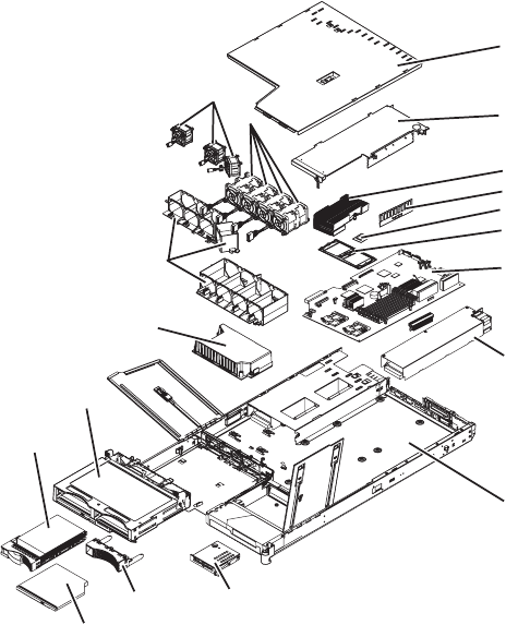
1
2
3
4
5
6
7
8
9
10
11
12
13
14
15
16
17
18
19
Chapter 7. Hardware Management Console Parts 121

Notes:
1. Field replaceable units (FRUs) must be serviced only by qualified field service technicians.
2. Customer replaceable units (CRUs) can be replaced by the customer. A definition of Tier 1 and Tier 2
CRUs for this model HMC is:
Tier 1 CRU
Uses a procedure that a customer is capable of doing without input from a service
representative. The procedure used to service this type of component is usually required to be
done by the customer.
Tier 2 CRU
Uses a procedure that a customer is capable of doing, but may require support from a service
representative. The procedure used to service this component is usually not required to be
done by the customer.
3. If the part you are replacing is not identified as being either Tier 1 or Tier 2 call your service
representative to service the FRU.
Table 1. 7315 Model CR3 Parts listing
Index Description FRU Tier 1
CRUs
Tier 2
CRUs
Part Number
1 Top cover * 23K4219
2 Riser card assembly, PCI * 23K4211
Riser card (PCI-X * 90P1957
3 Heat sink (field replaceable unit) 90P5281
4 Memory, 512MB ECC DRR * 13N1424
5 Microprocessor, 3.2GHz (field replaceable unit)
Note: Use BIOS CD FRU P/N 03N5955 when
replacing the microprocessor if the HMC BIOS level is
1.06 or higher is not installed in the CR3
13M8294
6 Heat sink retention module (field replaceable unit) 90P5282
7 System board (field replaceable unit)
Note: When ordering or replacing a CR3 system
board you must order the HMC BIOS Update CD. The
FRU part number 03N5955
25R9195
8 VRM, 1U/75A (on system board) * 24R2698
9 Power Supply * 24R2559
10 Chassis (field replaceable unit) 90P5284
11 Operator information panel (field replaceable unit) 23K4490
Operator information card (field replaceable unit) (not
shown)
48P9086
12 Bezel filler panel, hard disk drive * 59P5236
13 DVD-RAM Drive * 26K5411
13 DVD R/W Media * 18P7250
14 HDD 80 GB SATA * 71P7293
Cartridge SATA (not shown) * 23K4209
15 Cage assembly, 3.5 in. SCSI hard disk drive, with CD
and hard disk drive backplanes
* 73P8007
16 Power backplane * 23K4515
17 Fan holder with fan backplanes * 23K4992
122 Hardware Management Console for pSeries Maintenance Guide

Table 1. 7315 Model CR3 Parts listing (continued)
Index Description FRU Tier 1
CRUs
Tier 2
CRUs
Part Number
18 Fan, 40x40x56 * 33P2335
19 Fan, 40x40x28 * 23K4217
Battery, 3.0V * 33F8354
Bezel filler panel, SATA drive * 23K4990
Bezel filler panel, DVD drive * 23K4300
Table 2. 7315 Model CR3 Parts listing (continued)
Index Description FRU Tier 1
CRUs
Tier 2
CRUs
Part Number
Cable, fan power (field replaceable unit) 33P2352
Cable management arm * 90P1958
Cable, signal, front panel * 25R4052
Filler panel * 26K8680
Kit, miscellaneous parts (all models)
Bezel blank filler
EIA bracket assembly, left
EIA bracket assembly, right
Rail set, DVD
Power supply filler
Screw, 3.5mm
Screw, M3.5 steel
* 90P5285
Kit, toolless rail * 23K4218
Riser card, PCI-X 1.0 * 90P1957
Service label * 23K4220
Service label, generic * 23K4991
USB connector cable, front panel (field replaceable
unit)
23K4215
Y cord, 1345mm * 25R2567
HMC BIOS Update CD 03N5955
Chapter 7. Hardware Management Console Parts 123

Parts Listing for a 7310-C03 and a 7315-C03
Machine type 7315-C03 uses a personal computer machine type of 8187 Model F4U for its base
configuration. If necessary, to cross reference to the original PC hardware maintenance manuals, go to
“Related Publications” on page x.
Note: Each PC hardware maintenance manual may reference more than one machine type in the title of
the pub. The title given in the Related Publications section of this publication only identifies the PC
machine types cross referenced in the following table. Use the part number to reference the correct
manual.
pSeries HMC Machine Type and
Model Number
Personal Computer Machine Type
and Model Number
Supporting Hardware Maintenance
Manual Part Number
7040 (FC 7315) 6578 Model KLU 06P1504
7040 (FC 7316) 6792 Model 31U 24P2934
7310 Model CR2 8676 Model 22X 48P9908
7310 Model CR3 8737 Model 22U 25K8109
7310 Model C03 8187 Model F4U 74P2661
7310 Model C04 8141 Model 31U 19R0486
7315 Model C01 (FC 7316) 6792 Model 31U 24P2934
7315 Model C02 8305 Model 41U 24P2969
7315 Model C03 8187 Model F4U
(without POV)
74P2661
7315 Model C04 8141 Model 31U 19R0486
7315 Model CR2 8676 Model 22X 48P9908
7315 Model CR3 8837 Model 22U 25K8109
124 Hardware Management Console for pSeries Maintenance Guide
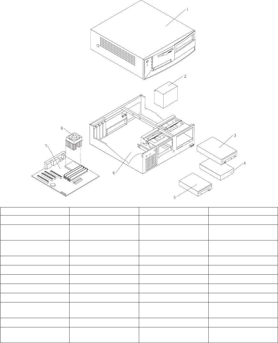
Parts Listing for a 7315-C03 or 7310-C03
Index Description Units Part Numbers
1 Top cover assembly 1 88P5962
2 Power supply, 230W 1 74P4300
74P4301
3 DVD-RAM 24P3615
33P3309
DVD-RW drive 26K5383
CD-ROM drive 33P3243
4 HDD, 40 GB EIDE 1 19K1568
5 FDD, 3.5 1.44 MB 76H4091
6 Chassis/top cover kit 88P5963
7 System board, Gigabit
E-net, POV
19R2562
8 Intel P4 3.0 GHz 88P5870
Fan sink 01R3330
32P4004
Chapter 7. Hardware Management Console Parts 125

The following table contains part descriptions and part numbers for parts not shown in the 7315 Model
C03 illustration.
Description Units Part Numbers
256 MB SDRAM 31P9121
512 MB SDRAM 31P9122
RFID antenna - velcro 03K9654
3.0V Battery 33F8354
Speaker with cable 00N5151
COM Port to Modem Async Cable 21L4322
Cable, C2 assembly 09K9827
PC Doctor Diagnostic Diskette 21H4251
5.25 EMC shield 19K5548
Retention kit 88P5915
Planar shield kit 88P5931
Cable, FDD 88P6515
Cable, HDD 88P5928
Cable, ATA66 1 drop 88P5967
Cable, ATA66 2 drop 88P5971
Cable, SATA 88P5927
Service label 88P5964
Bezel kit 49P4371
Pivot lock, 3.5 FDD 09N5748
Pivot lock, 5.25 DASD 09N5747
Fan bracket assembly 88P6700
Misc. hardware kit 88P5965
Cable, CD-ROM audio 75H9219
Mouse 24P0507
Keylock assembly, random 88P5920
HDD mounting bracket assembly 88P5916
Cable assembly, power/LED 37L5092
Cable, second serial port 49P4530
Cable, dual USB 2.0 49P4365
ASYNC 8 Way Adapter 93H6541
ASYNC 128 Way Adapter 93H6545
10/100 Ethernet Adapter 09P5023
126 Hardware Management Console for pSeries Maintenance Guide
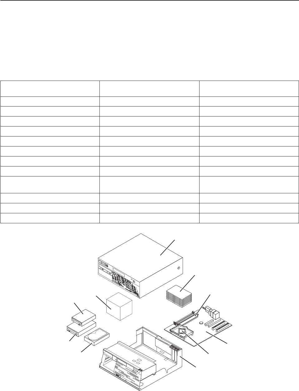
Parts Listing for a 7310-C04 and a 7315-C04
Machine type 7315-C04 uses a personal computer machine type of 8141 Model 31U for its base
configuration. If necessary, to cross reference to the original PC hardware maintenance manuals, go to
“Related Publications” on page x.
Note: Each PC hardware maintenance manual may reference more than one machine type in the title of
the pub. The title given in the Related Publications section of this publication only identifies the PC
machine types cross referenced in the following table. Use the part number to reference the correct
manual.
pSeries HMC Machine Type and
Model Number
Personal Computer Machine Type
and Model Number
Supporting Hardware Maintenance
Manual Part Number
7040 (FC 7315) 6578 Model KLU 06P1504
7040 (FC 7316) 6792 Model 31U 24P2934
7310 Model CR2 8676 Model 22X 48P9908
7310 Model CR3 8737 Model 22U 25K8109
7310 Model C03 8187 Model F4U 74P2661
7310 Model C04 8141 Model 31U 19R0486
7315 Model C01 (FC 7316) 6792 Model 31U 24P2934
7315 Model C02 8305 Model 41U 24P2969
7315 Model C03 8187 Model F4U
(without POV)
74P2661
7315 Model C04 8141 Model 31U 19R0486
7315 Model CR2 8676 Model 22X 48P9908
7315 Model CR3 8837 Model 22U 25K8109
1
2
3
4
5
6
7
8
9
10
Chapter 7. Hardware Management Console Parts 127

Notes:
1. Field replaceable units (FRUs) must be serviced only by qualified field service technicians.
2. Customer replaceable units (CRUs) can be replaced by the customer. A definition of Tier 1 and Tier 2
CRUs for this model HMC is:
Tier 1 CRU
Uses a procedure that a customer is capable of doing without input from a service
representative. The procedure used to service this type of component is usually required to be
done by the customer.
Tier 2 CRU
Uses a procedure that a customer is capable of doing, but may require support from a service
representative. The procedure used to service this component is usually not required to be
done by the customer.
3. If the part you are replacing is not identified as being either Tier 1 or Tier 2 call your service
representative to service the FRU.
Table 3. 7315 Model C04 Parts listing
Index Description FRU Tier 1
CRU
Tier 2
CRU
Part Number
1 Top Cover Asm * 89P6730
2 Heat sink * 89P6729
3 256MB PC2 3200 Memory DDR1 * 73P2683
3 512MB PC2 3200 Memory DDR1 * 73P2684
4 System board 10/1000 w/ POV * 29R8260
5 3.2 GHZ Prescott P4 * 19R0497
6 Chassis and top cover kit * 89P6732
7 HDD 40GB SATA * 71P7312
8 DVD RAM Media * 09P5407
8 DVD Drive (Black) * 26K5383
9 3.5 - 1.44MB 2 MODE FDD wo/Bezel * 76H4091
10 Power Supply 310 Watt * 24R2574
128 Hardware Management Console for pSeries Maintenance Guide

The following table contains part descriptions and part numbers for parts not shown in the 7315 Model
C04 illustration.
Table 4. 7315 Model C04 Parts listing (continued)
Description FRU Tier 1
CRU
Tier 2
CRU
Part Number
HDD Mounting Brkt Asm * 88P5916
Speaker Asm, internal (All EXCEPT CAU CBU) * 00N5151
Cable, Second Serial Port * 49P4530
Retention module assembly * 89P6725
Device Retaining Clips * 13N2449
PC-Doctor Diagnostic Diskette * 21H4251
Fan and Duct Asm * 39K5014
System board shield * 89P6727
Cable, SATA (all models) * 89P6728
Bezel Kit (all models) * 89P6731
Cable and Front USB/Audio Card (all models) * 89P6733
Cable, 2-drop IDE * 89P6734
Cable, FDD * 89P6735
Shield, Blank FDD * 89P6736
Miscellaneous Hardware kit * 89P6737
Cable, 1394 Front * 89P6738
Cable, Power/LED * 89P6739
Battery, 3.0V * 33F8354
Mouse, (Black) * 09N5532
Chapter 7. Hardware Management Console Parts 129
HMC modem cable part numbers
The following tables contain HMC modem cable part number information along with the name of the
country where used.
Telephone Cable Information
The following table contains a listing of countries along with the telephone cable name and part number
where used.
Primary Country Cable Name Cable Part Number
Austria AUS 21H4902
Australia AUZ 75G3807
Belgium BEL 21H4903
Denmark DN 75G3812
Finland FN 75G3809
France FR 75G3803
Germany GE 75G3804
Hong Kong HK 75G3808
Israel ISR 21H4905
Italy IT 75G3802
Netherlands NL 75G3810
South Africa SAF 21H4904
Sweden SW 75G3806
Switzerland SZ 75G3811
United Kingdom UK 75G3805
United States US 87G6236
External Modems - Multitech II MT5600BA
The following table lists the external modem part number along with the primary country where used.
Primary Country Modem Part Number
United States 80P5336
Australia 80P3786
Europe 80P3788
United Kingdom 80P3790
China 80P5337
Internal Modem
When ordering a replacement internal modem for your HMC use part number 80P4702.
Power Cords
For your safety, the manufacturer provides a power cord with a grounded attachment plug to use with this
product. To avoid electrical shock, always use the power cord and plug with a properly grounded outlet.
130 Hardware Management Console for pSeries Maintenance Guide
Power cords used in the United States and Canada are listed by Underwriter’s Laboratories (UL) and
certified by the Canadian Standards Association (CSA).
For units intended to be operated at 115 volts: Use a UL-listed and CSA-certified cord set consisting of a
minimum 18 AWG, Type SVT or SJT, three-conductor cord, a maximum of 15 feet in length and a parallel
blade, grounding-type attachment plug rated 15 amperes, 125 volts.
For units intended to be operated at 230 volts (U.S. use): Use a UL-listed and CSA-certified cord set
consisting of a minimum 18 AWG, Type SVT or SJT, three-conductor cord, a maximum of 15 feet in length
and a tandem blade, grounding-type attachment plug rated 15 amperes, 250 volts.
For units intended to be operated at 230 volts (outside the U.S.): Use a cord set with a grounding-type
attachment plug. The cord set should have the appropriate safety approvals for the country in which the
equipment will be installed.
The power cables used by your system are listed by country and shown in the following illustration and
table.
Chapter 7. Hardware Management Console Parts 131
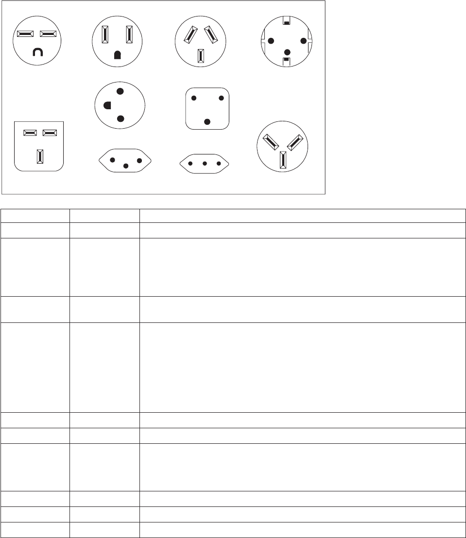
The power cords listed in the following table are specifically designed for a country or region and are
usually available only in that country or region.
123 4
78 9 10
56
Index Part Number Countries and Regions where Used
1 1838574 Thailand
2 6952301 Bahamas, Barbados, Bermuda, Bolivia, Brazil, Canada, Cayman Islands,
Colombia, Costa Rica, Dominican Republic, Ecuador, El Salvador, Guatemala,
Guyana, Haiti, Honduras, Jamaica, Japan, Korea (South), Liberia, Mexico,
Netherlands Antilles, Nicaragua, Panama, Peru, Philippines, Saudi Arabia,
Suriname, Taiwan, Trinidad (West Indies), United States of America, Venezuela
3 13F9940 Argentina, Australia, China (PRC), New Zealand, Papua New Guinea, Paraguay,
Uruguay, Western Samoa
4 13F9979 Afghanistan, Algeria, Andorra, Angola, Austria, Belgium, Benin, Bulgaria, Burkina
Faso, Burundi, Cameroon, Central African Rep., Chad, China (Macau S.A.R.),
Czech Republic, Egypt, Finland, France, French Guiana, Germany, Greece,
Guinea, Hungary, Iceland, Indonesia, Iran, Ivory Coast, Jordan, Lebanon,
Luxembourg, Malagasy, Mali, Martinique, Mauritania, Mauritius, Monaco,
Morocco, Mozambique, Netherlands, New Caledonia, Niger, Norway, Poland,
Portugal, Romania, Senegal, Slovakia, Spain, Sudan, Sweden, Syria, Togo,
Tunisia, Turkey, former USSR, Vietnam, former Yugoslavia, Zaire, Zimbabwe
5 13F9997 Denmark
6 14F0015 Bangladesh, Burma, Pakistan, South Africa, Sri Lanka
7 14F0033 Antigua, Bahrain, Brunei, Channel Islands, China (Hong Kong S.A.R.), Cyprus,
Dubai, Fiji, Ghana, India, Iraq, Ireland, Kenya, Kuwait, Malawi, Malaysia, Malta,
Nepal, Nigeria, Polynesia, Qatar, Sierra Leone, Singapore, Tanzania, Uganda,
United Kingdom, Yemen, Zambia
8 14F0051 Liechtenstein, Switzerland
9 14F0069 Chile, Ethiopia, Italy, Libya, Somalia
10 14F0087 Israel
132 Hardware Management Console for pSeries Maintenance Guide

Appendix A. Service Focal Point
This chapter provides information about using the Service Focal Point application.
Service representatives use the HMC as the starting point for all service issues. The HMC groups various
system management issues at one control point, allowing service representatives to use the Service Focal
Point application to determine an appropriate service strategy.
Traditional service strategies become more complicated in a partitioned environment. Each partition runs
on its own, unaware that other partitions exist on the same system. If one partition reports an error for a
shared resource, such as a managed system power supply, other active partitions report the same error.
The Service Focal Point application enables service representatives to avoid long lists of repetitive
call-home information by recognizing that these errors repeat, and the filtering them into one error code.
Errors that require service are reported to the HMC as serviceable events. Because the HMC stores these
serviceable events for 90 days and then discards them, it is important to have the partition and HMC date
and time set correctly. For instance, if the date on a partition’s software is set 90 days behind the HMC’s
set time, the serviceable events reported from this partition are immediately discarded. For more
information about setting the HMC’s date and time, see the IBM Hardware Management Console for
pSeries Installation and Operations Guide, order number SA38-0590. To set the partition’s date and time,
see the documentation provided with the operating system that is running on that partition.
Getting Started
When you are setting up Service Focal Point, keep the following in mind:
v If the time configured on a partition is 90 days older than time configured on the HMC, serviceable
events cannot be reported.
v Verify that the HMC host names are defined. For more information on using fully qualified and short
host names, see the IBM Hardware Management Console for pSeries Installation and Operations
Guide, order number SA38-0590.
v If you need to add or change a partition name, see IBM Hardware Management Console for pSeries
Installation and Operations Guide.
Testing Error Reporting
To ensure that Service Focal Point is configured properly, generate a test error by doing the following:
1. In the partition, run diagnostics to test the managed system’s operator panel.
2. When the diagnostics window asks you if you see 0000 on the managed system’s operator panel,
select NO. This action generates an error.
3. In the SRN window, type Enter to proceed.
4. When the system asks you if you want the error sent to Service Focal Point, select YES.
5. Type F3 to exit diagnostics.
6. Wait for one minute while the managed system sends the error to Service Focal Point.
7. Check the Serviceable Event window to ensure that the error was sent to Service Focal Point and that
Service Focal Point reported the error. For more information about working with serviceable events,
see “Working With Serviceable Events” on page 135.
133

Service Focal Point Settings
The Service Focal Point Settings task in the Contents area allows you to configure your HMC’s Service
Focal Point application.
Note: The Advanced Operator, Operator and Viewer roles have read-only access to the following tasks.
Automatic Call-Home Feature
You can configure the HMC to automatically call an appropriate service center when it identifies a
serviceable event.
To enable or disable the call-home feature, you must be a member of one of the following roles:
v System Administrator
v Service Representative
To enable or disable the call-home feature for one or more systems, do the following:
Note: It is strongly recommended that you not disable the call-home feature. When you disable the
call-home feature, serviceable events are not automatically reported to your service representative.
1. In the Navigation area, click the Service Applications icon.
2. In the Navigation area, double-click the Service Focal Point icon.
3. In the Contents area, click Service Focal Point Settings.
4. The Service Focal Point Settings window opens. Select the CEC Call Home tab on the top of the
window.
5. Click on the managed system you want to enable or disable.
6. Click Enable to enable call-home for the selected system, or click Disable to disable call-home for the
selected system.
7. Click OK.
Setting Up Surveillance
Service Focal Point surveillance generates serviceable events when it detects communication problems
between the HMC and its managed systems.
You can configure how you want the HMC to survey the following:
v The number of disconnected minutes considered an outage
v The number of connected minutes you want the HMC to consider a recovery
v The number of minutes between outages considered a new incident
To set up surveillance, you must be a member of one of the following roles:
v System Administrator
v Service Representative
To set up surveillance, do the following:
1. In the Navigation area, click the Service Applications icon.
2. In the Navigation area, double-click the Service Focal Point icon.
3. In the Contents area, select Service Focal Point Settings.
4. The Service Focal Point Settings window opens. Select the Surveillance Setup tab on the top of the
window.
5. In the first field, select the number of minutes you want the HMC to wait before sending a
disconnection error message.
134 Hardware Management Console for pSeries Maintenance Guide

6. In the second field, select the amount of connection time that the HMC is considered to be recovered.
This amount is expressed in minutes.
7. In the third field, select the number of minutes between outages that you want the HMC to wait before
sending a new incident report.
8. Select one or more managed systems from the table in the lower part of the window and then click
Enable or Disable. Surveillance is then either enabled or disabled for the selected managed systems.
Enabling Surveillance Notifications
You can enable or disable surveillance-error notification from this HMC to connected managed systems.
Enabling this notification causes errors to be passed to the Service Agent application for notification.
To set up surveillance, you must be a member of one of the following roles:
v System Administrator
v Service Representative
To set up surveillance-error notification, do the following:
1. In the Navigation area, click the Service Applications icon.
2. In the Navigation area, double-click the Service Focal Point icon.
3. In the Contents area, select Service Focal Point Settings.
4. The Service Focal Point Settings window opens. Select the Surveillance Notification tab on the top
of the window.
5. Select one or more managed systems from the list and then click Enable or Disable. Surveillance
notification is then either enabled or disabled for the selected managed systems.
Working With Serviceable Events
You can view, add, or update serviceable event information, including error details.
Viewing Serviceable Events
To view serviceable events, you must be a member of one of the following roles:
v System Administrator
v Service Representative
v Advanced Operator
v Operator
v Viewer
To view a serviceable event, do the following:
1. In the Navigation area, click the Service Applications icon.
2. In the Navigation area, double-click the Service Focal Point icon.
3. In the Contents area, click Select Serviceable Event.
4. Designate the set of serviceable events you want to view. Click OK when you are finished.
5. The Serviceable Event Overview window opens, and the entries displayed are ordered by time stamp.
Each line in the Serviceable Event Overview window corresponds to one error within a serviceable
event. On this window, designate the set of serviceable events you want to view by specifying your
search criteria (such as event status or error class).
Note: Only events that match all of the criteria that you specify are shown.
When you are finished, click OK.
Appendix A. Service Focal Point 135
When you select a line in the Serviceable Event Overview window, all lines in the same serviceable event
are selected. To open the Serviceable Event Details window for the selected event, select the event and
click Event Details.
Viewing Serviceable Event Details
To view serviceable event details, do the following:
1. Perform the steps in “Viewing Serviceable Events” on page 135.
2. The Serviceable Event Details window opens, showing extended serviceable event information,
including the following:
v Status
v Earliest original time stamp of any managed object
v AIX error log
v Should this error ever get called home?
v Error was called home
v Pointer to extended error-data collection on the HMC
The window’s lower table displays all of the errors associated with the selected serviceable event. The
information is shown in the following sequence:
v Failing device system name
v Failing device machine type/model/serial
v Error class
v Descriptive error text
Viewing Serviceable Event Error Details
To view serviceable event error details, do the following:
1. Perform the steps in “Viewing Serviceable Event Details.”
2. Select an error in the lower table, and click Error Details.
Viewing Service Processor Error Details
To view service processor error details, do the following:
1. Perform the steps in “Viewing Serviceable Event Error Details.”
2. If the serviceable event error details you are viewing are for a service processor-class error, the lower
table on the resulting window contains service processor errors. Select a service processor error from
the lower table, and click Service Processor Error Details to see further details.
Saving and Managing Extended Error Data
To save extended error (EE) data, do the following:
1. Perform the steps in “Viewing Serviceable Event Details.”
2. Click Save EE Data. To save extended error data for only one error associated with the serviceable
event (rather than for the entire serviceable event), select the error from the lower table and then click
Error Details. In the next menu, click Manage EE Data.
Viewing and Adding Serviceable Event Comments
To add comments to a serviceable event, you must be a member of the Service Representative role.
To add comments to a serviceable event, do the following:
Note: You cannot edit or delete previous comments.
1. Perform the steps in “Viewing Serviceable Event Details.”
136 Hardware Management Console for pSeries Maintenance Guide
2. Select the error to which you want to add comments to and click Comments.... If you want to close
the event and add comments, click Close Event from this window. The Serviceable Event Comments
window opens.
3. Type your name and add comments as appropriate. You can also review previous comments, but you
cannot edit this information.
4. If you clicked Comments on the Serviceable Event Details window, clicking OK commits your entry
and returns you to the Serviceable Event Details window.
If you clicked Close Event on the Serviceable Event Details window, clicking OK commits all changes and
opens the Update FRU Information window. For more information about updating field replaceable unit
information, see “Updating Field Replaceable Unit (FRU) Information.”
Closing a Serviceable Event
To close a serviceable event, do the following:
1. Perform the steps in “Viewing Serviceable Event Details” on page 136.
2. Select the error to which you want to add comments and click Comments....
3. Click Close Event from this window. The Serviceable Event Comments window opens.
4. Click OK to commit your comments. The Update FRU Information window displays. See “Updating
Field Replaceable Unit (FRU) Information” for information on completing this window. Click OK on the
Update FRU Information window to close the serviceable event.
Note: You must close a serviceable event after it has been serviced to ensure that if a similar error is
reported later, it is called home. If an old problem remains open, the new similar problem is
reported as a duplicate. Duplicate errors are neither reported nor called home to a service
center. Close a serviceable event when the partition that reports the error is active. Closing the
event causes the new status of the serviceable event to be properly sent to the partition.
Updating Field Replaceable Unit (FRU) Information
This task allows you to update the FRU information you changed or modified as a result of this serviceable
event. From this panel, you can also activate and deactivate LEDs and search for other serviceable events
that contain the same FRU entries.
To update FRU information, do the following:
1. Perform the steps in “Viewing Serviceable Event Details” on page 136.
2. Click FRU Information... . The Update FRU Information window opens.
The lower table shows any parts that you have replaced or added during your current update session
but that have not been committed to the serviceable event. The changes from the lower table are
committed by clicking the OK or Apply.
From this window, you can also activate and deactivate LEDs and search for other Serviceable Events that
contain the same FRU entries.
Replacing an Existing FRU
To replace a part already listed for this serviceable event, do the following:
1. Perform the steps in “Updating Field Replaceable Unit (FRU) Information.”
2. In the upper table, double-click the part you want to replace.
3. If the FRU has a new part number, type it in the New FRU Part Number field.
4. Click Replace FRU. The Update FRU Information window displays the FRU replacement information in
the lower table. Click OK or Apply to commit the changes to the serviceable event.
Appendix A. Service Focal Point 137

Adding a New FRU
You can add a part to the serviceable event that was not listed in the upper table of the Update FRU
Information window. To add a new FRU for this serviceable event, do the following:
1. Perform the steps in “Updating Field Replaceable Unit (FRU) Information” on page 137.
2. Click Add New FRU to List.
3. Type the FRU’s location code and its part number in the appropriate fields.
4. Click Add to List. The Update FRU Information window opens and displays the newly added FRU in
the lower table.
5. Click OK or Apply to commit these changes to the serviceable event.
Note: After you click OK or Apply, you cannot change this information. If you clicked the Close Event
button in the Serviceable Event Details window, then clicking OK also completes the close
dialog and changes the status of the serviceable event to Closed.
Viewing Serviceable Event Partition Information
You can view partition information associated with this serviceable event. This information includes each
affected partition’s state and resource use.
1. Perform the steps in “Viewing Serviceable Event Details” on page 136.
2. Click Partition Info....
Hardware Service Functions
The following section describes the Hardware Service Functions tool for the HMC.
Activating and Deactivating FRU Identity LEDs
This task allows you to activate or deactivate a managed system’s system attention LED or any FRU
identity LED. FRU identity LEDs are helpful in determining which FRUs need servicing.
To activate or deactivate a managed system’s System Attention LED, do the following:
1. In the Navigation area, click the Service Applications icon.
2. In the Navigation area, double-click the Service Focal Point icon.
3. In the Contents area, select Hardware Service Functions. The LED Management window opens.
4. In the LED Management window, select one or more managed systems from the table.
5. Select either Activate LED or Deactivate LED. The associated System Attention LED is then either
turned on or off.
To activate or deactivate a FRU associated with a particular managed system, do the following:
1. In the Navigation area, click the Service Applications icon.
2. In the Navigation area, double-click the Service Focal Point icon.
3. In the Contents area, click Hardware Service Functions. The LED Management window opens.
4. In the LED Management window, select one managed system from the table.
5. Click the List FRUs... button. The list of FRU slot indices and their respective current LED states
display.
6. Select one or more FRU slot indexes.
7. Click either the Activate LED or the Deactivate LED button.
The associated FRU Identity LEDs are now either enabled (blinking) or off.
138 Hardware Management Console for pSeries Maintenance Guide

Appendix B. Environmental Notices
Product Recycling and Disposal
This unit contains materials such as circuit boards, cables, electromagnetic compatibility gaskets and
connectors which may contain lead and copper/beryllium alloys that require special handling and disposal
at end of life. Before this unit is disposed of, these materials must be removed and recycled or discarded
according to applicable regulations. IBM offers product-return programs in several countries. For country
specific instructions refer to the following web site: http://www.ibm.com/ibm/environment/products/prp.phtml
This product may contain a sealed lead acid, nickel cadmium, nickel metal hydride, lithium, or
lithium ion battery. Consult your user manual or service manual for specific battery information.
The battery must be recycled or disposed of properly. Recycling facilities may not be available in
your area. For information on disposal of batteries, contact your local waste disposal facility.
In the United States, IBM has established a collection process for reuse, recycling, or proper disposal of
used IBM sealed lead acid, nickel cadmium, nickel metal hydride, and other battery packs from IBM
Equipment. For information on proper disposal of these batteries, please contact IBM at 1-800-426-4333.
Have the IBM part number listed on the battery available prior to your call.
Environmental Design
The environmental efforts that have gone into the design of this system signify IBM’s commitment to
improve the quality of its products and processes. Some of these accomplishments include the elimination
of the use of Class 1 ozone-depleting chemicals in the manufacturing process and reductions in
manufacturing wastes. For more information, contact an IBM account representative.
Acoustical Noise Emissions
The equivalent continuous A-weighted sound pressure level at workstations (emission sound pressure
level at the 1-meter bystander positions) does not exceed 70 dB(A).
Der Geräuschpegel der Einheit ist kleiner oder gleich 70 db(A).
139
140 Hardware Management Console for pSeries Maintenance Guide

Appendix C. Notices
This information was developed for products and services offered in the U.S.A.
The manufacturer may not offer the products, services, or features discussed in this document in other
countries. Consult the manufacturer’s representative for information on the products and services currently
available in your area. Any reference to the manufacturer’s product, program, or service is not intended to
state or imply that only that product, program, or service may be used. Any functionally equivalent product,
program, or service that does not infringe any intellectual property right of the manufacturer may be used
instead. However, it is the user’s responsibility to evaluate and verify the operation of any product,
program, or service.
The manufacturer may have patents or pending patent applications covering subject matter described in
this document. The furnishing of this document does not give you any license to these patents. You can
send license inquiries, in writing, to the manufacturer.
The following paragraph does not apply to the United Kingdom or any country where such
provisions are inconsistent with local law: THIS MANUAL IS PROVIDED ″AS IS″ WITHOUT
WARRANTY OF ANY KIND, EITHER EXPRESSED OR IMPLIED, INCLUDING, BUT NOT LIMITED TO,
THE IMPLIED WARRANTIES OF NON-INFRINGEMENT, MERCHANTABILITY OR FITNESS FOR A
PARTICULAR PURPOSE. Some states do not allow disclaimer of express or implied warranties in certain
transactions; therefore, this statement may not apply to you.
This information could include technical inaccuracies or typographical errors. Changes are periodically
made to the information herein; these changes will be incorporated in new editions of the publication. The
manufacturer may make improvements and/or changes in the product(s) and/or the program(s) described
in this publication at any time without notice.
Information concerning products made by other than the manufacturer was obtained from the suppliers of
those products, their published announcements, or other publicly available sources. The manufacturer has
not tested those products and cannot confirm the accuracy of performance, compatibility or any other
claims related to products made by other than the manufacturer. Questions on the capabilities of products
made by other than the manufacturer should be addressed to the suppliers of those products.
Product Recycling and Disposal
This unit contains materials such as circuit boards, cables, electromagnetic compatibility gaskets and
connectors which may contain lead and copper/beryllium alloys that require special handling and disposal
at end of life. Before this unit is disposed of, these materials must be removed and recycled or discarded
according to applicable regulations. IBM offers product-return programs in several countries. Information
on product recycling offerings can be found on IBM’s Internet site at
http://www.ibm.com/ibm/environment/products/prp.shtml
IBM encourages owners of information technology (IT) equipment to responsibly recycle their equipment
when it is no longer needed. IBM offers a variety of programs and services to assist equipment owners in
recycling their IT products. Information on product recycling offerings can be found on IBM’s Internet site
at http://www.ibm.com/ibm/environment/products/prp.shtml.
141
Battery Return Program
This product may contain sealed lead acid, nickel cadmium, nickel metal hydride, lithium, or lithium ion
battery. Consult your user manual or service manual for specific battery information. The battery must be
recycled or disposed of properly. Recycling facilities may not be available in your area. For information on
disposal of batteries outside the United States, go to
http://www.ibm.com/ibm/environment/products/batteryrecycle.shtml or contact your local waste disposal
facility.
In the United States, IBM has established a return process for reuse, recycling, or proper disposal of used
IBM sealed lead acid, nickel cadmium, nickel metal hydride, and other battery packs from IBM Equipment.
For information on proper disposal of these batteries, contact IBM at 1-800-426-4333. Please have the
IBM part number listed on the battery available prior to your call.
In the Netherlands, the following applies:
For Taiwan:
Please recycle batteries.
142 Hardware Management Console for pSeries Maintenance Guide

Index
A
about this book ix
ac, power cables 6
accessing information x
acoustical
noise
emissions 139
adapters
configuring RS422 ports on an 8-port 100
configuring serial 98
adding
FRUs 138
serviceable event comments 136
automatic call home
overview 134
B
backup profiles 96
battery
disposal, recycling 139
boot error values 91
C
cables
ac power 6
cabling, HMC 2
cabling, managed system 2
configuration, system 96
configuration, system board 96
console hardware logs, viewing 11
D
diagnostic procedures 17
diagnostics 9
diskette drive MAP 25
diskette MAP 28
display problems MAP 29
DVD RAM MAP 26
E
emissions
noise 139
entry MAP 14
error code to FRU index 31
error messages 31
perform a file system check indicated 90
reboot the HMC indicated 89
rebuild managed system indicated 89
backup and restore 59
CIMOM 63
HMC 64
inventory scout 31
error messages (continued)
managed system 44, 73
managed system resource 48
operating system reset 58
panel 65
partition 50
profile 55
profile data 34
recovery actions 89
service focal point 80
system profile 56
unity class 62
user management 66
virtual terminal 59, 84
errors
virtual terminal 84
Ethernet MAP 24
extended error data
managing 136
F
flow, diagnostic 9
FRU
updating information 137
FRU identity LEDs
activating 138
deactivating 138
FRU index, error code 31
FRUs
adding 138
replacing 137
H
hardware service functions 138
activating and deactivating FRU identity LEDs 138
highlighting ix
HMC
viewing the software log 11
HMC cabling 2
HMC code update 98
HMC lock
releasing 93
HMC log 11
HMC software support 11
HMC, overview 1
I
image, restoring the HMC 96
information, accessing x
inspection guide, service 6
installing 128–port ASYNC adapter 101
installing 8–port ASYNC adapter 98
143
L
laser compliance statement v
laser safety information v
locations 4
logical partitions
operating states 86
M
maintenance analysis procedures 9
managed system
error state 91
incomplete state 91
no connection state 90
open firmware state 91
recovery state 91
error messages 73
operating states 85
states 90
managed system cabling 2
managed system testing 19
managed system, operation 2
managing
extended error data 136
MAP 1020 problem determination 15
MAP 1520 problem determination 17
MAP 1530 testing the HMC 17
MAP, disk drive 25
MAP, diskette 28
MAP, display problems 29
MAP, DVD MAP 26
MAP, entry 14
MAP, Ethernet 24
MAP, modem 21
MAPs 9, 12
microcode update 96
modem MAP 21
N
noise
emissions 139
O
on/off, power 4
online publications x
operating states
error 91
HMC 90
incomplete 91
managed system 85
no connection 90
partition 86
recovery 91
recovery information 85
operation, managed system 2
overview
service focal point 133
Overview, diagnostic 9
overview, HMC 1
P
partition
operating states 86
parts list 105
6578-KLU 106
7315-C01 109
7315-C02 113
7315-C03 124
7315-C04 127
7315-CR2 116
7315-CR3 120
console parts 105
power cords 130
PC configuration 98
power cables, ac 6
power-on self-test 4
powering off 4
powering on 4
preface ix
problem determination 15, 17
application overview 11
viewing the HMC console log 11
procedures, diagnostic 17
procedures, maintenance analysis 12
procedures, removal and replacement 95
procedures, service 95
product disposal 139
profiles, backup 96
publications
accessing x
online x
R
recover information
incomplete state 91
recovery 9
recovery information 31
error 89
error state 91
managed system operating states 85
operating states 85, 86
rebooting the HMC 89
rebuilding a managed system 89
recovery procedure 93
recovery state 91
virtual terminal errors 84
recycling 139
removal and replacement procedures 95
removal and replacements 98
replacing
FRUs 137
restore information
no connection state 90
operating states 90
restoring the HMC image 96
RS422 ports
configuring on an 8-port adapter 100
144 Hardware Management Console for pSeries Maintenance Guide
S
safety notices v
laser compliance statement v
self-test, power-on 4
serial adapters
configuring 98
service focal point
activating and deactivating FRU identity LEDs 138
adding FRUs 138
call home overview 134
closing a serviceable event 137
enabling surveillance notifications 135
error messages 80
hardware service functions 138
overview 133
replacing FRUs 137
saving and managing extended error data 136
serviceable events 135
setting up surveillance 134
settings 134
testing error reporting 133
updating FRU information 137
viewing and adding serviceable event
comments 136
viewing error details 136
viewing service processor error details 136
viewing serviceable event details 136
viewing serviceable event partition information 138
viewing serviceable events 135
service inspection guide 6
service procedures 95
service shell 11
serviceable event
viewing partition information 138
serviceable events
adding comments 136
selecting and viewing 135
updating FRU information 137
viewing comments 136
viewing details 136
viewing error details 136
viewing service processor error details 136
working with 135
shell, service 11
software support 11
specifications 4
support, HMC software 11
symptom to action list 31
system board configuration 96
system configuration 96
system connection, managed 19
system unit locations 4
system unit testing 18
T
test 9
testing system unit 18
testing the HMC 17
U
update device microcode 96
update HMC ocode 98
updating
FRU information 137
user
error messages 66
V
viewing
serviceable event comments 136
serviceable event details 136
serviceable event error details 136
serviceable event partition information 138
viewing hardware console logs 11
virtual terminal
errors 84
Index 145
146 Hardware Management Console for pSeries Maintenance Guide

Readers’ Comments — We’d Like to Hear from You
Hardware Management Console for pSeries
Maintenance Guide
Publication No. SA38-0603-05
Overall, how satisfied are you with the information in this book?
Very Satisfied Satisfied Neutral Dissatisfied Very Dissatisfied
Overall satisfaction hhhhh
How satisfied are you that the information in this book is:
Very Satisfied Satisfied Neutral Dissatisfied Very Dissatisfied
Accurate hhhhh
Complete hhhhh
Easy to find hhhhh
Easy to understand hhhhh
Well organized hhhhh
Applicable to your tasks hhhhh
Please tell us how we can improve this book:
Thank you for your responses. May we contact you? h Yes h No
When you send comments to IBM, you grant IBM a nonexclusive right to use or distribute your comments in any
way it believes appropriate without incurring any obligation to you.
Name
Address
Company or Organization
Phone No.

Readers’ Comments — We’d Like to Hear from You
SA38-0603-05
SA38-0603-05
Cut or Fold
Along Line
Cut or Fold
Along Line
Fold and Tape Please do not staple Fold and Tape
Fold and Tape Please do not staple Fold and Tape
NO POSTAGE
NECESSARY
IF MAILED IN THE
UNITED STATES
BUSINESS
REPLY
MAIL
FIRST-CLASS MAIL PERMIT NO. 40 ARMONK, NEW YORK
POSTAGE WILL BE PAID BY ADDRESSEE
Information Development
Department H6DS-905-6C006
11501 Burnet Road
Austin, TX 78758-3493
_________________________________________________________________________________________
_________________________________________________________________________________________
___________________________________________________________________________________________________

Printed in USA
February 2005
SA38-0603-05
