3820 RWT & RWR.ib.Rev0 RWT_3820 RWR_ib_Rev0 RWR Ib Rev0
User Manual: 3820-RWT_3820-RWR_ib_Rev0
Open the PDF directly: View PDF ![]() .
.
Page Count: 13
3820-rwt & 3820-rwr.ib.rev0.doc Page 1 of 11 28/02/2006
IRT Eurocard
Types RWT-3820 / RWR-3820
L Band RF Fibre Optic Link
Designed and manufactured in Australia
IRT can be found on the Internet at:
http://www.irtelectronics.com
I R T Electronics Pty Ltd A.B.N. 35 000 832 575
26 Hotham Parade, ARTARMON N.S.W. 2064 AUSTRALIA
National: Phone: (02) 9439 3744 Fax: (02) 9439 7439
International: +61 2 9439 3744 +61 2 9439 7439
Email: sales@irtelectronics.com
Web: www.irtelectronics.com
DANGER
A
void direct exposure to beam
Peak power 2 m
W
Wavelength 1310 n
m
Class 1 LASER Product
Invisible LASER radiation-
3820-rwt & 3820-rwr.ib.rev0.doc Page 2 of 11 28/02/2006
RWT-3820 / RWR-3820
L BAND RF FIBRE OPTIC LINK
Instruction Manual
Table of Contents
Section Page
Operational Safety 3
General description 4
Technical specifications 5
Pre-installation 6
Installation 7
RWT-3820 LASER transmitter module 7
RWR-3820 photo-diode receiver module 8
Front and rear layouts 9
Maintenance & storage 10
Warranty & service 10
Equipment return 10
Drawing index 11
This instruction book applies to serial numbers later than S/N: 0410001

3820-rwt & 3820-rwr.ib.rev0.doc Page 3 of 11 28/02/2006
Operational Safety:
WARNING
Operation of electronic equipment involves the use of voltages and currents that
may be dangerous to human life. Note that under certain conditions dangerous
potentials may exist in some circuits when power controls are in the OFF position.
Maintenance personnel should observe all safety regulations.
Do not make any adjustments inside equipment with power ON unless proper
precautions are observed. All internal adjustments should only be made by suitably
qualified personnel. All operational adjustments are available externally without the
need for removing covers or use of extender cards.
Optical Safety
The light emitted from the LASER diode used in this system is
invisible and may be harmful to the human eye. Avoid looking
directly into the fibre optic cable or connectors or into the
collimated beam along their axis when the device is in operation.
Operating the LASER diode outside of its maximum ratings may
cause device failure or a safety hazard.
DANGER
A
void direct exposure to beam
Peak power 2 m
W
Wavelength 1310 nm
Class 1 LASER Product
Invisible LASER radiation-
3820-rwt & 3820-rwr.ib.rev0.doc Page 4 of 11 28/02/2006
IRT Eurocard
RWT-3820 / RWR-3820
L BAND RF FIBRE OPTIC LINK
General description
The IRT RWT-3820 / RWR-3820 Wide Band RF Fibre Optic Link is a modular system for transmitting broadband
RF ‘L’ band FM modulated signals over an optical fibre cable. The system response is from 900 - 2150 MHz.
The link is designed for transferring the down converted ‘L’ band signals from satellite dishes to main equipment
buildings. Fibre optic cable provides low signal attenuation with no gain or cable equalisation requirements with the
added benefit of immunity to RFI and EMI and protection against lightning strikes.
The system is designed for single mode fibre (9/125 µm) at 1300 nm with a path loss of up to 12 dB. The operating
distance will depend upon the actual cable and connector losses.
RF signal connections are made to 75Ω SMC connectors on the rear panels. BNC and F adapters are provided.
Optical connections are made to SC/PC optical connectors on at the rear of the module.
Modules can be installed in IRT 1 RU or 3 RU frames.
RWT-3820 Laser Transmitter.
Wide band amplifiers are used to drive the DFB LASER with the RF signals applied to the module input. The signal
level is set by a front panel control for optimum signal to noise ratio. A pilot signal is added to the RF path to
monitor the RF path integrity at the receiver.
Pilot signal level and laser output LED indicators are provided as well as a relay contact set for external alarm
indication of laser power or DC supply loss.
LNB power can be applied through a connector on the rear panel.
RWR-3820 Photo-diode Receiver.
The receiver consists of an optical detector diode module followed by an adjustable gain stage and amplifiers to
provide two RF outputs from the receiver.
The output signal level is adjusted to the required level as seen at the RF Mon connector. This level is the same as
the rear output signal level.
Pilot and optical signal level LED indicators are provided as well as a relay contact set for external alarm indication
of optical signal, pilot or DC supply loss.
NOTE: Direct connections are made to the rear of the RWT-3820 and RWR-3820 modules for the
OPTICAL and RF cabling, these must be disconnected when a module is to be mounted or removed from the
IRT Eurocard mounting frame.
3820-rwt & 3820-rwr.ib.rev0.doc Page 5 of 11 28/02/2006
RWT-3820 / RWR-3820 Technical specifications
RF signal connections 75Ω SMC on module rear panel. (BNC and F adapters provided).
RF Monitor connections BNC connectors on transmitter and
receiver front panels.
Allows easy setting up of RF levels.
RF input level Adjustable in the range
-40 dBm to -20 dBm total power.
RF output level Adjustable in the range
-45 dBm to –20 dBm total power.
Input / output VSWR < 2: 1 (75 Ω).
System frequency response 900MHz to 2150 MHz operation.
500 MHz flatness ± 1.5 dB.
36 MHz flatness ± 0.5 dB.
System group delay ±2 ns 900 MHz - 2150 MHz.
Carrier to noise > 26 dB for 36 MHz bandwidth.
Intermodulation products. < 40 dBc.
Tx optical output power 0 dBm.
Rx optical input power -5 dBm to –15 dBm.
(Note: 10 dB pad provided for back to back operation where path attenuation
is less than 5 dB).
System optical budget 12 dB.
Optical signal connections SC/PC (accessible from the rear of the module) for use with single mode
(9/125 µm) fibre cable.
LNB power supply 13 or 18V input to rear panel, SK3,
can be applied.
Power Requirements 28 Vac CT (14-0-14) or ±16 Vdc
Power consumption 6 VA for RWT-3820 and 5 VA for RWR-3820
Mechanical Suitable for mounting in IRT 19" rack chassis with optical, RF & alarm
connections at the rear.
Finish: Front panel Grey with black lettering & red IRT logo.
Rear assembly Detachable silk-screened PCB with direct mount connectors to Eurocard and
external signals.
Dimensions 32 mm x 3 U x 220 mm IRT Eurocard.
Optional accessories TME-6 module extender card.
N
NO
OT
TE
E:
:
A
Al
ll
l
t
th
he
e
p
pa
ar
ra
am
me
et
te
er
rs
s
s
sp
pe
ec
ci
if
fi
ie
ed
d
a
ar
re
e
o
on
nl
ly
y
a
ap
pp
pl
li
ic
ca
ab
bl
le
e
w
wh
he
en
n
u
us
si
in
ng
g
s
si
in
ng
gl
le
e
m
mo
od
de
e
(
(9
9/
/1
12
25
5
µ
µm
m)
)
f
fi
ib
br
re
e
c
ca
ab
bl
le
e
w
wi
it
th
h
a
a
r
re
et
tu
ur
rn
n
l
lo
os
ss
s
o
of
f
≥2
27
7
d
dB
B.
.
Due to our policy of continuing development these specifications are subject to change without notice.
3820-rwt & 3820-rwr.ib.rev0.doc Page 6 of 11 28/02/2006
Pre-installation:
Handling:
This equipment may contain or be connected to static sensitive devices and proper static free handling precautions
should be observed.
Where individual circuit cards are stored, they should be placed in antistatic bags. Proper antistatic procedures
should be followed when inserting or removing cards from these bags.
Power:
AC mains supply: Ensure that operating voltage of unit and local supply voltage match and that correct rating
fuse is installed for local supply.
DC supply: Ensure that the correct polarity is observed and that DC supply voltage is maintained within
the operating range specified.
Earthing:
The earth path is dependent on the type of frame selected. In every case particular care should be taken to ensure
that the frame is connected to earth for safety reasons. See frame manual for details.
Signal earth: For safety reasons a connection is made between signal earth and chassis earth. No attempt should be
made to break this connection.
3820-rwt & 3820-rwr.ib.rev0.doc Page 7 of 11 28/02/2006
Installation
NOTE: Direct connections are made to the rear of the RWT-3820 and RWR-3820 modules for the OPTICAL
and RF cabling, these must be disconnected when a module is to be mounted or removed from the IRT Eurocard
mounting frame.
Installation in frame or chassis:
See details in separate manual for selected frame type.
RWT-3820 LASER transmitter module
The RWT-3820 is factory preset for a optical output of 0 dBm and a RF input level of –40 dBm to –20 dBm.
Installation requires the unit to be plugged into the front of the selected IRT frame and the rear assembly to be
secured to the rear panel of the IRT frame. To install the module in a 1RU or 3RU frame please see the separate
instruction manual “Frames & PSU’s”.
RF signal connection is made to the 75 ohms SMC connector on the rear panel of the RWT-3820, adapters are
supplied to allow connection to circuits using BNC or F series connectors.
A RF signal monitor connector is provided on the front panel. The RF level at this connector should be –40dBm as
adjusted by the front panel RF gain control RV1. At this RF level the laser modulation is set for the best signal to
noise and inter-modulation of the transmission system. For a input signal of –40dBm the RF gain control will be at
the maximum (fully clock-wise) position, for higher input levels the gain will have to be backed up and adjusted to
set the level at the RF monitor connector to –40dBm. Note: the RF Monitor connector will need to be
terminated with the 75 ohms termination provided when not in use.
Optical signal connection is made to the SC/PC optical connector on the rear of the RWT-3820. Extreme care
must be taken to ensure the cleanliness and consequently the best return loss of the optical connections.
The optical output power is monitored by comparator circuits, which are adjusted to change state if the output level
varies by more than ± 3dB from the output level set during alignment. A led indicator on the front panel will light
green when the laser is operating normally and change to red if the laser power deviates by ± 3dB from the pre-set
level.
The RWT-3820 includes a pilot tone generator at 10.7 MHz. This allows for the verification of the RF signal path at
the receiver. A led indicator on the front panel will light green when the pilot is operating normally and change to
red if the pilot signal fails.
The alarm circuit accepts signals from the laser power low always, from the laser power high on LK1 closure and
pilot fail circuit on LK2 closure to operate relay RL1. External connections from the alarm relay are available on
pins 2 and 3 of SK4 on the rear panel. The alarm circuit is wired to give a relay contact closure when a fault
condition such as power failure, low or high optical output, failure of the pilot tone generator occurs. A second
alarm contact closure is available at J3.
LNB power can be applied to the RF in cable through J3 on the rear panel after closing LK5.
3820-rwt & 3820-rwr.ib.rev0.doc Page 8 of 11 28/02/2006
RWR-3820 photo-diode receiver module
The RWR-3820 is factory preset for use with the accompanying RWT-3820 transmitter and an optical path
attenuation of 2 dB, to give unity gain in the RF signal path.
Installation requires the unit to be plugged into the front of the selected IRT frame and the rear assembly to be
secured to the rear panel of the IRT frame. To install the module in a 1RU or 3RU frame please see the separate
instruction manual “Frames & PSU’s”.
RF signal connection is made to the SMC connector on the rear of the RWT-3820, adapters are supplied to allow
connection to circuits using BNC or F series connectors
Optical signal connection is made to the optical connector on the rear panel of the RWR-3820. Extreme care
must be taken to ensure the cleanliness and consequently the best return loss of the optical connections.
To overcome any optical path loss the RF signal level can be set using the front panel gain control (RV3), while at
the same time monitoring the output level using the front panel RF monitor connector which outputs the same RF
level as the rear output connector. Note: the RF Monitor connector will need to be terminated with the 75 ohms
termination provided when not in use.
The optical input signal level is monitored by a current sense and comparator circuit, which is adjusted to change
state if the optical path loss exceeds the maximum optical budget by 3 dB.
The alarm circuit accepts signals from the optical level on LK1 closure and pilot fail circuits on LK2 closure to
operate relay RL1. The external connections for the alarm circuit are available on pins 2 and 3 of SK4 on the rear
panel. The alarm circuit is wired to give a relay contact closure when a fault condition such as power failure or low
optical input occurs. A second alarm contact closure is available at J3.
RWT-3820 adjustments.
RV1 sets the RF modulation level of the laser by applying a bias voltage to the RF attenuator circuit.
RWT-3820 Preset adjustments.
RV2 sets the output LOW indicator circuit as shown by LD3 on the front panel.
RV3 sets the output HIGH indicator circuit as shown by LD3 on the front panel.
RV4 sets the bias current to the laser diode and thus the optical output from the RWT-3820.
RWR-3820 adjustment.
RV3 sets the output RF level of the module by applying a bias voltage to the RF attenuator circuit.
RWR-3820 Preset adjustment.
RV1 sets the pilot SIGNAL LOW alarm circuit threshold as shown by LD2 on the front panel.
RV2 sets the input SIGNAL LOW alarm circuit threshold as shown by LD3 on the front panel.
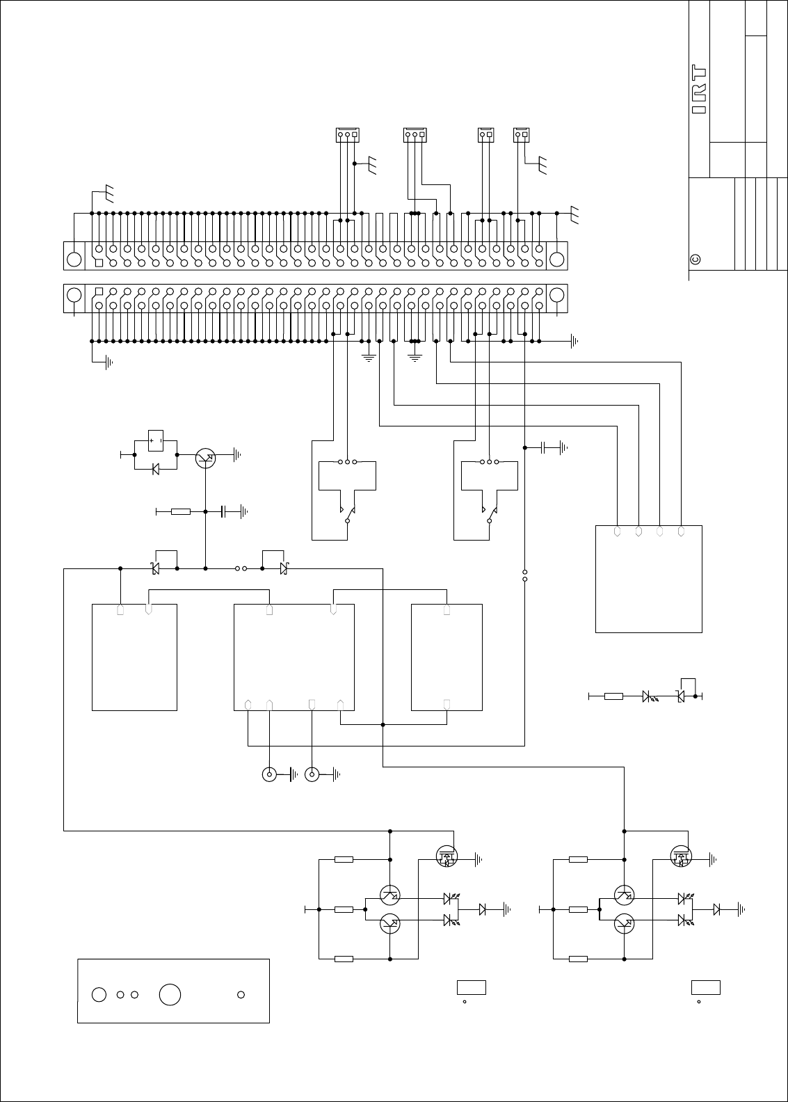
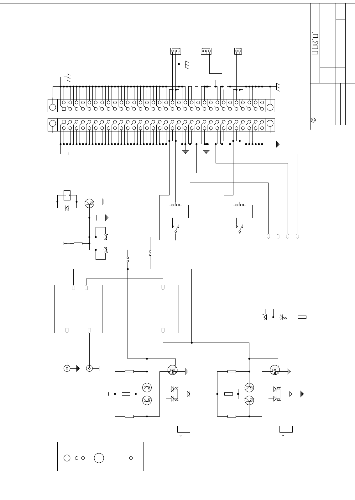
Diagrams are provided for the RWT-3820 and the RWR-3820. The optical and RF signal sections are housed in
sealed shielded sections containing no user serviceable parts. Should service be required on these circuits, please
return the unit to the supplier for repair and alignment.
3820-rwt & 3820-rwr.ib.rev0.doc Page 9 of 11 28/02/2006
RF Mon.
DC
RWT-3820
N140
RF GAIN
PILOT
LASER
CAUTION
Direct
connections
to module
RF GAIN
PILOT
OPTICAL
DC
RW
R
-3820
N140
RF Mon.
CAUTION
Direct
connections
to module
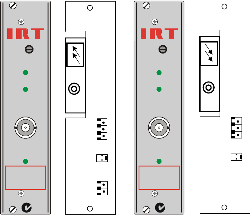
Front & rear panel connector diagrams
The following front panel and rear assembly drawings are not to scale and are intended to show connection order
and approximate layout only.
L BAND F.O. TX
3
2
1
SK4
OPTICAL
OUT
RF
IN
J3
2
1
SK3
A
larm
A
larm
LNB
DC
IN
L BAND F.O. RX
3
2
1
SK4
OPTICAL
IN
RF
OUT
J3
Alarm
Alarm
3820-rwt & 3820-rwr.ib.rev0.doc Page 10 of 11 28/02/2006
Maintenance & storage
Maintenance:
No regular maintenance is required.
Care however should be taken to ensure that all connectors are kept clean and free from contamination of any kind.
This is especially important in fibre optic equipment where cleanliness of optical connections is critical to
performance.
Storage:
If the equipment is not to be used for an extended period, it is recommended the whole unit be placed in a sealed
plastic bag to prevent dust contamination. In areas of high humidity a suitably sized bag of silica gel should be
included to deter corrosion.
Where individual circuit cards are stored, they should be placed in antistatic bags. Proper antistatic procedures
should be followed when inserting or removing cards from these bags.
Warranty & service
Equipment is covered by a limited warranty period of three years from date of first delivery unless contrary
conditions apply under a particular contract of supply. For situations when “No Fault Found” for repairs, a
minimum charge of 1 hour’s labour, at IRT’s current labour charge rate, will apply, whether the equipment is within
the warranty period or not.
Equipment warranty is limited to faults attributable to defects in original design or manufacture. Warranty on
components shall be extended by IRT only to the extent obtainable from the component supplier.
Equipment return:
Before arranging service, ensure that the fault is in the unit to be serviced and not in associated equipment. If
possible, confirm this by substitution.
Before returning equipment contact should be made with IRT or your local agent to determine whether the
equipment can be serviced in the field or should be returned for repair.
The equipment should be properly packed for return observing antistatic procedures.
The following information should accompany the unit to be returned:
1. A fault report should be included indicating the nature of the fault
2. The operating conditions under which the fault initially occurred.
3. Any additional information, which may be of assistance in fault location and remedy.
4. A contact name and telephone and fax numbers.
5. Details of payment method for items not covered by warranty.
6. Full return address.
7. For situations when “No Fault Found” for repairs, a minimum charge of 1 hour’s labour will apply,
whether the equipment is within the warranty period or not. Contact IRT for current hourly rate.
Please note that all freight charges are the responsibility of the customer.
The equipment should be returned to the agent who originally supplied the equipment or, where this is not
possible, to IRT direct as follows.
Equipment Service
IRT Electronics Pty Ltd
26 Hotham Parade
ARTARMON
N.S.W. 2064
AUSTRALIA
Phone: 61 2 9439 3744 Fax: 61 2 9439 7439
Email: service@irtelectronics.com
3820-rwt & 3820-rwr.ib.rev0.doc Page 11 of 11 28/02/2006
Drawing index
Drawing # Sheet # Description
804800s1 1 RWT-3820 schematic diagram – sheet 1
804797s1 1 RWR-3820 schematic diagram – sheet 1
Title
SCALE
SIZE
Sheet
DRAWN
CHECKED
ENG. APP.
Revision:
DO NOT COPY NOR
DISCLOSE TO ANY
THIRD PARTY
WITHOUT WRITTEN
CONSENT
of1
IRT Electronics Pty. Ltd.
Drawing No.
COPYRIGHT
ARTARMON NSW AUSTRALIA 2064
A3
N.T.S. 5
RWT-3820
804800
Date:
1
27-Feb-2006
K.N.
1 17-07-03
ALARM
Laser RF
Laser circuit
804800s2.sch
J2 optional power in
(used when fitted to FRU-1030 frame)
1
2
3J2
SK1
AC 1
AC 4
AC 2
AC 3
Power Supply Circuit
804800s5.sch
31
2
LK3
'DC'
grn
12
R71
680R
21
LD1
+12V
n.c.
n.o.
1 3
2
D12
BZX84C12
-5V
1A
1B
2A
2B
3A
3B
4A
4B
5A
6A
6B
7A
7B
8A
8B
10A
10B
5B
11A
11B
12A
12B
13A
13B
14A
15A
15B
17A
17B
18A
18B
9A
9B
20A
20B
14B
21A
21B
22A
22B
23A
24B
24A
25B
26A
27A
27B
28A
23B
19A
19B
30A
30B
26B
31A
31B
32A
32B
25A
16A
16B
28B
29A
29B
P1
DIN64RA
1 2
C38
100nF
+12V
Laser RFRF Input
RF Mon.
Pilot
Pilot Present
LNB Power
RF circuit
804800s3.sch
PilotPilot Present
Pilot Generator
804800s4.sch
SK2
RF IN
RF MON.
L-Band Fibre Optic Tx.
1
2J3
LASER
PILOT
GAIN
MON.
DC
21
LK2
1A
1B
2A
2B
3A
3B
4A
4B
5A
6A
6B
7A
7B
8A
8B
10A
10B
5B
11A
11B
12A
12B
13A
13B
14A
15A
15B
17A
17B
18A
18B
9A
9B
20A
20B
14B
21A
21B
22A
22B
23A
24B
24A
25B
26A
27A
27B
28A
23B
19A
19B
30A
30B
26B
31A
31B
32A
32B
25A
16A
16B
28B
29A
29B
J1
DIN64
2 1
D13
LS4148
1
2SK3
LNB DC INPUT
Alarm Logic
Rear Panel
Alarm Relay Contacts
13
2D8
BAT54
Rear Panel
Front Panel
'Laser On'
grn
1 2
R69
680R
+12V
red
'Alarm'
1
3
2
LD3
L-3WEGW
1 2
R68
10K
1 2
R70
10K
red
grn
1
2
3com.
1
32
Q13
BC846
1
32
Q12
BC846
32
1
Q11
BSS123
112
RL1A
FBR46ND012
7
8
10
RL1C
31
2
LK4
n.c.
n.o.
6
5
3
RL1B
'Pilot On'
grn
1 2
R66
680R
+12V
red
'Alarm'
1
3
2
LD2
L-3WEGW
1 2
R65
10K
1 2
R67
10K
red
grn
1
2
3com.
1
32
Q10
BC846
1
32
Q9
BC846
32
1
Q8
BSS123
1
2
3SK4
2 1
LK5
1 2
C70
0.1uF
21
D10
LS4148
21
D9
LS4148
1 3
2
D7
BAT54
1
32
Q4
BC846
1 2
R33
10K
+12V
(1B)
(Y2)
(L4)
(L4)
Title
SCALE
SIZE
Sheet
DRAWN
CHECKED
ENG. APP.
Revision:
DO NOT COPY NOR
DISCLOSE TO ANY
THIRD PARTY
WITHOUT WRITTEN
CONSENT
of1
IRT Electronics Pty. Ltd.
Drawing No.
COPYRIGHT
ARTARMON NSW AUSTRALIA 2064
A3
N.T.S. 1
RWR-3820
804797
Date:
1
27-Feb-2006
K.N.
Signal
Pilot
RF Out
RF Mon.
Detector circuit
804797s2.sch
J2 optional power in
(used when fitted to FRU-1030 frame)
1
2
3J2
SK1
AC 1
AC 4
AC 2
AC 3
Power Supply Circuit
804797s4.sch
31
2
LK3
'DC'
'grn'
1 2
R9
680R
+12V
n.c.
n.o.
1 3
2D3
BZX84C12
-5.2V
1A
1B
2A
2B
3A
3B
4A
4B
5A
6A
6B
7A
7B
8A
8B
10A
10B
5B
11A
11B
12A
12B
13A
13B
14A
15A
15B
17A
17B
18A
18B
9A
9B
20A
20B
14B
21A
21B
22A
22B
23A
24B
24A
25B
26A
27A
27B
28A
23B
19A
19B
30A
30B
26B
31A
31B
32A
32B
25A
16A
16B
28B
29A
29B
P1
DIN64RA
1 2
R10
4K7
+12V
Pilot InPilot Present
Pilot Detector
804797s3.sch
SK2
RF OUT
RF MON.
L-Band Fibre Optic Rx.
1
2J3
OPTICAL
PILOT
GAIN
MON.
DC
1A
1B
2A
2B
3A
3B
4A
4B
5A
6A
6B
7A
7B
8A
8B
10A
10B
5B
11A
11B
12A
12B
13A
13B
14A
15A
15B
17A
17B
18A
18B
9A
9B
20A
20B
14B
21A
21B
22A
22B
23A
24B
24A
25B
26A
27A
27B
28A
23B
19A
19B
30A
30B
26B
31A
31B
32A
32B
25A
16A
16B
28B
29A
29B
J1
DIN64
2 1
D7
LS4148
1 10-01-02
+12V
'Pilot'
grn
1 2
R12
680R
red
'Alarm'
1
3
2
LD2
L-3WEGW
1 2
R11
10K
1 2
R13
10K
red
grn
1
2
3com.
13
2
D1
BAT54
13
2
D2
BAT54
1
32
Q4
BC846
1
32
Q3
BC846
32
1
Q2
BSS123
'Signal'
grn
1 2
R15
680R
+12V
red
'Alarm'
1
3
2
LD3
L-3WEGW
1 2
R14
10K
1 2
R16
10K
red
grn
1
2
3com.
1
32
Q7
BC846
1
32
Q6
BC846
32
1
Q5
BSS123
Alarm Logic
Alarm Relay
Rear Panel
Front Panel
21
LK1
21
LK2
Rear Panel
1
32
Q1
BC846
112
RL1A
FBR46ND012
7
8
10
RL1C
31
2
LK4
n.c.
n.o.
6
5
3
RL1B
1
2
3SK4
21
D4
LS4148
21
D5
LS4148
1 2
C13
100nF
21
LD1
HLMP-1503
Contacts
BC846B (1B)
BSS123 (SA)
(1B)
+12
