38 40MV 2SM EEZ 38MVQ
User Manual: EEZ 38MVQ
Open the PDF directly: View PDF ![]() .
.
Page Count: 46
40MVC / 38MVC
40MVQ / 38MVQ
Service Manual
High---Wall Duct Free Split System
Sizes 009 To 024
TABLE OF CONTENTS
PAGE
SAFETY CONSIDERATIONS 1.........................
STANDARD FEATURES AND ACCESSORIES 2...........
SPECIFICATIONS -- COOLING ONLY 3..................
SPECIFICATIONS -- HEAT PUMP UNITS 4...............
DIMENSIONS 5......................................
SERVICE VALVE LOCATIONS 5........................
CLEARANCES 6.....................................
SYSTEM OPERATING ENVELOPE 7....................
ELECTRICAL DATA 7................................
WIRING 8...........................................
CONNECTION DIAGRAMS 9..........................
WIRING DIAGRAMS 10 -- 16...........................
REFRIGERATION CYCLE DIAGRAM 17.................
REFRIGERANT LINES 18.............................
SYSTEM EVACUATION AND CHARGING 19.............
CONTROL SYSTEM 20...............................
SYSTEM SAFETIES 20................................
3MINUTETIMEDELAY 20............................
COMPRESSOR OVERCURRENT PROTECTION 20 -- 21....
SEQUENCE OF OPERATION 21........................
MODES OF OPERATION 22 -- 24........................
TROUBLESHOOTING 25 -- 37..........................
APPENDIX 38 -- 43...................................
SAFETY CONSIDERATIONS
Improper installation, adjustment, alteration, service, maintenance,
or use can cause explosion, fire, electrical shock, or other
conditions which may cause death, personal injury, or property
damage. Consult a qualified installer, service agency, or your
distributor or branch for information or assistance. The qualified
installer or agency must use factory--authorized kits or accessories
when modifying this product. Refer to the individual instructions
packaged with the kits or accessories when installing.
Follow all safety codes. Wear safety glasses, protective clothing,
and work gloves. Use quenching cloth for brazing operations.
Have fire extinguisher available. Read these instructions
thoroughly and follow all warnings or cautions included in
literature and attached to the unit. Consult local building codes and
National Electrical Code (NEC) for special requirements.
Recognize safety information. This is the safety--alert symbol !!
When you see this symbol on the unit and in instructions or
manuals, be alert to the potential for personal injury.
Understand these signal words: DANGER, WARNING, and
CAUTION. These words are used with the safety--alert symbol.
DANGER identifies the most serious hazards which will result in
severe personal injury or death. WARNING signifies hazards
which could result in personal injury or death. CAUTION is used
to identify unsafe practices which may result in minor personal
injury or product and property damage. NOTE is used to highlight
suggestions which will result in enhanced installation, reliability, or
operation.
!WARNING
ELECTRICAL SHOCK HAZARD
Failure to follow this warning could result in personal injury
or death.
Before installing, modifying, or servicing system, main
electrical disconnect switch must be in the OFF position.
There may be more than 1 disconnect switch. Lock out and
tag switch with a suitable warning label.
INTRODUCTION
Section 1 of this Service Manual provides the necessary
information to service, repair, and maintain the EEZ family of
Puron air conditioners and heat pumps. Section 2 of this manual is
an appendix with data required to perform troubleshooting. Use
the Table of Contents to locate a desired topic.

2
MODEL NUMBER NOMENCLATURE
OUTDOOR UNIT
38 MVC 3 --- 01
---
018
A ir --- C o o l e d C o n d e n s e r
Unit Type
MVC --- C o o l i n g On l y
MVQ --- H e a t P u m p
Voltage
1--- 1 1 5 --- 1 --- 6 0
3--- 208/230---1 ---60
Nominal Capacity
009 --- 3 / 4 To n
012 --- 1 To n
018 --- 1 --- 1 / 2 To n
024 --- 2 To n s
INDOOR UNIT
40 MVC 3 --- 01
---
018
Fan Coil Unit
Unit Type
MVC --- C o o l i n g O n l y
MVQ --- H e a t P u m p
Voltage
--- --- 3 0 V D C
1--- 1 1 5 --- 1 --- 6 0
3--- 208/230---1 ---60
Nominal Capacity
009 --- 3 / 4 To n
012 --- 1 To n
018 --- 1 --- 1 / 2 To n
024 --- 2 To n s
SERIAL NUMBER NOMENCLATURE
01 06
Week of Manufacture
Year of Manufacture
00001
Serial Number
V
Manufacturing Site
38/40MVC, MVQ
3
STANDARD FEATURES AND ACCESSORIES
Ease Of Installation
Mounting Brackets S
Low Voltage Controls S
Comfort Features
Microprocessor Controls S
Wireless Remote Control S
Automatic Air Sweep S
Air Direction Control S
Auto Restart Function S
Cold Blow Protection On Heat Pumps S
Turbo Mode O n Sizes 9K and 12 K S
Auto Changeover On Heat Pumps S
Energy Saving Features
Sleep Mode S
Stop/Start Timer S
Safety And Reliability
3MinuteTimeDelayForCompressor S
Over Current Protection For Compressor S
Indoor Coil Freeze Protection S
Indoor Coil High Temperature Protection On Heat Pumps S
Condenser High Temperature Protection On heat Pumps{S
Accumulator On Heat Pumps S
Ease Of Service And Maintenance
Cleanable Filters S
Diagnostics S
Liquid Line Pressure Taps S
Suction And Discharge Pressure Taps (Sizes 18 and 24K) S
Application Flexibility
Low Ambient Controls (---20° F) A
Condensate Pumps A
Crankcase Heater A
Wind Baffles F
Warranty
5 ---Year Compressor Warranty S
1 --- Parts Warranty S
Compressor Extended Warranty Years 6 Thru 10 O
All Parts And Labor Years 2 Thru 5 O
All Parts And Labor Years 2 Thru 5, Compressor Years 6
Thru 10 O
{Sizes 18k & 24k
Legend
SStandard
A Accessory
OOptional
F Field Fabricated
INDOOR UNITS
A07892
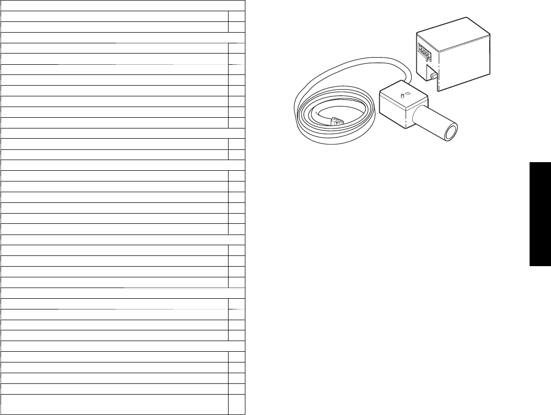
Fig. 1 – Condensate Pump
On high wall fan coils, the condensate pump has a lift capability of
18 ft (5.5 m) or the discharge side with the pump mounted in the
fan coil or 6 ft (1.8 m) on the suction side if the pump must be
remote mounted. The pump mounts inside the unit with quick
plug--in connections, and is recommended when adequate drain
line pitch cannot be provided, or when the condensate must move
up to exit.
NOTE: An external 115v power source will be required to run the
pump on unit sizes 9k and 12k.
OUTDOOR UNITS
LOW AMBIENT KIT
The kit controls condenser fan cycling using a pressure switch. It is
specifically designed to control fan--motor cycles in response to
saturated condensing pressure. This device maintains a constant
saturated condensing temperature of 100 _F±10 _F (37.78_C±
--12.22 _C) at outdoor--air temperatures between 55 _F and --20 _F
(12.78_C±--12.22_C), and can be used on all outdoor units
without changing the outdoor fan motor.
CRANKCASE HEATER
Available for units with rotary compressors. Heater clamps around
compressor oil sump. Recommended for low--ambient applications
on sizes 9, 12 , 18, 24 and long line applications.
38/40MVC, MVQ
4
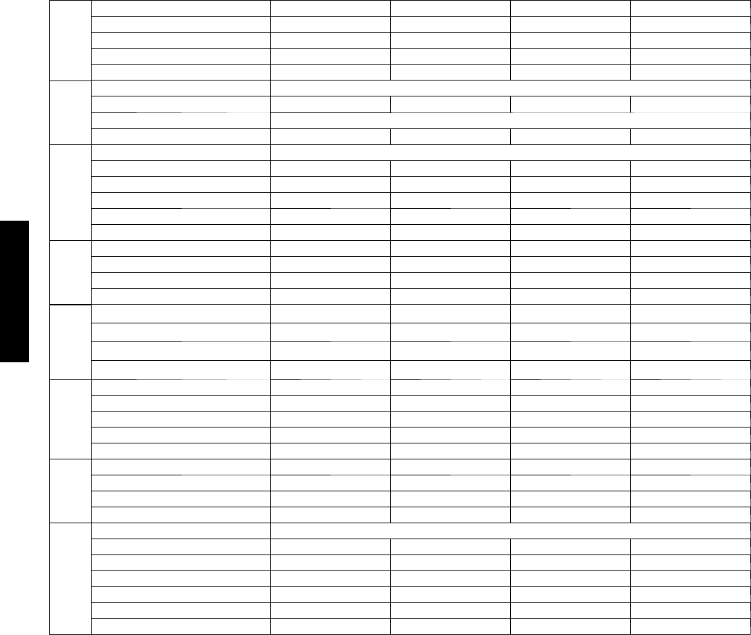
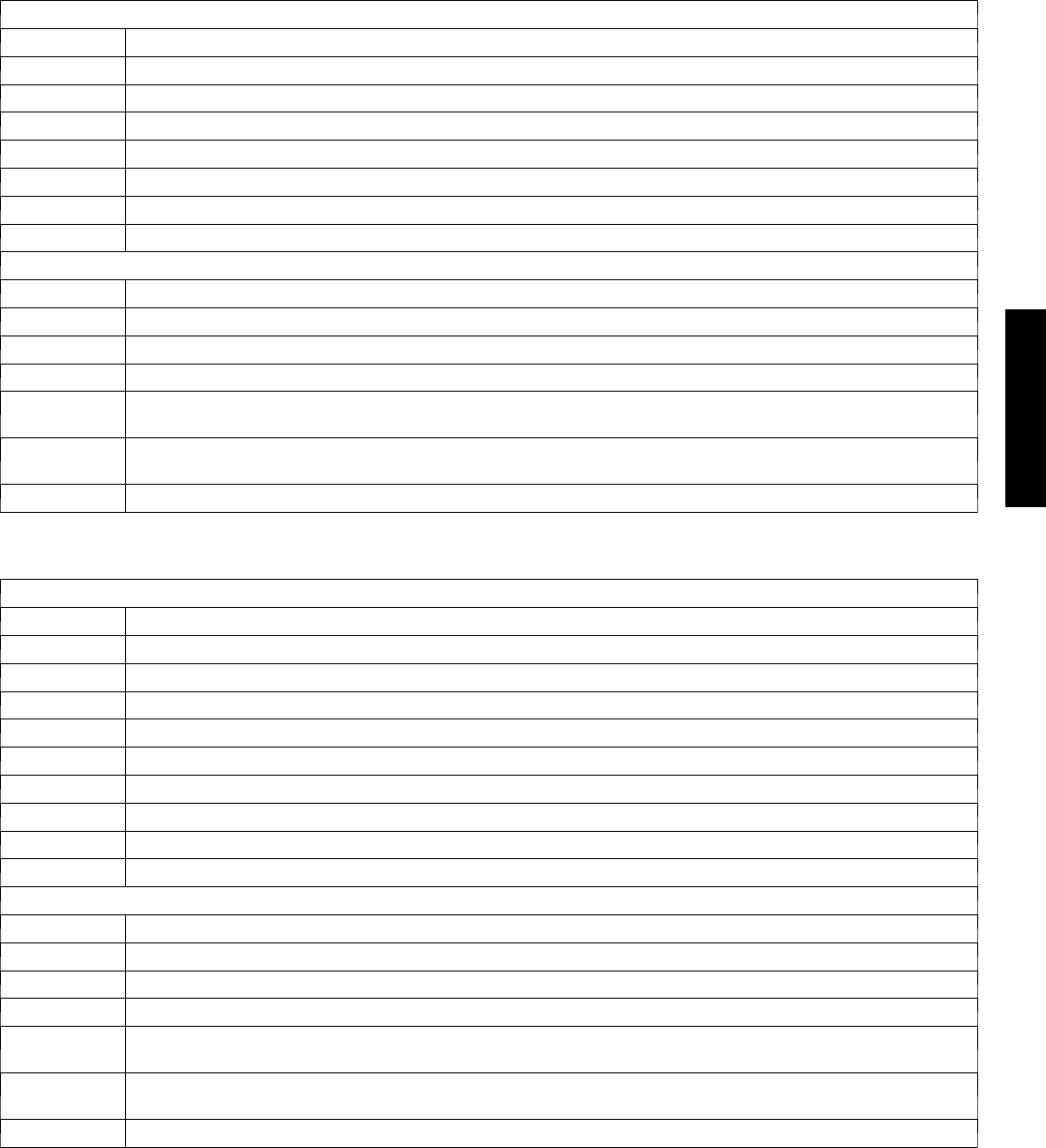
SPECIFICATIONS -- COOLING ONLY UNITS
System
System Model Number 5 3 M V C 0 0 9 --- --- --- 1 5 3 M V C 0 1 2 --- --- --- 1 5 3 M V C 0 1 2 --- --- --- 3 5 3 M V C 0 1 8 --- --- --- 3
System Voltage 115 V 115 V 208/230 208/230
Control Voltage 0 --- 1 2 P u l s e D C 0 --- 1 2 P u l s e D C 0 --- 1 2 P u l s e D C Pulse DC
Capacity (Btuh) 9000 12000 12000 18000
SEER 13.0 13.0 13.0 13.0
Refrigerant
Refrigerant Type R--- 410A
Design Pressure (PSIG) 550 550 550 550
Metering Device Capillary Tube in Outdoor Unit
Charge (lb) 2.3 2.9 3.0 4.4
Compressor
Type Rotary
Model EA82X1C--- 1FZDU1 EA108X1C--- 1FZDU1 PA108X1C--- 3FZDU PA150X2CS--- 3KUU
O i l C h a r g e ( P O E --- o z ) 11.8 11.8 11.8 25.4
Capacitor 45µF/250VAC 45µF/250VAC 35µF/370VAC 40µF/370VAC
Rated Current (RLA) 7.5 9.9 5.2 7.3
Locked Rotor Amp (LRA) 40 47 21 32.6
Outdoor
Motor
Rpm/CFM 900/1060 900/1090 900/1120 840/1470
Diameter (in) .. No. of Blades 15.8 …315.8 …315.8 …318.1 …3
Motor (hp) 0.102 0.102 0.102 0.224
Capacitor 6.5µF/260VAC 6.5µF/260VAC 2.5µF/450VAC 3µF/450VAC
Outdoor Coil
Face Area (sq. ft) 4.05 3.94 3.94 5.51
No. Rows 2 2 2 4
Fins per inch 17 17 17 18
Circuits 4 4 4 4
Indoor Motor
Motor Watts/HP 20/.034 20/.034 20/.034 25/.044
Rpm/Cfm (High) 1250/325 1270/425 1270/425 1070/630
Rpm/Cfm (Medium) 1000/260 1100/365 1100/365 1000/570
Rpm/Cfm (Low) 800/190 1000/340 1000/340 960/500
Blower Diameter …Length (in) 3.84 …25.87 4.17 …25.2 4.17 …25.2 4.21 …37.6
Indoor
Coil
Face Area (sq. ft) 2.15 2.54 2.54 4.36
No. Rows 2 2 2 2
Fins per inch 19.5 19.5 19.5 19.5
Circuits 2 3 3 6
Refrigerant
Lines
Connection Type Flare
Liquid (Mix Phase) (in) OD 1/4” 1/4” 1/4” 1/4”
Vapor Line (in) OD 3/8” 1/2” 1/2” 1/2”
Condensate Drain (in) .65 (OD) .53 (ID) .65 (OD) .53 (ID) .65 (OD) .53 (ID) .65 (OD) .53 (ID)
Maximum Length (ft) 65 65 65 100
Max Lift (Fan Coil Above) (ft) 35 35 35 50
Max Drop (Fan Coil Below) (ft) 35 35 35 50
38/40MVC, MVQ
5
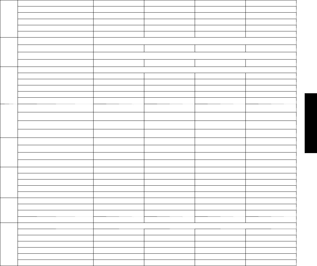
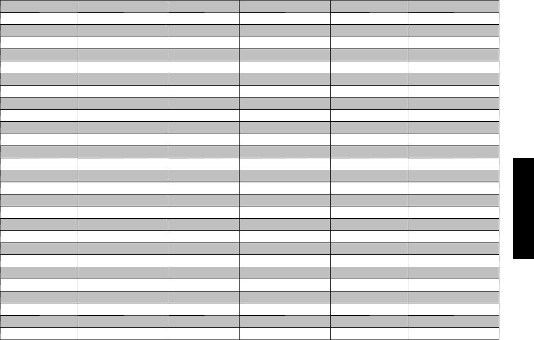
SPECIFICATIONS -- HEAT PUMP UNITS
System
System Model Number 5 3 M V Q 0 0 9 --- --- --- 1 5 3 M V Q 0 1 2 --- --- --- 1 5 3 M V Q 0 1 2 --- --- --- 3 5 3 M V Q 0 1 8 --- --- --- 3
System Voltage 115 V 115 V 208/230 208/230
Control Voltage 0 --- 1 2 P u l s e D C 0 --- 1 2 P u l s e D C 0 --- 1 2 P u l s e D C Pulse DC
Capacity (Btuh) 9000 12000 12000 18000
SEER 13.0 13.0 13.0 13.0
HSPF 7.7 7.7 7.7 7.7
Refrigerant
Refrigerant Type R--- 410A
Design Pressure (PSIG) 550 550 550 550
Metering Device Capillary Tubes in Outdoor Unit
Charge (lb) 2.35 3.0 3.0
Compressor
Type Rotary
Model EA82X1C--- 1FZDU1 EA108X1C--- 1FZDU1 PA108X1C--- 3FZDU PA150X2CS--- 3KUU
O i l C h a r g e ( P O E --- o z ) 11.8 11.8 11.8 25.4
Capacitor 45µF/250VAC 45µF/250VAC 35µF/370VAC 40µF/370VAC
Rated Current (RLA) 7.5 9.9 5.2 7.3
Locked Rotor Amp (LRA) 40 47 21 32.6
Outdoor Motor
Rpm/CFM 900/1060 900/1090 900/1120 840/1470
Diameter (in) .. No. of Blades 15.8 …315.8 …315.8 …318.1 …3
Motor (hp) 0.102 0.102 0.102 0.224
Capacitor 6.5µF/260VAC 6.5µF/260VAC 2.5µF/450VAC 3µF/450VAC
Outdoor Coil
Face Area (sq. ft) 4.05 3.94 3.94 5.51
No. Rows 2 2 2 4
Fins per inch 17 17 17 18
Circuits 4 4 4 4
Indoor
Motor
Motor Watts/HP 20/.034 20/.034 20/.034 25/.044
Rpm/Cfm (High) 1250/325 1270/425 1270/425 1070/630
Rpm/Cfm (Medium) 1000/260 1100/365 1100/365 1000/570
Rpm/Cfm (Low) 800/190 1000/340 1000/340 960/500
Blower Diameter …Length (in) 3.84 …25.87 4.17 …25.2 4.17 …25.2 4.21 …37.6
Indoor
Coil
Face Area (sq. ft) 2.15 2.54 2.54 4.36
No. Rows 2 2 2 2
Fins per inch 19.5 19.5 19.5 19.5
Circuits 2 3 3 6
Refrigerant
Lines
Connection Type Flare
Liquid (Mix Phase) (in) OD 1/4” 1/4” 1/4” 1/4”
Vapor Line (in) OD 3/8” 1/2” 1/2” 1/2”
Condensate Drain (in) .65 (OD) .53 (ID) .65 (OD) .53 (ID) .65 (OD) .53 (ID) .65 (OD) .53 (ID)
Maximum Length (ft) 65 65 65 100
Max Lift (Fan Coil Above) (ft) 35 35 35 50
Max Drop (Fan Coil Below) (ft) 35 35 35 50
38/40MVC, MVQ
6
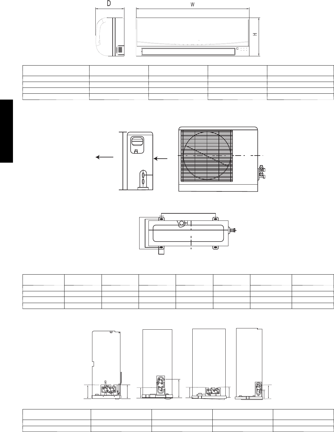
DIMENSIONS -- INDOOR
A07336
Model Size W
in. (mm)
H
in. (mm)
D
in. (mm) Weight lb (kg)
9K 32.09 (815) 11.02 (280) 7.68 (195) 24.2 (11)
12K 35.67 (906) 11.26 (286) 9.25 (235) 33.0 (15)
18K 49.21 (1250) 12.80 (325) 9.06 (230) 55.0 (25)
24K 49.21 (1250) 12.80 (325) 9.06 (230) 55.0 (25)
DIMENSIONS -- OUTDOOR
L1
L2
35
W
H
Air Flow
L3
A07337
Model Size W
in. (mm)
H
in. (mm)
L1
in. (mm)
L2
in. (mm)
L3
in. (mm)
Weight lb (kg)
Cooling Only Weight lb (kg)
Heat Pumps
9K 30.71 (780) 21.26 (540) 21.61 (549) 11.81 (300) 10.87 (276) 77.0 (35) 79.2 (36)
12K 29.92 (760) 23.23 (590) 20.87 (530) 12.40 (315) 11.42 (290) 85.8 (39) 90.2 (41)
18K 33.07 (840) 27.36 (695) 22.05 (560) 14.17 (360) 13.19 (335) 125.4 (57) 125.4 (57)
24K 31.16 (893) 33.86 (860) 23.11 (588) 13.98 (355) 13.11 (333) 159.5 (72) 160.6 (73)
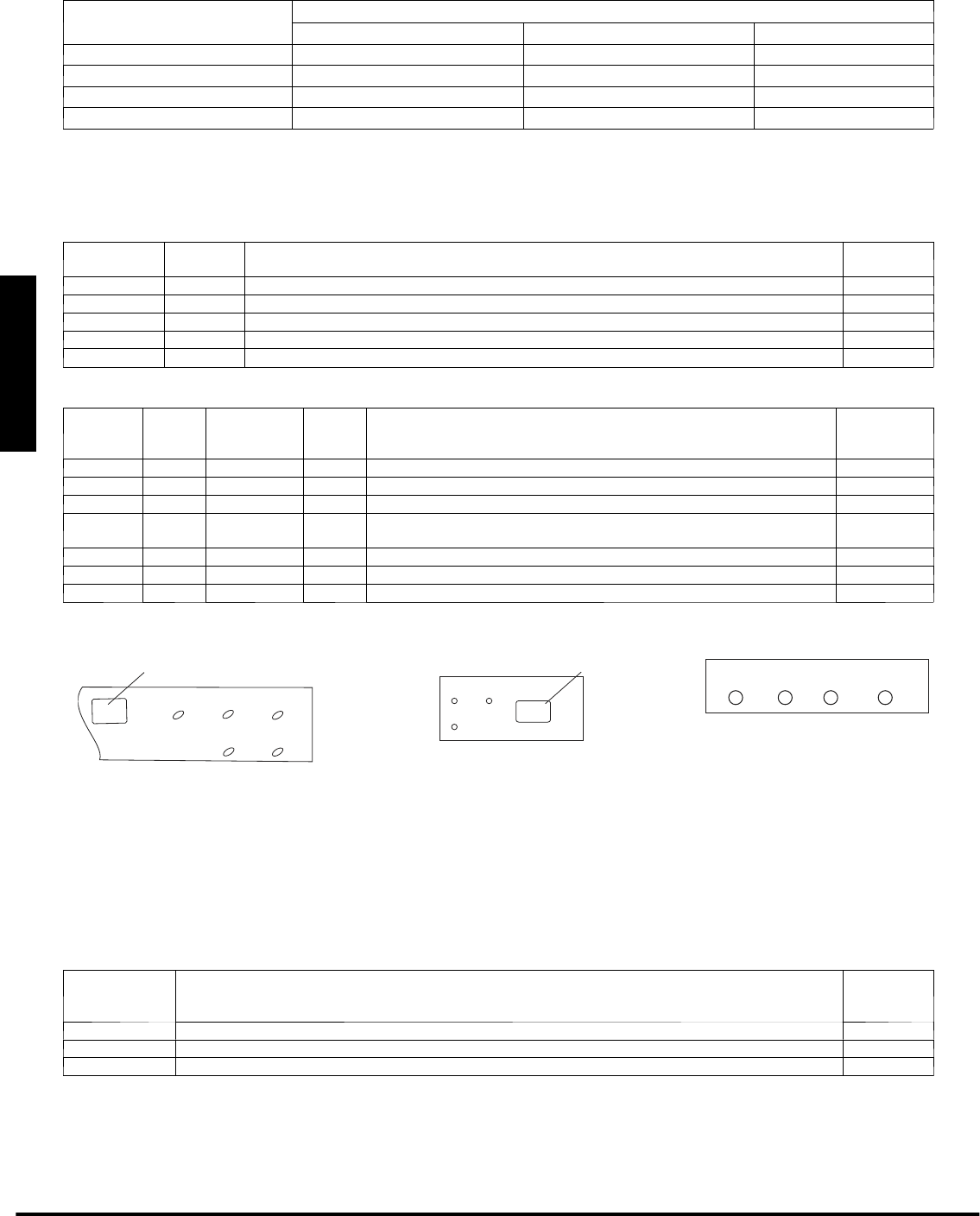
SERVICE VALVE LOCATIONS
J
K
9K 12K 18K 24K
J
K
JKK
J
A07376a
Service Valve Locations 9K
in. (mm)
12K
in. (mm)
18K
in. (mm)
24K
in. (mm)
J3.46 (88) 3.19 (81) 3.46 (88) 4.02 (102)
K3.46 (88) 5.63 (143) 3.62 (92) 6.57 (167)
38/40MVC, MVQ
7
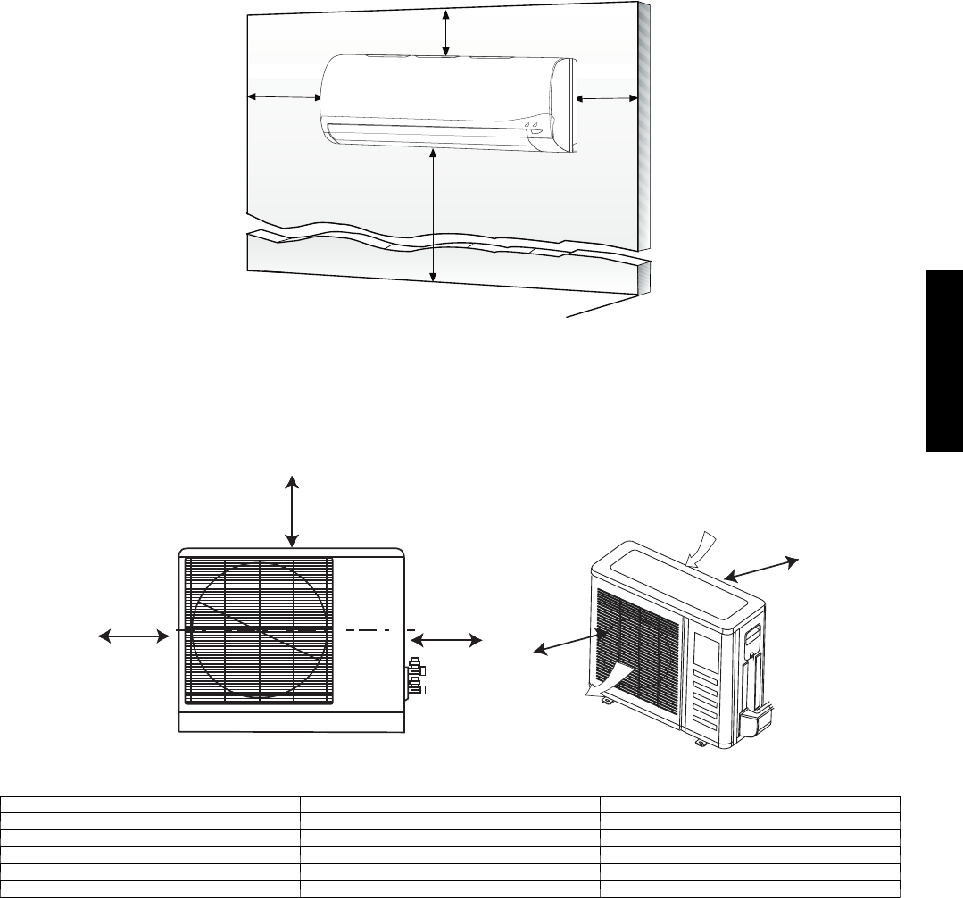
CLEARANCES -- INDOOR
6
"
(0.15m
)
min.
5
"
(0.13m)
min.
6'
5
"
(0.13m)
min.
(1.8m)
A07891
Fig. 2 – Indoor unit clearance
CLEARANCES -- OUTDOOR
A
DB
Air-outlet
Air-inlet
C
E
A07894
UNIT 9k and 12k in. (mm) 18k and 24k in. (mm)
A24 (610) 24 (610)
B24 (610) 36 (914)
C24 (610) 24 (610)
D4 (102) 12 (305)
E12 (305) 12 (305)
Fig. 3 – Outdoor Unit Clearance
38/40MVC, MVQ
8
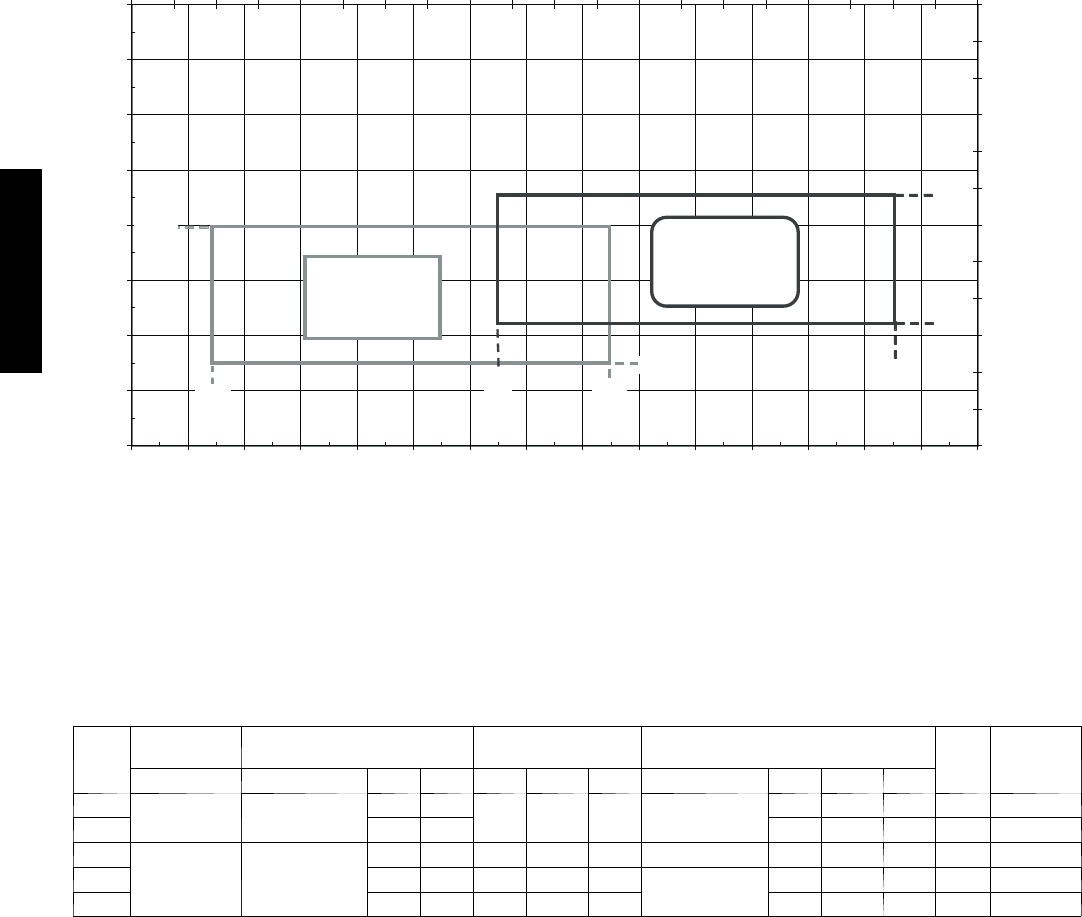
SYSTEM OPERATING ENVELOPE
53MVC/MVQ System Operating Envelope Chart
40
50
60
70
80
90
100
110
120
-10 0 10 20 30 40 50 60 70 80 90 100 110 120 130 140
Outdoor Temperature (ºF)
Indoor Temperature (ºF)
0
5
10
15
20
25
30
35
40
45
50
55
60
-40-35-30-25-20-15-10-5 0 5 1015202530354045505560
Outdoor Temperature (ºC)
Indoor Temperature (ºC)
Cooling
Continuous
Operation
Heating
Continuous
Operation
85º
F
62ºF
55º
75ºF
55ºF
5ºF
80ºF
125º
Use low ambient control if the unit will operate in cooling at ambient conditions below 55_F (12.78_C).
A08180
Fig. 4 – System Operating Enevelope
ELECTRICAL DATA
UNIT
SIZE
OPERATING
VOLTAGE* COMPRESSOR OUTDOOR FAN INDOOR FAN MCA
MAX
FUSE/CB
AMP
MAX/MIN V O L T S --- P H --- H Z RLA LRA FLA HP WVOLTS FLA HP W
009 127/104 1 1 5 --- 1 --- 6 0 7.5 40 0.60 0.102 23 35 DC 1.1 0.034 20 12 20
012 9.9 47 1.18 0.044 25 15 25
012
253/187 208/230---1 ---60
5.2 21 0.38 0.116 36 35 DC 1.18 0.044 25 915
018 7.3 32.6 0.78 0.224 53 208/230---1 ---60 0.26 0.075 31 11 20
024 9.7 34.8 0.62 0.218 100 0.39 0.112 50 14 25
*Permissible limits of the voltage range at which the unit will operate satisfactorily
LEGEND
FLA --- F u l l L o a d A m p s
LRA --- L o c k e d R o t o r Am p s
MCA --- Minimum Circuit Amps
RLA ---RatedLoadAmps
38/40MVC, MVQ
9
WIRING
The main power is supplied to the outdoor unit. The field supplied connecting cable from the outdoor unit to indoor unit consists of four
wires and provides the power for the indoor unit as well as the communication signal between the outdoor unit and indoor unit.
Voltage drop on the connecting cable should be kept to a minimum. Use cable size and max length below:
18 AWG 50 ft. (16 m)
16 AWG 100 ft. (33 m)
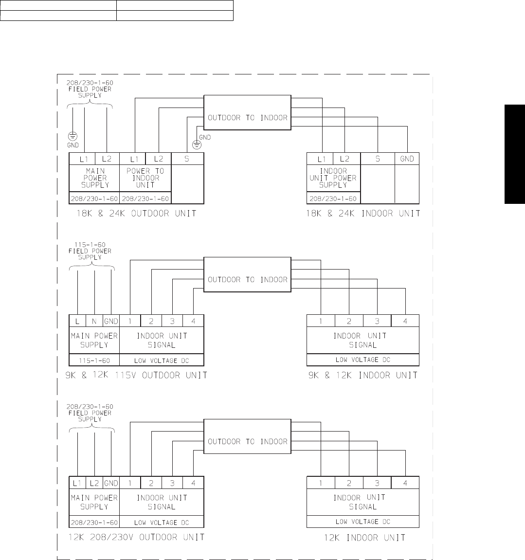
CONNECTION DIAGRAMS
CONNECTING CABLE
CONNECTING CABLE
CONNECTING CABLE
CONTROL CONTROL
Notes:
1. Do not use thermostat wire for any connection between indoor and outdoor units.
2. All connections between indoor and outdoor units must be as shown. The connections are sensitive to polarity.
3. On the 18k and 24k units, the “S” terminal “CONTROL” output is pulse DC with a potential AC voltage shock hazard.
A07654
Fig. 5 – Connection Diagrams
38/40MVC, MVQ
10
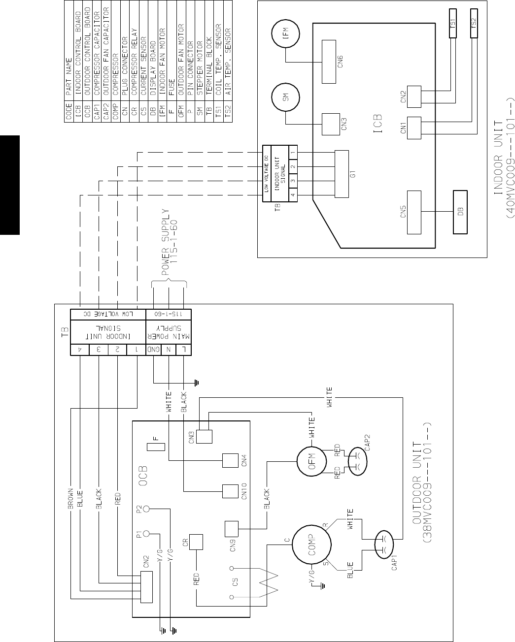
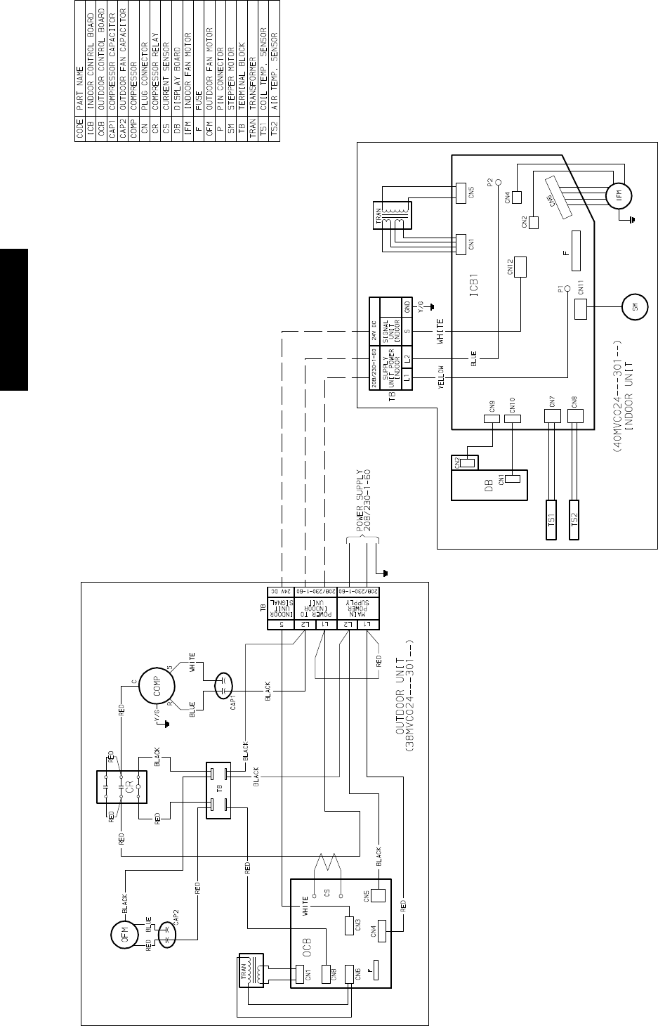
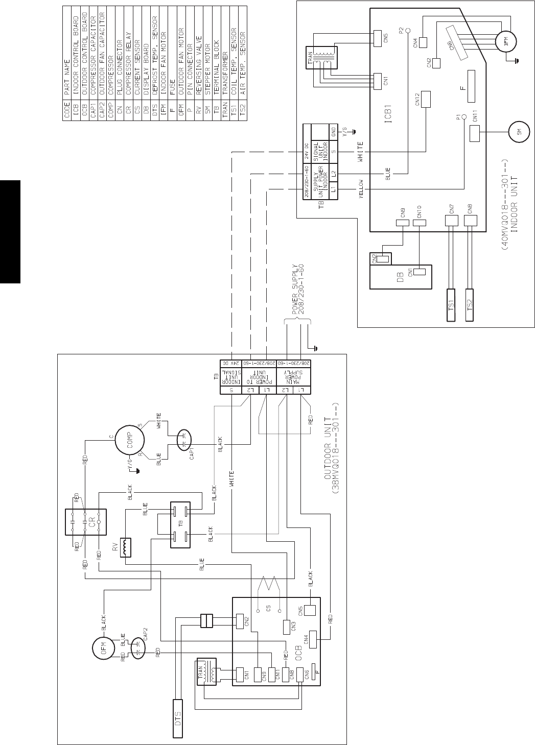
WIRING DIAGRAMS
Fig. 6 – Wiring Diagram 38MVC009------1 W/ 40MVC009------1
38/40MVC, MVQ
11
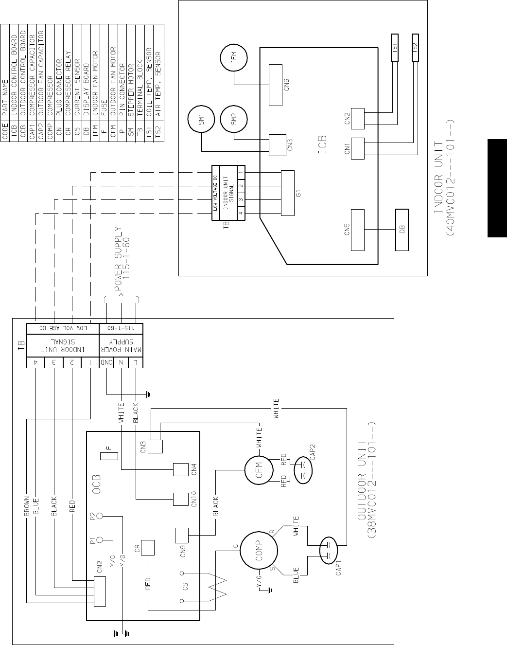
WIRING DIAGRAMS (CONT.)
Fig. 7 – Wiring Diagram 38MVC012------1 W/ 40MVC012------1
38/40MVC, MVQ
12
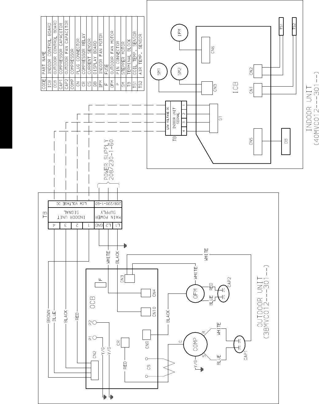
WIRING DIAGRAMS (CONT.)
Fig. 8 – Wiring Diagram 38MVC012------3 W/ 40MVC012------3
38/40MVC, MVQ
13
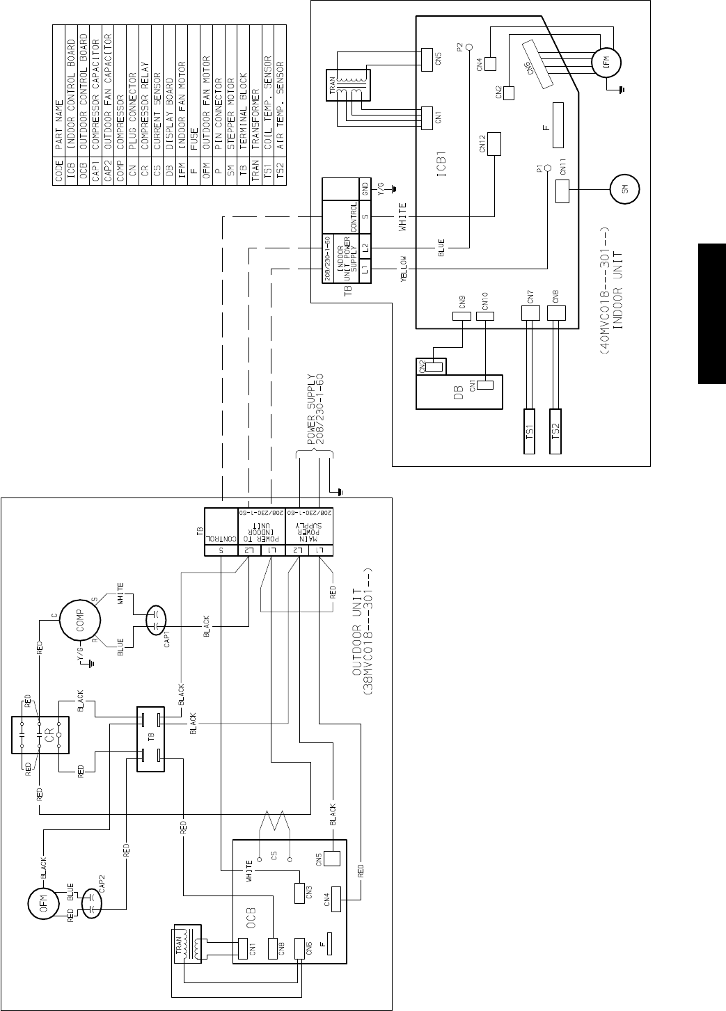
WIRING DIAGRAMS (CONT.)
Fig. 9 – Wiring Diagram 38MVC018------3 W/ 40MVC018------3
38/40MVC, MVQ
14
WIRING DIAGRAMS (CONT.)
Fig. 10 – Wiring Diagram 38MVC024------3 W/ 40MVC024------3
38/40MVC, MVQ
15
WIRING DIAGRAMS (CONT.)
Fig. 11 – Wiring Diagram 38MVQ009------1 W/ 40MVQ009------1
38/40MVC, MVQ
16
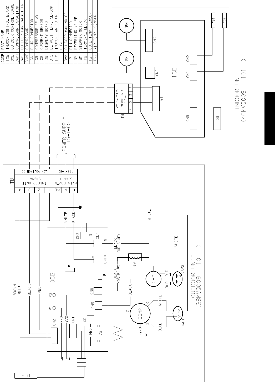
WIRING DIAGRAMS (CONT.)
Fig. 12 – Wiring Diagram 38MVQ012------1 W/ 40MVQ012------1
38/40MVC, MVQ
17
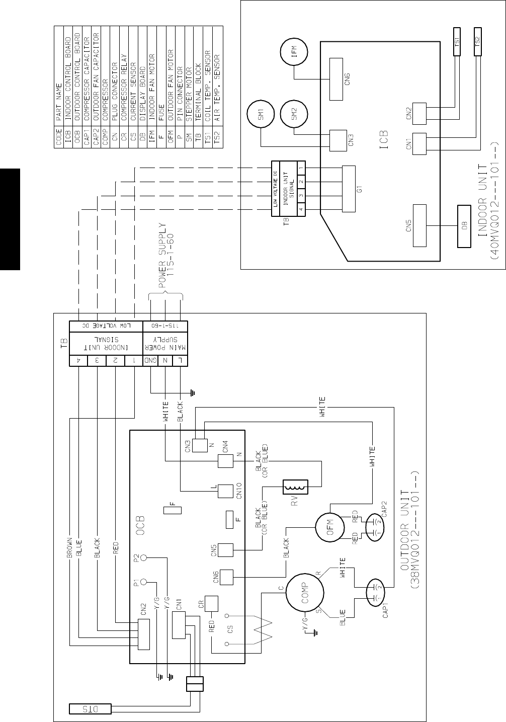
WIRING DIAGRAMS (CONT.)
Fig. 13 – Wiring Diagram 38MVQ012------3 W/ 40MVQ012------3
38/40MVC, MVQ
18
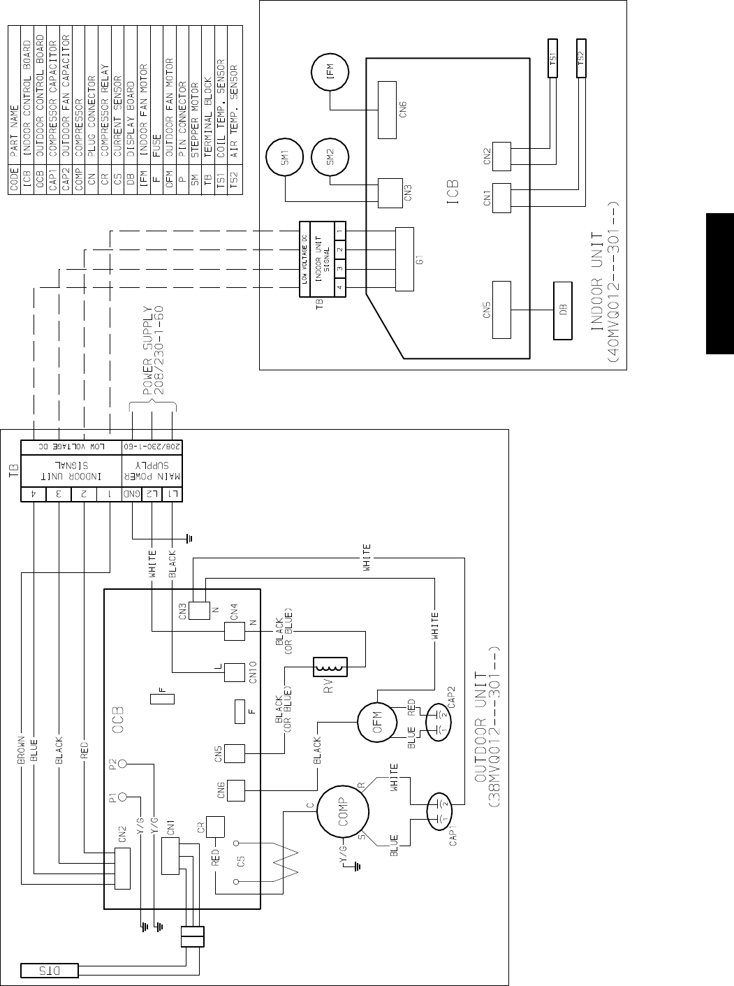
WIRING DIAGRAMS (CONT.)
Fig. 14 – Wiring Diagram 38MVQ018------3 W/ 40MVQ018------3
38/40MVC, MVQ
19
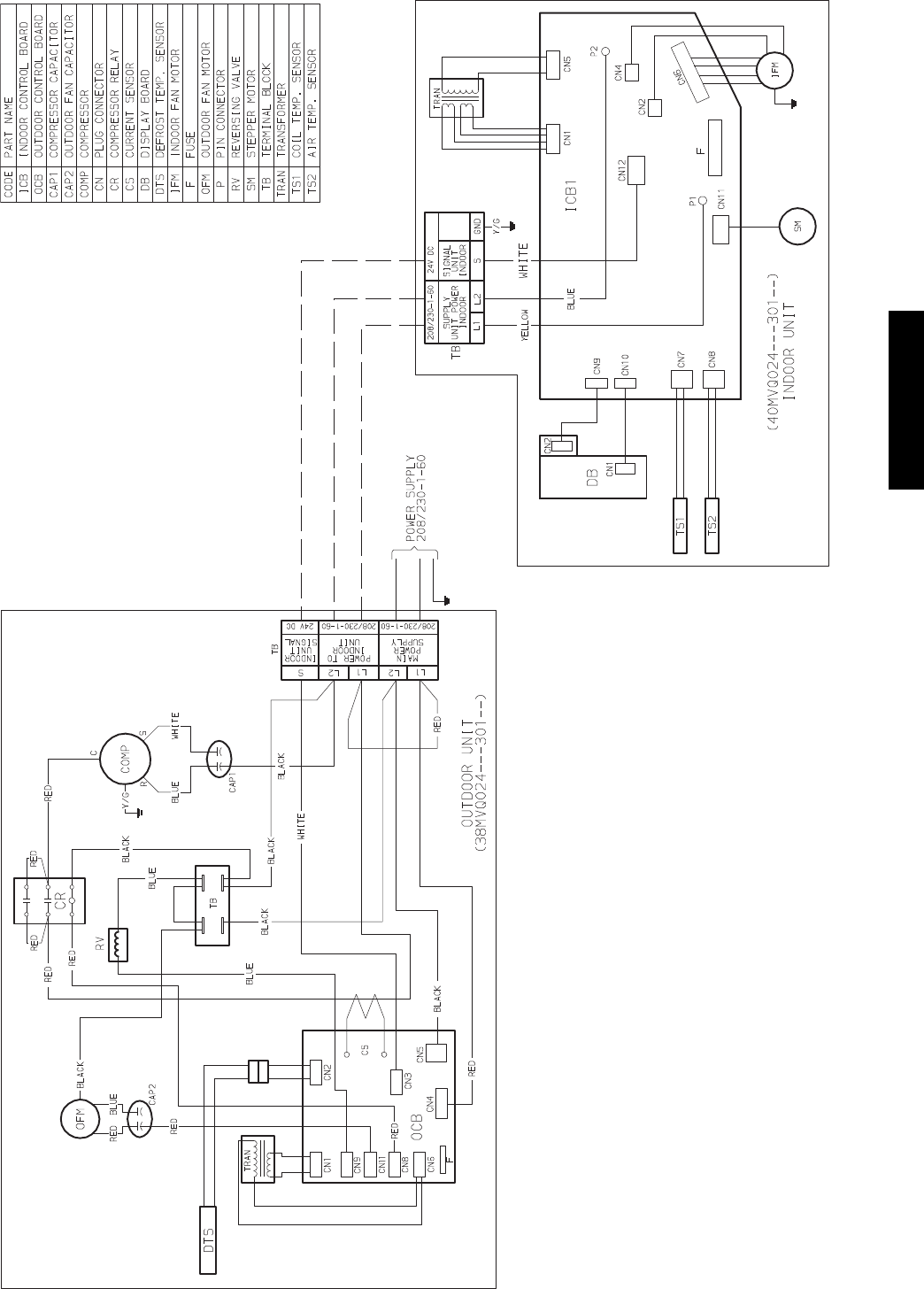
WIRING DIAGRAMS (CONT.)
Fig. 15 – Wiring Diagram 38MVQ024------3 W/ 40MVQ024------3
38/40MVC, MVQ
20
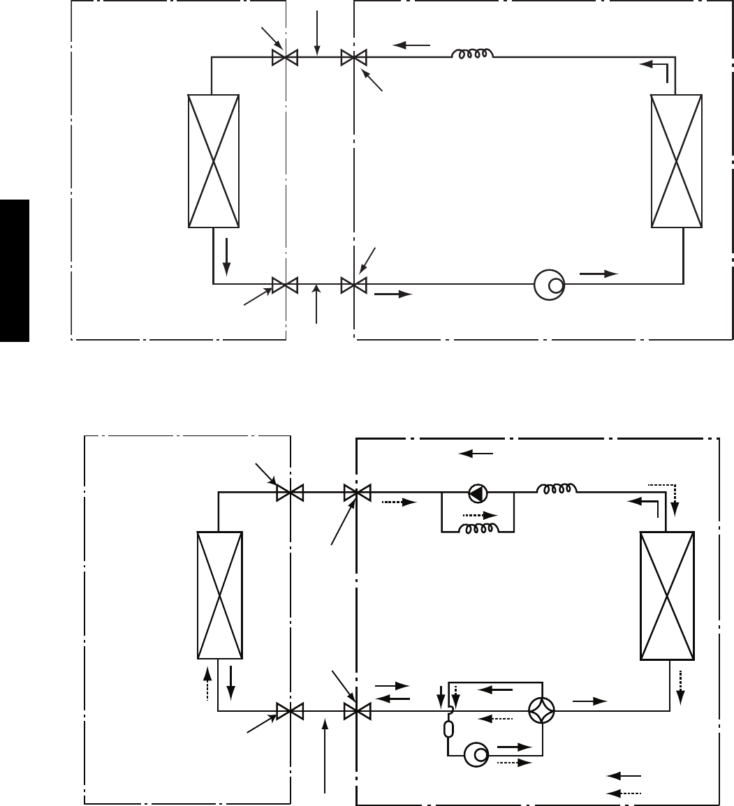
REFRIGERATION CYCLE DIAGRAM
CAPILLARY TUBE
HEAT
EXCHANGER
(CONDENSER)
HEAT
EXCHANGER
(EVAPORATOR)
FIELD
PIPING
COMPRESSOR
FLARE CONNECTION
SERVICE VALVE
SERVICE VALVE W/GUAGE PORT
TWO PHASE LIQUID LINE
SUCTION LINE
FIELD
PIPING
FLARE CONNECTION
A08104
Fig. 16 – Cooling
CAPILLARY TUBE
HEAT
EXCHANGER
(CONDENSER)
HEAT
EXCHANGER
(EVAPORATOR)
SERVICE VALVE
LIQUID HTG LIQUID
TWO PHASE
CHECK VALVE
(HEATING MODEL ONLY)
REVERSING
VALVE
(HEAT PUMP ONLY)
COOLING
HEATING
COMPRESSOR
SUCTION
DISCHARGE
SUCTION
ACCUMULATOR
SERVICE VALVE
W/ GUAGE PORT
FIELD
PIPING
INDOOR UNIT OUTDOOR UNIT
FLARE CONNECTION
FLARE CONNECTION
A08105
Fig. 17 – Heat Pumps
38/40MVC, MVQ
21
REFRIGERANT LINES
General refrigerant line sizing:
1. The 38MVC/MVQ units are shipped with a full charge of
R410A refrigerant. All charges, line sizing, and capacities
are based on runs of 25 ft (7.6 m). For runs over 25 ft (7.6
m), consult long--line section on this page for proper charge
adjustments.
2. Minimum refrigerant line length between the indoor and
outdoor units is 10 ft. (3 m).
3. Refrigerant lines should not be buried in the ground. If it is
necessary to bury the lines, not more than 36--in (914 mm)
should be buried. Provide a minimum 6--in (152 mm)
vertical rise to the service valves to prevent refrigerant
migration.
4. Both lines must be insulated. Use a minimum of 1/2--in.
(12.7 mm) thick insulation. Closed--cell insulation is
recommended in all long--line applications.
5. Special consideration should be given to isolating
interconnecting tubing from the building structure. Isolate
the tubing so that vibration or noise is not transmitted into
the structure.
SThe following maximum lengths are allowed:
REFRIGERANT LINE LENGTHS ft. (m)
Unit Size Max Line
Length
Max Elevation
(ID over OD)
Max Elevation
(OD over ID)
9K 65 (20) 35 (11) 35 (11)
12K 65 (20) 35 (11) 35 (11)
18K 100 (30) 50 (15) 50 (15)
24K 100 (30) 60 (18) 60 (18)
SThe following are the piping sizes.
PIPE SIZES
Unit Size Mix Phase Vapor
9K 1/4” 3/8”
12K 1/4” 1/2”
18K 1/4” 1/2”
24K 3/8” 5/8”
Refrigerant Charge
REFRIGERANT CHARGE lb. (kg)
Unit Size Air Conditioner Heat Pump
9K 2.3 (1.0) 2.4 (1.1)
12K 2.9 (1.3) 3.0 (1.4)
18K 4.4 (2.0) TBD
24K TBD TBD
SAbove charge is for piping runs up to 25 ft. (7.6 m).
SFor piping runs greater than 25 ft. (7.6 m), add 0.1 oz. of
refrigerant per foot of extra piping up to the allowable
length.
Long Line Applications, 38MVC Units:
1. A crankcase heater should be added for line lengths longer
than 25 ft (7.62 m) to prevent the migration of refrigerant to
the compressor during the “OFF” cycle.
2. A field fabricated wind baffle is recommended.
3. No change in line sizing is required.
4. Add refrigerant per table below.
ADDITIONAL CHARGE TABLE
Unit
Size
To t al
Line Length,
ft
Additional Charge, oz.
Min. Max. 10 --- 25 ft
(3.05 --- 7.62m)
> 2 5 --- 6 5 ft
(7.62 ---19.81m)
> 6 5 --- 1 0 0 ft
(19.81 ---30.48m)
9K
cool
only
10
65
none 0.1 oz per
foot
9K
hp
12K
cool
only
12K
hp
18K
cool
only
100 0.1 oz. per
foot
5. Reduction in capacity due to long lines can be calculated
from the chart below.
CAPACITY LOSS
Capacity,%Loss
Line Length, ft
Cooling: 25 45 65 100
9&12KBTU/Hmodels 0% 2% 5%
18 & 24 KBTU/H models 0% 2% 4% 7%
Heating:
9&12KBTU/Hmodels 0% 7% 11%
18 & 24 KBTU/H models 0% 7% 11% 15%
38/40MVC, MVQ
22
SYSTEM EVACUATION AND
CHARGING
UNIT DAMAGE HAZARD
Failure to follow this caution may result in equipment
damage or improper operation.
Never use the system compressor as a vacuum pump.
CAUTION
!
Refrigerant tubes and indoor coil should be evacuated using the
recommended deep vacuum method of 500 microns. The alternate
triple evacuation method may be used if the procedure outlined
below is followed. Always break a vacuum with dry nitrogen.
SYSTEM VACUUM AND CHARGE
Using Vacuum Pump
1. Completely tighten flare nuts A, B, C, D, connect manifold
gage charge hose to a charge port of the low side service
valve. (See Fig. 18.)
2. Connect charge hose to vacuum pump.
3. Fully open the low side of manifold gage. (See Fig. 19)
4. Start vacuum pump
5. Evacuate using either deep vacuum or triple evacuation
method.
6. After evacuation is complete, fully close the low side of
manifold gage and stop operation of vacuum pump.
7. The factory charge contained in the outdoor unit is good for
up to 25 ft. (8 m) of line length. For refrigerant lines longer
than 25 ft (8 m), add 0.1 oz. per foot of extra piping up to
the maximum allowable length.
8. Disconnect charge hose from charge connection of the low
side service valve.
9. Fully open service valves B and A.
10. Securely tighten caps of service valves.
Outdoor Unit Indoor Uni
t
Refrigerant
Service Valve
Low Side
High Side
A
B
C
D
A07360
Fig. 18 – Service Valve
Manifold Gage
500 microns
Low side valve
High side valve
Charge hose
Charge hose
Vacuum pump
Low side valve
A07361
Fig. 19 – Manifold
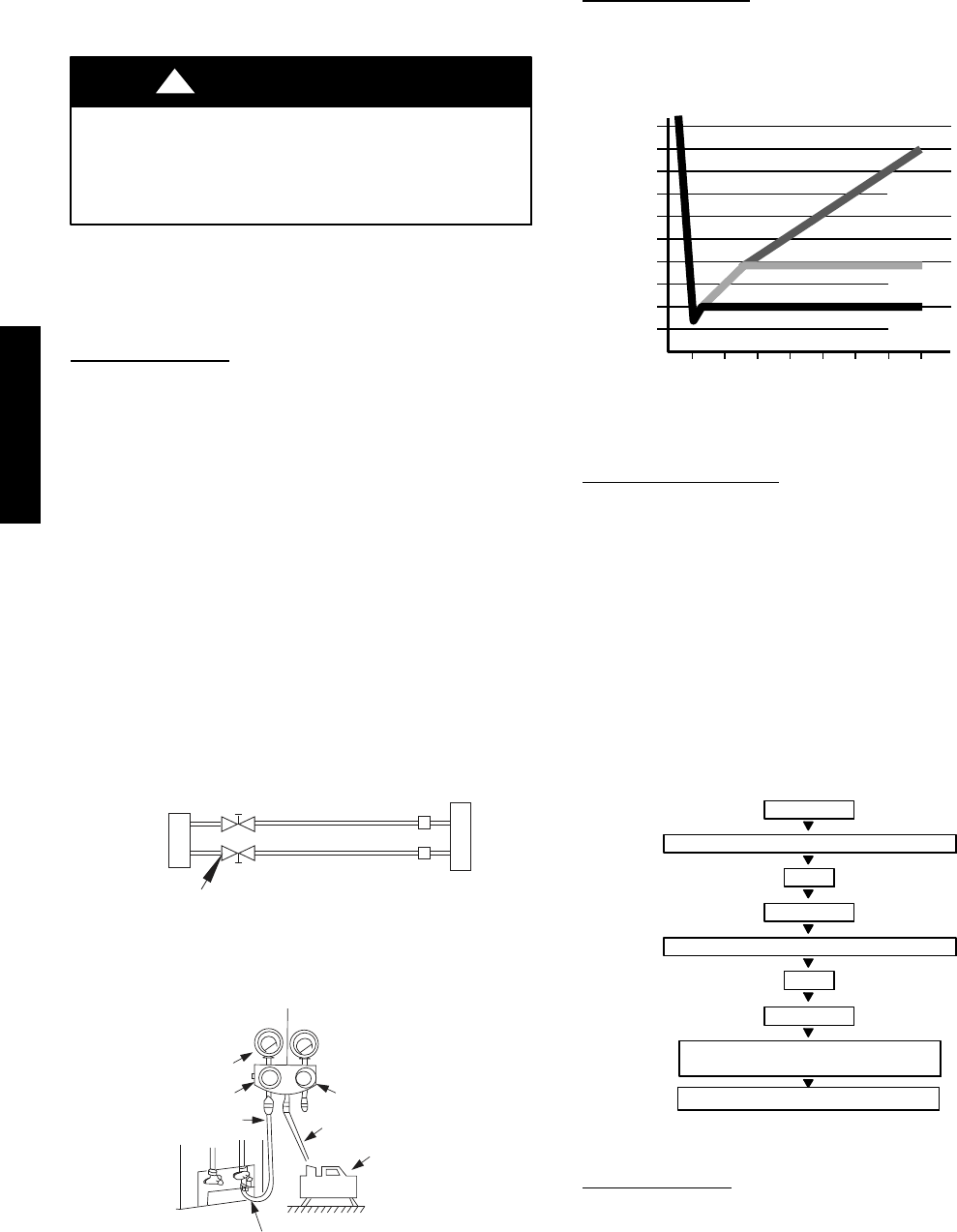
Deep Vacuum Method
The deep vacuum method requires a vacuum pump capable of
pulling a vacuum of 500 microns and a vacuum gage capable of
accurately measuring this vacuum depth. The deep vacuum method
is the most positive way of assuring a system is free of air and
liquid water. (See Fig. 20)
500
MINUTES
01234567
1000
1500
LEAK IN
SYSTEM
VACUUM TIGHT
TOO WET
TIGHT
DRY SYSTEM
2000
MICRONS
2500
3000
3500
4000
4500
5000
A95424
Fig. 20 – Deep Vacuum Graph
Triple Evacuation Method
The triple evacuation method should only be used when vacuum
pump is only capable of pumping down to 28 in. of mercury
vacuum and system does not contain any liquid water.
Refer to Fig. 21 and proceed as follows:
1. Pump system down to 28 in. of mercury and allow pump to
continue operating for an additional 15 minutes.
2. Close service valves and shut off vacuum pump.
3. Connect a nitrogen cylinder and regulator to system and
open until system pressure is 2 psig.
4. Close service valve and allow system to stand for 1 hr. Dur-
ing this time, dry nitrogen will be able to diffuse throughout
the system absorbing moisture.
5. Repeat this procedure as indicated in Fig. 21. System will
then be free of any contaminants and water vapor.
CHECK FOR TIGHT, DRY SYSTEM
(IF IT HOLDS DEEP VACUUM)
EVACUATE
BREAK VACUUM WITH DRY NITROGEN
WAIT
EVACUATE
RELEASE CHARGE INTO SYSTEM
BREAK VACUUM WITH DRY NITROGEN
EVACUATE
WAIT
A95425
Fig. 21 – Triple Evacuation Method
Final Tubing Check
IMPORTANT: Check to be certain factory tubing on both
indoor and outdoor unit has not shifted during shipment.
Ensure tubes are not rubbing against each other or any sheet
metal. Pay close attention to feeder tubes, making sure wire ties
on feeder tubes are secure and tight.
38/40MVC, MVQ
23
CONTROL SYSTEM
The 40MVC/MVQ unit is equipped with a microprocessor control to perform two functions:
1. Provide safety for the system
2. Control the system and provide optimum levels of comfort and efficiency
The main microprocessor is located on the control board of the fan coil unit (outdoor units have a microprocessor too) with thermistors
located in the fan coil air inlet and on the indoor coil. Heat pump units have a thermistor on the outdoor coil. These thermistors monitor the
system operation to maintain the unit within acceptable parameters and control the operating mode.
SYSTEM SAFETIES
Safety Cooling Only Heat Pump
9K 012K 018K 024K 09K 012K 018K 024K
3MinTimeDelay X X X X X X X X
Over Current Protection On Compressor X X X X X X X X
Indoor Coil Freeze Protection X X X X X X X X
Condenser High Temperature Protection X X X X
Indoor Evaporator High Temperature X X X X
3MINUTETIMEDELAY
In order to protect the compressor, there is a 3 minute delay on break even if the control is calling for heating or cooling.
COMPRESSOR OVERCURRENT PROTECTION
Overcurrent protection can result due to any of the following:
SThe ambient temperature is to high
SLocked rotor on the compressor
SBlockage in refrigeration circuit (cap tubes, for example)
SOutdoor air is blocked or restricted
The compressor current is monitored continuously and protection is provided as shown below:
3 sec
5 min
1 sec
Normal
Indoor fan: On
compressor: On
outdoor fan: On
Outdoor fan
off (heating)
Indoor fan low
speed (cooling)
Compressor off
(after 5 minutes)
Compressor off
(after 3 seconds)
Current down
Current up
A08117
Fig. 22 – Compressor Overcurrent Protection
If the compressor is stopped 4 times at the 5 minute limit or 1 time at the 3 second limit, the system will be locked off and the main power will
have to be reset before the system can be restarted.
Time Limit Compressor Current
38MVC(Q)009---1 38MVC(Q)012---1 38MVC(Q)012---3 38MVC(Q)018---3 38MVC(Q)024---3
3SEC 14 A 18 A 11 A 14 A 23 A
5MIN 12 A 16A 9A 12 A 21 A
ISEC 10.5 A 14 A 7A 11 A 18 A
NORMAL 9A 12.5 A 6A 10 A 16 A
38/40MVC, MVQ
24
Indoor Coil Freeze Protection
The indoor coil can freeze due to any of the following:
SLow system charge
SReduced indoor airflow
SRestricted refrigerant flow
SLow ambient temperature (outdoor)
SLow load (indoor)
In cooling mode, the thermistor located on a return bend of the
indoor coil monitors the coil temperature continuously. Any time
the coil temperature drops below the TE5 limit for five consecutive
minutes, the compressor and outdoor fan will be switched off until
the coil temperature rises above the TE6 as shown below:
Compressor and outdoor
fan off (after 5 mins)
Compressor and
outdorr fan on
EVAP temp. down EVAP temp. up
TE5 TE6 T
(Evap Temp.)
A08118
Fig. 23 – Indoor Coil Freeze Protection
Parameter
Coil Temperature ° F (° C)
40MVC(Q)
009 --- 1
40MVC(Q)
012 --- 1
40MVC(Q)
018 --- 3
40MVC(Q)
024 --- 3
TE5 39 (4) 41 (5) 36 (2) 36 (2)
TE6 50 (10) 54 (12) 54 (12) 54 (12)
Condenser High Temperature Protection
Condenser high temperature can occur due to any of the following
conditions:
SHigh outdoor ambient
SOutdoor fan blocked
SOutdoor coil blocked
The outdoor coil thermistor on a heat pump unit continuously
monitors the temperature of the outdoor coil. Anytime the coil
temperature exceeds the TE10 limit, the compressor is switched off
and the outdoor fan continues running to reduce the coil
temperature. When the coil temperature drops below the TE11
limit, the compressor is switched back on as shown below:
Compressor on
Outdoor fan on
COND temp. down
TE11 TE10 T
COND temp. up
Compressor off
Outdoor fan on
A08119
Fig. 24 – Condenser High Temp Protection
Parameter
Condenser Temp.
°F(°C)
38MVQ018 --- 3 38MVQ024--- 3
TE10 149 (63) 158 (70)
TE11 131 (55) 149 (65)
Indoor High Temperature Protection
High indoor coil temperature (in heating mode) can occur due to
any of the following:
SHigh outdoor ambient temperature
SIndoor fan blocked
SIndoor coil blocked (including dirty filters)
The indoor coil thermistor on a heat pump unit continuously
monitors the temperature of the indoor coil during heating
operation. Anytime the coil temperate exceeds the TE8 limit, the
outdoor fan is switched off. If the coil temperature continues to
climb and exceeds the TE7 limit, the compressor is switched off.
When the coil temperature drops below the TE9 limit, the
compressor and outdoor fan are switched back on as shown
below:
TE9 TE8 TE7 T
T temp. up
Compressor on
Fan on
T temp. down
Compressor off
Fan off
Compressor on
Fan off
A08120
Fig. 25 – Indoor High Temperature Protection
Parameter
Condenser Coil Temp.
°F(°C)
40MVQ
009 --- 1
40MVQ
012 --- 1
40MVQ
018 --- 3
40MVQ
024 --- 3
TE7 140 (60) 140 (60) 145 (63) 145 (63)
TE8 129 (54) 129 (54) 129 (54) 129 (54)
TE9 118 (48) 118 (48) 122 (50) 122 (50)
SEQUENCE OF OPERATION
Interface
A wireless remote control, supplied with the unit, is the interface
between the fan coil and the user. The wireless remote control has
the following characteristics:
SCapable of displaying _Cand_F with _C being the default
setting. To change the default setting, refer to the Owner’s
Manual or push the recessed F/C button once using a paper
clip or similar object*.
SThe remote control setpoint range is from 62_F(17_C) to
88_F(30_C) in increments of 2_F(1_C).
SThere is a dedicated cooling only and heat pump remote
control.
SThe wireless remote control has an operating range of 25 ft.
(7.62 m).
SThe same remote control can be used to control more than one
unit.
SIf the remote control is lost, damaged, or the batteries are
exhausted, the system can be operated by using the manual
button (forced Auto) located under the front panel.
Manual button
A07364
Fig. 26 – Manual Button Location on Unit
* On units produced during week 12 (2008) and later. Units
produced before week 12 have dedicated _Cor_F controls.
38/40MVC, MVQ
25
MODES OF OPERATION
The units have 5 main operating modes:
1. Fan Only
2. Cooling
3. Heating (heat pumps only)
4. Auto
5. Dehumidification (Dry)
The units have 2 other modes (manual operation) that are operated
in unique situations:
1. Auto Forced Mode (Emergency)
2. Test Mode
Fan Mode Only
In this mode, the system circulates the room air without changing
the room air temperature.
Cooling Mode
In this mode, the system cools and dries the room air with the fan
running continuously, either at a selected fan speed or Auto fan
speed. The fan runs even when the compressor cycles off. This
feature enhances room comfort and efficiency of the system.
When the unit is operating in cooling, two sub modes can also be
selected:
1. Sleep Mode is an energy saving feature that changes the set
point automatically.
2. Turbo Mode is a comfort feature on the 9k and 12k units
where the set point is reached quickly by having the fan run
on high speed regardless of the speed that has been selected.
Compressor and Outdoor Fan Operation
The compressor and outdoor fan motor cycle on and off based on
the conditions of the set point and the room temperature as shown
below. There is no minimum run time.
T = Room Temperature
Ts = Set Point Temperature
Compressor off
fan off
Compressor and
outdoor fan on
Room temp. down
0 1.8°FT-Ts
Room temp. up
A08106
Fig. 27 – Compressor and Outdoor Fan -- Cooling Mode
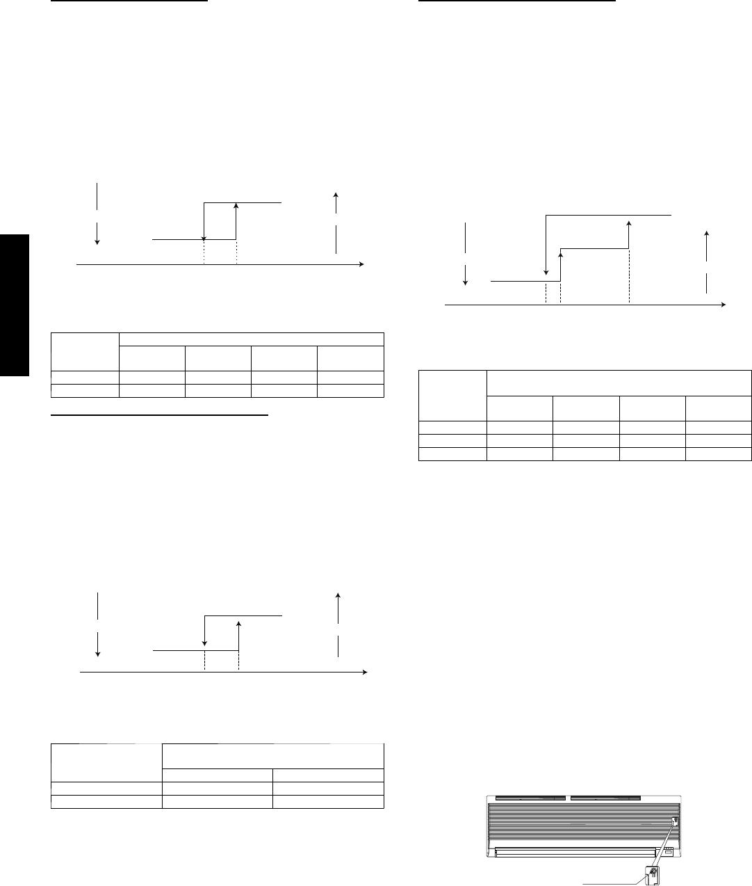
Indoor Fan Operation
When in cooling mode, the fan runs continuously either at the
chosen set speed , or in Auto mode, where the speed is determined
by the microprocessor based on the difference between the room
temperature and the temperature set point as shown below:
Room temp. up
Room temp. down
T= Room Temperature
Ts = Set Point Temperature
9.0 °F7.2 °F1.8 °F T-Ts
Low fan
High fan
Med fan
A08107
Fig. 28 – Auto Fan -- Cooling Mode
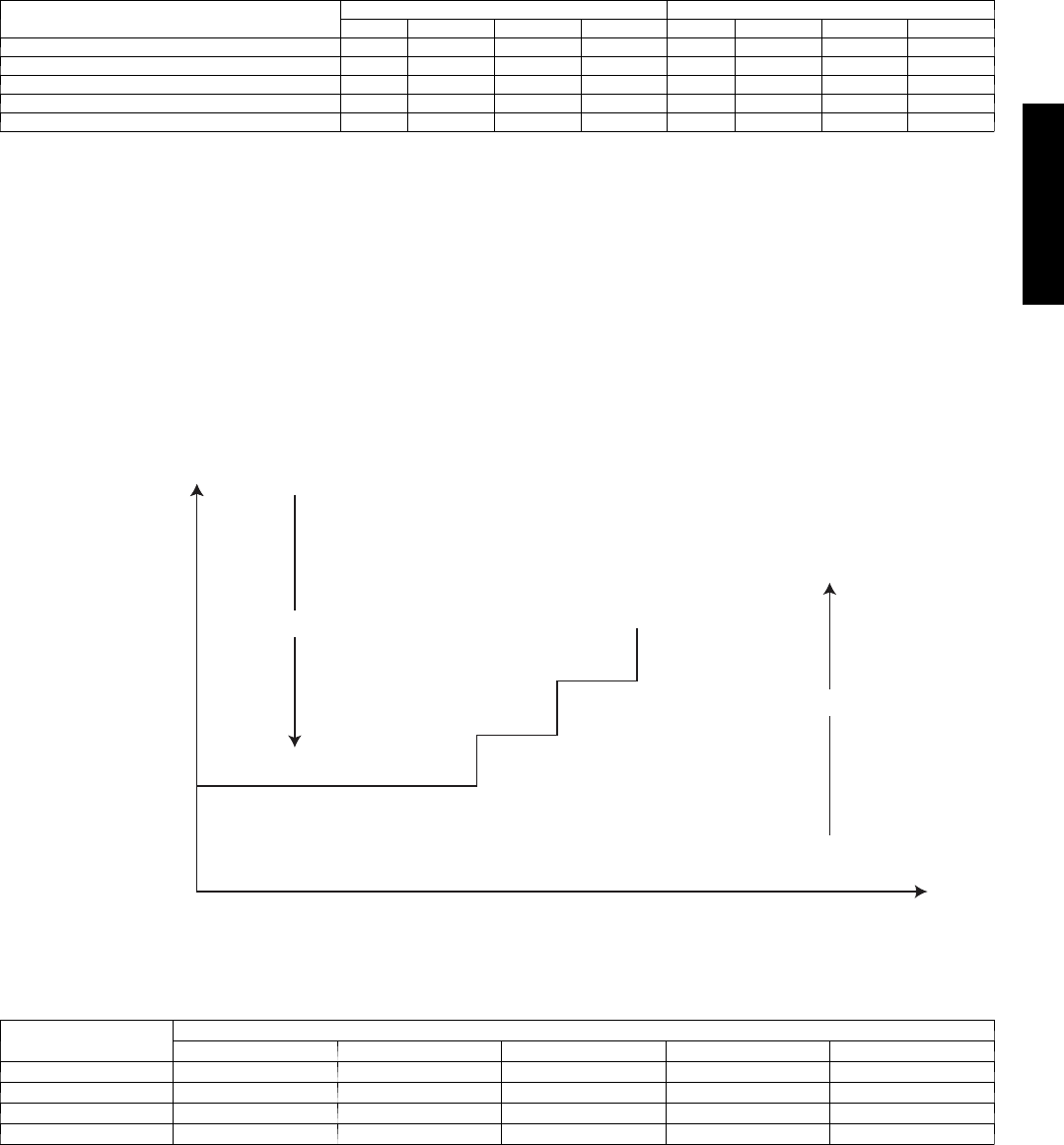
Sleep Mode
When in cooling mode, additional energy savings can be realized
by selecting the Sleep setting. When the Sleep setting is selected,
the temperature set point is adjusted automatically as shown below:
Set point
Time (hour)12
1.8
°
F
1.8
°
F
A08108
Fig. 29 – Sleep Mode
The unit will shut off 7 hours after the Sleep Mode is selected.
Turbo Mode
When in cooling mode, selecting Turbo will allow the indoor unit
to satisfy the temperature set point as quickly as possible. In Turbo
Mode, the indoor fan will shift to high speed and either run
continuously for 20 minutes or until the user pushes the Turbo
button again, at which point the fan speed will return to the original
setting.
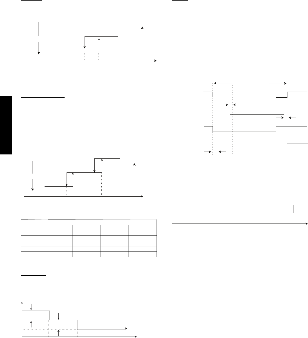
Heating Mode
In this mode, the system heats the room air with the indoor fan
running at either the selected speed or on Auto. As in the cooling
mode, the indoor fan will run continuously unless interrupted by
the cold blow algorithm. This algorithm will not allow the fan to
run if the indoor coil temperature drops below a preset value.
The sleep function can be selected while the unit is running in the
Heating Mode. Defrost is controlled by the on--board
microprocessor.
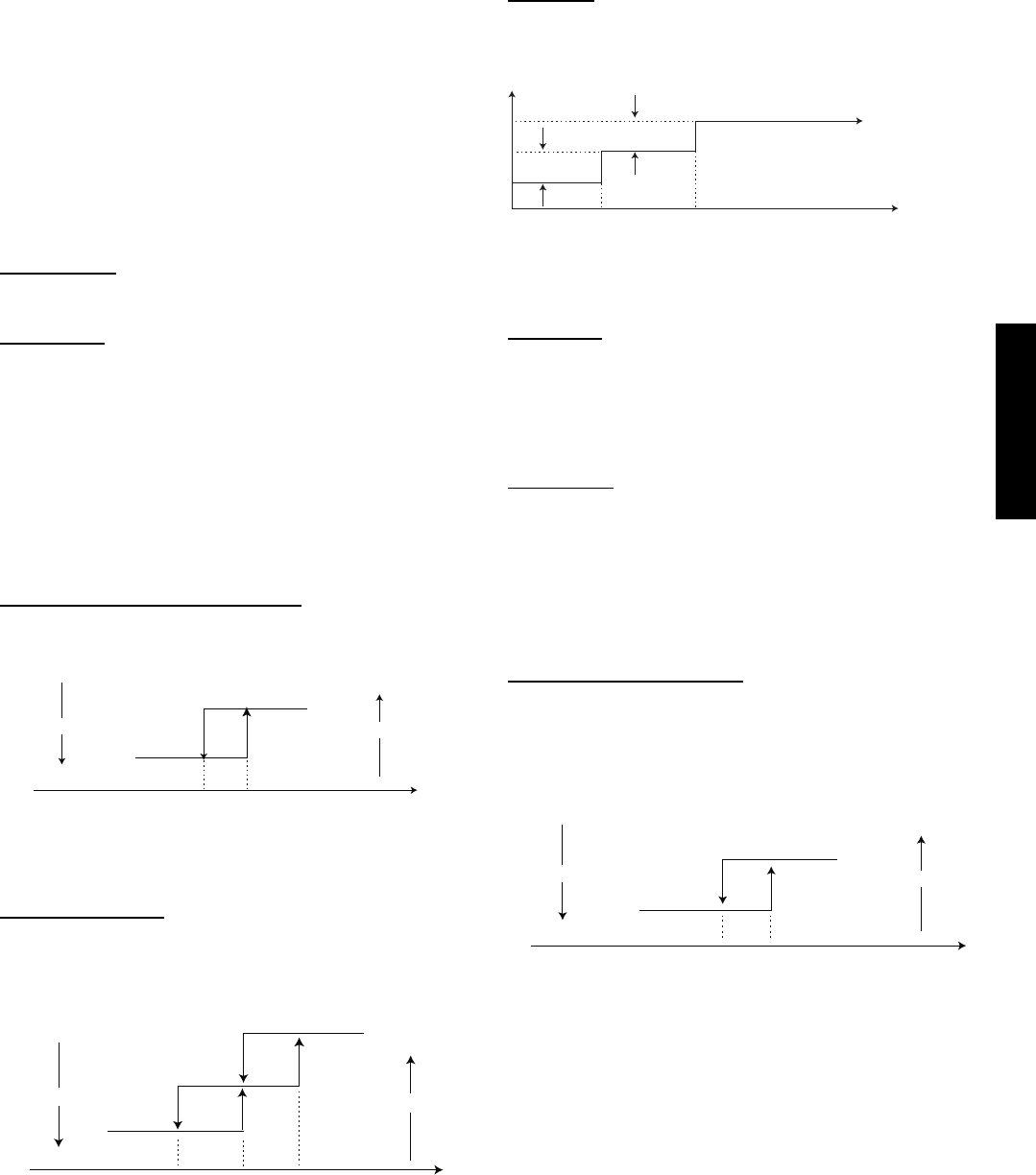
Compressor and Fan Operation
The compressor and outdoor fan cycle on and off based on the
actual room temperature versus the set point as shown below.
When the compressor starts, it will run continuously for 7 minutes
even if the set point condition is satisfied.
The 4--way value is energized in heating and will stay energized for
2 minutes after the mode is changed into a non--heating mode.
Compressor on
outdoor fan off
Room temp. up
Room temp. down
Compressor off
outdoor fan on
Ts+5.4*Ts+3.6*Ts T
T = Room Temperature
TS = Set Point Temperature
* For 9k & 12k Units Only. For 18k and 24k units, numbers will be 5.4 and 7.2 respectively.
A08109
Fig. 30 – Compressor and Outdoor Fan -- Heating Mode
38/40MVC, MVQ
26
Auto Fan
When the fan speed is set to Auto, the fan will run at either the
medium or low speed based on the difference between the room
temperature and the set point temperature as shown below:
Room temp. up
Room temp. down
T-Ts
0
Med. Speed
Low. Speed
3.6°F
T = Room Temperature
Ts = Set Point Temperature
A08112
Fig. 31 – Auto Fan -- Heating Mode
Manual Indoor Fan
The indoor fan will run continuously in heating at the set fan speed
(even if the compressor cycles off) unless the indoor coil
temperature begins to drop. When the coil temperature drops to
the TE3 limit, the 18k and 24k unit indoor fan switches to low
speed. On the 9k and 12k unit the indoor fan switches to ultra low
speed. When the coil temperature drops to the TE4 limit, the
indoor fan on all systems shuts off to prevent cold blow as shown
below. The cold blow algorithm also applies to the auto fan
setting.
T temp. up
T temp. down
Fan off
Low Speed /
Ultra Low Speed
Set fan speed
TE4 TE1 TE3 TE2 T
(Coil temp.)
A08111
Fig. 32 – Manual Indoor Fan -- Heating Mode
Parameter
Indoor Coil Temperature ° F (° C)
40MVQ
009 --- 1
40MVQ
012 --- 1
40MVQ
018 --- 3
40MVQ
024 --- 3
TE1 88 (31) 88 (31) 77 (25) 82 (28)
TE2 93 (34) 91 (33) 90 (32) 93 (34)
TE3 86 (30) 81 (27) 86 (30) 90 (32)
TE4 72 (22) 68 (20) 68 (20) 75 (24)
Sleep Mode
When in heating mode additional energy savings can be realized
by selecting the Sleep setting. When the Sleep setting is selected,
the temperature set point is adjusted automatically as shown below:
Set Point
Time (hour)12
1.8ºF
1.8ºF
A08110
Fig. 33 – Sleep Mode -- Heating
The unit will shut off 7 hours after the Sleep mode is selected.
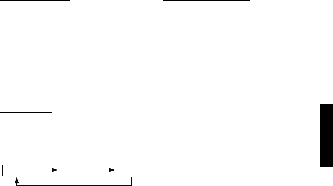
Defrost
Defrost on heat pump units is controlled by the microprocessor and
is initiated if either of the following conditions occur:
1. The outdoor coil temperature is lower than 32_F(0_C) for
more than 40 minutes and during that period, the coil
temperature is continuously lower than 26.6_F(--3_C) for 3
minutes.
2. If the first condition does not occur within 90 minutes of
termination of the last defrost cycle.
The defrost cycle will terminate 10 minutes after initiation or when
the coil temperature reaches 68_F(20_C). At the end of the
Defrost cycle the timer resets automatically.
The cycles of defrost algorithm are shown below:
Compressor
4-way valve
Outdoor fan
Indoor fan
Defrost 10 or 6 minutes
On
Off
5s
10s
25s
2s
A08114
Fig. 34 – Defrost Cycle
Auto Mode
When the Auto setting is selected, the microprocessor looks at the
difference between the room temperature (T) and the set point
(TS). The algorithm determines which mode the unit will run in as
shown below:
Heating (fan only in cooling) Fan only Cooling
-1.8
°
F 3.6
°
FT-TS
A08115
Fig.35–AutoMode
When the unit shifts modes, it will remain in that mode for at least
15 minutes while the algorithm ignores the difference between T
and TS. This ensures that the unit cannot change modes too
frequently.
38/40MVC, MVQ
27
Dry (Dehumidification) Mode
When more humidity control is desired, the Dry setting can be
selected. Lower humidity is achieved when the microprocessor
adjusts the indoor fan speed and compressor cycling by comparing
the room temperature (T) and the set point temperature (TS).
There are two different control algorithms:
Size 9k and 12 k units:
T = TS + 3.6 -- the compressor will run for 6 minutes and the
indoor fan will run at low speed. The compressor will be off for 4
minutes and the indoor fan will run in ultra low speed.
TS = T < TS + 3.6 -- The compressor will run for 5 minutes and the
indoor fan will run at low speed. The compressor will be off for 5
minutes and the indoor fan will run in ultra low speed.
T < TS -- The compressor will run for 4 minutes and the indoor
fan will run at low speed. The compressor will be off for 6 minutes
and the indoor fan will run in ultra low speed.
Size 18k and 24k units:
These units do not have ultra low speed. When set for
dehumidification, the indoor fan runs at low speed and the
compressor cycles based on the difference between T and TS.
Manual Operation
The unit can be set for Forced Auto or Forced Cooling manually
by pushing the Manual button once or twice as shown below:
Remote
mode Forced
auto Forced
cooling
Push 3 Times Push Once Push Twice
A08116
Fig. 36 – Manual Operation
Forced Auto (Emergency Operation)
Forced Auto option allows operation of the unit if the remote
control is lost or the batteries have expired. When the system is in
Forced Auto, it will run with a default set point of 75.2_F. While
in Forced Auto, the system will respond to signals from the remote
control.
Forced Cooling Operation
This option is used for diagnostic purposes. The system is forced
to run in cooling for 30 minutes.
After 30 minutes, the 9k and 12k systems will switch to Dry mode
with a default set point of 75.2_F. The 18k and 24k systems will
switch to Forced Auto mode. When the system is in Forced
Cooling mode, it will not respond to signals from the remote
control. The only way to exit the Forced Cooling mode is to push
the manual button once to switch the system to remote control
mode.
38/40MVC, MVQ
28
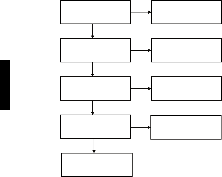
TROUBLESHOOTING
This section provides the required flow charts to troubleshoot problems that may arise.
NOTE:Information required in the diagnoses can be found either on the wiring diagrams or in the appendix.
Required Tools:
The following tools are needed when diagnosing the units:
SDigital multimeter
SScrew drivers (Phillips and straight head)
SNeedle--nose pliers
Recommended Steps
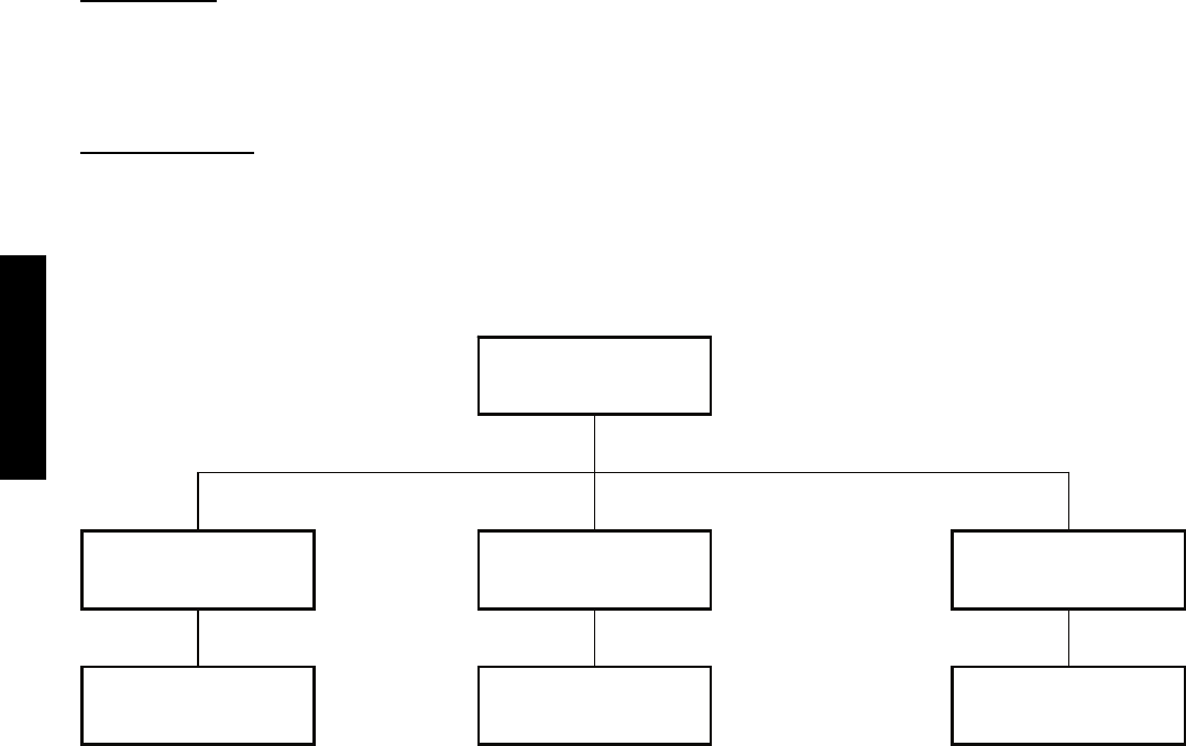
1. Refer to the diagnostic hierarchy chart below and determine the problem at hand.
2. Go to the chart listed in the diagnostic hierarchy and follow the steps in the chart for the selected problem.
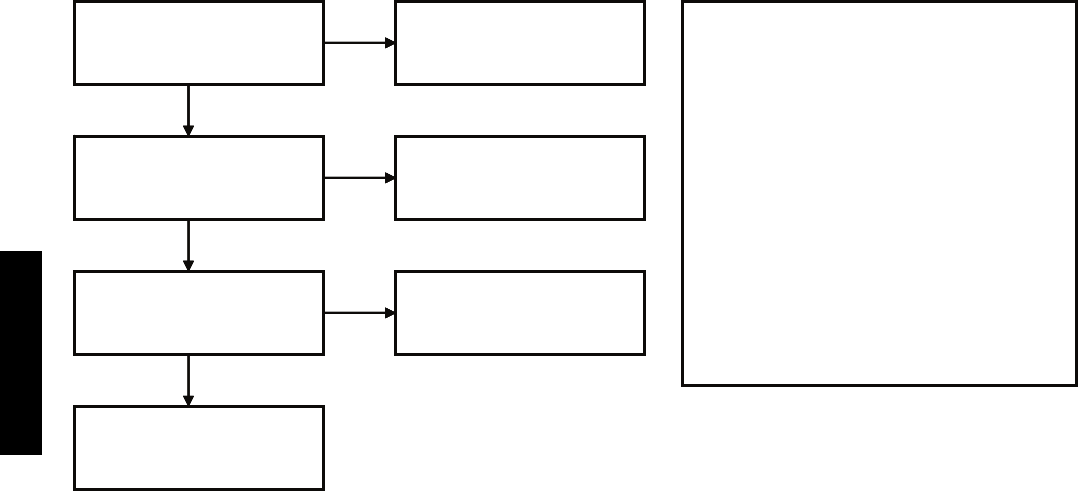
DIAGNOSTIC HIERARCHY
Unit has a problem
Unit displays a
diagnostic code
Unit not running and
no diagnostic code
Unit running but not
optimally
Refer to page ---
appropriate diagnostic chart
Go to chart # 7 Go to chart # 8 & 9
* For EEROM error, replace the indoor microprocessor board
Unit has a problem
Unit displays a
diagnostic code
Unit not running and
no diagnostic code
Unit running but not
optimally
Refer to page A8 & A9
identify error code* and use Go to chart Go to chart #
* For EEROM error, replace the indoor microprocessor board
A08165
For the ease of service, the systems are equipped with diagnostic
code display LED’s on both the indoor and outdoor units. The
outdoor diagnostic display is an LED on the outdoor unit board
and is limited to very few errors. However, it is useful in
identifying special error codes like a failure of the outdoor coil
sensor on heat pumps. The indoor diagnostic display is a
combination of flashing LED’s on the display panel on the front of
the unit. If possible always check the diagnostic codes displayed on
the indoor unit first.
The diagnostic codes for the indoor and outdoor units are listed in
appendix A8 and A9.
Problems may occur that are not covered by a diagnostic code, but
are covered by the diagnostic flow charts starting with the
diagnostic hierarchy. These problems will be typical air
conditioning mechanical or electrical issues that can be corrected
using standard air conditioning repair techniques.
For problems requiring measurements at the control boards please
note the following:
1. Always disconnect the main power.
2. When possible check the outdoor board first.
3. Start by removing the outdoor unit top cover.
4. Reconnect the main power
5. Probe the outdoor board inputs and outputs with a digital
multi--meter referring to the wiring diagrams and
input/output charts found in the appendix.
6. Connect the red probe to hot signal and the black probe to
the ground or negative.
7. Note that some of the DC voltage signals are pulse will give
continuously variable readings.
8. If it is necessary to check the indoor unit board you must
start by disconnecting the main power.
9. Next remove the front cover of the unit and then control
box cover.
10. Carefully remove the indoor board from the control box,
place it face up on a plastic surface (not metal).
11. Reconnect the main power and repeat steps 5,6, and 7.
12. Disconnect main power before reinstalling board to avoid
shock hazard and board damage.
38/40MVC, MVQ
29
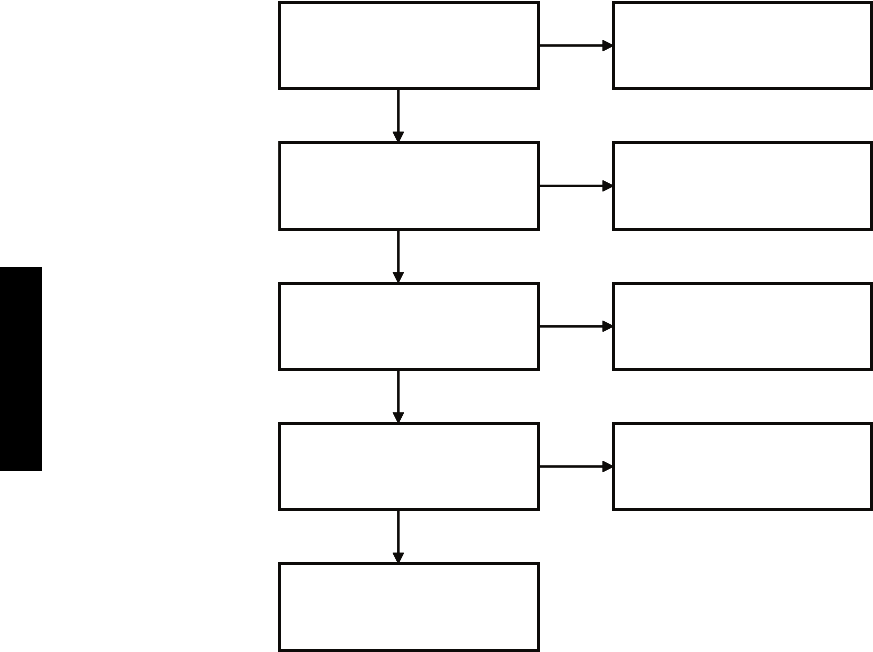
CHART 1 -- INDOOR FAN SPEED OUT OF CONTROL
Reset main power and
restart system using remote.
Problem persists?
Replace indoor fan motor
No further action is
required
No
Yes
Check IFM output and input
on indoor board.
Values good?
Yes
Check motor connection.
Connection good?
No
Fix connection
Yes
No
Replace indoor board
Reset main power and
restart system using remote.
Problem persists?
Replace indoor fan motor
No further action is
required
No
Yes
Yes
Check motor connection.
Connection good?
No
Fix connection
Yes
No
Replace indoor board
A08166
38/40MVC, MVQ
30
CHART 2 -- TEMPERATURE SENSOR
Reset main power and
restart system using remote.
Problem persists?
Appendix 6
No further action is
required
No
Yes
Check input and output
on indoor or outdoor board.
Yes
Check sensor connector
at ID or OD board
Connection good?
No
Fix connection
Yes
No
Replace board
Check sensor resistance.
No
Yes
Yes
No
Yes
No
No
Replace sensor
No
Double check connection,
for corrosion or high
resistance.
YesYes
A08167
38/40MVC, MVQ
31
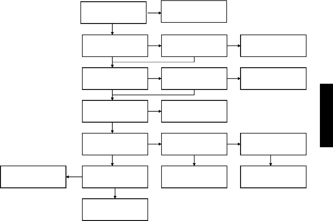
CHART 3 -- COMPRESSOR OVERCURRENT PROTECTION
Is unit running in outdoor
ambient higher than
125 °F?
Beyond operating range
Outdoor coil clean? Clean coil.
Problem persists? Problem solved
Check connections from
OD board. Corrosion, or
high resistance
Outdoor fan Ok?
Connect gauges to unit.
pressures ok?
Check amp draw to
compressor? Values within
range?
Replace outdoor board
Replace compressor
Clean/repair connection
Problem persists? Problem solved
Change outdoor motor
High head, high suction? High head, low suction?
Unit is overcharged.
Reclaim charge and weigh
in correct charge.
Yes
Yes
Yes
Yes
Yes
No
No
No
No No
No
No
Yes
Yes
No
No
Yes
Yes
Restriction in refrigeration
circuit.
A08168
38/40MVC, MVQ
32
CHART 4 -- INDOOR UNIT COMMUNICATION ERROR SIZE 9K AND 12K
Reset main power and
restart system using remote.
Problem persists?
.
No further action is
required
No
Yes
Measure Volts DC on
outdoor TB between 1 & 3.
Ok?**
Yes
Check the wires and
connections between
Indoor and outdoor units*
No
Fix connection or
replace wiring
No
Yes
Replace outdoor board.
** There is a 2 to 3 minute window to take the measurement before the diagnostic light is on again.
Measure Volts DC on
indoor TB between 1 & 3.
Ok?**
No
Replace indoor board.
Recheck wiring and
connections
Notes:
Before measuring the Volts DC on outdoor TB,
disconnect the field wire on terminal 1.
Before measuring the Volts DC on Indoor TB,
disconnect the field wire on terminal 1.
Have the red probe of the meter on terminal 1
and the black probe on terminal 3. Reconnect
wiring when measurements are complete.
Reset main power and
restart system using remote.
Problem persists?
.
No further action is
required
No
Yes
Measure Volts DC on
outdoor TB between 1 & 3.
Ok?**
Yes
Check the wires and
connections between
Indoor and outdoor units*
No
Fix connection or
replace wiring
No
Yes
Replace outdoor board.
* Make sure wires are connected per connection diagrams. Failing to do that will result in a communication error.
** There is a 2 to 3 minute window to take the measurement before the diagnostic light is on again.
Measure Volts DC on
indoor TB between 1 & 3.
Ok?**
No
Replace indoor board.
Recheck wiring and
connections
Notes:
Before measuring the Volts DC on outdoor TB,
disconnect the field wire on terminal 1.
Before measuring the Volts DC on Indoor TB,
A08181
38/40MVC, MVQ
33
CHART 5 -- OUTDOOR UNIT PROTECTS
Suction and head
equal?
Outdoor coil clean? Clean coil. Problem
persists?
Check sensors.
Flow Chart #2
Connect gauges to
unit. Pressures ok?
Check compressor
Normal suction,
high head?
Non condensables
in sys. Pump down
and recharge unit
High head, high
suction?
Unit is overcharged.
Reclaim charge and
weigh in correct charge
High head, low
suction?
Yes
No
No No No
Problem solved
No No
Yes
Yes
Yes
Yes
Yes Yes Yes
Check application
limits
Check outdoor unit
board. Indicator light
flashing twice?
No
See note below
*
* Restriction in system. Check capillary tube, check for moisture, and check for damage to liquid line between indoor and
outdoor units.
A08182
38/40MVC, MVQ
34
CHART 6 -- INDOOR UNIT COMMUNICATION ERROR SIZE 18K AND 24K
* Make sure wires are connected per connection diagrams i.e. L1 to L1 and L2 to L2. Failing to do that will result in a
communication error.
** There is a 2 to 3 minute window to take measurements before the diagnostic light is on again.
Reset main power and
restart system using remote.
Problem persists?
.
No further action is
required
No
Yes
Measure VDC reading on
outdoor between S and G.
Reading positive? **
Yes
Check the wires and
connections between
Indoor and outdoor units*
No
Fix connection or
replace wiring
Yes
No
Replace outdoor board
Replace indoor board.
Notes:
When unit is operating normally and a DC
voltage reading is taken between the S and
G terminal on the outdoor unit (or indoor
unit) positive and negative readings will
fluctuate between 0 and 24V DC.
If indoor board is bad, only a positive
readings will be registered between
terminals S and G on the outdoor unit. The
reverse will apply if outdoor board is bad
(only negative readings will register).
Above data is obtained by having the red
probe of the meter on the S terminal and
the black probe on the G terminal.
A08183
38/40MVC, MVQ
35
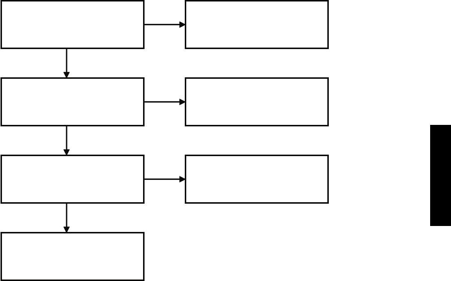
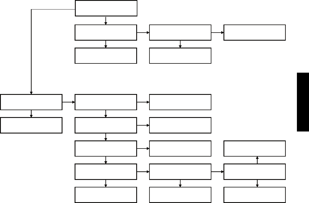
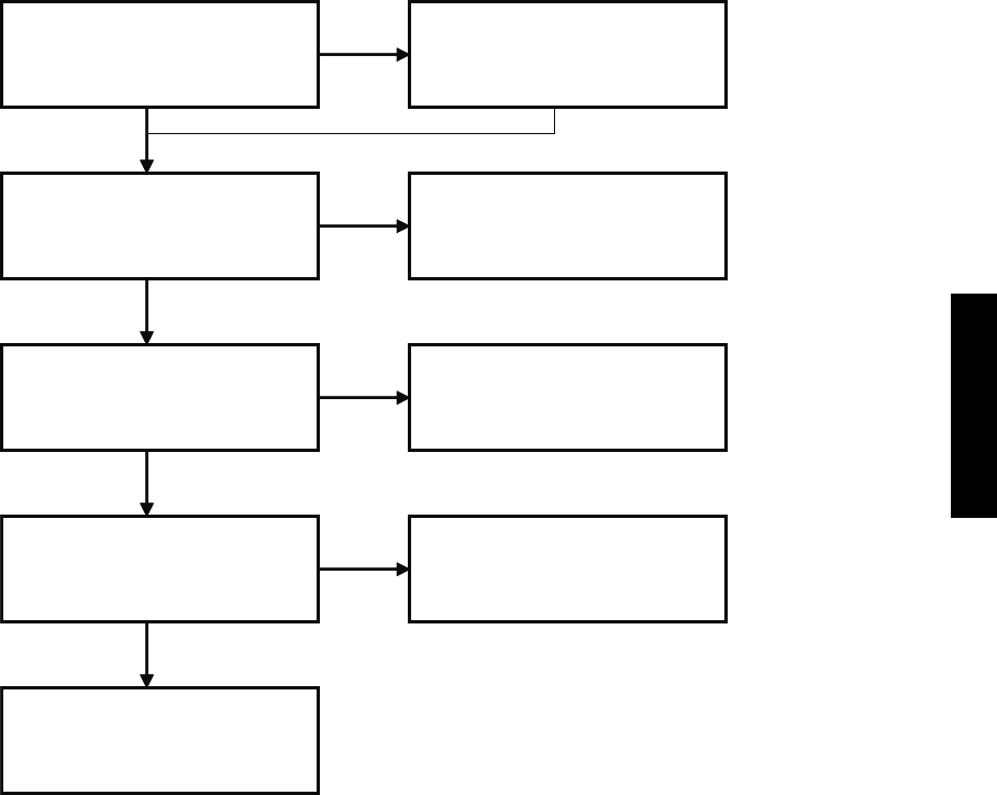
CHART 7 -- UNIT NOT RUNNING, NO DIAGNOSTIC CODE
Yes
Use auto forced function.
Unit runs?
Reset remote and restart
the unit. Is unit running?
Problem solved
Check batteries. OK? Replace battery
Go to chart #13
Reset circuit breaker. Is unit
running?
Yes
Problem solved
Is there power to outdoor
unit?
Yes
Check fuse on outdoor
board. Ok?
Yes
Check input and output on
outdoor board. Ok?
Check components. Ok?
Flow charts 10 thru 12
Yes
No
Replace defective
component
Check wiring and circuit
breaker and fix
Replace fuse
Replace outdoor board
Check fuse(s) on indoor
board. Ok?*
Replace fuse
Replace indoor board
Check input and output on
indoor board. Ok?
Determine defective
component and replace
Yes Yes
Yes Yes
No No
No
No
No
No
No No
No
* For sizes 18 and 24 K units only. For sizes 9 and 12K units proceed to check inputs and outputs on indoor boards.
Yes
Use auto forced function.
Unit runs?
Reset remote and restart
the unit. Is unit running?
Problem solved
Check batteries. OK? Replace battery
Reset circuit breaker. Is unit
running?
Yes
Problem solved
Is there power to outdoor
unit?
Yes
Check fuse on outdoor
board. Ok?
Yes
Check input and output on
outdoor board. Ok?
Check components. Ok?
Flow charts 10 thru 12
Yes
No
Replace defective
component
Check wiring and circuit
breaker and fix
Replace fuse
Replace outdoor board
Check fuse(s) on indoor
board. Ok?*
Replace fuse
Replace indoor board
Check input and output on
indoor board. Ok?
Determine defective
component and replace
Yes Yes
Yes Yes
No No
No
No
No
No
No No
No
* For sizes 18 and 24 K units only. For sizes 9 and 12K units proceed to check inputs and outputs on indoor boards.
A08169
38/40MVC, MVQ
36
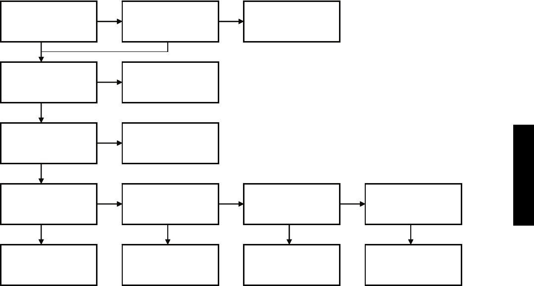
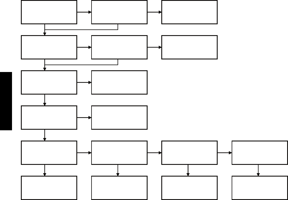
CHART 8 -- UNIT NOT RUNNING OPTIMALLY
Suction and head
equal?
Outdoor coil clean? Clean coil. Problem
persists?
Indoor filter clean? Clean filter. Problem
persists?
Check indoor fan
motor
Connect gauges to
unit. Pressures ok?
Replace indoor fan
motor.
Check compressor
Normal suction,
high head?
High head, high
suction?
Unit is overcharged.
Reclaim charge and
weigh in correct charge
High head, low
suction?
Yes
Yes
Yes
No
No No No
Problem solved
Problem solved
No No
No No
No
Yes
Yes
Yes
Yes
Yes Yes Yes
Check application
limits.
Non condensables
in sys. Pump down
and recharge unit
See note below*
* Restriction in system. Check capillary tube, check for moisture, and check for damage to liquid line between indoor and
outdoor units.
A08170
38/40MVC, MVQ
37
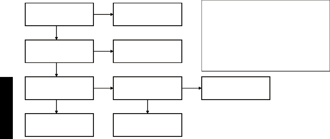
CHART 9 -- UNIT NOT RUNNING OPTIMALLY (HP IN HEATING)*
Visually check outdoor
Unit for ice blockage. **
Check reversing valve.
Go to flow chart #12
No
Yes
Yes
Check defrost sensor. Ok? No
Replace sensor
Check application limits.
Ok?
** Check for blockage on outdoor coil and drain pan. Are the holes in drain pans blocked?
No Beyond operating range
Yes
Yes
Check ambient conditions.
Prime icing?
Explain to customer
Visually check outdoor
Unit for ice blockage. **
Check reversing valve.
No
Yes
Yes
Check defrost sensor. Ok?
Go to flow chart #2
No
Replace sensor
Check application limits.
Ok?
* To supplement flow chart #8
es in drain pans blocked?
No Beyond operating range
Yes
Yes
Check ambient conditions.
Prime icing?
Explain to customer
A08184
38/40MVC, MVQ
38
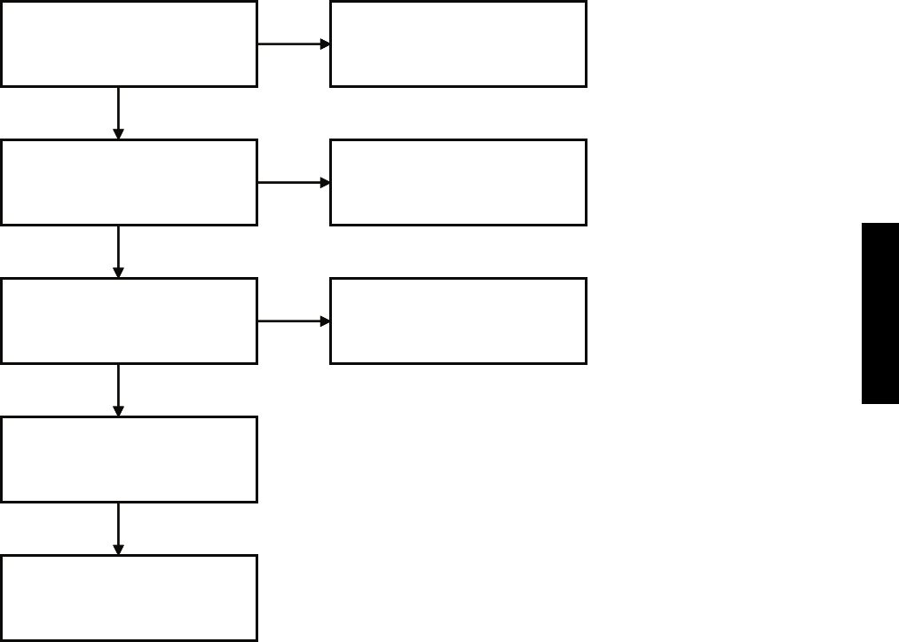
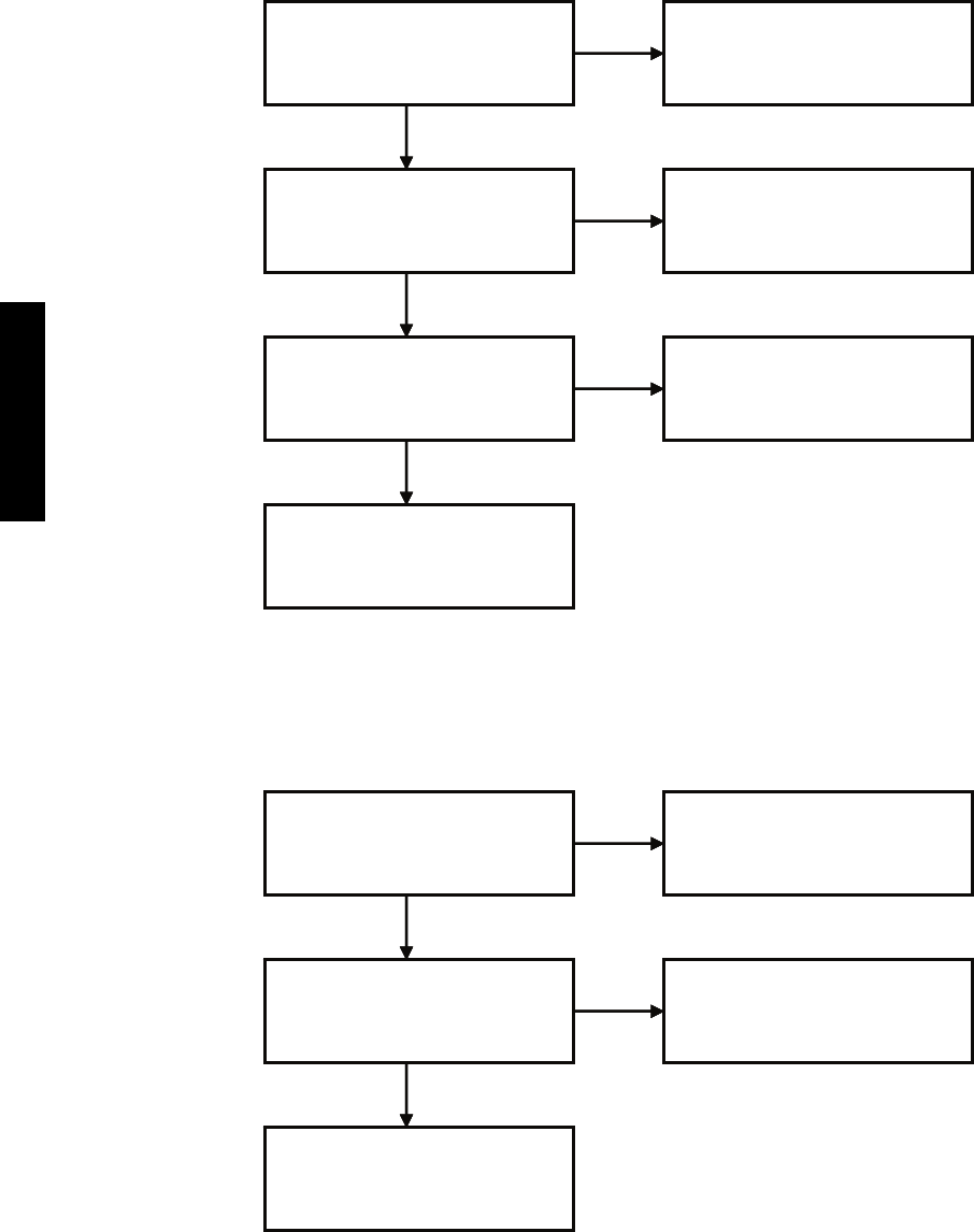
CHART 10 -- COMPRESSOR
Check contactor output on outdoor board if not done already.
If bad, replace outdoor board.
* For size 9 and 12k units contactor is on outdoor board.
Trace connections from
OD board. Connections
ok?
Check compressor
windings. Ok?
No fix connection
No
Yes
Check capacitor.
Capacitor ok?
Yes
Check contactor.*
Contactor ok?
No
Replace contactor
Yes
No Replace capacitor
No
Replace compressor
No
Compressor ok.
Trace connections from
OD board. Connections
ok?
Check compressor
windings. Ok?
No fix connection
No
Yes
Check capacitor.
Capacitor ok?
Yes
Check contactor.*
Contactor ok?
No
Replace contactor
Yes
No Replace capacitor
No
Replace compressor
No
Compressor ok.
A08171
38/40MVC, MVQ
39
CHART 11 -- OUTDOOR MOTOR
Trace connections from
OD board. Connections
ok?
Motor ok.
Fix connection
No
Yes
Yes
No
Replace capacitors
Yes
No
Replace motor
Check capacitor.
Capacitor ok?
Check motor windings.
Ok?
Visually confirm that fan
blades and outdoor coil
are not blocked.
Clear blockage
Yes
No
Trace connections from
OD board. Connections
ok?
Motor ok.
Fix connection
No
Yes
Yes
No
Replace capacitors
Yes
No
Replace motor
Check capacitor.
Capacitor ok?
Check motor windings.
Ok?
Visually confirm that fan
blades and outdoor coil
are not blocked.
Clear blockage
Yes
No
A08172
38/40MVC, MVQ
40
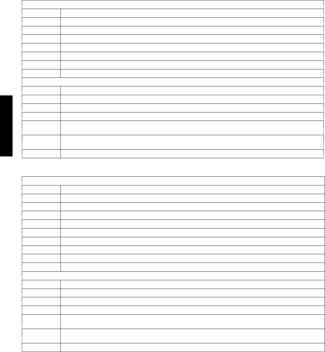
CHART 12 -- REVERSING VALVE
Check RV connection on
outdoor board. Ok?
Clean or repair the
connection
No
Yes
Yes
Check RV output on outdoor
board. Ok?
No
Replace outdoor board
Replace reversing valve.
Yes
Check RV solenoid. Ok? Replace solenoid
No
Check RV connection on
outdoor board. Ok?
Clean or repair the
connection
No
Yes
Yes
Check RV output on outdoor
board. Ok?
No
Replace outdoor board
Replace reversing valve.
Yes
Check RV solenoid. Ok? Replace solenoid
No
CHART 13 -- RECEIVER BOARD
Check wiring and
connection between
receiver and ID board. Ok?
Fix wiring or
connection
No
Yes
Replace remote control
Yes
Check input and output
on ID and receiver
boards. Ok?
No
Replace receiver board
Check wiring and
connection between
receiver and ID board. Ok?
Fix wiring or
connection
No
Yes
Replace remote control
Yes
Check input and output
on ID and receiver
boards. Ok?
No
Replace receiver board
A08173
38/40MVC, MVQ

41
APPENDIX
APPENDIX TABLE OF CONTENTS
DESCRIPTION NUMBER
Control Boards Input/Output tables for 53MVC009(12)------1 A1...................................................
Control Boards Input/Output tables for 53MVQ009(12)------1 A2...................................................
Control Boards Input/Output tables for 53MVC012------3 A3.......................................................
Control Boards Input/Output tables for 53MVQ012------3 A4......................................................
Control Boards Input/Output tables for 53MVC018------3 A5.......................................................
Temperature Sensor Values (Temperature vs. Resistance) A6.......................................................
Fuse Chart A7...........................................................................................
Indoor Unit Diagnostic Codes A8...........................................................................
Outdoor Unit Diagnostic Codes A9..........................................................................
38/40MVC, MVQ
42
A 1 -- 5 3 M V C 0 0 9 -- -- -- 1 / 5 3 M V C 0 1 2 -- -- -- 1
3 8 M V C 0 0 9 --- --- --- 1 / 3 8 M V C 0 1 2 --- --- --- 1 C O N T R O L B O A R D
CONNECTOR INPUT or OUTPUT VALUE
CN2 OUT: (Pin 1: Pulse 0 to 12 Volts DC) (Pin2: 35±2 Volts DC) (Pin 3: GND) (Pin 4: 13±4 Volts DC) all relative to Pin 3
CN3 OUT: Neutral
CN4 IN: Neutral
CN9 OUT: L 115 Volts AC
CN10 IN: L 115 Volts AC
P1 GND
P2 GND
4 0 M V C 0 0 9 --- --- --- 1 / 4 0 M V C 0 1 2 --- --- --- 1 C O N T R O L B O A R D
CONNECTOR INPUT or OUTPUT VALUE
CN1 I N : 0 --- 5 V o l t D C
CN2 I N : 0 --- 5 V o l t D C
CN3 Pulse drive output: 0--- 17 Volts DC(Pin 5: GND All other Pins are 0 to 17 Volt DC) All relative to Pin 5)
CN5 Power Output: (Pin 1: GND) (Pin 2: 5 Volts DC) Input: (Pin 3: Pulse 0 to 5 Volts DC) Output:(Pin 4~ Pin 10: Pulse 0 to 5
Volt DC) All relative to Pin 1
CN6 Out: (Pin 1: 35 Volt DC) ( Pin 2: Empty) (Pin 3: GND) (Pin 4: 5 Volt DC) (Pin 5: Pulse 0--- 5 Volt DC) IN: (Pin 6: Pulse 0 to 5
Volt DC) All relative to Pin 3
G1 IN: (Pin 1: Pulse 0 to 12 Volts DC) (Pin2: 35±2 Volts DC) (Pin 3: GND) (Pin 4: 13±4 Volts DC) all relative to Pin 3
A 2 -- 5 3 M V Q 0 0 9 -- -- -- 1 / 5 3 M V Q 0 1 2 -- -- -- 1
38MVQ009---1/38MVQ012--- --- ---1 CONTROL BOARD
CONNECTOR INPUT or OUTPUT VALUE
CN1 OUT: (Pin 1: GND, Pin 2: 5 Volts DC, Pin 3: Empty) IN: (Pin 4: 0 to 5 Volts DC) All relative to Pin 1
CN2 OUT: (Pin 1: Pulse 0 to 12 Volts DC) (Pin2: 35±2 Volts DC) (Pin 3: GND) (Pin 4: 13±4 Volts DC) all relative to Pin 3
CN3 OUT: Neutral
CN4 IN: Neutral
CN5 OUT: L 115 Volt AC
CN6 OUT: L 115 Volt AC
CN10 IN: L 115 Volt AC
P1 GND
P2 GND
40MVQ009---1/40MVQ012--- --- ---1 CONTROL BOARD
CONNECTOR INPUT or OUTPUT VALUE
CN1 I N : 0 --- 5 V o l t D C
CN2 I N : 0 --- 5 V o l t D C
CN3 Pulse drive output: 0--- 17 Volts DC(Pin 5: GND All other Pins are 0 to 17 Volt DC) All relative to Pin 5)
CN5 Power Output: (Pin 1: GND) (Pin 2: 5 Volts DC) Input: (Pin 3: Pulse 0 to 5 Volts DC) Output:(Pin 4~ Pin 10: Pulse 0 to 5
Volt DC) All relative to Pin 1
CN6 Out: (Pin 1: 35 Volt DC) ( Pin 2: Empty) (Pin 3: GND) (Pin 4: 5 Volt DC) (Pin 5: Pulse 0--- 5 Volt DC) IN: (Pin 6: Pulse 0 to 5
Volt DC) All relative to Pin 3
G1 IN: (Pin 1: Pulse 0 to 12 Volts DC) (Pin2: 35±2 Volts DC) (Pin 3: GND) (Pin 4: 13±4 Volts DC) all relative to Pin 3
38/40MVC, MVQ
43
A 3 -- 5 3 M V C 0 1 2 -- -- -- 3
3 8 M V C 0 1 2 --- --- --- 3 C O N T R O L B O A R D
CONNECTOR INPUT or OUTPUT VALUE
CN2 OUT: (Pin 1: Pulse 0 to 12 Volts DC) (Pin2: 35±2 Volts DC) (Pin 3: GND) (Pin 4: 13±4 Volts DC) all relative to Pin 3
CN3 OUT: L2 208/230 Volt AC
CN4 IN: L2 208/230 Volt AC
CN9 OUT: L1 208/230 Volt AC
CN10 IN: L1 208/230 Volt AC
P1 Ground
P2 Ground
4 0 M V C 0 1 2 --- --- --- 3 C O N T R O L B O A R D
CONNECTOR INPUT or OUTPUT VALUE
CN1 I N : 0 --- 5 V o l t D C
CN2 I N : 0 --- 5 V o l t D C
CN3 Pulse drive output: 0--- 17 Volts DC(Pin 5: GND All other Pins are 0 to 17 Volt DC) All relative to Pin 5)
CN5 Power Output: (Pin 1: GND) (Pin 2: 5 Volts DC) Input: (Pin 3: Pulse 0 to 5 Volts DC) Output:(Pin 4~ Pin 10: Pulse 0 to 5
Volt DC) All relative to Pin 1
CN6 Out: (Pin 1: 35 Volt DC) ( Pin 2: Empty) (Pin 3: GND) (Pin 4: 5 Volt DC) (Pin 5: Pulse 0--- 5 Volt DC) IN: (Pin 6: Pulse 0 to 5
Volt DC) All relative to Pin 3
G1 IN: (Pin 1: Pulse 0 to 12 Volts DC) (Pin2: 35±2 Volts DC) (Pin 3: GND) (Pin 4: 13±4 Volts DC) all relative to Pin 3
A 4 -- 5 3 M V Q 0 1 2 -- -- -- 3
3 8 M V Q 0 1 2 --- --- --- 3 C O N T R O L B O A R D
CONNECTOR INPUT or OUTPUT VALUE
CN1 OUT: (Pin 1: GND, Pin 2: 5 Volts DC, Pin 3: Empty) IN: (Pin 4: 0 to 5 Volts DC) All relative to Pin 1
CN2 OUT: (Pin 1: Pulse 0 to 12 Volts DC) (Pin2: 35±2 Volts DC) (Pin 3: GND) (Pin 4: 13±4 Volts DC) all relative to Pin 3
CN3 OUT: L2 208/230 Volt AC
CN4 IN: L2 208/230 Volt AC
CN5 OUT: L1 208/230 Volt AC
CN6 OUT: L1 208/230 Volt AC
CN10 IN: L1 208/230 Volt AC
P1 Ground
P2 Ground
4 0 M V Q 0 1 2 --- --- --- 3 C O N T R O L B O A R D
CONNECTOR INPUT or OUTPUT VALUE
CN1 I N : 0 --- 5 V o l t D C
CN2 I N : 0 --- 5 V o l t D C
CN3 Pulse drive output: 0--- 17 Volts DC(Pin 5: GND All other Pins are 0 to 17 Volt DC) All relative to Pin 5)
CN5 Power Output: (Pin 1: GND) (Pin 2: 5 Volts DC) Input: (Pin 3: Pulse 0 to 5 Volts DC) Output:(Pin 4~ Pin 10: Pulse 0 to 5
Volt DC) All relative to Pin 1
CN6 Out: (Pin 1: 35 Volt DC) ( Pin 2: Empty) (Pin 3: GND) (Pin 4: 5 Volt DC) (Pin 5: Pulse 0--- 5 Volt DC) IN: (Pin 6: Pulse 0 to 5
Volt DC) All relative to Pin 3
G1 IN: (Pin 1: Pulse 0 to 12 Volts DC) (Pin2: 35±2 Volts DC) (Pin 3: GND) (Pin 4: 13±4 Volts DC) all relative to Pin 3
38/40MVC, MVQ

44
A 5 -- 5 3 M V C 0 1 8 -- -- -- 3
3 8 M V C 0 1 8 --- --- --- 3 C O N T R O L B O A R D
CONNECTOR INPUT or OUTPUT VALUE
CN1 IN: 14.5±5V Volts AC
CN3 Pulse Signal 0 to 24 Volts DC (Relative to ground)
CN4 IN: L1 208/230 Volts AC
CN5 IN: L2 208/230 Volts AC
CN6 OUT: 208/230 Volts AC
CN8 OUT: 208/230 Volts AC
4 0 M V C 0 1 8 --- --- --- 3 C O N T R O L B O A R D
CONNECTOR INPUT or OUTPUT VALUE
CN1 IN:11.0±3VoltsAC(Pin1toPin2); 9.5±2VoltsAC(Pin3toPin4)
CN2 OUT: IFM Capacitor Terminal 1
CN4 OUT: IFM Capacitor Terminal 2
CN5 OUT: 208/230 Volts AC
CN6 OUT: 208/230 Volts AC (Pin 1 to Pin 2, Pin 1 to Pin 3, Pin 1 to Pin4)
CN7 IN: 0---5VoltDC(Notincluding0Vand5V)
CN8 IN: 0---5VoltDC(Notincluding0Vand5V)
CN9 OUT: (Pin 1: Ground, Pin 2: 5 Volts DC) IN: (Pin 1: Ground, Pin 3: 0 to 5 Volts DC) Pulse relative to Pin 1
CN10 OUT: (Pin 1: Ground, Pin 2 ~ Pin 5: 0 to 5 Volts DC) Pulse relative to Pin 1
CN11 OUT: (Pin 5: Ground, all other Pins are 0 to 17 Volts DC) Pulse relative to Pin 5
CN12 Two way signal, 0 to 24 Volts DC, Pulse relative to Ground
P1 IN: L1 208/230 Volts AC
P2 IN: L2 208/230 Volts AC
INDOOR UNIT DISPLAY BOARD
CONNECTOR INPUT or OUTPUT VALUE
CN1 IN: (Pin 1: Ground, Pin 2 ~ 5: 0 to 5 Volts DC) Pulse relative to Pin 1
CN2 IN: (Pin 1: Ground, Pin: 5 Volts DC) OUT: (Pin 3: 0 to 5 Volts DC) Pulse relative to Pin 1
38/40MVC, MVQ
45
A6 -- Characteristics of Temperature Sensor
Tem p. ° F/ ° C Resistance KΩTem p. ° F/° C Resistance KΩTem p. ° F/° C Resistance KΩ
14/--- 10 62.2756 62.6/17 14.6181 111.2/44 4.3874
15.8/--- 9 58.7079 64.4/18 13.918 113/45 4.2126
17.6/--- 80 56.3694 66.2/19 13.2631 114.8/46 4.0459
19.4/--- 7 52.2438 68/20 12.6431 116.6/47 3.8867
21.2/--- 6 49.3161 69.8/21 12.056 118.4/48 3.7348
23/--- 5 46.5725 71.6/22 11.5 120.2/49 3.5896
24.8/--- 4 44 73.4/23 10.9731 122/50 3.451
26.6/--- 3 41.5878 75.2/24 10.4736 123.8/51 3.3185
28.4/--- 2 39.8239 77/25 10 125.6/52 3.1918
30.2/--- 1 37.1988 78.8/26 9.5507 127.4/53 3.0707
32/0 35.2024 80.6/27 9.1245 129.2/54 2.959
33.8/1 33.3269 82.4/28 8.7198 131/55 2.8442
35.6/2 31.5635 84.2/29 8.3357 132.8/56 2.7382
37.4/3 29.9058 86/30 7.9708 134.6/57 2.6368
39.2/4 28.3459 87.8/31 7.6241 136.4/58 2.5397
41/5 26.8778 89.6/32 7.2946 138.2/59 2.4468
42.8/6 25.4954 91.4/33 6.9814 140/60 2.3577
44.6/7 24.1932 93.2/34 6.6835 141.8/61 2.2725
46.4/8 22.5662 95/35 6.4002 143.6/62 2.1907
48.2/9 21.8094 96.8/36 6.1306 145.4/63 2.1124
50/10 20.7184 98.6/37 5.8736 147.2/64 2.0373
51.8/11 19.6891 100.4/38 5.6296 149/65 1.9653
53.6/12 18.7177 102.2/39 5.3969 150.8/66 1.8963
55.4/13 17.8005 104/40 5.1752 152.6/67 1.83
57.2/14 16.9341 105.8/41 4.9639 154.4/68 1.7665
59/15 16.1156 107.6/42 4.7625 156.2/69 1.7055
60.8/16 15.3418 109.4/43 4.5705 158/70 1.6469
38/40MVC, MVQ
46
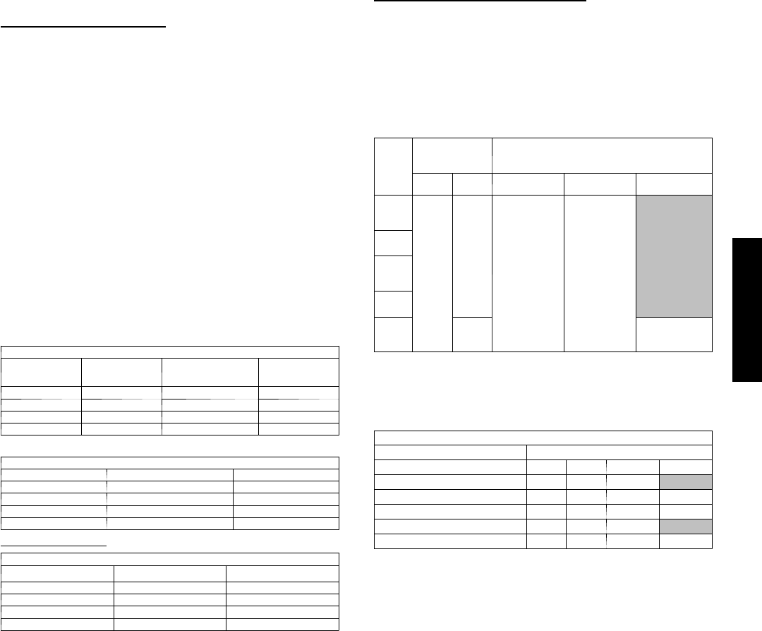
A7 -- Fuse Chart
Unit Size Fuse Rating (Amps/Volts)
Indoor Outdoor Outdoor
009 --- 3.15A/250V 2A/250V
012 --- 3.15A/250V 2A/250V
018 3.15A/250V 3.15A/250V ---
024 3.15A/250V 3.15A/250V ---
The 3.15A fuses protect the board against the indoor or outdoor fan motors.
The 2A fuses protect the board against a Class II circuit board failure.
A8 -- Indoor Unit Diagnostic Guides
9K & 12K Units
Operation
Lamp
Timer
Lamp Failure Mode Diagnostic
Chart
lXIndoor fan speed has been out of control for over 1 minute 1
lOn Indoor room temp. or evaporator sensor is open circuit or short circuited 2
XlCompressor over---current protection has been activated four times 3
On lEPROM error* ---
l l Indoor unit communication error (Illuminates simultaneously) 4
18K & 24K Units
Opera-
tion
Lamp
Timer
Lamp
Defrosting
Lamp
Auto
Lamp Failure Mode Diagnostic
Chart
l l l l Over--- current protection of the compressor occurs four times 3
XlX X Indoor room temp. sensor is open circuit or short circuited 2
lX X X Temp. sensor on indoor evaporator is open circuit or short circuited 2
X X lXTemp. sensor on outdoor condenser is open circuit or short circuited (not
cooling only modes) 2
X X l l Outdoor unit protects (outdoor temp. sensor, phase order, etc.) 5
XlXlEPROM error* ---
X X X lIndoor unit communication error 6
l=Flashing
X=Off
* = Replace Indoor Board
A07545a
A07544
A07546a
Model size 009 Model size 012 Model size 018--024*
Infrared signal receptor
OPERATION TIMER
PRE-DEF
AUTO
ECON
TIMER OPERATION
PRE-DEF
Infrared signal recepto
r
*PRE--DEF light will illuminate when the unit is running in FAN ONLY mode on Cooling Only units.
AUTO
TIMER
PRE.-DEF.
OPERATION
Fig. 37 – LED Display Panel
A9 -- Outdoor Unit Diagnostic Guides
Flashing
Times after 2
Second Off
Failure Mode Diagnostic
Chart
5Communication failure 4or6
2Condenser temperature sensor failure 2
1Other indoor failure –
If the unit is operating normally, the LED light on the outdoor board is lit continuously. If there is a failure, the LED light will flash a specific
number of times. Refer to the Outdoor Unit Diagnostic table above to determine failure.
Copyright 2012 Carrier Corp. S7310 W. Morris St. SIndianapolis, IN 46231
Manufacturer reserves the right to change, at any time, specifications and designs without notice and without obligations.
Catalog No.38---40MV---2SM
R e p l a c e s : 3 8 --- 4 0 M V --- 1 S M
Edition Date: 06/12
38/40MVC, MVQ
