393_Introduction_to_Operating_System_ _Mod_2 393 Introduction To Operating System Mod 2
393_Introduction_to_Operating_System_-_Mod_2 393_Introduction_to_Operating_System_-_Mod_2
User Manual: 393_Introduction_to_Operating_System_-_Mod_2
Open the PDF directly: View PDF ![]() .
.
Page Count: 28
110
SUBJECT:
SPECIAL
INSTRUCTIONS:
DATE:
May
20,
1966
8953
10566
Printed
in
U.
S.
A.
~
,
i~~~~":;--:-'
~_W~RE
BIJUEmlN
;~;~t;,,~
j_-,"~,-~~-:,-<::-:,-
" ,
__
,-
SERIES
200
INTRODUCTION TO
SERIES
200jOPERATING
SYSTEM-
MOD 2
General
Description
of
the
Series
200/0perating
System
-
Mod
2,
Third-Generation
Operating
System
for
Models
1200,
2200,
and
4200.
This
bulletin
introduces
the
functional
concepts,
benefits,
and
components
of
the
Series
200/
Opera-
ting
System
-
Mod
2.
This
prerequisite
publica-
tion
is
the
foundation
for
studying
the
Mod
2
Opera-
ting
System
programming
and
operating
facilities.
Appendix
A
is
a
publications
guide
for
further
study.
FILE
NO.
122.0005.
002J.
0-393
~'When
ordering
this
publication
please
specify
Title
and
Underscored
portion
of
the
File
Number.
Section
I
Section
II
Section
III
TABLE
OF
CONTENTS
Introduction
....................•.•..•.................•.•
The
Operating
System
Approach
........................•
Operating
System
Design
.....•..........•............
Stacked-Job
Processing
and
Program
Modularity
.•..•..
Benefits
of
the
Mod
2
Operating
System
...............•..
Ease
of
Programming
.•.•...•.................••....
Ease
of
Operating
••...••••..•...•..•..•.•..•.•.•.•••
Ease
of
Maintenance
and
Expansion
...........•.......
Over-all
Benefits
...•.••.•.••.•....••...•.••••••.•••
Functions
of
the
Mod
2
Operating
System
..........•.......•.
Job
Control
..••.••••.••.•.•...•.•.•.......•....•..•.•.
Page
1-1
1-1
1-1
1-2
1-3
1-3
1-4
1-5
1-5
2-1
2-1
Communication
and
Real-Time
Control................
2-1
Multiprogramming
Control.
. . . . . . . . . . . . . . . . . . . . . . . . • .
2-1
Inte
rrupt
Control.
. . . . . . • . . • • • . . . . . . . . • • • • . . . • • • • . . . • 2 - 2
Data
Control.
. • . • . . . . . • . . . . . . . • . . . • . . . . . . . . . . .
.•
. • . • . .
2-2
File
Access.
. . . . . . . . . • . . . . . • . . . . . . . . . . . . . . . . . . . . . . •
2-2
File·
Control.
. • . . . . . . . . . . . . . . . . . . . . . . . . . . . . . . . . . . . . . 2 - 3
Program
Preparation
and
Maintenance.
• . . . . . . . . .
•.
• • . . • .
2-3
Other
Functions.
. . . . . . . . .
..
. . . . . . . . . . . . . . . . . • . . . . . . . . .
2-4
Summary
of
System
Files.
• . . . . . • . . . . . . . . . • • • . . . . . • . • . . .
2-4
System
Operating
File
(SOF)
. . . . . . . . . . . . . . . . . . . . . . . . .
2-4
Go
File
(MGO)
. . . . . . . . . . . . . . . . . . . . . . . . . . . . . . . . . . . • . .
2-4
Job
File
(MJB)
..•..........•...................•...
2-4
Standard
Input
Unit
(SIU)
. . . . . . . . . . . . . . . . . . . . . . . . . . . . .
2-4
Standard
Print
Unit
(SPR)
. • . . . . . . . . . • . . . . • . . . . • . . • . . .
2-4
Standard
Punch
Unit
(SPU)
. . . . . . . • . . . . . . . . . . . . • . • •
••
•
2-4
Master
History
File
(MHF).
. • . . . . . . • . . . . . . . . .
•.
. . . . . .
2-4
Components
of
the
Mod
2
Operating
System
..........•.......
3-1
Supervisory
Components.
• . . . . . • . . . . . . . . • . . • . . . . • . • • . • • .
3-1
Resident
Monitor
J..........
...•.••.•.......•....••.
3-1
Transitional
Monitor
J...............................
3-2
Input/Output-File
Controller
J........................
3-2
Processing
Components........
..•..•..
..•..
.......•...
3-3
Language
Processors........................
......•.
3-3
Assembler
J.............
...••.•..............•.•
3-3
COBOL
Compiler
J . • . . . . . . . . . . . . . . . • . • . . . . . • . . . • •
3-4
Fortran
Compiler
J.
• • . . . • . . . . . . . . • . . . . • . . • . . . . . . •
3-4
Easytran
J
Transition
Program.
.
..
. . . • . . • . . . . . . . • •
3-5
Copyright
1966
Honeywell
Inc.
Electronic
Data
Processing
Division
Wellesley
Hills,
Massachusetts
02181
ii
~
..
Section
III
(cont)
Section
IV
Appendix
A
Figure
1-1.
Figure
A-I.
TABLE
OF
CONTENTS
(cont)
Linkage
Loader
J
........•.•..•.................•..•
System
Maintenance
J
....••....•..............•.•.•.
Tape
Sort
J
.••...•..•....•..•••...••..•..•.••••..•.
Mass
Storage
Sort
J
.••••.••••.••••..........•••.•••
Utility
Components
.•..•.•.......•..•.••..•.•.••••••
Input/Output
Editor
J
••••••....••••....•.•..•••.••
Storage
Print
J
..............•............•.••.••
Tape
Print
J
...............•..•.•.....•.••.•.••.
Minimum
Equipment
Requirements
•.........••...••.•••••.
Operating
System
-
Mod
2
Publications
.•......•••......•.••
LIST
OF
ILLUSTRATIONS
Turnaround
Times
for
Batched-Job
and
Stacked-Job
Page
3-6
3-6
3-7
3-7
3-8
3-8
3-8
3-8
4-1
A-I
Processing.
•
••
• . . • . • . . . . • . . • . • • • • . • • . . . . . . . . . • . • . • • . . •
1-3
Mod
2
Operating
System
Publications
Plan
...........•....••
A-2
iii
SECTION
I
INTRODUCTION
THE
OPERATING
SYSTEM
APPROACH
An
operating
system
is
an
integrated
set
of
interdependent
programs
providing
the
most
efficient
means
for
program
development
and
operation.
As
the
name
implies,
operating
sys-
tems
have
evolved
from
the
essential
need
to
replace
the
human
computer
operator
with
a
stored
program.
Human
intervention
wastes
a
tremendous
amount
of
processing
time
due
to
the
dis-
parity
in
operating
speeds
between
the
hardware
and
its
user.
The
first
objective
for
a
pro-
grammed
computer
operator
is
to
eliminate
human
operations
between
successive
program
ex-
ecutions.
Transition
between
programs
involves
clerical
duties
such
as
collecting
the
output
pro-
duced
by
the
previous
program,
submitting
the
next
group
of
input
data
for
proces
sing,
locating
the
next
program,
and
loading
it
into
memory.
Operating
System
Design
The
embryo,
and
still
the
basic
element,
of
today's
operating
systems
is
a
programmed
job
scheduler,
or
monitor,
which
automates
job-to-job
transition.
This
routine
resides
perma-
nently
in
core
storage
and
responds
to
control
specifications
which
determine
the
sequence
of
programs
to
be
executed
and
the
necessary
peripheral
equipment
assignments.
Merely
by
limit-
ing
the
setup
functions
of
a
human
operator,
even
such
primitive
operating
systems
can
effec-
tively
reduce
the
idle
time
between
program
runs.
A
second
source
of
wasted
processing
time
is
console
debugging.
Therefore,
primitive
operating
systems
are
augmented
by
standard
dynamic
dumping
routines
for
use
by
all
object
programs.
Entire
batches
of
unrelated
programs
can
then
be
executed
in
succession,
removing
both
programmer
and
operator
from
the
hardware
interface.
The
logical
extension
of
common
debugging
facilities
is
common
input/output
routines
for
all
programs.
By
placing
centralized
input/output
routines
in
core
storage
with
the
resident
monitor,
one
approxjmation
of
a
modern
operating
system
is
developed.
The
effect
of
a
resident
monitor
plus
common
input/output
control
and
debugging
facilities
is
standardization
of
both
programming
and
operating
procedures.
The
programmer
and
the
operator
are
required
to
communicate
with
the
operating
system,
rather
than
with
the
computer
itself.
A
common
set
of
operating
procedures
is
superimposed
on
all
programs
running
under
control
of
the
operating
system.
Independent
programs
use
common
routines
and
initiate
input/
output
operations
through
logical
directions
issued
to
the
centralized
input/output
control
system.
1-1
-
Stacked-Job
Processing
and
Program
Modularity
One
result
of
this
standardization
is
the
incorporation
of
the
language
processors
into
the
operating
system,
which
introduces
two
powerful
and
fundamental
concepts;
stacked-job
process-
ing
and
modular
program
structure.
Stacked-job
processing
is
a
refinement
of
the
earlier
batched-job
approach.
A
job
is
a
collection
of
related
programs.
Under
batched-job
processing,
a
single
processing
function,
e.
g.,
compilation,
is
applied
to
all
jobs
in
the
batch.
While
a
group
of
jobs
may
be
compiled
in
succession
and
then
executed
in
succession,
program
generation
is
divorced
from
the
execution
of
a
batch
of
pregenerated
programs.
Under
stacked-job
processing,
any
number
of
processing
functions
such
as
compilation,
maintenance,
and
execution
may
be
successively
applied
to
the
same
job.
Thus,
each
job
in
the
input
stack
is
processed
to
completion
before
the
next
job
is
accepted.
In
batched-job
processing,
the
elapsed
time
between
the
submission
of
a
job
and
re-
ceipt
of
results
(turnaround
time)
is
equal
to
the
total
processing
time
for
the
entire
batch
which
includes
the
job.
In
contrast,
stacked-job
processing
dramatically
reduces
turnaround
time
for
a
given
job
by
completely
processing
each
job
before
the
next.
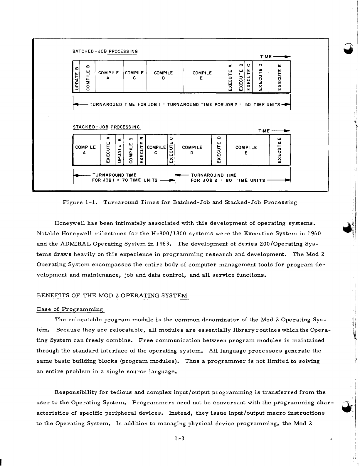
As
a
simple
example,
consider
the
two
jobs
described
below.
Turnaround
times
for
the
two
jobs
are
illustrated
in
Figure
1-1
for
both
a
batched-job
and
a
stacked-job
situation.
Job
1
Job
2
Compile
program
A •
••
20
time
units
Compile
program
D
•••
25
time
units
Update
program
B.
... 5
time
units
Compile
program
E •
••
30
time
units
Compile
program
B •
••
10
time
units
Execute
program
D
•••
10
time
units
Compile
program
C •
••
15
time
units
Execute
program
E
•••
15
time
units
Execute
program
A
•••
10
time
units
Execute
program
B 5
time
units
Execute
program
C 5
time
units
Program
development
under
the
operating
system
achieves
unprecedented
flexibility
with
the
introduction
of
the
program
module
concept.
A
program
module
is
the
basic
program
unit
in
the
operating
system.
Each
module
is
created
independently.
Modules
are
relocatable
and
can
be
combined
with
other
modules
to
fashion
a
variety
of
complete
programs.
These,
in
turn,
may
be
built
to
run
anywhere
in
core
storage
using
any
combination
of
modules.
Also,
all
language
processors
in
the
operating
system
generate
the
identical
type
of
relocatable
modules.
Hence,
a
complete
program
may
be
subdivided
into
program
modules
on
the
basis
of
physical
size,
functional
breakdown,
or
the
nature
of
the
source
language
best
suited
for
solving
a
portion
of
the
total
problem.
1-2
I
BATCHED -JOB
PROCESS
I
NG
TIME---..
III
<I:
III
U 0
I.IJ
III
I.IJ I.IJ
I.IJ
I.IJ
COMPILE COMPILE COMPILE COMPILE
I.IJ
I.IJ
I.IJ
-I
l-
I-
l-
I-
l-
I-
n:
A C 0 E
::> ::> ::> ::>
::>
<I:
u U u u u
0
::!:
I.IJ
I.IJ
I.IJ I.IJ I.IJ
a.
0 x x x x X
::>
u
I.IJ I.IJ
I.IJ I.IJ
I.IJ
I--
TURNAROUND
TIME
FOR
JOB I = TURNAROUND
TIME
FOR JOB 2 = 150
TIME
UNITS
~
STACKED
-JOB PROCESSING
TlME--.~·
<I:
III
III III
U 0
I.IJ
I.IJ I.IJ I.IJ
I.IJ I.IJ
...
COMPILE
I-
I.IJ
:::!
I-
COMPILE 5 COMPILE
I-
COMP
ILE
I-
::>
I-
::> ::>
:J
A u
<I:
a. u C u 0 u E u
I.IJ
0
::!:
I.IJ
I.IJ
I.IJ I.IJ
X a. 0 X X X X
I.IJ
::>
U
I.IJ
I.IJ
I.IJ I.IJ
I.--
TURNAROUND TIME
l-.-
TURNAROU
NO
TIME I
I -
FOR
JOB I =
70
TIME
UNITS
-----...j
-
FOR
JOB
2 =
80
TIME
UNITS
------..J
Figure
1-1.
Turnaround
Times
for
Batched-Job
and
Stacked-Job
Processing
Honeywell
has
been
intimately
associated
with
this
development
of
operating
systems.
Notable
Honeywell
milestones
for
the
H-800/1800
systems
were
the
Executive
System
in
1960
and
the
ADMIRAL
Operating
System
in
1963.
The
development
of
Series
200/0perating
Sys-
tems
draws
heavily
on
this
experience
in
programming
research
and
development.
The
Mod
2
Operating
System
encompasses
the
entire
body
of
computer
management
tools
for
program
de-
velopment
and
maintenance,
job
and
data
control,
and
all
service
functions.
BENEFITS
OF
THE
MOD
2
OPERATING
SYSTEM
Ease
of
Programming
The
relocatable
program
module
is
the
common
denominator
of
the
Mod
2
Operating
Sys-
tem.
Because
they
are
relocatable,
all
modules
are
essentially
library
routines
which
the
Opera-
ting
System
can
freely
combine.
Free
communication
between
program
modules
is
maintained
through
the
standard
interface
of
the
operating
system.
All
language
processors
generate
the
same
basic
building
blocks
(program
modules).
Thus
a
programmer
is
not
limited
to
solving
an
entire
problem
in
a
single
source
language.
Responsibility
for
tedious
and
complex
input/output
programming
is
transferred
from
the
user
to
the
Operating
System.
Programmers
need
not
be
conversant
with
the
programming
char-
acteristics
of
specific
peripheral
devices.
Instead,
they
issue
input/output
macro
instructions
to
the
Operating
System.
In
addition
to
managing
physical
device
programming,
the
Mod
2
1-3
!
I
•
Operating
System
automatically
frees
the
user
from
allocating
buffers,
checking
file
labels,
blocking
and
unblocking
records,
and
error-checking
data
transfer
operations.
Also,
the
Opera-
ting
System
ensures
optimal
use
of
the
system
facilities
by
maximizing
the
simultaneity
of
data
flow
and
internal
processing,
a
capability
which
is
inherent
in
Series
200
hardware.
Managing
the
flow
of
data
to
and
from
peripheral
devices
is
just
part
of
the
device
inde-
pendence
provided
by
the
data
control
functions
of
the
Mod
2
Operating
System.
The
Operating
System
also
manages
the
logical
data
files
themselves.
Programmers
designate
both
data
files
and
associated
peripheral
devices
by
symbolic
names.
The
names
and
properties
of
each
data
file
are
indexed
in
a
symbolic
catalog
within
the
Operating
System.
Programmers
may
request
data
files
by
using
only
their
symbolic
names.
The
mechanics
of
locating
and
retrieving
data
files
are
the
responsibility
of
the
Operating
System.
The
Operating
System
also
controls
space
allocation
and
formatting
on
mass
storage
devices.
Finally,
the
standardized
and
automatic
debugging
facilities
of
the
Mod
2
Operating
System,
coupled
with
the
brief
turnaround
time
per
job,
enhance
the
ease
and
efficiency
of
program
check-
out
•
.,
Ease
of
Operating
-w
A
single
set
of
operating
procedures
is
followed
for
user-written
programs
and
components
of
the
Operating
System.
Operators
do
not
have
to
cope
with
the
peculiarities
of
every
program,
a
fact
which
simplifies
operator
training
and
increases
the
reliability
of
machine
room
operation.
In
the
same
fashion,
man/machine
communication
is
reduced
to
a
standard
dialogue
between
the
operator
and
the
Operating
System.
Most
functions
required
for
automatic
job-to-job
transition,
like
finding
and
loading
the
next
program
and
assigning
tapes,
have
been
absorbed
by
the
Mod
2
Operating
System.
Those
manual
procedures
which
could
not
be
programmed
into
the
Operating
System,
like
mounting
tape
reels,
are
performed
by
the
operator
according
to
complete
instruc-
tions
issued
by
the
Operating
System.
In
addition
to
automating
job-to-job
transition,
the
Operating
System
also
administers
in-
ternal
hardware
facilities,
such
as
the
interrupt
system
and
storage
protection.
Thus,
machine
management
is
placed
under
control
of
the
Operating
System,
minimizing
and
simplifying
the
role
of
the
operator.
Standardized
operating
procedures
enhance
the
total
flexibility
of
operation.
Under
the
Mod
2
Operating
System,
the
mode
of
operation
is
sensitive
to
the
requirements
of
each
application.
Stacked-job
processing,
batched-job
processing,
and
real-time
processing
are
handled
with
equal
facility.
1-4
Ease
of
Maintenance
and
Expansion
Both
user
programs
and
Honeywell-supplied
components
of
the
Mod
2
Operating
System
are
easily
modified
because
of
their
modular
structure.
A
series
of
complex,
time-consuming
pro-
grams
is
required
initially
to
generate
some
operating
systems.
However,
the
same
single-phase
component
of
the
Mod
2
Operating
System
which
is
used
to
update
the
system
files
is
also
used
to
create
a
working
version
of
the
Operating
System
itself.
System
generation
is
both
selective
and
efficient.
A
personalized
operating
system
is
tailored
to
each
installation
by
incorporating
only
those
system
modules
required
by
the
user.
System
generation
is
rapid
because
file-access
time
in
the
Mod
2
Operating
System
is
optimized
by
efficient
blocking
and
by
use
of
the
read-backward
feature
of
Honeywell
magnetic
tape
units.
A
typical
business-oriented
version
of
the
Mod
2
Operating
System
is
generated
in
less
than
15
minutes.
System
programs
and
user
programs
are
easily
updated
without
recompiling.
For
example,
additional
modules
may
be
added
to
user
pro-
grams
to
take
advantage
of
newly
acquired
hardware.
Additional
module
s
may
be
added
to
the
Operating
System
to
provide
further
processing
capabilities
for
growing
applications.
Also,
the
Operating
System
may
be
expanded
by
the
inclusion
of
user-written
components.
Over-all
Benefits
From
the
perspective
of
the
data
processing
manager,
the
convenience
and
modularity
at
each
level
of
the
Mod
2
Operating
System
are
reflected
and
amplified
in
the
over-all
efficiency
.t'
and
reliability
of
the
hardware/
software
complex.
Standardized
programming
and
operating
pro-
cedures
provide
the
most
efficient
path
from
initial
formulation
of
a
programming
problem
to
final
utilization
of
the
solution.
Use
of
the
Mod
2
Operating
System
increases
throughput
as
a
result
of
total
hardware
utilization
and
reduced
idle
time.
At
the
same
time,
the
stacked-job
capability
provides
complete
software
service
with
minimal
turnaround
time
to
all
users
of
the
Operating
System.
The
flexible
framework
of
the
Mod
2
Operating
System
supports
growth
into
applications
such
as
total
information
and
real-time
systems.
The
magnitude
and
complexity
of
the
functions
performed
by
the
Mod
2
Operating
System
simplify
the
jobs
of
programmer,
opera--
tor,
and
manager.
By
furthering
the
independence
of
these
personnel
from
the
computer,
the
Mod
2
Operating
System
allows
them
to
use
it
more
effectively.
- I
~I
I
I
1-5
SECTION
II
FUNCTIONS
OF
THE
MOD
2
OPERATING
SYSTEM
Mod
2
Operating
System
functions
are
described
under
the
headings
of
job
control,
data
control,
program
preparation
and
maintenance,
and
other
functions.
JOB
CONTROL
Before
performing
other
job
control
functions,
the
Mod
2
Operating
System
reads
and
analyzes
system
control
cards.
A
second
job
control
function
is
loading
programs
into
memory,
including
dependent
programs
and any
nonresident
portions
of
the
Operating
System
required
to
carry
out
the
control
card
requests.
Peripheral
devices
are
also
assigned
on
the
basis
of
con-
trol
card
specifications.
After
loading
each
program
into
memory,
the
Operating
System
performs
its
monitoring
function,
which
is
the
crux
of
job
control.
Monitoring
consists
of
controlling
the
internal
seq-
uencing
of
dependent
programs,
i.
e.,
all
programs
executed
under
control
of
the
Mod
2
Opera-
W
ting
System.
At
the
proper
instant
in
time,
control
is
delegated
to
a
dependent
program
or
re-
trieved
from
it.
Another
job
control
function
is
communication
with
the
operator,
advising
him
of
the
status
of
processing
and
requesting
necessary
operator
actions.
Communication
and
Real-Time
Control
Monitoring
in
a
communication
environment
involves
the
control
of
message
flow
to
and
from
the
computer
and
message
processing
within
the
computer.
The
appropriate
dependent
programs
which
process
communication
data
are
located,
loaded,
and
entered
at
the
proper
point.
During
communication
processing,
the
status
of
communication
lines
and
buffers
is
constantly
monitored,
and
control
is
switched
so
that
supervisory,
input/
output,
and
message
processing
functions
are
performed
as
required.
Communication
monitoring
also
includes
the
function
of
preventing
memory
violations
by
inc
oming
data.
Multipr
ogr
amming
C
ontr
01
Monitoring
in
a
multiprogramming
environment
consists
of
supervising
the
concurrent
exe-
cution
of
two
programs.
One
program
is
normally
peripherally
limited
and
is
executed
in
upper
memory.
The
second
program
runs
in
lower
memory
during
the
peripheral
cycles
of
the
upper-
memory
program.
Multiprogramming
monitoring
functions
include
detecting
the
beginning
and
2-1
end
of
input/
output
operations,
switching
the
assignment
of
processor
cycles,
and
maintaining
the
integrity
of
each
program
while
the
other
program
is
active.
Memory
protection
must
often
be
enforced,
especially
when
the
lower-memory
program
is
undergoing
checkout.
Interrupt
Control
Monitoring
in
all
operating
environments,
including
communication
and
multiprogramming,
may
entail
handling
hardware
interrupts.
In
an
interrupt
situation,
registers
are
stored
and
re-
stored,
control
is
passed
to
the
proper
routine,
and
area
of
memory
are
protected
if
necessary.
DATA
CONTROL
Data
control
in
the
Mod
2
Operating
System
encompasses
all
functions
related
to
the
creation
and
maintenance
of
the
data
base.
The
data
base
of
the
Mod
2
Operating
System
is
the
entire
collection
of
information
which
enters
or
leaves
the
computer
main
memory
at
any
time.
System
programs,
user
programs,
execution
data,
and
groups
of
control
information
are
equiva-
lent
members
of
the
data
base.
The
facilities
available
under
data
control
provide
efficient
storage,
flow,
and
retrieval
of
all
data
in
the
system.
These
facilities
include
two
functions:
file
access
and
file
control.
File
Access
The
principal
file
access
function
of
the
Mod
2
Operating
System
is
the
physical
exchange
of
data
between
main
memory
and
auxiliary
storage
or
terminal
equipment.
Complete
flexibility
is
provided
for
the
transfer
of
data
to
and
from
unit
record,
magnetic
tape,
mass
storage,
and
communication
equipment.
Several
different
access
methods
are
available.
1.
Sequential
access.
Physical
or
logical
records
are
stored
or
retrieved
serially.
Data
access
may
be
initiated
on
demand
by
a
dependent
program
or
on
an
anticipatory
basis
by
the
Operating
System.
2.
3.
Direct
access.
Physical
or
logical
records
are
stored
or
retrieved
ran-
domly.
The
programmer
specifies
an
actual
physical
address,
the
rela-
tive
position
of
the
record
in
the
file,
or
the
address
at
which
a
search
for
key
match
is
to
begin
(if
the
records
contain
identifying
keys).
This
access
method
also
automatically
controls
the
allocation
of
storage
space
for
mass
storage
files.
Partitioned
access.
In
the
partitioned
access
method,
sequential
informa-
tion
is
interspersed
with
special
records
containing
keys
and
other
data.
The
information
contained
in
these
special
records
is
supplied
by
both
the
user
and
the
Operating
System.
The
partitioned
access
method
is
well
suited
for
the
efficient
storage
and
retrieval
of
relatively
short
strings
of
sequential
records.
4.
Controlled
sequential
access.
This
access
method
uses
a
multilevel
indexing
scheme
which
optimizes
space
utilization
and
data
access
time.
Physical
or
logical
records
are
stored
or
retrieved
either
in
a
logical
sequence
defined
by
a
key
field
or
randomly
by
an
individual
key.
2-2
5.
Communication
access.
The
Mod
2
Operating
System
automatically
sends
and
receives
messages
to
and
from
remote
terminals.
Incoming
messages
are
automatically
placed
in
an
input
queue.
Outgoing
messages
are
auto-
matically
taken
from
an
output
queue.
Dependent
programs
treat
the
queues
like
peripheral
devices.
Physical
or
logical
communication
rec-
ords
are
stored
or
retrieved
from
the
queues
in
a
sequential
fashion
similar
to
the
sequential
access
method.
The
other
file
access
functions
are
linked
with
the
data
transfer
function.
These
other
functions
are
automatic
error
detection
and
correction,
automatic
data
buffering,
automatic
data
blocking
and
unblocking,
dynamic
scheduling
of
input/
output
facilities,
and
overlapping
of
processing
with
input/
output
operations.
File
Control
The
file
control
function
of
the
Mod
2
Operating
System
includes
management
of
logical
data
files
at
a
level
which
is
independent
of
the
physical
characteristics
of
the
files
and
their
storage
devices.
The
Operating
System
automatically
allocates
and
partitions
file
storage
space,
providing
efficient
use
of
mass
storage
equipment.
Mass
storage
data
is
automatically
format-
ted
for
access
by
the
methods
described
above.
Storage
allocation
is
complemented
by
auto-
matic
file
protection.
All
files
are
assigned
symbolic
names,
and
the
Operating
System
maintains
a
symbolic
file
catalog.
The
catalog
is
constructed
with
several
qualifying
levels,
so
that
each
file
is
categorized
by
a
symbolic
description
of
its
functions.
Files
may
be
requested
by
means
of
these
symbolic
descriptions,
and
the
catalog
provides
the
unique
location
from
which
the
Opera-
ting
System
retrieves
each
file.
PROGRAM
PREPARATION
AND
MAINTENANCE
The
most
familiar
program
preparation
function
of
the
Mod
2
Operating
System
is
language
processing.
Programs
written
in
compiler
or
assembly
source
language
are
translated
to
pro-
gram
modules
in
relocatable
machine
language.
It
is
worth
noting
again
that
all
relocatable
program
modules
are
identical,
regardless
of
their
original
source
language.
The
second
program
preparation
function
consists
of
building
a
complete
program
by
selecting
specified
program
modules,
providing
linkages
between
the
modules,
and
assigning
absolute
memory
addresses
to
the
relocatable
machine
code.
The
program
maintenance
functions
include
adding
and
deleting
modules
from
all
system
files
and
correcting
lines
within
specified
modules.
Maintenance
may
be
carried
out
at
the
source-language,
relocatable-code,
or
absolute-code
level.
The
same
maintenance
functions
are
applied
to
both
system
and
user
programs.
Thus
program
maintenance
includes
creating
2-3
and
updating
both
the
systeITl
prograITl
and
user
prograITl
files,
as
well
as
incorporating
user-
written
ITlodules
into
the
Mod
2
Operating
SysteITl.
OTHER
FUNCTIONS
The
Mod
2
Operating
SysteITl
provides
autoITlatic
debugging
facilities
such
as
dynaITlic
core
and
tape
dUITlps.
The
Operating
SysteITl
data
editing
and
transcription
functions
include
sorting
and
ITlerging
data
in
ITlagnetic
tape
and
ITlass
storage
files,
and
perforITling
ITledia-conversion
operations.
SUMMAR
Y
OF
SYSTEM
FILES
SysteITl
Operating
File
(SOF)
This
file
contains
ITlodules
in
absolute
forITlat,
including
all
prograITls
of
the
Mod
2
Oper-
ating
SysteITl.
It
ITlay
also
contain
libraries
of
ITlodules
in
relocatable
ITlachine
language
and
sYITlbolic
source
language.
The
file
ITlay
exist
on
tape
or
ITlass
storage.
Go
File
(MGO)
This
file
contains
the
output
of
the
language
processors,
in
the
forITl
of
relocatable
ITla-
chine-language
ITlodules.
It
ITlay
exist
on
tape
or
ITlass
storage.
Job
File
(MJB)
This
file
contains
executable
prograITls.
The
job
file
is
created
as
a
result
of
linking
and
assigning
a~solute
addresses
to
relocatable
prograITl
ITlodules
residing
on
the
MGO,
standard
input
unit
(SIU),
or
relocatable
library
of
the
SOF.
This
file
ITlay
exist
on
tape
or
ITlass
storage.
Standard
Input
Unit
(SIU)
A
card
file,
or
optionally
a
ITlagnetic
tape
file,
the
SIU
is
the
source
of
control
inforITlation
for
the
Operating
SysteITl.
The
SIU
ITlay
also
supply
the
Operating
SysteITl
with
source-language
prograITls,
execution
data,
and
prograITl
ITlodules
in
relocatable
ITlachine
language.
Standard
Print
Unit
(SPR)
This
file
is
a
possible
destination
for
output
of
the
Mod
2
Operating
SysteITl.
It
ITlay
be
produced
on
a
printer
or,
optionally,
on
ITlagnetic
tape.
Standard
Punch
Unit
(SPU)
This
file
is
another
possible
destination
for
Operating
SysteITl
output.
It
ITlay
be
produced
on
a
card
punch
or,
optionally,
on
ITlagnetic
tape.
Master
History
File
(MHF)
This
is
a
Honeywell-
supplied
tape
file
containing
all
eleITlents
of
the
Mod
2
Operating
SysteITl
in
the
forITl
of
source-language
ITlodules.
2-4
.
I
I
•
SECTION
ITI
COMPONENTS
OF
THE
MOD
2
OPERATING
SYSTEM
The
Mod
2
Operating
System
comprises
supervisory
components
and
processing
com-
ponents.
The
supervisory
components
are
the
Resident
Monitor
J,
Transitional
Monitor
J,
and
Input/Output
(I/O)
-
File
Controller
J.
The
processing
components
include
the
language
pro-
cessors,
Linkage
Loader
J,
System
Maintenance
J,
utility
programs,
and
tape
and
mass
storage
sort/merge
programs.
The
supervisory
components
handle
program
control,
communication,
and
data
transfer
operations
which
are
essential
for
the
execution
of
all
other
programs.
Hence,
the
processing
components,
like
user-written
programs,
are
dependent
programs.
During
Mod
2
operation,
the
Resident
Monitor
and
part
of
the
I/O-File
Controller
reside
permanently
in
core
storage
and
provide
the
interface
through
which
all
dependent
programs
are
loaded
and
executed.
As
mentioned,
user-written
processing
programs
may
be
integrated
into
the
Mod
2
Opera-
ting
System
as
easily
as
Honeywell-supplied
programs.
In
addition,
Honeywell-supplied
com-
.
ponents
have
own-coding
provisions
for
the
inclusion
of
user-written
modifications.
SUPERVISOR
Y
COMPONENTS
Resident
Monitor
J
Resident
Monitor
J
is
the
nerve
center
of
the
Mod
2
Operating
System.
It
remains
in
mem-
ory
throughout
Mod
2
operation.
To
expedite
processing
of
the
job
stream,
the
Resident
Monitor
employs
a
temporary
nonresident
assistant,
Transitional
Monitor
J.
The
Resident
Monitor
reads
system
control
cards,
on
which
the
user
schedules
all
processing
under
the
Mod
2
Operating
Sys-
tem.
Then
the
Resident
Monitor
loads
the
Transitional
Monitor
from
the
SOF.
As
explained
be-
low,
one
of
the
functions
of
the
Transitional
Monitor
is
to
analyze
the
control
cards
and
advise
the
Resident
Monitor
of
required
processing
operations.
Then
the
Resident
Monitor
loads
speci-
fied
absolute
programs
into
memory
form
the
Job
File
or
the
SOF.
After
loading,
the
dependent
programs
are
started
and
executed
under
control
of
Resident
Monitor.
In
a
multiprogramming
or
communication
environment,
the
Resident
Monitor,
acting
on
interrupt
signals
and
program
demands,
switches
control
to
the
appropriate
dependent
pro-
gram.
At
the
end
of
a
program
execution,
the
Resident
Monitor
reclaims
control
from
the
de-
pendent
program,
ascertains
whether
or
not
the
program
terminated
normally,
performs
opera-
tions
required
in
the
event
of
program
failure,
and
recalls
the
Transitional
Monitor
to
continue
control
card
analysis.
3-1
The
Resident
Monitor
also
maintains
a
communication
region
and
input/output
tables.
The
communication
region
contains
data
and
addresses
which
provide
the
information
interface
for
both
user-written
programs
and
components
of
the
Mod
2
Operating
System.
The
input/output
tables
contain
information
describing
the
peripheral
equipment
configuration.
Using
the
input/
output
tables,
the
Resident
Monitor
and
the
Transitional
Monitor
work
as
a
team
to
assign
peri-
pheral
equipment
for
each
run.
Transitional
Monitor
J
Transitional
Monitor
J
does
not
reside
permanently
in
memory:
it
is
loaded
periodically
by
the
Resident
Monitor
to
handle
the
automatic
transitions
between
programs
within
a
job
and
between
jobs
in
the
input
stack.
The
Transitional
Monitor
interprets
the
system
control
cards,
indicates
to
the
Resident
Monitor
the
functions
specified,
locates
programs
to
be
loaded,
and
returns
control
to
the
appropriate
portion
of
the
Resident
Monitor.
Together
with
the
Resident
Monitor,
the
Transitional
Monitor
coordinates
input/output
assignments.
Input/Output-File
Controller
J
I/O-File
Controller
J
performs
the
file
access
and
file
control
functions
described
in
Section
II.
Part
of
the
I/O-File
Controller
remain~
in
core
storage
with
the
Resident
Monitor
to
handle
file
access.
The
resident
routines
of
the
I/O-File
Controller
execute
all
input/output
operations
for
card
equipment
(card
reader,
card
punch,
card
reader/punch),
high-speed
printers,
console
typewriter,
rnagnetic
tape
units,
rnass
rnernory
transports,
and
cornmunication
equip-
rnent.
These
routines
direct
the
dynarnic
allocation
of
read/write
channels
and
control
the
simul-
taneity
of
internal
cornputing
and
input/output
operations.
They
also
allocate
data buffers,
block
and
unblock
tape
records,
check
tape
labels,
and
detect
input/output
errors.
When
errors
cannot
be
autornatically
corrected,
the
I/O-File
Controller
furnishes
the
operator
with
an
account
of
the
error
and
directions
for
its
correction.
Own-code
exits
are
provided
for
the
incorporation
of
user's
routines
into
the
resident
portion
of
the
I/O-File
Controller.
File
access
functions
are
requested
by
staternents
in
the
user's
syrnbolic
source
prograrns.
In
assernbly-Ianguage
prograrns,
file-description
staternents
and
rnacro
instructions
are
directed
to
the
I/O-File
Controller.
The
rnacro
language
provides
instructions
for
sequential,
direct,
partitioned,
controlled-sequential,
and
cornrnunication
access
rnethods.
When
processed
by
Assernbler
J,
the
rnacro
instructions
are
translated
into
rnachine-Ianguage
links
to
the
approp-
riate
resident
routine
of
the
I/O-File
Controller.
In
COBOL
and
Fortran
programs,
directions
for
the
I/O-File
Controller
are
irnplernented
within
the
syntax
of
the
cornpiler
language
itself.
For
example,
a
READ
staternent
generates
a
rnachine
-language
link
to
the
appropriate
resident
routine
of
the
I/O-File
Controller.
3-2
-,
The
part
of
the
I/O-File
Controller
which
ITlanages
data
file
control
does
not
reside
in
ITleITlory
but
i's
loaded
froITl
the
SOF
when
needed.
These
routines
allocate
and
protect
storage
space
for
ITlass
storage
files.
They
also
construct
the
sYITlbolic
file
catalog.
Both
the
aITlount
and
the
nature
of
sYITlbolic
classification
levels
within
the
catalog
are
established
by
each
user.
The
I/O-File
Controller
receives
sy=bolic
file
designations
frOITl
the
user,
consults
the
catalog
to
deterITline
the
physical
identities
and
locations
of
the
files,
and
retrieves
the
specified
files.
PROCESSING
COMPONENTS
Language
Processors
The
language
processors
in
the
Mod
2
Operating
SysteITl
cOITlprise
three
source-language
translators
and
a
transition
prograITl
for
conversion
of
1410/7010
Autocoder
prograITls.
The
three
source-language
translators
are
AsseITlblerJ,
COBOL
COITlpiler
J,
and
Fortran
COITlpiler
J.
They
provide
alternate
paths
to
the
solution
of
a
prograITlITling
probleITl.
An
entire
probleITl
or
each
constituent
ITlodule
of
a
probleITl
ITlay
be
prograITlITled
in
the
ITlost
suitable
and
efficient
source
language.
All
the
source-language
translators
generate
relocatable
ITlachine-Ianguage
prograITl
ITlodule
s
in
the
Go
file.
The
relocatable
ITlodule
are
structurally
identical
building
blocks;
they
ITlay
be
cOITlbined
into
cOITlplete
executable
prograITls
by
the
Linkage
Loader
COITl-
ponent
without
regard
to
their
original
source
language.
The
transition
prograITl,
Easytran
SYrrl-
'.
bolic
Translator
J,
resolves
hardware
differences
which
are
reflected
in
1410/7010
Autocoder
and
its
cOITlpatible
superset,
Mod
2
asseITlbly
language.
ASSEMBLER
J
AsseITlbler
J
translates
a
sYITlbolic
ITlachine-oriented
language.
In
asseITlbly
language,
the
prograITlITler
expresses
ITlachine
operation
codes
and
ITleITlory
addresses
using
sYITlbolic
desig-
nations.
In
a
typical
asseITlbly-language
stateITlent,
the
ITlachine
operation
code
is
prograITlITled
by
a
fixed
ITlneITlonic
abbreviation.
References
to
ITleITlory
addresses
ITlay
be
coded
as
sYITlbolic
naITles
called
labels.
A
label
ITlay
identify
the
starting
ITleITlory
location
of
an
instruction,
a
storage
area,
or
a
field
containing
data
(an
operand)
to
be
operated
upon
by
the
hardware
logic
of
the
instruction.
Labels
are
created
by
the
prograITlITler;
ITlneITlonics
are
an
invariant
property
of
the
AsseITlbler.
Each
sYrrlbolic
stateITlent
which
abbreviates
a
ITlachine
function
is
translated
to
one
equiva-
lent
ITlachine
instruction
by
AsseITlbler
J.
MneITlonic
operation
code
s
are
translated
to
octal
codes,
and
a
ITlachine-Ianguage
address
is
assigned
to
each
syITlbolic
label.
Because
the
output
prograITl
ITlodules
are
relocatable,
the
AsseITlbler
assigns
ITlachine
addresses
relative
to
SOITle
base
loca-
l.,
tion.
I
3-3
Other
types
of
assem.bly-language
statem.ents
are
not
translated
to
a
single
m.achine
in-
struction.
These
statem.ents
generate
form.atted
data
in
m.em.ory,
provide
relocation
inform.a-
tion
for
Linkage
Loader
J,
control
the
Assem.bler
itself,
or
generate
a
block
of
m.achine-language
instructions.
A
statem.ent
which
is
not
translated
one-for-one
but
generates
a
sequence
of
m.achine
in-
structions
is
called
a
m.acro
instruction.
A
m.acro
instruction
contains
certain
param.eters
and
references
a
routine
which
exists
in
a
general
form.
on
the
SOF.
According
to
the
param.eter
s
specified
by
the
program.m.er,
the
Assem.bler
adapts
the
generalized
routine
on
the
SOF
to
the
purposes
of
the
calling
program.
and
replaces
the
m.acro
instruction
with
the
specialized
routine.
Macro
instructions
m.ay
be
used
repeatedly
to
include
a
specialized
sequence
of
instructions
at
several
points
in
a
program..
Macro
instructions
and
their
associated
routines
m.ay
be
defined
by
the
user.
The
Mod
2
Operating
System.
also
provides
a
set
of
m.acro
instructions
and
routines
to
facilitate
the
use
of
system.
com.ponents
(e.
g.,
the
I/O-File
Controller
J).
On
request,
the
Assem.bler
produces
a
listing
showing
the
sym.bolic
source
program.
and
the
corresponding
assem.bled
m.achine
instructions
and
constants.
Errors
in
the
source
program.
are
flagged.
A
second
optional
listing
provides
a
cross-reference
of
every
label
and
its
occur-
ences
in
the
program..
COBOL
COMPILER
J
COBOL
Com.piler
J
translates
source
program.s
written
in
the
business-oriented
COBOL
language.
An
industry
standard,
COBOL
source
language
is
patterned
closely
after
the
English
language.
COBOL
J
program.s
are
constructed
with
paragraphs,
sentences,
and
clauses.
Verbs
and
statem.ents
in
the
COBOL
vocabulary
are
tailored
to
com.m.ercial
application
and
are
inde-
pendent
of
the
hardware
considerations
for
a
specific
com.puter.
COBOL
J
translates
each
sym.-
bolic
COBOL
statem.ent
to
several
m.achine-language
instructions.
Thus,
a
business
program.m.er
using
COBOL
solves
problem.s
in
his-own
language
without
regard
to
program.m.ing
a
physical
com.puter.
COBOL
J
generates
a
listing
of
the
source
and
com.piled
program.s.
Diagnostic
m.ess-
ages
are
issued
for
all
source-program.
errors.
Debugging
is
therefore
carried
out
at
the
com.-
piler-language
level,
preserving
the
m.achine
independence
of
COBOL.
FOR
TRAN
COMPILER
J
Fortran
Com.piler
J
translates
source
program.s
written
in
Fortran
language,
which
is
designed
for
the
scientific
com.m.unity.
Scientific
program.m.ers
code
problem.s
using
a
notation
based
on
algebra.
Equations
are
written
to
describe
the
algebraic
processing
for
which
the
com.puter
is
program.m.ed,
the
variables
and
constants
operated
upon,
and
the
solutions
to
the
com.putations.
Program.m.ing
to
support
the
actual
calculations,
such
as
input/output
and
program.
3-4

'.
sequence
control,
is
also
described
by
machine-independent
Fortran
statements.
Like
the
'~
COBOL
Compiler,
Fortran
J
generates
several
machine-language
instructions
from
each
problem-
oriented
Fortran
statement.
Fortran
J
language
is
a
full
implementation
of
proposed
ASA
Fortran,
with
powerful
lan-
guage
extensions.
Some
of
the
significant
extensions
to
ASA
Fortran
are
the
BEGIN
TRACE
and
END
TRACE
debugging
statements,
mixed-mode
arithmetic
statements,
the
acceptance
of
Fortran
II
I/O
statements,
more
flexible
FORMAT
statements,
and
data
typing
via
IMPLICIT
statements.
The
program
modularity
of
the
Mod
2
Operating
System
is
reflected
in
its
Fortran
language.
The
language
is
based
upon
a
subprogram
structure,
under
which
relocatable
machine-language
subroutines
may
be
incorporated
into
Fortran
programs.
The
relocatable
library
on
the
SOF
may
include
user-written
subroutines
as
well
as
the
mathematical
subroutines
supplied
with
the
Fortran
compiler.
A
source
-program
listing
with
detailed
error
diagnostics
is
produced
at
each
compilation.
EASYTRAN
J
TRANSITION
PROGRAM
Included
in
Honeywell's
liberator
concept
for
elevating
1410/7010
users
to
Series
200
is
compatibility
with
the
Mod
2
Operating
System
in
the
areas
of
hardware,
data
files,
software,
and
operating
environments.
The
basic
supervisory
and
processing
functions
of
the
Mod
2
Op-
erating
System
include
all
those
of
the
1410/7010
Operating
System.
A
few
hardware
dissimi-
larities
between
1410/7010
and
Series
200
are
manifest
in
Mod
2
assembly
language
and
its
fully
compatible
subset,
1410/7010
Autocoder.
At
the
assembly
language
level,
the
automatic
transi-
tion
program
Easytran
Symbolic
Translator
J
resolves
differences
in
addressing,
indexing,
and
internal
character
codes.
Approximately
ninety-five
percent
of
all
1410/7010
Autocoder
instructions
are
translated
directly
to
Mod
2
assembly
language.
The
remaining
five
percent
are
flagged,
Easytran
J
ap-
plies
a
default
translation,
and
programmer
hand-tailoring
is
sometimes
indicated.
An
average
of
only
one
out
of
five
flagged
instructions
actually
requires
hand-tailoring;
the
others
require
only
verification
of
the
default
translation.
Easytran
J
produces
a
listing
which
shows
the
correspondence
between
the
original
1410/
7010
Autocoder
program
and
the
modified
Mod
2
assembly-language
program.
Converted
pro-
grams
are
full-fledged
components
of
the
Mod
2
Operating
System.
They
are
translated
by
the
Assembler,
processed
by
the
Linkage
Loader,
and
executed
under
control
of
the
Resident
Monitor,
and
they
may
be
updated
through
the
facilities
of
System
Maintenance.
3-5
Linkage
Loader
J
Linkage
Loader
J
produces
absolute
machine-language
programs
for
execution
by
selecting
and
combining
relocatable
program
modules
generated
by
the
source-language
translators.
Com-
plete
programs
may
be
built
from
any
combination
of
program
modules.
In
rendering
a
program
executable,
the
Linkage
Loader
J
assigns
absolute
addresses
to
the
relocatable
addresses
in
program
modules
and
to
the
system
linkage
symbols,
adjusting
the
relocatable
modules
to
accom-
modate
resident
components
of
the
Operating
System.
The
Linkage
Loader
resides
on
the
SOF
and
is
loaded
and
executed
under
control
of
the
Resident
Monitor.
Control
cards
and
programmed
calls
select
the
combination
of
program
modules
for
relocation.
The
Linkage
Loader
processes
program
modules
from
any
or
all
of
these
system
files:
the
Go
file,
the
relocatable
library
on
the
SOF,
and
the
SIU.
Each
execution
of
the
Linkage
Loader
creates
the
Job
file
of
complete
programs
in
absolute
machine
language.
Programs
on
the
Job
file
may
be
executed
under
control
of
the
Resident
Monitor
or
processed
by
System
Maintenance
J.
System
Maintenance
J
System
Maintenance
J
creates,
edits,
and
maintains
the
Master
History
file,
the
System
Operating
file,
the
Go
file,
and
the
Job
file.
For
each
installation,
System
Maintenance
J
initially
generates
a
version
of
the
Mod
2
Operating
System.
The
modular
design
of
the
Mod
2
Operating
System
permits
each
user
to
select
only
those
Operating
System
elements
required
for
his
ap-
plication
and
to
create
custom-tailored
MHF's,
SOF's,
and
libraries.
In
addition
to
Honeywell-
supplied
elements,
user-written
components
may
be
both
introduced
into
the
system
files
mentioned
above
and
maintained
by
System
Maintenance
J.
System
Maintenance
J
facilities
may
be
applied
to
programs
at
the
source-language,
relo-
catable
machine
-language,
and
absolute
machine
-language
levels.
In
addition,
control
card
decks
and
even
object
data
cards
can
be
incorporated
into
a
source
library.
Based
on
control
card
specifications
supplied
by
the
user,
System
Maintenance
J
can:
1.
Delete
a
specified
module
from
a
source,
relocatable,
or
absolute
system
file
or
library.
2.
Add
a
specified
module
to
a
source,
relocatable,
or
absolute
system
file
or
library.
3.
Position
a
system
file
or
library
after
a
specified
module.
4.
Correct
a
specified
source
module
by
deleting,
inserting,
or
replacing
specified
lines.
Combinations
of
these
actions
provide
three
System
Maintenance
J
operating
modes:
1.
Creating
a
new
system
file
or
library
by
adding
program
units
in
a
speci-
fied
order.
3-6
2.
Selecting
a
source
module
from
a
system
file
or
library,
producing
a
printed
listing,
and/or
placing
it
on
a
stacked
card-image
tape
for
later
system
input.
At
the
same
time,
line
numbers
of
the
module
can
be
reassigned.
3.
Updating
a
system
file
or
library
by
copying
an
older
version
while
deleting,
replacing,
or
inserting
specified
modules.
System
Maintenance
J
also
provides
directory
listings
of
system
files
and
libraries.
Tape
Sort
J
Tape
Sort
J
is
an
efficient
source
of
many
individualized
sorting
and
merging
programs.
Residing
on
the
SOF,
it
consists
of
a
group
of
relocatable
modules
which
perform
the
actual
sort/merge
functions
and
a
separate
routine
in
absolute
format
called
Sort
Definition
J.
The
Sort
Definition
program
is
loaded
by
the
Resident
Monitor
and
selects
the
relocatable
sort/merge
modules
required
to
create
the
user's
particular
sorting
program.
Sort
Definition
J
chooses
relocatable
modules
according
to
information
supplied
by
the
user,
such
as
whether
the
program
will
sort
or
merge
fixed-
or
variable-length
records,
the
number
of
pertinent
key
fields
for
the
sort
or
merge,
and
the
presence
or
absence
of
user-written
modifications.
After
the
required
modules
are
selected
by
Sort
Definition
J,
the
Linkage
Loader
is
executed
to
combine
the
modules
into
a
complete
sort/
merge
program
in
absolute
machine-language
format.
Complete
sort/merge
programs
may
be
created
once
for
all
future
processing,
or
they
may
be
generated
in
each
sorting
run.
If
own-coding
is
included
with
the
sort/merge
modules,
the
user
may
employ
special
linkage
symbols
which
are
provided
to
reference
locations
within
the
Honeywell-supplied
modules.
Such
symbols
are
also
assigned
absolute
addresses
by
the
Linkage
Loader.
A
complete
sort/merge
program
generated
by
the
Linkage
Loader
is
entered
into
the
Job
file,
from
where
it
is
loaded
and
executed
under
control
of
the
Resident
Monitor.
At
execution
time,
the
complete
sort/merge
program
adjusts
itself
to
accommodate
user
control
card
speci-
fications,
such
as
whether
to
sort
in
ascending
or
descending
order,
whether
to
us'e
the
label-
handling
facilities
of
the
resident
r/O-File
Controller
J,
and
whether
to
write
checkpoint
records.
Mass
Storage
Sort
J
Mass
Storage
Sort
J
performs
sorting
and
merging
functions
on
a
file
of
fixed-length
source
items
stored
on
a
mass
storage
transport.
In
addition
to
data,
the
source
items
may
contain
up
to
10
sorting
keys.
Mass
Storage
Sort
J
does
not
sort
the
actual
source
file
but
operates
upon
a
~
group
of
sorting
items
which
are
created
from
the
original
source
item.
The
input
file
of
source
items
is
preserved.
The
output
of
Mass
Storage
Sort
J
is
an
ordered
file
of
these
sorting
items
, .
3-7
I
which
is
stored
in
a
work
area
of
the
Mass
Memory
Transport.
Each
sorting
item
contains
the
key
fields
of
the
source
item,
the
address
of
the
source
item,
and
a
selected
portion
of
data
extracted
from
the
source
item.
Because
extracted
data
is
included
in
the
output
file,
access
to
the
original
source
items
is
often
not
necessary
to
process
the
sorted
information.
Depending
on
the
number
of
sorting
keys,
the
output
sorting
items
may
even
contain
all
the
data
from
the
source
items.
Mass
Storage
Sort
J
exists
as
a
library
routine
in
the
Assembler
macro
library
on
the
SOF.
Mass
Storage
Sort
J
is
specialized
at
assembly
time
for
the
types
of
files
to
be
sorted
and
the
equipment
available.
Parameters
are
entered
at
execution
time
to
specify:
the
number
of
relevant
sorting
key
fields;
whether
to
sort
in
ascending
order,
descending
order,
or
a
mixed
sequence;
the
selective
inclusion
or
deletion
of
certain
input
items;
and
the
presence
or
absence
of
user
own-coding.
Utility
Components
Utility
components
provide
program
testing
and
media
preparation
services.
The
utility
components
reside
on
the
SOF
and
are
loaded
and
executed
under
control
of
the
Resident
Monitor.
INPUT/OUTPUT
EDITOR
J
Input/Output
Editor
J
performs
two
functions:
1.
Converting
input
data
from
punched
cards
to
magnetic
tape
(for
use
as
the
SIU).
2.
Printing
and/or
punching
output
data
from
magnetic
tape
(the
SPR
or
SPU).
In
an
off-line
environment,
the
Input/Output
Editor
may
perform
these
functions
simultaneously
on
any
Series
200
processor
operating
under
the
Basic
Programming
System
or
Mod
1
Operating
System.
These
functions
may
also
be
performed
concurrently
with
the
execution
of
a
dependent
program
under
the
Mod
2
Operating
System.
STORAGE
PRINT
J
Storage
Print
J
is
executed
in
response
to
a
user's
control
cards.
According
to
specifications
on
the
control
cards,
the
Storage
Print
program
edits
and
writes
on
the
SPR
the
contents
of
any
selected
areas
of
memory.
The
addresses
of
system
symbols,
the
contents
of
index
registers,
and
special
messages
also
appear
on
the
printed
listing.
TAPE
PRINT
J
Tape
Print
J
dumps
the
contents
of
any
portion
of
a
magnetic
tape
reel.
According
to
con-
trol
cards,
any
number
of
entire
files
or
a
specified
number
of
fixed-
or
variable-length
records
within
a
file
are
written
on
the
SPR.
Record
counts,
character
counts,
and
special
messages
are
also
printed.
3-8
SECTION
IV
MINIMUM
EQUIPMENT
REQUIREMENTS
The
minimum
hardware
required
for
the
Mod
2
Operating
System
is:
A
Series
200
Model
1200,
2200,
or
4200
processor
with
49,192
characters
of
core
storage
and
the
Optional
Instruction
Feature
(0191).
5
Type
204B
Magnetic
Tape
Units
and
tape
control
equipped
with
the
IBM
Format
Feature
(050)
and
the
IBM
Code
Compatibility
Feature
(051).
OR
3
Type
204B
Magnetic
Tape
Units
and
1
Mass
Storage
Transport
1
Type
223
or
214-2
Card
Reader
and
control
OR
1
additional
magnetic
tape
unit
1
Type
222
Printer
with
132
print
positions
and
control
OR
1
additional
magnetic
tape
unit
Type
220-3
Console
Typewriter
4-1
I
APPENDIX
A
OPERATING
SYSTEM
-
MOD
2
PUBLICATIONS
The
publication
plan
for
the
Series
200
Operating
System
-
Mod
2
is
illustrated
schema-
tically
in
Figure
A-I.
The
solid
lines
connecting
the
boxes
that
contain
publication
titles
indi-
cate
prerequisite
reading,
while
the
broken
lines
indicate
recommended
reading.
This
bulletin,
which
is
prerequisite
to
all
the
others
shown,
is
at
the
left-hand
side
of
the
diagram.
In
order
to
determine
what
publications
contain
the
information
necessary
to
use
a
particular
operating
system
component,
follow
the
solid
line
from
the
box
denoting
this
bulletin
to
the
box
denoting
the
publication
which
describes
the
component
in
question.
Thus,
Introduction
to
Operating
System
-
Mod
2,
Study
Guide:
Operating
System
Mod
2,
and
Monitors
and
Linkage
Loader
J
are
prerequisites
for
Tape
Sort
J.
Input/
Output
-
File
Controller
J
and
its
prerequisite,
Assembler
J,
are
recommended
reading
relevant
to
Tape
Sort
J.
The
following
paragraphs
sUTnmarize
the
purpose
and
contents
of
the
Operating
System
-
Mod
2
publications.
Study
Guide:
Operating'>ystem
-
Mod
2 -
This
manual
continues
from
the
overview
of
Intro-
duction
to
Operating
System
-
Mod
2
to
explain
the
Operating
System
in
depth.
It
describes
the
functions
of
the
individual
operating
system
components
Ll
greater
detail
and
provides
all
of
the
introductory
"how-to"
information
necessary
to
tie
the
system
together
from
a
user's
point
of
view.
Operating
System
-
Mod
2
Operating
Procedures
-
The
operators'
manual
describing
how
to
run
Operating
System
-
Mod
2.
Provides
step-
by-
step
operating
instructions,
describes
control
card
configurations
and
deck
arrangements,
defines
operating
system
console
messages,
and
indicates
the
operator
actions
required
to
respond
to
messages.
Liberation
Guide
- A
description
of
the
procedures
for
processing
1410/7010
programs
and
files
under
the
Mod
2 -
Operating
System.
Monitors
and
Linkage
Loader
J - A
detailed
description
of
Resident
Monitor
J,
Transitional
Monitor
J,
and
Linkage
Loader
J,
describing
the
interfaces
among
these
components
and
the
other
operating
system
elements.
Includes
descriptions
of
the
linkage
coding
required
to
refer-
ence
Resident
Monitor
subroutines,
the
console
messages
produced
by
the
Monitor,
and
the
console
typeins
accepted.
A-I
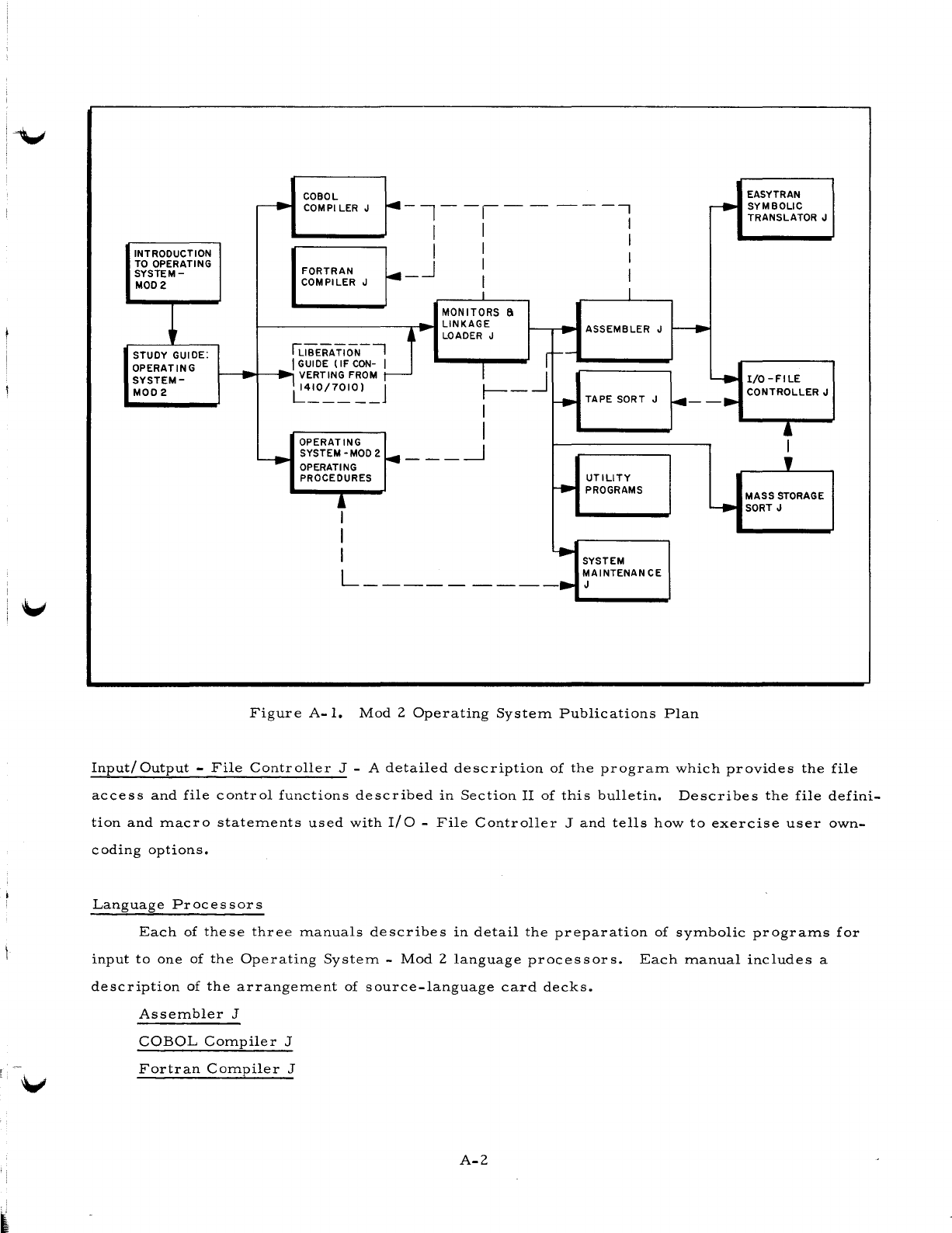
COBOL EASYTRAN
~
COMPI
LER
J
~-I--I--
----,
,........
SYMBOLIC
I TRANSLATOR J
I I I
INTRODUCTION I I I
TO
OPERATING
~_.J
I
SYSTEM-
FORTRAN I
MOD2
COMPILER J I
I I
MONITORS 6
LINKAGE
ASSEMBLER J
~
r p LOADER J -
STUDY GUIDE:
lliBiRA
Ti
ON-'
~_J
f--
OPERATING
..
I GUIDE
(IF
CON-
I
SYSTEM-
-_ VERTING
FROM
~
I/O-FILE
MOD2
L~O~~O~_J
r---
TAPE SORT J
....
--. CONTROLLER J
I
I ,
OPERATING
SYSTEM -
MOD
2
....
---~
I
--.
OPERATING ,
PROCEDURES
UTILITY
~
PROGRAMS
, MASS STORAGE
.....
SORT J
I
I
~
SYSTEM
L
_________
• MAINTENAN CE
J
Figure
A-I.
Mod
2
Operating
System
Publications
Plan
Input/
Output
-
File
Controller
J - A
detailed
description
of
the
program
which
provides
the
file
access
and
file
control
functions
described
in
Section
II
of
this
bulletin.
Describes
the
file
defini-
tion
and
macro
statements
used
with
I/O
-
File
Controller
J
and
tells
how
to
exercise
user
own-
coding
options.
Language
Processors
Each
of
these
three
manuals
describes
in
detail
the
preparation
of
symbolic
programs
for
input
to
one
of
the
Operating
System
-
Mod
2
language
processors.
Each
manual
includes
a
description
of
the
arrangement
of
source-language
card
decks.
Assembler
J
COBOL
Compiler
J
Fortran
Compiler
J
A-2
I
Easytran
Symbolic
Translator
J -
Describes
the
program
for
automatically
translating
1410/
7010
Autocoder
programs
into
Operating
System
-
Mod
2
Assembler
J
programs.
This
publica-
tion
describes
the
few
translation
considerations
and
provides
instructions
for
using
the
trans-
lator.
In
addition,
hand-tailoring
instructions
are
explained
where
required.
System
Maintenance
J -
Contains
detailed
functional
descriptions
of
System
Maintenance
J
and
the
procedures
for
creating,
editing,
and
maintaining
system
files.
Includes
a
description
of
the
control
cards
used
to
direct
the
operation
of
this
program.
Tape
Sort
J -
Contains
a
detailed
functional
description
of
Tape
Sort
J
and
instructions
for
Sort
Definition
and
the
resulting
sort/merge
programs.
Includes
information
on
control
cards,
console
messages,
timing,
and
the
exercise
of
user
own-coding
options.
Mass
Storage
Sort
J -
Describes
the
functions
of
Mass
Storage
Sort
J,
the
structures
of
input
and
output
files,
and
the
macro
instructions
and
parameters
for
initially
specializing
the
routine.
Includes
information
on
control
cards
for
modifying
Mass
Storage
Sort
J
at
execution
time,
console
messages,
timing,
and
own-coding.
Utility
Pr
ograms
-
Contains
detailed
functional
de
sc
r
iptions
of
Input/
Output
Editor
J,
Stor
age
Print
J,
and
Tape
Print
J.
Includes
information
about
the
requisite
control
cards
and
the
console
messages
which
are
produced.
A-3
F-
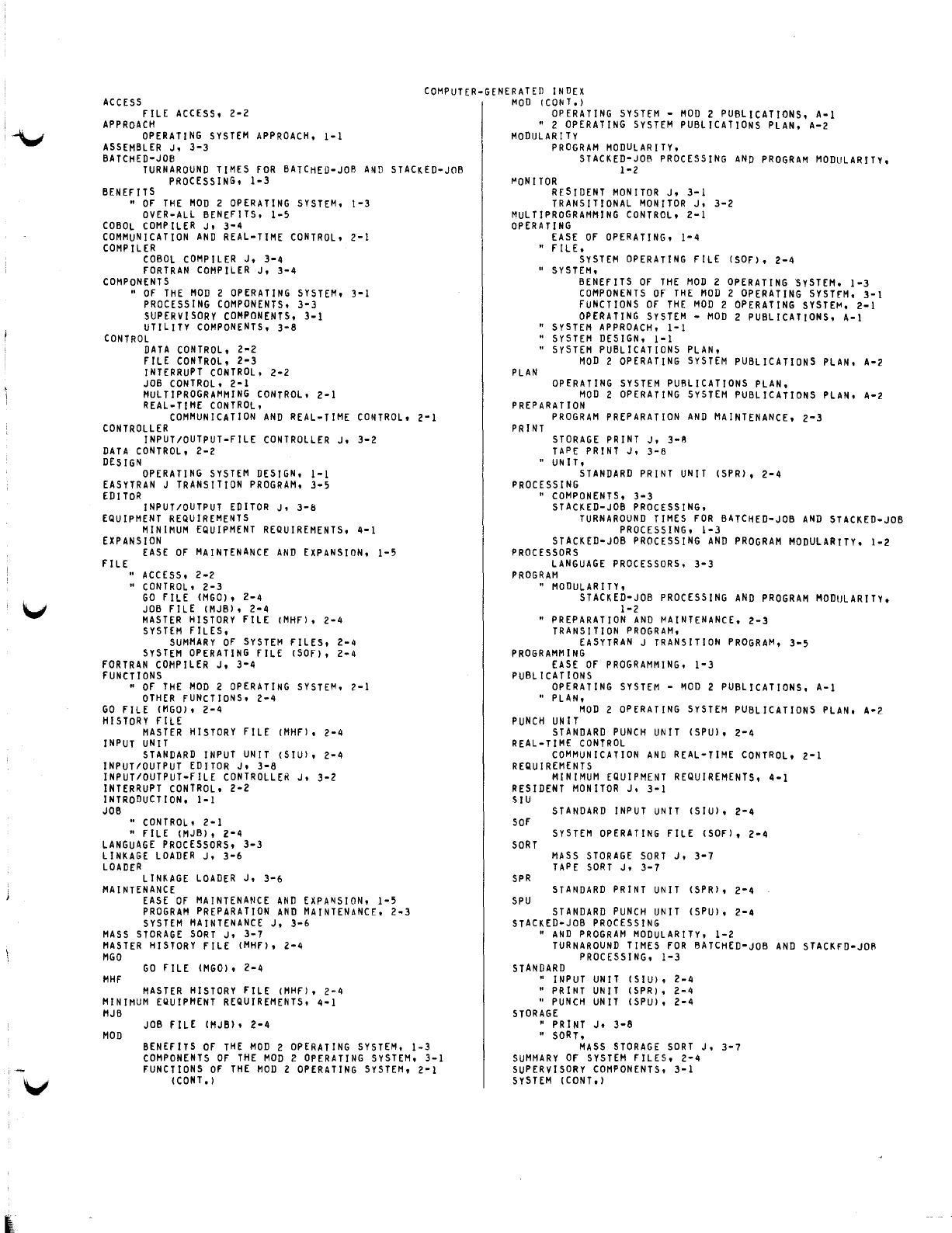
I
~
ACCESS
COMPUTER-GENERATED
INDEX
MOD
(CONT,)
fiLE
ACCESS,
2-2
APPROACH
OPERATING
SYSTEM
APPROACH,
1-1
ASSEMBLER
Jo
3-3
BATCH
ED-JOB
TURNAROUND
TIMES
fOR
BATCHED-JOB
PROCESSING,
1-3
BENEfITS
AND
STACKED-JOB
..
Of
THE
MOD
2
OPERATING
SYSTEM,
1-3
OVER-ALL
BENEfITS,
1-5
COBOL
COMPILER
J.
3-4
COMMUNICATION
AND
REAL-TIME
CONTROL,
2-1
COMPILER
COBOL
COMPILER
J,
3-4
fORTRAN
COMPILER
J,
3-4
COMPONENTS
..
Of
THE
MOD
2
OPERATING
SYSTEM,
3-1
PROCESSING
COMPONENTS,
3-3
SUPERVISORY
COMPONENTS,
3-1
UTILITY
COMPONENTS,
3-8
CONTROL
DATA
CONTROL,
2-2
fILE
CONTROL,
2-3
INTERRUPT
CONTROL,
2-2
JOB
CONTROL,
2-1
MULTIPROGRAMMING
CONTROL,
2-1
REAL-TIME
CONTROL,
COMMUNICATION
AND
REAL-TIME
CONTROL,
2-1
CONTROLLER
INPUT/OUTPUT-FILE
CONTROLLER
J,
3-2
DATA
CONTROL,
2-2
DESIGN
OPERATING
SYSTEM
DESIGN,
I-I
EASYTRAN
J
TRANSITION
PROGRAM,
3-5
EDITOR
INPUT/OUTPUT
EDITOR
J,
3-b
EQUIPMENT
REQUIREMENTS
MINIMUM
EQUIPMENT
REQUIREMENTS,
4-1
EXPANSION
fILE
EASE
Of
MAINTENANCE
AND
EXPANSION,
1-5
..
ACCESS,
2-2
..
CONTROL,
2-3
GO
FILE
(MGO),
2-4
JOB
fILE
(MJB),
2-4
MASTER
HISTORY
fILE
(MHF),
2-4
SYSTEM
fILES,
SUMMARY
Of
SYSTEM
fILES,
2-4
SYSTEM
OPERATING
FILE
(SOf),
2-4
fORTRAN
COMPILER
J,
3-4
fUNCTIONS
..
Of
THE
MOD
2
OPERATING
SYSTEM,
2-1
OTHER
fUNCTIONS,
2-4
GO
fILE
(MGO),
2-4
HISTORY
fILE
MASTER
HISTORY
FILE (MHf),
2-4
INPUT
UNIT
STANDARD
INPUT
UNIT
(SIU),
2-4
INPUT/OUTPUT
EDITOR
J,
3-8
INPUT/OUTPUT-FILE
CONTROLLER
J,
3-2
INTERRUPT
CONTROL,
2-2
INTRODUCTION.
1-1
JOB
..
CONTROL,
2-1
..
fiLE
(MJB),
2-4
LANGUAGE
PROCESSORS,
3-3
LINKAGE
LOADER
J,
3-6
LOADER
LINKAGE
LOADER
J,
3-6
MA
I
NTENANCE
EASE
OF
MAINTENANCE
ANn
EXPA~SION,
1-5
PROGRAM
PREPARATION
AND
MAINTENANCE,
2-3
SYSTEM
MAINTENANCE
J,
3-6
MASS
STORAGE
SORT
J,
3-7
MASTER
HISTORY
fILE
(MHf),
2-4
MGO
GO
fILE
(MGO),
2-4
MHf
MASTER
HISTORY
fILE
(MHF),
2-4
MINIMUM
EQUIPMENT
REQUIREMENTS,
4-1
MJB
MOD
JOB
fILE
(MJB).
2-4
BENEfITS
Of
THE
MOD
2
OPERATING
SYSTEM,
1-3
COMPONENTS
Of
THE
MOD
2
OPERATING
SYSTEM.
3-1
fUNCTIONS
Of
THE
MOD
2
OPERATING
SYSTEM,
2-1
(CONT,)
OPERATING
SYSTEM
-
MOD
2
PUBLICATIONS,
A-I
..
2
OPERATING
SYSTEM
PUBLICATIONS
PLAN,
A-2
MODULAR
I
TV
PROGRAM
MODULARITY,
STACKED-JOB
PROCESSING
AND
PROGRAM
MODULARITY,
1-2
"ONITOR
RESIDENT
MONITOR
J,
3-1
TRANSITIONAL
MONITOR
J,
3-2
MuLTIPROGRAMMING
CONTROL,
2-1
OPERATING
PLAN
EASE
Of
OPERATING,
1-4
..
fILE.
SYSTEM
OPERATING
fILE
(SOf),
2-4
..
SYSTEM,
BENEfITS
Of
THE
MOD
2
OPERATING
SySTEM.
1-3
COMPONENTS
Of
THE
MOD
2
OPERATING
SYSTfM.
3-1
fUNCTIONS
Of
THE
MOD
2
OPERATING
SYSTE~.
2-1
OPERATING
SYSTEM
-
MOD
2
PUBLICATIONS.
A-\
..
SYSTEM
APPROACH,
1-1
..
SYSTEM
DESIGN,
1-1
..
SySTEM
PUBLICATIONS
PLAN.
MoD
2
OPERATING
SYSTEM
PUBLICATIONS
PLAN.
A-2
OPERATING
SYSTEM
PUBLICATIONS
PLAN.
MOD
2
OPERATING
SYSTEM
PUBLICATIONS
PLAN.
A-2
PREPARATION
PROGRAM
PREPARATION
AND
MAINTENANCE,
2-3
PRINT
STORAGE
PRINT
J.
3-R
TAPE
PRINT
J.
3-8
" UNIT.
STANDARD
PRINT
UNIT
(SPR).
2-4
PROCESSING
..
COMPONENTS,
3-3
STACKED-JOB
PROCESSING.
TURNAROUND
TIMES
fOR
BATCHED-JOB
AND
STACKED-JOB
PROCESSING.
1-3
STACKED-JOB
PROCESSING
AND
PROGRAM
MODULARITY.
1-2
PROCESSORS
LANGUAGE
PROCESSORS.
3-3
PROGRAM
"
MODULARITY,
STACKED-JOB
PROCESSING
AND
PROGRAM
MODULARITy.
1-2
..
PREPARATION
AND
MAINTENANCE.
2-3
TRANSITION
PROGRAM.
EASYTRAN
J
TRANSITION
PROGRAM.
3-5
PROGRAMMING
EASE
Of
PROGRAMMING.
1-3
PUBL
ICATIONS
OPERATING
SYSTEM
-
~OD
2 PUBLICATIONS. A-I
"
PLAN.
MOD
2
OPERATING
SYSTEM
PUBLICATIONS
PLAN.
A-2
PUNCH
UNIT
STANDARD
PUNCH
UNIT
(SPU),
2-4
REAL-TIME
CONTROL
COMMUNICATION
AND
REAL-TIME
CONTROL,
2-1
REQUIREMENTS
MINIMUM
EQUIPMENT
REQUIREMENTS,
4-1
RESIDENT
MONITOR
J.
3-1
SIU
SOf
SORT
SPR
SPU
STANDARD
INPUT
UNIT
(SIU).
2-4
SYSTEM
OPERATING
fILE
(SOf),
2-4
MASS
STORAGE
SORT
J,
3-7
TAPE
SORT
J,
3-7
STANDARD
PRINT
UNIT
(SPR),
2-4
STANDARD
PUNCH
UNIT
(SPU).
2-4
STACKED-JOB
PROCESSING
..
AND
PROGRAM
MODULARITY.
1-2
TURNAROUND
TIMES
fOR
BATCHED-JOB
AND
STACKFD-JOR
PROCESSING.
1-3
STANDARD
"
INPUT
UNIT
(SIU),
2-4
..
PRINT
UNIT
(SPR).
2-4
"
PUNCH
UN
IT
(SPU),
2-4
STORAGE
"
PRINT
J.
3-8
"
SORT,
MASS
STORAGE
SORT
J.
3-7
SUMMARY
Of
SYSTEM
fILES,
2-4
SUPERVISORY
COMPONENTS,
3-1
SySTEM
(cONT.)
SYSTEM
COMPUTER-GENERATED
INDEX
TAPE
"
APPROACH,
OPERATING
SYSTEM
APPROACH,
1-1
"
OESIGN,
OPERATING
SYSTEM
DESIGN,
1-1
" FILES,
SUMMARY
or
SYSTEM
FilES,
2-4
"
MAINTENANCE
J,
3-6
"
OPERATING
rilE
(Sor),
2-4
OPERATING
SYSTEM,
BENErlTS
or
THE
MOD
2
OPERATING
SYSTEM,
1-3
COMPONENTS
or
THE
MOD
2
OPERATING
SYSTEM,
3-1
fUNCTIONS
OF
THE
MOD
2
OPERATING
SYSTEM,
2-1
OPERATING
SYSTEM
-
MOD
2
PUBLICATIONS,
A-I
"
PUBLICATIONS
PLAN,
MOD
2
OPERATING
SYSTEM
PUBLICATIONS
PLAN,
A-2
"
PRINT
J,
3-8
"
SORT
J.
3-7
TIMES
TURNAROUND
TIMES
rOR
BATCHED-JOB
AND
STACKfO-JOR
PROCESSING,
1-3
TRANSITION
PROGRAM
EASYTRAN
J
TRANSITION
PROGRAM.
3-5
TRANSITIONAL
MONITOR
J.
3-2
TURNAROUND
TIMES
rOR
BATCHED-JOB
AND
STACKED-JOB
PROCESSING.
1-3
UNIT
STANDARD
INPUT
UNIT
(SIU).
2-4
STANDARD
PRINT
UNIT
(SPR).
2-4
STANDARD
PUNCH
UNIT
(SPU).
2-4
UTiliTY
COMPONENTS.
3-8
'-~
..
~
GI
c:
::::i
Ill)
c:
o
<
SERIES
200
HONEYWELL
EDP
TECHNICAL
PUBLICATIONS
USERS'
REMARKS
FORM
DATED:
MAY,
1966
TITLE:
INTRODUCTION
TO
SERIES
200/0PERATING
SYSTEM
-
MOD
2
FILE
NO:
122.0005.
002J.
0-393
SOFTWARE
BULLETIN
ERRORS
NOTED:.
Fold
~
SUGGESTIONS
FOR
IMPROVEMENT:
o
Fold
FROM:
NAME
____________________________________
___
DATE
__________
_
COMPANY
__________________________________
__
TITLE
______________________________________
_
ADDRESS
__________________________________
___
BUSINEsS·REPlY<
.•
IIIAIII.:~····
Nopost.ge~amp
necessary
ifm~~J.
.
•...•......
POSTAGE.
WllJ;,
.
ATT'N: TECHNICAL COMMUNICATIONS DEPARTMENT
Honey~ell
ELECTRONIC
DATA
PROCESSING
FIRST CLASS
PERMIT NO.
39531
WELLESLEY HILLS
MASS.
J
0
C
r+
~
0 .,
:::I
DQ
r-
s·
CD
