DCS5B_OI_E_d 500 3ADW000055R0401 DCS500B Operating Instruction E D
User Manual: 500
Open the PDF directly: View PDF ![]() .
.
Page Count: 76
DCS 500 Thyristor Power Converters
for DC Drive Systems
25 to 5150 A
Operating Instructions
DCS 500B / DCF 500B
DCP 500B

How the DCS 500 Documentation System works
System Description
DCS 500B
3ADW000066
Volume II D
Operating Instructions
DCS 500B
3ADW000055
Volume IV D
Technical Data
3ADW000054
Volume III
Description of the converter
DCS 500B Operating Instructions
(documentation in hand) including in-
formation and advise to commission the
drive. If three phase DCF 500B field
supply units are needed please use the
same documents as for DCS 500B ar-
mature converters.
As additional documentation is avail-
able:
The System description describes the
functionality of DCS 500 converter units
as well as the cooperation of all single
components belonging to a complete
drive system.
DCS 500 Technical Data giving infor-
mation about all direct technical data for
components used inside and outside
the converter module.
The above mentioned documents are
usually delivered together with all or-
dered converter units of the DCS 500
family and represent the basic knowl-
edge which is essential for all users of
this product.
System Description
DCA 500B
3ADW000148
Volume II D1
Application Blocks
DCS 500B
3ADW000048
Volume V D2
SW Description
DCS 500B
3ADW000078
Volume V D1
Technical Guide
DCS
3ADW000163
Volume VII A
Service Manual
DCS 500(B)/600
3ADW000093
Volume VI A
Supplementary documentation
DCA 500 System description for
standard cubicles equipped with DC
drives.
For those, who want to reprogram or
adapt the software of their drive a de-
tailed comprehensive description of the
software structure of the drive as well
as of all available function blocks can
be delivered. This documentation is
only available as data file in English
language.
As separate document for service engi-
neers a DCS 500 Service Manual can
be ordered .
Engineering and design people for drive
systems can get a separate collection
of information with regard to installation,
sizing, fusing etc. of DC drives called
"Technical guide".
3ADW000055R0401_DCS500B_Operating Instruction_e_d
2002 ABB Automation Products GmbH. All rights reserved.
Thyristor Power Converters
Series
DCS 500B / DCF 500B
DCP 500B
25 to 5150 A
OPERATING INSTRUCTIONS
Code: 3ADW 000 055 R0401 Rev D
DCS_OI_E_D.DOC
EFFECTIVE: Oct. 30th, 2002
SUPERSEDES:Rev C Sept. 14th, 2001
3ADW000055R0401_DCS500B_Operating Instruction_e_d

DCS 500B / DCP 500B Operating Instructions
3ADW000055R0401_DCS500B_Operating Instruction_e_d
Safety Instructions
DCS 500B / DCP 500B Operating Instructions i
Overview This chapter contains safety instructions which must be complied
with during installation, operation and maintenance of the power
converters series DCS 500B / DCF 500B or DCP 500B. If these in-
structions are not complied with, this may result in injuries (perhaps
even with fatal) or in damage to the power converter, the motor and
the driven machine. Before starting with any work whatsoever at or
with this unit, you must read the information given in this chapter.
Warnings Warnings provide information on states which if the specified pro-
cedure for the state concerned is not meticulously complied with
may result in a serious error, in major damage to the unit, in injury
to persons and even in death.
They are identified by the following symbols:
Danger: High Voltage! This symbol warns you of
high voltages which may result in injuries to persons
and/or damage to equipment. Where appropriate, the
text printed adjacent to this symbol describes how
risks of this kind may be avoided.
● All electrical installation and maintenance work on the thyristor
power converter must be carried out by properly qualified staff
who have been thoroughly trained in electrical engineering.
● The thyristor power converter and its adjacent units must be
properly earthed by qualified professionals.
● You must NEVER perform any work on the thyristor power con-
verter while it is still switched on. First switch the unit off, use a
measuring instrument to make absolutely sure that the power
converter has really been de-energized, and only then you may
start with the work concerned.
● Due to external control circuits, there may be dangerously high
voltages present at the thyristor power converter even after the
line voltage has been switched off. So always work at the unit
with appropriate caution! Non-compliance with these instructions
may result in injury (or even death!).
3ADW000055R0401_DCS500B_Operating Instruction_e_d
Safety Instructions
ii DCS 500B / DCP 500B Operating Instructions
General warning: this symbol warns you of non-
electrical risks and dangers which may result in seri-
ous or even fatal injury to persons and/or in damage
to equipment. Where appropriate, the text printed ad-
jacent to this symbol describes how risks of this kind
may be avoided.
● When thyristor power converters are in use, the electric motors,
power transmission elements and the driven machines are work-
ing in an extended operating range, which means they have to
cope with a relatively high loading.
● You should have made sure that all units, devices and appli-
ances used are actually suitable for this higher loading.
● If you have to operate the thyristor power converter at a rated
motor voltage and/or a rated motor current significantly below
the figures stated in the thyristor power converter's output data,
you must take appropriate precautionary measures to protect the
unit against overspeed, overload, breakage, etc., by modifying
the software or hardware appropriately.
● For insulation testing, you must disconnect all cables from the
thyristor power converter. You should avoid operating your unit
at values other than the rated data. Non-compliance with these
instructions may cause lasting damage to the thyristor power
converter.
● The thyristor power converter possesses a number of automatic
reset functions. When these functions are executed, the unit will
be reset after an error and will then resume operation. These
functions should not be used if other units and devices are not
suitable for an operating mode of this kind, or if their use might
entail dangerous situations.
Warning of electrostatic discharge:
this symbol warns you against electrostatic discharges
which may damage the unit. Where appropriate, the
text printed next to this symbol describes how a risk of
this kind may be avoided.
3ADW000055R0401_DCS500B_Operating Instruction_e_d

Safety Instructions
DCS 500B / DCP 500B Operating Instructions iii
Notes Notes supply information on states requiring particular attention, or
indicate that additional information is available on a specific topic.
For this purpose, the following symbols are used:
CAUTION! Cautions are designed to draw your attention to a
particular state of affairs.
Note A note contains or refers you to additional informa-
tion available on the particular topic concerned.
Mains connection You can use a switch disconnector (with fuses) in the power supply
of the thyristor power converter to disconnect the electrical compo-
nents of the unit from the power supply for installation and mainte-
nance work. The type of disconnector used must be a switch dis-
connector as per EN 60947-3, Class B, so as to comply with EU
regulations, or a circuit-breaker type which switches off the load cir-
cuit by means of an auxiliary contact causing the breaker's main
contacts to open. The mains disconnector must be locked in its
"OPEN" position during any installation and maintenance work.
EMERGENCY STOP
buttons
EMERGENCY STOP buttons must be installed at each control desk
and at all other control panels requiring an emergency stop func-
tion. Pressing the STOP button on the CDP 31x control panel of the
thyristor power converter will neither cause an emergency motor
stop, nor will the drive be disconnected from any dangerous poten-
tial.
Intended use The operating instructions cannot take into consideration every
possible case of configuration, operation or maintenance. Thus,
they mainly give such advice only, which is required by qualified
personnel for normal operation of the machines and devices in
industrial installations.
If in special cases the electrical machines and devices are intended
for use in non-industrial installations - which may require stricter
safety regulations (e.g. protection against contact by
children or similar) -, these additional safety measures for the instal-
lation must be provided by the customer during assembly.
3ADW000055R0401_DCS500B_Operating Instruction_e_d

Contents
iv DCS 500B / DCP 500B Operating Instructions
IV A OPERATING INSTRUCTIONS
Safety Instructions
Chapter 1 - Introduction
How to use this manual ...........................................................................................................1-1
Contents of this manual...........................................................................................................1-1
Target group............................................................................................................................1-1
Associated publications..........................................................................................................1-1
Incoming inspection.................................................................................................................1-2
Storage and transport..............................................................................................................1-2
Rating plate .............................................................................................................................1-2
Chapter 2 - Start-Up Instructions
General notes..........................................................................................................................2-1
2.1 Preparatory work ...............................................................................................................2-5
2.2 Scaling intra-unit signals....................................................................................................2-6
2.3 Presetting the field supply unit...........................................................................................2-8
2.4 Adjusting the current controller........................................................................................2-10
2.5 Speed feedback balancing ..............................................................................................2-12
2.6 Balancing the field supply unit and the e.m.f. controller ..................................................2-14
2.7 Balancing the speed controller, plus fine-balancing the e.m.f. and the current contr......2-20
2.8 Matching the thyristor power converter unit to the system conditions concerned ...........2-21
2.9 Presetting the 3-phase field supply unit DCF 50xB.........................................................2-22
Chapter 3 - Handling of Control Panel CDP 31x
3.1 Overview............................................................................................................................3-1
Panel Link ....................................................................................................................3-1
Mounting the Panel.....................................................................................................3-1
3.2 Start Mode.........................................................................................................................3-2
3.3 Panel Functions.................................................................................................................3-3
Actual Signal Display Mode .........................................................................................3-3
Parameter Mode ..........................................................................................................3-4
Function Mode .............................................................................................................3-4
Drive Mode...................................................................................................................3-5
3.4 Pin/Parameter Selecting and Changing of Value ..............................................................3-5
3.5 Saving of the Parameters to backup memory ...................................................................3-7
3.6 FAULT RESETTING (RESET) ..........................................................................................3-8
3.7 EMERGENCY STOP RESETTING (RESET)....................................................................3-8
3.8 Fault History Display..........................................................................................................3-9
3.9 Uploading and Downloading of Parameters (UPLOAD/DOWNLOAD)............................3-10
3.10 Setting of the Display Contrast......................................................................................3-12
3.11 Full Name of output pins................................................................................................3-12
3.12 Selecting output pins .....................................................................................................3-13
3.13 Drive Mode ....................................................................................................................3-14
3.14 Running the Drive..........................................................................................................3-15
Operational Command Keys......................................................................................3-15
3ADW000055R0401_DCS500B_Operating Instruction_e_d

Contents
DCS 500B / DCP 500B Operating Instructions v
Running the DC- Drive from the CDP31x .................................................................3-15
3.15 Speed Reference Setting for the Drive..........................................................................3-16
Chapter 4 - Signals and Troubleshooting
4.1 Display of status, alarm and fault signals..........................................................................4-1
Categories of signals and possibilities of display.........................................................4-1
4.2 General messages ............................................................................................................4-2
4.3 Starting errors (E)..............................................................................................................4-2
4.4 Fault Signals (F)................................................................................................................4-3
4.5 Alarm Signals (A) ............................................................................................................4-12
4.6 Status Signals .................................................................................................................4-17
Appendix A - Connection diagrams
Connection diagram 1 .............................................................................................................A-1
Connection diagram 2 .............................................................................................................A-2
3ADW000055R0401_DCS500B_Operating Instruction_e_d

vi DCS 500B / DCP 500B Operating Instructions
3ADW000055R0401_DCS500B_Operating Instruction_e_d

Chapter 1 - Introduction
DCS 500B / DCP 500B Operating Instructions IV A 1 - 1
How to use this manual
The purpose of these operating instructions is to provide detailed in-
formation on how to start up a thyristor power converter from the
DCS 500B or DCP 500B series.
Note: If it is not mentioned explicitly all details given in
these Operating Instructions will be valid for both,
series DCS 500B / DCF 500B and series DCP 500B!
Contents of this manual Chapter 1 - Introduction
It describes how to use this manual and the boundary conditions
applying.
Chapter 2 - Start-Up Instructions
We recommend working your way through the Start-Up Instructions
step by step, since in this way you will get to perform all important
parameter setting routines.
Chapter 3 - How to Handle the Control and Display Panel
This chapter describes how to operate the CDP 31x control and
display panel.
Chapter 4 - Signals and Troubleshooting
This chapter describes the available signals and possibilities of dis-
play with DCS 500B and DCP 500B. As far as fault signals are con-
cerned there will be indicated measures (actions) to be taken for
troubleshooting.
Target group This manual is designed to help those responsible for planning, in-
stalling, starting up and servicing the thyristor power converter.
These people should possess
• basic knowledge of physics and electrical engineering, electrical
wiring principles, components and symbols used in electrical en-
gineering, and
• basic experience with DC drives and products.
Associated
publications
The DCS 500B / DCF 500B or DCP 500B documentation includes
the following:
• System Description DCS 500B / DCF 500B
• System Description DCP 500B
• Technical Data DCS 500B / DCF 500B, DCP 500B
• Operating Instructions (this document)
3ADW000055R0401_DCS500B_Operating Instruction_e_d

Chapter 1 - Introduction
IV A 1 - 2 DCS 500B / DCP 500B Operating Instructions
Incoming inspection After opening this package, you should check whether it contains
the following items:
● DCS 500B / DCF 500B or DCP 500B thyristor power con-
verter in the configuration ordered
● DCS 500B / DCF 500B or DCP 500B publications
● Accessories, including manuals if ordered
● Final test report
Check the consignment for any signs of damage. If you find any,
please contact the insurance company or the supplier.
Check the particulars given on the unit's rating plate to make sure
prior to installation and start-up that you have received the correct
unit type and unit version.
If the consignment is incomplete or contains any incorrect items,
please contact the supplier.
CAUTION! The thyristor power converter weighs quite a lot and
should therefore not be held by the front cover. Please put the unit
down only on its back (sizes C1/C2/A5). Always use care when
handling the unit, so as to avoid injuries or damage.
Storage and transport If the unit had been in storage prior to installation or is transported
to another location, care must be taken to ensure that the environ-
mental conditions are complied with (see "System Descriptions
DCS 500B / DCF 500B or DCP 500B").
Rating plate
For purposes of identification, each thyristor power converter is fit-
ted with rating plates, stating the type code and the serial number,
which serve for each unit's individual identification.
The type code contains information on the characteristics and the
configuration of the unit. The first three digits of the serial number
refer to the year and week of manufacture. The last digits complete
the serial number so as to preclude two units receiving the same
type code and the same serial number.
The 112xx group provides information on the unit's software con-
figuration.
The technical data and specifications are valid as of going to press.
ABB reserves the right to make subsequent alterations.
If you have any questions concerning your drive system, please
contact your local ABB agent.
3ADW000055R0401_DCS500B_Operating Instruction_e_d
Chapter 2 - Start-Up Instructions
DCS 500B / DCP 500B Operating Instructions IV A 2 - 1
General notes
CAUTION: it is absolutely essential that the applicable accident prevention
regulations be observed by the user (in this context, please also
read the chapter entitled "Safety Instructions")!
How this chapter is structured
For better understanding the individual steps of start-up work are distinguished by
a) frames without any additional marking on the left side:
These steps of start-up work must always be performed (= mandatory start-up work)!
Example:
522 = GERMAN [Only with the SDCS-CON-2 control board & the CDP 312 panel!]
Activates German texts on the display ...........
b) frames with marking on the left side („columns“ shaded in grey):
These steps of start-up work have to be performed only when the condition stated
(as heading) applies to the selected drive configuration! After this work has been
completed, the
mandatory start-up work has to be continued.
Example:
Only when connection diagram 1 (Appendix A) is being used!
906 = 12502
Function „EMERGENCY STOP“ de-activated ............
Recommended motor voltages and field voltages
• Motor voltage UA when the following units are used
DCS 501B / DCP 501B: UAmax = Line voltage * 1.16 (2- quadrant unit)
DCS 502B / DCP 502B: UAmax = Line voltage * 1.05 (4- quadrant unit)
• Field voltage UF (= max. output voltage) when the following is being used
SDCS-FEX-1: UF = Line voltage * 0.9
If there is a divergence of more than 10 % between the field supply unit's output
voltage and the rated field voltage UFrated stated on the motor's rating plate, then the
connecting voltage UN should be reduced, using a matching transformer or a series
resistor Rv: R
v = (0.9 * UN - UF) / IF IF = Rated field current
(Note: also suitable for fine-balancing the maximum motor voltage)
• Field voltage UF when the following is being used
SDCS-FEX-2 /
DCF 503 / DCF 504: UF = Line voltage * 0.6 ... 0.8
• Field voltage UF when the following is being used
DCF 501B / DCF 502B: UF = Line voltage * 0.5 ... 1.1
Maximally possible output voltage UAmax using
DCF 501B / DCF 502B: UF = Line voltage * 1.35
3ADW000055R0401_DCS500B_Operating Instruction_e_d

Chapter 2 - Start-Up Instructions
IV A 2 - 2 DCS 500B / DCP 500B Operating Instructions
Phase sequence when connecting to the mains / Potential isolation
No special phase sequence required for the main connections U1, V1 and W1!
Phase coordination between electronics section and power section not necessary!
For potential isolation and for avoiding ground loops, an isolating transformer should be
installed upstream when an oscilloscope is being used.
Preventing unintended operating states / Shutting the drive down
CAUTION! As laid down in DIN 57100 Part 727 / VDE 0100 Part 727 (Preventing
unintended operating states), shutting the drive down by means of the
signals at the binary inputs DIx is not sufficient in itself as the sole
measure involved for avoiding unintended operating states or shutting
the drive down in the event of danger!
Range of application for the Start-Up Instructions
The Start-Up Instructions are referenced to the parameter settings in their as-delivered
condition (default values) and to the unit wiring as shown in connection diagram 1 or 2
(see Appendix A). In both circuit variants, the binary inputs DI5, DI7 and DI8 can be used.
They will cause the reactions at the drive as described below.
The symbols stated in this context will be repeatedly used further on in the text.
Method of functioning of the binary inputs DI5, DI7 and DI8
• Binary input DI5; designation EM STOP
In operation, DI5 must be set to logical "1“. If it is set to "0“, the alarm signal A 102
will appear. The drive will react in accordance with the function set at Parameter 917
(shutdown with ramp, with torque limit/current limit, with controller blocking and
coasting). Once ramp-down has been completed (speed feedback below nmin), the
output is reset for controlling the line contactor. After that, the EM STOP input
should be set back to "1“, the alarm message acknowledged, and the ON/OFF input
likewise be set to "0“. After that, the drive can be started anew.
• Binary input DI7; designation ON/OFF
For connecting the drive to the mains, DI7 must be set to logical "1“. If there are no
ongoing faults, the outputs for controlling the contactors for the armature circuit and
the field circuit will be activated. If DI7 is set to "0“, the controllers will be blocked in-
ternally and the outputs reset after a time-delay.
The function which can be set with Parameter 915 (inputs DI7 and DI8 for switching
the contactors) will only be operative when the drive has been wired as shown
in connection diagram 2.
3ADW000055R0401_DCS500B_Operating Instruction_e_d
Chapter 2 - Start-Up Instructions
DCS 500B / DCP 500B Operating Instructions IV A 2 - 3
Symbols for switching the electronics or the power section ON and OFF
- Switch ON electronics
- Switch ON power
X6: 7 ⇒ „1“ signal
(K20 in connection example)
(input ON / OFF)
- Switch OFF electronics
- Switch OFF power
X6: 7 ⇒ „0“ signal
(K20 in connection example)
(input ON / OFF)
• Binary input DI8; designation RUN
For starting the drive, DI8 must be set to logical „1“. This enables the reference at the
REF_SEL and RAMP GENERATOR blocks, as well as the controllers. If DI8 is set to
"0“, the drive will react in accordance with the function set at Parameter 916 (shut-
down with ramp, with torque limit/current limit, with controller block and coasting).
Once ramp-down has been completed (speed feedback below nmin), the reference is
kept at zero, and the controllers blocked after a time-delay; the drive is torqueless.
Symbols for enabling / disabling the reference
- ENABLE reference X6: 8 ⇒ „1“ signal
(K21 in connection example) (input RUN)
- DISABLE reference X6: 8 ⇒ „0“ signal
(K21 in connection example)
(input RUN)
System-dependent planning
If you want the drive to react with a function other than that of Parameter 916 or 917, you
have to parameterize the unit accordingly, by connecting one of the inputs or an addi-
tional one with a control pin, e.g. at the ramp-function generator.
- Example 1:
Operational ramp-up and ramp-down in the event of reference changes with the same
ramp times, shutdown via RUN with a different time.
Solution:
use second parameter set ramp times; set time at DECEL2;
establish connection from P 1707 to P 10716.
- Example 2:
Implementing an EMERGENCY SHUTDOWN or EMERGENCY STOP function.
Solution:
this function stipulated in various regulations must always be planned in dependence on
the system involved! A basic distinction must be made here between electrical and me-
chanical risks. Since one signal at one input is not sufficient (see above), at least one
other switch-off option must be created, e.g. by means of a relay directly switch-
ing input DI5 to "0“. This is how the power converter attempts (in accordance with
P 917), to defuse the dangerous situation. A dropout-delay contact of the relay will
then switch the power off. If the delay is small or does not match the function selected
for P 917, then certain operating states (regeneration) may, due to laws of physics,
result in the unit fuses tripping, and in extreme cases in thyristor defects.
3ADW000055R0401_DCS500B_Operating Instruction_e_d
Chapter 2 - Start-Up Instructions
IV A 2 - 4 DCS 500B / DCP 500B Operating Instructions
Symbol for altering parameters or for establishing new connections
Enter at keyboard e.g. 1204 = 10000 Assign the value of 10000
to Parameter 1204
Symbol for displaying parameter values or connections
Display
Symbol for measuring physical variables
Measure
3ADW000055R0401_DCS500B_Operating Instruction_e_d

Chapter 2 - Start-Up Instructions
DCS 500B / DCP 500B Operating Instructions IV A 2 - 5
2.1 Preparatory work
Check the unit for damage in transit or other damage.
Install and wire unit; connect all inputs and outputs required.
Proceed in the same way for the field supply unit as well.
Check whether protective measures, earthing, screening, etc. have been taken in
accordance with the system conditions involved.
Check the rated value of the supply voltage for the electronics and the fan:
• matching transformer necessary when:
- electronics supply is not equal to 115 V/230 V
- single-phase-fan supply is not equal to 230 V
- three-phase-fan supply is not within the range of 400 V .... 690 V.
Check the rated value of the supply voltage for the armature-circuit converter's
power section; the particulars given on the rating plate must be > than the rated
line voltage.
If this condition is not satisfied, then the following applies:
- use an isolating transformer, or
- use a suitable unit.
Check the rated value of the supply voltage for the field supply unit.
(Particulars on rating plate > rated line voltage?
Is an auxiliary transformer or perhaps a series resistor necessary?)
Check the wiring, fusing, the cross-sectional areas of the cables.
Provide an option for switching binary inputs X6: 7 and X6: 8.
Check the system's EMERGENCY STOP for proper functioning! Set the system-side
monitoring functions, and activate them. Check whether auxiliaries, such as motor fans
or unit fans, function properly; while doing this, also check for correct direction of rota-
tion and voltage level as well!
3ADW000055R0401_DCS500B_Operating Instruction_e_d
Chapter 2 - Start-Up Instructions
IV A 2 - 6 DCS 500B / DCP 500B Operating Instructions
2.2 Scaling intra-unit signals
Make sure that the existing electronics supply voltage has been set on the SDCS-
POW-1 power supply board as well, using the SW1 switch.
If an encoder is being used as the speed feedback device, make sure that the correct
supply voltage has been seton the boards
SDCS-POW-1: ⇒ X3: / X4: / X5: SDCS-IOB-3: ⇒ S4
Switch on the power supply to the electronics section.
The display of Panel CDP 31x DCS 500
may show the following ** WARNING **
information: +Emergency stop
522 = GERMAN [Only with the SDCS-CON-2 control board & the CDP 312 panel!]
Activates German texts on the display
501 = Rated motor voltage
This is used to scale those parameters referring to the rated motor voltage, such
as field crossover point or maximum speed with e.m.f. control.
502 = Rated motor current
This is used to scale those parameters referring to the rated motor current, such
as current limitation or torque limitation.
507 = Rated line voltage
This is used to scale those parameters referring to the line voltage, such as line
undervoltage.
Only when connection diagram 1 (Appendix A) is being used!
906 = 12502
„Emergency Stop“ de-activated
910 = 10908
No check-back signal from unit fan necessary
911 = 10908
No acknowledge signal from motor fan necessary
Set this only for units with a rated current ≥ 2050A!
517 = Rated power converter current
Enter numerical value from rating plate here
518 = Rated power converter supply voltage
Enter numerical value from rating plate here
519 = 45 Grad Celsius
Temperature monitoring of power section
520 = 4 ⇒ Size C4 has been selected
Coding for unit type
521 = 1 : Single bridge (2-Q) converter ⇒ on rating plate: DCS 501 xxxx
4 : Double bridge (4-Q) converter ⇒ on rating plate: DCS 502 xxxx
Coding for power section (bridge) type
3ADW000055R0401_DCS500B_Operating Instruction_e_d
Chapter 2 - Start-Up Instructions
DCS 500B / DCP 500B Operating Instructions IV A 2 - 7
Set this only for units of the DCP 500 series!
517 = Rated power converter current
Enter numerical value from rating plate here
518 = 500 V (fixed!); rated power converter voltage
Enter numerical value 500 V here
519 = Temperature monitoring of power section
Enter value as indicated in the table „Technical Data“ here
520 = 4 ⇒ Size C4 has been selected
Coding for unit type
521 = 1 : Single bridge (2-Q) converter ⇒ on rating plate: DCP 501 xxxx
4 : Double bridge (4-Q) converter ⇒ on rating plate: DCP 502 xxxx
Coding for power section (bridge) type
507 = Rated line voltage;
Enter: Rated line voltage Uratedline in V * 1.05
Example: Uratedline = 400 V; entry for Parameter 507 ⇒ 420
CAUTION: Display of the line voltage feedback value is 5 % too high!
Switching thresholds referenced to the line voltage, how-
ever, are correct!
CAUTION! Please don't forget!
11202 = SAVE MOT1 SET
Save the altered values in the non-volatile memory!
Resetting the warning either by:
briefly setting ("H“ level) binary input X6:6
or
switching the electronics voltage supply OFF and ON again.
3ADW000055R0401_DCS500B_Operating Instruction_e_d
Chapter 2 - Start-Up Instructions
IV A 2 - 8 DCS 500B / DCP 500B Operating Instructions
2.3 Presetting the field supply unit
Make sure that existing supply voltages for power section, field supply unit (field ex-
citer) and field winding, fan, etc. match the rated data of the components used.
Switch ON power.
DANGER: System components now energized!
Please wait a few moments. During this time, the unit compares the phase sequence
set in the parameter with that obtaining at the power section.
If the unit outputs the "Phase sequence fault of power section“ signal (F 38):
- switch off unit completely and disconnect from the mains, interchange two phases at
the input, and start again from the beginning of this chapter.
or
- enter: 506 = R-T-S and then acknowledge fault signal.
Unit will automatically adapt to phase sequence; this signal is to be interpreted as in-
formation to the effect that the fans' direction of rotation may be wrong for size-C4
units.
Only for uncontrolled field supply with SDCS-FEX-1!
505 = 1 Panel display: DIODE FIELD EXCIT
Check field current and field voltage by measuring them.
Switch OFF power!
11202 = SAVE MOT1 SET
Save the altered values in the non-volatile memory!
Continue with Chapter 2.4
Only for controlled field supply with SDCS-FEX-2 or DCF 503/DCF 504!
505 = 2 Panel display: FEX2 OR FEX3
503 = Rated motor field current
Scales all parameters referenced to the motor field current, such as field cur-
rent limitation or field current monitoring
1305 = Field current for "Under-excitation" signal
Check field current and field voltage by measuring them;
if necessary, correct field current with 503.
3ADW000055R0401_DCS500B_Operating Instruction_e_d
Chapter 2 - Start-Up Instructions
DCS 500B / DCP 500B Operating Instructions IV A 2 - 9
Only for armature-circuit power converters with SDCS-CON-2 control board &
CDP 312 panel!
1201 = 5 Panel display: FEX2/3 AUTOTUNING
Activates the field current controller's auto-tuning function.
Action has been completed when NOT ACTIVATED is shown on the
display.
Switch OFF power!
11202 = SAVE MOT1 SET
Save the altered values in the non-volatile memory!
Continue with Chapter 2.4
Only for controlled field supply with DCF 501B or DCF 502B !
505 = 2 Panel display: FEX2 OR FEX3
503 = Rated motor field current
Scales all parameters referenced to the motor field current, such as field cur-
rent limitation or field current monitoring.
If field current is above 150A, multiply the value by 0.1 and use this number
(problem: upper limit of P503 / P504) ; the reference transferred to the DCF
500B is always 100% independent of this setting; by doing so all indications
on the panel CDP312 can be corrected quite easily by multiplying by 10
1305 = Field current for "Under-excitation" signal
Switch OFF power!
11202 = SAVE MOT1 SET
Save the altered values in the non-volatile memory!
Before adjustment of the armature-circuit power converter is continued
(Chapters 2.4 etc.),
First perform the start-up routine for the DCF 501B or DCF 502B field supply
unit (Chapter 2.9) and
then: continue with Chapter 2.4
3ADW000055R0401_DCS500B_Operating Instruction_e_d
Chapter 2 - Start-Up Instructions
IV A 2 - 10 DCS 500B / DCP 500B Operating Instructions
2.4 Adjusting the current controller
Make sure that static current limitation Bridge 1 (2307) and Bridge 2 (2308; with
4Q-unit) have been set to the same value; values of all parameters for current
reference limitation must be greater than 20 %; conditions have been satisfied if
default setting has been taken as starting point; setting to maximally required motor
current is recommended.
Drive must not turn! Do not preset an external reference!
1201 = 3 Panel display: ARM. AUTOTUNING
Activate the current controller's auto-tuning function.
Start the next two steps within the next 20 seconds!
Switch ON power.
DANGER: System components now energized!
Start drive.
When the display shows NOT ACTIVATED (action correctly completed), stop drive;
it may happen that the unit runs armature-circuit current since e.m.f. control is active;
nmin - signal (2201) ⇒ value too small.
Switch OFF power!
If the unit aborts the auto-tuning routine with a fault signal, then eliminate
cause of this as far as possible (supply, switching sequence, etc.; see also
description for 11201), then repeat the above points, or continue with next point.
Read out values of:
407 = ............ 408 = ............ 409 = ............ 410 = ............ 411 = ............
Only if the unit aborts the auto-tuning routine with a fault signal FIELD REMOVAL?!
505 = 0 Panel display: NO FIELD EXCITER
11202 = SAVE MOT1 SET
Save the altered values in the non-volatile memory!
Switch OFF power supply to the electronics section!
If the SDCS-FEX-1 field supply is being used:
make sure that no field current is flowing, e.g.
by removing the supply fuses!
Switch the electronics section's power supply on again!
3ADW000055R0401_DCS500B_Operating Instruction_e_d
Chapter 2 - Start-Up Instructions
DCS 500B / DCP 500B Operating Instructions IV A 2 - 11
Drive must not turn! Do not preset an external reference!
1201 = 3 Panel display: ARM. AUTOTUNING
Activate the current controller's auto-tuning function.
Start the next two steps within the next 20 seconds!
Switch ON power.
DANGER: System components now energized!
Start drive.
When the display shows NOT ACTIVATED (action correctly completed),
stop drive; it may happen that the unit runs armature-circuit current since
e.m.f. control is active; nmin - signal (2201) ⇒ value too small.
Switch OFF power!
Read out values of:
407 = ............ 408 = ............ 409 = ............ 410 = ............ 411 = ............
Use values of 409 and 410 from the first auto-tuning routine.
Re-activate the field unit used by entering:
a) 505 = 1 Panel display: DIODE FIELD EXCIT
and install the supply fuses removed before!
or
b) 505 = 2 Panel display: FEX2 OR FEX3
CAUTION! Please don't forget!
11202 = SAVE MOT1 SET
Save the altered values in the non-volatile memory!
3ADW000055R0401_DCS500B_Operating Instruction_e_d
Chapter 2 - Start-Up Instructions
IV A 2 - 12 DCS 500B / DCP 500B Operating Instructions
2.5 Speed feedback balancing
E.M.F. control active?
2102 = 5 Panel display: EMF SPEED ACT
Field weakening mode not selected?
1001 = 0 Panel display: CONSTANT FIELD
2103 = Desired speed / or motor rating plate
Scale speed control circuit to maximum speed.
1701 = 12516
Activates internal reference value; drive will use 20 sec for ramp-up/-down time.
12516 = 2000
Set internal reference value to 10 %.
CAUTION: Value will not be saved with SAVE MOT1 SET!
Switch ON power.
DANGER: System components now energized!
Start drive.
Drive should run up to 10 % of the rated voltage.
Only when an analog tacho is being used!
Connect measuring instrument to:
- to X3: 1... 3 or X1: 1... 3
+ to X3: 4 or X1: 4
Check to make sure that the tacho voltage does not exceed the input voltage
range selected with maximum speed.
Turn Potentiometer R9, R48 or R2716 to minimum (left-hand stop).The meas-
ured value must have a positive sign; if necessary interchange tacho cables.
Switch OFF power, thus stopping the drive; drive coasts.
101 = 3 Panel display: TACHO VOLT. +/-10
Activates the analog input for the speed feedback value.
2102 = 4 Panel display: ANALOG TACHO
Analog tacho is used for speed control.
Switch ON power; start drive.
DANGER: System components now energized!
Drive should run up to 10 % of the rated voltage.
Use R9, R48 or R2716 to set the tacho voltage to 10 % of the maximum tacho
voltage.
3ADW000055R0401_DCS500B_Operating Instruction_e_d
Chapter 2 - Start-Up Instructions
DCS 500B / DCP 500B Operating Instructions IV A 2 - 13
Only when an encoder (pulse encoder) is being used!
12104 = Content of pulse counter
If the shape of the curve corresponds to the diagram below, this means
the wiring is correct and the pulses will be correctly evaluated [see
also documentation entitled „Technical Data“, Chapter I/O boards].
0
65535
Fig.: Curve shape of the encoder’s pulse counter for sense of rotation "forwards“
Switch OFF power, thus stopping the drive; drive coasts.
2101 = No. of encoder pulses
As specified on the encoder's rating plate
2102 = 3 Panel display: ENCODER A+-, B+-
Encoder is used for speed control.
Switch ON power; start drive.
DANGER: System components now energized!
Drive should run at 10 % of the desired speed;
if possible, check with manual tacho.
Only when the e.m.f. signal is being used as speed feedback!
Drive should run at 10 % of the desired speed;
if possible, check with manual tacho.
Switch OFF power, thus stopping the drive; drive coasts.
CAUTION! Please don't forget!
11202 = SAVE MOT1 SET
Save the altered values in the non-volatile memory!
3ADW000055R0401_DCS500B_Operating Instruction_e_d
Chapter 2 - Start-Up Instructions
IV A 2 - 14 DCS 500B / DCP 500B Operating Instructions
2.6 Balancing the field supply unit and the e.m.f. controller
When matching the field supply unit to the system conditions, differences in the proce-
dures adopted must be taken into account; these different procedures result from the op-
erating mode used. Only the work of that section has to be performed which deals
with the operating mode actually used in your system!
Constant field current control ⇒ Section 2.6.1
Field weakening control with setting range smaller than 1 : 1.5 ⇒ Section 2.6.2
Field weakening control with setting range larger than 1 : 1.5 ⇒ Section 2.6.3
2.6.1 Constant field current control
Switch ON power; start drive.
DANGER: System components now energized!
Drive should run up to 10 % of the speed.
12516 = increase slowly!
Internal reference value is increased; scaling: 20000 corresp. to 100 % speed or
motor voltage, defined with P 501.
Measure motor voltage with the U ARM AC signal by changing between MODE ACT
and PAR; with a value set with P 501, it must remain constant, or must not exceed this
value if 12516 = 20000.
The motor voltage must not exceed the recommended motor voltage; see General
notes at the beginning of this chapter.
Measure speed with manual tacho;
check rated speed when an analog tacho is being used;
if necessary, correct with R9, R48 or R2716.
12516 = 0
Switch OFF power, thus stopping the drive!
Continue with Chapter 2.7
3ADW000055R0401_DCS500B_Operating Instruction_e_d
Chapter 2 - Start-Up Instructions
DCS 500B / DCP 500B Operating Instructions IV A 2 - 15
2.6.2 Field weakening control with setting range < 1 : 1.5
CAUTION: Not permitted when Chapter 2.5 was quit with e.m.f. control!
1001 = 1 Panel display: EMF, NO FIELD REV
Field weakening function activated
1012 = Speed at field weakening point as per motor rating plate
Switch ON power; start drive.
DANGER: System components now energized!
Drive should run at 10 % of the maximum speed.
12516 = increase slowly!
Internal reference value is increased; Scaling: 20000 corresp. to 100% speed.
Measure motor voltage with the U ARM AC signal by changing between MODE ACT
and PAR; with a value set with P 501, it must remain constant, or must not exceed this
value if 12516 = 20000.
Check that field is being weakened.
Do not exceed the maximum motor speed permitted. When an analog tacho is being
used, the display at the CDP 31x panel is not yet necessarily correct.
The motor voltage must not exceed the recommended motor voltage; see General
notes at the beginning of this chapter.
If the field is not being properly weakened, or not being weakened at all, perform the
work of section "Field weakening control with setting range larger than 1 : 1.5“!
Measure speed with manual tacho;
check rated speed when an analog tacho is being used;
if necessary, correct with R9, R48 or R2716.
12516 = 0
Switch OFF power, thus stopping the drive!
CAUTION! Please don't forget!
11202 = SAVE MOT1 SET
Save the altered values in the non-volatile memory!
Continue with Chapter 2.7
3ADW000055R0401_DCS500B_Operating Instruction_e_d
Chapter 2 - Start-Up Instructions
IV A 2 - 16 DCS 500B / DCP 500B Operating Instructions
2.6.3 Field weakening control with setting range > 1 : 1.5
CAUTION: Not permitted when Chapter 2.5 was quit with e.m.f. control!
Only when unit is fitted with an SDCS-CON-1 control board!
If the field time constant is known, e.g. from the motor data sheet!
1308 = leave as it is; if appropriate vary between 1...5.
P-gain of the field current controller
1309 = Enter value of field time constant, if necessary increase by factor 1...2.
I-gain of the field current controller
If possible, check controller behaviour with oscilloscope or CMT tool
11202 = SAVE MOT1 SET
Save the altered values in the non-volatile memory!
If the field time constant is not known!
1201 = 7 Panel display: FEXC2/3 MAN. TUNIN
Drive Mode: manual balancing of the field current controller
1204 = 4095
1205 = 1000
Ref. value jumps of field current between 25 % and 100 % with POT1 and POT2
11209 = 3
Change between POT1 and POT2 activated
12516 = 0
Switch ON power.
DANGER: System components now energized!
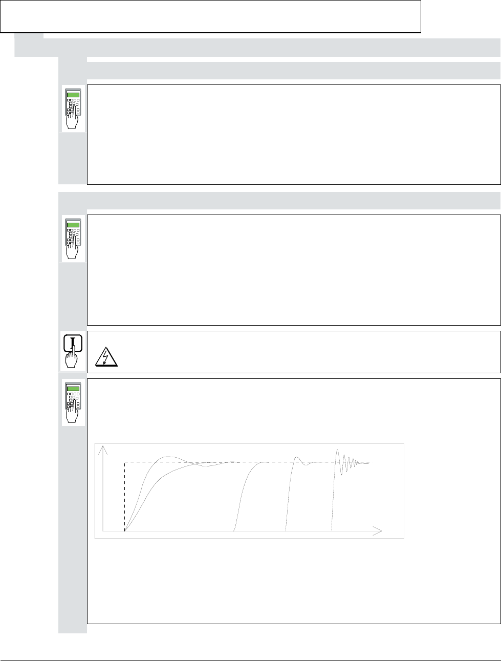
1308 = Match P-gain to field circuit.
1309 = Match I-gain to field circuit.
Oscillograph field current feedback via D/A output, or if one is to hand, use CMT
tool to depict it via the TRENDING menu and Parameter 11302.
t
A
B
CD
EF
Fig.: Transient response of controller
A: reference value jump
B: undercompensated; reset time and P-gain too small
C: undercompensated; P-gain too small
D: normal
E: slightly overcompensated; when a higher dynamic response is required
F: overcompensated; short reset time and a high P-gain
3ADW000055R0401_DCS500B_Operating Instruction_e_d
Chapter 2 - Start-Up Instructions
DCS 500B / DCP 500B Operating Instructions IV A 2 - 17
Switch OFF power!
1201 = 0 Panel display: NOT ACTIVATED
11202 = SAVE MOT1 SET
Save the altered values in the non-volatile memory!
When unit is fitted either with an SDCS-CON-1 or SDCS-CON-2 control board!
1001 = 1 Panel display: EMF, NO FIELD REV
Field weakening activated.
1002 = 12522
Links up a settable parameter as the flux reference value.
1004 = 12502
Activates the linked-up parameter.
1009 = 0
1010 = 0
e.m.f. controller switched off.
1012 = Speed at field weakening point as per motor rating plate
1013 = 40,0
1014 = 70,0
1015 = 90,0
Linear characteristic of field
12522 = 4095
Flux reference value set to 100 % corresponding to 4095.
12516 = 2000
Set internal reference value to 10 %.
Switch ON power; start drive.
DANGER: System components now energized!
Drive should run at 10 %.
The next steps serve to determine the motor's field characteristic. For this purpose,
the internal reference is used to set a speed n which is within the motor's basic speed
range and can be easily converted into 90 %, 70 % and 40 %.
Example: if n is selected so as to produce a motor voltage of 300 V, then 90 % will
correspond to 270 V, 70 % to 210 V and 40 % to 120 V.
12516 = increase slowly until a motor voltage is produced which can be
easily converted.
Note: Measure motor voltage with the U ARM AC signal
(change between ACT and PAR).
Scaling of 12516: 20000 corresponds to 100 % speed.
3ADW000055R0401_DCS500B_Operating Instruction_e_d
Chapter 2 - Start-Up Instructions
IV A 2 - 18 DCS 500B / DCP 500B Operating Instructions
12522 = decrease so that motor voltage is 90 %.
Flux and thus the field current as well are reduced.
How to proceed:
1. decrease 12522 (in steps of 100 at a time)
2. press ACT, read off motor voltage
3. press PAR and correct 12522 if necessary (then continue with 2.)
Read out and note down value of:
11003 = ......... (will later be entered in 1015)
12522 = decrease so that motor voltage is 70%.
Flux and thus the field current as well are reduced.
Proceed as described in (1. / 2. / 3.) above!
Read out and note down value of:
11003 = ......... (will later be entered in 1014)
12522 = decrease so that motor voltage is 40%.
Flux and thus the field current as well are reduced.
Proceed as described in (1. / 2. / 3.) above!
Read out and note down value of:
11003 = ......... (will later be entered in 1013)
12522 = 4095
12516 = 0
Internal reference value equal to zero.
Switch OFF power, thus stopping the drive!
1002 = 12512
1004 = 0
1009 = 10%
1010 = - 99%
As-delivered values (default values) for all 4 parameters restored.
1015 = equal to the 1st value of 11003
1014 = equal to the 2nd value of 11003
1013 = equal to the 3rd value of 11003
Linearization function matched to field circuit.
501 = 90 % of the rated motor voltage.
1012 = 90 % of the value on the motor rating plate.
This measure serves to provide a greater safety margin for the motor voltage
during start-up.
3ADW000055R0401_DCS500B_Operating Instruction_e_d
Chapter 2 - Start-Up Instructions
DCS 500B / DCP 500B Operating Instructions IV A 2 - 19
Only if analog tacho is used as speed feedback!
Switch ON power; start drive.
DANGER: System components now energized!
12516 = increase slowly up to 20000 (=100 % speed).
Check motor voltage; if value has been set with 501, motor voltage must
remain constant, or must not exceed this value.
Measure speed with manual tacho; balance maximum speed with R9, R48 or
R2716.
12516 = 0
Switch OFF power, thus stopping the drive!
CAUTION! Please don't forget!
11202 = SAVE MOT1 SET
Save the altered values in the non-volatile memory!
3ADW000055R0401_DCS500B_Operating Instruction_e_d
Chapter 2 - Start-Up Instructions
IV A 2 - 20 DCS 500B / DCP 500B Operating Instructions
2.7 Balancing the speed controller, plus fine-balancing the e.m.f. and the
current controllers
1701 = 11206
Change between POT1 and POT2 activated.
Extremely reduce the ramp-up time, depending on the system conditions:
1708 = 0,1 s
1709 = 0,1 s
Adjusting the potentiometers for speed controller balancing:
During acceleration/ braking, the drive should reach the current limitation, if
necessary increase the value of POT1.
Scaling of 1204 and 1205 ⇒ 20 000 corresponds to 100 % speed.
1204 (POT1) = 10%...20% max. speed
1205 (POT2) = 0
1206 (PERIOD) = Adapt as necessary.
Switch ON power; start drive.
DANGER: System components now energized!
Drive should run at speed values corresponding to POT1 and „0“.
For assessing control quality, the Fig. entitled "Transient response of
controller" ( ⇒ section 2.6.3) can be used.
For this purpose, the following parameters at the speed controller must be adapted:
2014 = desired response (behaviour) of controller
2018 = desired response (behaviour) of controller
Only when fine-balancing of the e.m.f. controller is wanted!
((Necessary when work as per section 2.6.3. has been performed)
Only when fine-balancing of the current controller is wanted!
For assessing control quality, the Fig. entitled "Transient response of
controller" ( ⇒ section 2.6.3) can be used.
- If fine-balancing of the current controller is wanted, the settings for
the software potentiometers can be retained.
The following parameters at the current controller must be adapted:
407 = desired response (behaviour) of controller
408 = desired response (behaviour) of controller
- If fine-balancing of the e.m.f. controller is wanted, potentiometers'
settings must be adapted:
1204 (POT1) approx. 10 % smaller than speed at field weakening point
1205 (POT2) ca. 10% greater than speed at field weakening point
The following parameters at the e.m.f. controller must be adapted:
1007 = desired response (behaviour) of controller
1008 = desired response (behaviour) of controller.
3ADW000055R0401_DCS500B_Operating Instruction_e_d
Chapter 2 - Start-Up Instructions
DCS 500B / DCP 500B Operating Instructions IV A 2 - 21
1204 = 0
1205 = 0
Switch OFF power, thus stopping the drive!
1701 = 11903
501 = Rated motor voltage set in Chapter 2.2.
1012 = Speed at rated motor voltage
CAUTION! Please don't forget!
11202 = SAVE MOT1 SET
Save the altered values in the non-volatile memory!
2.8 Matching the thyristor power converter unit to the system conditions concerned
- Ramp function generator
- Binary inputs and outputs
- Limit-value messages
- Additional functions
3ADW000055R0401_DCS500B_Operating Instruction_e_d
Chapter 2 - Start-Up Instructions
IV A 2 - 22 DCS 500B / DCP 500B Operating Instructions
2.9 Presetting the 3-phase field supply unit DCF 50xB
This is a new functionality available for the first time with software version S21.232.
When commissioning a drive consisting of a DCS converter for the armature supply
and a DCF converter for the field please try to make sure both converters will be
equipped with at least this software version.
Make sure that existing supply voltages for power section, field supply unit (field ex-
citer) and field winding, fan, etc. match the rated data of the components used.
402 = 11303
field current reference received from the DCS 500B via FEX-link connected to cur-
rent controller
405 = 1 Panel display: CURR_REF
input P402 via CURR_REF activated
409 = 0
current controller without feedforward function
420 = 2 or 3 Panel display: METHOD 2 ALARM or METHOD 2 FAULT
current ripple monitoring based on method 2; in case a current bubble is missing an
alarm or fault is generated
421 = 25.0
threshold for current ripple monitoring = 25%
501 = Rated motor voltage
keep it to default; if set to lower values adapt the current controller to avoid over
voltage faults
502 = Rated motor current
set this parameter to the motor´s nominal field current
507 = Rated line voltage
Used to scale parameters referring to the line voltage, such as line undervoltage.
901 = 10916
902 = 10916
no need for an external start command for the field converter; when the start command
is given to the DCS 500B feeding the armature, this converter automatically starts and
controls the DCF 500B
906 = 12502
emergency stop command disabled
907 = 10917
no need for an external reset command for the field converter; when an error occurred
either in the field or the armature converter the fault can be reset by the reset command
connected and given to the DCS 500B; it is internally transferred to the DCF 500B
911 = 10908
input motor fan acknowledge deactivated
1215 = 4 Panel display: FEXLINK NODE 1
DCF field mode, DCF 506 is monitored, FEX-link in use and DCF 500B is node 1
1216 = 10703
digital input 2 used to monitor the motor fan at a DCS 500B is now used to monitor
the DCF 506 overvoltage protection
1217 = 0 or 1 Panel display: OVP ALARM or OVP ALARM
3ADW000055R0401_DCS500B_Operating Instruction_e_d
Chapter 2 - Start-Up Instructions
DCS 500B / DCP 500B Operating Instructions IV A 2 - 23
alarm or fault indication / reaction, if DCF 506 has triggered
3601 = 15
only at DCF 502B; bridge reversal delayed to app. 50ms
3602 = 15
only at DCF 502B; in worst case bridge change over will take place when time of
3601 has elapsed plus app. 50ms
3603 = 600
only at DCF 502B; time delay of about 2s for F65 error message (reversal fault);
timer is started, when reference is reversed; time has to be higher than time of
P3601 + P3602 + time, needed to decrease the current to zero + safety margin
11202 = SAVE MOT1 SET
Save the altered values in the non-volatile memory!
According to the connection diagram there is no dedicated input prepared to switch on
and start the field converter. Nevertheless there are two possibilities to control the
converter:
- using the CDP 312 control panel and local mode; this gives access to the
switch on / off function / start / stop function / reset function
- using the armature converter´s input / outputs
Make sure the Emergency Stop Function mentioned at the
beginning of this chapter is working
Make sure, no reference is active (DCS 500B not switched on)
1215 = 2 Panel display: STAND ALONE
current controller set to STAND ALONE for high inductive load
Switch ON power.
DANGER: System components now energized!
Please wait a few moments. During this time, the unit compares the phase sequence
set in the parameter with that obtaining at the power section.
If the unit outputs the "Phase sequence fault of power section“ signal (F 38):
- switch off unit completely and disconnect from the mains, interchange two phases at
the input, and start again from the beginning of this chapter.
or
- enter: 506 = R-T-S and then acknowledge fault signal.
Unit will automatically adapt to phase sequence; this signal is to be interpreted as in-
formation to the effect that the fans' direction of rotation may be wrong for size-C4
units.
Start drive.
1201 = 5 Panel display: FEX2/3 AUTOTUNING
FEX2/3 AUTOTUNING is selected; when pressing the enter button the converter
will directly start running field current!
3ADW000055R0401_DCS500B_Operating Instruction_e_d
Chapter 2 - Start-Up Instructions
IV A 2 - 24 DCS 500B / DCP 500B Operating Instructions
When the display shows NOT ACTIVATED (action correctly completed):
Stop drive
Switch OFF power!
In case the autotuning failed:
1201 = 4 Panel display: ARM. MAN. TUNING
ARM.MAN_TUNING, if the FEX2/3 autotuning failed; activate the reference via pa-
rameter 11209 and set the parameters of the square wave function generator; then
adapt the current controller to get the behaviour shown at curve D chapter 2.6.3 in
this manual
1215 = 4 Panel display: FEXLINK NODE 1
DCF mode FEXLINK NODE1 via FEX-link activated
11202 = SAVE MOT1 SET
Save the altered values in the non-volatile memory!
The DCS converter in DCF-mode (parameter 1215=1 or higher) will not accept a start
command, if an alarm or fault is still active (an A or F indication on the 7-segment dis-
play). To ensure a correct function afterwards, please make sure the reasons for any
type of alarm or fault is no longer present.
Continue with Chapter 2.4
3ADW000055R0401_DCS500B_Operating Instruction_e_d

Chapter 3 - Handling of Control Panel CDP 31x
DCS 500B / DCP 500B Operating Instructions IV A 3 - 1
3.1 Overview
The Control and Display Panel [Control Panel] is used for parame-
ter setting, for feedback value measuring and for drive control with
series DCS 500B / DCF 500B and DCP 500B thyristor power con-
verters. This device is available in different versions depending on
the type of unit and software to be used:
Units with software S 21.1xx ⇒ CDP 310 or CDP 311
(recommended: CDP 311)
Units with software S 21.2xx ⇒ CDP 312
Hereinafter CDP 31x will be used as a common type designation for
the above mentioned versions of Control Panel. Differences be-
tween the versions which have to be taken into account with par-
ticular functions will be indicated separately!
Panel Link
The CDP 310/311 Control Panel is connected to the drive via
CDI-300 communication bus.This communication bus, which is
based on the RS485 standard, is a common bus protocol for ABB
Drives products.
MODBUS is used as communication bus connecting the CDP 312
Control Panel to the drive. This Control Panel combined with a
Software version S 21.2xx onwards makes it possible to show the
texts on the LCD in different languages.
The selection of language is performed by parameter [P 522].
Note: The display texts as shown in this chapter correspond
to the default setting of [P 522] ( ⇒ English)!
Mounting the
Panel The CDP 31x Control Panel can be handled in three different ways:
• Direct mounting on the thyristor power converter; the CDP 31x is
plugged into the moulded part of the cover of the converter and
connected via an adaptor of approx. 45 mm.
• Mounting on the door of the switchgear cabinet using an assem-
bly kit equipped with a connection cable.
• Use of Panel as remote control device with a connection cable.
3ADW000055R0401_DCS500B_Operating Instruction_e_d

Chapter 3 - Handling of Control Panel CDP 31x
IV A 3 - 2 DCS 500B / DCP 500B Operating Instructions
3.2 Start Mode Note: The CDP 31x can be connected to the drive without dis-
connecting the auxiliary power !
When connected and power is applied to the electronics, the dis-
play of the CDP 31x shows:
- software version of the Control Panel
- ID number of the CDP 31x and number of drives connected to
the link.
ID-NUMBER 31
CDP310 PANEL
TOTAL 1 DRIVES
ID-NUMBER 1
DCS 500
Display with CDP 310 / CDP 311 Display with CDP 312
After two seconds the display will clear, and the actual signals of
the selected drive will appear.
The following message is displayed if the CDP 31x is not able to
communicate with the drive:
**FAULT**
NO COMMUNICATION
NO COMMUNICATION [x]
[x]
1 The CDP is not active for 10 s
2 The drive is not active for 10 s
3 No data set received for 2 s
4 Bus administrator is offline
• The drive is not present on the link. This is the case if the drive
stops communicating.
• The link does not operate because of a hardware malfunction or
a cabling fault.
Action: Disconnect the
CDP 31x and connect it again to the
drive. By this means the CDP 31x will be forced to
the Start Mode another time!
3ADW000055R0401_DCS500B_Operating Instruction_e_d
Chapter 3 - Handling of Control Panel CDP 31x
DCS 500B / DCP 500B Operating Instructions IV A 3 - 3
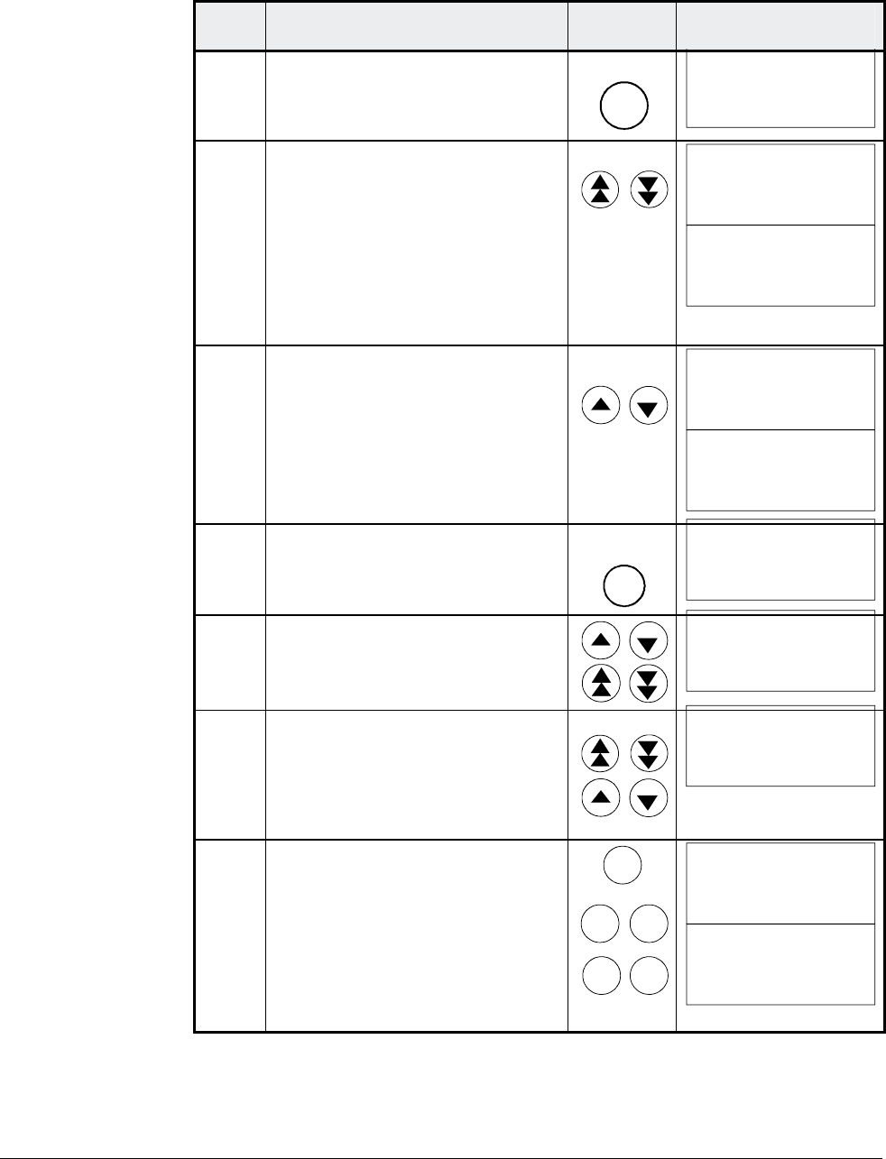
3.3 Panel Functions The CDP 31x has four different keypad modes:
• Actual Signal Display Mode (ACT)
• Parameter Mode (PAR)
• Function Mode (FUNC)
• Drive Mode (DRIVE) for further extensions
Actual Signal
Display Mode
ACT
This keypad mode will show, depending on the drive´s history:
• Actual Signals
• Faults
• Fault History Logger
If the ACT-key is pressed immediately after initialization this table is
displayed. If no panel-key is touched for more than one minute the
Actual Signal Display will appear automatically, except when Status
display or speed reference setting is active. (see chapter 3.13 and
3.15)
0 L 0.0 rpm 00
SPEED AC 0.0 rpm
CONV CUR 0 A
U ARM AC 0 V
Run Status
I = RUN
0 = STOP
Speed
reference
rpm
Main contactor
status
0 = Open
1 = Closed
Control
Location
L = Local
= Remote
ID-number
of the Drive
Statusrow
Actual Signal
Name, value and unit
_
Cursor shows
the selected row
Actual Signal Display
If a fault is effective in the drive, the Fault Display will appear auto-
matically. This will happen with all other modes as well, except the
Drive Mode is active.
Fault Display
0 L 0.0 rpm 00
DCS 500
*** FAULT ***
No ext. FAN ack.
Type of fault or alarm
To select Fault History Display see chapter 3.8
1 = last fault
2 = second last fault
...
Total time after
the power up
HHHH:MM:SS.ss
Fault History Display
0 L 0.0 rpm 00
1 LAST FAULT
I/O-Board not found
0000:14:12.64
Fault or alarm name
3ADW000055R0401_DCS500B_Operating Instruction_e_d
Chapter 3 - Handling of Control Panel CDP 31x
IV A 3 - 4 DCS 500B / DCP 500B Operating Instructions
Parameter Mode
PAR
The Parameter Mode is used for:
- change the structure in the firmware
- show signals and their actual status
- show and change values of parameters, if they are not
write-protected.
When the Parameter mode is entered parameter 101 appears after
initialization, otherwise the selected parameter is shown.
0 L 0.0 rpm 00
17 RAMP GENERATOR
01 RAMP.[IN]
119.03
Parameter and Signal Display
Statusrow
Group number
and name
Subgroup number
and name
Parameter value or
connection to or
status
All function blocks are characterised by inputs and outputs with
numbers. These inputs and outputs can be subdivided into two
categories:
• Pins for designating connections
• Parameters for setting values, such as ramp-up / ramp-
down time, controller´s gain, reference values, etc.
If a write-protected pin or parameter is selected, the following warn-
ing will be displayed.
**WARNING**
WRITE ACCESS DENIED
PARAMETER SETTING
NOT POSSIBLE
Function Mode
FUNC
The Function mode is used for special functions, such as:
• Parameter UPLOAD from drive to CDP 31x
• Parameter DOWNLOAD from CDP 31x to drive
• CDP 31x display contrast setting
0 L 0.0 rpm 00
UPLOAD <=<=
DOWNLOAD =>=>
CONTRAST 7
Statusrow
Selectable
Functions
Display contrast
adjusting
_
Function Display
3ADW000055R0401_DCS500B_Operating Instruction_e_d
Chapter 3 - Handling of Control Panel CDP 31x
DCS 500B / DCP 500B Operating Instructions IV A 3 - 5
Drive Mode
DRIVE
Drive mode is used to check the configuration. The display will
show the type and ID-number of the drive to whom the CDP 31x is
connected to.
DCS500
ID-NUMBER 0
TOTAL 1 DRIVES
Device type
The ID-number
Total number
of drives in
the link
Drive Display
Display with CDP 310 / CDP 311
The factory-adjusted (default) values of the ID-numbers for the
CDP and the drive depend on the specific CDP type:
CDP 310 / CDP 311 ⇒ ID = 31 with DCS 500 ⇒ ID = 0
CDP 312 ⇒ ID = 0 with DCS 500B ⇒ ID = 1
Caution: These values should not be changed!
1 L 30.5 % 00
FLUX_ REF 10 0%
EXMF_ FLS 0 Log
ARMCU RAC 14 7 A
CDI 300 link
(communication bus)
Control Panel
ID=0
DCS500 ID=31
Factory-adjusted (default) values for CDP 310 / CDP 311 with DCS 500
3.4 Pin/Parameter Selecting and Changing of Value
For input / parameter selection, the following applies:
• Ignore the two right-hand digits; the remaining digits are the
group and to be selected
• The two right-hand digits are the element and to be selected
DI7 10713
The selection can be done with the control panel CDP312, using
the keys / for the group and the keys / for the element
or a PC-based tool program CMT/DCS500B
Group 107
element 13
3ADW000055R0401_DCS500B_Operating Instruction_e_d
Chapter 3 - Handling of Control Panel CDP 31x
IV A 3 - 6 DCS 500B / DCP 500B Operating Instructions
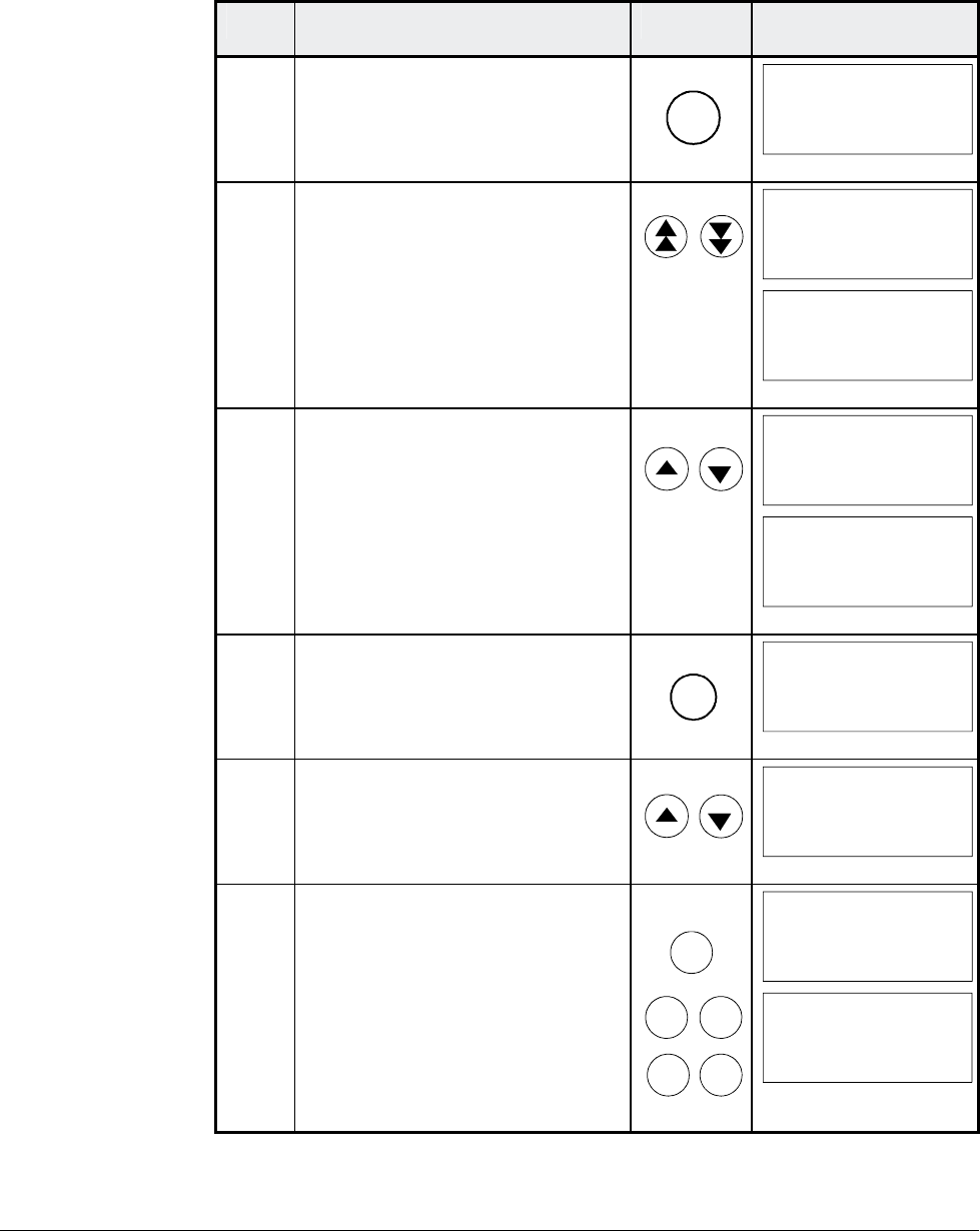
Step Function Press key Display after key is
pressed
1. To enter the Parameter Mode
Selection
PAR
0 L 0.0 rpm 00
17 RAMP GENERATOR
01 RAMP.[IN]
119.03
2. To select another group.
While holding the key down,
only the group number and
name is displayed. When the
key is released, number, name
and value of the first pin/ pa-
rameter in the group are dis-
played.
0 L 0.0 rpm 00
21 SPEED MEASUREMEN
0 L 0.0 rpm 00
21 SPEED MEASUREMEN
01 TACHOPULS NR
2048
3. To select a element.
While holding the key down,
only the element number and
name, representing a pin/ pa-
rameter, is displayed. When the
key is released the value of the
element is also displayed.
0 L 0.0 rpm 00
21 SPEED MEASUREMEN
02 SPEED MEAS MODE
0 L 0.0 rpm 00
21 SPEED MEASUREMEN
02 SPEED MEAS MODE
EMF SPEED ACT
4. To enter the Pin/Parameter Set-
ting Mode.
ENTER
0 L 0.0 rpm 00
21 SPEED MEASUREMEN
02 SPEED MEAS MODE
[EMF SPEED ACT]
5a. To change the Parameter
value: (slow change)
(fast change)
0 L 0.0 rpm 00
21 SPEED MEASUREMEN
02 SPEED MEAS MODE
[ANALOG TACHO]
5b. To change the Pin connection
at first: (group number) --->
then: (element number) --->
of the target.
0 L 0.0 rpm 00
2 ANALOG OUTPUTS
05 AO2.[IN]
[105.02]
6a.
6b.
To send the new value to the
drive.
To cancel the new setting and
keep the original value press
any key before pressing ENTER.
The selected Keypad Mode is
entered.
ENTER
ACT
PAR
FUNC DRIVE
0 L 0.0 rpm 00
21 SPEED MEASUREMEN
02 SPEED MEAS MODE
ANALOG TACHO
0 L 0.0 rpm 00
21 SPEED MEASUREMEN
02 SPEED MEAS MODE
EMF SPEED ACT
3ADW000055R0401_DCS500B_Operating Instruction_e_d
Chapter 3 - Handling of Control Panel CDP 31x
DCS 500B / DCP 500B Operating Instructions IV A 3 - 7
3.5 Saving of the Parameters to backup memory
Step Function Press key Display after key is
pressed
1. To enter the Parameter Mode
Selection
PAR
0 L 0.0 rpm 00
2 ANALOG OUTPUTS
05 AO2.[IN]
105.01
2. Select group 112.
While holding the arrow down,
only the group name is dis-
played. When the key is re-
leased, number, name and
value of the first parameter in
the group is displayed.
0 L 0.0 rpm 00
112 MAINTENANCE
0 L 0.0 rpm 00
112 MAINTENANCE
01 COMMIS STAT
NOT ACTIVATED
3. Select signal number 02 from
group 112.
While holding the arrow down,
only the signal name and num-
ber are displayed. When the key
is released the value is also dis-
played.
0 L 0.0 rpm 00
112 MAINTENANCE
02 BACKUPSTOREMODE
0 L 0.0 rpm 00
112 MAINTENANCE
02 BACKUPSTOREMODE
NONE
4. Press ENTER to select
BACKUPSTOREMODE.
ENTER
0 L 0.0 rpm 00
112 MAINTENANCE
02 BACKUPSTOREMODE
[NONE]
5. Saving of changed values.
Select Set1 (SAVE MOT1 SET)
or Set2 (SAVE MOT2 SET).
0 L 0.0 rpm 00
112 MAINTENANCE
02 BACKUPSTOREMODE
[SAVE MOT1 SET]
6a.
6b.
Confirmation of the saving.
Saving procedure is completed
when NONE is displayed.
To cancel the saving and keep
the original value press any key
before pressing ENTER.
The selected Keypad Mode is
entered.
ENTER
ACT
PAR
FUNC DRIVE
0 L 0.0 rpm 00
112 MAINTENANCE
02 BACKUPSTOREMODE
ERASING...
0 L 0.0 rpm 00
112 MAINTENANCE
02 BACKUPSTOREMODE
NONE
3ADW000055R0401_DCS500B_Operating Instruction_e_d
Chapter 3 - Handling of Control Panel CDP 31x
IV A 3 - 8 DCS 500B / DCP 500B Operating Instructions
3.6 FAULT RESETTING (RESET)
FAULT resetting and EMERGENCY STOP resetting (RESET) can
only be performed via the CDP 31x if LOCAL is active. If drive is in
REMOTE, please check whether LOCAL is a critical condition. If not
activate LOCAL, reset the fault and activate REMOTE again.
Step Function Press key Display after key is
pressed
1. To enter the Actual Signal
Display Mode
ACT
0 L 0.0 rpm 00
DCS500
*** FAULT ***
I/O-Board not found
2. To RESET the FAULT
RESET
0 L 0.0 rpm 00
SPC:OUT 0.0 %
CONV CUR 0 A
U ARM AC 0 V
_
3.7 EMERGENCY STOP RESETTING (RESET)
Step Function Press key Display after key is
pressed
1. If EMERGENCY STOP is acti-
vated, the control panel will
show the following ALARM
0 L 0.0 rpm 00
DCS500
** WARNING **
+Emergency stop
2. To enter the Fault History Dis-
play
0 L 0.0 rpm 00
1 LAST FAULT
+Emergency stop
xxxx:xx:xx.xx
3. To RESET the ALARM
RESET
0 L 0.0 rpm 00
1 LAST FAULT
-Emergency stop
xxxx:xx:xx.xx
3ADW000055R0401_DCS500B_Operating Instruction_e_d
Chapter 3 - Handling of Control Panel CDP 31x
DCS 500B / DCP 500B Operating Instructions IV A 3 - 9
3.8 Fault History Display
Up to 100 faults are stored time related and displayed together with
the time they appeared after electronics supply switched on.
Step Function Press key Display after key is
pressed
1. To enter the Actual Signal
Display Mode
ACT
0 L 0.0 rpm 00
SPC:OUT 0.0 %
CONV CUR 0 A
U ARM AC 0 V
_
2. To enter the Fault History Dis-
play.
These keys also scroll the
screen from Actual Signal Dis-
play to Fault Display, to Fault
History Display back to Actual
Signal Display.
0 L 0.0 rpm 00
1 LAST FAULT
+Type code changed
xxxx:xx:xx.xx
3. To select newer (UP) or older
fault (DOWN).
To clear a fault from the Fault
History Buffer
The previous fault is displayed.
Drive condition identical to 3.6
and 3.7
RESET
0 L 0.0 rpm 00
2 LAST FAULT
Armature overvoltage
xxxx:xx:xx.xx
0 L 0.0 rpm 00
1 LAST FAULT
Reset
xxxx:xx:xx.xx
4. To return to the Actual Signal
Display Mode.
0 L 0.0 rpm 00
SPC:OUT 0.0 %
CONV CUR 0 A
U ARM AC 0 V
_
3ADW000055R0401_DCS500B_Operating Instruction_e_d
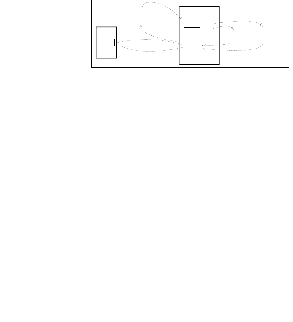
Chapter 3 - Handling of Control Panel CDP 31x
IV A 3 - 10 DCS 500B / DCP 500B Operating Instructions
3.9 Uploading and Downloading of Parameters (UPLOAD/DOWNLOAD)
CAUTION! The drive must be in standstill condition with given
STOP command (controllers blocked, power section
disconnected from the network) when UPLOAD/
DOWNLOAD function is selected.
DCS 500
FPROM D35
FPROM D33&34
RAM
Control
Panel
FPROM
DOWNLOAD
UPLOAD
FACTORY-
SET VALUE
FPROM = FLASH-PROM
RAM = Random Access Memory
SAVE MOT1 SET
SAVE MOT2 SET
Parameter 11202:
1 =
2 =
4 =
5 =SELECT MOT1 SET
SELECT MOT2 SET
Parameter 11202:
If one or both of these functions have been performed additional ac-
tions may be needed. For example BACKUPSTOREMODE should
be selected for saving the values to the backup memory, if a
DOWNLOAD had taken place.
UPLOAD will copy all parameters and connections, which are dif-
ferent to default, from the RAM memory of the drive to the FPROM
memory of the Control Panel CDP 31x.
Before a DOWNLOAD is started the factory-set values (default val-
ues) should be available within the drive´s RAM memory.
Factory-set values are always available in control board memory
and they can be called by means of BACKUPSTOREMODE pa-
rameter 11202 [FACTORY_SET_VALUE] or by means of S2 switch
on the control board SDCS-CON-x.
The DOWNLOAD will copy all values stored in the FPROM memory
of the CDP 31x to the RAM memory of the drive. Downloaded
parameters should be saved to the FPROM memory of the control
board SDCS-CON-x. See chapter 3.5"Saving of Parameters to
backup memory" .
Note: For reasons of safety the DOWNLOAD function will only
operate if „LOCAL mode“ of the Control Panel CDP 31x
is selected!
3ADW000055R0401_DCS500B_Operating Instruction_e_d
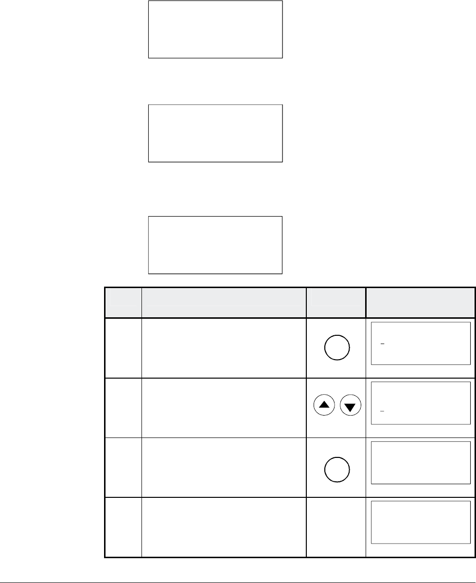
Chapter 3 - Handling of Control Panel CDP 31x
DCS 500B / DCP 500B Operating Instructions IV A 3 - 11
Depending on the drive´s condition and the status of the commis-
sioning, UPLOAD has to take place before DOWNLOAD, otherwise
a warning may be displayed:
**WARNING**
NOT UPLOADED
DOWNLOADING
NOT POSSIBLE
The drive must be in stopped state during the DOWNLOAD proc-
ess, otherwise the following warning is displayed.
**WARNING**
DRIVE IS RUNNING
DOWNLOADING
NOT POSSIBLE
The drive that receives the downloaded parameters must have a
compatible software version to the drive from which the parameters
were uploaded. Otherwise the panel will display a warning:
**WARNING**
DRIVE UNCOMPATIBLE
DOWNLOADING
NOT POSSIBLE
Step Function Press key Display after key is
pressed
1. To enter the Function Mode
FUNC
0 L 0.0 rpm 00
UPLOAD <= <=
DOWNLOAD => =>
CONTRAST 7
2. To select a function.
0 L 0.0 rpm 00
UPLOAD <= <=
DOWNLOAD => =>
CONTRAST 7
3. To activate the selected func-
tion.
ENTER
0 L 0.0 rpm 00
=> => => => => => =>
DOWNLOAD
4. Loading complete.
0 L 0.0 rpm 00
SPC:OUT 0.0 %
CONV CUR 0 A
U ARM AC 0 V
_
3ADW000055R0401_DCS500B_Operating Instruction_e_d
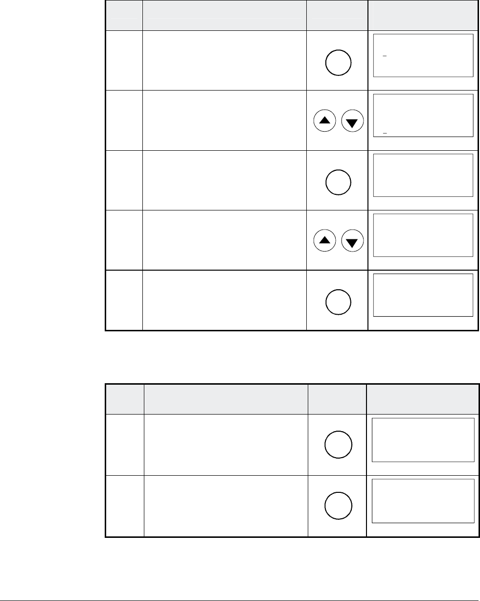
Chapter 3 - Handling of Control Panel CDP 31x
IV A 3 - 12 DCS 500B / DCP 500B Operating Instructions
3.10 Setting of the Display Contrast
Step Function Press key Display after key is
pressed
1. To enter the Function Mode.
FUNC
0 L 0.0 rpm 00
UPLOAD <= <=
DOWNLOAD => =>
CONTRAST 7
2. To select a function.
0 L 0.0 rpm 00
UPLOAD <= <=
DOWNLOAD => =>
CONTRAST 7
3. To enter contrast setting func-
tion.
ENTER
0 L 0.0 rpm 00
CONTRAST [7]
4. To set the contrast.
(1...7)
0 L 0.0 rpm 00
CONTRAST [4]
5. To accept the selected value.
ENTER
0 L 0.0 rpm 00
CONTRAST 4
3.11 Full Name of output pins
Step Function Press key Display after key is
pressed
1. To display the full name of the
three actual signals press key
and hold
ACT
0 L 0.0 rpm 00
SPEED ACT FILT
CONV CURR ACT
U ARM ACT
_
2. To return to the Actual Signal
Display Mode release key.
ACT
0 L 0.0 rpm 00
SPEED AC 0.0 rpm
CONV CUR 0 A
U ARM AC 0 V
_
3ADW000055R0401_DCS500B_Operating Instruction_e_d
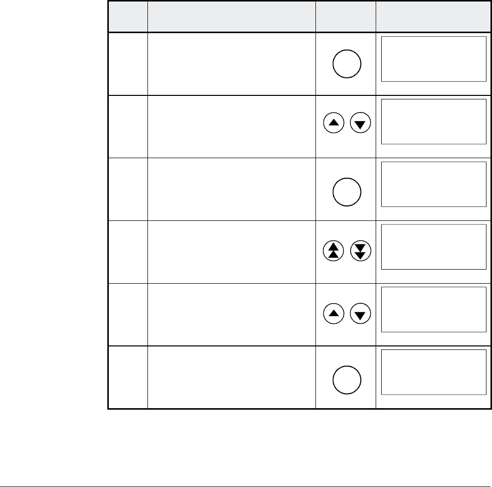
Chapter 3 - Handling of Control Panel CDP 31x
DCS 500B / DCP 500B Operating Instructions IV A 3 - 13
3.12 Selecting output pins
Note for CDP 310 / CDP 311:
Newly selected actual signals will be used for display until the elec-
tronics power supply is switched OFF.
Note for CDP 312:
If there is a need for permanent display of the newly selected pin
(e.g. after having switched OFF and ON again the electronics
power supply), BACKUPSTOREMODE (see chapter 3.5) should
be performed in order to save the values to the backup memory
before switching OFF the electronics power supply.
Step Function Press key Display after key is
pressed
1. To enter the Actual Signal
Display Mode
ACT
0 L 0.0 rpm 00
SPEED AC 0.0 rpm
CONV CUR 0 A
U ARM AC 0 V
_
2. To select the desired line.
0 L 0.0 rpm 00
SPEED ACT FILT
CONV CURR ACT
U ARM ACT
_
3. To get acces to the desired line.
ENTER
0 L 0.0 rpm 00
121 SPEED MEASUREMEN
03 SPEED ACT FILT
0.0 rpm
4. To select a different group.
0 L 0.0 rpm 00
120 SPEED CONTROLLER
01 ERR:OUT
0.0 rpm
5. To select a element.
0 L 0.0 rpm 00
120 SPEED CONTROLLER
04 SPC:OUT
0.0 %
6. To accept the selection and to
return to the Actual Signal
Display Mode.
ENTER
0 L 0.0 rpm 00
SPC:OUT 0.0 %
CONV CUR 0 A
U ARM AC 0 V
_
3ADW000055R0401_DCS500B_Operating Instruction_e_d
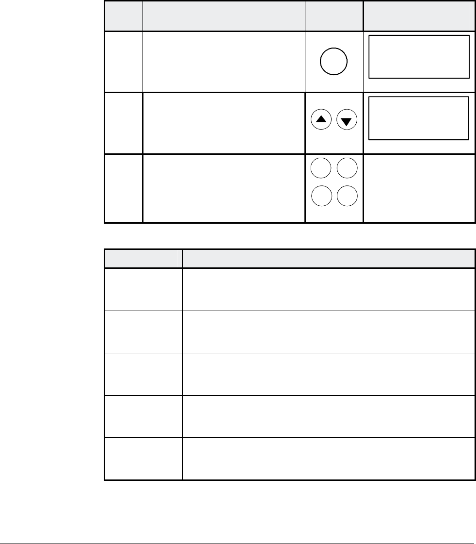
Chapter 3 - Handling of Control Panel CDP 31x
IV A 3 - 14 DCS 500B / DCP 500B Operating Instructions
3.13 Drive Mode
Display of the ID-number for the Drive and for the Control Panel
CDP 31x as well as display of the status (Status Display)
Step Function Press key Display after key is
pressed
1. To enter the Drive Mode
DRIVE
DCS500
ID-NUMBER 0
TOTAL 1 DRIVES
2. To select the Status Display
(see table below).
0 31P
Ü
3. To cancel the Drive Mode.
The selected Keypad Mode is
entered.
ACT PAR
FUNC DRIVE
Symbol Status Display
á
Stopped, main contactor ON (closed)
Ü
Stopped, main contactor OFF (open)
Ö
Running, main contactor ON (closed)
P
Control Panel CDP 31x
F
Alarm or fault signalling effective in the drive
3ADW000055R0401_DCS500B_Operating Instruction_e_d
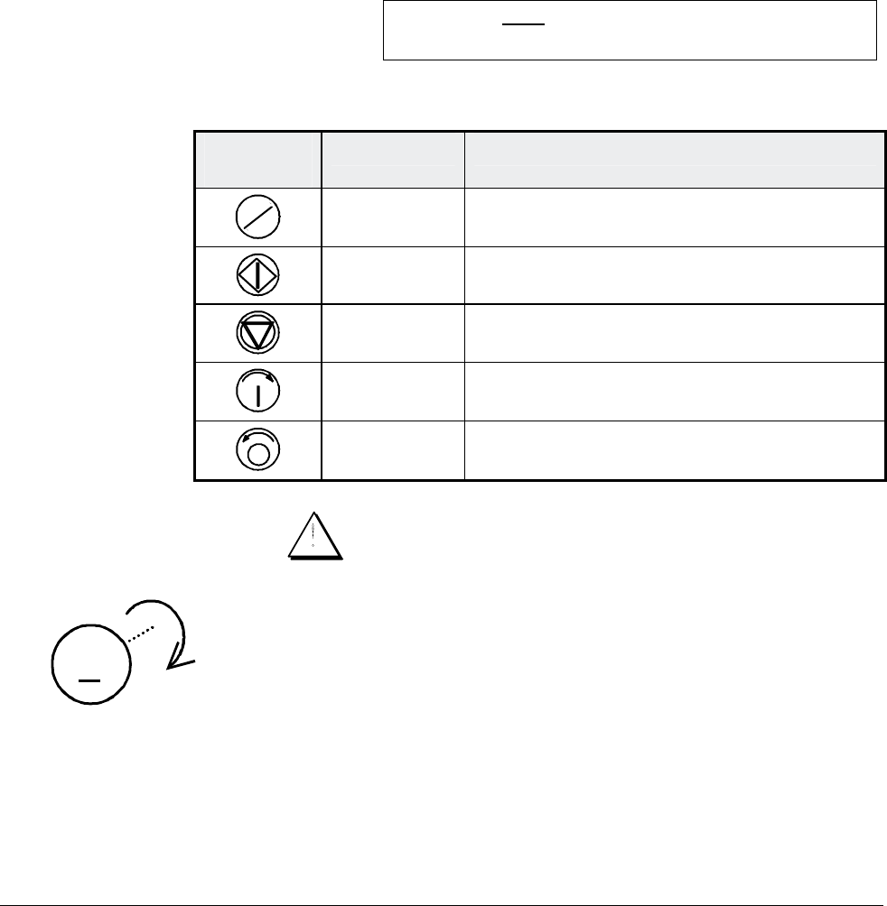
Chapter 3 - Handling of Control Panel CDP 31x
DCS 500B / DCP 500B Operating Instructions IV A 3 - 15
3.14 Running the Drive
Operational Com-
mand Keys
Operational commands can be given from the Control Panel
CDP31x every time when the status row is displayed. Operational
commands include START and STOP of the the drive, controlling
the main contactor and adjusting the reference.
CAUTION! To be able to give operational commands from the
CDP31x, the selected control location must be the
Control Panel. The control location can be changed
by means of LOC/REM key to LOCAL mode.
If LOC is activated some of the
binary inputs are no longer functioning.
Take care that the drive is engineered to allow opera-
tion with LOCAL mode.
Control
Panel Key Name of Key Function
LOC
REM
LOCAL /
REMOTE To select LOCAL (= CDP31x) or REMOTE
(= ext. control system) operation.
START Starts the drive, when in LOCAL mode.
STOP Stops the drive, when in LOCAL mode.
ON Main contactor closing control, when in
LOCAL mode.
OFF Main contactor opening control, when in
LOCAL mode.
Running the DC-
Drive from
the CDP31x Ensure safety before you start the drive test!
M
• Select LOCAL mode (LOCAL = CDP31x) by pressing
LOC/REMOTE key.
• Close (switch on) the main contactor by pressing the ON key
• Start the drive by pressing the START key. Motor will now ac-
celerate to the value of the reference.
• Direction of rotation can be changed by giving the opposite po-
larity reference value in case of 4Q drive.
• Stop the drive by pressing the STOP key. Motor will decelerate
to zero speed. (depending on the STOP MODE)
• Finally open (switch off) the main contactor by pressing the
OFF key.
3ADW000055R0401_DCS500B_Operating Instruction_e_d
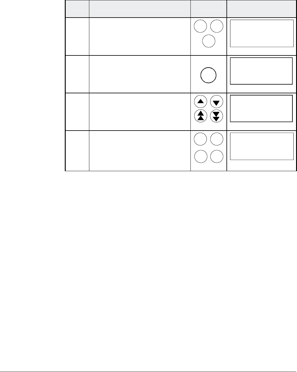
Chapter 3 - Handling of Control Panel CDP 31x
IV A 3 - 16 DCS 500B / DCP 500B Operating Instructions
3.15 Speed Reference Setting for the Drive
Step Function Press key Display after key is
pressed
1. Press one of these keys to get
the status row displayed.
ACT PAR
FUNC
0 L 0.0 rpm 00
SPEED AC 0.0 rpm
CONV CUR 0 A
U ARM AC 0 V
_
2. To enter the Reference Setting
Mode
REF
0 L [0.0 rpm] 00
SPEED AC 0.0 rpm
CONV CUR 0 A
U ARM AC 0 V
_
3. To change the reference:
(slow change)
(fast change)
0 L [219.0 rpm] 00
SPEED AC 0.0 rpm
CONV CUR 0 A
U ARM AC 0 V
_
4. To exit the Reference Setting
Mode.
The selected Keypad Mode is
entered.
ACT PAR
FUNC
DRIVE
0 L 219.0 rpm 00
SPEED AC 0.0 rpm
CONV CUR 0 A
U ARM AC 0 V
_
3ADW000055R0401_DCS500B_Operating Instruction_e_d

Chapter 4 - Signals and Troubleshooting
DCS 500B / DCP 500B Operating Instructions IV A 4 - 1
4.1 Display of status, alarm and fault signals
Categories of signals
and possibilities of
display
The signals (messages) to be available for thyristor power con-
verters series DCS 500B / DCF 500B or DCP 500 are subdivided
into five
categories:
General messages
Starting errors
F Fault signals
A Alarm signals
[112 . .] Status signals through parameters
A seven segment display on the control board SDCS-CON-x of the
thyristor power converters series DCS 500B / DCF 500B or
DCP 500 is used to show general messages, starting errors, fault
and alarm signals. The signals (messages) are displayed as codes.
If the codes consist of several parts, the characters/individual digits
will be indicated for 0.7 sec one after the other, e.g.:
0.7s 0.7s
0.7s
⇒⇒
F 14 = Speed measurement fault
⇑ ⇐ ⇓
In addition to this the DCS 500B DCF 500B or DCP 500 combined
with the LCD of the control panel CDP 31x will be able to show the
fault and alarm signals as well as the status signals (selected by
signal numbers [112 . .]) as clear text.
Note: The languages to be available for display as text depend
on the type of Control Panel and the Software version
( ⇒ Chapter „Handling of Control Panel CDP 31x“).
For subsequent evaluation via binary outputs or serial interfaces the
16 bit informations FAULT WORD1 [11101], FAULT WORD2 [11102]
and FAULT WORD3 [11103] as well as ALARM WORD1 [11104],
ALARM WORD2 [11105] and ALARM WORD3 [11106] contain several
fault and alarm signals as a binary code.
Each fault and alarm signal is coded as an individual error code to
the LATEST FAULT [11106] and LATEST ALARM [11107].
3ADW000055R0401_DCS500B_Operating Instruction_e_d

Chapter 4 - Signals and Troubleshooting
IV A 4 - 2 DCS 500B / DCP 500B Operating Instructions
4.2 General messages
The general messages will only be shown on the seven segment
display of the control board SDCS-CON-x.
Code
seven
segm.
display
Text on
LCD of control panel
CDP 31x
Definition – Remark
8 Not available Program is not running – (1)
. Not available Normal situation, no fault / no alarm signal –
L Not available Indication while loading another firmware
into the drive –
(1) Units should be switched off and on electrically; if fault occurs again, the PCBs SDCS-POW-1 and SDCS-CON-x
have to be checked and if necessary to be changed.
4.3 Starting errors (E)
The starting errors will only be shown on the seven segment display
of the control board SDCS-CON-x.
With starting errors it will not be possible to start the drive.
Code
seven
segm.
display
Text on
LCD of control panel
CDP 31x
Definition – Remark
E1 Not available ROM memory test error – (1)
E2 Not available RAM memory test error – (1)
E3 Not available No TC-link board
(not valid for software version S21.1xx)
–
E4 Not available Communic. board SDCS-COM-x faulty – (2)
E5 Not available No control program in memory – (3)
E6 Not available ASIC not O.K. – (1)
E7 Not available Parameter FLASH identity test failed – (1)
(1) Units should be switched off and on electrically; if fault occurs again, the PCBs SDCS-POW-1 and SDCS-CON-x
have to be checked and if necessary to be changed.
(2) Check communication board, plug in correctly and if necessary change the board.
(3) Load firmware once more.
3ADW000055R0401_DCS500B_Operating Instruction_e_d

Chapter 4 - Signals and Troubleshooting
DCS 500B / DCP 500B Operating Instructions IV A 4 - 3
4.4 Fault Signals (F)
The fault signals will be shown on the seven segment display of the
control board SDCS-CON-x as codes F . . as well as on the LCD of
the control panel CDP 31x as clear text.
All fault signals - with the exception of F 17, F 18 and F 44 - can be
reset (after elimination of the faults); F 20 would be self resetting, if
the communication had been re-established before.
For resetting (RESET) of fault signals the following steps are re-
quired:
• Switching off the commands ON/OFF and RUN
• Elimination of the faults
• Fault acknowledgement, i.e. resetting (RESET)
a) as described for CDP 31x
or b) by short-time setting of the command RESET
to high (logical one) via a binary input
(default setting = DI6).
• Depending on the application conditions generate the commands
ON/OFF and RUN once more.
The fault signals will result in switching off the signal [10910] resp. in
stopping the drive (installation-dependent).
If a fault occurs, there will be three different possibilities of reaction (see
column “Remark” in the fault list):
(1) Fault will switch off the signals energizing the main contactor, the field
contactor and the fan contactor.
(2) Fault will switch off the signals energizing the main contactor and the
field contactor.
(3) Fault will switch off at least the signal energizing the main contactor.
Code
seven
segm.
display
Text on
LCD of control panel
CDP 31x
Definition /
Action Status
signal
(FAULT_WORD_1/2)
Remark
F 1 Auxil. undervoltage Auxiliary voltage fault
Try to reset. Check internal auxiliary volt-
ages; if fault persists, change SDCS-CON-x
and/ or SDCS-POW 1 board (if required).
11101 bit 0 (1)
F 2 Overcurrent Overcurrent
Check: - Motor, load and armature cabling
for faults or blocking condition;
- Parameter setting of current con-
trol circuit/torque limitation;
- Parameter [P 512]
(overcurrent detection).
11101 bit 1 (3)
3ADW000055R0401_DCS500B_Operating Instruction_e_d

Chapter 4 - Signals and Troubleshooting
IV A 4 - 4 DCS 500B / DCP 500B Operating Instructions
Code
seven
segm.
display
Text on
LCD of control panel
CDP 31x
Definition /
Action Status
signal
(FAULT_WORD_1/2)
Remark
F 3 Conv.fan curr.fault Current converter fan not within limits
The current of the converter´s cooling fan is
measured via the option board PW1002/3.
Check: - Fan supply, fan current;
- Setting of PW1002,
SET_MAX_BR_TEMP [P519] and
CONV_TEMP_DELAY [P527]
- Direction of rotation, fan compo
nents, air inlet
11103 bit 11 (1)
S21.232
and
higher
F 4 Converter overtemp. Overtemperature power section
Check: - Fan supply, direction of rotation,
fan components, air inlet and
ambient temperature;
- Inadmissible load cycle?
11101 bit 3 (2)
F 5 Earth fault Earth fault (Σ I differs from zero)
Disconnect the mains and verify zero voltage
in armature and field circuits.
Make insulation test for the complete
installation.
Check sum current transformer; if necessary,
change transformer and SDCS-IOB-3 board.
11101 bit 4 (1)
F 6 Motor 1 overtemp. Overtemperature of MOTOR 1
Check: - Temperature sensor and its
cabling;
- Motor cooling or sizing;
- Inputs for temperature sensor
on board SDCS-IOB-3;
- Parameter setting
MOT1.TEMP_
FAULT_L [P 1403] correct?
Note: It will only be possible to reset this fault signal when the
motor temperature has fallen below the threshold which is
valid for the ⇒ alarm signal A 103; the signal will also be
evaluated while the mains contactor is de-energized (open).
11101 bit 5 (2)
F 7 Motor 1 overload Overload of MOTOR 1 (Thermal model 1)
Check: - Motor temperature (let motor cool
down and restart);
- Motor ratings and parameters of
thermal model;
- Motor sizing or load cycle.
11101 bit 6 (2)
3ADW000055R0401_DCS500B_Operating Instruction_e_d

Chapter 4 - Signals and Troubleshooting
DCS 500B / DCP 500B Operating Instructions IV A 4 - 5
Code
seven
segm.
display
Text on
LCD of control panel
CDP 31x
Definition /
Action Status
signal
(FAULT_WORD_1/2)
Remark
F 8 Current rise fault Actual current changed faster than allowed
The rate of current change is monitored.
Check: - Setting of current reference slope
[P406] and CURRENT_RISE_MAX
[P418];
Level and setting of line voltage
and motor voltage; setting of
current controler
11103 bit 10 (2)
S21.232
and
higher
F 14 Speed meas. fault Speed feedback (measurement) fault
Check: - Incremental encoder and connec-
tion cable, encoder power supply
(feedback might be too low);
- Tacho polarity and voltage
(does a total mismatch exist?)
- Electronic boards SDCS-CON-x,
SDCS-IOB-3, SDCS-POW 1;
- Connection converter – armature
circuit open?
- Correct setting for selection of
speed feedback monitoring?
11102 bit 5 (3)
F 17 Type coding fault (Converter) Type coding fault
SDCS-PIN-xx board not connected to board
SDCS-CON-x or SDCS-PIN-xx not coded.
Check: - Flat cables X12 and X13 O.K.?
- Faulty coding on SDCS-PIN-xx?
- Correct coding of unit size C4?
Note: This fault signal will be shown, if jumper S2 (on board
SDCS-CON-x) is in position 1–2 while switching ON the elec-
tronics supply. In that case select BACKUP-STOREMODE
[11202], save the paramter set, switch OFF the electronics,
reset jumper S2 and switch ON the electronics again.
11102 bit 8 (1)
Can
not be
reset
F 18 Backup read fault Backup read fault (Parameter saving fault)
Cause: Wrong or missing checksum, data error
while writing or reading.
Note: Try again BACKUP-STORE-MODE; for that purpose
- Move jumper S2 (on board SDCS-CON-x) to Pos. 1–2
with electronics supply switched OFF;
- Switch ON electronics again;
- Select BACKUPSTOREMODE [11202];
- Save default parameter set;
- Switch OFF electronics;
- Reset jumper S2 to ist original position;
- Switch ON electronics again.
If display shows F 18 once again, change SDCS-CON-x
board!
11102 bit 9 (1)
Can
not be
reset
3ADW000055R0401_DCS500B_Operating Instruction_e_d

Chapter 4 - Signals and Troubleshooting
IV A 4 - 6 DCS 500B / DCP 500B Operating Instructions
Code
seven
segm.
display
Text on
LCD of control panel
CDP 31x
Definition /
Action Status
signal
(FAULT_WORD_1/2)
Remark
F 20 Local & discon-
nected
No communication between CDP 31x/CMT
and DCS 500B / DCF 500B or DCP 500B in lo-
cal control mode (LOCAL)
Check: - Connection cable between
CDP 31x – DCS 500 / DCP 500
(unplug connection cable from
CDP 31x and plug in again);
- Communication board SNAT 6xx
and appropriate programm O.K.?
- Local mode terminated when
panel/PC was removed?
11102 bit 11 (1)
Self re-
setting
F 21 Ext.Overvolt.Fault Overvoltage protection DCF 506 has acted
There was an overvoltage condition in the
DC circuit of the field supply, which had been
limited by the activation of a free wheeling
circuit.
Check: - Power wiring of the field supply
- Control logic according to wiring
example?
- Does PP_DI_OVP [1216] has been
connected to a binary input?
- Setting of OVP_SELECT [1217]
correct? (see Alarm 121)
11103 bit 12 (1)
S21.232
and
higher
F 23 Motor stalled Motor stalled
While starting the motor the current exceeded
the value of parameter [P 2207] for a time
longer than parameter [P 2208] and the speed
feedback value was below parameter [P 2206].
Check: - Motor stalled?
- Load changed during start?
- Correct field current?
- Current/torque limitation;
- Parameter settings
[P 22xx].
11102 bit 14 (3)
F 27 Motor 2 overload Overload of MOTOR 2 (Thermal model 2).
{see Fault Code F 7}
11101 bit 9 (2)
3ADW000055R0401_DCS500B_Operating Instruction_e_d

Chapter 4 - Signals and Troubleshooting
DCS 500B / DCP 500B Operating Instructions IV A 4 - 7
Code
seven
segm.
display
Text on
LCD of control panel
CDP 31x
Definition /
Action Status
signal
(FAULT_WORD_1/2)
Remark
F 28 Armature over-
voltage
Armature (DC circuit) overvoltage
Check: - Setting of param. [P 511] suitable
for the system configuration?
- Setting of field current and actual
value as well as the complete
field supply (FIELD EXCITER);
- Was the motor accelerated by
the load?
- Speed scaling;
- Armature voltage feedback;
- Connections between SDCS-
CON-x and SDCS-PIN boards;
- Coding of voltage evaluation on
SDCS-PIN-xx board.
11101 bit 2 (1)
F 29 Mains undervoltage Mains supply undervoltage (AC); setting via
parameter [P 509]
Check: - Does the supply voltage exist?
- Did the mains contactor close?
- Setting of voltage feedback
coding (voltage scaling) correct?
- Connections between SDCS-
CON-x and SDCS-PIN-xx boards;
- Coding of voltage evaluation on
SDCS-PIN-xx board.
11101 bit 11 (3)
F 30 Mains overvoltage Mains supply overvoltage (AC)
Mains voltage > 130% of nominal value for
longer than 10s.
Fault tracing see Fault Code F 29.
11101 bit 12 (1)
F 31 Not in synchronism Synchronization fault (of mains)
Check: - Mains supply, fuses etc.;
- Mains voltage and stability.
11101 bit 13 (3)
F 32 Field ex.1 overcurr FIELD EXCITER 1 (field supply 1) overcurrent
Check: - Parameters of FIELD EXCITER 1;
- Connections of field exciter as
well as insulation level of cable
and of field winding.
11101 bit 14 (1)
F 33 Field ex.1 comerror FIELD EXCITER 1 communication error
Check: - Flat cable connections X14: or
cable X16: between SDCS-
CON-x board and field exciter;
- Auxil. voltage for ext. field exciter.
11101 bit 15 (1)
3ADW000055R0401_DCS500B_Operating Instruction_e_d

Chapter 4 - Signals and Troubleshooting
IV A 4 - 8 DCS 500B / DCP 500B Operating Instructions
Code
seven
segm.
display
Text on
LCD of control panel
CDP 31x
Definition /
Action Status
signal
(FAULT_WORD_1/2)
Remark
F 34 Arm. curent ripple Armature current ripple
One or several thyristors carry no current.
Check: - Current feedback with oscilloscope
(6 pulses within one cycle visible?)
- Branch fuses, thyristor gate con
nection; gate-cathode resistance.
- Sensitivity of monitoring function:
set CUR_RIPPLE_LIM [421] (de
pending on methode; see A 137)
11102 bit 0 (3)
modified
in
S21.232
F 35 Field ex.2 overcurr FIELD EXCITER 2 (field supply 2) overcurrent
{See Fault Code F 32} 11102 bit 1 (1)
F 36 Field ex.2 comerror FIELD EXCITER 2 communication error
{See Fault Code F 33} 11102 bit 2 (1)
F 37 Motor overspeed Motor overspeed
Speed feedback higher than parameter
[P 2204].
Check: - Scaling of speed controller loop;
- Drive speed;
- Field refererence values;
- Speed feedback and connection
of speed feedback;
- Was the motor accelerated by
the load?
11102 bit 15 (3)
F 38 Phase sequence
fault
Phase sequence fault of power section
Change supply phase sequency or make
correction with parameter [P 506].
Attention: Direction of rotation of 3-phase
fan correct?
11102 bit 3 (3)
F 39 No field ack. No field acknowledge from FIELD EXCITER
This message is either caused by the field exciter´s
missing „ready for operation“ signal (1) or the field
current being lower than the threshold (2). Reasons
for (1):
- field supply not in synchronism, or
- electronic power supply for the field unit not within
permissible limits
- power supply for the field unit not within permissi-
ble limits
Reasons for (2):
- field supply unit is broken
- field reversal took too long time
- field current lower than threshold because
11102 bit 4 (1)
3ADW000055R0401_DCS500B_Operating Instruction_e_d

Chapter 4 - Signals and Troubleshooting
DCS 500B / DCP 500B Operating Instructions IV A 4 - 9
Code
seven
segm.
display
Text on
LCD of control panel
CDP 31x
Definition /
Action Status
signal
(FAULT_WORD_1/2)
Remark
field weakening range too big / threshold
too high
Check: - Do selection parameters match
the field exciter (field supply)?
- Field exciter, it´s supply, cable and
field winding;
- Take this error message at the data
logger as a trigger condition and
record signals 11302 and 11203
- Status/level of acknowledge signal.
F 40 No ext. FAN ack. No acknowledge from FAN of motor
Check: - Was input for acknowledge
signal (parameter
[P 911]) used?
- Contactor circuit/supply for fan of
motor;
- Status of binary inputs/outputs
(DI/DO) on SDCS-IOB-1/2 board.
11102 bit 6 (1)
F 41 No main cont. ack. Missing main contactor acknowledge
Check: - Switch-ON/-OFF sequence
correct?
- Status of binary input DI for ac-
knowledge signal and of ACK
MAIN CONT ([P 912]) after main
contactor is closed;
- Status of binary output DO resp.
of auxiliary contactor (relay)
closing the main contactor after
ON/OFF command.
11102 bit 7 (3)
F 42 Field ex.1 not OK FIELD EXCITER 1 (field supply 1) status is not
O.K.
A fault was found during self-diagnosis of
field exciter {see [11203])}
Check: - Field exciter operation;
change the unit, if necessary.
11102 bit 12 (1)
F 43 Field ex.2 not OK FIELD EXCITER 2 (field supply 2) status is not
O.K.
{See Fault Code F 42}
11102 bit 13 (1)
3ADW000055R0401_DCS500B_Operating Instruction_e_d

Chapter 4 - Signals and Troubleshooting
IV A 4 - 10 DCS 500B / DCP 500B Operating Instructions
Code
seven
segm.
display
Text on
LCD of control panel
CDP 31x
Definition /
Action Status
signal
(FAULT_WORD_1/2)
Remark
F 44 I/O-Board not found Missing input/output (I/O-) boards
IOB1/2x/3/IOE1
The existance of the boards had been recog-
nized by the software and something hap-
pened to the board or the cable.
Check: - Is +/- 10 V supply available?
- Flat cable connections between
SDCS-CON-x and SDCS-IOB-1/2x/3/IOE1
11101 bit 7 (1)
Can
not be
reset
F 48 Motor 2 overtemp. Overtemperature of MOTOR 2
Check: - Parameter setting MOT2 TEMP_
FAULT_L [P 1603] correct?
{See Fault Code F 6}
11101 bit 8 (2)
F 50 No C FAN ack No CONVERTER FAN supply acknowledge
Depending on type of unit (size):
Size C4 ⇒ Fault signal
F 50
Sizes C1/C2/A5 ⇒ Alarm signal A 126
Check: - Was input for acknowledge
signal (parameter
[P 910]) used?
{See Fault Code F 40}.
11102 bit 10 (2)
F 52 No BRAKE ack No BRAKE acknowledge
Check: - Was parameter [P 304] used?
- Cabling and limit switches.
11101 bit 10 (2)
F 60 Fieldbus Timeout Serial interface (communication bus) is not
O.K.
Check: - Does a field bus module selected
via parameter
[P 4001] exist?
- Communication between control
system and module Nxxx-0x O.K.?
No or incomplete telegrams?
- Communication between module
Nxxx-0x and thyristor power con-
verter O.K.?
- Correct setting of the time inter-
val between two telegrams via
parameter
[P 921]?
11103 bit 13 /(3)
De-
pends
on
[P 920]
3ADW000055R0401_DCS500B_Operating Instruction_e_d

Chapter 4 - Signals and Troubleshooting
DCS 500B / DCP 500B Operating Instructions IV A 4 - 11
Code
seven
segm.
display
Text on
LCD of control panel
CDP 31x
Definition /
Action Status
signal
(FAULT_WORD_1/2)
Remark
F 65 Reversal Fault Reversal of direction of current is not O.K.
The reversal of the direction of current was
not correct.
Check: - External cabling between both
thyristor power converters;
- Correct plugging in of flat cable
X18:?
11103 bit 15 (3)
F 66 Current Difference Current feedback difference (deviation) be-
tween Master and Slave Drive
There is a current feedback difference (de-
viation) between Master and Slave Drive (in
twelve pulse configuration).
Check: - Parameter settings [P 3606] and
[P 3605];
- Power-circuit cabling;
- Symmetry of control logic and
scaling of signals exchanged
between Master and Slave Drive.
11103 bit 14 (3)
3ADW000055R0401_DCS500B_Operating Instruction_e_d

Chapter 4 - Signals and Troubleshooting
IV A 4 - 12 DCS 500B / DCP 500B Operating Instructions
4.5 Alarm Signals (A)
The alarm signals will be shown on the seven segment display of
the control board SDCS-CON-x as codes A . . as well as on the
LCD of the control panel CDP 31x as plain text. Alarm signals will
only be displayed, if there is no fault signal active.
The alarm signals - with the exception of A 101 and A 102 - will not
result in switching off the signal 10910 resp. in stopping the drive.
Code
seven
segm.
display
Text on
LCD of control panel
CDP 31x
Definition /
Possible source Signal
number
(ALARM_WORD_1/2)
Remark
A 101 Start inhibition Alarm Start Inhibition
Pin 908 (START_INHIBIT) is set to logical
"1“; drive cannot be switched ON.
When pin is set to logical "0“, the alarm sig-
nal will be reset.
11104 bit 0
A 102 Emergency stop Alarm EMERGENCY STOP
Pin 906 has a logical "0" level; for signal re-
set, see introductory remarks in Chapter 4.4
"Fault Signals“ and Chapter 3.7 "EMER-
GENCY STOP RESETTING“.
11104 bit 1
A 103 Motor 1 temp. alarm Alarm Overtemperature MOTOR 1
Check: - Parameter setting MOT1.TEMP_
ALARM_L [P 1402] correct?
See also Fault Code F 6.
11104 bit 2
A 104 Motor 1 overl.alarm Alarm Overload MOTOR 1 (Thermal Model 1)
Check: - See Fault Code F 7.
11104 bit 3
A 105 Conv. overtemp.
alarm
Alarm Overtemperature Power Section
This signal will already appear at approx.
10 °C below the shutdown temperature ap-
plying for Fault Signal F 4 (see P 10512).
Check: - See Fault Code F 4.
11104 bit 4
A 106 Current reg blocked Alarm Current Regulator/Controller blocked
Pin 404 (BLOCK) is set to logical "1“.
When pin is set to logical "0“, the alarm sig-
nal will be reset.
11104 bit 5
3ADW000055R0401_DCS500B_Operating Instruction_e_d

Chapter 4 - Signals and Troubleshooting
DCS 500B / DCP 500B Operating Instructions IV A 4 - 13
Code
seven
segm.
display
Text on
LCD of control panel
CDP 31x
Definition /
Possible source Signal
number
(ALARM_WORD_1/2)
Remark
A 108 RAM-backup failed Alarm No Battery Backup Function for RAM
Capacitor for RAM backup has discharged
(perhaps unit has been stored for too long
without the electronics voltage switched
on?); load capacitor by leaving unit electron-
ics switched on for a lengthy period.
11104 bit 7
A 110 System restart Alarm System Restart
Signal is filed in fault memory (fault logger),
but not displayed at the unit or the LC-
Display of the CDP 31x.
A 118 Mains underv.alarm Alarm Mains Undervoltage (AC)
Setting of undervoltage monitoring with Pa-
rameter [P 508]
Check: - See also Fault Code F 29.
11104 bit 10
A 120 Arm.curr.dev.alarm Alarm Armature Current Deviation
If the current reference [P 10405] deviates
from the current feedback for more than
5 sec by more than 20 %, referenced to the
rated current, this signal will be outputted.
11104 bit 13
A 121 Ext.Overvolt.Alarm Overvoltage protection DCF 506 has acted
There was an overvoltage condition in the
DC circuit of the field supply, which had been
limited by the activation of a free wheeling
circuit.
Check: - Power wiring of the field supply
- Control logic according to wiring
example?
- Does PP_DI_OVP [1216] has been
connected to a binary input?
- Setting of OVP_SELECT [1217]
correct? (see Fault 121)
11105 bit 6
S21.232
and
higher
A 123 Motor 2 temp. alarm Alarm Overtemperature MOTOR 2
Check: - Parameter setting MOT2.TEMP_
ALARM_L [P 1602] correct?
See also Fault Code F 6.
11104 bit 8
A 124 Motor 2 overl alarm Alarm Overload MOTOR 2 (Thermal Model 2)
Check: - See Fault Code F 7.
11104 bit 9
A 126 Conv.FAN ack.alarm Alarm No (Thyristor Power) Converter FAN
Acknowledge
Check: - See Fault Code F 50.
11104 bit 12
3ADW000055R0401_DCS500B_Operating Instruction_e_d

Chapter 4 - Signals and Troubleshooting
IV A 4 - 14 DCS 500B / DCP 500B Operating Instructions
Code
seven
segm.
display
Text on
LCD of control panel
CDP 31x
Definition /
Possible source Signal
number
(ALARM_WORD_1/2)
Remark
A 127 Ext. FAN ack.alarm Alarm No Acknowledge from External FAN (of
Motor)
Check: - See Fault Code F 40.
11104 bit 15
A 128 Panel disconnected Alarm No Communication with (Control)
Panel CDP 31x
No communicaiton is possible with the con-
trol Panel CDP 31x in REMOTE mode; the
alarm signal will disappear once communi-
cation is in order again.
11105 bit 0
A 129 Type code changed Alarm Type Code (Hardware Code of Thyris-
tor Power Converter) changed
Unit type code stored in memory differs from
the hardware coding.
Check: - New control board SDCS-
CON-x?
- Control board SDCS-CON-x /
SDCS-PIN-xx board inter-
changed?
Action: - Save values in non-volatile
memory using BACKUPSTORE-
MODE
[11202];
see also Alarm Code A 130.
11105 bit 1
A 130 Init values read,S2 Alarm Initializiation Values read into RAM
Default values have been loaded into the
RAM, e.g. using Jumper S2.
Signal will then often appear in conjunction
with Alarm Code A 129; but will not always
be shown on the unit's seven-segment dis-
play, though it will always be entered in the
Fault Logger.
11105 bit 2
A 132 Param set 2 missing Alarm Valid Parameter Set 2 missing
Check: - Has - before activation of Param-
eter Set 2 (over [P 913] or
[P 11202]) - the content of the
RAM been saved over [P 11202],
Value 5 (SELECT_MOT2_SET)
in Motor Set 2?
11105 bit 3
3ADW000055R0401_DCS500B_Operating Instruction_e_d

Chapter 4 - Signals and Troubleshooting
DCS 500B / DCP 500B Operating Instructions IV A 4 - 15
Code
seven
segm.
display
Text on
LCD of control panel
CDP 31x
Definition /
Possible source Signal
number
(ALARM_WORD_1/2)
Remark
A 134 Backup not allowed Alarm Change of Parameter Set not allowed
Signal will appear when an attempt has
been made to change from Motor Set 1 to
Motor Set 2 or vice versa, e.g. while the mo-
tor shaft is turning or the line contactor is
switched on.
11105 bit 4
A 136 Write backup alarm Alarm Write Backup of Values in Non-Volatile
Memory failed
The attempt to save values in non-volatile
memory has failed;
parameter memory could not be erased.
Check: - Is Jumper S3 enabling the save
routine?
11105 bit 5
A 137 Arm. current ripple Armature current ripple
One or several thyristors carry no current.
Check: - Current feedback with oscilloscope
(6 pulses within one cycle visible?)
- Branch fuses, thyristor gate con-
nection; gate-cathode resistance.
- Sensitivity of monitoring function:
set CUR_RIPPLE_LIM [421] (de
pending on the methode; see F34)
11105 bit 9 Can
not be re-
set
A 138 Init values read Alarm Initializiation Values read
Default values have been loaded, using
Parameter [P 11202], Value 3 (FACTORY_
SET_VALUE); signal may only be entered in
the Fault Logger.
A 140 Auto-reclosing Auto-Reclosing (Self-Restart)
This alarm indicates when self-restart is per-
formed. During that time the alarms F29,
F31, F39 and F41 are suppressed. This
function is started when the line voltage
drops below the alarm or error threshold,
when not in synchronism, no field or no line
contactor acknowledgement and with
PWR_LOSS_MODE [9.19] = enable and
PWR_DOWN_TIME [5.10] greater than
zero.
11105 bit 8
modified
in
S21.232
3ADW000055R0401_DCS500B_Operating Instruction_e_d

Chapter 4 - Signals and Troubleshooting
IV A 4 - 16 DCS 500B / DCP 500B Operating Instructions
Code
seven
segm.
display
Text on
LCD of control panel
CDP 31x
Definition /
Possible source Signal
number
(ALARM_WORD_1/2)
Remark
A 143 Macro change failed Alarm Change from Macro x to Macro y has
failed
At Macro x, macro-specific links or function
blocks have been changed in comparison
to the as-delivered status. The value of the
macro selection parameter has then also
been changed.
Notes on how to proceed when:
1. "selection parameter has been unintentionally altered"
- Set parameter to old value;
- Execute BACKUPSTOREMODE;
- Switch electronics supply OFF and then ON again.
2. "Macro x is be removed in its entirety"
- Move jumper S2 (on SDCS-CON-x) to Position 1–2
with electronics supply switched OFF;
- Switch ON electronics;
- Select BACKUPSTOREMODE [11202];
- Save default parameter set;
- Switch OFF electronics;
- Reset jumper S2 to its original position;
- Switch ON electronics again.
11105 Bit 7
S21.226
and
higher
3ADW000055R0401_DCS500B_Operating Instruction_e_d

Chapter 4 - Signals and Troubleshooting
DCS 500B / DCP 500B Operating Instructions IV A 4 - 17
4.6 Status Signals
The status of drive functions (autotuning of controllers; saving val-
ues) is shown by status signals named 11201 and 11202. The
status of the first and / or the second field exciter, the torque control
sequencing and the current controller is shown by the signals
11203 to 11205.
In case of a drive function, which is started by setting a parameter
to a defined value the status is indicated automatically on the LCD
display of the panel CDP 31x in plain text. The indication will show
the result directly or will cross-reference to the final location.
The status of the field exciter(s), torque control and current control-
ler is updated regularly by the converter software and can be
checked if one of the three signals is selected.
Depending on the tool in use (CDP 31x or CMT tool) the plain text
or a number appears on the display / screen. This number repre-
sents a code which is equivalent to the plain text for signal 11201;
for all others it´s a binary coded decimal number (the 16 bit word
with the binary value for each signals is transferred to decimal).
Para-
meter
Code
/
bit
Text on LCD of con-
trol panel CDP 31x Definition / explication of the signal Remark
11201 -- ---- COMMIS_STAT:
Result from a drive function. Gives feedback status
information when the DRIVEMODE parameter (1201)
was used to start a drive function.
0 NOT ACTIVATED selected function successfully worked out
1 RUN COMMAND ? see code 53
2 FEXC SEL ? wrong FEX selection
3 FEXC RDY OPER=0 FEX1 / 2 or DCF 503/4 not ready for operation
4 FEXC OK=0 field supply not o.k.; see error message on the dis-
play of the converter
5 FIELD ON=0 FEX1 / 2 or DCF 503/4 not switched on
6 IF NOT IN 95–105% field current not within 95% ..... 105%
7 NOT O.K.AFTER 20s drive was not released by hardware within 20s
8 reserved up to 34
35 CANNOT AUTOTUNE cannot autotune the armature current controller
36 reserved up to 48
49 IF AT START ? Field current does not reach reference within 10s,
when the selftuning is started
3ADW000055R0401_DCS500B_Operating Instruction_e_d

Chapter 4 - Signals and Troubleshooting
IV A 4 - 18 DCS 500B / DCP 500B Operating Instructions
Para-
meter
Code
/
bit
Text on LCD of con-
trol panel CDP 31x Definition / explication of the signal Remark
11201 -- ---- Gives feedback status information when the
DRIVEMODE parameter (1201) was used to start the
drive function 3, 5 or 6 (autotuning).
50 OHMIC LOAD ? Ohmic load not determined
51 IACT FEEDBACK ? Current feedback is less than current reference dur-
ing measurement of armature resistance. Current
limits are lower than the limit for continous current
flow or lower than 20%.
52 CURRENT CURVE ? Bad current curve. Fuse blown,thyristor not firing or
no motor load
53 RUN COMMAND ? Wrong starting conditions. The drive is running when
the autotuning is started or run command is not given
within 20 s after start of autotuning
54 TOO HIGH SPEED ? Too high speed during autotuning .Speed greater
than 1% or EMF greater than 15%.
55 INDUCTANCE ? Inductance cannot be determined. Fuse blown, thy-
ristor not firing or no motor load
56 CONT CURR LIM ? Limit for continous current flow cannot be determined
57 FIELD REMOVAL ? The field removal takes longer time than 10 s
58 STOP COMMAND ? Current regulator blocking or stop command appears
during autotuning
59 MUST BE LOCAL Drive is not in local mode
60 CANNOT AUTOTUNE cannot autotune the field current controller
61 ILL START COND. illegal start condition for field autotuning
11202 -- ---- BACKUPSTOREMODE:
Status of this mode. This is used to give commands
to parameter handling function in the drive
0 NONE
1 SAVE MOT1 SET Save motor set 1
2 SAVE MOT2 SET Save motor set 2
3 FACTORY SET VAL. Load factory values
4 SELECT MOT1 SET Load motor set 1
5 SELECT MOT2 SET Load motor set 2
3ADW000055R0401_DCS500B_Operating Instruction_e_d

Chapter 4 - Signals and Troubleshooting
DCS 500B / DCP 500B Operating Instructions IV A 4 - 19
Para-
meter
Code
/
bit
Text on LCD of con-
trol panel CDP 31x Definition / explication of the signal Remark
6 READ APPL BLOCKS Load application; if additional function blocks are ac-
tivated and saved via SAVE MOTx SET and modified
afterwards without saving the configuration before
the last modification (the one directly after the last
SAVE action) can be activated
11202 -- ---- While the command is executing the value of
BACKUPSTOREMODE will show what is happening
or the reason for error if the command fails
7 ERASE ERROR Error during erasing of parameter flash
8 ERASING… Erasing the parameter flash
9 PROGRAM ERROR Error during programing of parameter flash
10 PROGRAMMING… Programing the parameter flash
11 WRONG FLASH TYPE Verification error
12 READING… Reading the parameter flash
13 READ ERROR Error during reading of parameter flash
14 reserved
15 VERSION ERROR Bad type of parameter flash
16 reserved
17 SIZE ERROR Bad size of parameter flash
11203 -- ---- FEXC_STATUS:
Status of the field exciters 1 and 2
00 (FEXC1_RDY_OPER) 0 = not ready for operation; AC-voltage missing
01 (FEXC1_OK) 0 = self diagnostic failed or power failure in FEX 1
02 (EXC2_RDY_OPER) 0 = not ready for operation; AC-voltage missing
03 (EXC2_OK) 0 = self diagnostic failed or power failure in FEX 2
04 (ACK_FEXC1_ON) 1 = motor 1 field OK
05 (ACK_FEXC2_ON) 1 = motor 2 field OK
06 (FIELD_HEAT_ON) 1 = motor heating function active
07 (FIELD1_REV_ACK direction of the field 0 = forward, 1 = reverse
08 (ACK_CSC_ON) 1 = on-command accepted by sequence control
09 (ACK_FEXC_ON 1 = motor field OK
10 (FIELD_REF_ON) 1 = field current reference released
11 (FIELD1_CURR_MIN_L) 1 = motor 1 field current above min level
3ADW000055R0401_DCS500B_Operating Instruction_e_d

Chapter 4 - Signals and Troubleshooting
IV A 4 - 20 DCS 500B / DCP 500B Operating Instructions
Para-
meter
Code
/
bit
Text on LCD of con-
trol panel CDP 31x Definition / explication of the signal Remark
12 (FIELD2_CURR_MIN_L) 1 = motor 2 field current above min level
11204 -- ---- TC_STATUS:
Status of the torque control sequencing
00 (RDY ON) 1 = ready for closing contractor
01 (MAIN CONT ON) 1 = command to close contractor
02 (RDY RUNNING) 1 = ready for run command
03 (RUNNING) 1 = command to release controllers
04 (TC_RDY_REF) 1 = ready for reference
05 (TC_FIELD_CHANGE) 1 = field reversal is active
06 (CONTINUOUS_CURR) 1 = armature current is discontinuous
11205 -- ---- BC:
Status of the current regulator. If the value of BC is
zero, everything is OK. Otherwise different bits of
BC will indicate the reason for blocking the current
regulator
00 -------- Overcurrent
01 -------- Freewheeling unit was fired
02 -------- field reversal
03 -------- supply system undervoltage
04 -------- 12Puls only: fault 65 and 66 occurred
05 -------- 12Puls only: signal via cable X18
06 -------- supply system overvoltage
07 -------- type code error
08 -------- suppression of controller at regulator change-over
09 -------- processor overload
10 -------- thyristor diagnostic running
11 -------- --------
12 -------- primary (AC) or secondary (48Vdc) power failure
13 -------- synchronization signal missing
14 -------- pulse firing section not in synchronism
15 -------- not released
3ADW000055R0401_DCS500B_Operating Instruction_e_d
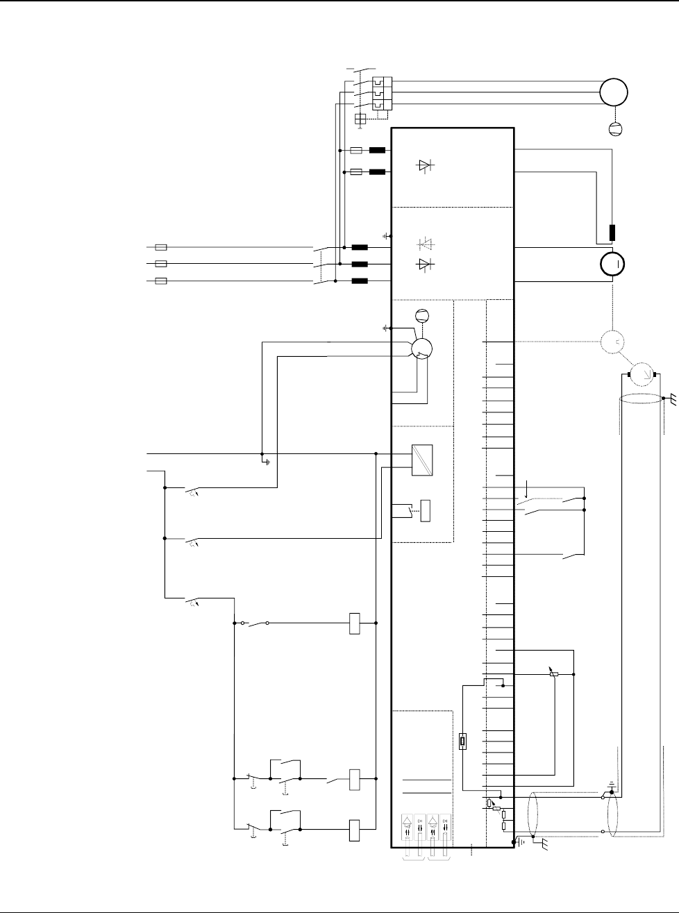
Appendix A - Connection diagrams
DCS 500B / DCP 500B Operating Instructions IV A A - 1
Connection diagram 1 For detailed information see
System description DCS 500B / DCF 500B.
IN3
OUT3
IN1
OUT1
V5
V6
V1
V2
X96:
DO8
12 X99:12 X2:45 X2:1 2 3 U1 W1V1 PE
K1
K20
K21K20 K1
X96:1
X96:2
L1 L2 L3
400V 50Hz
F1
F3
M
~
K21
X33
C 1 D 1
AITAC AI1 AI2 AI3 AI4 +10V -10V AO1 AO2 IACT DI1 DI2 DI3 DI4 DI5 DI6 DI7 DI8 +48V DO1 DO2 DO3 DO4 DO5 DO6 DO7
__ __ _
++++ +
T
TM
0V
0V0V0V0V
X3: 1 2 3 4 5 6 7 8 9 10 X4: 1 2 3 4 5 6 7 8 9 10 X6: 1 2 3 4 5 6 7 8 9 10 X7: 12345678 1...10
X5:
+_
+
_
K1
K20
K21
S4
56
F5
1
2
F8
1
2
F7
1
2
K1
135
246
L1
X1: 1 7
L3
X1: 5 3
+_
L1 MP
230V 50Hz
2
1
4
3
6
5
F6
I > I > I >
13
14
UVW
M
3~
Communication
board (COM-x) Control board (CON-2)
Power supply
(POW-1)
Converter
module
ON
OFF STOP
START
Field exciter unit
(SDCS-FEX-1/2)
depending on the unit type
an other configuration is possible
the polarities are shown for motor operation
if there are intermediate terminals
e.g. Pressure
switch at C4
module
3ADW000055R0401_DCS500B_Operating Instruction_e_d
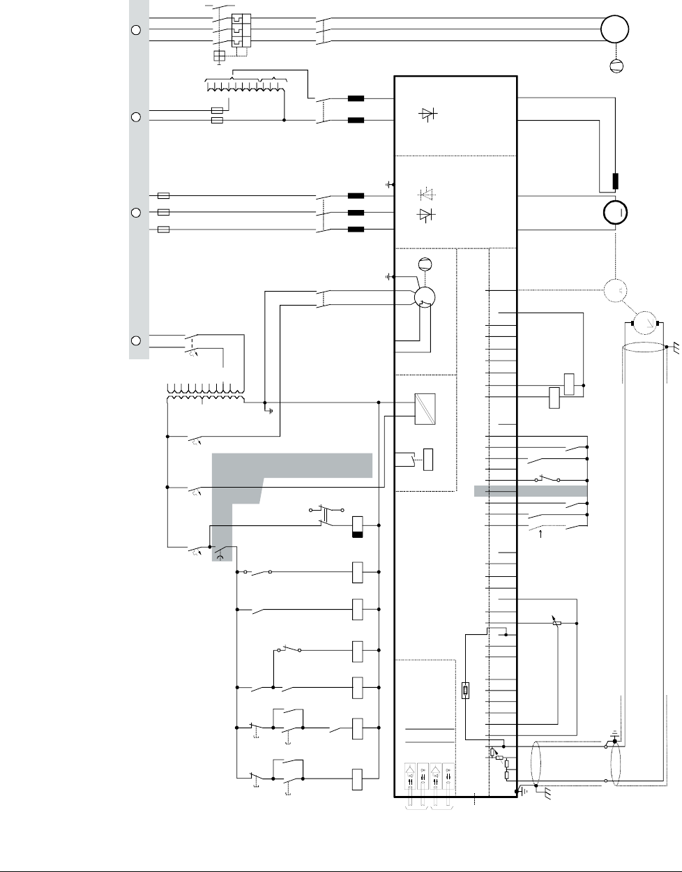
Appendix A - Connection diagrams
IV A A - 2 DCS 500B / DCP 500B Operating Instructions
Connection diagram 2 For detailed information see
System description DCS 500B / DCF 500B.
IN3
OUT3
IN1
OUT1
V5
V6
V1
V2
X96:
DO8
12 X99:12 X2:45 X2:1 2 3 U1 W1V1 PE
K1 F6
K20
K21K20 K3 K1
X96:1
X96:2
L1 L2 L3
F1
F3
K3
13
24
M
~
T3
F2
3
4
1
2
T2
690V
660V
600V
575V
525V
500V
450V
415V
400V
380V
115V
230V
K15
K15
S1
1
2
K6 K8
X2:4
X2:5
K11
K10
K21
500V
460V
415V
400V
365V
350V
265V
250V
90V
60V
30V
X33
C 1 D 1
AITAC AI1 AI2 AI3 AI4
+10V -10V AO1 AO2 IACT DI1 DI2 DI3 DI4 DI5 DI6 DI7 DI8 +48V DO1 DO2 DO3 DO4 DO5 DO6 DO7
__ __ _
++++ +
T
TM
0V
0V0V0V0V
X3: 1 2 3 4 5 6 7 8 9 10 X4: 1 2 3 4 5 6 7 8 9 10 X6: 1 2 3 4 5 6 7 8 9 10 X7: 12345678 1...10
X5:
+_
+
_
K1
K20
K21
K6
K8
1
2
S1
K11
K10
S4
56
246
135
K6
F5
1
2
F8
1
2
F7
1
2
2
1
4
3
6
5
F6
I > I > I >
13
14
U
VW
M
3~
K1
135
246
L1
1
2
3
4
K8
13
14
X1: 1 7
L3
X1: 5 3
+_
L1 N L1 N L1 L2 L3
Voltage levels
see description
A C D E
Communication
board (COM-x) Control board (CON-2)
Power supply
(POW-1)
Converter
module
ON
OFF STOP
START
EMER.
STOP
Field exciter unit
(SDCS-FEX-1/2)
depending on the unit type
an other configuration is possible
the polarities are shown for motor operation
if there are intermediate terminals
e.g. Pressure
switch at C4
module
3ADW000055R0401_DCS500B_Operating Instruction_e_d

Appendix A - Connection diagrams
DCS 500B / DCP 500B Operating Instructions IV A A - 3
3ADW000055R0401_DCS500B_Operating Instruction_e_d

ABB Automation Products GmbH
Postfach 1180
Lampertheim • GERMANY
Tel: +49 (0) 62 06-5 03-0
Fax: +49 (0) 62 06-5 03-6 09
www.abb.com/dc *055R0401A2440000*
*055R0401A2440000*
Ident. No.: 3ADW 000 055 R0401 Rev D
09_01
