40000_Bell_System_Technical_Reference_Catalog_Dec75 40000 Bell System Technical Reference Catalog Dec75
User Manual: 40000_Bell_System_Technical_Reference_Catalog_Dec75
Open the PDF directly: View PDF ![]() .
.
Page Count: 27
Bell System
TECHNICAL
REFERENCE
PUB 40000
Catalog
December 1975
TABLE
OF CONTENTS
GENERAL . . . . . . . . . . . . . . . . . . . . . . . . . . . . . . . . . . . . . . . . . . . . . . . . . . . . . . . . . . . . . . . . . . 1
ORDERING OF
TECHNICAL
REFERENCE . . . . . . . . . . . . . . . . . . . . . . . . . . . . . . . . . . . . . 1
ADMINISTRATION
. . . . . . . . . . . . . . . . . . . . . . . . . . . . . . . . . . . . . . . . . . . . . . . . . . . • . . . . . 3
DATA
COMMUNICATIONS
. . . . . . . . . . . . . . . . . . . . . . . . . . . . . . . . . . . . . . . . . . . . . . . . . 3
Facilities for Data Communications . . . . . . . . . . . . . . . . . . . . . . . . . . . . . . . . . . . . . . . . 3
Data Sets, Data Auxiliary Sets and Data Service Units . . . . . . . . . . . . . . . . . . . . . . . . 5
Data Communications Systems and Terminals . . . . . . . . . . . . . . . . . . . . . . . . . . . . . . 9
Data Interconnection . . . . . . . . . . . . . . . . . . . . . . . . . . . . . . . . . . . . . . . . . . . . . . . . . . . .
11
VOICE
COMMUNICATIONS
. . . . . . . . .
.. ..
.
..
.
..
.. .. ..
..
.
..
.
..
. .
..
.. ..
..
..
. . .
12
Protective Connecting Arrangements -Manual, Terminal . . . . . . . . . . . . . . . . . . .
12
Protective Connecting Arrangements -Automatic,
Terminal.................
14
Protective Connecting Arrangements -Manual, System
...................
_..
16
Protective Connecting Arrangements -Automatic,
System.........
. . . . . . . . .
17
Protective Connecting Arrangements -Private Line . . . . . . . . . . . . . . . . . . . . . . . .
19
Protective Connecting Arrangements -Miscellaneous. . . . . . . . . . . . . . . . . . . . . . . 20
Protective Connecting Arrangements -PBX Adjuncts. . . . . . . . . . . . . . . . . . . . . . .
21
RADIO
AND
TRANSMISSION
ENGINEERING . . . . . . . . . . . . . . . . . . . . . . . . . . . . . . . . 22
AlTESTATION
PROGRAMS
. . . . .
..
..
..
.. ..
.. .. .. ..
.. ..
.. .. ..
.. ..
. . . . . . . . . . . 23
CONFORMANCE
PROGRAMS
. . . . . . . . . . . . . . . . . . . . . . . . . . . . . . . . . . . . . . . . . . . . . . 24
BELL
SYSTEM
TECHNICAL
REFERENCES
GENERAL
Bell System Technical References provide inter-
face information to designers and manufacturers
of
business machines, communications systems
and terminal equipment. The subjects covered by
these Technical References include data set in-
ter.face
specifications,
data
communications
systems
and
terminals, data connecting arrange-
ments,
protective
connecting
arrangements,
various
transmission channels and
services,
PICTUREPHONE®service, Attestation Programs
and Conformance Programs. At the present time,
these Technical References fall into six basic
categories: Data Communications, Voice Com-
munications, Radio and Transmission Engineer-
ing,
PICTUREPHONE®service,
Attestation
Programs and Conformance Programs. As addi-
tional needs are determined, new Technical
References within these categories and new
categories will be provided.
Technical References are prepared
in
two
forms,
Standard
and
Preliminary. Standard Technical
References (e.g., Data Sets
201
A
and
201
B -
August 1969) are provided for equipment and
services
which
are
expected
to
remain
unchanged and avai I able for a relatively long
period of time. Preliminary Technical References
(e.g.,
AD1
-Preliminary-October
1974) are
provided for new equipment and services and in-
dicate information which may be changed
or
revised
in
a relatively short time. This does not
mean
that a manufacturer should not build equip-
ment that is compatible with the information listed
but it does offer a caution that the information
presented may change.
This catalog of Technical References, to be
published as required, lists all current Bell
System Technical References. Included for each
Technical Reference is the title, a synopsis and
an
ordering number
(PUB4XXXX).
In
addition, a
listing is provided to permit ordering of complete
sets of Technical References
in
either the Data
Communications
or
Voice
Communications
categories. Companies
on
standing order
dis-
tribution will automatically receive a copy
of
the
catalog.
® Registered Service Mark
of
AT&T Co.
1
Each
Protective
Connecting
Arrangement is
further defined by a Uniform Service Order Code
(USOC), e.g., QKT, which should be used for
or-
dering purposes when the customer desires the
installation
of
a connecting arrangement.
It is the responsibility
of
the manufacturer
to
ad-
vise the customer
of
the proper USOC; and it is
the customer's responsibility to order the proper
USOC from the Telephone Company.
ORDERING
OF
TECHNICAL
REFERENCES
One-Time
Orders
All
orders
should
indicate
the
Technical
Reference(s) desired by catalog number and
quantity using the following format:
(Quantity) Technical References (Catalog
Number)
If all Technical References
in
either the Data
Communications
or
Voice
Communications
categories are desired, they may be ordered as a
set using the catalog number assigned to that
particular category. For example:
(Quantity) Complete Set of Voice
Communications Technical
References -PUB42000
Standing
Orders
In
addition to one-time orders
it
is also possible
to place a standing order for
al
I new and revised
Technical References
in
a given category (i.e.,
Transmission Engineering
PICTUREPHONE
ser-
vice or Attestation Programs). To place a stand-
ing order, use the following words:
Standing order for (Quantity) copies
of
all
new
[Category,
(e.g.,
Voice,
Data
or
Transmission)] Technical References.
Bell
System
Companies
Bell System Organizations may order Technical
References using Form
SD-1
.80.80 and address
it to:
Western Electric Company, Incorporated
Indiana Publication Center
P.
0.
Box 26205
Indianapolis, Indiana
46226
Non-Bell
Companies
Non-Bell Companies should submit written re-
quests for Technical References to:
American Telephone and Telegraph Co.
Supervisor -Information Distribution Center
1 95 Broadway, Room 208
New York, New York 10007
Pricing
Information
All requests should include both billing and ship-
ping addresses. Billing will be rendered by the
Western Electric Company, therefore, all checks
should be made payable to
them.
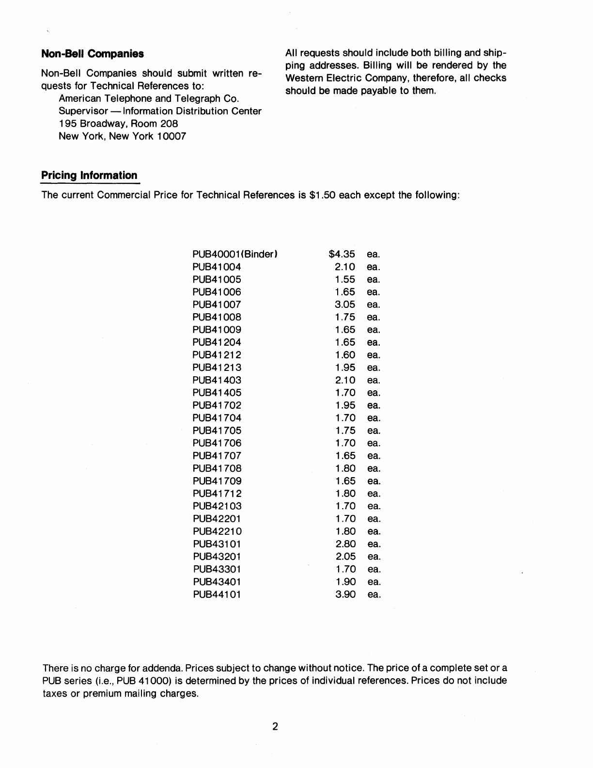
The current Commercial Price for Technical References is $1.50 each except the following:
PUB40001 (Binder) $4.35
ea.
PUB41004 2.10
ea.
PUB41005 1.55
ea.
PUB41006 1.65
ea.
PUB41007 3.05
ea.
PUB41008 1.75
ea.
PUB41009 1.65
ea.
PUB41204 1.65
ea.
PUB41212 1.60
ea.
PUB41213 1.95
ea.
PUB41403 2.10
ea.
PUB41405 1.70
ea.
PUB41702 1.95
ea.
PUB41704 1.70
ea.
PUB41705 1.75
ea.
PUB41706 1.70
ea.
PUB41707 1.65
ea.
PUB41708 1.80
ea.
PUB41709 1.65
ea.
PUB41712 1.80
ea.
PUB42103 1.70
ea.
PUB42201 1.70
ea.
PUB42210 1.80
ea.
PUB43101 2.80
ea.
PUB43201 2.05
ea.
PUB43301 1.70
ea.
PUB43401 1.90
ea.
PUB44101 3.90
ea.
There is no charge for addenda. Prices subject to change without notice. The price of a complete set or a
PUB
series (i.e.,
PUB
41000) is determined by the prices of individual references. Prices do not include
taxes or premium mailing charges.
2
ADMINISTRATION
*PUB40000 Technical Reference
Catalog-
December 197 5
PUB40001 Technical Reference Binder
DATA
COMMUNICATIONS
Lists
all
current
Bell
System
Technical
References
and
provides ordering information,
catalog numbers
and
synopsis.
A general purpose four-ring binder suitable for all
categories of Bell System Technical References.
This binder will hold approximately 15 individual
Technical References.
PUB41000 Complete Set of Data Communications Technical References
Facilities
for
Data
Communications
PUB41001
PUB41002
PUB41003
PUB41004
* Revised
30-Baud Private Line Channels
Interface
Specification
-
December 1 967
45- 55- & 75-Baud Private Line
Channels Interface
Specification -
December 1 967
1 50-Baud Private Line Channels
Interface
Specification
-
Revised September 1 97 5
Data Communications Using
Voiceband Private Line
Channels
-October
1 973
3
Describes a private line channel capable of
transmitting two-state ("mark-space," "binary")
signals at rates
up
to 30-baud for metering,
supervisory control
and
miscellaneous signaling
purposes. Metal lie continuity, end-to-end, is not a
requirement
of
this channel
and
will generally not
be
available.
The
interface signal is two-state
direct current.
Describes three private line channels capable of
transmitting two-state ("mark-space," "binary")
signals
up
to their respective rated speeds for
teletypewriter, data, metering, supervisory con-
trol
and miscellaneous signaling purposes.
Metallic continuity, end-to-end, is not a require-
ment
of this channel
and
wi
II
generally not be
available.
The
interface signal is two-state direct
current.
Defines the interface for the 1 50 Baud Private
Line Channel as presented to Customer-Provided
Terminals.
Describes voiceband channel arrangements for
private line data transmission. Provides analog
impairment limits supported
on
channels,
and
digital performance supported with Bell System
service
offerings; interface requirements for
analog channels; engineering considerations for
two-point
and
multipoint channel usage;
and
in-
fo rm
at
ion
on
maintenance
and
channel
availability.
PUB41005
PUB41006
PUB41007
PUB41008
PUB41009
PUB41011
PUB41012
PUB41013
Data Communications Using
The
Switched Telecommunications
Network-Revised
May
1971
Attenuation
and
Envelope Delay
Characteristics
from
the
1969-70
Switched Telecommunications
Network Connection Survey -
June
1973
1 969 -70 Switched
Telecommunications Network
Connection Survey (Reprints
of Bell System Technical
Journal Articles) -
April 1971
Analog Parameters
Affecting
Voiceband Data Transmission -
Describes the structure
and
operation of
the
DOD
network; presents switching
and
transmission
performance data
on
the
network
and
discusses
topics related to data communications
on
the
DOD
network.
Provides detailed information
on
attenuation
and
envelope delay characteristics
on
toll connec-
tions
from
the
1969-70 Switched Telecom-
munications Network Connection Survey.
Describes analog transmission parameter perfor-
mance, low-speed data transmission perfor-
mance,
and
high-speed voiceband data transmis-
sion performance of the Switched Telecom-
munications Network. This is a series of three
Bell System Technical Journal Articles which
summarize
Bell
Telephone
Laboratories'
1969-70 Connection Survey.
A tutorial describing analog parameter which
may
effect data transmission over voiceband chan-
Description
of
Parameters -nels.
July 1974
Transmission Parameters
Affecting Data Transmission -
Measuring
Techniques-
Revised
May
1975
Transmission Specifications for
Voice Grade Private Line
Protective Relaying Channels -
May
1973
1 A Data Station, Multichannel
Arrangement Used
in
Provision
of Two-Point Channelizing
Service
-June
1973
Transmission Specifications for
Low Speed Signaling System
Channels-July
1975
4
This Technical Reference
br~efly
defines
the
parameters affecting data transmission described
in
the
companion
Technical
Reference
(PUB41008)
and
describes the techniques used
by the Bel I System to measure these parameters.
In
addition, physical
and
environmental require-
ments of test equipment used by the Bell System
are provided.
This Technical Reference provides information
on
a voice grade private line channel specifically
designed for power industry protective relaying
applications.
The
1 A Data Station, Multichannel Arrangement is
a frequency division multiplexer capable of deriv-
ing
75and/or150
baud
channels from a 3002 pri-
vate line voiceband channel. It is arranged for
mounting
on
the
customer's premises
and
pro-
vides test capability for trouble sectionalization.
Describes a private line channel capable of
unidirectional transfer of customer generated
signals generally characterized
as
"McCulloh"
systems. Metallic continuity is not a requirement
of this channel.
PUB41021
PUB41022
Digital Data System -Channel
Interface Specifications -
Preliminary-March
1973
Multistation
DAT
APHONE®Dig
ital
Service
-Preliminary
-
September 1 97 4
Describes the Digital Data System
(DDS)
and
the
interface between the channel termination equip-
ment of the
DDS,
contained
in
a Channel Service
Unit
(CSU)
and
the customer's data terminal
equipment. A
CSU
is used when the customer's
equipment performs the following functions: cod-
ing
and
decoding, timing recovery, synchronous
sampling, formatting,
and
generation
and
recogni-
tion of control signals. Also see
PUB41
450.
Describes the Multistation DATAPHONE®Digital
Service which utilizes the Digital Data System
(DDS)
to
provide
a full-duplex transmission
capability between a control station
and
two or
more remote stations.
Each
station
may
have the
service terminated
in
either a
DDS
Channel
S.er-
vice Unit
(CSU)
or a Data Service Unit
(DSU),
described
in
PUB's 41021
and
41450, respec-
tively. Data can
be
transmitted at the synchronous
data rates of 2.4, 4.8, 9.6, or 56 kb/s.
Data
Sets,
Data
Auxiliary
Sets
and
Data
Service
Units
PUB41101
PUB41102
Data
Set
1
03A
Interface
Specification
-February
1967
Data Set 1 03A3
Data Set 1 03E
Data Set 1 03G
Data Set 103H
Interface Specification -
October 1973
® Registered Service Mark of AT&T Co.
5
Data Set 103A provides full-duplex low-speed
serial data transmission at rates
up
to
300
bps.
The
103A is used
in
conjunction with Data Auxili-
ary Set 80481
and
may
be arranged for automatic
origination, automatic answering
and
alternate
voice. This data set is used for
DATAPHONE
ser-
vice
and
in
TWX-CE applications.
Data Sets 1 03A3,
E,
G,
and
H provide
ful
I-duplex
low-speed serial data transmission at rates
up
to
300 bps. The 1 03E is a basic data set without
power supply
and
attendant controls
and
is
designed for multiple set installations.
The
1 03A3
set consists of a 103E
in
a single unit housing
and
operates with a standard key telephone set.
The
103G is similar to the 103E but has
an
integrated
housing
and
provides a card dialer.
The
103H is
also similar to the 103E but is designed for
mounting
in
a data terminal.
The
103G
and
H are
now rated Manufacture Discontinued. These data
sets are used for
DATAPHONE
service.
PUB41103
PUB41104
PUB41105
PUB41201
PUB41202
PUB41203
PUB41204
Data
Set
1
03F
Interface
Specification -May 1964
Data
Set
11
3A
Interface
Specification
-August
1 973
11
3-
Type Data Station -
Interface
Specification-
October 1971
Data Sets
201
A&B
-
August
1969
Data
Sets
202C&D
Interface
Specifications -
May
1964
Data Set 202E Series -
Revised September 1971
Data Set 203-Type -
Revised Apri I 1 97 4
6
Data Set 1 03F provides
ful
I-duplex low-speed
serial data transmission at rates
up
to 300 bps. It
is intended for use
on
private line channels
and
does not include a provision for voice transmis-
sion.
Data Set 113A is
an
originate only, full-duplex
low-speed serial data set for use at rates
up
to
300
bps. This is a I
ine
powered data set designed
for
DATAPHONE
service applications.
Description:
The
113-type Data Station provides
for
low-speed, serial, FSK, full-duplex data
transmission over
the
switched telecommunica-
tions network. It is intended for use
in
multiple
data set, answer-only installations such
as
those
associated with a time-shared computer.
The
Data Station consists of Data Sets 1138,
an
ap-
propriate cabinet
(3
available sizes)
and
Data
Auxiliary Set 804T.
The
Data Set 201-type transmits serial binary
data over voice bandwidth facilities using
PSK
modulation. Operation is synchronous full-duplex
or
half-duplex
and
may
be at 2000 bps for
DATAPHONE
service over the switched telecom-
munications network or
at
2400 bps over condi-
tioned private line channels.
The Data Sets 202C&D provide a medium speed,
binary, serial data transmission system. They
operate at rates
up
to 1 200 bps for
DAT
APHONE
service
and
up
to 1800 bps
on
conditioned pri-
vate I ine channels.
The Data Set 202E series is a modularized family
of
data set transmitters designed primarily to be
used
as
input stations
in
data collection systems.
This data set
may
be
used
on
either the switched
telecommunications network or
on
private line
channels
and
operates at speeds compatible with
Data Sets 202C&D.
The Data Set 203 family is designed to provide
synchronous transmission
and
reception
of
high-
speed digital data over the switched telecom-
munications network or conditioned private line
data channels. These sets are capable of operat-
ing at bit rates between 1800
and
1 0,800 bps
and
various options such
as
separate transmitter
and
receiver, secondary channel
and
alternate voice
are available.
PU841208
PU841209
PU841210
PU841211
PU841212
PU841213
Data
Set
202R
Interface
Specification-June
1971
Data
Set
208A
Interface
Specification -November 1 973
Data
Set
201
C
Interface
Specification
-April
1973
Data
Set
2088
Interface
Specification
-August
1 973
Data Sets 202S
and
202T -
Interface Specification -
August 1974
Data
Set
209A
Interface
Specification-Preliminary-
May
1974
7
The
Data Set 202R is a
manual
only,
minimum
feature data set. It
may
be
used
on
either the
telecommunications network or
on
private line
channels
and
operates at speeds compatible with
Data
Sets 202C
and
D.
The
Data
Set 208A provides synchronous, binary
4800 bps service over basic (unconditioned)
30E>2-type
four-wire channels. Features include
automatic adaptive equalization, 50 millisecond
turnaround time, status
lamps
and
loop-around
test capabilities. These features
make
the set
especially well suited for multipoint polling ap-
plications
as
well
as
point-to-point systems.
The
Data
Set
201
-type transmits serial binary
data over voice bandwidth facilities using
PSK
modulation. Operation is synchronous
ful
I-duplex
or half-duplex
and
may
be
at
2000 bps
(201
A)
or
at 2400 bps
(201
8 or
201
C)
over the Switched
Telecommunications Network
or
private line
channels.
The
Data Set 2088 provides synchronous, binary
4800 bps service
on
the switched telecom-
munications network. Features include automatic
adaptive equalization, 50 millisecond turnaround
time, built-in line control, status
lamps,
and
exten-
sive testing capabilities which provide powerful
system trouble isolating tools. These features
make
the set especially well suited for switched
network systems requiring reliable high thruput
service.
Data Sets 202S
and
202T, members of the new
data set family, provide 1200 bps asynchronous
service
on
the Switched Network
and
1800 bps
asynchronous
service
on the
private
I ine
facilities, respectively. These data sets are line
compatible with all 202-Type
Data
Sets;
and
pro-
vide
an
optional 5 bps reverse channel, indicator
tamps
that visually display
the
status of
the
set,
and
test features which provide
the
customer,
as
well
as
the
Telephone Company, with fault isolat-
ing
capabilities.
The Data Set 209A is a synchronous, binary serial
9600 bps data set for
use
on
a voiceband
(a
3002
data channel equipped with Type D-1, High Per-
formance
Data
Conditioning) 4-wire private line.
The
data set features multiplexing options, rapid
start-up times, extensive customer testing
capabilities, modern design technology,
and
an
attractive appearance.

PUB41301
Data
Set
301
B
Interface
Specification -March 1967
PUB41302 Wideband Data Stations
303-
Type Interface
Specification-
Revised December 1974
PUB41303
The
Display Data Set F-58167
Used to Provide Computer
Access Service for
PICTUREPHONE
Stations -
Preliminary-August
1970
PUB41304 Wideband Data Set 306-Type
Interface Specification -
July 1971
PUB41
403
Data
Set
4 0 1 J I n t
er
face
Specification
-September
1965
PUB41
405 Data Sets 402C -402D
Interface Specification -
November 1 964
*PUB41
408 Data Set 407 Interface
Specification-Preliminary-
Revised June 1975
®Registered Service Mark of AT&T Co.
The Data Set
301
B provides for the transmission
of binary serial synchronous data at 40,800 bps.
This data set requires a group bandwidth channel
and
is used
in
private line applications only.
Data Stations 303 comprise a family of wideband
data stations for use
in
the transmission of serial
binary synchronous or nonsynchronous data.
Speeds available range from 19.2 to 460.8 kbps
and
operation
may
be over either analog or digital
facilities.
The Display Data Set F-58167 provides
an
inter-
face between a customer-provided computer and
the
PICTUREPHONE
switching network. This data
set permits the
PICTUREPHONE
station to in-
teract with the computer and generates character
display signals which are displayed
on
the
PIC-
TUREPHONE
screen.
Data Set 306A provides for the transmission of
serial binary synchronous data at the transfer rate
of 1.344 Mb/s over
T1
carrier facilities.
Data Set
401
J is a multi-frequency data receiver
intended for use
on
DATAPHONE
service. It can
receive either 3-out-of-14
or
2-out-of-8 parallel
signals at a speed of
up
to 20 characters/second.
Data Sets 402C (transmitter)
and
402D (receiver)
compose a medium speed, binary, parallel data
transmission system for
DATAPHONE
Service
or
private line service.
The
system will transmit any
number of data levels
up
to 8 at any speed
up
to
75 characters per second.
Data Set 407 is a multi-frequency data receiver
designed for multiline installations.
The
data set
receives at a rate of
up
to ten (10) characters per
second over the switched telephone network
or
over basic (unconditioned) private lines from
TOUCH-TONE®telephone sets, TOUCH-TONE
pads, Bell System
401
-type data set transmitter
in
the "numeric mode" (two out of eight signals),
or equivalent signal sources.
*Revised -Supersedes "Data Set 407 A Interface Specification -November
1973"
8
PU841450
and
PU841450A
PU841451
and
PU841451A
PU841601
PU841602
Digital Data System
-Data
Service Unit Interface
Specifications-Preliminary-
March 1973
Addendum -November 1 97 4
1.544 M8/S Service Channel
Interface Specifications -
Pre
I iminary February 1 97 4
Addendum-January
1975
Data
Auxiliary
Set
801
A
(Automatic Calling Unit) Interface
Specification-March
1964
Data
Auxiliary
Set
801
C
(Automatic Calling Unit) Interface
Specification -September 1 965
Data
Communications
Systems
and
Terminals
PU841701
PU841702
8383 Teletypewriter Selective
Cal
I ing System -
September 1967
85A 1
and
85A2 Data Selective
Calling Service Stations -
October 1971
9
A data Service Unit
(DSU)
is used
on
data ser-
vices provided via
the
Digital Data System
(DDS).
It provides plug-for-plug interchangeability with
existing
EIA
Type D or E interfaces at syn-
chronous speeds of 2400, 4800,
and
9600 bits
per second.
At
56,000 bits per second the
DSU
provides the standard CCITT balanced
de
inter-
face. Also see PU841021.
A service channel providing point-to-point, full
duplex transmission of serial bipolar synchronous
pulses at a transfer rate of 1.544 Mb/s with con-
straints
on
signal format.
The
Data Auxiliary Set
801
A is a
de
dial pulse
Automatic Calling Unit
(ACU)
which permits a
business machine
to
place
calls
over
the
switched telecommunications network.
In
opera-
tion, a telephone number stored
in
the business
machine is passed to
the
ACU
which sets
up
the
call
and
transfers the circuit to the associated
data set for the automatic transmission of data.
The
Data
Auxi
I iary Set
801
C is a TOUCH-TONE
dialing Automatic Calling Unit
(ACU)
which per-
mits a buswness machine to place calls over the
switched telecommunications network.
In
opera-
tion, a telephone number stored
in
the business
machine is passed to
the
ACU
which sets
up
the
call
and
transfers the circuit to the associated
data set for the automatic transmission of data.
The
8383
Teletypewriter
Selective
Calling
System is five-level half-duplex private line
system using Model 28 equipment at speeds
up
to 1
00
words per minute.
The
traffic flow is
governed
by
a
control
station
which
automatically polls the other stations to start
their tape readers.
The
85A-type Data Selective Calling Service
Stations are used
in
providing eight-level, half-
duplex, private line selective calling systems.
The
85A 1 station pro
vi
des for 1
00
wpm
operation
using Model 33 or 35 equipment while
the
85A2
station provides for 150
wpm
operation using
Model 37 equipment.
The
traffic flow is ad-
ministered by a customer-provided computer
(line control station) which sequentially polls the
station transmitter
and
selects the designated
receivers.
PU841703
PU841704
PU841705
PU841706
PU841707
PU841708
PU841709
86A 1 and 86A2 Data Selective
Calling Service Stations
~
June
1969
868-Types Data Selective Call-
ing
System Stations -
November 1
968
Data Line Concentrator System
(DLCS) Arrangements -
May 1971
Model
37
Teletypewriter Stations
for DATAPHONE Service -
September 1
968
DATASPEED®
Type-4 System -
September 1
969
Type-5
DAT ASPEED System -
June
1970
Receive-Only
DATASPEED
Printer
Station
Agreements
System Interface Specification -
January 1
970
®Registered Service Mark
of
AT&T Co.
10
The 86A1 and 86A2 Data Selective Calling Ser-
vice Stations are used in providing eight-level
half-duplex selective calling systems. The 86A1
station provides for
100
wpm operation using
Model
33
or
35
equipment while the 86A2 station
provides for 150 wpm operation using Model
37
equipment. Control of these stations is from a
customer-provided computer (line control sta-
tions). 86A-type stations are used in applications
where the customer-provided computer controls
both half- and full-duplex circuits.
868-type
Data Selective Calling System Stations
are used
in
providing 8-level full-duplex selective
calling systems. The 8681 stations operate at
100
wpm using Model
33
and
35
equipment. The
8682
stations operate at 150 wpm using Model
37
equipment. Control
of
these stations is from a
customer-provided computer.
Data Line Concentrator System Arrangements
provide for the connection
of
a number
of
stations
to a smaller number of computer communications
ports. The service includes a data line concentra-
tor, private line transmission facilities and is used
with Model
33
or
35
Teletypewriters and also
customer-provided terminals.
Describes the operating
and
line characteristics
of
the M37 Teletypewriter Station operating
on
DATAPHONE
Service.
Included
is
a
list
of
features that are available
or
are planned to be
available.
The DATASPEED Type-4 Service is a paper tape
transmission system operating at either 1
050
wpm
or
1
200
wpm. This system provides error-
detection and correction by tape pull back and
re-transmission
on
error indication.
The DATASPEED
Type-5
system is a medium
speed paper tape transmission operating at 750
wpm. the system uses a separate sender and
receiver and can accommodate 5-, 6-, 7-,
or
8-
level paper tape.
The receive-only
DATASPEED
Printer is a high
speed nonimpact terminal. It operates at either
1050
wpm
or
1 200 wpm using serial transmission
and
750
wpm using parallel transmission.
PUB41710
PUB41712
PUB41713
PUB41714
PUB41715
4200 Series Magnetic Tape
Terminal
-August
1970
DAT
ASPEED
Type-2
System -
December 1
970
Models 33, 35
and
37 Stations for
Point-to-Point Private Line
Service-August
1971
9131
Teletypewriter
Selective
Calling Station Arrangement -
January 1 97 4
DATASPEED
40 Stations for
DATAPHONE
Service -
Preliminary-December
1973
Data
Interconnection
The
4200 Series Magnetic Tape Set will send
from or receive data
and
record it
on
magnetic
tape
in
a 150,000-character capacity cartridge.
This system accommodates
an
eight-level code
and
operates at speeds from 1
00
wpm
to 2400
wpm.
The
DATASPEED
Type 2 system is a
medium
speed, serial data transmission system.
The
system consists of a Sending terminal, paper tape
punch,
and
a receiving terminal, paper tape
punch. Operating speed is 1
050
wpm
using a
202-type data set. Information presented con-
sists of on-line
signa1ing
and
terminal charac-
teristics.
Describes Point-to-Point Private Line Service
in
which Model 33, 35 or 37 Teletypewriter Stations
are connected to
one
or both points
on
a com-
munication link.
The
arrangements described are
composed of two interconnecting stations
and
their communications control capability.
The
9131 Teletypewriter Selective Calling Sta-
tion Arrangement is used
in
providing
an
eight-
level, half-duplex, private line selective calling
system. It provides for 1 00
wpm
operation using
Model 33 or 35 teletypewriters. It is a contention
type system
(i.e.,
not controlled by a master sta-
tion) intended primarily for handling intraline
traffic.
The
DATASPEED
40 is a
medium
speed data ter-
minal which provides advanced facilities for en-
tering, displaying, editing, printing, sending
and
receiving data.
DAT
APHONE
operation at 1 050
or 1 200 bits per second using 202-type data sets
is described.
PUB41800 Complete Set
of
Data Interconnection Technical References
PUB41801 Data Access Arrangement
CDT
for
Manual
Originating
and
Answering
Terminals-
Revised May 1 973
11
Data Access Arrangement
CDT
is used to con-
nect customer-provided terminal equipment to
the switched telecommunications network. It pro-
vides for
manual
origination
and
answering
of
calls
and
includes a standard telephone set
equipped with
an
exclusion key used to manually
transfer between the TALK
and
DAT
A modes.
PUB41
802 Data Couplers
CBS
and
CBT
for
Automatic Terminals -
Revised
May
1 97 4
PUB41803 Acoustic
and
Inductive Coupling
for Data
and
Voice Transmis-
sion -October 1972
# PUB41804 Switched Network
Transaction
Telephone
System -
Pre
I iminary -
June
1975
VOICE COMMUNICATIONS
Data Couplers
CBS
and
CBT
are used to connect
customer-provided terminal equipment to the
switched telecommunications network. They pro-
vide for automatic answering, terminating and/or
de
dial pulse originating of calls
and
include a
network control signaling unit
and
a data access
arrangement. Data Coupler
CBS
provides
EIA-RS
232C voltage type control leads. Data Coupler
CBT provides contact closure type control leads.
The
conditions under which customer-provided
data stations
may
generate tone signals for
the
purpose of addressing
the
switched telecom-
munications network are described.
Provides information of interest to the designer of
acoustically or inductively coupled data
and
voice transmission equipment. Information in-
cludes system design considerations, transmis-
sion speeds, transmission to other data sets,
power limitations,
and
a test instrument assembly.
The
Transaction Telephone System is a short-
message inquiry-response system, connecting
transaction telephone terminals to a customers
computer center via the switched telecom-
munications network. It provides a service
in
which inquiries are sent semi-automatically
as
TOUCH-TONE
signals,
and
responses
are
returned
in
either voice or visual
form.
PUB42000 Complete Set of Voice Communications Technical References
*Protective Connecting Arrangments -Manual, Terminal
usoc
PUB42101
QKT-
Revised June 1971
PUB42102
CDX-
Revised February 1973
#New
Technical Reference
Manual
connecting arrangement used for the con-
nection of customer-provided voice transmitting
and/or receiving equipment or communications
systems to a
PBX
or central office station line
through
a
Telephone
Company-provided
telephone set equipped with
an
exclusion key.
Manual
voice connecting arrangement used to
connect a customer-provided device, typically
patching devices, which enables the connection
of
an
incoming call to a Telephone Company pro-
vided
PBX
and
an
outgoing central office trunk
line from a Telephone Company-provided
PBX.
* PUB41803 listed under the
Data
Interconnection section provides information of interest to the
designer of acoustically or inductively coupled devices for Voice
as
well
as
Data Transmission.
12
PUB42103
PUB42104
PUB42105
PUB42106
PUB42107
CEBAX/CEBBX
-
Pre
I iminary -
Revised
June
1970
LOH
-Preliminary -
July 1970
LVH
-Preliminary
-
July 1970
CEBAV
-Preliminary -
August 1970
CEBAW-Preliminary-
August 1970
13
Voice Connecting Arrangement
CEBAX
permits a
customer to manually connect
and
disconnect
customer-provided equipment, typically multi-
line conferencing devices, to a specific line ter-
minated
on
a Telephone Company-provided key
set (control station). For use with customer-pro-
vided equipment with only
one
supervisory con-
tact. Furnished
on
a per line per control station
basis.
Voice Connecting Arrangement
CEBBX
permits a
customer to manually connect
and
disconnect
customer-provided equipment, typically multi-
line conferencing devices, to a specific line ter-
minated
on
a Telephone Company-provided key
set (control station). For use with customer-pr:o-
vided equipment with two supervisory contacts.
Furnished
on
a per line basis.
Voice connecting arrangment permitting the con-
nection of customer-provided background music
or other recorded material to central office lines
terminated
in
a Telephone Company-provided
switchboard.
Voice connecting arrangement permitting the
connection of customer-provided background
music or other recorded material to central office
or
PBX
lines, terminated
in
Telephone Company-
provided key telephone sets, while
the
line is
in
the hold
mode.
Voice connecting arrangement which permits a
customer to manually connect
and
disconnect
customer-provided equipment, typically
manual
announcement sets, which answers
an
incoming
call, to a specific line terminated
on
a Telephone
Company-provided key set (control station). For
use
with customer-provided equipment with only
one supervisory contact.
Voice connecting arrangement which permits the
customer to manually connect
and
automatically
disconnect
customer-provided
equipment,
typically intercom systems, to a specific line ter-
minated
on
a Telephone Company-provided key
set (associated station). For use with customer-
provided equipment with two supervisory con-
tacts.
PUB42108
FTP-Preliminary-
April 1974
*PUB42109
FTM
-Preliminary -
November 1 975
Voice Connecting Arrangement
F!P
provides a
means
of
connecting a customer-provided
source of music or recorded information to the
Music-On-Hold and/or Background-Music-Over-
Paging features of the Telephone Company-pro-
vided Com-Key®718
and
1434 Communications
Systems.
Protective Connecting Arrangement
FTM
pro-
vides a
means
of
connecting a customer-pro-
vided source of music or recorded information to
the Music-On-Hold feature of a Telephone Com-
pany-provided key telephone system.
Protective
Connecting
Arrangements
-
Automatic,
Terminal
# PUB42201 CAU/SU3/SU4/SUe -
Revised October 1975
PUB42202
PUB42203
and
PUB42203A
PUB42204
SU7QW-
Revised April 1975
RTT
-Preliminary -
January 1970
Addendum
-October
197 4
RDL/RDM-Preliminary-
Revised January 1 973
*New Technical Reference
®Registered Trademark of AT&T
Co.
Protective Connecting Arrangement
CAU
is
an
alarm coupler which provides one-way transmis-
sion for use with customer-provided alarm device
with dial pulse signaling.
SU3
is a tone signaling unit for use with Protec-
tiv,e
Connecting Arrangements
CAU
or
SUe
-
permits the operation of the alarm device to be
tested or verified from a remote location.
Protective Connecting Arrangement
SU4
is the
combination of Protective Connecting Arrange-
ments
CAU
and
SU3.
There is
no
assigned code
for the combination of Protective Connecting Ar-
rangements
sue
and
SU3.
Protective Connecting Arrangement
SUe
is
an
alarm
coupler
modified to provide
two-way
transmission, to permit detection
of
dial tone or
proper signal from a remote point.
See
SUeAQ.
Protective Connecting Arrangement SU7QW pro-
vides the
means
for automatically connecting
customer-provided dial pulse repertory dialers.
Connecting arrangement that generates a tone to
both parties under control of a customer-pro-
vided call duration timer.
Voice Connecting Arrangement
RDL
is a recorder
coupler arranged for one-way recording Voice
Connecting Arrangement
ROM
is a recorder
coupler
modified
to
provide
two-way
simultaneous transmission. See
RDMZR.
~
Revised-Supersedes 11 CAU/SU3/SUe -Preliminary -November
19e9"
14
PUB42205
PUB42206
and
PUB42206A
PUB42207
PUB42208
PUB42209
PUB42210
RCZ-
Revlsed July 1975
RC1
-Preliminary-
Revised June 1971
Addendum
-October
197 4
C2ACP
/C2AKS -
Revised February 1975
STC -Pre I iminary -
Revised February 1974
RDMZR/RDY-
Revised December 1973
SU6AQ/STS-Preliminary
-
June 1971
15
Recorder connector used to connect customer-
provided two-way recording equipment which
provides a distinctive
Connecting arrangement which provides the
means
for customer-provided equipment to cause
a·
short burst of 1400Hz tone to be sent to the
local part; used for call duration timing.
Protective Connecting Arrangement C2ACP is
an
automatic
arrangement
used
to
connect
customer-provided terminal equipment
to
a.
WATS
access line, a central office station line, or
a PBX/Centrex extension line.
Protective Connecting Arrangement C2AKS is
an
·automatic
arrangement
used
to
connect
customer-provided terminal equipment
to
a
WATS
access line, a central office station line, or
a PBC/Centrex extension line which concurrently
terminates
in
a Telephone Company-provided
station.
Voice connecting arrangement that provides the
means
for automatically connecting customer-
provided transmitting
and
receiving speech ter-
minal equipment, e.g., telephone sets, utilizing a
three-wire interface.
Voice Connecting Arrangement
RDMZR
provides
the
means
for automatically connecting customer
provided receive-only speech terminal equip-
ment,
e.g., answering sets; it supersedes
and
replaces Voice Connecting Arrangement
ROM.
Voice Connecting Arrangement
ROY
provides all
of the features of Voice Connecting Arrangement
RDMZR
and,
in
addition, provides volume-limited
receive transmission.
Voice Connecting Arrangement
SU6AQ
provides
the
means
for
automatically
connecting
customer-provided transmitting
and
receiving
speech terminal equipment, e.g., alarm systems,
utilizing a multi-wire interface; it supersedes
and
replaces Voice Connecting Arrangement
SU6.
Voice Connecting Arrangement
STS
provides all
of
the features of Voice Connecting Arrangement
SU6AQ
and,
in
addition, permits the transmission
of customer-provided supervisory tone signals;
it
provides
an
alternative to Voice Connecting Ar-
rangement
SU3.
PUB42211
PUB42212
PUB42213
PUB42214
CEZ
-Preliminary -
November 1
971
STP
-Preliminary
-
May
1973
ADI
-Preliminary -
October 1 97 4
GTS
-Preliminary -
December 1 97 4
Voice connecting arrangement which permits
the
manual
connection
and
automatic disconnection
of customer-provided equipment (typically con-
ferencing devices) to a specific line
on
an
associ-
ated
Telephone
Company
provided
key
telephone set.
Voice Connecting Arrangement
STP
provides a
means
for automatically connecting customer-
provided transmitting
and
receiving speech ter-
minal
equipment, e.g., key telephone systems.
Connecting Arrangement
ADI
provides a
means
to
associate dial pulse dialers with single or multi-
line telephone sets.
Protective Connecting Arrangement
GTS
pro-
vides a means of connecting
an
automatic
answering device to a telephone line. The
customer-provided answering device connects
via a standard 4-prong telephone jack.
Protective
Connecting
Arrangements
-Manual,
System
PUB42301
PUB42302
PUB42303
PUB42304
PUB42305
2A
(COB)
-Preliminary-
February 1969
1 A
(CDA)
~Preliminary
-
June
1969
3A
(CON)
-Preliminary-
June
1969
CD1
-Preliminary-
July 1969
CD4
-Preliminary -
August 1969
16
Manual
voice connecting arrangement used to
connect a line
from
a customer-provided system,
which provides supervisory signals, to a central
office trunk line through a Telephone Company-
provided cord switchboard position.
Manual
voice connecting arrangement used to
connect a cord switchboard position
of
a
customer-provided system, which provides
supervisory signals, to
an
exchange trunk line.
Manual
voice connecting arrangement used to
connect a line
from
a customer-provided system,
which provides supervisory signals, to
an
ex-
change line through a Telephone Company-pro-
vided key station.
Manual
voice connecting arrangement used to
connect a cord switchboard position
of
a
customer-provided system, which does not pro-
vide supervisory signals, to
an
exchange trunk
line.
Manual
voice connecting arrangement used to
connect a line from a customer-provided system,
which does not provide supervisory signals to
an
exchange trunk line through a Telephone
Com,;,
pany-provided cord switchboard position.
PUB42306
PUB42307
CD5
-Preliminary
-
August 1969
COY
-Preliminary -
October 1 969
Manual
voice connecting arrangement used to
connect a line
from
a customer-provided system,
which does not provide supervisory signals, to
an
exchange line through a Telephone Company-
provided key telephone station.
Voice connecting arrangement used to termi-
nate
-without
exchange
connection-a
line
from
a customer-provided system
in
a Telephone
Company-provided key telephone station.
Protective
Connecting
Arrangements
-
Automatic,
System
PUB42401
PUB42402
CDH
and
CBF-
Revised March 1 97 4
CD7
/CDB/CD9
and
CBF
-
Revised March 1974
17
Automatic voice connecting arrangement used to
connect the attendant position
and
dial switching
equipment of a customer-provided system to
an
exchange trunk line arranged for two-way com-
bination rotary or
TOUCH-TONE
service.
Connecting Arrangement
CBF
is provided
in
addi-
tion to
CDH
when
Data Communications equip-
ment
is used behind the
PBX.
CBF
provides a
linear attenuator which limits the three-second
average power level transmitted to the central
office without distorting the signal.
The
maximum
allowable power level is determined at the time of
installation.
Voice Connecting Arrangement CD7 is
an
automatic arrangement used to connect the at-
tendant position of a customer-provided system
to
an
exchange trunk line arranged for one-way
outgoing rotary or
TOUCH-TONE
service.
Voice Connecting Arrangement
COB
is
an
automatic arrangement used to connect the dial
switching equipment of a customer-provided
system to
an
exchange trunk line arranged for
one-way outgoing rotary or
TOUCH-TONE
ser-
vice.
Voice Connecting Arrangement CD9 is
an
automatic arrangement used to connect the at-
tendant position of a customer-provided system
to
an
exchange trunk line arranged for two-way
rotary or
TOUCH-TONE
service.
Connecting Arrangement
CBF
is provided
in
addi-
tion to
CD7,
COB,
or
CD9,
when
Data Communica-
tions equipment is used behind
the
PBX.
CBF
pro-
vides a linear attenuator which limits the three-
second average power level transmitted to the
central office without distorting the signal.
The
maximum
allowable power level is determined
at
the time of installation.
PUB42403
and
PUB42403A
PUB42404
PUB42405
and
PUB42405A
PUB42406
and
PUB42406A
PUB42407
PUB42408
CET
-Preliminary-
October
1970
Addendum
-June
197
4
CD6 -Preliminary -
December 1
969
CED
-Preliminary -
April
1970
Addendum -June 197 4
C22 -Preliminary -
March 1971
Addendum
-October
1972
C24/C2H -Preliminary -
October 1 971
C27
/C2K
-Preliminary -
October 1 971
18
Automatic voice connecting arrangement used
to
connect a customer-provided system
to
an
ex-
change trunk line arranged for one-way service to
the operator position
of
a Telephone Company
long distance switchboard (the equivalent
of
a
toll terminal).
Automatic voice connecting arrangement used
to
connect
an
exchange trunk line arranged for one-
way incoming service to the attendant position
of
a customer-provided system.
Automatic voice connecting arrangement used
to
connect a customer-provided system
to
an
ex-
change trunk line, arranged for
two-way
service,
to the operator position
of
a Telephone Company
long distance switchboard (the equivalent
of
a
toll terminal).
Automatic voice connecting arrangement used
to
connect
an
exchange trunk line arranged for one-
way
direct
inward dialing
(DID)
service
to
the dial
switching equipment
of
a customer-provided
system.
Voice
Connecting
Arrangement
C24
is
an
automatic arrangement used for
two-way
service
which provides a four-wire voice transmission in-
terface for connecting customer-provided chan-
nel facilities
to
a Telephone Company
PBX.
An
E
and M type signaling interface is provided.
Voice
Connecting
Arrangement C2H
is
an
automatic arrangement used for
two-way
service
which provides a four-wire voice transmission in-
terface for connecting customer-provided chan-
nel facilities to Telephone Company Centrex ser-
vice.
An
E and M type signaling interface is pro-
vided.
Voice
Connecting
Arrangement
C27
is
an
automatic arrangement used for
two-way
service
which provides a
two-wire
voice transmission in-
terface for connecting customer-provided chan-
nel facilities
to
a Telephone Company
PBX.
An
E
and M type signaling interface is provided.
Voice
Connecting
Arrangement
C2K
is
an
automatic arrangement used for
two-way
service
which provides a
two-wire
voice transmission in-
terface for connecting customer-provided chan-
nel facilities
to
Telephone Company Centrex ser-
vice.
An
E and M type signaling interface is pro-
vided
Protective
Connecting
Arrangements
-
Private
Line
PUB42501
PUB42502
PUB42503
PUB42504
PUB42505
CDQ4W
-Preliminary-
August 1969
CDQ2W/CDQ2X -
Preliminary -
June 1971
C234W-Preliminary-
February
1971
C232W-Preliminary-
September 1
971
CDQ4X
-Preliminary -
October 1
971
19
Automatic voice connecting arrangement ar-
ranged for two-way service which provides a
four-wire
voice
transmission
interface
to
customer-provided dial switching equipment -
used with a Telephone Company-provided four-
wire
private
line
channel
equipped
with
Telephone Company-provided channel signaling
with a contact-type signaling interface.
Voice Connecting Arrangement
CDQ2W
is ar-
ranged for two-way service,
and
provides a two-
wire interface to customer-provided dial switch-
ing
equipment.
Used
with Telephone Company-
provided private line channel
and
Telephone
Company-provided channel signaling with a con-
tact-type signaling interface.
Voice Connecting Arrangement
CDQ2W
is ar-
ranged for two-way service,
and
provides a two-
wire interface to customer-provided dial switch-
ing
equipment.
Used
wlth Telephone Company-
provided private line
channel
and
Telephone
Company-provided channel signaling with
an
E-
and
M-type signaling interface.
Voice connecting arrangement for two-way ser-
vice, which provides a four-wire voice transmis-
sion interface to customer-provided dial switch-
ing
equipment.
Used
with a Telephone Company-
provided four-wire private line channel and
customer-provided channel signaling.
Voice connecting arrangement arranged for two-
way service, which provides a two-wire interface
to customer-provided dial switching or station
terminal equipment. Used with a Telephone Com-
pany-provided private line
channel
and
customer-
provided
channel
signaling (inband signaling
only).
Automatic voice connecting arrangement ar-
ranged for two-way service, which provides a
four-wire interface to customer-provided dial
switching equipment.
Used
with a Telephone
Company-provided four-wire private line channel
equipped with Telephone Company-provided
channel signaling with a E
and
M signaling inter-
face.
Protective
Connecting.
Arrangements
-
Miscellaneous
PUB42601
PUB42602
PUB42603
PUB42604
CEK
-Preliminary -
April 1970
CAK
-Preliminary
-
Revised
May
1 972
C1
V /RCX/GC2 -Pre I iminary -
Revised June 1972
C25
-Preliminary
-
July 1971
PUB42605
CTD
-
Revised June 1975
\
20
Connecting arrangement used to
associate
customer-provided message registers where the
customer is
providing
the communications
system
and
the necessary equipment to associ-
ate the station with the message registers with a
central office trunk line.
Specification CAK describes a procedure used
by
AT
& T Co. for the evaluation
of
customer-pro-
vided antique/decorator set housings. Replaces
B drawings previously furnished by the local
Telephone Companies.
Connecting Arrangement
C1
Vis
used to connect
customer-provided elapsed time or
pen
register
equipment to
PBX
WATS lines,
PBX
central office
trunks or station lines. This arrangement provides
a closure that is maintained
when
the line is off-
hook
and
will not follow dial pulses.
Connecting Arrangement
ACX
is used to connect
customer-provided elapsed time or
pen
register
equipment to
PBX
WATS lines,
PBX
central office
trunks, or station I ines. This arrangement pro-
vides a closure that is maintained
when
the line is
off-hook
and
opens
on
each dial pulse.
Connecting Arrangement GC2 consists of
an
ac
ring-up relay bridged across the line. Provides a
contact closure to customer-provided equipment
when ringing voltage is present. Used with ring
indicator devices.
Connecting arrangement used to connect the
customer-provided automatic number identifica-
tion equipment of a customer-provided com-
munications system to a Bell System central
office for automatic identified outward dial
(AIOD)
service.
Protective connecting arrangement used to con-
nect customer-provided call diversion equipment
to a Telephone Company
CO
trunk terminated
on
a Telephone Company
PBX.
The
arrangement
provides a high impedance line status indication
of the supervisory
and
address signals
on
the
trunk
and
receives a contact closure to cause
diversion of
an
outgoing call from the
PBX
in
the
normal
manner.
PUB42606
PUB42607
PUB42608
PUB42609
HZM
-Preliminary -
November 1 97 2
VCP-NOTICE-
May
25,
1973
KTX -Preliminary -
October 1
973
CTH
-Preliminary-
December 1 973
Connecting Arrangement
HZM
is used to connect
customer-provided traffic measuring equipment
to station lines,
PBX
C.
0.
trunks,
and
some types
of tie lines. Permits the deduction of on-hook, off-
hook, dial pulse, TOUCH-TONE,
and
signaling
through a high resistance connection to the line.
Connecting Arrangement
VCP
provides
the
capability for a customer,
on
an
optional basis, to
supply the de power to voice connecting ar-
rangements associated with customer-provided
PBX's
and
certain other voice connecting ar-
rangements where specifically provided for
in
its
technical reference.
Connecting
arrangement
used
to
connect
customer-provided call diversion equipment to a
Telephone
Company
line
terminated
in a
Telephone Company Key Telephone System.
The
arrangment provides a high impedance line status
indication of the supervisory
and
address signals
on
the line
and
receives a constant closure to
divert
an
outgoing call. Restriction tone or
an
an-
nouncement is provided by the customer.
Protective connecting arrangement used to con-
nect customer-provided call diversion equipment
to a Telephone Company
C.O.
trunk terminated
in
a Telephone Company
PBX.
The
arrangement
provides a high impedance line status indication
of the supervisory
and
address signals
on
the
trunk
and
receives a contact closure to cause
diversion of the call. Restriction tone or
an
an-
nouncement is provided by the customer.
Protective
Connecting
Arrangements
-
PBX
Adjuncts
PUB42701
PUB42702
DCT -Pre I iminary -
June 1971
DCW -Pre I iminary -
July 1971
21
Voice connecting arrangement (formerly desig-
nated Recorded Telephone Dictation Trunk Cir-
cuit) which provides trunk level access, e.g.,dial
"7",
from a station
on
a Bell System
PBX
or
Centrex system to customer-provided dictation
equipment.
Voice connecting arrangement (formerly desig-
nated Interface Trunk Circuit) which provides a
two-part trunk level access,e.g.,dial
"7",
from a
station
on
a Bell System
PBX
or Centrex system
to
customer-provided
equipment capable
of
receiving dialed digits (serial or parallel coded)
for central purposes.
PUB42703
PUB42704
DCK/DCL-
Revised October 1974
TSPXY
/TSPZ1 -Preliminary -
March 1975
RADIO
AND
TRANSMISSION
ENGINEERING
Voice Connecting Arrangements
DCK
and
DCL
provide trunk level access,e.g.,dial
"7"
from a
station
on
a Bell System
PBX
or Centrex system
to customer-provided equipment (e.g., dictation
or radio paging) capable of receiving TOUCH-
TONE
digits directly or dial pulse digits over a
separate pair for control purposes.
Protective Connecting Arrangements
TSPXY
and
TSPZ1
provide a
means
of
connecting customer-
provided recording
and
control equipment to
PBX
trunks. With these arrangements,
an
outgoing
trunk can be split to allow dialing extra digits or
to pulse a number into the central office.
PUB43000 Complete Set
of
Radio
and
Transmission Engineering Technical References.
Private
Line
Facilities
PUB43101
Voice Grade Entrance Facilities
for Extending Customer-Provided
Communications
Channels -
Preliminary -
May
1969
PUB43201 Private Line Interconnection
Voice Applications -
Preliminary -
June
1 970
PUB43401
~Transmission
Specifications for
Mobile
Radio
Private Line Metallic Circuits -
Preliminary-December
1971
PUB43301
Domestic Public Land Mobile
Telephone
Service-Customer-
Prov
i
ded
Dial
Stations
-
Preliminary-March
1973
22
Describes the various entrance facility serving
arrangements, provides transmission charac-
teristics of entrance facilities, describes signal
power limitations
and
discusses the division of
responsibility for design, operation
and
mainte-
nance.
Describes the standard private line offerings for
voice applications which
may
be interconnected
at one or both ends with customer-provided
voice communications systems
or
terminal equip-
ment.
Also describes
minimum
protection criteria,
signaling arrangements
and
maintenance techni-
ques.
Describes the signal level criteria objectives for
private line metallic circuits (cable pairs without
signal battery or
amp
I ification devices). This
material is provided for those who use the
metallic continuity of local private line channels
implemented by wire pairs. It should be noted that
the Telephone Companies have no obligation to
provide private line channels
on
a metallic basis.
Provides
information
needed
to
interface
customer-provided mobile telephone dial sta-
tions with Telephone Company-provided mobile
telephone radio systems.
PUB43302
PUB43303
Intermodulation Interference
in
Radio Systems -
November 1 97 2
Domestic Public Land Mobile
and
Maritime Radio Service System
Interface
Criteria-
Preliminary - June 1 97 4
PICTUREPHONE SERVICE
With the explosive growth of radio systems,
problems of "overpopulation" are beginning to
misuse valuable radio spectrum.
One
of the prin-
cipal overpopulation problems encountered to-
day, yet one about which relatively little informa-
tion is available, is intermodulation interference.
This Technical Reference represents present
views of the problem
and
presents some possible
solutions.
This Technical Reference is a guide for desig-
ners, manufacturers,
and
operators of common
carrier radio systems which interface with the
Bell System telephone network.
The
document
describes the electrical information which must
pass between a Bell System Central Office
and
a
common carrier radio system
in
order to originate
and
terminate calls. This Technical Reference is
not
intended
to
provide
complete
design
specifications or parameters or to assure the
qua
I ity or performance of the common carrier
radio system.
PUB44000 Complete Set of
PICTUREPHONE
Service Technical References
PICTUREPHONE Interconnection
PUB44101
PVF
- Preliminary -
September 1
970
ATTESTATION PROGRAMS
PICTUREPHONE
connecting arrangement which
permits the connection of customer-provided
video/audio
terminal
equipment
to
PIC-
TUREPHONE
facilities using a Telephone Com-
pany-provided TOUCH-TONE telephone set.
PUB45000 Complete Set of Attestation Program Technical References
Headsets
PUB45001
and
PUB45001A
PUB45002
and
PUB45002A
4-Wire Headset Interface Ter-
minations
and
Interface
Specification 1
001
-
Preliminary-Revised
July 1973
Addendum -August 1 97 4
6-Wire Headset Interface Ter-
minations
and
Interface
Specification 1 002 -
Preliminary-October
1974
Addendum -January 1 97 5
23
Provides
the
procedural requirements
and
techni-
cal specifications (Interface Specification 1
001
)
for the attestation of certain customer-provided
4-wire headsets for use with headset jacks
(Headset Interface Terminations)
in
Bell System
attendant switchboards, attendant consoles,
and
telephone sets.
Provides the procedural requirements
and
techni-
cal specifications (Interface Specification 1002)
for the attestation of certain customer-provided
6-wire headsets for use with headset jacks
(Headset Interface Terminations)
in
Bell System
attendant switchboards, attendant consoles,
and
telephone sets.
Non-Powered
Conferencing
Devices
PUB45101 Interface Termination JTC
and
and
Interface Specification
2001
-
PUB45101 A
Preliminary-May
1973
Addendum
-October 1 97 3
CONFORMANCE
PROGRAMS
Provides the procedural requirements
and
techni-
cal specifications (Interface Specification
2001
)
for the attestation of certain non-powered con-
ferencing devices for use with Interface Termina-
tion JTC which is associated with
Bel
I System
key telephone system stations.
PUB46000 Complete Set
of
Conformance Program Technical References
PUB46001
and
PUB46001A
Conformance
Program
for
Answering Devices Incorporating
Authorized Protective Connect-
ing
Modules
-Preliminary-
Revised January 1975
Addendum
-October 1 97 5
24
Provides the procedural requirements
and
techni-
cal specifications (Interface Specification 3001 )
for the conforming of certain customer-provided
automatic answering devices for use with in-
dividual line exchange service or PBX/Centrex
station service.

326-299
