QuickTake 30 Sample Pump Cat. No. 228 9530 Operating Instructions Form 40079 PDF
User Manual: 40079
Open the PDF directly: View PDF ![]() .
.
Page Count: 14
Form 40079 Rev 1705
Page 1 of 14
www.skcinc.com
QuickTake 30 Sample Pump
Cat. No. 228-9530
Operating Instructions
863 Valley View Road, Eighty Four, PA 15330 USA • Tel: 724-941-9701 • www.skcinc.com
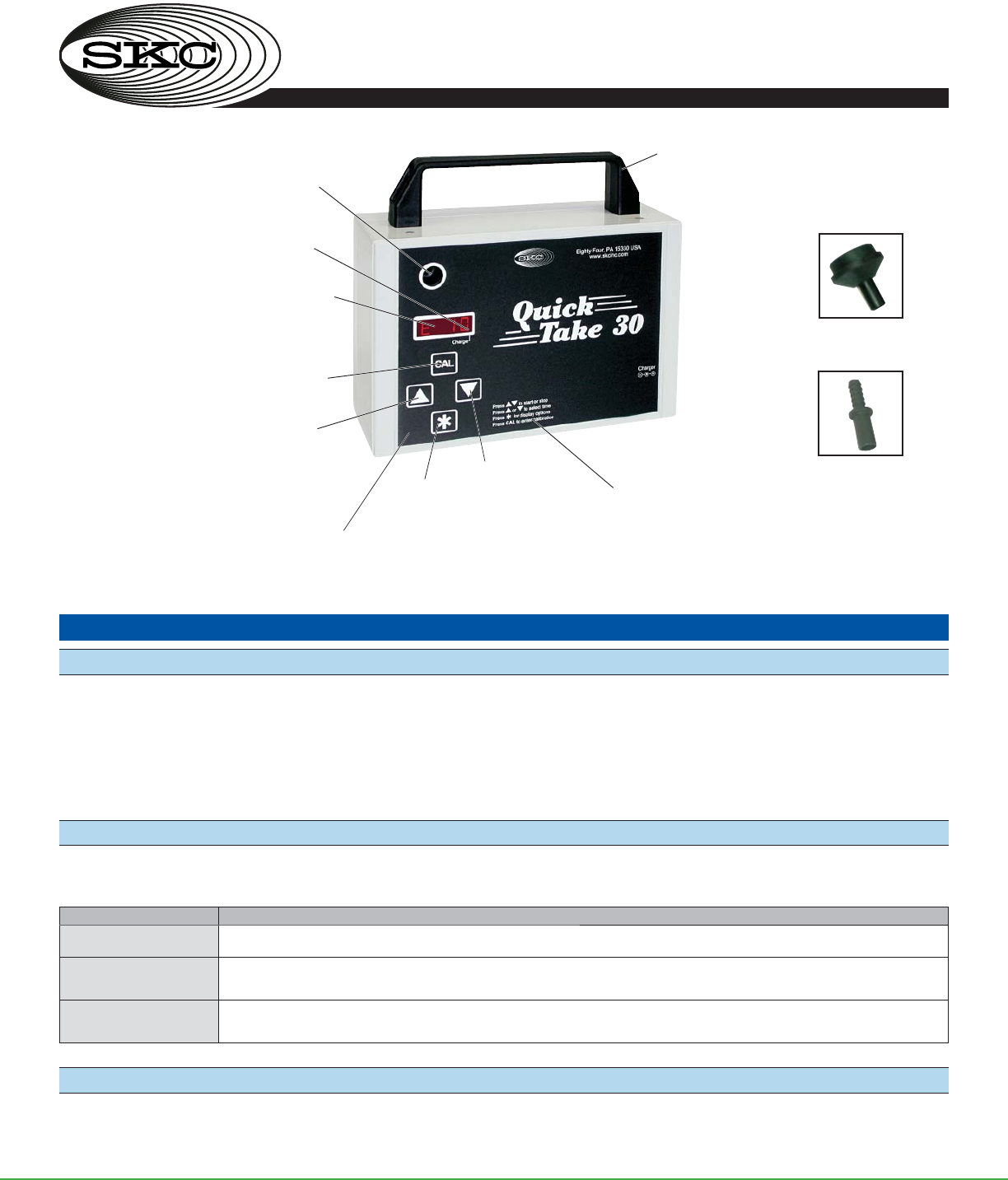
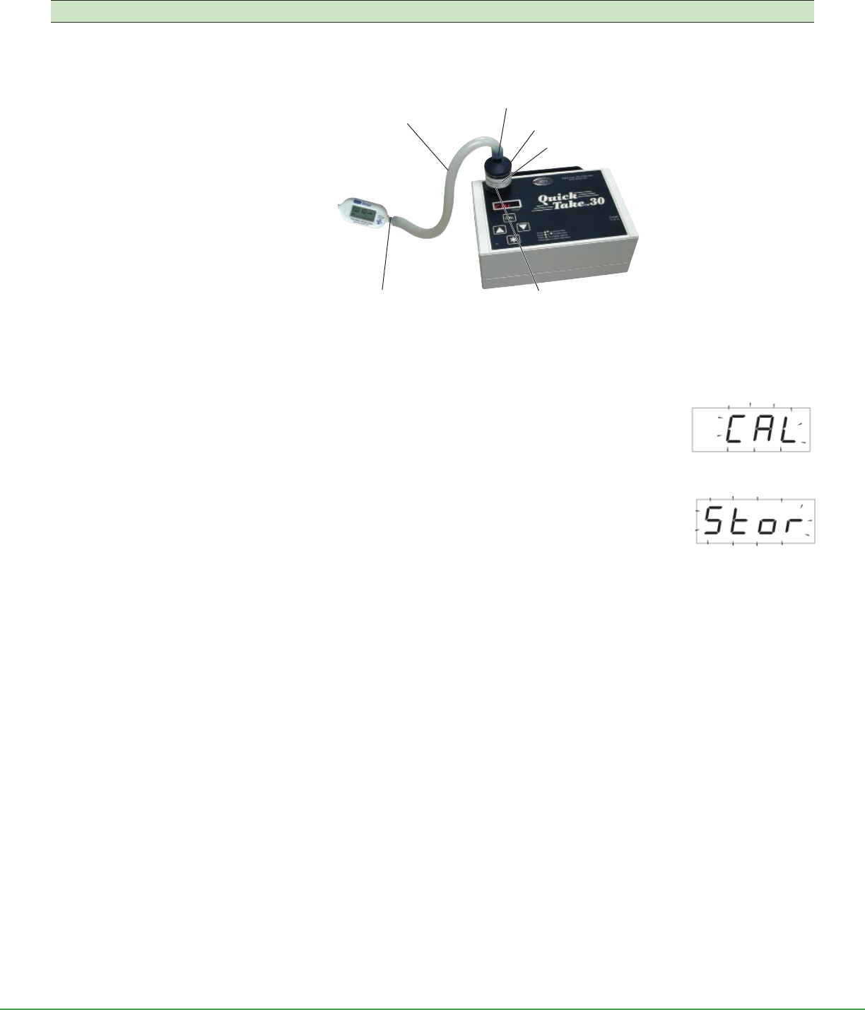
Figure 1. QuickTake 30 Sample Pump
Introduction
Description
The QuickTake® 30 Sample Pump (Figure 1) is a portable battery-powered air sample pump that maintains constant airflow from
10 to 30 L/min for use with the BioStage® viable cascade impactor, spore trap cassettes such as VersaTrap®, asbestos cassettes, microvacuum
cassettes, or other samplers requiring flows up to 30 L/min. A diaphragm pump operating with a closed loop flow control system, the
QuickTake 30 maintains true constant flow. The QuickTake 30 features a programmable timer that provides up to eight programmable
run time presets of 1 to 999 minutes, continuous run with manual shut-off, or intermittent sampling. A rechargeable lithium-ion battery
pack provides effective run times. See Appendix: Performance Profile - Typical Cumulative Run Time.
Checking Pump/Kit Contents
Use the table below to verify that you received all items associated with the Cat. No. ordered. If you are missing items, contact
SKC at 800-752-8472 (U.S. only) or 724-941-9701.
If You Ordered Cat. No. Your Package Should Contain
228-9530C QuickTake 30 Pump with lithium-ion (Li-Ion) battery pack and cassette/tubing adapters
228-9530 QuickTake 30 Pump and Charger includes pump with Li-Ion battery pack, 100-240 V AC charger/adapter,
cassette/tubing adapters, and tubing
228-9530A QuickTake 30 Pump, Rotameter, and Charger includes pump with Li-Ion battery pack, 100-240 V charger/adapter,
cassette/tubing adapters, calibrator, and tubing
Required Equipment
; 1/4-inch ID (3/8-inch OD) Tygon® tubing
; Charger for Li-Ion ba ery-powered pump
Handle
for easy
portability
Charging jack
(on side of case, not
shown)
High-contrast LED display
for readout of presets, run
time, and battery status
Calibration
mode button
Up arrow
increases fl ow
and time and
scrolls through
presets
Inlet
(shown without adapter)
LED
indicates active
battery charging
Down arrow
decreases fl ow
and time and
scrolls through
presets
Star button
activates LED
and toggles
between
displays
Speaker
for end of timed run alarm
Printed Quick Guide
Tubing Adapter
Cassette Adapter
Form 40079 Rev 1705
Page 2 of 14
www.skcinc.com
Getting Started
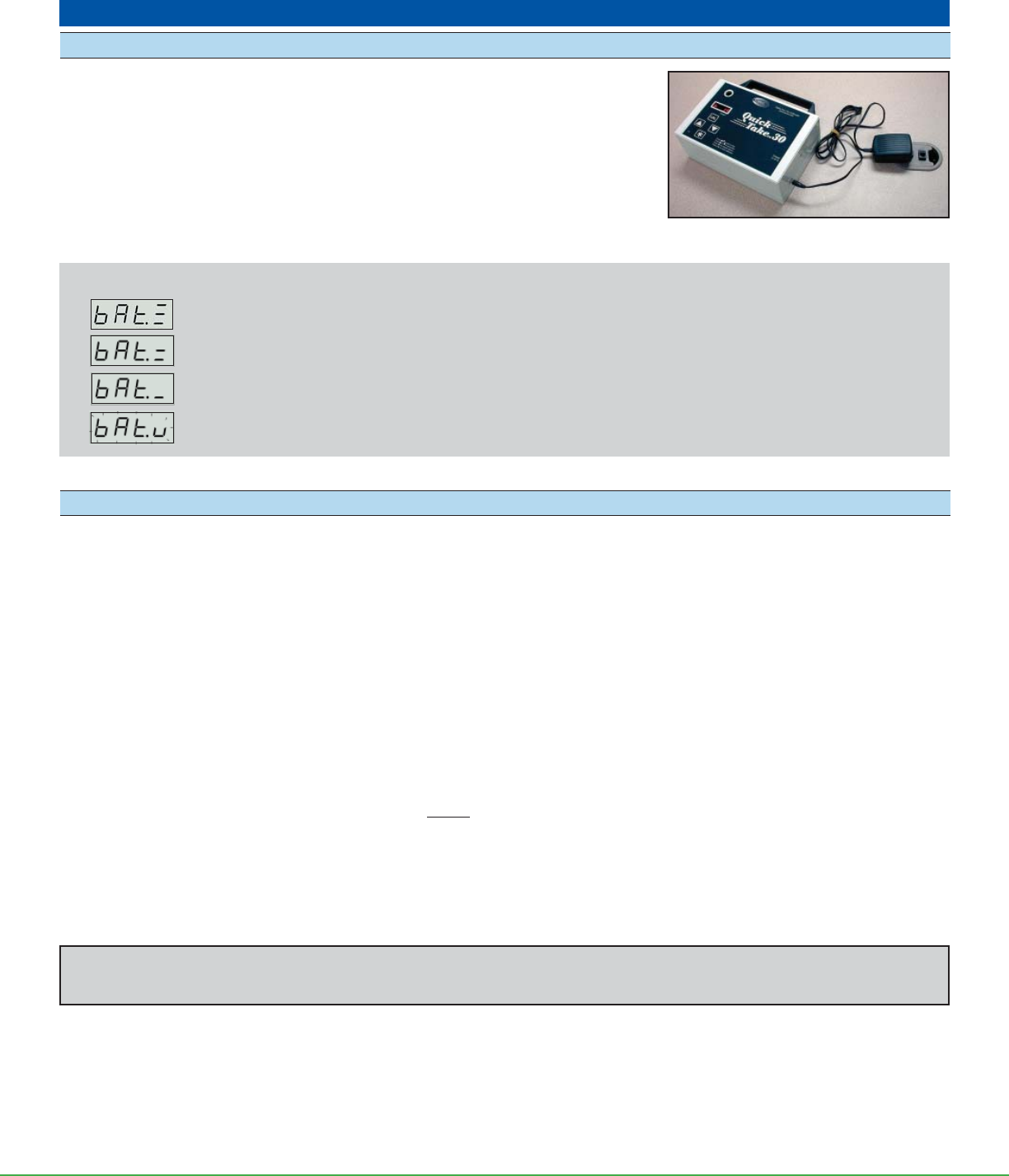
Charge the Battery
1. For a complete charge, ensure the pump is not running. Insert the charger plug into
the charging jack on the pump.
2. Insert the charger into a wall outlet. A red LED will fl ash on the pump display to
indicate the unit is charging. When charging is complete, the LED will stop fl ashing
and the pump will go to sleep. The ba ery charges completely in 5 hours. Note: The
QuickTake 30 can be operated using AC power. See Operate from AC Power.
Determining Battery Charge
Ba ery Status Indicators
Full charge; approximately 75 to 100% ba ery capacity remaining
Ba ery is charged enough to operate the pump; approximately 25 to 75% ba ery capacity remaining.
Ba ery charge is low (charge ba ery); approximately 1 to 25% ba ery capacity remaining.
Low Ba ery Fault. Pump will stop running, beep, and go to sleep in 10 seconds.
Notes and Cautions
• After charging the battery pack, it is good practice to run the pump for approximately 5 minutes before calibrating. This ensures
the battery is in a more steady-state condition and improves the agreement in pre and post-sampling calibrations.
• The pump will not sleep during charging. Connecting a sleeping pump to the charger will wake it up from sleep.
• The AC charger/adapter can be used to extend battery run time, but it is not a battery eliminator. Therefore, it will not provide
indefi nite run times.
• Do not operate or charge the pump in hazardous locations.
• Use only the SKC-approved charger for this pump. Use of an unapproved charger may damage the battery and the pump
and voids any warranty.
• The battery pack may be kept on the SKC-approved charger for an indefi nite time.
• Ensure proper orientation of the charging cable before plugging it into the charging jack. Improper orientation/contact will
short circuit the battery and voids any warranty.
• Short-circuiting the battery pack will render it immediately inoperative.
• Failure to follow warnings and cautions voids any warranty.
See www.skcinc.com/instructions/1918.pdf for more information on SKC pump lithium-ion batteries.
Charging train
Form 40079 Rev 1705
Page 3 of 14
www.skcinc.com
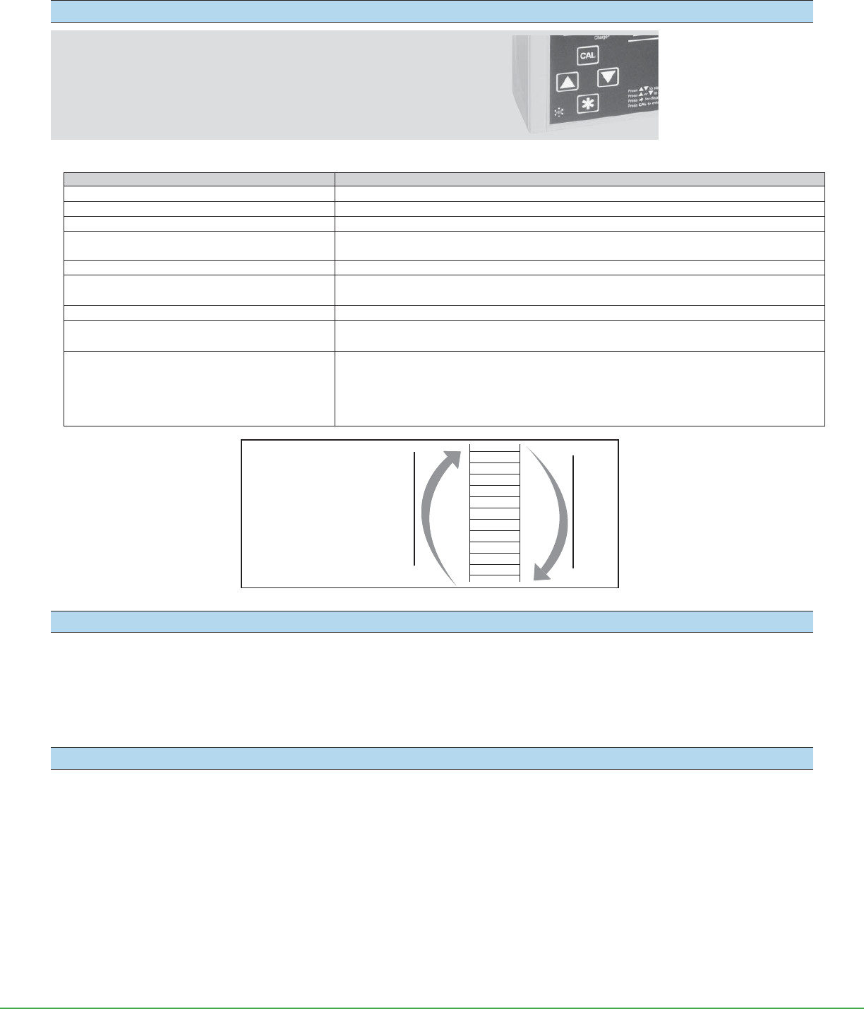
How to Use Button Sequences
Bu ons must be pressed in the sequence shown.
or = Press individually
[] = Press both simultaneously
= Security code, press in sequence
Operating the Pump
Operation/Function Action
Turn pump power on/off (activate LED) Press and hold for 2 seconds to activate LED
Check battery status With LED on, press . If battery status is low, recharge battery. See Charge the Battery.
Navigate presets and displays Press or to scroll through presets and displays.
Select a run time preset and run the pump 1. Scroll to desired run time preset. See below.
2. Select preset by pressing []. The pump will start to run.
Run pump or place in Hold Press [].
Repeat sample run From Done, reset (rSET), or sampling error (SErr), press [] to return to run time preset. Press
[] to sample.
Turn off LED The LED is automatically turned off after being idle for 4 minutes. To reactivate the LED, press and hold .
Interrupt run, terminate sample, or reset pump 1. With pump in Hold, press . Sample reset (rSEt) will be displayed.
2. Press [] to reset the pump or to ignore the reset and return to Hold.
Set fl ow or calibrate 1. With pump connected to calibrator, scroll to desired run time preset.
2. Press and hold CAL for 2 seconds to enter calibration mode (pump will start running).
3. Press or to reach desired fl ow rate (not displayed on LED).
4. Press to display Stor and press [] to save setting or to ignore changes.
See Set/Calibrate Flow Rate for details.
Operate from AC Power
The QuickTake 30 may be run using AC power with the ba ery and AC charger/adapter:
1. Insert the charger plug into the charging jack on the pump.
2. Insert the charger into a standard wall outlet.
3. Operate the pump.
Notes and Cautions
• The charge light on the LED will fl ash if the battery is charging during AC operation.
• The AC charger/adapter can be used to extend battery run time, but it is not a battery eliminator. Therefore, it will not provide indefi nite run times.
• Do not operate or charge the pump in hazardous locations.
• Use only the SKC-approved battery and charger for this pump. Use of an unapproved battery and/or charger may damage the battery and the pump
and voids any warranty.
• To reduce risk of injury, fi re, or electric shock, always follow basic safety precautions when using this product.
• Do not submerge the pump or subject it to any liquids.
• Protect the sample pump from weather when in use outdoors.
• Tampering with the battery pack or using a repaired or rebuilt battery pack voids any warranty and UL Listing for intrinsic safety.
• Do not open, disassemble, short circuit, crush, incinerate, or expose the battery to fi re or high temperatures.
• Failure to follow warnings or cautions voids any warranty.
Selecting the
Available Presets
Press or
Press
5
4
3
2
1
CONT
INTT
END
999
998
997
Press
Form 40079 Rev 1705
Page 4 of 14
www.skcinc.com
Operation
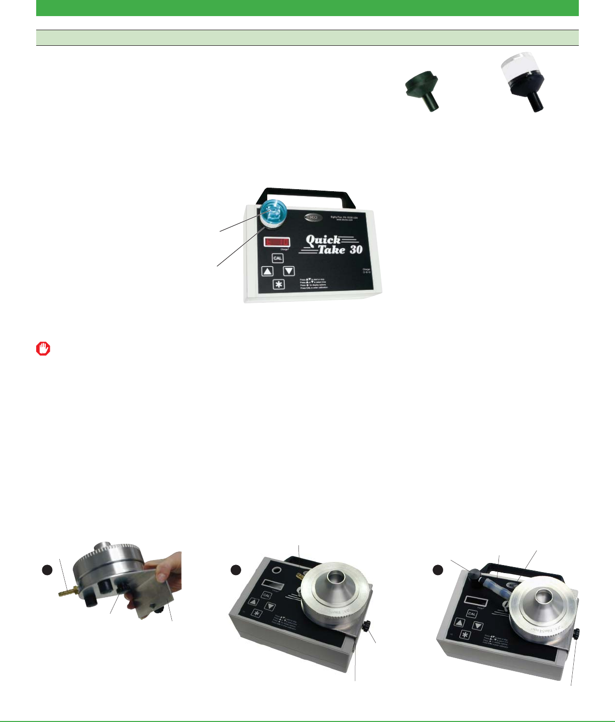
Mount Sampling Media
Spore Trap Cassette
Use the casse e adapter supplied with the pump.
1. Insert the tube end of the adapter into the pump inlet up to the fl ange.
2. Remove the seal from the outlet of the casse e and push the casse e onto
the bowl end of the adapter until a fi rm seal is established.
Calibration Note: Flow rate can be calibrated by pushing the bowl end of a second cassette adapter onto the spore trap cassette inlet (seal
removed), attaching fl exible tubing to the tube end of the second adapter, and attaching the other end of the fl exible tubing to the outlet of a
calibrator. See Set/Calibrate Flow Rate.
For bioaerosol sampling at 15 L/min, SKC recommends using the Leland Legacy® pump (5 to 15 L/min) or the QuickTake 30 pump
(10 to 30 L/min).
BioStage Impactor
Use with Mounting Bracket accessory (Cat. No. 228-9531).
1. Place the BioStage on the L-shaped bracket. Align the BioStage outlet to the 10 o’clock position on the bracket. Secure with thumbscrew
on the bo om of the bracket.
2. Place the L-shaped bracket to the right on the pump faceplate with the short leg of the bracket fi ing over the right edge of the
pump. Align the hole on the short leg of the bracket with the hole on the side of the pump. Secure the bracket to the pump with the
thumbscrew.
3. Insert the inlet adapter (included with bracket) into the pump inlet and connect the inlet adapter tubing to the BioStage outlet.
Empty cassette
adapter
Cassette adapter with
spore trap cassette
VersaTrap
cassette
Cassette
adapter
QuickTake 30 with VersaTrap cassette
mounted in cassette adapter
BioStage
outlet
Short leg
of bracket
Thumbscrew
securing
BioStage
BioStage outlet
aligned to 10 o’clock position
Bracket
Thumbscrew
securing
bracket
Inlet adapter
inserted into
inlet
Inlet
adapter
tubing BioStage
outlet
Thumbscrew
securing
bracket
1
2
3
Form 40079 Rev 1705
Page 5 of 14
www.skcinc.com
Set/Calibrate Flow Rate
• Calibrate the fl ow rate with a representative sampling medium in line.
• Allow pump to equilibrate after moving it from one temperature extreme to another.
1. Ensure the pump has run for 5 minutes before calibrating. Using 3/8-inch ID fl exible tubing and appropriate adapters, connect the
inlet of the pump to the outlet of a representative sampling medium; connect a calibrator to the inlet of the representative sampling
medium. See the example of a calibration train above.
2. Scroll to any run time preset. Press and hold the CAL bu on for 2 seconds. The pump will start running and
a fl ashing CAL will appear on the LED.
3. Press or to increase or decrease the fl ow until the desired fl ow rate is displayed on the calibrator.
4. Press
. A fl ashing Stor will appear on the LED.
• To save new se ing: Press []. The pump will stop running.
• To ignore new se ing: Press . The pump will stop running.
Note: A security code is not needed to change fl ow rate. It is only required when changing factory se ings. To change
factory se ings, see Advanced Operation.
Tubing
Calibrator outlet Pump inlet
Spore trap cassette
Note: Use a second cassette adapter to
attach calibrator to a spore trap cassette.
Calibration train with a spore trap cassette
Cassette adapter
Digital display:
Calibration mode
Digital display:
Store setting
Form 40079 Rev 1705
Page 6 of 14
www.skcinc.com
Set Up Run Time Modes
Press or to scroll through the run time presets on the LED.
Run Time Mode LED Display
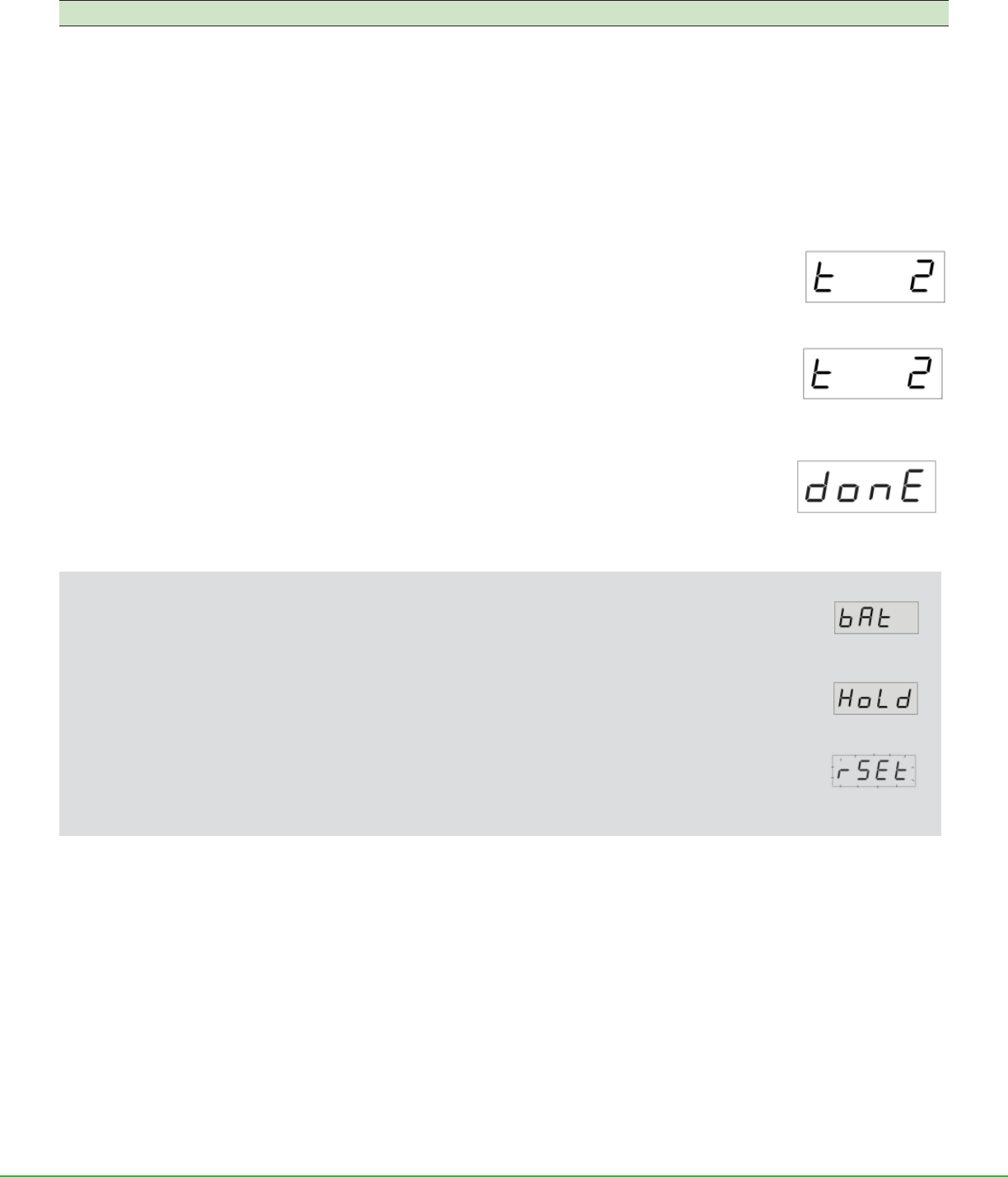
Timed Run (defaults: 15, 10, 5, 2, and 1 min) t xx
Intermi ent Sampling* In
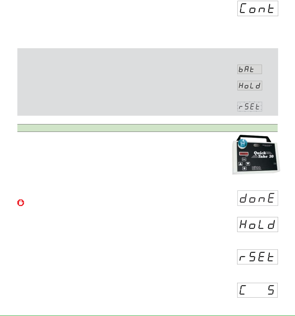
Continuous Run Cont
* For setup and sampling in this mode or to change (program) run time presets, see Advanced Operation.
Timed Run
• Run time accumulates only while the pump is running.
Timed Run mode is designed to perform one sample for a predetermined time from 1 to 999 minutes (selected
from presets). The user starts the pump running, and the pump automatically stops running after the sample
time has elapsed.
1. Press or to scroll to the desired run time preset.
2. Press [] to select the desired preset. The pump will start running and the LED will display a countdown
to zero (run time remaining below one minute is displayed in seconds with a colon). The pump will stop and
beep four times. The display will fl ash Done.
3. Press
to return to the run time preset display. To repeat the sample, press [].
User Options During Timed Run Sampling
Viewing ba ery status
Press . Display will automatically return to run time remaining after 5 seconds or press again.
Hold mode
Press [] while the sample is running to place the pump and timer in Hold. Run time remaining and Hold will
display alternately. Press [] while in Hold to continue the sample run.
Terminating a sample and rese ing the pump
Press while in Hold. Sample Reset (rSEt) will fl ash on the LED.
• To terminate the sample and reset the pump: Press [].
• To continue the sample run: Press to return the display to Hold. Press [].
Digital display:
Timed Run 2 minutes
Digital display:
Run time remaining is
2 seconds
:
Digital display:
Sample run completed
Form 40079 Rev 1705
Page 7 of 14
www.skcinc.com
Continuous Run with Manual Stop
• Run time accumulates only while the pump is running.
Continuous Run mode performs one sample from 1 to 999 minutes, and then automatically resets to zero and counts up to 999 again until
the user manually stops the pump.
1. Press or to scroll to Cont. Press [] to select it. The pump will start running and the LED will
display cumulative run time up to 59 seconds in seconds, and then switch to minutes. The timer will
count up to 999 minutes, automatically reset to zero, and count up to 999 minutes again until the user
manually stops the pump.
2. Press [] to place the pump in Hold when the desired sampling time has elapsed. The LED will
display cumulative run time and Hold alternately.
• To continue the sample run: Press [].
• To terminate the sample and reset the pump: Press while in Hold. Sample Reset (rSEt) will fl ash on the LED. Press [].
User Options During Continuous Run Sampling
Viewing ba ery status
Press . Display will automatically return to cumulative run time after fi ve seconds or press again.
Hold mode
Press [] while the sample is running to place the pump and timer in Hold. Hold and cumulative run
time will display alternately. Press [] while in Hold to continue the sample run.
Terminating a sample and rese ing the pump
Press while in Hold. Sample Reset (rSEt) will fl ash on the LED.
• To terminate the sample and reset the pump: Press [].
• To continue the sample run: Press to return the display to Hold. Press [].
Sample
• Allow the pump to equilibrate after moving it from one temperature extreme to another.
• Protect the sample pump from weather when in use outdoors.
• Do not operate or charge the pump in hazardous locations.
1. Replace the representative sampling medium used for calibration with a fresh unexposed sampling
medium. See example of sampling train at right.
2. Press or to scroll to a run time preset. See Timed Run, Continuous Run, or Intermi ent Sampling.
3. Once the desired preset is displayed, press [] to start the pump running. Record sample
start time.
To stop sampling and reset the pump, see End Sample and Reset the Pump.
4. When sampling is completed, perform the following actions depending on the run time mode:
a. Timed Run mode - The display will count down to zero and the pump will stop. The alarm will beep four
times. The display will fl ash donE. Press to return to presets. If a repeat sample is desired, press [].
b. Continuous Run mode - The timer will count up to 999 minutes, automatically reset to zero, and count
again to 999 minutes until user stops the pump. Press [] to place the pump in Hold when the desired
sampling time has elapsed. HoLd and cumulative run time will fl ash alternately. Press while in Hold.
Sample reset (rSEt) will appear on the LED. Press [] to terminate the cumulative run and reset the
pump. If a repeat sample is desired, press [].
c. Intermi ent Sampling mode - The display will count up to set run time, count down from set delay time
to 0, then run again. The pump will cycle until the programmed number of cycles are completed. The alarm
will beep four times. The display will fl ash donE. Press [] to return to the run time preset. If a repeat
sample is desired, press [].
5. Remove and seal the sample medium.
6. Reassemble the calibration train (see Set/Calibrate Flow Rate) and verify fl ow.
7. Send sample, blanks, and pertinent sampling information to a laboratory for analysis.
Digital display:
Continuous Run
Sampling train with cassette adapter
and a spore trap cassette
Digital display:
Cumulative run time
Digital display:
Sample run completed
Digital display:
Pump and Timer in
Hold
Digital display:
Terminate sample and
reset pump
Form 40079 Rev 1705
Page 8 of 14
www.skcinc.com
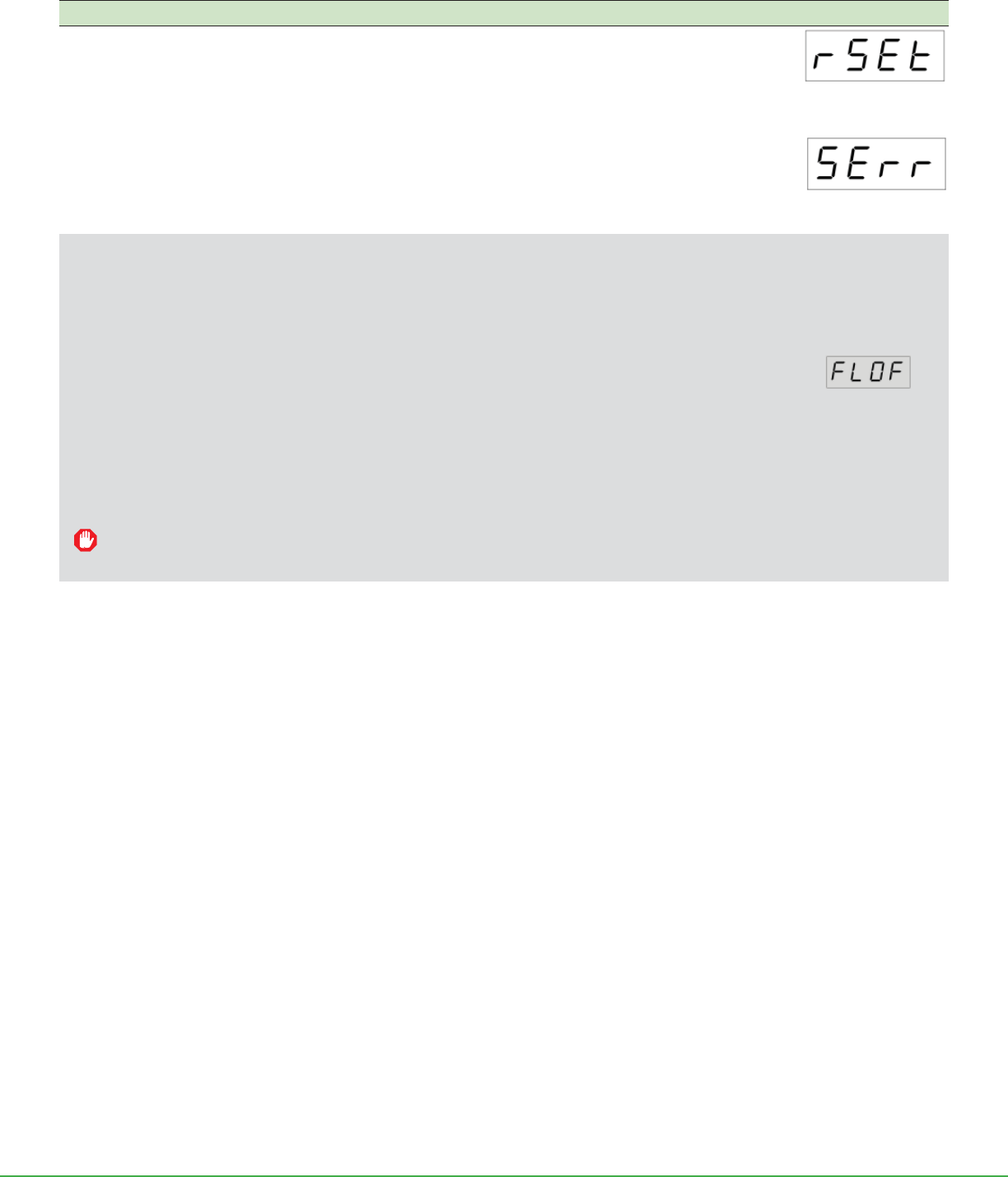
End Sample and Reset the Pump
For timed and continuous runs: from a running pump, press []. The pump is now in Hold. Press while in
Hold. Sample reset (rSEt) will display. Press [] to zero the cumulative run time and reset the pump.
For intermi ent sampling, there is no Hold. Press [] to stop the pump. The LED will display SErr (sampling
error). Press to view cumulative run time. Press [] to return to run time presets. Note: Cumulative run time
resets to 0 even if intermi ent sampling is started again.
Flow Fault
Manufacturer default: enabled. User may disable feature.
If the pump is not able to compensate due to excessive back pressure, a fl ashing FLOF will appear on the LED. If the fault is not
corrected within fi ve seconds, the pump will beep four times and stop running.
Restoring Sampling from a Flow Fault
Fault restart (manufacturer default: enabled)
Fault restart will a empt to restart the pump every 10 seconds up to fi ve times. Cumulative run time can be
displayed by pressing . Press again to return to the fault (FLOF) display. If the pump does not automatically
restart, a empt to correct the fl ow blockage, then press [] to place the pump in Hold. Press [] to resume
sampling.
Fault restart (user disabled)
Cumulative run time can be displayed by pressing . Press again to return to the FLOF display. A empt to correct fl ow blockage
and press [] to place the pump in Hold. Press [] to resume sampling.
The fl ow fault and fl ow fault restart features can be enabled or disabled by the user as desired. See Advanced Operation,
Enable/Disable Alarm and Fault Features.
Digital display:
Terminate sample and
reset pump
Digital display:
Sampling Error
Digital display:
Flow fault
Form 40079 Rev 1705
Page 9 of 14
www.skcinc.com
Advanced Operation
Intermittent Sampling (Setup and Sampling)
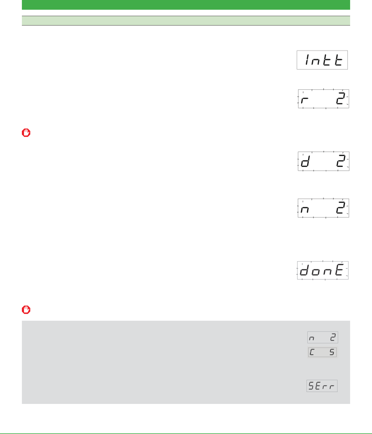
Intermi ent Sampling mode allows the pump to be programmed to run for a specifi c number of minutes up to 999, to shut off for a
programmed length of time, and to continue sampling on and off for a predetermined number of cycles. An example is programming the
pump to run three cycles (n) of 15 minutes each (r) with a 5-minute delay (d) between each cycle.
Enter Intermittent Sampling Mode
Press or to scroll to In . Press to enter the intermi ent sampling setup mode.
Set Run Time (r)
1. Press or to increase or decrease run time. The display will fl ash. If no change to run time is desired, press
to move to delay time.
2. When fi nished, press . Stor will fl ash on the display.
To save the new se ing: Press []. Press to move to delay time setup.
To ignore the new se ing: Press . Display will move to the delay time.
If displayed values are not changed, the fl ashing Stor will not appear and pressing will move the display to the next
parameter to be set.
Set Delay Time (d)
1. Press or to increase or decrease delay time. The display will fl ash. If no change to delay time is desired,
press to move to number of cycles.
2. When fi nished, press . Stor will fl ash on the display.
To save the new se ing: Press []. Press to move to number of cycles setup.
To ignore the new se ing: Press . Display will move to the number of cycles.
Set the Number of Cycles (n)
1. Press or to increase or decrease the number of cycles. The display will fl ash. If no change to the number
of cycles is desired, press to return to In .
2. When fi nished, press . Stor will fl ash on the display.
To save the new se ing: Press []. Press to return to In .
To ignore the new se ing: Press . The LED will return to In .
Sample
1. Press []. The LED will count up to 59 seconds, then switch to minutes up to the set minutes run
time. The pump will stop for the programmed number of delay minutes while the LED displays a count
down from the set delay time to zero. The pump will start sampling again. The pump will beep four
times and the display will fl ash donE after the desired cycles are completed.
2. Press
to display cumulative run time.
3. Press
to return to donE.
4. Press [] to return the display to the run time preset. If a repeat sample is desired, press [].
Intermittent sampling settings are retained when the pump goes to sleep.
User Options During Intermittent Sampling
Viewing number of cycles remaining and cumulative run time
Press repeatedly while the sample or delay is running. If the unit is left untouched for 5 seconds, the display
will automatically return to cumulative time.
Terminating a sample and rese ing the pump
Hold is not available in Intermi ent Sampling. Press [] to stop the sampling and the LED will display SErr
(sampling error). Press to view cumulative run time. Press [] to return to run time presets.
Digital display:
Intermittent Sampling
Digital display:
Set run time
Digital display:
Set delay time
Digital display:
Sample run completed
Digital display:
Set number of cycles
Form 40079 Rev 1705
Page 10 of 14
www.skcinc.com
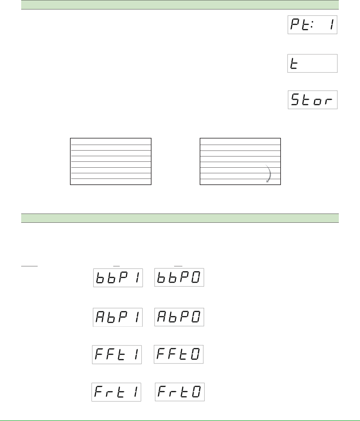
Program Run Time Presets
1. Press .
2. Pt: 1 will alternately display with t xx. This corresponds to the fi rst stored preset time.
3. Press to scroll to the number of minutes (1 to 999). Press to scroll to Cont, In , or End mode options.
End will not appear as an option during setup of the fi rst preset.
4. When the LED displays the desired time or mode, press to move to the next preset time.
5. Repeat Steps 3 and 4 for each preset up to eight presets. The sequence will repeat from one to eight.
6. When fi nished, press []. Stor will display on the LED.
To save the new se ings: Press []. The pump will return to normal pump operation.
To ignore the new se ings: Press . The pump will return to normal pump operation.
Note: While programming presets, scrolling below In will display End after the fi rst preset is selected. Choosing End
will truncate the stored preset sequence (see below). For example, if the user wants to store only two presets, preset
time 3 can be set to End, shortening the number of presets to scroll through. Times programmed for preset times Pt: 4
through 8 will not display until the presets are changed to make them display or the factory defaults are reset. See Reset
Pump to Manufacturer Default Se ings.
Presets Sequence
Enable/Disable Alarm and Fault Features
1. Press the security code to enter setup mode.
2. Press the CAL bu on. The pump software version number will display briefl y.
3. Press or to turn feature on or off (see below). Press to advance to next feature.
4. Press [] to exit feature setup. Press [] again to return to run time presets.
Feature ON OFF
Button Beeper: On/Off
Alarm Beeper: On/Off
Flow Fault: On/Off
Flow Fault Restart: On/Off
Digital display:
Button beep on
Digital display:
Button beep off
Digital display:
Alarm beep on
Digital display:
Alarm beep off
Digital display:
Flow fault on
Digital display:
Flow fault off
Digital display:
Flow restart on
Digital display:
Flow restart off
Preset 8 End
Preset 7 Intt
Preset 6 Cont
Preset 5 t 15
Preset 4 t 10
Preset 3 t 5
Preset 2 t 2
Preset 1 t 1
Preset 8 End
Preset 7 Intt
Preset 6 Cont
Preset 5 t 1 - 999
Preset 4 End
Preset 3 t 1 - 999
Preset 2 t 1 - 999
Preset 1 t 1 - 999
Manufacturer Default Presets The pump returns to the beginning preset at the fi rst End
it encounters. This allows the user to shorten the number of
presets to be scrolled through. Preset 1 cannot be set to End.
5
Digital display:
Store settings
Digital display:
First preset
Digital Display:
Time set for preset 1
Form 40079 Rev 1705
Page 11 of 14
www.skcinc.com
Maintenance
Notes and Cautions
• The charge light on the LED will fl ash if the battery is charging during AC operation.
• The AC charger/adapter can be used to extend battery run time, but it is not a battery eliminator. Therefore, it will not provide indefi nite run times.
• Do not operate or charge the pump in hazardous locations.
• Use only the SKC-approved battery and charger for this pump. Use of an unapproved battery and/or charger may damage the battery and the
pump and voids any warranty.
• To reduce risk of injury, fi re, or electric shock, always follow basic safety precautions when using this product.
• Do not submerge the pump or subject it to any liquids.
• Protect the sample pump from weather when in use outdoors.
• Tampering with the battery pack or using a repaired or rebuilt battery pack voids any warranty and UL Listing for intrinsic safety.
• Do not open, disassemble, short circuit, crush, incinerate, or expose the battery to fi re or high temperatures.
• Failure to follow warnings or cautions voids any warranty.
• Keep the pump clean and free of dust and dirt. It may be wiped with a dry cloth.
• Keep the battery charged (see Charge the Battery). Charge periodically when pump is not used for prolonged periods.
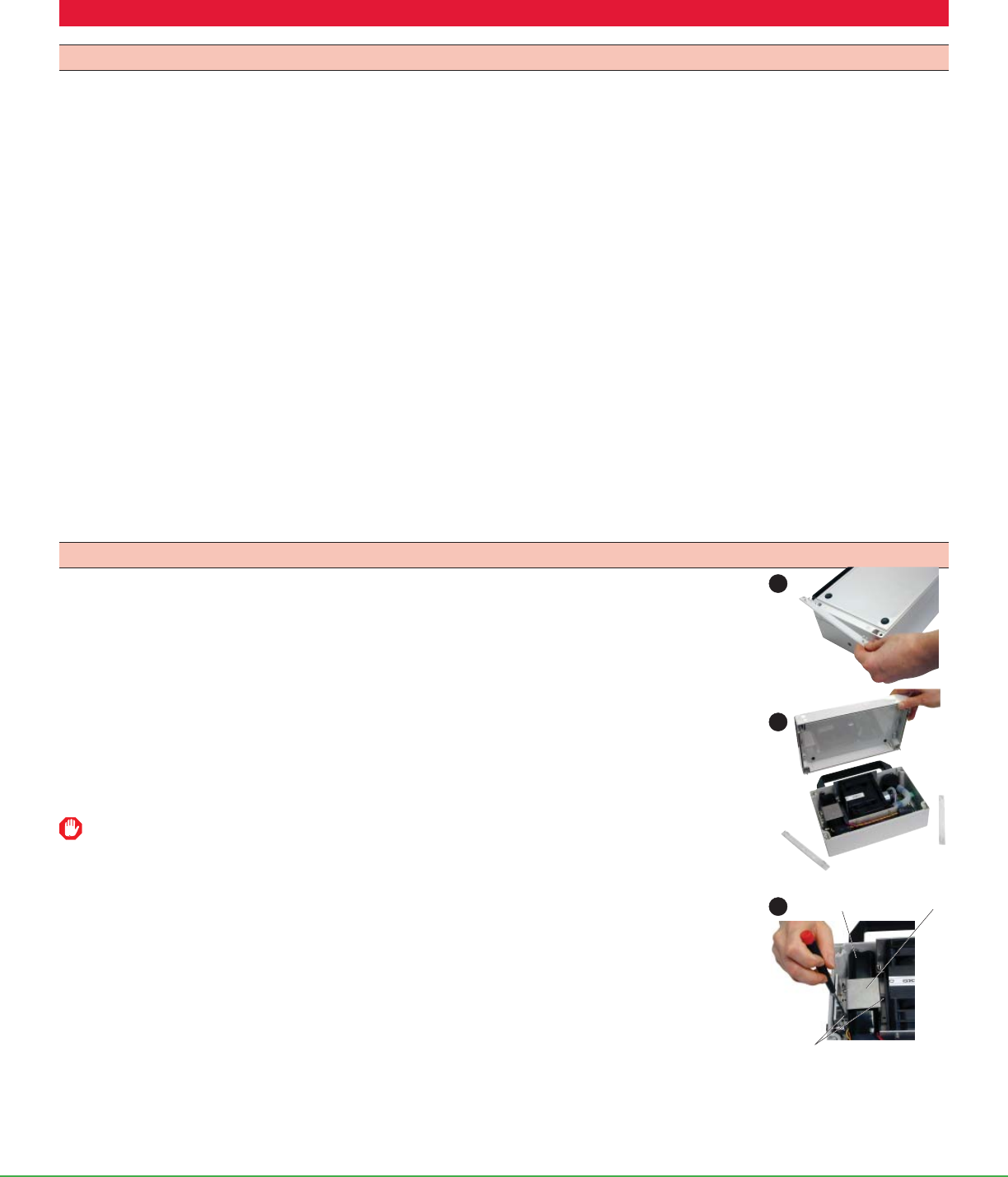
Change the Battery
1. With the back of the pump facing you (serial number at bo om left), use a small fl at-head screwdriver
(tweaker) to pry up and remove two strip panels from the left and right ends of the back of the
case. Remove the pressure-fi t panels to reveal four safety screws.
2. Use a Phillips head or fl at-head screwdriver to loosen the four safety screws.
3. Lift off the back of the pump case.
4. Use a Phillips head screwdriver to loosen the two screws (with washers) from the ba ery bracket.
Use forceps to remove the screws and washers from the case; set the screws aside.
Do not lose washers.
Bracket
screws
Battery Bracket
1
3
4
Form 40079 Rev 1705
Page 12 of 14
www.skcinc.com
Maintenance (Cont)
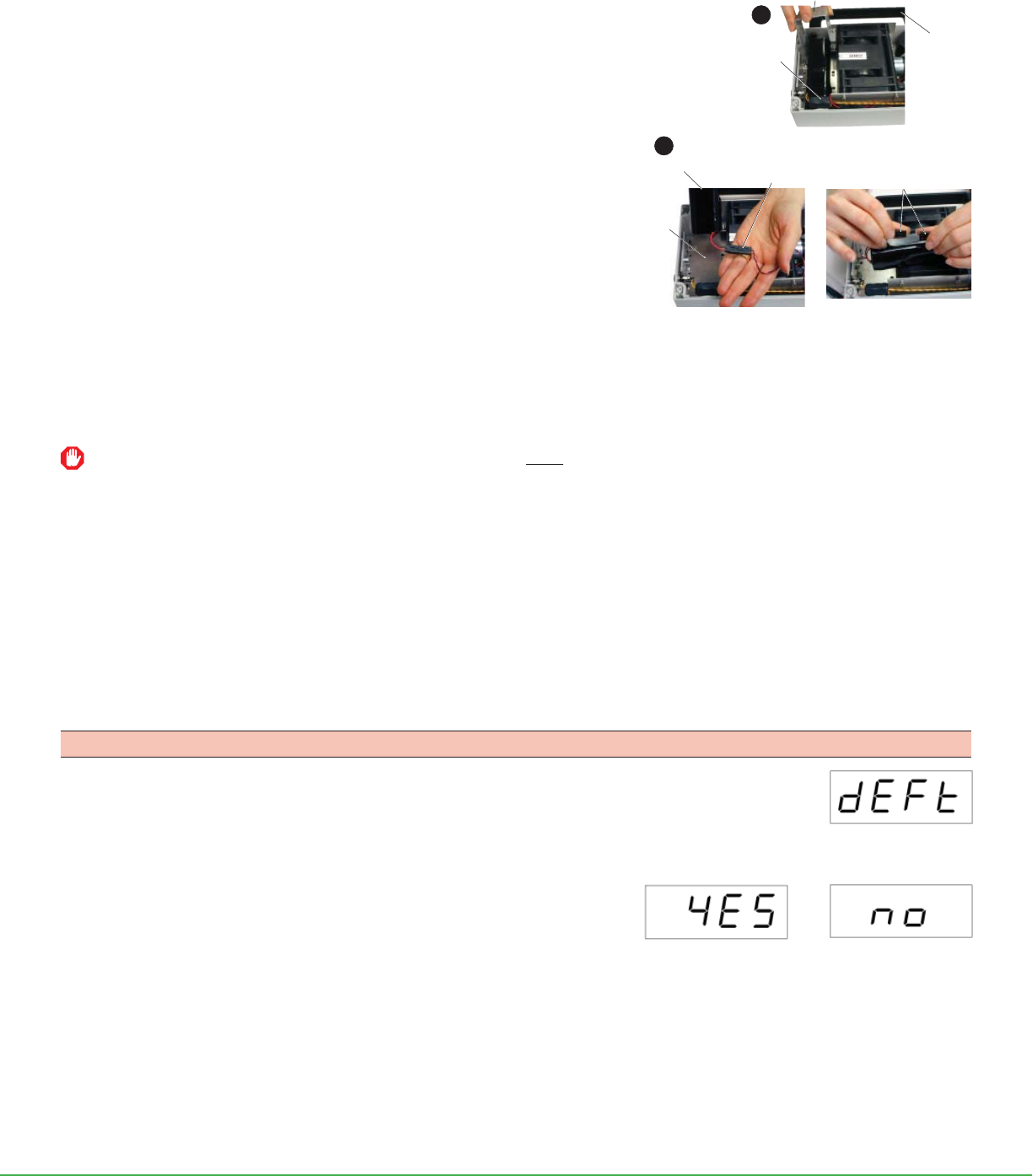
5. Lift the bracket slightly, slide it toward the case handle, and lift it out of the
case.
6. Detach the ba ery from the ba ery harness by pressing on the connector tab
(left side of connector) and pulling both sides of the connector apart.
7. Using a full-size fl at-head screwdriver, insert its tip underneath the ba ery
end nearest the case handle. Maneuver the screwdriver to apply an upward
force to the bo om of the ba ery until the double-sided tape adhesive on its
bo om releases its hold and the ba ery can be lifted from the case.
8. A ach the new ba ery to the ba ery harness connector by aligning the two
sides of the connector and pressing them together until they click.
9. Install the ba ery.
a. If installing a new ba ery (Cat. No. P75689), remove the protective strip
from double-sided mounting tape on the bo om of the new ba ery to expose
adhesive.
b. If reinstalling the existing ba ery, remove as much of the previous adhesive as possible from the bo om of the ba ery. Remove
the protective strip from one side of a new two-inch piece of double-sided mounting tape (available from SKC as Cat. No. 51872)
and apply to the bo om of the ba ery. Remove the protective strip from the tape’s remaining side to expose adhesive.
Ensure the battery harness wires on battery pack are facing away from the case handle before inserting battery in case.
10. Align the ba ery in case (as shown above) before allowing the bo om of the ba ery to come into contact with and adhere to the pump
base plate. Press down gently to ensure the ba ery pack adheres to the base plate.
11. From the case handle side of the pump, slide the ba ery bracket into place until two openings in the bracket are aligned with the two
screw holes in the pump base plate.
12. Use needlenose pliers to align the two screws with washers with the screw holes. Tighten screws using a small fl at-head screwdriver.
13. Replace the back of the pump case (serial number label should be in the lower left corner) and tighten the four safety screws.
14. Replace the two strip panels and press them down until they are completely installed.
Reset Pump to Manufacturer Default Settings
1. Press the security code and then press the CAL bu on. The pump software version number will
display briefl y.
2. Press repeatedly to scroll through until the LED displays dEFt.
3. Press []. The word no will appear on the display.
To reset to factory default se ings: Press . YES will appear on the display.
Press [].
To retain existing se ings: Press to scroll to no and press [].
The number 30 will appear briefl y, then the display will return to run time presets.
Digital display:
Yes, reset to pump
default
Digital display:
Pump default
Digital display:
No, do not reset to
pump default
Pull apart battery
harness connector.
Battery harness
connector
Battery
Battery
cavity
Slide bracket toward
case handle and lift out.
Battery harness wires
Case
handle
5
6

Form 40079 Rev 1705
Page 13 of 14
www.skcinc.com
Accessories/Replacement Parts
Accessories Cat. No.
Charger/Adapter, 100-240 V 223-245
Mounting Bracket for BioStage Impactor includes inlet adapter 228-9531
Rotameter, 3 to 30 L/min 320-100
Tygon Tubing, 3/8-inch ID 10 feet
50 feet
225-1351
225-1352
TSI 4146 Calibration Kit
, 0.01 to 20 L/min, includes calibrator, soft-sided case, mounting lugs, tubing (1/4-in ID),
battery pack, 6 AA batteries, inlet fi lter, dampening module, NIST certifi cate, and manual
740-4146
Replacement Parts Cat. No.
Replacement Inlet Filters, pk/50
P40021A
Stem Tubing Adapter, pk/2
P31239
Cassette Adapter
P33100
Reducing Adapter for Tubing, 3/8 inch to 1/4 inch, pk/2
P31211
Replacement Battery Pack,
* Li-Ion P75689
Replacement Stack for QuickTake 30
P21266
Any warranty is void if pumps are not repaired by SKC or authorized SKC repair centers. Use only SKC-approved parts to ensure
reliable performance. Failure to do so voids any warranty.
Use of a repaired or rebuilt battery pack voids any warranty.
Li-Ion Battery Testing and Shipment
Rechargeable lithium-ion batteries for use with SKC sample pumps have been tested in accordance with the UN Manual and are proven to meet requirements of each test in the
UN Manual of Tests and Criteria, Part III, subsection 38.3. The batteries are rated below 100 watt-hours (Wh).
Consult with your carrier for more information on Lithium Battery Shipping Regulations UN 3480 and UN 3481 or visit SKC’s website for more information at www.skcinc.com/catalog/
pdf/instructions.1921.pdf.
SKC Limited Warranty and Return Policy
SKC products are subject to the SKC Limited Warranty and Return Policy, which provides SKC’s sole liability and the buyer’s exclusive
remedy. To view the complete SKC Limited Warranty and Return Policy, go to h p://www.skcinc.com/warranty.asp.
* Pump contains Li-Ion ba ery and may be subject to special shipping regulations.
Form 40079 Rev 1705
Page 14 of 14
www.skcinc.com
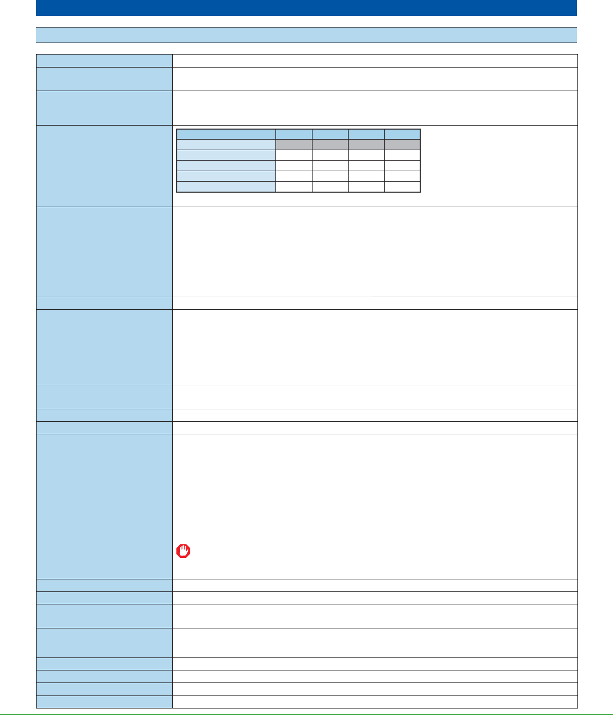
Appendix
Performance Profi le
Flow Range 10 to 30 L/min
Flow Compensation
Accuracy
± 5% of set fl ow
Compensating Flow Back
Pressure Range
10 L/min at 90 inches water back pressure
20 L/min at 50 inches water back pressure
30 L/min at 15 inches water back pressure
Typical Back Pressure of
Sampling Media
(inches water)
Flow Rate (L/min) 10 12 15 20
Filter/Pore Size (μm)
25-mm MCE, 0.8 65 80 103 148
25-mm MCE, 0.45 138 172 > 200 —
37-mm MCE, 0.8 22 28 36 51
37-mm PVC, 5.0 9 11 15 21
Compare the information in this table to pump compensation range to determine appropriate applications.
Flow Fault Features If the pump is unable to compensate due to excessive back pressure, the pump will go into fl ow
fault mode (see Flow Fault). Flow fault features are enabled as the default setting. Flow fault may
be disabled at the user’s option. See Advanced Operation.
Flow fault: Flow fault displays immediately
Pump shuts off after 5 sec
Fault restart: Pump attempts restart every 10 sec up to fi ve times
Tubing Requires 3/8-in ID tubing
Run Time Features User-selectable features, user-adjustable presets. See Advanced Operation.
Preset timed runs: 1, 2, 5, 10, or 15 min
Manually set continuous
run with manual shut-off: 1 to 999 min (repeats 1 to 999-min runs indefi nitely until
user stops pump or power supply is depleted)
Intermittent sampling: See Advanced Operation.
Media Compatibility Viable cascade impactors, spore trap cassettes (e.g., VersaTrap), asbestos cassettes,
microvacuum cassettes, and other impaction samplers that require fl ows from 10 to 30 L/min
Operating Temperature 32 to 104 F (0 to 40 C)
Operating Humidity 0 to 95% non-condensing
Typical Cumulative
Run Time†
• Spore Trap* (e.g., VersaTrap): 5 hrs at 15 L/min (battery only)
• BioStage viable cascade impactor: 4 hrs at 28.3 L/min (battery only)
• 25-mm, 1.2-μm MCE fi lter: 9+ hrs at 10 L/min
To achieve, use QuickTake 30 with a fully charged battery and AC charger/adapter.
• 37-mm, 0.8-μm MCE fi lter: > 14 hrs at 10 L/min (battery only)
* Sampling times when using spore traps are usually ≤ 10 min. SKC recommends reducing length of sample time when
using a 30 L/min fl ow rate to prevent overloading the media.
† Results obtained using a new pump and new fully charged ba eries. Pump and ba ery performance may vary.
The AC charger/adapter can be used to extend ba ery run time, but it is not a ba ery eliminator.
Therefore, it will not provide indefi nite run times.
Storage Temperature -4 to 95 F (-20 to 35 C)
Noise Level Average < 64 dBA at 3 ft (using 37-mm 0.8-um MCE fi lter at 16.8 L/min)
Power • Rechargeable lithium-ion (Li-Ion) battery, 7.4 V, 10.4-Ah capacity, 76.96 Wh
• Battery with AC charger/adapter, 100-240 V
Battery Recharge Time
(varies with battery capacity and
level of discharge)
Approximately 5 hrs
Charging Temperature 32 to 113 F (0 to 45 C)
Dimensions 9.3 x 8.4 x 3.5 in (23.6 x 21.3 x 8.9 cm)
Weight 4.8 lbs (2.2 kg)
Housing ABS plastic
