E580 401 Suspension Syst For Acoustical Lay In Ceilings Seismic Des Cat D E And F 2013
User Manual: E580
Open the PDF directly: View PDF ![]() .
.
Page Count: 4

NWCB Technical Document
HEADQUARTERS
2825 Eastlake Ave E Ste 350 | Seattle, WA 98102
tel 206-524-4243 | email info@nwcb.org
OREGON
tel 503-295-0333
email oregon@nwcb.org
www.nwcb.org
© NORTHWEST WALL AND CEILING BUREAU
Suspension Systems for Acoustical Lay-in Ceilings
Seismic Design Categories D, E & F
SUSPENDED CEILINGS
401
12/13
This document has been revised based on current Building Code standards. In all buildings, other than structures classied as
essential facilities, suspended ceilings installed in accordance with the prescriptive provisions of the 401 document are
deemed to comply with the current building code interpretation.
This document provides the IBC-2012 referenced standards for the installation of suspension systems for acoustical lay-in
ceilings. Incorporation of this document will provide a more uniform standard for installation and inspection. This document is
designed to accomplish the intent of the International Building Code (IBC) with regard to the requirements for seismic design
category D, E and F for suspended ceilings and related items. Unless supported by engineering, the suspension system shall be
installed per these requirements and those of the referenced documents. Manufacturers’ recommendations should be followed
where applicable.
General Recommendations
• Referenced sources per hierarchy: 2012 International Building Code (IBC), American Society of Civil Engineers
(ASCE 7-10), American Society of Testing Materials (ASTM C 635, ASTM C 636, ASTM E 580/E 580M), and
Ceilings and Interior Systems Construction Association (CISCA).
• Partitions that are tied to the ceiling and all partitions greater than 6 feet in height shall be laterally braced to the
structure. Bracing shall be independent of the ceiling splay bracing system. Source: ASCE 7-10 Section 13.5.8.1
• For further information on bracing of non-load bearing partitions refer to NWCB Technical Document #200-501.
• All main beams are to be Heavy Duty (HD). Source: ASTM E580 Section 5.1.1
• Ceilings less than or equal to 144 ft2 and surrounded by walls connected to the structure above are exempt from
the seismic design requirements. Source ASTM E580 Section 1.4
• These recommendations are intended for suspended ceilings and related
components in areas that require resistance to the effects of earthquake motions.
Source: ASTM E580 Section 3.2
• All wire ties are to be three tight turns around itself within three inches. Twelve gage
Hanger wire spaced 4 foot on center (gure 1). Source: ASTM C636 Section 2.3.4
• Changes in ceiling planes will require positive bracing. Source: ASTM E580 Section 5.2.8.6
maximum 3"
(76mm)
gure 1
PAGE 1 OF 4
www.nwcb.org
© NORTHWEST WALL AND CEILING BUREAU
PAGE 2 OF 4
EMT CONDUIT
½" EMT conduit up to 5' 10"
¾" EMT conduit up to 7' 8"
1" EMT conduit up to 9' 9"
METAL STUDS
Single 15⁄8" metal stud (20 gage) up to 12' 0"
Back-to-back 15⁄8" metal stud
(20 gage)
up to 15' 0"
Single 2 ½" metal stud (20 gage) up to 13' 6"
Back-to-back 2 ½" metal stud (25 gage) up to 15' 0"
gure 3
Maximum Recommended Lengths for
Vertical Struts
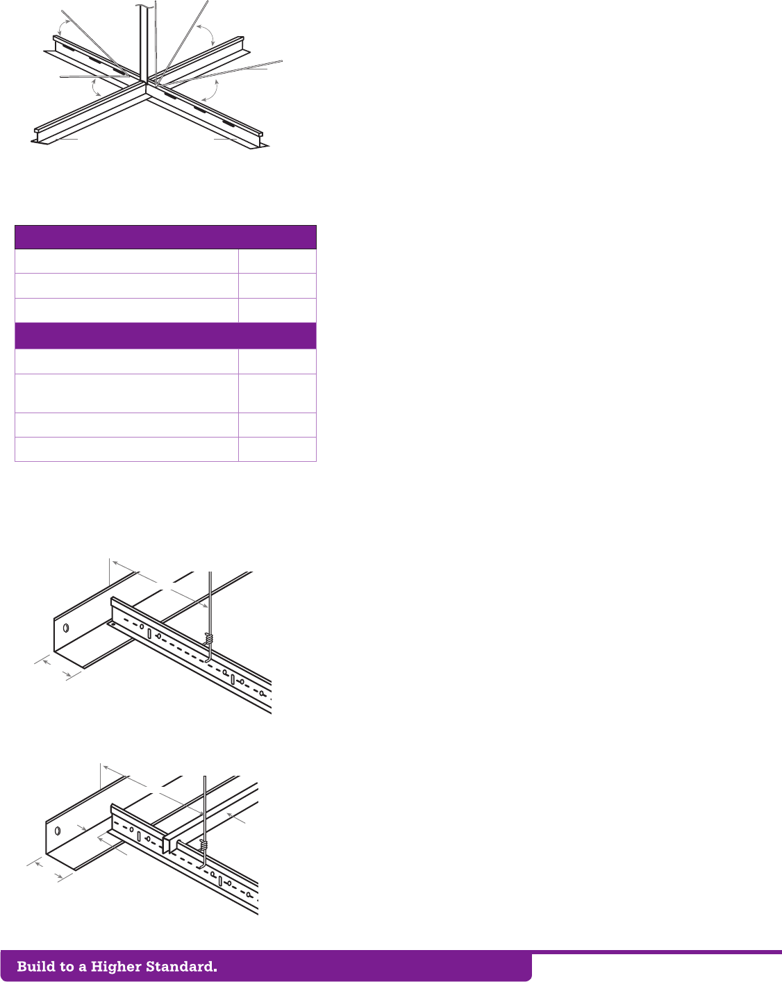
45º or less
45º or less 45º or less
45º or less
12 gage
splayed
brace
wires
Main beamCross tee
gure 2
Lateral force Bracing
Note: Plenum areas greater than 15' 0" will require engineering
calculations.
Source: Portland Building Department
maximum 8" (202 mm)
WALL
minimum
2" (50 mm)
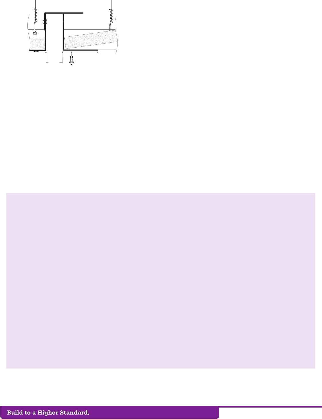
gure 4a
Attached Wall Molding Requirements
gure 4b
Unattached Wall Molding Requirements
maximum 8" (202 mm)
WALL
minimum
2" (50 mm)
minimum
3/4" (19 mm)
at unattached walls
Speader bar or
other suitable
system required to
keep perimeter
compents from
spreading apart
Lateral Force Bracing (gures 2 and 3)
• Ceilings constructed of screw-or-nail-attached gypsum board on
one level that are surrounded by and connected to walls or softs
that are laterally braced to the structure above are exempt from
seismic design requirements. Source: ASCE 7-10 Section 13.5.6.2.2 Exception 2,
ASTM E580 Section 1.7
• Ceiling areas of 1000 ft2 or less shall be exempt from later force
bracing requirements. Source: ASTM E580 Section 1.6
• Lateral force bracing is the use of vertical struts (compression
posts) and splay wires (see gure 2).
• Lateral Force Bracing shall be 12 feet on center (maximum) and
begin no farther than 6 feet from walls. Source: ASTM E580 Section 5.2.8.2
• Seismic splay wires are to be four 12 gage wires attached to the
main beam. Wires are arrayed 90° from each other and at an
angle not exceeding 45° from the plane of the ceiling. Source: ASTM
E580 Section 5.2.8.2
• Seismic splay wires shall be attached to the grid and to the
structure in such a manner that they can support a design load of
not less than 200 pounds or the actual design load, with a safety
factor of 2, whichever is greater (gure 6b). Source: CISCA zones 3-4
• Power Actuated Fasteners (PAF’s), when used for seismic
application as part of the prescriptive path in Seismic Design
Categories D, E and F, shall have an ICC-ES approval for seismic
applications and shall require “special inspection” irrespective of
the type of occupancy category the structure is in. PAF anchors
for kicker wires (splayed wires installed for purposes other than
seismic restraint) are exempt from this requirement. Source: State of
Oregon, Building Codes Division
• Splay wires are to be within 2 inches of the connection of the
vertical strut to suspended ceiling. Source: ASTM E580 Section 5.2.8.2
• Rigid bracing may be used in lieu of splay wires. Source: ASTM E580
Section 5.2.8.4
• Ceilings with plenums less than 12 inches to structure are not
required to have lateral force bracing. Source: Portland Building Department
• Vertical struts must be positively attached to the suspension
systems and the structure above. Source: ASTM E580 Section 5.2.8.2
• The vertical strut may be EMT conduit, metal studs or a proprietary
compression post (see gure 3).
Wall Moldings (gures 4a and 4b)
• Wall moldings (perimeter closure angles) are required to have a
horizontal ange 2 inches wide. One end of the ceiling grid shall
be attached to the wall molding, the other end shall have a ¾ inch
clearance from the wall and free to slide. Source: ASTM E580 Section 5.2.2,
Section 5.2.3
• Where substantiating documentation has been provided to the
local jurisdiction, perimeter clips may be used to satisfy the
requirements for the 2-inch closure angle. Source: State of Oregon, Building
Codes Division
• The grid shall be attached at two adjacent walls (pop rivets or
approved method). Softs extending to a point at least level
with the bottom plane of the grid and independently supported
and laterally braced to the structure above are deemed to be

www.nwcb.org
© NORTHWEST WALL AND CEILING BUREAU
PAGE 3 OF 4
3" (76 mm)
minimum
45º angle
minimum
45º angle
maximum 8"
plumb 1/6
gure 5b • Countersloping
gure 5a
45º
Splayed seismic bracing wire attachment
drill-in expansion anchor
Structural concrete
Steel strap 1" wide x 2" long x
12 gage minimum
3 turns
Splayed seismic bracing wire
Vertical hanger wire attachment
Shot-in anchor
Structural concrete
Ceiling clip
3 turns
Vertical hanger wire
3/4"
5/8"
max.
gure 6a
gure 6b
equivalent to walls. Source: State of Oregon, Building Codes Division, ASTM E580 Section
5.2.3, Section 5.2.9.1
Spreader Bars (gure 4b)
• Terminal ends of main runners and cross members shall be tied
together or have some other approved means to prevent their
spreading. Stabilizer bars, cross tees or other means to prevent
spreading shall occur within 8 in. of each wall. Source: ASTM E580 Section 5.2.4
• Spreader bars are not required at perimeters where runners are
attached directly to closure angles.
• Spreader bars are not required if a 90 degree intersecting cross or main
is within 8 inches of the perimeter wall.
• Where substantiating documentation has been provided to the local
jurisdiction, perimeter clips may be used to satisfy the requirements for
spreader bars. Source: State of Oregon, Building Codes Division
Hanger (Suspension) Wires (gures 5a and 5b)
• Hanger and perimeter wires must be plumb within 1 in 6 unless (gure 5a)
counter sloping wires are provided (gure 5b). Source: ASTM C636 Section 2.1.4
• Hanger wires shall be 12 gage and spaced 4 feet on center or 10 gage
spaced 5 feet on center. Source: ASTM C636 Section 2.1
• Any connection device at the supporting construction shall be capable
of carrying not less than 100 pounds. Source: CISCA zones 3-4
• Powder Actuated Fasteners (PAFs) are an approved method of
attachment for hanger wires. Source: State of Oregon, Building Codes Division
• Terminal ends of each main beam and cross tee must be supported
within 8 inches of each wall with a perimeter wire (see gure 4 & 5 a).
Source: ASTM E580 Section 5.2.6
• Wires shall not attach to or bend around interfering material or
equipment. A trapeze or equivalent device shall be used where
obstructions preclude direct suspension. Trapeze suspensions shall
be sized to resist the dead load and lateral forces appropriate for the
seismic category. Source: ASTM E580 Section 5.2.7.4
Electrical xtures
• Light xtures weighing less than 10 pounds shall have one 12 gage
hanger wire connected from the xture to the structure above. This wire
may be slack. Source: ASTM E580 Section 5.3.4
• Light xtures weighing more than 10 pounds and less than 56 lbs. shall
have two 12 gage wires attached at opposing corners of the light xture to
the structure above. These wires may be slack. Source: ASTM E580 Section 5.3.5
• Light Fixtures weighing more than 56 lbs. shall be supported directly
from the structure above by approved hangers. Source: ASTM E580 Section 5.3.6
• Pendant mounted xtures shall be directly supported from the structure
above using a 9 gage wire or an approved alternate support without
using the ceiling suspension system for direct support. Source: ASTM E580
Section 5.3.7
• Tandem xtures may utilize common wires.
Mechanical Services
• Terminals or services weighing less than 20 lbs. shall be positively attached
to the ceiling suspension main runners or to cross runners that have the
same carrying capacity as the main runners. Source: ASTM E580 Section 5.4.1
www.nwcb.org
© NORTHWEST WALL AND CEILING BUREAU
PAGE 4 OF 4
• Terminals or services weighing 20 lbs. but not more
than 56 lbs. shall have, in addition to 5.4.1, two 12 gage
wires connecting them to the ceiling system hangers or
the structure above. These wires may be slack. Source:
ASTM E580 Section 5.4.2
• Terminals or services weighing more than 56 lbs. shall
be supported directly from the structure above by
approved hangers. Source: ASTM E580 Section 5.4.3
Seismic Separation Joints (gure 7)
• For ceiling areas exceeding 2,500 square feet, a
seismic separation joint or full height wall partition that
breaks the ceiling shall be provided unless analyses
are performed of the ceilings bracing system, closure
angles and penetrations to provide sufcient clearance.
Source: ASCE 7-10 Section 13.5.6.2.2 b
• The layout and location of the seismic separation
joint shall be per the designer of record and noted on
the plans. If a seismic separation joint is required by
the designer, the designer may use the generic joint
detailed in this document or a proprietary joint. The
amount of free movement (gap design) shall be a
minimum of ¾ inch. Source: State of Oregon, Building Codes Division
• In lieu of seismic separation joints, the ceiling may be
divided into areas less than 2500 square feet by the use
of partitions or softs as follows: partitions shall extend a
minimum of 6 inches above the level of the plane of the
grid and shall be independently braced to the structure
above. Softs shall extend to a point at least level with
the bottom plane of the grid and shall be independently
supported and laterally braced to the structure above.
Source: State of Oregon Building Codes Division, ASTM E580 Section 5.2.9.1
Sprinklers
• For ceilings without rigid bracing, sprinkler head
penetrations shall have a 2 inch oversize ring, sleeve or
adapter through the ceiling tile to allow free movement of
at least 1 inch in all horizontal directions. Flexible head
design that can accommodate 1 inch free movement shall
be permitted as an alternate. Source: ASTM E580 Section 5.2.8.5
Flange
Pop
Rivet
3/4"
minimum
gure 7
Glossary for this Document (regional terminology may vary)
CROSS TEES The cross member that interlock with the main
beams, also known as cross runners or cross T-bars.
DIFFUSER A circular or rectangular metal grill used for the
passage of air from a ducted system.
ESSENTIAL SERVICE BUILDINGS Any buildings designed to be
used by public agencies as a re station, police station, emer-
gency operations center, State Patrol ofce, sheriff’s ofce, or
emergency communication dispatch center.
GRID The main beams and cross tees of the suspension system.
HANGER WIRE 10 or 12 gage soft annealed wire used as pri-
mary support for the grid system. Also called suspension wires.
LATERAL FORCE BRACING The bracing method used to prevent
ceiling uplift or restrict lateral movement during a seismic event.
Lateral force bracing consists of vertical struts and splay wires.
MAIN BEAM The primary suspension member supported by
hanger wires, also known as the main runner, carrying tee,
carrying runner or mains.
MOLDING/CLOSURE ANGLE A light gauge metal angle or chan-
nel fastened to the perimeter wall or partition to support the
perimeter ends of an accoustical ceiling grid.
PERIMETER CLIPS Proprietary angle bracket attached directly
to the wall molding/closure angle which allows for ¾” move-
ment in the event of seismic activity and interlocks properly
with ends of grid system.
PERIMETER WIRES Hanger wires placed within eight inches of
the surrounding walls.
PLENUM The space above a suspended ceiling.
SLACK WIRE A 12 gage wire that is not tight or taut.
SPREADER or SPACER BAR A bar with notches to prevent the
suspension system from separating, also called a stabilizer
bar.
SPLAY WIRES Wires installed at an angle rather than perpen-
dicular to the grid.
VERTICAL STRUTS The rigid vertical member used in later-
al force bracing of the suspension system. Also known as
compression posts, seismic pods, seismic struts. Common
materials are electrical conduit (EMT), metal studs or propri-
etary products.
The NWCB has been serving the construction industry for over forty years. It is recognized as a technical authority, educational body and spokesperson for the wall and ceiling
industry. It provides services to architects and the construction community on all matters relating to the diversied wall and ceiling industry. As the industry’s development
and coordination organization, the NWCB saw the need to establish a document to provide clarication and the intent of NEHRP (National Earthquake Hazards Reduction
Program) an agency of FEMA (Federal Emergency Management Agency). It is meant to serve as a set of recommendations and is not intended for any specic construction
project. This technical document is to serve as a guideline and it is not intended for any specic construction projects. NWCB makes no express or implied warranty or
guarantee of the techniques, construction methods or materials identied herein.
