40413
User Manual: 40413
Open the PDF directly: View PDF ![]() .
.
Page Count: 18
DIVISION OF S&H INDUSTRIES
5200 Richmond Road Cleveland, OH 44146
Phone 216-831-0550 Toll Free 800-253-9726
Fax 216-831-9573
www.shindustries.com
E-mail: www.service@shindustries.com
Rev. 1/19/12
41413
60” x 24” CABINET BLASTER
INSTRUCTION AND ASSEMBLY MANUAL
PLEASE READ INSTRUCTIONS COMPLETELY BEFORE STARTING
ANY ASSEMBLY

40413 Assembly Instructions
Page 2
WARNING!
Do not use an ALC Cabinet Blaster until you have read this manual and you understand its
contents and warnings. These warnings are included for the health and safety of the operator
and those in the immediate vicinity. Keep this manual for future reference.
Dust created by power sanding, sawing, grinding, drilling, and other construction activities
may contain chemicals known to cause cancer, birth defects or other reproductive harm and
respiratory illnesses. Some examples of the chemicals include:
Lead from lead based paints
Crystalline silica from bricks, cement and other masonry products
Arsenic and chromium from chemically-treated lumber
Your risk from these exposures varies, depending on how often you do this type of work. To
reduce your exposure to these chemicals: Work in a ventilated area, and work with approved
safety equipment, such as those dust masks that are specially designed to filter out
microscopic particles.
Abrasive blasting produces harmful dust. Everyone in the blasting area must wear a properly
fitted and properly maintained NIOSH approved air supplied respirator.
SILICOSIS AND OTHER DUST WARNINGS:
Breathing dust from silica sand may cause silicosis, a fatal lung disease. Breathing dust
during blasting operations may also cause asbestosis and/or other serious or fatal diseases.
A NIOSH-approved, well maintained air supplied abrasive blasting respirator must be used by
anyone blasting, anyone handling or using media containing toxic substances or media with
more than point one percent (.001) free crystalline silica and anyone in the area of the dust.
Harmful dust can remain suspended in the air for long periods of time after blasting has
ceased, causing serious injury or death.
Before removing respirator, use an air monitoring instrument to determine if atmosphere is
safe to breathe. Contact local OHSA or NIOSH office to determine the proper respirator for
your particular application.
Air supplied respirators do not remove or protect against carbon monoxide (CO) or any other
toxic gas. Use a carbon monoxide removal device and monitoring device with the respirator
to ensure grade D quality air. Follow all applicable OSHA standards and OSHA regulation
1910.134 (d).

40413 Assembly Instructions
Page 3
CABINET OPERATION
1. Assemble light and siphon gun/foot pedal per instructions.
2. Attach gloves to inner glove hole collar and secure with glove
clamps included in parts kit.
3. Remove dust collector hose from bottom of drum and connect
one end to the dust collector and the other end to the right upper
side of cabinet.
4. Plug light and dust collector electric cords into your 110 volt, 60
cycle electric line.
5. Pour 25 – 50 pounds of dry abrasive blasting material into cabinet
through door opening.
6. Attach air line to air inlet (if you have a trigger gun) or foot pedal
valve marked “IN” (if you have the foot pedal option).
7. Most blasting operations will be performed between 60 and 100
PSI. Regulate pressure at compressor as necessary. Maximum
110 PSI.
WARNING AND SAFETY INFORMATION
Do not operate cabinet or air flow with cabinet door
open or with cabinet lens removed.
Do not use fluids or mix fluids with blast media.
This cabinet is designed for dry blasting only.
Do not exceed maximum operating pressure of 110 PSI.
WARNING!
Disconnecting hose while Unit is under pressure could cause serious injury or death. Use
safety lock pins and safety cables in all coupling connections to help prevent hose couplings
from accidental disconnection.

40413 Assembly Instructions
Page 4
If twist-on type air hose couplings are used, they must be secured by safety lock pins or wires
to prevent accidental disconnection while under pressure. Hose disconnection while under
pressure could cause serious injury.
PRESSURE BLASTER SAFETY PROCEDURES
CAUTION: READ THESE SAFETY PROCEDURES IN THEIR ENTIRETY –
PARTS OF THE OPERATING INSTRUCTIONS ARE WITHIN THESE WARNINGS.
These procedures are not intended to be exhaustive due to the many variables in the abrasive
blasting field. Therefore, we INSIST that the hands, ears, mouth, nose and eyes be covered with
appropriate safety protection at all times.
ADDITIONAL WARNINGS!
CAUTION MUST BE EXERCISED BY USER AT ALL TIMES
1. Do not exceed maximum working pressure of 110 PSI. Failure to keep maximum
working pressure below 110 PSI can cause the blast machine to burst, causing death or
serious injury.
2. Everyone in the blast area including the equipment operator should correctly use and
maintain a NIOSH approved air supplied respirator, even after blasting has ceased.
Harmful dust can remain suspended in the air for long periods of time after blasting has
ceased causing injury or death
3. Before using the pressure blaster: Put on safety glasses, gloves, and NIOSH approved
respirator. Always wear these protective items when operating and while servicing your
abrasive blaster. A well maintained air supplied blasting respirator must be used by
anyone blasting.
4. For safe operation, perform recommended preventive maintenance on blaster cabinet,
and accessories. Replace all worn parts before they fail. Immediate replacement of
worn components is required. Failure to replace worn components could result in
exposing the operator or bystanders to high speed media and compressed air, causing
serious injury.
5. Do not use corrosive materials of any type in unit. Use only clean, dry media.
6. Static electricity can be created by the use of this equipment. Do not use within fifty feet
of any explosive, potentially explosive substances, or their vapors as an explosion can
occur.

40413 Assembly Instructions
Page 5
7. Do not use this equipment in any area that might be considered hazardous or where
flammable gases or liquids are present. Failure to do so may cause an explosion
resulting in serious injury.
AIR COMPRESSOR RECOMMENDATION:
To permit efficient operation of your air compressor, follow these guidelines:
1. Use a smaller size nozzle and air jet to control the demand of air.
2. Do not blast continuously. Stop blasting operation periodically to allow the compressor to cool.
No compressor is designed to constantly run at full RPM. Use 70% of the rated output.
3. Use a minimum 1/2” air hose or metal piping from your air compressor to the blaster. If your
compressor is creating an excessive amount of moisture, we recommend using a water trap or
a moisture separator.
4. The air compressor should be drained at the bottom of the supply tank through a drain valve
and should be blown down daily. It is not unusual to drain three or four gallons of water from
the supply tank on a high humidity day. An additional supply tank will help.
5. Keep dust and media created by blasting away from the air compressor unit. Observe
maximum air pressure requirements for the blaster and either set your compressor to run
within these limits or use a pressure regulator valve to reduce the air pressure to the
appropriate range.
ABRASIVE (MEDIA) USAGE:
1. If moisture is in the media it will eventually damage the blaster tank or plug the system. Keep
the media and compressor air dry to avoid this problem.
2. If media is moist, screen it and dry it before using.
3. Do not leave media in the tank after blasting because it can absorb moisture and impair
blasting performance.
4. Store media in a dry place; keep media off the ground or concrete floors. Put it on a wooden
skid.
5. If the humidity is excessively high, it may not be advisable to blast at that time.
6. Consider using different grades or different types of media to prevent nozzle clogging due to
high moisture content.
7. Do not use sand.

40413 Assembly Instructions
Page 6
MAINTENANCE
Check siphon gun nozzle and air jet for wear when replacing. Proper
matching of nozzle and air jet is very important for effective blasting.
Match size or color small/small (gold), medium/medium (silver) and
large/large (black). Replace media when worn or excessive dusting
occurs. Check and clean dust collector and filter frequently.
WARNING!
The threads on the nozzle holder and set screws must be inspected each time the nozzle is
secured to the holder. Check the threads for wear, and make sure nozzle set screw securely
grips the nozzle. The nozzle washer must also be inspected for wear. Worn nozzle washers
cause erosion. A loose-fitting nozzle may eject from the holder under pressure and could
cause severe injury.
WARNING!
Failure to observe the following before performing any maintenance could cause serious
injury or death from the sudden release of compressed air:
Depressurize the blast cabinet.
Disconnect power supply.
Lockout and tagout the compressed air supply.
Bleed the air supply line to the blast gun.
Immediate replacement of worn components is required. Failure to replace worn components
could expose the operator or bystanders to high speed media and compressed air could
cause death or serious injury.
Leaks around couplings and nozzle holders indicate worn or loose fitting parts. Nozzle
holders and couplings that do not fit tightly on hose and nozzles that do not fit tightly in
nozzle holders could disconnect while under pressure. Impact from nozzles, couplings,
hoses, or abrasive, and parts disconnected while under pressure could cause severe injury.
40413 Assembly Instructions
Page 7
LIGHT ASSEMBLY INSTRUCTIONS
Before assembly check to see that all components have been received
with cabinet.
Part
No. Qty. Description Part
No. Qty. Description
11007 1 Light fixture 11012 1 Power cord connector
11008 1 Power cord 11014 1 ¾’’ Sheet Metal Plug
11009 1 Switch 11013 1 Wire nut
11010 1 Electrical box 11160 2 8-32 x 1/2” machine screw
11011 1 Box cover 11161 4 8-32 hex nut
NOTE: Gasket and 8-32 x 1” machine screws are in light assembly.
Follow all electrical and safety codes, as well as the National Electric
Code (NEC) and OSHA regulations.
Please read and follow instructions in sequence for proper installation.
Refer to schematic for help in installation.

40413 Assembly Instructions
Page 8
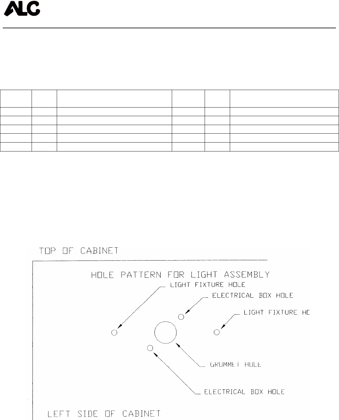
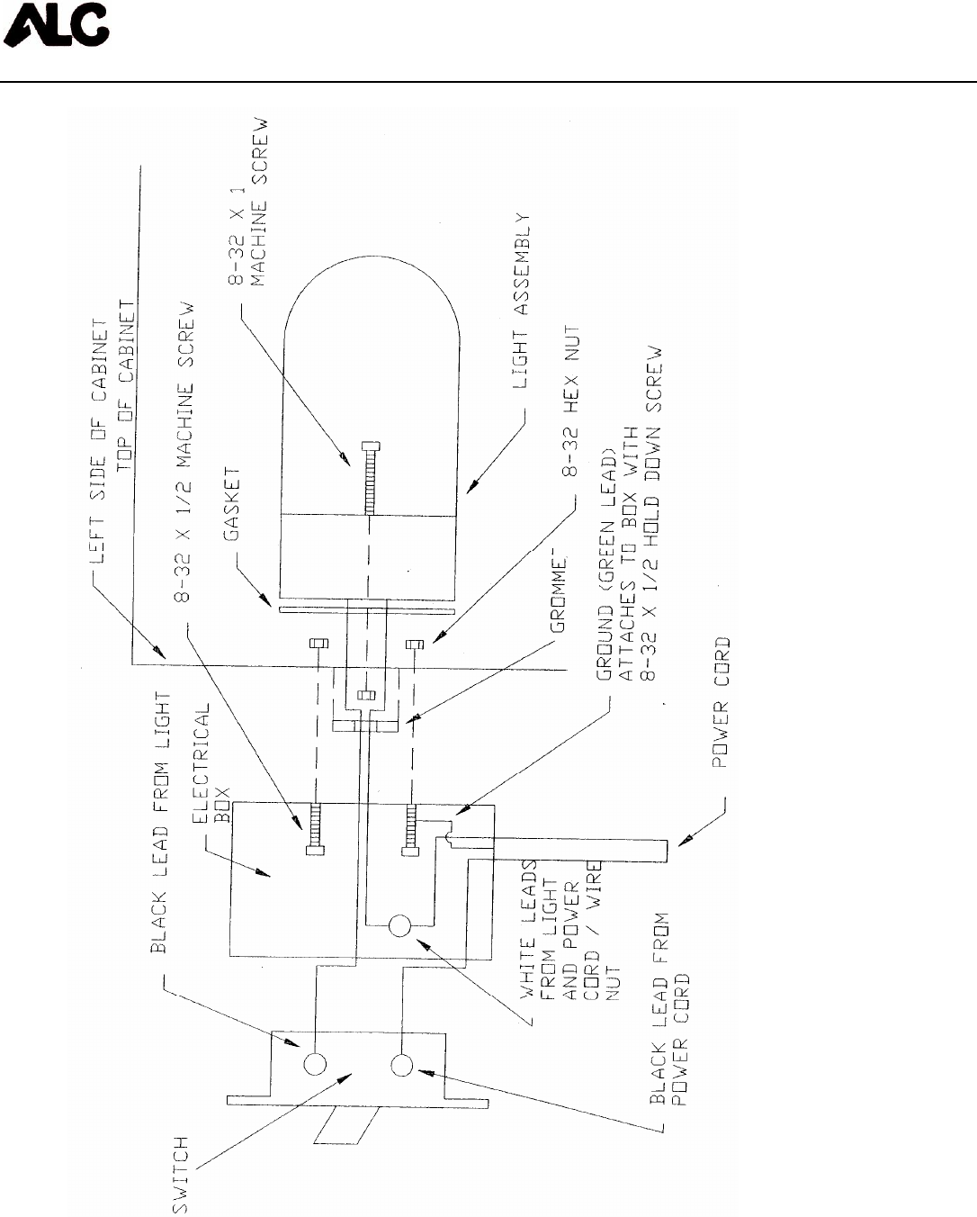
LIGHT ASSEMBLY INSTRUCTIONS
1. Press metal plug into 3/4” diameter hole from inside of
cabinet. (The purpose of the grommet is to prevent abrasion
of the light wires.)
2. Install electrical box to outside of cabinet using two 8-32 x
1/2” machine screws and two 8-32 hex nuts. Holes in box
and cabinet are prepunched. NOTE: Use one of the
machine screws to secure ground wire (green wire) to back of
box. Power cord is secured to box and should face down
when box is properly attached.
3. Route wires from light base through gasket and center of
grommet into electrical box. Install light with gasket between
cabinet wall and light base using two 8-32 x 1” machine
screws and two 8-32 hex nuts.
4. Secure white wire from light and white wire from power cord
with wire nut and leave in box.
5. The electrical switch has two screws on the side of the
switch. Attach black lead from light to one screw and black
lead from power cord to other screw. Attach switch to box
and install box cover to switch.
6. Before installing bulb and plugging in power cord, it is
recommended that all connections be checked and light
fixture hot, neutral and ground connections be checked using
appropriate testing meters.
7. Install light bulb (not included) maximum 60 watt.
40413 Assembly Instructions
Page 9
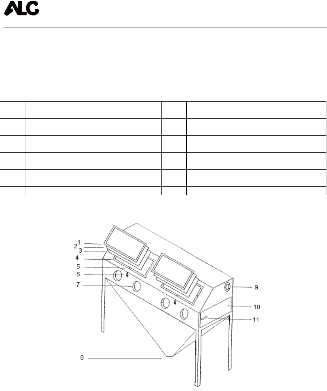
ASSEMBLY DIAGRAM FOR BLAST CABINET
Below is the component breakdown for ALC Cabinet Blasters.
Please see separate instructions and parts breakdowns for light
assembly, siphon gun/foot pedal and dust collector.
Item
No. Part
No. Description Item
No. Part
No. Description
1 11635 Window frame (2) 6 11161 8-32 hex nut
2 40251 Window lens – 2 pair 7 40248 Gloves – 2 pair
3 40253 Window lens underlayment (2) 7 40240 Glove clamp – 2 pair
4 11601 1/2” x 1” sealing foam (per foot) 8 10904 Drain plug
5 10199 1/4-20 x 1” machine screw 9 11574 Grommet for dust collector hose
5 10201 1/4-20 hex nut 10 11589 Side door
5 10218 1/4” USS washer 11 11610 Handle for side door
6 11109 Hasp 11 11611 CAM for side door handle
6 11160 8-32 x 1/2” machine screw
40413 Assembly Instructions
Page 10
Use maximum 60 watt bulb (not included)

40413 Assembly Instructions
Page 11
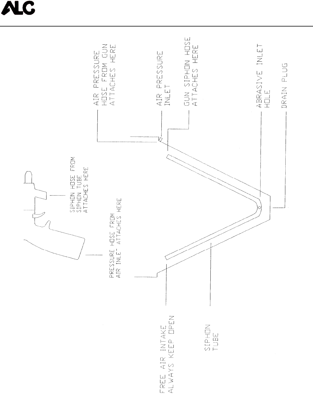
OPTIONAL SIPHON GUN/FOOT PEDAL ASSEMBLY
INSTRUCTIONS
Below is the component breakdown for siphon gun/foot pedal.
Part No. Description
11595 Siphon gun pressure hose (8’)
11596 Foot pedal pressure hose (6’)
11594 Foot pedal assembly
11632 Foot pedal valve
11606 1/4” pipe coupling (air pressure inlet)
10188 1/2” washer (pressure hose to pipe coupling washer)
11579 Siphon tube (pickup tube)
11597 Siphon hose (5/8” ID) – 8’
NOTE: See separate sheet for siphon gun parts breakdown.
1. Put end of 6’ pressure hose through 1/2” washer and insert
through air inlet hole from inside of cabinet. Install 1/4” pipe
coupler to end of pressure hose from outside of cabinet and
tighten.
2. Install siphon gun to opposite end of 6’ pressure hose and
tighten securely.
3. Shop air installs to 1/4” pipe coupling.
4. If installing foot pedal option, install 8’ pressure hose to pipe
coupling from outside and install other end of pressure hose
to foot pedal valve marked “OUT”. Shop air installs to foot
pedal valve marked “IN”. Foot pedal valve fitting marked
“EXHAUST” must be kept open at all times.
5. Install siphon hose to siphon gun and opposite end to siphon
tube at right front of cabinet. Opposite end of siphon tube

40413 Assembly Instructions
Page 12
must be kept open and clear of any debris for proper
operation.
40413 Assembly Instructions
Page 13
40413 Assembly Instructions
Page 14
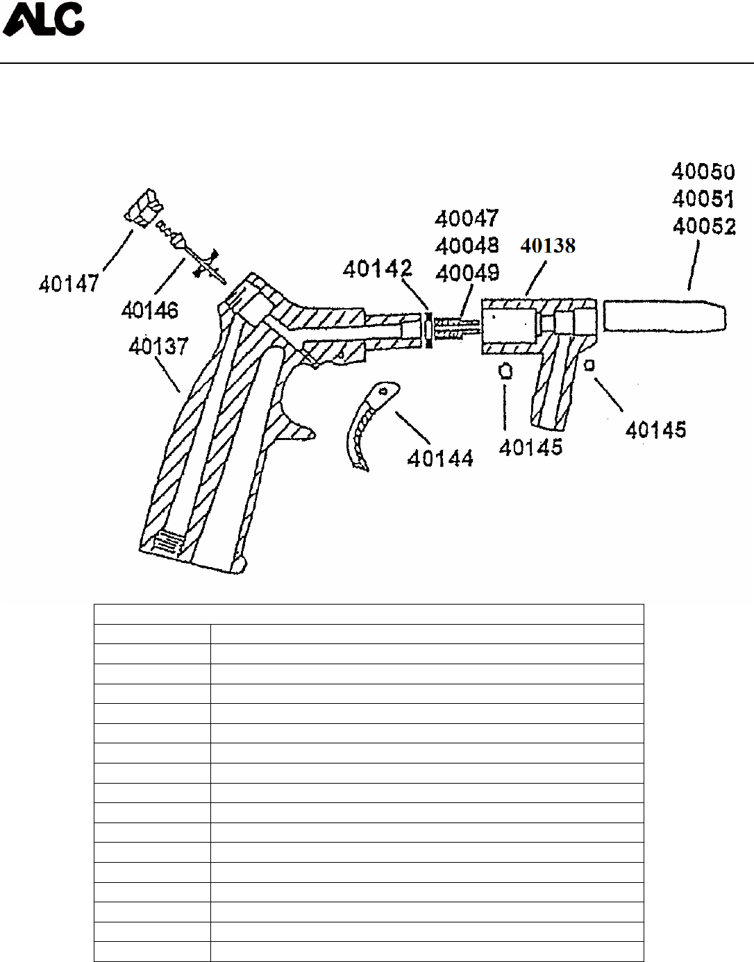
SIPHON GUN PARTS BREAKDOWN
Replacement Parts and Optional Accessories
REPLACEMENT PARTS
PART NO. DESCRIPTION
11665 Blast gun for foot pedal
40153 Blast gun for trigger operation
40137 Blast gun handle only, with trigger and valve
11664 Blast gun handle only, for foot pedal
40138 Blast gun siphon head only, with nozzle and air jet
40142 Washer
40144 Blast gun trigger
40145 Blast gun set screw
40146 Blast gun valve, spring and seat assembly
40147 Valve nut
40050 13/64” - steel nozzle (optional)
40051 1/4” steel nozzle (included)
40052 5/16” steel nozzle (optional)
40047 5/64” air jet (gold) (optional)
40048 1/8” air jet (silver) (included)
40049 5/32” air jet (black) (optional)
40413 Assembly Instructions
Page 15
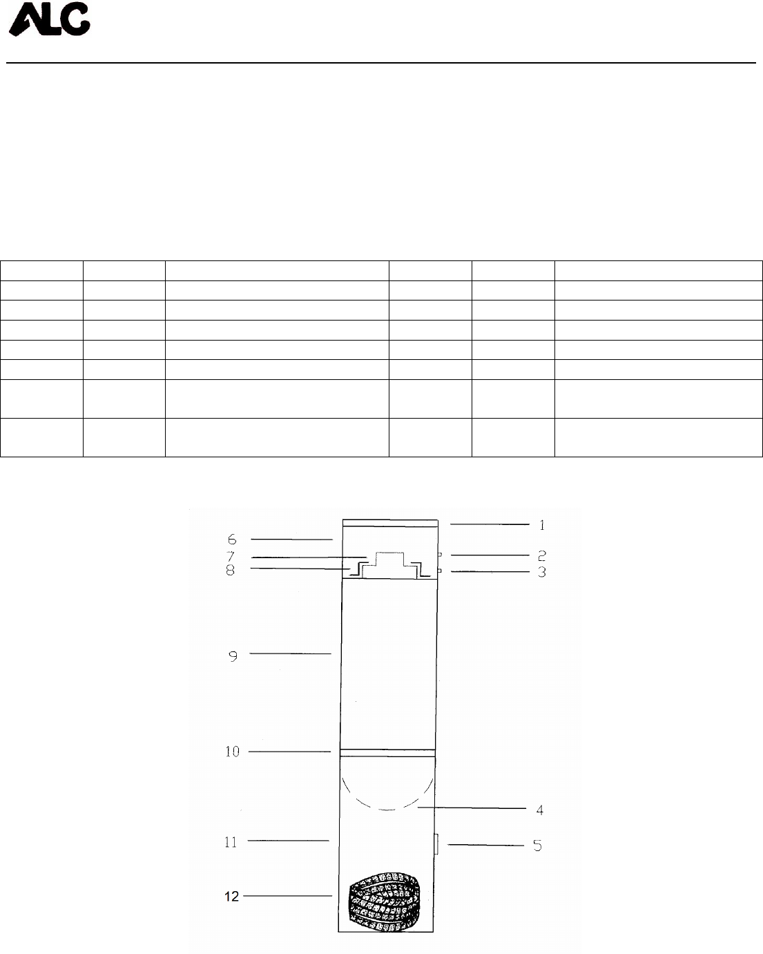
ASSEMBLY DIAGRAM FOR DUST COLLECTOR
Below is the component breakdown for ALC 100 CFM dust
collector. The dust collector is assembled and ready for use. Dust
collector hose is located in the bottom drum of the collector and
must be removed and attached to dust collector and cabinet.
Item No.
Part No. Description Item No. Part No. Description
1 11568 Cap for dust collector 6 11567 Motor screen
1 10759 Protective edging 7 40287 Vacuum motor
2 11637 Switch 8 11602 Motor support bracket
3 11012 Connector 9 11564P Top drum
3 11008 Electric cord 10 N/A
4 40267
SM Filter bag 11 11565P Bottom drum
5 n/a 12 11575 Dust Collector Hose 2 ¼”
x 6”

40413 Assembly Instructions
Page 16
TROUBLESHOOTING TIPS
PROBLEM/CAUSE POSSIBLE SOLUTION
Surging of blast flow:
Air pressure too low Check pressure gauge on air compressor
Excessive media consumption:
Air pressure too low Check pressure gauge on air compressor
Clogging and plugging of blast flow:
Debris in media Purge and screen
Media size too large Use smaller grit size
Nozzle plugs Use larger nozzle and correct
Wet media Dry media, drain water from air
Moisture in abrasive media:
Wet media Change or use dry media
Water in air Drain water from air lines
Humid weather:
Moderate humidity Keep media as dry as possible
Moderate humidity Use drier or moisture separator
High humidity Avoid that period of use if possible
Overtaxed Compressor:
Compressor too small Restrict time used
Nozzle size too large Use smaller size
Too many leaks in plumbing Seal and tighten plumbing
Holes in abrasive hose Replace hose
Air filter on compressor plugged Clean or replace filter
Lack of air pressure:
Compressor too small Use smaller nozzle
Supply valves not on full position Open valves
Nozzle size too large Use smaller size
Leaks in plumbing Seal and tighten plumbing
Holes in abrasive hose Replace hose
Air filter on compressor plugged Clean or replace filter
Lack of abrasive flow:
Blaster empty Fill cabinet
Moisture in media Dry media
Not enough air pressure Check system
Abrasive hose kinked Straighten hose
Debris in media Clean or screen media

40413 Assembly Instructions
Page 17
Coal Slag #40093
Coal Slag is used when paint and rust has to be removed from steel, such as car bodies, tanks or
heavy machinery. Coal Slag is faster cutting, can be re-used, is moisture free, and will not pack or
absorb moisture. (25 Lb. container)
Steel Grit #40109
Steel grit is extremely fast cutting on rusty metal and hard to remove paint. Steel Grit is popular
because it leaves a very smooth finish. It is also comparable in price to most other specialty
abrasives. Steel Grit is recommended in reclaim systems or cabinets. (25 Lb. container)
Glass Bead #40105
Glass Bead is used in creating a satin or matte finish. Glass Bead is recommended in reclaim
systems or cabinets. (25 Lb. container)
Aluminum Oxide #40098
Aluminum Oxide is a high quality abrasive that is sharper than sand (not recommended) and cuts
twice as fast as sand. It leaves a smooth textured finish with no pits or burrs. Aluminum Oxide is
rougher than glass bead and can be used over and over again. It is one of the most economical
abrasives you can use in any reclaim systems or cabinets. (4/25 Lb. container)
Plastic Grit #40110
Primarily used to strip aluminum and fiberglass. Great for stripping paint, light oxidation and surface
rust. Recommended for use in blast cabinets because it creates very little dust. Works quickly, last a
long time and increases visibility within the cabinet. (10 Lb. container)
Walnut Shells #40112
Walnut shells are recommended for use on “soft” surfaces such as aluminum, glass, wood, and other
areas where no pitting is desired. Leaves a smooth, dull finish. (10 Lb. container)

40413 Assembly Instructions
Page 18
Disclaimer of Warranties. S & H Industries, Inc. ("Seller") makes no warranties with respect to any
goods delivered to Buyer or users except as specifically set forth within this manual. S & H
INDUSTRIES, INC. MAKES NO IMPLIED WARRANTIES OF MERCHANTABILITY OR FITNESS
FOR A PARTICULAR PURPOSE WITH RESPECT TO ANY OF THE GOODS, AND S & H
INDUSTRIES, INC. EXPRESSLY DISCLAIMS ANY IMPLIED WARRANTIES AGAINST
INFRINGEMENT. S & H INDUSTRIES, INC. WARRANTIES SHALL NOT APPLY TO ANY DAMAGE
OR NON-CONFORMITY RESULTING FROM THE NEGLIGENT OF IMPROPER ASSEMBLY OR
USE OF ANY GOODS BY USERS OR BUYER OR ITS EMPLOYEES OR AGENTS, OR FROM
ALTERATION OR ATTEMPTED REPAIR BY ANY PERSON OTHER THAN S & H INDUSTRIES,
INC. ALL USED, REPAIRED, MODIFIED OR ALTERED ITEMS ARE PURCHASED AS-IS AND
WITH ALL FAULTS.
Indemnification Agreement. Buyer agrees, to the fullest extent permitted by the law, to fully
indemnify, hold harmless, and defend Seller, its parent, subsidiary, and affiliated companies, its
owners, officers, directors, employees, agents, representatives and insurers (collectively,
“Indemnities”) from and against any and all claims, demands, suits, damages, judgments of sums of
money, losses and expenses, including but limited to attorney’s fees and costs (collectively “referred
to herein as “Claims”) arising out of or resulting from any bodily injury, sickness, disease or death or
injury to or destruction of tangible property, arising out of or resulting from the use, sale or distribution
of any and all products purchased from Seller by Buyer, regardless of whether or not such claim
arises in whole or in part out of Seller’s alleged fault, including but not limited to Seller’s negligence,
strict liability, products liability, breach of warranty or any other act or omission. Buyer expressly
waives any and all immunity from suit by Seller, its parent, subsidiary, and affiliated companies, and
its owners, officers, directors, employees, agents, representatives and insurers, by operation of any
workers’ compensation law or statute. By purchasing from S & H Industries, Inc., Buyer
acknowledges and represents that Buyer has read, fully understands and agrees to the
Indemnification provisions set forth above.
LIMITED WARRANTY
S & H Industries Inc. warrants this product to be free from defects in materials or
workmanship for two years after the date of original purchase.
If the product should become defective within that warranty period, we will repair or replace it
(at our option) free of charge including return transportation to you provided you deliver it
prepaid to S & H Industries Inc., 5200 Richmond Road, Bedford Hts., Ohio 44146.
This warranty does not include damage resulting from accident, abuse or misuse of the
product. Nor does it apply to parts subject to abrasive wear, i.e., nozzles, air jets, seal blocks,
valves, hose connections and hoses.
Implied warranties including those of merchantability and fitness for a particular purpose are
excluded to the extent permitted by law, and any and all implied warranties are excluded. This
is the exclusive remedy and liability for consequential damages under any and all warranties
are excluded to the extent exclusion is permitted by law.
