Interconnection Of 5 1055 KW Generating Facilities To APS 750a 4 1 08 QUEUE No. 35 Feasibility Study
User Manual: APS 750a
Open the PDF directly: View PDF ![]() .
.
Page Count: 9
Generation Project Feasibility Study Report February 6, 2008
APS Contract 52059 Page of
1 9
Small Generator Interconnection
Feasibility Study Results
Background: CUSTOMER submitted an application in the form of Attachment 6 to the Small Generator
Interconnection Procedures (SGIP) for the interconnection of a Small Generating Facility
(“Application”) dated October 8, 2007 to interconnect 3 MW of generation to APS’ transmission
system. As a result of this Application, APS determined that a small generator interconnection
Feasibility Study was required and the Customer and APS entered into an Interconnection Study
Agreement, APS Contract No. 52059 executed on October 11, 2007.
Customer intends to invest in, construct, own, maintain and operate a Generating Facility ("GF"),
which will be connected to and operated in electrical parallel with APS’ electric transmission
(distribution) system via a newly constructed dedicated underground generator tie line. For the
purpose of this Study, and in the absence of more specific information, it is assumed that the Point of
Interconnection along with associated metering will be located approximately 1500 feet north of Ave
at or near Customer’s step-up transformer. Pursuant to the results of the scoping meeting held on
October 2, 2007, two interconnection options were agreed to be studied by APS: Option 1 is an
interconnection to the 12 kV system (defined by APS as “distribution” voltage level); Option 2 is an
interconnection to the 69 kV transmission system. Both options were studied and the results are
included in this report.
The following interconnection study results are provided:
Location Address
of Generating
Facilities: Glendale, AZ 85311
In-Service Date: December 15, 2008
As required in the Interconnection Study Agreement Paragraph 5 on page 2 of 4, the
information on the following items is identified:
(i) All permitting/siting requirements,
Line route is located in the City of and Maricopa County and for purposes hereof, the required
dedicated underground generator tie line is expected to follow existing line route/corridor.
Permit(s) will be required before construction can begin. In order to meet the Customer’s in-
service date of December 15, 2008, all permits/easements must be obtained by June 1, 2008. In
the event that APS is unable to obtain the appropriate permits/easements by June 1, 2008, the
In-Service Date will have to be delayed. If APS is unable to obtain permits/easements for the
expected line route and another line route is necessary, the estimated costs herein shall be
revised.
(ii) Identify the necessary right-of-way,
APS expects that the dedicated generator underground tie line will be located in existing road
right-of-way or Customer-provided private easements. As noted above, should APS be unable
to obtain the necessary right-of-way or private easements for the line and structures, the
estimated costs herein shall be revised to reflect the new design, line route and other factors
impacting the facilities required to provide interconnection service to the Customer.
(iii) Describe regulatory and siting process
APS does not anticipate having to obtain regulatory and siting approval based upon the expected
line route is to be used. However, APS will apply to the City of and Maricopa County as
necessary/required for the applicable permits. It is assumed that Customer will render any
assistance required in this process.
Generation Project Feasibility Study Report February 6, 2008
APS Contract 52059 Page of
2 9
(iv) A detailed description of the required Interconnection Facilities and cost
Option 1 - Interconnection to 12.47 kV
• Customer has requested interconnection of their facilities at their GF located at the . APS
will be required to extend its distribution system by installing an APS-owned dedicated
12.47kV generator (in this case, underground) tie line at Customer’s expense. A dedicated
underground generator tie line is required for operational safety and reliability of the utility
distribution system.
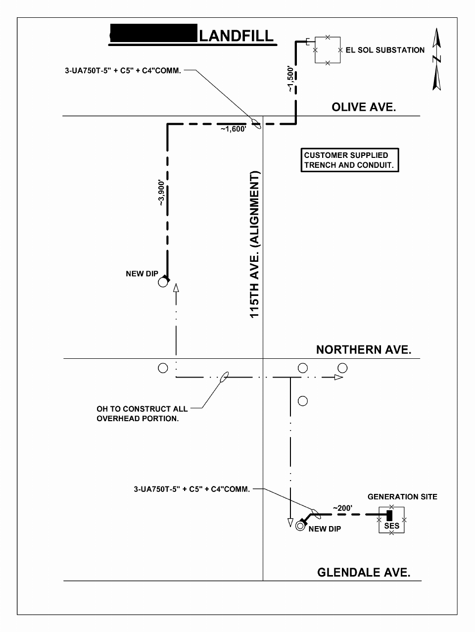
• This 12kV dedicated underground generator tie line will originate at APS’ El Sol
Substation (115th Ave approximately 1500 ft N/O Olive Ave) and terminate at the utility
metering section at the Customer’s Generating Facility (GF), located approximately 1300 ft
n/o Ave on the east side of 115th Ave.
• In El Sol Substation, APS will install 1-12.47kV dedicated generator underground tie line
breaker, 2-5” conduits and 1-4” communications conduit from this dedicated breaker to a
location approximately 5.0 feet outside the substation fence wall. This substation work
includes foundations, grounding, electrical equipment (Relay’s, Control, Communication
and SCADA) and bus work associated with a 12kV feeder bay installation..
• APS will install approximately 7200 ft of 3-750A, 15kV Cable in Customer provided and
installed 2-5” conduits (along with associated pull boxes) from the 12kV feeder breaker in
El Sol Substation to a new transition pole located approximately 0.25 miles n/o Northern
Ave and 900ft w/o 115th Ave. (Note: the Customer will begin trench and conduit
installation at the 2-5” conduit “stubs” located outside El Sol Substation. The trench will
extend approximately 1500ft south to Olive Ave,, approximately 1600ft to the west along
Olive Ave, and approximately 3900ft south to a new APS installed transition pole). At the
generator site, APS will install approximately 200 ft of 3-750A, 15kV cable from A
transition pole; in Customer installed 2-5” conduits, to the Customer’s utility metering
section. In addition to the 2-5” conduits, the Customer is required to provide and install 1-
4” conduit (along with associated pull-boxes) required for communications/protection for
the entire trench route. Fiber optic cable for a required transfer trip scheme will be required
between APS’ feeder breaker in its El Sol Substation and the Customer’s main breaker at its
Generating Facility (GF).
• From the new transition pole located approximately 0.25 miles n/o Northern Ave and 900ft
w/o 115th Ave, APS will under-build approximately 7200ft of an existing 69kV line with 3-
795A & neutral, 12.47kVoverhead conductor along with communication cable (48 Fiber
Count) to a (new transition pole at the “GF” site; located) approximately 1300ft n/o Ave on
the east side of 115th Ave.
• APS-owned 12kV substation breaker and controls, protective relaying for both 12kV and
69kV areas within APS-owned system, including a Customer-owned visibly-open
Disconnect Device equipped with grounding provisions acceptable to APS and APS-owned
bi-directional utility metering equipment.
• Install fiber optic cable and communication equipment for communication with the APS
Energy Control Center Energy Management System (ECC EMS) and protection of the new
Interconnection Facilities. The protective relaying system is a permissive over reading
scheme with transfer tripping capability.
• Communication to RTU for EMS.
• APS will require bi-directional metering to be installed in the switchgear at the Customer’s
small Generating Facility at Customer’s expense. These meters define the Point of
Interconnection (POI) between Customer and APS. In addition, APS will require metering
and an RTU (appropriately located to which these meters will be connected) to be installed
at the output of the generator at Customer’s expense. The meters and RTU will be owned
and operated by APS. Details regarding access to the RTU and meters will need to be
addressed in the Operating Agreement between APS and the Customer. The RTU will carry
the metering data back to Adobe Substation using some of the fibers to be installed.
Customer is solely responsible for providing a suitable AC or DC power supply for the
RTU that meets APS’ requirements.

Generation Project Feasibility Study Report February 6, 2008
APS Contract 52059 Page of
3 9
• Estimated cost of the facilities described above in Option 1 is $1,150,000, excluding costs
3associated with obtaining City of permits, easements or income tax or other tax effect and
the cost associated with any Customer-owned equipment required for the interconnection
of the generators including protective relaying and a visible open utility disconnect switch.
Please note: that all trench and conduit required shall be supplied by the Customer and is
excluded from the above costs.
• DIRECT ASSIGNMENT CHARGE – This Project is a FERC jurisdictional small generator
interconnection. Under Option 1 of this study, the Project would be interconnected to the
APS distribution system (defined as less than 69 kV). As such, the Customer shall be
responsible for a monthly Direct Assignment Charge (“DAC”) that covers the costs of
Operations, Maintenance and Replacement of the dedicated generator tie line (in this case
an underground line) and its associated equipment. This DAC is derived utilizing an APS
standard methodology and is estimated during the study phase of the Project. After
construction of the dedicated generator underground tie line, the DAC is identified and
charged to the Customer based on actual costs of construction. The actual-cost based DAC
will be a fixed monthly charge for the life of the FERC Interconnection Agreement. The
estimated DAC is $51.58 per month and is subject to revision during further stages of the
study process, and final update after the actual construction is complete.
Option 2- Interconnection to 69kV
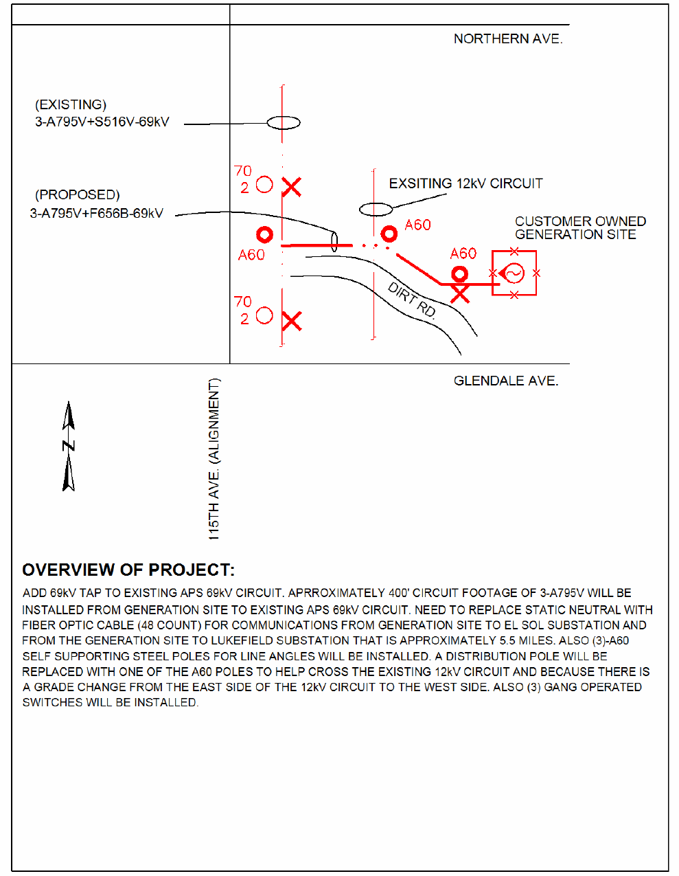
• APS will extend its sub-transmission system (69kV) to the Customer’s Generator Facility
(GF) by installing approximately 400ft of 69kV overhead line and required 69kV
equipment at the “Customer-owned” GF site.
• From a location of 115th Ave and Ave, tap the existing 69kV O.H. line and extend
approximately 400ft of three phase 69kV line. This line construction will include 3-gang
operated (3-phase) switches and three self supporting steel poles. Additionally,
approximately 3.0 miles of static neutral will be replaced with fiber optic cable (48 count)
for the required communications/protective relaying.
• At the “Generator Facility”, APS will construct 69kV buswork/structures with associated
protection and metering, foundations, grounding, control conduits, electrical equipment,
communications and SCADA. In addition, the 69kV relays at El Sol Sub and Luke Field
Sub will have to be upgraded.
• Customer shall be responsible to provide their own 69 kV step-up transformer for this
interconnection.
• Customer shall provide flat, level, compacted subsite (80’ & 100’). Site shall be free of any
and all landfill (garbage) and have a minimum 3’ base of clean, level, compacted fill dirt.
Site shall be able to pass all environmental requirements/ inspections. In addition, site shall
have 24 hour access by an all weather road and shall also have required storm water
drainage.
• Estimated cost of the facilities described above in Option 2 is $970,000 excluding costs
associated with obtaining City of permits, easements or income tax or other tax effect and
the cost associated with any Customer-owned equipment required for the interconnection of
the generators including protective relaying and a visible open utility disconnect switch.
(v) A detailed description of all System Protection Facilities required and associated costs
Option 1 – 12.47
1. System Protection Facilities to be installed by APS at Customer’s expense.
• APS-owned Substation 12.47kV breaker and controls
• APS-owned Substation 12.47kV bus extension and equipment
• Schweitzer SEL351 with 50/51/51N feature protective relay with the Mirrored Bit option at the
APS-owned Substation 12.47kV breaker to accomplish the transfer tripping of the GF via fiber
optic cable. This relay has the advantage of being able to communicate relay to relay and make
the 50/51/51N elements operate in a directional mode.
Generation Project Feasibility Study Report February 6, 2008
APS Contract 52059 Page of
4 9
• An additional APS-owned relay on the 69kV side to detect ground over-voltages on the 69kV
system in case the 69kV system becomes isolated and fed from the generators.
• Devices equipped with grounding provisions acceptable to APS.
• The cost of these facilities is included in the project cost quoted in item (iv).
2. System Protection Facilities installed by Customer at its Generating Facility and at its expense:
This study does not specifically address any requirements for the Customer Generating Facilities.
However, the Customer must comply with all APS requirements for a generator operating in parallel
with APS’ electrical system. For interconnection at the 12kV level, interconnection requirements are
specified in the APS document titled: Interconnection Requirements for Distributed Generation
(APS IRDG manual).
• The Customer small Generating Facility must comply with the APS safety, metering, protection,
and contractual requirements specified in the relevant APS documents pertaining to the
interconnection and operation of a small Generating Facility in parallel with the APS distribution
system. All relevant sections of the APS Distribution Interconnection Agreement, as referenced in
the IRDG manual, will be incorporated and attached to the SGIA. A sample copy of this
agreement is available upon request from APS.
• Minimum control and protective devices installed at the facility’s main 15kV circuit breaker as
follows:
A Schweitzer SEL351 relay that incorporated the following functions:
(a) Over / Under Frequency
(b) Over / Under Voltage
(c) 50/51/51N functions.
(d) Alarm contacts to trip off the generators in the event of relay failure.
(e) Transfer trip
(f) Sync-check
• Circuit breakers on each of the Customer’s generators, with the following minimum control and
protective device(s) installed on each generator breaker and the low-side (4.16 kV) common
breaker :
(a) Synchronizing facilities
• Suitable interlocks to prevent any breaker or switch from allowing the APS grid to be closed onto
an energized out-of-sync Customer bus or generator. Any potential open points such as breakers,
fused disconnect switches, etc, located between the generator breaker and utility service need to be
appropriately equipped with either (1) Keyed interlocks to prevent them from being inadvertently
opened when the generator breaker is closed, or (2) contacts that will instantaneously trip the
generator breaker if any such switch were opened while the generator breaker was closed. This is
to prevent the opening and subsequent (inadvertent) reclosing of such a breaker or switch onto an
un-synchronized generator.
• Such other equipment as shall mutually be agreed upon by the Customer and APS from time to
time during the term of this Agreement.
Option 2 – 69kV
• Similar to Option 1 above, details to be provided at a later date.
Generation Project Feasibility Study Report February 6, 2008
APS Contract 52059 Page of
5 9
(vi) Diagrams detailing how APS proposes to interconnect Customer’s Generating Facility to the Transmission
System
See attached Exhibits A and B for details.
(vii) Details requiring upgrades to the Transmission System if required (but not reflective of potential
Transmission System upgrades that may be required pursuant to a request for firm Transmission Service)
Not Applicable
(viii) Applicable cost responsibilities
Customer is responsible for all costs of the APS-owned facilities required to
interconnect the GF to the APS-owned 12kV or 69kV facilities referenced in Section iv
to the GF step-up transformer, the installation and testing of the System Protection
facilities and the addition of a bi-directional meter at an appropriate location near the
Point of Interconnection.
APS shall design, construct, install, operate and maintain the facilities required from
APS-owned facilities to the Point of Interconnection. Customer shall be responsible for
the total actual cost, plus any income tax or other tax effect, for such facilities.
Additionally, Customer shall pay a monthly direct assignment charge for operation,
maintenance and replacement (OM&R) of such APS-owned facilities during the term
of the Interconnection and Operating Agreement. The estimated cost of the monthly
direct assignment charge has not yet been determined. APS is currently reviewing our
methodology to determine this dedicated underground generator interconnection tie
line OM&R cost. We anticipate having this monthly cost available to the Customer by
December 14, 2007. Customer shall be responsible for the total cost of replacement (if
required) of the APS-owned facilities installed for interconnection service to the
Customer.
Estimated cost to Engineer, Procure and Construct (EPC) said work for Option 1 is
$1,150,000. If income tax gross-up is required, the total estimated cost including
income tax gross up is $1,506,500. An Interconnection and Operating Agreement shall
be signed between APS and the Customer before the EPC process is initiated.
Estimated cost to Engineer, Procure and Construct (EPC) said work for Option 2 is
$970,000. If income tax gross-up is required, the total estimated cost including income
tax gross up is $1,270,700. An Interconnection and Operating Agreement shall be
signed between APS and the Customer before the EPC process is initiated.
(ix) APS’ good faith estimate for completion of all regulatory and siting hearings and rights-of-way acquisition
City of and Maricopa County permits may be required for this work. It is expected that
such process may take up to 12-16 weeks, depending upon the City/County workload.
(x) A good faith estimate of the lead-time needed to order the equipment and construct the facilities in order to
meet the in-service date of the Customer’s Generating Facility
Total time to design, order materials and construction is estimated to take 40-45 weeks.
The design is to commence upon execution of the Interconnection and Operating
Agreement.
(xi) Additional comments
• APS will still require the following information from the Customer to complete a
detailed review of the proposed facility. This information should be provided to

Generation Project Feasibility Study Report February 6, 2008
APS Contract 52059 Page of
6 9
APS as soon as it becomes available so that the facilities design and costs can be
finalized and the information referenced in the Interconnection and Operating
Agreement.
(a) Generator Information
Manufacturer
Type (Synchronous, Induction, D.C.)
Nameplate kW rating
Voltage
Power Factor
Model No.
Type of Excitation System (Self or Separate)
Generator Electrical Characteristics (on the machine base)
-Synchronous Reactance (Xd)
-Transient Reactance (X’d)
-Subtransient Reactance (X”d)
-Zero sequence reactance (XO)
-Negative sequence reactance (X2)
(b) Prime Mover
Manufacturer
Manufacturer’s Reference Number
(c) Interface Equipment
Synchronizer for Synchronous Generator:
-Manufacturer
-Manufacturer’s Reference Number
-Automatic or Manual Synchronizer
(d) Protective Devices and settings
Manufacturer’s Name for each Protective Device
Manufacturer’s Reference Number for each Protective Device
Range of Available Settings for each Protective Device
Proposed Settings (trip setpoint and time) for each Protective Device
Ratios of associated current transformer. If multi-ratio, state the available
ratios and which ratio will be used
(e) Supplementary Information
-Electrical One-Line Diagram:
Provide 4 sets, including any and all revisions or changes as they are
made. Diagram(s) must also include project name and address, show
generator size and all protective relaying and control equipment, as well as
(proposed) electric service entrance and utility meter.
-Electrical Three-Line Diagram:
Provide 4 sets, including any and all revisions or changes as they are
made. Diagram(s) must also include project name and address, show
generator size and all protective relaying and control equipment, as well as
electric service entrance and utility meter, and include all neutral and
ground conductors and connections.
-AC & DC Control Schematics:
Provide 4 sets, including any and all revisions or changes as they are
made, for all projects comprising rotating machinery. Diagrams must
Generation Project Feasibility Study Report February 6, 2008
APS Contract 52059 Page of
7 9
show the detailed wiring of all protective relays and control functions, and
include control power source and wiring.
-Detailed Map:
Provide 4 sets of detailed maps, including any and all revisions or changes
as they are made. Maps should show major cross streets and proposed
plant location, and include the street address.
-Site Plan:
Provide 4 sets of site plans, including any and all revisions as they are
made, showing the arrangement of the major equipment, including the
electric service entrance section and utility meter, location of generator
and interface equipment, and location of the Disconnect Switch. Include
the street address, and location of the any lock-boxes, etc.
-Testing Company:
Provide the name of the company that will do the protective relay bench
testing and the trip circuit functional tests and the anticipated start up date.
-Point of Contact
If the interconnection and start-up process is to be coordinated through a
party or individual other than the Customer, provide the name, company,
address and phone number of that individual or party with whom the utility
is to coordinate the interconnection.
Generation Project Feasibility Study Report February 6, 2008
APS Contract 52059 Page of
8 9
Exhibit A – Interconnect at 12 kV
Generation Project Feasibility Study Report February 6, 2008
APS Contract 52059 Page of
9 9
Exhibit B - Interconnect at 69 kV
