VISTA 4120XM Installation Instructions Manual
User Manual: 4120XM Installation Manual AlarmHow.net Library
Open the PDF directly: View PDF ![]() .
.
Page Count: 80
- Vista 4120XM Installation Instructions
- Table of Contents
- General Information
- Zone Configurations
- Remote Consoles, External Sounders & Phone Connections
- Mounting the Cabinet, PC Board & Lock
- Powering the System
- System Operation
- System Communication
- Table of Contact ID Event Codes
- Programming the System
- Standard Vocabulary of Words Stored in Memory
- Downloading Primer
- Testing the System
- Troubleshooting
- Specifications
- Summary of Connections
- Dip Switch Tables
- FCC Statements
- Canadian DOC Statement
- Limitations of the Alarm System
- Limited Warranty
- Programming Form

VISTA
4V20XM
INSTALLATION
INSTRUCTIONS
I%U)EMCOI
N6493V110/93


CONGRATUMTIONS!
On Your Purchase of the Ademco 4120XM
The purpose of these Installation Instructions is to give you acomplete
overview of the system, and provide detailed instructions for installing a
basic system.
CONTACTING TECHNICAL SUPPORT
PLE.ASE,
Before you call Technical Support, be sure you:
●READ THE INSTRUCTIONS!
●Check all wiring connections.
.Determine that the power supply and/or backup battery are
supplying proper voltages.
.Veri& your programming information where applicable.
sNote the proper model number of this product, and the version
level (if known) along with any documentation that came with
the product.
●Note your ADEMCO customer number and/or company name.
Having this information handy will make it easier for us to serve
you quickly and effectively.
You may contact Technical Support via Toll-Free FAX. Please include your
return FAX number. You will receive areply within 24 hours. You may also
contact Technical Support via modem to ATLIS-BBS, Technical Support’s
Electronic Bulletin Board System. Replies are posted within 24 hours.
East Coast Technical Support: 1-800-645-7492 (8 a.m.-6p.m. E.S.T.)
West Coast Technical Support: 1-800-458-9469 (8 a.m.-5p.m. P.S.T.)
Technical Support FM Number: 1-800-447-5086
ATLIS-BBS Electronic Bulletin Board System: 1-516-496-3980
(1200 -9600 Baud, 8Data Bits, 1Start/Stop Bit, No Parity)
ATLIS FM -Automated Fax Retrieval System: l-800-645-7568 /Ext. 1403
-3-
GENERAL INFORMATION .................................................................................7
SUMMARY OF SYSTEM FEATURES ..................................................................7
System Features ...................................................................................................8
ZONE CONFIGUMTIONS ..................................................................................9
ZONE TYPES &APPLICABLE SENSORS ...........................................................9
BASIC 8HARD-WIRED ZONES ......................................................................... 10
Zone 1.............................................................................................................. 10
Compatible Smoke Detectors .......................................................................... 11
Zones 2 –8 ......................................................................................................ll
Compatible Glassbreak Detectors ................................................................... 12
Glassbreak Detector Connections ................................................................... 12
Wired Zone Expansion ..................................................................................... 13
4219 Zone Expander........................................................................................ 13
WIRELESS EXPANSION (Zones 1-63) .............................................................. 14
General Information (Receivers) ...................................................................... 14
4281 Series Receivers ..................................................................................... 15
5700 Seties TransmiHers ................................................................................. 16
Wireless Zone Types ....................................................................................... 17
Advisories ........................................................................................................ 18
Fault Annunciation ........................................................................................... 18
Important Battery Notice .................................................................................. 18
Compatible 5700 Series Wireless Devices ...................................................... 18
VOLTAGE TRIGGER OUTPUTS (Connector TB2) ........................................... 19
General Information ......................................................................................... 19
Remote Keyswitch Usage ................................................................................2O
Remote Console Sounder ............................................................................... 20
Application ........................................................................................................2O
Programming &Witing ...............................................i........m......m........m.........oo.2O
REMOTE CONSOLES, EXTERNAL SOUNDERS
AND PHONE CONNECTIONS .......................................................................... 22
REMOTE CONSOLES ........................................................................................ 22
General ............................................................................................................22
4127 .................................................................................................................22
4137AD ............................................................................................................22
5137AD ............................................................................................................22
6137 .................................................................................................................22
6139 .................................................................................................................23
Mounting The Consoles ...................................................................m............o..23
Wiring Consoles ...............................................................................................23
Powering Additional Consoles ........................................................................"23
EXTERNAL SOUNDERS ..................................................................................."24
Relay Output ....................................................................................................24
UL Installations ...............................................................0................................ 24
Non-UL Installations .........................................................................................
Compatible Sounders ......................................................................................H
PHONE CONNECTIONS ....................................................................................24
Phone Line Connections ..................................................................................24
Ground Start Module......................................................................................."25
MOUNTING THE CABINET, PC BOARD& LOCK .........................................26
MOUNTING THE CABINET ................................................................................26
MOUNTING THE PC BOARD ............................................................................. 26
MOUNTING THE CABINET LOCK .....................................................................26
-4-
.,
~POWERINQ THE SYSTEM .............................................................................. 27
PRIMARY POWER .............................................................................................27
BACK-UP POWER ..............................................................................................27
EARTH GROUND Connections ....................................................................27
POWER-UP PROCEDURE .................................................................................27
WIRING INFORMATION FOR CONSOLES, RF RECEIVERS,
AND OTHER DEVICES .................................................................................. 28
SYSTEM OPERATION ......................................................................................29
SECURITY ACCESS CODES.............................................................................29
General Information .........................................................................................29
Choice of 4-Digit (Standard) or 6-Digit (High Security) Codes ......................... 29
User Codes &Levels Of Authority ...................................................................29
Assigning or Deleting Temporary Codes By User 2.........................................30
Assigning or Deleting Temporary Codes By User 3.........................................31
CONSOLE KEYPAD FUNCTIONS ..................................................................... 31
General Information .........................................................................................3l
Arming Functions .............................................................................................32
Panic Keys .......................................................................................................32
Viewing Downloaded Messages (Alpha Consoles Only) ................................. 32
Using The Built-in User’s Guide (Alpha Consoles Only).................................. 33
Displaying Descriptors (Alpha Consoles Only) ................................................33
Recalling Alarm &Trouble Messages ..............................................................33
Trouble Conditions ........................................................................................... 33
“Check Messages ........................................................................................... 33
Other Trouble Conditions ................................................................................. 34
Power Failure ...................................................................................................U
.0
~SYSTEM COMMUNICATION ...........................................................................35
SPLIT/DUAL REPORTING .................................................................................35
ADEMCO LOW SPEED ......................................................................................35
SESCOWRADIONICS ........................................................................................ 35
4+2 REPORTING .........................................................................................- --’..35
4+2 EXPRESS ....................................................................................................36
ADEMCO HIGH SPEED REPORTING ...............................................................36
CONTACT ID Reporting ................................................................................37
Table of Contact ID Event Codes ....................................................................37
4120XM Communication Programming Guide.................................................38
-,:
~PROGRAMMING THE SYSTEM ...................................................................... 39
General ............................................................................................................39
Default Programming .......................................................................................39
Data Programming ........................................................................................... 39
Programming Steps .........................................................................................4O
COMMUNICATION DEFAULT PROGWMMING ............................................... 41
Easy To Program Communication Fields.........................................................4l
Low Speed .......................................................................................................4l
Ademco Express ..............................................................................................42
Ademco High Speed ........................................................................................ 42
Ademco Contact lD ..........................................................................................42
Communication Defaults For Low Speed Format ............................................43
Communication Defaults For Ademco Express Format ...................................44
Communication Defaults For Ademco High Speed Format ............................. 45
Communication Defaults For Ademco’s Contact Id Format ............................. 46
DESCRIPTION OF 4120XM PROGRAMMING FIELDS.....................................47
-5-
.,
PROGRAMMING ZONE DESCRIPTIONS (Alpha Consoles) ............................. 57
General ............................................................................................................57
Entering Zone Descriptions .............................................................................. 57
Adding Custom Words .....................................................................................58
Creating aCustom Message Display (Installer’s Message)............................. 58
Standard Vocabulary of Words Stored in Memory........................................... 59
DOWNLOADING PRIMER ................................................................................6O
What is Downloading? .....................................................................................6O
How Does Downloading Work? .......................................................................60
What Can Be Done Once Panel is On.Line? ................................................... 61
How Secure is Downloading? .......................................................................... 61
DIRECT WIRE Downloading ........................................................................62
Direct Wire Connections .................................................................................. 62
TESTING THE SYSTEM ................................................................................... 63
USING THE TEST MODE................................................................................... 63
ARMED SYSTEM TEST .....................................................................................63
TURNING THE SYSTEM OVER TO THE USER ..............................................64
Troubleshooting .......................................................................................65
REMOTE CONSOLES ........................................................................................ 65
HARD-WIRED ZONES l.8 .................................................................................65
HARD-WIRED ZONES ON 4219 WIRED ZONE EXPANDER ...........................65
WIRELESS ..........................................................................................................66
COMMUNICATIONS ........................................................................................... 67
IN THE EVENT OF TELEPHONE OPERATIONAL PROBLEMS ....................... 67
SPECIFICATIONS .............................................................................................68
4120XM Control ..................................................................................................68
4127 Console ......................................................................................................68
4137AD/5137AD Console ...........................)....m...................mm............................. 68
6127 Console ......................................................................................................69
6137 Console ......................................................................................................69
6139 Console ......................................................................................................6g
DIP SWITCH TABLES FOR WIRELESS DEVICES ........................................................................71
FCC STATEMENTS ........................................................................................................................72
DOC STATEMENT ..........................................................................................................................73
LIMITATIONS STATEMENT ...........................................................................................................74
ADEMCO LIMITED WARRANTY .................................................... ............................................... 75
TABLE 1. AUXILIARY DEVICE CURRENT DRAW WORKSHEET .............................................. 28
TABLE 2. WIRING RUN CHART FOR DEVICES DRAWING POWER
Figure 1.
Figure 2.
Figure 3.
Figure 4.
Figure 5.
Figure 6.
Figure 7.
Figure 8.
Figure 9.
FROM THE CONTROL (Terminals 5&8) ....................................................................28
LIST OF ILLUSTRATIONS
4219 ZONE EXPANDER .............................................................................................. 13
4281 TYPE RF RECEIVER .......................................................................................... 15
REMOTE KEYSWITCH WIRING ..................................................................................21
PHONE Connections ..............................................................................................25
GROUND START MODULE CONNECTIONS ............................................................. 25
MOUNTING THE PC BOARD ..................................................................................m"""26
MOUNTING THE CABINET LOCK............................................................................... 26
DIRECT WIRE DOWNLOADING CONNECTIONS ......................................................62
SUMMARY OF CONNECTIONS DIAGRAM ................................................................ 70
-6-
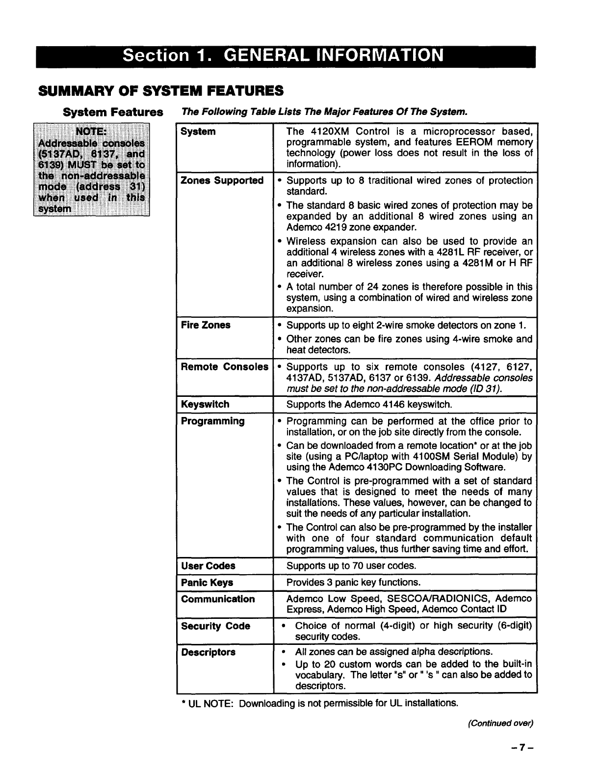
SUMMARY OF SYSTEM FEATURES
The Following Table Lists The Major Features Of The System.
System The 4120XM Control is amicroprocessor based,
programmable system, and features EEROM memory
technology (power loss does not result in the loss of
information).
Zones Supported ●Supports up to 8traditional wired zones of protection
standard.
cThe standard 8basic wired zones of protection may be
expanded by an additional 8wired zones using an
Ademco 4219 zone expander.
●Wireless expansion can also be used to provide an
additional 4wireless zones with a 4281L RF receiver, or
an additional 8wireless zones using a 4281Mor HRF
receiver.
●Atotal number of 24 zones is therefore possible in this
system, using acombination of wired and wireless zone
expansion.
Fire Zones ●Supports up to eight 2-wire smoke detectors on zone 1.
●Other zones can be fire zones using 4-wire smoke and
heat detectors.
Remote Consoles ●Supports up to six remote consoles (4127, 6127,
4137AD, 5137AD, 6137 or 6139. Addressable conso/es
must be set to the non-addressab/e mode (/D 37).
Keyswitch Suppotis the Ademco 4146 keyswitch.
Programming ●Programming can be performed at the office prior to
installation, or on the job site directly from the console.
cCan be downloaded from aremote location* or at the job
site (using aPC/laptop with 41OOSMSerial Module) by
using the Ademco4130PC Downloading Software.
cThe Control is pre-programmed with aset of standard
values that is designed to meet the needs of many
installations. These values, however, can be changed to
suit the needs of any particular installation.
●The Control can also be pre-programrned by the installer
with one of four standard communication default
programming values, thus futiher saving time and effort.
User Codes Supports up to 70 user codes.
Panic Keys Provides 3panic key functions.
Communication Ademco Low Speed, SESCOA/RADIONICS, Ademco
Express, Adernco High Speed, Ademco Contact ID
Security Code ●Choice of normal (4-digit) or high security (6-digit)
security codes.
Descriptors ●All zones can be assigned alpha descriptions.
●Up to 20 custom words can be added to the built-in
vocabulary. The letter “s” or”’s” can also be added to
descriptors.
●UL NOTE: Downloading is not permissible for UL installations.
(Continued ove~
-7-
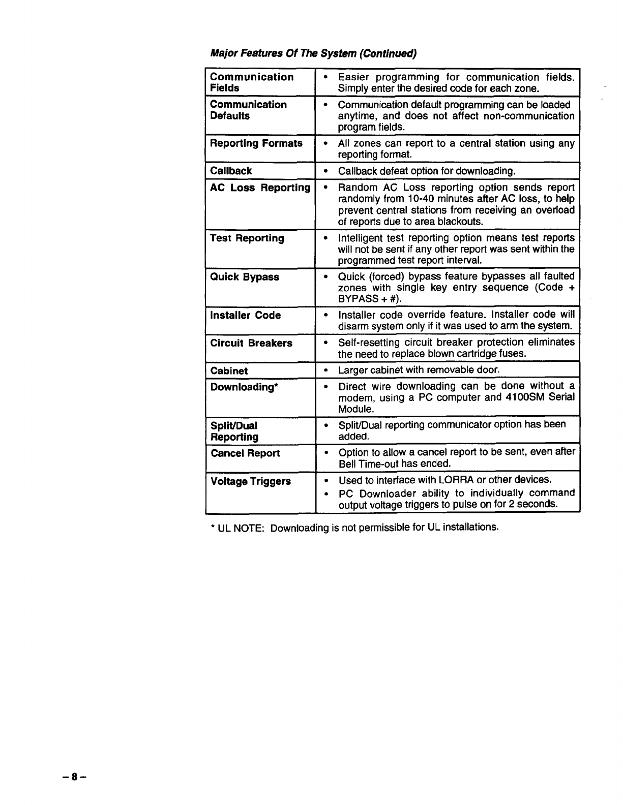
Major Features Of The System (Continued)
Communication ●Easier programming for communication fields.
Fields Simply enter the desired code for each zone.
Communication ●Communication default programming can be loaded
Defaults anytime, and does not affect non-communication
program fields.
Reporting Formats .All zones can report to acentral station using any
reporting format.
Callback “Callback defeat option for downloading.
AC Loss Reporting GRandom AC Loss reporting option sends report
randomly from 10-40 minutes after AC loss, to help
prevent central stations from receiving an overload
of reports due to area blackouts.
Test Reporting ●Intelligent test reporting option means test repods
will not be sent if any other report was sent within the
programmed test report interval.
Quick Bypass ●Quick (forced) bypass feature bypasses all faulted
zones with single key entry sequence (Code +
BYPASS +#).
Installer Code cInstaller code override feature. Installer code will
disarm system only if it was used to arm the system.
Circuit Breakers ●Self-resetting circuit breaker protection eliminates
the need to replace blown cartridge fuses.
Cabinet ●Larger cabinet with removable door.
Downloading* cDirect wire downloading can be done without a
modem, using aPC computer and 41OOSMSerial
Module.
Split/Dual .Split/Dual reporting communicator option has been
Reporting added.
Cancel Report ●Option to allow acancel report to be sent, even after
Bell Time-out has ended.
Voltage Triggers ●Used to interface with LORRA or other devices.
●PC Downloader ability to individually command
output voltage triggers to pulse on for 2seconds.
●UL NOTE: Downloading is not permissible for UL installations.
-8-
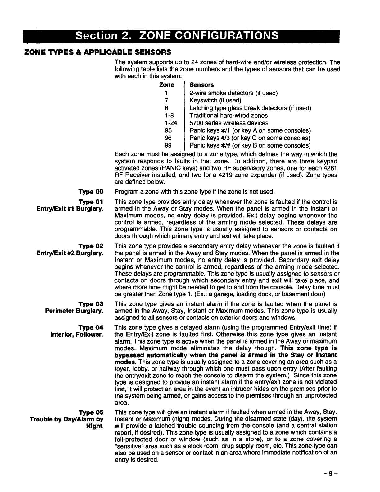
ZONE TYPES &APPLICABLE SENSORS
Type 00
Type 01
Entry/Exit #1 Burglary.
Type 02
Entry/Exit #2 Burglary.
Type 03
Perimeter Burglary.
Type 04
Interior, Follower.
Type 05
Trouble by Day/Alarm by
Night.
The system supports up to 24 zones of hard-wire and/or wireless protection. The
foliowing table lists the zone numbers and the types of sensors that can be used
with each in this system:
Zone Sensors
12-wire smoke detectors (if used)
7Keyswitch (if used)
6Latching type giass break detectors (if used)
1-8 Traditiona{ hard-wired zones
1-24 5700 series wireiess devices
95 Panic keys #t/l (or key Aon some consoles)
96 Panic keys #/3 (or key Con some consoles)
99 Panic keys W# (or key Bon some consoles)
Each zone must be assigned to azone type, which defines the way in which the
system responds to faults in that zone. In addition, there are three keypad
activated zones (PANiC keys) and two RF supervisory zones, one for each 4281
RF Receiver installed, and two for a 4219 zone expander (if used). Zone types
are defined below.
Program azone with this zone type if the zone is not used.
This zone type provides entry delay whenever the zone is faulted if the control is
armed in the Away or Stay modes. When the panei is armed in the instant or
Maximum modes, no entry delay is provided. Exit delay begins whenever the
controi is armed, regardless of the arming mode selected. These delays are
programmable. This zone type is usually assigned to sensors or contacts on
doors through which primary entry and exit will take place.
This zone type provides asecondaty entry delay whenever the zone is faulted if
the panel is armed in the Away and Stay modes. When the panei is armed in the
Instant or Maximum modes, no entry delay is provided. Secondary exit delay
begins whenever the control is armed, regardless of the arming mode selected.
These delays are programmable. This zone type is usually assigned to sensors or
contacts on doors through which secondary entry and exit will take place, and
where more time might be needed to get to and from the console. Deiay time must
be greater than Zone type 1. (Ex.: agarage, loading dock, or basement door)
This zone type gives an instant alarm if the zone is faulted when the panel is
armed in the Away, Stay, Instant or Maximum modes. This zone type is usually
assigned to all sensors or contacts on exterior doors and windows.
This zone type gives adelayed alarm (using the programmed Entry/exit time) if
the Entry/Exit zone is faulted first. Otherwise this zone type gives an instant
alarm. This zone type is active when the panel is armed in the Away or maximum
modes. Maximum mode eliminates the delay though. This zone type is
bypassed automatically when the panei is armed in the Stay or instant
modes. This zone type is usually assigned to azone covering an area such as a
foyer, lobby, or hallway through which one must pass upon entry (After faulting
the entry/exit zone to reach the console to disarm the system.) Since this zone
type is designed to provide an instant alarm if the entry/exit zone is not violated
first, it will protect an area in the event an intruder hides on the premises prior to
the system being armed, or gains access to the premises through an unprotected
area.
This zone type will give an instant alarm if faulted when armed in the Away, Stay,
Instant or Maximum (night) modes. During the disarmed state (day), the system
will provide alatched trouble sounding from the console (and acentrai station
report, if desired). This zone type is usually assigned to azone which contains a
foil-protected door or window (such as in astore), or to azone covering a
“sensitive” area such as astock room, drug supply room, etc. This zone type can
also be used on a sensor or contact in an area where immediate notification of an
entry is desired.
-9-
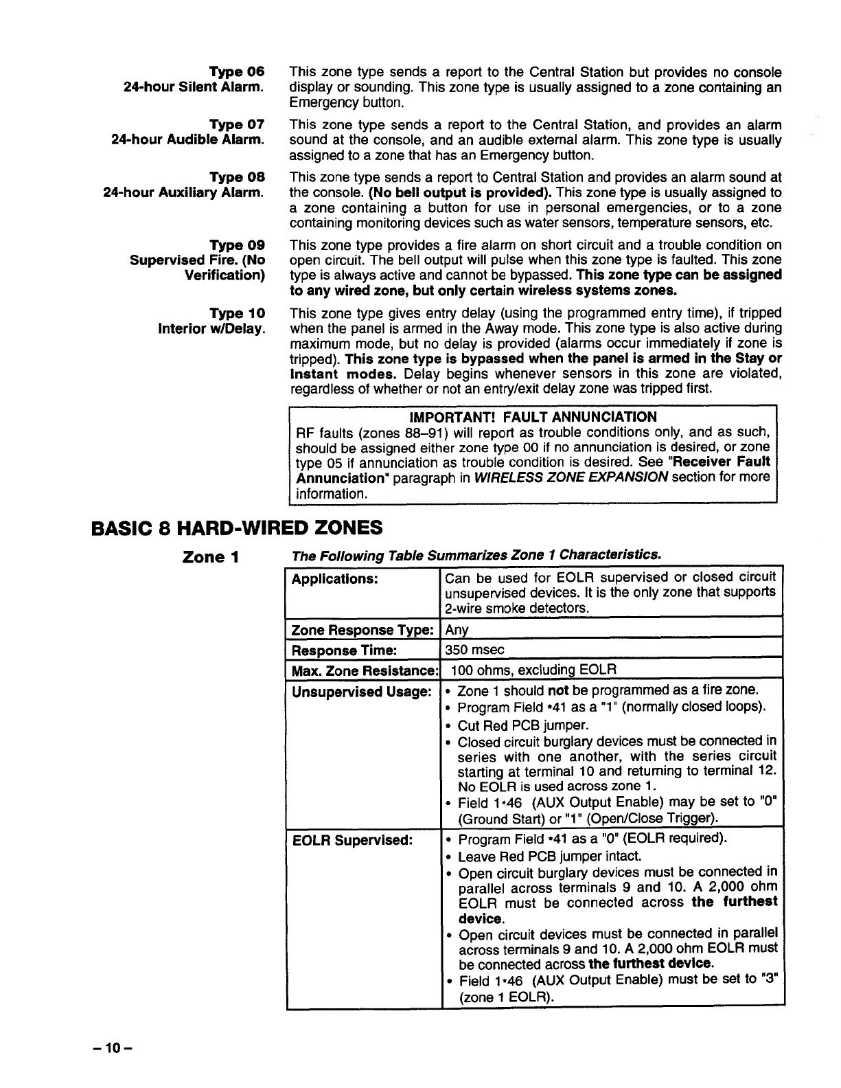
Type 06
24-hour Silent Alarm.
Type 07
24-hour Audible Alarm.
Type 08
24-hour Auxiliary Alarm.
Type 09
Supervised Fire. (No
Verification)
Type 10
Interior w/Delay.
This zone type sends areport to the Central Station but provides no console
display or sounding. This zone type is usually assigned to azone containing an
Emergency button.
This zone type sends areport to the Central Station, and provides an alarm
sound at the console, and an audible external alarm. This zone type is usually
assigned to azone that has an Emergency button.
This zone type sends areport to Central Station and provides an alarm sound at
the console. (No bell output is provided). This zone type is usually assigned to
azone containing abutton for use in personal emergencies, or to azone
containing monitoring devices such as water sensors, temperature sensors, etc.
This zone type provides afire alarm on short circuit and a trouble condition on
open circuit. The bell output will pulse when this zone type is faulted. This zone
type is always active and cannot be bypassed. This zone type can be assigned
to any wired zone, but only certain wireless systems zones.
This zone type gives entry delay (using the programmed entry time), if tripped
when the panel is armed in the Away mode. This zone type is also active during
maximum mode, but no delay is provided (alarms occur immediately if zone is
tripped). This zone type is bypassed when the panel is armed in the Stay or
Instant modes. Delav beains whenever sensors in this zone are violated,
regardless of whether o; not;n entry/exit delay zone was tripped first.
IMPORTANT! FAULT ANNUNCIATION
RF faults (zones 88–91)will report as trouble conditions only, and as such,
should be assigned either zone type 00 if no annunciation is desired, or zone
type 05 if annunciation as trouble condition is desired. See “Receiver Fault
Annunciation” paragraph in WIRELESS ZONE EXPANS/ON section for more
information.
BASIC 8HARD-WIRED ZONES
Zone 1The Following Table Summarizes Zone 1Characteristics.
Applications:
Zone Resnonse TvDe:
Response Time:
Max. Zone Resistance
Unsupervised Usage:
EOLR Supervised:
Can be used for EOLR supervised or closed circuit
unsupewised devices. It is the only zone that supports
2-wire smoke detectors.
Any
350 msec
100 ohms, excluding EOLR
●
●
●
●
●
Zone 1should not be programmed as afire zone.
Program Field *41 as a”1” (normally closed loops).
Cut Red PCB jumper.
Closed circuit burglary devices must be connected in
series with one another, with the series circuit
starting at terminal 10 and returning to terminal 12.
No EOLR is used across zone 1.
Field 1*46 (AUX Output Enable) may be set to “O”
(Ground Sta~) or”1” (Open/Close Trigger).
.Program Field ●41 as a“O”(EOLR required).
●Leave Red PCB jumper intact.
●Open circuit burglary devices must be connected in
parallel across terminals 9 and 10. A2,000 ohm
EOLR must be connected across the furthest
device.
cOpen circuit devices must be connected in parallel
across terminals 9 and 10. A2,000 ohm EOLR must
be connected across the fufihest device.
~Field 1*46 (AUX Output Enable) must be set to “3
(zone 1EOLR).
-1o-
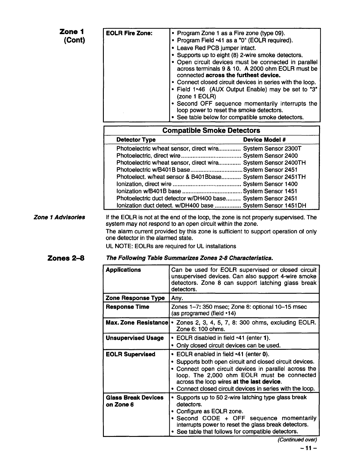
Zone 1
(Cent)
Zone 1Advisories
Zones 2-8
EOLR Fire Zone: ●
●
●
●
●
●
●
●
●
Program Zone 1as aFire zone (type 09).
Program Field ●41 as a“O” (EOLR required).
Leave Red PCB jumper intact.
Supports up to eight (8) 2-wire smoke detectors.
Open circuit devices must be connected in parallel
across terminals 9&10. A2000 ohm EOLR must be
connected across the furthest device.
Connect closed circuit devices in series with the loop.
Field 1*46 (AUX Output Enable) may be set to “3”
(zone 1EOLR)
Second OFF sequence momentarily interrupts the
loop power to reset the smoke detectors.
See table below for compatible smoke detectors.
Compatible Smoke Detectors
Detector Type Device Model #
Photoelectric w/heat sensor, direct wire.............. System Sensor 2300T
Photoelectric, direct wire ..................................... System Sensor 2400
Photoelectric w/heat sensor, direct wire.............. System Sensor 2400TH
Photoelectric w/B401B base ................................System Sensor 2451
Photoelect. w/heat sensor& B401Base. ........... System Sensor 2451TH
Ionization, direct wire .......................................... System Sensor 1400
Ionization w/B401Bbase .....................................System Sensor 1451
Photoelectric duct detector w/DH400 base......... System Sensor 2451
Ionization duct detect. w/DH400 base ................ Svstem Sensor 1451DH
If the EOLR is not at the end of the loop, the zone is not properly supervised. The
system may not respond to an open circuit within the zone.
The alarm current provided by this zone is sufficient to support operation of only
one detector in the alarmed state.
UL NOTE: EOLRSare required for UL installations
The Following Table Summarizes Zones 2-8 Characteristics.
Applications 1Can be used for EOLR supervised or closed circuit
unsupervised devices. Can also support 4-wire smoke
detectors. Zone 8can support latching glass break
detectors.
Zone Response Type Any.
Response Time Zones 1-7:350 msec; Zone 8: optional 10-15 msec
(as programed (field ●14)
Max. Zone Resistance sZones 2, 3, 4, 5, 7, 8:300 ohms, excluding EOLR.
Zone 6:100 ohms.
Unsupewised Usage .EOLR disabled in field *41 (enter 1).
●Only closed circuit devices can be used.
EOLR Supervised .EOLR enabled in field ●41 (enter O).
●Supports both open circuit and closed circuit devices.
●Connect open circuit devices in parallel across the
loop. The 2,000 ohm EOLR must be connected
across the loop wires at the last device.
●Connect closed circuit devices in series with the loop.
Glass Break Devices ●Supports up to 50 2-wire latching type glass break
on Zone 6detectors.
●Configure as EOLR zone.
●Second CODE +OFF sequence momentarily
interrupts power to reset the glass break detectors.
“See table that follows for compatible detectors.
(Continued over)
-11-
Zones 2-8
(Cent)
L
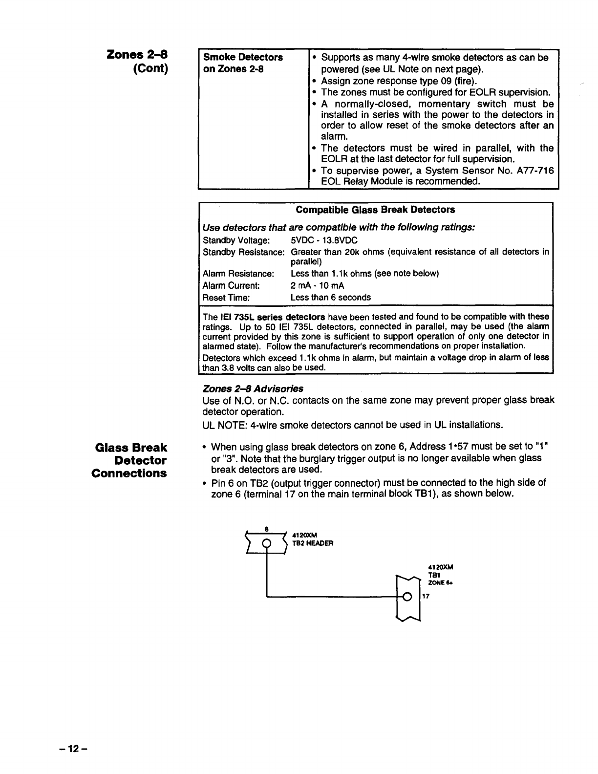
Smoke Detectors ●Supports as many 4-wire smoke detectors as can be
mZones 2-8 powered (see UL Note on next page).
●Assign zone response type 09 (fire).
●The zones must be configured for EOLR supervision.
●Anormally-closed, momentary switch must be
installed in series with the power to the detectors in
order to allow reset of the smoke detectors after an
alarm.
●The detectors must be wired in parallel, with the
EOLR at the last detector for full supervision.
●To supervise power, aSystem Sensor No. A77-716
EOL Relay Module is recommended.
Compatible Glass Break Detectors
Use detectors that are compatible with the following ratings:
StandbyVoltage: 5VDC-13.8VDC
StandbyResistance: Greaterthan 20k ohms (equivalent resistance of all detectors in
parallel)
AlarmResistance: Lessthan 1.1kohms(seenotebelow)
AlarmCurrent: 2mA-10mA
ResetTime: Lessthan6seconds
The IEI 735L series detectors have been tested and found to be compatible with these
ratings. Up to 50 IEI 735L detectors, connected in parallel, may be used (the alarm
current provided by this zone is sufficient to support operation of only one detector in
alarmed state). Follow the manufacturer’s recommendations on proper installation.
Detectors which exceed 1.1kohms in alarm, but maintain avoltage drop in alarm of less
than 3.8 volts can also be used.
Zones 2-8 Advisories
Glass Break ●
Detector
Connections
●
Use of N.O. or N.C. contacts on the same zone may prevent proper glass break
detector operation.
UL NOTE: 4-wire smoke detectors cannot be used in UL installations.
When using glass break detectors on zone 6, Address 1*57 must be set to”1”
or “3. Note that the burglary trigger output is no longer available when glass
break detectors are used.
Pin 6 on TB2 (output trigger connector) must be connected to the high side of
zone 6(terminal 17 on the main terminal block TB1), as shown below.
6
Q4120XM
TS2 HEAOER
-12-
4219 Zone Expander ●
●
●
●
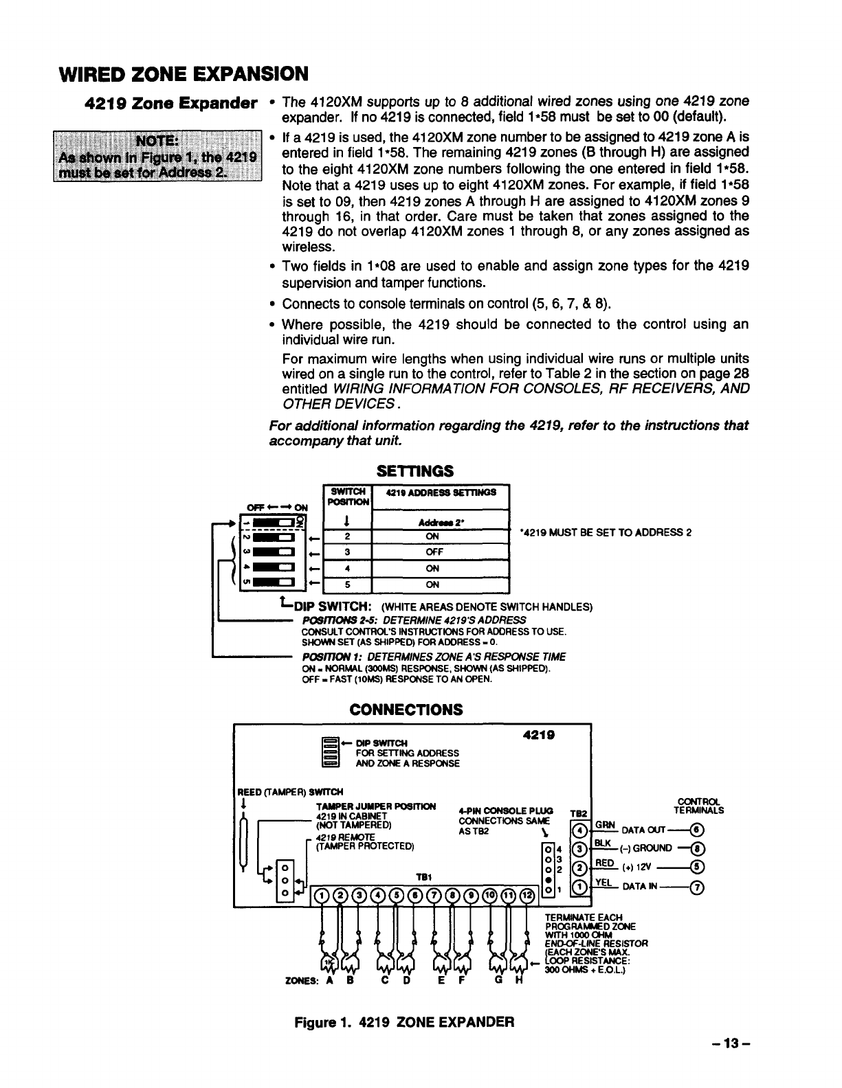
The 4120XM supports up to 8additional wired zones using one 4219 zone
expander. If no 4219 is connected, field 1●58 must be set to 00 (default).
If a 4219 is used, the4120XM zone numbertobeassignedto4219 zone Ais
entered in field 1●58. The remaining 4219 zones (B through H) are assigned
to the eight 4120XM zone numbers following the one entered in field 1●58.
Note that a 4219 uses up to eight 4120XM zones. For example, if field 1●58
is set to 09, then 4219 zones Athrough Hare assigned to 4120XM zones 9
through 16, in that order. Care must be taken that zones assigned to the
4219 do not overlap 4120XM zones 1through 8, or any zones assigned as
wireless.
Two fields in I*O8 are used to enable and assign zone types for the 4219
supervision and tamper functions.
Connects to console terminals on control (5,6,7, &8).
Where possible, the 4219 should be connected to the control using an
individual wire run.
For maximum wire lengths when using individual wire runs or multiple units
wired on a single run to the control, refer to Table 2in the section on page 28
entitled WIRING INFORMATION FOR CONSOLES, RF RECEIVERS, AND
OTHER DEVICES .
For additional information regarding the 4219, refer to the instructions that
accompany that unit.
SEITINGS
Swrrcl’1 4219
ADDRESSsEmNGs
opp++~ ~
-~
p~
1Ad&m 2“
.--------
~~ + 2ON “4219MUST BE SET TO
-~ t3OFF
-~ +4ON
~~ + 5ON
~DIP SWITCH: (WHITE AREAS DENOTE SWITCH HANDLES)
Posmorus2-5: DETERMINE4219s ADDRESS
CONSULTCONTROL’SINSTRUCTIONSFORADDRESSTOUSE.
SHOWNSET(ASSHIPPED)FORAODRESS.0.
iwsmofu1: DETERMINESZONEA’SREL3PCYVSETIME
ON. NORMAL(ZOOMS)RESPONSE,SHOWN(ASSHIPPED).
OfF =FAST(1OMS)RESPONSETOANOPEN.
CONNECTIONS
IADDRESS 2
M
=+
DIPSWITCH 4219
FORSETflNGAOORESS
ANDZONEARESPCWSE
iREED(TAMPER)SWITCH I
1’” TAMPERJUMPERPOSK~ ccf4TRoL
OQ
4219INCABINET 4-PM~~ p~ T= TERMIN4LS
(NOTTAMPERED) CONNECTIONSSAW
4219REKW2 ASTB2 ;4: ‘W DATAOUT-@
(TAMPERPROTECTED)
nk
‘K (-) GROUND-@
o03
02@ RED (+) 12V .—@
oTB1 ●‘EL DATAIN
ommmmmmmmmmmml 0’ ‘—@
ZONE9A”ti C” DE~d ii —,
Figure 1.4219 ZONE EXPANDER
-13-
WIRELESS ZONE EXPANSION (Zones 1-63)
GeneraI Information
(Receivers)
Transmitters Supported
By Various Re&ivers
The Following Table Summarizes Wireless Expansion Characteristics.
Zones Supported
4281 RF Receiver
(General)
Receiver Supervision
House Identification
Sniffer Mode For
House ID
~Code +[#] +[2])
●
●
●
●
D
D
D
B
B
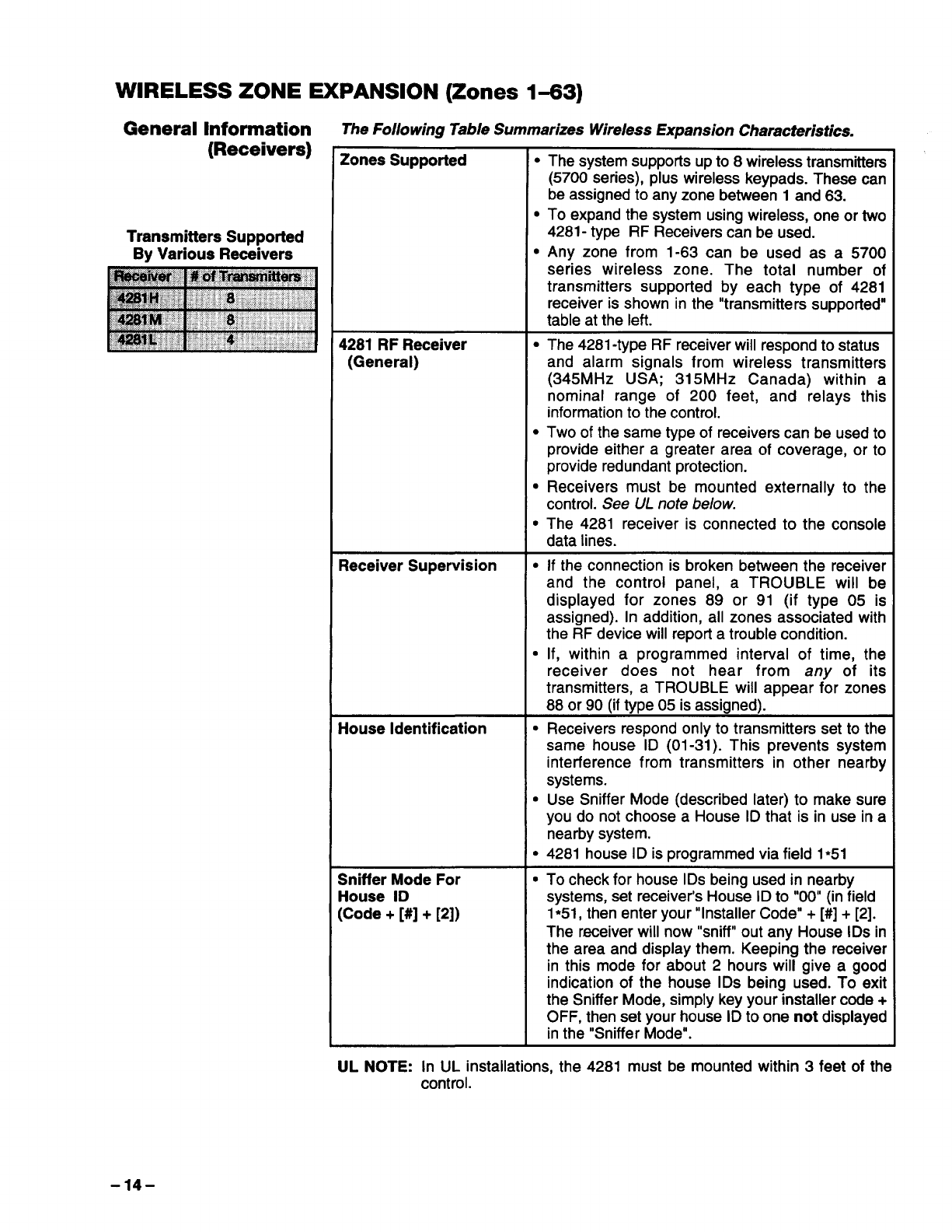
The system suppofts up to 8wireless transmitters
(5700 series), plus wireless keypads. These can
be assigned to any zone between 1 and 63.
To expand the system using wireless, one or two
4281- type RF Receivers can be used.
Any zone from 1-63 can be used as a 5700
series wireless zone. The total number of
transmitters supported by each type of 4281
receiver is shown in the “transmitters supported”
table at the left.
The 4281-type RF receiver will respond to status
and alarm signals from wireless transmitters
(345 MHz USA; 315 MHz Canada) within a
nominal range of 200 feet, and relays this
information to the control.
Two of the same type of receivers can be used to
provide either agreater area of coverage, or to
provide redundant protection.
Receivers must be mounted externally to the
control. See UL note be/ow.
The 4281 receiver is connected to the console
data lines.
If the connection is broken between the receiver
and the control panel, aTROUBLE will be
displayed for zones 89 or 91 (if type 05 is
assigned). In addition, all zones associated with
the RF device will report atrouble condition.
If, within aprogrammed interval of time, the
receiver does not hear from any of its
transmitters, aTROUBLE will appear for zones
88 or 90 (if type 05 is assigned).
JReceivers respond only to transmitters set to the
same house ID (01-31). This prevents system
interference from transmitters in other nearby
systems.
IUse Sniffer Mode (described later) to make sure
you do not choose aHouse ID that is in use in a
nearby system.
B4281 house IDis programmed via field 1●51
JTo check for house IDs being used in nearby
systems, set receiver’s House ID to “00” (in field
1●51, then enter your “installer Code”+ [#]+ [2].
The receiver will now “sniff” out any House IDs in
the area and display them. Keeping the receiver
in this mode for about 2hours will give a good
indication of the house IDs being used. To exit
the Sniffer Mode, simply key your installer code +
OFF, then set your house ID to one not displayed
in the “Sniffer Mode”.
LJLNOTE: In UL installations, the 4281 must be mounted within 3feet of the
-14-
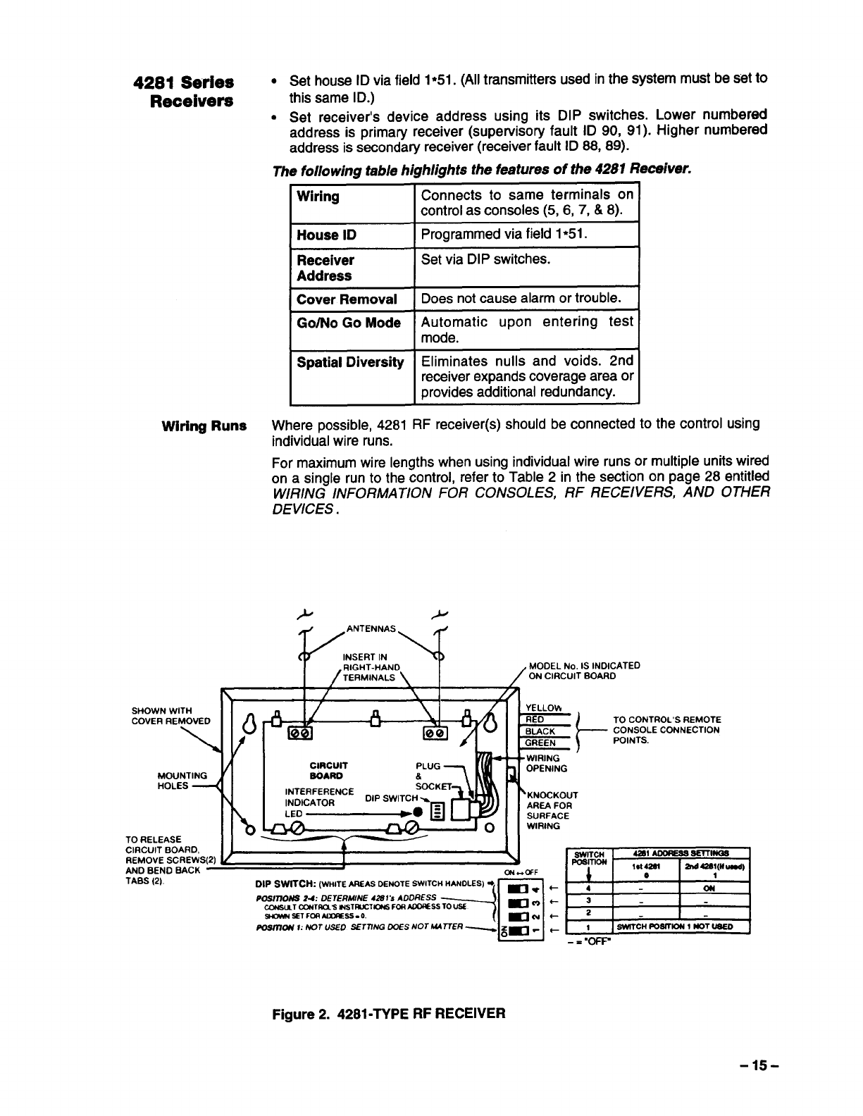
4281 Series .Set house ID via field 1●51. (All transmitters used in the system must be set to
Receivers this same ID.)
.Set receiver’s device address using its DIP switches. Lower numbered
address is primary receiver (supervisory fault ID 90, 91). Higher numbered
address is secondaIy receiver (receiver fault ID 88, 89).
The fo//owing table highlights the features of the 4281 Receiver.
Wiring Connects to same terminals on
control as consoles (5, 6, 7, &8).
House ID Programmed via field 1●51.
Receiver Set via DIP switches.
Address
Cover Removal Does not cause alarm or trouble.
Go/No Go Mode Automatic upon entering test
mode.
Spatial Diversity Eliminates nulls and voids. 2nd
receiver expands coverage area or
provides additional redundancy.
Wiring Runs Where possible, 4281 RF receiver(s) should be connected to the control using
individual wire runs.
For maximum wire lengths when using individual wire runs or multiple units wired
on a single run to the control, refer to Table 2in the section on page 28 entitled
WIRING INFORMATION FOR CONSOLES, RF RECEIVERS, AND OTHER
DEVICES .
/w%k%’wrO
I /
SHOWNWITH Ad’ ““\ 1~ ,
COVERREMOVED
\-w
u
J’11 CIRCUIT PLUG
MOUNTING SOARD
HOLES “’“TERFERENCE ~i
‘w”%
DIP SWITCH %
ILF- w
TO RELEASE
CIRCUIT BOARD,
REMOVE SCREW:
ANO BEND BACK
TABS (2).
IL
l-d *k-REO
BIACK
GREEN t
-WIRING
3
OPENING
‘KNOCKOUT
AREA FOR
SURFACE
WIRING
IIN
IN)
TO CONTROL’S REMOTE
CONSOLE CONNECTION
POINTS.
I1- 1
-----
DIP SWITCH: (WHITEAREASDENOTE SWITCH HANDLES) @_~ +
==wx=--+~l:l~l
POSITIONS 24: DETERMINE 42sl ‘SADDRESS
/OSlllON 1: NOT WED SETTING 005S NOT UATTER ~.+ SWITCH fOSITION 1NOT~
-=”om
Figure 2. 4281-TYPE RF RECEIVER
-15-
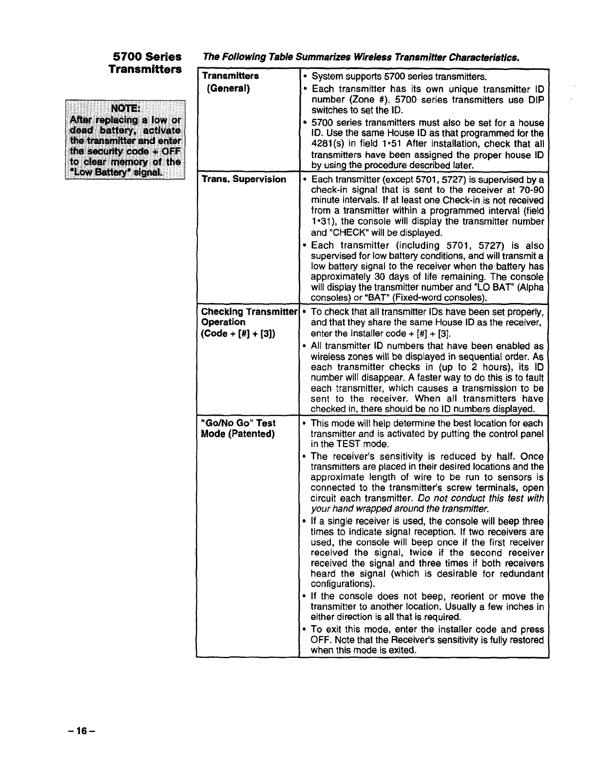
The Following Table Summarizes Wireless Transmitter Characteristics.
Transmitters ●System supports 5700 series transmitters.
(General) GEach transmitter has its own unique transmitter ID
number (Zone #). 5700 series transmitters use DIP
switches to set the ID.
●5700 series transmitters must also be set for ahouse
ID. Use the same House ID as that programmed for the
4281(s) in field 1*51 After installation, check that all
transmitters have been assigned the proper house ID
by using the procedure described later.
Trans. Supervision ●Each transmitter (except 5701, 5727) is supervised by a
check-in signal that is sent to the receiver at 70-90
minute intervals. If at least one Check-in is not received
from atransmitter within aprogrammed interval (field
1●31), the console will display the transmitter number
and “CHECK” will be displayed.
●Each transmitter (including 5701, 5727) is also
supervised for low battery conditions, and will transmit a
low battery signal to the receiver when the battery has
approximately 30 days of life remaining. The console
will display the transmitter number and “LO BAT” (Alpha
consoles) or “BAT” (Fixed-word consoles).
Checking Transmitter ●To check that all transmitter IDs have been set properly,
Operation and that they share the same House ID as the receiver,
(Code +[#]+ [3]) enter the Installercode +[#] +[3],
cAll transmitter ID numbers that have been enabled as
wireless zones will be displayed in sequential order. As
each transmitter checks in (up to 2hours), its ID
number will disappear. Afaster way to do this is to fault
each transmitter, which causes atransmission to be
sent to the receiver. When all transmitters have
checked in, there should be no ID numbers displayed.
“Go/No Go” Test ●This mode will help determine the best location for each
Mode (Patented) transmitter and is activated by putting the control panel
in the TEST mode.
●The receiver’s sensitivity is reduced by half. Once
transmitters are placed in their desired locations and the
approximate length of wire to be run to sensors is
connected to the transmitter’s screw terminals, open
circuit each transmitter. Do not conduct this test with
your hand wrapped around the kmmifter.
●If asingle receiver is used, the console will beep three
times to indicate signal reception. If two receivers are
used, the console will beep once if the first receiver
received the signal, twice if the second receiver
received the signal and three times if both receivers
heard the signal (which is desirable for redundant
configurations),
●If the console does not beep, reorient or move the
transmitter to another location. Usually afew inches in
either direction is all that is required.
●To exit this mode, enter the installer code and press
OFF. Note that the Receiver’s sensitivity is fully restored
when this mode is exited.
-16-
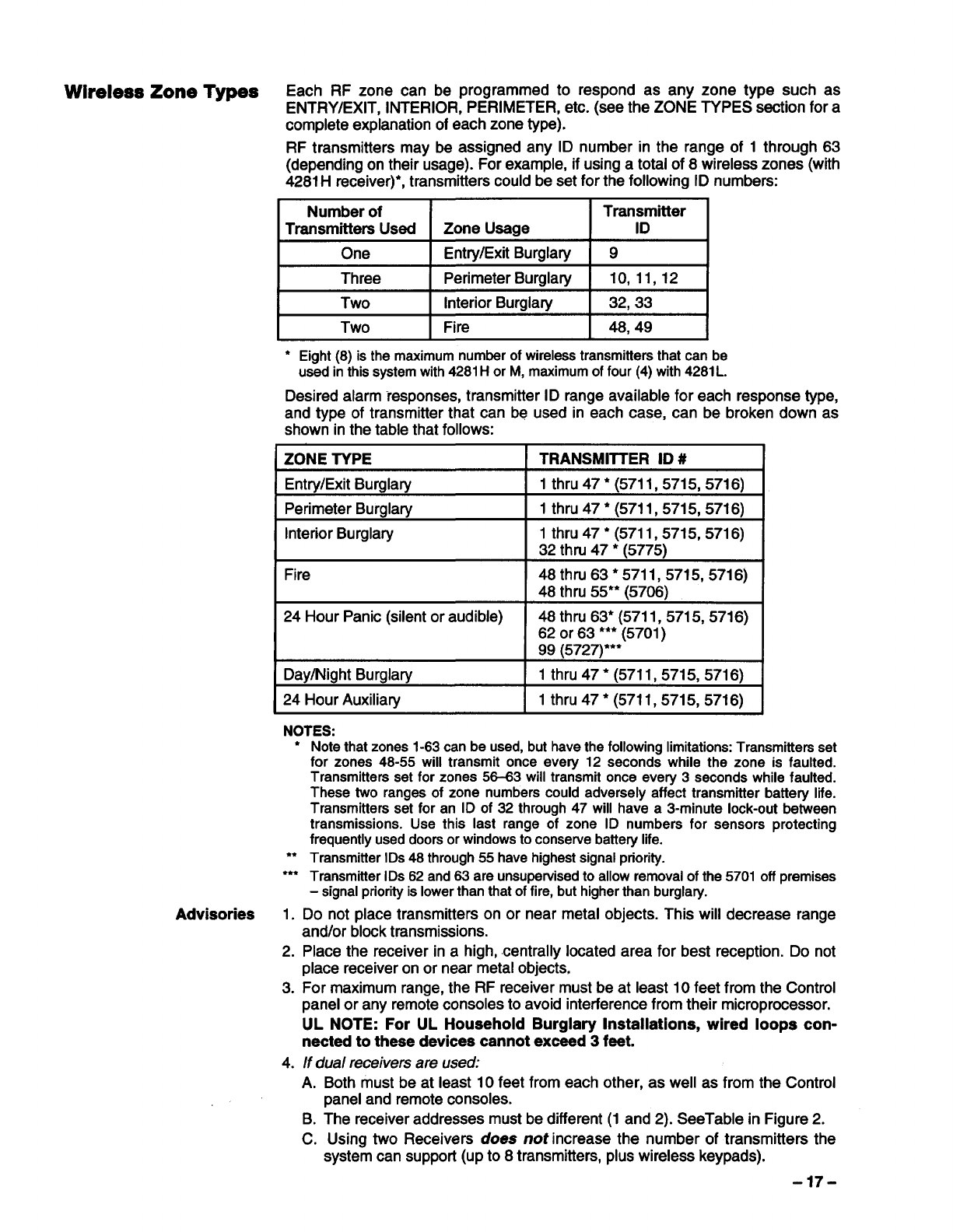
Wireless Zone Types Each RF zone can be programmed to respond as any zone type such as
ENTRY/EXIT, INTERIOR, PERIMETER, etc. (see the ZONE TYPES section for a
complete explanation of each zone type).
RF transmitters may be assigned any ID number in the range of 1through 63
(depending on their usage). For example, if using atotal of 8wireless zones (with
4281Hreceiver)*, transmitters could be set for the following ID numbers:
Number of Transmitter
Transmitters Usecf Zone Usage ID
One Entry/Exit Burglary 9
Three Perimeter Burglary 10,11,12
Two Interior Burglaty 32,33
Two Fire 48,49
●Eight(8) is the maximumnumberof wirelesstransmittersthat can be
usedin this systemwith4281Hor M,maximumof four (4)with4281L.
Desired alarm responses, transmitter ID range available for each response type,
and type of transmitter that can be used in each case, can be broken down as
shown in the table that follows:
IZONE TYPE ITRANSMITTER ID #
Entry/Exit Burglary 1thru47*(5711, 5715, 5716)
Perimeter Burglary 1thru47•(5711, 5715, 5716)
Interior Burglary 1thru47•(5711, 5715, 5716)
32 thru 47 *(5775)
Fire 48thru63•5711, 5715,571 6)
48 thru 55** (5706)
24 Hour Panic (silent or audible) 48 thru 63* (5711, 5715, 5716)
62 or 63 *** (5701)
99 (5727)***
Day/Night Burglary 1thru47•(5711, 5715, 5716)
24 Hour Auxiliaty 1thru47•(5711, 5715, 5716)
NOTES:
*
●☛
☛☛☛
Advisories 1.
2.
3.
4.
Note that zones 1-63 can be used, but have the followina limitations: Transmitters set
for zones 48-55 will transmit once every 12 second; while the zone is faulted.
Transmitters set for zones 56-63 will transmit once every 3seconds while faulted.
These two ranges of zone numbers could adversely affect transmitter battery life.
Transmitters set for an ID of 32 through 47 will have a3-minute lock-out between
transmissions. Use this last range of zone ID numbers for sensors protecting
frequently used doors or windows to conserve battery life.
Transmitter IDs 48 through 55 have highest signal priority.
Transmitter IDs 62 and 63 are unsupervised to allow removal of the 5701 off premises
-signal priority is lower than that of fire, but higher than burglary.
Do not place transmitters on or near metal objects. This will decrease range
and/or block transmissions.
Place the receiver in ahigh, centrally located area for best reception. Do not
place receiver on or near metal objects,
For maximum range, the RF receiver must be at least 10 feet from the Control
panel or any remote consoles to avoid interference from their microprocessor.
UL NOTE: For UL Household Burglary Installations, wired loops con-
nected to these devices cannot exceed 3feet.
If dual receivers are used:
A.
B.
c.
Both must be at least 10 feet from each other, as well as from the Control
panel and remote consoles.
The receiver addresses must be different (1 and 2). SeeTable in Figure 2.
Using two Receivers does not increase the number of transmitters the
system can supporl (up to 8transmitters, plus wireless keypads).
-17-
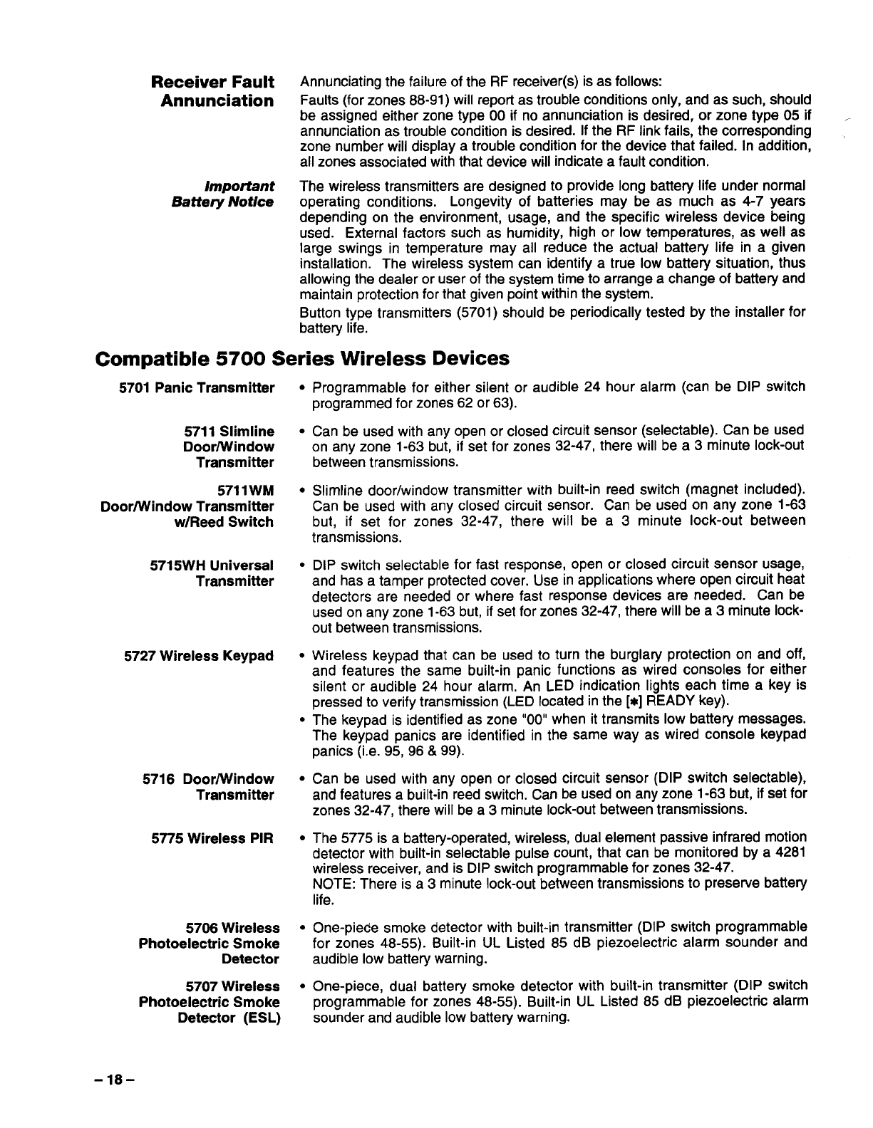
Receiver Fault Annunciating the failure of the RF receiver(s) is as follows:
Annunciation Faults (for zones 88-91)will report as trouble conditions only, and as such, should
be assigned either zone type 00 if no annunciation is desired, or zone type 05 if
annunciation as trouble condition is desired. If the RF link fails, the corresponding
zone number will display atrouble condition for the device that failed. In addition,
all zones associated with that device will indicate afault condition.
Important The wireless transmitters are designed to provide long battery life under normal
Battery Notice operating conditions. Longevity of batteries may be as much as 4-7 years
depending on the environment, usage, and the specific wireless device being
used. External factors such as humidity, high or low temperatures, as well as
large swings in temperature may all reduce the actual battery life in agiven
installation. The wireless system can identify atrue low battery situation, thus
allowing the dealer or user of the system time to arrange achange of battery and
maintain protection for that given point within the system.
Button type transmitters (5701)should be periodically tested by the installer for
battery life.
Compatible 5700 Series Wireless Devices
5701 Panic Transmitter
5711 Slimline
Door/Window
Transmitter
5711 WM
Door/Window Transmitter
w/Reed Switch
571 5WH Universal
Transmitter
5727 Wireless Keypad
5716 Door/Window
Transmitter
5775 Wireless PIR
5706 Wireless
Photoelectric Smoke
Detector
5707 Wireless
Photoelectric Smoke
Detector (ESL)
●Programmable for either silent or audible 24 hour alarm (can be DIP switch
programmed for zones 62 or 63).
●Can be used with any open or closed circuit sensor (selectable). Can be used
on any zone 1-63 but, if set for zones 32-47, there will be a3minute lock-out
between transmissions.
●Slimline door/window transmitter with built-in reed switch (magnet included).
Can be used with any closed circuit sensor. Can be used on any zone 1-63
but, if set for zones 32-47, there will be a 3 minute lock-out between
transmissions.
●DIP switch selectable for fast response, open or closed circuit sensor usage,
and has atamper protected cover. Use in applications where open circuit heat
detectors are needed or where fast response devices are needed. Can be
used on any zone 1-63 but, if set for zones 32-47, there will be a 3 minute lock-
out between transmissions.
●Wireless keypad that can be used to turn the burglary protection on and off,
and features the same built-in panic functions as wired consoles for either
silent or audible 24 hour alarm. An LED indication lights each time akey is
pressed to verify transmission (LED located in the [x] READY key).
●The keypad is identified as zone “00” when it transmits low battery messages.
The keypad panics are identified in the same way as wired console keypad
panics (i.e. 95, 96& 99).
●Can be used with any open or closed circuit sensor (DIP switch selectable),
and features abuilt-in reed switch. Can be used on any zone 1-63 but, if set for
zones 32-47, there will be a 3 minute lock-out between transmissions.
●The 5775 is abattery-operated, wireless, dual element passive infrared motion
detector with built-in selectable pulse count, that can be monitored by a 4281
wireless receiver, and is DIP switch programmable for zones 32-47.
NOTE: There is a3minute lock-out between transmissions to preserve battery
life.
●One-piece smoke detector with built-in transmitter (DIP switch programmable
for zones 48-55). Built-in UL Listed 85 dB piezoelectric alarm sounder and
audible low battery warning.
●One-piece, dual battery smoke detector with built-in transmitter (DIP switch
programmable for zones 48-55). Built-in UL Listed 85 dB piezoelectric alarm
sounder and audible low battefy warning.
-18-
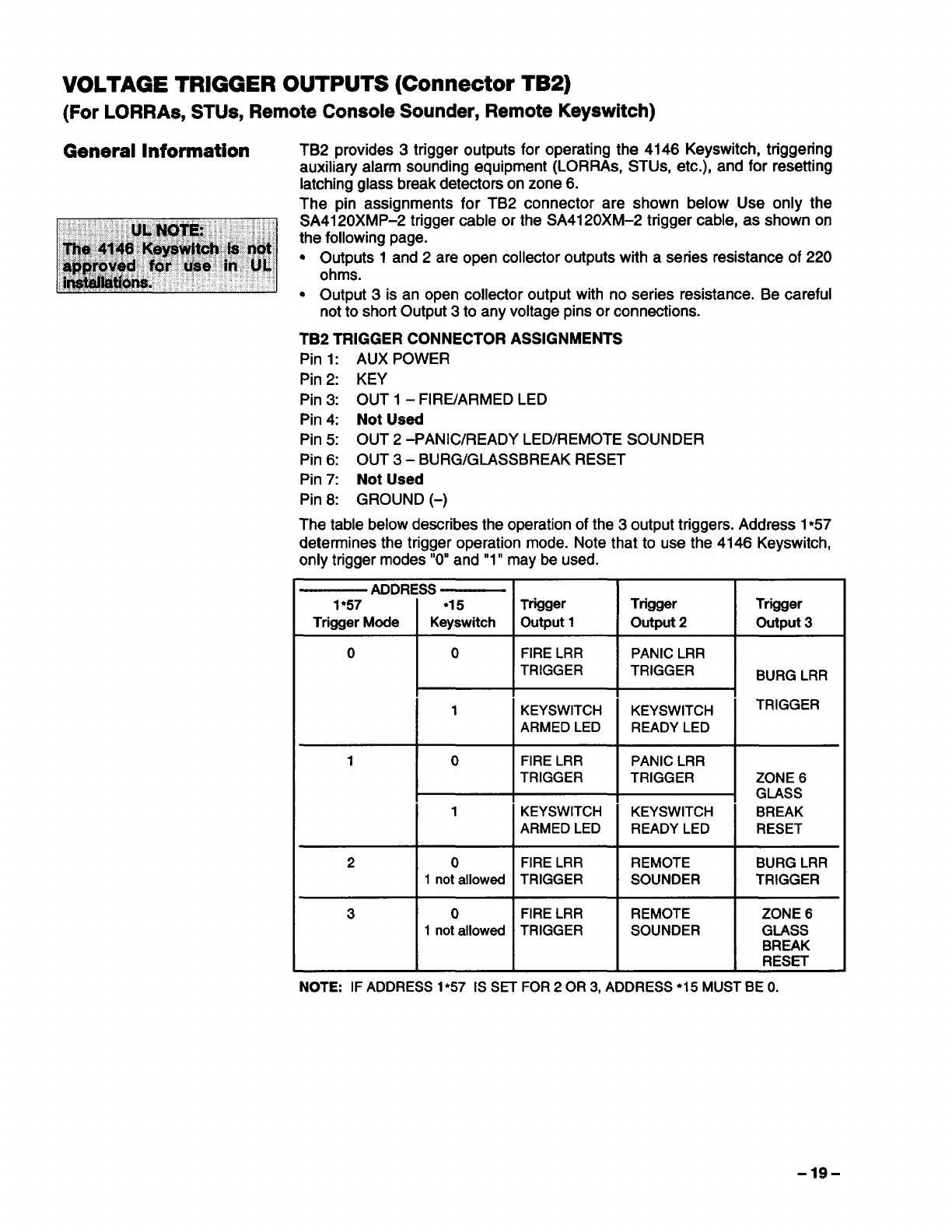
VOLTAGE TRIGGER OUTPUTS (Connector TB2)
(For LORRAS, STUS, Remote Console Sounder, Remote Keyswitch)
TB2 provides 3trigger outputs for operating the 4146 Keyswitch, triggering
auxiliary alarm sounding equipment (LORRAS, STUS, etc.), and for resetting
latching glass break detectors on zone 6.
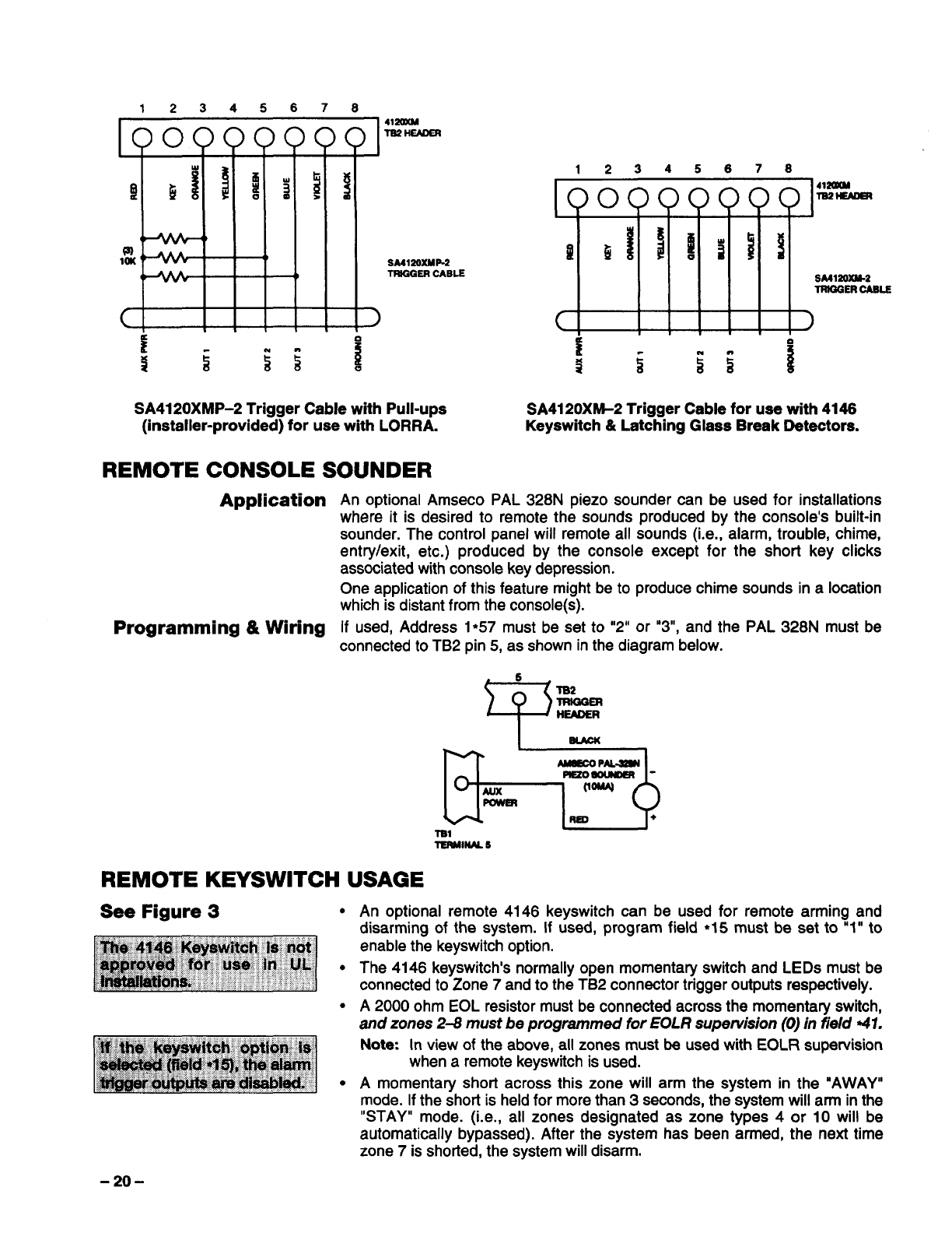
The pin assignments for TB2 connector are shown below Use only the
SA4120XMP-2 trigger cable or the SA4120XM-2 trigger cable, as shown on
the following page.
“Outputs 1 and 2 are open collector outputs with aseries resistance of 220
ohms.
GOutput 3is an open collector output with no series resistance. Be careful
not to shorl Output 3to any voltage pins or connections.
TB2 TRIGGER CONNECTOR ASSIGNMENTS
Pin 1: AUX POWER
Pin 2: KEY
Pin 3: OUT 1 – FIRE/ARMED LED
Pin 4: Not Used
Pin 5: OUT 2-PANIC/READY LED/REMOTE SOUNDER
Pin 6: OUT 3- BURG/GLASSBREAK RESET
Pin 7: Not Used
Pin 8: GROUND (-)
The table below describes the operation of the 3output triggers. Address 1●57
determines the trigger operation mode. Note that to use the 4146 Keyswitch,
only trigger modes “O”and”1” may be used.
—ADDRESS —
1*57 *15Trigger Trigger Trigger
Trigger Mode Keyswitch output 1output 2output 3
0 0 FIRE LRR PANIC LRR
TRIGGER TRIGGER BURG LRR
1KEYSWITCH KEYSWITCH TRIGGER
ARMED LED READY LED
10FIRE LRR PANIC LRR
TRIGGER TRIGGER ZONE 6
GLASS
1KEYSWITCH KEYSWITCH BREAK
ARMED LED READY LED RESET
20FIRE LRR REMOTE BURG LRR
1not allowed TRIGGER SOUNDER TRIGGER
3 0 FIRE LRR REMOTE ZONE 6
1not allowed TRIGGER SOUNDER GLASS
BREAK
RESET
NOTE: IF ADDRESS 1*57 1SSET FOR 2OR 3, ADDRESS ●15 MUST BE O.
-19-
12345678
00000000 41mcM
lB2 HEADER
!l diii$j
(I
a
10M ‘* t}SM12GXMP2
()lRtGGER CASLE
c>
,,,1n,
SA4120XMP-2 Trigger Cable with Pull-ups
(installer-provided) for use with LORRA.
Application
Programming &Wiring
SA4120XM-2 Trigger Cable for use with 4146
Keyswitch &Latching Glass Break Detectors.
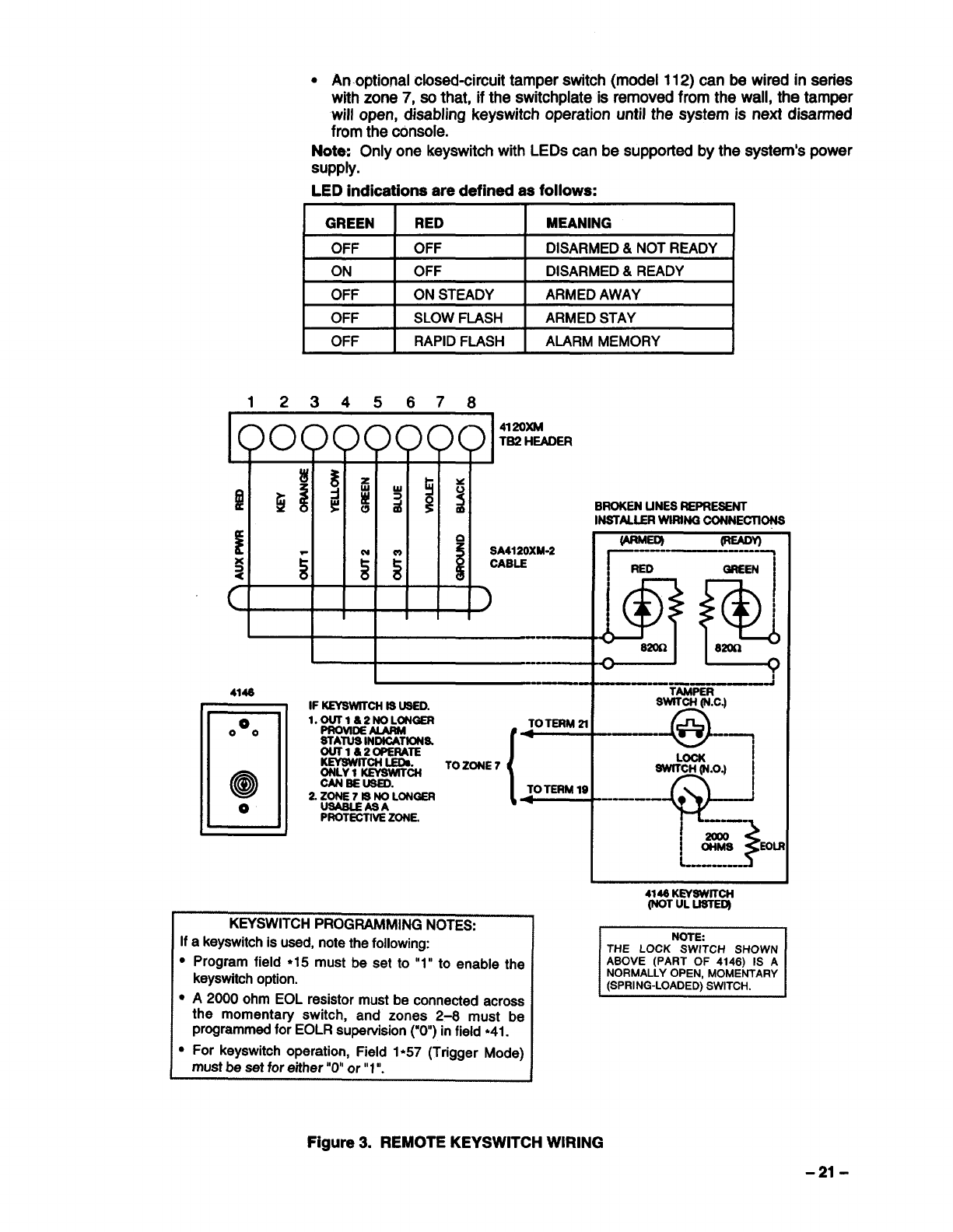
An optional Amseco PAL 328N piezo sounder can be used for installations
where it is desired to remote the sounds produced by the console’s built-in
sounder. The control panel will remote all sounds (i.e., alarm, trouble, chime,
entry/exit, etc.) produced by the console except for the short key clicks
associated with console key depression.
One application of this feature might be to produce chime sounds in alocation
which is distant from the console(s).
If used, Address 1*57 must be set to “2” or “3”, and the PAL 328N must be
connected to TB2 pin 5, as shown in the diagram below.
6
Fls2
TRIGQER
HEADER
.!
TERMINM5
●
●
●
●
An optional remote 4146 keyswitch can be used for remote arming and
disarming of the system. If used, program field ●I5must be set to “1” to
enable the keyswitch option.
The 4146 keyswitch’s normally open momentary switch and LEDs must be
connected to Zone 7and to the TB2 connector trigger outputs respectively.
A2000 ohm EOL resistor must be connected across the momentaty switch,
and zones 2-8 must be programmed for EOLR supervision (0) in field 41.
Note: In view of the above, all zones must be used with EOLR supervision
when aremote keyswitch is used.
Amomentary shori across this zone will arm the system in the “AWAY”
mode. If the short is held for more than 3seconds, the system will arm in the
“STAY” mode. (i.e., all zones designated as zone types 4or 10 will be
automatically bypassed). After the system has been armed, the next time
zone 7is shorted, the system will disarm.
-20-
●An optional closed-circuit tamper switch (model 112) can be wired in series
with zone 7, so that, if the switchplate is removed from the wall, the tamper
will open, disabling keyswitch operation until the system is next disarmed
from the console.
Note: Only one keyswitch with LEDs can be supported by the system’s power
supply.
LED indications are defined as follows:
GREEN RED MEANING
OFF OFF DISARMED&NOTREADY
ON OFF DISARMED&READY
OFF ON STEADY ARMEDAWAY
OFF SLOWFLASH ARMEDSTAY
OFF RAPIDFLASH ALARM MEMORY
12345678
I! a
:ii
SA4120XM-2
55$CABLE
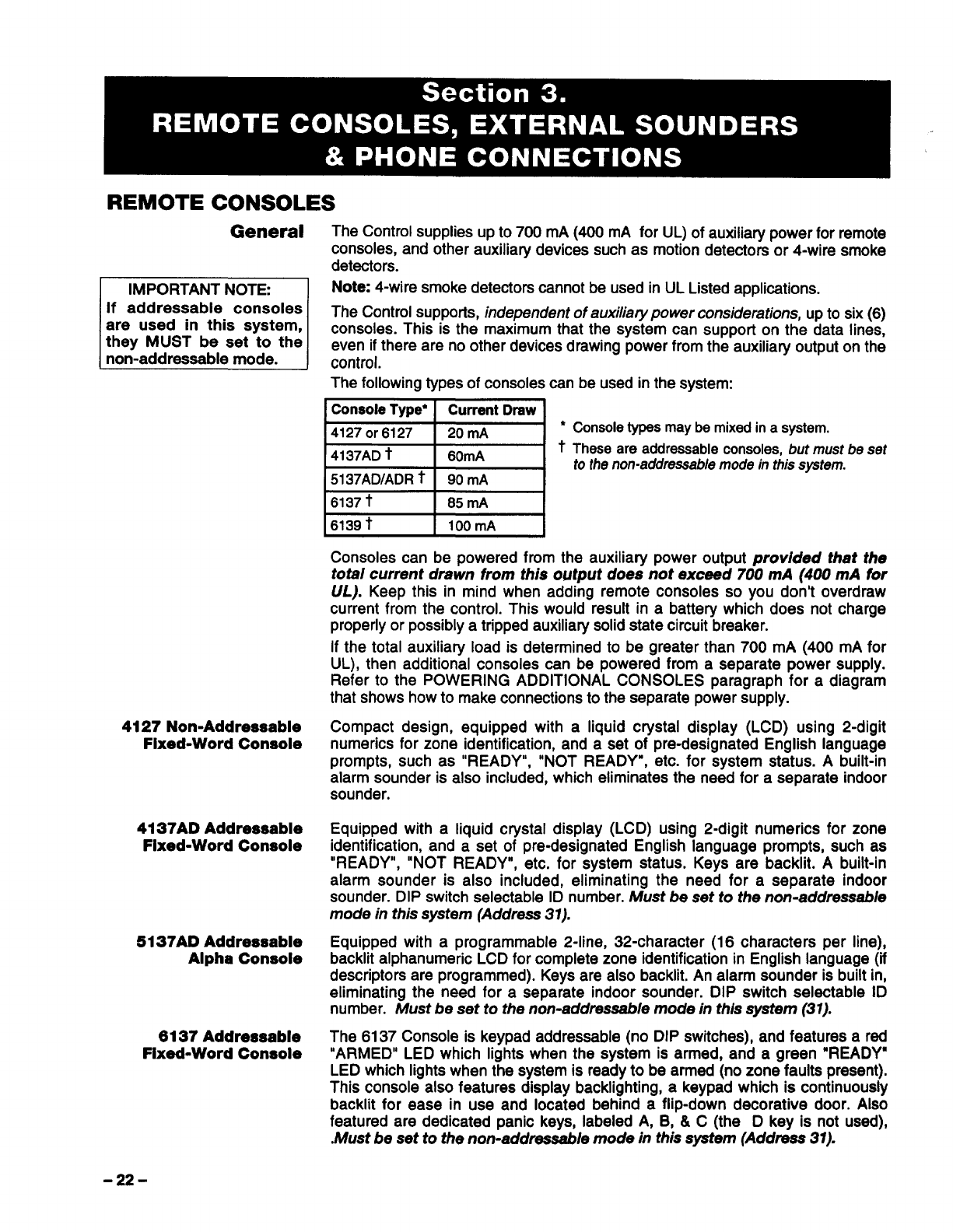
KEYSWITCH PROGRAMMING NOTES:
If akeyswitch is used, note the following:
cProgram field ●15 must be set to “1” to enable the
keyswitch option.
●A2000 ohm EOL resistor must be connected across
the momentary switch, and zones 2-8 must be
programmed for EOLR supervision (“0) in field ●41.
●For keyswitch operation, Field 1●57 (Trigger Mode)
must be set for either ‘O”or” 1”.
fARMEO) *V
r----- ----
RED GREEN
I
!?H?$
!
Smn am
—..—---- TAMPER
‘c
.—— e“”
--------t
I
$
!‘—-
~c%% Eou
L----------
414SKLWSWITCN
(NOTUL USTED)
NOTE
THE LOCK SWITCH SHOWN
ABOVE (PART OF 4146) IS A
NORMALLYOPEN, MOMENTARY
(SPRING-LOADED)SWITCH.
Figure 3. REMOTE KEYSWITCH WIRING
-21-
REMOTE CONSOLES
General
IMPORTANT NOTE: I
If addressable consoles [
4127 Non-Addressable
Fixed-Word Console
4137AD Addressable
Fixed-Word Console
5137AD Addressable
Alpha Console
6137 Addressable
Fixed-Word Console
The Control supplies up to 700 mA (400 mA for UL) of auxiliary power for remote
consoles, and other auxiliaty devices such as motion detectors or 4-wire smoke
detectors.
Note 4-wire smoke detectors cannot be used in UL Listed applications.
The Control supports, independent of awdiarypower considerations, up to six (6)
consoles. This is the maximum that the system can support on the data lines,
even if there are no other devices drawing power from the auxiliary output on the
control.
The following types of consoles can be used in the system:
~Console Type* [Current Drsw [
m
II●
~4127 or 6127 20 mA
I11+
‘4137AD tI60mA I‘
1
5137AD/ADR t I 90 mA I
6137 tI85 mA I
6139 tI100mA I
Consoletypesmaybe mixed in asystem.
These are addressable consoles, but must be set
to the non-addressable mode in this system.
Consoles can be powered from the auxiliary power output provided that the
total current drawn from this output does not exceed 700 frill (4fXl rml for
UL). Keep this in mind when adding remote consoles so you don’t overdraw
current from the control. This would result in abattery which does not charge
properly or possibly atripped auxiliaty solid state circuit breaker.
If the total auxiliary load is determined to be greater than 700 mA (400 mA for
UL), then additional consoles can be powered from aseparate power supply.
Refer to the POWERING ADDITIONAL CONSOLES paragraph for adiagram
that shows how to make connections to the separate power supply.
Compact design, equipped with aliquid crystal display (LCD) using 2-digit
numerics for zone identification, and a set of pre-designated English language
prompts, such as “READY”, “NOT READY”, etc. for system status. Abuilt-in
alarm sounder is also included, which eliminates the need for aseparate indoor
sounder.
Equipped with aliquid crystal display (LCD) using 2-digit numerics for zone
identification, and a set of pre-designated English language prompts, such as
“READY”, “NOT READY”, etc. for system status. Keys are backlit. Abuilt-in
alarm sounder is also included, eliminating the need for aseparate indoor
sounder. DIP switch selectable ID number. Must be set to the non-addressable
mode in this system (Address 31).
Equipped with aprogrammable 2-iine, 32-character (16 characters per line),
backlit alphanumeric LCD for complete zone identification in English language (if
descriptors are programmed). Keys are also backlit. An alarm sounder is built in,
eliminating the need for aseparate indoor sounder. DIP switch selectable ID
number. IUust be set to the non-addressable mode in this system (31).
The 6137 Console is keypad addressable (no DIP switches), and features ared
“ARMED” LED which lights when the system is armed, and a green “READY”
LED which lights when the system is ready to be armed (no zone faults present).
This console also features display backlighting, akeypad which is continuously
backlit for ease in use and located behind aflip-down decorative door. Also
featured are dedicated panic keys, labeled A, B, &C(the Dkey is not used),
.Must be set to the non-addressable mode in this system (Address 31).
-22-
6139 Deluxe
Addressable
Alpha Console
Mounting The
Consoles
Wiring Consoles
Powering Additional
Consoles
The 6139 Remote Console is keypad addressable (no DIP switches) console,
and features ared “ARMED” LED which lights when the system is armed, and a
green “READY” LED which lights when the system is ready to be armed (no zone
faults present). This console also features display backlighting. The keypad,
which is continuously backlit for ease in use, is located behind aflip-down
decorative door. The keypad also features dedicated panic keys, labeled A, B, &
C(the Dkey is not used). Must be set to the non-addressable mode in this
system (Address 31).
The console can be surface mounted directly to adrywall, or to asingle or double
gang electrical box. For flush mounting to drywall, use the optional 6139TRK
flush mount kit.
Note that field wiring to the consoles must be completed before the consoles can
be mounted.
The consoles can be either surface mounted or flush mounted (using an
appropriate Trim Ring Kit: 5137TRK or 6139TRK). Refer to the mounting
instructions and template included with the console and/or trim ring kit for specific
information.
Be sure to take the height of the users into account when mounting consoles.
If convenient, consoles should be wired on individual wire runs to the control. For
maximum wire lengths when using individual wire runs or multiple units wired on
asingle run to the control, refer to Table 2in the section on page 28 entitled
WIRING INFORMATION FOR CONSOLES, RF RECEIVERS, AND OTHER
DEVICES .
As indicated previously, all consoles can be powered from the auxiliary power
output provided that the 700mA rating is not exceeded for all devices drawing
power from the auxiliary output. The backup battery will supply power to these
consoles in the event that AC power is lost.
If necessary, additional consoles can be connected to the system by using a
regulated, 12VDC power supply (e.g., 487-12 supplies 12V, 250mA; 488-12
supplies 12V, 500mA). Use aUL Listed, battery-backed supply for UL
installations.
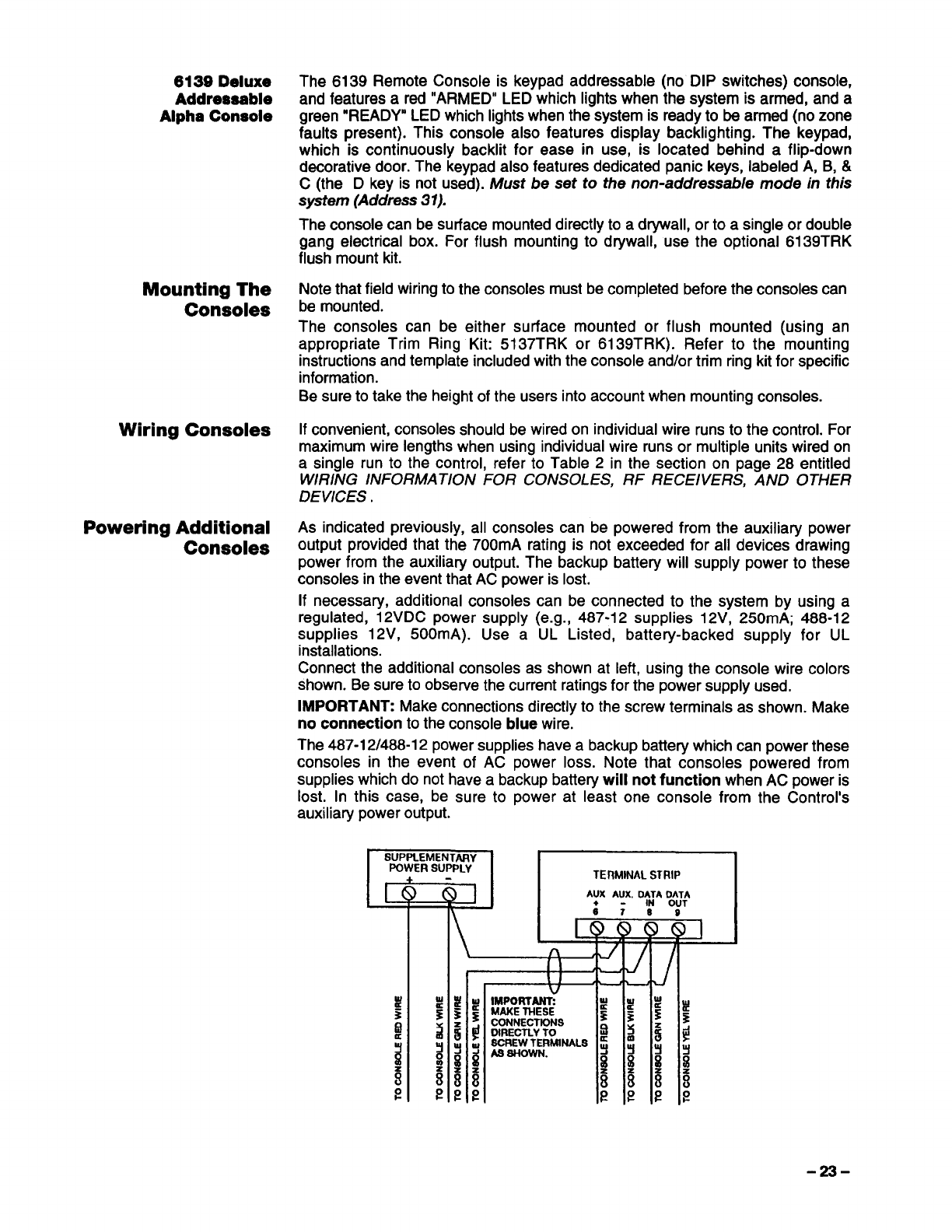
Connect the additional consoles as shown at left, using the console wire colors
shown. Be sure to observe the current ratings for the power supply used.
IMPORTANT: Make connections directly to the screw terminals as shown. Make
no connection to the console blue wire.
The 487-12/488-12power supplies have abackup battery which can power these
consoles in the event of AC power loss. Note that consoles powered from
supplies which do not have abackup battery will not function when AC power is
lost. In this case, be sure to power at least one console from the Control’s
auxiliary power output. “
Itiumttl
POWER
+
I I~1 /l
-23-
EXTERNAL SOUNDERS
Relay Output The 4120XM provides awet bell relay output which is used to power external
alarm sounders. Connections are made to terminals 3(positive output) and 4
(negative return). See SUMMARY OF CONNECTIC)NS Diagram.
UL Installations For UL installations, the total current drawn from this output and the auxiliary
power output, combined, cannot exceed 700 mA. In addition, the sounding
device must be a UL Listed audible signal appliance rated to operate in a10.2-
13.8 VDC voltage range, and must be mounted indoors. Example: Wheelock
Signals Inc. siren model 34T-12 (provides 85dB[A] for NFPA 74 &Standard 985).
Non-UL Installations The total current drawn from this output cannot exceed 2.8 amps. Abattery must
be installed since this current is supplied by the battery. Up to two 702 sirens can
be used, wired in series. Up to two 719 sirens can be used, wired in parallel.
IMPORTANT: Going beyond the limits indicated above will overload the power
supply or may possibly trip the bell output thermal circuit breaker.
COMPATIBLE SOUNDERS
702 Outdoor Siren
719 Outdoor Siren
(Compact)
740 High Intensity
Sounder
ABB1031 Motor Bell&
Box
PA400B (beige)/PA400R
(red) Indoor Piezo
Sounder
Self-contained siren (driver built-in) and weatherproof for outdoor use. Can be
wired for either asteady or yelp sound and is rated at 120 dB @10 feet. This
siren can also be tamper protected, or can be mounted in ametal cabinet
(716), which can be tamper protected.
Compact, self-contained siren (driver built-in), and weatherproof for outdoor
use. Can be wired for asteady or yelp sound, and rated at 90 dB @10 feet. A
tamper protected 708BE cabinet is available.
Compact high intensity sounder rated at 123 dB @10 feet. This sounder emits
an ‘ear piercing”, high frequency sound, and can be mounted indoors (bracket
included) or outdoors (in 708BE cabinet).
AMSECO motor bell& box, rated at 81 dB @10 feet.
BRK indoor piezo sounder (red or beige), rated at 90 dB @10 feet.
UL NOTE: Use only UL Listed sounding devices for UL installations.
PHONE CONNECTIONS
Phone Line Incoming phone line and handset wiring is connected to the main terminal block
Connections (via aRJ31Xjack) as follows (refer to Figure 4 and the SUMMARY OF
CONNECTIONS diagram):
Term. 22: Local Handset (TIP -Brown*)
Term. 23: Local Handset (RING –Gray*)
Term. 24: Incoming Phone Line (TIP –Green*)
Term. 25: Incoming Phone Line (RING -Red*)
*Colors of wires in RJ31X(CA38A in Canada) telephone wall jack.
Warning: To prevent the risk of shock, disconnect phone lines at the telco jack
before servicing the control.
If you wish to connect the control to phone lines that require ground start
capability, a675 Ground Starl Module must be used. This module is triggered
by atriggered output (terminal 9) on the control. See GROUND START
MODULE paragraph.
PABX Important! If the communicator is connected to atelephone line inside aPABX,
be sure the PABX has aback-up power supply that can support the PABX for 24
hours. Many PABXSare not power backed up and connection internally to such a
PABX will result in acommunication failure if power is lost.
-24-
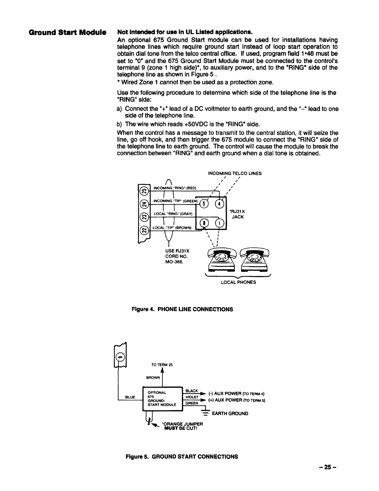
Ground Start Module Not intended for use in UL Listed applications.
An optional 675 Ground Start module can be used for installations having
telephone lines which require ground start instead of loop start operation to
obtain dial tone from the telco central office. If used, program field 1●46 must be
set to “O” and the 675 Ground Starl Module must be connected to the control’s
terminal 9(zone 1high side)*, to auxiliary power, and to the “RINGmside of the
telephone line as shown in Figure 5.
●Wired Zone 1cannot then be used as aprotection zone.
Use the following procedure to determine which side of the telephone line is the
“RING” side:
a) Connect the “+” lead of aDC voltmeter to earth ground, and the “-” lead to one
side of the telephone line.
b) The wire which reads +50VDC is the “RING” side.
When the control has amessage to transmit to the central station, it will seize the
line, go off hook, and then trigger the 675 module to connect the “RING” side of
the telephone line to earth ground. The control will cause the module to break the
connection between “RING” and earth ground when adial tone is obtained.
INCOMING TELCO LINES
/
—n/
/ /
/1/’
‘RJ31x
JACK
USE RJ31X
CORD NO.
MO-366.
LOCALPHONES
Figure 4. PHONE LINE CONNECTIONS
TO TERM 25
BROWN t
Figure 5. GROUND START CONNECTIONS
-25-
Mounting the
Control Cabinet
Mounting The PC
Board
Advisory
Mounting The
Cabinet Lock
The 4120XM is supplied with a12.5”W x14.5”H x3“D cabinet suitable for use in
residential and non-certified commercial burglary installations.
Mount the Control cabinet to asturdy wall using fasteners or anchors (not
supplied). Install in aclean, dry area which is not readily accessible to the general
public. The back of the Control cabinet has 4holes for this purpose.
/nstall the PC board and cabinet lock only after the cabinet is mounted.
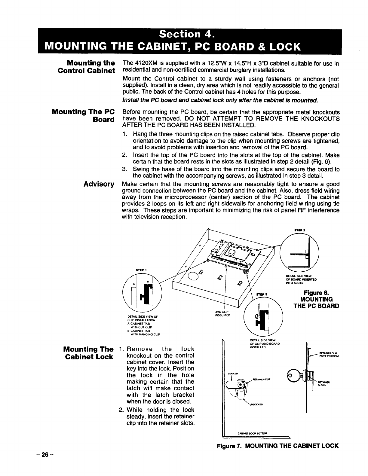
Before mounting the PC board, be certain that the appropriate metal knockouts
have been removed. DO NOT ATTEMPT TO REMOVE THE KNOCKOUTS
AFTER THE PC BOARD HAS BEEN INSTALLED.
1. Hang the three mounting clips on the raised cabinet tabs. Observe proper clip
orientation to avoid damage to the clip when mounting screws are tightened,
and to avoid problems with insertion and removal of the PC board.
2. Insert the top of the PC board into the slots at the top of the cabinet. Make
certain that the board rests in the slots as illustrated in step 2detail (Fig. 6).
3. Swing the base of the board into the mounting clips and secure the board to
the cabinet with the accompanying screws, as illustrated in step 3detail.
Make certain that the mounting screws are reasonably tight to ensure a good
ground connection between the PC board and the cabinet. Also, dress field wiring
away from the microprocessor (center) section of the PC board. The cabinet
provides 2loops on its left and right sidewalls for anchoring field wiring using tie
wraps. These steps are important to minimizing the risk of panel RF interference
with television reception.
BTU2
STEP 1
MAIL SIOE VISW
OFSOAROlNSERTEO
INTO SLOTS
DETAIL SIDE VIEW 0+ REOUIRED
CLIP tNSTALbiTlON
A.CABINET TAB
WITHOUT CLIP
B-CABINET TAB
WITH HANGING CLIP
Figure 6.
MOUNTING
THE PC BOARD
1.
2.
Remove the lock
knockout on the control
cabinet cover. Insert the
key into the lock. Position
the lock in the hole
making certain that the
latch will make contact
with the latch bracket
when the door is closed.
While holding the lock
steady, insert the retainer
clip into the retainer slots.
)041TAIL SIOEVIEW
DFC2fCyD SOARD
I
I
I
u—cmoa -
\
Figure 7. MOUNTING THE CABINET LOCK
-26-
POWERING THE SYSTEM
Primary Power
Back-Up Power
Earth Ground
Connections
Power-Up Procedure
Power to the Control panel is supplied by model No. 1321/TF2* Plug-in
Transformer which is rated at 16.5VAC, 25VA. Caution must be taken when
wiring this transformer to the panel to guard against blowing the fuse inside the
transformer (non-replaceable).
●NOTE: Use 1321CN Transformer in Canadian installations.
In the event of an AC power loss, the Control panel is supported by aback-up,
rechargeable gel cell battery. YUASA NP4-12 (12V, 4AH*) and NP7-12 (12V,
7AH) batteries are recommended. Do not use Gates batteries (sealed lead-
acid type).
●Use 4AH battery for UL installations.
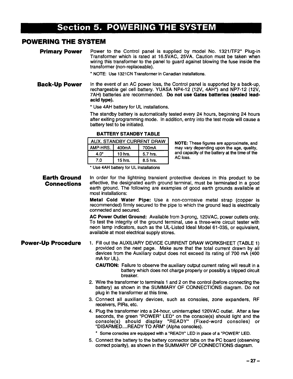
The standby battery is automatically tested every 24 hours, beginning 24 hours
after exiting programming mode. In addition, entry into the test mode will cause a
battery test to be initiated.
BATTERY STANDBY TABLE
AUX. STANDBY CURRENT DRAW NOTE: These figures are approximate, and
AMP-HRS. 400mA 700mA mayvary dependinguponthe age,quality,
4.0” 10 hrs. 5.7 hrs. and capacity of the battery at the time of the
7.0 15 hrs. 8.5 hrs. AC 10SS.
●Use 4AHbatteryfor ULinstallations
In order for the lightning transient protective devices in this product to be
effective, the designated earth ground terminal, must be terminated in a good
earth ground. The following are examples of good earth grounds available at
most installations:
Metal Cold Water Pipe: Use anon-corrosive metal strap (copper is
recommended) firmly secured to the pipe to which the ground lead is electrically
connected and secured.
AC Power Outlet Ground: Available from 3-prong, 120VAC, power outlets only.
To test the integrity of the ground terminal, use athree-wire circuit tester with
neon lamp indicators, such as the UL-Listed Ideal Model 61-035, or equivalent,
available at most electrical supply stores.
1.
2.
3.
4.
5.
Fill out the AUXILIARY DEVICE CURRENT DRAW WORKSHEET (TABLE 1)
provided on the next page. Make sure that the total current drawn by all
devices from the Auxiliary output does not exceed its rating of 700 mA (400
mA for UL).
CAUTION: Failure to observe the auxiliary output current rating will result in a
battery which does not charge properly or possibly atripped circuit
breaker.
Wire the transformer to terminals 1 and 2 on the control (before connecting the
battery) as shown in the SUMMARY OF CONNECTIONS diagram. Do not
plug in the transformer at this time.
Connect all auxiliary devices, such as consoles, zone expanders, RF
receivers, PIRs, etc.
Plug the transformer into a24-hour, uninterrupted 120VAC outlet. After afew
seconds, the green “POWER” LED* on the console(s) should light and the
console(s) should display “READY” (Fixed-word consoles) or
“DISARMED.,..READY TO ARM” (Alpha consoles).
●Some consoles are equipped with a“READY” LED in place of a“POWER”LED.
Connect the battery to the battery connector tabs on the PC board (observing
correct polarity), as shown in the SUMMARY OF CONNECTIONS diagram.
-27-
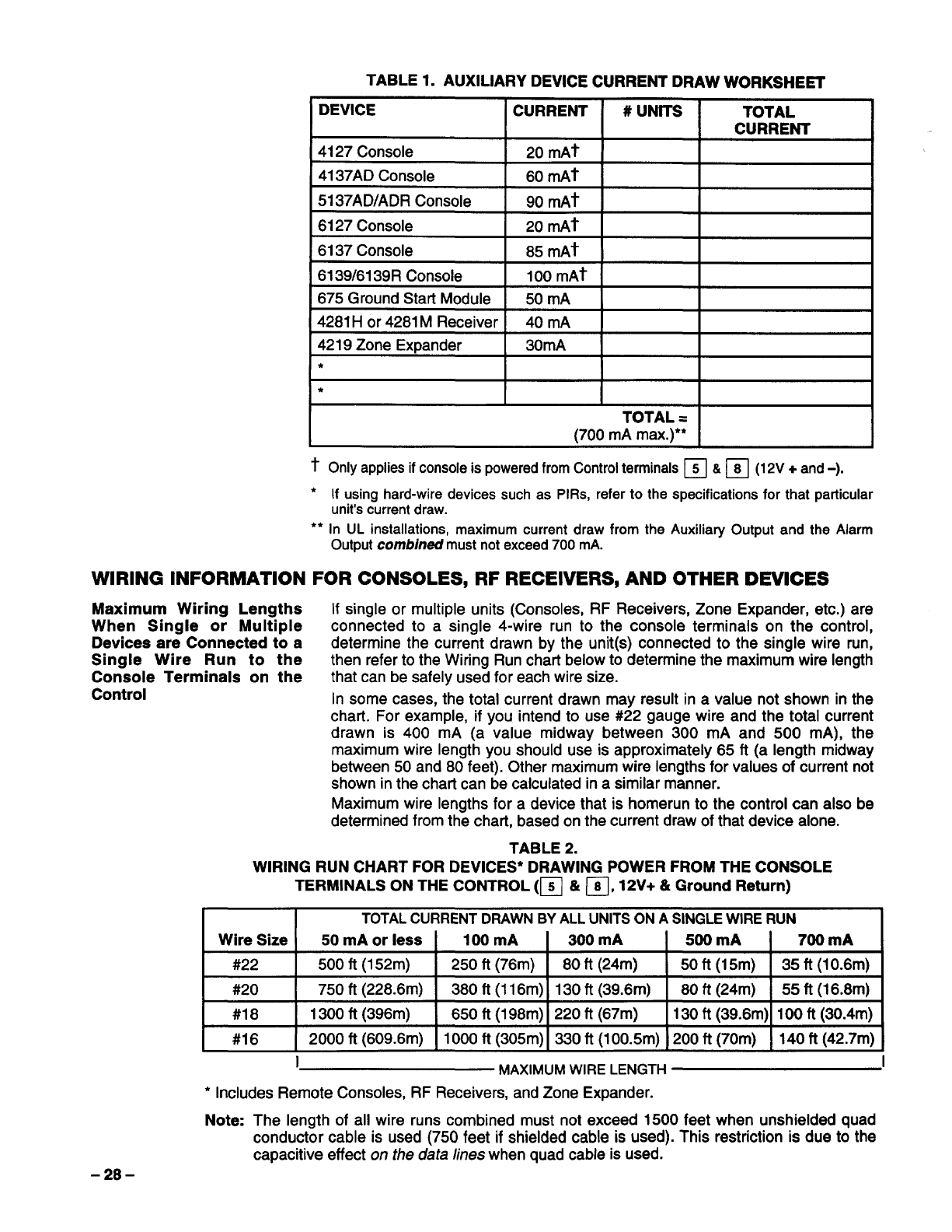
TABLE 1. AUXILIARY DEVICE CURRENT DRAW WORKSHEET
DEVICE CURRENT #uNITs TOTAL
CURRENT
4127 Console 20 mAt
4137AD Console 60 mAt
5137AD/ADR Console 90 mAt
6127 Console 20 mAt
6137 Console 85 mAt
6139/6139R Console 100 mAt
675 Ground Start Module 50 mA
4281Hor 4281MReceiver 40 mA
4219 Zone Expander 30mA
*
*
TOTAL =
(700 mA max.)**
tonly applies if console is powered from Control terminals ❑&❑(12V +and -),
●If using hard-wire devices such as PIRs, refer to the specifications for that particular
unit’s current draw.
●*In UL installations, maximum current draw from the Auxiliary Output and the Alarm
Output combined must not exceed 700 mA.
WIRING INFORMATION FOR CONSOLES, RF RECEIVERS, AND OTHER DEVICES
Maximum Wiring Lengths If single or multiple units (Consoles, RF Receivers, Zone Expander, etc.) are
When Single or Multiple connected to asingle 4-wire run to the console terminals on the control,
Devices are Connected to adetermine the current drawn by the unit(s) connected to the single wire run,
Single Wire Run to the then refer to the Wiring Run chati below to determine the maximum wire length
Console Terminals on the that can be safely used for each wire size.
Control In some cases, the total current drawn may result in avalue not shown in the
chart. For example, if you intend to use #22 gauge wire and the total current
drawn is 400 mA (a value midway between 300 mA and 500 mA), the
maximum wire length you should use is approximately 65 ft (a length midway
between 50 and 80 feet). Other maximum wire lengths for values of current not
shown in the chart can be calculated in asimilar manner.
Maximum wire lengths for adevice that is homerun to the control can also be
determined from the chart, based on the current draw of that device alone.
TABLE 2.
WIRING RUN CHART FOR DEVICES* DRAWING POWER FROM THE CONSOLE
TERMINALS ON THE CONTROL (~ &❑,12V+ &Ground Return)
TOTAL CURRENT DRAWN BY ALL UNITS ON ASINGLE WIRE RUN
Wire Size 50 mA or less 100 mA 300 mA 500 mA 700 mA
#22 500 ft (152m) 250 ft (76m) 80 ft (24m) 50ft(15m) 35ft(10.6m)
#20 750 ft (228.6m) 380 ft (116m) 130 ft (39.6m) 80 ft (24m) 55 ft (16.8m)
#18 1300 ft (396m) 650 ft(198m) 220 ft (67m) 130 ft (39.6m) 100 ft (30.4m)
#16 2000 fl (609.6m) 1000 ft (305m) 330 ft(100.5m) 200 ft (70m) 140 ft (42.7m)
IMAXIMUM WIRE LENGTH I
*Includes Remote Consoles, RF Receivers, and Zone Expander.
Note: The length of all wire runs combined must not exceed 1500 feet when unshielded quad
conductor cable is used (750 feet if shielded cable is used). This restriction is due to the
capacitive effect on the data lines when quad cable is used.
-28-
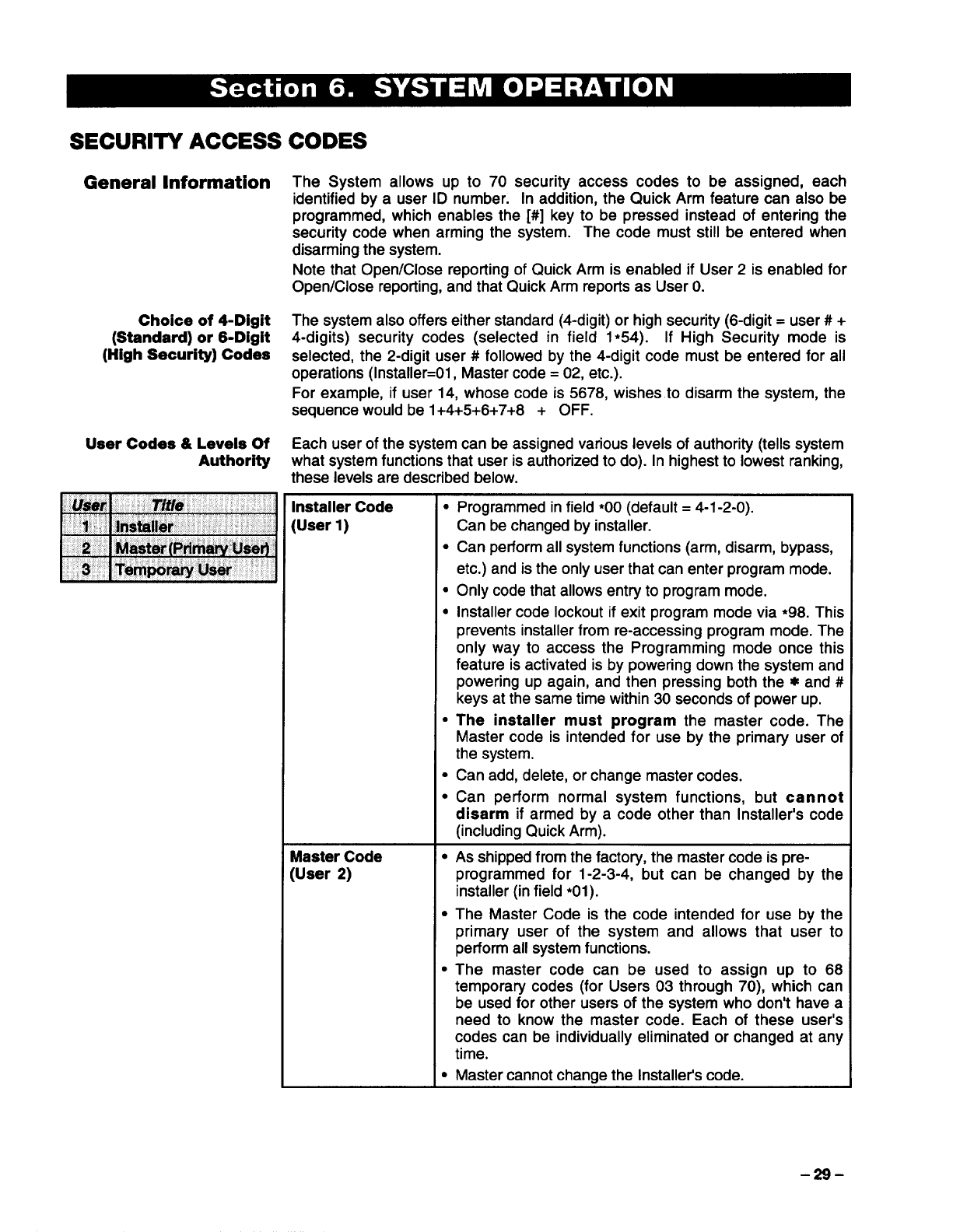
SECURITY ACCESS CODES
General Information
Choice of 4-Digit
(Standard) or 6-Digit
(High Security) Codes
User Codes &Levels Of
Authority
The System allows up to 70 security access codes to be assigned, each
identified by auser ID number. In addition, the Quick Arm feature can also be
programmed, which enables the [#] key to be pressed instead of entering the
security code when arming the system. The code must still be entered when
disarming the system.
Note that Open/Close reporting of Quick Arm is enabled if User 2is enabled for
Open/Close reporting, and that Quick Arm reports as User O.
The system also offers either standard (4-digit) or high security (6-digit= user #+
4-digits) security codes (selected in field 1*54). If High Security mode is
selected, the 2-digit user #followed by the 4-digit code must be entered for all
operations (lnstaller=Ol, Master code= 02, etc.).
For example, if user 14, whose code is 5678, wishes to disarm the system, the
sequence would be 1+4+5+6+7+8 +OFF.
Each user of the system can be assigned various levels of authority (tells system
what system functions that user is authorized to do). In highest to lowest ranking,
these levels are described below.
Installer Code cProgrammed in field *OO(default =4-1-2-O).
[User 1) Can be changed by installer.
●Can perform all system functions (arm, disarm, bypass,
etc.) and is the only user that can enter program mode.
●Only code that allows entry to program mode.
●Installer code lockout if exit program mode via ●98. This
prevents installer from re-accessing program mode. The
only way to access the Programming mode once this
feature is activated is by powering down the system and
powering up again, and then pressing both the xand #
keys at the same time within 30 seconds of power up.
“The installer must program the master code. The
Master code is intended for use by the primary user of
the system.
●Can add, delete, or change master codes.
●Can perform normal system functions, but cannot
disarm if armed by acode other than Installer’s code
(including Quick Arm).
Master Code ●As shipped from the factory, the master code is pre-
~User 2) programmed for 1-2-3-4, but can be changed by the
installer (in field *O1).
●The Master Code is the code intended for use by the
primary user of the system and allows that user to
perform all system functions.
●The master code can be used to assign up to 68
temporary codes (for Users 03 through 70), which can
be used for other users of the system who don’t have a
need to know the master code. Each of these user’s
codes can be individually eliminated or changed at any
time.
●Master cannot change the Installer’s code.
-29-
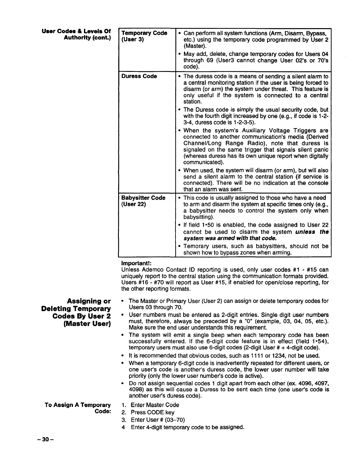
..-. ---- .
user Goaes 4kLevels of
Authority (cont.)
Assigning or
Deleting Temporary
Codes By User 2
(Master User)
To Assign ATemporary
Code:
Temporary Code
(User 3)
Duress Code
Babysitter Code
(User 22)
Important!:
●Can perform all system functions (Arm, Disarm, Bypass,
etc.) using the temporaty code programmed by User 2
(Master).
●May add, delete, change temporary codes for Users 04
through 69 (User3 cannot change User 02’s or 70’s
code).
●
●
●
●
The duress code is ameans of sending asilent alarm to
acentral monitoring station if the user is being forced to
disarm (or arm) the system under threat. This feature is
only useful if the system is connected to acentral
station.
The Duress code is simply the usual security code, but
with the fourth digit increased by one (e.g., if code is 1-2-
3-4, duress code is 1-2-3-5).
When the system’s Auxiliary Voltage Triggers are
connected to another communication’s media (Derived
Channel/Long Range Radio), note that duress is
signaled on the same trigger that signals silent panic
(whereas duress has its own unique report when digitally
communicated).
When used, the system will disarm (or arm), but will also
send asilent ala~m to the central station” (if service is
connected). There will be no indication at the console
that an alarm was sent.
●This code is usually assigned to those who have a need
to arm and disarm the system at specific times only (e.g.,
ababysitter needs to control the system only when
babysitting).
●If field 1*5O is enabled, the code assigned to User 22
cannot be used to disarm the system unless the
system was armed with that code.
●Temorary users, such as babysitters, should not be
shown how to bypass zones when arming.
Unless Ademco Contact ID reporting is used, only user codes #1 -#15 can
uniquely report to the central station ~sing the communication formats provided.
Users #16 -#70 will report as User#15, if enabled for open/close reporting, for
the other reporting formats,
●
●
●
●
●
●
1.
2.
3.
4
The Master or Primary User (User 2) can assign or delete temporary codes for
Users 03 through 70.
User numbers must be entered as 2-digit entries. Single digit user numbers
must, therefore, always be preceded by a“O” (example, 03, 04, 05, etc.).
Make sure the end user understands this requirement.
The system will emit asingle beep when each temporary code has been
successfully entered. If the 6-digit code feature is in effect (field 1●54),
temporary users must also use 6-digit codes (2-digit User #+4-digit code).
It is recommended that obvious codes, such as 1111 or 1234, not be used.
When atemporary 6-digit code is inadvertently repeated for different users, or
one user’s code is another’s duress code, the lower user number will take
priority (only the lower user number’s code is active).
Do not assign sequential codes 1digit apart from each other (ex. 4096, 4097,
4098) as this will cause aDuress to be sent each time (one user’s code is
another user’s duress code).
Enter Master Code
Press CODE key
Enter User #(03-70)
Enter 4-digit temporary code to be assigned.
-30-
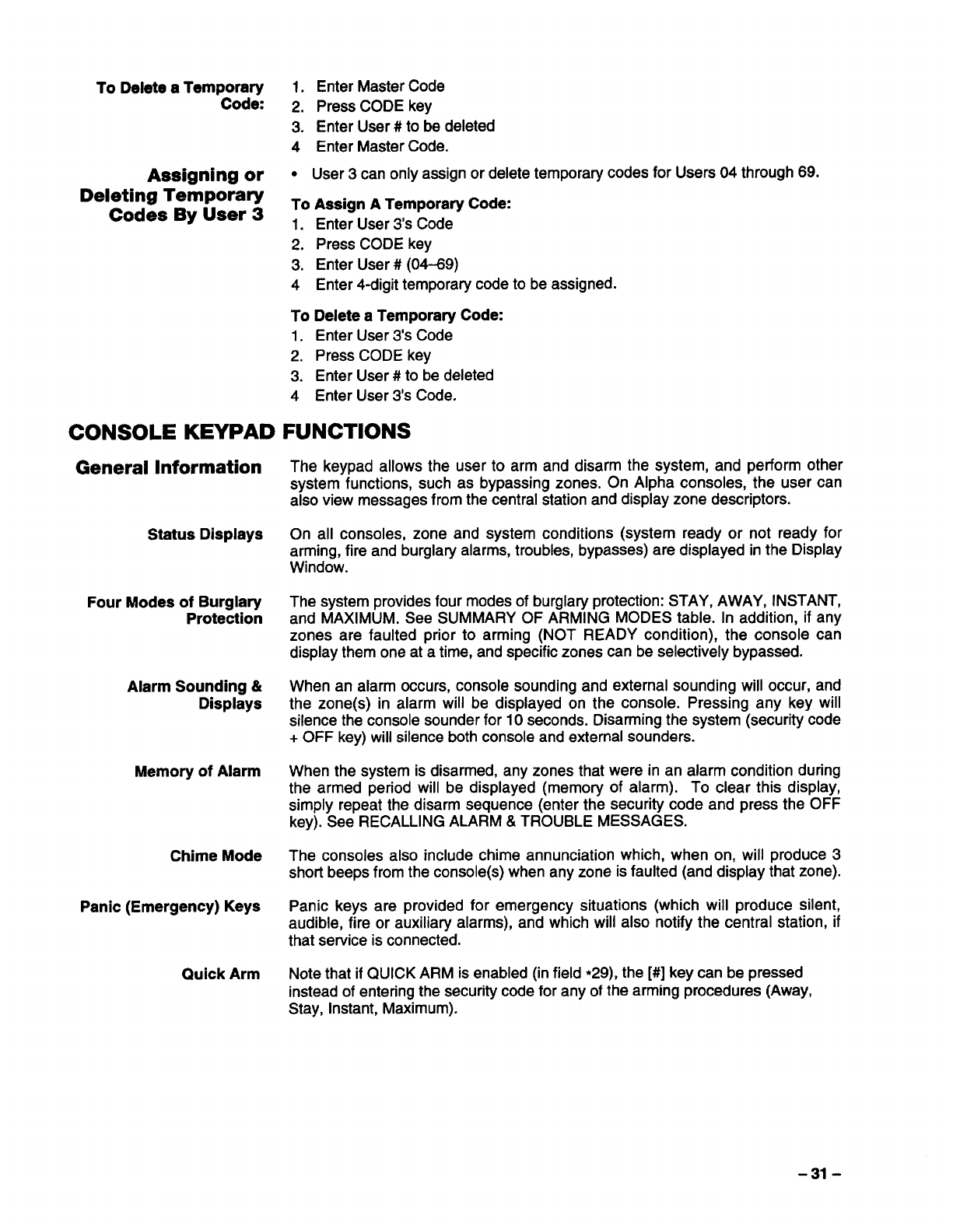
To Delete alemp;~d~ 1. Enter Master Code
.
.2. Press CODE key
3. Enter User #to be deleted
4Enter Master Code.
Assigning or ●User 3can only assignor delete temporary codes for Users 04 through 69.
Deleting Temporaty
Codes By User 3To Assign ATemporary Code:
1. Enter User 3’s Code
2. Press CODE key
3. Enter User #(04-69)
4Enter 4-digit temporary code to be assigned.
To Delete aTemporary Code:
1. Enter User 3’s Code
2. Press CODE key
3. Enter User #to be deleted
4Enter User 3’s Code.
CONSOLE KEYPAD FUNCTIONS
General Information The keypad allows the user to arm and disarm the system, and perform other
system functions, such as bypassing zones. On Alpha consoles, the user can
also view messages from the central station and display zone descriptors.
Status Displays On all consoles, zone and system conditions (system ready or not ready for
arming, fire and burglary alarms, troubles, bypasses) are displayed in the Display
Window.
Four Modes of Burglary The system provides four modes of burglay protection: STAY, AWAY, INSTANT,
Protection and MAXIMUM. See SUMMARY OF ARMING MODES table. In addition, if any
zones are faulted prior to arming (NOT READY condition), the console can
display them one at atime, and specific zones can be selectively bypassed.
Alarm Sounding &When an alarm occurs, console sounding and external sounding will occur, and
Displays the zone(s) in alarm will be displayed on the console. Pressing any key will
silence the console sounder for 10 seconds. Disarming the system (security code
+OFF key) will silence both console and external sounders.
Memory of Alarm When the system is disarmed, any zones that were in an alarm condition during
the armed period will be displayed (memory of alarm). To clear this display,
simply repeat the disarm sequence (enter the security code and press the OFF
key). See RECALLING ALARM &TROUBLE MESSAGES.
Chime Mode The consoles also include chime annunciation which, when on, will produce 3
short beeps from the console(s) when any zone is faulted (and display that zone).
Panic (Emergency) Keys Panic keys are provided for emergency situations (which will produce silent,
audible, fire or auxiliary alarms), and which will also notify the central station, if
that service is connected.
Quick Arm Note that if QUICK ARM is enabled (in field *29), the [#] key can be pressed
instead of entering the security code for any of the arming procedures (Away,
Stay, Instant, Maximum).
-31-
Arming Functions The following is abrief list of system commands. For detailed information
concerning system functions, refer to the User’s Manual.
Disarmed /Not Ready Before arming, the system must be in the READY
condition (all zones must be intact). If the “NOT READY”
message appears, press the READY [*] key to display
faulted zones.
Arming Away Enter code +AWAY [2].
Arming Stay Enter code +STAY [3].
Arming Instant Enter code +INSTANT [7’1.
Arming Maximum Enter code +MAXIMUM [4].
Disarming Enter code +OFF [1].
Bypassing Zones Enter code +BYPASS [6]+ zone number.
To automatically bypass all faulted zones, use the “Quick
Bypass” method: Enter code +BYPASS+ [#].
Chime Mode Enter code +CHIME [9]. To turn chime mode off, enter
code +CHIME again.
SUMMARY OF ARMING MODES
Mode Features For Each Arming Mode
Exit Entry Perimeter Interior
Delay Delay Armed Armed
AWAY Yes Yes Yes Yes
STAY Yes Yes Yes No
INSTANT Yes No Yes No
MAXIMUM Yes No Yes Yes
Panic Keys Some consoles make use of three key pairs for panic, while others are equipped
with three separate panic keys (see below). If programmed, they can be used to
manually initiate alarms and send areport to the central station. Each key pair (or
single key) can be individually programmed for 24-Hour Silent, Audible, Auxiliary
or Fire responses. The panic function is activated when the appropriate key (or
key pair) is pressed. Key pairs must be pressed at the same time.
The panic functions are identified by the system as follows:
[*I+[W IB1991
For Alpha consoles, these panic keys can also be
descriptor.
Important: For the silent Panic functions to be of
must be connected to acentral station.
programmed with an alpha
practical value, the system
Viewing Downloaded Users may occasionally receive messages on the console display from their
Messages (Alpha installation company. When this occurs, the console will display the following:
Consoles Only) “Message. Press Ofor 5sees.”
Instruct the user to press and hold the [0] key to display the central station’s
message. Note that the system must be in the READY state to view these
messages.
-32-
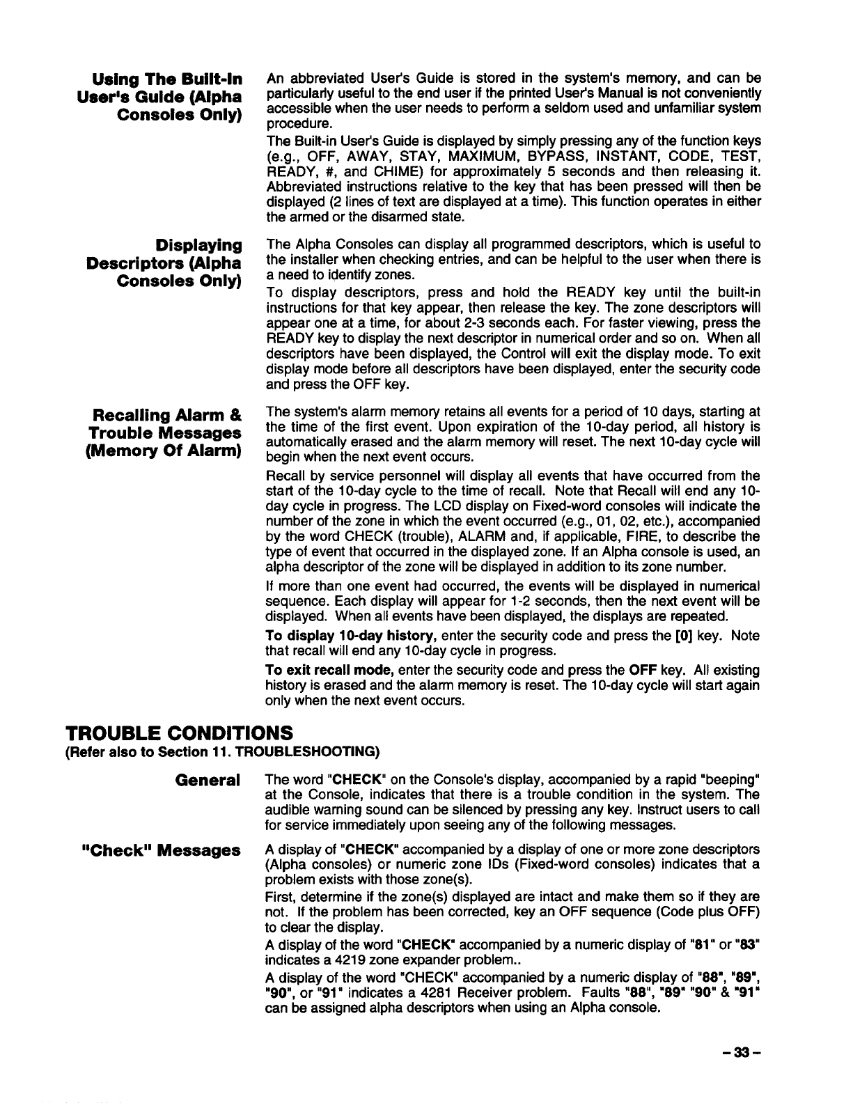
Using The Built-In
User% Guide (Alpha
Consoles Only)
Displaying
Descriptors (Alpha
Consoles Only)
Recalling Alarm &
Trouble Messages
(Memory Of Alarm)
An abbreviated User’s Guide is stored in the system’s memory, and can be
particularly useful to the end user if the printed User’s Manual is not conveniently
accessible when the user needs to perform aseldom used and unfamiliar system
procedure.
The Built-in User’s Guide is displayed by simply pressing any of the function keys
(e.g., OFF, AWAY, STAY, MAXIMUM, BYPASS, INSTANT, CODE, TEST,
READY, #, and CHIME) for approximately 5seconds and then releasing it.
Abbreviated instructions relative to the key that has been pressed will then be
displayed (2 lines of text are displayed at atime). This function operates in either
the armed or the disarmed state.
The Alpha Consoles can display all programmed descriptors, which is useful to
the installer when checking entries, and can be helpful to the user when there is
a need to identify zones.
To display descriptors, press and hold the READY key until the built-in
instructions for that key appear, then release the key. The zone descriptors will
appear one at atime, for about 2-3 seconds each. For faster viewing, press the
READY key to display the next descriptor in numerical order and so on. When all
descriptors have been displayed, the Control will exit the display mode. To exit
display mode before all descriptors have been displayed, enter the security code
and press the OFF key.
The system’s alarm memory retains all events for aperiod of 10 days, starting at
the time of the first event. Upon expiration of the 10-day period, all history is
automatically erased and the alarm memory will reset. The next 10-day cycle will
begin when the next event occurs.
Recall by service personnel will display all events that have occurred from the
start of the 10-day cycle to the time of recall. Note that Recall will end any 10-
day cycle in progress. The LCD display on Fixed-word consoles will indicate the
number of the zone in which the event occurred (e.g., 01, 02, etc.), accompanied
by the word CHECK (trouble), ALARM and, if applicable, FIRE, to describe the
type of event that occurred in the displayed zone. If an Alpha console is used, an
alpha descriptor of the zone will be displayed in addition to its zone number.
If more than one event had occurred, the events will be displayed in numerical
sequence. Each display will appear for 1-2 seconds, then the next event will be
displayed. When all events have been displayed, the displays are repeated.
To display 10-day history, enter the security code and press the [0] key. Note
that recall will end any 10-day cycle in progress.
To exit recall mode, enter the security code and press the OFF key. All existing
history is erased and the alarm memory is reset. The 10-day cycle will start again
only when the next event occurs.
TROUBLE CONDITIONS
(Refer also to Section 11. TROUBLESHOOTING)
General The word “CHECK on the Console’s display, accompanied by arapid “beeping”
at the Console, indicates that there is atrouble condition in the system. The
audible warning sound can be silenced by pressing any key. Instruct users to call
for service immediately upon seeing any of the following messages.
CcCheck”Messages Adisplay of “CHECK accompanied by adisplay of one or more zone descriptors
(Alpha consoles) or numeric zone IDs (Fixed-word consoles) indicates that a
problem exists with those zone(s).
First, determine if the zone(s) displayed are intact and make them so if they are
not. If the problem has been corrected, key an OFF sequence (Code plus OFF)
to clear the display.
Adisplay of the word “CHECK” accompanied by anumeric display of “81” or “83”
indicates a 4219 zone expander problem..
Adisplay of the word “CHECK” accompanied by anumeric display of “88”, “89”,
“90”, or “91” indicates a 4281 Receiver problem. Faults “88”, “89” “90”& “91”
can be assigned alpha descriptors when using an Alpha console.
-33-
Other Trouble Adisplay of “COMM. FAILURE” (Alpha consoles) or “FCM(Fixed-word consoles)
Conditions at the Console indicates that afailure occurred in the telephone communication
pottion of the system.
Adisplay of “LO BAT” (Alpha consoles) with azone number and descriptor, or
“BAT (Fixed-word consoles) with azone number, and accompanied by aonce-
per-minute beep at the Console, indicates that alow battery condition exists in
the wireless transmitter displayed.
The audible warning sound may be silenced by pressing any key.
Adisplay of “SYSTEM LO BAT” (Alpha consoles) or “BAT” with no zone ID
(Fixed-word consoles) indicates that alow battery condition exists with the
system’s backup battery.
Adisplay of “4281 SET UP ERROR” (Alpha consoles) or “E8” (Fixed-word
consoles) at the console indicates that a 4281 receiver is being used in asystem
with more than 8RF zones programmed. If this is not corrected, none of the
zones in the system will be protected.
Adisplay of “MODEM COM” (Alpha consoles) or “CC” (Fixed-word consoles)
indicates that the control is on-line with the remote computer and the control is
not operating.
Adisplay of two numbers and “NO AC” (Fixed-word consoles) indicates the
control is in the programming mode and is not operating.
Power Failure If the message “AC LOSS (Alpha consoles) or “NO AC” (Fixed-word consoles)
is displayed, the Console is operating on battery power only.
Check to see that the system’s plug-in transformer has not been accidentally
pulled out. Instruct the user to call aservice representative immediately if AC
power cannot be restored.
-34-
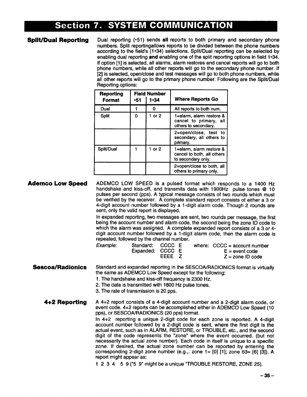
Split/Duai Reporting Dual reporting (*51)sends all reports to both primary and secondary phone
numbers. Split reportingallows reports to be divided between the phone numbers
according to the field’s (1●34) selections. Split/Dual reporting can be selected by
enabling dual reporting and enabling one of the split reporting options in field 1●34.
If option [1]is selected, all alarms, alarm restores and cancel reports will go to both
phone numbers, while all other reports will go to the secondary phone number. If
[2] is selected, open/close and test messages will go to both phone numbers, while
all other reports will go to the primary phone number. Following are the Split/Dual
Reporting options:
IReporting
I
Field Number
Format ●51 I1*34 IWhere Reports Go
Dual 10All reports to both num.
Split olor2 1=alarm, alarm restore &
cancel to primary, all
others to s~onda~-.
2=openlclose, test to
secondary, all others to
primary.
Split/Dual 1lor2 1=alarm, alarm restore &
cancel to both, all others
to secondary only.
2=open/close to both, all
others to primary only.
Ademco Low Speed ADEMCO LOW SPEED is apulsed format which responds to a 1400 Hz
handshake and kiss-off, and transmits data with 1900Hz pulse tones @10
pulses per second (pps). Atypical message consists of two rounds which must
be verified by the receiver. Acomplete standard report consists of either a 3 or
4-digit account number followed by a1-digit alarm code. Though 2rounds are
sent, only the valid report is displayed.
In expanded reporting, two messages are sent, two rounds per message, the first
being the account number and alarm code, the second being the zone ID code to
which the alarm was assigned. Acomplete expanded report consists of a 3 or 4-
digit account number followed by a1-digit alarm code, then the alarm code is
repeated, followed by the channel number.
Example: Standard: CCCC Ewhere: CCCC =account number
Expanded: CCCC E E =event code
EEEE ZZ=zone ID code
Sescoa/Radionics Standard and expanded reporting in the SESCOA/RADIONICS format is virtually
the same as ADEMCO Low Speed except for the following:
1. The handshake and kiss-off frequency is 2300 Hz.
2. The data is transmitted with 1800 Hz pulse tones.
3. The rate of transmission is 20 pps.
4+2 Reporting A4+2 report consists of a4-digit account number and a 2-digit alarm code, or
event code. 4+2 reports can be accomplished either in ADEMCO Low Speed (1O
pps), or SESCOA/RADIONICS (20 pps) format.
In 4+2 reporting aunique 2-digit code for each zone is reported. A4-digit
account number followed by a2-digit code is sent, where the first digit is the
actual event, such as in ALARM, RESTORE, or TROUBLE, etc., and the second
digit of the code represents the “zone” where the event occurred. (but not
necessarily the actual zone number). Each code in itself is unique to aspecific
zone. If desired, the actual zone number can be reported by entering the
corresponding 2-digit zone number (e.g.,. zone 1= [0] [1]; zone 63= [6] [3]). A
report might appear as:
1 2 34 5 9 (“5 9might be a unique “TROUBLE RESTORE, ZONE 25).
-35-
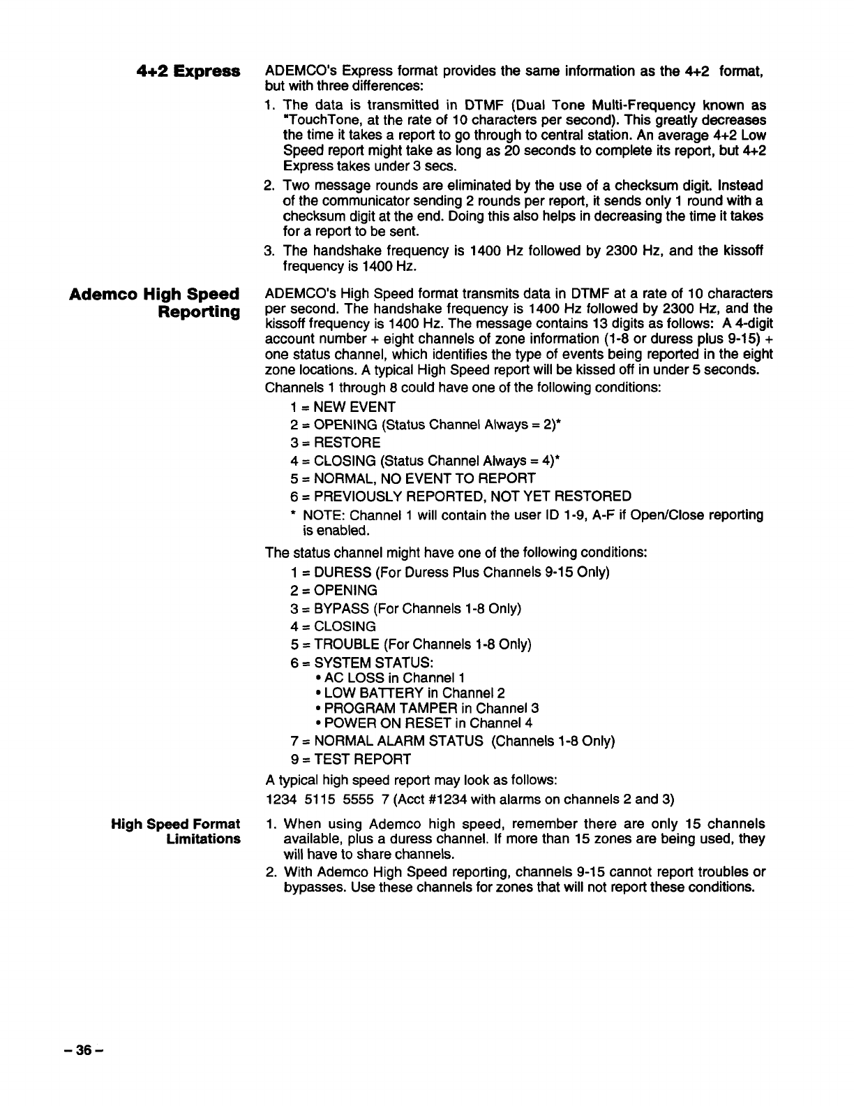
4+2 Express ADEMCO’S Express format provides the same information as the 4+2 format,
but with three differences:
1. The data is transmitted in DTMF (Dual Tone Multi-Frequency known as
“TouchTone, at the rate of 10 characters per second). This greatly decreases
the time it takes areport to go through to central station. An average 4+2 Low
Speed report might take as long as 20 seconds to complete its report, but 4+2
Express takes under 3sees.
2. Two message rounds are eliminated by the use of achecksum digit. Instead
of the communicator sending 2rounds per report, it sends only 1round with a
checksum digit at the end. Doing this also helps in decreasing the time it takes
for areport to be sent.
3. The handshake frequency is 1400 Hz followed by 2300 Hz, and the kissoff
frequency is 1400 Hz.
Ademco High Speed ADEMCO’S High Speed format transmits data in DTMF at arate of 10 characters
Reporting per second. The handshake frequency is 1400 Hz followed by 2300 Hz, and the
kissoff frequency is 1400 Hz. The message contains 13 digits as follows: A4-digit
account number +eight channels of zone information (1-8 or duress plus 9-15) +
one status channel, which identifies the type of events being reported in the eight
zone locations. Atypical High Speed report will be kissed off in under 5seconds.
Channels 1through 8could have one of the following conditions:
1=NEW EVENT
2=OPENING (Status Channel Always= 2~
3=RESTORE
4=CLOSING (Status Channel Always= 4)*
5=NORMAL, NO EVENT TO REPORT
6=PREVIOUSLY REPORTED, NOT YET RESTORED
*NOTE: Channel 1will contain the user ID 1-9, A-F if Open/Close reporting
is enabled.
The status channel might have one of the following conditions:
1=DURESS (For Duress Plus Channels 9-15 Only)
2=OPENING
3=BYPASS (For Channels 1-8 Only)
4=CLOSING
5=TROUBLE (For Channels 1-8 Only)
6=SYSTEM STATUS:
●AC LOSS in Channel 1
●LOW BAITERY in Channel 2
●PROGRAM TAMPER in Channel 3
●POWER ON RESET in Channel 4
7=NORMAL ALARM STATUS (Channels 1-8 Only)
9=TEST REPORT
Atypical high speed report may look as follows:
1234 5115 5555 7(Acct#1234 with alarms on channels 2 and 3)
High Speed Format 1. When using Ademco high speed, remember there are only 15 channels
Limitations available, plus aduress channel. If more than 15 zones are being used, they
will have to share channels.
2. With Ademco High Speed reporting, channels 9-15 cannot report troubles or
bypasses. Use these channels for zones that will not report these conditions.
-36-
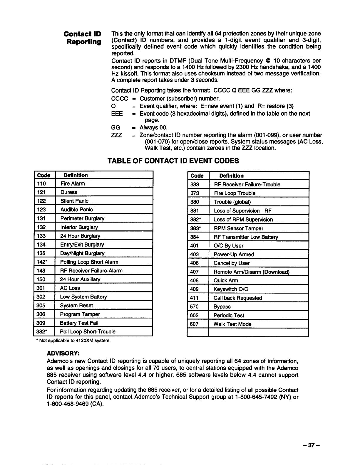
Contact ID This the only format that can identify all 64 protection zones by their unique zone
Reporting (Contact) ID numbers, and provides al-digit event qualifier and 3-digit,
specifically defined event code which quickly identifies the condition being
repoited.
Contact ID reports in DTMF (Dual Tone Multi-Frequency @10 characters per
second) and responds to a 1400 Hz followed by 2300 Hz handshake, and a 1400
Hz kissoff. This format also uses checksum instead of two message verification.
Acomplete report takes under 3seconds.
Contact ID Reporting takes the format: CCCC QEEE GG ZZZ where:
Cccc =
Q=
EEE =
GG =
Zzz=
Customer (subscriber) number.
Event qualifier, where: E=new event(1) and R= restore (3)
Event code (3 hexadecimal digits), defined in the table on the next
page.
Always 00.
Zone/contact ID number reDortinathe alarm (001-099). or user number
(001-070) for open/close’repo~s. System ~atus messages (AC Loss,
Walk Test, etc.) contain zeroes in the ZZZ location.
TABLE OF CONTACT ID EVENT CODES
Code Definition Definition
110 FireAlarm 333 RF ReceiverFailure-Trouble
121 Duress 373 Fire Loop Trouble
122 Silent Panic 380 Trouble (global)
123 Audible Panic 381 Loss of Supervision -RF
131 Perimeter Burgla~ 382* Loaa of RPM Supervision
132 Interior Burglary 383* RPM Sensor Tamper
133 24 Hour Burgla~ 384 RF Transmitter Low Battery
134 Entry/Exit Burglary 401 O/C By User
135 Day/Night Burgla~ 403 Power-Up Armed
142* Polling Loop Short Alarm 406 Cancel by User
143 RF Receiver Failure-Alarm 407 Remote ArrnlDisarm (Download)
150 24 Hour Auxiliary 408 Quick Arm
301 AC Loss 409 Keyswitch O/C
302 Low System Battery 411 Call back Requested
305 System Reset 570 Bypass
308 Program Tamper 602 Periodic Test
309 Battery Test Fail 607 Walk Test Mode
332* Poll Loop Shott-Trouble *
●Notapplicableto4120XMsystem.
ADVISORY:
Ademco’s new Contact ID reporting is capable of uniquely reporting all 64 zones of information,
as well as openings and closings for all 70 users, to central stations equipped with the Ademco
685 receiver using software level 4.4 or higher. 685 software levels below 4.4 cannot support
Contact ID reporting.
For information regarding updating the 685 receiver, or for adetailed listing of all possible Contact
ID reports for this panel, contact Ademco’s Technical Support group at 1-800-645-7492 (NY) or
1-800-458-9469 (CA).
-37-
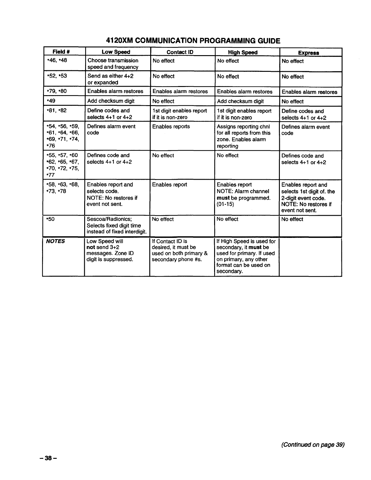
Field #Low Speed Contact ID High Speed Express
*46, *48 Choose transmission No effect No effect No effect
speed and frequency
●52, ●53 Send as either 4+2 No effect No effect No effect
or expanded
*79, *8O Enables alarm restores Enables alarm restores Enables alarm restores Enables alarm restores
*49 Add checksum digit No effect Add checksum digit No effect
*81 ,*82 Define codes and 1st digit enables report 1st digit enables report Define codes and
selects 4+1 or 4+2 if it is non-zero if it is non-zero selects 4+1 or 4+2
*54, *56, ●59, Defines alarm event Enables reports Assigns reporting chnl Defines alarm event
*61 ,*64, ●66, code for all reports from this code
*69, *71 ,*74, zone. Enables alarm
*76 reporling
*55, ●57, ●6O Defines code and No effect No effect Defines code and
*62, *65, ●67, selects 4+1 or 4+2 selects 4+1 or 4+2
●70, *72, ●75,
●77
*58, *63, *68, Enables report and Enables report Enables report Enables report and
●73, ●78 selects code. NOTE: Alarm channel selects 1st digit of. the
NOTE: No restores if must be programmed. 2-digit event code.
event not sent. (01-15) NOTE: No restores if
event not sent.
●5O SescoaiRadionics; No effect No effect No effect
Selects fixed digit time
instead of fixed interdigit.
NOTES Low Speed will If Contact ID is If High Speed is used for
not send 3+2 desired, it must be secondary, it must be
messages. Zone ID used on both primary &used for primary. If used
digit is suppressed. secondary phone #s. on primary, any other
format can be used on
secondary.
(Continued on page 39)
-38-
Programming Procedures
General
Default
Programming
Data Programming
Note: Atear-out blank programming form has been included at the centerfold of
this manual.
The system is shipped with aset of pre-programmed values that are designed to
meet the needs of many installations. These can be changed by the installer to
suit specific needs if desired. In addition, four sets of pre-programmed
communication default values can also be loaded by the installer, each set
designed for aspecific communication format. These too can be changed to suit
the needs of aparticular installation.
Changes to these pre-programmed values can be programmed directly from the
console (Alpha consoles only) or from an IBM compatible computer terminal
either remotely (using aHAYES 1200 SMARTMODEM or aHAYES brand
Optima 24 PLUS FAX 96 modem), or at the office or job site (using the 41OOSM
Serial Module –see DIRECT WIRE DOWNLOADING section). Both methods
use the 4130PC Downloading software (be sure that the software version used
includes a4120XM menu selection). Sea the f)OkVfWOAD/fVG PRIMER section
(Section 9) for more information.
For alpha consoles, English Language descriptions of the zones and acustom
installer message (which appears when the system is ready to arm) can be
programmed using the built-in vocabulary of words (see PROGRAMMING ZONE
DESCRIPTIONS paragraphs later in this section).
There are five sets of pre-programmed defaults available (one standard, plus four
different communication defaults). Any one of these can be loaded into the
system’s memory. Refer to the COMMUNICATION DEFAULT PROGRAMMING
section for instructions.
The programming fields are grouped into two sets of addresses. The first set is
accessed as soon as programming mode is entered. To access the second set of
addresses (indicated on the programming form by a”1” in front of the 2-digit field
address), press ●94 while in programming mode, then press [x] plus the first field
number desired. Note that the alpha consoles display the words ALT PROGRAfvl
MODE, and the Fixed-word consoles display the word CHECK to indicate the
second set of addresses. To return to the first set of addresses, press *99, then
press [x] plus the field number desired.
To program specific data fields, press [x] plus the 2-digit field address, then
make the required entry. The console will beep when afield has been completely
programmed and will automatically display the ne~ field in numerical order. If the
number of digits that you enter in the data field is less than the maximum
permitted (for example, phone number), the console displays the last entry and
waits. To proceed, the next data field address to be programmed must be
entered manually (for example, press ●05).
To view the contents of adata field, press [#] plus the 2-digit field address.
The field’s entries will be displayed, but no changes to these entries can be
made.
In case of errors: If an address is improperly entered, the console will display
FC . If aprogram entry is improperly entered (for example, alarger number than
that which is permitted), the console display will go blank. In either case, simply
re-enter the correct number.
To exit programming mode, press either ●98 or ●99. Use *98 to prevent re-
access to programming mode by installer code method. *99 allows installer code
access to programming mode.
(Continued from page 3S)
-39-
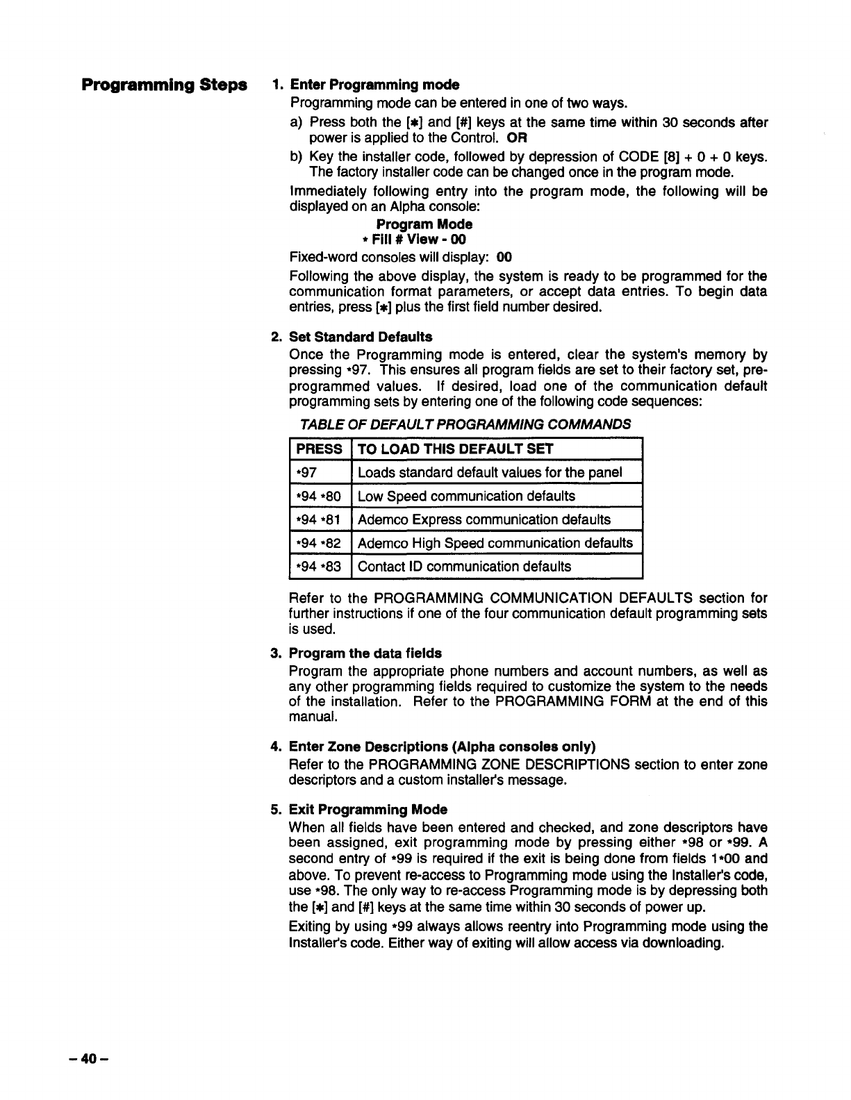
Programming Steps 1. Enter Programming mode
Programming mode can be entered in one of two ways.
a) Press both the [K] and [#] keys at the same time within 30 seconds after
power is applied to the Control. OR
b) Key the installer code, followed by depression of CODE [8] +O+Okeys.
The factory installer code can be changed once in the program mode.
Immediately following entry into the program mode, the following will be
displayed on an Alpha console:
Program Mode
●Fill #View -00
Fixed-word consoles will display: 00
Following the above display, the system is ready to be programmed for the
communication format parameters, or accept data entries. To begin data
entries, press [x] plus the first field number desired.
2. Set Standard Defaults
Once the Programming mode is entered, clear the system’s memory by
pressing ●97, This ensures all program fields are set to their factory set, pre-
programmed values. If desired, load one of the communication default
programming sets by entering one of the following code sequences:
TABLE OF DEFAULT PROGRAMMING COMMANDS
IPRESS ITO LOAD THIS DEFAULT SET I
●97 ILoads standard default values for the panel I
*94 *8O Low Speed communication defaults
*94 *81 Ademco Express communication defaults
*94 *82 Ademco High Speed communication defaults
*94 *83 Contact ID communication defaults
Refer to the PROGRAMMING COMMUNICATION DEFAULTS section for
further instructions if one of the four communication default programming sets
is used.
3. Program the data fields
Program the appropriate phone numbers and account numbers, as well as
any other programming fields required to customize the system to the needs
of the installation. Refer to the PROGRAMMING FORM at the end of this
manual.
4. Enter Zone Descriptions (Alpha consoles only)
Refer to the PROGRAMMING ZONE DESCRIPTIONS section to enter zone
descriptors and a custom installer’s message.
5. Exit Programming Mode
When all fields have been entered and checked, and zone descriptors have
been assigned, exit programming mode by pressing either *98 or ●99. A
second entry of ●99 is required if the exit is being done from fields 1●OOand
above. To prevent re-access to Programming mode using the Installer’s code,
use ●98. The only way to re-access Programming mode is by depressing both
the [x] and [#] keys at the same time within 30 seconds of power up.
Exiting by using ●99 always allows reentry into Programming mode using the
Installer’s code. Either way of exiting will allow access via downloading.
-40-
Communication Default Programming
General To help expedite the installation, Ademco has incorporated 4different
communication defaults in the Control (Low Speed, Ademco Express, Ademco
High Speed &Ademco’s new Contact ID). These defaults automatically program
industty-standard code assignments for zones, keypad panics, non-alarm and
supervisory conditions, and can be loaded at any time without affecting non-
communication program fields.
Using these defaults saves programming time! After loading one of the
communication defaults, you only need to wire the devices to their appropriate
zones, and program the following:
●Central station phone number(s), fields *33 &●34
●Subscriber’s account number(s), fields ●32 &*9O
●Zone type responses, fields ●02-*05 &1*O1-1●O5
●Delays, timeouts, and miscellaneous control options.
The system is then operational.
The program fields that are affected by loading one of the communication
defaults are fields ●45 -●82. Default values for each communication default are
listed on the pages at the end of this manual.
For detailed information about reporting formats, see the SYSTEM
COMMUNICATION section.
Easy-To-Program The VISTA XM programming scheme eliminates the need to program zones to
Communication channels, and then channels to codes. If programming communication fields
Fieids manually, simply enter whatever code (3+1, 4+1, 4+2 or Ademco Express) is to
be sent for each zone (including panics, non-alarm codes and supervisory
codes). NOTE: Enter “1O“ to transmit an “A”, which appears as “O” at the
receiver.
All zones are separated into groups of 8, with common restore, trouble and
bypass codes for every 2groups (16 zones). There are 2double-digit entries for
each code.
For 3+1, 4+1, 4+2 and Ademco Express, the first entry is the alarm code for a
standard report and also assigns the reporting channel. The second entry is the
ID digit for an expanded 3+1 or 4+1 report, or for a4+2 or Ademco Express
report. If the second digit is O,only 3+1 or 4+1 (or 4+1 express) non-expanded
messages will be sent, If only three digits are entered in the account number
field, the ID or second digits are ignored, if entered.
For Ademco High Speed format, the first digit entry is the channel assignment for
that zone, and the second digit is ignored, if entered,
For Contact ID reporting, the first digit entry (any non zero entry) enables
reporting for that zone and also assigns the reporting channel, and the second
digit is ignored.
Note: Restoral reports for an event will not be sent if the event itself is not
enabled, even if arestore code is programmed for that event.
Low Speed Loading this default does the following:
(*94 *80) ●Selects low speed, standard format with no checksum, for both phone
numbers.
“Assigns the following report codes:
03 for zones 2-47
01 for zones 1&48-55 (fire zones)
02 for zones 62,63 (panic transmitters), &95, 96,99
(keypad panics)
09 for all alarm restores
cEnables all zone type restores.
-41-
Ademco Express Loading this default does the following:
(*94 ●81) ●Selects Ademco express reporting format, with checksum, for both phone
numbers.
.Report codes for zones 1-64, 4281s and keypad panics are sent as their
respective zone ID numbers (01-64, 88-91, 95-99), Duress is sent as “DD”.
Alarm restore is “E”+ second digit.
●Enables all zone type restores.
Ademco High Speed Loading this default does the following:
(*94 *82) ●Selects Ademco High Speed format, with no checksum, for both phone
numbers.
“Reporting is assigned to the following channels:
Channel 1for zones 1&zones 48-55 (Fire zones)
Channel 2for zones 2-8
Channel 3for zones 9-16
Channel 4for zones 17-31
Channel 5for zones 32-47 (RF interior zones)
Channel 6for zones 56-61 &64
Channel 9for zones 62 &63 (panic transmitter)
Channel 7for second 4281 (88& 89)
Channel 8for first 4281 (90& 91)
Channels 10, 11 &12 for keypad panics 95, 96&99 respectively
●Enables all zone type restores.
●Enables Duress to be sent.
Contact ID Loading this default does the following:
(*94 ●83) ●Selects Contact ID format for both phone numbers.
●Reporting is enabled for all zones.
●Enables all zone type restores.
●Refer to the SYSTEM COMMUNICATION section for event code definitions.
-42-
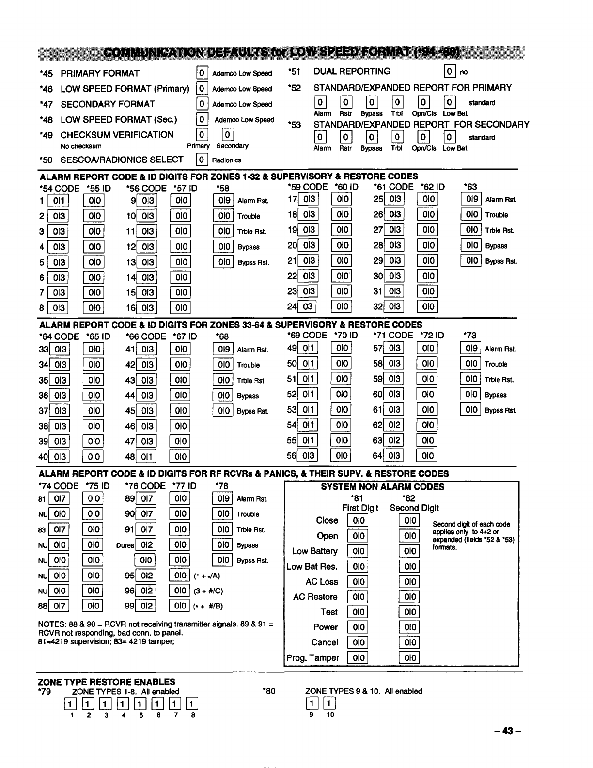
●45 PRIMARY FORMAT ❑
OAderncaLowSpeed *51 DUAL REPORTING •1
Ono
●46 LOW SPEED FORMAT (Primary) ❑AdeMCOLOWspeed *52 STANDARD/EXPANDED REPORT FOR PRIMARY
●47 SECONDARY FORMAT •1
OAdemcoLowSpeed III III EZIIIIEZIIII””””
*46 LOW SPEED FORMAT (Sec.) •1
OAdemooLowSpeed Alarm Rstr Bypass TM OpnKXs LowSet
❑m
●53 STANDARD/EXPANDED REPORT FOR SECONDARY
●49 CHECKSUM VERIFICATION
No checksum Prfmary Serxmda~ IIlmmmmmsta”dsrd
Alarm Rstr Bvoeee Trbl Oon/Cis LowBat
●5O SESCOWRADIONICS SELECT ❑Radionios
.,
ALARM REPORT CODE &ID DIGITS FOR ZONES 1-32 &SUPERVISORY& RESTORE CODES
●
54 CODE ●55 ID
m
ml
m
ml
●58
n019 AlarmRst.
●61 CODE ●62 ID ●63
Eil
ImiIl
ml
ml
Emil
ml
ml
ml
~AlarmRat.
~Trouble
n010 TrbleRst.
Q010 BMMSS
~Trouble
o010 TrbleRst.
n010 Bypass
ml
El
EJ
I@il
n
010 BYPSSRst. ~ByPeeRsl
ALARM REPORT CODE &ID DIGITS FOR ZONES 33-64 &SUPERVISORY& RESTORE CODES
●64 CODE ●65 ID ●66 CODE ●67 ID ●68 ●69 CODE *7OID ’71 CODE *72 ID ●73
33~ ~41~ ~ ~ Alarm Rst. 49~ ~[ 57~ ~ ~ AlarmRst.
34~ ~42~ ~ ~ Trouble 50~ ~58~ ml ~Trouble
35~ ~43E ~ ~ TrbleRst. 51~ ~59B ~ ~ TtbleRst.
36~ ~44~ m~BVDSSS 52~ ~60~ ~ ~ Bypass
45~
46~
—-.
n
010 BYPSS Rst. 53~
54~
—
El
Imil
Q
~BypeeRst.
ALARM REPORT CODE &ID DIGITS FOR RF RCVRS&PANICS, &THEIR SUPV. &RESTORE CODES
●
74 CODE ’75 ID ●76 CODE 77 ID ’78
81~ ~89~ ~ ~ AlarmRst.
SYSTEM NON ALARM CODES
*81 *82
First Digit Second Digit
Semnd digitofeachoode
applieaonly to4+2 or
expended(flelda●52 &’53)
formats.
.OWBat Res. IJ!!?.1 @!.1
AC bss ~El
AC Restore ~m
NUI 010 I I 010 j96~ ~(3+ #/C)
88~ ~99~ ~(*+ #/8)
NOTES: 88& 90= RCVR not receiving transmitter signals. 89 &91 =
RCVR not responding, bad corm. to panel.
81=421 9supervision; 83= 4219 tampen
Test ~B
Power ~
Cancel ~
Prog. Tamper ~IJ!!ll
ZONE TYPE RESTORE ENABLES
●79 ZONE TYPES 1-8. All enabled ●8O ZONE TYPES 9&10. All enabled
❑mmmmmmm ❑m
1234567S 9 10
-43-
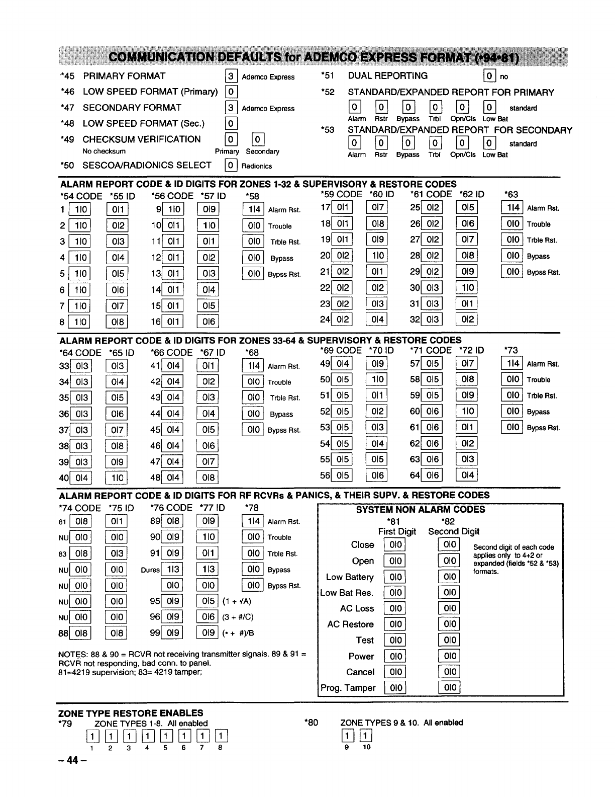
‘*45
*46
*47
●48
’49
●5O
PRIMARY FORMAT ~AdenKoExPress
LOW SPEED FORMAT (Primary) ❑
SECONDARY FORMAT ❑AdwncoE)rPress
LOW SPEED FORMAT (Sec.) ❑
CHECKSUM VERIFICATION ❑m
No checksum Primary Secondary
SESCOA/RADIONICS SELECT ❑Radionics
*51 DUAL REPORTING ~.
●52 STANDARD/EXPANDED REPORT FOR PRIMARY
EIIEHIIE mHIIlsta*fd
Alarm Rstr Bypass TtiIl Opn/Cls Low Bat
●53 STANDARD/EXPANDED REPORT FOR SECONDARY
❑IIKumIHIlstanderd
Alarm Rstr Bypass Trbl Opn/Cls Low Bat
ALARM REPORT CODE &ID DIGITS FOR ZONES 33-64 &SUPERVISORY& RESTORE CODES
ALARM REPORT CODE &ID DIGITS FOR RF RCVRS &PANICS, &THEIR SUPV. &RESTORE CODES
’74 CODE ●75 ID *76 CODE ●77 ID ●78
131m ~89~ ~ ~ AlarmRst.
~(3 +#/c)
~(=+#)/B
NOTES: 88& 90= RCVR not receiving transmitter signals. 89 &91 =
RCVR not responding, bad corm.to panel.
81=4219supervision;83= 4219 tampefi
SYSTEM NON ALARM CODES
’81 ●82
First Digit Second Digit
Close ~BSecond
digit of each code
Open ~Bappfies only to 4+2 or
expended (fields “52 &’53)
Low Battery ~m
formats.
Low Bat Res. Bm
AC !_oSS ~El
AC Restore ~B
Test ~m
Power ~I@l
Cancel ~m
Prog. Tamper ~m
ZONE TYPE RESTORE ENABLES
●79 ZONE TYPES 1-8. All enabled ●8O ZONE TYPES 9&10. All enabled
❑mHIIlmmlIln ❑lIl
12345678 910
-44-
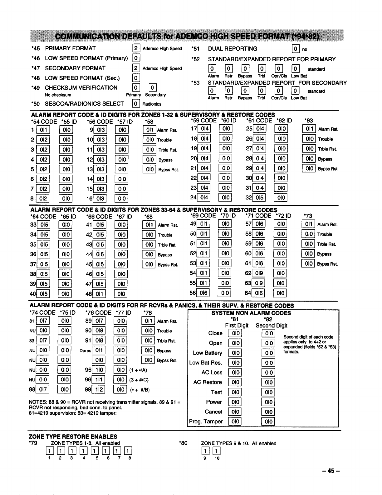
●45 PRIMARY FORMAT ~
2AdemcoHighSpeed ●51 DUAL REPORTING •1
Ono
●46 LOW SPEED FORMAT (Primary) ❑●52 STANDARD/EXPANDED REPORT FOR PRIMARY
●47 SECONDARY FORMAT ❑AdemHighSpead EIEHEHIIEIEl@en*rd
’48 LOW SPEED FORMAT (Sec.) ❑Alarm Ratr Bypass Ttt)l OprVOls LowBat
●49 CHECKSUM VERIFICATION ❑m
●53 STANDARD/EXPANDED REPORT FOR SECONDARY
Nochecksum Ptfmary Secondary •mmmmmat~~rd
Afarm Rstr Bypass Trbl OprVCla LowBat
●5O SESCOWRADIONICS SELECT ❑Radionics
’73
~AlarrnRst.
~Trouble
~TrbleRst
~Bypass
~BypssRst.
ALARM REPORT CODE &ID DIGITS FOR RF RCVRS &PANICS, &THEIR SUPV. &RESTORE CODES
●74 CODE *75 ID ●76 CODE ●77 ID ●78 SYSTEM NON ALARM CODES
81~ ~89~ ~ ~ Alarm Rat. *8I●82
First Digit Second Digit
NUB ~9op@ /@ ~-rro”t)le Close ~B
63~ ~91~ ~ ~ Trble Rst. Open ~m
NUB ~“Uresm BII@ ‘Ypas Low Battety ~ml
NUB ~~ ~ ~ BmssRst. LOWBat Res ~m
NUB ~95~ ~(1 +*/A) AC LOSS ~m
NUB ~96~ ~(3+ #/C) AC Restore ~B
88~ ~99~ ~(=+ #/B) Test ~I@l
NOTES: 88& 90= RCVR not receiving transmitter signals. 89 &91 =Power ~B
RCVR not responding, bad corm. to panel.
81=421 9supervision; 83= 4219 tamper Cancel ~~
Prog. Tamper ~IJ?!!l
Seoorrddigitofeachcode
appliea only to 4+2 or
expanded (fields “52 &“53)
formats.
ZONE TYPE RESTORE ENABLES
●79 ZONE TYPES 1-8. Allenabled ●8O ZONE TYPES 9&10. Allenabled
❑mmmmmmm ❑m
12345676 910
-45-

●45
●46
●47
’48
●49
●5O
PRIMARY FORMAT ❑
1Ademco ContactlD
LOW SPEED FORMAT (Primary) ❑
SECONDARY FORMAT ❑AderncoContsctlD
LOW SPEED FORMAT (Sec.) ❑
CHECKSUM VERIFICATION ❑m
No checksum Pttmarv Secondarv
SESCOA/RADIONICS SELECT ❑Radionics
●51
’52
*53
DUAL REPORTING •1
Ono
STANDARD/EXPANDED REPORT FOR PRIMARY
•mmmmmstands~
Alarm Rstr Bypass Trbl Opn/Cla Low Bat
STANDARD/EXPANDED REPORT FOR SECONDARY
II Ilmammm standard
Alarm Rstr Bypass Trbl OpnJCls Low Eat
●73
Q011 Alarm Rst.
~Trouble
~Ttt)leRst.
~Bypass
~Bypss.at.
ALARM REPORT CODE &ID DIGITS FOR RF RCVRS &PANICS, &THEIR SUPV. &RESTORE CODES
●
74 CODE ●75 ID ●76 CODE *77 ID ●78 SYSTEM NON ALARM CODES
L!U?-./90~
m91 m
~ ~ AlamrFtst.
~ ~ Trouble
m m ‘“’e ‘St
C!Zl ~BWass
m m ‘ypssRst
~(1 +4A)
~(3+ #/c)
~(*+#/B)
I*81 *82
First Digit Second Digit
Close LOICJ ~Second digit ofeachcode
Open ~mapplies only to 4+2 or
expandad (fields “52& “53)
Low Batte~ @mformats.
Low Bat Res. ~m
AC LOSS ~@El
AC Restore ~m
Test ~m
NOTES: 88& 90= RCVR not receiving transmitter signals. 89 &91 =Power ~
RCVR not responding, bad corm. to panel. I@l
81=4219supervision;83= 4219 tamper; Cancel ~@
Prog. Tamper ~I_!!.!J
ZONE TYPE RESTORE ENABLES
’79 ZONE TYPES 1-8. Allenabled ●8O ZONE TYPES 9&10. Allenabled
Klmmlmmtml
1234587S ❑m
910
-46-
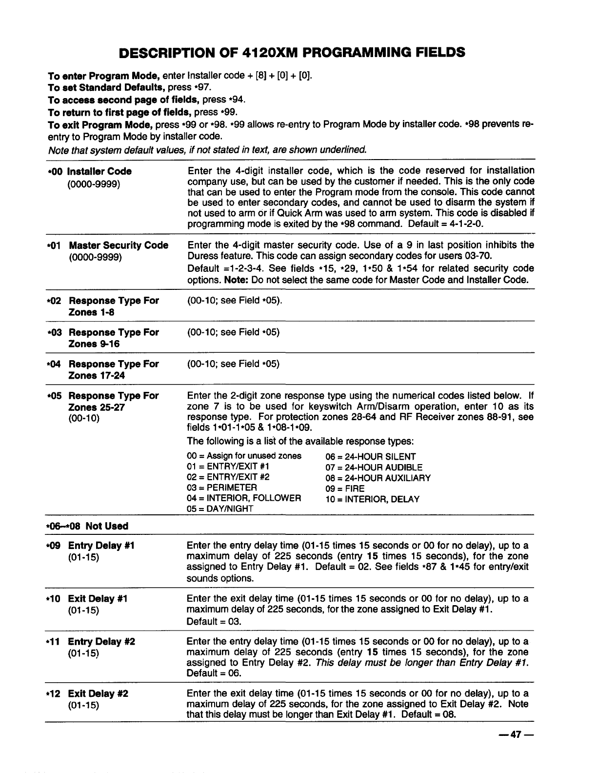
DESCRIPTION OF 4120XM PROGRAMMING FIELDS
To enter Program Mode, enter Installer code+ [8]+ [0]+ [0].
To set Standard Defaults, press ●97.
To access second page of fields, press *94.
To return to first page of fields, press ●99.
To exit Program Mode, press ●99 or *98. *99 allows re-entry to Program Mode by installer code. *98 prevents re-
entry to Program Mode by installer code.
Note that system defau/t values, if not stated in text, are shown underlined.
*OO Installer Code Enter the 4-digit installer code, which is the code reserved for installation
(0000-9999) company use, but can be used by the customer if needed. This is the only code
that can be used to enter the Program mode from the console. This code cannot
be used to enter secondary codes, and cannot be used to disarm the system if
not used to arm or if Quick Arm was used to arm system. This code is disabled if
programming mode is exited by the ●98 command. Default= 4-1-2-O.
●O1 Master Security Code Enter the 4-digit master security code. Use of a 9 in last position inhibits the
(0000-9999) Duress feature. This code can assign seconda~ codes for users 03-70.
Default =1-2-3-4. See fields ●15, *29, 1●5O & 1*54 for related security code
options. Note: Do not select the same code for Master Code and Installer Code.
●O2 Response Type For (00-10; see Field *05).
Zones 1-8
*O3 Response Type For (00-10; see Field *05)
Zones 9-16
*O4 Response Type For (00-10; see Field ●05)
Zones 17-24
●O5 Response Type For Enter the 2-digit zone response type using the numerical codes listed below. If
Zones 25-27 zone 7is to be used for keyswitch Arm/Disarm operation, enter 10 as its
(00-1 o) response type. For protection zones 28-64 and RF Receiver zones 88-91, see
fields 1*01-1●O5& 1*08-1●09.
The following is alid of the available response types:
00= Assignfor unusedzones 06= 24-HOUR SILENT
01 =ENTRY/EXIT #1 07= 24-HOUR AUDIBLE
02= ENTRY/EXIT #2 08= 24-HOUR AUXILIARY
03= PERIMETER 09= FIRE
04= INTERIOR, FOLLOWER 10= INTERIOR, DELAY
05= DAY/NIGHT
●~08 Not Used
*O9 Entry Delay #1 Enter the entry delay time (01-15 times 15 seconds or 00 for no delay), up to a
(01-15) maximum delay of 225 seconds (entry 15 times 15 seconds), for the zone
assigned to Entry Delay #1. Default =02. See fields ●87 &1●45 for entry/exit
sounds options.
●1OExit Delay #1 Enter the exit delay time (01-15 times 15 seconds or 00 for no delay), up to a
(01-15) maximum delay of 225 seconds, for the zone assigned to Exit Delay #1.
Default =03.
*11 Entry Delay #2 Enter the entry delay time (01-15 times 15 seconds or 00 for no delay), up to a
(01-15) maximum delay of 225 seconds (entry 15 times 15 seconds), for the zone
assigned to Entry Delay #2. This delay must be longer than Entry ~e/ay #l.
Default =06.
●12 Exit Delay #2 Enter the exit delay time (01-15 times 15 seconds or 00 for no delay), up to a
(01-15) maximum delay of 225 seconds, for the zone assigned to Exit Delay #2. Note
that this delay must be longer than Exit Delay #1. Default= 08.
—47—
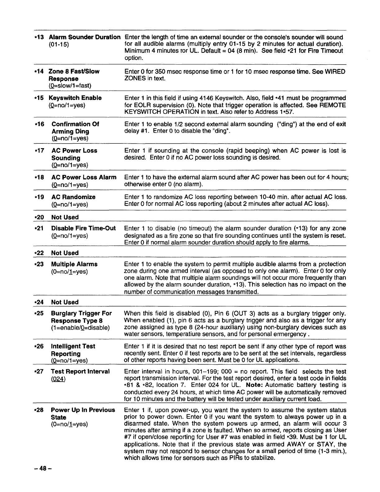
*13 Alarm Sounder Duration Enter the length of time an external sounder or the console’s sounder will sound
(01-1 5) for all audible alarms (multiply entry 01-15 by 2minutes for actual duration).
Minimum 4minutes ror UL. Default= 04 (8 rein). See field ●21 for Fire Timeout
option.
*14 Zone 8Fast/Slow Enter Ofor 350 msec response time or 1for 10 msec response time. See WIRED
Response ZONES in text.
(Q=slow/l=fast)
*15 Keyswitch Enable Enter 1in this field if using 4146 Keyswitch. Also, field *41 must be programmed
(Q=no/l=yes) for EOLR supervision (0). Note that trigger operation is affected. See REMOTE
KEYSWITCH OPERATION in text. Also refer to Address 1*57.
*16 Confirmation Of Enter 1to enable 1/2 second external alarm sounding (“ding”) at the end of exit
Arming Ding delay #1. Enter Oto disable the “ding”.
(Q=no/1 =yes)
*17 AC Power Loss Enter 1if sounding at the console (rapid beeping) when AC power is lost is
Sounding desired, Enter Oif no AC power loss sounding is desired.
(Q=no/l=yes)
*18 AC Power Loss Alarm Enter 1to have the external alarm sound after AC power has been out for 4hours;
(Q=no/1=yes) otherwise enter O(no alarm).
*19 AC Randomize Enter 1to randomize AC loss reporting between 10-40 min. after actual AC loss.
(Q=no/1=yes) Enter Ofor normal AC loss reporting (about 2minutes after actual AC loss).
*2O Not Used
*21 Disable Fire Time-Out Enter 1to disable (no timeout) the alarm sounder duration (*13) for any zone
(Q=no/l=yes) designated as afire zone so that fire sounding continues until the system is reset.
Enter Oif normal alarm sounder duration should apply to fire alarms.
*22 Not Used
*23 Multiple Alarms Enter 1to enable the system to permit multiple audible alarms from aprotection
(O=no/l=yes) zone during one armed interval (as opposed to only one alarm). Enter Ofor only
one alarm. Note that multiple alarm soundings will not occur more frequently than
allowed by the alarm sounder duration, *13). This selection has no impact on the
number of communication messages transmitted.
*24 Not Used
*25 Burglary Trigger For When this field is disabled (0), Pin 6(OUT 3) acts as aburglary trigger only.
Response Type 8When enabled (1), pin 6acts as aburglary trigger and also as atrigger for any
(1=enable/Q=disable) zone assigned as type 8(24-hour auxiliary) using non-burglary devices such as
water sensors, temperature sensors, and for personal errnergency.
*26 Intelligent Test Enter 1if it is desired that no test report be sent if any other type of report was
Reporting recently sent. Enter Oif test reports are to be sent at the set intervals, regardless
(Q=no/1=yes) of other reports having been sent. Must be Ofor UL applications.
*27 Test Report Interval Enter interval in hours, 001–1 99; 000 =no report. This field selects the test
(w) report transmission interval. For the test report desired, enter atest code in fields
*81 &*82, location 7. Enter 024 for UL. Note: Automatic battery testing is
conducted every 24 hours, at which time AC power will be automatically removed
for 10 minutes and the battery will be tested under auxiliary current load.
*28 Power Up In Previous Enter 1if, upon power-up, you want the system to assume the system status
State prior to power down. Enter Oif you want the system to always power up in a
(O=no/l=yes) disarmed state. When the system powers up armed, an alarm will occur 3
minutes after arming if azone is faulted. When so armed, reports closing as User
#7 if open/close reporting for User #7 was enabled in field *39. Must be 1 for UL
applications. Note that if the previous state was armed AWAY or STAY, the
system may not respond to sensor changes for asmall period of time (1-3 min.),
which allows time for sensors such as PIRs to stabilize.
-48-
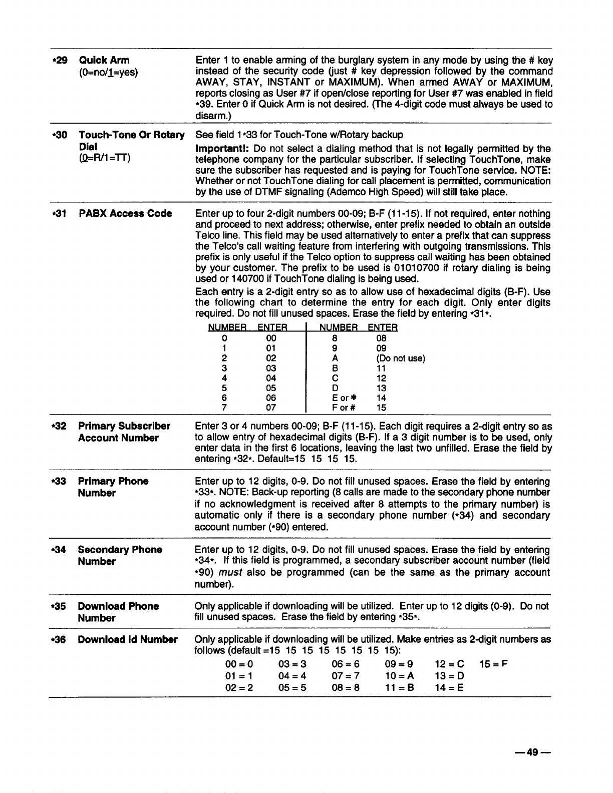
●29 Quick Arm
(O=no/l=yes)
●3O Touch-Tone Or Rotary
Dial
(Q=R/1=-IT)
●31 PABX Access Code
Enter 1to enable arming of the burglary system in any mode by using the #key
instead of the security code (just #key depression followed by the command
AWAY, STAY, INSTANT or MAXIMUM). When armed AWAY or MAXIMUM,
reports closing as User #7 if open/close reporting for User #7 was enabled in field
●39. Enter Oif Quick Arm is not desired. (The 4-digit code must always be used to
disarm.)
See field 1●33 for Touch-Tone w/Rotary backup
Important!: Do not select adialing method that is not legally permitted by the
telephone company for the particular subscriber. If selecting TouchTone, make
sure the subscriber has requested and is paying for TouchTone service. NOTE:
Whether or not TouchTone dialing for call placement is permitted, communication
by the use of DTMF signaling (Ademco High Speed) will still take place.
Enter up to four 2-digit numbers 00-09; B-F(11 -15). If not required, enter nothing
and proceed to next address; otherwise, enter prefix needed to obtain an outside
Telco line. This field may be used alternatively to enter aprefix that can suppress
the Telco’s call waiting feature from interfering with outgoing transmissions. This
prefix is only useful if the Telco option to suppress call waiting has been obtained
by your customer. The prefix to be used is 01010700 if rotary dialing is being
used or 140700 if TouchTone dialing is being used.
Each entry is a2-digit entry so as to allow use of hexadecimal digits (B-F). Use
the following chart to determine the entry for each digit. Only enter digits
required. Do not fill unused spaces. Erase the field by entering ●31●.
NUM~FR_EMT.ER
o00 8 08
1 01 909
202 A\~ not use)
3 03
404 :12
05 D13
;06 Eorx 14
707 For# 15
●32 Primary Subscriber Enter 3or 4numbers 00-09; B-F(11 -15). Each digit requires a2-digit entry so as
Account Number to allow entry of hexadecimal digits (B-F). If a3digit number is to be used, only
enter data in the first 6locations, leaving the last two unfilled. Erase the field by
entering ●32*. Default=15 15 15 15.
●33 Primary Phone Enter up to 12 digits, O-9. Do not fill unused spaces. Erase the field by entering
Number ●33*. NOTE: Back-up reporting (8 calls are made to the secondafy phone number
if no acknowledgment is received after 8attempts to the primary number) is
automatic only if there is asecondary phone number (*34) and secondary
account number ~90) entered.
●34 Secondary Phone Enter up to 12 digits, O-9. Do not fill unused spaces. Erase the ,field by entering
Number *34*. If this field is programmed, asecondary subscriber account number (field
*90) must also be programmed (can be the same as the primary account
number).
●35 Download Phone Only applicable if downloading will be utilized. Enter up to 12 digits (O-9). Do not
Number fill unused spaces. Erase the field by entering *35*.
●36 Download Id Number Only applicable if downloading will be utilized. Make entries as 2digit numbers as
follows (default =15 15 15 15 15 15 15 15):
00=0 03=3 06=6 09=9 12=C 15=F
01=1 04=4 07=7 10=A 13=D
02=2 05=5 08=8 ll=B 14=E
—49—
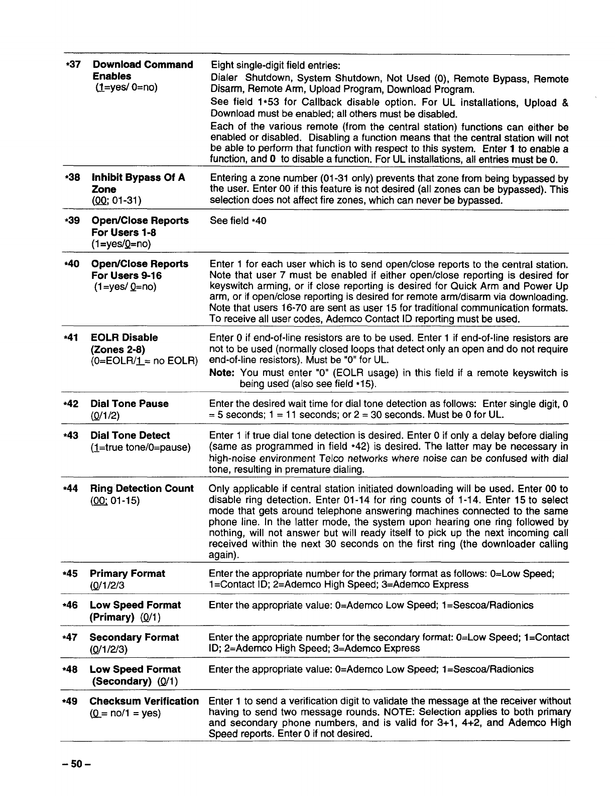
●37 Download Command Eight single-digit field entries:
Enables Dialer Shutdown, System Shutdown, Not Used (0), Remote Bypass, Remote
@=yes/ O=no) Disarm, Remote Arm, Upload Program, Download Program.
See field 1●53 for Callback disable option. For UL installations, Upload &
Download must be enabled; all others must be disabled.
Each of the various remote (from the central station) functions can either be
enabled or disabled. Disabling afunction means that the central station will not
be able to perform that function with respect to this system. Enter 1to enable a
function, and Oto disable afunction. For UL installations, all entries must be O.
●
38 Inhibit Bypass Of AEntering azone number (01-31 only) prevents that zone from being bypassed by
Zone the user. Enter 00 if this feature is not desired (all zones can be bypassed). This
(m 01-31) selection does not affect fire zones, which can never be bypassed.
●39 Open/Close Reports See field *4O
For Users 1-8
(l=yes/Q=no)
*4O Open/Close Reports Enter 1for each user which is to send open/close reports to the central station.
For Users 9-16 Note that user 7must be enabled if either open/close reporting is desired for
(1=yes/ Q=no) keyswitch arming, or if close reporting is desired for Quick Arm and Power Up
arm, or if open/close reporting is desired for remote arm/disarm via downloading.
Note that users 16-70 are sent as user 15 for traditional communication formats.
To receive all user codes, Ademco Contact ID reporting must be used.
*41 EOLR Disable Enter Oif end-of-line resistors are to be used. Enter 1if end-of-line resistors are
(Zones 2-8) not to be used (normally closed loops that detect only an open and do not require
(O=EOLR/1= no EOLR) end-of-line resistors). Must be “O”for UL.
Note: You must enter “O” (EOLR usage) in this field if aremote keyswitch is
being used (also see field ●15).
●42 Dial Tone Pause Enter the desired wait time for dial tone detection as follows: Enter single digit, O
(Q/1/2) =5seconds; 1=11 seconds; or 2=30 seconds. Must be Ofor UL.
*43 Dial Tone Detect Enter 1if true dial tone detection is desired. Enter Oif only adelay before dialing
(I=true tone/O=pause) (same as programmed in field *42) is desired. The latter may be necessary in
high-noise environment Telco networks where noise can be confused with dial
tone, resulting in premature dialing.
●
44 Ring Detection Count Only applicable if central station initiated downloading will be used. Enter 00 to
(B O1-15) disable ring detection. Enter 01-14 for ring counts of 1-14. Enter 15 to select
mode that gets around telephone answering machines connected to the same
phone line. In the latter mode, the system upon hearing one ring followed by
nothing, will not answer but will ready itself to pick up the next incoming call
received within the next 30 seconds on the first ring (the downloader calling
again).
*45 Primary Format Enter the appropriate number for the primary format as follows: O=Low Speed;
(Qfl1213 1=Contact ID; 2=Ademco High Speed; 3=Ademco Express
●46 Low Speed Format Enter the appropriate value: O=Ademco Low Speed; 1=Sescoa/Radionics
(Primary) (Q/1)
●
47 Secondary Format Enter the appropriate number for the secondary format: O=Low Speed; 1=Contact
(Q/1 /2f3) ID; 2=Ademco High Speed; 3=Ademco Express
●48 Low Speed Format Enter the appropriate value: O=Ademco Low Speed; 1=Sescoa/Radionics
(Secondary) (Q/l )
●49 Checksum Verification Enter 1to send averification digit to validate the message at the receiver without
(Q= non =yes) having to send two message rounds. NOTE: Selection applies to both primary
and secondary phone numbers, and is valid for 3+1, 4+2, and Ademco High
Speed reports. Enter Oif not desired.
-50-
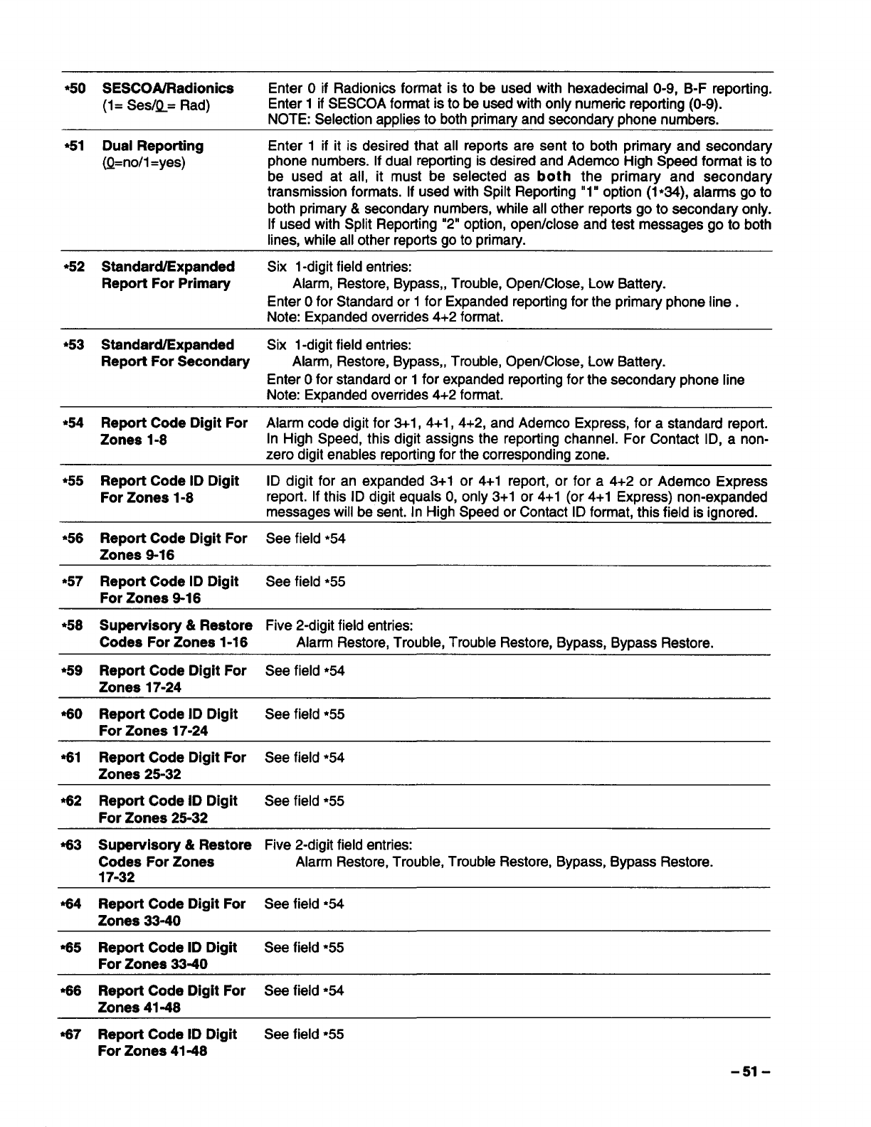
*5O SESCOA/Radionica Enter Oif Radionics format is to be used with hexadecimal O-9, B-F reporting.
(1= Ses/!l= Rad) Enter 1if SESCOA format is to be used with only numeric reporting (O-9).
NOTE: Selection applies to both primary and secondary phone numbers.
*51 Dual Reporting Enter 1if it is desired that all reports are sent to both primary and secondary
(Q=no/1 =yes) phone numbers. If dual reporting is desired and Ademco High Speed format is to
be used at all, it must be selected as both the primary and secondary
transmission formats. If used with Spilt Repotting “1” option (1*34), alarms go to
both primary &secondary numbers, while all other reports go to secondary only.
If used with Split Reporting “2” option, open/close and test messages go to both
lines, while all other reports go to primary.
*52 Standard/Expanded Six l-digit field entries:
Report For Primary Alarm, Restore, Bypass,, Trouble, Open/Close, Low Battery.
Enter Ofor Standard or 1for Expanded reporting for the primary phone line.
Note: Expanded overrides 4+2 format.
●53 Standard/Expanded Six 1-digitfield entries:
Report For Secondary Alarm, Restore, Bypass,, Trouble, Open/Close, Low Battery.
Enter Ofor standard or 1for expanded reporting for the secondary phone line
Note: Expanded overrides 4+2 format.
*54 Report Code Digit For Alarm code digit for 3+1, 4+1, 4+2, and Ademco Express, for astandard report.
Zones 1-8 In High Speed, this digit assigns the reporting channel. For Contact ID, anon-
zero digit enables reporting for the corresponding zone.
●55 Report Code ID Digit ID digit for an expanded 3+1 or 4+1 report, or for a4+2 or Ademco Express
For Zones 1-8 report. If this ID digit equals O,only 3+1 or 4+1 (or 4+1 Express) non-expanded
messages will be sent. In High Speed or Contact ID format, this field is ignored.
*56 Report Code Digit For See field *54
Zones 9-16
●57 Report Code ID Digit See field *55
For Zones 9-16
*58 Supervisory &Restore Five 2-digit field entries:
Codes For Zones 1-16 Alarm Restore, Trouble, Trouble Restore, Bypass, Bypass Restore.
●
59 Report Code Digit For See field ●54
Zones 17-24
%0 Report Code ID Digit See field ●55
For Zones 17-24
*61 Report Code Digit For See field *54
Zones 25-32
●62 Report Code ID Digit See field ●55
For Zones 25-32
%3 Supervisory& Restore Five 2-digit field entries:
Codes For Zones Alarm Restore, Trouble, Trouble Restore, Bypass, Bypass Restore.
17-32
%4 Report Code Digit For See field ●54
Zones 33-40
●65 Report Code ID Digit See field *55
For Zones 33-40
%6 Report Code Digit For See field ●54
Zones 41-48
%7 Report Code ID Digit See field ●55
For Zones 41-48
-51-
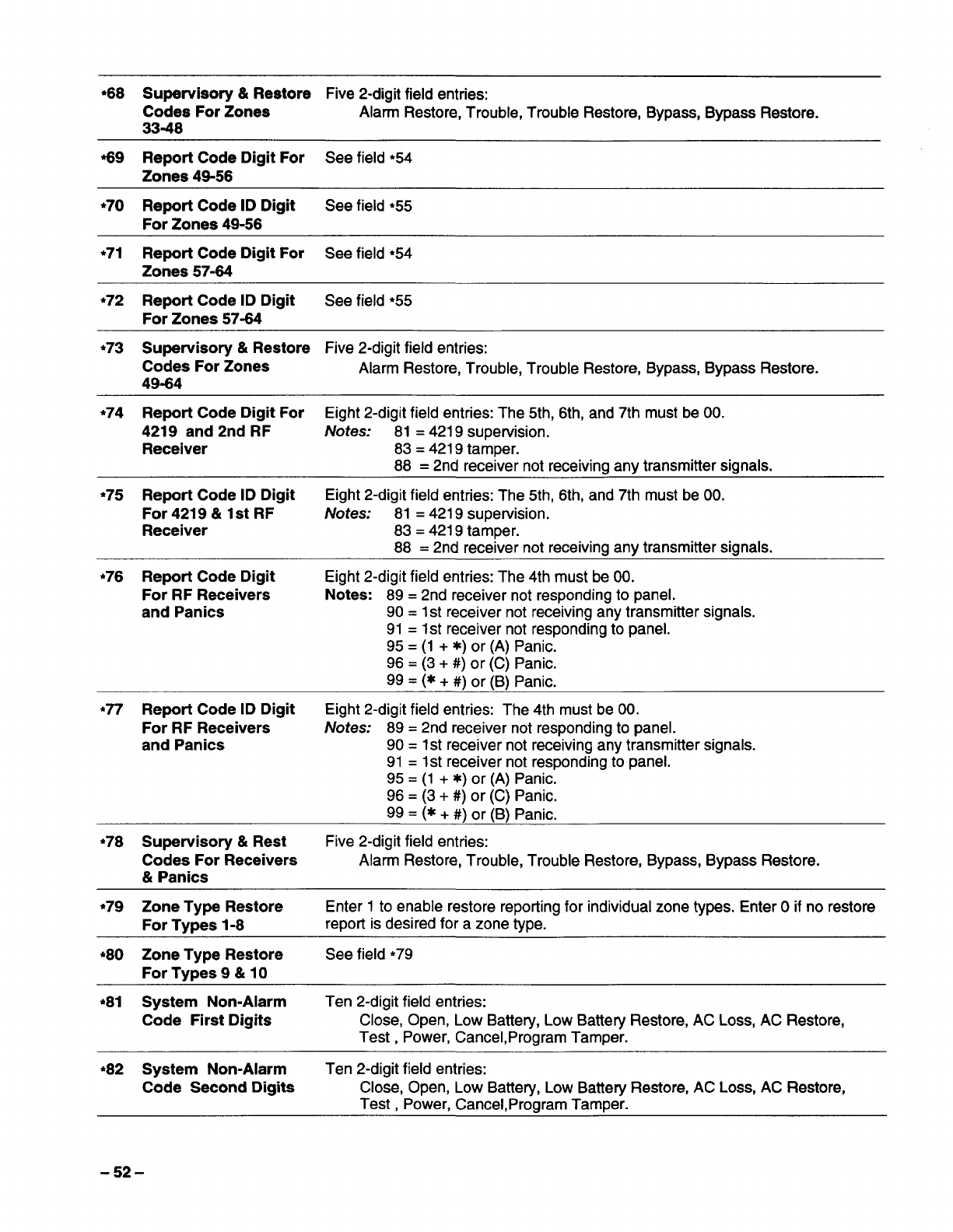
*68 Supervisory &Restore Five 2-digit field entries:
Codes For Zones Alarm Restore, Trouble, Trouble Restore, Bypass, Bypass Restore.
33-48
%9 Report Code Digit For See field ●54
Zones 49-56
*7O Report Code ID Digit See field *55
For Zones 49-56
*71 Report Code Digit For See field ●54
Zones 57-64
●72 Report Code ID Digit See field ●55
For Zones 57-64
*73 Supervisory &Restore Five 2-digit field entries:
Codes For Zones Alarm Restore, Trouble, Trouble Restore, Bypass, Bypass Restore.
49-64
●74 Report Code Digit For Eight 2-digit field entries: The 5th, 6th, and 7th must be 00.
4219 and 2nd RF Notes: 81 =4219 supervision.
Receiver 83 =4219 tamper.
88 =2nd receiver not receiving any transmitter signals.
●75 Report Code ID Digit Eight 2-digit field entries: The 5th, 6th, and 7th must be 00.
For 4219 &1st RF Notes: 81 =4219 supervision.
Receiver 83= 4219 tamper.
88 =2nd receiver not receiving any transmitter signals.
*76 Report Code Digit Eight 2-digit field entries: The 4th must be 00.
For RF Receivers Notes: 89= 2nd receiver not responding to panel.
and Panics 90= 1st receiver not receiving any transmitter signals.
91 =1st receiver not responding to panel.
95= (1 +x) or (A) Panic.
96= (3+ #) or (C) Panic.
99= (*+ #) or (B) panic.
●77 Report Code ID Digit Eight 2-digit field entries: The 4th must be 00.
For RF Receivers Notes: 89= 2nd receiver not responding to panel.
and Panics 90= 1st receiver not receiving any transmitter signals.
91 =1st receiver not responding to panel.
95 =(1 +x) or (A) Panic.
96= (3+ #) or (C) Panic.
99= (*+ #) or (B) panic.
*78 Supervisory &Rest Five 2-digit field entries:
Codes For Receivers Alarm Restore, Trouble, Trouble Restore, Bypass, Bypass Restore.
&Panics
●
79 Zone Type Restore Enter 1to enable restore reporting for individual zone types, Enter Oif no restore
For Types 1-8 report is desired for azone type.
*8O Zone Type Restore See field *79
For Tv~es 9&10
●81 System Non-Alarm Ten 2-digit field entries:
Code First Digits Close, Open, Low Battery, Low Battefy Restore, AC Loss, AC Restore,
Test ,Power, Cancel,Program Tamper.
*82 System Non-Alarm Ten 2-digit field entries:
Code Second Digits Close, Open, Low Battery, Low Battery Restore, AC Loss, AC Restore,
Test ,Power, Cancel,Program Tamper.
-52-
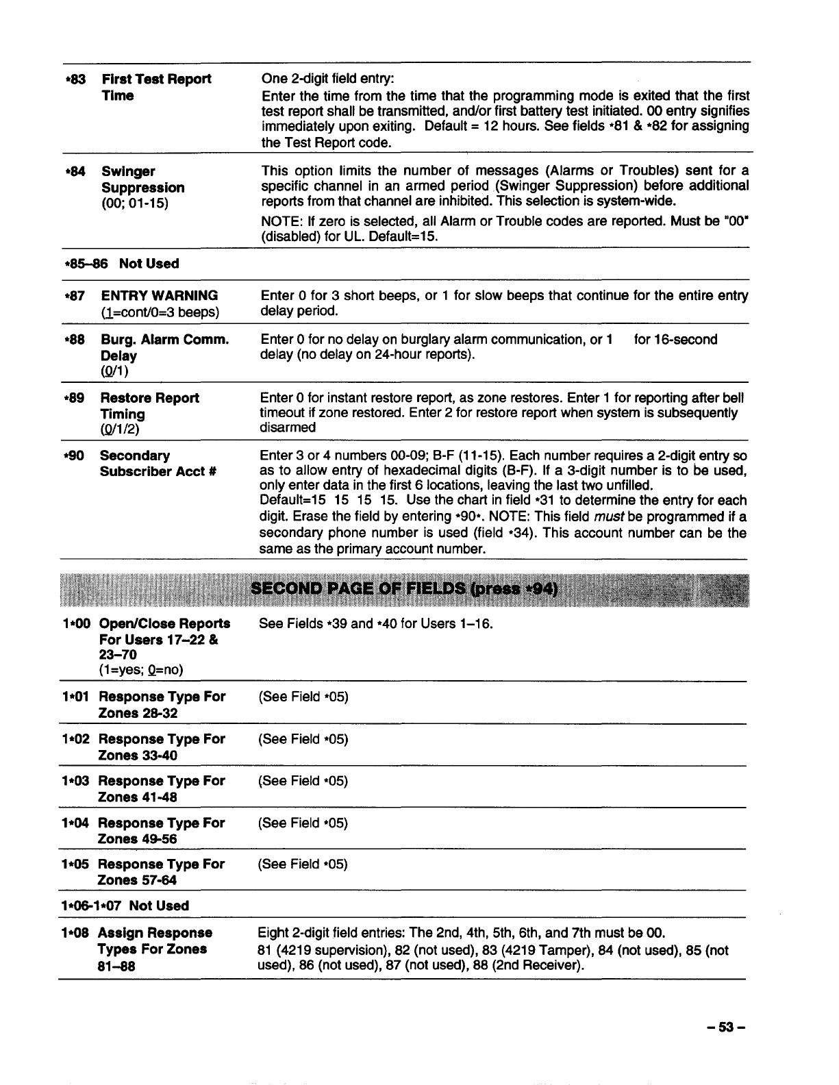
●63 First Test Repofi One 2digit fieid entry:
Time Enter the time from the time that the programming mode is exited that the first
test report shall be transmitted, antior first battery test initiated. 00 entry signifies
immediately upon exiting. Default =12 hours. See fields ●81 &●82 for assigning
the Test Report code.
*64 Swinger This option iimits the number of messages (Alarms or Troubles) sent for a
Suppression specific channel in an armed period (Swinger Suppression) before additional
(00;01-15) reports from that channel are inhibited. This seiection is system-wide.
NOTE: if zero is selected, all Aiarm or Trouble codes are reported. Must be “00”
(disabled) for UL. Default=15.
●85-86 Not Used
*87 ENTRY WARNiNG Enter Ofor 3short beeps, or 1for slow beeps that continue for the entire entry
H=cont10=3 beerx) delay period.
*88 Burg. Aiarm Comm. Enter Ofor no delay on burglary alarm communication, or 1for 16-second
Deiay delay (no delay on 24-hour reports).
(Q/1)
●89 Restore Report Enter Ofor instant restore report, as zone restores. Enter 1for reporting after bell
Timing timeout if zone restored. Enter 2for restore report when system is subsequently
(Q/1/2) disarmed
40 Secondary Enter 3or 4numbers 00-09; B-F (11-15). Each number requires a2-digit entry so
Subscriber Acct #as to allow entry of hexadecimal digits (B-F). If a3-digit number is to be used,
only enter data in the first 6locations, leaving the last two unfilled.
Default=l 5 15 15 15. Use the chart in field ●31 to determine the entry for each
digit. Erase the field by entering *90*. NOTE: This field must be programmed if a
secondary phone number is used (field ●34). This account number can be the
same as the rximaw account number.
1●OO Open/Ciose Reporta See Fields ●39 and ●4O for Users 1-16.
For Users 17-22 &
23-70
(1=yes; Q=no)
1●O1 Response Type For (See Field *05)
Zones 28-32
1●O2 Response Type For (See Field ●05)
Zones 33-40
1*O3 Response Type For (See Field ●05)
Zones 41-48
1*O4 Response Type For (See Field ●05)
Zones 49-56
1●O5 Response Type For (See Field ●05)
Zones 57-64
1*O8 Assign Response Eight 2-digit field entries: The 2nd, 4th, 5th, 6th, and 7th must be 00.
Typas For Zones 81 (4219 supervision), 82 (not used), 83 (4219 Tamper), 64 (not used), 85 (not
81-88 used), 86 (not used), 87 (not used), 88 (2nd Receiver).
-53-
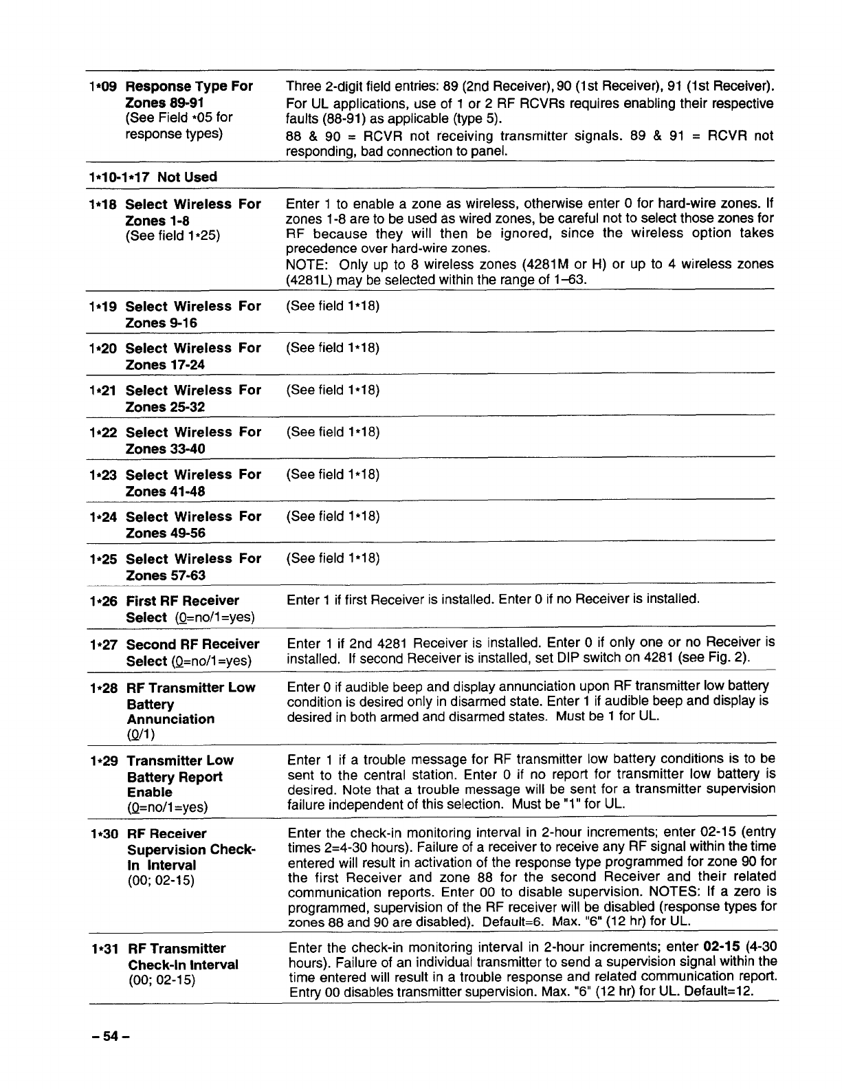
1*O9 Response Type For Three 2-digit field entfies:89 (2nd Receiver),90 (lst Receiver),9l (lst Receiver).
Zones 89-91 For UL applications, use of 1or 2RF RCVRS requires enabling their respective
(See Field *O5 for faults (88-91 )as applicable (type 5).
response types) 88&90= RCVR not receiving transmitter signals. 89 &91 =RCVR not
responding, bad connection to panel.
1*1o.1*17 Not Used
1*18Select Wireless For Enter 1to enable azone as wireless, otherwise enter Ofor hard-wire zones. If
Zones 1-8 zones 1-8 are to be used as wired zones, be careful not to select those zones for
(See field 1●25) RF because they will then be ignored, since the wireless option takes
precedence over hard-wire zones.
NOTE: Only up to 8wireless zones (4281Mor H) or up to 4wireless zones
(4281 L) maybe selected within the range of 1-83.
1*19 Select Wireless For (See field 1*18)
Zones 9-16
1*2O Select Wireless For (See field1*18)
Zones 17-24
1●21 Select Wireless For (See field 1*18)
Zones 25-32
1●22 Select Wireless For (See field 1*18)
Zones 33-40
1*23 Select Wireless For (See field 1*18)
Zones 41-48
1*24 Select Wireless For (See field 1•18)
Zones 49-56
1*25 Select Wireless For (See field 1●18)
Zones 57-63
1●26 First RF Receiver Enter 1if first Receiver is installed. Enter Oif no Receiver is installed.
Select (Q=no/1=yes)
1●27 Second RF Receiver Enter 1if 2nd 4281 Receiver is installed. Enter Oif only one or no Receiver is
Select (Q=no/1=yes) installed, If second Receiver is installed, set DIP switch on 4281 (see Fig. 2).
1●28 RF Transmitter Low Enter Oif audible beep and display annunciation upon RF transmitter low battery
Battery condition is desired only in disarmed state. Enter 1if audible beep and display is
Annunciation desired in both armed and disarmed states. Must be 1 for UL.
(Qfl)
1,29 Transmitter LOW Enter 1if atrouble message for RF transmitter low battery conditions is to be
Battery Report sent to the central station. Enter Oif no report for transmitter low battery is
Enable desired. Note that atrouble message will be sent for atransmitter supervision
(Q=no/1 =yes) failure independent of this selection. Must be”1” for UL.
1.30 RF Receiver Enter the check-in monitoring interval in 2-hour increments; enter 02-15 (entry
Supervision Check- times 2=4-30 hours). Failure of areceiver to receive any RF signal within the time
In Interval entered will result in activation of the response type programmed for zone 90 for
(00; 02-1 5) the first Receiver and zone 88 for the second Receiver and their related
communication reports. Enter 00 to disable supervision. NOTES: If azero is
programmed, supervision of the RF receiver will be disabled (response types for
zones 88 and 90 are disabled). Default=6. Max. “6” (12 hr) for UL.
1●31 RF Transmitter Enter the check-in monitoring intetval in 2-hour increments; enter 02-15 (4-30
Check-In Interval hours). Failure of an individual transmitter to send asupervision signal within the
(00; 02-15) time entered will result in atrouble response and related communication repoti.
Entry 00 disables transmitter supervision. Max. “6” (12 hr) for UL. DefauIt=12.
-54-
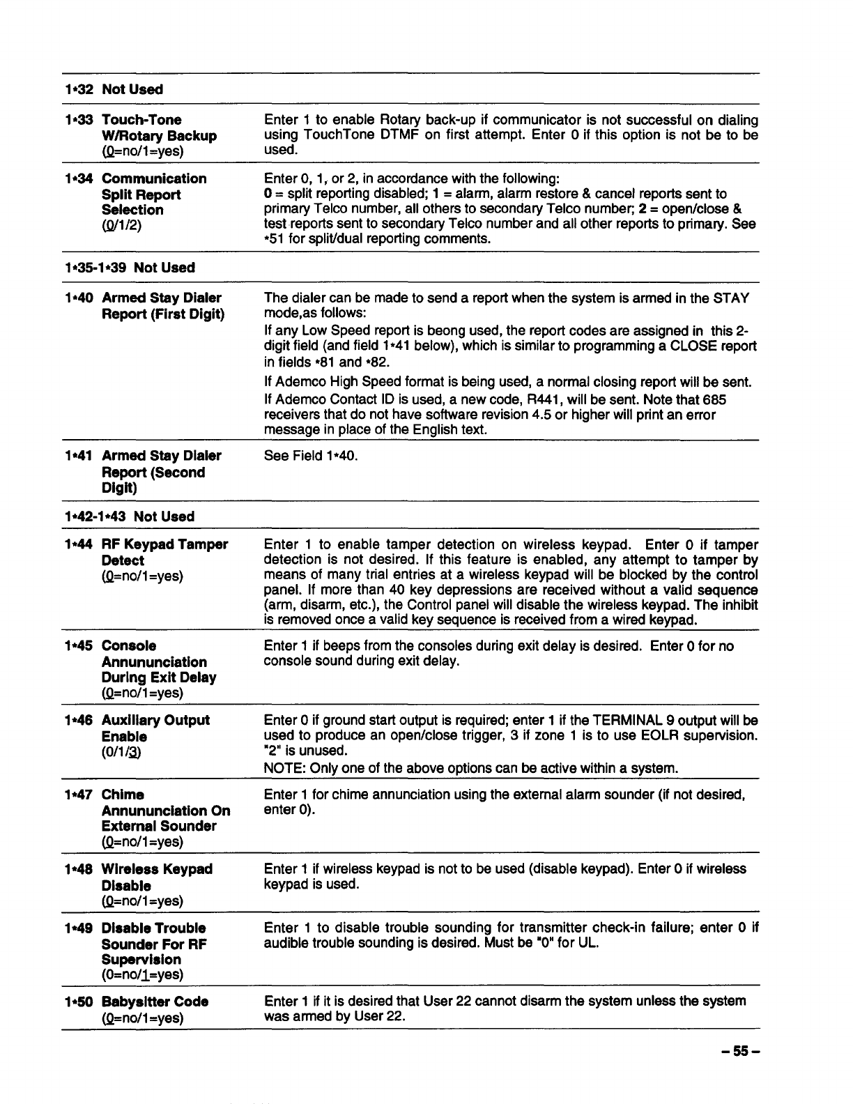
1●33 Touchstone Enter 1to enable Rotary back-up if communicator is not successful on dialing
W/Rotary Backup using TouchTone DTMF on first attempt. Enter Oif this option is not be to be
(Q=no/l=yes) used.
1.34 communication Enter O, 1, or 2, in accordance with the following:
Split Report O=split reporting disabled; 1=alarm, alarm restore& cancel reports sent to
Selection primaty Telco number, all others to secondary Telco number 2=operdclose &
(Q/1/2) test reports sent to secondary Telco number and all other reports to primary. See
*51 for spliffdual reporting comments.
1●35.1 .39 Not Used
1●4O Armed Stay Dialer The dialer can be made to send areport when the system is armed in the STAY
Report (First Digit) mode,as follows:
If any Low Speed reporl is beong used, the report codes are assigned in this 2-
digit field (and field 1*41 below), which is similar to programming aCLOSE report
in fields ●81 and ●82.
If Ademco High Speed format is being used, anormal closing report will be sent.
If Ademco Contact ID is used, anew code, R441, will be sent. Note that 685
receivers that do not have software revision 4.5 or higher will print an error
message in place of the English text.
1●41 Armed Stsy Dialer See Field 1●40,
Report (Second
Digit)
1,42.1 ●43 Not Used
1*44 RF Keypad Tamper Enter 1to enable tamper detection on wireless keypad. Enter Oif tamper
Detect detection is not desired. If this feature is enabled, any attempt to tamper by
(Q=no/l=yes) means of many trial entries at awireless keypad will be blocked by the control
panel. If more than 40 key depressions are received without avalid sequence
(arm, disarm, etc.), the Control panel will disable the wireless keypad. The inhibit
is removed once avalid key sequence is received from awired keypad.
1.45 Console Enter 1if beeps from the consoles during exit delay is desired. Enter Ofor no
Annununciation console sound during exit delay.
During Exit Delay
(Q=no/1=yes)
1*46 Auxiliary Output Enter Oif ground start output is required; enter 1if the TERMINAL 9output will be
Enable used to produce an operdclose trigger, 3if zone 1is to use EOLR supervision.
(ollf~ “2” is unused.
NOTE: Onlv one of the above oDtionscan be active within asvstem.
1*47 Chime Enter 1for chime annunciation using the external alarm sounder (if not desired,
Annununciation On enter O).
External Sounder
(Q=no/l=yes)
1*48 Wireless Keypad Enter 1if wireless keypad is not to be used (disable keypad). Enter Oif wireless
Disable keypad is used.
(Q=no/1=yes)
1s49 DisabIe Trouble Enter 1to disable trouble sounding for transmitter check-in failure; enter Oif
Sounder For RF audible trouble sounding is desired. Must be “O”for UL.
Supervision
(O=no/l=yes)
1*5O Babysitter Code Enter 1if it is desired that User 22 cannot disarm the system unless the system
(Q=no/1=yes) was armed by User 22.
-55-
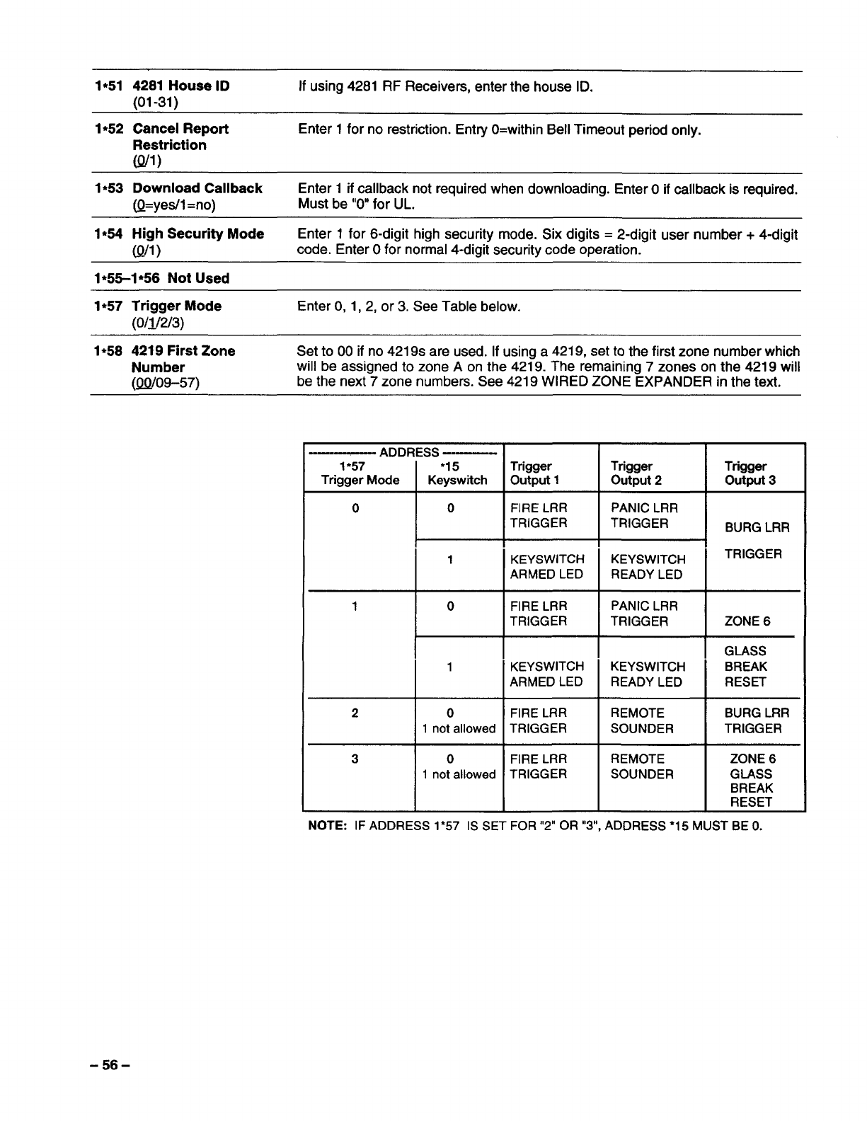
1*51 4281 HouselD If using 4281 RF Receivers, enter the house ID.
(01 -31 )
1●52 Cancel Repo~ Enter 1for no restriction. Enhy O=within Bell Timeout period only.
Restriction
(Q/I)
1●
53 Download Callback Enter 1if callback not required when downloading. Enter Oif callback is required.
(Q=yetil=no) Must be “O”for UL.
1●54 High Security Mode Enter 1for 6-digit high security mode. Six digits =2-digit user number+ 4-digit
(Q/l)code. Enter Ofor normal 4-digit security code operation.
1●5%1 .56 Not Used
1●57 Trigger Mode Enter O, 1, 2, or 3. See Table below.
(0/1/2/3)
1●58 4219 first Zone Set to 00 if no 4219s are used. If using a4219, set to the first zone number which
Number will be assigned to zone Aon the 4219. The remaining 7zones on the 4219 will
(QQ/09-57) be the next 7zone numbers. See 4219 WIRED ZONE EXPANDER in the text.
-—-— ADDRESS --—
1●57 ‘15 Trigger Trigger
Trigger Mode Keyswitch output 1output 2
00FIRE LRR PANIC LRR
TRIGGER TRIGGER
I,m
II
1KEYSWITCH KEYSWITCH
ARMED LED READY LED
1’ KEYSWITCH -KEYSWITCH
ARMED LED READY LED
2 0 FIRE LRR REMOTE
1not allowed TRIGGER SOUNDER
30FIRE LRR REMOTE
1not allowed TRIGGER SOUNDER
III
NOTE: IF ADDRESS 1*57 IS SET FOR “2” OR “3, ADDRESS•15 M
Trigger
output 3
BURG LRR
TRIGGER
ZONE 6
GLASS
BREAK
RESET
BURG LRR
TRIGGER
ZONE 6
GLASS
BREAK
RESET
TBE O.
-56-
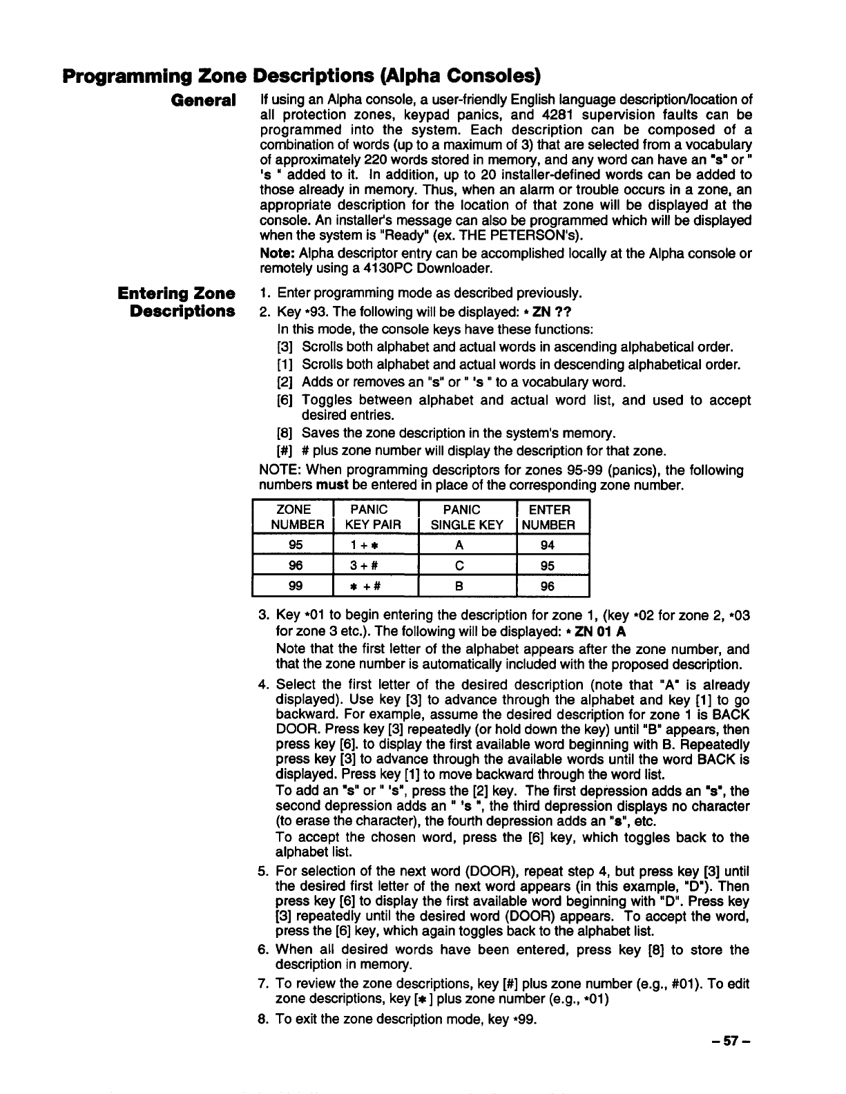
Programming Zone
General
Entering Zone
Descriptions
If using an Alpha console, auser-friendly English language description/location of
all protection zones, keypad panics, and 4281 supervision faults can be
programmed into the system. Each description can be composed of a
combination of words (up to amaximum of 3) that are selected from avocabulary
of approximately 220 words stored in memory, and any word can have an “s”or”
‘s “added to it. In addition, up to 20 installer-defined words can be added to
those already in memory. Thus, when an alarm or trouble occurs in azone, an
appropriate description for the location of that zone will be displayed at the
console. An installer’s message can also be programmed which will be displayed
when the system is “Ready” (ex. THE PETERSON’s).
Note: Alpha descriptor entry can be accomplished locally at the Alpha console or
remotely using a4130PC Downloader.
1. Enter programming mode as described previously.
2. Key ●93. The following will be displayed: ●ZN ??
In this mode, the console keys have these functions:
[3]
[1]
[2]
[6]
[8]
[#]
NOTE: When programming descriptors for zones 95-99 (panics), the following
numbers must be entered in place of the corresponding zone number.
Scrolls both alphabet and actual words in ascending alphabetical order.
Scrolls both alphabet and actual words in descending alphabetical order.
Adds or removes an “s” or”’s” to avocabulary word.
Toggles between alphabet and actual word list, and used to accept
desired entries.
Saves the zone description in the system’s memory.
#plus zone number will display the description for that zone.
ZONE PANIC PANIC ENTER
NUMBER KEY PAIR SINGLE KEY NUMBER
95 1+* A94
96 3+# c95
99 *+# B96
3,
4.
5.
6.
7.
8.
Key ●O1to begin entering the description for zone 1, (key ●O2for zone 2, *O3
for zone 3etc.). The following will be displayed: ●ZN 01 A
Note that the first letter of the alphabet appears after the zone number, and
that the zone number is automatically included with the proposed description.
Select the first letter of the desired description (note that “A= is already
displayed). Use key [3] to advance through the alphabet and key [1] to go
backward. For example, assume the desired description for zone 1is BACK
DOOR. Press key [3] repeatedly (or hold down the key) until “B” appears, then
press key [6]. to display the first available word beginning with B. Repeatedly
press key [3] to advance through the available words until the word BACK is
displayed. Press key [1] to move backward through the word list.
To add an “s” or” ‘s”, press the [2] key. The first depression adds an “s”, the
second depression adds an “*s “, the third depression displays no character
(to erase the character), the fourth depression adds an “s”, etc.
To accept the chosen word, press the [6] key, which toggles back to the
alphabet list.
For selection of the next word (DOOR), repeat step 4, but press key [3] until
the desired first letter of the next word appears (in this example, “D”). Then
press key [6] to display the first available word beginning with “D”. Press key
[3] repeatedly until the desired word (DOOR) appears. To accept the word,
press the [6] key, which again toggles back to the alphabet list.
When all desired words have been entered, press key [8] to store the
description in memory.
To review the zone descriptions, key [#] plus zone number (e.g., #01). To edit
zone descriptions, key [x] plus zone number (e.g., ●O1)
To exit the zone description mode, key ●99.
-57-
Adding Custom Up to 20 installer-defined words can be added to the built-in vocabulary. Each of
Words the 20 “words” can actually consist of several words, but bear in mind that a
maximum of 10 characters can be used for each word string. To create the
custom word or word string, proceed as follows:
1.
2.
3.
4.
5.
6.
7.
8.
9.
Enter the programming mode.
Key ●93. The following will be displayed: *ZN ??
Now key 00 to get into the mode which will allow the custom words to be
created. The following will be displayed: ●ED ??
In this mode, the keys perform the following functions:
[3] Advances through alphabet in ascending order.
[1] Advances through alphabet in descending order.
[6] Selects the desired letter, and moves the cursor to the right one space.
[4] Moves the cursor one space to the left.
[7] Inserts aspace at the cursor location, erasing any character at that
location.
[8] Saves the new word in the system’s memory.
[x] Returns to description entry mode.
Key the number of the custom word or word string to be created (01-20). For
example, if you are creating the first word (or word string), enter 01; when
creating the second word, enter 02, and so on. Acursor will now appear at the
beginning of the second line.
Use the [3] key to advance through the alphabet (numbers, symbols and
special characters are included). Use the [1] key to move back through the
alphabet.
/mportant: Custom words must begin with an alphabetic character. If
numbers or symbols are used as the first character, the word will not be
saved.
When you have reached the desired character, press the [6] key to select it.
The cursor will then move to the right, in position for the next character.
Repeat steps 5 and 6 to create the desired word (or words). Note that the [4]
key can be used to move the cursor to the left if necessary, and that key [71
can be used to enter ablank (or to erase an existing character). Each word or
word string cannot exceed 10 characters.
Press the [8] key to save the custom word(s) and return to the ●ED ??
display. The custom word (or string of words) will be automatically added to
the built-in vocabulary at the end of the group of words beginning with the
same letter.
Repeat steps 4through 8to create up to 19 additional custom words (or word
strings).
10. Press the [x] key to return to the ●ZN ?? display, and follow the zone
description entry procedure to assign the new words to azone description.
11. Key ●99 to exit the zone description programming mode.
Creating ACustom Normally, when the system is in the disarmed state, the following display is
Message Display present on the Console.
(Installer’s Message) ****DISARMED+***
READY TO ARM
Part or all of the above message can be modified to create acustom installer
message. For example, ****DISARMED**** on the first line or READY TO ARM
on the second line could be replaced by the installation company name or phone
number for service. Note that there are only 16 character spaces on each of the
two lines. To create acustom display message, proceed as follows:
1. Enter the programming mode.
2. Key ●93. The following will be displayed: ●ZN ??
3. Key 00. The following will appeac ●ED ??
4. Key 00 again. The following will appea~
●***DISARMED****
READY TO ARM
-58-
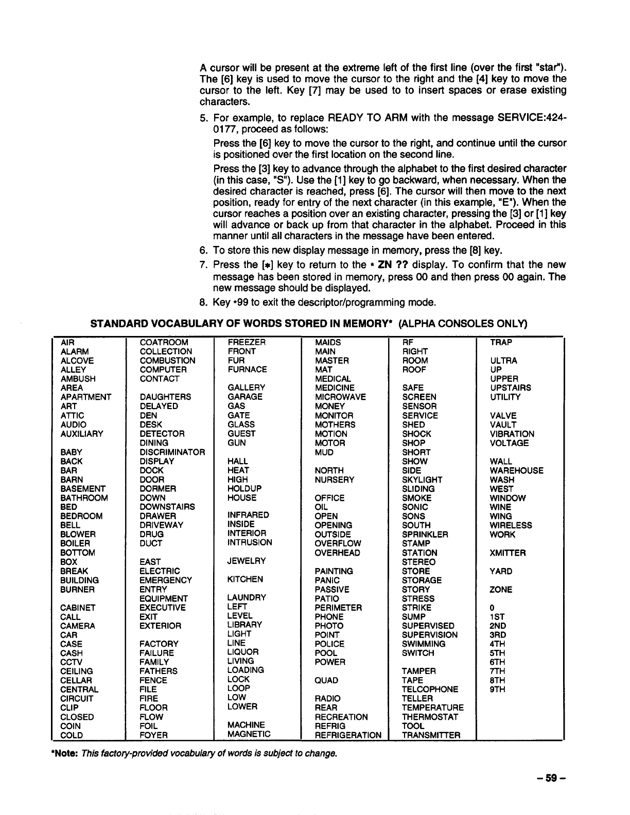
Acursor will be present at the extreme left of the first line (over the first “star”).
The [6] key is used to move the cursor to the right and the [4] key to move the
cursor to the left. Key [7] may be used to to insert spaces or erase existing
characters.
5.
6.
7.
8.
For example, to replace READY TO ARM with the message SERVlCE:424-
0177, proceed as follows:
Press the [6] key to move the cursor to the right, and continue until the cursor
is positioned over the first location on the second line.
Press the [3] key to advance through the alphabet to the first desired character
(in this case, “S”). Use the [1] key to go backward, when necessary. When the
desired character is reached, press [6]. The cursor will then move to the next
position, ready for entry of the next character (in this example, “E”). When the
cursor reaches aposition over an existing character, pressing the [3] or [1]key
will advance or back up from that character in the alphabet. Proceed in this
manner until all characters in the message have been entered.
To store this new display message in memory, press the [8] key.
Press the [x] key to return to the *ZN ?? display. To confirm that the new
message has been stored in memory, press 00 and then press 00 again. The
new message should be displayed.
Key ●99 to exit the descriptor/programming mode,
STANDARD VOCABULARY OF WORDS STORED IN MEMORY* (ALPHA CONSOLES ONLY)
AIR
ALARM
ALCOVE
ALLEY
AMBUSH
AREA
APARTMENT
ART
AITIC
AUDIO
AUXILIARY
BABY
BACK
BAR
BARN
BASEMENT
BATHROOM
BED
BEDROOM
BELL
BLOWER
BOILER
BOTTOM
BOX
BREAK
BUILDING
BURNER
CABINET
CALL
CAMERA
CAR
CASE
CASH
CCN
CEILING
CELLAR
CENTRAL
CIRCUIT
CLIP
CLOSED
COIN
COLD
COATROOM
COLLECTION
COMBUSTION
COMPUTER
CONTACT
DAUGHTERS
DELAYED
DEN
DESK
DETECTOR
DINING
DISCRIMINATOR
DISPLAY
DOCK
DOOR
DORMER
DOWN
DOWNSTAIRS
DRAWER
DRIVEWAY
DRUG
DUCT
EAST
ELECTRIC
EMERGENCY
ENTRY
EQUIPMENT
EXECUTIVE
EXIT
EXTERIOR
FACTORY
FAILURE
FAMILY
FATHERS
FENCE
FILE
FIRE
FLOOR
FLOW
FOIL
FOYER
FREEZER
FRONT
FUR
FURNACE
GALLERY
GARAGE
GAS
GATE
GLASS
GUEST
GUN
HALL
HEAT
HIGH
HOLDUP
HOUSE
INFRARED
INSIDE
INTERIOR
INTRUSION
JEWELRY
KITCHEN
LAUNDRY
LE~
LEVEL
LIBRARY
LIGHT
LINE
LIQUOR
LIVING
LOADING
LOCK
LOOP
LOW
LOWER
MACHINE
MAGNETIC
MAIDS
MAIN
MASTER
MAT
MEDICAL
MEDICINE
MICROWAVE
MONEY
MONITOR
MOTHERS
MOTION
MOTOR
MUD
NORTH
NURSERY
OFFICE
OIL
OPEN
OPENING
OUTSIDE
OVERFLOW
OVERHEAD
PAINTING
PANIC
PASSIVE
PATIO
PERIMETER
PHONE
PHOTO
POINT
POLICE
POOL
POWER
QUAD
RADIO
REAR
RECREATION
REFRIG
REFRIGERATION
RF
RIGHT
ROOM
ROOF
SAFE
SCREEN
SENSOR
SERVICE
SHED
SHOCK
SHOP
SHORT
SHOW
SIDE
SKYLIGHT
SLIDING
SMOKE
SONIC
SONS
SOUTH
SPRINKLER
STAMP
STATION
STEREO
STORE
STORAGE
STORY
STRESS
STRIKE
SUMP
SUPERVISED
SUPERVISION
SWIMMING
SWITCH
TAMPER
TAPE
TELCOPHONE
TELLER
TEMPERATURE
THERMOSTAT
TOOL
TRANSMllTER
TRAP
ULTRA
UP
UPPER
UPSTAIRS
UTILITY
VALVE
VAULT
VIBRATION
VOLTAGE
WALL
WAREHOUSE
WASH
WEST
WINDOW
WINE
WING
WIRELESS
WORK
XMITTER
YARD
ZONE
o
1ST
2ND
3RD
4TH
5TH
8TH
7TH
8TH
9TH
●Note: This factory-provided vocabulary of words is subject to change,
-59-
What Is Downloading allows the installer or central station operator to remotely access,
Downloading? program, and control the security system over normal telephone lines. Anything
that can be done directly from the keypad can be done remotely, using
DOWNLOADING. To Download, the following is required:
1. An IBM PC, or compatible computer with MS DOS 3.1 or higher, to run the
DOWNLOADING program. MS DOS stands for: MicroSoft Disk Operating
System.
2. AHAYES 1200 SMARTMODEM (external: level 1.2 or higher; internal: level
1.1 or higher). If these levels cannot be found locally, an external modem can
be purchased from ADEMCO, or contact HAYES for afree update. Other
brands are not compatible, even if claimed to be 100% compatible.
3. 4130PC V-LINK@ DOWNLOADING software, from ADEMCO. This software is
available in both 3-1/2” (4130P3-3) and 5-1/4” diskettes, and includes a
complete User’s Manual.
How Does At the protected premises, the Control panel must be connected to the existing
Downloading Work? telephone line (refer to the PHONE LINE CONNECTIONS section). No
programming of the panel is required before downloading to an initial installation.
To download, do the following:
1.
2.
3.
At the console, enter the installer code +[#] +[5]. The panel temporarily
enables aring count of 5 and sets the Download Callback option to “1”
(callback not required).
Call the panel using the downloader software set to “FIRST
COMMUNICATION” mode.
The downloader will establish asession with no callback. The panel
information can then be downloaded.
In order to remotely access, control, or program the alarm panel, a“link” must be
established between the computer and the control panel, as follows:
1.
2.
3.
4.
5.
6.
7.
The computer calls up the Control panel. (The phone number for each
customer is entered into the customer’s account file on the computer).
The Control panel “answers” at the pre-programmed ring count and executes
ahandshake with the computer.
The computer sends arequest for call-back to the Control, unless call-back is
not required.
The panel acknowledges the request and hangs up. During the next few
seconds, the Control will process the request making sure certain encrypted
information, received from the computer, matches its own memory.
Upon asuccessful match, the Control panel will seize the phone line and call
the computer back, unless call-back is not required.
The computer answers, usually by the second ring, and executes a
handshake with the panel.
The panel then sends other default information to the computer. If this
information matches the computer’s information, asuccessful link is
established. This is known as being “ON-LINE”.
ADVISORIES:
1. Alarm and trouble responses and reports are disabled during on-line time.
Should an event occur during this time, the response will take place and the
report will go through as soon as the remote access sequence is completed.
Alarm and trouble conditions are not ignored, they are simply delayed.
2. The keypads are inactive during downloading communication, and resume
normal functions after hang up. All keypad entries are ignored during on-line
time.
-60-
What Can Be Done ●Arm the System in the Away Mode; Disarm the System
once Panel IS ●Bypass aZone
‘lOn-Linell? cForce the System to Accept aNew Program Download
●Shut Down Communication (dialer) Functions (non-payment of monitoring fees
in an owned system)
●Shut Down all Security System Functions (non-payment for aleased system)
“Inhibit Local Keypad Programming (prevents takeover of your accounts)
●Leave amessage for customer (5137 ONLY)
●Command the System to Upload aCopy of its Resident Program to the office
●Read: Arming Status, AC Power Status, List of Faulted Zones, List of
Bypassed Zones, 10-Day Alarm History Log, 10-Day Trouble Histoy Log, List
of Zones Currently in Alarm, List of Zones Currently in Trouble, List of RF
sensors with low battery conditions
How Secure Is Accessing the Control from aremote location is protected against compromise by
Downloading? the use of 4levels of protection:
1. Security Code Handshake: The subscribers account number as well as an 8-
digit ID number (known only to the office) must be matched between the
Control and computer.
2. Hang-Up and Cal/-Back: The Control panel will “hang-up” and call the
computer back at the pre-programmed number only if the security codes
match.
3. Data Encryption: All data that is exchanged between the computer and Control
is encrypted to reduce the possibility of anyone “tapping” the line and corrupting
data.
4. Operator Access Levekx Up to 15 operators can have access to the
DOWNLOADER, each having their own log-on code. However, each operator
can be assigned one of three levels of access in both FILE and COMMAND
functions, as follows:
FILE ACCESS:
Read On/y: able only to look at the database; cannot change any information,
and cannot see the customer’s access codes.
Part Read/lWrite: able to look at and change all information. except the
customer’s access codes.
Fu// ReaoWVrite.’ able to look at and change any and all information in the
database.
CONTROUCOMM ACCESS:
Read On/y: able only to Upload and arm the system. Not able to DISARM,
BYPASS, or change any information.
Parl Read/Write: able to ARM, BYPASS, UPLOAD, DOWNLOAD but cannot
shutdown the system.
Fu// Read/Write: able to perform all control and status commands, as well as
shutdown all or part of the system.
Notes:
1. Each time the Control panel is accessed (whether successful or
unsuccessful), aPROGRAM TAMPER report ~40) is sent to central station, if
programmed.
2. When downloading, the console will display “MODEM COMM” (Alpha
consoles) or “CC” (Fixed-word consoles)
3. Whenever adownload or asave is done, an automatic time stamp is done,
indicating the date and time of the last download (or save) and the operator ID
number.
4. The average time for acomplete download, including initial call-up, hang-up
and call-back is under 4minutes.
5. Acomplete hard copy of each individual account can be obtained by
connecting aprinter to the computer. Refer to your computer owner’s manual
or contact your dealer for printer recommendations.
—61—
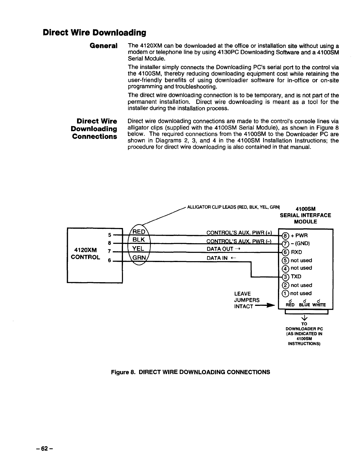
Direct Wire Downloading
General The 4120XM can be downloaded at the office or installation site without using a
modem or telephone line by using 4130PC Downloading Software and a 41 OOSM
Serial Module.
The installer simply connects the Downloading PC’s serial port to the control via
the 4100SM, thereby reducing downloading equipment cost while retaining the
user-friendly benefits of using downloader software for in-office or on-site
programming and troubleshooting.
The direct wire downloading connection is to be temporary, and is not part of the
permanent installation. Direct wire downloading is meant as atool for the
installer during the installation process.
Direct ~re Direct wire downloading connections are made to the control’s console lines via
Downloading alligator clips (supplied with the 4100SM Serial Module), as shown in Figure 8
Connections below. The required connections from the 4100SM to the Downloader PC are
shown in Diagrams 2, 3, and 4 in the 41 OOSM Installation Instructions; the
procedure for direct wire downloading is also contained in that manual.
ALLIGATOR CLIP LEADS (RED, ELK, YEL, GRN) 41OOSM
SERIAL INTERFACE
5CONTROL’S AUX. PWR (+)
8/BLK \co~s AUX. p#lR [.)
4120XM 7!YEL DATAOUT +
CONTROL ~\GRNj DATA IN +
1
!
LEAVE
JUMPERS
INTACT ~
MODULE
@+ PWR
~-(GND)
@RXD
@not used
@not used
@TXD
@not used
@not used
Cfdd
RED BLUE WHITE
w
TO
DOWNLOADER PC
(AS INDICATED IN
4100SM
INSTRUCTIONS)
Figure 8. DIRECT WIRE DOWNLOADING CONNECTIONS
-62-
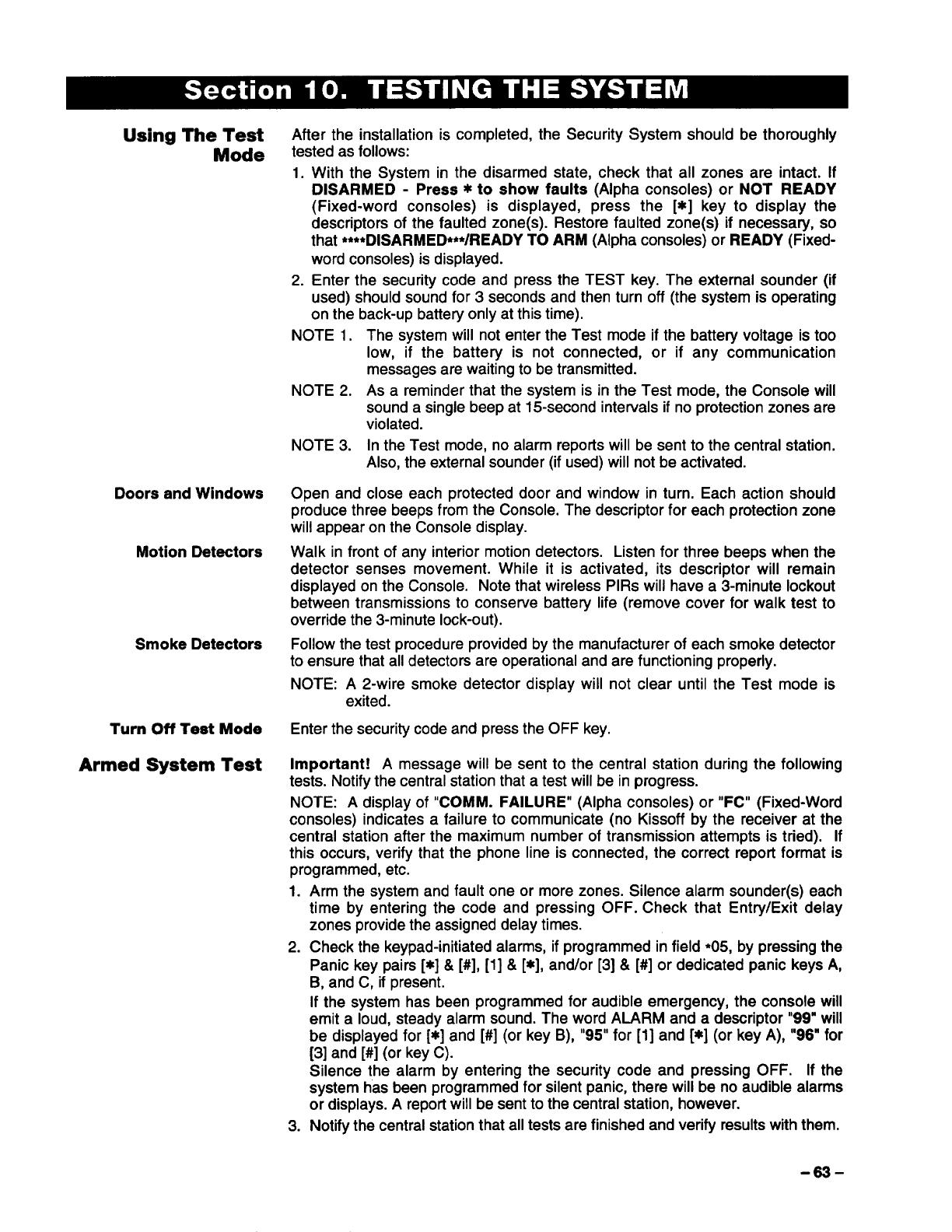
Using The Test
Mode
Doors and Windows
Motion Detectors
Smoke Detectors
Turn Off Test Mode
Armed System Test
After the installation is completed, the Security System should be thoroughly
tested as follows:
1. With the System in the disarmed state, check that all zones are intact. If
DISARMED -Press *to show faults (Alpha consoles) or NOT READY
(Fixed-word consoles) is displayed, press the [*] key to display the
descriptors of the faulted zone(s). Restore faulted zone(s) if necessary, so
that ●***DISARMED***/READY TO ARM (Alpha consoles) or READY (Fixed-
word consoles) is displayed.
2. Enter the security code and press the TEST key. The external sounder (if
used) should sound for 3seconds and then turn off (the system is operating
on the back-up battety only at this time).
NOTE 1. The system will not enter the Test mode if the battery voltage is too
low, if the battery is not connected, or if any communication
messages are waiting to be transmitted.
NOTE 2. As areminder that the system is in the Test mode, the Console will
sound asingle beep at 15-second intervals if no protection zones are
violated.
NOTE 3. In the Test mode, no alarm reports will be sent to the central station.
Also, the external sounder (if used) will not be activated.
Open and close each protected door and window in turn. Each action should
produce three beeps from the Console. The descriptor for each protection zone
will appear on the Console display.
Walk in front of any interior motion detectors. Listen for three beeps when the
detector senses movement. While it is activated, its descriptor will remain
displayed on the Console. Note that wireless PIRs will have a3-minute lockout
between transmissions to conserve battery life (remove cover for walk test to
override the 3-minute lock-out).
Follow the test procedure provided by the manufacturer of each smoke deteotor
to ensure that all detectors are operational and are functioning properly.
NOTE: A2-wire smoke detector display will not clear until the Test mode is
exited.
Enter the security code and press the OFF key.
Important! Amessage will be sent to the central station during the following
tests. Notify the central station that atest will be in progress.
NOTE: Adisplay of “COMM. FAILURE” (Alpha consoles) or “FC” (Fixed-Word
consoles) indicates afailure to communicate (no Kissoff by the receiver at the
central station after the maximum number of transmission attempts is tried). If
this occurs, verify that the phone line is connected, the correct report format is
programmed, etc.
1. Arm the system and fault one or more zones. Silence alarm sounder(s) each
time by entering the code and pressing OFF. Check that Entry/Exit delay
zones provide the assigned delay times.
2. Check the keypad-initiated alarms, if programmed in field *05, by pressing the
Panic key pairs [x] &[#], [1] &[*], and/or [3] &[#] or dedicated panic keys A,
B, and C, if present.
If the system has been programmed for audible emergency, the console will
emit aloud, steady alarm sound. The word ALARM and a descriptor “99” will
be displayed for [*] and [#] (or key B), “95” for [1] and [*] (or key A), “96” for
[3] and [#] (or key C).
Silence the alarm by entering the security code and pressing OFF. If the
system has been programmed for silent panic, there will be no audible alarms
or displays. Areport will be sent to the central station, however.
3. Notify the central station that all tests are finished and verify results with them.
-63-
Turning The System 1. Fully explain the operation of the system to the user by going over each of its
Over To The User functions as well as the User’s Manual supplied.
2. In particular, explain the operation of each zone (entry/exit, perimeter, interior,
fire, etc.). Be sure the user understands how to operate any emergency
feature(s) programmed into the system.
Important!:
In the spaces provided in the User’s Manual, record the Entty and Exit Delay
times, and those functions that have been programmed into the PANIC keys:
Key pairs [x] &[#], [1] &[x], [3]& [#], or,
individual keys, A, B, and C.
3. Make sure the user understands the importance of testing the system at least
weekly, following the procedure provided in the User’s Manual.
TO THE INSTALLER
Regular maintenance and inspection (at least annually) by the installer and
frequent testing by the user are vital to continuous satisfactory operation of any
alarm system.
The installer should assume the responsibility of developing and offering a
regular maintenance program to the user as well as acquainting the user with
the proper operation and limitations of the alarm system and its component
parts. Recommendations must be included for aspecific program of frequent
testing (at least weekly) to insure the system’s proper operation at all times.
-64-
Remote Consoles
Console Is Inoperable; “
Erratic Display
●
●
Power down completely (AC +battety), disconnect the battery, and power up
again (AC only).
Check that auxiliary voltage is between 12.5VDC-14.0VDC. If not, disconnect all
auxiliary devices, and take another reading. If now within the above range, there
was too much current being drawn by the auxiliary devices. (see the Auxiliary
Device Worksheet for the current draw of each device). If still not within the
above range, check incoming power from the No. 1361 transformer. Voltage
should be 16.5VAC. If below 15VAC, carefully check the AC supply for a
minimum of 110 VAC.
With all auxiliary devices and batterv still disconnected, check the voltaae on the
red &black bafiery leads. It should be 13.65VDC (approx.). If not, re~lace the
Control. If it is @13.65VDC, the battery may not be at full charge (allow the
battery to charge 12-24 hours before reconnecting the auxiliary devices) or the
battery may be bad, and not able to hold acharge.
Hard-Wired Zones, 1-8
Zone 1in trouble ●If zone 1is programmed for fire (response type 9), make sure that field 1●46 is
(“CHECK” or “FAULT”) set to “3” (zone 1EOLR). Also,make sure that the RED jumper is intact and that
there is a2,000 ohm EOLR across the last device, as described in the SYSTEM
CONFIGURATION: ZONES section. All devices must be normally open and
connected in parallel across terminals 9 and 10.
●If zone 1is programmed as anon-fire response type and field ●41 is
programmed as a“O”(EOLR required), make sure that the RED jumper is intact
and that there is a 2000 ohm EOLR connected across the last device, as
described in the SYSTEM CONFIGURATION: ZONES section.All devices must
be normally open and connected in parallel across terminals 9 and 10. Check
that field 1●46 is set to “3” (zone 1EOLR).
cIf zone 1is programmed as anon-fire response type and field *41 is
programmed as a”1” (normall closed loops), make sure that the RED jumper is
cut, and that normally closed devices are connected in series between terminals
10 and 12 as described nthe SYSTEM CONFIGURATION: ZONES section.
Zones 2-8 not detecting ●If using EOLRS,check that program field *41=0; if not using EOLRS,●41=1.
faults when their EOLRS
are shorted (READY
display stays on)
Zones 1-8 is not detecting “Check program fields 1•18 and 1•19 to make sure the wired zone(s) in question
faults (READY light stays have not been enabled as RF zones.
on)
Hard-Wired Zones On 4219 Wired Zone Expander
Zones on 4219 not ●
detecting faults ●
●
“81” appears in the ●
console dispiay and rapid .
beeping occurs. ●
●
Make sure that RF zones do not overlap any of the 4219 zones.
Make sure that Address 1*58 is programmed correctly and that the correct
response types have been entered for the corresponding zones.
Make sure that the dipswitches on the 4219 are set in accordance with Figure 1
in the section titled WIRED ZONE EXPANSION.
The 4219 wired zone expander is not responding to the control panel.
Check that the control is wired properly to the 4219.
Check that the wire run length is in agreement with the recommended wire
gauge.
Make sure that the dipswitches on the 4219 are set in accordance with Figure 1
in the section titled WIRED ZONE EXPANSION.
-65-
Wireless
“SET-UP ERROR” (Alpha
consoles), “E4” or “E8”
Fixed-Word consoles)
displayed
“88” or “90” appears in
console display and rapid
beeping occurs
“89” or “91” appears in
console display and rapid
beeping occurs
Zones, not programmed in
the system, are indicating
“CHECK” conditions
Zones indicating a“NOT
READY” condition, but
transmitter contact loop is
intact
One or more transmitters
are indicating “CHECK”
conditions after awhile;
console beeping rapidly:
“READY” display not
going out when RF zones
faulted
-68-
More than the allowed RF zones have been enabled in fieldsl*18-1 ●25 (see below).
●
●
●
●
●
●
●
●
●
9
9
●
●
●
●
●
●
●
●
●
●
●
●
●
Console Type RF Receiver Type Error Message
Alpha 4281 L(4 zones) “SET-UP ERROR”
Alpha 4281H/M (8 zones) “SET-UP ERROR”
Fixed-Word 4281L (4 zones) ,,E4”
Fixed-Word 4281H/M (8 zones) “E8”
The 4281 receiver is not receiving any signals from any of the transmitters in the
system. An “88” is for the 2nd receiver; a“90” is for the 1st receiver. These
displays are enabled by assigning azone response type in program fields 1●08,
and 1*09. The recommended response is either zone type 05 or 07.
Check that the antenna is installed properly and is not shorted to any metal
object, refer to WIRELESS EXPANSION section for details.
Check that the transmitters are powered up with fresh 9volt batteries.
Check that the house ID’s match between transmitters and the entry in field 1*51.
Determine if anything is blocking transmission to the receiver (ex: metal cabinets
or shelves, etc.)
Put the system in the test mode, then see if the transmitters check-in. If not,
move the 4281 receiver to another location and test again.
The 4281 receiver is not responding to the Control panel. An “89” refers to the
second receiver and a “91” refers to the first receiver.
Check that the control is wired properly to the receiver.
Check that the dipswitches for each 4281 receiver are set in accordance with
Figure 2in the WIRELESS ZONE EXPANSION section.
Check that the wire run length is in agreement with the recommended wire
gauge.
Check program fields *O2 through *05, and 1●O1 through 1*O5 to make sure all
unused zones are 00s.
Check program fields 1*18through 1●25 to make sure that all non-RF zones are
0s.
Put the system in the SNIFFER MODE for at least 2hours, to see if another
system in the area is using the same house ID. If so, change this system’s house
ID number.
Make sure zones in question are selected as RF in fields 1*18-1●25.
Check that the transmitters have the correct house ID programmed.
Check that the transmitters have the correct transmitter ID assigned.
Check that the transmitters have fresh batteries.
Check that the house ID’s match between the transmitters and the receiver.
Check that the receiver is enabled in program fields 1*26 for the first receiver and
1.27 for the second receiver.
Check that the zones in question are enabled for RF in program fields 1*18
through 1*25.
Check that azone response is programmed for the zones in question, in fields
●O2through *05, and 1*O1through 1●05.
Check that the receiver’s antenna is properly installed.
Remove any sensors from the transmitters and short across the transmitter
terminals. Then fault the transmitter to see if the “READY” light goes out. If it
does not go out, check the programming for that particular transmitted if it does
go out, check the sensors on that zone.
Move the receiver to another location for better reception.

Console displays “NOT
READY” but no zone is
displayed when [*] READY
key is depressed
While in the “TEST” mode,
some or all of the
transmitters are not
responding, or are re-
sponding irregularly
Communications
“FC” or “COMM
FAILURE”, is displayed
●
●
●
●
●
●
●
●
●
●
●
●
●
●
●
●
●
✎
ASilent Panic condition may be present. Key the security code +OFF to see if
the condition clears.
The Test mode cuts the receiver’s sensitivity by 50%. This means that as long as
atransmitter responds, its location is satisfactory.
Move the affected transmitters to another location and re-test. There may be
something blocking its transmission path.
If all transmitters are affected, move the receiver to another location. There may
be something blocking its reception.
If no receiver location can be found that can reliably receive all transmitters, add
asecond receiver in adifferent location in the premises to extend the RF
coverage of the system.
“FC” (Fixed-word consoles) or “COMM FAILURE” (Alpha consoles) indicates that
the communicator has attempted 8times to send areport to the central station
but did not get kissoff.
If backup reporting is enabled, as many as 16 attempts may be made before
obtaining the “FC” error,
Check with the central station to make sure the programmed format is acceptable
to the central station’s receiver.
Check program field *49 to see if single message with checksum has been
enabled. The central station receiver might not be able to handle checksum.
Check program field 1*34 to see if split reporting is enabled. If only aprimary
central station phone number is being used, field 1●34 must =O!
Check program field *31, PABX ACCESS CODE. Enter up to 4-digits only if an
outside line must be accessed before the number is dialed or if “call waiting” is to
be suppressed. The latter feature must be obtained from the local telephone
company. To make sure this field is empty, key ●31*to erase this location.
Check program field *3Ofor either TouchTone or rotary dialing. In most cases, if
rotary is selected dialing will be successful, but if TouchTone is selected, then the
line must be a TouchTone line. It is possible that aline that had permitted
TouchTone service previously was now being blocked from that use by the
telephone company because the user was not paying for that service. At
installation time, it is important to check with the user to determine if they are
paying for TouchTone service.
If SESCOA/RADIONICS format is being used, check program field ●50. If
hexadecimal codes are being sent, enter a“O”. If only O-9 is being sent, either a
“1” or a“O” is acceptable. Check with the central station to verify acceptance of
B-F codes.
If 3+1/4+1 LOW SPEED is being used, check the ID portion of the report code
fields. There should be “O” in all of these fields. Some central station receivers
cannot handle second digit reporting.
Check the telephone numbers programmed in fields ●33 &●34.
Listen to the outgoing call attempts using ahandset.
Check the wiring on the Telco connector.
IN THE EVENT OF TELEPHONE OPERATIONAL PROBLEMS
In the event of telephone operational problems, disconnect the control panel by removing the plug
from the RJ31 X(CA38A in Canada) wall jack. We recommend that you demonstrate disconnecting
the phones on installation of the system. Do not disconnect the phone connection inside the Control
Panel. Doing so will result in the loss of your phone lines. If the regular phone works correctly after
the Control Panel has been disconnected from the phone lines, the Control Panel has aproblem and
should be returned for repair. If upon disconnection of the Control Panel, there is still aproblem on
the line, notify the telephone company that they have aproblem and request prompt repair service.
The user may not under any circumstances (in or out of warranty) attempt any service or repairs to
the system. It must be returned to the factory or an authorized service agency for all repairs.
-67-
4120XM CONTROL Physical: 12-1/2”W X14-1/2”H X3“D
(317mm x368mm x76mm)
Electrical:
Voltage Input: From Ademco No. 1321/TF2 Plug-In Transformer
(use 1321CN in Canada) rated 16.5VAC, 25 VA.
A/arm Sounder Otput: 10VDC-13.8VDC, 2.8 amps max. (non-UL
installations). See UL note below.
Aux.Power Output:9.6VDC-13.8VDC, 700mA max (700 mA less
Aux current draw for UL installations). For UL installations, the
accessories connected to the output must be UL Listed, and rated
to operate in the above voltage range.
UL NOTE: The current draw from the Aux Output and Alarm
Output combined must not exceed 700 mA in UL installations.
Back-up Battery: 12VDC, 4AH or 7AH gel cell. YUASA NP4-12
(12V, 4AH) or NP7-12 (12V, 7AH) recommended. Use 4AH
battery for UL installations.
Standby: 4hours min. with 500 mA aux. load using 4AH battery.
Circuit Protectors: Thermal circuit breakers are used on battery
input to protect against reverse battery connections and on alarm
sounder output to protect against wiring faults (shorts) and on
auxiliary power output to protect against wiring faults (shorts).
DIGITAL COMMUNICATOR
Formats Suppoded:
ADEMCO HIGH SPEED
ADEMCO 4+2 EXPRESS
ADEMCO LOW SPEED
ADEMCO CONTACT ID
SESCOA
RADIONICS LOW SPEED
LINE SEIZE: Double Pole
RINGER EQUIVALENCE: 0.7B
FCC REGISTRATION NO.: AC398U-681 92-AL-E
4127 REMOTE CONSOLE Physical: 5-5/8”W X4-1 1/16“HX7/8”D
(143mm x119mm x22mm)
Electrical: Voltage Input: 12VDC
Current Drain: 20 mA
Interface Wiring:
RED: 12VDC input (+) -auxiliary power
GREEN: Data to control panel
YELLOW: Data from control panel
BLACK: Ground and (-) connection from supplemental
power supply.
4137AD15137AD REMOTE Physical: 8.4” WX4.75” HX1.1” D
CONSOLES (213mm x121mm x28mm)
Electrical: Voltage Input: 12VDC
Current Drain: 60 mA (4137AD)
90 mA (5137AD)
Interface Wiring:
RED: 12VDC input (+) auxiliary power
BLUE: (If present) Not Used
GREEN: Data to control panel
YELLOW: Data from control panel
BLACK: Ground and (-) connection from supplemental
power supply.
-ss -
6127 REMOTE CONSOLE Physical: 5.75” Wx4.75”HX1“D
(146mm x 121mm x26mm)
Electrical: Vottage Input 12VDC
Current Drain: 20 mA
Interface Wiring:
RED: 12VDC input (+) auxiliary power
BLUE: (If present) Not Used
GREEN: Data to control panel
YELLOW: Data from control panel
BLACK Ground and (-) connection from supplemental
power supply.
6137 REMOTE CONSOLE Physical: 6.25” WX4.75H X1“D
(159mm x121mm x26mm)
Electrical: Voltage Input: 12VDC
Current Drain: 85 mA
Interface Wiring:
RED: 12VDC input (+) auxiliary power
BLUE: (If present) Not Used
GREEN: Data to control panel
YELLOW: Data from control panel
BLACK: Ground and (-) connection from supplemental
power supply.
6139 REMOTE CONSOLE Physical: 6.25” WX4.75”H X1.25” D
(159mm x121mm x32mm)
Electrical: Voltage Input: 12VDC
Current Drain: 100 mA
Interface Wiring:
RED: 12VDC input (+) auxiliary power
BLUE: (If present) Not Used
GREEN: Data to control panel
YELLOW: Data from control panel
BLACK: Ground and (-) connection”from supplemental
power supply.
-69-
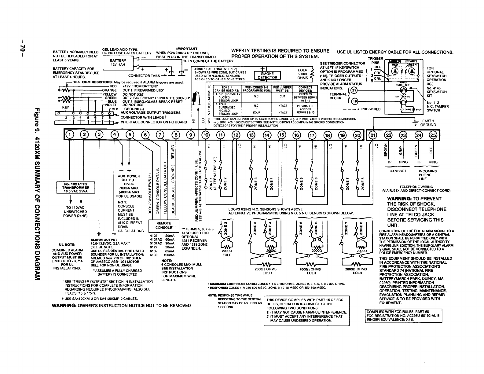
u
.
k’
1
Figure 9. 4120XM SUMMARY OF CONNECTIONS DIAGRAM
-70-
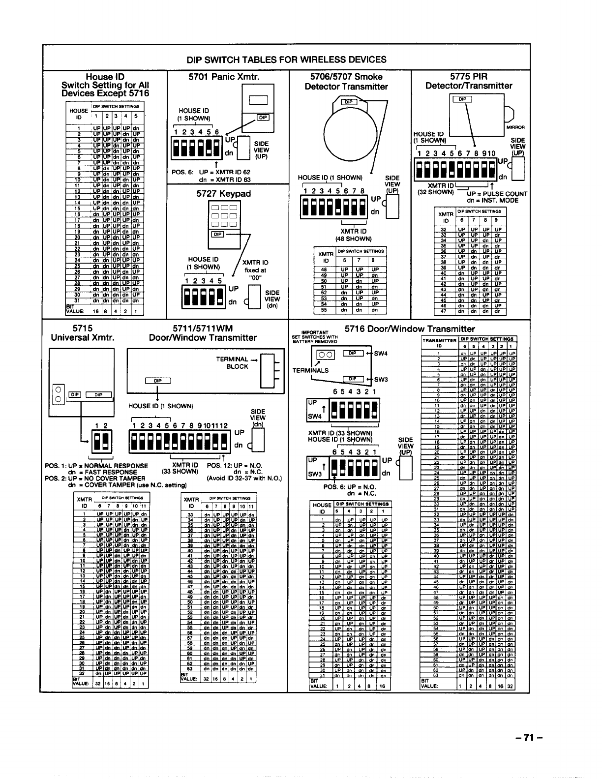
DIP SWITCH TABLES FOR WIRELESS DEVICES
-71-
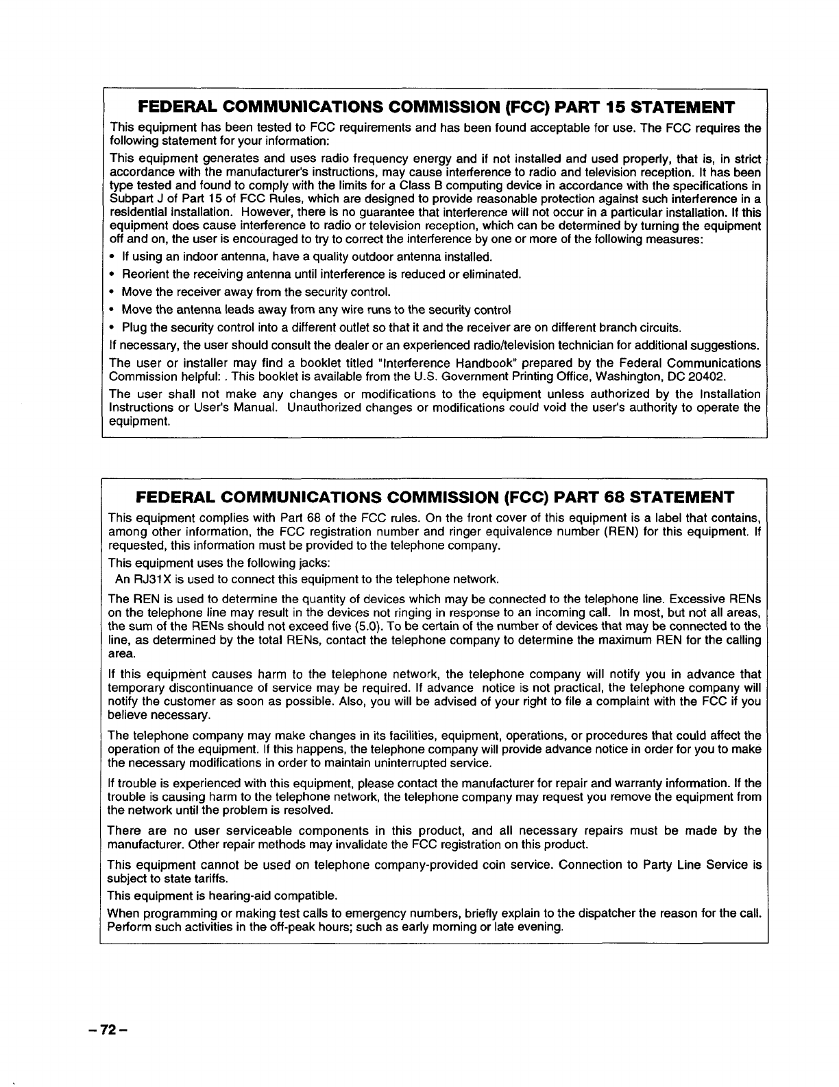
IFEDERAL COMMUNICATIONS COMMISSION (FCC) PART 15 STATEMENT \
This equipment has been tested to FCC requirements and has been found acceptable for use. The FCC requires the
following statement for your information:
This equipment generates and uses radio frequency energy and if not installed and used properly, that is, in strict
accordance with the manufacturer’s instructions, may cause interference to radio and television reception. It has been
type tested and found to comply with the limits for aClass Bcomputing device in accordance with the specifications in
Subpart Jof Part 15 of FCC Rules, which are designed to provide reasonable protection against such interference in a
residential installation. However, there is no guarantee that interference will not occur in aparticular installation. If this
equipment does cause interference to radio or television reception, which can be determined by turning the equipment
off and on, the user is encouraged to try to correct the interference by one or more of the following measures:
●If using an indoor antenna, have aquality outdoor antenna installed.
●Reorient the receiving antenna until interference is reduced or eliminated.
●Move the receiver away from the security control.
●Move the antenna leads away from any wire runs to the security control
I●Plug the security control into adifferent outlet so that it and the receiver are on different branch circuits. I
If necessary, the user should consult the dealer or an experienced radio/television technician for additional suggestions.
The user or installer may find abooklet titled “Interference Handbook” prepared by the Federal Communications
Commission helpful: .This booklet is available from the U.S. Government Printing Office, Washington, DC 20402.
The user shall not make any changes or modifications to the equipment unless authorized by the Installation
Instructions or User’s Manual. Unauthorized changes or modifications could void the user’s authority to operate the
equipment.
IFEDERAL COMMUNICATIONS COMMISSION (FCC) PART 68 STATEMENT I
This equipment complies with Part 68 of the FCC rules. On the front cover of this equipment is alabel that contains,
among other information, the FCC registration number and ringer equivalence number (REN) for this equipment. If
requested, this information must be provided to the telephone company.
This equipment uses the following jacks:
An RJ31 Xis used to connect this equipment to the telephone network.
The REN is used to determine the quantity of devices which maybe connected to the telephone line. Excessive RENs
on the telephone line may result in the devices not ringing in response to an incoming call. In most, but not all areas,
the sum of the RENs should not exceed five (5.0). To be certain of the number of devices that may be connected to the
line, as determined by the total RENs, contact the telephone company to determine the maximum REN for the calling
area.
If this equipment causes harm to the telephone network, the telephone company will notify you in advance that
temporary discontinuance of service may be required. If advance notice is not practical, the telephone company will
notify the customer as soon as possible. Also, you will be advised of your right to file acomplaint with the FCC if you
believe necessary.
The telephone company may make changes in its facilities, equipment, operations, or procedures that could affect the
operation of the equipment. If this happens, the telephone company will provide advance notice in order for you to make
the necessaty modifications in order to maintain uninterrupted service.
If trouble is experienced with this equipment, please contact the manufacturer for repair and warranty information. If the
trouble is causing harm to the telephone network, the telephone company may request you remove the equipment from
the network until the problem is resolved.
There are no user serviceable components in this product, and all necessary repairs must be made by the
manufacturer. Other repair methods may invalidate the FCC registration on this product.
This equipment cannot be used on telephone company-provided coin service. Connection to Party Line Service is
subject to state tariffs.
This equipment is hearing-aid compatible.
When programming or making test calls to emergency numbers, briefly explain to the dispatcher the reason for the call.
Perform such activities in the off-peak hours; such as early morning or late evening.
-72-
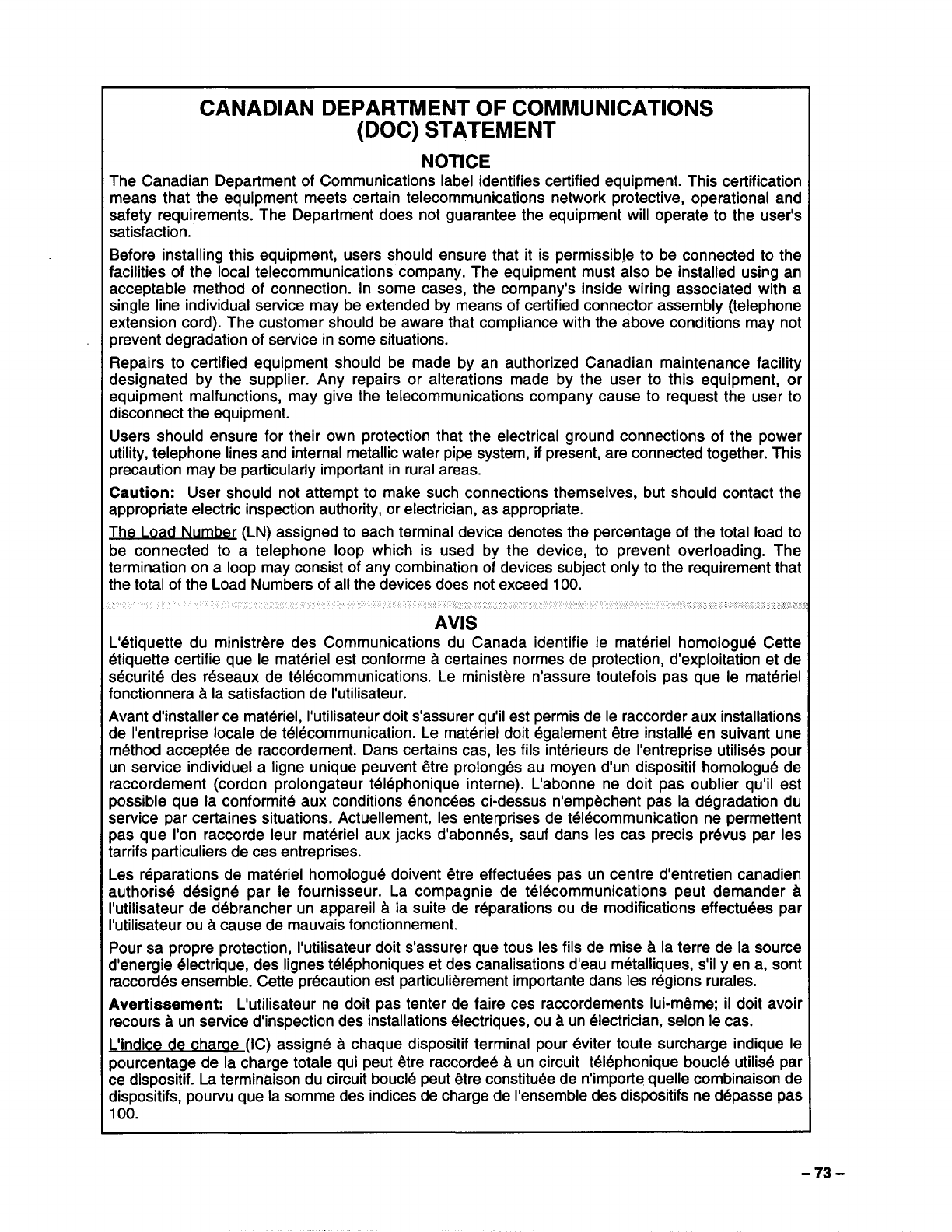
CANADIAN DEPARTMENT OF COMMUNICATIONS
(DOC) STATEMENT
NOTICE
The Canadian Department of Communications label identifies certified equipment. This certification
means that the equipment meets certain telecommunications network protective, operational and
safety requirements. The Department does not guarantee the equipment will operate to the user’s
satisfaction.
Before installing this equipment, users should ensure that it is permissible to be connected to the
facilities of the local telecommunications company. The equipment must also be installed usi~g an
acceptable method of connection. In some cases, the company’s inside wiring associated with a
single line individual service may be extended by means of certified connector assembly (telephone
extension cord). The customer should be aware that compliance with the above conditions may not
prevent degradation of service in some situations.
Repairs to certified equipment should be made by an authorized Canadian maintenance facility
designated by the supplier. Any repairs or alterations made by the user to this equipment, or
equipment malfunctions, may give the telecommunications company cause to request the user to
disconnect the equipment.
Users should ensure for their own protection that the electrical ground connections of the power
utility, telephone lines and internal metallic water pipe system, if present, are connected together. This
precaution may be particularly important in rural areas.
Caution: User should not attempt to make such connections themselves, but should contact the
appropriate electric inspection authority, or electrician, as appropriate.
The Load Number (LN) assigned to each terminal device denotes the percentage of the total load to
be connected to atelephone loop which is used by the device, to prevent overloading. The
termination on a loop may consist of any combination of devices subject only to the requirement that
the total of the Load Numbers of all the devices does not exceed 100.
AVIS
L’6tiquette du ministrbre des Communications du Canada identifie Ie mat6riel homologu6 Cette
btiquette certifie que Ie matc%ielest conforme ~certaines normes de protection, d’exploitation et de
s6curit6 des r6seaux de t616communications. Le ministbre n’assure toutefois pas que Ie matt%iel
fonctionnera ~la satisfaction de I’utilisateur.
Avant d’installer ce matr%el, I’utilisateur doit s’assurer qu’il est permis de Ie raccorder aux installations
de I’entreprise locale de tddcommunication. Le mat&iel doit dgalement 6tre instal16en suivant une
m6thod accept6e de raccordement. Dans certains cas, Ies fils intdrieurs de I’entreprise utilis6s pour
un service individual aIigne unique peuvent 6tre prolong6s au moyen d’un dispositif homologu4 de
raccordement (cordon prolongateur t614phonique interne). L’abonne ne doit pas oublier qu’il est
possible que la conformity aux conditions enoncdes ci-dessus n’empbchent pas la degradation du
service par certaines situations. Actuellement, Ies enterprises de tdldcommunication ne permettent
pas que I’on raccorde Ieur mat6riel aux jacks d’abonnbs, sauf clans Ies cas precis prr%us par Ies
tarrifs particuliers de ces entreprises.
Les reparations de mak%iel homologu6 doivent ~tre effectudes pas un centre d’entretien canadien
authoris4 dbsignb par Ie fournisseur. La compagnie de t616communications peut demander A
I’utilisateur de d6brancher un appareil hla suite de reparations ou de modifications effectu6es par
I’utilisateur ou Acause de mauvais fonctionnement.
Pour sa propre protection, I’utilisateur doit s’assurer que tous Ies fils de mise 3la terre de la source
d’energie dlectrique, des Iignes tr514phoniqueset des canalisations d’eau m6talliques, s’il yen a, sent
raccord4s ensemble. Cette precaution est particulibrement importanceclans Ies r6gions rurales.
Avertissement: L’utilisateur ne doit pas tenter de faire ces raccordements lui-mi2me; il doit avoir
recours aun service d’inspection des installations dlectriques, ou Aun electrician, selon Ie cas.
Eindice de charae (IC) assigrv$ ~chaque dispositif terminal pour 6viter toute surcharge indique Ie
pourcentage de la charge totale qui peut &tre raccorde6 h un circuit t616phonique bouc16utilisd par
ce dispositif. La terminaison du circuit bouc14peut 6tre constitu~e de n’importe quelle combinaison de
dispositifs, pourvu que la somme des indices de charge de I’ensemble des dispositifs ne d6passe pas
100.
-73-
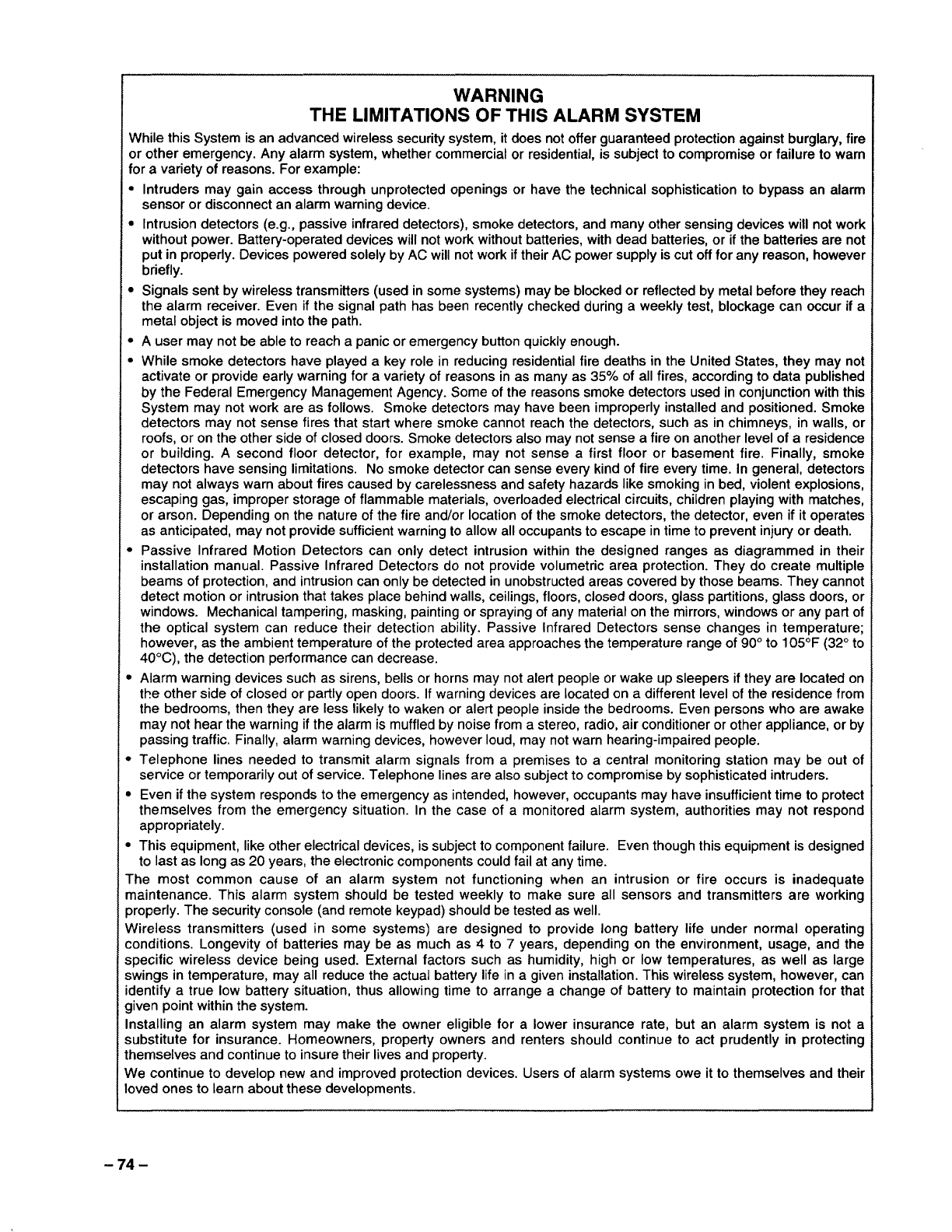
WARNING
THE LIMITATIONS OF THIS ALARM SYSTEM
While this System is an advanced wireless security system, it does not offer guaranteed protection against burglary, fire
or other emergency. Any alarm system, whether commercial or residential, is subject to compromise or failure to warn
for avariety of reasons. For example:
Intruders may gain access through unprotected openings or have the technical sophistication to bypass an alarm
sensor or disconnect an alarm warning device.
Intrusion detectors (e.g., passive infrared detectors), smoke detectors, and many other sensing devices will not work
without power. Battery-operated devices will not work without batteries, with dead batteries, or if the batteries are not
put in properly. Devices powered solely by AC will not work if their AC power supply is cut off for any reason, however
briefly.
Signals sent by wireless transmitters (used in some systems) maybe blocked or reflected by metal before they reach
the alarm receiver. Even if the signal path has been recently checked during aweekly test, blockage can occur if a
metal object is moved into the path.
Auser may not be able to reach apanic or emergency button quickly enough.
While smoke detectors have played a key role in reducing residential fire deaths in the United States, they may not
activate or provide early warning for avariety of reasons in as many as 35% of all fires, according to data published
by the Federal Emergency Management Agency. Some of the reasons smoke detectors used in conjunction with this
System may not work are as follows. Smoke detectors may have been improperly installed and positioned. Smoke
detectors may not sense fires that start where smoke cannot reach the detectors, such as in chimneys, in walls, or
roofs, or on the other side of closed doors. Smoke detectors also may not sense afire on another level of aresidence
or building. Asecond floor detector, for example, may not sense afirst floor or basement fire. Finally, smoke
detectors have sensing limitations. No smoke detector can sense every kind of fire every time. In general, detectors
may not always warn about fires caused by carelessness and safety hazards like smoking in bed, violent explosions,
escaping gas, improper storage of flammable materials, overloaded electrical circuits, children playing with matches,
or arson. Depending on the nature of the fire and/or location of the smoke detectors, the detector, even if it operates
as anticipated, may not provide sufficient warning to allow all occupants to escape in time to prevent injury or death.
Passive Infrared Motion Detectors can only detect intrusion within the designed ranges as diagramed in their
installation manual. Passive Infrared Detectors do not provide volumetric area protection. They do create multiple
beams of protection, and intrusion can only be detected in unobstructed areas covered by those beams. They cannot
detect motion or intrusion that takes place behind walls, ceilings, floors, closed doors, glass partitions, glass doors, or
windows. Mechanical tampering, masking, painting or spraying of any material on the mirrors, windows or any part of
the optical system can reduce their detection ability. Passive Infrared Detectors sense changes in temperature;
however, as the ambient temperature of the protected area approaches the temperature range of 90° to 105°F (32° to
40”C), the detection performance can decrease.
Alarm warning devices such as sirens, bells or horns may not alert people or wake up sleepers if they are located on
the other side of closed or partly open doors. If warning devices are located on adifferent level of the residence from
the bedrooms, then they are less likely to waken or alert people inside the bedrooms. Even persons who are awake
may not hear the warning if the alarm is muffled by noise from astereo, radio, air conditioner or other appliance, or by
passing traffic. Finally, alarm warning devices, however loud, may not warn hearing-impaired people.
Telephone lines needed to transmit alarm signals from apremises to acentral monitoring station may be out of
service or temporarily out of service. Telephone lines are also subject to compromise by sophisticated intruders.
Even if the system responds to the emergency as intended, however, occupants may have insufficient time to protect
themselves from the emergency situation. In the case of amonitored alarm system, authorities may not respond
appropriately.
This ecwipment, like other electrical devices, is subiect to component failure. Even thoucrhthis eauiDment is desianed
to last as”long as 20 years, the electronic components could fail at any time. . .
I_he most common cause of an alarm system not functioning when an intrusion or fire occurs is inadequate
maintenance. This alarm system should be tested weekly to make sure all sensors and transmitters are working
]roperly. The security console (and remote keypad) should be tested as well.
Nireless transmitters (used in some systems) are designed to provide long battery life under normal operating
:onditions. Longevity of batteries may be as much as 4 to 7years, depending on the environment, usage, and the
lpecific wireless device being used. External factors such as humidity, high or low temperatures, as well as iarge
;wings in temperature, may all reduce the actual battery life in agiven installation. This wireless system, however, can
dentify atrue low batte~ situation, thus allowing time to arrange achange of battery to maintain protection for that
]iven point within the system.
nstalling an alarm system may make the owner eligible for alower insurance rate, but an alarm system is not a
;ubstitute for insurance. Homeowners, property owners and renters should continue to act prudently in protecting
hemselves and continue to insure their lives and property.
Me continue to develop new and improved protection devices. Users of alarm systems owe it to themselves and their
oved ones to learn about these developments.
-74-
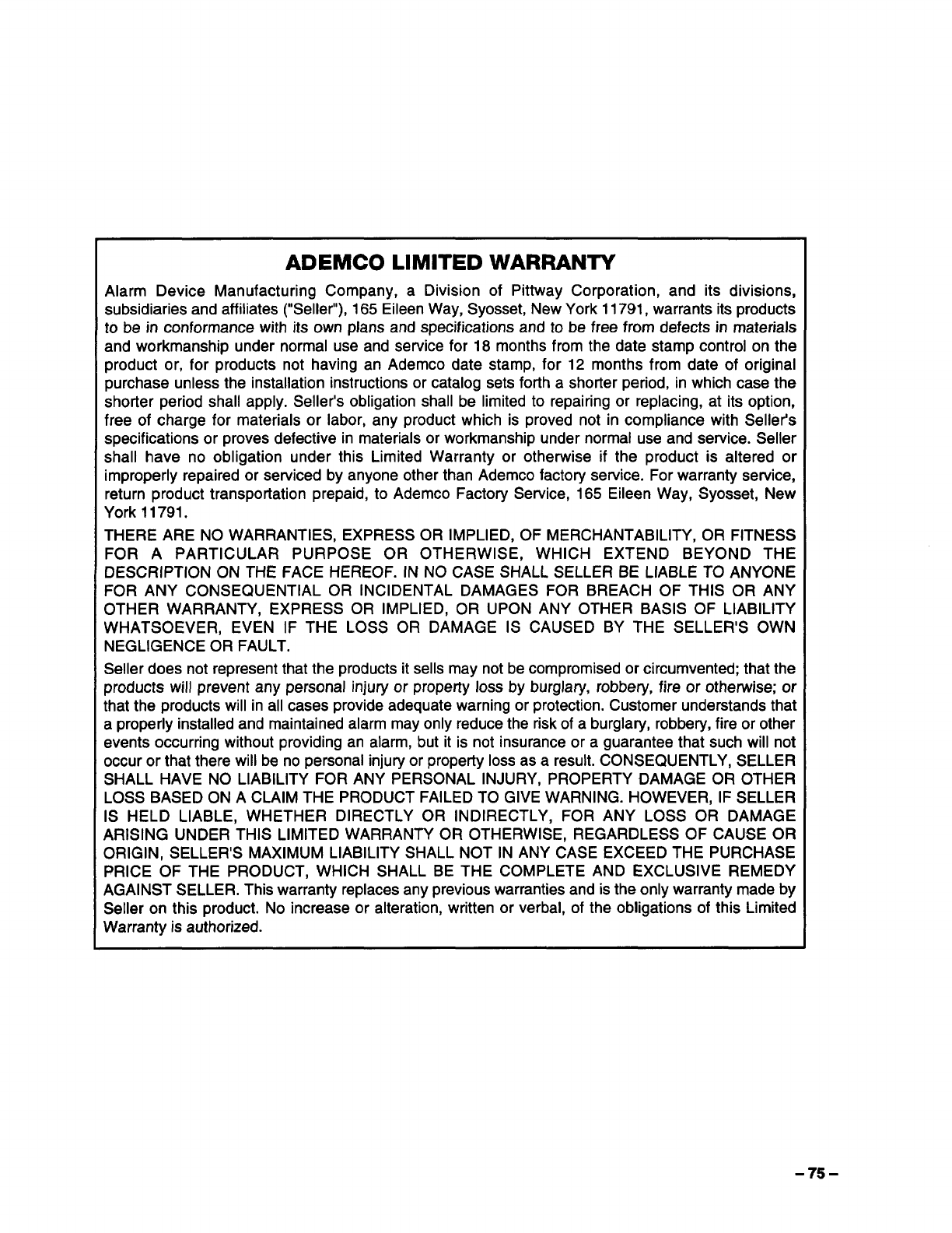
ADEMCO LIMITED WARRANTY
Alarm Device Manufacturing Company, aDivision of Pittway Corporation, and its divisions,
subsidiaries and affiliates (“Seller”), 165 Eileen Way, Syosset, New York 11791, warrants its products
to be in conformance with its own plans and specifications and to be free from defects in materials
and workmanship under normal use and service for 18 months from the date stamp control on the
product or, for products not having an Ademco date stamp, for 12 months from date of original
purchase unless the installation instructions or catalog sets forth ashorter period, in which case the
shorter period shall apply. Seller’s obligation shall be limited to repairing or replacing, at its option,
free of charge for materials or labor, any product which is proved not in compliance with Seller’s
specifications or proves defective in materials or workmanship under normal use and service. Seller
shall have no obligation under this Limited Warranty or otherwise if the product is altered or
improperly repaired or serviced by anyone other than Ademco factory service. For warranty service,
return product transportation prepaid, to Ademco Factory Service, 165 Eileen Way, Syosset, New
York 11791.
THERE ARE NO WARRANTIES, EXPRESS OR IMPLIED, OF MERCHANTABILITY, OR FITNESS
FOR APARTICULAR PURPOSE OR OTHERWISE, WHICH EXTEND BEYOND THE
DESCRIPTION ON THE FACE HEREOF. IN NO CASE SHALL SELLER BE LIABLE TO ANYONE
FOR ANY CONSEQUENTIAL OR INCIDENTAL DAMAGES FOR BREACH OF THIS OR ANY
OTHER WARRANTY, EXPRESS OR IMPLIED, OR UPON ANY OTHER BASIS OF LIABILITY
WHATSOEVER, EVEN IF THE LOSS OR DAMAGE IS CAUSED BY THE SELLER’S OWN
NEGLIGENCE OR FAULT.
Seller does not represent that the products it sells may not be compromised or circumvented; that the
products will prevent any personal injury or property loss by burglary, robbery, fire or otherwise; or
that the products will in all cases provide adequate warning or protection. Customer understands that
aproperly installed and maintained alarm may only reduce the risk of aburglary, robbery, fire or other
events occurring without providing an alarm, but it is not insurance or aguarantee that such will not
occur or that there will be no personal injury or propefiy loss as aresult. CONSEQUENTLY, SELLER
SHALL HAVE NO LIABILITY FOR ANY PERSONAL INJURY, PROPERTY DAMAGE OR OTHER
LOSS BASED ON ACLAIM THE PRODUCT FAlLED TO GIVE WARNING. HOWEVER, IF SELLER
IS HELD LIABLE, WHETHER DIRECTLY OR INDIRECTLY, FOR ANY LOSS OR DAMAGE
ARISING UNDER THIS LIMITED WARRANTY OR OTHERWISE, REGARDLESS OF CAUSE OR
ORIGIN, SELLER’S MAXIMUM LIABILITY SHALL NOT IN ANY CASE EXCEED THE PURCHASE
PRICE OF THE PRODUCT, WHICH SHALL BE THE COMPLETE AND EXCLUSIVE REMEDY
AGAINST SELLER. This warranty replaces any previous warranties and is the only warranty made by
Seller on this product. No increase or alteration, written or verbal, of the obligations of this Limited
Warranty is authorized.
-75-

ALARM DEVICE MANUFACTURING CO.
ADIVISION OF PlllWAY CORPORATION
165 Eileen Way, Syosset, New York 11791
Copyright O1993 PlllWAY CORPORATION
N6493V1 10/93
k~.,
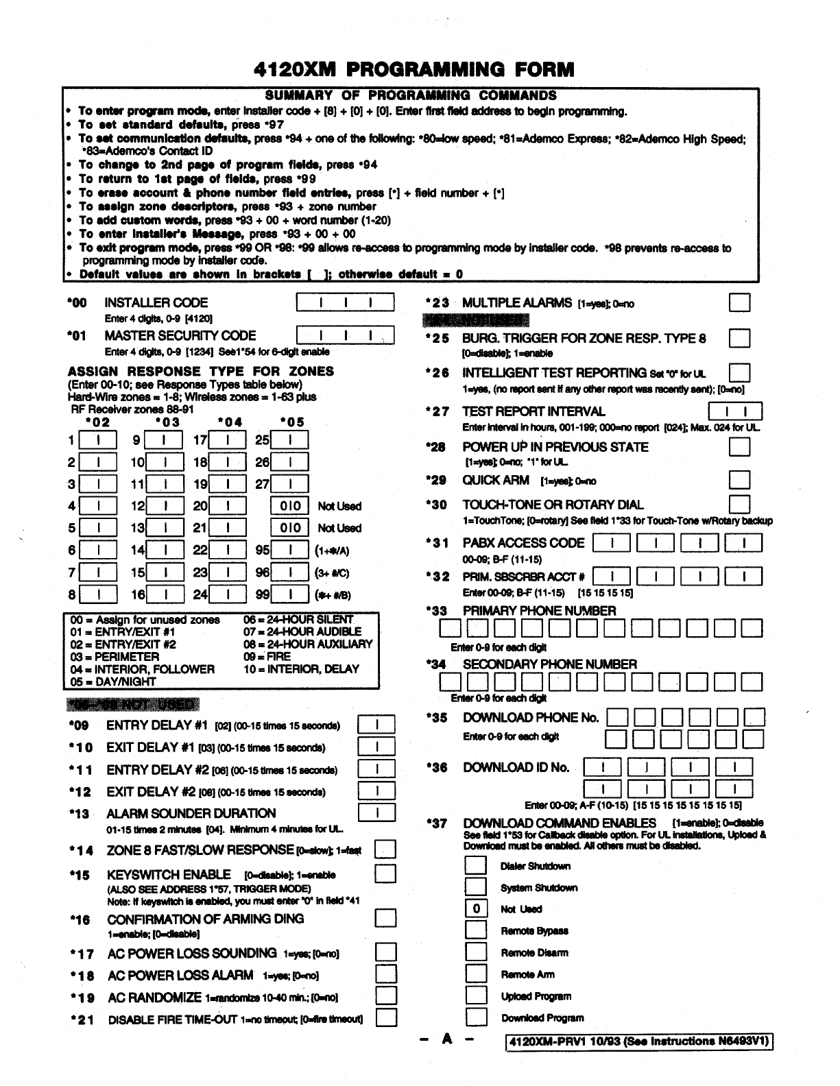
4120XM PROORAMM8NQ FORM
SUMMARY OF PROGRAMMING COMMANDS
●To enter p~em rnodq eriterInetellercode +[8] +[0] +[0]. Enter firstfiatd sddressto begin pmpmmhg.
*To set standard defaulte, press “97
●low~mmunl~n tiub-~+m~ti~-. ”e -●81=AdemcoExprees WMdemco
‘*==AdSm:S OontactID High s-
.To changa to 2nd page of program Wlda, press●94
.To return to 1●tpaga of flelde, press ●99
●10 erase aooourrt &phona number fletd antdq press p] +field number+~]
.To aeslgn zorw daeori~ press ●W+zone number
●To add ouetom words, press*3+ 00 +wordnurnbar(1.20)
●To anter Inatallar’a Meaaa~ press●93 +00 +00
●loaxitprogram m~preeew 0R~W9allowe m-amasstopmgrammlngrnodebyinetallercode. ~preventem-amessto
programmingmudsby inetaHercode.
●Default valuaa are shown In brackets ihOtherwlaedafault =o
*OO INSTALLERCODE IIll 1
Enrer4dlgile, o-2 la?ol
*O1 MASTERSECURITYCODE ~
Enter4111@h3,0-2[1224] 8ebl*54for6d@ ensble
ASSIGN RESPONSE TYPE FOR ZONES
(EnterW-IQ see ReepwweTypestsble below)
Hard-wirezones= l-8; wireISei3zones=l-83pkre
RFReceiverzones88-91
Ndueed
Ndueed
Or)= A@gnforunueedzonee os =24-HOUR SILENT
01 =E~RY~lT #l 07= 24-I-IOUR AUOIBLE 1
02= ENTRYEXIT#i? 08= 24-HouRAUXILIARY
~ = PERIMETER og. FIF?E
04= \NTERmR,FOLLOWER 10. INTERIOR, DEIAY
05= DAY/NIQHT
’09
’10
●I1
‘12
*13
●14
●15
“16
ENTRYDEIAY #1 [OSI(0M5tInws 15seconds) ml
EXITDEIAY #1 {0S](00-15-15 seconds) nI
n
ENTRYDELAYW[06](00-15tlmee15sswwis) I
EXITDELAY#2 [eel(00-15umss15seumds) m
AARM BOUNDERDURATION u
01.15 tlmen2rnhwtss [04]. Mlnwnum4~foruL
ZONE 8FAST/SLOWRESPONSEIo=@owl1* ❑
KEYSWITCHENABLE [o=#MMs
~l=er@le •1
(AL8082EAooRE881 %7, TRmQERmq
NOwHlqswlMlssnsMut youmults-winlw”41
CONFIRMATIONOF ARMING DING •1
l=snsbi6 [OdseMe I
●17
●18
●19
●21
AC POWERLOSSSOUNDINGl=ysG PI@ u
AC POWER LOSSALARM l=yerKKbno] •1
AC ~DoMt= l=mmkmke lo.4orllimml ❑
DISABLEFIRETIME-OUTlm~ [-- ❑
*2 ~MULTIPLEAUIRMS [l=ws~O=m •1
●25
●26
●27
●26
●29
●3O
●31
●32
●33
BURG.TRIGGERFORZONERESP.TYPE8❑
W=dsewMl=ensbte
INTELLIGENT TESTREPORTINGsa‘o’forrJL cl
l=yss,(norspOasenttfsnycrtherreportwasrecenuyd, [~]
TEST REPORTINTERVAL
Enterlntervdinhours,OO1-lw OOO=rIOreporlf024~ Msx.024fortJL
POWER Up tN PREVIOUSSTATE •1
[lEysskOdvJ ‘l”foru
QUICK ARM [l=yklslO=no •1
TOUCH-TONEORROTARYDtAL •1
l=TouchTornx@=rc4ery]8ss Ssld1Y4Sforlouch-lone w/Roterybeckup
PABXACCESSCODE IT ~~1 ml
0cbOX8-F(ll-15)
PRIM. sssoRsRACOT# ~~ml (--l-l
Entermff (11-15) [151515 lq
PRIMARYPHONE NUMBER
❑lclclnclclclclclnclcl
Entero-9fareectrdlgfr
“34 SECONDARYPHONE NUMBER
❑00000000000
Eniero-2foreechrlMl
●
35 DOWNLOADfiE W. 1—1m m rl m~1 ‘
EmerO-9fIXeechdl@ Ilnnnncl
●36 DOWNLOADIDNo. ~1 ml ~ ~
Dmlmlml
Errter004Xl A-F(W45) [151515 15151515151
●37 tX3NNLOAD
COMMANDENABLES [1~1 ~
8eeflsMl*5SforOaiIback_ o@krn.FofULImI@Wom,Wkmd6
DowuoedrrnlstbesnahledNloarsrsrnustbeasabled.
❑
•1 ==
•1
orwumd
•1 RsmoteBylress
•1 RemoteDlssrm
•1 ~Arrn
c1 ww~
•1 DownlaMProgrern
-A- ]4120XM-PRV110/83 (SeeInetruotions N8493V1)]
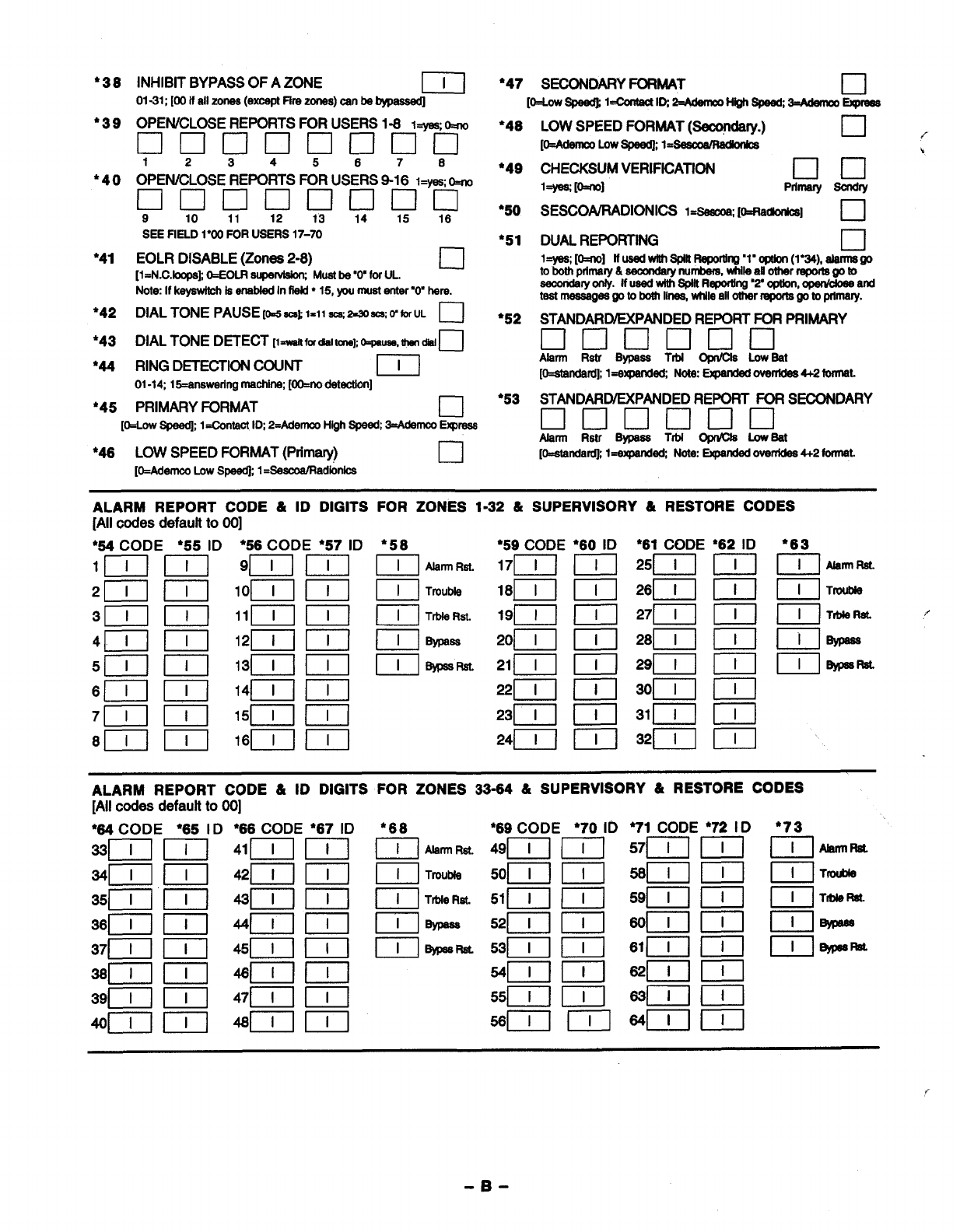
●38
*39
●4O
●41
●42
●43
’44
*45
INHIBIT BYPASS OF AZONE u
01-31; [00 if all zones(exceptFfrazones)can be~
*47 SECONDARYFORMAT •1
[O=Lowspaedl
l=ContaUID 2=AdammH@hSpe@34damco&preaa
OPEN/CLOSEREPORTS FORUSERS1-8 l=WSb
❑clclclclclclcl
1234 5 678
OPEN/CLOSEREPORTSFORUSERS9-16 I=H o=m
❑0000000
910 11 12 13 14 15 16
SEE FIELD 1“~ FOR USERS 17-70
EOLRDISABLE(Zones2-8) •1
[l=N.C.bq)a~ O=EOLRaupe~ Muatbe 00’forUL,
Note If kayawltchlaenebfadInfbfd* 15, yournuatanter’ry hare.
DIAL TONE PAUSE[M =~ 1=11 am 2=WSCS o’ for UL c1
DIALTONEDETECT[l~fwdlalrcne~ o-pause,ttwnM•1
RING D~ECTION COUNT D
01-1415=anaweringrnaohirw[OO=nodatactlon]
PRIMARY FORMAT •1
[O=LOW-l=Ocmfact ID 2-AderncoHighspeed;3=Adamm Erqxaaa
●46 LOW SPEED FORMAT (Primary) ❑
[O=AderncoLowSpaed~l=SaacoalRadbnica
●48
*49
*5O
●51
*52
●53
LOW SPEED FORMAT (Seco@ary.) cl{
[~ Lowspaadl 1=~
CHECKSUMVERIFICATION ❑0’
l=ye&&m] Pmnary Bondry
SESCONRADIONICS 1~ [O=RaUo@cs] •1
STANDARIXXPANDED REPORTFOR PRIMARY
Llclclmucl
Alarm Rstr Bypaas Trbl Opr@la LowBat
[O=atandardll=expanded Note:G@ndad ovarrfdaa4+2 forrnet.
STANDARWEXPANDEDREPORT FOR SECONDARY
❑lmnclclcl
Abnn Rstr Bypaaa Trbl O@Ola LowBat
[O=standa~ l=axpanded Note Expandd ovanidaa4+2 format.
ALARM REPORT CODE &ID DIGITS FOR ZONES 1-32 &SUPERVISORY &RESTORE CODES
[Allcodes defaultto 00]
●58
m
ml
ml
ml
El
I
Abnn Rat.
Tmutrb
TrbfeRet.
Bypaamt
*59 CODE
17~1
c1
I
c1
&
●63
DAbnrlRat.
0. ITrouble
ALARM REPORT CODE &ID DIGITS FOR ZONES 33-64 &SUPERVISORY &RESTORE CODES
[All codes defaultto 00]
D
..
-B-
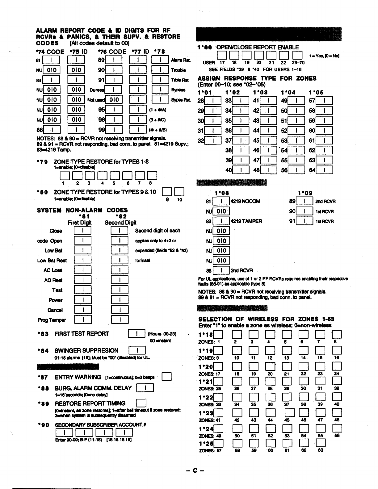
ALARM REPORT CODE &ID DIQITS FOR RF
RCVRS &PANICS, &TNEIR SUPV. &RESTORE
CODES [Alloodea defaultto 00] 1●OO OPEWCLOSE REPORT ENASLE
❑000000 l=y=~=~
usER171s 19 20 21 22 23-70
SEEFIELOS●3S 6●4O FOR USERS1-16
ASSIGN RESPONSE TYPE FOR ZONES
(Enter 00-lQ aee “W*05)
1“01 1●O4 1*O5
●79 2“lYW’JEJW.3TORE for TYPES 1-8
❑lnciclnclcn
12345678
1*O8 1●O9
61p74219NocoM 89~J 2ndRcvR
NJpiq 90~j lstRcvR
83 ~J4219TMPER 91IT1 lstRcvR
“80 ZOIKJY=WtEforTYP ES9& 10 1—] rl
910
SYSTEM NON-ALARM CODES
●81 ●
82
Fi(at Diq Secorahgit NJpiiq
NJpiiq
I@iq
NJpiq
88~lamcvR
Forlne@c@bne* useoflor2RF RcvFMraquire5eMblln2 thelrmsfwoWe
feu118(s6@aeaF@bble(l %le5).
NOTES; 8S&SO=RCVRnotmceMngtranambreignale.
SS&91=RCVR notmpmding, klconn. topaneL
SELECTION OF WIRELESS FOR ZONES 1-63
Enter “1” to enable azone ae wirelea% (%non-wireleea
Seconddigit ofeach
epplieawllyto4+20r
expended(flelda“526 ●53)
Codeoperl
Lwfsat
l-!-l
ml
El
I
0I
c1
I
El
I
nI
nI
nI
nI
I-!-J
ml
El
I
c1
h
El
I
El
I
El
I
El
I
nI
LowSatReet
AC Loea
AC Reel
Test
PmgTemper
—
1W8DOOOOOOU
ZONES1 2 3 4 5 6 7 6
●83 FIRSTTEST REPORT [~ ](w. mm)
Oodru!m
●84 SWINGER SUPPRESSION ~j
ol-15elelllM [lm Mu8tbew (db8bi@foruL ❑clclclnncl
10 11 12 13 14 15 16
1’200
ZONla 17
1“210
mm 25
’87
●88
●89
Uuuu
2a 27 2S 29 30 31 32
SURC3.AIARM COMM. DELAY [ I I
l=16~P=n0deleyl ❑lclclclclncl
34 3a 36 37 36 39 40
1’220
ZONES33
RESTORE REPORTTIMING n
1“230
Zow& 41 EHZOCIUCIEI
424344454s47 46
●SO 6EcoNDARY6m8cRlBERAccQuNr#
mmmlm
EnteroGm S-F(11-W) [15151s lSI
❑ILICHZICICICI
fltlrlrlflfl”
3s 50 30 61 32 33
-c-
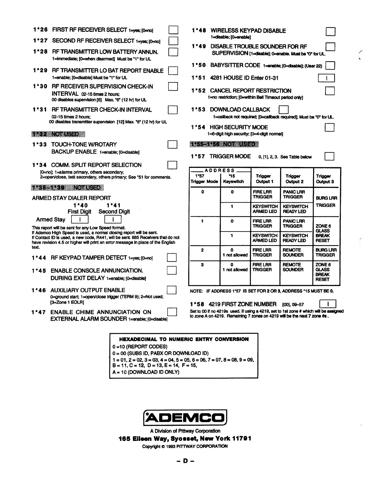
1●26
1*27
1*26
1’29
1*3O
1’31
FIRST RF RECEIVER SELECT l=yes[O=rio]
SECOND RF RECEIVER SELECT 1- [O=rro]
RFTRANSMllTER LOW BA7TERY ANNUN.
l=imrnadlatq [O=whandfaarr@ Muafbe “1”forUL
RF TRANSMllTER LOSAT REPORT ENABLE
1~ [O=disebla]Mustbe ‘1’ forUL
RF RECEIVER SUPERVISION CHECK-IN
INTERVAL 02-15
times2houm
00 diaeblessuparvisbn[6] Mex.%’ (12 hr)forUL
RF TRANSMITTER CHECK-IN INTERVAL
❑
•1
❑
Cl
02-15 times2hou~
00 ctisabfaatransmittersupervision[12] Mex. “6’(12 hr)forUL
. . ..*. A..
~~
1●33 TOUCH-TONE W/ROTARY c1
BACKUP ENABLE I=anabiw p=dbebfe]
1*3 4COMM. SPLIT REPORT SELECTION c1
[O=no~
l=alarmeptimary,otherssecondary
2=opanlcIoss,te$tsacondaty,othersprfmatySee●51 forcomments.
i-xm~~
ARMED STAY DIALER REPORT
1“40 I*41
First Digit Second Digit
Armed Stay IT] ml
This report willbe sentforany LowSpeedformat.
If AdemcoHigh S#ead ISused,anom’raldosingrapotlwilfbesent.
IfContactID is used,anewcode, R441,willbe sent.SS5Racsiverathatdo not
haverevision4.5 or higherwiflmintan errormessageinDISCSofthe Errgiiah
text.
1*44
1*45
1*46
1’47
RF KEYPAD TAMPER DETECT l=yaa [o=no] ❑
ENABLE CONSOLE ANNUNCIATION. ❑
DURING EXIT DELAY I=ensb@[@disatrIsI
AUXILIARY OUTPUT ENABLE ❑
o=gmmdstarLl=opmkfose trigger(TERM9h2=Notused
[3=Zone1EOLR]
ENABLE CHIME ANNUNCIATION ON u
~ERNAL ALARM SOUNDER I=enabe[O=diaabla]
1●48
1●49
1*5O
1*51
1*52
WIRELESS KEYPAD DISABLE
l=dbablq [O=ensMe
1c1
DISABLETROUSLESOUNDERFORRF n
SUPERVISION[l=cfla&klo=enabb.
MustbeW’forUL
BABYSlllER CODE i=anat#q [~k-=) ❑
4281 HOUSE ID Enter01-31 m
CANCELREPORTRESTRICTION n
I=no reMUfoW [O=wlthfnSaflTlmaoutperfodorrly] -
1*53 DOWNLOADCALLBACK ❑
I=mllbsoknotraquir@[O=caflbackmqui~ MuettmVfor LL
1•54 HIGHSECURITY MODE ❑
l=6diiif h@hSSOU~ [0=4-di@ norrna~
1●57 TRIGGER MODE O,[1],2,3. sssTablebabw ❑
I
—ADDRESS—
1●57 75 Tr@@r Trlg@r Trl~
Trigger M@s Kayawftoh Outputl 01rtput2 output 3
0 0 FIRELRR PANICLRR
TRIGGER TRIGGER sum LRR
1KEYSWiTCH KEYSWITCH TRIGGER
ARMEDLED READYLED
10flRE LRR PANICLRR
TRIGGER TRIGGER ZONE 6
GIASS
1KEYSWfTCH KEYSWITCH SREAX
ARMEDLED READYLED RESET
2 0 FIRELRR REMOTE SURGLRR
1notalbwed TRIGGER SOUNDER TRIGGER
30FfRELRR REMOTE ZONE 6
rmta’b-lm’GGERlwNDml=!
III I 1
NOTE: IF ADDRESS1“57 IS SET FOR2OR 3, ADDRESS●15 MUSTSE O.
1*5 8 4219 FIRSTZONE NUMBER [00],-7 u
HEXADECIMALTO NUMERIC ENTRY CONVERSION
o=10 (REPORT CODES)
O= 00 (SUBSID, PABXOR DOWNLOAD ID)
1=01,2 =02,3 =03,4 =04,5 =05,6 =06,7 =07,8 =0S,9=09,
B=ll, C=12, D=13, E=14, F=15,
A= 10 (DOWNLOADID ONLY)
I/
ADivisionOf PittWytirf.watia’t
165 Eilesn Way, $yosset, New York 11791
@fVf@f@1S33
PRTWAY CORPORATION
-D-
