4153 Point Protection Control/Communicator Vector 3000 Installation Manual
User Manual: 4153 Vector 3000 Installation Manual AlarmHow.net Library
Open the PDF directly: View PDF ![]() .
.
Page Count: 62
.
,,rAPEMCOj
1NSTALLAT;ON
No.4153
INSTRUCTIONS
POINT PROTECTION
CONTROL/COMM~UNlCATOR
THIS ISSUE HAS BEEN SUBSTANTIALLY REVISED
I. TABLBOP COWlY?Xl% PAGBNOS.
I. TABLE OF CONTENTS
. . . . . . . . . . . . . . . . . . . . . . . . . . . . . . . . . . . . . . . . . . 1
II. INTRODUCTION . . . . . . . . . . . . . . . . . . . . . . . . . . . . . . . . . . . . . . . . . . . . . . . 1
III. PRINCIPLE OF OPERATION
. . . . . . . . . . . . . . . . . . . . . . . . . . . . . . . . . . . . . 3
Iv.
REMOTE PROGRAMMING AND CONTROL
. . . . . . . . . . . . . . . . . . . . . . . . . . . . . 3
V. POINT PROTECTION EQUIPMENT . . . . . . . . . . . . . . . . . . . . . . . . . . . . . . . . . 5
VI. OPERATION
. . . . . . . . . . . . . . . . . . . . . . . . . . . . . . . . . . . . . . . . . . . . . . . . . . 7
VII. INSTALLATION . . . . . . . . . . . . . . . . . . . . . . . . . . . . . . . . . . . . . . . . . . . . . . . 10
.
WIRING TRE POLLING AND COWTACT LOOPS..* ................. 10
. 419OWH DCID RPM PREPARATION
............................. 12
.
CONFIGURING THE
RPM
................................ 12
. SELECTING AN RPM ID NUMBER ......................... 14
.
INSTALLING THE 4153 C-COM
. . . . . . . . . . . . . . . . . . . . . . . . . . . . . . . 17
.
WIRING TRE 4153
.................................... 17
. WIRING THE 4153RD RING DETECTOR
.................... 18
. WIRING 'IRE 4152LMB LOOP MODULE.......; ............. 19
. INSTALLING AWD WIRING KEYPADS ...................... 19
. INSTALLING VECTOR SYSTEMS NEAR AN INI'ERCOM SYSTEM . . 21
. PROGRAMMING THE 4153
............................... 23
. FACTORY PROGRAMMING TABLE
.......................... 24
. SPECIFIC ADDRESS PRCXZUMMING INSTRDCTIONS
........... 28
. MST&L1 NG AND REMOVING CIRCUIT BOARDS
............. 53
. BEFORE RELEASING THE SYSTPM
........................ 55
VIII. SERVICE . . . . . . . . . . . . . . . . . . . . . . . . . . . . . . . . . . . . . . . . . . . . . . . . . . . . 55
.
RECALLING ALARM AND TROUBLE MESSAGES............... 55
IX.
SPECIFICATIONS
. . . . . . . . . . . . . . . . . . . . . . . . . . . . . . . . . . . . . . . . . . . . . 56
The ADEMO;) No. 4153 POINT PROTECTION CONTROL COMFZINICATOR is a microprocessor
based security control and the heart of the VECTOR 3000 security system. The
characteristic point protection design affords an extremely reliable system
which is easy to install and convenient to use. The many programmable options
permit. the installer to tailor the No. 4153 to the design requirements of a
particular installation.
N2759V3 II90
.
The No. 4153 can monitor and annunciate up to 37 protection points and indicate
PANIC alarms, polling loop short circuits and open circuits. The ARKUS
AUTNORITY LEvKt feature allows the system to be controlled hy up to eight'
separate user assigned ID codes of varying authority. The control may aJ60 be
used to trigger an alternative communication means - Long Range Radio, Derived
Channel S.T.U.. etc....
The No. 4153 also has
several
options which further extend system capabilities.
When used with the factory standard No. 4153RD RING DEL'BCXIR. the control may be
(when programmed) controlled and programmed from a remote location using a No.
699 PROGRAMMER or an IBM PC. The No. 415ZIJ! LINE HODULB is another option that
enables the No. 4153 to be installed with a CLASS A polling loop configuration
at the cost of giving up remote control/programming. The No. 4197 LINI3 KX!Z%NDRR
?SDDULB doubles the length of the polling loop and is used to solve installation
problems where polling loop communication is weak.
The No. 4153 CONTROL COMMUNICATOR communication format is program selectable.
The installer may select from a 3+1 or 4+1 zone qpe reporting format (3 or 4
digit account number and a 1 digit event code) or from a 4+2 format (4 digit
account number and a 2 digit went code). The 4+2 format may be programmed to
report either by sensor or by
zone
type.
NOTR: The No. 4153 is part of the VECTOR 3000 Digital Point Annunciation
Alarm Control System described in the System's User's Manual.
2
.
III. PRINCIPLE OFOFRRATION: .
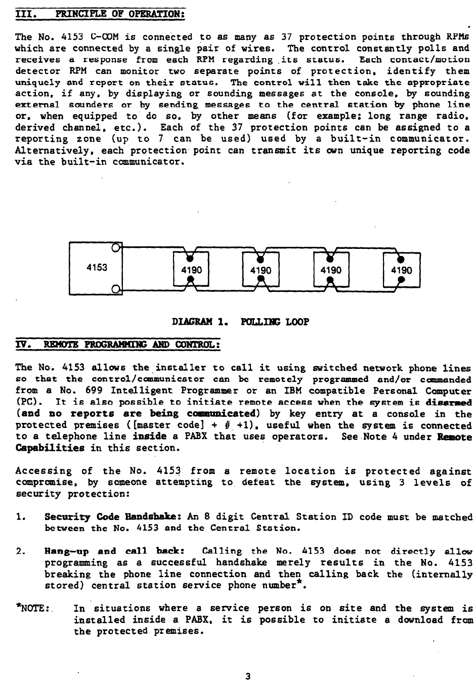
The No. 4153 C-CCM is connected to as many as 37 protection points through RPHs
which are connected by a single pair of wires. The control constantly polls and
receives
a response from each RPM regarding .its status. Each contact/motion
detector RPM can monitor two separate points of protection, identify them
uniquely and report on their status. The control will then take the appropriate
action. if any, by displaying or sounding messages at the console, by sounding
external sounders or by sending, messages to the central station by phone line
or. when equipped to do so. by other means (for example; long range radio.
derived channel, etc.). Each of the 37 protection points can be assigned to a
reporting zone (up to 7 can be used) used by a built-in communicator.
Alternatively, each protection.point can transmit its own unique reporting code
via the built-in communicator.
0’
4153 4190 4190 4190 4190
0, R *
d \
DIAGRAN 1. POLLxlsLooP
Iv. RENOTE-ANDCONTROL:
The Noi 4153 allows the.installer to call it using bwitched network phone lines
so that the control/canmunicator can be remotely programmed and/or canmanded
from a No. 699 Intelligent Programmer or an IBM compatible Personal Computer
(PC) l
It is also possible to initiate remote access when the system
is
dimmed
(and no reports are being communi
cated) by key entry at a console in the
protected premises ([master code1 + #,+l). useful when the system is connected
to a telephone line inside a PABX that uses operators. See-Note 4 under &mote
Capabilities in this section.
Accessing of the No. 4153 from a remote location is protected against
compromise, by someone attempting to defeat the system, using 3 levels of
security protection:
1. Security Code Bandshake: An 8 digit Central Station ID code must be matched
between the No. 4153 and the Central Station.
2. Bang-up and call back:
Calling
the No. 4153 does not directly allow
programming as a successful handshake merely results in the No. 4153
breaking the phone line connection and then calling back the (internally
stored) central station service phone number*.
*NOTE: In 'situations where a service person
is
on site and the system is
installed inside a PABX. it is possible to initiate a dwnload from
the protected premises.
3

3. Data Nmrypticln: Data passed between the central station and the No. 4153
is encrypted
for
security so
that
it is very difficult for a foreign device
tapped into the phone line to take wet communication and substitute
system
compranising information. !r)
. '. _
.
EqaipmentRequired
At the prerises
The No. 4153 must be used with the (factory installed) No. 4153RD Ring
Detector if remote programming and/or control is desired. The No. 4152LM.
providing Class 'A' polling loop operation csnnot be used when the 4153RD
is used.
At the central station (or the installer's office/home)
.
A No. 699MD Intelligent Programmer that incorporates an internal modem
and a No. 695-53 Progrsm Cartridge.
OR
. An IBM PC compatible computer. a Hayes Brand Model 1200 Modem, No.
4153PC Downloading Software Diskette, and appropriate interconnecting
cables.
. Remote Capabilities (See Note 2)
Rogr-g
All programming functions accessible from the unit's keypad
or
via local
No. 699 direct programming.
conanding
There are two types of commands that can be issued to the system:
.
Control Commands -
To
Arm
the System in the Away Mode
*Cl)
To Disarm the System
To Bypass a Sensor or Sensors
To Force the System
to
Accept a New Program Dwnload
To Disable Operation because of Lease Non-Payment (a display of
dE will be left on the console)
To Lockout Local Console or 6991P Programming. Preventing System
Takeover By Another Alarm Company
.
Status Commands -
To Cause the System to Upload a Copy of its Resident Program to
the central station
To Read System Status:
Arming Status
Ready Status
Presence of Alarma (past
or
present)
Presence of Troubles (past or present)
AC
Pauer Status
4
.
*NOTES :
1. If the system is programmed for open/close reporting by user, User #l will.
be reported.
2. After the 4153 and the 699 or PC have established valid communication, each
console displays an 'OC' and emits a trouble sound. This indicates that
the 4153 is not polling the consoles or the RPMs. The 4153 will resee the
normal security functions after it.is commanded to hang up. See the 4153PC
or 695-53 instructions for details.
The detailed operation of the functions described below is covered in the
Installation Instructions for the No. 695-53 Program Cartridge and for the
4153PC Dwnload Software Diskette.
To Read List of Faulted Sensors
To Read List of Bypassed Sensors
To Read 10 Day Alarm History Log
To Read 10 Day Trouble History Log
To Read List of Sensors Currently in Alarm
To Read List of Sensors Currently in Trouble
.
Remote Communication Specifications
l
Transmission Rate - 75 baud, half duplex
. Program Download Time - 2 minutes for a complete program
. Typical Total Time Including Call Up/Call-Back - 5-7 minutes.
.
Remote Comend/Rogramming Advisofies
. Alarm and Trouble Reporting are disabled during the time that the
system and the central station are linked to each other for the
described functions, follwing a valid exchange .of codes.
.
Keypad entries are ignored during the same time interval cited above.
The console emits a trouble tone during this interval.
. Should an alarm transpire during the remote program/control interval,
the system'would not respond to the alarm condition until the remote
mode was ended. The Nos. 4190WH. 4192, 4194WH. 4196. and 4208 all
store their fault conditions until they are read by the No. 4153. As
such, alarm conditions from these RPM6 would not be missed, only
delayed.
.
A copy of the program downloaded may be produced from either the No.
699 Intelligent Programmer or the IBM PC compatible computer, using
those products' internal report generators, when an optional printer
is connected.
V. POINT PRoTmrIoN EQUIPMKNT:
The. No. 4153 C-COM is a special control designed to operate with a point
protection.polling loop. It should not be used to operate other kinds of, alarm
circuits, such as separate conventional wired zones. The No. 4153 can presently
be used with the following equipment:
5
No. 4lS7 SBUFRITY CONSOLE
The No. 4157 CONSOLE prwides all system status indications and permits all /"\
I
system control functions. The console is used to program the system, to arm and - ', ,'
disarm the burglary system, to assign and remwe programmed selections, activate
PANIC alarms, to provide protection point identification and to prwide visible
and audible system indications. Up to 4 consoles can be supported (as many as 6
if supplemental 12 volt power is supplied to operate these additional consoles).
No. 419mDDAL POIHT m pOIFFfnormr%'(RP~!)
This device permits the interface of any dry contact sensor (for
example: magnetic contacts, foil, vibration sensors, motion detectors, smoke
detectors, etc.) and provides the identification and status of the protection
points to the No. 4153 C-COM. Each RPM .supports two sensor loops (referred to
as a left loop and a right loop). The left loop can support N.O. and
N.C. contacts and tbe right loop supports N.C. contacts. A trouble or a fault
detected by the RPM will be indicated at the console along with the location of
the alarm. When smoke detectors, motion detectors or other devices requiring
pwer are used that are not "matched components" from the Vector series, 2
additional wires must be run to pwer these devices.
No. 4208 8 POINT I POINT HBDULE (RPN)
The No. 4208 performs similarly to the No. 4190 except that it interfaces 8 end-
of-line resistor supervised protective loops to the control. Communication ,path
and pwer requirements are provided by the polling loop. When smoke detectors,
motion detectors, or other devices not of the Vector
family
are used, then
separate pwer lines must be used.
No. 4192 SgRIgs OF gMDRE DRTRC!l'OR/RR!#YFE PDIPFl' FgBmLBg p .- -'
These smoke detectors (4192CP - ionization. 4192SD - photoelectric, 4192SDT-
photoelectric with thermostat) report to the control all faults and identify the
alarm location at the console. If other smoke detectors (4-wire qpe) are used
in conjunction with the left loop of the 419ClWH RPM. 2 additional wires must be
run to pwer these detectors and a switch must be provided to interrupt the
pwer to these detectors to reset them. The Vector series detectors are totally
accommodated by the polling loop
for
their pwer and resetting and they draw
less than 1 mA each from the loop.
Nos. 4l39UE. 4194WR. 4191WH RZBD
coNTAcT~#)INTNDDuLEs
These surface mount (4139WH and 4194WH) and recessed mount (4191WH) Magnetic
Reed Contacts, each with a built-in RPM, allw windws and doors to be monitored
without the need to separately mount and wire an RPM.
Nos. 4196 QUAD
and 4275 DDAL RFDIgOR w PO= MODDLRg
These "matched" Passive Infrared detectors respond to rapid changes of infrared
energy associated with an intrusion into the protected area and reports the
went to the control. The
RPM
built into the "matched" Vector 4196 Quad PIR
also permits nearby closed circuit contacts to be interfaced to the unit,
enhancing the economy of the
RPM.
The PIRs have a naninal coverage of 35' x 35'
and can be wended to 45' x 45' cwerage by mounting adjustment. The 4196
utilizes two dual detectors to achieve verified PIR operation. By mirror
changeout, the PIRs can be adapted for long range (corridor) application. 70' x
16' (4196)
or
80' x 10' (4275). These PIRs are directly powered by the polling
6
loop and no separate power wiring is required. If other motion detectors are
used. separate power wiring is required. Up to 5 4196 PIRs can be selected to
utilize pulse count to further enhance their false alarm immunity (each 4275 ha6
a built-in pulse count option). Additional 4196 PIR's can be utilized without
pulse count. Do not use pulse count feature with PIRs configured for long range
coverage. Do not use software pulse counting for 4275s internally set for pulse
count.
No. 4l52LN8 CLASS
“A”
POLLIMGLOOPADAPTHR
This add-on circuit board is used tc provide additional security by enabling the
polling loop to be connected Class 'A' where it car: be polled
even
though the
loop may be broken. This adapter may also be wired as a separate open ended
loop to effectively double the length of the polling loops that can be supported
(See SECTION 'WIRING THE POLLING LOOP"). Use of this adapter does not increase .
the number of sensors that the system can uniquely identify. This adapter
cannot be used if central station initiated rem&e command or programming is to
be used with this product.
No. 4197
LOOP EXTBNDHR I3DDuLB
This device i6 a signal repeater that double6 the maximum polling loop length
from the point of loop cut-in.
It
may also be used to enhance polling loops
with marginal or poor signaling performance at certain extended RPMs. by
prwiding signal boosting for the marginal devices. It can be powered from the
control or locally from AC power via a No. 729 plug-in pat?er supply (provide
local rechargeable battery in the latter instance).
No. 4198 POLLIfS LOOP TgsrlgR
This diagnostic device tests the polling loop for potential failure due to
excessive length or inappropriate gauge. When inserted between the control
panel and the polling loop it places a load on-line and tests those loops which
might extend too fsr from the panel.
VI. OPERATION:
A point protection security system use6 a computer based control panel connected
to a 6ingle multiplex communication circuit called a polling loop. The polling
loop consists of a run of paired wire (twisted is preferred, but is not
mandatory) with multiple RPMs (e.g. Nos. 4190WH, 4192, 4194WH. 4196. 4208)
connected in parallel to each other. Sensor devices are connected to the RPM6
by a contact loop. Each contact loop forms a protection point. Vector 3000
supports up to 37 such protection points on the polling loop and monitor6 the
condition of this polling loop for opens and Shorts.
As the control receives individual sensor status, it check6 the installer
defined assignments stored in the EEPROM (Electrically Erasable PRCM that
retains its memory in the absence of power) to determine what action has to be
taken. The control then respond6 accordingly with
an
appropriate alarm display,
audible console annunciation, external sounder and/or dialer communication.
Each protection point.is assigned a zone type by the'installer for alarm
response and for central station reporting (when point reporting
i6
not used).
When the control receives a reply from an RPM, the microprocessor determine6 the
zone type of the protection point and responds in a predefined manner. The
following information describes the zone types and their associated responses.
7
ARNEDSTATB:
designated In response to a burglary sensor fault from a point that ha6 been
"entry/exit". alarm6 are activated at the end of the timeout of the'
entry/exit timer. Separate entry and exit delay times are installer selected
from 0 seconds to 150 seconds (in 10 second increments). Upon entry. a slowly
beeping console warning signal i6 initiated. If [Code + OFF] is not keyed
before the end of the timing cycle, an alarm is then initiated and the point in
alarm is identified on the console. Either one alarm or multiple alarms per
protection point (per armed period)
i$
installer selectable as a systemwide
selection. This zone type is capable of reporting dialer RESTORE messages.
(See address *85 in Programming Section).
DISARNED STATE: A faulted sensor designated as "entry/exit" will result in the
READY LED being extinguished. Depressing the READY key will cause the display
of all faulted contacts. No dialer communication is initiated.
zoNETYPE PKRINETER
ARNEU STATE:
A faulted sensor that has been designated PERIMETER causes an
instantaneous audible alarm, a latched display of the sensor ID number on the
console, and a dialer report (installer defined). Either one alarm or multiple
alarms per protection point (per armed period) is installer selectable as a
systemwide selection. Dialer RESTORE messages can he reported. (See address
*85 in Programming Section).
DISARMEDSTATE: A faulted sensor results in the READY LED being extinguished.
Depressing the READY key causes the display of the ID number of all faulted
sensors. No dialer communication is initiated.
ZONETYPE 3 IN!l'ERIOR/FOLLCHBRDBLAY
AENED STATE:
All sensors assigned to the interior zone have exit delay. These
sensors have entry delay when a zone type 1 (Entry/Exit) fault precede6 this
fault. Otherwise, any zone type 3 fault produce6 an immediate audible alarm, a
latched display and a dialer report (installer defined). Either one alarm or
multiple alarms per protection point (per armed period) i6 installer selectable
a6 a systemwide selection. Dialer RESTORE messages can be reported for alarms.
Interior sensors may all be directly bypassed by use of the STAY arming feature.
(See address *85 it Programming Section).
DISARHEDSTA!PE: A faulted sensor
results
in the READY LED being extinguished.
Depressing the RBADY key cause6 the display of the ID numbers of all faulted
sensors. No dialer communication is initiated.
ZONE !lTPE 4 TROUBLE BYBAY/AIJBXBYNIGBT
ARMED STATE:
A faulted sensor that has been designated as DAY/NIGHT causes an
instantaneous audible alarm, a latched display of the ID number of the sensor,
and a dialer report (installer defined). Either one alarm or multiple alarms
per protection point (par armed period) is installer selectable as a systemwide
selection. Dialer RBsroRB messages can be reported for alarms. (See address
*85 iti Programming Section).
DISABMKD STATE: A faulted sensor will result in a TROUBLE condition. The
console will beep rapidly and display the ID number of all faulted sensors. The n
console !CMUBLB LED will glow. The first trouble can initiate a dialer TROUBLE
report. Subsequent TROUBLES, prior to a TROUBLE RESTORE. will not initiate
8
additional dialer reports. When all TROUBLES have been removed, a 6ysteUI
TROUELB RESlTBB message can he reported.
Pressing any key silences the beeping. A subsequent entry [Code + OFF]. clear6
the display. ZONETYFESSAND6 24EOlJRZONES
Operational response is individually selectable for zones 5 and 6 from the belaw
listed 24 hour modes:
SILRNT: A faulted sensor initiates a dialer report (installer defined) with no
local display and no sounders activated. Upon disarming, there will not be a
memory indication of the faulted sensor. Faults in the disarmed state will
result in the RgADp LED being extinguished. Dialer reports are limited by the
sounder duration programmed selection. ‘Only one dialer report will be issued
per sounder duration defined period. When using the 4+2 fomt. alarm and
restore reports are sent as they occur. (See address *85 in Programming
Section).
ADDIBLB: A faulted sensor initiates an audible alarm, a latched display of the
ID number of the sensor'and a dialer report (installer defined). Either one
alarm or multiple alarms per protection point (until system is next disarmed/
armed) is installer selectable a6 a systemwide selection. Dialer RE$XORE
messages can be reported.
AUXILIARY: Faulted contacts initiate a, steady sounding at the console. a
latched display of the ID number of the sensor and a dialer report (installer
defined). Either one alarm or multiple alarms per protection point (until
system is next disarmed/armed) is installer selectable as a systemwide
selection. Dialer RESS0RE messages can be reported. (See 'address *85 in
Programming Section). ZONETYPE 7 FIREZONE
Alarms (shorted thermostat6 or pull stations or activated smoke detectors)
initiate a pulsed sounder alarm for a time duration defined by the installer.
Concurrent fire alarms, burglary alarm6 and trouble6 are alternately displayed,
but the sounder will always give priority to fire alarms. (Fire alarms are
displayed when field 17 is enabled).
Fire zone protection .points may not be bypassed. An open fire zone circuit
(TROUBLE) WILL NOT prevent the arming of the burglary system. A shorted sensor
(ALARM) WILL prevent system arming.
Either one alarm or multiple alarms per protection point (until system i6 next
disarmed/armed) is installer Selectable as system-wide selection. Contact 6
which have been subsequently faulted will be displayed at the console. (See
address *85 in Programming Section).
ZONBT!IPB8 DDRBSS(AMBDSE)
This is a zone only in the sense that it report6 a message to the Central
Station. To activate the DURESS feature, enter the first three number6 of the
SZCDRITY WDB and increase the fourth digit by 1. ONPORTANTI If the last
SECURITY CODE digit is 9. or if no report code is assigned, the duress feature
is disabled.)
a
The DURESS feature does not initiate any audible or visual signals, but reports
a silent alarm. It does not cause a dialer RESTORE message to be transmitted.
9
TAMPER: Refer6 to the removal of a 419OWH RPM cover. TAMPER detection will
always result
in
a trouble signal (if program enabled) if it occurs when the
q6tm is not armed and will display the ID nrrmber of the left loop of the
affected RPM. If the system is armed ‘and a tamper detection occurs when the
left loop
is
utilized for burglary protection (zones l-4). a burglary alarm will
result. If the left loop is Used for fire, panic or auxiliary, a tamper
detection will result in a trouble signal. The implication of the latter is
that a tamper fault duting the armed mode will only result in a trouble if the
left loop is used for non-burglary response even though the right loop is Used
for burglary detection. Removal of a cover of a fire programmed (left loop)
4190WH will always result in a Trouble signal, whether tamper is program enabled
or not.
suPERV1s1oW: Refers to non-responding RPM6 when there are no break6 in the
polling loop. However, RPM6 situated between multiple breaks in a Class 'A'
polling loop or RPM6 beyond a single break in an open ended polling loop will
appear a6 supervision faults. SUPERVISION FAULT will always result in a trouble
signal if it occurs when the system is not armed and will display the ID ntrmber
of the left loop. If the system is armed and a supervision fault occurs when
the left loop is utilized for burglary protection (zones l-4). a burglary alarm
will result. If the left loop i6 used for fire, panic, or auxiliary, a
supervision fault will result in a trouble signal even though the right loop i6
used for burglary detection and the system is armed.
VII. IN-ON :
Installing a point protection system involve6 wiring the polling and sensor
loops, preparing and mounting the RPMs: and programming. morPlting and wiring the
control. It is important that the installer completely read this section before
attempting any of the installation procedures.
NOTE: The following installation procedure6 involve the No. 4190WH RPM only.
Please refer to the instructions included with the No. 4208 for
information regarding those products. Both products will perform a
similar function to that of the No. 4190 and
msy
be more appropriate
for portion6 or all of your installation.
Wiring the polling and contact loops first is the most efficient way to install
a point protection system. By following this method, the installer not only
establishes all circuit6 but also create6 a programming plan. For this reason
the installer should keep a record of what zone is to be assigned to each
protection point and how that protection point is to perform.
10
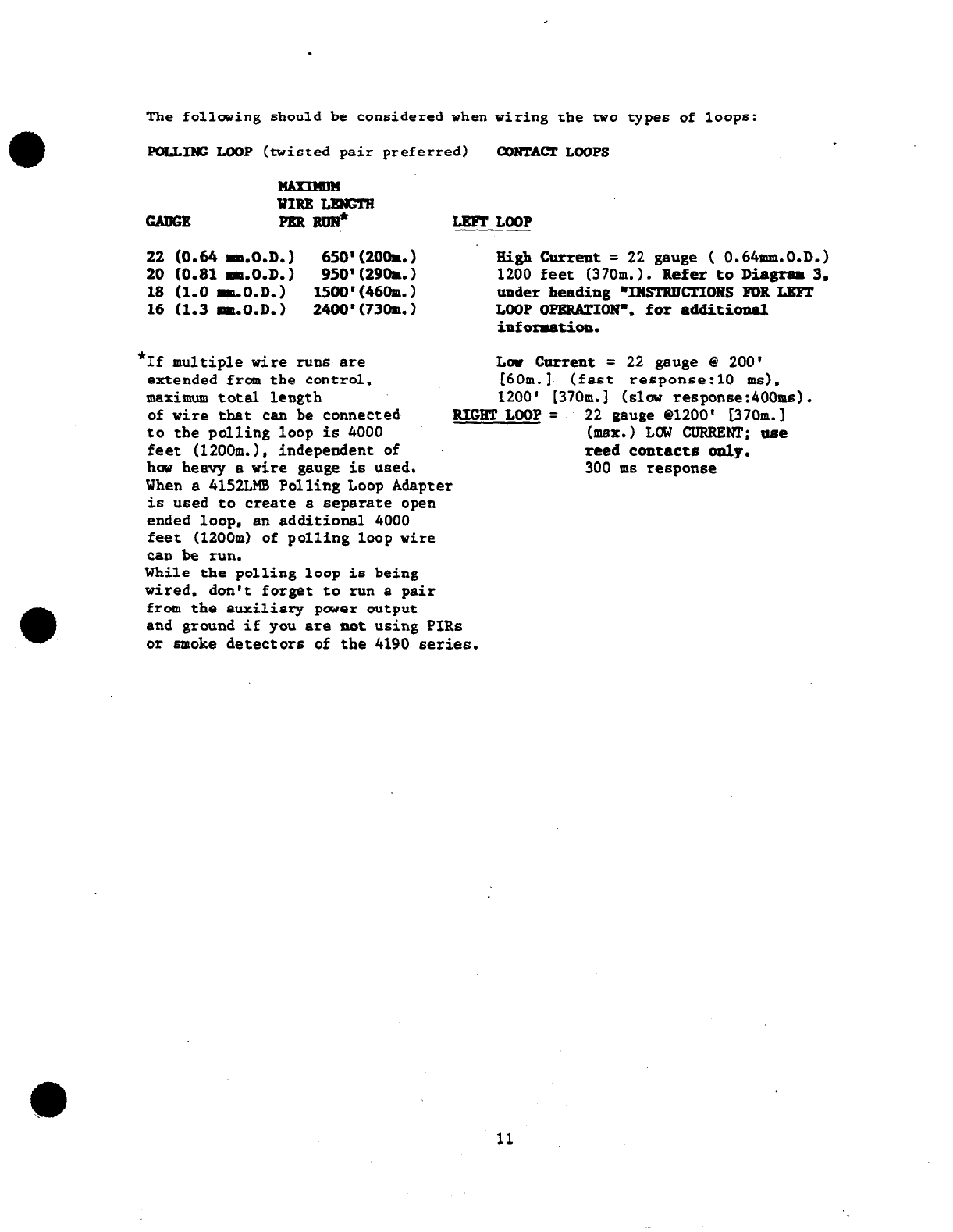
The following should be considered when wiring the two
types of lOOp6:
POLLING LOOP (twisted pair preferred) cONTAcTLOoPs
WIRE LmElw
PEREm?* LEFTLOOP
22 (0.64 mm.0.D.) 650'(2O(h.) High Current = 22 gauge ( 0.64mm.O.D.)
20 (0.81 m.0.D.) 950' (29th. ) 1200 feet (370m.1. Refer to Diagram 3.
18 (1.0 mm.0.D.) 1500'(46Om.1 under heading "INSTRDCTIONS FOR LBF!l'
16 (1.3 mm.0.D.) 2400'(73Om.) LOOP OPERATIONS. for additional
infoxmation.
*If multiple wire runs are Lw current = 22 gauge 8 200'
extended from the control, [60m.]. (fast response:10 BIB),
maximum total length 1200' L370m.l
(slow response:400ms).
of wire that can be connected RIGHTLOOP= 22 gauge @1200' [370m.]
to the polling loop is 4000 (max.) LOW CURRENT; tlee
feet (1200m.1, independent of reed contacts only.
how heavy a wire gauge is
Used.
300 m6 response
When a 4152LMB Polling Loop Adapter
is used to create a separate
open
ended loop, an additional 4000
feet (1200m) of polling loop wire
can be run.
While the polling loop is being
wired, don't forget to run a pair
from the auxiliary paJer output
and ground if you are
not
using
Pm6
or
smoke
detectors of the 4190 series.
11
.
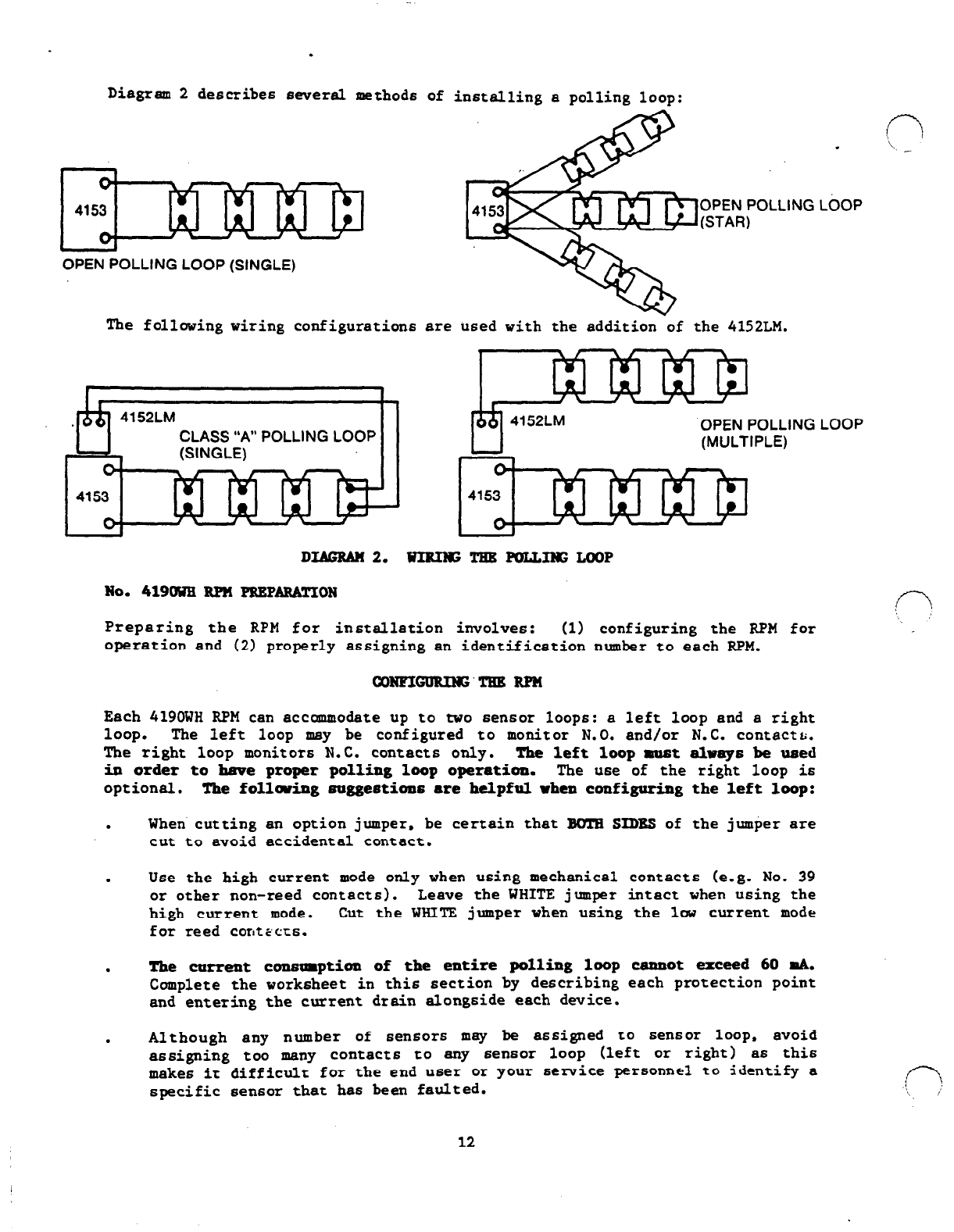
Diagram 2 describes several methods of installing a polling loop:
OPEN POLLING LOOP (SINGLE)
The following wiring configuration6 are used with the addition-of the 4152LM.
CLASS “A” POLLING LOOP
(SINGLE) II
OPEN POLLING LbOP
(STAR 1
.
OPEN POLLING LOOP
(MULTIPLE)
DIAGRAM 2. UIRIlGTEBPOLLIwGM)oP
No. 419OWE RPU PREPARATION
Preparing the RPM for installation involves: (1) configuring the RPM for
operation and (2) properly assigning an identification number to each RPM.
c-3
\ --
n
‘\
WNFIGURING’TBB RPN
Each 419OWH RPM can accommodate up to two 6ensor loops: a left loop and a right
loop. The left loop may be configured to monitor N.O. and/or N.C. contectr;.
The right loop monitor6 N.C. contacts only. The left loop must always be used
in or&r to have proper polling loop operation. The u6e of the right loop i6
optional. The follwing mggeetims
are
helpful when configuring the left loop:
.
When cutting an option jumper, be certain that BOTH SIDBS of the jumper are
cut to avoid accidental contact.
.
Use the high current mode only when using mechanical contacts (e.g. No. 39
or other non-reed contacts>. Leave the WHITE jumper intact when using the
high current mode. Cut the WHITE jumper when using the low current mode
for reed contEcts.
.
The current coxmmption of the entire polling loop cannot exceed 60 mA.
Complete the worksheet in thie section by describing each protection point
and entering the current drain alongside each dwice.
.
Although any number of sensors may be assigned to sensor loop, avoid
assigning too many contacts to any 6en6or loop (left or right) as this
make6 it difficult for the end
u6er
or your service personnel to identify a
specific 6en6or that has been faulted.
12

See Below for
Jumper Options 6,
RED .
COMMON I
fl
WHITE
..cTl
, 14190 I 14190 I I 4190 I 1Ql
)i Ai
. ‘1 7
’ I 4 II’ I
I I
POLLING LOOP
. ALWAYS OBSERVE POLARITY.
. ALWAYS CONNECT IN PARALLEL.
. SEE TEXT FOR WIRE GAUGE AND
WIRE LENGTH REQUIREMENTS.
INSTRUCTIONS FOR SETTlNG ID# INSTRUCTIONS FOR LEFT LOOP OPTIONS
CONVER?
SETTINGS
ON
OFF
ID NUMBER TO DIP SWITCH
1 ACCORDING TO THIS TABLE
LEAVE THESE IN OFf’
POSITION. (RED
EXPOSE0 AT OFF)
YOU ONLY NEED TO SET THE
LEFT LOOP #I
WHEN BOTH LOOPS ARE USED,
THE TRANSPONDER WILL
AUTOMATICALLY ADD (+l) TO
SET THE RIGHT LOOP #.
IF ONLY ONE LOOP IS USED,
USE THE LEFT LOOP, SET THE
ID #, AND USE THE NEXT CON-
SECUTIVE W FOR THE NEXT
TRANSPONDER.
ON - 1
OFF - 2
gf: ::
OFF-12
ON l
13
OFF - 14
ON
l 15
OFF
l
16
ON - 17
OFF - 16
EL = 3
ON : 21
SF’ E
)T’N’ : g
OFF : 26
ti% l ::
.
ON - 29
E=:P
OFF : 32
ON -33
OFF.34
See Bslow.for DIP Switch
Settings
RIGHT LOOP: FOR N.C. SERIES
CIRCUITS ONLY. USE SEALED
LEFT LOOP: FOR NC. CIRCUIT
(INTERNAL EOLR) OR N.C.
AND/OR N.O. CIRCUIT (EXTER-
NAL EOLR). (See Left Loop
Jumper Options Below.)
1. RED JUMPER SETS LOOP
RESPONSE TIME
CUT = 10 MSEC
UNCUT = 400 MSEC
2. WHtTE JUMPER SETS CUR-
RENT ON LOOP
CUT = O.lmA FOR REED
CONTACTS
UNCUT = 1 mA FOR
MECHANICAL SWITCHES
3. BLUE JUMPER - CUT ONLY
WHEN AN EOLR IS NOT USED
(WHITE JUMPER MUST ALSO
BE CUT)
NOTE: IF YOU USE HIGH CUR-
RENT FOR MECHANICAL
SWITCHES YOU MUST USE
AN EOLR (DO NOT CUT
BLUE OR WHITE JUMPERS)
A RED
A WHITE
A BLUE
Diagram3. 419CWH RPM SUMMARY OF ODNNBCTIONS
13
If using a fast acting sensor. such 66 a glass break or a vibration
(ADEMoD NO. 11) 6en6or. cut the BED
jampar
to configure the RPM for 10 MSEG
response. <T-T
. _
As delivered, the left loop
is
configured to be used with bodl p8r6llel
N.O. and series N.C. sensor6 (loop is supervised against opens and shorts)
and an external End-of-Line Resistor (either 4700 ohm6 [small, YELLOW-
VIOLET-RED l/4 vatt size] for high current [mechanical switch] operation or
30,000 ohm6 [large, ORANGE-BLACK-ORANGE l/2 vatt size] for lov current
[reed] operation) must be connected across the loop at the last (furthest)
6en6 or. (The vhite
jumper
must be cut to use the 30.000 Ohm EOLR.) If this
level
of
supervision is not desired and if only N.C. contacts will be used,
the requirement for using the external End-of-Line Resistor can be
eliminated by cutting the BLUg jmper. Uhen this is done onlyla current
operation of the sensor loop in possible (i.e. only reed contact6 may be
used).
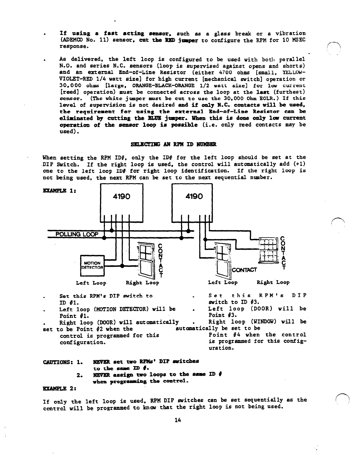
When setting the RPM IDO. only the ID0 for the left loop should be set at
.DIP Switch. If the right loop is used. the control vi11 automatically add (
one to the left loop ID# for right loop identification. If the right loop
not beinn used. the next RPM can be set to the next sequential nunbet.
the
+1)
is
Left Loop Right Loop
-!l&ii, - #I/
:u.l
“CONTACT
D$
I
T
Left Loop Right Loop
.
Set this RPM's DIP switch to . Set this RPM'6 DIP
ID #l. switch to ID #3.
. Left
loop
(MOTION DETECTOR)
will
be . Left loop (DOOR) will be
Point #l. Point 83.
Right loop (DOOR) will automatically
;et to be Point #2 when the . Right loop (WINDOW) will be
autanatically be set to be
control is programmed for this Point 84 when the control
configuration. is programmed for this config-
uration.
CADTIONS: 1. m met tvo BIlzs' DIP dtcbes
to the sam ID 1.
2. massi- two loops to the 8(1111e ID #
when progrdg the control.
- 2:
If only the left loop is used. RPM DIP 6vitches can be set sequentially as the
control vi11 be programmed to knckl that the right loop is not being used.
14
.
.
Set this
RPM’s
DIP
switch to ID 81.
l
Since right loop is unused.
no ID # will be essigned by
the control.
.
Set this RPM's DIP svitch
to ID to 12.
HINTS:
.
Right loop cannot be used without first using Left loop.
.
Smoke'Detector RPM6 do
not
support a Right loop.
.
Assign ID numbers vith future expansion in mind. If many ID'6 are not
being used, skip an ID number whenever the Right loop of a 419OWH or
4196 i6 NOT Used. Right loop sensors can then be added later if an
installation is being expanded, without having to reprogram the DIP
switches on any of the RPM6 and just by reprogramming of the control.
.
4208 sensor loops, 4139WH6, 4191WHs. 4194WHs and 42756 are all to be
assigned Left Loop response.
15
.
r
.
:
:
-
I
I
TRANSPONDER PROTECTIC
LOCATION POINT
DINING RM WINDOW
BEHIND VERT. BLlNDS CONTACT
KITCHEN DOOR BCK DOOR
RADIATOR WELL CONTACT
NOT
USED
INSIDE BASEMENT :SMOKE
DOOR (CEILING)
bo not us’e sensor; of &Id
l
Ol’
if ring detection is enabled.
FOR EXAMPLE ONLY.
ACTUAL ENTRIES SHOULD BE MADE ON THE
ACCOMPANYING WORKSHEET.
I I I
*LEFT LOOP ID #‘IS TRANSPONDER DIP SWITCH SETTING
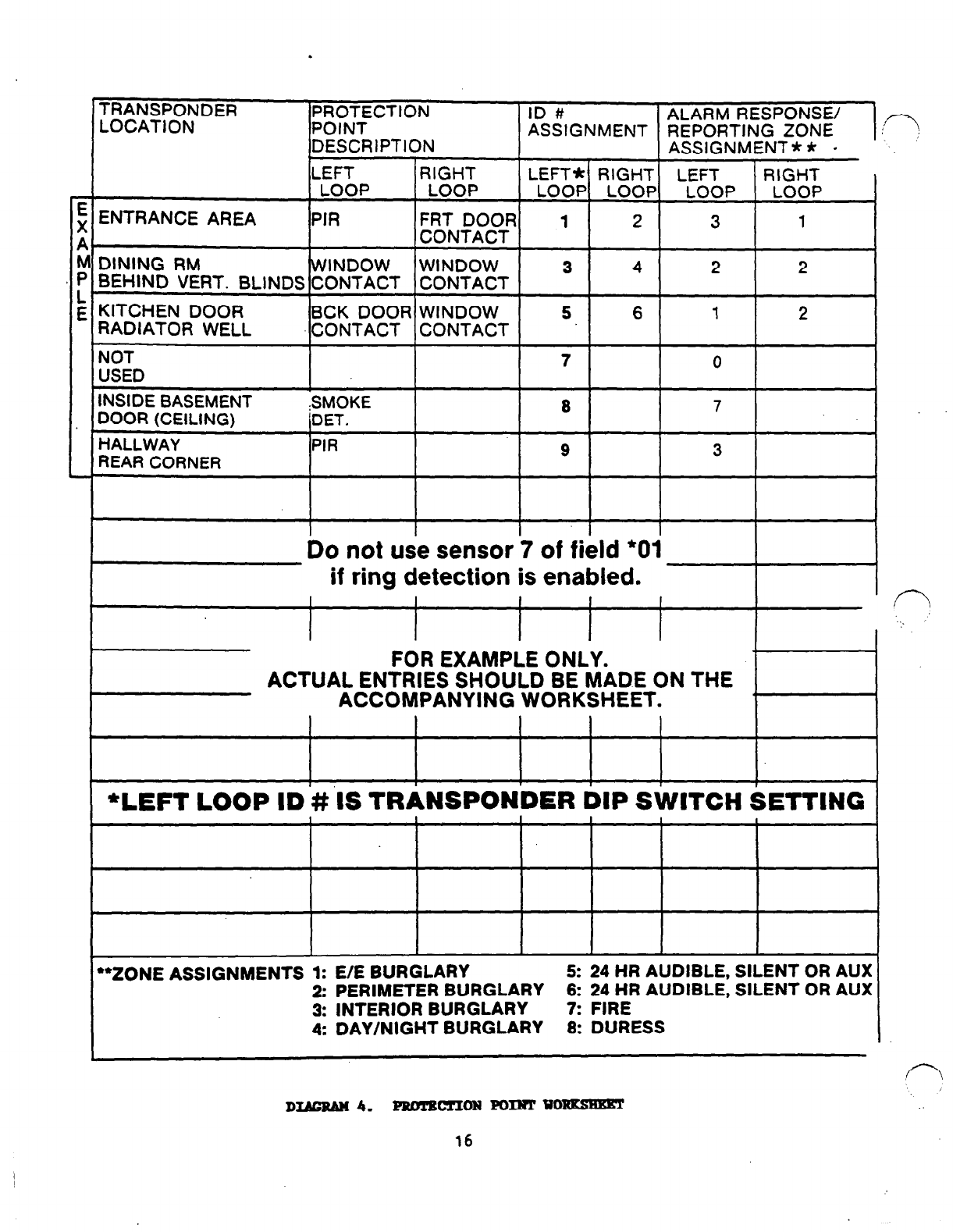
‘*ZONE ASSIGNMENTS 1: E/E BURGLARY 5: 24 HR AUDIBLE, SILENT OR AUX
2: PERIMETER BURGLARY 6: 24 HR AUDIBLE, SILENT OR AUX
3: INTERIOR BURGLARY 7: FIRE
4: DAY/NIGHT BURGLARY 8: DURESS
D- 4. PROTBCTION POINT WORKSBET
16
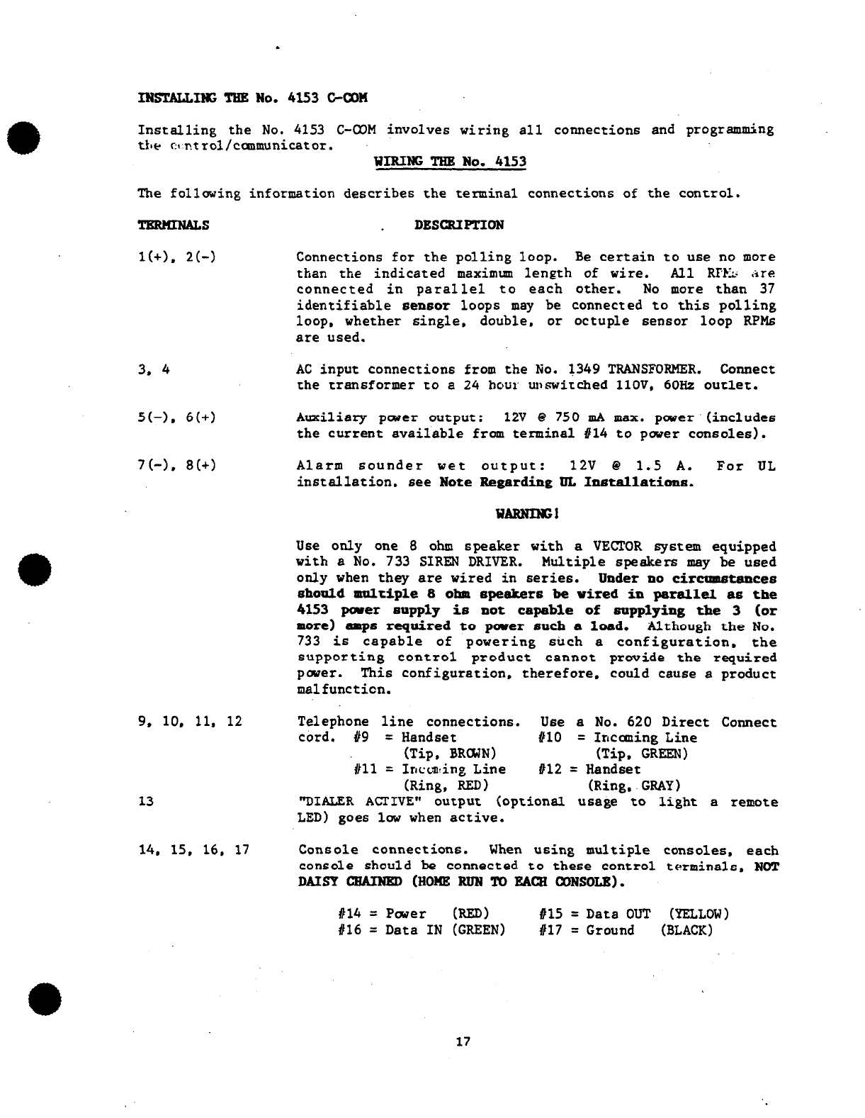
INsTALLING~wo. 4153 C-CON
Installing the No. 4153 C-COM involves wiring all connections and programming
the c~ntrol/caumunicator. WIRING THE No. 4153
The following information describes the terminal connections of the control.
TERNIULS DESCXIPTION
l(+). 2(-j Connections
for
the polling loop. Be certain to use no more
than the indicated maximum length of wire. All RPMz .ire
connected in parallel to each other. No more than 37
identifiable aenaor loops may be connected to this polling
loop. whether single. double, or octuple sensor loop RPMs
are used.
3, 4
5(-l, 6(+)
7(-l, 8(+)
AC input connections from the No. 1349 TRANSFORMER.
Connect
the transformer to a 24 hour unswitched llOV, 6OHz outlet.
Auxiliary pclwer output: 12V Q 750 mA max. pcwer'(includes
the current available from terminal #I4 to power consoles).
Alarm sounder wet output: 12V Q 1.5 A. For UL
installation, see
Note
Regarding IJL Installatioua.
WARNING1
Use only one 8 ohm speaker with a VECTOR system equipped
with a No. 733 SIREN DRIVER. Multiple speakers may be used
only when they are wired in series. Under no circumstances
should multiple 8 ohm speakers be wired in parallel as the
4153 parer mupply is not capable of sopplying the 3 (or
more) amps required to parer such a load. Although the No.
733 is capable of powering such a configuration. the
supporting control product cannot provide the required
power. This configuration, therefore. could cause a product
malfunction.
9, 10. 11, 12
13
Telephone line connections. Use a No. 620 Direct Connect
cord. #9 = Handset #lO = Incaning Line
‘#ll (Tip. BRaWN) (Tip. GREEN)
= Incon!ing Line 812 = Handset
(Ring, RED) (Ring..GRAY)
"DIALER ACTIVE" output (optional usage to light a remote
LED) goes low when active.
14. 15, 16. 17 Console connections. When using multiple consoles, each
console should be connected to these control terminals, NOT
DAISY CHAINED (HOME RUN TO EACH CONSOLE).
#14 = Pwer (RED) a15 = Data OUT (YELLOW)
#16 = Data IN (GREEN) a17 = Ground (BLACK)
17
.
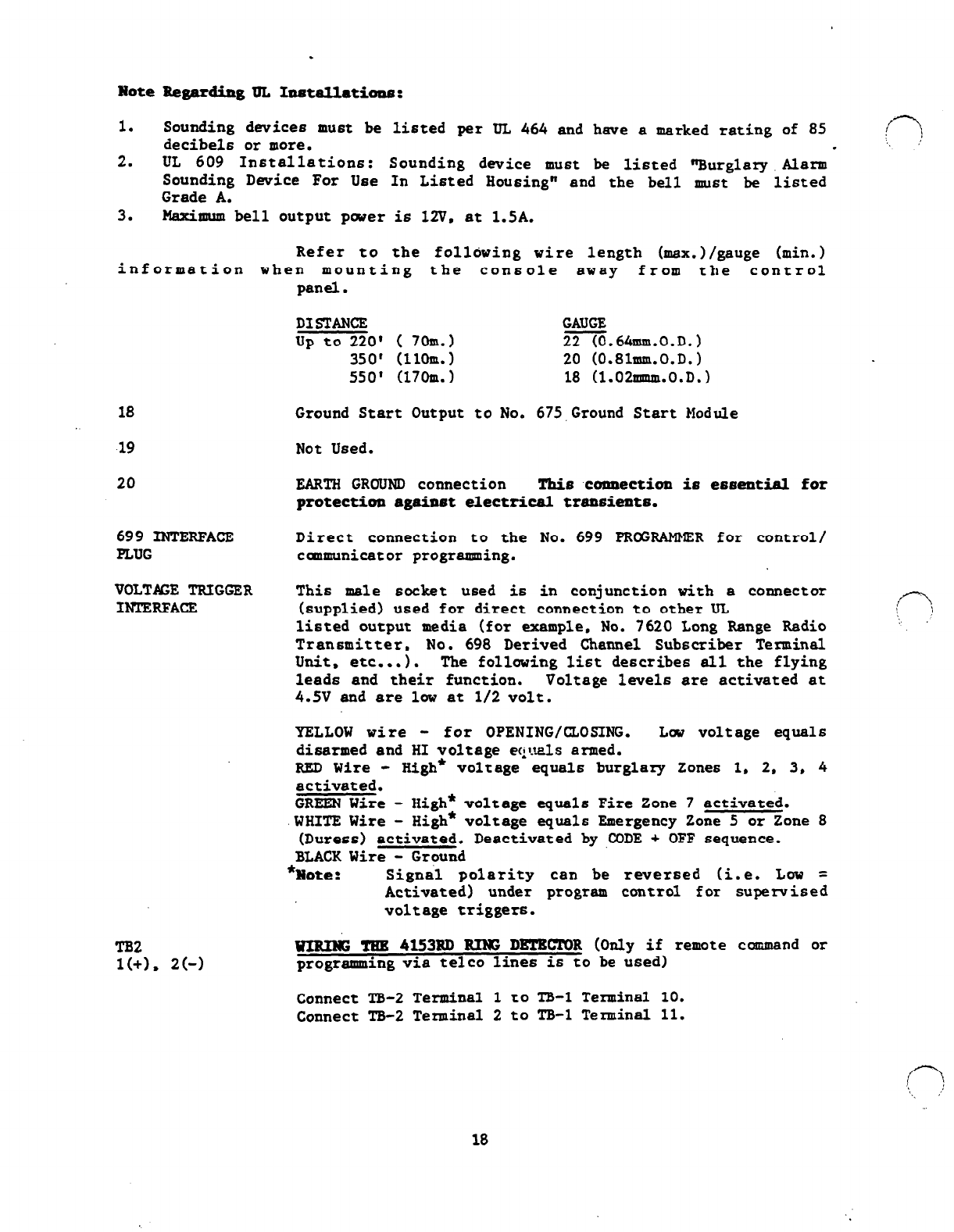
Note Regarding TJL Installations:
1. Sounding devices must be listed per UL 464 and have a marked rating of 85
decibels or more. c-7
,, ,'
.
2. UL 609 Installations: Sounding device must be listed sBurglaxyAlarm
Sounding Device For Use In Listed Housing" and the bell must be listed
Grade A.
3. Maximum bell output pwer is 12V. at 1.5A.
Refer to the following wire length (max.)/gauge (min.)
information when mounting the console away from the control
panel.
DISTANCE
up to 220' ( 7om.1 GAUGE
22.641~m.0.~.)
350' (llom.1 20 (0.81null.0.D.)
550' (170m.1 18 (1.02mmm.0.D.)
18 Ground Start Output to No. 675,Ground Start Module
19 Not Used.
20 EARTH GROUND connection This connection is essentisl
for
protection against electrical transients.
699 INTERFACE
PLUG Direct connection to the No. 699
PRU3AMM!ZR
for control/
caumunicator prograrsning.
VOLT&E TRIGGER This male socket used is in conjunction with a connector
INTERFACE (supplied) used for direct connection to other UL <n
listed output media
(for
example, No. 7620 Long
Range
Radio -
Transmitter, No. 698 Derived Channel Subscriber Terminal
Unit. etc...). The following list describes all the flying
leads and their function. Voltage levels are activated at
4.5V and are lw at l/2 volt.
YELLOW wire - for OPENING/CLOSING. Lw voltage equals
disarmed and HI voltage equals armed.
RED Wire - High* voltage equals burglary Zones 1, 2, 3, 4
activated.
GREEN Wire - High* voltage equals Fire Zone 7 activated.
.WHITE Wire - High* voltage equals Emergency Zone 5 or Zone 8
(Duress) activated. Deactivated by ,CODE + OFF sequence.
BLACK Wire - Ground
*Note: Signs1 polarity can be rwersed (i.e. Low =
Activated) under program control for supervised
voltage triggers.
TB2
l(+). 2(-J UIHING THE 4l53RD HIW DETECTOR (Only if remote command or
programming via telco lines is to be used)
Connect TB-2 Terminal 1 to TB-1 Terminal 10.
Connect TB-2 Terminal 2 to TB-1 Terminal 11.
18
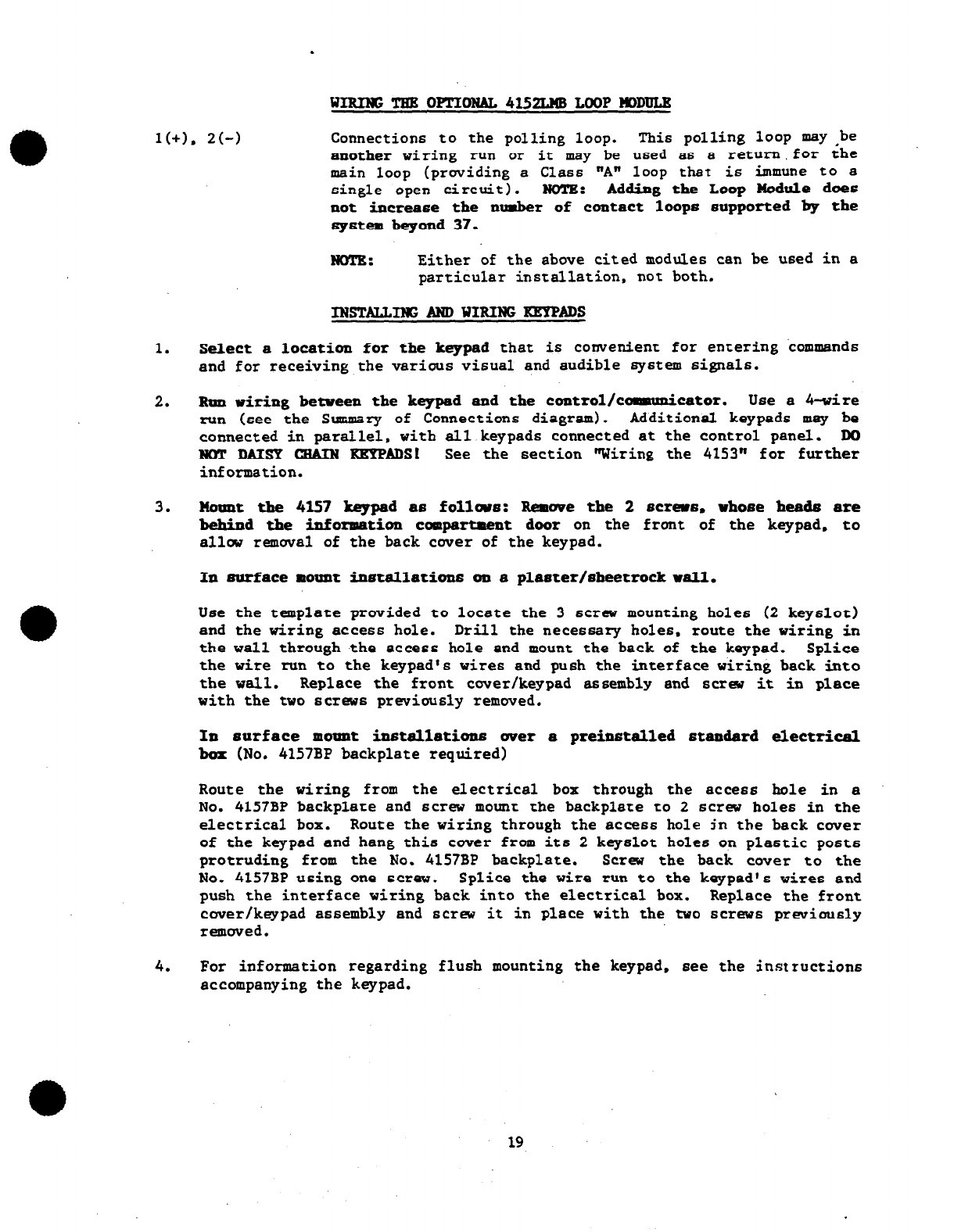
WIRINGTHE OPTIORAL4152LmLOOPEiDDUI.R
l(+). 2(-j Connections to the polling loop. This polling loop may ,be
another wiring run or it may be used as a return.for the
main loop (providing a Class "A" loop that is immune to a
single open circuit). NOTE: Adding the Loop Module does
not increase the number of contact loops supported by the
system
beyond 37.
NoTg: Either of the above cited modules can be used in a
particular installation, not both.
1. Select a location for the keypad that is convenient for entering commands
and for receiving the various visual and audible system signals.
2. Run wiring between the keypad and the control/camunicator. Use a rt-wire
run (see the Summary of Connections diagram). Additional keypads may be
connected in parallel, with all keypads connected at the control panel. DO
NOT DAISY CZIAIN KRYPADSI See the section "Wiring the 4153" for further
information.
3. Nount the 4l57 keypad as follws: Remove the 2
scram,
vhose heada
are
behind
the
information
compartment door on the front of the keypad, to
allw removal of the back cover of the keypad.
In surface mount installations
on a plaster/sheetrock wall.
Use the template provided to locate the 3 screw mounting holes (2 keyslot)
and the wiring access hole. Drill the necessary holes. route the wiring in
the wall through the access hole and mount the back
of
the keypad. Splice
the wire run to the keypad's wires and push the interface wiring back into
the wall. Replace the front cover/keypad assembly and screw it in place
with the two screws previously removed.
In surface mount installations uver a preinstalled standard electrical
box (No. 4157BP backplate required)
Route the wiring from the electrical box through the access hole in a
No. 4157BP backplate and screw mount the backplate to 2 screw holes in the
electrical box. Route the wiring through the access hole jn the back cover
of the keypad and hang this cover from its 2 keyslot holes on plastic posts
protruding from the No. 4157BP backplate. Screw the back cover to the
No. 4157BP using one screw. Splice the wire run to the keypad's wires and
push the interface wiring back into the electrical box. Replace the front
cover/keypad assembly and screw it in place with the two screws prwiously
removed.
4. For information regarding flush mounting the keypad, see the instructions
accompanying the keypad.
19
.
FOR UL SOS GRADE A INSTALLATIONS:
SEE
II SUPPLEMENT FOR 4153ML.
c-7
. ‘\
No. 4163 POINT PBOTECTION C-COY
COMPLIES WITH FCC RULES PART 68
FCC REGISTRATION No AC396lJ-69192-AL-
RINGER EOUIVALENCE 0 08 1
1coNsoLE lztxNSOLEsl3cONsoLEs
MTENY RLOUNENENTS: SEE INSTAlJATtDN
INSTRUCTIONS
WARNING!
FOR CONTINUED PROTECTION
AGAINST THE RISK OF FIRE, REPLACE
ONLY WITH SAME TYPE AND RATING FUSE.
GROUND (BLK)
ALARM
MGGER
PUTPUTS
TYPICAL 4-WIRE SMOKE DETEC-
CONTACT LOOP
- TRAW~PONOER CONNECTIONS _ _ - - _ _ y
--1-------..1----------- no. 419own DCID
INSfRUCTIONS)
EANTN 0NouND
(COLD WATER
PIPE OR
ELECTRICAL EOX
MAY BE SUITABLE
IN SOME
SITUATIONS)
NOT USED
WOUND START OUTPUT
(TO No. 675 GROUND START
MODULE)
+DATAIN 1
,-+Z DATA,OUT 1
E~NTRDL 1
yott: OTHER CONSOLES
MAY BE USED. CONNECT EACH
CONSOLE TO THE CONTROL
PANEL. DO NOT OAl8V CFJAM
w
FROM TERMINAL 6) -- l’
TELEPHONE LINE CONNECTION al5
~~- - -- -- ----
USING NO 620 DIRECT CONNECT CORD
PLUG INTO RJ31X JACK
No 4196PIR , , 4THE RECEIVING UNIT TO WHICH THIS EOUIP-
; ; MENT TRANSMITS SIGNILS b&V OR MAY NOT
DBYUL
HAVEBEENEVALUATE
*TRANSMISSION OF THI
FIRE ALARM HEADOUARTERS OR CENTRALSTk
TION SiALL BE PERMITTED ONLY WITH AP-
PROVAL OF THE LOCAL AUTHORITV HAVING
JURISDICTION
CUT JUMPER
‘12 -1
I FIRE ALARM SIGNAL TO A
.THE BURGLAR ALARM SIGNAL SliALL NOT BE
TRANSMITTED TO A POLICE EUERGENCY NUMBER
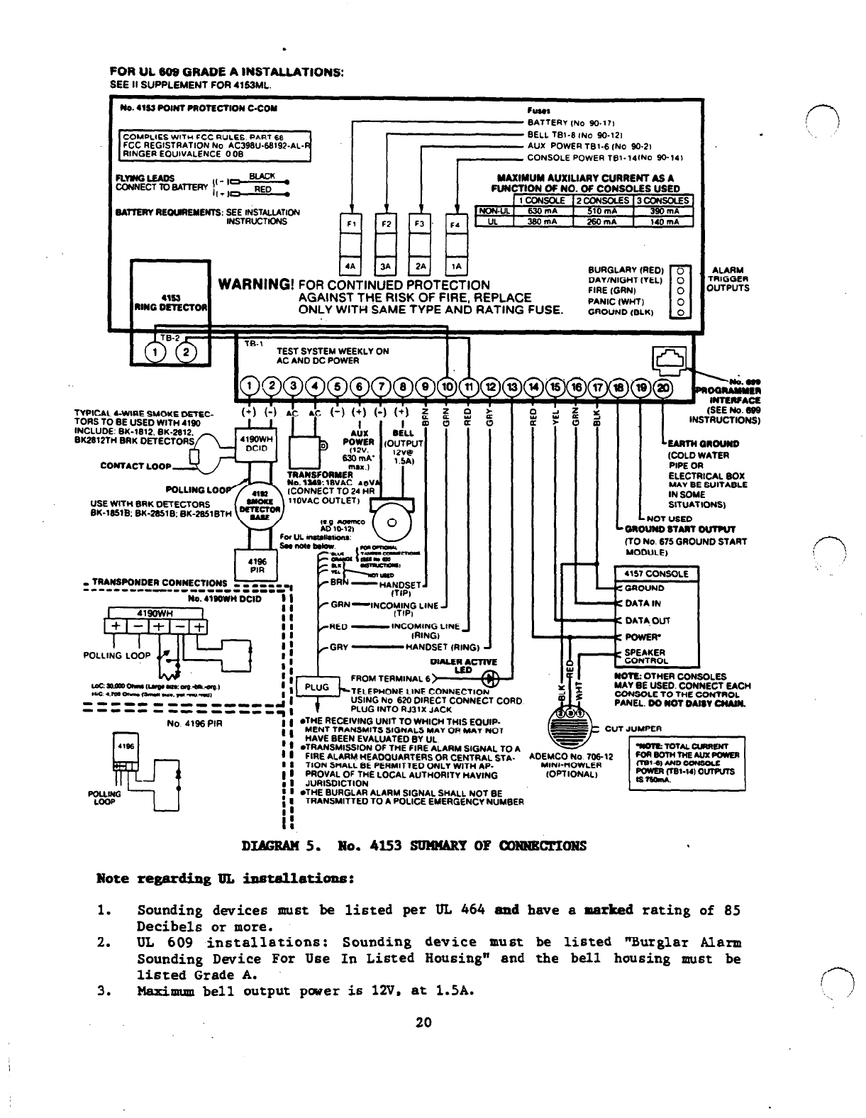
DIAGRAM 5. No.
4l53 SUNNARY OF cowNEC7lWNS
Note
regarding Ill,
installations :
1. Sounding devices must be listed per UL 464 and have a marked rating of 85
Decibels or more.
2.
UL 609 installations: Sounding device must be listed "Burglar Alarm
Sounding Dwice For Use In Listed Housing" and the bell housing must be
listed Grade A.
3.
Maximum bell output pwer is 12V. at 1.5A.
20
n
‘,\_ ,,’
The polling loop and 6ensor loops connected
to
transponder6 (RPM's) can cause
audio interference when installed too close to the wiring running between the
master station and remote stations of an intercom system. To avoid this
problem, the following precautions must be taken:
.
A minimum distance of three. inches must be maintained between the
polling/sensor loop wires of the VECTOR security system and those of the
intercom.
.
Where it is not practical to maintain a three inch distance between the two
systems. it is necessary to install shielded wiring for either the VECTOR
polling and/or sensor loops or for the intercom system wiring (depending
which was installed first). Whenever shielded wires are used, the shields .
must be earth grounded at the control or, in the case of the intercom, at
the master unit.
If both the VECTOR and the intercom system are being installed at the same tiloe.
it may be easier to use shielded cable in the interccan system (See Diagram 61:
1. Shield the audio wiring running between the master station and remote
stations which is in close proximity to VECTOR system wiring.
2. All shield6 must be grounded at the
master
intercom unit.
3. Observe all precaution6 established by the manufacturer.
4. Ground the master intercom unit to earth ground. A cold water pipe or
electrical box may often be suitable.
When using shielded cable with the VECTOR system (See Diagram 7):
1. When multiple wire runs are made from the polling connection on the
control, the combined length of all runs is reduced from 4.000 feet to
2,000 feet independent of wire gauge. The maximum length of any single run
ermains unchanged.
2. When using a 4152LMB LOOP MODULE all of the aforementioned wire length
restrictions must be observed.
3. When using a 4197 LINE EXTENDER MODULE all of the aforementioned wire
length restriction6 must be observed.
4. All sensor loop wiring in close proximity to intercom system wiring must
utilize shielded cable. These cable length6 must comply with the
restrictions presented in the installation instructions.
There
is no upper
limit wire length reduction as there was with the polling loop cable.
21
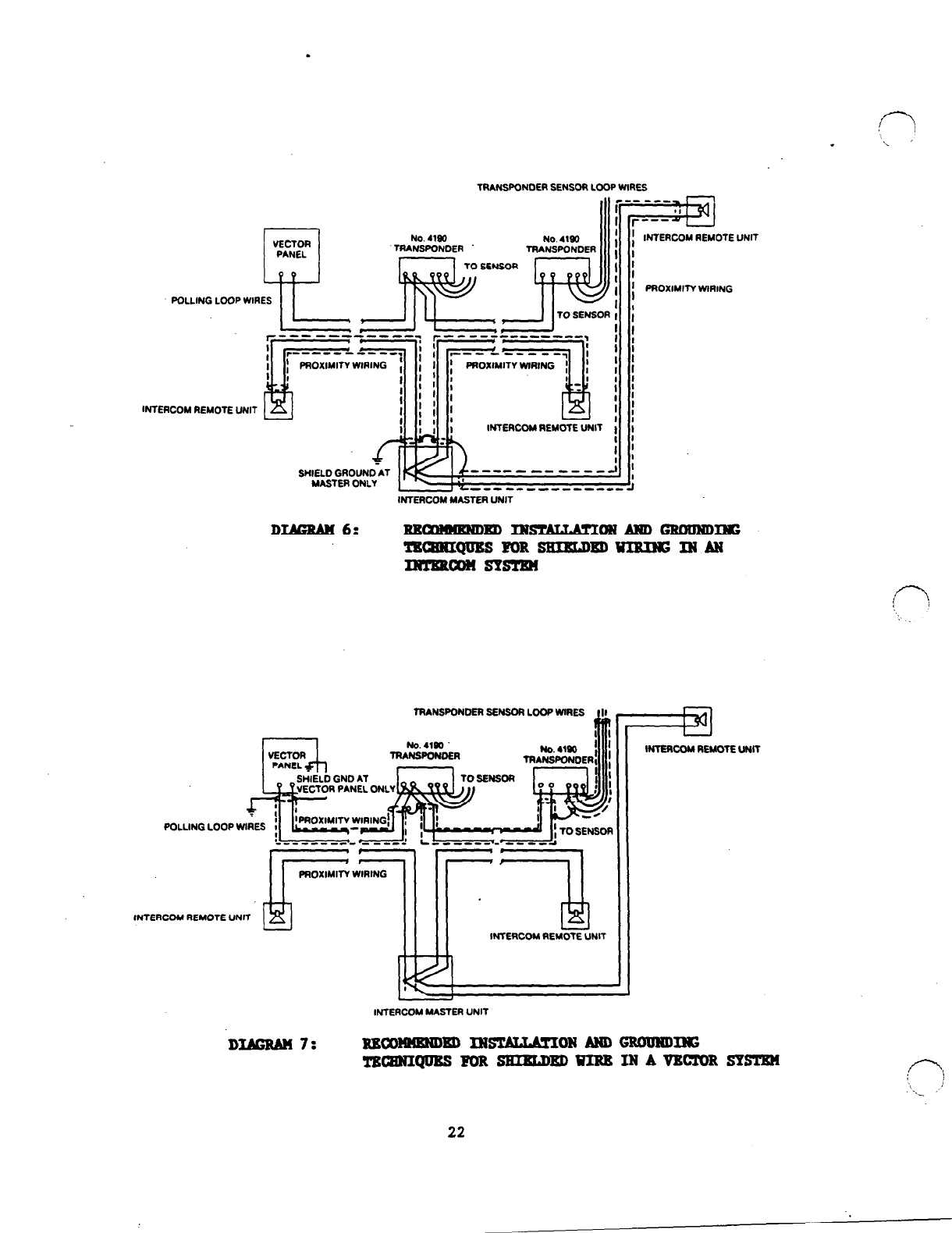
INTERCOM REMOTE UNIT
OTE UNIT
POLLING ‘CW; WlRifT 1 Proximity W1RING
PROXIMITY WIRING
: : p : : l-/-%j /
r-‘---71--‘-i; .‘i -----se- --- “;? 1 I
TRANSPONOER SENSOR LOOP WIRES
lNTERCOM REMOTE UNIT
INTERCOM MASTER UNIT
DIMS&f 6: NE-m IN- ONAmGRouNo~
TBQNUQUESFORSNIRLDBDWIRINGMAN
INTERam sYs!cm
TRANSPONDER SENSOR LOOP WIRES I II
INTERCOM REMOTE UNIT
DUERAW 7:
Jr7
INTERCOM REMOTE UNIT
INTERCOM MASTER UNIT
NECONNNND~ INsTLLuLcLRoH AND GRODNDING
!l'BCElUIQUBSFORSEIBLD~VIBBINAVBC!L'ORSYSlgn
22
- TNB No. 4153
Hew the 4153 C-COM performs is determined by the installer's programming.
Programming may be done from a CONSOLE keypad, from the No. 699 PROGRAMMER (The
No. 699 is simpler to use because of its large alphanumeric English language
display that prompts installer responses to questions), or remotely from the
central station. Information regarding the programmer. whether used locally or
remotely,
i6
included with the No. 695-53 Progremming Cartridge or the 4153PC.1
All information required for programming via a console keypad is included on the
worksheet which follows.
When programming from the console. consider the following:
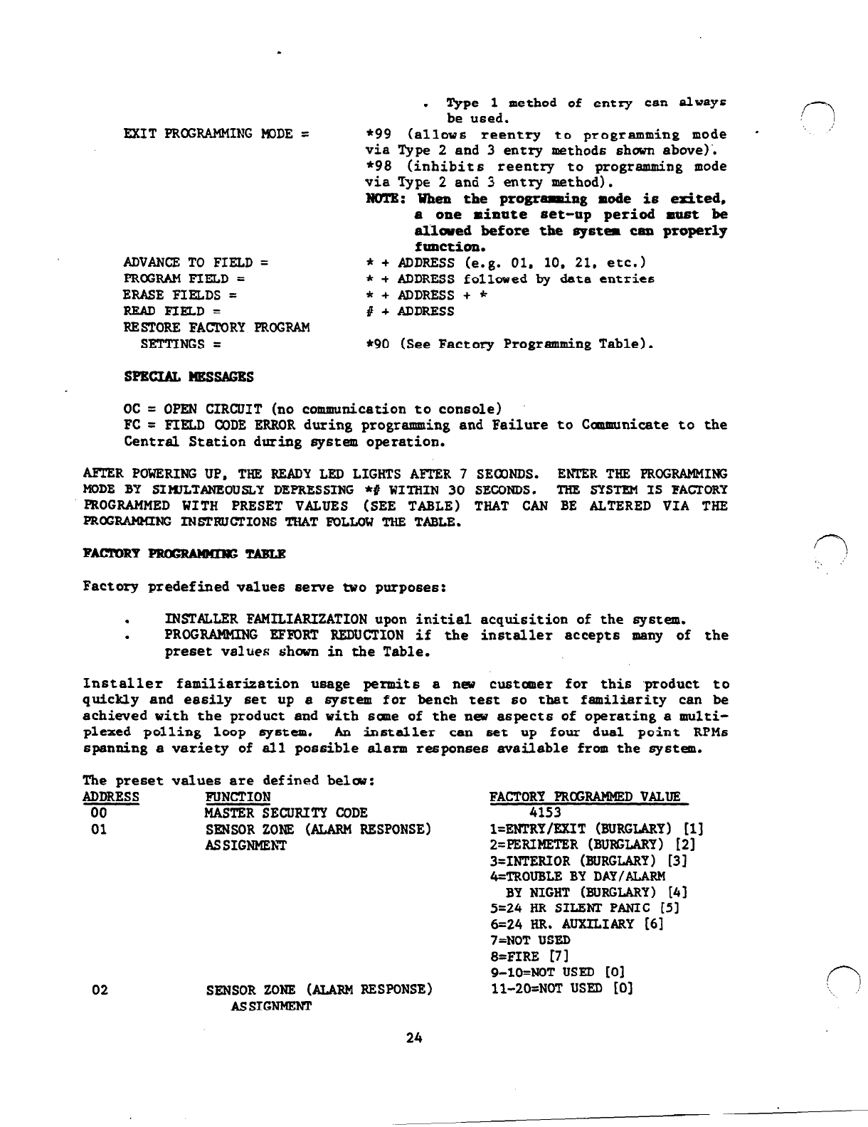
. The system is factory programmed to a set of preset values. which can be
altered by the installer to suit the specific need6 of a particular
installation or installation company. .The preset values are detailed in
the Factory Programming Table.
. Enter the keypad progrsnming mode by simultaneously depressing * # on the
keypad WITHIN 30 SECONDS AFTRR POWBR IS APPLIED TO TEB ODNTROL
or
subsequently by keying the code 4 + 1 + 5 + 3 followed by CODE key + 0 key
depression. Once a master code is programmed, use it instead of 4153 (a6
4153
is
then no longer present) to gain access to the programming mode.
.
When a data field ha6 been completely programmed fran the keypad, the
console will beep three times and then automatically proceed to and display
the
next data field address to be programmed.
. If the ntnnber of digit6 that you enter in the data field i6 lese than the
maximum permitted (for example phone number). then the console will display
the last data entered. To proceed, the next data field address to be
programmed must be entered (for example *05).
.
If an address is improperly entered, the console will display eFCw. If a
program entry is improperly entered (for example a larger number than what
is permitted). the console display will go
blank.
In either case, 6imply
re-enter the number.
.
Enter each address separately when you are first beginning to use the
product to insure that the control is properly programmed. All entries
msy
be changed as often as required.
.
The following describes 3 method6 of using the programming mode:
EWTKRPRCXXAMMIWG~DE=
OR
OR
1. POWER UP (AC or DC) + Depress * and
# simultaneously within 30 seconds.
2. IHI-Y: 4 + 1 + 5 + 3
+ [CODE] KAY
+ 0.
3. APTBR NASI'BR CODB IS PBocI'BBwIIgD:
blaster
Code1 + [CODE] Key + 0.
NOTBS: .
Types
2
and
3
method6 of entry
to the programming mode can be
eubsequently inhibited if the
programming mode is exited via use
of *98 instead of *99.
23
. Type 1 method of entry can always
be used.
MIT PROGRAMMING PlDDE = *99 (allows reentry to programming mode * ' '
via Type
2
and
3
entry methods shown above)'.
*98 (inhibit6 reentry to programming mode
via Type 2 and 3 entry method).
NO!CB: Wheu the programing mode is edted,
a one minute set-up period must be
allowed before
the spstem can properly
function.
ADVANCE TO FIELD = * + ADDRESS (e.g. 01, 10. 21. etc.)
PROGRAMFIELD= * + ADDRESS followed by data entries
ERASE FIELDS = * + ADDRESS + *
READFIELD= # + ADDRESS
RESTORE FAcrORY PROGRAM
SETTINGS = *90 (See Factory Programming Table).
SPECIAL ImssAGBs
oc = OPEN CIRCUIT (no communication to console)
FC = FIELD CODE ERROR during programming and Failure to Caumunicate to the
Central Station during system operation.
AFTER POWERING UP, TEE READY LED LIGHTS AFTER 7 SEOONDS. ENTER TEE PMX%AMMING
MCDE BY SIMlLTANEOUSLY DEPRESSING *# WITHIN 30 SECONDS. TEE SYSTEM IS FACTORY
PROGRAMMED WITH PRESET VALUES (SEE TABLE) TEAT CAN BE ALTERED VIA TEE
PROGRAMMING INSTRUCTIONS TEAT FDLLGW TEE TABLE.
Factory predefined values seme two purposes:
.
INSTALLER FAMILIARIZATION upon initial acquisition of the system.
. PROGRAMMING EFFORT REDUCTION if the installer accept6 many of the
preset value6 shown in the Table.
Installer familiarization usage
permit6
a new cu6tamer for this ,product to
quickly and easily set up a system for bench test 60 that familiarity can be
achieved with the product and with 6-e of the new aspects of operating a multi-
plexed polling loop
system.
An installer can set up four dual point
RPM6
spanning a variety of all possible alarm responses available from the system.
The preset values are defined belau:
FUNCTION
MASTER SECURITY CODE FACTORY PROGRAMMEDVALUE
4153
SENSOR ZONE (ALARM RESPONSE)
ASSIGNMEhT
SENSOR ZONE (ALARM RESPONSE)
AS SIGNMENl
~=EBTRY/FJUT (BURGLARY) [ii
2=PERIMETER (BURGLARY) [23
3=INTERIOR (BURGLARY) [31
4=TROUBLE BY DAY/ALARM
BY NIGHT (BURGLARY) [43
5=24
HR SILENT PANIC 151
6=24
HR. AUXILIARY I61
7=NOT USED
8=FIRE [71
9-lO=NOT USED [O]
ll-2O=NOT USED [O] f-3
: /
‘\~ .’
24
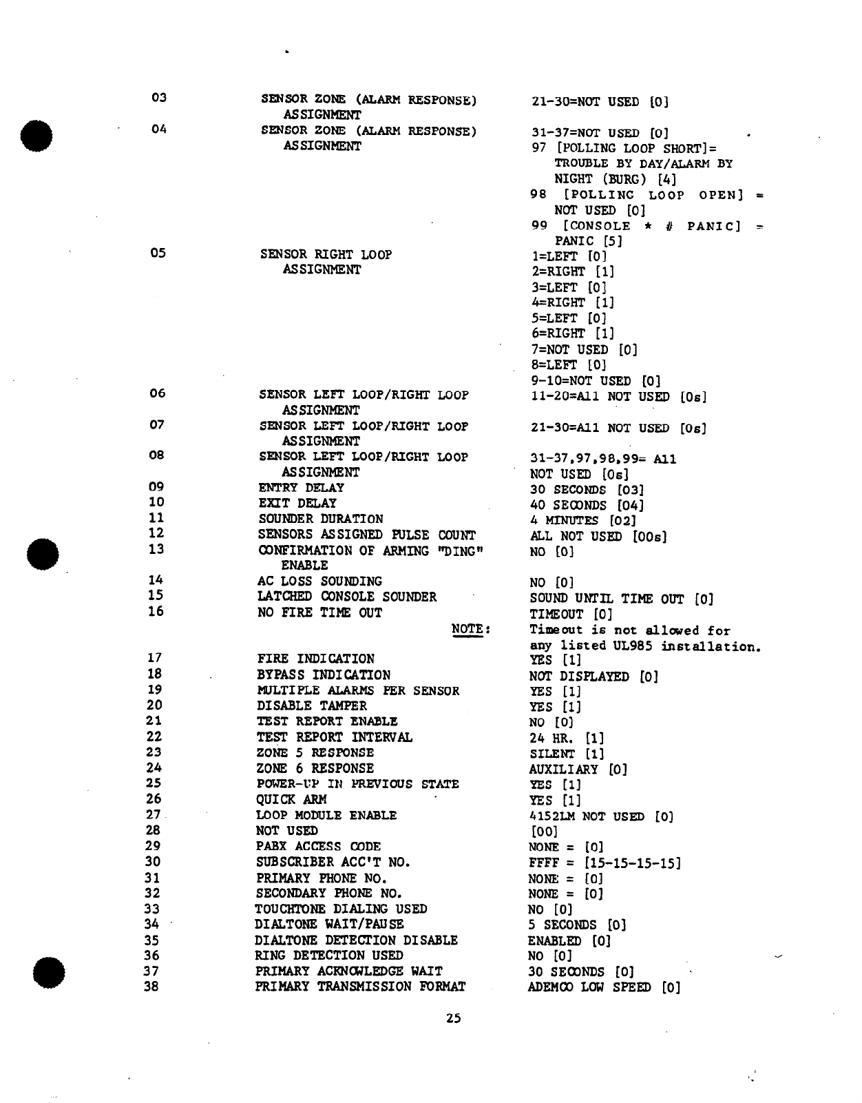
03
04
05
06
07
08
09
10
11
12
13
14
15
16
17 FIRE INDICATION
18 BYPASS INDICATION
19 MULTIPLE URMS PER SENSOR
20 DISABLE TAMPER
21 TEST REPORT ENABLE
22 TEF REPORT INTERVAL
23 ZONE 5 RESPONSE
24 ZONE 6 RESPONSE
25 POWER-Up IN PREVIOUS STATE
26 QUICK ARM
27. LOOP MODULE ENABLE
28 NOT USED
29 PABX ACCESS CODE
30 SUBSCRIBER ACC'T NO.
31 PRIMARY PHONE NO.
32 SECONDARY PHONE NO.
33 TOUCHT0NE DIALING USED
34 DIALTONE WAIT/PAUSE
35 DIALTONE DETECTION DISABLE
36 RING DETECTION USED
37 PRIMARY ACRNaJLEDGE WAIT
38 PRIMARY TRANSMISSION FORMAT
SENSOR ZONE (ALARM RESPONSE)
ASSIGNMENT
SENSOR ZONE (ALARM RESPONSE)
ASSIGNMENT
SENSOR RIGHT LOOP
ASSIGNMENT
SENSOR LEFT LOOP/RIGHT LOOP
ASSIGNMENT
SENSOR LEFT LOOP/RIGHT LOOP
ASSIGNMENT
SENSOR LEFT LOOP/RIGHT LOOP
ASSIGNMENT
ENTRYDELAY
EXIT DELAY
SOUNDER DURATION
SENSORS ASSIGNED PULSE COUNT
CONFIRMATION OF ARMING "DING"
ENABLE
AC LOSS SOUNDING
LATCHED CONSOLE SOUNDER
NO FIRE TIME OUT NOTE:
21-3O=N0T USED [0]
31-37=NOT USED [0] .
97 [POLLING LOOP SHORT]=
TROUBLE BY DAY/ALARM BY
NIGHT (BURG) [4]
98 [POLLING LOOP OPEN] =
NOT USED [O]
99 [CONSOLE * 11 PANIC] =
PANIC [Sl
l=LEFT [O]
2=RIGHT [l]
3=LEFT [0]
4=RIGHT [ll
5=LEFT [0]
6=RIGHT [l]
7=NOT USED [0]
8=LEFI [O]
9-lO=NOT USED [0]
11-20=Al1 NOT USED
[OS]
21-3O=All NOT USED
[OS]
31-37.97.98,99= All
NOT USED [OS]
30 SECONDS [03]
40 SECONDS [04]
4 MINUTES [021
AlaL NOT USED [0063
NO LOI
NO LOI
SOUND UNTIL TIME OUT [0]
TIMEOUT [O]
Timeout is not allowed for
any listed UL985 installation.
YES [II
NOT DISPLAYED [O]
YES [ll
YES r11
NO lOI
24 HR. [l]
SILENT 111
AUXILIARY [0]
YES r11
YES r11
4152LM NOT USED [O]
Km1
NONE = [O]
FFFF = r15-15-15-151
NONE = [O]
NONE = [O]
NO tOI
5 SECONDS [0]
ENABLED [O]
NO [Ol
30 SEONDS [0] *
ADEMCO LOW SPEED [O]
25
.
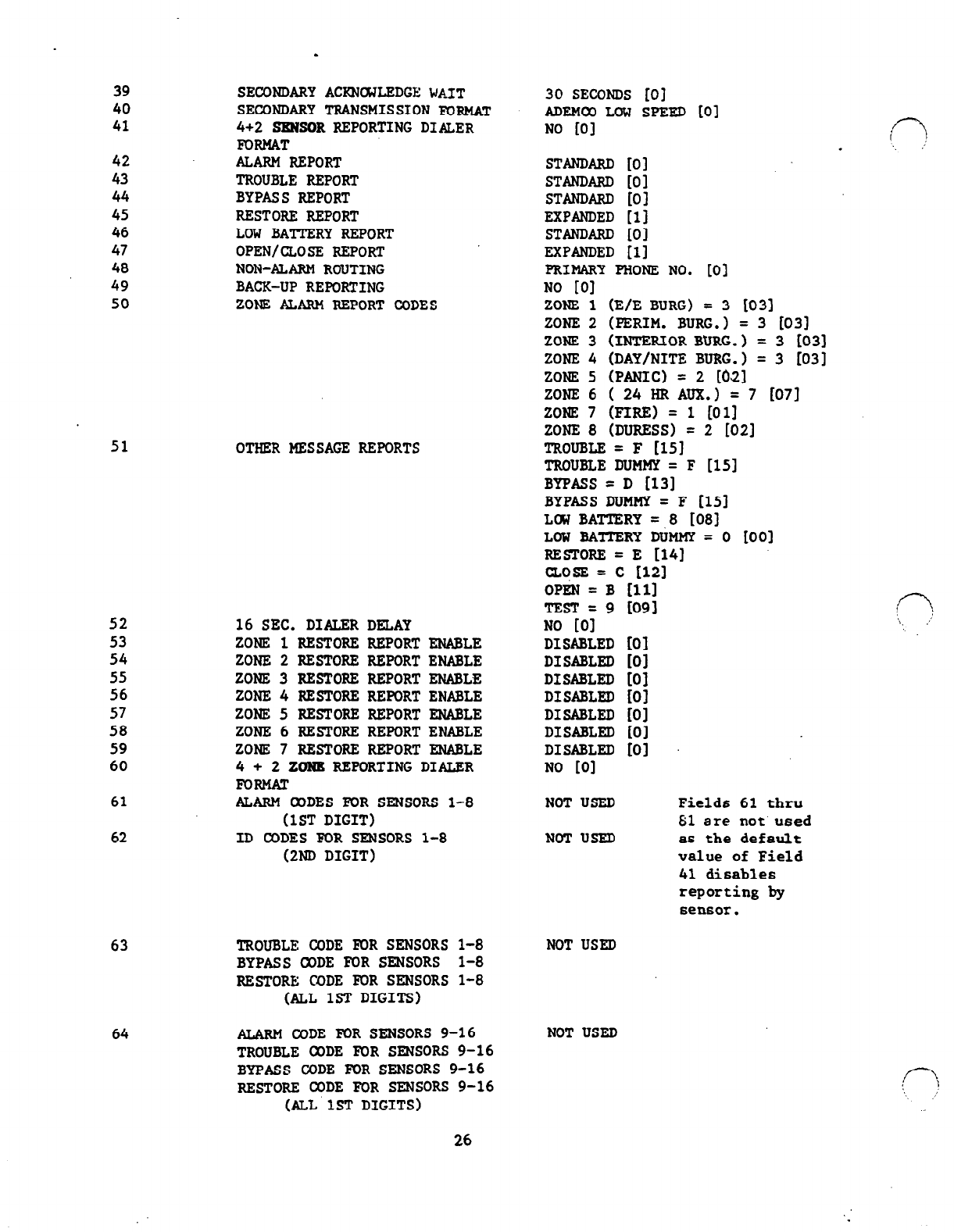
39
40
41
42
43
44
45
46
47
48
49
50
51
52
53
54
55
56
57
58
59
60
61
62
63
64
SECONDARY ACRNCWLEDGE
WAIT
SECONDARY TRANSMISSION FORMAT
4+2 =sOR REPORTING DIALER
FORMAT
ALARM REPORT
TROUBLE REPORT
BYPASS REPORT
RESTORE REPORT
LOW BATTERY REPORT
OPEN/CLOSE REPORT
NON-ALARM ROUTING
BACK-UP REPORTING
ZONE ALARM REPORT CODES
OTHER MESSAGE REPORTS
16 SEC. DIALER DELAY
ZONE 1 RESTORE REPORT ENABLE
ZONE 2 RESTORE REPORTENABLE
ZONE 3 RESTORE REPORT ENABLE
ZONE 4 RESTORE REPORT ENABLE
ZONE 5 RESTORE REPORT ENABLE
ZONE 6 RESTORE REPORTENABLE
ZONE 7 RESTORE REPORT ENABLE
4 + 2 ZONE REPORTING DIALER
FORMAT
ALARM WDES FOR SENSORS l-8
(1ST DIGIT)
ID CODES F0R SENSORS 1-8
(2ND DIGIT)
30 SECONDS [O]
ADEMW LOW SPEED [Ol
NO @I
STANDARD 101
STANDARD [O]
STANDARD [Ol
EXPANDED 111
STANDARD (01
EXPANDED [l]
PRIMARY PHONE NO. 101
NO 101
ZONE 1 (E/E BURG) = 3 1031
ZONE 2 (PERIM. BURG.1 = 3 [031
ZONE 3 (INTERIOR BURG.) = 3 LO31
ZONE 4 (DAY/NITE BURG.) = 3 (031
ZONE 5 (PANIC) = 2
ml
ZONE6 (24HRAUX.) =7 [071
ZONE 7
mRE) = 1 1011
ZONE 8 (DURESS) = 2 1021
TROUBLE = F [151
TROUBLE DUMMY= F 1151
BYPASS = D [131
BYPASS DUMMY = F [151
LOW BATTERY = 8 1081
LOW BATIERY DUMMY = 0 to01
RESTORE = E 1141
CLOSE = c 1123
OPEN
= B [ll]
TEST=9 I091
NO [Ol
DISABLED 101
DISABLED 101
DISABLED [01
DISABLED 101
DISABLED 101
DISABLED i01
DISABLED [01
NO 101
NOTUSED
NOTUSED
TROUBLE CODE FOR SENSORS 1-8
BYPASS CODE FOR SENSORS l-8
RESTORE WDE FOR SENSORS l-8
(ALL 1ST DIGITS)
NOT USED
ALARM CODE MR SENSORS 9-16 NOT USED
TROUBLE CODE F0R SENSORS 9-16
BYPASS CODE FOR SENSORS 9-16
RESTORE CODE FOR SENSORS 9-16
(ALL'lST DIGITS)
1C-J
. . . .’
f--l
‘\. ,I
Fields 61 thru
81 are not used
as the default
value of Field
41 disables
reporting by
sensor.
26
.
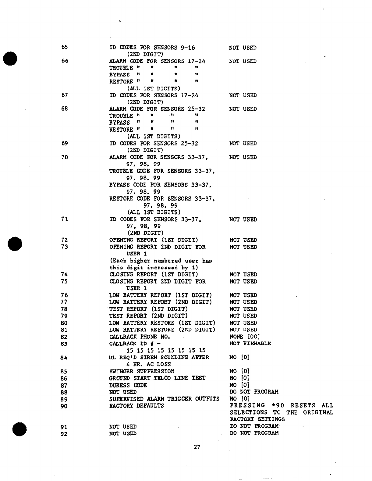
65
66
67
68
69
70
71
72
73
74
75
76
77
78
79
80
81
82
83
84
85 SWINGER SUPPRESSION
86 GROUND STARTTEZW LINE TEST
87 DURESS CODE
88 NOT USED
89 SUPERVISED ALARM TRIGGER OUTPUTS
90 FACTORY DEFAULTS
91 NOT USED
92 NOT USED
ID CODES F0R SENSORS 9-16
(2ND DIGIT) NOT USED
ALARM WDE FUR SENSORS 17-24
TROUBLE " " I( 81
BYPASS n " ,I
11
RESTORE " II
(ALL 1ST DIGIT;) fl
NOT USED
ID CODES FOR SENSORS 17-24
(2ND DIGIT) NOT USED
ALARM WDE FOR SENSORS 25-32
TROUBLE w w I, n
BYPASS n " II (1
RESTORE " "
(ALL 1ST DIG&) II
NOT USED
ID CODES FOR SENSORS 25-32
(2ND DIGIT) NOT USED
AMRM CODE FOR SENSORS 33-37,
97. 98. 99
TROUBLE CODE FUR SENSORS 33-37,
97, 98, 99
NOT USED
BYPASS CODE FOR SENSORS 33-37,
97, 98, 99
RESTORE CODE FOR SENSORS 33-37,
97, 98, 99
(ALL 1ST DIGITS)
ID CODES FOR SENSORS 33-37. NOT USED
97, 98, 99
(2ND DIGIT)
OPENING REPORT (1ST DIGIT) NOT USED
OPENING REPORT 2ND DIGIT M)R NOTUSED
USER1
(Each higher numbered user has
this digit increased by 1)
CLOSING REPORT (1ST DIGIT)
CLOSING REPORT 2ND DIGIT FOR NOT USED
NOT USED
USER1
LOW BATTERY REPORT (1ST DIGIT)
LOW BATTERY REPORT (2ND DIGIT)
TEST REPORT (1ST DIGIT)
TEST REPORT (2ND DIGIT)
LOW BATPERY RESTORE (1ST DIGIT)
LOW BATTERY RESTORE (2ND DIGIT)
CALLBACK PHONE NO.
CALLBACK ID # -
15 15 15 15 15 15 15 15
UL REQ'D SIRENSOUNDING AFTER
4 HR. AC LOSS
NOT USED
NOT USED
NOTUSED
NOTUSED
NOT USED
NOT USED
NONE [OO]
NOT VIEWABLE
NO TOI
NO 101
NO 101
NO [Ol
DO NOT PROGRAM
NO 101
PRESSING *90 RESETS ALL
SELECTIONS TO THE ORIGINAL
FACTORY SETTINGS
DONOTFROGRAM- \
DO NOT PROGRAM
27
.
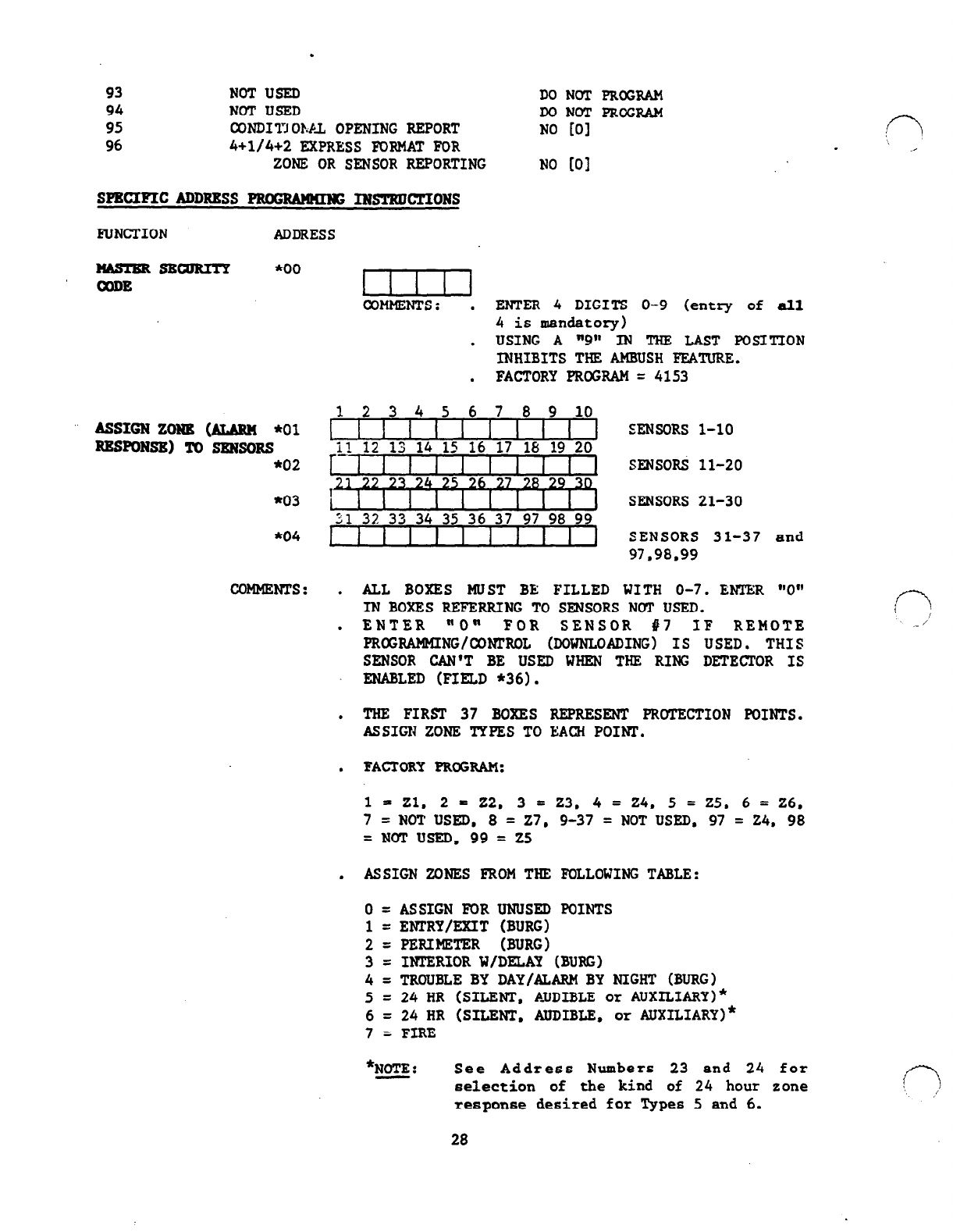
93 NOTUSED
94 NOTUSED
95 CONDITlOhbL OPENING REPORT
96
4+1/4+2
EXPRESS FORMAT FOR
ZONE OR SENSOR REPORTING
SPECIFICADDRESS
PRoGRdwIIIK; INSTRDCTIONS
FUNCTION ADDRESS
DO NOT PROGRAM
DO NOT PROGRAM
NO [Ol
NO (01
NAsTERsBcIIRITp *oo
CODE
ASSIGN ZOWE (ALAwl *01
RESPONSE) To 8EN8oRs
*02
*03
*04
COMMENTS :
I I I I I
COMMENTS: .
ENTER 4 DIGITS O-9 (entry of all
4
is mandatory)
. USING A "9" IN THE LAST POSITION
INHIBITS THE AMBUSH FEATURE.
. FACTORY PROGRAM = 4153
12 3 4 5 6 7 8 9 10
11) SENSORS l-10
11 12 13 14 15 16 17 lb 19 20
1 I I I I I
I I I1
SENSORS 11-20
SENSORS 21-30
SENSORS 31-37 and
97.98.99
. ALL BOXES MUST BE FILLED WITH O-7. ENTER "0"
INBOXES REFERRING TO SENSORS NOT USED.
. ENTER "0" FOR SENSOR 117 IF REMOTE
moGRAMMING/wmRoL (DOWNLOADJNG)
Is
USED. THIS
SENSOR
CAN'T BE USED WHEN THE RING DETECTOR IS
ENABLED (FIELD *36).
. THE FIRST 37 BOXES REPRESENT PROTECTION POINTS.
ASSIGN ZONE TYPES TO EACH POINT.
. FACTORY PROGRAM:
1 = Zl. 2 = 22. 3 = 23. 4 = 24. 5 = 25. 6 = 26,
7
= NOT USED, 8 = 27, 9-37 = NOT USED. 97 = 24, 98
=NOTUSED, 99= 25
. ASSIGN ZONES FROM THE FOLLOWING TABLE:
0 = ASSIGN FOR UNUSED POINTS
1 = ENTRY/FXIT (BURG)
2
= PERIMETER (BURG)
3
= INTERIOR W/DELAY (BURG)
4
= TROUBLE BY DAY/ALARM BY NIGHT (BURG)
5
= 24 HR (SILENT, AUDIBLE or AUXILIARY)*
6
= 24 HR (SILENT, AUDIBLE, or AUXILIARY)*
7
= FIRE
*NOTE: See Address Numbers 23 and 24 for
selection of the kind of 24 hour zone
response desired for Types 5 and 6.
28
.
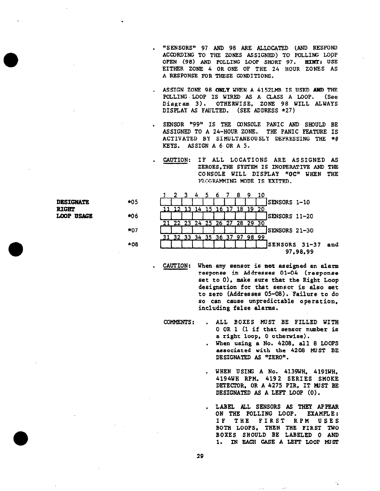
DBSI-
EIGNT
LOOPUSAGE
*05
*06
*07
*08
. "SENSORS"
97 AND 98 ARE p,tLOCATED (AND RESPOND
ACCORDING TO THE ZONES ASSIGNED) TO POLLING LOQP
OPEN
(98) AND POLLING LOOP SHORT 97. El-N!C: USE
EITHER ZONE 4 OR ONE OF THE 24 HOUR ZONES AS
A RESPONSE FOR THESE CONDITIONS.
.
ASSIGN ZONE 98 ONLY WHEN A 4152LMB IS USED AND THE
POLLING.LOOP IS WIRED AS A CLASS A LOOP. (See
Diagram 3). .OTHERWISE, ZONE 98 WILL ALWAYS
DISPLAY AS FAULTED. (SEE ADDRESS *27)
.
SENSOR "99" IS THE CONSOLE PANIC AND SHOULD BE
ASSIGNED TO A 24-HOUR ZONE. THE PANIC FEATURE IS
ACTIVATED BY SIMULTANEOUSLY DEPRESSING THE *#
KEYS. ASSIGN A 6 OR A 5.
. CAUTION: IF ALL LOCATIONS ARE ASSIGNED AS
ZEROES.THE SYSTEM IS INOPERATIVE AND THE
CONSOLE WILL DISPLAY "OC" WHEN THE
P?KRAMMING MODE IS EXITED.
10 9
12345678mm~
1 1 1 1 1 1 i t i &=ORS l-10
I
11 12 13 14 15 36 17 18 19 20
I I I I I .I 1 1 I 1
SENSORS 11-20
,21
22 23 24 25 26 27 28,
29
30
I )
SENSORS 21-30
SENSORS 31-3
97.98,99 7 and
.
CAUTION: When any sensor
is
not assigned an alarm
response in AddreSSeS 01-04 (response
set to 0), make sure that the Right Loop
designation for that sensor is &SO set
to zero (Addresses
05-08).
Failure to do
60
can
cause unpredictable operation,
including false alarms.
coMlm?Ts: . ALL BOXES MUST BE FILLED WITH
0 OR 1 (1 if that sensor number is
a right loop, 0 otherwise).
. When using a No.
4208.
all
8
LOOPS
associated with the
4208
MUST BE
DESIGNATED As "ZERO".
.
WHEN USING A No.
4139WH.
4191WH.
4194WH RPM, 4192 SERIES SMOKE
DETECPOR, OR A 4275 PIR, IT MIST BE
DESIGNATED AS A LEFT LOOP (0).
.
LABEL ALL SENSORS AS THEY APPEAR
ON
THE
POLLING LOOP. EXAMPLE:
IF THE FIRST RPM USES
BOTH LOOPS, THEN THE FIRST TWO
BOXES SHOULD BE LABELED 0 AND
1. INEACH CASEALEFT LOOP MUST
29
.
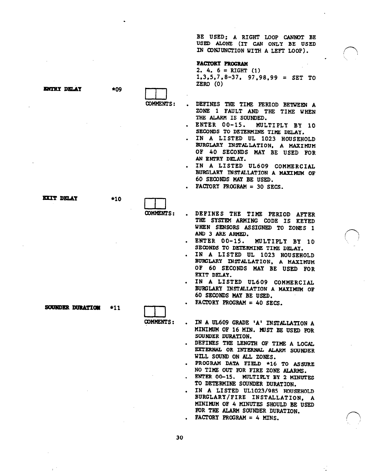
=lRYDlLAY
mIT.DmJLY
l 09
In
CoMMENrs: .
.
.
*lo m
COMMENTS: .
.
suJmBRDlnkmx~
*11
r-rl l
I 1 1
tp@lEms: .
.
BE USED; A RIGHT LOOP CANNOT BE
USED ALONE (IT CAN ONLY BE USED
IN CON.TUNCTION WITH A LEFT LOOP). In
. '\,
=CTDRY-
2. 4. 6 = RIGHT (1)
1.3.5.7.8-37. 97.98.99 = SET TO
ZERO
(0)
DEFINES THE TIME PERIOD BETWEm A
ZONE 1 FAULT AND THE TIMF, WHEN
THE ALARM IS SOUNDED.
ENTER 00-15. MULTIPLY BY 10
SECONDS
TO DETERMINE TIME DELAY.
IN A LISTED UL 1023 HOUSEHOLD
BURGLARY INSTALLATION,
A
MAXIMUM
OF 40 SECONDS MAY BE USED FOR
ANENTRY DELAY.
TN
A
LISTED UL609 COMMERCIAL
BURGLARY INSTALLATION A MAXIMUM OF
60
SECONDS
MAY BE USED.
FACRORY PROGRAM = 30 SECS.
DEFINES THE TIME PERIOD
AFTER
THE SYSTEM ARMING CODE IS KEYED
WHEN SENSORS ASSIGNED TO ZONES 1
AND3AREARMED.
ENTER 00-15. MULTIPLY BY 10
SECONDS TO DETERMINE TIME DELAY.
IN A LISTED UL 1023 HOUSEHOLD
BUEIGLARY INSTALLATION, A MAXIMUM
OF 60 SECONDS MAY BE USED FOR
EKITDELAY.
IN A LISTED UL609 COMMERCIAL
BURXARY INSTALLATION A MAXIMUM OF
60 SECONDS MAY BE USED.
FACTORY PROGRAM = 40 SECS.
IN A IL609 GRADE 'A' INSTALLATION
A
MINIMUM OF 16MIN. WST BE USED FOR
SOUNDER DURATION.
DEFINES THE LENGTH OF TIME A LOCAL
EXTERNAL OR INTERN& ALARM SOUNDER
WILL SOUND ON ALL ZONES.
PROGRAM DATA FIELD *16 TO ASSURE
NO TIME OUT FOR FIRE ZONE ALARMS.
ENTER 00-15. MULTIFLY BY 2
MINUTES
TO DETERMINE SOUNDER DURATION.
IN A LISTED UL1023/985 HOUSEHOLD
BURGLARY/FIRE INSTALLATION, A
MINIMtJM OF 4 MINUTES SHOULD BE USED
FOR THE ALAR&f SOUNDER DURATION.
FACTORY PROGRAM = 4 MINS.
30
.
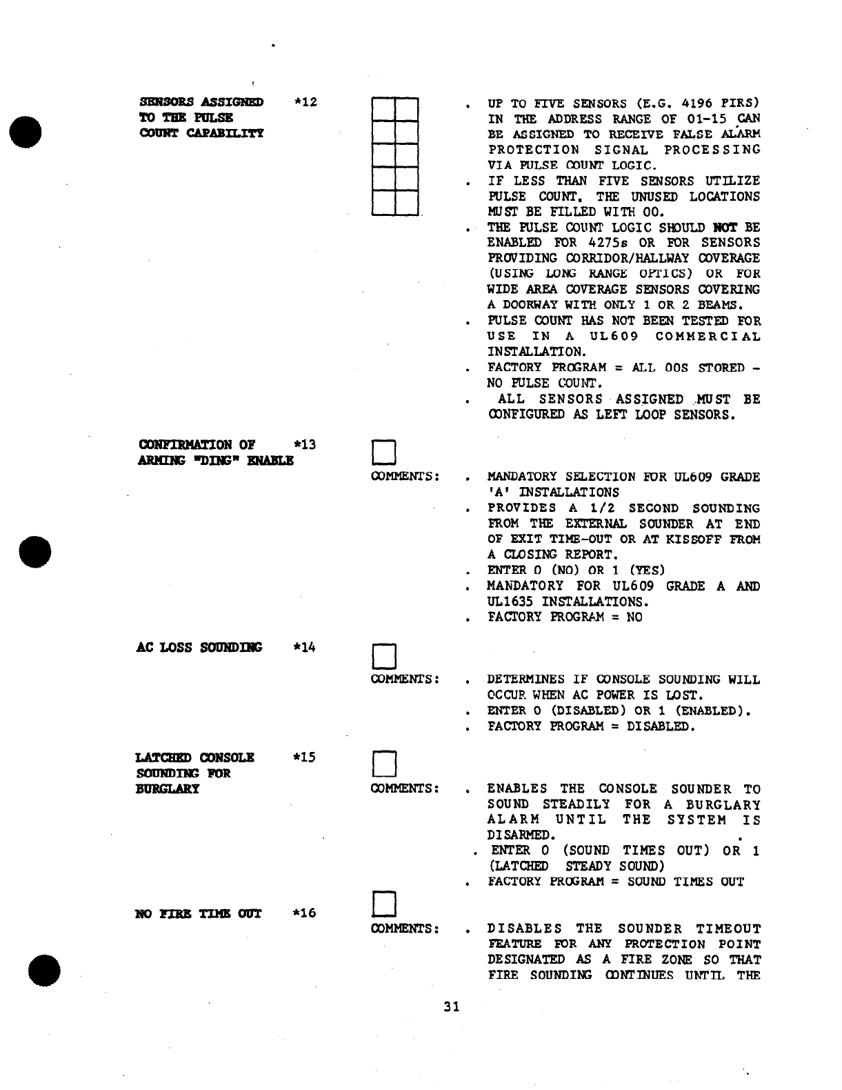
SENSORSASSIGNRD *12
ToTNEFmsE
COUNT c&PABILITY
Eli
-ON OF
*13
AENINGaING"ENABLR cl
AC Loss 8ouRDIIoG
IamczED CONSOLE
SODNDING FOR
BURGURY
NoFIRETImoTJT
COMMENTS :
*14 cl
COMMENTS :
*15 cl
COMMENTS :
*16 rl
COMMENTS :
.
.
.
.
.
.
.
.
.
.
.
.
.
.
.
UP TO FIVE SENSORS (E.G. 4196 PIRS)
IN THE ADDRESS RANGE OF 01-15 CAN
BE ASSIGNED TO RECENE FALSE ALARM
PROTECTION SIGNAL PROCESSING
VIA PULSE COUNT LOGIC.
IF LESS THAN FIVE SENSORS UTILIZE
PULSE COUNT, THE UNUSED LOCATIONS
MUST BE FILLED WITH 00.
THE PULSE COUNT LOGIC SHCULD NOT BE
ENABLED FOR 4275s OR FOR SENSORS
PRCIVIDING CORRIDOR/HALLWAY COVERAGE
(USING LONG RANGE OPTICS) OR FOR
WIDE AREA COVERAGE SENSORS COVERING
A DOORWAY WITH ONLY 1 OR 2 BEAMS.
PULSE COUNT HAS NOT BEEN TESTED FOR
USE IN A UL609 COMMERCIAL
INSTALLATION.
FACTORY PROGRAM
= ALL 00s STORED-
NO PULSE COUNT,
ALL SENSORS ASSIGNED MUST BE
ONFIGURED AS LEFT, LOOP SENSORS.
MANDATORY SELECTION FOR UL609 GRADE
'A' INSTALLATIONS
PROVIDES A l/2 SECOND SOUNDING
FROM THE
EXTERNAL
SOUNDER AT END
OF EXIT TIME-OUT OR AT KISSOFF FROM
A CLOSING REPORT.
ENTER 0 (NO) OR 1 (YES)
MANDATORY FOR UL609 GRADE A AND
UL1635
INSTALLATIONS.
FACTORY PROGRAM = NO
DETERMINES IF CONSOLE SOUNDING WILL
CXCURWHEN AC POWER IS Ix)ST,
ENTER 0 (DISABLED) OR 1 (ENABLED).
FACTORY PROGRAM = DISABLED.
ENABLES THE CONSOLE SOUNDER TO
SOUND STEADILY FOR A BURGLARY
ALARM UNTIL THE SYSTEM IS
DISARMED. .
.
ENTER 0 (SOUND TIMES OUT) OR 1
(LATCHED STEADYSOUND)
. FACTORY PROGRAM = SOUND TIMES OUT
.
DISABLES THE SOUNDER TIMEOUT
FEATURE EDR ANY PROTECTION POINT
DESIGNATED AS A FIRE ZONE SO THAT
FIRE SOUNDING a)NTINUES UNTIL THE
31
.
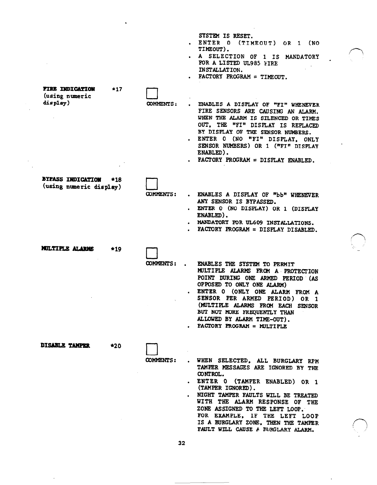
SYSTFM IS RESET.
ENTER 0 (TIMEOUT) OR 1 (NO
TIMEOUT).
A SELECTION OF 1 IS MANDATORY f-7
FOR A LISTED UL985 FIRE .
INSTALLATION.
FACTORY PROGRAM = TIMEOUT.
.
FIRBlmIcmIon
*17
(using numeric
q
display) COMMENTS: I
BYFASS INDICA!CION
*18
(using maneric display) cl
COMMENTS: .
mLTIPm ALANRE *19 cl
COMMENTS: .
.
.
DISABU TAMPER *20 cl
WMMENTS: .
.
.
ENABLES A DISPLAY OF "FI" WHENEVER
FIRE SENSORS ARE CAUSING AN ALARM.
WHENTHEALARM IS SILENCED ORTIMES
OUT, THE "FI" DISPLAY IS REPLACED
BY DISPLAY OF THE SENSOR
NUMBERS.
ENTER 0 (NO "FI" DISPLAY, ONLY
SENSOR NUMBERS) OR 1 ("FIN DISPLAY
ENABLED).
FACTORY PROGRAM
= DISPLAY ENABLED.
ENABLES A DISPLAY
OF
"bb" WHENEVER
ANY SENSOR IS BYPASSED.
ENTER 0 (NO DISPLAY) OR 1 (DISPLAY
ENABLED).
MANDATCRY FOR UL6C9 INSTALLATIONS.
FACMRY PROGRAM = DISPLAY DISABLED.
ENABLES THE SYSTEM TO PERMIT
FIILTIPLE ALARMS FRCN A. PROTECTION
POINT DURING ONE ARMED PERIOD' (AS
OPPOSED TO ONLY ONE ALARM)
ENTER 0 (ONLY ONE ALARM FROM A
SENSOR PER ARMED PERIOD) OR 1
(MULTIPLE ALARMS FRCM EACH SWSGR
BUTNOTMORE FREQUENTLYTHAN
ALLOWED BY ALARM TIME-OUT).
FACTORY PROGRAM = PplLTIPLE
WHEN SELECTED, ALL BURGLARY RPM
TAMPER MESSAGES ARE IGNORED BY THE
CCNrRoL.
ENTER 0 (TAMPER ENABLED) OR 1
(TAMPER IGNORED).
NIGHT TAMPERFAULTSWILL BE TREATFJI
WITH THE ALARM RESPONSE
OF
THE
ZONE ASSIGNED TC THE LEFT LOOP:
FOR EZAMPLE. IF THE LEFT LOOP
IS ABURGLARYZONS. THEN THE TAMPER
FAULT WILL CAUSE A BURGLARY ALARM.
(7 .:
32
.
.
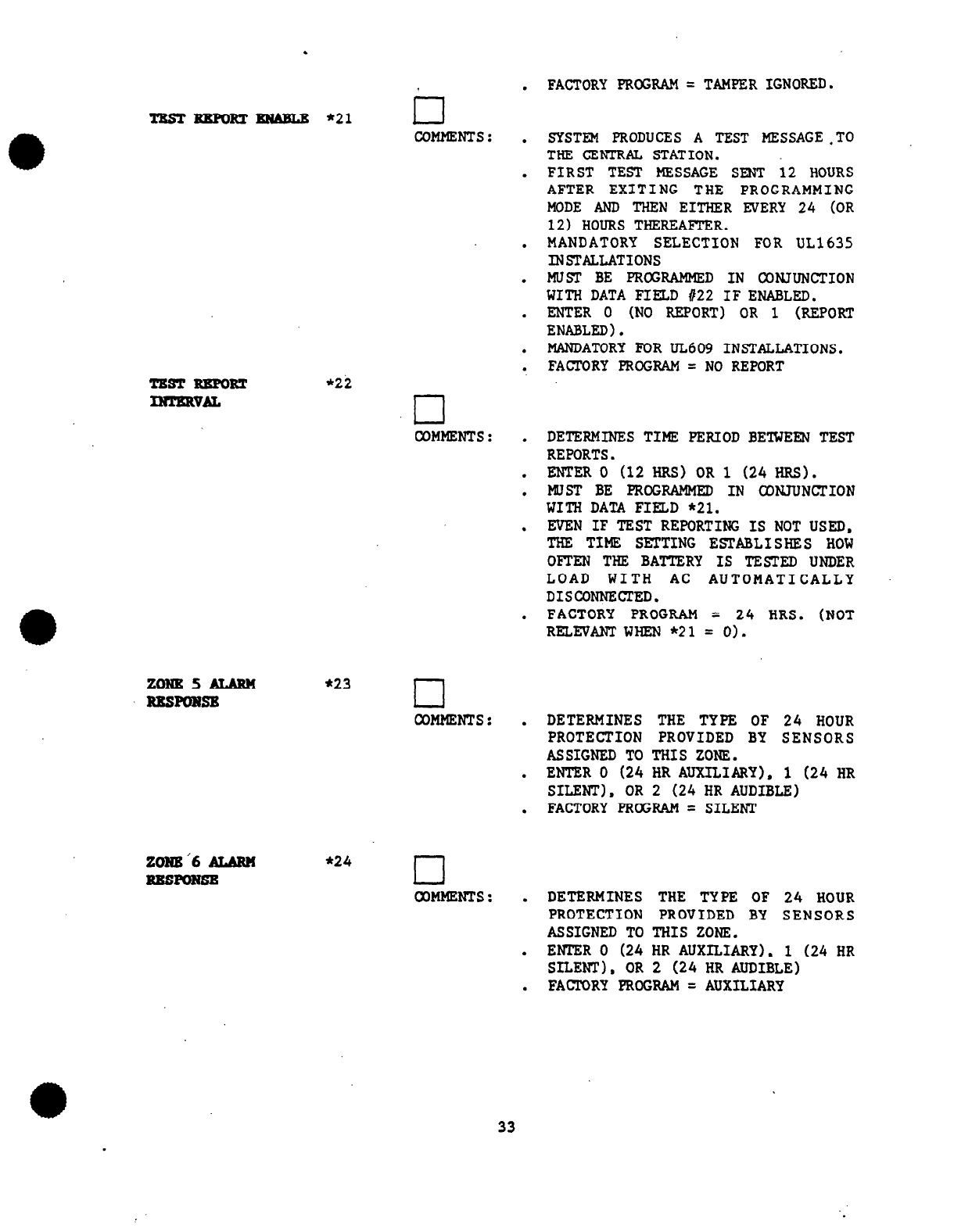
TBsrRBmRzBNABLE *21 II
COMMENTS: .
.
.
.
.
.
.
TEST EBPORT
*22
INTBRVAL
Ll
COMMENTS:
.
.
.
.
.
FACTORY PROGRAM = TAMPER IGNORED.
SYSTEM PRODUCES A TEST MESSAGE-TO
THE CENTRAL STATION.
FIRST TEST MESSAGE SENT 12 HOURS
AFTER EXITING THE PROGRAMMING
MODE AND THEN EITHER EVERY 24 (OR
12) HOURS THEREAFTER.
MANDATORY SELECTION FOR UL1635
INSTALLATIONS
MUST BE PROGRAMMED IN CONJUNCTION
WITH DATA FIELD #22 IF ENABLED.
mm 0 (No REPORT) OR i (REPORT
ENABLED).
MANDATORY FOR UL609 INSTALLATIONS.
FACTORY PRCGRAM = NO REPORT
DETERMINES TIME PERIOD BETWEEN TEST
REPORTS.
ENTER 0 (12 HRS) OR 1 (24 HRS).
MUST BE PROGRAMMED IN CGNJUNCTION
WITH DATA FIELD *21.
EVEN IF TEST REPORTING IS NOT USED,
THE TIME SGTTING ESTABLISHES HOW
OFTEN THE BATTERY IS TESTED UNDER
LOAD WITH AC AUTOMATICALLY
DISCONNECTED.
FACTORY PROGRAM = 24 HRS. (NOT
RELEVANT WHEN *21 = 0).
ZONESALARM *23
EBSPONSR cl
COMMENTS: . DETERMINES THE TYPE OF 24 HOUR
PROTECTION PROVIDED BY SENSORS
ASSIGNED TO THIS ZONE.
ENTER 0 (24 HR AUXILIARY), 1 (24 HR
' SILENT). OR 2 (24 HR AUDIBLE)
. FACTORY PROGRAM = SILENT
ZONE’6
AURN
*24
r-l
EESPONSE WMMENTS: . DETERMINES THE TYPE OF 24 HOUR
PROTECTION PROVIDED BY SENSORS
ASSIGNED TO THIS ZONE.
. ENTER 0 (24 HR AUXILIARY), 1 (24 HR
SILENT), OR 2
(24
HR AUDIBLE)
. FACICRY PROGRAM = AUXILIARY
4D .
33
.
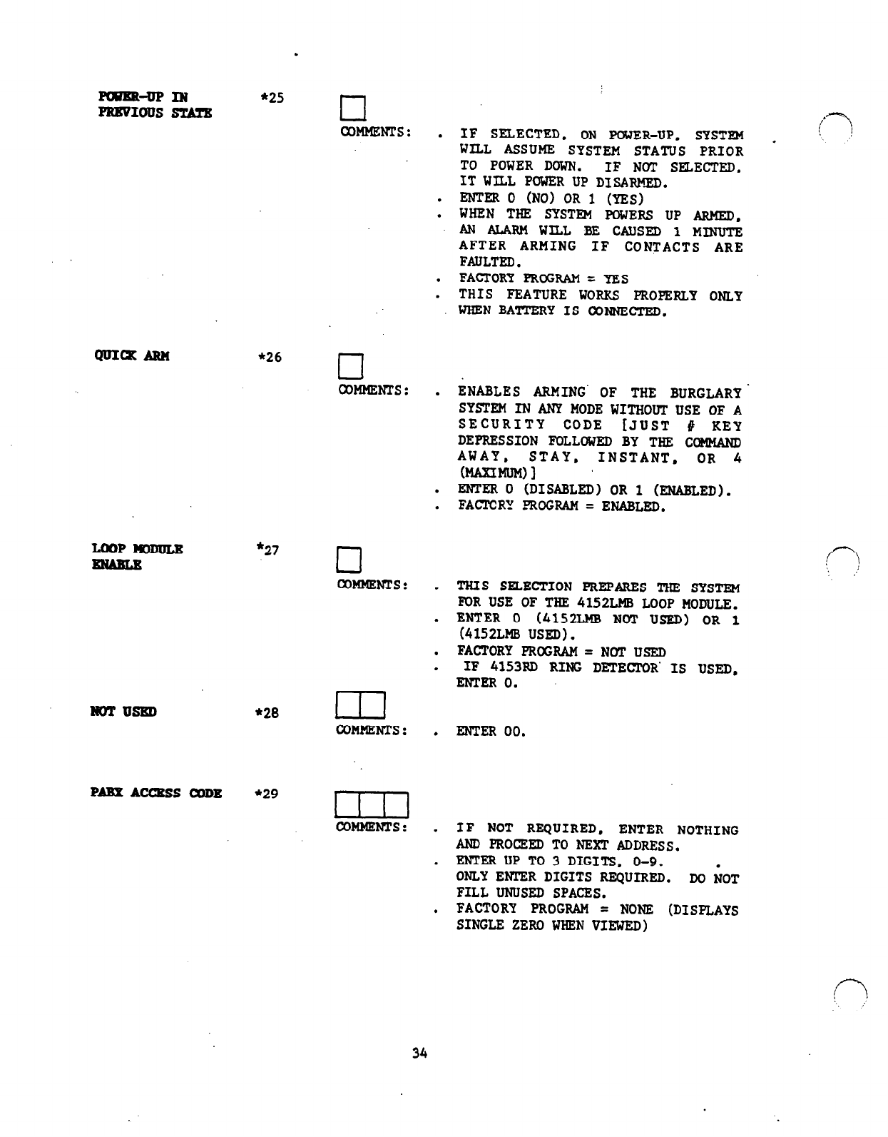
FmBkuPIN
*25
PRWIOUS STATS cl
CoMMEms: .
.
.
.
.
*26 cl
COMMENTS: .
.
.
LOOP-
*27 cl
wMMENTs: .
.
.
.
NOTUSED *28 ul
COMMENTS: .
IF SELECTED, ON POWER-UP. SYSTEM
WILL ASSUME SYSTEM STATUS PRIOR
TO POWER DOWN. IF NOT SELECTED.
ITWILL POWER UP DISARMED.
ENTER 0 (NO) OR 1 (YES)
WHEN THE SYSTEM PCWERS UP ARMED.
AN ALARM WILL BE CAUSED 1 MINUTE
AFTER ARMING
IF
CONTACTS ARE
FAULTED.
FACTORY PROGRAM = YES
THIS FEATURE WORKS PROPERLY ONLY
WHENBATTERYISCONNECTED.
ENABLES ARMING' OF THE BURGLARY'
SYSTEM IN ANY MODE WITHOUT USE OF A
SECURITY CODE [JUST # KEY
DEPRESSION FOLLOWED BY THE COMMAND
AWAY, STAY, INSTANT, OR 4
o4AmmM)l
ENTER 0 (DISABLED) OR 1 (ENABLED).
FACTCRY -FROGRAM= ENABLED.
THIS SELECTION PREPARES THE SYSTEM
ECR USE OF THE 4152LMB LOOP MODULE.
ENTER 0 (4152LMB NOT USF.D) OR 1
(4152LMB USED).
FACTORY PROGRAM=NGTUSED
IF 4153RD RING DETECTOR' IS USED.
ENTER 0.
ENTER 00.
PABXACCBSSCODB *2g un
COMMENTS : . IF NOT REQUIRED, ENTER NOTHING
AND PROCEED TO NEXT ADDRESS.
. ENTER UP TO 3 DIGITS, O-9.
ONLY ENTER DIGITS REQUIRED. DO NOT
FILL UNUSED SPACES.
, FACTORY PROGRAM = NONE (DISPLAYS
SINGLE ZERO WHEN VIEWED)
34
.
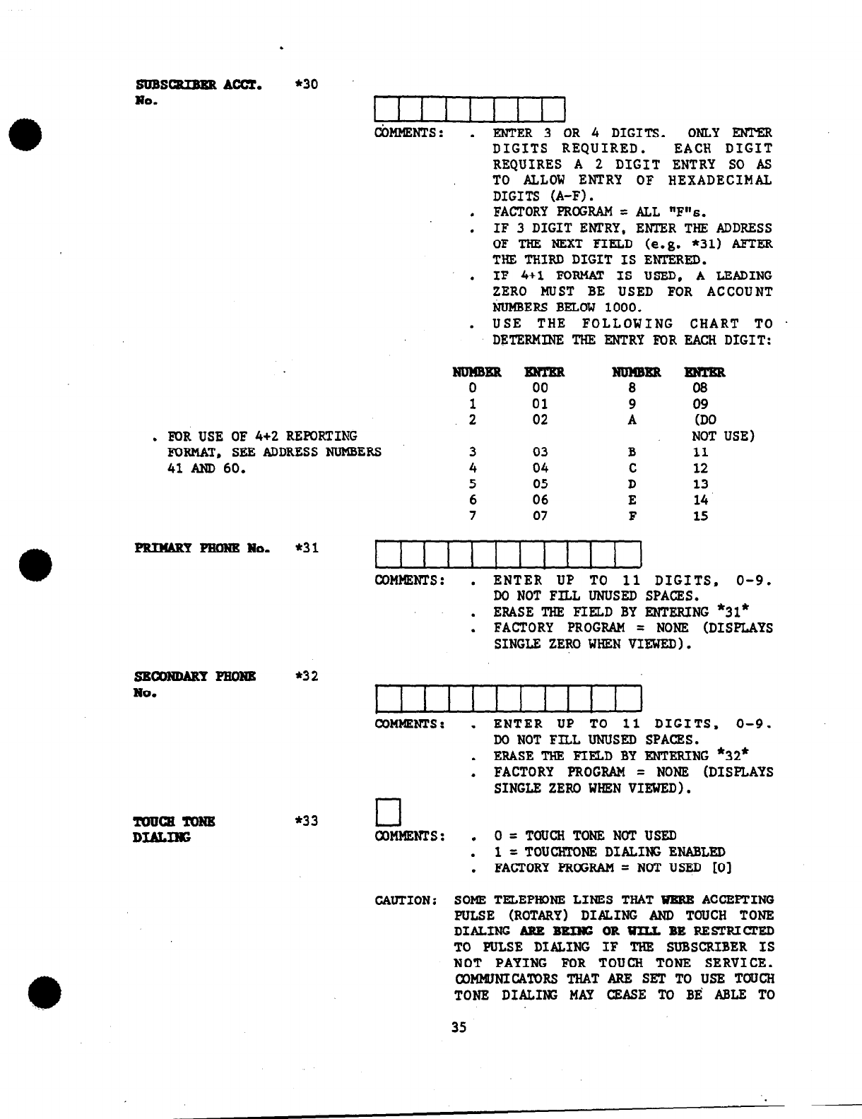
SUBSatTRaa Am.
*30
No. I I I I I I I I I
ctimmms: .
ENTER 3 OR 4 DIGITS. ONLY EN!PER
DIGITS REQUIRED. EACH DIGIT
REQUIRES A 2 DIGIT ENTRY SO AS
TO ALLOW ENTRY OF HEXADECIMAL
DIGITS (A-F).
. FACTORY PROGRAM = ALL "F"s.
. IF 3 DIGIT ENTRY, ENTER THE ADDRESS
OF THE NEXT FIELD (e.g. *31) AFTER
THE THIRD DIGIT IS ENTERED.
. IF 4+1 FORMAT IS USED, A LEADING
ZERO MUST BE USED FOR ACCOUNT
NUMBERS BELOW 1000.
USE THE FOLLOWING CHART TO .
l
DETERMINE THE ENTRY FOR EACH DIGIT:
NumBR BNTER RmmER mTm
0 00 8 08
1 01 9 09
2 02 A (DO
. FOR USE OF 4+2 REWRTING NOT USE)
FORMAT. SEE ADDRESS NUMBERS 3 03 B 11
41 AND60.
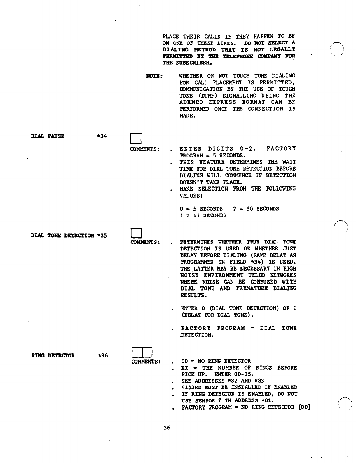
sEcoNMRYPRoRE
No.
!muQTToRB
DEALXNG
4 04 C 12
5 05 D 13
6 06 E 14
7 07 F 15
COMMENTS: . ENTER UP TO 11 DIGITS, O-9.
DO NOT FILL UNUSED SPACES.
. ERASE THE FIELD BY ENTERING *31*
FACTORY PROGRAM
= NONE (DISPLAYS
l
SINGLE ZERO WHEN VIEWED).
*32
COMMENTS: .
.
.
*33 cl
CoMMENrs: .
.
.
ENTER UP TO 11 DIGITS, O-9.
DO NOT FILL UNUSED SPACES.
ERASE THE FIELD BY ENTERING *32*
FACTORY PROGRAM = NONE (DISPLAYS
SINGLE ZERO WHEN VIEWED).
0
= TOUCH TONE NOT USED
1 =TOUCHTCNE DIALINGENABLFD
FACTORY PROGRAM = NOT USED [O]
CAUTION: SOME TELEPHDNE LINES THATWRREACCEPTING
PULSE (ROTARY) DIALING AND TOUCH TONE
DIALING ARE BEXNG OR m BE RESTRICTED
TO PULSE DIALING IF THE SUBSCRIBER IS
NOT PAYING FOR TOUCH TONE SERVICE.
CXX4MUNICA'TORSTHATARE SETTOUSE TOUCH
TONE DIALING MAY CEASE TO BR ABLE TO
35
DIALPADSE *34
DI&TONEDETMTION*35
RIlGDBTEClYOR
*36
PLACZ TdEIR CALLS IF THEY HAPPEN TO BE
ON ONE OF THESE LINES.
DOBOT8BLE~A
DIALING HBTEOD TEAT IS NOT LBGALLT
- BY TEE TPzEmoNE WNPANY FOR -
TRR suBsauEER.
NOTE:
WHETHER OR NOT TOUCH TONE DIALING
FOR CALL PLACEMENT IS PERMITTED,
.COMMUNICATION BY THE USE OF TOUCH
TONE (DTMF) SIGNALLING USING THE
ADEMCO EXPRESS FORMAT CAN BE
PERFORMED ONCE THE CONNECTION IS
MADE.
COMMENTS : . ENTER DIGITS 0-2. FACTORY
PRCGRAM = 5 SECONDS.
. THIS FEATURE DETERMINES THE WAIT
TIME FOR DI& TONE DETECFION BEFORE
DIALING WILL COMMENCE IF DETECTION
DOESN'T TAKE FLACE.
. MAKE SELECTION FRCH THE FOLLOWING
VALUES:
0 = 5 SECONDS 2 = 30 SECONDS
1 = 11 SECONDS
LJ
CoMMENrs: .
DETERMINES WHETHER TRUE DIAL TONE
DETECTION IS USED OR WHETHER JUST
DELAY BEFORE DIPiCING (SAME DELAY AS
PROGRAMMED IN FIELD *34) IS USED.
THE.LATYER MAY BE NECESSARY IN HIGH
NOISE ENVIRONMENT TFLCO NETWORKS
WHERE NOISE CAN BE CONFUSED WITH
DIAL TONE AND PREMATURE DIALING
RESVLTS.
ENTER 0 (DIAL TONE DETECTION) OR 1
l
(DELAY FOR DIAL TONE).
. FACTORY PROGRAM = DIAL TONE
DETECTION.
ul
COMMENTS : . oo=
NO RING DETECTOR
. xx = THE NUMBER
OF
RINGS BEFORE
PICKUP. ENTER 00-15.
. SEE ADDRESSES *82 AND *83
, 4153RD MUST BE INSTALLED IF ENABLED
. IF RING DETECTOR IS ENABLED, Do NOT
USE SENSOR 7 IN ADDRESS *Ol.
. FACTORY PROGRAM = NO RING DETECl'OR [OO]
,p i
f-7
‘\~ ’
_,*’
36
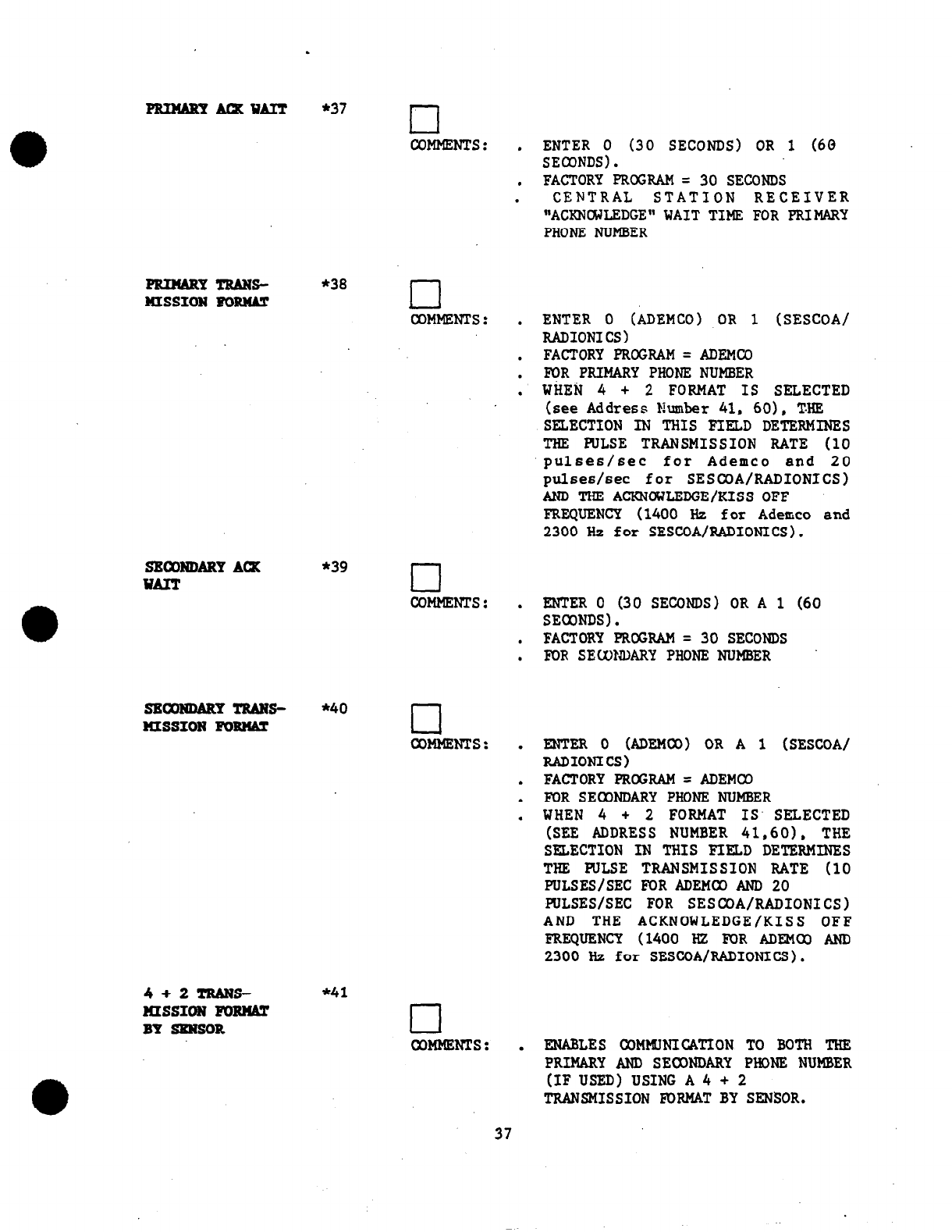
PRINARYluxuAl!r
FRINARY TRANS-
HISSION mm
SECONDARY ACX
WAIT
SECONDARY TRANS-
HISSION FORtUT
4+2-S-
luss1ON I
BYSRNSOR
.
*37
n
COMMENTS: ,
ENTER 0 (30 SECONDS) OR 1 (60
SECONDS).
. FACTORY PROGRAM = 30 SECONDS
. CENTRAL STATION RECEIVER
"ACKNCXJLEDGE" WAIT TIME FOR PRIMARY
PHONE NUMBER
*38 l-l
1
COMMENTS: .
ENTER 0 (ADEMCO) OR 1 (SESCOA/
RADIONICS)
. FACTORY PRCGRAM=ADEMUl
. FOR PRIMARY PHONE NUMBER
l
WiIE& 4 + 2 FORMAT IS SELECTED
(
see Address Number 41, 60), T.HF,
*39
cl
COMMENTS :
*40 cl
WMMENTS:
*41
cl
COMMENTS :
SELECTION IN THIS FIELD DETERMINES
THE PULSE TRANSMISSION RATE (10
pulses/set for Ademco and 20
pulses/set for SESCOA/RADIONICS)
AND THE ACKNOWLEDGE/KISS OFF
FREQUENCY (1400 Hz for Ademo and
2300 Hz for SESCOA/RADIONICS).
ENTER 0 (30 SECONDS) OR A 1 (60
l
SECONDS).
. FACTORY PROGRAM = 30 SECONDS
. FOR SELUNDARY PHONE NUMBER
mm
0
Umr4co)
l
RADIONICS)
OR
A 1 (SESCoA/
.
FACTORY PROGRAM = ADEMCO
.
FOR SECONDARY PHONE NUMBER
WHEN 4 + 2 FORMAT IS' SELECTED
l
(SEE ADDRESS NUMBER 41,60), THE
SELECTION IN THIS FIELD DETERMINES
THE PULSE TRANSMISSION RATE (10
PULSES/SEC M>R ADEMOD AND 20
PULSES/SEC FOR SESCOA/RADIONICS)
AND THE ACKNOWLEDGE/KISS OFF
FREQUENCY (1400 HZ FOR ADEMO AND
2300 Hz for SESCOAhADIONICS).
. ENABLES COMMJNICATION TO BOTH THE
PRIMARY AND SECONDARY PHONE NUMBER
(IF USED) USING A 4 + 2
TRANSMISSION FORMAT BY SENSOR.
37
.
This
sezmor format eelection can
also be used to create a zone ('7
reporting format that offers *
certain advantages over the
standard 4+2 zone transmission
format. These advantages are:
1.
Tnte Restore - The
4+2 sensor
reporting format has true
restore capability in that a
restore report will be
transmitted as soon as the
sensor restores, independent
of when the alarm sounder
times out.
2. True Zone Reporting - The 4+2
sensor reporting format allaJs
the installer to assign each
sensor to a particular alarm
report. Therefore, if it was
desirable to have one group of
sensors (ex: sensors 9-14) he
treated as a particular
perimeter grouping and another
group of sensors (ex: sensors
15-21) be treated as another
perimeter grouping. each of
the sensors in one group could
be assigned to the same alarm
report code and each of the
sensors in the other group
could be assigned a common but
different alar6 report code.
As such. installers can create
their own %one" reporting
scheme.
.
THE PRIMARY AND SECONDARY FORMAT
SELECTIONS IN ADDRESS *38 AND *40
(IF SEC0NDARY ISUSKD) ARE REQUIRED
TO SELECT THE APPROPRIATE DATA
TRANSMISSION PULSE RATE AND
ACKNC%JLRDGR/KISS-OFF FREQUENCY.
. ENTER 0 (DISABLED) OR 1 (ENABLED).
. FACTORY PROGRAM = DISABLED.
. IF PROGRAMMED FOR 0 CONTINUE ON
TO PROGRAM ALL FIELDS UM'U. FIELD
*60.
THE DURESS REPORT USES THE SAME
REPORT CODE
AS
THE KEYPAD PANIC
(SENSOR #99) WHEN THE POINT ID 4+2
REPORT FORMAT IS USED.
IF FIELD 41 (4+2 TRANSMISSION
FORMAT BY SENSOR) Is ENABLED, (SET
TO ONE), FIELDS 42 THROUGH 47
ALWAYS YIELD EXPANDED FORMAT,
ri I
c-7
‘\ ,!
38

REGARDLESS OF THEIR SETTING.
D: IF PROGRAMMED FOR "1" SKIP TO
QUESTION 61 AND PROGRAM FIELDS 61
THRU 81. OTBERWISE CONTINUE. *
TBE REPORTS IN FIELDS *42 THROUGH *47 MAY BE DESIGNATED TO REPORT EITHER IN
STANDARD OREXPANDED FORMAT. IN ALL CASES THE STANDARD MESSAGE REPORTS TO THE:
CENTRAL STATION A SUBSCRIBER ID NUMBER AND A REPORT (e.g. ALARM [see Address
*421.
TROUBLE, RESTORE, OPEN/CLOSE) CODE. TBE EXPANDED MESSAGE REPORTS A
SUBSCRIBER ID NUMBER, THE REPORT CODE, FOLLOWED BY A SECOND LINE WHERE THE
REPORT CODE IS REPEATED THREE OR FOUR TIMES (when 3+1
or
4+1 formats are used)
AND IS TRAILED BY THE ZONE TYPE (ORUSER ID) RELATED TO THAT REPORT.
Expanded TROUBLE and RESTORE reporting with channel numbers (i.e. TROUBLE DUMMY
for TROUBLE and ALARM code for RESTORE) higher than 9 should not be used if 3+1
or 4+1 reporting formats are used and ADEMCO's No. 685 Digital Receiver is the
message monitoring receiver at the central station. The 4+2 format should be
used if number6 higher than 9 mU6t be used. Failure to heed this advisory will
result in the message
meaningless message.
Report
Alarm
Trouble
Bypass
Low Battery
Open
Close
Test
Restore:
Alarm
Trouble
Bypass
Low Battery
3+1/4+1
Standard
SSS(S) A
SSS(S) T
SSS(S) B
SSS(S) L
SSS(S) 0
SSS(S) c
SSS(S) Te
SSS(S) R
SSS(S) R
SSS(S) R
SSS(S> R
being erroneously converted by the No. 685 into a
3+1/4+1
Xxpanded
.SSS(S) A
AAA(A) Z
SSS(S) T
TTT(T) Td
SSS(S> B
BBB(B) Bd
SSS(S) L
LLL(L) Ld
SSS(S) 0
000(O) u
SSS(S> c
CCC(C) u
SSS(S) Te
. SSS(S) R
RRR(R) A
SSS(S) R
RRR(R) Td
SSS(S> R
R.RR(R) Bd
SSS(S> R
RRR(R) Ld
4+2 Standard 4+2 B;rpanded
SSSS A0 ssss AZ
SSSS TO SSSS TTd
SSSS BO SSSS BBd
ssss LO SSSS LLd
ssss
00
ssss ou
ssss c0 ssss cu
SSSS Te0 SSSS Te0
SSSS RO
SSSS R0
SSSS R0
ssss RA
SSSS RTd
SSSS RBd
SSSS RO SSSS RLd
where: SSS or SSSS = Subscriber ID where: L = Lrrw Battery Code
A= Alarm Code Ld = Lav Battery Dmmy Code
0
= Zero 0 = Open Code
Z = Zone Type C = Close Code
T = Trouble Code U = User Number
Td = Trouble Dmmy Code Te =
Test
Code
B = Bypass Code R = Restore Code
Bd = Bypass Dmmy Code
39
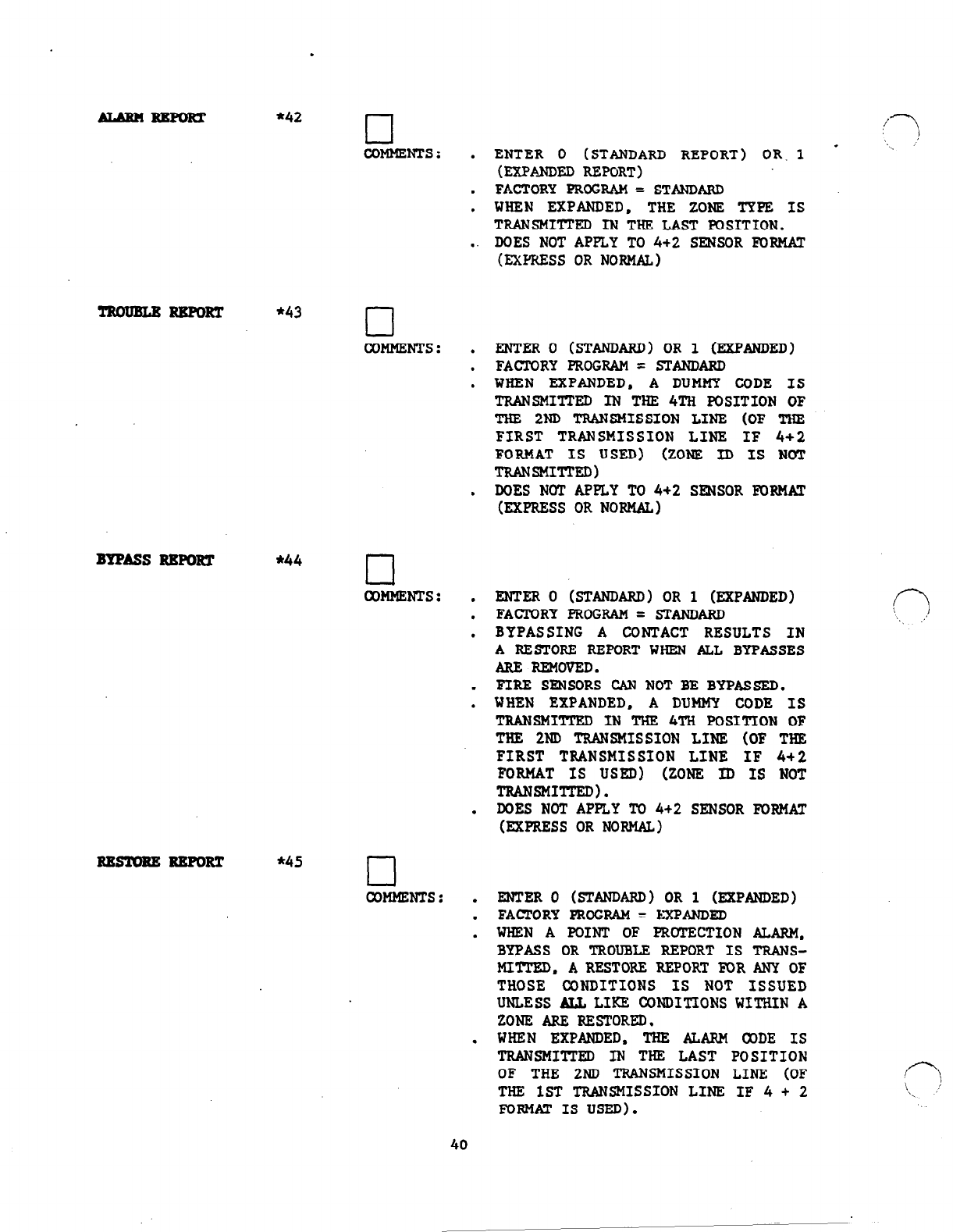
.
ALARM RRPORT *42 l-l
COMHENTS: .
ENTER 0 (STANDARD REPORT) OR. 1 -
(EXPANDED REPORT)
. FACTORY PROGRAM = STlWDARD
. WHEN EXPANDED, THE ZONE TYPE IS
TRANSMITTED IN THE LAST POSITION.
DOES NOT APPLY TO 4+2 SENSOR FORMAT
-. (EXPRESS OR NORMAL)
TRcmEuRRRmRT *43 cl
COMMENTS: .
.
.
.
BYPASS RRmRT *44 cl
COMMENTS: .
.
.
.
.
.
RRlnvRE RRPORT *45 0
COMMENTS: .
.
.
.
ENTER 0 (STANDARD) OR 1 (EXPANDED)
FACTORY PROGRAM = STANDARD
WHEN EXPANDED, A DUMMY CODE IS
TRANSMITTED IN THE 4TH POSITION OF
THE 2ND TRANSMISSION LINE (OF THE
FIRST TRANSMISSION LINE IF 4+2
FORMAT IS USED) (ZONE ID IS NOT
TRmSMITmD)
DOES
NOT APPLY TO 4+2 SENSOR mRMAT
(EXPRESS OR NORMAL)
ENTER 0 (STANDARD) OR 1 (EXPANDED)
FAC'IQRY PROGRAM = STANDARD
BYPASSING A CONTACT RESULTS IN
A RESTORE REPORT WHEN ALL BYPASSES
ARE REMOVED.
FIRE SENSORS CAN NOT BE BYPASSED.
WHEN EXPANDED, A DUMMY CODE IS
TRANSMITTED IN THE 4TH POSITION OF
THE 2ND TRANSMISSION LINE (OF THE
FIRST TRANSMISSION LINE IF 4+2
FORMAT IS USED) (ZONE ID IS NOT
TRANSMITTED).
DOES NOT APPLY To 4+2 SENSOR FORMAT
(EXPRESS OR NORMAL)
ENTER 0 (STANDARD) OR 1 (EXPANDED)
FACTORY PROGRAM = I%PANDED
WHEN A POINT OF PROTECTION ALARM,
BYPASS OR TROUBLE REPORT IS TRANS-
MITTFD, A RESTORE REPORT FOR ANY OF
THOSE CONDITIONS IS NOT ISSUED
UNLESS ALL LIKE CONDITIONS WITHIN A
ZONE ARE RESTORED.
WHEN EXPANDED, THE ALARM CODE IS
TRANSMIlITED IN THE LAST POSITION
OF THE 2ND TRANSMISSION LINE (OF
THE 1ST TRANSMISSION LINE IF 4 + 2
FORMAT1suSED).
i-Y
>. !
_
r?
‘.
.I’
,P
‘, ,,’
40
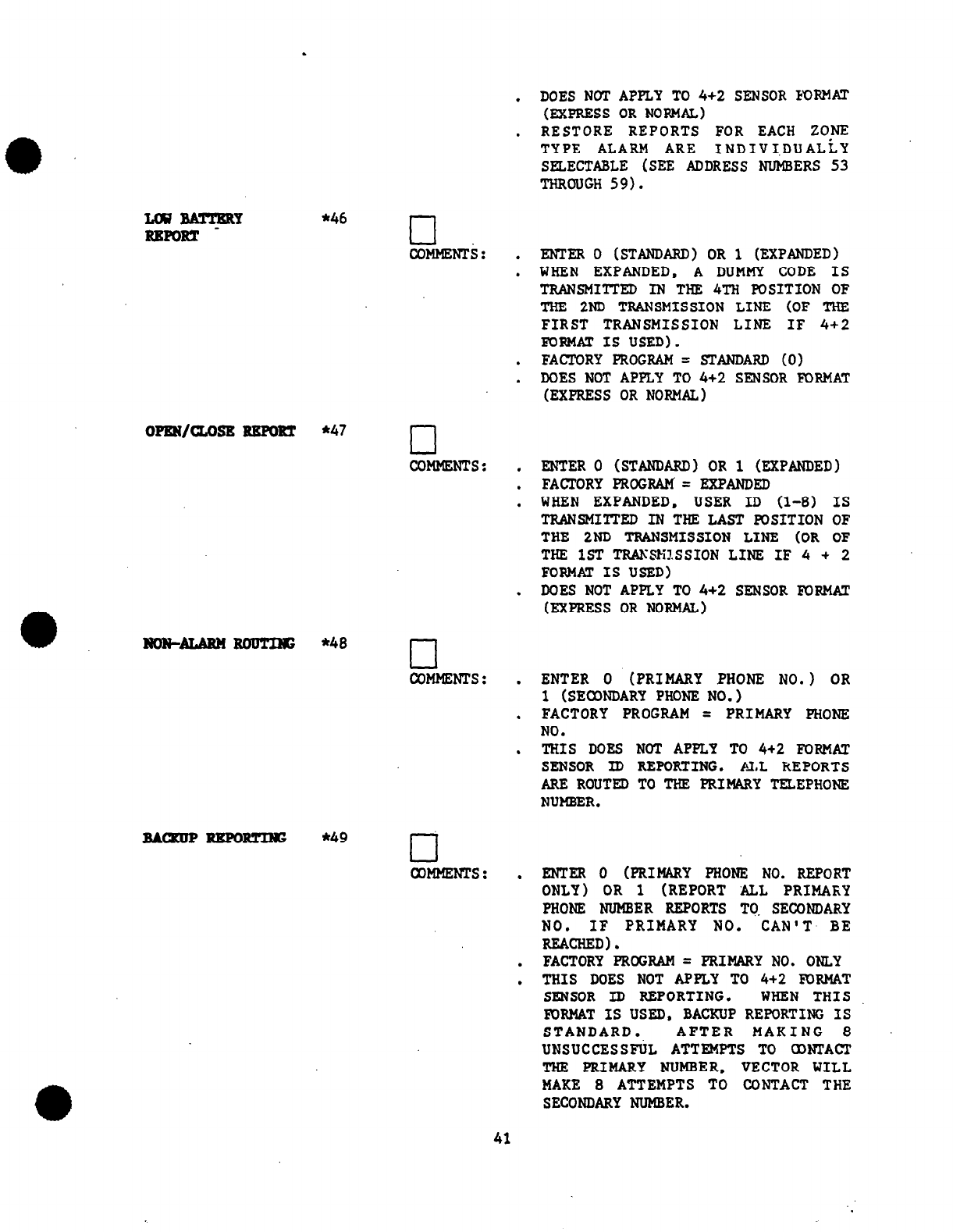
.
LCWBA!pCRY *46
RRPORT cl
COMMENTS: .
.
.
.
DOES NOT APPLY TO 4+2 SENSOR FORMAT
l
(EXPRESS ORNORMAL)
. RESTORE REPORTS FOR EACH ZONE
TYPE ALARM ARE INDIVI,DUALLY
SELECTABLE (SEE ADDRESS NUMBERS 53
THROUGH 59).
oPRN/cLosR RRmRT
*47 cl
COMMENTS: .
.
.
.
ltoN--- *48 cl
COMMENTS: .
.
.
BAmIIP RRPORTIS *49
cl
COMMENTS: .
.
.
ENTER 0 (STANDARD) OR 1 (EXPANDED)
WHEN EXPANDED. A DUMMY CODE IS
TRANSMITTED IN THE 4TH POSITION
OF
THE 2ND TRANSMISSION LINE (OF THE
FIRST TRANSMISSION LINE IF 4+2
FORMAT IS USED).
FACTORY PROGRAM = STANDARD (0)
DOES NOT APPLY TO 4+2 SENSOR FORMAT
(EXPRESS OR NORMAL)
ENTER 0 (STANDARD) OR 1 (EXPANDED)
FACTORY PROGRAM= EXPANDED
WHEN EXPANDED, USER ID (l-8) IS
TRANSMITTED IN THE LAST POSITION
OF
THE 2ND TRANSMISSION LINE (OR OF
THE 1ST TRAKSM?.SSION LINE IF 4 + 2
FORMAT IS USED)
DOES NOT APPLY TO 4+2 SENSOR FORMAT
(EXPRESS OR NORMAL)
ENTER 0 (PRIMARY PHONE NO.) OR
1 (SECONDARY PHONE NO.)
FACTORY PROGRAM = PRIMARY PHONE
NO.
THIS DOES NOT APPLY TO 4+2 FORMAT
SENSOR ID REPORTING. ALL REPORTS
ARE ROUTED TO THE PRIMARY TELEPHONE
NUMBER.
ENTER 0 (PRIMARY PHONE NO. REPORT
ONLY) OR 1 (REPORT ALL PRIMAKY
PHONE NUMBER REPORTS TC. SECONDARY
NO. IF PRIMARY NO. CAN'T BE
REACHED).
FACTORY PROGRAM = PRIMARY NO. ONLY
THIS DOES NOT APPLY TO 4+2 KmMAT
SENSOR ID REPORTING. WHEN THIS
FORMAT IS USED, BACKUP REPORTING IS
STANDARD. AFTER MAKING 8
UNSUCCESSFUL ATTEMPTS TO aDNTACl'
THE PRIMARY NUMBER, VECTOR WILL
MAKE 8 ATTEMPTS TO CONTACT THE
SECONDARY NUMBER.
41

ZONES1-8AlARU *50
RRmRT CODE
OTRRR laBssAGE
l
s1
RRmR.Ts
IF NO SECONDARY NUMBER
MAKE CERTAIN THE PRXMARY
NUMBER IS ENTERED BOTH IN
AND 32.
‘_ :
IS USED. -
TELEPHONE
FIELDS 31
ZONE 1 (E/E BURG) COMMENTS :
ZONE 2 (PER. BURG)
ZONe 3 (INT. BURG) . ENTER ALL
ZONE 4 (D/N BURG.) CODES AS
ZONE 5 (24 HR AUD. DOUBLE DIGITS
SIL, OR AIJX) (e.g. Ol=l.
ZONE 6 (24 HR ALID, 02=2.....
El3
SIL. OR AUX) lO=A. ll=B.
ZONE 7 (FIRE) 12=C, 13=D.
ZONE 8 '(DURESS) 14=E, 15=F)
DISABLED=00
(NO REPORT)
FACTORY PRCIGRAM:
Z1=3. Z2=3. Z3=3,
Z4=3, Z5=2. Z6=7.
Z7=1, Z8=2
ROTRS: IF THE COMMUNICATOR
WITHIN TEE 41S3 IS NOT
GOING TOBE USED, PRCKXAM
&L CODES IN ADDRESSES
50 AND 51 AS 00. THIS
PREVENTS UNWANTED
TELEPHONE LINE SEIZURES. ,-
. WHEN4 + 2 BYZONE FORMAT
IS USED, THE CODES
ASSIGNED IN ADDRESS SO
REPRESENT THE LEADING OR
FIRST DIGIT OF THE 2
DIGIT EVENT CODE. THE
2ND DIGIT OF THE EVEm
CODE IS THE NUHSER OF THE
ZONE.
TROUBLE CoMMEms:
TROUBLE DUMMY .
BYPASS
BYPASS DUMMY
LUJ BATTERY .
LOW BA'JTERY DUMMY
RESTORE .
CLOSE
OPEN
TEST
ENTER ALL CODES
AS DOUBLE DIGITS
(see above)
DISABLED = 00
(NO REPORT)
TO DISABLE RESTORE
REPORTS. PROGRAM
ALL CODES IN
ADDRESSES 53-59
As 0.
;‘1
:
.
42
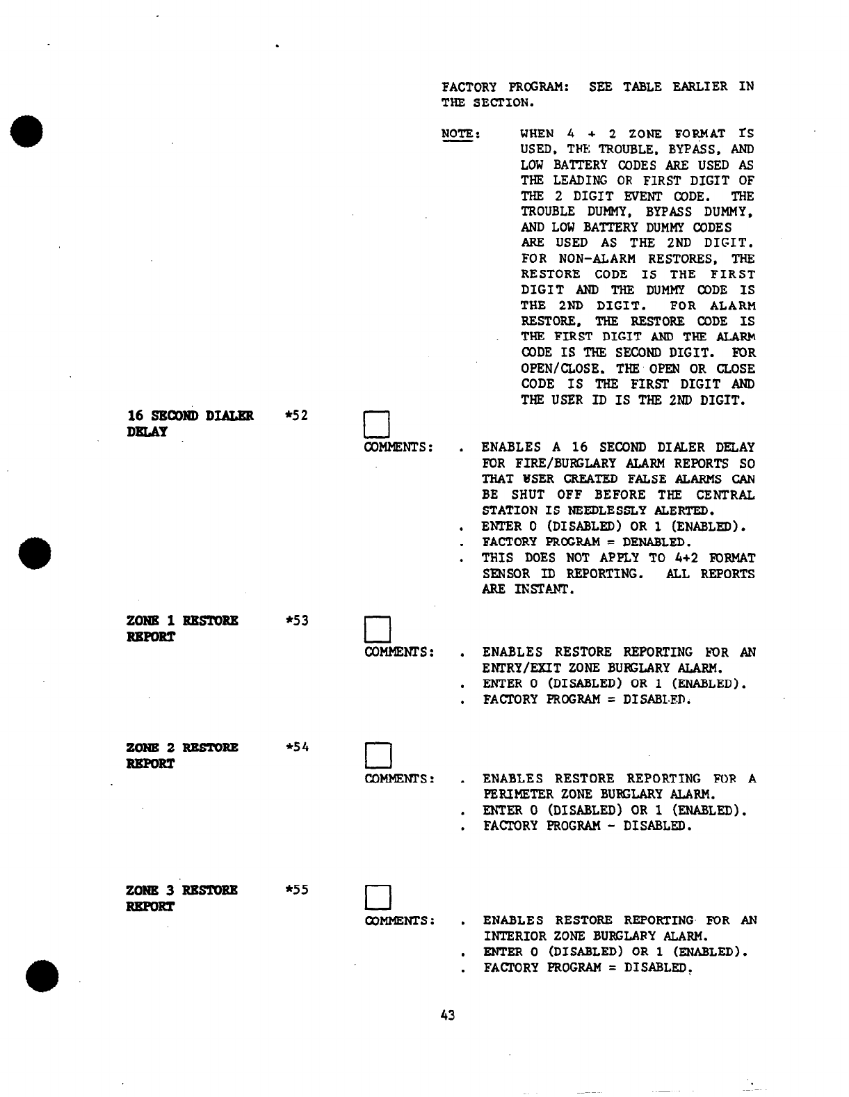
FACTORY PROGRAM: SEE TABLE EARLIER IN
THE SECTION.
NOTE : WHEN 4 + 2 ZONE FORMAT fS
USED, THE TROUBLE, BYPASS, AND
LOW BAITERY CODES ARE USED AS
THE LEADING OR FIRST DIGIT OF
THE 2 DIGIT EVENT CODE. THE
TROUBLE DUMMY, BYPASS DUMMY,
AND LOW BATTERY DUMMY CODES
ARE USED AS THE 2ND DIGIT.
FOR NON-ALARM RESTORES, THE
RESTORE CODE IS THE FIRST
DIGIT AND THE DUMMY CODE IS
THE 2ND DIGIT. FOR ALARM
RESTORE, THE RESTORE CODE IS
THE FIRST DIGIT AND THE ALARh
CODE IS THE SECOND DIGIT. FOR
OPEN/CLOSE. THE OPEN OR CLOSE
CODE IS THE FIRST DIGIT AND
THE USER ID IS THE 2ND DIGIT.
16SBCOtiDIbLER *52
DKtAY cl
coMmNTs :
ZONE 1ItBsYoRE *s3
RBmRT cl
COMMENTS :
zoNB2REsmRE *54
RBPORT cl
COMMENTS :
.
.
.
.
.
.
.
.
.
.
ENABLES A 16 SECOND DIALER DELAY
FOR FIRE/BURGLARY ALARM REPORTS SO
THAT HSER CREATED FALSE ALARMS CAN
BE SHUT OFF BEFORE THE CENTRAL
STATION IS NEEDLESSLY ALERTED.
ENTER 0 (DISABLED) OR 1 (ENABLED).
FACTORY PROGRAM = DENABLED.
THIS DOES NOT APPLY TO 4+2 FORMAT
SENSOR ID REPORTING. ALL REPORTS
ARE INSTANT.
ENABLES RESTORE REPORTING lzOR AN
ENTRY/EXIT ZONE BURGLARY ALARM.
ENTER 0 (DISABLED) OR i (ENABLED).
FACTORY PROGRAM = DISABLED.
ENABLES RESTORE REPORTING FOP A
PERIMETER ZONE BURGLARY ALARM.
ENTER 0 (DISABLED) OR 1 (ENABLED).
FACTORY PROGRAM - DISABLED.
zom3RBsToRB *55
RBPORT cl
wMMENTs: .
ENABLES RESTORE REPORTING- FOR AN
INTERIOR ZONE BURGLARY ALARM.
. ENTER 0 (DISABLED) OR i (ENABLED).
. FACTORY PROGRAM = DISABLED,
43
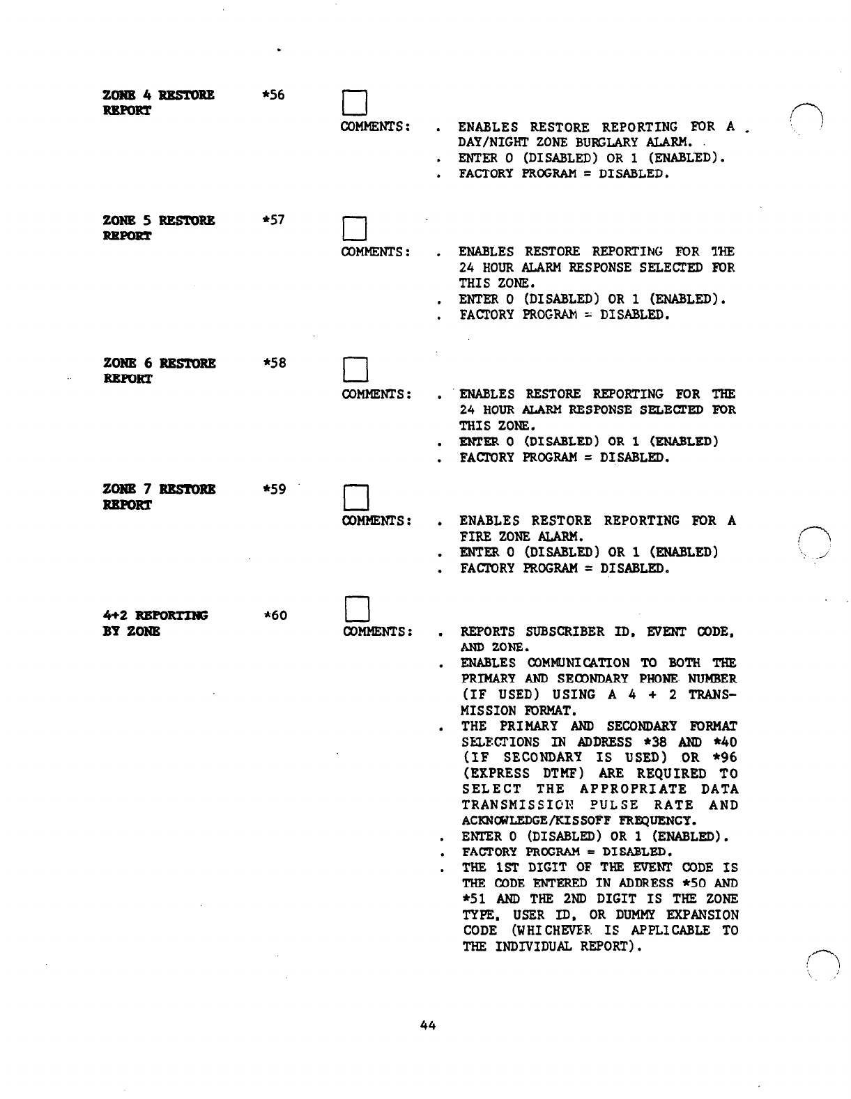
zowE4RBs!mRZ
RRmRT
.
*S6
cl
COMMENTS: . ENABLES RESTORE REPORTING FOR A .
DAY/NIGHT ZONE BUKLARY ALARM.
. ENTER 0 (DISABLED) OR 1 (ENABLED).
. FACTORY PROGRAM = DISABLED.
ZONE
5
RRsroRg
*s7
cl
COMMENTS: .
ENABLES RESTORE REPORTING FOR THE
24
HOURALARMRESPONSE SELECTED FOR
THIS ZONE.
. ENTER 0 (DISABLED) OR 1 (ENABLED).
. FACTORY PROGRAh = DISABLED.
ZONB6RESToRZ *58
RRPORT
zoNB7RKsroRE
*59
REPORT
4+2
RRPoRTING
BY ZONR
*60
r-l
COMHENTS:
'ENABLES RESTORE REPORTING FOR THE
l
24
HOUR
ALARM RESPONSE SELECTED FOR
THIS ZONE.
. ENTER 0 (DISABLED) OR 1 (ENABLED)
. FACJ.WRY PROGRAM = DfSABLFiD.
coMmNTs: . ENABLES RESTORE REPORTING FOR A
FIRE ZONE ALARM.
. mm 0 (DISABLED) OR 1 (ENABLED) ': J
. FACTORY PROGRAM = DISABLED.
cl
COMMENTS: .
REPORTS SUBSCRIBER ID. EVENT CODE.
AND ZONE.
. ENABLES COMMUNICATION To BOTH THE
PRIMARY AND SEaONDARY PHONE NUMBER
(IF USED) USING A 4 + 2 TRANS-
MISSION FDRMAT.
. THE PRIMARY AND
SECONDARY
FORMAT
SELECTIONS IN ADDRESS *38 AND *40
(IF SECONDARY IS USED) OR *96
(EXPRESS DTMF) ARE REQUIRED TO
SELECT THE APPROPRIATE DATA
TRANSMISSICF FULSE RATE AND
ACKNarJLEDGE/XISSOFF FREQUENCY.
. ENTER 0 (DISABLED) OR 1 (ENABLED).
. FACTORY PROGRAM = DISABLED.
. THE 1ST DIGIT OF THE EVENT CODE IS
THE CODE ENTERED IN ADDRESS *50 AND
*51 AND THE 2ND DIGIT IS THE ZONE
TYPE, USER ID, OR DUMMY EXPANSION
CODE (WHICHEVER IS APPLICABLE TO
THE INDIVIDUAL REPORT). T---J
\ ’
’
44
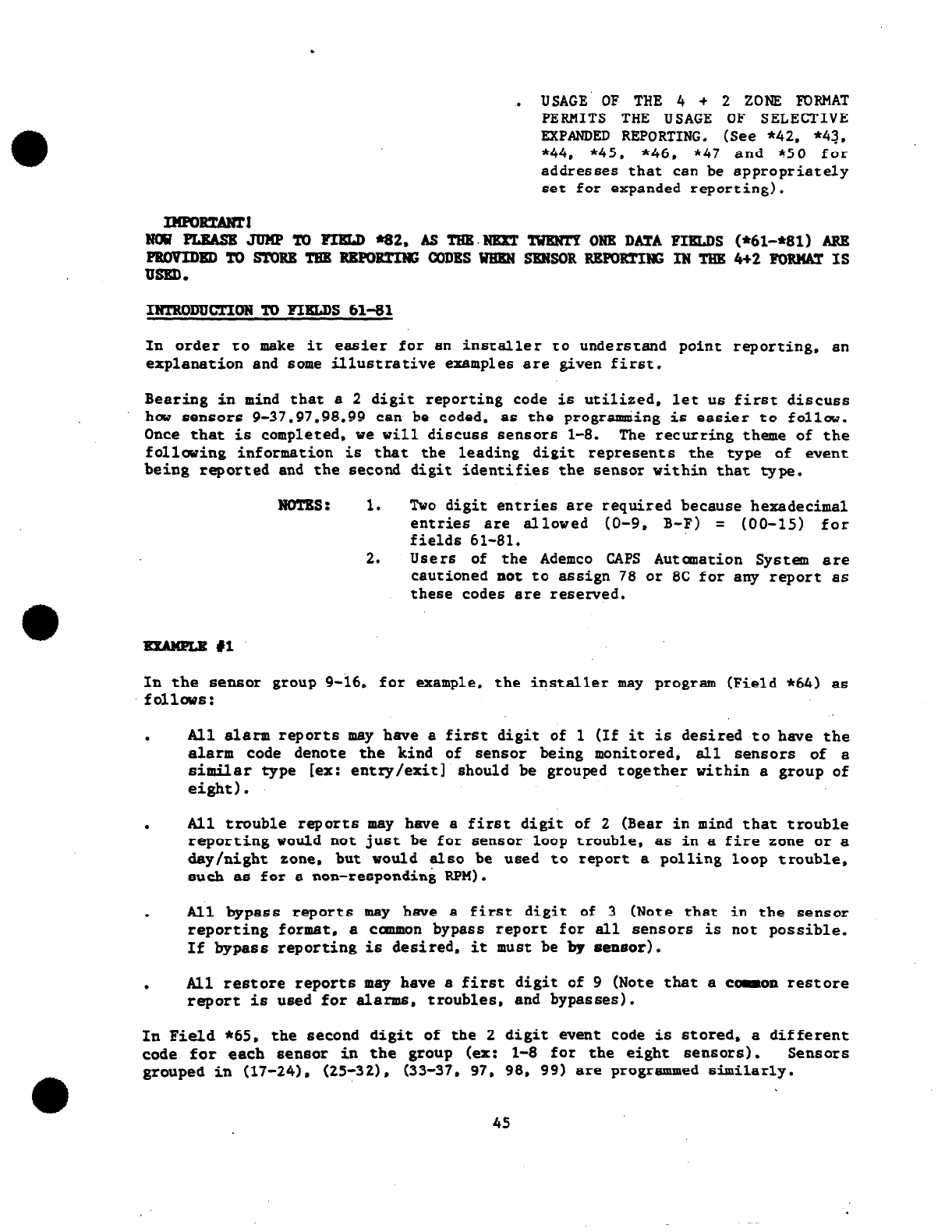
.
USAGE' OF THE 4 + 2 ZONE FORMAT
PERMITS THE USAGE
OF
SELECTIVE
EXPANDED REPORTING. (See *42. *43.
*44, *45. *46. *47 and *50 for
addresses that can be appropriately
set for expanded reporting).
INTRODUC!RONToFIRLDS 61-81
In order to make it easier for 6n installer to understand point reporting, an
explanation and some illustretive example6 are given first.
Bearing in mind that 6 2 digit reporting code is utilized. let
u6
first di6CU66
how 6en6or6 9-37.97.98.99 can be coded, a6 the programming is easier to follw.
OnCe that
is
completed, we will discuss 6en6ors l-8. The recurring theme of the
follwing information is that the leading digit represent6 the type of event
being reported and the second digit identifies the sensor within that type.
Noms: 1. Two digit entries are required because hexadecimal
entries are allowed (O-9, B-F) = (00-15) for
fields 61-81.
2. Users of the Ademco CAPS Automation System are
cautioned not to assign 78 or 8C for
any
report as
these code6 are reserved.
EXMPLR il
In the 6en6or group g-id, for example, the installer may program (Field *64) as
fOllW6:
.
All alarm report6 may have a first digit
of
1 (If it is desired to have the
alarm code denote the kind of sen6or being monitored, all sensors of a
similar type [ex: entry/exit] should be grouped together within a group of
eight 1.
.
All trouble reports may have 6 first digit of 2 (Bear in mind that trouble
reporting would not ju6t be for 6en6or loop trouble, a6 in a fire zone or a
day/night zone, but would also be used to report a polling loop trouble,
such
a6 for a non-responding RPM).
.
All bypass reports may hgve 6 fir6t digit of 3 (Note that in the sensor
reporting format, a Caamon bypass report for all sen6or6 is not possible.
If bypass reporting is desired, it muet be by
seneor).
. All restore reports may have a first digit of 9 (Note
that
a caon restore
rapott is used
for
6larm6. troubles, and bypasses).
In Field *65. the eecond digit of the 2 digit event code i6 stored. a different
code for each sensor in the group (ex: l-8 for the eight sensors). Sensors
grouped in (17-24). (25-321, (33-37. 97. 98, 99) are programmed 6ildlarly.
45
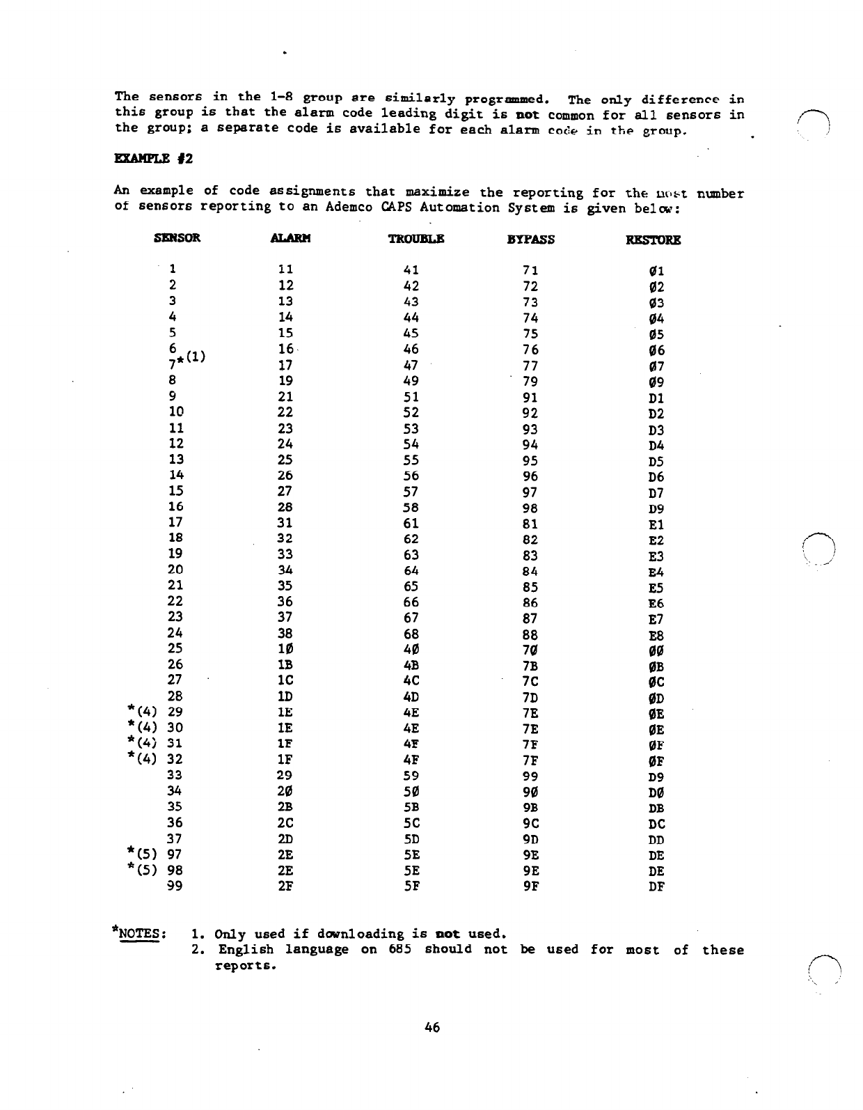
.
The
sensors in the l-8 group are similarly programmed.
this The only difference in
group is that
the
alarm code leading digit is
not
common for all sensors in
the group; a separate code is available for each alarm code in the group. !7 /
*
RXAMPLE 12
An example of code assignments that maximize the reporting for the mrrbt number
of sensor6 reporting to an Ademco CAPS Automation System is given belw:
SENSOR
1
2
3
4
5
6
7*(1)
8
9
10
11
12
13
14
15
16
17
18
19
20
21
22
23
24
25
26
27
*(4> 2
*(4) 30
*(4j 31
*(4> 32
33
34
35
36
*(5) '9:
*(5> 98
99
11 41 71 01
12 42 72 02
13 43 73 03
14 44 74 04
1s 4s 75 05
16, 46 76 06
17 47 77 07
19 49 79 09
21 51 91 Dl
22 52 92 D2
23 53 93 D3
24 54 94 D4
25 5s 95 D5
26 56 96 D6
27 57 97 D7
28 58 98 D9
31 61 81 El
32 62 82 E2
33 63 83 E3
34 64 84 E4
35 65 85 E5
36 66 86 E6
37 67 87 E7
38 68 88 E8
10
40 70
00
1B 4B 7B 0B
1c 4c 7c 0c
1D 4D 7D OD
1E 4E
7E
BE
IE 4E 7E BE
1F 4F 7F 0F
1F 4F 7F QF
29 59 99 D9
20 50 90 DQ
2B 5B 9B DB
2c 5c 9c DC
20 5D 9D DD
2E SE 9E DE
2E SE 9E DE
2F 5F 9F DF
BYPASS
*NOTES :
1. Only used if downloading is
not
used.
2.
English language on
685
should not be used for most of these
reports. !C----J
;.
~\ ,
46
3.
Note that B and C are not used for leading digit6 in the aboye
table or in the table on the next page. It is suggested that these
digit6 be reserved for u6e in reporting wopenings" and "closings"
60 that the appropriate dieplay and print out can be obtained at
the central station receiver and an automation system can be given
the appropriate information.
4. Within the 77 code locations allocated for the sensor report
format, it is
not
possible for Ademco CAPS Autanation System User6
to uniquely report alarm, trouble. bypass. and re6tore for at1 40
point6 plus handle open, close. test, lw bettery, and lw battery
restore. A6 6uch. several 6en6or6 must share reports. In the
example shwn, the pairs including
31
and
32, 36
and
37.
97 and 98
each
share
a canmon report.
5. The fact that the 97 and 98 share a common report is irrelevant in
installations where downloading i6 Used (4153BB is installed) as a
loop open 98 condition cannot be detected without 6 4152LM
connected for u6e with a Cla6s 'A' ,polling loop. Tbat module
cannot be used when downloading is desired.
Other possible grouping6 of codes could have alarm6 in consecutive hexadecimal
SOUPS.
For example:
0.
Fire Alarm6 - 10-17
Panic Alarm6 - 18. 19. lB-1F
Burglary Alarm6 - 20-29. 2%2F. 30-37
Troubles and Bypasses could be treated similarly in consecutive hexadecimal
groups. Restore6 cannot be
60
treated if we desire to reserve B and C for
opening6 and closing just to get English language printout of open/close on the
685'6 printer.
The latter arrangement will make it easier for non-automated ,centrel station
personnel to interpret the information. An example of such an arrangement is
given belw. Thi6 example is equally relevant for user6 of the Ademco/MAS
Automation
Syetem.
47
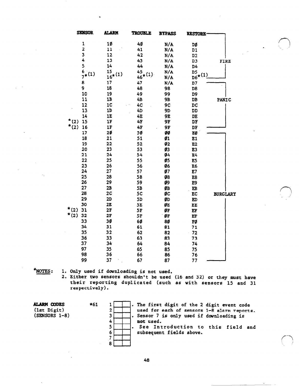
SmsoR
1
2
3
4
5
6
7*(1)
8
9
10
11
12
13
*(2) ::
*(2) 16
17
18
19
20
21
22
23
24
25
26
27
28
29
y; 3;
33
34
35
36
37
97
98
99
.
10
40
11
41
12 42
13 43
14 44
1s
&1)
4s
46*(l)
17 47
18 48
19 49
18 4B
1c 4c
1D 4D
1E
4E
1F 4F
1F 4F
20 50
21 51
22 52
23 53
24 54
25 55
26 56
27 57
28 58
29 59
2B 5B
2c 5c
2D 5D
2E
5E
2F 5F
2F
SF
30 60
31 61
32
62
33
63
34
64
35
65
36
66
37 ‘.
67
BYPASS
N/A
N/A
N/A
N/A
N/A
N/A
N/A
N/A
98
99
9B
9c
9D
9E
9F
ii;
01
02
03
04
ii'6
07
;i
0B
0c
0D
BE
0F
0F
80
81
82
83
84
85
86
87
D0 f-7
.
Dl '_, .1
D2
D3 FIRE
D4 J
;5,*w I
D7
D8
D9
DB
DC
DD
DE
DF
DF
EB
El
E2
E3
E4
E5
E6
E7
E8
E9
.EB
EC
ED
EE
EF
EIF
F0
71
72
73
74
75
76
77
1
PANIC
_1
BURC
*NOTES : 1. Only used if downloading is not used.
2. Either two 6ensor6 shouldn't be Used (16 and 32) or they must have
their reporting duplicated (such as with sensors 15 and 31
respectively).
lum.?! CODE
*61 1 . The first digit of the 2 digit went code
(1st Digit) 2 used for each of sensors
1-8 alarm
reports.
(SENSORS l-8) 3 . Sensor 7 is only used if downloading is
4
not
used.
5 . See Introduction to this field and
6 subsequent field6 above.
7
8
f-7
C--?
48
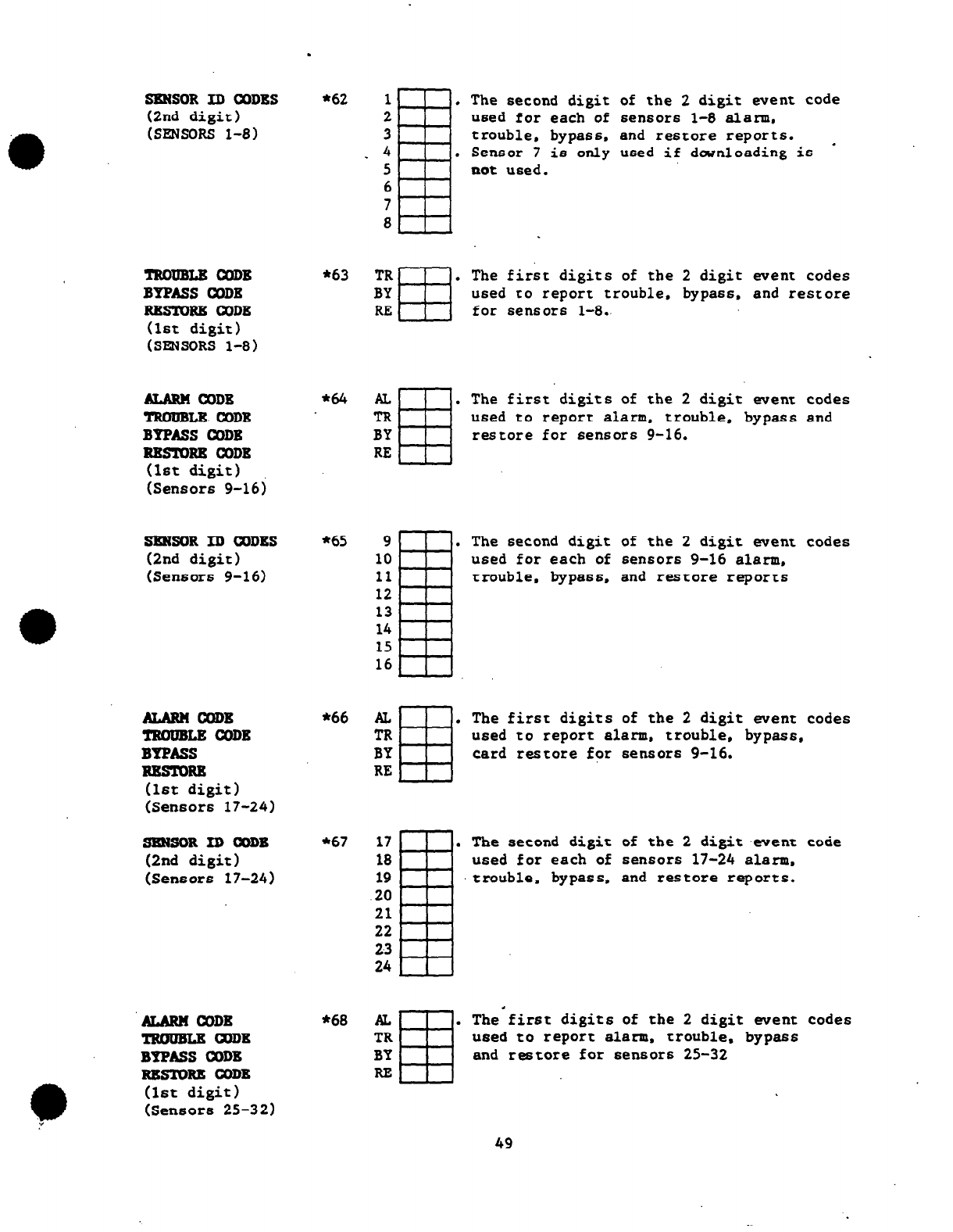
.
*62
*63
*64
*6S
*66
*67
*68
SKNSOR ID CDDES
(2nd digit)
(SENSORS l-8)
of the 2 digit went code
sen6ors l-8
alarm.
and restore reports.
used if dwnloading is a
The second digit
used for each of
trouble, bypass.
Sensor 7 is only
not used.
The first digits of the 2 digit went codes
Used
to report trouble. bypass, and restore
for sensors l-8.-
TR .
BY
lu3
a
YRMrBLR CODE
BYPASSCODE
RRSTOBR OODE
(1st digit)
(SENSORS l-8)
AL
ffl
.
TR
BY
RE
ALARM CODE
TROUBLE CODE
BYPASSOODE
RRSTDRE CODE
(1st digit)
(Sensor6 9-16)
The first digits of the 2 digit went Code6
used to report alarm, trouble, bypass and
restore for 6ensors 9-16.
=sOR ID CQDES
(2nd digit)
(Sensors 9-16)
The second digit of the 2 digit went codes
used for each of sensor6 9-16 alerm,
trouble, bypass. and reStore reports
The first digit6 of the 2 digit went codes
used to report alarm. trouble, bypass,
ALARMCODE
TROUBLR CQDB
BYPASS
RBSTORE
(1st digit)
(Sensors 17-24)
card restore for censors 9-16.
SKNSORIDf%IDB
(2nd digit)
(Sensors 17-24)
The second digit of the 2 digit .went
used for each of sensors 17-24 alarm.
trouble, bypass. and reStore reports.
code
of the 2 digit went code6
.
The first digits
AL .
TR
BY
RE
ALARM CODB
TROUBLRCDDB
BYPASS CODB
RRST0R.E
CODB
(1st digit)
(Sensors 25-32)
used to report alarm. trouble. bypass
and restore for 6en6or6 2S-32
49
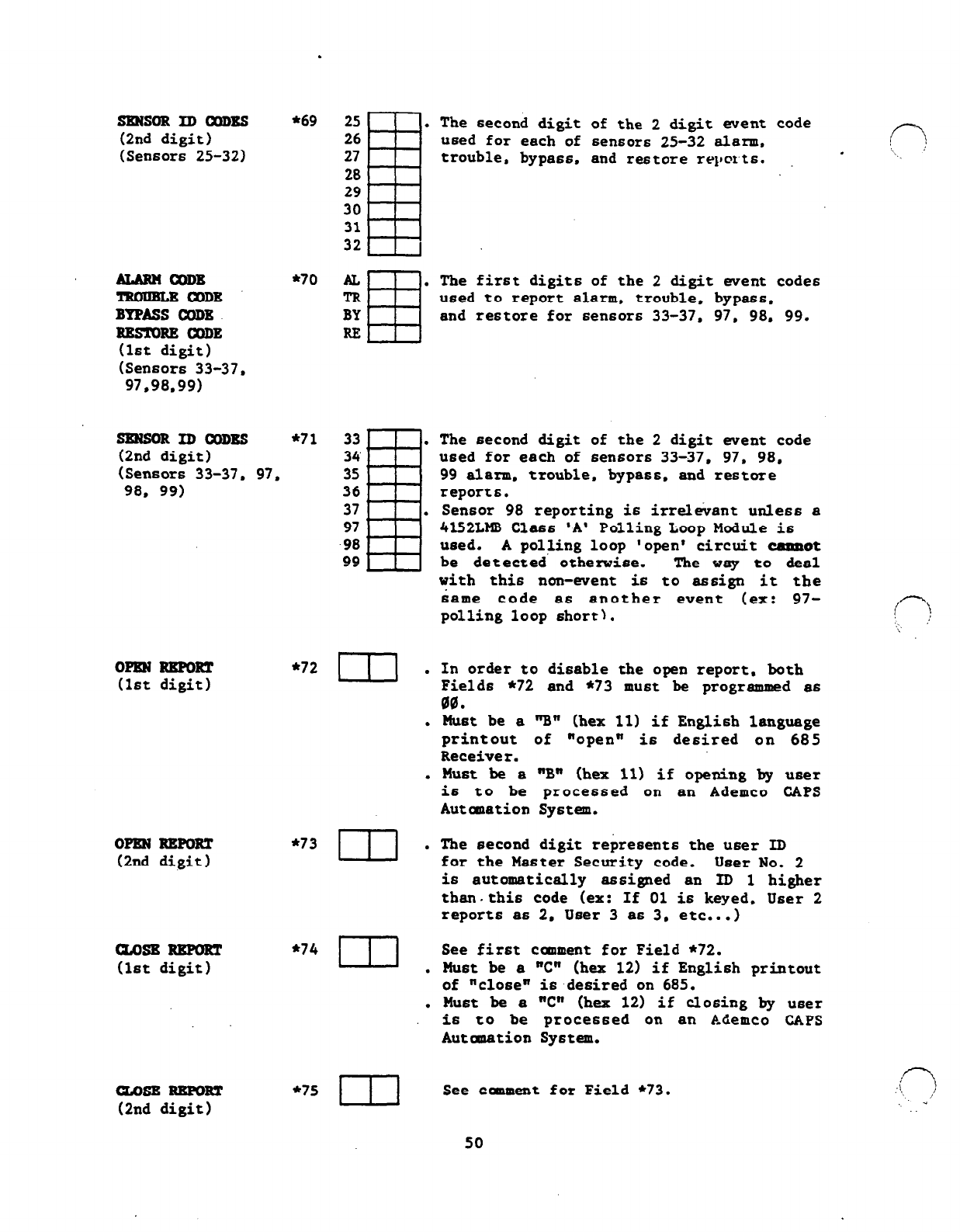
.
SmsoR ID mDBs *69
(2nd digit)
(Sensors 25-32)
iuaARNcaDB
l
70
lmmBLBaaDE
BTPASS COBB
RB!mmE mm
(1st digit)
(Sensors 33-37,
97,98.99)
sxNsoRIDamEs *71
(2nd digit)
(Sensors 33-37, 97,
98. 99)
om RKFORT
(1st digit)
OPEN REPORT
(2nd digit)
uosBRRFoRT
(1st digit)
CZOSE REFORT
(2nd digit)
*72
*73
*74
*75
ul .
.
.
m .
III .
.
III
The second digit
used
for
each of
trouble. bypass,
The first digits
of the 2 digit went code
sensors 25-32 alarm.
and restore reports. .
of the 2 digit went codes
used to report alarm. trouble, bypass.
and restore for sensors 33-37, 97, 98. 99.
The second digit of the 2 digit
went
code
used for each of sensors 33-37, 97. 98.
99 alarm. trouble, bypass, and restore
reports.
Sensor 98 reporting is irrelevant unless a
4lS2LM8 Class 'A' Polling Loop Module is
ueed. A polling loop 'open' circuit
cannot
be detected' otherwise. The vay to &al
vith this non-went
is
to assign it the
same code as another event (ex: 97-
polling loop short).
In order to disable the open report. both
Field6 *72 and *73 must be programmed as
00.
Must be a "B" (hex 11) if English language
printout of "open"
is
desired on 685
Receiver.
Must be a "Bn (hex 11) if opening by u6er
is
to be processed on an Ademco CAPS
Automation System.
The second digit represents the user ID
for the Master Security code. User No. 2
is automatically assigned an ID 1 higher
thau.this code (ex: If 01 is keyed, User 2
reports as 2. User 3 as 3, etc...)
See first canment for Field *72.
Must be a "C" (hex 12) if English printout
of "close"
is
desired on 685.
Must be
a "C" (hex 12) if closing by user
is to be processed on an Ademco CAPS
Autanation System.
See canment for Field *73.
.i* \
‘, ,I
: -
50
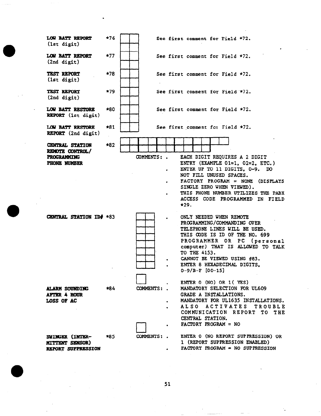
.
LwBA!rTREFoRT
(1st digit)
LwBATTRBFoRT
(2nd digit)
TEsTImoRT
(1st
digit)
TXST REFORT
(2nd digit)
LWBAlTREs!mRB
REFORT (1st digit)
LcwBAmREs!mRE
REPORT (2nd digit)
cENTRALs!cATIoN
~anJTRoL/
moNENumER
tamTRALsTATIoNID#
*83
ALARM SOUNDING
AFl%R4EauR
LOSS OF AC
SWIEER ml!ER-
EmTENT SENSOR)
REmRTsuPmEss1oN
*76
m
See first comment for Field *72.
.
*77
See first comment for Field *72.
*78
See first comment for Field *72.
*79
I
See first comment for Field'*72.
I i I
*80
See first comment for Field *72.
*81 See first ,co+ment fct Field *72.
*82 1 I
*84
COMMENTS: .
cl .
COMMENTS: .
.
.
cl .
*85 COMMENTS: .
.
EACH DIGIT REQUIRES A 2 DIGIT
ENTRY (EXAMPLE
oi=l.
02=2, ETC.)
ENTER UP TO 11 DIGITS, O-9. DO
NOT FILL UNUSED SPACES.
FACTORY PROGRAM = NONE (DISPLAYS
SINSLE ZERO WHEN VIEWED).
THIS PHONE NUMBER UTILIZES THE PABX
ACCESS CODE PROGRAMMED IN FIELD
*29.
ONLY NEEDED WHEN REMOTE
PROGRAMMING/COMMANDING OVER
TELEPHONE LINES WILL BE USED.
THIS 03DE IS ID OF THE NO. 699
PROGRAMMER OR PC (personal
computer) THAT IS ALLOWED TO TALK
TO THE 4153.
CANNOT BE VIEWED USING #83.
ENTER 8 HEXADECIMAZ, DIGITS,
0-9/B-F [OO-151
ENl'ER 0 (NO) OR 1( YES)
MANDATORY SELECTION FOR UL609
GRADE A INSTALLATIONS.
MANDATORY FOR UL1635 INSTALLATIONS.
ALSO ACTIVATES TROUBLE
COMMUNICATION REPORT TO THE
CENTRAL STATION.
FACTORY PROGRAM = NO
ENl'ER 0 (NO REPORT SUPPRESSION) OR
1 (REPORT SUPPRESSION ENABLED)
FAcrORY PROGRAM = NO SUPPRESSION
51
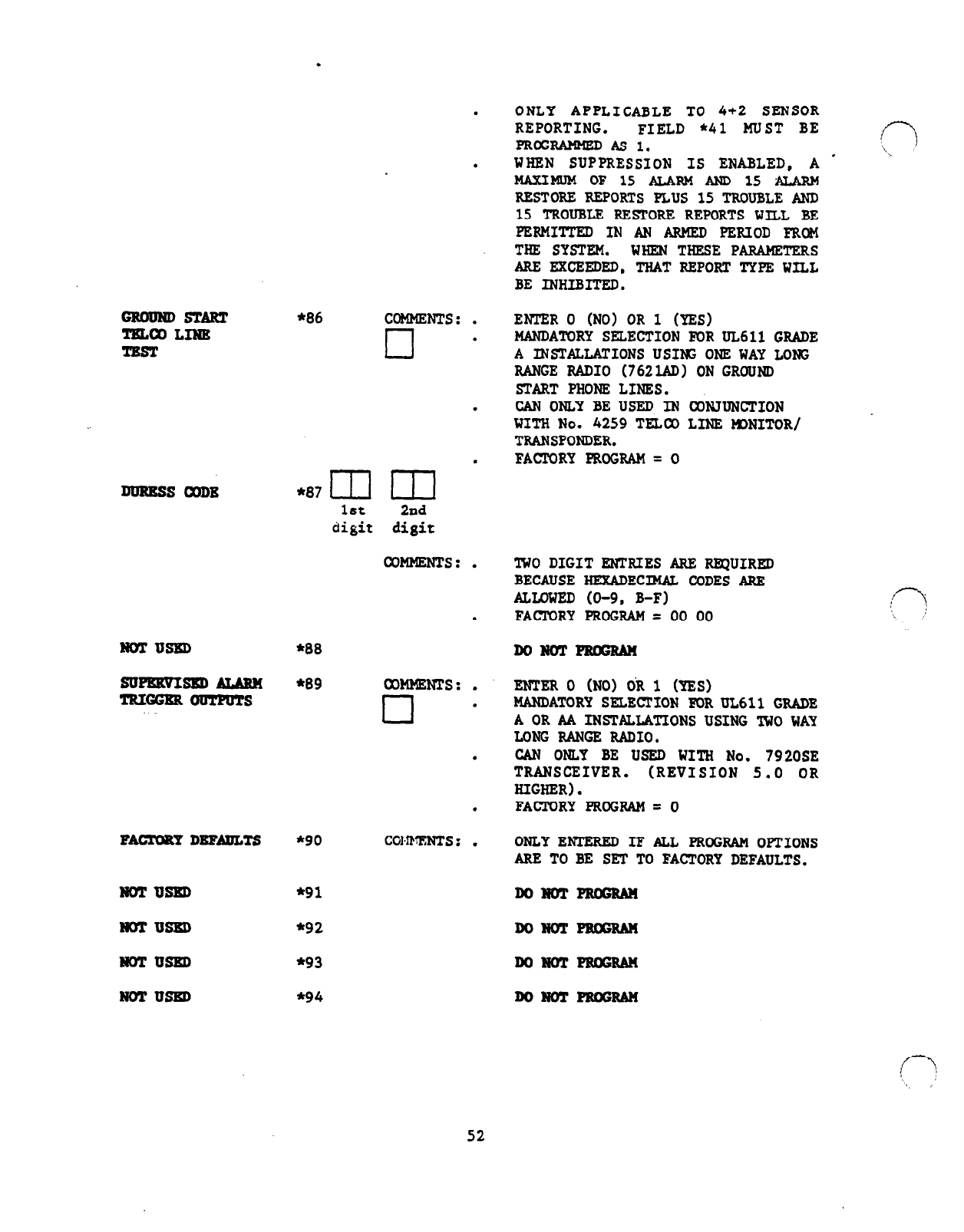
.
ONLY APPLICABLE TO 4+2 SENSOR
REPORTING. FIELD *41 MUST BE
PRoGRABMEDAsl.
WREN SUPPRESSION IS ENABLED, A
MAXIMUM OF 15 ALARM AND 15 ALARM
RESTORE REFORTS PLUS 15 TROUBLE AND
15 TROUBLE RESTORE REPORTS WILL BE
PERMITTED IN AN AIMED PERIOD FRCM
THE SYSTEM. WHENTHESEPARAMETERS
ARE EXCEEDED, THATREPORT TYPE WILL
BE INHIEITED.
.
.
GROUNDSTART
TmcCLINE
TEST
*86
ENTER 0 (NO) OR 1 (YES)
MANDATORY SELECTION FDRUL611 GRADE
A INSTALLATIONS USIS ONE WAY LOK;
RANGE RADIO (762lAD) ON GROUND
START PHONE LINES.
CAN ONLY BE USED IN C&UNCTION
WITH No. 4259 TELCO LINE MDNITOR/
TRANSPONDER.
FACFORYPROGRAM=O
COMMENTS :
.
.
cl
.
.
*87 m m
1st
2nd
digit digit
DURESS CODE
COMMENTS : TWO DIGIT ENTRIES ARE RFQUIRED
BECAUSE HEXADECIMAL CODES ARE
ALLOWED (O-9. B-F)
FACICRY PROGRAM = 00 00
.
.
NOTUSXD
*88
DoNoTPRmum
suPBxvIspp, ALARM *89
lRxaERomPuTs coMM8NTs : ENTER 0 (NO) CR 1 (YES)
MANDATORY SELECTION FOR UL6ll GRADE
A
OR AA INSTALLATIONS USING IWO WAY
LONG RANGE RADIO,
CAN ONLY BE USED WITH No. 7920SE
TRANSCEIVER. (REVISION 5.0
OR
HIGHER).
FACTORYpROGRAM=O
.
.
cl
.
FACFORYDEFABLTS *90 COHMENTS : ONLYENTERED IF ALL PROGRAM OFTIONS
ARR
TO BE SET TO
FACTORY
DEFAULTS.
NOTUSED *91
NOTUSED *92
NOTUSED *93
NOTUSBD *94
DONOTPRSRAN
DoNoTPRaxtAM
52
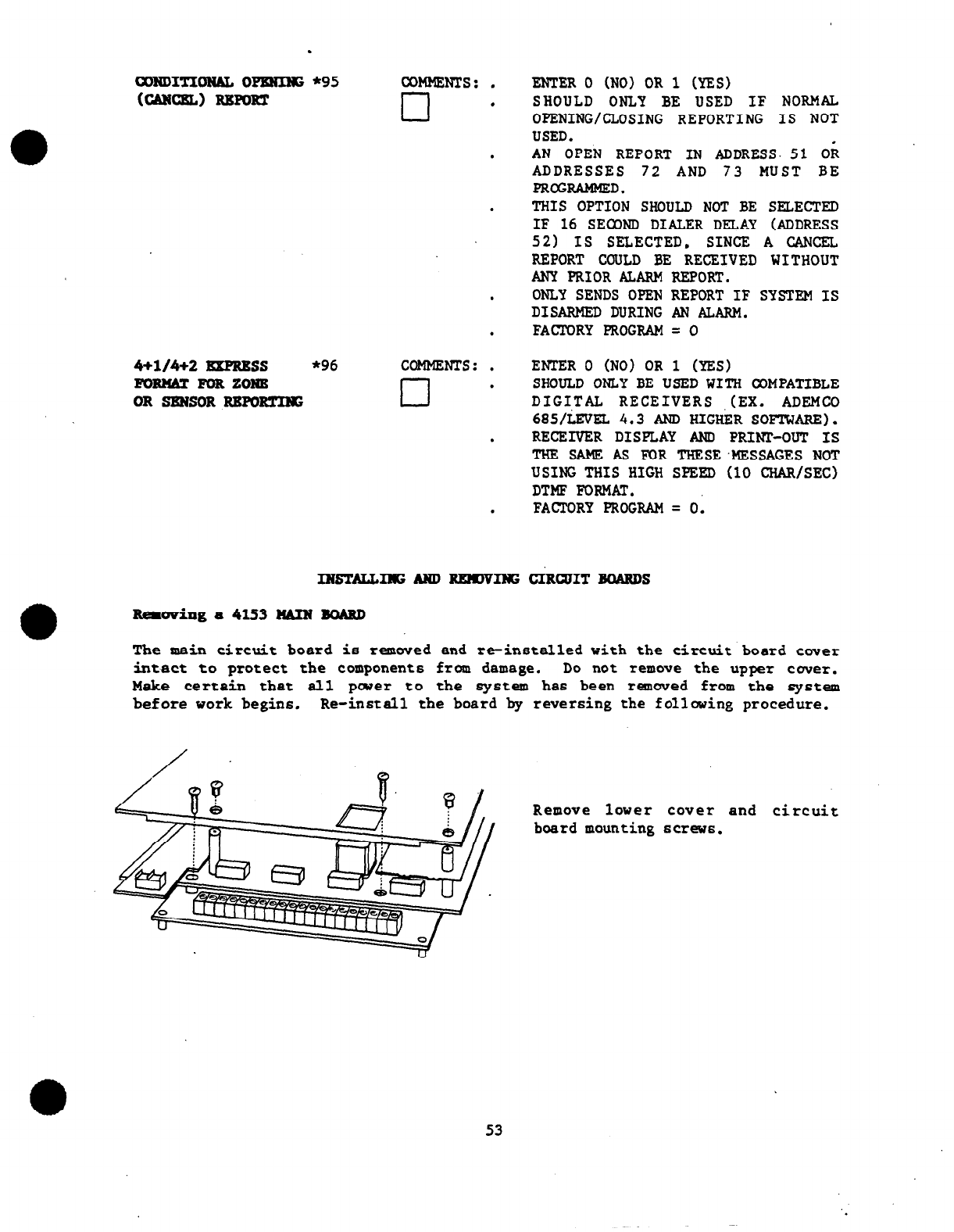
.
coND1TIoNAL0pKNIHz*95 COMMENTS: .
uikumL) RBmRT cl .
.
.
.
.
4+1/4+2 EXPRESS *96 COMMENTS: .
FORMT FOR zoN8 cl .
OR SKNSOR REFoR!rIIG
.
.
ENTER 0 (NO) OR 1 (YES)
SHOULD ONLY BE USED IF NORMAL
OPENING/CLOSING REPORTING IS NOT
USED.
AN OPEN REPORT IN ADDRESS. 51 OR
ADDRESSES 72 AND 73 MUST BE
PROGRAMMED.
THIS OPTION SHOULD NOT BE SELECTED
IF 16 sEom DIAPER DELAY (ADDRESS
521 IS SELECTED, SINCE A CANCEL
REPORT CGULD BE RECEIVED WITHOUT
ANY PRIOR ALARM REPORT.
ONLY SENDS OPEN REPORT IF SYSTEM IS
DISARMED DURING AN ALARM.
FACTORY PROGRAM = 0
EI?XZR 0 (NO)
OR
1 (YES)
SHOULD ONLY BE USED WITH COMPATIBLE
DIGI,TAL RECEIVERS .(EX. ADEMCO
685/LEVEL 4.3 AND HIGHER SOFTWARE).
RECEIVER DISPLAY AND PRINP-OUT IS
THE SAME AS FOR THlXE.MESSAGES NOT
USING THIS HIGH SPEED (10 CHAR/SEC)
DTMF FORMAT.
FACTORY PROGRAM = 0.
INSTALLIlIGANDRg)lDvING CIRQJITBOARDS
Remwing a 4153 WIN BOARD
The main circuit board is removed and Ix-installed with the circuit board cwer
intact to protect the components from damage. Do not remove the upper cover.
Make certain that all pcuer to the
system
ha6 been removed from the system
before work begins. Re-install the board by reversing the following procedure.
Remove lover cover and circuit
board mounting screw6.
53
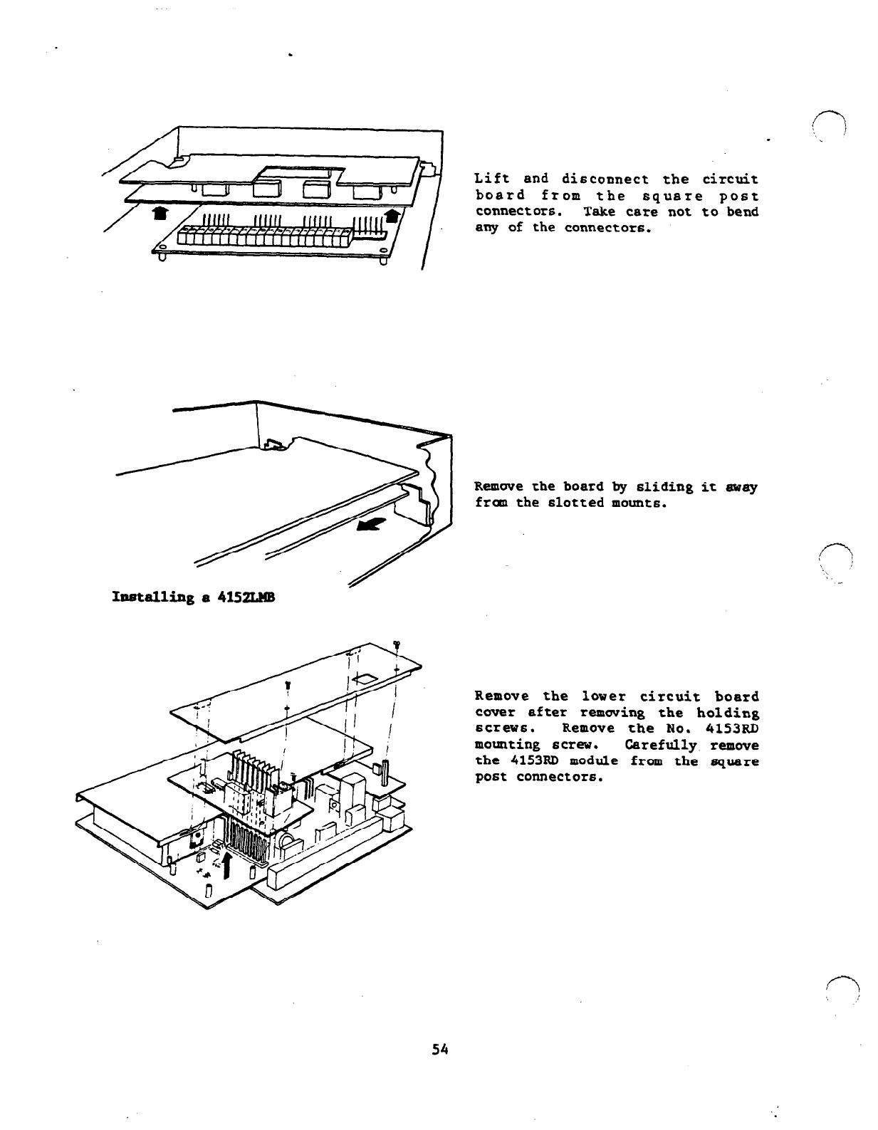
.
Lift and disconnect the circuit
board from the square post
connectors. Take care not to bend
any of the connectors.
Remove.the board by sliding it away
fram the slotted mounts.
Im3talli.nga4152LMB
i
Remove the lover circuit boarc
cover after removing the holding
screws. Remove the No. 4153RD
mounting screv. Carefully remove
the 4153RD module from the square
post connectors.
54
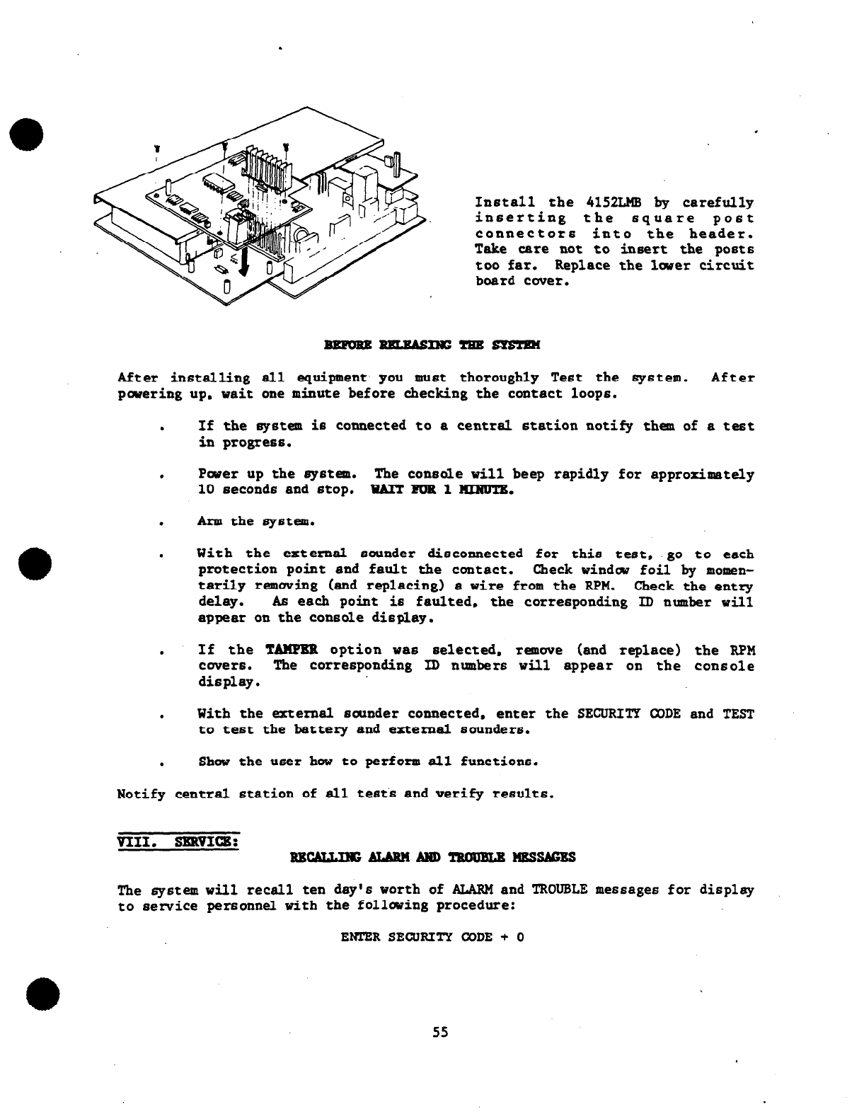
.
.
Install the 4152LMB bv carefully
inserting the square post
connectors
into
the header.
Take care not to insert the posts
too far. Replace the lover circuit
board cover.
After installing all equipment you must thoroughly Test the system. After
povering up. wait one minute before checking the contact loops.
.
If the system is connected to a central station notify them of a test
in progress.
.
Pwer up the system. The console vi11 beep rapidly for approximately
10 second6 and stop. WAR FOR 1 KINUTR.
.
Arm the system.
.
With the external sounder disconnected for this test, go to each
protection point and fault the contact. Check vindcv foil by momen-
tarily removing (and replacing) a vire from the
RPM.
Check the entry
delay. As each point is faulted, the corresponding ID number vill
appear on the console display.
.
If the TAXPER option vas selected, remove (and replace) the RPM
cwers.
The corresponding ID numbers will appear on tbe console
display.
.
With the external sounder connected, enter the SECURITY CODE and TEST
to test the battery and external sounders.
.
Shov the
user
hov to perform all functions.
Notify central station of all tests and verify results.
The system vill retell ten day's worth of ALARM and TROUBLE messages for display
to service personnel with the folloving procedure:
ENTERSECURITY CODE+ 0
55
The
memory
vi11 retain alarm and trouble reports ten days from the last alarm or
trouble went, pinpointing their specific
sensor
location. If no subsequent
events occur,
then
all previous events are autanatically removed from memory.
If nev events occur within the ten day period, then all events are retained and *
the ten day cycle starts again.
f-l
',, ‘
After displaying all alarm and trouble reports, the memory is erased vhen this
mode .is .exited, by entering aODE + OFF.
This feature does not prwide information concerning tim of occurrence or
sequence of
ocicurrence.
It simply indicates that an alarm or trouble occurred
on a particular point during the period.
WARNING!
If the system is atnred and the user exits through various interior sensors and
then through the entry/exit door and one interior sensor remains faulted, the
system vi11 go into alarm at the end of the exit delay (plus entry delay), as it
should. However., the console vill not only display the sensor that remained
faulted, but also every other sensor that the user faulted on his way out (which
.had
been
restored).
If an ALARM occurs during the AWAY mode and the user returns.and directly
transits
from
the AWAY mode to the STAY mode. then user alarm memory
is
lost.
Subsequent disarming results in a blank numeric display and the READY LED
remains out (requiring CODE +
OFF
to restore it).
IX. SPBCI~~X [@ 32'F (O'C) - 120'F (SO'C) 90% RH non condensing]
No. 4153 C-ON
1.
PHYSICAL
WIDTH: 12.25" (306 mm)
HEIGHT: 17"
(432 mm)
DEPTH: 4" (102 mm)
2. BsmxRIcAL
VOLTAGE.INPUT: 18 VAC (from ADEMOO No. 1349 PLUG-IN TRANSFORMER). 40 VA.
WNTINUOUS OUTPUT: IZVDC, 750 mA (combined output available from the
Auxiliary and Console Pwer Output Terminals)
POLLING LOOP
CURRENT AVAILABLE:
60
mA @ 11V max. (Cannot be used a6 a D.C. supply)
ALARM SOUNDER OUTPUT:
1.5 AMPS
eizv
ALARM TRIGGER OUTPUTS: ON = 5V 6' 1:s mA
OFF = OV
4152LM8 DRAIN: 64 mA e 11V max.
STANDBY: BATTERY 12 VDC,
2.7
AH (No. 465-627; 2
EACH)
or
5.4AH (No. 465-654. 2
each)
56
!p /
‘Y
n
_
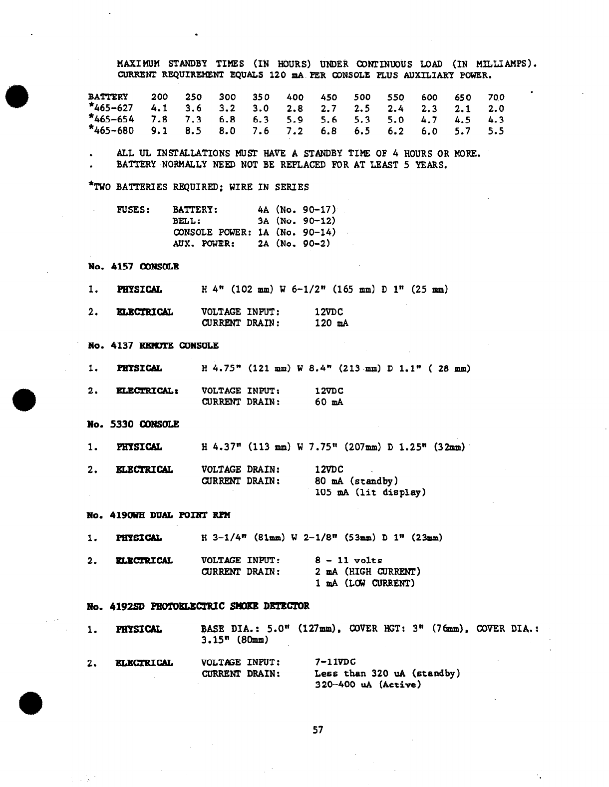
.
MAXIMUM STANDBY TIMES (IN HOURS) UMlER CONTINUOUS LOAD (IN MILLIAMPS).
CURRENT REQUIREMENT EQUALS 120 mA PER CONSOLE PLUS AUXILIARY POWER.
* BATTERY 200 250 300 350 400 450 500 559 600 650 700
*465-627 4.1 3.6 3.2 3.0 2.8 2.7 2.5 2.4 2.3 2.1 2.0
*465-654 7.8 7.3 6.8 6.3 5.9 5.6 5.3 5.0 4.7 4.5 4.3
*465-680 9.1 8.5 8.0 7.6 7.2 6.8 6.5 6.2 6.0 5.7 5.5
.
ALL UL INSTALLATIONS MUST HAVE A STANDBY TIME OF 4 HOURS OR MORE.
. BATTERY,NOPMALLY NEED NOT BE REPLACED FOR AT LEAST 5 YEARS.
*TWO BAITERIES REQUIRED; WIRE IN SERIES
FUSES : BATTERY: 4A (No. 90-17)
BELL: 3A (No. 90-12)
CONSOLE POWER: 1A (No. 90-14)
AUX. POWER: 2A (No. 90-2)
No. 4157 CONSOLE
1. PHYSICAL
H
4" (102 mm) W 6-l/2" (165 mm) D 1" (25 mm)
2. lEBcifTu~ VOLTAGE
GLJRRENT
No. 4137 REIPDTB OONSOLE
1. PE??SICAL H 4.75"
2. BIacrRIcAL: VOLTAGE
CURRENT
No. 5330 CONSOLE
1. PHYSICAL H 4.37" (113 mm) W 7.75" (207mm) D 1.25" (32s~~)
2. ELmxRIcAL VOLTAGE
GURRENT
INPUT: 12VDc
DRAIN: 120 IllA
(121 mm) W 8.4" (213mm) D 1.1" ( 28 mm)
INPUT: 12VDc
DRAIN: 60 HIA
DRAIN:
DRAIN: 12VDc
80
HIA (staidby)
105 mA (lit display)
No. 419OUH DUAL POINT RR!
1. PHYSICAL H 3-l/4" (81mm) W 2-l/8" (53mm) D 1" (23mm)
2. EImmucAL VOLTAGE INPUT: 8- 11 volts
WRRENPDRAIH: 2 ICIA (HIGH Gr~Rmrr)
1mA (LC%J CURRENT)
No. 419250 PEOTURLETRIC SMDKR DETRcrOR
1. PBYSICAL BASE DIA.: 5.0" (127mm). COVER HGT: 3" (76mm). COVER DIA.:
3.15" (8Omm)
2. NLRBCAL VOLTAGE INPUT: 7-11VDc
CURRENT DRAIN: Less than 320 uA (standby)
320-400 uA (Active)
57
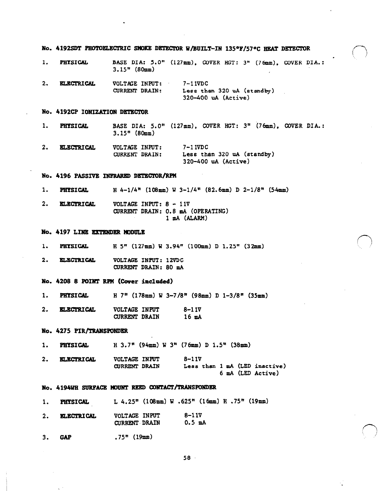
.
No. 4192SDT PEOTDELECTRIC SHORR DETECTOR W/BUILT-IN 13S"P/57“C HEAT DKTEZTOR
1. PUYSICAL BASE DIA: 5.0" (127mm). COVER HGT: 3" (76mm). COVER DIA.: -
3.15" (8Omm)
2. ELBcrRIcAL VOLTAGE INPUT: 7-1lVDC
CURRENT DRAIN: Less than 320 uA
(standby)
320-400 uA (Active)
No. 4192CP IONI2ATION DRTRCTOR
1. PHPSICAL BASE DIA: 5.0" (127mm). COVER HGT: 3" i76mm), COVER DIA.:
3.15" (8Omm)
2. EtBcrRIcAL VOLTAGE INPUT: 7-11VDc
CURRENT DRAIN: Less than 320 uA (standby)
320-400 uA (Active)
No. 4196 PASSIVE INFRMEDDRTECTOR/RP!4
1. PHYSICAL H 4-l/4" (108mm) W 3-l/4" (82.6mm) D 2-l/8" (54mm)
2. ELXTRICAL VOLTAGE INPUT: 8 - 1lV
CURRENT DRAIN: 0.8 mA (OPERATING)
1mAMLAR.M)
No. 4197 LINR ExTgMlER llDDULB
1. PEYSICAL
H
5" (127mm) W 3.94" (lOOmud D 1.25" (32mm)
2. lELwrRIcAL VOLTAGE INPUT: 12VDC
CURRENTDRAIN: mA
No. 4208 8 KUNT RPM
(Cover
included)
1. PEXSICAL H 7" (178mm) W 3-7/8" (98mm) D l-3/8" (35mm)
2. BLEcTRIcAL VOLTAGE INPUT 8-1lV
CURRENT DRAIN 16 mA
No. 4275 PIR/TRANSKMDER
1. WPSICAL
H
3.7" (94mm) W 3" (76mm) D 1.5" (38mm)
2. EtBc!cRIcAL VOLTAGE INPUT 8-1lV
CURRENTDRAIN Less than 1 mA (LED inactive)
6 mA (LED Active)
No. 4194WE SURFACE HIUNT RRED CONTACT/TRANSPONDER
1. PHTS1GA.L L 4.25" (108~~) W .625" (16mm) H .75" (19mm)
2. xLEcTRIc&.s VOLTAGE INPUT 8-1lV
WRRRNTDRAIN 0.5 mA
3. GAP .75" (19lllm)
58

.
No. 4139UE/GY/BR SURFACR-RBRD
OQNUCT/TRANSP
1. PHYSICAL H .56" (14mnd W .50" (13mm) L 1.5" (64od
2. xErRIcAL VOLTAGE INPUT
8-1lV
CURm DRAIN
0.5 mA
3. GAP .875” (22md
No. 419lUR RRCRSS MNJNT RRED
CONTAWTRANSP
1. 'PEYSICAL DIAMETER .50" (13mm) LENGTH 2" (5lmm)
TO THE INSTALLER
Regular maintenance and inspection (at least annually) by the installer and frequent testing by the user
are vital to continuous satisfactory operation of any alarm system.
The installer should assume the responsibility of developing and offering a regular maintenance
program to the user as well as acquainting the user with the proper operation and limitations of the
alarm system and its component parts. Recommendations must be included for a specific program of
frequent testing (at least weekly) to insure the system’s proper operation at all times.
59
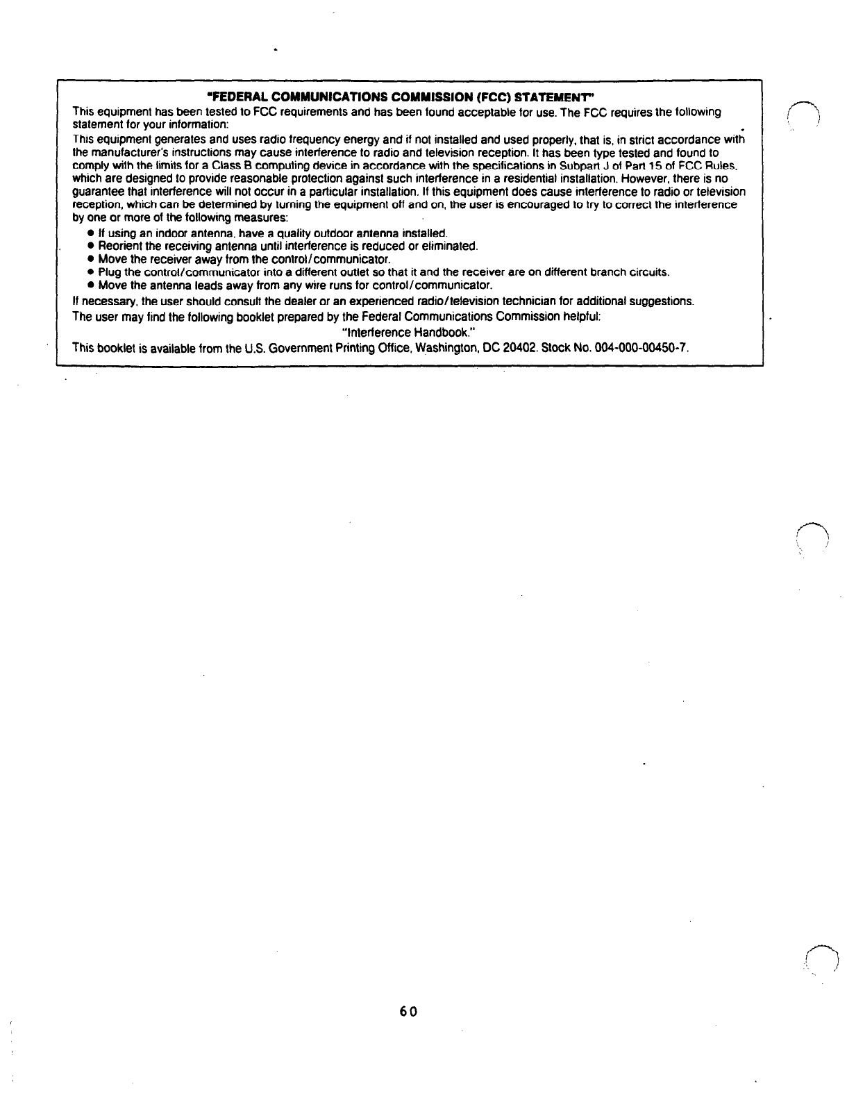
I 1
“FEDERAL COMMUNICATIONS COMMISSION (FCC) STATEMENT’
This equipment has been tested to FCC requirements and has been found acceptable for use. The FCC requires the following
statement for your information:
This equipment generates and uses radio frequency energy and if not installed and used properly, that is, in strict accordance with
the manufacturer’s instructions may cause interference to radio and television reception. It has been type tested and found to
comply with the limits for a Class B computing device in accordance with the specifications in Subpart J of Part 15 of FCC Rules.
which are designed to provide reasonable protection against such interference in a residential installation. However, there is no
guarantee that interference will not occur in a particular installation. If this equipment does cause interference to radio or television
reception, which can be determined by turning the equipment off and on, the user is encouraged to try to correct the interference
by one or more of the following measures:
l
If using an indoor antenna, have a quality outdoor antenna installed.
l
Reorient the receiving antenna until interference is reduced or eliminated.
l
Move the receiver away from the control/communicator.
0 Plug the control/communicator into a different outlet so that it and the receiver are on different branch circuits.
0 Move the antenna leads away from any wire runs for control/communicator.
If necessary, the user should consult the dealer or an experienced radio/television technician for additional suggestions.
The user may find the following booklet prepared by the Federal Communications Commission helpful:
“Interference Handbook.”
This booklet is available from the U.S. Government Printing Office, Washington, DC 20402. Stock No. 004-000-00450-7.
60

l
.
WARNING
THE LIMITATIONS OF THIS ALARM SYSTEM
While this system is an advanced design security system, it does not offer guaranteed protection
against burglary or fire or other emergency. Any alarm system, whether commercial or residential, is
subject to compromise or failure to warn for a variety of reasons. For example:
0 Intruders may gain access through unprotected openings or have the technical sophistication to
bypass an alarm sensor or disconnect an alarm warning device.
l
Intrusion detectors (e.g., passive infrared detectors), smoke detectors. and many other sensing
devices will not work without power. Battery operated devices will not work without batteries, with
dead batteries, or if the batteries are not put in properly. Devices powered solely by AC will not
work if their AC power supply is cut off for any reason, however briefly.
0 A user may not be abte to reach a panic or emergency button quickly enough.
0 While smoke detectors have played a key role in reducing residential fire deaths in the United
States, they may not activate or provide early warning for a variety of reasons in as many as 35%
of all fires, according to data published by the Federal Emergency Management Agency. Some of
the reasons smoke detectors used in conjunction with this System may not work are as follows:
Smoke detectors may have been improperly installed and positioned. Smoke detectors may not
sense fires that start where smoke cannot reach the detectors, such as in chimneys, in walls, or
roofs, or on the other side of closed doors. Smoke detectors also may not sense a fire on another
level of a residence or building. A second floor detector, for example, may not sense a first floor
or basement fire. Moreover, smoke detectors have sensing limitations, No smoke detector can
sense every kind of fire every time. In general, detectors may not always warn about fires caused
by carelessness and safety hazards like smoking in bed, violent explosions. escaping gas,
improper storage of flammable materials, overloaded electrical circuits, children playing with
matches, or arson. Depending on the nature of the fire and/or the location of the smoke
detectors, the detector, even if it operates as anticipated, may not provide sufficient warning to
allow all occupants to escape in time to prevent injury or death.
0 Alarm warning devices such as sirens, bells or horns may not alert people or wake up sleepers if
they are located on the other side of closed or partly open doors. If warning devices are located
on a different level of the residence from the bedrooms, then they are less likely to waken or alert
people inside bedrooms. Even persons who are awake may not hear the warning if the alarm is
muffled by noise from a stereo. radio, air conditioner or other appliances, or by passing traffic.
Finally, alarm warning devices, however loud, may not warn hearing-impaired people or waken
deep sleepers.
0 Telephone lines needed to transmit alarm signals from a premises to a central monitoring station
may be out of service or temporarily out of service. Telephone lines are also subject to
compromise by sophisticated intruders.
0 This equipment, like other electrical devices, is subject to component failure. Even though this
equipment is designed to last as long as 10 years, the electronic components could fail at any
time.
The most common cause of an alarm system not functioning when an intrusion or fire occurs is
inadequate maintenance. This alarm system should be tested weekly to make sure all sensors are
working properly.
tnstalling an alarm system may make one eligible for lower insurance rates, but an alarm system is
not a substitute for insurance. Homeowners, property owners and renters should continue to act
prudently in protecting themselves and continue to insure their lives and property.
We continue to develop new and improved protection devices. Users of alarm systems owe it to
themselves and their loved ones to learn about these developments.
61

.
ADEMCO
LIMITED WARRANTY
Alarm Device Manufacturing Company, a Division of Pittway Corporation. and its divisions, subsidiaries and affiliates (“Seller”). 165 Eileen Way,
Syosset. New York 11791, warrants its products to be in conformance with its onin plans and specifications and 10 be free from defects in materials
and workmanship under normal use and service for 18 months from the date stamp control on the product or, for products not having an Ademco
date stamp, for 12 months from date 01 original purchase unlessthe installation instructions or catalog sets forth a shorter period, in which case the
shorter period shall apply. Seller’s obligation shall be limited to repairing or replacing, at its option. free of charge for materials or labor. any part which
is proved not in compliance with Seller’s specifications or proves defective in materials or workmanship under normal use and service. Seller shall
have no obligation under this Limited Warranty or otherwise if the product is altered or improperfy repaired or serviced by anyone other Ihan Ademco
factory service. For warranty service, return product transportation prepaid. to Ademco Factory Service. 165 Eileen Way, Syosset. New York 11791.
THERE ARE NO WARRANTIES, EXPRESS OR IMPLIED, OF MERCHANTABILITY.OR FfTNESS FOR A PART&Z&AR PURPOSEOROTHERWISE,
WHICH EXTEND BEYOND THE DESCRIPTION ON THE FACE HEREOF. IN NO CASE SHALL SELLER BE LIABLE TO ANYONE FOR ANY
CONSEOUENTIAL OR INCIDENTAL DAMAGES FOR BREACH OFTHIS OR ANY OTHER WARRANTY, EXPRESS OR IMPLIED, OR UPON ANY
OTHER BASIS OF LIABILITY WHATSOEVER, EVEN IF THE LOSS OR DAMAGE IS CAUSED BY THE SELLER’S OWN NEGLIGENCE OR FAULT.
Seller does not represent that its product may not be compromised or circumvented; that the product will prevent any personal injury or property loss
by burglary. robbery, fire or otherwise; or that the product will in all cases provide adequate warning or protection. Buyer understands that a properly
installed and maintained alarm may only reduce the risk of a burglary, robbery or fire without warning. but it is nol insurance or a guarantee that such
will not occur or that there will be no personal injury or properly loss as a result. CONSEQUENTLY. SELLER SHALL HAVE NO LIABILITY FOR ANY
PERSONAL INJURY, PROPERTY DAMAGE OR OTHER LOSS BASED ON A CLAIM THE PRODUCT FAILED TO GIVE WARNING. However, if Seller
is held liable, whether directly or indirectly. for any loss or damage arising under lhii Limited Warranty or otherwise, regardless of cause or origin,
Seller’s maximum liability shall not in any case exceed the purchase price of the product. which shall be the complete and exclusive remedy against
Seller.
This warranty replaces any previous warrantis and is the only warranty made by Seller on this product. No increase or alteration.wrMen or verbal. of
the obligation of this Limited Warranty is authorized.
ALARM DEVICE MANUFACTURING CO.
A DIVISION OF PITIWAY CORPORATION
165 Elleen Way, Syosset, New York 11791
N2759V3 l/90 Copyright e 19137 PITTWAY CORPORATION
