42006 011C
User Manual: 42006-011C
Open the PDF directly: View PDF ![]() .
.
Page Count: 2

Pub. 42006-011C
GAI-Tronics Corporation P.O. Box 1060, Reading, PA 19607-1060 USA
610-777-1374 n 800-492-1212 n Fax: 610-775-6540
GAI-TRONICS CORPORATION
Field Maintenance Bulletin
Handset/Cord Repair Procedure
Part# 10108-007, 10108-008 and 10108-009
FOR MODELS 780 AND 7805 DIV. 1 HAZARDOUS AREA STATIONS
Confidentiality Notice
This manual is provided solely as an operational, installation, and maintenance guide and contains sensitive
business and technical information which is confidential and proprietary to GAI-Tronics. GAI-Tronics
retains all intellectual property and other rights in or to the information contained herein, and such
information may only be used in connection with the operation of your GAI-Tronics product or system.
This manual may not be disclosed in any form, in whole or in part, directly or indirectly, to any third party.
Tools Required
• 7/16-inch hex socket or combination wrench
• Phillips screwdriver
• Pipe wrench or channel lock pliers
• Hammer
• Nailset or hardened 1/8-inch diameter rod, approximately 4-inches long
• Torque wrench
Liability Disclaimer
Notice: Follow all the steps in the procedure outlined below to ensure personnel safety, to avoid
equipment damage, and to maintain agency approvals.
Procedure
WARNING Disconnect power before making any repairs to a hazardous area station.
Note: The internal outer edge of the front cover is machined. Take precautions to ensure that the finish is
preserved. If damaged, the explosion-proof integrity can be lost.
1. Turn off power.
2. Remove the 14 bolts from the cover using a socket or a combination wrench.
3. Lift off the cover, and disconnect the flat ribbon cable.
4. Remove the 4 screws which hold the amplifier assembly to the cover.
Page: 2 of 2
HANDSET/CORD REPAIR PROCEDURE FOR MODELS 780 AND 7805 Pub. 42006-011C
f:\standard ioms - current release\unique manual #\42006-011c.doc
06/01
5. Remove the 4 screws that hold
the cover on the safety barrier.
Remove the cover. Disconnect
the 4 handset cord wires from
the safety barrier.
6. Remove the pin holding the
handset hook and remove the
handset hook.
Note: The pin is tapered and
can only be removed one way.
Strike from the non-splined
end.
7. Using a pipe wrench or channel
lock pliers, remove the elbow
of the broken handset cord.
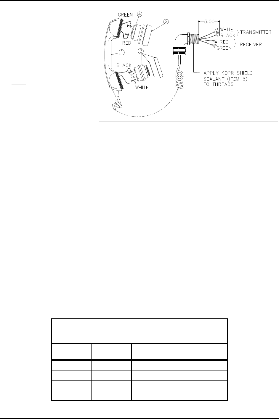
8. Feed wires on the elbow end of the handset cord assembly through the threaded hole. Apply
weatherproof sealing material (customer-supplied) to the threads of front cover after wires are fed
through the hole.
9. Secure the elbow to the front cover with a wrench. The handset bushing must be secured with 5 to 7
full threads. This is critical to the explosion-proof integrity. When complete, the elbow should point
downward.
10. Reconnect the 4 handset wires on the barrier inside the front cover. Be certain to match the wire color
to the terminal marking. See Figure 1.
11. Replace the cover over the safety barrier. Replace the 4 screws.
12. Reconnect the 4 handset cord wires from the safety barrier to the amplifier assembly.
13. Replace the amplifier assembly on the cover, aligning the flat of the party line knob shaft with the
switch shaft. Replace the 4 screws.
14. Replace the handset hook and pin.
15. Inspect the front cover (machined edge) for explosion-proof integrity.
16. Connect the flat ribbon cable and mount the front cover to the enclosure and replace the 14 bolts.
17. Tighten to a torque of 8 ft-lb.
18. Restore power and test for proper operation.
Replacement Handset with Cord
Parts List for 10108-007, 10108-008, and 10108-009
Ref.
Designator Part No. Description
113201-002 Handset Handle
213204-001 Receiver Cap, Gray
312511-001 Dynamic Transmitter and Cap
413205-006 Receiver
Figure 1. Replacement Handset with Cord
