424.p65 424
User Manual: 424 AlarmHow.net Library
Open the PDF directly: View PDF ![]() .
.
Page Count: 6
Notes:
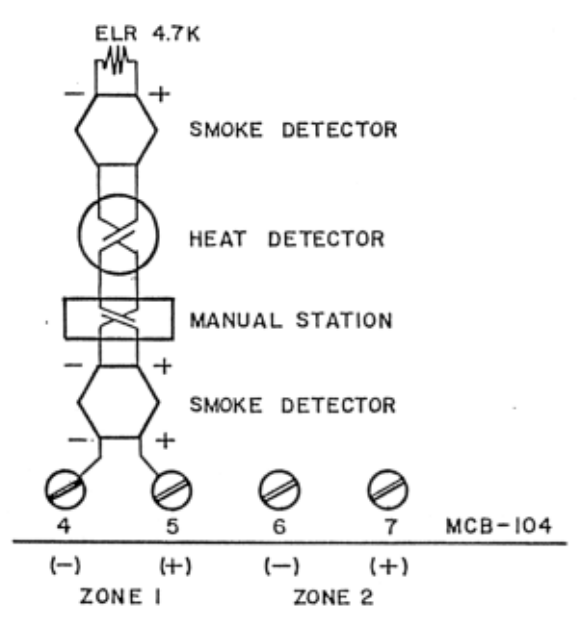
1) Detection loop specifications
Operation: Class B
Voltage standby: 23VDC
Alarm current: 15mA
Short circuit current: 35mA±10mA
Supervision current: 5mA
End-of-line resistor: 4.7k, 5%
Maximum loop resistance: 200 ohms
Maximum detector current: 2.0mA/Zone
2) Smoke and ionization detectors requiring separate 24VDC can be powered from MCB-104 terminals 12 (+) & 13 (-). Use
end-of-line relay (SDLR-B) to supervise power circuit wiring.
3) Detector loop current is sufficient to ensure operation of one detector per zone.
4) Compatible, U.L. listed, 2-wire detectors available from Fire-Lite.
5) Initiating devices include: Manual stations, heat detectors, smoke detectors, ionization detectors, waterflow alarm devices,
coded manual stations.
6) Use mechanical water motor gong if waterflow alarm devices are connected to the zone.
7) Inhibit latching circuit by removing diode marked with a * from DZC-2 card if coded manual stations are connected.
8) Compatible, U.L. listed, 2-wire detector available from Fire-Lite, include the following series: CP101, CP204, CP311,
CP711, CP751, SD12T and SD32T.
Initiating Device Connection (Typical)
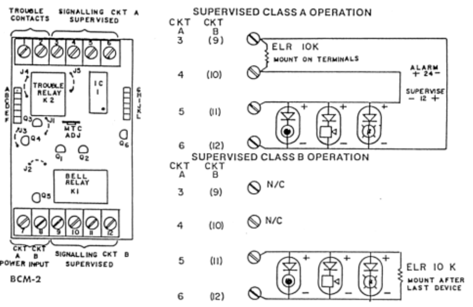
Figure 3: Supervised Class B Operation
Notes:
1) Modes of operation
a) For non-disconnectable bells, remove jumper J3 but leave jumper J2.
b) For disconnectable bells remove jumper J2 but leave jumper J3.
c) For MTC bell signal, remove jumper J1.
d) Select normally open or normally closed trouble contact by removing J4 or J5 respectively. Trouble contact is provided
at Terminals 1 and 2. It is rated 2 amps, 28 VDC.
2) a) Connect signalling circuit as shown.
b) Size wire for a maximum voltage drop of 2 VDC.
c) Use polarized, U.L. listed, signalling devices with a minimum rated voltage range of 18 to 30 VDC.
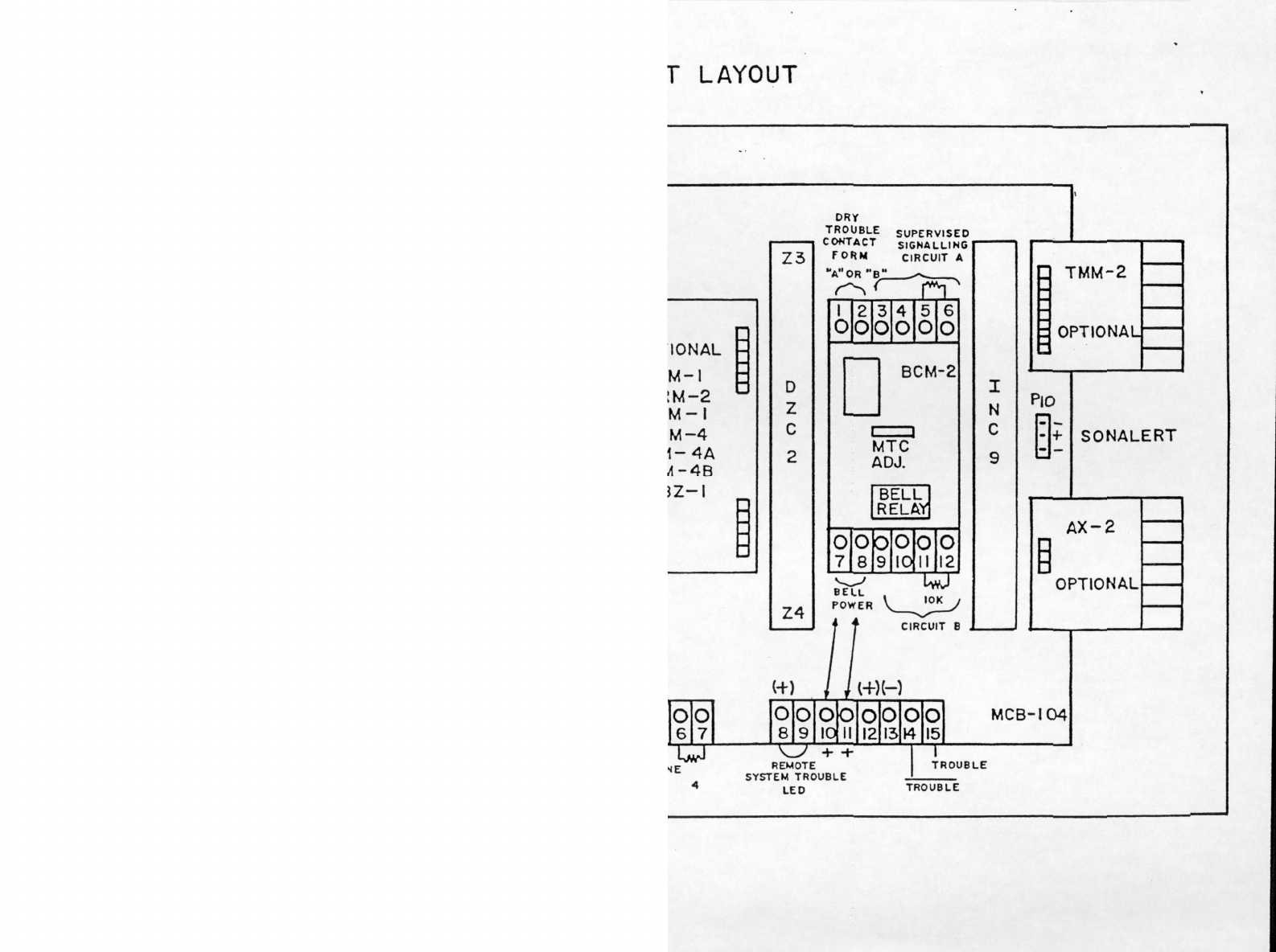
3) For bell power, connect terminal 7 (positive input CKT A), terminal 8 (positive input CKT B) of BCM-2 to terminal 10 &
11 of MCB-104 respectively. Maximum bell load is 1.1 amps per CKT.
BCM-2 Bell Circuit
Figure 5

eciveD forebmuN
seciveD
reptnerruC
eciveD
)serepma(
eciveDlatoT
tnerruC
)serepma(
,9-CNI,2-MCB,42-BSP,401-BCM
)mralanierasenozhtob(2-CZD 861.0=
RO ro=
owt,9-CNI,2-MCB,42-BSP,401-BCM
)mralanierasenozruoflla(s2-CZD 092.0=
*1-MRZ010.0=
*2-MRZ070.0=
*1-MZC090.0=
mralani2-MMT 5310.0=
mralani2-XA 530.0=
tnerrucybdnats-daehrotcetederiwowT
)seireS007-PC,23-DS,21-DS( 1000.0=
,WB41DS(daehrotcetederiwruoF
)ybdnats 51000.0=
)CDV42-43DS(daehrotcetederiwruoF520.0=
yalerenilfodnE520.0=
B4-MR,A4-MR,4-MRZ410.0=
Alarm current load on regulator (add last column)
Alarm current should not exceed 0.75 amp.
Rectified, unfiltered, unregulated bell power = 2.2 amps total.
* Remove both jumpers in DZC-2 card(s) if optional module(s) employed.
eciveD forebmuN
seciveD
reptnerruC
eciveD
)serepma(
eciveDlatoT
tnerruC
)serepma(
:etoN(2-CZD,2-MCB,9-CNI,42-BSP,401-BCM
)langiselbuortelbidua&lausiv,fforewopCA 950.0=
roro
2-CZDowt,2-MCB,9-CNI,42-BSP,401-BCM
elbuortelbidua&lausiv,fforewopCA:etoN(
)langis
070.0=
*1-MRZ 000.0
*2-MRZ 000.0
*1-MZC520.0=
)deyolpme2-MMTfi"TD"edoidevomeR(2-MMT 6200.0=
)deyolpme2-XAfi"XAR"rotsiserevomeR(2-XA
elbawollamumixam(sdaehrotcetederiw-owT
-DS.enozrep)Am2(pma200.0sitnerrucrotceted
)seires007-PC,23-DS,21
1000.0=
)WB41DS(daehrotcetederiwruoF51000.0=
)CDV4243DS(daehrotcetederiwruoF500.0=
)B-RLDS(yalerenilfodnE520.0=
)trelanoSrof(4-AZR 5700.0
ecivedgnillangiselbuortetomeR
B4-MR,A4-MR,4-MRZ 000.0
)nmuloctsaldda(tnerrucybdnatsyrettaB
Part 2: Standby Battery Requirements
* Remove both jumpers in DZC-2 card(s) if optional module(s) employed.
Part 3: Calculate Ampere-Hour
61enil(tnerrucybdnatsyrettaB
)2traPfo
yllareneg(sruohniemitybdnatS
*)sruoh06ro42
2enilyb1enilylpitluM
serepmanidaolmralA)xam(spma0.3
5yllareneg(sruohniemitmralA
)ruoh480.0=setunim
ylpitlum,sruoherepmamralA
5enilyb4enil
3enildda,sruoherepmalatoT
6dna
* NFPA 72A, 72D, 74 required 24 hours standby. NFPA 72B and 72C required 60 hours standby.
Select battery from Part 4 with amp-hour rating larger than line 7 of part 3.
Part 4: Battery Selection
ruoH-erepmA
gnitaR yrettaB
5036setaG)2(owT
6)21-6PN(asauY)2(owT
6)066-CG(ebolG)4(ruoF
8)086-CG(rehciPelgaE)4(ruoF
9)096-CG(noinUebolG)4(ruoF
Do not use 24VDC regulated supply for inductive loads.
