N8MPN100F14B1 44108201001
User Manual: N8MPN100F14B1
Open the PDF directly: View PDF ![]() .
.
Page Count: 46
MULTI POSITION
SINGLE STAGE
2--STAGE
GAS FURNACES
Part Number
441 08 2010 01
N8MPN, N8MPL, *8MPN, *8MPL,
*8DNL, *8MPT & *8MPV
Manufactured by:
This manual supports condensing gas furnaces manufactured in 2003
ã2001 International Comfort Products Corporation (USA) 10/2004
N8MPN -- Non--Condensing Single Stage
N8MPL -- Non--Condensing Single Stage Low Nox
*8MPN-- Non--Condensing Single Stage Deluxe
*8MPL-- Non--Condensing Single Stage Deluxe Low Nox
*8DNL -- Non--Condensing Single Stage Downflow
*8MPT-- Non--Condensing Two Stage PSC Motor
*8MPV-- Non--Condensing Two Stage Variable Speed
* Denotes Brand (T, C or H)

Service Manual
Multi Position Furnace
TABLE OF CONTENTS
1. INTRODUCTION 2............................................................
2. UNIT IDENTIFICATION 2.....................................................
3. FURNACE THEORY OF OPERATION 3........................................
4. ELECTRICAL SUPPLY 4......................................................
5. INTERLOCK SWITCH 5......................................................
6. GAS SUPPLY 6..............................................................
7. BURNERS 8................................................................
8. L.P. PRESSURE SWITCH 8...................................................
9. HIGH ALTITUDE OPERATION 9...............................................
10. CHECKING TEMPERATURE RISE 9..........................................
11. ROOM THERMOSTATS 10....................................................
12. CONTROL WIRING 11.......................................................
13. TWINNING KITS 11..........................................................
14. LIMIT SWITCHES 11.........................................................
15. PRESSURE SWITCHES 12...................................................
16. ST9160B -- UNIQUE CONTROL FUNCTIONS/RESPONSES 16...................
17. HONEYWELL SV9541M GAS VALVE/IGNITION SYSTEM 17.....................
18. HONEYWELL SV9541M SYSTEM OPERATION 17..............................
19. CHECKING FLAME CURRENT 17.............................................
20. CAPACITORS 17............................................................
21. BLOWER ASSEMBLY 17.....................................................
22. HEAT EXCHANGER REMOVAL/REPLACEMENT 20.............................
SV9541M “SMART VALVE” -- Sequence of Operation 21.............................
SV9541M “SMART VALVE” -- Trouble shooting 23...................................
SV9541M “SMART VALVE” -- Electrical Variation 25.................................
WIRING DIAGRAM 26...........................................................
TECHNICAL SERVICE DATA (N8MPN) 30.........................................
TECHNICAL SERVICE DATA (N8MPL) 31..........................................
TECHNICAL SERVICE DATA (*8MPN) 32..........................................
TECHNICAL SERVICE DATA (*8MPL) 33..........................................
TECHNICAL SERVICE DATA (*8DNL) 34..........................................
TECHNICAL SERVICE DATA (*8MPV) 35..........................................
TECHNICAL SERVICE DATA (*8MPT) 36..........................................
BLOWER PERFORMANCE DATA 37..............................................
APPENDIX OF HELPFUL INFORMATION 43.......................................
Single Stage Multi Position Furnace
Service Manual
2
441 08 2010 01
1. INTRODUCTION
This service manual is designed to be used in conjunction
with the installation manual and/or technical support manual
provided with each furnace.
These furnaces represent the very latest in mid--efficiency
gas furnace technology. Consequently, they incorporate the
use of certain controls that contain highly sophisticated elec-
tronic components which are not user serviceable. there-
fore,itisessentialthatonlycompetent,qualified, serviceper-
sonnel attempt to install, service, or maintain this product.
This Service manual was written to assist the professional
HVAC service technician to quickly and accurately diagnose
and repair any malfunction of this product.
This servicemanual coversour newmulti--positionfurnaces.
The overall operation of all of these models is essentially the
same.
This manual, therefore, will deal with all subjects in ageneral
nature (I.E. all text will pertain to all models) unless that sub-
ject is unique to a particular model or family, in which case it
will be so indicated.
The information contained in this manual is
intended for use by a qualified service technician
who is familiar with the safety procedures required
in installation and repair and who is equipped with
the proper tools and test instruments.
Installation or repairs made by the unqualified
persons can result in hazards subjecting the
unqualifiedpersonmakingsuchrepairstotheriskof
injury or electrical shock which can be serious, or
even fatalnotonly tothem, butalso to persons being
served by the equipment.
If you install or perform service on equipment, you
must assume responsibility for any bodily injury or
property damage which may result to you or others.
We will not be responsiblefor anyinjury orproperty
damage arising from improper installation, service
and/or service procedures.
!
2. UNIT IDENTIFICATION
The unit’s rating plate contains important information for the
service technician. It also lists the complete Model Manufac-
turing and Serial Numbers.
These complete numbers are required to obtain correct re-
placement parts (example, in certain model families a unit
having a MARKET REVISION of “C” is likely to be equipped
with one or more different components.
MODEL NUMBER IDENTIFICATION GUIDE
* 8 MP D075 B12 A 1
Brand Identifier Engineering Rev.
T=Tempstar Denotes minor changes
C = Comfortmaker Marketing Digit
H=Heil Denotes minor change
A = Arcoaire
X = Evaluation Cooling Airflow
Brand Identifier 08 = 800 CFM
8 = Non--Condensing, 80+% Gas Furnace 12 = 1200 CFM
9 = Condensing, 90+% Gas Furnace 14 = 1400 CFM
Installation Configuration 16 = 1600 CFM
UP = Upflow DN = Downflow UH = Upflow/Horizontal 20 = 2000 CFM
HZ = Horizontal DH = Downflow/Horizontal
MP = Multiposition, Upflow/Downflow/Horizontal Cabinet Width
Major Design Feature B = 15.5²Wide
1 = One (Single) Pipe N = Single Stage F = 19.1²Wide
2=TwoPipe P=PVCVent J = 22.8²Wide
D = 1 or 2 Pipe T = Two Stage L = 24.5²Wide
L = Low NOx V = Variable Speed Input (Nominal MBTUH)
Multi Position Furnace Service Manual
3441 08 2010 01
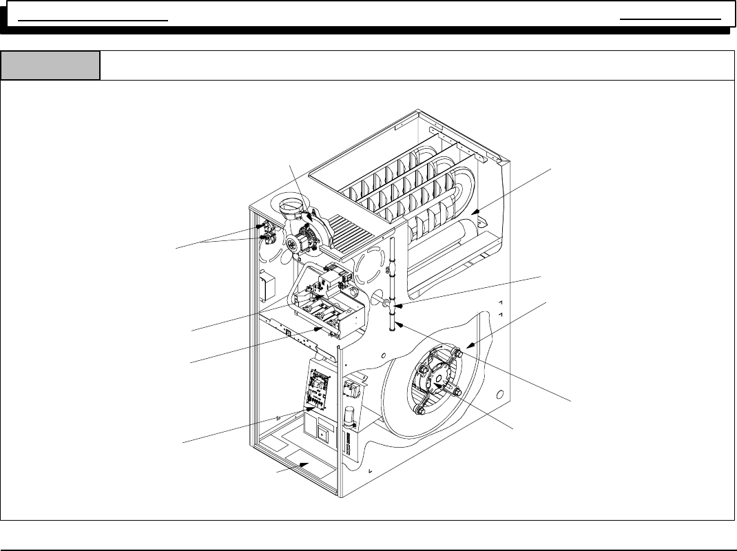
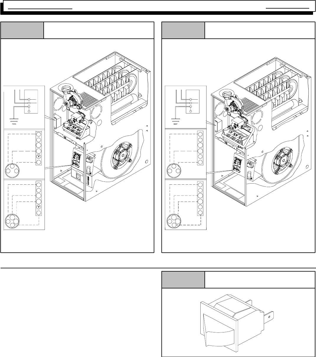
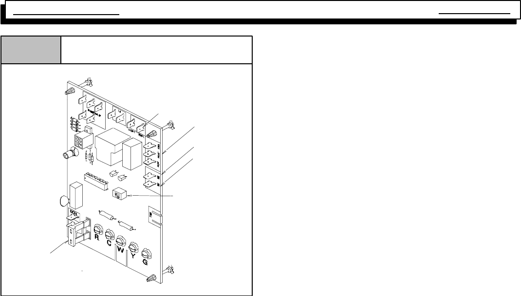
Component Locations for Four Position Furnaces
Figure 1
25--24--30V
Gas Valve
Main Burners
Circulating Blower
Motor
Heat Exchanger
Combustion
Blower
Circulating Blower
Fan/Delay
Control
Manual Gas
Valve
Pressure Switch
(2 switches on some
models)
Representative drawing only, some models may vary in appearance.
Rating
Plate
Drip Leg
3. FURNACE THEORY OF OPERATION
Thehigh efficiencies andlower profile(compared toprevious
series)of thisfurnace havebeenobtainedusingdesigntech-
niques not typical of traditional furnace designs. A brief de-
scription of these new design techniques and the purpose
they serve follows.
1. Reducing the height of the furnace while maintaining
the high efficiency of pervious models required main-
taining the surface area of the heat exchanger and yet
minimizing the overall size.
The design required to achieve these results is the “SER-
PENTINE”design,whereinthefluegassesmustfollowaser-
pent shaped passage through the heat exchanger via con-
vection.
This “Serpentine” path is resistive to normal convective flow,
and requires that a partial vacuum be created at the outlet of
the heat exchanger to maintain the flow of flue products
through the heat exchanger.
2. The serpentine heat exchanger design does not lend
itself well to the ribbon type, or slotted port type burner
foundin moretraditionaldesignfurnaces for thefollow-
ing reasons:
A. The flame “height” of a ribbon or slotted port type
burner would make it difficult (if not impossible) to
prevent impingement of the flame on the heat ex-
changer surfaces whole maintaining the low profile
heat exchanger.
For these reasons, an “INSHOT” type burner is used in this
series. The inshot burner (also called a “jet” burner) fires a
flame straight out its end. This burner is designed to fire into
a tube style heat exchanger, making it an ideal application in
the tube--like passages of the serpentine heat exchanger.
3. To overcome the resistance to convective flow of the
heat exchanger requires the use of an Induced Draft
Combustion Blower Assembly.
4. The Combustion Blower Assembly is mounted on the
outletsideoftheheatexchanger,Thisblowercreatesa
partial vacuum (negative pressure) within the heat ex-
changers drawing the flue products out of the furnace.
5. A pressure switch (Air Proving Switch) is used as a
safetydevicethat preventsthe ignitionsystem from fir-
ing the furnace until it senses that a proper draft has
been established through the furnace.
Single Stage Multi Position Furnace
Service Manual
4
441 08 2010 01
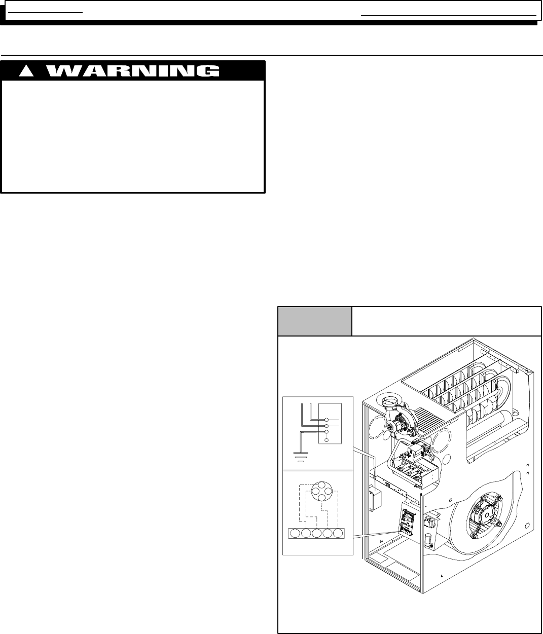
4. ELECTRICAL SUPPLY
ELECTRICAL SHOCK HAZARD.
Failure to do so can result in death, personal injury
and/or property damage.
Turn OFF electric power at fuse box or service panel
before making any electrical connections and en-
sure a proper ground connection is made before
connecting line voltage.
!
SUPPLY CIRCUIT
The furnace cannot be expected to operate correctly unless
it is properly connected (wired) to an adequately sized (15
amp.) single branch circuit.
SUPPLY VOLTAGE
Supply voltage to the furnace should be a nominal 115 volts.
It MUST be between 97 volts and 132 volts. Supply voltage
to the furnace should be checked WITH THE FURNACE IN
OPERATION. Voltage readings outside the specified range
can be expected to cause operating problems. Their cause
MUST be investigated and corrected.
ELECTRICAL GROUND
GroundingoftheelectricalsupplytoALLFURNACESISRE-
QUIRED for safety reasons.
CHECKING GROUNDING AND POLARITY
Grounding may be verified as follows:
1. Turn the power supply “OFF”.
2. Using an Ohmmeter check for continuity between the
Neutral (white) wire and Ground wire (green) of the
supply circuit.
3. With the Ohmmeter set on the R x 1scale, the reading
should be zero Ohms.
4. A zero Ohm reading indicates that the neutral is
grounded back to the main panel.
5. An alternate check would be to check for continuity
from the Neutral to a cold water pipe, (Pipe must be
metal,and must havea continuous, uninterruptedcon-
nection to ground) or to a continuous, uninterrupted
connection to ground) or to a driven ground rod.
6. AnyreadingsotherthanzeroOhmswould indicatea
poor ground, or no ground.
Polarity may be verified as follows:
1. Turn the power supply “ON”.
2. Using a Voltmeter check for voltage between the Hot
(Black) and Neutral (White) wire of supply circuit.
POLARITY
CORRECT POLARITY of the line voltage supply to all fur-
naces is also required for safety reasons.
3. Reading should be Line (Supply) Voltage.
4. Check for Voltage between the Neutral (White) wire
and Ground wire of the supply circuit.
5. Reading should be zero Volts. (if line voltage is read,
polarity is reversed)
6. A zero Volt reading indicates there is no voltage poten-
tial on Neutral wire.
7. Double check by checking for voltage between the Hot
(Black) wire and Ground wire of the supply circuit.
8. ReadingshouldbeLine (supply)Voltage.(ifzerovolts
is read, there is no ground, or polarity is reversed.)
Figure 2 Electrical Connections
Single Stage
25--24--33
NOTE: 115 VAC/60Hz/single--phase
Operating voltage range*: 127 max, 104 min.
* Permissible limits of voltage at which unit will operate satisfactorily
115V. 60Hz.
W
BK
G
Connectio
n
Box
Ground
HOT
NEUT.
Thermostat
Low Voltage
Terminal Board
R
G
G
G
YR
Y
W
W
C
Multi Position Furnace Service Manual
5441 08 2010 01
Figure 3 Electrical Connections
*8MPV
G
G
W
NOTE: Junction Box can be mounted to either the left or right side.
24--24--33a
NOTE: 115 VAC/60Hz/single--phase
Operating voltage range*: 127 max, 104 min.
* Permissible limits of voltage at which unit will operate satisfactorily
Ground
115V. 50 Hz.
Correction
Box
W1
W
W
W1
W2
W2
W1
W2
BK
G
G
G
W1
R
R
R
R
C
C
Two Stage
Thermostat
Low Voltage
Terminal Board
Low Voltage
Terminal Board
Single Stage
Thermostat
HOT
Figure 4 Electrical Connections
*8MPT
W1
G
NOTE: Junction Box can be mounted to either the left or right side.
25--24--33
NOTE: 115 VAC/60Hz/single--phase
Operating voltage range*: 127 max, 104 min.
* Permissible limits of voltage at which unit will operate satisfactorily
115V. 50 Hz.
W1
Low Voltage
Terminal Board
Low Voltage
Terminal Board
BK
G
G
G
W1
W2
W2
W2
W
W
Correction
Box
R
C
Two Stage
Thermostat
C
G
R
R
R
Y
Y
Single Stage
Thermostat
Ground
HOT
NEUT.
5. INTERLOCK SWITCH
The blower compartment door of all models is equipped with
an interlock switch. This switch is “Normally Open” (closes
when the door is on the furnace) and interrupts furnace op-
eration whenthe dooris open. This interlock switch is asafe-
ty device, and SHOULD NEVER BE BY--PASSED.
Since this is a single pole switch, (breaking only one side of
the line) properline voltage is essential to insure that furnace
components are not “HOT” when switch is open. (See
Checking Grounding and Polarity)
Figure 5 Typical Interlock Switch
10--12--96
Single Stage Multi Position Furnace
Service Manual
6
441 08 2010 01
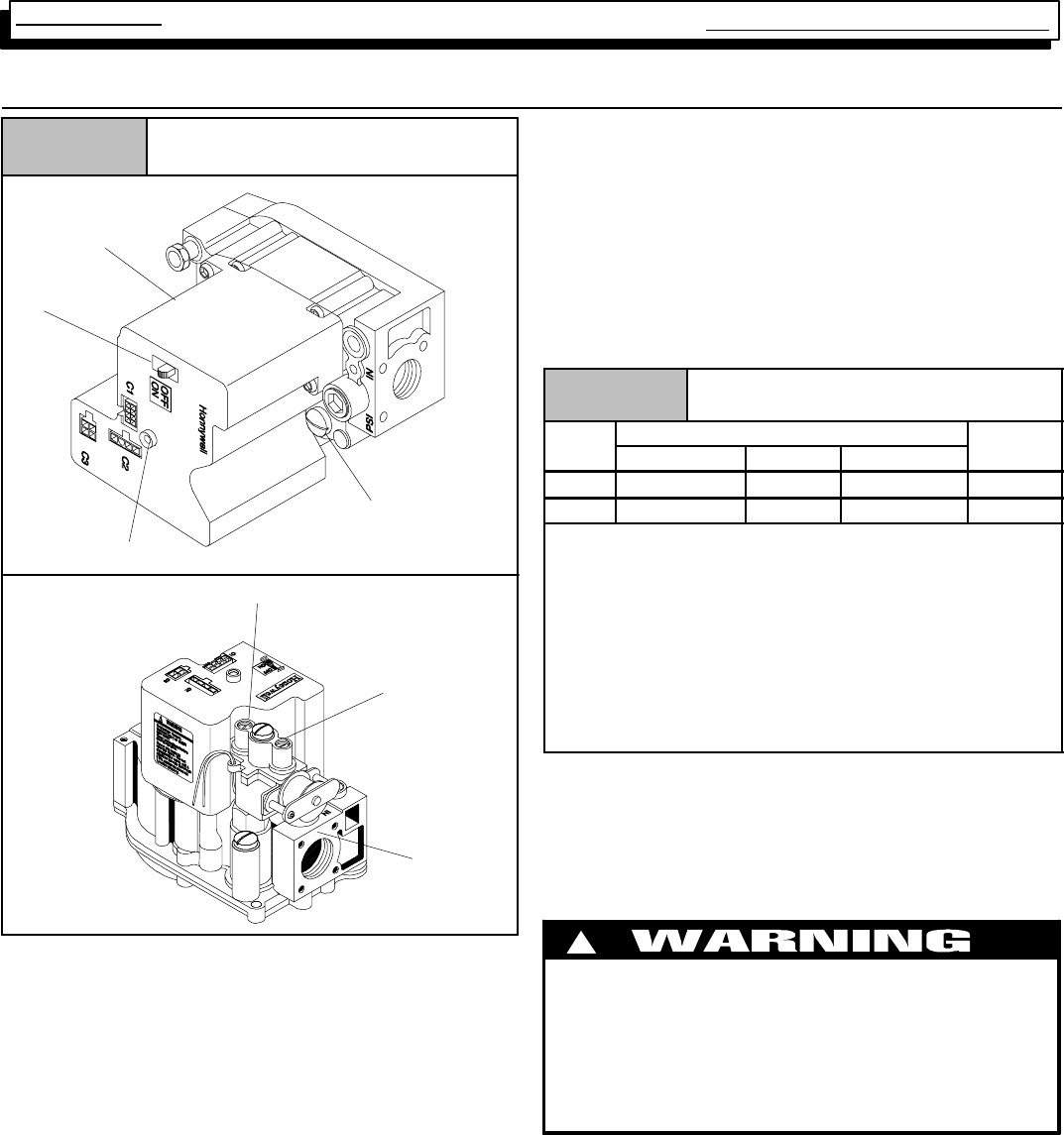
6. GAS SUPPLY
Typical Gas Valve HoneywellFigure 6
dwg 25--23--31a
INLET
Manifold Pressure
Adjustment
Pilot Pressure
Adjustment (Hidden)
On\Off
Switch
Diagnostic Light
OUTLET Single Stage
INLET
OUTLET Gas
Supply
Pressure
Tap on
Inlet
Boss
Behind
Coil
LO
HI
Two--Stage
An adequately sized gas supply to the furnaceis requiredfor
properoperation.Gaspipingwhichisundersizedwillnot pro-
videsufficientcapacityforproper operation.Pipingshouldbe
sized in accordance with accepted industry standards.
NATURAL GAS
Inlet (Supply) pressure to the furnace should be checked (at
the gas valve) with ALL OTHER GAS FIRED APPLIANCES
OPERATING. Inlet (Supply) pressure to the furnace under
these conditions MUST be a minimum of 4.5²W.C. (Water
Column). If the inlet pressure is less, it may be an indication
of undersized piping or regulator problems.
LP GAS
Inlet (Supply) pressure to the furnace should be checked in
the same manner as for Natural Gas, however with LP Gas,
the inlet pressure MUST be a minimum of 11²W.C. If this
cannot be obtained, problems are indicated in either the reg-
ulator or pipe sizing.
Table 1 Gas Pressures Below 2000¢
¢¢
¢
Gas
T
Supply Pressure Manifold
P
Type Recommended Max. Min. Pressure
Natural 7²14²4.5²3.5²
LP 11²14²11²10²
Important Note:
·With Propane gas, the rated input is obtained when the
BTU content is 2,500 BTU per cubic foot and manifold
pressure set at 10²
²²
²W.C.
·If Propane gas has a different BTU content, orifices
MUST be changed by licensed Propane installer.
·Measured input can NOT exceed rated input.
·Any majorchange ingas flowrequires changing burner
orifice size.
CHECKING INPUT (FIRING) RATE
Once it has been determined that the gas supply is correct
to the furnace, it is necessary to check the input (firing) rate,
This can be done in two (2) ways. First by checking and ad-
justing (as necessary) the manifold (Outlet) pressure. The
second way is to “Clock” the gas meter.
FIRE OR EXPLOSION HAZARD.
Failure to turn OFF gas at shut off before
connecting manometer can result in death,
personal injury and/or property damage.
Turn OFF gas at shut off before connecting
manometer.
!
Multi Position Furnace Service Manual
7441 08 2010 01
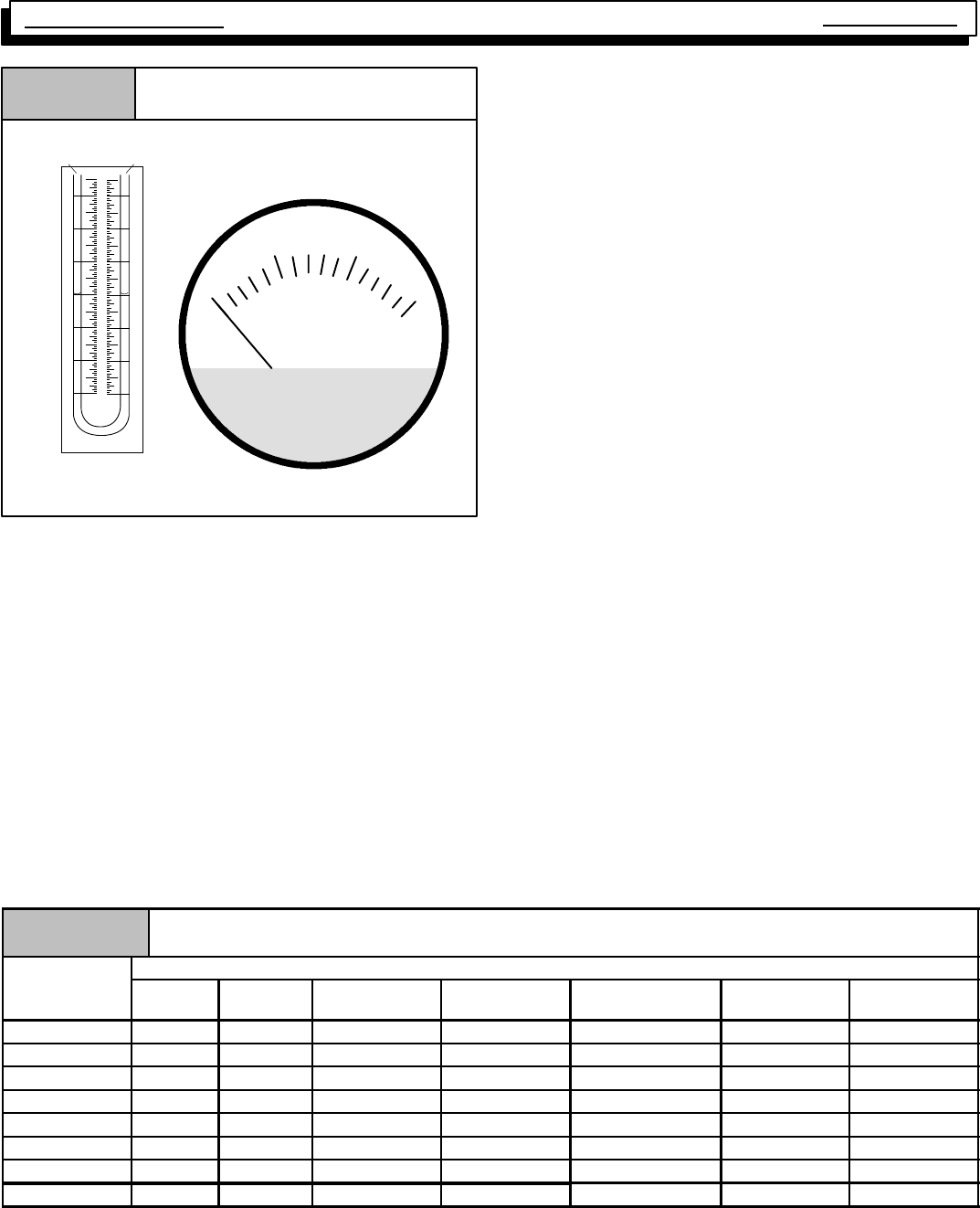
Gas Pressure Testing Devices
Figure 7
MAGNEHELIC
MAX. PRESSURE 15 PSIG
0
510
15
INCHES OF WATER
Pressure Connections
Typical "U" Tube
Manometer
0
1
1
2
2
3
3
CHECKING MANIFOLD PRESSURE For Single Stage
1. Connect a manometer or Magnehelic gauge (0--12²
W.C. range) to the pressure tap on the “OUTLET” side
of the gas valve.
2. Turn gas “ON”, fire the furnace, and remove adjust-
ment cover (screw--cap).
3. Turn adjustment screw clockwise (IN) to INCREASE
pressure, andcounterclockwise(OUT) to DECREASE
pressure.
4. At altitudes BELOW 2,000¢
¢¢
¢set manifold pressure to
3.5²W.C. for Natural Gas, and 10²W.C. for LP Gas.
5. For Natural Gas units ABOVE 2,000¢
¢¢
¢, set manifold
pressure according to Table 2.
6. For LP Gas units ABOVE 2,000¢
¢¢
¢, insure that orifice
size has been changed (per “National Fuel Gas Code”
-- Appendix “F”) if gas supply has not already been de--
rated for altitude by the gas supplier.
7. For ALL UNITS ABOVE 8,000¢, contact the factory for
SPECIFIC de--rating information.
CHECKING MANIFOLD PRESSURE for Two Stage
1. Connect manometer or Magnehelic gauge to the
tapped opening on the outlet side of gas valve. Use a
manometer with a 0 to 12²minimum water column
range.
2. Turngas ON.Operatethe furnaceonhighfirebyusing
ajumper wireontheRtoW1& W2thermostatconnec-
tions on the fan board.
3. Remove the adjustment cover on the gas valve. Turn
adjusting screw counterclockwise to decrease the
manifold pressure and clockwise to increase. See
Figure 6.
4. Set the manifold pressure to value shown in Table 1 or
Table 3.
5. Operate the furnace on low fire by using a jumper wire
on the R to W1 thermostat connections on the fan
board.
Note: The fourth (4th) DIP switch should be in the on
position to set the low fire manifold pressure. (See wir-
ing digram)
6. Repeat steps 4 and 5 for low fire operation.
7. When the manifold pressures are properly set, replace
the adjustment screw covers on the gas valve.
8. Remove the jumper wires from the thermostat connec-
tions on the fan board. Remove manometer and re-
place plug in gas valve.
9. Reture fourth (4th) DIP switch to previous setting.
10. Replace the burner compartment door.
MANIFOLD PRESSURE AND ORIFICE SIZE FOR HIGH ALTITUDE APPLICATIONS For Single Stage
Table 2 NATURAL GAS
H
e
a
t
V
a
l
u
e
Elevation Above Sea Level
H
eat
V
a
l
ue
Btu/Cu.Ft. 0--1999
(²
²²
²×
××
×wc) 2000--2999
(²
²²
²×
××
×wc) 3000--3999
(²
²²
²×
××
×wc) 4000--4999
(²
²²
²×
××
×wc) 5000--5999
(²
²²
²×
××
×wc) 6000--6999
(²
²²
²×
××
×wc) 7000--7999
(²
²²
²×
××
×wc)
800 3.5 3.5 3.5 3.5 3.5 3.5 3.5
850 3.5 3.5 3.5 3.5 3.5 3.5 3.5
900 3.5 3.5 3.5 3.5 3.5 3.5 3.4
950 3.5 3.5 3.5 3.5 3.3 3.2 3.1
1000 3.5 3.4 3.3 3.2 3.0 2.9 2.8
1050 3.2 3.1 3.0 2.9 2.7 2.6 2.5
1100 2.9 2.8 2.7 2.6 2.5 2.4 2.3
Orifice Size #42 #42 #42 #42 #42 #42 #42
Single Stage Multi Position Furnace
Service Manual
8
441 08 2010 01
MANIFOLD PRESSURE AND ORIFICE SIZE FOR HIGH ALTITUDE APPLICATIONS For Two-Stage
Table 3 High Altitude Pressure Chart
2000--8000 ft. (Natural Gas)
H
t
V
l
Elevation Above Sea Level
Heat
V
alue
B
t
u
/
C
u
.
F
t
.
0--1999 2000--2999 3000--3999 4000--4999 5000--5999 6000--6999 7000--7999
B
t
u
/
C
u
.
F
t
.High Low High Low High Low High Low High Low High Low High Low
800 3.5 1.7 3.5 1.7 3.5 1.7 3.5 1.7 3.5 1.7 3.5 1.7 3.5 1.7
850 3.5 1.7 3.5 1.7 3.5 1.7 3.5 1.7 3.5 1.7 3.5 1.7 3.5 1.7
900 3.5 1.7 3.5 1.7 3.5 1.7 3.5 1.7 3.5 1.7 3.5 1.7 3.4 1.7
950 3.5 1.7 3.5 1.7 3.5 1.7 3.5 1.7 3.3 1.6 3.2 1.6 3.1 1.5
1000 3.5 1.7 3.4 1.7 3.3 1.6 3.2 1.5 3.0 1.5 2.9 1.4 2.8 1.4
1050 3.2 1.6 3.1 1.5 3.0 1.5 2.9 1.4 2.7 1.3 2.6 1.3 2.5 1.2
1100 2.9 1.4 2.8 1.4 2.7 1.3 2.6 1.3 2.5 1.2 2.4 1.2 2.3 1.1
Orifice Size #42 #42 #42 #42 #42 #42 #42
“CLOCKING” GAS METER (NATURAL GAS)
1. Check with gas supplier to obtain ACTUAL BTU con-
tent of gas.
2. Turn “OFF” gas supply to ALL other gas appliances.
3. Timehowmanysecondsittakesthesmallest(normally
1cfh)dialonthegasmetertomakeone completerevo-
lution.
4. Calculate input rate by using ACTUAL BTU content of
gas in formula shown in example.
Example
Natural Gas
BTU Content No. of Seconds
Per Hour Time Per Cubic
Foot in Seconds BTU Per
Hour
1,000 3,600 48 75,000
1,000 x 3,600 ¸48 = 75,000 BTUH
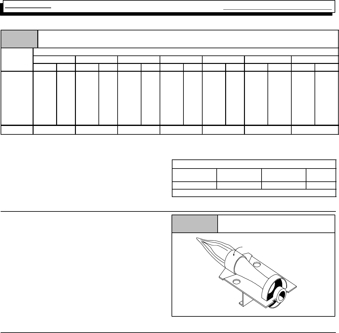
7. BURNERS
Burners used in this series of furnace are of the “INSHOT”
type. Their operation can be compared to that of a torch in
that they produce a hard, sharp, somewhat noisy flame.
Noise should not be an issue, however, because of the
closed compartment design. In order to insure that the burn-
ers are operating properly, and at their design noise level,
proper adjustment of the gas (manifold) pressure is essen-
tial. See page 6 for further information on manifold pressure
adjustments.
The burners usedin this series ARENOT EQUIPPEDWITH
AIR SHUTTERS, as none are required. Proper operation
(flame characteristics) is obtained by insuring that the orifice
size, and manifold pressure are correct for the fuel being
used and the altitude of the installation.
Main Burner
Burner Face
10--10--78
Figure 8
8. LP PRESSURE SWITCH
Models converted to operate on LP Gas will be installed with
an LP Pressure Switch. If so equipped, the switch will be lo-
cated in the gas supply line (in a “Tee” fitting), just ahead of
the gas valve.
Thepurposeofthisswitchistopreventfurnaceoperatingun-
der low line (Supply) pressure conditions. Operating under
lowlinepressureconditions, cancreateproblemssuchasin-
complete combustion, flashback, sooting, etc.
The switch is a “Normally Open” pressure operated switch
that iswiredinseries withthefurnace(vent) pressureswitch.
The LP Pressure Switch closes when line (Supply) pressure
is 8.0²W.C. or higher. the LP Pressure Switch Opens if line
pressure falls below 6.0²+0.6²W.C. interrupting power to
the gas valve.
On some models, it is located (electrically) between the Fur-
nace (vent) pressure switch and the gas Valve.
Multi Position Furnace Service Manual
9441 08 2010 01
Typical LP Pressure Switch
Figure 9
9. HIGH ALTITUDE OPERATION
Thesefurnaces aredesignedto operateinthemajority ofthe
country without modifications. At altitudes over 2,000¢above
sea level, however, certain measures need to be taken to in-
sure continued, safe reliable operation. For example, units
mustbede--ratedforaltitude(byadjusting manifoldpressure
and/or changingorificesize) basedupon thetypeof fuel(I.E.
Natural Gas or LP gas), Btu content of the gas, and installed
altitude.
ALL UNITS must have a high altitude pressure switch
installed at altitudes above 4,000¢above sea level.
When servicing a unit installed at altitudes above 2,000¢in-
sure that it has been properly modified to operate at that alti-
tude. See the sections on Gas pressure (Page 9), and pres-
sureswitches(Page12) toobtain specificinformationforyou
particular installation altitude.
10. CHECKING TEMPERATURE RISE
Air Flow
Checking Temperature Rise
Figure 10
Thermometer:
Return Air Temp.
Thermometer;
Supply Air Temp.
Supply
Air Flow
Return
The furnace is designed to operate within a certain specified
range of temperature rise.
Operating the furnace outside the specified range may result
in lower efficiency and/or comfort levels, as well as prema-
ture combustion component failures.
Simplystated,thetemperaturerisethroughthefurnaceisthe
differenceintemperaturebetweenthereturnair,andthesup-
ply air.
NOTE: BEFORE CHECKING TEMPERATURE RISE BE
CERTAIN THAT MANIFOLD PRESSURE IS PROPERLY
ADJUSTED.
TYPICAL OPERATING TEMPERATURE RISE RANGE
Single--Stage
Model Range
50 Mbtu 35°F--65°F
75, 100 & 125 Mbtu 40°F--70°F
Two--Stage
Model Fire Range
5
0
M
b
t
u
HI 35°F--65°F
50 Mbtu LOW 35°F--65°F
7
5
M
b
t
u
1
0
0
M
b
t
u
&
1
2
5
M
b
t
u
HI 40°F--70°F
75 Mbtu, 100 Mbtu & 125 Mbtu LOW 40°F--70°F
For specific temperature rise check pages 30 thru 36 of this
manual.
Always check current “Technical Support Manual”
Operate the furnace for 15 minutes before taking tempera-
ture readings. Subtract the return air temperature from the
supply air temperature. The result is the temperature rise.
Compare with the allowable rise listed for the model (size)
you are checking.
Single Stage Multi Position Furnace
Service Manual
10
441 08 2010 01
Temperature Rise can bechecked by placing athermometer
inthe returnair duct within6¢offurnace.Placeasecondther-
mometer in the supply duct at lease two (2) ft. away from the
furnace. (This willprevent any false readings caused by radi-
ation from the furnace heat exchanger) Make sure that the
FILTER IS CLEAN and that ALL REGISTERS AND/OR
DAMPERS ARE OPEN.
If the riseisnot withinthespecifiedrange, itwillbenecessary
to change the heating blower speed. Iftheriseistoohigh,
itwillbenecessarytoincreasetheblowerspeed.Iftherise
istoo low,itwillbenecessarytoreducetheblowerspeed.
Example: Supply Temp. 170°
Return Temp. 70°
Temperature Rise 100°= Too High
Solution: Increase Blower Speed
11. ROOM THERMOSTATS
Room thermostats are available from several different
manufacturesin awidevariety ofstyles. Theyrangefromthe
very simpleandinexpensiveBi--metallic typetothecomplex.
They are simply a switch (or series of switches) designed to
turn equipment (or components) “ON” or “OFF” at the de-
sired conditions.
An improperly operating, or poorly located room thermostat
can be the source of perceived equipment problems. A care-
ful check of the thermostat and wiring must be made then to
insure that it is not the source of problems.
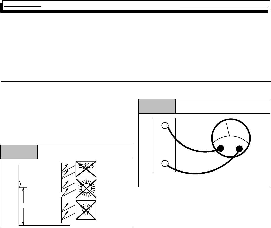
Thermostat Location
Figure 11
5 ft.
DRAFTS
SUN
THERMOSTAT
LIGHT
SHIELD
LOCATION
The thermostat should not be mounted where it may be af-
fected by drafts, discharge air from registers (hot or cold), or
heat radiated from the sun of appliances. Never install in al-
coves, bathrooms or bedrooms.
The thermostat should be located about 5 ft. above the floor
in an area of average temperature, with good air circulation.
Normally, an area in close proximity to the return air grille is
the best choice.
Mercurybulbtypethermostats MUSTbeleveltocontroltem-
perature accurately to the desired set--point. Electronic digi-
tal type thermostats SHOULD be level for aesthetics.
HEAT ANTICIPATORS
Heat anticipators are small resistance heaters built into most
electric--mechanicalthermostats.Theirpurposeis toprevent
wide swings in room temperature during furnace operation.
Inordertoaccomplishthis,theheat outputfromtheanticipa-
tor must be the same regardless of the current flowing
through it. Consequently, most thermostats have an adjust-
ment to compensate for varying current draw in the thermo-
stat circuit.
Thepropersettingof heat anticipators then isimportanttoin-
sure proper temperature control and customer satisfaction.
Measuring Current Draw
Figure 12
Ammeter
W
R
Subbase
Amps
The best method to obtain the required setting for the heat
anticipator, is to measure the actual current draw in the con-
trol circuit (“W”) using a low range (0--2.0 Amps) Ammeter.
(SeeFigure 12)Aftermeasuringthecurrentdraw,simplyset
the heat anticipator to match that value.
If a low range ammeter is not available, a “Clamp--on” type
meter may be used as follows:
1. Wrap EXACTLY ten (10) turns of wire around the jaws
of a clamp--on type ammeter.
2. Connect one end of the wire to the “W” terminal of the
thermostat sub--base,andtheothertothe“R”terminal.
3. Turn power on, and wait approximately 1 minute, then
read meter.
4. Divide meter reading by10 to obtain correct anticipator
setting.
NOTE: For 2 Stage heating thermostats the above proce-
dure MUST be performed twice. Once for first
stage (W1), and once for second stage (W2), if
both stages have adjustable heat anticipators.
If anammeter isnot available, asettingof 0.30 amps maybe
used for models equipped with the HONEYWELL SV9541M
Gas Valve/Ignition Control. They should, however, provide
satisfactory operation in most cases.
Electronic thermostats do not use aresistance type anticipa-
tor. These thermostats use a microprocessor (computer)
that determines a cycle rate based on aprogram loaded into
it at the factory.

Multi Position Furnace Service Manual
11 441 08 2010 01
These cycle rates are normally field adjustable for different
types to equipment. The method of adjustment, however,
varies from one thermostat manufacturer to another. Check
with the thermostat manufacturer to find out the proper way
of adjusting the cycle rate.
12. CONTROL WIRING
Control wiring is an important part of the total equipment
installation, since it provides the vital communications link
between the thermostat, and the equipment malfunctions.
Controlwiringthatiseithertoolong,undersized,orimproper-
ly connected (be it simply loose, or on the wrong terminal)
can in fact be the source of many equipment problems.
ALWAYS check to make sure that the control wiring is con-
nected to the proper terminal(s) of the equipment and ther-
mostat you are using. Remember, also, that the thermostat
terminals are not always identified alike by different thermo-
statmanufacturers. Connections MUST becleanandtightto
insure trouble--free operation.
For years, installers have run a wire from the “Y” terminal of
the room thermostat and connected it directly to the contact
on coil of a condensing unit. (not making any connection to
the furnace with this wiring. Then, run the low voltage “Com-
mon” wire from the condensing unit back to the “C” terminal
of the furnace.
With the HONEYWELL ST9160B electronic Fan Timer/Fur-
nace Control, the “Y” terminal of the furnace does in fact
serve a particular purpose. Failure to connect it will result in
certain improper operation as follows:
The COOLING fan speed is energized via the “Y” terminal.
Failure to connect the thermostat “Y” terminal to the “Y” ter-
minal on the control will result in the failure to energize the
COOLING speed on a call for cooling from the thermostat.
(The HEATING speed will be energized instead via the “G”
terminal)
13. TWINNING KITS
Some installations may require a Heating capacity or Airflow
capabilities greater than a single furnace of this series can
provide.. When this is necessary, furnaces may be installed
in a “Twinned” configuration.
The Twinning Kit allows the two (2) furnaces to be controlled
bythesameroomthermostat.WhenTwinned, thecirculating
(conditioned air) blowers of BOTH furnaces will operate si-
multaneously.
Models equipped with a HONEYWELL ST9160B series Fan
Timer/Furnace Control may be twinned using a model
NAHA003WK01 twinning kit.
To assist troubleshooting efforts of “Twinned” installations,
“TYPICAL” control wiring diagrams are provided on pages **
through **.
14. LIMIT SWITCHES
Two (2) different kinds of limit switches are used on this se-
ries of furnaces. They are the main limit and roll out limit
switches. The main limit, and roll limit switches are used on
all models.
NOTE:Alllimitswitchesaresafetydevicesandotherthan
for testing purposes, should never be jumped out! Limit
switches are “normally closed” electrical switches, designed
to open when their predetermined “limit setting” has been
reached.
It should also be remembered, that when a limit switch
opens, it more than likely is not due to a bad switch! The
cause of the opening limit must be found and corrected, be-
fore the furnace can resume proper operation.
FIRE HAZARD.
Failure to do so can result in death, personal injury
and/or property damage.
Limit controls are factory preset and MUST NOT be
adjusted. Use ONLY manufacturer’s authorized
replacement parts.
!
Thespecificfunctionsofthetwo(2)limit switchesusedinthis
series of furnaces are as follows:
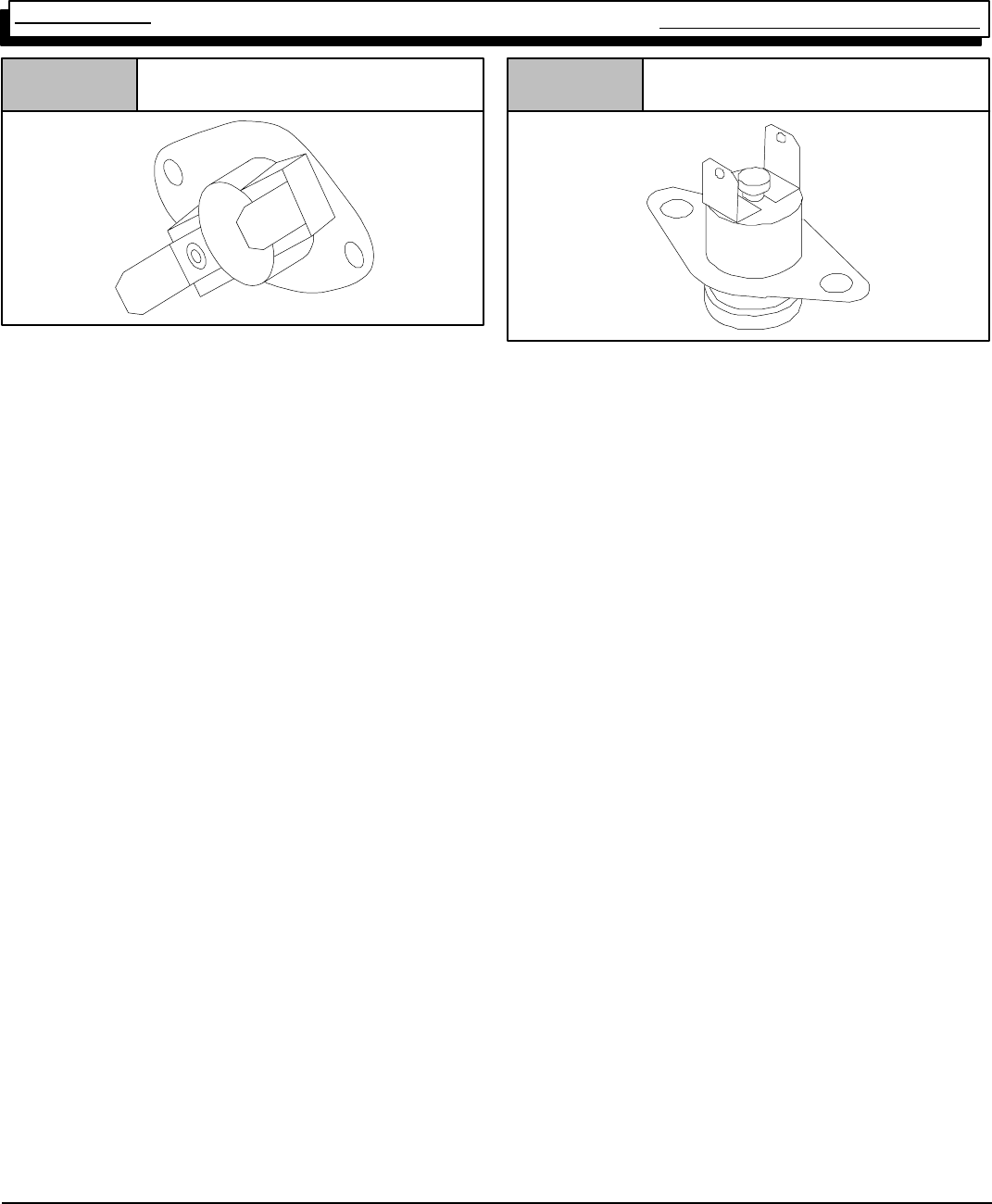
MAIN LIMIT SWITCH
A “Normally Closed” switch located on the front partition of
the furnace. It monitors supply air temperature, and inter-
rupts furnace (burner) operation when a supply air tempera-
ture is sensed which would result in the furnace exceeding
Maximum allowable outlet air temperature. While the main
limit is open, combustion blower, and/or the circulating blow-
erwillbeenergizedcontinuously.Thiscontrolisan“Automat-
ic” reset control, which will reset itself when the temperature
sensed drops to a safe level.
If furnace (burner) cycles on this limit switch, (I.E. switch
opens and closes during furnace operation) it is more than
likely due to a high temperature rise through the furnace.
(See checking temperature on page 8 of this manual)
High temperature rise can be caused by either OVER
FIRING (high manifold pressure. incorrect orifices, etc.) or
LOW AIRFLOW (dirty filter,blowerspeedtoolow,excessive
static in duct system, etc.)
Single Stage Multi Position Furnace
Service Manual
12
441 08 2010 01
Typical Limit Switch
Figure 13
Toverifythis, thecut--out(opening)point oftheswitchshould
be checked (using a thermocouple type thermometer con-
nected to the face of the switch) as follows:
1. Operate furnace for several minutes.
2. Block return air grille(s) to furnace.
3. Observe temperature at which switch opens (burner
operation ceases).
4. Remove blockage from return grille(s).
5. Observe temperature at which switch closes (burner
operation resumes).
6. Compare readings with the limit setting listed in the
appropriate chart for the model you are servicing.
Ifswitchisopeningwithinthespecifiedrange,thenitissimply
doing its job,and thecause of the over--temperature must be
determined and corrected.
If, however, the switch is found to be opening prematurely,
then it should be replaced. When replacing ANY limit switch,
use ONLY a switch of EXACTLY the same temperature set-
ting. Use of a different temperature limit switch can create a
dangerous situation. Someof the main limitswitches usedin
this series are SIMILAR IN APPEARANCE. DIFFERENT
TEMPERATURE SETTINGS, HOWEVER, ARE USED for
different models. Be certain you have the correct control for
the model you are servicing.
ROLL OUT LIMIT
A “Normally Closed” switch (wired in series with the Main
Limit switch) mounted on the burner box.
This switch may be of the manual type, depending upon the
particular model and/or family. Different temperature
(OPENING) settings are also used on different models.
When replacing this switch, be absolutely certain the correct
one is used.
Typical Roll Out Limit Switch
Figure 14
CAUTION
NEVER use an automatic reset roll out switch to replace
a manual reset type roll out switch.
Doing so may cause potentially unsafe and/or intermit-
tent operation.
The roll out switch monitors the temperature inside the burn-
er box, and interrupts furnace (burner) operation when its
temperature indicates flame roll out has occurred.
If the roll out switch has opened, the cause must be deter-
mined. Some possible reasons for flame roll out include are-
stricted primary or secondary heat exchanger or over fired
furnace.
MANUAL RESET SWITCH MODELS
Furnace models which are equipped with a Honeywell
ST9160 Fantimer/furnace controluseamanualresetrollout
switch.Oncetherolloutswitchhasopened,burneroperation
will be prevented until the roll out switch is “Manually Reset”
by pressing the red button located on the switch. While the
rolloutswitchisopen,(Dependingupontheparticularmodel)
the combustion blower and/or circulating blower will beener-
gized continuously.
AUXILIARY LIMIT SWITCHES
Allmodelsareequippedwithone(1)additional(AUXILIARY)
limit switch mounted on the blower deck. Its purpose is to
monitor return air temperature, and interrupt burner opera-
tion when a temperature is sensed which could result in the
filter surface(s) exceeding allowable temperatures. Depend-
ing uponthe particular model, the combustion blower, and/or
circulating blower may be energized continuously while the
auxiliary limit switch remains open.
This control is an “Automatic” reset control which will reset
itself when the temperature drops to a safe level. See the
Tech. Service Data Sheet for the model you are servicing, to
obtain its specific auxiliary limit switch setting.
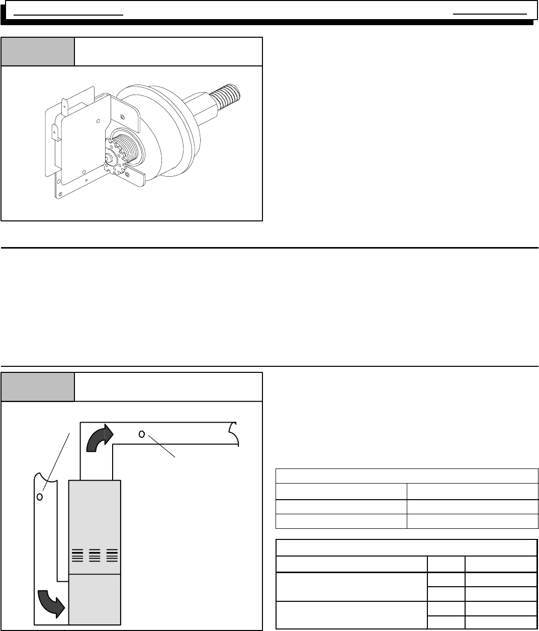
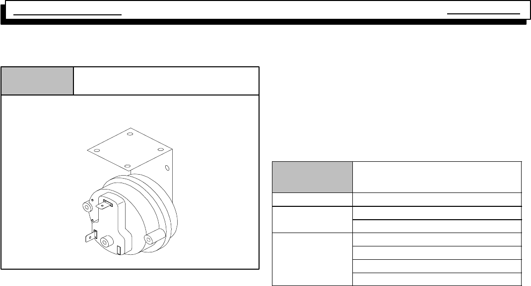
15. PRESSURE SWITCHES
Blower Pressure Switch
An air proving switch (pressure switch) is used on all models
to insure that a draft has been established through the heat
exchanger before allowing burner operation.
To insure continued SAFE, RELIABLE, operation, NEVER
SUBSTITUTEapressureswitchwithonethatissimilarinap-
pearance. ONLY FACTORY PROVIDED or
AUTHORIZED SUBSTITUTES ARE ACCEPTABLE.
All models installed at altitudes of 4,000¢above sea level or
higher require replacing the standard pressure switch with a
high altitude pressure switch. The different pressure switch
Multi Position Furnace Service Manual
13 441 08 2010 01
settings allow continued SAFE, RELIABLE, high altitude
operation.
Pressure Switches
Figure 15
10--13--04a
Under normal operating conditions, sufficient negative pres-
sure will be created to close the pressure switch, and keep
it closed to keep furnace operating. Under abnormal condi-
tions,however,suchasarestrictedvent pipe,oraleakinone
of the heat exchangers, sufficient negative pressure will not
be created. This will result in the switch failing to close or fail-
ing to remain closed during furnace operation.
When servicing a unit whose pressure switch will not close,
or remain closed during operation, the operating pressure of
that furnace should be checked and compared to
approximate operating pressures listed in Table 4 and the
switch setting(s) listed above for the model family you are
servicing.
It is important to remember, that greater negative pressures
are created by the furnace when “HOT” (I.E. upon initial
start--up) than when “COLD” (I.E. after furnaces has beenin
operation for a few minutes). Because of this, furnace pres-
sure should ONLY be checked when “HOT” to insure accu-
rate readings.
Table 4 lists approximate operating pressures. They are in-
cluded in this manual to provide you with a “Barometer” to
gauge our pressures against. The pressures you obtain in
the field willdiffer slightly from these figures based uponvent
length, gas pressure, operating temperature, etc.
Major discrepancies in pressures, will normally cause
problems with pressure switch operation. These Major dis-
crepancies should be investigated as follows:
Table 4 APPROXIMATE OPERATING
PRESSURES (²
²²
²OF W.C.)
Model Vent Length
Single Stage Close --0.69
S
i
n
g
l
e
S
t
a
g
e
ALL Models Open --0.59
Hi Fire (Close) --0.60
2--Stage & Variable
S
p
e
e
d
Hi Fire (Open) --0.59
S
peed
ALL Models Lo Fire (Close) --0.40
A
L
L
M
o
d
e
l
s
Lo Fire (Open) --0.30
Lower (Lesser) Negative Pressures
Lower than normal negative pressures measured at the
Combustion Blower may be caused by:
1. Restriction on the Outlet side of the combustion blow-
er. (I.E. Blocked Flue, Vent too long, Heat Exchanger
leak, etc.)
2. Leak (lack of restriction) on the Inlet side of the com-
bustion blower.
Higher (Greater) Negative Pressures
Higher than normal negative pressures measured at the
Combustion Blower may be caused by:
1. Restriction on the Inlet side of the combustion blower.
(I.E.PluggedHeatExchanger,airinletorificetoosmall)
Single Stage Multi Position Furnace
Service Manual
14
441 08 2010 01
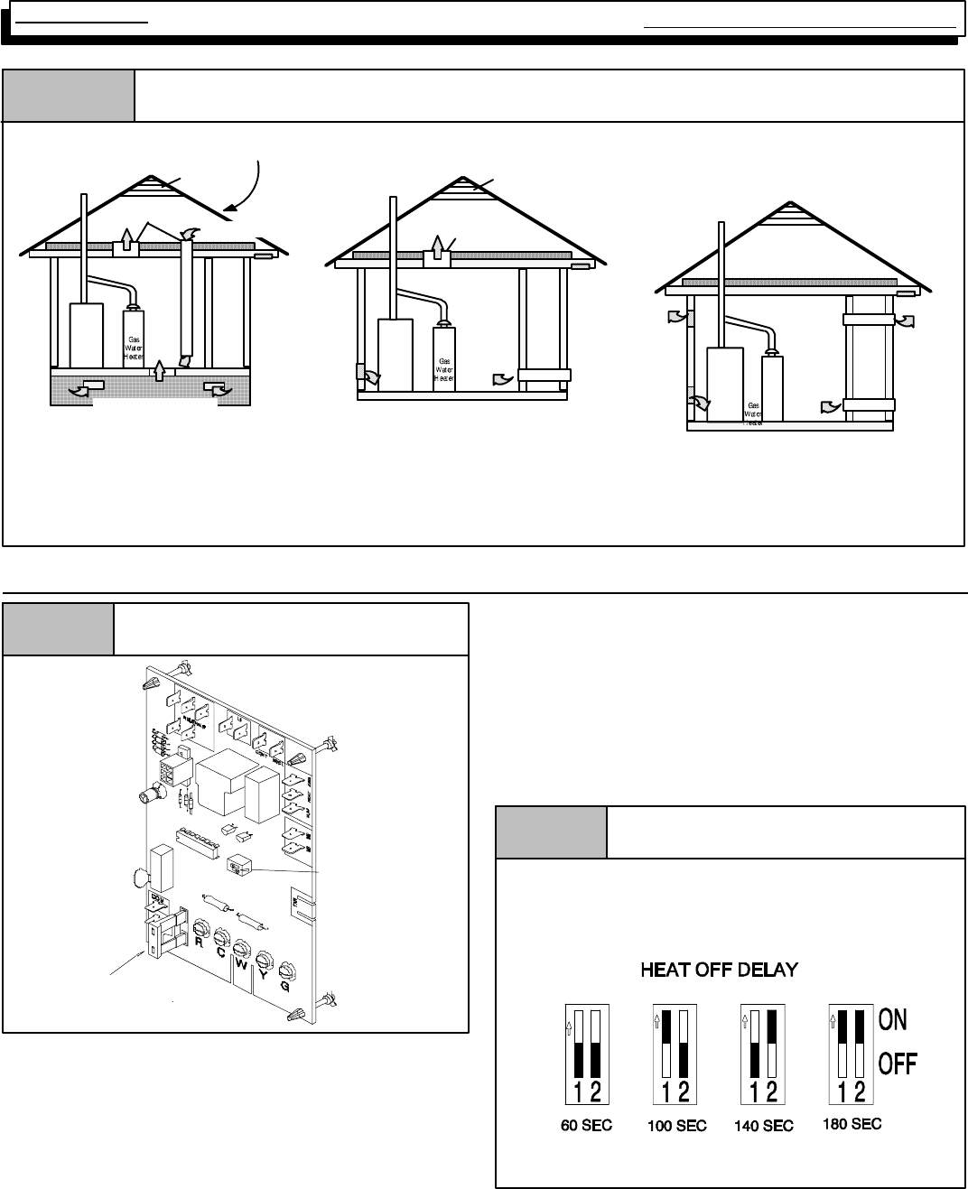
Figure 16 Typical Vent/Combustion Air Piping Installation
Furnace
Furnace
Minimum One Inlet and One Outlet Air Supply is Required
Maybe in and Combination Shown
Inlet Air Opening Must be Within12²(300mm) of floor
Outlet Air Opening Must beWithin12²(300mm) of ceiling
(1) 1 Square Inch (6cm2) per 4000 BTUH
(2) 1 Square Inch (6cm2) per 2000 BTUH
This installation NOT approved in Canada
Gas Vent
Gas Vent
Gas Vent
Gable Vent Gable Vent
Outlet
Air (1)
Outlet Air (1)
Outlet Air (1)
Furnace
Outlet
Air (2)
Optional Inlet Air (1)
Ventilated Attic Ventilated Attic
Ventilated Crawl Space
Inlet
Air (1) Inlet
Air (1) Inlet
Air (1)
Inlet
Air (2) Inlet
Air (2)
Top Above Insulation
Top Above Insulation
Soffit Vent
Soffit Vent
16. HONEYWELL ST9160B Series FAN TIMER/FURNACE CONTROL
Figure 17 Honeywell ST9160B
Dip
Switch
2 5 -- 2 3 -- 6 3
FUSE
The Honeywell ST9160B Electronic Fan Timer/Furnace
Control contains NO USER SERVICEABLE COM-
PONENTS. It is, as its name implies, a fan timer and a fur-
nace control of sorts. In addition to controlling the fan opera-
tion for heating, italso takes theplace of theblower relay, the
combustion air relay and/or the system relay.
TheST9160B isusedinmodelsequipped withtheSV9541M
GAS VALVE/IGNITION CONTROL. It provides the power
source to begin the ignition sequence through a monitored
safety circuit. It also serves as a low voltage terminal strip.
Accessory terminals forconnectingaHumidifierand/orElec-
tronic Air cleaner are also provided, as well as a Continuous
fan terminal which allows for continuous fan operation at a
speed other than either the heating or cooling speed.
The control provides a fixed (non--adjustable) 60 second
“ON” and 60 second “OFF” delay for the circulating blower in
COOLING and a 30 second “ON” delay for the circulating
blower in HEATING.
The ST9160B control also provides an adjustable HEATING
“OFF” delay for the circulating blower which can be field ad-
justed to 60, 100, 140, or 180 seconds.
25--23--47
Figure 18 Heating “OFF” Delay DIP switch
Setting
COOL ON DELAY: 6 SEC.
COOL OFF DELAY: 60 SEC.
HEAT ON DELAY: 30 SEC.
Setting “OFF” and “ON”
Setting the ST9160B Heating Fan “OFF” Delay is accom-
plished by the positioning of “DIP” switches. The label on the
back of the furnace door indicates how to position these
switches to obtain the desired setting. (See Figure 18)

Multi Position Furnace Service Manual
15 441 08 2010 01
The ST9160B Heating “OFF” delay can be set to (60. 100,
140,or180). Thecontrolwasshippedoutinthe140position.
This may be satisfactory for some installations, but not for
others.
TheHeating “ON” delay isfixedat 30seconds is notad-
justable.
The “OFF” delay should be set as long as possible without
creating “COLD AIR” complaints at the end of the cycle.
Troubleshooting
The operation of the HONEYWELL ST9160B series FAN
TIMER/FURNACE CONTROL (as well as the operation of
thefurnaceingeneral)canbeverifiedinafewminutesbyus-
ing two (2) jumper wires (to jumper terminals of the low volt-
age terminal strip) and the “TEST SEQUENCE” below.
17. ST9160B TESTING SEQUENCE
If furnace successfully passes this testing sequence, it can
be assumed that there are no problems with the ST9160B
FAN TIMER/FURNACE CONTROL. If it does not, however,
itdoesnot necessarilymeanthatthere areproblemswiththe
control. Any malfunctions should be thoroughly investigated
before replacing and components.
CHECKING COOLING FUNCTIONS
1. JUMPER “Y” & “G” TO “R”
2. CHECK COOLING FAN DELAY “ON”
3. CHECK COOLING SPEED FAN OPERATION
4. REMOVE JUMPER
5. CHECK COOLING FAN “OFF” DELAY
CHECKING HEATING FUNCTIONS
1. JUMPER “W” TO “R”
2. CHECK COMBUSTION BLOWER START--UP
3. CHECK IGNITION SYSTEM ACTIVATION
4. WHEN MAIN BURNER LIGHTS, CHECK HEATING
FAN “ON” DELAY
5. CHECK HEATING SPEED FAN OPERATION
6. REMOVE JUMPER
7. CHECK POST PURGE DELAY
8. CHECK HEATING FAN “OFF” DELAY
18. ST9160B - UNIQUE CONTROL FUNCTIONS/RESPONSES
There are some unique responses from these controls that
differ from what one would normally expect, and may be
somewhat confusing. (See Figure 17) Specifically, these
are as follows:
Energizingthe“G”terminalof thiscontrolwillcausetheblow-
er to run on the HEATING speed. (With most other furnaces,
the blower relay is energized via the “G” terminal normally
causing the blower to run on the cooling speed.)
Energizing the “G” & “Y” terminals (together) will cause the
blowertorunontheCOOLING speed.It isimportantthatyou
take note of this, since control wiring improperly connected
can cause perceived as well as real equipment problems.
For example, in the past, the “Y” terminal in nearly all fur-
naces was simply a binding post. There was no electrical
connection between this terminal and the rest of the furnace.
Consequently, many installers would not use this terminal to
connect the “Y” signal from the thermostat, but would run it
directly from the thermostat to the condensing unit, the run
the “Common” signal back to the furnace “C” terminal.
This method of wiring will result in improper operation from
this control. The control MUST receive a “Y” signal in order
for it to energize the “COOL” terminal, bringing on the blower
in the cooling speed. If it is wired as above, the condensing
unit will come on, but the blower will run on the HEATING
speed.
“NO TERMINALS” ENERGIZED (on low voltage terminal
strip) -- If a speed tap wire has been connected to the
“CONT.” (continuous) terminal, (operational terminal pro-
vided on the ST9160B series controls) the blower will run on
thisspeed.Maximumallowableconnectedloadforthistermi-
nal is 8.0 FLA.
The “CONTINUOUS” terminal of the ST9160B control is en-
ergized ONLY when there is NO OTHER CALL FOR OP-
ERATION of any kind. If there is a call for HEAT, COOL, or
“FANON”, this terminal is DE--ENERGIZED. The purpose of
this terminal is to provide a means of air circulation during
“OFF CYCLES” at a different speed than either heating or
cooling. Theuseof thisterminal isoperational,andthere
will be no speed tap wires connected to this terminal
when the furnace is shipped.
“CONTINUOUS” fan should not be confused with “FAN ON”
which is obtained by switching the fan selector switch on the
thermostatsub--baseto“FAN ON”,(energizingthe“G”termi-
nal) which causes the blower to run on the “HEATING”
speed.
The ST9160B Electronic Air Cleaner terminal (EAC)IS
ONLY energized in conjunction with the HEATING and
COOLING speedterminals. Themaximumallowablecon-
nected load to the HUM terminal is 0.8 (eight tenths)
Amp.*
*The combined connected loads of the EAC and HUM termi-
nals cannot exceed a total of 0.8 (eight tenths) amp.
Single Stage Multi Position Furnace
Service Manual
16
441 08 2010 01
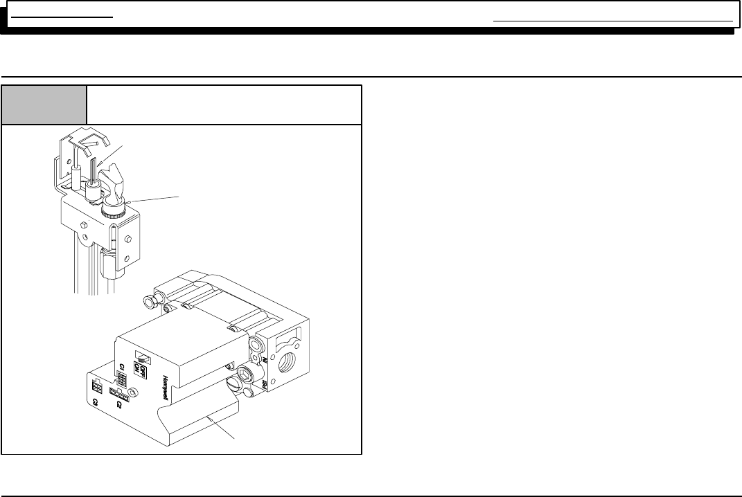
19. HONEYWELL SV9541M GAS VALVE/IGNITION CONTROL
dwg 25--23--31a
Figure 19 Honeywell ST9541M Ignition System
Gas Valve/Ignition Control
Ignition/Sensor
Pilot Burner/Sensor
The system consists basically of only two (2) components.
The Ignition System Control and the Pilot Hardware. The op-
erate on Two (2) 24 volt power circuits received from the
ST9160B Fan Timer/Furnace Control. One isthe power sup-
ply to the ignitor, the second is to activate the ignition se-
quence.
TheIgnition System Control managestheignitionsequence,
and the flow of gas to the pilot and main burners. It is in es-
sence a combination Gas Valve and Ignition control.
It contains sophisticated electronic components (internally)
and has NO USER SERVICEABLE COMPONENTS.
Should a problem be verified internally within the device, IT
IS NOT REPAIRABLE, and must be replaced.
The Pilot Hardware includes the pilot burner, the hot surface
element that lights the pilot burner,the flame rod that senses
pilot flame,andthecablethatattachestothesystemcontrol.
Thehotsurfaceelement is madeof tough breakresistant ce-
ramic composite material. It operates on 24 Volts A.C. The
Igniter/Flame Rod assembly can be replaced independently
from the pilot burner assembly.
The system operation is quite simple, and forgiving (I.E. nui-
sance lockouts are eliminated)
20. HONEYWELL SV9541M SYSTEM OPERATION
Connecting the furnace to the line voltage supply with the
blower door interlock switch closed provides 24 volts to pow-
erthesystem.(Thisisaccomplishedbytheconnectionsfrom
terminals [pins] #4& #2from theST9160B fantimer totermi-
nals #1 & #3 of the SV9541M gas valve.)
When the thermostat calls for heat, (the combustion blower
starts, causing the pressure switch to close completing the
circuit to the ignition system control) there will be approxi-
mately atwo (2) second delay, while theignition systemcon-
trol runs a self check.
Part of the self check is to see if a flame signal is detected.
If aflamesignalis detectedupon acallforheat (andnaturally
there shouldn’t be), the ignition system control will energize
the electronic fan timer output (causing the conditioned air
blower to start after the fixed 60 second “ON” delay) and will
keep the valve and ignitor to circuit off.
Assuming that no flame signal is detected upon the call for
heat,(Normaloperation),theignitionsystemcontrolwillpow-
er the ignitor circuit (24 volts) causing the ignitor to heat up.
If the ignitor circuit is not proven (I.E. the ignitor is missing,
broken, or the connections are loose) their will be no re-
sponse from the ignition system control. (Lockout)
Once the ignitor circuit has been proven, and the ignitor be-
gins to heat up, thepilot valve will beenergized allowing gas
to flow to the pilot burner.
With the ignitor nowhot, andgas flowing to the pilot , the pilot
should light, and the sensor should sense flame.
Ifnoflameissensed,(I.E.nogas,pilotnotlit,flamenotenvel-
oping sensor, etc.) the ignitor will stay on, and the pilot valve
will remain open until it does sense flame, or until the call for
heat is satisfied. THE SYSTEM WILL NOT LOCK OUT un-
der this condition.
Assuming that the pilot does light, and flameis sensed, (nor-
mal operation) the ignition system control will turn the ignitor
off, while energizing the main valve. This will allow the pilot
to light the mainburner. It willalso energize the electronic fan
timer output (causing the conditioned air blower to start after
the fixed 60 second “ON” delay).
If a flame outage (I.E. loss of gas supply, blown out, etc.)
should occur during a run cycle (Main burner operation), the
ignition system immediately de--energize themain valve and
re--power the ignitor circuit placing the system back in to the
“Trial For Ignition” mode.
As previously, it will remain in this “Trial For Ignition” mode
(Ignitor powered and pilot valve open) either until the pilot
lights and flame is sensed, or until the call for heat ends.
TheSV9541Msystemis not sensitive tofurnacegrounding
or line voltage polarity. Accordingly, you cannot experience
a lockout due to those reasons.
Assuming that the main burner did not experience any prob-
lems during the run cycle (normal operation) it would contin-
ue to operate as long as the call for heat remained.
Once the call for heat ended, the ignition system control
would immediately close the main and pilot valves, and de--
energize the electronic fan timer output.
De--energizing the electronic fan timer output causes the
“OFF” delay timing tobegin, and whenthe pre--selected time
(90, 100, 140, or 180 seconds) expires, the blower will turn
off.
Multi Position Furnace Service Manual
17 441 08 2010 01
TROUBLESHOOTING
Malfunctions of the HONEYWELL SV9541M “Smart Pilot”
system may be easily diagnosed using a voltmeter and a
spare igniter/flame rod assembly.
The igniter itself can also be checked using an Ohmmeter.
Resistance of a “Good” igniter should be 10 Ohms or less.
See trouble shooting flow chart and the sequence of opera-
tionflowchart onpages 36and37of thismanualforaddition-
al information on the operation and troubleshooting of this
system.
21. CHECKING FLAME CURRENT
The Honeywell SV9541Q Ignition system used in this furnace
series proves (verifies) flame via the Flame Rectification
method.
Flame Rectification is a process of converting Alternating
Current (A.C.) into Direct Current (D.C.) During the ignition
sequence, an alternating current (A.C.) Voltage is applied to
the Flame probe.
When the burner lights the flame conducts an electrical cur-
rent between the flame probe and the burner ground. Due to
thedifferenceinsizebetweentheflameprobeandtheburner
ground area this current flows mostly in one direction. This
creates a pulsating Direct Current that flows back to the igni-
tion control proving flame.
This flame current (D.C. Microamps) may be checked (while
flame is present) using a D.C. Flame Sensor kit is available
from outside vendors.
Minimum Micro Amp Current is 0.2 micro amps.
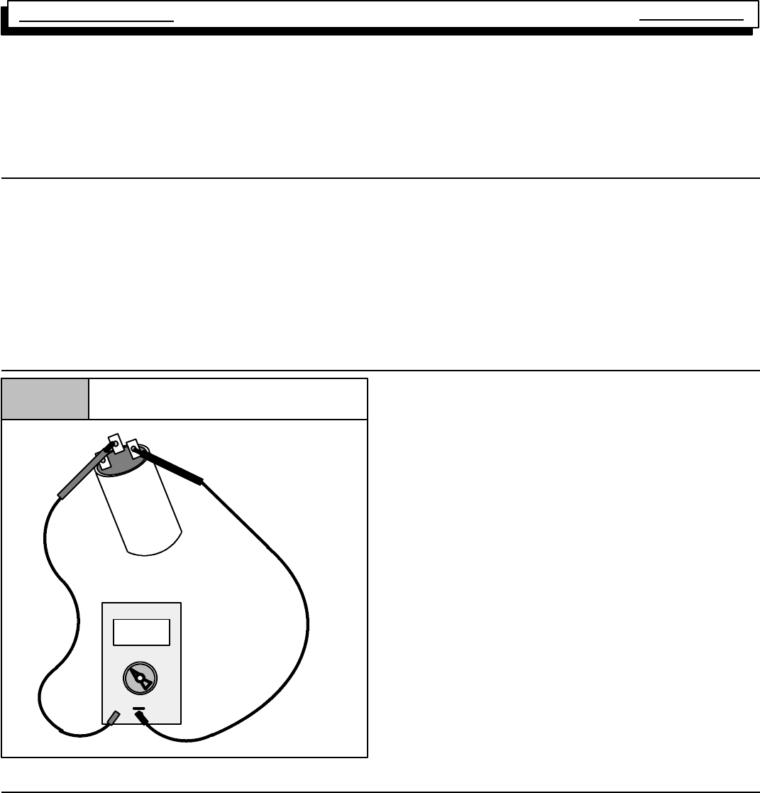
22. CAPACITORS
Figure 20 Checking Capacitor
100 m¦
Microfarads
+
5mp
10 m¦
1000
m¦
10000 m¦
Capacitors are used for both the circulating (conditioned air)
blower motor and the exhaust (combustion) blower. Before
replacingoneofthesemotors(assumedtobebad)thecondi-
tion of its capacitor should be verified, since it, and not the
motor, may be the source of the problem.
Before checking any capacitor, the supply power to the unit
should be turned “OFF”. The capacitor should then be dis-
charged (through a resistor) before testing. A 20,000 Ohm 2
Watt resistor can be used for this purpose.
The condition of the capacitor should then be verified with a
capacitor analyzer (one that indicated the capacitor’s value
in microfarads) rather than with an Ohmmeter. The reason
forthis,isthatanOhmmetertestcanonly indicateif acapaci-
tor is “OPEN’, or “SHORTED”, it cannot verify if its value(mi-
crofarads) is within an acceptable range.
Capacitorshouldtesttowithin10%ofitsratedvalue.Capaci-
torstestingoutsidethisrangeshouldbereplaced.Aweakca-
pacitor can be the cause of a motor failing to start.
23. BLOWER ASSEMBLY
All modelsuse amulti--speed, permanent split capacitor mo-
tor,direct--drive,blowerassembly.Differentsize(HP)motors
and/or different diameter blower wheels are used in each
model to obtain the required air flow. The entire blower as-
sembly slidesoutonrailsforservicingafter removing thetwo
screws at the front.
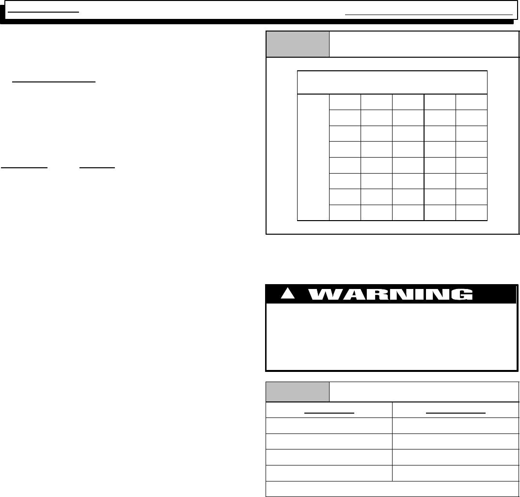
SELECTING BLOWER SPEEDS
The wide variety of applications and installations of furnaces
throughout the country makes it impossible to “Factory Se-
lect” blower speeds that will provide proper operation for all
installations. This means then, that the blower speeds for
both heating and cooling must be “Field Selected” for each
particularinstallationtoinsureproper operation. istoprevent
wide swings in room temperature during furnace operation.
The criteria for selecting the proper blower speeds IS NOT
“High for Cooling, Low for Heating”. Although that may be
how it works out SOMETIMES, it can (inmanycases) beex-
actly the opposite. (I.E. a Lower speed for Cooling, and a
Higher speed for Heating)
The PROPER CRITERIA FOR SELECTING BLOWER
SPEEDS is as follows:
HEATING
A blower speed must be selected that will provide proper
temperature rise through the furnace. (See “checking tem-
Single Stage Multi Position Furnace
Service Manual
18
441 08 2010 01
perature rise” found elsewhere in this manual), The required
CFM for a particular temperature rise can also be calculated
using the following formula:
Output BTU
Temp. Rise X 1.08 = CFM
EXAMPLE:usinga75Mbtufurnaceofthisserieswithanout-
put of 67,500 Btuh and a desired temperature rise of 50°F
(rangeof40--70°Fallowable)andameasuredexternalstatic
pressure of 0.2²W.C. with a dry coil.
67,500 or 67,500
50 X 1.08 54 = 1250 CFM
Checking the blower performance data for this model, (see
Figure 36) indicates that @ 0.2²W.C. E.S.P. medium--high
speed will deliver 1249 CFM. Accordingly, medium speed
should be used in this example for the HEATING speed.
COOLING
A blower speed must be selected that will provide proper air
flow (Nominal 400 CFM per ton) for the size (capacity) air
conditioning coil being used at the external static pressure of
the Duct system (installation). This requires CHECKING
THE EXTERNAL STATIC PRESSURE, then consulting the
BLOWERPERFORMANCEDATAtodeterminetherequired
speed tap.
EXAMPLE: A 24,000 BTU (2 TON) air conditioning system,
usingthesame75,000BTUfurnaceasinthepreviousexam-
ple. The external static pressure is measured and found to
be 0.4²W.C.
400 CFM (nominal) per TON required
400x2=800CFMrequired
Checking the blower performance data (see Figure 36) for
this modelindicates that @ 0.4²W.C. ESP low speed will de-
liver 788 CFM. Accordingly, low speed should beused in this
example for the COOLING speed.
Table 5 Blower Performance Data
75,0000 BTUH
Air Delivery in Cubic Feet per Minute (CFM)
(Furnace Rated @ 0.5²W.C. ESP)
TAP LOW MED L MED H HIGH
ure
.10 778 984 1263 1576
ress
u
.C.
.20 786 1003 1249 1532
t
ic Pr
o
fW.
C
.30 790 1003 1244 1489
l
Stat
i
hes
o
.40 788 1001 1215 1432
e
rnal
Inc
h
.50 781 982 1186 1371
Ext
e
.60 765 962 1146 1308
.70 743 923 1094 1229
SAMPLE ONLY
CHANGING BLOWER SPEED
The procedure for changing blower speeds (if needed) is
shoun in Table 6.
ELECTRICAL SHOCK HAZARD.
Failure to do so can result in death and/or personal
injury.
Turn OFF power to furnace before changing speed
taps.
!
Table 6 Blower Speed Chart
Wire Color Motor Speed
Black High
Orange* Med--High
Blue Medium
Red Low
*Med--High speed may not be provided on all models.
Multi Position Furnace Service Manual
19 441 08 2010 01
Figure 21 Honeywell ST9160B
Dip
Switch
25--23--63
FUSE
M1
M2
Heat
Cool
HONEYWELL ST9160B
HEATING SPEED
Should it be necessary to change blower speeds to obtain
proper temperature rise, simply take the appropriate speed
tap wire, and plug it on to the terminal marked “HEAT”.
COOLING SPEED
When the proper speed has been determined, simply plug it
on to the terminal of the control marked “COOL”.
“UNUSED” TERMINALS
There are two (2) terminals (marked “UNUSED MOTOR
LEADS” on the Honeywell ST9160B which has no internal
connection to the control. Their purpose is to provide a place
to connect. “UNUSED” speed tap wires to keep them out of
the way and prevent them from shorting out against the fur-
nace casing, or each other.
Single Stage Multi Position Furnace
Service Manual
20
441 08 2010 01
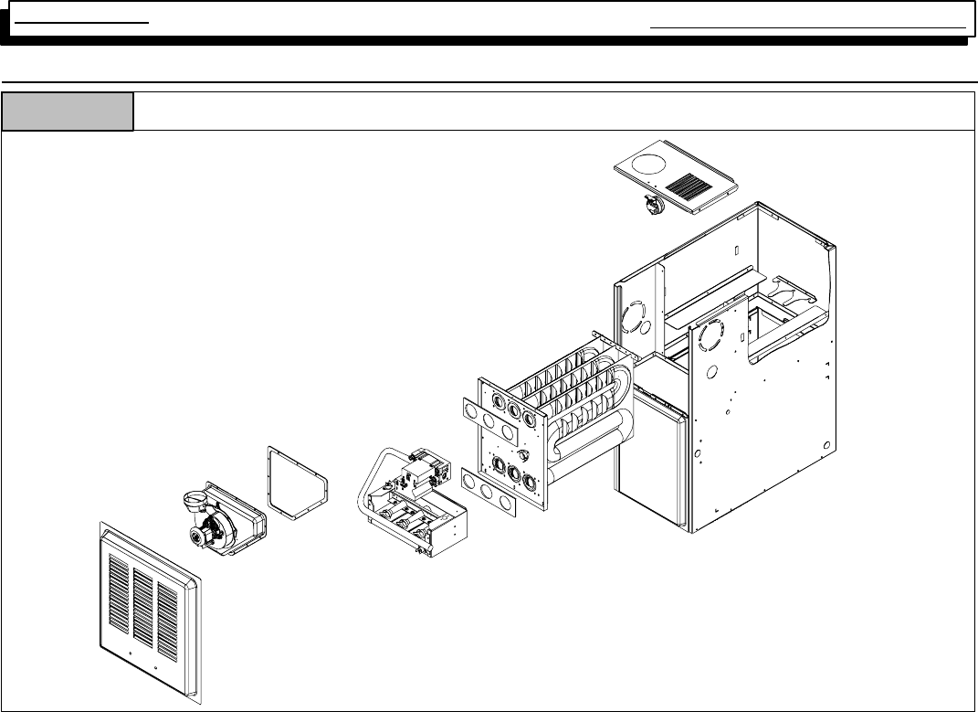
24. HEAT EXCHANGER REMOVAL/REPLACEMENT
“Exploded” Parts View -- Typical Four Position Furnaces
Figure 22
25--41--61
Primary Heat Exchanger
1. Turn ”OFF” electrical power and gas supply to furnace.
2. Disconnect vent pipe to furnace at flexible coupling.
3. Disconnect combustion air inlet pipe at top panel (if
needed).
4. Remove furnace top panel.
5. Disconnectgas pipingtofurnace atgasvalve. Note:Be-
fore performing next step, insure that the wiring dia-
gram is available and readable, or tag all wires first.
6. Disconnect tubing and wiring to pressure switch, limit
switches, and gas valve.
7. Remove screws securing burner box to front partition.
8. Remove combustion blower.
9. Remove machine screws securing transition assembly
to furnace partition.
10. Remove the collector box.
11. Remove machine screws securing secondary heat ex-
changer inlet flange to lower partition.
12. Remove screws around perimeter of both the upper
and lower partitions (leaving the screws across the
center of the two panels in place).
13. Primary Heat Exchanger can now be removed with
both upper and lower partitions attached.
14. Reverse procedure to reinstall, making sure that any
gasketsthathave beentornduringdisassembly arere-
placed with new ones.
15. After reassembly, turn the gas supply on, and check for
leaks. All leaks must be repaired immediately.
16. Perform an operational check of the furnace.

Multi Position Furnace Service Manual
21 441 08 2010 01
HONEYWELL SV9541M “SMART VALVE” Sequence of Operation
The following is the normal operating sequence for the control system.
Cooling (Y) Request:
24 VAC signals applied to Y & G terminals of EFT (electronic fan timer) control.
·Cool motor speed energized after 6 second Cool Fan On Delay time.
Y & G signals removed from EFT.
·Cool motor speed de--energized after 60 second Cool Fan Off Delay time.
Circulating Fan (G) Request:
24 VAC signals applied to G terminals of EFT control.
·Heat motor speed energized without delay.
G signal removed from EFT.
·Heat motor speed de--energized without delay.
Heating (W) Request:
24 VAC signals applied to W terminal of EFT control.
·Inducer motor turns on.
·The gas valve solenoid energizes.
·Followinga3secondprepurge delay, the pilot valve opens and the ignitor begins to warm up.
·After the pilot lights, the main burners energize and light.
·Timed from the openingof the maingas valve, the control willdelay 30seconds before switching the fan to Heat speed.
W signal removed from EFT.
·The gas valve de--energizes and the main burners go out.
·The inducer runs at its present speed for a 30 second postpurge period.
·Timed from the gas valve de--energizing, the Heat fan speed de--energizes after the selected Heat Fan Delay time
expires.
Heating Request with Gas Supply Line Shut Off:
24 VAC signals applied to W terminal of EFT control.
·Inducer motor turns on.
·The gas valve solenoid energizes.
·Followinga3secondprepurge delay, the pilot valve opens and the ignitor begins to warm up.
·The ignitor glows red--hot for 30 seconds, then turns off.
·The igniter stays off for 25 seconds, then begins to warm--up again.
·The igniter glows red--hot for 30 seconds, then turns off.
·The pilot valve closes 3 seconds after the igniter de--energizes.
·The inducer de--energizes 5 seconds after the pilot valve closes.
·The SmartValve proceeds to soft lockout and flashes error code 6.
·The control exits soft lockout after 5 minutes and begins
another ignition sequence.
Single Stage Multi Position Furnace
Service Manual
22
441 08 2010 01
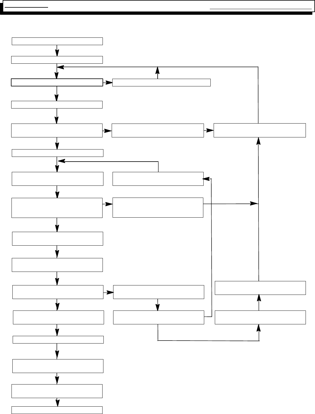
HONEYWELL SV9541M “SMART VALVE” Sequence of Operation
POWER APPLIED TO APPLIANCE
THERMOSTAT CALLS FOR HEAT
COMBUSTION BLOWER ENERGIZED
PRESSURE SWITCHES CLOSED WITHIN
30 SECONDS? COMBUSTION BLOWER DE--ENERGIZED
PILOT VALVE OPENS:
IGNITOR POWERED (1) THREE SECOND FLAME
FAILURERECYCLE DELAY
3 SECOND PRE--PURGE
FIVE MINUTE WAIT PERIOD
PILOT LIGHTS AND FLAME IS SENSED
DURING 90 SECOND TRAIL FOR
IGNITION?
PILOT VALVE CLOSES;
PILOT IGNITOR OFF
MAIN VALVE OPENS,
HEATING FAN “ON” DELAY BEGINS
AFTER DELAY: CIRCULATING BLOWER
STARTS
FLAME SENSE LOST? CIRCULATING BLOWER OFF AFTER
DELAY
PILOT AND MAIN VALVE CLOSE
COMBUSTION AIRBLOWER OFF AFTER
POST PURGE
FLAME SENSE LOST MORE THAN FIVE
TIMESINTHISCALLFORHEAT?
THERMOSTAT CALL FOR HEAT ENDS
COMBUSTION BLOWER DE--ENERGIZED
AFTER 30 SECOND POST PURGE
PILOT AND MAIN VALVE CLOSE
CIRCULATING BLOWER OFF AFTER
DELAY
WAIT FOR NEXT CALL FOR HEAT
PRESSURE SWITCHES PROVED OPEN? NO
NO
NO
NO
YES
YES
WAIT FOR PRESSURE SWITCHES TO OPEN
(1) Ignitor “ON” for first 30 seconds oftrial forignition, then “OFF” for next 30 seconds.
Ifthe pilot hasnot lit,it turns back “ON” for the final 30 seconds.The pilot valve remains
energized during the entire 90 second trial for ignition.
NOTE: Ifmain limit string opens and takeslonger than 2 minutes to close,system goes
into 1 hour waitperiod (indicating circulating blower).
YES
NO
Multi Position Furnace Service Manual
23 441 08 2010 01
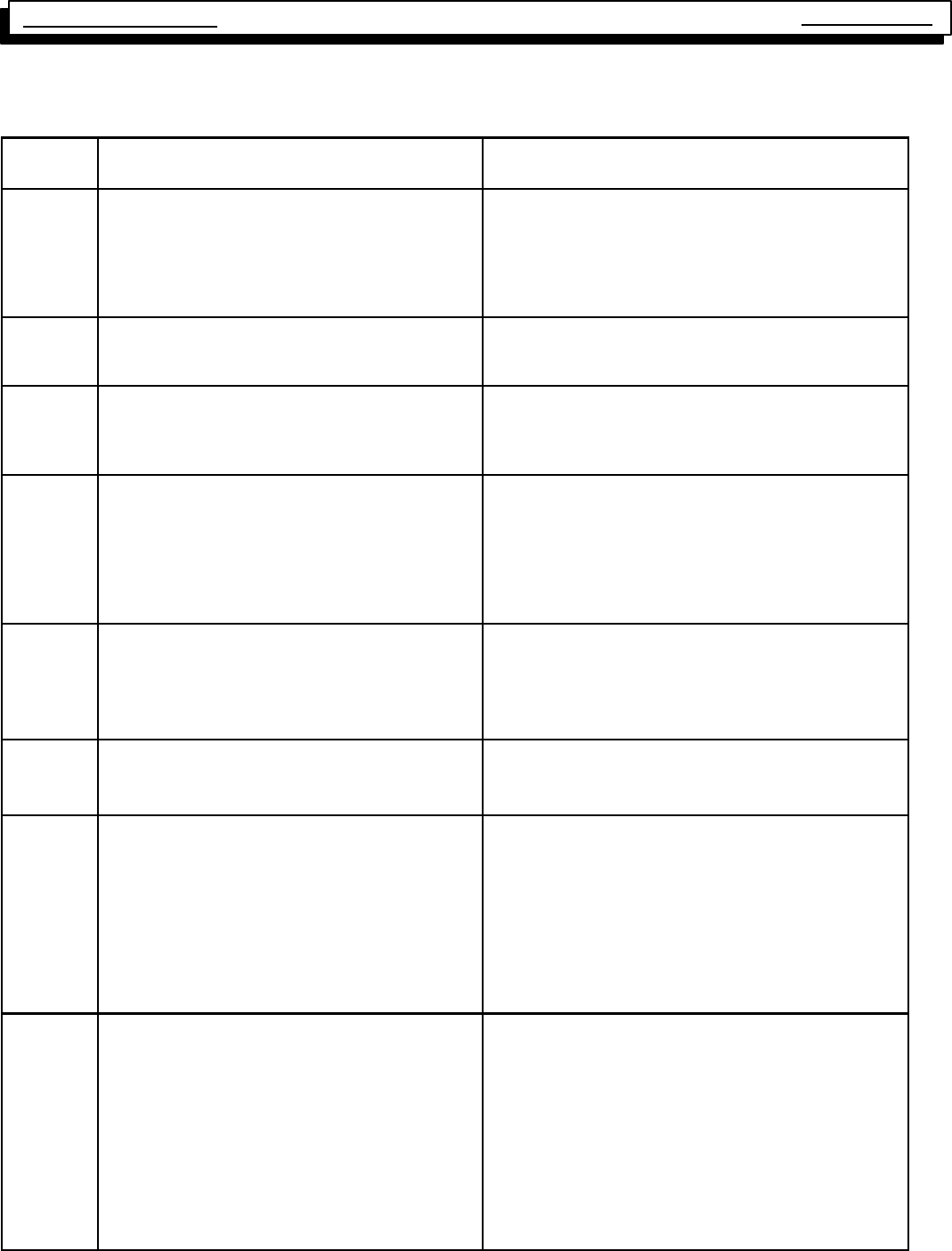
HONEYWELL SV9541 “SMART VALVE” Trouble shooting
The 6 + X designation indicates a combination of flash codes: 6
flashes shows the control is in soft lockout,followed by X flashes to indicate the reason the control went into soft lockout. Last status
code indicates repair to address first
LED
STATUS INDICATES CHECK/REPAIR
Off No power to system control.
LinevoltageinputatL1andNeutralconnectorsonST9160B
Fan Timer.
Low voltage (24V) powerat 24 VAC and COM terminals on
ST9160B
System wiring harness is in good condition and securely
connected.
Heartbeat
Bright –
Dim
Normal indication whenever the system is powered,
unless some abnormal event has occurred. NotApplicable -- NormalOperation(standbyorcallforheat)
2 Flashes
Pressure switches closed when it should be open
(i.e. when call for heat begins).
(Combustion bloweris notenergized untilpressure
switches opens)
Pressure switches stuck closed (system will wait for pres-
sure switch to open).
Pressure switches miswired or jumpered.
3 Flashes
Pressureswitches,openwhentheyshouldbeclosed
(i.e. longer than 30 seconds after combustion blower/
inducer is energized).
System goes into 5--minute delay period, with com-
bustion blower/inducer off. At end of the 5--minute
delay, another cycle will begin.
Ignition system control switch must be in the ON position.
Pressure switches operation, tubing, and wiring.
Restrictions in furnace air intake or vent piping.
4 Flashes
Main Limit or Roll Out Switch is open.
Combustion blowerisenergized,Circulating blower is
energized heat speed.
Main limit switch.
Manual reset burner rollout switch.
Limit and rollout switch wiring is in good condition and se-
curely connected.
Duct restriction/overfire.
5 Flashes Flame signal sensed out of proper sequence.
Combustion blowerisenergized,Circulating blower is
energized heat speed after the “ON” delay.
Flame at pilot burner.
6 Flashes
+
1Flash
Soft Lockout.
Failed to light pilot during 90 sec. trial for ignition
Combustion air blower is de--energized, Circulating
blower is de--energized after the “OFF” delay.
After 5--minute delay time, control system will reset
and initiate a new ignition sequence,
Gas supply off or pressure too low or high for appliance to
operate.
Damaged or broken HIS element
Flame sense rod contaminated or in incorrect position.
Pilot burner located in incorrect position.
Pilotburnerleadwiresareingoodconditionandpoperycon-
nected.
Pressure switches operation, tubing, and wiring.
6 Flashes
+
2 Flashes
Soft Lockout.
Last failure was Flame Sense lost during run.
Maximum recycle count exceeded
Combustion air blower is de--energized, Circulating
blower is de--energized after the “OFF” delay.
After 5--minute delay time, control system will reset
and initiate a new ignition sequence,
Gas supply off or pressure too low or high for appliance to
operate.
Flame sense rod contaminated or in incorrect position.
Pilot burner located in incorrect position.
Pilot burner lead wires are in good condition and properly
connected.
Cycling, pressure switch
Pressure switches operation, tubing, and wiring.
Single Stage Multi Position Furnace
Service Manual
24
441 08 2010 01
HONEYWELL SV9541 “SMART VALVE” Trouble shooting continued
LED
STATUS INDICATES CHECK/REPAIR
6 Flashes
+
3 Flashes
Soft Lockout.
Last failure was pressure switch
Maximum recycle count exceeded
Combustion air blower is de--energized, Circulating
blower is de--energized after the “OFF” delay.
After 5--minute delay time, control system will reset
and initiate a new ignition sequence,
Ignition system control switch must be in the ON position.
Pressure switches operation, tubing, and wiring.
High winds blowing against vent.
6 Flashes
+
4 Flashes
Soft Lockout.
Last failure was limit circuit opened during run.
Combustion air blower is de--energized, Circulating
blower is de--energized after the “OFF” delay.
After 5--minute delay time, control system will reset
and initiate a new ignition sequence,
Main limit switch.
Limit and rollout switch wiring is in good condition and se-
curely
connected.
Restriction in duct work.
Dirty filter
Overfire
7 Flashes
Soft Lockout.
Blower failure (typical)
Limit trip took longer than 2 minutes to reset.
System will start a new ignition sequenceafter1 hour,
if call for heat still present.
Dead blower.
Blocked duct work.
Multi Position Furnace Service Manual
25 441 08 2010 01
SV9541M ELECTRICAL VARIATION
SINGLE STAGE
Connector (Pin #) Description Voltage Signal When Signal is Present
Neutrals
(5--1/4²QC’s) Neutral 0VAC
(Neutral and earth ground should
be at the same potential)
Always present
L1
(2--1/4²QC’s) Line Voltage 115 VAC Present when blower door interlock switch is closed.
HEAT
(1/4²QC’s) Fan power *115 VAC Present when Heat fan speed is on (Open Limit mode)
COOL
(1/4²QC’s) Fan power *115 VAC Present when Cool fan speed is on (Cool (Y) mode).
EAC
(1/4²QC’s) Electronic Air--
Cleaner power 115 VAC Present when High Heat or Cool fan speed is on.
CONSTANT FAN
(1/4²QC’s) Continuous Fan
power *115 VAC Present when other fan speeds is off.
HUM
(1/4²QC’s) Humidifier power 115 VAC Present when the Heat speeds is on.
P1 (pin 1) Line Voltage 115 VAC Present when the door interlock switch is closed.
P1 (pin 2) Data Line Non--periodic 1/2 wave rectified AC
(measures as an unstable AC volt-
age bouncing between 12 VAC and
16 VAC
Present when the door interlock switch is closed.
P1 (pin 3) C (xfmr common) 0VAC Always present
P1 (pin 4) Neutral 0VAC Always present
P1 (pin 5) 24 VAC 24 VAC Present when the door interlock switch is closed.
P1 (pin 6) R 24 VAC Present when the door interlock switch is closed.
C1 (pin 1) Limit return 1/2 wave rectified AC Present when the door interlock switch is closed. This
voltage decreases when a limit switch is open.
C1 (pin 2) Pressure Switch supply 1/2 wave rectified AC Present when the door interlock switch is closed. This
signal is the same as the C1 (pin 1)
C1 (pin 3) Pressure Switch return 1/2 wave rectified AC Present when the door interlock switch is closed. This
AC voltage decreases when the Low Pressure Switch
closes.
C1 (pin 4) Data Line Non--periodic 1/2 wave
rectified AC Present when the door interlock switch is closed. Same
signal as P1 (pin 5).
C1 (pin 5) Limit Supply 1/2 wave rectified AC Present when the 24 VAC transformer is powered.
C1 (pin 6) C (xfmr common) 0VAC Always present
C1 (pin 7) R24 VAC Present when the door interlock switch is closed.
C1 (pin 8) 24 VAC 24 VAC Present when the door interlock switch is closed.
C2 (pin 1) HSI return 24 VAC (with igniter present) Present when HSI is not turned on. When HSI is on, this
signal is 0 VAC to 10 VAC depending on input line volt-
age potential.
C2 (pin 2) HSI supply 24 VAC Present when the door interlock switch is closed.
C2 (pin 3) Not connected 0VAC Not connected
C2 (pin 4) Flame sense >80 VAC Present when the door interlock switch is closed.
C3 (pin 1) Inducer supply 115 VAC Present when the inducer draft blower motor is on (Heat
modes, Open Limit mode).
C3 (pin 2) L1 115 VAC Present when the door interlock switch is closed.
C3 (pin 3) Inducer return 0VAC Always present (neutral connection).
C3 (pin 4) L2 (neutral) 0VAC Always present
* With a motor tap connected, voltage appears at “unpowered” fan terminals whenever the motor is running due to feed-
back through the motor windings.
** Voltage appears on the “unpowered” inducer terminal whenever the inducer motor is running due to feedback through
the motor windings.
NOTE1: Using a Fluke 79 digital Multi--Meter (DMM), 1/2 wave rectified AC voltage typically measures about 14 VAC.
The Fluke 79 is not a “true” RMS meter.
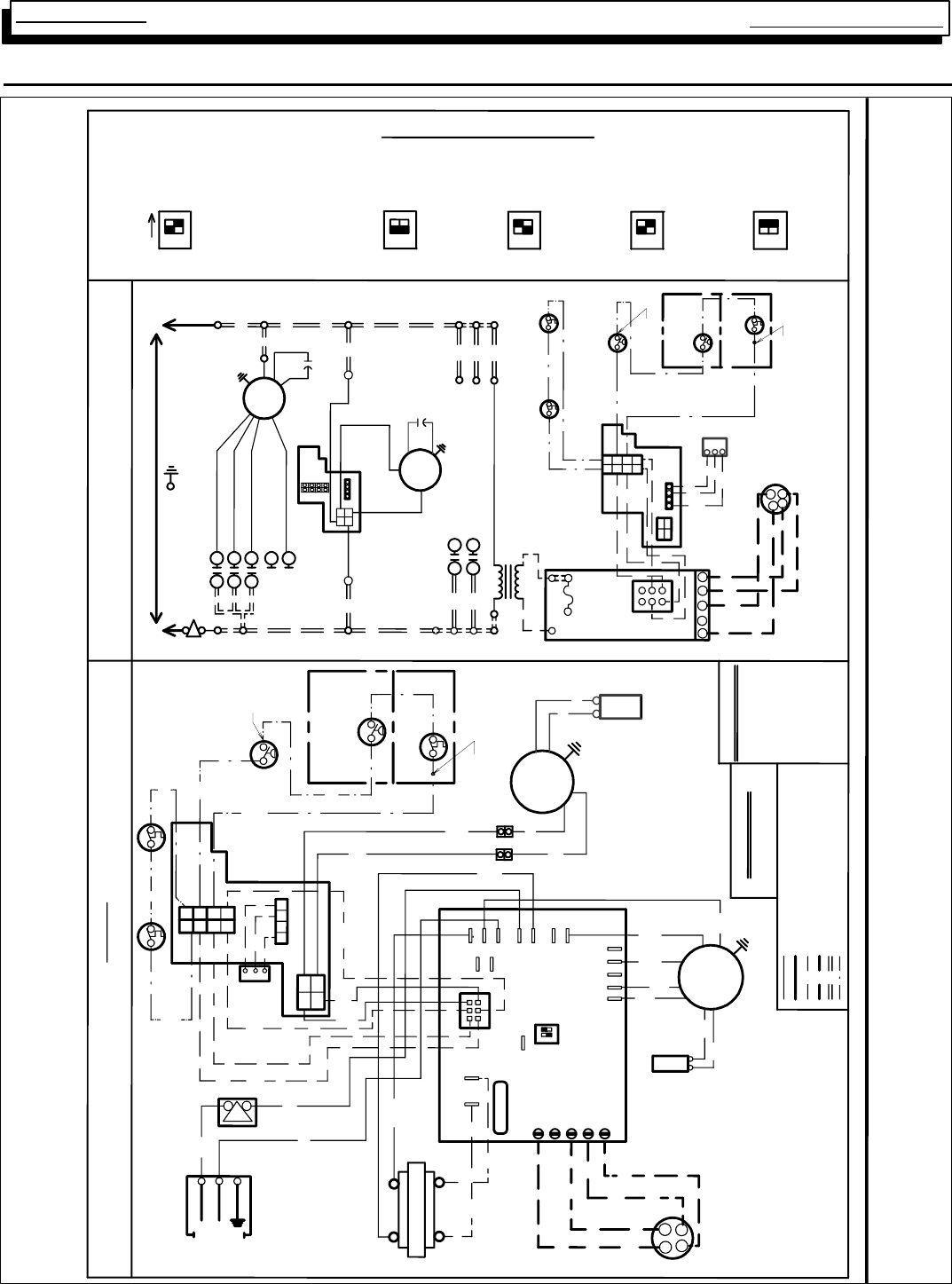
Multi Position Furnace
Service Manual
26
441 08 2010 01
25. Wiring Diagram N8MPN/L, *8MPN/L & *8DNL
YG
THERMOSTAT
23
4
MAIN LIMIT
GAS
VALVE
N
N
G
N
Y
1
5
INDUCER
MOTOR
EAC
115V
ROLLOUT SWITCH
1 TO 3 IN SERIES
DEPENDING ON MODEL
3
6
4
2
TRANSFORMER
L1
HUM
L1
12
FAN CONTROL MODULE
W
Y
G
G
W
Y
W
TRANSFORMER
BLOWER
MOTOR
L1
L1
L1
C1
NEUTRAL
BL
BK
INDUCER
MOTOR
R
FURNACE
CONTROL
BK
W
ROLLOUT SWITCH
1 TO 3 IN SERIES
DEPENDING ON
MODEL
W
BL
W
BK
O
R
4
L1
CONT
COOL
1
2
EAC
3
HEAT
4
C2
4
56
24V SECONDARY
23
DATA
5A FUSE
24V
24VAC
O
BK
R
ON
115V
60HZ
HEAT ON DELAY: 30 SEC.
1014484
DISCONNECT BEFORE SERVICING
WARNING: ELECTRICAL SHOCK HAZARD
CONNECTION DIAGRAM
COOL ON DELAY: 5 SEC
COOL OFF DELAY: 90 SEC
S1
HEAT OFF DELAY
BL
GAS VALVE
R
W
BL
P
W
BK
GND
COPPER
CONDUCTORS
ONLY
6
NEUTRAL
HOT
W
5
4
3
2
8
1
7
3
C3
COM
W
24
VAC
C
Y
R
C
BL
R
W
Y
FURNACE CONTROL
G
BR
BR
CAPACITOR
Y
R
R
1
2
3
4
3
7
2
1
6
5
4
8
1
EAC
HUM
N
24
8
7
12
3
4
4
SEE MANUALS FOR ADJUSTING SPEED TAPS FOR PROPER HEATING, COOLING & CIRCULATING SPEEDS.
COLOR CODE
6
3
5
BLACK BK
BLUE BL
BROWN BR
GREEN G
ORANGE O
RED R
WHITE W
YELLOW Y
PURPLE P
1
SPEED TAP CODE
BLACK-HI BLUE-MLO
ORANGE-MHI RED-LO
*
LINE VOLTAGE FACTORY
LINE VOLTAGE FIELD
LOW VOLTAGE FACTORY
LOW VOLTAGE FIELD
INTERNAL CIRCUIT BOARD WIRING
5 A
FUSE
FACTORY
SETTING
1
2
N
N
BLOWER
MOTOR
LO (R)
M2
M1 MLO (BL)
GND.
HEAT MHI (O)
COOL HI (BK)
LADDER DIAGRAM
INTERLOCK
SWITCH
HOT 115V-60HZ NEUTRAL
IF ANY OF THE ORIGINAL WIRE AS SUPPLIED WITH THE APPLIANCE
MUST BE REPLACED, IT MUST BE REPLACED WITH TYPE
AWM - 105°C WIRE OR ITS EQUIVALENT.
GAS
VALVE
LP PRESSURE
SWITCH
(LP MODELS ONLY)
ON
INTERLOCK
SWITCH
1
MAIN LIMIT
FIELD
CONNECTION
BOX
LP PRESSURE
SWITCH
(LP MODELS ONLY)
1 2
HUM
M2
M1
115V PRIMARY
R
1
2
3
THERMOSTAT
4
12
12
60 SEC. 140 SEC. 180 SEC.
12
100 SEC.
12
1
L1
L1
COM
BL
L1
SENSOR
IGNITOR
BL
PRESSURE SWITCH
1 TO 2 IN SERIES
DEPENDING ON
MODEL
PRESSURE SWITCH
1 TO 2 IN SERIES
DEPENDING ON MODEL
BR
BR
CAPACITOR
(SOME MODELS)
CAPACITOR
(SOME MODELS)
IGNITER
SENSOR
RECTIFIED AC VOLTAGE FACTORY
NOTE:
1. MOST VOLT METERS WILL READ 13-16 VOLTS
TO CHASSIS ON BOTH SIDES OF AN OPEN LIMIT
OR PRESSURE SWITCH IN THE RECTIFIED AC
VOLTAGE CIRCUIT
2. FACTORY CONNECTED WHEN BVSS,
(CHIMNEY ADAPTER ACCESSORY KIT) OR LP
PRESSURE SWITCH IS NOT INSTALLED.
BK
CAPACITOR
BVSS
(FIELD INSTALLED)
NOTE 2
NOTE 2
BVSS
(FIELD INSTALLED)
NOTE 2
NOTE 2
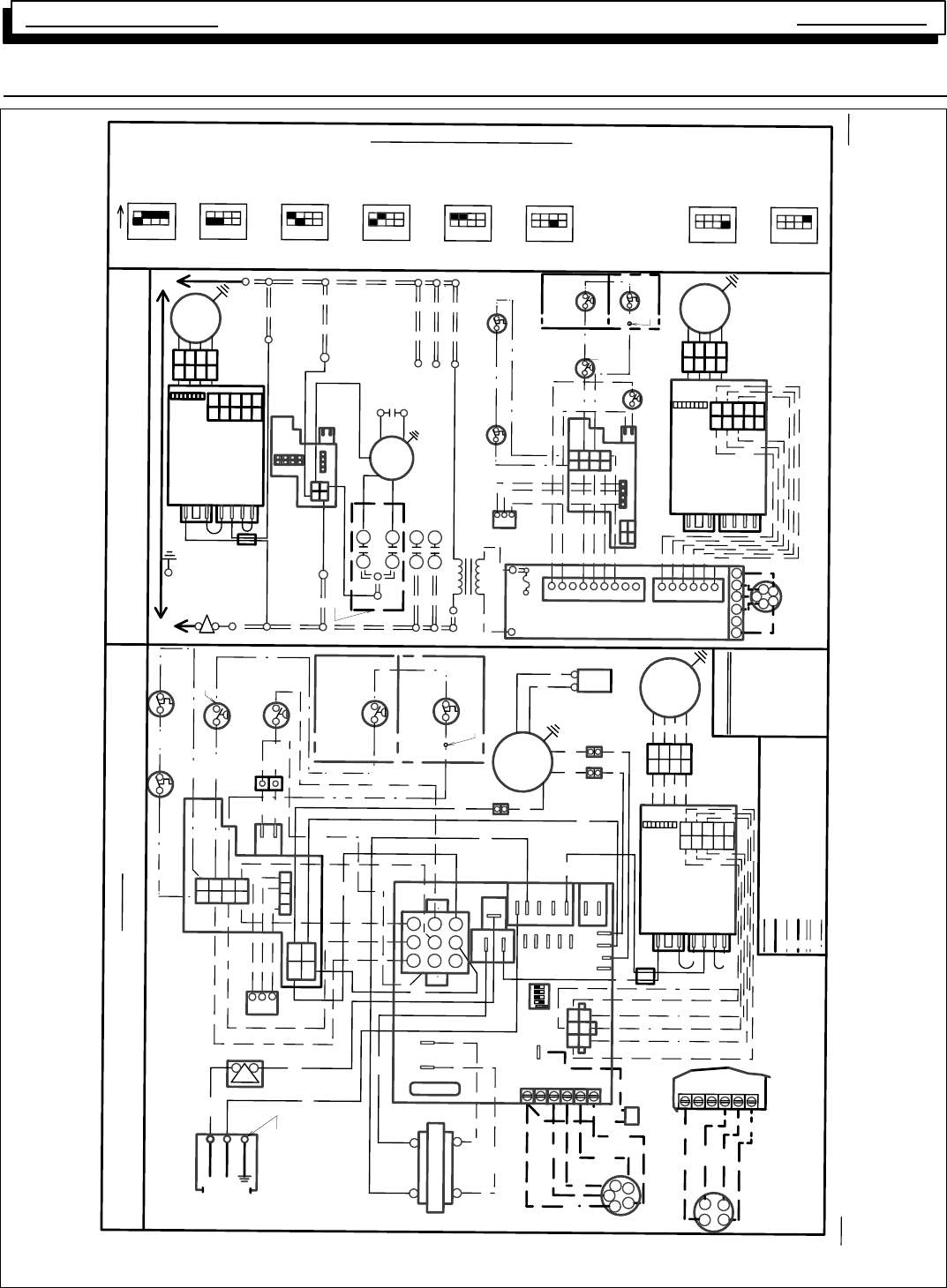
Multi Position Furnace Service Manual
27 440 08 2010 01
Wiring Diagram (1/2HP DC Blower Motor)
12 12 12
12
12
2 STAGE
43
12
SINGLE STAGE
LIMIT
MAIN
12
1
*
THERMOSTAT
4
2 STAGE
P2
INTERNAL CIRCUIT BOARD WIRING
LOW VOLTAGE FIELD
LOW VOLTAGE FACTORY
LINE VOLTAGE FIELD
LINE VOLTAGE FACTORY
8
2
N
HUM
N
EAC
24V
N
HUM
ON
34
43
SETTING
FACTORY
4
60 SEC.
THERMOSTAT TYPE
33
100 SEC.
4
HOT 115V-60HZ NEUTRAL
WARNING: ELECTRICAL SHOCK HAZARD
DISCONNECT BEFORE SERVICING
GND.
SWITCH
INTERLOCK
CONNECTION DIAGRAM
SWITCH
INTERLOCK
BOX
CONNECTION
FIELD
HEAT ON DELAY: 30 SEC
COOL ON DELAY: 5 SEC
1014486
SEE MANUALS FOR ADJUSTING SWITCHES FOR PROPER HEATING, COOLING & CIRCULATING SPEEDS.
S1
L1
EAC
CAPACITOR
(SOME MODELS)
N
LADDER DIAGRAM
60HZ
115V
3344
G
Y
G
R
W1
W2
G
Y
C
R
R
SWITCH
PRESSURE
SWITCH
PRESSURE
LOW
3
2
3
8
7
+
VALVE
GAS
-
2
6
23
4
1
5
1
ON
R
Y
4
BK
9
BK
HOT
85
W
6
51
GND
6
2
2
BL
73
NEUTRAL
84
3
1
Y
THERMOSTAT
SINGLE STAGE
R
R
Y
BL
BK
Y
W
W
BL
BK
IND LOW
HEAT LOW
5A FUSE
G
BL
R
BR
YBK
C
G
G
Y
W1
R
W2
24V SECONDARY
115V PRIMARY
FAN CONTROL MODULE
140 SEC. 180 SEC.
4
3
12
1
8
FURNACE CONTROL
R
SWITCH
PRESSURE
HIGH
R
GAS VALVE
R
SWITCH
PRESSURE
LOW
MAIN LIMIT
BL
34
7
THERMOSTAT
2-STAGE
2
VALVE
GAS
5
R
N
BL
BL
N
SENSOR
1
2
3
4
L1
IGNITER
BK
W
+
2 STAGE
BK
PBL
(LP MODELS ONLY)
SWITCH
LP PRESSURE
4
2
4
L1
HEAT HI
IND HI
COOL
EAC
HUM
CONT
IND IN
R
W
W
O
W
W
P1
W MOTOR
INDUCER
M2
M1
W
L1
XFMR
O
L1
BK
BK
1
4
4
P1
2
1
5
3
7
4
6
5
3
6
9
1
W1
Y
W2
G
TRANSFORMER
Y
W
LINE
120 VAC
XFMR DC M
TR
P1
COM
3
NEUTRAL
2
1
VAC
24
47
P2
Y2
C
R
(OPTIONAL)
HUMIDISTAT
W
G
Y
Y
W1
G
TRANSFORMER
HIGH
INDH
MOTOR
INDUCER
LO
INDIN INDL
1
234
3
1
115V
R
R
COM
BR
24VAC
BR
5 A FUSE
24VAC
IGNITER
SENSOR
2 STAGE
-
+
-
SHIE LD
BEAD
G
BL
HIGH
IF ANY OF THE ORIGINAL WIRE AS SUPPLIED WITH THE APPLIANCE MUST BE
REPLACED, IT MUST BE REPLACED WITH TYPE AWM-105ºC WIRE OR EQUIV.
SHIE LD
BEAD
115V HOT
JUMPER, SURGE
JUMPER, SURGE
115V NEUTRAL
JUMPER, 115V
JUMPER, 115V
DC MOTOR
CONTROL
*AIRFLOW
DIP SWITCHES
1
MOTOR
BLOWER
DC
G
BL
Y
R
G
BL
Y
R
DC
BLOWER
MOTOR
MOTOR
BLOWER
DC
HEAT OFF DELAY SWITCH 3 NOT DEFINED OR
SWITCH 3 NOT USED
CAPACITOR
(SOME MODELS)
ROLLOUT SWITCH 1 TO 3 IN
SERIES DEPENDING ON MODEL
(HI VOLT FIELD)
COPPER
CONDUCTORS
ONLY
1
2
3
4
1
2
3
45
4
3
2
1
10
9
8
7
6
*AIRFLOW
DIP SWITCHES
DC MOTOR
CONTROL
JUMPER, 115V
JUMPER, 115V
115V NEUTRAL
JUMPER, SURGE
JUMPER, SURGE
115V HOT
W2
1
4
23
56
BK
BL
BR
G
O
R
W
Y
P
BLACK
BLUE
BROWN
GREEN
ORANGE
RED
WHITE
YELLOW
PURPLE
COLOR CODE
ROLLOUT SWITCH 1 TO 3 IN
SERIES DEPENDING ON MODEL
1
2
3
4
1
2
3
4
*AIRFLOW
DIP SWITCHES
DC MOTOR
CONTROL
JUMPER, 115V
JUMPER, 115V
115V NEUTRAL
JUMPER, SURGE
JUMPER, SURGE
115V HOT
5
4
3
2
1
10
9
8
7
6
CIRCUIT BOARD
LP PRESSURE
SWITCH
(LP MODELS
ONLY)
1
2
3
4
1
2
3
4
5
4
3
2
1
10
9
8
7
6
EAC +HUM: 0.8 A MAX. COMBINED
2345678
12345678
12345678
2-STAGE
NOTE: 1. MOST VOLT METERS WILL READ 13-16 VOLTS TO
CHASSIS ON BOTH SIDES OF AN OPEN LIMIT OR PRESSURE
SWITCH IN THE RECTIFIED AC VOLTAGE CIRCUIT.
2. FACTORY CONNECTED WHEN BVSS, (CHIMNEY ADAPTOR
ACCESSORY KIT) OR LP PRESS. SWITCH, IS NOT INSTALLED.
W2
W1
6
RECTIFIED AC VOLTAGE FACTORY
BVSS
(FIELD INSTALLED)
NOTE 2
NOTE 2
NOTE 2
NOTE 2
COOL OFF DELAY: 90 SEC
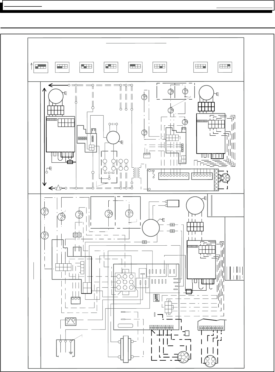
Multi Position Furnace
Service Manual
28
441 08 2010 01
Wiring Diagram (1 HP DC Blower Motor)
12 12 12
12
12
2 STAGE
43
12
SINGLE STAGE
LIMIT
MAIN
12
1
*
2-STAGE
4
2 STAGE
P2
INTERNAL CIRCUIT BOARD WIRING
LOW VOLTAGE FIELD
LOW VOLTAGE FACTORY
LINE VOLTAGE FIELD
LINE VOLTAGE FACTORY
COLOR CODE
8
2
N
HUM
N
EAC
24V
N
HUM
ON
34
43
SETTING
FACTORY
4
60 SEC.
33
100 SEC.
4
HOT 115V-60HZ NEUTRAL
WARNING: ELECTRICAL SHOCK HAZARD
DISCONNECT BEFORE SERVICING
GND.
SWITCH
INTERLOCK
CONNECTION DIAGRAM
SWITCH
INTERLOCK
BOX
CONNECTION
FIELD
COOL OFF DELAY: 90 SEC
COOL ON DELAY: 5 SEC
SEE MANUALS FOR ADJUSTING SWITCHES FOR PROPER HEATING, COOLING & CIRCULATING SPEEDS.
S1
L1
EAC
CAPACITOR
(SOME MODELS)
N
LADDER DIAGRAM
60HZ
115V
3344
G
Y
G
R
W1
W2
G
Y
C
R
R
SWITCH
PRESSURE
LOW
3
2
3
8
7
+
VALVE
GAS
-
2
6
23
4
1
5
1
ON
R
Y
4
BK
9
BK
HOT
85
W
6
51
GND
6
2
2
BL
73
NEUTRAL
84
3
1
Y
THERMOSTAT
SINGLE STAGE
R
R
Y
BL
BK
Y
W
W
BL
BK
IND LOW
HEAT LOW
5A FUSE
W2
W1
G
BL
R
BR
YBK
C
G
G
Y
W1
R
W2
24V SECONDARY
115V PRIMARY
FAN CONTROL MODULE
140 SEC. 180 SEC.
4
3
12
1
8
FURNACE CONTROL
R
SWITCH
PRESSURE
HIGH
R
GAS VALVE R
SWITCH
PRESSURE
LOW
MAIN LIMIT
BL
3
6
4
7
THERMOSTAT
2-STAGE
2
VALVE
GAS
5
R
N
BL
BL
N
SENSOR
1
2
3
4
L1
IGNITER
BK
W
+
2 STAGE
BK
PBL
(LP MODELS ONLY)
SWITCH
LP PRESSURE
4
2
4
L1
HEAT HI
IND HI
COOL
EAC
HUM
CONT
IND IN
R
W
W
O
W
W
P1
W MOTOR
INDUCER
M2
M1
W
L1
XFMR
O
L1
BK
BK
1
4
4
P1
2
1
5
3
7
4
6
5
3
6
9
1
W1
Y
W2
G
TRANSFORMER
Y
W
LINE
120 VAC
XFMR DC MTR
P1
COM
3
NEUTRAL
2
1
VAC
24
47
P2
Y2
C
R
(OPTIONAL)
HUMIDISTAT
W
G
1 2 3 4
Y
Y
W1
G
TRANSFORMER
HIGH
INDH
MOTOR
INDUCER
LO
INDIN INDL
1
2
34
3
1
115V
R
R
COM
BR
24VAC
BR
5 A FUSE
24VAC
IGNITER
SENSOR
2 STAGE
-
+
-
SHIELD
BEAD
G
BL
IF ANY OF THE ORIGINAL WIRE AS SUPPLIED WITH THE APPLIANCE MUST BE
REPLACED, IT MUST BE REPLACED WITH TYPE AWM-105ºC WIRE OR EQUIV.
SHIELD
BEAD
115V HOT
JUMPER, SURGE
JUMPER, SURGE
115V NEUTRAL
JUMPER, 115V
JUMPER, 115V
DC MOTOR
CONTROL
*AIRF LOW
DIP SWITCHES
THERMOSTAT TYPE
SWITCH 3 NOT USED
HEAT OFF DELAY
ROLLOUT SWITCH 1 TO 3
IN SERIES DEPENDING ON
MODEL
HIGH
PRESSURE
SWITCH
ROLLOUT SWITCH 1 TO 3
IN SERIES
DEPENDING ON MODEL
CAPACITOR
(SOME MODELS)
(HI VOLT FIELD)
COPPER
CONDUCTORS
ONLY
CIRCUIT BOARD
1
4
23
56
G
BL
Y
R
G
BL
Y
R
DC
BLOWER
MOTOR
5
4
3
2
1
10
9
8
7
6
1
2
3
4
5
1
2
3
4
5
12345678
MOTOR
BLOWER
DC
*AIRF LOW
DIP SWITCHES
DC MOTOR
CONTROL
JUMPER, 115V
JUMPER, 115V
115V NEUTR AL
JUMPER, SURGE
JUMPER, SURGE
115V HOT
5
4
3
2
1
10
9
8
7
6
1
2
3
4
5
1
2
3
4
5
12345678
5
4
3
2
1
10
9
8
7
6
1
2
3
4
5
1
2
3
4
5
12345678
MOTOR
BLOWER
DC
*AIRF LOW
DIP SWITCHES
DC MOTOR
CONTROL
JUMPER, 115V
JUMPER, 115V
115V NEUTRAL
JUMPER, SURGE
JUMPER, SURGE
115V HOT
LP PRESSURE
SWITCH
(LP MODELS
ONLY)
W2
BLACK
BLUE
BROWN
GREEN
ORANGE
RED
WHITE
YELLOW
PURPLE
BK
BL
BR
G
O
R
W
Y
P
EAC + HUM: 0.8 A MAX. COMBINED
THERMOSTAT
NOTE: 1. MOST VOLT METERS WILL READ 13-16 VOLTS TO
CHASSIS ON BOTH SIDES OF AN OPEN LIMIT OR PRESSURE
SWITCH IN THE RECTIFIED AC VOLTAGE CIRCUIT.
2. FACTORY CONNECTED WHEN BVSS, (CHIMNEY ADAPTOR
ACCESSORY KIT), OR LP PRESSURE SWITCH IS NOT INSTALLED.
RECTIFIED AC VOLTAGE FACTORY
BVSS
(FIELD INSTALLED)
NOTE 2
BVSS
(FIELD
INSTALLED)
NOTE 2
NOTE 2
SWITCH 3 NOT DEFINED
HEAT ON DELAY: 30 SEC
1014487 REV. 2
CN
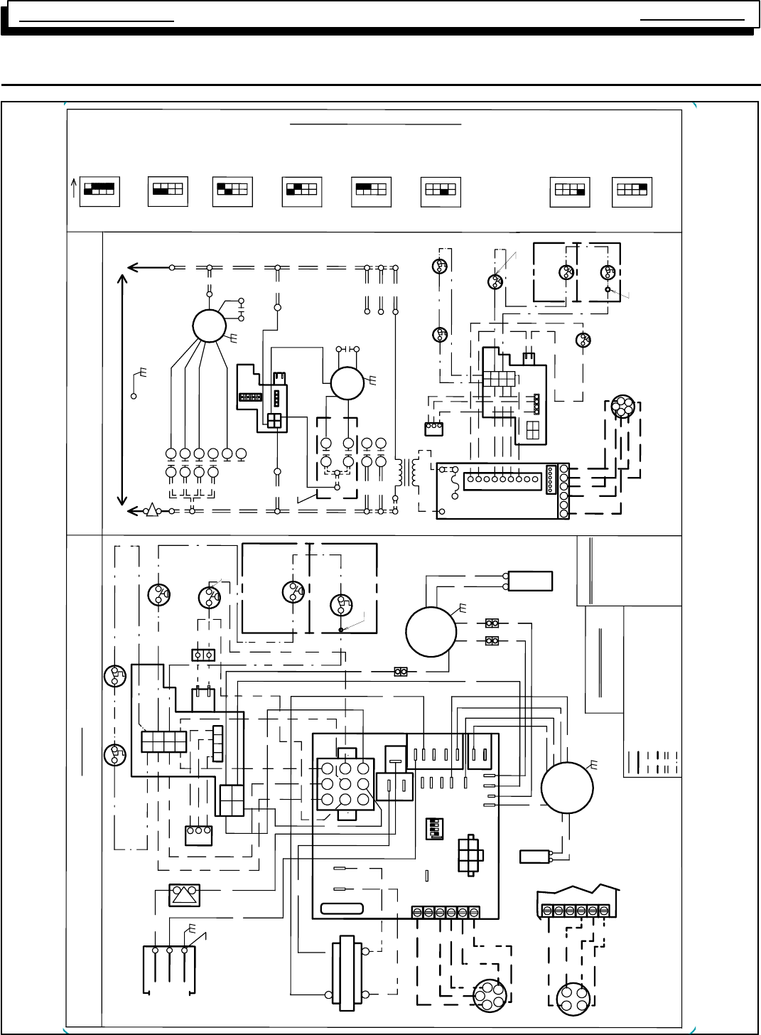
Multi Position Furnace Service Manual
29 440 08 2010 01
Wiring Diagram *8MPT
1014485 REV. 2
N
2 STAGE
8
51
6
2
4
1
3
7
N
SENSOR
(SOME MODELS)
CAPACITOR
IGNITER
HUM
EAC
N
MOTOR
INDUCER
INDH
LO
N
HIGH
21
HOT
NEUTRAL
ONLY
COPPER
GND
R
BK
W
BL
BK
Y
IGNITER
SENSOR
R
GAS VALVE
HEAT OFF DELAY THERMOSTAT TYPE
3
MAIN LIMIT
43
SETTING
FACTORY 60 SEC. 100 SEC.
SINGLE STAGE
12
12 12
12
2 STAGE
FAN CONTROL MODULE
43 4
3
12
Y
BL
R
R
G
THERMOSTAT
SINGLE STAGE
R
BL Y
W
Y
4 5 6
1 3 2
BL
W
G
BR
TRANSFORMER
BR
C
BK
TRANSFORMER
115V
XFMR
24V
24VAC
COM
2
8
1
9
6
P1
3
5
4
3
ON
CONNECTION DIAGRAM
DISCONNECT BEFORE SERVICING
WARNING: ELECTRICAL SHOCK HAZARD
4
SWITCH
INTERLOCK
COOL OFF DELAY: 90 SEC
COOL ON DELAY: 5 SEC EAC + HUM: 0.8 A MAX. COMBINED
BOX
CONNECTION
FIELD
1
S1
VALVE
GAS
A
CIRCUIT BOARD
GND.
COOL HI (BK)
HEAT H MHI (O)
HEAT L MLO (BL)
M1 LO (R)
CONT (OPT)
L1
L1
L1
L1
L1
M2
SWITCH
PRESSURE
LOW
FURNACE CONTROL
DEPENDING ON MODEL
1 TO 3 IN SERIES
ROLLOUT SWITCH
MAIN LIMIT
SWITCH
HIGH PRESSURE
RCY
W1
G
W2
R
G
W2
W1
R
G
1 2 3 4
(HI VOLT FIELD)
G
W1
Y
W2
R
THERMOSTAT
2-STAGE
60HZ
115V
6
1
5
5A FUSE
M2
M1
FUSE
5 A
SEE MANUALS FOR ADJUSTING SPEED TAPS FOR PROPER HEATING, COOLING & CIRCULATING SPEEDS.
2
INTERNAL CIRCUIT BOARD WIRING
LOW VOLTAGE FIELD
LOW VOLTAGE FACTORY
LINE VOLTAGE FIELD
LINE VOLTAGE FACTORY
*
ORANGE-MHI RED-LO
BLACK-HI BLUE-MLO
SPEED TAP CODE
HEAT LOW
IND LOW
PURPLE P
YELLOW Y
WHITE W
RED R
ORANGE O
GREEN G
BROWN BR
BLUE BL
BLACK BK
IND IN
IND HI
3
COLOR CODE
24V SECONDARY
115V PRIMARY
P1
4
43
21
78
4
4343
12
4
3
180 SEC.140 SEC.
EAC
-
BL
SERIES DEPENDING ON MODEL
ROLLOUT SWITCH 1 TO 3 IN
O
BL
BL
O
MOTOR
INDUCER
W
BR
BR
R
BK
OR
NEUTRAL
(SOME MODELS)
CAPACITOR
HEAT HI
COOL
HUM
CONT
BK
BK
R
R
W
W
W
SWITCH
PRESSURE
LOW
W
W
+
2 STAGE
BK
P
BK
BL
(LP MODELS ONLY)
SWITCH
LP PRESSURE
W
3
4
R
ON
2 STAGE
2
3
4
-
+
THERMOSTAT
Y
-
+
43
VALVE
GAS
21
W2
Y
G
Y
P1
XFMR DC MTR
VAC
24
LINE
120 VAC
COM
3
2
41
MOTOR
BLOWER
PSC
4
(LP MODELS ONLY)
SWITCH
LP PRESSURE
12
12
W
P2
Y2
C
G
Y
W1
CAPACITOR
R
7
W1
W2
MOTOR
BLOWER
PSC
N
N
AWM - 105°C WIRE OR ITS EQUIVALENT.
MUST BE REPLACED, IT MUST BE REPLACED WITH TYPE
IF ANY OF THE ORIGINAL WIRE AS SUPPLIED WITH THE APPLIANCE
P2
1234
7
56
HOT 115V-60HZ NEUTRAL
SWITCH
INTERLOCK
LADDER DIAGRAM
L1
L1
INDIN
HUM
L1
EAC
INDL
L1
CAPACITOR
8
9
5
4
2
R
6
3
1
5
4
6
7
1
3
8
2
2
3
4
1
NOTE:
1. MOST VOLT METERS WILL READ 13-16 VOLTS TO CHASSIS
ON BOTH SIDES OF AN OPEN LIMIT OR PRESSURE
SWITCH IN THE RECTIFIED AC VOLTAGE CIRCUIT
2. FACTORY CONNECTED WHEN BVSS, (CHIMNEY ADAPTOR
ACCESSORY KIT) OR LP PRESS. SWITCH IS NOT INSTALLED.
CONDUCTORS
RECTIFIED AC VOLTAGE FACTORY
BVSS,
(FIELD INSTALLED)
NOTE 2
BVSS
(FIELD INSTALLED)
NOTE 2
NOTE 2
NOTE 2
HEAT ON DELAY: 30 SEC
SWITCH 3 NOT DEFINED
OR SWITCH 3 NOT USED
SWITCH
PRESSURE
HIGH
CN
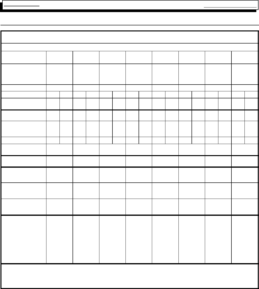
Multi Position Furnace
Service Manual
30
441 08 2010 01
26. Model Specifications
Manufacturers Number (Mfr No -SeeRatingPlate)
ALL Models (N8MPN) Specifications
N8MPN
050B12 N8MPN
075B12 N8MPN
075F16 N8MPN
100F14 N8MPN
100F20 N8MPN
100J22 N8MPN
125J20 N8MPN
125J22
General
Input (Btuh)
Output (Btuh)
Temp. Rise (°F)
50,000
40,000
35--65
75,000
60,000
35--65
75,000
60,000
25--55
100,000
80,000
30--60
100,000
80,000
35--65
100,000
81,000
30--60
125,000
100,000
30--60
125,000
100,000
30--60
Electrical (Volts/Hz/FLA) 115/60/9.8 115/60/8.9 115/60/10.6 115/60/9.0 115/60/12.0 115/60/12.0 115/60/12.0 115/60/12.0
Gas Type Nat LP Nat LP Nat LP Nat LP Nat LP Nat LP Nat LP Nat LP
Transformer Size (VA)
T’stat Heat Anticipator 40
.10 40
.10 40
.10 40
.10 40
.10 40
.10 40
.10 40
.10 40
.10 40
.10 40
.10 40
.10 40
.10 40
.10 40
.10 40
.10
Gas & Ignition
Std. Main Orifices (No/Size) 2/#42 2/#54 3/#42 3/#54 3/#42 3/#54 4/#42 4/#54 4/#42 4/#54 4/#42 4/#54 5/#42 5/#54 5/#42 5/#54
Gas Valve Honeywell SV
Regulation Type
Manifold Press. (Inch’s WC)
9541
SNAP
3.5
9541
SNAP
10.0
9541
SNAP
3.5
9541
SNAP
10.0
9541
SNAP
3.5
9541
SNAP
10.0
9541
SNAP
3.5
9541
SNAP
10.0
9541
SNAP
3.5
9541
SNAP
10.0
9541
SNAP
3.5
9541
SNAP
10.0
9541
SNAP
3.5
9541
SNAP
10.0
9541
SNAP
3.5
9541
SNAP
10.0
Pilot Orifice Size .018 .011 .018 .011 .018 .011 .018 .011 .018 .011 .018 .011 .018 .011 .018 .011
Ignition Type/Series
Lock--Out Time HW HSP
NA HW HSP
NA HW HSP
NA HW HSP
NA HW HSP
NA HW HSP
NA HW HSP
NA HW HSP
NA
Combustion
Flue Outlet Size (Inches) 4444444 4
Limits & Controls
Thermal Sensor (°F)
Limit Control 300
See Parts List 300
See Parts List 300
See Parts List 300
See Parts List 300
See Parts List 300
See Parts List 300
See Parts List 300
See Parts List
Std. Pressure Sw. (Part No)
Press (Close)
Press (Open)
1013529
--0.69
--0.59
1013529
--0.69
--0.59
1013529
--0.69
--0.59
1013529
--0.69
--0.59
1013529
--0.69
--0.59
1013529
--0.69
--0.59
1013529
--0.69
--0.59
1013529
--0.69
--0.59
Fan Control (Type)
Fan Control On
(Timed--secs) Off
HW ST9160
30
60,100,140,180
HW ST9160
30
60,100,140,180
HW ST9160
30
60,100,140,180
HW ST9160
30
60,100,140,180
HW ST9160
30
60,100,140,180
HW ST9160
30
60,100,140,180
HW ST9160
30
60,100,140,180
HW ST9160
30
60,100,140,180
Blower Data
Type & Size
Motor Amps/Rpm
Motor Type/H.p.
Cap. Mfd/Volts
Filter Type (600 FPM)
Filter Size (²) (Not Supplied)
1600 CFM and over
Min. Cool Cap. (Tons)
Max. Cool Cap. (Tons)
11--8
10.3/1100
PSC/1/2
10/370
Washable
14x25x1
-- --
1.5
3
11--8
8/1050
PSC/1/2
7.5/370
Washable
14x25x1
-- --
1.5
3
11--10
10.3/1100
PSC/1/2
10/370
Washable
16x25x1
16x25 (2)
3
4
11--10
8/900
PSC/1/2
7.5/370
Washable
16x25x1
-- --
2
3.5
11--10
10/1050
PSC/1/2
10/370
Washable
16x25x1 (2)
16x25 (2)
3
5
11--10
11.9/900
PSC/3/4
40/370
Washable
20x25x1
16x25 (2)
3
5.5
11--10
10/1050
PSC/1/2
10/370
Washable
20x25x1
16x25 (2)
3
5
11--10
11.9/900
PSC/3/4
40/370
Washable
20x25x1
16x25 (2)
3
5.5
Gas Conversion Kits
Nat to LP NAHF002LP or *1009509
LP to Nat NAHF002NG, *1009510
* Must be ordered from Service Parts
Two side filter racks (left and right) required for upflow applications. Side returns are not permitted with downflow or horizontal furnace applications.
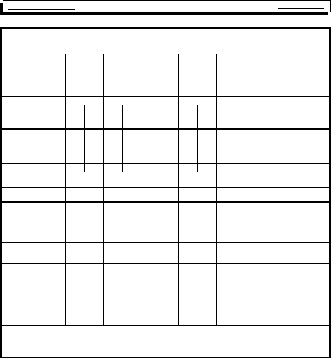
Multi Position Furnace Service Manual
31 440 08 2010 01
Manufacturers Number (Mfr No -SeeRatingPlate)
ALL Models (N8MPL) Specifications
N8MPL
050B12 N8MPL
075B12 N8MPL
075F16 N8MPL
100F20 N8MPL
100J22 N8MPL
125J20 N8MPL
125J22
General
Input (Btuh)
Output (Btuh)
Temp. Rise (°F)
50,000
40,000
35--65
75,000
60,000
35--65
75,000
60,000
25--55
100,000
80,000
35--65
100,000
80,000
30--60
125,000
100,000
30--60
125,000
100,000
30--60
Electrical (Volts/Hz/FLA) 115/60/9.8 115/60/8.9 115/60/10.6 115/60/12.0 115/60/12.0 115/60/12.0 115/60/12.0
Gas Type Nat LP Nat LP Nat LP Nat LP Nat LP Nat LP Nat LP
Transformer Size (VA)
T’stat Heat Anticipator 40
.10 40
.10 40
.10 40
.10 40
.10 40
.10 40
.10 40
.10 40
.10 40
.10 40
.10 40
.10 40
.10 40
.10
Gas & Ignition
Std. Main Orifices (No/Size) 2/#42 2/#54 3/#42 3/#54 3/#42 3/#54 4/#42 4/#54 4/#42 4/#54 5/#42 5/#54 5/#42 5/#54
Gas Valve Honeywell SV
Regulation Type
Manifold Press. (Inch’s WC)
9541
SNAP
3.5
9541
SNAP
10.0
9541
SNAP
3.5
9541
SNAP
10.0
9541
SNAP
3.5
9541
SNAP
10.0
9541
SNAP
3.5
9541
SNAP
10.0
9541
SNAP
3.5
9541
SNAP
10.0
9541
SNAP
3.5
9541
SNAP
10.0
9541
SNAP
3.5
9541
SNAP
10.0
Pilot Orifice Size .018 .011 .018 .011 .018 .011 .018 .011 .018 .011 .018 .011 .018 .011
Ignition Type/Series
Lock--Out Time HW HSP
NA HW HSP
NA HW HSP
NA HW HSP
NA HW HSP
NA HW HSP
NA HW HSP
NA
Combustion
Flue Outlet Size (Inches) 444444 4
Limits & Controls
Thermal Sensor (°F)
Limit Control 300
See Parts List 300
See Parts List 300
See Parts List 300
See Parts List 300
See Parts List 300
See Parts List 300
See Parts List
Std. Pressure Sw. (Part No)
Press (Close)
Press (Open)
1013529
--0.69
--0.59
1013529
--0.69
--0.59
1013529
--0.69
--0.59
1013529
--0.69
--0.59
1013529
--0.69
--0.59
1013529
--0.69
--0.59
1013529
--0.69
--0.59
Fan Control (Type)
Fan Control On
(Timed--secs) Off
HW ST9160
30
60,100,140,180
HW ST9160
30
60,100,140,180
HW ST9160
30
60,100,140,180
HW ST9160
30
60,100,140,180
HW ST9160
30
60,100,140,180
HW ST9160
30
60,100,140,180
HW ST9160
30
60,100,140,180
Blower Data
Type & Size
Motor Amps/Rpm
Motor Type/H.p.
Cap. Mfd/Volts
Filter Type (600 FPM)
Filter Size (²) (Not Supplied)
1600 CFM and over
Min. Cool Cap. (Tons)
Max. Cool Cap. (Tons)
11--8
10.3/1100
PSC/1/2
10/370
Washable
14x25x1
-- --
1.5
3
11--8
8/1050
PSC/1/2
7.5/370
Washable
14x25x1
-- --
1.5
3
11--10
10.3/1100
PSC/1/2
10/370
Washable
16x25x1
16x25 (2)
3
4
11--10
10/1050
PSC/1/2
10/370
Washable
16x25x1
-- --
3
5
11--10
11.9/900
PSC/3/4
40/370
Washable
20x25x1
16x25 (2)
3
5.5
11--10
10/1050
PSC/1/2
10/370
Washable
20x25x1
16x25 (2)
3
5
11--10
11.9/900
PSC/3/4
40/370
Washable
20x25x1
16x25 (2)
3
5.5
Gas Conversion Kits
Nat to LP NAHF002LP, *1009509
LP to Nat NAHF002NG, *1009510
* Must be ordered from Service Parts
Two side filter racks (left and right) required for upflow applications. Side returns are not permitted with downflow or horizontal furnace applications.
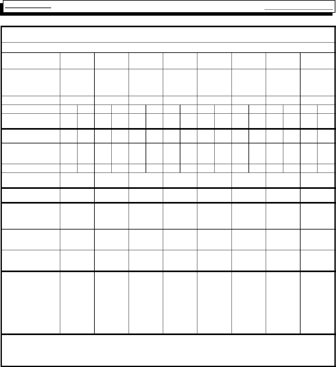
Multi Position Furnace
Service Manual
32
441 08 2010 01
Manufacturers Number (Mfr No -SeeRatingPlate)
ALL Models (*8MPN) Specifications
*8MPN
050B12 *8MPN
075B12 *8MPN
075F16 *8MPN
100F14 *8MPN
100F20 *8MPN
100J20 *8MPN
125J20 *8MPN
150J20
General
Input (Btuh)
Output (Btuh)
Temp. Rise (°F)
50,000
40,000
35--65
75,000
60,000
30--60
75,000
60,000
30--60
100,000
81,000
35--65
100,000
81,000
35--65
100,000
81,000
35--65
125,000
101,000
35--65
150,000
121,000
35--65
Electrical (Volts/Hz/FLA) 115/60/9.8 115/60/8.9 115/60/10.0 115/60/9.0 115/60/12.0 115/60/12.0 115/60/12.0 115/60/12.0
Gas Type Nat LP Nat LP Nat LP Nat LP Nat LP Nat LP Nat LP Nat LP
Transformer Size (VA)
T’stat Heat Anticipator 40
.30 40
.30 40
.30 40
.30 40
.30 40
.30 40
.30 40
.30 40
.30 40
.30 40
.30 40
.30 40
.30 40
.30 40
.30 40
.30
Gas & Ignition
Std. Main Orifices (No/Size) 2/#42 2/#54 3/#42 3/#54 3/#42 3/#54 4/#42 4/#54 4/#42 4/#54 4/#42 4/#54 5/#42 5/#54 6/#42 6/#54
Gas Valve Honeywell SV
Regulation Type
Manifold Press. (Inch’s WC)
9541
SNAP
3.5
9541
SNAP
10.0
9541
SNAP
3.5
9541
SNAP
10.0
9541
SNAP
3.5
9541
SNAP
10.0
9541
SNAP
3.5
9541
SNAP
10.0
9541
SNAP
3.5
9541
SNAP
10.0
9541
SNAP
3.5
9541
SNAP
10.0
9541
SNAP
3.5
9541
SNAP
10.0
9541
SNAP
3.5
9541
SNAP
10.0
Pilot Orifice Size .018 .011 .018 .011 .018 .011 .018 .011 .018 .011 .018 .011 .018 .011 .018 .011
Ignition Type/Series
Lock--Out Time HW HSP
NA HW HSP
NA HW HSP
NA HW HSP
NA HW HSP
NA HW HSP
NA HW HSP
NA HW HSP
NA
Combustion
Flue Outlet Size (Inches) 4444444 4
Limits & Controls
Thermal Sensor (°F)
Limit Control
Auxiliary Limit (°F)
300
See Parts List
130
300
See Parts List
130
300
See Parts List
130
300
See Parts List
130
300
See Parts List
130
300
See Parts List
130
300
See Parts List
130
300
See Parts List
130
Std. Pressure Sw. (Part No)
Press (Close)
Press (Open)
1013529
--0.69
--0.59
1013529
--0.69
--0.59
1013529
--0.69
--0.59
1013529
--0.69
--0.59
1013529
--0.69
--0.59
1013529
--0.69
--0.59
1013529
--0.69
--0.59
1013529
--0.69
--0.59
Fan Control (Type)
Fan Control On
(Timed--secs) Off
HW ST9160
30
60,100,140,180
HW ST9160
30
60,100,140,180
HW ST9160
30
60,100,140,180
HW ST9160
30
60,100,140,180
HW ST9160
30
60,100,140,180
HW ST9160
30
60,100,140,180
HW ST9160
30
60,100,140,180
HW ST9160
30
60,100,140,180
Blower Data
Type & Size
Motor Amps/Rpm
Motor Type/H.p.
Cap. Mfd/Volts
Filter Type (600 FPM)
Filter Size (²) (Not Supplies)
1600 CFM and over
Min. Cool Cap. (Tons)
Max. Cool Cap. (Tons)
11--8
10.3/1100
PSC/1/2
10/370
Washable
14x25x1
-- --
1.5
3
11--8
8/1050
PSC/1/2
7.5/370
Washable
14x25x1
-- --
1.5
3
11--10
10.3/1100
PSC/1/2
10/370
Washable
16x25x1
16x25 (2)
3
4
11--10
8/900
PSC/1/2
7.5/370
Washable
16x25x1
-- --
2
3.5
11--10
10/1050
PSC/1/2
10/370
Washable
16x25x1
16x25 (2)
3
5
11--10
11.9/900
PSC/3/4
40/370
Washable
20x25x1
16x25 (2)
3
5
11--10
10/1050
PSC/1/2
10/370
Washable
20x25x1
16x25 (2)
3
5
12--12
11.9/900
PSC/3/4
40/370
Washable
20x25x1
16x25 (2)
3
5
Gas Conversion Kits
Nat to LP NAHF002LP, *1009509
LP to Nat NAHF002NG, *1009510
* Must be ordered from Service Parts
Two side filter racks (left and right) required for upflow applications. Side returns are not permitted with downflow or horizontal furnace applications.
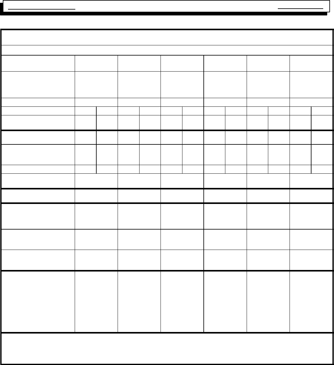
Multi Position Furnace Service Manual
33 440 08 2010 01
Manufacturers Number (Mfr No -SeeRatingPlate)
ALL Models (*8MPL) Specifications
*8MPL
050B12 *8MPL
075B12 *8MPL
075F16 *8MPL
100F20 *8MPL
100J20 *8MPL
125J20
General
Input (Btuh)
Output (Btuh)
Temp. Rise (°F)
50,000
40,000
35--65
75,000
60,000
30--60
75,000
60,000
30--60
100,000
81,000
35--65
100,000
81,000
35--65
125,000
101,000
35--65
Electrical (Volts/Hz/FLA) 115/60/9.8 115/60/8.9 115/60/10.0 115/60/12.0 115/60/12.0 115/60/12.0
Gas Type Nat LP Nat LP Nat LP Nat LP Nat LP Nat LP
Transformer Size (VA)
T’stat Heat Anticipator 40
.30 40
.30 40
.30 40
.30 40
.30 40
.30 40
.30 40
.30 40
.30 40
.30 40
.30 40
.30
Gas & Ignition
Std. Main Orifices (No/Size) 2/#42 2/#54 3/#42 3/#54 3/#42 3/#54 4/#42 4/#54 4/#42 4/#54 5/#42 5/#54
Gas Valve Honeywell SV
Regulation Type
Manifold Press. (Inch’s WC)
9541
SNAP
3.5
9541
SNAP
10.0
9541
SNAP
3.5
9541
SNAP
10.0
9541
SNAP
3.5
9541
SNAP
10.0
9541
SNAP
3.5
9541
SNAP
10.0
9541
SNAP
3.5
9541
SNAP
10.0
9541
SNAP
3.5
9541
SNAP
10.0
Pilot Orifice Size .018 .011 .018 .011 .018 .011 .018 .011 .018 .011 .018 .011
Ignition Type/Series
Lock--Out Time HW HSP
NA HW HSP
NA HW HSP
NA HW HSP
NA HW HSP
NA HW HSP
NA
Combustion
Flue Outlet Size (Inches) 4444 4 4
Limits & Controls
Thermal Sensor (°F)
Limit Control
Auxiliary Limit (°F)
300
See Parts List
130
300
See Parts List
130
300
See Parts List
130
300
See Parts List
130
300
See Parts List
130
300
See Parts List
130
Std. Pressure Sw. (Part No)
Press (Close)
Press (Open)
1013529
--0.69
--0.59
1013529
--0.69
--0.59
1013529
--0.69
--0.59
1013529
--0.69
--0.59
1013529
--0.69
--0.59
1013529
--0.69
--0.59
Fan Control (Type)
Fan Control On delay
(Timed--secs) Off delay
HW ST9160
30
60,100,140,180
HW ST9160
30
60,100,140,180
HW ST9160
30
60,100,140,180
HW ST9160
30
60,100,140,180
HW ST9160
30
60,100,140,180
HW ST9160
30
60,100,140,180
Blower Data
Type & Size
Motor Amps/Rpm
Motor Type/H.p.
Cap. Mfd/Volts
Filter Type
Filter Size (²) (Not Supplied)
1600 CFM and over
Min. Cool Cap. (Tons)
Max. Cool Cap. (Tons)
11--8
10.3/1100
PSC/1/2
10/370
Washable
14x25x1
-- --
1.5
3
11--8
8/1050
PSC/1/2
7.5/370
Washable
14x25x1
-- --
1.5
3
11--10
10.3/1100
PSC/1/2
10/370
Washable
16x25x1
16x25 (2)
3
4
11--10
10/1050
PSC/1/2
10/370
Washable
16x25x1
16x25 (2)
3
5
11--10
11.9/900
PSC/3/4
40/370
Washable
20x25x1
16x25 (2)
3
5
11--10
10/1050
PSC/1/2
10/370
Washable
20x25x1
16x25 (2)
3
5
Gas Conversion Kits
Nat to LP NAHF002LP, *1009509
LP to Nat NAHF002NG, *1009510
* Must be ordered from Service Parts
Two side filter racks (left and right) required for upflow applications. Side returns are not permitted with downflow or horizontal furnace applications.
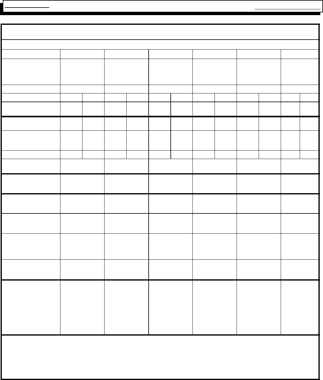
Multi Position Furnace
Service Manual
34
441 08 2010 01
Manufacturers Number (Mfr No -SeeRatingPlate)
ALL Models Specifications
*8DNL050B12 *8DNL075B12 *8DNL075F16 *8DNL100F14 *8DNL100L20 *8DNL125L20
General
Input (Btuh)
Output (Btuh) +
Temp. Rise (°F)
50,000
40,000
35--65
75,000
60,000
35--65
75,000
60,000
35--65
100,000
80,000
35--65
100,000
80,000
30--60
125,000
100,000
35--65
Electrical (Volts/Hz/FLA) 115/60/8.9 115/60/7.6 115/60/10.6 115/60/8.9 115/60/11.2 115/60/11.2
Gas Type Nat LP Nat LP Nat LP Nat LP Nat LP Nat LP
Transformer Size (VA)
T’stat Heat Anticipator 40
.10 40
.10 40
.10 40
.10 40
.10 40
.10 40
.10 40
.10 40
.10 40
.10 40
.10 40
.10
Gas & Ignition
Std. Main Orifices (No/Size) 2/#42 2/#54 3/#42 3/#54 3/#42 3/#54 4/#42 4/#54 4/#42 4/#54 5/#42 5/#54
Gas Valve Honeywell SV
Regulation Type
Manifold Press. (Inch’s WC)
9541
SNAP
3.5
9541
SNAP
10.0
9541
SNAP
3.5
9541
SNAP
10.0
9541
SNAP
3.5
9541
SNAP
10.0
9541
SNAP
3.5
9541
SNAP
10.0
9541
SNAP
3.5
9541
SNAP
10.0
9541
SNAP
3.5
9541
SNAP
10.0
Pilot Orifice Size .018 .011 .018 .011 .018 .011 .018 .011 .018 .011 .018 .011
Ignition Type/Series
Lock--Out Time HW HSP
NA HW HSP
NA HW HSP
NA HW HSP
NA HW HSP
NA HW HSP
NA
Combustion
Flue Outlet Size (Inches)
Std. Outlet Temp (°F) 4
<480 4
<480 4
<480 4
<480 4
<480 4
<480
Limits & Controls
Thermal Sensor (°F)
Limit Control 300
See Parts List 300
See Parts List 300
See Parts List 300
See Parts List 300
See Parts List 300
See Parts List
Std. Pressure Sw. (Part No)
Press (Close)
Press (Open)
1013529
--0.69
--0.59
1013529
--0.69
--0.59
1013529
--0.69
--0.59
1013529
--0.69
--0.59
1013529
--0.69
--0.59
1013529
--0.69
--0.59
Hi.Alt.PressureSw.(Part#)
6,000¢to 10,000¢
Press (Close)
Press (Open)
1014051
-- .57
-- .47
1014051
-- .57
-- .47
1014051
-- .57
-- .47
1014051
-- .57
-- .47
1014051
-- .57
-- .47
1014051
-- .57
-- .47
Fan Control (Type)
Fan Control On
(Timed--secs) Off
HW ST9160
30
60,100,140,180
HW ST9160
30
60,100,140,180
HW ST9160
30
60,100,140,180
HW ST9160
30
60,100,140,180
HW ST9160
30
60,100,140,180
HW ST9160
30
60,100,140,180
Blower Data
Type & Size
Motor Amps/Rpm
Motor Type/H.p.
Cap. Mfd/Volts
Filter Type
Filter Size (²)
Min. Cool Cap. (Tons)
Max. Cool Cap. (Tons)
11--8
8/1050
PSC/1/2
7.5/370
Washable
16x18x1 (2)
1.5
3
11--8
8/1050
PSC/1/3
5.0/370
Washable
16x18x1 (2)
1.5
3
11--10
10/1050
PSC/1/2
10/370
Washable
16x18x1 (2)
3
4
11--10
8/900
PSC/1/2
7.5/370
Washable
16x18x1(2)
2
3.5
11--10
11.9/900
PSC/3/4
40/370
Washable
16x18x1 (2)
3
5
11--10
11.9/900
PSC/3/4
40/370
Washable
16x18x1 (2)
3
5
Gas Conversion Kits
Nat to LP NAHF002LP (*1009509) or NAHL002LP (*1160991)
LP to Nat NAHF002NG, *1009510*
LP High Altitude *1160992
* Must be ordered from Service Parts
+ Tentative
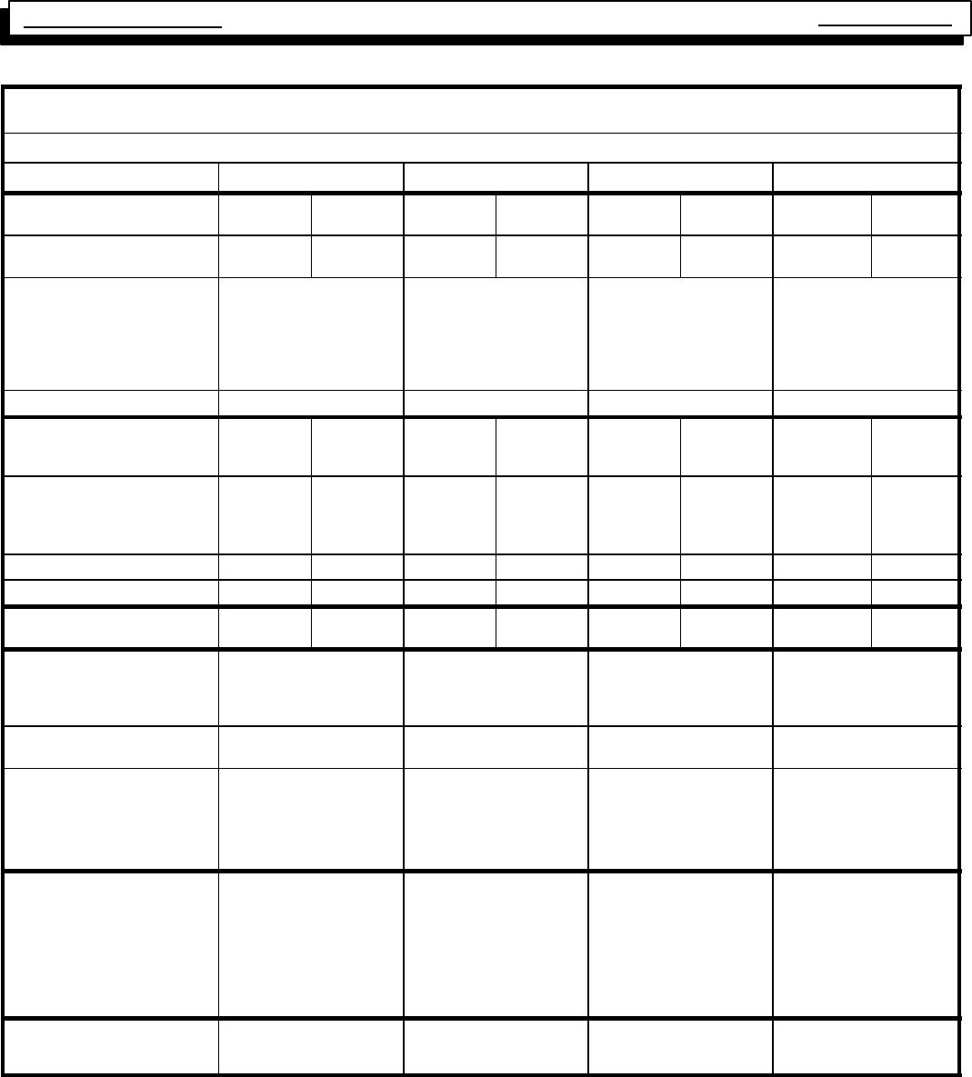
Multi Position Furnace Service Manual
35 440 08 2010 01
Manufacturers Number (Mfr No --SeeRatingPlate)
ALL Models Specifications
*8MPV050B12A *8MPV075F14A *8MPV100J20A *8MPV125J20A
General
Gas Type Nat LP Nat LP Nat LP Nat LP
Transformer Size (VA)
T’stat Heat Anticipator 40
.10 40
.10 40
.10 40
.10 40
.10 40
.10 40
.10 40
.10
Input (Btuh) Std/Alt. Hi Fire
Lo Fire
Output (Btuh) Std/Alt. Hi Fire
Lo Fire
Temp. Rise (°F) Hi Fire
Lo Fire
50,000
35,000
40,000
28,000
30--60
25--55
75,000
52,500
60,000
42,000
30--60
25--55
100,000
70,000
81,000
61,000
35--65
35--65
125,000
87,500
101,000
71,000
30--60
25--55
Electrical (Volts/Hz/FLA) 115/60/8.2 115/60/9 115/60/12 115/60/12
Gas & Ignition
Gas Type
Std. Main Orifices (No/Size) Nat
2/#42 LP
2/#54 Nat
3/#42 LP
3/#54 Nat
4/#42 LP
4/#54 Nat
5/#42 LP
5/#54
Gas Valve (Honeywell)
Regulation Type
Manifold Press. Hi Fire (²WC)
Lo Fire (²WC)
SV 9541
SNAP
3.5
1.7
SV 9541
SNAP
10.0
4.9
SV 9541
SNAP
3.5
1.7
SV 9541
SNAP
10.0
4.9
SV 9541
SNAP
3.5
1.7
SV 9541
SNAP
10.0
4.9
SV 9541
SNAP
3.5
1.7
SV 9541
SNAP
10.0
4.9
Pilot Orifice Size .018 .011 .018 .011 .018 .011 .018 .011
Ignition Type/Series HW HSP HW HSP HW HSP HW HSP HW HSP HW HSP HW HSP HW HSP
Combustion
Flue Outlet Size (Inches) 4 4 4 4 4 4 4 4
Limits & Controls
Fan Control (Type)
Fan Control On delay
(Timed--secs) Off delay
HW ST9162
30
60,100,140,180
HW ST9162
30
60,100,140,180
HW ST9162
30
60,100,140,180
HW ST9162
30
60,100,140,180
Thermal Sensor (°F)
Limit Control Setting (°F) 300
See Limit in Parts List 300
See Limit in Parts List 300
See Limit in Parts List 300
See Limit in Parts List
Std. Pressure Sw. (Part #)
Hi Fire Press (Close)
Hi Fire Press (Open)
Lo Fire Press (Close)
Lo Fire Press (Open)
1013862
--0.69
--0.59
--0.40
--0.30
1013862
--0.69
--0.59
--0.40
--0.30
1013862
--0.69
--0.59
--0.40
--0.30
1013862
--0.69
--0.59
--0.40
--0.30
Blower Data
Type & Size
Motor Amps/Rpm
Motor Type/H.p.
Filter Type
Filter Size (²)
Min. Cool Cap. (Tons)
Max. Cool Cap. (Tons)
11--8
4.6/1050
DC/1/2
Washable
14x25x1/2
1.5
3
11--10
12/900
DC/1
Washable
16x25x1/2
1.5
3.5
11--10
12/900
DC/1
Washable
16x25x1/2(2)
3
5
11--10
12/900
DC/1
Washable
16x25x1/2(2)
3
5
Gas Conversion Kits
Nat to LP
LP to Nat *1011789
*1011787 *1011789
*1011787 *1011789
*1011787 *1011789
*1011787
*Must be ordered from Service Parts
Use the Fuel Gas Code to establish proper vent sizing.
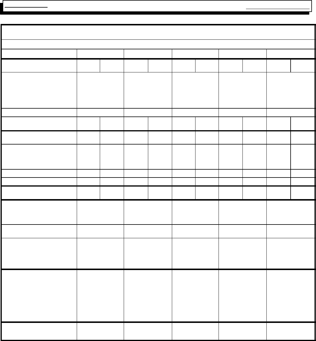
Multi Position Furnace
Service Manual
36
441 08 2010 01
Manufacturers Number (Mfr No --SeeRatingPlate)
ALL Models Specifications
*8MPT050B12A *8MPT075F14A *8MPT100F14A *8MPT100J20A *8MPT125J20A
General
Gas Type Nat LP Nat LP Nat LP Nat LP Nat LP
Input (Btuh) Std/Alt. Hi Fire
Lo Fire
Output (Btuh) Std/Alt. Hi Fire
Lo Fire
Temp. Rise (°F) Hi Fire
Lo Fire
50,000
35,000
40,000
28,000
30--60
25--55
75,000
52,500
60,000
42,000
30--60
25--55
100,000
70,000
81,000
57,000
35--65
35--65
100,000
70,000
81,000
61,000
35--65
35--65
125,000
87,500
101,000
71,000
30--60
25--55
Electrical (Volts/Hz/FLA) 115/60/5.3 115/60/9.2 115/60/9.2 115/60/12 115/60/12
Transformer Size (VA)
T’stat Heat Anticipator 40
.30 40
.30 40
.30 40
.30 40
.30 40
.30 40
.30 40
.30 40
.30 40
.30
Gas & Ignition
GStd. Main Orifices (No/Size) 2/#42 2/#54 3/#42 3/#54 4/#42 4/#54 4/#42 4/#54 5/#42 5/#54
Gas Valve (Honeywell)
Regulation Type
Manifold Press. Hi Fire (²WC)
Lo Fire (²WC)
SV 9541
SNAP
3.5
1.7
SV 9541
SNAP
10.0
4.9
SV 9541
SNAP
3.5
1.7
SV 9541
SNAP
10.0
4.9
SV 9541
SNAP
3.5
1.7
SV 9541
SNAP
10.0
4.9
SV 9541
SNAP
3.5
1.7
SV 9541
SNAP
10.0
4.9
SV 9541
SNAP
3.5
1.7
SV 9541
SNAP
10.0
4.9
Pilot Orifice Size .018 .011 .018 .011 .018 .011 .018 .011 .018 .011
Ignition Type/Series (Honeywell) HSP HSP HSP HSP HSP HSP HSP HSP HSP HSP
Combustion
Flue Outlet Size (Inches 4 4 4 4 4 4 4 4 4 4
Limits & Controls
Fan Control (Type)
Fan Control On delay
(Timed--secs) Off delay
HW ST9162A
30
60,100,140,180
HW ST9162A
30
60,100,140,180
HW ST9162A
30
60,100,140,180
HW ST9162A
30
60,100,140,180
HW ST9162A
30
60,100,140,180
Thermal Sensor (°F)
Limit Control Setting (°F) 300
See Limit in Parts List 300
See Limit in Parts List 300
See Limit inParts List 300
See Limit in Parts List 300
See Limit in Parts List
Std. Pressure Sw. (Part No)
Hi Fire Press (Close)
Hi Fire Press (Open)
Lo Fire Press (Close)
Lo Fire Press (Open)
1013862
--0.69
--0.59
--0.40
--0.30
1013862
--0.69
--0.59
--0.40
--0.30
1013862
--0.69
--0.59
--0.40
--0.30
1013862
--0.69
--0.59
--0.40
--0.30
1013862
--0.69
--0.59
--0.40
--0.30
Blower Data
Type & Size
Motor Amps/Rpm
Motor Type/H.p.
Cap. Mfd/Volts
Filter Type
Filter Size (²)
Min. Cool Cap. (Tons)
Max. Cool Cap. (Tons)
11--8
10.3/1100
PSC/1/2
10/370
Washable
14x25x1
1.5
3
11--10
10.3/1100
PSC/1/2
10/370
Washable
16x25x1
1.5
3.5
11--10
8/900
PSC/1/2
7.5/370
Washable
16x25x1
1.5
3.5
11--10
10/1050
PSC/3/4
40/370
Washable
16x25x1 (2)
3
5
11--10
10/1050
PSC/1/2
40/370
Washable
16x25x1 (2)
3
5
Gas Conversion Kits
Nat to LP
LP to Nat *1011789
*1011787 *1011789
*1011787 *1011789
*1011787 *1011789
*1011787 *1011789
*1011787
*Must be ordered from Service Parts
Use the Fuel Gas Code to establish proper vent sizing.
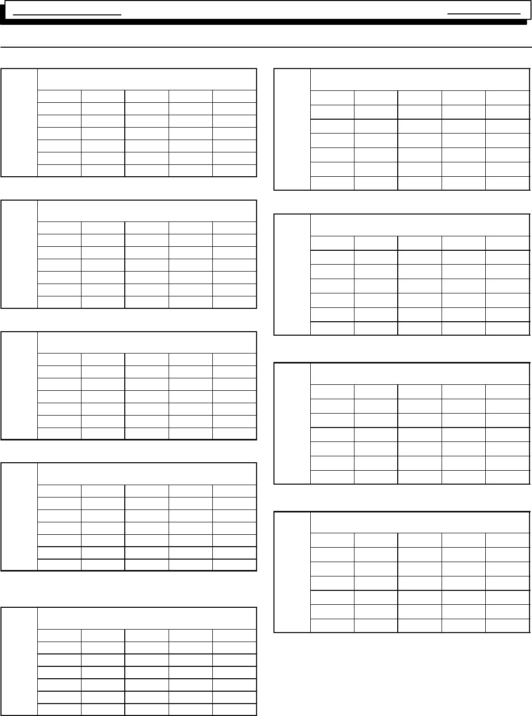
Exterrnal Static Pressure
Inches of W.C.
Exterrnal Static Pressure
Inches of W.C.
Exterrnal Static Pressure
Inches of W.C.
Exterrnal Static Pressure
Inches of W.C.
Exterrnal Static Pressure
Inches of W.C.
Exterrnal Static Pressure
Inches of W.C.
Exterrnal Static Pressure
Inches of W.C.
Exterrnal Static Pressure
Inches of W.C.
Exterrnal Static Pressure
Inches of W.C.
Multi Position Furnace Service Manual
37 440 08 2010 01
27. Circulation Air Blower Data
N8MPN/L050B12 & *8MPN/L050B12
Air Delivery in Cubic Feet per Minute (C.F.M.)
(Furnace Rated @0.5²
²²
²WC ESP)
TAP LOW MED L MED H HIGH
.10 454 672 1116 1335
.30 351 609 1055 1237
.50 278 550 991 1160
.70 201 498 897 1029
.90 -- -- -- 422 783 903
1.00 -- -- -- 353 718 822
N8MPN/L075B12 & *8MPN/L075B12
Air Delivery in Cubic Feet per Minute (C.F.M.)
(Furnace Rated @0.5²
²²
²WC ESP)
TAP LOW MED L MED H HIGH
.10 665 925 1171 1501
.30 616 893 1136 1407
.50 563 840 1074 1307
.70 517 741 977 1200
.90 442 650 866 1050
1.00 394 593 804 963
N8MPN/L075F16 & *8MPN/L075F16
Air Delivery in Cubic Feet per Minute (C.F.M.)
(Furnace Rated @0.5²
²²
²WC ESP)
TAP LOW MED L MED H HIGH
.10 803 1091 1548 2194
.30 760 1082 1557 2070
.50 699 1028 1500 1913
.70 618 934 1369 1708
.90 502 772 1138 1447
1.00 423 661 984 1254
N8MPN100F14 & *8MPN100F14
Air Delivery in Cubic Feet per Minute (C.F.M.)
(Furnace Rated @0.5²
²²
²WC ESP)
TAP LOW MED L MED H HIGH
.10 742 916 1287 1723
.30 625 845 1195 1638
.50 525 747 1079 1515
.70 440 662 1006 1371
.90 348 553 868 1185
1.00 297 490 787 1066
N8MPN/L100F20, *8MPN/L100F20, N8MPL100J20 &
*8MPN/L100J20
Air Delivery in Cubic Feet per Minute (C.F.M.)
(Furnace Rated @0.5²
²²
²WC ESP)
TAP LOW MED L MED H HIGH
.10 1845 2058 2285 2508
.30 1790 1992 2189 2379
.50 1714 1903 2066 2232
.70 1592 1769 1914 2049
.90 1404 1571 1711 1839
1.00 1291 1444 1541 1694
N8MPN/L100J22
Air Delivery in Cubic Feet per Minute (C.F.M.)
(Furnace Rated @0.5²
²²
²WC ESP)
TAP LOW MED L MED H HIGH
.10 1820 2144 2218 2252
.30 1747 1982 2135 2254
.50 1680 1862 1996 2092
.70 1551 1668 1819 1899
.90 1353 1448 1584 1744
1.00 1253 1380 1504 1633
N8MPN/L125J20 & *8MPN/L125J20
Air Delivery in Cubic Feet per Minute (C.F.M.)
(Furnace Rated @0.5²
²²
²WC ESP)
TAP LOW MED L MED H HIGH
.10 839 1211 1584 2267
.30 829 1188 1559 2151
.50 798 1111 1553 2049
.70 734 1079 1505 1912
.90 651 1015 1400 1704
1.00 595 897 1308 1585
N8MPN/L125J22
Air Delivery in Cubic Feet per Minute (C.F.M.)
(Furnace Rated @0.5²
²²
²WC ESP)
TAP LOW MED L MED H HIGH
.10 1832 2041 2257 2366
.30 1766 1958 2144 2291
.50 1700 1864 2001 2116
.70 1567 1705 1812 1956
.90 1393 1507 1639 1750
1.00 1284 1395 1529 1618
*8MPN150J20
Air Delivery in Cubic Feet per Minute (C.F.M.)
(Furnace Rated @0.5²
²²
²WC ESP)
TAP LOW MED L MED H HIGH
.10 1590 1827 2073 2283
.30 1519 1708 1993 2262
.50 1440 1623 1904 2150
.70 1331 1525 1774 1991
.90 1163 1381 1579 1813
1.00 1079 1277 1494 1694
* Denotes Brand
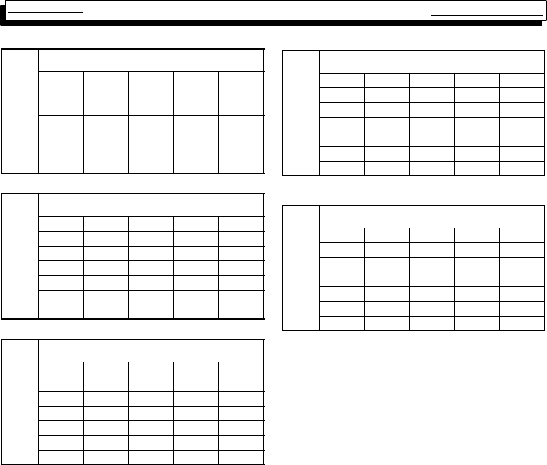
Exterrnal Static Pressure
Inches of W.C.
Exterrnal Static Pressure
Inches of W.C.
Exterrnal Static Pressure
Inches of W.C.
Exterrnal Static Pressure
Inches of W.C.
Exterrnal Static Pressure
Inches of W.C.
Multi Position Furnace
Service Manual
38
441 08 2010 01
*8DNL050B12/075F16
Air Delivery in Cubic Feet per Minute (C.F.M.)
(Furnace Rated @0.5²
²²
²WC ESP)
TAP LOW MED L MED H HIGH
.10 673 929 1211 1481
.30 599 815 1138 1365
.50 490 733 1049 1266
.70 394 595 884 1068
.90 297 451 641 910
1.00 238 420 510 777
*8DNL075B12Air Delivery in Cubic Feet per Minute (C.F.M.)
(Furnace Rated @0.5²
²²
²WC ESP)
TAP LOW MED L MED H HIGH
.10 649 748 975 1390
.30 540 668 926 1317
.50 445 575 1172 1201
.70 379 463 733 1056
.90 216 300 592 882
1.00 168 192 524 768
*8MDNL100F14
Air Delivery in Cubic Feet per Minute (C.F.M.)
(Furnace Rated @0.5²
²²
²WC ESP)
TAP LOW MED L MED H HIGH
.10 714 963 1310 1812
.30 553 845 1216 1658
.50 463 742 1125 1546
.70 365 658 989 1425
.90 -- -- -- 629 834 1233
1.0 -- -- -- 419 733 1083
*8DNL100F14
Air Delivery in Cubic Feet per Minute (C.F.M.)
(Furnace Rated @0.5²
²²
²WC ESP)
TAP LOW MED L MED H HIGH
.10 1738 1963 2150 2288
.30 1651 1839 2015 2125
.50 1560 1722 1859 1975
.70 1421 1566 1699 1789
.90 1239 1385 1500 1583
1.00 1030 1225 1361 1451
*8DNL125L20
Air Delivery in Cubic Feet per Minute (C.F.M.)
(Furnace Rated @0.5²
²²
²WC ESP)
TAP LOW MED L MED H HIGH
.10 1860 2085 2226
.30 1776 1954 2138 2246
.50 1662 1830 1981 2084
.70 1478 1629 1787 1878
.90 1279 1432 1539 1623
1.00 1168 1301 1369 1478
* Denotes Brand
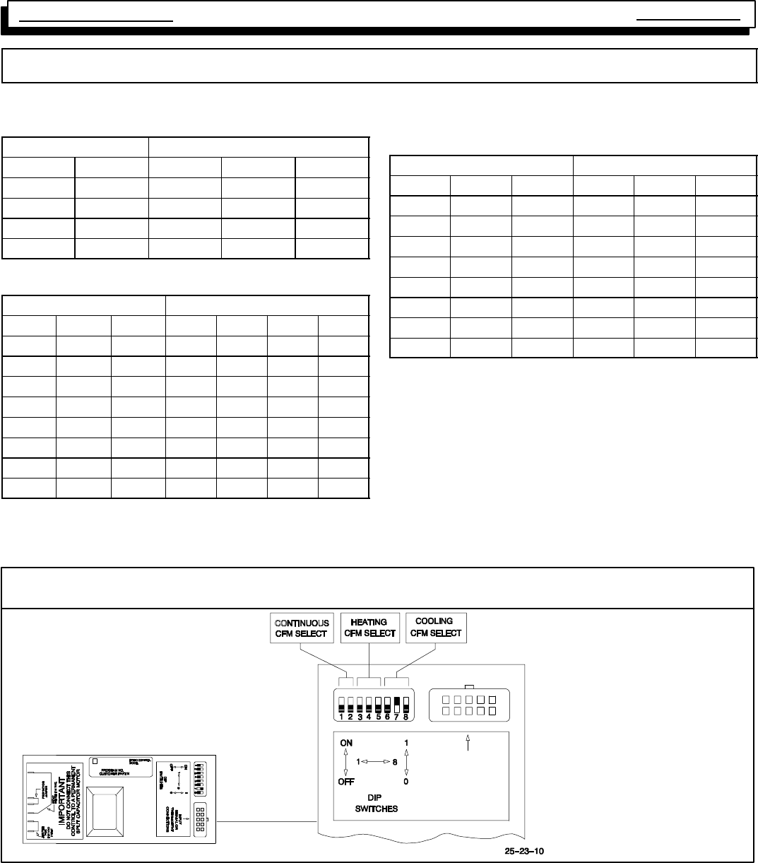
Multi Position Furnace Service Manual
39 440 08 2010 01
Circulation Air Blower Data - *8MPV
Heating, Cooling & Continuous Airflow Settings
Continuous Blower (CFM) @ 0.10²
²²
²Static
Switch Settings Furnace Model
#1 #2 50K 75K 100/125K
0* 0* 911 1046 1174
0 1 777 903 1032
1 0 664 771 858
1 1 542 632 698
*Factory Setting
Heating Air Temperature Adjustment (°
°°
°F)*
Switch Settings Furnace Model
#3 #4 #5 50K 75K 100K 125K
0** 0** 0** 0 0 0 0
0 0 1 1 1 3 3
0 1 0 2 2 5 5
0 1 1 3 4 7 8
1 0 0 6 5 8 10
1 0 1 -- 3 -- 3 -- 5 -- 1
1 1 0 -- 5 -- 6 -- 8 -- 2
1 1 1 -- 7 -- 9 -- 12 -- 4
*Approximate air temperature change from factory setting @ 0.20²static
on high heat )low heat speed changes with change of high heat speed on
most settings)
**Factory setting
Cooling (CFM) @ 0.50²
²²
²Static
(See Figure 1 -- 3 for complete Airflow Range)
Switch Settings Furnace Model
#6 #7 #8 50K 75K 100/125K
0* 0* 0* 1167 1414 2169
0 0 1 1115 1306 2003
0 1 0 1000 1209 1806
0 1 1 907 1105 1601
1 0 0 810 1009 1408
1 0 1 760 907 1204
1 1 0 703 842 1006
1 1 1 656 816 813
*Factory setting
*EXAMPLE
Cooling Airflows Switches 6, 7 & 8:
000 3.5 Ton
001 3.0 Ton
010 2.5 Ton
011 2.0 Ton
*See “Technical Support Manual”
for correct airflow rates.
010
Blower Motor Settings
INPUT
SIGNAL OR
THERMOSTAT
CONNECTIONS
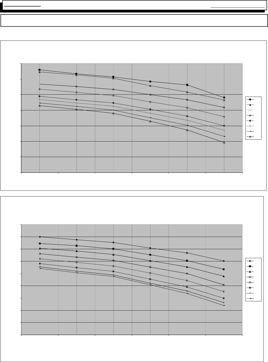
Multi Position Furnace
Service Manual
40
441 08 2010 01
Circulation Air Blower Data - *8MPV
Heating, Cooling & Continuous Airflow Settings
*8MPV050B12 COOLING
0
200
400
600
800
1000
1200
1400
0.1 0.2 0.3 0.5 0.7 1.0
" w.c. ESP
SCFM
000
001
010
011
100
101
110
111
Figure 1
*8MPV075F14 COOLING
0
200
400
600
800
1000
1200
1400
1600
1800
0.1 0.2 0.3 0.5 0.7 1.0
" w.c. ESP
CFM
000
001
010
011
100
101
110
111
Figure 2
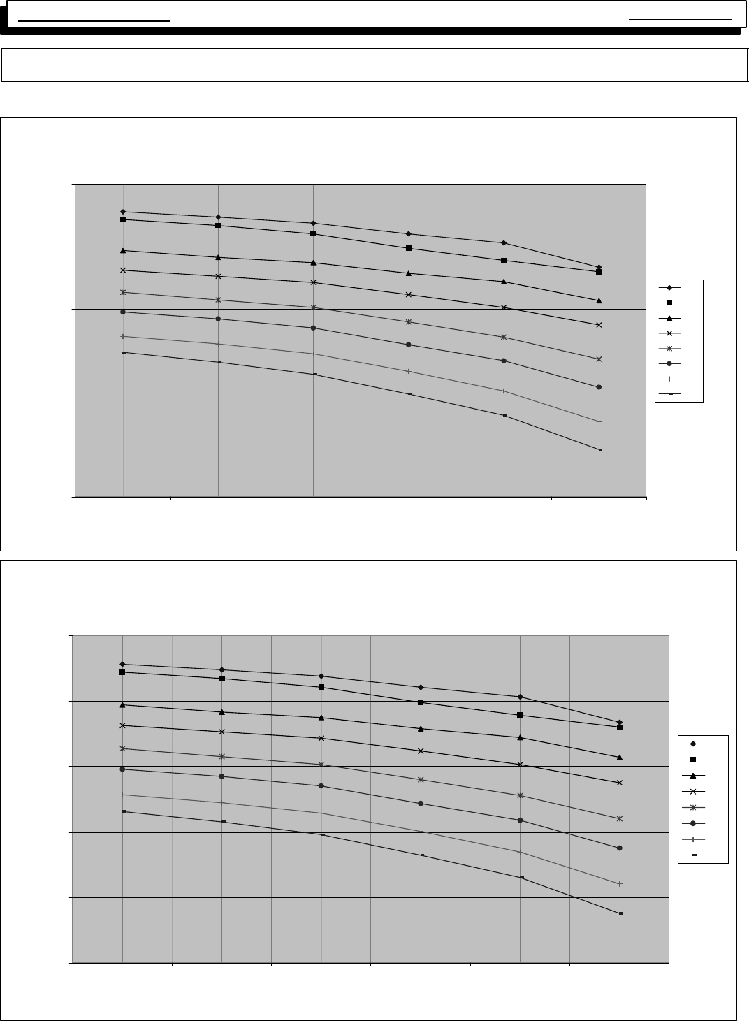
Multi Position Furnace Service Manual
41 440 08 2010 01
Circulation Air Blower Data - *8MPV
Heating, Cooling & Continuous Airflow Settings
8MPV100J20 COOLING
0
500
1000
1500
2000
2500
0.10.20.30.50.71.0
"w.c. ESP
CFM
000
001
010
011
100
101
110
111
Figure 3
8MPV125J20 COOLING
0
500
1000
1500
2000
2500
0.1 0.2 0.3 0.5 0.7 1.0
"w.c. ESP
CFM
000
001
010
011
100
101
110
111
Figure 4
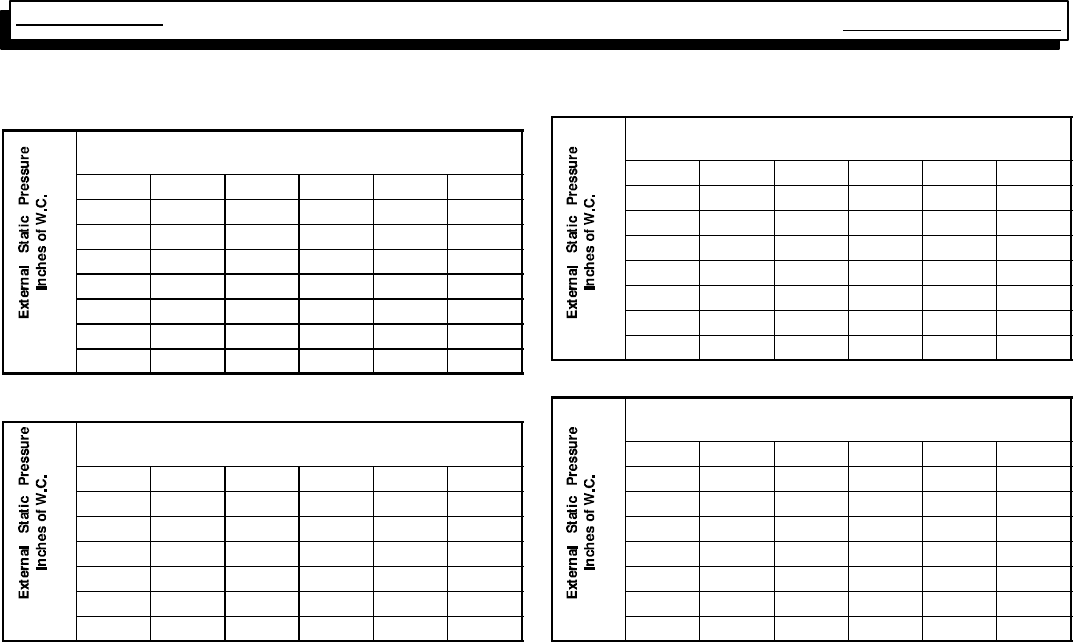
Multi Position Furnace
Service Manual
42
441 08 2010 01
CIRCULATION AIR BLOWER DATA
*8MPT050B
Air Delivery in Cubic Feet per Minute (C.F.M.)
(Furnace Rated @0.5²
²²
²WC ESP)
TAP LOW MED L MED MED H HIGH
.10 675 859 -- -- 1015 1394
.20 662 846 -- -- 999 1342
.30 651 819 -- -- 977 1289
.40 636 795 -- -- 952 1227
.50 608 765 -- -- 914 1163
.60 564 735 -- -- 870 1086
.70 514 685 -- -- 818 1002
*8MPT075F14 & *8MPT100F14
Air Delivery in Cubic Feet per Minute (C.F.M.)
(Furnace Rated @0.5²
²²
²WC ESP)
TAP LOW MED L MED MED H HIGH
.10 691 882 -- -- 1211 1633
.30 591 850 -- -- 1155 1544
.50 536 785 -- -- 1089 1464
.70 433 711 -- -- 982 1307
.90 342 856 -- -- 850 1120
1.00 308 527 -- -- 763 1041
*8MPT100J20
Air Delivery in Cubic Feet per Minute (C.F.M.)
(Furnace Rated @0.5²
²²
²WC ESP)
TAP LOW MED L MED MED H HIGH
.10 1210 1441 -- -- 1773 2104
.20 1201 1430 -- -- 1740 2078
.30 1197 1453 -- -- 1740 2061
.40 1191 1441 -- -- 1718 2020
.50 1167 1425 -- -- 1707 2005
.60 1160 1390 -- -- 1676 1953
.70 1130 1365 -- -- 1654 1917
*8MPT125J20
Air Delivery in Cubic Feet per Minute (C.F.M.)
(Furnace Rated @0.5²
²²
²WC ESP)
TAP LOW MED L MED MED H HIGH
.10 1264 1520 -- -- 1841 2161
.20 1251 1506 -- -- 1803 2132
.30 1249 1486 -- -- 1772 2079
.40 1219 1456 -- -- 1736 2042
.50 1168 1427 -- -- 1702 1991
.60 1178 1415 -- -- 1672 1914
.70 1143 1358 -- -- 1614 1838
INDEX
A
Adjusting Heat Anticipator, 10
Adjusting Manifold Pressure, 7
Air Proving Switch, See Pressure Switch
Auxiliary Limit Switch, 12
B
Blower Assembly, Conditioned Air, 18
Blower Speeds, Changing, 18
Blower Speeds, Selecting, 18
Burners, 8
C
Capacitors, 17
Checking Capacitors, 17
Checking Flame Current, 17
Checking Grounding and Polarity, 4
Checking Input (Firing) Rate, 6
Checking Manifold Pressure, 7
Checking Temperature Rise, 9
Circulating Air Blower Data, 37
Combustion Air/Vent Piping, 14
Combustion Blower. See Exhaust Blower
Control Wiring, 11
D
“DIP” Switch Settings, ST9160, 15
E
Electrical Supply, 4
Electrical Variation (SV9541M),25
Electronic Fan Timer, 15
F
Fan Timer, Electronic, 15
Flame Current, Checking, 17
G
Gas Valve/Ignition Control, Honeywell SV9541M, 16
Ground, Electrical, 4
H
Heat Anticipators, 10
Heat Exchanger Removal/Replacement, 20
High Altitude Operation, 7
Honeywell ST9160B Fan Timer, 19
Honeywell SV9541 Gas Valve/Ignition Control, 16
I
Inlet Air Restrictor, 10
Interlock Switch, 5
Introduction, 1
K
Kits, Twinning, 11
L
Limit Switches, 11
P
Piping, Vent/Combustion Air, 14
Polarity, Line Voltage, 4
Pressure Switches, 13
Pressures, Approximate Operating, 13
INDEX
R
Roll Out Limit Switch, 12
Room Thermostat, 10
S
Sequence of Operation Chart, SV9541M, 21
ST9160 Testing Sequence, 15
Supply, Electrical, 4
Supply, Gas, 6
SV9541M System Operation, 16
Switch, Blower Door Interlock, 5
Switch, “DIP”-- ST9140, 15
Switch, Auxiliary Limit, 12
Switch, Transition Pressure, 12
Switch,L.P.GasPressure,8
Switch, Main Limit, 11
Switch, Pressure, 12--13
Switch, Roll Out Limit, 12
Switches, Limit, 11
T
Technical Service Data , 30 -- 36
Temperature Rise, 9
Testing Sequence, ST9160, 15
Thermostat, Room, 10
Transition Pressure Switch, 13
Troubleshooting Chart, Honeywell SV9541M, 23
Twinning Kits, 11
U
Unit Identification, 2
V
Vent Termination, Standard, 14
Vent/Combustion Air Piping, 14
W
Wiring Diagram, 26 -- 29
Wiring, Control, 10
