Top Mounting Level Switches Instruction Manual BE44 604 XDC 60 200 44
User Manual: XDC 60-200
Open the PDF directly: View PDF ![]() .
.
Page Count: 12
T20 & T21
Top mounting
Liquid level switches
®
INSTRUCTION MANUAL AND REPLACEMENT PARTS
AGENCY APPROVALS
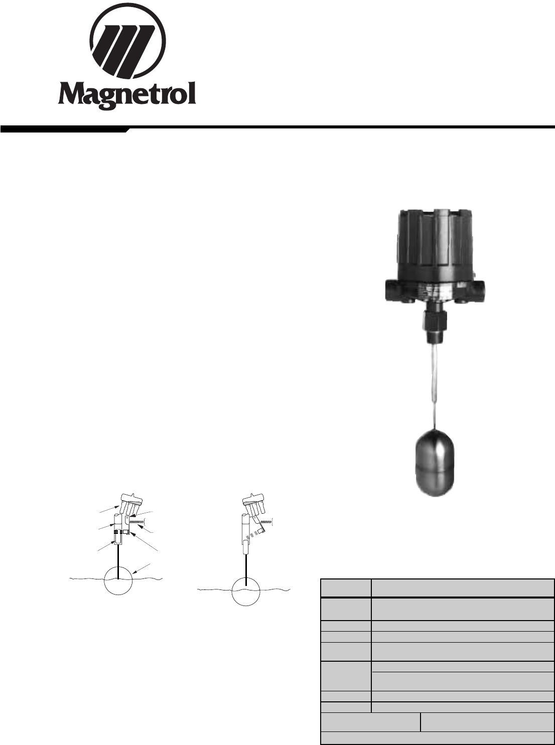
DESCRIPTION
T20 and T21 units are simple, reliable float switches
designed for top mounting to tanks or vessels. T20 units
utilize a single switch mechanism and float. T21 tandem
units utilize two switch mechanisms and two separate
floats when widely spaced actuating levels are required.
T20 and T21 tandem models are available for any type of
open or closed vessel with either threaded or flanged type
mounting and actuating depths up to 1219 mm (48 inches)
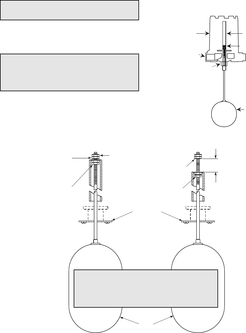
OPERATING PRINCIPLE
A permanent magnet ①is attached to a pivoted switch
actuator ②. As the float/ displacer ③rises following the liq-
uid level, it raises the attraction sleeve ④into the field of
the magnet, which then snaps against the non-magnetic
enclosing tube ⑤, actuating the switch. The enclosing tube
provides a static pressure boundary between the switch
mechanism and the process. On a falling level, an inconel
spring retracts the magnet, deactivating the switch.
②
⑤
④
③
①
pivot
return spring
rising level
falling level
UNPACKING
Unpack the instrument carefully. Inspect all units for dam-
age. Report any concealed damage to carrier within 24
hours. Check the contents of the packing slip and purchase
order. Check and record the serial number for future refer-
ence when ordering parts.
Agency Approval
ATEX II 2G EEx d II C T6, explosion proof
II 1G EEx ia II C T6, intrinsically safe
CENELEC EEx d II C T6, explosion proof
CCE ➀R1 (1) 136/MI/433, explosion proof
FM Class I, Div. 1, Groups C & D
Class II, Div. 1, Groups E, F & G, Type NEMA 7/9
FM/CSA ➁Non-Hazardous area
Explosion proof area –
Groups B, C, D, E, F & G Type NEMA 4X/7/9
SAA ➁Explosion proof area
LRS Lloyds Register of Shipment (marine applications)
GOST/ Russian Authorisation Standards
GOSGORTECHNADZOR ➁
Other approvals are available, consult factory for more details
➀For CCE approved units, use the ATEX explosion proof model
numbers.
➁Consult factory for proper model numbers.
2
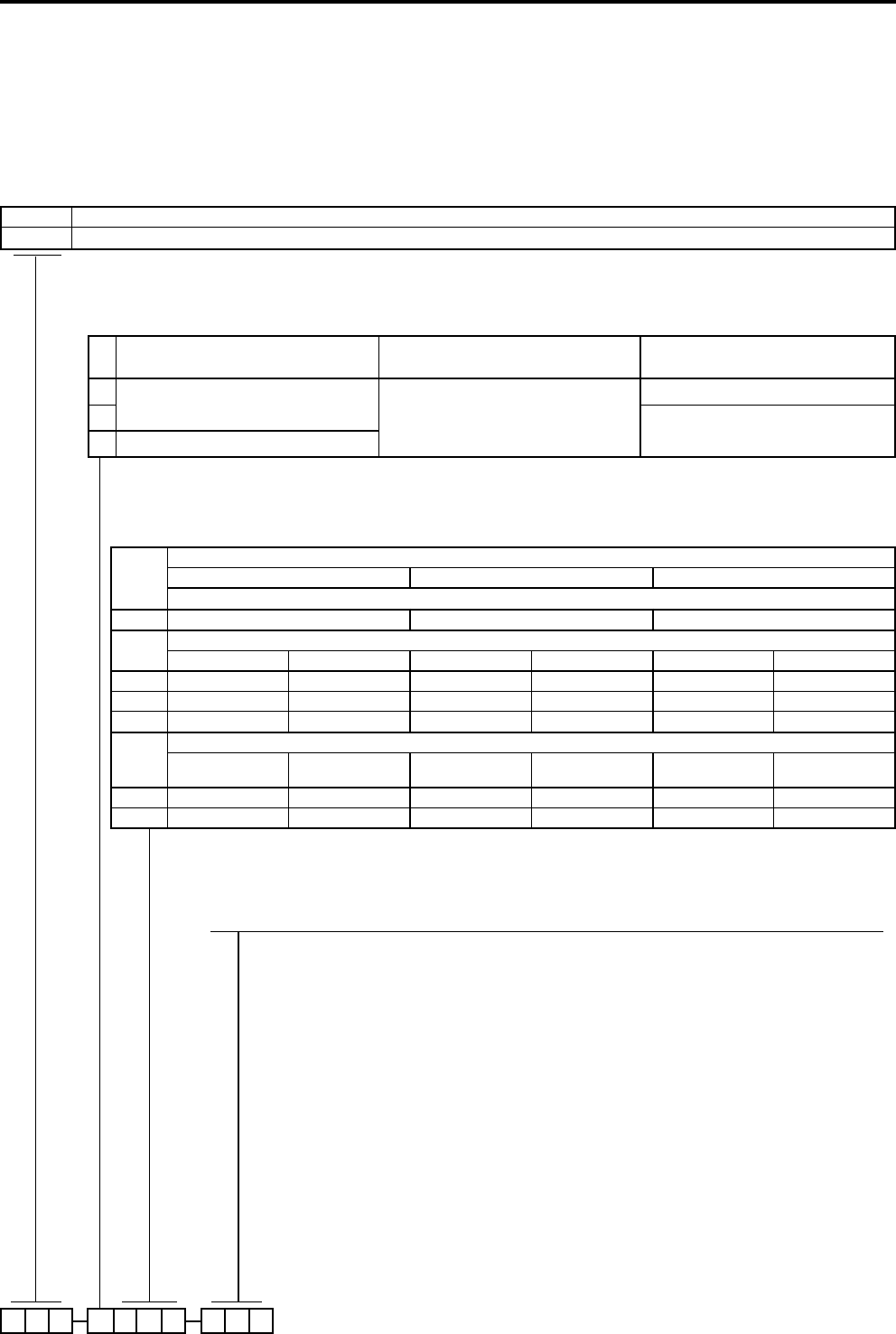
MODEL IDENTIFICATION
1. Code for top mounting liquid float level switches
BASIC MODEL NUMBER1
A complete measuring system consists of:
1. Code for top mounted models (each unit can be factory calibrated when specific level differentials are specified separately
– specify actuating level(s) for either rising or falling level and operating S.G.)
2. Code for modified models or adders: put an "X" in front of the closest matching order code and specify the modifications/
adders separately
eg. XT20-AB2A-AAP X = with material certification EN 10204 / DIN 50049-3.1.B
MATERIALS OF CONSTRUCTION
PROCESS CONNECTION
T20 single float - top mounted liquid float level switch
T21 tandem float - top mounted liquid float level switch
SWITCH MECHANISM & ENCLOSURE (see page 3)
complete code for top mounted models
Code
Cage & process
connection material Float and trim Magnetic sleeve
ACarbon steel 316 SST (1.4401)
400 series SST
B316 SST (1.4401)
D316/316L (1.4401/1.4404)
Float sizes
ø 76 x 127 mm (3" x 5") ø 102 mm (4") ø 114 mm (4 1/2")
Threaded NPT connection - for T20 models only
1" B2A B2B B2C
ANSI Flanges - for all models
150 lbs RF 300 lbs RF 150 lbs RF 300 lbs RF 150 lbs RF 300 lbs RF
4" H3A H4A - - - -
5" J3A -J3B -J3C -
6" K3A K4A K3B K4B K3C K4C
DIN flanges form to DIN 2526 - for all models
PN 16
Form C
PN 25/40
Form C
PN 16
Form C
PN 25/40
Form C
PN 16
Form C
PN 25/40
Form C
DN 100
8FA 8GA - - - -
DN 150
9FA 9GA 9FB 9GB 9FC 9GC
3
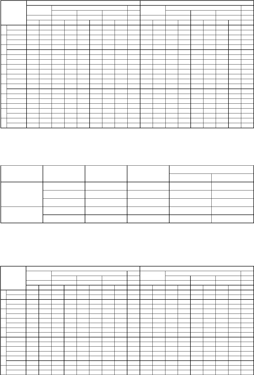
MODEL IDENTIFICATION (cont.)
Select electric switch mechanism & enclosure for models T20 (see page 3 for switch ratings)
Select electric switch mechanism & enclosure for models T21
Select pneumatic switch mechanism & enclosure - for models T20 only
qty and
switch
type
All models with material code A All models with material codes B and D
Weather proof
(IP 66)
ATEX (IP 66)
FM (IP 66)
Weather proof
(IP 66)
ATEX (IP 66)
FM (IP 66)
II 2G EEx d IIC T6 II 1G EEx ia II C T6 II 2G EEx d IIC T6
NEMA 7/9
II 2G EEx d IIC T6 II 1G EEx ia II C T6 II 2G EEx d IIC T6
NEMA 7/9
cast Aluminium cast Aluminium cast Aluminium cast Iron cast Alu. cast Aluminium cast Aluminium cast Aluminium cast Iron cast Alu.
M20 x 1,5
1" NPT
M20 x 1,5
1" NPT
M20 x 1,5
1" NPT
M20 x 1,5
3/4" NPT
1" NPT
M20 x 1,5
1" NPT
M20 x 1,5
1" NPT
M20 x 1,5
1" NPT
M20 x 1,5
3/4" NPT
1" NPT
A1 x SPDT A2P AAP AHC AAC - - AK7 AU7 AKP A2Q AAQ AH9 AA9 - - AK5 AU5 AKQ
1 x DPDT A8P ADP AJC ABC - - AD7 AW7 ANP A8Q ADQ AJ9 AB9 - - AD5 AW5 ANQ
31 x SPDT 32P 3AP 3HC 3AC - - 3K7 3U7 3KP 32Q 3AQ 3H9 3A9 - - 3K5 3U5 3KQ
1 x DPDT 38P 3DP 3JC 3BC - - 3D7 3W7 3NP 38Q 3DQ 3J9 3B9 - - 3D5 3W5 3NQ
B1 x SPDT B2P BAP BHC BAC - - BK7 BU7 BKP B2Q BAQ BH9 BA9 - - BK5 BU5 BKQ
1 x DPDT B8P BDP BJC BBC - - BD7 BW7 BNP B8Q BDQ BJ9 BB9 - - BD5 BW5 BNQ
C1 x SPDT C2P CAP CHC CAC C2L CAL CK7 CU7 CKP C2Q CAQ CH9 CA9 C2S CAS CK5 CU5 CKQ
1 x DPDT C8P CDP CJC CBC C8L CDL CD7 CW7 CNP C8Q CDQ CJ9 CB9 C8S CDS CD5 CW5 CNQ
D1 x SPDT - - - - - - - - - D2Q DAQ DH9 DA9 - - DK5 DU5 DKQ
1 x DPDT - - - - - - - - - D8Q DDQ DJ9 DB9 - - DD5 DW5 DNQ
F1 x SPDT F2P FAP FHC FAC - - FK7 FU7 FKP F2Q FAQ FH9 FA9 - - FK5 FU5 FKQ
1 x DPDT F8P FDP FJC FBC - - FD7 FW7 FNP F8Q FDQ FJ9 FB9 - - FD5 FW5 FNQ
HS 1 x SPDT - - - - - - - - - H7A HM2 HFC HA9 - - HB3 HB4 HM3
1 x DPDT - - - - - - - - - H7C HM6 HGC HB9 - - HB7 HB8 HM7
U1 x SPDT U2P UAP UHC UAC U2L UAL UK7 UU7 UKP U2Q UAQ UH9 UA9 U2S UAS UK5 UU5 UKQ
1 x DPDT U8P UDP UJC UBC U8L UDL UD7 UW7 UNP U8Q UDQ UJ9 UB9 U8S UDS UD5 UW5 UNQ
V - - - - - VFS VHS - - - - - - - V5S VBS ---
W1 x SPDT W2P WAP WHC WAC W2L WAL WK7 WU7 WKP W2Q WAQ WH9 WA9 W2S WAS WK5 WU5 WKQ
1 x DPDT - - - - - - - - - W8Q WDQ WJ9 WB9 W8S WDS WD5 WW5 WNQ
X1 x SPDT X2P XAP XHC XAC X2L XAL XK7 XU7 XKP X2Q XAQ XH9 XA9 X2S XAS XK5 XU5 XKQ
1 x DPDT - - - - - - - - - X8Q XDQ XJ9 XB9 X8S XDS XD5 XW5 XNQ
Pneumatic switch type Max supply pressure
bar (psi)
Max liquid temperature
°C (°F)
Bleed orifice Ø
mm (inches)
NEMA 3R (IP 53)
material code A material codes B & D
Series J
(open air)
6,9 (100) 200 (400) 1,60 (0.063) JDG JDE
4,1 (60) 200 (400) 2,39 (0.094) JEG JEE
4,1 (60) 370 (700) 1,40 (0.055) JFG JFE
Series K
(closed circuit)
6,9 (100) 200 (400) –KOE KOE
2,8 (40) 200 (400) –KOG –
qty and
switch
type
All models with material code A All models with material codes B and D
Weather proof
(IP 66)
ATEX (IP 66)
FM (IP 66)
Weather proof
(IP 66)
ATEX (IP 66)
FM (IP 66)
II 2G EEx d II C T6 II 1G EEx ia II C T6 II 2G EEx d II C T6
NEMA 7/9
II 2G EEx d II C T6 II 1G EEx ia II C T6 II 2G EEx d II C T6
NEMA 7/9
cast Aluminium cast Aluminium cast Aluminium cast Iron cast Alu. cast Aluminium cast Aluminium cast Aluminium cast Iron cast Alu.
M20 x 1,5
1" NPT
M20 x 1,5
1" NPT
M20 x 1,5
1" NPT
M20 x 1,5
3/4" NPT
1" NPT
M20 x 1,5
1" NPT
M20 x 1,5
1" NPT
M20 x 1,5
1" NPT
M20 x 1,5
3/4" NPT
1" NPT
A2 x SPDT A4A ABA ALC ADC - - AL7 AV7 ALA A4B ABB AL9 AD9 - - AL5 AV5 ALB
2 x DPDT A1A AEA APC AGC - - AO7 AY7 AOA A1B AEB AP9 AG9 - - AO5 AY5 AOB
32 x SPDT 34E 3BE 39E 3DE - - 3L7 3V7 3LE 34B 3BB 3L9 3D9 - - 3L5 3V5 3LB
2 x DPDT 31A 3EA 3PC 3GC - - 3O7 3Y7 3OA 31B 3EB 3P9 3G9 - - 3O5 3Y5 3OB
B2 x SPDT B4A BBA BLC BDC - - BL7 BV7 BLA B4B BBB BL9 BD9 - - BL5 BV5 BLB
2 x DPDT B1A BEA BPC BGC - - BO7 BY7 BOA B1B BEB BP9 BG9 - - BO5 BY5 BOB
C2 x SPDT C4A CBA CLC CDC C4X CBX CL7 CV7 CLA C4B CBB CL9 CD9 C4T CBT CL5 CV5 CLB
2 x DPDT C1A CEA CPC CGC C1X CEX CO7 CY7 COA C1B CEB CP9 CG9 C1T CET CO5 CY5 COB
D2 x SPDT D4B DBB DL9 DD9 - - DL5 DV5 DLB D4B DBB DL9 DD9 - - DL5 DV5 DLB
2 x DPDT D1B DEB DP9 DG9 - - DO5 DY5 DOB D1B DEB DP9 DG9 - - DO5 DY5 DOB
F2 x SPDT FFA FBA FLC FDC - - FL7 FV7 FLA FFB FBB FL9 FD9 - - FL5 FV5 FLB
2 x DPDT FHA FEA FPC FGC - - FO7 FY7 FOA FHB FEB FP9 FG9 - - FO5 FY5 FOB
U2 x SPDT U4A UBA ULC UDC U4X UBX UL7 UV7 ULA U4B UBB UL9 UD9 U4T UBT UL5 UV5 ULB
2 x DPDT U1A UEA UPC UGC U1X UEX UO7 UY7 UOA U1B UEB UP9 UG9 U1T UET UO5 UY5 UOB
W2 x SPDT W4A WBA WLC WDC W4X WBX WL7 WV7 WLA W4B WBB WL9 WD9 W4T WBT WL5 WV5 WLB
2 x DPDT W1B WEB WP9 WG9 W1T WET WO5 WY5 WOB W1B WEB WP9 WG9 W1T WET WO5 WY5 WOB
X2 x SPDT X4A XBA XLC XDC X4X XBX XL7 XV7 XLA X4B XBB XL9 XD9 X4T XBT XL5 XV5 XLB
2 x DPDT X1B XEB XP9 XG9 X1T XET XO5 XY5 XOB X1B XEB XP9 XG9 X1T XET XO5 XY5 XOB
4
INSTALLATION
MOUNTING
Before assembling control to tank or vessel, check thread-
ed or flanged mounting nozzle for the following:
–Nozzle length and inside diameter must be sized correct-
ly to allow for switch actuation at design levels within the
maximum differential available (see table on page 4).
–Nozzle should be checked for horizontal alignment.
Finished mounting must allow control switch housing to
be within 3° degrees of vertical for proper operation. A
three degree slant is noticeable by eye, but installation
should be checked with a spirit level.
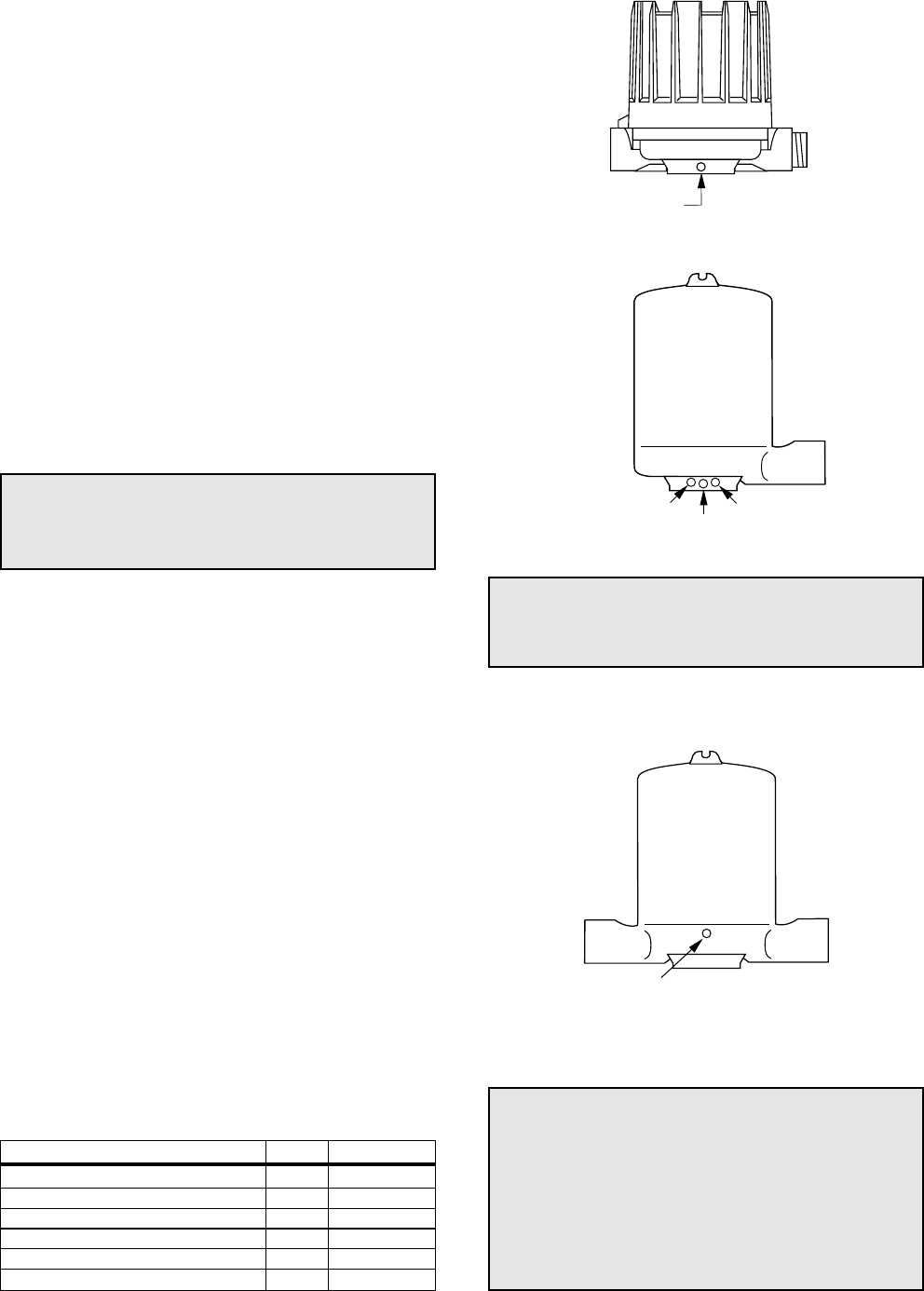
WIRING
Most mechanical control switch housings are designed to
allow 360° positioning of the cable entries by loosening the
set screw(s). See figure 2. On high temperature applica-
tions (above 120° C [250° F]), high temperature wire should
be used between control and first junction box located in a
cooler area.
1. To gain access to switch mechanism(s) remove switch
housing cover.
2. Pull in supply wires (conductors), wrap them around
enclosing tube under the baffle plate and connect to cor-
rect terminals. Be certain that excess wire does not
interfere with "tilt" of switch and that adequate clearance
exists for replacement of switch housing cover.
CAUTION:
In hazardous area, do not power the unit until
the cable gland is sealed and the enclosure
cover is screwed down securely.
NOTE: See bulletin on switch mechanism furnished with
your control (as listed below) for proper connections.
3. Connect power supply to control and test switch action
by varying liquid level in tank or vessel.
NOTE: If switch mechanism fails to function properly, check
vertical alignment of control housing and consult installation
instructions in switch mechanism bulletin.
4. Replace switch housing cover and place control into ser-
vice.
NOTE: If control has been furnished with an explosion proof
(cast) or moisture proof (gasketed) switch housing, check
the following:
–After wiring connections have been completed, housings
must be sealed via the correct cable gland to prevent
entrance of air.
–Check cover to base fit, to be certain gasketed joint is
tight. A positive seal is necessary to prevent infiltration of
moisture laden air or corrosive gases into switch housing.
Set screw
Set screw
Locking screw
Set screw
Position
screw
Switch mechanism Bulletin Reference series
Mercury switches 42-783 A
Dry contact switches 42-783 B, C, D, U, W, X
Anti-vibration mercury switches E
Anti-vibration dry contact switches 42-684 G, H, I
Bleed type pneumatic valve 42-685 J
Non-bleed type pneumatic valve 42-686 K
CAUTION:
-DO NOT attempt to reposition NEMA 4 /
NEMA 7/9 housings without loosening the
set screws; ATEX housings MAY NOT BE
REPOSITIONNED. ALWAYS retighten set
screw(s) after repositionning.
-DO NOT attempt to unscrew cover of ATEX
housings before loosening locking screw in
base of housing. ALWAYS retighten locking
screw after replacing cover.
Figure 2
NEMA 4x
NEMA 7/9
ATEX
OBSERVE ALL APPLICABLE ELECTRICAL CODES AND
PROPER WIRING PROCEDURES
CAUTION:
-DO NOT attempt to reposition NEMA 4X /
NEMA 7/9 housings without loosening the
set screws.
5
Figure 4
Normal Factory Setting
(minimum differential)
Figure 5
Differential adjustment
Figure 3
SWITCH DIFFERENTIAL ADJUSTMENT
The standard differential of T20 and T21 Liquid Level
Switches may be field adjusted. Adjustment may be nec-
essary if a wider differential needs to be set to overcome
switch chatter caused by the process.
The differential, or the amount of level travel between
switch-on and switch-off, may be adjusted by repositioning
the lower jam nuts on the float stem. The standard factory
setting is for a minimum amount of play (gap) between the
top jam nuts and the attraction sleeve as shown in
Figure 4.
NOTE: For assistance in computing level differential
change for a specific control, consult the factory giving the
model and serial numbers of the control.
NOTE: To widen the differential 13 mm (0.5"), the lower
jam nuts must be set proportionately lower on the stem (i.e.
in this example 13 mm (0.5")).
1. Determine what change in differential is necessary.
2. Make sure power source is turned off.
3. Unscrew and remove switch housing cover.
4. Disconnect power supply wires from switch mecha-
nism. Pull wires out of conduit connection opening in
housing base. Refer to Figure 3.
5a. Perform system shut-down procedures as required to
relieve pressure from tank or vessel and drain off liquid
head, if required. Allow unit to cool.
5b. The amount of level travel between switch-on and
switch-off actuations (differential) may be field adjusted
by repositioning the lower jam nuts on the float stem.
The standard factory setting is for a minimum amount
of play (gap) between the top jam nuts and the attrac-
tion sleeve, as shown in Figure 4. This setting may be
increased to a maximum of 13 mm (0.50"), as shown
in Figure 5.
6. Remove switch housing assembly by loosening hex
nut, which is located immediately below housing base.
Refer to Figure 3.
CAUTION: Maximum differential adjustment is 13 mm
(0.5").
CAUTION: Before attempting any work on the control,
pull disconnect switch, or otherwise assure that electri-
cal circuit(s) through the control is deactivated. Close
operating medium supply valve on controls equipped
with pneumatic switch mechanisms.
Switch housing
cover
Slight play (gap)
must be allowed
(0.8 mm (.03") typical)
Position of bottom jam
nuts (normal factory
setting)
For access to bottom jam
nuts, mark position,
remove top jam nuts,
washer, and attracting
sleeve
Maximum gap setting
(Applies to models having
a single switch mechanism
with a single magnet
actuator only)
Replace in
same position
Drop bottom jam nuts to
increase gap setting
(see instructions below)
Sleeve stop
strap
Float
13 mm
(0.50")
Cable connexion
Enclosing tube nut
Enclosing tube
Housing base
Float
Refer to Figures 4 and 5
CAUTION: After increasing gap setting, be certain to
check for proper operation of switch mechanism by rais-
ing and lowering float assembly. Magnet must snap clean-
ly, with additional float movement available after magnet
snaps.

6
7. With switch housing removed, jam nuts and attraction
sleeve are accessible. Measure position of upper jam
nuts from stem end; then loosen and remove upper
jam nuts, guide washer, and attraction sleeve.
8. Loosen and adjust lower jam nuts to desired position.
Make certain jam nuts are retightened securely.
NOTE: Use new gasket in assembly of switch housing to
chamber (Part No. 12-1301-002).
9. Test switch actuation by varying liquid level in tank or
vessel.
SWITCH DIFFERENTIAL ADJUSTMENT cont.
CAUTION: Instructions given are for standard base
model units which use a single magnet switch mecha-
nism only. No differential adjustment should be attempt-
ed on tandem float models in the field. Switch actuation
levels have been set at the factory to meet specific cus-
tomer specifications. Variations in actual conditions
from design conditions usually requires special control
modifications. Consult with the factory or local repre-
sentative for assistance
TROUBLE SHOOTING
Usually the first indication of improper operation is failure of
the controlled equipment to function, i.e.: pump will not start
(or stop), signal lamps fail to light, etc. When these
symptoms occur, whether at time of installation or during
routine service thereafter, check the following potential
external causes first.
— Fuses may be blown.
— Reset button(s) may need resetting.
— Power switch may be open.
— Controlled equipment may be faulty.
— Wiring leading to control may be defective.
If a thorough inspection of these possible conditions fails to
locate the trouble, proceed next to a check of the control’s
switch mechanism.
CHECK SWITCH MECHANISM
1. Pull disconnect switch or otherwise disconnect power to
the control.
2. Remove switch housing cover.
3. Disconnect power wiring from switch assembly.
4. Swing magnet assembly in and out by hand to check
carefully for any sign of binding. Assembly should
require minimal force to move it through its full swing.
5. If binding exists, magnet may be rubbing enclosing
tube. If magnet is rubbing, loosen magnet clamp screw
and shift magnet position. Retighten magnet clamp
screw.
6. If switch magnet assembly swings freely and mechanism
still fails to actuate, check installation of control to be cer-
tain it is within the specified three (3°) degrees of vertical
(Use spirit level on side of enclosing tube in two place, 90°
apart.
7. If mechanism is equipped with a mercury switch,
examine glass mercury tube closely as previously
described in “Preventive Maintenance” section. If
switch is damaged, replace it immediately.
8. If switch mechanism is operating satisfactorily, proceed
to check sensing unit.
CHECK SENSING UNIT
1. Re-connect power supply and carefully actuate switch
mechanism manually (using a non-conductive tool) to
determine whether controlled equipment will operate.
CAUTION:
With electrical power “on”, care should be taken
to avoid contact with switch leads and connec-
tions at terminal block.
2. If controlled equipment responds to manual actuation
test, trouble may be located in the level sensing portion
of the control (float, stem and magnetic attraction
sleeve[s]).
NOTE: Check first to be certain liquid is entering storage
tank or vessel. A valve may be closed or pipe line plugged.
3. With liquid in tank or vessel, proceed to check level
sensing action by removing switch housing assembly.
4. Inspect magnetic attraction sleeve(s) and inside of
enclosing tube for excessive corrosion or solids build-
up which could restrict movement, preventing sleeve(s)
from reaching field of magnet(s).
5. If differential has been changed in the field, check tight-
ness and position of the jam nuts.
NOTE: Differential adjustment affects a change in the
amount of level travel between “switch on” and “switch off”
actuations. Do NOT attempt adjustment without first con-
sulting factory for assistance in computing level differential
change for your control.
6. Check float to be certain it is buoyant in the liquid (tank
or vessel must have adequate liquid level). If float is
determined to be filled with liquid or collapsed, it must
be replaced immediately. Do NOT attempt to repair a
float.
If all the components in the control are in operating condi-
tion, the trouble must be (and should be) located external
to the control. Repeat inspection of external conditions pre-
viously described.
NOTE: When in doubt about the condition or performance
of a Magnetrol control, return it to the factory. See “Our
Service Policy” on back page.

7
PREVENTIVE MAINTENANCE
Periodic inspections are a necessary means to keep your Magnetrol level control in good working order. This control
is, in reality, a safety device to protect the valuable equipment it serves. Therefore, a systematic program of "preven-
tive maintenance" should be implemented when control is placed into service. If the following sections on "what to
do" and "what to avoid" are observed, your control will provide reliable protection of your capital equipment for many
years.
WHAT TO DO
1. Keep control clean
NEVER leave switch housing cover off the control. This
cover is designed to keep dust and dirt from interfering
with switch mechanism operation. In addition, it protects
against damaging moisture and acts as a safety feature
by keeping bare wires and terminals from being
exposed. Should the housing cover become damaged
or misplaced, order a replacement immediately.
2. Inspect switch mechanisms, terminals and connec-
tions monthly.
–Mercury switches may be visually inspected for short
circuit damage. Check for small cracks in the glass
tube containing the mercury. Such cracks can allow
entrance of air into the tube causing the mercury to
"oxidize". This is noticeable as the mercury will
appear dirty and have a tendency to "string out" like
water, instead of breaking into round pools. If these
conditions exist, replace the mercury switch immedi-
ately.
–Dry contact switches should be inspected for exces-
sive wear on actuating lever or misalignment of
adjusting screw at point of contact between screw
and lever. Such wear can cause false switch actuat-
ing levels. Adjust switch mechanism to compensate
(if possible) or replace switch.
Do NOT operate your control with defective or malad-
justed switch mechanisms (refer to bulletin on switch
mechanism furnished for service instructions).
–Magnetrol controls may sometimes be exposed to
excessive heat or moisture. Under such conditions,
insulation on electrical wires may become brittle,
eventually breaking or peeling away. The resulting
"bare" wires can cause short circuits.
Check wiring carefully and replace at first sign of brittle
insulation.
–Vibration may sometimes cause terminal screws to
work loose. Check all terminal connections to be cer-
tain that screws are tight. Air (or gas) operating medi-
um lines subjected to vibration may eventually crack
or become loose at connections causing leakage.
Check lines and connections carefully and repair or
replace, if necessary.
–On units with pneumatic switches, air (or gas) oper-
ating medium lines subjected to vibration, may even-
tually crack or become loose at connections carefully
and repair or replace, if necessary.
NOTE: As a matter of good practice, spare switches should
be kept on hand at all times.
3. Inspect entire unit periodically
Isolate control from vessel. Raise and lower liquid level
to check for switch contact and reset.
WHAT TO AVOID
1. NEVER leave switch housing cover off the control longer
than necessary to make routine inspections.
2. NEVER use lubricants on pivots of switch mechanisms.
A sufficient amount of lubricant has been applied at the
factory to insure a lifetime of service. Further oiling is
unnecessary and will only tend to attract dust and dirt
which can interfere with mechanism operation.
3. NEVER place a jumper wire across terminals to "cut-
out" the control. If a "jumper" is necessary for test pur-
poses, be certain it is removed before placing control
into service.
4. NEVER attempt to make adjustments or replace switch-
es without reading instructions carefully. Certain adjust-
ments provided for in Magnetrol controls should not be
attempted in the field. When in doubt, consult the facto-
ry or your local Magnetrol representative.
8
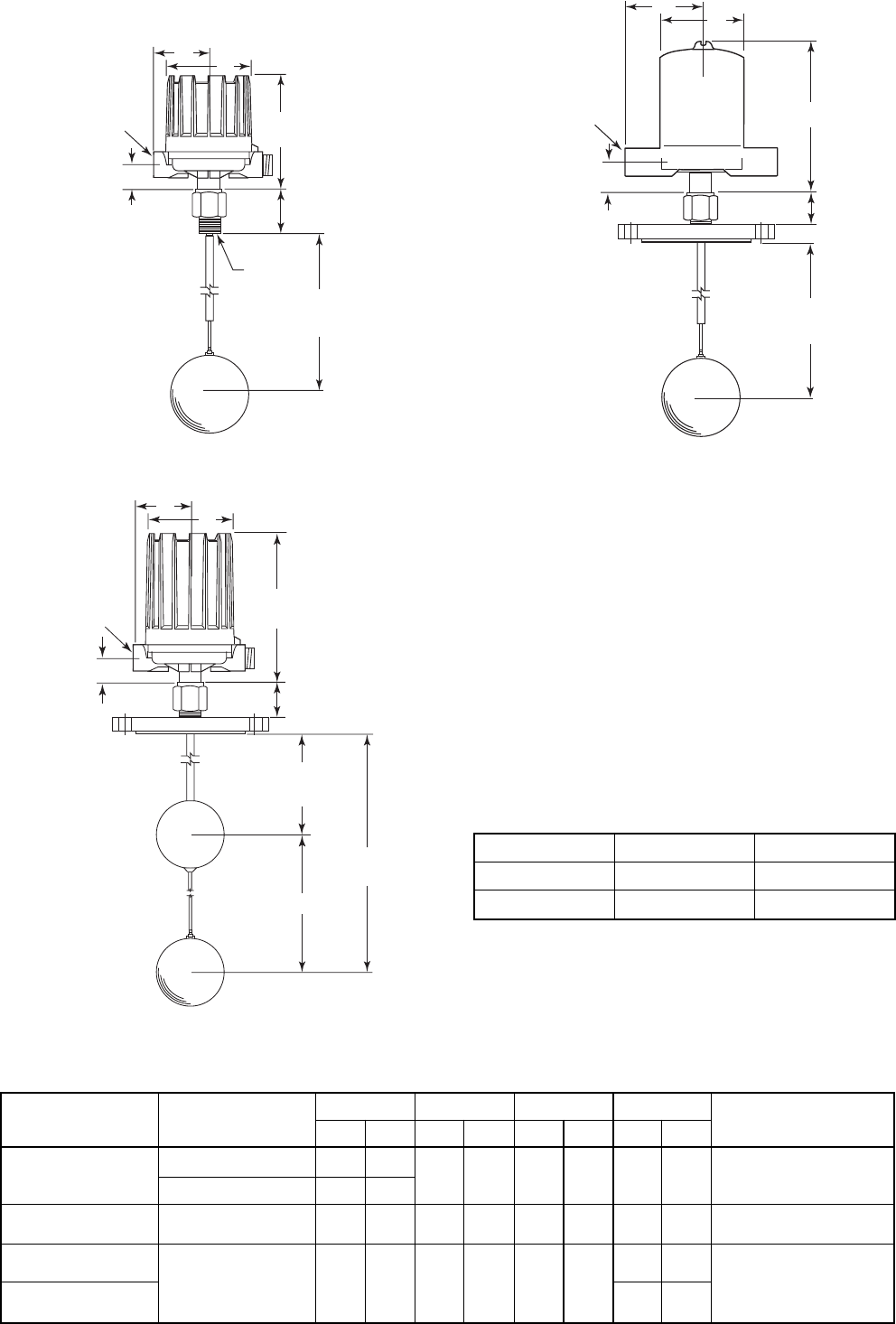
DIMENSIONAL SPECIFICATIONS mm (inches)
Allow 200 mm (7.87") overhead clearance / All housings are 360 °rotatable
Model T20 with 1" NPT Model T20 with flange
Model T21 with flange
V
X
Y
Z
W
62 (2.44)
1" NPT
Distance to
actuating level
min 102 (4)
Actuating
level Actuating
level
V
X
Y
Z
W
46 (1.81) Ref.
Distance to
actuating level
min 102 (4)
Actuating
level
Actuating
level
V
X
Y
Z
W
46 (1.81) Ref.
min 204 (8)
Distance to upper
actuating level
min 102 (4)
Distance to lower
actuating level
Note: On model T21, the lower float actuates the upper
switch mechanism. The upper float actuates the lower
switch mechanism.
Housing type Models V W ø X YZ
mm inches mm inches mm inches mm inches
Weatherproof-
FM (NEMA 7/9) -
ATEX (Cast Alu)
T21 and T20 with HS-switch
257 10.12 42 1.66 151 5.93 109 4.29
M20 x 1,5 (*) or 1" NPT
(2 entries - 1 plugged)
(*) not for FM (NEMA 7/9)
T20 excl. HS-switch 202 7.94
CENELEC (Cast Iron) All 249 9.80 45 1.77 143 5.63 110 4.33 M20 x 1,5 or 3/4" NPT
(single entry - 2 entries at request)
Pneumatics
Switch Module J All 165 6.50 39 1.54 118 4.65
110 4.33
1/4" NPT
Pneumatics
Switch Module K 130 5.12
Distance to Maximum Minimum
Upper level 1016 mm (40") 102 (4")
Lower level 1219 mm (48") 305 (12")

9
FLOAT SELECTION AND INSERTION DEPTH
T20/T21 switches are fabricated to meet customer specific
insertion depth, from mounting fitting to actuating level. The
maximum available insertion depth is governed by the liq-
uid specific gravity and selected float size as given in the
table below. The minimum insertion depth is 102 mm (4").
PRESSURE RATINGS
Float ratings are the maximum allowable pressure rating,
even though the tank connections may have higher ratings.
Pressure Rating Bar (PSIG)
@ 40° C @ Maximum
(100° F) Temperature
76 x 127 mm 34,5 Bar 20,7 Bar @ 400° C
(3.00" x 5.00") (500 PSIG) (300 PSIG @ 750° F)
102 mm 41,3 Bar 27,6 Bar @ 400° C
(4") (600 PSIG) (400 PSIG @ 750° F)
114 mm 34,5 Bar 23,4 Bar @ 400° C
(4.50") (500 PSIG) (340 PSIG @ 750° F)
T20 models - float sizes
Specific Gravity
ø 76 x 127 mm
(3" x 5")
ø 102 mm
(4")
ø 114 mm
(4 1/2")
0.60 - - 140 (5.5)
0.70 - - 914 (36)
0.80 -254 (10) 1219 (48)
0.90 432 (17) 813 (32) 1219 (48)
1.00 889 (35) 1219 (48) 1219 (48)
➀Max actuating levels as per lowest float
T21 models - float sizes ➀
Specific Gravity
ø 76 x 127 mm
(3" x 5")
ø 102 mm
(4")
ø 114 mm
(4 1/2")
0.70 - - 711 (28)
0.80 -305 (12) 1219 (48)
0.90 406 (16) 660 (26) 1219 (48)
1.00 711 (28) 1016 (40) 1219 (48)
10
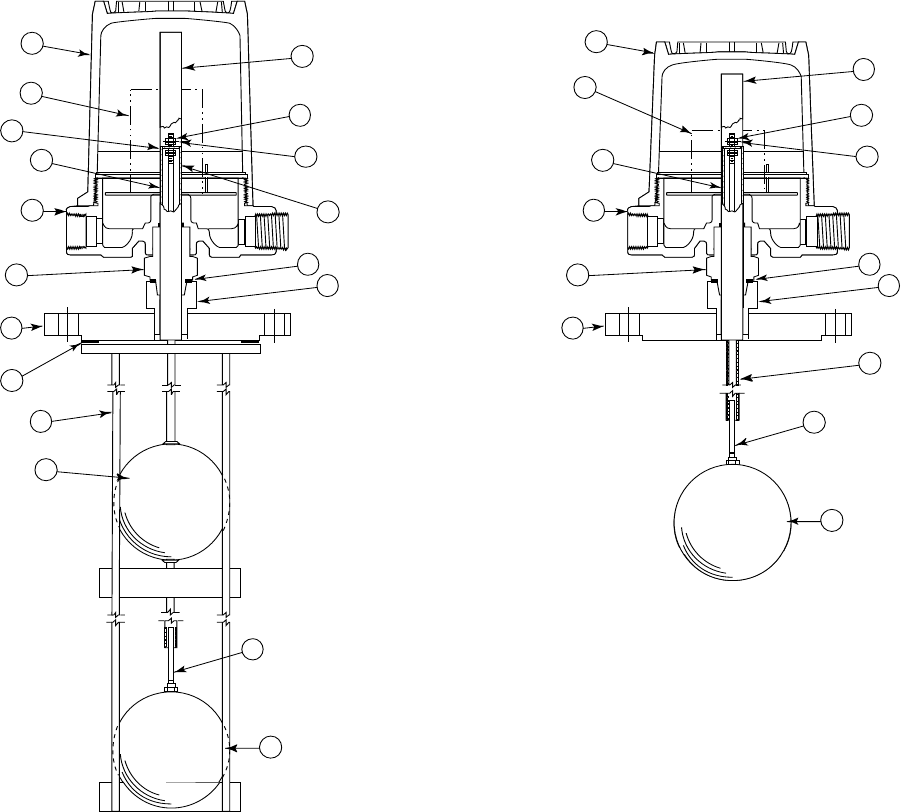
REPLACEMENT PARTS
SINGLE FLOAT MODELS TANDEM FLOAT MODELS
ITEM DESCRIPTION T20-1 T20-4 T21-1 T21-4
1Housing Cover Housing Refer to bulletin on switch mechanism and
2Housing Base Kits housing furnished (listed on page 4).
3Switch Mechanism(s)
4Attraction Sleeve
5Jam Nuts Float and
6Guide Washer(s) Stem Kits Consult Factory
7Float Stem ➀ ➁
FLOAT SIZE 07-1202-003 07-1202-003
8Float 3 X 5
407-1102-008 07-1102-008
4.50 07-1102-009 07-1102-009
9Attraction Sleeve, Stop Upper Float FLOAT SIZE
Tube, and Washers and Tube NOT REQUIRED 3 X 589-3230-001
10 Retaining Rings Assy. Kit 4 Consult Factory
11 Float and Tube Assy. ➀ ➁ 4.50
12 Adaptor Bushing 04-5734-126 04-5734-123 04-5734-126 04-5734-123
13 Stem Guide Tube ➁011-1418-194 011-1418-434 NOT REQUIRED
14 E-Tube Gasket 12-1301-002
15 Enclosing Tube
BASEEFA & CENELEC
032-6344-002 032-6344-001 032-6344-002 032-6344-001
NEMA 4X, NEMA 7/9
Pneumatic housing
032-6302-031 032-6302-036 032-6302-033 032-6302-037
(only for T20)
16 Mounting Flange ➂See Replacement Mounting Flange Chart
17 Float Guide Cage (optional) ➃Guide
NOT REQUIRED
Guide Cages are special
18 Guide Cage Gasket Cage order items.
Kits See Gasket Chart Below
REPLACEMENT MOUNTING FLANGES (Item 16) ➂CAGE GASKETS (Item 18)
Size 125 Lb. 150 Lb. 300 Lb. 150 Lb. 150 Lb. 125 Lb. & 300 Lb.
Cast Iron Forged Steel Forged Steel Forged T-304 Forged T316 150 Lb.
4" 04-5840-001 04-5840-011 04-5840-016 04-5840-021 04-5840-026 12-1301-014 12-1301-012
5" 04-5840-002 04-5840-012 04-5840-017 04-5840-022 04-5840-027 12-1301-008 12-1204-008
6" 04-5840-003 04-5840-013 04-5840-018 04-5840-023 04-5840-028 12-1301-009 12-1301-013
8" 04-5840-004 04-5840-014 04-5840-019 04-5840-024 04-5840-029 12-1301-026 12-1301-027
IMPORTANT:
When ordering, please specify:
A. Model and serial number of control.
B. Name and number of replacement part or
assembly (Kit).
NOTES:
➀All replacements furnished in kit form are for standard base
models which use single magnet switch mechanisms only.
Consult local representative for ordering assistance on all spe-
cial model replacement parts not included in above listing.
➁Float stem and tube component lengths are cut to meet
original customer specifications. When ordering these
replacement kits, be certain to always give complete
model and serial numbers of control.
➂Flanges listed are standard ANSI raised face items. When
ordering, please specify size, type, and part number.
➃Float cages are specially built to meet original customer speci-
fications. When ordering, specify part numbers of float guide
cage and gasket (as charted above relative to size of float and
mounting flange respectively), as well as an overall cage
length dimension from original assembly.
11
REPLACEMENT PARTS cont.
8
12
14
15
16
17
18
11
7
6
5
4
1
3
4
29
10
8
12
14
15
16
7
6
5
4
1
3
4
2
13
T21
T20

IMPORTANT
SERVICE POLICY
Owners of Magnetrol products may request the return of a control; or, any part of a control for complete rebuilding or
replacement. They will be rebuilt or replaced promptly. Magnetrol International will repair or replace the control, at no cost to
the purchaser, (or owner) other than transportation cost if:
a. Returned within the warranty period; and,
b. The factory inspection finds the cause of the malfunction to be defective material or workmanship.
If the trouble is the result of conditions beyond our control; or, is NOT covered by the warranty, there will be charges for labour
and the parts required to rebuild or replace the equipment.
In some cases, it may be expedient to ship replacement parts; or, in extreme cases a complete new control, to replace the orig-
inal equipment before it is returned. If this is desired, notify the factory of both the model and serial numbers of the
control to be replaced. In such cases, credit for the materials returned, will be determined on the basis of the applicability of our
warranty.
No claims for misapplication, labour, direct or consequential damage will be allowed.
RETURNED MATERIAL PROCEDURE
So that we may efficiently process any materials that are returned, it is essential that a “Return Material Authorisation” (RMA)
form will be obtained from the factory. It is mandatory that this form will be attached to each material returned. This form is avail-
able through Magnetrol’s local representative or by contacting the factory. Please supply the following information:
1. Purchaser Name
2. Description of Material
3. Serial Number
4. Desired Action
5. Reason for Return
6. Process details
All shipments returned to the factory must be by prepaid transportation. Magnetrol will not accept collect shipments.
All replacements will be shipped FOB factory.
®
www.magnetrol.com
BENELUX Heikensstraat 6, 9240 Zele, België
Tel. +32 (0)52.45.11.11 • Fax. +32 (0)52.45.09.93 • E-Mail: info@magnetrol.be
DEUTSCHLAND Alte Ziegelei 2-4, D-51491 Overath
Tel. 02204 / 9536-0 • Fax. 02204 / 9536-53 • E-Mail: vertrieb@magnetrol.de
FRANCE 40 - 42, rue Gabriel Péri, 95130 Le Plessis Bouchard
Tél. 01.34.44.26.10 • Fax. 01.34.44.26.06 • E-Mail: magnetrolfrance@magnetrol.fr
ITALIA Via Arese 12, I-20159 Milano
Tel. (02) 607.22.98 (R.A.) • Fax. (02) 668.66.52 • E-Mail: mit.gen@magnetrol.it
UNITED Unit 1 Regent Business Centre, Jubilee Road Burgess Hill West Sussex RH 15 9TL
KINGDOM Tel. (01444) 871313 • Fax (01444) 871317 • E-Mail: sales@magnetrol.co.uk
INDIA E-22, Anand Niketan, New Delhi - 110 021
Tel. 91 (11) 6186211 • Fax 91 (11) 6186418 • E-Mail: info@magnetrolindia.com
BULLETIN N°: BE 44-604.10
EFFECTIVE: JANUARY 2005
SUPERSEDES: February 1997
UNDER RESERVE OF MODIFICATIONS
