455924 ERV 522 455924ERV Iom
User Manual: 455924 ERV-522
Open the PDF directly: View PDF ![]() .
.
Page Count: 36
®
1
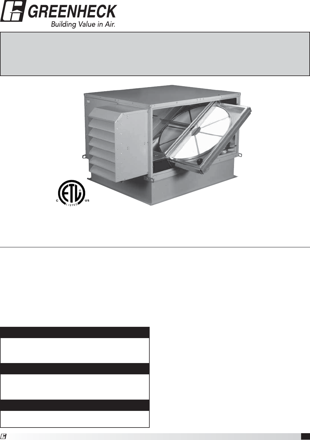
Energy Recovery Ventilator
®
Installation, Operation and Maintenance Manual
Please read and save these instructions. Read carefully before attempting to assemble, install, operate or maintain the
product described. Protect yourself and others by observing all safety information. Failure to comply with instructions
could result in personal injury and/or property damage! Retain instructions for future reference.
Document #455924
Energy Recovery Ventilators
Only qualified personnel should install this system.
Personnel should have a clear understanding of these
instructions and should be aware of general safety
precautions. Improper installation can result in electric
shock, possible injury due to coming in contact with
moving parts, as well as other potential hazards.
Other considerations may be required if high winds
or seismic activity are present. If more information
is needed, contact a licensed professional engineer
before moving forward.
1. Follow all local electrical and safety codes, as well
as the National Electrical Code (NEC), the National
Fire Protection Agency (NFPA), where applicable.
Follow the Canadian Electrical Code (CEC) in
Canada.
2. All moving parts must be free to rotate without
striking or rubbing any stationary objects.
3. Unit must be securely and adequately grounded.
4. Do not spin fan wheel faster than maximum
cataloged fan RPM. Adjustments to fan speed
significantly effects motor load. If the fan RPM is
changed, the motor current should be checked to
make sure it is not exceeding the motor nameplate
amps.
5. Do not allow the power cable to kink or come in
contact with oil, grease, hot surfaces or chemicals.
Replace cord immediately if damaged.
6. Verify that the power source is compatible with the
equipment.
7. Never open access doors to the unit while it is
running.
General Safety Information
DANGER
Always disconnect power before working on or near
this equipment. Lock and tag the disconnect switch
or breaker to prevent accidental power up.
CAUTION
When servicing the unit, the internal components
may be hot enough to cause pain or injury. Allow
time for cooling before servicing.
CAUTION
Precaution should be taken in explosive
atmospheres.
Models: ERV-251
ERV-361
ERV-521
ERV-581
ERV-522
ERV-582

2Energy Recovery Ventilator
Machined parts coated with rust preventive should
be restored to good condition promptly if signs of
rust occur. Immediately remove the original rust
preventive coating with petroleum solvent and clean
with lint-free cloths. Polish any remaining rust from
surface with crocus cloth or fine emery paper and oil.
Do not destroy the continuity of the surfaces. Wipe
clean thoroughly with Tectyl® 506 (Ashland Inc.) or
the equivalent. For hard to reach internal surfaces or
for occasional use, consider using Tectyl® 511M Rust
Preventive or WD-40® or the equivalent.
Receiving
Upon receiving the product, check to make sure
all items are accounted for by referencing the bill
of lading to ensure all items were received. Inspect
each crate for shipping damage before accepting
delivery. Notify the carrier if any damage is noticed.
The carrier will make notification on the delivery
receipt acknowledging any damage to the product.
All damage should be noted on all the copies of
the bill of lading which is countersigned by the
delivering carrier. A Carrier Inspection Report should
be filled out by the carrier upon arrival and the Traffic
Department. If damaged upon arrival, file claim
with carrier. Any physical damage to the unit after
acceptance is not the responsibility of Greenheck Fan
Corporation.
Unpacking
Verify that all required parts and the correct quantity
of each item have been received. If any items are
missing report shortages to your local representative
to arrange for obtaining missing parts. Sometimes it
is not possible that all items for the unit be shipped
together due to availability of transportation and truck
space. Confirmation of shipment(s) must be limited to
only items on the bill of lading.
Handling
Units are to be rigged and moved by the lifting
brackets provided or by the skid when a forklift is
used. Location of brackets varies by model and size.
Handle each piece in such a manner as to keep from
scratching or chipping the coating. Damaged finish
may reduce ability of the unit to resist corrosion.
Storage
Units are protected against damage during shipment.
If the unit cannot be installed and operated
immediately, precautions need to be taken to prevent
deterioration of the unit during storage. The user
assumes responsibility of the unit and accessories
while in storage. The manufacturer will not be
responsible for damage during storage. These
suggestions are provided solely as a convenience to
the user.
Inspection and Maintenance during
Storage
While in storage, inspect units once per month. Keep
a record of inspection and maintenance performed
If moisture or dirt accumulations are found on parts,
the source should be located and eliminated. At each
inspection, rotate all moving components by hand
ten to fifteen revolutions to distribute lubricant on
motor and bearings. If paint deterioration begins,
consideration should be given to touch-up or
repainting. Units with special coatings may require
special techniques for touch-up or repair.
3
Energy Recovery Ventilator
Table of Contents
Basic Operation . . . . . . . . . . . . . . 3
Installation
Supplemental Installation, Operation and
Maintenance Manuals . . . . . . . . . . . 3
Installation Concerns. . . . . . . . . . . . 3
Lifting . . . . . . . . . . . . . . . . . . 4
Roof Curb and Rail Mounting
Recommended Roof Opening . . . . . . . . 4
Roof Curb Mounting . . . . . . . . . . . . 5
Curb Dimensions and Weights . . . . . . . . 5
Ductwork Connections . . . . . . . . . . . 5
Rail Mounting / Layout . . . . . . . . . . . 6
Service Clearances . . . . . . . . . . . . 7
Electrical Information
General Electrical Information . . . . . . . . 8
Control Center Components . . . . . . . . . 9
Electric Heater Application/Operation . . . . . 9
Unit Accessories. . . . . . . . . . . . . . 9
Access Panel Description and Location . . 10-11
Dimensional Data . . . . . . . . . . . .12-13
Optional Accessories
Frost Control Application/Operation . . . . . 14
Economizer Application/Operation . . . . . . 15
Variable Frequency Drives and Wiring . . . . 16-17
Typical Wiring Diagram . . . . . . . . . . . 18
Sensors and Lights . . . . . . . . . . . . 19
Remote Control Panel and Wiring . . . . . . 20
Sensors Mounted by Factory . . . . . . . . 21
Sequence of Operation
Start-Up
Unit . . . . . . . . . . . . . . . . . . . 22
Optional Accessories . . . . . . . . . . . 23
Fan . . . . . . . . . . . . . . . . . . . 24
Energy Recovery Wheel . . . . . . . . . . 25
Routine Maintenance Checklist
General . . . . . . . . . . . . . . . . .26
Fan Belts. . . . . . . . . . . . . . . . . 26
Fan Motors . . . . . . . . . . . . . . . . 26
Fan Wheel and Fasteners . . . . . . . . . . 27
Fan Bearings . . . . . . . . . . . . . . . 27
Filters . . . . . . . . . . . . . . . . . . 27
Door Seal Maintenance . . . . . . . . . . . 27
Energy Recovery Wheel Maintenance
Accessing Energy Recovery Wheel . . . .27-28
Removing Wheel Segments . . . . . . . . 28
Cleaning Wheel Segments . . . . . . . . 29
Wheel Belt . . . . . . . . . . . . . . . 29
Wheel Bearing . . . . . . . . . . . . . 29
Parts List . . . . . . . . . . . . . . . . . 30
Sequence of Operation . . . . . . . . . . . 31
Troubleshooting – Airflow. . . . . . . . . . 32
Troubleshooting – Unit . . . . . . . . . 33-34
Maintenance Log . . . . . . . . . . . . . 35
Warranty . . . . . . . . . . . . . Backcover
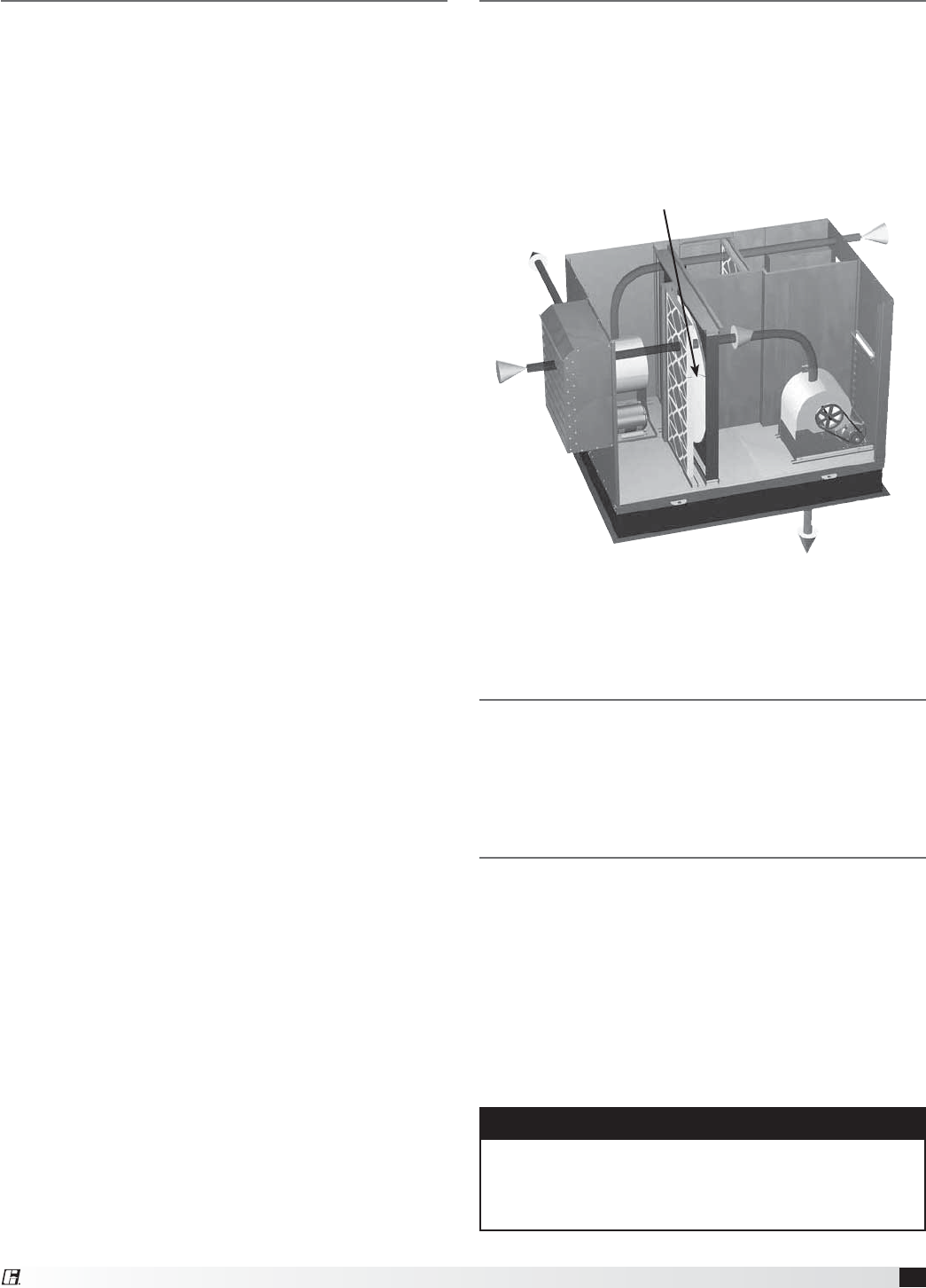
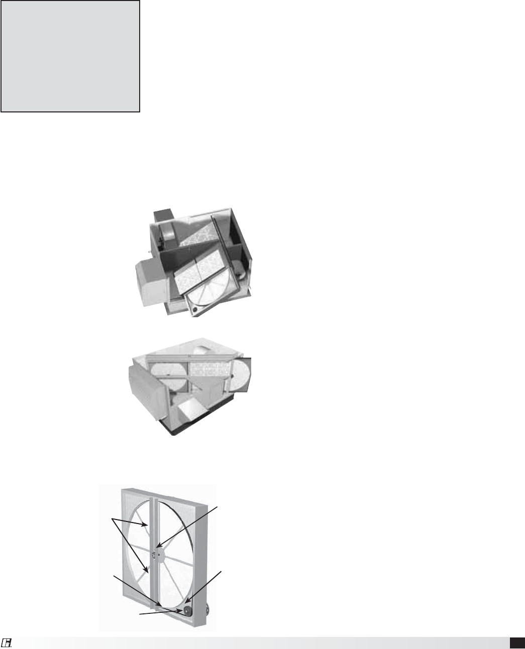
Basic Operation
The ERV brings in fresh, outdoor air and removes
stale, exhaust air. Prior to discharging the exhaust
air, the energy recovery wheel transfers energy from
the exhaust air to the outdoor air at an efficiency
of 70-80%. Simply put, this unit preconditions the
outdoor air to save money on heating and cooling
costs.
Outdoor
air
Exhaust air
discharged
outside
Exhaust air
from building
Preconditioned air
sent to space
Energy Recovery
Wheel
Installation
The system design and installation should follow
accepted industry practice, such as described in the
ASHRAE Handbook.
Adequate space should be left around the unit for
filter replacement and maintenance. Sufficient space
should be provided on the side of the unit for routine
service and component removal should that become
necessary.
See Service Clearances and Access Panel Description
sections for more details.
Supplemental Installation,
Operation and Maintenance
Manuals
Refer to the following Installation, Operation and
Maintenance Manuals for additional details:
Part #460988 — ERV-522 and ERV-582 Curbs
Part #462844 — ERV Exhaust Weatherhood
WARNING
All factory provided lifting lugs must be used when
lifting the unit. Failure to comply with this safety
precaution could result in property damage, serious
injury or death.
4Energy Recovery Ventilator
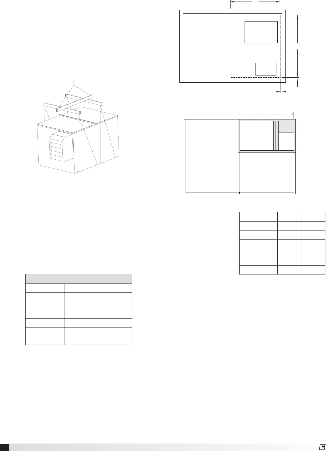
Lifting
1. Before lifting, be sure that all shipping material
has been removed from unit.
2. To assist in determining rigging requirements,
weights are shown below.
3. Unit must be lifted by all lifting lugs provided on
base structure.
4. Rigger to use suitable mating hardware to attach
to unit lifting lugs.
5. Spreader bar(s) must span the unit to prevent
damage to the cabinet by the lift cables.
6. Always test-lift the unit to check for proper
balance and rigging before hoisting to desired
location.
7. Never lift units by weatherhoods.
8. Never lift units in windy conditions.
9. Preparation of curb and roof openings should be
completed prior to lifting unit to the roof.
10. Check to be sure that gasketing (supplied by
others) has been applied to the curb prior to
lifting the unit and setting on curb.
11. Do not use fork lifts for handling unit.
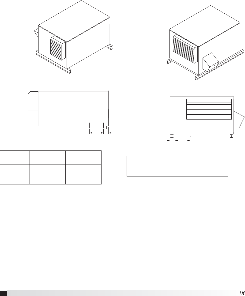
Recommended Roof Opening
Unit Weights
Unit Size Approx. Weight (lbs)*
ERV-251 340
ERV-361 860
ERV-521 1290
ERV-581 1470
ERV-522 3230
ERV-582 3700
*Weight assumes outdoor unit with
filters, weatherhoods and outdoor
air intake damper.
SUPPLY
DISCHARGE
EXHAUST
INTAKE
U
V
0.50
0.50
ERV-251, 361, 521 and 581
U
V
EXHAUST
INLET
SUPPLY
DISCHARGE
ERV-522 and 582
Position the unit roof
opening such that the
supply discharge and
exhaust inlet of the
unit will line up with
the corresponding
ductwork. Be sure
to allow for the
recommended service
clearances when
positioning opening
(see Service Clearances). Do not face the outdoor air
intake of the unit into prevailing wind and keep the
intake away from any other exhaust fans. Likewise,
position the exhaust discharge opening away from
outdoor air intakes of any other equipment.
When cutting only duct openings, cut opening 1 inch
(25mm) larger than duct size to allow clearance for
installation. Area enclosed by roof curb must comply
with clearance to combustible materials. If the roof is
constructed of combustible materials, area within the
roof curb must be ventilated, left open, or covered
with non-combustible material which has an “R”
value of at least 5. If area within curb is open, higher
radiated sound levels may result.
Where the supply or warm air duct passes thru a
combustible roof, a clearance of one inch must be
maintained between the outside edges of the duct
and combustible material in accordance with NFPA
Standard 90A.
Unit Size U V
ERV-251 26.5 20
ERV-361 43 26
ERV-521 58 35
ERV-581 60 30
ERV-522 62 36
ERV-582 77 38
All dimensions are in inches.
5
Energy Recovery Ventilator
R
o
t
a
t
i
o
n
Length of Straight Duct
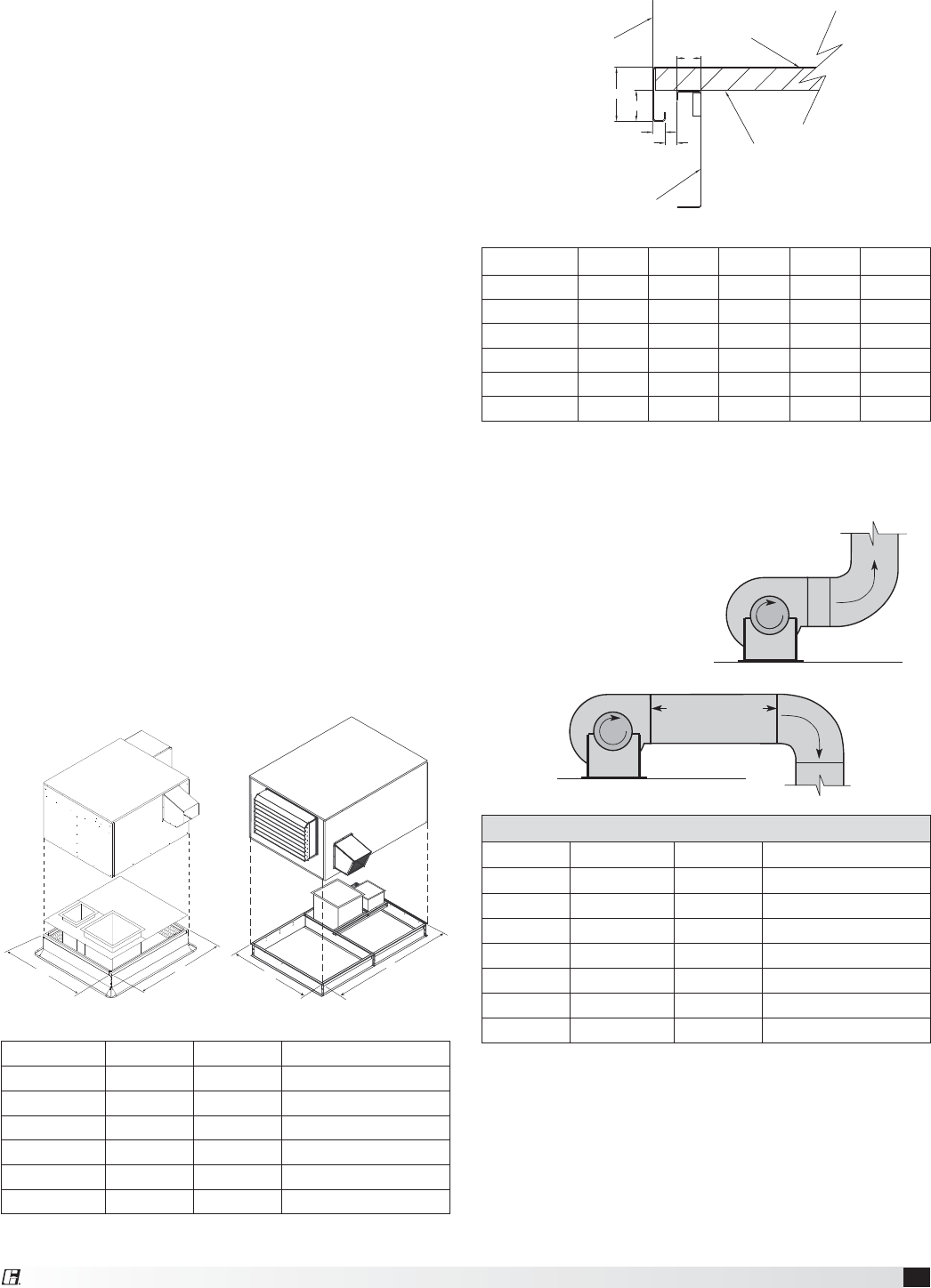
GOOD
Roof Curb Mounting
Roof curb details including duct location dimensions,
are available on ERV-522 & 582 Roof Curb Assembly
Instructions, Part #460988.
Rooftop units require curbs to be mounted first. The
duct connections must be located so they will be
clear of structural members of the building.
1. Factory Supplied Roof Curbs: Roof curbs are
Model GPI or GPNS for the ERV-251, 361, 521,
581. The GPI or GPNS ships assembled and
includes a duct adapter.
Roof curbs are Model GKD for the ERV-522 and
582. The GKD ships in a knockdown kit (includes
duct adapter) and requires field assembly (by
others). Assembly instructions are included with
the GKD curbs.
2. Install Curb: Locate curb over roof opening and
fasten in place. (Refer to Recommended Roof
Openings). Check that the diagonal dimensions
are within ±1/8 inch of each other and adjust
as necessary. For proper unit operation, it is
important that the installation be level. Shim as
required to level.
3. Install Ductwork: Installation of all ducts should
be done in accordance with SMACNA and AMCA
guidelines. Duct adapter provided to support
ducts prior to setting the unit.
4. Set the Unit: Lift unit to a point directly above
the curb and duct openings. Guide unit while
lowering to align with duct openings. Roof curbs
fit inside the unit base. Make sure the unit is
properly seated on the curb and is level.
Unit Size L W Curb Weight (lbs.)
ERV-251 42.5 30.5 60
ERV-361 58.5 47.5 115
ERV-521 63.5 63.5 160
ERV-581 71.8 66 185
ERV-522 120.5 80.5 520
ERV-582 142.25 93 700
All dimensions are in inches. Weights are for 12-inch high
GPI type curbs.
WL
ERV-251, 361, 521 and 581
W
L
ERV-522 and 582
Curb Outside Dimensions and Weights
Roof Curb
Side of Unit Base
1-inch Insulation
E
D
C
A
B
Unit Size A BCDE
ERV-251 1.75 2.00 1.00 1.125 0.750
ERV-361 1.75 2.00 1.00 1.200 0.875
ERV-521 1.75 2.00 1.00 0.813 0.875
ERV-581 1.75 2.00 1.00 0.813 0.750
ERV-522 1.813 4.00 1.75 1.000 0.750
ERV-582 1.938 4.125 1.938 1.125 0.625
All dimensions are in inches.
Curb Cap Details for Factory Supplied Roof Curbs
Curb Outside Dimensions - continued
Recommended Discharge Duct Size and Length
Model Blower Size Duct Size Straight Duct Length
ERV-251 10 9 x 9 36
ERV-361 10 14 x 14 36
ERV-521 12 20 x 20 36
ERV-581 15 28 x 28 60
ERV-522S 15 28 x 28 60
ERV-522H 18 32 x 32 60
ERV-582 20 34 x 34 72
All dimensions shown in inches.
t 3FDPNNFOEFEEVDUTJ[FTBSFCBTFEPOWFMPDJUJFTBDSPTTUIF
cfm range of each model at approximately 800 feet per minute
(FPM) at minimum airflow and up to 1600 fpm at maximum
airflow. Recommended duct sizes are only intended to be a
guide and may not satisfy the requirements of the project.
Refer to plans for appropriate job specific duct size and/or
velocity limitations.
t 4USBJHIUEVDUMFOHUITXFSFDBMDVMBUFECBTFEPOFGGFDUJWF
duct length requirements as prescribed in AMCA Publication
201. Calculated values have been rounded up to nearest foot.
Ductwork Connections
Examples of poor and good fan-to-duct connections
are shown. Airflow out of the fan should
be directed straight or curve the
same direction as the
fan wheel rotates. Poor
duct installation will
result in low airflow and
other system effects.
R
o
t
a
t
i
o
n
POOR
6Energy Recovery Ventilator
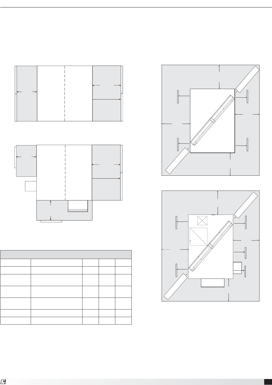
Isometric view of
ERV on rails
Side view of
ERV on rails
OUTDOOR AIR INTAKE END
OUTDOOR AIR INTAKE END
OUTDOOR AIR INTAKE HOOD
B
SUPPLY/EXHAUST
OPENING
A
ERV-522
ERV-582
Unit Size A B
ERV-522 4.625 32
ERV-582 4.875 33.25
All dimensions are in inches.
OUTDOOR AIR SIDE
Isometric view of
ERV on rails
Side view of
ERV on rails AB
SUPPLY/EXHAUST
OPENING
OUTDOOR
AIR
INTAKE
HOOD OUTDOOR AIR SIDE
ERV-251
ERV-361
ERV-521
ERV-581
Unit Size A B
ERV-251 4.50 16
ERV-361 4.75 18
ERV-521 5.75 24
ERV-581 4.875 22
All dimensions are in inches.
Rail Mounting / Layout
t 3BJMTEFTJHOFEUPIBOEMFUIFXFJHIUPGUIF&37TIPVMECFQPTJUJPOFEBTTIPXOPOUIFEJBHSBNSBJMTCZ
others).
t .BLFTVSFUIBUSBJMQPTJUJPOJOHEPFTOPUJOUFSGFSFXJUIUIFTVQQMZBJSEJTDIBSHFPQFOJOHPSUIFFYIBVTUBJS
intake opening on the ERV unit. Avoid area dimensioned “B” below.
t 3BJMTTIPVMEFYUFOECFZPOEUIFVOJUBNJOJNVNPGJODIFTPOFBDITJEF
t 4FUVOJUPOSBJMT
7
Energy Recovery Ventilator
Cassette slides out*
Access Panels
Access Panels
Exhaust
Side
Outdoor
Air Side
Service Clearances
ERV-251, 361, 521 and 581 units require minimum clearances to perform routine maintenance, such as filter
replacement, energy wheel cassette inspection, and fan belt adjustment. Blower and motor assemblies,
energy recovery wheel cassette and filter sections are always provided with a service door or panel for proper
component access. Clearances for component removal may be greater than the service clearances, refer to
drawings below for these dimensions.
ERV-251, ERV-361, ERV-521, ERV-581 ERV-522, ERV-582
Intake Hood
Exhaust
Hood
Cassette slides out*
Access Panels
Access Panel
Access Panel
Exhaust
Side
Outdoor
Air Side
Recommended Service Clearances
Unit Size R S T X
ERV-251 32 30 30
ERV-361 44
(30 for maintenance) 30 30
ERV-521 60
(39 for maintenance) 40 40
ERV-581 65
(32 for maintenance) 40 40
ERV-522 38
ERV-582 42
All dimensions are in inches.
Arrangement A
Arrangement B, C or D
T
T
R
S
Arrangement A
Cassette
Cassette
Access PanelAccess Panel
Access Panel
Access Panel
X
X
X
X
Cassette
Cassette
Supply
Weatherhood
Exhaust
Weatherhood
Access PanelAccess Panel
Access PanelAccess Panel
Access Panel
Arrangement B, C or D
X
*ERV-251, 361, and 521 only.
*ERV-251, 361, and 521 only.
R
X
X
X
8Energy Recovery Ventilator
Electrical Information
The unit must be electrically grounded in accordance
with the current National Electrical Code, ANSI/NFPA
70. In Canada, use current CSA Standard C22.1,
Canadian Electrical Code, Part 1. In addition, the
installer should be aware of any local ordinances or
electrical company requirements that might apply.
System power wiring must be properly fused and
conform to the local and national electrical codes.
System power wiring is to the unit main disconnect
(door interlocking disconnect switch standard
on most units) or distribution block and must be
compatible with the ratings on the nameplate: supply
power voltage, phase, and amperage (Minimum
Circuit Amps - MCA, Maximum Overcurrent Protection
- MOP). All wiring beyond this point has been done
by the manufacturer and cannot be modified without
affecting the unit’s agency / safety certification.
If field installing an additional disconnect switch, it
is recommended that there is at least four feet of
service room between the switch and system access
panels. When providing or replacing fuses in a fusible
disconnect, use dual element time delay fuses and
size according to the rating plate.
If power supply is desired through bottom of unit, run
the wiring through the curb, cut a hole in the cabinet
bottom, and wire to the disconnect switch. Seal
penetration in cabinet bottom to prevent leakage.
The electric supply to the unit must meet stringent
requirements for the system to operate properly.
Voltage supply and voltage imbalance between
phases should be within the following tolerances.
If the power is not within these voltage tolerances,
contact the power company prior to operating the
system.
Voltage Supply: See voltage use range on the rating
plate. Measure and record each supply leg voltage at
all line disconnect switches. Readings must fall within
the allowable range on the rating plate.
Voltage Imbalance: In a 3-phase system, excessive
voltage imbalance between phases will cause motors
to overheat and eventually fail. Maximum allowable
imbalance is 2%. To determine voltage imbalance,
use recorded voltage measurements in this formula.
Key: V1, V2, V3 = line voltages as measured
VA (average) = (V1 + V2 + V3) / 3
VD = Line voltage (V1, V2 or V3) that
deviates farthest from average (VA)
Formula: % Voltage Imbalance = [100 x (VA-VD)] / VA
WARNING
To prevent injury or death due to electrocution or
contact with moving parts, lock disconnect switch
open.
CAUTION
If any of the original wire as supplied with the
appliance must be replaced, it must be replaced
with wiring material having a temperature rating of
at least 105ºC.
Most factory supplied electrical components are
prewired. To determine what electrical accessories
require additional field wiring, refer to the unit specific
wiring diagram located on the inside of the unit
control center access door. The low voltage control
circuit is 24 VAC and control wiring should not exceed
0.75ohms.
Refer to Field Control Wiring Length/Gauge table for
wire length maximums for a given wire gauge.
Control wires should not be run inside the same
conduit as that carrying the supply power. Make sure
that field supplied conduit does not interfere with
access panel operation.
If wire resistance exceeds 0.75 ohms, an industrial-
style, plug-in relay should be added to the unit
control center and wired in place of the remote
switch (typically between terminal blocks R and G
on the terminal strip (refer to Typical Control Center
Components). The relay must be rated for at least
5 amps and have a 24 VAC coil. Failure to comply
with these guidelines may cause motor starters to
“chatter” or not pull in which can cause contactor
failures and/or motor failures.
Field Control Wiring Length/Gauge
Total
Wire Length
Minimum
Wire Gauge
125 ft. 18
200 ft. 16
300 ft. 14
450 ft. 12
9
Energy Recovery Ventilator
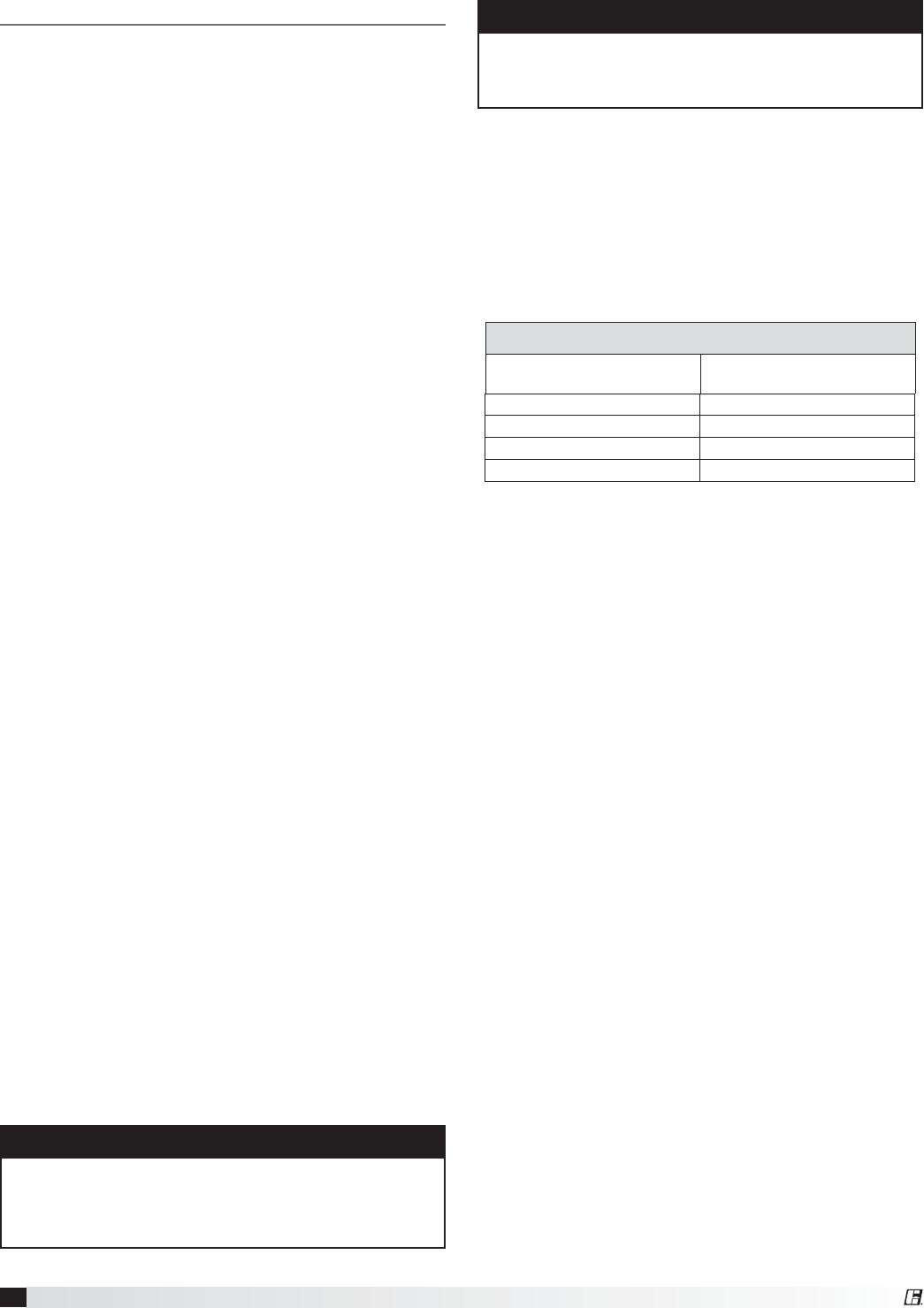
Typical Control Center Components
1. Main Disconnect (non-fusible, lockable)
2. Motor Starter – Exhaust Air Fan
3. Motor Starter – Outdoor Air Fan
4. Motor Contactor – Energy Wheel
5. 24 VAC Control Transformer
6. 24 VAC Terminal strip
7. Fuses for blower motors
1
2 3 4
7
5
Exploded Detail
of Terminal Strip
Exhaust
Hood
Intake
Hood
ERV-251, 361, 521, 581
Access to Control Center Components
is gained through the access panel indicated.
6
ERV-522
Exhaust Hood
Intake
Hood
ERV-582
Exhaust Hood
Intake
Hood
Electric Heater Application/Operation
Factory installed electric heaters can be provided for
preheat frost control. An electric preheater warms
the outdoor air prior to the energy recovery wheel
to prevent frosting on the wheel. Electric heaters
are available in 208, 230, or 460 VAC (refer to heater
nameplate for voltage).
Preheaters: Preheaters are standard as single-stage
on/off control. Preheaters are single point wired at
the factory. A thermodisc temperature sensor (with
a 5°F set point) is mounted in the outdoor airstream
after the preheater to turn the preheater on. See Frost
Control Application/Operation for typical set points. If
the temperature falls below
the set point and the wheel
pressure drop sensor is
triggered, the preheater will
turn on.
Access to the preheater
control panel is through the
outdoor air filter door.
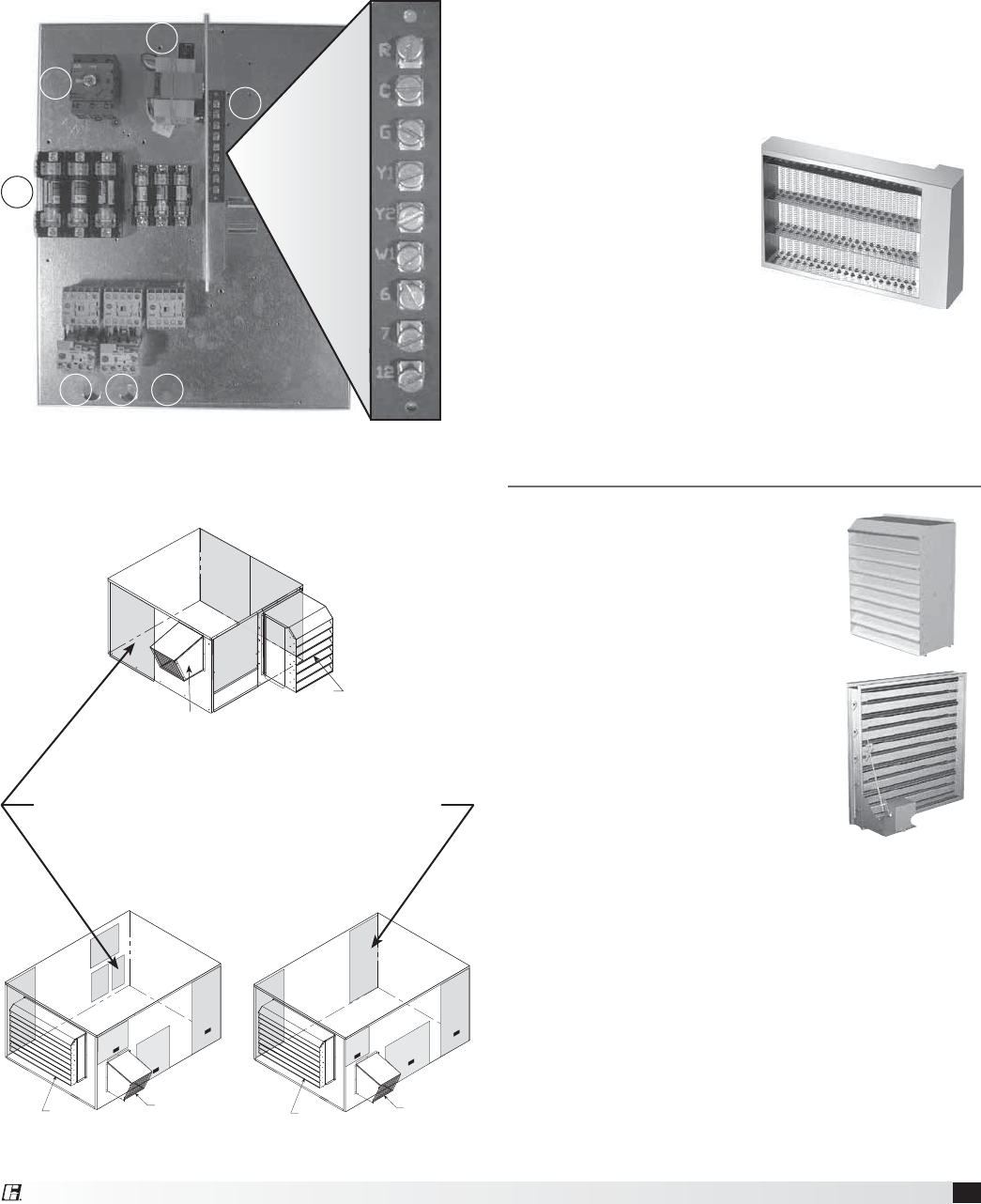
Outdoor Air Weatherhood
Outdoor air weatherhood will be
factory mounted.
Exhaust Weatherhood
The exhaust weatherhood is shipped
separately as a kit with its own
instructions.
Dampers
Backdraft dampers are always
included as an integral part of the
exhaust hood assemblies. Motorized
outdoor air and exhaust air dampers
are optional and are factory mounted
(and wired) at the intake.
Unit Accessories
10 Energy Recovery Ventilator
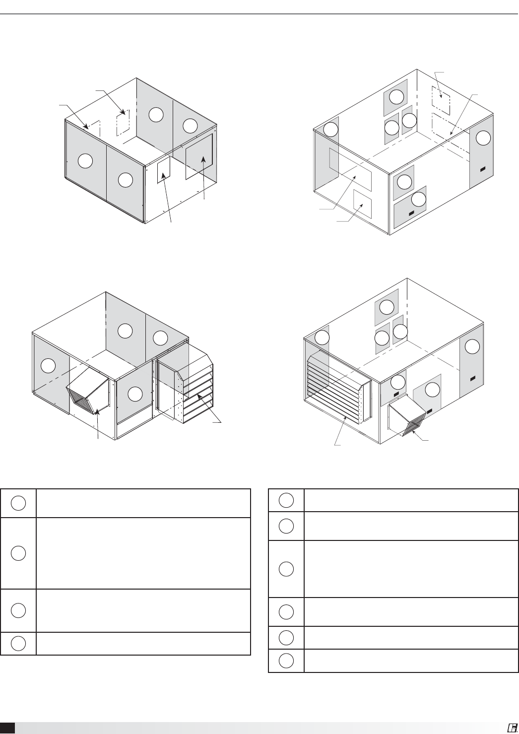
Access Panel Description and Location
ERV-251, ERV-361, ERV-521, ERV-581 ERV-522
Outdoor Air
Inlet
Exhaust Air
Discharge
Exhaust Air
Inlet
Outdoor Air
Discharge
Arrangement A
1
2
3
4
Exhaust
Hood
Intake
Hood
Arrangement B, C or D
12
3
4
Rooftop
Exhaust Hood
Intake Hood
Arrangement B, C or D
1
2
3
3
4
5
6
Interior
Exhaust Air
Inlet
Outdoor Air Inlet
Exhaust Air Discharge
Outdoor Air
Discharge
Arrangement A
1
2
3
4
5
6
3
1Outdoor air blower and motor
Energy wheel cassette
2
Energy wheel cassette
Internal filters
Outdoor air intake damper
Frost control
Outdoor air sensors
3
Main disconnect
Electrical control center
Internal filters
4Exhaust air blower and motor
1Exhaust blower and motor
2Electric control center
Main Disconnect
3
Energy wheel cassette
Internal filters
Frost control
Outdoor air sensors
4Preheater controls
Outdoor air intake damper
5Supply blower and motor
6Exhaust air intake damper
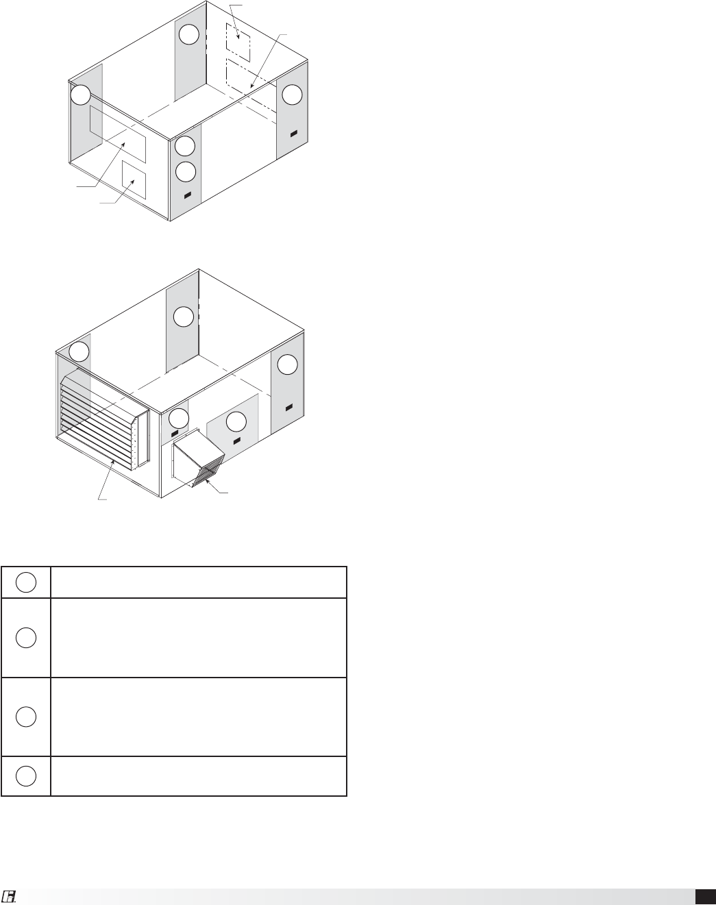
11
Energy Recovery Ventilator
Exhaust Air
Inlet
Outdoor Air Inlet
Exhaust Air Discharge
Outdoor Air
Discharge
1
2
3
3
4
Exhaust Hood
Intake
Hood
2
4
3
3
1
ERV-582
Arrangement B, C or D
Arrangement A
1Exhaust blower and motor
2
Electric control center
Main disconnect
Supply blower and motor
Exhaust air intake damper
3
Energy wheel cassette
Internal filters
Frost control
Outdoor air sensor
4Preheater controls
Outdoor air intake damper
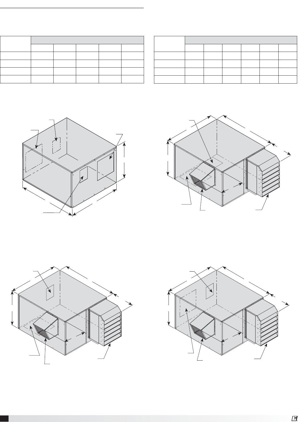
12 Energy Recovery Ventilator
ERV-251, 361, 521 and 581
Dimensional Data
AB
C
Outdoor Air Inlet
Q x P
Exhaust Air Discharge
LxK
Outdoor Air Discharge
LxK
Exhaust Air Inlet
FxG
C
BA
D
E
Exhaust Hood
Intake Hood
Exhaust Air Inlet
FxG
Outdoor Air Discharge
LxK
Exhaust Air Inlet
FxG
Outdoor Air Discharge
LxK
Intake Hood
C
BA
D
E
Exhaust Hood
C
BA
D
E
Exhaust Air Inlet
FxG
Outdoor Air Discharge
LxK
Intake Hood
Exhaust Hood
Arrangement A Arrangement B
Arrangement C Arrangement D
Unit Size Exterior Dimensions
ABCDE
ERV-251 46 34 27 12 8
ERV-361 62 51 34 18 15
ERV-521 67 67 44 16 15
ERV-581 75 70 67 16 22
All dimensions are in inches.
Unit Size Unit Opening Dimensions
FGKLQP
ERV-251 10 16 63⁄471016
ERV-361 18 18 83⁄8111⁄219 18
ERV-521 24 24 103⁄4131⁄226 26
ERV-581 22 27 16 183⁄428 48
All dimensions are in inches.
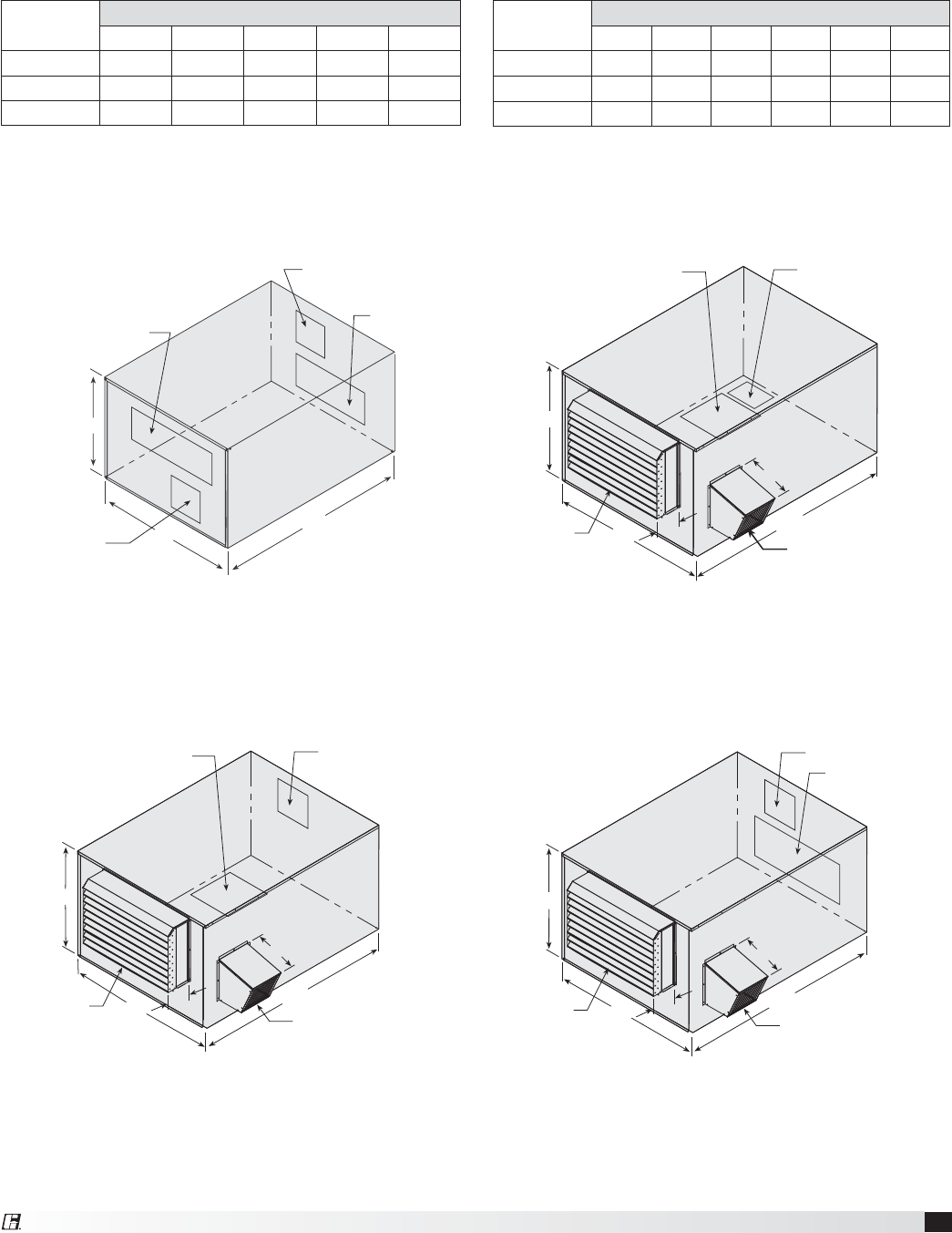
13
Energy Recovery Ventilator
Outdoor Air Discharge
L x K
Exhaust Air Inlet
F x G
Exhaust Air Discharge
L x K
Outdoor Air Inlet
Q x P
C
B
A
C
B
DA
E
Outdoor Air Discharge
L x K
Exhaust Air Inlet
H x J
Exhaust
Hood
Intake
Hood
C
B
DA
E
Outdoor Air Discharge
L x K
Exhaust Air Inlet
F x G
Exhaust
Hood
Intake
Hood
C
BDA
E
Outdoor Air Discharge
L x K
Exhaust Air Inlet
H x J
Exhaust
Hood
Intake
Hood
Arrangement A Arrangement B
Arrangement C Arrangement D
ERV-522 and 582
Unit Size Exterior Dimensions
ABCDE
ERV-522S 124 84 64 16 19
ERV-522H 124 84 64 16 19
ERV-582H 146 97 77 171⁄2263⁄4
All dimensions are in inches.
Unit Size Unit Opening Dimensions
FGKLQP
ERV-522S 48 25 16 185⁄860 25
ERV-522H 48 25 19 22 60 25
ERV-582H 60 28 23 25 70 30
All dimensions are in inches.
14 Energy Recovery Ventilator
t "GUFSUFTUJOHTFUUIF5JNFS4DBMFBTGPMMPXT
T1 = 10 minutes, T2 = 1 hour
t 4FUUIF5JNFS4FUUJOHTBTGPMMPXT
T1 = 0.5, T2 = 0.5
The timer is now set for 5 minutes off and 30
minutes on. Remember to remove the jumper.
Electric preheat frost control includes an electric
heater (at outdoor air intake), an airflow pressure
switch and thermodisc temperature sensor (located
at the preheater) in addition to a pressure sensor
across the energy wheel. (Refer to Electric Heater
Application/Operation for electric preheater location).
When electric preheat frost control is initiated, the
electric preheater will turn on and warm the air
entering the energy wheel to avoid frosting. The
thermodisc temperature sensor installed has a 5°F
nonadjustable set point. For custom temperature set
point thermodiscs, please contact the factory. Use the
following test procedure for troubleshooting.
Testing:
t +VNQFSPVUUIFUIFSNPEJTDUFNQFSBUVSFTFOTPS
and the wheel pressure sensor. The heater should
turn on.
t *GJUEPFTOUFJUIFSQVUUIFPVUEPPSBJSTJEFEPPST
on or temporarily jumper the airflow pressure
switch in the preheater control center to avoid
nuisance tripping of the pressure switch. Also
check the airflow switch pressure tap located
at the supply discharge blower to ensure the
tubing is connected and the tap is not blocked.
Remember to remove the jumpers.
Modulating wheel frost control includes a variable
frequency drive in addition to the thermostat and
pressure sensor. When modulating wheel frost control
is initiated, the variable frequency drive will reduce
the speed of the wheel. Reducing the speed of the
energy wheel reduces its effectiveness, which keeps
the exhaust air condition from reaching saturation,
thus, eliminating condensation and frosting. If the
outdoor air temperature is greater than the frost
threshold temperature OR the pressure differential
is less than the set point, the wheel will run at full
speed. If the outdoor air temperature is less than
the frost threshold temperature AND the pressure
differential is greater than the set point, the wheel will
run at reduced speed until the pressure differential
falls below the set point. The temperature and
pressure differential set points are set at the factory,
but are field-adjustable (refer to VFD section for more
information). The variable frequency drive will be fully
programmed at the factory.
Frost Control Application/Operation
Extremely cold outdoor air temperatures can cause
moisture condensation and frosting on the energy
recovery wheel. Frost control is an optional feature
that will prevent/control wheel frosting. Three options
are available:
1. Timed Exhaust frost control
2. Electric preheat frost control
3. Modulating wheel frost control
All of these options are provided with a thermostat
(with probe) mounted in the outdoor air intake
compartment and a pressure sensor to monitor
pressure drop across the wheel.
The typical temperature setting corresponds to the
indoor air relative humidity as shown in the Frost
Threshold Temperatures Table and represents when
frost can occur. An increase in pressure drop would
indicate that frost is occurring. Both the pressure
sensor AND the outdoor air temperature sensor
must trigger in order to initiate frost control. The
two sensors together ensure that frost control is
only initiated during a real frost condition. Field
wiring of a light (or other alarm) between 6 & C in
the control center will notify personnel when unit is
in frost control mode (refer to Remote Panel Wiring
schematics section for wiring details). The following
explains the three options in more detail.
Timed exhaust frost control includes a timer in
addition to the thermostat and wheel pressure sensor.
When timed exhaust frost control is initiated, the
timer will turn the supply blower on and off to allow
the warm exhaust air to defrost the energy recovery
wheel. Default factory settings are 5 minutes off and
30 minutes on. Use the following test procedure for
troubleshooting.
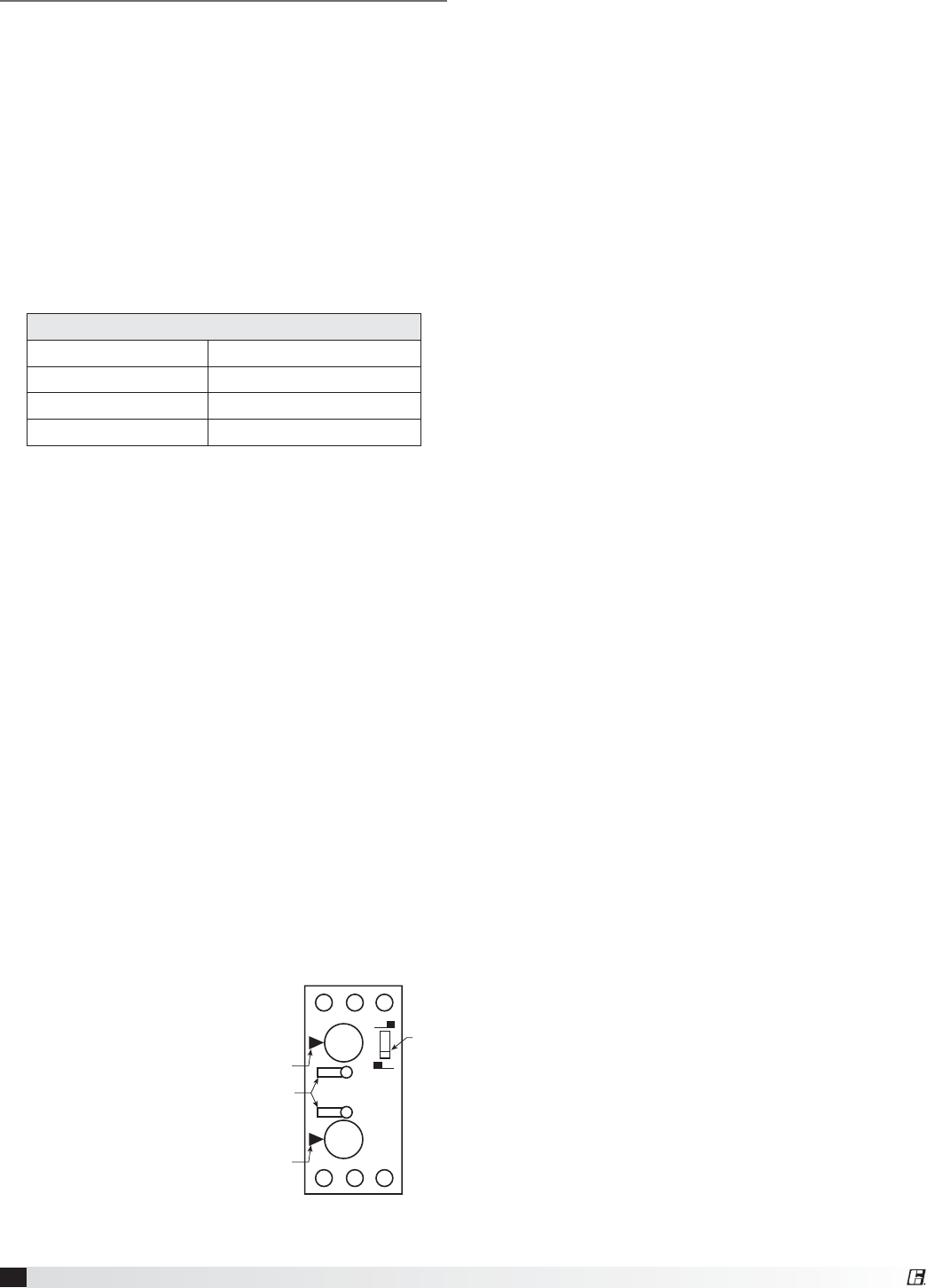
Testing (refer to Timer Faceplate drawing below)
t +VNQFSUIFXIFFM
pressure switch in the
unit control center. Set
the Timer Scale for T1
and T2 to 1 minute. Set
the Timer Settings for
T1 and T2 to 1.0. Set the
dip switch to the down
position. (normal position)
t 5VSOUIFUFNQFSBUVSF
sensor up as high as
possible. The supply blower should cycle on for
one minute, then turn off for one minute.
Frost Threshold Temperatures
Indoor RH @ 70°F Frost Threshold Temp
20% -10º F
30% -5º F
40% 0º F
A1 B1 15
16 18 A2
0.20
0.41.0
0.60.8
0.20
0.41.0
0.60.8
T1
T2 T21 MIN
T11 MIN
Timer
Scale
Dip
Switch
Optional Accessories
15
Energy Recovery Ventilator
Economizer Application/Operation
The energy recovery wheel operation can be altered
to take advantage of economizer operation (free
cooling). Two modes are available:
1. De-energizing the wheel
2. Modulating the wheel
A field supplied call for cool (Y1) is required.
De-energizing the wheel is accomplished with a signal
from a Temperature or Enthalpy sensor mounted
in the air intake compartment. This primary sensor
will de-energize the energy wheel when the outdoor
air temperature (factory default is 65ºF) or enthalpy
(factory default is the ‘D’ setting) is below the field
adjustable set point. An Override temperature
sensor is also furnished in the outdoor air intake
compartment to deactivate economizer mode. The
Override (with field adjustable set point) is set at
some temperature lower than the primary sensor
(factory default is 50ºF). Effectively, the two sensors
create a deadband where the energy recovery wheel
will not operate and free cooling from outside can be
brought into the building unconditioned.
Testing
Temperature Sensor with Override
t 5VSOCPUI5FNQFSBUVSFBOE
Override thermostats down as low
as they go. The wheel should be
rotating.
t 5VSOUIF5FNQFSBUVSFTFOTPSVQ
as high as it goes, and keep the
Override sensor as low as it will go.
The wheel should stop rotating.
t 5VSOCPUITFOTPSTBTIJHIBTUIFZXJMMHP5IF
wheel should start rotating.
t 4FUUIF5FNQFSBUVSFTFOTPSBUEFTJSFEQPJOU
for economizer operation to begin. Set the
Override sensor at desired point for economizer
operation to end (factory default is 65ºF and 50ºF,
respectively).
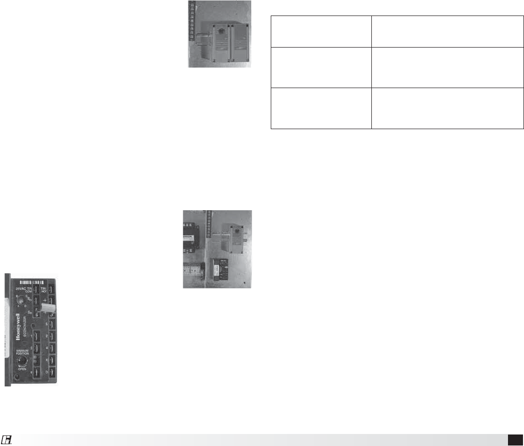
Enthalpy Sensor with Override
t 5VSOVOJUQPXFSPGG%JTDPOOFDU
C7400 Solid State Enthalpy Sensor
from terminal So on the enthalpy
controller. Also, disconnect the
620 ohm resistor from
terminal Sr on the
enthalpy controller.
Turn unit power on. The
LED on the enthalpy
controller should light
and the energy recovery wheel should
not rotate.
t5VSOVOJUQPXFSPGG3FDPOOFDU
ohm resistor to terminal Sr on the
enthalpy controller. Turn unit power on.
The LED on the enthalpy controller should not light
and the energy recovery wheel should energize
and rotate.
If these steps provide the results described, the
enthalpy economizer is working properly.
t 5VSOVOJUQPXFSPGG3FDPOOFDU$4PMJE4UBUF
Enthalpy Sensor to terminal So.
Modulating the Wheel
In applications in which an internal heat gain is
present in the space, the rotational speed of the
energy wheel may be modulated (via variable
frequency drive) to avoid overheating the space
during the winter. The speed of the energy wheel
will be controlled in response to the discharge
temperature set point.
Sequence of Operation: The variable frequency
drive is fully programmed at the factory (refer to VFD
section for more information). A “call for cool” must
be field wired to the unit (terminals provided in unit -
refer to wiring diagram in unit control center) to allow
for initiation of economizer mode. When the space
calls for cooling, factory supplied controls will drive
the following wheel operations:
Where (TOA) is the outdoor air temperature set point,
(TRA) is the return air temperature set point, and (TSA)
is the supply air discharge thermostat set point.
Temperature
Sensor with
Override
Enthalpy
Sensor with
Override
TOA > TRA
Wheel runs at full speed.
(maximum energy recovery)
TOA < TRA
and
TOA > TSA
Wheel is at minimum speed.
(no energy recovery)
TOA < TRA
and
TOA < TSA
Wheel will modulate to maintain
discharge temperature.
Enthalpy
Controller
16 Energy Recovery Ventilator
Factory Set Points
Variable Frequency Drives (VFDs) for the blowers are
factory setup to operate in one of the three following
modes:
Modulating: 0-10 VDC signal wired in the field by
others varies the speed of the blower between 30
and 60Hz
Multi-speed: Digital contact closures by others
command the VFD to run at multiple speed settings:
t4$UP4%SJWFSVOTBU)[
t4$UP4%SJWFSVOTBU)[
CO2 Sensor: A digital contact closure from an
optional factory provided CO2 sensor sends the
VFD to high or low speed depending on CO2 ppm
levels at the sensor.
The terminal locations for Modulating (option 1) and
Multi-speed (option 2) are shown on the left. Most
of the set points in the VFDs are Yaskawa factory
defaults. However, a few set points are changed at
Greenheck and are shown in the tables on the next
page. These settings are based on the VFD mode
selected.
To gain access to change set points on the V1000 and
+ESJWFTQBSBNFUFS"OFFETUPCFTFUBUiw
To prevent access or tampering with drive settings on
either drive, change parameter A1-01 to “0”.
Drive Operation
SC to S1 contact for On/Off
A1 (0-10 VDC) referenced to AC. Can use +15 VDC
from +V
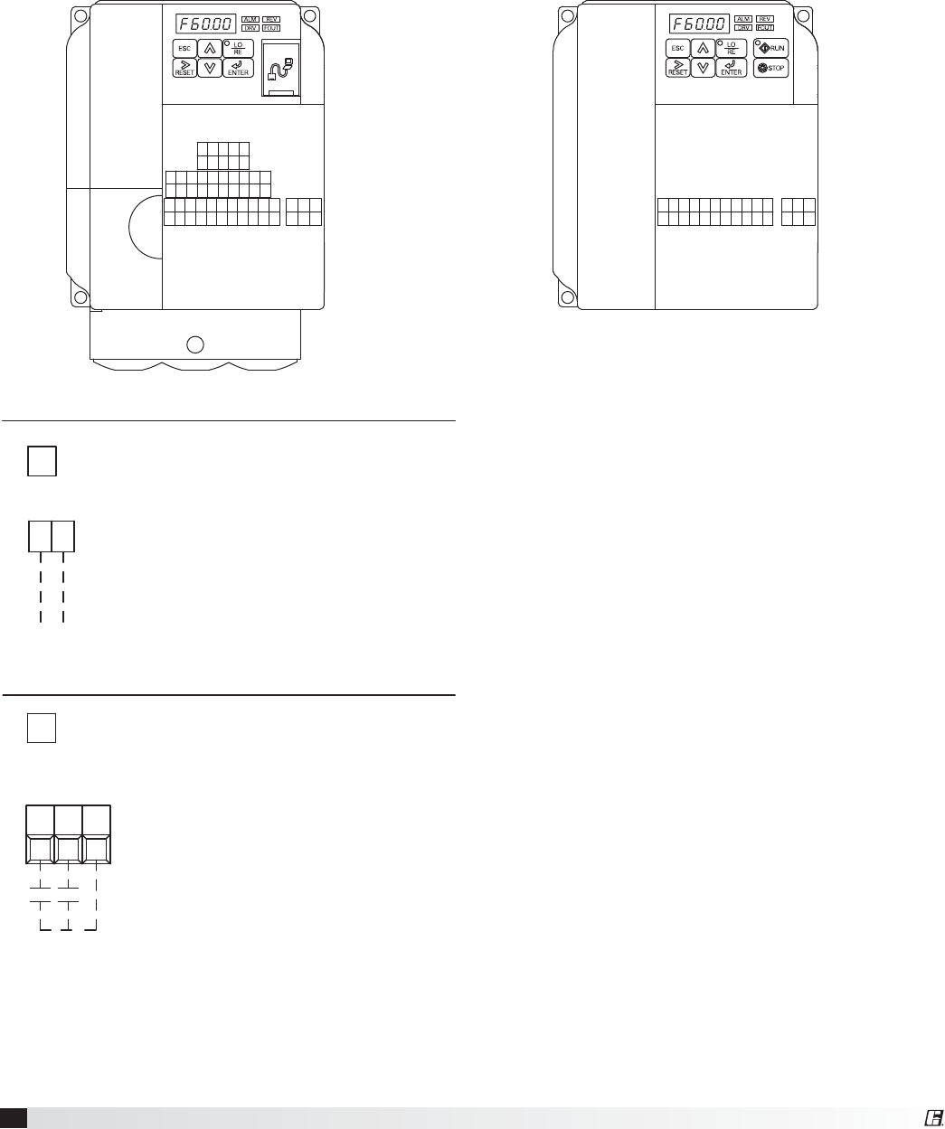
Variable Frequency Drives for Energy Recovery Blowers
Optional factory installed, wired, and programmed variable frequency drives (VFDs) may have been provided
for modulating or multi-speed control of the blowers. One VFD is provided for each blower (supply air and
FYIBVTU5IF7'%TQSPWJEFEBSFFJUIFS:BTLBXBNPEFM7PS+3FGFSUPUIFUBCMFTJOUIJTTFDUJPOGPS
factory settings and field wiring requirements. Refer to the unit control center for unit specific wiring diagram (an
example wiring diagram has been provided in this manual for reference). When making adjustments outside of
the factory set points, refer to Yaskawa VFD instruction manual, which can be found online at www.drives.com.
For technical support, contact Yaskawa direct at 1-800-927-5292.
MA MB MCRPH1SCHCS7S6S5S4S3S2S1
MPACAMAC+VA2A1PCP2P1
IGS-S+R-R+
V1000
MA MB MCACAMAC+VA1SCS5S4S3S2S1
J1000
OPTION 1 - 0-10 VDC CONTROL
SEE VFD INSTALLATION MANUAL FOR MORE DETAIL
USER TO PROVIDE ISOLATION AS REQUIRED
FOR CONTINUOUS 60Hz OPERATION JUMPER TERMINALS A1 AND +V.
WIRED TO A1 (+) AND AC (COMMON)
0-10 VDC CONTROL SIGNAL (BY OTHERS)
10 VDC=60 Hz
0 VDC=30 Hz
A1 AC
FOR ONE 0-10 SIGNAL, WIRE TO DRIVES IN PARALLEL
OPTION 2 - MULTI SPEED CONTROL
S5S4 SC NEITHER S4 OR S5 CONTACT CLOSED
DRIVE SPEED = 60 Hz.
DRIVE SPEED = 40 Hz.
S4 TO SC CONTACT CLOSED (BY OTHERS)
S5 TO SC CONTACT CLOSED (BY OTHERS)
DRIVE SPEED = 30 Hz.
TO CHANGE THE FACTORY SET Hz CHANGE THE FOLLOWING PARAMETERS.
PARAMETER n01 CHANGE TO 1
PARAMETER n22 FOR NEW 40Hz SETTING
PARAMETER n21 FOR NEW 60Hz SETTING
PARAMETER n23 FOR NEW 30Hz SETTING
PARAMETER n01 CHANGE TO 0
USER TO PROVIDE CONTACTS AND ISOLATION
AS REQUIRED
SEE VFD INSTALLATION MANUAL FOR MORE DETAIL

17
Energy Recovery Ventilator
Parameter 4FUUJOHo+
A1-01 Access Level 2
b1-17 VFD Auto Start 1
C6-02 Carrier Frequency 2
d2-01 Ref Upper Limit 100% or 66%*
d2-02 Ref Lower Limit 5%
E2-01 Motor Rated FLA Motor FLA
E2-03 Motor No-Load Current Must be less than
FLA
H1-02 Multi-Function Input
(Terminal S2) 6
H2-01 Multi-Function Output
(MA, MB, MC) 5
Economizer Signal Source
(0-10 VDC)
Setting
Honeywell
Module
Carel
Controller
H3-03 Analog Frequency Reference
(Gain) 0 100
H3-04 Analog Frequency Reference
(Bias) 99 0
L1-01 Elect Thermal Overload 2
L4-01 Frequency Detection Level 20
A1-01 Access Level 0
*36 inch wheel is 66% (40 Hz). All other wheels are 100% (60 Hz).
MODULATING CONTROL FOR FAN SPEED
(0-10 VDC)
Parameter Setting
V1000 +
A1-01 Access Level 2 2
b1-17 VFD Start-Up Setting 1 1
C1-01 Acceleration Time 30 sec. 30 sec.
C1-02 Deceleration Time 30 sec. 30 sec.
C6-02 Carrier Frequency 1 1
d2-02 Ref Lower Limit 50% 50%
E2-01 Motor Rated FLA Motor
FLA
Motor
FLA
H3-04 Terminal A1 Bias 50% 50%
A1-01 Access Level 0 0
MULTI-SPEED CONTROL FOR FAN SPEED
(1/3 OR 1/2 SPEED REDUCTION)
Parameter Setting
V1000 +
A1-01 Access Level 2 2
b1-01 Reference Source (Frequency) 0 0
b1-17 VFD Start-Up Setting 1 1
C1-01 Acceleration Time 30 sec. 30 sec.
C1-02 Deceleration Time 30 sec. 30 sec.
C6-02 Carrier Frequency 1 1
d1-01 Frequency Reference 1 60 Hz 60 Hz
d1-02 Frequency Reference 2 40 Hz 40 Hz
d1-03 Frequency Reference 3 30 Hz 30 Hz
d1-04 Frequency Reference 4 60 Hz 60 Hz
d2-02 Ref Lower Limit 50% 50%
E2-01 Motor Rated FLA Motor
FLA
Motor
FLA
H1-04 Multi-Function Input Sel 4
(Terminal S4) 33
H1-05 Multi-Function Input Sel 5
(Terminal S5) 44
H1-06 Multi-Function Input Sel 6
(Terminal S6) 5NA
H3-10 A2 Not Used F NA
A1-01 Access Level 0 0
CO2 SENSOR CONTROL FOR FAN SPEED
(1/2 SPEED WHEN C02 DROPS BELOW 700 PPM)
Parameter Setting
V1000 +
A1-01 Access Level 2 2
b1-01 Reference Source (Frequency) 0 0
b1-17 VFD Start-Up Setting 1 1
C1-01 Acceleration Time 30 sec. 30 sec.
C1-02 Deceleration Time 30 sec. 30 sec.
C6-02 Carrier Frequency 1 1
d1-01 Frequency Reference 1 60 Hz 30 Hz
d1-02 Frequency Reference 2 30 Hz 60 Hz
d2-02 Ref Lower Limit 50% 50%
E2-01 Motor Rated FLA Motor
FLA
Motor
FLA
H3-10 A2 Not Used F NA
A1-01 Access Level 0 0
Factory Set Points - continued
Resetting the drive to factory defaults
To reset the drive back to Greenheck factory defaults
go to parameter A1-01 and set it to “2”. Then go to
A1-03 and change it to “1110” and press enter. The
drive is now reset back to the settings programmed at
Greenheck.
Variable Frequency Drives for Energy
Recovery Wheel
Optional factory installed VFD for the energy recovery
wheel is programmed at the factory per the settings
shown below for economizer and frost control modes.
5IF7'%QSPWJEFEJTB:BTLBXBNPEFM+3FGFS
to the VFD instruction manual that ships with the unit
when making adjustments.
18 Energy Recovery Ventilator
FACTORY SUPPLIED AND WIRED
G
MULTI-VOLTAGE PRIMARY
24 SECONDARY
TR1
C
FU5
TO UNIT
MAIN POWER
L3
L2
L1
DS1
SUPPLY DAMPER
D2
ENERGY WHEEL
R1
R
TR1
SO
SR
3
FR
FC
2-10V
-
+
1
TR
5
4
2
SR+
RETURN AIR SENSOR
MIXED AIR
SENSOR
T
T1
620 OHM RESISTOR OR
OUTDOOR AIR
SENSOR
SO+
4
S1
VFD-W
L3
34
SC
L2
L1
MC
T3
MA
T2
T1
PS1
NO C COM NO
TS1
6
FROST CONTROL
A1
T1
A2
B1
16
15
T1
ENERGY WHEEL
S1
R1
LEGEND
CC COMPRESSOR CONTACTOR
CF CONDENSING FAN CONTACTOR
CH COMPRESSOR SUMP HEATER
D DAMPER
DB POWER DISTRIBUTION BLOCK
DL DAMPER LIMIT SWITCH
DS DISCONNECT SWITCH
EC ECONOMIZER CONTROLLER
FCS CONDENSOR FAN CYCLE SWITCH
FU FUSES
FU5 CONTROL TRANSFORMER FUSES (NOT ON CLASS II)
FZ1 FREEZE PROTECTION
HPS HIGH PRESSURE SWITCH (MANUAL RESET )
LPS LOW PRESSURE SWITCH
PS1 WHEEL FROST PRESSURE SWITCH
PS2 SUPPLY DIRTY FILTER PRESSURE SWITCH
PS3 EXHAUST DIRTY FILTER PRESSURE SWITCH
R1 ENERGY WHEEL RELAY/CONTACTOR
R2 OCCUPIED/UNOCCUPIED RELAY
R3 EXHAUST BLOWER VFD RELAY
R4 SUPPLY BLOWER VFD RELAY
R5 MODULATING WHEEL FROST CONTROL RELAY
R6 ECONOMIZER RELAY
R7 COMPRESSOR INTERLOCK RELAY
R8 EVAP RELAY (INDIRECT)
R9 EVAP RELAY (DIRECT)
R10 UNIT RELAY
S1 FAN SWITCH
S2 ROTATION SENSOR REED SWITCH
S3 ROTATION SENSOR REED SWITCH
S4 CALL FOR HEAT SWITCH
S5 BYPASS SWITCH
S6 CALL FOR COOL SWITCH (FIRST STAGE)
S7 CALL FOR COOL SWITCH (SECOND STAGE)
ST MOTOR STARTER
T1 FROST CONTROL TIMER
TYPICAL SETTINGS t1(OFF) = 5 MIN., t2(ON) = 30 MIN.
T2 ROTATION SENSOR TIMER
T3 ROTATION SENSOR TIMER
T4 ECONOMIZER WHEEL JOG TIMER
TYPICAL SETTINGS t1(OFF) = 3 HRS., t2(ON) = 10 SEC.
T5 EVAP DELAY OFF TIMER
T6 COMPRESSOR MINIMUM OFF TIMER (TYP. 3 MIN.)
T7 COMPRESSOR MINIMUM OFF TIMER (TYP. 3 MIN.)
TR TRANSFORMER
TS1 FROST CONTROL THERMOSTAT (JUMPER - HEAT)
CLOSES ON TEMP. DECREASE TYPICAL SETTING 5º F.
TS2 ECONOMIZER LOW LIMIT THERMOSTAT (JUMPER - HEAT )
OPENS ON TEMP. DECREASE TYP. SETTING 20º OFFSET OR 50ºF.
TS3 ECONOMIZER UPPER LIMIT THERMOSTAT (JUMPER - HEAT)
CLOSES ON TEMP. DECREASE TYP. SETTING 65º F. /2 º DIFF.
TS4 ROOM OVERRIDE SENSOR
TS5 INLET AIR POST HEATER LOCKOUT THERMOSTAT (AFTER WHEEL)
CLOSES ON TEMP. DECREASE TYPICAL SETTING 65º F.
TS6 INLET AIR COMPRESSOR LOCKOUT THERMOSTAT (JUMPER-HEAT)
OPENS ON TEMP. DECREASE TYPICAL SETTING 60º F./2º DIFF.
A2 A1
o FIELD WIRED
FIELD CONTROL WIRING RESISTANCE SHOULD NOT EXCEED 0.75 OHM. IF
RESISTANCE EXCEEDS 0.75 OHM THEN CONSULT FACTORY. USE 14 GAUGE
MINIMUM WIRE THICKNESS FOR CONTROL WIRING.
REPLACEMENT FUSES: MUST HAVE A MINIMUM I.R. RATING OF 5 KA
CAUTION:
UNIT SHALL BE GROUND IN ACCORDANCE WITH N.E.C.
POWER MUST BE OFF WHILE SERVICING.
USER INTERFACE CONNECTIONS:
*
*
*
*
*
*
o
*
*
*
*
*
*
*
*
D1 EXHAUST DAMPER
GROUND
FR FC
CR
CR
FROST CONTROL INDICATOR
6C
12 C
ROTATION INDICATOR
DIRTY FILTER INDICATOR SHOWN AS 24V POWER FROM UNIT.
SUPPLY DIRTY
FILTER SWITCH
EXHAUST DIRTY
FILTER SWITCH
DIRTY FILTER INDICATOR SHOWN AS 24V POWER FROM UNIT.
USER INTERFACE CONNECTIONS:USER INTERFACE CONNECTIONS:USER INTERFACE CONNECTIONS:
USER TO VERIFY THAT TR1 CAN HANDLE THE VA LOAD OF INDICATOR DEVICES.USER TO VERIFY THAT TR1 CAN HANDLE THE VA LOAD OF INDICATOR DEVICES.USER TO VERIFY THAT TR1 CAN HANDLE THE VA LOAD OF INDICATOR DEVICES.
USER TO VERIFY THAT TR1 CAN HANDLE THE VA LOAD OF INDICATOR DEVICES.
TO FR AND FC
ON VFD-W
SEE BELOW FOR
TERMINAL CONNECTIONS
C
NC NO
NC CNO
ECONOMIZER CONTROL
S6
Y1
MOTOR
MOTOR
EXHAUST FAN
SUPPLY FAN
SC
R4
R3
1
L1
L3
L2
S1
1
0-10 VDC
0-10 VDC
3
FR
VFD-S
3
FC
T1
T3
T2
SC
L1
L3
L2
S1 FR
VFD-E
FC
T1
T3
T2
VFD-E O.L.
MB MC
R3
27
EXHAUST FAN
VFD-S O.L.
MB MC
R4
27
SUPPLY FAN
6
R3
8
*
*
62
NC
S2 1
T2
C
12
MC
ROTATION SENSOR
MA
ON VFD-W
TO MA AND MC
*
EC
THERMOSTAT(S) TS1,
24 VAC THERMOSTAT CONTROLLER(S)
OA-SENSOR
SENSOR COM
o
PS2
PS3
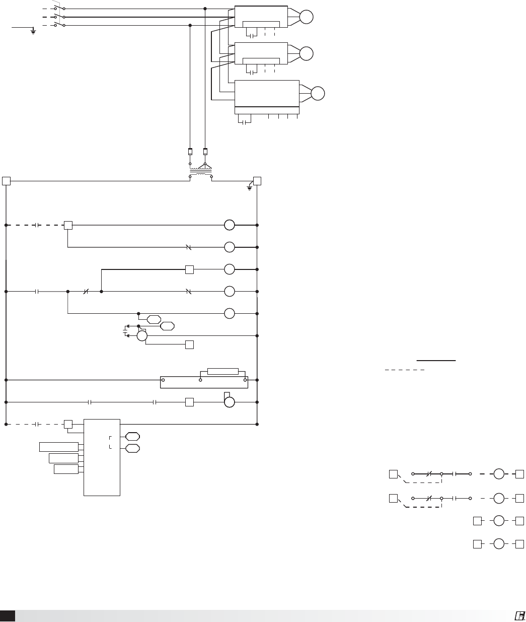
Typical Wiring Diagram
Following is an example of a typical wiring diagram located in the unit control center. This wiring diagram
includes a legend highlighting which accessories were provided with the unit. Factory wiring and field wiring
are also indicated. This particular example includes 1) variable frequency drives on the blowers requiring a
modulating input, 2) modulating energy recovery wheel with factory controls for economizer, 3) energy recovery
wheel rotation sensor, 4) outdoor air and exhaust air dirty filter switches, 5) motorized outdoor air and exhaust
air intake dampers, and 6) timed exhaust frost control. Many other factory installed and wired accessories are
available.
19
Energy Recovery Ventilator
Rotation Sensor
The rotation sensor monitors energy recovery wheel
rotation. If the wheel should stop rotating, the sensor
will close a set of contacts in the unit control center.
Field wiring of a light (or other alarm) between
terminals R & 12 in the unit control center will notify
maintenance personnel when a failure has occurred
(refer to Remote Panel Wiring Schematics section for
wiring details).
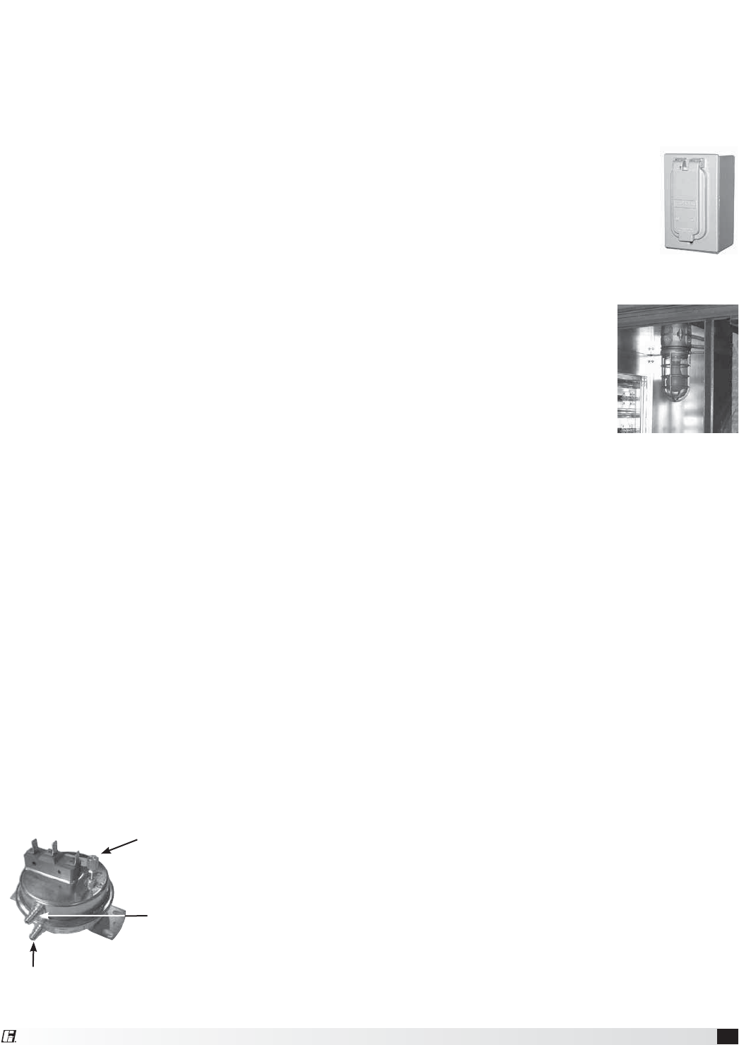
Dirty Filter Sensor
Dirty filter sensors monitor pressure drop across the
outdoor air filters, exhaust air filters or both. If the
pressure drop across the filters exceeds the set point,
the sensor will close a set of contacts in the unit
control center. Field wiring of a light (or other alarm)
to these contacts will notify maintenance personnel
when filters need to be replaced.
The switch has not been set at the factory due to
external system losses that will affect the switch. This
switch will need minor field adjustments after the
unit has been installed with all ductwork complete.
The dirty filter switch is mounted in the exhaust inlet
compartment next to the unit control center or in unit
control center.
To adjust the switch, the unit must be running with
all of the access doors in place, except for the
compartment where the switch is located (exhaust
intake compartment). Model ERV units require the
opening around the control center to be covered (with
cardboard, plywood, etc.) to set up the dirty filter
switch.
The adjusting screw is located on the top of the
switch. Open the filter compartment and place a
sheet of plastic or cardboard over 50% of the filter
media. Replace the filter compartment door. Check to
see if there is power at the alert signal leads (refer to
electrical diagram).
Whether there is power or not, turn the adjustment
screw on the dirty filter gauge (clockwise if you did
not have power, counterclockwise if you did have
power) until the power comes on or just before the
power goes off. Open the filter compartment and
remove the obstructing material. Replace the door
and check to make sure that you do not have power
at the alert signal leads. The unit is now ready for
operation.
Setscrew (on front of switch) must
be manually adjusted after the
system is in operation.
Negative pressure connection
is toward the ‘front or top’ of
the switch. (senses blower side
of filters)
Positive pressure connection is toward the ‘back or
bottom’ of the switch. (senses air inlet side of filters)
CO2 Sensor
This accessory is often used to provide a modulating
control signal to a variable frequency drive to raise
and lower airflow in relationship to the CO2 levels
in the space. This strategy is often referred to as
Demand Control Ventilation and provides further
energy savings to the system. Follow instructions
supplied with sensor for installation and wiring details.
Service Outlet
120 VAC GFCI service outlet ships
loose for field installation. Requires
separate power source so power is
available when unit main disconnect is
turned off for servicing.
Vapor Tight Lights
Vapor tight lights provide light to each of the
compartments in the energy
recovery unit. The lights are wired
to a junction box mounted on the
outside of the unit. The switch to
turn the lights on is located in the
unit control center. The switch
requires a separate power source
to allow for power to the lights
when the unit main disconnect is
off for servicing.
20 Energy Recovery Ventilator
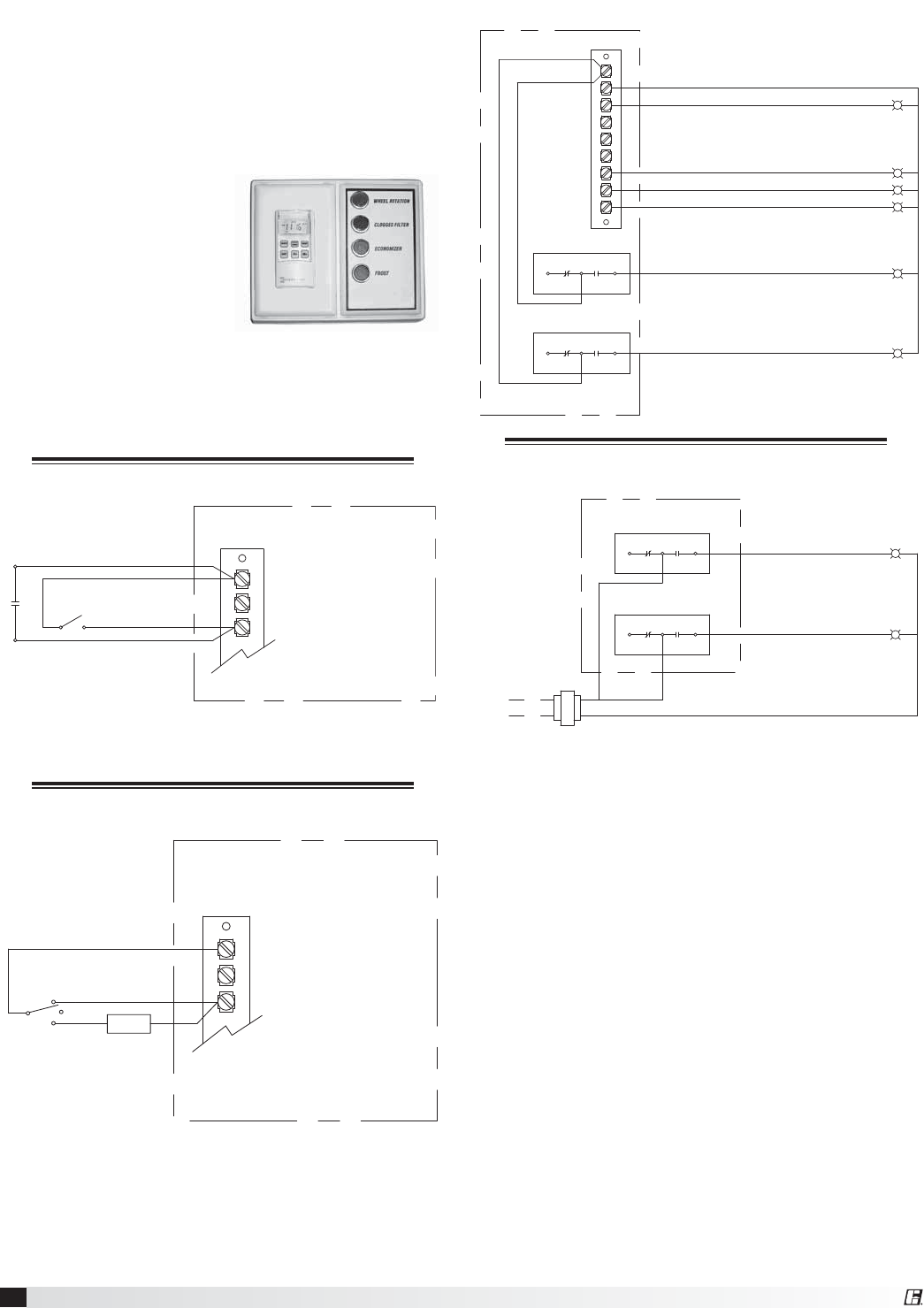
Remote Control Panel and Wiring
Schematics
Indicator Lights powered by the ER Unit
Dirty Filter Indicator (power by others)
Refer to Pressure Switch for voltage and load ratings.
7-Day Timer or On/Off Switch
G
C
R
7-Day Timer
S1 - Unit On/Off
Terminal Block
in Unit
Control Center
For 7-Day Timer, use blue and black wires.
Red wires should be capped off.
G
C
R
On
Off BMS
Auto
Terminal Block
in unit
Control Center
Hand/Off/Auto Switch
Hand/Off/Auto Switch allows the unit to
“Off” - off
“On” - Manual Operation
“Auto” - Unit is controlled by BMS, RTU, etc.
NOTE: RTU controllers are by others.
The remote panel is available with a number of
different alarm lights and switches to control the unit.
The remote panel ships loose and requires mounting
and wiring in the field
The remote panel is available with the following
options:
t 6OJUPOPGGTXJUDI
t 6OJUPOPGGMJHIU
t EBZUJNFDMPDL
t )BOEPGGBVUPTXJUDI
t 5JNFEFMBZPWFSSJEF
t &DPOPNJ[FSMJHIU
t 'SPTUDPOUSPMMJHIU
t &YIBVTUBJSEJSUZmMUFSMJHIU
t 0VUEPPSBJSEJSUZmMUFSMJHIU
t 8IFFMSPUBUJPOTFOTPSMJHIU
Refer to Electrical Connections section for Field Control
Wiring recommendations.
W1
12
7
6
Y2
Y1
G
C
R
NC C
NC C
NO
NO
Exhaust Dirty Filter
Supply Dirty Filter
Rotation Sensor
Economizer
PS2
PS3
Frost Control
Unit On/Off
NC
NC
NO
C
NO
C
Exhaust Dirty Filter
Supply Dirty Filter
Hot
L1
PS2
PS3
21
Energy Recovery Ventilator
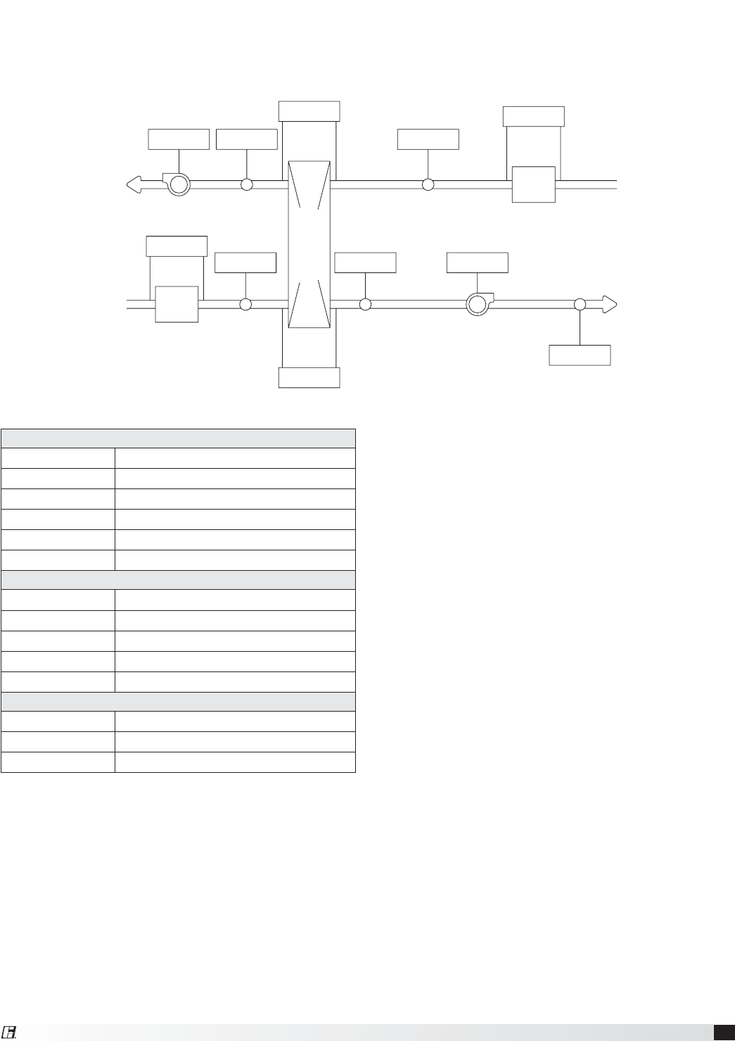
Temperature Sensors - 1K Ohm RTD
Drawing Labels Terminal Strip Labels
OAI OA/Supply Inlet Temp
OAAW OA After Wheel
RAI RA/Exhaust Inlet Temp
OAD Supply Discharge Temp
EAW Exhaust After Wheel Temp
Pressure Sensors (analog or digital)
Drawing Labels Terminal Strip Labels
OAF-P OA/Supply Filter Pressure
OAW-P Outdoor Air Wheel Pressure
RAF-P RA/Exhaust Filter Pressure
EW-P Exhaust Wheel Pressure
Amp - Current Sensors (analog or digital)
Drawing Labels Terminal Strip Labels
OAF-A Supply Fan Amps
EF-A Exhaust Fan Amps
Sensors Mounted by Factory
Factory mounted temperature, pressure, and current sensors are available in the locations indicated on the unit
diagram below. A list of available sensors is shown below. The specific sensors provided on a given unit are
labeled in the unit control center on the terminal strip. Sensors are wired to the terminal strip to make it easy for
the controls contractor to connect the Building Management System for monitoring purposes.
RAI
RAF-P
RA
FILTER
OAAW OAF-A
OAD
SUPPLY
BLOWER
TO
INSIDE
FROM
INSIDE
EW-P
OAW-P
ENERGY WHEEL
EAWEF-A
OAI
OA
FILTER
OAF-P
TO
OUTSIDE
FROM
OUSTIDE
EXHAUST
BLOWER

22 Energy Recovery Ventilator
Start-Up Rotate the fan wheels and energy recovery wheels
by hand and ensure no parts are rubbing. If
rubbing occurs, refer to Start-Up section for more
information.
Check the fan belt drives for proper alignment
and tension (refer to Start-Up section for more
information).
Filters can load up with dirt during building
construction. Replace any dirty pleated filters and
clean the aluminum mesh filters in the intake hood
(refer to Routine Maintenance section).
Verify that non-motorized dampers open and close
properly.
Check the tightness of all factory wiring
connections.
Verify control wire gauge (refer to the Electrical
Connections section).
Verify diameter seal settings on the energy
recovery wheel (refer to Start-Up section for more
information).
General Start-Up Information
Every installation requires a comprehensive start-
up to ensure proper operation of the unit. As part
of that process, the following checklist must be
completed and information recorded. Starting up
the unit in accordance with this checklist will not
only ensure proper operation, but will also provide
valuable information to personnel performing future
maintenance. Should an issue arise which requires
factory assistance, this completed document
will allow unit experts to provide quicker resolve.
Qualified personnel should perform start-up to ensure
safe and proper practices are followed.
Unit Model Number _______________________________
(e.g. ERV-361)
Unit Serial Number _______________________________
(e.g. 04C99999 or 10111000)
Energy Wheel Date Code __________________________
(e.g. 0450)
Start-Up Date _______________________________
Start-Up Personnel Name __________________________
Start-Up Company _______________________________
Phone Number _______________________________
Pre Start-Up Checklist – check as items are
completed.
Disconnect and lock-out all power switches
Remove any foreign objects that are located in the
energy recovery unit.
Check all fasteners, set-screws, and locking collars
on the fans, bearings, drives, motor bases and
accessories for tightness.
DANGER
Electric shock hazard. Can cause injury or death.
Before attempting to perform any service or
maintenance, turn the electrical power to unit
to OFF at disconnect switch(es). Unit may have
multiple power supplies.
WARNING
Use caution when removing access panels or other
unit components, especially while standing on a
ladder or other potentially unsteady base. Access
panels and unit components can be heavy and
serious injury may occur.
Do not operate energy recovery ventilator without
the filters and birdscreens installed. They prevent
the entry of foreign objects such as leaves, birds,
etc.
CAUTION
Do not run unit during construction phase. Damage
to internal components may result and void
warranty.
Start-Up Checklist
The unit will be in operational mode during start-up.
Use necessary precautions to avoid injury. All data
must be collected while the unit is running. In order to
measure volts & amps, the control center door must
be open, and the unit energized using a crescent
wrench to turn the disconnect handle.
Check line voltage at unit disconnect
_______ L1-L2 volts
_______ L2-L3 volts
_______ L1-L3 volts
Motor Amp Draw
t4VQQMZ'BO t&YIBVTU'BO
_______ L1 amps ______ L1 amps
_______ L2 amps ______ L2 amps
_______ L3 amps ______ L3 amps
t&OFSHZ8IFFM
_______ L1 amps
_______ L2 amps
_______ L3 amps
Fan RPM
_______ Supply Fan ______ Exhaust Fan
Correct fan rotation direction
Supply Fan Yes / No
Exhaust Fan Yes / No
SPECIAL TOOLS REQUIRED
t 7PMUBHF.FUFSXJUIXJSFQSPCFT
t "NQFSBHF.FUFS
t 5IFSNPNFUFS
t 5BDIPNFUFS
t *ODMJOFNBOPNFUFSPSFRVJWBMFOU

23
Energy Recovery Ventilator
Frost Control Application / Operation section: Setting Factory Default
Yes No Frost Control set point 5ºF
Differential 2ºF
Timer Refer to IOM
Yes No Frost Control Modulating Refer to IOM
Economizer Application / Operation section:
Yes No Economizer (temperature)
Set point 65ºF
Offset 20ºF
Differential 2ºF
Yes No Economizer (enthalpy)
Set point D
Yes No Economizer (modulating) Refer to IOM
Optional Accessories section: Operational
Yes No Wheel Rotation Sensor Yes No N/A
Yes No OA Dirty Filter Sensor Yes No N/A
Yes No EA Dirty Filter Sensor Yes No N/A
Yes No CO2 Sensor Yes No N/A
Yes No Service Outlet Yes No N/A
Yes No Vapor Tight Lights Yes No N/A
Yes No Remote Control Panel Yes No N/A
Variable Frequency Drives section: Operational
Yes No Blower VFDs Yes No N/A
Yes No Wheel VFD Yes No N/A
Damper section: Operational
Yes No Outdoor Air Damper Yes No N/A
Yes No Exhaust Air Damper Yes No N/A
Optional Accessories Checklist
Refer to the respective sections in this Installation, Operation and Maintenance Manual for detailed information.
Refer to wiring diagram in unit control center to determine what electrical accessories were provided.
Provided with Unit?
24 Energy Recovery Ventilator
Unit Start-Up
Refer to Parts List section for component locations.
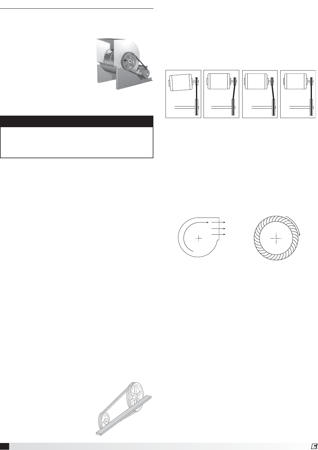
Fans
The ERV models contain two
forward curved (supply &
exhaust) fans. These forward
curved fans should be checked
for free rotation. If any binding
occurs, check for concealed
damage and foreign objects
in the fan housing. Be sure to
check the belt drives per the
start-up recommendations in
the following section.
CAUTION
When operating conditions of the fan are to be
changed (speed, pressure, temperature, etc.),
consult Greenheck to determine if the unit can
operate safely at the new conditions.
5. Place belts over sheaves. Do not pry or force
belts, as this could result in damage to the cords
in the belts.
6. With the fan off, adjust the belt tension by moving
the motor base. (See belt tensioning procedures in
the Routine Maintenance section of this manual).
When in operation, the tight side of the belts
should be in a straight line from sheave to sheave
with a slight bow on the slack side.
Fan Performance Modifications
Due to job specification revisions, it may be
necessary to adjust or change the sheave or pulley to
obtain the desired airflow at the time of installation.
Start-up technician must check blower amperage
to ensure that the amperage listed on the motor
nameplate is not exceeded. Amperage to be tested
with access doors closed and ductwork installed.
Fan Belt Drives
The fan belt drive components, when supplied by
Greenheck, have been carefully selected for the
unit’s specific operating condition. Utilizing different
components than those supplied could result in
unsafe operating conditions which may cause
personal injury or failure of the following components:
t'BO4IBGU t #FBSJOHT t.PUPS
t'BO8IFFM t #FMU
Tighten all fasteners and set screws securely and
realign drive pulleys after adjustment. Check pulleys
and belts for proper alignment to avoid unnecessary
belt wear, noise, vibration and power loss. Motor and
drive shafts must be parallel and pulleys in line (see
diagrams in this section).
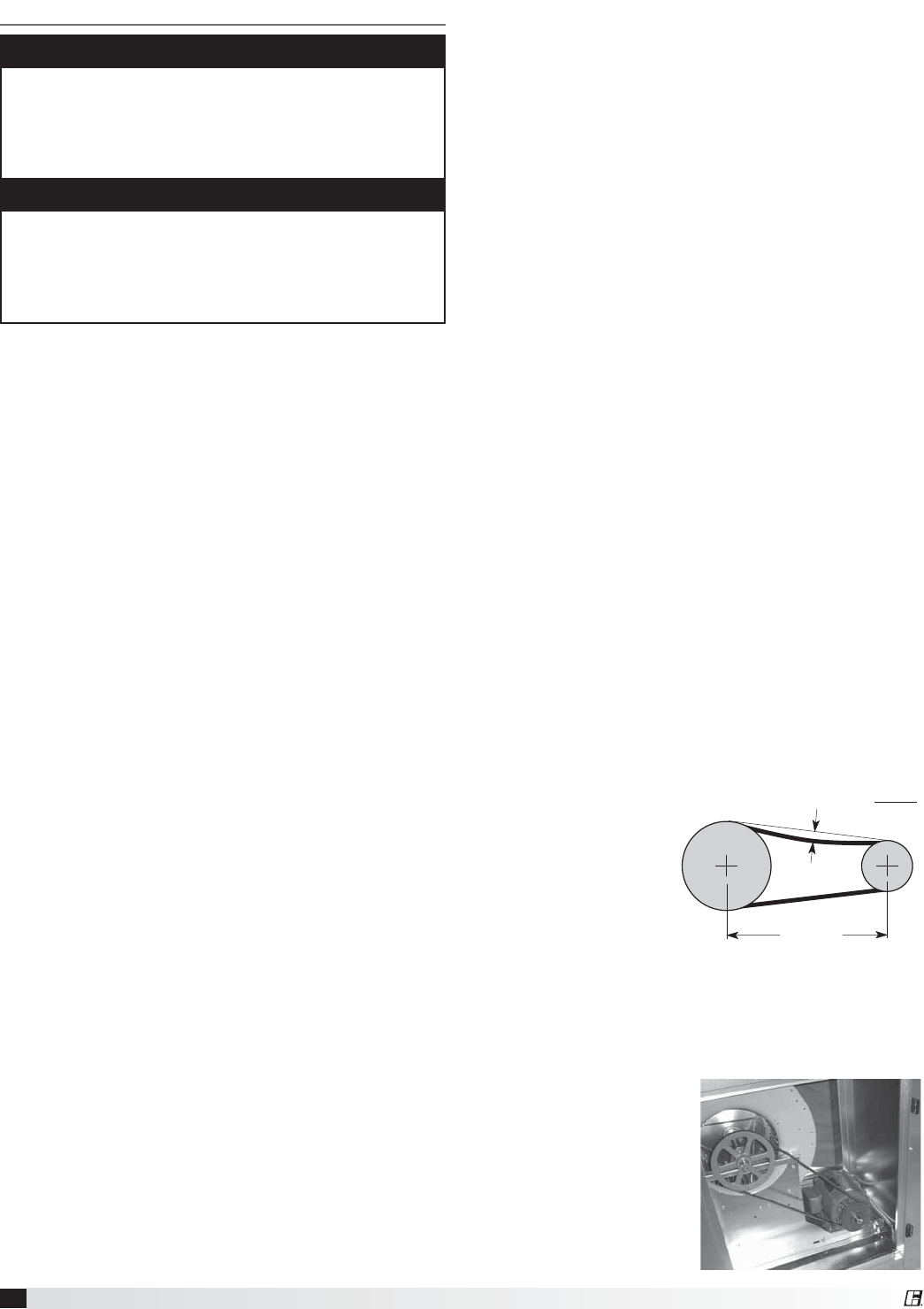
Belt Drive Installation
1. Remove the protective coating from the end of
the fan shaft and assure that it is free of nicks and
burrs.
2. Check fan and motor shafts for
parallel and angular alignment.
3. Slide sheaves on shafts. Do not
drive sheaves on as this may
result in bearing damage.
4. Align fan and motor sheaves
with a straight-edge or
string and tighten.
WRONG WRONG WRONG CORRECT
Forward Curved
Exhaust Fan
Direction of Fan Wheel Rotation
Blower access is labeled on unit. Check for proper
wheel rotation by momentarily energizing the fan.
Rotation is determined by viewing the wheel from the
drive side and should match the rotation decal affixed
to the fan housing (see Rotation Direction figures).
If the wheel is rotating the wrong way, direction can
be reversed by interchanging any two of the three
electrical leads. Check for unusual noise, vibration, or
overheating of bearings. Refer to the Troubleshooting
section of this manual if a problem develops.
Fan RPM
Supply fan and exhaust fan will have an adjustable
motor pulley (on 15 HP and below) preset at the
factory to the customer specified RPM. Fan speed
can be increased or decreased by adjusting the pitch
diameter of the motor pulley. Multi-groove variable
pitch pulleys must be adjusted an equal number
of turns open or closed. Any increase in fan speed
represents a substantial increase in load on the
motor. Always check the motor amperage reading
and compare it to the amperage rating shown on the
motor nameplate when changing fan RPM. All access
doors must be installed except the control center
door. Do not operate units with access doors open or
without proper ductwork in place as the fan motors
will overload.
R
o
t
a
t
i
o
n
Airflow
R
o
ta
t
io
n
Forward Curved
25
Energy Recovery Ventilator
Vibration
Excessive vibration may be experienced during initial
start-up. Left unchecked, excessive vibration can
cause a multitude of problems, including structural
and/or component failure. The most common sources
of vibration are listed.
Many of these conditions can be discovered by
careful observation.
Refer to the
Troubleshooting
section of this manual
for corrective actions.
If observation cannot
locate the source of
vibration, a qualified
technician using
vibration analysis
equipment should be consulted. If the problem is
wheel unbalance, in-place balancing can be done.
Generally, fan vibration and noise is transmitted
to other parts of the building by the ductwork. To
eliminate this undesirable effect, the use of heavy
canvas connectors is recommended.
Wheel Unbalance
Drive Pulley Misalignment
Incorrect Belt Tension
Bearing Misalignment
Mechanical Looseness
Faulty Belts
Drive Component Unbalance
Poor Inlet/Outlet Conditions
Foundation Stiffness
Drive Belt
Inspect the drive belt. Make sure the belt rides
smoothly through the pulley and over the wheel rim.
Air Seals
Check that the air seals located around the outside of
the wheel and across the center (both sides of wheel)
are secure and in good condition. Air seal clearance
is determined by placing a sheet of paper, to act as a
feeler gauge, against the wheel face. To access seals,
enter the unit for the ERV-581 and 582, or pull out the
cassette for the ERV-251, 361, 521, and 522, following
the instructions in the Energy Recovery Wheel
Maintenance section. To adjust the air seals, loosen
all eight seal retaining screws. These screws are
located on the bearing support that spans the length
of the cassette through the wheel center. Tighten the
screws so the air seals tug slightly on the sheet of
paper.
Replace cassette into unit, plug in wheel drive,
replace access door and apply power. Observe by
opening door slightly (remove filters if necessary to
view wheel) the wheel should rotate freely at about
50-60 RPM.
Energy Recovery Wheel
The ERV models contain a
total energy recovery wheel.
The wheels are inspected
for proper mechanical
operation at the factory.
However, during shipping
and handling, shifting
can occur that may affect
wheel operation. The wheel
is accessible through
the access door marked
“Energy Wheel Cassette
Access”. For the ERV-
251, 361, 521, and 522,
the wheel cassette(s)
slide out. Due to the size
and weight of the ERV-
581 and 582 wheels, they
remain stationary and all
maintenance is performed
in place. There is room inside the unit to perform
energy recovery wheel servicing.
Turn the
energy
recovery
wheels by
hand to verify
free operation.
The wheel
should rotate
smoothly and
should not
wobble.
Inside layout of ERV-361
Inside layout of ERV-522
Drive Belt
Adjustable
Air Seals
Label
showing
cassette
serial #
and date
code
Bearing
Support
Drive Pulley
26 Energy Recovery Ventilator
Dampers
Check all dampers to ensure they open and close
properly and without binding. Backdraft dampers can
be checked by hand to determine if blades open and
close freely. Apply power to motorized dampers to
ensure the actuator opens and closes the damper as
designed.
Fan Belts
Belts must be checked on a regular basis for
wear, tension, alignment, and dirt accumulation.
Premature or frequent belt failures can be caused by
improper belt tension (either too loose or too tight)
or misaligned sheaves. Abnormally high belt tension
or drive misalignment will cause excessive bearing
loads and may result in failure of the fan and/or motor
bearings. Conversely, loose belts will cause squealing
on start-up, excessive belt flutter, slippage, and
overheated sheaves. Both loose and tight belts can
cause fan vibration.
When replacing belts on multiple groove drives, all
belts should be changed to provide uniform drive
loading. Do not pry belts on or off the sheave. Loosen
belt tension until belts can be removed by simply
lifting the belts off the sheaves. After replacing belts,
insure that slack in each belt is on the same side of
the drive. Belt dressing should never be used.
Do not install new belts on worn sheaves. If the
sheaves have grooves worn in them, they must be
replaced before new belts are installed.
The proper belt setting is the lowest tension at which
the belts will not slip under peak load operation.
For initial tensioning, set the belt deflection at 1/64-
inch for each inch of belt span (measured half-
way between sheave centers). For example, if the
belt span is 64 inches, the belt deflection should
be oneinch (using
moderate thumb
pressure at mid-point
of the drive). Check
belt tension two times
during the first 24hours
of operation and
periodically thereafter.
Fan Motors
Motor maintenance is generally limited to cleaning
and lubrication. Cleaning should be limited to exterior
surfaces only. Removing dust and grease buildup
on the motor housing assists proper motor cooling.
Never wash-down motor
with high pressure spray.
Greasing of motors is
only intended when
fittings are provided.
Many fractional motors
are permanently
lubricated for life and
require no further
lubrication.
Routine Maintenance
DANGER
Electric shock hazard. Can cause injury or death.
Before attempting to perform any service or
maintenance, turn the electrical power to unit
to OFF at disconnect switch(es). Unit may have
multiple power supplies.
CAUTION
Use caution when removing access panels or other
unit components, especially while standing on a
ladder or other potentially unsteady base. Access
panels and unit components can be heavy and
serious injury may occur.
Once the unit has been put into operation, a routine
maintenance program should be set up to preserve
reliability and performance. Items to be included in
this program are:
Lubrication
Apply lubrication where required
Dampers
Check for unobstructed operation
Fan Belts
Check for wear, tension, alignment
Motors
Check for cleanliness
Blower Wheel & Fasteners
Check for cleanliness
Check all fasteners for tightness
Check for fatigue, corrosion, wear
Bearings
Check for cleanliness
Check set screws for tightness
Lubricate as required
External Filter
Check for cleanliness - clean if required
Internal Filter
Check for cleanliness - replace if required
Door Seal
Check if intact and pliable
Energy Recovery Wheel
Check for cleanliness - clean if required
Check belt for wear
Check pulley, bearings, and motor
Maintenance Procedures:
Lubrication
Check all moving components for proper lubrication.
Apply lubrication where required. Any components
showing excessive wear should be replaced to
maintain the integrity of the unit and ensure proper
operation.
Belt Span
Deflection = Belt Span
64
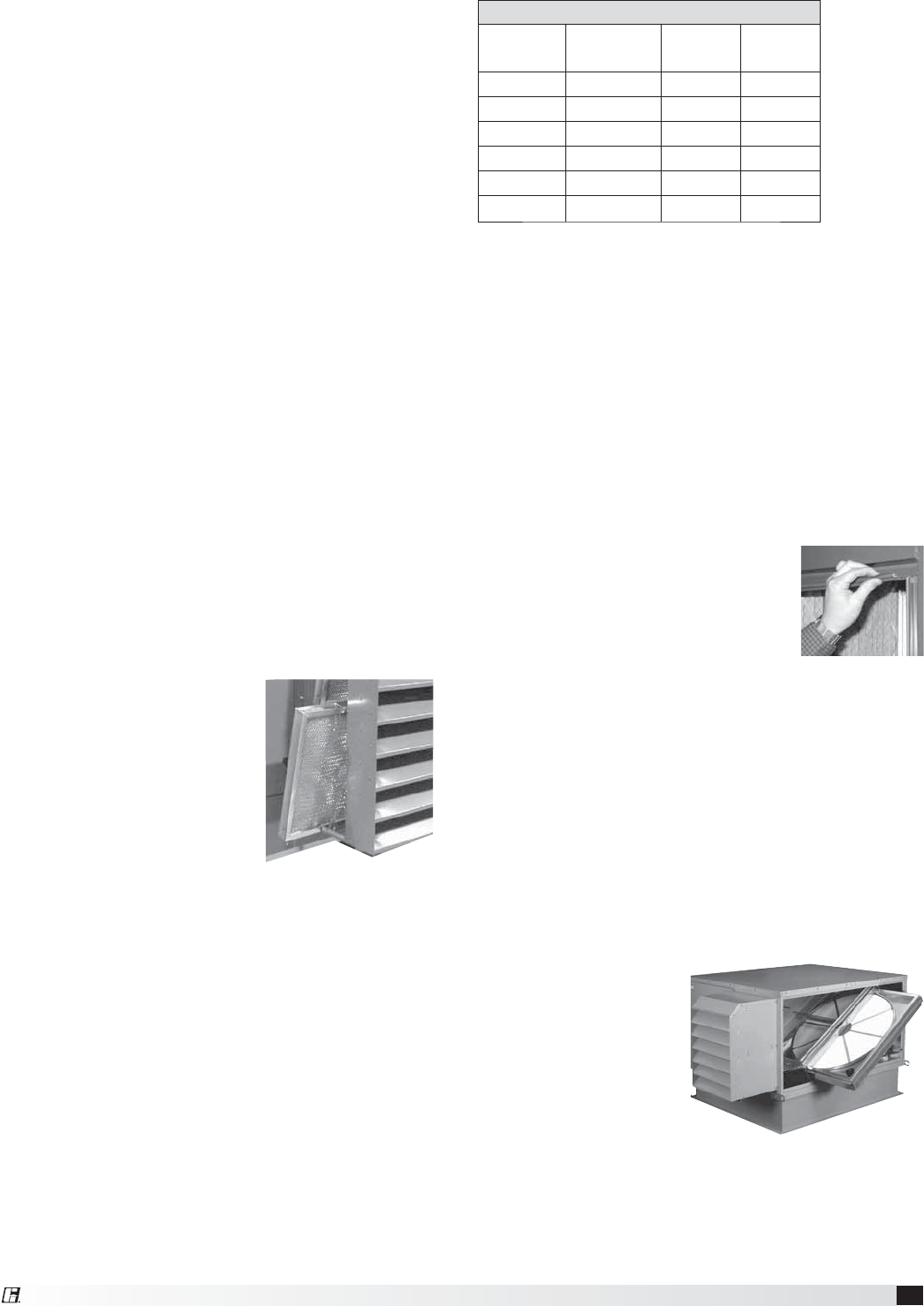
27
Energy Recovery Ventilator
Fan Wheel & Fasteners
Wheels require very little attention when moving clean
air. Occasionally oil and dust may accumulate on the
wheel causing imbalance. When this occurs the wheel
and housing should be cleaned to assure smooth and
safe operation. Inspect fan impeller and housing for
fatigue, corrosion or wear.
Routinely check all fasteners, set screws and locking
collars on the fan, bearings, drive, motor base and
accessories for tightness. A proper maintenance
program will help preserve the performance and
reliability designed into the fan.
Bearings
Most bearings are permanently lubricated and require
no further lubrication under normal use. Normal use
being considered -20ºF to 120ºF and in a relatively
clean environment. Some bearings are re-lubricatable
and will need to be regreased depending on fan use.
Check your bearings for grease zerk fittings to find
out what type of bearing you have. If your fan is not
being operated under normal use, bearings should be
checked monthly for lubrication.
External Filter Maintenance
Aluminum mesh, 2-inch deep filters are located in the
supply weatherhood (if the weatherhood option was
purchased). Filters should be checked and cleaned
on a regular basis for best efficiency. The frequency
of cleaning depends upon the cleanliness of the
incoming air. These filters should be cleaned prior to
start-up.
To access these filters,
remove bottom bolt in the
access door on the side of
the weatherhood. Slide the
access door up and then pull
bottom out to remove door.
Then, slide the filters out (see
picture at right).
Clean filters by rinsing with
a mild detergent in warm
water.
Internal Filter Maintenance
The ERV units will typically be provided with 2-inch,
pleated filters in the outdoor air and exhaust
airstreams. These filters should be checked per
a routine maintenance schedule and replaced as
necessary to ensure proper airflow through the
unit. See table for pleated filter size and quantity
for each unit. Replacement filters shall be of same
performance and quality as factory installed filters.
Filter type must be pleated design with integral metal
grid. Two acceptable filter replacements are Aerostar
Series 400 or Farr 30/30®.
Filter Size and Quantities
Unit Size Internal
Filter Size
Quantity
Supply
Quantity
Exhaust
ERV-251 16 x 25 1 1
ERV-361 16 x 20 2 2
ERV-521 16 x 25 3 3
ERV-581 16 x 20 6 6
ERV-522 16 x 25 7 7
ERV-582 20 x 25 6 6
All dimensions in inches.
Outdoor Air Filters: Access to the outdoor air filters
is through the door labeled as “Filter Access” on the
outdoor air side of the unit.
Exhaust Air Filters: Access to the exhaust air filters
is through the door labeled as “Filter Access” on the
exhaust air side of the unit.
Refer to Access Door Descriptions section for
additional information on filter locations.
Door Seal Maintenance
ERV-251, 361, 521, and 581: Closed cell foam
tape is installed on the perimeter of the door. Inspect
at least annually to ensure that the seal is still intact.
ERV-522 & 582: Slip-on type vinyl
seal is installed on the perimeter of
the door openings. Inspect at least
annually to ensure that seal is still
pliable and intact.
Outdoor air intake hood
mesh filter access
Accessing the Energy Recovery Wheel in
Models ERV-251, 361, 521 and 581
Disconnect power to the ERV. Remove access
panel(s) labeled “Energy Wheel Cassette Access”.
Unplug the wheel drive
motor. The center
channel must be
removed to access the
energy wheel cassette.
Use a 5/16 inch open
or closed wrench to
remove the three (3)
fasteners that hold the
center channel in place.
Pull the cassette halfway out as shown. (Except on
ERV-581, wheel is stationary).
When service is complete, reattach the center
channel before putting access panels back in place.
Energy Recovery Wheel Maintenance
Annual inspection of the energy recovery wheel is
recommended. Units ventilating smoking lounges
and other non-clean air spaces should have energy
recovery wheel inspections more often based upon
need. Inspections for smoke ventilation applications
are recommended bimonthly to quarterly until a
regular schedule can be established.
Access to wheel through
outdoor air filter door
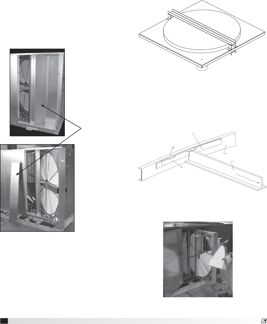
28 Energy Recovery Ventilator
Accessing the Energy Recovery Wheel in
Models ERV-522 and 582
Disconnect power to the ERV. Remove access
panel(s) labeled “Energy Wheel Cassette Access”,
which reveals the energy wheel cassette. There are
additional panels that must be removed in order
to slide out the cassettes. (See pictures providing
additional visual information).
Unplug the wheel drive motor and pull the cassette
halfway out as shown.
NOTE: ERV-522 has two energy wheels with access
panels for both wheels. Wheels slide out on opposite
corners.
Energy recovery wheels for ERV-582 are hard-wired
and not designed to slide out.
This panel must
be removed before
the energy wheel
can slide out.
(ERV-522 only)
Removing the Energy Recovery Wheel in
ERV-251
First, remove the drive belts and the collars in both
bearings. On the pulley side of the cassette, remove
the four (4) fasteners that hold the bearing support
channel in place. Once the bearing support is
removed the wheel can be pulled from the cassette.
To replace the wheel, reverse this procedure.
Removing the Energy Recovery Wheel Segments
ERV-361, 521, 581, 522 and 582
(stainless steel rim)
Steel retainers are located on the inside of the wheel
rim. Push the retainer towards the center of the
wheel, then lift up and away to release segments.
Wheel segment removed
Bracket Segment
Retainer
Lift away from
segment
Catch Segment
Retainer
Push toward center
Center of Wheel
Spoke
Inside of wheel rim
Important! Place retainers back in the original
position before rotating the energy recovery wheel,
otherwise damage to retainer will occur.
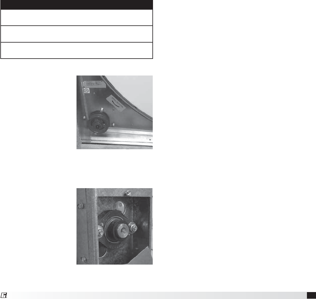
29
Energy Recovery Ventilator
Cleaning the Energy Recovery Wheel
If the wheel appears excessively dirty, it should be
cleaned to ensure maximum operating efficiency.
Only excessive buildup of foreign material needs to
be removed. Discoloration and staining of energy
recovery wheel does not affect its performance.
Thoroughly spray wheel matrix with household
cleaner such as Fantastik® or equivalent. Gently rinse
with warm water and using a soft brush remove any
heavier accumulation. A detergent/water solution can
also be used. Avoid aggressive organic solvents, such
as acetone. The energy recovery wheel segments
can be soaked in the above solution overnight for
stubborn dirt or accumulation.
After cleaning is complete, shake the excess water
from the wheel or segments. Dry wheel or segments
before placing them back into the cassette. Place
wheel or segments back into cassette by reversing
removal procedures.
CAUTION
Do not clean energy recovery wheel segments with
water in excess of 140ºF (60ºC).
Do not dry energy recovery wheel segments in air in
excess of 140ºF (60ºC).
The use of a pressure washer to clean segments is
not recommended. Damage could result.
Energy Recovery Wheel Belt
Inspect belts each time
filters are replaced. Belts
that look chewed up
or are leaving belt dust
near the motor pulley
may indicate a problem
with the wheel. Be sure
to inspect wheel for
smooth and unrestricted
rotation. If a belt requires
replacement, contact
the local Greenheck
representative. Instructions
for replacement will ship with the new belt.
Energy Recovery Wheel Bearing
In the unlikely event that
a wheel bearing fails,
the bearing is behind a
removable plate on the
wheel support beam
which is accessible
through the outdoor air
filter door (and exhaust
filter door on the ERV-
522 and 582). Contact
the local Greenheck
representative for detailed
instructions on how to
replace the bearing.
Wheel Bearing
Wheel Belt & Pulley
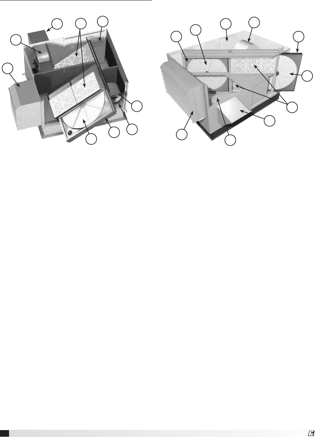
30 Energy Recovery Ventilator
Parts List
(shown with intake weatherhood, exhaust weatherhood, outdoor air filters, and exhaust air filters)
1. Supply blower
t 'PSXBSEDVSWFEGBO
t "EKVTUBCMFNPUPSNPVOUGPSCFMUUFOTJPOJOH
t "EKVTUBCMFTIFBWFTGPSTQFFEDPOUSPM
2. Vibrations isolators (quantity 4 per blower)
t /FPQSFOF
3. Energy recovery wheel cassette
t POFXIFFMPONPEFMT&37
t UXPXIFFMTPONPEFMT&37
4. Removable energy recovery wheel segments
5. Optional supply weatherhood with 2 inch
aluminum mesh filter
6. Optional exhaust weatherhood with birdscreen
7. Optional supply and exhaust air filter racks for
2 inch pleated, 30% efficient filters
8. Electrical control box (standard features)
t 4JOHMFQPJOUQPXFS
t %JTDPOOFDUJOUFSMPDLFEXJUIBDDFTTEPPS
t .PUPSTUBSUFSTGPSUIFTVQQMZCMPXFSFYIBVTU
blower and energy wheel motors
t 7"$DPOUSPMDJSDVJUXJUIUFSNJOBMTUSJQ
9. Exhaust blower
t 'PSXBSEDVSWFEGBO
t "EKVTUBCMFNPUPSNPVOUGPSCFMUUFOTJPOJOH
t "EKVTUBCMFTIFBWFTGPSTQFFEDPOUSPM
Inside layout of ERV-361 Inside layout of ERV-522
5
1
2
3
4
8
67
9
1
3
4
5
6
7
8
9
3
4

31
Energy Recovery Ventilator
Sequence of Operation
Basic Unit
The ERV units are prewired such that when a call
for outside air is made (via field supplied 24 VAC
control signal wired to unit control center), the supply
fan, exhaust fan and energy wheel are energized
and optional motorized dampers open. The ERV is
normally slaved (24 volt) to the roof top air handler.
When the roof top air handler starts, the auxiliary
contactor in the air handler closes to start the ERV.
Summer Operation
Outdoor air is preconditioned (temperature and
moisture levels are decreased) by the transfer of
energy from the cooler, drier, exhaust air via the
energy recovery wheel. The preconditioned air is
typically mixed with return air going back to the air
handler for final conditioning.
Economizer Operation: Refer to Economizer
Application/Operation section.
Winter Operation
Outdoor air is preconditioned (temperature and
moisture levels are increased) by the transfer of
energy from the warmer, more humid exhaust air via
the energy recovery wheel. The preconditioned air is
typically mixed with return air going back to the air
handler for final conditioning.
Frost Control Operation: Refer to Frost Control
Application/Operation section.
Other Accessories:
Rotation Sensor: Refer to Optional Accessories
section
Dirty Filter Sensor: Refer to Optional Accessories
section
CO2 Sensor: Refer to Optional Accessories section
Variable Frequency Drive (VFD) on Blowers: VFDs
on blowers are often used as part of a demand
control ventilation system. This type of system takes
advantage of varying occupancy through the use
of CO2 sensors to monitor space CO2 levels. If CO2
levels are low in the space, the VFD will operate the
blowers at minimum airflow required by code. As the
space occupancy increases and CO2 levels increase,
the VFD will increase the amount of fresh outdoor
air being brought in to offset the CO2 levels in the
space (exhaust airflow is increased proportionally as
outdoor airflow increases). As CO2 levels come back
down, the airflow will decrease back to minimum
requirements.

32 Energy Recovery Ventilator
Troubleshooting – Airflow
Test and Balance Report
The Test and Balance Report (TAB) is utilized to determine whether the appropriate amount of outdoor air
and exhaust air is being supplied and removed from a building, respectively. There are no set rules on what
information must be included in a TAB report. As such, if a TAB report indicates that the airflow on a unit is low,
prior to contacting the factory, please determine the following information:
Airflow problems can often be tied back to improper ductwork installation. Be sure to install ductwork in
accordance with SMACNA and AMCA guidelines.
Unit #1 Unit #2 Unit #3 Unit #4
Model Number
Serial Number
Nameplate Information
Voltage
Hertz
Phase
Outdoor Air Fan Amps
Exhaust Fan Amps
Outdoor Air Fan Horsepower
Exhaust Fan Horsepower
Design Airflow
Outdoor Air
Exhaust
Measured Airflow
Outdoor Air
Exhaust
Measured Data
Blower Rotation
Outdoor Air Fan RPM
Exhaust Fan RPM
Outdoor Air Fan Amp Draw
Exhaust Fan Amp Draw
Pressure Drop Across Energy Recovery Wheel
Outdoor Air Side
Exhaust Air Side

33
Energy Recovery Ventilator
Always have a completed Pre Start-Up Checklist, unit Start-Up Checklist, and Optional Accessories Checklist prior to requesting parts or
service information.
Symptom Possible Cause Corrective Action
Blower fails to
operate
Blown fuse or open circuit breaker. Replace fuse or reset circuit breaker and check
amps.
Defective motor or capacitor. Replace.
Motor starter overloaded. Reset starter and check amps.
Electrical. Check for On/Off switches. Check for correct
supply voltage.
Drive. Check for broken or loose belts. Tighten loose
pulleys.
Motor starters
“chatter” or
do not pull in
Control power (24 VAC) wiring run is too long
(resistance should not exceed 0.75 ohms).
Shorten wiring run to mechanical room or
install a relay which will turn unit on/off. Consult
Factory for relay information.
Incoming supply power is less than anticipated.
Voltage supplied to starter coil must be within
+10% / -15% of nominal voltage stated on the coil.
Need to increase supply power or use a special
control transformer which is sized for the actual
supply power.
Motor over amps
CFM too high. Check cfm and adjust drives if needed.
Static pressures are higher or lower than
design.
If higher, ductwork should be improved.
If lower, fan rpm should be lower.
Blower rotation is incorrect. Check rotation and reverse if necessary.
Motor voltage incorrect. Check motor nameplate versus supplied
voltage.
Motor horsepower too low. See specifications and catalog for fan curves to
determine if horsepower is sufficient.
Shorted windings in motor. Replace motor.
Low airflow (cfm)
Unit damper not fully open. Adjust damper linkage or replace damper motor.
System static pressure too high. Improve ductwork to eliminate losses using
good duct practices.
Blower speed too low. Check for correct drives and rpm with catalog
data.
Fan wheels are operating backwards. For 3-phase, see Direction of Fan Wheel
Rotation under Unit Start-Up section.
Dirty filter or energy wheel. Follow cleaning procedures in Routine
Maintenance section.
Leaks in ductwork. Repair.
Elbows or other obstructions may be
obstructing fan outlet. Correct or improve ductwork.
Belt slippage. Adjust belt tension.
High airflow (cfm)
Blower fan speed too high. Check for correct fan rpm. Decrease fan speed
if necessary.
Filter(s) not in place. Install filters.
Insufficient static pressure (Ps) (airflow
resistance).
Induce Ps into system ductwork. Make sure
grilles and access doors are installed. Decrease
fan speed if necessary.
Troubleshooting – Unit

34 Energy Recovery Ventilator
Troubleshooting – Unit
Always have a completed Pre Start-Up Checklist, unit Start-Up Checklist, and Optional Accessories Checklist prior to requesting parts or
service information.
Symptom Possible Cause Corrective Action
One or both
blowers turn off
intermittently and
back on after
about 2 minutes
Exhaust Only frost control sensors are tripping. Adjust frost temperature sensor set point as
needed.
Energy wheel does
NOT turn
Air seals are too tight. See Energy Recovery Wheel under Unit Start-Up
section.
“Economizer” sensors are operating. Adjust temperature or enthalpy set points as
needed.
No power to wheel motor. Make sure wheel drive is plugged in. Verify
power is available.
Wheel drive belt. Check for loose or broken belts. Replace belts
(consult factory).
VFD overload. (OL1 on readout) Refer to VFD section. Compare motor amp
rating to setting in VFD. Adjust accordingly.
Energy wheel runs
intermittently
Wheel motor overloads are tripping, due to
rubbing between wheel and air seals.
Recheck air seals, make sure they are not too
tight. See Energy Recovery Wheel under Unit
Start-Up Section.
Excessive noise
or vibration
Fan wheel rubbing on inlet. Adjust wheel and/or inlet cone. Tighten wheel
hub or bearing collars on shaft.
Bearings. Replace defective bearing(s). Lubricate
bearings. Tighten collars and fasteners.
Wheel out of balance. Replace or rebalance.
Loose wheel on shaft. Tighten wheel setscrew.
Loose motor or blower sheave. Tighten sheave setscrew.
Belts too loose. Adjust belt tension after 24 hours of operation.
Belts too tight. Loosen to maintain a 3/8 inch deflection per
foot of span between sheaves.
Worn belt. Replace.
Motor base or blower loose. Tighten mounting bolts.
Buildup of material on wheel. Clean wheel and housing.
Bearing and drive misaligned. Realign.
Noise being transmitted by duct.
Make sure ductwork is supported properly.
Make sure ductwork metal thickness is sized for
proper stiffness. Check duct size at discharge to
ensure that air velocities are not too high.

35
Energy Recovery Ventilator
Maintenance Log
Date __________________ Time _____________ AM/PM
Notes:___________________________________________
_________________________________________________
_________________________________________________
_________________________________________________
_________________________________________________
Date __________________ Time _____________ AM/PM
Notes:___________________________________________
_________________________________________________
_________________________________________________
_________________________________________________
_________________________________________________
Date __________________ Time _____________ AM/PM
Notes:___________________________________________
_________________________________________________
_________________________________________________
_________________________________________________
_________________________________________________
Date __________________ Time _____________ AM/PM
Notes:___________________________________________
_________________________________________________
_________________________________________________
_________________________________________________
_________________________________________________
Date __________________ Time _____________ AM/PM
Notes:___________________________________________
_________________________________________________
_________________________________________________
_________________________________________________
_________________________________________________
Date __________________ Time _____________ AM/PM
Notes:___________________________________________
_________________________________________________
_________________________________________________
_________________________________________________
_________________________________________________
Date __________________ Time _____________ AM/PM
Notes:___________________________________________
_________________________________________________
_________________________________________________
_________________________________________________
_________________________________________________
Date __________________ Time _____________ AM/PM
Notes:___________________________________________
_________________________________________________
_________________________________________________
_________________________________________________
_________________________________________________
Date __________________ Time _____________ AM/PM
Notes:___________________________________________
_________________________________________________
_________________________________________________
_________________________________________________
_________________________________________________
Date __________________ Time _____________ AM/PM
Notes:___________________________________________
_________________________________________________
_________________________________________________
_________________________________________________
_________________________________________________
Date __________________ Time _____________ AM/PM
Notes:___________________________________________
_________________________________________________
_________________________________________________
_________________________________________________
_________________________________________________
Date __________________ Time _____________ AM/PM
Notes:___________________________________________
_________________________________________________
_________________________________________________
_________________________________________________
_________________________________________________

36 t&373FW4FQUFNCFS $PQZSJHIUª(SFFOIFDL'BO$PSQPSBUJPO
As a result of our commitment to continuous improvement, Greenheck reserves the right to change specifications
without notice.
Specific Greenheck product warranties are located on greenheck.com within the product area tabs and in the
Library under Warranties.
Greenheck’s Energy Recovery Ventilator catalog provides
additional information describing the equipment, fan
performance, available accessories, and specification data.
®
1IPOFt'BYt&NBJMHGDJOGP!HSFFOIFDLDPNtWebsite: www.greenheck.com
Our Commitment
AMCA Publication 410-96, Safety Practices for Users and
*OTUBMMFSTPG*OEVTUSJBMBOE$PNNFSDJBM'BOTQSPWJEFT
additional safety information. This publication can be obtained
from AMCA International, Inc. at www.amca.org.
