4690man
User Manual: 4690man
Open the PDF directly: View PDF ![]() .
.
Page Count: 98
- CD-ROM Table of Contents
- Models 2088, 2090P, 2090F Pressure Transmitters
- Section 1 Introduction
- Section 2 Commissioning the Transmitter
- Section 3 Installation
- Section 4 Maintenance and Troubleshooting
- Section 5 Specifications and Reference Data
- Appendix A LCD Meter
- Appendix B Model 275 HART Communicator
- Appendix C Model 2088 Low Power Option
- Appendix D Approval Drawings
- Appendix E European ATEX Directive Information
- Models 2088, 2090P, 2090F Pressure Transmitters

Models 2088, 2090P,
and 2090F Pressure
Transmitters
00809-0100-4690
English
Rev. DA

Product Manual
The products described in this document are NOT designed for nuclear-
qualified applications.
Using non-nuclear qualified products in applications that require nuclear-
qualified hardware or products may cause inaccurate readings.
For information on Rosemount nuclear-qualified products, contact your local
Rosemount Sales Representative.
NOTICE
Read this manual before working with the product. For personal and system
safety, and for optimum product performance, make sure you thoroughly
understand the contents before installing, using, or maintaining this product.
Within the United States, Rosemount Inc. has two toll-free assistance numbers.
Customer Central: 1-800-999-9307 (
7:00 a.m. to 7:00 p.m. CST)
Technical support, quoting, and order-related questions.
North American 1-800-654-7768 (
24 hours a day – Includes Canada)
Response Center: Equipment service needs.
For equipment service or support needs outside the United States, contact your
local Rosemount representative.
Fisher-Rosemount satisfies all obligations coming from legislation
to harmonize product requirements in the European Union.
Rosemount Inc.
8200 Market Boulevard
Chanhassen, MN 55317 USA
Tel 1-800-999-9307
Fax (612) 949-7001
© 2000 Rosemount Inc.
P
R
I
N
T
E
D
IN
U.
S.
A.
www.rosemount.com
1Models 2088, 2090P, and
2090F Pressure Transmitters
Rosemount Model 2088 Smart Pressure Transmitters may be protected by one or more U.S. and foreign
patents issued and pending.
Rosemount Models 2088, 2090P, and 2090F Pressure Transmitters may be protected by one or more of the
following U.S. Patent Nos.: 4,970,898 and 5,083,091. May depend on model. Other foreign patents issued
and pending.
Rosemount, the Rosemount logotype, and SMART FAMILY are registered trademarks of Rosemount Inc.
Coplanar is a trademark of Rosemount Inc.
HART is a registered trademark of the HART Communication Foundation.
Teflon is a registered trademark of E.I. du Pont de Nemours & Co.
Neobee is a registered trademark of Stepan Chemical Company.
Hastelloy is a registered trademark of Haynes International.
Tri-Clamp is a registered trademark of Tri-Clover Inc. of the Alfa-Laval Group.
PMC is a registered trademark of Paper Machine Company.
Viton is a registered trademark of E.I. Du Pont de Numours & Co.
Cover Photo: 2088-006AB

i
Table of Contents
IMPORTANT . . . . . . . . . . . . . . . . . . . . . . . . . . . . . . . . . . . . . . . . i
SECTION 1
Introduction
Using this Manual . . . . . . . . . . . . . . . . . . . . . . . . . . . . . . . . . . . . 1-1
Safety Messages . . . . . . . . . . . . . . . . . . . . . . . . . . . . . . . . . . . . . . 1-1
SECTION 2
Commissioning the
Transmitter
Overview . . . . . . . . . . . . . . . . . . . . . . . . . . . . . . . . . . . . . . . . . . . . 2-1
Safety Messages . . . . . . . . . . . . . . . . . . . . . . . . . . . . . . . . . . . . . . 2-1
Warnings . . . . . . . . . . . . . . . . . . . . . . . . . . . . . . . . . . . . . . . . . 2-1
Commission: On the Bench or In the Loop . . . . . . . . . . . . . . . . . 2-2
Commissioning the Smart Transmitter . . . . . . . . . . . . . . . . . . . . 2-2
Set up the Smart Transmitter and the Communicator . . . . 2-2
Review Configuration Data . . . . . . . . . . . . . . . . . . . . . . . . . . . . . 2-2
Review . . . . . . . . . . . . . . . . . . . . . . . . . . . . . . . . . . . . . . . . . . 2-3
Check Output . . . . . . . . . . . . . . . . . . . . . . . . . . . . . . . . . . . . . . . . 2-3
Process Variables . . . . . . . . . . . . . . . . . . . . . . . . . . . . . . . . . . 2-3
Basic Setup . . . . . . . . . . . . . . . . . . . . . . . . . . . . . . . . . . . . . . . . . . 2-3
Tag . . . . . . . . . . . . . . . . . . . . . . . . . . . . . . . . . . . . . . . . . . . . . . 2-3
Output Units . . . . . . . . . . . . . . . . . . . . . . . . . . . . . . . . . . . . . . 2-3
Rerange . . . . . . . . . . . . . . . . . . . . . . . . . . . . . . . . . . . . . . . . . . 2-3
Damping . . . . . . . . . . . . . . . . . . . . . . . . . . . . . . . . . . . . . . . . . 2-4
Detailed Setup . . . . . . . . . . . . . . . . . . . . . . . . . . . . . . . . . . . . . . . . 2-5
Meter Setup . . . . . . . . . . . . . . . . . . . . . . . . . . . . . . . . . . . . . . 2-5
Burst Mode . . . . . . . . . . . . . . . . . . . . . . . . . . . . . . . . . . . . . . 2-5
Save, Recall, or Clone Configuration Data . . . . . . . . . . . . . . 2-6
Enable or Disable Local Span and Zero Buttons . . . . . . . . 2-6
Calibration . . . . . . . . . . . . . . . . . . . . . . . . . . . . . . . . . . . . . . . . . . 2-6
Calibration Overview . . . . . . . . . . . . . . . . . . . . . . . . . . . . . . . 2-6
Sensor Trim . . . . . . . . . . . . . . . . . . . . . . . . . . . . . . . . . . . . . . 2-7
Output Trim . . . . . . . . . . . . . . . . . . . . . . . . . . . . . . . . . . . . . . 2-8
Diagnostics and Service . . . . . . . . . . . . . . . . . . . . . . . . . . . . . . . 2-10
Multidrop Communication . . . . . . . . . . . . . . . . . . . . . . . . . . . . . 2-10
SECTION 3
Installation
Overview . . . . . . . . . . . . . . . . . . . . . . . . . . . . . . . . . . . . . . . . . . . . 3-1
Safety Messages . . . . . . . . . . . . . . . . . . . . . . . . . . . . . . . . . . . . . . 3-1
Warnings . . . . . . . . . . . . . . . . . . . . . . . . . . . . . . . . . . . . . . . . . 3-1
General Considerations . . . . . . . . . . . . . . . . . . . . . . . . . . . . . . . . 3-3
Environmental Considerations . . . . . . . . . . . . . . . . . . . . . . . . . . 3-3
Temperature . . . . . . . . . . . . . . . . . . . . . . . . . . . . . . . . . . . . . . 3-3
Moisture and Corrosives . . . . . . . . . . . . . . . . . . . . . . . . . . . . 3-3
Hazardous Locations Installations . . . . . . . . . . . . . . . . . . . . 3-3
Procedures and instructions in this manual may require special precautions to
ensure the safety of the personnel performing the operations. Information that
raises potential safety issues is indicated by a warning symbol ( ). Refer to the
safety messages, listed at the beginning of each section, before performing
an operation preceded by this symbol.
IMPORTANT

Rosemount Model 2088/2090 Pressure Transmitters
ii
Mechanical Considerations . . . . . . . . . . . . . . . . . . . . . . . . . . . . . 3-4
Mounting . . . . . . . . . . . . . . . . . . . . . . . . . . . . . . . . . . . . . . . . . 3-4
Impulse Piping . . . . . . . . . . . . . . . . . . . . . . . . . . . . . . . . . . . . 3-5
Access Requirements . . . . . . . . . . . . . . . . . . . . . . . . . . . . . . . 3-6
Model 2090P . . . . . . . . . . . . . . . . . . . . . . . . . . . . . . . . . . . . . . 3-7
Model 2090F . . . . . . . . . . . . . . . . . . . . . . . . . . . . . . . . . . . . . 3-10
Electrical Considerations . . . . . . . . . . . . . . . . . . . . . . . . . . . . . . 3-11
Power Supply . . . . . . . . . . . . . . . . . . . . . . . . . . . . . . . . . . . . 3-11
Field Wiring . . . . . . . . . . . . . . . . . . . . . . . . . . . . . . . . . . . . . 3-11
Failure Mode and Security Jumpers . . . . . . . . . . . . . . . . . . . . . 3-12
Failure Mode . . . . . . . . . . . . . . . . . . . . . . . . . . . . . . . . . . . . . 3-12
Jumper Locations . . . . . . . . . . . . . . . . . . . . . . . . . . . . . . . . . 3-13
Transmitter Security . . . . . . . . . . . . . . . . . . . . . . . . . . . . . . 3-13
Zero and Span Adjustments . . . . . . . . . . . . . . . . . . . . . . . . . . . . 3-14
Rerange Procedure . . . . . . . . . . . . . . . . . . . . . . . . . . . . . . . . 3-14
SECTION 4
Maintenance and
Troubleshooting
Safety Messages . . . . . . . . . . . . . . . . . . . . . . . . . . . . . . . . . . . . . . 4-1
Troubleshooting . . . . . . . . . . . . . . . . . . . . . . . . . . . . . . . . . . . . . . 4-3
Downscale Alarm . . . . . . . . . . . . . . . . . . . . . . . . . . . . . . . . . . . . . 4-4
Disassembly Procedure . . . . . . . . . . . . . . . . . . . . . . . . . . . . . . . . . 4-5
Reassembly Procedure . . . . . . . . . . . . . . . . . . . . . . . . . . . . . . . . . 4-5
Returning Rosemount Products and/or Materials . . . . . . . . . . . 4-6
SECTION 5
Specifications and
Reference Data
Overview . . . . . . . . . . . . . . . . . . . . . . . . . . . . . . . . . . . . . . . . . . . . 5-1
Functional Specifications . . . . . . . . . . . . . . . . . . . . . . . . . . . . . . . 5-1
Performance Specifications . . . . . . . . . . . . . . . . . . . . . . . . . . . . . 5-3
Physical Specifications . . . . . . . . . . . . . . . . . . . . . . . . . . . . . . . . . 5-5
Spare Parts . . . . . . . . . . . . . . . . . . . . . . . . . . . . . . . . . . . . . . . . . . 5-7
Ordering Information . . . . . . . . . . . . . . . . . . . . . . . . . . . . . . . . . 5-10
Calibration . . . . . . . . . . . . . . . . . . . . . . . . . . . . . . . . . . . . . . . . . 5-12
Tagging . . . . . . . . . . . . . . . . . . . . . . . . . . . . . . . . . . . . . . . . . . . . 5-12
APPENDIX A
LCD Meter LCD Meter . . . . . . . . . . . . . . . . . . . . . . . . . . . . . . . . . . . . . . . . . . .A-1
Safety Messages . . . . . . . . . . . . . . . . . . . . . . . . . . . . . . . . . . . . . .A-1
Warnings . . . . . . . . . . . . . . . . . . . . . . . . . . . . . . . . . . . . . . . . .A-1
Custom Meter Configuration . . . . . . . . . . . . . . . . . . . . . . . . . . . .A-2
Diagnostic Messages . . . . . . . . . . . . . . . . . . . . . . . . . . . . . . . . . . .A-3
APPENDIX B
Model 275 HART
Communicator
Overview . . . . . . . . . . . . . . . . . . . . . . . . . . . . . . . . . . . . . . . . . . . .B-1
Safety Messages . . . . . . . . . . . . . . . . . . . . . . . . . . . . . . . . . . . . . .B-1
Warnings . . . . . . . . . . . . . . . . . . . . . . . . . . . . . . . . . . . . . . . . .B-1
Connections and Hardware . . . . . . . . . . . . . . . . . . . . . . . . . . . . .B-4
Communicator Keys . . . . . . . . . . . . . . . . . . . . . . . . . . . . . . . . . . .B-5
Fast Key Sequences . . . . . . . . . . . . . . . . . . . . . . . . . . . . . . . .B-7
Menus and Functions . . . . . . . . . . . . . . . . . . . . . . . . . . . . . . . . . .B-7
Main Menu . . . . . . . . . . . . . . . . . . . . . . . . . . . . . . . . . . . . . . .B-7
Online Menu . . . . . . . . . . . . . . . . . . . . . . . . . . . . . . . . . . . . . .B-8
Diagnostic Messages . . . . . . . . . . . . . . . . . . . . . . . . . . . . . . .B-9

iii
Table of Contents
APPENDIX C
Model 2088
Low Power Option
Overview . . . . . . . . . . . . . . . . . . . . . . . . . . . . . . . . . . . . . . . . . . . . C-1
Safety Messages . . . . . . . . . . . . . . . . . . . . . . . . . . . . . . . . . . . . . .C-1
Commissioning the Transmitter . . . . . . . . . . . . . . . . . . . . . . . . .C-1
Installation . . . . . . . . . . . . . . . . . . . . . . . . . . . . . . . . . . . . . . . . . .C-1
Wiring . . . . . . . . . . . . . . . . . . . . . . . . . . . . . . . . . . . . . . . . . . . . . . C-2
Calibration . . . . . . . . . . . . . . . . . . . . . . . . . . . . . . . . . . . . . . . . . .C-3
Selector Switch . . . . . . . . . . . . . . . . . . . . . . . . . . . . . . . . . . . .C-3
Potentiometer Adjustment . . . . . . . . . . . . . . . . . . . . . . . . . . .C-4
Setting the Zero . . . . . . . . . . . . . . . . . . . . . . . . . . . . . . . . . . .C-4
Setting the Span . . . . . . . . . . . . . . . . . . . . . . . . . . . . . . . . . . .C-5
Transient Protection Option . . . . . . . . . . . . . . . . . . . . . . . . . . . . .C-6
Installation Procedures . . . . . . . . . . . . . . . . . . . . . . . . . . . . . . . . C-6
Transient Protection Board Installation . . . . . . . . . . . . . . . .C-6
Transient Protection Board Wiring . . . . . . . . . . . . . . . . . . . .C-6
Specifications . . . . . . . . . . . . . . . . . . . . . . . . . . . . . . . . . . . . . . . . C-7
Functional Specifications . . . . . . . . . . . . . . . . . . . . . . . . . . . .C-7
Performance Specifications. . . . . . . . . . . . . . . . . . . . . . . . . . C-7
APPENDIX D
Approval Drawings Overview . . . . . . . . . . . . . . . . . . . . . . . . . . . . . . . . . . . . . . . . . . . .D-1
APPENDIX E
European ATEX Directive
Information

Rosemount Model 2088/2090 Pressure Transmitters
iv

Section
1-1
1Introduction
USING THIS MANUAL This manual provides information on commissioning, installing, and
operating the Rosemount Models 2088, 2090P, and 2090F Pressure
Transmitters. The manual is organized into the following sections:
Section 2: Commission the Transmitter
provides information on commissioning and operating the transmitters,
software functions, configuration parameters, and on-line variables.
Section 3: Installation
provides mechanical and electrical installation instructions.
Section 4: Maintenance and Troubleshooting
provides basic troubleshooting instructions, including sensing module
checkout, disassembly, and reassembly procedures.
Section 5: Specifications and Reference Data
provides functional specifications, physical specifications, performance
specifications, for the Model 2088, 2090P, and 2090F Pressure
Transmitters.
Appendix A: LCD Meter
provides operating instructions for the optional LCD meter.
Appendix B: Model 275 HART Communicator
contains a communicator overview, a HART Communicator menu tree
for the Model 2088 Smart, and a table of HART Communicator fast key
sequences. A table of diagnostic messages associated with this
communicator is also included.
Appendix C: Low Power Option
provides installation and calibration information specific to the Low
Power Option.
Appendix D: Transient Protection Option
provides installation, wiring, and specification information for the
transient protection option
Appendix E: Approval Drawings
provides the drawings necessary to install the transmitter in
hazardous location.
Appendix F: European ATEX Directive Information
provides information on European ATEX compliance.
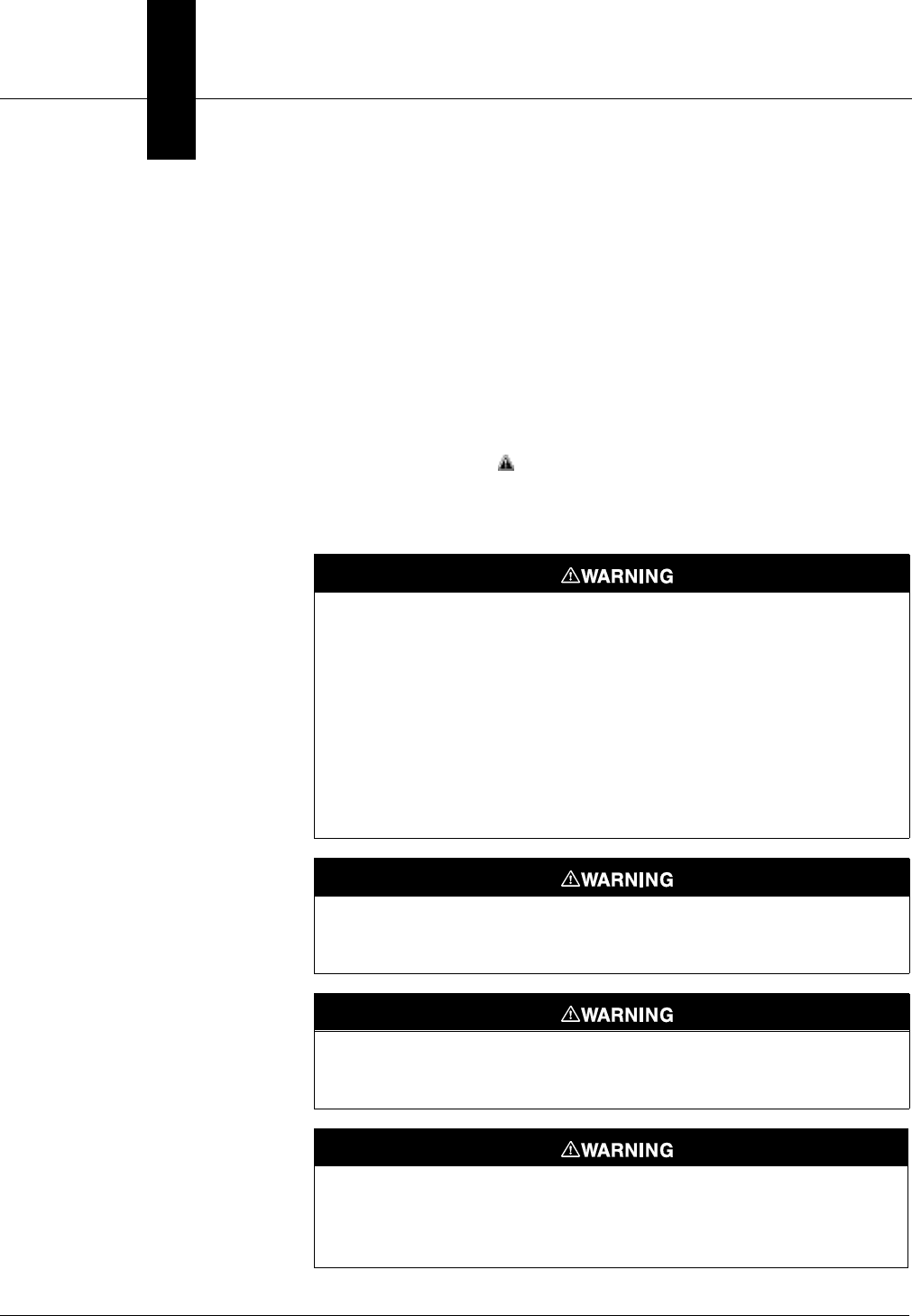
SAFETY MESSAGES Procedures and instructions in this manual may require special
precautions to ensure the safety of the personnel performing the
operations. Information that raises potential safety issues is indicated
by a warning symbol ( ). Refer to the safety messages, listed at the
beginning of each section, before performing an operation preceded by
this symbol.

Rosemount Model 2088/2090 Pressure Transmitters
1-2
Section
2-1
2Commissioning the Transmitter
OVERVIEW This section contains information on commissioning the transmitter.
Commissioning involves reviewing configuration data, setting the 4 and
20 mA points, configuring the transmitter to recognize accessories such
as an LCD meter, and testing the transmitter output.
SAFETY MESSAGES This section contains procedures that require connecting a communicator
to the transmitter, or making connections in an explosive atmosphere.
The following safety messages apply to all procedures throughout this
section requiring cover removal and communicator or ammeter
connection to the transmitter terminal block. Keep the following safety
messages in mind whenever you perform an operation requiring cover
removal or the connection of a communicator or other device to a
measurement loop.
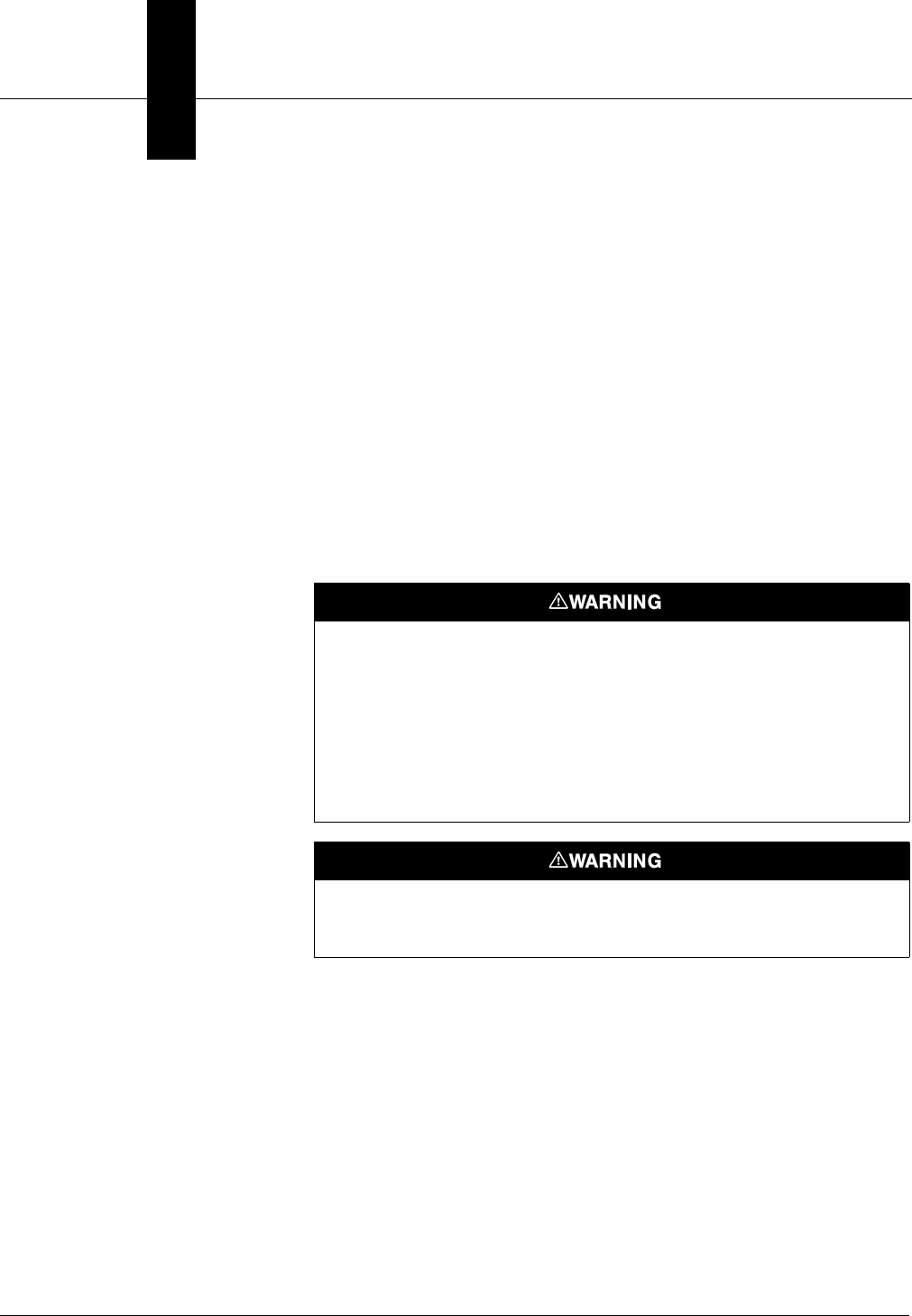
Warnings
Explosions could result in death or serious injury:
• Do not remove the transmitter covers in explosive atmospheres
when the circuit is alive.
• Before connecting a HART-based communicator in an explosive atmosphere,
make sure the instruments in the loop are installed in accordance with
intrinsically safe or non-incendive field wiring practices.
• Both transmitter covers must be fully engaged to meet
explosion-proof requirements.
High voltage that may be present on leads could cause electrical shock:
• Avoid contact with leads and terminals.
Rosemount Model 2088/2090 Pressure Transmitters
2-2
COMMISSION: ON THE
BENCHORINTHELOOP
Commission the Model 2088 Transmitter before or after installation. It
may be useful to commission the transmitter on the bench before
installation to ensure proper operation, to familiarize yourself with
transmitter functionality, and to avoid exposing the transmitter
electronics to the plant environment.
Commissioning consists of :
• Reviewing configuration data
• Setting output units
• Setting the 4 and 20 mA points
• Configuring the transmitter for any non-standard accessories or
functions, and testing the transmitter output
COMMISSIONING THE
SMART TRANSMITTER
Set up the Smart
Transmitter and the
Communicator
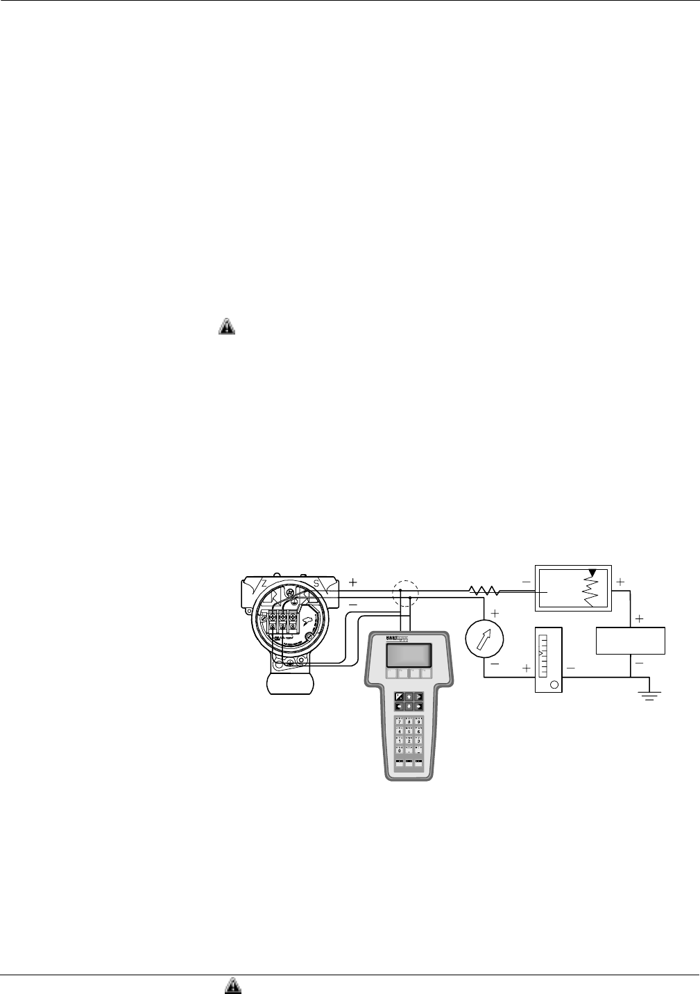
To configure the smart transmitter on the bench, connect the
transmitter and the communicator as shown in Figure 2-1. To power
the transmitter you will need a power supply capable of providing 10.5
to 36.0 V dc and a meter to measure output current. To enable
communication, a resistance of at least 250 ohms must be present
between the communicator loop connection and the power supply. You
can connect the communicator leads at any termination point in the
signal loop, but it is most convenient to connect them to the terminals
labeled “COMM” on the terminal block.
After you connect the bench equipment as shown in Figure 2-1, turn on
the communicator by pressing the ON/OFF key. The communicator will
search for a HART-compatible device and will indicate when the
connection is made. If the connection is not made, the communicator
will indicate that no device was found.
REVIEW
CONFIGURATION DATA
Review all of the factory-set configuration data to ensure that it reflects
the needs of your application before operating the transmitter in an
actual installation.
Power
Supply
RL≥ 250 V
FIGURE 2-1. Connecting
a HART Communicator to
a Transmitter Loop.
The signal loop may be grounded
at any single point in the loop, or
may be left ungrounded
2088S-2088C02C
See “Safety Messages” on page 2-1 for complete warning information.

2-3
Commissioning the Transmitter
Review Review the transmitter configuration parameters set at the factory to
ensure accuracy and compatibility with your particular application.
After activating the review function, scroll through the data list to
check each variable. Refer to “Basic Setup” in this section of the
manual if a change to the transmitter configuration data is necessary.
CHECK OUTPUT Before performing other transmitter on-line operations, review the
digital output parameters to ensure that the transmitter is operating
properly and is configured to the appropriate process variables.
Process Variables The process variables for the Model 2088 provide the transmitter
output, and are continuously updated. The Process Variables menu
displays the following process variables:
•Pressure
• Percent Range
• Analog Output
BASIC SETUP From the Basic Setup menu you can configure the transmitter for certain
basic variables. In many cases, all of these variables are pre-configured at
the factory. Configuration may be required if your transmitter is not
configured or if the configuration variables need revision.
Tag The Tag variable is the easiest way to identify and distinguish between
transmitters in multi-transmitter environments. Use this variable to
label transmitters electronically according to the requirements of your
application. The tag you define is automatically displayed when a
HART-based communicator establishes contact with the transmitter at
power-up. The tag may be up to eight characters long and has no impact
on the primary variable readings of the transmitter.
Output Units The Unit command sets the desired primary variable units. Set the
transmitter output to one of the following engineering units:
•inH
20
•inHg
•ftH
20
• mmH20
•psi
•bar
•mbar
•inH
2O @ 4 °C
NOTE
After changing units, press SEND (F2) so the microprocessor will
recalculate the associated variables (4–20 mA points, for example). The
Model 2088 Smart recalculates all variables that depend on units. After
the transmitter recalculates the variables, you may change any of the
remaining parameters.
Rerange The Range Values command sets the 4 and 20 mA points (lower and
upper range values). Setting the range values to the limits of expected
readings maximizes transmitter performance; the transmitter is most
accurate when operated within the expected pressure ranges for your
application. In practice, you may reset the transmitter range values as
often as necessary to reflect changing process conditions.
HART Fast Keys 1, 5
HART Fast Keys 1, 1
HART Fast Keys 1, 3, 1
HART Fast Keys 1, 3, 2 •g/cm
2
•kg/cm
2
•Pa
•kPa
•torr
•atm
• mmH20 @ 4 °C
HART Fast Keys 1, 3, 3
See “Safety Messages” on page 2-1 for complete warning information.

Rosemount Model 2088/2090 Pressure Transmitters
2-4
NOTE
Regardless of the range points, the Model 2088 Smart will measure and
report all readings within the digital limits of the sensor. For example,
if the 4 and 20 mA points are set to 0 and 10 inH20, and the transmitter
detects a pressure of 25 inH20, it digitally outputs the 25 in H20
reading and a 250% percent of span reading. However, there may be up
to ±5.0% error associated with output outside of the range points.
You may use one of three methods to rerange the transmitter. Each
method is unique; examine all three closely before deciding which
method to use.
Method 1:Rerange Using the
Communicator Reranging using only the communicator is the easiest and most
popular way to rerange the transmitter. This method changes the
values of the analog 4 and 20 mA points independently without a
pressure input.
To rerange using only the communicator enter the fast-key sequence
above, select 1 Keypad input, and follow the on-line instructions. Or
enter the values directly from the HOME screen.
Method 2:Rerange Using the
Communicator and a Pressure
Source or Process Pressure
Reranging using the communicator and a pressure source or process
pressure is a way of reranging the transmitter when specific 4 and 20
mA points are not known. This method changes the values of the
analog 4 and 20 mA points. When you set the 4 mA point the span is
maintained; when you set the 20 mA point the span changes.
To rerange using the communicator and a pressure source or process
pressure enter the fast-key sequence above, select 2 Apply values, and
follow the on-line instructions.
Method 3:Rerange Using the
Local Zero and Span Buttons
and a Pressure Source or
Process Pressure
Reranging using the local zero and span adjustments and a pressure
source is a way of reranging the transmitter when specific 4 and 20 mA
points are not known and a communicator is not available. When you
set the 4 mA point the span is maintained; when you set the 20 mA
point the span changes.
Damping The Damping command changes the response time of the transmitter to
smooth variations in output readings caused by rapid changes in input.
Determine the appropriate damping setting based on the necessary
response time, signal stability, and other requirements of the loop
dynamics of your system. The default damping value is 0.50 seconds
and can be reset in fixed increments of 0.05, 0.10, 0.20, 0.40, 0.80, 1.60,
3.20, 6.40, 12.8, or 25.6 seconds.
HART Fast Keys 1. 3. 5

2-5
Commissioning the Transmitter
DETAILED SETUP
Meter Setup The Meter Type command allows you to configure the transmitter for use
with an LCD meter. Transmitters shipped without meters are set to
“NONE.” Change the meter settings as often as necessary to reflect
changing process or application conditions. To change the meter settings,
and thereby configure the transmitter to recognize the LCD meter, perform
the following procedure.
1. Select 1 Device setup, 3 Basic setup, 6 Meter type to prepare to
change the meter settings.
2. Select the appropriate variable configuration from the “Meter
type” screen, and press enter.
NOTE
Selecting “None” from the meter type screen will disable the meter.
3. Select SEND to download the new meter configuration
information to the transmitter.
For a more detailed description of the LCD meter features and
diagnostic messages, refer to “LCD Meter” on page A-1.
Burst Mode Burst Mode sets the transmitter to maintain digital contact with a
Digital Control System that has custom software to support burst
mode. When the Model 2088 Smart is configured for burst mode, it
provides faster digital communication from the transmitter to the
control system by eliminating the time required for the control system
to request information from the transmitter.
Burst mode is compatible with use of the analog signal. Because HART®
protocol features simultaneous digital and analog data transmission,
the analog value can drive other equipment in the loop while the control
system is receiving the digital information. Burst mode applies only to
the transmission of dynamic data (pressure and temperature in
engineering units, pressure in percent of range, and/or analog output in
mA), and does not affect the way other transmitter data is accessed.
Access to information other than dynamic transmitter data is obtained
through the normal poll/response method of HART communication. A
HART-based communicator or the control system may request any of
the information that is normally available while the transmitter is in
burst mode. Between each message sent by the transmitter, a short
pause allows the HART-based communicator or a control system to
initiate a request. The transmitter will receive the request, process the
response message, and then continue “bursting” the data
approximately three times per second.
HART Fast Keys 1, 3, 6
HART Fast Keys 1, 4, 3, 3, 3

Rosemount Model 2088/2090 Pressure Transmitters
2-6
Save, Recall, or Clone
Configuration Data
Data that was entered off-line can be stored in the communicator
memory and downloaded to other transmitters later. Data also can be
copied from a transmitter in order to be sent to other transmitters in a
process known as “cloning”. This is especially useful if you work with a
large number of transmitters that require the same configuration data.
Enable or Disable Local
Span and Zero Buttons
The Local Keys command allows you to enable or disable the local span
and zero buttons. Disabling the local keys will prevent unauthorized
reranging using the span and zero buttons, but will not prevent
reranging using the communicator. To prevent all changes to the
configuration data, use the transmitter security jumper (see
“Transmitter Security” on page 3-13).
CALIBRATION Calibrating the transmitter increases the precision of your
measurement system. You may use one or more of a number of trim
functions when calibrating.
To understand the trim functions, it is necessary to understand that
smart transmitters operate differently from analog transmitters. An
important difference is that smart transmitters are factory-characterized;
they are shipped with a standard sensor curve stored in the transmitter
firmware. In operation, the transmitter uses this information to
produce a process variable output, in engineering units, dependent on
the sensor input. The trim functions allow you to make corrections to
the factory-stored characterization curve by digitally altering the
transmitter’s interpretation of the sensor input.
The trim functions should not be confused with the rerange functions.
Although the rerange command matches a sensor input to a 4–20 mA
output—as in conventional calibration—it does not affect the
transmitter’s interpretation of the input.
Calibration Overview Complete calibration of the Model 2088 Smart Pressure Transmitter
involves one or more of the following tasks:
Configure the Analog Output Parameters
• Set Process Variable Units (Page 2-3)
• Rerange (Page 2-3)
• Set Output Type (Page 2-3)
• Set Damping (Page 2-4)
Calibrate the Sensor
• Full Trim (Page 2-8)
• Zero Trim (Page 2-7)
Calibrate the 4–20 mA Output
• Digital to Analog Trim (Page 2-9) or
• Scaled Digital to Analog Trim (Page 2-9)
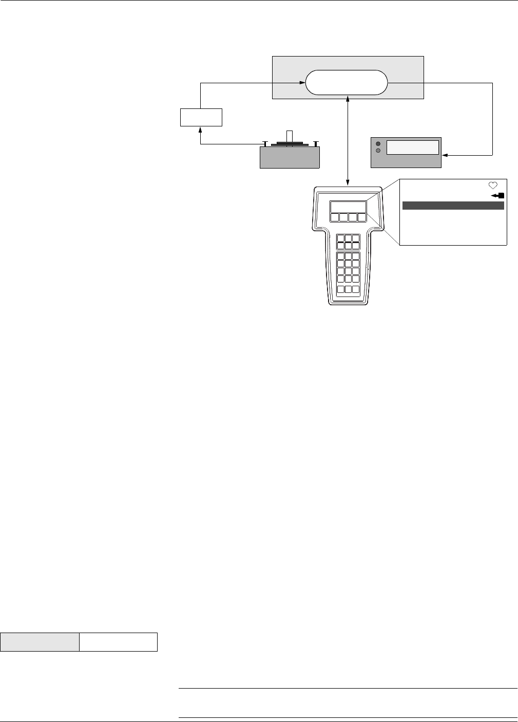
Figure 2-2 illustrates the Model 2088 Smart Pressure Transmitter data
flow. This data flow can be summarized in four major steps:
1. A change in pressure is measured by a change in the sensor
output (Sensor Signal).
2. The sensor signal is converted to a digital format that can be
understood by the microprocessor (Analog-to-Digital Signal
Conversion).
3. Corrections are performed in the microprocessor to obtain a
digital representation of the process input (Digital PV).
4. The Digital PV is converted to an analog value
(Digital-to-Analog Signal Conversion).
HART Fast Keys left arrow, 3 (note)
HART Fast Keys 1, 4, 4, 1, 7
2-7
Commissioning the Transmitter
FIGURE 2-2. Transmitter Data Flow
with Calibration Options.
Deciding Which Trim
Procedure to Use To decide which trim procedure to use, you must first determine
whether the analog-to-digital section or the digital-to-analog section of
the transmitter electronics is in need of calibration. To do so, refer to
Figure 2-2 and perform the following procedure:
1. Connect a pressure source, a HART communicator, and a digital
readout device to the transmitter.
2. Establish communication between the transmitter
and the communicator.
3. Apply pressure (100 in H20, for example).
4. Compare the applied pressure to the Process Variable (PV) line on
the Communicator Online Menu. If the PV reading on the
communicator does not match the applied pressure, and you are
certain your test equipment is accurate, perform a sensor trim.
5. Compare the Analog Output (AO) line on the communicator online
menu to the digital readout device. If the AO reading on the
communicator does not match the digital readout device, and you are
certain your test equipment is accurate, perform an output trim.
Sensor Trim You can trim the sensor using either the full trim or the zero trim
function. The trim functions vary in complexity, and their use is
application-dependent. Both alter the transmitter’s interpretation of
the input signal.
Zero Trim A Zero Trim is a single-point adjustment. It is useful for compensating
for mounting position effects, and is most effective when performed
with the transmitter installed in its final mounting position. Since this
correction maintains the slope of the characterization curve, it should
not be used in place of a full trim over the full sensor range.
NOTE
Use full trim on absolute transmitters; do not use zero trim.
Transmitter Electronics Module
Microprocessor
Digital PV
Sensor
Input Device Output Device
20.00 mA
2088s:PT-4763
1➡Device Setup
Online
2 PV 100.00 inH2O
3 AO 20.00 mA
4 LRV 0.00 inH2O
5 URV 100.00 inH2O
Transmitter Ranged 0 to 100 inH2O
Input
Pressure
Sensor
Signal
Analog Output
HART
Communicator
NOTE
Value on PV line should equal
the input pressure. Value on
AO line should equal the
output device reading.
1151-1151F05B
HART Fast Keys 1, 2, 3, 3, 1

Rosemount Model 2088/2090 Pressure Transmitters
2-8
To calibrate the sensor using the Zero Trim function, perform the
following procedure.
1. Vent the transmitter and attach a communicator to the
measurement loop.
2. From the communicator main menu select 1 Device setup,
2 Diagnostics and service, 3 Calibration, 3 Sensor trim, 1 Zero
trim to prepare to adjust the zero trim.
NOTE
The transmitter must be within 3% of true zero (zero based) in order to
calibrate using the zero trim function.
3. Follow the commands provided by the communicator to complete
the adjustment of the zero trim.
Full Trim A Full Trim is a two-point sensor calibration where two end-point
pressures are applied, and all output is linearized between them. You
should always adjust the low trim value first to establish the correct
offset. Adjustment of the high trim value provides a slope correction to
the characterization curve based on the low trim value. The factory-
established characterization curve is not changed by this procedure.
The trim values allow you to optimize performance over your specified
measuring range at the calibration temperature.
To calibrate the sensor using the Full Trim function, perform the
following procedure.
1. Assemble and power the entire calibration system including a
transmitter, communicator, power supply, pressure input source,
and readout device.
NOTE
Use a pressure input source that is at least three times more accurate
than the transmitter, and allow the input pressure to stabilize for 10
seconds before entering any values.
2. From the communicator main menu select 1 Device setup,
2 Diagnostics and service, 3 Calibration, 3 Sensor trim, 2 Lower
sensor trim to prepare to adjust the lower trim point.
NOTE
Select pressure input values so that the low and high values are equal
to or outside the 4 and 20 mA points. Do not attempt to obtain reverse
output by reversing the high and low points. The transmitter allows
approximately a 5% URL deviation from the characterized curve
established at the factory.
3. Follow the commands provided by the communicator to complete
the adjustment of the lower value.
4. Repeat the procedure for the upper value, replacing 2 Lower
sensor trim with 3 Upper sensor trim in Step 2.
Output Trim The Output Trim commands allow you to alter the transmitter’s
conversion of the input signal to a 4–20 mA output (see Figure 2-2 on
page 2-7). Adjust the analog output signal at regular intervals to
maintain precision. You can trim the transmitter output using either
the digital to analog trim or the scaled digital to analog trim function.
HART Fast Keys 1, 2, 3, 3

2-9
Commissioning the Transmitter
Digital to Analog Trim To perform a Digital-to-Analog Trim, perform the following procedure.
1. From the HOME screen, select 1 Device setup, 2 Diag/Service, 3
Calibration, 4 D/A trim. Select “OK” to after you set the control loop
to manual.
2. Connect an accurate reference meter to the transmitter at the
“Connect reference meter” prompt. To do so, connect the positive
lead to the positive terminal and the negative lead to the test
terminal in the transmitter terminal compartment, or shunt the
transmitter power through the reference meter at some point.
3. Select “OK” after connecting the reference meter.
4. Select “OK” at the “Setting fld dev output to 4 mA” prompt.
The transmitter outputs 4.00 mA.
5. Record the actual value from the reference meter, and enter it at
the “Enter meter value” prompt.
The communicator prompts you to verify whether or not the
output value equals the value on the reference meter.
6. Select 1 Yes if the reference meter value equals the transmitter
output value, or 2 No if it does not.
If you select 1 Yes, proceed to Step 7.
If you select 2 No, repeat Step 5.
7. Select “OK” at the “Setting fld dev output to 20 mA” prompt, and
repeat Steps 5 and 6 until the reference meter value equals the
transmitter output value.
Select “OK” after you return the control loop to automatic control.
Scaled Digital to Analog Trim The Scaled Digital-to-Analog Trim command matches the 4 and 20 mA
points to a user-selectable reference scale other than 4 and 20 mA (1 to
5 volts if measuring across a 250 ohm load, or 0 to 100 percent if
measuring from a DCS, for example). To perform a scaled D/A trim,
connect an accurate reference meter to the transmitter and trim the
output signal to scale as outlined in the Output Trim procedure.
NOTE
Use a precision resistor for optimum accuracy. If you add a resistor to
the loop, ensure that the power supply is sufficient to power the
transmitter to a 20 mA output with the additional loop resistance.
HART Comm. 1, 2, 3, 2, 1
Model 268 F4, F4, F3, F1, F1
HART Comm. 1, 2, 3, 2, 2
Model 268 F4, F4, F3, F1, F2

Rosemount Model 2088/2090 Pressure Transmitters
2-10
DIAGNOSTICS
AND SERVICE
Test Device The Test Device command initiates a more extensive diagnostic routine
than that performed continuously by the transmitter. The transmitter
test routine can identify an electronics failure. If the transmitter test
detects a problem, the communicator displays messages to indicate the
source of the problem.
Loop Test The Loop Test command verifies the output of the transmitter, the
integrity of the loop, and the operations of any recorders or similar
devices installed in the loop. To initiate a loop test, perform the
following procedure:
1. Connect a reference meter to the transmitter. To do so, either
connect the meter to the test terminals on the transmitter terminal
block, or shunt the power to the transmitter through the meter at
some point in the loop.
2. From the HOME screen, Select 1 Device Setup, 2 Diagnostics and
Service, 2 Loop Test, to prepare to perform a loop test.
3. Select “OK” after you set the control loop to manual.
The communicator displays the loop test menu.
4. Select a discreet milliamp level for the transmitter to output. At
the “Choose analog output” prompt, select 1 4mA, 2 20mA, or select
3 other to manually input a value between 4 and 20 milliamps.
5. Check the current meter installed in the test loop to verify that it
reads the value you commanded the transmitter to output. If the
readings do not match, the transmitter requires an output trim or
the current meter is malfunctioning.
After completing the test procedure, the display returns to the loop test
screen and allows you to choose another output value.
MULTIDROP
COMMUNICATION
Multidropping transmitters refers to the connection of several
transmitters to a single communications transmission line.
Communication between the host and the transmitters takes place
digitally with the analog output of the transmitters deactivated. Many
of the Rosemount SMART FAMILY transmitters can be multidropped.
With the HART communications protocol, up to 15 transmitters can be
connected on a single twisted pair of wires or over leased phone lines.
Note that Burst Mode Operation is not compatible with multidrop
communications.
The application of a multidrop installation requires consideration of the
update rate necessary from each transmitter, the combination of
transmitter models, and the length of the transmission line. Multidrop
installations are not recommended where intrinsic safety is a
requirement. Communication with the transmitters can be
accomplished with commercially available Bell 202 modems and a host
implementing the HART protocol. Each transmitter is identified by a
unique address (1-15) and responds to the commands defined in the
HART protocol.
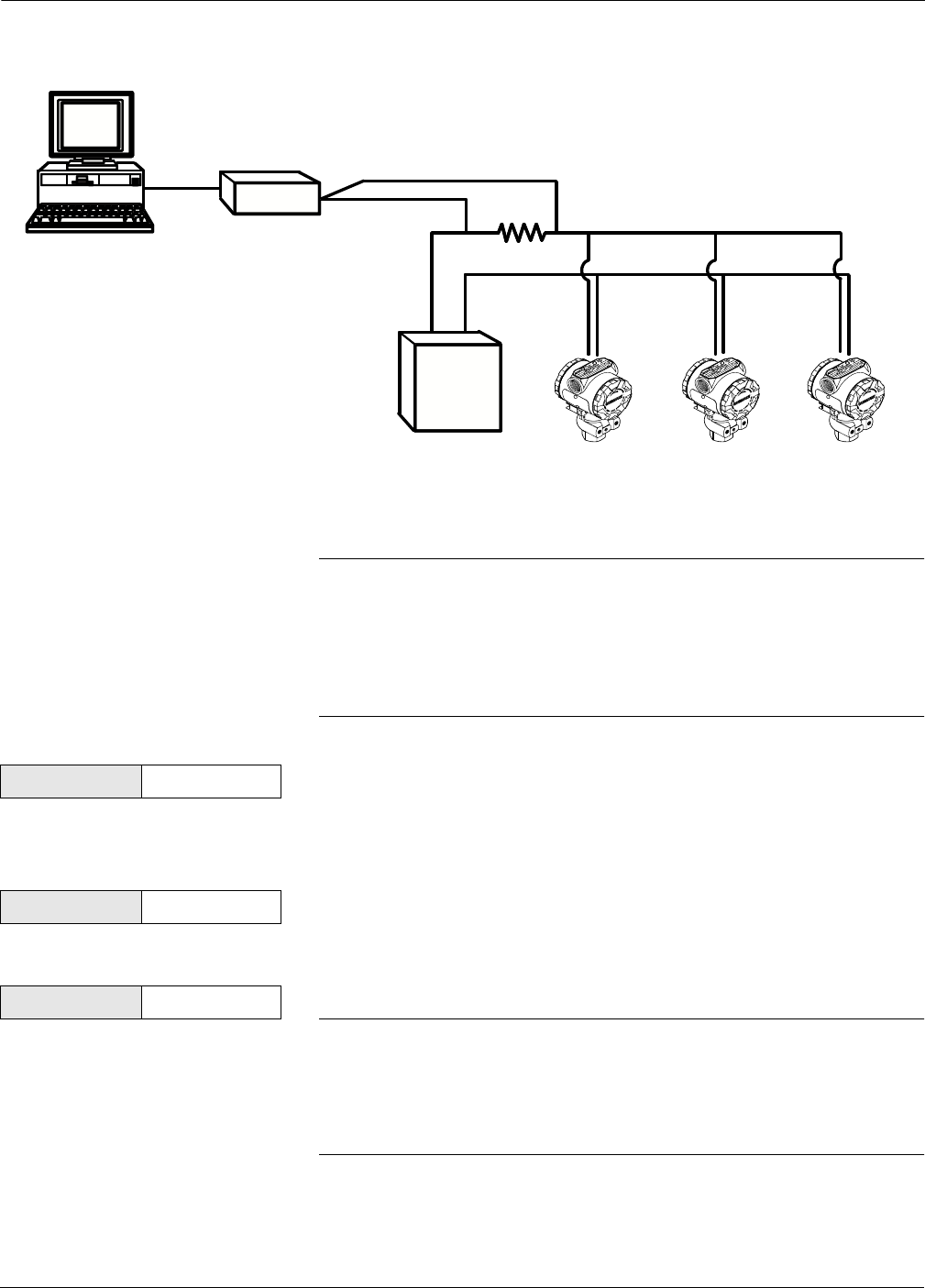
Figure 2-3 shows a typical multidrop network. This figure is not
intended as an installation diagram. Contact Rosemount product
support with specific requirements for multidrop applications.
HART Fast Keys 1, 2, 1, 1
HART Fast Keys 1, 2, 2
2-11
Commissioning the Transmitter
FIGURE 2-3. Typical
Multidrop Network.
HART-based communicators can test, configure, and format a
multidropped transmitter the same way as a transmitter in a standard
point-to-point installation.
NOTE
The transmitter is set to address 0 at the factory, allowing it to operate in
the standard point-to-point manner with a 4–20 mA output signal. To
activate multidrop communication, you must change the transmitter
address to a number from 1 to 15. This change deactivates the 4–20 mA
analog output, locking it to 4 mA. It also disables the failure mode alarm
signal, which is controlled by the upscale/downscale jumper position.
Changing a Transmitter Address To change the address of a multidropped transmitter, follow these fast
key sequences. To activate multidrop communication, the transmitter
address must be changed to a number from 1 to 15.
Communicating with a
Multidropped Transmitter To communicate with a multidropped transmitter for the purpose of
testing, configuring, or formatting.
Polling a Multidropped Loop Polling a multidropped loop determines the model, address, and
number of transmitters on the given loop.
NOTE
The Model 275 HART Communicator requires you to use the Utility
Menu to perform an auto poll. This menu is available from the Main
Menu of the HART Communicator. Press the left arrow to move from
the Online Menu to the Main Menu. Press 4 from the Main Menu to
access the Utility Menu.
Bell 202
Modem
Power
Supply
RS-232-C
3051-0087A
HART Fast Keys 1, 4, 3, 3, 1
HART Fast Keys 1, 4, 3, 3, 2
HART Fast Keys Left Arrow, 4, 1, 1

Rosemount Model 2088/2090 Pressure Transmitters
2-12
Section
3-1
3Installation
OVERVIEW This section is designed to guide you through a successful Models 2088,
2090F, or 2090P Transmitter installation. Starting with an installation
flowchart, this section contains information on installation
considerations and transmitter options. Dimensional drawings are also
included in this section.
SAFETY MESSAGES Instructions and procedures in this section may require special
precautions to ensure the safety of the personnel performing the
operations. Information that raises potential safety issues is indicated
by a warning symbol ( ). Please refer to the following safety messages
before performing an operation preceded by this symbol.
Warnings
Explosions could result in death or serious injury:
• Do not remove the transmitter cover in explosive atmospheres
when the circuit is alive.
• Before connecting a HART-based communicator in an explosive atmosphere,
make sure the instruments in the loop are installed in accordance with
intrinsically safe or non-incendive field wiring practices.
• Verify that the operating atmosphere of the transmitter is consistent with the
appropriate hazardous locations certifications.
• Both transmitter covers must be fully engaged to meet
explosion-proof requirements.
Failure to follow these installation guidelines could result in death or serious injury:
• Make sure only qualified personnel perform the installation.
High voltage that may be present on leads could cause electrical shock:
• Avoid contact with leads and terminals.
Use appropriately rated sanitary clamps and gaskets during installation. The maximum
working pressure of the clamp and gasket must be greater than or equal to the working
pressure range of the transmitter. Failure to use proper clamps and gaskets can cause
process leaks and can result in death or serious injury.
Rosemount Model 2088/2090 Pressure Transmitters
3-2
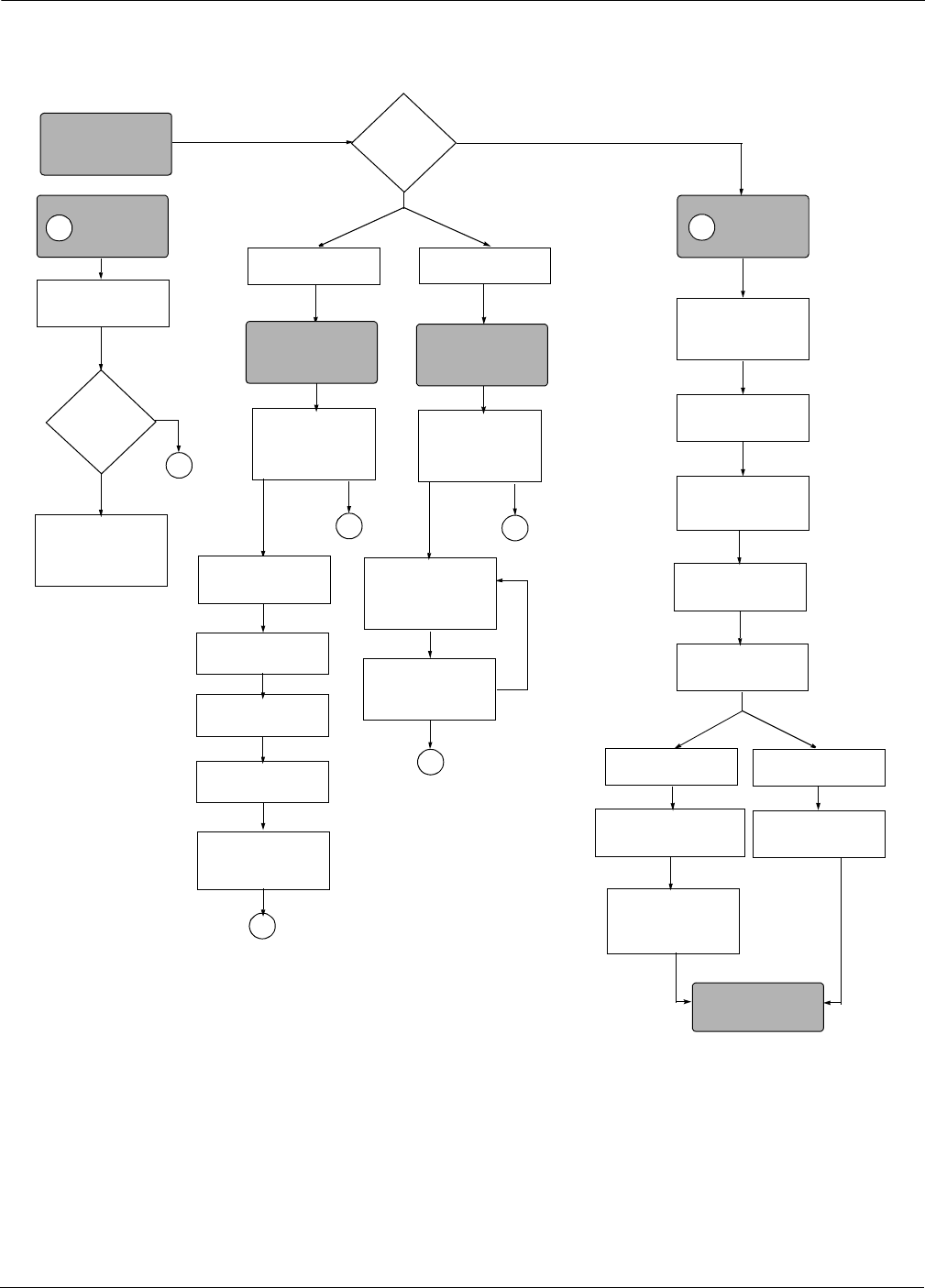
FIGURE 3-1. Installation Flowchart.
Check for Leaks
(Process Connections)
Zero Trim Transmitter for
Mounting Effects
No
B
Yes
A
Yes
No
Check Jumper or
Switches
(Smart Only)
Wire
Transmitter
Power
Transmitter
Zero
Transmitter
DONE
Repeat Steps until
Calibrated
Mount
Transmitter
Apply Pressure
Refer to
Troubleshooting
Section
Within
Specifications?
VERIFY
START HERE
Bench
Calibration?
FIELD INSTALL
A
B
Smart Analog
Set Output Type
Check Configuration
(See Chapter 2)
A
Set Range Points
Set Units
(See Chapter 2)
Set Damping Analog
Smart
Confirm Transmitter
Configuration
Within
Specifications?
Yes
A
No
Check Configuration
(See Chapter 3)
Within
Specifications?
Yes
A
No
ADJUST ANALOG
ZERO/SPAN
(See Chapter 3)
Perform Sensor and/or
Output Trim
3-3
Installation
GENERAL
CONSIDERATIONS
The accuracy of the pressure measurement depends on proper
installation of the transmitter and impulse piping. The piping between
the process and transmitter must accurately transmit pressure to the
transmitter. Mount the transmitter close to the process and use a
minimum of impulse piping to achieve the best accuracy. Keep in mind,
however, the need for convenient access, safety of personnel, practical
field calibration, and a suitable transmitter environment. In general,
install the transmitter to minimize vibration, shock, and temperature
fluctuations.
ENVIRONMENTAL
CONSIDERATIONS
Temperature Mount the transmitter in a manner that minimizes variations in
ambient temperature.
Moisture and Corrosives The transmitter is designed to resist attack by moisture and corrosives.
The electronics module is fully encapsulated and mounted in a
compartment that is sealed from the power-side conduit entries. O-ring
seals protect both compartments when the covers are installed.
In humid environments, it is possible for moisture to accumulate in the
conduit lines and reach the terminal compartment of the transmitter
housing. To prevent moisture from entering the terminal compartment,
mount the transmitter at a high point in the conduit run, if possible.
Also, remove the terminal compartment cover periodically and inspect
the terminals for moisture and corrosion.
Hazardous Locations
Installations
Models 2088, 2090P, and 2090F transmitters are designed with
explosion-proof electronics enclosures and circuitry that complies with
intrinsic safety requirements and non-incendive operation. Individual
transmitters are clearly tagged with approvals. Refer to Section 5:
Specifications and Reference Data for a complete list of available
approvals. To maintain certified ratings for installed transmitters,
install with applicable installation codes and approval drawings.
NOTE
Once a device labeled with multiple approval types is installed, it
should not be reinstalled using any other approval types. Permanently
mark the approval label to distinguish it from unused approval types.
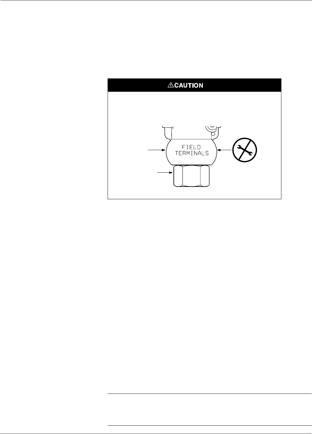
Do not apply torque directly to the electronics housing. Rotation
between the electronics housing and the process connection can
damage the electronics. To avoid damage, apply torque only to the
hex-shaped process connection.
Electronics
Housing
Process
Connection
2088-2088B02G
Rosemount Model 2088/2090 Pressure Transmitters
3-4
MECHANICAL
CONSIDERATIONS
Mounting
Model 2088 The Model 2088 Smart Transmitter weighs approximately 2.44 lb
(1,11 kg). The Model 2088 Analog Transmitter weighs approximately
1.9 lb (0,86 kg). In many cases, its compact size and light weight makes it
possible to mount the Model 2088 directly to the impulse line without
using an additional mounting bracket. When this is not desirable, mount
directly to a wall, panel, or two-inch pipe using the optional mounting
bracket (see Figure 3-2).
The Model 2088 also offers several process connections. Use your plant-
approved thread sealant to ensure a leak-proof connection.
Model 2090P The Model 2090P is designed to be mounted directly to the process pipe
using a weld spud (see Figure 3-7). Mount the transmitter using an
existing weld spud, or install a new one using the instructions on
page 3-7.
Model 2090F The Model 2090F is designed to be mounted directly to the process pipe
using a standard sanitary fitting (see Figure 3-8). The transmitter is
available with either a 1.5- or 2-inch Tri-Clamp® connection.
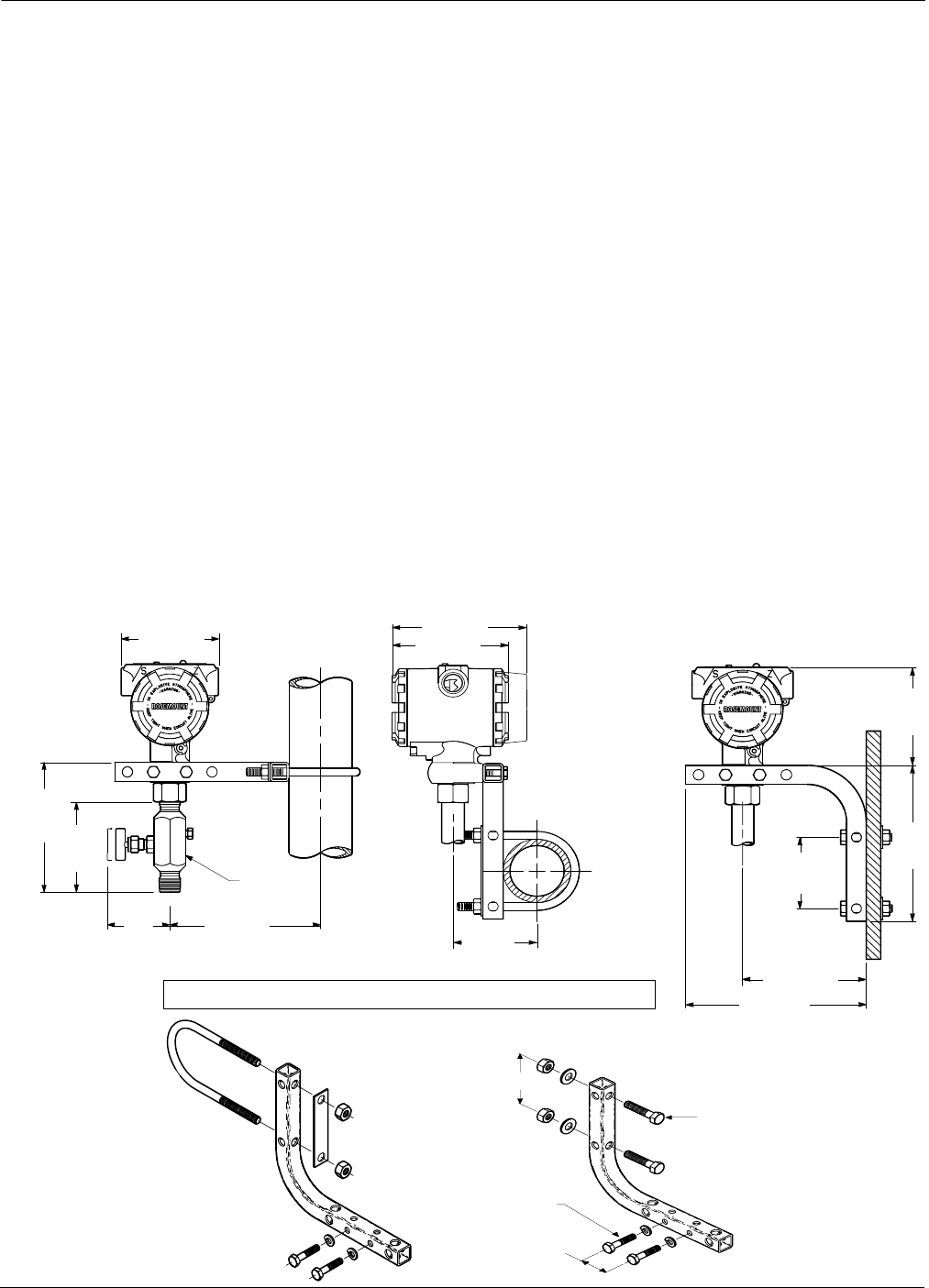
FIGURE 3-2. Transmitter Mounting
Configurations with Optional Bracket.
2-inch U-Bolt
for Pipe Mounting
NOTE
Dimensions are in in. (mm). 1.30 (33)
2.81 (71)
PIPE MOUNTING PANEL MOUNTING
Mounting bracket ordering code B4, and optional block and bleed valve.
5/16×1½Bolts
for Panel Mounting
(not supplied)
2088S-2088A04A, B04A, C04A; 2088-2088A04A, A04B
5/16×1½Bolts
for Panel Mounting
(not supplied)
3.9 (100) 5.0 (125)
4.3 (110)
6.0 (150)
2.5
(63)
3.6
(90)
5.0
(139)
1.25 (32)
HEX
3.0 (80)
3.9
(100)
6.2
(160)
2.8
(70)
4.75 (120)
7.0 (175)
3-5
Installation
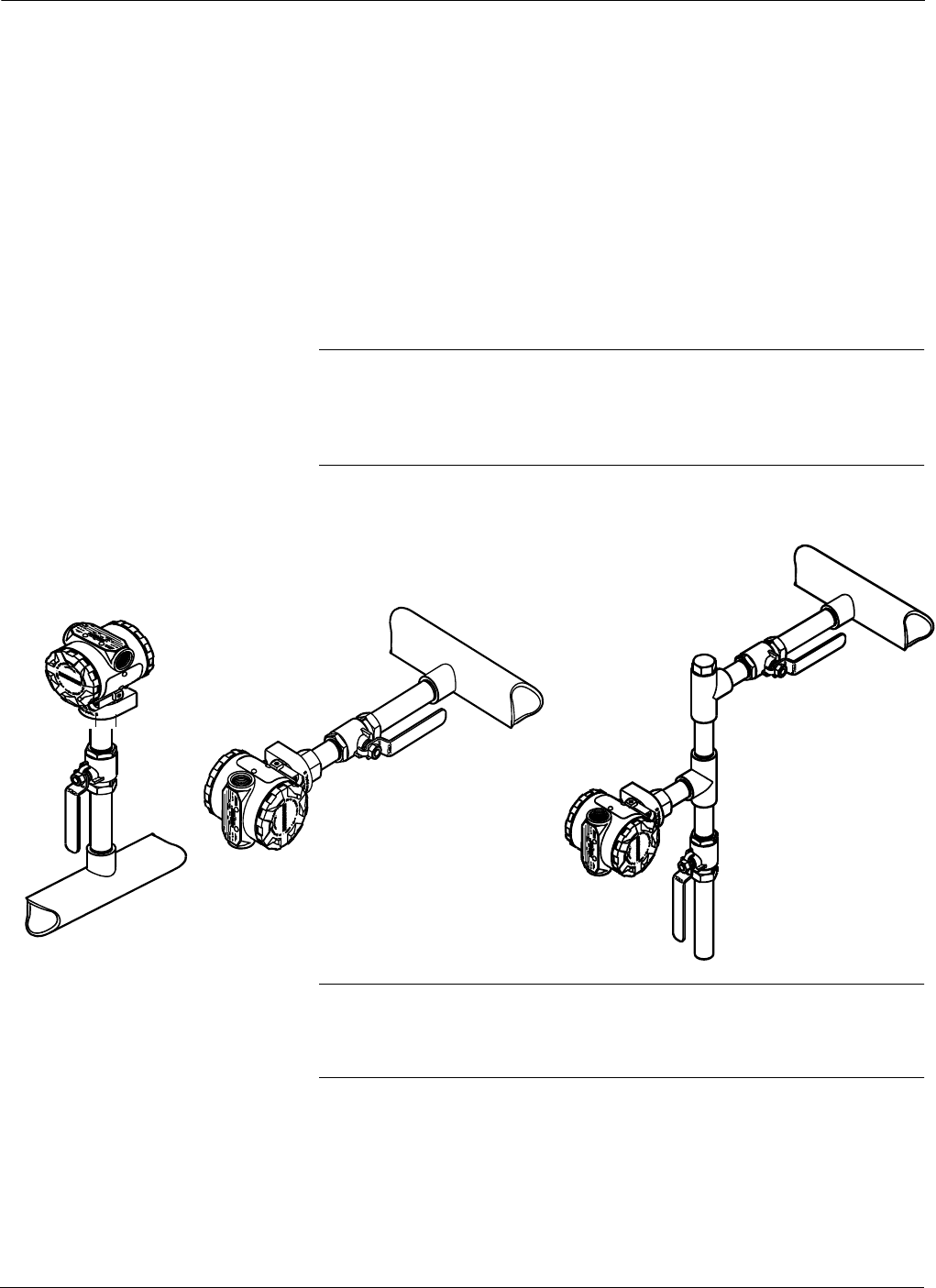
Impulse Piping Impulse piping configurations depend on specific measurement
conditions. Use the following information and Figure 3-3 as a guideline
when installing impulse piping.
Liquids: Make the line tap on the side of the pipe to prevent sediment
deposits from plugging the impulse line or transmitter. Mount the
transmitter level with or below the tap so gases vent into the
process line.
Gases: Make line taps on either the top or the side of the process line.
Mount the transmitter level with or above the line tap so liquids
drain into the process line.
Steam: Make line taps in the side of the process line. Mount the
transmitter below the line tap to ensure that the impulse line
remains filled with condensate.
NOTE
Installing a “T”-connection with a shut-off valve in the impulse line
between the transmitter and the valve to the process line will allow you
to vent the transmitter to atmosphere, thereby enabling calibration
without removing the transmitter.
NOTE
In steam or other high-temperature services, the temperature at the
process connection must not exceed the process temperature limit of the
transmitter, which is 250 °F (121 °C).
In steam service above 250 °F (121 °C), fill impulse lines with water to
prevent steam from contacting the transmitter. Condensate chambers
are not necessary since the volumetric displacement of the Model 2088
is negligible.
GAS
SERVICE
LIQUID OR STEAM
SERVICE
2088-2088A01A, C, B
GAS OR LIQUID
SERVICE
FIGURE 3-3. Transmitter
Mounting Configurations for
Liquids, Gases, and Steam.
Rosemount Model 2088/2090 Pressure Transmitters
3-6
Access Requirements When choosing a mounting location and position, take into account the
need for access to the transmitter.
Make wiring terminations through the conduit openings at the top of
the electronics housing. The field terminal side of the transmitter is
clearly marked on the transmitter neck. Test terminals are
incorporated on the terminal block; you do not need access to the
electronics compartment to perform calibration procedures.
The transmitter electronics compartment contains the electronics
module with failure mode and security jumpers, and the optional LCD
meter. Consider the need for access to both compartments when
installing the transmitter. Refer to Figure 3-4 for transmitter
dimensional drawings.
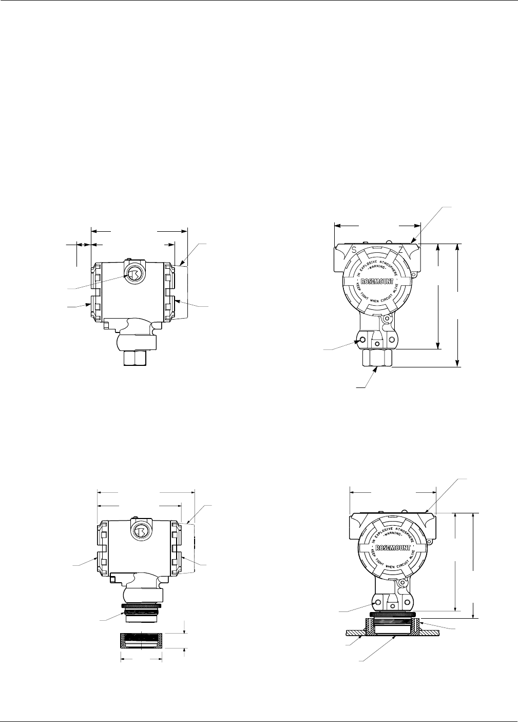
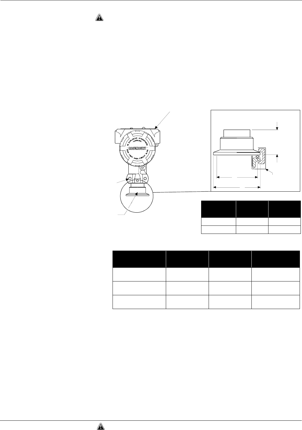
FIGURE 3-4. Smart Transmitter Dimensional Drawings.
2088S-2088A07A, B07A
*
M20
3
1.5 Female (CM20), PG 13.5, and G ½Female (PF ½) also available as options.
†
DIN 16288 G ½Male, RC ½Female (PT ½), and M20
3
1.5 Male (CM20) also available .
23½–14 NPT*
Conduit
Connection
Terminal
Connections
5.0 (125)
Optional Meter Cover
Transmitter Circuitry
Certifications Tag
23¼–20 UNC-2B
Mounting Holes
½–14 NPT Female†Process Connection
4.3 (110) Max.
3.9 (100)
0.75 (20)
Clearance for
Cover Removal
4.7
(120)
5.4
(140)
Model 2088
5.1(130)
Typical
2.38
(60)
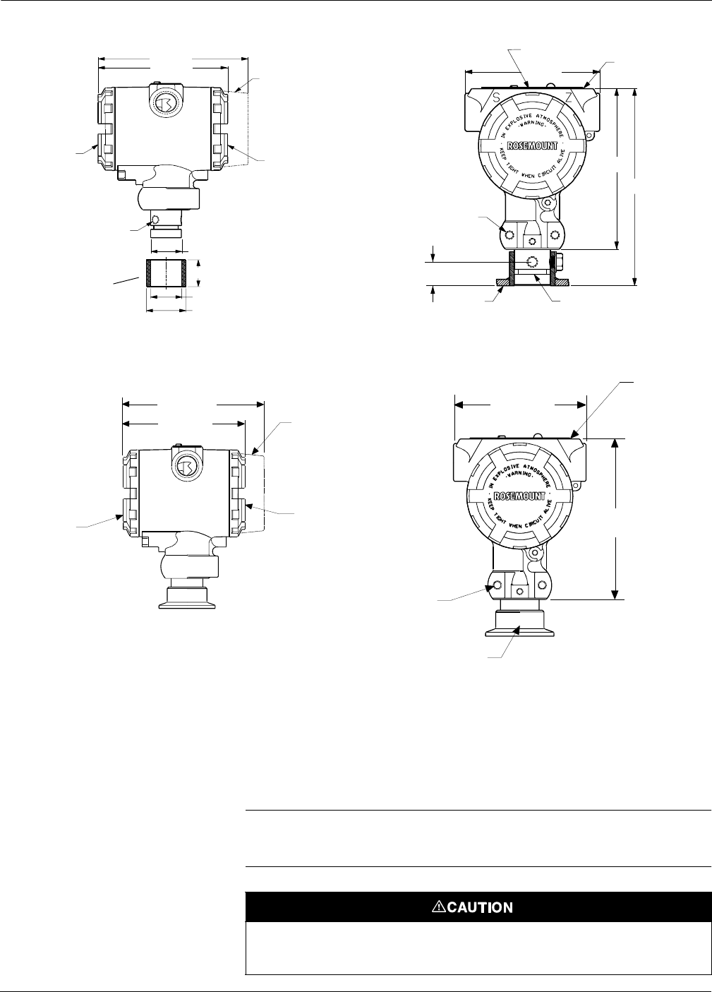
2090-2088A07P, B07P
5.0 (125)
Optional Meter Cover
Transmitter Circuitry
Terminal
Connections
M44 31.25
Weld Spud
23 ¼–20 UNC–2BX
Depth 0.60
Mounting Holes
4.7
(120)
3.9 (100)
0.82
(21)
Weld Spud
Certification Tag
4.3 (110)
Model 2090P (1.5-in.)
Vessel Wall
NOTE: Dimensions are in in. (mm).
3-7
Installation
Model 2090P Installing the Model 2090P transmitter involves attaching a weld spud
to the tapped process vessel, attaching the transmitter to the weld
spud, and making electrical connections. If you intend to use an
existing weld spud, proceed to the transmitter section of this
installation procedure.
NOTE
The Model 2090P Isolating Diaphragm can be mounted flush with the
inside diameter of any vessel larger than three inches in diameter.
Nameplate
3.9
(100)
2X ¼–20 UNC–2BX 0.60 Deep
Mounting Bracket Holes
4.7 (140)
Terminal
Connections Transmitter Circuitry Side
Optional Meter Cover
5.0 (125)
Weld Spud
1.0 (25.4)
Vessel Wall
4.3 (110)
1.05 (26.6)
1.32 (33,4)
5.75 (146)
3X 5/16–18 UNC
Mounting Holes for
Rotational Mounting
0.7 (17,8)
O-ring (Viton®standard)
External Zero/Span (under Nameplate)
1.03 (26.2)
Model 2090P Compatible with 1-in. PMC
®
Process Connection
2090-2090A07A, 2090B07A
1½ or 2-in. Tri-Clamp Connection
23 ¼–20 UNC–2BX 0.60
Deep Mounting Holes
4.7
(120)
3.9 (100)
2090-2088A07F, 2088B07F
*
M20
3
1.5 Female (M20) and PG 13.5 also available.
NOTE:Dimensions are in inches (millimeters).
Optional Meter Cover
Transmitter Circuitry Side
Terminal
Connections
5.0 (125)
4.3 (110)
Certifications Tag
Model 2090F
Installation of the weld spud should be performed by a skilled welder using a
TIG welder. Improper installation may result in weld spud distortion.

Rosemount Model 2088/2090 Pressure Transmitters
3-8
Weld Spud 1. Using the appropriate size hole saw, cut a hole in the process
vessel to accept the weld spud. The diameter for a weld spud with
heat isolator groove is 2.37 inch (60 mm); when compatible with
1-in. PMC® process connection style spud, diameter is 1.32 in.
(33,4 mm). The hole should produce a tight, uniform fit when
coupled with the weld spud.
2. Bevel the edge of the vessel hole to accept filler material (see
Figure 3-5).
3. Remove the weld spud from the transmitter and remove the
Teflon® gasket from the weld spud.
4. Position the weld spud in the vessel hole, place heat sink and tack
spud in place using the welding sequence shown in Figure 3-5.
Cool each section with a wet cloth before proceeding to the next
section.
5. Weld the spud in place using 0.030 to 0.045 in. (0,762 to
1,143 mm) stainless steel rod as filler in the bevelled area. Using
between 100 and 125 amps., adjust the amperage for 0.080 in.
(2,032 mm) penetration.
Transmitter 1. After the weld spud has cooled, remove the heat sink and install
the Teflon gasket into the weld spud. Ensure that the gasket is
properly positioned within the weld spud; improper placement
could cause a process leak (see Figure 3-6).
2. Position the transmitter into the spud and begin to engage the
threads. Rotate the transmitter prior to seating the threads
completely to enable access to the housing compartments, the
conduit entry, and the local indicator.
3. Hand tighten the transmitter using the knurled retaining ring,
then snug an additional 1/8 turn with adjustable pliers.
IMPORTANT
Do not over-tighten the retaining ring. A spanner wrench (P/N 02088-
0193-0001) hole is located on the knurled portion of the retaining ring
to assist in transmitter removal if it is over-tightened.
Excessive heat will distort the weld spud. Weld in sections, as shown in Figure
3-5, cooling each section with a wet cloth. Allow adequate cooling between
passes.
To reduce the chances of distorting the weld spud (for 1.5-in. connection), use
a heat sink—Rosemount Part Number 02088-0196-0001.
3-9
Installation
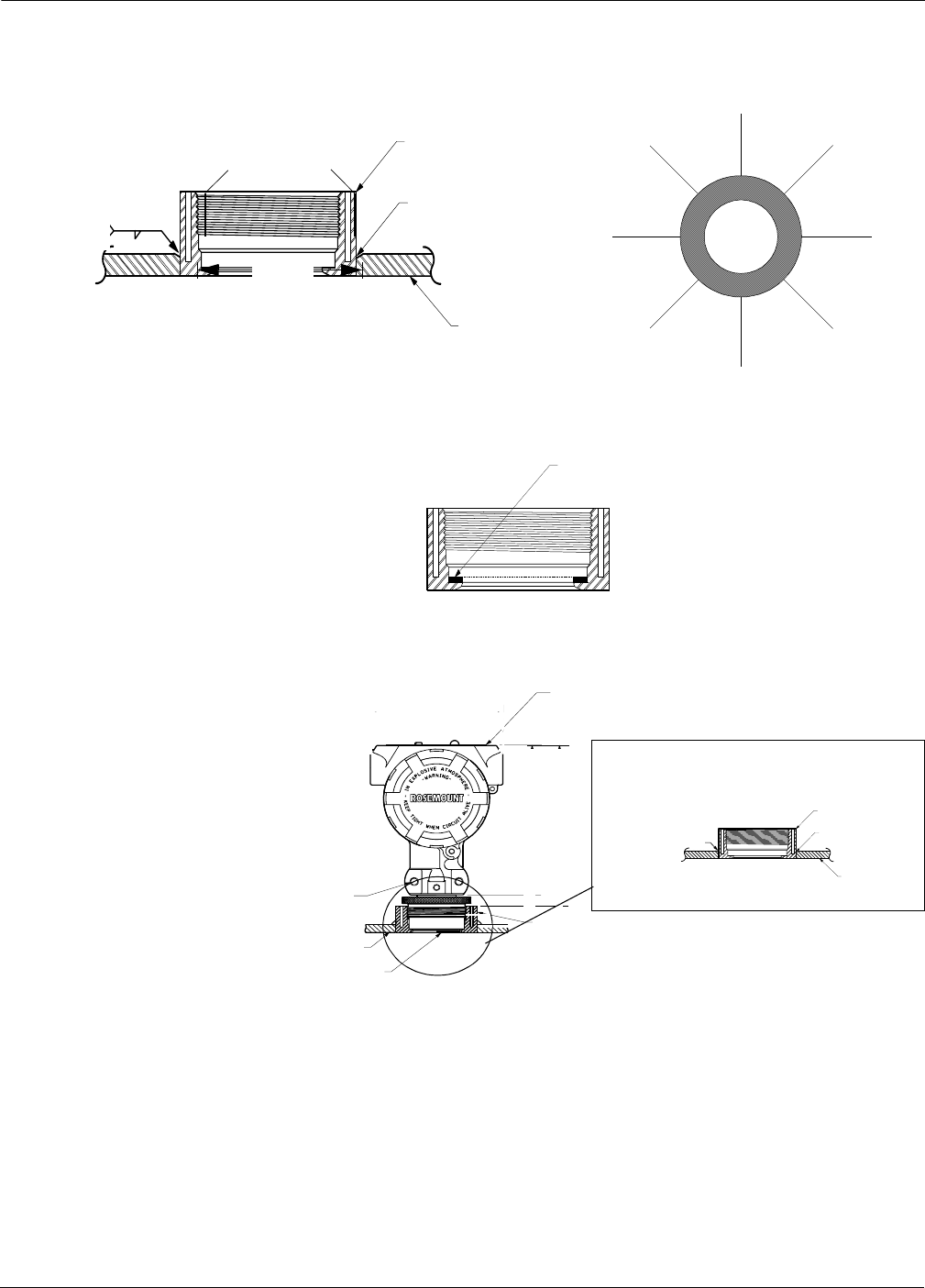
FIGURE 3-5. Installing the Weld Spud.
FIGURE 3-6. Teflon Gasket Placement.
FIGURE 3-7. Model 2090P Mounting
Configuration Using a Weld Spud.
PREPARING THE VESSEL HOLE
4
6
8
1
3
5
7
2
2090-0208E07B
Process
Vessel
Bevelled
Edge
Weld Spud
100–125 Amps
recommended
308L SST
2.37 (60)
Code “C” in Model Structure or
P/N 02088-0295-0003
WELDING SEQUENCE
Heat Isolation
Grooves
Teflon Gasket
Nameplate
23¼–20
UNC–2BX
Depth 0.60
Mounting
Holes
Bevelled Edge
Vessel
Wall
Weld Spud
DETAIL OF WELD SPUD
Vessel Wall
2090-2088B07P, 2088E07B
100–125 Amps
recommended
Weld Spud
2090-2088E07A
Rosemount Model 2088/2090 Pressure Transmitters
3-10
Model 2090F The Model 2090F sanitary pressure transmitter is designed to be
installed directly to a sanitary fitting. The transmitter is available with
either a 1.5- or 2-inch clamp connection.
When installing the transmitter to the sanitary fitting it is important to
use the proper sanitary clamp and gasket (user-supplied). Check the
clamp and gasket specifications before installing. Refer to Standard
Sanitary Clamp Models in Figure 3-8 for a list of standard sanitary
clamps, their respective maximum pressure ranges, and the
recommended torque to be applied when mounting.
FIGURE 3-8. Model 2090F Mounting
Configuration Using a Sanitary Fitting.
Nameplate
1.5- or 2-in.
Tri-Clamp
Connection
1.1 (28)
Typical
User Supplied
Gasket and
Clamp
B
A
DETAIL OF SANITARY
CONNECTION
STANDARD SANITARY CLAMP MODELS
Clamp Model psi @ 70 °F
(kPa @ 21 °C) psi @ 250 °F
(kPa @ 121 °C) Recommended
Torque
13 MHHM 1.5-inch
13 MHHM 2-inch
450 (3 103)
500 (3 448)
250 (1 724)
250 (1 724) 25 in-lb (2.8 N•m)
13 MHHS 1.5-inch
13 MHHS 2-inch
600 (4 138)
550 (3 793)
300 (2 069)
275 (1 896) 25 in-lb (2.8 N•m)
13 MHP 1.5-inch
13 MHP 2-inch
1500 (10 345)
1000 (6 896)
1200 (8 276)
800 (5 517) 20 ft-lb (27 N•m)
CONNECTION SIZE
* Dimensions are in inches (millimeters)
Connection
Size* A B
1.50 (38) 1.99 (50) 1.71 (43)
2.00 (51) 2.52 (64) 2.22 (56)
2088-2088B07D, 2090-2088D07A
Mounting
Hole
See “Safety Messages” on page 3-1 for complete warning information.
3-11
Installation
ELECTRICAL
CONSIDERATIONS
The wiring terminations on the Models 2088, 2090P, and 2090F are
located in the side of the transmitter housing marked “FIELD
TERMINALS.” Access to these terminations is required during
installation and may be necessary during periodic calibration of the
transmitter.
Power Supply The dc power supply should provide power to the transmitter with less
than one percent ripple. The total loop resistance load is the sum of the
resistance of the signal wires and the resistance load of the controller,
indicator, and other pieces of equipment in the loop. Note that the
resistance of intrinsic safety barriers, if used, must be included. Figure
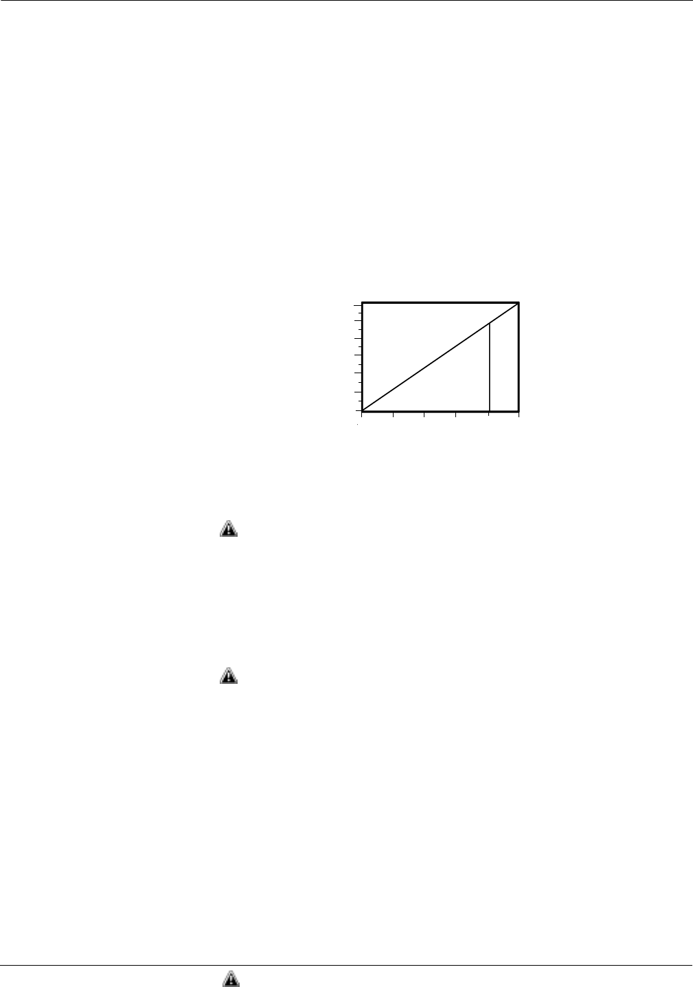
3-9 shows the transmitter power supply load limitations.
FIGURE 3-9. Transmitter
Load Limitations.
Field Wiring All power to the transmitter is supplied over the signal wiring. Signal
wiring need not be shielded, but use twisted pairs for best results. Do
not run unshielded signal wiring in conduit or open trays with power
wiring, or near heavy electrical equipment. To power the transmitter,
connect the positive power lead to the terminal marked “PWR/COMM+”
and the negative power lead to the terminal marked “–” (see Figure
3-10). Tighten the terminal screws to ensure that proper contact is
made. Avoid contact with the leads and the terminals. No additional
power wiring is required.
To connect test equipment for monitoring the output of the Model 2088
Smart during maintenance procedures, connect one lead to the terminal
labeled “TEST+” and the other lead to the terminal labeled “–” (see
Figure 3-10). Avoid contact with the leads and the terminals.
Signal wiring may be grounded at any one point on the measurement
loop, or it may be left ungrounded. The negative side of the power
supply is a recommended grounding point. The transmitter case may be
grounded or left ungrounded.
Conduit connections at the transmitter should be sealed to prevent
moisture accumulating in the field terminal side of the transmitter
housing. Also, install wiring with a drip loop with the bottom of the drip
loop lower than the conduit connection of the transmitter housing.
(1) For CENLEC EX ia Approval, power supply must not exceed 30 volts.
NOTE
Minimum load impedance for Output Code N is 100 kilohms.
Load (Ohms)
Operating
Region
Max. Load = 45.4 (Power Supply Voltage) –10.5
10.5 15 20 25 30(1) 36
Power Supply (dc Volts)
1158
1000
800
600
400
200
0
2088-0098A
See “Safety Messages” on page 3-1 for complete warning information.

Rosemount Model 2088/2090 Pressure Transmitters
3-12
FIGURE 3-10. Model 2088 Smart
Signal Wiring Terminals.
FAILURE MODE AND
SECURITY JUMPERS
Failure Mode As part of normal operation, the Model 2088/2090 Smart Pressure
Transmitter continuously monitors its own operation. This automatic
diagnostic routine is a timed series of checks repeated continuously. If
the diagnostic routine detects a failure in the transmitter, the
transmitter drives its output either below or above specific values
depending on the position of the failure mode jumper or switch.
The values to which 4–20 mA transmitters drive their output in failure
mode depend on whether they are factory-configured to standard or
NAMUR-compliant operation. The values for each are as follows:
Standard Operation
Linear output: 3.9 ≤ I ≤ 20.8 mA
Fail low: I ≤ 3.75 mA
Fail high: I ≥ 21.75 mA
NAMUR-Compliant Operation (Option Code C4)
Linear output: 3.8 ≤ I ≤ 20.8 mA
Fail low: I ≤ 3.6 mA
Fail high: 21.0 ≤ I ≤ 23.0 mA
To determine the failure mode configuration of your transmitter, review
the failure mode options using a Model 275 HART Communicator.
NOTE
The failure mode configuration, whether standard or NAMUR-
compliant, is configured at the factory and can not be changed in
the field.
Positive
Negative
Test
2088S-2088C02D
See “Safety Messages” on page 3-1 for complete warning information.
3-13
Installation
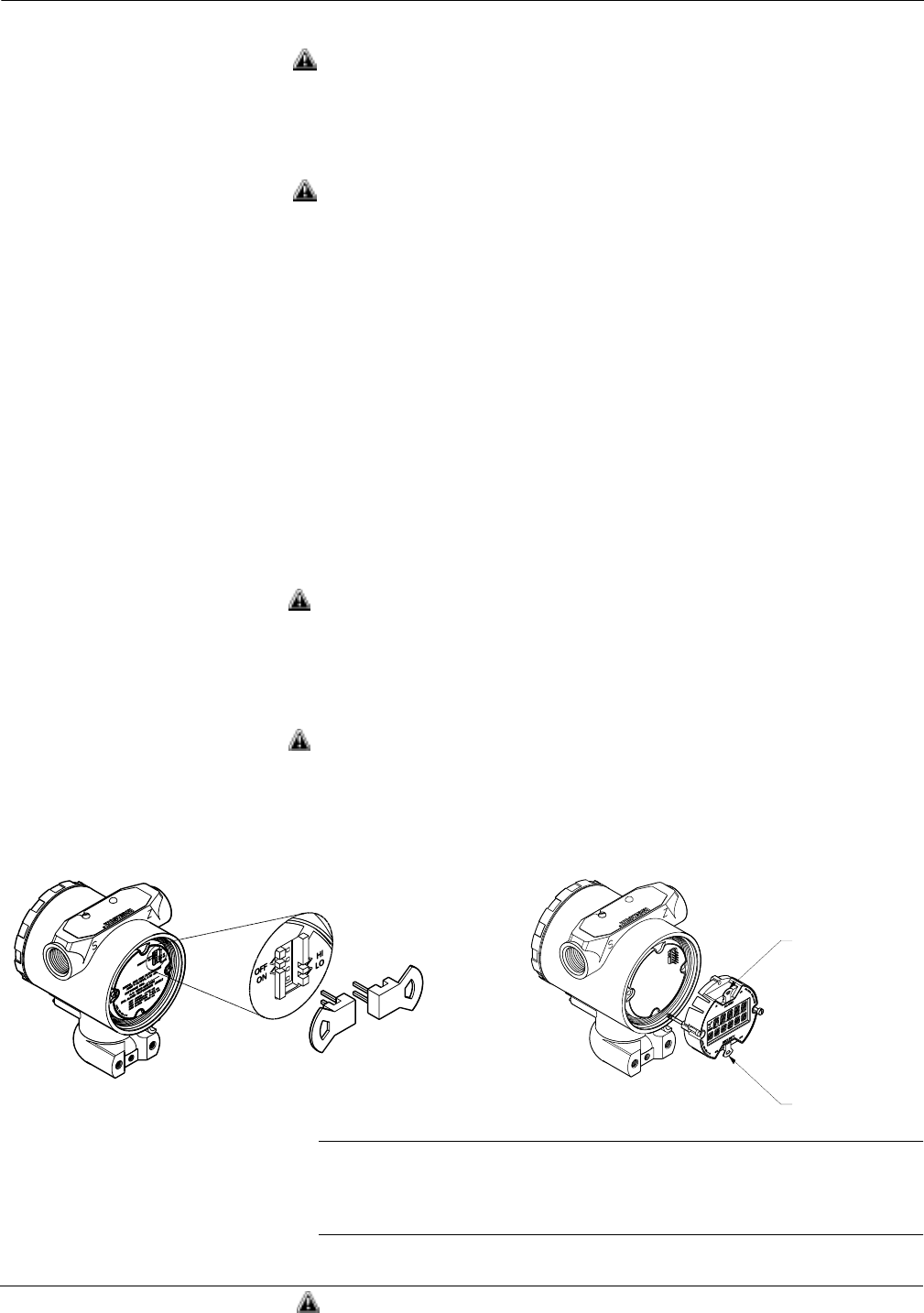
Jumper Locations Without a meter installed
The failure mode alarm jumper is located on the front side of the
electronics module just inside the electronics housing cover and is
labeled ALARM (See Figure 3-11). Do not remove the transmitter
cover in explosive atmospheres when the circuit is alive. Both covers
must be fully engaged to meet explosion-proof requirements.
With a meter installed
The failure mode alarm jumper is located on the LCD faceplate in the
electronics module side of the transmitter housing and is labeled
ALARM (See Figure 3-11). Do not remove the transmitter cover in
explosive atmospheres when the circuit is alive. Both covers must be
fully engaged to meet explosion proof requirements.
Transmitter Security After commissioning the transmitter, you may wish to protect the
configuration data from unwarranted changes. The transmitter is
equipped with a security jumper that can be positioned to prevent
changes to the configuration data (see Figure 3-11). The circuit board is
electrostatically sensitive. Observe handling precautions for static-
sensitive components to avoid circuit board damage.
When the transmitter security jumper is in the “ON” position, the
transmitter will not accept any “writes” to its memory. This means that
configuration changes (such as digital trim and reranging) cannot take
place when the transmitter security is on. To reposition the jumper, use
the following procedure.
1. If the transmitter is installed, secure the loop, and remove power.
2. Remove the housing cover opposite the field terminal side. Do not
remove the instrument cover in explosive atmospheres when the
circuit is alive.
3. Reposition the jumper. Avoid contact with the leads and the
terminals. Refer to Figure 3-11 for the location of the jumper and
the ON and OFF positions.
4. Reattach the transmitter cover. The cover must be fully engaged
to comply with explosion-proof requirements.
FIGURE 3-11. Transmitter Alarm and
Security Jumper Locations.
NOTE
If either the alarm or security jumper is dislodged or removed from its
position the transmitter reverts to default alarm or security settings of:
Alarm: Output high; Security: Off
Alarm
Security
Alarm and Security Jumpers Without Meter Alarm and Security Jumpers With Meter
Alarm
Security
2088S-2088A05A, 2088A05C
See “Safety Messages” on page 3-1 for complete warning information.
Rosemount Model 2088/2090 Pressure Transmitters
3-14
ZERO AND SPAN
ADJUSTMENTS
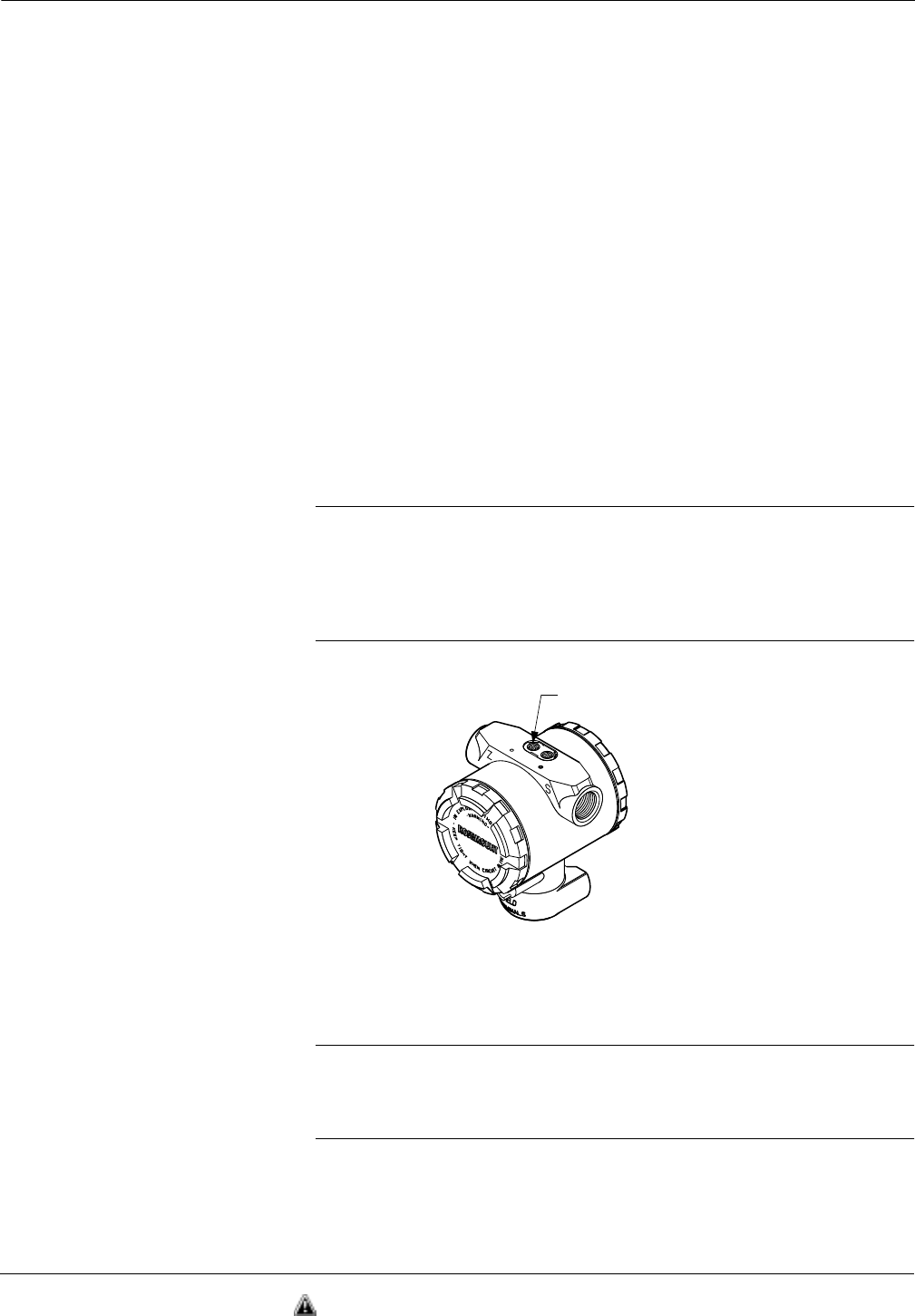
The smart Model 2088 is equipped with local zero and span adjustment
buttons. The buttons are located on the top of the transmitter beneath
the certifications label. Use the zero and span adjustments to set the
4 and 20 mA output points.
Rerange Procedure To rerange the transmitter using the span and zero buttons, perform
the following procedure.
1. Loosen the screw holding the nameplate on top of the transmitter
housing and rotate the nameplate to expose the zero and span
buttons (see Figure 3-12).
2. Using a pressure source with an accuracy three to ten times the
desired calibrated accuracy, apply a pressure equivalent to the
lower range value.
3. To set the 4 mA point, press and hold the zero button for at least
two seconds, then verify that the output is 4 mA. If a meter is
installed, it will display ZERO PASS.
4. Apply a pressure equivalent to the upper range value.
5. To set the 20 mA point, press and hold the span button for at least
two seconds, then verify that the output is 20 mA. If a meter is
installed, it will display SPAN PASS.
NOTE
If the transmitter security jumper is in the “ON” position, or if the local
zero and span adjustments are disabled through the software, you will
not be able to make adjustments to the zero and span using the local
buttons. Refer to Figure 3-11 on page 3-13 for the proper placement of
the transmitter security jumper.
FIGURE 3-12. Local Zero
and Span Adjustments.
Disabling the Zero
andSpanAdjustments After you rerange the transmitter using the span and zero adjustments,
you may wish to disable the adjustments to prevent further reranging. To
disable the span and zero adjustments, activate the transmitter security
jumper (see Transmitter Security on Page 3-13).
NOTE
The transmitter security jumper prevents any changes to the
transmitter configuration data. The software lockout sequence only
disables the local span and zero adjustment buttons.
2088S-2088A02A
Span and Zero Adjustment Buttons
See “Safety Messages” on page 3-1 for complete warning information.

3-15
Installation

Rosemount Model 2088/2090 Pressure Transmitters
3-16

Section
4-1
4Maintenance and
Troubleshooting
This section contains the following transmitter maintenance and
troubleshooting information:
• Troubleshooting
• Disassembly Procedure
• Reassembly Procedure
• Return of Materials
• Replacement Parts
SAFETY MESSAGES This section contains procedures that require connecting a communicator
to the transmitter, or making connections in an explosive atmosphere.
The following safety messages apply to all procedures throughout this
section requiring cover removal and communicator or ammeter
connection to the transmitter terminal block. Keep the following safety
messages in mind whenever you perform an operation requiring cover
removal or the connection of a communicator or other device to a
measurement loop.
The following performance limitations may inhibit efficient or safe operation.
Critical applications should have appropriate diagnostic and backup systems
in place.
Pressure transmitters contain an internal fill fluid. It is used to transmit the
process pressure through the isolating diaphragms to the pressure sensing
element. In rare cases, oil leak paths in oil-filled pressure transmitters can be
created. Possible causes include: physical damage to the isolator
diaphragms, process fluid freezing, isolator corrosion due to an incompatible
process fluid, etc.
A transmitter with an oil fill fluid leak can continue to perform normally for a
period of time. Sustained oil loss will eventually cause one or more of the
operating parameters to exceed published specifications while a small drift in
operating point output continues. Symptoms of advanced oil loss and other
unrelated problems include:
• Sustained drift rate in true zero and span or operating
point output or both.
• Sluggish response to increasing or decreasing pressure or both.
• Limited output rate or very nonlinear output or both.
• Change in output process noise.
• Noticeable drift in operating point output.
• Abrupt increase in drift rate of true zero or span or both.
• Unstable output.
• Output saturated high or low.
Rosemount Models 2088/2090 Pressure Transmitters
4-2
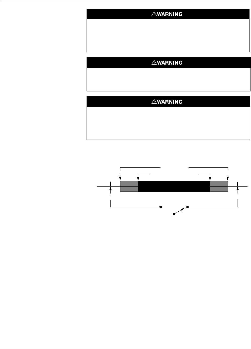
FIGURE 4-1. Range of Output.
Unauthorized procedures or parts can affect product performance and the
output signal used to control a process, and can cause death or serious
injury. Use only the procedures and new parts specifically referenced in
this manual. Direct any questions concerning these procedures or parts to
Rosemount Inc.
Explosions can result in death or serious injury. Do not remove the
instrument cover in explosive environments while power is supplied to
transmitter.
Mishandling products exposed to a hazardous substance can cause death
or serious injury. If the product being returned was exposed to a
hazardous substance as defined by OSHA, a copy of the required Material
Safety Data Sheet (MSDS) for each hazardous substance identified must
be included with the returned goods.
mA
3.75 for Smart(1)
20.8
3.9 Normal Operating Range 20
4
Hardware Alarm
Process Variable
OutofRange
Fail Low Fail High
Smart only
21.75
(1) Failure mode for output code M is ≤1V.
(2) Above Values are for Standard Failure Mode. NAMUR compliant values are different than above.

4-3
Maintenance and Troubleshooting
TROUBLESHOOTING
TABLE 4-1. Smart Transmitter Troubleshooting and Corrective Actions.
Symptom Potential Source Corrective Action
High Output Impulse Piping, • Check for blockage in the impulse line.
• Check to ensure that the blocking valve is fully open.
• Check for trapped gas in a liquid line, or trapped liquid in a gas line.
• Check to ensure that the density of the fluid in the impulse line is unchanged.
• Check for sediment in the transmitter process connection. If you find sediment,
flush the process connection clean with water or an appropriate solvent.
Do not attempt to scrape sediment free; doing so could puncture the thin
isolating diaphragm and destroy the transmitter.
• Check for frozen process fluid in the process connector.
Electronics • Check test equipment.
• Perform full sensor trim.
Power Supply • Check the output voltage of the power supply at the transmitter.(1)
(1) A transmitter with Output Code S should have 10.5–36.0 V dc with no load at the terminals; A transmitter with Output Code M should have
6.0–14.0 V dc.
Other Components • Replace the transmitter.
Erratic Output Impulse Piping • Check for leaks or blockage in the impulse line.
• Check to ensure that the blocking valve is fully open.
• Check for trapped gas in a liquid line, or trapped liquid in a gas line.
• Check to ensure that the density of the fluid in the impulse line is unchanged.
• Check for sediment in the transmitter process connection. If you find sediment,
flush the process connection clean with water or an appropriate solvent.
• Check for frozen process fluid in the process connector.
• Check for trapped gas in a liquid line, or trapped liquid in a gas line.
Loop Wiring • Check for adequate voltage to the transmitter.(1)
• Check for intermittent shorts, open circuits, and multiple grounds.
Electronics • Check for EMF interference.
• Check damping.
• Replace the output board and recalibrate the transmitter.
Other Components • Replace the transmitter.
Low Output or No
Output
Impulse Piping • Check for leaks or blockage in the impulse line.
• Check to ensure that the blocking valve is fully open.
• Check for trapped gas in a liquid line, or trapped liquid in a gas line.
• Check to ensure that the density of the fluid in the impulse line is unchanged.
• Check for sediment in the transmitter process connection. If you find sediment,
flush the process connection clean with water or an appropriate solvent.
Do not attempt to scrape sediment free; doing so could puncture the thin
isolating diaphragm and destroy the transmitter.
• Check for frozen process fluid in the process connector.
Low Output or No
Output
Loop Wiring • Check test equipment.
• Check for adequate voltage to the transmitter.(1)
• Check the current rating of the power supply against the total current being drawn
by all transmitters being powered.
• Check for intermittent shorts, open circuits, and multiple grounds.
• Check for proper polarity at the signal terminals.
• Check the loop impedance.
Electronics • Replace the electronics board and recalibrate the transmitter.
Other Components • Replace the transmitter.

Rosemount Models 2088/2090 Pressure Transmitters
4-4
TABLE 4-2. Analog Transmitter Troubleshooting Symptoms and Corrective Actions.
DOWNSCALE ALARM Models 2088, 2090P, and 2090F transmitters can identify certain types
of failure conditions. These failures may arise from four possible
sources:
1. No updated information is being received by the microprocessor
from the sensor.
2. The sensor is damaged.
3. Calibration information for zero and span is not being stored
correctly within the memory of the microprocessor.
4. Microprocessor malfunction.
Symptom Potential Source Corrective Action
High Output Impulse Piping • Check for blockage in the impulse line..
• Check to ensure that the blocking valve is fully open.
• Check for trapped gas in a liquid line, or trapped liquid in a gas line.
• Check to ensure that the density of the fluid in the impulse line is unchanged.
• Check for sediment in the transmitter process connection. If you find sediment, flush
the process connection clean with water or an appropriate solvent.
Do not attempt to scrape sediment free; doing so could puncture the thin isolating
diaphragm and destroy the transmitter.
• Check for frozen process fluid in the process connector.
Power Supply • Check the output voltage of the power supply at the transmitter.(1)
(1) A transmitter with Output Code A should have 10.5–36.0 V dc with no load at the terminals; A transmitter with Output Code M should have
6.0–14.0 V dc.
Output Electronics • Replace the output board and recalibrate the transmitter.
Other Components • Replace the transmitter.
Symptom Potential Source Corrective Action
Erratic Output Impulse Piping • Check for leaks or blockage in the impulse line.
• Check to ensure that the blocking valve is fully open.
• Check for trapped gas in a liquid line, or trapped liquid in a gas line.
• Check to ensure that the density of the fluid in the impulse line is unchanged.
• Check for sediment in the transmitter process connection. If you find sediment, flush
the process connection clean with water or an appropriate solvent.
• Check for frozen process fluid in the process connector.
• Check for trapped gas in a liquid line, or trapped liquid in a gas line.
Loop Wiring • Check for adequate voltage to the transmitter.(1)
• Check for intermittent shorts, open circuits, and multiple grounds.
Output Electronics • Replace the output board and recalibrate the transmitter.
Other Components • Replace the transmitter.
Low Output or No
Output
Impulse Piping • Check for leaks or blockage in the impulse line.
• Check to ensure that the blocking valve is fully open.
• Check for trapped gas in a liquid line, or trapped liquid in a gas line.
• Check to ensure that the density of the fluid in the impulse line is unchanged.
• Check for sediment in the transmitter process connection. If you find sediment, flush
the process connection clean with water or an appropriate solvent.
Do not attempt to scrape sediment free; doing so could puncture the thin isolating
diaphragm and destroy the transmitter.
• Check for frozen process fluid in the process connector.
Loop Wiring • Check for adequate voltage to the transmitter.(1)
• Check the current rating of the power supply against the total current being drawn
by all transmitters being powered.
• Check for intermittent shorts, open circuits, and multiple grounds.
• Check for proper polarity at the signal terminals.
• Check the loop impedance.
Output Electronics • Replace the output board and recalibrate the transmitter.
Other Components • Replace the transmitter.
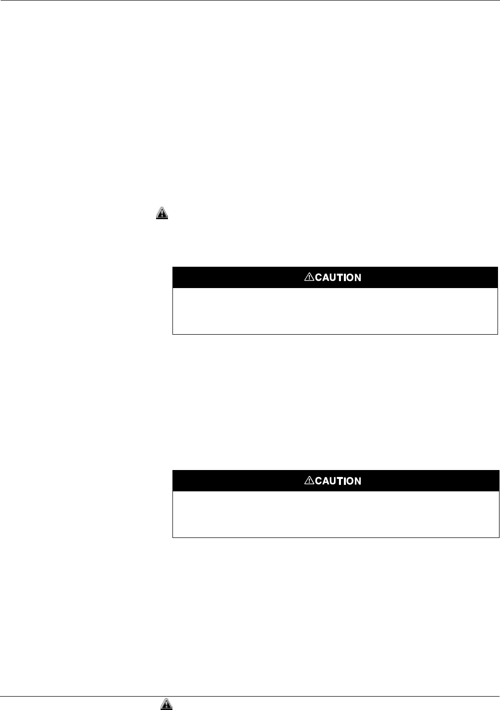
4-5
Maintenance and Troubleshooting
If the transmitter experiences failure conditions, it drives the output
below the lower output limit (less than 3.75 mA for Output Code S; less
than 1 V for Output code M), and if a local indicator is installed, it
displays “FAIL.” If the transmitter encounters the first or second
condition it locks the output at the lower limit. If the transmitter
encounters the third condition it locks the output at the lower limit
after the switch is turned to the “RUN” position.
If you experience downscale alarm, momentarily interrupt power to the
transmitter. After re-applying power, attempt to reset the calibration
point that caused the failure. If the transmitter does not accept the set
value after repeated attempts, the microprocessor board is probably
inoperable. Check the operation of the microprocessor board by
eliminating other sources of low output (i.e. blocked impulse piping).
Remove the output board for spare parts and replace the transmitter.
DISASSEMBLY
PROCEDURE
You can easily repair the Models 2088, 2090P, and 2090F Pressure
Transmitters in the event of a malfunction in the output stage of the
transmitter electronics.
To remove the output circuit board use the following procedure:
1. Remove the cover from the electronics side of the transmitter
housing.
2. Loosen the two captive screws that hold the output board in place.
3. Carefully remove the output board from the multi-pin connector
and the power leads.
REASSEMBLY
PROCEDURE
To replace the output circuit board use the following procedure:
1. Align the two long power leads on the transmitter electronics
board with the power receptacles on the output board. Gently
insert the power leads into the receptacles.
2. Align the multi-pin connector on the output board with the
receptacles on the transmitter electronics board. Gently insert the
multi-pin connector into the receptacles.
3. Push the board firmly into position and tighten the screws.
To view an exploded view, see Figure 5-1 on page 5-7.
Disconnect power to the transmitter before removing the output board.
Failure to follow this procedure could result in permanent damage to the
transmitter electronics.
The circuit board is electrostatically sensitive. To prevent damage to the
circuit board, observe handling precautions for static-sensitive
components.
See “Safety Messages” on page 4-1 for complete warning information.

Rosemount Models 2088/2090 Pressure Transmitters
4-6
RETURNING ROSEMOUNT
PRODUCTS AND/OR
MATERIALS
To expedite the return process outside the United States, contact the
nearest Rosemount representative.
Within the United States, call the Rosemount National Response
Center using the 1-800-654-RSMT (7768) toll-free number. This center,
available 24 hours a day, will assist you with any needed information or
materials.
The center will ask for product model and serial numbers, and will
provide a Return Material Authorization (RMA) number. The center
will also ask for a description of the process material to which the
product was last exposed.
The Rosemount National Response Center will detail the additional
information and procedures necessary to return goods exposed to
hazardous substances.
See “Safety Messages” on page 4-1 for complete warning information.

Section
5-1
5Specifications and
Reference Data
OVERVIEW This section contains the following transmitter specifications and
reference data:
• Model 2088, Model 2090P, and Model 2090F
Functional Specifications
Performance Specifications
Physical Specifications
• Spare Parts
• Ordering Information
FUNCTIONAL
SPECIFICATIONS
Service
Model 2088
Liquid, gas, and vapor applications.
Model 2090P
Liquid, gas, vapor, and high-viscosity applications.
Model 2090F
Liquid, gas, vapor, and sanitary applications.
Ranges for Model 2088
Ranges for Model 2090F
Ranges for Model 2090P
Range Minimum Span
(Smart) URL/Max.span/Sensor Limit
1 1.5 psi (103 mbar) 30 psi (2,06 bar)
2 7.5 psi (517 mbar) 150 psi (10,34 bar)
3 40 psi (2,76 bar) 800 psi (55,15 bar)
4 200 psi (13,8 bar) 4000 psi (275,79 bar)
Range Minimum Span
(Smart) URL/Max.span/Sensor Limit
1 1.5 psi (103 mbar) 30 psi (2,06 bar)
2 7.5 psi (517 mbar) 150 psi (10,34 bar)
3 40 psi (2,76 bar) 300 psi (20,68 bar)
Range Minimum Span
(Smart) URL/Max.span/Sensor Limit
1 1.5 psi (103 mbar) 30 psi (2,06 bar)
2 7.5 psi (517 mbar) 150 psi (10,34 bar)
3 40 psi (2,76 bar) 300 psi (20,68 bar)

Rosemount Model 2088/2090 Pressure Transmitters
5-2
Output
Code S: 4–20 mA dc.
Load Limitations(1)
Maximum loop resistance is determined by the power supply voltage, as
described by:
Power Supply
External power supply(2) required. Transmitter operates on
10.5–36 V dc with no load. Reverse polarity protection is standard.
Zero Elevation and Suppression
Zero can be suppressed between atmosphere for gage transmitters, or
0 psia for absolute transmitters, and upper range limit, provided the
calibrated span is equal to or greater than the minimum span, and the
upper range value does not exceed the upper range limit. Vacuum
calibrations are allowed on the Model 2088G transmitter with
compound range option (CR).
Overpressure Limits
Ranges 0 and 1: 120 psig max.
All other ranges: twice the upper range limit.
Temperature Limits
Process
Model 2088 Silicone fill sensor: –40 to 250 °F (–40 to 121 °C).
Inert fill sensor: –22 to 250 °F (–30 to 121 °C).
Model 2090P –4 to 250 °F (–20 to 121 °C).
Model 2090F –4 to 284 °F (–20 to 140 °C).
Ambient:
Model 2088 –40 to 185 °F (–40 to 85 °C).
–4 to 175 °F (–20 to 80 °C) with LCD meter.
Model 2090P –4 to 185 °F (–20 to 85 °C).
Model 2090F –4 to 185 °F (–20 to 85 °C).
Storage:
Model 2088 –50 to 230 °F (–46 to 110 °C).
–40 to 185 °F (–40 to 85 °C) with LCD meter.
Model 2090P –50 to 185 °F (–45 to 85 °C).
Model 2090F –22 to 185 °F (–30 to 85 °C).
(1) Minimum load impedance for Output Code M is 100 kilohms.
(2) For CENELEC Ex ia approval, the power supply must not exceed 30 volts.
Max. Loop Resistance = 45.4 3(Power Supply Voltage – 10.5)
10.5 15 20 25 30 36
0
200
400
600
1000
800
1158
Operating
Region
Load (ohms)
Voltage (V dc)
Note: Communication requires minimum loop resistance: 250 ohm
s

5-3
Specifications and Reference Data
Process temperatures above 185 °F (85 °C) require derating the
ambient limits:
Humidity Limits
0–100% relative humidity.
Volumetric Displacement
Less than 0.00042 cm3.
Turn-on Time
Output Code S
2.0 seconds, no warm-up required.
Failure Mode
Output Code S
If self-diagnostics detect a sensor or microprocessor failure, the
analog signal is driven either high or low to alert the user. High or
low failure mode is user-selectable with a jumper on the transmitter.
The values to which the transmitter drives its output in failure mode
depend on whether it is factory-configured to standard or
NAMUR-compliant operation. The values for each are as follows:
Standard Operation
Linear Output: 3.9 ≤ I ≤ 20.8
Fail High: I ≥ 21.75 mA
Low: I ≤ 3.75 mA
NAMUR-Compliant Operation (Option Code C4)
Linear Output: 3.8 ≤ I ≤ 20.5
Fail High: I ≥ 22.5 mA
Low: I ≤ 3.6 mA
PERFORMANCE
SPECIFICATIONS
(Zero-based spans, reference conditions, and 316 SST isolating diaphragm.)
Reference Accuracy
Output Code S
±0.20% of calibrated span. Includes combined effects of linearity,
hysteresis, and repeatability.
Ambient Temperature Effect
Expressed as a total effect per 100 °F (56 °C).
Output Code S
± (0.3% URL + 0.3% of span) from –40 to 185 °F (–40 to 85 °C).
Stability
Output Code S
±0.10% of upper range limit for 12 months.
Vibration Effect
Less than ±0.1% of upper range limit when subjected to vibration of:
peak to peak constant displacement of 4 mm (5–15 Hz) and constant
acceleration of 2 g (15–150 Hz) and 1 g (150–2000 Hz).
Power Supply Effect
Less than 0.01% of calibrated span per volt.
185 Process Temp 185–()
1.5
-----------------------------------------------------------–=
Maximum Ambient
Temperature in °F
85 Process Temp 85–()
1.5
-------------------------------------------------------–=
Maximum Ambient
Temperature in °C

Rosemount Model 2088/2090 Pressure Transmitters
5-4
Mounting Position Effect
Zero shift of up to 1.2 inH2O (3 mbar), which can be calibrated out. No
span effect.
RFI Effect
Less than ±0.25% of upper range limit from 20–1000 MHz at 30 V/m
with leads in conduit. Less than ±0.25% of upper range limit at 10 V/m
with unshielded twisted pair (no conduit).
Transient Protection Limits
IEEE 587 Category B
6 kV Crest (1.2 3 50 ms).
3 kV Crest (8 3 20 ms).
6 kV Crest (0.5 ms by 100 kHz).
IEEE 472
SWC 2.5 kV Crest.
1 MHz waveform.
General Specifications
Tested to IEC 801-3.
Ordinary Location Certification
Factory Mutual (FM) Approval
As standard, the transmitter has been examined and tested to
determine that the design meets basic electrical, mechanical, and fire
protection requirements by FM, a nationally recognized testing
laboratory (NRTL) as accredited by the Federal Occupational Safety
and Health Administration (OSHA).
Hazardous Locations Certifications
Factory Mutual (FM) Approvals
E5 Explosion Proof for Class I, Division 1, Groups B, C, and D.
Dust-Ignition Proof for Class II, Division 1, Groups E, F, and G.
Suitable for Class III, Division 1, indoor and outdoor (NEMA 4X)
hazardous locations; factory sealed.
I5 Instrinsically safe for use in Class I, Division 1, Groups A, B, C, D;
Class II, Division 1, Groups E, F, and G; and Class III, Division 1
when connected in accordance with Rosemount drawing
02088-1018. Non-incendive for Class I, Division 2, Groups A, B, C,
and D.
Canadian Standards Association (CSA) Approvals
C6 Explosion Proof for Class I, Division 1, Groups B, C, and D.
Dust-Ignition Proof for Class II, Division 1, Groups E, F, and G.
Suitable for Class III, indoor and outdoor hazardous locations,
CSA enclosure Type 4X; factory sealed. Approved for Class I,
Division 2, Groups A, B, C, and D.
Intrinsically Safe for Class I, Division 1, Groups A, B, C, and D.
Temp. Code T3C. Intrinsically safe when connected with
approved barriers in accordance with Rosemount drawing
02088-1024.
CENELEC Flameproof Approvals
E8 Centro Elettrotecnico Sperimentale Italiano (CESI) Flameproof
Approval (Analog only)
Certification Number Ex 91C120.
EEx d IIC T4 (Tamb = 80 °C)
EEx d IIC T6 (Tamb = 40 °C).
ED KEMA/CENELEC 97 ATEX 2378 (Smart only)
EEx d IIC T4 (Tamb = 80 °C)
EEx d IIC T6 (Tamb = 40 °C).

5-5
Specifications and Reference Data
British Approvals Service for Electrical Equipment in Flammable
Atmospheres (BASEEFA) Approvals
I1 BASEEFA/CENELEC Intrinsic Safety
Ex 90C2158 for analog transmitters
Ex97D2276X for smart transmitters.
EEx ia IIC T5 (Tamb = 40 °C).
EEx ia IIC T4 (Tamb = 70 °C).
N1 BASEEFA Type N Certification
Ex 90Y4159 for analog transmitters
Ex 97Y4277X for smart transmitters.
Ex N IIC T5 (Tamb = 70 °C).
Standards Association of Australia (SAA)
Explosion Proof (Flameproof) Certification
E7 Ex d IIC T6 (Tamb = 40 °C) (Available with analog output,
Code A, only.)
I7 Ex ia IIC T6. (Available with analog output, Code A, only.)
Ex ia IIC T4 (Tamb = 70 °C).
Combinations of Approvals
K5 Combination of E5 and I5
K6 Analog: Combination of C6, I1, and E8.
SMART: Combination of C6, I1, and ED.
PHYSICAL
SPECIFICATIONS
Electrical Connection
½–14 NPT, M20 3 1.5 (CM20), PG 13.5, or G ½ female (PF ½ female)
conduit entry.
Process Connection
Model 2088
½–14 NPT female, DIN 16288 G ½ male, RC ½ female (PT ½ female),
M20 3 1.5 (CM20) male.
Model 2090P
M44 3 1.25 male, compatible with a 1-in. PMC® process connection.
Model 2090F
1½-inch or 2-inch Tri-Clamp Connection
Process Wetted Parts
Isolating Diaphragm
Model 2088 316L stainless steel or Hastelloy.
Model 2090P 316L stainless steel.
Model 2090F 316L stainless steel.
Process Connector
Model 2088 316L stainless steel or Hastelloy.
Model 2090P 316L stainless steel.
TFE process connector gasket.
Model 2090F 316L stainless steel.
Non-wetted Parts
Electronics Housing
Low-copper aluminum, NEMA 4X, IP65, IP67, CSA enclosure
Type 4X.
Paint
Polyurethane.
Cover O-rings
Buna-N.

Rosemount Model 2088/2090 Pressure Transmitters
5-6
Fill Fluid
Model 2088 Silicone or inert fill.
Model 2090P Silicone
Model 2090F Neobee
Weight
Model 2088 Approximately 2.44 lb (1,11 kg).
Model 2090P Approximately 2.96 lb (1,34 kg).
Model 2090F Approximately 2.74 lb (1,24 kg).
Accessory Block and Bleed Valve (S5 Option)
For information on Model 306 Integral Manifold (pre-assembled to
transmitter and leak checked), refer to Product Data Sheet
00813-0100-4733.
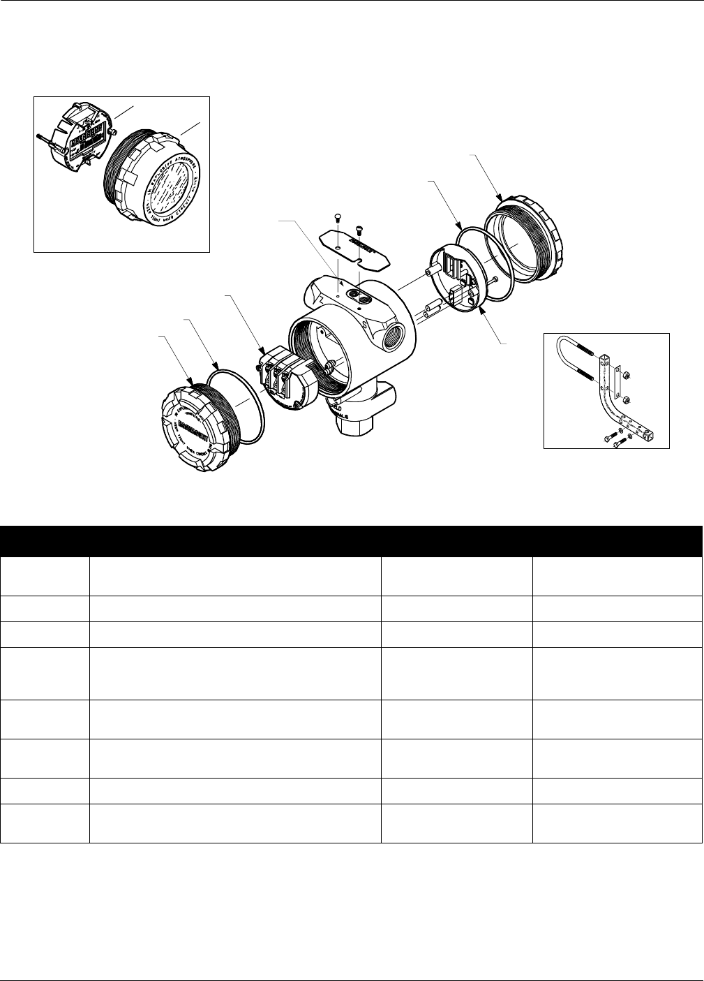
5-7
Specifications and Reference Data
SPARE PARTS .
2088-2088A04A
4
3
2
7
8
FIGURE 5-1. Replacement Parts for
the Model 2088 Smart Transmitter.
2088-2088A08B
6
5
LCD Meter Cover Assembly
includes LCD Cover and O-ring
1
2
1
3051-3031A05F
Item No. Part Description Part Number Spares Category(1)
1, 2
Smart Transmitters (Output Code S)
Electronics Cover (with O-ring) 03031-0292-0001 —
6LCD Meter Cover Assembly 03031-0193-0002 B
2Cover O-rings 03031-0232-0001 B
3
3
Electronics Board Kits
S Output (4–20 mA/Digital HART Protocol)
S Output (NAMUR Compliant Operation) 02088-0306-0002
02088-0306-0003
A
A
4
Optional Mounting Bracket
(with 2-inch U-Bolt for Pipe Mounting) 02088-0071-0001 —
5, 6
5
LCD Meter Kit with Cover
LCD Meter Kit without Cover 03031-0193-0101
03031-0193-0103
—
A
7Local Zero and Span Kit 3031-0293-0002 A
8
8
Standard Terminal Block
Transient Protection Block 3031-0332-0003
3031-0332-0004
B
B
(1) One spare part is recommended for every 25 transmitters in category A, and one spare part for every 50 transmitters in category B.
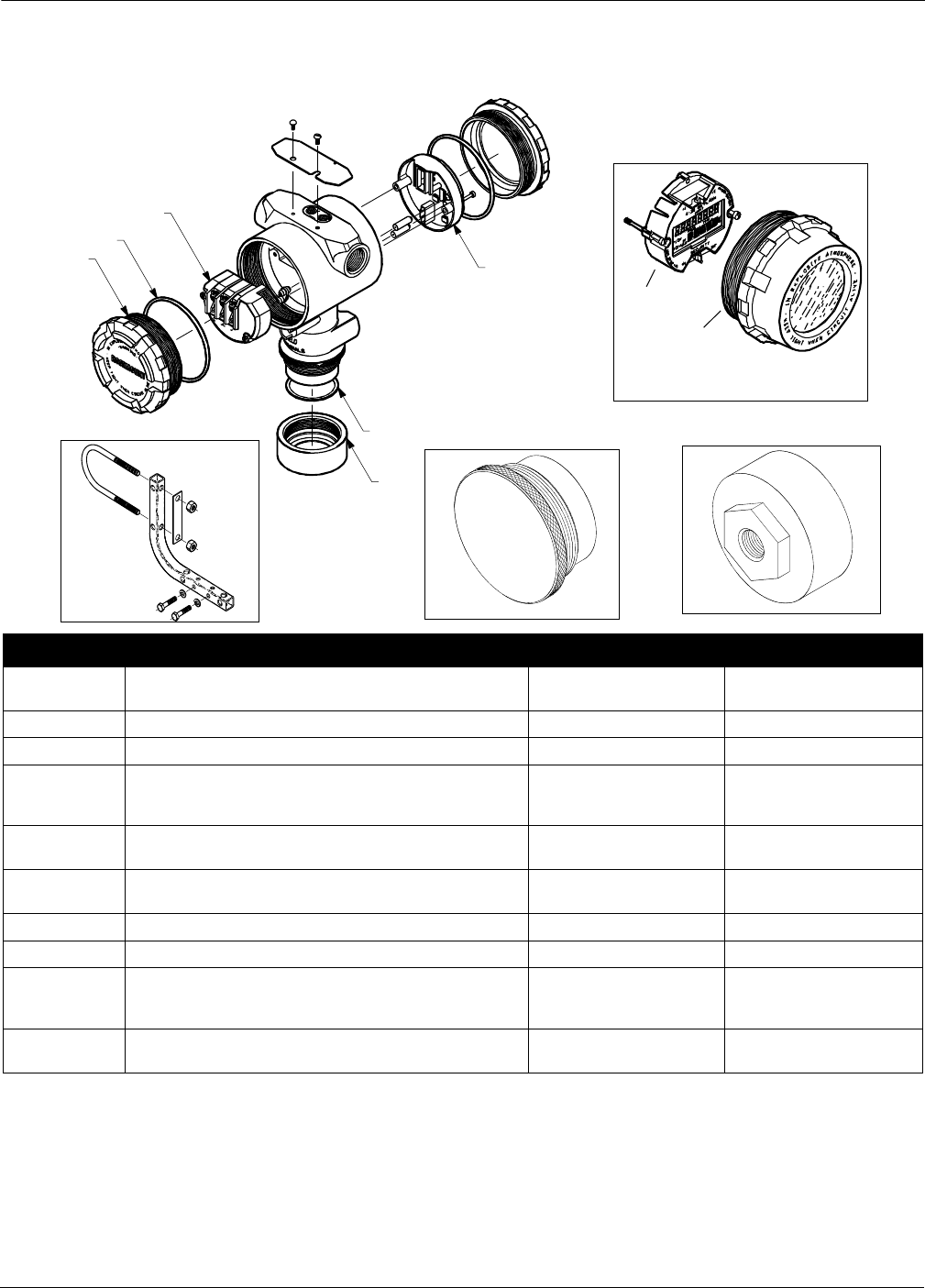
Rosemount Model 2088/2090 Pressure Transmitters
5-8
FIGURE 5-2. Replacement Parts for
the Model 2090P.
LCD Meter Cover Assembly
includes LCD Cover and O-ring
9
10
11
Item No. Part Description Part Number Category(1)
(1) One spare part is recommended for every 25 transmitters in category A, and one spare part for every 50 transmitters in category B.
1,2
Smart Transmitters (Output Code S)
Electronics Cover (with O-ring) 03031-0292-0001 —
10 LCD Meter Cover Assembly 03031-0193-0002 B
2Cover O-rings 03031-0232-0001 B
3
3
Electronics Boards
S Output (4–20 mA/Digital HART Protocol)
S Output (NAMUR Compliant Operation) 02088-0306-0002
02088-0306-0003
A
A
4
Optional Mounting Bracket
(with 2-inch U-Bolt for Pipe Mounting) 02088-0071-0001 —
9, 10
9
LCD Meter Kit with Cover
LCD Meter Kit without Cover 03031-0193-0101
03031-0193-0103
—
A
8Calibration Adapter 02088-0197-0001 A
5
Teflon
Gaskets (package of 12) 02088-0078-0001 A
6
6
7
316 SST Weld Spud with Heat Isolator Groove
316 SST Weld Spud
316 SST Plug/Heat Sink
02088-0295-0003
02088-0195-0001
02088-0196-0001
—
—
A
11
11
Standard Terminal Block
Transient Terminal Block 03031-0332-0003
03031-0332-0004
B
B
2088-2088A04A
2090-2088A08S
2090-2088C03A
8
4
12
3
5
6
2090-2088B03A
7
3051-3031A05F
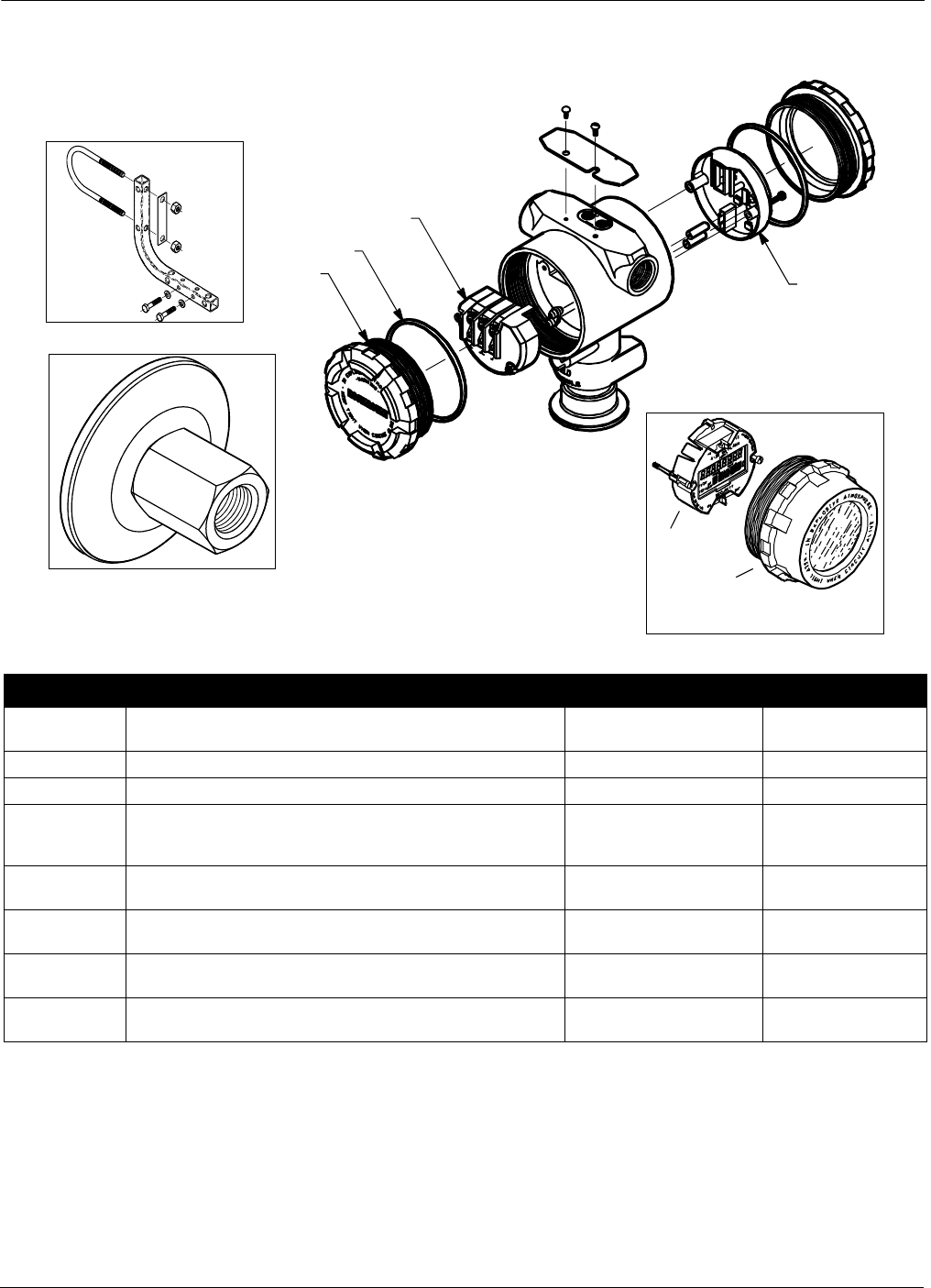
5-9
Specifications and Reference Data
FIGURE 5-3. Replacement Parts for the
Model 2090F.
LCD Meter Cover Assembly
includes LCD Cover and O-ring
4
5
NOTE: Sanitary clamp and gasket to be supplied by user.
Item No. Part Description Part Number Category(1)
(1) One spare part is recommended for every 25 transmitters in category A, and one spare part for every 50 transmitters in category B.
1
Smart Transmitters (Output Code S)
Electronics Cover (with O-ring) 03031-0292-0001 —
5LCD Meter Cover Assembly 03031-0193-0002 B
2O-rings 03031-0232-0001 B
3
3
Electronics Boards
S Output (4–20 mA/Digital HART Protocol)
S Output (NAMUR Compliant Operation) 02088-0306-0002
02088-0306-0003
A
A
7
Optional Mounting Bracket
(with 2-inch U-Bolt for Pipe Mounting) 02088-0071-0001 —
4, 5
4
LCD Meter Kit with Cover
LCD Meter Kit without Cover 03031-0193-0101
03031-0193-0103
—
A
6
6
Calibration Adapter, 1½ inch
Calibration Adapter, 2 inch 02088-0197-0011
02088-0197-0012
A
A
8
8
Standard Terminal Block
Transient Terminal Block 03031-0332-0003
03031-0332-0004
B
B
2090–2088E03A
2090-2088A08R
6
1
2
3
2088-2088A04A
7
8
3051-3031A05F

Rosemount Model 2088/2090 Pressure Transmitters
5-10
ORDERING INFORMATION
TABLE 5-1. Model 2088 Typical Model Structure.
(1) Range 0 is only available with low power output, 8 to1 rangedown, stainless steel wetted parts and silicone oil fill fluid.
(2) Meets NACE material recommendations.
(3) Inert fill fluid not available with range 0 transmitters.
(4) Hazardous locations approvals not available for Model 2088 Smart Transmitter (Output Code S).
Model Product Description (Select One)
2088A
2088G
Absolute Pressure Transmitter
Gage Pressure Transmitter
Code Range
0(1)
1
2
3
4
0–8 psi (0–6,89 to 0–552 mbar) Low power only
0–30 psi (0–2 bar)
0–150 psi (0–10,3 bar)
0–800 psi (0–55,15 bar)
0–4000 psi (0–275,8 bar)
Code Output
M
S
1–5 V dc Low Power
4–20 mA dc/Digital
HART
Protocol
Code MATERIALS OF CONSTRUCTION
Process Connection Isolating Diaphragm Oil Fill
22(2)
33(2)
2B(2)
3C(2)
316 SST 316 SST Silicone
Hastelloy
C-276
Hastelloy
C-276 Silicone
316 SST 316 SST Inert(3)
Hastelloy
C-276
Hastelloy
C-276 Inert
Code Process Connection
A
B
C
D
½–14 NPT Female
DIN 16288 G ½ Male
RC ½ Female (PT ½ Female)
M20x1.5(CM20)
Code Conduit Thread
1
2
3
4
½–14 NPT
M20x1.5(CM20)
PG 13.5
G ½ Female (PF ½ Female)
Code Remote Seal Connection
S1 One Remote Seal (Select from Product Data Sheet 00813-0100-4016)
Code Options(4)
M5
M7
B4
S5
S1
C6
I1
N1
E4(4)
E5
E7(4)
E8
ED
I5
I7(4)
K5
K6
N7(4)
P2
Q4
Q8
T1
C4
CN
C9
LCD Meter, scaled 0–100%
LCD Meter, special configuration
SST Mounting Bracket with SST Bolts
Assembly to Model 306 Integral Manifold (see PDS 00813-0100-4733 for ordering information)
One Diaphragm Seal (Select from Product Data Sheet 00813-0100-4016)
CSA Explosion-Proof, Intrinsic Safety, and Non-Incendive Approval
BASEEFA EEx ia IIC T5 (CENELEC) Intrinsic Safety Approval (Entity Concept)
BASEEFA Type N EX N IIC T5
JIS Explosion-Proof Approval
FM Explosion-Proof Approval
SAA Flame-Proof Certification
CESI/CENELEC Explosion-Proof Approval (available with analog output, Code A, only)
KEMA/CENELEC Explosion-Proof Approval (available with smart output, Code S, only)
FM Non-Incendive and Intrinsic Safety Approval (Entity Concept)
SAA Intrinsic Safety Certification
E5 and I5 Combination
CSA/CENELEC Explosion-Proof and Intrinsic Safety Approval
SAA Non-Incendive Certification
Cleaning for Special Service
Calibration Data Sheet
Material Traceability per DIN 3.1B
Transient Protection Terminal Block
Analog Output Levels Compliant with NAMUR Recommendation NE43, 27-June-1996 (Available with Output Code S only)
NOTE: NAMUR-Compliant operation is pre-set at the factory and cannot be changed to standard operation in the field.
Analog Output Levels Compliant with NAMUR Recommendation NE43, 27-June-1996: Low Alarm Configuration
NOTE: NAMUR-Compliant operation is pre-set at the factory and cannot be changed to standard operation in the field.
Software Configuration (Available with Output Code S only)
Typical Model Number: 2088G 1 S 22 A 1
Rangeability
Output Code Min.Span
SURL/20
MURL/10

5-11
Specifications and Reference Data
TABLE 5-2. Model 2090P Typical Model Structure.
Model Product Description (Select One)
2090PA
2090PG
Absolute Pressure Transmitter
Gage Pressure Transmitter
Code Range
1
2
3(1)
(1) Range 3 miniumum span: 0–40 psi.
0–30 psi (0–2 bar)
0–150 psi (0–10,3 bar)
0–300 psi (0–20,7 bar)
Code Output
S4–20 mA dc/Digital
HART
Protocol
Code MATERIALS OF CONSTRUCTION
Process Connection Isolating Diaphragm Oil Fill
22 316 SST 316 SST Silicone
Code Process Connection
A
B
C
No Weld Spud, includes
Teflon
Gasket
316 SST Weld Spud,
Teflon
Gasket
316 SST Weld Spud with Heat Isolator Groove
Code Conduit Thread
1
2
3
½–14 NPT
M20x1.5(CM20)
PG 13.5
Code Options
M5
M7
B4
S5
C6
I1
N1
E5
E8
ED
I5
K5
K6
P2
Q4
Q8
T1
LCD Meter, scaled 0–100%
LCD Meter, special configuration
SST Mounting Bracket with SST Bolts
Assembly to Model 306 Integral Manifold (see PDS 00813-0100-4733 for ordering information)
CSA Explosion-Proof, Intrinsic Safety, and
Non-Incendive Approval
BASEEFA EEx ia IIC T5 (CENELEC) Intrinsic Safety Approval (Entity Concept)
BASEEFA Type N EX N IIC T5
FM Explosion-Proof Approval
CESI/CENELEC Explosion-Proof Approval (available with analog output, Code A, only)
KEMA/CENELEC Explosion-Proof Approval (available with smart output, Code S, only)
FM Non-Incendive and Intrinsic Safety Approval (Entity Concept)
E5 and I5 Combination
CSA/CENELEC Explosion-Proof and Intrinsic Safety Approval
Cleaning for Special Service
Calibration Data Sheet
Material Traceability per DIN 3.1B
Transient Protection Terminal Block
Typical Model Number: 2090PG 2 S 22 B 1
Rangeability
Output Code Min.Span
SURL/20

Rosemount Model 2088/2090 Pressure Transmitters
5-12
TABLE 5-3. Model 2090F Typical Model
Structure.
NOTE
One product manual is included per shipment.
CALIBRATION All transmitters are factory calibrated to customer’s specified range. If
calibration is not specified, transmitters are calibrated at maximum
range. Calibration is at ambient temperature.
TAGGING Transmitter are tagged, at no charge, in accordance with customer
requirements. All tags are stainless steel. The standard tag is wired to
the transmitter. Tag character height is 1/8-inch (0,318 cm). A
permanently attached tag is available upon request.
Model Product Description (Select One)
2090FA
2090FG
Sanitary Absolute Pressure Transmitter
Sanitary Gage Pressure Transmitter
Code Range
1
2
3(1)
0–30 psi (0–2 bar)
0–150 psi (0–10,3 bar)
0–300 psi (0–20,7 bar)
Code Output
S 4–20 mA dc/Digital
HART
Protocol
Code MATERIALS OF CONSTRUCTION
Process Connection Isolating Diaphragm Oil Fill
2D 316 SST 316 SST Neobee
Code Process Connection
E
F
1½-inch
Tri-Clamp
Connection
2-inch
Tri-Clamp
Connection
Code Conduit Thread
1
2
3
½–14 NPT
M20x1.5(CM20)
PG 13.5
Code Options
M5
M7
B4
S5
C6
I1
N1
E5
E8
ED
I5
K5
K6
P2
Q4
Q8
T1
LCD Meter, scaled 0–100%
LCD Meter, special configuration
SST Mounting Bracket with SST Bolts
Assembly to Model 306 Integral Manifold (see PDS 00813-0100-4733 for ordering information)
CSA Explosion-Proof, Intrinsic Safety, and Non-Incendive Approval
BASEEFA EEx ia IIC T5 (CENELEC) Intrinsic Safety Approval (Entity Concept)
BASEEFA Type N EX N IIC T5
FM Explosion-Proof Approval
CESI/CENELEC Explosion-Proof Approval (available with analog output, Code A, only)
KEMA/CENELEC Explosion-Proof Approval (available with smart output, Code S, only)
FM Non-Incendive and Intrinsic Safety Approval (Entity Concept)
E5 and I5 Combination
CSA/CENELEC Explosion-Proof and Intrinsic Safety Approval
Cleaning for Special Service
Calibration Data Sheet
Material Traceability per DIN 3.1B
Transient Protection Terminal Block
Typical Model Number: 2090FG 2 S 2D E 1
(1) Range 3 minimum span: 0–40 psi.
Rangeability
Output Code Min.Span
SURL/20
Appendix
A-1
ALCD Meter
LCD METER The LCD meter provides local indication of the output, and abbreviated
diagnostic messages governing transmitter operation. The meter is
located on the electronics module side of the transmitter, maintaining
direct access to the signal terminals. An extended cover is required to
accommodate the meter.
The new meter features a two-line display that accommodates five
digits for reporting the process variable on the top line, and six
characters for displaying engineering units on the bottom line. The
meter uses both lines to display diagnostic messages. You can configure
the meter to display the following information:
• Engineering Units
• Percent of Range
• User-Configurable LCD Scale
• Alternating between any two of the above
SAFETY MESSAGES Procedures and instructions in this section may rewuire special
precautions to ensure the safety of the personnel performing the
operations. Information that raises potential safety issues is indicated
by a warning symbol ( ). Refer to the following safety messages before
performing an operation preceded by this symbol.
Warnings ( )
Explosions can result in death or serious injury.
• Do not remove the transmitter covers in explosive environments when the
circuit is alive.
• Transmitter covers must be fully engaged to meet explosionproof requirements.
• Before connecting a communicator in an explosive atmosphere, make sure the
instruments in the loop are installed in accordance with intrinsically safe or
nonincendive field wiring practices.

Rosemount Model 2088/2090 Pressure Transmitters
A-2
CUSTOM METER
CONFIGURATION
The user-configurable scale is a feature that enables the LCD meter to
display flow, level, or custom pressure units. The meter can be
configured using a Model 275 HART Communicator or AMS.
The user-configurable scale feature can define:
• decimal point position
• upper range values
• lower range values
• engineering units
• transfer function
To configure the meter using AMS, click the LOCAL DISPLAY tab on
the CONFIGURATION PROPERTIES screen. To configure the meter
with a HART communicator, perform the following procedure:
1. Connect the communicator to the transmitter. Before connecting
a communicator in an explosive atmosphere, make sure the
instruments in the loop are installed according to intrinsically
safe or nonincendive field wiring practices.
2. From the ONLINE screen, select 1Device Setup, 3 Basic Setup,
7 Meter Options, 2 Custom Meter Setup.
3. To specify decimal point position:
a. Select 1 Sel dec pt pos. Choose the decimal point
representation that will provide the most accurate output for
your application. For example, when outputting between 0 and
75 GPM, choose XX.XXX.
b. Go to step 8.
4. To specify a custom upper range value:
a. Select 2 CM Upper Value. Type the value that you want the
transmitter to read at the 20 mA point.
b. Go to step 8.
5. To specify a custom lower range value:
a. Select 3 CM Lower Value. Type the value that you want the
transmitter to read at the 4 mA point.
b. Go to step 8.
6. To define custom units:
a. Select 4 CM Units. Enter the custom units (five characters
maximum) that you want the meter to display.
b. Go to step 8.
7. To choose the transmitter transfer function for the meter:
a. Select 5 CM xfer fnct. Enter the transmitter transfer function
for the meter. Select sq root to display flow units. The custom
meter transfer function is independent of the analog output
transfer function.
8. Select F2 SEND to upload the configuration to the transmitter.
See “Safety Messages” on page A-1 for complete warning information.
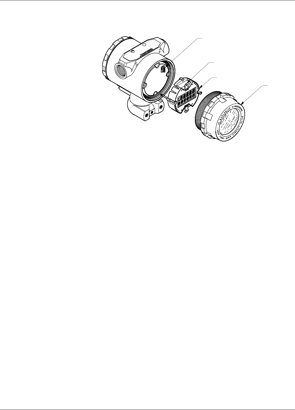
A-3
LCD Meter
FIGURE A-1. Exploded View of the
Transmitter with Optional LCD Meter.
DIAGNOSTIC MESSAGES In addition to the output, the LCD meter displays abbreviated
operation, error, and warning messages for troubleshooting the
transmitter. Messages appear according to their priority, with normal
operating messages appearing last. To determine the cause of a
message, use a Model 275 HART Communicator to further interrogate
the transmitter. A description of each LCD diagnostic message follows.
Error Error messages appear on the LCD meter display to inform you of
serious problems effecting the operation of the transmitter. The meter
displays an error message until the error condition is corrected, and the
analog output is driven to the specified alarm level. No other
transmitter information is displayed during an alarm condition.
FAIL
The transmitter CPU board and the sensor module are incompatible.
FAIL MODULE
The sensor module is disconnected or is malfunctioning. Verify that the
sensor module ribbon cable is connected to the back of the electronics
board. If the ribbon cable is not disconnected, there is a problem within
the sensor module. Possible sources of problems include:
• Pressure or temperature updates are not being received in the
sensor module.
• A non-volatile memory fault that will effect transmitter operation
has been detected in the module by the memory verification
routine.
FAIL ELECT
The transmitter electronics module is malfunctioning. Possible causes
include:
• Internal fault
• A non-volatile memory fault that will effect transmitter operation
has been detected in the module by the memory verification
routine
Neither problem is repairable; the electronics board must be replaced.
Interconnecting Pins
Jumpers (top and bottom)
LCD Meter
Extended Cove
r
2088S-2088A05B

Rosemount Model 2088/2090 Pressure Transmitters
A-4
FAIL CONFIG
A non-volatile memory fault has been detected in the transmitter
memory by the memory verification routine. The memory fault is in a
location that could effect transmitter operation, and is user-accessible.
To correct this problem, use a Model 275 HART Communicator to
interrogate and reconfigure the appropriate portion of the
transmitter memory.
Warnings Warnings appear on the LCD meter display to alert you of user-
repairable problems with the transmitter, or current transmitter
operations. Warnings appear alternately with other transmitter
information until the warning condition is corrected or the transmitter
completes the operation that triggered the warning message.
PRESS LIMIT
The process variable read by the transmitter is outside of sensor
range limits.
CURR FIXED
The transmitter is in multidrop mode. The analog output is not
tracking pressure changes.
CURR SATURD
The pressure read by the module is outside of the specified range, and
the analog output has been driven to saturation levels (see Failure
Mode and Security Jumpers on page 3-12).
LOOP TEST
A loop test is in progress. During a loop test or 4–20 mA trim, the
analog output is set to a fixed value. The meter display alternates
between the current selected in milliamps and “LOOP TEST.”
XMTR INFO
A non-volatile memory fault has been detected in the transmitter
memory by the memory verification routine. The memory fault is in a
location containing transmitter information. To correct this problem,
use a Model 275 HART Communicator to interrogate and reconfigure
the appropriate portion of the transmitter memory. This warning does
not effect the transmitter operation.
Operation Normal operation messages appear on the LCD meter to confirm actions
or inform you of transmitter status. Operation messages are displayed
with other transmitter information, and warrant no action to correct or
alter the transmitter settings.
ZERO PASS
The zero value, set with the local zero adjustment button, has been
accepted by the transmitter, and the output should change to 4 mA.
ZERO FAIL
The zero value, set with the local zero adjustment button, exceeds the
maximum rangedown allowed for a particular range, or the pressure
sensed by the transmitter exceeds the sensor limits.
SPAN PASS
The span value, set with the local span adjustment button, has been
accepted by the transmitter, and the output should change to 20 mA.

A-5
LCD Meter
LOCAL DSBLD
This message appears during reranging with the integral zero and span
buttons and indicates that the transmitter local zero and span
adjustments have been disabled. The adjustments may have been
disabled by the transmitter security jumper on the transmitter circuit
board or through software commands from the Model 275. Refer to
Failure Mode and Security Jumpers on page 3-12 for information on
the position of the security jumper, and for information on the
software lockout.
WRITE PROTCT
The write protect (SECURITY) jumper is set to disable changes to the
transmitter configuration data. Refer to Failure Mode and Security
Jumpers on page 3-12 for more information on the security jumper.

Rosemount Model 2088/2090 Pressure Transmitters
A-6
Appendix
B-1
BModel 275 HART Communicator
OVERVIEW This appendix provides basic communicator information on the Model
275 HART Communicator when used with Models 2088, 2090P, or
2090F Smart Pressure Transmitters.
Included in this appendix are a menu tree, a table of fast key sequences,
and information on using the HART communicator.
For more complete information on the HART Communicator, refer to
the HART Communicator Product Manual 00809-0100-4275.
This brief appendix will familiarize you with the HART Communicator
but is not meant to replace the HART Communicator product manual.
SAFETY MESSAGES Instructions and procedures in this section may require special
precautions to ensure the safety of the personnel performing the
operations. Information that raises potential safety issues is indicated
by a warning symbol ( ). Please refer to the following safety messages
before performing an operation preceded by this symbol.
Warnings
Explosions could result in death or serious injury:
• Do not make connections to the serial port or NiCad recharger jack in an
explosive atmosphere.
• Before connecting a HART-based communicator in an explosive atmosphere,
make sure the instruments in the loop are installed in accordance with
intrinsically safe or non-incendive field wiring practices.
• Both transmitter covers must be fully engaged to meet
explosion-proof requirements.
High voltage that may be present on leads could cause electrical shock:
• Avoid contact with leads and terminals.

Rosemount Model 2088/2090 Pressure Transmitters
B-2
FIGURE B-1. HART Communicator
Menu Tree for the Model 2088 Smart.
9 Pressure
10 Percent Range
11 Analog Output
9Tag
10 Unit
11 RANGE VALUES
12 DEVICE INFO
13 Damp
14 METER
OPTIONS
9 Self test
10 Status
9 Keypad Input
10 Apply Values
9 Loop Test
10 Digital-to-Analog Trim
11 Scaled D/A Trim
12 AO Alarm Type
9 Poll Address
10 Number of Req.
Pream.
11 Burst Mode
9 Digital-to-Analog Trim
10 Scaled D/A Trim
9ZeroTrim
10 Lower Sensor Trim
11 Upper Sensor Trim
12 Sensor Trim Cal
Type
9Date
10 Descriptor
11 Message
12 Write
9 Keypad Input
10 Apply Values
9Pressure
10 Percent Range
9 Keypad Input
10 Apply Values
9 Pressure
10 Percent Range
11 Analog Output
9 FIELD DEVICE INFO
10 SENSOR INFO
11 Self Test
12 DIAPHRAGM
SEALS INFO
9 DEVICE SETUP
10 PV
11 AO
12 LRV
13 URV
9 PROCESS
VARIABLES
10 DIAGNOSTIC
S AND
SERVICE
11 BASIC SETUP
12 DETAILED
SETUP
9 TEST DEVICE
10 Loop Test
11 CALIBRATION
9 RERANGE
10 ANALOG
OUTPUT TRIM
11 SENSOR TRIM
9 Pressure
10 % Range
9 PROCESS
VARIABLES
10 SENSOR
TRIM
11 Unit
Online Menu
9ZeroTrim
10 Lower Sensor Trim
11 Upper Sensor Trim
12 Snsr Trim Cal Type
13 Sensor Trim Points
9 PRESSURE SNSR
9 SENSORS
10 SIGNAL
CONDITION
11 OUTPUT
CONDITION
12 DEVICE
INFORMATION 9Tag
10 Date
11 Descriptor
12 Message
13 Model
14 Write Protect
15 Local Keys
16 REVISION #s
17 Final Assy #
Device ID
Distributor
9 Measurement Type
10 Isolator Material
11 Fill Type
12 Proc. Conn. Type
13 Proc. Conn.
9 Meter Type
10 CUSTOM
METER SETUP
9 Select Dec. Pt. Pos.
10 CM Upper Value
11 CM Lower Value
12 CM Units
9 PROCESS
VARIABLES
10 RANGE VALUES
11 Unit
12 Damp
9PROCESS
VARIABLES
10 ANALOG
OUTPUT
11 HART OUTPUT
12 METER
9 Diaph. Seal Type
10 Diaph. Seal Fill
Fluid
9 Meter Type
10 CUSTOM
METER SETUP
11 Custom Meter
9 Select Dec. Pt. Pos.
10 CM Upper Value
11 CM Lower Value
12 CM Units
9Univ.Rev.
10 Fld. Dev.
Rev.

B-3
Model 275 HART Communicator
TABLE B-1. HART Fast Key
Sequences for the Model 2088S.
Function HART Communicator Fast Key Sequences
Analog Output 3
Analog Output Alarm 1, 4, 3, 2, 4
Burst Mode Control 1, 4, 3, 3, 3
Burst Operation 1, 4, 3, 3, 4
Calibration 1, 2, 3
Damping 1, 3, 5
Date 1, 3, 4, 1
Descriptor 1, 3, 4, 2
Digital To Analog Trim (4–20 mA Output) 1, 2, 3, 2, 1
Disable Local Span/Zero Adjustment 1, 4, 4, 1, 7
FieldDeviceInfo 1,4,4,1
Keypad Input 1, 2, 3, 1, 1
Loop Test 1, 2, 2
Lower Range Value 4, 1
Lower Sensor Trim 1, 2, 3, 3, 2
Message 1, 3, 4, 3
MeterType 1,3,6,1
Number of Requested Preambles 1, 4, 3, 3, 2
Output Trim 1, 2, 3, 2
Percent Range 1, 1, 2
Poll Address Left Arrow, 5, 1
Pressure 2
Range Values 1, 3, 3
Rerange 1, 2, 3, 1
Scaled D/A Trim (4–20 mA Output) 1, 2, 3, 2, 2
Self Test (Transmitter) 1, 2, 1, 1
Sensor Info 1, 4, 4, 2
Sensor Trim (Full Trim) 1, 2, 3, 3
Sensor Trim Points 1, 2, 3, 3, 5
Status 1, 2, 1, 2
Tag 1, 3, 1
Transmitter Security (Write Protect) 1, 3, 4, 4
Units (Process Variable) 1, 3, 2
Upper Range Value 5
UpperSensorTrim 1,2,3,3,3
Zero Trim 1, 2, 3, 3, 1
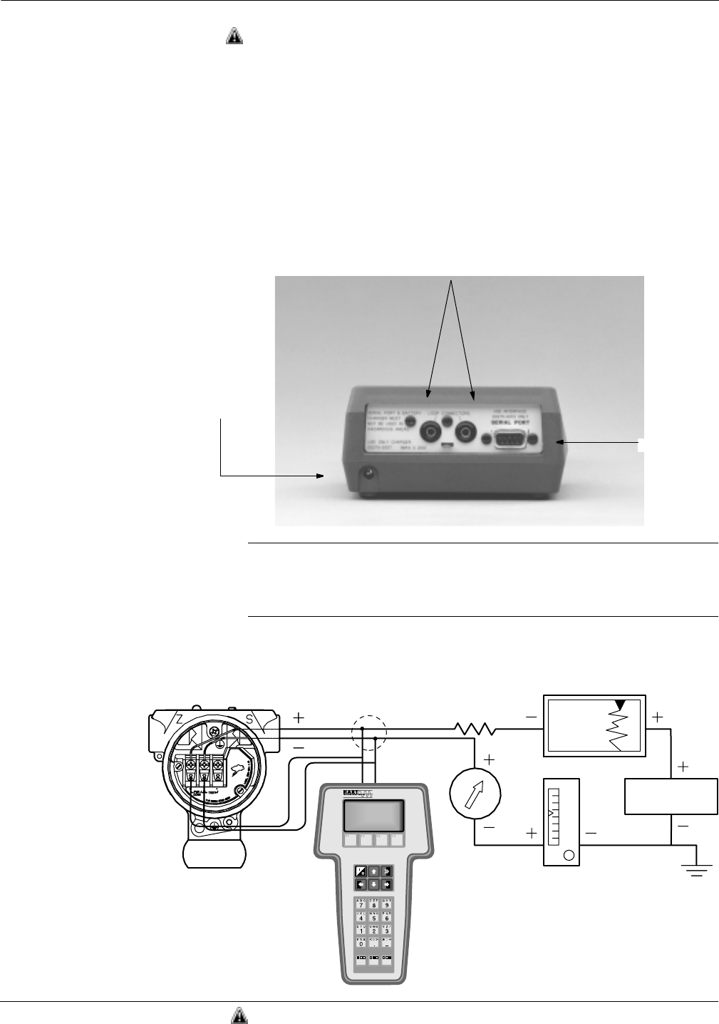
Rosemount Model 2088/2090 Pressure Transmitters
B-4
CONNECTIONS AND
HARDWARE
The HART Communicator Model 275 can interface with a transmitter
from the control room, the instrument site, or any wiring termination point
in the loop through the rear connection panel as shown in Figure B-2. To
communicate, connect the HART Communicator in parallel with the
instrument or load resistor. The connections are non-polarized. Avoid
contact with leads and terminals. Do not make connections to the serial
port or NiCad recharger jack in an explosive atmosphere. Before
connecting the HART Communicator in an explosive atmosphere, make
sure the instruments in the loop are installed in accordance with
intrinsically safe or nonincendive field wiring practices. Both transmitter
covers must be fully engaged to meet explosion proof requirements.
FIGURE B-2. Rear Connection Panel
with Optional NiCad Recharger Pack.
NOTE
The HART Communicator needs a minimum of 250 ohms resistance in
the loop to function properly. The HART Communicator does not
measure loop current directly.
FIGURE B-3. Bench Hook-up
(4–20 mA Transmitters).
Loop Connection Ports
Serial Port
Optional NiCad
Recharger Jack
275-008AB
24 V dc
Supply
Current
Meter
RL≥250 V
2088S-2088C02C
The signal loop may be grounded at any single
point in the loop, or may be left ungrounded.
See “Safety Messages” on page B-1 for complete warning information.
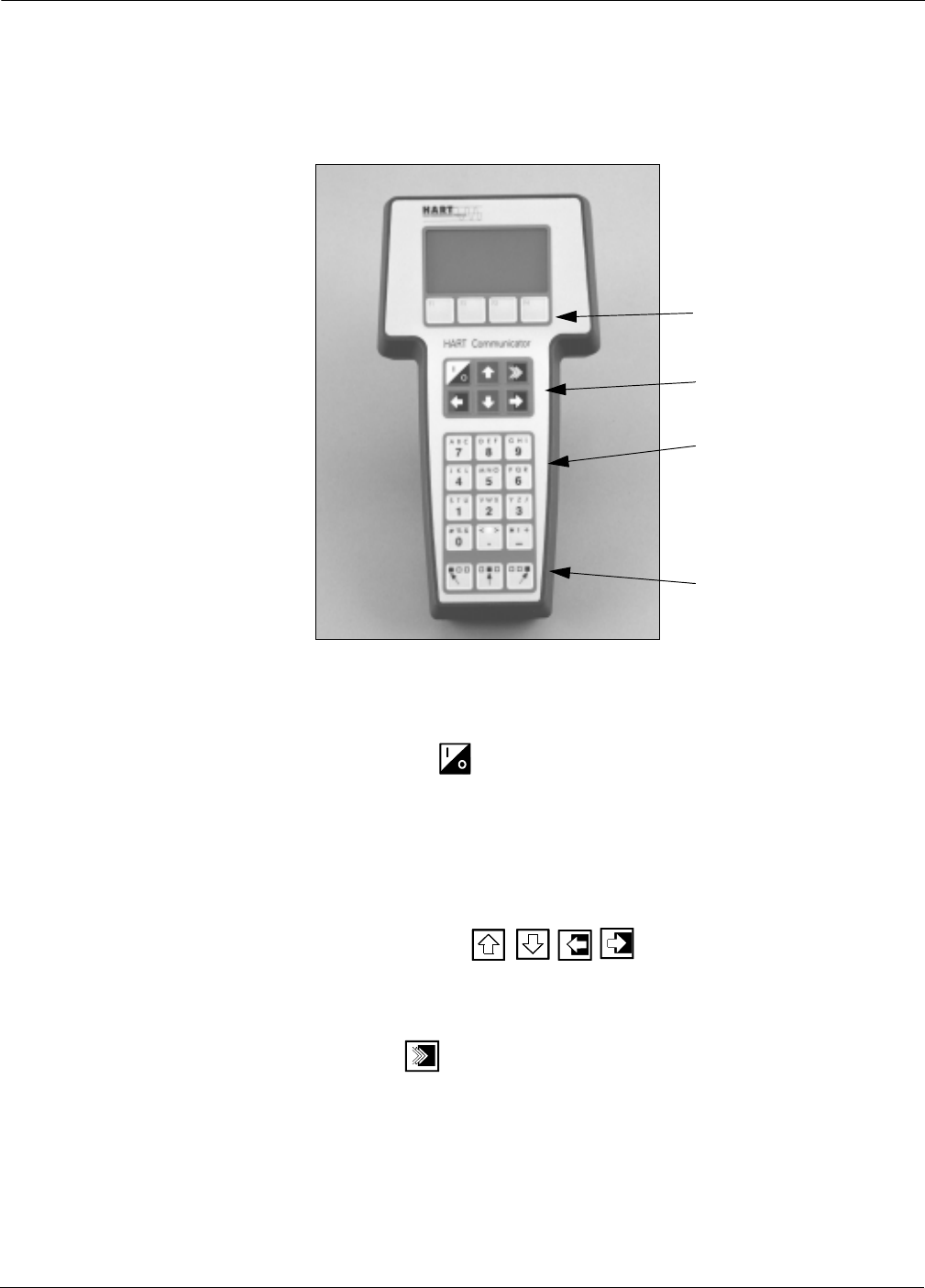
B-5
Model 275 HART Communicator
COMMUNICATOR KEYS The keys of the HART Commuincator include action, function,
alphanumeric, and shift keys
FIGURE B-4. The HART
Communicator.
Action Keys As shown in Figure B-4, the action keys are the six blue, white, and
black keys located above the alphanumeric keys. The function of each
key is described as follows:
ON/OFF Key
Use this key to power the HART Communicator. When the
communicator is turned on, it searches for a transmitter on the
4–20 mA loop. If a device is not found, the communicator displays the
message, “No Device Found. Press OK.”
If a HART-compatible device is found, the communicator displays the
Online Menu with device ID and tag.
Directional Keys
Use these keys to move the cursor up, down, left, or right. The right
arrow key also selects menu options, and the left arrow key returns to
the previous menu.
HOT Key
Use this key to quickly access important, user-selectable options when
connected to a HART-compatible device. Pressing the Hot Key turns
the HART Communicator on and displays the Hot Key Menu.
See Customizing the Hot Key Menu in the HART Communicator
manual for more information.
Function Keys
Action Keys
Alphanumeric Keys
Shift Keys
275-011AB
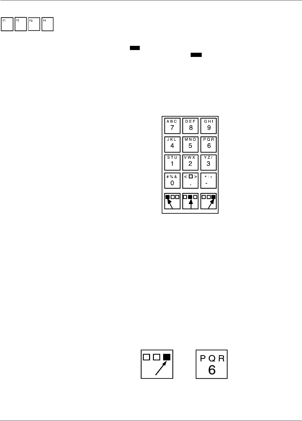
Rosemount Model 2088/2090 Pressure Transmitters
B-6
Function Keys Use the four software-defined function keys, located below the LCD, to
perform software functions. On any given menu, the label appearing
above a function key indicates the function of that key for the current
menu. As you move among menus, different function key labels appear
over the four keys. For example, in menus providing access to on-line
help, the label may appear above the F1 key. In menus providing
access to the Online Menu, the label may appear above the F3 key.
Simply press the key to activate the function. See your HART
Communicator manual for details on specific function key definitions.
Alphanumeric and Shift Keys The alphanumeric keys, see Figure B-5 perform two functions: the fast
selection of menu options and data entry.
FIGURE B-5. HART Communicator
Alphanumeric and Shift Keys.
Data Entry Some menus require data entry. Use the alphanumeric and shift keys to
enter all alphanumeric information into the HART Communicator. If
you press an alphanumeric key alone from within an edit menu, the
bold character in the center of the key appears. These large characters
include the numbers zero through nine, the decimal point (.), and the
dash symbol (—).
To enter an alphabetic character, first press the shift key that
corresponds to the position of the letter you want on the alphanumeric
key. Then press the alphanumeric key. For example, to enter the letter
R, first press the right shift key, then the “6” key, see Figure B-6. Do not
press these keys simultaneously, but one after the other.
FIGURE B-6. Data Entry Key Sequence.
HELP
HOME
2088S-275-0383A
2088S-275-0352A, 0343A

B-7
Model 275 HART Communicator
Fast Key Sequences HART Fast Key Sequences provide quick on-line access to transmitter
variables and functions. Instead of stepping your way through the menu
structure using the action keys, you can press a HART fast key sequence
to move from the Online Menu to the desired variable or function.
On-screen instructions guide you through the rest of the screens.
Conventions The fast key sequences for the Model 275 use the following conventions
for their identification:
1 through 9–Refer to the keys located directly below the dedicated
keypad.
Left Arrow–Refers to the left arrow directional key.
Example HART fast key sequences are made up of the series of numbers
corresponding to the individual options in each step of the menu
structure. For example, from the Online Menu you can change the Date.
Following the menu structure, press 1 to reach Device Setup, press 3
for Basic Setup, press 4 for Device Info, press 5 for Date. The
corresponding HART fast key sequence is 1,3,4,5.
HART fast keys are operational only from the Online Menu. If you use
them consistently, you will need to return to the Online Menu by
pressing (F3) when it is available. If you do not start at the Online
Menu, the HART fast key sequences will not function properly.
Use Table B-1, an alphabetical listing of every on-line function, to find
the corresponding HART fast key sequences. These codes are applicable
only to Model 2088S transmitters and the HART Communicator.
MENUS AND FUNCTIONS The HART Communicator is a menu driven system. Each screen
provides a menu of options that can be selected as outlined above, or
provides direction for input of data, warnings, messages, or other
instructions.
Main Menu When the HART Communicator is turned on, one of two menus will
appear. If the HART Communicator is connected to an operating loop,
the communicator will find the device and display the Online Menu (see
below). If it is not connected to a loop, the communicator will indicate
that no device was found. When you press OK (F4), it will display the
Main menu.
The Main Menu provides the following options:
•Offline–saves or retrieves transmitter configuration information.
•Online–connects the communicator to a compatible device.
NOTE
Online communication with the transmitter automatically loads the
current transmitter data to the HART Communicator. Changes in
online data are made active by pressing SEND (F2). The transfer
function is used only for off-line data retrieval and sending.
•Frequency Device–The Frequency Device option displays the
frequency output and corresponding pressure output of
current-to-pressure transmitters.
•Utility–The Utility option provides access to the contrast control
for the HART Communicator LCD screen and to the autopoll
setting used in multidrop applications.
HOME

Rosemount Model 2088/2090 Pressure Transmitters
B-8
Once selecting a main menu option, the HART Communicator provides
the information you need to complete the operation. If further details
are required, consult the HART Communicator manual.
Online Menu The Online Menu can be selected from the main menu as outlined
above, or it may appear automatically if the HART Communicator is
connected to an active loop and can detect an operating transmitter.
NOTE
The main menu can be accessed from the Online Menu. Press the left
arrow action key to deactivate the on-line communication with the
transmitter and to activate the main menu options.
When configuration variables are reset in the on-line mode, the new
settings are not activated until the data are sent to the transmitter.
Press SEND (F2) when it is activated to update the process variables of
the transmitter.
On-line mode is used for direct evaluation of a particular meter,
reconfiguration, changing parameters, maintenance, and other
functions.

B-9
Model 275 HART Communicator
Diagnostic Messages The following pages contain a list of messages used by the HART
Communicator (HC) and their corresponding descriptions.
Variable parameters within the text of a message are indicated with
<variable parameter>.
Reference to the name of another message is identified by
[another message].
Message Description
Add item for ALL device types or only for this
ONE device type.
Asks the user whether the hot key item being added should be added for all device types or only
for the type of device that is connected.
Command Not Implemented The connected device does not support this function.
Communication Error Either a device sends back a response indicating that the message it received was unintelligible,
or the HC cannot understand the response from the device.
Configuration memory not compatible with
connected device
The configuration stored in memory is incompatible with the device to which a transfer has
been requested.
Device Busy The connected device is busy performing another task.
Device Disconnected Device fails to respond to a command.
Device write protected Device is in write-protect mode. Data can not be written.
Device write protected. Do you still want to
shut off? Device is in write-protect mode. Press YES to turn the HC off and lose the unsent data.
Display value of variable on hotkey menu? Asks whether the value of the variable should be displayed adjacent to its label on the hotkey
menu if the item being added to the hotkey menu is a variable.
Download data from configuration memory
to device PromptsusertopressSENDsoftkeytoinitiateamemorytodevicetransfer.
Exceed field width Indicates that the field width for the current arithmetic variable exceeds the device- specified
description edit format.
Exceed precision Indicates that the precision for the current arithmetic variable exceeds the device- specified
description edit format.
Ignore next 50 occurrences of status? Asked after displaying device status. Softkey answer determines whether next 50 occurrences of
device status will be ignored or displayed.
Illegal character An invalid character for the variable type was entered.
Illegal date The day portion of the date is invalid.
Illegal month The month portion of the date is invalid.
Illegal year The year portion of the date is invalid.
Incomplete exponent The exponent of a scientific notation floating point variable is incomplete.
Incomplete field The value entered is not complete for the variable type.
Looking for a device Polling for multidropped devices at addresses 1–15.
Mark as read only variable on hotkey menu? Asks whether the user should be allowed to edit the variable from the hotkey menu if the item
being added to the hotkey menu is a variable.
No device configuration in
configuration memory There is no configuration saved in memory available to reconfigure off-line or transfer to a device.
No Device Found Poll of address zero fails to find a device, or poll of all addresses fails to find a device if auto-poll
is enabled.
No hotkey menu available for this device. There is no menu named “hotkey” defined in the device description for this device.
No offline devices available. There are no device descriptions available to be used to configure a device offline.
No simulation devices available. There are no device descriptions available to simulate a device.
No UPLOAD_VARIABLES in ddl for this
device
There is no menu named “upload_variables” defined in the device description for this device. This
menu is required for offline configuration.
No Valid Items The selected menu or edit display contains no valid items.
OFF KEY DISABLED Appears when the user attempts to turn the HC off before sending modified data or before
completing a method.
Online device disconnected with unsent data.
RETRY or OK to lose data.
There is unsent data for a previously connected device. Press RETRY to send data, or press OK
to disconnect and lose unsent data.

Rosemount Model 2088/2090 Pressure Transmitters
B-10
Message Description
Out of memory for hotkey configuration.
Delete unnecessary items.
There is no more memory available to store additional hotkey items. Unnecessary items should
be deleted to make space available.
Overwrite existing configuration memory Requests permission to overwrite existing configuration either by a device-to-memory transfer or
by an offline configuration. User answers using the softkeys.
Press OK... Press the OK softkey. This message usually appears after an error message from the application
or as a result of HART communications.
Restore device value? The edited value that was sent to a device was not properly implemented. Restoring the device
value returns the variable to its original value.
Save data from device to
configuration memory Prompts user to press SAVE softkey to initiate a device-to-memory transfer.
Saving data to configuration memory. Data is being transferred from a device to configuration memory.
Sending data to device. Data is being transferred from configuration memory to a device.
There are write only variables which have not
been edited. Please edit them.
There are write-only variables which have not been set by the user. These variables should be set
or invalid values may be sent to the device.
There is unsent data. Send it before
shutting off?
Press YES to send unsent data and turn the HC off. Press NO to turn the HC off and lose the
unsent data.
Too few data bytes received Command returns fewer data bytes than expected as determined by the device description.
Transmitter Fault Device returns a command response indicating a fault with the connected device; the transmitter
is in alarm.
Units for <variable label> has changed. Unit
must be sent before editing, or invalid data
will be sent.
The engineering units for this variable have been edited. Send engineering units to the device
before editing this variable.
Unsent data to online device. SEND or
LOSE data There is unsent data for a previously connected device which must be sent or thrown away before
connecting to another device.
Use up/down arrows to change contrast. Press
DONE when done. Gives direction to change the contrast of the HC display.
Value out of range The user-entered value is either not within the range for the given type and size of variable or not
within the min/max specified by the device.
<message> occurred reading/writing
<variable label>
Either a read/write command indicates too few data bytes received, transmitter fault, invalid
response code, invalid response command, invalid reply data field, or failed pre- or post-read
method; or a response code of any class other than SUCCESS is returned reading a
particular variable.
<variable label> has an unknown value. Unit
must be sent before editing, or invalid data
will be sent.
A variable related to this variable has been edited. Send related variable to the device before
editing this variable.

Appendix
C-1
CModel 2088 Low Power Option
OVERVIEW The information in this appendix is specific to the Model 2088 Low
Power Pressure Transmitter. This transmitter outputs a 1–5 V dc
signal proportional to input pressure. The Low Power Option is
designated with Output Code M.
SAFETY MESSAGES Instructions and procedures in this section may require special
precautions to ensure the safety of the personnel performing the
operations. Information that raises potential safety issues is indicated
by a warning symbol ( ). Power and signal connections are made by
removing the housing cover on the field terminal side of the transmitter
housing.
COMMISSIONING THE
TRANSMITTER
The Model 2088 Analog Pressure Transmitter can be continuously
adjusted to spans between maximum span and 1/10 of maximum span(1).
Transmitter linearity information is programmed into the
microprocessor at the factory; linearity adjustment is not necessary in
the field.
INSTALLATION To install the low power analog transmitter, follow the procedures in
Section 3 Installation. The housing of the analog transmitter is slightly
different from that of the smart transmitter. Dimensional drawings of
the analog transmitter are provided in Figure C-1.
Explosions could result in death or serious injury:
• Do not remove the transmitter cover in explosive atmospheres when the circuit
is alive.
• Verify that the operating atmosphere of the transmitter is consistent with the
appropriate hazardous locations certifications.
• Both transmitter covers must be fully engaged to meet explosionproof
requirements.
Failure to follow these installation guidelines could result in death or
serious injury:
• Make sure only qualified personnel perform the installation.
(1) For Model 2088 Range 0, minimum span is 1 psi.
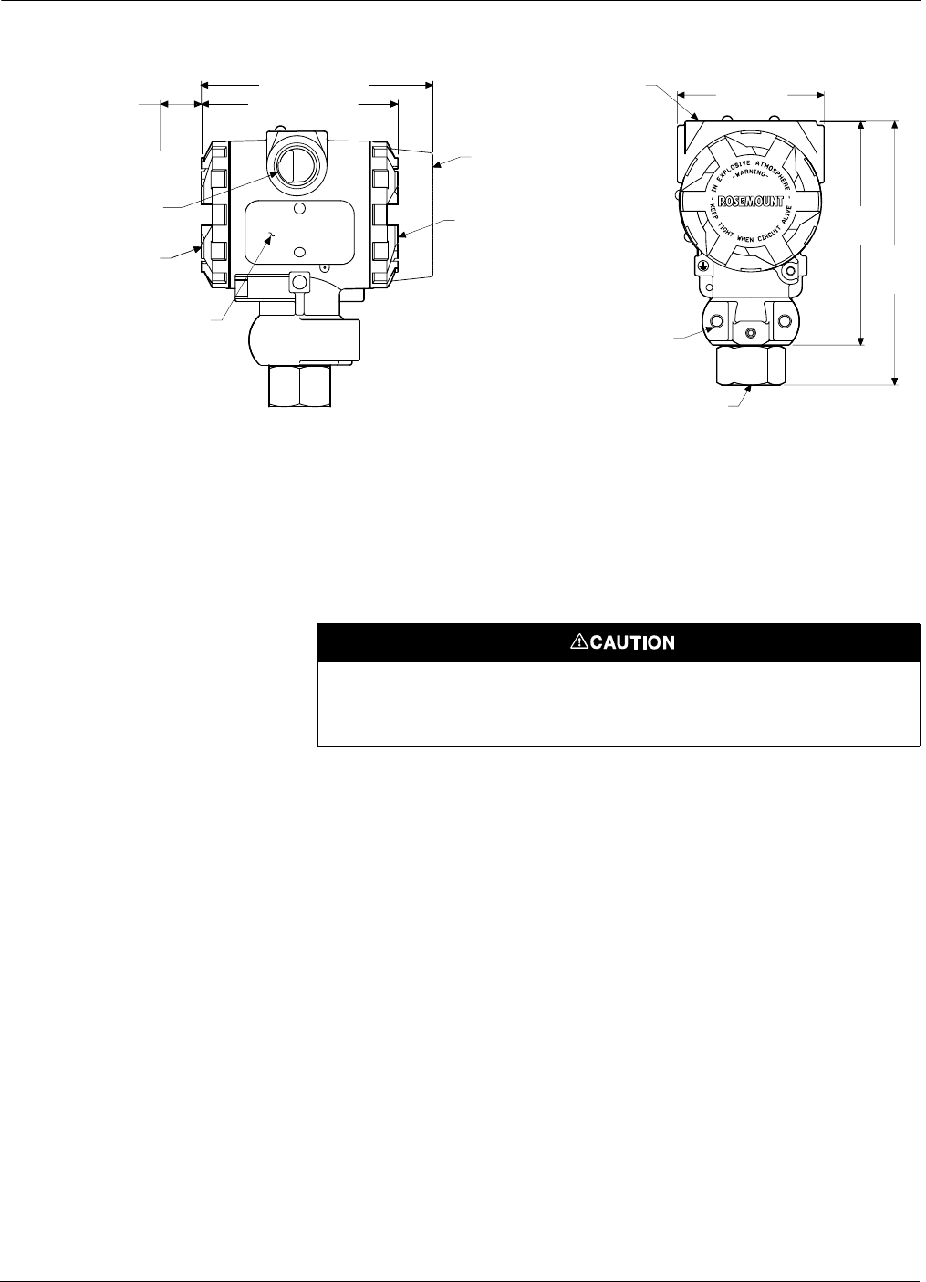
Rosemount Model 2088/2090 Pressure Transmitters
C-2
Figure C-1. Low Power Analog Transmitter Dimensional Drawings.
WIRING Power and signal connections are made by removing the housing cover
on the field terminal side of the transmitter housing.
Connect the positive lead from the power supply to the (+) PWR
terminal and the negative lead to the (–) terminal. Connect the positive
lead of the readout device or A/D converter to the “Vout” terminal and
the negative lead to the “–” terminal. Shielded pair wiring is
recommended and all common leads should be connected to the same
ground, see Figure C-2.
0.75 (19)
Clearance for
Cover Removal
231/2–14 NPT*
Conduit
Connection
Terminal
Connections Side
Certifications Tag
Transmitter
Circuitry Side
Optional Meter
4.36 (119)
3.80 (97) Max.
Nameplate
231/4-20 UNC - 2B
Mounting Holes
1/2- 14 NPT Female†
Process Connection
2.80 (71)
4.29
(109)
5.10
(130)
Typical
*M2031.5 Female (CM20), PG 13.5, and G 1/2Female (PF 1/2), also available as options.
†DIN 16288 G 1/2Male, RC 1/2Female (PT 1/2(+) and M20 31.5 Male [CM20]), also available as options.
Dimensions are in in. (mm).
2088-2088A07A, B07A
Do not connect the positive lead from the power supply to the “+” V out termination on
the terminal side of the electronic housing. This may result in an erroneous output and
may damage the output board, the power supply, or both.
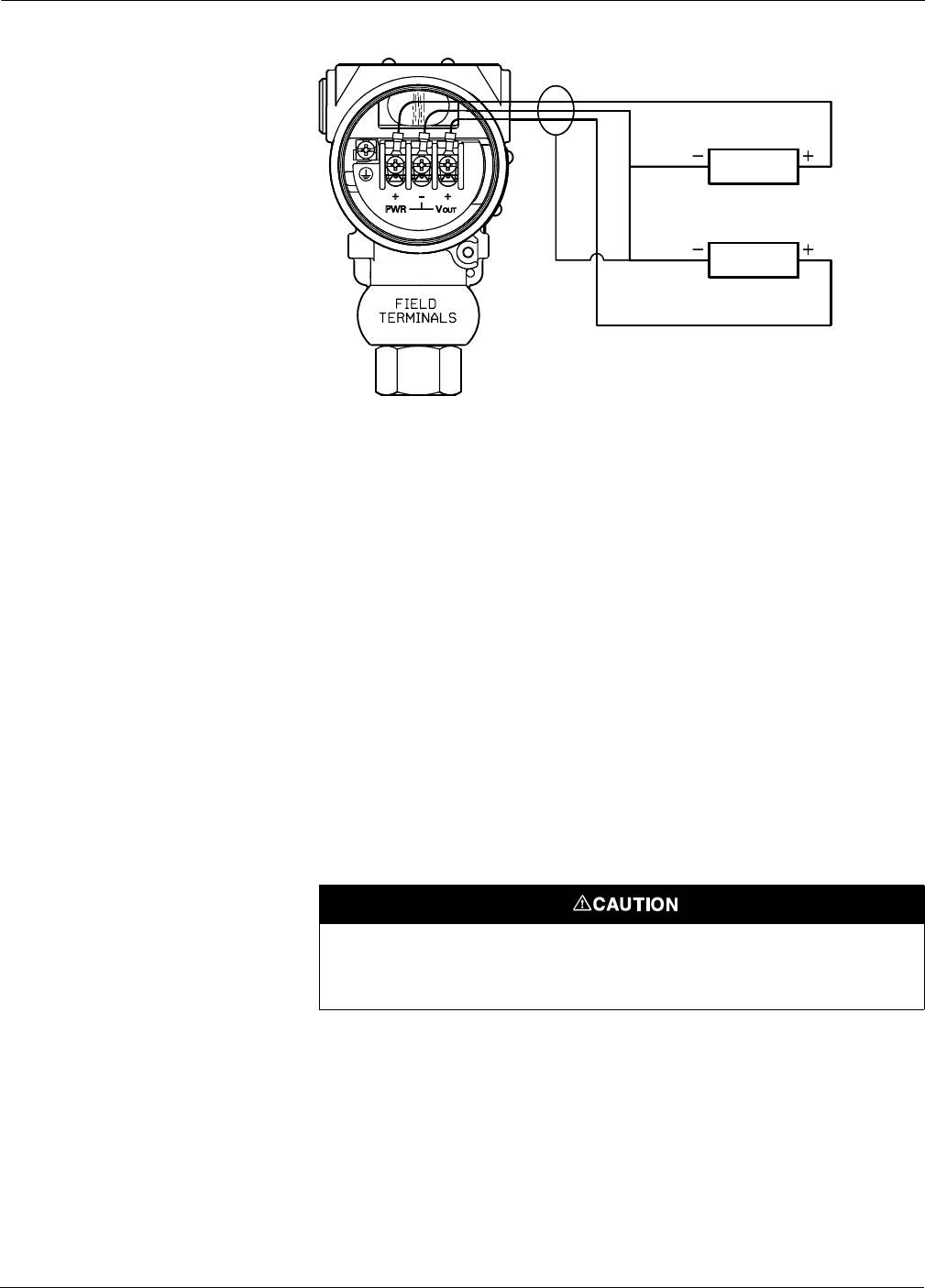
C-3
Model 2088 Low Power Option
Figure C-2. Field Wiring for Model 2088—Low Power Option Code M.
CALIBRATION The procedure for calibrating the Model 2088 is different from that of
other pressure transmitters and takes some time to become accustomed
to. However, this method of calibration is considerably faster than other
calibration methods. In addition, there is no interaction between the
zero and span adjustments.
An important feature of this design is that the potentiometer is an
active part of the circuit only during calibration. The potentiometer is
removed from the active circuit when the switch is placed in the “RUN”
position. The design that allows deactivation of the potentiometer
eliminates the temperature drift and stability shifts often associated
with common potentiometers.
Selector Switch The selector switch is labeled “Z” (Zero), “RUN,” and “S” (Span). The
switch is set to the “RUN” position at the factory and should remain
there under normal operation. The microprocessor will not accept a new
value from the switch until you adjust the potentiometer. Therefore, in
case you accidentally change the switch position, you can return it to
the “RUN” position without affecting calibration if you do not turn the
potentiometer.
Power Supply
AtoD
Converter
Shield
2088-B02F
The selector switch must be returned to the “RUN” position after setting the proper
calibration. Failure to return the switch to the “RUN” position will result in erroneous
transmitter output during an overpressure condition.
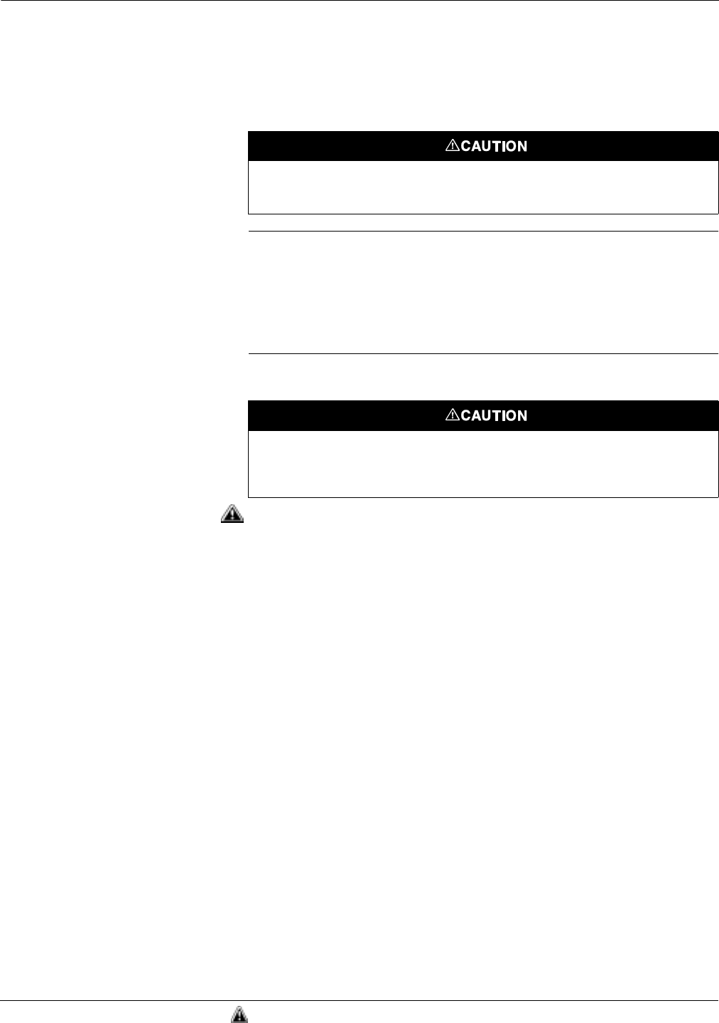
Rosemount Model 2088/2090 Pressure Transmitters
C-4
Potentiometer Adjustment The potentiometer is marked “DN” (Down), “FINE,” and “UP.” The
coarse adjustment regions are at each end, and a fine adjustment
region is in the center. The output of the transmitter increases or
decreases automatically when the potentiometer is placed in the coarse
adjustment regions. The longer the potentiometer is held in the coarse
adjustment region, the faster the rate of change in output.
NOTE
When the transmitter output is saturated, the potentiometer may
appear to have no effect on the transmitter calibration because the
microprocessor is adjusting the calibration, but the current-limiting
circuitry is maintaining the output at the saturation levels. Place the
potentiometer in the coarse-adjust region and wait several seconds for
the output to change.
Setting the Zero
Setting the zero point of the transmitter involves applying pressure and
adjusting the potentiometer accordingly. To set the zero point of the
transmitter, use the following procedure.
1. If the transmitter does not have a readout device, attach a
voltmeter. Terminals for monitoring or calibrating are located in
two separate locations. The first is in the terminal compartment.
Connect the positive lead to the “–” terminal. When calibrating
directly from the output board, connect the positive lead of the
voltmeter to the terminal labeled “+ TEST” and the negative lead
to the “– TEST” terminal, see Figure C-3.
2. Ensure that the selector switch is in the “RUN” position. Apply
the pressure to which the zero point will be calibrated.
3. Set the selector switch to “Z.”
4. Using the potentiometer, adjust the transmitter output until the
readout device reads the desired value.
5. Return the selector switch to the “RUN” position.
The potentiometer is a 3/4-turn device and has a mechanical stop to prevent full rotation.
Do not exert large twisting forces against the mechanical stop or damage will result.
Do not contact meter leads from either test terminal on the output board to case ground.
Contact can result in the maximum current from the power supply flowing through the
test meter and may blow the test meter fuse, or damage the test meter or transmitter.
See “Safety Messages” on page C-1 for complete warning information.
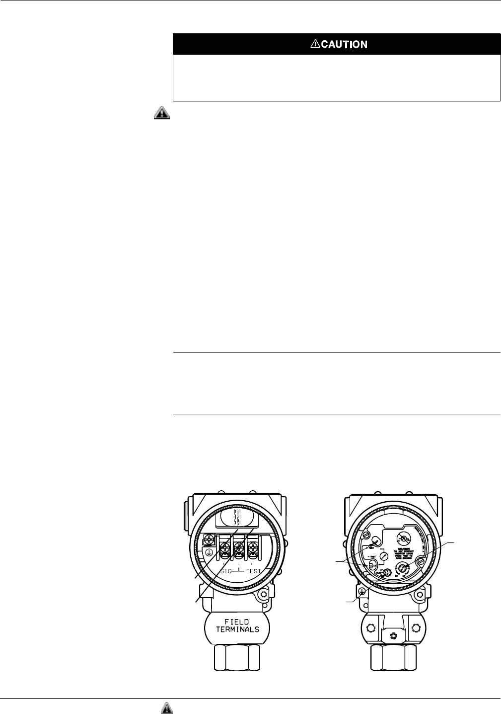
C-5
Model 2088 Low Power Option
Setting the Span
Setting the span of the transmitter involves applying pressure and
adjusting the potentiometer accordingly. To set the span of the
transmitter, use the following procedure:
1. If the transmitter does not have a readout device, attach a
voltmeter. Terminals for monitoring or calibrating are located in
two separate locations. The first is in the terminal compartment.
Connect the positive lead of the voltmeter to the “V out” terminal
and the negative lead to the “–” terminal. When calibrating
directly from the output board, connect the positive lead of the
voltmeter to the terminal labeled “+ TEST” and the negative lead
to the “– TEST” terminal, see Figure C-3.
2. Ensure that the selector switch is in the “RUN” position. Expose
the transmitter to full scale pressure.
3. Set the selector switch to “S.”
4. Using the potentiometer, adjust the transmitter output until the
readout device reads the desired value.
5. Return the switch to “RUN.”
NOTE
The microprocessor limits the amount of rangedown allowed for span. If
the rangedown conditions are violated, transmitter calibration is
unaffected as long as the switch is placed in the “S” position and the
potentiometer is adjusted.
Figure C-3. Transmitter Terminal and
Electronics Compartments.
Do not contact meter leads from either test terminal on the output board to case ground.
Contact can result in the maximum current from the power supply flowing through the
test meter and may blow the test meter fuse, or damage the test meter or transmitter.
Test
Terminals
Selector
Switch
Potentio-
meter
Negative
Terminal
Test
Terminal
2088-B02H, A02A
TERMINAL
COMPARTMENT ELECTRONICS
DEPARTMENT
See “Safety Messages” on page C-1 for complete warning information.

Rosemount Model 2088/2090 Pressure Transmitters
C-6
TRANSIENT PROTECTION
OPTION
The transient protection option helps to protect the transmitter
electronics from potentially damaging transient voltages.
The transient protection board is installed at the factory or may be
installed in the field directly over the transmitter terminal block using
the existing terminal screws. To install the transient protection board
in the field, perform the appropriate procedure.
NOTE
In order to maintain hazardous locations approvals, transient
protection boards must be installed at a Rosemount Service Center. All
approvals are void if customer installs transient protection boards.
INSTALLATION
PROCEDURES
Transient Protection
Board Installation
1. Remove the four screws on the transmitter terminal block. Save
the screws and the cable clamps.
2. Disconnect the power signal wires from the terminals.
3. Insert the transient protection board directly over the terminal
block, taking care to feed the power signal wires through the
access cutout at the top of the board, see Figure C-4.
4. Replace and tighten the terminal screws. Take care to adequately
tighten the ground (EGND) screw using the #8 lock washer
provided.
5. Reconnect the signal wires, see Figure C-4.
Transient Protection
Board Wiring
The Model 2088 terminal screws remain visible with a transient
protection board installed. Do not use the existing Model 2088 terminal
screws to power the transmitter; doing so will render the transient
protection board useless.
To power the low power transmitter with the transient protection board
installed, connect the positive power lead to the terminal marked “+” on
the transient protection board, and the negative power lead to the
center terminal screw on the transmitter terminal block. Connect the
positive lead from the readout device or A/D converter to the terminal
marked “S” on the transient protection board, and the negative lead to
the center terminal screw on the transmitter terminal block,
see Figure C-4.
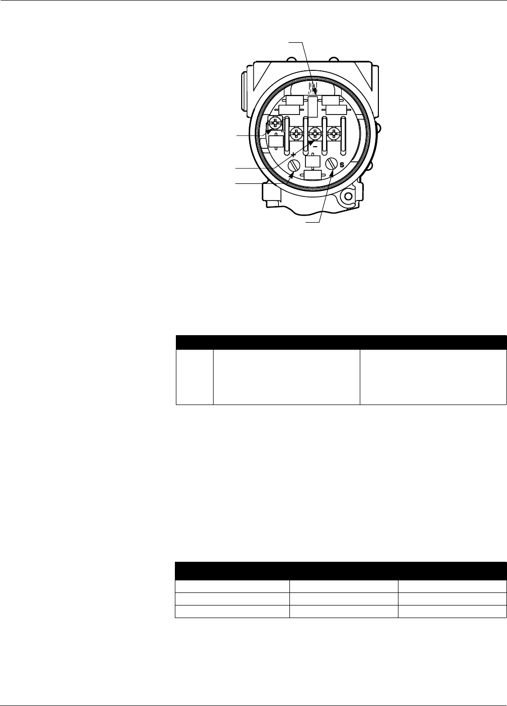
C-7
Model 2088 Low Power Option
Figure C-4. 1–5 V dc Transient
Protection Wiring.
SPECIFICATIONS The specifications listed below are unique to the Option code M, Low
Power Analog Transmitter. All other specifications are identical to
those listed in Section 5 Specifications and Reference Data.
Functional Specifications
Output
1–5 V dc, low power. (Outputs are directly proportional to the
input pressure.)
Turn-on Time
0.3 seconds maximum at reference operating conditions.
Failure Mode
If self diagnostics detect a sensor or microprocessor failure, the
analog signal is driven low to alert the user (I ≤ 1V).
Performance
Specifications Ambient Temperature Effect
Total effect includes zero and span effects.
2088-1000B04B
Ground Terminal
Negative Terminal
Positive Terminal
Signal Wire Access Cutout
Signal Terminal
TABLE C-1. Ranges for Model 2088.
Range Minimum Span URL/Max. Span/Sensor Limit
0 1 psi (69 mbar) 8 psi (552 mbar)
1 3 psi (207 mbar) 30 psi (2,08 bar)
2 15 psi (1 bar) 150 psi (10,34 bar)
3 80 psi (5,5 bar) 800 psi (55,15 bar)
4 400 psi (27,6 bar) 4000 psi (275,79 bar)
Temperature Ranges 1–4 Range 0
–40 to 0 °F(–40 to –18 °C) ±(0.7% URL + 0.8% Span) ±(1.3% URL + 0.5% Span)
0 to 140 °F (–18 to 60°C) ±(0.5% URL + 0.5% Span) ±(1.0% URL + 0.5% Span)
140 to 185 °F (60 to 85°C) ±(0.7% URL + 0.8% Span) ±(1.3% URL + 0.5% Span)

Rosemount Model 2088/2090 Pressure Transmitters
C-8

Appendix
D-1
DApproval Drawings
OVERVIEW This section contains transmitter hazardous location installation
drawings. Follow the installation guidelines presented by these
drawings in order to maintain certified ratings for installed
transmitters.
This section contains the following drawings:
Rosemount Drawing 02088-1018, Rev. AB, 7 sheets:
Index of Intrinsic Safety Factory Mutual for Models 2088 and 2090.
Rosemount Drawing 02088-1024, Rev. AA, 3 sheets:
CSA Intrinsic Safety Approvals for Models 2088 and 2090.
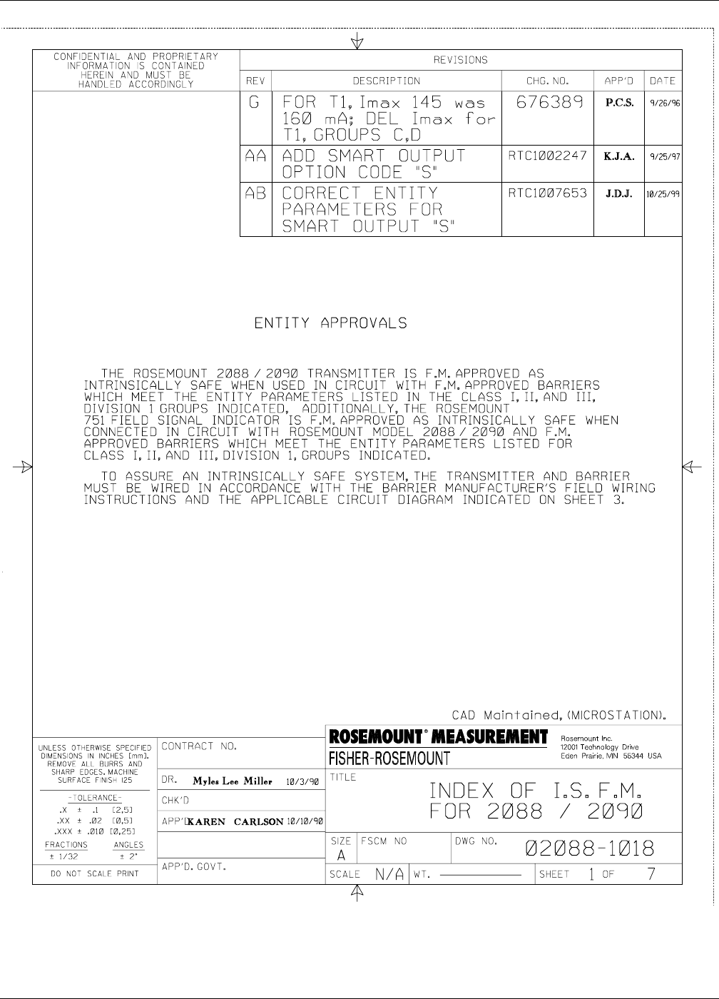
Rosemount Model 2088/2090 Pressure Transmitters
D-2
FIGURE D-1. Index of Intrinsic Safety Factory Mutual for Models 2088 and 2090 Installation Drawing 02088-1018, Rev. AB.
2088-1018AB1
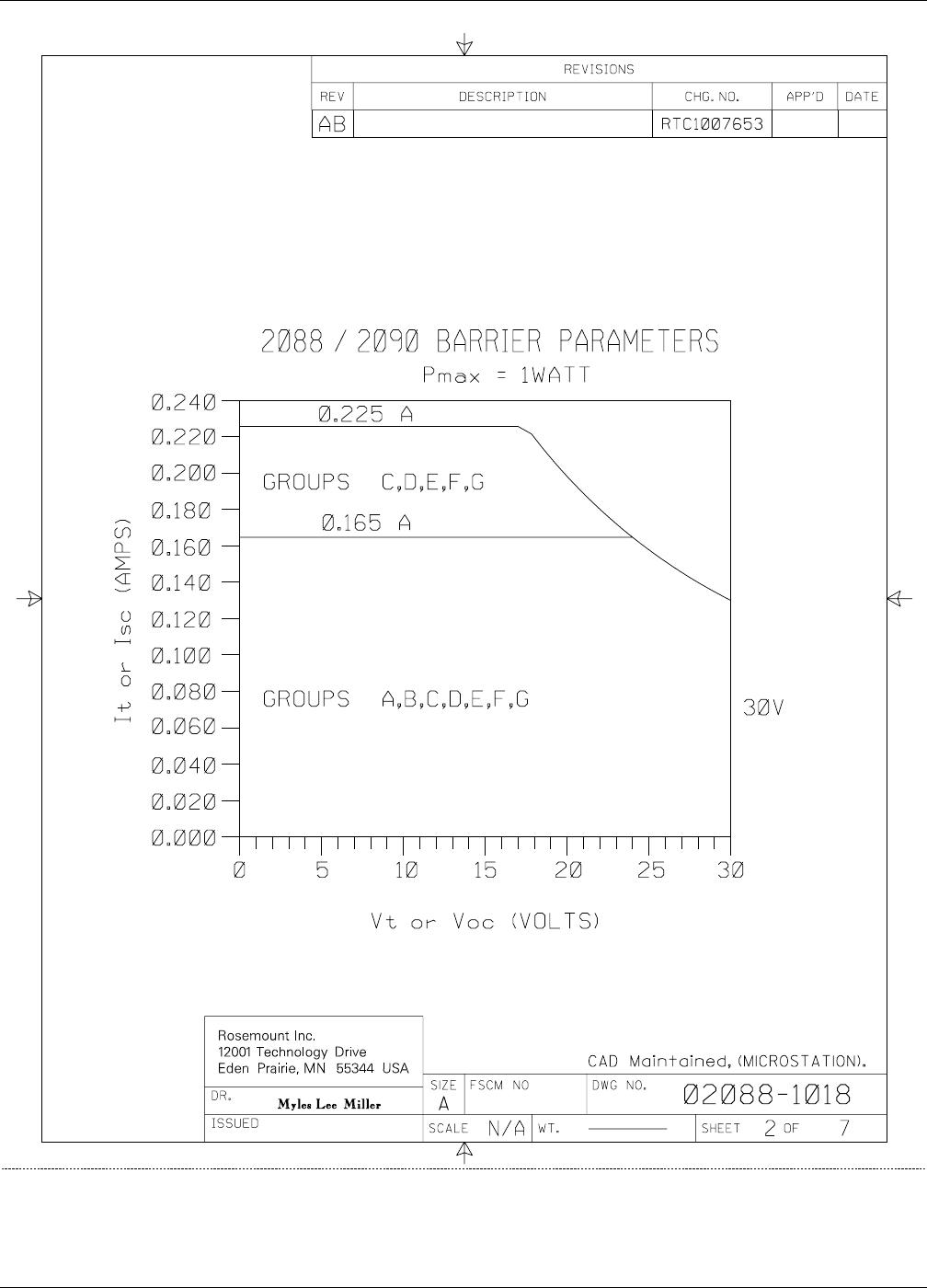
D-3
Approval Drawings
2088-1018AB2
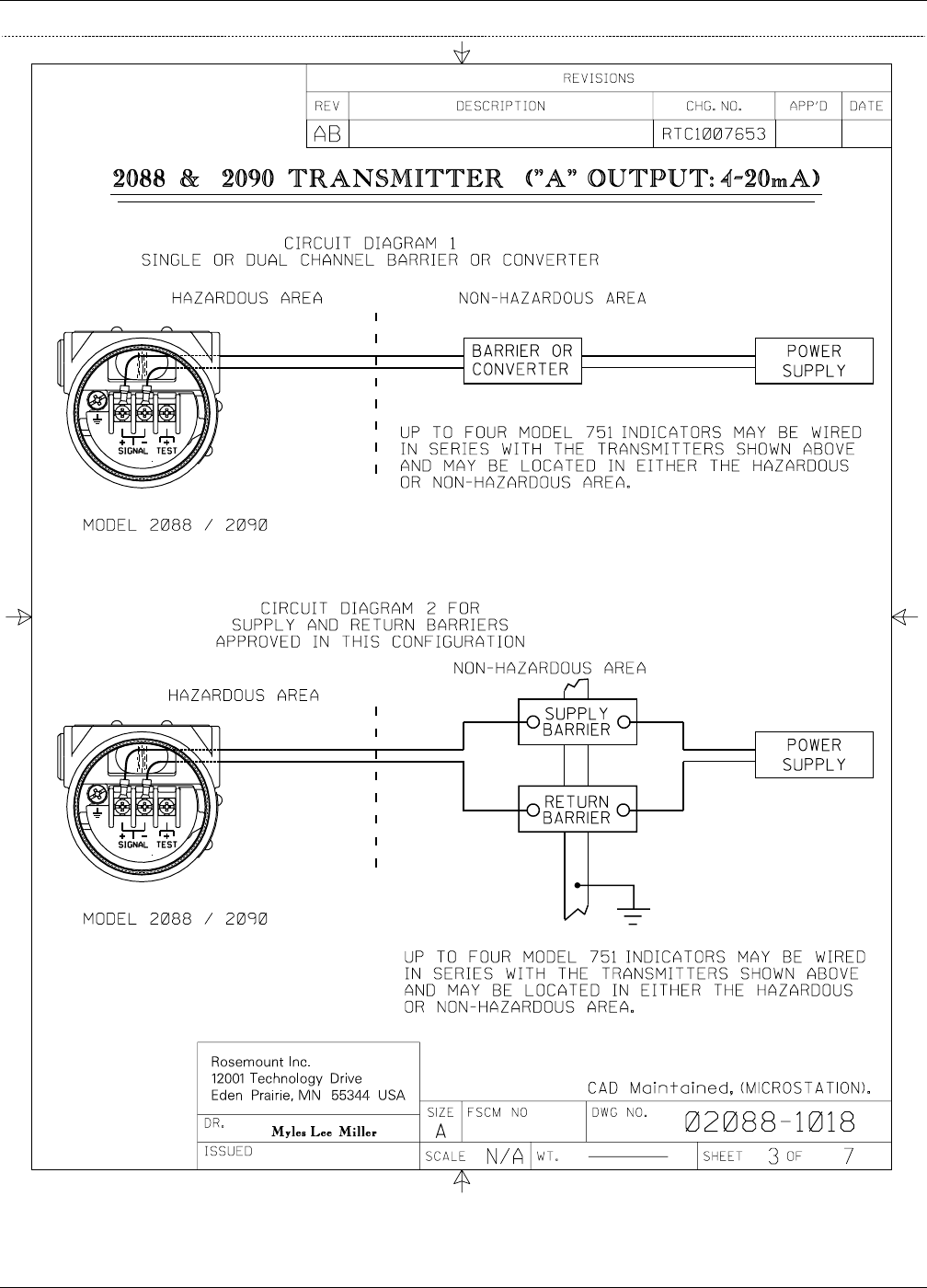
Rosemount Model 2088/2090 Pressure Transmitters
D-4
2088-1018AB4
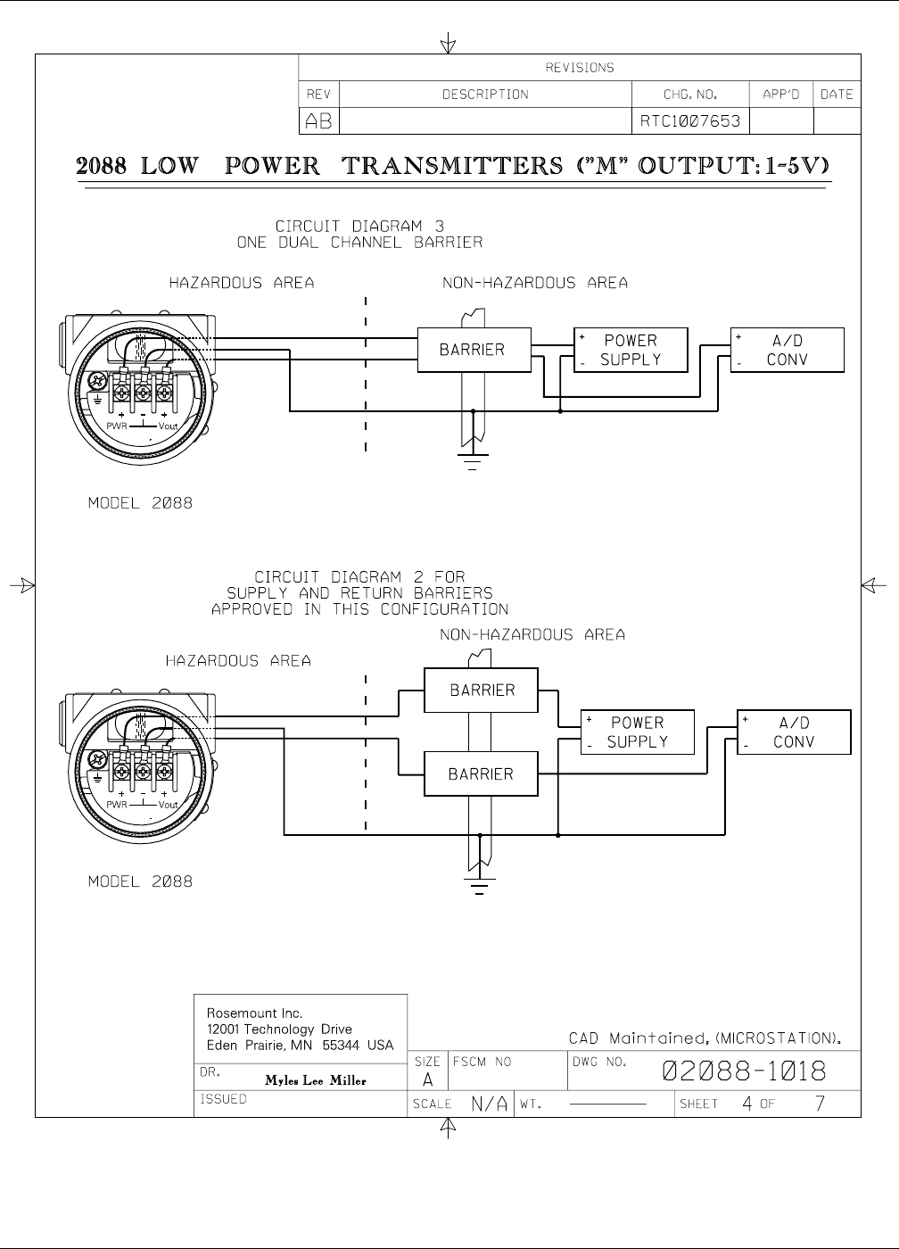
D-5
Approval Drawings
2088-1018AB5
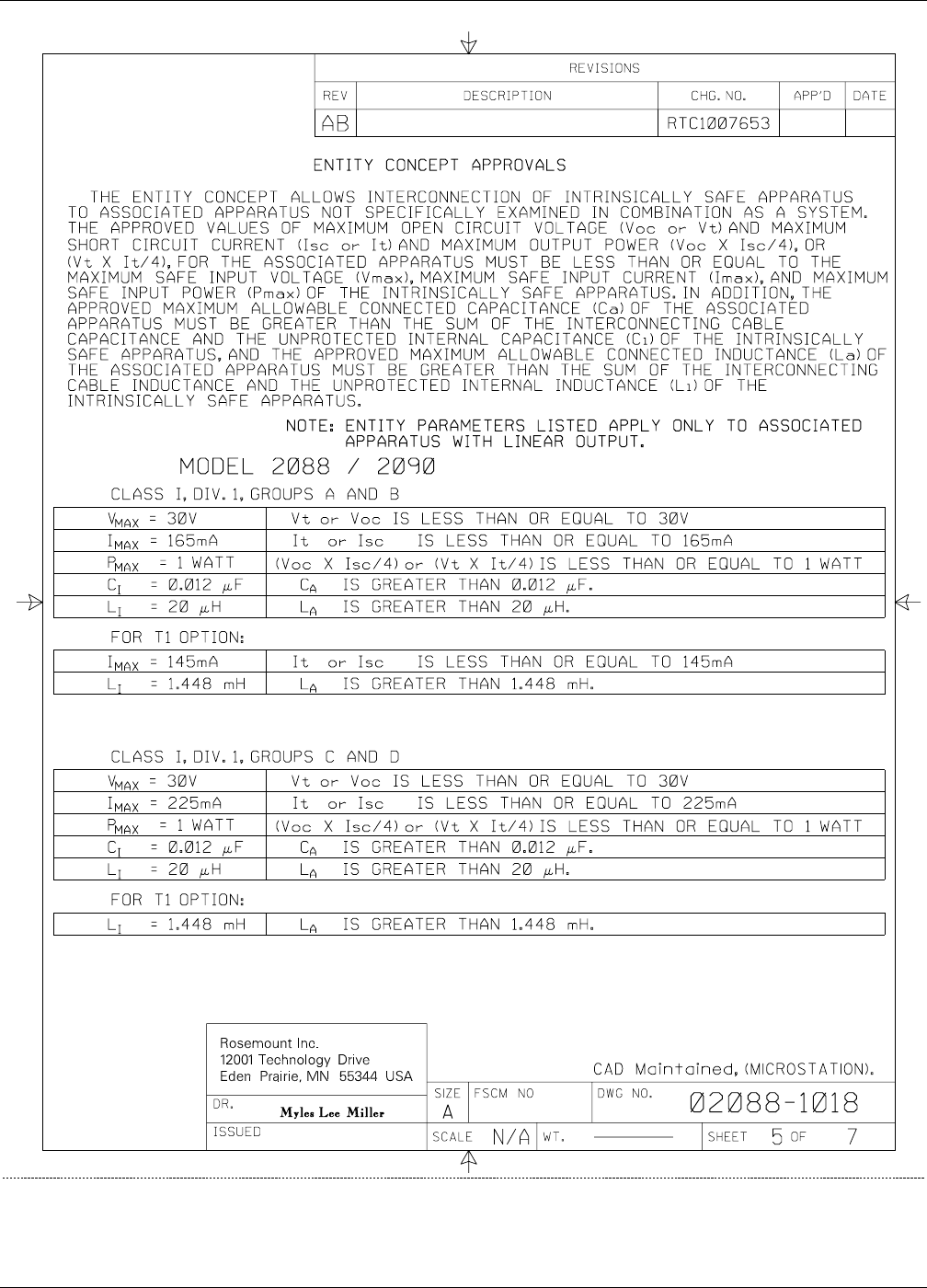
Rosemount Model 2088/2090 Pressure Transmitters
D-6
2088-1018AB6
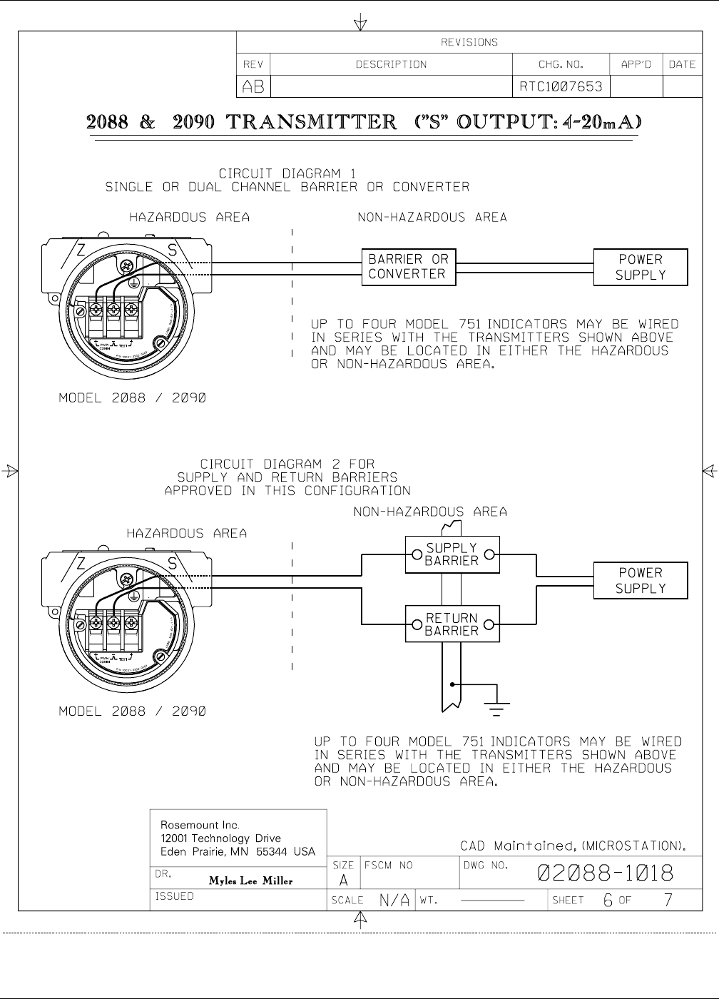
D-7
Approval Drawings
2088-1018AB6
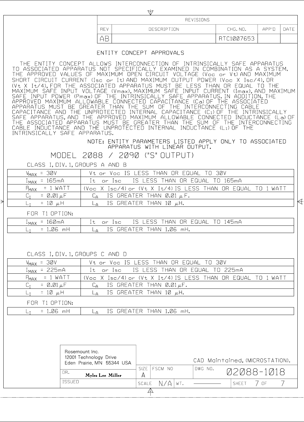
Rosemount Model 2088/2090 Pressure Transmitters
D-8
2088-1018AB7
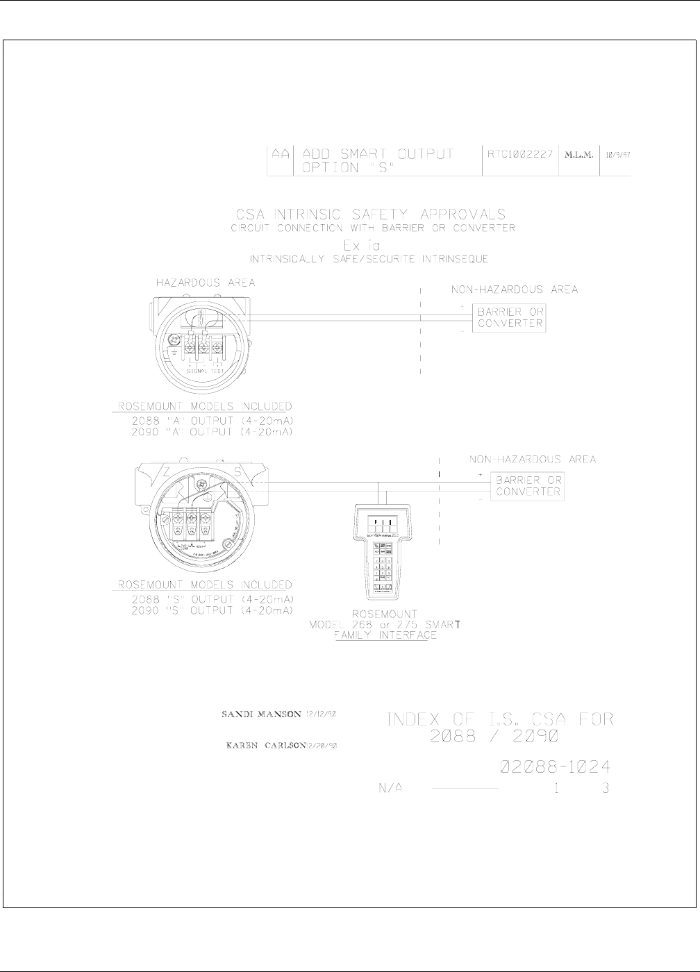
D-9
Approval Drawings
FIGURE D-2. CSA Intrinsic Safety Approvals for Models 2088 and 2090, Rev. AA.
2088-1024_01A
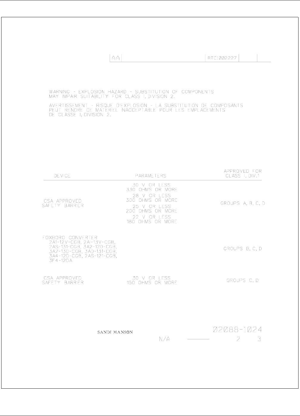
Rosemount Model 2088/2090 Pressure Transmitters
D-10
2088-1024_02A
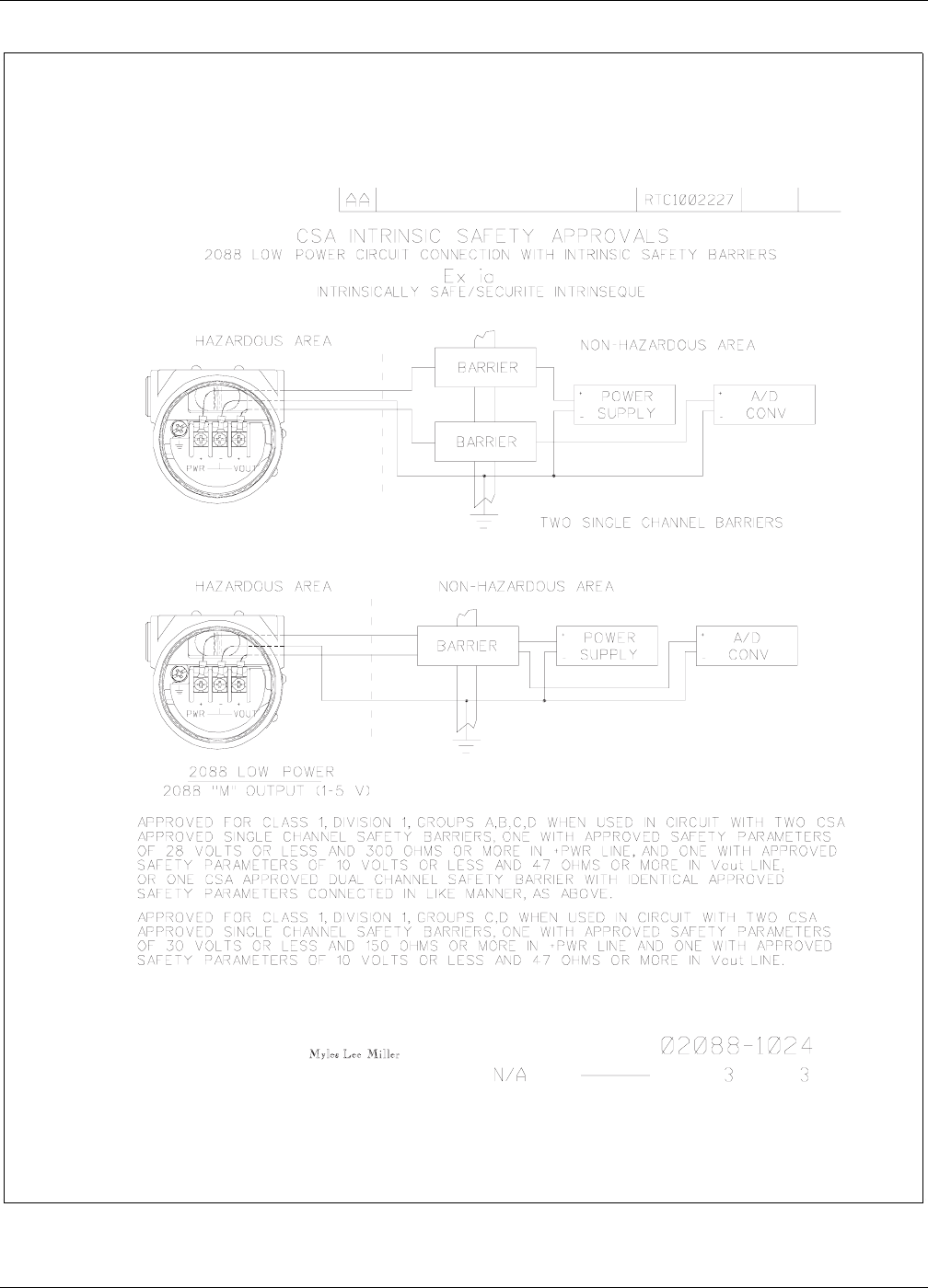
D-11
Approval Drawings
2088-1024_03A

Rosemount Model 2088/2090 Pressure Transmitters
D-12

Appendix
E-1
EEuropean ATEX Directive
Information
Rosemount Model 2088, 2090P, and 2090F Smart Pressure
Transmitters that have the following label attached, have been certified
to comply with Directive 94/9/EC of the European Parliament and the
Council as published in the Official Journal of the European
Communities No. L 100/1 on 19 April 1994.
The following information is provided as part of the labeling of the
transmitter
• Name and address of the manufacturer (may be any of
the following):
•Rosemount USA
•Rosemount England
•Rosemount Germany
•Rosemount Singapore
• Complete model number
• The serial number of the device
• Year of construction
• Marking for explosion protection:
•EExdIICT6(Ta=40°C)
•EExdIICT4(Ta=80°C)
• KEMA ATEX certificate number: 97ATEX 2378
275_01A
0600
II 1/2 G

Rosemount Model 2088/2090 Pressure Transmitters
E-2

I-1
Index
A
Access requirements 3-6
Action keys B-5
Address 2-11
Approval Drawings D-1–D-5
B
Basic setup
Damping 2-4
Output units 2-3
Rerange 2-3
Tag 2-3
Burst mode 2-5
C
Calibration 2-6
Full trim 2-8
Output trim 2-8
Overview 2-6
Sensor trim 2-7
Zero trim 2-7
Commissioning the Smart
transmitter 2-2
Communicating with a multidrop
2-11
Configuration data
Clone 2-6
Recall 2-6
Save 2-6
Connecting to a transmitter loop
2-2
Custom meter configuration A-2
D
Damping 2-4
Detailed setup
Burst mode 2-5
Clone configuration data 2-6
Meter setup 2-5
Save, recall, clone
configuration data 2-6
Diagnostics and service 2-10
Dimensional drawings
Model 2088 3-6
Model 2090F 3-6
Model 2090P 3-6
Mounting bracket 3-6
Disassembly procedure 4-5
Downscale alarm 4-4
Drawings
Approval D-1
E
Electrical considerations 3-11
Load limitations 3-11
Power supply 3-11
Environmental considerations 3-3
European ATEX directive
information E-1
F
Failure mode alarm 3-12
Field wiring 3-11
Low power C-2
Full trim 2-8
Functional specifications 5-1
H
HART communicator B-1
Action keys B-5, B-6
Data entry B-6
Function keys B-6
Model 275 B-1
Hazardous locations 3-3
I
Impulse piping 3-5
Installation
Electrical considerations 3-11
Environmental
considerations 3-3
General considerations 3-3
Hazardous locations 3-3
Mechanical considerations 3-
4
Introduction 1-1
K
Keypad
Action keys B-5, B-6
Function keys B-6
L
LCD meter
Custom meter configuration
A-2
Diagnostic messages A-3
Load limitations 3-11
Low power option
Calibration C-3
Commissioning C-1
Installation C-1
Potentiometer
adjustment C-4
Setting span C-5
Setting zero C-4
Specifications C-7
Transient protection C-6
Wiring C-2
M
Maintenance 4-1
Disassembly procedure 4-5
Reassembly procedure 4-5
Returning product 4-6
Mechanical considerations 3-4
Meter setup 2-5
Model 2090F 3-10
Model 2090P 3-7
Model 275 HART
communicator B-1
Mounting
Model 2088 3-4
Model 2090F 3-4
Model 2090P 3-4
Mounting configurations 3-4
Using a sanitary fitting 3-10
Using a weld spud 3-9
Multidrop communication 2-10
N
NAMUR-compliant
operation 3-12
O
Ordering information 5-10
Model 2088 5-10
Model 2090F 5-12
Model 2090P 5-11
Output trim 2-8
Output units 2-3
P
Performance specifications 5-3
Physical specifications 5-5
Polling a multidrop loop 2-11
Potentiometer adjustment C-4
Power supply 3-11

I-2
Rosemount Model 2088/2090 Pressure Transmitters
R
Range values 2-4
Reassembly procedure 4-5
Reference data 5-1
Replacement parts
Model 2088 5-7
Model 2090F 5-9
Model 2090P 5-8
Rerange 2-3
Returning product 4-6
S
Safety messages 1-1
Security (Write protection) 3-13
Security jumpers 3-12
Sensor Trim 2-7
Sensor trim
Full trim 2-8
Zero trim 2-7
Set sensor type 2-3
Spare parts 5-7
Specifications 5-1
Functional 5-1
Performance 5-3
Physical 5-5
T
Tag 2-3
Transient protection C-6
Troubleshooting 4-1
W
Weld spud 3-8
Wiring 3-11
Low power C-2
Z
Zero and span adjustments 3-14
Zero trim 2-7

00809-0100-4690 Rev. DA 01/00
http://www.rosemount.com
¢00809-0100-4690D¤
Rosemount Inc.
8200 Market Boulevard
Chanhassen, MN 55317 USA
Tel 1-800-999-9307
Fax (612) 949-7001
© 2000 Rosemount Inc.
P
R
I
N
T
E
D
IN
U.
S.
A.
Fisher-Rosemount Limited
Heath Place
Bognor Regis
West Sussex PO22 9SH
England
Tel 44 (1243) 863 121
Fax 44 (1243) 867 5541
Fisher-Rosemount
Singapore Pte Ltd.
1 Pandan Crescent
Singapore 128461
Tel (65) 777-8211
Fax (65) 770-8007
