4737_RevFAcd 4737
User Manual: 4737
Open the PDF directly: View PDF ![]() .
.
Page Count: 12

Product Data Sheet
00813-0100-4737, Rev FA
Catalog 2002 – 2003
www.rosemount.com
• Provide an installation-ready solution using
Complete Point Solutions™ (CPS)
• Accept a wide variety of 2-, 3-, and 4-wire
RTDs and thermocouple sensor types
• Configure using the Model 244EC
Configuration Interface and a standard PC
• Provide 500 VAC input to output isolation
• Mount in remote and integral applications
using the universal head
Model 244ER Model 244EH
Content
The Model 244E . . . . . . . . . . . . . . . . . . . . . . . . . . . . . . . . . . . . . . . . . . . . . . .page Temperature-76
Specifications . . . . . . . . . . . . . . . . . . . . . . . . . . . . . . . . . . . . . . . . . . . . . . . . .page Temperature-77
Hazardous Locations Certifications. . . . . . . . . . . . . . . . . . . . . . . . . . . . . . . . .page Temperature-81
Dimensional Drawings. . . . . . . . . . . . . . . . . . . . . . . . . . . . . . . . . . . . . . . . . . .page Temperature-82
Ordering Information . . . . . . . . . . . . . . . . . . . . . . . . . . . . . . . . . . . . . . . . . . . .page Temperature-84

Product Data Sheet
00813-0100-4737, Rev FA
Catalog 2002 – 2003
Temperature-76
The Rosemount® Model 244E is a cost-efficient solution for non-critical temperature monitoring applications.
Compared to wiring direct, the Model 244E will save money in cabling and installation costs while delivering
accurate and reliable measurement.
INSTALLATION READY SOLUTIONS
The Model 244E is part of the Rosemount Complete
Point Solutions (CPS) program. CPS guarantees that
the transmitter, sensor, extension, and thermowell
will be shipped from the factory as an installation
ready assembly to save on installation costs.
FLEXIBILITY
The Model 244E allows for great flexibility in
selecting a sensor type that is appropriate for the
process being measured. The Model 244E accepts
inputs from a wide variety of 2-, 3-, and 4-wire
RTDs as well as thermocouples, millivolt, and ohm
sensor types.
ISOLATION
The Model 244E is designed with 500 VAC input to
output isolation. This isolation helps to ensure the
integrity of the temperature measurement in
industrial environments and not damage sensitive
system electronics.
PROGRAMMABLE
The Model 244EC Configuration Interface consists
of a programmer, cables, and configuration software.
The Model 244EE configuration software, when used
in conjunction with the interface, provides the tools
necessary to select the sensor type, sensor range,
and sensor error action in addition to many
other options.
UNIVERSAL HEAD
The Model 244EH head mount transmitter offers
different configurations for mounting. Using the
Rosemount Universal Head, the Model 244EH
may be mounted either integrally or remotely to
fit the needs of the specific temperature monitoring
application.
Rosemount Temperature Solutions
Model 3144P Temperature Transmitter
Field mount style available with HART® protocol.
Model 3244MV Temperature Transmitter
Field mount style available with FOUNDATION™
fieldbus and Profibus-PA protocols.
Model 644 Smart Temperature Transmitter
Head or rail mount styles available with HART
protocol.
Model 848T Eight Input Temperature Transmitter
Eight input transmitter available with FOUNDATION
fieldbus protocol.
Model 244E Temperature Transmitters
Head or rail mount styles that are
PC-programmable.
Model 144H Temperature Transmitters
PC-programmable head mount style for 2- and
3-wire RTD sensor inputs.
Rosemount sensors, thermowells, and
extensions
Rosemount has a broad offering of RTD and
thermocouples that are designed to meet plant
requirements.
Product Data Sheet
00813-0100-4737, Rev FA
Catalog 2002 – 2003
Temperature-77
FUNCTIONAL SPECIFICATIONS
Inputs
User-selectable using the Model 244EC Configuration Interface
and the Model 244EC Configuration Software. Sensor terminals
are rated to 42.4 V dc. See “Accuracy”.
Output
2-wire 4–20 mA, linear with temperature for RTDs and
thermocouples and linear with input for millivolts and ohms.
Isolation
Input/output isolation tested to 500 V ac rms (707 V dc) at 50/60
Hz
Power Supply
An external power supply is required. The transmitter operates on
12.0 to 42.4 V dc. Transmitter power terminals are rated to
42.4 V dc.
Failure Mode
The Model 244E features software driven alarm diagnostics and
an independent circuit. These features are designed to provide
backup alarm outputs in case the microprocessor, electronics,
hardware, or software fails. The alarm levels are user-selectable
using the failure mode switch. In case of alarm, the position of the
jumper determines the direction in which the output is driven (HI or
LO). The jumper switch feeds into the digital-to-analog (D/A)
converter, which drives the proper alarm output even if the
microprocessor fails. The values that the transmitter drives its
output in failure mode depends on whether it is factory configured
to standard or NAMUR compliant operation. The values for
standard and NAMUR-compliant operation are as follows.
TABLE 1. Standard vs. NAMUR-compliant specifications
Humidity Limits
0–99% relative humidity, non-condensing
Transient Protection
The Model 470 prevents transmitter damage from transients
induced by lightning, welding, heavy electrical equipment, or
switch gears. Refer to the Model 470 Product Data Sheet
(document number 00813-0100-4191) for more information.
Update Time
Approximately 0.5 seconds
Temperature Limits
Turn-on Time
Performance within specifications is less than 5.0 seconds after
power is applied to transmitter when damping value is set to zero
seconds
PHYSICAL SPECIFICATIONS
Electrical Connections
Standard (1)
(1) Measured in milliamperes
NAMUR- Compliant(1)
Linear Output: 3.9 £ I £ 20.5 3.8 £ I £ 20.5
Fail High: 21 £ I £ 23 (default) 21 £ I £ 23 (default)
Fail Low: I £ 3.75 I £ 3.6
Operating Limit Storage Limit
–40 to 85 °C (–40 to 185 °F) –50 to 120 °C (–58 to 248 °F)
Model
Power and Sensor
Terminals
Communication
Terminals
Model 244EH Compression screws
permanently fixed to
terminal block
Clips permanently
fixed to terminal block
Model 244ER Compression screw
permanently fixed to
front panel
Clips permanently
fixed to front panel
WAGO® spring clamp terminals are optional (option code G5)
Product Data Sheet
00813-0100-4737, Rev FA
Catalog 2002 – 2003
Temperature-78
Materials of Construction
Mounting
The Model 244ER attaches directly to a wall or a DIN rail. The
Model 244EH installs in a connection head or universal head
mounted directly on a sensor assembly, apart from a sensor
assembly using a universal head, or to a DIN rail using an optional
mounting clip. (See page Temperature-83 for more information.)
Weight
Enclosure Ratings (Model 244EH)
Option codes J5 and J6 are NEMA 4X, IP66, and IP68.
Option code J6 is CSA Enclosure Type 4X
PERFORMANCE SPECIFICATIONS
The Models 244EH and 244ER maintain a specification
conformance of at least 3s.
Stability
RTDs and thermocouples have a stability of ±0.1% of reading or
0.1 °C (whichever is greater) for twelve months.
Power Supply Effect
Less than ±0.005% of span per volt
Vibration Effect
The Model 244EH and Model 244ER are tested to the following
specifications with no effect on performance:
CE Electromagnetic Compatibility Compliance Testing
The Models 244EH and 244ER meet all requirements listed under
IEC 61326: Amendment 1, 1998.
.
Electronics Housing and Terminal Block Construction
Material
Model 244EH Noryl® glass reinforced
Model 244ER Lexan® polycarbonate
Code Options Add(1)
(1) All weights are in grams (ounces).
Model 244EH Head Mount 78 (2.75)
J5, J6 Universal Head 520 (18.43)
Model 244ER Rail Mount 173 (6.10)
Frequency Vibration
10 to 60 Hz 0.21 displacement
60 to 2000 Hz 3 g peak acceleration
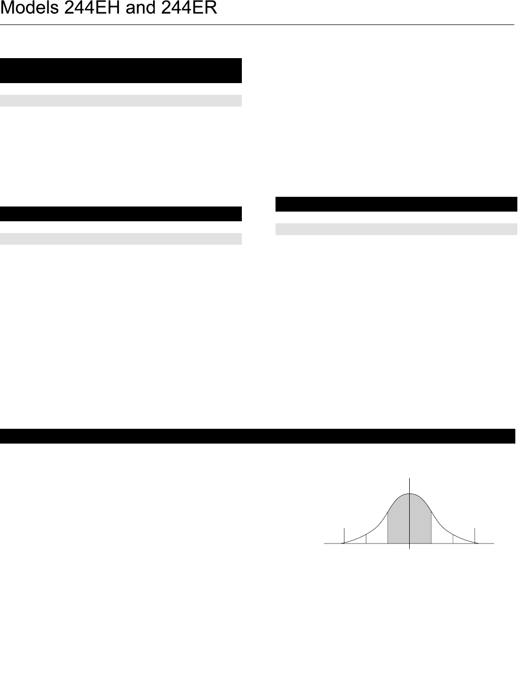
Rosemount Conformance to Specifications
You can be confident that a Rosemount product not only meets its published
specifications, but most likely exceeds them. Our advanced manufacturing techniques
and use of Statistical Process Control provide specification conformance to at least
±3(1). In addition, our commitment to continual improvement ensures that product
design, reliability, and performance will improve every year.
For example, the Reference Accuracy distribution for the Model 244E Temperature
Transmitter is shown to the right. Our Specification Limits are ± 0.2 °C, but, as the
shaded area shows, approximately 68% of the units perform three times better than
the limits. Therefore, it is very likely that you will receive a device that performs much
better than our published specifications.
Conversely, a vendor who “grades” product without using Process Control, or who is
not committed to ± 3 performance, will ship a much higher percentage of units that
are barely within (or even outside of) advertised specification limits.
Note: Accuracy distribution shown is for Model 244E,
Pt 100 RTD sensor, range 0 to 100 °C.
(1) Sigma (s) is a statistical symbol to designate the standard deviation from the mean value of a normal distribution.
Lower
Specification
Limit
Upper
Specification
Limit
Typical
Accuracy
3144-GRAPH
–3s–2s–1s1s2s3s
Product Data Sheet
00813-0100-4737, Rev FA
Catalog 2002 – 2003
Temperature-79
Accuracy
TABLE 2. Accuracy/Input Options
Accuracy Example
When using a Pt 100 (a = 0.00385) sensor input with a 75 to 150
°C range, the accuracy will be ±0.15 °C of span + 0.15 °C or
0.2 °C, whichever is greater. Sample Calculation: [0.0005
(150-75)+0.15] = 0.19 °C, whichever is less than 0.2 °C, so the
accuracy equals 0.2.
Sensor
Options
Sensor
Reference
Input
Ranges
Recommended
Min. Span(1)
Accuracy (whichever is greater)
2-, 3-, 4-wire RTDs °C °F °C °F
Pt 100 IEC 751, 1995 (a = 0.00385) –200 to 850 –328 to 1562 10 18 0.05% of span + 0.15 °C or 0.2 °C
Pt 100 JIS 1604, 1981 (a = 0.003916) –200 to 645 –328 to 1093 10 18 0.05% of span + 0.15 °C or 0.2 °C
Pt 200 IEC 751, 1995 (a = 0.00385) –200 to 850 –328 to 1562 10 18 0.01% of span or 0.4 °C
Pt 500 IEC 751, 1995 (a = 0.00385) –200 to 850 –328 to 1562 10 18 0.01% of span or 0.3 °C
Pt 1000 IEC 751, 1995 (a = 0.00385) –200 to 300 –328 to 572 10 18 0.01% of span or 0.3 °C
Ni 120 Edison Curve No. 7 –70 to 300 –94 to 572 10 18 0.01% of span or 0.2 °C
Cu 10 Edison Copper Winding No. 1 –50 to 250 –58 to 482 10 18 0.5% of span or 1.5 °C
Thermocouples(2)
Type B(3) NIST Monograph 175, IEC 584 100 to 1820 212 to 3308 25 40 0.2% of span or 1.0 °C
Type E NIST Monograph 175, IEC 584 –50 to 1000 –58 to 1832 25 40 0.1% of span or 0.5 °C
Type J NIST Monograph 175, IEC 584 –180 to 760 –292 to 1400 25 40 0.1% of span or 0.5 °C
Type K NIST Monograph 175, IEC 584 –180 to 1372 –292 to 2502 25 40 0.1% of span or 1.0 °C
Type N NIST Monograph 175, IEC 584 –200 to 1300 –328 to 2372 25 40 0.1% of span or 1.0 °C
Type R NIST Monograph 175, IEC 584 0 to 1768 32 to 3214 25 40 0.1% of span or 1.0 °C
Type S NIST Monograph 175, IEC 584 0 to 1768 32 to 3214 25 40 0.1% of span or 1.0°C
Type T NIST Monograph 175, IEC 584 –200 to 400 –328 to 752 25 40 0.1% of span or 0.5 °C
DIN Type L DIN 43710 –200 to 900 –328 to 1652 25 40 0.1% of span or 0.5 °C
DIN Type U DIN 43710 –200 to 600 –328 to 1112 25 40 0.1% of span or 0.5 °C
Type
W5Re/W26Re
ASTME 988-96 0 to 2000 32 to 3632 25 40 0.1% of span or 1.0 °C
Millivolt Input –10 to 100 mV 3 mV 0.025 mV + 0.003% of span
2-, 3-, 4-wire Ohm Input 0 to 2000 ohms 20 ohm 0.75 W + 0.03% of span
(1) No minimum or maximum span restrictions within the input ranges. Recommended minimum span will hold noise within accuracy specification with damping
at zero seconds.
(2) Total digital accuracy for thermocouple measurement: sum of digital accuracy +0.5 °C (cold junction accuracy).
(3) Accuracy for NIST Type B thermocouple is ±3.0 °C from 100 to 300 °C.
Product Data Sheet
00813-0100-4737, Rev FA
Catalog 2002 – 2003
Temperature-80
Ambient Temperature Effect
Transmitters can be installed in locations where the ambient
temperature is between –40 and 85 °C (–40 and 185 °F). To
maintain excellent accuracy performance, each transmitter is
individually characterized over this ambient temperature range at
the factory. The transmitters automatically adjust for component
temperature drift caused by changing environmental conditions.
TABLE 3. Ambient Temperature Effects
Temperature Effects Example
Example 1:
When using a Type J thermocouple with a 50 °C to 600 °C
temperature range at an ambient temperature of 60 °C and a
reading of –25 °C, the ambient temperature effect according to °C
is:
• [fixed value (a) + (% of reading (b) x reading) = (% of span (c)
x span)] = [0.006 + (–0.000025 x (–25)) + (0.00001 x 650)] =
0.013 °C per °C.
With the ambient temperature 40 °C above reference condition
temperature, the total ambient temperature effect is:
• 40 x 0.013 = 0.52 °C
Example 2:
When using a Type J thermocouple with a – 50 °C to 600 °C
temperature range at an ambient temperature of 60 °C and a
reading of 525 °C, the ambient temperature effect according to °C
is:
• [fixed value (a) + (% of reading (b) x reading) = (% of span (c)
x span)] = [0.006 + (–0.0000054 x 525) + (0.00001 x 650)] =
0.015 °C per °C.
With the ambient temperature 40 °C above reference condition
temperature, the total ambient temperature effect is:
• 40 x 0.015 = 0.6 °C
Example 3:
The worst case error would be:
• Reference Accuracy + CJC Accuracy + Temp Effects = 0.65
°C + 0.5 °C + 0.52 °C = 1.67 °C.
Total probably error:
Sensor Options(1) Fixed Value % of reading % of Span
(if reading > 0) (if reading is < 0)
2-, 3-, 4-wire RTDs
Pt 100 (a = 0.00385) 0.003 °C — — 0.001% of span
Pt 100 (a = 0.003916) 0.003 °C — — 0.001% of span
Pt 200 0.004 °C — — 0.001% of span
Pt 500 0.003 °C — — 0.001% of span
Pt 1000 0.003 °C — — 0.001% of span
Ni 120 0.003 °C — — 0.001% of span
Cu 10 0.03 °C — — 0.001% of span
Thermocouples
Type B (100 °C £ reading < 300 °C) 0.064 °C – 0.011 —0.001% of span
(300 °C £ reading < 1000 °C) 0.040 °C – 0.025 —0.001% of span
(reading ³ 1000 °C) 0.014 °C — — 0.001% of span
Type E 0.005 °C – 0.00043 – 0.0043 0.001% of span
Type J, K, DIN L 0.006 °C – 0.00054 – 0.0025 0.001% of span
Type N 0.007 °C – 0.00036 —0.001% of span
Type R, S (reading < 200 °C) 0.023 °C – 0.0036 —0.001% of span
(reading ³ 200 °C) 0.016 °C — — 0.001% of span
Type T, DIN U 0.007 °C — – 0.043 0.001% of span
Type W5Re/W26Re 0.023 °C – 0.0036 —0.001% of span
0.016°C —
Millivolt Input 0.0005 mV — — 0.001% of span
2-, 3-, 4-wire Ohm 0.0084 W— — 0.001% of span
(1) Change in ambient is with reference to the calibration temperature of the transmitter 68 °F (20 °C) from factory.
6520.520.522
+ + 0.97°C=
Product Data Sheet
00813-0100-4737, Rev FA
Catalog 2002 – 2003
Temperature-81
Factory Mutual (FM) Approvals
E5 Explosion-Proof for Class I, Division 1, Groups B, C, and D.
Dust-Ignition Proof for Class II, Division 1, Groups E, F, and G.
Dust-Ignition Proof for Class III, Division 1 hazardous locations
when installed in accordance with Rosemount Drawing
00644-1049. Non-Incendive for Class I, Division 2,Groups A, B,
C, and D. Temperature Code T5 (Tamb = 85 °C). Conduit seal
not required for compliance with NEC 501-5a(1).
NOTE:
Approval E5 is only available with Model 244EH option codes
J5 and J6.
I5 Intrinsically Safe for Class I, II, III, Division 1, Groups A, B, C, D,
E, F, G; Non-incendive for Class I, Division 2, Groups A, B, C, D
hazardous locations when installed in accordance with
Rosemount Drawing 00644-0009. Temperature Code T5
(Tamb = 80 °C) (T6 (Tamb = 40 °C))
Special Conditions for Safe Use (X):
When the output of the associated apparatus does not exceed
Po = 0.67 Watts, the temperature code is T6 (Tamb = 50 °C)
K5 Combination of E5 and I5
NOTE:
Approval K5 is only available with Model 244EH option codes
J5 and J6.
Canadian Standards Association (CSA) Approvals
I6 Intrinsically safe for Class I, Division 1, Groups A, B, C, and D
when connected in accordance with Rosemount drawing
00644-1064
C6 Combination of I6 and the following: Explosion-Proof for Class I,
Division 1, Groups B, C, and D. Dust-ignition proof for Class II,
Division 1, Groups E, F, and G. Dust-ignition proof for Class III,
Division 1 hazardous locations when installed in accordance
with Rosemount Drawing 00644-1059 factory sealed. Suitable
for Class I, Division 2, Groups A, B, C, and D.
NOTE:
Approval C6 is only available with Model 244EH option code J6.
CENELEC/KEMA Approvals
ED ATEX Category II 2 G Certification number KEMA 99ATEX8715
Flameproof (Zone 1) (Model 244EH only)
EEx d IIC T6 (Tamb = –40 to 65 °C).
Requires a connection head or Universal head.
CENELEC/British Approvals Service for Electrical Equipment
in Flammable Atmospheres (BASEEFA) Approvals
I1 ATEX Category II 1 G, Certification number BAS00ATEX1033X
Intrinsically Safe Operation (Zones 0)
EEx ia IIC T6 (Tamb = –60 to 40 °C) Pi = 0.67W
EEx ia IIC T5 (Tamb = –60 to 50 °C) Pi = 0.67W
EEx ia IIC T5 (Tamb = –60 to 40 °C) Pi = 1.0W
EEx ia IIC T5 (Tamb = –60 to 80 °C) Pi = 1.0W
Special Conditions for Safe Use (X):
The apparatus must be installed in an enclosure which affords it a
degree of protection of at least IP20. Non-metallic enclosures must
have a surface resistance of less than 1GW, light alloy or
zirconimum enclosures must be protected from impact and friction
when installed.
N1 ATEX Category II 3 G Certification number BAS00ATEX3145
Type ‘nL’ Operation Non-Incendive Approval (Zone 2 only)
EEx nL IIC T5 (Tamb = –40 to 70 °C)
(Type ‘nL’ certification is only available as a complete assembly
with the Rosemount universal head, thermometer,
and thermowell.)
Standard Australia Quality Assurance Service (SAA)
NOTE
Consult factory for SAA availability.
I7 Intrinsic Safety,
Ex ia IIC
N7 Type n Approval,
Ex n IIC
E7 Flameproof Approval (Model 244EH only)
Ex d IIC T6 (Tamb = 65 °C)
Special Conditions for Safe Use (X):
It is a condition of safe use that a thermowell must be utilized on
installations incorporating a DIN style or a sprint loaded sensor
assembly, with all threaded connections sealed with sealing tape to
maintain the IP rating of IP66 /IP68 (at 3 meters).
It is a condition of safe use that when a thermowell is utilized on
installation, this gland must be Standard Australia certified and must be
capable of maintaining the IP rating. This also requires the use of
thread sealing tape on all gland entries.
NOTE:
Flameproof certification is only available as a complete assembly
with Rosemount universal head – option codes J5 or J6.
Gostandart
Tested and approved by the Russian Metrological Institute
GOSTANDART.
TABLE 4. Entity Parameters
Power/Loop Sensor
Ui = 30 V dc Uo = 13.6 V
Ii = 200 mA Io = 80 mA
Pi = 1.0 W Pi = 80 mW
Ci = 10 nF Co = 0.73 µF
Lo = 5.8 mH
Co = 5.12 µF
Lo = 23.36 mH
Co = 18.52 µF
Lo = 48.06 mH
Product Data Sheet
00813-0100-4737, Rev FA
Catalog 2002 – 2003
Temperature-82
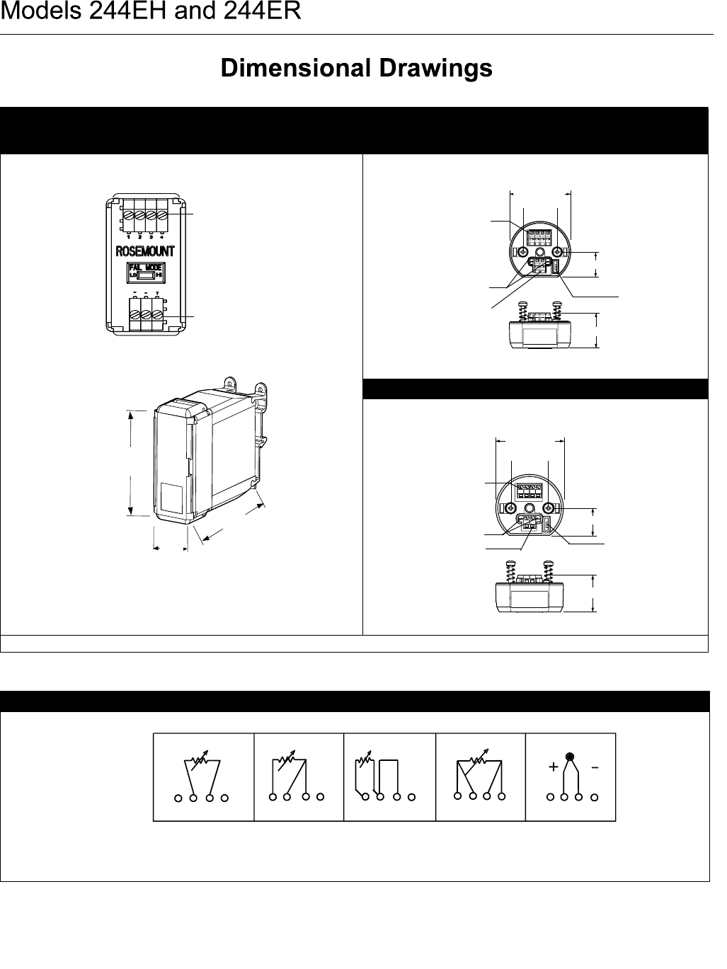
Model 244ER Model 244EH
Shown with Standard Compression Screw Terminals
Shown with WAGO Spring Clamp Terminals
Dimensions are in millimeters (inches)
36
(1.4)
104
(4.1)
82
(3.2)
Sensor Terminals
Power Terminals
644-1105E01A. 1101A01A
Standard Sensor
Terminals
Communication
Terminals
644-1360A02A
Failure
Mode Switch
34 (1.33)
60 (2.4)
33 (1.3)
Power Terminals
24 (1.0)
644-1360B02A
33 (1.30)
WAGO
® Spring
Clamp Sensor
Terminals
24 (1.0)
Power Terminals
Communication
Terminals Failure Mode
Switch
33 (1.3)
60 (2.4)
Model 244E Sensor Connections
* Rosemount Inc. provides 4-wire sensors for all single element RTDs. You can use these RTDs in 3-wire configurations by leaving the unneeded leads
disconnected and insulated with electrical tape.
** The transmitters must be configured for a 3-wire RTD in order to recognize an RTD with a compensation loop.
12341234 12 34 12
3
41234
644-0000B01A
1
2-wire
RTD
and
3-wire
RTD
and
4-wire
RTD
and
T/C
and mV
RTD with
Comp.
Loop
***
Product Data Sheet
00813-0100-4737, Rev FA
Catalog 2002 – 2003
Temperature-83
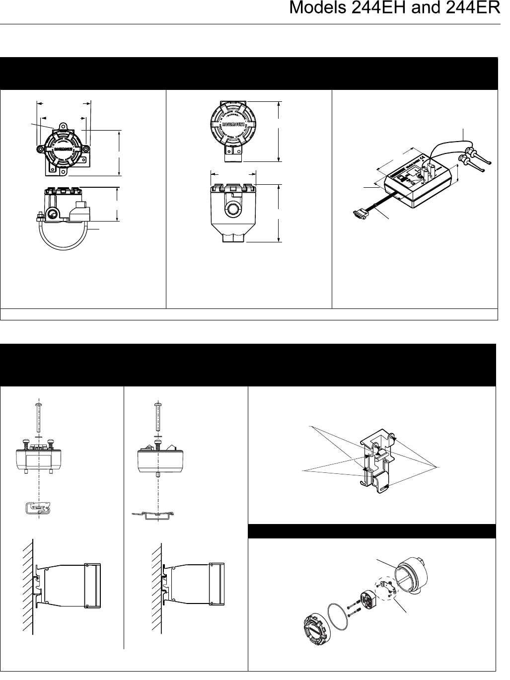
Threaded-Sensor Universal
Head (Option code J5 or J6)
Integral DIN Style Sensor
Connection Head
Model 244EC
Configuration Interface
Note: A “U” Bolt is shipped with each
universal head unless assembly option X1,
X2, or X3 is ordered. However, since
the head can be integrally mounted to the
sensor, it may not need to be used.
Note: The DIN Style Integral sensor
connection head is only available through
Volume 2 of the Rosemount Temperature
Sensors and Accessories Product Data Sheet
(document number 00810-0101-2654).
Dimensions are in millimeters (inches)
95 (3.74)
96 (3.76)
112 (4.41)
SST “U” Bolt
Mounting,
2-inch Pipe
Label
75 (2.93)
104 (4.09)
100 (3.93)
78 (3.06
)
0.61 m (2 ft)
Configuration
Leads
38 (1.5)
1.83 m (6 ft)
Ribbon Cable
84 (3.3)
114 (4.5)
644-4420A02A, 4410AO1A, 3300A01A
Mounting
G-Rail (asymmetric) Top Hat Rail (symmetric)
Universal Clip for Mounting the Model 244ER to a Wall or a Rail
(part number 03044-4301-0001)
Model 244EH Retrofit Kit
Note: Kit (part number 00644-5301-0010 includes mounting
hardware and both types of rail kits.
Note: Kit (part number 00644-5321-0010) includes a new mounting
bracket and the hardware necessary to facilitate the installation.
Model 244EH
Transmitter
Mounting
Hardware
Rail
Clip
Model 244EH
Transmitter
Mounting
Hardware
Rail Clip
3044-4001A01B, 644-5302B01A, D02A
G-Rail
Grooves
Top Hat Rail
Grooves
Screw Holes
for Mounting
to a Wall
Model 244ER
Transmitter
Model 244ER
Transmitter
3044-0000C01B, D01B,
644-1041B02B,G02B
Kit includes replacement
bracket and screws.
Existing Threaded
Sensor Connection Head
(former option code L1)
Product Data Sheet
00813-0100-4737, Rev FA
Catalog 2002 – 2003
Temperature-84
TABLE 5. Model 244EH and Model 244ER Ordering Table
• = Available
— = Not available
Model Product Description
Head
Mount
Rail
Mount
244EH Head Mount Temperature Transmitter •—
244ER Rail Mount Temperature Transmitter — •
Code Hazardous Area Certifications
Enclosure
Purchase
Required?
Head
Mount
Rail
Mount
E5 FM explosion-proof approval Yes •—
I5(1)
(1) Transmitters with intrinsic safety approvals can be ordered without enclosures. However, to meet intrinsic safety requirements, the transmitter must be
installed in an enclosure with IP20 or higher rating. Model 244EH transmitters ordered with enclosure options J5 or J6 meet this requirement.
FM intrinsic safety and non-incendive approval No • •
K5 FM intrinsic safety, non-incendive, and explosion-proof approval combination Yes •—
I6(1) CSA intrinsic safety and non-incendive approval No • •
C6 CSA intrinsic safety, non-incendive, and explosion-proof approval combination Yes •—
N1 CENELEC/BASEEFA type n approval Yes • —
ED CENELEC/KEMA flameproof approval Yes • —
I1(1) CENELEC/BASEEFA intrinsic safety approval No • •
E7 SAA flameproof approval. Consult factory for availability. Yes • —
N7 SAA type n approval. Consult factory for availability Yes • —
I7(1) SAA intrinsic safety approval. Consult factory for availability. No • •
NA(1) No approval No • •
Code Options
Assembly (Model 244EH Only)(2)
(2) If ordering (X1), (X2), or (X3) options, specify the same code on the sensor model number. Option codes X1 and X3 are not available with CSA approval.
(Hazardous Area Certifications C6 or I6.)
X1 Assemble transmitter to a sensor assembly (hand tight, Teflon® (PTFE) tape where appropriate, fully wired) • —
X2 Assemble transmitter to a sensor assembly (hand tight, no Teflon (PTFE) tape, unwired) • —
X3 Assemble transmitter to a sensor assembly (wrench tight, Teflon (PTFE) where appropriate, fully wired) • —
Enclosure
J5(3)
(3) Remote mount only. Sensor assembly options X1, X2, and X3 are not available.
Universal Head (junction box with M20 entries), aluminum alloy with 50.8 (2-in.) SST pipe bracket • —
J6 Universal Head (junction box with 1/2–14 NPT entries), aluminum alloy with 50.8 (2-in.) SST pipe bracket • —
Configuration
A1 Analog output levels compliant with NAMUR-recommendations NE 43:June 1997 • •
CN Analog output levels compliant with NAMUR-recommendations NE 43: June 1997: alarm configuration low • •
F6 60 Hz line voltage filter • •
Calibration
C4 5-Point calibration. Use Q4 option to generate a calibration certificate • •
Q4 Calibration certificate. 3-point standard; use C4 with Q4 option for a 5-point calibration certificate. • •
Accessory (Model 244EH only)
G1 External ground screw (See “External Ground Screw Assembly” on page Temperature-85). Only available with
enclosure options J5 or J6.
• —
G2 Cable gland. Only available with option code J5. • —
G3 Cover chain. Only available with enclosure options J5 or J6. • —
G5 WAGO® Spring Clamp Terminals • —
Typical Model Number: 244EH I1 X1 J6
Typical Model Number: 244ER I1

Product Data Sheet
00813-0100-4737, Rev FA
Catalog 2002 – 2003
Temperature-85
Hardware Tag
• No charge
• Tagged in accordance with customer requirements
• Tags are adhesive labels
• Permanently attached to transmitter
• Character height is
1/16-in (1.6 mm)
Software Tag
• The transmitter can store up to 8 characters in its memory
• Transmitter can be ordered with different software and
hardware tags
• If the software tag characters are not specified, the software
tag will default to the first 30 characters of the hardware tag.
Special Mounting Considerations
Special mounting hardware is available for:
• Mounting a Model 244EH to a DIN rail. See “Mounting”.
• Retrofitting a new Model 244EH to replace an existing Model
244EH transmitter in an existing threaded sensor connection
head. See “Mounting”.
External Ground Screw Assembly
The external ground screw assembly can be ordered by specifying
option code G1 when an enclosure is specified. However, some
approvals include the ground screw assembly in the transmitter
shipment, hence it is not necessary to order option code G1. See
below to determine which approval options include the external
ground screw assembly.
TABLE 6. Model 244EC Configuration Interface Ordering Information
• = Available
— = Not available
Model Product Description 244EH 244ER
244EC Model 244EC Configuration Interface Hardware and Software • •
Typical Model Number: 244EC
TABLE 7. Transmitter Accessories
Part Description Part Number
Aluminum alloy Universal Head, standard cover—M20 entries 00644-4420-0002
Aluminum alloy Universal Head, standard cover—1/2-14 NPT entries 00644-4420-0001
Ground Screw Assembly Kit 00644-4431-0001
Models 244EH and 244ER configuration software (Four 3.5” diskettes) 00244-3401-0003
Black MINIGRABBER™ configuration lead C539920001
Red MINIGRABBER configuration lead C539920002
Universal clip for rail or wall mount (Model 244ER only) 03044-4103-0001
Kit, hardware for mounting a Model 244EH to a DIN rail (includes clips for symmetrical and asymmetrical rails) 00644-5301-0010
Kit, hardware for retrofitting a Model 244EH in an existing threaded sensor connection head (former option code L1) 00644-5321-0010
24 Inches of symmetric (Top Hat) rail 03044-4200-0001
24 Inches of asymmetric (G) rail 03044-4201-0001
Ground Clamp for symmetric or asymmetric rail 03044-4202-0001
End Clamp for symmetric or asymmetric rail 03044-4203-0001
Blank transmitter configuration labels (sheet of 48) 00644-5154-0001
Snap Rings Kit (used for assembly to DIN sensor) 00644-4432-0001
Approval Type
External Ground Screw
Assembly Included
E5, K5, I5, I6, C6, NA No–Order option code G1
N1, ED, E7, I7, N7, I7 Yes
Product Data Sheet
00813-0100-4737, Rev FA
Catalog 2002 – 2003
Emerson Process Management
© 2002 Rosemount, Inc.
Rosemount and the Rosemount logotype are registered trademarks of Rosemount Inc.
HART is a registered trademark of the HART Communication Foundation.
FOUNDATION is a trademark of the Fieldbus Foundation.
WAGO is a registered trademark of WAGO KontakHechnik GmbH, Germany.
Noryl is a registered trademark of General Electric.
Lexan is a registered trademark of General Electric.
All other marks are the property of their respective owners.
¢00813-0100-4737L¤
Rosemount Temperature GmbH
Frankenstrasse 21
63791 Karlstein
Germany
T 49 (6188) 992 0
F 49 (6188) 992 112
Fisher Rosemount
Singapore Pte Ltd.
1 Pandan Crescent
Singapore 128461
T (65) 777 8211
F (65) 777 0947
AP.RMT-Specialist@emersonprocess.com
Rosemount Inc.
8200 Market Boulevard
Chanhassen, MN 55317 USA
T (U.S.) 1-800-999-9307
T (International) (952) 906-8888
F (952) 949-7001
www.rosemount.com
Configuration
Unless specified, the transmitter will be shipped as follows:
Custom Configuration
The transmitter can be ordered with custom configuration. Use the
following table to determine the requirements when specifying the
custom configuration.
Configuration Software
The PC-based configuration software for the Models 244EH and
244ER allow comprehensive configuration of the transmitters.
Used in conjunction with a Model 244EC Configuration Interface,
the software provides the tools necessary to configure and view
the process variable of a Model 244EH or Model 244ER.
Using the software, the following parameters are available:
• Process Variable
• Sensor type
• Number of Wires
• 50/60 Hz selection
• Engineering Units
• Upper and lower range values
• Damping value
• Transmitter electronic tag
Software for the Model 244EC is available in English, French,
German, Italian, Spanish, Chinese, Japanese, and Korean. A
spreadsheet for printing labels and one sheet of labels are
included with the software. The labels can be used when the
transmitter configuration has been changed. The user can place a
new label on the transmitter to reflect the new configuration
parameter.
Model 244EC Configuration Interface
The Model 244EC Configuration interface is a portable,
self-contained communication link between your PC and
transmitter.
The Model 244EC connects to the serial port on your PC with a
standard 9-pin interconnecting plug and to a transmitter using two
MINIGRABBER™ clips. Power is provided by one replaceable
9-volt battery. The Model 244EC will also operate using a wall
power adapter.
The Model 244EC is approved for Factory Mutual (FM) and
Canadian Standards Association (CSA) Ordinary Locations.
Sensor Type: RTD, Pt 100 (a = 0.00385, 4-wire)
4 mA Value: 0 °C
20 mA Value: 100 °C
Damping: 5 seconds
Failure Mode: High/Upscale
LIne Voltage Filter: 50 Hz
Tag See “Hardware Tag” and “Software Tag”
Option Code Requirements/Specification
A1: NAMUR-
compliant
See Table 1
CN: NAMUR-
Compliant, Low
Alarm
See Table 1
C4:
Five Point
Calibration
Will include five-point calibration at 0, 25,
50, 75, and 100% analog and digital
output points. Use with Rosemount
Calibration Certificate Q4.
F6: 60 Hz Line Filter Calibrated to a 60 Hz line voltage filter
instead of the standard 50 Hz filter
