4809_RevAA 4809_Rev AA 4809 Rev
User Manual: 4809_RevAA
Open the PDF directly: View PDF ![]() .
.
Page Count: 190 [warning: Documents this large are best viewed by clicking the View PDF Link!]
- CD-ROM Table of Contents
- Annubar Flowmeter Series
- Section 1 Introduction
- Section 2 Installation
- Section 3 Commissioning
- Section 4 Operation and Maintenance
- Appendix A Specifications and Reference Data
- Model 3051SFA ProBar Flowmeter
- Model 3095MFA Mass ProBar Flowmeter
- Model 485 Annubar Primary
- Dimensional Drawings
- Model 3051SFA Pak–Lok Probar
- Model 3051SFA Flange– Lok Probar
- Model 3051SFA Flange Probar
- Model 3051SFA Flange Flo–Tap Probar
- Model 3051SFA Threaded Flo–Tap Probar
- Model 3095MFA Pak–Lok Mass ProBar
- Model 3095MFA Flange– Lok Mass ProBar
- Model 3095MFA Flange Mass ProBar
- Model 3095MFA Flange Flo–Tap Mass ProBar
- Model 3095MFA Threaded Flo–Tap Mass ProBar
- Model 485 Pak–Lok Annubar
- Model 485 Flange–Lok Annubar
- Model 485 Flange Annubar
- Model 485 Flange Flo– Tap Annubar
- Model 485 Threaded Flo– Tap Annubar
- Mounting
- Ordering Information
- Appendix B Approvals
- Annubar Flowmeter Series
www.rosemount.com
Reference Manual
00809-0100-4809, Rev AA
August 2002
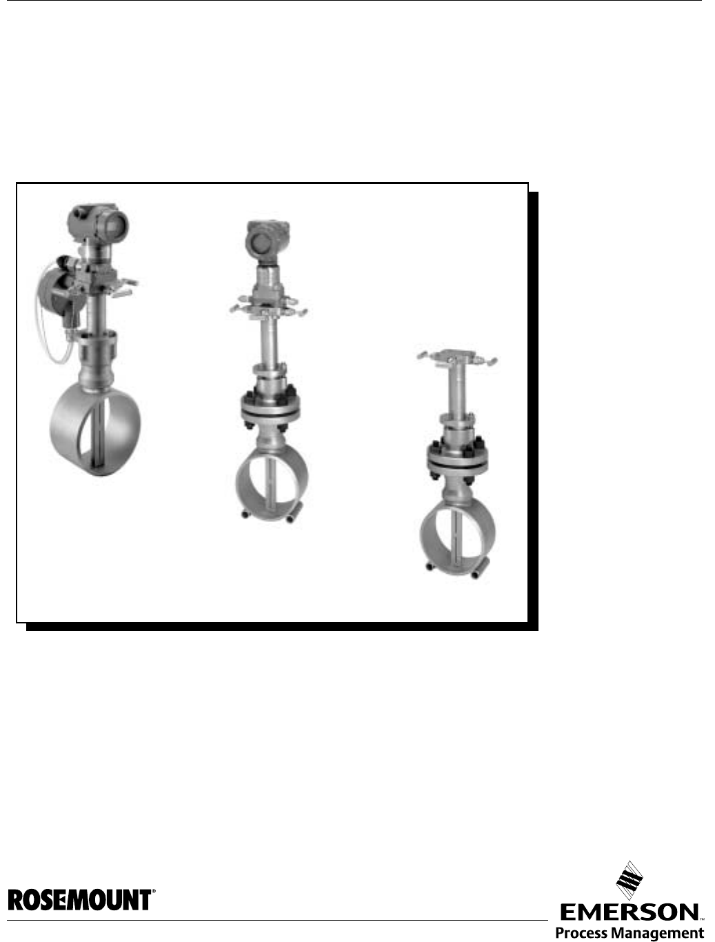
The Annubar® Flowmeter Series
Model 3051SFA
ProBar®
Model 3095MFA
Mass ProBar
Model 485
Annubar®Primary
Reference Manual
00809-0100-4809, Rev AA
August 2002 Annubar Flowmeter Series
www.rosemount.com
The Annubar Flowmeter Series
May be protected by one or more of the following U.S. Patent Nos.4,559,836; 4,717,159;
5,710,370; 5,773,726; 4,633, 713; and various foreign patents. Other foreign patents issued and
pending.
NOTICE
Read this manual before working with the product. For personal and system safety, and for
optimum product performance, make sure you thoroughly understand the contents before
installing, using, or maintaining this product.
The United States has two toll-free assistance numbers and one International number.
Customer Central
1-800-999-9307 (7:00 a.m. to 7:00 P.M. CST)
International
1-(952) 906-8888
National Response Center
1-800-654-7768 (24 hours a day)
Equipment service needs
The products described in this document are NOT designed for nuclear-qualified
applications. Using non-nuclear qualified products in applications that require
nuclear-qualified hardware or products may cause inaccurate readings.
For information on Rosemount nuclear-qualified products, contact your local Rosemount
Sales Representative.
This device is intended for use in temperature monitoring applications and should not be
used in control and safety applications.

Reference Manual
00809-0100-4809, Rev AA
June 2002 Annubar Flowmeter Series
www.rosemount.com
Table of Contents
SECTION 1
Introduction
Using This Manual . . . . . . . . . . . . . . . . . . . . . . . . . . . . . . . . . . . . . . . . 1-1
Receiving and Inspection. . . . . . . . . . . . . . . . . . . . . . . . . . . . . . . . . . . 1-2
Returning the Product . . . . . . . . . . . . . . . . . . . . . . . . . . . . . . . . . . . . . 1-2
Considerations. . . . . . . . . . . . . . . . . . . . . . . . . . . . . . . . . . . . . . . . . . . 1-2
Limitations . . . . . . . . . . . . . . . . . . . . . . . . . . . . . . . . . . . . . . . . . . . 1-2
Environmental. . . . . . . . . . . . . . . . . . . . . . . . . . . . . . . . . . . . . . . . . 1-3
Process Considerations . . . . . . . . . . . . . . . . . . . . . . . . . . . . . . . . . 1-4
Electrical . . . . . . . . . . . . . . . . . . . . . . . . . . . . . . . . . . . . . . . . . . . . . 1-5
SECTION 2
Installation
Safety Messages . . . . . . . . . . . . . . . . . . . . . . . . . . . . . . . . . . . . . . . . . 2-1
Installation Flowchart and Checklist . . . . . . . . . . . . . . . . . . . . . . . . . . 2-2
Mounting . . . . . . . . . . . . . . . . . . . . . . . . . . . . . . . . . . . . . . . . . . . . . . . 2-4
Tools and Supplies . . . . . . . . . . . . . . . . . . . . . . . . . . . . . . . . . . . . . 2-4
Mounting Brackets . . . . . . . . . . . . . . . . . . . . . . . . . . . . . . . . . . . . . 2-4
Bolt Installation Guidelines . . . . . . . . . . . . . . . . . . . . . . . . . . . . . . . 2-4
Instrument Manifolds . . . . . . . . . . . . . . . . . . . . . . . . . . . . . . . . . . . 2-5
Straight Run Requirements . . . . . . . . . . . . . . . . . . . . . . . . . . . . . . 2-6
Integral (Direct) Mount . . . . . . . . . . . . . . . . . . . . . . . . . . . . . . . . . . 2-8
Remote Mount . . . . . . . . . . . . . . . . . . . . . . . . . . . . . . . . . . . . . . . . 2-9
Installation . . . . . . . . . . . . . . . . . . . . . . . . . . . . . . . . . . . . . . . . . . . . . 2-12
Pak-Lok Model . . . . . . . . . . . . . . . . . . . . . . . . . . . . . . . . . . . . . . . 2-12
Flanged Model . . . . . . . . . . . . . . . . . . . . . . . . . . . . . . . . . . . . . . . 2-18
Flange-Lok Model. . . . . . . . . . . . . . . . . . . . . . . . . . . . . . . . . . . . . 2-23
Threaded Flo-Tap Model . . . . . . . . . . . . . . . . . . . . . . . . . . . . . . . 2-28
Flanged Flo-Tap Model . . . . . . . . . . . . . . . . . . . . . . . . . . . . . . . . 2-34
Connect the Wiring . . . . . . . . . . . . . . . . . . . . . . . . . . . . . . . . . . . . . . 2-40
Wiring Diagrams . . . . . . . . . . . . . . . . . . . . . . . . . . . . . . . . . . . . . . 2-40
Equipment . . . . . . . . . . . . . . . . . . . . . . . . . . . . . . . . . . . . . . . . . . 2-41
Field Wiring (Power and Signal) . . . . . . . . . . . . . . . . . . . . . . . . . . 2-42
Grounding. . . . . . . . . . . . . . . . . . . . . . . . . . . . . . . . . . . . . . . . . . . 2-42
SECTION 3
Commissioning
Safety Messages . . . . . . . . . . . . . . . . . . . . . . . . . . . . . . . . . . . . . . . . . 3-1
Commissioning on the Bench (Model 3051SFA Only) . . . . . . . . . . . . 3-2
Set the Switches. . . . . . . . . . . . . . . . . . . . . . . . . . . . . . . . . . . . . . . 3-2
Commissioning The Annubar . . . . . . . . . . . . . . . . . . . . . . . . . . . . . . . 3-5
Direct Mount . . . . . . . . . . . . . . . . . . . . . . . . . . . . . . . . . . . . . . . . . . 3-5
Remote Mount . . . . . . . . . . . . . . . . . . . . . . . . . . . . . . . . . . . . . . . 3-10
Setting the Loop to Manual. . . . . . . . . . . . . . . . . . . . . . . . . . . . . . 3-14
Model 275 HART Communicator. . . . . . . . . . . . . . . . . . . . . . . . . . . . 3-14
Connections and Hardware . . . . . . . . . . . . . . . . . . . . . . . . . . . . . 3-14
Model 3051SFA Probar . . . . . . . . . . . . . . . . . . . . . . . . . . . . . . . . . . . 3-14
Updating the Model 275 HART Communication Software . . . . . . 3-15
HART Menu Tree . . . . . . . . . . . . . . . . . . . . . . . . . . . . . . . . . . . . . 3-15
Fast Key Sequences . . . . . . . . . . . . . . . . . . . . . . . . . . . . . . . . . . 3-17

Reference Manual
00809-0100-4809, Rev AA
June 2002
Annubar Flowmeter Series
TOC-ii
Review Configuration Data. . . . . . . . . . . . . . . . . . . . . . . . . . . . . . 3-17
Check Output . . . . . . . . . . . . . . . . . . . . . . . . . . . . . . . . . . . . . . . . 3-18
Basic Setup . . . . . . . . . . . . . . . . . . . . . . . . . . . . . . . . . . . . . . . . . 3-18
Detailed Setup . . . . . . . . . . . . . . . . . . . . . . . . . . . . . . . . . . . . . . . 3-20
Diagnostics and Service . . . . . . . . . . . . . . . . . . . . . . . . . . . . . . . . 3-20
Calibration . . . . . . . . . . . . . . . . . . . . . . . . . . . . . . . . . . . . . . . . . . 3-21
Advanced Functions . . . . . . . . . . . . . . . . . . . . . . . . . . . . . . . . . . . 3-30
Model 3095MFA Mass Probar . . . . . . . . . . . . . . . . . . . . . . . . . . . . . . 3-30
EA Software/ HART Communicator Comparison . . . . . . . . . . . . . 3-30
Engineering Assistant (EA) Software . . . . . . . . . . . . . . . . . . . . . . 3-31
Model 275 HART Communicator . . . . . . . . . . . . . . . . . . . . . . . . . 3-31
SECTION 4
Operation and
Maintenance
Safety Messages . . . . . . . . . . . . . . . . . . . . . . . . . . . . . . . . . . . . . . . . . 4-1
Model 3095MFA Mass Probar . . . . . . . . . . . . . . . . . . . . . . . . . . . . . . . 4-2
Troubleshooting . . . . . . . . . . . . . . . . . . . . . . . . . . . . . . . . . . . . . . . 4-2
Disassembly . . . . . . . . . . . . . . . . . . . . . . . . . . . . . . . . . . . . . . . . . . . . 4-3
Remove the Flowmeter from Service . . . . . . . . . . . . . . . . . . . . . . . 4-3
Terminal Block . . . . . . . . . . . . . . . . . . . . . . . . . . . . . . . . . . . . . . . . 4-3
Electronics Board . . . . . . . . . . . . . . . . . . . . . . . . . . . . . . . . . . . . . . 4-4
RTD Maintenance . . . . . . . . . . . . . . . . . . . . . . . . . . . . . . . . . . . . . . . . 4-5
Replacing a RTD . . . . . . . . . . . . . . . . . . . . . . . . . . . . . . . . . . . . . . 4-5
APPENDIX A
Specifications and
Reference Data
Model 3051SFA ProBar Flowmeter . . . . . . . . . . . . . . . . . . . . . . . . . . . A-1
Performance . . . . . . . . . . . . . . . . . . . . . . . . . . . . . . . . . . . . . . . . . . A-1
Functional . . . . . . . . . . . . . . . . . . . . . . . . . . . . . . . . . . . . . . . . . . . . A-2
Installation Considerations . . . . . . . . . . . . . . . . . . . . . . . . . . . . . . . A-4
Physical . . . . . . . . . . . . . . . . . . . . . . . . . . . . . . . . . . . . . . . . . . . . . A-4
Model 3095MFA Mass ProBar Flowmeter. . . . . . . . . . . . . . . . . . . . . . A-7
Performance . . . . . . . . . . . . . . . . . . . . . . . . . . . . . . . . . . . . . . . . . . A-7
Functional . . . . . . . . . . . . . . . . . . . . . . . . . . . . . . . . . . . . . . . . . . . . A-7
Installation Considerations . . . . . . . . . . . . . . . . . . . . . . . . . . . . . . . A-9
Physical . . . . . . . . . . . . . . . . . . . . . . . . . . . . . . . . . . . . . . . . . . . . . A-9
Model 485 Annubar Primary . . . . . . . . . . . . . . . . . . . . . . . . . . . . . . . A-12
Performance . . . . . . . . . . . . . . . . . . . . . . . . . . . . . . . . . . . . . . . . . A-12
Functional . . . . . . . . . . . . . . . . . . . . . . . . . . . . . . . . . . . . . . . . . . . A-12
Installation Considerations . . . . . . . . . . . . . . . . . . . . . . . . . . . . . . A-13
Physical . . . . . . . . . . . . . . . . . . . . . . . . . . . . . . . . . . . . . . . . . . . . A-13
Dimensional Drawings . . . . . . . . . . . . . . . . . . . . . . . . . . . . . . . . . . . . A-16
Model 3051SFA Pak–Lok Probar . . . . . . . . . . . . . . . . . . . . . . . . . A-16
Model 3051SFA Flange–Lok Probar . . . . . . . . . . . . . . . . . . . . . . A-17
Model 3051SFA Flange Probar . . . . . . . . . . . . . . . . . . . . . . . . . . A-18
Model 3051SFA Flange Flo–Tap Probar . . . . . . . . . . . . . . . . . . . A-19
Model 3051SFA Threaded Flo–Tap Probar . . . . . . . . . . . . . . . . . A-20
Model 3095MFA Pak–Lok Mass ProBar . . . . . . . . . . . . . . . . . . . A-21
Model 3095MFA Flange–Lok Mass ProBar . . . . . . . . . . . . . . . . . A-22
Model 3095MFA Flange Mass ProBar . . . . . . . . . . . . . . . . . . . . . A-23
Model 3095MFA Flange Flo–Tap Mass ProBar . . . . . . . . . . . . . . A-24
Model 3095MFA Threaded Flo–Tap Mass ProBar. . . . . . . . . . . . A-25
Model 485 Pak–Lok Annubar . . . . . . . . . . . . . . . . . . . . . . . . . . . . A-26
Model 485 Flange–Lok Annubar . . . . . . . . . . . . . . . . . . . . . . . . . A-27
Model 485 Flange Annubar . . . . . . . . . . . . . . . . . . . . . . . . . . . . . A-28
Model 485 Flange Flo–Tap Annubar . . . . . . . . . . . . . . . . . . . . . . A-29

Reference Manual
00809-0100-4809, Rev AA
June 2002
TOC-iii
Annubar Flowmeter Series
Model 485 Threaded Flo–Tap Annubar . . . . . . . . . . . . . . . . . . . . A-30
Mounting. . . . . . . . . . . . . . . . . . . . . . . . . . . . . . . . . . . . . . . . . . . . A-31
Ordering Information . . . . . . . . . . . . . . . . . . . . . . . . . . . . . . . . . . . . . A-32
APPENDIX B
Approvals
Hazardous Locations Installations . . . . . . . . . . . . . . . . . . . . . . . . . . . . B-1
Hazardous Locations Certifications . . . . . . . . . . . . . . . . . . . . . . . . . . . B-1
Models 3051SFA . . . . . . . . . . . . . . . . . . . . . . . . . . . . . . . . . . . . . . B-1
Model 3095MFA Mass ProBar . . . . . . . . . . . . . . . . . . . . . . . . . . . . B-2
Installation Drawings . . . . . . . . . . . . . . . . . . . . . . . . . . . . . . . . . . . . . . B-4
Model 3051SFA ProBar Flowmeter . . . . . . . . . . . . . . . . . . . . . . . . B-4
Model 3095MFA Mass ProBar Flowmeter . . . . . . . . . . . . . . . . . . . B-4

Reference Manual
00809-0100-4809, Rev AA
June 2002
Annubar Flowmeter Series
TOC-iv

Reference Manual
00809-0100-4809, Rev AA
August 2002 Annubar Flowmeter Series
www.rosemount.com
Section 1 Introduction
Using This Manual . . . . . . . . . . . . . . . . . . . . . . . . . . . . . . . page 1-1
Receiving and Inspection . . . . . . . . . . . . . . . . . . . . . . . . . page 1-2
Returning the Product . . . . . . . . . . . . . . . . . . . . . . . . . . . . page 1-2
Considerations . . . . . . . . . . . . . . . . . . . . . . . . . . . . . . . . . . page 1-2
USING THIS MANUAL This product manual provides installation, configuration,
calibration, troubleshooting, and maintenance instructions
for the Annubar Flowmeter Series.
Section 2: Installation
• Installation flowchart and checklist
• Setting the Failure Model Alarm and Write Protect switches
• Orienting, mounting, and installing the flowmeter
• Connecting the Wiring
• Commissioning the flowmeter according to the application
Section 3: Commissioning
• Using the Model 275 HART® Communicator
• Configuring the flowmeter using the Model 275 HART Communicator
• Calibrating the flowmeter
Section 4: Operation and Maintenance
• Troubleshooting information
• Disassembly
• RTD maintenance
• Model 275 HART Communicator diagnostic messages
Appendix A: Specifications and Reference Data
• Specifications
• Dimensional drawings
Appendix B: Approvals
• Approvals certifications
• Installation drawings

Reference Manual
00809-0100-4809, Rev AA
August 2002
Annubar Flowmeter Series
1-2
RECEIVING
AND INSPECTION
Flowmeters are available in different models and with different options, so it is
important to inspect and verify that the appropriate model was delivered
before installation.
Upon receipt of the shipment, check the packing list against the material
received and the purchase order. All items are tagged with a model number,
serial number, and customer tag number. Report any damage to the carrier.
RETURNING THE
PRODUCT
To expedite the return process, call the Rosemount National Response
Center toll-free at 800-654-7768. This center, available 24 hours a day, will
assist you with any needed information or materials.
The center will ask for the following information:
• Product model
• Serial numbers
• The last process material to which the product was exposed
The center will provide
• A Return Material Authorization (RMA) number
• Instructions and procedures that are necessary to return goods that
were exposed to hazardous substances
NOTE
If a hazardous substance is identified, a Material Safety Data Sheet (MSDS),
required by law to be available to people exposed to specific hazardous
substances, must be included with the returned materials.
CONSIDERATIONS Information in this manual applies to circular pipes only. Consult Rosemount
Customer Central for instructions regarding use in square or rectangular
ducts.
Limitations Structural
Structural limitations are printed on the sensor tag. Exceeding structural
limitations may cause sensor failure.
Functional
The most accurate and repeatable flow measurement occurs in the following
conditions:
• The structural limit differential pressure, as printed on the sensor tag, is
not exceeded.
• The instrument is not used for two-phase flow or for steam service
below saturation temperature.
Install the flowmeter in the correct location within the piping branch to prevent
measurement inaccuracies caused by flow disturbances.
Reference Manual
00809-0100-4809, Rev AA
August 2002
1-3
Annubar Flowmeter Series
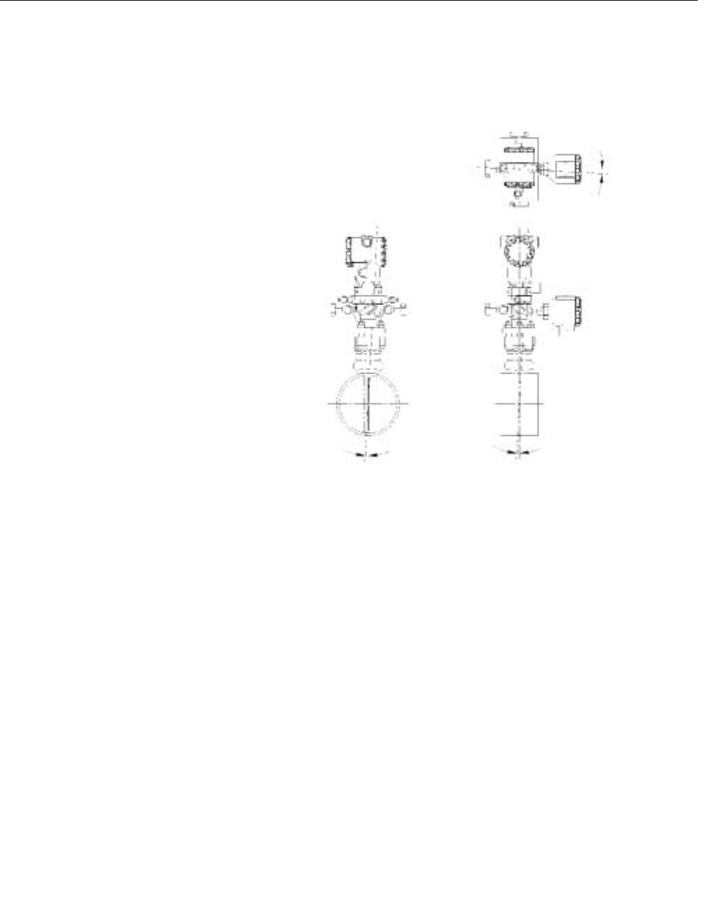
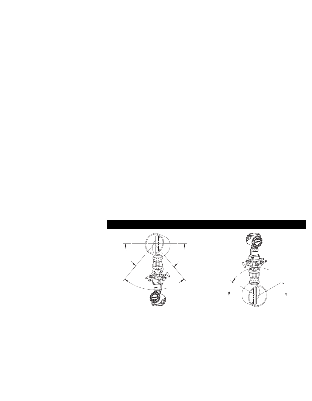
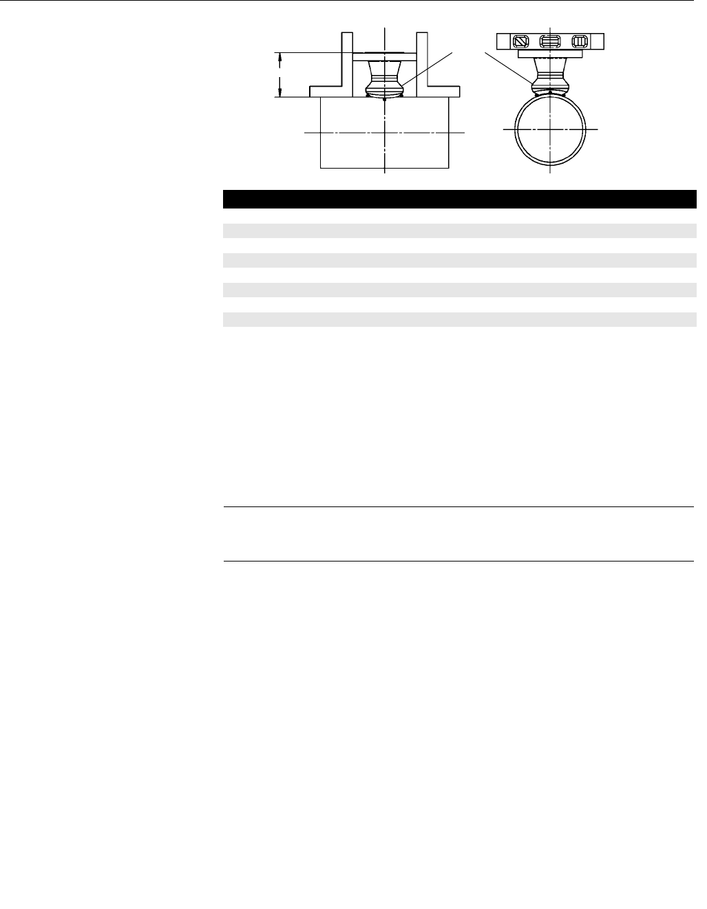
The flowmeter can be installation with a maximum misalignment of 3 degrees
(see Figure 1-1). Misalignment beyond 3 degrees will cause flow
measurement errors.
Figure 1-1. Permissible
Misalignment
Environmental Mount the flowmeter in a location with minimal ambient temperature changes.
Appendix A: Specifications and Reference Data lists the temperature
operating limits. Mount to avoid vibration, mechanical shock, and external
contact with corrosive materials.
Access Requirements
Consider the need to access the flowmeter when choosing an installation
location and orientation.
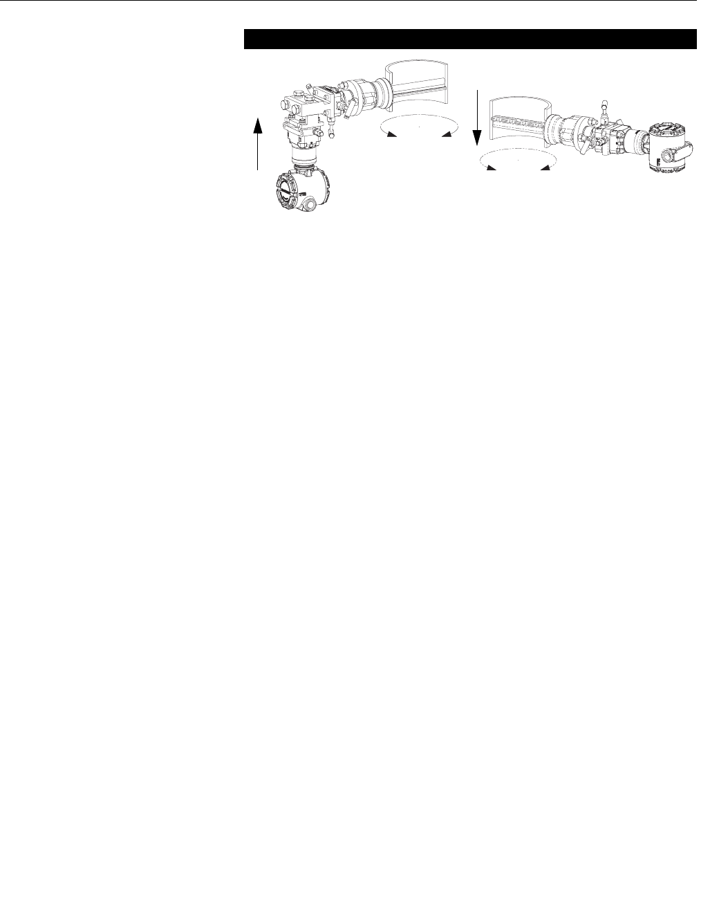
Process Flange Orientation
Orient the process flanges on a remote mounted flowmeter so that process
connections can be made. For safety reasons, orient the drain/vent valves so
that process fluid is directed away from technicians when the valves are used.
In addition, consider the possible need for a testing or calibration input.
Housing Rotation
The electronics housing may be rotated up to 180 degrees (left or right) to
improve field access to the two compartments or to better view the optional
LCD meter. To rotate the housing, release the housing rotation set screw and
turn the housing up to 180 degrees.
3° max.
3° max.
28-490000-940A01A
3° max.
Reference Manual
00809-0100-4809, Rev AA
August 2002
Annubar Flowmeter Series
1-4
NOTE
Rotating the housing more than 180 degrees will damage the sensor module
and void the warranty.
Electronics Housing
Terminal Side
The circuit compartment should not routinely need to be opened when the
unit is in service. Wiring connections are made through the conduit
openings on the top side of the housing. The field terminal side is marked
on the electronics housing. Mount the flowmeter so that the terminal side
is accessible. A 0.75-in. (19 mm) clearance is required for cover removal.
Use a conduit plug on the unused side of the conduit opening. A 3-in. (76
mm) clearance is required for cover removal if a meter is installed.
Exterior
The integral span and zero push-buttons are located under the
certifications plate on the top of the ProBar. The plate will be blank if no
certifications are ordered.
Cover Installations
Always install the electronics housing covers metal-to-metal to ensure a
proper seal.
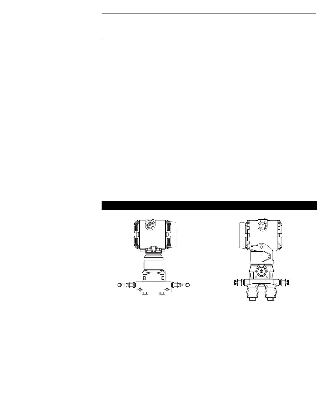
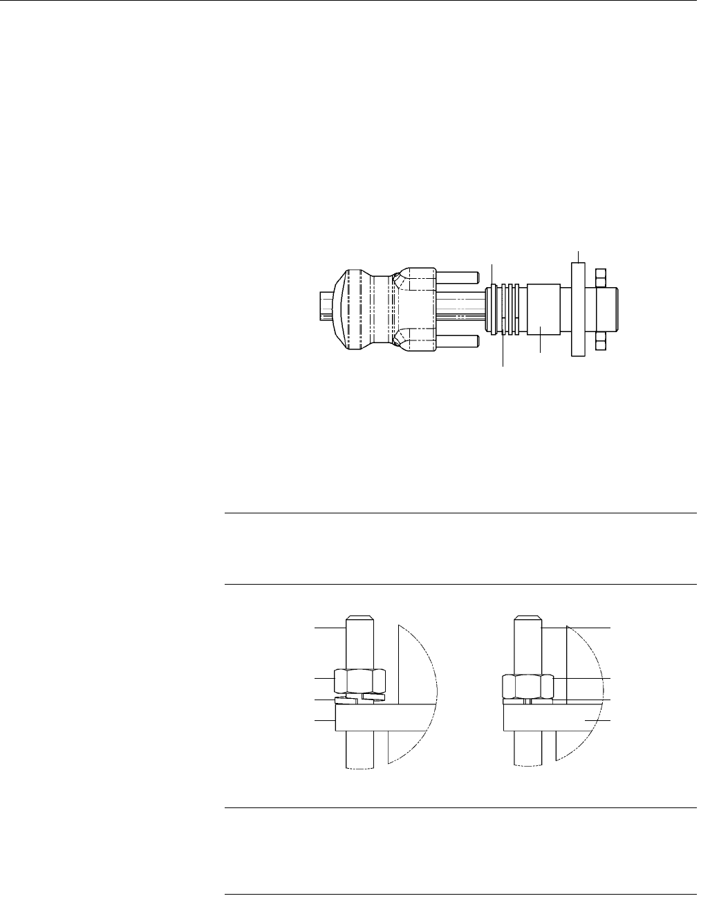
Figure 1-2. Electronics Housing
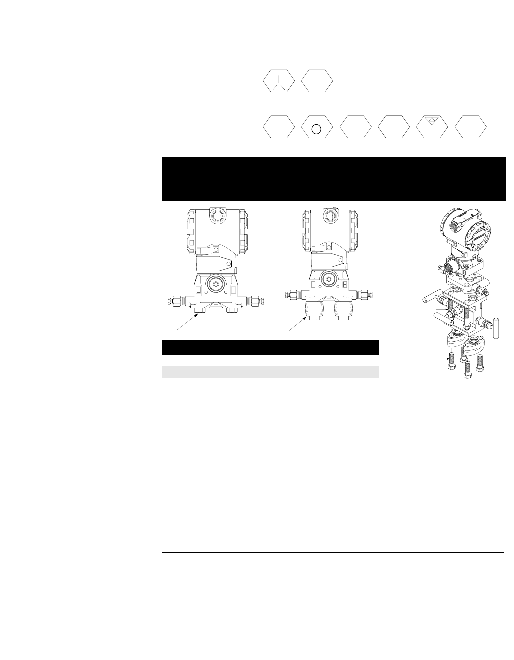
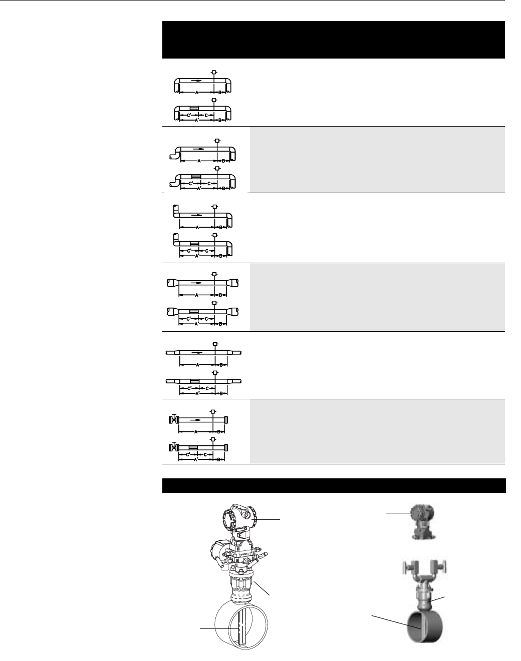
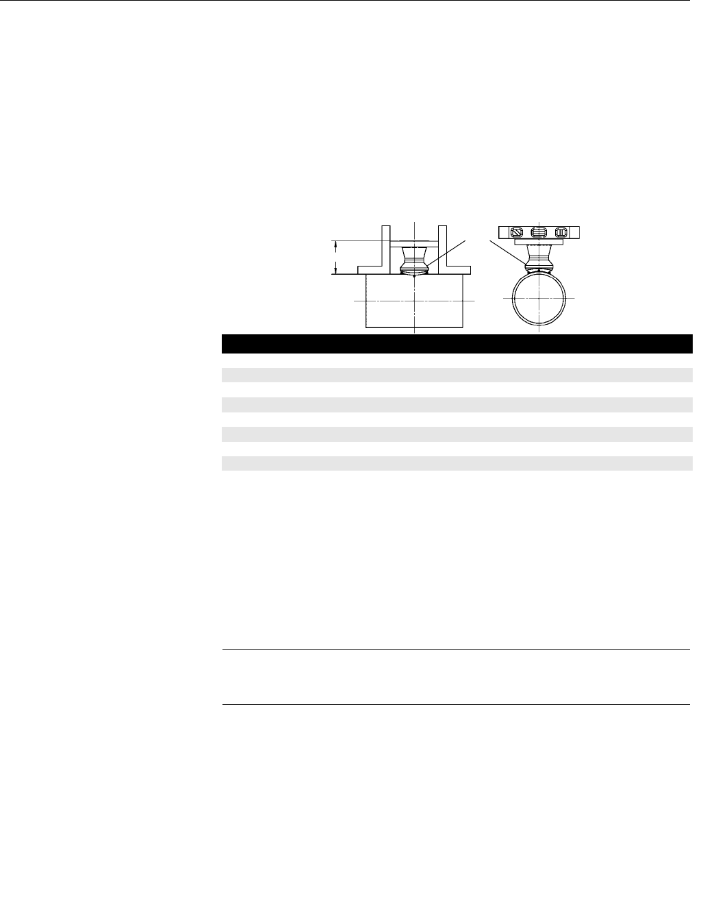
Process Considerations The process connections on the transmitter flange are 1/4–18 NPT. Flange
adapter unions with 1/2–14 NPT connections are available as options. These
are Class 2 threads; use the plant-approved lubricant or sealant when making
the process connections. The process connections on the transmitter flange
are on 21/8–in. (54 mm) centers to allow direct mounting to a three- or
five-valve manifold. By rotating one or both of the flange adapters, connection
centers of 2–, 21/8–, or 21/4–in. (51, 54, or 57 mm) may be obtained.
Rosemount Model 3051S Transmitter Rosemount Model 3095 Transmitter
3051S_COPLANAAR_3051A
01F, 3095-3095G05C

Reference Manual
00809-0100-4809, Rev AA
August 2002
1-5
Annubar Flowmeter Series
Failure to install proper flange adapter O-rings can cause process leaks,
which can result in death or serious injury. There are two styles of Rosemount
flange adapters, each requiring a unique O-ring, as shown below. Each flange
adapter is distinguished by its unique groove.
Use only the O-ring designed to seal with the corresponding flange adapter.
Refer to the factory for the correct part numbers of the flange adapters and
O-rings designed for the flowmeter.
Teflon ® (PTFE) O-rings tend to cold flow when compressed, which aids in
their sealing capabilities. Whenever flanges or adapters are removed, visually
inspect the Teflon (PTFE) O-rings. Replace them if there are any signs of
damage. If the O-rings are replaced, the flange bolts may need to be
retorqued after installation to compensate for cold flow.
Electrical The signal terminals are located in a compartment of the electronics housing.
Connections for the Model 275 HART Communicator are located below the
signal terminals. The Model 272 Field Calibrator can be connected at the
signal terminals to provide temporary power to the electronics for calibration
or diagnostic purposes. Otherwise, the calibrator may be attached to the test
connections on the terminal block of the electronics for indication purposes.
Power Supply
The dc power supply should provide power with less than 2% ripple. The total
resistance load is the sum of the resistance of the signal leads and the load
resistance of the controller, indicator, and related pieces. Note that the
resistance of intrinsic safety barriers, if used, must be included.
NOTE
A loop resistance between 250-1100 ohms is required to communicate with a
personal computer. With 250 ohms of loop resistance, a power supply voltage
of at least 16.5 V dc is required.(1)
If a single power supply is used to power more than one Model 3095MFA
Mass ProBar, the power supply used, and circuitry common to the Mass
ProBars, should not have more than 20 ohms of impedance at 1200 Hz.
MODEL 3051/2024/3001/3095
Flange Adapter
O-ring
Unique O-ring
Grooves
(1) Quick troubleshooting check: There must be at least 11.0 V DC across the Model 3095MFA
Mass ProBar electronics terminals.

Reference Manual
00809-0100-4809, Rev AA
August 2002
Annubar Flowmeter Series
1-6
Reference Manual
00809-0100-4809, Rev AA
August 2002 Annubar Flowmeter Series
www.rosemount.com
Section 2 Installation
Safety Messages . . . . . . . . . . . . . . . . . . . . . . . . . . . . . . . . . page 2-1
Installation Flowchart and Checklist . . . . . . . . . . . . . . . . page 2-2
Mounting . . . . . . . . . . . . . . . . . . . . . . . . . . . . . . . . . . . . . . . page 2-4
Installation . . . . . . . . . . . . . . . . . . . . . . . . . . . . . . . . . . . . . . page 2-12
Connect the Wiring . . . . . . . . . . . . . . . . . . . . . . . . . . . . . . . page 2-40
SAFETY MESSAGES Instructions and procedures in this section may require special precautions to
ensure the safety of the personnel performing the operations. Please refer to
the following safety messages before performing any operation in this section.
Explosions could result in death or serious injury:
• Do not remove the transmitter cover in explosive atmospheres when the circuit is
live.
• Before connecting a Model 275 HART Communicator in an explosive atmosphere,
make sure the instruments in the loop are installed in accordance with intrinsically
safe or non-incendive field wiring practices.
• Verify that the operating atmosphere of the transmitter is consistent with the
appropriate hazardous locations certifications.
• Both transmitter covers must be fully engaged to meet explosion-proof
requirements.
Failure to follow these installation guidelines could result in death or serious injury:
• Make sure only qualified personnel perform the installation.
Reference Manual
00809-0100-4809, Rev AA
August 2002
Annubar Flowmeter Series
2-2
INSTALLATION
FLOWCHART AND
CHECKLIST
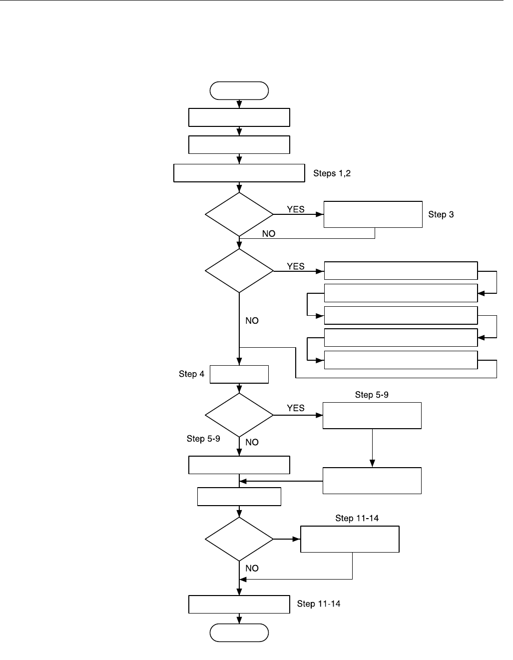
Figure 2-1 is an installation flowchart that provides guidance through the
installation process. Following the figure, an installation checklist has been
provided to verify that all critical steps have been taken in the installation
process. The checklist numbers are indicated in the flowchart.
Figure 2-1. Installation Chart
Start.
Unpack Instrument
Review Product
Manual.
Verify proper location.
Hazardous
Location?
Bench
Configure?
Review Appendix B.
Configure write-protect and
failure alarm
Connect the bench power supply
Connect the instrument to a PC
Perform bench configuration tasks
(Optional) Perform bench
calibration tasks
Verify model
Remote
Mounted
Electronics?
Install electronics
Install flowmeter
Wire
Remote
Mounted
Electronics?
Finish.
Commission
Install hardware
Commission

Reference Manual
00809-0100-4809, Rev AA
August 2002
2-3
Annubar Flowmeter Series
The following list is a summary of the steps required to complete a flowmeter
installation. If this a new installation, begin with step 1. If the mounting is
already in place, verify that the hole size and the fittings match the
recommended specifications (see Table 2-3 on page 2-13) and begin with
step 5.
1. Determine where the flowmeter is to be placed within the piping
system.
2. Establish the proper orientation as determined by the intended
application.
3. Review Appendix B: Approvals and determine if the flowmeter is
located in a hazardous location.
4. Confirm the configuration.
5. Drill the correct sized hole into the pipe.
• For instruments equipped with opposite-side support, drill a second
hole 180° from the first hole.
6. Weld the mounting and clean the burrs and welds.
7. Measure the pipe’s internal diameter (ID), preferably at 1 x ID from
the hole (upstream or downstream).
NOTE
To maintain published flowmeter accuracy, provide the pipe ID when
purchasing the flowmeter.
8. Check the fit-up of the instrument assembly to the pipe.
9. Install the flowmeter.
10. Wire the instrument.
11. Supply power to the flowmeter.
12. Perform a trim for mounting effects.
13. Check for leaks.
14. Commission the instrument

Reference Manual
00809-0100-4809, Rev AA
August 2002
Annubar Flowmeter Series
2-4
MOUNTING
Tools and Supplies Tools required include the following:
• Open end or combination wrenches (spanners) to fit the pipe fittings
and bolts: 9/16-in., 5/8-in., 7/8-in.
• Adjustable wrench: 15-in. (1½-in. jaw).
• Nut driver: 3/8-in. for vent/drain valves (or 3/8-in. wrench).
• Phillip’s screwdriver: #1.
• Standard screwdrivers: ¼-in., and 1/8-in. wide.
• Pipe wrench: 14-in.
• Wire cutters/strippers
•7/16-in. box wrench (required for the ferry head bolt design)
Supplies required include the following:
• ½-in. tubing (recommended) or ½-in. pipe to hook up the electronics to
the sensor probe. The length required depends upon the distance
between the electronics and the sensor.
• Fittings including (but not limited to)
• Two tube or pipe tees (for steam or high temperature liquid) and
• Six tube/pipe fittings (for tube)
• Pipe compound or Teflon (PTFE) tape (where local piping codes
allow).
Mounting Brackets Optional mounting brackets available with the instrument facilitate mounting to
a panel, wall, or 2-in. (50.8 mm) pipe. The bracket option for use with the
Coplanar flange is 316 SST with 316 SST bolts. See “Mounting” on page A-31
for bracket dimensions.
When installing the transmitter to one of the mounting brackets, torque the
bolts to 125 in-lb (169 n-m).
Bolt Installation
Guidelines
The following guidelines have been established to ensure a tight flange,
adapter, or manifold seal. Only use bolts supplied with the instrument or sold
by the factory.
The instrument is shipped with the coplanar flange installed with four 1.75-in.
(44.5 mm) flange bolts. The following bolts also are supplied to facilitate other
mounting configurations:
• Four 2.25-in. (57.2 mm) manifold/flange bolts for mounting the coplanar
flange on a three-valve manifold. In this configuration, the 1.75-in. (44.5
mm) bolts may be used to mount the flange adapters to the process
connection side of the manifold.
• (Optional) If flange adapters are ordered, four 2.88-in. (73.2 mm)
flange/adapter bolts for mounting the flange adapters to the coplanar
flange.
Reference Manual
00809-0100-4809, Rev AA
August 2002
2-5
Annubar Flowmeter Series
Stainless steel bolts supplied by Rosemount Inc. are coated with a lubricant to
ease installation. Carbon steel bolts do not require lubrication. Do not apply
additional lubricant when installing either type of bolt. Bolts supplied by
Rosemount Inc. are identified by the following head markings:
Figure 2-2. Coplanar Mounting
Bolts and Bolting Configurations
for Coplanar Flange.
Instrument Manifolds Figure 2-3 on page 2-6 identifies the valves on a 5-valve and a 3-valve
manifold. Table 2-1 on page 2-6 explains the purpose of these valves.
An instrument manifold is recommended for all installations. A manifold allows
an operator to equalize the pressures prior to the zero calibration of the
electronics as well as to isolate the electronics from the rest of the system
without disconnecting the impulse piping. Although a 3-valve manifold can be
used, a 5-valve manifold is recommended.
5-valve manifolds provide a positive method of indicating a partially closed or
faulty equalizer valve. A closed faulty equalizer valve will block the DP signal
and create errors that may not be detectable otherwise. The labels for each
valve will be used to identify the proper valve in the procedures to follow.
NOTE
Some recently-designed instrument manifolds have a single valve actuator,
but cannot perform all of the functions available on standard 5-valve units.
Check with the manufacturer to verify the functions that a particular manifold
can perform. In place of a manifold, individual valves may be arranged to
provide the necessary isolation and equalization functions.
Carbon Steel Head
Markings (CS)
Stainless Steel Head
Markings (SST)
B7M
316 316
RB8M STM
316 316
SW
316
Transmitter with
Flange Bolts
Transmitter with Optional
Flange Adapters and
Flange/Adapter Bolts
Transmitter with 3-Valve
Manifold, Manifold/Flange
Bolts, Flange Adapters
and Flange/Adapter bolts
Description Size in. (mm)
Flange bolts (4) 1.75 -in. (44 mm)
Flange/adapter bolts (4) 2.88 -in. (73 mm)
Manifold/flange bolts (4) 2.25 -in. (57 mm)
1.75 (44) ⫻ 4 2.88 (73) ⫻ 4
1.75 (44) ⫻ 4
2.25 (57) ⫻ 4
3095-3095D05A, 3095E05A, 3095B29A
Reference Manual
00809-0100-4809, Rev AA
August 2002
Annubar Flowmeter Series
2-6
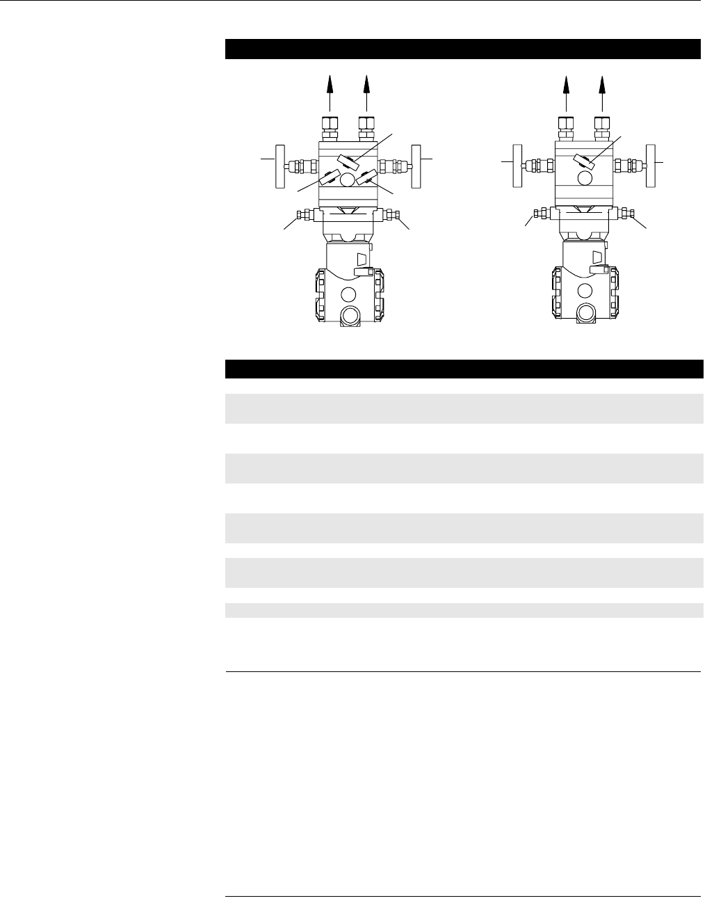
Figure 2-3. Valve Identification
for 5-valve and 3-Valve
Manifolds
Table 2-1. Description of
Impulse Valves and
Components
Straight Run
Requirements
Use the following to aid in determining the straight run requirements
NOTE
•For gas service, multiply values from Table 2-2 on page 2-7 by 1.5.
• If longer lengths of straight run are available, position the mounting
such that 80% of the run is upstream and 20% is downstream.
• The information contained in this manual is applicable to circular pipes
only. Consult the factory for instructions regarding use in square or
rectangular ducts.
• Straightening vanes may be used to reduce the required straight
run length.
• Row 5 in Table 2-2 is to be used if a “through type” valve will remain
open. Row 6 in Table 2-2 applies to gate, globe, plug, and other
throttling valves that are partially opened, as well as control valves.
5-Valve Manifold 3-Valve Manifold
To PH To PL
MH
MV
ML
DVLDVH
MELMEH
2
1
To PH To PL
MH
ME
ML
DVLDVH
8900_8900_35A
2
1
Name Description Purpose
Manifold and Impulse Pipe Valves
PH Primary Sensor – High Pressure Isolates the flowmeter sensor from the
impulse piping system
PL Primary Sensor – Low Pressure
DVH Drain/Vent Valve – High Pressure Drains (for gas service) or vents (for liquid or
steam service) the DP electronics chambers
DVL Drain/Vent Valve – Low Pressure
MH Manifold – High Pressure Isolates high side or low side pressure from
the process.
ML Manifold – Low Pressure
MEH Manifold Equalizer – High Pressure Allows high and low pressure side access to
the vent valve, or for isolating the process fluid
MEL Manifold Equalizer – Low Pressure
ME Manifold Equalizer Allows high and low side pressure to equalize
MV Manifold Vent Valve Vents process fluid
Components
1Electronics Reads Differential Pressure Isolates and
equalizes electronics.
2Manifold
3 Vent Chambers Collects gases in liquid applications.
4Condensate Chamber Collects condensate in gas applications.
Reference Manual
00809-0100-4809, Rev AA
August 2002
2-7
Annubar Flowmeter Series
Table 2-2. Straight Run
Requirements
Figure 2-4. Mounting
Configuration
Upstream dimension Downstream
Dimensions
Without vanes With vanes
In plane A Out of plane A A’ CC’ B
1.
8
–
10
–
–
8
–
4
–
4
4
4
2.
11
–
16
–
–
8
–
4
–
4
4
4
3.
23
–
28
–
–
8
–
4
–
4
4
4
4.
12
–
12
–
–
8
–
4
–
4
4
4
5.
18
–
18
–
–
8
–
4
–
4
4
4
6.
30
–
30
–
–
8
–
4
–
4
4
4
1295-0573B
1
295-0573C
1295-0573D
1295-0573E
1295-0573F
1295-0573G
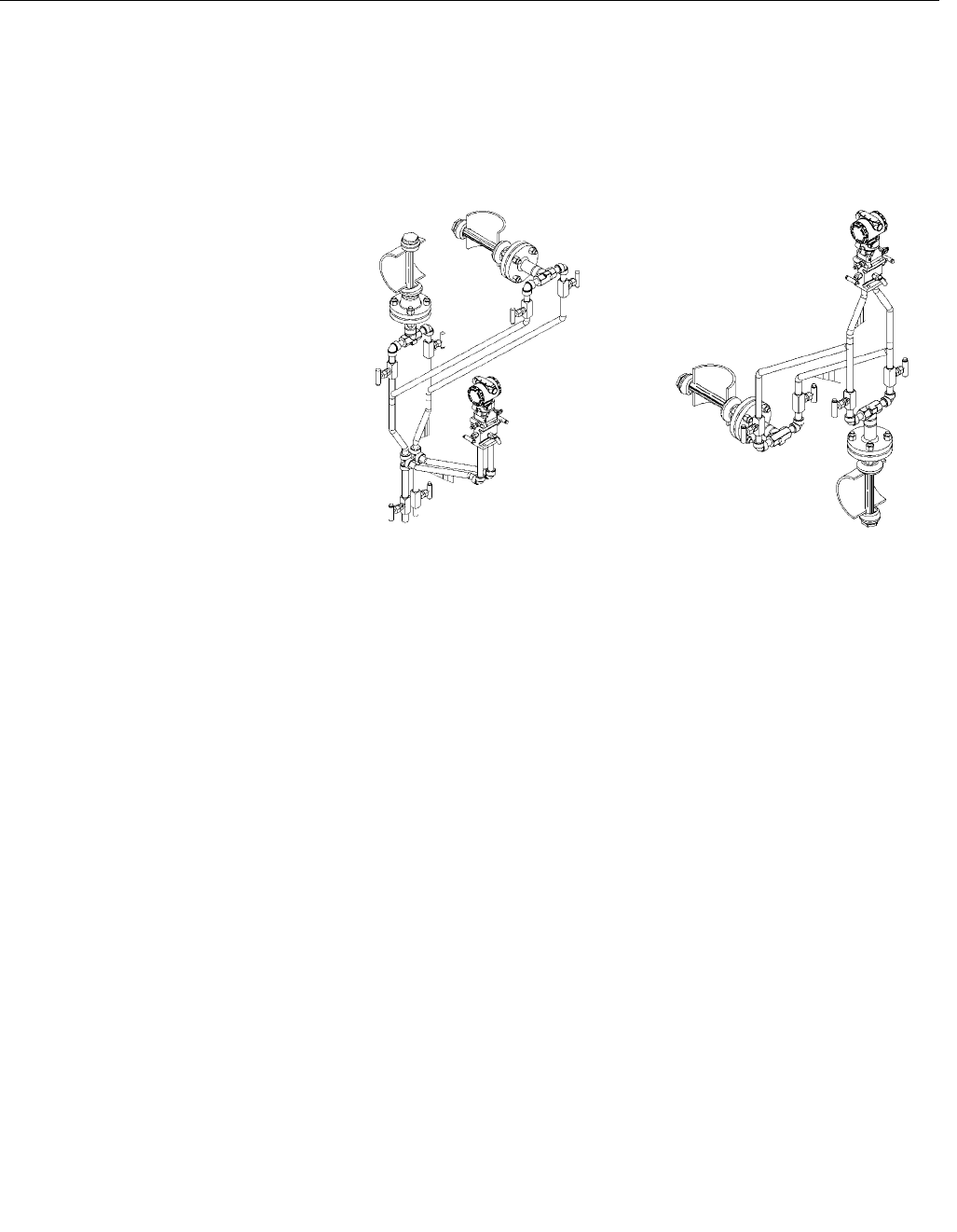
Integral Mount Remote Mount
Electronics
Sensor
Mounting
Configuration
28-490000-945A01A, 946A01A
Electronics
Sensor
Mounting
Configuration
Reference Manual
00809-0100-4809, Rev AA
August 2002
Annubar Flowmeter Series
2-8
Integral (Direct) Mount
NOTE
The integral mount flowmeter is usually shipped with the electronics bolted
directly to the sensor. If this is not so, contact Rosemount Customer Central
for more information.
Horizontal Pipes
Liquid or Steam Applications
Due to the possibility of air getting trapped in the probe, the sensor should
be located according to Figure 2-5 for liquid or steam applications. The
area between 0° and 30° angle should not be used unless full bleeding of
air from the probe is possible.
For liquid applications, mount the side drain/vent valve upward to allow the
gases to vent.
In steam applications, fill the lines with water to prevent the steam from
contacting the electronics. Condensate chambers are not required
because the volumetric displacement of the electronics is negligible.
Air and Gas Applications
Figure 2-5 illustrates the recommended location of the flowmeter in air or
gas applications. The sensor should be located on the upper half of the
pipe, at least 30° above the horizontal line.
For air and gas applications, mount the drain/vent valve downward to allow
liquid to drain.
Figure 2-5. Horizontal Pipe
Applications
Vertical Pipes
Liquid, Steam, Air, and Gas Applications
Figure 2-6 illustrates the recommended location of the flowmeter in liquid,
air, or gas applications.
The sensor can be installed in any position around the circumference of
the pipe, provided the vents are positioned properly for bleeding or
venting. Vertical pipe installations require more frequent bleeding or
venting, depending on the location.
Liquid or Steam Applications Air or Gas Applications
!!
!
30
degrees
30
degrees
120 degrees
Recommended
Zone
!
!
!
30
degrees 30
degrees
Recommended
Zone 120
degrees
9
-490000-909A02A, 909A01A
Reference Manual
00809-0100-4809, Rev AA
August 2002
2-9
Annubar Flowmeter Series
Figure 2-6. Vertical Pipe
Applications
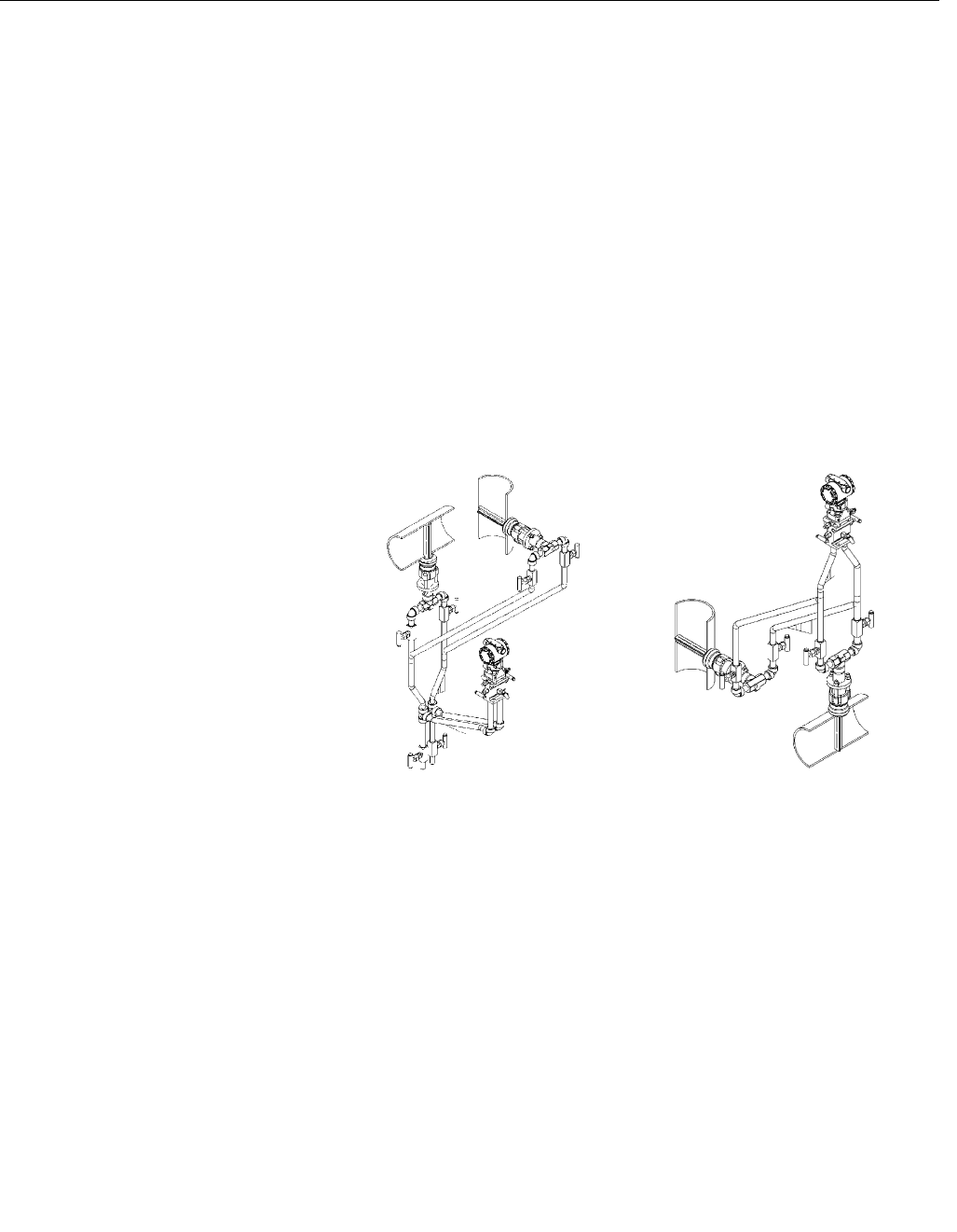
Remote Mount Instrument head connections differ between horizontal and vertical pipes.
Consult your specification head code number to confirm the proper pipe
orientation.
Valves and Fittings
Throughout the remote mounting process:
• Use only valves, fittings, and pipe thread sealant compounds that are
rated for the service pipeline design pressure and temperature as
specified in Appendix A: Specifications and Reference Data.
• Verify that all connections are tight and that all instrument valves are
fully closed.
• Verify that the sensor probe is properly oriented for the intended type of
service: liquid, gas or steam (see Figures “Integral (Direct) Mount” on
page 2-8 and “Remote Mount” on page 2-9).
Impulse Piping
Impulse piping connects remote mounted electronics to the sensor.
Temperatures in excess of 250 °F (121 °C) at the electronics will damage
electronics components; impulse piping allows service flow temperatures to
decrease to a point where the electronics is no longer vulnerable.
The following restrictions and recommendations apply to impulse piping
location.
• Piping used to connect the sensor probe and electronics must be rated
for continuous operation at the pipeline-designed pressure and
temperature
• Impulse piping that runs horizontally must slope at least 1–in. per foot
(83mm/m).
• It must slope downwards (toward the electronics) for liquid and steam
applications.
• It must slope up (away from the electronics) for gas applications.
• For applications where the pipeline temperature is below 250 °F
(121 °C), the impulse piping should be as short as possible to minimize
flow temperature changes. Insulation may be required.
Liquid or Steam Applications Air or Gas Applications
360
degrees
Flow
Flow
360
degrees
Reference Manual
00809-0100-4809, Rev AA
August 2002
Annubar Flowmeter Series
2-10
• For applications where pipeline temperature is above 250 °F (121 °C),
the impulse piping should have a minimum length of 1-ft. (0.30 m) for
every 100 °F (38 °C) over 250 °F (121 °C), which is the maximum
operating electronics temperature. Impulse piping must be uninsulated
to reduce fluid temperature. All threaded connections should be
checked after the system comes up to temperature, because
connections may be loosened by the expansion and contraction
caused by temperature changes.
• A minimum of 1/2-in. (12mm) outer diameter (OD) stainless steel tubing
with a wall thickness of at least 0.035-in. is recommended.
• Outdoor installations for liquid, saturated gas, or steam service may
require insulation and heat tracing to prevent freezing.
• For installations where the electronics are more than 6-ft. (1.8m) from
the sensor probe, the high and low impulse piping must be run together
to maintain equal temperature. They must be supported to prevent
sagging and vibration.
• Threaded pipe fittings are not recommended because they create voids
where air can become entrapped and have more possibilities for
leakage.
• Run impulse piping in protected areas or against walls or ceilings. If the
impulse piping is run across the floor, ensure that it is protected with
coverings or kick plates. Do not locate the impulse piping near high
temperature piping or equipment.
• Use an appropriate pipe sealing compound rated for the service
temperature on all threaded connections. When making threaded
connections between stainless steel fittings, Loctite® PST® Sealant is
recommended.
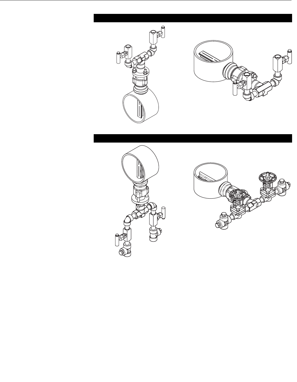
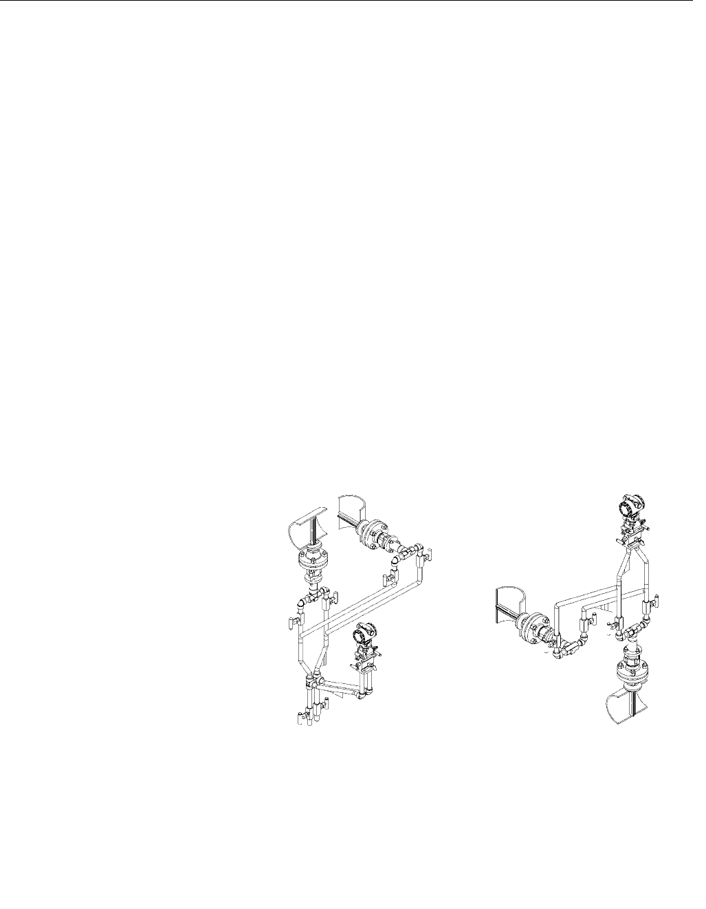
Figure 2-7. Liquid Service
Horizontal Vertical
29-490000-941A01A, 942A01A
Reference Manual
00809-0100-4809, Rev AA
August 2002
2-11
Annubar Flowmeter Series
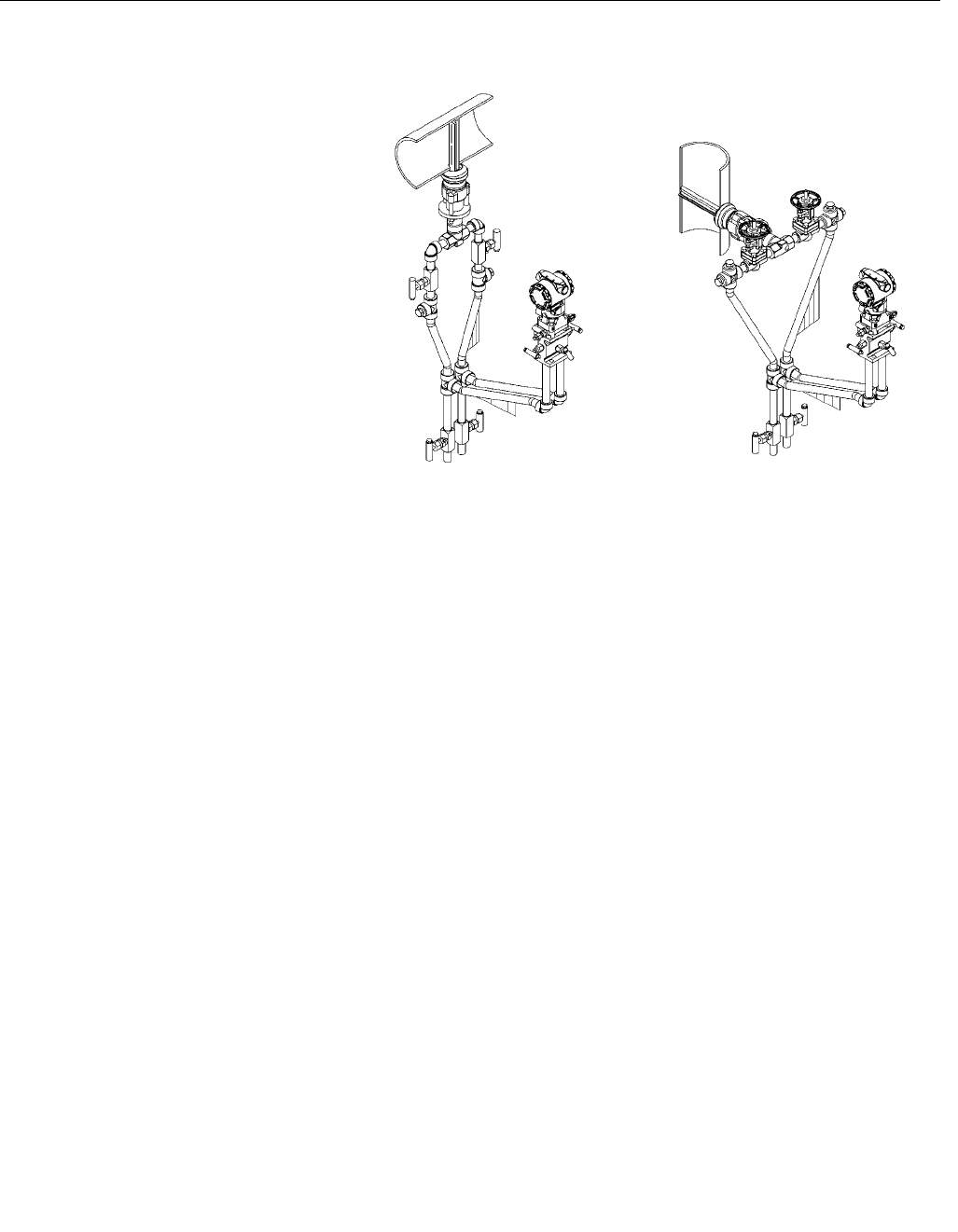
Figure 2-8. Gas Service
Figure 2-9. Steam Service
Horizontal Vertical
29-490000-
9
Horizontal Vertical
29-490000-980A02A, 981A01A
Reference Manual
00809-0100-4809, Rev AA
August 2002
Annubar Flowmeter Series
2-12
INSTALLATION This manual contains the horizontal and vertical installation procedures for
the Pak-Lok, Flanged, Flange-Lok, and Threaded Flow-Tap Annubar models.
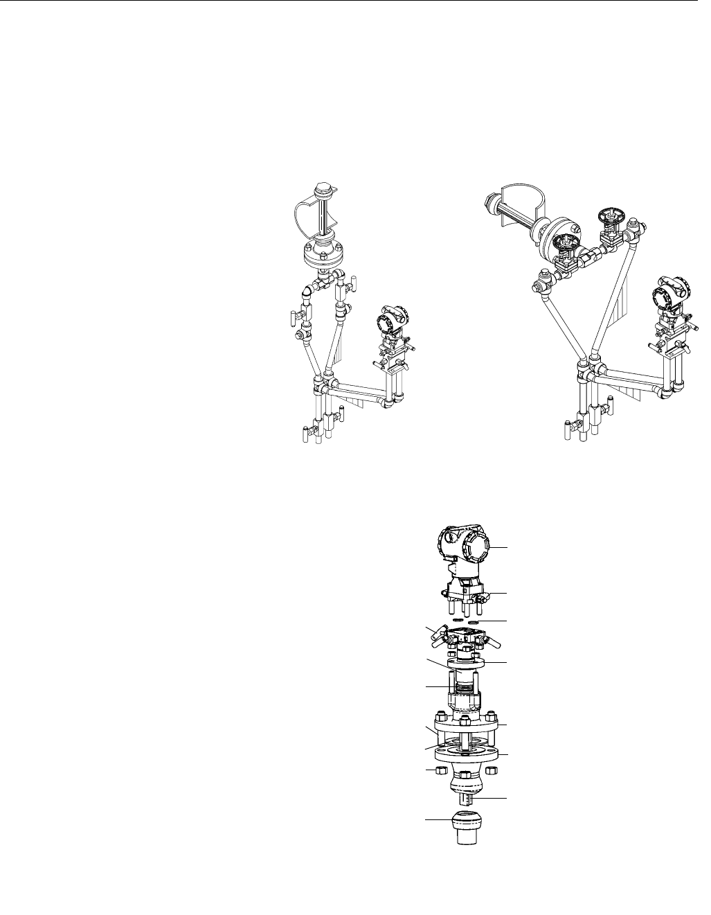
Pak-Lok Model Figure 2-10 identifies the components of the Pak-Lok assembly.
Figure 2-10. Components
Step 1: Set the Switches
Refer to “Mounting” on page 2-4 for more information
Step 2: Determine the Proper Orientation
Please refer to “Mounting” on page 2-4 for straight run requirements and
orientation information.
Step 3: Drill a Hole into the Pipe
Follow the steps below to drill the hole in the pipe.
1. Depressurize and drain the pipe.
2. From the previous steps, select the location to drill the hole.
3. Determine the diameter of the hole to be drilled according to the
specifications in Table 2-3 and drill the hole. Do not torch cut the
hole.
Transmitter
Compression Plate
Coplanar Flange with Drain
Vents
O-Rings (2)
Annubar Sensor
Retaining Ring
Direct Mount Electronics
Connection with Valves
Studs
Opposites Side Support
(optional)
Pak-Lok Body
Packing Rings (3)
Follower
Nuts
28-49000-956A, 900A

Reference Manual
00809-0100-4809, Rev AA
August 2002
2-13
Annubar Flowmeter Series
Table 2-3. Drill Hole into Pipe
4. If opposite-side support coupling is supplied, a second identically
sized hole must be drilled opposite the first hole so that the sensor
can pass completely through the pipe. (To determine a opposite-side
support model, measure the distance from the tip of the first slot or
hole. If the distance is greater than 1-in. (25.4 mm), it is the
opposite-side model.) To drill the second hole, follow these steps:
a. Measure the pipe circumference with a pipe tape, soft wire, or string
(for the most accurate measurement the pipe tape needs to be
perpendicular to the axis of flow).
b. Divide the measured circumference by two to determine the location
of the second hole.
c. Rewrap the pipe tape, soft wire, or string from the center of the first
hole. Then, using the number calculated in the preceding step, mark
the center of what will become the second hole.
d. Using the diameter determined from Table 2-3, drill the hole into the
pipe with a hole saw or drill. Do not torch cut the hole.
5. Deburr the drilled hole(s) on the inside of the pipe.
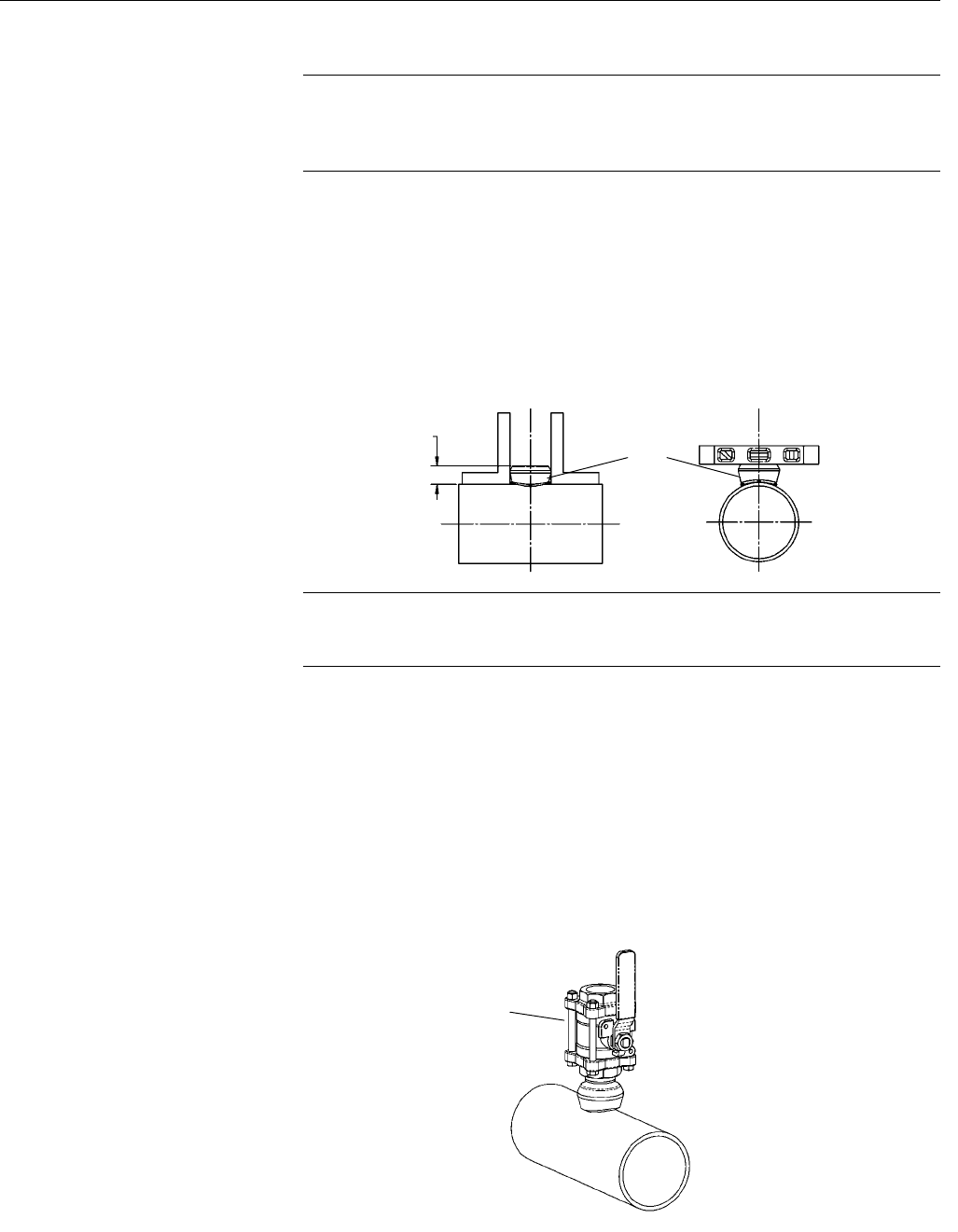
Step 4: Weld the Mounting Hardware
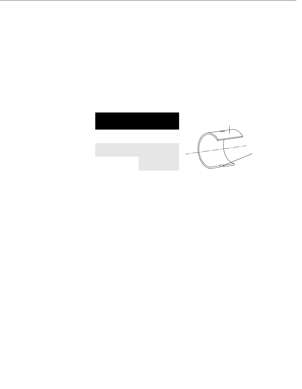
1. Center the Pak-Lok body over the mounting hole, gap 1/16-in. (1.5 mm)
and place four 1/4-in. (6-mm) tack welds at 90° increments. Check
alignment of the Pak-Lok body both parallel and perpendicular to the
axis of flow. If alignment of mounting is within tolerances (see
Figure 2-11), finish weld per local codes. If alignment is outside of
specified tolerance make adjustments prior to finish weld.
Sensor Size / Hole Diameter Chart
Sensor Diameter
T1
3/4-in.
(19 mm)
+ 1/32-in (1 mm)
– 0.00
T2 15/16-in.
(34 mm)
+ 1/16-in. (1 mm)
– 0.00
T3 21/2-in.
(64 mm)
+ 1/16-in. (1 mm)
– 0.00
8900-8900_15A
Drill the
appropriate
diameter hole
through the pipe
wall.
Note: Drill the hole 180 degrees from the first
hole for opposite-side support models.
Reference Manual
00809-0100-4809, Rev AA
August 2002
Annubar Flowmeter Series
2-14
Figure 2-11. Alignment
2. If opposite side support is being used, center the fitting for the
opposite
side support over the opposite side hole, gap 1/16-in. (1.5 mm) and
place
four 1/4-in. (6 mm) tack welds at 90° increments. Insert the sensor into
the mounting hardware. Verify that the tip of the bar is centered in the
opposite side fitting and verify that the plug will fit around bar. If the
bar is centered in the fitting and plug fits around the bar, finish weld
per local codes. If the alignment of the bar does not allow enough
clearance to insert the opposite side plug, make the necessary
adjustments prior to making the finish weld.
NOTE
To avoid serious burns, allow the mounting hardware to cool
before continuing.
Step 5: Insert into the Pipe
After the mounting hardware has cooled, use the following steps for
installation.
1. Thread studs into the Pak-Lok body.
2. To ensure that the flowmeter contacts the opposite side wall, mark
the
tip of the sensor with a marker. (Do not mark if the sensor was
ordered with special-cleaned option code P2.)
3. Rotating the flowmeter back and forth, insert the flowmeter into the
Pak-Lok body until the sensor tip contacts the pipe wall (or support
plug).
4. Remove the flowmeter.
5. Verify that the sensor tip made contact with the pipe wall by removing
the pipe and ensuring that some of the marker has been rubbed off.
For special-cleaned bars, look for wear marks on the tip. If the tip did
not touch the wall, verify pipe dimensions and the height of mounting
body from the OD of the pipe and re-insert.
6. Re-insert the flowmeter into the Pak-Lok body and install the first
packing ring on the sensor between the lock ring and the packing
follower. Do not damage the split packing rings.
7. Push the packing ring into the Pak-Lok body and against the weld
lock ring. Repeat this process for the two remaining rings, alternating
the location of the packing ring split by 180°.
Tack
Welds
LMH
28-490000_906A04A
Reference Manual
00809-0100-4809, Rev AA
August 2002
2-15
Annubar Flowmeter Series
Figure 2-12. Packing Ring Detail
8. Tighten the nuts onto the studs:
• Place the included split-ring lock washer between each of the nuts and
the compression plate. Give each nut one half (1/2) turn in succession
until the split-ring lock washer is flat between the nut and the
compression plate. Inspect the unit for leakage; if any exists, tighten
the nuts in one-quarter (1/4) turn increments until there is no leakage.
NOTE
On sensor size (1), failure to use the split-ring lock washers, improper washer
orientation, or over-tightening the nuts may result in damage to the flowmeter.
Figure 2-13. Split-Ring Lock
Washer Orientation
NOTE
Pak-Lok sealing mechanisms generate significant force at the point where the
sensor contacts the opposite pipe wall. Caution needs to be exercised on
thin-walled piping (ANSI Schedule 10 and below) to avoid damage to the
pipe.
Step 6: Mount the Transmitter
Direct Mount Head
With Valves
• Place Teflon (PTFE) O-rings into grooves on the face of head.
• Align the high side of the transmitter to the high side of the probe
(“Hi” is stamped on the side of the head) and install.
• Tighten the nuts in a cross pattern to 400 in•lb (45 N•m).
Compression
Plate
28-490000_942A01A
Packing
Ring
Retaining
Ring
Follower
28-490000_943A01A
Before Tightening After Tightening
Split ring
lock washer
Nut
Stud
Compression
Plate
Split ring
lock washer
Nut
Stud
Compression
Plate
Reference Manual
00809-0100-4809, Rev AA
August 2002
Annubar Flowmeter Series
2-16
Without Valves
• Place Teflon (PTFE) O-rings into grooves on the face of head.
• Orient the equalizer valve or valves so they are easily accessible.
Install manifold with the smooth face mating to the face of the head.
Tighten in cross pattern to a torque of 400 in•lb (45 N•m).
• Place Teflon (PTFE) O-rings into grooves on the face of the manifold.
• Align the high side of the transmitter to the high side of the probe
(“Hi” is stamped on the side of the head) and install.
• Tighten the nuts in a cross pattern to 400 in•lb (45 N•m).
Remote Mount Head – temperatures below 250 °F (121 °C)
See “Remote Mount” on page 2-9 for more information.
Remote Mount Head – temperature above 250 °F (121 °C)
Liquid or Steam Applications
The electronics must be mounted below the process piping. Route the
impulse piping down to the electronics and fill the system with cool water
through the two tee fittings.
Liquid Applications Gas Applications
Secure the electronics below the
sensor to ensure that air will not be
introduced into the impulse piping
or the electronics.
Secure the electronics above the
sensor to prevent condensable
liquids from collecting in the impulse
piping and the DP cell.
28_490000_931A01A, 932A01A
Reference Manual
00809-0100-4809, Rev AA
August 2002
2-17
Annubar Flowmeter Series
Horizontal Line Vertical Line
28_490000_933A01A, 934A01A
Reference Manual
00809-0100-4809, Rev AA
August 2002
Annubar Flowmeter Series
2-18
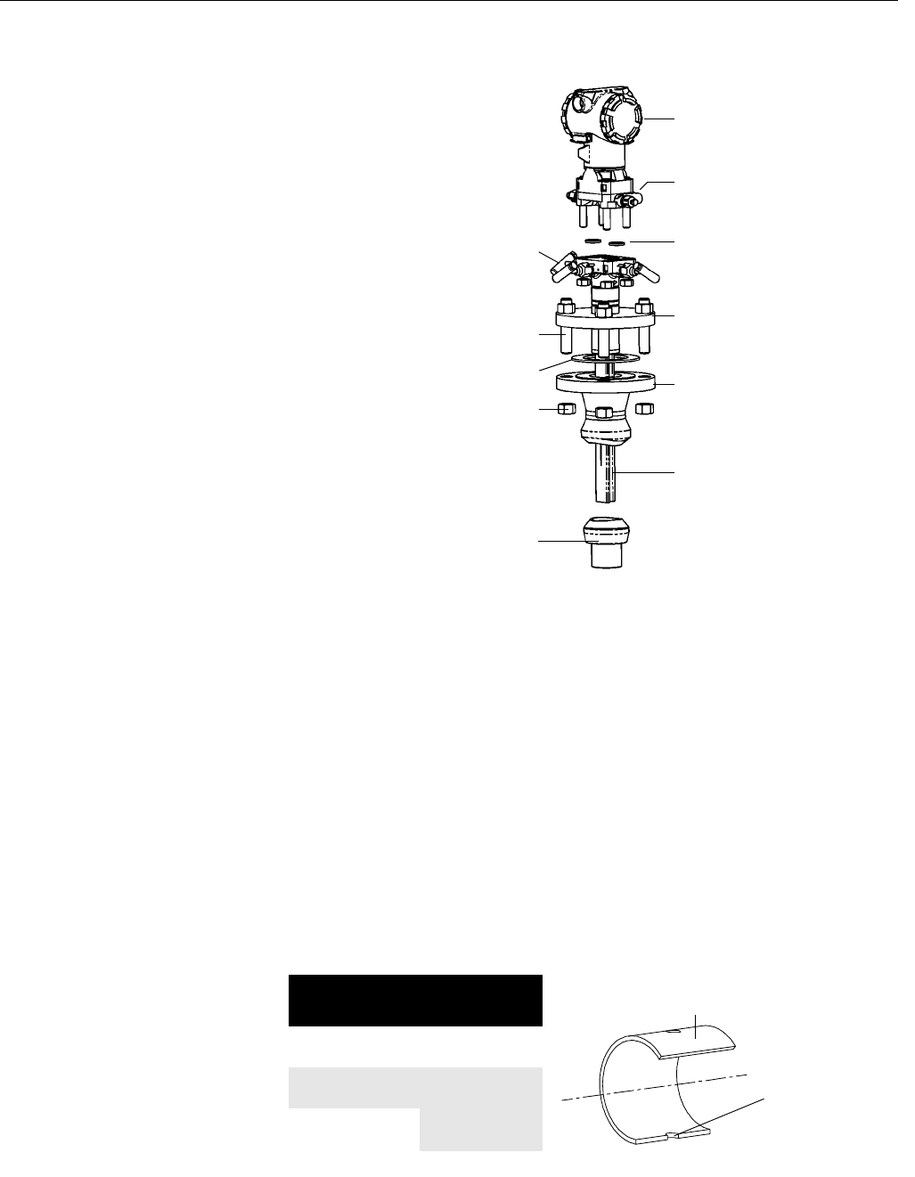
Flanged Model Figure 2-14 identifies the components of the Flanged assembly.
Figure 2-14. Components
Step 1: Set the Switches
Refer to “Mounting” on page 2-4 for more information
Step 2: Determine the Proper Orientation
Please refer to “Mounting” on page 2-4 for straight run requirements and
orientation information.
Step 3: Drill a Hole into the Pipe
Follow the steps below to drill the hole in the pipe.
1. Depressurize and drain the pipe.
2. From the previous steps, select the location to drill the hole.
3. Determine the diameter of the hole to be drilled according to the
specifications in Table 2-4 and drill the hole with a hole saw or a drill.
Do not torch cut the hole.
Table 2-4. Drill Hole into Pipe
Transmitter
Sensor Flange
Coplanar Flange
with Drain Vents
O-Rings (2)
Annubar Sensor
Mounting Flange
Assembly
Direct Mount Electronics
Connection with Valves
Studs
Gasket
Nuts
Opposites Side
Support
28-490000-902A
Sensor Size / Hole Diameter Chart
Sensor Diameter
T1
3/4-in.
(19 mm)
+ 1/32-in (1 mm)
– 0.00
T2 15/16-in.
(34 mm)
+ 1/16-in. (1 mm)
– 0.00
T3 21/2-in.
(64 mm)
+ 1/16-in. (1 mm)
– 0.00
8900-8900_15A
Drill the
appropriate
diameter hole
through the pipe
wall.
Note: Drill the hole 180 degrees from the first
hole for opposite-side support models.
Reference Manual
00809-0100-4809, Rev AA
August 2002
2-19
Annubar Flowmeter Series
4. If opposite-side support coupling is supplied, a second identically
sized hole must be drilled opposite the first hole so that the sensor
can pass completely through the pipe. (To determine a opposite-side
support model, measure the distance from the tip of the first slot or
hole. If the distance is greater than 1-in. (25.4 mm), it is the
opposite-side model.) To drill the second hole, follow these steps:
a. Measure the pipe circumference with a pipe tape, soft wire, or string
(for the most accurate measurement the pipe tape needs to be
perpendicular to the axis of flow).
b. Divide the measured circumference by two to determine the location
of the second hole.
c. Rewrap the pipe tape, soft wire, or string from the center of the first
hole. Then, using the number calculated in the preceding step, mark
the center of what will become the second hole.
d. Using the diameter determined from Table 2-4, drill the hole into the
pipe with a hole saw or drill. Do not torch cut the hole.
5. Deburr the drilled hole or holes on the inside of the pipe.
Step 4: Assemble and check Fit-Up
1. Assemble the bar to the mounting hardware with the gaskets and
bolts.
2. Hand tighten the bolts just enough to hold the position of the sensor
centered in the mounting hardware.
3. Check the fit of the assembly to the pipe by inserting a rule, stick, or
stiff wire through both mounting holes. Note the measured distance.
4. Add 1/16-in. (1.5 mm) to the measured distance and transfer to the
assembly starting at the high point of the weldolet.
5. Measure the distance from the high point of the weldolet to the first
sensing hole, port B, then subtract 1/16-in. (1.5 mm).
6. Measure the distance from the end of the transferred length in step 4
to the last sensing hole, port A.
7. Compare the numbers obtained in steps 5 and 6.
Small discrepancies can be compensated for with the fit-up of the mounting
hardware. Large discrepancies may cause installation problems or error.
Figure 2-15. Fit-up Check for
Annubar with Opposite Side
Support
Liquid or Steam Gas
Port B
Pipe
Outside
Diameter
ODF
The same
within 1/8-in.
(3 mm)
Port A
Port A
Port B
ODF
Pipe
Outside
Diameter
The same
within
1/8-in. (3 mm)
28-490000-917A01A, 930A01A
Reference Manual
00809-0100-4809, Rev AA
August 2002
Annubar Flowmeter Series
2-20
Step 5: Weld the Mounting Hardware
1. Center the Flanged body over the mounting hole, gap 1/16-in. (1.5 mm)
and measure the distance from the OD of the pipe to the face of the
flange. Compare this to the table below and adjust the gap as
necessary.
2. Place four 1/4-in. (6-mm) tack welds at 90° increments. Check
alignment of the mounting both parallel and perpendicular to the axis
of flow (see Figure 2-16). If alignment of the mounting is within
tolerances, finish weld per local codes. If outside of specified
tolerance, make adjustments prior to making the finish weld.
Figure 2-16. Alignment
3. If opposite side support is being used, center the fitting for the
opposite side support over the opposite side hole, gap 1/16-in. (1.5
mm) and place four 1/4-in. (6 mm) tack welds at 90° increments. Insert
the sensor into the mounting hardware. Verify that the tip of the bar is
centered in the opposite side fitting and that the plug will fit around
bar. If the bar is centered in the fitting and plug fits around the bar,
finish weld per local codes. If alignment of the bar does not allow
enough clearance to insert the opposite side plug, make the
necessary adjustments prior to making the finish weld.
NOTE:
To avoid serious burns, allow the mounting hardware to cool
before continuing.
Step 6: Insert into Pipe
After the mounting hardware has cooled, use the following steps for
installation.
Size ODF (in.) Size ODF (mm)
1.0-in. 150# 3.38-in. (85.8 mm) DN25 PN16 2.68-in. (68.2 mm)
1.0-in. 300# 3.63-in. (92.2 mm) DN25 PN40 2.76-in. (70.2 mm)
1.0-in. 600# 3.88-in. (98.5 mm) DN25 PN100 3.47-in. (88.2 mm)
2.0-in. 150# 4.13-in. (104.8 mm) DN50 PN16 3.40-in. (86.3 mm)
2.0-in. 300# 4.38-in. (111.2 mm) DN50 PN40 3.51-in. (89.3 mm)
2.0-in. 600# 4.76-in. (120.8 mm) DN50 PN100 4.30-in. (109.3 mm)
3.0-in. 150# 4.63-in. (117.5 mm) DN80 PN16 3.84-in. (97.6 mm)
3.0-in. 300# 5.00-in. (126.9 mm) DN80 PN40 4.16-in. (105.6 mm)
3.0-in. 600# 5.38-in. (136.6 mm) DN80 PN100 4.95-in. (125.6 mm)
ODF
Tack
Weld
28-490000-915A01A

Reference Manual
00809-0100-4809, Rev AA
August 2002
2-21
Annubar Flowmeter Series
1. Assemble the bar to the mounting flange using a gasket, bolts, and
nuts.
2. Tighten the nuts in a cross pattern to allow even compression of the
gasket.
3. If opposite side support is threaded, apply an appropriate thread
sealing compound to the support plug threads and tighten until no
leakage occurs.
4. If opposite side support is a socket weld fitting, insert the plug into the
sockolet fitting until the parts contact. Retract the plug 1/16-in. (1.5 mm)
and apply fillet weld per local codes.
Step 7: Mount the Transmitter
Direct Mount Head
With Valves
1. Place Teflon (PTFE) O-rings into grooves on the face of head.
2. Align the high side of the transmitter to the high side of the probe
(“Hi” is stamped on the side of the head) and install.
3. Tighten the nuts in a cross pattern to 400 in•lb (45 N•m).
Without Valves
1. Place Teflon (PTFE) O-rings into grooves on the face of head.
2. Orient the equalizer valve or valves so they are easily accessible.
Install manifold with the smooth face mating to the face of the head.
Tighten in cross pattern to a torque of 400 in•lb (45 N•m).
3. Place Teflon (PTFE) O-rings into grooves on the face of the manifold.
4. Align the high side of the transmitter to the high side of the probe
(“Hi” is stamped on the side of the head) and install.
5. Tighten the nuts in a cross pattern to 400 in•lb (45 N•m).
Reference Manual
00809-0100-4809, Rev AA
August 2002
Annubar Flowmeter Series
2-22
Remote Mount Head – temperature below 250 °F (121 °C)
See “Remote Mount” on page 2-9 for more information
Liquid Applications Gas Applications
Secure the electronics below the
sensor to ensure that air will not be
introduced into the impulse piping or
the electronics.
Secure the electronics above the
sensor to prevent condensable
liquids from collecting in the impulse
piping and the DP cell.
28_490000_950A01A, 951A01A
Reference Manual
00809-0100-4809, Rev AA
August 2002
2-23
Annubar Flowmeter Series
Remote Mount Head – temperature above 250 °F (121 °C)
Liquid or Steam Applications
The electronics must be mounted below the process piping. Route the
impulse piping down to the electronics and fill the system with cool water
through the two tee fittings.
Flange-Lok Model Figure 2-17 identifies the components of the Flange-Lok assembly.
Figure 2-17. Components
Step 1: Set the Switches
Refer to “Mounting” on page 2-4 for more information
Horizontal Line Vertical Line
28_490000_952A01A, 953A01A
Transmitter
Compression Plate
Coplanar Flange with Drain Vents
O-Rings (2)
Annubar Sensor
Flange-Lok Assembly
Direct Mount Electronics
Connection with Valves
Studs
Gasket
Nuts
Opposites Side Support (optional)
Mounting Flange
Assembly
Packing Rings (3)
Follower
28-490000-912A, 901A
Reference Manual
00809-0100-4809, Rev AA
August 2002
Annubar Flowmeter Series
2-24
Step 2: Determine the Proper Orientation
Please refer to “Mounting” on page 2-4 for straight run requirements and
orientation information.
Step 3: Drill a Hole into the Pipe
Follow the steps below to drill the hole in the pipe.
1. Depressurize and drain the pipe.
2. From the previous steps, select the location to drill the hole.
3. Determine the diameter of the hole to be drilled according to the
specifications in Table 2-5 and drill the hole with a hole saw or a drill.
Do not torch cut the hole.
Table 2-5. Drill Hole into Pipe
4. If opposite-side support coupling is supplied, a second identically
sized hole must be drilled opposite the first hole so that the sensor
can pass completely through the pipe. (To determine a opposite-side
support model, measure the distance from the tip of the first slot or
hole. If the distance is greater than 1-in. (25.4 mm), it is the
opposite-side model.) To drill the second hole, follow these steps:
a. Measure the pipe circumference with a pipe tape, soft wire, or string
(for the most accurate measurement the pipe tape needs to be
perpendicular to the axis of flow).
b. Divide the measured circumference by two to determine the location
of the second hole.
c. Rewrap the pipe tape, soft wire, or string from the center of the first
hole. Then, using the number calculated in the preceding step, mark
the center of what will become the second hole.
d. Using the diameter determined from Table 2-5, drill the hole into the
pipe with a hole saw or drill. Do not torch cut the hole.
5. Deburr the drilled hole or holes on the inside of the pipe.
Step 4: Weld the Mounting Hardware
1. Center the Flange-Lok body over the mounting hole, gap 1/16-in. (2
mm) and measure the distance from the OD of the pipe to the face of
the flange. Compare this to the table below and adjust the gap as
necessary.
2. Place four 1/4-in. (6-mm) tack welds at 90° increments. Check
alignment of the mounting both parallel and perpendicular to the axis
of flow (see Figure 2-18). If alignment of the mounting is within
tolerances, finish weld per local codes. If outside of specified
tolerance, make adjustments prior to making the finish weld.
Sensor Size / Hole Diameter Chart
Sensor Diameter
T1
3/4-in.
(19 mm)
+ 1/32-in (1 mm)
– 0.00
T2 15/16-in.
(34 mm)
+ 1/16-in. (1 mm)
– 0.00
T3 21/2-in.
(64 mm)
+ 1/16-in. (1 mm)
– 0.00
8900-8900_15A
Drill the
appropriate
diameter hole
through the pipe
wall.
Note: Drill the hole 180 degrees from the first
hole for opposite-side support models.
Reference Manual
00809-0100-4809, Rev AA
August 2002
2-25
Annubar Flowmeter Series
Figure 2-18. Alignment
3. If opposite side support in being used, center the fitting for the
opposite side support over the opposite side hole, gap 1/16-in. (1.5
mm) and place four 1/4-in. (6-mm) tack welds at 90° increments. Insert
the sensor into the mounting hardware. Verify that the tip of the bar is
centered in the opposite side fitting and that the plug will fit around
bar. If the bar is centered in the fitting and plug fits around the bar,
finish weld per local codes. If alignment of the bar does not allow
enough clearance to insert the opposite side plug, make the
necessary adjustments prior to making the finish weld.
NOTE:
To avoid serious burns, allow the mounting hardware to cool
before continuing.
Step 5: Insert into Pipe
After the mounting hardware has cooled, use the following steps for
installation.
1. Assemble the sensor flange to the mounting flange using gasket,
studs, and nuts.
2. Tighten the nuts in a cross pattern to allow even compression of
the gasket.
3. Thread studs into Flange-Lok body.
4. To ensure that the flowmeter contacts the opposite side wall, mark
the
tip of the sensor with a marker. (Do not mark if the sensor was
ordered with special-cleaned option code P2.)
5. Rotating the flowmeter back and forth, insert the flowmeter into the
Pak-Lok body until the sensor tip contacts the pipe wall (or support
plug).
6. Remove the flowmeter.
Size ODF (in.) Size ODF (mm)
1.0-in. 150# 3.38-in. (85.8 mm) DN25 PN16 2.68-in. (68.2 mm)
1.0-in. 300# 3.63-in. (92.2 mm) DN25 PN40 2.76-in. (70.2 mm)
1.0-in. 600# 3.88-in. (98.5 mm) DN25 PN100 3.47-in. (88.2 mm)
2.0-in. 150# 4.13-in. (104.8 mm) DN50 PN16 3.40-in. (86.3 mm)
2.0-in. 300# 4.38-in. (111.2 mm) DN50 PN40 3.51-in. (89.3 mm)
2.0-in. 600# 4.76-in. (120.8 mm) DN50 PN100 4.30-in. (109.3 mm)
3.0-in. 150# 4.63-in. (117.5 mm) DN80 PN16 3.84-in. (97.6 mm)
3.0-in. 300# 5.00-in. (126.9 mm) DN80 PN40 4.16-in. (105.6 mm)
3.0-in. 600# 5.38 (136.6 mm) DN80 PN100 4.95-in. (125.6 mm)
ODF
Tack Weld
28-490000-915A01A
Reference Manual
00809-0100-4809, Rev AA
August 2002
Annubar Flowmeter Series
2-26
7. Verify that the sensor tip made contact with the pipe wall by removing
the pipe and ensuring that some of the marker has been rubbed off.
For special-cleaned bars, look for wear marks on the tip. If the tip did
not touch the wall, verify pipe dimensions and the height of the
mounting body from the OD of the pipe and re-insert.
8. Re-insert the flowmeter into the Flange-Lok body and install the first
packing ring on the sensor between the lock ring and the packing
follower. Do not damage the split packing rings.
9. Push the packing ring into the Flange-Lok body and against the weld
lock ring. Repeat this process for the two remaining rings, alternating
the location of the packing ring split by 180°.
Figure 2-19. Packing Ring Detail
10. Tighten the nuts onto the studs:
• Place the included split-ring lock washer between each of the nuts and
the compression plate. Give each nut one half (1/2) turn in succession
until the split-ring lock washer is flat between the nut and the
compression plate. Inspect the unit for leakage; if any exists, tighten
the nuts in one-quarter (1/4) turn increments until there is no leakage.
NOTE
On sensor size (1), failure to use the split-ring Lock washers, improper
washer orientation, or over-tightening the nuts may result in damage to the
flowmeter.
Figure 2-20. Split-Ring Lock
Washer Orientation
NOTE
Flange-Lok sealing mechanisms generate significant force at the point where
the sensor contacts the opposite pipe wall. Caution needs to be exercised on
thin-walled piping (ANSI Schedule 10 and below) to avoid damage to the
pipe.
C
ompress
i
on
Plate
28-490000_942A01A
Packing
Ring
Retaining
Ring
Follower
28-490000_943A01A
Before Tightening After Tightening
Split ring
lock washer
Nut
Stud
Compression
Plate
Split ring
lock washer
Nut
Stud
Compression
Plate
Reference Manual
00809-0100-4809, Rev AA
August 2002
2-27
Annubar Flowmeter Series
Step 6: Mount the Transmitter
Direct Mount Head
With Valves
1. Place Teflon (PTFE) O-rings into grooves on the face of head.
2. Align the high side of the transmitter to the high side of the probe
(“Hi” is stamped on the side of the head) and install.
3. Tighten the nuts in a cross pattern to 400 in•lb (45 N•m).
Without Valves
1. Place Teflon (PTFE) O-rings into grooves on the face of head.
2. Orient the equalizer valve or valves so they are easily accessible.
Install manifold with the smooth face mating to the face of the head.
Tighten in cross pattern to a torque of 400 in•lb (45 N•m).
3. Place Teflon (PTFE) O-rings into grooves on the face of the manifold.
4. Align the high side of the transmitter to the high side of the probe
(“Hi” is stamped on the side of the head) and install.
5. Tighten the nuts in a cross pattern to 400 in•lb (45 N•m).
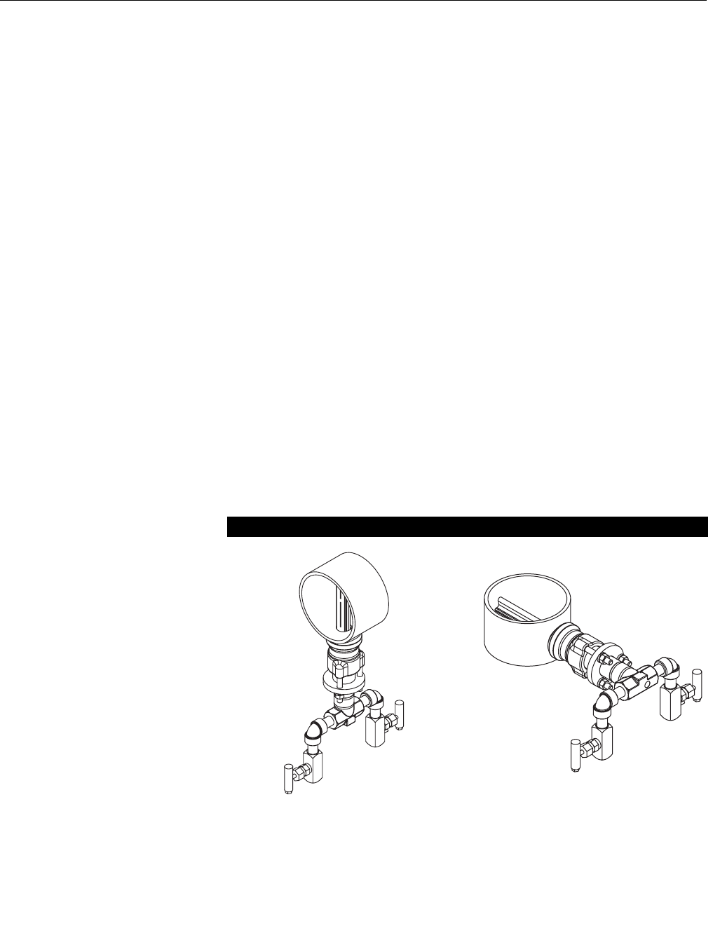
Remote Mount Head – temperature below 250 °F (121 °C)
See “Remote Mount” on page 2-9 for more information
Remote Mount Head – temperature above 250 °F (121 °C)
Liquid or Steam Applications
The electronics must be mounted below the process piping. Route the
impulse piping down to the electronics and fill the system with cool water
through the two tee fittings.
Liquid Applications Gas Applications
Secure the electronics below the
sensor to ensure that air will not be
introduced into the impulse piping or
the electronics.
Secure the electronics above the
sensor to prevent condensable
liquids from collecting in the impulse
piping and the DP cell.
28_490000_954A01A, 955A01A
Reference Manual
00809-0100-4809, Rev AA
August 2002
Annubar Flowmeter Series
2-28
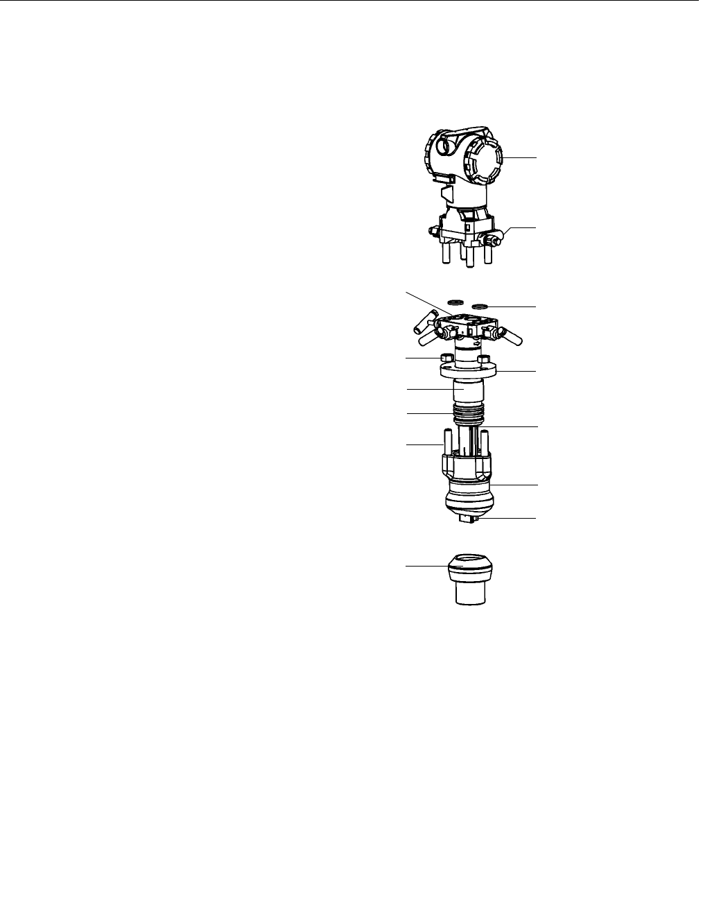
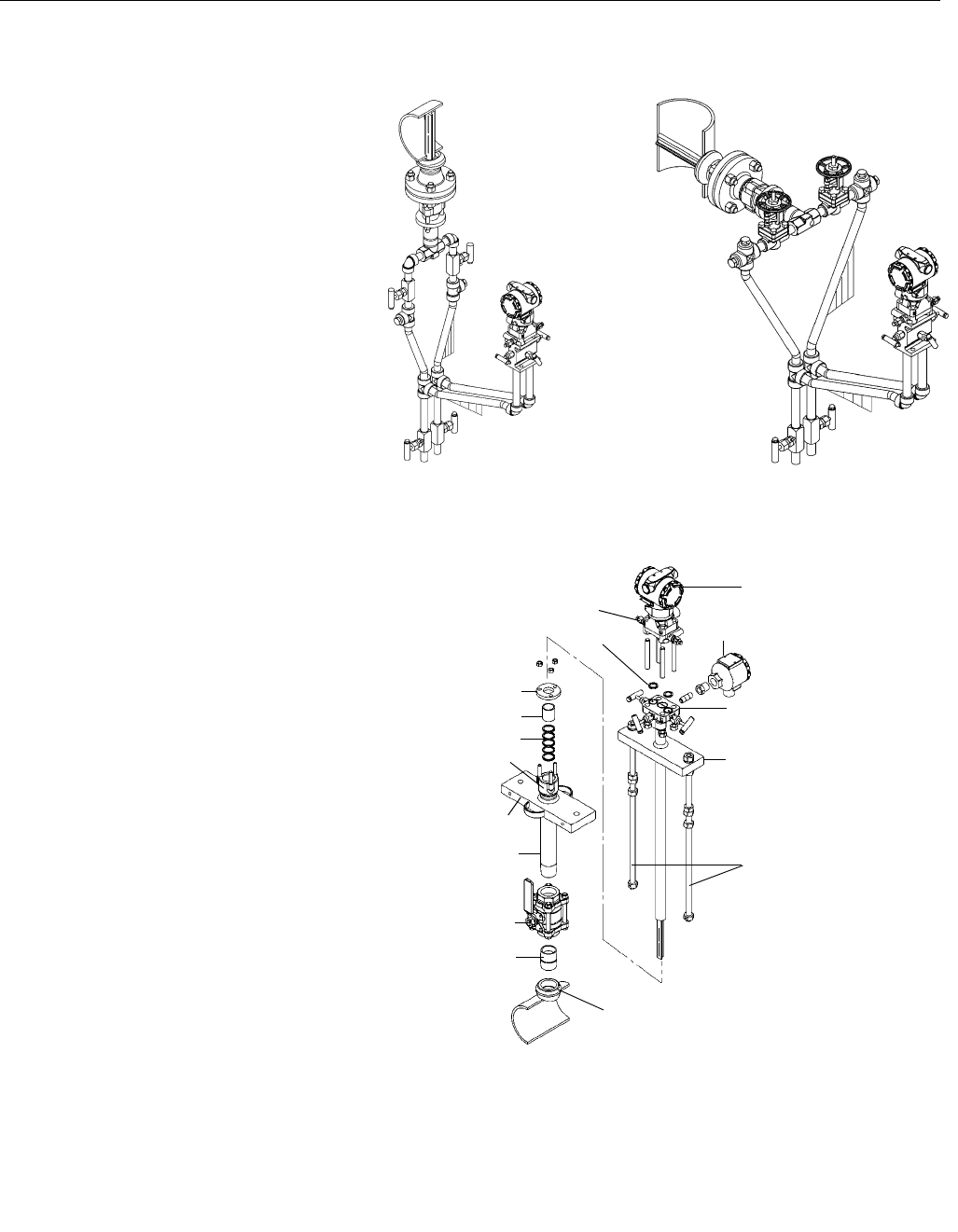
Threaded Flo-Tap Model Figure 2-21 identifies the components of the Threaded Flo-Tap assembly.
Figure 2-21. Components
Step 1: Set the Switches
Refer to “Mounting” on page 2-4 for more information
Step 2: Determine the Proper Orientation
Please refer to “Mounting” on page 2-4 for straight run requirements and
orientation information.
Horizontal Line Vertical Line
28_490000_956A01A, 957A01A
Transmitter
Temperature Sensor
Connection Housing
Direct Mount Electronics
Connection with Valves
Cage Nipple
O-Rings (2)
Head Plate
Drive Rods
Threaded Pipe Fitting
Guide Nipple
Isolation Valve
Support Plate
Packing Gland
Packing
Follower
Compression Plate
Coplanar Flange with Drain Vents
-
49000-937A
Reference Manual
00809-0100-4809, Rev AA
August 2002
2-29
Annubar Flowmeter Series
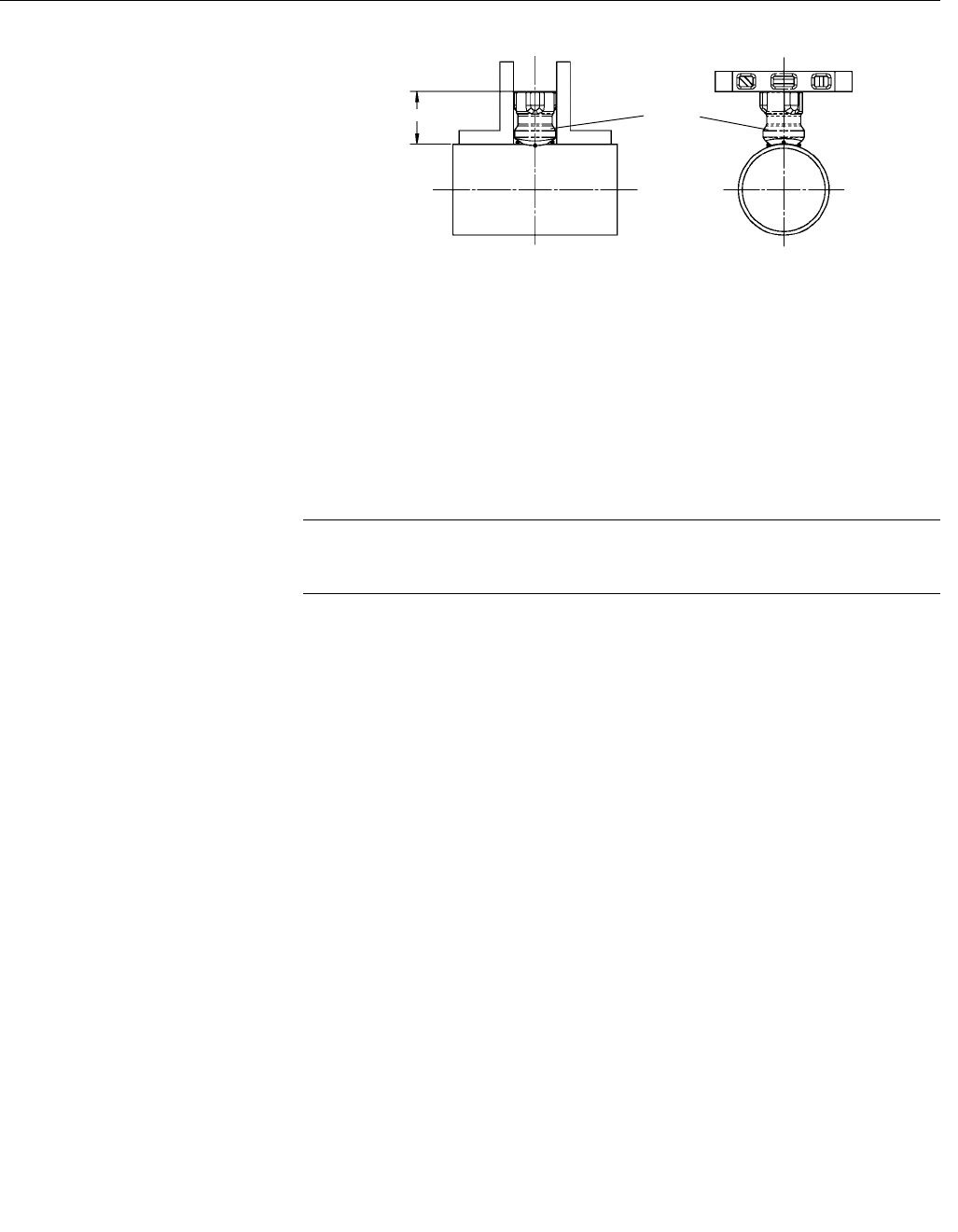
Step 3: Weld the Mounting Hardware
NOTE
Rosemount-supplied mounting includes critical alignment hardware that
assists in the correct drilling of the mounting hole. This significantly reduces
problems encountered during insertion.
1. At the pre-determined position, place the threadolet on the pipe, gap
1/16 in. (1.5 mm) and place four 1/4-in. (6-mm) tack welds at 90°
increments.
2. Check alignment of the mounting both parallel and perpendicular to
the axis of flow.
3. If the mounting alignment is within tolerances, finish weld per local
codes. If outside of tolerances, make adjustments prior to making the
finish weld.
Figure 2-22. Alignment
NOTE:
To avoid serious burns, allow the mounting hardware to cool
before continuing.
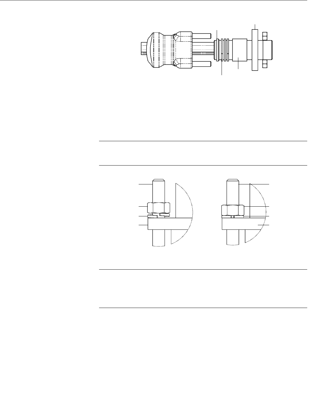
Step 4: Install the Isolation Valve
After the mounting hardware has cooled, use the following steps for
installation.
1. Thread the guide nipple into the mounting.
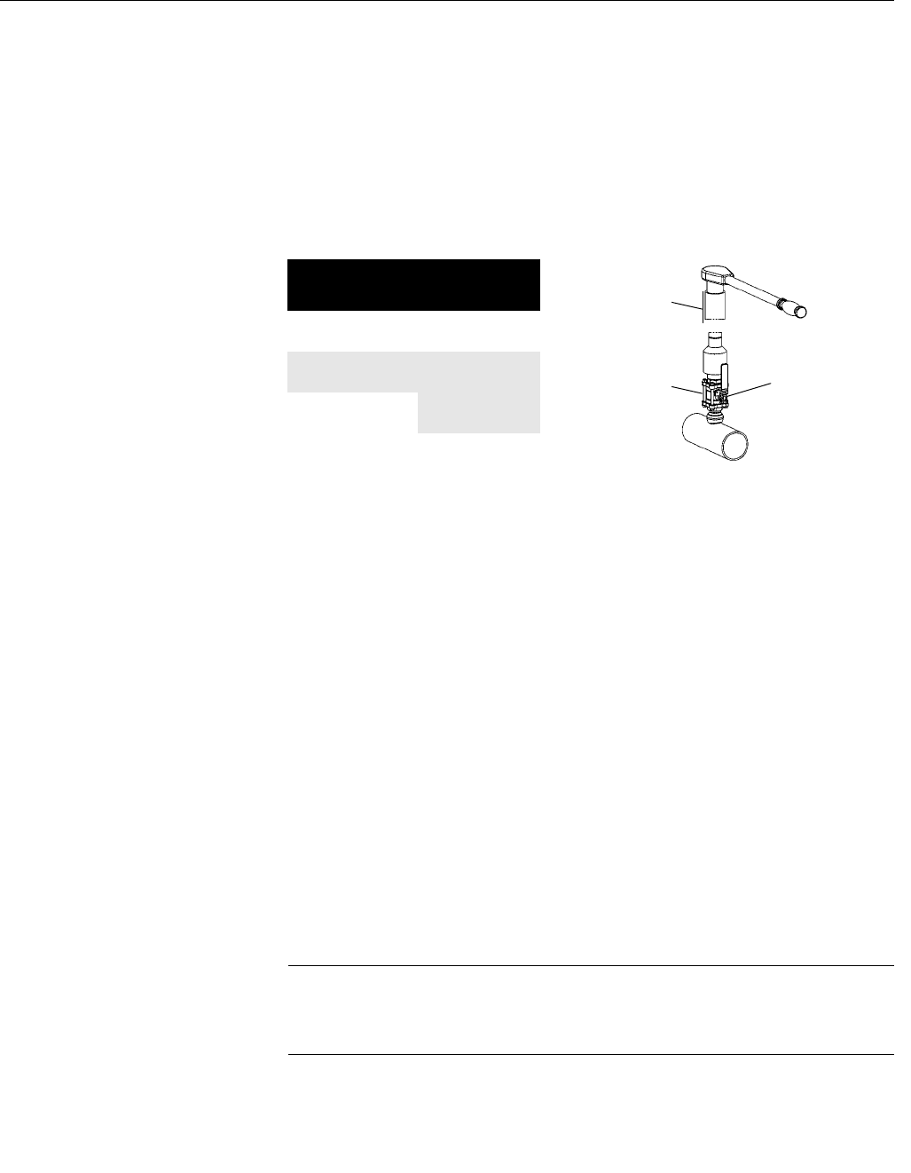
2. Thread the isolation valve into the guide nipple, ensuring that the
valve stem is positioned so that when the Flo-Tap is installed, the
insertion rods will straddle the pipe and the valve handle will be
centered between the rods (see Figure 2-23). Caution, if valve is
located in line with the rods, interference will occur.
Figure 2-23. Install the Isolation
Valve
LMH
Tack
Weld
28-490000-925A01A
28-490000-966A01A
Isolation Valve
Reference Manual
00809-0100-4809, Rev AA
August 2002
Annubar Flowmeter Series
2-30
Step 5: Mount the Drilling Machine / Drill Hole
Use Table 2-6 to select the proper drill bit for the sensor that is being used.
1. Mount the drilling machine to the isolation valve.
2. Fully open the valve.
3. Drill the hole into the pipe wall in accordance with the instructions
provided by the drilling machine manufacturer.
4. Fully retract the drill beyond the valve
Table 2-6. Drill Hole into Pipe
Step 6: Remove the Drilling Machine
Follow these steps to remove the drilling machine:
1. Verify that the drill has been fully retracted past the valve.
2. Close the unit isolation valve to isolate the process.
3. Bleed drilling machine pressure and remove.
4. Check isolation valve and mounting for leakage.
Step 7: Mount the Annubar
1. Install the complete Flo-Tap assembly (fully retracted) onto the unit
isolation valve by threading the close nipple into the valve using the
proper thread sealant compound.
2. Rotate the Flo-Tap assembly until the flow arrow on the head aligns
with the direction of flow in the pipe.
3. Ensure that the vent valves are closed before proceeding to the
next step.
4. Quickly open and close the isolation valve to pressurize the Annubar.
5. Check the entire installation for leakage. Tighten as required to stop
any connection from leaking. Repeat steps 4 and 5 until there is no
leakage.
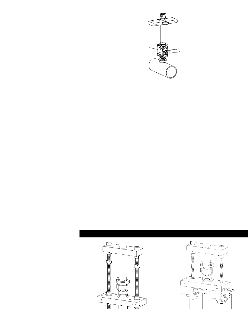
NOTE
Flo-Tap Annubars have the potential to carry a large amount of weight at a
great distance from the piping, necessitating external support. The support
plate has threaded holes to assist in supporting the Annubar.
Sensor Size / Hole Diameter Chart
Sensor Diameter
T1
3/4-in.
(19 mm)
+ 1/32-in (1 mm)
– 0.00
T2 15/16-in.
(34 mm)
+ 1/16-in. (1 mm)
– 0.00
T3 21/2-in.
(64 mm)
+ 1/16-in. (1 mm)
– 0.00
28-490000_967A01A
Pressure
Drilling
Machine
Isolation Valve is
fully open when
inserting drill
Isolation Valve is
fully closed after
withdrawing drill
Reference Manual
00809-0100-4809, Rev AA
August 2002
2-31
Annubar Flowmeter Series
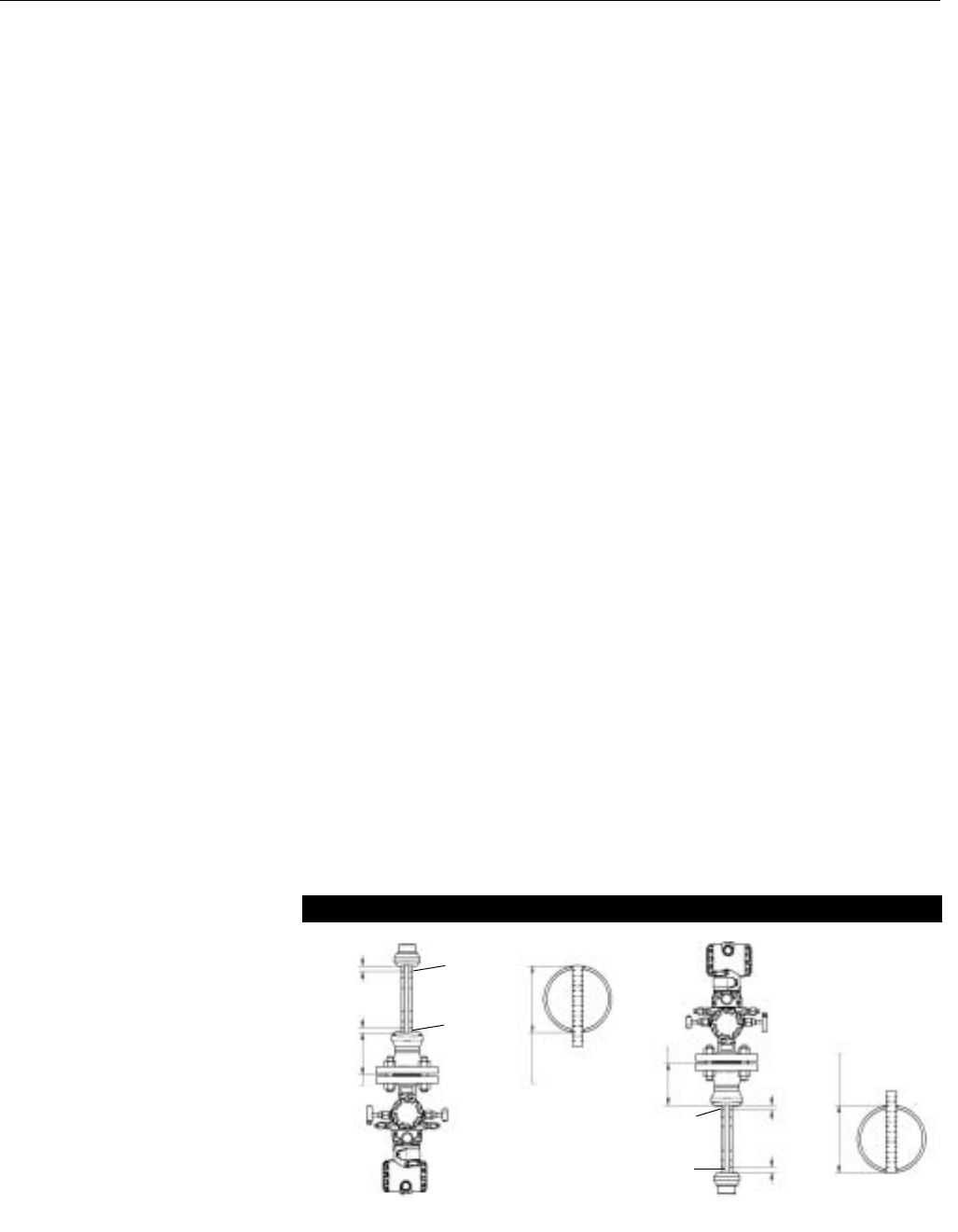
Figure 2-24. Flo-Tap Installation
Step 8: Insert the Annubar
Insert the sensor with one of the two drive options available – standard drive
(M) or gear drive (G).
Standard Drive (M)
1. Fully open the isolation valve.
2. Insert the sensor by rotating drive nuts clockwise as viewed from the
top. The nuts must be tightened alternately, about two turns at a time
to prevent binding caused by unequal loading.
3. Continue this procedure until the tip of the probe firmly contacts the
opposite side of the pipe. The orange stripe on the insertion rods are
used as a guide for full insertion.
Gear Drive (G)
1. Fully open the isolation valve.
2. Insert the sensor by rotating the crank clockwise. If a power drill with
an adapter is used, do not exceed 200 rpm.
3. Continue rotating the crank until the sensor firmly contacts the
opposite side of the pipe. The orange stripe on the insertion rods are
used as a guide for full insertion.
4. Secure the drive by inserting the drive lock pin as shown in
Figure 2-25.
Figure 2-25. Insert Annubar
Isolation Valve
28-490000_968A01A
Standard Drive (M) Gear Drive (G)
28-490000_938A01A, 939A01A

Reference Manual
00809-0100-4809, Rev AA
August 2002
Annubar Flowmeter Series
2-32
Step 9: Retract the Annubar
Standard Drive (M)
1. Retract by rotating the drive nuts counter-clockwise. The nuts must
be turned alternately, about two turns at a time, to prevent binding
caused by unequal loading.
2. Continue this procedure until the rod end nuts are against the packing
body mechanism.
Gear Drive (G)
1. Remove the drive lock pin.
2. Retract the sensor by rotating the crank counter-clockwise. If a power
drill with an adapter is used, do not exceed 200 rpm.
3. Retract until the rod end nuts are against the packing body
mechanism.
Step 10: Mount the Transmitter
Direct Mount Head
With Valves
1. Place Teflon (PTFE) O-rings into grooves on the face of head.
2. Align the high side of the transmitter to the high side of the probe
(“Hi” is stamped on the side of the head) and install.
3. Tighten the nuts in a cross pattern to 400 in•lb (45 N•m).
Without Valves
1. Place Teflon (PTFE) O-rings into grooves on the face of head.
2. Orient the equalizer valve or valves so they are easily accessible.
Install manifold with the smooth face mating to the face of the head.
Tighten in cross pattern to a torque of 400 in•lb (45 N•m).
3. Place Teflon (PTFE) O-rings into grooves on the face of the manifold.
4. Align the high side of the transmitter to the high side of the probe
(“Hi” is stamped on the side of the head) and install.
5. Tighten the nuts in a cross pattern to 400 in•lb (45 N•m).
Remote Mount Head – temperature below 250 °F (121 °C)
See “Remote Mount” on page 2-9 for more information
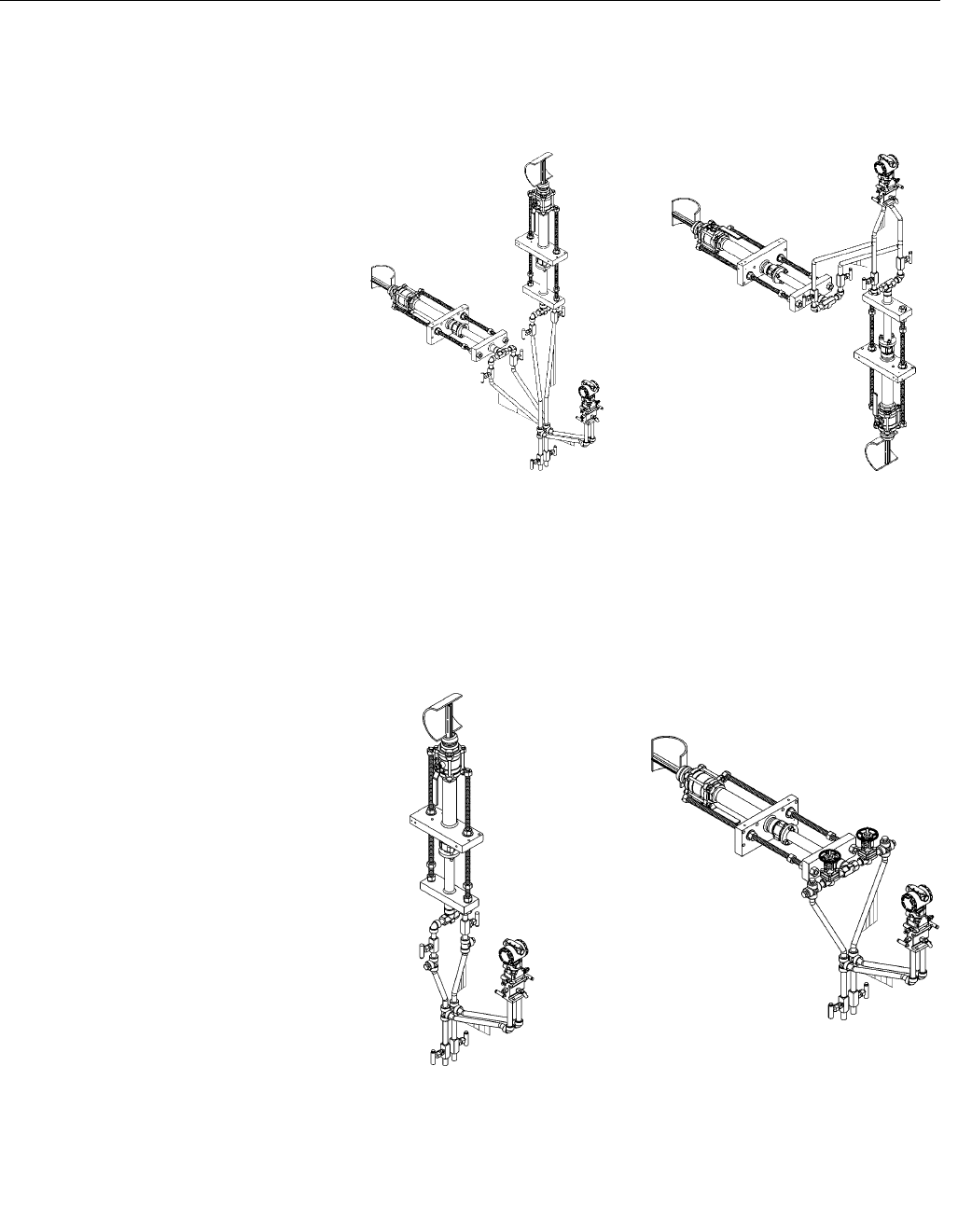
Reference Manual
00809-0100-4809, Rev AA
August 2002
2-33
Annubar Flowmeter Series
Remote Mount Head – temperature above 250 °F (121 °C)
Liquid or Steam Applications
The electronics must be mounted below the process piping. Route the
impulse piping down to the electronics and fill the system with cool water
through the two tee fittings.
Liquid Applications Gas Applications
Secure the electronics below the
sensor to ensure that air will not be
introduced into the impulse piping or
the electronics.
Secure the electronics above the
sensor to prevent condensable
liquids from collecting in the impulse
piping and the DP cell.
Horizontal Line Vertical Line
28_490000_962A01A, 963A01A
28_490000_964A01A, 965A01A
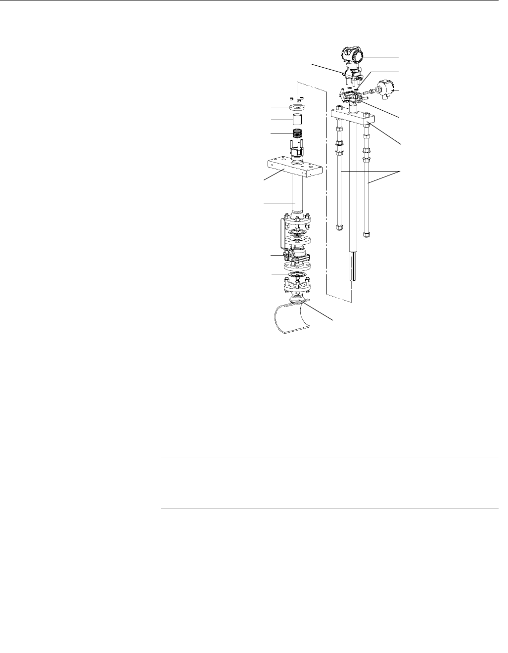
Reference Manual
00809-0100-4809, Rev AA
August 2002
Annubar Flowmeter Series
2-34
Flanged Flo-Tap Model Figure 2-26 identifies the components of the Flanged Flo-Tap assembly.
Figure 2-26. Components
Step 1: Set the Switches
Refer to “Mounting” on page 2-4 for more information
Step 2: Determine the Proper Orientation
Please refer to “Mounting” on page 2-4 for straight run requirements and
orientation information.
Step 3: Weld the Mounting Hardware
NOTE
Rosemount-supplied mounting includes critical alignment hardware that
assists in the correct drilling of the mounting hole. This significantly reduces
problems encountered during insertion.
1. At the pre-determined position, place the flanged assembly on the
pipe, gap 1/16 in (1.5 mm). and measure the distance from the OD of
the pipe to the face of the flange. Compare this to the chart below and
adjust the gap as necessary.
2. Place four 1/4-in. (6-mm) tack welds at 90° increments. Check
alignment of the mounting both parallel and perpendicular to the axis
of flow.
3. If the mounting alignment is within tolerances, finish weld per local
codes. If outside of tolerances, make adjustments prior to making the
finish weld.
Transmitter
Temperature Sensor
Connection Housing
Direct Mount Electronics
Connection with Valves
Cage Nipple
O-Rings (2)
Head Plate
Drive Rods
Mounting Flange Assembly
Gasket
Isolation Valve
Support Plate
Packing Gland
Packing
Follower
Compression Plate
Coplanar Flange with Drain Vents
28-49000-903A
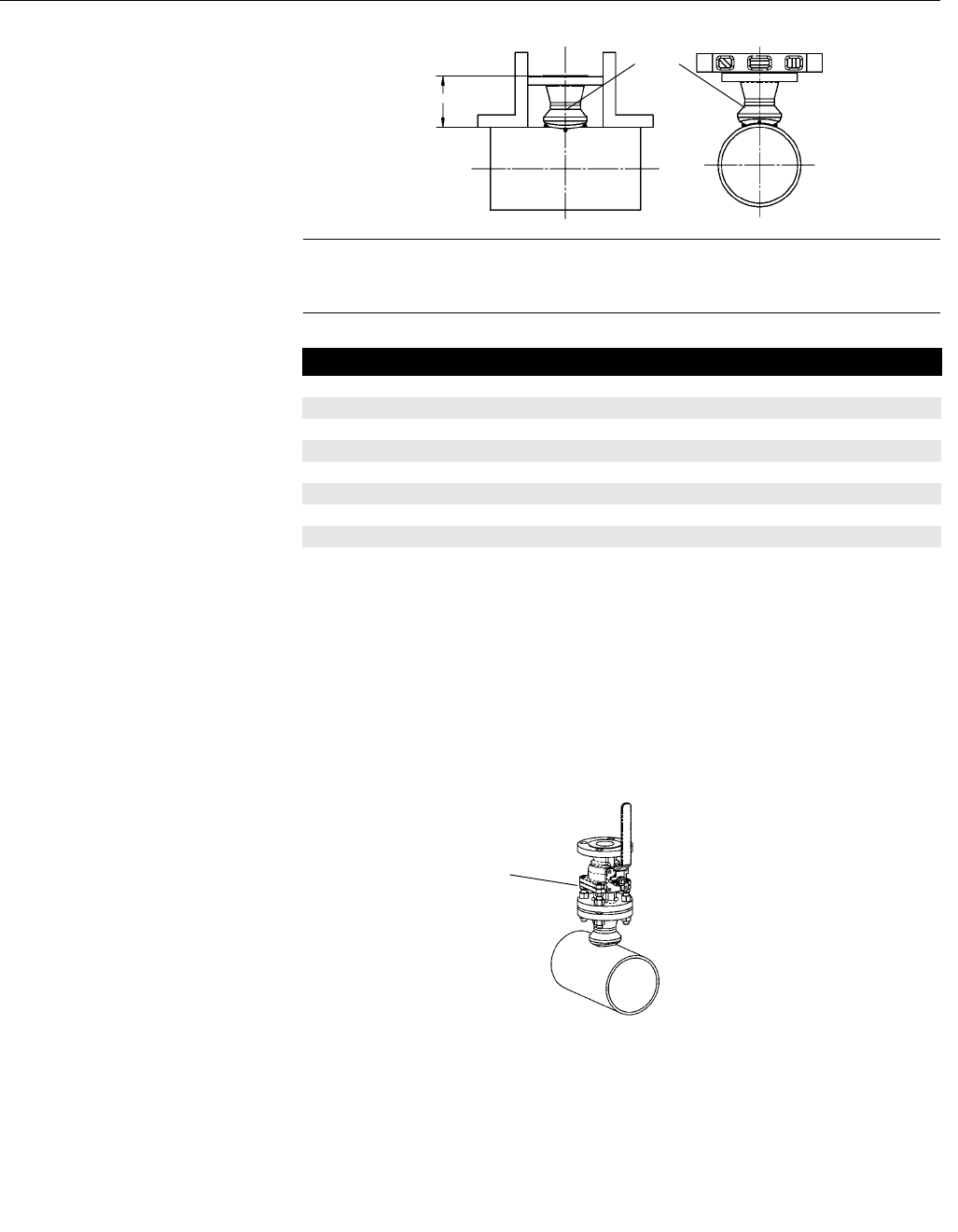
Reference Manual
00809-0100-4809, Rev AA
August 2002
2-35
Annubar Flowmeter Series
Figure 2-27. Alignment
NOTE:
To avoid serious burns, allow the mounting hardware to cool
before continuing.
Step 4: Install the Isolation Valve
1. Position the isolation valve onto the mounting flange ensuring that the
valve stem is positioned such that when the Flo-Tap is installed, the
insertion rods will straddle the pipe and the valve handle will be
centered between the rods (see Figure 2-28). Caution, if valve is
located in line with the rods, interference will occur.
2. Fasten the isolation valve to the mounting with gasket, bolts, and
nuts.
Figure 2-28. Install
Isolation Valve
Size ODF (in.) Size ODF (mm)
1-in. 150# 3.38-in. (85.8 mm) DN25 PN16 2.68-in. (68.2 mm)
1-in. 300# 3.63-in. (92.2 mm) DN25 PN40 2.76-in. (70.2 mm)
1-in. 600# 3.88-in. (98.5 mm) DN25 PN100 3.47-in. (88.2 mm)
2-in. 150# 4.13-in. (104.8 mm) DN50 PN16 3.40-in. (86.3 mm)
2-in. 300# 4.38-in. (111.2 mm) DN50 PN40 3.51-in. (89.3 mm)
2-in. 600# 4.76-in. (120.8 mm) DN50 PN100 4.30-in. (109.3 mm)
3-in. 150# 4.63-in. (117.5 mm) DN80 PN16 3.84-in. (97.6 mm)
3-in. 300# 5.00-in. (126.9 mm) DN80 PN40 4.16-in. (105.6 mm)
3-in. 600# 5.38-in. (136.6 mm) DN80 PN100 4.95-in. (125.6 mm)
28-490000-925A01A
ODF Tack Weld
Isolation Valve
28-490000_969A01A
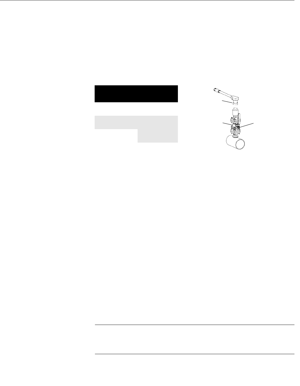
Reference Manual
00809-0100-4809, Rev AA
August 2002
Annubar Flowmeter Series
2-36
Step 5: Mount the Drilling Machine / Drill Hole
Use Table 2-6 to select the proper drill bit for the sensor that is being used.
1. Mount the drilling machine to the isolation valve.
2. Fully open the valve.
3. Drill the hole into the pipe wall in accordance with the instructions
provided by the drilling machine manufacturer.
4. Fully retract the drill beyond the valve
Table 2-7. Drill Hole into Pipe
Step 6: Remove the Drilling Machine
Follow these steps to remove the drilling machine:
1. Verify that the drill has been fully retracted past the valve.
2. Close the unit isolation valve to isolate the process.
3. Bleed drilling machine pressure and remove.
4. Check isolation valve and mounting for leakage.
Step 7: Mount the Annubar
Install the complete Flo-Tap assembly as shown in Figure 2-29.
1. Align the flow arrow on the head with the direction of flow.
1. Use the gaskets and flange bolts supplied to fasten the Flo-Tap
assembly to the isolation valve.
2. Tighten the nuts in a cross pattern to compress the gasket evenly.
3. Ensure that the vent valves are closed before proceeding to the next
step.
4. Quickly open and close the isolation valve to pressurize the Annubar.
5. Check the entire installation for leakage. Tighten as required to stop
any connection from leaking. Repeat steps 4 and 5 until there is no
leakage.
NOTE
Flo-Tap Annubars have the potential to carry a large amount of weight at a
great distance from the piping, necessitating external support. The support
plate has threaded holes to assist in supporting the Annubar.
Sensor Size / Hole Diameter Chart
Sensor Diameter
T1
3/4-in.
(19 mm)
+ 1/32-in (1 mm)
– 0.00
T2 15/16-in.
(34 mm)
+ 1/16-in. (1 mm)
– 0.00
T3 21/2-in.
(64 mm)
+ 1/16-in. (1 mm)
– 0.00
28-490000_970A01A
Pressure Drilling
Machine
Isolation Valve is
fully open when
inserting drill
Isolation Valve is
fully closed after
withdrawing drill
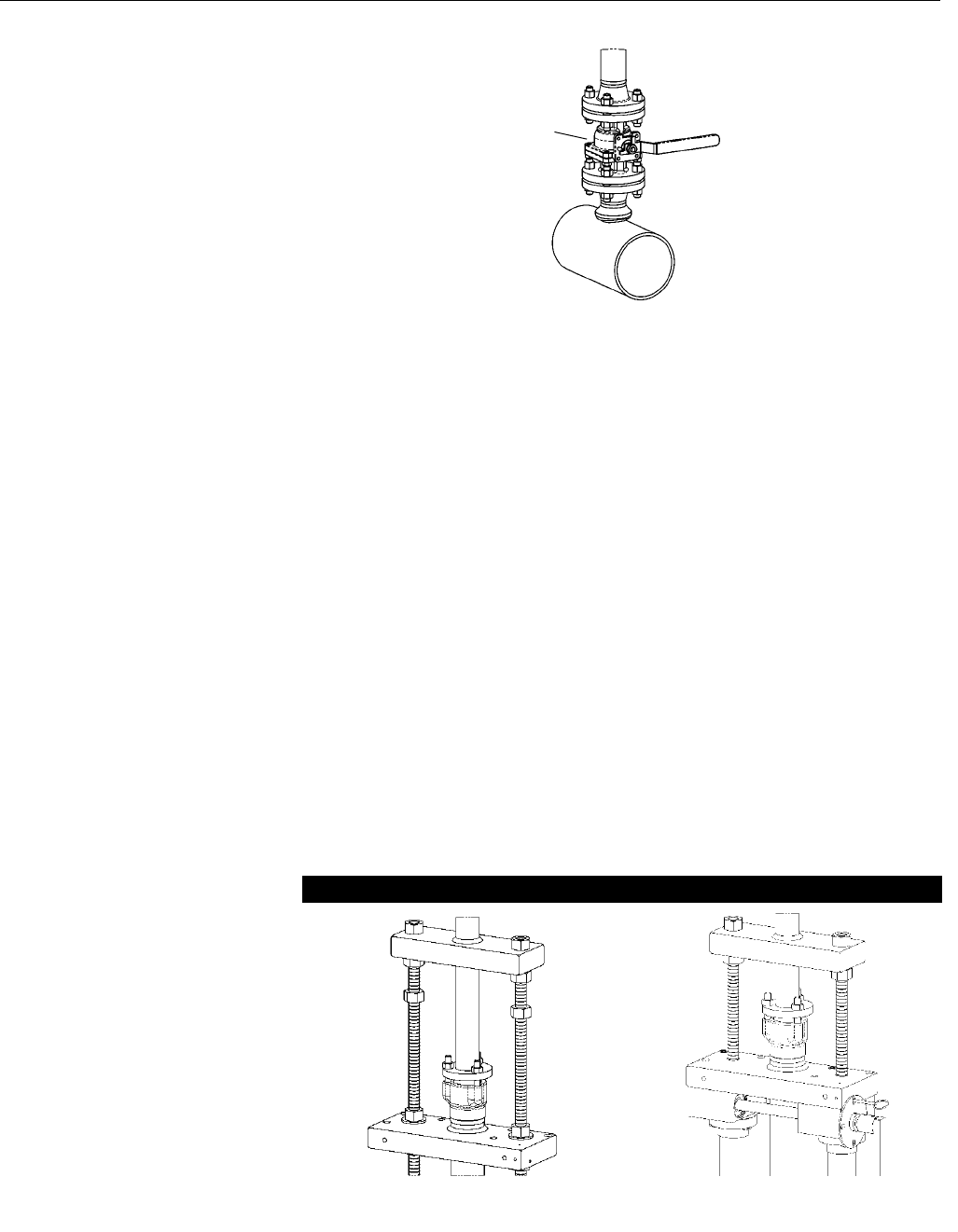
Reference Manual
00809-0100-4809, Rev AA
August 2002
2-37
Annubar Flowmeter Series
Figure 2-29. Flo-Tap Installation
Step 8: Insert the Annubar
Insert the sensor with one of the two drive options available – standard drive
(M) or gear drive (G).
Standard Drive (M)
1. Fully open the isolation valve.
2. Insert the sensor by rotating drive nuts clockwise as viewed from the
top. The nuts must be tightened alternately, about two turns at a time
to prevent binding caused by unequal loading.
3. Continue this procedure until the tip of the probe firmly contacts the
opposite side of the pipe. The orange stripe on the insertion rods are
used as a guide for full insertion.
Gear Drive (G)
1. Fully open the isolation valve.
2. Insert the sensor by rotating the crank clockwise. If a power drill with
an adapter is used, do not exceed 200 rpm.
3. Continue rotating the crank until the sensor firmly contacts the
opposite side of the pipe. The orange stripe on the insertion rods are
used as a guide for full insertion.
4. Secure the drive by inserting the drive lock pin as shown in
Figure 2-30.
Figure 2-30. Insert Annubar
Isolation Valve
28-490000_968A01A
Standard Drive (M) Gear Drive (G)
28-490000_938A01A, 939A01A

Reference Manual
00809-0100-4809, Rev AA
August 2002
Annubar Flowmeter Series
2-38
Step 9: Retract the Annubar
Standard Drive (M)
1. Retract by rotating the drive nuts counter-clockwise. The nuts must
be turned alternately, about two turns at a time, to prevent binding
caused by unequal loading.
2. Continue this procedure until the rod end nuts are against the packing
body mechanism.
Gear Drive (G)
1. Remove the drive lock pin.
2. Retract the sensor by rotating the crank counter-clockwise. If a power
drill with an adapter is used, do not exceed 200 rpm.
3. Retract until the rod end nuts are against the packing body
mechanism.
Step 10: Mount the Transmitter
Direct Mount Head
With Valves
1. Place Teflon (PTFE) O-rings into grooves on the face of head.
2. Align the high side of the transmitter to the high side of the probe
(“Hi” is stamped on the side of the head) and install.
3. Tighten the nuts in a cross pattern to 400 in•lb (45 N•m).
Without Valves
1. Place Teflon (PTFE) O-rings into grooves on the face of head.
2. Orient the equalizer valve or valves so they are easily accessible.
Install manifold with the smooth face mating to the face of the head.
Tighten in cross pattern to a torque of 400 in•lb (45 N•m).
3. Place Teflon (PTFE) O-rings into grooves on the face of the manifold.
4. Align the high side of the transmitter to the high side of the probe
(“Hi” is stamped on the side of the head) and install.
5. Tighten the nuts in a cross pattern to 400 in•lb (45 N•m).
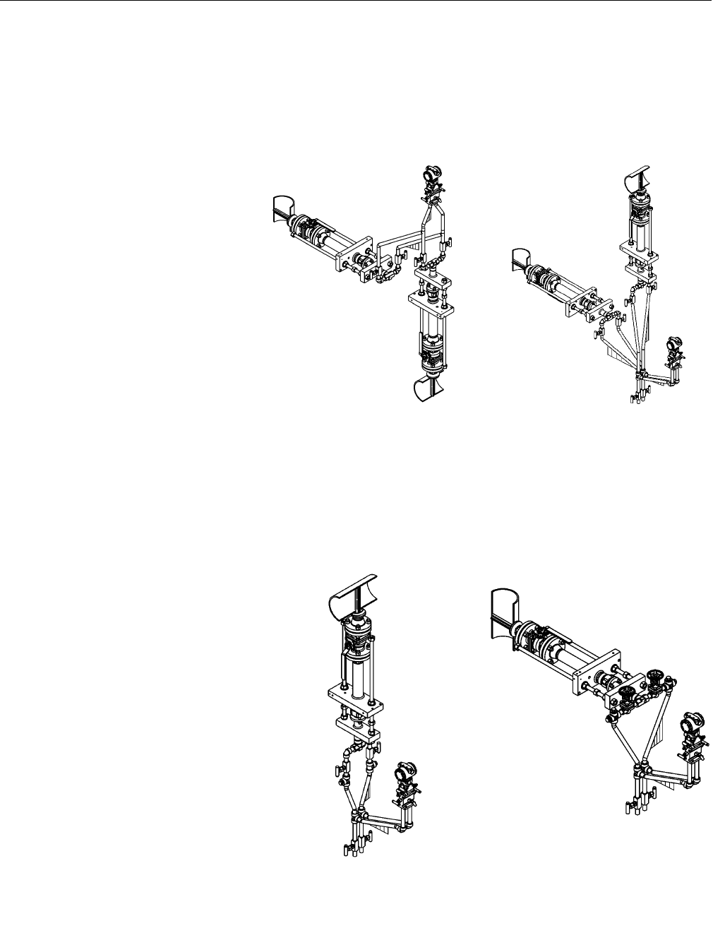
Reference Manual
00809-0100-4809, Rev AA
August 2002
2-39
Annubar Flowmeter Series
Remote Mount Head – temperature below 250 °F (121 °C)
See “Remote Mount” on page 2-9 for more information
Remote Mount Head – temperature above 250 °F (121 °C)
Liquid or Steam Applications
The electronics must be mounted below the process piping. Route the
impulse piping down to the electronics and fill the system with cool water
through the two tee fittings.
Liquid Applications Gas Applications
Secure the electronics below the
sensor to ensure that air will not be
introduced into the impulse piping or
the electronics.
Secure the electronics above the
sensor to prevent condensable
liquids from collecting in the impulse
piping and the DP cell.
Horizontal Line Vertical Line
28_490000_959A01A, 958A01A
28_490000_960A01A, 961A01A
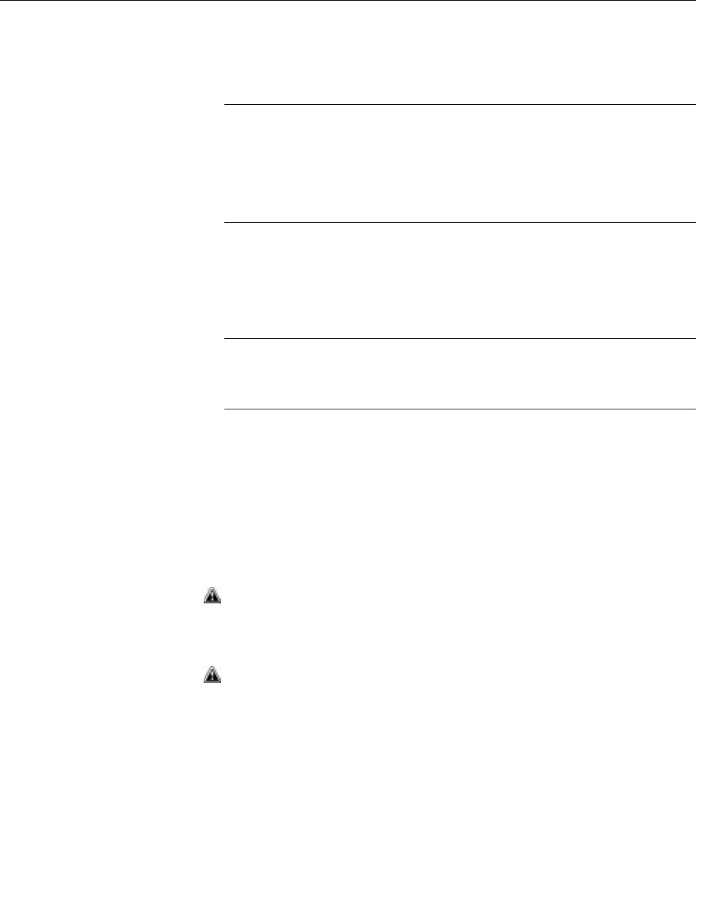
Reference Manual
00809-0100-4809, Rev AA
August 2002
Annubar Flowmeter Series
2-40
CONNECT THE WIRING The dc power supply should provide power with less than 2 percent ripple.
The total resistance load is the sum of the resistance of the signal leads and
the load resistance of the controller, indicator, and related pieces. Note that
the resistance of intrinsic safety barriers, if used, must be included.
NOTE
A minimum loop resistance of 250 ohms is required to communicate with a
Model 275 HART Communicator. With 250 ohms of loop resistance, the
electronics will require a minimum of 15.5 volts to output 20 mA. If a single
power supply is used to power more than one flowmeter, the power supply
used, and circuitry common to the electronics, should not have more than 20
ohms of impedance at 1200Hz.
The flowmeter has an explosion-proof housing and circuitry suitable for
intrinsically safe and non-incendive operation. Individual Annubar models are
clearly marked with a tag indicating the certifications they carry. See
Appendix A: Specifications and Reference Data for specific approval
categories.
NOTE
Signal wiring does not require shielding; however, twisted pairs provide the
best results. In order to ensure communication, wiring should be 24 AWG or
larger and shorter than 5,000 feet (1500 meters) in length.
Do not connect the powered signal wiring to the test terminals. Power may
damage the test diode in the test connection.
Plug and seal unused conduit connections on the electronics housing to avoid
moisture accumulation in the terminal side of the housing. Excess moisture
accumulation may damage the electronics. If the connections are not sealed,
the electronics should be remote mounted with the electrical housing
positioned downward for drainage. Wiring should be installed with a drip loop
and the bottom of the drip loop should be lower then the conduit connections
and the housing.
Inductive-based transient protectors, including the Rosemount Model 470
transient protector, can adversely affect the output of the Annubar. If transient
protection is desired, install the Transient Protection Terminal Block. Consult
the factory for instructions.
Wiring Diagrams 1. Remove the housing cover on the side marked FIELD TERMINALS.
Do not remove the instrument covers in explosive atmospheres when
the circuit is live.
2. Connect the lead that originates at the positive side of the power
supply to the terminal marked “+” and the lead that originates at the
negative side of the power supply to the terminal marked “–.” Avoid
contact with the leads and terminals.
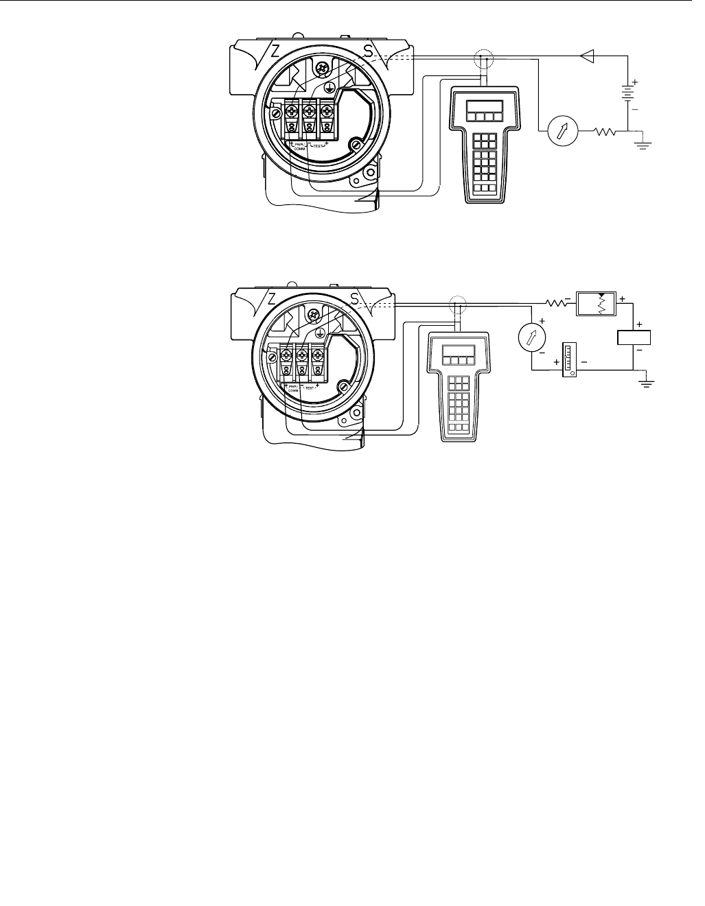
Reference Manual
00809-0100-4809, Rev AA
August 2002
2-41
Annubar Flowmeter Series
Figure 2-31. Bench Hook-up
(4–20 mA Flowmeters).
Figure 2-32. Field Hook-up (4-20
mA Flowmeters)
Equipment The following equipment and tools are not provided with the Annubar. Be sure
to review this list before field wiring the Annubar.
• Installation tools
• Field wire between the power supply and the Annubar
• Barriers or seals required for hazardous locations
• Power supply
•Tie wraps
Current
Meter
24 V dc
Supply
RL≥ 250 ς
3051-3031G02B
CAUTION
Do not use inductive-based transient protectors.
Signal point may be grounded at any
point or left ungrounded.
RL≥ 250
Power
Supply
Current
Meter
3051-3031H02B
Reference Manual
00809-0100-4809, Rev AA
August 2002
Annubar Flowmeter Series
2-42
Field Wiring (Power and
Signal)
Make field wiring connections (see Figure 2-31 and Figure 2-32). These
connections provide both power and signal wiring.
NOTES
• Do not run field wiring in conduit or open trays with other power wiring
or near heavy electrical equipment.
• Field wiring need not be shielded, but twisted pairs provide the best
results.
• To ensure communication, wiring should be 24 AWG or larger and less
than 5,000 feet (1,500 meters) in length.
• For connections in ambient temperatures above 140 °F (60 °C), use
wiring rated for at least 194°F (90°C).
• Incorrect field wiring connections may damage the Mass ProBar
electronics. Do not connect field wiring to the “TEST +” terminals.
1. Remove the cover on the side marked FIELD TERMINALS
on the electronics housing.
2. Connect the lead that originates at the positive side of the
power supply to the terminal marked “+ SIG.” Be sure to include loop
resistance.
3. Connect the lead that originates at the negative side of the
power supply to the terminal marked “-.”
4. Plug and seal unused conduit connections on the electronics housing
to avoid moisture accumulation in the terminal side of the housing.
NOTE
If the conduit connections are not sealed, mount the electronics with the
electrical housing positioned downward for drainage. Conduit should be
installed with a drip loop and the bottom of the drip loop should be lower than
the conduit connections or the electronics housing.
Grounding Grounding the Signal Wiring
Do not run signal wiring in conduit or open trays with power wiring, or near
heavy electrical equipment. Signal wiring may be grounded at any one point
on the signal loop, or it may be left ungrounded. The negative terminal of the
power supply is a recommended grounding point.
Ground the Electronics Case
The electronics case should always be grounded in accordance with national
and local electrical codes. The most effective electronics case grounding
method is a direct connection to the earth ground with minimal impedance.
Methods for grounding the electronics case include:
Internal Ground Connection
Inside the FIELD TERMINALS side of the electronics housing is the
Internal Ground Connection screw. This screw is identified by a ground
symbol: .

Reference Manual
00809-0100-4809, Rev AA
August 2002
2-43
Annubar Flowmeter Series
NOTE
The transient protection terminal block does not provide transient protection
unless the electronics case is properly grounded. Do not run the transient
protection ground wire with field wiring because the transient protector ground
wire may carry excessive current if a lightening strike occurs. Grounding the
electronics case using a threaded conduit connection may not provide
sufficient ground.
Field Wiring Ground (Optional)
Field wiring may be grounded at any one point on the signal loop, or it may be
left ungrounded. The negative terminal of the power supply is a
recommended grounding point.

Reference Manual
00809-0100-4809, Rev AA
August 2002
2-44
Annubar Flowmeter Series

Reference Manual
00809-0100-4809, Rev AA
August 2002
2-45
Annubar Flowmeter Series

Reference Manual
00809-0100-4809, Rev AA
August 2002
Annubar Flowmeter Series
2-46

Reference Manual
00809-0100-4809, Rev AA
June 2002 Annubar Flowmeter Series
www.rosemount.com
Section 3 Commissioning
Safety Messages . . . . . . . . . . . . . . . . . . . . . . . . . . . . . . . . . page 3-1
Commissioning on the Bench (Model 3051SFA Only) . . page 3-2
Model 275 HART Communicator . . . . . . . . . . . . . . . . . . . . page 3-14
Model 3051SFA Probar . . . . . . . . . . . . . . . . . . . . . . . . . . . . page 3-14
Model 3095MFA Mass Probar . . . . . . . . . . . . . . . . . . . . . . page 3-30
SAFETY MESSAGES Instructions and procedures in this section may require special precautions to
ensure the safety of the personnel performing the operations. Please refer to
the following safety messages before performing any operation in this section.
Explosions could result in death or serious injury:
• Do not remove the transmitter cover in explosive atmospheres when the circuit is
live.
• Before connecting a Model 275 HART Communicator in an explosive atmosphere,
make sure the instruments in the loop are installed in accordance with intrinsically
safe or non-incendive field wiring practices.
• Verify that the operating atmosphere of the transmitter is consistent with the
appropriate hazardous locations certifications.
• Both transmitter covers must be fully engaged to meet explosion-proof
requirements.
Failure to follow these installation guidelines could result in death or serious injury:
• Make sure only qualified personnel perform the installation.
• If the line is pressurized, serious injury or death could occur by opening valves.

Reference Manual
00809-0100-4809, Rev AA
August 2002
Annubar Flowmeter Series
3-2
COMMISSIONING ON
THE BENCH (MODEL
3051SFA ONLY)
Commissioning consists of testing the flowmeter, testing the loop, and
verifying the flowmeter configuration data. The flowmeter can be
commissioned either before (on the bench) or after (in the field) installation.
Commissioning on the bench ensures that all flowmeter components are in
good working order and acquaints the user with the operation of the device.
To avoid exposing the flowmeter electronics to the environment after
installation, set the failure mode and flowmeter security switches while
commissioning the flowmeter on the bench.
Figure 2-3 on page 2-6 identifies the valves on a 5-valve and a 3-valve
manifold. Table 2-1 on page 2-6 explains the purpose of these valves.
Complete the following tasks before beginning the commissioning procedure:
1. Power the Annubar, if required.
2. Connect an appropriate readout instrument so the differential
pressure signal can be monitored.
3. Identify the manifold equalizer valves by their ME prefix.
• 5-valve manifolds have two equalizer valves, MEH and MEL.
• 3-valve manifolds have one equalizer valve, ME.
Close all valves before commissioning the system.
Set the Switches Both the write protect and alarm switches are located on the electronics board
inside the electronics housing cover. (See Figure 3-1) To avoid exposing the
flowmeter electronics to the plant environment after installation,
set these switches during the commissioning stage on the bench.
The flowmeters are delivered with the write-protect switch set to “OFF,” and
the alarm switch set to “High.”
Figure 3-1. Write Protect and
Alarm Switches
OUTPUT ELECTRONICS BOARD
OFF
ON
ALARM
<
SECURITY
>HI
LO
NOTE
Security switch not installed = Not
Write Protected. Alarm switch not
installed = High Alarm.

Reference Manual
00809-0100-4809, Rev AA
June 2002
3-3
Annubar Flowmeter Series
Failure Mode Alarm Switches
As part of normal operation, the flowmeter continuously monitors its own
operation. This automatic diagnostic routine is a timed series of checks
repeated continuously. If the diagnostic routine detects a failure, the flowmeter
drives its output either below or above specific values depending on the
position of the failure mode switch.
• For 4–20 mA flowmeters factory-configured for standard operation, the
flowmeter drives its output either below 3.75 mA or above 21.75 mA.
• For 4–20 mA flowmeters factory-configured for NAMUR-compliant
operation, the flowmeter drives its output either below 3.6 mA or above
22.5 mA.
The failure mode alarm switch is located on the front of the electronics board
inside of the electronics housing cover. The position of this switch determines
whether the output is driven high or low when a failure is detected. If the alarm
switch is not installed the flowmeter will operate normally, and the default
alarm condition will be high.
NOTE
The failure mode alarm switch pins occupy one row of a ten-pin socket that is
also used to attach the optional LCD meter. To function appropriately, the
switch must be positioned correctly.
Use the following steps to change the switch settings:
1. If the transmitter is installed, secure the loop and remove power.
2. Remove the housing cover opposite the field terminal side.
3. Locate the switch on the output electronics board and move the
switch to the desired setting (see Figure 3-1).
4. Reattach the transmitter cover. To avoid condensation, metal to metal
contact is preferred. Flowmeter covers must be fully engaged to meet
explosion-proof requirements.
5. If the transmitter is installed, reapply power.
Failure Mode Alarm vs. Saturation Output Values
The failure mode alarm output levels differ from the output values that
occur when applied pressure is outside the range points. When pressure is
outside the range points, the analog output continues to track the input
pressure until reaching the saturation value listed below; the output does
not exceed the listed saturation value regardless of the applied pressure.
For example, with standard alarm and saturation levels and pressures
outside the 4–20 range points, the output saturates at 3.9 mA or 20.8 mA.
When the flowmeter diagnostics detect a failure, the analog output is set to
a specific alarm value that differs from the saturation value to allow for
proper troubleshooting.
Table 3-1. Analog Output:
Standard Alarm Values vs.
Saturation Values.
Level 4–20 mA Saturation Value 4–20 mA Alarm Value
Fail Low 3.9 mA ≤ 3.75 mA
Fail High 20.8 mA ≥ 21.75 mA

Reference Manual
00809-0100-4809, Rev AA
August 2002
Annubar Flowmeter Series
3-4
Table 3-2. Analog Output:
NAMUR-Compliant Alarm
Values vs. Saturation Values.
NOTE
You can alter the actual flowmeter mA output values from the values listed
above by performing an analog output trim (see “Analog Output Trim” on
page 3-28).
When a flowmeter is in an alarm condition, the hand-held HART
communicator indicates the analog output the flowmeter would drive if the
alarm condition did not exist.
The preceding output values can be altered by an analog output trim
procedure.
Alarm and Saturation Values for Flowmeters Set to Burst Mode
Saturation and alarm conditions operate differently when a flowmeter is set
to burst mode operation:
Alarm Condition (Hi or Lo):
• Analog output switches to alarm level (see Table 3-1).
Saturation:
• Analog output switches to saturation level (see Table 3-1).
Alarm Level Verification
Flowmeters with electronics board revision 5.3 or later (shrouded design)
have increased functionality that allows verification testing of alarm current
levels. When the electronics board, sensor module, or LCD meter is repair
or replace, verify the alarm level before returning the flowmeter to service.
This feature is also useful in testing the reaction of the control system to a
flowmeter in an alarm state. To verify the flowmeter alarm levels, perform a
loop test (see "Loop Test" on page 3-21).
Write Protect Switch
Changes to the flowmeter configuration data can be prevented by using the
write protection switch. Position the switch in the “ON” position to prevent
accidental or deliberate change of configuration data. Figure 3-1 shows the
switch positions for 4–20 mA flowmeters.
If the flowmeter write protection switch is in the “ON” position, the
flowmeter will not accept any “writes” to its memory. Configuration
changes (such as digital trim and reranging) cannot take place when the
flowmeter security is on. To reposition the switch, perform the following
procedure.
Level 4–20 mA Saturation Value 4–20 mA Alarm Value
Fail Low 3.8 mA ≤ 3.6 mA
Fail High 20.5 mA ≥ 22.5 mA

Reference Manual
00809-0100-4809, Rev AA
June 2002
3-5
Annubar Flowmeter Series
1. If the flowmeter is installed, secure the loop and remove power.
2. Remove the housing cover opposite the field terminal side. Do not
remove the flowmeter covers in explosive atmospheres when the
circuit is live.
3. Reposition the switch (see Figure 3-1 for the ON and OFF switch
positions). To activate security using a two-pin assembly, install the
switch. To activate security with the three-pin assembly, move the
switch to the ON pin position.
4. Reattach the flowmeter cover. To avoid condensation, metal-to-metal
contact is preferred. Flowmeter covers must be fully engaged to meet
explosion-proof requirements.
5. If the flowmeter is installed, reapply power.
NOTE
If the security switch is not installed, the flowmeter will continue to operate in
the security OFF configuration.
COMMISSIONING THE
ANNUBAR
Direct Mount Liquid Service
1. Open the high and low manifold valves MH and ML.
2. Open the equalizer valve ME.
3. Open the drain/vent valves on the electronics DVL and DVH; bleed
until no air is apparent in the liquid.
4. Close both drain/vent valves DVL and DVH.
5. Close the high and low manifold valves MH and ML.
6. Check the electronics zero by noting the output—this is called a wet
zero. If the signal reads outside of the range 3.98 mA to 4.02 mA, air
is probably still in the system; repeat step 2, and trim zero if
necessary.
7. Open the high and low manifold valves ML and MH.
8. Close equalizer valve ME. The system is now operational.
Liquid Service 3-Valve Manifold
Dry Zero
1. Prior to commissioning the flowmeter a dry zero should be performed
to eliminate any positional effects to the transmitter.
2. Keeping both the high and low main valves closed MH and ML open
the equalizer valve ME.
3. Perform a zero trim (“Trim the Transmitter” on page 3-26)
4. Check the electronics zero by noting the output. If the signal reads
outside of the range 3.98 mA to 4.02 mA then repeat step 3 and 4.
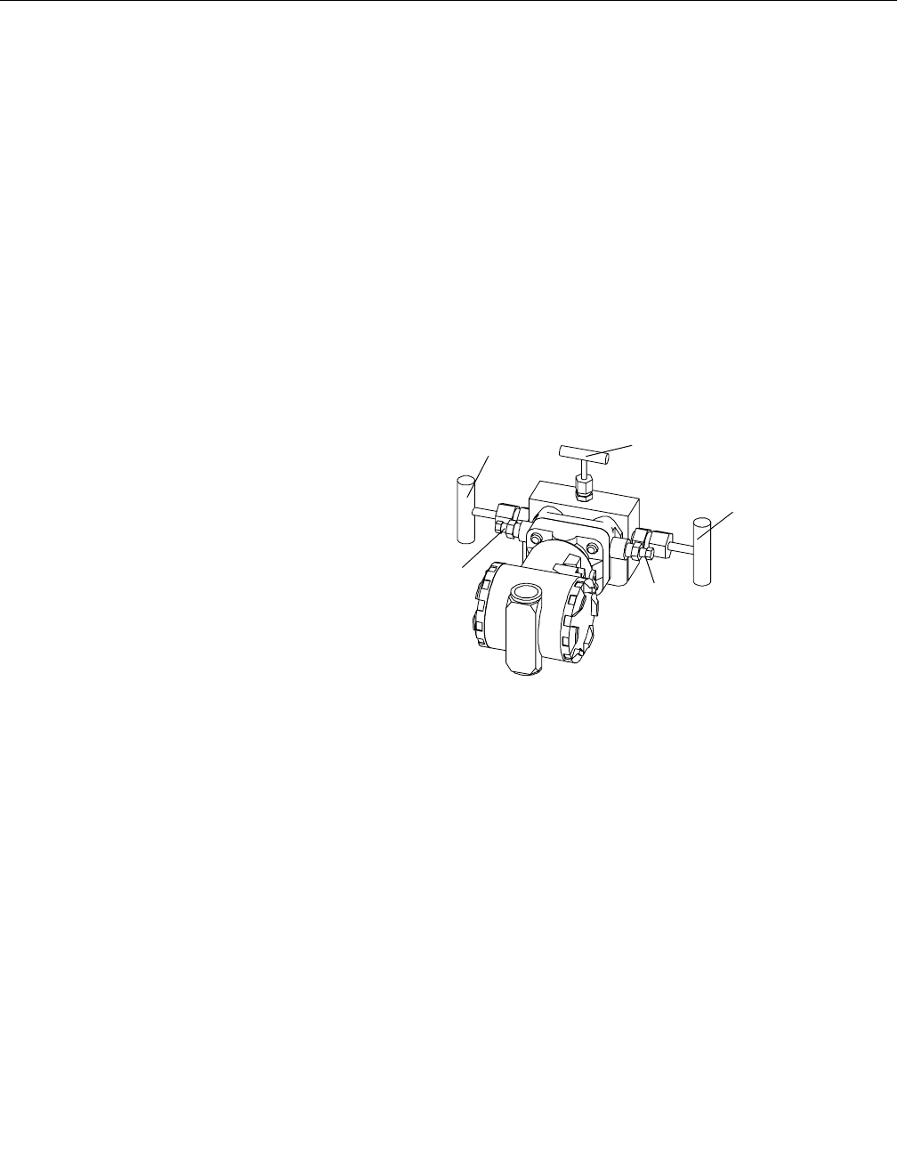
Reference Manual
00809-0100-4809, Rev AA
August 2002
Annubar Flowmeter Series
3-6
Wet Zero
1. Open the High and Low manifold valves MH and ML.
2. Open the Equalizer valve ME.
3. Open the drain/vent valves on the electronics DVH and DVL; bleed
until no air is apparent in the liquid.
4. Close both drain/vent valve DVH and DVL.
5. Close the High side valve MH.
6. Check the electronics zero by noting the output. If the signal reads
outside of the range 3.98 mA to 4.02 mA then perform a zero trim.
7. Check the electronics zero by noting the output. If the signal reads
outside of the range 3.98 mA to 4.02 mA then repeat steps 1 - 6.
8. Close the Equalizer valve ME.
9. Open the High side valve MH and ensure that the Low side valve ML
is open.
10. The system is now operational.
Figure 3-2. Valve Identification
for Direct Mounted Annubar
Models in Liquid Service
Gas Service
1. Ensure that the pipe is pressurized.
2. Open both high and low side main valves MH and ML.
3. Open equalization valve ME.
4. Open the drain valves DVL and DVH on the electronics to ensure that
no liquid is present.
5. Close drain valves DVL and DVH.
6. Check the electronics for the 4 mA signal. Trim zero if necessary.
7. Close the equalizer valve ME. The system is now operational.
8900-8900V01A
DVH
DVL
ML ME
MH
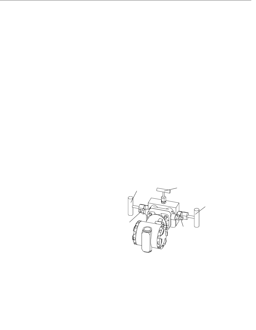
Reference Manual
00809-0100-4809, Rev AA
June 2002
3-7
Annubar Flowmeter Series
Gas Service 3-Valve Manifold
Dry Zero
1. Prior to commissioning the flowmeter a dry zero should be performed
to eliminate any positional effects to the transmitter.
2. Keeping both the high and low main valves closed MH and ML open
the equalizer valve ME.
3. Perform a zero trim (see “Trim the Transmitter” on page 3-26).
4. Check the electronics zero by noting the output. If the signal reads
outside of the range 3.98 mA to 4.02 mA then repeat step 3.
Wet Zero
1. 1. Open the High and Low manifold valves MH and ML.
2. Open the Equalizer valve ME.
3. Open the drain/vent valves on the electronics DVH and DVL; bleed to
ensure that no liquid is present.
4. Close both drain/vent valve DVH and DVL.
5. Close the High side valve MH.
6. Check the electronics zero by noting the output. If the signal reads
outside of the range 3.98 mA to 4.02 mA then perform a zero trim.
7. Check the electronics zero by noting the output. If the signal reads
outside of the range 3.98 mA to 4.02 mA then repeat steps 1 - 6.
8. Close the Equalizer valve ME.
9. Open the High side valve MH, ensure that the Low side valve ML is
open. The system is now operational.
Figure 3-3. Valve Identification
for Direct Mounted Models in
Gas Service
8900-8900V01A
DVH
DVL
ML ME
MH

Reference Manual
00809-0100-4809, Rev AA
August 2002
Annubar Flowmeter Series
3-8
Steam Service (see Figure 3-4 on page 3-10
1. Ensure that the steam line is depressurized with no steam.
2. Check the electronics for a dry zero of 4 mA with no water loss.
3. Attach a water supply to the hose connection. The water supply
should have a maximum psi of 100.
4. Open the high and low main valves MH and ML and equalizer valve
ME.
5. Close low side vent DVL on the electronics.
6. Open the hose connect valve for a minimum of 30 seconds.
Water will flow through both the high and low chambers and
into the pipe.
7. Close the high MH for 30 seconds to force water to the ML side.
8. Re-open the MH valve.
9. Open low side vent DVL on the electronics until no air is observed.
10. Close the vent.
11. Close the hose connect valve.
12. Close both MH and ML.
13. Check the instrument zero by noting the electronics output. If the
signal reads outside of the range 3.98 mA to 4.02 mA, air is probably
still in the system; repeat this procedure from step 2, and trim sensor
if necessary.
14. Open MH and ML.
15. Close equalizer valve ME. The system is now operational.

Reference Manual
00809-0100-4809, Rev AA
June 2002
3-9
Annubar Flowmeter Series
3-Valve Steam No Flow
1. Prior to commissioning the flowmeter a dry zero should be performed
to eliminate any positional effects to the transmitter.
2. Keeping both the high and low main valves closed MH and ML open
the equalizer valve ME.
3. Perform a zero trim (see “Trim the Transmitter” on page 3-26).
4. Check the electronics zero by noting the output. If the signal reads
outside of the range 3.98 mA to 4.02 mA then repeat step 3.
5. Verify that the line is depressurized with no steam.
6. Attach a water supply to the hose connection. The water supply
should have a maximum of 100 psi.
7. Open the High and Low main valves as well as the equalizer valve
MH, ML and ME.
8. Close low side vent DVL on the electronics.
9. Open the hose connect valve for a minimum of 30 seconds. Water will
flow through both the high and low chambers and into the pipe.
10. Close the high valve MH for 30 seconds to force water to the Low
side.
11. Re-open the main High valve MH.
12. Open the low side vent DVL on the electronics until no air is
observed.
13. Close the low side vent DVL.
14. Close the hose connect valve, and remove the hose.
15. Open both the high and low main valves MH and ML and close the
equalizer valve ME.
16. The sensor is ready for flow.
17. After flow has been started and allowed to reach operating conditions
a wet zero needs to be performed.
18. Using the drain/vent valves on the electronics DVH and DVL; burp
(carefully crack vents open and closed to ensure that no air is
present, this may need to be done more than one time.)
19. Close the High side main valve MH.
20. Open the Equalizer valve ME.
21. Check the electronics zero by noting the output. If the signal reads
outside of the range 3.98 mA to 4.02 mA then perform a zero trim.
22. After zero trim is done check the electronics zero by noting the
output. If the signal reads outside of the range 3.98 mA to 4.02 mA.
Set sensor back to flow by closing the Equalizer valve ME and
opening the High side valve MH. Repeat steps 14 - 17.
23. Close the Equalizer valve ME.
24. Open the High side valve MH, ensure that the Low side valve ML is
open. The system is now operational
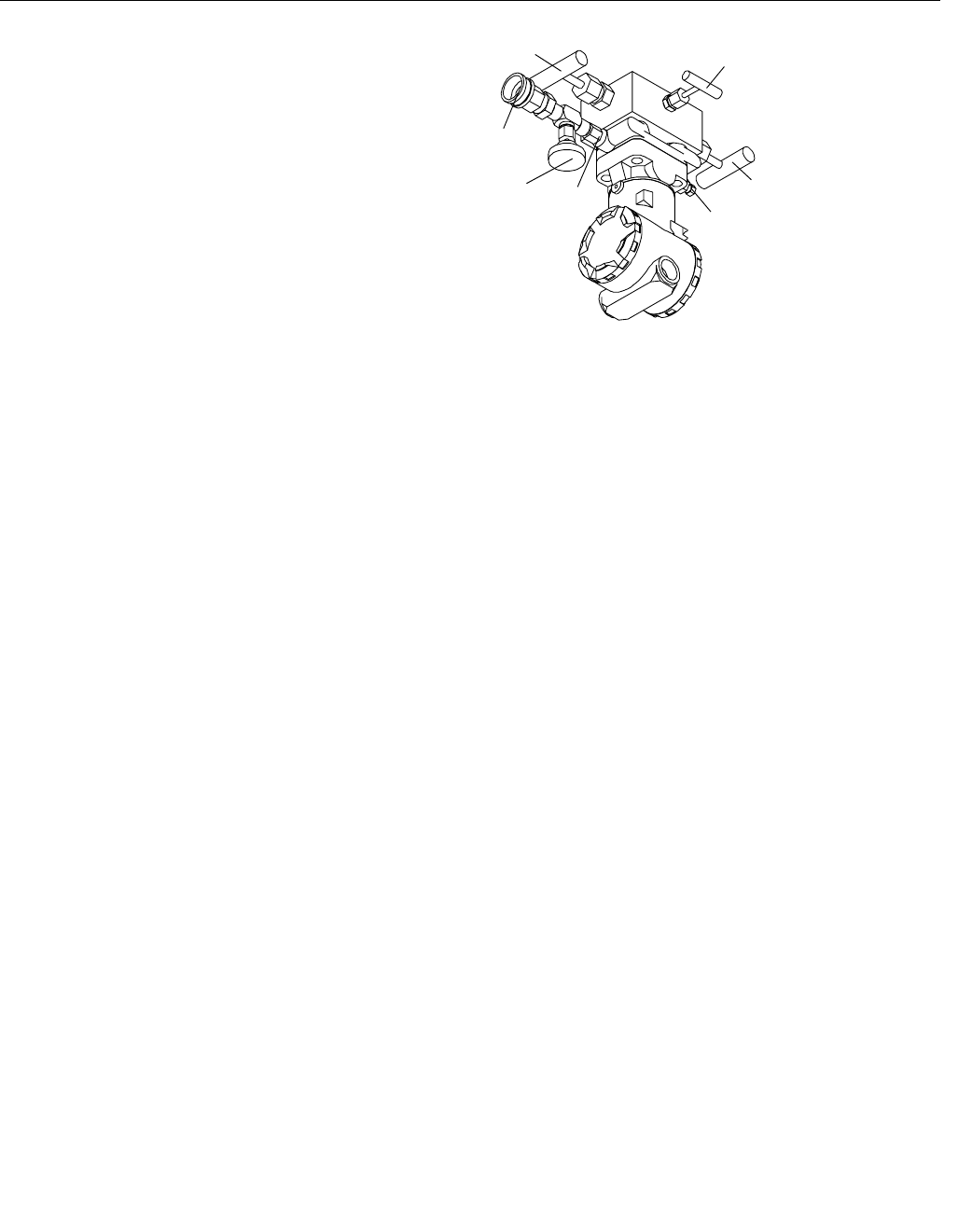
Reference Manual
00809-0100-4809, Rev AA
August 2002
Annubar Flowmeter Series
3-10
Figure 3-4. Valve Identification
for Direct Mounted Annubar
Models in Steam Service
Remote Mount Zero the Electronics
Before the electronics are exposed to line pressure, check the “zero”
calibration (or, “dry” zero) by using the following procedure.
1. Open first the equalizer valve(s) MEL and MEH or ME.
2. Close valves MH and ML.
3. Read the Annubar output. It should read within the range 3.98 mA to
4.02 mA. If the output is outside of this range, zero trim as described
in “Zero Trim” on page 3-27.
Check for System Leaks
Check the system for leaks after installation is complete. A leak in a
differential pressure instrument system can produce a difference in pressure
that is larger than the signal itself.
Before the system is filled and/or commissioned, it is a simple matter to use
compressed air or another inert, compressed gas to check for leaks. The gas
pressure must be below the maximum allowed, but at least equal to the
normal operating pressure in order to reveal potential leaks. A typical
pressure used is 100 psig (690 kPa).
Before pressurizing the system, check for leaks by doing the following:
1. Open equalizer valve(s) MEH, MEL or ME to prevent overpressuring
the DP.
2. Close valves PH, PL (unless the piping system is also being
pressure-checked), MV, DVH, DVL.
• If present, also close valves BH and BL or DH and DL.
3. Open valves MH and ML.
4. Install all appropriate tapped plugs.
5. Install a current meter to read the signal, if necessary.
Apply pressure at a convenient point on either the high or low side of the
system. Use a suitable leak detection solution and apply to all of the impulse
piping, valves, manifold, and connections. A leak is indicated by a continuous
stream of bubbles.
8900-8900V02A
Hose
Connect
Valve
Hose
Connection
ML ME
MH
DVL
DHL

Reference Manual
00809-0100-4809, Rev AA
June 2002
3-11
Annubar Flowmeter Series
5-Valve Manifolds
If a 5-valve manifold is installed, the equalizer valves can be tested by
performing the following procedure after system leaks are repaired and the
system is stable.
1. Close equalizer valves MEH and MEL.
2. Open vent valve MV. There should be no leakage from the manifold
vent.
3. Close vent valve MV.
4. Open equalizer valves MEH and MEL.
5. Bleed off the air and remove the source fitting.
6. Return the system to the original configuration. Use extreme
care when bleeding high temperature fluids. Bleed piping may need
to be installed.
“Calibrate Out” Temperature Effects
NOTE
Do not begin this procedure until the system leak check has been completed
and all leaks have been fixed.
The flowmeter’s proportional output-to-flow ratio makes a true “zero”
calibration critical for producing accurate measurements. The “zero”
calibration procedure is affected by static pressure and ambient temperature,
but these effects can be removed by calibrating them “out.”
The effect of static pressure is calibrated out by exposing the Annubar
electronics to the line pressure and performing a “zero” or wet calibration, as
described below. In order to calibrate out the effect of ambient temperature,
two aspects should be taken into consideration:
• The electronics should be located where the ambient temperature does
not change rapidly or vary by more than 10 to 15 °F (26 to 29 °C).
• When commissioning the electronics, the flowing fluid
(condensate/water for steam service) could bring the sensor to a
temperature significantly different than the temperature during normal
operations. In this situation, perform another “zero” calibration at least
60 minutes after the Annubar has been commissioned. The sensor
temperature can be monitored using a HART communicator, as
described in “Zero or Wet Calibration” .
Although the above effects are relatively small, they significantly affect the
accuracy of the Annubar when used with low flows.
Periodic “zero” calibration and/or commissioning is recommended to maintain
the accuracy of Annubar. The frequency of this type of maintenance should
be established for each individual application.
Zero or Wet Calibration
Follow this procedure to obtain a true zero at static or “pipe” pressure:

Reference Manual
00809-0100-4809, Rev AA
August 2002
Annubar Flowmeter Series
3-12
1. Open equalizer valves:
• For 5-valve manifolds, open valves MEH and MEL
• For 3-valve manifolds, open valves ME and high side MH
2. Close low side valve ML to prevent generating differential pressure.
Liquid Service below 250 °F (121 °C)
1. Ensure that primary instrument valves PH and PL are closed.
2. Open valves ME, ML, and MH.
a.For 5-valve manifolds, open valves MEH and MEL.
3. Slowly open valve PL and then PH, which are the primary instrument
valves.
4. Open drain/vent valves DVL and DVH to bleed air out of system.
Bleed until no air is apparent in the liquid.
5. Close valves DVL and DVH.
NOTE
For the alternate electronics location, open vent valves VH and VL and bleed
until no air is apparent in the liquid.
6. Slowly open vent valve MV to bleed out any entrapped air in manifold.
Bleed until no air is apparent in the liquid.
7. Close vent valve MV.
8. Gently tap the electronics body, valve manifold, and impulse piping
with a small wrench to dislodge any remaining entrapped air.
9. Repeat steps 2, 2A, and 3.
10. Close valve PH.
11. Check the Annubar zero by noting the electronics output — this is
called a wet zero. The electronics should indicate a zero DP
(Differential Pressure) signal. If the signal reads outside the range
3.98 mA to 4.02 mA, air is probably still in the system; repeat the
procedure from step 2. Trim zero if necessary.
12. Close equalizer valve(s).
a.For 3-valve manifolds, close valve ME.
b.For 5-valve manifolds, close valves MEH and MEL.
13. Slowly open valve PH. The system is now operational.

Reference Manual
00809-0100-4809, Rev AA
June 2002
3-13
Annubar Flowmeter Series
a.For 5-valve manifolds only: Open valve MV. If valve MV is leaking,
valves MEH and/or MEL are not fully closed or require repair. This
must be done before taking any readings.
Gas Service
1. For an impulse piping arrangement as shown in Figure 8-11 (vertical
pipe) only, open primary instrument valves PH and PL.
2. Open drain valves DH and DL slowly to allow the condensate
to drain.
3. Close valves DH and DL.
4. Ensure that primary instrument valves PH and PL closed.
5. Open valves ME, ML and MH.
a.For 5-valve manifolds, open valves MEH and MEL.
6. Slowly open valve PL, the primary high pressure instrument valve.
7. Check electronics zero by noting the electronics reading. The
electronics should indicate a “zero” DP signal. If the signal reads
outside of the range 3.98 mA to 4.02 mA, condensate may be in the
DP electronics or system; repeat the procedure from step 1 to remove
any condensate. A signal outside the range 3.98 mA to 4.02 mA can
also be caused by system leaks; check for leaks in system.
8. Close equalizer valve(s).
a.For 3-valve manifolds, close valve ME.
b.For 5-valve manifolds, close valves MEH and MEL.
9. Slowly open valve PH. The system is now operational.
a.For 5-valve manifolds only: Open valve MV. If valve MV is leaking,
valves MEH and/or MEL are not fully closed or require repair. This
must be done before taking any readings.
Steam Service or Liquid Service above 250 °F (121 °C)
1. Ensure that primary instrument valves PH and PL closed; ME, ML
and MH are closed; and DVL and DVH are closed.
a.For 5-valve manifolds, ensure that valves MEH and MEL
are closed.
2. Fill tees with water on each side until water overflows.
3. Open valves MH, ML and equalizer valve ME.

Reference Manual
00809-0100-4809, Rev AA
August 2002
Annubar Flowmeter Series
3-14
a.For 5-valve manifolds, open equalizer valves MEH and MEL.
4. Open valves DVL and DVH.
5. Tap manifold until no air bubbles are visible.
6. Close both valves DVL and DVH.
7. Refill tees with water.
8. Gently tap electronics body, valve manifold, and impulse piping with a
small wrench to dislodge any remaining entrapped air.
9. Check Annubar zero by noting the electronics output — this is called
a wet zero. The electronics should indicate a “zero” DP signal. If the
signal reads outside of the range 3.98 mA to 4.02 mA, air is probably
still in the system; repeat this procedure from step 2. Trim zero if
necessary.
10. Close equalizer valve ME.
a.For 5-valve manifolds, close equalizer valves MEH and MEL.
11. Replace plugs in tees.
12. Slowly open valves PH and PL. The system is now operational.
a.For 5-valve manifolds only: Open valve MV. If valve MV is leaking,
valves MEH and/or MEL are not fully closed or require repair. This
must be done before taking any readings.
Setting the Loop to
Manual
When preparing to send or request data that would disrupt the loop or change
the output of the flowmeter, set the process application loop to manual. The
HART Communicator Model 275 will prompt the user to set the loop to
manual when necessary. Keep in mind that acknowledging this prompt does
not set the loop to manual. The prompt is only a reminder, set the loop to
manual as a separate operation.
MODEL 275 HART
COMMUNICATOR
The HART Communicator exchanges information with the transmitter from
the control room, the instrument site, or any wiring termination point in the
loop. The flowmeter must be configured for certain basic variables to operate.
In many cases, all of these variables are pre-configured at the factory.
Configuration may be required if the transmitter is not configured or if the
configuration variables need revision.
Connections and
Hardware
To facilitate communication, connect the HART Communicator in parallel with
the flowmeter (see Figure 2-10 on page 2-13) using the non-polarized loop
connection ports that are located on the rear panel of the HART
Communicator.
NOTE
Do not make connections to the serial port or the NiCad recharger jack in
explosive atmospheres. Before connecting the HART communicator in an
explosive atmosphere, make sure the instruments in the loop are installed in
accordance with intrinsically safe or non-incendive field wiring practices.
MODEL 3051SFA
PROBAR
The ProBar can be configured either online or off-line. During online
configuration (when the transmitter is connected to a HART communicator)
data is entered in the working register of the communicator and sent directly
to the transmitter.

Reference Manual
00809-0100-4809, Rev AA
June 2002
3-15
Annubar Flowmeter Series
Off-line configuration consists of storing configuration data in a HART
Communicator while it is not connected to a transmitter. Data is stored in
nonvolatile memory and can be downloaded to the transmitter at a later time.
This section contains a brief summary of the HART communicator, but is not
meant to replace the Model 275 HART Communicator Reference Manual
(document number 00809-0100-4275).
Updating the Model 275
HART Communication
Software
The Model 275 HART Communicator software may need to be upgraded to
take advantage of the additional features available in the Annubar (field
device revision 3). Perform the following steps to determine if an upgrade is
required.
1. Turn on the HART communicator and select 4 Utility, then 5
Simulation.
2. Choose “Rosemount” from the list of manufacturers and “3051” from
the list of models.
3. If the Fld Dev Rev choices include “Dev v3, DD v2,” an upgrade is
not required. If the only choice is “Dev v1” or “Dev v2” (with any DD
version), than the communicator should be upgraded.
HART Menu Tree Figure 3-5 displays a complete Annubar menu tree for use with the Model 275
HART Communicator. Options listed in bold type indicate that a selection
provides other options.
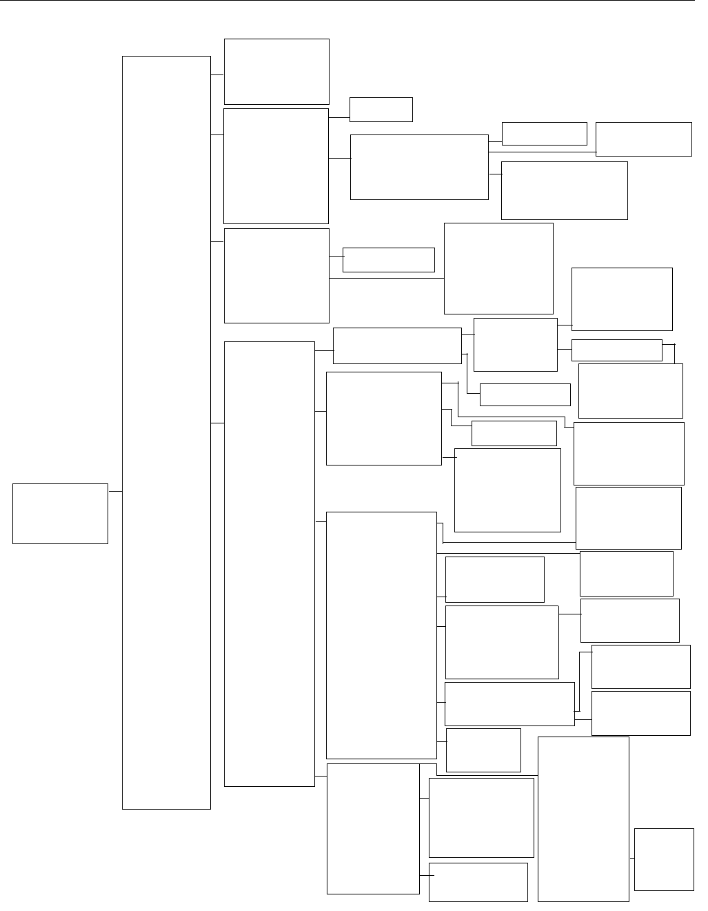
Reference Manual
00809-0100-4809, Rev AA
August 2002
Annubar Flowmeter Series
3-16
Figure 3-5. HART Communicator Menu Tree
1. Universal.
Rev.
2. Field.
Dev. Rev.
3. Software
Rev
1. Tag
2. Date
3. Descriptor
4. Message
5. Model
6. Model Number 1
7. Model Number II
8. Model Number III
9. Write Protect
Conf Write
Protect Local
Keys
REVISION #’S
Final Assembly
Num
Dev ID
Distributor
1. Meas Typ
2. Module config Type
3. Isoltr matl
4. Fill fluid
5. Process Connector
6. Process Conn Matl
7. O ring Malt
8. Drain Vent Matl
1. Press Alert Mode
2. Temp Alert Mode
3. CONFIG PRESS ALERT
4. CONFIG TEMP ALERT
1. Pres
2. Percent Range
3. Analog Output (AO)
4. Snsr Temp
5. SV
6. PV is
1. PRESSURE SENSOR
2. DEVICE TEMP. SENSOR
1. Date
2. Descriptor
3. Message
4. Write Protect
5. Conf Write Protect
6. Model
7. Model Number 1
8. Model Number II
9. Model Number III
1. Pres
2. Percent Range
3. Analog Output (AO)
4. Snsr temp
5. SV
6. PV is
1. Tag
2. Unit
3. RANGE VALUES
4. DEVICE INFO
5. Xfer fnctn
6. Damp
7. LCD display config
1. Self test
2. Status
1. Keypad Input
2. Apply Values
1. SV DATA POINTS
2. SV Units
3. SV Xfer Function
4. SV Cutoff Mode
5. SV Low Flow Cutoff
6. SV Linear Offset
7. SV Config
1. Digital-to-Analog
Trim
2. Scaled D/A Trim
1. Keypad Input
2. Apply Values
1. Keypad Input
2. Apply Values
1. Poll Addr
2. Num Req Preams
3. Burst Mode
4. Burst Option
1. FIELD DEVICE
INFO
2. SENSOR INFO
3. Self Test
4. DIAPHRAGM
SEALS INFO
1. DEVICE SETUP
2. PV
3. AO
4. PV URV
5. PV LRV
1. PROCESS
VARIABLES
2. DIAG/SERVICE
3. BASIC SETUP
4. DETAILED
SETUP
5. Review
1. TEST DEVICE
2. Loop Test
3. CALIBRATION
1. RERANGE
2. ANALOG OUTPUT TRIM
3. SENSOR TRIM
4. Recall fact trim
Online Menu
1. PROCESS
VARIABLES
2. SENSOR
SERVICE
3. Unit
1. SENSORS
2. SIGNAL
CONDITION
3. OUTPUT
CONDITION
4. DEVICE
INFORMATION
1. PROCESS
VARIABLES
2. RANGE VALUES
3. Unit
4. Transfer Function
5. Damp
6. Snsr Temp Unit
7. ALM/SAT LEVELS 1. Alarm Direction
2. High Alarm
3. Low Alarm
4. High Sat
5. Low Sat
6. Config Alarm Dir
7. Config Alarm Level
8. Config Sat Levels
1. PROCESS
VARIABLES
2. ANALOG OUTPUT
3. HART OUTPUT
4. SCALED VARIABLE
5. PROCESS ALERTS
6. VARIABLE
REMAPPING
1. Zero Trim
2. Lower Sensor Trim
3. Upper Sensor Trim
4. Sensor Trim Cal Typ
5. Sensor Trim Points
1. Pres
2. Percent Range
3. Analog Output (AO)
4. Snsr temp
5. SV
6. PV is
1. SENSOR TRIM
2. Recall Fact Trim
1. Zero trim
2. Lower Sensor Trim
3. Upper Sensor Trim
4. Snsr Trip Cal Typ
5. Sensor Trim Points
1. Snsr Temp
2. Snsr Temp Unit
1. Pressure
2. Percent Range
3. Analog Output (AO)
4. Snsr temp
5. SV
6. PV is
1. Loop Test
2. D/A trim
3. Scaled D/A Trim
4. Alarm Direction
1. Press Input 1
2. Press Input 2
3. SV Ouput 1
4. SV Output 2
1. Press Hi Alert Val
2. Press Lo Alert Val
3. USL
4. LSL
1. Temp Hi Alert Val
2. Temp Lo Alert Val
3. Snsr Temp USL
4. Snsr Temp LSL
1. PV is
2. SV is
3. TV is
4. Re-mapping
1. # of diaph seals
2. Seal Type
3. Seal Fill Fluid
4. RS Isoltr Matl

Reference Manual
00809-0100-4809, Rev AA
June 2002
3-17
Annubar Flowmeter Series
Fast Key Sequences Fast key sequences are listed below for common transmitter functions.
NOTE:
The fast key sequences assume that Device Descriptor Dev v3, DD v2 is
being used. Table 3-3 provides alphabetical function lists for all Model 275
HART Communicator tasks as well as their corresponding fast key
sequences.
Table 3-3. Model 3051SFA Fast
Key Sequence
The following menu indicates fast key sequences for common functions.
Review Configuration
Data
Before operating the Annubar in the actual installation, review all of the
factory-set configuration data to ensure that it reflects the current application.
Function HART Fast Key Sequence
Alarm Level Config. 1, 4, 2, 7, 7
Alarm and Saturation Levels 1, 4, 2, 7
Analog Output Alarm Direction 1, 4, 2, 7, 6
Analog Output Trim 1, 2, 3, 2
Burst Mode On/Off 1, 4, 3, 3, 3
Burst Options 1, 4, 3, 3, 4
Damping 1, 3, 6
Date 1, 3, 4, 1
Descriptor 1, 3, 4, 2
Digital To Analog Trim (4-20 mA Output) 1, 2, 3, 2, 1
Field Device Information 1, 4, 4, 1
Loop Test 1, 2, 2
Lower Sensor Trim 1, 2, 3, 3, 2
Message 1, 3, 4, 3
Meter Configuration 1, 3, 7
Number of Requested Preambles 1, 4, 3, 3, 2
Pressure Alert Config. 1, 4, 3, 5, 3
Poll Address 1, 4, 3, 3, 1
Poll a Multidropped Transmitter Left Arrow, 4, 1, 1
Re-mapping 1, 4, 3, 6, 4
Rerange- Keypad Input 1, 2, 3, 1, 1
Saturation Level Config. 1, 4, 2, 7, 8
Scaled D/A Trim (4–20 mA Output) 1, 2, 3, 2, 2
Scaled Variable Config. 1, 4, 3, 4, 7
Self Test (Transmitter) 1, 2, 1, 1
Sensor Information 1, 4, 4, 2
Sensor Temperature 1, 1, 4
Sensor Trim 1, 2, 3, 3
Sensor Trim Points 1, 2, 3, 3, 5
Status 1, 2, 1, 2
Tag 1, 3, 1
Temperature Alert Config. 1, 4, 3, 5, 4
Transfer Function (Setting Output Type) 1, 3, 5
Transmitter Security (Write Protect) 1, 3, 4, 5
Units (Process Variable) 1, 3, 2
Upper Sensor Trim 1, 2, 3, 3, 3
Zero Trim 1, 2, 3, 3, 1
Reference Manual
00809-0100-4809, Rev AA
August 2002
Annubar Flowmeter Series
3-18
Review
After activating the Review function, scroll through the data list to check each
variable. If changes to the transmitter configuration data are necessary, refer
to the functions below.
Check Output Before performing other flowmeter on-line operations, review the
configuration of the flowmeter digital output parameters to ensure that the
flowmeter is operating properly.
Process Variables
The Process Variables for the ProBar provide the flowmeter output and are
continuously updated. The process variable menu displays the following
process variables:
•Flow Pressure
• Percent of Range
• Analog Output
• DP Pressure
• Sensor Temperature
The flow pressure reading in both Engineering Units and Percent of Range
will continue to track with pressures outside of the defined range from the
lower to the upper range limit of the sensor module.
Sensor Temperature
The ProBar contains a temperature sensor that is located above the pressure
sensor in the sensor module. When reading this temperature, keep in mind
that this is not a process temperature reading.
Basic Setup Set Process Variable Units
The PV Unit command sets the process variable so the process can be
monitored using the appropriate units of measure. Select from the following
engineering units:
HART Comm. 1, 5
HART Comm. 1, 2
HART Comm. 1, 1, 5
HART Comm. 1, 3
•in H
2O
•in H
2O at 39.2 °F (4 °C)
•in Hg
• ft H2O
•mm H
2O
•mm H
2O at 39.2 °F (4 °C)
•mm Hg
•psi
•bar
•mbar
•g/cm
2
•kg/cm
2
•Pa
•kPa
•torr
•atm
Reference Manual
00809-0100-4809, Rev AA
June 2002
3-19
Annubar Flowmeter Series
Set Output
Activate the flowmeter square root output option to make the analog output
proportional to flow. To avoid the extremely high gain that results as the input
approaches zero, the ProBar automatically switches to a linear output in order
to ensure a more stable output near zero. The transition from linear to square
root output is smooth, with no step change or discontinuity in output.
The transition from linear to square root is not adjustable. It occurs at 0.8% of
ranged pressure input. In earlier software, the transition point occurred at 4%
of ranged pressure input, or 20% of full scale flow output.
From 0 percent to 0.6 percent of the ranged pressure input, the slope of the
curve is unity (y = x). This allows accurate calibration near zero. Greater
slopes would cause large changes in output for small changes at input. From
0.6 percent to 0.8 percent, the slope of the curve equals 42 (y = 42x) to
achieve continuous transition from linear to square root at the transition point.
NOTE
The transmitter accuracy declines after a 10:1 turndown.
Figure 3-6. Square Root Output
Transition Point Damping
The PV Damp command changes the response time of the flowmeter to
smooth variations in output readings caused by rapid changes in input.
Determine the appropriate damping setting based on the necessary response
time, signal stability, and other requirements of the of loop dynamics of the
system. The default damping value is 1.6 seconds, and can be reset to any
value between 0 and 25.6 seconds.
LCD Meter Options
The Meter Options command customizes the LCD meter for use in the
application. The meter can be configured to display the following information:
• Engineering Units
• Percent of Range
• User-Configurable LCD Scale
• Alternating between any two of the above
HART Comm. 1, 3, 5
Accuracy 0.025 0.005 URL
Span
--------------
+% of Span=
Accuracy 0.005 0.0035 URL
Span
--------------
+% of Span=
HART Comm. 1, 3, 6
HART Comm. 1, 4, 3, 4
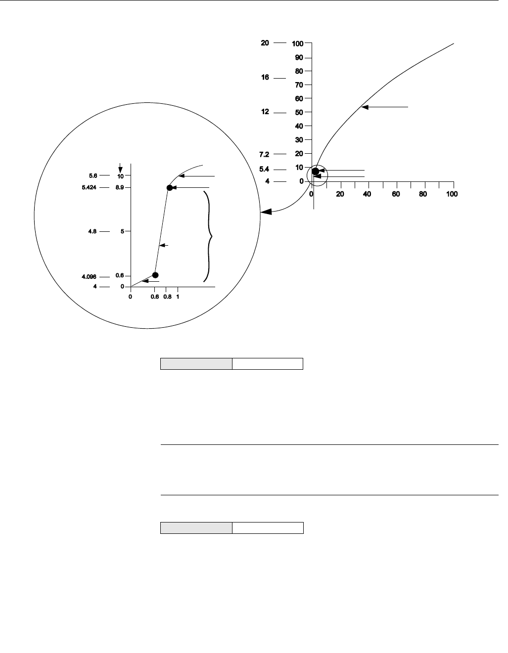
Reference Manual
00809-0100-4809, Rev AA
August 2002
Annubar Flowmeter Series
3-20
Detailed Setup Local Span and Zero Control
The Local Keys command allows software control over the use of the local
span and zero adjustments. To enable or disable the span and zero
adjustment buttons on the flowmeter, perform the following fast key
sequence: 1 Device Setup, 4 Detailed Setup, 4 Device Information, 1 Field
Device Information, 7 Local Keys Enable.
NOTE
Disabling the local keys does not disable all flowmeter configuration changes.
With the local keys disabled, changes can still be made to the flowmeter
configuration using a HART Communicator.
Diagnostics and Service Transmitter Test
The Transmitter Test command initiates a more extensive diagnostics routine
than that performed continuously by the flowmeter. The flowmeter test routine
can quickly identify potential electronics problems. If the transmitter test
detects a problem, messages to indicate the source of the problem are
displayed on the communicator screen. This test can be performed either on
the bench or in the field.
Full Scale
Flow (%)
Square
Root Curve
Transition Point
Linear Section of Curve
Full Scale Pressure (%)
0.8%
Slope = 1
Linear
Transition
Detail
Full Scale Pressure (%)
Square
Root
Curve
Linear
Section
of Curve
Transition
Point
Full
Scale
Flow
(%)
Full Scale
Output (mA dc)
Full Scale
Output (mA dc)
Slope = 42
HART Comm. 1, 4, 4, 1, 7
HART Comm. 1, 2, 1, 1

Reference Manual
00809-0100-4809, Rev AA
June 2002
3-21
Annubar Flowmeter Series
Loop Test
The Loop Test command verifies the output of the flowmeter, the integrity of
the loop, and the operations of any recorders or similar devices installed in the
loop. This test should only be performed after the flowmeter is installed. To
initiate a loop test, perform the following procedure:
1. Connect a reference meter to the flowmeter. To do so, either connect
the meter to the test terminals on the flowmeter terminal block, or
shunt the power to the flowmeter through the meter at some point in
the loop.
2. From the HOME screen, Select 1 Device Setup, 2 Diagnostics and
Service, 2 Loop Test, to prepare to perform a loop test.
3. Select “OK” after you set the control loop to manual. The
communicator displays the loop test menu.
4. Select a discrete milliampere level for the flowmeter to output. At the
“Choose analog output” prompt, select 1 4mA, 2 20mA, or select
3Other to manually input a value. If a loop test is being performed to
verify the output of a flowmeter, enter a value between 4 and 20 mA.
If a loop test is being performed to verify the flowmeter alarm levels,
enter the milliampere value at which the flowmeter should enter an
alarm state.
5. Check the electrical current meter installed in the test loop to verify
that the flowmeter reads the appropriate value it was commanded to
output. If the readings match, the flowmeter and the loop are
configured and functioning properly. If the readings do not match
there may be a fault in the wiring, the flowmeter may require an
output trim, or the electrical current meter may be malfunctioning.
After completing the test procedure, the display returns to the loop test
screen.
Calibration A smart flowmeter uses a microprocessor that contains information about the
sensor’s specific characteristics in response to pressure and temperature
inputs; each sensor varies slightly. A smart flowmeter compensates for these
sensor variations. The process of generating the sensor performance profile
is called factory characterization and it enables a smart flowmeter to maintain
higher performance specifications than analog flowmeters.
Calibrating a smart flowmeter is different from calibrating an analog flowmeter.
The one-step calibration process of an analog flowmeter is done in three
steps with a smart flowmeter:
• Rerange – sets the 4 and 20 mA points at the desired pressures
• Sensor Trim – Adjusts the position of the factory characterization curve
to optimize the flowmeter performance over a specified pressure range
or to adjust for mounting effects
• Analog Output Trim – Adjusts the analog output to match the plant
standard or the control loop
HART Comm. 1, 2, 2

Reference Manual
00809-0100-4809, Rev AA
August 2002
Annubar Flowmeter Series
3-22
It is important to understand the difference between the trim and the rerange
functions of smart flowmeters. Reranging sets the flowmeter analog output to
the selected upper and lower range points, and can be done with or without
an applied pressure. Reranging does not change the factory characterization
curve stored in the microprocessor. In contrast, sensor trimming requires an
accurate pressure input, and adds additional compensation that adjusts the
position of the factory characterization curve.
NOTE
Sensor trimming adjusts the position of the factory characterization curve. It is
possible to degrade the performance of the flowmeter if the sensor trim is
done improperly or with equipment that does not meet the accuracy
requirements. Contact a Rosemount representative for more information.
Table 3-7 on page 3-23 illustrates the flowmeter data flow. This data flow can
be summarized in four major steps:
1. A change in pressure is measured by a change in the sensor output
(Sensor Signal)
2. The sensor signal is converted to a digital format that can be
understood by the microprocessor (Analog-to-Digital Signal
Converter)
3. Corrects are performed in the microprocessor to obtain a digital
representation of the process input (Digital PV)
4. The Digital PV is converted to an analog value (Digital- to-Analog
Signal Conversion)
Figure 3-7 also identifies the approximate flowmeter location for each
calibration task. Note that the data flows from left to right and a parameter
change affects all values to the right of the changed parameter.
Not all calibration procedures should be performed for each flowmeter. Some
procedure are appropriate for bench calibration but should not be performed
during field calibration. Figure 3-7 identifies the recommended calibration
procedure for each type of flowmeter for both bench and field calibration.
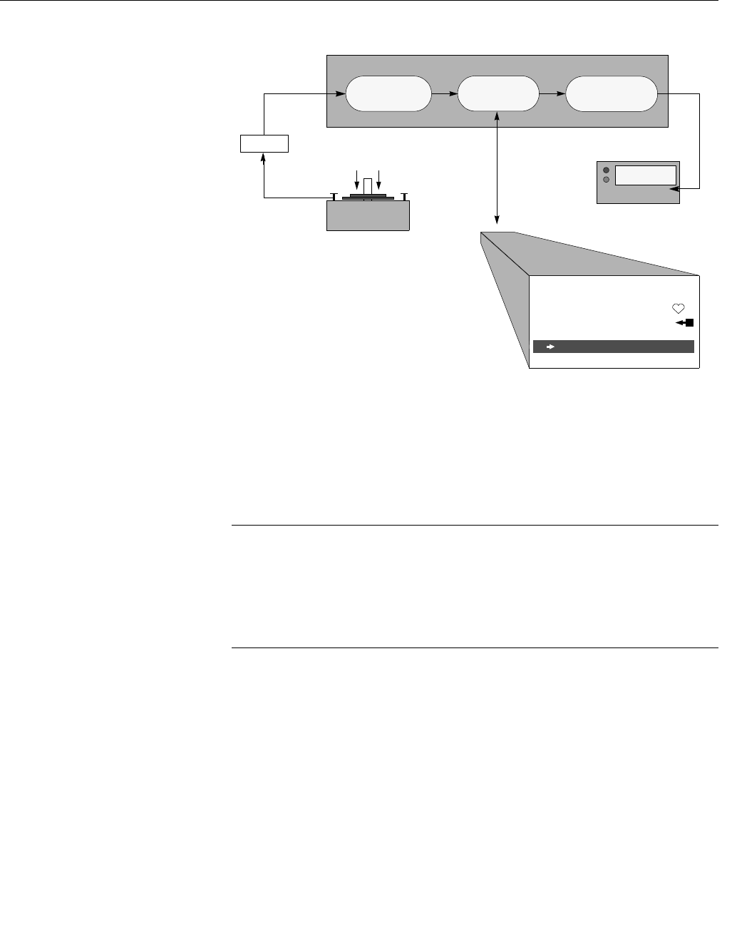
Reference Manual
00809-0100-4809, Rev AA
June 2002
3-23
Annubar Flowmeter Series
Figure 3-7. Flowmeter Data
Flow with Calibration Options
Rerange
The Range Values command sets the 4 and 20 mA points (lower and upper
range values). Setting the range values to the limits of expected readings
maximizes flowmeter performance; the flowmeter is most accurate when
operated within the expected pressure ranges for your application. In practice,
reset the flowmeter range values as often as necessary to reflect changing
process conditions.
NOTE
Regardless of the range points, the will measure and report all readings within
the digital limits of the sensor. For example, if the 4 and 20 mA points are set
to 0 and 10 inH20, and the flowmeter detects a pressure of 25 inH20, it
digitally outputs the 25 in H20 reading and a 250% percent of span reading.
However, there may be up to ±5.0% error associated with output outside of
the range points.
When reranging a calibrated, the new DP must be calculated at the factory
during calibration. The is a flowmeter calibrated at reference conditions and
has been ranged according to the conditions given at the time of order
placement. If the density, pressure, temperature, fluid, or pipe ID has
changed, use Flow Handbook (document number DS-4012) for equations
prior to reranging the flowmeter.
Specific information can be found on the flow calibration report (as shown
below) or on the ProBar flowmeter tag.
To rerange the output, use the following equation:
New DP Range
Example:
Current Information
HART
Communications
Microprocessor
Digital PV
Digital-to-Analog
Signal Conversion
Analog-to-Digital
Signal Conversion
Flowmeter Electronics Module
Analog Output
100 inH2O
(Flowmeter Ranged 0 to 100 inH2O)
ProBar: FT-4001
Process Variables
1Flow Press
2% rnge100.00
3AO20.00 mA
4Press0.00 inH2O
5Snsr Temp23.0 °C
Output
Device
20.00 mA
Input Device
NOTES
1)Value on PV line should equal
the input pressure
2)Value on AO line should equal the
output device reading
Sensor
Signal
Input
Pressure
Sensor
newQmax
oldQmax
-----------------------------
=2 ⫻ Old DP Range

Reference Manual
00809-0100-4809, Rev AA
August 2002
Annubar Flowmeter Series
3-24
Model: Flanged
Serial#: 222222.2
Max Flow @ 20 mA: 1600 GPM
Max DP @ 20 mA: 153 inH2O
To rerange 20 mA to 2000 gpm, the calculation is as follows:
New DP Range
The flowmeter can now be reranged to the following new settings:
4 mA = 0 in H2O
20 mA = 239 inH20
Use one of the following three methods to rerange the flowmeter. Each
method is unique; examine all three closely before deciding which method to
use.
Method 1: Rerange with a Communicator Only
Reranging using only the communicator is the easiest and most popular
way to rerange the flowmeter. This method changes the values of the
analog 4 and 20 mA points independently without a pressure input.
Changing the lower or upper range point results in similar changes to
the span.
NOTE
If the flowmeter security switch is in the “ON” position, adjustments cannot be
made to the zero and span. Refer to Figure 3-1 on page 3-2 for the
appropriate placement of the flowmeter security switch.
1. Enter the values directly from the HOME screen
or
2. Enter the fast-key sequence 1, 2, 3, 1, 1.
3. Select 1 Keypad input and follow the on-line instructions.
Method 2: Rerange with a Pressure Input Source and a
Communicator
Reranging using the communicator and a pressure source or process
pressure is a way of reranging the flowmeter when specific 4 and 20 mA
points are not known. This method changes the values of the analog 4 and
20 mA points. When the 4 mA point is set, the span is maintained. When
the 20 mA point is set, the span changes. If the lower range point is set
to a value that causes the upper range point to exceed the sensor
limit, the upper range point is automatically set to the sensor limit
and the span is adjusted accordingly.
HART Comm. 1, 2, 3, 1, 1
HART Comm. 1, 2, 3, 1, 2
2000
1600
-------------
=2 ⫻ 153 inH2O = 239 inH2O

Reference Manual
00809-0100-4809, Rev AA
June 2002
3-25
Annubar Flowmeter Series
NOTE
If the flowmeter security switch is in the “ON” position, adjustments cannot be
made to the zero and span. Refer to Figure 3-1 on page 3-2 for the
appropriate placement of the flowmeter security switch.
1. Enter the fast-key sequence 1, 2, 3, 1, 2.
2. Select 2 Apply values and follow the on-line instructions.
Method 3: Rerange with a Pressure Input Source and the Local Zero
and Span Buttons
Reranging using the local zero and span adjustments (see "Local Span
and Zero Control" on page 3-20) and a pressure source is a way of
reranging the flowmeter when specific 4 and 20 mA points are not known
and a communicator is not available. When the 4 mA point is set, the span
is maintained. When the 20 mA point is set, the span changes. If the lower
range point is set to a value that causes the upper range point to exceed
the sensor limit, the upper range point is automatically set to the sensor
limit and the span is adjusted accordingly.
To rerange the flowmeter using the span and zero buttons, perform the
following procedure.
1. Loosen the screw holding the certifications label on top of the
flowmeter housing. Rotate the label to expose the zero and span
buttons.
2. Using a pressure source with an accuracy three to ten times the
desired calibrated accuracy, apply a pressure equivalent to the lower
range value to the high side of the flowmeter.
3. To set the 4 mA point, press and hold the zero button for at least two
seconds. Verify that the output is 4 mA. If a meter is installed, it will
display ZERO PASS.
NOTE
The zero and span adjustments on previous versions of the flowmeter are
screws instead of buttons. To activate the zero or span adjustment, loosen the
screw until it pops up.
4. Apply a pressure equivalent to the upper range value to the high side
of the flowmeter.
5. To set the 20 mA point, press and hold the span button for at least two
seconds. Verify that the output is 20 mA. If a meter is installed, it will
display SPAN PASS.
NOTE
If the flowmeter security switch is in the “ON” position or if the local zero and
span adjustments are disabled through the software, adjustments cannot be
made to the zero and span using the local buttons. Refer to Figure 3-1 on
page 3-2 for the proper placement of the flowmeter security switch. Or refer to
"Local Span and Zero Control" on page 3-20 for instructions on how to enable
the span and zero buttons.

Reference Manual
00809-0100-4809, Rev AA
August 2002
Annubar Flowmeter Series
3-26
After you rerange the flowmeter using the span and zero adjustments, it is
possible to disable the adjustments to prevent further reranging. Refer to
"Local Span and Zero Control" on page 3-20 for more information.
Calibration Test
Bench
1. Set output configuration parameters
a.Set the transmitter range points
b.Set the Output Units
c.Set the Output Type
2. Set the Damping Values
3. Perform a full sensor trim (optional) – an accurate pressure source is
required.
NOTE
Do not perform a full trim for ProBar flowmeters with a device-type ProBar and
a field revision earlier than revision 3.
4. Perform an analog output trim (optional) – an accurate multimeter is
required.
Field
1. Reconfigure parameters if necessary
2. Zero Trim the transmitter to compensate for mounting position effects
or static pressure effects.
Trim the Transmitter
To decide which trim procedure to use, first determine whether the
analog-to-digital section or the digital-to-analog section of the flowmeter
electronics need calibration. To do so, perform the following procedure:
1. Connect a pressure source, a HART communicator, and a digital
readout device to the flowmeter.
2. Establish communication between the flowmeter and the
communicator.
3. Apply pressure equal to the upper range point pressure
(100 in H20, for example).
4. Compare the applied pressure to the Secondary Variable (Press) line
on the Communicator Process Variables Menu. If the Press reading
on the communicator does not match the applied pressure, but the
test equipment is accurate, perform a sensor trim.
5. Compare the Analog Output (AO) line on the communicator on-line
menu to the digital readout device. If the AO reading on the
communicator does not match the digital readout device, but the test
equipment is accurate, perform an output trim.
Sensor Trim
Trim the sensor using either the zero trim or the full trim function. The trim
functions vary in complexity and their use is application-dependent. Both
trim functions alter the interpretation of the input signal.
Reference Manual
00809-0100-4809, Rev AA
June 2002
3-27
Annubar Flowmeter Series
Zero Trim
A zero trim is a single-point adjustment. It is useful when compensating for
the mounting position effects and is most effective when performed with
the flowmeter installed in its final mounting position. Since this correction
maintains the slope of the characterization curve, it should not be used in
place of a full trim over the full sensor range.
When performing a zero trim, ensure that the equalizing valve is open and
all wet legs are filled to the correct levels.
Perform the following procedure to calibrate the sensor with a HART
Communicator using the zero trim function.
1. Vent the flowmeter and attach a communicator to the loop.
2. From the communicator main menu select 1 Device setup,
2 Diagnostics and service, 3 Calibration, 3 Sensor trim, 1 Zero trim to
prepare to adjust the zero trim.
NOTE
The flowmeter must be within 3% of true zero (zero based) in order to
calibrate using the zero trim function.
3. Follow the commands provided by the communicator to complete the
adjustment of the zero trim.
Full Trim
A full trim is a two-point sensor calibration where two end-point pressures
are applied and all output is linearized between them. Always adjust the
low trim value first to establish the correct offset. Adjustment of the high
trim value provides a slope correction to the characterization curve based
on the low trim value. The factory-established characterization curve is not
changed by this procedure. The trim values optimize performance over the
specified measuring range at the calibration temperature.
NOTE
Do not perform a full trim for flowmeters with a device-type and a field revision
earlier than field revision 3.
Perform the following procedure to calibrate the sensor with a HART
communicator.
1. Assemble and power the entire calibration system including the
flowmeter, HART communicator, power supply, pressure input
source, and readout device (see Figure 3-8).
HART Comm. 1, 2, 3, 3, 1
HART Comm. 1, 2, 3, 3

Reference Manual
00809-0100-4809, Rev AA
August 2002
Annubar Flowmeter Series
3-28
NOTE
Use a pressure input source that is at least three times more accurate than
the flowmeter. Allow the input pressure to stabilize for 10 seconds before
entering any values.
2. From the communicator main menu select 1 Device setup,
2 Diagnostics and service, 3 Calibration, 3 Sensor trim, 2 Lower
sensor trim to prepare to adjust the lower trim point.
NOTE
Select pressure input values so the low and high values are equal to or
outside the 4 and 20 mA points. Do not attempt to obtain reverse output by
reversing the high and low points. The flowmeter allows approximately a 5%
URL deviation from the characterized curve established at the factory.
3. Follow the commands provided by the communicator to complete the
adjustment of the lower value.
4. Repeat the procedure for the upper value, replacing 2 Lower sensor
trim with 3 Upper sensor trim in Step 2.
Analog Output Trim
The Analog Output Trim commands adjust the current output at the 4 and
20 mA points to match plant standards. This command adjusts the digital
to analog signal conversion.
Digital to Analog Trim
Use the following procedure to perform a digital-to-analog trim with a
HART communicator.
HART Comm. 1, 2, 3, 2, 1

Reference Manual
00809-0100-4809, Rev AA
June 2002
3-29
Annubar Flowmeter Series
1. From the HOME screen, select 1 Device setup, 2 Diag/Service, 3
Calibration, 4 D/A trim. Set the control loop to manual (see "Setting
the Loop to Manual" on page 3-14) and select OK.
2. Connect an accurate reference meter to the flowmeter at the
“Connect reference meter” prompt. To do so, connect the positive
lead to the positive terminal and the negative lead to the test terminal
in the flowmeter terminal compartment, or shunt the flowmeter power
through the reference meter at some point.
3. Select “OK” after connecting the reference meter.
4. Select “OK” at the “Setting fld dev output to 4 mA” prompt.
The flowmeter outputs 4.00 mA.
5. Record the actual value from the reference meter, and enter it at the
“Enter meter value” prompt. Verify that the output value equals the
value on the reference meter when the prompt appears.
6. Select 1 Yes if the reference meter value equals the flowmeter output
value or 2 No if it does not.
If you select 1 Yes, proceed to Step 7.
If you select 2 No, repeat Step 5.
7. Select “OK” at the “Setting fld dev output to 20 mA” prompt, and
repeat Steps 5 and 6 until the reference meter value equals the
flowmeter output value.
8. Select “OK” after you return the control loop to automatic control.
Digital to Analog Trim Using Other Scale
The Scaled D/A Trim command matches the 4 and 20 mA points to a
user-selectable reference scale other than 4 and 20 mA (1 to 5 volts if
measuring across a 250 ohm load, or 0 to 100 percent if measuring from a
DCS, for example). To perform a scaled D/A trim, connect an accurate
reference meter to the flowmeter and trim the output signal to scale as
outlined in the Output Trim procedure.
NOTE
Use a precision resistor for optimum accuracy. When adding a resistor to the
loop, ensure that the power supply is sufficient to power the flowmeter to a 20
mA output with the additional loop resistance.
HART Comm. 1, 2, 3, 2, 2
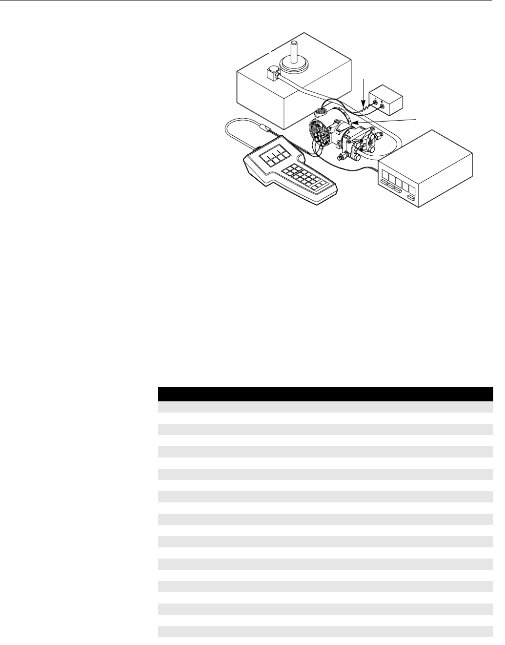
Reference Manual
00809-0100-4809, Rev AA
August 2002
Annubar Flowmeter Series
3-30
Figure 3-8.
Digital Trim Connection.
Drawing (4–20 mA Flowmeters)
Advanced Functions For complete instructions, refer to the Model 3051S Series Pressure
Transmitter Family Reference Manual (document number 00809-0100-4801).
MODEL 3095MFA MASS
PROBAR
EA Software/
HART Communicator
Comparison
Table A-1 identifies the functionality of the Model 3095 MV Engineering
Assistant and the Model 275 HART Communicator.
Any changes that are associated with flow parameters (pipe, fluid, primary
element) require EA software.
NOTE
4–20 mA wiring shown.
Dead Weight Tester
Calibration Standard
for Sensor Trim Only
250 Ω
Minimum Loop
Resistance
24 V dc Power Supply
HART Communicator Precision
Meter
ProBar
3051-3051A01A
Function EA HART
Compensated Flow Setup
Liquid, Gas, Steam, or Natural Gas YES NO
Differential Producer Type YES NO
Primary Element Diameter YES NO
Pipe internal Diameter YES NO
Operating Static Pressure Range YES NO
Operating Temperature Range YES NO
Pressure Standard Reference Condition YES NO
Temperature Standard Reference Condition YES NO
12 or 63 Point Density Data YES NO
4 Point Viscosity Data YES NO
Density at Standard Condition YES NO
Molecular Weight YES NO
Isentropic Exponent YES NO
RTD Fixed Mode YES YES
Transmitter Setup
Range Values (Flow, DP, AP, GP, T) YES YES
Units (Flow, DP, AP, GP, T) YES YES
Damping (DP, AP, GP, T) YES YES
Primary Variable YES YES
Device Information (tag, date, desc., etc.) YES YES

Reference Manual
00809-0100-4809, Rev AA
June 2002
3-31
Annubar Flowmeter Series
Engineering Assistant
(EA) Software
Please see the Model 3095MV Pressure Transmitter MultiVariable
Multilingual Field Manual (MFM) (document number 00810-0100-4716) for
instruction on how to commissioning the Model 3095MFA Mass ProBar.
Model 275 HART
Communicator
See “Model 3095MV HART Menu Tree” on page 3-32 and “Model 3095MFA
Fast Key Sequence” on page 3-33.
LCD Settings YES YES
Totalizer Settings YES YES
Special Units YES YES
DP Low Flow Cutoff YES YES
Burst Mode YES YES
Address YES YES
Maintenance
Change Password YES NO
Read Output YES YES
Module Info (range limits, matl, flange, etc.) YES YES
Identification Info (serial no., revisions) YES YES
Sensor Trim (DP, AP, GP, T) YES YES
Process Temperature Mode YES YES
Output Trim YES YES
Loop Test YES YES
Test Flow Calculation YES NO
Diagnostic Messages YES YES

Reference Manual
00809-0100-4809, Rev AA
August 2002
Annubar Flowmeter Series
3-32
Figure 3-9. Model 3095MV HART Menu Tree
1. TEST/STATUS
2. CALIBRATION
1. Differential Pressure
2. Absolute Pressure
(AP)
3. Process Temperature
4. Gage Pressure (GP)
5. Flow Rate
1. ANALOG OUPUT
2. HART OUTPUT
1. Identify Primary Var.
2. Pri. Value
3. Pri. Range
4. A01
5. Change Pri. Var.
1. OUTPUT
CONDITIONING
2. SIGNAL
CONDITIONING
3. LCD
4. TOTALIZER
5. SPECIAL UNITS
6. DP Low Flow
Cutoff
1. DEVICE SETUP
2. PV
3. PV AO
4. PV LRV
5. PV URV
1. PROCESS
VARIABLES
2. DIAGNOSTICS/
SERVICE
3. BASIC
SETUP
4. DETAILED
SETUP
5. REVIEW
1. Absolute AP
2. AP% Range
3. A01
4. VIEW FIELD
DEV VARS
5. VIEW OUTPUT
VARS 1. VIEW PRI. VAR -
ANALOG 1
2. VIEW SECOND VAR.
3. VIEW TERT. VAR.
4. VIEW 4TH VAR.
5. OUTPUT VAR UNITS
Online Menu
1. Tag
2. XMTR VAR ENG
UNITS
3. Range Values
4. DEVICE INFO
5. CONSTRUCTION
MATERIALS
1. Tag
2. Descriptor
3. Message
4. Date
5. Final Assembly
No.
6. Manufacturer
7. Model
8. Write Protect
9. REVISIONS
1. DP Sensor Range
2. SP Sensor Range
3. SP Type
4. Isolator Material
5. Fill Fluid
6. Flange Material
7. Flange Type
8. Drain Vent Material
9. O-Ring Material
10.RS Type
11.RS Fill Fluid
12.RS Isolator Material
13.Number of Rmt
Seals
1. Loop Test
2. View Status
3. Reset
1. SENSOR TRIM
2. ANALOG TRIM
1. DP Sens Trim
2. AP Sens Trim
3. GP Sens Trim
4. Temp Sens Trim
1. AO Alarm Type
2. Loop Test
3. ANALOG TRIM
1. Universal Rev
2. Fld Dev Rev
3. Software Rev
4. Hardware Rev
5. Snsr Module sw Rev
6. Snsr Module hw Rev
1. DP Unit
2. AP Unit
3. Process Temp
Unit
4. GP Unit
5. Flow Unit
6. Flow Total Unit
1. Identify Secondary Var.
2. Sec. Value
3. Change Sec. Var. Assignment
1. Identify Tertiary Var.
2. Tertiary Value
3. Change Ter. Var. Assignment
1. Identify Fourth Var.
2. Fourth Value
3. Change Fourth Var. Assignment
1. Primary Var. Units
2. Secondary Var. Units
3. Tertiary Var Units
4. Fourth Var. Units
1. D/A Trim
2. Scaled D/A Trim
3. Factory Trim
1. CALIBRATION
2. RTD Config
3. Atm Press
Cnfg
4. DP Damping
5. XMTR VAR
DAMPING
6. XMTR VAR
ENG UNITS
1. D/A Trim
2. Scaled D/A Trim
3. Factory Trim
1. Poll Address
2. No. Request Pream
3. No. Response PreaM
4. BURST MODE OPER
1. Burst Option
2. Burst Mode
3. Xmtr Var Slot Assn
1. SENSOR TRIM
2. ANALOG TRIM
1. DP Sens Trim
2. AP Sens Trim
3. GP Sens Trim
4. Temp Sens Trim
1. D/A Trim
2. Scaled D/A Trim
3. Factory Trim
1. DP Damping
2. AP Damping
3. Temp Damping
4. GP Damping
1. DP Units
2. AP Units
3. Temp Units
4. GP Units
5. Flow Units
6. Flow Total Unit
1. Display Period
2. Local Display
1. Mode
2. Total
1. FLOW
2. TOTAL
1. Base Unit
2. Scaling Factor
3. Unit String
1. Base Unit
2. Scaling Factor
3. Unit String

Reference Manual
00809-0100-4809, Rev AA
June 2002
3-33
Annubar Flowmeter Series
Table 3-4. Model 3095MFA Fast
Key Sequence
The following menu indicates fast key sequences for common functions.
Function HART Fast Key Sequences
% rnge 1, 1, 2
% rnge 1, 1, 5, 1, 3
4V is 1, 1, 5, 4, 1
AO Alrm typ 1, 4, 1, 1, 1
AO1 1, 1, 3
AO1 3
AP Damping 1, 4, 2, 5, 2
AP Sens Trim 1, 2, 2, 1, 2
AP Units 1, 3, 2, 2
Absolute (AP) 1, 1, 4, 2
Atm Press Cnfg 1, 4, 2, 3
Burst mode 1, 4, 1, 2, 4, 2
Burst option 1, 4, 1, 2, 4, 1
Change PV Assgn 1, 1, 5, 1, 5
Change SV Assgn 1, 1, 5, 2, 3
Change TV Assgn 1, 1, 5, 3, 3
Change 4V Assgn 1, 1, 5, 4, 3
D/A trim 1, 2, 2, 2, 1
DP Low Flow Cutoff 1, 4, 6
DP LRV 4
DP Sens Trim 1, 2, 2, 1, 1
DP Snsr Range 1, 3, 5, 1
DP URV 5
DP unit 1, 3, 2, 1
Date 1, 3, 4, 4
Descriptor 1, 3, 4, 2
Diff pres damp 1, 4, 2, 4
Diff pres 1, 1, 1
Diff pres 2
Drain vent matl 1, 3, 5, 8
Factory Trim 1, 2, 2, 2, 3
Fill fluid 1, 3, 5, 5
Final asmbly num 1, 3, 4, 5
Flange type 1, 3, 5, 7
Fld dev rev 1, 3, 4, 9, 2
Flnge matl 1, 3, 5, 6
Flo rate 1, 1, 4, 5
Flow Rate Special Units 1, 4, 5, 1
Flow Units 1, 3, 2, 5
GP Damping 1, 4, 2, 5, 4
GP Sens Trim 1, 2, 2, 1, 3
GP Units 1, 3, 2, 4
Gage (GP) 1, 1, 4, 4
Hardware rev 1, 3, 4, 9, 4
Isoltr matl 1, 3, 5, 4
LCD Settings 1, 4, 3
Loop test 1, 2, 1, 1
Manufacturer 1, 3, 4, 6
Message 1, 3, 4, 3
Model 1, 3, 4, 7
Num remote seal 1, 3, 5, 13
Num req preams 1, 4, 1, 2, 2

Reference Manual
00809-0100-4809, Rev AA
August 2002
Annubar Flowmeter Series
3-34
Num resp preams 1, 4, 1, 2, 3
O ring matl 1, 3, 5, 9
PV is 1, 1, 5, 1, 1
Poll addr 1, 4, 1, 2, 1
Process temp unit 1, 3, 2, 3
Process temp 1, 1, 4, 3
RS fill fluid 1, 3, 5, 11
RS isoltr matl 1, 3, 5, 12
RS type 1, 3, 5, 10
RTD Config 1, 4, 2, 2
Range values 1, 3, 3
Reset 1, 2, 1, 3
SP Snsr Range 1, 3, 5, 2
SP Type 1, 3, 5, 3
SV is 1, 1, 5, 2, 1
Scaled D/A trim 1, 2, 2, 2, 2
Snsr module hw rev 1, 3, 4, 9, 6
Snsr module sw rev 1, 3, 4, 9, 5
Software rev 1, 3, 4, 9, 3
Status group 1 1, 6
To t a l i ze r 1, 4, 4
Totalizer Special Units 1, 4, 5, 2
TV is 1, 1, 5, 3, 1
Tag 1, 3, 1
Tem p Se n s Tri m 1, 2, 2, 1, 4
Temp damp 1, 4, 2, 5, 3
Universal rev 1, 3, 4, 9, 1
View status 1, 2, 1, 2
Write protect 1, 3, 4, 8
Xmtr Var Slot Assn 1, 4, 1, 2, 4, 3

Reference Manual
00809-0100-4809, Rev AA
June 2002
3-35
Annubar Flowmeter Series

Reference Manual
00809-0100-4809, Rev AA
August 2002
Annubar Flowmeter Series
3-36
Reference Manual
00809-0100-4809, Rev AA
August 2002 Annubar Flowmeter Series
www.rosemount.com
Section 4 Operation and Maintenance
Safety Messages . . . . . . . . . . . . . . . . . . . . . . . . . . . . . . . . . page 4-1
Model 3095MFA Mass Probar . . . . . . . . . . . . . . . . . . . . . . page 4-2
Disassembly . . . . . . . . . . . . . . . . . . . . . . . . . . . . . . . . . . . . page 4-3
RTD Maintenance . . . . . . . . . . . . . . . . . . . . . . . . . . . . . . . . page 4-5
SAFETY MESSAGES Procedures and instructions in this section may require special precautions to
ensure the safety of the personnel performing the operations. Information that
raises potential safety issues is indicated by a warning symbol ( ). Refer to
the following safety messages before performing an operation preceded by
this symbol.
Explosions can result in death or serious injury.
• Do not remove the instrument cover in explosive environments when the circuit is
live.
• Both transmitter covers must be fully engaged to meet
explosion-proof requirements.
• Before connecting a communicator in an explosive atmosphere, make sure the
instruments in the loop are installed in accordance with intrinsically safe or
nonincendive field wiring practices.
Electrical shock can result in death or serious injury.
• Avoid contact with the leads and the terminals.

Reference Manual
00809-0100-4809, Rev AA
August 2002
Annubar Flowmeter Series
4-2
MODEL 3095MFA MASS
PROBAR
Troubleshooting If a malfunction is suspected despite the absence of a diagnostic messages
on the communicator display, follow the procedures described below to verify
that the flowmeter hardware and process connections are in good working
order. Always approach the most likely and easiest-to-check conditions first.
Symptom Possible Cause Corrective Action
Questionable accuracy or
erroneous flow signal
Improper installation • Is the r flow arrow pointed in the direction of the flow?
• Verify that the cross reservoirs are perfectly level with one another.
• Is there sufficient straight run upstream and downstream of the
flowmeter?
System leaks Check for leaks in instrument piping. Repair and seal all leaks.
Contamination/plugging Remove the flowmeter and check for contamination.
Closed valve Verify that both Mass ProBar (PH & PL) or (MH & ML) valves are
open. Verify that vent, equalizer, and line valves are properly
positioned per the “start up procedure.”
Calibration Is the calibration too high or low for the flow rate?
Connections (remote mount only) Verify that the high side of the electronics is connected to the high
side of the flowmeter. Check the same for the low side.
Entrapped air (liquid applications) Are there uneven water legs caused by air entrapment in the
instrument connections? If so, bleed air.
Mass ProBar misalignment Misalignment of the flowmeter beyond 3 degrees will cause an
erroneous signal.
Opposite-side support Mass ProBar If the flowmeter is an opposite-side support model, is it installed
through the pipe wall and into the support plug?
Operating conditions Are the operating conditions in compliance with those given at the
time the flowmeter was purchased? Check the flow calculation and
the fluid parameters for accuracy. Double-check pipe inside diameter
for proper sizing.
Note: For the multipoint flow calibrated flowmeter, refer to the
Handbook for corrections.
Spiking flow signal Two-phase flow The flowmeter is a head measurement device and will not accurately
measure a two-phase flow.
Spiking flow signal (Stream
Service)
Improper insulation (Vertical pipes
only)
Excessive vibration
Added insulation may be required to ensure that a phase change
occurs at the cross reservoirs.
Check the impulse piping for vibration.
Vibration of sensor or
leakage at Pak-Lok fitting
Pak-Lok Compression nut(s) loose Tighten compression nut(s) until condition is corrected and then ½
turn more only.
Milliamp reading is zero • Check if power polarity is reversed
• Verify voltage across terminals (should be 10–55V dc)
• Check for bad diode in terminal block
• Replace electronics terminal block
Electronics not in
communication
• Check power supply voltage at electronics (10.5V minimum)
• Check load resistance (250 ohms minimum)
• Check if unit is addressed properly
• Replace electronics board
Milliamp reading is low or
high
• Check pressure variable reading for saturation
• Check if output is in alarm condition
• Perform 4–20 mA output trim
• Replace electronics board
Reference Manual
00809-0100-4809, Rev AA
August 2002
4-3
Annubar Flowmeter Series
DISASSEMBLY
Remove the Flowmeter
from Service
NOTE
Once you have determined a that flowmeter is inoperable, remove it from
service.
Be aware of the following:
• Isolate and vent the process from the flowmeter before removing the
flowmeter from service.
• Remove all electrical leads and conduit.
• Do not detach the process flange or the electronics without consulting
the factory.
Terminal Block Remove
Electrical connections are located on the terminal block in the compartment
labelled “FIELD TERMINALS.”
Loosen the two small screws located at the 9 and 4 o'clock positions. Pull the
entire terminal block out.
NOTE
To remove the terminal block from the housing of a previous version of the
flowmeter, manually disconnect the power leads from the rear of the terminal
block prior to separating it from the housing.
Install
Gently slide the terminal block into place, making sure the posts from the
electronics housing properly engage the receptacles on the terminal block.
Tighten the captive screws, and replace the electronics housing cover. The
flowmeter covers must be fully engaged to meet explosion-proof
requirements.
NOTE
When reassembling a previous version of the terminal block, attach the black
and red wires to the back side of the block before inserting it into the
electronics housing.
No response to changes in
applied flow
• Check test equipment
• Check impulse piping for blockage
• Check for disabled span adjustment
• Check electronics security switch
• Verify calibration settings (4 and 20 mA points)
• Contact factory for replacement
Low reading/high reading • Check impulse piping for blockage
• Check test equipment
• Perform full sensor trim (if software revision is 35 or higher)
• Contact factory for replacement
Erratic reading for pressure
variable
• Check impulse piping for blockage
• Check damping
• Check for EMF interference
• Contact factory for replacement
Symptom Possible Cause Corrective Action

Reference Manual
00809-0100-4809, Rev AA
August 2002
Annubar Flowmeter Series
4-4
Electronics Board Removal
The flowmeter electronics board is located in the compartment opposite the
terminal side. To remove the electronics board perform the following
procedure:
1. Remove the housing cover opposite the field terminal side.
2. Loosen the two captive screws that anchor the board to the housing.
The electronics board is electrostatically sensitive; observe handling
precautions for static-sensitive components.
NOTE
When disassembling a flowmeter with a LCD meter, loosen the two captive
screws that are visible on the right and left sides of the meter display. The two
screws anchor the LCD meter to the electronics board and the electronics
board to the housing.
3. Slowly pull the electronics board out of the housing. With the two
captive screws free of the flowmeter housing, only the sensor module
ribbon cable holds the board to the housing.
NOTE
Previous versions of the electronics board utilize a snap-in power plug and
receptacle. Carefully unsnap the power plug from the receptacle to free the
board from the power cord.
4. Disconnect the sensor module ribbon cable to release the electronics
board from the flowmeter.
Attaching
1. Remove the cable connector from its position inside of the internal
shroud and attach it to the electronics board.
2. Insert the electronics board into the housing. Make sure the posts from
the electronics housing properly engage the receptacles on the
electronics board.
NOTE
When reassembling a previous version of the electronics board or placing a
new version of the electronics board in a previous version of the housing,
attach the snap-in power connection to the receptacle on the board with the
black and red wires routed towards the center of the board and below the
white reed switch holder.
3. Tighten the captive mounting screws.
4. Replace the electronics housing cover. The flowmeter covers must be
engaged metal-to-metal to ensure proper seal and to meet
explosion-proof requirements.
Reference Manual
00809-0100-4809, Rev AA
August 2002
4-5
Annubar Flowmeter Series
NOTE
Electronics board revision 5.3.163 or later (all shrouded designs) have
increased functionality that allows verification testing of alarm current levels.
When repairing or replacing the flowmeter electronics board, sensor module
or LCD meter, verify the flowmeter alarm level before you return the flowmeter
to service (see "Mounting" on page 2-4).
RTD MAINTENANCE This section covers RTD maintenance procedures.
Replacing a RTD Direct Mount
If an RTD needs to be replaced on a direct mounted Mass ProBar, proceed as
follows:
1. Close instrument valves to ensure that the pressure is disconnected
from the transmitter.
2. Open the bleed valves on the transmitter to remove all pressure.
3. Remove the cap and the RTD wiring only from the terminal.
4. Remove the RTD cable as follows:
a. Unscrew the cable adapter.
b. Remove the black cable connector.
c. Unscrew the cap from the compression fitting.
d. Remove the cable.
5. Remove the hex nuts.
6. Remove the transmitter.
7. Remove the ½–14 NPT plug.
8. Pull the RTD wire out of the nipple and remove the RTD. The RTD is in
a thermowell, so no live line pressure will be present.
9. Install the new RTD and thread finger tight plus 1/8 of a turn. Thread the
wires through the nipple.
10.For all threaded connections, use appropriate thread lubricant.
Reinstall the 1/2-in. NPT plug.
11. Use the same teflon gaskets to reinstall the transmitter to the Mass
ProBar sensor head.
12.Use a torque wrench to tighten the stainless steel hex nuts in a cross
pattern to 300 in-lbs (650 in-lbs for carbon steel hex nuts).
13.Reconnect the RTD wires to the terminal. This diagram is for a typical
RTD transmitter wiring connection.
14.Refasten the transmitter hex nut to the transmitter and tighten.
15.Open the instrument valves.
3095-0020D01A
Rubber Bushing
(Slide stop to edge of armored cable)
3/4 to 1/2–in. NPT Adapter
(
Screws into RTD Connection Head
)
Compression Fitting
Connect to
transmitter
Compression
Fitting
Cap
Brushing
Washer
Cap

Reference Manual
00809-0100-4809, Rev AA
August 2002
Annubar Flowmeter Series
4-6
Remote Mount
If an RTD needs to be replaced on a remote mount, proceed as follows:
1. Close instrument valves to ensure that the pressure is disconnected
from the transmitter.
2. Open the bleed valves on the transmitter to remove all pressure.
3. Remove the cap.
4. Remove the RTD wiring only from the terminal.
5. Remove the Terminal Housing from the head.
6. Pull the RTD wire out of the nipple and remove the RTD. The RTD is in
a thermowell, so no live line pressure will be present.
7. Install the new RTD and thread the wires through the nipple.
8. Using the appropriate thread lubricant or tape, install the terminal
housing onto the remote head.
9. Reconnect the RTD wires to the terminal. This diagram is for a typical
RTD transmitter wiring connection.
10.Open the instrument valves.

Reference Manual
00809-0100-4809, Rev AA
August 2002
Annubar Flowmeter Series
4-7

Reference Manual
00809-0100-4809, Rev AA
August 2002
Annubar Flowmeter Series
4-8

Reference Manual
00809-0100-4809, Rev AA
August 2002 Annubar Flowmeter Series
www.rosemount.com
Appendix A Specifications and
Reference Data
Model 3051SFA ProBar Flowmeter . . . . . . . . . . . . . . . . . . page A-1
Model 3095MFA Mass ProBar Flowmeter . . . . . . . . . . . . . page A-7
Model 485 Annubar Primary . . . . . . . . . . . . . . . . . . . . . . . page A-12
Dimensional Drawings . . . . . . . . . . . . . . . . . . . . . . . . . . . . page A-16
Ordering Information . . . . . . . . . . . . . . . . . . . . . . . . . . . . . page A-32
MODEL 3051SFA
PROBAR FLOWMETER
Performance System Reference Accuracy
• Accuracy is ±0.90% of volumetric flow rate in liquids
• Accuracy is ±1.4% of volumetric flow rate in gas and steam
Repeatability
±0.1%
Turndown
8:1 flow turndown
Line Sizes
Sensor Size 1
• 2-in. to 8-in. (50 to 200 mm)
Sensor Size 2
• 6-in. to 36-in. (150 to 900 mm)
Sensor Size 3
• 12-in. to 72-in. (300 to 1800 mm)
Sensor Size Minimum Rod Reynolds Number (Rd)Probe Width (d) (inches)
1 6000 0.590
212500 1.060
3 25000 1.935
Where
d = Probe width (feet)
v = Velocity of fluid (ft/sec)
p = Density of fluid (lbm/ft3)
µ = Viscosity of the fluid (lbm/ft-sec)
R
ddv×
p
×
µ
--------------------
----
=

Reference Manual
00809-0100-4809, Rev AA
August 2002
Annubar Flowmeter Series
A-2
Annubar Sensor Surface Finish
The front surface of the Annubar primary is textured for high Reynolds
number applications. The surface texture creates a more turbulent boundary
layer on the front surface of the sensor. The increased turbulence produces a
more predictable and repeatable separation of flow at the edge of the sensor.
Performance Statement Assumptions
• Density uncertainty is ±2.2 percent
• Measured pipe I.D
• Electronics are trimmed for optimum flow accuracy
Functional Service
•Liquid
•Gas
• Steam
Process Temperature Limits
Direct Mount Electronics
• 500 °F (260 °C)
Remote Mount Electronics
• 1250 °F (677 °C) – Hastelloy®
• 850 °F (454 °C) – Stainless Steel
Electronics Temperature Limits
Ambient
• –40 to 185 °F (–40 to 85 °C)
• With Integral Mount LCD Display: –4 to 175 °F (–20 to 80 °C)
Storage
• –50 to 230 °F (–46 to 110 °C)
• With Integral Mount LCD Display: –40 to 185 °F (–40 to 85 °C)
Pressure Limits(1)
Direct Mount Electronics
• Up to 3626 psig (250 bar)
Remote Mount Electronics
• Up to 3626 psig (250 bar)
Power Supply
4–20 mA option
• External power supply required. Standard transmitter
(4–20 mA) operates on 10.5 to 42.4 v dc with no load
FOUNDATION™ Fieldbus option
• External power supply required. Transmitters operate on 9.0 to 32.0 V dc
transmitter terminal voltage
(1) Static pressure selection may effect pressure limitations.
Reference Manual
00809-0100-4809, Rev AA
August 2002
A-3
Annubar Flowmeter Series
Range and Sensors Limits
Table A-1. Range and Sensor
Limits
Turn-On Time
Performance within specifications less than 2.0 seconds after power is
applied to the transmitter
Damping
Analog output response to a step input change is user-selectable from 0 to 60
seconds for one time constant. This software damping is in addition to sensor
module response time
Load Limitations
Maximum loop resistance is determined by the voltage level of the external
power supply, as described by:
Static Pressure Limits
• Range 1A: Operates within specification between static line pressures of
0.5 to 2000 psig (0.03 to 138 bar)
• Ranges 2A– 3A: Operates within specifications between static line
pressures of 0.5 and 3626 psig (0.03 to 250 bar)
Humidity Limits
• 0–100% relative humidity
Failure Mode Alarm
HART 4–20mA (output code A)
• If self-diagnostics detect a gross transmitter failure, the analog signal will
be driven offscale to alert the user. Rosemount standard, NAMUR, and
custom alarm levels are available (see Table A-2 below)
• High or low alarm signal is software-selectable or hardware-selectable via
the optional switch (option D1)
Range
Minimum Span Range and Sensor Limits
Ultra Classic Upper (URL) Lower (LRL)
1A 0.5 inH2O
(1.24 mbar)
0.5 inH2O
(1.24 mbar)
25.0 inH2O
(0.0623 bar)
0 inH2O
(0 mbar)
2A 1.3 inH2O
(3.11 mbar)
2.5 inH2O
(6.23 mbar)
250.0 inH2O
(0.62 bar)
0 inH2O
(0 bar)
3A 5.0 inH2O
(12.4 mbar)
10.0 inH2O
(24.9 mbar)
1000.0 inH2O
(2.49 bar)
0 inH2O
(0 bar)
HART communication requires a minimum loop resistance of 250 ohms.
Max. Loop Resistance = 43.5 (Power Supply Voltage – 10.5)
1387
010.5
4–20 mA dc
55
Power Supply Voltage
42.4
Operating
Region
20
1000
500
30
Load (Ohms)

Reference Manual
00809-0100-4809, Rev AA
August 2002
Annubar Flowmeter Series
A-4
Table A-2. Alarm Configuration
FOUNDATION Fieldbus (output code F)
• The AI block allows the user to configure HI-HI, HI, LO, or LO-LO, alarms
FOUNDATION Fieldbus (output code F)
Power Supply
• External power supply required; transmitters operate on 9.0 to 32.0 V dc
transmitter terminal voltage
Current Draw
• 17.5 mA for all configurations (including LCD display option)
Overpressure Limits
Flowmeters withstand the following limits without damage:
• Range 1A: 2000 psig (138 bar)
• Ranges 2A–3A: 3626 psig (250 bar)
Table A-3. Overpressure
Limits(1)
Installation
Considerations
Drill Hole Size According to Sensor Size
Physical Annubar Type
• See “Dimensional Drawings” on page A-16 for visual representation of the
different Annubar types available
Pak-Lok (option P)
• Provided with a threaded connection rated up to 600# ANSI (1440 psig at
100 °F (99 bar at 38 °C))
• Graphite Packing
Flanged with Opposite Side Support (option F)
• Provided with opposite side support, which requires a second pipe
penetration
High Alarm Low Alarm
Rosemount ≥ 21.75 mA ≤ 3.75 mA
NAMUR compliant(1)
(1) Analog output levels are compliant with NAMUR recommendation NE 43 (June 27, 1996).
≥ 22.5 mA ≤ 3.6 mA
Custom levels(2)
(2) Low alarm must be 0.1 mA less than low saturation and high alarm must be 0.1 mA greater than
high saturation.
20.2 - 23.0 mA 3.6 - 3.8 mA
(1) Carbon Steel and Stainless Steel Ratings are measured in psig (bar).
Standard Type Carbon Steel Rating Stainless Steel Rating
ANSI/ASME Class 150 285 (20) 275 (19)
ANSI/ASME Class 300 740 (51) 720 (50)
ANSI/ASME Class 600 1480 (102) 1440 (99)
At 100 °F (38 °C), the rating decreases with increasing temperature.
DIN PN 10/40 580 (40) 580 (40)
DIN PN 10/16 232 (16) 232 (16)
DIN PN 25/40 580 (40) 580 (40)
At 248 °F (120 °C), the rating decreases with increasing temperature.
Sensor Size Diameter
13/4-in. (19 mm)
2 15/16-in. (34 mm)
32
1/2-in. (64 mm)

Reference Manual
00809-0100-4809, Rev AA
August 2002
A-5
Annubar Flowmeter Series
All Flanged Models
• Sensor flange is the same material as the Annubar sensor and the
mounting flange is the same material as the pipe material
• Flanged mounting hardware: nuts, bolts and gaskets (constructed from the
same material as the pipe material)
Flange Size According to Sensor Size
Annubar Type Specification Chart
Annubar Sensor Material
• 316 Stainless Steel
• Hastelloy 276
Packing Gland
• Only required for the Flo-Tap Annubar types
• The packing gland is a wetted part and matches sensor material
Flo-Tap Packing Gland Material Temperature Limits
• Urethane: –20 to 250 °F (–29 to 121 °C)
• Graphite: –300 to 850 °F (–184 to 454 °C)
Sensor Size Up to 600# Up to 1500 # Up to 2500 #
11
1/2-in. (38 mm)
schedule 80
11/2-in. (38 mm)
schedule 80
11/2-in. (38 mm)
schedule XX heavy
22-in. (50 mm)
schedule 80
2-in. (50 mm)
schedule 80
2-in. (50 mm)
schedule XX heavy
3 3-in. (76 mm)
schedule 40
3-in. (76 mm)
schedule 40
3-in. (76 mm)
schedule XX heavy
Option
Code Description
Pak-Lok(1)
(1) Available up to 600# ANSI (1440 psig at 100 °F (99 bar at 38 °C)).
Flange-Lok
Flange
Manual and Gear
Drive Flo-Tap
T1(1) Threaded connection XX
A1 150# RF ANSI X X X
A3 300# RF ANSI XX X
A6 600# RF ANSI X X X
A9(2)
(2) Remote mount only.
900# RF ANSI XX
AF(2) 1500# RF ANSI X X
AT(2) 2500# RF ANSI XX
D1 DN PN 16 X X X
D3 DN PN 40 XX X
D6 DN PN 100 X X X
R9(2) 900# RTJ Flange XX
RF(2) 1500# RTJ Flange X X
RT(2) 2500# RTJ Flange XX

Reference Manual
00809-0100-4809, Rev AA
August 2002
Annubar Flowmeter Series
A-6
Isolation Valve
• Only required for the Flo-Tap Annubar types
• The isolation valve will carry the same pressure rating as the sensor flange
and mounting flange specified in the mounting type
• Ball valves have a 300# limitation
Temperature Measurement
Integral RTD
• 100 Ohm platinum RTD
• 4-wire RTD (α = 0.00385)
Remote RTD
• 100 Ohm platinum RTD, spring loaded with 1/2-in. NPT nipple and union
• Remote RTD material is the same as the specified pipe material
Thermowell
•1/2-in. x 1/2-in NPT, 316 Stainless Steel with 1/2-in. Carbon Steel weld
couplet
Electronic Connections for Remote Mount
1/2–14 NPT, G1/2, and M20 × 1.5 (CM20) conduit. HART interface connections
fixed to terminal block for output code A
Installed in Flanged Pipe Spool Section (option code H2)
• All flanged pipe spool sections are flanged pipe sections
• The flanged pipe spool section is constructed from the same material as
the pipe
• The flange rating of the flanged pipe section will be the same as the flange
rating selected for the mounting type
• Consult the factory for Pak-Lok and Flo-Tap Annubar Type flanged pipe
spool sections, remote temperature measurement, and ANSI ratings
above 600#
Table A-4. Flange Pipe Spool
Section Schedule
Table A-5. Flange Pipe Spool
Section Length
ANSI Schedule
150# ANSI 40
300# ANSI 40
600# ANSI 80
Nominal Pipe Size Length
2-in. (50 mm) 10.52-in. (267.2 mm)
3-in. (80 mm) 11.37-in. (288.8 mm)
4-in. (100 mm) 12.74-in. (323.6 mm)
6-in. (150 mm) 14.33-in. (364.0 mm)
8-in. (200 mm) 16.58-in. (421.1 mm)

Reference Manual
00809-0100-4809, Rev AA
August 2002
A-7
Annubar Flowmeter Series
MODEL 3095MFA MASS
PROBAR FLOWMETER
Performance System Mass Flow Reference Accuracy
Accuracy is ±1.0% of mass flow rate in gas and steam
Repeatability
±0.1%
Turndown
8:1 flow turndown
Line Sizes
Sensor Size 1
• 2-in. to 8-in. (50 to 200 mm)
Sensor Size 2
• 6-in. to 36-in. (150 to 900 mm)
Sensor Size 3
• 12-in. to 72-in. (300 to 1800 mm)
Annubar Sensor Surface Finish
The front surface of the Annubar primary is textured for high Reynolds
number applications. The surface texture creates a more turbulent boundary
layer on the front surface of the sensor. The increased turbulence produces a
more predictable and repeatable separation of flow at the edge of the sensor.
Performance Statement Assumptions
• Density uncertainty is ±0.1%
• Measured pipe I.D.
• Electronics are trimmed for optimum flow accuracy.
Functional Service
•Liquid
•Gas
• Steam
Process Temperature Limits
Direct Mount Electronics
• 500 °F (260 °C)
Sensor Size Minimum Rod Reynolds Number (Rd)Probe Width (d) (inches)
1 6000 0.590
212500 1.060
3 25000 1.935
Where
d = Probe width (feet)
v = Velocity of fluid (ft/sec)
p = Density of fluid (lbm/ft3)
µ = Viscosity of the fluid (lbm/ft-sec)
R
ddv×
p
×
µ
--------------------
----
=

Reference Manual
00809-0100-4809, Rev AA
August 2002
Annubar Flowmeter Series
A-8
Remote Mount Electronics
• 1250 °F (677 °C) – Hastelloy
• 850 °F (454 °C) – Stainless Steel
Electronics Temperature Limits
Ambient
• –40 to 185 °F (–40 to 85 °C)
• With Integral Mount LCD Display: –4 to 175 °F (–20 to 80 °C)
Storage
• –50 to 230 °F (–46 to 110 °C)
• With Integral Mount LCD Display: –40 to 185 °F (–40 to 85 °C)
Pressure Limits(1)
Direct Mount Electronics
• Up to 3626 psig (250 bar)
Remote Mount Electronics
• Up to 3626 psig (250 bar)
Power Supply
4–20 mA option
• External power supply required. Standard transmitter (4–20 mA) operates
on 11 to 55 v dc with no load
Output Protocol
Two-wire 4–20 mA, user-selectable for DP, AP,
GP, PT, mass flow, or totalized flow. Digital HART protocol superimposed on
4–20 mA signal, available to any host that conforms to the HART protocol
Turn-on Time
Digital and analog measured variables will be within specifications 7–10
seconds after power is applied to transmitter
Digital and analog flow output will be within specifications 10–14 seconds
after power is applied to transmitter
Damping
Analog output response to a step input change is user-selectable from 0 to 29
seconds for one time constant. This software damping is in addition to sensor
module response time
Load Limitations
Maximum loop resistance is determined by the voltage level of the external
power supply, as described by:
(1) Static pressure selection may effect pressure limitations.
Reference Manual
00809-0100-4809, Rev AA
August 2002
A-9
Annubar Flowmeter Series
Static Pressure Limits
• Operates within specification between static pressures of 0.5 psia (34
mbar) and the URL of the absolute pressure sensor
Humidity Limits
0–100% relative humidity
Failure Mode Alarm
HART 4–20 mA (output code A)
• If self-diagnostics detect a gross transmitter failure, the analog signal will
be driven either below 3.75 mA or above 21.7 mA to alert the user. High or
low alarm signal is user-selectable by internal jumper
Overpressure Limits
Zero to two times the absolute pressure range with a maximum of 3626 psia
(250 bar).
Installation
Considerations
Drill Hole Size According to Sensor Size
Physical Annubar Type
• See “Dimensional Drawings” on page A-16 for visual representation of the
different Annubar types available
Pak-Lok (option P)
• Provided with a threaded connection rated up to 600# ANSI (1440 psig at
100 °F (99 bar at 38 °C))
• Graphite Packing
Flanged with Opposite Side Support (option F)
• Provided with opposite side support, which requires a second pipe
penetration
For CSA approval, power supply must not exceed 42.4 V dc. HART
communication requires a minimum loop resistance of 250 ohms.
Max. Loop Resistance = Power Supply Voltage – 11.0
2000
010.5
4–20 mA dc
55
Power Supply Voltage
42.4
Operating
Region
16.5
250
Load (Ohms)
0.022
Sensor Size Diameter
13/4-in. (19 mm)
2 15/16-in. (34 mm)
32
1/2-in. (64 mm)

Reference Manual
00809-0100-4809, Rev AA
August 2002
Annubar Flowmeter Series
A-10
All Flanged Models
• Sensor flange is the same material as the Annubar sensor and the
mounting flange is the same material as the pipe material
• Flanged mounting hardware: nuts, bolts and gaskets (constructed from the
same material as the pipe material)
Flange Size According to Sensor Size
Annubar Type Specification Chart
Annubar Sensor Material
• 316 Stainless Steel
• Hastelloy 276
Packing Gland
• Only required for the Flo-Tap Annubar types
• The packing gland is a wetted part and matches sensor material
Flo-Tap Packing Gland Material Temperature Limits
• Urethane: –20 to 250 °F (–29 to 121 °C)
• Graphite: –300 to 850 °F (–184 to 454 °C)
Sensor Size Up to 600# Up to 1500 # Up to 2500 #
1 11/2-in. (38 mm)
schedule 80
11/2-in. (38 mm)
schedule 80
11/2-in. (38 mm)
schedule XX heavy
22-in. (50 mm)
schedule 80
2-in. (50 mm)
schedule 80
2-in. (50 mm)
schedule XX heavy
33-in. (76 mm) schedule
40
3-in. (76 mm) schedule
40
3-in. (76 mm)
schedule XX heavy
Option
Code Description
Pak-Lok(1)
(1) Available up to 600# ANSI (1440 psig at 100 °F (99 bar at 38 °C)).
Flange-Lok
Flange
Manual and Gear
Drive Flo-Tap
T1(1) Threaded connection XX
A1 150# RF ANSI X X X
A3 300# RF ANSI XX X
A6 600# RF ANSI X X X
A9(2)
(2) Remote mount only.
900# RF ANSI XX
AF(2) 1500# RF ANSI X X
AT(2) 2500# RF ANSI XX
D1 DN PN 16 X X X
D3 DN PN 40 XX X
D6 DN PN 100 X X X
R9(2) 900# RTJ Flange XX
RF(2) 1500# RTJ Flange X X
RT(2) 2500# RTJ Flange XX

Reference Manual
00809-0100-4809, Rev AA
August 2002
A-11
Annubar Flowmeter Series
Isolation Valve
• Only required for the Flo-Tap Annubar types
• The isolation valve will carry the same pressure rating as the sensor flange
and mounting flange specified in the mounting type
• Ball valves have a 300# limitation
Temperature Measurement
Integral RTD
• 100 Ohm platinum RTD
• 4-wire RTD (α = 0.00385)
Remote RTD
• 100 Ohm platinum RTD, spring loaded with 1/2-in. NPT nipple and union
• Remote RTD material is the same as the specified pipe material
Thermowell
•1/2-in. x 1/2-in NPT, 316 Stainless Steel with 1/2-in. Carbon Steel weld
couplet
Electronic Connections for Remote Mount
1/2–14 NPT, G1/2, and M20 × 1.5 (CM20) conduit. HART interface connections
fixed to terminal block for output code A
Installed in Flanged Pipe Spool Section (option code H2)
• All flanged pipe spool sections are flanged pipe sections
• The flanged pipe spool section is constructed from the same material as
the pipe
• The flange rating of the flanged pipe section will be the same as the flange
rating selected for the mounting type
• Consult the factory for Pak-Lok and Flo-Tap Annubar Type flanged pipe
spool sections, remote temperature measurement, and ANSI ratings
above 600#
Table A-6. Flange Pipe Spool
Section Schedule
Table A-7. Flange Pipe Spool
Section Length
ANSI Schedule
150# ANSI 40
300# ANSI 40
600# ANSI 80
Nominal Pipe Size Length
2-in. (50 mm) 10.52-in. (267.2 mm)
3-in. (80 mm) 11.37-in. (288.8 mm)
4-in. (100 mm) 12.74-in. (323.6 mm)
6-in. (150 mm) 14.33-in. (364.0 mm)
8-in. (200 mm) 16.58-in. (421.1 mm)

Reference Manual
00809-0100-4809, Rev AA
August 2002
Annubar Flowmeter Series
A-12
MODEL 485 ANNUBAR
PRIMARY
Performance Discharge Coefficient Factor
±0.75% of flow rate
Repeatability
±0.1%
Flow Turndown
10:1
Line Sizes
Sensor Size 1
• 2-in. to 8-in. (50 to 200 mm)
Sensor Size 2
• 6-in. to 36-in. (150 to 900 mm)
Sensor Size 3
• 12-in. to 72-in. (300 to 1800 mm)
Annubar Sensor Surface Finish
The front surface of the Annubar primary is textured for high Reynolds
number applications. The surface texture creates a more turbulent boundary
layer on the front surface of the sensor. The increased turbulence produces a
more predictable and repeatable separation of flow at the edge of the sensor.
Performance Statement Assumptions
Measured pipe I.D.
Functional Service
•Liquid
•Gas
• Steam
Temperature Limits
Direct Mount Electronics
• 500°F (260 °C)
Remote Mount Electronics
• 1250 °F (677 °C) – Hastelloy
• 850 °F (454 °C) – Stainless Steel
Sensor Size Minimum Rod Reynolds Number (Rd)Probe Width (d) (inches)
1 6000 0.590
212500 1.060
3 25000 1.935
Where
d = Probe width (feet)
v = Velocity of fluid (ft/sec)
p = Density of fluid (lbm/ft3)
µ = Viscosity of the fluid (lbm/ft-sec)
R
ddv×
p
×
µ
--------------------
----
=

Reference Manual
00809-0100-4809, Rev AA
August 2002
A-13
Annubar Flowmeter Series
Pressure Limits(1)
Direct Mount Electronics
• Up to 600# ANSI (1440 psig at 100 °F (99 bar at 38 °C)).
Remote Mount Electronics
• Up to 2500# ANSI (6000 psig at 100 °F (413 bar at 38 °C)).
Installation
Considerations
Drill Hole Size According to Sensor Size
Physical Annubar Type
• See “Model 485 Pak–Lok Annubar” on page A-26 for visual representation
of the different Annubar types available
Pak-Lok (option P)
• Provided with a threaded connection rated up to 600# ANSI (1440 psig at
100 °F (99 bar at 38 °C))
• Graphite Packing
Flanged with Opposite Side Support (option F)
• Provided with opposite side support, which requires a second pipe
penetration
All Flanged Models
• Sensor flange is the same material as the Annubar sensor and the
mounting flange is the same material as the pipe material
• Flanged mounting hardware: nuts, bolts and gaskets (constructed from the
same material as the pipe material)
Flange Size According to Sensor Size
(1) Static pressure selection may effect pressure limitations.
Sensor Size Diameter
13/4-in. (19 mm)
2 15/16-in. (34 mm)
32
1/2-in. (64 mm)
Sensor Size Up to 600# Up to 1500 # Up to 2500 #
1 11/2-in. (38 mm)
schedule 80
11/2-in. (38 mm)
schedule 80
11/2-in. (38 mm)
schedule XX heavy
22-in. (50 mm)
schedule 80
2-in. (50 mm)
schedule 80
2-in. (50 mm)
schedule XX heavy
33-in. (76 mm) schedule
40
3-in. (76 mm) schedule
40
3-in. (76 mm)
schedule XX heavy

Reference Manual
00809-0100-4809, Rev AA
August 2002
Annubar Flowmeter Series
A-14
Annubar Type Specification Chart
Annubar Sensor Material
• 316 Stainless Steel
• Hastelloy 276
Packing Gland
• Only required for the Flo-Tap Annubar types
• The packing gland is a wetted part and matches sensor material
Flo-Tap Packing Gland Material Temperature Limits
• Urethane: –20 to 250 °F (–29 to 121 °C)
• Graphite: –300 to 850 °F (–184 to 454 °C)
Isolation Valve
• Only required for the Flo-Tap Annubar types
• The isolation valve will carry the same pressure rating as the sensor flange
and mounting flange specified in the mounting type
• Ball valves have a 300# limitation
Temperature Measurement
Integral RTD
• 100 Ohm platinum RTD
• 4-wire RTD (α = 0.00385)
Remote RTD
• 100 Ohm platinum RTD, spring loaded with 1/2-in. NPT nipple and union
• Remote RTD material is the same as the specified pipe material
Thermowell
•1/2-in. x 1/2-in NPT, 316 Stainless Steel with 1/2-in. Carbon Steel weld
couplet
Option
Code Description
Pak-Lok(1)
(1) Available up to 600# ANSI (1440 psig at 100 °F (99 bar at 38 °C)).
Flange-Lok
Flange
Manual and Gear
Drive Flo-Tap
T1(1) Threaded connection XX
A1 150# RF ANSI X X X
A3 300# RF ANSI XX X
A6 600# RF ANSI X X X
A9(2)
(2) Remote mount only.
900# RF ANSI XX
AF(2) 1500# RF ANSI X X
AT(2) 2500# RF ANSI XX
D1 DN PN 16 X X X
D3 DN PN 40 XX X
D6 DN PN 100 X X X
R9(2) 900# RTJ Flange XX
RF(2) 1500# RTJ Flange X X
RT(2) 2500# RTJ Flange XX

Reference Manual
00809-0100-4809, Rev AA
August 2002
A-15
Annubar Flowmeter Series
Electronic Connections for Remote Mount
1/2–14 NPT, G1/2, and M20 × 1.5 (CM20) conduit. HART interface connections
fixed to terminal block for output code A
Installed in Flanged Pipe Spool Section (option code H2)
• All flanged pipe spool sections are flanged pipe sections
• The flanged pipe spool section is constructed from the same material as
the pipe
• The flange rating of the flanged pipe section will be the same as the flange
rating selected for the mounting type
• Consult the factory for Pak-Lok and Flo-Tap Annubar Type flanged pipe
spool sections, remote temperature measurement, and ANSI ratings
above 600#
Table A-8. Flange Pipe Spool
Section Schedule
Table A-9. Flange Pipe Spool
Section Length
ANSI Schedule
150# ANSI 40
300# ANSI 40
600# ANSI 80
Nominal Pipe Size Length
2-in. (50 mm) 10.52-in. (267.2 mm)
3-in. (80 mm) 11.37-in. (288.8 mm)
4-in. (100 mm) 12.74-in. (323.6 mm)
6-in. (150 mm) 14.33-in. (364.0 mm)
8-in. (200 mm) 16.58-in. (421.1 mm)
Reference Manual
00809-0100-4809, Rev AA
August 2002
Annubar Flowmeter Series
A-16
DIMENSIONAL DRAWINGS
Model 3051SFA Pak–Lok
Probar
Pak-Lok ProBar Flowmeter(1)
Front View Side View Top View
(1) The Pak-Lok Annubar model is available up to 600# ANSI (1440 psig at 100 °F (99 bar at 38 °C)).
A
B
D
C
TABLE 1. Pak-Lok ProBar Flowmeter Dimensional Data
Sensor Size
A ± 0.25-in.
(6.4 mm) B (Max) C (Max) D (Max)
1 7.50-in.
(190.5 mm)
16.03-in.
(407.2 mm)
9.00-in.
(228.6 mm)
6.90-in.
(175.3 mm)
29.25-in.
(235.0 mm)
17.78-in.
(451.7 mm)
9.00-in.
(228.6 mm)
6.90-in.
(175.3 mm)
3 12.00-in.
(304.8 mm)
20.53-in.
(521.5 mm)
9.00-in.
(228.6 mm)
6.90-in.
(175.3 mm)
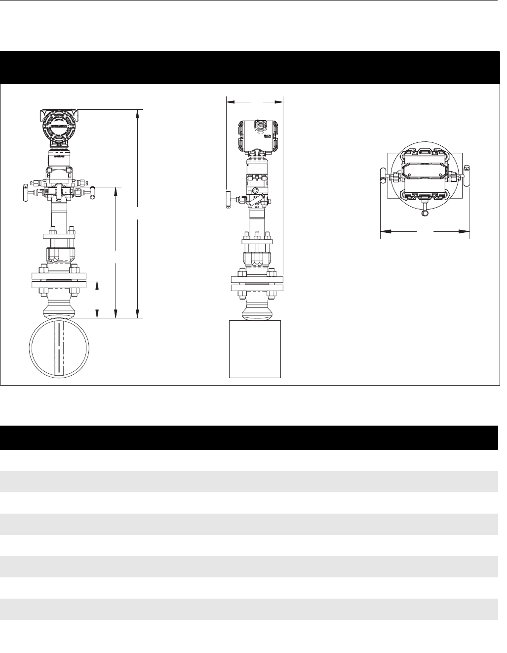
Reference Manual
00809-0100-4809, Rev AA
August 2002
A-17
Annubar Flowmeter Series
Model 3051SFA Flange–
Lok Probar
Flange-Lok ProBar Flowmeter(1)
Front View Side View Top View
(1) The Flange-Lok Annubar model can be direct mounted up to 600# ANSI (1440 psig at 100 °F (99 bar at 38 °C)).
B
C
A
E
D
TABLE 2. Flange-Lok ProBar Flowmeter Dimensional Data
Sensor Size –
Flange Rating
A ± 0.125-in.
(3.2 mm)
B ± 0.25-in.
(6.4 mm) C (Max) D (Max) E (Max)
1 – 150# 3.88-in.
(98.6 mm)
12.25-in.
(311.2 mm)
20.80-in.
(528.4 mm)
9.00-in.
(228.6 mm)
6.60-in.
(167.6 mm)
1 – 300# 4.13-in.
(104.9 mm)
12.25-in.
(311.2 mm)
20.80-in.
(528.4 mm)
9.00-in.
(228.6 mm)
7.15-in.
(181.6 mm)
1 – 600# 4.44-in.
(112.8 mm)
12.25-in.
(311.2 mm)
20.80-in.
(528.4 mm)
9.00-in.
(228.6 mm)
7.15-in.
(181.6 mm)
2 – 150# 4.13-in.
(104.9 mm)
14.25-in.
(362.0 mm)
22.80-in.
(579.2 mm)
9.00-in.
(228.6 mm)
7.10-in.
(180.3 mm)
2 – 300# 4.38-in.
(111.3 mm)
14.25-in
(362.0 mm)
22.80-in.
(579.2 mm)
9.00-in.
(228.6 mm)
7.35-in.
(186.7 mm)
2 – 600# 4.76-in.
(120.9 mm)
14.25-in.
(362.0 mm)
22.80-in.
(579.2 mm)
9.00-in.
(228.6 mm)
7.35-in.
(186.7 mm)
3 – 150# 4.63-in.
(117.6 mm)
17.50-in.
(444.5 mm)
26.05-in.
(661.7 mm)
9.00-in.
(228.6 mm)
7.85-in.
(200.0 mm)
3 – 300# 5.00-in.
(127.0 mm)
17.50-in.
(444.5 mm)
26.05-in.
(661.7 mm)
9.00-in.
(228.6 mm)
8.21-in.
(208.5 mm)
3 – 600# 5.38-in.
(136.7 mm)
17.50-in.
(444.5 mm)
26.05-in.
(661.7 mm)
9.00-in.
(228.6 mm)
8.21-in.
(208.5 mm)
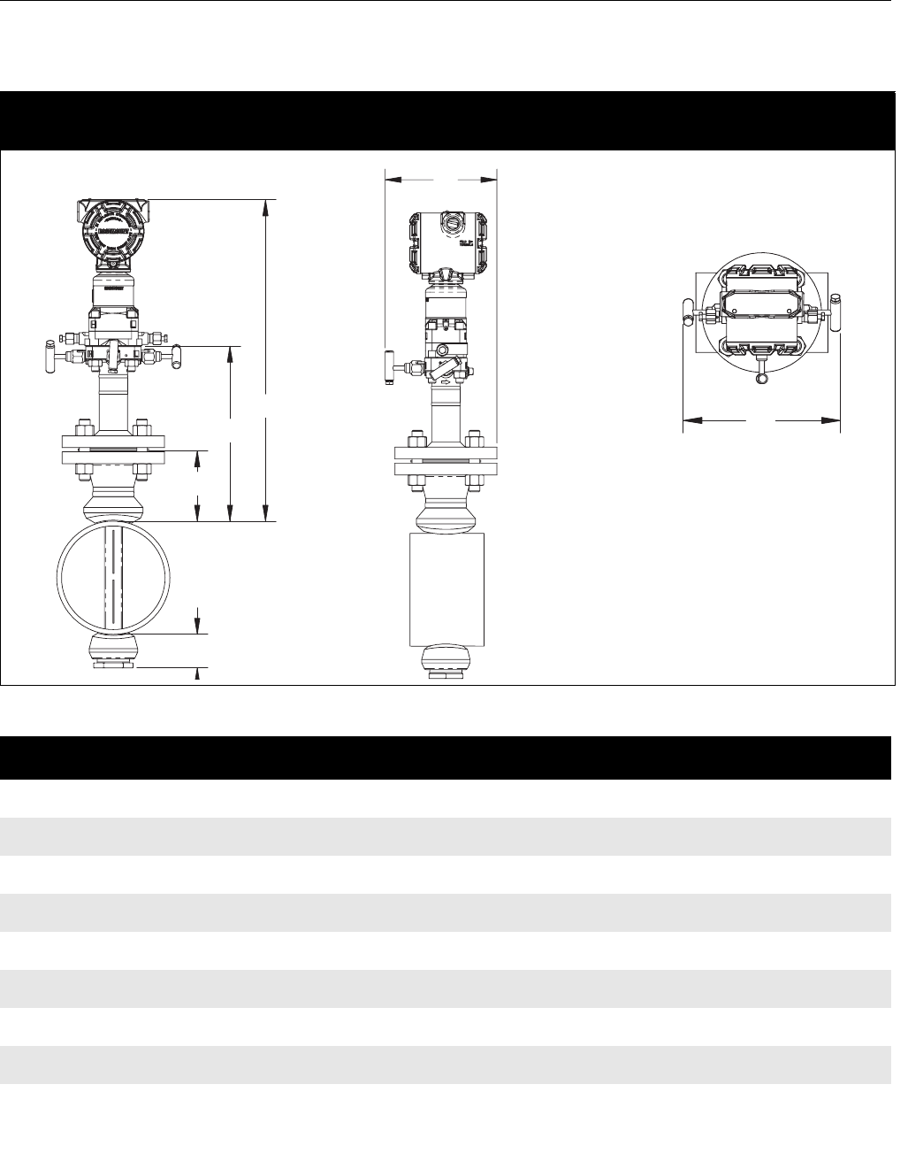
Reference Manual
00809-0100-4809, Rev AA
August 2002
Annubar Flowmeter Series
A-18
Model 3051SFA Flange
Probar
Flange ProBar Flowmeter
Front View Side View Top View
B
C
A
F
E
D
TABLE 3. Flange ProBar Flowmeter Dimensional Data
Sensor Size –
Flange Rating
A ± 0.125-in.
(3.2 mm) B (Max) C (Max) D (Max)
E ± 0.5-in.
(12.7 mm) F (Max)
1 – 150# 4.13-in.
(104.9 mm)
10.5-in.
(266.7 mm)
19.05-in.
(483.9 mm)
9.00-in.
(228.6 mm)
6.60-in.
(167.6 mm)
2.46-in.
(62.5 mm)
1 – 300# 4.13-in.
(104.9 mm)
10.5-in.
(266.7 mm)
19.05-in.
(483.9 mm)
9.00-in.
(228.6 mm)
7.15-in.
(181.6 mm)
2.46-in.
(62.5 mm)
1 – 600# 4.44-in.
(112.8 mm)
10.5-in.
(266.7 mm)
19.05-in.
(483.9 mm)
9.00-in.
(228.6 mm)
7.15-in.
(181.6 mm)
2.46-in.
(62.5 mm)
2 – 150# 4.13-in.
(104.9 mm)
11.00-in.
(279.4 mm)
19.55-in.
(496.6 mm)
9.00-in.
(228.6 mm)
7.10-in.
(180.3 mm)
2.76-in.
(70.1 mm)
2 – 300# 4.38-in.
(111.3 mm)
11.00-in
(279.4 mm)
19.55-in.
(496.6 mm)
9.00-in.
(228.6 mm)
7.35-in.
(186.7 mm)
2.76-in.
(70.1 mm)
2 – 600# 4.76-in.
(120.9 mm)
11.00-in.
(279.4 mm)
19.55-in.
(496.6 mm)
9.00-in.
(228.6 mm)
7.35-in.
(186.7 mm)
2.76-in.
(70.1 mm)
3 – 150# 4.63-in.
(117.6 mm)
13.50-in.
(342.9 mm)
22.05-in.
(560.1 mm)
9.00-in.
(228.6 mm)
7.85-in.
(200.0 mm)
3.88-in.
(98.6 mm)
3 – 300# 5.00-in.
(127.0 mm)
13.50-in.
(342.9 mm)
22.05-in.
(560.1 mm)
9.00-in.
(228.6 mm)
8.21-in.
(208.5 mm)
3.88-in.
(98.6 mm)
3 – 600# 5.38-in.
(136.7 mm)
13.50-in.
(342.9 mm)
22.05-in.
(560.1 mm)
9.00-in.
(228.6 mm)
8.21-in.
(208.5 mm)
3.88-in.
(98.6 mm)
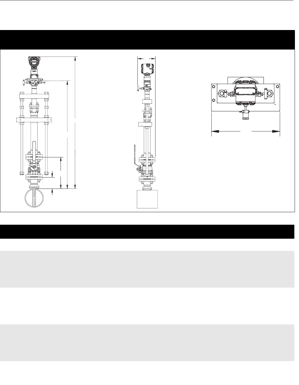
Reference Manual
00809-0100-4809, Rev AA
August 2002
A-19
Annubar Flowmeter Series
Model 3051SFA Flange
Flo–Tap Probar
Flange Flo-Tap ProBar Flowmeter
Front View Side View Top View
B
C
A
D
F
E
TABLE 4. Flange Flo-Tap ProBar Flowmeter Dimensional Data
Sensor Size –
Flange Rating
A ± 0.125-in.
(3.2 mm)
B ± 0.25-in.
(6.4 mm) C (Max) D (Max) E (Max) F (Max)
Use formulas below to
determine C value
1 – 150# 4.13-in.
(104.9 mm)
10.50-in.
(266.7 mm)
Manual Drive (C1):
20-in. (508 mm)
Gear Drive (C1):
25.5-in. (648 mm) D = C + 8.53
10.00-in.
(254.0 mm)
6.60-in.
(167.6 mm)
1 – 300# 4.13-in.
(104.9 mm)
11.75-in.
(298.5 mm)
10.00-in.
(254.0 mm)
7.15-in.
(181.6 mm)
1 – 600# 4.44-in.
(112.8 mm)
14.06-in.
(357.2 mm)
10.00-in.
(254.0 mm)
7.15-in.
(181.6 mm)
2 – 150# 4.13-in.
(104.9 mm)
11.25-in.
(285.8 mm)
Manual Drive (C1):
23.0-in. (584 mm)
Gear Drive (C1):
27.5-in. (699 mm) D = C + 8.53
12.56-in.
(319.0 mm)
7.10-in.
(180.3 mm)
2 – 300# 4.38-in.
(111.3 mm)
13.00-in
(330.2 mm)
12.56-in.
(319.0 mm)
7.35-in.
(186.7 mm)
2 – 600# 4.76-in.
(120.904 mm)
16.38-in.
(416.0 mm)
12.56-in.
(319.0 mm)
7.35-in.
(186.7 mm)
3 – 150# 4.63-in.
(117.6 mm)
12.75-in.
(323.9 mm)
Manual Drive (C1):
25.5-in. (648 mm)
Gear Drive (C1):
29.5-in. (749 mm) D = C + 8.53
13.63-in.
(346.2 mm)
7.85-in.
(200.0 mm)
3 – 300# 5.00-in.
(127.0 mm)
16.25-in.
(412.8 mm)
13.63-in.
(346.2 mm)
8.21-in.
(208.5 mm)
3 – 600# 5.38-in.
(136.7 mm)
19.50-in.
(495.4 mm)
13.63-in.
(346.2 mm)
8.21-in.
(208.5 mm)
Use the appropriate formula to determine C value:
Inserted formula: Pipe I.D. + Wall Thickness + Value B + C1 (use the Manual Drive or Gear drive values for C1)
Retracted formula: [2 x (Pipe I.D. + Wall Thickness + Value B)] + C1 (use the Manual Drive or Gear drive values for C1)
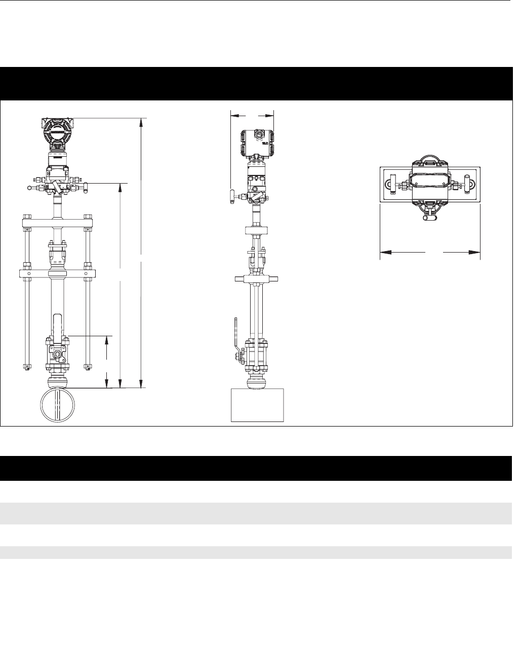
Reference Manual
00809-0100-4809, Rev AA
August 2002
Annubar Flowmeter Series
A-20
Model 3051SFA
Threaded Flo–Tap
Probar
Threaded Flo-Tap ProBar Flowmeter
Front View Side View Top View
C
B
A
E
D
TABLE 5. Threaded Flo-Tap ProBar Flowmeter Dimensional Data
Sensor
Size
A ± 0.25-in.
(6.4 mm) B (Max) C (Max) D (Max) E (Max)
Use formulas below to
determine B value
16.71-in.
(170.5 mm)
Manual Drive (B1):
20-in. (508 mm)
Gear Drive (B1):
25.5-in. (648 mm)
C = B + 8.53 10.00-in.
(254.0 mm)
6.90-in.
(175.3 mm)
28.11-in.
(206.0 mm)
Manual Drive (B1):
23.0-in. (584 mm)
Gear Drive (B1):
27.5-in. (699 mm)
C = B + 8.53 12.56-in.
(319.0 mm)
6.90-in.
(175.3 mm)
Sensor Size 3 is not available in a Threaded Flo-Tap.
Use the appropriate formula to determine C value:
Inserted formula: Pipe I.D. + Wall Thickness + Value A + B1 (use the Manual Drive or Gear drive values for B1)
Retracted formula: [2 x (Pipe I.D. + Wall Thickness + Value A)] + B1 (use the Manual Drive or Gear drive values for B1)
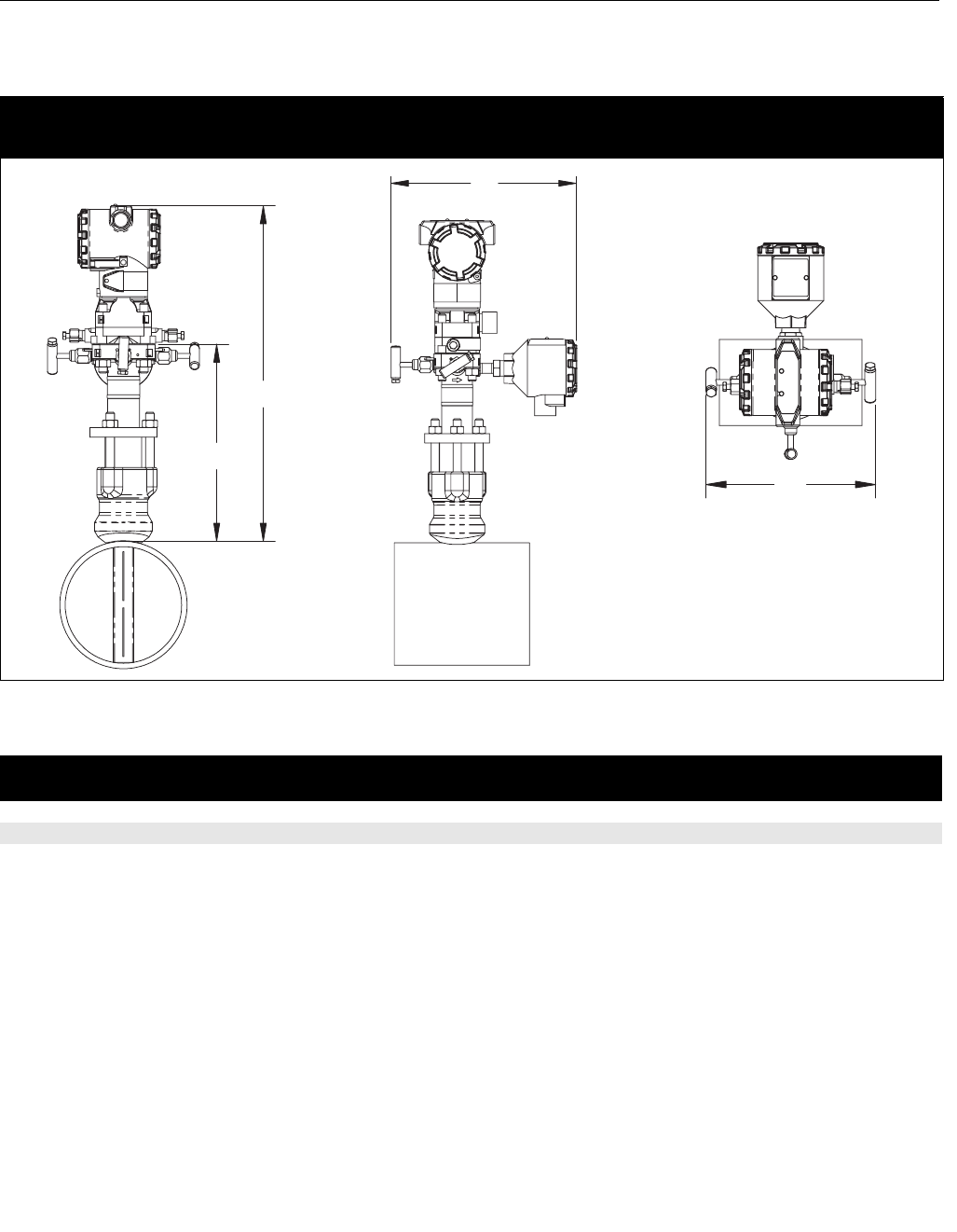
Reference Manual
00809-0100-4809, Rev AA
August 2002
A-21
Annubar Flowmeter Series
Model 3095MFA Pak–Lok
Mass ProBar
Pak-Lok Mass ProBar Flowmeter(1)
Front View Side View Top View
(1) The Pak-Lok Annubar model is available up to 600# ANSI (1440 psig at 100 °F (99 bar at 38 °C)).
F
B
A
D
E
C
TABLE 6. Pak-Lok Mass ProBar Flowmeter Dimensional Data
Sensor
Size
A ± 0.25-in.
(6.4 mm) B (Max) C (Max) D (Max)
1 7.50-in. (190.5 mm) 14.60-in. (370.9 mm) 9.00-in. (228.6 mm) 11.25-in. (285.8 mm)
29.25-in. (235.0 mm) 16.35-in. (415.3 mm) 9.00-in. (228.6 mm) 11.25-in. (285.8 mm)
3 12.00-in. (304.8 mm) 19.10-in. (485.2 mm) 9.00-in. (228.6 mm) 11.25-in. (285.8 mm)
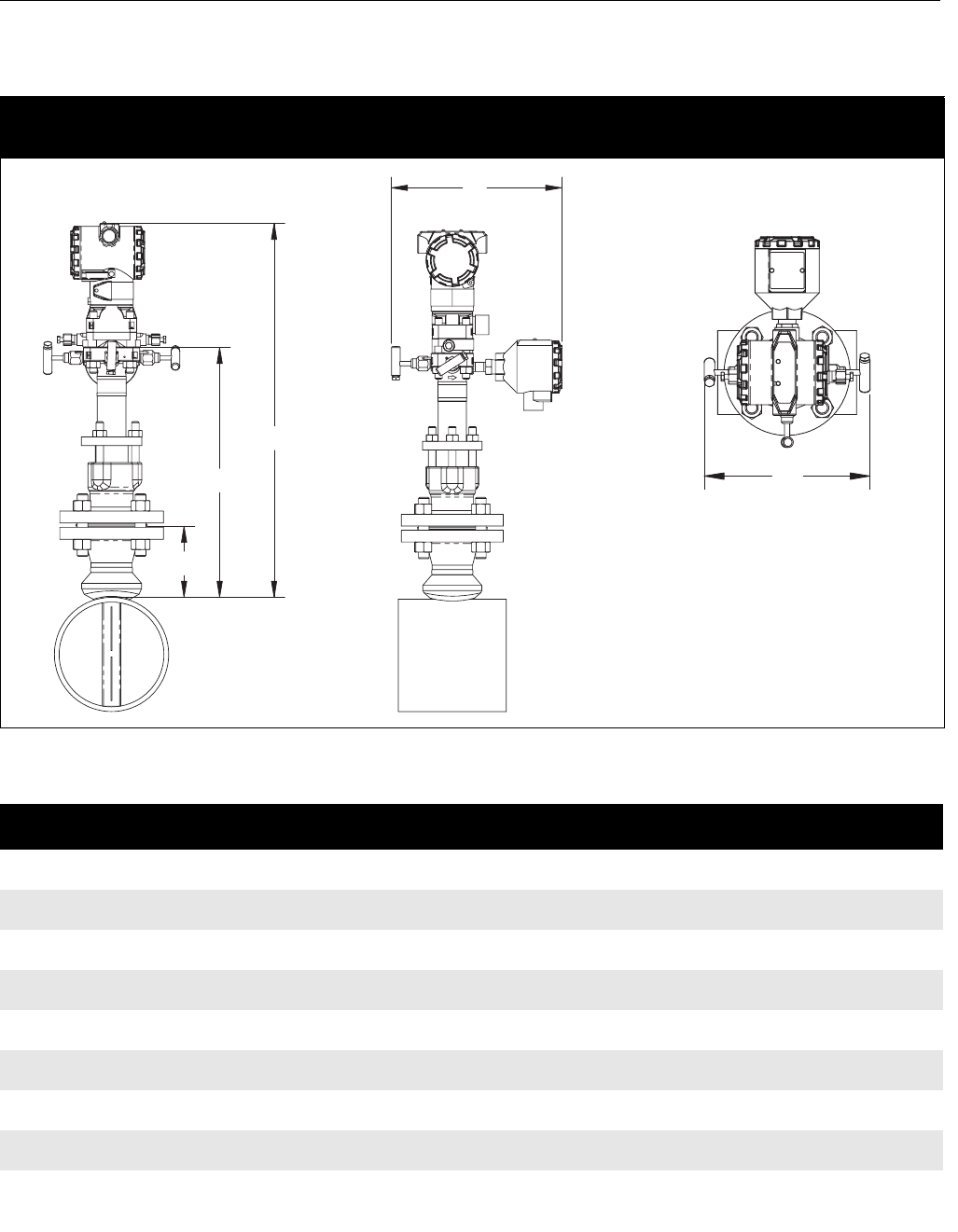
Reference Manual
00809-0100-4809, Rev AA
August 2002
Annubar Flowmeter Series
A-22
Model 3095MFA Flange–
Lok Mass ProBar
Flange-Lok Mass ProBar Flowmeter(1)
Front View Side View Top View
(1) The Flange-Lok Annubar model can be direct mounted up to 600# ANSI (1440 psig at 100 °F (99 bar at 38 °C)).
B
C
A
E
D
TABLE 7. Flange-Lok Mass ProBar Flowmeter Dimensional Data
Sensor Size –
Flange Rating
A ± 0.125-in.
(3.2 mm)
B ± 0.25-in.
(6.4 mm) C (Max) D (Max) E (Max)
1 – 150# 3.88-in.
(98.6 mm)
12.25-in.
(311.2 mm)
19.35-in.
(491.5 mm)
9.00-in.
(228.6 mm)
11.25-in.
(285.8 mm)
1 – 300# 4.13-in.
(104.9 mm)
12.25-in.
(311.2 mm)
19.35-in.
(491.5 mm)
9.00-in.
(228.6 mm)
11.25-in.
(285.8 mm)
1 – 600# 4.44-in.
(112.8 mm)
12.25-in.
(311.2 mm)
19.35-in.
(491.5 mm)
9.00-in.
(228.6 mm)
11.25-in.
(285.8 mm)
2 – 150# 4.13-in.
(104.9 mm)
14.25-in.
(362.0 mm)
21.35-in.
(542.3 mm)
9.00-in.
(228.6 mm)
11.25-in.
(285.8 mm)
2 – 300# 4.38-in.
(111.3 mm)
14.25-in
(362.0 mm)
21.35-in.
(542.3 mm)
9.00-in.
(228.6 mm)
11.25-in.
(285.8 mm)
2 – 600# 4.76-in.
(120.9 mm)
14.25-in.
(362.0 mm)
21.35-in.
(542.3 mm)
9.00-in.
(228.6 mm)
11.25-in.
(285.8 mm)
3 – 150# 4.63-in.
(117.6 mm)
17.50-in.
(444.5 mm)
24.60-in.
(626.4 mm)
9.00-in.
(228.6 mm)
11.25-in.
(285.8 mm)
3 – 300# 5.00-in.
(127.0 mm)
17.50-in.
(444.5 mm)
24.60-in.
(626.4 mm)
9.00-in.
(228.6 mm)
11.25-in.
(285.8 mm)
3 – 600# 5.38-in.
(136.7 mm)
17.50-in.
(444.5 mm)
24.60-in.
(624.8 mm)
9.00-in.
(228.6 mm)
11.25-in.
(285.8 mm)
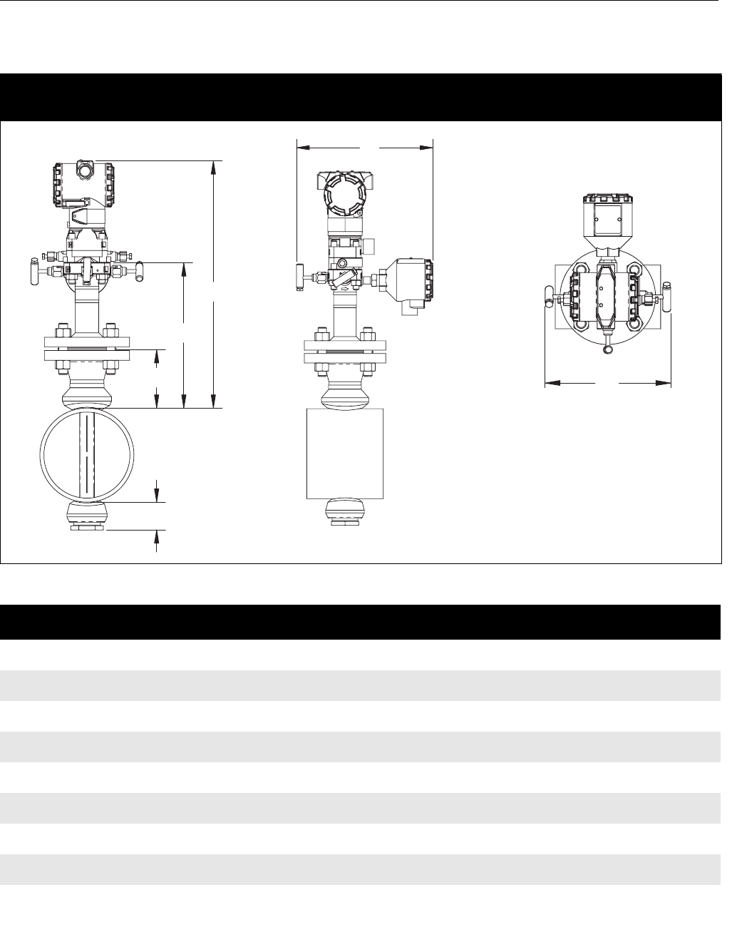
Reference Manual
00809-0100-4809, Rev AA
August 2002
A-23
Annubar Flowmeter Series
Model 3095MFA Flange
Mass ProBar
Flange Mass ProBar Flowmeter
Front View Side View Top View
B
C
A
F
E
D
TABLE 8. Flange Mass ProBar Flowmeter Dimensional Data
Sensor Size –
Flange Rating
A ± 0.125-in.
(3.2 mm) B (Max) C (Max) D (Max) E (Max) F (Max)
1 – 150# 4.13-in.
(104.9 mm)
10.5-in.
(266.7 mm)
17.60-in.
(447.1 mm)
9.00-in.
(228.6 mm)
11.25-in.
(285.8 mm)
2.46-in.
(62.5 mm)
1 – 300# 4.13-in.
(104.9 mm)
10.5-in.
(266.7 mm)
17.60in.
(447.1 mm)
9.00-in.
(228.6 mm)
11.25-in.
(285.8 mm)
2.46-in.
(62.5 mm)
1 – 600# 4.44-in.
(112.8 mm)
10.5-in.
(266.7 mm)
17.60-in.
(447.1 mm)
9.00-in.
(228.6 mm)
11.25-in.
(285.8 mm)
2.46-in.
(62.5 mm)
2 – 150# 4.13-in.
(104.9 mm)
11.00-in.
(279.4 mm)
18.10-in.
(459.8 mm)
9.00-in.
(228.6 mm)
11.25-in.
(285.8 mm)
2.76-in.
(70.1 mm)
2 – 300# 4.38-in.
(111.3 mm)
11.00-in
(279.4 mm)
18.10-in.
(459.8 mm)
9.00-in.
(228.6 mm)
11.25-in.
(285.8 mm)
2.76-in.
(70.1 mm)
2 – 600# 4.76-in.
(120.9 mm)
11.00-in.
(279.4 mm)
18.10-in.
(459.8 mm)
9.00-in.
(228.6 mm)
11.25-in.
(285.8 mm)
2.76-in.
(70.1 mm)
3 – 150# 4.63-in.
(117.6 mm)
13.50-in.
(342.9 mm)
20.60-in.
(523.3 mm)
9.00-in.
(228.6 mm)
11.25-in.
(285.8 mm)
3.88-in.
(98.6 mm)
3 – 300# 5.00-in.
(127.0 mm)
13.50-in.
(342.9 mm)
20.60-in.
523.3 mm)
9.00-in.
(228.6 mm)
11.25-in.
(285.8 mm)
3.88-in.
(98.6 mm)
3 – 600# 5.38-in.
(136.7 mm)
13.50-in.
(342.9 mm)
20.60-in.
(523.3 mm)
9.00-in.
(228.6 mm)
11.25-in.
(285.8 mm)
3.88-in.
(98.6 mm)
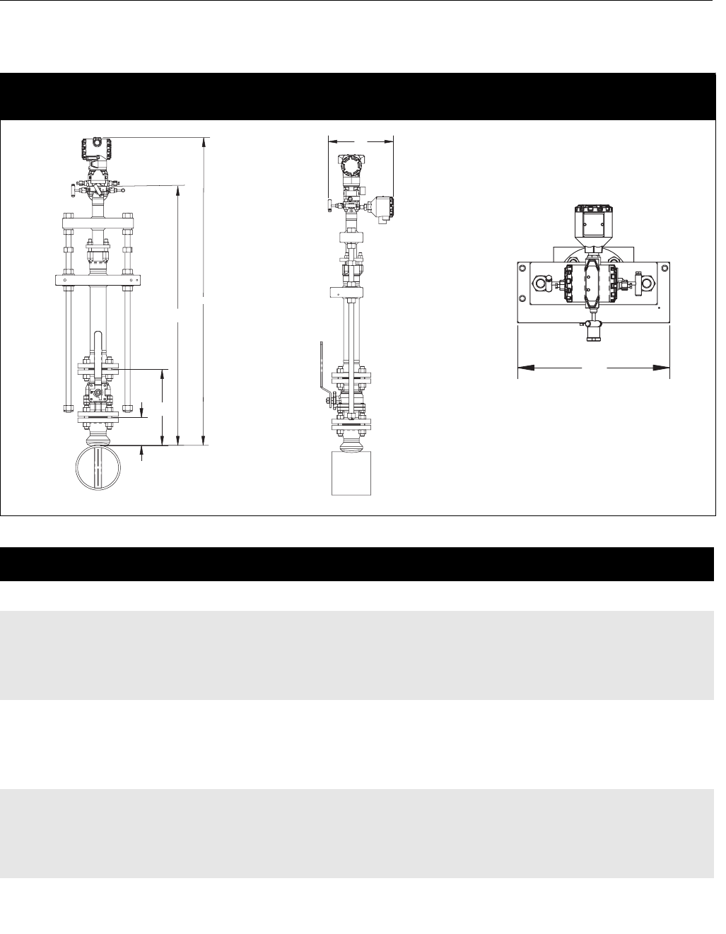
Reference Manual
00809-0100-4809, Rev AA
August 2002
Annubar Flowmeter Series
A-24
Model 3095MFA Flange
Flo–Tap Mass ProBar
Flange Flo-Tap Mass ProBar Flowmeter
Front View Side View Top View
C
D
B
A
F
E
TABLE 9. Flange Flo-Tap Mass ProBar Flowmeter Dimensional Data
Sensor Size –
Flange Rating
A ± 0.125-in.
(3.2 mm)
B ± 0.25-in.
(6.4 mm) C (Max) D (Max) E (Max) F (Max)
Use formulas below to
determine C value
1 – 150# 4.13-in.
(104.9 mm)
10.50-in.
(266.7 mm)
Manual Drive (C1):
20-in. (508 mm)
Gear Drive (C1):
25.5-in. (648 mm) D = C + 7.1
10.00-in.
(254.0 mm)
11.25-in.
(285.8 mm)
1 – 300# 4.13-in.
(104.9 mm)
11.75-in.
(298.5 mm)
10.00-in.
(254.0 mm)
11.25-in.
(285.8 mm)
1 – 600# 4.44-in.
(112.8 mm)
14.06-in.
(357.2 mm)
10.00-in.
(254.0 mm)
11.25-in.
(285.8 mm)
2 – 150# 4.13-in.
(104.9 mm)
11.25-in.
(285.8 mm)
Manual Drive (C1):
23.0-in. (584 mm)
Gear Drive (C1):
27.5-in. (699 mm) D = C + 7.1
12.56-in.
(319.0 mm)
11.25-in.
(285.8 mm)
2 – 300# 4.38-in.
(111.3 mm)
13.00-in
(330.2 mm)
12.56-in.
(319.0 mm)
11.25-in.
(285.8 mm)
2 – 600# 4.76-in.
(120.9 mm)
16.38-in.
(416.0 mm)
12.56-in.
(319.0 mm)
11.25-in.
(285.8 mm)
3 – 150# 4.63-in.
(117.6 mm)
12.75-in.
(323.9 mm)
Manual Drive (C1):
25.5-in. (648 mm)
Gear Drive (C1):
29.5-in. (749 mm) D = C + 7.1
13.63-in.
(346.2 mm)
11.25-in.
(285.8 mm)
3 – 300# 5.00-in.
(127.0 mm)
16.25-in.
(412.8 mm)
13.63-in.
(346.2 mm)
11.25-in.
(285.8 mm)
3 – 600# 5.38-in.
(136.7 mm)
19.50-in.
(495.4 mm)
13.63-in.
(346.2 mm)
11.25-in.
(285.8 mm)
Use the appropriate formula to determine C value:
Inserted formula: Pipe I.D. + Wall Thickness + Value B + C1 (use the Manual Drive or Gear drive values for C1)
Retracted formula: [2 x (Pipe I.D. + Wall Thickness + Value B)] + C1 (use the Manual Drive or Gear drive values for C1)
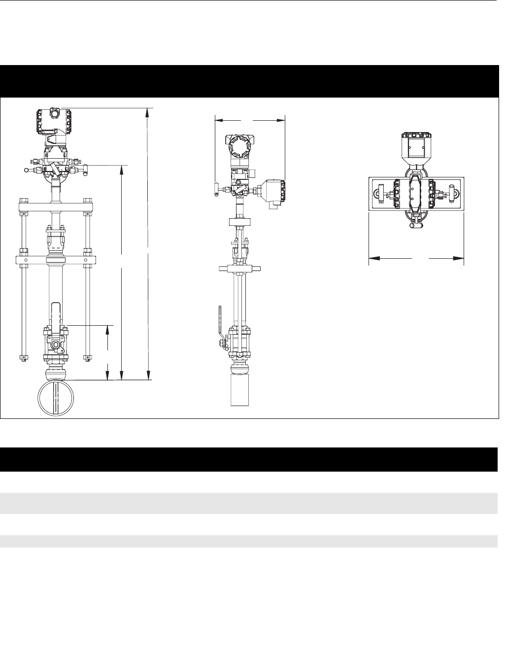
Reference Manual
00809-0100-4809, Rev AA
August 2002
A-25
Annubar Flowmeter Series
Model 3095MFA
Threaded Flo–Tap Mass
ProBar
Threaded Flo-Tap Mass ProBar Flowmeter
Front View Side View Top View
C
B
A
E
D
TABLE 10. Threaded Flo-Tap Mass ProBar Flowmeter Dimensional Data
Sensor Size
A ± 0.25 -in.
(6.4 mm) B (Max) C (Max) D (Max) E (Max)
Use formulas below to
determine B value
16.71-in.
(170.5 mm)
Manual Drive (B1):
20-in. (508 mm)
Gear Drive (B1):
25.5-in. (648 mm)
C = B + 7.1 10.00-in.
(254.0 mm)
11.25-in.
(285.8 mm)
28.11-in.
(206.0 mm)
Manual Drive (B1):
23.0-in. (584 mm)
Gear Drive (B1):
27.5-in. (699 mm)
C = B + 7.1 12.56-in.
(319.0 mm)
11.25-in.
(285.8 mm)
Sensor Size 3 is not available in a Threaded Flo-Tap.
Use the appropriate formula to determine C value:
Inserted formula: Pipe I.D. + Wall Thickness + Value A + B1 (use the Manual Drive or Gear drive values for B1)
Retracted formula: [2 x (Pipe I.D. + Wall Thickness + Value A)] + B1 (use the Manual Drive or Gear drive values for B1)
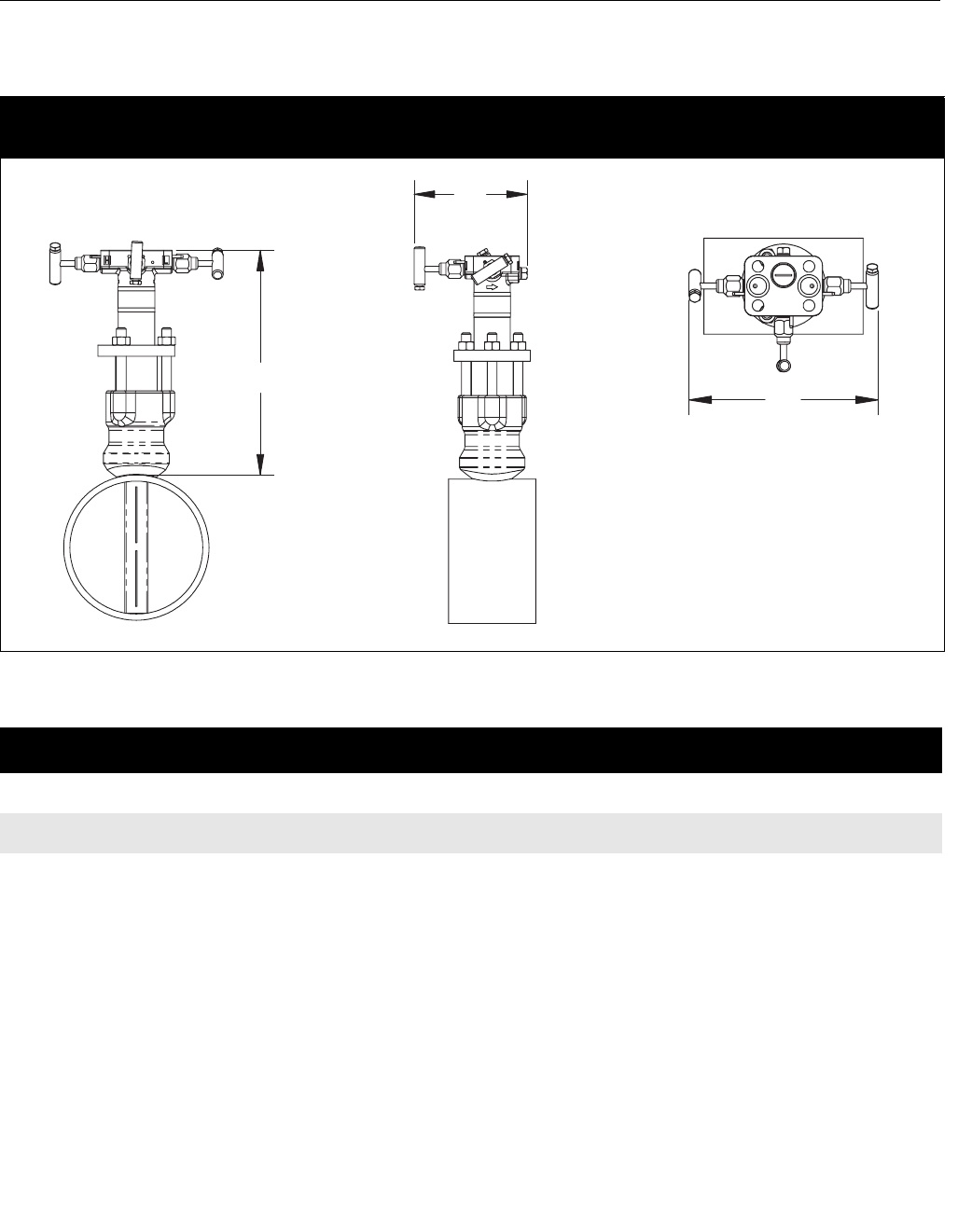
Reference Manual
00809-0100-4809, Rev AA
August 2002
Annubar Flowmeter Series
A-26
Model 485 Pak–Lok
Annubar
Pak-Lok Model 485 Annubar Primary(1)
Front View Side View Top View
(1) The Pak-Lok Annubar model is available up to 600# ANSI (1440 psig at 100 °F (99 bar at 38 °C)).
A
C
B
TABLE 11. Pak-Lok Model 485 Annubar Primary Dimensional Data
Sensor Size
A ± 0.25-in.
(6.4 mm) B (Max) C (Max)
1 7.50-in.
(190.5 mm)
9.00-in.
(228.6 mm)
5.70-in.
(144.8 mm)
29.25-in.
(235.0 mm)
9.00-in.
(228.6 mm)
5.70-in.
(144.8 mm)
3 12.00-in.
(304.8 mm)
9.00-in.
(228.6 mm)
5.70-in.
(144.8 mm)
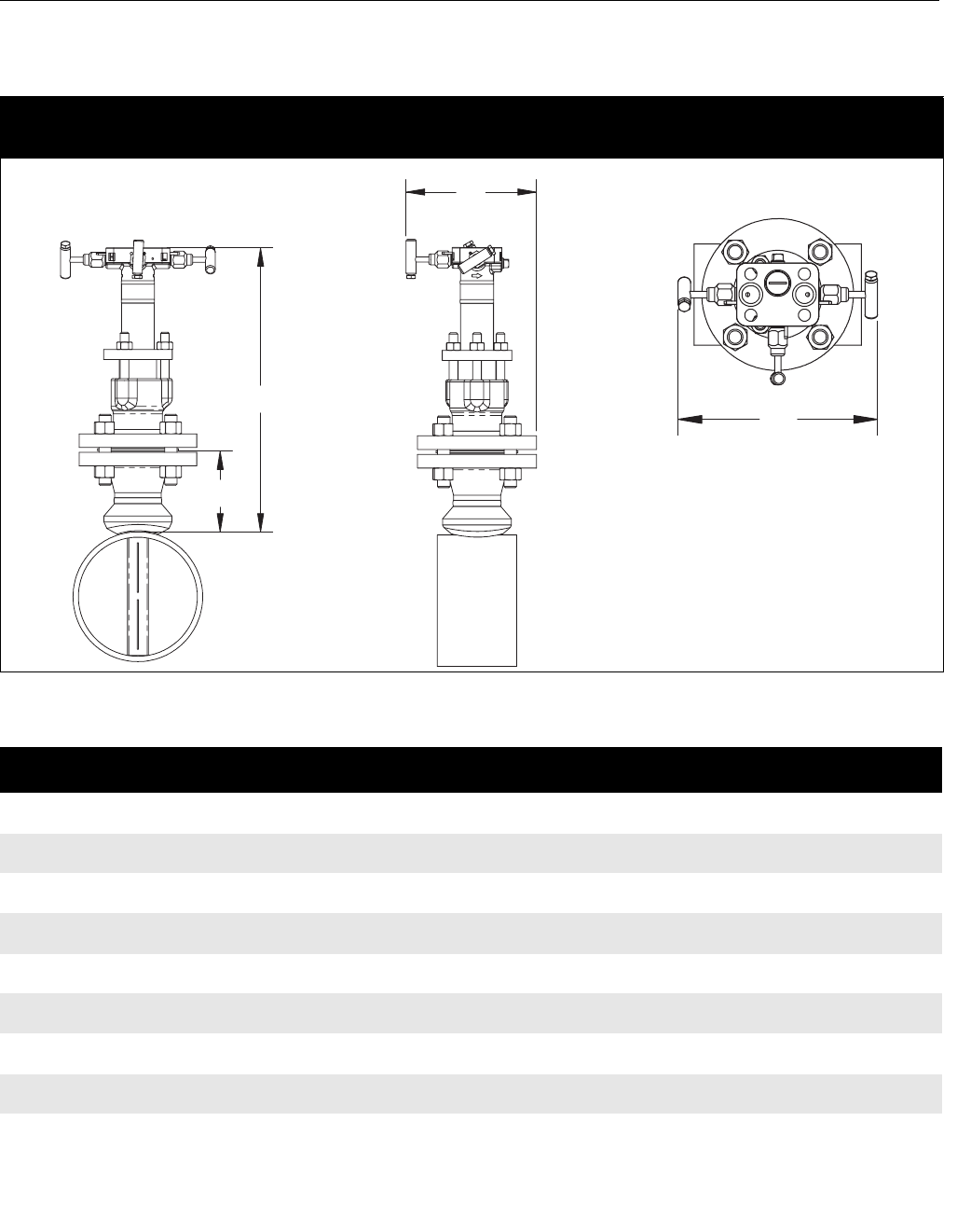
Reference Manual
00809-0100-4809, Rev AA
August 2002
A-27
Annubar Flowmeter Series
Model 485 Flange–Lok
Annubar
Flange-Lok Model 485 Annubar Primary(1)
Front View Side View Top View
(1) The Flange-Lok Annubar model can be direct mounted up to 600# ANSI (1440 psig at 100 °F (99 bar at 38 °C)).
A
B
D
C
TABLE 12. Flange-Lok Model 485 Annubar Primary Dimensional Data
Sensor Size –
Flange Rating
A ± 0.125-in.
(3.2 mm)
B ± 0.25-in.
(6.4 mm) C (Max) D (Max)
1 – 150# 3.88-in.
(98.6 mm)
12.25-in.
(311.2 mm)
9.00-in.
(228.6 mm)
6.60-in.
(167.6 mm)
1 – 300# 4.13-in.
(104.9 mm)
12.25-in.
(311.2 mm)
9.00-in.
(228.6 mm)
7.15-in.
(181.6 mm)
1 – 600# 4.44-in.
(112.8 mm)
12.25-in.
(311.2 mm)
9.00-in.
(228.6 mm)
7.15-in.
(181.6 mm)
2 – 150# 4.13-in.
(104.9 mm)
14.25-in.
(362.0 mm)
9.00-in.
(228.6 mm)
7.10-in.
(180.3 mm)
2 – 300# 4.38-in.
(111.3 mm)
14.25-in
(362.0 mm)
9.00-in.
(228.6 mm)
7.35-in.
(186.7 mm)
2 – 600# 4.76-in.
(120.9 mm)
14.25-in.
(362.0 mm)
9.00-in.
(228.6 mm)
7.35-in.
(186.7 mm)
3 – 150# 4.63-in.
(117.6 mm)
17.50-in.
(444.5 mm)
9.00-in.
(228.6 mm)
7.85-in.
(200.0 mm)
3 – 300# 5.00-in.
(127.0 mm)
17.50-in.
(444.5 mm)
9.00-in.
(228.6 mm)
8.21-in.
(208.5 mm)
3 – 600# 5.38-in.
(136.7 mm)
17.50-in.
(444.5 mm)
9.00-in.
(228.6 mm)
8.21-in.
(208.5 mm)
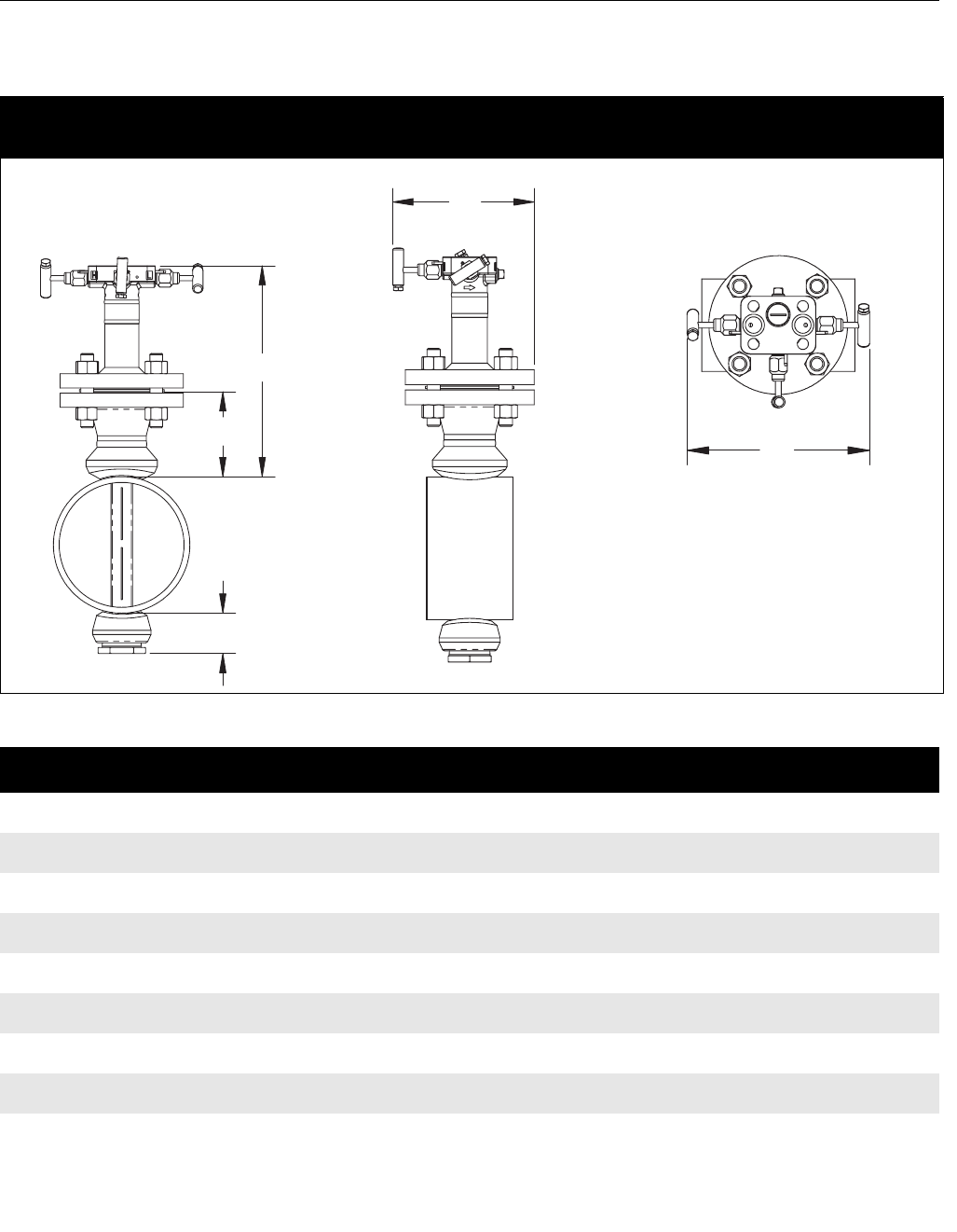
Reference Manual
00809-0100-4809, Rev AA
August 2002
Annubar Flowmeter Series
A-28
Model 485 Flange
Annubar
Flange Model 485 Annubar Primary
Front View Side View Top View
F
B
A
D
C
TABLE 13. Flange Model 485 Annubar Primary Dimensional Data
Sensor Size –
Flange Rating
A ± 0.125-in.
(3.2 mm) B (Max) C (Max)
D ± 0.5-in.
(12.7 mm) F (Max)
1 – 150# 4.13-in.
(104.9 mm)
10.5-in.
(266.7 mm)
9.00-in.
(228.6 mm)
6.60-in.
(167.6 mm)
2.46-in.
(62.5 mm)
1 – 300# 4.13-in.
(104.9 mm)
10.5-in.
(266.7 mm)
9.00-in.
(228.6 mm)
7.15-in.
(181.6 mm)
2.46-in.
(62.5 mm)
1 – 600# 4.44-in.
(112.8 mm)
10.5-in.
(266.7 mm)
9.00-in.
(228.6 mm)
7.15-in.
(181.6 mm)
2.46-in.
(62.5 mm)
2 – 150# 4.13-in.
(104.9 mm)
11.00-in.
(279.4 mm)
9.00-in.
(228.6 mm)
7.10-in.
(180.3 mm)
2.76-in.
(70.1 mm)
2 – 300# 4.38-in.
(111.3 mm)
11.00-in
(279.4 mm)
9.00-in.
(228.6 mm)
7.35-in.
(186.7 mm)
2.76-in.
(70.1 mm)
2 – 600# 4.76-in.
(120.9 mm)
11.00-in.
(279.4 mm)
9.00-in.
(228.6 mm)
7.35-in.
(186.7 mm)
2.76-in.
(70.1 mm)
3 – 150# 4.63-in.
(117.6 mm)
13.50-in.
(342.9 mm)
9.00-in.
(228.6 mm)
7.85-in.
(200.0 mm)
3.88-in.
(98.6 mm)
3 – 300# 5.00-in.
(127.0 mm)
13.50-in.
(342.9 mm)
9.00-in.
(228.6 mm)
8.21-in.
(208.5 mm)
3.88-in.
(98.6 mm)
3 – 600# 5.38-in.
(136.7 mm)
13.50-in.
(342.9 mm)
9.00-in.
(228.6 mm)
8.21-in.
(208.5 mm)
3.88-in.
(98.6 mm)
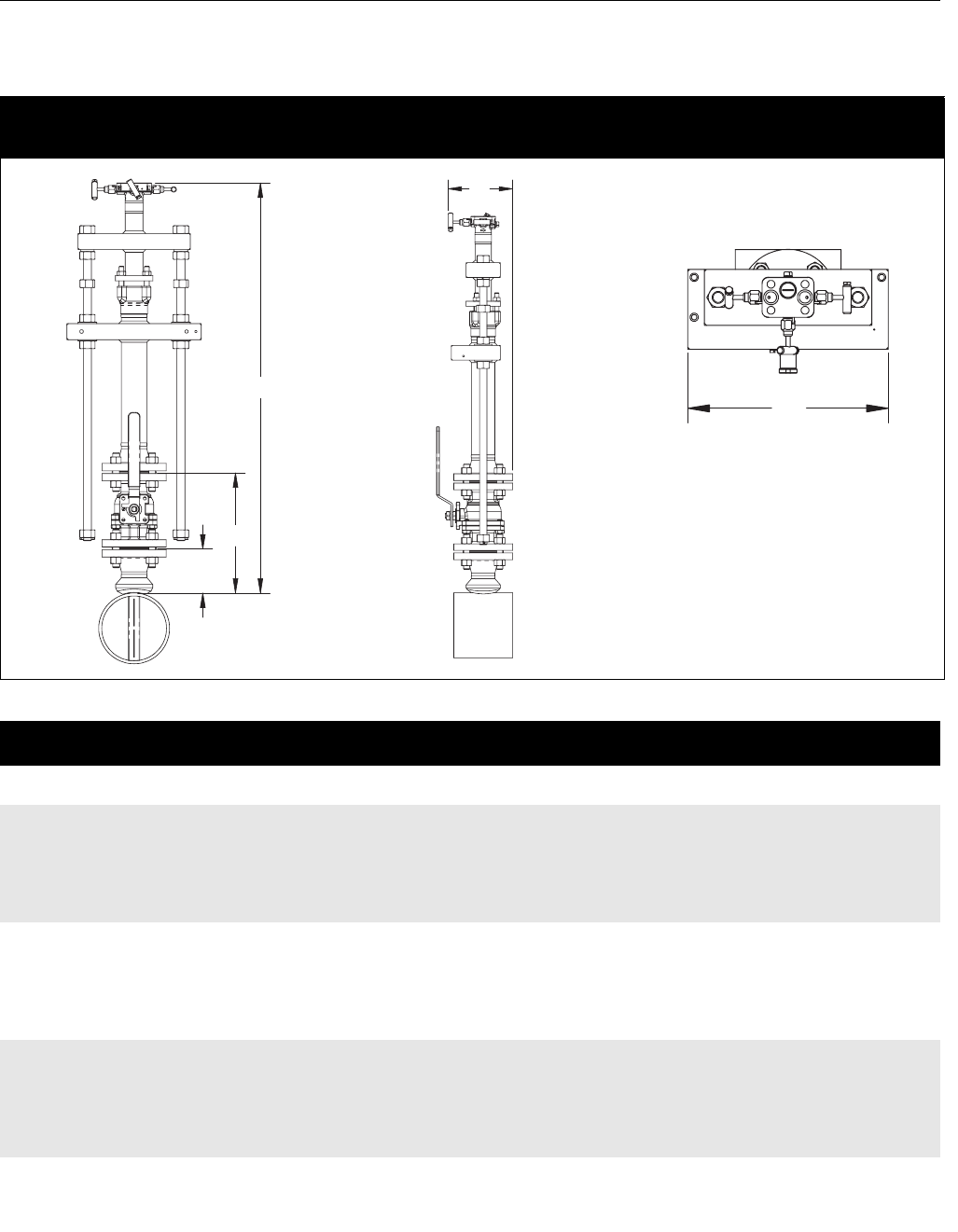
Reference Manual
00809-0100-4809, Rev AA
August 2002
A-29
Annubar Flowmeter Series
Model 485 Flange Flo–
Tap Annubar
Flange Flo-Tap Model 485 Annubar Primary
Front View Side View Manifold
C
B
A
E
D
TABLE 14. Flanged Flo-Tap Model 485 Annubar Primary Dimensional Data
Sensor Size –
Flange Rating
A ± 0.125-in.
(3.2 mm)
B ± 0.25-in.
(6.4 mm) C (Max) D (Max) E (Max)
Use formulas below to
determine C value
1 – 150# 4.13-in.
(104.9 mm)
10.50-in.
(266.7 mm)
Manual Drive (C1):
20-in. (508 mm)
Gear Drive (C1):
25.5-in. (648 mm)
10.00-in.
(254.0 mm)
6.60-in.
(167.6 mm)
1 – 300# 4.13-in.
(104.9 mm)
11.75-in.
(298.5 mm)
10.00-in.
(254.0 mm)
7.15-in.
(181.6 mm)
1 – 600# 4.44-in.
(112.8 mm)
14.06-in.
(357.2 mm)
10.00-in.
(254.0 mm)
7.15-in.
(181.6 mm)
2 – 150# 4.13-in.
(104.9 mm)
11.25-in.
(285.8 mm)
Manual Drive (C1):
23.0-in. (584 mm)
Gear Drive (C1):
27.5-in. (699 mm)
12.56-in.
(319.0 mm)
7.10-in.
(180.3 mm)
2 – 300# 4.38-in.
(111.3 mm)
13.00-in
(330.2 mm)
12.56-in.
(319.0 mm)
7.35-in.
(186.7 mm)
2 – 600# 4.76-in.
(120.9 mm)
16.38-in.
(416.0 mm)
12.56-in.
(319.0 mm)
7.35-in.
(186.7 mm)
3 – 150# 4.63-in.
(117.6 mm)
12.75-in.
(323.9 mm)
Manual Drive (C1):
25.5-in. (648 mm)
Gear Drive (C1):
29.5-in. (749 mm)
13.63-in.(
346.2 mm)
7.85-in.
(200.0 mm)
3 – 300# 5.00-in.
(127.0 mm)
16.25-in.
(412.8 mm)
13.63-in.
(346.2 mm)
8.21-in.
(208.5 mm)
3 – 600# 5.38-in.
(136.7 mm)
19.50-in.
(495.4 mm)
13.63-in.
(346.2 mm)
8.21-in.
(208.5 mm)
Use the appropriate formula to determine C value:
Inserted formula: Pipe I.D. + Wall Thickness + Value B + C1 (use the Manual Drive or Gear drive values for C1)
Retracted formula: [2 x (Pipe I.D. + Wall Thickness + Value B)] + C1 (use the Manual Drive or Gear drive values for C1)
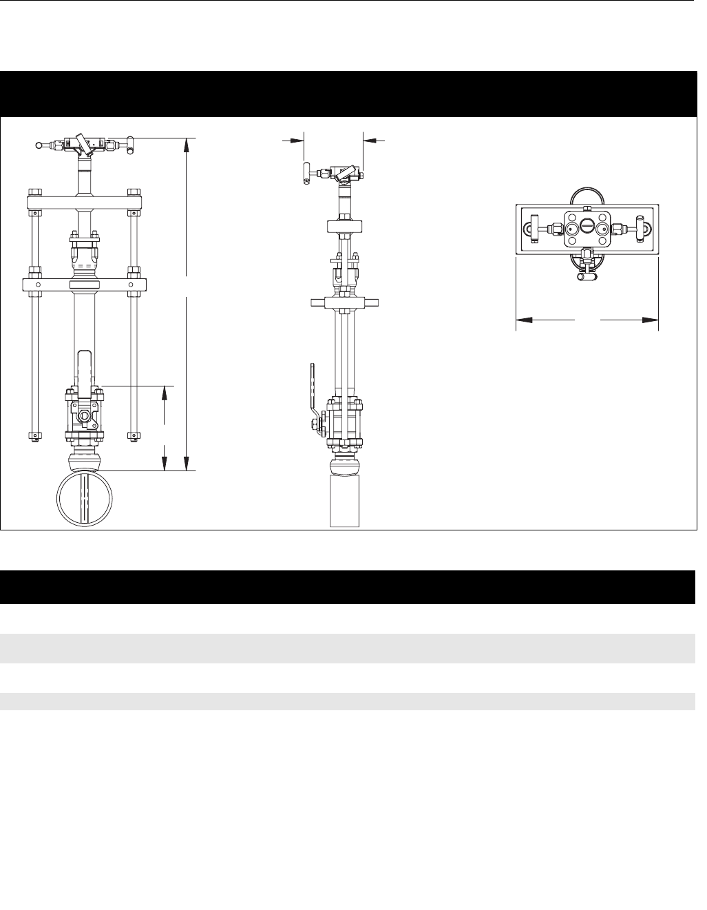
Reference Manual
00809-0100-4809, Rev AA
August 2002
Annubar Flowmeter Series
A-30
Model 485 Threaded Flo–
Tap Annubar
Threaded Flo-Tap Model 485 Annubar Primary
Front View Side View Top View
B
A
D
C
TABLE 15. Threaded Flo-Tap Model 485 Annubar Primary Dimensional Data
Sensor Size
A ± 0.25-in.
(6.4 mm) B (Max) C (Max) D (Max)
Use formulas below to
determine B value
16.71-in.
(170.5 mm)
Manual Drive (B1):
20-in. (508 mm)
Gear Drive (B1):
25.5-in. (648 mm)
10.00-in.
(254.0 mm)
5.70-in
(144.8 mm)
28.11-in.
(206.0 mm)
Manual Drive (B1):
23.0-in. (584 mm)
Gear Drive (B1):
27.5-in. (699 mm)
12.56-in.
(319.0 mm)
5.70-in
(144.8 mm)
Sensor Size 3 is not available in a Threaded Flo-Tap.
Use the appropriate formula to determine C value:
Inserted formula: Pipe I.D. + Wall Thickness + Value A + B1 (use the Manual Drive or Gear drive values for B1)
Retracted formula: [2 x (Pipe I.D. + Wall Thickness + Value A)] + B1 (use the Manual Drive or Gear drive values for B1)
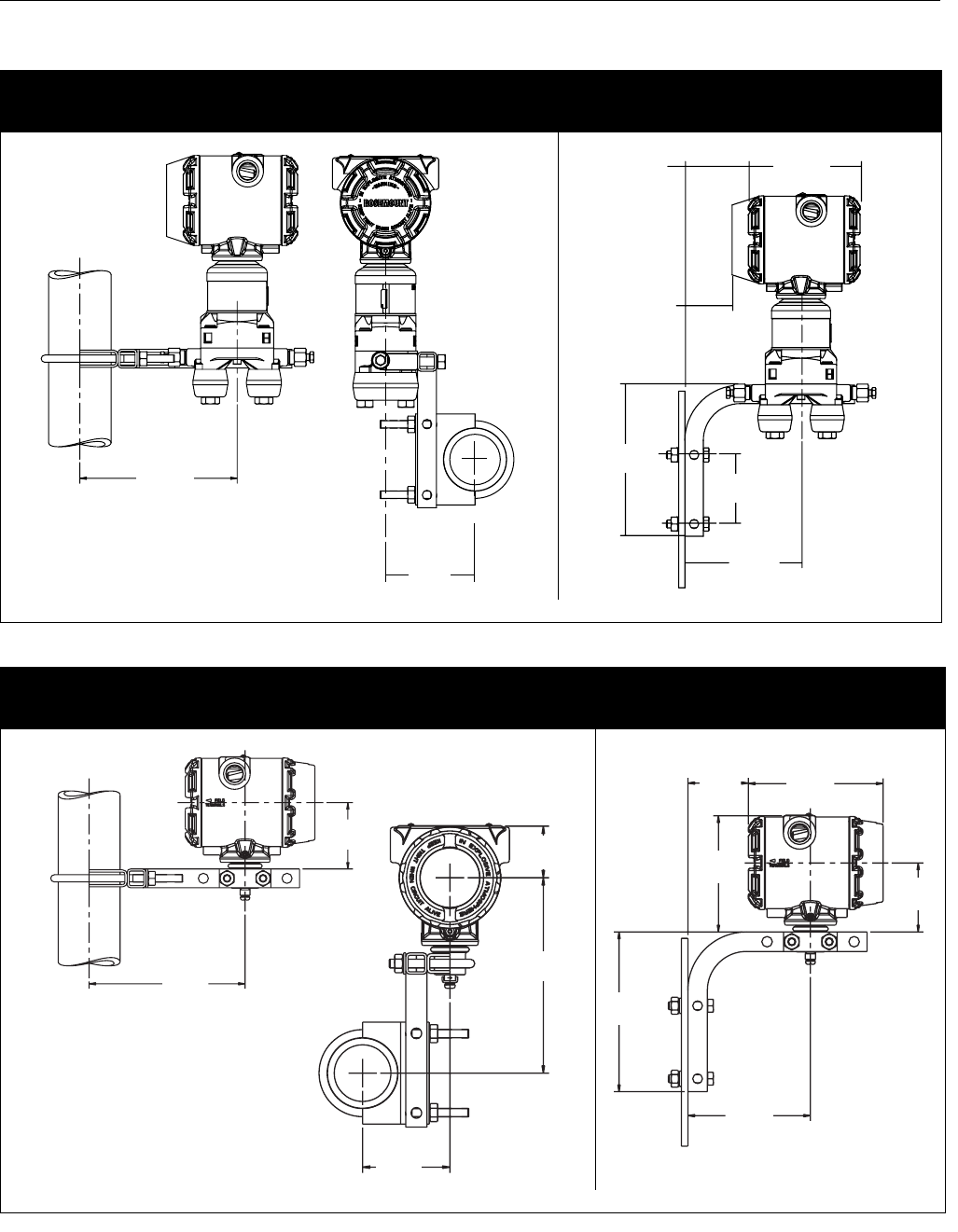
Reference Manual
00809-0100-4809, Rev AA
August 2002
A-31
Annubar Flowmeter Series
Mounting
Integral Mount
Pipe Mount Panel Mount
Dimensions are in inches (millimeters)
6.25
(159)
3.54
(90)
2.58
(66)
4.55
(116)
1.92
(49)
6.15
(156)
2.81
(71)
4.7
(120)
3051S/COPLANAR/3151/3151_F101A, 3151G_101A, 3151_H101A
Remote Mount
Pipe Mount Panel Mount
Dimensions are in inches (millimeters)
1.82
(46)
3.08
(78)
6.90
(175)
2.66
(67)
6.24
(159)
1
_C104A, 3151_D104A, 3151_E104A
2.33
(59)
5.19
(132)
4.72
(120)
2.66
(67)
6.15
(156)
4.48
(114)

Reference Manual
00809-0100-4809, Rev AA
August 2002
Annubar Flowmeter Series
A-32
ORDERING
INFORMATION
Please see the Annubar Flowmeter Series Product Data Sheet (document
number 00813-0100-4809) for a complete list of the ordering tables.

Reference Manual
00809-0100-4809, Rev AA
August 2002 Annubar Flowmeter Series
www.rosemount.com
Appendix B Approvals
Hazardous Locations Installations . . . . . . . . . . . . . . . . . . page B-1
Hazardous Locations Certifications . . . . . . . . . . . . . . . . . page B-1
Installation Drawings . . . . . . . . . . . . . . . . . . . . . . . . . . . . . page B-4
HAZARDOUS
LOCATIONS
INSTALLATIONS
The flowmeter is designed with explosion-proof housings and circuitry
suitable for intrinsically safe and non-incendive operation. Each flowmeter is
clearly marked with a tag indicating the approvals. To maintain certified
ratings for installed transmitters, install in accordance with all applicable
installation codes and approval drawings. Verify that the operating
atmosphere of the transmitter is consistent with the appropriate hazardous
locations certifications. Both transmitter covers must be fully engaged to meet
explosion proof requirements.
HAZARDOUS
LOCATIONS
CERTIFICATIONS
Models 3051SFA Factory Mutual (FM) Approvals
1 Explosion Proof for Class 1, Division 1. Groups B, C, and D. Dust-ignition
Proof for Class II, Division 1, Groups E,F, and G. Dust ignition Proof for
Class III, Division 1. NEMA 4X. Factory Sealed.
2 Combination of Approval Code 5 and the following: Intrinsically Safe for
use in Class I, Division 1, Groups B, C, and D; Class II, Division 2,
Groups E, F, and G; Intrinsically sage for Class III, Division 1.
Nonincendive for Class I, Division 2, Groups A, B, C, and D.
Temperature Code T4. Install per Rosemount drawings 03031-1019 and
00268-0031.
Canadian Standards Association (CSA)
3 Explosion Proof for Class I, Division 1, Groups C, and D. Dust-ignition
Proof for Class II, Divsion1, Groups E, F, and G. Dust-ignition Proof for
Class III, Division 1. Suitable for Class I, Division 2, Groups A, B, C, and
D. CSA Enclosure Type 4X. Factory-sealed.
4 Combination of Approval Code K6 and the following:Intrinsically safe for
use in Class I, Division1, Groups C and D when connected in
accordance with Rosemount drawings 03031-1024. Temperature Code
T3C.

Reference Manual
00809-0100-4809, Rev AA
August 2002
Annubar Flowmeter Series
B-2
KEMA/CENELEC
5 Explosion Proof.
EEx d IIC T5 (Tamb = 70 °C)
EEx d IIC T6 (Tamb = 40 °C)
Enclosure Type: IP65.
6 Intrinsically Safe
EEx ia IIC T5 (Tamb = –45 to 40 °C)
EEx ia IIC T4 (Tamb = –45 to 70 °C)
Ui = 30V dc
Ii = 200 mA
Pi = 1.0 W
Ci = 0.012 uF
Li = 0
European Pressure Equipment Directive (PED)
The Model 3051SFA Probar Flowmeter is designed to conform with PED
97/23/EC.
Model 3095MFA Mass
ProBar
Factory Mutual (FM) Approvals
1 Explosion Proof for Class 1, Division 1. Groups B, C, and D. Dust-ignition
Proof for Class II, Division 1, Groups E,F, and G. Dust ignition Proof for
Class III, Division 1. NEMA 4X. Factory Sealed. Install per Rosemount
drawing 03095-1025.
2 Combination of Approval Code K5 and the following: Intrinsically Safe for
use in Class I, Division 1, Groups B and C; Class II, Division 2, Groups E,
F, and G; Intrinsically sage for Class III, Division 1. Nonincendive for
Class I, Division 2, Groups A, B, C, and D. Temperature Code T4. Install
per Rosemount drawing 03095-1020.
Canadian Standards Association (CSA)
3 Explosion Proof for Class I, Division 1, Groups C, and D. Dust-ignition
Proof for Class II, Divsion1, Groups E, F, and G. Dust-ignition Proof for
Class III, Division 1. Suitable for Class I, Division 2, Groups A, B, C, and
D. CSA Enclosure Type 4X. Factory-sealed.
4 Combination of Approval Code K6 and the following:Intrinsically sage for
use in Class I, Divsion1, Groups A, B, C and D when connected in
accordance with Rosemount Drawings 03095-1021. Temperature Code
T3C.
KEMA/CENELEC
5 Explosion Proof.
EEx d IIC T5 (Tamb = 70 °C), EEx d IIC T6 (Tamb = 40 °C)
Enclosure Type: IP65.
6 Intrinsically Safe
EEx ia IIC T5 (Tamb = –45 to 40 °C), EEx ia IIC T4
(Tamb = –45 to 70 °C)
Ui = 30V dc, Ii = 200 mA, Pi = 1.0 W, Ci = 0.012 uF, Li = 0

Reference Manual
00809-0100-4809, Rev AA
August 2002
B-3
Annubar Flowmeter Series
European Pressure Electronics Directive (PED)
The Model 3095MFA Mass Probar Flowmeter is designed to conform with
PED 97/23/EC.

Reference Manual
00809-0100-4809, Rev AA
August 2002
Annubar Flowmeter Series
B-4
INSTALLATION
DRAWINGS
Model 3051SFA ProBar
Flowmeter
Rosemount Drawing 03031-1019, 12 Sheets:
Factory Mutual (FM) Installation Drawing.
Rosemount Drawing 00268-0031, 7 Sheet:
Factory Mutual (FM) Installation Drawing.
Rosemount Drawing 03031-1024, 1 Sheet:
Canadian Standards Association (CSA) Installation Drawing.
Model 3095MFA Mass
ProBar Flowmeter
Rosemount Drawing 03095-1025, 1 Sheet:
Factory Mutual (FM) Installation Drawing.
Rosemount Drawing 03095-1020, 1 Sheet:
Factory Mutual (FM) Installation Drawing.
Rosemount Drawing 03095-1021, 1 Sheet:
Canadian Standards Association (CSA) Installation Drawing.
IMPORTANT
Once a device labeled with multiple approval types is installed, it should not
be reinstalled using any of the other labeled approval types. To ensure this,
the approval label should be permanently marked to distinguish the used from
the unused approval type(s).
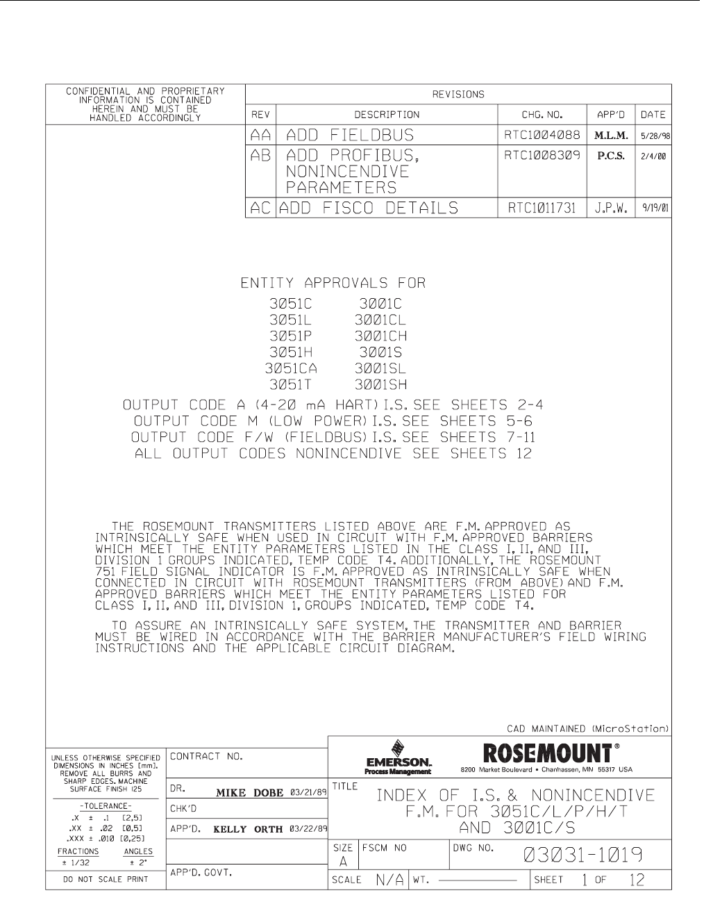
Reference Manual
00809-0100-4809, Rev AA
August 2002
B-5
Annubar Flowmeter Series
Figure B-1. FM Installation
Drawing 03031-1019, Rev. AC
Page 1 of 12
03031-1019A01A
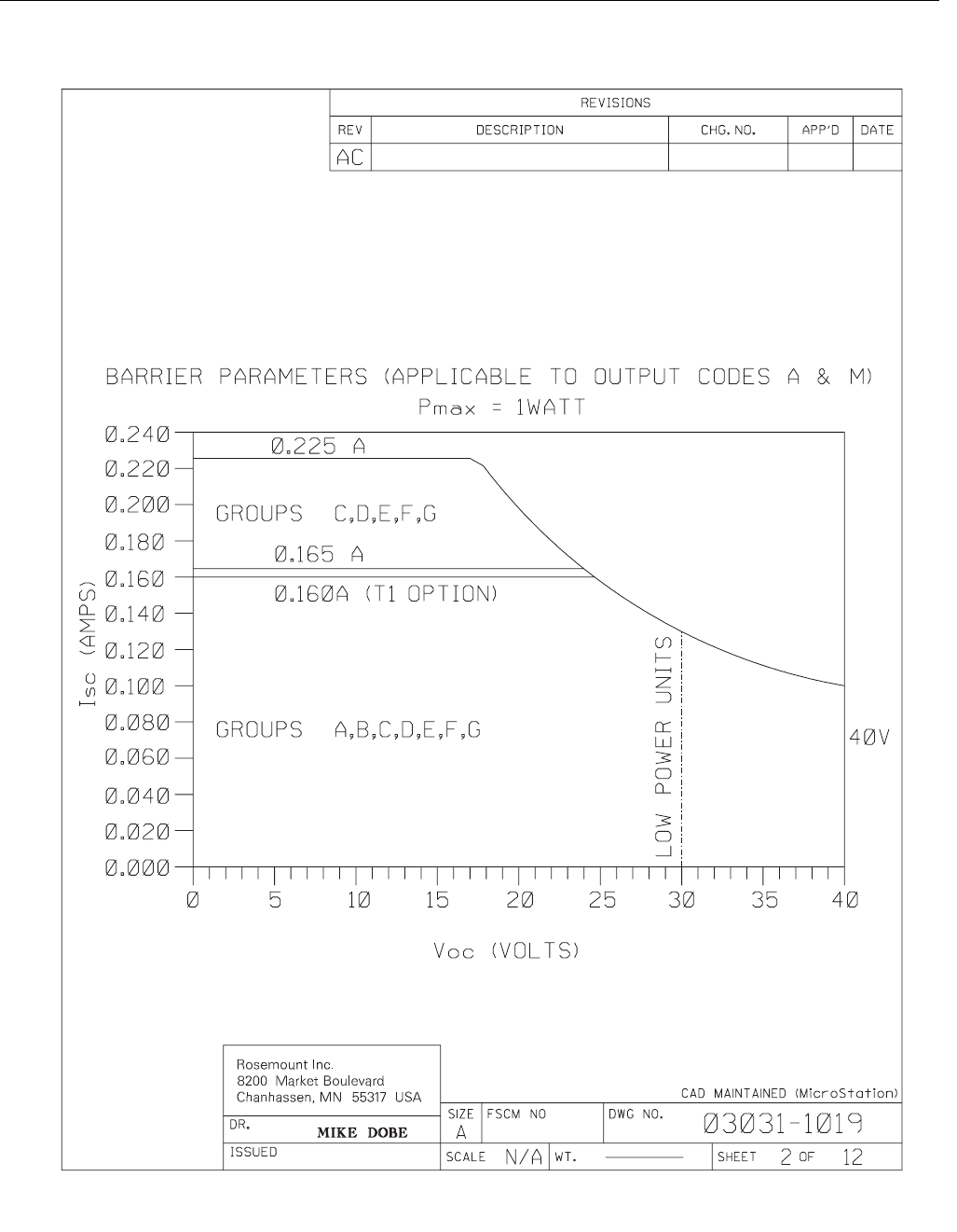
Reference Manual
00809-0100-4809, Rev AA
August 2002
Annubar Flowmeter Series
B-6
Page 2 of 12
03031-1019A02A
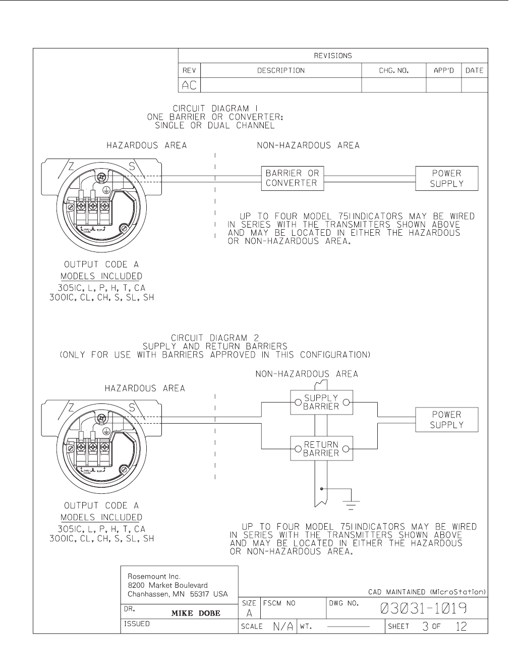
Reference Manual
00809-0100-4809, Rev AA
August 2002
B-7
Annubar Flowmeter Series
Page 3 of 12
03031-1019A03A
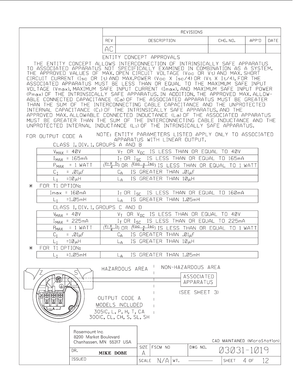
Reference Manual
00809-0100-4809, Rev AA
August 2002
Annubar Flowmeter Series
B-8
Page 4 of 12
03031-1019A04A
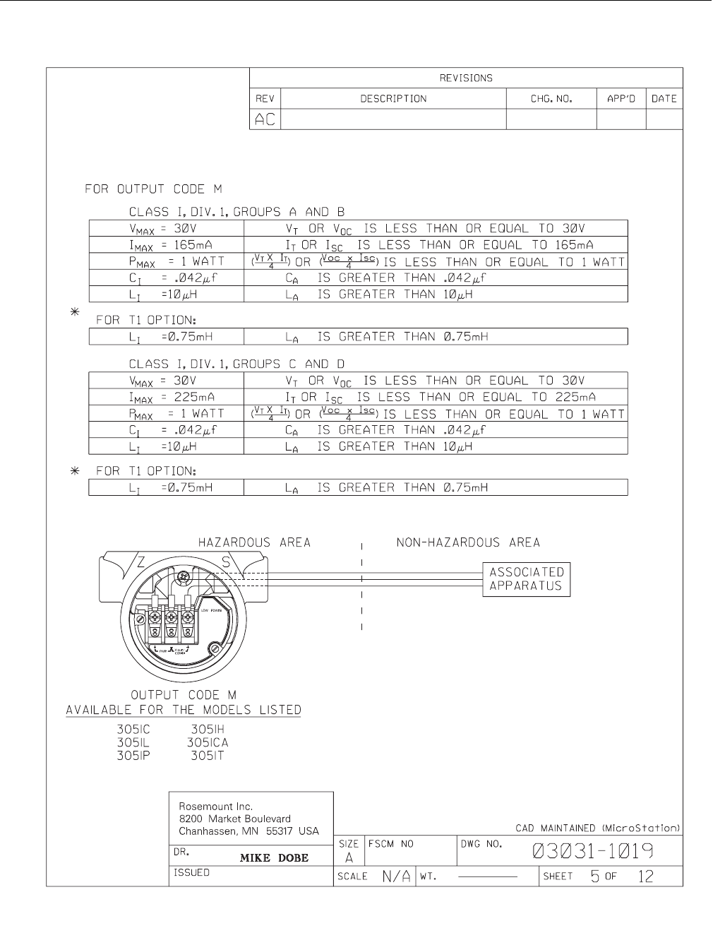
Reference Manual
00809-0100-4809, Rev AA
August 2002
B-9
Annubar Flowmeter Series
Page 5 of 12
03031-1019A05A
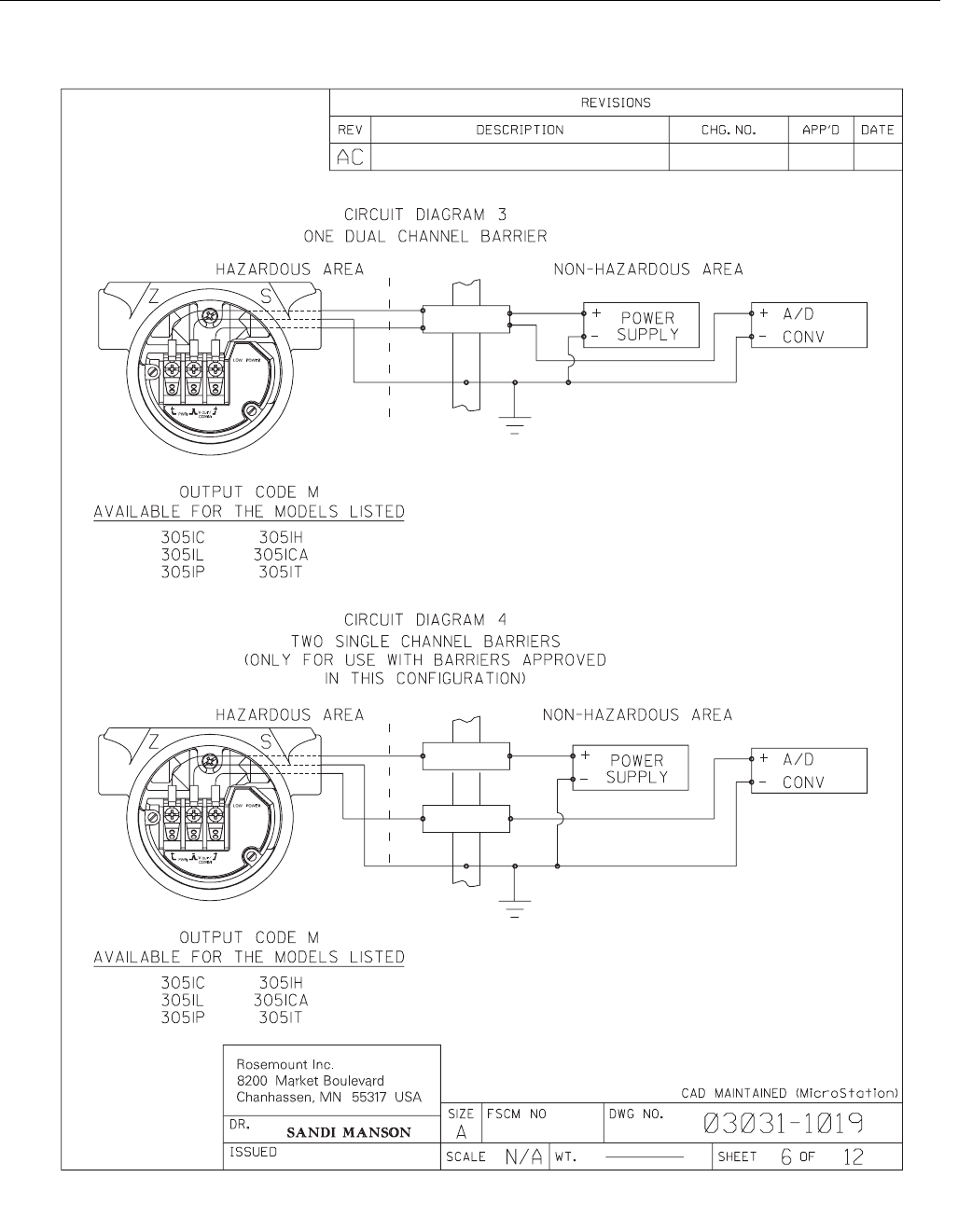
Reference Manual
00809-0100-4809, Rev AA
August 2002
Annubar Flowmeter Series
B-10
Page 6 of 12
03031-1019A06A
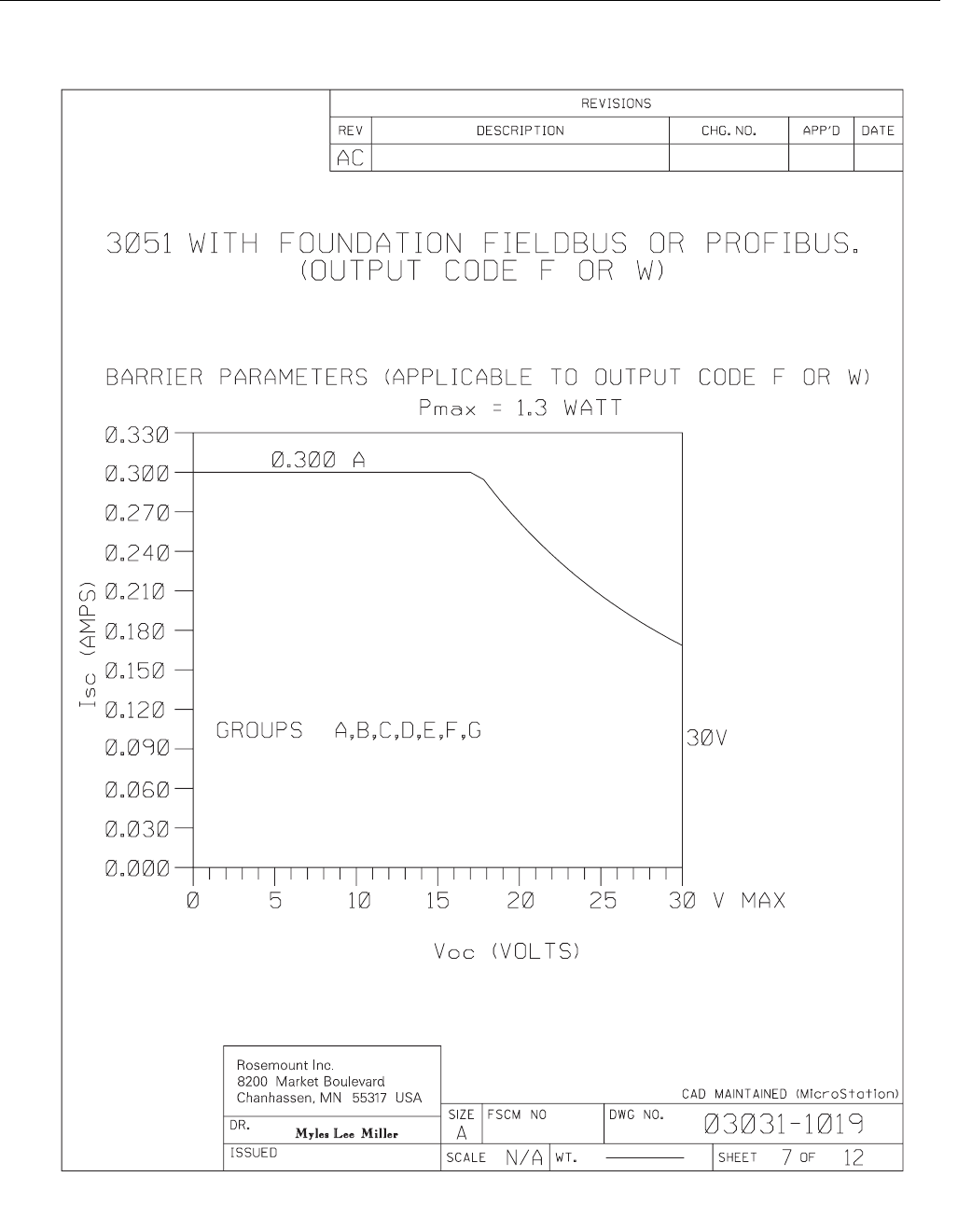
Reference Manual
00809-0100-4809, Rev AA
August 2002
B-11
Annubar Flowmeter Series
Page 7 of 12
03031-1019A07A
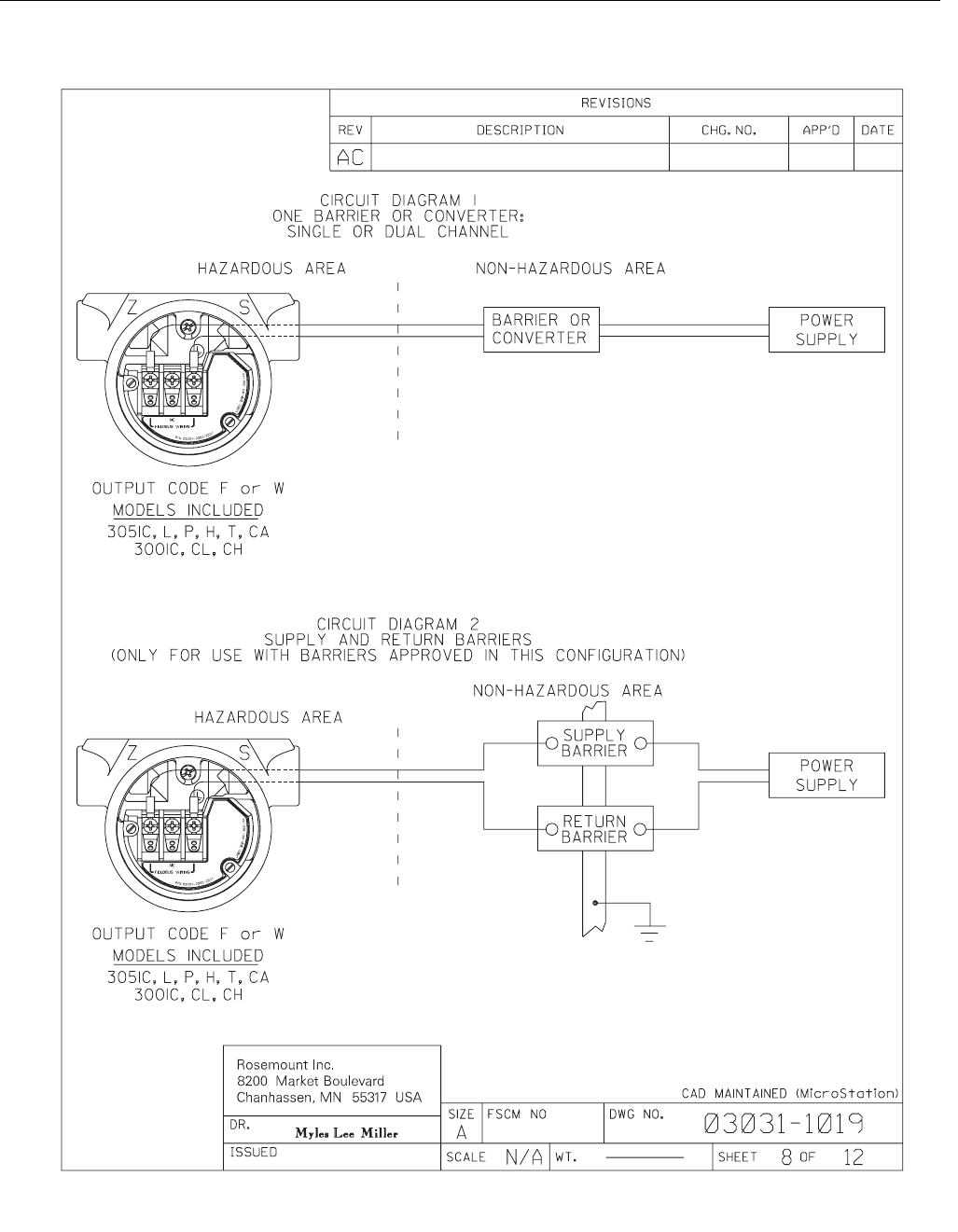
Reference Manual
00809-0100-4809, Rev AA
August 2002
Annubar Flowmeter Series
B-12
Page 8 of 12
03031-1019A08A
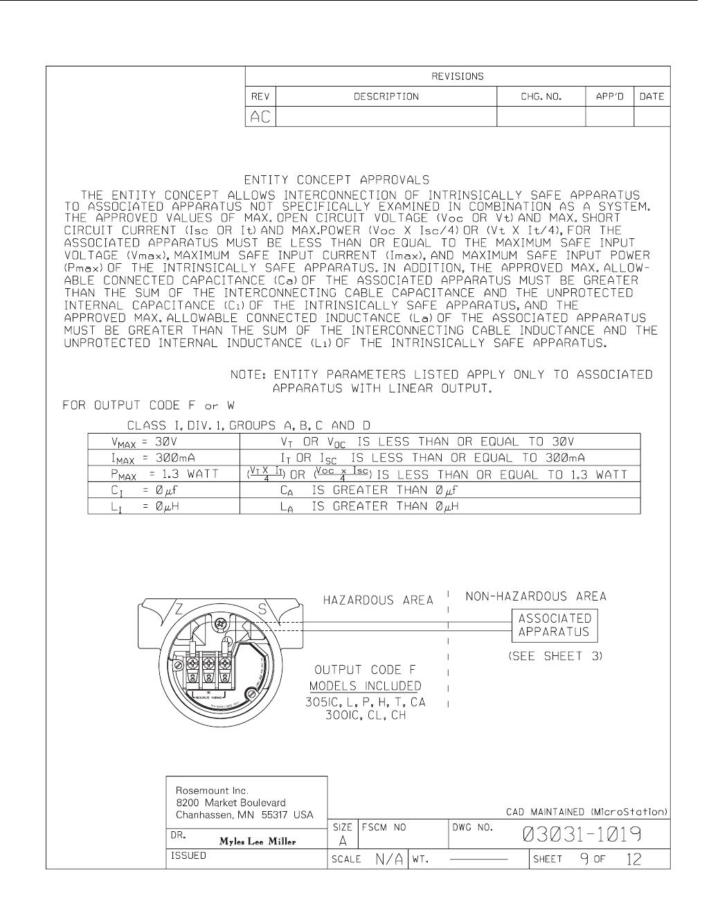
Reference Manual
00809-0100-4809, Rev AA
August 2002
B-13
Annubar Flowmeter Series
Page 9 of 12
03031-1019A09A
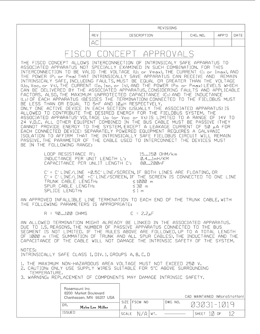
Reference Manual
00809-0100-4809, Rev AA
August 2002
Annubar Flowmeter Series
B-14
Page 10 of 12
03031-1019A10A
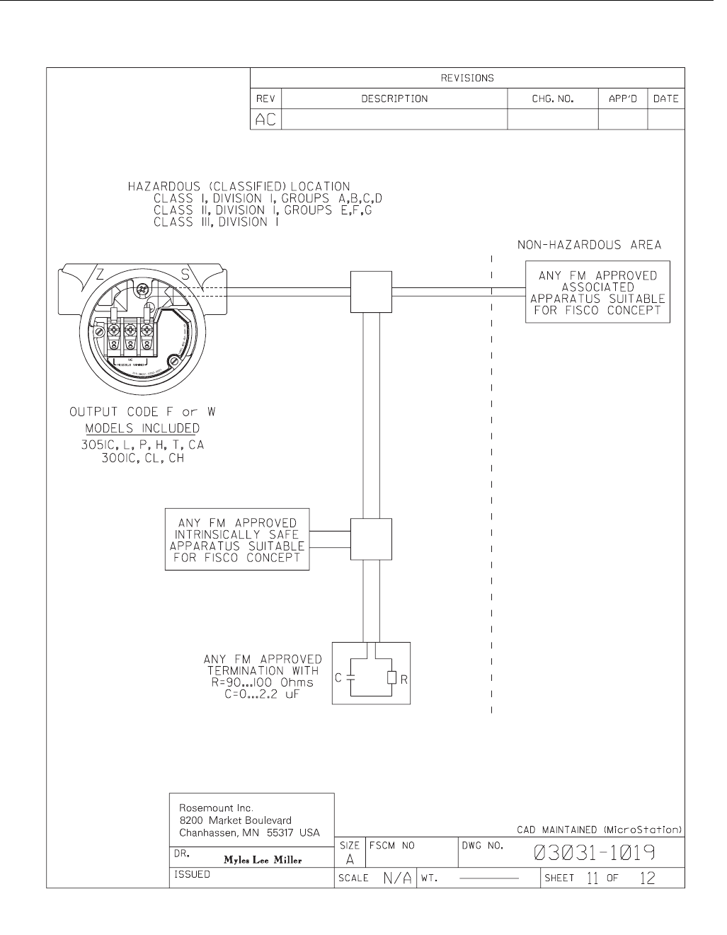
Reference Manual
00809-0100-4809, Rev AA
August 2002
B-15
Annubar Flowmeter Series
Page 11 of 12
03031-1019A11A
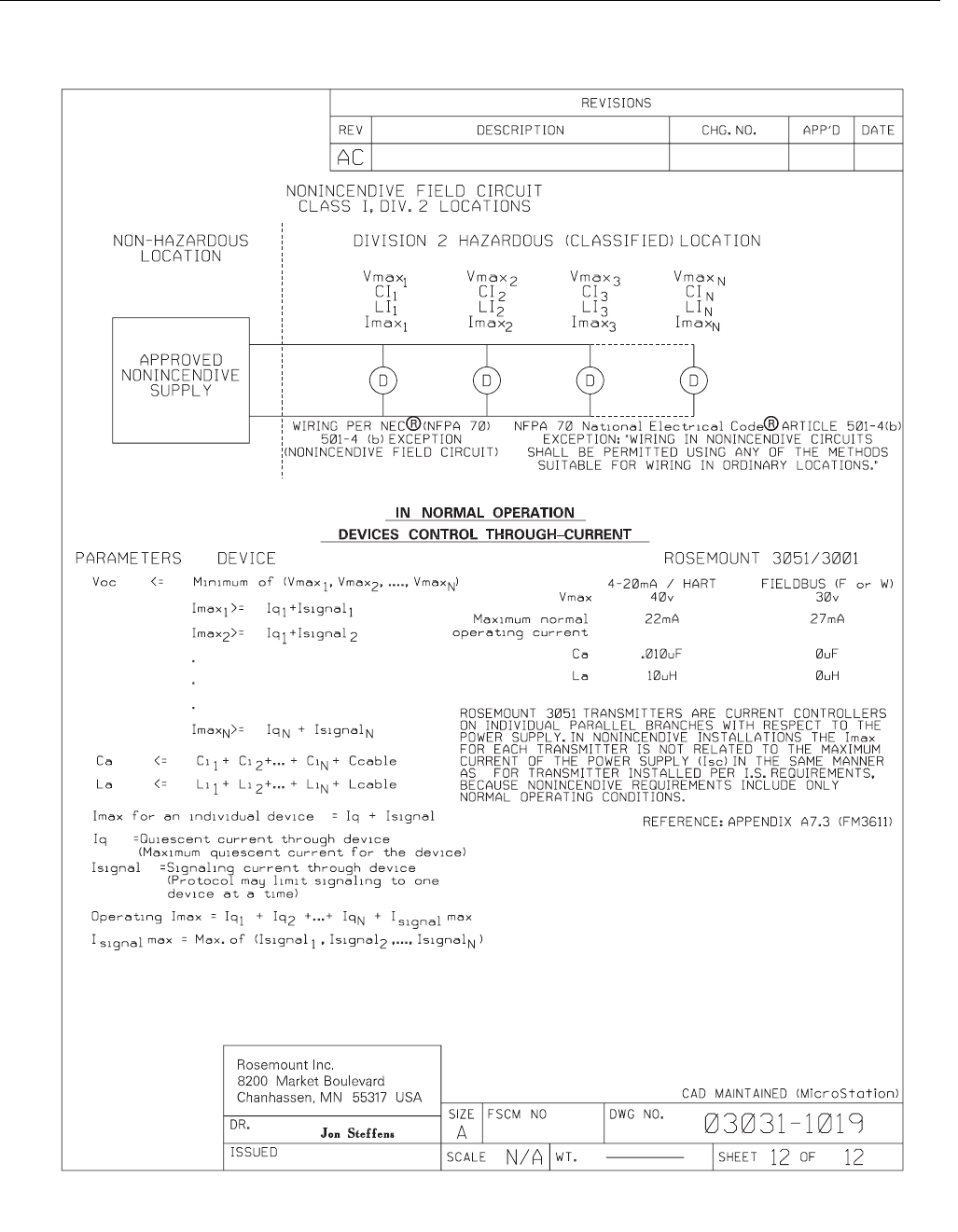
Reference Manual
00809-0100-4809, Rev AA
August 2002
Annubar Flowmeter Series
B-16
Page 12 of 12
03031-1019A12A
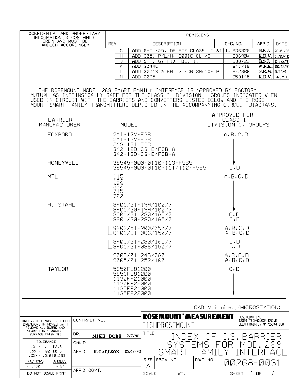
Reference Manual
00809-0100-4809, Rev AA
August 2002
B-17
Annubar Flowmeter Series
Figure B-2. FM Installation
Drawing 00268-0031, Rev. M
Page 1 of 7
0031A01A
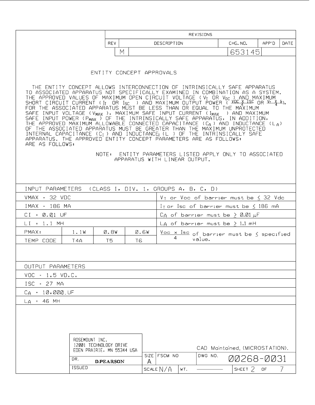
Reference Manual
00809-0100-4809, Rev AA
August 2002
Annubar Flowmeter Series
B-18
Page 2 of 7
0031A02A
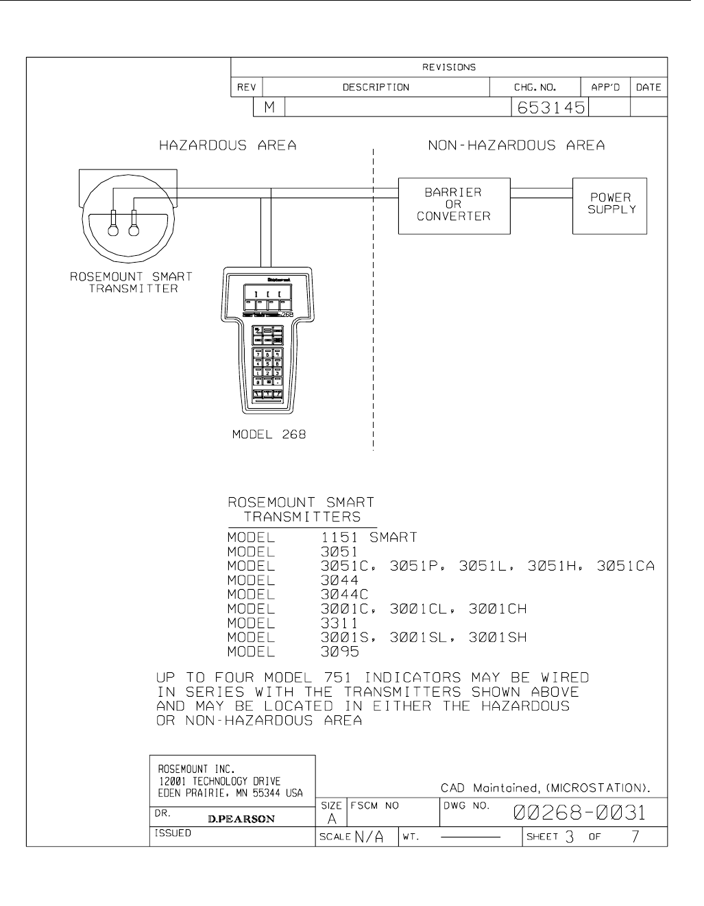
Reference Manual
00809-0100-4809, Rev AA
August 2002
B-19
Annubar Flowmeter Series
Page 3 of 7
0031A03A
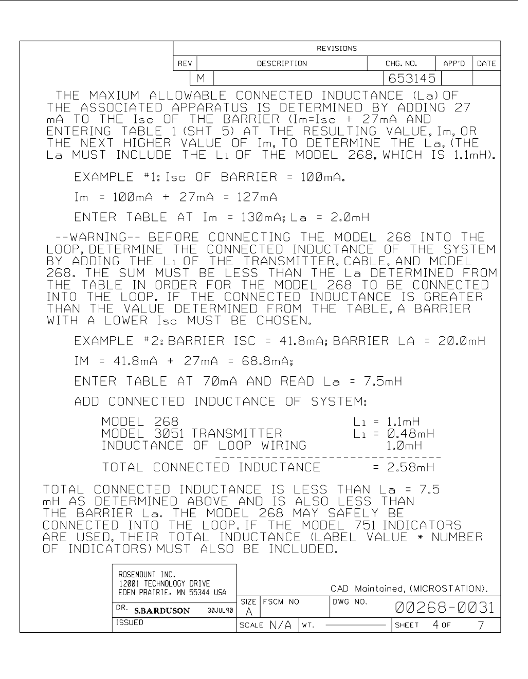
Reference Manual
00809-0100-4809, Rev AA
August 2002
Annubar Flowmeter Series
B-20
Page 4 of 7
0031A04A
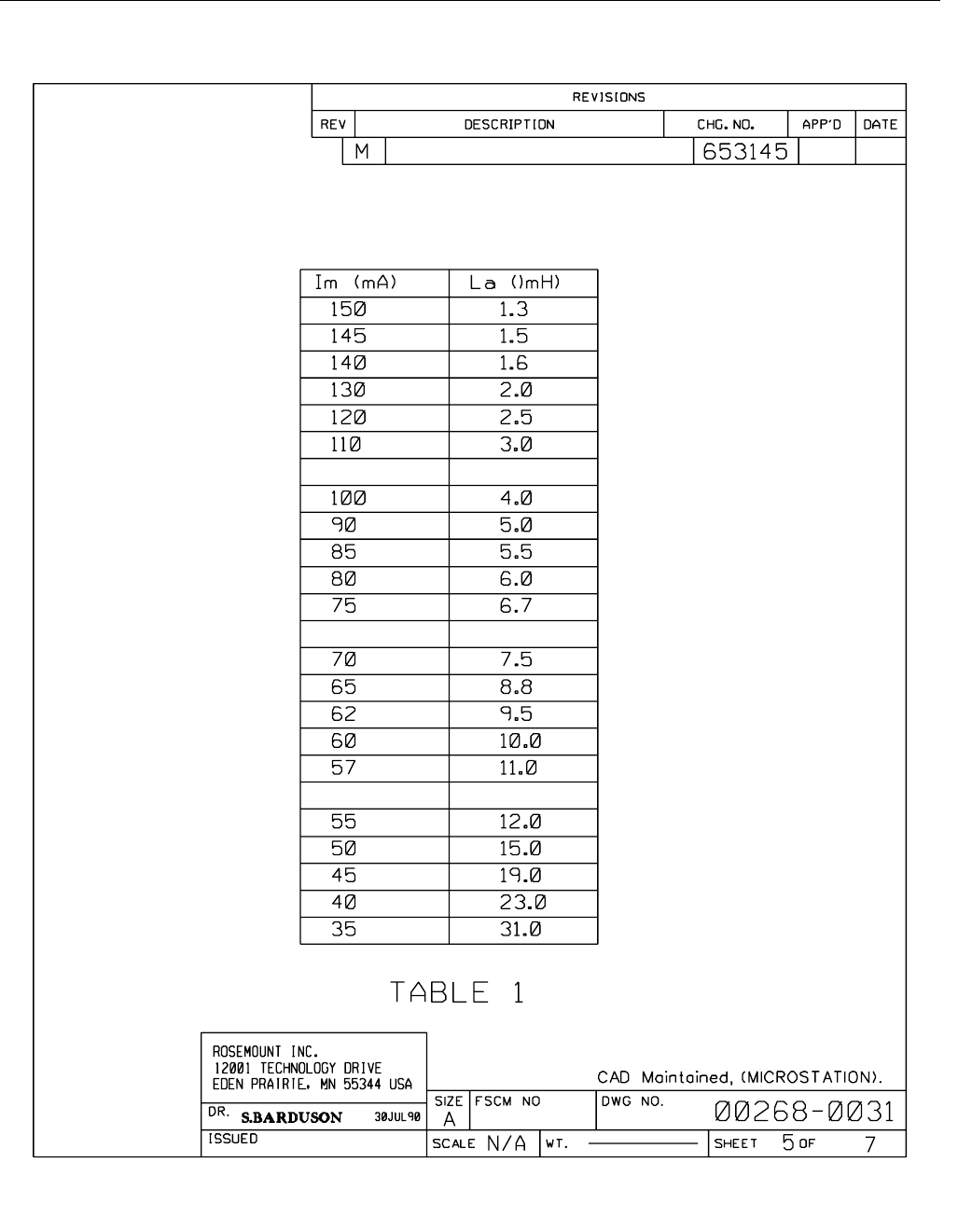
Reference Manual
00809-0100-4809, Rev AA
August 2002
B-21
Annubar Flowmeter Series
Page 5 of 7
0031A05A
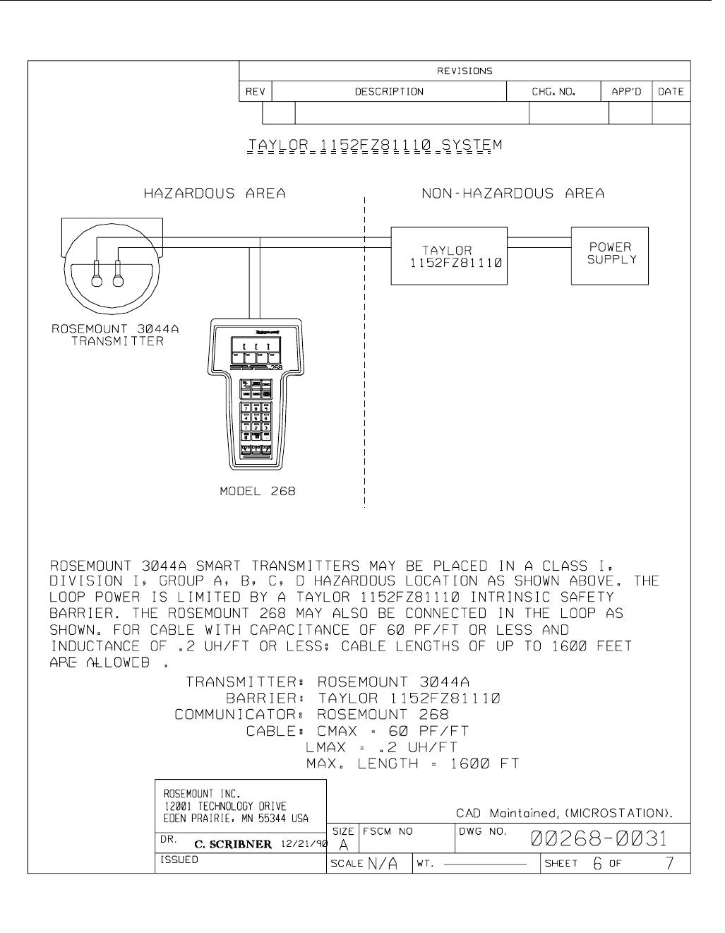
Reference Manual
00809-0100-4809, Rev AA
August 2002
Annubar Flowmeter Series
B-22
Page 6 of 7
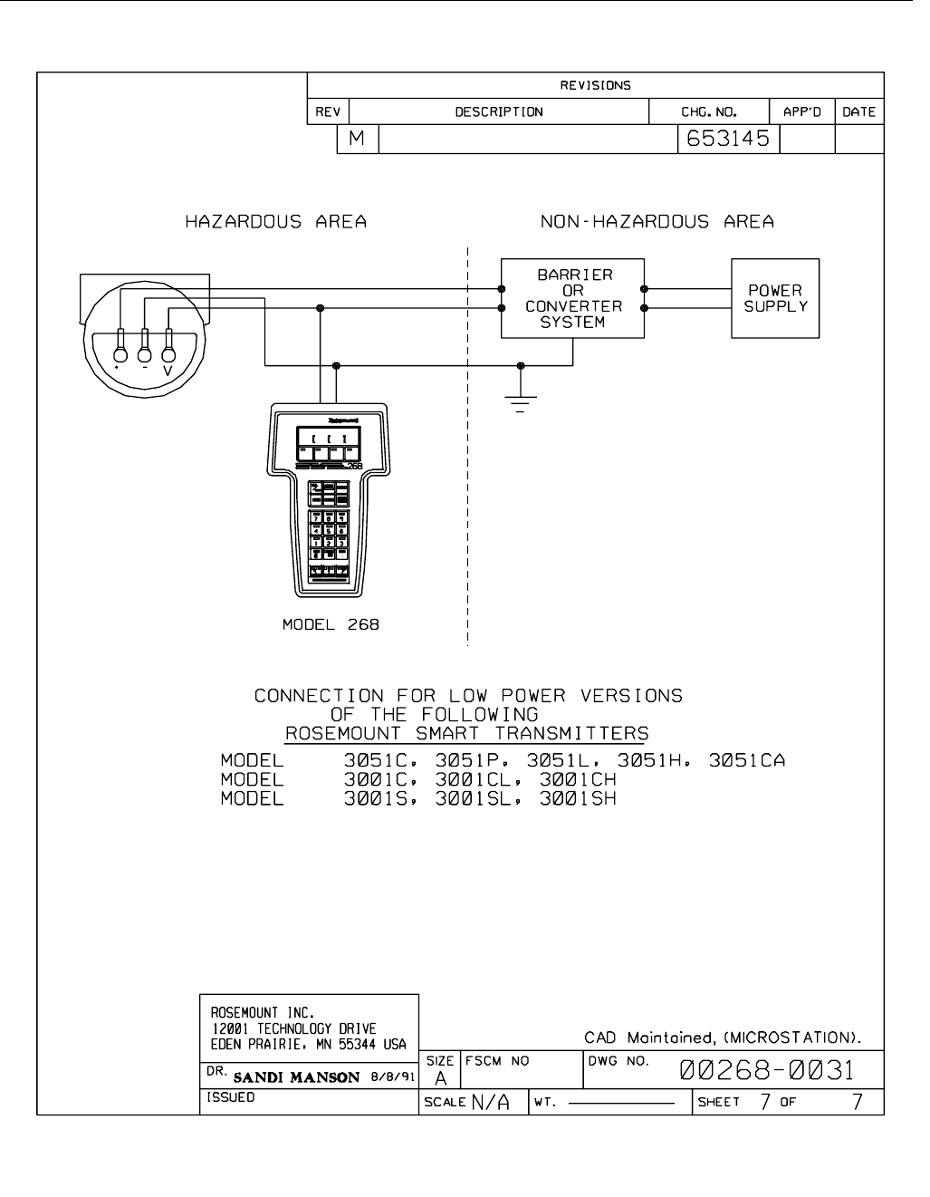
Reference Manual
00809-0100-4809, Rev AA
August 2002
B-23
Annubar Flowmeter Series
Page 7 of 7
0031A07A
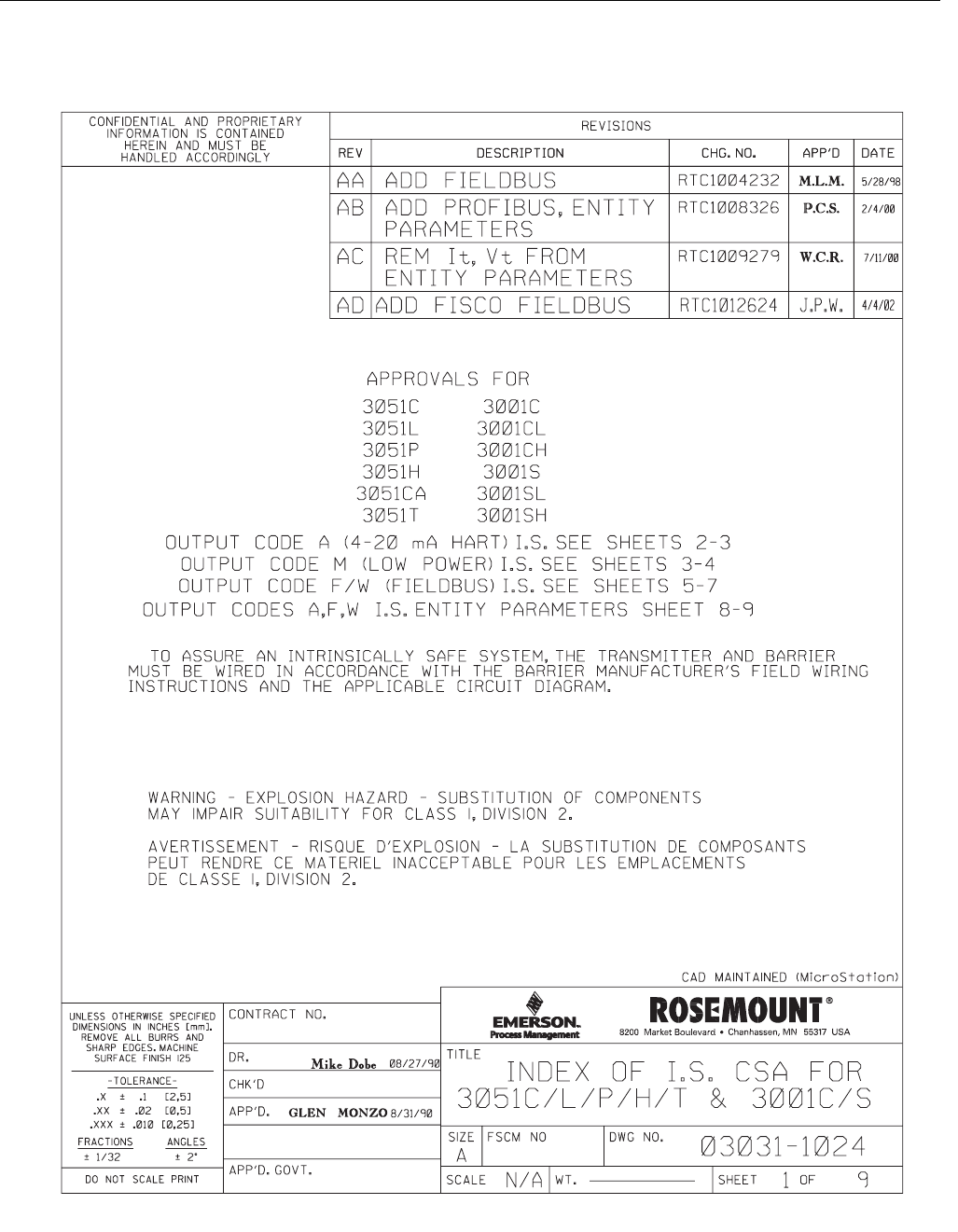
Reference Manual
00809-0100-4809, Rev AA
August 2002
Annubar Flowmeter Series
B-24
Figure B-3. CSA Installation
Drawing 03031-1024, Rev. AD
Page 1 of 9
03031-1024A01A
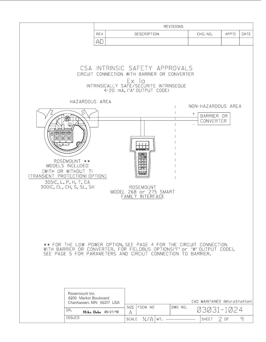
Reference Manual
00809-0100-4809, Rev AA
August 2002
B-25
Annubar Flowmeter Series
Page 2 of 9
03031-1024A02A
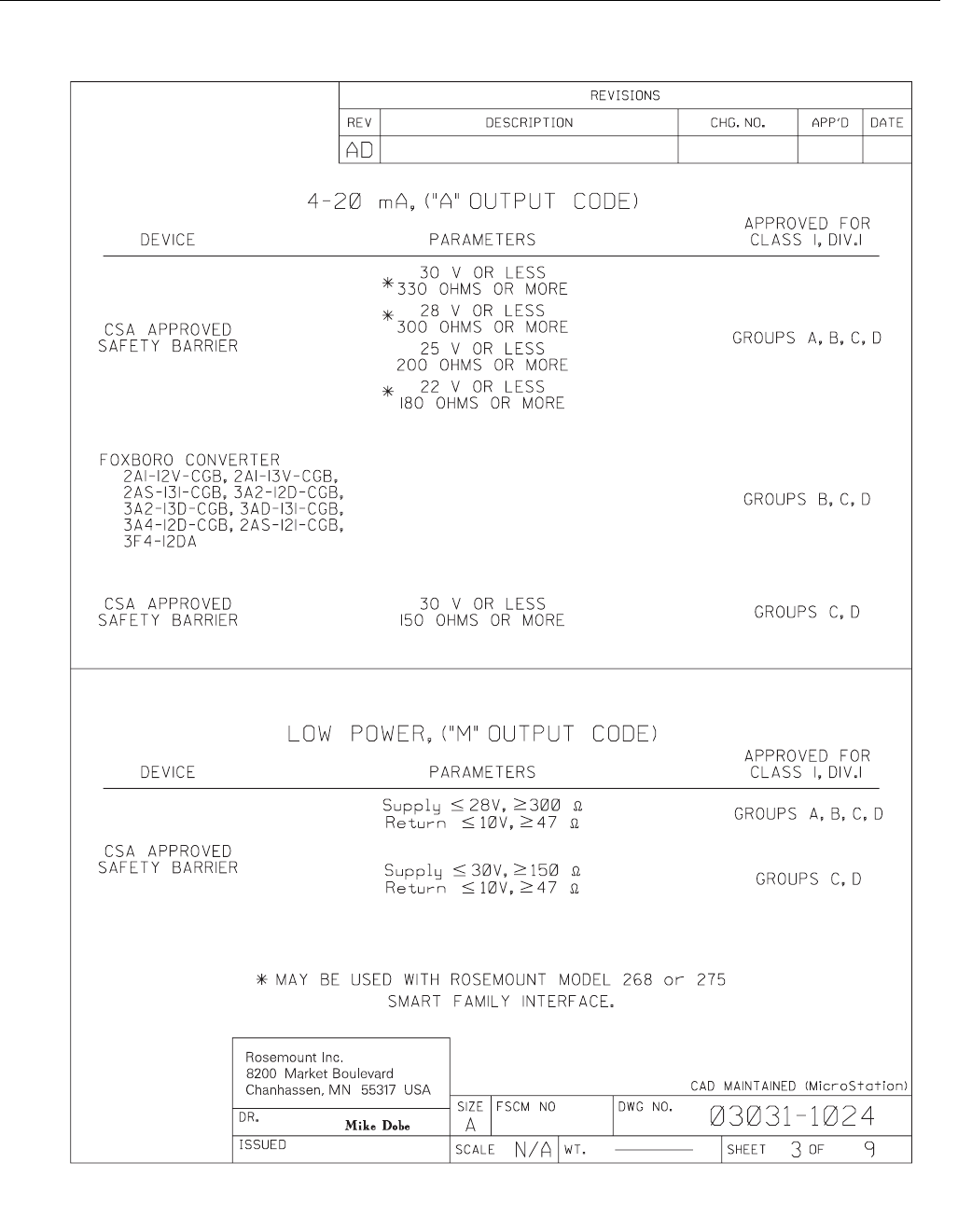
Reference Manual
00809-0100-4809, Rev AA
August 2002
Annubar Flowmeter Series
B-26
Page 3 of 9
03031-1024A03A
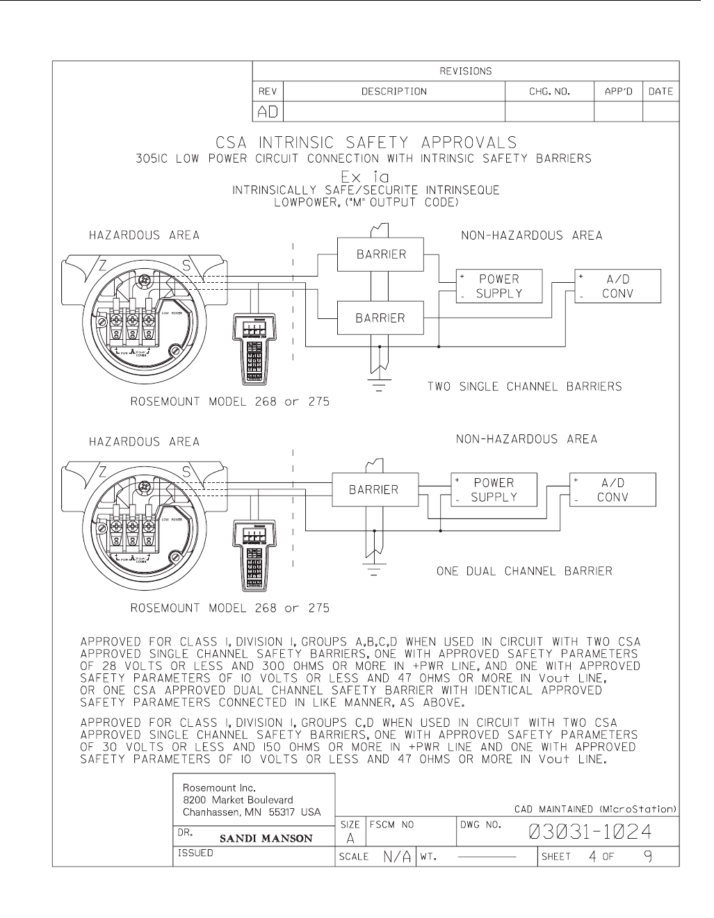
Reference Manual
00809-0100-4809, Rev AA
August 2002
B-27
Annubar Flowmeter Series
Page 4 of 9
03031-1024A04A
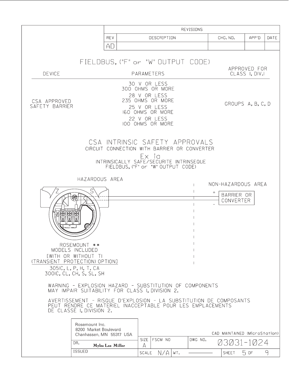
Reference Manual
00809-0100-4809, Rev AA
August 2002
Annubar Flowmeter Series
B-28
Page 5 of 9
03031-1024A05A
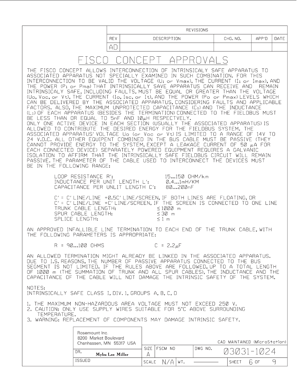
Reference Manual
00809-0100-4809, Rev AA
August 2002
B-29
Annubar Flowmeter Series
Page 6 of 9
03031-1024A06A
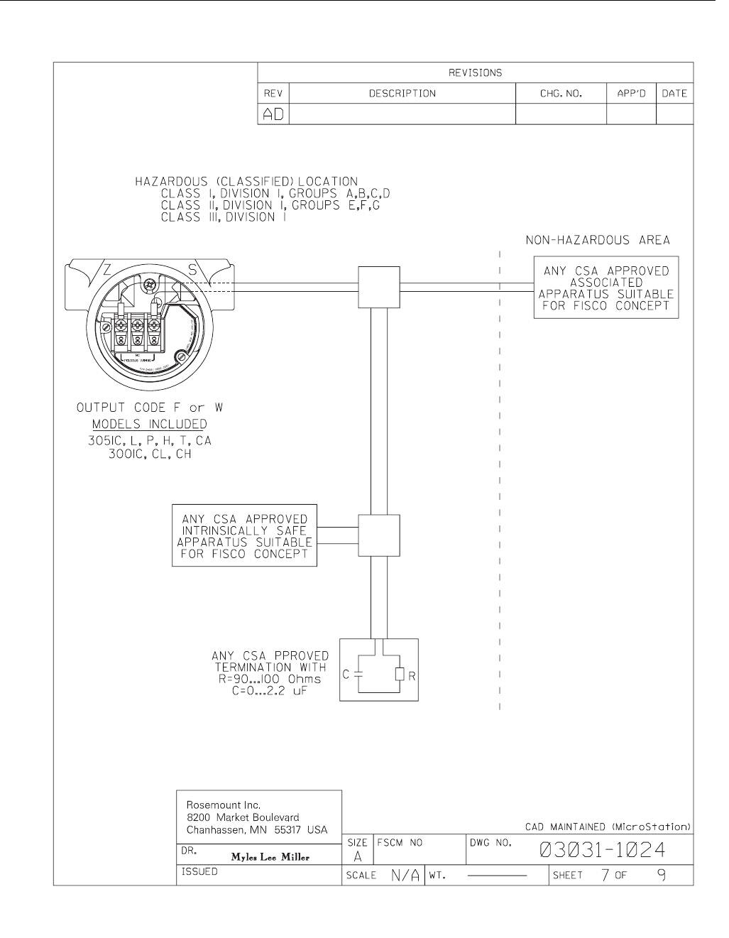
Reference Manual
00809-0100-4809, Rev AA
August 2002
Annubar Flowmeter Series
B-30
Page 7 of 9
03031-1024A07A
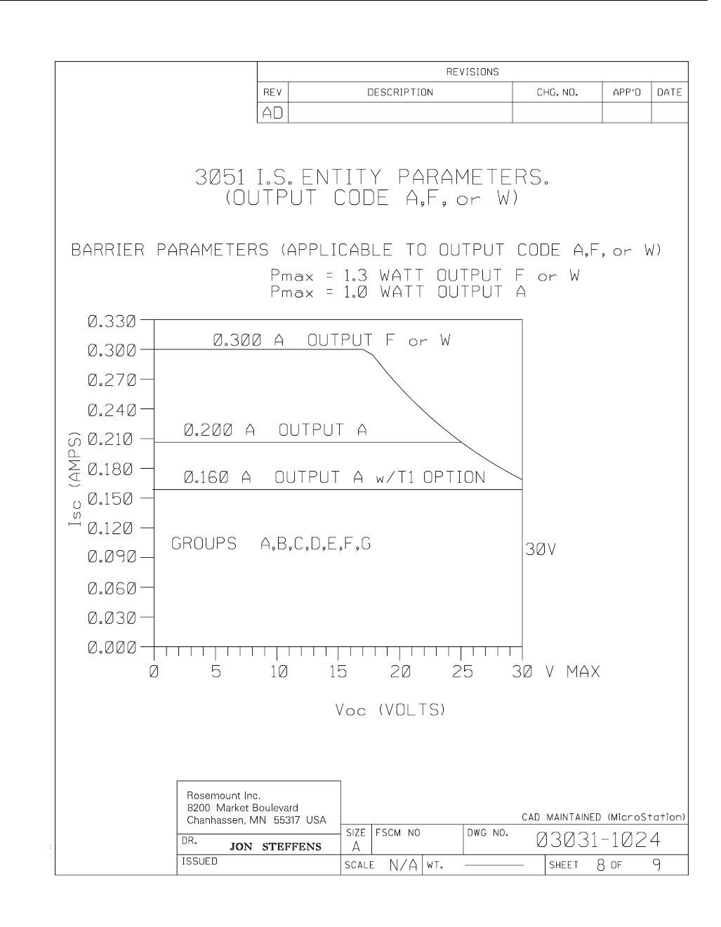
Reference Manual
00809-0100-4809, Rev AA
August 2002
B-31
Annubar Flowmeter Series
Page 8 of 9
03031-1024A08A
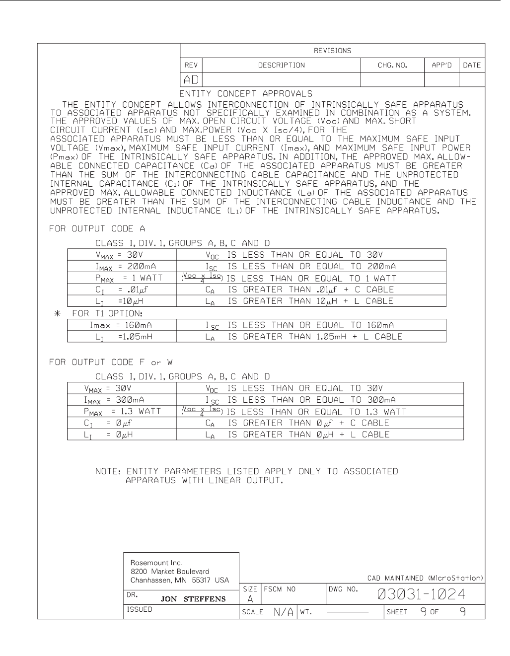
Reference Manual
00809-0100-4809, Rev AA
August 2002
Annubar Flowmeter Series
B-32
Page 9 of 9
03031-1024A09A
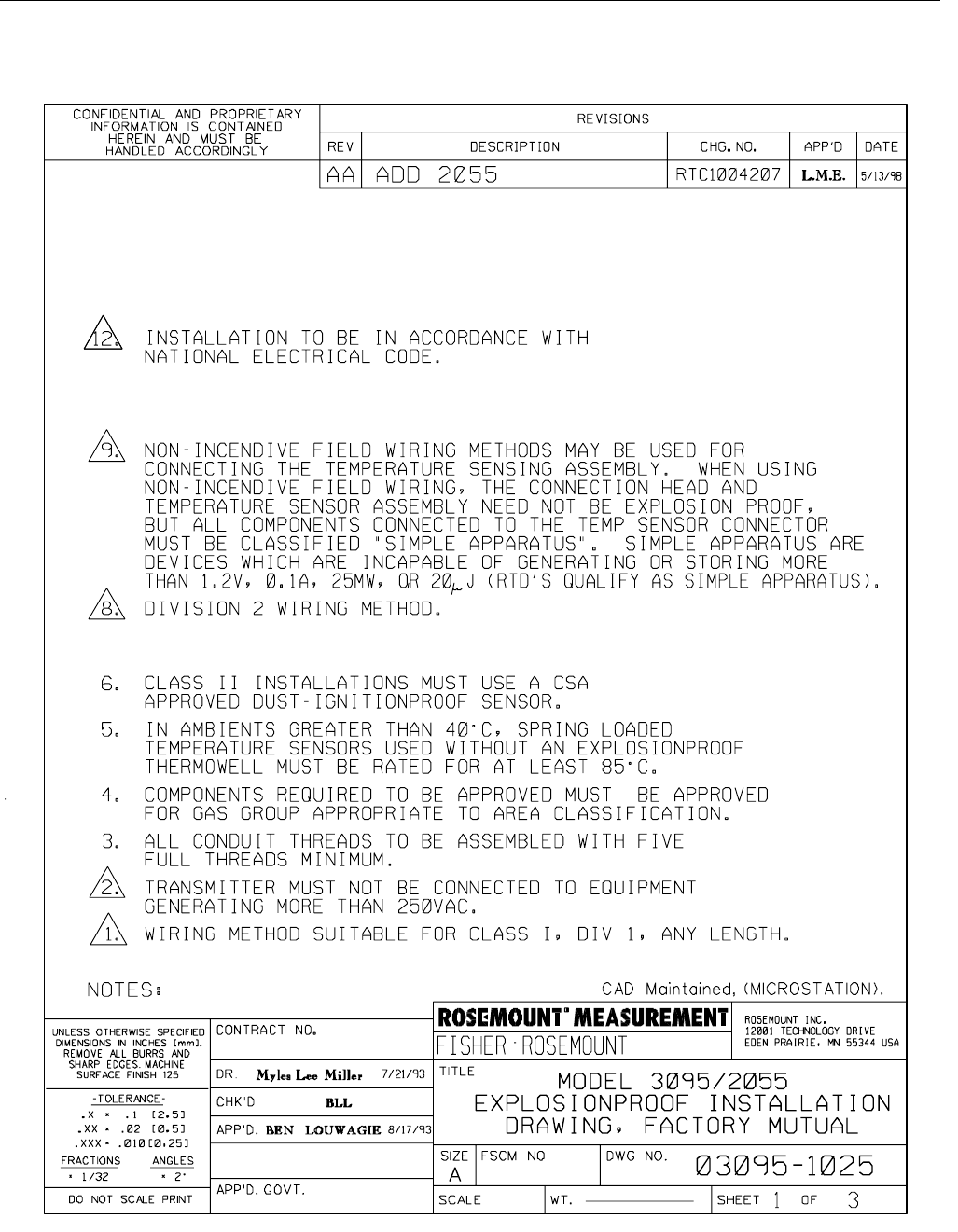
Reference Manual
00809-0100-4809, Rev AA
August 2002
B-33
Annubar Flowmeter Series
Figure B-4. FM Installation
Drawing 03095-1025, Rev. AA
Page 1 of 3
3095-1025A01A
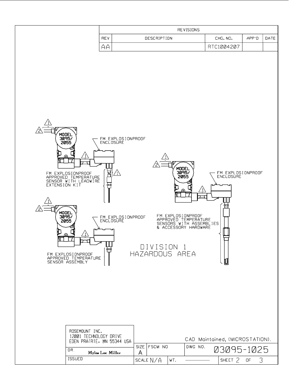
Reference Manual
00809-0100-4809, Rev AA
August 2002
Annubar Flowmeter Series
B-34
Page 2 of 3
3095-1025A02A
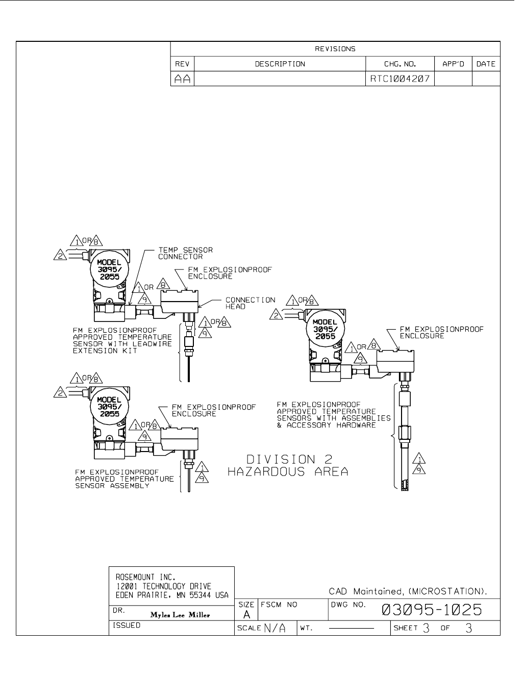
Reference Manual
00809-0100-4809, Rev AA
August 2002
B-35
Annubar Flowmeter Series
Page 3 of 3
3095-1025A03A
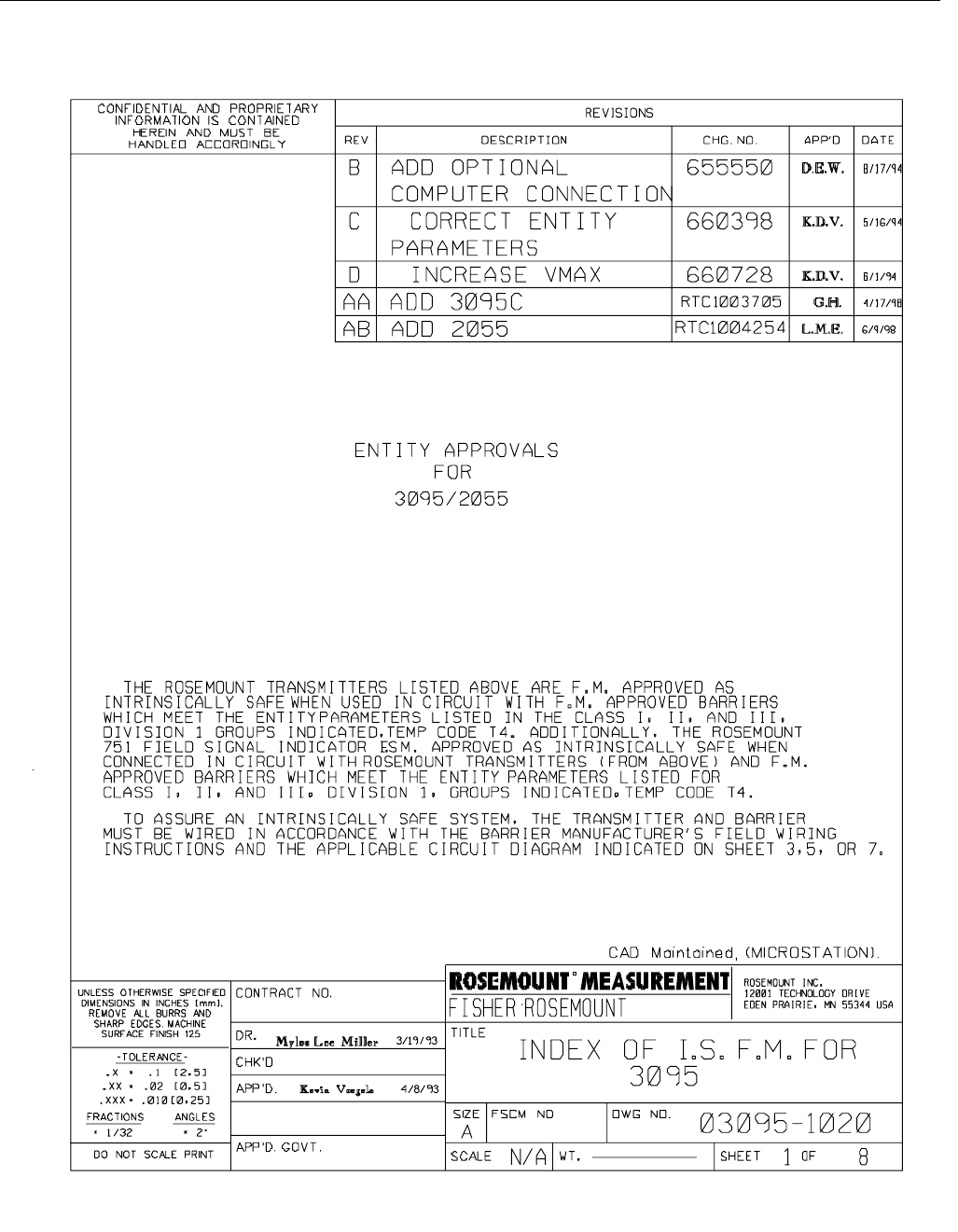
Reference Manual
00809-0100-4809, Rev AA
August 2002
Annubar Flowmeter Series
B-36
Figure B-5. FM Installation
Drawing 03095-1020, Rev. AB
Page 1 of 8
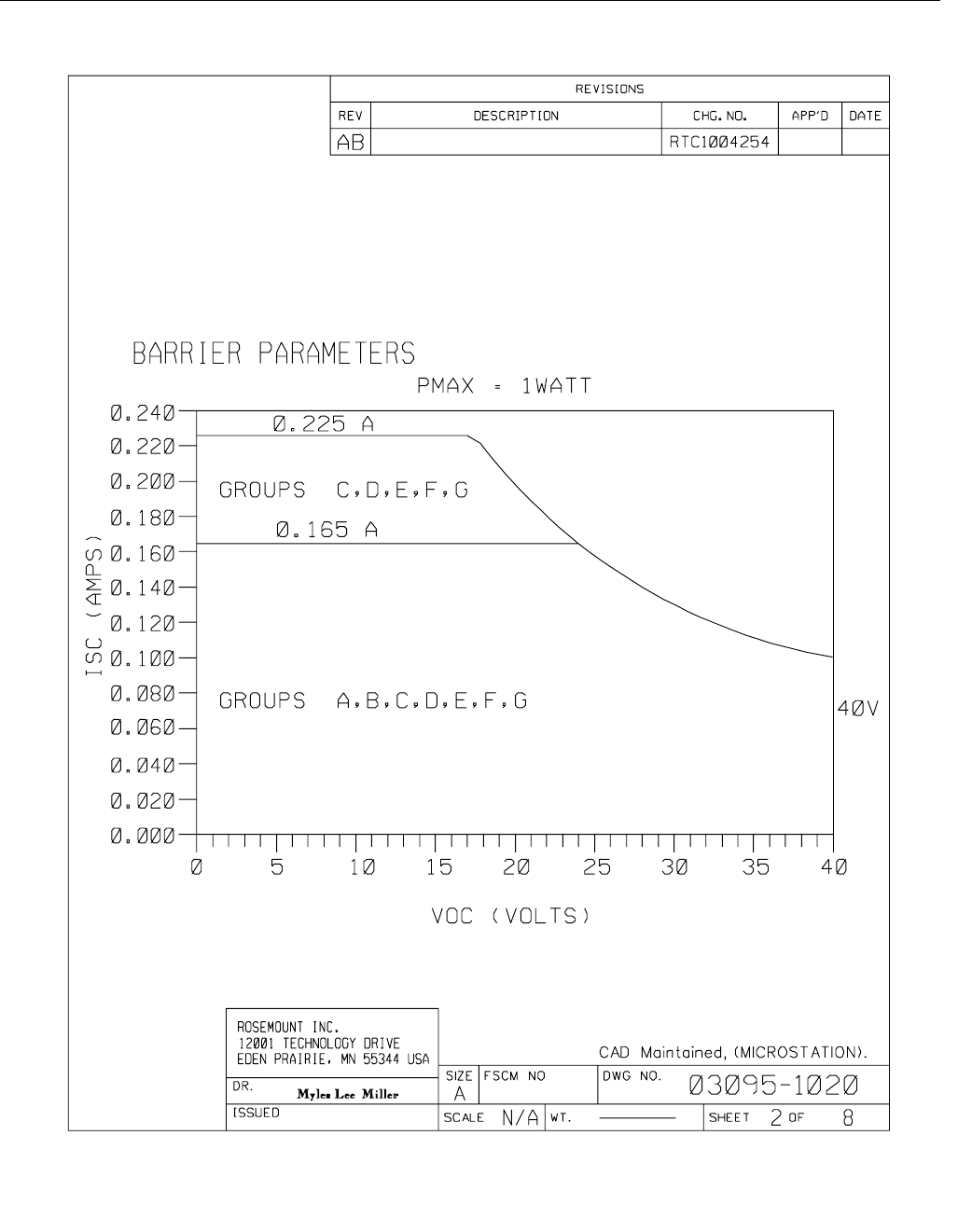
Reference Manual
00809-0100-4809, Rev AA
August 2002
B-37
Annubar Flowmeter Series
Page 2 of 8
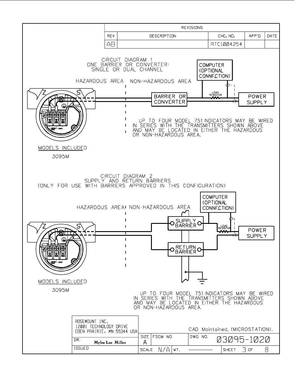
Reference Manual
00809-0100-4809, Rev AA
August 2002
Annubar Flowmeter Series
B-38
Page 3 of 8
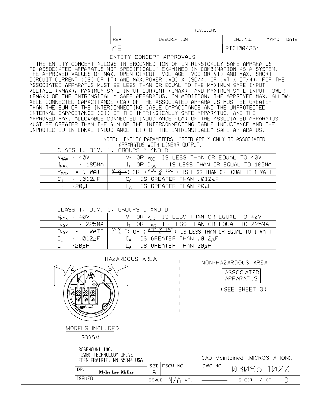
Reference Manual
00809-0100-4809, Rev AA
August 2002
B-39
Annubar Flowmeter Series
Page 4 of 8
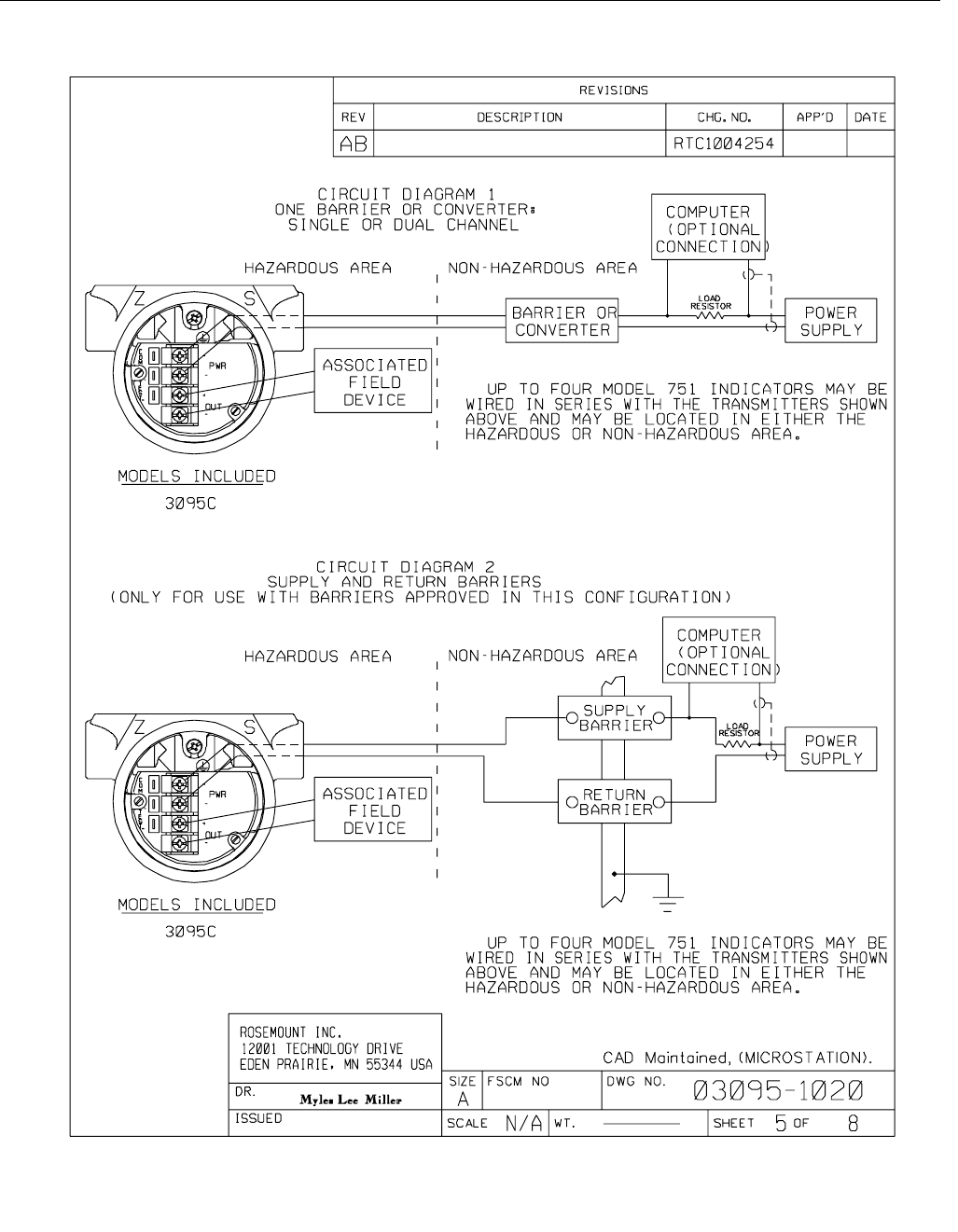
Reference Manual
00809-0100-4809, Rev AA
August 2002
Annubar Flowmeter Series
B-40
Page 5 of 8
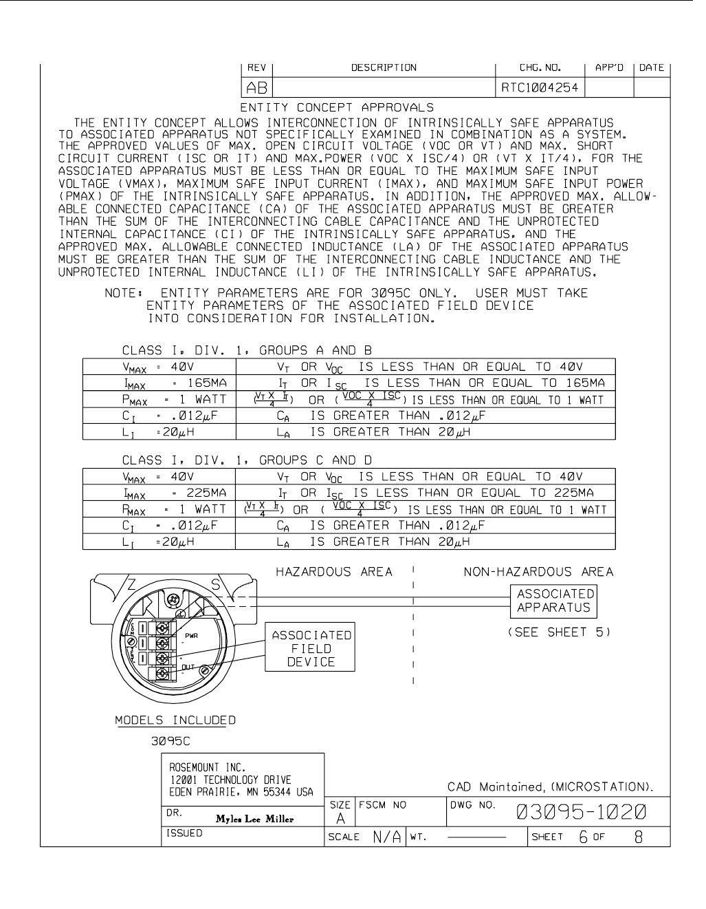
Reference Manual
00809-0100-4809, Rev AA
August 2002
B-41
Annubar Flowmeter Series
Page 6 of 8
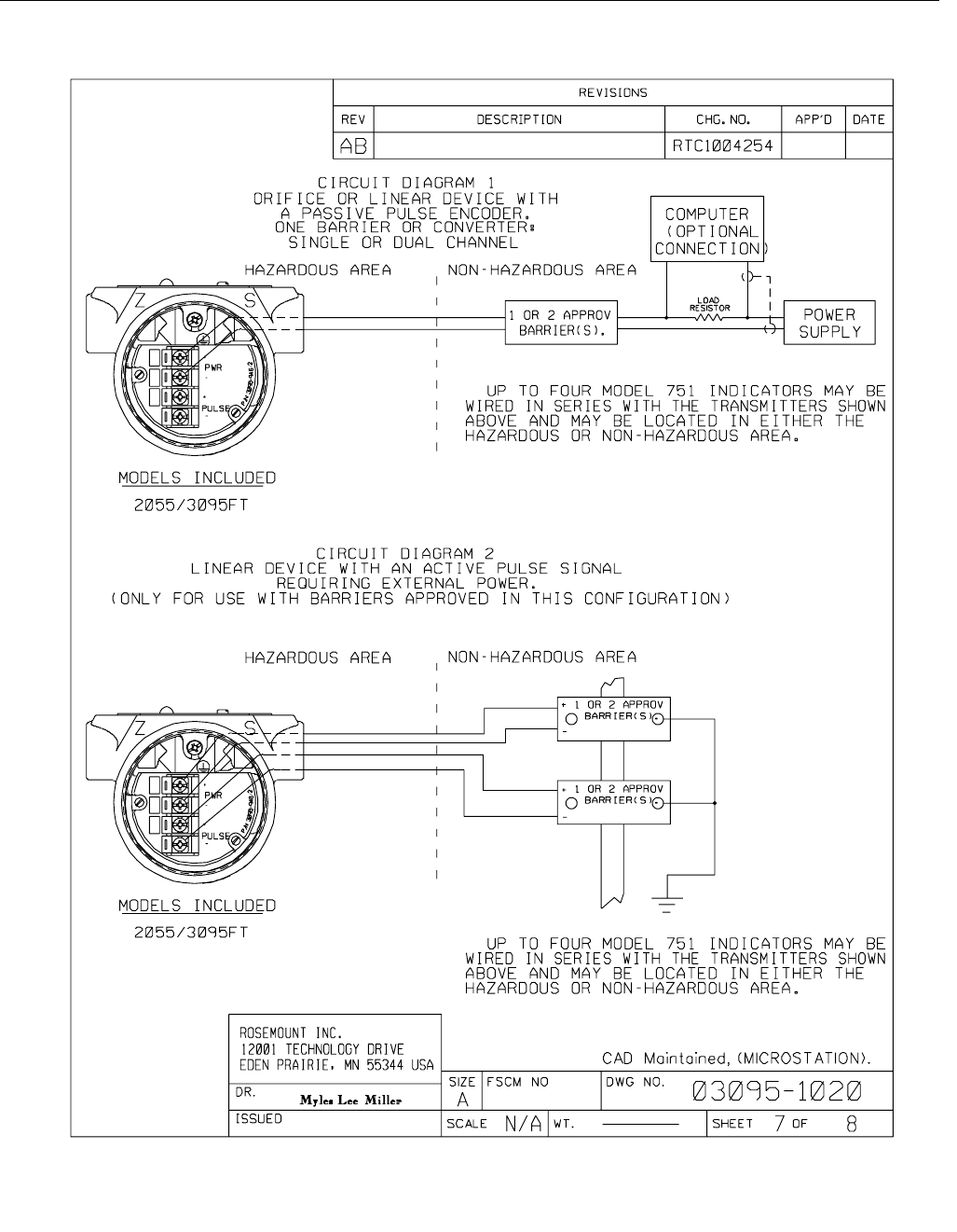
Reference Manual
00809-0100-4809, Rev AA
August 2002
Annubar Flowmeter Series
B-42
Page 7 of 8
Page 8 of 8
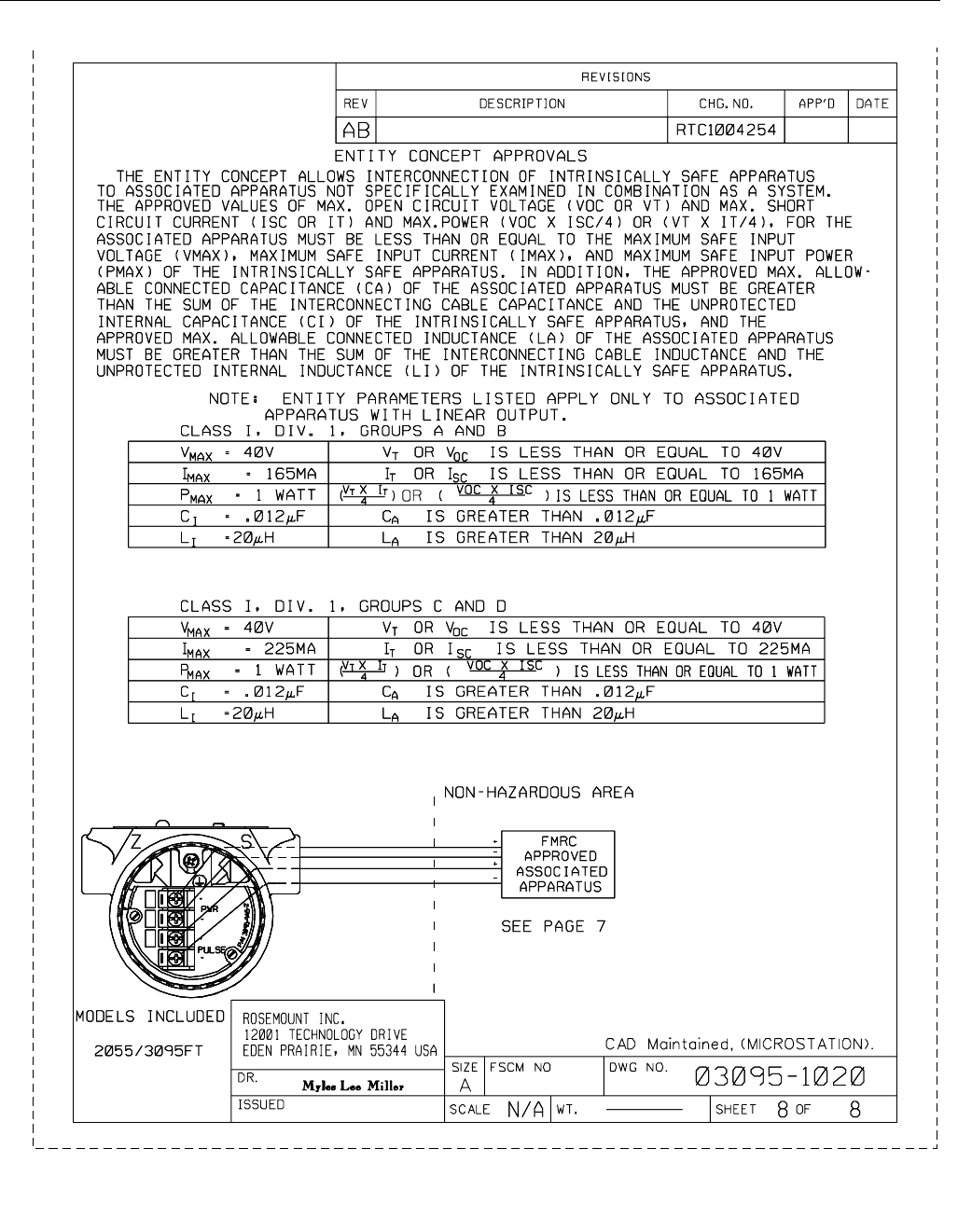
Reference Manual
00809-0100-4809, Rev AA
August 2002
B-43
Annubar Flowmeter Series
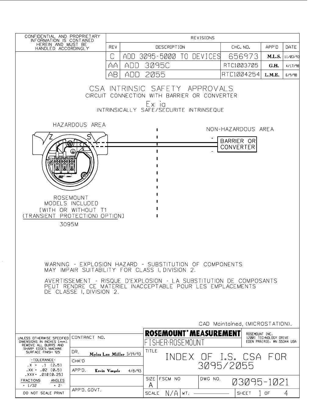
Reference Manual
00809-0100-4809, Rev AA
August 2002
Annubar Flowmeter Series
B-44
Figure B-6. CSA Installation
Drawing 03095-1021, Rev. AB
Page 1 of 4
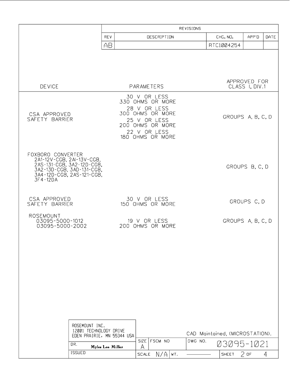
Reference Manual
00809-0100-4809, Rev AA
August 2002
B-45
Annubar Flowmeter Series
Page 2 of 4
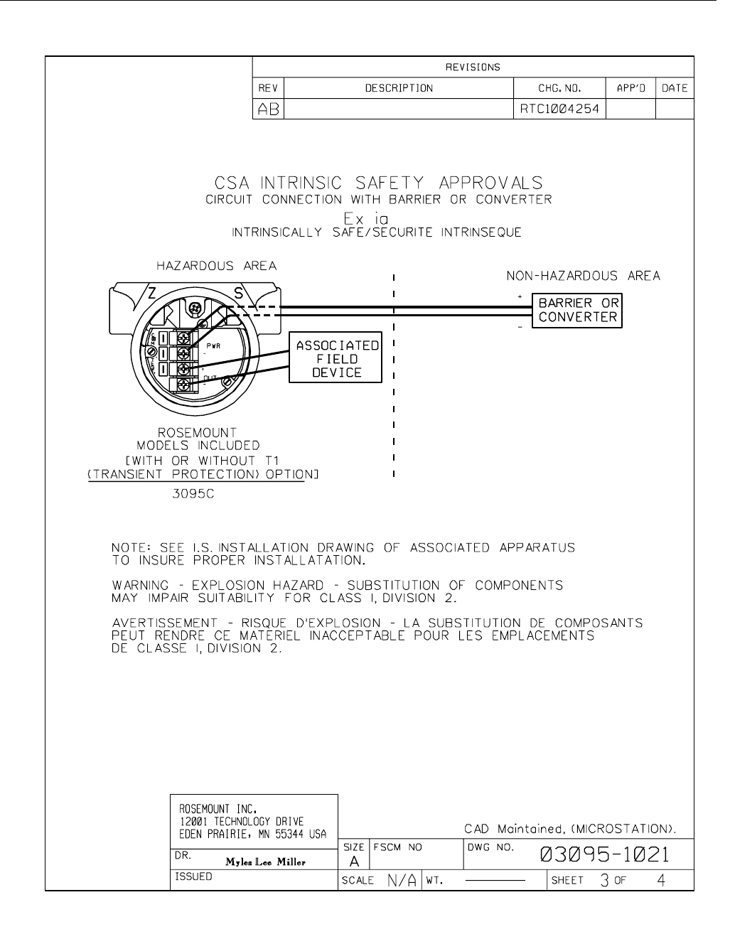
Reference Manual
00809-0100-4809, Rev AA
August 2002
Annubar Flowmeter Series
B-46
Page 3 of 4
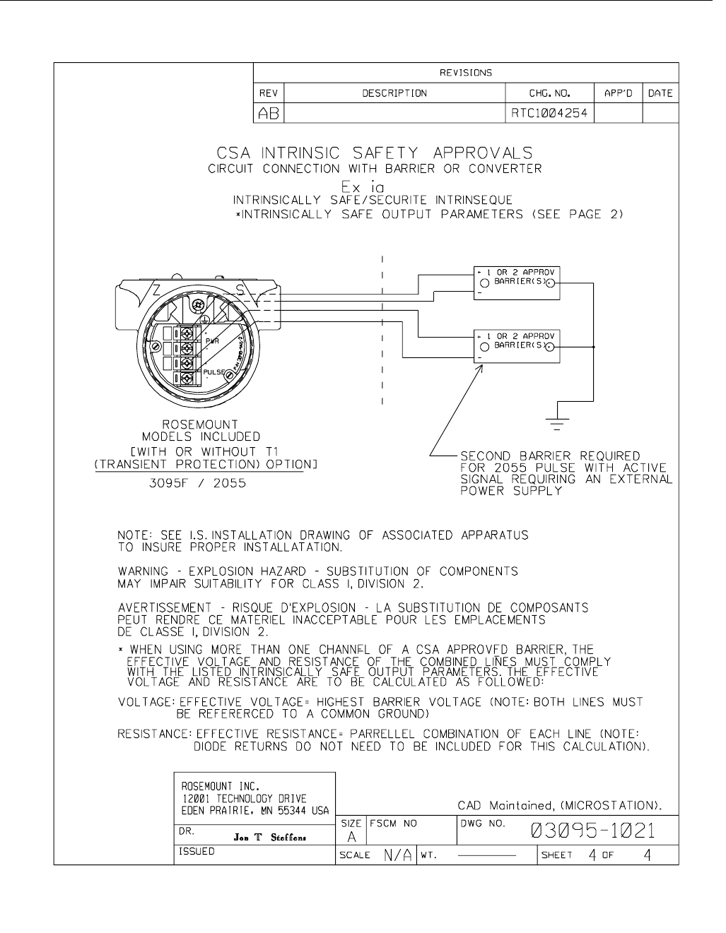
Reference Manual
00809-0100-4809, Rev AA
August 2002
B-47
Annubar Flowmeter Series
Page 4 of 4

Reference Manual
00809-0100-4809, Rev AA
August 2002
Annubar Flowmeter Series
B-48

Reference Manual
00809-0100-4809, Rev AA
June 2002 Annubar Flowmeter Series
www.rosemount.com
Index
Numerics
275 HART Communicator . . . 3-14
Advanced Functions . . . 3-30
Basic Setup . . . . . . . . . 3-18
Calibration . . . . . . . . . . 3-21
Check Output . . . . . . . . 3-18
Connections . . . . . . . . . 3-14
Detailed Setup . . . . . . . 3-20
Diagnostics and Service . 3-20
Fast Key Sequence
Model 3051SFA . . . 3-17
Model 3095MFA . . . 3-33
Hardware . . . . . . . . . . . 3-14
HART Menu Tree
Model 3051SFA . . . 3-15
Model 3095MFA . . . 3-32
Review Configuration Data 3-17
Updating HART Software 3-15
A
Air Applications
Horizontal Pipe . . . . . . . . 2-8
Vertical Pipes . . . . . . . . . 2-8
B
Bench
Commissioning . . . . . . . . 3-2
Switches . . . . . . . . . 3-2
Bolt Installation
Guidelines . . . . . . . . . . . 2-4
C
Commissioning
Bench . . . . . . . . . . . . . . 3-2
Switches . . . . . . . . . 3-2
Direct Mount . . . . . . . . . . 3-5
3-Valve Steam No Flow 3-9
Gas 3-Valve Manifold 3-7
Gas Service . . . . . . . 3-6
Liquid 3-Valve Manifold 3-5
Liquid Service . . . . . 3-5
Steam Service . . . . . 3-8
Remote Mount . . . . . . . 3-10
5-Valve Manifolds . . 3-11
Gas Service . . . . . . 3-13
Liquid Service 3-12, 3-13
Steam Service . . . . 3-13
System Leaks . . . . 3-10
Temperature Effects 3-11
Zero the Electronics 3-10
Set the Loop to Manual . 3-14
Considerations . . . . . . . . . . . 1-2
Electrical . . . . . . . . . . . . 1-5
Power Supply . . . . . 1-5
Environmental . . . . . . . . 1-3
Access Requirements 1-3
Cover Installation . . . 1-4
Electronics Housing . 1-4
Flange Orientation . . 1-3
Housing Rotation . . . 1-3
Installation
Model 3051SFA . . . . A-4
Model 3095MFA . . . . A-9
Model 485 Annubar A-13
Limitations . . . . . . . . . . . 1-2
Functional . . . . . . . . 1-2
Structural . . . . . . . . . 1-2
Process . . . . . . . . . . . . . 1-4
D
Diagrams
Wiring . . . . . . . . . . . . . 2-40
Dimensional Drawings . . . . . A-16
Model 3051SFA
Flange . . . . . . . . . A-18
Flange Flo-Tap . . . A-19
Flange-Lok . . . . . . A-17
Pak-Lok . . . . . . . . A-16
Threaded Flo-Tap . A-20
Model 3095MFA
Flange . . . . . . . . . A-23
Flange Flo-Tap . . . A-24
Flange-Lok . . . . . . A-22
Pak-Lok . . . . . . . . A-21
Threaded Flo-Tap . A-25
Model 485 Annubar
Flange . . . . . . . . . A-28
Flange Flo-Tap . . . A-29
Flange-Lok . . . . . . A-27
Pak-Lok . . . . . . . . A-26
Threaded Flo-Tap . A-30
Mounting . . . . . . . . . . . A-31
Direct Mount . . . . . . . . . . . . .3-5
Gas Service . . . . . . . . . . .3-6
3-Valve Manifold . . . .3-7
Liquid Service . . . . . . . . .3-5
3-Valve Manifold . . . .3-5
Replacing a RTD . . . . . . .4-5
Steam Service . . . . . . . . .3-8
3-valve No Flow . . . . .3-9
Disassembly . . . . . . . . . . . . .4-3
Electronics Board . . . . . . .4-4
Attaching . . . . . . . . .4-4
Removal . . . . . . . . . .4-4
Remove the Flowmeter . . .4-3
E
Electrical Considerations . . . . .1-5
Power Supply . . . . . . . . .1-5
Electronics
Disassembly . . . . . . . . . .4-4
Attaching . . . . . . . . .4-4
Removal . . . . . . . . . .4-4
Engineering Assistant . . . . . .3-31

Reference Manual
00809-0100-4809, Rev AA
June 2002
Annubar Flowmeter Series
Index-2
Environmental Considerations . 1-3
Access Requirements . . . 1-3
Cover Installations . . . . . . 1-4
Electronics Housing . . . . . 1-4
Flange Orientation . . . . . . 1-3
Housing Rotation . . . . . . . 1-3
F
Failure Mode Alarm Switches . 3-3
Alarm and Saturation Values 3-4
Alarm Level Verification . . 3-4
Burst Mode . . . . . . . . . . . 3-4
vs. Saturation Output Values 3-3
Field Wiring
Wiring . . . . . . . . . . . . . 2-42
Flanged
Installation . . . . . . . . . . 2-18
Flanged Flo-Tap
Installation . . . . . . . . . . 2-34
Flange-Lok
Installation . . . . . . . . . . 2-23
G
Gas Applications
Horizontal Pipe . . . . . . . . 2-8
Vertical Pipes . . . . . . . . . 2-8
Grounding . . . . . . . . . . . . . . 2-42
Electronics Case . . . . . . 2-42
Field Wiring . . . . . . . . . 2-43
Internal Ground Connection 2-42
Signal Wiring . . . . . . . . 2-42
H
Hazardous Locations . . . . . . . B-1
Certifications
Model 3051SFA . . . . B-1
Model 3095MFA . . . . B-2
Horizontal Pipes
Mounting . . . . . . . . . . . . 2-8
Air . . . . . . . . . . . . . . 2-8
Gas . . . . . . . . . . . . . 2-8
Liquid . . . . . . . . . . . 2-8
Steam . . . . . . . . . . . 2-8
I
Inspection . . . . . . . . . . . . . . . 1-2
Installation . . . . . . . . . . . . . . 2-12
Flanged . . . . . . . . . . . . 2-18
Flanged Flo-Tap . . . . . . 2-34
Flange-Lok . . . . . . . . . . 2-23
Pak-Lok . . . . . . . . . . . . 2-12
Threaded Flo-Tap . . . . . 2-28
Installation Drawings . . . . . . . B-4
Instrument Manifolds . . . . . . . 2-5
Valve Identification . . . . . 2-6
Integral (Direct) Mount . . . . . . 2-8
Horizontal Pipes . . . . . . . 2-8
Air . . . . . . . . . . . . . 2-8
Gas . . . . . . . . . . . . 2-8
Liquid . . . . . . . . . . . 2-8
Steam . . . . . . . . . . . 2-8
Vertical Pipes . . . . . . . . . 2-8
Air . . . . . . . . . . . . . 2-8
Gas . . . . . . . . . . . . 2-8
Liquid . . . . . . . . . . . 2-8
Steam . . . . . . . . . . . 2-8
L
Limitations
Functional . . . . . . . . . . . 1-2
Structural . . . . . . . . . . . . 1-2
Liquid Applications
Horizontal Pipes . . . . . . . 2-8
Vertical Pipes . . . . . . . . . 2-8
M
Model 275 HART Communicator 3-14
Advanced Functions . . . 3-30
Basic Setup . . . . . . . . . 3-18
Calibration . . . . . . . . . . 3-21
Check Output . . . . . . . . 3-18
Connections . . . . . . . . . 3-14
Detailed Setup . . . . . . . 3-20
Diagnostics and Service 3-20
Fast Key Sequence
Model 3051SFA . . . 3-17
Model 3095MFA . . . 3-33
Hardware . . . . . . . . . . . 3-14
HART Menu Tree
Model 3051SFA . . . 3-15
Model 3095MFA . . . 3-32
Review Configuration Data 3-17
Updating HART Software 3-15
Model 3051SFA . . . . . 3-14, A-1
Drawing
Flange . . . . . . . . . . A-18
Flange Flo-Tap . . . A-19
Flange-Lok . . . . . . A-17
Pak-Lok . . . . . . . . . A-16
Threaded Flo-Tap . . A-20
Fast Key Sequences . . . 3-17
HART Menu Tree . . . . . 3-15
Specification
Functional . . . . . . . . A-2
Installation . . . . . . . . A-4
Performance . . . . . . A-1
Physical . . . . . . . . . A-4
Updating HART Software 3-15
Model 3095MFA . . . . . . 3-30, A-7
Drawing
Flange . . . . . . . . . A-23
Flange Flo-Tap . . . A-24
Flange-Lok . . . . . . A-22
Pak-Lok . . . . . . . . A-21
Threaded Flo-Tap . A-25
Engineering Assistant (EA) 3-31
Fast Key Sequence . . . .3-33
HART Menu Tree . . . . . .3-32
Specification
Functional . . . . . . . . A-7
Installation . . . . . . . A-9
Performance . . . . . . A-7
Physical . . . . . . . . . A-9
Model 485 Annubar . . . . . . . A-12
Drawing
Flange . . . . . . . . . A-28
Flange Flo-Tap . . . A-29
Flange-Lok . . . . . . A-27
Pak-Lok . . . . . . . . A-26
Threaded Flo-Tap . A-30
Specification
Functional . . . . . . . A-12
Installation . . . . . . A-13
Performance . . . . . A-12
Physical . . . . . . . . A-13
Mounting . . . . . . . . . . . . . . . .2-4
Bolt Installation Guidelines 2-4
Brackets . . . . . . . . . . . . .2-4
Drawings . . . . . . . . . . . A-31
Instrument Manifolds . . . .2-5
Integral (Direct) Mount . . .2-8
Horizontal Pipes . . . .2-8
Vertical Pipes . . . . . .2-8
Remote Mount . . . . . . . . .2-9
Impulse Piping . . . . . .2-9
Valves and Fittings . .2-9
Straight Run Requirements 2-6
Tools and Supplies . . . . . .2-4
O
Ordering Information . . . . . . A-32
P
Pak-Lok
Installation . . . . . . . . . . .2-12
Permissible Misalignment . . . .1-3
Power Supply . . . . . . . . . . . . .1-5
Process Considerations . . . . . .1-4
R
Receiving . . . . . . . . . . . . . . . .1-2

Index-3
Reference Manual
00809-0100-4809, Rev AA
June 2002 Annubar Flowmeter Series
Remote Mount . . . . . . . 2-9, 3-10
5-Valve Manifolds . . . . . 3-11
Gas Service . . . . . . . . . 3-13
Impulse Piping . . . . . . . . 2-9
Liquid Service
Above 250 °F (121 °C) 3-13
Below 250 °F (121 °C) 3-12
Replacing a RTD . . . . . . . 4-6
Steam Service
Above 250 °F (121 °C) 3-13
System Leaks . . . . . . . . 3-10
Temperature Effects . . . 3-11
Wet Calibration . . . . 3-11
Zero Calibration . . . 3-11
Valves and Fittings . . . . . 2-9
Zero the Electronics . . . . 3-10
Remove the Flowmeter . . . . . . 4-3
Returning the Product . . . . . . . 1-2
RTD Maintenance . . . . . . . . . 4-5
Replacing a RTD . . . . . . . 4-5
Direct Mount . . . . . . . 4-5
Remote Mount . . . . . 4-6
S
Set Loop to Manual . . . . . . . 3-14
Specification
Model 3051SFA
Functional . . . . . . . . A-2
Installation . . . . . . . . A-4
Performance . . . . . . . A-1
Physical . . . . . . . . . . A-4
Model 3095MFA
Functional . . . . . . . . A-7
Installation . . . . . . . . A-9
Performance . . . . . . . A-7
Physical . . . . . . . . . . A-9
Model 485 Annubar
Functional . . . . . . . A-12
Installation . . . . . . . A-13
Performance . . . . . . A-12
Physical . . . . . . . . . A-13
Steam Applications
Horizontal Pipes . . . . . . . 2-8
Vertical Pipes . . . . . . . . . 2-8
Straight Run Requirements . . . 2-6
Switches . . . . . . . . . . . . . . . . 3-2
Failure Model Alarm . . . . . 3-3
Write Protect . . . . . . . . . . 3-4
T
Terminal Block . . . . . . . . . . . . 4-3
Install . . . . . . . . . . . . . . . 4-3
Remove . . . . . . . . . . . . . 4-3
Threaded Flo-Tap
Installation . . . . . . . . . . 2-28
U
Using This Manual . . . . . . . . . 1-1
V
Vertical Pipes
Mounting . . . . . . . . . . . . 2-8
Air . . . . . . . . . . . . . 2-8
Gas . . . . . . . . . . . . 2-8
Liquid . . . . . . . . . . . 2-8
Steam . . . . . . . . . . . 2-8
W
Wiring . . . . . . . . . . . . . . . . 2-40
Diagrams . . . . . . . . . . . 2-40
Equipment . . . . . . . . . . 2-41
Field Wiring . . . . . . . . . 2-42
Grounding . . . . . . . . . . 2-42
Write Protect Switch . . . . . . . 3-4

Reference Manual
00809-0100-4809, Rev AA
June 2002
Annubar Flowmeter Series
Index-4


Emerson Process Management
© 2002 Rosemount Inc. All rights reserved.
¢00809-0100-4809g¤
Rosemount, the Rosemount logotype, Annubar, and ProBar are registered trademarks of Rosemount Inc.
HART is a registered trademark of the HART Communication Foundation.
FOUNDATION is a trademark of the Fieldbus Foundation.
Loctite and PST are registered trademarks of the Loctite Corporation.
Hastelloy is a registered trademark of Haynes International.
Teflon (PTFE) is a registered trademark of E.I du Pont de Nemours & Co.
All other marks are the property of their respective owners.
Rosemount Inc.
8200 Market Boulevard
Chanhassen, MN 55317 USA
T (U.S.) 1-800-999-9307
T (International) (952) 906-8888
F (952) 949-7001
www.rosemount.com
Reference Manual
00809-0100-4809, Rev AA
May 2002
Annubar Flowmeter Series
