48PG 5PD 48PG03 16
User Manual: 48PG03---16
Open the PDF directly: View PDF ![]() .
.
Page Count: 210 [warning: Documents this large are best viewed by clicking the View PDF Link!]
- FEATURES/BENEFITS
- MODEL NUMBER NOMENCLATURE
- ARI* CAPACITY RATINGS
- OPERATION AIR QUANTITY LIMITS
- PHYSICAL DATA
- OPTIONS AND ACCESSORIES
- BASE UNIT DIMENSION
- BASE UNIT DIMENSION --EnergyX
- ACCESSORY DIMENSIONS
- ACCESSORY DIMENSIONS --EnergyX
- SELECTION PROCEDURE
- PERFORMANCE DATA
- ELECTRICAL DATA
- ELECTRICAL DATA -- EnergyX
- TYPICAL WIRING SCHEMATICS
- CONTROLS
- APPLICATION DATA
- GUIDE SPECIFICATIONS
- GUIDE SPECIFICATIONS--EnergyX
48PG03---28
Ultra High Efficiency Single Package Gas Heating/Electric Cooling
Commercial Rooftop Units with PURONR(R ---410A) Refrigerant
2to25NominalTons
Product Data
EnergyX model shown

2
TABLE OF CONTENTS
PAGE
FEATURES/BENEFITS 2...............................
MODEL NUMBER NOMENCLATURE 6.................
ARI CAPACITY RATINGS 7............................
PHYSICAL DATA 12..................................
OPTIONS AND ACCESSORIES 24......................
BASE UNIT DIMENSIONS 26..........................
ACCESSORY DIMENSIONS 40.........................
SELECTION PROCEDURE 55..........................
PERFORMANCE DATA 56.............................
ELECTRICAL DATA 169..............................
TYPICAL WIRING SCHEMATICS 187...................
CONTROLS 195......................................
APPLICATION DATA 201.............................
GUIDE SPECIFICATIONS 203..........................
Carrier’s CENTURION 48PG Series commercial packaged
rooftops offer:
SPuron environmentally sound refrigerant (R--410A)
SUltra--high efficiencies up to 14.8 SEER and 12.5 EER
SIndustry leading sound ratings as low as 72 dB
STXV refrigerant metering with cooling operation up to 125 F
SFactory--installed Humidi--MiZertadaptive dehumidification
system
SFactory--installed EnergyX, Energy Recovery Ventilator system
SHinged access doors with double wall construction
SConvertible duct airflow configuration from vertical to
horizontal
SModels with internally sloped, slideout condensate pan
SSlide--out filter rack with up to 4--in. capabilities
SSlide--out blower motor assembly
FEATURES/BENEFITS
Carrier’s Centurion 48PG commercial packaged rooftop unit is
Carrier’s most efficient, easiest to service, and most reliable rooftop
unit utilizing Puron refrigerant.
Premium Performance
The Centurion 48PG Series provides ARI (Air Conditioning and
Refrigeration Institute) certified cooling SEERs (Seasonal Energy
Efficiency Ratios) up to 14.8, EERs (Energy Efficiency Ratio) up
to 12.5 and IPLVs (Integrated Part--Load Values) up to 13.3. Gas
heating efficiencies are as high as 82%.
The 48PG unit well exceeds ASHRAE (American Society of
Heating, Refrigeration and Air Conditioning Engineers) 90.1 and
ENERGY STARrlevels. These efficiency ratings ensure low
operating costs, qualify for attractive utility rebates in many areas
and earn credits for Leadership in Energy and Environmental
Design (LEEDt) issued by Green Building Council.
These units offer ultra--high energy efficiency and environmental
benefits by utilizing Carrier’s Puronr(R--410A) refrigerant that
eliminates all concerns of mandated refrigerant phase out of R--22
(HCFC) in 2010. Each unit has been specifically designed for use
with Puron refrigerant to provide years of optimum efficiency.
Easy Installation
The 48PG rooftop units accommodate easy installation.
Field--convertible units easily switch from vertical to horizontal
configuration. Units come factory standard with vertical discharge
and return duct configuration but can be easily converted in the
field for horizontal airflow. If needed, a factory option can be
ordered on larger sizes to specifically meet your exact
configuration, further saving installation costs.
The entire Centurion 48PG Series from 2 to 25 ton only uses 5
roof curb sizes. The contractor can order and install the roof curb
early in the construction stage, before decisions on size
requirements are made.
Unit controls provide optimum flexibility to meet any application
or customer requests. A choice of either base electro--mechanical
controls or the popular integrated intelligent ComfortLinkt
controls can be ordered from the factory.
Large component areas facilitate easy installation for electrical, gas
or any other field accessory that may be required.
All units feature rigid base rails with rigging holes for easier
maneuvering, rigging, and lifting to and on the job site. Durable
packaging protects all units during shipment and storage.
A full range of time saving factory--installed options are available
such as power exhaust, hail guards, breakers, smoke detectors, and
air management devices. All factory options are preengineered and
certified.
Large and accessible wiring terminal boards, located in the base
unit control box, facilitate connections to room thermostat or
sensor, outdoor thermostat(s), and economizer. Hinged service
panels are provided, permitting easy access.
Thru--the--curb power and control wiring connections route
through both the curb and unit, minimizing roof penetrations.
Connections are located in an enclosed area away from harsh
ambient conditions, eliminating water entry. Both power and
control connections are made on the same side of the unit to
simplify installation. In addition, color--coded and labeled wires
permit easy tracing and diagnostics.
The Carrier Centurion units with ComfortLink controls will
operate in the cooling mode down to 0_F ambient temperature,
eliminating the need for expensive aftermarket low ambient
controllers while providing comfort in the harshest environments.
Easy Maintenance and Service
Maintaining and servicing a rooftop unit has never been easier
thanks to the new Centurion design. Integrated hinged access
panels for the filter, indoor--fan motor/blower assembly,
compressors, control box, and gas heat areas provide quick access
to major components.
Each hinged panel has multiple heavy--duty quarter--turn
latches and is permanently mounted to the unit, thereby
eliminating the concern of a dropped or wind--blown panel
puncturing delicate roof materials. Door tie downs are also
provided to ensure panels remain stationary, eliminating any panel
blowback conditions.
Indoor fan system slides out for easy access. Blower wheels,
motors, belts, and bearings can be easily serviced and maintained.
Evaporator and condenser coils are of a single slab/single pass
design that facilitates optimum cleaning without unit disassembly
or coils separation as with hybrid type coil designs. Each coil has a
dedicated access door to ensure ease of cleaning.
48PG

3
Optional ComfortLink Controls
provide temperature, pressure readings and all diagnostics
electronically on the unit by utilizing a large visual display on the
Scrolling Marquee. All messages are largely displayed in full text
so no decoding is required. All sensor information can be accessed
at the Scrolling Marquee, so no gages are needed. If remote
capabilities are necessary, ComfortLink provides network
capabilities as well.
Optional Humidi--MiZertAdaptive
Dehumidification System
Carrier’s Humidi--MiZer adaptive dehumidification system is an
all--inclusive factory--installed option that can be ordered with any
Centurion 48PG03--28 rooftop unit.
This system expands the envelope of operation of Carrier’s
Centurion rooftop products to provide unprecedented flexibility to
meet year--round comfort conditions.
The Humidi--MiZer adaptive dehumidification system has the
industry’s only dual dehumidification mode setting. The
Humidi--MiZer system includes two new modes of operation.
The Centurion 48PG03--28 rooftop coupled with the
Humidi--MiZer system is capable of operating in normal design
cooling mode, subcooling mode, and hot gas reheat mode. Normal
design cooling mode is when the unit will operate under its normal
sequence of operation by cycling compressors to maintain comfort
conditions.
Subcooling mode will operate to satisfy part load type conditions
when the space requires combined sensible and a higher proportion
of latent load control. Hot Gas Reheat mode will operate when
outdoor temperatures diminish and the need for latent capacity is
required for sole humidity control. Hot Gas Reheat mode will
provide neutral air for maximum dehumidification operation.
Optional fan and filter indicator switches will alert necessary
personnel when filters require changing or the system fan is not
operating properly.
DedicatedhingedfilterdoorandwithanEasyGlidetslide out
filter tracks make air filter replacement easy. This eliminates the
need to reach within the unit. All filters are a standard off--the--shelf
size for easy availability and lower replacement costs.
Compressors are located in a dedicated insulated compartment that
allows troubleshooting without creating air bypass that causes
misreadings and diagnostics.
Optional EnergyXtSystem
EnergyX is a factory integrated, single piece, fully tested and
certified energy recovery system specifically designed for the PG
series rooftop product family (vertical return duct only).
The EnergyX system recycles exhausted air and provides latent
and sensible energy exchange to intake air prior to entering either
the unit DX coil or heating section. This preconditioning of air
allows even higher operating efficiencies and increased comfort
control. Operating cost savings of up to 4 tons per 1,000 cfm in
cooling and 80,000 Btu/hour per 1,000 cfm in heating can be
achieved by the EnergyX system. This also would allow for the
base unit capacity requirements reduction and installation cost
savings, while providing lower life--cycle energy consumption
during operation.
The Combined Efficiency (CEF) by ARI Guideline V can be
higher than 19.0. EnergyX Energy Recovery Whell also is rated in
accordance with ARI 1060 and has UL/CUL certification.
EnergyX system comes with the following standard features:
SDouble wall fully gasketed hinged access panels with
quarter--turn handles.
SDirect or belt drive exhaust and intake blower motors with
centrifugal fans.
SExhaust and Intake 2--in filters (exhaust filters are optional).
SSingle point electrical connection.
SRotary heat exchanger wheel with desiccant silica gel coating.
S“Stop Jog” logic that prevents dirt and contaminants from
building on the wheel by rotating the wheel while the pressure
differential is sensed (provided with Economizer bypass models
only).
SAir flow test ports to properly balance the exhaust and intake air.
SPre--assembled exhaust and intake hoods.
SFive year wheel warranty.
The following optional features are available with the
EnergyX system:
Frost protection
In extremely cold climates, this option monitors wheel pressure
drop and outside temperature. When outside air temperature is
20_F or lower and the pressure drop measurement confirms frost
build--up, the wheel activates and exhaust fan energizes to remove
accumulated frost.
Motor Status Switch
This factory option monitors the system pressure drop of all
EnergyX motors, which includes the intake, exhaust and rotating
energy wheel motors. If lack of pressure is detected, a signal is sent
to a field--supplied 24 volt indicator light advising that
maintenance is required (not available on 48PG03--07 units).
Filter Maintenance Switch
This factory--installed option monitors pressure drop through both
outside air and exhaust air filters. If excess pressure drop is
detected, a signal is sent to a field--supplied 24 volt indicator light
advising that maintenance is required (not available on 03--07
units). Exhaust filters are included.
Indoor Air Quality Begins With Carrier Rooftops
Two--in. disposable filters are factory furnished as standard in
every unit with the capability of accommodating 4--in. filters as
well as factory--installed MERV--8 pleated filters. The same track is
used so no special field kits are required on 48PG03--16 units. On
48PG20--28 units a factory--installed option is available.
Internally sloped condensate pans are self--draining to ensure
minimizing biological growth in rooftop units in accordance with
ASHRAE Standard 62.
All 48PG03--16 units use a high impact polycarbonate slide--out
condensate pan while the 48PG20--28 units use an epoxy
powder--coated steel condensate pan.
Unit uses foil--faced cleanable insulation that is securely fastened.
Selected panels are mechanically fastened for added support. All
edges are either sealed or encapsulated so no fibers enter the
airstream.
Optional tilt--out economizers (sizes 03--16) with single enthalpy
controls maximize building humidity control.
Built--in capability for DCV (demand control ventilation) is
standard and integrates with CO2sensors, both as a
factory--installed option or a field--installed accessory.
Belt--driven evaporator fans provide quiet and efficient
operation. The belt--driven evaporator--fan with variable--pitch
pulleys allows adjustment to available static pressure to meet the
job requirements of even the most demanding applications.
Multiple motor and drive options are available to match system
airflow and static pressure requirements.
48PG

4
Durable, Dependable Construction
Weather--resistant cabinets are constructed of galvanized steel
and all exterior panels are coated with a prepainted baked enamel
finish. The paint finish is a non--chalking type that provides years
of maximum aesthetic protection.
Fully--insulated cabinets include non--fibrous, foil--faced
cleanable insulation that is mechanically secured and encapsulated
in unit design.
Totally enclosed condenser--fan, gas heat vent motor, and
evaporator fan motor use permanently lubricated bearings to
provide additional unit dependability. The shaft--down design of
the condenser fan also ensures protection from the continued harsh
environments.
Quality and Reliability
To assure optimum life expectancy and performance, every rooftop
unit is factory run tested prior to shipping to the job site. Individual
components are also tested at many levels to assure than only the
best parts make it into the Carrier rooftop units. All units are
manufactured in a facility registered to ISO 9001:2000.
Reliable, fully hermetic scroll compressors with crankcase
heater(s) are mounted on a dedicated formed pad and are secured
for quiet operation.
A TXV (thermostatic expansion valve) for refrigerant metering
on each circuit allows efficient operation up to 125_Fambient
cooling temperature, with removable power head.
Each circuit contains a solid core liquid line filter drier specifically
designed for Puron refrigerant systems.
Units contain provisions to eliminate internal damage if a blower
motor belt breaks or comes off during operation. Specially located
stop bars or strategically located belt drive eliminates damages to
sensitive areas such as coils, piping and metering devices.
Standard warranty coverage provides one--year parts warranty,
5--year compressor warranty, and 10--year aluminized gas heat
exchanger warranty (15 years on stainless steel heat exchanger).
Integrated Economizers and Outdoor Air
Management
During a call for cooling, if the outdoor--air temperature is below
the control changeover set point, unit control modulates the
economizer outdoor--air damper open to achieve the set point. If
economizer cooling is not sufficient, additional compressor stages
are energized in addition to the economizer. If the outdoor--air
temperature is above the changeover set point, the first stage of
compression is activated and the economizer stays at minimum
position. Economizer operation is controlled by a thermistor that
senses outdoor--air temperature.
Gear driven, spring return, close on power loss economizers
with dry bulb or single enthalpy are available as a factory--installed
option as well as two--position motorized dampers, manual
dampers and power exhaust. All provide the flexibility to meet any
application needs or codes.
Ultra Low Sound
Outdoor sound levels of 72 dB are the lowest in the industry for
this type of equipment. Low sound levels allow for maximum
installation flexibility and greater indoor environmental comfort,
and reduce or eliminate the need for expensive sound barriers
requiredbymanyothers.
Integrated Gas Heating Unit Controller (IGC)
Provides 2--stage Heating Capacity Control on All
Sizes.
All ignition components are contained in the compact IGC that is
easily accessible for servicing. The IGC control board, designed
and manufactured exclusively for Carrier rooftop units, provides
built--in diagnostic capability. An 4 LED (light--emitting diode)
simplifies troubleshooting by providing visual fault notification
and system status confirmation.
The IGC also contains an anti--cycle protection for gas heat
operation. After 4 continuous automatic cycles on the unit
high--temperature limit switch, the gas heat operation is disabled,
and an error code is issued. This feature greatly improves reliability
of the rooftop unit.
The IGC also contains burner control logic for accurate and
dependable gas ignition. This LED fault--notification system
reduces service person troubleshooting time and minimizes service
costs. The IGC can also maximize heating efficiency by controlling
evaporator fan on and off delays.
Efficient, Dependable Operation
Tubular, dimpled gas heat exchangers optimize heat transfer for
improved efficiency. The tubular design permits hot gases to make
multiple passes across the path of the supply air. The dimpled
design creates a turbulent gas flow to maximize heating efficiency.
The extra thick Alumagardtheat exchanger coating provides
corrosion resistance and ensures long life. An optional stainless
steel heat exchanger is also available.
The induced draft combustion system eliminates the unsightly
appearance of flue stacks and diminishes the effects of wind on
heating operations. The inducer fan draws hot combustion gas
through the heat exchanger at the optimum rate for the most
effective heat transfer. Induced draft heating systems are safer than
positive pressure, forced draft heating systems. With the induced
draft heating system, the heat exchanger operates under negative
pressure, preventing flue gas leakage into the indoor supply air.
During the Heating mode, the evaporator--fan relay automatically
starts the evaporator fan after the heat exchanger warms up to a
suitable temperature. The 30--second fan delay prevents cold air
from entering the supply duct system when the conditioned space
is calling for heat to maximize efficiency.
The direct--spark ignition system saves operating expense when
compared to pilot ignition systems. No crossover tube is required,
therefore no sooting or pilot fouling problems can occur.
Safety is built in
All 48PG units have a flame rectification sensor to quickly sense
the burner flame. Fast shutdown is a certainty since the sensor
reacts quickly to any flame outage or system failure. In the event of
a shutdown, an error code is issued at the IGC board.
Heating safety controls will shut down the unit if there is a
problem. If excessive temperatures develop, limit switches shut off
the gas valve. After 4 continuous short cycles of the high
temperature limit switch, the IGC board locks out the gas heat
cycle to prevent any further short cycles. This safety feature is
provided exclusively on Carrier rooftop units. The rollout switch
also de--energizes the gas valve in the event of a flame rollout.
48PG

5
ComfortLinktControl Option
The ComfortLink control is your link to a world of simple and easy
to use rooftop units that offer outstanding performance and value.
When used with a space temperature sensor, the ComfortLink
controls’ intelligence maintains control over the economizer and
condenser fans and optimizes the performance of the refrigeration
circuits as conditions change resulting in the following features:
Sbetter control of temperature and humidity
Ssuperior reliability
Sautomatic redundancy
Slow ambient cooling operation to 0_F
Smore accurate diagnostics, at unit or remote
The ComfortLink Scrolling Marquee is very easy to use. The
messages are displayed in easy to understand English, no decoding
is required. A scrolling readout provides detailed explanations of
control information. Only four, large, easy--to--use buttons are
required to maneuver through the entire menu. The readout is
designed to be visible even in the brightest sunlight. A handheld
Navigatortaccessory or System Pilottdevice can be used for
added service flexibility.
The ComfortLink control provides unparalleled service diagnostic
information. Temperature and pressure can be read directly from
the display with no need for separate gages. Other data, such as
compressor cycles, unit run time hours, current alarms, can also be
accessed. A history of alarms is also available for viewing.
The service run test can be very helpful when troubleshooting. The
user can run test major components to determine the root cause of a
problem. The unit can be run--tested before an installation is
complete to ensure satisfactory start--up.
To ensure reliability, the ComfortLink control prevents reverse
compressor rotation.
No laptop computers are required for start--up. Time schedules are
built in and the Scrolling Marquee display provides easy access to
set points.
The ComfortLink control accepts input from a CO2sensor and a
smoke detector. Both are available as factoryinstalled options or as
field--installed accessories.
ComfortLink controls are fully communicating and are
cable--ready for connection to the Carrier Comfort Networkr
(CCN) communication network. The control communicates at 38.4
kilobaud. This provides highspeed communications for remote
monitoring via the Internet. Multiple Centurion rooftop units can
be daisychained together using a 3--wire communication bus at the
rooftop level. The ComfortLink/CCN system is a peer--to--peer
system, rather than a polling system. This results in lower cost
installations.
The Centurion rooftop units have a terminal strip on board,
therefore, the Centurion units can operate with a standard
thermostat. Expensive interface devices are not required.
3VtControl System
The Centurion rooftop unit is linkage compatible for use with the
3V zoning system. Carrier’s 3V control system provides optimized
equipment control through airside linkage. Linkage allows the
Centurion rooftop unit to adjust its supply air temperature set
points and occupancy schedules to run in the most efficient
manner. The 3V zoning system maintains precise temperature
control in the space by regulating the flow of conditioned air into
the space using Carrier’s VVTRZone and Bypass Controllers.
48PG

6
MODEL NUMBER NOMENCLATURE
48PG 6
06
Product Series Type
48PG --- Single Packaged Rooftop Unit with PURONR
Refrigerant Gas Heat Electric Cooling,
Constant Volume
Nominal Capacity --- Tons
0 3 --- 2Ton 1 2 --- 10 Ton
04 --- 3 To n 14 --- 1 2 . 5 To n
05 --- 4 To n 16 --- 1 5 To n
06 --- 5 To n 20 --- 1 8 To n
07 --- 6 To n 24 --- 2 0 To n
08 --- 7 . 5 To n 28 --- 2 5 To n
09 --- 8 . 5 To n
C
Other Control Options{{
A--- C O 2Sensor
B--- Return Air Smoke Detector
D--- F a n a n d F i l t e r S w i t ch
H--- Return and Supply Air Smoke Detectors
Voltage Description
1--- 5 7 5 --- 3 --- 6 0
3--- 208/230--- 1---60
5--- 208/230--- 3---60
6--- 4 6 0 --- 3 --- 6 0
A
Coil Protection Options/Humidi --- MiZert{
--- --- S t a n d a r d C o i l s
A--- P r e --- C o a t e d C o n d e ns e r
D--- Copper/Copper Condenser
J--- H u mi d i --- M i Z e r
Indoor Fan Motor/Phase Loss}
A&E--- L o w R a n g e
B&F--- M i d --- L o w R a n g e
C&G--- M i d --- H i g h R a n g e
D&H --- H i g h R a n g e
J--- P h a s e L o s s
*2--- 5 ton models low NOx combined with stainless steel exchanger.
** See page 24 for additional factory--- installed options
*** See pages 24 and 25 for additional EnergyX options
{See page 25 for additional coil protection/Humidi--- MiZer options
}See page 24 for additional indoor fan motor/phase loss options
{{ See page 24 and 25 for additional control options
Single---phase units are 1---stage gas heat
D
Gas Heat Options
D --- Low Gas Heat with Aluminized Steel Heat Exchanger
E --- Medium Gas Heat with Aluminized Steel Heat Exchanger
F --- High Gas Heat with Aluminized Steel Heat Exchanger
L * --- Low Gas Heat with Stainless Steel Heat Exchanger
M * --- Medium Gas Heat with Stainless Steel Heat Exchanger
N * --- High Gas Heat with Stainless Steel Heat Exchanger
Base Unit Control Type
C --- Integrated ComfortLinktControls with Visual Display
M --- Electro---Mechanical Controls{
A A --- --- BB
Design Rev
F a c t o r y --- I n s t a l l e d O p t i o n s * *
A0 --- E c o n o m i z e r
BB --- Economizer and Power Exhaust
Quality Assurance
Certified to ISO 9001:2000
Well exceeds
ASHRAE 90.1 and
Energy Star Standards
EnergyXtOptions***
--- --- Standard, No EnergyX
E--- L o w C F M E n e r g y X
G--- H i g h C F M E n e r g y X
H--- Low CFM EnergyX with Motor Status Switch
K--- High CFM EnergyX with Motor Status Switch
L--- Low CFM EnergyX with Frost Protection
N--- High CFM EnergyX with Frost Protection
P--- Low CFM EnergyX with Frost Protection and
Motor Status Switch
R--- High CFM EnergyX with Frost Protection and
Motor Status Switch
This product has been designed and manufactured
to meet Energy Star®criteria for energy efficiency.
However, proper refrigerant charge and proper air
flow are critical to achieve rated capacity and
efficiency. Installation of this product should follow
all manufacturer’s refrigerant charging and air flow
instructions. Failure to confirm proper charge and
air flow may reduce energy efficiency and
shorten equipment life.
48PG
7
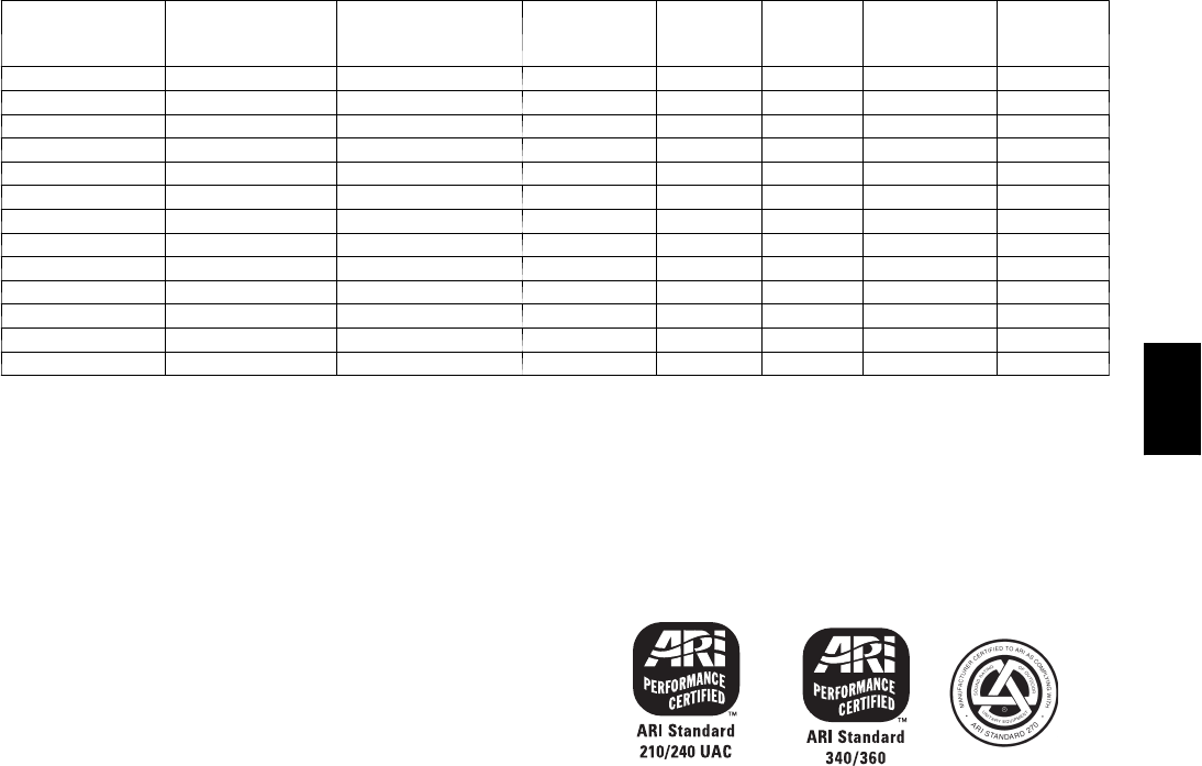
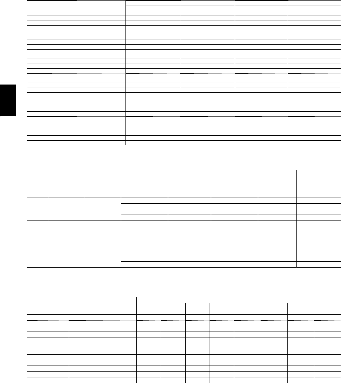
ARI* CAPACITY RATINGS
UNIT 48PG NOMINAL
CAPACITY (Tons)
NET COOLING
CAPACITY (Btuh)
TOTAL
POWER
(kW)
SEER EER[SOUND
RATING (dB) IPLV**
03 224,000 2.1 14.0 11.4 75 —
04 335,800 3.1 14.0 11.7 73 —
05 447,500 4.0 14.8 12.0 72 —
06 558,500 4.9 14.6 12.0 78 —
07 669,000 5.8 —12.0 78 —
08 71/288,000 7.0 —12.5 80 13.3
09 81/2102,000 8.4 —12.2 80 13.3
12 10 119,000 9.9 —12.0 80 13.1
14 121/2150,000 13.2 —11.4 83 12.1
16 15 182,000 15.9 —11.4 84 12.7
20 18 202,000 17.4 —11.6 81.7 12.4
24 20 238,000 20.5 —11.6 84.6 12.0
28[[ 25 298,000 27.2 —11.0 84.6 12.0
LEGEND
ASHRAE --- American Society of Heating, Refrigeration and Air
Conditioning Engineers
db --- D r y B u l b
EER --- Energy Efficiency Ratio
IPLV --- I n t e gr a t e d Pa r t --- L o a d V a l u e s
SEER --- Seasonal Energy Efficiency Ratio
wb --- We t B u l b
*Air Conditioning and Refrigeration Institute.
{ARI does not require EER ratings for units with capacity below 65,000
Btuh.
**IPLV values are calculated based on control configuration T.CTL = 2 (2
Stage Y1).
{{Size28unitisnotlistedwithARI,butistestedtoARIStandards.
NOTES:
1. Tested in accordance with ARI Standards 210---94 (03 ---12 sizes), and
360---95 (14 ---28 sizes).
2. Ratings are net values, reflecting the effects of circulating fan heat.
3. Ratings are based on:
Cooling Standard: 80 F db, 67 F wb indoor entering---air temperature and
95 F db air entering outdoor unit.
IPLV Standard: 80 F db, 67 F wb indoor entering---air temperature and 80 F
db outdoor entering---air temperature.
4. All 48PG units are in compliance with ENERGY STARRand ASHRAE
90.1 2001 Energy Standard for minimum SEER and EER requirements.
5. Units are rated in accordance with ARI sound standards 270 or 370.
48PG
8
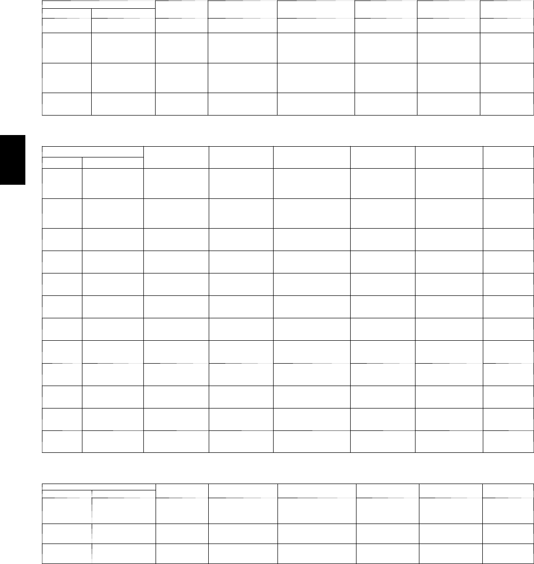
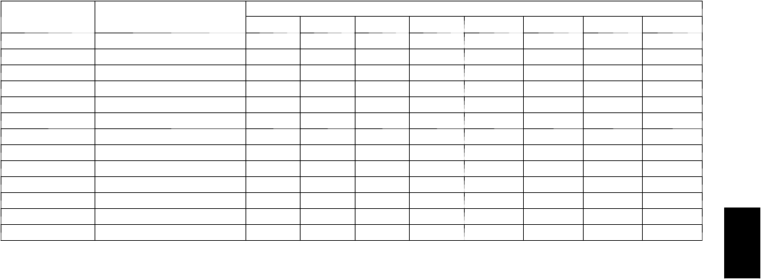
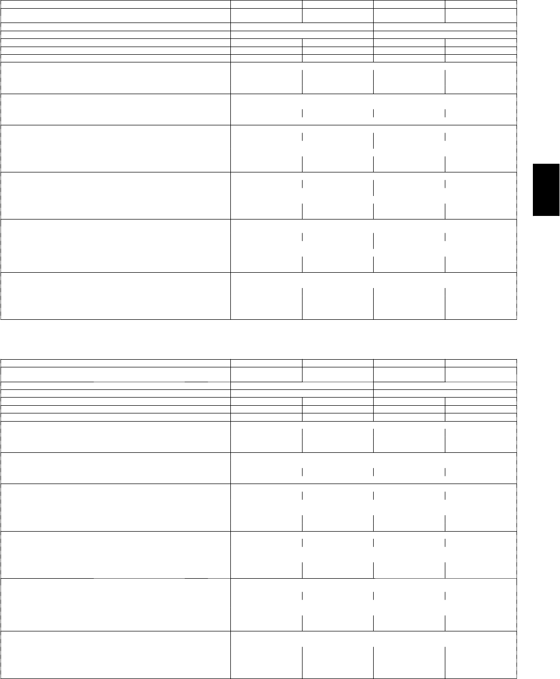
Heating Capacities and Efficiencies -- 48PG03--28
Vertical and Horizontal Supply Units with Natural Gas (Single Phase)
UNIT 48PG HEATING
INPUT (Btuh)
HEATING
CAPACITY[(Btuh)
TEMPERATURE RISE
Min --- Max (F)
MINIMUM
HEATING CFM**
THERMAL
EFFICIENCY (%) AFUE (%)[
Standard Stainless Steel
—
F03
N03*
—
51,000
56,000
39,400
43,300
25 --- 70
25 --- 70
500
600 81.0 80.0
—
D04
E04
F04
L04*
—
M04*
N04*
51,000
56,000
75,000
113,000
39,400
43,300
58,800
89,900
25 --- 70
25 --- 70
20 --- 60
30 --- 75
500
600
940
1,130
81.0 80.0
—
D05
E05
F05
L05*
—
M05*
N05*
51,000
56,000
75,000
113,000
39,400
43,300
58,800
89,900
25 --- 70
25 --- 70
20 --- 60
30 --- 75
500
600
940
1,130
81.0 80.0
D06
E06
F06
L06*
M06*
N06*
75,000
113,000
151,000
58,800
89,900
121,500
20 --- 60
30 --- 75
45 --- 75
940
1,130
1,510
81.0 80.0
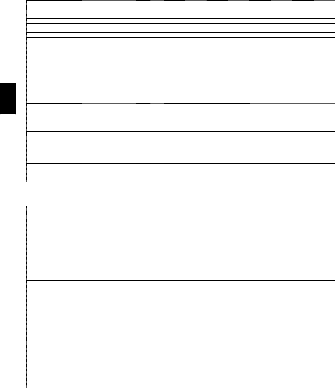
Vertical and Horizontal Supply Units with Natural Gas (Three Phase)
UNIT 48PG HEATING INPUT
Stage 2 (Btuh)
HEATING INPUT
Stage 1 (Btuh)
OUTPUT CAPACITY
Stage 2 (Btuh)
TEMPERATURE
RISE
Min --- Max (F)
MINIMUM HEATING
CFM**
THERMAL
EFFICIENCY
(%)
Standard Stainless Steel
—
D04
E04
F04
L04*
—
M04*
N04*
51,000
56,000
75,000
113,000
35,700
39,200
52,500
79,100
41,300
45,400
60,800
91,500
25 --- 70
25 --- 70
20 --- 60
30 --- 75
500
600
940
1,130
81.0
—
D05
E05
F05
L05*
—
M05*
N05*
51,000
56,000
75,000
113,000
35,700
39,200
52,500
79,100
41,300
45,400
60,800
91,500
25 --- 70
25 --- 70
20 --- 60
30 --- 75
500
600
940
1,130
81.0
D06
E06
F06
L06*
M06*
N06*
75,000
113,000
151,000
52,500
79,100
105,700
60,800
91,500
122,300
20 --- 60
30 --- 75
45 --- 75
940
1,130
1,510
81.0
D07
E07
F07
L07
M07
N07
75,000
113,000
151,000
52,500
79,100
105,700
60,800
91,500
122,300
20 --- 60
30 --- 75
45 --- 75
940
1,130
1,510
81.0
D08
E08
F08
L08
M08
N08
136,000
181,000
226,000
95,200
126,700
158,200
111,500
148,400
185,300
20 --- 50
20 --- 65
35 --- 70
2,060
2,110
2,450
82.0
D09
E09
F09
L09
M09
N09
136,000
181,000
226,000
95,200
126,700
158,200
111,500
148,400
185,300
20 --- 50
20 --- 65
35 --- 70
2,060
2,110
2,450
82.0
D12
E12
F12
L12
M12
N12
181,000
226,000
249,000
126,700
158,200
174,300
148,400
185,300
204,200
20 --- 65
35 --- 70
30 --- 60
2,110
2,450
3,150
82.0
D14
E14
F14
L14
M14
N14
181,000
226,000
249,000
126,700
158,200
174,300
148,400
185,300
204,200
20 --- 65
35 --- 70
30 --- 60
2,110
2,450
3,150
82.0
D16
E16
F16
L16
M16
N16
220,000
310,000
400,000
176,000
248,000
320,000
178,000
251,000
324,000
25 --- 55
30 --- 60
35 --- 65
3,040
3,870
4,670
81.0
D20
E20
F20
L20
M20
N20
250,000
365,000
400,000
199,000
281,000
317,000
205,000
296,000
328,000
15 --- 45
25 --- 55
25 --- 55
4,218
4,977
5,522
82.0
81.0
82.0
D24
E24
F24
L24
M24
N24
250,000
365,000
400,000
199,000
281,000
317,000
205,000
296,000
328,000
15 --- 45
25 --- 55
25 --- 55
4,218
4,977
5,522
82.0
81.0
82.0
D28
E28
F28
L28
M28
N28
250,000
365,000
400,000
199,000
281,000
317,000
205,000
296,000
328,000
15 --- 45
25 --- 55
25 --- 55
4,218
4,977{{
5,522{{
82.0
81.0
82.0
Vertical and Horizontal Supply Units with Propane Gas (Single Phase)
UNIT 48PG HEATING
INPUT (Btuh)
HEATING
CAPACITY[(Btuh)
TEMPERATURE RISE
Min --- Max (F)
MINIMUM
HEATING CFM**
THERMAL
EFFICIENCY (%) AFUE (%)[
Standard Stainless Steel
F03
D04
E04
F04
N03
L04
M04
N04
55,000
55,000
74,000
111,000
42,500
42,500
58,000
88,400
25 --- 70
25 --- 70
20 --- 60
30 --- 75
600
600
940
1,130
81.0 80.0
D05
E05
F05
L05
M05
N05
55,000
74,000
111,000
42,500
58,000
88,400
25 --- 70
20 --- 60
30 --- 75
600
940
1,130
81.0 80.0
D06
E06
F06
L06
M06
N06
74,000
111,000
148,000
58,000
88,400
119,100
20 --- 60
30 --- 75
45 --- 75
940
1,130
1,510
81.0 80.0
LEGEND
AFUE -- Annual Fuel Utilization Efficiency
ASHRAE --- American Society of heating, Refrigeration and Air Conditioning
Engineers
LP --- L i q u i d P r o p a n e
* These models are certified for NOx emissions less than 40 hg/J. Fully compliant with
California SCAQMD Rule 1111.
{Annual Fuel Utilization Efficiency (AFUE) and Heating Capacity of single--- phase units
are calculated according to ASHRAE Standard 103--- 1993.
** Minimum Heating cfm must be maintained to ensure proper heating operation.
{{ 7000 cfm minimum recommended above 1.0 in. wg external static pressure.
NOTES:
1. Minimum allowable temperature of mixed air entering the heat exchanger during first
stage heating is 45_F. Both stages of heat must be energized when the temperature of the
mixed air entering the heat exchanger is below 45_F for standard heat exchangers or 35 F
for optional stainless steel heat exchangers.
2. Propane operation requires field---installed accessory kit.
3. All data is applicable to 2000 ft of altitude.
48PG
9
ARI* CAPACITY RATINGS (CONT)
Heating Capacities and Efficiencies -- 48PG03--28 (Cont)
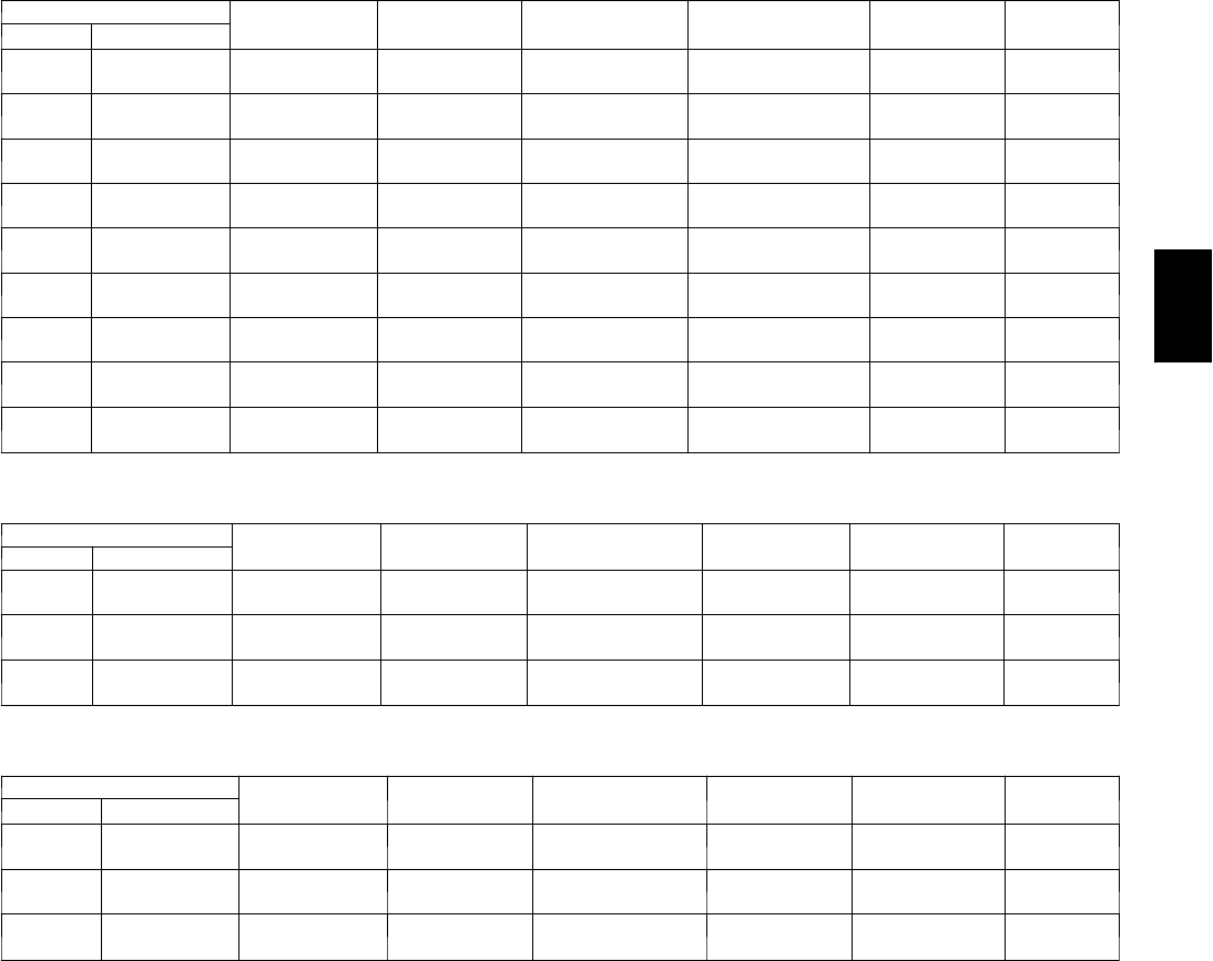
Vertical and Horizontal Supply Units With Propane Gas (Three Phase)
UNIT 48PG HEATING INPUT
Stage 2 (Btuh)
HEATING INPUT
Stage 1 (Btuh)
OUTPUT CAPACITY
Stage 2 (Btuh)
TEMPERATURE RISE
Min --- Max (F)
MINIMUM
HEATING CFM**
THERMAL
EFFICIENCY
(%)
Standard Stainless Steel
D04
E04
F04
L04
M04
N04
55,000
74,000
111,000
38,500
51,800
77,700
44,600
60,000
90,000
25 --- 70
20 --- 60
30 --- 75
600
940
1,130
81.0
D05
E05
F05
L05
M05
N05
55,000
74,000
111,000
38,500
51,800
77,700
44,600
60,000
90,000
25 --- 70
20 --- 60
30 --- 75
600
940
1,130
81.0
D06
E06
F06
L06
M06
N06
74,000
111,000
148,000
51,800
77,700
103,600
60,000
90,000
120,000
20 --- 60
30 --- 75
45 --- 75
940
1,130
1,510
81.0
D07
E07
F07
L07
M07
N07
74,000
111,000
148,000
51,800
77,700
103,600
60,000
90,000
120,000
20 --- 60
30 --- 75
45 --- 75
940
1,130
1,510
81.0
D08
E08
F08
L08
M08
N08
130,000
174,000
217,000
91,000
121,800
151,900
106,600
142,700
178,000
20 --- 50
20 --- 65
35 --- 70
2,060
2,110
2,450
82.0
D09
E09
F09
L09
M09
N09
130,000
174,000
217,000
91,000
121,800
151,900
106,600
142,700
178,000
20 --- 50
20 --- 65
35 --- 70
2,060
2,110
2,450
82.0
D12
E12
F12
L12
M12
N12
174,000
217,000
239,000
121,800
151,900
167,300
142,700
178,000
196,000
20 --- 65
35 --- 70
30 --- 60
2,110
2,450
3,150
82.0
D14
E14
F14
L14
M14
N14
174,000
217,000
239,000
121,800
151,900
167,300
142,700
178,000
196,000
20 --- 65
35 --- 70
30 --- 60
2,110
2,450
3,150
82.0
D16
E16
F16
L16
M16
N16
214,000
305,000
396,000
171,000
244,000
317,000
172,000
246,000
320,000
25 --- 55
30 --- 60
35 --- 65
3,040
3,870
4,670
81.0
Vertical Supply Units With Propane Gas (Three Phase)
UNIT 48PG HEATING INPUT
Stage 2 (Btuh)
HEATING INPUT
Stage 1 (Btuh)
OUTPUT CAPACITY
Stage 2 (Btuh)
TEMPERATURE
RISE Min --- Max
(F)
MINIMUM HEATING
CFM**
THERMAL
EFFICIENCY
(%)
Standard Stainless Steel
D20
E20
F20
L20
M20
N20
250,000
365,000
400,000
207,000
291,000
331,000
205,000
296,000
328,000
15 --- 45
25 --- 55
25 --- 55
4,218
4,480
5,522
82.0
81.0
82.0
D24
E24
F24
L24
M24
N24
250,000
365,000
400,000
207,000
291,000
331,000
205,000
296,000
328,000
15 --- 45
25 --- 55
25 --- 55
4,218
4,480
5,522
82.0
81.0
82.0
D28
E28
F28
L28
M28
N28
250,000
365,000
400,000
207,000
291,000
331,000
205,000
296,000
328,000
15 --- 45
25 --- 55
25 --- 55
4,218
4,480
5,522
82.0
81.0
82.0
Horizontal Supply Units With Propane Gas (Three Phase)
UNIT 48PG HEATING INPUT
Stage 2 (Btuh)
HEATING INPUT
Stage 1 (Btuh)
OUTPUT CAPACITY
Stage 2 (Btuh)
TEMPERATURE
RISE Min --- Max
(F)
MINIMUM
HEATING CFM**
THERMAL
EFFICIENCY
(%)
Standard Stainless Steel
D20
E20
F20
L20
M20
N20
225,000
329,000
350,000
207,000
291,000
331,000
185,000
266,000
292,000
15 --- 45
25 --- 55
25 --- 55
3,807
4,480
4,916
82.0
81.0
82.0
D24
E24
F24
L24
M24
N24
225,000
329,000
350,000
207,000
291,000
331,000
185,000
266,000
292,000
15 --- 45
25 --- 55
25 --- 55
3,807
4,480
4,916
82.0
81.0
82.0
D28
E28
F28
L28
M28
N28
225,000
329,000
350,000
207,000
291,000
331,000
185,000
266,000
292,000
15 --- 45
25 --- 55
25 --- 55
3,807
4,480{{
4,916{{
82.0
81.0
82.0
LEGEND
AFUE -- Annual Fuel Utilization Efficiency
ASHRAE --- American Society of heating, Refrigeration and Air Conditioning
Engineers
LP --- L i q u i d P r o p a n e
* These models are certified for NOx emissions less than 40 hg/J. Fully compliant with
California SCAQMD Rule 1111.
{Annual Fuel Utilization Efficiency (AFUE) and Heating Capacity of single--- phase units
are calculated according to ASHRAE Standard 103--- 1993.
** Minimum Heating cfm must be maintained to ensure proper heating operation.
{{ 7000 cfm minimum recommended above 1.0 in. wg external static pressure.
NOTES:
1. Minimum allowable temperature of mixed air entering the heat exchanger during first
stage heating is 45_F. Both stages of heat must be energized when the temperature of the
mixed air entering the heat exchanger is below 45_F for standard heat exchangers or 35 F
for optional stainless steel heat exchangers.
2. Propane operation requires field---installed accessory kit.
3. All data is applicable to 2000 ft of altitude.
48PG
10
OPERATION AIR QUANTITY LIMITS
48PG03--16 Vertical and Horizontal Units
UNIT
48PG
COOLING (cfm) HEATING (cfm)*
Min Max Min Max
03 600 1000 600 1680
04 (Low Heat) 900 1500 600 1680
04 (Med Heat) 900 1500 940 2810
04 (High Heat) 900 1500 1130 2820
05 (Low Heat) 1200 2000 600 1680
05 (Med Heat) 1200 2000 940 2810
05 (High Heat) 1200 2000 1130 2820
06 (Low Heat) 1500 2500 940 2810
06 (Med Heat) 1500 2500 1130 2820
06 (High Heat) 1500 2500 1510 2520
07 (Low Heat) 1800 3000 940 2810
07 (Med Heat) 1800 3000 1130 2820
07 (High Heat) 1800 3000 1510 2520
08 (Low Heat) 2250 3750 2060 5160
08 (Med Heat) 2250 3750 2110 6870
08 (High Heat) 2250 3750 2450 4900
09 (Low Heat) 2550 4250 2060 5160
09 (Med Heat) 2550 4250 2110 6870
09 (High Heat) 2550 4250 2450 4900
12 (Low Heat) 3000 5000 2110 6870
12 (Med Heat) 3000 5000 2450 4900
12 (High Heat) 3000 5000 3150 6300
14 (Low Heat) 3750 6250 2110 6870
14 (Med Heat) 3750 6250 2450 4900
14 (High Heat) 3750 6250 3150 6300
16 (Low Heat) 4500 7500 3040 6680
16 (Med Heat) 4500 7500 3870 7750
16 (High Heat) 4500 7500 4670 8680
*Consult tables on pages 8 and 9 if using a stainless steel heat exchanger.
48PG20--28 Units
48PG
COOLING
GAS HEAT
HEATING
(NAT. GAS,
VERTICAL)
HEATING
(NAT. GAS,
HORIZONTAL)
HEATING
(PROPANE,
VERTICAL)
HEATING
(PROPANE,
HORIZONTAL)
Maximum
Cfm Minimum Cfm Minimum Cfm Minimum Cfm Minimum Cfm Minimum Cfm
20 5000 9,000
High Heat (8 Cell) 5522 5522 5522 4920
Medium Heat (8
Cell) 4977 4977 4480 4480
Low Heat (5 Cell) 4218 4218 4218 3796
24 5500 10,000
High Heat (8 Cell) 5522 5522 5522 4920
Medium Heat (8
Cell) 4977 4977 4480 4480
Low Heat (5 Cell) 4218 4218 4218 3796
28 6500 12,000
High Heat (8 Cell) 5522 5470* 5522 4920*
Medium Heat (8
Cell) 4977 4977* 4480 4480*
Low Heat (5 Cell) 4218 4218 4218 3796
*7000 cfm minimum recommended above 1.0 in. wg external static
pressure.
Outdoor Sound Power (Total Unit)
UNIT
48PG
A --- W E I G H T E D *
(dB)
OCTAVE BAND LEVELS dB
63 125 250 500 1000 2000 4000 8000
03 75.0 82.6 79.9 75.7 73.3 70.0 64.3 58.4 50.5
04 73.2 79.8 77.2 74.1 70.1 68.0 63.6 58.4 51.9
05 71.9 79.7 79.6 72.6 69.6 66.0 61.4 56.4 48.5
06 78.5 82.2 82.6 79.5 75.7 73.9 68.6 64.0 56.3
07 78.5 87.5 83.0 78.5 76.3 73.8 68.4 63.8 56.5
08 80.0 91.7 83.6 81.0 77.9 75.0 69.9 66.0 59.3
09 79.9 89.1 82.7 80.0 77.7 75.0 70.2 66.3 57.8
12 80.0 90.4 83.1 80.9 77.8 75.2 70.0 66.1 57.6
14 83.3 86.4 85.9 85.3 81.8 78.2 72.2 67.9 59.9
16 84.0 90.3 85.2 83.5 81.1 79.0 73.7 70.5 65.4
20 81.7 90.2 84.8 80.7 79.0 77.6 71.4 66.7 60.7
24 84.9 90.0 86.3 83.6 82.9 80.3 74.9 71.4 66.5
28 84.9 90.0 86.3 83.6 82.9 80.3 74.9 71.4 66.5
LEGEND
dB --- D e c i b e l
* Sound Rating ARI or tone Adjusted, A---Weighted Sound Power Level in dB. For sizes 03---12, the sound rating is in accordance with ARI Standard 270---1995.
For sizes 14---28, the sound rating is in accordance with ARI 370---2001.
48PG
11
Outdoor Sound Power (Total Unit)
with High CFM EnergyX
UNIT
48PG w/ERV
A --- W E I G H T E D *
(dB)
OCTAVE BAND LEVELS dB
63 125 250 500 1000 2000 4000 8000
03 83.0 82.8 81.4 79.7 78.1 77.9 76.5 72.5 70.1
04 82.7 80.2 79.6 79.1 77.3 77.6 76.5 72.5 70.1
05 82.6 80.1 81.1 78.8 77.2 77.4 76.4 72.4 70.0
06 83.8 82.4 83.4 81.6 79.1 78.8 76.9 72.9 70.2
07 83.8 87.6 83.8 81.1 79.3 78.8 76.9 72.9 70.2
08 87.3 92.0 86.8 84.5 82.4 81.8 80.5 78.0 74.2
09 87.2 89.6 86.4 84.1 82.4 81.8 80.5 78.1 74.2
12 87.3 90.8 86.5 84.5 82.4 81.8 80.5 78.0 74.2
14 88.2 87.2 88.0 87.0 84.2 82.7 80.8 78.2 74.3
16 91.4 93.2 92.8 88.2 86.3 85.5 84.4 83.4 78.4
20 91.2 93.1 92.7 87.4 85.8 85.2 84.2 83.3 78.3
24 91.7 93.0 93.0 88.2 86.9 85.8 84.5 83.5 78.5
28 91.7 93.0 93.0 88.2 86.9 85.8 84.5 83.5 78.5
LEGEND
dB --- D e c i b e l
* Sound Rating ARI or tone Adjusted, A---Weighted Sound Power Level in dB. For sizes 03---12, the sound rating is in accordance with ARI Standard 270---1995.
For sizes 14---28, the sound rating is in accordance with ARI 370---2001.
48PG
12
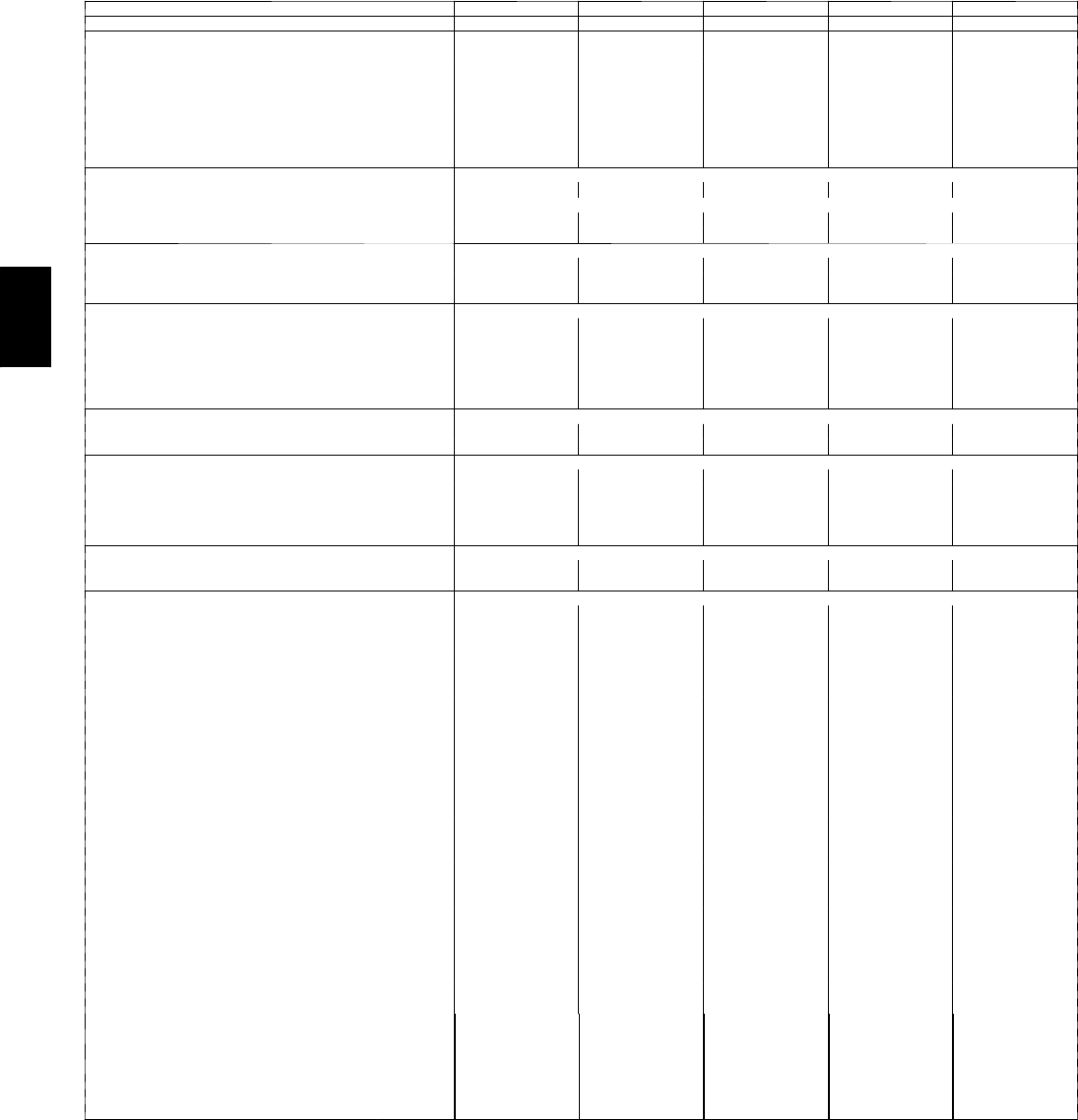
PHYSICAL DATA
Physical Data -- 48PG03--07
BASE UNIT 48PG 03 04 05 06 07
NOMINAL CAPACITY (Tons) 23456
OPERATING WEIGHT (lb)
Unit* 774 786 901 921 961
Economizer
Vertical 40 40 40 40 40
Horizontal 50 50 50 50 50
Humidi-MiZer™System 22 22 31 27 26
Roof Curb
14-in. 122 122 122 122 122
24-in. 184 184 184 184 184
COMPRESSOR Fully Hermetic Scroll
Quantity 11111
Oil Type Copeland 3MA
Number of Refrigerant Circuits 11111
Oil (oz) 38 42 42 66 56
REFRIGERANT TYPE R-410A (Puron®Refrigerant)
Expansion Device TXV TXV TXV TXV TXV
Operating Charge (lb) — Standard Unit 7.3 9.0 15.7 16.6 19.0
Operating Charge (lb) — Humidi-MiZer Unit 11.75 13.50 25.00 22.00 22.70
CONDENSER COIL Enhanced Copper Tubes, Aluminum Lanced Fins
Condenser A (Outer)
Rows...Fins/in. 1…17 1…17 2…17 2…17 2…17
Face Area (sq ft) 12.6 12.6 12.6 12.6 12.6
Condenser B (Inner)
Rows...Fins/in. — 1…17 2…17 2…17 2…17
Face Area (sq ft) —12.6 12.6 12.6 12.6
Humidi-MiZer Coil Enhanced Copper Tubes and Aluminum Lanced Fins
Rows...Fins/in. 1…17 1…17 1…17 1…17 1…17
Face Area (sq ft) 6.4 6.4 9.3 9.3 9.3
CONDENSER FAN Propeller
Quantity…Diameter (in.) 1…24 1…24 1…24 1…24 1…24
Nominal Cfm (Total, all fans) 3500 3500 3500 4500 4500
Motor Hp 1/81/81/81/41/4
Nominal Rpm — High Speed 825 825 825 1100 1100
Nominal Rpm — Low Speed 300 300 300 300 300
EVAPORATOR COIL Enhanced Copper Tubes, Aluminum Double-Wavy Fins, Face Split
Rows…Fins/in. 2…15 2…15 2…15 3…15 4…15
Face Area (sq ft) 9.3 9.3 9.3 9.3 9.3
EVAPORATOR FAN Centrifugal Type, Belt Drive
Quantity…Size (in.) Low 1...12 x 9 1...12 x 9 1...12 x 9 1...12 x 9 1...12 x 9
High 1...12 x 9 1...12 x 9 1...12 x 9 1...12 x 9 1...12 x 9
Ty pe D r i v e Low Belt Belt Belt Belt Belt
High Belt Belt Belt Belt Belt
Nominal Cfm 800 1200 1600 2000 2400
Maximum Continuous Bhp Low 0.85 0.85 0.85 0.85/2.40† 2.40
High 0.85 0.85 1.60/2.40† 1.60/2.40† 3.10
Motor Nominal Rpm 1620 1620 1620 1725 1725
Motor Frame Size Low 48Y 48Y 48Y 56Y 56Y
High 48Y 48Y 56Y 56Y 56Y
Fan Rpm Range Low 482-736 482-736 596-910 690-978 796-1128
High 656-1001 796-1128 828-1173 929-1261 1150-1438
Motor Bearing Type Ball Ball Ball Ball Ball
Maximum Fan Rpm 2000 2000 2000 2000 2000
Motor Pulley Pitch Diameter Range (in.) Low 1.9-2.9 1.9-2.9 1.9-2.9 2.4-3.4 2.4-3.4
High 1.9-2.9 2.4-3.4 2.4-3.4 2.8-3.8 4.0-5.0
Fan Pulley Pitch Diameter (in.) Low 6.8 6.8 5.5 6.0 5.2
High 5.0 5.2 5.0 5.2 6.0
Nominal Motor Shaft Diameter (in.) Low 1/21/21/25/85/8
High 1/21/25/85/87/8
Belt...Pitch Length (in.) Low 49.3 49.3 49.3 49.3 49.3
High 49.3 49.3 49.3 49.3 52.3
Belt…Typ e Low AX AX AX AX AX
High AX AX AX AX AX
Pulley Center Line Distance Min. (in.) Low 16.2 16.2 16.2 16.2 16.2
High 16.2 16.2 16.2 16.2 16.2
Pulley Center Line Distance Max. (in.) Low 20.2 20.2 20.2 20.2 20.2
Speed Change per Full Turn of
Movable Pulley Flange (rpm)
Low 48 48 59 58 66
High 65 62 69 66 58
Movable Pulley Maximum Full
Turns from Closed Position
Low 55 5 5 5
High 55 5 5 5
FactoryPulleySetting(rpm) Low 736 736 910 978 1128
High 794 929 1035 1128 1323
Fan Shaft Diameter at Pulley (in.) 3/43/43/43/43/4
*See Legend on next page.
48PG
13
PHYSICAL DATA (CONT)
Physical Data -- 48PG03--07 (cont)
BASE UNIT 48PG 03 04 05 06 07
GAS HEAT SECTION
Rollout Switch
Open Temperature (F) Low N/A 195 195 195 195
Med N/A 195 195 225 225
High 195 225 225 195 195
Closed Temperature (F) Low N/A 115 115 115 115
Med N/A 115 115 175 175
High 115 175 175 115 115
Standard Units
Gas Input (Btuh) Stage 1/Stage 2 PGD/L —39,200/ 56,000 39,200/ 56,000 52,500/ 75,000 52,500/ 75,000
PGE/M —52,500/ 75,000 52,500/ 75,000 79,100/113,000 79,100/113,000
PGF/N 56,000 79,100/113,000 79,100/113,000 105,700/151,000 105,700/151,000
Low NOx Units PGD/L —56,000 56,000 75,000 —
PGE/M —75,000 75,000 113,000 —
PGF/N 56,000 113,000 113,000 151,000 —
Burner Orifice Diameter (in. ...drill size)**
Natural Gas 0.0820...45 0.0820...45 0.0820...45 0.0820...45 0.0820...45
Liquid Propane 0.0650...52 0.0650...52 0.0650...52 0.065...52 0.065...52
Thermostat Heat Anticipator Setting (amps)
First Stage 0.3 0.3 0.3 0.3 0.3
Second Stage 0.4 0.4 0.4 0.4 0.4
Manifold Pressure (in. wg)
Natural Gas 3.5 3.5 3.5 3.5 3.5
Liquid Propane 3.5 3.5 3.5 3.5 3.5
Gas Valve Quantity 11111
Gas Supply Pressure Range (in. wg) 5.0-13.0 5.0-13.0 5.0-13.0 5.0-13.0 5.0-13.0
Field Gas Connection Size (in.) 1/21/21/21/21/2
HIGH-PRESSURE SWITCH (psig)
Cutout 660 ±10 660 ±10 660 ±10 660 ±10 660 ±10
Reset (Auto.) 505 ±20 505 ±20 505 ±20 505 ±20 505 ±20
RETURN-AIR FILTERS Throwaway Type
Quantity…Size (in.) 4…16 x 20 x 2 4…16 x 20 x 2 4…16 x 20 x 2 4…16 x 20 x 2 4…16 x 20 x 2
LEGEND
TXV --- Thermostatic Expansion Valve
* Aluminum Evaporator Coil/Aluminum Condenser Coil.
{Single phase/three phase.
** For applications less than 2000 ft elevation.
48PG
14
PHYSICAL DATA (CONT)
Physical Data -- 48PG08--14
BASE UNIT 48PG 08 09 12 14
NOMINAL CAPACITY (Tons) 71/281/210 121/2
OPERATING WEIGHT (lb)
Unit* (High Heat) 1217 1224 1324 1400
Economizer
Vertical 57 57 57 57
Horizontal 59 59 59 59
Humidi-MiZer™System 45 45 44 45
Roof Curb
14-in. 180 180 180 180
24-in. 268 268 268 268
COMPRESSOR Fully Hermetic Scroll
Quantity 2 2 2 2
Oil Type Sys A Copeland 3MA Copeland 3MA Copeland 3MA Copeland 3MA
Sys B Copeland 3MA Copeland 3MA Copeland 3MA Copeland 3MA
Number of Refrigerant Circuits 2 2 2 2
Oil (oz) Sys A 42 42 66 56
Sys B 42 42 66 56
REFRIGERANT TYPE R-410A (Puron®Refrigerant)
Expansion Device TXV TXV TXV TXV
Operating Charge (lb) Sys A 11.8 11.3 13.7 17.2
Sys B 11.8 11.3 13.7 17.2
Operating Charge Total All Systems (lb) 23.6 22.6 27.4 34.4
Unit with Humidi-MiZer System
Operating Charge (lb) Sys A 16.5 16.5 17.7 22.5
Sys B 16.7 16.7 18.2 21.8
Total All Systems (lb) 33.2 33.6 35.9 44.3
CONDENSER COIL Enhanced Copper Tubes, Aluminum Lanced Fins, Face Split
Condenser A (Outer)
Rows...Fins/in. 2…17 2…17 2…17 3…17
Face Area (sq ft) 17.4 17.4 17.4 17.4
Condenser B (Inner)
Rows...Fins/in. 2...17 2...17 2...17 3...17
Face Area (sq ft) 17.4 17.4 17.4 17.4
Humidi-MiZer Coil Copper Enhanced Tubes with Aluminum Lanced Fins
Rows...Fins/in. 1...17 1...17 1...17 1...17
Face Area (sq ft) 14.9 14.9 14.9 14.9
CONDENSER FAN Propeller
Quantity…Diameter (in.) 2...24 2...24 2...24 2...24
Nominal Cfm (Total, all fans) 7204 7204 8241 7300
Motor Hp 1/41/41/31/3
Nominal Rpm 1100 1100 1100 1100
EVAPORATOR COIL Enhanced Copper Tubes, Aluminum Double-Wavy Fins, Face Split
Rows…Fins/in. 3…15 3…15 4…15 4…15
Face Area (sq ft) 14.9 14.9 14.9 14.9
EVAPORATOR FAN Centrifugal Type, Belt Drive
Quantity…Size (in.) Low 1...15 x 15 1...15 x 15 1...15 x 15 1...15 x 15
High 1...15 x 15 1...15 x 15 1...15 x 15 1...15 x 15
Ty pe D r i v e Low Belt Belt Belt Belt
High Belt Belt Belt Belt
Nominal Cfm 3000 3400 4000 5000
Maximum Continuous Bhp Low 2.4 2.4 3.1 3.7
High 3.1 3.7 3.7 5.25
Motor Nominal Rpm 1725 1725 1725 1725
Motor Frame Size Low 56Y 56Y 56Y 56Y
High 56Y 56Y 56Y 56Y
Fan Rpm Range Low 568-771 568-771 690-893 690-893
High 812-1015 812-1015 852-1055 852-1055
Motor Bearing Type Ball Ball Ball Ball
Maximum Fan Rpm 1600 1600 1600 1600
Motor Pulley Pitch Diameter Range (in.) Low 2.8-3.8 2.8-3.8 3.4-4.4 3.4-4.4
High 4.0-5.0 4.0-5.0 4.6-5.6 4.6-5.6
Fan Pulley Pitch Diameter Low 8.5 8.5 8.5 8.5
High 8.5 8.5 8.5 8.5
Nominal Motor Shaft Diameter (in.) Low 5/85/87/87/8
High 7/87/87/87/8
Belt...Pitch Length (in.) Low 63.3 63.3 63.3 63.3
High 65.3 65.3 65.3 65.3
Belt…Typ e Low AX AX AX AX
High AX AX AX AX
Pulley Center Line Distance Min. (in.) Low 21.0 21.0 21.0 21.0
High 21.0 21.0 21.0 21.0
Pulley Center Line Distance Max. (in.) Low 23.4 23.4 23.4 23.4
High 23.4 23.4 23.4 23.4
Speed Change per Full Turn of Movable Pulley Flange (rpm) Low 41 41 41 41
High 41 41 41 41
Movable Pulley Maximum Full Turns from Closed Position Low 55 5 5
High 55 5 5
FactoryPulleySetting(rpm) Low 568 568 690 690
High 812 812 852 852
Fan Shaft Diameter at Pulley (in.) 1 1 1 1
*See Legend on next page.
48PG
15
PHYSICAL DATA (CONT)
Physical Data -- 48PG08--14
BASE UNIT 48PG 08 09 12 14
GAS HEAT SECTION
Rollout Switch
Open Temperature (F) Low 225 225 225 225
Med 225 225 225 225
High 225 225 225 225
Closed Temperature (F) Low 175 175 175 175
Med 175 175 175 175
Gas Input (Btuh) Stage 1 /Stage 2 PGD/L 95,200/136,000 95,200/136,000 126,700/181,000 126,700/181,000
PGE/M 126,700/181,000 126,700/181,000 158,200/226,000 158,200/226,000
PGF/N 158,200/226,000 158,200/226,000 174,300/249,000 174,300/249,000
Burner Orifice Diameter (in. ...drill size)†
Natural Gas 0.089...43 0.089...43 0.089...43 0.089...43
Liquid Propane 0.070...50 0.070...50 0.070...50 0.070...50
Thermostat Heat Anticipator Setting (amps)
First Stage .14 .14 .14 .14
Second Stage .20 .20 .20 .20
Manifold Pressure (in. wg)
Natural Gas 3.5 3.5 3.5 3.5
Liquid Propane 3.5 3.5 3.5 3.5
Gas Valve Quantity 1 1 1 1
Gas Supply Pressure Range (in. wg) 5.0-13.0 5.0-13.0 5.0-13.0 5.0-13.0
Field Gas Connection Size (in.) 3/43/43/43/4
HIGH-PRESSURE SWITCH (psig)
Cutout 660 ±10 660 ±10 660 ±10 660 ±10
Reset (Auto.) 505 ±20 505 ±20 505 ±20 505 ±20
RETURN-AIR FILTERS Throwaway
Quantity…Size (in.) 4...20 x 25 x 2 4...20 x 25 x 2 4...20 x 25 x 2 4...20 x 25 x 2
LEGEND
TXV --- Thermostatic Expansion Valve
* Aluminum Evaporator Coil/Aluminum Condenser Coil.
{For applications less than 2000 ft elevation.
48PG
16
PHYSICAL DATA (CONT)
Physical Data -- 48PG16
BASE UNIT 48PG 16
NOMINAL CAPACITY (Tons) 15
OPERATING WEIGHT (lb)
Unit* (High Heat) 1895
Economizer 149
Humidi-MiZer™System 64
Roof Curb
14-in. 240
24-in. 360
COMPRESSOR Fully Hermetic Scroll
Quantity 3
Oil Type Sys A Copeland 3MA
Sys B Copeland 3MA
Sys C Copeland 3MA
Number of Refrigerant Circuits 3
Oil (oz) Sys A 66
Sys B 66
Sys C 66
REFRIGERANT TYPE R-410A (Puron®Refrigerant)
Expansion Device TXV
Operating Charge (lb) Sys A 13.5
Sys B 15.0
Sys C 15.0
Operating Charge Total All Systems (lb) 43.5
Unit with Humidi-MiZer System
Operating Charge (lb) Sys A 18.8
Sys B 16.7
Sys C 18.8
Total All Systems (lb) 54.3
CONDENSER COIL Enhanced Copper Tubes, Aluminum Lanced Fins, Face
Split
Condenser A (Outer)
Rows...Fins/in. 2…17
Face Area (sq ft) 26.6
Condenser B (Inner)
Rows...Fins/in. 2...17
Face Area (sq ft) 30.2
Humidi-MiZer Coil Copper Enhanced Tubes with Aluminum Lanced Fins
Rows...Fins/in. 1...17
Face Area (sq ft) 22.2
CONDENSER FAN Propeller
Quantity…Diameter (in.) 3...24
Nominal Cfm (Total, all fans) 12,500
Motor Hp 1/3
Nominal Rpm 1100
EVAPORATOR COIL Enhanced Copper Tubes, Aluminum Double-Wavy Fins, Face Split
Rows…Fins/in. 3…15
Face Area (sq ft) 22.2
EVAPORATOR FAN Centrifugal Type, Belt Drive
Quantity…Size (in.) Low 1...15x15, 1...12x12
Mid-Low 1...15x15, 1...12x12
High 1...15x15, 1...12x12
Ty pe D r i v e Low Belt
Mid-Low Belt
High Belt
Nominal Cfm 6000
Maximum Continuous Bhp Low 3.7
Mid-Low 5.25
High 7.5
Motor Frame Size Low 56
Mid-Low 56
High S213T
Fan Rpm Range Low 710- 879
Mid-Low 872-1066
High 1066-1260
Motor Bearing Type Ball
Motor Pulley Pitch Diameter Min (in.) Low 4.2
Mid-Low 4.2
High 4.2
Motor Pulley Pitch Diameter Max (in.) Low 5.2
Mid-Low 5.2
High 6.2
Fan Pulley Pitch Diameter (in.) Low 10.2
Mid-Low 8.5
High 8.5
Nominal Motor Shaft Diameter (in.) Low 7/8
Mid-Low 7/8
High 13/8
Belt...Pitch Length (in.) Low 49.3
Mid-Low 47.8
High 43.8
Belt…Typ e Low AX
Mid-Low BX
High BX
Pulley Center Line Distance Min. (in.) Low 14.2
Mid-Low 10.8
High 8.6
Pulley Center Line Distance Max. (in.) Low 10.8
Mid-Low 14.2
High 12
48PG

17
PHYSICAL DATA (CONT)
Physical Data -- 48PG16
BASE UNIT 48PG 16
Speed Change (rpm) Low 34
Mid-Low 41
High 41
Movable Turns Low 5
Mid-Low 5
High 5
FactoryPulleySetting(rpm) Low 812
Mid-Low 983
High 1191
Fan Shaft Diameter at Pulley (in.) 13/16
GAS HEAT SECTION
Rollout Switch
Open Temperature (F) Low 195
High 195
Closed Temperature (F) Low 115
High 115
Gas Input (Btuh) Stage 1/Stage 2 PGD/L 176,000/220,000
PGE/M 248,000/310,000
PGF/N 320,000/400,000
Burner Orifice Diameter (in. ...drill size)†
Natural Gas Std 0.1285...30
Liquid Propane Alt 0.1015...38
Thermostat Heat Anticipator Setting (amps)
First Stage .14
Second Stage .20
Manifold Pressure (in. wg)
Natural Gas Std 3.0
Liquid Propane Alt 3.0
Gas Valve Quantity 1
Gas Supply Pressure Range (in. wg) 5.0-13.0
Field Gas Connection Size (in.) 3/4
HIGH-PRESSURE SWITCH (psig)
Cutout 660 ±10
Reset (Auto.) 505 ±20
RETURN-AIR FILTERS Throwaway
Quantity…Size (in) 8...20 x 20 x 2
LEGEND
TXV --- Thermostatic Expansion Valve
* Aluminum Evaporator Coil/Aluminum Condenser Coil.
{For applications less than 2000 ft elevation.
48PG
18
PHYSICAL DATA (CONT)
Physical Data -- 48PG20--28
UNIT 48PG 20 24 28
VOLTAGE 208/230 and
460 575 208/230 and
460 575 208/230 and
460 575
NOMINAL CAPACITY (Tons) 18 18 20 20 25 25
OPERATING WEIGHT (lb)
48 Series (Low Heat) Al/Al 2480 2480 2588 2588 2773 2773
COMPRESSOR Fully Hermetic Scroll
Quantity 2 2 2 2 3 3
Number of Refrigerant Circuits 2 2 2 2 2 2
Oil (ounces) Comp A1, A2, B1 85, NA, 85 85, NA, 85 85, NA, 85 85, NA, 85 85, 85, 85 85, 85, 85
REFRIGERANT TYPE Puron®Refrigerant (R-410A)
Expansion Device TXV TXV TXV TXV TXV TXV
Change Type
Operating Charge (lb)
Circuit A 25.3 25.3 35.7 35.7 49.3 49.3
Circuit B 25.3 25.3 33.5 33.5 24.3 24.3
To t al C h a r ge 50.6 50.6 69.2 69.2 73.6 73.6
OPERATING CHARGE (lb) — Unit with
Humidi-MiZer™System
Circuit A 42.9 42.9 46.5 46.5 66.1 66.1
Circuit B 39.8 39.8 44.5 44.5 35.7 35.7
To t al C h a r ge 82.7 82.7 91.0 91.0 101.8 101.8
CONDENSER COIL Enhanced Copper Tubes, Aluminum Lanced Fins
Rows...Fins/inch 2...17 2...17 3...17 3...17 3...17 3...17
Width (in.) 60 60 60 60 60 60
Total Face area (sq. ft) 33.46 33.46 33.46 33.46 33.46 33.46
CONDENSER FAN Propeller
Nominal Cfm (Total, all fans) 14,000 14,000 21,000 21,000 21,000 21,000
Quantity...Diameter (in.) 4...22 4...22 6...22 6...22 6...22 6...22
Motor Hp...Rpm 1/4...1100 1/4...1100 1/4...1100 1/4...1100 1/4...1100 1/4...1100
Watts input (Total) 1400 1400 2100 2100 2100 2100
HUMIDI-MIZER COIL
Weight 80 80 80 80 100 100
Rows...Fins/Inch 2...15 2...15 2...15 2...15 2...15 2...15
Width (in.) 32 32 32 32 44 44
To t a l F ac e A r e a ( s q f t ) 12.4 12.4 12.4 12.4 17.1 17.1
EVAPORATOR COIL Enhanced Copper Tubes, Face Split, Aluminum Double-Wavy Fins
Rows...Fins/inch 4...15 4...15 4...15 4...15 4...15 4...15
Length of Tube Sheets (in.) 69.4 69.4 69.4 69.4 69.4 69.4
Width (in.) 48 48 48 48 60 60
Total Face area (sq. ft) 23.13 23.13 23.13 23.13 28.92 28.92
EVAPORATOR FAN Centrifugal, Belt Type
Quantity...Size (in.) 2...15 x 11 2...15 x 11 2...15 x 11 2...15 x 11 2...15 x 11 2...15 x 11
Ty pe D r i v e Belt Belt Belt Belt Belt Belt
Nominal Cfm 7000 7000 8000 8000 10,000 10,000
Motor Bearing Type Ball Ball Ball Ball Ball Ball
Maximum Allowable Fan Rpm 1400 1400 1400 1400 1400 1400
FURNACE SECTION
Rollout Switch Cutout Temp (F) Vertical 225 225 225 225 225 225
Burner Orifice Diameter (in. ...drill size) 0.136...29 0.136...29 0.136...29 0.136...29 0.136...29 0.136...29
Gas Natural Natural Natural Natural Natural Natural
Thermostat Heat Anticipator Setting
Stage 1 (amps) 0.98 0.98 0.98 0.98 0.98 0.98
Stage 2 (amps) 0.44 0.44 0.44 0.44 0.44 0.44
Gas Input (Btuh) HIGH HEAT Stage 1 317,000 317,000 317,000 317,000 317,000 317,000
Stage 2 400,000 400,000 400,000 400,000 400,000 400,000
Efficiency (Steady State) % Vertical 82 82 82 82 82 82
TemperatureRiseRange 25-55 25-55 25-55 25-55 25-55 25-55
Gas Input (Btuh) MEDIUM HEAT Stage 1 281,000 281,000 281,000 281,000 281,000 281,000
Stage 2 365,000 365,000 365,000 365,000 365,000 365,000
Efficiency (Steady State) % Vertical 81 81 81 81 81 81
TemperatureRiseRange 25-55 25-55 25-55 25-55 25-55 25-55
Gas Input (Btuh) LOW HEAT Stage 1 199,000 199,000 199,000 199,000 199,000 199,000
Stage 2 250,000 250,000 250,000 250,000 250,000 250,000
Efficiency (Steady State) % Vertical 82 82 82 82 82 82
TemperatureRiseRange 15-45 15-45 15-45 15-45 15-45 15-45
Manifold Pressure
Natural Gas (in. wg) Vertical 3.00 3.00 3.00 3.00 3.00 3.00
Natural Gas (in. wg) Horizontal 2.95 2.95 2.95 2.95 2.95 2.95
Gas Valve Quantity 1 1 1 1 1 1
Gas Valve Pressure Range (in. wg) 5.5-13.0 5.5-13.0 5.5-13.0 5.5-13.0 5.5-13.0 5.5-13.0
Min-Max Allowable (psig) .235-.469 .235-.469 .235-.469 .235-.469 .235-.469 .235-.469
Field Gas Connection Size (in...FPT) 3/43/43/43/43/43/4
HIGH-PRESSURE SWITCHES (psig)
Cutout 630 ±10 630 ±10 630 ±10 630 ±10 630 ±10 630 ±10
Reset (Auto) 505 ±20 505 ±20 505 ±20 505 ±20 505 ±20 505 ±20
OUTDOOR AIR INLET SCREENS
Quantity...Size (in.) 3...20 x 25 3...20 x 25 3...20 x 25 3...20 x 25 3...20 x 25 3...20 x 25
RETURN-AIR FILTERS
Quantity...Size (in.) 9...16 x 25 x 2 9...16 x 25 x 2 9...16 x 25 x 2 9...16 x 25 x 2 9...20 x 25 x 2 9...20 x 25 x 2
LEGEND
TXV --- Thermostatic Expansion Valve
48PG
19
48PG03--07 EnergyX for use with Vertical Return Air Only
BASE UNIT 48PG EnergyX
Low CFM Low CFM with
Bypass** High CFM High CFM with
Bypass**
NOMINAL CAPACITY (CFM) 350 1,000
OUTSIDE AIR CAPACITY (CFM) 100--- 500 500--- 1,400
EXHAUST AIR CAPACITY RANGE (CFM) 100--- 500 100--- 1,500 500--- 1,400 500---1,890
MAXIMUM SHIPPING WEIGHT (lb) 190 202 530 550
MAXIMUM OPERATING WEIGHT (lb) 190 202 530 550
ERV DIMENSIONS (including hoods)
Width (in.) 44.0 44.0 46.08 46.08
Depth (in.) 33.7 33.7 66.39 66.39
Height (in.) 28.18 28.18 39.09 39.09
ROTARY ENERGY EXCHANGER
Typ e Enthalpy Lightweight Polymer with Silica Gel Desiccant Coating
Size (Dia. x Depth) (in.) 22.5 x 2 22.5 x 2 29.0 x 3 29.0 x 3
Nominal Drive Motor (hp) 1/10
SUPPLY AIR FAN
Qty...Type 1 1 1 1
Drive Type Direct Adjustable Belt Drive
Fan Isolation Neoprene Rubber Pads
Wheel Dimensions (Dia. x Depth) 5.5 x 5.5 5.5 x 5.5 9x7 9x7
Nominal Motor (hp) 0.54 0.54 1 1
ERV EXHAUST AIR FAN
Qty...Type 1 1 1 1
Drive Type Direct Adjustable Belt Drive
Fan Isolation Neoprene Rubber Pads
Wheel Dimensions (Dia. x Depth) 5.5 x 5.5 5.5 x 5.5 9x7 9x7
Nominal Motor (hp) 0.54 0.54 1 1
ECONOMIZER EXHAUST AIR FAN (Used only with ERVs
with bypass)
Qty...Type NA 2NA 1
Drive Type Direct Adjustable Belt Drive
Fan Isolation Neoprene Rubber Pads
Wheel Dimensions (Dia. x Depth) NA 5.5 x 5.5 NA 9x7
Nominal Motor (hp) NA 0.54 NA 2
FILTERS
Typ e 2 --- i n . P l e a t e d --- 3 0 % E f f i c i e n c y
Exhaust air (optional)*...Qty…Size (in.)
(2) 10 x 20 x 2 (2) 10 x 20 x 2 (2) 14 x 20 x 2 (2) 14 x 20 x 2
Outside air.Size...Qty…Size (in.)
(1) 10 x 20 x 2 (1) 10 x 30 x 2 (1) 14 x 25 x 2 (1) 14 x 25 x 2
48PG08--14 EnergyX for Use with Vertical Return Air Only
BASE UNIT 48PG EnergyX
Low CFM Low CFM with
Bypass** High CFM High CFM with
Bypass**
NOMINAL CAPACITY (CFM) 1,000 2,800
OUTSIDE AIR CAPACITY (CFM) 500--- 1,400 1,400---3,900
EXHAUST AIR CAPACITY RANGE (CFM) 500--- 1,400 500--- 3,900 1,400--- 3,900 1,400--- 4.900
MAXIMUM SHIPPING WEIGHT (lb) 755 775 865 885
MAXIMUM OPERATING WEIGHT (lb) 755 775 865 885
ERV DIMENSIONS (including hoods)
Width (in.) 64.24 64.24 64.24 64.24
Depth (in.) 74.06 74.06 74.06 74.06
Height (in.) 50.65 50.65 50.65 50.65
ROTARY ENERGY EXCHANGER
Typ e Enthalpy Lightweight Polymer with Silica Gel Desiccant Coating
Size (Dia. x Depth) (in.) 29.0 x 3 29.0 x 3 39.8 x 3 39.8 x 3
Nominal Drive Motor (hp) 1/10
SUPPLY AIR FAN
Qty...Type 1 1 1 1
Drive Type Adjustable Belt Drive
Fan Isolation Neoprene Rubber Pads
Wheel Dimensions (Dia. x Depth) 10 x 10 10 x 10 12 x 12 12 x 12
Nominal Motor (hp) 1 1 1 1
ERV EXHAUST AIR FAN
Qty...Type 1 1 1 1
Drive Type Adjustable Belt Drive
Fan Isolation Neoprene Rubber Pads
Wheel Dimensions (Dia. x Depth) 10 x 10 10 x 10 10 x 10 10 x 10
Nominal Motor (hp) 1 1 3 3
ECONOMIZER EXHAUST AIR FAN (Used only with ERVs
with bypass)
Qty...Type NA 1NA 1
Drive Type Adjustable Belt Drive
Fan Isolation Neoprene Rubber Pads
Wheel Dimensions (Dia. x Depth) NA 10 x 10 NA (1) 12 x 12
Nominal Motor (hp) NA 3NA 2
FILTERS
Typ e 2 --- i n . P l e a t e d --- 3 0 % E f f i c i e n c y
Exhaust air (optional)*...Qty…Size (in.)
(2) 18 x 25 x 2 (2) 18 x 25 x 2 (2) 18 x 25 x 2 (2) 18 x 25 x 2
Outside air.Size...Qty…Size (in.)
(1) 18 x 25 x 2 (1) 18 x 25 x 2 (2) 16 x 20 x 2 (2) 16 x 20 x 2
* Exhaust air filter comes with the optional filter maintenance switch.
** Bypass models include modulating economizer, 100% bypass damper, and additional exhaust blower.
48PG
20
PHYSICAL DATA (CONT)
48PG16 EnergyX for Use with Vertical Return Air Only
BASE UNIT 48PG EnergyX
Low CFM Low CFM with
Bypass** High CFM High CFM with
Bypass**
NOMINAL CAPACITY (CFM) 1,500 2,800
OUTSIDE AIR CAPACITY (CFM) 900--- 2,000 1,400---3,900
EXHAUST AIR CAPACITY RANGE (CFM) 900--- 2,000 900--- 4,700 1,400--- 3,900 1,400--- 4,700
MAXIMUM SHIPPING WEIGHT (lb) 914 934 1046 1066
MAXIMUM OPERATING WEIGHT (lb) 914 934 1046 1066
ERV DIMENSIONS (added to hvac) (in.)
Width (in.) 94.39 94.39 94.39 94.39
Depth (in.) 73.89 73.89 73.89 73.89
Height (in.) 50.62 50.62 50.62 50.62
ROTARY ENERGY EXCHANGER
Typ e Enthalpy Lightweight Polymer with Silica Gel Desiccant Coating
Size (Dia. x Depth) (in.) 34.0 x 3 34.0 x 3 39.8 x 3 39.8 x 3
Nominal Drive Motor (hp) 1/10 1/10 1/6 1/6
SUPPLY AIR FAN
Qty...Type 1 1 1 1
Drive Type Adjustable Belt Drive
Fan Isolation Neoprene Rubber Pads
Specify for use in Vertical Applications Only 12 x 12 12 x 12 12 x 12 12 x 12
Nominal Motor (hp) 2 2 3 3
ERV EXHAUST AIR FAN
Qty...Type 1 1 1 1
Drive Type Adjustable Belt Drive
Fan Isolation Neoprene Rubber Pads
Wheel Dimensions (Dia. x Depth) 12 x 12 12 x 12 12 x 12 12 x 12
Nominal Motor (hp) 2 2 3 3
ECONOMIZER EXHAUST AIR FAN (Used only with ERVs
with bypass)
Qty...Type NA 1NA 1
Drive Type Adjustable Belt Drive
Fan Isolation Neoprene Rubber Pads
Wheel Dimensions (Dia. x Depth) NA 12 x 12 NA 12 x 12
Nominal Motor (hp) NA 3NA 2
FILTERS
Typ e 2 --- i n . P l e a t e d --- 3 0 % E f f i c i e n c y
Exhaust air (optional)*...Qty...Size (in.) (4) 16 x 20 x 2 (4) 16 x 20 x 2 (4) 16 x 20 x 2 (4) 16 x 20 x 2
Outside air.Size...Qty…Size (in.) (2) 16 x 20 x 2 (2) 16 x 20 x 2 (2) 16 x 20 x 2 (2) 16 x 20 x 2
48PG20--28 EnergyX for Use with Vertical Return Air Only
BASE UNIT 48PG EnergyX 48PG20--- 24 48PG28
Low CFM Low CFM with
Bypass** Low CFM Low CFM with
Bypass**
NOMINAL CAPACITY (CFM) 2.600 3,000
OUTSIDE AIR CAPACITY (CFM) 2,000---3,500 2,000--- 3,500
EXHAUST AIR CAPACITY RANGE (CFM) 2,000--- 3,500 2,000--- 6,800 2,000---3,500 2,000--- 6,800
MAXIMUM SHIPPING WEIGHT (lb) 1033 1048 1053 1068
MAXIMUM OPERATING WEIGHT (lb) 1033 1048 1053 1068
ERV DIMENSIONS (added to hvac) (in.)
Width (in.) 86.7 86.7 86.7 86.7
Depth (in.) 56.8 56.8 56.8 56.8
Height (in.) 56.3 56.3 56.3 56.3
ROTARY ENERGY EXCHANGER
Typ e Enthalpy Lightweight Polymer with Silica Gel Desiccant Coating
Size (Dia. x Depth) (in.) 39.8 x 3 39.8 x 3 39.8 x 3 39.8 x 3
Nominal Drive Motor (hp) 1/6 1/6 1/6 1/6
SUPPLY AIR FAN
Qty...Type 1 1 1 1
Drive Type Adjustable Belt Drive
Fan Isolation Neoprene Rubber Pads
Specify for use in Vertical Applications Only 12 x 12 12 x 12 12 x 12 12 x 12
Nominal Motor (hp) 2 2 2 2
ERV EXHAUST AIR FAN
Qty...Type 1 1 1 1
Drive Type Adjustable Belt Drive
Fan Isolation Neoprene Rubber Pads
Wheel Dimensions (Dia. x Depth) 10 x 10 10 x 10 10 x 10 10 x 10
Nominal Motor (hp) 3 3 3 3
ECONOMIZER EXHAUST AIR FAN (Used only with ERVs
with bypass)
Qty...Type 1 1 1 1
Drive Type Adjustable Belt Drive
Fan Isolation Neoprene Rubber Pads
Wheel Dimensions (Dia. x Depth) NA 10 x 10 NA 10 x 10
Nominal Motor (hp) NA 3NA 3
FILTERS
Typ e 2 --- i n . P l e a t e d --- 3 0 % E f f i c i e n c y
Exhaust air (optional)*...Qty...Size (in.) (2) 20 x 25 x 2 (2) 20 x 25 x 2 (2) 20 x 25 x 2 (2) 20 x 25 x 2
Outside air.Size...Qty…Size (in.) (2) 20 x 25 x 2 (2) 20 x 25 x 2 (2) 20 x 25 x 2 (2) 20 x 25 x 2
* Exhaust air filter comes with the optional filter maintenance switch.
** Bypass models include modulating economizer, 100% bypass damper, and additional exhaust blower.
48PG
21
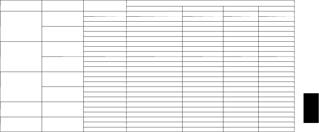
Effectiveness — 48PG03--28 EnergyX
Size CFM range CFM(O/A) EFFECTIVENESS (%)
Sensible Latent TClg THtg
03---07
Low CFM
100 83.3 77.7 80.3 81.3
350 76.4 67.2 71.2 73.2
500 69.7 56.8 62.3 65.2
High CFM
500 77.7 74.4 76.1 76.5
1000 69.4 62.8 65.8 67.0
1400 62.7 53.3 57.5 59.3
08---14
Low CFM
500 77.7 74.4 76.1 76.5
1000 69.4 62.8 65.8 67.0
1400 62.7 53.3 57.5 59.3
High CFM
1400 78.5 73.5 75.5 76.7
2800 65.8 57.4 60.7 62.8
3900 59.4 49.2 53.3 55.8
16
Low CFM
900 75.8 71.7 73.7 74.3
1500 68.9 62.1 65.3 66.5
2000 63.1 54 58.1 59.9
High CFM
1400 78.5 73.5 75.5 76.7
2800 65.8 57.4 60.7 62.8
3900 59.4 49.2 53.3 55.8
20---24 Low CFM
2000 74.9 68.9 71.3 72.7
2600 67.6 59.7 62.9 64.8
3500 59.4 49.2 53.3 55.8
28 Low CFM
2000 68.6 60.9 63.9 65.8
3000 64 55.1 58.6 60.8
3500 59.4 49.2 53.3 55.8
LEGEND
O/A --- Outside Air
T Clg --- Total Cooling Capacity
T Htg --- Total Heating Capacity
48PG

22
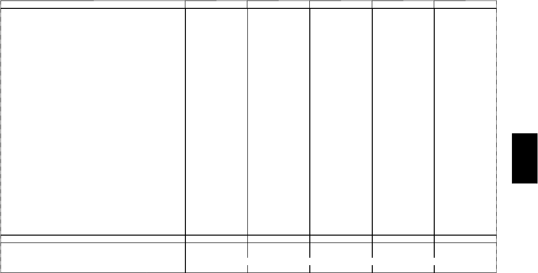
PHYSICAL DATA (CONT)
Fan Motor and Drive Data -- Vertical Supply/Return -- 48PG20--28
48PG 20 24 28
208/230,460 575 208/230,460 575 208/230,460 575
LOW RANGE
Motor Hp 3.7 53.7 555
Motor Nominal Rpm 1750 1750 1750 1750 1750 1750
Maximum Continuous Bhp 4.26/4.26,4.26 5.75 4.26/4.26,4.26 5.75 5.37/5.75,5.75 5.75
Maximum Continuous Watts 3700 5015 3700 5015 4578/5115 5015
Motor Frame Size 56HZ S184T 56HZ S184T S184T S184T
Motor Shaft Diameter (in.) 7/811/87/811/811/811/8
Fan Rpm Range 685-939 751-954 685-939 751-954 687-873 687-873
Motor Pulley Min. Pitch Diameter (in.) 2.7 3.7 2.7 3.7 3.7 3.7
Motor Pulley Max. Pitch Diameter (in.) 3.7 4.7 3.7 4.7 4.7 4.7
Blower Pulley Pitch Diameter (in.) 6.8 8.6 6.8 8.6 9.4 9.4
Blower Pulley Shaft Diameter (in.) 13/16 13/16 13/16 13/16 13/16 13/16
Blower Pulley Type Fixed Fixed Fixed Fixed Fixed Fixed
Pulley Center Line Distance (in.) 11.293-13.544 9.81-13.055 11.293-13.544 9.81-13.055 9.81-13.055 9.81-13.055
Belt, Quantity...Type...Length (in.) 1...BX38...39.8 1...BX40...41.8 1...BX38...39.8 1...BX40...41.8 1...BX41...42.8 1...BX41...42.8
Speed Change Per Turn — Moveable Pulley (rpm) 42 34 42 34 31 31
Moveable Pulley Maximum Full Turns 666666
Factory Speed Setting (rpm) 812 853 812 853 780 780
MID-LOW RANGE
Motor Hp 555555
Motor Nominal Rpm 1750 1750 1750 1750 1750 1750
Maximum Continuous Bhp 5.37/5.75,5.75 5.75 5.37/5.75,5.75 5.75 5.37/5.75,5.75 5.75
Maximum Continuous Watts 4578/5115 5015 4578/5115 5015 4578/5115 5015
Motor Frame Size S184T S184T S184T S184T S184T S184T
Motor Shaft Diameter (in.) 11/811/811/811/811/811/8
Fan Rpm Range 949-1206 949-1206 949-1206 949-1206 805-1007 805-1007
Motor Pulley Min. Pitch Diameter (in.) 3.7 3.7 3.7 3.7 4.8 4.8
Motor Pulley Max. Pitch Diameter (in.) 4.7 4.7 4.7 4.7 6 6
Blower Pulley Pitch Diameter (in.) 6.8 6.8 6.8 6.8 10.4 10.4
Blower Pulley Shaft Diameter (in.) 13/16 13/16 13/16 13/16 13/16 13/16
Blower Pulley Type Fixed Fixed Fixed Fixed Fixed Fixed
Pulley Center Line Distance (in.) 9.81-13.055 9.81-13.055 9.81-13.055 9.81-13.055 9.81-13.055 9.81-13.055
Belt, Quantity...Type...Length (in.) 1...BX38...39.8 1...BX38...39.8 1...BX38...39.8 1...BX38...39.8 1...BX45...46.8 1...BX45...46.8
Speed Change Per Turn — Moveable Pulley (rpm) 43 43 43 43 34 34
Moveable Pulley Maximum Full Turns 666666
Factory Speed Setting (rpm) 1078 1078 1078 1078 906 906
MID-HIGH RANGE
Motor Hp 7.5 7.5 7.5 7.5 7.5 7.5
Motor Nominal Rpm 1750 1750 1750 1750 1750 1750
Maximum Continuous Bhp 7.66/8.51,8.63 8.63 7.66/8.51,8.63 8.63 7.66/8.51,8.63 8.63
Maximum Continuous Watts 6458/7586 7586 6458/7586 7586 6458/7586 7586
Motor Frame Size S213T S213T S213T S213T S213T S213T
Motor Shaft Diameter (in.) 13/813/813/813/813/813/8
Fan Rpm Range 941-1176 941-1176 941-1176 941-1176 941-1176 941-1176
Motor Pulley Min. Pitch Diameter (in.) 4.8 4.8 4.8 4.8 4.8 4.8
Motor Pulley Max. Pitch Diameter (in.) 6.0 6.0 6.0 6.0 6.0 6.0
Blower Pulley Pitch Diameter (in.) 8.9 8.9 8.9 8.9 8.9 8.9
Blower Pulley Shaft Diameter (in.) 13/16 13/16 13/16 13/16 13/16 13/16
Blower Pulley Type Fixed Fixed Fixed Fixed Fixed Fixed
Pulley Center Line Distance (in.) 9.025-12.179 9.025-12.179 9.025-12.179 9.025-12.179 9.025-12.179 9.025-12.179
Belt, Quantity...Type...Length (in.) 1...BX42...43.8 1...BX42...43.8 1...BX42...43.8 1...BX42...43.8 1...BX42...43.8 1...BX42...43.8
Speed Change Per Turn —
Moveable Pulley (rpm) 39 39 39 39 39 39
Moveable Pulley Maximum Full Turns 666666
Factory Speed Setting (rpm) 1059 1059 1059 1059 1059 1059
HIGH RANGE
Motor Hp 10 10 10 10 10 10
Motor Nominal Rpm 1750 1750 1750 1750 1750 1750
Maximum Continuous Bhp 9.94/10.45,11.19 11.50 9.94/10.45,11.19 11.50 9.94/10.45,11.19 11.50
Maximum Continuous Watts 8284/9330 9711 8284/9330 9711 8284/9330 9711
Motor Frame Size S215T S215T S215T S215T S215T S215T
Motor Shaft Diameter (in.) 13/813/813/813/813/813/8
Fan Rpm Range 1014-1297 1014-1297 1014-1297 1014-1297 1014-1297 1014-1297
Motor Pulley Min. Pitch Diameter (in.) 4.3 4.3 4.3 4.3 4.3 4.3
Motor Pulley Max. Pitch Diameter (in.) 5.5 5.5 5.5 5.5 5.5 5.5
Blower Pulley Pitch Diameter (in.) 7.4 7.4 7.4 7.4 7.4 7.4
Blower Pulley Shaft Diameter (in.) 13/16 13/16 13/16 13/16 13/16 13/16
Blower Pulley Type Fixed Fixed Fixed Fixed Fixed Fixed
Pulley Center Line Distance (in.) 9.025-12.179 9.025-12.179 9.025-12.179 9.025-12.179 9.025-12.179 9.025-12.179
Belt, Quantity...Type...Length (in.) 2...BX38...39.8 2...BX38...39.8 2...BX38...39.8 2...BX38...39.8 2...BX38..39.8 2...BX38...39.8
Speed Change Per Turn — Moveable Pulley (rpm) 47 47 47 47 47 47
Moveable Pulley Maximum Full Turns 666666
Factory Speed Setting (rpm) 1156 1156 1156 1156 1156 1156
NOTE: See evaporation fan motor specifications.
48PG
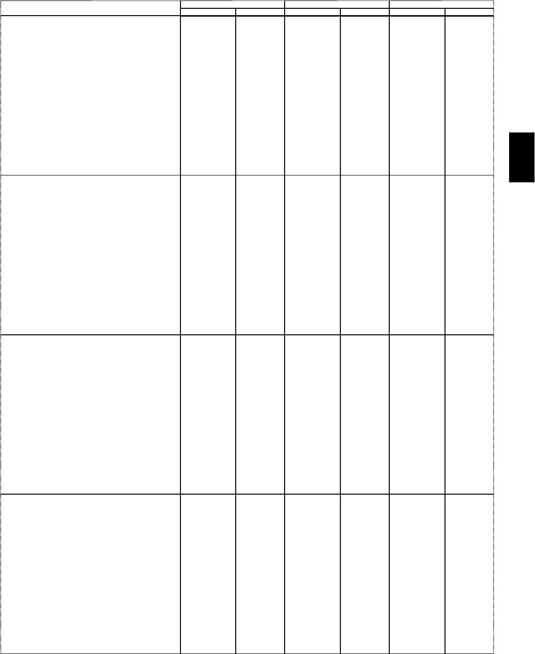
23
PHYSICAL DATA (CONT)
Fan Motor and Drive Data -- Horizontal Supply/Return -- 48PG20--28
48PG 20 24 28
208/230,460 575 208/230,460 575 208/230,460 575
LOW RANGE
Motor Hp — — — — 5 5
Motor Nominal Rpm — — — — 1750 1750
Maximum Continuous Bhp — — — — 5.37/5.75,5.75 5.75
Maximum Continuous Watts — — — — 4578/5115 5015
Motor Frame Size — — — — S184T S184T
Motor Shaft Diameter (in.) — — — — 11/811/8
Fan Rpm Range — — — — 687-873 687-873
Motor Pulley Min. Pitch Diameter (in.) — — — — 3.7 3.7
Motor Pulley Max. Pitch Diameter (in.) — — — — 4.7 4.7
Blower Pulley Pitch Diameter (in.) — — — — 9.4 9.4
Blower Pulley Shaft Diameter (in.) — — — — 13/16 13/16
Blower Pulley Type — — — — Fixed Fixed
Pulley Center Line Distance (in.) — — — — 9.81-13.055 9.81-13.055
Belt, Quantity...Type...Length (in.) — — — — 1...BX41...42.8 1...BX41...42.8
Speed Change Per Turn —
Moveable Pulley (rpm) — — — — 31 31
Moveable Pulley Maximum Full Turns — — — — 6 6
Factory Speed Setting (rpm) — — — — 780 780
MID-LOW RANGE
Motor Hp 3.7 53.7 555
Motor Nominal Rpm 1750 1750 1750 1750 1750 1750
Maximum Continuous Bhp 4.26/4.26,4.26 5.75 4.26/4.26,4.26 5.75 5.37/5.75,5.75 5.75
Maximum Continuous Watts 3700 5015 3700 5015 4578/5115 5015
Motor Frame Size 56HZ S184T 56HZ S184T S184T S184T
Motor Shaft Diameter (in.) 7/811/87/811/811/811/8
Fan Rpm Range 896-1227 873-1108 896-1227 873-1108 805-1007 805-1007
Motor Pulley Min. Pitch Diameter (in.) 2.7 3.7 2.7 3.7 4.8 4.8
Motor Pulley Max. Pitch Diameter (in.) 3.7 4.7 3.7 4.7 6.0 6.0
Blower Pulley Pitch Diameter (in.) 5.2 7.4 5.2 7.4 10.4 10.4
Blower Pulley Shaft Diameter (in.) 13/16 13/16 13/16 13/16 13/16 13/16
Blower Pulley Type Fixed Fixed Fixed Fixed Fixed Fixed
Pulley Center Line Distance (in.) 11.293-13.544 9.81-13.055 11.293-13.544 9.81-13.055 9.81-13.055 9.81-13.055
Belt, Quantity...Type...Length (in.) 1...BX35...36.8 1...BX38...39.8 1...BX35...36.8 1...BX38...39.8 1...BX45...46.8 1...BX45...46.8
Speed Change Per Turn —
Moveable Pulley (rpm) 55 39 55 39 34 34
Moveable Pulley Maximum Full Turns 666666
Factory Speed Setting (rpm) 1062 991 1062 991 906 906
MID-HIGH RANGE
Motor Hp 5 5 5 5 7.5 7.5
Motor Nominal Rpm 1750 1750 1750 1750 1750 1750
Maximum Continuous Bhp 5.37/5.75,5.75 5.75 5.37/5.75,5.75 5.75 7.66/8.51,8.63 8.63
Maximum Continuous Watts 4578/5115 5015 4578/5115 5015 6458/7586 7586
Motor Frame Size S184T S184T S184T S184T S213T S213T
Motor Shaft Diameter (in.) 11/811/811/811/813/813/8
Fan Rpm Range 1113-1414 1113-1414 1113-1414 1113-1414 941-1176 941-1176
Motor Pulley Min. Pitch Diameter (in.) 3.7 3.7 3.7 3.7 4.8 4.8
Motor Pulley Max. Pitch Diameter (in.) 4.7 4.7 4.7 4.7 6.0 6.0
Blower Pulley Pitch Diameter (in.) 5.8 5.8 5.8 5.8 8.9 8.9
Blower Pulley Shaft Diameter (in.) 13/16 13/16 13/16 13/16 13/16 13/16
Blower Pulley Type Fixed Fixed Fixed Fixed Fixed Fixed
Pulley Center Line Distance (in.) 9.81-13.055 9.81-13.055 9.81-13.055 9.81-13.055 9.025-12.179 9.025-12.179
Belt, Quantity...Type...Length (in.) 1...BX35...36.8 1...BX35...36.8 1...BX35...36.8 1...BX35...36.8 1...BX42...43.8 1...BX42...43.8
Speed Change Per Turn —
Moveable Pulley (rpm) 50 50 50 50 39 39
Moveable Pulley Maximum Full Turns 666666
Factory Speed Setting (rpm) 1264 1264 1264 1264 1059 1059
HIGH RANGE
Motor Hp 7.5 7.5 7.5 7.5 10 10
Motor Nominal Rpm 1750 1750 1750 1750 1750 1750
Maximum Continuous Bhp 7.66/8.51,8.63 8.63 7.66/8.51,8.63 8.63 9.94/10.45,11.19 11.50
Maximum Continuous Watts 6458/7586 7586 6458/7586 7586 8284/9330 9711
Motor Frame Size S213T S213T S213T S213T S215T S215T
Motor Shaft Diameter (in.) 13/813/813/813/813/813/8
Fan Rpm Range 1096-1339 1096-1339 1096-1339 1096-1339 1014-1297 1014-1297
Motor Pulley Min. Pitch Diameter (in.) 5.4 5.4 5.4 5.4 4.3 4.3
Motor Pulley Max. Pitch Diameter (in.) 6.6 6.6 6.6 6.6 5.5 5.5
Blower Pulley Pitch Diameter (in.) 8.6 8.6 8.6 8.6 7.4 7.4
Blower Pulley Shaft Diameter (in.) 13/16 13/16 13/16 13/16 13/16 13/16
Blower Pulley Type Fixed Fixed Fixed Fixed Fixed Fixed
Pulley Center Line Distance (in.) 9.025-12.179 9.025-12.179 9.025-12.179 9.025-12.179 9.025-12.179 9.025-12.179
Belt, Quantity...Type...Length (in.) 1...BX42...43.8 1...BX42...43.8 1...BX42...43.8 1...BX42...43.8 1...BX38...39.8 1...BX38...39.8
Speed Change Per Turn —
Moveable Pulley (rpm) 41 41 41 41 47 47
Moveable Pulley Maximum Full Turns 666666
Factory Speed Setting (rpm) 1218 1218 1218 1218 1156 1156
NOTE: See evaporation fan motor specifications.
48PG

24
OPTIONS AND ACCESSORIES
ITEM FACTORY ---INSTALLED OPTIONS FIELD---INSTALLED ACCESSORIES
Intelligent ComfortLink™Controls X
Electro---Mechanical Controls X
H u m i d i --- M i Z e r ™Adaptive Dehumidification System X
Economizer With Single Enthalpy Sensor (1) X X
Differential Enthalpy Sensor X
Economizer with Dry Bulb Sensor X
Differential Dry Bulb Sensor X
EnergyX (Energy Recovery Ventilator) X
Line---Side Powered 115---volt GFI Convenience
Outlet X
N o n --- P o w e r e d 1 1 5 --- v o l t G F I C o n v e n i e n c e O u t l e t X
HACR Breaker X
Non---Fused Disconnect Switch X
Manual Outdoor Air Damper (2) X X
Two ---Position Motorized Outdoor Air Damper (2) X X
Barometric Relief Damper (Part of Economizer on
03---16 units) X X
Power Exhaust (2) X X
CondenserCoilHailGuardGrille X X
MERV---8 Pleated Return Air Filters X
4---in. Filter Capabilities (20--- 28) X
CO2Sensor X X
Return Air Smoke Detector X X
Return and Supply Air Smoke Detectors X X
Fan and Plugged Filter Switches X X
Horizontal Duct Configuration (2) X (only 16--- 28 models) X
Low Range Fan Performance Motor/Drive X
Mid---Low Fan Performance Motor/Drive X
Mid---High Fan Performance Motor/Drive X
High Fan Performance Motor/Drive X
Phase Loss Protection X X
Pre---Coated Aluminum Fin/Copper Tube Coil X
Copper Fin/Copper Tube Coil X
E---Coated Aluminum Fin/Copper Tube Coil X
E---Coated Copper Fin/Copper Tube Coil X
Stainless Steel Heat Exchanger X
LowNOxGasModels(2---5tononly) X
14---in. Full Perimeter Roof Curb X
24---in. Full Perimeter Roof Curb X
Roof Curb Burglar Bars X
Adapter Curbs (03---16) (2) X
Liquefied Propane (LP) Gas Conversion Kits X
High Altitude Gas Kits X
Flue Gas Discharge Deflector (03---14) X
T h r u --- T h e --- C u r b G a s C o n n e c t i o n K i t ( 0 3 --- 1 6 ) X
T h r u --- T h e --- B o t t o m G a s C o n n e c t i o n K i t ( 0 3 --- 1 6 ) X
Thermostats and Subbases X
Electronic Programmable Thermostats X
LEGEND
GFI --- Ground Fault Interrupt
H A C R --- Heating, Air Conditioning, and Refrigeration
M E R V --- Minimum Efficiency Reporting Value
(1) Economizer with enthalpy is included with EnergyX units with bypass
(2) Can not be used on units with EnergyX
48PG
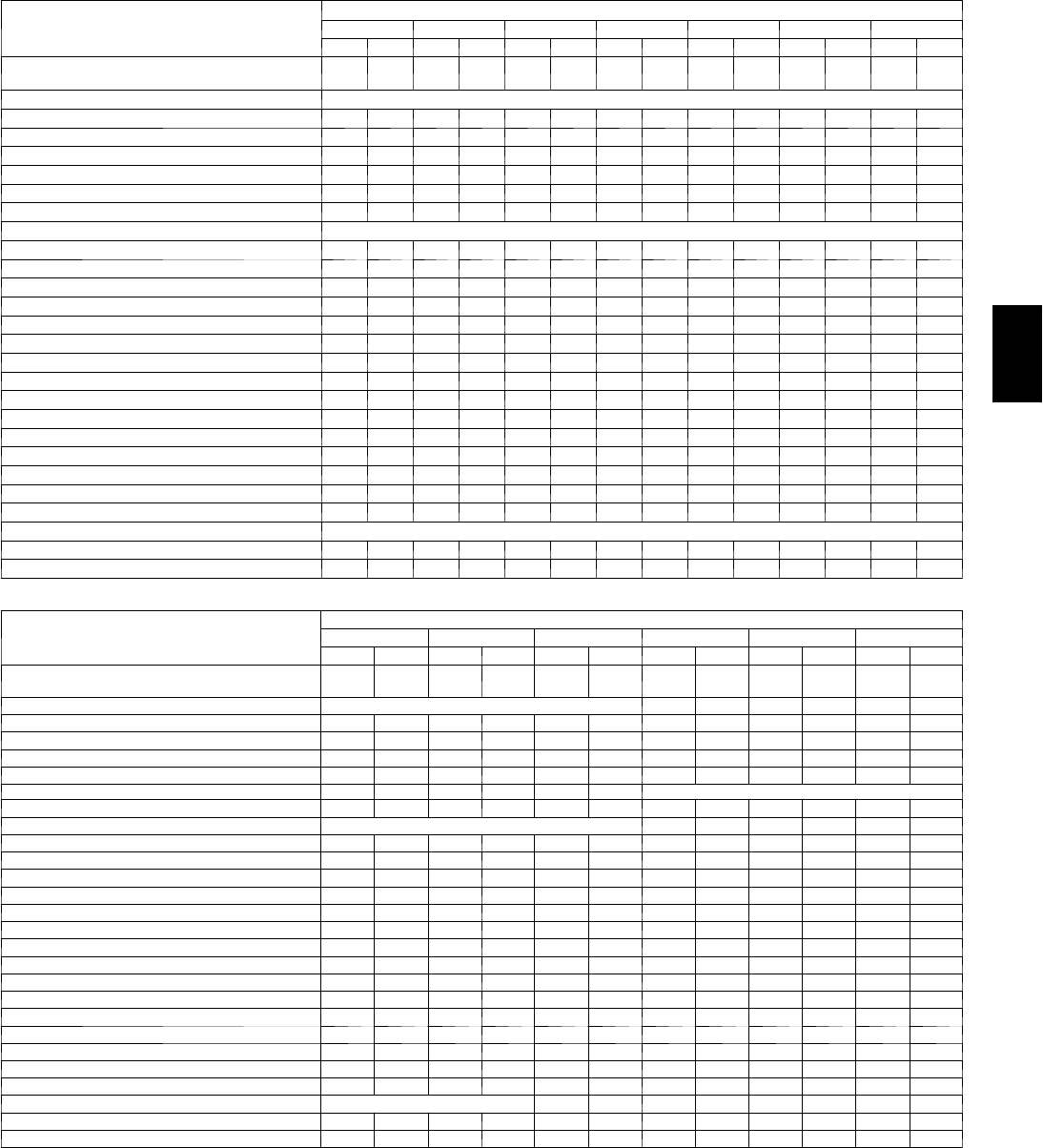
25
Weight Adders
OPTION/ACCESSORY
OPTION/ACCESSORY WEIGHTS
48PG03 48PG04 48PG05 48PG06 48PG07 48PG08 48PG09
lb kg lb kg lb kg lb kg lb kg lb kg lb kg
H u m i d i --- M i Z e r ™Adaptive Dehumidification
System 22 10 22 10 31 14 27 12 26 12 45 20 45 20
Barometric Relief Damper NO ADDITIONAL WEIGHT
Power Exhaust 30 14 30 14 30 14 30 14 30 14 40 18 40 18
Economizer 55 25 55 25 55 25 55 25 65 29 65 29 65 29
Cu Condenser Coils 100 45 100 45 100 45 100 45 100 45 162 73 162 73
Cu Condenser and Evaporator Coils 175 79 175 79 175 79 175 79 175 79 250 113 250 113
Low Gas Heat --- 3 0 --- 1 4 --- 3 0 --- 1 4 --- 3 0 --- 1 4 --- 3 0 --- 1 4 --- 3 0 --- 1 4 --- 2 5 --- 1 1 --- 2 5 --- 1 1
Medium Gas Heat --- 1 5 --- 7 --- 1 5 --- 7 --- 1 5 --- 7 --- 1 5 --- 7 --- 1 5 --- 7 --- 1 0 --- 4 . 5 --- 1 0 --- 4 . 5
High Gas Heat NO ADDITIONAL WEIGHT
Roof Curb (14 in.) 145 66 145 66 145 66 145 66 145 66 175 79 175 79
Roof Curb (24 in.) 155 70 155 70 155 70 155 70 155 70 190 86 190 86
Optional Indoor Motor/Drive 10 510 510 510 510 515 715 7
Hail Guard 50 23 50 23 50 23 50 23 50 23 65 29 65 29
CO2Sensor 52525252525252
Return Smoke Detector 52525252525252
Supply Smoke Detector 52525252525252
Plugged Filter Indicator 21212121212121
Fan Status 21212121212121
Non--- Fused Disconnect 15 715 715 715 715 715 715 7
HACR Breaker 20 920 920 920 920 920 920 9
Line--- Side Powered Convenience Outlet 35 16 35 16 35 16 35 16 35 16 35 16 35 16
Non --- Powered Convenience Outlet 20 920 920 920 920 920 920 9
Enthalpy Sensor 21212121212121
Differential Enthalpy Sensor 31313131313131
4--- In. Filter Capability NO ADDITIONAL WEIGHT
Two---Position Motorized Damper 30 14 30 14 30 14 30 14 30 14 35 16 35 16
Manual Damper 30 14 30 14 30 14 30 14 30 14 35 16 35 16
NOTE: All weights do not include packaging.
OPTION/ACCESSORY
OPTION/ACCESSORY WEIGHTS (cont)
48PG12 48PG14 48PG16 48PG20 48PG24 48PG28
lb kg lb kg lb kg lb kg lb kg lb kg
H u m i d i --- M i Z e r ™Adaptive Dehumidification
System 44 20 45 20 64 29 80 36 80 36 100 45
Barometric Relief Damper NO ADDITIONAL WEIGHT 50 23 50 23 50 23
Power Exhaust 40 18 40 18 44 20 125 57 125 57 125 57
Economizer 65 29 65 29 149 68 170 77 170 77 195 88
Cu Condenser Coils 162 73 162 73 240 109 202 92 290 132 290 132
Cu Condenser and Evaporator Coils 250 113 250 113 375 170 330 150 418 190 453 205
Low Gas Heat --- 2 5 --- 1 1 --- 2 5 --- 1 1 --- 2 2 --- 1 0 NO ADDITIONAL WEIGHT
Medium Gas Heat --- 1 0 --- 4 . 5 --- 1 0 --- 4 . 5 --- 1 1 --- 5 5 2 10 210 2
High Gas Heat NO ADDITIONAL WEIGHT 28 13 28 13 28 13
Roof Curb (14 in.) 175 79 175 79 240 109 305 138 305 138 270 122
Roof Curb (24 in.) 190 86 190 86 360 163 385 175 385 175 345 156
Optional Indoor Motor/Drive 15 715 773 33 73 33 73 33 40 18
Hail Guard 65 29 65 29 97 44 100 45 100 45 100 45
CO2Sensor 525252525252
Return Smoke Detector 525252525252
Supply Smoke Detector 525252525252
Plugged Filter Indicator 212121212121
Fan Status 212121212121
Non--- Fused Disconnect 15 715 715 715 715 715 7
HACR Breaker 20 920 920 920 920 920 9
Line--- Side Powered Convenience Outlet 35 16 35 16 35 16 35 16 35 16 35 16
Non --- Powered Convenience Outlet 20 920 9 9 4 20 920 920 9
Enthalpy Sensor 212121212121
Differential Enthalpy Sensor 313131313131
4--- In. Filter Capability NO ADDITIONAL WEIGHT 4 2 10 510 515 7
Two---Position Motorized Damper 35 16 35 16 35 16 40 18 40 18 40 18
Manual Damper 35 16 35 16 35 16 25 11 25 11 25 11
NOTE: All weights do not include packaging.
48PG
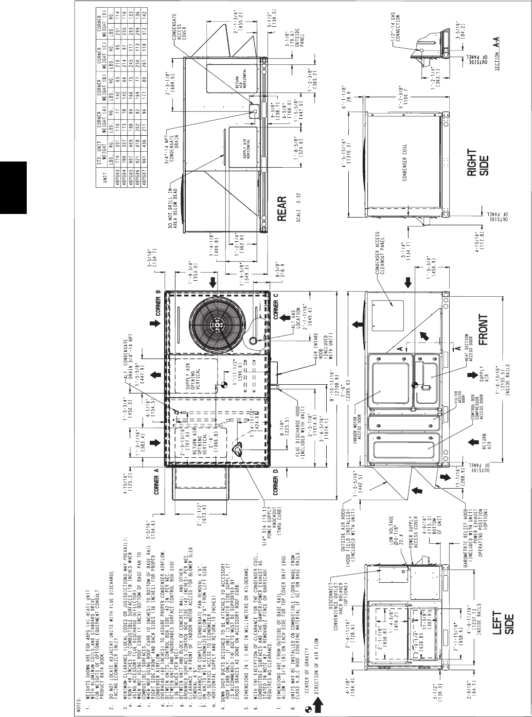
26
BASE UNIT DIMENSION -- 48PG03--07
C08178
48PG
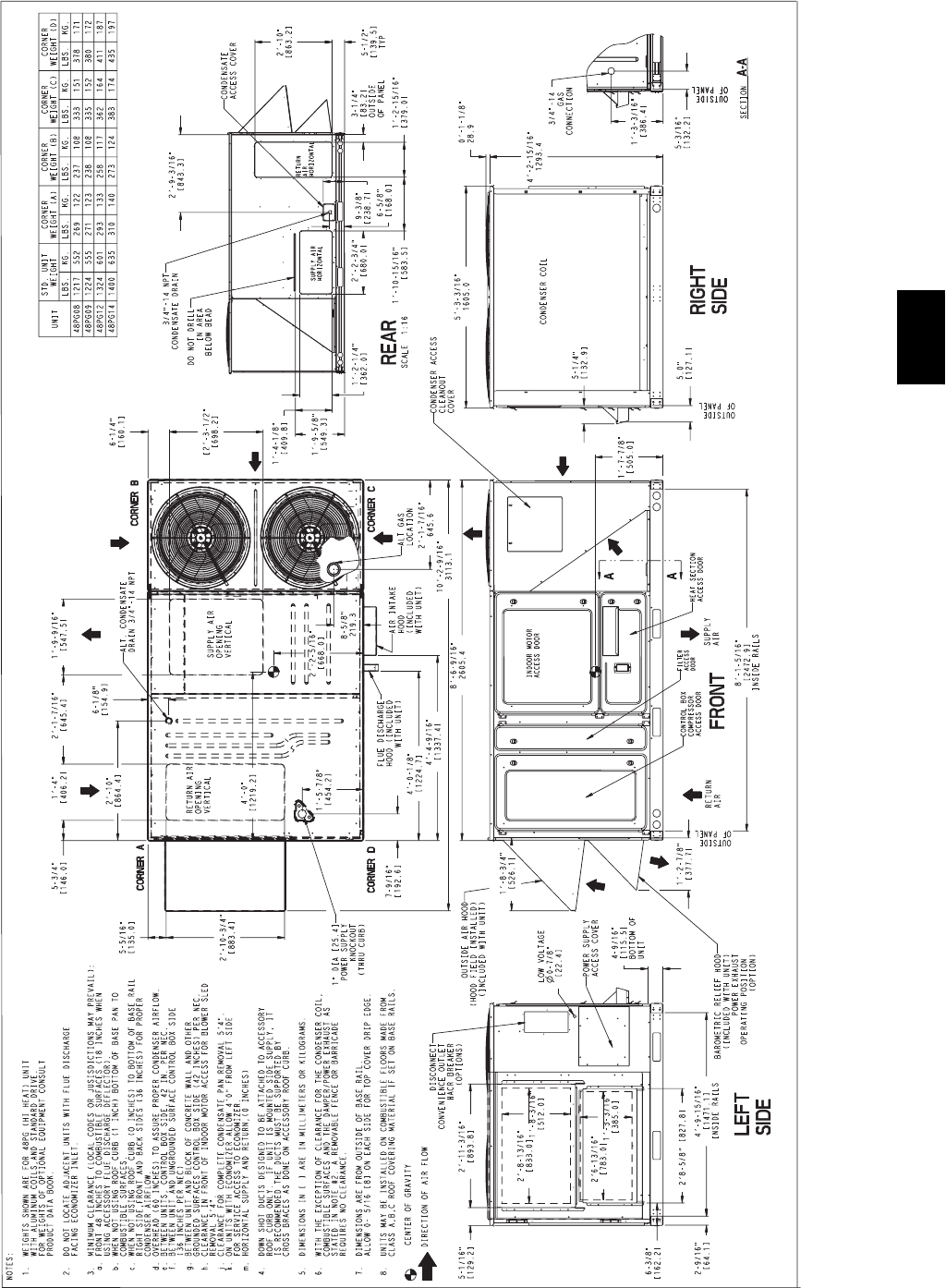
27
BASE UNIT DIMENSION -- 48PG08--14
C08179
48PG
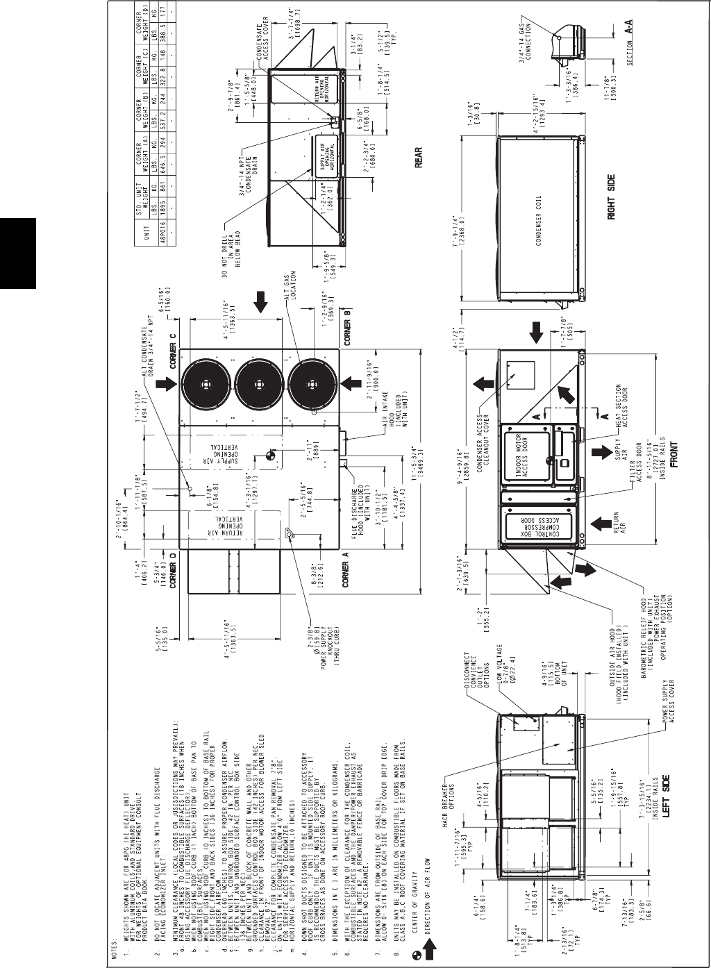
28
BASE UNIT DIMENSION -- 48PG16
C08180
48PG
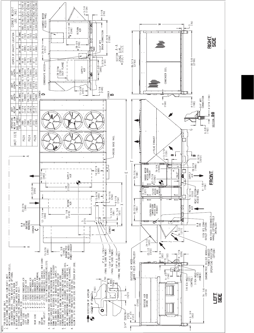
29
BASE UNIT DIMENSION -- 48PG20--28
C08181
48PG
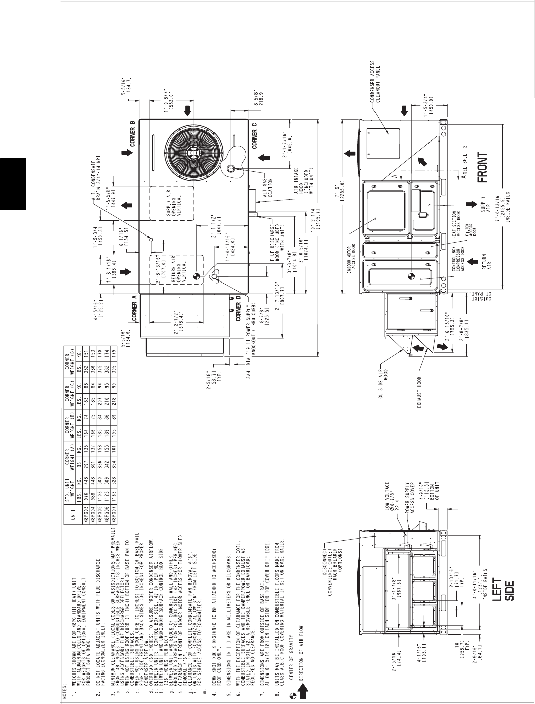
30
BASE UNIT DIMENSION -- 48PG03--07 WITH LOW CFM EnergyX
C08182
48PG

31
BASE UNIT DIMENSION -- 48PG03--07 WITH LOW CFM EnergyX
(CONT)
C08182A
48PG
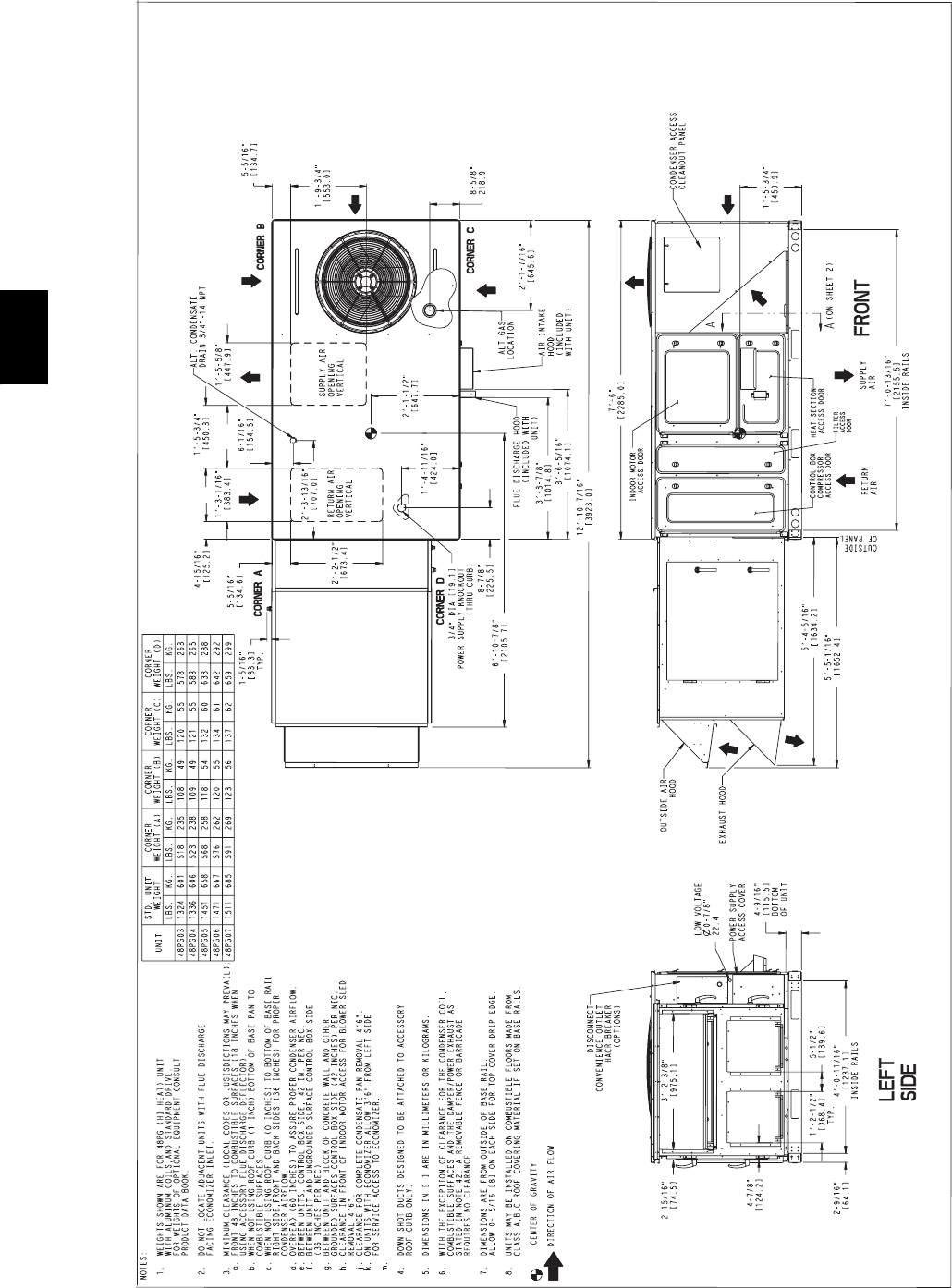
32
BASE UNIT DIMENSION -- 48PG03--07 WITH HIGH CFM EnergyX
C08183
48PG
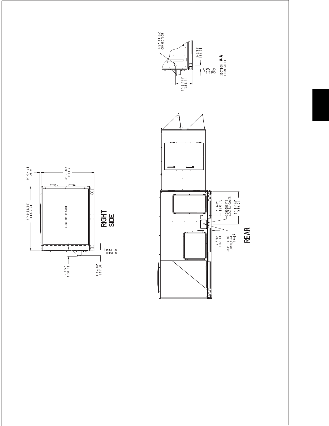
33
BASE UNIT DIMENSION -- 48PG03--07 WITH HIGH CFM EnergyX
(CONT)
C08183A
48PG
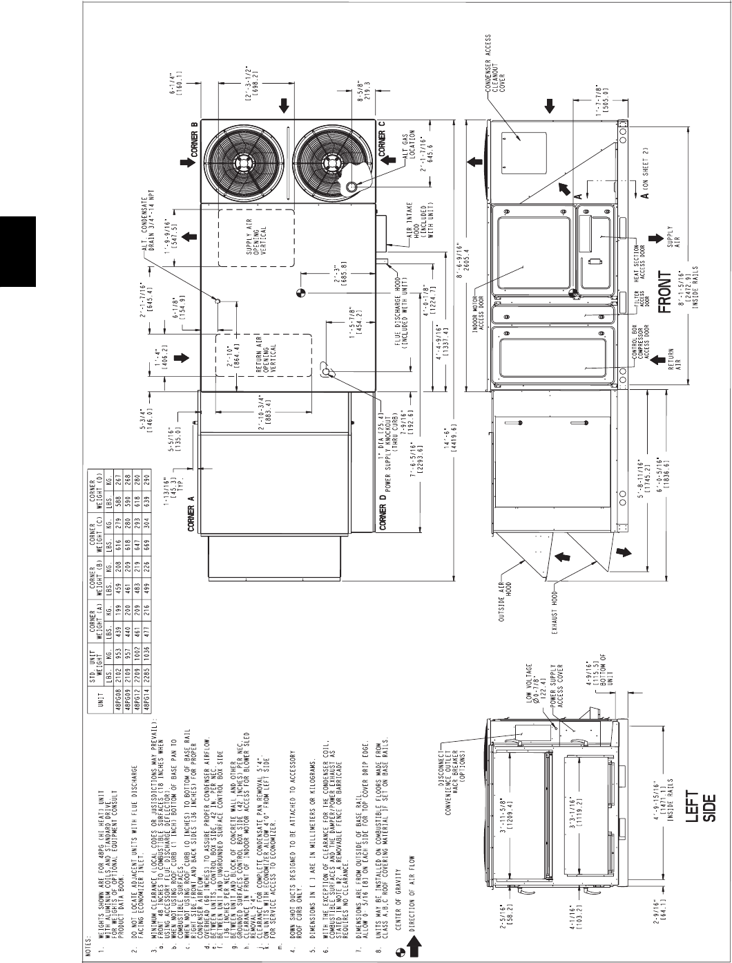
34
BASE UNIT DIMENSION -- 48PG08--14 WITH HIGH OR LOW CFM EnergyX
C08184
48PG
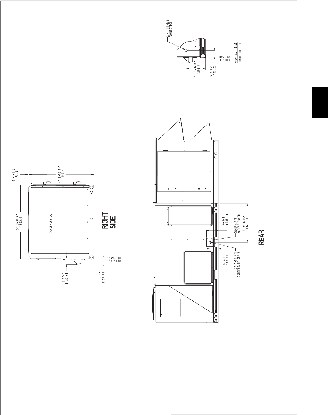
35
BASE UNIT DIMENSION -- 48PG08--14 WITH HIGH OR LOW CFM EnergyX
(CONT)
C08184A
48PG
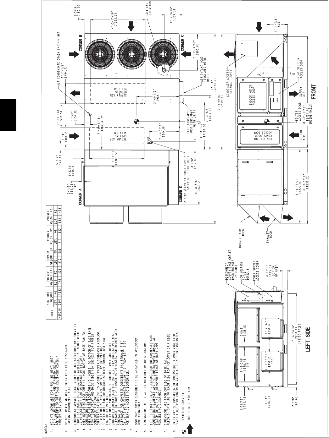
36
BASE UNIT DIMENSION -- 48PG16 WITH HIGH OR LOW CFM EnergyX
C08185
48PG
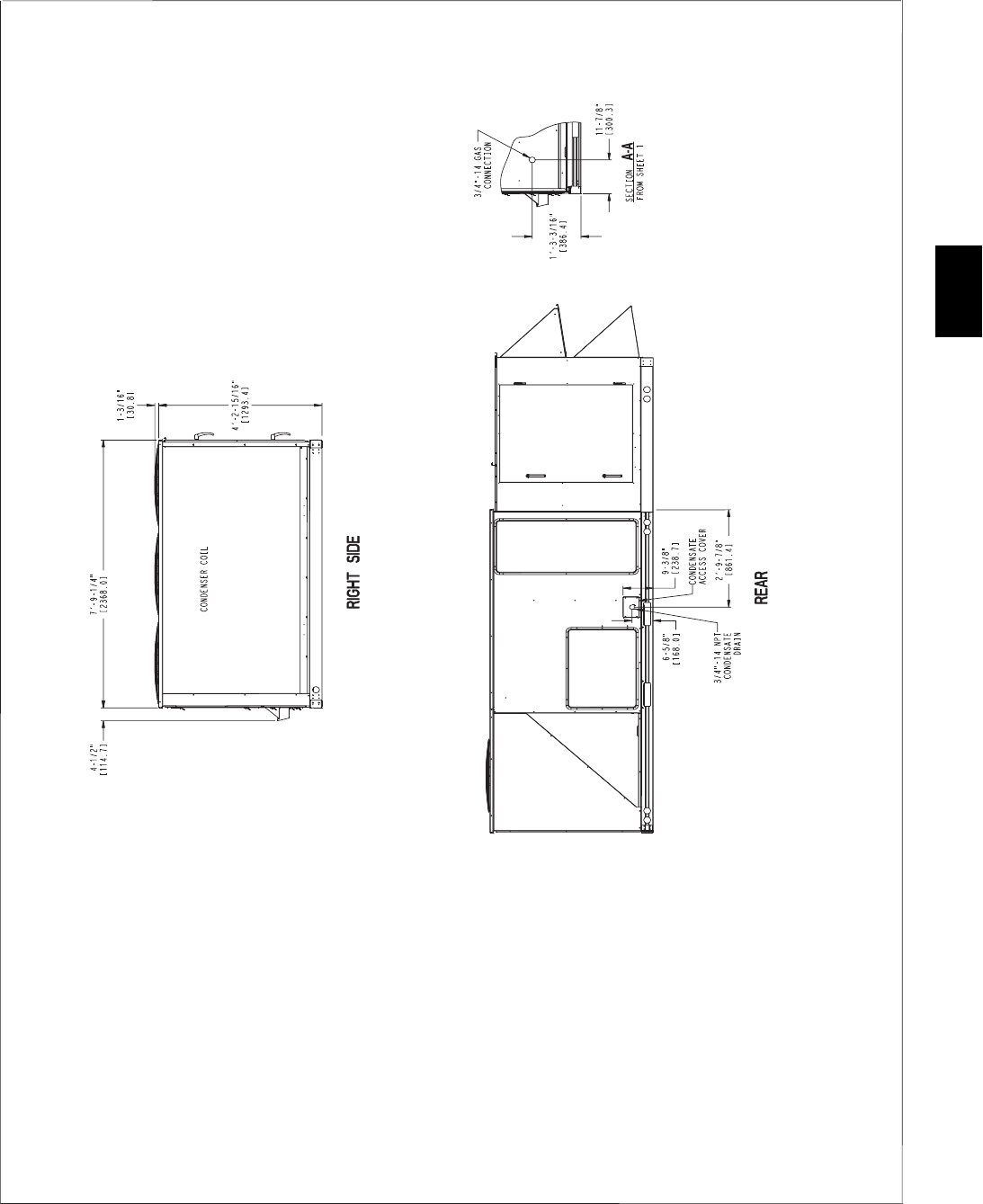
37
BASE UNIT DIMENSION -- 48PG16 WITH HIGH OR LOW CFM EnergyX
(CONT)
C08185A
48PG
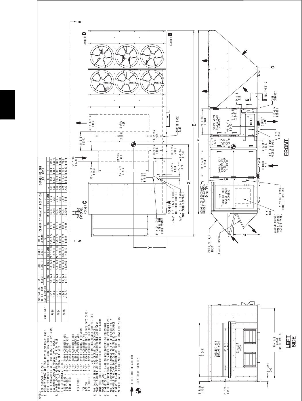
38
BASE UNIT DIMENSION -- 48PG20--28 WITH EnergyX
C08186
48PG
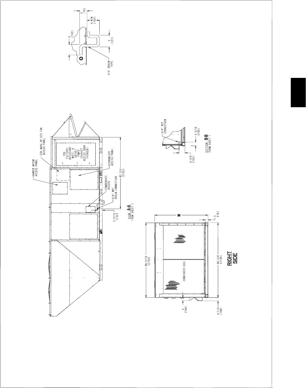
39
BASE UNIT DIMENSION -- 48PG20--28 WITH EnergyX
(CONT)
C08186A
48PG
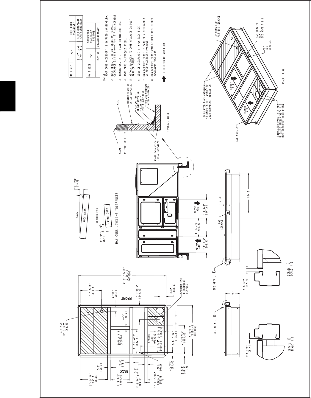
40
ACCESSORY DIMENSIONS -- 48PG03--07
Roof Curb
05-06
05-06
48PD
48PD
C07313
48PG
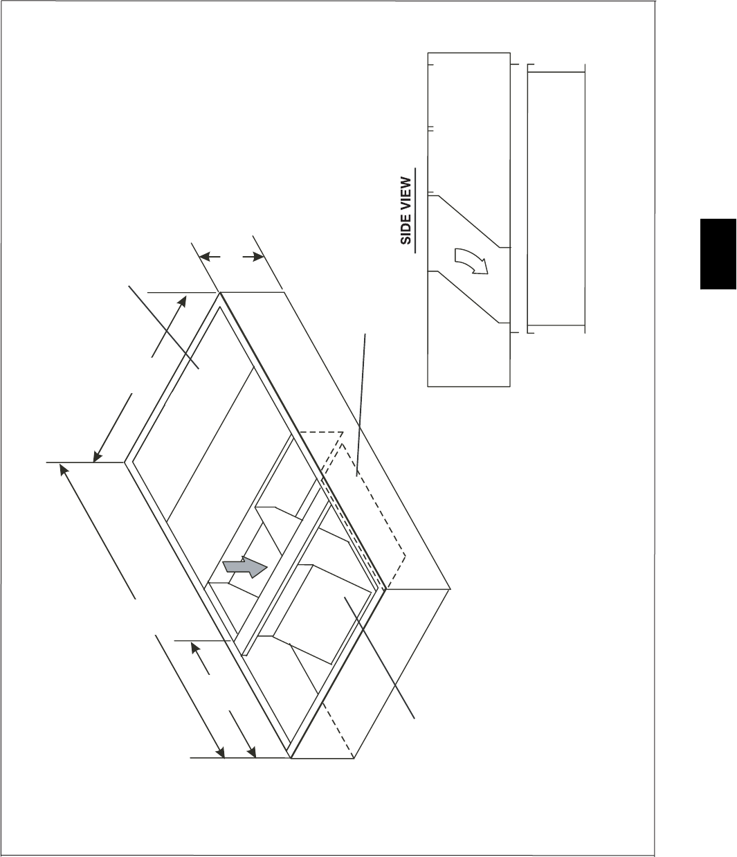
41
Curb Adaptor -- 48PG03--07 (Part No. CRADCURB001A00)
RETURN OPENING IN BOTTOM
CURB ADAPTOR
20"
48 3/16"
INSULATED DECKS
83 3/4"
34 5/8"
SUPPLY TRANSITION
EXISTING CURB
NOTES:
1. Ships fully assembled and includes duct transitions
2. Can not be used on units with EnergyX.
3. Curb adapter is design to be used with existing standard.
Carrier 48/50 DJ, LJ, TF, TM, TJ, HJ 003-006 curbs.
C07520
48PG
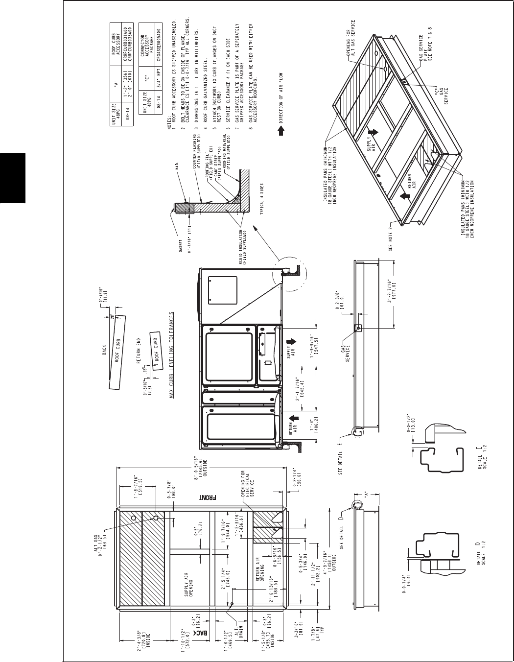
42
ACCESSORY DIMENSIONS -- 48PG08--14
C06252
48PG
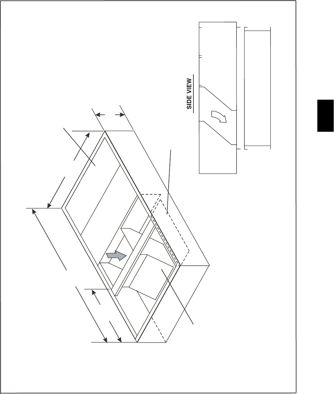
43
Curb Adaptor -- 48PG08--14 (Part No. CRADCURB002A00)
RETURN OPENING IN BOTTOM
CURB ADAPTOR
20"
57 3/16"
INSULATED DECKS
96 1/4"
45 1/2"
SUPPLY TRANSITION
EXISTING CURB
NOTES:
1. Ships fully assembled and includes duct transitions
2. Can not be used on units with EnergyX.
3. Curb adapter is design to be used with existing standard.
Carrier 48/50 DJ, TJ, LJ, TM, TF, HJ 008-014 curbs.
C07521
48PG
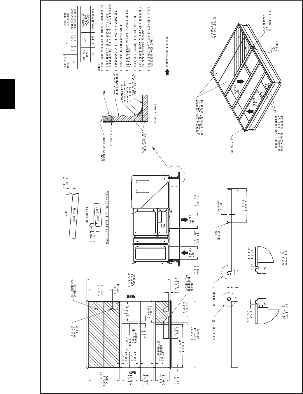
44
ACCESSORY DIMENSIONS -- 48PG16
Roof Curb -- 48PG16
C06228
48PG
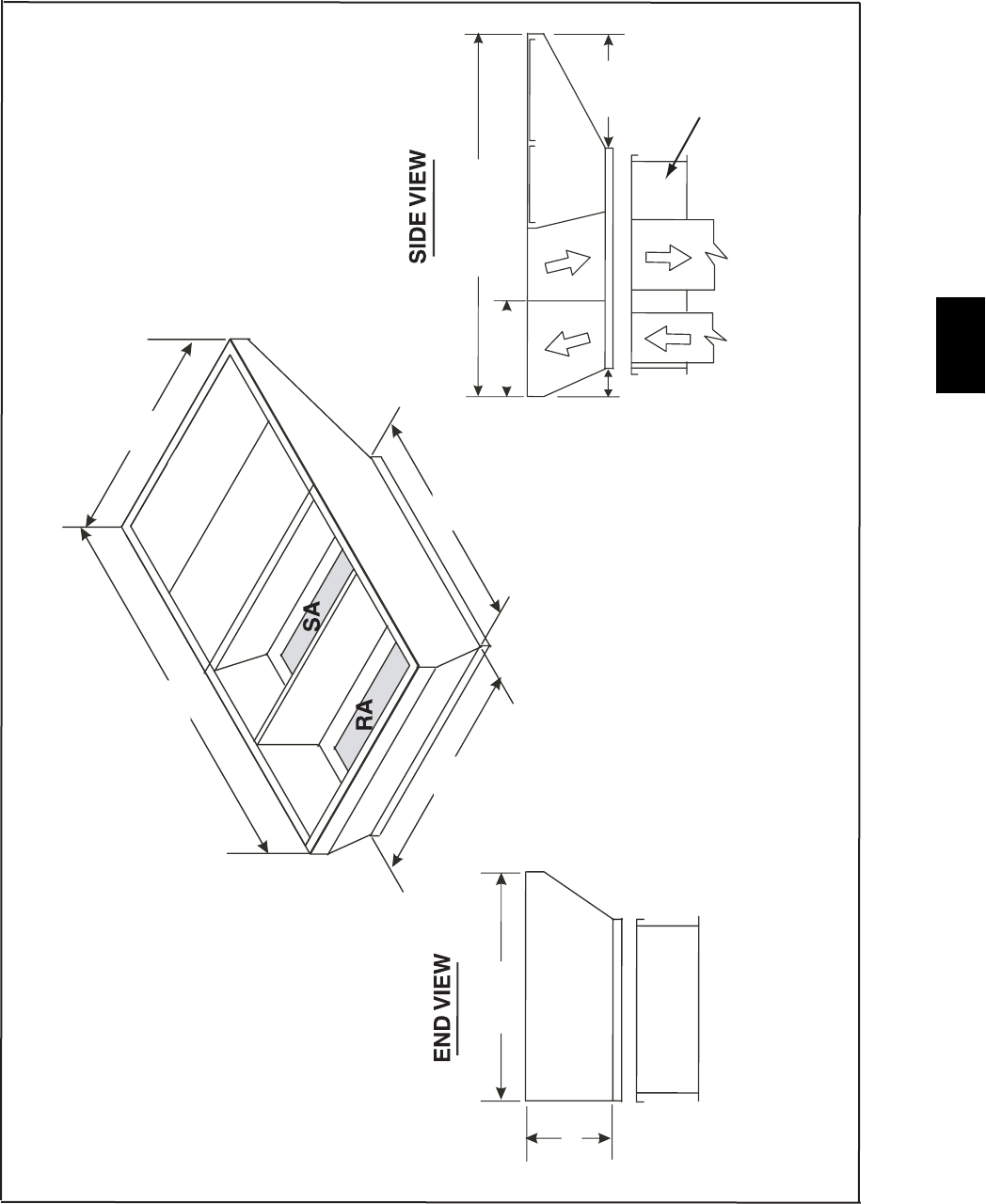
45
Accessory Dimension Curb Adaptor -- 48PG16 (CRADCURB003A00)
106 3/4"
87 7/16"
72"
79 1/4"
10"
41 3/4"
106 1/4"
24 1/4"
87.46"
14"
EXISTING CURB
EXISTING CURB
NOTES:
1. Ships fully assembled and includes duct transitions
2. Can not be used on units with EnergyX.
3. Curb adapter is design to be used with existing standard
Carrier 48/50 DP, DR, TJ, HJ, TM 016-024 curbs.
C07522
48PG
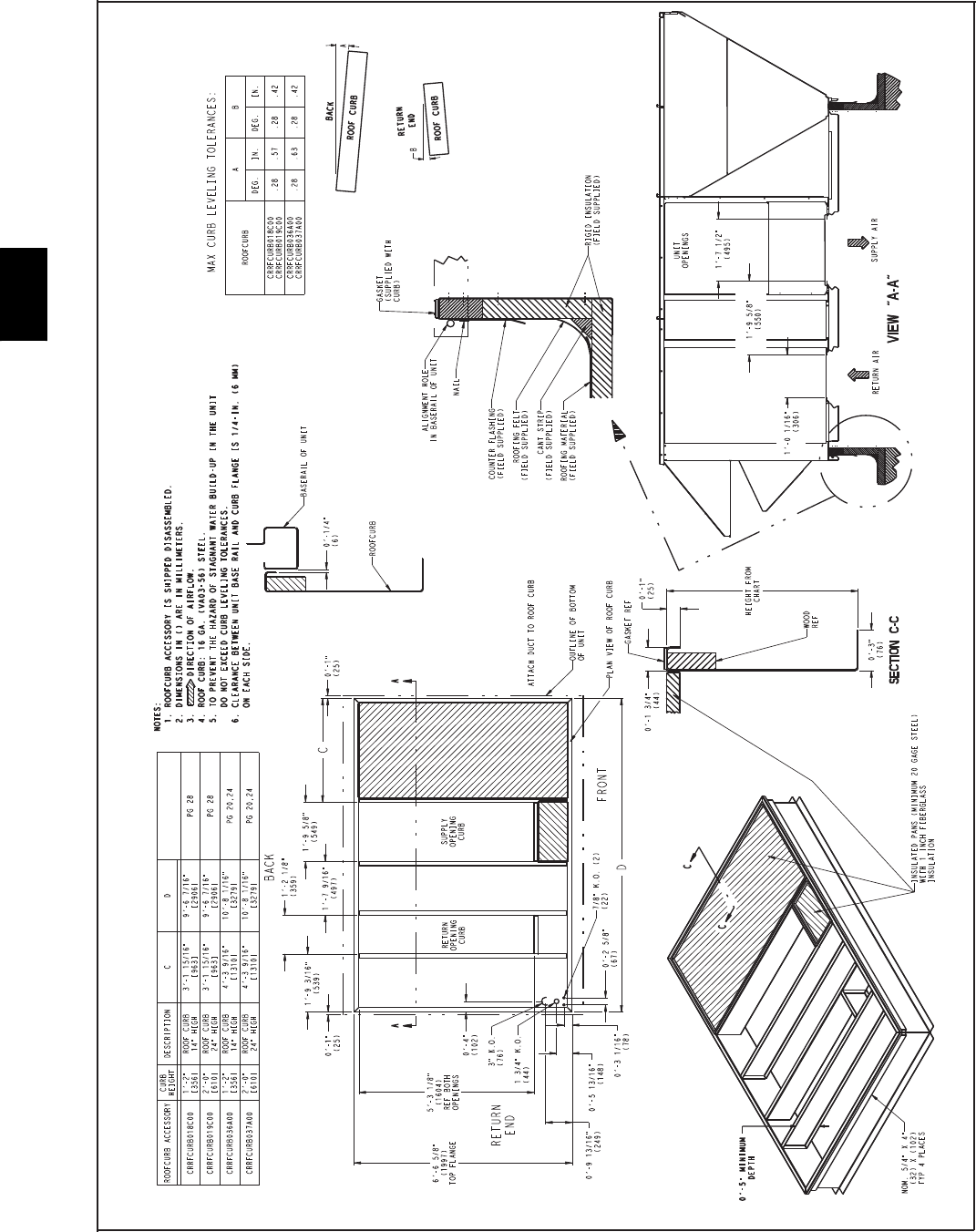
46
ACCESSORY DIMENSIONS -- 48PG20--28
Roof Curb
C07524
48PG
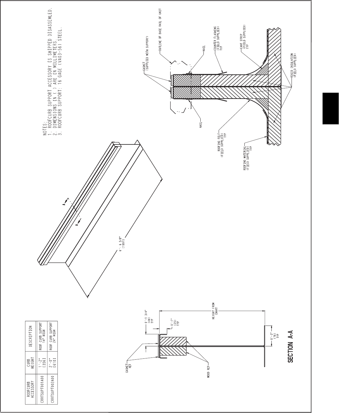
47
Roof Curb Support
Equipment Support Rail provides required base
unit support when placing unit on past installed
roofcurb DP, DR, TJ, HJ units sized 20-28.
C07525
48PG
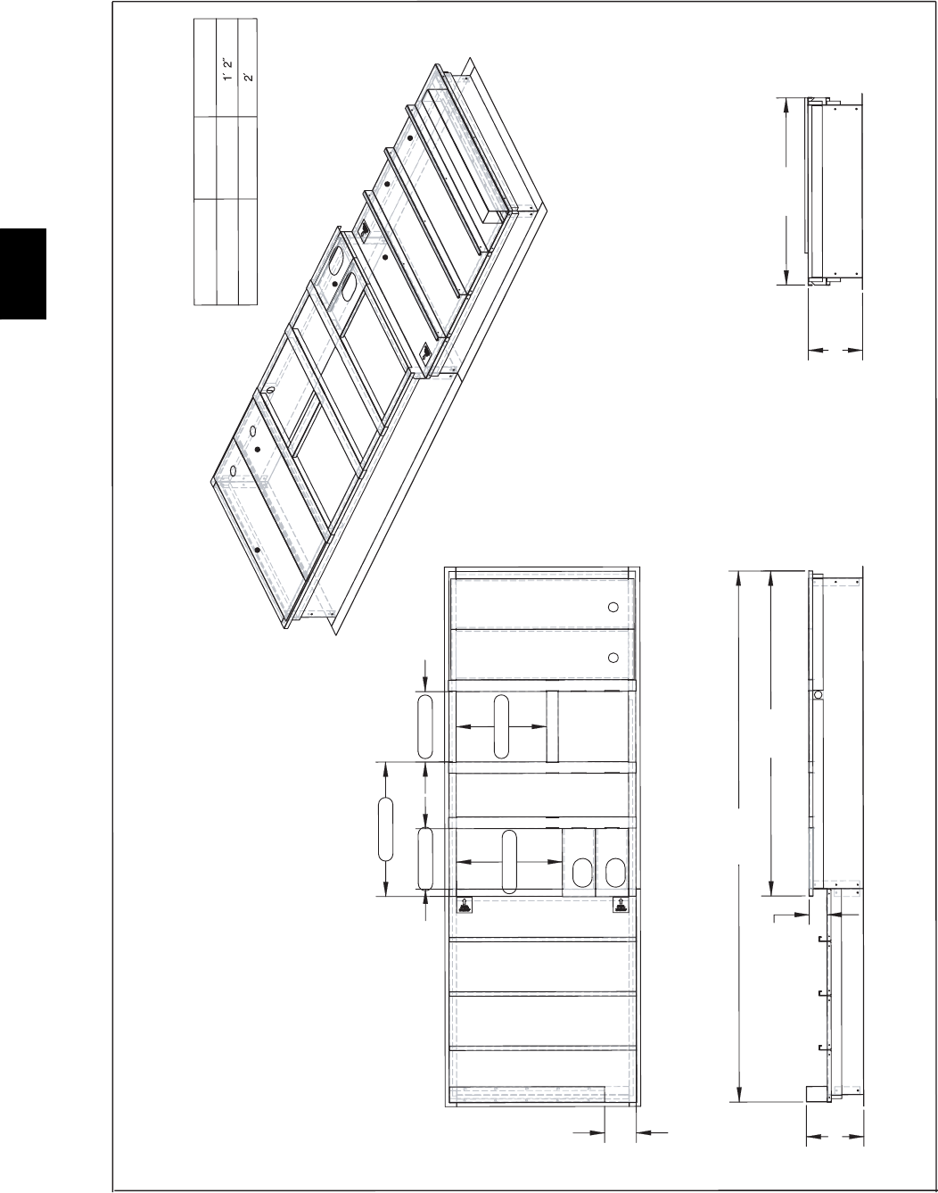
48
ACCESSORY DIMENSIONS -- FULL PERIMETER ROOF CURB FOR 48PG03--07 WITH
HIGH CFM EnergyX UNIT
Roof Curb -- CREXCURB005A00 and CREXCURB006A00
86
8
.
6
3
1
1
6
7.
3
8
526
.
4
402
.
8
4
04
3
.7
2
331.81
323.3
2
495
.
5
1
3
76.4
3
4
0
2
.
8
CREXCURB00A00
CREXCURB00A00
DIMENSION
A
A
CURB HEIGHT
AA
Supply Air
Return Air
NOTE:
1. Roofcurbs ship knockdown.
2. Install ductwork into roofcurb before
placing the rooftop unit.
C08031
48PG
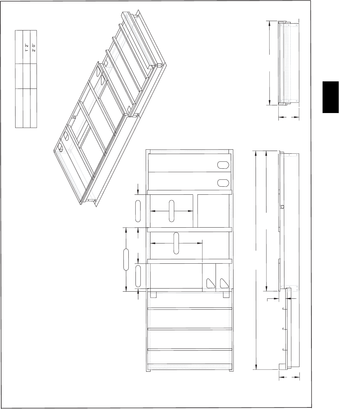
49
PERIMETER ROOF CURB FOR 48PG08--14 WITH LOW OR HIGH CFM EnergyX UNITS
Roof Curb -- CREXCURB007A00 and CREXCURB008A00
02
5.2
2
0
2
5
.5
3
60
1
.
7
1
3
15
.
3
4
2
5
2
.
9
2
0
2
4.
7
5
5
26
.
41
8
6.
5
9
7
60.9
4
1
CREXCURB007A00
CREXCURB008A00
DIMENSION
A
A
CURB HEIGHT
AA
Supply Air
NOTE:
1. Roofcurbs ship knockdown.
2. Install ductwork into roofcurb before
placing the rooftop unit.
Return Air
C08030
48PG
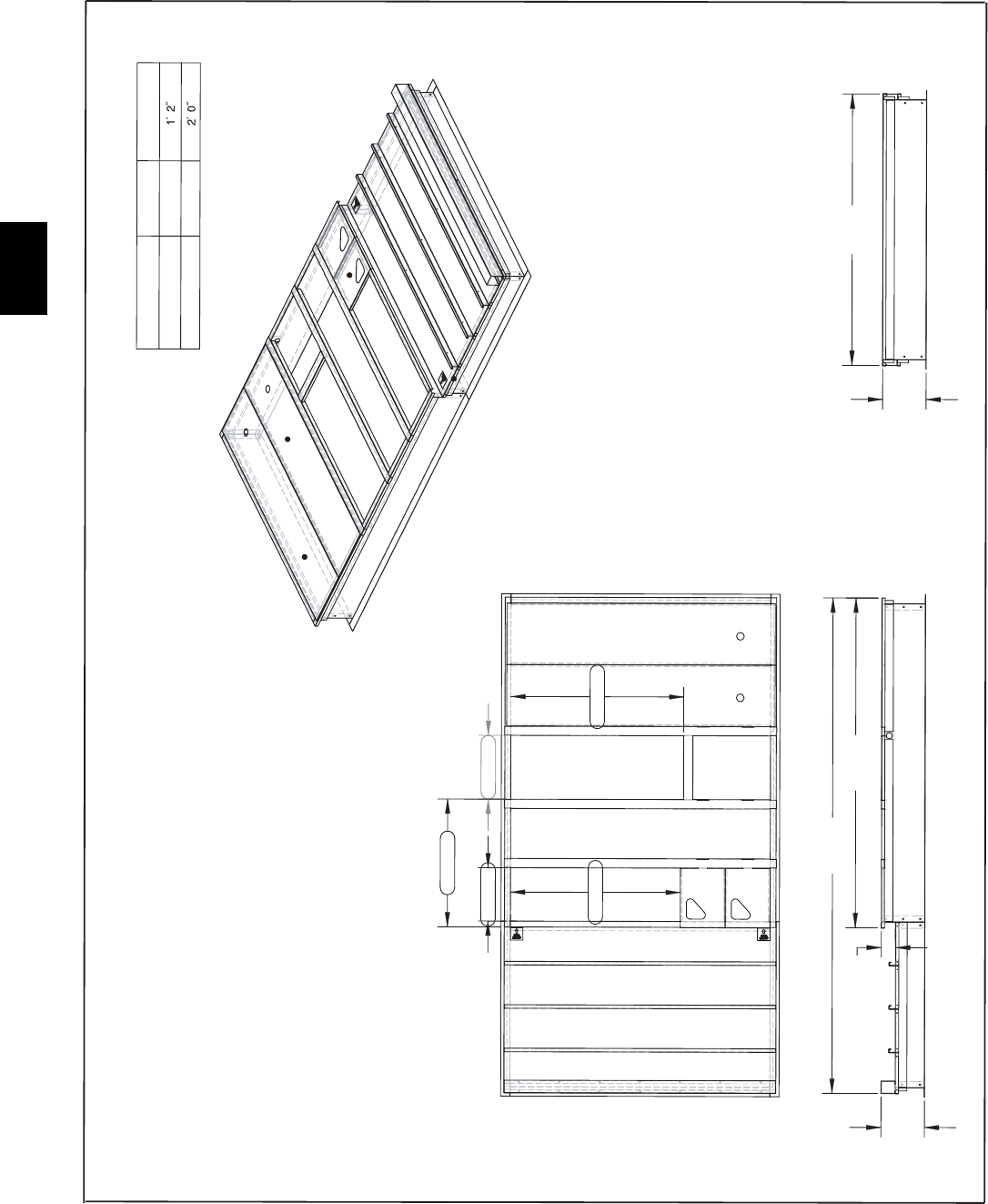
50
ACCESSORY DIMENSIONS -- FULL PERIMETER ROOF CURB FOR 48PG16 WITH
EnergyX
Roof Curb -- CREXCURB011A00 and CREXCURB012A00
2
72
.
60
1
85
6
.
95
1
526.
4
55
5.0
2
0
2
7.
5
5
6
57
.4
5
3
91
.
7
1
37
1
.
1
4
7
5
4
.7
8
CREXCURB011A00
CREXCURB012A00
DIMENSION
A
A
CURB HEIGHT
AA
Supply Air
Return Air
NOTE:
1. Roofcurbs ship knockdown.
2. Install ductwork into roofcurb before
placing the rooftop unit.
C08032
48PG
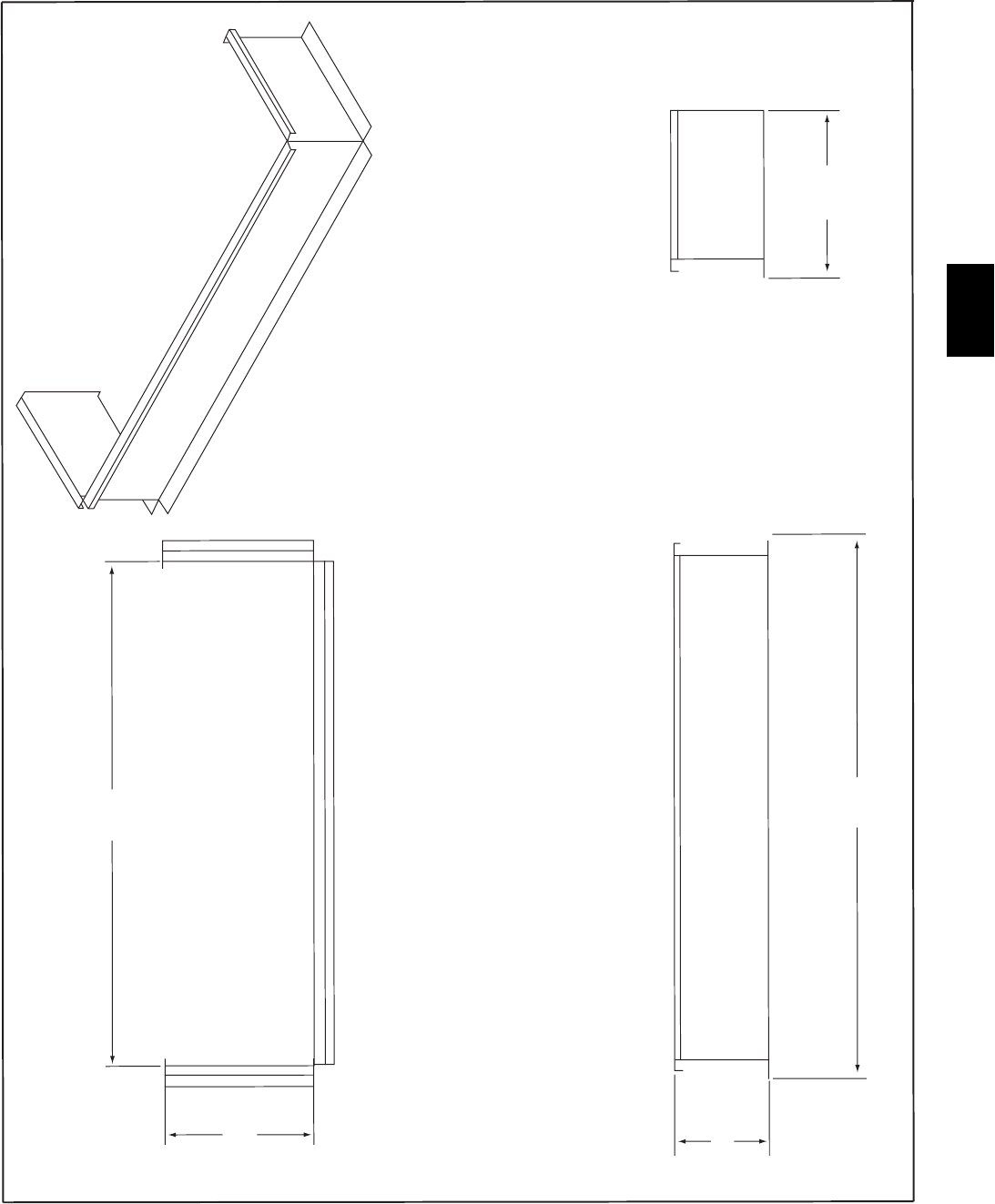
51
Roof Curb -- 14 and 24 Inch Curb Extension To Use With Standard Unit Roof Curb for
Units 48PG20--28 With EnergyX
75.125
I.D.
22.007
I.D.
A
81.125
25.066
C08036
48PG
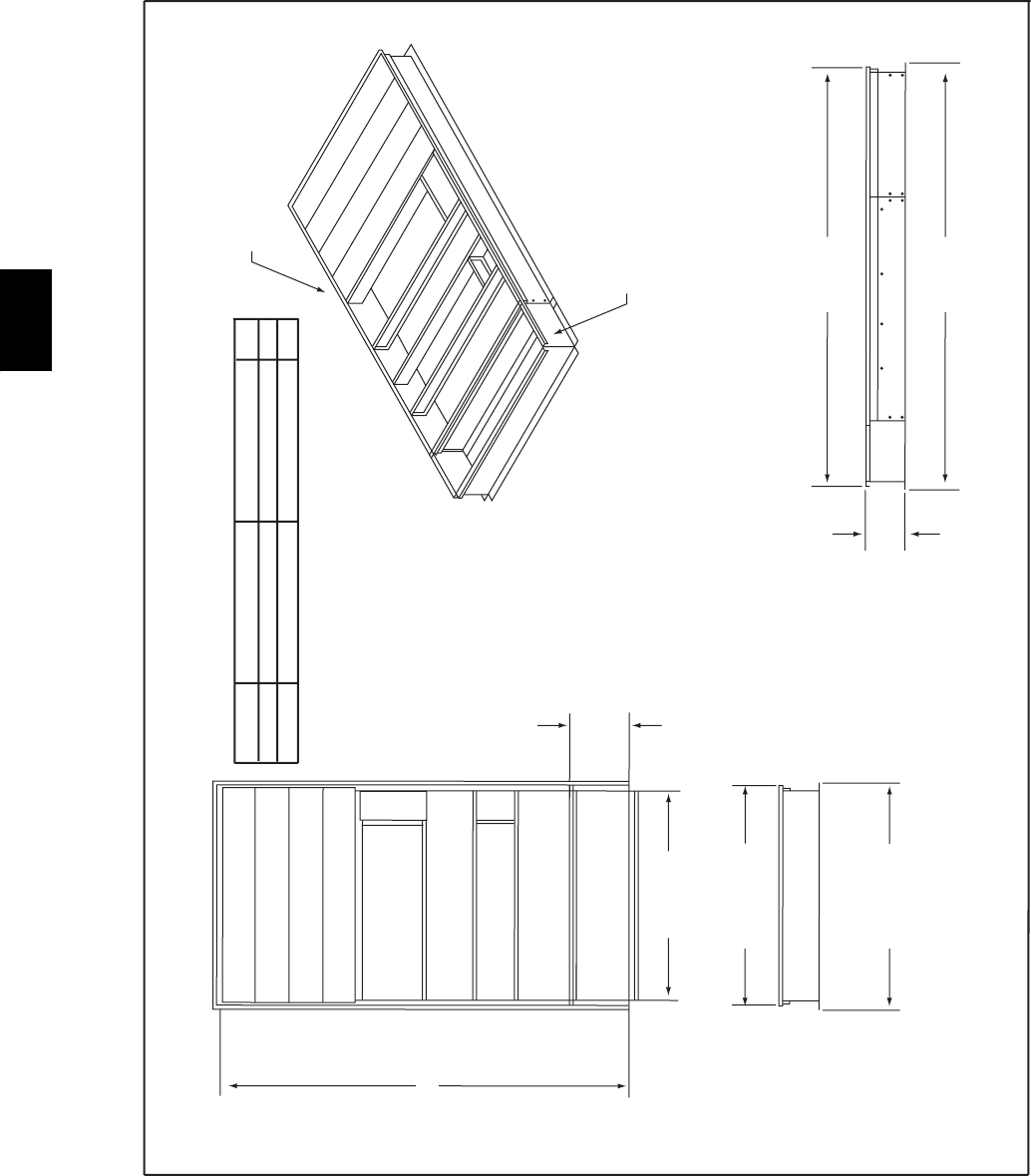
52
ACCESSORY DIMENSIONS -- EnergyX
Curb Extension Assembly Drawing to Use With 48PG20--24 Standard Roof Curb
146688 I.D.
22.125
75.125 I.D.
81.125 I.D.
78.618
150.313
A
152.688
EnergyX CURB EXTENSION
NOTE:
1. Curb extension is field assembled and connected to standard PG roof curb.
STANDARD
PG20-24 ROOF CURB
PG UNIT BASE UNIT CURB EXTENSTION A
20-24 CRRFCURB036A00 CREXCURB015A00 14”
20-24 CRRFCURB037A00 CREXCURB016A00 24”
Return Air
Supply Air
C08034
48PG
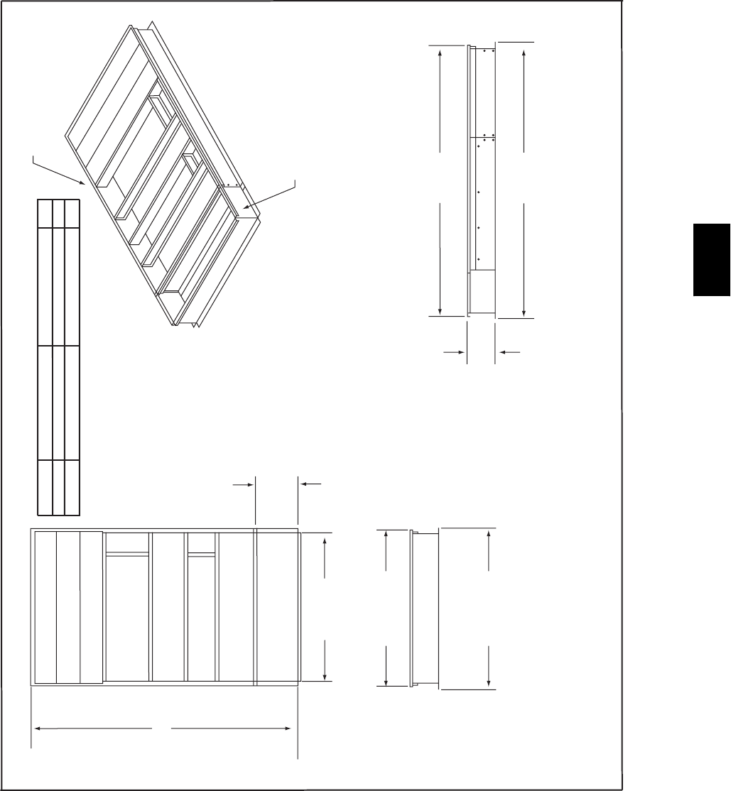
53
Curb Extension Assembly Drawing To Use With 48PG28 Standard Roof Curb
133.263 I.D.
22.126
75.127 I.D.
EnergyX CURB EXTENSION
78.750
78.613
136.769
A
136.768
STANDARD
PG28 ROOF CURB
NOTE:
1. Curb extension is field assembled and connected to standard PG roof curb.
PG UNIT BASE UNIT CURB EXTENSTION A
28 CRRFCURB018C00 CREXCURB015A00 14”
28 CRRFCURB019C00 CREXCURB016A00 24”
Return Air
Supply Air
C08035
48PG
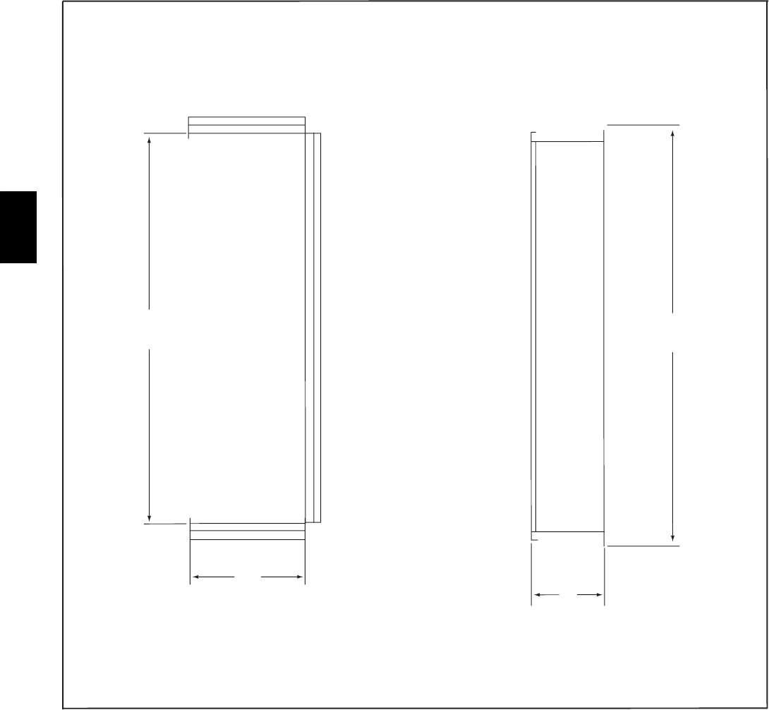
54
ACCESSORY DIMENSIONS -- EnergyX
Curb Extension
75.125
I.D.
22.007
I.D.
A
81.125
C08036
48PG

55
SELECTION PROCEDURE (WITH 48PGE06 EXAMPLE)
I. Determine cooling and heating requirements at design
conditions.
Given:
SRequired Gross Cooling
Capacity(TC)................57,000Btuh
SGross Sensible Heat
Capacity(SHC)...............37,000Btuh
SRequiredHeatingCapacity........90,000Btuh
SCondenser Entering Air
Temperature................95_F Summer
SIndoor Air Temperature ......80_F edb, 67_Fewb
SEvaporator Air Quantity............1,700cfm
SExternalStaticPressure............0.60in.wg
SElectricalCharacteristics(V--Ph--Hz).....230--3--60
Vertical supply required.
II. Select unit based on required cooling capacity.
SEnter Cooling Capacities table for 48PGE06 at condens-
er entering temperature of 95_F, evaporator air quantity
of 1,700 cfm, and indoor air temperature of 80/67_F.
The 48PGE06 unit will provide a total cooling capacity
of 60,300 Btuh and a SHC of 41,800 Btuh. For evapor-
ator air temperatures other than 80_F, calculate SHC
correction using formula in notes under cooling capacity
tables.
SUnit meets design conditions for TC and SHC
SNOTE: Unit ratings are gross capacities and do not in-
clude the effect of indoor fan motor heat. To calculate net
capacities, see Step V.
III. Select heating capacity of unit to provide design condition
requirement.
In Heating Capacities and Efficiencies table, note that
48PGE06 (medium heat) unit will provide 91,500 Btuh
with an input of 113,000 Btuh.
IV. Determine fan speed and power requirements at design
conditions.
SBefore entering the Fan Performance tables, calculate the
total static pressure required based on unit components.
Tabulated fan performance includes unit casing, filters,
and wet evaporator coil.
SCalculate pressure drop:
Design External Static Pressure 0.60
0.60 in.wg (ESP)
SEnter Fan Performance tables for 48PGE06 (medium
heat units, vertical supply) at 1,700 cfm and 0.60 in. wg.
The rpm is 826 and the Bhp is 0.6. The factory--installed
1--1/2 hp motor and standard drive are sufficient for this
operation.
V. Determine net cooling capacities.
SCooling capacities are gross capacities and do not in-
clude indoor (evaporator) fan motor (IFM) heat. To
determine input power to the motor, enter the Fan
Performance tables for 48PGE06 (medium heat units) at
1,700 cfm and 0.60 in. wg. Calculated input watts to the
motor are 613.
SDetermine Input Watts
Input Watts = (746 x Bhp)/(motor eff)
Input Watts = (746 x 0.60)/(0.73)
Input Watts = 613
SDetermine net cooling capacity and net sensible cooling
capacity using the following formulas:
IFM Heat = Input Watts x 3.412 Btuh/Watt
= 613 x 3.412
= 2091 Btuh
Net Capacity = Gross Capacity -- IFM Heat
= 60,300 -- 2091
= 58,208 Btuh
Net Sensible Cap. = Gross Sensible Cap. -- IFM Heat
= 41,800 -- 2091
= 39,709 Btuh
The calculations show that a 48PGE06 unit is the correct
selection for the given conditions.
VI. Select the unit that corresponds to power source available.
The electrical data table shows that the 230--3--60 unit is
available.
48PG
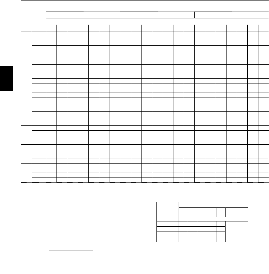
56
PERFORMANCE DATA
Cooling Capacities
48PG03 (2 Tons) — STANDARD UNIT AND UNIT WITH HUMIDI-MIZER™SYSTEM IN COOLING MODE
Te m p ( F )
Air Ent
Condenser
(
Edb
)
AirEnteringEvaporator—Cfm
600 800 1000
AirEnteringEvaporator—Ewb(F)
80 76 72 67 62 58 54 80 76 72 67 62 58 54 80 76 72 67 62 58 54
60
TC 33.7 31.7 29.8 27.4 25.2 23.5 23.0 35.6 33.6 31.6 29.2 26.9 25.4 25.4 36.9 34.9 32.9 30.4 28.0 27.3 27.3
SHC 9.1 11.7 14.2 17.1 20.0 22.2 22.6 9.3 12.5 15.7 19.5 23.2 25.0 25.0 9.4 13.3 17.0 21.6 26.0 26.8 26.8
kW 0.92 0.91 0.91 0.90 0.90 0.90 0.90 0.93 0.92 0.91 0.91 0.90 0.90 0.90 0.93 0.93 0.92 0.91 0.91 0.90 0.90
BF 0.00 0.00 0.21 0.18 0.17 0.17 0.33 0.00 0.00 0.20 0.19 0.18 0.25 0.44 0.00 0.25 0.20 0.20 0.20 0.36 0.52
70
TC 32.7 30.8 28.9 26.6 24.5 22.8 22.5 34.6 32.6 30.6 28.3 26.0 24.8 24.8 35.8 33.7 31.8 29.4 27.1 26.5 26.5
SHC 8.8 11.4 13.9 16.9 19.7 21.8 22.1 8.9 12.2 15.4 19.2 22.9 24.4 24.4 9.1 12.9 16.7 21.4 25.6 26.1 26.1
kW 1.10 1.10 1.09 1.09 1.09 1.08 1.08 1.11 1.11 1.10 1.09 1.09 1.09 1.09 1.12 1.11 1.11 1.10 1.09 1.09 1.09
BF 0.00 0.00 0.19 0.16 0.16 0.17 0.35 0.00 0.00 0.18 0.17 0.17 0.27 0.46 0.00 0.24 0.19 0.18 0.20 0.37 0.53
75
TC 32.2 30.3 28.4 26.2 24.0 22.4 22.2 34.0 32.0 30.1 27.8 25.6 24.4 24.4 35.1 33.1 31.2 28.8 26.6 26.1 26.1
SHC 8.7 11.2 13.7 16.7 19.6 21.5 21.8 8.8 12.0 15.2 19.0 22.8 24.0 24.0 8.9 12.7 16.5 21.2 25.3 25.7 25.7
kW 1.20 1.20 1.19 1.19 1.19 1.18 1.18 1.21 1.21 1.20 1.20 1.19 1.19 1.19 1.22 1.21 1.21 1.20 1.19 1.19 1.19
BF 0.00 0.00 0.18 0.15 0.15 0.17 0.36 0.00 0.00 0.18 0.17 0.17 0.28 0.46 0.00 0.23 0.19 0.18 0.20 0.38 0.54
85
TC 31.1 29.3 27.4 25.2 23.1 21.7 21.5 32.6 30.7 28.9 26.7 24.5 23.7 23.7 33.8 31.8 29.9 27.6 25.5 25.3 25.3
SHC 8.3 10.7 13.3 16.3 19.2 20.8 21.2 8.4 11.6 14.8 18.6 22.4 23.3 23.3 8.6 12.3 16.1 20.8 24.6 24.9 24.9
kW 1.42 1.42 1.41 1.41 1.40 1.40 1.39 1.43 1.42 1.42 1.41 1.40 1.40 1.40 1.43 1.43 1.42 1.41 1.41 1.41 1.41
BF 0.00 0.00 0.17 0.15 0.14 0.20 0.37 0.00 0.28 0.17 0.16 0.16 0.30 0.48 0.00 0.21 0.18 0.17 0.22 0.40 0.55
95
TC 30.0 28.1 26.2 24.1 22.1 20.8 20.8 31.3 29.4 27.6 24.9 23.4 22.8 22.8 32.3 30.4 28.6 26.4 24.5 24.3 24.3
SHC 8.1 10.3 12.9 15.9 18.9 20.5 20.4 8.0 11.2 14.3 17.9 21.8 22.4 22.4 8.1 11.9 15.7 20.3 23.5 23.9 23.9
kW 1.65 1.66 1.65 1.64 1.64 1.63 1.63 1.67 1.67 1.66 1.65 1.64 1.64 1.64 1.68 1.67 1.66 1.65 1.64 1.64 1.64
BF 0.00 0.00 0.16 0.14 0.13 0.19 0.39 0.00 0.23 0.16 0.15 0.16 0.33 0.50 0.00 0.20 0.18 0.17 0.25 0.42 0.57
105
TC 28.5 26.8 25.0 23.0 21.1 20.0 20.0 29.8 28.0 26.3 24.2 22.2 21.9 21.9 30.7 28.9 27.2 25.0 23.3 23.3 23.3
SHC 7.5 9.9 12.4 15.4 18.4 19.7 19.7 7.6 10.7 13.9 17.7 21.2 21.5 21.5 7.6 11.4 15.2 19.8 22.9 22.9 22.9
kW 1.93 1.92 1.92 1.91 1.90 1.89 1.89 1.93 1.93 1.93 1.91 1.90 1.90 1.90 1.95 1.94 1.93 1.92 1.91 1.91 1.91
BF 0.00 0.00 0.15 0.13 0.12 0.22 0.42 0.00 0.21 0.16 0.15 0.17 0.35 0.52 0.00 0.19 0.17 0.17 0.26 0.44 0.58
115
TC 27.0 25.3 23.7 21.8 19.9 19.1 19.1 28.2 26.5 24.8 22.9 21.0 20.9 20.9 29.0 27.2 25.6 23.6 22.2 22.2 22.2
SHC 7.1 9.5 12.0 14.9 17.9 18.8 18.8 7.1 10.3 13.4 17.2 20.3 20.6 20.6 7.2 10.9 14.7 19.3 21.9 21.9 21.9
kW 2.21 2.21 2.20 2.19 2.18 2.17 2.17 2.23 2.22 2.21 2.20 2.18 2.18 2.18 2.24 2.23 2.22 2.21 2.19 2.19 2.19
BF 0.00 0.00 0.14 0.13 0.12 0.25 0.44 0.00 0.18 0.16 0.15 0.19 0.38 0.54 0.00 0.18 0.17 0.16 0.29 0.47 0.60
125
TC 25.3 23.7 22.2 20.5 18.7 18.2 18.2 26.3 24.7 23.2 21.4 19.8 19.8 19.8 27.1 25.4 23.9 22.0 21.0 21.0 21.0
SHC 6.6 9.0 11.4 14.4 17.3 17.9 17.9 6.6 9.7 12.8 16.6 19.5 19.5 19.5 6.7 10.4 14.1 18.7 20.6 20.6 20.6
kW 2.53 2.52 2.51 2.53 2.50 2.50 2.50 2.54 2.54 2.52 2.51 2.52 2.52 2.52 2.56 2.54 2.53 2.51 2.50 2.50 2.50
BF 0.00 0.21 0.13 0.12 0.12 0.29 0.47 0.00 0.17 0.15 0.14 0.21 0.41 0.56 0.00 0.18 0.17 0.16 0.33 0.50 0.62
LEGEND
BF --- B y p a s s Fa c t o r
Edb --- E n t e r i n g D r y --- B u l b
Ewb --- E n t e r i n g W e t --- B u l b
kW --- Compressor Motor Power Input
Idb --- L e a v i n g D r y --- B u l b
Iwb --- L e a v i n g W e t --- B u l b
SHC --- Sensible Heat Capacity (1000 Btuh) Gross
TC --- Total Capacity (1000 Btuh) Gross
NOTES:
1. Direct interpolation is permissible. Do not extrapolate.
2. The following formulas may be used:
tldb =t
edb –sensible capacity (Btuh)
1.10 x cfm
tlwb = Wet --- bulb temperature corresponding to enthalpy of air leaving
evaporator coil (hlwb)
hlwb =h
ewb –total capacity (Btuh)
4.5 x cfm
Where: hewb = Enthalpy of air entering evaporator coil
3. The SHC is based on 80_F edb temperature of air entering evaporator coil
Below 80_F edb, subtract (corr factor x cfm) from SHC.
Above 80
_
F edb, add (corr factor x cfm) to SHC.
BYPASS
FACTOR
(BF)
ENTERING AIR DRY-BULB TEMP (F)
79 78 77 76 75 under 75
81 82 83 84 85 over 85
Correction Factor
.05 1.04 2.07 3.11 4.14 5.18
Use formula
shown below.
.10 .98 1.96 2.94 3.92 4.90
.20 .87 1.74 2.62 3.49 4.36
.30 .76 1.53 2.29 3.05 3.82
Interpolation is permissible.
C o r r e l a t i o n F a c t o r = 1 . 0 9 x ( 1 --- B F ) x ( e d b --- 8 0 ) .
4. Cooling capacities for 48PG03--- 16 units with Humidi--- MiZer system in Cooling
mode are the same as standard units.
48PG
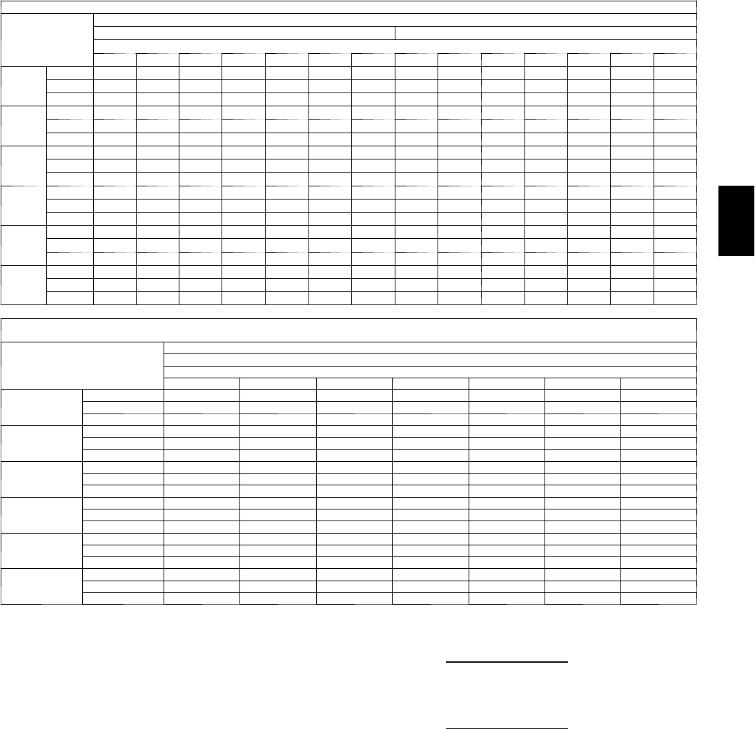
57
PERFORMANCE DATA (CONT)
Cooling Capacities (Cont)
4 8 P G 0 3 ( 2 To n s ) --- U N I T W I T H H U M I D I --- M I Z E R tSYSTEM IN SUBCOOLING MODE
Te m p ( F ) A i r E n t
Condenser
(Edb)
AirEnteringEvaporator—CFM
600 800
AirEnteringEvaporator—Ewb(F)
80 76 72 67 62 57 54 80 76 72 67 62 57 54
75
TC 33.7 31.4 29.2 26.4 23.7 20.9 19.2 35.4 33.1 30.8 27.9 25.0 22.1 20.4
SHC 8.6 10.8 12.9 15.6 18.4 20.9 19.2 10.2 12.3 14.4 17.0 19.6 22.1 20.4
kW 1.19 1.19 1.21 1.22 1.23 1.24 1.25 1.19 1.19 1.21 1.22 1.23 1.24 1.3
85
TC 30.5 28.4 26.3 23.6 20.9 18.3 16.7 32.4 30.2 28.0 25.2 22.4 19.6 17.9
SHC 4.5 7.2 9.9 13.3 16.7 20.1 22.1 6.3 8.9 11.6 14.8 18.1 21.4 23.4
kW 1.41 1.41 1.42 1.43 1.44 1.45 1.45 1.41 1.41 1.42 1.43 1.44 1.45 1.5
95
TC 27.4 25.4 23.3 20.8 18.2 15.6 14.1 29.5 27.3 25.1 22.4 19.7 17.0 15.4
SHC 0.3 3.6 6.9 11.0 15.0 15.6 14.1 2.4 5.5 8.7 12.7 16.6 17.0 15.4
kW 1.62 1.62 1.63 1.64 1.64 1.65 1.65 1.62 1.62 1.63 1.64 1.64 1.65 1.7
105
TC 24.3 22.4 20.4 17.9 15.5 13.0 11.5 26.5 24.4 22.3 19.7 17.1 14.4 12.9
SHC –3.8 0.0 3.8 8.6 13.4 13.0 11.5 –1.6 2.2 5.9 10.5 15.1 14.4 12.9
kW 1.84 1.84 1.85 1.85 1.85 1.85 1.85 1.84 1.84 1.85 1.85 1.85 1.85 1.9
115
TC 21.2 19.3 17.4 15.1 12.7 10.4 8.9 23.5 21.4 19.4 16.9 14.4 11.9 10.4
SHC –7.9 –3.6 0.8 6.3 11.7 10.4 8.9 –5.5 –1.2 3.0 8.3 13.6 11.9 10.4
kW 2.06 2.06 2.06 2.06 2.06 2.06 2.05 2.06 2.06 2.06 2.06 2.06 2.06 2.1
125
TC 18.1 16.3 14.5 12.2 10.0 7.7 6.4 20.5 18.5 16.6 14.2 11.7 9.3 7.9
SHC –12.1 –7.2 –2.2 3.9 10.0 7.7 6.4 –9.4 –4.6 0.2 6.2 11.7 9.3 7.9
kW 2.28 2.28 2.27 2.27 2.26 2.26 2.26 2.28 2.28 2.27 2.27 2.26 2.26 2.3
48PG03 (2 Tons) --- UNIT WITH HUMIDI--- MIZER SYSTEM IN SUBCOOLING MODE (CONT)
Te m p ( F ) A i r E n t C o n d e n s e r
(Edb)
AirEnteringEvaporator—CFM
1000
AirEnteringEvaporator—Ewb(F)
80 76 72 67 62 57 54
75
TC 36.9 34.5 32.1 29.1 26.1 23.1 21.3
SHC 11.5 13.5 15.5 18.1 20.6 23.1 21.3
kW 1.19 1.19 1.21 1.22 1.23 1.24 1.25
85
TC 33.9 31.6 29.3 26.4 23.5 20.6 18.8
SHC 7.7 10.3 12.8 16.0 19.2 22.4 24.3
kW 1.41 1.41 1.42 1.43 1.44 1.45 1.45
95
TC 31.0 28.8 26.5 23.7 20.9 18.1 16.4
SHC 4.0 7.0 10.1 14.0 17.9 18.1 16.4
kW 1.62 1.62 1.63 1.64 1.64 1.65 1.65
105
TC 28.1 26.0 23.8 21.0 18.3 15.6 13.9
SHC 0.2 3.8 7.4 12.0 16.5 15.6 13.9
kW 1.84 1.84 1.85 1.85 1.85 1.85 1.85
115
TC 25.2 23.1 21.0 18.4 15.7 13.1 11.5
SHC –3.6 0.6 4.7 9.9 15.1 13.1 11.5
kW 2.06 2.06 2.06 2.06 2.06 2.06 2.05
125
TC 22.3 20.3 18.2 15.7 13.1 10.6 9.1
SHC –7.3 –2.7 2.0 7.9 13.1 10.6 9.1
kW 2.28 2.28 2.27 2.27 2.26 2.26 2.26
LEGEND
Edb --- E n t e r i n g D r y --- B u l b
Ewb --- E n t e r i n g W e t --- B u l b
kW --- Compressor Motor Power Input
Idb --- L e a v i n g D r y --- B u l b
Iwb --- L e a v i n g W e t --- B u l b
SHC --- Sensible Heat Capacity (1000 Btuh) Gross
TC --- Total Capacity (1000 Btuh) Gross
NOTES:
1. Direct interpolation is permissible. Do not extrapolate.
2. The following formulas may be used:
tldb =t
edb –sensible capacity (Btuh)
1.10 x cfm
tlwb = Wet --- bulb temperature corresponding to enthalpy of air leaving
evaporator coil (hlwb)
hlwb =h
ewb –total capacity (Btuh)
4.5 x cfm
Where: hewb = Enthalpy of air entering evaporator coil
48PG
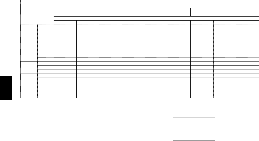
58
Cooling Capacities (Cont)
4 8 P G 0 3 ( 2 T O N S ) --- U N I T W I T H H U M I D I --- M I Z E R tSYSTEM IN HOT GAS REHEAT MODE
Te m p ( F ) A i r E n t
Condenser (Edb)
AirEnteringEvaporator—Ewb(F)
75 Dry Bulb
62.5 Wet Bulb (50% RH)
75 Dry Bulb
64 Wet Bulb (55% RH)
75 Dry Bulb
65.3 Wet Bulb (60% RH)
AirEnteringEvaporator—Cfm
700 800 900 700 800 900 700 800 900
80
TC 9.9 10.4 10.9 10.6 11.2 11.7 11.2 11.8 12.3
SHC 2.0 2.6 3.1 0.8 1.3 1.8 –0.3 0.2 0.7
kW 1.28 1.28 1.28 1.29 1.29 1.29 1.29 1.29 1.29
75
TC 10.6 11.2 11.6 11.3 11.9 12.4 12.0 12.5 13.0
SHC 2.6 3.1 3.6 1.4 1.9 2.4 0.4 0.9 1.4
kW 1.26 1.26 1.26 1.27 1.27 1.27 1.27 1.27 1.27
70
TC 11.4 11.9 12.3 12.1 12.6 13.1 12.7 13.2 13.7
SHC 3.1 3.6 4.0 2.0 2.5 3.0 1.1 1.6 2.0
kW 1.24 1.24 1.24 1.25 1.25 1.25 1.25 1.25 1.25
60
TC 12.9 13.4 13.7 13.6 14.0 14.4 14.2 14.6 15.0
SHC 4.2 4.6 5.0 3.3 3.7 4.1 2.5 2.9 3.3
kW 1.20 1.20 1.20 1.21 1.21 1.21 1.22 1.22 1.22
50
TC 14.5 14.8 15.1 15.1 15.5 15.8 15.7 16.1 16.4
SHC 5.2 5.6 5.9 4.5 4.9 5.2 3.9 4.3 4.6
kW 1.17 1.17 1.17 1.17 1.17 1.17 1.18 1.18 1.18
40
TC 16.0 16.3 16.5 16.6 16.9 17.2 17.2 17.5 17.7
SHC 6.3 6.6 6.9 5.8 6.1 6.4 5.4 5.7 6.0
kW 1.13 1.13 1.13 1.14 1.14 1.14 1.15 1.15 1.15
LEGEND
Edb --- E n t e r i n g D r y --- B u l b
Ewb --- E n t e r i n g W e t --- B u l b
kW --- Compressor Motor Power Input
Idb --- L e a v i n g D r y --- B u l b
Iwb --- L e a v i n g W e t --- B u l b
SHC --- Sensible Heat Capacity (1000 Btuh) Gross
TC --- Total Capacity (1000 Btuh) Gross
NOTES:
1. Direct interpolation is permissible. Do not extrapolate.
2. The following formulas may be used:
tldb =t
edb –sensible capacity (Btuh)
1.10 x cfm
tlwb = Wet --- bulb temperature corresponding to enthalpy of air leaving
evaporator coil (hlwb)
hlwb =h
ewb –total capacity (Btuh)
4.5 x cfm
Where: hewb = Enthalpy of air entering evaporator coil
48PG
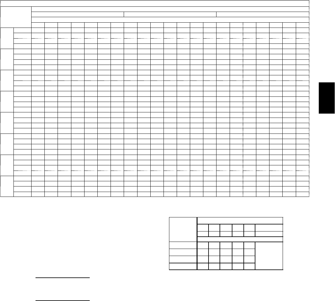
59
PERFORMANCE DATA (CONT)
Cooling Capacities (Cont)
48PG04 (3 Tons) — STANDARD UNIT AND UNIT WITH HUMIDI-MIZER™SYSTEM IN COOLING MODE
Te m p ( F )
Air Ent
Condenser
(Edb)
AirEnteringEvaporator—Cfm
900 1200 1500
AirEnteringEvaporator—Ewb(F)
80 76 72 67 62 58 54 80 76 72 67 62 58 54 80 76 72 67 62 58 54
60
TC 49.5 46.3 43.4 39.9 36.7 34.3 33.1 52.8 49.6 46.4 42.7 39.2 37.0 36.7 54.6 51.3 48.2 44.4 40.9 39.4 39.4
SHC 13.7 17.4 20.7 25.2 29.4 32.5 33.1 14.1 18.3 23.2 28.8 34.1 35.0 36.7 14.2 19.6 25.3 32.0 38.2 39.4 39.4
kW 1.66 1.64 1.62 1.60 1.59 1.57 1.57 1.67 1.66 1.64 1.62 1.60 1.59 1.58 1.69 1.67 1.65 1.63 1.61 1.60 1.60
BF 0.00 0.17 0.21 0.18 0.18 0.19 0.36 0.00 0.33 0.20 0.19 0.20 0.32 0.47 0.00 0.25 0.20 0.20 0.22 0.38 0.54
70
TC 48.1 45.1 42.3 38.8 35.6 33.1 32.3 51.0 47.9 44.8 41.2 37.9 35.8 35.8 52.6 49.5 46.5 42.8 39.3 38.4 38.4
SHC 13.2 17.0 20.4 24.8 29.0 31.8 32.3 13.5 17.8 22.7 28.3 33.7 35.8 35.8 13.6 19.1 24.7 31.4 37.4 38.4 38.4
kW 1.88 1.87 1.86 1.84 1.83 1.81 1.81 1.90 1.88 1.87 1.85 1.83 1.83 1.83 1.91 1.90 1.88 1.86 1.84 1.84 1.84
BF 0.00 0.18 0.19 0.17 0.17 0.20 0.38 0.00 0.29 0.19 0.18 0.19 0.29 0.48 0.00 0.24 0.20 0.20 0.23 0.39 0.55
75
TC 47.4 44.4 41.6 38.1 35.0 32.5 31.9 50.0 46.9 43.9 40.5 37.2 35.3 35.3 51.6 48.5 45.5 42.0 38.6 37.8 37.8
SHC 13.0 16.7 20.1 24.5 28.8 31.3 31.9 13.2 17.6 22.4 28.0 62.1 35.3 35.3 13.3 18.8 24.4 31.2 36.9 37.8 37.8
kW 2.01 2.00 1.99 1.97 1.95 1.94 1.94 2.03 2.01 2.00 1.98 1.97 1.95 1.95 2.04 2.02 2.01 1.99 1.98 1.97 1.97
BF 0.00 0.18 0.18 0.17 0.17 0.20 0.39 0.00 0.27 0.19 0.18 0.19 0.31 0.49 0.00 0.24 0.20 0.20 0.23 0.40 0.56
85
TC 45.7 42.8 40.0 36.8 33.7 31.3 31.0 47.9 45.0 42.2 38.8 35.6 34.1 34.1 49.4 46.4 43.6 40.1 37.0 36.5 36.5
SHC 12.5 16.1 19.6 24.0 28.2 30.4 31.0 12.6 17.1 21.8 27.4 32.9 34.1 34.1 12.7 18.2 23.7 30.5 35.9 36.5 36.5
kW 2.30 2.28 2.27 2.25 2.23 2.22 2.21 2.31 2.30 2.28 2.26 2.24 2.23 2.23 2.32 2.31 2.29 2.27 2.25 2.24 2.24
BF 0.00 0.19 0.17 0.16 0.16 0.21 0.41 0.00 0.24 0.18 0.18 0.18 0.33 0.51 0.00 0.23 0.20 0.20 0.24 0.42 0.58
95
TC 43.7 41.0 38.3 35.2 32.2 29.9 29.9 45.7 42.9 40.2 36.0 34.0 32.9 32.9 47.0 44.1 41.5 38.3 35.3 35.1 35.1
SHC 11.8 15.2 19.0 23.4 27.5 29.9 29.9 11.9 16.5 21.1 26.1 32.1 32.9 32.9 12.0 17.5 23.0 29.7 34.9 35.1 35.1
kW 2.60 2.58 2.57 2.54 2.53 2.51 2.51 2.61 2.60 2.58 2.53 2.54 2.53 2.53 2.63 2.61 2.59 2.57 2.54 2.54 2.54
BF 0.00 0.29 0.16 0.15 0.16 0.22 0.43 0.00 0.22 0.18 0.18 0.18 0.35 0.52 0.00 0.22 0.20 0.20 0.26 0.45 0.59
105
TC 41.5 39.0 36.4 33.5 30.7 28.9 28.8 43.2 40.6 38.1 35.2 32.3 31.6 31.6 44.4 41.7 39.2 36.2 33.6 33.6 33.6
SHC 11.1 14.5 18.3 22.7 26.9 28.9 28.8 11.2 15.8 20.4 26.0 30.9 31.6 31.6 11.3 16.8 22.3 28.9 33.6 33.6 33.6
kW 2.92 2.91 2.89 2.87 2.85 2.85 2.85 2.94 2.93 2.91 2.89 2.87 2.86 2.86 2.95 2.94 2.91 2.89 2.87 2.87 2.87
BF 0.00 0.29 0.15 0.15 0.16 0.25 0.45 0.00 0.21 0.18 0.17 0.20 0.38 0.55 0.00 0.22 0.20 0.20 0.28 0.47 0.61
115
TC 39.0 36.6 34.3 31.6 29.1 27.5 27.5 40.6 38.1 35.8 33.1 30.5 30.1 30.1 41.6 39.1 36.8 34.0 32.0 32.0 32.0
SHC 10.4 13.9 17.6 22.0 26.1 27.5 27.5 10.5 15.0 19.6 25.2 29.7 30.1 30.1 10.5 16.0 21.5 28.1 32.0 32.0 32.0
kW 3.29 3.27 3.26 3.24 3.22 3.20 3.20 3.30 3.29 3.27 3.25 3.23 3.22 3.22 3.31 3.30 3.28 3.25 3.24 3.24 3.24
BF 0.00 0.22 0.15 0.15 0.15 0.28 0.47 0.00 0.20 0.17 0.17 0.22 0.41 0.57 0.00 0.21 0.20 0.20 0.32 0.50 0.63
125
TC 36.3 34.1 32.0 29.5 27.1 26.1 26.1 37.6 35.3 33.3 30.7 28.5 28.4 28.4 38.4 36.2 34.1 31.6 30.0 30.0 30.0
SHC 9.5 13.1 16.8 21.1 25.3 26.1 26.1 9.6 14.2 18.7 24.2 28.1 28.4 28.4 9.6 15.1 20.5 27.2 30.0 30.0 30.0
kW 3.67 3.66 3.64 3.62 3.60 3.59 3.59 3.68 3.67 3.65 3.63 3.61 3.61 3.61 3.69 3.68 3.66 3.64 3.62 3.62 3.62
BF 0.00 0.19 0.15 0.15 0.15 0.32 0.50 0.00 0.19 0.17 0.17 0.25 0.45 0.59 0.00 0.21 0.20 0.20 0.36 0.53 0.65
LEGEND
BF --- B y p a s s Fa c t o r
Edb --- E n t e r i n g D r y --- B u l b
Ewb --- E n t e r i n g W e t --- B u l b
kW --- Compressor Motor Power Input
Idb --- L e a v i n g D r y --- B u l b
Iwb --- L e a v i n g W e t --- B u l b
SHC --- Sensible Heat Capacity (1000 Btuh) Gross
TC --- Total Capacity (1000 Btuh) Gross
NOTES:
1. Direct interpolation is permissible. Do not extrapolate.
2. The following formulas may be used:
tldb =t
edb –
sensible capacity (Btuh)
1.10 x cfm
tlwb = Wet --- bulb temperature corresponding to enthalpy of air leaving
evaporator coil (hlwb)
hlwb =h
ewb –total capacity (Btuh)
4.5 x cfm
Where: hewb = Enthalpy of air entering evaporator coil
3. The SHC is based on 80_F edb temperature of air entering evaporator coil
Below 80_F edb, subtract (corr factor x cfm) from SHC.
Above 80
_
F edb, add (corr factor x cfm) to SHC.
BYPASS
FACTOR
(BF)
ENTERING AIR DRY-BULB TEMP (F)
79 78 77 76 75 under 75
81 82 83 84 85 over 85
Correction Factor
.05 1.04 2.07 3.11 4.14 5.18
Use formula
shown below.
.10 .98 1.96 2.94 3.92 4.90
.20 .87 1.74 2.62 3.49 4.36
.30 .76 1.53 2.29 3.05 3.82
Interpolation is permissible.
C o r r e l a t i o n Fa c t o r = 1 . 0 9 x ( 1 --- B F ) x ( e d b --- 8 0 ) .
4. Cooling capacities for 48PG03---16 units with Humidi---MiZer system in
Coolingmodearethesameasstandardunits.
48PG
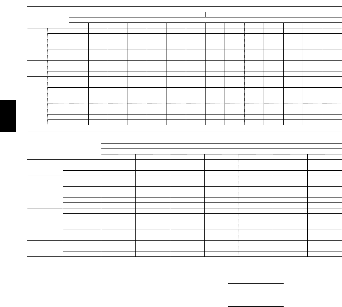
60
Cooling Capacities (Cont)
48PG04 (3 Tons) — UNIT WITH HUMIDI-MIZER™SYSTEM IN SUBCOOLING MODE
Te m p ( F )
Air Ent
Condenser
(Edb)
AirEnteringEvaporator—CFM
900 1200
AirEnteringEvaporator—Ewb(F)
80 76 72 67 62 57 54 80 76 72 67 62 57 54
75
TC 49.2 46.2 43.1 39.3 35.6 31.8 29.5 52.1 48.9 45.7 41.7 37.8 33.8 31.4
SHC 15.4 18.6 21.8 25.8 29.8 31.8 29.5 17.9 21.0 24.1 27.9 31.7 33.8 31.4
kW 1.97 1.97 1.97 1.97 1.97 1.98 1.98 1.97 1.97 1.97 1.97 1.97 1.98 1.98
85
TC 45.1 42.2 39.3 35.7 32.0 28.4 26.2 48.1 45.0 41.9 38.1 34.3 30.4 28.1
SHC 9.9 13.9 17.9 22.8 27.8 32.8 35.8 12.7 16.6 20.4 25.3 30.1 34.9 37.8
kW 2.27 2.27 2.27 2.27 2.27 2.27 2.27 2.27 2.27 2.27 2.27 2.27 2.27 2.27
95
TC 41.0 38.2 35.4 32.0 28.5 25.0 22.9 44.1 41.1 38.2 34.5 30.8 27.1 24.9
SHC 4.3 9.1 13.9 19.9 25.9 25.0 22.9 7.5 12.2 16.8 22.6 28.4 27.1 24.9
kW 2.58 2.58 2.57 2.57 2.56 2.56 2.56 2.58 2.58 2.57 2.57 2.56 2.56 2.56
105
TC 36.9 34.2 31.6 28.3 25.0 21.7 19.7 40.0 37.2 34.4 30.8 27.3 23.8 21.6
SHC –1.2 4.4 10.0 17.0 24.0 21.7 19.7 2.3 7.7 13.2 20.0 26.7 23.8 21.6
kW 2.89 2.89 2.88 2.87 2.86 2.85 2.85 2.89 2.89 2.88 2.87 2.86 2.85 2.85
115
TC 32.8 30.3 27.7 24.6 21.4 18.3 16.4 36.0 33.3 30.6 27.2 23.8 20.4 18.4
SHC –6.7 –0.3 6.1 14.1 21.4 18.3 16.4 –2.9 3.3 9.5 17.3 23.8 20.4 18.4
kW 3.20 3.20 3.18 3.17 3.15 3.14 3.13 3.20 3.20 3.18 3.17 3.15 3.14 3.13
125
TC 28.7 26.3 23.9 20.9 17.9 14.9 13.1 31.9 29.4 26.8 23.5 20.3 17.1 15.1
SHC –12.3 –5.1 2.1 11.1 17.9 14.9 13.1 –8.1 –1.1 5.9 14.7 20.3 17.1 15.1
kW 3.51 3.51 3.48 3.47 3.45 3.43 3.42 3.51 3.51 3.48 3.47 3.45 3.43 3.42
48PG04 (3 Tons) — UNIT WITH HUMIDI-MIZER SYSTEM IN SUBCOOLING MODE (cont)
Te m p ( F )
Air Ent
Condenser
(Edb)
AirEnteringEvaporator—CFM
1500
AirEnteringEvaporator—Ewb(F)
80 76 72 67 62 57 54
75
TC 54.5 51.2 47.8 43.7 39.5 35.4 32.9
SHC 19.9 22.9 25.8 29.6 33.3 35.4 32.9
kW 1.97 1.97 1.97 1.97 1.97 1.98 1.98
85
TC 50.5 47.3 44.1 40.1 36.1 32.0 29.6
SHC 15.0 18.7 22.4 27.1 31.8 36.5 39.3
kW 2.27 2.27 2.27 2.27 2.27 2.27 2.27
95
TC 46.5 43.4 40.3 36.5 32.6 28.7 26.4
SHC 10.0 14.5 19.0 24.7 30.4 28.7 26.4
kW 2.58 2.58 2.57 2.57 2.56 2.56 2.56
105
TC 42.5 39.5 36.6 32.9 29.1 25.4 23.2
SHC 5.1 10.4 15.6 22.3 28.9 25.4 23.2
kW 2.89 2.89 2.88 2.87 2.86 2.85 2.85
115
TC 38.5 35.7 32.8 29.3 25.7 22.1 20.0
SHC 0.1 6.2 12.2 19.8 25.7 22.1 20.0
kW 3.20 3.20 3.18 3.17 3.15 3.14 3.13
125
TC 34.5 31.8 29.1 25.6 22.2 18.8 16.7
SHC –4.8 2.0 8.9 17.4 22.2 18.8 16.7
kW 3.51 3.51 3.48 3.47 3.45 3.43 3.42
LEGEND
Edb --- E n t e r i n g D r y --- B u l b
Ewb --- E n t e r i n g W e t --- B u l b
kW --- Compressor Motor Power Input
Idb --- L e a v i n g D r y --- B u l b
Iwb --- L e a v i n g W e t --- B u l b
SHC --- Sensible Heat Capacity (1000 Btuh) Gross
TC --- Total Capacity (1000 Btuh) Gross
NOTES:
1. Direct interpolation is permissible. Do not extrapolate.
2. The following formulas may be used:
tldb =tedb –sensible capacity (Btuh)
1.10 x cfm
tlwb = Wet---bulb temperature corresponding to enthalpy of air leaving
evaporator coil (hlwb)
hlwb =h
ewb –total capacity (Btuh)
4.5 x cfm
Where: hewb = Enthalpy of air entering evaporator coil
48PG
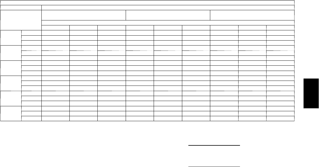
61
PERFORMANCE DATA (CONT)
Cooling Capacities (CONT)
4 8 P G 0 4 ( 3 T O N S ) --- U N I T W I T H H U M I D I --- M I Z E R tSYSTEM IN HOT GAS REHEAT MODE
AirEnteringEvaporator—Ewb(F)
Te m p ( F ) A i r E n t
Condenser (Edb)
75 Dry Bulb
62.5 Wet Bulb (50% RH)
75 Dry Bulb
64 Wet Bulb (55% RH)
75 Dry Bulb
65.3 Wet Bulb (60% RH)
AirEnteringEvaporator—Cfm
1050 1200 1350 1050 1200 1350 1050 1200 1350
80
TC 15.6 16.4 17.1 16.8 17.6 18.3 17.8 18.6 19.4
SHC 5.9 6.8 7.5 4.3 5.1 5.9 2.9 3.7 4.5
kW 0.11 0.11 0.11 1.40 1.40 1.40 2.52 2.52 2.52
75
TC 16.0 16.7 17.4 17.1 17.9 18.6 18.1 18.9 19.6
SHC 6.7 7.5 8.2 5.2 6.0 6.7 3.9 4.7 5.4
kW 0.25 0.25 0.25 1.46 1.46 1.46 2.51 2.51 2.51
70
TC 16.4 17.1 17.7 17.5 18.2 18.8 18.4 19.2 19.8
SHC 7.5 8.2 8.9 6.1 6.9 7.5 4.9 5.7 6.3
kW 0.39 0.39 0.39 1.52 1.52 1.52 2.51 2.51 2.51
60
TC 17.1 17.7 18.3 18.2 18.8 19.3 19.1 19.7 20.3
SHC 9.1 9.7 10.3 7.9 8.6 9.2 7.0 7.6 8.2
kW 0.67 0.67 0.67 1.65 1.65 1.65 2.50 2.50 2.50
50
TC 17.9 18.4 18.9 18.9 19.4 19.9 19.7 20.2 20.7
SHC 10.6 11.2 11.7 9.7 10.3 10.8 9.0 9.6 10.1
kW 0.95 0.95 0.95 1.78 1.78 1.78 2.50 2.50 2.50
40
TC 18.7 19.1 19.5 19.6 20.0 20.4 20.3 20.7 21.1
SHC 12.2 12.7 13.1 11.6 12.1 12.5 11.0 11.5 12.0
kW 1.24 1.24 1.24 1.91 1.91 1.91 2.49 2.49 2.49
LEGEND
Edb --- E n t e r i n g D r y --- B u l b
Ewb --- E n t e r i n g W e t --- B u l b
kW --- Compressor Motor Power Input
Idb --- L e a v i n g D r y --- B u l b
Iwb --- L e a v i n g W e t --- B u l b
SHC --- Sensible Heat Capacity (1000 Btuh) Gross
TC --- Total Capacity (1000 Btuh) Gross
NOTES:
1. Direct interpolation is permissible. Do not extrapolate.
2. The following formulas may be used:
tldb =tedb –sensible capacity (Btuh)
1.10 x cfm
tlwb = Wet --- bulb temperature corresponding to enthalpy of air leaving
evaporator coil (hlwb)
hlwb =h
ewb –total capacity (Btuh)
4.5 x cfm
Where: hewb = Enthalpy of air entering evaporator coil
48PG
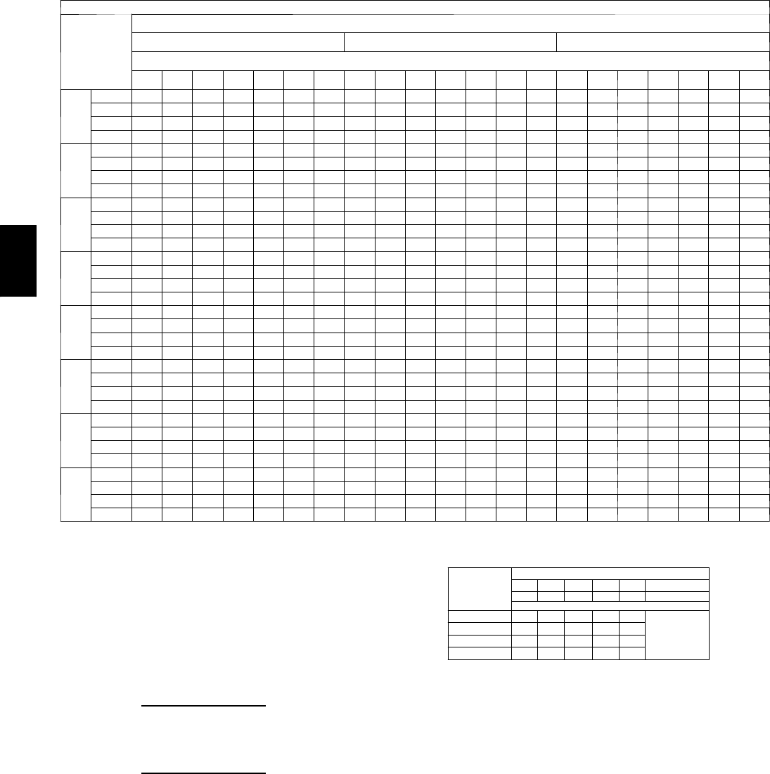
62
Cooling Capacities (Cont)
48PG05 (4 Tons) — STANDARD UNIT AND UNIT WITH HUMIDI-MIZER™SYSTEM IN COOLING MODE
Te m p ( F )
Air Ent
Condenser
(
Edb
)
AirEnteringEvaporator—Cfm
1200 1600 2000
AirEnteringEvaporator—Ewb(F)
80 76 72 67 62 58 54 80 76 72 67 62 58 54 80 76 72 67 62 58 54
60
TC 66.6 62.4 58.4 53.6 49.1 45.7 44.5 70.5 66.2 61.9 57.0 52.3 49.2 49.2 72.9 68.3 64.1 59.1 54.3 52.7 52.7
SHC 18.3 23.4 27.8 33.8 39.6 43.4 44.5 18.6 24.3 31.0 38.6 45.8 49.2 49.2 18.7 26.1 33.7 42.7 51.0 52.7 52.7
kW 2.22 2.18 2.14 2.10 2.06 2.03 2.02 2.26 2.22 2.17 2.13 2.09 2.06 2.06 2.28 2.24 2.20 2.15 2.11 2.09 2.09
BF 0.00 0.00 0.00 0.24 0.22 0.23 0.37 0.00 0.00 0.27 0.23 0.23 0.30 0.47 0.00 0.00 0.26 0.24 0.25 0.39 0.55
70
TC 64.4 60.3 56.4 51.8 47.5 44.1 43.3 67.9 63.6 59.5 54.8 50.4 47.8 47.8 70.0 65.6 61.6 56.8 52.1 51.1 51.1
SHC 17.6 22.6 27.2 33.2 38.9 42.3 43.3 17.8 23.7 30.2 37.8 45.1 47.8 47.8 17.9 25.3 32.8 41.9 49.7 51.1 51.1
kW 2.53 2.49 2.45 2.41 2.37 2.33 2.33 2.57 2.52 2.48 2.43 2.39 2.37 2.37 2.59 2.55 2.50 2.46 2.41 2.40 2.40
BF 0.00 0.00 0.36 0.22 0.20 0.24 0.39 0.00 0.00 0.25 0.22 0.22 0.31 0.49 0.00 0.36 0.25 0.24 0.26 0.41 0.56
75
TC 63.2 59.1 55.4 50.8 46.6 43.4 42.7 66.4 62.3 58.3 53.7 49.4 47.0 47.0 68.4 64.1 60.2 55.6 51.1 50.3 50.3
SHC 17.2 22.2 26.9 32.8 38.6 41.8 42.7 17.4 23.4 29.8 37.3 44.7 47.0 47.0 17.5 24.9 32.4 41.4 49.1 50.3 50.3
kW 2.70 2.66 2.62 2.57 2.53 2.50 2.50 2.74 2.69 2.65 2.60 2.56 2.54 2.54 2.76 2.71 2.67 2.62 2.57 2.57 2.57
BF 0.00 0.00 0.29 0.22 0.20 0.24 0.40 0.00 0.00 0.24 0.22 0.22 0.33 0.50 0.00 0.33 0.25 0.24 0.27 0.42 0.57
85
TC 60.6 56.7 53.1 48.8 44.7 41.7 41.3 63.5 59.5 55.7 51.4 47.2 45.4 45.4 65.3 61.2 57.5 53.1 49.0 48.5 48.5
SHC 16.3 21.3 26.1 32.0 37.7 40.3 41.3 16.5 22.6 28.9 36.5 43.6 45.4 45.4 16.6 24.0 31.4 40.5 47.6 48.5 48.5
kW 3.06 3.02 2.98 2.93 2.89 2.86 2.86 3.10 3.05 3.01 2.96 2.92 2.90 2.90 3.12 3.07 3.03 2.98 2.94 2.93 2.93
BF 0.00 0.00 0.26 0.20 0.19 0.27 0.41 0.00 0.00 0.23 0.21 0.22 0.35 0.51 0.00 0.30 0.24 0.23 0.28 0.44 0.58
95
TC 57.9 54.2 50.7 46.6 42.7 39.9 39.9 60.4 56.5 53.1 48.9 44.9 43.7 43.7 62.0 58.1 54.6 50.5 46.6 46.5 46.6
SHC 15.5 20.1 25.2 31.2 36.8 39.9 39.9 15.6 21.7 28.0 35.5 42.4 43.7 43.7 15.7 23.1 30.5 39.5 46.6 46.5 46.6
kW 3.46 3.42 3.38 3.33 3.29 3.26 3.26 3.49 3.45 3.41 3.36 3.32 3.30 3.30 3.51 3.47 3.43 3.38 3.33 3.33 3.33
BF 0.00 0.00 0.23 0.19 0.19 0.24 0.43 0.00 0.36 0.22 0.21 0.22 0.37 0.53 0.00 0.27 0.23 0.23 0.28 0.46 0.60
105
TC 54.8 51.4 48.0 44.2 41.9 38.3 38.3 57.0 53.4 50.2 46.3 42.6 41.9 41.9 58.3 54.8 51.6 47.7 44.5 44.5 44.5
SHC 14.5 19.1 24.3 30.2 31.0 38.3 38.3 14.6 20.8 27.0 34.5 41.0 41.9 41.9 14.7 22.1 29.5 38.4 44.2 44.5 44.5
kW 3.90 3.86 3.81 3.77 3.70 3.70 3.70 3.93 3.88 3.84 3.79 3.75 3.74 3.74 3.95 3.90 3.86 3.81 3.77 3.77 3.77
BF 0.00 0.00 0.21 0.18 0.18 0.27 0.45 0.00 0.28 0.21 0.21 0.23 0.40 0.55 0.00 0.26 0.23 0.23 0.32 0.48 0.61
115
TC 51.3 48.2 45.2 41.6 38.3 36.6 36.6 53.2 50.0 47.1 43.5 40.2 39.9 39.9 54.3 51.2 48.3 44.7 42.2 42.2 42.2
SHC 13.5 18.3 23.2 29.2 34.9 36.6 36.6 13.5 19.7 25.9 33.4 39.3 39.9 39.9 13.6 21.0 28.3 37.3 42.2 42.2 42.2
kW 4.36 4.32 4.29 4.24 4.20 4.18 4.18 4.39 4.35 4.31 4.27 4.22 4.22 4.22 4.41 4.36 4.33 4.28 4.25 4.25 4.25
BF 0.00 0.00 0.19 0.18 0.18 0.30 0.48 0.00 0.24 0.21 0.20 0.26 0.42 0.57 0.00 0.24 0.23 0.23 0.34 0.51 0.63
125
TC 47.4 44.5 41.9 38.7 35.7 34.6 34.6 48.9 46.0 43.4 40.3 37.5 37.5 37.5 49.9 47.0 44.5 41.3 39.5 39.5 39.5
SHC 12.3 17.2 22.1 28.0 33.5 34.6 34.6 12.3 18.6 24.7 32.2 37.5 37.5 37.5 12.4 19.8 27.1 35.9 39.5 39.5 39.5
kW 4.86 4.82 4.79 4.75 4.71 4.70 4.70 4.88 4.84 4.81 4.77 4.73 4.73 4.73 4.90 4.86 4.82 4.78 4.76 4.76 4.76
BF 0.00 0.26 0.18 0.17 0.18 0.34 0.50 0.00 0.22 0.20 0.20 0.27 0.46 0.59 0.01 0.23 0.22 0.23 0.38 0.54 0.66
LEGEND
BF --- B y p a s s Fa c t o r
Edb --- E n t e r i n g D r y --- B u l b
Ewb --- E n t e r i n g W e t --- B u l b
kW --- Compressor Motor Power Input
Idb --- L e a v i n g D r y --- B u l b
Iwb --- L e a v i n g W e t --- B u l b
SHC --- Sensible Heat Capacity (1000 Btuh) Gross
TC --- Total Capacity (1000 Btuh) Gross
NOTES:
1. Direct interpolation is permissible. Do not extrapolate.
2. The following formulas may be used:
tldb =t
edb –sensible capacity (Btuh)
1.10 x cfm
tlwb = Wet --- bulb temperature corresponding to enthalpy of air leaving
evaporator coil (hlwb)
hlwb =h
ewb –total capacity (Btuh)
4.5 x cfm
Where: hewb = Enthalpy of air entering evaporator coil
3. The SHC is based on 80_F edb temperature of air entering evaporator coil
Below 80_F edb, subtract (corr factor x cfm) from SHC.
Above 80
_
F edb, add (corr factor x cfm) to SHC.
BYPASS
FACTOR
(BF)
ENTERING AIR DRY-BULB TEMP (F)
79 78 77 76 75 under 75
81 82 83 84 85 over 85
Correction Factor
.05 1.04 2.07 3.11 4.14 5.18
Use formula
shown below.
.10 .98 1.96 2.94 3.92 4.90
.20 .87 1.74 2.62 3.49 4.36
.30 .76 1.53 2.29 3.05 3.82
Interpolation is permissible.
C o r r e l a t i o n F a c t o r = 1 . 0 9 x ( 1 --- B F ) x ( e d b --- 8 0 ) .
4. Cooling capacities for 48PG03--- 16 units with Humidi--- MiZer system in Cooling
mode are the same as standard units.
48PG
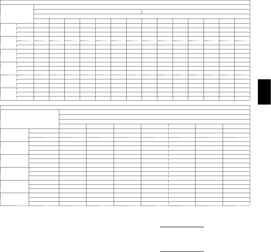
63
Cooling Capacities (Cont)
48PG05 (4 Tons) — UNIT WITH HUMIDI-MIZER™SYSTEM IN SUBCOOLING MODE
Te m p ( F )
Air Ent
Condenser
(Edb)
AirEnteringEvaporator—CFM
1200 1600
AirEnteringEvaporator—Ewb(F)
80 76 72 67 62 57 54 80 76 72 67 62 57 54
75
TC 64.0 59.5 55.0 49.3 43.7 38.1 34.7 68.0 63.3 58.5 52.6 46.7 40.7 37.2
SHC 17.3 21.4 25.4 30.5 35.7 38.1 34.7 21.0 24.9 28.8 33.7 38.5 40.7 37.2
kW 2.51 2.51 2.49 2.48 2.46 2.45 2.45 2.51 2.51 2.49 2.48 2.46 2.45 2.45
85
TC 60.0 55.5 51.0 45.4 39.8 34.2 30.9 64.1 59.4 54.6 48.7 42.8 36.9 33.3
SHC 10.1 15.2 20.3 26.6 33.0 39.4 43.2 14.2 19.1 24.0 30.2 36.3 42.4 46.1
kW 2.94 2.94 2.91 2.89 2.87 2.85 2.84 2.94 2.94 2.91 2.89 2.87 2.85 2.84
95
TC 56.0 51.5 47.1 41.5 35.9 30.4 27.0 60.2 55.4 50.7 44.8 38.9 33.0 29.5
SHC 2.8 9.0 15.1 22.7 30.4 30.4 27.0 7.5 13.4 19.3 26.7 34.0 33.0 29.5
kW 3.37 3.37 3.33 3.30 3.27 3.24 3.22 3.37 3.37 3.33 3.30 3.27 3.24 3.22
105
TC 52.0 47.5 43.1 37.6 32.1 26.5 23.2 56.2 51.5 46.8 40.9 35.0 29.2 25.6
SHC –4.4 2.8 9.9 18.8 27.8 26.5 23.2 0.8 7.7 14.6 23.2 31.8 29.2 25.6
kW 3.81 3.81 3.75 3.71 3.67 3.63 3.61 3.81 3.81 3.75 3.71 3.67 3.63 3.61
115
TC 48.0 43.6 39.2 33.7 28.2 22.7 19.4 52.3 47.6 42.9 37.0 31.2 25.3 21.8
SHC –11.6 –3.4 4.7 14.9 25.1 22.7 19.4 –6.0 1.9 9.8 19.7 29.6 25.3 21.8
kW 4.24 4.24 4.17 4.12 4.07 4.03 4.00 4.24 4.24 4.17 4.12 4.07 4.03 4.00
125
TC 44.0 39.6 35.2 29.7 24.3 18.8 15.5 48.3 43.7 39.0 33.1 27.3 21.5 18.0
SHC –18.8 –9.6 –0.4 11.0 22.5 18.8 15.5 –12.7 –3.8 5.1 16.2 27.3 21.5 18.0
kW 4.68 4.68 4.59 4.53 4.48 4.42 4.39 4.68 4.68 4.59 4.53 4.48 4.42 4.39
48PG05 (4 Tons) — UNIT WITH HUMIDI-MIZER SYSTEM IN SUBCOOLING MODE (cont)
Te m p ( F )
Air Ent
Condenser
(Edb)
AirEnteringEvaporator—CFM
2000
AirEnteringEvaporator—Ewb(F)
80 76 72 67 62 57 54
75
TC 71.3 66.4 61.4 55.2 49.0 42.8 39.1
SHC 23.8 27.6 31.4 36.1 40.8 42.8 39.1
kW 2.51 2.51 2.49 2.48 2.46 2.45 2.45
85
TC 67.4 62.5 57.6 51.4 45.2 39.0 35.3
SHC 17.5 22.2 27.0 32.9 38.8 44.8 48.3
kW 2.94 2.94 2.91 2.89 2.87 2.85 2.84
95
TC 63.6 58.6 53.7 47.5 41.3 35.1 31.4
SHC 11.1 16.8 22.6 29.7 36.9 35.1 31.4
kW 3.37 3.37 3.33 3.30 3.27 3.24 3.22
105
TC 59.7 54.7 49.8 43.6 37.5 31.3 27.6
SHC 4.8 11.5 18.2 26.5 34.9 31.3 27.6
kW 3.81 3.81 3.75 3.71 3.67 3.63 3.61
115
TC 55.8 50.8 45.9 39.8 33.6 27.5 23.8
SHC –1.6 6.1 13.8 23.4 33.0 27.5 23.8
kW 4.24 4.24 4.17 4.12 4.07 4.03 4.00
125
TC 51.9 47.0 42.0 35.9 29.7 23.6 19.9
SHC –8.0 0.7 9.4 20.2 29.7 23.6 19.9
kW 4.68 4.68 4.59 4.53 4.48 4.42 4.39
LEGEND
Edb --- E n t e r i n g D r y --- B u l b
Ewb --- E n t e r i n g W e t --- B u l b
kW --- Compressor Motor Power Input
Idb --- L e a v i n g D r y --- B u l b
Iwb --- L e a v i n g W e t --- B u l b
SHC --- Sensible Heat Capacity (1000 Btuh) Gross
TC --- Total Capacity (1000 Btuh) Gross
NOTES:
1. Direct interpolation is permissible. Do not extrapolate.
2. The following formulas may be used:
tldb =t
edb –
sensible capacity (Btuh)
1.10 x cfm
tlwb = Wet --- bulb temperature corresponding to enthalpy of air leaving
evaporator coil (hlwb)
hlwb =h
ewb –
total capacity (Btuh)
4.5 x cfm
Where: hewb = Enthalpy of air entering evaporator coil
48PG
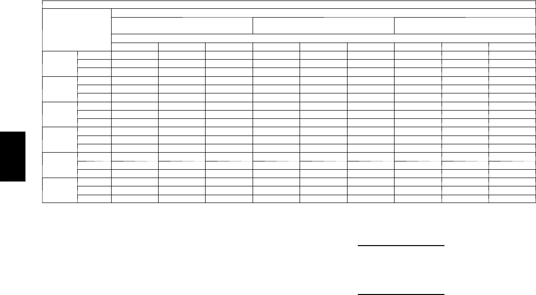
64
PERFORMANCE DATA (CONT)
Cooling Capacities (CONT)
4 8 P G 0 5 ( 4 T O N S ) --- U N I T W I T H H U M I D I --- M I Z E R tSYSTEM IN HOT GAS REHEAT MODE
Te m p ( F )
Air Ent
Condenser
(Edb)
AirEnteringEvaporator—Ewb(F)
75 Dry Bulb
62.5 Wet Bulb (50% RH)
75 Dry Bulb
64 Wet Bulb (55% RH)
75 Dry Bulb
65.3 Wet Bulb (60% RH)
AirEnteringEvaporator—Cfm
1200 1600 2000 1200 1600 2000 1200 1600 2000
80
TC 16.7 19.1 21.0 18.7 21.2 23.1 20.5 23.0 25.0
SHC 2.4 4.5 6.2 0.8 3.0 4.6 –0.5 1.6 3.3
kW 2.47 2.47 2.47 2.46 2.46 2.46 2.45 2.45 2.45
75
TC 17.3 19.5 21.3 19.2 21.5 23.3 20.9 23.3 25.1
SHC 2.6 4.5 6.1 1.1 3.1 4.7 –0.2 1.8 3.4
kW 2.48 2.48 2.48 2.48 2.48 2.48 2.48 2.48 2.48
70
TC 17.8 19.9 21.6 19.7 21.9 23.5 21.3 23.5 25.2
SHC 2.7 4.6 6.0 1.3 3.2 4.7 0.1 2.0 3.5
kW 2.50 2.50 2.50 2.50 2.50 2.50 2.50 2.50 2.50
60
TC 19.0 20.8 22.2 20.6 22.5 24.0 22.1 24.0 25.5
SHC 3.0 4.6 5.9 v1.8 3.4 4.7 0.8 2.4 3.7
kW 2.54 2.54 2.54 2.55 2.55 2.55 2.56 2.56 2.56
50
TC 20.1 21.6 22.8 21.6 23.2 24.4 22.9 24.5 25.8
SHC 3.3 4.6 5.7 2.3 3.7 4.8 1.5 2.9 4.0
kW 2.58 2.58 2.58 2.60 2.60 2.60 2.61 2.61 2.61
40
TC 21.2 22.5 23.4 22.6 23.8 24.8 23.7 25.0 26.0
SHC 3.6 4.6 5.5 2.8 3.9 4.8 2.2 3.3 4.2
kW 2.62 2.62 2.62 2.65 2.65 2.65 2.67 2.67 2.67
LEGEND
Edb --- E n t e r i n g D r y --- B u l b
Ewb --- E n t e r i n g W e t --- B u l b
kW --- Compressor Motor Power Input
Idb --- L e a v i n g D r y --- B u l b
Iwb --- L e a v i n g W e t --- B u l b
SHC --- Sensible Heat Capacity (1000 Btuh) Gross
TC --- Total Capacity (1000 Btuh) Gross
NOTES:
1. Direct interpolation is permissible. Do not extrapolate.
2. The following formulas may be used:
tldb =t
edb –sensible capacity (Btuh)
1.10 x cfm
tlwb = Wet --- bulb temperature corresponding to enthalpy of air leaving
evaporator coil (hlwb)
hlwb =h
ewb –total capacity (Btuh)
4.5 x cfm
Where: hewb = Enthalpy of air entering evaporator coil
48PG
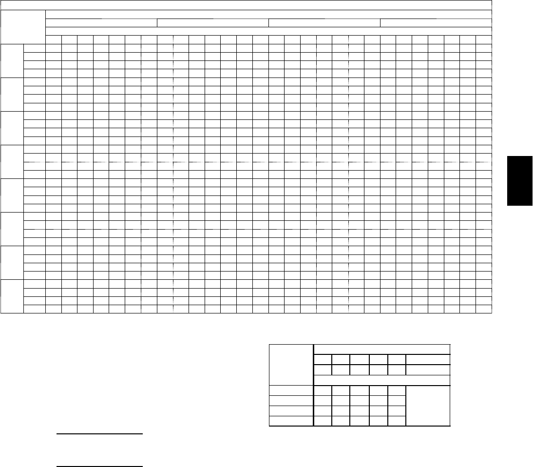
65
Cooling Capacities (Cont)
48PG06 (5 Tons) — STANDARD UNIT AND UNIT WITH HUMIDI-MIZER™SYSTEM IN COOLING MODE
Te m p ( F )
Air Ent
Condenser
(Edb)
AirEnteringEvaporator—Cfm
1500 1700 2000 2500
AirEnteringEvaporator—Ewb(F)
80 76 72 67 62 58 54 80 76 72 67 62 58 54 80 76 72 67 62 58 54 80 76 72 67 62 58 54
60
TC 83.9 78.6 73.6 67.9 62.6 58.8 57.3 86.2 80.8 75.9 69.9 64.5 60.5 59.8 88.6 83.2 78.1 72.0 66.7 63.2 63.2 91.2 85.8 80.8 74.9 69.4 67.6 67.6
SHC 23.0 29.6 35.7 43.4 51.1 55.7 57.2 23.3 30.3 37.6 45.9 54.5 58.2 59.8 23.4 31.6 39.9 49.6 59.3 63.1 63.1 23.5 33.4 43.2 55.3 65.6 67.5 67.5
kW 2.54 2.52 2.50 2.49 2.46 2.45 2.45 2.54 2.52 2.50 2.49 2.47 2.46 2.46 2.55 2.53 2.51 2.47 2.47 2.47 2.47 2.56 2.54 2.52 2.50 2.48 2.47 2.48
BF 0.00 0.17 0.17 0.16 0.16 0.20 0.37 0.00 0.24 0.17 0.17 0.17 0.24 0.41 0.00 0.22 0.17 0.17 0.18 0.29 0.47 0.00 0.22 0.20 0.19 0.22 0.39 0.55
70
TC 81.1 76.2 71.3 65.8 60.6 56.7 55.7 83.2 78.2 73.3 67.6 62.3 58.2 58.2 85.4 80.2 75.4 69.4 64.4 61.4 61.5 87.8 82.6 78.0 72.2 67.0 65.8 65.7
SHC 22.1 28.8 34.9 42.6 50.1 54.2 55.6 22.3 29.2 36.6 45.1 53.5 58.1 58.1 22.5 30.6 38.8 48.6 58.1 61.4 61.4 22.6 32.5 42.2 54.2 64.1 65.7 65.7
kW 2.93 2.91 2.90 2.88 2.86 2.84 2.84 2.94 2.93 2.90 2.88 2.86 2.85 2.85 2.96 2.93 2.91 2.86 2.87 2.86 2.86 2.97 2.95 2.92 2.90 2.88 2.87 2.87
BF 0.00 0.17 0.16 0.16 0.16 0.21 0.39 0.00 0.28 0.16 0.16 0.17 0.24 0.44 0.00 0.22 0.17 0.17 0.18 0.31 0.49 0.00 0.22 0.20 0.19 0.23 0.41 0.56
75
TC 79.9 74.9 70.1 64.7 59.5 55.6 54.8 81.7 76.7 71.9 66.3 61.0 57.5 57.4 83.8 78.6 73.9 68.1 63.2 60.6 60.6 85.9 81.0 76.4 70.8 65.7 64.8 64.8
SHC 21.7 28.3 34.4 42.1 49.4 53.6 54.8 21.9 28.8 36.1 44.6 52.5 57.4 57.4 22.0 30.1 38.3 48.1 57.5 60.5 60.5 22.0 31.9 41.7 53.6 63.3 64.7 64.7
kW 3.15 3.13 3.11 3.09 3.06 3.05 3.04 3.16 3.14 3.11 3.09 3.07 3.05 3.05 3.17 3.15 3.12 3.07 3.07 3.06 3.06 3.19 3.16 3.14 3.11 3.08 3.08 3.08
BF 0.00 0.18 0.16 0.16 0.16 0.21 0.40 0.00 0.26 0.16 0.16 0.18 0.24 0.44 0.00 0.22 0.17 0.17 0.18 0.32 0.50 0.00 0.22 0.20 0.19 0.24 0.42 0.57
85
TC 76.9 72.1 67.5 62.2 57.2 53.7 53.3 78.5 73.6 68.9 63.7 58.8 55.7 55.7 80.3 75.3 70.9 65.4 60.6 58.6 58.6 82.0 77.5 73.2 67.8 63.0 62.5 62.5
SHC 20.8 27.1 33.5 41.1 48.7 52.0 53.2 20.9 27.9 34.9 43.6 51.7 55.6 55.6 21.0 29.1 37.2 46.8 56.0 58.5 58.6 20.9 30.9 40.6 52.3 61.4 62.5 62.5
kW 3.60 3.58 3.56 3.53 3.50 3.47 3.48 3.62 3.59 3.56 3.53 3.50 3.49 3.49 3.63 3.60 3.57 3.53 3.51 3.50 3.50 3.64 3.61 3.59 3.55 3.52 3.52 3.52
BF 0.00 0.23 0.15 0.15 0.15 0.23 0.42 0.00 0.22 0.17 0.16 0.17 0.27 0.46 0.00 0.21 0.17 0.18 0.19 0.34 0.52 0.00 0.22 0.20 0.20 0.25 0.44 0.58
95
TC 73.6 68.8 64.5 59.5 54.8 51.5 51.5 74.9 70.2 66.0 60.3 56.2 53.6 53.6 76.4 71.8 67.7 62.4 57.9 56.5 56.5 77.9 73.7 69.7 64.6 60.1 60.1 60.1
SHC 19.7 25.8 32.4 40.1 47.4 51.4 51.4 19.8 26.9 33.9 41.8 50.7 53.6 53.6 19.8 28.0 36.1 45.9 54.6 56.4 56.4 19.8 29.7 39.4 51.2 60.0 60.0 60.1
kW 4.10 4.06 4.03 4.00 3.97 3.96 3.96 4.11 4.07 4.04 4.02 3.99 3.97 3.97 4.12 4.09 4.06 3.98 4.00 3.99 3.98 4.13 4.10 4.07 4.03 4.00 4.00 4.00
BF 0.00 0.27 0.15 0.15 0.16 0.23 0.44 0.00 0.21 0.16 0.16 0.17 0.29 0.48 0.00 0.20 0.17 0.17 0.20 0.37 0.53 0.00 0.22 0.20 0.19 0.26 0.46 0.60
105
TC 69.8 65.3 61.3 56.6 52.1 49.4 49.3 71.0 66.5 62.6 57.9 53.4 51.4 51.5 72.1 68.0 64.2 59.2 55.0 54.1 54.1 73.3 69.8 66.0 61.2 57.7 57.4 57.5
SHC 18.6 24.9 31.2 38.9 46.2 49.3 49.3 18.6 25.7 32.7 41.3 49.2 51.4 51.4 18.6 26.8 34.8 44.6 52.8 54.1 54.1 18.5 28.5 38.1 49.9 56.2 57.4 57.4
kW 4.64 4.61 4.58 4.54 4.50 4.48 4.48 4.65 4.62 4.59 4.55 4.51 4.50 4.50 4.66 4.63 4.60 4.52 4.52 4.51 4.52 4.68 4.65 4.62 4.57 4.55 4.54 4.54
BF 0.00 0.20 0.15 0.15 0.15 0.26 0.46 0.00 0.19 0.16 0.15 0.17 0.32 0.50 0.00 0.20 0.17 0.17 0.21 0.39 0.55 0.00 0.22 0.20 0.20 0.31 0.48 0.62
115
TC 65.6 61.5 57.8 53.4 49.0 47.0 47.1 66.5 62.6 59.0 54.5 50.4 49.0 49.0 67.4 63.8 60.3 55.8 51.8 51.5 51.4 68.3 65.3 61.9 57.5 54.5 54.6 54.6
SHC 17.3 23.7 30.0 37.7 44.8 47.0 47.0 17.3 24.5 31.4 39.9 47.7 49.0 49.0 17.3 25.5 33.5 43.2 50.5 51.4 51.4 17.2 27.1 36.7 48.4 54.5 54.5 54.5
kW 5.21 5.17 5.14 5.10 5.06 5.03 5.03 5.22 5.18 5.15 5.11 5.07 5.06 5.06 5.23 5.20 5.16 5.07 5.08 5.08 5.08 5.24 5.22 5.18 5.13 5.11 5.11 5.11
BF 0.00 0.18 0.15 0.14 0.15 0.30 0.49 0.00 0.18 0.16 0.16 0.18 0.36 0.52 0.00 0.20 0.17 0.17 0.23 0.42 0.57 0.00 0.22 0.20 0.20 0.33 0.51 0.64
125
TC 60.8 57.2 53.8 49.7 45.7 44.5 44.5 61.4 58.1 54.7 50.7 46.7 46.2 46.2 62.0 59.1 56.0 51.7 48.4 48.4 48.4 62.6 60.3 57.4 53.3 51.0 51.1 51.1
SHC 15.9 22.3 28.5 36.1 42.9 44.4 44.5 15.8 23.1 29.9 38.4 45.2 46.2 46.2 15.8 24.0 32.0 41.6 47.8 48.3 48.3 15.6 25.5 35.0 46.7 51.0 51.0 51.0
kW 5.81 5.77 5.74 5.70 5.65 5.63 5.63 5.82 5.79 5.75 5.71 5.67 5.66 5.65 5.83 5.80 5.76 5.66 5.68 5.68 5.68 5.84 5.81 5.78 5.73 5.71 5.71 5.71
BF 0.00 0.17 0.15 0.14 0.17 0.34 0.51 0.00 0.18 0.16 0.16 0.20 0.40 0.55 0.00 0.20 0.18 0.17 0.27 0.46 0.60 0.00 0.23 0.21 0.20 0.38 0.54 0.66
LEGEND
BF --- B y p a s s F a c to r
Edb --- E n t e r i n g D r y --- B u l b
Ewb --- E n t e r i n g W e t --- B u l b
kW --- Compressor Motor Power Input
Idb --- L e a v i n g D r y --- B u l b
Iwb --- L e a v i ng W e t --- B u l b
SHC --- Sensible Heat Capacity (1000 Btuh) Gross
TC --- Total Capacity (1000 Btuh) Gross
NOTES:
1. Direct interpolation is permissible. Do not extrapolate.
2. Thefollowingformulasmaybeused:
tldb =tedb –sensible capacity (Btuh)
1.10 x cfm
tlwb = Wet---bulb temperature corresponding to enthalpy of air leaving evaporator
coil (hlwb)
hlwb =h
ewb –total capacity (Btuh)
4.5 x cfm
Where: hewb = Enthalpy of air entering evaporator coil
3. The SHC is based on 80_F edb temperature of air entering evaporator coil
Below 80_F edb, subtract (corr factor x cfm) from SHC.
Above 80
_
F edb, add (corr factor x cfm) to SHC.
BYPASS
FACTOR
(BF)
ENTERING AIR DRY-BULB TEMP (F)
79 78 77 76 75 under 75
81 82 83 84 85 over 85
Correction Factor
.05 1.04 2.07 3.11 4.14 5.18
Use formula
shown below.
.10 .98 1.96 2.94 3.92 4.90
.20 .87 1.74 2.62 3.49 4.36
.30 .76 1.53 2.29 3.05 3.82
Interpolation is permissible.
C o r r e l a t i o n F a c to r = 1 . 0 9 x ( 1 --- B F ) x ( e d b --- 8 0 ) .
4. Cooling capacities for 48PG03---16 units with Humidi---MiZer system in Cooling
mode are the same as standard units.
48PG

66
PERFORMANCE DATA (CONT)
Cooling Capacities (cont)
4 8 P G 0 6 ( 5 T O N S ) --- U N I T W I T H H U M I D I --- M I Z E R tSYSTEM IN SUBCOOLING MODE
Te m p ( F ) A i r E n t
Condenser
(Edb)
AirEnteringEvaporator—CFM
1500 2000
AirEnteringEvaporator—Ewb(F)
80 76 72 67 62 57 54 80 76 72 67 62 57 54
75
TC 81.2 74.8 68.5 60.5 52.5 44.6 39.8 97.6 88.4 79.3 67.8 56.4 45.0 38.1
SHC 21.4 26.7 32.0 38.5 45.1 44.6 39.8 25.7 30.8 35.9 42.2 48.5 45.0 38.1
kW 3.14 3.14 3.11 3.09 3.07 3.05 3.04 3.14 3.14 3.11 3.09 3.07 3.05 3.04
85
TC 76.0 70.5 65.0 58.1 51.2 44.3 40.1 87.9 79.9 72.0 62.1 52.1 42.2 36.3
SHC 11.4 18.0 24.6 32.9 41.1 49.4 54.3 16.2 22.6 29.0 37.0 45.0 52.9 57.7
kW 3.63 3.63 3.58 3.55 3.52 3.50 3.48 3.63 3.63 3.58 3.55 3.52 3.50 3.48
95
TC 70.9 66.2 61.5 55.7 49.8 44.0 40.4 78.2 71.5 64.7 56.3 47.9 39.4 34.4
SHC 1.3 9.3 17.2 27.2 37.1 44.0 40.4 6.7 14.4 22.1 31.7 41.4 39.4 34.4
kW 4.11 4.11 4.05 4.01 3.98 3.94 3.92 4.11 4.11 4.05 4.01 3.98 3.94 3.92
105
TC 65.7 61.9 58.0 53.2 48.4 43.6 40.8 68.5 63.0 57.5 50.5 43.6 36.7 32.5
SHC –8.8 0.5 9.8 21.5 33.1 43.6 40.8 –2.9 6.2 15.2 26.5 37.8 36.7 32.5
kW 4.59 4.59 4.52 4.48 4.43 4.39 4.36 4.59 4.59 4.52 4.48 4.43 4.39 4.36
115
TC 60.6 57.6 54.6 50.8 47.1 43.3 41.1 58.8 54.5 50.2 44.8 39.3 33.9 30.7
SHC –18.9 –8.2 2.4 15.8 29.1 42.4 41.1 –12.4 –2.1 8.3 21.3 34.2 33.9 30.7
kW 5.07 5.07 4.99 4.94 4.89 4.84 4.80 5.07 5.07 4.99 4.94 4.89 4.84 4.80
125
TC 55.4 53.3 51.1 48.4 45.7 43.0 41.4 49.2 46.0 42.9 39.0 35.1 31.2 28.8
SHC –28.9 –16.9 –4.9 10.1 25.1 40.1 41.4 –21.9 –10.3 1.4 16.0 30.6 31.2 28.8
kW 5.55 5.55 5.46 5.40 5.34 5.28 5.25 5.55 5.55 5.46 5.40 5.34 5.28 5.25
48PG06 (5 TONS) --- UNIT WITH HUMIDI--- MIZER SYSTEM IN SUBCOOLING MODE (CONT)
Te m p ( F )
Air Ent
Condenser
(Edb)
AirEnteringEvaporator—CFM
2500
AirEnteringEvaporator—Ewb(F)
80 76 72 67 62 57 54
75
TC 115.1 103.0 90.9 75.7 60.6 45.4 36.3
SHC 29.1 34.0 38.9 45.0 51.2 45.4 36.3
kW 3.14 3.14 3.11 3.09 3.07 3.05 3.04
85
TC 100.6 90.1 79.5 66.4 53.2 40.0 32.1
SHC 20.0 26.2 32.4 40.2 47.9 55.7 60.4
kW 3.63 3.63 3.58 3.55 3.52 3.50 3.48
95
TC 86.1 77.1 68.2 57.0 45.8 34.6 27.9
SHC 10.8 18.4 25.9 35.3 44.7 34.6 27.9
kW 4.11 4.11 4.05 4.01 3.98 3.94 3.92
105
TC 71.5 64.2 56.8 47.6 38.4 29.2 23.7
SHC 1.7 10.5 19.4 30.4 38.4 29.2 23.7
kW 4.59 4.59 4.52 4.48 4.43 4.39 4.36
115
TC 57.0 51.2 45.5 38.3 31.1 23.8 19.5
SHC –7.4 2.7 12.9 25.5 31.1 23.8 19.5
kW 5.07 5.07 4.99 4.94 4.89 4.84 4.80
125
TC 42.5 38.3 34.1 28.9 23.7 18.5 15.3
SHC –16.5 –5.1 6.4 20.7 23.7 18.5 15.3
kW 5.55 5.55 5.46 5.40 5.34 5.28 5.25
LEGEND
Edb --- E n t e r i n g D r y --- B u l b
Ewb --- E n t e r i n g W e t --- B u l b
kW --- Compressor Motor Power Input
Idb --- L e a v i n g D r y --- B u l b
Iwb --- L e a v i n g W e t --- B u l b
SHC --- Sensible Heat Capacity (1000 Btuh) Gross
TC --- Total Capacity (1000 Btuh) Gross
NOTES:
1. Direct interpolation is permissible. Do not extrapolate.
2. The following formulas may be used:
tldb =tedb –sensible capacity (Btuh)
1.10 x cfm
tlwb = Wet --- bulb temperature corresponding to enthalpy of air leaving
evaporator coil (hlwb)
hlwb =h
ewb –total capacity (Btuh)
4.5 x cfm
Where: hewb = Enthalpy of air entering evaporator coil
48PG
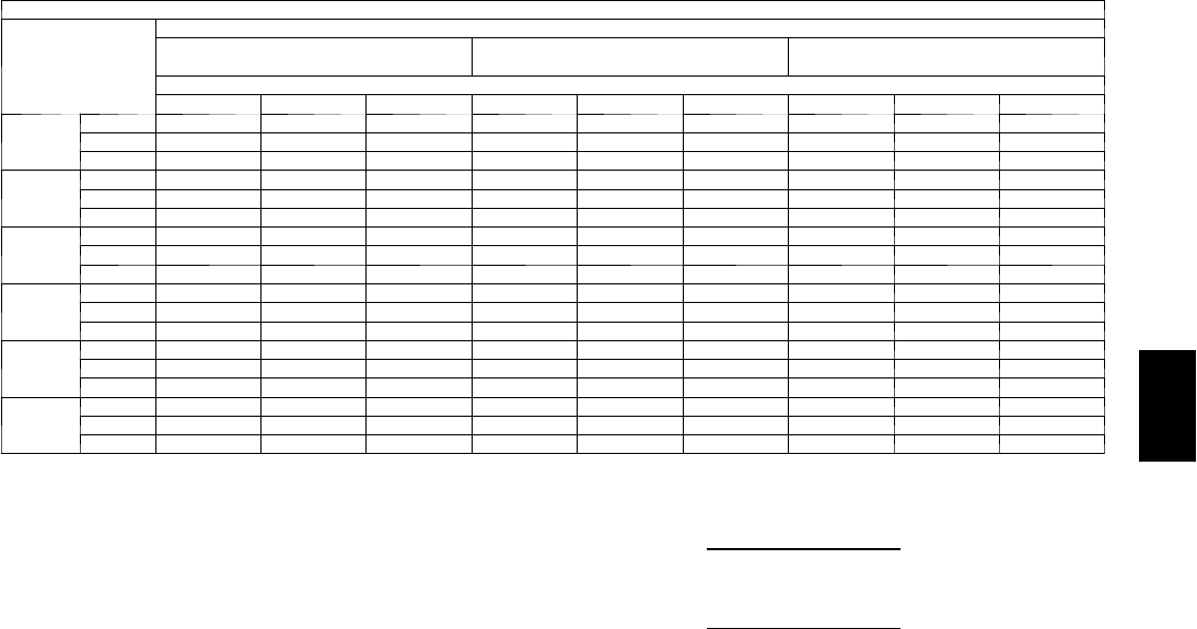
67
Cooling Capacities (cont)
4 8 P G 0 6 ( 5 T O N S ) --- U N I T W I T H H U M I D I --- M I Z E R tSYSTEM IN HOT GAS REHEAT MODE
Te m p ( F )
Air Ent
Condenser
(Edb)
AirEnteringEvaporator—Ewb(F)
75 Dry Bulb
62.5 Wet Bulb (50% RH)
75 Dry Bulb
64 Wet Bulb (55% RH)
75 Dry Bulb
65.3 Wet Bulb (60% RH)
AirEnteringEvaporator—Cfm
1750 2000 2250 1750 2000 2250 1750 2000 2250
80
TC 24.2 25.7 27.0 26.0 27.5 28.8 27.6 29.1 30.5
SHC 5.6 6.4 7.2 3.4 4.2 5.0 1.5 2.3 3.1
kW 3.08 3.08 3.08 3.07 3.07 3.07 3.07 3.07 3.07
75
TC 24.5 25.9 27.1 26.3 27.7 28.9 27.8 29.2 30.5
SHC 5.3 6.1 6.8 3.3 4.1 4.8 1.5 2.3 3.0
kW 3.10 3.10 3.10 3.10 3.10 3.10 3.10 3.10 3.10
70
TC 24.8 26.1 27.2 26.5 27.8 29.0 28.0 29.3 30.5
SHC 5.1 5.8 6.5 3.2 3.9 4.6 1.5 2.2 2.9
kW 3.13 3.13 3.13 3.13 3.13 3.13 3.14 3.14 3.14
60
TC 25.4 26.5 27.5 27.0 28.1 29.1 28.3 29.5 30.5
SHC 4.5 5.2 5.8 2.9 3.6 4.1 1.5 2.2 2.7
kW 3.18 3.18 3.18 3.19 3.19 3.19 3.21 3.21 3.21
50
TC 26.0 27.0 27.8 27.4 28.4 29.3 28.6 29.6 30.5
SHC 4.0 4.6 5.1 2.7 3.2 3.7 1.5 2.1 2.6
kW 3.23 3.23 3.23 3.26 3.26 3.26 3.28 3.28 3.28
40
TC 26.6 27.4 28.1 27.9 28.7 29.4 29.0 29.8 30.5
SHC 3.5 4.0 4.4 2.4 2.9 3.3 1.5 2.0 2.4
kW 3.28 3.28 3.28 3.32 3.32 3.32 3.35 3.35 3.35
LEGEND
Edb --- E n t e r i n g D r y --- B u l b
Ewb --- E n t e r i n g W e t --- B u l b
kW --- Compressor Motor Power Input
Idb --- L e a v i n g D r y --- B u l b
Iwb --- L e a v i n g W e t --- B u l b
SHC --- Sensible Heat Capacity (1000 Btuh) Gross
TC --- Total Capacity (1000 Btuh) Gross
NOTES:
1. Direct interpolation is permissible. Do not extrapolate.
2. The following formulas may be used:
tldb =tedb –sensible capacity (Btuh)
1.10 x cfm
tlwb = Wet --- bulb temperature corresponding to enthalpy of air leaving
evaporator coil (hlwb)
hlwb =h
ewb –total capacity (Btuh)
4.5 x cfm
Where: hewb = Enthalpy of air entering evaporator coil
48PG
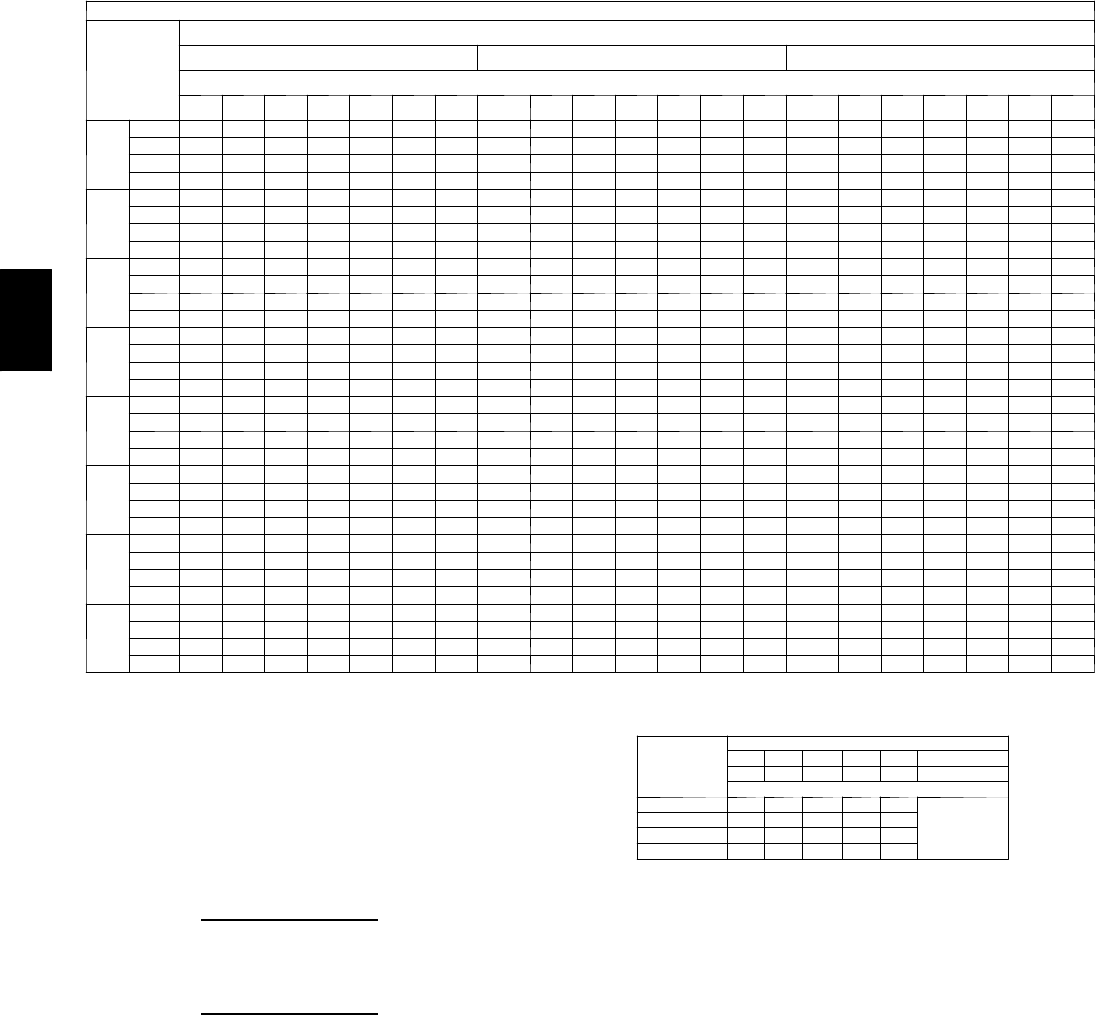
68
PERFORMANCE DATA (CONT)
Cooling Capacities (cont)
48PG07 (6 Tons) — STANDARD UNIT AND UNIT WITH HUMIDI-MIZER™SYSTEM IN COOLING MODE
Te m p ( F )
Air Ent
Condenser
(
Edb
)
AirEnteringEvaporator—Cfm
1800 2400 3000
AirEnteringEvaporator—Ewb(F)
80 76 72 67 62 58 54 80 76 72 67 62 58 54 80 76 72 67 62 58 54
60
TC 96.6 90.8 85.2 78.6 72.3 67.8 67.1 101.4 95.7 90.2 83.4 77.1 74.1 74.1 104.6 98.7 93.1 86.3 80.1 79.2 79.2
SHC 26.2 33.5 41.8 51.4 60.7 65.7 66.6 26.4 36.3 46.8 59.5 71.9 73.5 73.4 26.6 38.8 51.3 66.8 77.8 78.6 78.6
kW 2.95 2.90 2.86 2.82 2.79 2.76 2.76 2.98 2.94 2.90 2.85 2.81 2.80 2.80 3.01 2.97 2.92 2.87 2.83 2.82 2.82
BF 0.00 0.00 0.15 0.13 0.12 0.18 0.36 0.00 0.29 0.13 0.11 0.11 0.29 0.47 0.00 0.18 0.13 0.12 0.20 0.39 0.54
70
TC 93.4 88.3 82.7 76.1 70.0 65.5 65.5 97.8 92.3 86.9 80.5 74.4 72.0 72.0 100.9 95.1 89.7 83.2 77.3 77.3 77.3
SHC 25.1 32.3 40.9 50.5 60.0 65.0 65.0 25.3 35.3 45.7 58.6 70.6 71.4 71.4 25.5 37.7 50.1 65.8 76.7 76.7 76.6
kW 3.36 3.33 3.28 3.23 3.19 3.17 3.17 3.40 3.35 3.31 3.27 3.22 3.21 3.21 3.42 3.38 3.33 3.28 3.24 3.24 3.24
BF 0.00 0.00 0.14 0.11 0.10 0.17 0.38 0.00 0.22 0.13 0.10 0.11 0.31 0.48 0.00 0.17 0.13 0.11 0.20 0.40 0.55
75
TC 91.6 86.6 81.1 75.0 68.8 65.4 64.6 95.8 90.5 85.2 79.0 73.0 70.9 70.9 98.7 93.2 87.9 81.5 76.0 76.1 76.1
SHC 24.6 31.7 40.3 50.4 59.6 64.9 64.1 24.7 34.8 45.2 58.0 69.9 70.3 70.3 24.9 37.2 49.6 65.2 75.4 75.4 75.4
kW 3.59 3.55 3.51 3.46 3.42 3.38 3.39 3.62 3.58 3.54 3.49 3.44 3.43 3.43 3.65 3.60 3.56 3.51 3.47 3.47 3.47
BF 0.00 0.00 0.13 0.09 0.10 0.17 0.38 0.00 0.20 0.12 0.10 0.12 0.32 0.49 0.00 0.16 0.12 0.11 0.21 0.41 0.56
85
TC 87.9 82.9 78.0 71.9 66.4 62.7 62.7 91.8 86.7 81.7 75.7 70.0 68.8 68.8 94.5 89.1 84.0 77.9 73.4 73.4 73.4
SHC 23.4 31.0 39.3 49.0 58.8 62.2 62.1 23.6 33.6 44.0 56.8 68.0 68.2 68.2 23.7 35.9 48.4 63.9 72.8 72.8 72.8
kW 4.07 4.03 3.99 3.93 3.89 3.87 3.87 4.11 4.06 4.02 3.97 3.92 3.91 3.91 4.14 4.08 4.04 3.98 3.95 3.95 3.95
BF 0.00 0.00 0.12 0.10 0.08 0.20 0.40 0.00 0.17 0.11 0.10 0.13 0.34 0.50 0.00 0.15 0.12 0.11 0.23 0.43 0.57
95
TC 83.9 79.2 74.6 68.8 63.4 60.6 60.6 87.4 82.5 77.8 72.1 66.7 66.3 66.3 89.8 84.7 79.9 74.1 70.5 70.5 70.5
SHC 22.2 29.8 38.1 47.9 57.4 60.1 60.1 22.3 32.4 42.7 55.5 65.2 65.7 65.7 22.5 34.7 47.2 62.4 69.9 69.9 69.9
kW 4.61 4.56 4.52 4.46 4.41 4.39 4.39 4.64 4.59 4.54 4.49 4.44 4.44 4.44 4.67 4.61 4.56 4.51 4.48 4.48 4.48
BF 0.00 0.00 0.11 0.09 0.09 0.23 0.42 0.00 0.15 0.10 0.09 0.16 0.36 0.52 0.00 0.14 0.11 0.11 0.26 0.45 0.59
105
TC 79.5 75.1 70.7 65.4 60.1 58.2 58.2 82.7 78.0 73.6 68.2 63.6 63.4 63.4 84.8 80.0 75.4 69.9 67.3 67.3 67.3
SHC 20.8 28.6 36.7 46.5 55.9 57.7 57.7 21.0 31.1 41.3 54.0 62.1 62.9 62.9 21.1 33.3 45.7 60.9 66.7 66.7 66.7
kW 5.18 5.13 5.09 5.03 4.98 4.96 4.96 5.22 5.16 5.12 5.06 5.01 5.01 5.01 5.24 5.18 5.13 5.08 5.05 5.05 5.05
BF 0.00 0.23 0.10 0.08 0.08 0.25 0.44 0.00 0.13 0.10 0.09 0.20 0.38 0.54 0.00 0.12 0.10 0.11 0.30 0.47 0.61
115
TC 74.6 70.5 66.4 61.4 56.5 55.3 55.3 77.4 73.0 68.9 63.9 60.2 60.2 60.2 79.2 74.7 70.4 65.4 63.6 63.6 63.6
SHC 19.4 27.1 35.2 44.9 54.0 54.9 54.8 19.5 29.6 39.8 52.3 59.7 59.7 59.7 19.6 31.8 44.2 59.0 63.1 63.1 63.1
kW 5.79 5.74 5.70 5.64 5.58 5.57 5.57 5.82 5.77 5.73 5.67 5.62 5.62 5.62 5.84 5.79 5.74 5.69 5.66 5.66 5.66
BF 0.00 0.16 0.09 0.08 0.09 0.29 0.47 0.00 0.11 0.09 0.09 0.21 0.41 0.56 0.00 0.11 0.10 0.11 0.33 0.50 0.63
125
TC 69.0 65.2 61.4 56.9 52.4 52.3 52.3 71.2 67.3 63.4 58.9 56.4 56.4 56.4 72.7 68.7 64.8 60.2 59.3 59.3 59.3
SHC 17.7 25.5 33.4 43.1 51.6 51.8 51.8 17.8 27.9 38.0 50.4 56.0 55.9 55.9 17.8 30.1 42.4 56.9 58.8 58.8 58.8
kW 6.43 6.38 6.34 6.28 6.22 6.22 6.22 6.45 6.41 6.36 6.31 6.27 6.27 6.27 6.46 6.42 6.38 6.32 6.31 6.31 6.31
BF 0.00 0.12 0.08 0.08 0.11 0.33 0.50 0.00 0.10 0.09 0.09 0.26 0.45 0.59 0.00 0.11 0.10 0.12 0.38 0.53 0.65
LEGEND
BF --- B y p a s s F a c to r
Edb --- E n t e r i n g D r y --- B u l b
Ewb --- E n t e r i n g W e t --- B u l b
kW --- Compressor Motor Power Input
Idb --- L e a v i n g D r y --- B u l b
Iwb --- L e a v i ng W e t --- B u l b
SHC --- Sensible Heat Capacity (1000 Btuh) Gross
TC --- Total Capacity (1000 Btuh) Gross
NOTES:
1. Direct interpolation is permissible. Do not extrapolate.
2. Thefollowingformulasmaybeused:
tldb =t
edb –sensible capacity (Btuh)
1.10 x cfm
tlwb = Wet---bulb temperature corresponding to enthalpy of air leaving evaporator
coil (hlwb)
hlwb =hewb –
total capacity (Btuh)
4.5 x cfm
Where: hewb = Enthalpy of air entering evaporator coil
3. The SHC is based on 80_F edb temperature of air entering evaporator coil
Below 80_F edb, subtract (corr factor x cfm) from SHC.
Above 80
_
F edb, add (corr factor x cfm) to SHC.
BYPASS
FACTOR
(BF)
ENTERING AIR DRY-BULB TEMP (F)
79 78 77 76 75 under 75
81 82 83 84 85 over 85
Correction Factor
.05 1.04 2.07 3.11 4.14 5.18
Use formula
shown below.
.10 .98 1.96 2.94 3.92 4.90
.20 .87 1.74 2.62 3.49 4.36
.30 .76 1.53 2.29 3.05 3.82
Interpolation is permissible.
C o r r e l a t i o n F a c to r = 1 . 0 9 x ( 1 --- B F ) x ( e d b --- 8 0 ) .
4. Cooling capacities for 48PG03---16 units with Humidi---MiZer system in Cooling
mode are the same as standard units.
48PG

69
Cooling Capacities (cont)
4 8 P G 0 7 ( 6 T O N S ) --- U N I T W I T H H U M I D I --- M I Z E R tSYSTEM IN SUBCOOLING MODE
Te m p ( F )
Air Ent
Condenser
(Edb)
AirEnteringEvaporator—CFM
1800 2400
AirEnteringEvaporator—Ewb(F)
80 76 72 67 62 57 54 80 76 72 67 62 57 54
75
TC 94.5 88.8 83.2 76.0 68.9 61.8 57.6 102.2 96.0 89.9 82.3 74.6 67.0 62.4
SHC 26.2 32.7 39.3 47.5 55.7 61.8 57.6 32.2 38.5 44.8 52.7 60.6 67.0 62.4
kW 3.69 3.69 3.63 3.59 3.55 3.51 3.49 3.69 3.69 3.63 3.59 3.55 3.51 3.49
85
TC 87.0 81.5 76.1 69.3 62.5 55.7 51.6 94.4 88.5 82.6 75.3 68.0 60.6 56.2
SHC 14.0 22.2 30.4 40.7 51.0 61.2 67.4 20.8 28.7 36.6 46.5 56.5 66.4 72.3
kW 4.26 4.26 4.18 4.13 4.08 4.03 4.00 4.26 4.26 4.18 4.13 4.08 4.03 4.00
95
TC 79.4 74.2 69.0 62.5 56.1 49.6 45.7 86.6 81.0 75.3 68.3 61.3 54.3 50.1
SHC 1.9 11.8 21.6 34.0 46.3 49.6 45.7 9.4 18.9 28.5 40.4 52.4 54.3 50.1
kW 4.82 4.82 4.73 4.67 4.60 4.54 4.51 4.82 4.82 4.73 4.67 4.60 4.54 4.51
105
TC 71.8 66.9 62.0 55.8 49.6 43.4 39.7 78.8 73.4 68.1 61.4 54.7 48.0 43.9
SHC –10.2 1.3 12.8 27.2 41.6 43.4 39.7 –2.0 9.1 20.3 34.3 48.3 48.0 43.9
kW 5.39 5.39 5.27 5.20 5.13 5.06 5.02 5.39 5.39 5.27 5.20 5.13 5.06 5.02
115
TC 64.3 59.6 54.9 49.0 43.2 37.3 33.8 71.0 65.9 60.8 54.4 48.0 41.6 37.8
SHC –22.4 –9.2 4.0 20.4 36.9 37.3 33.8 –13.5 –0.7 12.1 28.2 44.2 41.6 37.8
kW 5.95 5.95 5.82 5.74 5.66 5.57 5.53 5.95 5.95 5.82 5.74 5.66 5.57 5.53
125
TC 56.7 52.3 47.8 42.3 36.7 31.2 27.8 63.2 58.3 53.5 47.4 41.4 35.3 31.7
SHC –34.5 –19.7 –4.9 13.7 32.2 31.2 27.8 –24.9 –10.4 4.0 22.0 40.1 35.3 31.7
kW 6.52 6.52 6.37 6.28 6.18 6.09 6.03 6.52 6.52 6.37 6.28 6.18 6.09 6.03
48PG07 (6 TONS) --- UNIT WITH HUMIDI--- MIZER SYSTEM IN SUBCOOLING MODE (CONT)
Te m p ( F )
Air Ent
Condenser
(Edb)
AirEnteringEvaporator—CFM
3000
AirEnteringEvaporator—Ewb(F)
80 76 72 67 62 57 54
75
TC 108.4 102.0 95.5 87.4 79.3 71.2 66.3
SHC 36.9 43.0 49.1 56.7 64.4 71.2 66.3
kW 3.69 3.69 3.63 3.59 3.55 3.51 3.49
85
TC 100.5 94.2 88.0 80.2 72.5 64.7 60.0
SHC 26.1 33.8 41.5 51.1 60.7 70.4 76.2
kW 4.26 4.26 4.18 4.13 4.08 4.03 4.00
95
TC 92.5 86.5 80.5 73.1 65.6 58.2 53.7
SHC 15.2 24.5 33.8 45.5 57.1 58.2 53.7
kW 4.82 4.82 4.73 4.67 4.60 4.54 4.51
105
TC 84.5 78.8 73.1 65.9 58.8 51.7 47.4
SHC 4.4 15.3 26.2 39.8 53.5 51.7 47.4
kW 5.39 5.39 5.27 5.20 5.13 5.06 5.02
115
TC 76.5 71.1 65.6 58.8 52.0 45.2 41.1
SHC –6.5 6.0 18.5 34.2 49.8 45.2 41.1
kW 5.95 5.95 5.82 5.74 5.66 5.57 5.53
125
TC 68.5 63.4 58.2 51.7 45.2 38.7 34.8
SHC –17.3 –3.2 10.9 28.5 45.2 38.7 34.8
kW 6.52 6.52 6.37 6.28 6.18 6.09 6.03
LEGEND
Edb --- E n t e r i n g D r y --- B u l b
Ewb --- E n t e r i n g W e t --- B u l b
kW --- Compressor Motor Power Input
Idb --- L e a v i n g D r y --- B u l b
Iwb --- L e a v i n g W e t --- B u l b
SHC --- Sensible Heat Capacity (1000 Btuh) Gross
TC --- Total Capacity (1000 Btuh) Gross
NOTES:
1. Direct interpolation is permissible. Do not extrapolate.
2. The following formulas may be used:
tldb =tedb –sensible capacity (Btuh)
1.10 x cfm
tlwb = Wet --- bulb temperature corresponding to enthalpy of air leaving
evaporator coil (hlwb)
hlwb =h
ewb –total capacity (Btuh)
4.5 x cfm
Where: hewb = Enthalpy of air entering evaporator coil
48PG

70
PERFORMANCE DATA (CONT)
Cooling Capacities (cont)
48PG07(6Tons)—UNITWITHHUMIDI---MIZER™SYSTEM IN HOT GAS REHEAT MODE
Te m p ( F )
Air Ent
Condenser
(Edb)
AirEnteringEvaporator—Ewb(F)
75 Dry Bulb
62.5 Wet Bulb (50% RH)
75 Dry Bulb
64 Wet Bulb (55% RH)
75 Dry Bulb 65.3
Wet Bulb (60% RH)
AirEnteringEvaporator—Cfm
2100 2400 2700 2100 2400 2700 1750 2000 2700
80
TC 30.0 32.4 34.6 32.1 34.6 36.8 30.6 33.1 38.8
SHC 11.4 11.4 11.4 8.5 8.5 8.5 6.0 6.0 6.0
kW 3.34 3.34 3.34 3.35 3.35 3.35 3.35 3.35 3.35
75
TC 30.3 32.6 34.6 32.4 34.7 36.8 30.9 33.3 38.7
SHC 11.0 11.0 11.0 8.3 8.3 8.3 5.9 5.9 5.9
kW 3.35 3.35 3.35 3.36 3.36 3.36 3.37 3.37 3.37
70
TC 30.6 32.8 34.7 32.6 34.8 36.8 31.2 33.5 38.5
SHC 10.6 10.6 10.6 8.0 8.0 8.0 5.8 5.8 5.8
kW 3.37 3.37 3.37 3.38 3.38 3.38 3.39 3.39 3.39
60
TC 31.2 33.1 34.8 33.0 35.0 36.7 31.9 33.9 38.3
SHC 9.7 9.7 9.7 7.5 7.5 7.5 5.7 5.7 5.7
kW 3.39 3.39 3.39 3.41 3.41 3.41 3.43 3.43 3.43
50
TC 31.9 33.5 34.9 33.5 35.1 36.6 32.6 34.3 38.1
SHC 8.8 8.8 8.8 7.0 7.0 7.0 5.5 5.5 5.5
kW 3.41 3.41 3.41 3.44 3.44 3.44 3.47 3.47 3.47
40
TC 32.5 33.8 35.0 33.9 35.3 36.5 33.3 34.7 37.9
SHC 8.0 8.0 8.0 6.5 6.5 6.5 5.3 5.3 5.3
kW 3.43 3.43 3.43 3.47 3.47 3.47 3.51 3.51 3.51
LEGEND
Edb --- E n t e r i n g D r y --- B u l b
Ewb --- E n t e r i n g W e t --- B u l b
kW --- Compressor Motor Power Input
Idb --- L e a v i n g D r y --- B u l b
Iwb --- L e a v i n g W e t --- B u l b
SHC --- Sensible Heat Capacity (1000 Btuh) Gross
TC --- Total Capacity (1000 Btuh) Gross
NOTES:
1. Direct interpolation is permissible. Do not extrapolate.
2. The following formulas may be used:
tldb =tedb –sensible capacity (Btuh)
1.10 x cfm
tlwb = Wet --- bulb temperature corresponding to enthalpy of air leaving
evaporator coil (hlwb)
hlwb =h
ewb –total capacity (Btuh)
4.5 x cfm
Where: hewb = Enthalpy of air entering evaporator coil
48PG
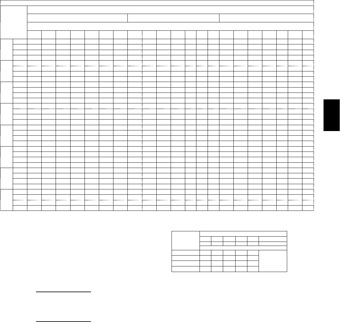
71
Cooling Capacities (cont)
48PG08 (71/2Tons) — STANDARD UNIT AND UNIT WITH HUMIDI-MIZER™SYSTEM IN COOLING MODE
Te m p ( F )
Air Ent
Condenser
(Edb)
AirEnteringEvaporator—Cfm
2250 3000 3750
AirEnteringEvaporator—Ewb(F)
80 76 72 67 62 58 54 80 76 72 67 62 58 54 80 76 72 67 62 58 54
60
TC 125.6 116.3 106.2 97.2 89.2 81.7 78.5 132.0 122.8 113.8 103.9 94.9 88.7 88.4 137.0 128.0 118.7 108.2 98.9 97.2 95.7
SHC 38.0 46.5 53.9 64.8 76.9 80.1 78.5 97.6 49.8 60.6 74.3 88.4 88.7 88.4 39.4 53.7 66.9 83.3 96.6 97.2 95.7
kW 3.35 3.45 3.51 3.49 3.44 3.48 3.50 3.43 3.49 3.50 3.49 3.47 3.49 3.49 3.43 3.43 3.50 3.49 3.48 3.43 3.46
BF 0.00 0.00 0.14 0.22 0.15 0.25 0.38 0.00 0.00 0.25 0.21 0.19 0.35 0.48 0.01 0.24 0.22 0.21 0.25 0.39 0.55
70
TC 120.8 112.1 103.6 94.2 86.6 79.1 77.5 127.6 119.6 110.4 100.8 91.4 87.2 86.6 131.9 123.2 114.6 105.1 96.0 93.5 93.4
SHC 36.4 44.5 53.3 63.7 76.3 77.9 77.5 37.4 49.1 59.7 74.4 86.3 87.2 86.6 37.9 51.8 65.8 84.9 96.0 93.5 93.4
kW 4.01 4.05 4.05 4.04 4.01 4.03 4.03 4.06 4.00 4.05 4.03 4.04 4.03 4.04 4.04 4.05 4.03 4.00 4.01 4.05 4.05
BF 0.00 0.00 0.10 0.21 0.13 0.27 0.39 0.00 0.16 0.23 0.17 0.20 0.31 0.49 0.01 0.27 0.20 0.15 0.21 0.41 0.56
75
TC 119.1 110.4 101.9 92.7 84.5 78.8 77.3 125.4 117.5 109.2 99.4 89.7 85.0 86.2 129.6 120.9 112.7 102.7 93.9 92.0 92.2
SHC 35.9 44.0 52.7 63.2 74.5 78.8 77.3 36.7 48.5 60.5 75.0 85.7 85.0 86.2 37.2 51.1 65.3 82.6 92.2 92.0 92.2
kW 4.31 4.35 4.35 4.34 4.33 4.32 4.33 4.36 4.31 4.31 4.31 4.34 4.34 4.34 4.36 4.35 4.35 4.34 4.34 4.34 4.35
BF 0.00 0.00 0.09 0.20 0.16 0.18 0.39 0.00 0.28 0.15 0.14 0.20 0.38 0.49 0.01 0.26 0.20 0.18 0.29 0.42 0.56
85
TC 114.3 106.7 98.4 89.3 81.1 75.7 74.7 120.7 112.5 104.8 95.4 86.1 83.9 83.1 124.1 115.8 108.0 98.4 91.3 89.5 90.5
SHC 34.3 42.8 51.5 62.1 72.5 75.7 74.7 35.2 47.0 59.1 73.7 83.6 83.9 83.1 35.6 49.6 63.8 81.1 90.0 89.5 90.5
kW 5.01 5.01 5.00 4.99 4.98 4.97 4.97 4.96 4.97 4.98 4.97 4.99 4.98 4.98 5.01 5.00 5.01 4.99 4.99 4.99 4.97
BF 0.00 0.00 0.24 0.18 0.17 0.24 0.41 0.00 0.22 0.14 0.13 0.20 0.34 0.51 0.01 0.23 0.19 0.18 0.30 0.44 0.57
95
TC 109.5 102.5 94.7 85.6 77.7 72.6 73.1 114.9 106.8 99.8 90.7 82.5 81.7 80.1 118.4 110.5 103.0 93.8 86.5 86.3 87.3
SHC 32.8 41.8 50.6 60.8 71.7 72.6 73.1 33.5 44.8 57.2 70.8 82.2 81.7 80.1 33.9 48.5 63.1 81.0 86.5 86.3 87.3
kW 5.72 5.71 5.71 5.71 5.70 5.69 5.68 5.71 5.72 5.71 5.71 5.70 5.69 5.70 5.70 5.70 5.71 5.70 5.71 5.71 5.70
BF 0.00 0.00 0.18 0.16 0.14 0.26 0.42 0.01 0.26 0.15 0.16 0.20 0.35 0.53 0.01 0.18 0.15 0.14 0.32 0.46 0.59
105
TC 104.4 97.5 90.3 82.0 74.1 70.7 71.1 108.9 101.8 94.5 86.1 79.0 77.9 77.6 112.2 104.5 96.9 88.5 83.5 83.1 83.0
SHC 31.2 40.3 49.5 60.7 70.3 70.7 71.1 31.7 43.6 55.6 70.3 79.0 77.9 77.6 32.1 46.2 60.2 77.9 83.5 83.1 83.0
kW 6.49 6.51 6.50 6.49 6.47 6.46 6.47 6.49 6.50 6.49 6.50 6.48 6.48 6.49 6.51 6.52 6.51 6.51 6.50 6.49 6.49
BF 0.00 0.00 0.12 0.11 0.14 0.25 0.44 0.01 0.17 0.13 0.12 0.18 0.38 0.54 0.01 0.20 0.18 0.16 0.34 0.47 0.61
115
TC 98.4 91.8 84.7 77.1 69.8 67.6 67.9 102.5 95.5 88.8 80.8 74.9 74.6 73.6 105.2 98.1 91.0 83.0 78.9 79.3 78.4
SHC 29.3 38.2 46.9 58.2 68.4 67.6 67.9 29.8 42.0 53.6 68.2 74.9 74.6 73.6 30.1 44.5 58.4 75.5 78.9 79.3 78.4
kW 7.35 7.38 7.38 7.36 7.34 7.33 7.34 7.35 7.38 7.36 7.36 7.34 7.35 7.35 7.38 7.38 7.38 7.37 7.37 7.36 7.37
BF 0.00 0.10 0.16 0.13 0.13 0.28 0.46 0.01 0.12 0.13 0.12 0.25 0.41 0.56 0.01 0.17 0.16 0.17 0.33 0.50 0.63
125
TC 91.6 85.4 79.1 71.9 65.1 63.9 64.0 95.6 88.9 82.5 75.0 69.6 69.5 69.2 97.8 91.1 84.5 76.8 74.4 74.5 73.7
SHC 27.2 36.2 45.1 55.9 65.8 63.9 64.0 27.7 39.5 50.8 65.2 69.6 69.5 69.2 28.0 42.2 56.3 73.2 74.4 74.5 73.7
kW 8.30 8.32 8.31 8.30 8.28 8.27 8.26 8.32 8.32 8.32 8.30 8.29 8.28 8.29 8.32 8.32 8.31 8.31 8.30 8.29 8.29
BF 0.00 0.19 0.14 0.13 0.14 0.32 0.49 0.01 0.16 0.15 0.14 0.26 0.45 0.59 0.02 0.18 0.16 0.16 0.37 0.53 0.65
LEGEND
BF --- B y p a s s Fa c t o r
Edb --- E n t e r i n g D r y --- B u l b
Ewb --- E n t e r i n g W e t --- B u l b
kW --- Compressor Motor Power Input
Idb --- L e a v i n g D r y --- B u l b
Iwb --- L e a v i n g W e t --- B u l b
SHC --- Sensible Heat Capacity (1000 Btuh) Gross
TC --- Total Capacity (1000 Btuh) Gross
NOTES:
1. Direct interpolation is permissible. Do not extrapolate.
2. The following formulas may be used:
tldb =t
edb –sensible capacity (Btuh)
1.10 x cfm
tlwb = Wet --- bulb temperature corresponding to enthalpy of air leaving
evaporator coil (hlwb)
hlwb =hewb –total capacity (Btuh)
4.5 x cfm
Where: hewb = Enthalpy of air entering evaporator coil
3. The SHC is based on 80_F edb temperature of air entering evaporator coil
Below 80_F edb, subtract (corr factor x cfm) from SHC.
Above 80
_
F edb, add (corr factor x cfm) to SHC.
BYPASS
FACTOR
(BF)
ENTERING AIR DRY-BULB TEMP (F)
79 78 77 76 75 under 75
81 82 83 84 85 over 85
Correction Factor
.05 1.04 2.07 3.11 4.14 5.18
Use formula
shown below.
.10 .98 1.96 2.94 3.92 4.90
.20 .87 1.74 2.62 3.49 4.36
.30 .76 1.53 2.29 3.05 3.82
Interpolation is permissible.
C o r r e l a t i o n F a c t o r = 1 . 0 9 x ( 1 --- B F ) x ( e d b --- 8 0 ) .
4. Cooling capacities for 48PG03--- 16 units with Humidi--- MiZer system in Cooling
mode are the same as standard units.
48PG
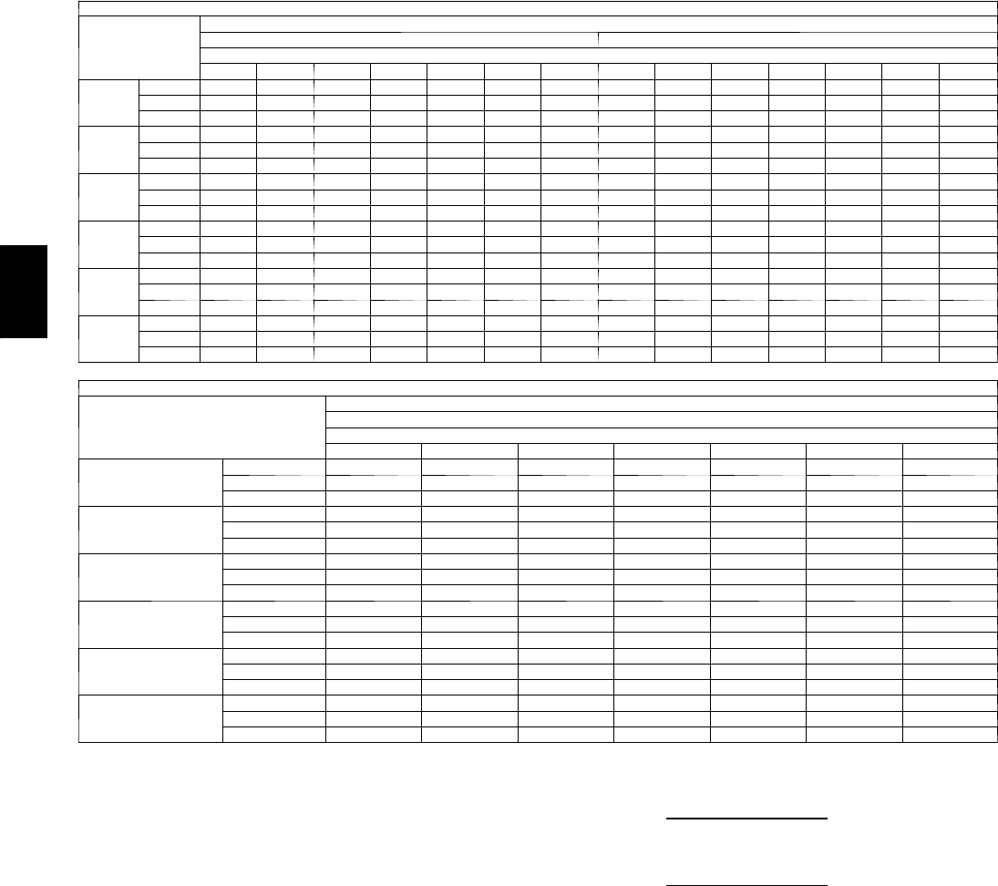
72
PERFORMANCE DATA (CONT)
Cooling Capacities (cont)
4 8 P G 0 8 ( 7 --- 1 / 2 To n s ) --- U N I T W I T H H U M I D I --- M I Z E R ™SYSTEM IN SUBCOOLING MODE
Te m p ( F )
Air Ent
Condenser
(Edb)
AirEnteringEvaporator—CFM
2250 3000
AirEnteringEvaporator—Ewb(F)
80 76 72 67 62 57 54 80 76 72 67 62 57 54
75
TC 112.2 104.6 97.1 87.7 78.3 68.9 63.3 132.0 121.9 111.7 99.1 86.5 73.8 66.3
SHC 32.3 40.8 49.2 59.8 70.3 68.9 63.3 38.3 46.6 54.9 65.2 75.6 73.8 66.3
kW 4.15 4.15 4.15 4.15 4.15 4.15 4.16 4.15 4.15 4.15 4.15 4.15 4.15 4.16
85
TC 104.9 98.2 91.6 83.3 74.9 66.6 61.6 118.8 110.0 101.1 90.0 79.0 67.9 61.3
SHC 18.2 28.7 39.1 52.3 65.4 78.5 86.4 24.6 35.0 45.3 58.2 71.2 84.1 91.9
kW 4.81 4.81 4.80 4.80 4.79 4.78 4.78 4.81 4.81 4.80 4.80 4.79 4.78 4.78
95
TC 97.6 91.8 86.0 78.8 71.6 64.4 60.0 105.7 98.1 90.5 81.0 71.5 62.0 56.3
SHC 4.0 16.5 29.1 44.8 60.4 64.4 60.0 11.0 23.4 35.8 51.3 66.7 62.0 56.3
kW 5.48 5.48 5.46 5.44 5.43 5.42 5.41 5.48 5.48 5.46 5.44 5.43 5.42 5.41
105
TC 90.3 85.4 80.5 74.3 68.2 62.1 58.4 92.5 86.2 79.8 71.9 64.0 56.0 51.3
SHC –10.2 4.4 19.0 37.2 55.5 62.1 58.4 –2.6 11.8 26.2 44.3 62.3 56.0 51.3
kW 6.15 6.15 6.11 6.09 6.07 6.05 6.03 6.15 6.15 6.11 6.09 6.07 6.05 6.03
115
TC 83.0 79.0 74.9 69.9 64.8 59.8 56.8 79.4 74.3 69.2 62.8 56.5 50.1 46.3
SHC –24.4 –7.7 8.9 29.7 50.5 59.8 56.8 –16.3 0.2 16.7 37.3 56.5 50.1 46.3
kW 6.82 6.82 6.77 6.74 6.71 6.68 6.66 6.82 6.82 6.77 6.74 6.71 6.68 6.66
125
TC 75.7 72.5 69.4 65.4 61.5 57.5 55.1 66.3 62.4 58.6 53.8 49.0 44.2 41.3
SHC –38.6 –19.9 –1.2 22.2 45.6 57.5 55.1 –29.9 –11.4 7.1 30.3 49.0 44.2 41.3
kW 7.48 7.48 7.42 7.38 7.35 7.31 7.28 7.48 7.48 7.42 7.38 7.35 7.31 7.28
4 8 P G 0 8 ( 7 --- 1 / 2 T O N S ) --- U N I T W I T H H U M I D I --- M I Z E R S Y S T E M I N S U B C O O L I N G M O D E ( C O N T )
Te m p ( F )
Air Ent
Condenser (Edb)
AirEnteringEvaporator—CFM
3750
AirEnteringEvaporator—Ewb(F)
80 76 72 67 62 57 54
75
TC 152.6 139.8 127.0 111.0 95.0 79.0 69.4
SHC 42.9 51.1 59.3 69.5 79.8 79.0 69.4
kW 4.15 4.15 4.15 4.15 4.15 4.15 4.16
85
TC 133.4 122.2 111.0 97.1 83.2 69.2 60.9
SHC 29.7 40.0 50.2 63.0 75.8 88.5 96.2
kW 4.81 4.81 4.80 4.80 4.79 4.78 4.78
95
TC 114.1 104.6 95.1 83.2 71.4 59.5 52.4
SHC 16.5 28.8 41.1 56.4 71.4 59.5 52.4
kW 5.48 5.48 5.46 5.44 5.43 5.42 5.41
105
TC 94.9 87.0 79.2 69.4 59.6 49.7 43.9
SHC 3.3 17.6 31.9 49.8 59.6 49.7 43.9
kW 6.15 6.15 6.11 6.09 6.07 6.05 6.03
115
TC 75.7 69.5 63.3 55.5 47.8 40.0 35.4
SHC –9.9 6.5 22.8 43.2 47.8 40.0 35.4
kW 6.82 6.82 6.77 6.74 6.71 6.68 6.66
125
TC 56.4 51.9 47.3 41.6 35.9 30.3 26.9
SHC –23.0 –4.7 13.7 36.7 35.9 30.3 26.9
kW 7.48 7.48 7.42 7.38 7.35 7.31 7.28
LEGEND
Edb --- E n t e r i n g D r y --- B u l b
Ewb --- E n t e r i n g W e t --- B u l b
kW --- Compressor Motor Power Input
Idb --- L e a v i n g D r y --- B u l b
Iwb --- L e a v i n g W e t --- B u l b
SHC --- Sensible Heat Capacity (1000 Btuh) Gross
TC --- Total Capacity (1000 Btuh) Gross
NOTES:
1. Direct interpolation is permissible. Do not extrapolate.
2. The following formulas may be used:
tldb =tedb –sensible capacity (Btuh)
1.10 x cfm
tlwb = Wet --- bulb temperature corresponding to enthalpy of air leaving
evaporator coil (hlwb)
hlwb =h
ewb –total capacity (Btuh)
4.5 x cfm
Where: hewb = Enthalpy of air entering evaporator coil
48PG
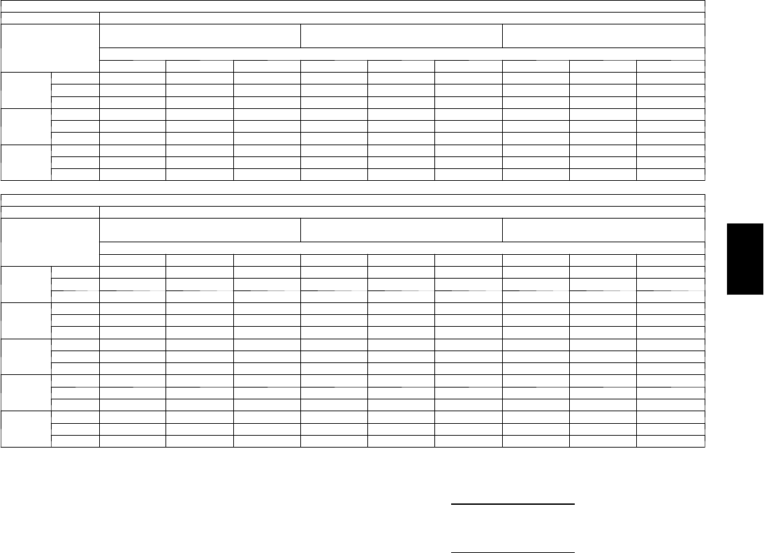
73
Cooling Capacities (cont)
4 8 P G 0 8 ( 7 --- 1 / 2 To n s ) — U N I T W I T H H U M I D I --- M I Z E R ™SYSTEM IN HOT GAS REHEAT MODE (CIRCUIT A ONLY)
AirEnteringEvaporator—Ewb(F)
Te m p ( F )
Air Ent
Condenser
(Edb)
75 Dry Bulb
62.5 Wet Bulb (50% RH)
75 Dry Bulb
64 Wet Bulb (55% RH)
75 Dry Bulb
65.3 Wet Bulb (60% RH)
AirEnteringEvaporator—Cfm
2625 3000 3375 2625 3000 3375 2625 3000 3375
50
TC 8.2 9.1 9.8 17.0 17.8 18.6 24.5 25.4 26.1
SHC –0.9 –0.9 –0.9 –0.1 –0.1 –0.1 0.6 0.6 0.6
kW 2.16 2.16 2.16 2.11 2.11 2.11 2.06 2.06 2.06
40
TC 5.8 6.4 7.0 12.8 13.4 14.0 18.8 19.5 20.0
SHC –0.6 –0.6 –0.6 0.1 0.1 0.1 0.6 0.6 0.6
kW 2.17 2.17 2.17 2.14 2.14 2.14 2.10 2.10 2.10
30
TC 3.3 3.8 4.2 8.5 9.0 9.4 13.0 13.5 13.9
SHC –0.3 –0.3 –0.3 0.2 0.2 0.2 0.6 0.6 0.6
kW 2.18 2.18 2.18 2.16 2.16 2.16 2.15 2.15 2.15
4 8 P G 0 8 ( 7 --- 1 / 2 T O N S ) --- U N I T W I T H H U M I D I --- M I Z E R S Y S T E M I N H O T G A S R E H E A T M O D E ( A L L C I R C U I T S )
AirEnteringEvaporator—Ewb(F)
Te m p ( F )
Air Ent
Condenser
(Edb)
75 Dry Bulb
62.5 Wet Bulb (50% RH)
75 Dry Bulb
64 Wet Bulb (55% RH)
75 Dry Bulb
65.3 Wet Bulb (60% RH)
AirEnteringEvaporator—Cfm
2625 3000 3375 2625 3000 3375 2625 3000 3375
80
TC 28.9 30.6 32.0 30.9 32.6 34.1 32.6 34.3 35.8
SHC 7.6 9.7 11.6 3.0 5.1 6.9 –0.9 1.1 2.8
kW 4.20 4.20 4.20 4.20 4.20 4.20 4.21 4.21 4.21
75
TC 30.3 31.8 33.2 32.2 33.8 35.2 33.8 35.5 36.9
SHC 8.8 10.8 12.6 4.5 6.5 8.3 0.9 2.8 4.5
kW 4.13 4.13 4.13 4.14 4.14 4.14 4.14 4.14 4.14
70
TC 31.6 33.1 34.4 33.5 35.0 36.4 35.1 36.7 38.0
SHC 9.9 11.9 13.7 6.0 7.9 9.6 2.7 4.5 6.1
kW 4.06 4.06 4.06 4.07 4.07 4.07 4.08 4.08 4.08
60
TC 34.4 35.7 36.8 36.1 37.5 38.7 37.7 39.0 40.3
SHC 12.3 14.1 15.7 9.1 10.8 12.4 6.2 7.9 9.5
kW 3.92 3.92 3.92 3.94 3.94 3.94 3.96 3.96 3.96
50
TC 37.1 38.2 39.2 38.7 39.9 41.0 40.2 41.4 42.5
SHC 14.7 16.3 17.8 12.1 13.7 15.1 9.8 11.4 12.8
kW 3.78 3.78 3.78 3.81 3.81 3.81 3.83 3.83 3.83
LEGEND
Edb --- E n t e r i n g D r y --- B u l b
Ewb --- E n t e r i n g W e t --- B u l b
kW --- Compressor Motor Power Input
Idb --- L e a v i n g D r y --- B u l b
Iwb --- L e a v i n g W e t --- B u l b
SHC --- Sensible Heat Capacity (1000 Btuh) Gross
TC --- Total Capacity (1000 Btuh) Gross
NOTES:
1. Direct interpolation is permissible. Do not extrapolate.
2. The following formulas may be used:
tldb =tedb –sensible capacity (Btuh)
1.10 x cfm
tlwb = Wet --- bulb temperature corresponding to enthalpy of air leaving
evaporator coil (hlwb)
hlwb =h
ewb –total capacity (Btuh)
4.5 x cfm
Where: hewb = Enthalpy of air entering evaporator coil
48PG
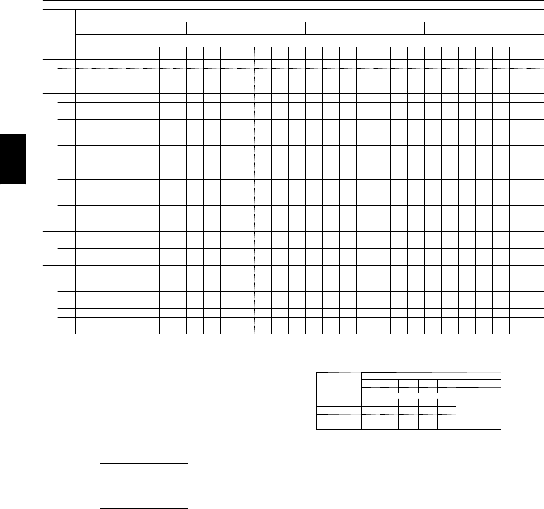
74
PERFORMANCE DATA (CONT)
Cooling Capacities (cont)
48PG09 (81/2Tons) — STANDARD UNIT AND UNIT WITH HUMIDI-MIZER™SYSTEM IN COOLING MODE
Temp (F )
Air Ent
Condenser
(Edb)
Air Entering Evaporator — Cfm
2550 3000 3400 4250
Air Entering Evaporator — Ewb (F)
80 76 72 67 62 58 54 80 76 72 67 62 58 54 80 76 72 67 62 58 54 80 76 72 67 62 58 54
60
TC 146.3 136.3 126.9 115.0 104.6 96.8 94.1 151.8 141.9 131.8 119.7 108.9 101.2 100.3 155.8 145.6 135.4 123.6 112.1 105.2 105.1 161.5 151.0 140.6 128.6 116.9 113.4 113.3
SHC 41.4 51.4 60.9 72.2 83.6 91.3 94.1 42.2 53.0 64.9 78.2 91.3 98.3 100.3 42.8 55.0 68.3 83.8 97.9 103.0 105.1 43.5 58.9 74.6 93.5 109.5 113.4 113.3
kW 4.36 4.36 4.37 4.37 4.37 4.37 4.38 4.35 4.36 4.36 4.37 4.37 4.37 4.38 4.35 4.36 4.36 4.38 4.38 4.38 4.39 4.34 4.35 4.36 4.37 4.37 4.39 4.39
BF 0.00 0.00 0.15 0.24 0.21 0.22 0.34 0.00 0.00 0.28 0.23 0.21 0.26 0.41 0.00 0.00 0.25 0.21 0.21 0.31 0.45 0.00 0.15 0.24 0.22 0.24 0.37 0.53
70
TC 142.0 132.3 123.1 111.5 101.8 93.7 92.0 146.9 137.5 127.7 116.3 105.4 98.6 97.9 150.7 140.8 130.9 119.3 108.2 102.6 102.5 156.2 145.7 135.7 123.9 112.9 109.9 110.0
SHC 39.9 49.9 59.6 70.9 83.0 90.3 92.0 40.6 51.1 63.5 77.3 90.0 96.3 97.9 41.2 53.6 66.7 82.3 96.3 100.3 102.5 41.9 57.3 72.9 91.8 108.2 109.9 110.0
kW 5.03 5.03 5.04 5.03 5.03 5.02 5.02 5.02 5.03 5.04 5.03 5.03 5.02 5.03 5.03 5.03 5.04 5.04 5.04 5.03 5.04 5.02 5.03 5.04 5.04 5.04 5.04 5.04
BF 0.00 0.00 0.13 0.22 0.19 0.21 0.36 0.00 0.00 0.25 0.20 0.20 0.27 0.42 0.00 0.00 0.23 0.20 0.21 0.33 0.47 0.00 0.14 0.23 0.21 0.23 0.39 0.54
75
TC 139.5 130.2 121.0 110.0 99.7 92.2 90.8 144.3 134.9 125.4 114.1 103.4 96.9 96.7 147.9 138.2 128.4 117.1 106.5 101.0 100.6 153.4 142.8 132.9 121.2 110.8 108.7 107.7
SHC 39.1 49.1 58.8 70.7 81.7 89.1 90.8 39.8 50.6 62.7 76.5 89.2 95.0 96.7 40.3 52.8 65.9 81.4 96.1 99.0 100.6 41.0 56.4 72.0 90.6 106.6 108.7 107.7
kW 5.39 5.39 5.39 5.38 5.37 5.36 5.36 5.38 5.39 5.39 5.39 5.38 5.37 5.38 5.40 5.40 5.40 5.40 5.39 5.38 5.38 5.34 5.40 5.40 5.40 5.39 5.39 5.38
BF 0.00 0.00 0.12 0.20 0.19 0.22 0.37 0.00 0.00 0.24 0.20 0.20 0.28 0.43 0.00 0.00 0.22 0.20 0.20 0.33 0.47 0.00 0.33 0.22 0.22 0.24 0.40 0.55
85
TC 134.3 125.6 116.5 105.9 96.3 89.3 88.3 139.4 129.5 120.3 109.4 99.5 93.8 93.8 142.5 132.5 123.2 112.1 102.2 98.1 98.0 146.6 136.8 127.3 116.3 106.6 105.2 105.1
SHC 37.4 46.8 57.2 69.2 80.8 87.0 88.3 38.2 49.1 60.9 74.5 87.7 92.1 93.8 38.6 51.1 64.1 79.3 94.1 98.1 98.0 39.1 54.5 70.1 89.1 103.4 105.2 105.1
kW 6.15 6.15 6.14 6.13 6.11 6.09 6.09 6.15 6.15 6.14 6.14 6.12 6.11 6.10 6.12 6.16 6.16 6.15 6.13 6.12 6.12 6.17 6.17 6.16 6.16 6.14 6.13 6.13
BF 0.00 0.00 0.25 0.19 0.17 0.23 0.38 0.00 0.00 0.22 0.19 0.19 0.30 0.44 0.00 0.16 0.21 0.20 0.20 0.32 0.49 0.00 0.29 0.22 0.20 0.26 0.42 0.56
95
TC 129.6 120.2 111. 6 101.4 92.2 86.0 85.6 133.2 123.7 114.9 104.8 95.2 90.7 90.7 135.8 126.5 117.6 107.3 97.7 94.7 94.6 139.8 130.2 121.3 110.8 102.1 101.3 101.2
SHC 35.9 44.9 55.5 67.4 79.0 84.4 85.6 36.3 47.4 59.0 73.0 86.2 88.9 90.7 36.6 49.2 62.1 77.7 91.8 95.1 94.6 37.1 52.5 68.1 87.0 99.6 101.3 101.2
kW 6.96 6.97 6.96 6.93 6.90 6.88 6.87 6.98 6.97 6.96 6.94 6.91 6.90 6.89 6.99 6.99 6.98 6.96 6.93 6.92 6.92 7.00 7.00 6.98 6.97 6.94 6.94 6.94
BF 0.00 0.00 0.22 0.18 0.17 0.24 0.40 0.00 0.00 0.20 0.18 0.18 0.32 0.46 0.00 0.13 0.20 0.19 0.20 0.34 0.51 0.00 0.26 0.21 0.20 0.28 0.44 0.58
105
TC 123.1 114.3 106.2 96.6 87.7 83.1 82.4 126.5 118.0 109.4 99.6 90.5 87.2 87.2 128.8 120.2 111. 6 101.8 92.7 90.9 90.8 132.5 123.6 114.6 105.0 97.7 97.0 96.9
SHC 33.7 43.3 53.5 65.5 77.1 81.4 82.4 34.2 45.7 57.1 71.0 84.0 87.2 87.2 34.4 47.7 60.1 75.7 89.3 90.9 90.8 35.0 50.6 66.4 84.9 95.1 97.0 96.9
kW 7.86 7.84 7.83 7.79 7.75 7.72 7.72 7.86 7.85 7.84 7.80 7.77 7.75 7.74 7.88 7.85 7.85 7.82 7.78 7.77 7.77 7.88 7.87 7.88 7.84 7.81 7.80 7.80
BF 0.00 0.00 0.20 0.17 0.16 0.27 0.42 0.00 0.14 0.19 0.17 0.18 0.31 0.48 0.00 0.22 0.20 0.18 0.20 0.37 0.52 0.00 0.23 0.19 0.20 0.31 0.46 0.59
115
TC 116.1 108.2 100.4 91.2 82.8 78.9 78.8 118.9 111. 0 103.2 94.0 85.5 83.4 83.3 120.9 112.9 105.1 95.8 87.7 86.7 86.7 123.9 115.8 107.8 98.3 92.8 92.3 92.3
SHC 31.6 41.6 51.4 63.4 74.9 78.9 78.8 31.9 43.4 55.1 68.9 81.3 83.4 83.3 32.1 45.0 58.1 73.4 85.5 86.7 86.7 32.5 48.7 64.8 84.4 90.5 92.3 92.3
kW 8.79 8.77 8.75 8.70 8.65 8.62 8.62 8.79 8.79 8.76 8.73 8.68 8.66 8.66 8.80 8.79 8.77 8.74 8.70 8.68 8.68 8.82 8.81 8.78 8.75 8.73 8.72 8.72
BF 0.00 0.00 0.18 0.16 0.16 0.26 0.45 0.00 0.25 0.17 0.17 0.19 0.34 0.50 0.00 0.23 0.18 0.18 0.23 0.40 0.55 0.00 0.18 0.16 0.16 0.35 0.48 0.61
125
TC 107.3 100.4 93.7 85.4 77.6 75.6 74.8 110.4 103.0 96.0 87.5 80.2 79.3 77.6 112.1 104.8 97.4 89.0 82.4 82.5 82.2 114.7 107.4 99.7 91.2 87.4 87.3 87.3
SHC 28.9 39.1 49.2 62.3 73.9 75.9 74.8 29.3 41.2 52.6 67.7 78.3 79.3 77.6 29.5 42.6 55.4 72.4 80.7 82.8 82.2 29.8 45.9 62.1 81.5 87.8 87.3 87.3
kW 9.74 9.74 9.71 9.69 9.63 9.62 9.65 9.79 9.77 9.73 9.70 9.64 9.62 9.59 9.79 9.79 9.76 9.71 9.66 9.67 9.65 9.80 9.80 9.76 9.72 9.70 9.70 9.70
BF 0.00 0.24 0.16 0.11 0.12 0.30 0.48 0.00 0.17 0.17 0.13 0.20 0.38 0.54 0.00 0.20 0.17 0.14 0.27 0.43 0.57 0.00 0.19 0.16 0.16 0.35 0.51 0.63
LEGEND
BF --- B y p a s s F a c to r
Edb --- E n t e r i n g D r y --- B u l b
Ewb --- E n t e r i n g W e t --- B u l b
kW --- Compressor Motor Power Input
Idb --- L e a v i n g D r y --- B u l b
Iwb --- L e a v i ng W e t --- B u l b
SHC --- Sensible Heat Capacity (1000 Btuh) Gross
TC --- Total Capacity (1000 Btuh) Gross
NOTES:
1. Direct interpolation is permissible. Do not extrapolate.
2. Thefollowingformulasmaybeused:
tldb =t
edb –sensible capacity (Btuh)
1.10 x cfm
tlwb = Wet---bulb temperature corresponding to enthalpy of air leaving evaporator
coil (hlwb)
hlwb =h
ewb –total capacity (Btuh)
4.5 x cfm
Where: hewb = Enthalpy of air entering evaporator coil
3. The SHC is based on 80_F edb temperature of air entering evaporator coil
Below 80_F edb, subtract (corr factor x cfm) from SHC.
Above 80
_
F edb, add (corr factor x cfm) to SHC.
BYPASS
FACTOR
(BF)
ENTERING AIR DRY-BULB TEMP (F)
79 78 77 76 75 under 75
81 82 83 84 85 over 85
Correction Factor
.05 1.04 2.07 3.11 4.14 5.18
Use formula
shown below.
.10 .98 1.96 2.94 3.92 4.90
.20 .87 1.74 2.62 3.49 4.36
.30 .76 1.53 2.29 3.05 3.82
Interpolation is permissible.
C o r r e l a t i o n F a c to r = 1 . 0 9 x ( 1 --- B F ) x ( e d b --- 8 0 ) .
4. Cooling capacities for 48PG03---16 units with Humidi---MiZer system in Cooling
mode are the same as standard units.
48PG

75
Cooling Capacities (cont)
4 8 P G 0 9 ( 8 --- 1 / 2 To n s ) — U N I T W I T H H U M I D I --- M I Z E R ™SYSTEM IN SUBCOOLING MODE
Te m p ( F )
Air Ent
Condenser
(Edb)
AirEnteringEvaporator—CFM
2550 3400
AirEnteringEvaporator—Ewb(F)
80 76 72 67 62 57 54 80 76 72 67 62 57 54
75
TC 127.2 119.0 110.8 100.5 90.3 80.1 73.9 148.1 137.4 126.7 113.4 100.1 86.7 78.7
SHC 36.6 45.8 54.9 66.4 77.9 80.1 73.9 46.4 55.2 64.1 75.3 86.4 86.7 78.7
kW 5.23 5.23 5.19 5.17 5.14 5.12 5.10 5.23 5.23 5.19 5.17 5.14 5.12 5.10
85
TC 121.4 113.7 106.0 96.4 86.8 77.2 71.5 137.1 127.2 117.3 104.9 92.5 80.1 72.7
SHC 21.7 33.1 44.5 58.7 72.9 87.2 95.7 32.4 43.5 54.6 68.5 82.3 96.2 104.5
kW 6.04 6.04 5.99 5.95 5.92 5.88 5.86 6.04 6.04 5.99 5.95 5.92 5.88 5.86
95
TC 115.6 108.4 101.2 92.3 83.3 74.4 69.0 126.1 117.0 107.8 96.3 84.9 73.4 66.6
SHC 6.8 20.4 34.0 51.0 68.0 74.4 69.0 18.5 31.8 45.1 61.7 78.2 73.4 66.6
kW 6.86 6.86 6.78 6.74 6.69 6.64 6.61 6.86 6.86 6.78 6.74 6.69 6.64 6.61
105
TC 109.8 103.1 96.5 88.2 79.8 71.5 66.5 115.2 106.8 98.3 87.8 77.3 66.8 60.5
SHC –8.1 7.7 23.5 43.3 63.0 71.5 66.5 4.6 20.1 35.5 54.9 74.2 66.8 60.5
kW 7.68 7.68 7.58 7.52 7.46 7.40 7.37 7.68 7.68 7.58 7.52 7.46 7.40 7.37
115
TC 104.0 97.8 91.7 84.0 76.4 68.7 64.1 104.2 96.5 88.9 79.3 69.7 60.1 54.4
SHC –23.0 –5.0 13.0 35.5 58.1 68.7 64.1 –9.3 8.4 26.0 48.1 69.7 60.1 54.4
kW 8.49 8.49 8.38 8.31 8.24 8.16 8.12 8.49 8.49 8.38 8.31 8.24 8.16 8.12
125
TC 98.2 92.6 86.9 79.9 72.9 65.8 61.6 93.3 86.3 79.4 70.8 62.1 53.5 48.3
SHC –37.9 –17.7 2.5 27.8 53.1 65.8 61.6 –23.2 –3.4 16.5 41.3 62.1 53.5 48.3
kW 9.31 9.31 9.18 9.09 9.01 8.93 8.88 9.31 9.31 9.18 9.09 9.01 8.93 8.88
4 8 P G 0 9 ( 8 --- 1 / 2 T O N S --- U N I T W I T H H U M I D I --- M I Z E R S Y S T E M I N S U B C O O L I N G M O D E ( C O N T )
Te m p ( F )
Air Ent
Condenser
(Edb)
AirEnteringEvaporator—CFM
4250
AirEnteringEvaporator—Ewb(F)
80 76 72 67 62 57 54
75
TC 169.4 156.2 143.0 126.5 110.0 93.5 83.6
SHC 54.1 62.8 71.4 82.3 93.1 93.5 83.6
kW 5.23 5.23 5.19 5.17 5.14 5.12 5.10
85
TC 153.1 140.9 128.7 113.5 98.2 83.0 73.8
SHC 41.0 51.8 62.6 76.2 89.7 103.3 111.4
kW 6.04 6.04 5.99 5.95 5.92 5.88 5.86
95
TC 136.9 125.7 114.5 100.5 86.5 72.5 64.1
SHC 27.8 40.8 53.9 70.1 86.4 72.5 64.1
kW 6.86 6.86 6.78 6.74 6.69 6.64 6.61
105
TC 120.7 110.5 100.3 87.5 74.7 61.9 54.3
SHC 14.7 29.9 45.1 64.0 74.7 61.9 54.3
kW 7.68 7.68 7.58 7.52 7.46 7.40 7.37
115
TC 104.5 95.2 86.0 74.5 62.9 51.4 44.5
SHC 1.6 18.9 36.3 58.0 62.9 51.4 44.5
kW 8.49 8.49 8.38 8.31 8.24 8.16 8.12
125
TC 88.2 80.0 71.8 61.5 51.2 40.9 34.7
SHC –11.6 8.0 27.5 51.9 51.2 40.9 34.7
kW 9.31 9.31 9.18 9.09 9.01 8.93 8.88
LEGEND
Edb --- E n t e r i n g D r y --- B u l b
Ewb --- E n t e r i n g W e t --- B u l b
kW --- Compressor Motor Power Input
Idb --- L e a v i n g D r y --- B u l b
Iwb --- L e a v i ng W e t --- B u l b
SHC --- Sensible Heat Capacity (1000 Btuh) Gross
TC --- Total Capacity (1000 Btuh) Gross
NOTES:
1. Direct interpolation is permissible. Do not extrapolate.
2. The following formulas may be used:
tldb =tedb –sensible capacity (Btuh)
1.10 x cfm
tlwb = Wet---bulb temperature corresponding to enthalpy of air leaving evaporator
coil (hlwb)
hlwb =h
ewb –total capacity (Btuh)
4.5 x cfm
Where: hewb = Enthalpy of air entering evaporator coil
48PG
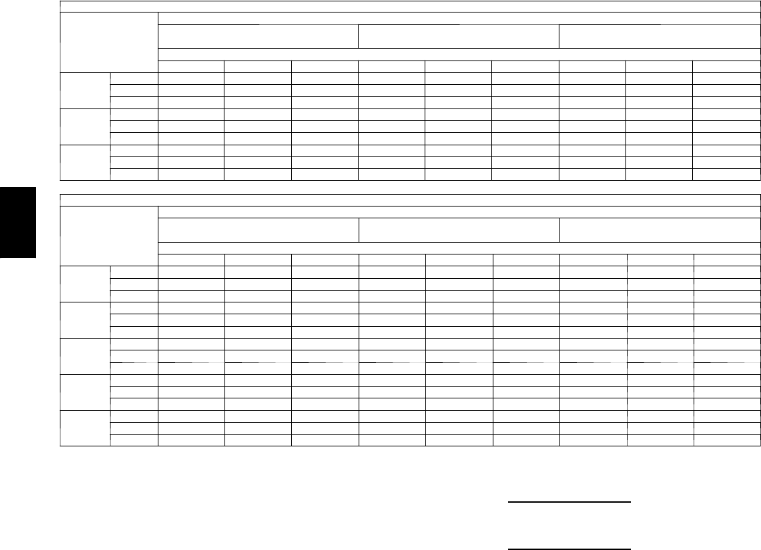
76
PERFORMANCE DATA (CONT)
Cooling Capacities (cont)
4 8 P G 0 9 ( 8 --- 1 / 2 To n s ) — U N I T W I T H H U M I D I --- M I Z E R ™SYSTEM IN HOT GAS REHEAT MODE (CIRCUIT A ONLY)
Te m p ( F )
Air Ent
Condenser
(Edb)
AirEnteringEvaporator—Ewb(F)
75 Dry Bulb
62.5 Wet Bulb (50% RH)
75 Dry Bulb
64 Wet Bulb (55% RH)
75 Dry Bulb
65.3 Wet Bulb (60% RH)
AirEnteringEvaporator—Cfm
2975 3400 3825 2975 3400 3825 2975 3400 3825
50
TC 21.8 21.8 21.8 24.5 24.5 24.5 26.8 26.8 26.8
SHC 8.3 8.3 8.3 5.3 5.3 5.3 2.6 2.6 2.6
kW 2.64 2.64 2.64 2.63 2.63 2.63 2.62 2.62 2.62
40
TC 20.9 20.9 20.9 23.1 23.1 23.1 25.0 25.0 25.0
SHC 6.6 6.6 6.6 4.1 4.1 4.1 2.0 2.0 2.0
kW 2.70 2.70 2.70 2.70 2.70 2.70 2.71 2.71 2.71
30
TC 20.1 20.1 20.1 21.8 21.8 21.8 23.3 23.3 23.3
SHC 4.8 4.8 4.8 3.0 3.0 3.0 1.4 1.4 1.4
kW 2.75 2.75 2.75 2.77 2.77 2.77 2.79 2.79 2.79
4 8 P G 0 9 ( 8 --- 1 / 2 T O N S --- U N I T W I T H H U M I D I --- M I Z E R S Y S T E M I N H O T G A S R E H E A T M O D E ( A L L C I R C U I T S )
Te m p ( F )
Air Ent
Condenser
(Edb)
AirEnteringEvaporator—Ewb(F)
75 Dry Bulb
62.5 Wet Bulb (50% RH)
75 Dry Bulb
64 Wet Bulb (55% RH)
75 Dry Bulb
65.3 Wet Bulb (60% RH)
AirEnteringEvaporator—Cfm
2975 3400 3825 2975 3400 3825 2975 3400 3825
80
TC 35.9 37.9 39.7 37.5 39.6 41.5 39.0 41.1 43.0
SHC 9.6 12.7 15.5 4.8 7.8 10.6 0.6 3.6 6.4
kW 5.16 5.16 5.16 5.16 5.16 5.16 5.16 5.16 5.16
75
TC 37.7 39.6 41.4 39.3 41.3 43.1 40.7 42.8 44.6
SHC 10.7 13.7 16.4 6.2 9.2 11.8 2.4 5.3 7.9
kW 5.10 5.10 5.10 5.10 5.10 5.10 5.11 5.11 5.11
70
TC 39.5 41.3 43.0 41.1 43.0 44.7 42.5 44.5 46.2
SHC 11.8 14.7 17.3 7.7 10.5 13.1 4.2 6.9 9.4
kW 5.03 5.03 5.03 5.04 5.04 5.04 5.05 5.05 5.05
60
TC 43.0 44.7 46.2 44.7 46.4 47.9 46.1 47.8 49.3
SHC 14.1 16.7 19.0 10.7 13.2 15.5 7.7 10.2 12.5
kW 4.90 4.90 4.90 4.93 4.93 4.93 4.95 4.95 4.95
50
TC 46.6 48.1 49.4 48.2 49.7 51.1 49.6 51.2 52.5
SHC 16.4 18.7 20.8 13.6 15.9 18.0 11.3 13.5 15.6
kW 4.77 4.77 4.77 4.81 4.81 4.81 4.84 4.84 4.84
LEGEND
Edb --- E n t e r i n g D r y --- B u l b
Ewb --- E n t e r i n g W e t --- B u l b
kW --- Compressor Motor Power Input
Idb --- L e a v i n g D r y --- B u l b
Iwb --- L e a v i ng W e t --- B u l b
SHC --- Sensible Heat Capacity (1000 Btuh) Gross
TC --- Total Capacity (1000 Btuh) Gross
NOTES:
1. Direct interpolation is permissible. Do not extrapolate.
2. The following formulas may be used:
tldb =tedb –sensible capacity (Btuh)
1.10 x cfm
tlwb = Wet---bulb temperature corresponding to enthalpy of air leaving evaporator
coil (hlwb)
hlwb =h
ewb –total capacity (Btuh)
4.5 x cfm
Where: hewb = Enthalpy of air entering evaporator coil
48PG
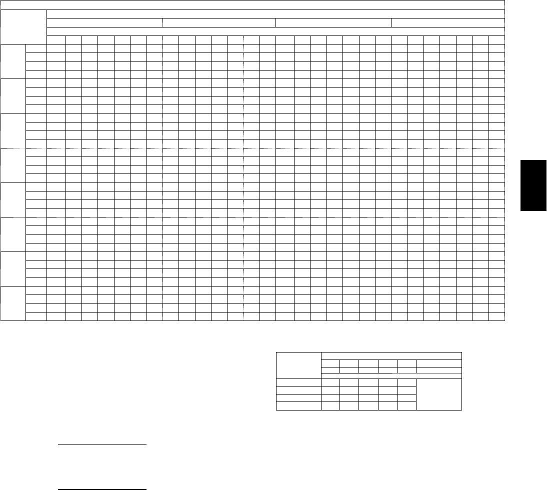
77
Cooling Capacities (cont)
48PG12 (10 Tons) — STANDARD UNIT AND UNIT WITH HUMIDI-MIZER™SYSTEM IN COOLING MODE
Te m p ( F )
Air Ent
Condenser
(Edb)
AirEnteringEvaporator—Cfm
3000 3500 4000 5000
AirEnteringEvaporator—Ewb(F)
80 76 72 67 62 58 54 80 76 72 67 62 58 54 80 76 72 67 62 58 54 80 76 72 67 62 58 54
60
TC 172.0 160.6 149.2 135.7 123.6 114.8 112.9 177.7 165.6 154.8 140.4 128.4 121.0 120.2 182.3 170.7 158.7 144.9 132.4 125.3 126.7 189.2 176.6 164.7 150.6 138.5 136.2 136.1
SHC 47.1 59.8 72.7 87.2 102.3 110.9 112.9 47.9 62.2 77.0 94.0 112.4 118.6 120.2 48.5 65.2 81.6 101.5 120.4 125.3 126.7 49.5 69.9 90.3 115.5 134.3 136.2 136.1
kW 5.28 5.21 5.14 5.09 5.00 4.95 4.93 5.37 5.28 5.22 5.12 5.03 4.99 4.99 5.37 5.29 5.23 5.15 5.07 5.04 5.01 5.43 5.35 5.27 5.18 5.11 5.09 5.09
BF 0.00 0.00 0.12 0.12 0.10 0.15 0.32 0.00 0.00 0.14 0.12 0.10 0.21 0.39 0.00 0.20 0.12 0.11 0.12 0.25 0.43 0.00 0.15 0.11 0.10 0.17 0.35 0.51
70
TC 166.1 155.5 144.2 131.6 119.9 111. 5 110.0 171.9 160.8 149.4 136.3 124.2 117.4 116.3 176.5 164.7 153.4 140.2 127.8 122.9 122.9 182.2 170.4 158.8 145.2 133.9 132.4 132.0
SHC 45.2 57.6 70.1 85.7 100.6 108.4 110.0 46.0 60.6 75.2 93.0 109.9 115.6 116.3 46.7 63.3 80.0 100.0 118.3 122.9 122.9 47.4 68.1 88.8 113.9 128.7 132.4 132.0
kW 6.10 6.02 5.95 5.86 5.78 5.72 5.71 6.11 6.06 5.97 5.89 5.82 5.76 5.76 6.15 6.08 6.00 5.92 5.84 5.80 5.80 6.20 6.11 6.03 5.94 5.88 5.87 5.87
BF 0.00 0.00 0.15 0.11 0.10 0.16 0.34 0.00 0.00 0.12 0.10 0.10 0.22 0.40 0.00 0.17 0.11 0.10 0.12 0.27 0.45 0.00 0.12 0.09 0.09 0.21 0.37 0.53
75
TC 163.7 152.7 142.0 129.4 117.7 109.7 108.2 169.0 157.7 146.8 134.0 122.1 115.5 115.2 173.1 161.6 150.5 137.4 125.2 121.1 120.6 178.6 166.9 155.6 142.3 131.6 130.4 130.2
SHC 44.4 56.7 69.6 84.8 99.4 107.0 108.2 45.1 59.6 74.4 92.4 109.4 113.6 115.2 45.7 62.2 79.0 99.3 117.0 121.1 120.6 46.3 67.0 87.9 113.1 128.9 130.4 130.2
kW 6.51 6.43 6.35 6.27 6.20 6.14 6.14 6.54 6.47 6.39 6.29 6.22 6.19 6.18 6.56 6.49 6.41 6.32 6.24 6.22 6.22 6.60 6.52 6.44 6.35 6.28 6.28 6.28
BF 0.00 0.00 0.12 0.11 0.10 0.17 0.35 0.00 0.12 0.11 0.09 0.10 0.24 0.41 0.00 0.16 0.10 0.09 0.12 0.28 0.46 0.00 0.12 0.09 0.09 0.19 0.38 0.53
85
TC 157.6 147.0 136.5 124.3 113.2 106.4 105.2 162.2 151.4 141.0 128.5 117.2 111. 5 111. 2 165.8 154.8 144.2 131.8 120.5 117.5 117.6 170.7 159.5 148.7 136.1 126.5 126.0 125.8
SHC 42.4 55.0 68.1 82.9 97.8 104.6 105.2 43.0 57.7 72.4 90.3 107.1 111. 5 111. 2 43.4 60.2 77.1 97.5 114.5 117.5 117.6 43.9 64.8 85.6 111.0 125.1 126.0 125.8
kW 7.38 7.31 7.23 7.16 7.08 7.03 7.02 7.43 7.34 7.27 7.18 7.10 7.08 7.08 7.44 7.36 7.28 7.20 7.14 7.11 7.12 7.48 7.39 7.31 7.23 7.17 7.17 7.17
BF 0.00 0.00 0.09 0.10 0.09 0.18 0.37 0.00 0.17 0.10 0.09 0.10 0.24 0.43 0.00 0.13 0.09 0.08 0.12 0.30 0.47 0.00 0.11 0.08 0.08 0.21 0.40 0.55
95
TC 150.6 140.4 130.5 119.0 108.2 102.2 101.2 154.8 144.4 134.5 122.8 112.1 107.7 107.7 157.9 147.4 137.3 125.6 114.7 113.0 112.9 161.7 151.3 141.2 129.3 121.2 121.1 121.0
SHC 40.1 52.8 65.6 81.1 95.9 100.8 101.2 40.6 55.4 70.3 88.3 104.9 107.7 107.7 41.0 57.9 74.8 95.3 111. 2 113.0 112.9 41.3 62.2 83.2 108.7 120.0 121.1 121.0
kW 8.36 8.28 8.21 8.12 8.04 8.01 8.01 8.38 8.30 8.23 8.14 8.08 8.06 8.05 8.40 8.32 8.24 8.16 8.09 8.09 8.09 8.42 8.35 8.27 8.19 8.17 8.14 8.14
BF 0.00 0.10 0.09 0.08 0.08 0.21 0.39 0.00 0.13 0.08 0.08 0.09 0.26 0.45 0.00 0.11 0.08 0.08 0.13 0.32 0.49 0.00 0.10 0.08 0.08 0.25 0.42 0.57
105
TC 142.8 133.3 124.0 113.1 103.2 97.9 98.0 146.5 136.8 127.4 116.4 106.0 103.6 103.5 149.0 139.3 129.8 118.7 109.3 108.3 108.2 153.5 142.4 133.1 121.9 115.9 115.8 115.7
SHC 37.6 50.4 63.3 78.9 93.8 97.9 98.0 38.0 53.0 67.9 86.1 101.4 103.6 103.5 38.3 55.2 72.2 93.0 107.3 108.3 108.2 38.9 59.4 80.5 105.8 115.9 115.8 115.7
kW 9.39 9.31 9.24 9.16 9.09 9.06 9.06 9.41 9.34 9.27 9.18 9.10 9.10 9.10 9.43 9.35 9.28 9.20 9.13 9.14 9.14 9.48 9.38 9.31 9.23 9.19 9.20 9.20
BF 0.00 0.15 0.08 0.07 0.08 0.21 0.41 0.00 0.11 0.07 0.07 0.11 0.29 0.47 0.00 0.10 0.07 0.07 0.15 0.35 0.51 0.00 0.09 0.07 0.08 0.26 0.45 0.58
115
TC 133.9 125.2 116.5 106.4 96.8 93.9 93.7 136.6 128.0 119.3 109.0 100.0 98.9 98.8 137.7 129.6 121.4 111. 0 103.6 103.1 103.0 141.0 131.5 123.6 113.7 109.9 109.8 109.7
SHC 34.8 47.8 60.7 76.4 91.1 93.9 93.7 35.0 50.1 65.1 83.4 97.7 98.9 98.8 34.9 52.2 69.3 90.1 102.5 103.1 103.0 35.3 56.1 77.5 102.6 109.9 109.8 109.7
kW 10.49 10.43 10.36 10.28 10.19 10.17 10.17 10.51 10.45 10.38 10.30 10.22 10.23 10.22 10.50 10.45 10.40 10.32 10.26 10.26 10.26 10.54 10.46 10.41 10.34 10.32 10.32 10.32
BF 0.00 0.11 0.07 0.06 0.07 0.25 0.44 0.00 0.09 0.07 0.06 0.12 0.32 0.49 0.00 0.09 0.07 0.06 0.19 0.38 0.54 0.00 0.08 0.07 0.08 0.30 0.47 0.61
125
TC 122.3 115.4 107.7 98.3 89.9 88.7 88.6 124.7 117.7 110.0 100.6 93.5 93.2 93.1 126.6 118.3 110.3 102.2 97.0 96.9 96.8 128.8 120.9 112.5 104.4 102.6 102.5 102.5
SHC 31.2 44.6 57.6 73.4 87.1 88.7 88.6 31.4 46.8 61.8 80.2 92.6 93.2 93.1 31.6 48.6 65.6 86.9 97.0 96.9 96.8 31.8 52.9 73.8 98.6 102.6 102.5 102.5
kW 11. 63 11.5 9 11. 54 11 .45 11. 37 11. 3 7 11 . 37 11. 65 11. 62 11. 56 11 .48 11. 41 11. 4 1 11. 41 11. 66 11 . 61 11. 55 11 . 50 11. 45 11 . 45 11. 45 11. 69 11. 63 11 .57 11. 52 11 .50 11. 51 11. 51
BF 0.00 0.09 0.06 0.05 0.09 0.29 0.47 0.00 0.08 0.06 0.06 0.16 0.36 0.52 0.00 0.08 0.06 0.06 0.22 0.42 0.56 0.00 0.08 0.07 0.08 0.34 0.51 0.63
LEGEND
BF --- B y p a s s F a c to r
Edb --- E n t e r i n g D r y --- B u l b
Ewb --- E n t e r i n g W e t --- B u l b
kW --- Compressor Motor Power Input
Idb --- L e a v i n g D r y --- B u l b
Iwb --- L e a v i ng W e t --- B u l b
SHC --- Sensible Heat Capacity (1000 Btuh) Gross
TC --- Total Capacity (1000 Btuh) Gross
NOTES:
1. Direct interpolation is permissible. Do not extrapolate.
2. Thefollowingformulasmaybeused:
tldb =t
edb –sensible capacity (Btuh)
1.10 x cfm
tlwb = Wet---bulb temperature corresponding to enthalpy of air leaving evaporator
coil (hlwb)
hlwb =h
ewb –total capacity (Btuh)
4.5 x cfm
Where: hewb = Enthalpy of air entering evaporator coil
3. The SHC is based on 80_F edb temperature of air entering evaporator coil
Below 80_F edb, subtract (corr factor x cfm) from SHC.
Above 80
_
F edb, add (corr factor x cfm) to SHC.
BYPASS
FACTOR
(BF)
ENTERING AIR DRY-BULB TEMP (F)
79 78 77 76 75 under 75
81 82 83 84 85 over 85
Correction Factor
.05 1.04 2.07 3.11 4.14 5.18
Use formula
shown below.
.10 .98 1.96 2.94 3.92 4.90
.20 .87 1.74 2.62 3.49 4.36
.30 .76 1.53 2.29 3.05 3.82
Interpolation is permissible.
C o r r e l a t i o n F a c to r = 1 . 0 9 x ( 1 --- B F ) x ( e d b --- 8 0 ) .
4. Cooling capacities for 48PG03---16 units with Humidi---MiZer system in Cooling
mode are the same as standard units.
48PG

78
PERFORMANCE DATA (CONT)
Cooling Capacities (cont)
48PG12 (10 Tons) — UNIT WITH HUMIDI ---MIZER™SYSTEM IN SUBCOOLING MODE
Te m p ( F )
Air Ent
Condenser
(Edb)
AirEnteringEvaporator—CFM
3000 4000
AirEnteringEvaporator—Ewb(F)
80 76 72 67 62 57 54 80 76 72 67 62 57 54
75
TC 149.0 139.0 128.9 116.3 103.7 91.1 83.5 176.9 163.6 150.3 133.7 117.0 100.4 90.4
SHC 36.7 49.2 61.6 77.2 92.7 91.1 83.5 47.4 59.7 72.0 87.4 102.9 100.4 90.4
kW 6.34 6.34 6.26 6.22 6.17 6.12 6.09 6.34 6.34 6.26 6.22 6.17 6.12 6.09
85
TC 140.1 131.0 121.9 110.6 99.2 87.8 81.0 160.8 149.0 137.1 122.3 107.5 92.7 83.8
SHC 17.0 32.3 47.7 66.8 86.0 105.2 116.7 28.4 43.6 58.9 77.9 97.0 116.0 127.5
kW 7.33 7.33 7.23 7.16 7.10 7.04 7.00 7.33 7.33 7.23 7.16 7.10 7.04 7.00
95
TC 131.1 123.0 114.9 104.8 94.7 84.6 78.6 144.7 134.3 123.9 110.9 97.9 85.0 77.2
SHC –2.7 15.5 33.7 56.5 79.3 84.6 78.6 9.4 27.6 45.7 68.4 91.1 85.0 77.2
kW 8.32 8.32 8.19 8.11 8.03 7.95 7.90 8.32 8.32 8.19 8.11 8.03 7.95 7.90
105
TC 122.1 115.1 108.0 99.1 90.3 81.4 76.1 128.6 119.7 110.7 99.6 88.4 77.2 70.5
SHC –22.5 –1.4 19.8 46.1 72.5 81.4 76.1 –9.5 11.5 32.6 58.9 85.2 77.2 70.5
kW 9.31 9.31 9.16 9.06 8.96 8.87 8.81 9.31 9.31 9.16 9.06 8.96 8.87 8.81
115
TC 113.2 107.1 101.0 93.4 85.8 78.2 73.6 112.5 105.0 97.6 88.2 78.9 69.5 63.9
SHC –42.2 –18.2 5.8 35.8 65.8 78.2 73.6 –28.5 –4.5 19.5 49.4 78.9 69.5 63.9
kW 10.30 10.30 10.12 10.01 9.90 9.78 9.71 10.30 10.30 10.12 10.01 9.90 9.78 9.71
125
TC 104.2 99.1 94.0 87.7 81.3 75.0 71.2 96.4 90.4 84.4 76.9 69.4 61.8 57.3
SHC –62.0 –35.1 –8.2 25.5 59.1 75.0 71.2 –47.4 –20.6 6.3 39.9 69.4 61.8 57.3
kW 11.29 11.29 11.09 10.96 10.83 10.70 10.62 11.29 11.29 11.09 10.96 10.83 10.70 10.62
4 8 P G 1 2 ( 1 0 T O N S ) --- U N I T W I T H H U M I D I --- M I Z E R S Y S T E M I N S U B C O O L I N G M O D E ( C O N T )
Te m p ( F )
Air Ent
Condenser
(Edb)
AirEnteringEvaporator—CFM
5000
AirEnteringEvaporator—Ewb(F)
80 76 72 67 62 57 54
75
TC 205.8 189.1 172.5 151.6 130.8 110.0 97.5
SHC 55.9 68.1 80.3 95.6 110.9 110.0 97.5
kW 6.34 6.34 6.26 6.22 6.17 6.12 6.09
85
TC 182.3 167.6 152.9 134.5 116.0 97.6 86.6
SHC 37.5 52.7 67.9 86.8 105.8 124.7 136.1
kW 7.33 7.33 7.23 7.16 7.10 7.04 7.00
95
TC 158.8 146.0 133.2 117.3 101.3 85.3 75.7
SHC 19.2 37.3 55.4 78.0 100.6 85.3 75.7
kW 8.32 8.32 8.19 8.11 8.03 7.95 7.90
105
TC 135.3 124.5 113.6 100.1 86.5 72.9 64.8
SHC 0.9 21.9 42.9 69.1 86.5 72.9 64.8
kW 9.31 9.31 9.16 9.06 8.96 8.87 8.81
115
TC 111.8 102.9 94.0 82.9 71.7 60.6 53.9
SHC –17.5 6.5 30.4 60.3 71.7 60.6 53.9
kW 10.30 10.30 10.12 10.01 9.90 9.78 9.71
125
TC 88.3 81.4 74.4 65.7 57.0 48.2 43.0
SHC –35.8 –8.9 17.9 51.4 57.0 48.2 43.0
kW 11.29 11.29 11.09 10.96 10.83 10.70 10.62
LEGEND
Edb --- E n t e r i n g D r y --- B u l b
Ewb --- E n t e r i n g W e t --- B u l b
kW --- Compressor Motor Power Input
Idb --- L e a v i n g D r y --- B u l b
Iwb --- L e a v i ng W e t --- B u l b
SHC --- Sensible Heat Capacity (1000 Btuh) Gross
TC --- Total Capacity (1000 Btuh) Gross
NOTES:
1. Direct interpolation is permissible. Do not extrapolate.
2. The following formulas may be used:
tldb =tedb –sensible capacity (Btuh)
1.10 x cfm
tlwb = Wet---bulb temperature corresponding to enthalpy of air leaving evaporator
coil (hlwb)
hlwb =h
ewb –total capacity (Btuh)
4.5 x cfm
Where: hewb = Enthalpy of air entering evaporator coil
48PG

79
Cooling Capacities (cont)
48PG12 (10 Tons) — UNIT WITH HUMIDI ---MIZER™SYSTEM IN HOT GAS REHEAT MODE (CIRCUIT A ONLY)
AirEnteringEvaporator—Ewb(F)
Te m p ( F )
Air Ent
Condenser
(Edb)
75 Dry Bulb
62.5 Wet Bulb (50% RH)
75 Dry Bulb
64 Wet Bulb (55% RH)
75 Dry Bulb
65.3 Wet Bulb (60% RH)
AirEnteringEvaporator—Cfm
3500 4000 4500 3500 4000 4500 3500 4000 4500
50
TC 27.7 30.4 32.8 29.7 32.5 34.9 31.4 34.3 36.8
SHC 12.1 12.1 12.1 8.6 8.6 8.6 5.5 5.5 5.5
kW 3.11 3.11 3.11 3.10 3.10 3.10 3.08 3.08 3.08
40
TC 27.6 29.8 31.7 29.3 31.6 33.5 30.8 33.1 35.1
SHC 9.8 9.8 9.8 7.0 7.0 7.0 4.5 4.5 4.5
kW 3.16 3.16 3.16 3.17 3.17 3.17 3.17 3.17 3.17
30
TC 27.5 29.1 30.6 28.9 30.6 32.1 30.2 31.9 33.4
SHC 7.5 7.5 7.5 5.4 5.4 5.4 3.5 3.5 3.5
kW 3.21 3.21 3.21 3.23 3.23 3.23 3.25 3.25 3.25
48PG12 (10 Tons) — UNIT WITH HUMIDI ---MIZER™SYSTEM IN HOT GAS REHEAT MODE (ALL CIRCUIT)
AirEnteringEvaporator—Ewb(F)
Te m p ( F )
Air Ent
Condenser
(Edb)
75 Dry Bulb
62.5 Wet Bulb (50% RH)
75 Dry Bulb
64 Wet Bulb (55% RH)
75 Dry Bulb
65.3 Wet Bulb (60% RH)
AirEnteringEvaporator—Cfm
3500 4000 4500 3500 4000 4500 3500 4000 4500
80
TC 49.3 50.8 52.1 52.0 53.6 55.0 54.5 56.0 57.5
SHC 13.4 17.1 20.4 6.9 10.4 13.6 1.2 4.7 7.8
kW 6.10 6.10 6.10 6.12 6.12 6.12 6.14 6.14 6.14
75
TC 51.2 52.6 54.0 53.9 55.4 56.8 56.3 57.8 59.2
SHC 14.7 18.2 21.4 8.7 12.1 15.2 3.4 6.7 9.7
kW 6.02 6.02 6.02 6.04 6.04 6.04 6.06 6.06 6.06
70
TC 53.1 54.5 55.8 55.7 57.2 58.6 58.1 59.6 61.0
SHC 16.0 19.4 22.5 10.4 13.7 16.7 5.6 8.8 11.7
kW 5.94 5.94 5.94 5.97 5.97 5.97 5.99 5.99 5.99
60
TC 56.9 58.3 59.5 59.4 60.9 62.2 61.7 63.1 64.5
SHC 18.7 21.8 24.6 14.0 17.0 19.7 10.0 12.9 15.5
kW 5.77 5.77 5.77 5.81 5.81 5.81 5.85 5.85 5.85
50
TC 60.7 62.0 63.3 63.1 64.5 65.8 65.3 66.7 68.0
SHC 21.3 24.1 26.6 17.6 20.3 22.7 14.3 17.0 19.4
kW 5.61 5.61 5.61 5.66 5.66 5.66 5.70 5.70 5.70
LEGEND
Edb --- E n t e r i n g D r y --- B u l b
Ewb --- E n t e r i n g W e t --- B u l b
kW --- Compressor Motor Power Input
Idb --- L e a v i n g D r y --- B u l b
Iwb --- L e a v i ng W e t --- B u l b
SHC --- Sensible Heat Capacity (1000 Btuh) Gross
TC --- Total Capacity (1000 Btuh) Gross
NOTES:
1. Direct interpolation is permissible. Do not extrapolate.
2. The following formulas may be used:
tldb =tedb –sensible capacity (Btuh)
1.10 x cfm
tlwb = Wet---bulb temperature corresponding to enthalpy of air leaving evaporator
coil (hlwb)
hlwb =h
ewb –total capacity (Btuh)
4.5 x cfm
Where: hewb = Enthalpy of air entering evaporator coil
48PG
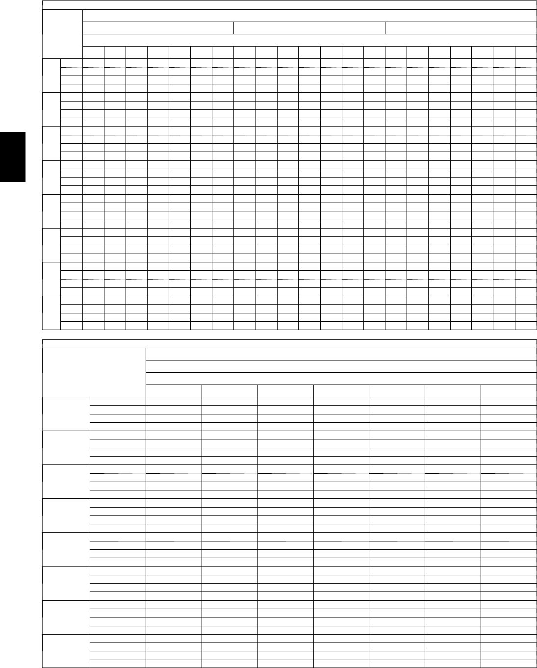
80
PERFORMANCE DATA (CONT)
Cooling Capacities (cont)
50PG14 (121/2Tons) — STANDARD UNIT AND UNIT WITH HUMIDI-MIZER™SYSTEM IN COOLING MODE
Te m p ( F )
Air Ent
Condenser
(
Edb
)
AirEnteringEvaporator—Cfm
3750 4375 5000
AirEnteringEvaporator—Ewb(F)
80 76 72 67 62 58 54 80 76 72 67 62 58 54 80 76 72 67 62 58 54
60
TC 215.9 202.7 187.9 171.5 156.2 145.7 141.5 224.4 210.3 195.7 178.2 162.7 153.2 151.1 229.5 215.9 201.0 183.7 167.7 158.4 157.1
SHC 58.5 74.4 88.7 106.6 124.1 136.3 140.3 60.0 76.8 95.3 115.4 135.8 146.7 149.9 60.5 80.8 100.6 124.1 146.6 152.9 155.9
kW 7.52 7.35 7.14 6.93 6.69 6.55 6.50 7.66 7.46 7.25 7.02 6.80 6.67 6.63 7.77 7.54 7.34 7.10 6.87 6.74 6.74
BF 0.00 0.00 0.09 0.19 0.17 0.19 0.33 0.00 0.00 0.20 0.18 0.17 0.23 0.39 0.00 0.00 0.18 0.17 0.17 0.30 0.44
70
TC 205.9 196.4 182.8 166.6 152.1 142.0 137.6 214.9 203.1 189.2 172.9 157.5 148.1 146.1 219.9 208.0 194.0 177.5 161.8 154.3 152.9
SHC 55.3 71.9 87.2 105.1 122.8 135.1 136.4 57.0 74.9 92.6 113.8 133.9 142.4 144.9 57.6 78.1 98.1 122.3 143.9 148.5 151.7
kW 8.69 8.32 8.12 7.88 7.67 7.51 7.45 8.79 8.43 8.22 7.98 7.75 7.60 7.58 8.90 8.50 8.29 8.04 7.81 7.71 7.68
BF 0.00 0.00 0.22 0.17 0.16 0.18 0.35 0.00 0.00 0.19 0.16 0.16 0.25 0.41 0.00 0.13 0.17 0.15 0.17 0.32 0.46
75
TC 200.9 193.4 179.8 163.4 149.3 138.5 136.8 210.2 199.3 185.9 169.9 154.9 144.8 145.1 215.1 204.2 190.8 174.6 159.4 152.4 151.0
SHC 53.7 70.9 86.2 103.3 121.3 129.4 135.6 55.5 73.8 91.8 112.9 133.2 139.1 143.9 56.1 77.0 97.1 121.3 143.3 146.5 149.8
kW 9.27 8.83 8.63 8.39 8.17 8.01 7.97 9.36 8.93 8.73 8.49 8.26 8.11 8.10 9.47 9.01 8.81 8.56 8.33 8.23 8.21
BF 0.00 0.00 0.20 0.18 0.16 0.23 0.35 0.00 0.00 0.17 0.15 0.15 0.27 0.41 0.00 0.11 0.16 0.15 0.16 0.33 0.46
85
TC 190.9 186.3 173.0 158.0 144.0 134.5 132.3 200.6 191.5 178.9 163.4 149.1 140.7 141.0 205.4 195.7 182.8 167.3 153.2 147.3 146.8
SHC 50.5 67.9 83.6 101.9 119.5 126.6 131.1 52.5 71.3 89.4 110.5 130.9 135.9 139.8 53.2 74.3 94.5 118.8 140.8 146.1 145.6
kW 10.43 9.94 9.72 9.48 9.25 9.09 9.15 10.49 10.02 9.82 9.57 9.34 9.20 9.20 10.60 10.09 9.88 9.63 9.41 9.32 9.31
BF 0.00 0.00 0.18 0.15 0.14 0.24 0.37 0.00 0.00 0.15 0.14 0.14 0.28 0.43 0.00 0.24 0.15 0.14 0.16 0.30 0.48
95
TC 180.9 177.7 165.9 151.5 138.1 128.8 127.7 191.1 182.8 170.5 156.0 142.7 135.8 135.4 195.8 184.8 174.2 159.9 146.2 142.2 141.8
SHC 47.4 65.3 81.0 99.5 117.3 124.2 126.5 49.5 68.5 86.4 107.9 128.0 134.6 134.2 50.2 70.9 91.5 116.1 137.2 141.0 140.6
kW 11.59 11.10 10.90 10.65 10.42 10.26 10.33 11.63 11.19 10.98 10.73 10.51 10.39 10.38 11.73 11.35 11.05 10.81 10.57 10.50 10.50
BF 0.00 0.00 0.16 0.14 0.13 0.23 0.39 0.00 0.10 0.15 0.13 0.14 0.26 0.45 0.00 0.21 0.14 0.13 0.16 0.32 0.49
105
TC 170.9 162.4 157.2 143.8 131.3 124.3 123.2 181.6 171.8 161.6 148.3 135.5 130.5 130.4 186.2 174.0 163.4 151.1 138.3 136.3 136.0
SHC 44.2 72.4 77.9 96.6 114.5 119.7 122.0 46.5 65.1 83.3 105.0 124.7 129.3 129.2 47.3 67.6 88.4 112.9 132.1 135.1 134.8
kW 12.75 12.24 12.14 11.90 11.66 11.54 11.51 12.76 12.49 12.22 11.99 11.75 11.66 11.65 12.86 12.62 12.35 12.04 11.81 11.77 11.76
BF 0.00 0.14 0.14 0.13 0.13 0.26 0.41 0.00 0.11 0.13 0.12 0.14 0.29 0.47 0.00 0.18 0.12 0.13 0.18 0.35 0.51
115
TC 160.9 147.8 139.9 135.3 123.8 117.8 118.0 172.1 160.7 150.6 138.2 127.0 124.6 124.4 176.6 163.1 152.6 131.6 130.9 129.8 129.7
SHC 41.0 77.8 88.3 93.4 111.1 116.6 116.8 43.6 61.7 79.8 101.4 120.9 123.4 123.2 44.3 64.2 85.3 123.4 124.9 128.6 128.5
kW 13.91 13.48 13.32 13.22 13.00 12.86 12.87 13.90 13.80 13.57 13.33 13.06 13.01 13.01 14.00 13.89 13.65 13.16 13.14 13.12 13.11
BF 0.00 0.10 0.10 0.11 0.12 0.25 0.44 0.00 0.11 0.11 0.12 0.14 0.32 0.49 0.00 0.15 0.10 0.11 0.22 0.38 0.54
125
TC 150.9 144.5 135.2 141.7 114.1 108.5 108.2 159.6 149.6 139.6 128.1 118.7 116.7 116.5 158.6 152.2 141.8 121.3 121.1 120.7 120.6
SHC 37.8 53.0 64.8 58.4 104.2 107.3 107.0 39.8 58.3 76.4 97.7 113.4 115.5 115.3 39.1 60.9 82.2 117.4 118.0 119.5 119.4
kW 15.07 15.00 14.83 15.01 14.33 14.32 14.20 15.27 15.10 14.91 14.68 14.46 14.44 14.42 15.23 15.15 14.95 14.51 14.52 14.50 14.53
BF 0.00 0.10 0.13 0.14 0.06 0.24 0.43 0.00 0.11 0.09 0.11 0.19 0.36 0.52 0.00 0.11 0.07 0.09 0.25 0.42 0.57
50PG14 (121/2Tons) — STANDARD UNIT AND UNIT WITH HUMIDI-MIZER™SYSTEM IN COOLING MODE (cont)
Te m p ( F )
Air Ent
Condenser
(
Edb
)
AirEnteringEvaporator—Cfm
6250
AirEnteringEvaporator—Ewb(F)
80 76 72 67 62 58 54
60
TC 238.1 223.0 208.4 191.0 175.0 169.4 169.6
SHC 61.7 86.2 110.7 140.2 163.5 168.2 168.4
kW 7.88 7.66 7.45 7.20 6.98 6.93 6.91
BF 0.00 0.23 0.17 0.16 0.21 0.36 0.52
70
TC 228.4 215.2 201.0 184.3 169.0 165.5 165.6
SHC 58.8 83.7 108.3 138.2 159.4 164.3 164.4
kW 8.97 8.61 8.40 8.15 7.93 7.89 7.88
BF 0.00 0.21 0.16 0.15 0.22 0.37 0.53
75
TC 223.5 211.1 197.1 181.0 165.8 163.1 162.7
SHC 57.4 82.5 107.1 137.0 158.2 161.9 161.5
kW 9.52 9.12 8.91 8.67 8.43 8.40 8.40
BF 0.00 0.20 0.16 0.15 0.22 0.38 0.54
85
TC 213.8 200.7 188.7 173.3 159.7 157.9 157.5
SHC 54.5 79.5 104.3 134.3 151.8 156.7 156.3
kW 10.61 10.31 9.98 9.74 9.52 9.50 9.49
BF 0.00 0.18 0.15 0.15 0.25 0.40 0.55
95
TC 204.1 190.2 179.6 164.5 153.3 151.9 151.8
SHC 51.7 76.6 101.2 131.2 146.1 150.7 150.6
kW 11.71 11.50 11.15 10.89 10.70 10.68 10.67
BF 0.00 0.15 0.15 0.14 0.28 0.42 0.57
105
TC 194.4 179.8 168.2 154.1 146.1 145.4 145.2
SHC 48.8 73.6 97.8 127.5 141.0 144.2 144.0
kW 12.80 12.69 12.44 12.20 11.96 11.94 11.94
BF 0.00 0.13 0.14 0.14 0.30 0.45 0.59
115
TC 181.4 169.4 156.7 143.7 138.0 137.8 137.7
SHC 45.0 70.7 94.3 123.7 136.8 136.6 136.5
kW 14.10 13.88 13.74 13.50 13.30 13.29 13.28
BF 0.00 0.10 0.12 0.13 0.30 0.48 0.61
125
TC 161.8 158.6 145.3 133.3 128.5 128.3 125.3
SHC 39.4 66.8 90.8 120.0 127.3 127.1 131.6
kW 15.30 15.27 15.03 14.80 14.70 14.71 14.64
BF 0.00 0.12 0.11 0.13 0.35 0.51 0.09
48PG
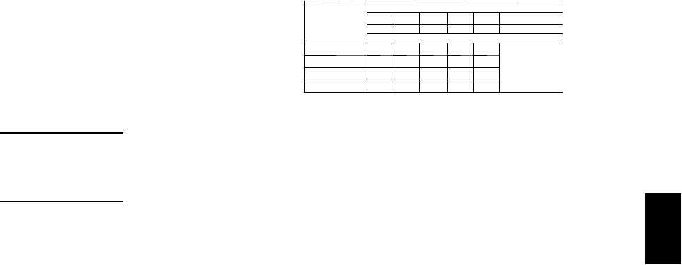
81
LEGEND
BF --- B y p a ss Fa c t o r
Edb --- E n t e r in g D r y --- B u l b
Ewb --- E n t e r in g W e t --- B u l b
kW --- Compressor Motor Power Input
Idb --- L e a v in g D r y --- B u l b
Iwb --- L e a v i n g We t --- B u l b
SHC --- Sensible Heat Capacity (1000 Btuh) Gross
TC --- Total Capacity (1000 Btuh) Gross
NOTES:
1. Direct interpolation is permissible. Do not extrapolate.
2. The following formulas may be used:
tldb =t
edb –sensible capacity (Btuh)
1.10 x cfm
tlwb = Wet---bulb temperature corresponding to enthalpy of air leaving
evaporator coil (hlwb)
hlwb =h
ewb –total capacity (Btuh)
4.5 x cfm
Where: hewb = Enthalpy of air entering evaporator coil
3. The SHC is based on 80_F edb temperature of air entering evaporator
coil
Below 80_F edb, subtract (corr factor x cfm) from SHC.
Above 80
_
F edb, add (corr factor x cfm) to SHC.
BYPASS
FACTOR
(BF)
ENTERING AIR DRY-BULB TEMP (F)
79 78 77 76 75 under 75
81 82 83 84 85 over 85
Correction Factor
.05 1.04 2.07 3.11 4.14 5.18
Use formula
shown below.
.10 .98 1.96 2.94 3.92 4.90
.20 .87 1.74 2.62 3.49 4.36
.30 .76 1.53 2.29 3.05 3.82
Interpolation is permissible.
C o r r e l a t i o n Fa c t o r = 1 . 0 9 x ( 1 --- B F ) x ( e d b --- 8 0 ) .
4. Cooling capacities for 48PG03---16 units with Humidi---MiZer system in
Coolingmodearethesameasstandardunits.
48PG

82
PERFORMANCE DATA (CONT)
Cooling Capacities (cont)
48PG14 (12 --- 1/2 Tons) — UNIT WITH HUMIDI --- MIZER™SYSTEM IN SUBCOOLING MODE
Te m p ( F )
Air Ent
Condenser
(Edb)
AirEnteringEvaporator—CFM
3750 5000
AirEnteringEvaporator—Ewb(F)
80 76 72 67 62 57 54 80 76 72 67 62 57 54
75
TC 191.8 179.8 167.9 152.9 138.0 123.0 114.0 223.0 207.7 192.4 173.2 154.1 134.9 123.4
SHC 46.4 61.5 76.6 95.4 114.3 123.0 114.0 61.8 76.8 91.8 110.5 129.2 134.9 123.4
kW 9.28 9.28 8.97 8.77 8.58 8.38 8.27 9.28 9.28 8.97 8.77 8.58 8.38 8.27
85
TC 179.9 169.7 159.5 146.7 134.0 121.3 113.6 200.5 187.9 175.2 159.4 143.6 127.7 118.2
SHC 23.2 41.7 60.3 83.5 106.8 130.0 143.9 39.7 58.2 76.6 99.7 122.8 145.9 159.8
kW 10.40 10.40 10.05 9.84 9.63 9.41 9.28 10.40 10.40 10.05 9.84 9.63 9.41 9.28
95
TC 167.9 159.5 151.1 140.6 130.1 119.6 113.3 178.1 168.1 158.1 145.6 133.1 120.6 113.1
SHC –0.1 22.0 44.1 71.6 99.2 119.6 113.3 17.6 39.5 61.5 89.0 116.5 120.6 113.1
kW 11.51 11.51 11.14 10.91 10.67 10.44 10.30 11.51 11.51 11.14 10.91 10.67 10.44 10.30
105
TC 156.0 149.3 142.7 134.4 126.1 117.9 112.9 155.6 148.2 140.9 131.7 122.6 113.4 107.9
SHC –23.3 2.3 27.8 59.7 91.7 117.9 112.9 –4.6 20.9 46.4 78.3 110.2 113.4 107.9
kW 12.63 12.63 12.22 11.97 11.72 11.46 11.31 12.63 12.63 12.22 11.97 11.72 11.46 11.31
115
TC 144.0 139.2 134.3 128.3 122.2 116.1 112.5 133.1 128.4 123.7 117.9 112.1 106.3 102.8
SHC –46.5 –17.5 11.6 47.8 84.1 116.1 112.5 –26.7 2.3 31.3 67.6 103.9 106.3 102.8
kW 13.75 13.75 13.31 13.04 12.76 12.49 12.33 13.75 13.75 13.31 13.04 12.76 12.49 12.33
125
TC 132.1 129.0 125.9 122.1 118.3 114.4 112.1 110.6 108.6 106.6 104.1 101.6 99.1 97.6
SHC –69.7 –37.2 –4.7 35.9 76.6 114.4 112.1 –48.8 –16.3 16.2 56.9 97.5 99.1 97.6
kW 14.86 14.86 14.39 14.10 13.81 13.52 13.34 14.86 14.86 14.39 14.10 13.81 13.52 13.34
4 8 P G 1 4 ( 1 2 --- 1 / 2 T O N S --- U N I T W I T H H U M I D I --- M I Z E R S Y S T E M I N S U B C O O L I N G M O D E ( C O N T )
Te m p ( F )
Air Ent
Condenser
(Edb)
AirEnteringEvaporator—CFM
6250
AirEnteringEvaporator—Ewb(F)
80 76 72 67 62 57 54
75
TC 255.7 236.8 218.0 194.4 170.9 147.3 133.2
SHC 74.3 89.1 104.0 122.6 141.1 147.3 133.2
kW 9.28 9.28 8.97 8.77 8.58 8.38 8.27
85
TC 222.2 206.9 191.7 172.6 153.5 134.5 123.0
SHC 53.0 71.4 89.8 112.8 135.8 158.8 172.6
kW 10.40 10.40 10.05 9.84 9.63 9.41 9.28
95
TC 188.6 177.0 165.3 150.8 136.2 121.6 112.9
SHC 31.7 53.7 75.6 103.0 130.4 121.6 112.9
kW 11.51 11.51 11.14 10.91 10.67 10.44 10.30
105
TC 155.1 147.1 139.0 128.9 118.9 108.8 102.7
SHC 10.5 35.9 61.4 93.3 118.9 108.8 102.7
kW 12.63 12.63 12.22 11.97 11.72 11.46 11.31
115
TC 121.6 117.2 112.7 107.1 101.5 96.0 92.6
SHC –10.8 18.2 47.2 83.5 101.5 96.0 92.6
kW 13.75 13.75 13.31 13.04 12.76 12.49 12.33
125
TC 88.1 87.2 86.4 85.3 84.2 83.1 82.5
SHC –32.1 0.5 33.0 73.7 84.2 83.1 82.5
kW 14.86 14.86 14.39 14.10 13.81 13.52 13.34
LEGEND
Edb --- E n t e r i n g D r y --- B u l b
Ewb --- E n t e r i n g W e t --- B u l b
kW --- Compressor Motor Power Input
Idb --- L e a v i n g D r y --- B u l b
Iwb --- L e a v i ng W e t --- B u l b
SHC --- Sensible Heat Capacity (1000 Btuh) Gross
TC --- Total Capacity (1000 Btuh) Gross
NOTES:
1. Direct interpolation is permissible. Do not extrapolate.
2. The following formulas may be used:
tldb =tedb –sensible capacity (Btuh)
1.10 x cfm
tlwb = Wet---bulb temperature corresponding to enthalpy of air leaving evaporator
coil (hlwb)
hlwb =h
ewb –total capacity (Btuh)
4.5 x cfm
Where: hewb = Enthalpy of air entering evaporator coil
48PG
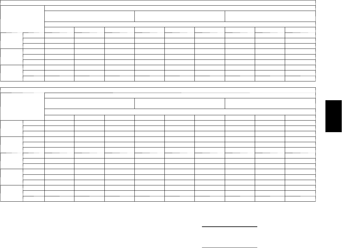
83
Cooling Capacities (cont)
48PG14 (12 --- 1/2 Tons) — UNIT WITH HUMIDI --- MIZER™SYSTEM IN HOT GAS REHEAT MODE (CIRCUIT A ONLY)
Te m p ( F )
Air Ent
Condenser
(Edb)
AirEnteringEvaporator—Ewb(F)
75 Dry Bulb
62.5 Wet Bulb (50% RH)
75 Dry Bulb
64 Wet Bulb (55% RH)
75 Dry Bulb
65.3 Wet Bulb (60% RH)
AirEnteringEvaporator—Cfm
4375 5000 5625 4375 5000 5625 4375 5000 5625
50
TC 33.8 36.6 39.1 34.0 36.8 39.4 34.1 37.0 39.6
SHC 14.8 14.8 14.8 9.0 9.0 9.0 3.9 3.9 3.9
kW 4.57 4.57 4.57 4.59 4.59 4.59 4.61 4.61 4.61
40
TC 35.4 37.7 39.8 35.7 38.1 40.2 36.0 38.4 40.5
SHC 14.2 14.2 14.2 9.6 9.6 9.6 5.6 5.6 5.6
kW 4.61 4.61 4.61 4.65 4.65 4.65 4.68 4.68 4.68
30
TC 37.0 38.8 40.4 37.5 39.4 41.0 38.0 39.8 41.4
SHC 13.5 13.5 13.5 10.1 10.1 10.1 7.2 7.2 7.2
kW 4.65 4.65 4.65 4.70 4.70 4.70 4.75 4.75 4.75
48PG14 (12--- 1/2 Tons) — UNIT WITH HUMIDI--- MIZER SYSTEM IN HOT GAS REHEAT MODE (ALL CIRCUITS)
Te m p ( F )
Air Ent
Condenser
(Edb)
AirEnteringEvaporator—Ewb(F)
75 Dry Bulb
62.5 Wet Bulb (50% RH)
75 Dry Bulb
64 Wet Bulb (55% RH)
75 Dry Bulb
65.3 Wet Bulb (60% RH)
AirEnteringEvaporator—Cfm
4375 5000 5625 4375 5000 5625 4375 5000 5625
80
TC 65.0 67.5 69.7 67.2 69.7 72.0 69.1 71.7 74.0
SHC 20.6 26.5 31.9 10.7 16.4 21.5 2.1 7.6 12.6
kW 8.61 8.61 8.61 8.67 8.67 8.67 8.72 8.72 8.72
75
TC 66.8 69.2 71.4 69.0 71.5 73.7 70.9 73.4 75.7
SHC 22.0 27.6 32.8 12.8 18.2 23.2 4.8 10.0 14.8
kW 8.55 8.55 8.55 8.62 8.62 8.62 8.68 8.68 8.68
70
TC 68.6 71.0 73.1 70.8 73.3 75.4 72.7 75.2 77.4
SHC 23.4 28.8 33.8 14.9 20.1 24.8 7.5 12.5 17.1
kW 8.49 8.49 8.49 8.57 8.57 8.57 8.64 8.64 8.64
60
TC 72.3 74.5 76.5 74.5 76.8 78.9 76.4 78.7 80.9
SHC 26.2 31.1 35.6 19.1 23.8 28.1 12.9 17.4 21.6
kW 8.38 8.38 8.38 8.47 8.47 8.47 8.55 8.55 8.55
50
TC 75.9 78.1 80.0 78.1 80.3 82.3 80.1 82.3 84.3
SHC 29.0 33.4 37.5 23.2 27.5 31.4 18.2 22.4 26.2
kW 8.26 8.26 8.26 8.37 8.37 8.37 8.46 8.46 8.46
LEGEND
Edb --- E n t e r i n g D r y --- B u l b
Ewb --- E n t e r i n g W e t --- B u l b
kW --- Compressor Motor Power Input
Idb --- L e a v i n g D r y --- B u l b
Iwb --- L e a v i ng W e t --- B u l b
SHC --- Sensible Heat Capacity (1000 Btuh) Gross
TC --- Total Capacity (1000 Btuh) Gross
NOTES:
1. Direct interpolation is permissible. Do not extrapolate.
2. The following formulas may be used:
tldb =tedb –sensible capacity (Btuh)
1.10 x cfm
tlwb = Wet---bulb temperature corresponding to enthalpy of air leaving evaporator
coil (hlwb)
hlwb =h
ewb –total capacity (Btuh)
4.5 x cfm
Where: hewb = Enthalpy of air entering evaporator coil
48PG
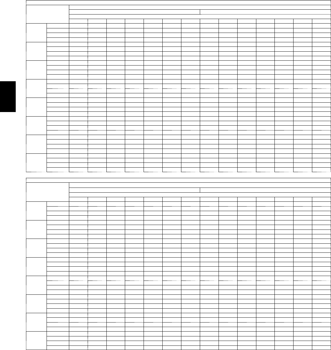
84
PERFORMANCE DATA (CONT)
Cooling Capacities (cont)
48PG16 (15 Tons) — STANDARD UNIT AND UNIT WITH HUMIDI-MIZER™SYSTEM IN COOLING MODE
Temp (F )
Air Ent
Condenser
(Edb)
Air Entering Evaporator — Cfm
4500 5250
Air Entering Evaporator — Ewb (F)
80 76 72 67 62 58 54 80 76 72 67 62 58 54
60
TC 265.1 247.6 230.2 210.2 192.2 178.3 175.3 276.7 257.1 239.0 218.7 199.1 186.1 185.0
SHC 73.4 91.5 109.5 132.7 156.9 172.5 175.3 74.1 93.8 116.9 144.4 170.6 184.9 185.0
kW 8.72 8.60 8.47 8.35 8.19 8.10 8.07 8.80 8.68 8.55 8.39 8.25 8.15 8.16
BF 0.00 0.00 0.24 0.14 0.10 0.12 0.30 0.00 0.00 0.18 0.12 0.11 0.17 0.37
70
TC 257.4 240.4 223.6 204.0 185.5 172.1 170.9 266.7 248.8 231.7 211.0 192.5 180.9 180.2
SHC 62.0 88.6 107.4 131.3 153.8 167.6 170.9 71.8 91.1 115.2 141.6 168.5 178.4 180.2
kW 9.92 9.78 9.65 9.48 9.35 9.25 9.23 9.98 9.86 9.70 9.55 9.40 9.31 9.30
BF 0.00 0.00 0.19 0.11 0.10 0.14 0.32 0.00 0.00 0.14 0.11 0.10 0.20 0.39
75
TC 252.7 236.3 219.4 200.1 182.4 169.1 167.6 266.6 244.3 227.1 207.1 188.8 178.1 177.2
SHC 68.7 87.1 106.0 129.5 153.0 166.8 167.6 71.8 90.6 113.6 140.4 167.0 176.0 177.2
kW 10.55 10.41 10.27 10.12 9.96 9.86 9.85 10.66 10.48 10.33 10.17 10.01 9.94 9.93
BF 0.00 0.00 0.17 0.11 0.09 0.13 0.33 0.00 0.00 0.13 0.11 0.09 0.21 0.40
85
TC 243.4 227.3 211.1 192.2 175.1 163.5 162.8 256.3 234.0 217.4 198.6 180.8 172.5 172.3
SHC 65.6 83.6 103.3 126.8 150.0 163.4 162.8 68.4 87.8 110.2 137.4 163.5 172.5 172.3
kW 11.89 11.76 11.61 11.45 11.30 11.19 11.19 12.01 11.81 11.67 11.51 11.35 11.28 11.28
BF 0.00 0.00 0.13 0.09 0.08 0.13 0.35 0.00 0.07 0.12 0.10 0.09 0.22 0.41
95
TC 232.1 216.8 201.5 183.6 166.9 157.6 157.5 238.2 222.4 207.0 188.8 171.9 166.3 166.1
SHC 61.9 79.7 99.9 123.4 146.2 157.6 157.5 62.7 84.2 106.6 133.5 159.4 166.3 166.1
kW 13.36 13.22 13.09 12.92 12.76 12.67 12.67 13.42 13.28 13.14 12.97 12.81 12.76 12.75
BF 0.00 0.00 0.11 0.09 0.08 0.16 0.37 0.00 0.23 0.11 0.09 0.09 0.24 0.43
105
TC 219.4 205.0 190.5 173.7 158.0 151.1 150.9 224.6 209.8 195.5 178.5 162.6 159.2 159.0
SHC 57.8 76.4 95.9 119.4 142.1 151.1 150.9 58.5 80.2 102.4 129.4 154.8 159.2 159.0
kW 14.94 14.82 14.68 14.52 14.36 14.28 14.28 15.01 14.87 14.73 14.57 14.41 14.37 14.37
BF 0.00 0.06 0.10 0.08 0.08 0.19 0.40 0.00 0.16 0.10 0.09 0.09 0.27 0.45
115
TC 205.1 191.6 178.4 162.9 148.2 143.7 143.5 209.5 196.1 182.7 167.0 152.6 151.0 150.9
SHC 53.3 72.2 91.5 114.9 137.5 143.7 143.5 53.8 75.8 97.9 124.9 149.2 151.0 150.9
kW 16.64 16.52 16.39 16.23 16.08 16.02 16.02 16.70 16.58 16.44 16.28 16.12 16.11 16.11
BF 0.00 0.18 0.09 0.08 0.08 0.23 0.42 0.00 0.13 0.09 0.08 0.11 0.31 0.48
125
TC 188.7 177.1 164.9 150.5 137.3 135.0 134.9 192.3 180.1 168.5 154.0 141.8 141.6 141.4
SHC 48.2 67.5 86.6 110.0 132.0 135.0 134.9 48.6 70.7 92.9 119.8 141.8 141.6 141.4
kW 18.41 18.33 18.21 18.05 17.89 17.87 17.86 18.46 18.36 18.25 18.09 17.95 17.95 17.95
BF 0.00 0.13 0.08 0.07 0.08 0.28 0.46 0.00 0.11 0.09 0.08 0.13 0.35 0.51
48PG16 (15 Tons) — STANDARD UNIT AND UNIT WITH HUMIDI-MIZER SYSTEM IN COOLING MODE (cont)
Temp (F )
Air Ent
Condenser
(Edb)
Air Entering Evaporator — Cfm
6000 7500
Air Entering Evaporator — Ewb (F)
80 76 72 67 62 58 54 80 76 72 67 62 58 54
60
TC 288.3 267.2 246.2 224.4 205.0 194.8 194.1 295.2 276.6 255.2 233.5 213.5 209.3 208.7
SHC 74.8 99.6 124.5 154.2 184.2 192.1 194.1 77.9 107.4 137.0 174.3 206.6 209.3 208.7
kW 8.89 8.74 8.59 8.44 8.29 8.23 8.22 8.96 8.81 8.66 8.50 8.35 8.32 8.32
BF 0.00 0.00 0.15 0.13 0.11 0.25 0.42 0.00 0.23 0.14 0.13 0.15 0.34 0.50
70
TC 276.9 254.9 237.3 216.8 197.7 189.8 188.9 282.1 263.2 245.5 224.6 205.4 203.1 203.1
SHC 73.9 96.4 121.6 152.2 181.6 189.8 188.9 73.9 103.5 134.0 171.3 202.2 203.1 203.1
kW 10.06 9.90 9.75 9.59 9.44 9.37 9.38 10.11 9.96 9.82 9.65 9.51 9.49 9.49
BF 0.00 0.08 0.13 0.11 0.11 0.25 0.44 0.00 0.19 0.13 0.12 0.16 0.36 0.52
75
TC 273.1 249.9 232.7 212.4 193.8 186.6 186.4 276.0 257.7 240.2 219.7 201.8 200.2 199.9
SHC 72.7 95.0 120.1 150.7 180.0 186.6 186.4 72.1 101.9 132.3 169.6 198.5 200.2 199.9
kW 10.70 10.52 10.38 10.21 10.06 10.00 10.00 10.74 10.59 10.44 10.27 10.13 10.12 10.12
BF 0.00 0.17 0.13 0.11 0.11 0.26 0.44 0.00 0.17 0.13 0.12 0.17 0.37 0.52
85
TC 265.7 238.7 222.4 203.0 185.1 180.5 180.2 263.0 245.7 229.2 209.5 193.9 193.4 193.1
SHC 70.4 91.5 116.7 147.2 175.8 180.5 180.2 68.2 98.2 128.6 165.7 193.0 193.4 193.1
kW 12.08 11.86 11.72 11.55 11.39 11.35 11.35 12.08 11.93 11.79 11.61 11.47 11.47 11.47
BF 0.00 0.20 0.11 0.10 0.11 0.28 0.46 0.00 0.16 0.12 0.12 0.19 0.39 0.54
95
TC 242.8 226.7 211.3 193.1 176.3 173.8 173.6 249.1 232.9 217.3 198.6 186.3 185.5 185.3
SHC 63.3 87.8 112.8 143.3 171.0 173.8 173.6 64.1 94.2 124.5 161.5 183.3 185.5 185.3
kW 13.47 13.33 13.18 13.02 12.85 12.83 12.83 13.55 13.40 13.25 13.07 12.95 12.95 12.95
BF 0.00 0.16 0.11 0.10 0.11 0.31 0.48 0.00 0.15 0.12 0.11 0.23 0.41 0.56
105
TC 228.5 213.8 199.2 182.1 167.0 166.0 165.8 234.1 219.1 204.5 187.1 176.9 176.7 176.6
SHC 58.9 83.7 108.6 139.0 165.0 166.0 165.8 59.7 89.8 120.1 157.1 176.9 176.7 176.6
kW 15.05 14.92 14.78 14.61 14.45 14.44 14.44 15.13 14.99 14.84 14.67 14.56 14.56 14.56
BF 0.00 0.14 0.10 0.10 0.13 0.34 0.50 0.00 0.14 0.12 0.11 0.25 0.44 0.58
115
TC 212.8 199.2 186.0 170.1 157.8 157.2 157.0 217.4 204.0 190.4 174.4 167.0 166.8 166.7
SHC 54.2 79.0 103.9 134.3 156.3 157.2 157.0 54.8 85.2 115.4 152.1 167.0 166.8 166.7
kW 16.74 16.62 16.48 16.32 16.18 16.18 16.18 16.81 16.68 16.54 16.38 16.29 16.29 16.29
BF 0.00 0.13 0.10 0.09 0.17 0.37 0.53 0.00 0.13 0.11 0.11 0.29 0.47 0.60
125
TC 195.0 183.5 171.2 156.5 147.2 147.0 146.9 198.5 186.7 174.9 160.1 155.6 155.5 155.4
SHC 48.9 74.1 98.9 129.1 147.2 147.0 146.9 49.4 79.8 110.0 146.2 155.6 155.5 155.4
kW 18.51 18.41 18.28 18.13 18.02 18.02 18.01 18.57 18.44 18.33 18.17 18.12 18.12 18.11
BF 0.00 0.11 0.09 0.09 0.21 0.41 0.56 0.00 0.12 0.11 0.12 0.34 0.50 0.63
* See Legend and Notes on next page
48PG

85
LEGEND
BF --- B y p a s s F a c to r
Edb --- E n t e r i n g D r y --- B u l b
Ewb --- E n t e r i n g W e t --- B u l b
kW --- Compressor Motor Power Input
Idb --- L e a v i n g D r y --- B u l b
Iwb --- L e a v i ng W e t --- B u l b
SHC --- Sensible Heat Capacity (1000 Btuh) Gross
TC --- Total Capacity (1000 Btuh) Gross
NOTES:
1. Direct interpolation is permissible. Do not extrapolate.
2. Thefollowingformulasmaybeused:
tldb =t
edb –sensible capacity (Btuh)
1.10 x cfm
tlwb = Wet---bulb temperature corresponding to enthalpy of air leaving evaporator
coil (hlwb)
hlwb =h
ewb –total capacity (Btuh)
4.5 x cfm
Where: hewb = Enthalpy of air entering evaporator coil
3. The SHC is based on 80_F edb temperature of air entering evaporator coil
Below 80_F edb, subtract (corr factor x cfm) from SHC.
Above 80
_
F edb, add (corr factor x cfm) to SHC.
BYPASS
FACTOR
(BF)
ENTERING AIR DRY-BULB TEMP (F)
79 78 77 76 75 under 75
81 82 83 84 85 over 85
Correction Factor
.05 1.04 2.07 3.11 4.14 5.18
Use formula
shown below.
.10 .98 1.96 2.94 3.92 4.90
.20 .87 1.74 2.62 3.49 4.36
.30 .76 1.53 2.29 3.05 3.82
Interpolation is permissible.
C o r r e l a t i o n F a c to r = 1 . 0 9 x ( 1 --- B F ) x ( e d b --- 8 0 ) .
4. Cooling capacities for 48PG03---16 units with Humidi---MiZer system in Cooling
mode are the same as standard units.
48PG
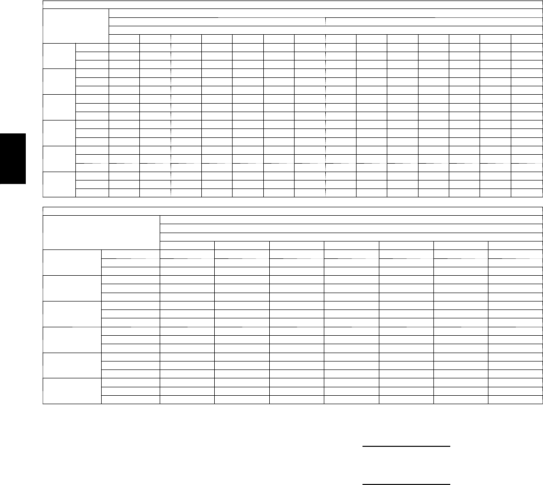
86
PERFORMANCE DATA (CONT)
Cooling Capacities (cont)
48PG16 (15 Tons) — UNIT WITH HUMIDI ---MIZER™SYSTEM IN SUBCOOLING MODE
Te m p ( F )
Air Ent
Condenser
(Edb)
AirEnteringEvaporator—CFM
4500 6000
AirEnteringEvaporator—Ewb(F)
80 76 72 67 62 57 54 80 76 72 67 62 57 54
75
TC 235.9 218.6 201.4 179.8 158.2 136.6 123.6 267.2 246.0 224.8 198.3 171.7 145.2 129.3
SHC 56.0 72.0 88.1 108.1 128.1 136.6 123.6 65.6 84.3 103.0 126.3 149.7 145.2 129.3
kW 10.07 10.07 9.81 9.64 9.48 9.32 9.22 9.89 9.89 9.85 9.82 9.79 9.77 9.75
85
TC 222.6 207.0 191.3 171.7 152.1 132.5 120.8 244.4 225.5 206.5 182.9 159.2 135.6 121.4
SHC 32.5 52.2 71.9 96.5 121.2 145.8 160.6 38.3 61.2 84.2 112.9 141.6 170.3 187.6
kW 11.62 11.62 11.30 11.10 10.90 10.70 10.58 11.41 11.41 11.34 11.30 11.25 11.21 11.19
95
TC 209.4 195.3 181.2 163.7 146.1 128.5 118.0 221.5 204.9 188.3 167.5 146.7 125.9 113.5
SHC 8.9 32.3 55.7 85.0 114.2 128.5 118.0 10.9 38.1 65.4 99.5 133.6 125.9 113.5
kW 13.16 13.16 12.79 12.55 12.32 12.09 11.95 12.93 12.93 12.84 12.78 12.72 12.66 12.62
105
TC 196.1 183.6 171.2 155.6 140.1 124.5 115.2 198.7 184.4 170.0 152.1 134.2 116.3 105.6
SHC –14.6 12.5 39.6 73.4 107.3 124.5 115.2 –16.5 15.0 46.6 86.0 125.5 116.3 105.6
kW 14.71 14.71 14.28 14.01 13.74 13.47 13.31 14.45 14.45 14.33 14.25 14.18 14.10 14.06
115
TC 182.8 171.9 161.1 147.6 134.0 120.5 112.4 175.9 163.8 151.8 136.8 121.7 106.7 97.7
SHC –38.2 –7.4 23.4 61.8 100.3 120.5 112.4 –43.9 –8.1 27.8 72.6 117.4 106.7 97.7
kW 16.25 16.25 15.77 15.46 15.16 14.86 14.68 15.97 15.97 15.82 15.73 15.64 15.55 15.49
125
TC 169.5 160.3 151.1 139.5 128.0 116.5 109.6 153.0 143.3 133.5 121.4 109.2 97.1 89.8
SHC –61.7 –27.3 7.2 50.3 93.4 116.5 109.6 –71.3 –31.2 9.0 59.2 109.2 97.1 89.8
kW 17.80 17.80 17.26 16.92 16.58 16.24 16.04 17.49 17.49 17.32 17.21 17.10 16.99 16.93
4 8 P G 1 6 ( 1 5 T O N S ) --- U N I T W I T H H U M I D I --- M I Z E R S Y S T E M I N S U B C O O L I N G M O D E ( C O N T )
Te m p ( F )
Air Ent
Condenser
(Edb)
AirEnteringEvaporator—CFM
7500
AirEnteringEvaporator—Ewb(F)
80 76 72 67 62 57 54
75
TC 298.1 273.0 247.9 216.5 185.1 153.7 134.9
SHC 74.2 95.2 116.3 142.6 168.8 153.7 134.9
kW 9.75 9.75 9.88 9.96 10.04 10.12 10.17
85
TC 265.9 243.7 221.6 193.9 166.2 138.6 122.0
SHC 43.4 69.3 95.1 127.5 159.8 192.1 211.5
kW 11.25 11.25 11.38 11.45 11.53 11.61 11.66
95
TC 233.6 214.4 195.3 171.3 147.4 123.4 109.0
SHC 12.6 43.3 74.0 112.4 147.4 123.4 109.0
kW 12.75 12.75 12.87 12.95 13.03 13.11 13.15
105
TC 201.3 185.1 168.9 148.7 128.5 108.2 96.1
SHC –18.3 17.3 52.8 97.3 128.5 108.2 96.1
kW 14.25 14.25 14.37 14.45 14.52 14.60 14.64
115
TC 169.0 155.8 142.6 126.1 109.6 93.1 83.2
SHC –49.1 –8.7 31.7 82.2 109.6 93.1 83.2
kW 15.75 15.75 15.87 15.94 16.02 16.09 16.13
125
TC 136.7 126.5 116.3 103.5 90.7 77.9 70.2
SHC –79.9 –34.7 10.5 67.1 90.7 77.9 70.2
kW 17.25 17.25 17.37 17.44 17.51 17.58 17.63
LEGEND
Edb --- E n t e r i n g D r y --- B u l b
Ewb --- E n t e r i n g W e t --- B u l b
kW --- Compressor Motor Power Input
Idb --- L e a v i n g D r y --- B u l b
Iwb --- L e a v i n g W e t --- B u l b
SHC --- Sensible Heat Capacity (1000 Btuh) Gross
TC --- Total Capacity (1000 Btuh) Gross
NOTES:
1. Direct interpolation is permissible. Do not extrapolate.
2. The following formulas may be used:
tldb =tedb –
sensible capacity (Btuh)
1.10 x cfm
tlwb = Wet--- bulb temperature corresponding to enthalpy of air leaving
evaporator coil (hlwb)
hlwb =h
ewb –
total capacity (Btuh)
4.5 x cfm
Where: hewb = Enthalpy of air entering evaporator coil
48PG
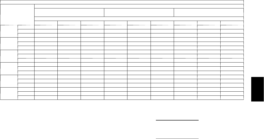
87
Cooling Capacities (cont)
4 8 P G 1 6 ( 1 5 T O N S ) --- U N I T W I T H H U M I D I --- M I Z E R S Y S T E M I N H O T G A S R E H E A T M O D E
Te m p ( F )
Air Ent
Condenser
(Edb)
AirEnteringEvaporator—Ewb(F)
75 Dry Bulb
62.5 Wet Bulb (50% RH)
75 Dry Bulb
64 Wet Bulb (55% RH)
75 Dry Bulb
65.3 Wet Bulb (60% RH)
AirEnteringEvaporator—Cfm
5250 6000 6750 5250 6000 6750 5250 6000 6750
80
TC 49.5 51.9 54.0 52.6 55.0 57.2 55.2 57.7 60.0
SHC 1.8 3.6 5.1 –14.3 –11.8 –9.6 –28.3 –25.1 –22.3
kW 12.33 12.39 12.45 12.47 12.46 12.52 12.46 12.52 12.58
75
TC 52.9 55.2 57.3 55.9 58.3 60.5 58.5 61.0 63.2
SHC 3.6 5.2 6.6 –11.5 –9.2 –7.2 –24.6 –21.6 –19.0
kW 11.98 12.03 12.08 12.11 12.11 12.16 12.11 12.17 12.22
70
TC 56.3 58.6 60.6 59.2 61.6 63.7 61.8 64.3 66.5
SHC 5.4 6.8 8.0 –8.7 –6.6 –4.8 –20.8 –18.2 –15.8
kW 11.62 11.67 11.72 11.75 11.75 11.80 11.76 11.82 11.87
60
TC 63.0 65.2 67.2 65.9 68.2 70.3 68.4 70.8 72.9
SHC 8.9 10.0 10.9 –3.0 –1.4 0.0 –13.3 –11.2 –9.3
kW 10.90 10.94 10.98 11.04 11.04 11.08 11.07 11.11 11.16
50
TC 69.7 71.9 73.8 72.5 74.8 76.8 75.0 77.3 79.4
SHC 12.5 13.2 13.7 2.7 3.8 4.8 –5.8 –4.2 –2.9
kW 10.18 10.22 10.25 10.33 10.32 10.36 10.37 10.41 10.45
40
TC 76.4 78.5 80.4 79.2 81.4 83.3 81.6 83.8 85.8
SHC 16.1 16.4 16.6 8.4 9.0 9.6 1.7 2.7 3.6
kW 9.47 9.50 9.52 9.61 9.61 9.64 9.68 9.71 9.73
LEGEND
Edb --- E n t e r i n g D r y --- B u l b
Ewb --- E n t e r i n g W e t --- B u l b
kW --- Compressor Motor Power Input
Idb --- L e a v i n g D r y --- B u l b
Iwb --- L e a v i n g W e t --- B u l b
SHC --- Sensible Heat Capacity (1000 Btuh) Gross
TC --- Total Capacity (1000 Btuh) Gross
NOTES:
1. Direct interpolation is permissible. Do not extrapolate.
2. The following formulas may be used:
tldb =tedb –
sensible capacity (Btuh)
1.10 x cfm
tlwb = Wet--- bulb temperature corresponding to enthalpy of air leaving
evaporator coil (hlwb)
hlwb =h
ewb –
total capacity (Btuh)
4.5 x cfm
Where: hewb = Enthalpy of air entering evaporator coil
48PG
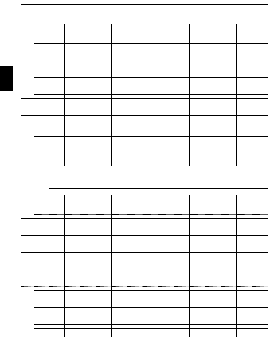
88
PERFORMANCE DATA (CONT)
Cooling Capacities (cont)
48PG20 (18 Tons) — STANDARD UNIT
Te m p ( F )
Air Ent
Condenser
(Edb)
AirEnteringEvaporator—Cfm
5400 6300
AirEnteringEvaporator—Ewb(F)
80 76 72 67 62 57 54 80 76 72 67 62 57 54
60
TC 306 290 274 254 234 214 203 307 291 276 256 236 216 204
SHC 131 142 152 166 179 193 201 138 148 159 172 185 198 204
kW 7.9 7.9 7.9 7.8 7.8 7.8 7.8 8.1 8.0 8.0 8.0 7.9 7.9 7.9
BF 0.00 0.23 0.11 0.04 0.08 0.21 0.42 0.00 0.25 0.13 0.05 0.09 0.23 0.44
70
TC 290 275 260 241 222 203 191 292 277 261 242 223 204 193
SHC 110 125 140 158 177 195 191 119 133 147 165 183 201 193
kW 9.9 9.8 9.8 9.7 9.7 9.6 9.6 10.1 10.0 9.9 9.9 9.8 9.7 9.7
BF 0.00 0.24 0.13 0.06 0.10 0.22 0.43 0.00 0.26 0.15 0.07 0.12 0.24 0.45
75
TC 282 267 252 234 215 197 186 284 269 254 236 217 198 187
SHC 100 117 134 154 175 196 186 109 125 142 162 182 198 187
kW 10.9 10.8 10.7 10.7 10.6 10.5 10.5 11.0 11.0 10.9 10.8 10.7 10.7 10.6
BF 0.00 0.25 0.14 0.08 0.11 0.23 0.44 0.00 0.27 0.16 0.08 0.13 0.25 0.46
85
TC 266 252 238 220 203 185 174 269 254 240 222 204 187 176
SHC 80 101 121 147 173 185 174 90 110 130 155 180 187 176
kW 12.8 12.7 12.6 12.5 12.4 12.3 12.3 13.0 12.9 12.8 12.7 12.6 12.5 12.4
BF 0.00 0.27 0.16 0.10 0.13 0.25 0.46 0.00 0.29 0.18 0.11 0.15 0.27 0.48
95
TC 251 237 224 207 190 173 163 253 240 226 209 192 175 165
SHC 60 84 109 139 170 173 163 71 95 119 149 179 175 165
kW 14.8 14.7 14.6 14.4 14.3 14.2 14.1 15.0 14.9 14.8 14.6 14.5 14.3 14.2
BF 0.00 0.28 0.18 0.12 0.15 0.26 0.47 0.00 0.31 0.21 0.13 0.18 0.29 0.50
105
TC 235 222 209 193 177 161 152 238 225 212 196 180 163 154
SHC 40 68 96 132 167 161 152 52 80 108 142 177 163 154
kW 16.7 16.6 16.5 16.3 16.1 16.0 15.9 17.0 16.9 16.7 16.5 16.3 16.2 16.1
BF 0.00 0.31 0.20 0.14 0.17 0.29 0.50 0.00 0.33 0.23 0.15 0.20 0.31 0.52
115
TC 219 207 195 180 165 149 140 222 210 198 182 167 152 143
SHC 20 52 84 124 165 149 140 33 65 96 136 167 152 143
kW 18.7 18.5 18.4 18.2 18.0 17.8 17.7 19.0 18.8 18.6 18.4 18.2 18.0 17.9
BF 0.00 0.33 0.22 0.16 0.19 0.31 0.52 0.00 0.35 0.25 0.17 0.23 0.33 0.54
125
TC 203 192 180 166 152 138 129 207 195 184 169 155 140 132
SHC 10 35 72 117 152 138 129 14 49 85 129 155 140 132
kW 20.6 20.5 20.3 20.1 19.8 19.6 19.5 21.0 20.8 20.6 20.3 20.1 19.8 19.7
BF 0.00 0.35 0.24 0.18 0.21 0.33 0.54 0.00 0.37 0.27 0.19 0.25 0.35 0.56
48PG20 (18 Tons) — STANDARD UNIT (cont)
Te m p ( F )
Air Ent
Condenser
(Edb)
AirEnteringEvaporator—Cfm
7200 8100
AirEnteringEvaporator—Ewb(F)
80 76 72 67 62 57 54 80 76 72 67 62 57 54
60
TC 309 293 277 257 237 217 205 310 294 278 258 238 217 205
SHC 143 154 164 177 189 202 205 148 158 168 181 193 205 205
kW 8.2 8.2 8.1 8.1 8.0 8.0 8.0 8.3 8.2 8.2 8.2 8.1 8.1 8.0
BF 0.00 0.26 0.15 0.05 0.11 0.24 0.45 0.00 0.28 0.17 0.05 0.12 0.26 0.47
70
TC 294 278 263 244 224 205 194 295 279 264 245 225 206 195
SHC 125 139 153 171 188 205 194 131 145 159 176 193 206 195
kW 10.2 10.1 10.1 10.0 9.9 9.8 9.8 10.3 10.2 10.2 10.1 10.0 9.9 9.9
BF 0.00 0.28 0.17 0.07 0.14 0.26 0.47 0.00 0.30 0.19 0.07 0.16 0.28 0.49
75
TC 286 271 256 237 218 199 188 287 272 257 238 219 200 189
SHC 116 132 148 168 188 199 188 123 138 154 173 193 200 189
kW 11.2 11.1 11.0 11.0 10.9 10.8 10.7 11.3 11.2 11.2 11.1 11.0 10.9 10.8
BF 0.00 0.29 0.18 0.08 0.15 0.27 0.48 0.00 0.31 0.20 0.09 0.17 0.29 0.50
85
TC 271 256 242 224 206 188 177 272 258 243 225 207 189 178
SHC 98 118 138 162 187 188 177 105 125 144 168 192 189 178
kW 13.2 13.1 13.0 12.9 12.7 12.6 12.5 13.3 13.2 13.1 13.0 12.9 12.7 12.6
BF 0.00 0.31 0.21 0.11 0.18 0.29 0.50 0.00 0.33 0.23 0.11 0.20 0.31 0.52
95
TC 256 242 228 211 194 177 166 257 244 230 212 195 178 168
SHC 80 104 127 157 186 177 166 88 111 134 163 192 178 168
kW 15.2 15.1 15.0 14.8 14.6 14.5 14.4 15.4 15.2 15.1 14.9 14.7 14.6 14.5
BF 0.00 0.33 0.23 0.13 0.20 0.31 0.52 0.00 0.35 0.25 0.14 0.22 0.33 0.54
105
TC 240 227 214 198 182 165 155 242 229 216 200 183 167 157
SHC 62 90 117 151 182 165 155 71 98 125 158 183 167 157
kW 17.2 17.1 16.9 16.7 16.5 16.3 16.2 17.4 17.2 17.1 16.9 16.6 16.4 16.3
BF 0.00 0.35 0.25 0.15 0.23 0.33 0.54 0.00 0.37 0.27 0.16 0.25 0.35 0.56
115
TC 225 213 200 185 169 154 144 227 215 202 187 171 155 146
SHC 44 75 106 145 169 154 144 54 84 115 153 171 155 146
kW 19.2 19.0 18.9 18.6 18.4 18.2 18.0 19.4 19.2 19.0 18.8 18.5 18.3 18.2
BF 0.00 0.37 0.28 0.17 0.26 0.35 0.56 0.00 0.39 0.30 0.19 0.28 0.37 0.58
125
TC 210 198 186 172 157 142 134 212 200 189 174 159 144 135
SHC 26 61 96 139 157 142 134 37 71 105 148 159 144 135
kW 21.2 21.0 20.8 20.5 20.3 20.0 19.9 21.4 21.2 21.0 20.7 20.4 20.2 20.0
BF 0.00 0.39 0.30 0.20 0.28 0.37 0.58 0.00 0.41 0.32 0.21 0.30 0.39 0.60
48PG
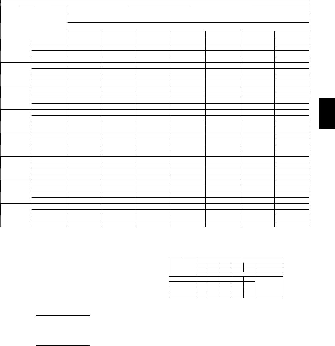
89
Cooling Capacities (cont)
48PG20 (18 Tons) — STANDARD UNIT (cont)
Te m p ( F )
Air Ent
Condenser
(
Edb
)
AirEnteringEvaporator—Cfm
9000
AirEnteringEvaporator—Ewb(F)
80 76 72 67 62 57 54
60
TC 311 295 279 258 238 218 206
SHC 153 162 172 184 196 209 206
kW 8.4 8.3 8.3 8.2 8.2 8.1 8.1
BF 0.00 0.29 0.18 0.05 0.13 0.27 0.48
70
TC 296 281 265 246 226 207 195
SHC 136 150 163 180 197 207 195
kW 10.4 10.3 10.3 10.2 10.1 10.0 9.9
BF 0.00 0.31 0.20 0.07 0.17 0.29 0.50
75
TC 289 273 258 239 220 201 190
SHC 128 143 158 178 197 201 190
kW 11.4 11.3 11.2 11.1 11.0 10.9 10.9
BF 0.00 0.32 0.21 0.09 0.18 0.30 0.51
85
TC 274 259 245 227 208 190 179
SHC 111 130 149 173 197 190 179
kW 13.5 13.3 13.2 13.1 12.9 12.8 12.7
BF 0.00 0.34 0.24 0.11 0.21 0.32 0.53
95
TC 259 245 231 214 196 179 169
SHC 95 118 140 169 196 179 169
kW 15.5 15.3 15.2 15.0 14.8 14.7 14.6
BF 0.00 0.36 0.26 0.14 0.23 0.34 0.55
105
TC 244 231 218 201 184 168 158
SHC 78 105 131 164 184 168 158
kW 17.5 17.4 17.2 17.0 16.8 16.5 16.4
BF 0.00 0.38 0.28 0.17 0.25 0.36 0.57
115
TC 229 217 204 188 172 157 147
SHC 62 92 122 160 172 157 147
kW 19.6 19.4 19.2 18.9 18.7 18.4 18.3
BF 0.00 0.40 0.30 0.20 0.29 0.38 0.59
125
TC 214 202 190 175 160 146 137
SHC 46 79 113 156 160 146 137
kW 21.6 21.4 21.1 20.9 20.6 20.3 20.1
BF 0.00 0.42 0.32 0.22 0.31 0.40 0.61
LEGEND
BF --- B y p a ss Fa c t o r
Edb --- E n t e r in g D r y --- B u l b
Ewb --- E n t e r in g W e t --- B u l b
kW --- Compressor Motor Power Input
Idb --- L e a v in g D r y --- B u l b
Iwb --- L e a v i n g We t --- B u l b
SHC --- Sensible Heat Capacity (1000 Btuh) Gross
TC --- Total Capacity (1000 Btuh) Gross
NOTES:
1. Direct interpolation is permissible. Do not extrapolate.
2. The following formulas may be used:
tldb =t
edb –sensible capacity (Btuh)
1.10 x cfm
tlwb = Wet---bulb temperature corresponding to enthalpy of air leaving
evaporator coil (hlwb)
hlwb =h
ewb –total capacity (Btuh)
4.5 x cfm
Where: hewb = Enthalpy of air entering evaporator coil
3. The SHC is based on 80_F edb temperature of air entering evaporator
coil
Below 80_F edb, subtract (corr factor x cfm) from SHC.
Above 80
_
F edb, add (corr factor x cfm) to SHC.
BYPASS
FACTOR
(BF)
ENTERING AIR DRY-BULB TEMP (F)
79 78 77 76 75 under 75
81 82 83 84 85 over 85
Correction Factor
.05 1.04 2.07 3.11 4.14 5.18
Use formula
shown below.
.10 .98 1.96 2.94 3.92 4.90
.20 .87 1.74 2.62 3.49 4.36
.30 .76 1.53 2.29 3.05 3.82
Interpolation is permissible.
C o r r e l a t i o n Fa c t o r = 1 . 0 9 x ( 1 --- B F ) x ( e d b --- 8 0 ) .
48PG
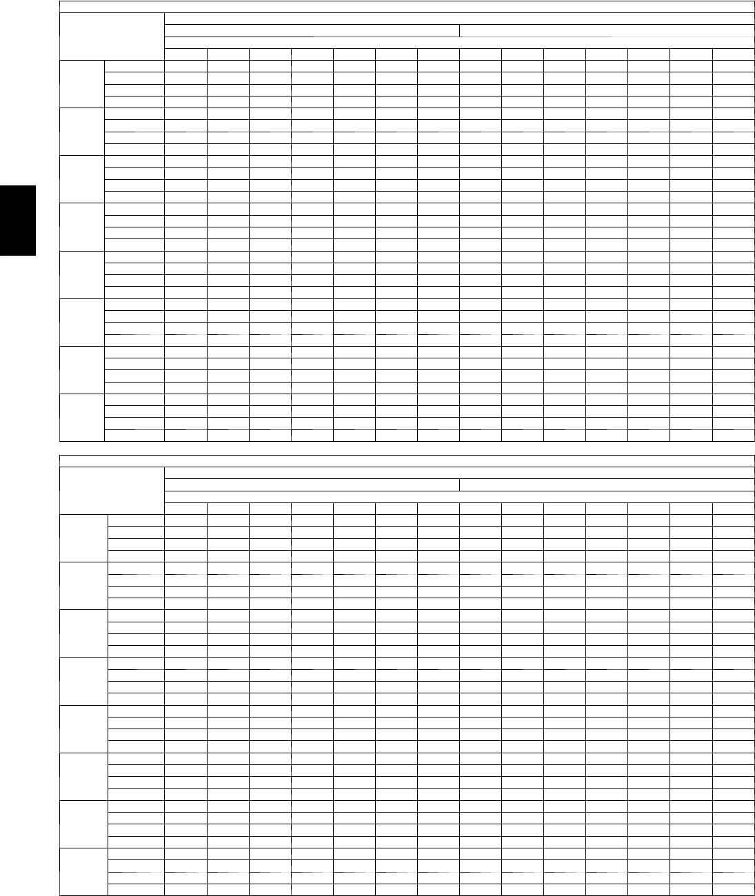
90
PERFORMANCE DATA (CONT)
Cooling Capacities (cont)
48PG20 (18 Tons) — UNIT WITH HUMIDI-MIZER™SYSTEM — COOLING MODE
Te m p ( F )
Air Entering
Condenser
(Edb)
Evaporator Air Quantity — CFM/BF
5400 6300
AirEnteringEvaporator—Ewb(F)
80 76 72 67 62 57 54 80 76 72 67 62 57 54
60
TC 308 290 273 252 231 209 196 312 295 277 256 234 212 199
SHC 122 133 144 159 173 187 195 130 141 152 166 179 193 199
kW 8.0 8.0 8.0 8.0 8.0 8.0 8.0 8.1 8.1 8.1 8.1 8.1 8.1 8.1
BF 0.00 0.23 0.11 0.04 0.08 0.21 0.42 0.00 0.25 0.13 0.05 0.09 0.23 0.44
70
TC 294 277 260 240 219 198 185 299 282 265 244 223 201 189
SHC 104 119 134 153 172 191 185 113 128 143 161 179 198 189
kW 10.1 10.1 10.1 10.1 10.1 10.1 10.1 10.3 10.3 10.3 10.3 10.3 10.3 10.3
BF 0.00 0.24 0.13 0.06 0.10 0.22 0.43 0.00 0.26 0.15 0.07 0.12 0.24 0.45
75
TC 287 271 254 233 213 192 180 293 276 259 238 217 196 183
SHC 95 112 129 150 171 192 180 105 122 138 159 179 196 183
kW 11.1 11.1 11.1 11.1 11.1 11.1 11.1 11.3 11.3 11.3 11.3 11.3 11.3 11.3
BF 0.00 0.25 0.14 0.08 0.11 0.23 0.44 0.00 0.27 0.16 0.08 0.13 0.25 0.46
85
TC 273 257 241 221 201 181 168 280 263 247 226 206 185 173
SHC 76 97 118 144 170 181 168 88 109 129 154 179 185 173
kW 13.3 13.3 13.3 13.2 13.2 13.2 13.1 13.6 13.5 13.5 13.4 13.4 13.3 13.3
BF 0.00 0.27 0.16 0.10 0.13 0.25 0.46 0.00 0.29 0.18 0.11 0.15 0.27 0.48
95
TC 260 244 228 208 189 169 157 267 251 235 215 194 174 162
SHC 58 83 108 138 169 169 157 72 96 120 150 180 174 162
kW 15.5 15.5 15.4 15.3 15.2 15.2 15.1 15.8 15.7 15.7 15.6 15.5 15.4 15.3
BF 0.00 0.28 0.18 0.12 0.15 0.26 0.47 0.00 0.31 0.21 0.13 0.18 0.29 0.50
105
TC 246 231 215 196 177 158 146 254 238 222 203 183 163 152
SHC 40 69 97 133 168 158 146 55 83 110 145 180 163 152
kW 17.7 17.6 17.5 17.4 17.3 17.2 17.1 18.1 17.9 17.8 17.7 17.5 17.4 17.3
BF 0.00 0.31 0.20 0.14 0.17 0.29 0.50 0.00 0.33 0.23 0.15 0.20 0.31 0.52
115
TC 232 217 202 184 165 146 135 241 226 210 191 172 153 141
SHC 22 54 86 127 165 146 135 38 70 101 140 172 153 141
kW 19.9 19.8 19.7 19.5 19.3 19.2 19.1 20.3 20.1 20.0 19.8 19.6 19.4 19.3
BF 0.00 0.33 0.22 0.16 0.19 0.31 0.52 0.00 0.35 0.25 0.17 0.23 0.33 0.54
125
TC 219 204 189 171 153 135 124 228 213 198 179 160 142 130
SHC 440 76 121 153 135 124 22 57 92 136 160 142 130
kW 22.2 22.0 21.8 21.6 21.4 21.2 21.0 22.5 22.4 22.2 21.9 21.7 21.4 21.3
BF 0.00 0.35 0.24 0.18 0.21 0.33 0.54 0.00 0.37 0.27 0.19 0.25 0.35 0.56
48PG20 (18 Tons) — UNIT WITH HUMIDI-MIZER SYSTEM — COOLING MODE (cont)
Te m p ( F )
Air Entering
Condenser
(Edb)
Evaporator Air Quantity — CFM/BF
7200 8100
AirEnteringEvaporator—Ewb(F)
80 76 72 67 62 57 54 80 76 72 67 62 57 54
60
TC 316 298 281 259 237 215 202 319 301 283 261 239 217 204
SHC 137 148 158 171 185 198 202 143 153 163 176 189 202 204
kW 8.2 8.2 8.2 8.2 8.2 8.2 8.2 8.3 8.3 8.3 8.3 8.3 8.3 8.3
BF 0.00 0.26 0.15 0.05 0.11 0.24 0.45 0.00 0.28 0.17 0.05 0.12 0.26 0.47
70
TC 303 286 269 248 226 205 192 307 290 272 251 229 207 194
SHC 122 136 150 168 186 203 192 128 142 156 174 191 207 194
kW 10.4 10.4 10.4 10.4 10.4 10.4 10.4 10.5 10.5 10.5 10.5 10.5 10.5 10.5
BF 0.00 0.28 0.17 0.07 0.14 0.26 0.47 0.00 0.30 0.19 0.07 0.16 0.28 0.49
75
TC 297 280 263 242 221 199 187 301 284 267 245 224 202 189
SHC 114 130 146 166 186 199 187 121 137 153 172 192 202 189
kW 11.5 11.5 11.5 11.5 11.5 11.4 11.4 11.6 11.6 11.6 11.6 11.6 11.5 11.5
BF 0.00 0.29 0.18 0.08 0.15 0.27 0.48 0.00 0.31 0.20 0.09 0.17 0.29 0.50
85
TC 285 268 252 231 210 189 176 290 273 256 234 213 192 179
SHC 98 118 138 163 187 189 176 107 126 145 170 194 192 179
kW 13.8 13.7 13.7 13.6 13.5 13.5 13.4 13.9 13.9 13.8 13.7 13.7 13.6 13.6
BF 0.00 0.31 0.21 0.11 0.18 0.29 0.50 0.00 0.33 0.23 0.11 0.20 0.31 0.52
95
TC 273 256 240 220 199 179 166 278 261 245 224 203 182 170
SHC 83 106 130 159 188 179 166 92 115 138 167 196 182 170
kW 16.0 15.9 15.9 15.7 15.6 15.5 15.5 16.2 16.1 16.0 15.9 15.8 15.7 15.6
BF 0.00 0.33 0.23 0.13 0.20 0.31 0.52 0.00 0.35 0.25 0.14 0.22 0.33 0.54
105
TC 261 245 228 208 188 168 156 266 250 233 213 193 172 160
SHC 67 94 122 155 188 168 156 78 104 131 164 193 172 160
kW 18.3 18.2 18.1 17.9 17.7 17.6 17.5 18.5 18.4 18.2 18.1 17.9 17.7 17.6
BF 0.00 0.35 0.25 0.15 0.23 0.33 0.54 0.00 0.37 0.27 0.16 0.25 0.35 0.56
115
TC 248 233 217 197 177 158 146 254 238 222 202 182 162 150
SHC 52 83 113 152 177 158 146 63 94 124 161 182 162 150
kW 20.6 20.4 20.2 20.0 19.8 19.6 19.5 20.8 20.6 20.4 20.2 20.0 19.8 19.6
BF 0.00 0.37 0.28 0.17 0.26 0.35 0.56 0.00 0.39 0.30 0.19 0.28 0.37 0.58
125
TC 236 221 205 186 167 147 136 243 227 211 192 172 152 140
SHC 36 71 105 148 167 147 136 49 83 117 159 172 152 140
kW 22.8 22.6 22.4 22.2 21.9 21.7 21.5 23.1 22.9 22.6 22.4 22.1 21.8 21.7
BF 0.00 0.39 0.30 0.20 0.28 0.37 0.58 0.00 0.41 0.32 0.21 0.30 0.39 0.60
48PG
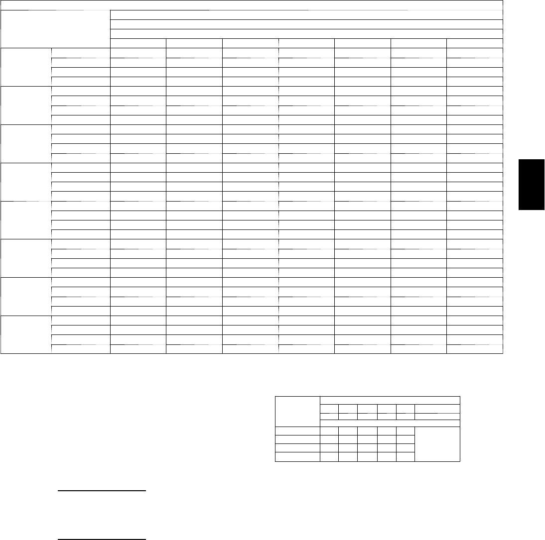
91
Cooling Capacities (cont)
48PG20 (18 Tons) — UNIT WITH HUMIDI-MIZER™SYSTEM — COOLING MODE (cont)
Te m p ( F )
Air Entering
Condenser
(Edb)
Evaporator Air Quantity — CFM/BF
9000
AirEnteringEvaporator—Ewb(F)
80 76 72 67 62 57 54
60
TC 321 304 286 264 241 219 206
SHC 148 158 168 181 193 206 206
kW 8.4 8.4 8.4 8.4 8.4 8.4 8.4
BF 0.00 0.29 0.18 0.05 0.13 0.27 0.48
70
TC 310 293 275 253 231 209 196
SHC 134 148 162 179 196 209 196
kW 10.6 10.6 10.6 10.6 10.6 10.6 10.6
BF 0.00 0.31 0.20 0.07 0.17 0.29 0.50
75
TC 305 287 270 248 226 205 192
SHC 128 143 158 178 197 205 192
kW 11.8 11.7 11.7 11.7 11.7 11.6 11.6
BF 0.00 0.32 0.21 0.09 0.18 0.30 0.51
85
TC 293 276 259 238 216 195 182
SHC 114 133 152 176 199 195 182
kW 14.1 14.0 13.9 13.9 13.8 13.7 13.6
BF 0.00 0.34 0.24 0.11 0.21 0.32 0.53
95
TC 282 265 248 227 206 185 173
SHC 100 123 146 174 202 185 173
kW 16.4 16.3 16.2 16.0 15.9 15.8 15.7
BF 0.00 0.36 0.26 0.14 0.23 0.34 0.55
105
TC 271 254 238 217 196 176 163
SHC 87 113 139 172 196 176 163
kW 18.7 18.5 18.4 18.2 18.0 17.8 17.7
BF 0.00 0.38 0.28 0.17 0.25 0.36 0.57
115
TC 260 243 227 207 186 166 154
SHC 73 103 133 170 186 166 154
kW 21.0 20.8 20.6 20.4 20.1 19.9 19.8
BF 0.00 0.40 0.30 0.20 0.29 0.38 0.59
125
TC 249 233 216 196 176 156 144
SHC 60 93 126 168 176 156 144
kW 23.3 23.1 22.8 22.5 22.3 22.0 21.8
BF 0.00 0.42 0.32 0.22 0.31 0.40 0.61
LEGEND
BF --- B y p a ss Fa c t o r
Edb --- E n t e r in g D r y --- B u l b
Ewb --- E n t e r in g W e t --- B u l b
kW --- Compressor Motor Power Input
Idb --- L e a v in g D r y --- B u l b
Iwb --- L e a v i n g We t --- B u l b
SHC --- Sensible Heat Capacity (1000 Btuh) Gross
TC --- Total Capacity (1000 Btuh) Gross
NOTES:
1. Direct interpolation is permissible. Do not extrapolate.
2. The following formulas may be used:
tldb =t
edb –sensible capacity (Btuh)
1.10 x cfm
tlwb = Wet---bulb temperature corresponding to enthalpy of air leaving
evaporator coil (hlwb)
hlwb =h
ewb –total capacity (Btuh)
4.5 x cfm
Where: hewb = Enthalpy of air entering evaporator coil
3. The SHC is based on 80_F edb temperature of air entering evaporator
coil
Below 80_F edb, subtract (corr factor x cfm) from SHC.
Above 80
_
F edb, add (corr factor x cfm) to SHC.
BYPASS
FACTOR
(BF)
ENTERING AIR DRY-BULB TEMP (F)
79 78 77 76 75 under 75
81 82 83 84 85 over 85
Correction Factor
.05 1.04 2.07 3.11 4.14 5.18
Use formula
shown below.
.10 .98 1.96 2.94 3.92 4.90
.20 .87 1.74 2.62 3.49 4.36
.30 .76 1.53 2.29 3.05 3.82
Interpolation is permissible.
C o r r e l a t i o n Fa c t o r = 1 . 0 9 x ( 1 --- B F ) x ( e d b --- 8 0 ) .
48PG
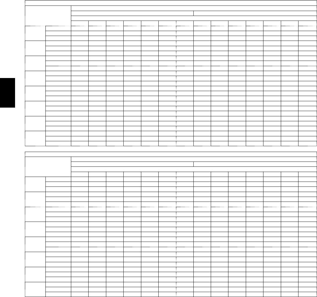
92
PERFORMANCE DATA (CONT)
Cooling Capacities (cont)
48PG20 (18 Tons) — UNIT WITH HUMIDI ---MIZER™SYSTEM — SUBCOOLING MODE
Te m p ( F )
Air Entering
Condenser
(Edb)
AirEnteringEvaporator—Cfm
5400 6300
AirEnteringEvaporator—Ewb(F)
80 76 72 67 62 57 54 80 76 72 67 62 57 54
60
TC 316 297 279 256 233 211 197 320 301 283 260 237 214 200
SHC 128 139 149 163 176 190 197 135 146 156 169 182 195 200
kW 8.2 8.2 8.2 8.2 8.2 8.2 8.2 8.4 8.4 8.4 8.4 8.4 8.4 8.4
70
TC 299 281 263 241 219 196 183 304 286 268 245 223 200 186
SHC 102 117 132 151 169 188 183 111 126 140 158 176 194 186
kW 10.2 10.2 10.2 10.2 10.2 10.2 10.2 10.4 10.4 10.4 10.4 10.4 10.4 10.4
75
TC 291 273 255 233 211 189 176 296 278 260 238 216 193 180
SHC 90 107 124 145 166 187 176 99 116 132 153 173 193 180
kW 11.3 11.3 11.2 11.2 11.1 11.1 11.1 11.6 11.5 11.5 11.4 11.3 11.3 11.2
85
TC 274 257 240 218 197 175 162 280 263 245 223 202 180 166
SHC 64 85 106 133 159 175 162 75 95 116 142 167 180 166
kW 13.4 13.4 13.3 13.2 13.1 13.0 13.0 13.7 13.6 13.5 13.4 13.3 13.2 13.1
95
TC 258 241 224 203 182 161 148 265 247 230 209 187 166 153
SHC 39 64 89 120 152 161 148 51 75 100 130 161 166 153
kW 15.6 15.4 15.3 15.2 15.1 14.9 14.8 15.9 15.7 15.6 15.5 15.3 15.1 15.0
105
TC 241 225 208 188 167 147 135 249 232 215 194 173 152 140
SHC 13 42 72 108 145 147 135 26 55 84 119 155 152 140
kW 17.7 17.5 17.4 17.2 17.0 16.8 16.7 18.0 17.9 17.7 17.5 17.3 17.1 17.0
115
TC 225 209 193 173 153 133 121 233 217 200 180 159 139 127
SHC –12 21 54 96 138 133 121 235 68 108 149 139 127
kW 19.8 19.6 19.4 19.2 19.0 18.7 18.6 20.2 20.0 19.8 19.5 19.3 19.0 18.9
125
TC 208 192 177 157 138 119 107 217 201 185 165 145 125 113
SHC –38 037 84 131 119 107 –22 15 51 97 143 125 113
kW 21.9 21.7 21.5 21.2 20.9 20.7 20.5 22.3 22.1 21.9 21.6 21.2 20.9 20.8
4 8 P G 2 0 ( 1 8 T O N S ) --- U N I T W I T H H U M I D I --- M I Z E R S Y S T E M --- S U B C O O L I N G M O D E ( C O N T )
Te m p ( F )
Air Entering
Condenser
(Edb)
AirEnteringEvaporator—Cfm
7200 8100
AirEnteringEvaporator—Ewb(F)
80 76 72 67 62 57 54 80 76 72 67 62 57 54
60
TC 323 305 286 263 239 216 202 326 307 289 265 242 218 204
SHC 142 152 162 174 187 199 202 147 157 166 179 191 203 204
kW 8.5 8.5 8.5 8.5 8.5 8.5 8.5 8.6 8.6 8.6 8.6 8.6 8.6 8.6
70
TC 308 290 272 249 226 203 189 312 293 275 252 229 206 192
SHC 118 132 147 164 182 199 189 125 138 152 169 187 204 192
kW 10.6 10.6 10.6 10.6 10.6 10.6 10.6 10.7 10.7 10.7 10.7 10.7 10.7 10.7
75
TC 301 282 264 242 219 196 183 304 286 268 245 222 199 185
SHC 107 123 139 159 179 196 183 113 129 145 165 184 199 185
kW 11.8 11.7 11.6 11.6 11.5 11.4 11.4 11.9 11.8 11.8 11.7 11.6 11.5 11.5
85
TC 285 268 250 228 206 183 170 290 272 254 231 209 186 173
SHC 84 104 124 149 174 183 170 91 111 131 155 180 186 173
kW 13.9 13.8 13.7 13.6 13.5 13.4 13.3 14.1 14.0 13.9 13.8 13.6 13.5 13.4
95
TC 270 253 236 214 192 170 157 275 258 240 218 196 174 160
SHC 60 85 109 139 169 170 157 69 93 116 146 175 174 160
kW 16.1 16.0 15.8 15.7 15.5 15.3 15.2 16.3 16.2 16.0 15.8 15.6 15.5 15.3
105
TC 255 238 221 200 178 157 144 261 243 226 204 183 161 148
SHC 37 65 94 129 164 157 144 47 74 102 136 171 161 148
kW 18.3 18.1 17.9 17.7 17.5 17.3 17.1 18.5 18.3 18.1 17.9 17.7 17.4 17.3
115
TC 240 223 207 186 165 144 131 246 229 212 191 170 148 136
SHC 14 46 78 119 159 144 131 24 56 88 127 167 148 136
kW 20.5 20.3 20.0 19.8 19.5 19.2 19.1 20.7 20.5 20.3 20.0 19.7 19.4 19.2
125
TC 225 209 192 172 151 131 119 232 215 198 177 156 136 123
SHC –9 27 63 108 151 131 119 238 73 118 156 136 123
kW 22.7 22.4 22.1 21.8 21.5 21.2 21.0 22.9 22.7 22.4 22.0 21.7 21.4 21.2
48PG
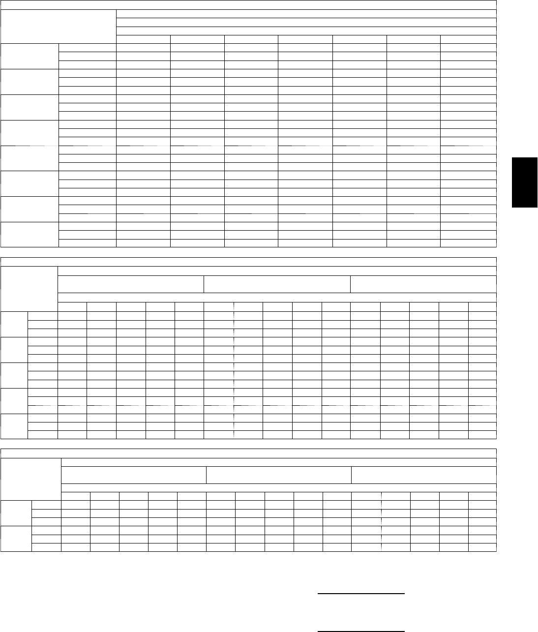
93
Cooling Capacities (cont)
48PG20 (18 Tons) — UNIT WITH HUMIDI ---MIZER™SYSTEM — SUBCOOLING MODE (cont)
Te m p ( F )
Air Entering
Condenser
(Edb)
AirEnteringEvaporator—Cfm
9000
AirEnteringEvaporator—Ewb(F)
80 76 72 67 62 57 54
60
TC 329 310 291 267 244 220 206
SHC 151 161 171 183 195 207 206
kW 8.7 8.7 8.7 8.7 8.7 8.7 8.7
70
TC 315 296 278 254 231 208 194
SHC 130 143 157 174 191 208 194
kW 10.8 10.8 10.8 10.8 10.8 10.8 10.8
75
TC 308 289 271 248 225 202 188
SHC 119 135 150 169 189 202 188
kW 12.0 12.0 11.9 11.8 11.7 11.6 11.6
85
TC 294 276 257 235 212 189 176
SHC 98 117 136 161 185 189 176
kW 14.3 14.1 14.0 13.9 13.7 13.6 13.5
95
TC 280 262 244 222 199 177 163
SHC 76 99 123 152 181 177 163
kW 16.5 16.3 16.2 16.0 15.8 15.6 15.5
105
TC 266 248 230 208 186 164 151
SHC 55 82 109 143 177 164 151
kW 18.7 18.5 18.3 18.0 17.8 17.6 17.4
115
TC 252 234 217 195 174 152 139
SHC 33 64 96 135 174 152 139
kW 20.9 20.7 20.4 20.1 19.8 19.5 19.4
125
TC 238 221 203 182 161 140 127
SHC 12 47 82 126 161 140 127
kW 23.1 22.9 22.6 22.2 21.9 21.5 21.3
48PG20 (18 Tons) — UNIT WITH HUMIDI ---MIZER™SYSTEM —HOT GAS REHEAT MODE — ALL CIRCUITS
Te m p ( F )
Air Entering
Condenser
(Edb)
AirEnteringEvaporator—Ewb(F)
75 Dry Bulb
62.5 Wet Bulb (50% RH)
75 Dry Bulb
64 Wet Bulb (55% RH)
75 Dry Bulb
65.3 Wet Bulb (60% RH)
AirEnteringEvaporator—Cfm
5400 6300 7200 8100 9000 5400 6300 7200 8100 9000 5400 6300 7200 8100 9000
80
TC 79 82 85 87 88 85 88 91 93 95 90 94 96 98 100
SHC 17 23 28 32 35 814 19 23 26 0 6 11 15 19
kW 12.1 12.2 12.2 12.2 12.3 12.2 12.2 12.3 12.3 12.4 12.2 12.3 12.3 12.4 12.4
75
TC 82 85 87 89 91 88 91 93 96 97 93 96 99 101 103
SHC 21 26 31 35 38 13 18 23 27 30 511 16 20 23
kW 11.8 11.9 11.9 11.9 12.0 11.9 11.9 12.0 12.0 12.1 11.9 12.0 12.1 12.1 12.1
70
TC 85 88 90 92 94 91 94 96 98 100 96 99 101 103 105
SHC 25 30 34 38 41 17 22 27 30 33 11 16 20 24 27
kW 11.5 11.6 11.6 11.6 11.7 11.6 11.6 11.7 11.7 11.8 11.7 11.7 11.8 11.8 11.8
60
TC 92 94 96 98 99 97 99 101 103 104 102 104 106 108 109
SHC 33 37 41 44 46 27 31 35 38 40 21 26 29 32 35
kW 10.9 11.0 11.0 11.0 11.1 11.0 11.1 11.1 11.1 11.2 11.1 11.1 11.2 11.2 11.2
50
TC 98 100 102 103 104 103 105 107 108 109 107 110 111 113 114
SHC 41 44 47 50 52 36 40 43 45 47 32 35 38 41 43
kW 10.3 10.4 10.4 10.4 10.4 10.4 10.5 10.5 10.5 10.6 10.5 10.6 10.6 10.6 10.7
48PG20 (18 Tons) — UNIT WITH HUMIDI ---MIZER™SYSTEM —HOT GAS REHEAT MODE — CIRCUIT A ONLY
Te m p ( F )
Air Entering
Condenser
(Edb)
AirEnteringEvaporator—Ewb(F)
75 Dry Bulb
62.5 Wet Bulb (50% RH)
75 Dry Bulb
64 Wet Bulb (55% RH)
75 Dry Bulb
65.3 Wet Bulb (60% RH)
AirEnteringEvaporator—Cfm
5400 6300 7200 8100 9000 5400 6300 7200 8100 9000 5400 6300 7200 8100 9000
50
TC 48 51 54 56 59 49 53 56 58 60 51 54 57 60 62
SHC 21 24 27 29 31 15 19 21 24 26 10 14 17 19 21
kW 5.4 5.4 5.5 5.5 5.5 5.4 5.5 5.5 5.5 5.5 5.4 5.5 5.5 5.5 5.5
40
TC 51 54 56 58 59 53 55 58 60 61 54 57 59 61 63
SHC 23 25 28 30 31 18 21 23 25 27 14 17 20 22 23
kW 5.3 5.3 5.3 5.3 5.3 5.3 5.3 5.3 5.4 5.4 5.3 5.4 5.4 5.4 5.4
LEGEND
Edb --- E n t e r i n g D r y --- B u l b
Ewb --- E n t e r i n g W e t --- B u l b
kW --- Compressor Motor Power Input
Idb --- L e a v i n g D r y --- B u l b
Iwb --- L e a v i n g W e t --- B u l b
RH --- Relative Humidity
SHC --- Sensible Heat Capacity (1000 Btuh) Gross
TC --- Total Capacity (1000 Btuh) Gross
NOTES:
1. Direct interpolation is permissible. Do not extrapolate.
2. The following formulas may be used:
tldb =tedb –
sensible capacity (Btuh)
1.10 x cfm
tlwb = Wet--- bulb temperature corresponding to enthalpy of air leaving
evaporator coil (hlwb)
hlwb =h
ewb –
total capacity (Btuh)
4.5 x cfm
Where: hewb = Enthalpy of air entering evaporator coil
48PG
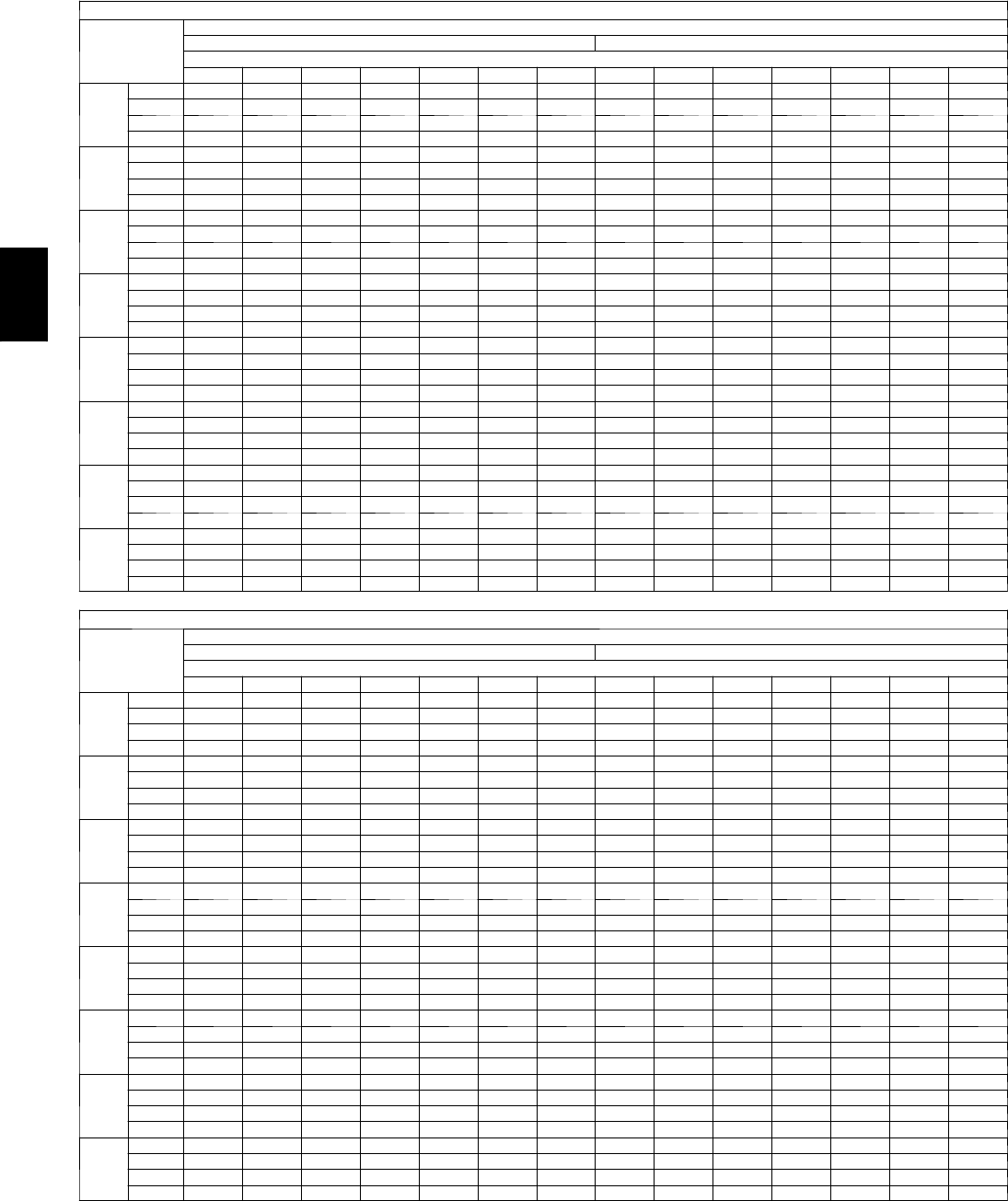
94
PERFORMANCE DATA (CONT)
Cooling Capacities (cont)
48PG24 (20 Tons) — STANDARD UNIT
Te m p ( F )
Air Ent
Condenser
(Edb)
AirEnteringEvaporator—Cfm
6,000 7,000
AirEnteringEvaporator—Ewb(F)
80 76 72 67 62 57 54 80 76 72 67 62 57 54
60
TC 372 350 328 300 272 244 228 375 352 330 302 274 246 230
SHC 162 172 181 193 205 217 224 170 179 188 200 211 222 229
kW 8.6 8.6 8.6 8.6 8.6 8.6 8.6 8.8 8.7 8.7 8.7 8.7 8.7 8.7
BF 0.00 0.14 0.08 0.03 0.04 0.12 0.33 0.00 0.15 0.09 0.04 0.05 0.13 0.34
70
TC 356 334 312 284 257 229 213 359 337 315 287 259 232 215
SHC 140 153 167 184 201 217 228 149 162 175 191 208 224 215
kW 10.8 10.8 10.8 10.7 10.7 10.7 10.7 11.0 11.0 11.0 10.9 10.9 10.8 10.8
BF 0.00 0.17 0.11 0.04 0.06 0.16 0.36 0.00 0.19 0.12 0.05 0.06 0.17 0.39
75
TC 348 326 304 276 249 222 205 351 329 307 279 252 224 208
SHC 128 144 159 179 198 218 229 138 153 168 187 206 224 208
kW 12.0 11.9 11.9 11.8 11.8 11.7 11.7 12.2 12.1 12.1 12.0 12.0 11.9 11.9
BF 0.00 0.19 0.13 0.05 0.07 0.18 0.38 0.00 0.20 0.14 0.06 0.08 0.19 0.41
85
TC 331 310 288 261 234 207 190 335 313 292 264 237 210 193
SHC 106 125 145 169 194 219 233 117 136 155 179 203 210 193
kW 14.2 14.1 14.1 14.0 13.9 13.8 13.8 14.5 14.4 14.3 14.2 14.1 14.0 14.0
BF 0.00 0.22 0.16 0.08 0.11 0.21 0.41 0.00 0.24 0.17 0.10 0.12 0.23 0.44
95
TC 315 293 272 245 218 192 175 319 298 276 249 222 195 179
SHC 83 107 130 160 190 219 237 96 119 142 171 199 195 179
kW 16.5 16.4 16.3 16.2 16.1 16.0 15.9 16.8 16.7 16.6 16.4 16.3 16.2 16.1
BF 0.00 0.26 0.20 0.13 0.14 0.25 0.45 0.00 0.28 0.22 0.16 0.15 0.27 0.48
105
TC 299 277 256 230 203 176 161 304 282 261 234 207 180 164
SHC 60 88 116 151 185 220 241 74 101 128 162 196 180 164
kW 18.7 18.6 18.5 18.4 18.2 18.1 18.0 19.1 18.9 18.8 18.6 18.5 18.3 18.2
BF 0.00 0.29 0.23 0.16 0.18 0.28 0.48 0.00 0.31 0.25 0.19 0.19 0.30 0.51
115
TC 282 261 240 214 188 161 146 288 266 245 219 192 165 149
SHC 38 70 101 141 181 221 244 53 84 115 154 193 165 149
kW 21.0 20.8 20.7 20.5 20.4 20.2 20.1 21.4 21.2 21.0 20.8 20.7 20.5 20.3
BF 0.00 0.33 0.27 0.19 0.21 0.31 0.52 0.00 0.35 0.29 0.23 0.23 0.33 0.55
125
TC 266 245 224 198 172 146 131 272 251 230 203 177 151 135
SHC 15 51 87 132 176 221 248 32 67 102 146 189 151 135
kW 23.2 23.1 22.9 22.7 22.5 22.3 22.2 23.7 23.5 23.3 23.1 22.8 22.6 22.5
BF 0.00 0.36 0.30 0.23 0.25 0.35 0.55 0.00 0.39 0.32 0.28 0.27 0.38 0.58
48PG24 (20 Tons) — STANDARD UNIT (cont)
Te m p ( F )
Air Ent
Condenser
(Edb)
AirEnteringEvaporator—Cfm
8,000 9,000
AirEnteringEvaporator—Ewb(F)
80 76 72 67 62 57 54 80 76 72 67 62 57 54
60
TC 377 355 332 304 276 248 231 379 356 334 306 278 249 232
SHC 177 185 194 205 216 227 231 182 191 199 210 221 231 232
kW 8.9 8.9 8.9 8.8 8.8 8.8 8.8 9.0 9.0 9.0 8.9 8.9 8.9 8.9
BF 0.00 0.15 0.09 0.04 0.05 0.13 0.34 0.00 0.16 0.10 0.05 0.06 0.14 0.35
70
TC 362 339 317 289 261 234 217 364 342 319 291 263 235 218
SHC 157 169 182 198 214 230 217 163 176 188 204 219 234 218
kW 11.2 11.2 11.1 11.1 11.0 11.0 10.9 11.4 11.3 11.3 11.2 11.1 11.1 11.0
BF 0.00 0.20 0.13 0.06 0.07 0.18 0.41 0.00 0.22 0.13 0.06 0.07 0.20 0.44
75
TC 354 332 310 282 254 226 210 356 334 312 284 256 228 211
SHC 146 161 176 194 213 226 210 154 168 182 200 218 228 211
kW 12.4 12.3 12.3 12.2 12.1 12.0 12.0 12.5 12.5 12.4 12.3 12.2 12.1 12.1
BF 0.00 0.22 0.15 0.08 0.08 0.21 0.44 0.00 0.23 0.16 0.09 0.09 0.22 0.47
85
TC 339 317 295 267 239 212 195 341 319 297 269 242 214 197
SHC 126 145 164 187 210 212 195 135 153 171 194 217 214 197
kW 14.7 14.6 14.5 14.4 14.3 14.2 14.1 14.9 14.8 14.7 14.6 14.4 14.3 14.2
BF 0.00 0.25 0.18 0.13 0.13 0.24 0.47 0.00 0.27 0.20 0.15 0.13 0.26 0.50
95
TC 323 301 279 252 225 198 181 326 304 282 255 227 200 183
SHC 106 129 151 180 208 198 181 115 137 160 187 215 200 183
kW 17.0 16.9 16.8 16.6 16.5 16.3 16.3 17.2 17.1 17.0 16.8 16.6 16.5 16.4
BF 0.00 0.30 0.23 0.18 0.16 0.29 0.52 0.00 0.32 0.25 0.21 0.17 0.31 0.55
105
TC 308 286 264 237 210 183 167 311 289 268 240 213 186 169
SHC 86 113 139 172 205 183 167 96 122 148 181 213 186 169
kW 19.3 19.2 19.0 18.9 18.7 18.5 18.4 19.6 19.4 19.2 19.0 18.9 18.7 18.5
BF 0.00 0.33 0.26 0.23 0.21 0.32 0.55 0.00 0.36 0.28 0.26 0.22 0.34 0.58
115
TC 292 271 249 222 196 169 153 296 275 253 226 199 171 155
SHC 66 96 127 165 196 169 153 77 107 137 174 199 171 155
kW 21.7 21.5 21.3 21.1 20.9 20.7 20.5 21.9 21.7 21.5 21.3 21.1 20.8 20.7
BF 0.00 0.38 0.31 0.27 0.24 0.36 0.58 0.00 0.40 0.33 0.31 0.26 0.38 0.60
125
TC 277 256 234 208 181 154 138 281 260 238 211 184 157 141
SHC 46 80 115 157 181 154 138 58 92 126 168 184 157 141
kW 24.0 23.8 23.6 23.3 23.1 22.8 22.7 24.2 24.0 23.8 23.5 23.3 23.0 22.8
BF 0.00 0.41 0.35 0.32 0.29 0.40 0.60 0.00 0.44 0.37 0.37 0.31 0.43 0.63
48PG

95
Cooling Capacities (cont)
48PG24 (20 Tons) — STANDARD UNIT (cont)
Te m p ( F )
Air Ent
Condenser
(Edb)
AirEnteringEvaporator—Cfm
10,000
AirEnteringEvaporator—Ewb(F)
80 76 72 67 62 57 54
60
TC 381 358 335 307 279 251 234
SHC 187 196 204 214 225 235 234
kW 9.1 9.1 9.1 9.0 9.0 9.0 8.9
BF 0.00 0.16 0.10 0.05 0.06 0.14 0.35
70
TC 366 343 321 293 265 237 220
SHC 169 181 193 208 224 237 220
kW 11.5 11.4 11.4 11.3 11.2 11.1 11.1
BF 0.00 0.23 0.14 0.07 0.08 0.21 0.47
75
TC 359 336 314 286 258 230 213
SHC 160 174 188 206 223 230 213
kW 12.7 12.6 12.5 12.4 12.3 12.2 12.2
BF 0.00 0.25 0.17 0.10 0.09 0.23 0.49
85
TC 344 322 299 271 244 216 199
SHC 142 160 177 200 222 216 199
kW 15.0 14.9 14.8 14.7 14.5 14.4 14.3
BF 0.00 0.29 0.21 0.17 0.14 0.27 0.53
95
TC 329 307 285 257 229 202 185
SHC 123 145 167 194 221 202 185
kW 17.4 17.2 17.1 16.9 16.8 16.6 16.5
BF 0.00 0.34 0.26 0.23 0.18 0.33 0.59
105
TC 314 292 270 243 215 188 171
SHC 105 131 156 188 215 188 171
kW 19.7 19.6 19.4 19.2 19.0 18.8 18.7
BF 0.00 0.38 0.30 0.29 0.23 0.36 0.61
115
TC 300 278 256 229 201 174 157
SHC 87 116 146 183 201 174 157
kW 22.1 21.9 21.7 21.4 21.2 21.0 20.8
BF 0.00 0.43 0.35 0.35 0.27 0.40 0.63
125
TC 285 263 241 214 187 160 144
SHC 69 102 135 177 187 160 144
kW 24.4 24.2 24.0 23.7 23.4 23.1 23.0
BF 0.00 0.47 0.39 0.41 0.33 0.46 0.65
LEGEND
BF --- B y p a ss Fa c t o r
Edb --- E n t e r in g D r y --- B u l b
Ewb --- E n t e r in g W e t --- B u l b
kW --- Compressor Motor Power Input
Idb --- L e a v in g D r y --- B u l b
Iwb --- L e a v i n g We t --- B u l b
SHC --- Sensible Heat Capacity (1000 Btuh) Gross
TC --- Total Capacity (1000 Btuh) Gross
NOTES:
1. Direct interpolation is permissible. Do not extrapolate.
2. The following formulas may be used:
tldb =t
edb –sensible capacity (Btuh)
1.10 x cfm
tlwb = Wet---bulb temperature corresponding to enthalpy of air leaving
evaporator coil (hlwb)
hlwb =h
ewb –total capacity (Btuh)
4.5 x cfm
Where: hewb = Enthalpy of air entering evaporator coil
3. The SHC is based on 80_F edb temperature of air entering evaporator
coil
Below 80_F edb, subtract (corr factor x cfm) from SHC.
Above 80
_
F edb, add (corr factor x cfm) to SHC.
BYPASS
FACTOR
(BF)
ENTERING AIR DRY-BULB TEMP (F)
79 78 77 76 75 under 75
81 82 83 84 85 over 85
Correction Factor
.05 1.04 2.07 3.11 4.14 5.18
Use formula
shown below.
.10 .98 1.96 2.94 3.92 4.90
.20 .87 1.74 2.62 3.49 4.36
.30 .76 1.53 2.29 3.05 3.82
Interpolation is permissible.
C o r r e l a t i o n Fa c t o r = 1 . 0 9 x ( 1 --- B F ) x ( e d b --- 8 0 ) .
48PG

96
PERFORMANCE DATA (CONT)
Cooling Capacities (cont)
48PG24 (20 Tons) — UNIT WITH HUMIDI-MIZER™SYSTEM — COOLING MODE
Te m p ( F )
Air Entering
Condenser
(Edb)
AirEnteringEvaporator—Cfm
6000 7000
AirEnteringEvaporator—Ewb(F)
80 76 72 67 62 57 54 80 76 72 67 62 57 54
60
TC 351 330 309 284 258 232 217 354 334 313 287 261 235 220
SHC 145 158 172 189 205 222 217 155 168 181 197 213 229 220
kW 9.0 9.0 9.0 9.0 9.0 9.0 9.0 9.1 9.1 9.1 9.1 9.1 9.1 9.1
BF 0.00 0.14 0.08 0.03 0.04 0.12 0.33 0.00 0.15 0.09 0.04 0.05 0.13 0.34
70
TC 336 316 295 270 244 219 204 340 320 299 274 248 222 207
SHC 121 140 158 180 203 219 204 133 151 168 190 212 222 207
kW 11.2 11.2 11.2 11.1 11.1 11.0 11.0 11.4 11.4 11.3 11.3 11.2 11.1 11.1
BF 0.00 0.17 0.11 0.04 0.06 0.16 0.36 0.00 0.19 0.12 0.05 0.06 0.17 0.39
75
TC 329 308 288 263 238 212 197 333 313 292 267 241 216 200
SHC 110 130 151 176 201 212 197 123 142 162 187 211 216 200
kW 12.4 12.3 12.3 12.2 12.1 12.0 12.0 12.6 12.5 12.4 12.3 12.3 12.2 12.1
BF 0.00 0.19 0.13 0.05 0.07 0.18 0.38 0.00 0.20 0.14 0.06 0.08 0.19 0.41
85
TC 314 294 274 249 224 199 184 319 299 279 254 228 203 188
SHC 86 111 136 168 199 199 184 101 125 149 180 210 203 188
kW 14.7 14.6 14.5 14.3 14.2 14.1 14.0 14.9 14.8 14.7 14.5 14.4 14.2 14.2
BF 0.00 0.22 0.16 0.08 0.11 0.21 0.41 0.00 0.24 0.17 0.10 0.12 0.23 0.44
95
TC 299 280 260 235 210 186 171 305 285 265 240 215 190 175
SHC 63 93 122 159 196 186 171 79 108 137 173 209 190 175
kW 16.9 16.8 16.7 16.5 16.3 16.1 16.0 17.2 17.0 16.9 16.7 16.5 16.3 16.2
BF 0.00 0.26 0.20 0.13 0.14 0.25 0.45 0.00 0.28 0.22 0.16 0.15 0.27 0.48
105
TC 285 265 246 221 197 172 158 291 272 252 227 202 177 162
SHC 40 74 108 151 194 172 158 58 91 124 166 202 177 162
kW 19.2 19.0 18.9 18.6 18.4 18.2 18.0 19.5 19.3 19.1 18.9 18.6 18.4 18.2
BF 0.00 0.29 0.23 0.16 0.18 0.28 0.48 0.00 0.31 0.25 0.19 0.19 0.30 0.51
115
TC 270 251 231 207 183 159 144 277 258 238 214 189 164 150
SHC 16 55 94 143 191 159 144 36 74 112 159 189 164 150
kW 21.5 21.3 21.1 20.8 20.5 20.2 20.1 21.8 21.6 21.3 21.0 20.7 20.4 20.3
BF 0.00 0.33 0.27 0.19 0.21 0.31 0.52 0.00 0.35 0.29 0.23 0.23 0.33 0.55
125
TC 255 236 217 193 169 146 131 263 244 225 200 176 151 137
SHC 10 37 80 134 189 146 131 15 57 99 152 176 151 137
kW 23.8 23.5 23.3 22.9 22.6 22.3 22.1 24.1 23.9 23.6 23.2 22.9 22.5 22.3
BF 0.00 0.36 0.30 0.23 0.25 0.35 0.55 0.00 0.39 0.32 0.28 0.27 0.38 0.58
48PG24 (20 Tons) — UNIT WITH HUMIDI-MIZER SYSTEM — COOLING MODE (cont)
Te m p ( F )
Air Entering
Condenser
(Edb)
AirEnteringEvaporator—Cfm
8000 9000
AirEnteringEvaporator—Ewb(F)
80 76 72 67 62 57 54 80 76 72 67 62 57 54
60
TC 357 337 316 290 263 237 222 360 339 318 292 265 239 223
SHC 163 176 188 204 220 236 222 171 183 195 210 225 239 223
kW 9.2 9.2 9.2 9.2 9.2 9.2 9.1 9.3 9.3 9.3 9.3 9.2 9.2 9.2
BF 0.00 0.15 0.09 0.04 0.05 0.13 0.34 0.00 0.16 0.10 0.05 0.06 0.14 0.35
70
TC 344 323 303 277 251 225 209 347 326 305 279 253 227 211
SHC 143 160 177 198 220 225 209 152 168 185 206 226 227 211
kW 11.6 11.5 11.5 11.4 11.3 11.2 11.2 11.7 11.6 11.6 11.5 11.4 11.3 11.3
BF 0.00 0.20 0.13 0.06 0.07 0.18 0.41 0.00 0.22 0.13 0.06 0.07 0.20 0.44
75
TC 337 317 296 270 244 219 203 341 320 299 273 247 221 205
SHC 133 152 172 196 220 219 203 142 161 180 203 227 221 205
kW 12.7 12.7 12.6 12.5 12.4 12.3 12.2 12.9 12.8 12.7 12.6 12.5 12.4 12.3
BF 0.00 0.22 0.15 0.08 0.08 0.21 0.44 0.00 0.23 0.16 0.09 0.09 0.22 0.47
85
TC 324 303 283 257 232 206 191 328 307 286 260 235 209 193
SHC 113 137 160 190 220 206 191 123 147 170 199 228 209 193
kW 15.1 14.9 14.8 14.7 14.5 14.4 14.3 15.2 15.1 15.0 14.8 14.6 14.5 14.4
BF 0.00 0.25 0.18 0.13 0.13 0.24 0.47 0.00 0.27 0.20 0.15 0.13 0.26 0.50
95
TC 310 290 270 244 219 194 178 315 294 274 248 222 197 181
SHC 93 121 149 184 219 194 178 104 132 160 194 222 197 181
kW 17.4 17.2 17.1 16.9 16.7 16.4 16.3 17.6 17.4 17.2 17.0 16.8 16.6 16.4
BF 0.00 0.30 0.23 0.18 0.16 0.29 0.52 0.00 0.32 0.25 0.21 0.17 0.31 0.55
105
TC 297 277 257 232 206 181 166 302 281 261 235 210 184 169
SHC 73 105 138 179 206 181 166 86 118 150 189 210 184 169
kW 19.7 19.5 19.3 19.1 18.8 18.5 18.4 19.9 19.7 19.5 19.2 18.9 18.7 18.5
BF 0.00 0.33 0.26 0.23 0.21 0.32 0.55 0.00 0.36 0.28 0.26 0.22 0.34 0.58
115
TC 284 264 244 219 194 169 154 289 268 248 223 198 172 157
SHC 53 90 127 173 194 169 154 67 103 139 185 198 172 157
kW 22.1 21.8 21.6 21.3 20.9 20.6 20.4 22.3 22.0 21.7 21.4 21.1 20.8 20.6
BF 0.00 0.38 0.31 0.27 0.24 0.36 0.58 0.00 0.40 0.33 0.31 0.26 0.38 0.60
125
TC 270 250 231 206 181 156 141 276 256 236 210 185 160 145
SHC 32 74 115 167 181 156 141 48 89 129 180 185 160 145
kW 24.4 24.1 23.8 23.4 23.1 22.7 22.5 24.6 24.3 24.0 23.6 23.2 22.9 22.6
BF 0.00 0.41 0.35 0.32 0.29 0.40 0.60 0.00 0.44 0.37 0.37 0.31 0.43 0.63
48PG
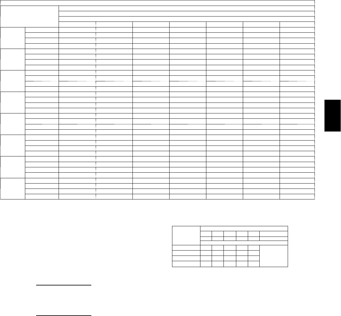
97
Cooling Capacities (cont)
48PG24 (20 Tons) — UNIT WITH HUMIDI ---MIZERtSYSTEM --- COOLING MODE (cont)
Te m p ( F )
Air Ent
Condenser
(Edb)
AirEnteringEvaporator—Cfm
10,000
AirEnteringEvaporator—Ewb(F)
80 76 72 67 62 57 54
60
TC 362 341 320 294 267 241 225
SHC 177 189 201 216 230 241 225
kW 9.4 9.4 9.4 9.3 9.3 9.3 9.3
BF 0.00 0.16 0.10 0.05 0.06 0.14 0.35
70
TC 350 329 308 281 255 229 213
SHC 159 175 192 212 232 229 213
kW 11.8 11.7 11.6 11.6 11.5 11.4 11.3
BF 0.00 0.23 0.14 0.07 0.08 0.21 0.47
75
TC 343 322 301 275 249 223 207
SHC 150 169 187 210 233 223 207
kW 13.0 12.9 12.8 12.7 12.6 12.4 12.4
BF 0.00 0.25 0.17 0.10 0.09 0.23 0.49
85
TC 331 310 289 263 237 211 195
SHC 132 155 178 206 235 211 195
kW 15.3 15.2 15.1 14.9 14.7 14.5 14.4
BF 0.00 0.29 0.21 0.17 0.14 0.27 0.53
95
TC 318 298 277 251 225 199 184
SHC 115 142 169 203 225 199 184
kW 17.7 17.5 17.3 17.1 16.9 16.7 16.5
BF 0.00 0.34 0.26 0.23 0.18 0.33 0.59
105
TC 306 285 265 239 213 187 172
SHC 97 128 160 199 213 187 172
kW 20.1 19.8 19.6 19.3 19.0 18.8 18.6
BF 0.00 0.38 0.30 0.29 0.23 0.36 0.61
115
TC 293 273 252 227 201 175 160
SHC 79 115 150 195 201 175 160
kW 22.4 22.2 21.9 21.5 21.2 20.9 20.7
BF 0.00 0.43 0.35 0.35 0.27 0.40 0.63
125
TC 281 260 240 214 189 164 148
SHC 61 101 141 191 189 164 148
kW 24.8 24.5 24.2 23.8 23.4 23.0 22.7
BF 0.00 0.47 0.39 0.41 0.33 0.46 0.65
LEGEND
BF --- B y p a ss Fa c t o r
Edb --- E n t e r in g D r y --- B u l b
Ewb --- E n t e r in g W e t --- B u l b
kW --- Compressor Motor Power Input
Idb --- L e a v in g D r y --- B u l b
Iwb --- L e a v i n g We t --- B u l b
SHC --- Sensible Heat Capacity (1000 Btuh) Gross
TC --- Total Capacity (1000 Btuh) Gross
NOTES:
1. Direct interpolation is permissible. Do not extrapolate.
2. The following formulas may be used:
tldb =t
edb –sensible capacity (Btuh)
1.10 x cfm
tlwb = Wet---bulb temperature corresponding to enthalpy of air leaving
evaporator coil (hlwb)
hlwb =h
ewb –total capacity (Btuh)
4.5 x cfm
Where: hewb = Enthalpy of air entering evaporator coil
3. The SHC is based on 80_F edb temperature of air entering evaporator
coil
Below 80_F edb, subtract (corr factor x cfm) from SHC.
Above 80
_
F edb, add (corr factor x cfm) to SHC.
BYPASS
FACTOR
(BF)
ENTERING AIR DRY-BULB TEMP (F)
79 78 77 76 75 under 75
81 82 83 84 85 over 85
Correction Factor
.05 1.04 2.07 3.11 4.14 5.18
Use formula
shown below.
.10 .98 1.96 2.94 3.92 4.90
.20 .87 1.74 2.62 3.49 4.36
.30 .76 1.53 2.29 3.05 3.82
Interpolation is permissible.
C o r r e l a t i o n Fa c t o r = 1 . 0 9 x ( 1 --- B F ) x ( e d b --- 8 0 ) .
48PG

98
PERFORMANCE DATA (CONT)
Cooling Capacities (cont)
48PG24 (20 Tons) — UNIT WITH HUMIDI-MIZER™SYSTEM — SUBCOOLING MODE
Te m p ( F )
Air Entering
Condenser
(Edb)
AirEnteringEvaporator—Cfm
6000 7000
AirEnteringEvaporator—Ewb(F)
80 76 72 67 62 57 54 80 76 72 67 62 57 54
60
TC 352 330 309 283 257 230 214 357 336 314 288 261 234 218
SHC 149 159 169 181 194 206 214 158 168 177 189 201 213 218
kW 9.1 9.1 9.0 9.0 9.0 9.0 9.0 9.2 9.2 9.2 9.1 9.1 9.1 9.1
70
TC 335 314 293 267 241 215 199 342 320 299 273 246 220 204
SHC 122 136 150 168 186 204 199 133 147 161 178 195 212 204
kW 11.3 11.3 11.2 11.2 11.1 11.0 11.0 11.5 11.4 11.4 11.3 11.2 11.1 11.1
75
TC 327 306 285 259 233 207 192 334 313 292 265 239 213 197
SHC 108 125 141 162 182 203 192 121 137 152 172 192 212 197
kW 12.5 12.4 12.3 12.2 12.1 12.0 12.0 12.6 12.5 12.5 12.4 12.2 12.1 12.1
85
TC 310 290 269 243 218 192 177 318 297 276 250 224 198 182
SHC 82 102 123 149 175 192 177 96 116 136 161 186 198 182
kW 14.8 14.6 14.5 14.4 14.2 14.1 14.0 14.9 14.8 14.7 14.5 14.3 14.2 14.1
95
TC 293 273 253 228 202 177 162 303 282 261 235 209 184 168
SHC 55 80 105 136 167 177 162 71 95 119 149 179 184 168
kW 17.0 16.9 16.7 16.5 16.3 16.1 16.0 17.2 17.0 16.9 16.7 16.4 16.2 16.1
105
TC 277 257 237 212 187 162 147 287 266 246 220 195 169 154
SHC 28 57 86 123 159 162 147 46 74 102 137 173 169 154
kW 19.3 19.1 18.9 18.6 18.4 18.1 18.0 19.5 19.3 19.1 18.8 18.5 18.3 18.1
115
TC 260 240 221 196 171 147 132 271 251 231 205 180 155 139
SHC 135 68 110 152 147 132 20 53 85 126 166 155 139
kW 21.6 21.3 21.1 20.8 20.5 20.1 20.0 21.8 21.5 21.3 21.0 20.6 20.3 20.1
125
TC 244 224 205 180 156 131 117 256 236 215 190 165 140 125
SHC –25 12 50 97 144 131 117 –5 32 69 114 160 140 125
kW 23.8 23.5 23.3 22.9 22.5 22.2 22.0 24.1 23.8 23.5 23.1 22.7 22.4 22.1
48PG24 (20 Tons) — UNIT WITH HUMIDI-MIZER SYSTEM — SUBCOOLING MODE (cont)
Te m p ( F )
Air Entering
Condenser
(Edb)
AirEnteringEvaporator—Cfm
8000 9000
AirEnteringEvaporator—Ewb(F)
80 76 72 67 62 57 54 80 76 72 67 62 57 54
60
TC 362 340 319 292 265 238 221 366 344 322 295 268 240 224
SHC 167 176 185 196 208 219 221 174 183 192 203 214 225 224
kW 9.3 9.3 9.2 9.2 9.2 9.1 9.1 9.4 9.3 9.3 9.3 9.2 9.2 9.2
70
TC 347 326 304 277 251 224 208 352 330 308 281 254 227 211
SHC 143 156 170 186 203 219 208 152 164 177 193 209 225 211
kW 11.6 11.5 11.5 11.4 11.3 11.2 11.1 11.7 11.6 11.5 11.4 11.3 11.3 11.2
75
TC 340 318 297 270 244 217 201 345 323 301 274 247 220 204
SHC 131 147 162 181 200 217 201 140 155 170 189 207 220 204
kW 12.8 12.7 12.6 12.5 12.3 12.2 12.1 12.8 12.7 12.6 12.5 12.4 12.3 12.2
85
TC 325 304 282 256 229 203 187 331 309 288 261 234 207 191
SHC 108 127 146 171 195 203 187 118 137 156 179 203 207 191
kW 15.1 14.9 14.8 14.6 14.4 14.3 14.2 15.2 15.0 14.9 14.7 14.5 14.3 14.2
95
TC 310 289 268 242 215 189 173 316 295 274 247 220 194 178
SHC 84 107 131 160 190 189 173 96 119 141 170 199 194 178
kW 17.4 17.2 17.0 16.8 16.6 16.3 16.2 17.5 17.3 17.1 16.9 16.6 16.4 16.3
105
TC 295 274 253 227 201 175 159 302 281 260 233 207 180 164
SHC 60 88 115 150 184 175 159 73 100 127 161 194 180 164
kW 19.7 19.4 19.2 18.9 18.7 18.4 18.2 19.8 19.6 19.3 19.1 18.8 18.5 18.3
115
TC 280 260 239 213 187 161 146 288 267 246 220 193 167 151
SHC 37 68 100 140 179 161 146 51 82 113 152 190 167 151
kW 22.0 21.7 21.4 21.1 20.8 20.4 20.2 22.1 21.8 21.6 21.2 20.9 20.5 20.3
125
TC 266 245 225 199 173 147 132 274 253 232 206 180 153 138
SHC 13 49 85 129 173 147 132 28 63 98 142 180 153 138
kW 24.3 24.0 23.7 23.3 22.9 22.5 22.3 24.4 24.1 23.8 23.4 23.0 22.6 22.4
48PG
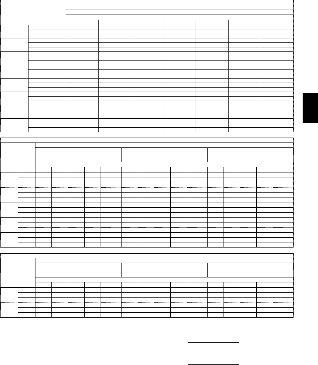
99
Cooling Capacities (cont)
4 8 P G 2 4 ( 2 0 T O N S ) --- U N I T W I T H H U M I D I --- M I Z E R tSYSTEM --- SUBCOOLING MODE (CONT)
Te m p ( F )
Air Entering
Condenser
(Edb)
AirEnteringEvaporator—Cfm
10,000
AirEnteringEvaporator—Ewb(F)
80 76 72 67 62 57 54
60
TC 369 347 325 298 270 243 226
SHC 180 189 197 208 218 229 226
kW 9.4 9.4 9.4 9.3 9.3 9.2 9.2
70
TC 356 334 312 285 257 230 214
SHC 159 171 184 200 215 230 214
kW 11.8 11.7 11.6 11.5 11.4 11.3 11.2
75
TC 349 327 305 278 251 223 207
SHC 148 163 177 195 213 223 207
kW 12.9 12.8 12.7 12.6 12.5 12.3 12.3
85
TC 335 314 292 265 238 210 194
SHC 127 146 164 187 210 210 194
kW 15.2 15.1 15.0 14.8 14.6 14.4 14.3
95
TC 322 300 279 252 225 198 181
SHC 106 128 151 179 207 198 181
kW 17.6 17.4 17.2 17.0 16.7 16.5 16.3
105
TC 309 287 265 238 211 185 168
SHC 85 111 137 170 203 185 168
kW 19.9 19.7 19.4 19.1 18.8 18.6 18.4
115
TC 295 274 252 225 198 172 155
SHC 63 94 124 162 198 172 155
kW 22.2 22.0 21.7 21.3 21.0 20.6 20.4
125
TC 282 260 239 212 185 159 143
SHC 42 76 111 154 185 159 143
kW 24.6 24.2 23.9 23.5 23.1 22.7 22.5
4 8 P G 2 4 ( 2 0 T O N S ) --- U N I T W I T H H U M I D I --- M I Z E R S Y S T E M --- H O T G A S R E H E A T M O D E --- A L L C I R C U I T S
Te m p ( F )
Air Ent
Condenser
(Edb)
AirEnteringEvaporator—Ewb(F)
75 Dry Bulb
62.5 Wet Bulb
(50% RH)
75 Dry Bulb
64 Wet Bulb
(55% RH)
75 Dry Bulb
65.3 Wet Bulb
(60% RH)
AirEnteringEvaporator—Cfm
6000 7000 8000 9000 10,000 6000 7000 8000 9000 10,000 6000 7000 8000 9000 10,000
80
TC 98 104 108 112 115 101 107 112 116 119 104 110 115 119 122
SHC 22 30 38 44 51 11 19 26 33 39 210 17 23 29
kW 15.2 15.2 15.3 15.3 15.3 15.3 15.3 15.3 15.4 15.4 15.4 15.4 15.4 15.4 15.4
75
TC 103 108 112 116 119 106 112 116 120 123 109 115 119 123 126
SHC 27 35 42 49 55 17 25 32 38 44 916 23 29 35
kW 14.7 14.7 14.7 14.8 14.8 14.8 14.8 14.8 14.9 14.9 14.9 14.9 14.9 14.9 14.9
70
TC 108 113 117 120 123 111 116 120 123 126 114 119 123 127 130
SHC 32 39 47 53 59 23 30 37 43 49 15 22 29 35 41
kW 14.2 14.2 14.2 14.3 14.3 14.3 14.3 14.3 14.4 14.4 14.4 14.4 14.4 14.4 14.4
60
TC 117 121 125 127 130 120 125 128 131 134 123 128 131 134 137
SHC 41 49 56 62 67 34 41 48 54 59 28 35 41 47 52
kW 13.2 13.2 13.2 13.2 13.3 13.3 13.3 13.3 13.4 13.4 13.4 13.4 13.4 13.4 13.5
50
TC 126 130 133 135 137 130 133 136 139 141 133 137 140 142 144
SHC 51 58 65 70 76 46 52 59 64 69 41 47 53 59 64
kW 12.2 12.2 12.2 12.2 12.2 12.3 12.3 12.3 12.3 12.4 12.4 12.4 12.4 12.4 12.5
4 8 P G 2 4 ( 2 0 T O N S ) --- U N I T W I T H H U M I D I --- M I Z E R S Y S T E M --- H O T G A S R E H E A T M O D E --- C I R C U I T A O N LY
Te m p ( F ) A i r
Entering
Condenser
(Edb)
AirEnteringEvaporator—Ewb(F)
75 Dry Bulb
62.5 Wet Bulb
(50% RH)
75 Dry Bulb
64 Wet Bulb
(55% RH)
75 Dry Bulb
65.3 Wet Bulb
(60% RH)
AirEnteringEvaporator—Cfm
6000 7000 8000 9000 10,000 6000 7000 8000 9000 10,000 6000 7000 8000 9000 10,000
50
TC 68 75 82 87 92 69 77 84 89 94 71 79 86 91 96
SHC 28 35 41 46 50 22 29 35 40 44 16 24 30 35 39
kW 6.7 6.7 6.7 6.7 6.7 6.7 6.7 6.7 6.7 6.7 6.7 6.7 6.7 6.7 6.7
40
TC 72 78 83 87 91 74 80 85 89 93 75 82 87 91 95
SHC 30 36 40 44 48 25 31 36 40 43 21 27 32 36 39
kW 6.5 6.5 6.5 6.6 6.6 6.5 6.5 6.6 6.6 6.6 6.5 6.6 6.6 6.6 6.6
LEGEND
Edb --- E n t e r i n g D r y --- B u l b
Ewb --- E n t e r i n g W e t --- B u l b
kW --- Compressor Motor Power Input
Idb --- L e a v i n g D r y --- B u l b
Iwb --- L e a v i n g W e t --- B u l b
RH --- Relative Humidity
SHC --- Sensible Heat Capacity (1000 Btuh) Gross
TC --- Total Capacity (1000 Btuh) Gross
NOTES:
1. Direct interpolation is permissible. Do not extrapolate.
2. The following formulas may be used:
tldb =tedb –
sensible capacity (Btuh)
1.10 x cfm
tlwb = Wet--- bulb temperature corresponding to enthalpy of air leaving
evaporator coil (hlwb)
hlwb =h
ewb –
total capacity (Btuh)
4.5 x cfm
Where: hewb = Enthalpy of air entering evaporator coil
48PG

100
PERFORMANCE DATA (CONT)
Cooling Capacities (cont)
48PG28 (25 Tons) — STANDARD UNIT
Te m p ( F )
Air Ent
Condenser
(Edb)
AirEnteringEvaporator—Cfm
7,500 8,250
AirEnteringEvaporator—Ewb(F)
80 76 72 67 62 57 54 80 76 72 67 62 57 54
60
TC 457 432 407 375 343 312 293 460 434 409 377 345 313 294
SHC 184 199 214 233 251 270 281 193 209 224 243 262 281 293
kW 12.3 12.3 12.3 12.3 12.3 12.3 12.3 12.5 12.4 12.4 12.4 12.4 12.4 12.4
BF 0.00 0.21 0.10 0.04 0.06 0.16 0.26 0.00 0.23 0.11 0.05 0.06 0.17 0.28
70
TC 436 411 387 356 325 294 275 439 414 389 358 327 296 277
SHC 158 178 199 224 250 275 275 168 188 209 235 261 287 277
kW 15.2 15.2 15.1 15.1 15.1 15.0 15.0 15.4 15.3 15.3 15.2 15.2 15.2 15.1
BF 0.00 0.21 0.10 0.04 0.06 0.16 0.26 0.00 0.23 0.11 0.05 0.06 0.17 0.28
75
TC 425 401 377 346 316 285 267 428 404 379 349 318 287 269
SHC 145 168 191 220 249 277 267 155 178 202 231 260 287 269
kW 16.6 16.6 16.6 16.5 16.5 16.4 16.4 16.8 16.8 16.7 16.7 16.6 16.5 16.5
BF 0.00 0.22 0.11 0.05 0.07 0.17 0.27 0.00 0.24 0.12 0.06 0.08 0.18 0.29
85
TC 404 380 356 327 297 267 250 408 384 360 330 300 270 252
SHC 119 147 176 211 247 267 250 129 158 187 223 259 270 252
kW 19.5 19.5 19.4 19.3 19.2 19.2 19.1 19.7 19.7 19.6 19.5 19.4 19.3 19.2
BF 0.00 0.23 0.13 0.06 0.09 0.19 0.29 0.00 0.25 0.14 0.07 0.10 0.20 0.31
95
TC 383 360 336 308 279 250 233 387 363 340 311 282 253 235
SHC 93 127 161 203 245 250 233 103 138 172 215 258 253 235
kW 22.1 22.0 21.9 21.8 21.8 21.7 21.6 22.7 22.6 22.5 22.3 22.2 22.1 22.0
BF 0.00 0.23 0.13 0.06 0.09 0.19 0.29 0.00 0.25 0.14 0.07 0.10 0.20 0.31
105
TC 361 339 316 288 260 232 215 366 343 320 292 264 235 218
SHC 67 106 145 194 243 232 215 77 117 157 207 256 235 218
kW 25.3 25.2 25.1 24.9 24.8 24.6 24.5 25.6 25.4 25.3 25.2 25.0 24.8 24.7
BF 0.00 0.24 0.13 0.07 0.09 0.19 0.29 0.00 0.26 0.14 0.08 0.10 0.20 0.31
115
TC 340 318 296 269 242 215 198 345 323 301 273 246 218 202
SHC 41 86 130 186 241 215 198 52 97 142 198 246 218 202
kW 28.2 28.1 27.9 27.7 27.6 27.4 27.3 28.5 28.3 28.2 28.0 27.8 27.6 27.5
BF 0.00 0.25 0.14 0.08 0.10 0.20 0.30 0.00 0.27 0.15 0.09 0.11 0.22 0.32
125
TC 319 297 276 250 223 197 181 324 302 281 254 228 201 185
SHC 16 65 115 177 223 197 181 26 77 127 190 228 201 185
kW 31.1 30.9 30.8 30.5 30.3 30.1 30.0 31.4 31.2 31.0 30.8 30.6 30.3 30.2
BF 0.00 0.25 0.15 0.09 0.11 0.21 0.31 0.00 0.27 0.16 0.10 0.12 0.23 0.33
48PG28 (25 Tons) — STANDARD UNIT (cont)
Te m p ( F )
Air Ent
Condenser
(Edb)
AirEnteringEvaporator—Cfm
9,500 10,750
AirEnteringEvaporator—Ewb(F)
80 76 72 67 62 57 54 80 76 72 67 62 57 54
60
TC 463 437 412 380 348 315 296 465 440 414 382 350 317 298
SHC 207 222 238 257 277 296 296 219 235 250 270 290 309 298
kW 12.6 12.6 12.6 12.6 12.5 12.5 12.5 12.8 12.7 12.7 12.7 12.6 12.6 12.6
BF 0.00 0.24 0.12 0.05 0.07 0.18 0.30 0.00 0.26 0.12 0.06 0.07 0.20 0.32
70
TC 442 417 392 361 330 299 280 445 420 395 364 332 301 282
SHC 181 202 223 250 276 299 280 193 215 236 263 290 301 282
kW 15.6 15.5 15.5 15.4 15.4 15.3 15.3 15.7 15.7 15.6 15.6 15.5 15.4 15.4
BF 0.00 0.24 0.12 0.05 0.07 0.18 0.30 0.00 0.26 0.12 0.06 0.07 0.20 0.32
75
TC 432 408 383 352 321 290 272 436 411 386 355 324 292 274
SHC 168 192 216 246 276 290 272 180 205 229 259 290 292 274
kW 17.0 17.0 16.9 16.8 16.8 16.7 16.6 17.2 17.2 17.1 17.0 16.9 16.8 16.8
BF 0.00 0.25 0.13 0.06 0.08 0.20 0.31 0.00 0.27 0.13 0.07 0.09 0.21 0.33
85
TC 412 388 364 334 303 273 255 416 391 367 337 306 276 258
SHC 143 172 201 238 275 273 255 155 185 215 252 290 276 258
kW 20.0 19.9 19.8 19.7 19.6 19.5 19.4 20.2 20.1 20.0 19.9 19.7 19.6 19.5
BF 0.00 0.26 0.15 0.07 0.10 0.22 0.33 0.00 0.28 0.16 0.08 0.11 0.23 0.36
95
TC 392 368 345 315 286 256 239 396 372 348 319 289 259 241
SHC 117 152 187 231 275 256 239 129 165 201 245 289 259 241
kW 22.9 22.8 22.7 22.6 22.4 22.3 22.2 23.2 23.0 22.9 22.7 22.6 22.4 22.3
BF 0.00 0.26 0.15 0.07 0.10 0.22 0.33 0.00 0.28 0.16 0.08 0.11 0.23 0.36
105
TC 371 348 325 297 268 239 222 376 353 329 301 272 243 225
SHC 91 132 172 223 268 239 222 104 145 186 238 272 243 225
kW 25.9 25.7 25.6 25.4 25.2 25.0 24.9 26.1 26.0 25.8 25.6 25.4 25.2 25.1
BF 0.00 0.28 0.15 0.08 0.10 0.22 0.33 0.00 0.29 0.16 0.09 0.11 0.23 0.36
115
TC 351 329 306 278 250 222 206 356 333 311 283 254 226 209
SHC 65 112 158 216 250 222 206 78 125 172 231 254 226 209
kW 28.8 28.7 28.5 28.3 28.0 27.8 27.7 29.1 28.9 28.7 28.5 28.3 28.0 27.9
BF 0.00 0.29 0.16 0.09 0.12 0.23 0.35 0.00 0.31 0.17 0.10 0.12 0.25 0.37
125
TC 330 309 287 260 233 206 189 336 314 292 264 237 209 193
SHC 40 92 143 208 233 206 189 52 105 158 224 237 209 193
kW 31.8 31.6 31.4 31.1 30.9 30.6 30.4 32.1 31.9 31.6 31.4 31.1 30.8 30.6
BF 0.00 0.29 0.17 0.10 0.13 0.24 0.36 0.00 0.31 0.18 0.11 0.13 0.26 0.38
48PG

101
Cooling Capacities (cont)
48PG28 (25 Tons) — STANDARD UNIT (cont)
Te m p ( F )
Air Ent
Condenser
(
Edb
)
AirEnteringEvaporator—Cfm
12,000
AirEnteringEvaporator—Ewb(F)
80 76 72 67 62 57 54
60
TC 468 442 416 384 351 319 299
SHC 230 246 262 282 302 319 299
kW 12.9 12.8 12.8 12.8 12.7 12.7 12.7
BF 0.00 0.27 0.13 0.06 0.08 0.21 0.34
70
TC 448 423 397 366 334 303 284
SHC 204 226 248 275 302 303 284
kW 15.9 15.8 15.7 15.7 15.6 15.5 15.5
BF 0.00 0.27 0.13 0.06 0.08 0.21 0.34
75
TC 438 413 388 357 326 294 276
SHC 192 216 241 272 303 294 276
kW 17.4 17.3 17.2 17.1 17.0 16.9 16.9
BF 0.00 0.29 0.14 0.07 0.09 0.22 0.35
85
TC 419 394 370 339 309 278 260
SHC 166 197 227 265 303 278 260
kW 20.4 20.2 20.1 20.0 19.9 19.7 19.6
BF 0.00 0.30 0.17 0.08 0.12 0.25 0.38
95
TC 399 375 351 322 292 262 244
SHC 140 177 213 259 292 262 244
kW 23.4 23.2 23.1 22.9 22.7 22.5 22.4
BF 0.00 0.30 0.17 0.08 0.12 0.25 0.38
105
TC 380 356 333 304 275 245 228
SHC 115 157 199 252 275 245 228
kW 26.3 26.2 26.0 25.8 25.6 25.4 25.2
BF 0.00 0.31 0.17 0.09 0.12 0.25 0.38
115
TC 360 337 315 286 258 229 212
SHC 89 137 185 245 258 229 212
kW 29.3 29.1 28.9 28.7 28.4 28.2 28.0
BF 0.00 0.33 0.18 0.10 0.13 0.26 0.39
125
TC 341 318 296 268 241 213 196
SHC 64 118 171 239 241 213 196
kW 32.3 32.1 31.9 31.6 31.3 31.0 30.8
BF 0.00 0.33 0.20 0.11 0.14 0.27 0.40
LEGEND
BF --- B y p a ss Fa c t o r
Edb --- E n t e r in g D r y --- B u l b
Ewb --- E n t e r in g W e t --- B u l b
kW --- Compressor Motor Power Input
Idb --- L e a v in g D r y --- B u l b
Iwb --- L e a v i n g We t --- B u l b
SHC --- Sensible Heat Capacity (1000 Btuh) Gross
TC --- Total Capacity (1000 Btuh) Gross
NOTES:
1. Direct interpolation is permissible. Do not extrapolate.
2. The following formulas may be used:
tldb =t
edb –sensible capacity (Btuh)
1.10 x cfm
tlwb = Wet---bulb temperature corresponding to enthalpy of air leaving
evaporator coil (hlwb)
hlwb =h
ewb –total capacity (Btuh)
4.5 x cfm
Where: hewb = Enthalpy of air entering evaporator coil
3. The SHC is based on 80_F edb temperature of air entering evaporator
coil
Below 80_F edb, subtract (corr factor x cfm) from SHC.
Above 80
_
F edb, add (corr factor x cfm) to SHC.
BYPASS
FACTOR
(BF)
ENTERING AIR DRY-BULB TEMP (F)
79 78 77 76 75 under 75
81 82 83 84 85 over 85
Correction Factor
.05 1.04 2.07 3.11 4.14 5.18
Use formula
shown below.
.10 .98 1.96 2.94 3.92 4.90
.20 .87 1.74 2.62 3.49 4.36
.30 .76 1.53 2.29 3.05 3.82
Interpolation is permissible.
C o r r e l a t i o n Fa c t o r = 1 . 0 9 x ( 1 --- B F ) x ( e d b --- 8 0 ) .
48PG

102
PERFORMANCE DATA (CONT)
Cooling Capacities (cont)
48PG28 (25 Tons) — UNIT WITH HUMIDI-MIZER™SYSTEM — COOLING MODE
Te m p ( F )
Air Entering
Condenser
(Edb)
Evaporator Air Quantity — CFM
7500 8250
AirEnteringEvaporator—Ewb(F)
80 76 72 67 62 57 54 80 76 72 67 62 57 54
60
TC 447 423 398 367 337 306 288 449 425 400 369 339 308 289
SHC 182 198 213 233 253 273 284 190 206 222 242 262 282 289
kW 11.9 11.9 11.8 11.8 11.8 11.7 11.7 12.0 12.0 11.9 11.9 11.8 11.8 11.8
BF 0.00 0.21 0.10 0.04 0.06 0.16 0.26 0.00 0.23 0.11 0.05 0.06 0.17 0.28
70
TC 426 402 379 349 319 289 271 429 405 381 351 321 291 273
SHC 155 176 197 224 251 277 271 163 184 206 233 260 287 273
kW 15.1 15.0 14.9 14.8 14.7 14.6 14.5 15.2 15.1 15.0 14.9 14.7 14.6 14.5
BF 0.00 0.21 0.10 0.04 0.06 0.16 0.26 0.00 0.23 0.11 0.05 0.06 0.17 0.28
75
TC 416 392 369 339 310 281 263 419 395 371 342 312 283 265
SHC 141 165 189 219 249 279 263 149 173 198 229 259 283 265
kW 16.7 16.6 16.4 16.3 16.1 16.0 15.9 16.8 16.7 16.5 16.4 16.2 16.0 15.9
BF 0.00 0.22 0.11 0.05 0.07 0.17 0.27 0.00 0.24 0.12 0.06 0.08 0.18 0.29
85
TC 395 372 349 321 292 264 247 398 375 352 323 295 266 249
SHC 114 144 173 210 247 264 247 122 152 182 220 257 266 249
kW 19.9 19.7 19.5 19.2 19.0 18.8 18.6 20.0 19.8 19.6 19.4 19.1 18.8 18.7
BF 0.00 0.23 0.13 0.06 0.09 0.19 0.29 0.00 0.25 0.14 0.07 0.10 0.20 0.31
95
TC 374 352 330 302 274 247 230 378 355 333 305 277 249 232
SHC 87 122 157 201 245 247 230 94 130 166 211 255 249 232
kW 23.0 22.8 22.5 22.2 21.9 21.6 21.4 23.2 23.0 22.7 22.4 22.0 21.7 21.5
BF 0.00 0.23 0.13 0.06 0.09 0.19 0.29 0.00 0.25 0.14 0.07 0.10 0.20 0.31
105
TC 353 332 310 283 257 230 214 357 335 314 287 260 233 216
SHC 60 101 141 192 243 230 214 67 108 150 202 253 233 216
kW 26.2 25.9 25.6 25.2 24.8 24.4 24.1 26.5 26.1 25.8 25.3 24.9 24.5 24.2
BF 0.00 0.24 0.13 0.07 0.09 0.19 0.29 0.00 0.26 0.14 0.08 0.10 0.20 0.31
115
TC 332 311 291 265 239 213 197 337 316 295 268 242 216 200
SHC 33 79 125 183 239 213 197 40 87 134 193 242 216 200
kW 29.4 29.0 28.6 28.1 27.7 27.2 26.9 29.7 29.3 28.9 28.3 27.8 27.3 27.0
BF 0.00 0.25 0.14 0.08 0.10 0.20 0.30 0.00 0.27 0.15 0.09 0.11 0.22 0.32
125
TC 311 291 271 246 221 196 181 316 296 275 250 225 199 184
SHC 658 109 174 221 196 181 13 65 118 184 225 199 184
kW 32.6 32.1 31.7 31.1 30.6 30.0 29.6 32.9 32.4 31.9 31.3 30.7 30.1 29.8
BF 0.00 0.25 0.15 0.09 0.11 0.21 0.31 0.00 0.27 0.16 0.10 0.12 0.23 0.33
48PG28 (25 Tons) — UNIT WITH HUMIDI-MIZER SYSTEM — COOLING MODE (cont)
Te m p ( F )
Air Entering
Condenser
(Edb)
Evaporator Air Quantity — CFM
9500 10,750
AirEnteringEvaporator—Ewb(F)
80 76 72 67 62 57 54 80 76 72 67 62 57 54
60
TC 452 427 403 372 341 310 291 454 429 405 373 342 311 293
SHC 201 217 234 254 275 295 291 211 227 244 265 286 307 293
kW 12.1 12.1 12.0 12.0 11.9 11.8 11.8 12.2 12.2 12.1 12.0 12.0 11.9 11.8
BF 0.00 0.24 0.12 0.05 0.07 0.18 0.30 0.00 0.26 0.12 0.06 0.07 0.20 0.32
70
TC 432 408 384 354 323 293 275 435 410 386 356 326 295 277
SHC 173 195 218 245 273 293 275 183 205 228 257 285 295 277
kW 15.4 15.3 15.1 15.0 14.8 14.7 14.6 15.5 15.4 15.3 15.1 14.9 14.7 14.6
BF 0.00 0.24 0.12 0.05 0.07 0.18 0.30 0.00 0.26 0.12 0.06 0.07 0.20 0.32
75
TC 422 398 374 345 315 285 267 425 401 377 347 317 287 269
SHC 159 184 210 241 272 285 267 168 194 220 252 284 287 269
kW 17.0 16.8 16.7 16.5 16.3 16.1 16.0 17.2 17.0 16.8 16.6 16.4 16.2 16.0
BF 0.00 0.25 0.13 0.06 0.08 0.20 0.31 0.00 0.27 0.13 0.07 0.09 0.21 0.33
85
TC 402 379 356 327 298 269 251 405 382 359 329 300 271 254
SHC 131 162 193 232 271 269 251 140 172 204 243 283 271 254
kW 20.3 20.0 19.8 19.5 19.2 18.9 18.8 20.4 20.2 20.0 19.6 19.3 19.0 18.8
BF 0.00 0.26 0.15 0.07 0.10 0.22 0.33 0.00 0.28 0.16 0.08 0.11 0.23 0.36
95
TC 382 359 337 309 281 252 235 386 363 340 312 283 255 238
SHC 104 141 177 223 269 252 235 112 150 188 235 282 255 238
kW 23.5 23.2 22.9 22.5 22.2 21.8 21.6 23.7 23.4 23.1 22.7 22.3 21.9 21.7
BF 0.00 0.26 0.15 0.07 0.10 0.22 0.33 0.00 0.28 0.16 0.08 0.11 0.23 0.36
105
TC 362 340 318 291 263 236 220 366 344 322 294 267 239 222
SHC 76 119 161 214 263 236 220 84 128 171 226 267 239 222
kW 26.8 26.4 26.0 25.6 25.1 24.6 24.4 27.0 26.6 26.2 25.7 25.2 24.8 24.5
BF 0.00 0.28 0.15 0.08 0.10 0.22 0.33 0.00 0.29 0.16 0.09 0.11 0.23 0.36
115
TC 342 321 299 273 246 220 204 346 325 303 277 250 223 207
SHC 48 97 145 206 246 220 204 56 106 155 217 250 223 207
kW 30.0 29.6 29.1 28.6 28.0 27.5 27.1 30.3 29.8 29.4 28.8 28.2 27.6 27.3
BF 0.00 0.29 0.16 0.09 0.12 0.23 0.35 0.00 0.31 0.17 0.10 0.12 0.25 0.37
125
TC 322 301 281 255 229 203 188 327 306 285 259 233 207 191
SHC 21 75 129 197 229 203 188 28 84 139 209 233 207 191
kW 33.3 32.7 32.2 31.6 31.0 30.3 29.9 33.6 33.0 32.5 31.8 31.1 30.5 30.1
BF 0.00 0.29 0.17 0.10 0.13 0.24 0.36 0.00 0.31 0.18 0.11 0.13 0.26 0.38
48PG
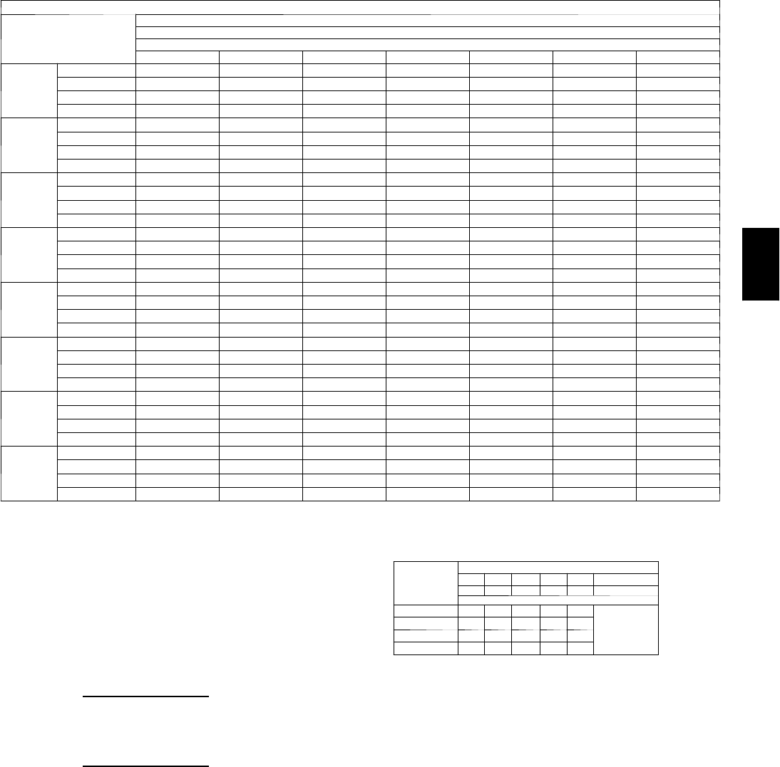
103
Cooling Capacities (cont)
48PG28 (25 Tons) — UNIT WITH HUMIDI-MIZER™SYSTEM — COOLING MODE (cont)
Te m p ( F )
Air Entering
Condenser
(Edb)
Evaporator Air Quantity — CFM
12,000
AirEnteringEvaporator—Ewb(F)
80 76 72 67 62 57 54
60
TC 456 431 406 375 344 313 294
SHC 220 237 254 275 297 313 294
kW 12.3 12.3 12.2 12.1 12.0 11.9 11.9
BF 0.00 0.27 0.13 0.06 0.08 0.21 0.34
70
TC 437 413 388 358 327 297 279
SHC 191 214 238 267 296 297 279
kW 15.6 15.5 15.3 15.2 15.0 14.8 14.7
BF 0.00 0.27 0.13 0.06 0.08 0.21 0.34
75
TC 427 403 379 349 319 289 271
SHC 177 203 230 262 295 289 271
kW 17.3 17.1 16.9 16.7 16.5 16.2 16.1
BF 0.00 0.29 0.14 0.07 0.09 0.22 0.35
85
TC 408 385 361 332 302 273 255
SHC 149 181 213 254 294 273 255
kW 20.6 20.3 20.1 19.8 19.4 19.1 18.9
BF 0.00 0.30 0.17 0.08 0.12 0.25 0.38
95
TC 389 366 343 314 286 257 240
SHC 120 159 197 245 286 257 240
kW 23.9 23.6 23.2 22.8 22.4 22.0 21.7
BF 0.00 0.30 0.17 0.08 0.12 0.25 0.38
105
TC 369 347 325 297 269 241 225
SHC 92 136 181 237 269 241 225
kW 27.2 26.8 26.4 25.9 25.4 24.9 24.5
BF 0.00 0.31 0.17 0.09 0.12 0.25 0.38
115
TC 350 328 307 280 253 226 209
SHC 63 114 165 228 253 226 209
kW 30.5 30.0 29.6 29.0 28.3 27.7 27.4
BF 0.00 0.33 0.18 0.10 0.13 0.26 0.39
125
TC 331 310 289 262 236 210 194
SHC 35 92 149 220 236 210 194
kW 33.8 33.3 32.7 32.0 31.3 30.6 30.2
BF 0.00 0.33 0.20 0.11 0.14 0.27 0.40
LEGEND
BF --- B y p a ss Fa c t o r
Edb --- E n t e r in g D r y --- B u l b
Ewb --- E n t e r in g W e t --- B u l b
kW --- Compressor Motor Power Input
Idb --- L e a v in g D r y --- B u l b
Iwb --- L e a v i n g We t --- B u l b
SHC --- Sensible Heat Capacity (1000 Btuh) Gross
TC --- Total Capacity (1000 Btuh) Gross
NOTES:
1. Direct interpolation is permissible. Do not extrapolate.
2. The following formulas may be used:
tldb =t
edb –sensible capacity (Btuh)
1.10 x cfm
tlwb = Wet---bulb temperature corresponding to enthalpy of air leaving
evaporator coil (hlwb)
hlwb =h
ewb –total capacity (Btuh)
4.5 x cfm
Where: hewb = Enthalpy of air entering evaporator coil
3. The SHC is based on 80_F edb temperature of air entering evaporator
coil
Below 80_F edb, subtract (corr factor x cfm) from SHC.
Above 80
_
F edb, add (corr factor x cfm) to SHC.
BYPASS
FACTOR
(BF)
ENTERING AIR DRY-BULB TEMP (F)
79 78 77 76 75 under 75
81 82 83 84 85 over 85
Correction Factor
.05 1.04 2.07 3.11 4.14 5.18
Use formula
shown below.
.10 .98 1.96 2.94 3.92 4.90
.20 .87 1.74 2.62 3.49 4.36
.30 .76 1.53 2.29 3.05 3.82
Interpolation is permissible.
C o r r e l a t i o n Fa c t o r = 1 . 0 9 x ( 1 --- B F ) x ( e d b --- 8 0 ) .
48PG
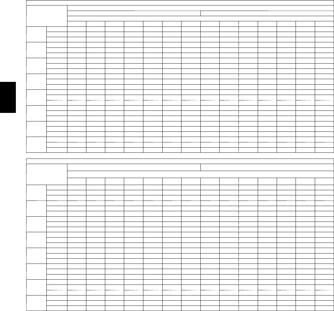
104
PERFORMANCE DATA (CONT)
Cooling Capacities (cont)
4 8 P G 2 8 ( 2 5 T O N S ) --- U N I T W I T H H U M I D I --- M I Z E R tSYSTEM --- SUBCOOLING MODE
Te m p ( F )
Air Entering
Condenser
(Edb)
AirEnteringEvaporator—Cfm
7500 8250
AirEnteringEvaporator—Ewb(F)
80 76 72 67 62 57 54 80 76 72 67 62 57 54
60
TC 448 423 397 366 334 303 284 451 426 400 368 337 305 286
SHC 183 198 213 231 250 268 279 191 206 221 240 259 278 286
kW 13.1 13.0 12.9 12.8 12.7 12.6 12.5 13.1 13.0 12.9 12.8 12.7 12.6 12.6
70
TC 425 400 376 345 314 284 265 429 404 379 348 317 286 268
SHC 147 167 188 214 240 265 265 155 176 197 223 249 275 268
kW 16.0 15.9 15.8 15.6 15.4 15.2 15.1 16.1 15.9 15.8 15.6 15.4 15.3 15.2
75
TC 413 389 365 334 304 274 256 417 393 368 338 307 277 258
SHC 129 152 176 205 234 264 256 136 160 184 214 244 274 258
kW 17.5 17.3 17.2 17.0 16.8 16.6 16.4 17.5 17.4 17.2 17.0 16.8 16.6 16.5
85
TC 390 367 343 314 284 255 237 395 371 347 317 288 258 240
SHC 93 122 151 188 224 255 237 100 130 159 197 234 258 240
kW 20.5 20.2 20.0 19.8 19.5 19.2 19.1 20.5 20.3 20.1 19.8 19.5 19.2 19.1
95
TC 367 344 321 293 264 236 218 372 349 326 297 268 239 222
SHC 56 92 127 170 214 236 218 63 99 135 179 224 239 222
kW 23.4 23.1 22.9 22.5 22.2 21.9 21.7 23.5 23.2 22.9 22.6 22.2 21.9 21.7
105
TC 344 322 300 272 244 216 200 350 327 305 277 249 220 204
SHC 20 61 102 153 204 216 200 26 68 110 162 214 220 204
kW 26.4 26.0 25.7 25.3 24.9 24.5 24.3 26.4 26.1 25.8 25.4 24.9 24.5 24.3
115
TC 321 299 278 251 224 197 181 327 305 284 256 229 202 185
SHC –16 31 78 136 194 197 181 –10 37 85 145 204 202 185
kW 29.3 28.9 28.6 28.1 27.6 27.1 26.9 29.4 29.0 28.6 28.1 27.7 27.2 26.9
125
TC 298 277 256 230 204 178 162 305 284 262 236 209 183 167
SHC –52 053 119 184 178 162 –47 760 127 194 183 167
kW 32.3 31.8 31.4 30.9 30.3 29.8 29.5 32.3 31.9 31.5 30.9 30.4 29.8 29.5
4 8 P G 2 8 ( 2 5 T O N S ) --- U N I T W I T H H U M I D I --- M I Z E R S Y S T E M --- S U B C O O L I N G M O D E ( C O N T )
Te m p ( F )
Air Entering
Condenser
(Edb)
9500 10,750
AirEnteringEvaporator—Ewb(F)
80 76 72 67 62 57 54 80 76 72 67 62 57 54
60
TC 455 429 404 372 340 308 289 458 433 407 375 342 310 291
SHC 203 218 233 253 272 291 289 213 229 244 264 284 303 291
kW 13.1 13.1 13.0 12.9 12.8 12.7 12.6 13.2 13.1 13.0 12.9 12.8 12.7 12.6
70
TC 433 408 383 352 321 290 271 437 412 387 355 324 292 273
SHC 165 187 208 235 262 289 271 175 197 219 246 274 292 273
kW 16.1 16.0 15.8 15.7 15.5 15.3 15.2 16.1 16.0 15.9 15.7 15.5 15.3 15.2
75
TC 422 398 373 342 311 280 262 426 402 377 346 314 283 265
SHC 147 171 196 226 257 280 262 156 181 206 238 269 283 265
kW 17.6 17.4 17.3 17.0 16.8 16.6 16.5 17.6 17.5 17.3 17.1 16.9 16.7 16.5
85
TC 400 376 352 322 292 262 244 405 381 357 326 296 266 247
SHC 109 140 171 209 247 262 244 118 149 181 220 259 266 247
kW 20.6 20.3 20.1 19.8 19.6 19.3 19.1 20.6 20.4 20.1 19.9 19.6 19.3 19.1
95
TC 379 355 332 302 273 244 226 384 360 337 307 277 248 230
SHC 72 109 145 191 237 244 226 80 117 155 202 249 248 230
kW 23.5 23.2 23.0 22.6 22.3 21.9 21.7 23.6 23.3 23.0 22.7 22.3 22.0 21.8
105
TC 357 334 311 283 254 226 208 363 340 317 288 259 230 212
SHC 34 77 120 174 228 226 208 42 86 130 185 240 230 212
kW 26.5 26.1 25.8 25.4 25.0 24.6 24.3 26.5 26.2 25.9 25.4 25.0 24.6 24.4
115
TC 335 313 291 263 235 207 191 342 319 296 268 240 212 195
SHC –3 46 95 156 218 207 191 454 104 167 230 212 195
kW 29.4 29.1 28.7 28.2 27.7 27.2 27.0 29.5 29.1 28.7 28.2 27.8 27.3 27.0
125
TC 313 292 270 243 216 189 173 320 298 276 249 222 194 178
SHC –40 15 70 139 208 189 173 –34 22 79 150 220 194 178
kW 32.4 32.0 31.5 31.0 30.4 29.9 29.6 32.5 32.0 31.6 31.0 30.5 29.9 29.6
48PG
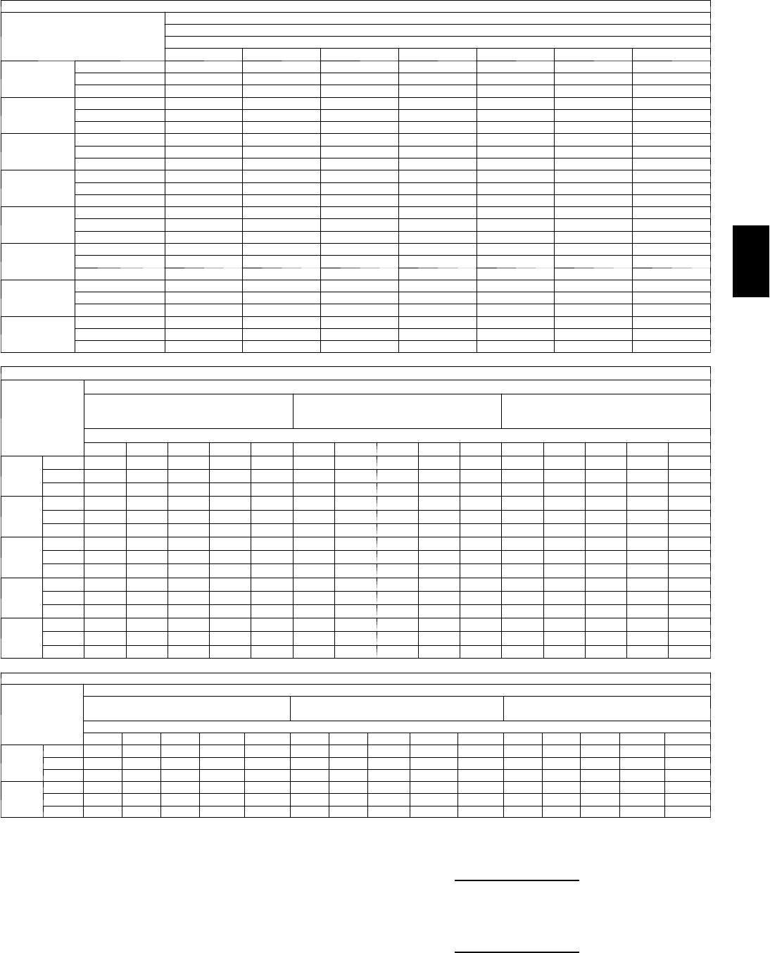
105
Cooling Capacities (cont)
4 8 P G 2 8 ( 2 5 T O N S ) --- U N I T W I T H H U M I D I --- M I Z E R tSYSTEM --- SUBCOOLING MODE (CONT)
Te m p ( F )
Air Entering
Condenser
(Edb)
AirEnteringEvaporator—Cfm
12,000
AirEnteringEvaporator—Ewb(F)
80 76 72 67 62 57 54
60
TC 461 435 409 377 345 312 293
SHC 222 238 254 274 294 312 293
kW 13.2 13.1 13.0 12.9 12.8 12.7 12.6
70
TC 440 415 390 358 326 295 276
SHC 184 206 228 257 285 295 276
kW 16.2 16.0 15.9 15.7 15.5 15.3 15.2
75
TC 430 405 380 349 317 286 267
SHC 164 190 216 248 280 286 267
kW 17.7 17.5 17.3 17.1 16.9 16.7 16.5
85
TC 409 385 360 330 299 268 250
SHC 126 158 190 230 270 268 250
kW 20.6 20.4 20.2 19.9 19.6 19.3 19.2
95
TC 389 365 341 311 281 251 233
SHC 87 126 164 212 260 251 233
kW 23.6 23.3 23.0 22.7 22.3 22.0 21.8
105
TC 368 344 321 292 263 233 216
SHC 48 93 138 195 251 233 216
kW 26.6 26.2 25.9 25.5 25.1 24.6 24.4
115
TC 347 324 302 273 244 216 199
SHC 10 61 113 177 241 216 199
kW 29.5 29.1 28.8 28.3 27.8 27.3 27.0
125
TC 326 304 282 254 226 198 182
SHC –29 29 87 159 226 198 182
kW 32.5 32.1 31.6 31.1 30.5 30.0 29.6
48PG28 (25 Tons) — UNIT WITH HUMIDI-MIZER SYSTEM — HOT GAS REHEAT MODE — ALL CIRCUITS
Te m p ( F )
Air Ent
Condenser
(Edb)
AirEnteringEvaporator—Ewb(F)
75 Dry Bulb
62.5 Wet Bulb
(50% RH)
75 Dry Bulb
64 Wet Bulb
(55% RH)
75 Dry Bulb
65.3 Wet Bulb
(60% RH)
AirEnteringEvaporator—Cfm
7400 8250 9500 10,750 12,000 7400 8250 9500 10,750 12,000 7400 8250 9500 10,750 12,000
80
TC 107 111 116 121 124 112 116 122 126 130 116 121 126 131 135
SHC 19 24 31 37 42 12 17 24 30 35 611 18 24 29
kW 19.9 20.0 20.0 20.1 20.1 20.0 20.1 20.1 20.2 20.2 20.1 20.1 20.2 20.3 20.3
75
TC 113 117 122 127 130 119 123 128 132 135 123 127 132 137 140
SHC 22 27 33 39 45 16 21 27 33 38 10 15 21 27 32
kW 19.3 19.3 19.4 19.4 19.5 19.3 19.4 19.5 19.5 19.6 19.4 19.5 19.6 19.6 19.7
70
TC 120 124 129 132 136 125 129 134 138 141 130 134 139 143 146
SHC 25 30 36 42 47 19 24 30 36 41 14 19 25 31 35
kW 18.6 18.7 18.7 18.8 18.8 18.7 18.8 18.8 18.9 18.9 18.8 18.8 18.9 19.0 19.0
60
TC 134 137 141 144 147 139 142 146 150 153 144 147 151 154 157
SHC 32 36 41 46 51 27 31 36 41 46 23 27 32 37 42
kW 17.3 17.3 17.4 17.4 17.5 17.4 17.4 17.5 17.5 17.6 17.5 17.6 17.6 17.6 17.7
50
TC 148 150 154 156 159 153 156 159 162 164 157 160 163 166 169
SHC 38 42 47 51 55 34 38 43 47 51 31 35 40 44 48
kW 16.0 16.0 16.1 16.1 16.1 16.1 16.1 16.2 16.2 16.3 16.2 16.3 16.3 16.3 16.4
4 8 P G 2 8 ( 2 5 T O N S ) --- U N I T W I T H H U M I D I --- M I Z E R S Y S T E M --- H O T G A S R E H E A T M O D E --- C I R C U I T A O N LY
Te m p ( F ) A i r
Entering
Condenser
(Edb)
AirEnteringEvaporator—Ewb(F)
75 Dry Bulb
62.5 Wet Bulb (50% RH)
75 Dry Bulb
64 Wet Bulb (55% RH)
75 Dry Bulb
65.3 Wet Bulb (60% RH)
AirEnteringEvaporator—Cfm
7400 8250 9500 10,750 12,000 7400 8250 9500 10,750 12,000 7400 8250 9500 10,750 12,000
50
TC 104 106 109 111 113 107 109 112 114 116 109 111 114 117 119
SHC 44 49 55 60 64 32 37 43 48 52 21 26 32 38 42
kW 10.9 10.9 10.9 10.9 10.9 10.9 10.9 10.9 10.9 10.9 10.9 10.9 10.9 10.9 10.9
40
TC 110 112 114 116 117 113 114 117 119 120 115 117 119 121 123
SHC 50 54 59 63 66 40 44 49 53 57 32 36 41 45 49
kW 10.4 10.4 10.4 10.4 10.4 10.4 10.4 10.4 10.4 10.4 10.4 10.5 10.5 10.5 10.5
LEGEND
Edb --- E n t e r in g D r y --- B u l b
Ewb --- E n t e r in g W e t --- B u l b
kW --- Compressor Motor Power Input
Idb --- L e a v in g D r y --- B u l b
Iwb --- L e a v i n g We t --- B u l b
RH --- Relative Humidity
SHC --- Sensible Heat Capacity (1000 Btuh) Gross
TC --- Total Capacity (1000 Btuh) Gross
NOTES:
1. Direct interpolation is permissible. Do not extrapolate.
2. The following formulas may be used:
tldb =t
edb –sensible capacity (Btuh)
1.10 x cfm
tlwb = Wet---bulb temperature corresponding to enthalpy of air leaving
evaporator coil (hlwb)
hlwb =h
ewb –total capacity (Btuh)
4.5 x cfm
Where: hewb = Enthalpy of air entering evaporator coil
48PG
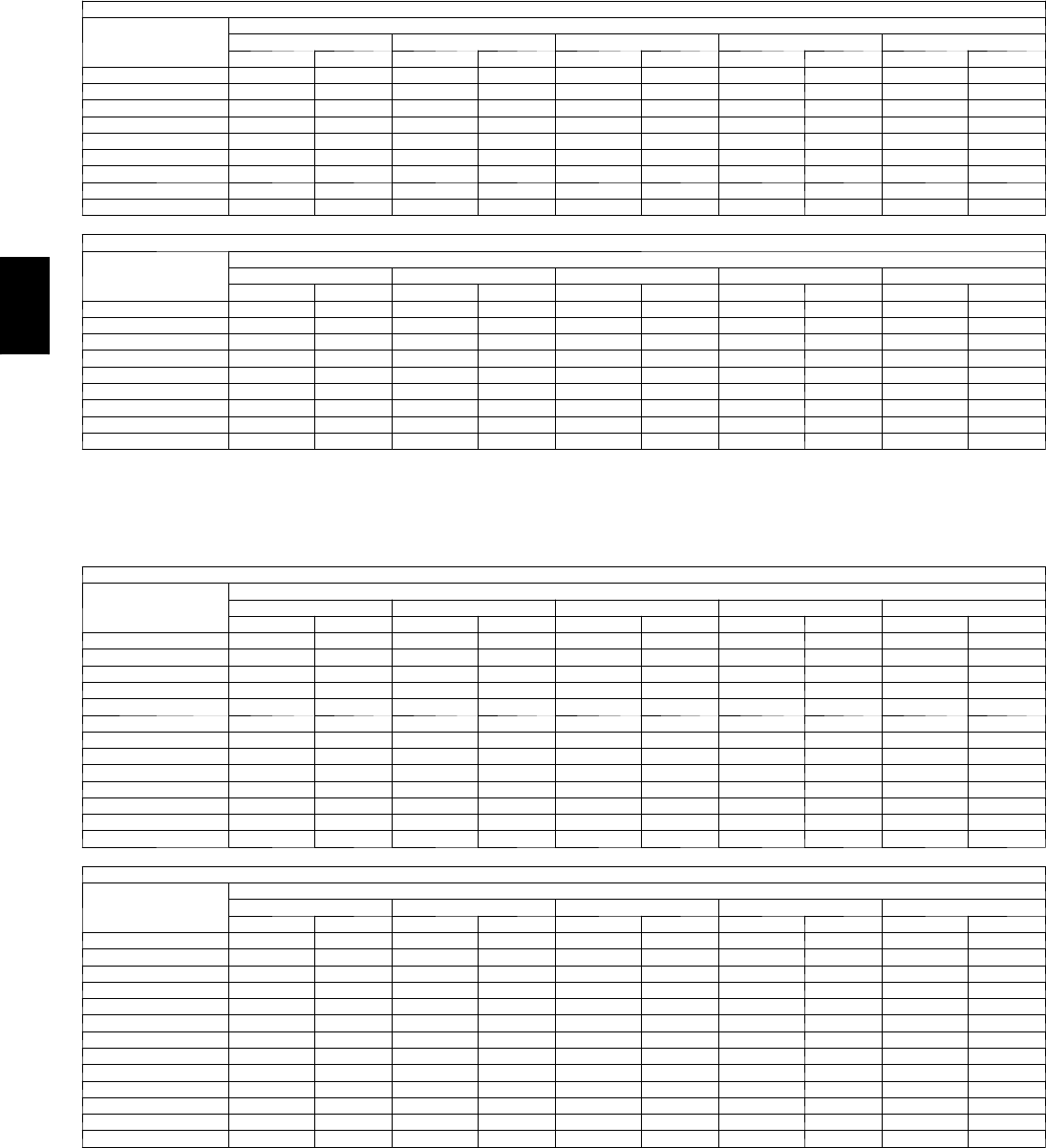
106
PERFORMANCE DATA (CONT)
Fan Performance — Vertical Supply/Return Units
48PGD03 (Low Heat Units)
AIRFLOW
(Cfm)
AVAILABLEEXTERNALSTATICPRESSURE(in.wg)
0.2 0.4 0.6 0.8 1.0
Rpm Bhp Rpm Bhp Rpm Bhp Rpm Bhp Rpm Bhp
600 407 0.05 551 0.10 663 0.15 759 0.21 843 0.27
650 413 0.06 555 0.11 667 0.17 763 0.22 847 0.29
700 419 0.06 560 0.12 671 0.18 766 0.24 851 0.30
750 425 0.07 565 0.13 676 0.19 770 0.25 854 0.32
800 433 0.08 570 0.14 680 0.20 774 0.27 858 0.34
850 440 0.08 575 0.15 685 0.22 779 0.29 862 0.36
900 448 0.09 581 0.16 690 0.23 783 0.30 866 0.38
950 456 0.10 587 0.17 695 0.24 788 0.32 871 0.40
1000 465 0.11 594 0.18 700 0.26 792 0.34 875 0.42
48PGD03 (Low Heat Units) (cont)
AIRFLOW
(Cfm)
AVAILABLEEXTERNALSTATICPRESSURE(in.wg)
1.2 1.4 1.6 1.8 2.0
Rpm Bhp Rpm Bhp Rpm Bhp Rpm Bhp Rpm Bhp
600 920 0.33 990 0.40 1056 0.47 1117 0.54 1176 0.62
650 923 0.35 994 0.42 1059 0.49 1121 0.57 1179 0.65
700 927 0.37 997 0.44 1063 0.52 1124 0.60 1182 0.68
750 931 0.39 1001 0.47 1066 0.54 1128 0.62 1186 0.71
800 934 0.41 1004 0.49 1070 0.57 1131 0.65 1189 0.74
850 938 0.44 1008 0.52 1073 0.60 1135 0.68 1193 0.77
900 942 0.46 1012 0.54 1077 0.63 1138 0.71 1196 0.80
950 946 0.48 1016 0.57 1081 0.65 1142 0.74 1200 0.83
1000 950 0.51 1020 0.59 1085 0.68 1146 0.78 1204 0.87
LEGEND
B h p --- Brake Horsepower
NOTES:
1. Motor drive range is 482 to 736 rpm for low range motor/drive and 656 to 1001 rpm
for high range motor/drive. All other rpms require a field-supplied drive.
2. Maximum continuous bhp is 0.85 for low range motor/drive and 0.85 for high range
motor/drive.
3. See General Fan Performance Notes.
48PGD04 (Low Heat Units)
AIRFLOW
(Cfm)
AVAILABLEEXTERNALSTATICPRESSURE(in.wg)
0.2 0.4 0.6 0.8 1.0
Rpm Bhp Rpm Bhp Rpm Bhp Rpm Bhp Rpm Bhp
900 448 0.09 581 0.16 690 0.23 783 0.30 866 0.38
950 456 0.10 587 0.17 695 0.24 788 0.32 871 0.40
1000 465 0.11 594 0.18 700 0.26 792 0.34 875 0.42
1050 474 0.12 600 0.20 706 0.27 797 0.36 880 0.44
1100 483 0.13 607 0.21 711 0.29 803 0.38 884 0.46
1150 493 0.14 614 0.22 717 0.31 808 0.40 889 0.49
1200 503 0.16 622 0.24 724 0.33 813 0.42 894 0.51
1250 513 0.17 630 0.25 730 0.34 819 0.44 899 0.54
1300 524 0.19 638 0.27 737 0.36 825 0.46 905 0.56
1350 535 0.20 646 0.29 744 0.38 831 0.48 910 0.59
1400 546 0.22 655 0.31 751 0.41 837 0.51 916 0.61
1450 557 0.24 664 0.33 759 0.43 844 0.53 922 0.64
1500 569 0.25 673 0.35 766 0.45 851 0.56 928 0.67
48PGD04 (Low Heat Units) (cont)
AIRFLOW
(Cfm)
AVAILABLEEXTERNALSTATICPRESSURE(in.wg)
1.2 1.4 1.6 1.8 2.0
Rpm Bhp Rpm Bhp Rpm Bhp Rpm Bhp Rpm Bhp
900 942 0.46 1012 0.54 1077 0.63 1138 0.71 1196 0.80
950 946 0.48 1016 0.57 1081 0.65 1142 0.74 1200 0.83
1000 950 0.51 1020 0.59 1085 0.68 1146 0.78 --- ---
1050 955 0.53 1024 0.62 1089 0.71 1150 0.81 --- ---
1100 959 0.56 1028 0.65 1093 0.74 1154 0.84 --- ---
1150 963 0.58 1032 0.68 1097 0.78 --- --- --- ---
1200 968 0.61 1037 0.71 1101 0.81 --- --- --- ---
1250 973 0.64 1041 0.74 1105 0.84 --- --- --- ---
1300 978 0.66 1046 0.77 --- --- --- --- --- ---
1350 983 0.69 1051 0.80 --- --- --- --- --- ---
1400 988 0.72 1056 0.83 --- --- --- --- --- ---
1450 994 0.75 --- --- --- --- --- --- --- ---
1500 1000 0.79 --- --- --- --- --- --- --- ---
LEGEND
B h p --- Brake Horsepower
NOTES:
1. Motor drive range is 482 to 736 rpm for low range motor/drive and 796 to 1128 rpm
for high range motor/drive. All other rpms require a field-supplied drive.
2. Maximum continuous bhp is 0.85 for low range motor/drive and 0.85 for high range
motor/drive.
3. See General Fan Performance Notes.
48PG
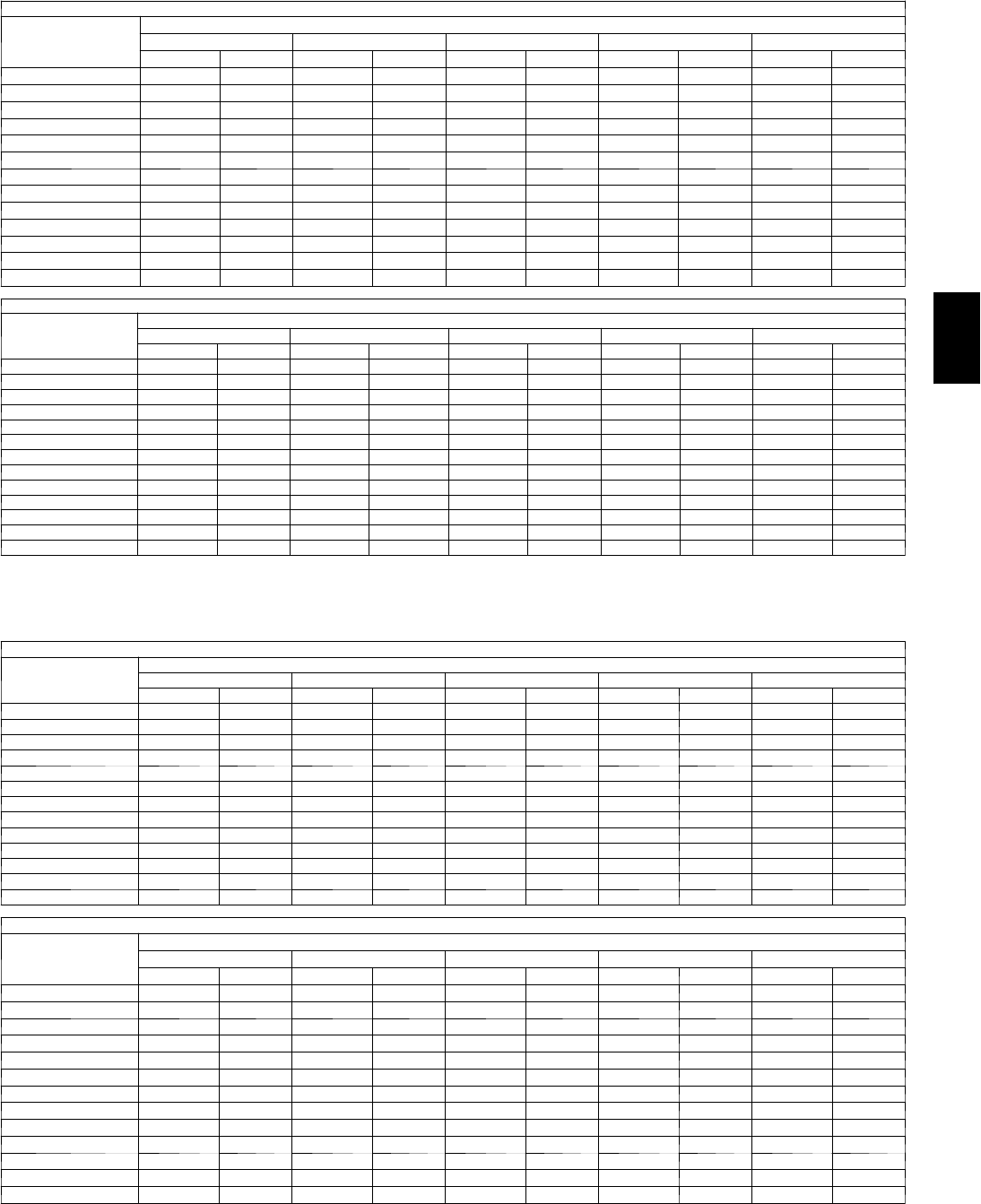
107
Fan Performance — Vertical Supply/Return Units
48PGE04 (Medium Heat Units)
AIRFLOW
(Cfm)
AVAILABLEEXTERNALSTATICPRESSURE(in.wg)
0.2 0.4 0.6 0.8 1.0
Rpm Bhp Rpm Bhp Rpm Bhp Rpm Bhp Rpm Bhp
900 452 0.09 584 0.16 693 0.23 786 0.31 870 0.38
950 460 0.10 590 0.17 698 0.25 791 0.32 874 0.40
1000 469 0.11 597 0.18 703 0.26 796 0.34 878 0.42
1050 479 0.12 604 0.20 709 0.28 801 0.36 883 0.45
1100 488 0.13 611 0.21 715 0.29 806 0.38 888 0.47
1150 498 0.15 619 0.23 721 0.31 812 0.40 893 0.49
1200 509 0.16 627 0.24 728 0.33 817 0.42 898 0.52
1250 519 0.17 635 0.26 735 0.35 823 0.44 903 0.54
1300 530 0.19 643 0.28 742 0.37 829 0.47 909 0.57
1350 542 0.21 652 0.29 749 0.39 836 0.49 915 0.59
1400 553 0.22 661 0.31 756 0.41 842 0.51 921 0.62
1450 565 0.24 670 0.33 764 0.44 849 0.54 927 0.65
1500 577 0.26 680 0.36 772 0.46 856 0.57 933 0.68
48PGE04 (Medium Heat Units) (cont)
AIRFLOW
(Cfm)
AVAILABLEEXTERNALSTATICPRESSURE(in.wg)
1.2 1.4 1.6 1.8 2.0
Rpm Bhp Rpm Bhp Rpm Bhp Rpm Bhp Rpm Bhp
900 945 0.46 1016 0.55 1081 0.63 1143 0.72 1201 0.81
950 950 0.49 1019 0.57 1085 0.66 1146 0.75 1204 0.84
1000 954 0.51 1023 0.60 1089 0.69 1150 0.78 — —
1050 958 0.53 1028 0.63 1093 0.72 1154 0.81 — —
1100 963 0.56 1032 0.65 1097 0.75 1158 0.85 — —
1150 967 0.59 1036 0.68 1101 0.78 — — — —
1200 972 0.61 1041 0.71 1105 0.81 — — — —
1250 977 0.64 1045 0.74 1110 0.85 — — — —
1300 982 0.67 1050 0.78 — — — — — —
1350 987 0.70 1055 0.81 — — — — — —
1400 993 0.73 1060 0.84 — — — — — —
1450 999 0.76 — — — — — — — —
1500 1004 0.79 — — — — — — — —
LEGEND
B h p --- Brake Horsepower
NOTES:
1. Motor drive range is 482 to 736 rpm for low range motor/drive and 796 to 1128 rpm
for high range motor/drive. All other rpms require a field-supplied drive.
2. Maximum continuous bhp is 0.85 for low range motor/drive and 0.85 for high range
motor/drive.
3. See General Fan Performance Notes.
48PGF04 (High Heat Units)
AIRFLOW
(Cfm)
AVAILABLEEXTERNALSTATICPRESSURE(in.wg)
0.2 0.4 0.6 0.8 1.0
Rpm Bhp Rpm Bhp Rpm Bhp Rpm Bhp Rpm Bhp
900 459 0.10 590 0.16 698 0.24 792 0.31 876 0.39
950 468 0.11 597 0.18 704 0.25 797 0.33 881 0.41
1000 477 0.12 604 0.19 710 0.27 802 0.35 885 0.43
1050 488 0.13 611 0.20 716 0.28 807 0.37 890 0.45
1100 498 0.14 619 0.22 722 0.30 813 0.39 895 0.48
1150 509 0.15 627 0.23 729 0.32 819 0.41 900 0.50
1200 520 0.17 636 0.25 736 0.34 825 0.43 906 0.53
1250 531 0.18 644 0.27 743 0.36 831 0.45 911 0.55
1300 543 0.20 653 0.28 751 0.38 838 0.48 917 0.58
1350 555 0.21 663 0.30 759 0.40 845 0.50 923 0.61
1400 567 0.23 672 0.32 767 0.42 852 0.53 930 0.63
1450 579 0.25 682 0.35 775 0.45 859 0.55 936 0.66
1500 592 0.27 692 0.37 784 0.47 867 0.58 943 0.69
48PGF04 (High Heat Units) (cont)
AIRFLOW
(Cfm)
AVAILABLEEXTERNALSTATICPRESSURE(in.wg)
1.2 1.4 1.6 1.8 2.0
Rpm Bhp Rpm Bhp Rpm Bhp Rpm Bhp Rpm Bhp
900 953 0.47 1023 0.56 1089 0.64 1151 0.73 1210 0.82
950 957 0.49 1027 0.58 1093 0.67 1155 0.76 — —
1000 961 0.52 1031 0.61 1097 0.70 1159 0.80 — —
1050 965 0.54 1035 0.64 1101 0.73 1162 0.83 — —
1100 970 0.57 1040 0.67 1105 0.76 — — — —
1150 975 0.60 1044 0.69 1109 0.80 — — — —
1200 980 0.62 1049 0.73 1114 0.83 — — — —
1250 985 0.65 1054 0.76 — — — — — —
1300 990 0.68 1059 0.79 — — — — — —
1350 996 0.71 1064 0.82 — — — — — —
1400 1002 0.74 — — — — — — — —
1450 1008 0.78 — — — — — — — —
1500 1014 0.81 — — — — — — — —
LEGEND
B h p --- Brake Horsepower
NOTES:
1. Motor drive range is 482 to 736 rpm for low range motor/drive and 796 to 1128 rpm
for high range motor/drive. All other rpms require a field-supplied drive.
2. Maximum continuous bhp is 0.85 for low range motor/drive and 0.85 for high range
motor/drive.
3. See General Fan Performance Notes.
48PG
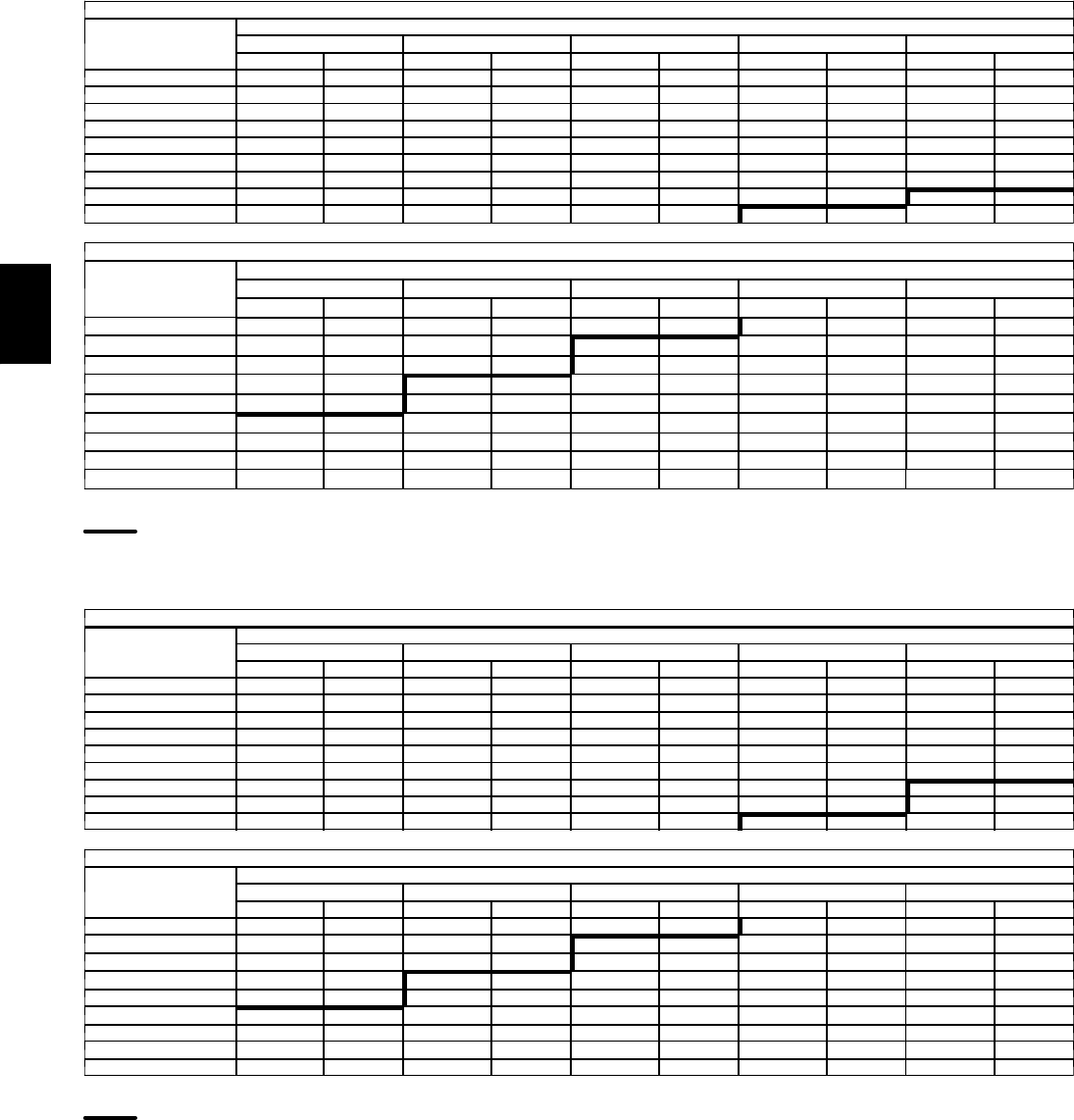
108
PERFORMANCE DATA (CONT)
Fan Performance — Vertical Supply/Return Units
48PGD05 (Low Heat Units)
AIRFLOW
(Cfm)
AVAILABLEEXTERNALSTATICPRESSURE(in.wg)
0.2 0.4 0.6 0.8 1.0
Rpm Bhp Rpm Bhp Rpm Bhp Rpm Bhp Rpm Bhp
1200 504 0.16 613 0.23 710 0.31 798 0.40 881 0.49
1300 527 0.19 632 0.27 725 0.35 810 0.44 890 0.54
1400 551 0.22 652 0.31 741 0.40 823 0.49 900 0.59
1500 576 0.26 673 0.35 759 0.44 838 0.54 912 0.65
1600 600 0.30 694 0.40 777 0.50 854 0.60 926 0.71
1700 626 0.35 716 0.45 797 0.55 871 0.66 941 0.78
1800 651 0.40 739 0.51 817 0.62 889 0.73 957 0.85
1900 677 0.46 762 0.57 838 0.69 908 0.80 974 0.93
2000 703 0.52 785 0.64 859 0.76 927 0.88 992 1.01
48PGD05 (Low Heat Units) (cont)
AIRFLOW
(Cfm)
AVAILABLEEXTERNALSTATICPRESSURE(in.wg)
1.2 1.4 1.6 1.8 2.0
Rpm Bhp Rpm Bhp Rpm Bhp Rpm Bhp Rpm Bhp
1200 957 0.59 1030 0.70 1098 0.80 1163 0.91 1225 1.03
1300 964 0.64 1035 0.75 1102 0.86 1166 0.98 1227 1.10
1400 973 0.70 1042 0.81 1107 0.92 1170 1.04 1231 1.17
1500 983 0.76 1050 0.87 1114 0.99 1176 1.12 1235 1.24
1600 994 0.82 1060 0.94 1122 1.06 1183 1.19 1241 1.32
1700 1007 0.89 1071 1.02 1132 1.14 1191 1.27 1248 1.41
1800 1021 0.97 1083 1.10 1143 1.23 1200 1.36 1256 1.50
1900 1037 1.05 1097 1.18 1155 1.32 1211 1.45 1266 1.60
2000 1053 1.14 1111 1.27 1168 1.41 1223 1.55 1276 1.70
LEGEND
B h p --- Brake Horsepower
High Range Motor/Drive Required
NOTES:
1. Motor drive range is 596 to 910 rpm for low range motor/drive and 828 to 1173 rpm
for high range motor/drive. All other rpms require a field-supplied drive.
2. Maximum continuous bhp is 0.85 for low range motor/drive and 1.60 (single phase)
and 2.40 (3 phase) for high range motor/drive.
3. See General Fan Performance Notes.
48PGE05 (Medium Heat Units)
AIRFLOW
(Cfm)
AVAILABLEEXTERNALSTATICPRESSURE(in.wg)
0.2 0.4 0.6 0.8 1.0
Rpm Bhp Rpm Bhp Rpm Bhp Rpm Bhp Rpm Bhp
1200 509 0.16 618 0.24 714 0.32 802 0.41 884 0.50
1300 533 0.19 637 0.27 730 0.36 814 0.45 894 0.55
1400 557 0.23 658 0.31 746 0.40 828 0.50 905 0.60
1500 582 0.27 679 0.36 764 0.45 843 0.55 917 0.66
1600 608 0.31 701 0.40 783 0.50 860 0.61 931 0.72
1700 634 0.36 723 0.46 803 0.56 877 0.67 947 0.79
1800 660 0.41 747 0.52 824 0.63 896 0.74 963 0.86
1900 686 0.47 770 0.58 846 0.70 915 0.82 981 0.94
2000 713 0.54 795 0.66 868 0.78 935 0.90 999 1.02
48PGE05 (Medium Heat Units) (cont)
AIRFLOW
(Cfm)
AVAILABLEEXTERNALSTATICPRESSURE(in.wg)
1.2 1.4 1.6 1.8 2.0
Rpm Bhp Rpm Bhp Rpm Bhp Rpm Bhp Rpm Bhp
1200 961 0.60 1033 0.70 1101 0.81 1166 0.92 1228 1.03
1300 968 0.65 1039 0.76 1106 0.87 1169 0.98 1230 1.10
1400 977 0.70 1046 0.82 1111 0.93 1174 1.05 1234 1.17
1500 987 0.77 1054 0.88 1118 1.00 1180 1.12 1239 1.25
1600 999 0.83 1065 0.95 1127 1.07 1187 1.20 1245 1.33
1700 1013 0.90 1076 1.03 1137 1.15 1196 1.28 1253 1.42
1800 1027 0.98 1089 1.11 1148 1.24 1206 1.37 1261 1.51
1900 1043 1.06 1103 1.20 1161 1.33 1217 1.47 1271 1.61
2000 1060 1.16 1118 1.29 1175 1.43 1229 1.57 1282 1.72
LEGEND
B h p --- Brake Horsepower
High Range Motor/Drive Required
NOTES:
1. Motor drive range is 596 to 910 rpm for low range motor/drive and 828 to 1173 rpm
for high range motor/drive. All other rpms require a field-supplied drive.
2. Maximum continuous bhp is 0.85 for low range motor/drive and 1.60 (single phase)
and 2.40 (3 phase) for high range motor/drive.
3. See General Fan Performance Notes.
48PG
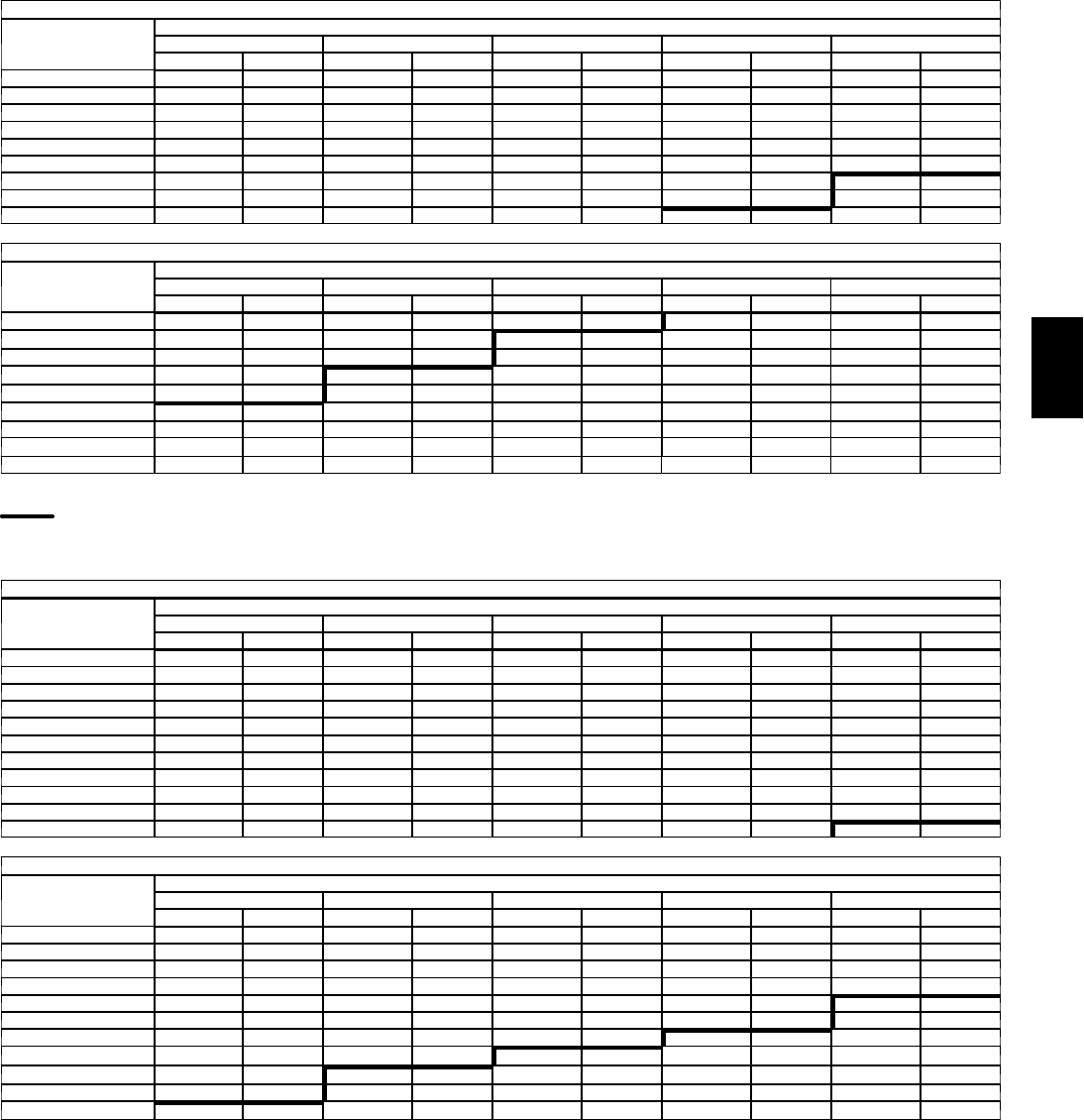
109
Fan Performance — Vertical Supply/Return Units
48PGF05 (High Heat Units)
AIRFLOW
(Cfm)
AVAILABLEEXTERNALSTATICPRESSURE(in.wg)
0.2 0.4 0.6 0.8 1.0
Rpm Bhp Rpm Bhp Rpm Bhp Rpm Bhp Rpm Bhp
1200 520 0.17 628 0.24 723 0.33 811 0.41 892 0.51
1300 545 0.20 648 0.28 739 0.37 823 0.46 902 0.56
1400 570 0.24 668 0.32 756 0.41 837 0.51 913 0.61
1500 596 0.28 691 0.37 775 0.46 853 0.56 927 0.67
1600 623 0.32 714 0.42 795 0.52 870 0.62 942 0.73
1700 650 0.37 737 0.48 816 0.58 889 0.69 958 0.80
1800 677 0.43 762 0.54 838 0.65 909 0.76 976 0.88
1900 705 0.50 787 0.61 861 0.72 929 0.84 994 0.97
2000 734 0.57 813 0.68 884 0.80 951 0.93 1014 1.06
48PGF05 (High Heat Units) (cont)
AIRFLOW
(Cfm)
AVAILABLEEXTERNALSTATICPRESSURE(in.wg)
1.2 1.4 1.6 1.8 2.0
Rpm Bhp Rpm Bhp Rpm Bhp Rpm Bhp Rpm Bhp
1200 968 0.61 1040 0.71 1108 0.82 1172 0.93 1233 1.04
1300 976 0.66 1046 0.77 1112 0.88 1176 1.00 1237 1.11
1400 985 0.72 1054 0.83 1119 0.95 1181 1.07 1241 1.19
1500 996 0.78 1063 0.90 1127 1.02 1188 1.14 1247 1.27
1600 1009 0.85 1074 0.97 1136 1.09 1196 1.22 1254 1.35
1700 1024 0.92 1087 1.05 1147 1.17 1205 1.31 1262 1.44
1800 1039 1.00 1100 1.13 1159 1.26 1216 1.40 1272 1.54
1900 1056 1.09 1116 1.22 1173 1.36 1229 1.50 1283 1.64
2000 1074 1.19 1132 1.32 1188 1.46 1242 1.61 1295 1.75
LEGEND
B h p --- Brake Horsepower
High Range Motor/Drive Required
NOTES:
1. Motor drive range is 596 to 910 rpm for low range motor/drive and 828 to 1173 rpm
for high range motor/drive. All other rpms require a field-supplied drive.
2. Maximum continuous bhp is 0.85 for low range motor/drive and 1.60 (single phase)
and 2.40 (3 phase) for high range motor/drive.
3. See General Fan Performance Notes.
48PGD06 (Low Heat Units)
AIRFLOW
(Cfm)
AVAILABLEEXTERNALSTATICPRESSURE(in.wg)
0.2 0.4 0.6 0.8 1.0
Rpm Bhp Rpm Bhp Rpm Bhp Rpm Bhp Rpm Bhp
1500 593 0.27 688 0.37 773 0.46 851 0.56 925 0.67
1600 620 0.32 711 0.42 793 0.52 868 0.62 939 0.73
1700 646 0.37 734 0.47 813 0.58 886 0.69 955 0.80
1800 673 0.43 758 0.53 835 0.64 905 0.76 972 0.88
1900 700 0.49 783 0.60 857 0.72 925 0.84 990 0.96
2000 728 0.56 807 0.68 879 0.80 946 0.92 1009 1.05
2100 755 0.63 833 0.76 903 0.88 968 1.01 1029 1.14
2200 783 0.71 858 0.84 926 0.97 990 1.11 1050 1.24
2300 811 0.80 884 0.94 950 1.07 1012 1.21 1071 1.35
2400 840 0.90 910 1.04 975 1.18 1035 1.33 1092 1.47
2500 868 1.00 937 1.15 1000 1.30 1059 1.45 1115 1.60
48PGD06 (Low Heat Units) (cont)
AIRFLOW
(Cfm)
AVAILABLEEXTERNALSTATICPRESSURE(in.wg)
1.2 1.4 1.6 1.8 2.0
Rpm Bhp Rpm Bhp Rpm Bhp Rpm Bhp Rpm Bhp
1500 995 0.78 1061 0.89 1125 1.01 1186 1.14 1245 1.26
1600 1007 0.85 1072 0.96 1134 1.09 1194 1.22 1252 1.35
1700 1021 0.92 1084 1.04 1145 1.17 1203 1.30 1260 1.44
1800 1036 1.00 1098 1.13 1157 1.26 1214 1.39 1269 1.53
1900 1053 1.08 1112 1.22 1170 1.35 1226 1.49 1280 1.63
2000 1070 1.18 1128 1.31 1184 1.45 1238 1.60 1291 1.74
2100 1088 1.28 1145 1.42 1199 1.56 1253 1.71 1304 1.86
2200 1107 1.38 1162 1.53 1216 1.68 1268 1.83 1318 1.98
2300 1127 1.50 1181 1.65 1233 1.80 1284 1.95 1333 2.11
2400 1147 1.62 1200 1.77 1251 1.93 1300 2.09 1349 2.25
2500 1168 1.75 1220 1.91 1270 2.07 1318 2.23 1365 2.40
LEGEND
B h p --- Brake Horsepower
NOTES:
1. Motor drive range is 690 to 978 rpm for low range motor/drive and 929 to 1261 rpm
for high range motor/drive. All other rpms require a field-supplied drive.
2. Maximum continuous bhp is 0.85 (single phase) and 2.40 (3 phase) for low range
motor/drive and 1.60 (single phase) and 2.40 (3 phase) for high range motor/drive.
3. See General Fan Performance Notes.
48PG
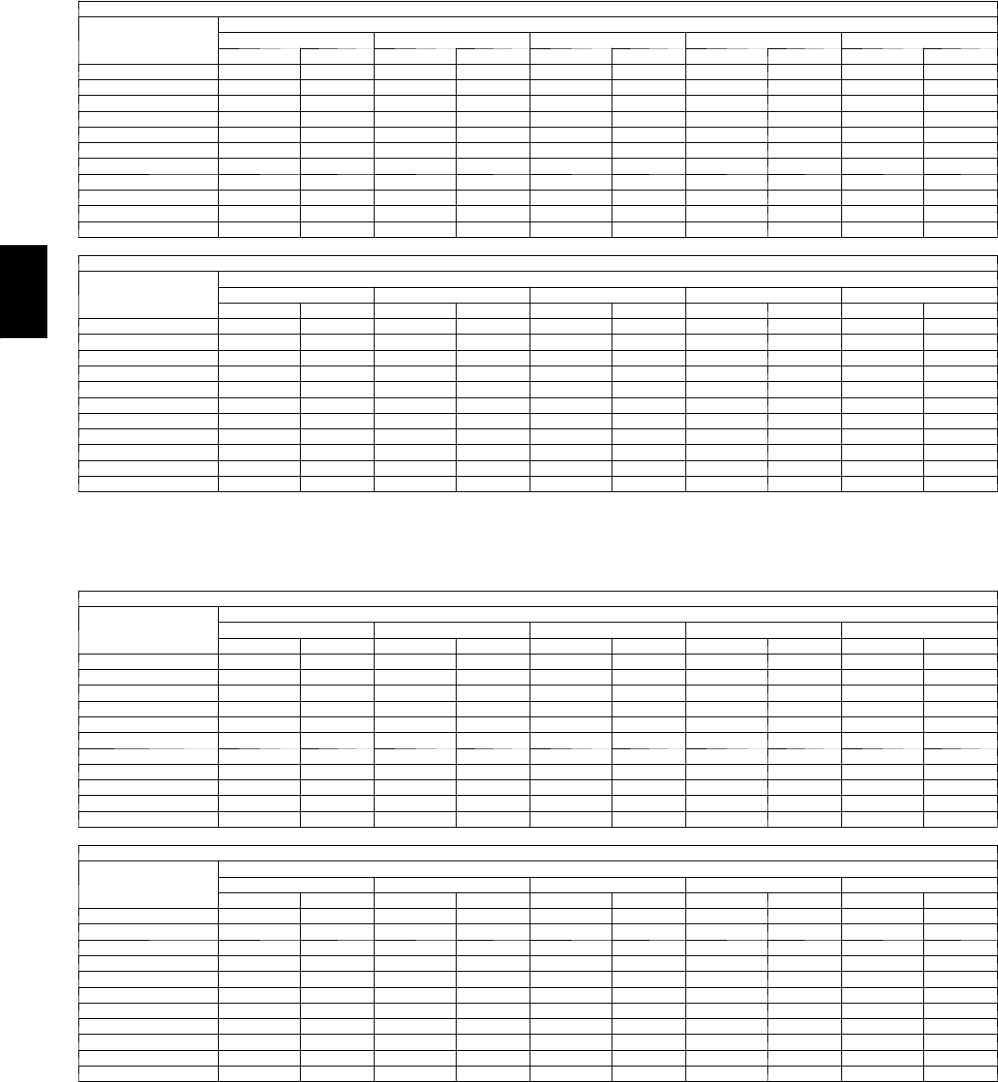
110
PERFORMANCE DATA (CONT)
Fan Performance — Vertical Supply/Return Units
48PGE06 (Medium Heat Units)
AIRFLOW
(Cfm)
AVAILABLEEXTERNALSTATICPRESSURE(in.wg)
0.2 0.4 0.6 0.8 1.0
Rpm Bhp Rpm Bhp Rpm Bhp Rpm Bhp Rpm Bhp
1500 607 0.29 700 0.38 784 0.47 861 0.57 934 0.68
1600 634 0.33 724 0.43 804 0.53 879 0.64 950 0.75
1700 662 0.39 748 0.49 826 0.60 898 0.71 967 0.82
1800 690 0.45 773 0.55 848 0.67 918 0.78 985 0.90
1900 719 0.51 799 0.63 872 0.74 940 0.86 1004 0.98
2000 748 0.59 825 0.70 896 0.83 962 0.95 1024 1.08
2100 777 0.67 852 0.79 920 0.92 985 1.05 1045 1.18
2200 807 0.75 879 0.88 946 1.01 1008 1.15 1067 1.29
2300 837 0.85 907 0.98 971 1.12 1032 1.26 1090 1.40
2400 867 0.95 935 1.09 998 1.24 1057 1.38 1113 1.53
2500 897 1.06 963 1.21 1024 1.36 1082 1.51 1137 1.66
48PGE06 (Medium Heat Units) (cont)
AIRFLOW
(Cfm)
AVAILABLEEXTERNALSTATICPRESSURE(in.wg)
1.2 1.4 1.6 1.8 2.0
Rpm Bhp Rpm Bhp Rpm Bhp Rpm Bhp Rpm Bhp
1500 1004 0.79 1070 0.91 1133 1.03 1194 1.15 1253 1.28
1600 1017 0.86 1081 0.98 1143 1.11 1203 1.24 1260 1.37
1700 1032 0.94 1094 1.06 1155 1.19 1213 1.32 1269 1.46
1800 1048 1.02 1109 1.15 1168 1.28 1224 1.42 1279 1.56
1900 1066 1.11 1125 1.24 1182 1.38 1237 1.52 1291 1.66
2000 1084 1.21 1142 1.35 1197 1.49 1251 1.63 1304 1.78
2100 1104 1.31 1160 1.45 1214 1.60 1267 1.75 1318 1.90
2200 1124 1.43 1179 1.57 1231 1.72 1283 1.87 1333 2.03
2300 1145 1.55 1198 1.70 1250 1.85 1300 2.01 1349 2.17
2400 1167 1.68 1219 1.83 1269 1.99 1318 2.15 1366 2.31
2500 1189 1.82 1240 1.97 1290 2.14 1337 2.30 — —
LEGEND
B h p --- Brake Horsepower
NOTES:
1. Motor drive range is 690 to 978 rpm for low range motor/drive and 929 to 1261 rpm
for high range motor/drive. All other rpms require a field-supplied drive.
2. Maximum continuous bhp is 0.85 (single phase) and 2.40 (3 phase) for low range
motor/drive and 1.60 (single phase) and 2.40 (3 phase) for high range motor/drive.
3. See General Fan Performance Notes.
48PGF06 (High Heat Units)
AIRFLOW
(Cfm)
AVAILABLEEXTERNALSTATICPRESSURE(in.wg)
0.2 0.4 0.6 0.8 1.0
Rpm Bhp Rpm Bhp Rpm Bhp Rpm Bhp Rpm Bhp
1500 620 0.30 711 0.39 794 0.49 871 0.59 944 0.70
1600 648 0.35 736 0.45 816 0.55 890 0.65 960 0.76
1700 677 0.40 762 0.51 838 0.61 910 0.72 978 0.84
1800 707 0.47 788 0.58 862 0.69 931 0.80 997 0.92
1900 737 0.54 815 0.65 887 0.77 954 0.89 1017 1.01
2000 767 0.61 843 0.73 912 0.85 977 0.98 1039 1.11
2100 798 0.70 871 0.82 938 0.95 1001 1.08 1061 1.21
2200 829 0.79 900 0.92 965 1.05 1026 1.19 1084 1.33
2300 861 0.89 929 1.03 992 1.17 1052 1.31 1108 1.45
2400 893 1.00 959 1.15 1020 1.29 1078 1.43 1133 1.58
2500 925 1.12 989 1.27 1048 1.42 1105 1.57 1158 1.72
48PGF06 (High Heat Units) (cont)
AIRFLOW
(CFM)
AVAILABLEEXTERNALSTATICPRESSURE(in.wg)
1.2 1.4 1.6 1.8 2.0
Rpm Bhp Rpm Bhp Rpm Bhp Rpm Bhp Rpm Bhp
1500 1013 0.81 1078 0.92 1141 1.05 1202 1.17 1260 1.30
1600 1027 0.88 1091 1.00 1152 1.13 1211 1.25 1269 1.39
1700 1043 0.96 1105 1.08 1165 1.21 1222 1.35 1278 1.48
1800 1060 1.05 1120 1.18 1179 1.31 1235 1.44 1290 1.59
1900 1078 1.14 1137 1.27 1194 1.41 1249 1.55 1302 1.70
2000 1098 1.24 1155 1.38 1210 1.52 1264 1.67 1316 1.81
2100 1119 1.35 1174 1.49 1228 1.64 1280 1.79 1331 1.94
2200 1140 1.47 1195 1.62 1247 1.77 1298 1.92 1348 2.08
2300 1163 1.60 1216 1.75 1267 1.90 1317 2.06 1365 2.22
2400 1186 1.73 1238 1.89 1288 2.05 1336 2.21 1384 2.37
2500 1210 1.88 1261 2.04 1309 2.20 1357 2.37 — —
LEGEND
B h p --- Brake Horsepower
NOTES:
1. Motor drive range is 690 to 978 rpm for low range motor/drive and 929 to 1261 rpm
for high range motor/drive. All other rpms require a field-supplied drive.
2. Maximum continuous bhp is 0.85 (single phase) and 2.40 (3 phase) for low range
motor/drive and 1.60 (single phase) and 2.40 (3 phase) for high range motor/drive.
3. See General Fan Performance Notes.
48PG

111
Fan Performance — Vertical Supply/Return Units
48PGD07 (Low Heat Units)
AIRFLOW
(Cfm)
AVAILABLEEXTERNALSTATICPRESSURE(in.wg)
0.2 0.4 0.6 0.8 1.0
Rpm Bhp Rpm Bhp Rpm Bhp Rpm Bhp Rpm Bhp
1800 686 0.44 769 0.55 845 0.66 915 0.77 982 0.89
1900 714 0.51 794 0.62 868 0.73 936 0.85 1000 0.98
2000 742 0.58 820 0.70 891 0.82 957 0.94 1020 1.07
2100 770 0.66 846 0.78 915 0.91 979 1.03 1040 1.17
2200 799 0.74 872 0.87 939 1.00 1002 1.13 1061 1.27
2300 828 0.83 899 0.97 964 1.10 1025 1.24 1083 1.39
2400 856 0.93 926 1.07 989 1.22 1049 1.36 1105 1.51
2500 886 1.04 953 1.19 1015 1.33 1073 1.48 1128 1.64
2600 915 1.15 980 1.31 1040 1.46 1097 1.62 1151 1.77
2700 944 1.28 1008 1.44 1067 1.60 1122 1.76 1175 1.92
2800 974 1.41 1035 1.58 1093 1.74 1147 1.91 1199 2.08
2900 1003 1.55 1063 1.72 1120 1.90 1173 2.07 1223 2.24
3000 1033 1.70 1092 1.88 1146 2.06 1198 2.24 — —
48PGD07 (Low Heat Units) (cont)
AIRFLOW
(Cfm)
AVAILABLEEXTERNALSTATICPRESSURE(in.wg)
1.2 1.4 1.6 1.8 2.0
Rpm Bhp Rpm Bhp Rpm Bhp Rpm Bhp Rpm Bhp
1800 1045 1.02 1106 1.14 1165 1.28 1222 1.41 1277 1.55
1900 1062 1.10 1121 1.24 1179 1.37 1234 1.51 1288 1.66
2000 1080 1.20 1138 1.34 1193 1.48 1247 1.62 1300 1.77
2100 1099 1.30 1155 1.44 1209 1.59 1262 1.73 1313 1.89
2200 1118 1.41 1173 1.56 1226 1.71 1278 1.86 1328 2.01
2300 1138 1.53 1192 1.68 1244 1.83 1294 1.99 1343 2.15
2400 1159 1.66 1212 1.81 1262 1.97 1312 2.13 1360 2.29
2500 1181 1.79 1232 1.95 1282 2.11 1330 2.27 — —
2600 1203 1.93 1253 2.10 1301 2.26 — — — —
2700 1226 2.08 1275 2.25 — — — — — —
2800 1249 2.25 — — — — — — — —
2900 — — — — — — — — — —
3000 — — — — — — — — — —
LEGEND
B h p --- Brake Horsepower
NOTES:
1. Motor drive range is 796 to 1128 rpm for low range motor/drive and 1150 to 1438
rpm for high range motor/drive. All other rpms require a field-supplied drive.
2. Maximum continuous bhp is 2.40 for low range motor/drive and 3.10 for high range
motor/drive.
3. See General Fan Performance Notes.
48PGE07 (Medium Heat Units)
AIRFLOW
(Cfm)
AVAILABLEEXTERNALSTATICPRESSURE(in.wg)
0.2 0.4 0.6 0.8 1.0
Rpm Bhp Rpm Bhp Rpm Bhp Rpm Bhp Rpm Bhp
1800 703 0.46 784 0.57 859 0.68 928 0.80 994 0.92
1900 732 0.53 811 0.64 882 0.76 950 0.88 1014 1.00
2000 761 0.61 838 0.72 907 0.85 972 0.97 1034 1.10
2100 791 0.69 865 0.81 932 0.94 996 1.07 1056 1.20
2200 822 0.78 893 0.91 958 1.04 1020 1.18 1079 1.31
2300 852 0.88 921 1.01 985 1.15 1045 1.29 1102 1.43
2400 883 0.98 950 1.13 1011 1.27 1070 1.41 1125 1.56
2500 914 1.10 978 1.25 1039 1.39 1096 1.55 1150 1.70
2600 945 1.22 1008 1.38 1066 1.53 1122 1.69 1175 1.84
2700 976 1.36 1037 1.52 1094 1.68 1148 1.84 1200 2.00
2800 1007 1.50 1067 1.67 1122 1.83 1175 2.00 1226 2.17
2900 1039 1.65 1097 1.82 1151 2.00 1203 2.17 1252 2.34
3000 1071 1.82 1127 2.00 1180 2.17 1230 2.35 — —
48PGE07 (Medium Heat Units) (cont)
AIRFLOW
(Cfm)
AVAILABLEEXTERNALSTATICPRESSURE(in.wg)
1.2 1.4 1.6 1.8 2.0
Rpm Bhp Rpm Bhp Rpm Bhp Rpm Bhp Rpm Bhp
1800 1057 1.04 1117 1.17 1176 1.30 1232 1.44 1287 1.58
1900 1075 1.13 1134 1.27 1191 1.40 1246 1.54 1299 1.69
2000 1094 1.23 1151 1.37 1207 1.51 1260 1.65 1312 1.80
2100 1114 1.34 1170 1.48 1224 1.63 1276 1.77 1327 1.93
2200 1135 1.46 1189 1.60 1242 1.75 1293 1.90 1343 2.06
2300 1157 1.58 1209 1.73 1261 1.88 1311 2.04 1359 2.20
2400 1179 1.71 1231 1.87 1281 2.02 1329 2.19 1377 2.35
2500 1202 1.85 1252 2.01 1301 2.18 1349 2.34 — —
2600 1226 2.01 1275 2.17 1323 2.34 — — — —
2700 1250 2.17 1298 2.34 — — — — — —
2800 1275 2.34 — — — — — — — —
2900 — — — — — — — — — —
3000 — — — — — — — — — —
LEGEND
B h p --- Brake Horsepower
NOTES:
1. Motor drive range is 796 to 1128 rpm for low range motor/drive and 1150 to 1438
rpm for high range motor/drive. All other rpms require a field-supplied drive.
2. Maximum continuous bhp is 2.40 for low range motor/drive and 3.10 for high range
motor/drive.
3. See General Fan Performance Notes.
48PG
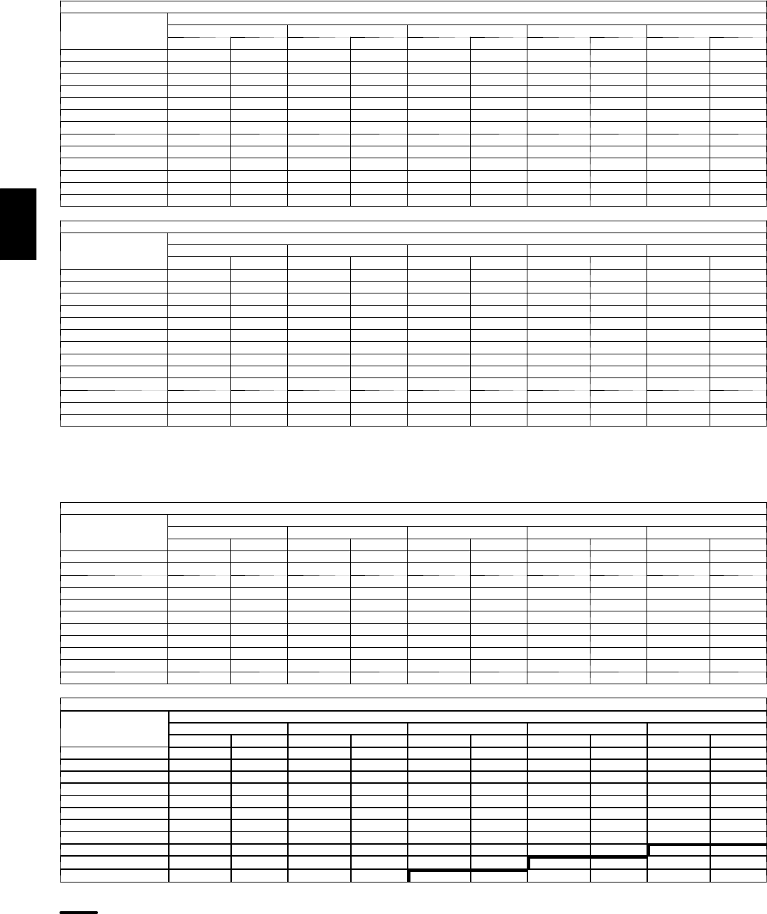
112
PERFORMANCE DATA (CONT)
Fan Performance — Vertical Supply/Return Units
48PGF07 (High Heat Units)
AIRFLOW
(Cfm)
AVAILABLEEXTERNALSTATICPRESSURE(in.wg)
0.2 0.4 0.6 0.8 1.0
Rpm Bhp Rpm Bhp Rpm Bhp Rpm Bhp Rpm Bhp
1800 719 0.48 799 0.59 872 0.70 941 0.82 1006 0.94
1900 749 0.55 826 0.67 897 0.79 964 0.91 1027 1.03
2000 780 0.63 855 0.75 923 0.88 988 1.00 1049 1.13
2100 812 0.72 884 0.85 950 0.97 1012 1.10 1072 1.24
2200 844 0.82 913 0.95 977 1.08 1038 1.22 1096 1.36
2300 876 0.92 943 1.06 1005 1.20 1064 1.34 1120 1.48
2400 908 1.04 973 1.18 1033 1.32 1091 1.47 1145 1.62
2500 941 1.16 1003 1.31 1062 1.46 1118 1.61 1171 1.76
2600 974 1.29 1034 1.45 1092 1.60 1146 1.76 1198 1.92
2700 1007 1.43 1066 1.59 1121 1.76 1174 1.92 1225 2.08
2800 1040 1.59 1097 1.75 1151 1.92 1203 2.09 1252 2.26
2900 1073 1.75 1129 1.93 1181 2.10 1232 2.27 — —
3000 1107 1.93 1161 2.11 1212 2.29 — — — —
48PGF07 (High Heat Units) (cont)
AIRFLOW
(Cfm)
AVAILABLEEXTERNALSTATICPRESSURE(in.wg)
1.2 1.4 1.6 1.8 2.0
Rpm Bhp Rpm Bhp Rpm Bhp Rpm Bhp Rpm Bhp
1800 1069 1.06 1129 1.19 1187 1.33 1243 1.46 1297 1.61
1900 1088 1.16 1146 1.29 1202 1.43 1257 1.57 1310 1.72
2000 1108 1.26 1165 1.40 1220 1.54 1273 1.69 1325 1.84
2100 1129 1.38 1184 1.52 1238 1.67 1290 1.82 1340 1.97
2200 1151 1.50 1205 1.65 1257 1.80 1308 1.95 1357 2.11
2300 1174 1.63 1227 1.78 1278 1.93 1327 2.09 1375 2.25
2400 1198 1.77 1249 1.92 1299 2.08 1347 2.25 — —
2500 1223 1.92 1273 2.08 1321 2.24 — — — —
2600 1248 2.08 1297 2.24 — — — — — —
2700 1274 2.25 — — — — — — — —
2800 — — — — — — — — — —
2900 — — — — — — — — — —
3000 — — — — — — — — — —
LEGEND
B h p --- Brake Horsepower
NOTES:
1. Motor drive range is 796 to 1128 rpm for low range motor/drive and 1150 to 1438
rpm for high range motor/drive. All other rpms require a field-supplied drive.
2. Maximum continuous bhp is 2.40 for low range motor/drive and 3.10 for high range
motor/drive.
3. See General Fan Performance Notes.
48PGD08 (Low Heat Units)
AIRFLOW
(Cfm)
AVAILABLEEXTERNALSTATICPRESSURE(in.wg)
0.2 0.4 0.6 0.8 1.0
Rpm Bhp Rpm Bhp Rpm Bhp Rpm Bhp Rpm Bhp
2250 464 0.35 541 0.46 612 0.58 677 0.70 739 0.83
2400 479 0.40 554 0.52 622 0.64 686 0.77 745 0.90
2550 496 0.46 568 0.58 633 0.71 695 0.84 753 0.98
2700 512 0.53 582 0.65 646 0.79 705 0.92 762 1.07
2850 530 0.60 597 0.73 658 0.87 716 1.01 771 1.16
3000 547 0.68 612 0.82 672 0.96 728 1.11 782 1.26
3150 565 0.77 628 0.91 686 1.06 741 1.21 793 1.37
3300 583 0.86 644 1.01 701 1.17 754 1.32 805 1.49
3450 602 0.97 661 1.12 716 1.28 768 1.44 817 1.61
3600 621 1.08 678 1.24 732 1.41 782 1.57 831 1.75
3750 640 1.20 696 1.37 748 1.54 797 1.71 844 1.89
48PGD08 (Low Heat Units) (cont)
AIRFLOW
(Cfm)
AVAILABLEEXTERNALSTATICPRESSURE(in.wg)
1.2 1.4 1.6 1.8 2.0
Rpm Bhp Rpm Bhp Rpm Bhp Rpm Bhp Rpm Bhp
2250 797 0.96 852 1.10 905 1.25 955 1.40 1003 1.55
2400 802 1.04 856 1.19 908 1.34 957 1.49 1005 1.65
2550 808 1.13 861 1.28 912 1.43 960 1.59 1007 1.75
2700 816 1.22 867 1.37 917 1.53 965 1.70 1011 1.86
2850 824 1.31 874 1.47 923 1.64 970 1.81 1015 1.98
3000 833 1.42 882 1.58 930 1.75 976 1.93 1020 2.11
3150 843 1.53 891 1.70 937 1.88 982 2.05 1026 2.24
3300 854 1.66 900 1.83 946 2.01 990 2.19 1033 2.38
3450 865 1.79 911 1.97 955 2.15 998 2.34 1040 2.53
3600 877 1.93 922 2.11 965 2.30 1007 2.49 1048 2.69
3750 889 2.08 933 2.26 976 2.46 1017 2.65 1057 2.86
LEGEND
B h p --- Brake Horsepower
High Range Motor/Drive Required
NOTES:
1. Motor drive range is 568 to 771 rpm for low range motor/drive and 812 to 1015 rpm
for high range motor/drive. All other rpms require a field-supplied drive.
2. Maximum continuous bhp is 2.40 for low range motor/drive and 3.10 for high range
motor/drive.
3. See General Fan Performance Notes.
48PG

113
Fan Performance — Vertical Supply/Return Units
48PGE08 (Medium Heat Units)
AIRFLOW
(Cfm)
AVAILABLEEXTERNALSTATICPRESSURE(in.wg)
0.2 0.4 0.6 0.8 1.0
Rpm Bhp Rpm Bhp Rpm Bhp Rpm Bhp Rpm Bhp
2250 463 0.35 541 0.46 611 0.58 677 0.70 738 0.83
2400 481 0.41 556 0.52 623 0.64 687 0.77 747 0.90
2550 499 0.47 571 0.59 637 0.72 698 0.85 756 0.99
2700 518 0.54 587 0.66 650 0.80 710 0.93 766 1.08
2850 537 0.62 603 0.75 665 0.88 722 1.03 777 1.18
3000 556 0.70 620 0.84 680 0.98 735 1.13 789 1.28
3150 575 0.79 637 0.93 695 1.08 749 1.24 801 1.40
3300 595 0.89 655 1.04 711 1.19 764 1.35 814 1.52
3450 615 1.00 673 1.16 727 1.32 778 1.48 828 1.65
3600 635 1.12 691 1.28 744 1.44 794 1.62 842 1.79
3750 655 1.24 710 1.41 761 1.58 810 1.76 856 1.94
48PGE08 (Medium Heat Units) (cont)
AIRFLOW
(Cfm)
AVAILABLEEXTERNALSTATICPRESSURE(in.wg)
1.2 1.4 1.6 1.8 2.0
Rpm Bhp Rpm Bhp Rpm Bhp Rpm Bhp Rpm Bhp
2250 797 0.96 852 1.10 904 1.25 954 1.40 1002 1.55
2400 803 1.04 857 1.19 909 1.34 958 1.49 1006 1.65
2550 811 1.13 864 1.28 914 1.44 963 1.60 1009 1.76
2700 820 1.23 871 1.38 921 1.54 968 1.71 1014 1.88
2850 829 1.33 879 1.49 928 1.66 974 1.83 1019 2.00
3000 840 1.44 888 1.61 936 1.78 981 1.95 1026 2.13
3150 851 1.56 898 1.73 944 1.90 989 2.08 1033 2.27
3300 862 1.69 909 1.86 954 2.04 998 2.23 1040 2.41
3450 875 1.82 920 2.00 964 2.19 1007 2.38 1049 2.57
3600 888 1.97 932 2.15 975 2.34 1017 2.54 1058 2.73
3750 901 2.12 944 2.31 987 2.51 1028 2.71 1068 2.91
LEGEND
B h p --- Brake Horsepower
High Range Motor/Drive Required
NOTES:
1. Motor drive range is 568 to 771 rpm for low range motor/drive and 812 to 1015 rpm
for high range motor/drive. All other rpms require a field-supplied drive.
2. Maximum continuous bhp is 2.40 for low range motor/drive and 3.10 for high range
motor/drive.
3. See General Fan Performance Notes.
48PGF08 (High Heat Units)
AIRFLOW
(Cfm)
AVAILABLEEXTERNALSTATICPRESSURE(in.wg)
0.2 0.4 0.6 0.8 1.0
Rpm Bhp Rpm Bhp Rpm Bhp Rpm Bhp Rpm Bhp
2250 468 0.36 545 0.46 615 0.58 680 0.71 741 0.83
2400 486 0.41 560 0.53 627 0.65 691 0.78 750 0.91
2550 505 0.48 576 0.60 641 0.72 702 0.86 760 1.00
2700 524 0.55 592 0.68 655 0.81 714 0.95 771 1.09
2850 544 0.63 609 0.76 670 0.90 728 1.04 782 1.19
3000 564 0.71 627 0.85 686 1.00 741 1.14 794 1.30
3150 584 0.81 645 0.95 702 1.10 756 1.26 807 1.42
3300 604 0.91 663 1.06 719 1.22 771 1.38 821 1.54
3450 625 1.02 682 1.18 736 1.34 787 1.51 835 1.68
3600 646 1.15 701 1.31 753 1.48 803 1.65 850 1.82
3750 667 1.28 720 1.45 771 1.62 819 1.80 865 1.98
48PGF08 (High Heat Units) (cont)
AIRFLOW
(Cfm)
AVAILABLEEXTERNALSTATICPRESSURE(in.wg)
1.2 1.4 1.6 1.8 2.0
Rpm Bhp Rpm Bhp Rpm Bhp Rpm Bhp Rpm Bhp
2250 799 0.97 854 1.11 907 1.26 957 1.40 1005 1.56
2400 807 1.05 860 1.20 912 1.35 961 1.50 1008 1.66
2550 815 1.14 867 1.29 918 1.45 966 1.61 1013 1.77
2700 824 1.24 875 1.40 925 1.56 972 1.72 1018 1.89
2850 834 1.35 884 1.51 932 1.67 979 1.84 1024 2.02
3000 845 1.46 894 1.63 941 1.80 986 1.97 1030 2.15
3150 857 1.58 904 1.75 950 1.93 995 2.11 1038 2.29
3300 869 1.71 916 1.89 960 2.07 1004 2.25 1046 2.44
3450 882 1.85 928 2.03 971 2.22 1014 2.41 1055 2.60
3600 896 2.00 940 2.19 983 2.38 1025 2.57 1065 2.77
3750 910 2.16 953 2.35 995 2.55 1036 2.75 1076 2.95
LEGEND
B h p --- Brake Horsepower
High Range Motor/Drive Required
NOTES:
1. Motor drive range is 568 to 771 rpm for low range motor/drive and 812 to 1015 rpm
for high range motor/drive. All other rpms require a field-supplied drive.
2. Maximum continuous bhp is 2.40 for low range motor/drive and 3.10 for high range
motor/drive.
3. See General Fan Performance Notes.
48PG
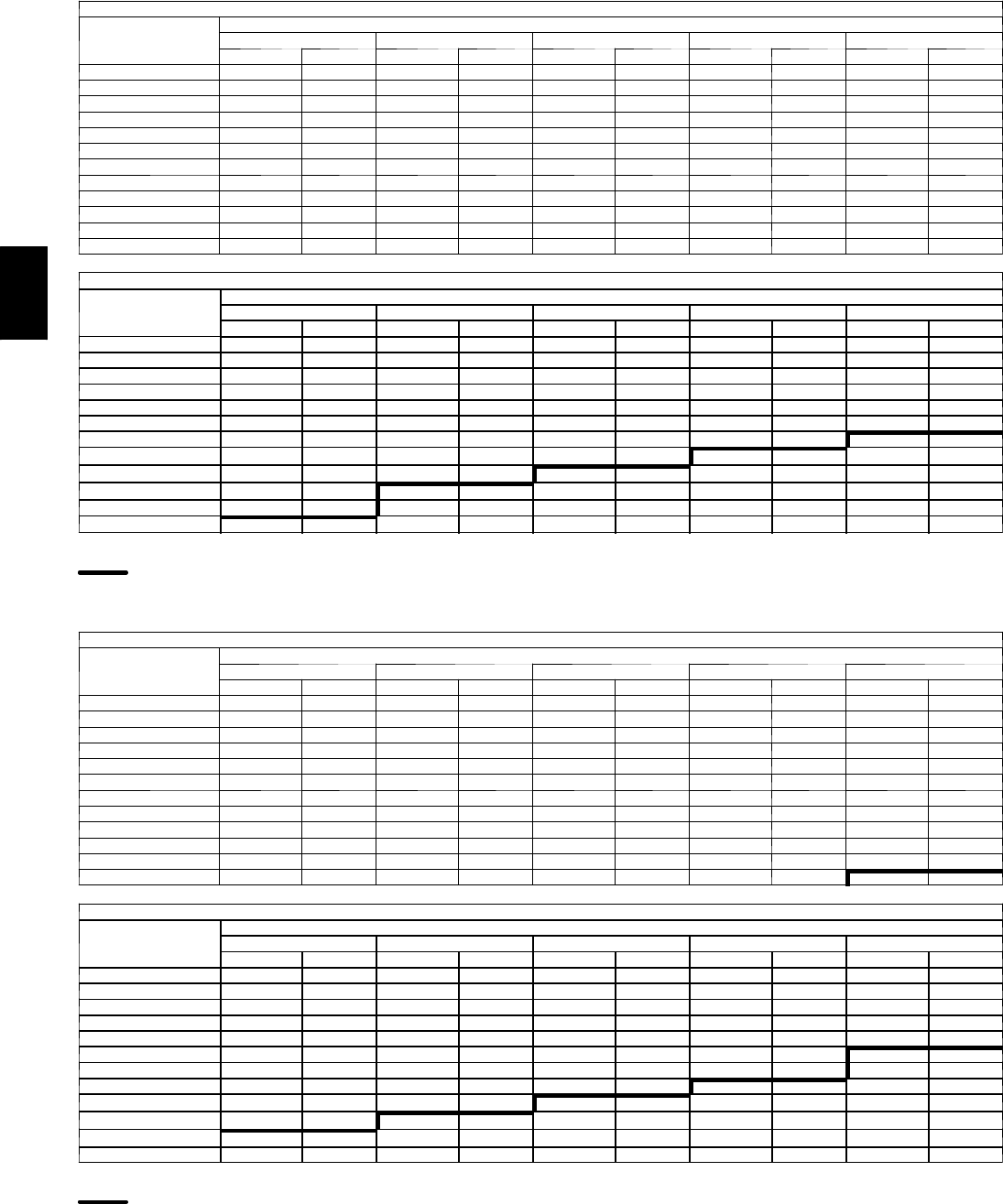
114
PERFORMANCE DATA (CONT)
Fan Performance — Vertical Supply/Return Units
48PGD09 (Low Heat Units)
AIRFLOW
(Cfm)
AVAILABLEEXTERNALSTATICPRESSURE(in.wg)
0.2 0.4 0.6 0.8 1.0
Rpm Bhp Rpm Bhp Rpm Bhp Rpm Bhp Rpm Bhp
2550 496 0.46 568 0.58 633 0.71 695 0.84 753 0.98
2700 512 0.53 582 0.65 646 0.79 705 0.92 762 1.07
2850 530 0.60 597 0.73 658 0.87 716 1.01 771 1.16
3000 547 0.68 612 0.82 672 0.96 728 1.11 782 1.26
3150 565 0.77 628 0.91 686 1.06 741 1.21 793 1.37
3300 583 0.86 644 1.01 701 1.17 754 1.32 805 1.49
3450 602 0.97 661 1.12 716 1.28 768 1.44 817 1.61
3600 621 1.08 678 1.24 732 1.41 782 1.57 831 1.75
3750 640 1.20 696 1.37 748 1.54 797 1.71 844 1.89
3900 659 1.33 713 1.50 764 1.68 812 1.86 858 2.05
4050 679 1.47 731 1.65 781 1.83 828 2.02 873 2.21
4200 698 1.62 750 1.81 798 2.00 844 2.19 888 2.38
48PGD09 (Low Heat Units) (cont)
AIRFLOW
(Cfm)
AVAILABLEEXTERNALSTATICPRESSURE(in.wg)
1.2 1.4 1.6 1.8 2.0
Rpm Bhp Rpm Bhp Rpm Bhp Rpm Bhp Rpm Bhp
2550 808 1.13 861 1.28 912 1.43 960 1.59 1007 1.75
2700 816 1.22 867 1.37 917 1.53 965 1.70 1011 1.86
2850 824 1.31 874 1.47 923 1.64 970 1.81 1015 1.98
3000 833 1.42 882 1.58 930 1.75 976 1.93 1020 2.11
3150 843 1.53 891 1.70 937 1.88 982 2.05 1026 2.24
3300 854 1.66 900 1.83 946 2.01 990 2.19 1033 2.38
3450 865 1.79 911 1.97 955 2.15 998 2.34 1040 2.53
3600 877 1.93 922 2.11 965 2.30 1007 2.49 1048 2.69
3750 889 2.08 933 2.26 976 2.46 1017 2.65 1057 2.86
3900 903 2.24 945 2.43 987 2.63 1027 2.83 1067 3.03
4050 916 2.40 958 2.60 999 2.81 1038 3.01 1077 3.22
4200 930 2.58 971 2.79 1011 3.00 1050 3.21 1088 3.42
LEGEND
B h p --- Brake Horsepower
High Range Motor/Drive Required
NOTES:
1. Motor drive range is 568 to 771 rpm for low range motor/drive and 812 to 1015 rpm
for high range motor/drive. All other rpms require a field-supplied drive.
2. Maximum continuous bhp is 2.40 for low range motor/drive and 3.70 for high range
motor/drive.
3. See General Fan Performance Notes.
48PGE09 (Medium Heat Units)
AIRFLOW
(Cfm)
AVAILABLEEXTERNALSTATICPRESSURE(in.wg)
0.2 0.4 0.6 0.8 1.0
Rpm Bhp Rpm Bhp Rpm Bhp Rpm Bhp Rpm Bhp
2550 499 0.47 571 0.59 637 0.72 698 0.85 756 0.99
2700 518 0.54 587 0.66 650 0.80 710 0.93 766 1.08
2850 537 0.62 603 0.75 665 0.88 722 1.03 777 1.18
3000 556 0.70 620 0.84 680 0.98 735 1.13 789 1.28
3150 575 0.79 637 0.93 695 1.08 749 1.24 801 1.40
3300 595 0.89 655 1.04 711 1.19 764 1.35 814 1.52
3450 615 1.00 673 1.16 727 1.32 778 1.48 828 1.65
3600 635 1.12 691 1.28 744 1.44 794 1.62 842 1.79
3750 655 1.24 710 1.41 761 1.58 810 1.76 856 1.94
3900 675 1.38 728 1.55 778 1.73 826 1.91 871 2.10
4050 695 1.52 747 1.71 796 1.89 842 2.08 886 2.27
4200 716 1.68 766 1.87 814 2.06 859 2.25 902 2.45
48PGE09 (Medium Heat Units) (cont)
AIRFLOW
(Cfm)
AVAILABLEEXTERNALSTATICPRESSURE(in.wg)
1.2 1.4 1.6 1.8 2.0
Rpm Bhp Rpm Bhp Rpm Bhp Rpm Bhp Rpm Bhp
2550 811 1.13 864 1.28 914 1.44 963 1.60 1009 1.76
2700 820 1.23 871 1.38 921 1.54 968 1.71 1014 1.88
2850 829 1.33 879 1.49 928 1.66 974 1.83 1019 2.00
3000 840 1.44 888 1.61 936 1.78 981 1.95 1026 2.13
3150 851 1.56 898 1.73 944 1.90 989 2.08 1033 2.27
3300 862 1.69 909 1.86 954 2.04 998 2.23 1040 2.41
3450 875 1.82 920 2.00 964 2.19 1007 2.38 1049 2.57
3600 888 1.97 932 2.15 975 2.34 1017 2.54 1058 2.73
3750 901 2.12 944 2.31 987 2.51 1028 2.71 1068 2.91
3900 915 2.29 957 2.48 999 2.68 1039 2.89 1078 3.09
4050 929 2.47 971 2.67 1011 2.87 1051 3.08 1089 3.29
4200 944 2.65 985 2.86 1024 3.07 1063 3.28 1100 3.50
LEGEND
B h p --- Brake Horsepower
High Range Motor/Drive Required
NOTES:
1. Motor drive range is 568 to 771 rpm for low range motor/drive and 812 to 1015 rpm
for high range motor/drive. All other rpms require a field-supplied drive.
2. Maximum continuous bhp is 2.40 for low range motor/drive and 3.70 for high range
motor/drive.
3. See General Fan Performance Notes.
48PG

115
Fan Performance — Vertical Supply/Return Units
48PGF09 (High Heat Units)
AIRFLOW
(Cfm)
AVAILABLEEXTERNALSTATICPRESSURE(in.wg)
0.2 0.4 0.6 0.8 1.0
Rpm Bhp Rpm Bhp Rpm Bhp Rpm Bhp Rpm Bhp
2550 505 0.48 576 0.60 641 0.72 702 0.86 760 1.00
2700 524 0.55 592 0.68 655 0.81 714 0.95 771 1.09
2850 544 0.63 609 0.76 670 0.90 728 1.04 782 1.19
3000 564 0.71 627 0.85 686 1.00 741 1.14 794 1.30
3150 584 0.81 645 0.95 702 1.10 756 1.26 807 1.42
3300 604 0.91 663 1.06 719 1.22 771 1.38 821 1.54
3450 625 1.02 682 1.18 736 1.34 787 1.51 835 1.68
3600 646 1.15 701 1.31 753 1.48 803 1.65 850 1.82
3750 667 1.28 720 1.45 771 1.62 819 1.80 865 1.98
3900 688 1.42 740 1.60 789 1.77 836 1.96 881 2.14
4050 709 1.57 760 1.75 808 1.94 854 2.13 898 2.32
4200 730 1.73 780 1.92 827 2.12 871 2.31 914 2.51
48PGF09 (High Heat Units) (cont)
AIRFLOW
(Cfm)
AVAILABLEEXTERNALSTATICPRESSURE(in.wg)
1.2 1.4 1.6 1.8 2.0
Rpm Bhp Rpm Bhp Rpm Bhp Rpm Bhp Rpm Bhp
2550 815 1.14 867 1.29 918 1.45 966 1.61 1013 1.77
2700 824 1.24 875 1.40 925 1.56 972 1.72 1018 1.89
2850 834 1.35 884 1.51 932 1.67 979 1.84 1024 2.02
3000 845 1.46 894 1.63 941 1.80 986 1.97 1030 2.15
3150 857 1.58 904 1.75 950 1.93 995 2.11 1038 2.29
3300 869 1.71 916 1.89 960 2.07 1004 2.25 1046 2.44
3450 882 1.85 928 2.03 971 2.22 1014 2.41 1055 2.60
3600 896 2.00 940 2.19 983 2.38 1025 2.57 1065 2.77
3750 910 2.16 953 2.35 995 2.55 1036 2.75 1076 2.95
3900 925 2.33 967 2.53 1008 2.73 1048 2.93 1087 3.14
4050 940 2.52 981 2.72 1021 2.92 1060 3.13 1099 3.35
4200 956 2.71 996 2.92 1035 3.13 1074 3.34 1111 3.56
LEGEND
B h p --- Brake Horsepower
High Range Motor/Drive Required
NOTES:
1. Motor drive range is 568 to 771 rpm for low range motor/drive and 812 to 1015 rpm
for high range motor/drive. All other rpms require a field-supplied drive.
2. Maximum continuous bhp is 2.40 for low range motor/drive and 3.70 for high range
motor/drive.
3. See General Fan Performance Notes.
48PGD12 (Low Heat Units)
AIRFLOW
(Cfm)
AVAILABLEEXTERNALSTATICPRESSURE(in.wg)
0.2 0.4 0.6 0.8 1.0
Rpm Bhp Rpm Bhp Rpm Bhp Rpm Bhp Rpm Bhp
3000 566 0.72 630 0.86 688 1.00 744 1.15 797 1.31
3200 593 0.85 653 0.99 710 1.15 763 1.30 814 1.46
3400 620 0.99 678 1.15 732 1.30 783 1.47 832 1.64
3600 647 1.15 702 1.31 754 1.48 804 1.65 851 1.83
3800 674 1.33 728 1.50 778 1.67 825 1.85 871 2.03
4000 702 1.52 753 1.70 802 1.88 848 2.07 892 2.26
4200 729 1.73 779 1.92 826 2.11 870 2.31 913 2.50
4400 757 1.96 805 2.16 850 2.36 894 2.56 935 2.77
4600 785 2.21 832 2.42 875 2.63 917 2.84 958 3.05
4800 814 2.49 858 2.70 901 2.92 941 3.14 981 3.36
5000 842 2.78 885 3.01 926 3.23 966 3.46 1004 3.69
48PGD12 (Low Heat Units) (cont)
AIRFLOW
(Cfm)
AVAILABLEEXTERNALSTATICPRESSURE(in.wg)
1.2 1.4 1.6 1.8 2.0
Rpm Bhp Rpm Bhp Rpm Bhp Rpm Bhp Rpm Bhp
3000 847 1.47 896 1.63 943 1.80 988 1.98 1032 2.16
3200 863 1.63 910 1.80 955 1.98 999 2.16 1042 2.35
3400 879 1.81 925 1.99 969 2.17 1012 2.36 1054 2.55
3600 897 2.01 941 2.19 984 2.38 1026 2.58 1066 2.78
3800 915 2.22 958 2.41 1000 2.61 1040 2.81 1080 3.02
4000 935 2.45 976 2.65 1017 2.86 1056 3.06 1095 3.28
4200 955 2.71 995 2.91 1035 3.12 1073 3.34 1110 3.55
4400 976 2.98 1015 3.19 1053 3.41 1090 3.63 --- ---
4600 997 3.27 1035 3.49 --- --- --- --- --- ---
4800 1019 3.59 --- --- --- --- --- --- --- ---
5000 --- --- --- --- --- --- --- --- --- ---
LEGEND
B h p --- Brake Horsepower
High Range Motor/Drive Required
NOTES:
1. Motor drive range is 690 to 893 for low range motor/drive and 852 to 1055 rpm for
high range motor/drive. All other rpms require a field-supplied drive.
2. Maximum continuous bhp is 3.10 for low range motor/drive and 3.70 for high range
motor/drive.
3. See General Fan Performance Notes.
48PG
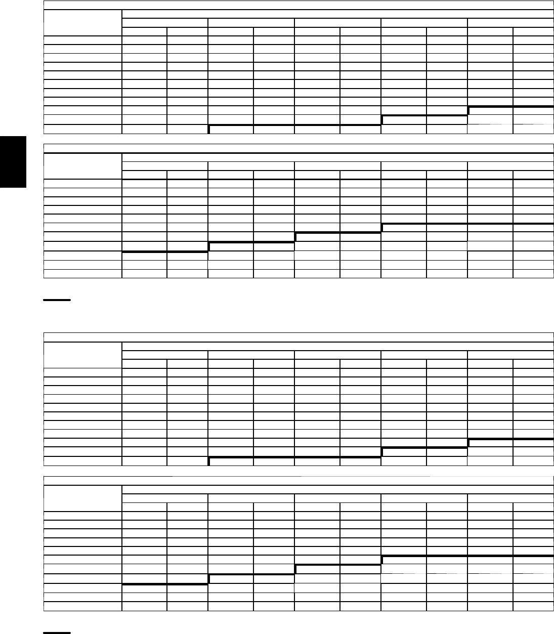
116
PERFORMANCE DATA (CONT)
Fan Performance — Vertical Supply/Return Units
48PGE12 (Medium Heat Units)
AIRFLOW
(Cfm)
AVAILABLEEXTERNALSTATICPRESSURE(in.wg)
0.2 0.4 0.6 0.8 1.0
Rpm Bhp Rpm Bhp Rpm Bhp Rpm Bhp Rpm Bhp
3000 574 0.74 636 0.87 695 1.02 750 1.17 802 1.32
3200 601 0.87 661 1.01 717 1.17 770 1.32 820 1.49
3400 629 1.02 686 1.17 740 1.33 791 1.49 840 1.66
3600 657 1.18 712 1.34 764 1.51 813 1.68 860 1.86
3800 686 1.36 739 1.53 788 1.71 836 1.89 881 2.07
4000 715 1.56 765 1.74 813 1.93 859 2.12 903 2.31
4200 744 1.78 792 1.97 839 2.17 883 2.36 925 2.56
4400 773 2.03 820 2.22 864 2.43 907 2.63 949 2.84
4600 802 2.29 848 2.50 891 2.71 932 2.92 972 3.13
4800 832 2.58 876 2.79 917 3.01 958 3.23 996 3.45
5000 862 2.88 904 3.11 944 3.34 983 3.56 --- ---
48PGE12 (Medium Heat Units) (cont)
AIRFLOW
(Cfm)
AVAILABLEEXTERNALSTATICPRESSURE(in.wg)
1.2 1.4 1.6 1.8 2.0
Rpm Bhp Rpm Bhp Rpm Bhp Rpm Bhp Rpm Bhp
3000 853 1.48 901 1.65 948 1.82 993 2.00 1037 2.18
3200 869 1.65 916 1.83 961 2.00 1005 2.19 1048 2.37
3400 887 1.84 932 2.02 976 2.20 1019 2.39 1060 2.58
3600 905 2.04 949 2.23 992 2.42 1033 2.61 1074 2.81
3800 925 2.26 967 2.46 1009 2.65 1049 2.86 1088 3.06
4000 945 2.50 987 2.70 1027 2.91 1066 3.12 1104 3.33
4200 967 2.76 1007 2.97 1046 3.18 1084 3.40 1121 3.62
4400 988 3.05 1027 3.26 1065 3.48 1102 3.70 --- ---
4600 1011 3.35 1049 3.57 --- --- --- --- --- ---
4800 1034 3.68 --- --- --- --- --- --- --- ---
5000 --- --- --- --- --- --- --- --- --- ---
LEGEND
B h p --- Brake Horsepower
High Range Motor/Drive Required
NOTES:
1. Motor drive range is 690 to 893 for low range motor/drive and 852 to 1055 rpm for
high range motor/drive. All other rpms require a field-supplied drive.
2. Maximum continuous bhp is 3.10 for low range motor/drive and 3.70 for high range
motor/drive.
3. See General Fan Performance Notes.
48PGF12 (Medium Heat Units)
AIRFLOW
(Cfm)
AVAILABLEEXTERNALSTATICPRESSURE(in.wg)
0.2 0.4 0.6 0.8 1.0
Rpm Bhp Rpm Bhp Rpm Bhp Rpm Bhp Rpm Bhp
3000 578 0.74 640 0.88 698 1.03 753 1.18 805 1.33
3200 606 0.88 665 1.03 721 1.18 774 1.34 824 1.50
3400 635 1.03 691 1.18 745 1.34 795 1.51 844 1.68
3600 663 1.20 718 1.36 769 1.53 818 1.70 865 1.88
3800 693 1.38 745 1.56 794 1.73 841 1.91 886 2.10
4000 722 1.59 772 1.77 820 1.95 865 2.14 909 2.33
4200 752 1.81 800 2.00 846 2.20 889 2.39 932 2.59
4400 781 2.06 828 2.26 872 2.46 914 2.66 955 2.87
4600 811 2.33 856 2.54 899 2.75 940 2.96 980 3.17
4800 841 2.62 884 2.84 926 3.05 966 3.28 1004 3.50
5000 871 2.94 913 3.16 953 3.39 992 3.62 --- ---
48PGF12 (Medium Heat Units) (cont)
AIRFLOW
(Cfm)
AVAILABLEEXTERNALSTATICPRESSURE(in.wg)
1.2 1.4 1.6 1.8 2.0
Rpm Bhp Rpm Bhp Rpm Bhp Rpm Bhp Rpm Bhp
3000 856 1.49 904 1.66 951 1.83 996 2.01 1040 2.19
3200 873 1.67 919 1.84 965 2.02 1008 2.20 1051 2.39
3400 891 1.85 936 2.03 980 2.22 1022 2.41 1064 2.60
3600 910 2.06 954 2.25 996 2.44 1037 2.63 1078 2.83
3800 930 2.29 972 2.48 1014 2.68 1054 2.88 1093 3.09
4000 951 2.53 992 2.73 1032 2.94 1071 3.15 1109 3.36
4200 973 2.80 1013 3.00 1051 3.22 1089 3.43 1126 3.65
4400 995 3.08 1034 3.30 1072 3.52 --- --- --- ---
4600 1018 3.39 1056 3.61 --- --- --- --- --- ---
4800 --- --- --- --- --- --- --- --- --- ---
5000 --- --- --- --- --- --- --- --- --- ---
LEGEND
B h p --- Brake Horsepower
High Range Motor/Drive Required
NOTES:
1. Motor drive range is 690 to 893 for low range motor/drive and 852 to 1055 rpm for
high range motor/drive. All other rpms require a field-supplied drive.
2. Maximum continuous bhp is 3.10 for low range motor/drive and 3.70 for high range
motor/drive.
3. See General Fan Performance Notes.
48PG
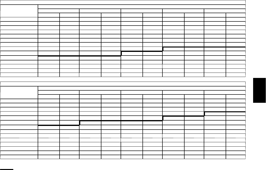
117
Fan Performance — Vertical Supply/Return Units
48PGD14 (Low Heat Units)
AIRFLOW
(Cfm)
AVAILABLEEXTERNALSTATICPRESSURE(in.wg)
0.2 0.4 0.6 0.8 1.0
Rpm Bhp Rpm Bhp Rpm Bhp Rpm Bhp Rpm Bhp
3750 667 1.28 721 1.45 772 1.62 820 1.80 866 1.98
3950 695 1.47 747 1.65 796 1.83 842 2.01 887 2.20
4150 723 1.68 772 1.86 820 2.05 865 2.25 908 2.44
4350 750 1.90 799 2.10 844 2.30 888 2.50 930 2.70
4550 778 2.15 825 2.35 869 2.56 911 2.77 952 2.98
4750 807 2.42 851 2.63 894 2.85 935 3.06 975 3.28
4950 835 2.71 878 2.93 920 3.15 960 3.38 998 3.61
5150 863 3.02 905 3.25 946 3.48 984 3.72 1022 3.95
5350 892 3.36 933 3.60 972 3.84 1009 4.08 1046 4.32
5550 920 3.72 960 3.97 998 4.22 1035 4.47 1070 4.72
5750 949 4.10 987 4.36 1024 4.62 1060 4.88 1095 5.14
5950 978 4.52 1015 4.78 1051 5.05 — — — —
6150 1006 4.96 1043 5.23 — — — — — —
6250 1021 5.19 — — — — — — — —
48PGD14 (Low Heat Units) (cont)
AIRFLOW
(Cfm)
AVAILABLEEXTERNALSTATICPRESSURE(in.wg)
1.2 1.4 1.6 1.8 2.0
Rpm Bhp Rpm Bhp Rpm Bhp Rpm Bhp Rpm Bhp
3750 911 2.17 954 2.36 996 2.55 1037 2.75 1076 2.95
3950 930 2.39 972 2.59 1012 2.79 1052 3.00 1091 3.21
4150 950 2.64 991 2.85 1030 3.05 1069 3.27 1106 3.48
4350 971 2.91 1010 3.12 1048 3.34 1086 3.55 1123 3.78
4550 992 3.20 1030 3.41 1068 3.64 1104 3.86 1140 4.09
4750 1013 3.50 1051 3.73 1087 3.96 1123 4.19 1158 4.43
4950 1036 3.84 1072 4.07 1108 4.31 1142 4.55 1176 4.79
5150 1058 4.19 1094 4.43 1129 4.68 1162 4.93 1196 5.18
5350 1082 4.57 1116 4.82 1150 5.07 — — — —
5550 1105 4.98 1139 5.23 — — — — — —
5750 — — — — — — — — — —
5950 — — — — — — — — — —
6150 — — — — — — — — — —
6250 — — — — — — — — — —
LEGEND
B h p --- Brake Horsepower
High Range Motor/Drive Required
NOTES:
1. Motor drive range is 690 to 893 for low range motor/drive and 852 to 1055 rpm for
high range motor/drive. All other rpms require a field-supplied drive.
2. Maximum continuous bhp is 3.70 for low range motor/drive and 5.25 for high range
motor/drive.
3. See General Fan Performance Notes.
GENERAL NOTES FOR FAN PERFORMANCE DATA TABLES
1. Static pressure losses from accessories and options
(Humidi-MiZer™system, economizer, etc.) must be added
to external static pressure before entering Fan Performance
table.
2. Interpolation is permissible. Do not extrapolate.
3. Fan performance is based on wet coils, clean filters, and
casing losses. See Accessory/FIOP Static Pressure informa-
tion.
4. Extensive motor and drive testing on these units ensures
that the full horsepower range of the motor can be utilized
with confidence. Using your fan motors up to the bhp rating
shown will not result in nuisance tripping or premature
motor failure. Unit warranty will not be affected.
5. Use of a field-supplied motor may affect wire size.
Recalculate the unit power supply MCA and MOCP if
required. Contact your Carrier representative for details.
6. Use the following formula to calculate input watts:
Input Watts = Bhp x (746/Motor Eff)
48PG
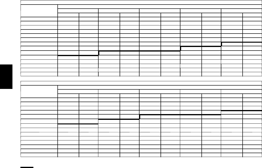
118
PERFORMANCE DATA (CONT)
Fan Performance — Vertical Supply/Return Units
48PGE14 (Medium Heat Units)
AIRFLOW
(Cfm)
AVAILABLEEXTERNALSTATICPRESSURE(in.wg)
0.2 0.4 0.6 0.8 1.0
Rpm Bhp Rpm Bhp Rpm Bhp Rpm Bhp Rpm Bhp
3750 679 1.31 732 1.49 782 1.66 830 1.84 876 2.02
3950 708 1.51 759 1.69 807 1.87 853 2.06 897 2.25
4150 737 1.73 786 1.92 832 2.11 877 2.30 920 2.50
4350 766 1.96 813 2.16 858 2.36 901 2.56 943 2.76
4550 795 2.22 841 2.43 884 2.63 926 2.84 966 3.06
4750 825 2.50 869 2.72 911 2.93 951 3.15 990 3.37
4950 854 2.80 897 3.03 938 3.25 977 3.48 1015 3.71
5150 884 3.13 925 3.36 965 3.60 1003 3.83 1040 4.07
5350 914 3.49 954 3.73 992 3.97 1029 4.21 1065 4.46
5550 944 3.86 982 4.11 1020 4.36 1056 4.62 1091 4.87
5750 974 4.27 1011 4.53 1048 4.79 1083 5.05 — —
5950 1004 4.70 1040 4.97 1076 5.24 — — — —
6150 1034 5.17 — — — — — — — —
6250 — — — — — — — — — —
48PGE14 (Medium Heat Units) (cont)
AIRFLOW
(Cfm)
AVAILABLEEXTERNALSTATICPRESSURE(in.wg)
1.2 1.4 1.6 1.8 2.0
Rpm Bhp Rpm Bhp Rpm Bhp Rpm Bhp Rpm Bhp
3750 920 2.21 963 2.40 1004 2.59 1045 2.79 1084 3.00
3950 940 2.44 982 2.64 1022 2.84 1061 3.05 1100 3.26
4150 961 2.70 1001 2.90 1041 3.11 1079 3.33 1116 3.54
4350 983 2.97 1022 3.19 1060 3.40 1097 3.62 1134 3.85
4550 1005 3.27 1043 3.49 1080 3.72 1117 3.94 1152 4.17
4750 1028 3.59 1065 3.82 1101 4.05 1137 4.29 1171 4.52
4950 1052 3.94 1088 4.17 1123 4.41 1157 4.65 1191 4.90
5150 1076 4.31 1111 4.55 1145 4.80 1179 5.05 — —
5350 1100 4.70 1134 4.95 1168 5.21 — — — —
5550 1125 5.13 — — — — — — — —
5750 — — — — — — — — — —
5950 — — — — — — — — — —
6150 — — — — — — — — — —
6250 — — — — — — — — — —
LEGEND
B h p --- Brake Horsepower
High Range Motor/Drive Required
NOTES:
1. Motor drive range is 690 to 893 for low range motor/drive and 852 to 1055 rpm for
high range motor/drive. All other rpms require a field-supplied drive.
2. Maximum continuous bhp is 3.70 for low range motor/drive and 5.25 for high range
motor/drive.
3. See General Fan Performance Notes.
48PG
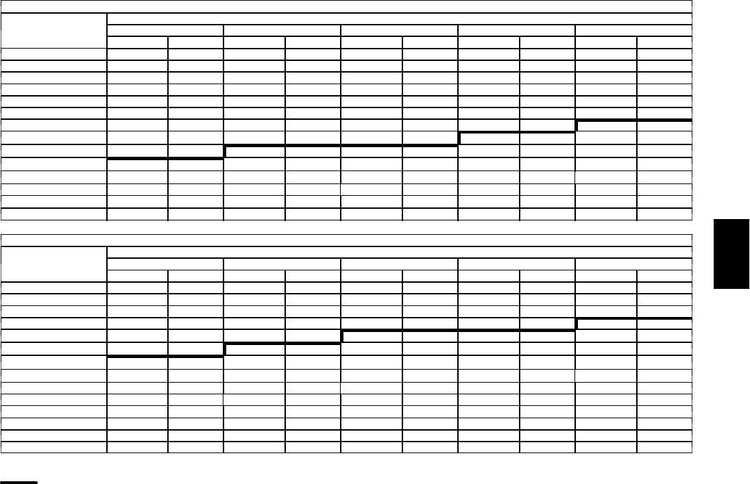
119
Fan Performance — Vertical Supply/Return Units
48PGF14 (High Heat Units)
AIRFLOW
(Cfm)
AVAILABLEEXTERNALSTATICPRESSURE(in.wg)
0.2 0.4 0.6 0.8 1.0
Rpm Bhp Rpm Bhp Rpm Bhp Rpm Bhp Rpm Bhp
3750 685 1.33 738 1.51 788 1.68 835 1.86 881 2.04
3950 715 1.54 765 1.71 813 1.90 859 2.08 903 2.27
4150 744 1.76 793 1.94 839 2.13 883 2.33 926 2.53
4350 774 2.00 821 2.19 865 2.39 908 2.59 950 2.80
4550 804 2.26 849 2.47 892 2.67 934 2.88 974 3.10
4750 834 2.54 877 2.76 919 2.98 959 3.19 998 3.42
4950 864 2.85 906 3.08 946 3.30 985 3.53 1023 3.76
5150 894 3.19 935 3.42 974 3.65 1012 3.89 1049 4.13
5350 924 3.55 964 3.79 1002 4.03 1039 4.28 1074 4.52
5550 955 3.94 993 4.19 1030 4.44 1066 4.69 1101 4.94
5750 985 4.35 1023 4.61 1058 4.87 1093 5.13 — —
5950 1016 4.79 1052 5.06 — — — — — —
6150 — — — — — — — — — —
6250 — — — — — — — — — —
48PGF14 (High Heat Units) (cont)
AIRFLOW
(Cfm)
AVAILABLEEXTERNALSTATICPRESSURE(in.wg)
1.2 1.4 1.6 1.8 2.0
Rpm Bhp Rpm Bhp Rpm Bhp Rpm Bhp Rpm Bhp
3750 925 2.23 968 2.42 1009 2.62 1050 2.82 1089 3.02
3950 946 2.47 987 2.67 1027 2.87 1067 3.08 1105 3.29
4150 967 2.73 1007 2.93 1047 3.14 1085 3.36 1122 3.58
4350 990 3.01 1029 3.22 1067 3.44 1104 3.66 1140 3.89
4550 1012 3.31 1050 3.53 1087 3.76 1123 3.99 1159 4.22
4750 1036 3.64 1073 3.87 1109 4.10 1144 4.34 1178 4.57
4950 1060 3.99 1096 4.23 1131 4.47 1165 4.71 1199 4.96
5150 1084 4.37 1119 4.61 1153 4.86 1187 5.11 — —
5350 1109 4.77 1143 5.02 — — — — — —
5550 1135 5.20 — — — — — — — —
5750 — — — — — — — — — —
5950 — — — — — — — — — —
6150 — — — — — — — — — —
6250 — — — — — — — — — —
LEGEND
B h p --- Brake Horsepower
High Range Motor/Drive Required
NOTES:
1. Motor drive range is 690 to 893 for low range motor/drive and 852 to 1055 rpm for
high range motor/drive. All other rpms require a field-supplied drive.
2. Maximum continuous bhp is 3.70 for low range motor/drive and 5.25 for high range
motor/drive.
3. See General Fan Performance Notes.
48PG
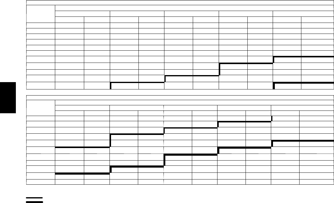
120
PERFORMANCE DATA (CONT)
Fan Performance — Vertical Supply/Return Units
48PGD16 (Low Heat Units)
AIRFLOW
(Cfm)
AVAILABLEEXTERNALSTATICPRESSURE(in.wg)
0.2 0.4 0.6 0.8 1.0
Rpm Bhp Rpm Bhp Rpm Bhp Rpm Bhp Rpm Bhp
4500 606 0.91 693 1.25 764 1.58 827 1.91 884 2.23
4800 633 1.05 718 1.41 789 1.77 851 2.12 907 2.47
5100 661 1.21 744 1.60 814 1.98 875 2.35 930 2.73
5400 689 1.39 771 1.80 839 2.20 899 2.60 954 3.00
5700 717 1.58 797 2.01 864 2.44 924 2.87 978 3.29
6000 745 1.80 824 2.25 890 2.70 949 3.15 1002 3.60
6300 774 2.04 851 2.51 916 2.98 974 3.46 1027 3.93
6600 803 2.30 878 2.78 942 3.28 1000 3.78 1052 4.27
6900 832 2.58 906 3.08 969 3.61 1025 4.13 1077 4.65
7200 861 2.89 933 3.41 996 3.95 1051 4.50 1102 5.04
7500 891 3.22 961 3.76 1023 4.32 1078 4.89 1128 5.46
48PGD16 (Low Heat Units) (cont)
Airflow
(Cfm)
AVAILABLEEXTERNALSTATICPRESSURE(in.wg)
1.2 1.4 1.6 1.8 2.0
Rpm Bhp Rpm Bhp Rpm Bhp Rpm Bhp Rpm Bhp
4500 937 2.56 987 2.88 1034 3.21 1079 3.53 1122 3.86
4800 959 2.82 1008 3.16 1054 3.51 1098 3.85 1141 4.20
5100 981 3.09 1030 3.46 1075 3.83 1119 4.20 1161 4.56
5400 1004 3.39 1052 3.78 1097 4.17 1140 4.56 1181 4.95
5700 1028 3.70 1075 4.12 1119 4.53 1161 4.94 1202 5.35
6000 1051 4.04 1098 4.47 1142 4.91 1183 5.34 1224 5.77
6300 1075 4.39 1121 4.85 1165 5.31 1206 5.76 1246 6.22
6600 1100 4.76 1145 5.25 1188 5.73 1229 6.21 1268 6.68
6900 1125 5.16 1169 5.67 1212 6.17 1252 6.67 1291 7.17
7200 1149 5.58 1194 6.11 1236 6.64 1276 7.16 — —
7500 1175 6.02 1219 6.58 1260 7.13 — — — —
LEGEND
B h p --- Brake Horsepower
Mid--- Low Range Motor/Drive Required
High---Range Motor/Drive Required
NOTES:
1. Motor drive range is 710 to 879 for low range motor/drive, 872 to 1066 rpm for mid---
low range motor/drive, and 1066 to 1260 rpm for high range motor/drive. All other
rpms require a field-supplied drive.
2. Maximum continuous bhp is 3.70 for low range motor/drive, 5.25 for mid---low range
motor/drive, and 7.50 for high range motor/drive.
3. See General Fan Performance Notes.
48PG
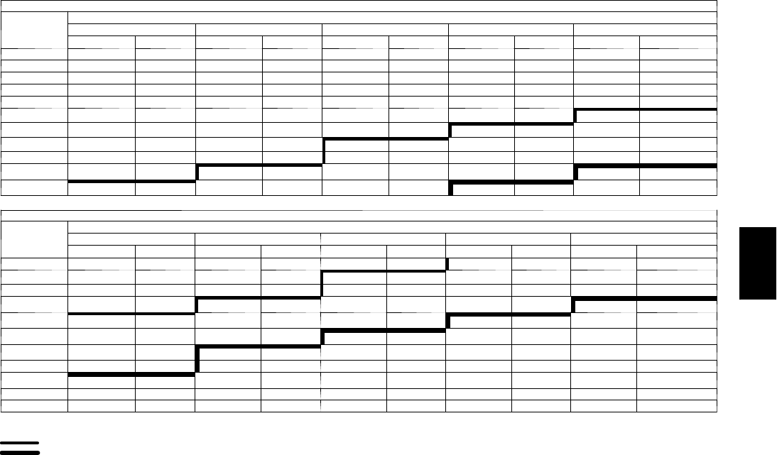
121
Fan Performance — Vertical Supply/Return Units
48PGE16 (Medium Heat Units)
AIRFLOW
(Cfm)
Available External Static Pressure (in. wg)
0.2 0.4 0.6 0.8 1.0
Rpm Bhp Rpm Bhp Rpm Bhp Rpm Bhp Rpm Bhp
4500 646 1.05 727 1.40 795 1.74 856 2.07 911 2.40
4800 678 1.23 756 1.60 822 1.96 882 2.31 937 2.67
5100 709 1.42 785 1.82 851 2.20 909 2.58 962 2.96
5400 741 1.64 815 2.06 879 2.47 936 2.87 989 3.27
5700 774 1.88 846 2.32 908 2.75 964 3.18 1016 3.60
6000 806 2.14 876 2.60 937 3.06 993 3.52 1043 3.96
6300 839 2.42 907 2.91 967 3.40 1021 3.88 1071 4.35
6600 872 2.74 938 3.25 997 3.76 1050 4.26 1100 4.76
6900 905 3.08 970 3.61 1027 4.15 1080 4.68 1128 5.20
7200 938 3.45 1002 4.01 1058 4.57 1109 5.12 1157 5.66
7500 972 3.85 1034 4.43 1089 5.01 1139 5.59 1186 6.16
48PGE16 (Medium Heat Units) (cont)
AIRFLOW
(Cfm)
Available External Static Pressure (in. wg)
1.2 1.4 1.6 1.8 2.0
Rpm Bhp Rpm Bhp Rpm Bhp Rpm Bhp Rpm Bhp
4500 963 2.72 1012 3.05 1058 3.38 1103 3.71 1145 4.05
4800 988 3.02 1036 3.37 1081 3.72 1125 4.07 1167 4.42
5100 1012 3.33 1060 3.70 1105 4.07 1147 4.45 1189 4.82
5400 1038 3.67 1085 4.06 1129 4.45 1171 4.85 1211 5.24
5700 1064 4.02 1110 4.44 1153 4.86 1195 5.27 1235 5.69
6000 1091 4.41 1136 4.85 1179 5.29 1219 5.72 1259 6.16
6300 1118 4.82 1162 5.28 1204 5.74 1245 6.20 1283 6.66
6600 1146 5.25 1189 5.74 1231 6.23 1270 6.71 — —
6900 1173 5.72 1216 6.23 1257 6.74 1296 7.24 — —
7200 1202 6.21 1244 6.74 1284 7.28 — — — —
7500 1230 6.73 1272 7.29 — — — — — —
LEGEND
B h p --- Brake Horsepower
Mid--- Low Range Motor/Drive Required
High---Range Motor/Drive Required
NOTES:
1. Motor drive range is 710 to 879 for low range motor/drive, 872 to 1066 rpm for mid---
low range motor/drive, and 1066 to 1260 rpm for high range motor/drive. All other
rpms require a field-supplied drive.
2. Maximum continuous bhp is 3.70 for low range motor/drive, 5.25 for mid---low range
motor/drive, and 7.50 for high range motor/drive.
3. See General Fan Performance Notes.
48PG
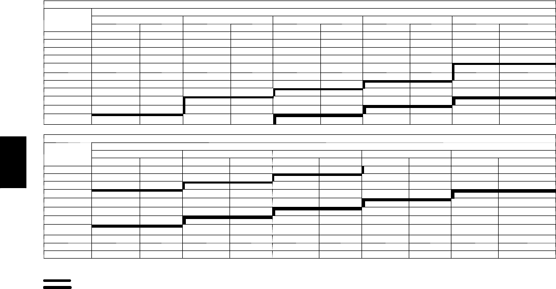
122
PERFORMANCE DATA (CONT)
Fan Performance — Vertical Supply/Return Units
48PGF16 (High Heat Units)
Airflow
(Cfm)
Available External Static Pressure (in. wg)
0.2 0.4 0.6 0.8 1.0
Rpm Bhp Rpm Bhp Rpm Bhp Rpm Bhp Rpm Bhp
4500 660 1.11 739 1.46 806 1.80 867 2.13 922 2.46
4800 693 1.29 769 1.67 835 2.03 894 2.39 948 2.74
5100 725 1.50 800 1.90 864 2.29 922 2.67 975 3.05
5400 759 1.73 831 2.15 894 2.57 950 2.97 1002 3.37
5700 792 1.98 862 2.43 924 2.87 979 3.30 1030 3.73
6000 826 2.26 894 2.73 954 3.20 1009 3.65 1059 4.11
6300 860 2.57 926 3.06 985 3.55 1038 4.04 1088 4.51
6600 894 2.90 959 3.42 1016 3.94 1069 4.44 1117 4.94
6900 929 3.26 992 3.81 1048 4.35 1099 4.88 1147 5.41
7200 963 3.66 1024 4.23 1079 4.79 1130 5.35 1177 5.90
7500 998 4.08 1058 4.68 1111 5.27 1161 5.85 1207 6.42
48PGF16 (High Heat Units) (cont)
Airflow
(Cfm)
Available External Static Pressure (in. wg)
1.2 1.4 1.6 1.8 2.0
Rpm Bhp Rpm Bhp Rpm Bhp Rpm Bhp Rpm Bhp
4500 974 2.79 1022 3.12 1069 3.46 1113 3.79 1155 4.13
4800 999 3.10 1047 3.45 1092 3.80 1135 4.16 1177 4.51
5100 1025 3.42 1072 3.80 1116 4.17 1159 4.55 1200 4.93
5400 1051 3.77 1097 4.17 1141 4.57 1183 4.97 1224 5.36
5700 1078 4.15 1124 4.57 1167 4.99 1208 5.41 1248 5.83
6000 1106 4.55 1151 5.00 1193 5.44 1234 5.88 1273 6.32
6300 1134 4.98 1178 5.45 1220 5.92 1260 6.38 1298 6.84
6600 1163 5.44 1206 5.93 1247 6.42 1286 6.91 — —
6900 1191 5.93 1234 6.44 1274 6.96 — — — —
7200 1221 6.45 1263 6.99 — — — — — —
7500 1250 7.00 — — — — — — — —
LEGEND
B h p --- Brake Horsepower
Mid--- Low Range Motor/Drive Required
High---Range Motor/Drive Required
NOTES:
1. Motor drive range is 710 to 879 for low range motor/drive, 872 to 1066 rpm for mid---
low range motor/drive, and 1066 to 1260 rpm for high range motor/drive. All other
rpms require a field-supplied drive.
2. Maximum continuous bhp is 3.70 for low range motor/drive, 5.25 for mid---low range
motor/drive, and 7.50 for high range motor/drive.
3. See General Fan Performance Notes.
48PG
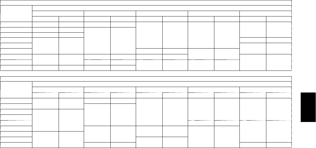
123
Fan Performance — Vertical Supply/Return Units
48PGD20 (Low Heat Units)
Airflow
(Cfm)
Available External Static Pressure (in. wg)
0.2 0.4 0.6 0.8 1.0
Rpm Bhp Rpm Bhp Rpm Bhp Rpm Bhp Rpm Bhp
5000 590 1.47 663 1.74 727 2.01
A
786 2.26
A
840 2.52
5500 633 1.82 703 2.11 764 2.40 820 2.67 872 2.94
6000 677 2.21 744 2.53 A803 2.84 857 3.13 907 3.42
6500 722 2.67 A786 3.01 842 3.33 894 3.64 942 3.95
7000 A767 3.17 828 3.53 883 3.88 933 4.21 979 4.53
7500 813 3.74 871 4.12 924 4.48 972 4.83 B1017 5.18
8000 B859 4.36 915 4.77 B966 5.15 B1012 5.52
C
1056 5.88
8500 906 5.05 B959 5.47 C1008 5.87 C1053 6.26 1096 6.64
9000 C952 5.81 C1004 6.25 1051 6.67 1095 7.07 1136 7.47
48PGD20 (Low Heat Units) (cont)
Airflow
(Cfm)
Available External Static Pressure (in. wg)
1.2 1.4 1.6 1.8 2.0
Rpm Bhp Rpm Bhp Rpm Bhp Rpm Bhp Rpm Bhp
5000 A891 2.77 940 3.02
B
987 3.27
B
1032 3.52
B
1076 3.77
5500 921 3.21
B
968 3.48 1014 3.74 1057 4.01 1099 4.27
6000
B
954 3.70 999 3.99 1042 4.27 1084 4.55 1125 4.83
6500 988 4.25 1032 4.55 1073 4.85 1114 5.14 1153 5.44
7000 1024 4.85 1066 5.17 1106 5.48 C1145 5.79
D
1183 6.10
7500 1060 5.51
C
1101 5.84 C1140 6.17
D
1178 6.50 1215 6.82
8000
C
1098 6.23 1138 6.58 1176 6.92 1213 7.26 1249 7.60
8500 1137 7.01 1175 7.38 D1212 7.74 1248 8.09 1283 8.45
9000 1176 7.86 D1214 8.24 1250 8.61 1285 8.99 1319 9.36
LEGEND
Bhp --- Brake Horsepower Input to Fan
Boldface indicates field--- supplied drive required.
NOTES:
1. Motor drive ranges:
(A) Low Range: 685 to 939 rpm, 4.26 Bhp (208/230 and 460-v), 751 to 954
rpm, 5.75 Bhp (575-v)
(B) Mid-Low Range: 949 to 1206 rpm, 5.37 Bhp (208-v), 5.75 Bhp (230 and
460-v), 5.75 Bhp (575-v)
(C) Mid-High Range: 941 to 1176 rpm, 7.66 Bhp (208-v), 8.51 Bhp (230-v),
8.63 Bhp (460 and 575-v)
(D) High Range: 1014 to 1297 rpm, 9.94 Bhp (208-v), 10.45 Bhp (230-v),
11.19 Bhp (460-v), 11.50 Bhp (575-v)
All other rpms require field --- supplied drive.
2. See General Fan Performance Notes.
48PG
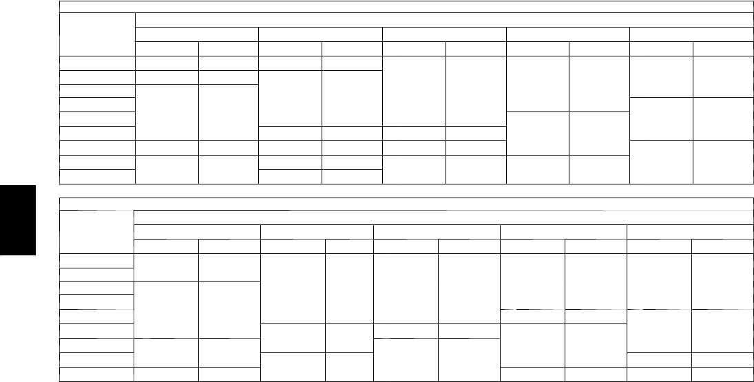
124
PERFORMANCE DATA (CONT)
Fan Performance — Vertical Supply/Return Units
48PGE20 (Medium Heat Units)
Airflow
(Cfm)
Available External Static Pressure (in. wg)
0.2 0.4 0.6 0.8 1.0
Rpm Bhp Rpm Bhp Rpm Bhp Rpm Bhp Rpm Bhp
5000 607 1.53 677 1.80
A
740 2.06
A
797 2.31
A
850 2.57
5500 652 1.90
A
719 2.19 779 2.47 833 2.74 884 3.01
6000
A
699 2.32 763 2.63 819 2.93 872 3.22 921 3.50
6500 746 2.79 807 3.12 861 3.44 911 3.75
B
958 4.05
7000 794 3.33 851 3.68 904 4.02
B
952 4.34 998 4.66
7500 842 3.93 897 4.30 947 4.65 994 5.00 1038 5.33
8000 891 4.59 943 4.98 B991 5.35 1036 5.71
C
1079 6.07
8500 C940 5.32 B990 5.72 C1036 6.11 C1080 6.49 1121 6.87
9000 990 6.12 C1037 6.54 1082 6.95 1124 7.35 1163 7.73
48PGE20 (Medium Heat Units) (cont)
Airflow
(Cfm)
Available External Static Pressure (in. wg)
1.2 1.4 1.6 1.8 2.0
Rpm Bhp Rpm Bhp Rpm Bhp Rpm Bhp Rpm Bhp
5000 A900 2.82
B
949 3.06
B
995 3.31
B
1040 3.56
B
1083 3.81
5500 933 3.27 979 3.54 1023 3.80 1066 4.06 1108 4.33
6000
B
967 3.79 1011 4.07 1054 4.35 1095 4.62 1135 4.90
6500 1003 4.35 1046 4.65 1087 4.94 1127 5.24 1165 5.53
7000 1041 4.98 1082 5.29 1122 5.60 C1160 5.91
D
1197 6.22
7500 1079 5.67 C1119 5.99 C1158 6.32
D
1195 6.64 1231 6.96
8000 C1119 6.42 1158 6.76
D
1195 7.10 1231 7.44 1267 7.78
8500 1160 7.23 D1198 7.59 1234 7.95 1269 8.30 1303 8.65
9000 D1202 8.12 1238 8.49 1273 8.87 1308 9.23 1341 9.60
LEGEND
Bhp --- Brake Horsepower Input to Fan
Boldface indicates field--- supplied drive required.
NOTES:
1. Motor drive ranges:
(A) Low Range: 685 to 939 rpm, 4.26 Bhp (208/230 and 460-v), 751 to 954
rpm, 5.75 Bhp (575-v)
(B) Mid-Low Range: 949 to 1206 rpm, 5.37 Bhp (208-v), 5.75 Bhp (230 and
460-v), 5.75 Bhp (575-v)
(C) Mid-High Range: 941 to 1176 rpm, 7.66 Bhp (208-v), 8.51 Bhp (230-v),
8.63 Bhp (460 and 575-v)
(D) High Range: 1014 to 1297 rpm, 9.94 Bhp (208-v), 10.45 Bhp (230-v),
11.19 Bhp (460-v), 11.50 Bhp (575-v)
All other rpms require field --- supplied drive.
2. See General Fan Performance Notes.
48PG
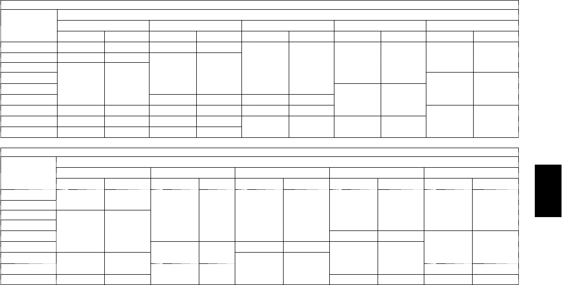
125
Fan Performance — Vertical Supply/Return Units
48PGF20 (High Heat Units)
Airflow
(Cfm)
Available External Static Pressure (in. wg)
0.2 0.4 0.6 0.8 1.0
Rpm Bhp Rpm Bhp Rpm Bhp Rpm Bhp Rpm Bhp
5000 607 1.53 677 1.80
A
740 2.06
A
797 2.31
A
850 2.57
5500 652 1.90
A
719 2.19 779 2.47 833 2.74 884 3.01
6000
A
699 2.32 763 2.63 819 2.93 872 3.22 921 3.50
6500 746 2.79 807 3.12 861 3.44 911 3.75
B
958 4.05
7000 794 3.33 851 3.68 904 4.02
B
952 4.34 998 4.66
7500 842 3.93 897 4.30 947 4.65 994 5.00 1038 5.33
8000 891 4.59 943 4.98 B991 5.35 1036 5.71
C
1079 6.07
8500 940 5.32 B990 5.72 C1036 6.11 C1080 6.49 1121 6.87
9000 C990 6.12 C1037 6.54 1082 6.95 1124 7.35 1163 7.73
48PGF20 (High Heat Units) (cont)
Airflow
(Cfm)
Available External Static Pressure (in. wg)
1.2 1.4 1.6 1.8 2.0
Rpm Bhp Rpm Bhp Rpm Bhp Rpm Bhp Rpm Bhp
5000 A900 2.82
B
949 3.06
B
995 3.31
B
1040 3.56
B
1083 3.81
5500 933 3.27 979 3.54 1023 3.80 1066 4.06 1108 4.33
6000
B
967 3.79 1011 4.07 1054 4.35 1095 4.62 1135 4.90
6500 1003 4.35 1046 4.65 1087 4.94 1127 5.24 1165 5.53
7000 1041 4.98 1082 5.29 1122 5.60 C1160 5.91
D
1197 6.22
7500 1079 5.67 C1119 5.99 C1158 6.32
D
1195 6.64 1231 6.96
8000 C1119 6.42 1158 6.76
D
1195 7.10 1231 7.44 1267 7.78
8500 1160 7.23 D1198 7.59 1234 7.95 1269 8.30 1303 8.65
9000 D1202 8.12 1238 8.49 1273 8.87 1308 9.23 1341 9.60
LEGEND
Bhp --- Brake Horsepower Input to Fan
Boldface indicates field--- supplied drive required.
NOTES:
1. Motor drive ranges:
(A) Low Range: 685 to 939 rpm, 4.26 Bhp (208/230 and 460-v), 751 to 954
rpm, 5.75 Bhp (575-v)
(B) Mid-Low Range: 949 to 1206 rpm, 5.37 Bhp (208-v), 5.75 Bhp (230 and
460-v), 5.75 Bhp (575-v)
(C) Mid-High Range: 941 to 1176 rpm, 7.66 Bhp (208-v), 8.51 Bhp (230-v),
8.63 Bhp (460 and 575-v)
(D) High Range: 1014 to 1297 rpm, 9.94 Bhp (208-v), 10.45 Bhp (230-v),
11.19 Bhp (460-v), 11.50 Bhp (575-v)
All other rpms require field --- supplied drive.
2. See General Fan Performance Notes.
48PG

126
PERFORMANCE DATA (CONT)
Fan Performance — Vertical Supply/Return Units
48PGD24 (Low Heat Units)
Airflow
(Cfm)
Available External Static Pressure (in. wg)
0.2 0.4 0.6 0.8 1.0
Rpm Bhp Rpm Bhp Rpm Bhp Rpm Bhp Rpm Bhp
5500 633 1.82
A
703 2.11
A
764 2.40
A
820 2.67 A872 2.94
6000 677 2.21 744 2.53 803 2.84 857 3.13 907 3.42
6500
A
722 2.67 786 3.01 842 3.33 894 3.64 942 3.95
7000 767 3.17 828 3.53 883 3.88 933 4.21 B979 4.53
7500 813 3.74 871 4.12 924 4.48 B972 4.83 1017 5.18
8000 859 4.36 915 4.77 B966 5.15 1012 5.52
C
1056 5.88
8500 906 5.05 B959 5.47
C
1008 5.87
C
1053 6.26 1096 6.64
9000
C
952 5.81
C
1004 6.25 1051 6.67 1095 7.07 1136 7.47
9500 999 6.63 1049 7.09 1094 7.53 1137 7.95 D1177 8.36
10000 1047 7.53 1094 8.00 1138 8.46 D1180 8.90 1219 9.33
48PGD24 (Low Heat Units) (cont)
Airflow
(Cfm)
Available External Static Pressure (in. wg)
1.2 1.4 1.6 1.8 2.0
Rpm Bhp Rpm Bhp Rpm Bhp Rpm Bhp Rpm Bhp
5500 A921 3.21
B
968 3.48
B
1014 3.74
B
1057 4.01
B
1099 4.27
6000
B
954 3.70 999 3.99 1042 4.27 1084 4.55 1125 4.83
6500 988 4.25 1032 4.55 1073 4.85 1114 5.14 1153 5.44
7000 1024 4.85 1066 5.17 1106 5.48 C1145 5.79
D
1183 6.10
7500 1060 5.51
C
1101 5.84 C1140 6.17
D
1178 6.50 1215 6.82
8000
C
1098 6.23 1138 6.58 1176 6.92 1213 7.26 1249 7.60
8500 1137 7.01 1175 7.38
D
1212 7.74 1248 8.09 1283 8.45
9000 1176 7.86
D
1214 8.24 1250 8.61 1285 8.99 1319 9.36
9500 D1216 8.77 1253 9.17 1288 9.56 1322 9.95 1355 10.33
10000 1256 9.75 1292 10.16 1328 10.57 1360 10.98 1393 11.38
LEGEND
Bhp --- Brake Horsepower Input to Fan
Boldface indicates field--- supplied drive required.
NOTES:
1. Motor drive ranges:
(A) Low Range: 685 to 939 rpm, 4.26 Bhp (208/230 and 460-v), 751 to 954
rpm, 5.75 Bhp (575-v)
(B) Mid-Low Range: 949 to 1206 rpm, 5.37 Bhp (208-v), 5.75 Bhp (230 and
460-v), 5.75 Bhp (575-v)
(C) Mid-High Range: 941 to 1176 rpm, 7.66 Bhp (208-v), 8.51 Bhp (230-v),
8.63 Bhp (460 and 575-v)
(D) High Range: 1014 to 1297 rpm, 9.94 Bhp (208-v), 10.45 Bhp (230-v),
11.19 Bhp (460-v), 11.50 Bhp (575-v)
All other rpms require field --- supplied drive.
2. See General Fan Performance Notes.
48PG
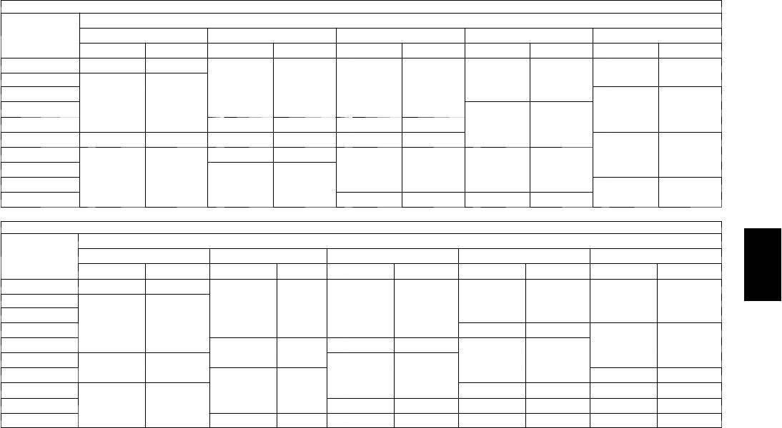
127
Fan Performance — Vertical Supply/Return Units
48PGE24 (Medium Heat Units)
Airflow
(Cfm)
Available External Static Pressure (in. wg)
0.2 0.4 0.6 0.8 1.0
Rpm Bhp Rpm Bhp Rpm Bhp Rpm Bhp Rpm Bhp
5500 652 1.90
A
719 2.19
A
779 2.47
A
833 2.74 A884 3.01
6000
A
699 2.32 763 2.63 819 2.93 872 3.22 921 3.50
6500 746 2.79 807 3.12 861 3.44 911 3.75
B
958 4.05
7000 794 3.33 851 3.68 904 4.02
B
952 4.34 998 4.66
7500 842 3.93 897 4.30 947 4.65 994 5.00 1038 5.33
8000 891 4.59 943 4.98 B991 5.35 1036 5.71
C
1079 6.07
8500
C
940 5.32 B990 5.72
C
1036 6.11
C
1080 6.49 1121 6.87
9000 990 6.12
C
1037 6.54 1082 6.95 1124 7.35 1163 7.73
9500 1039 7.00 1085 7.43 1128 7.85 1168 8.27 D1207 8.67
10000 1089 7.95 1133 8.40 D1174 8.83 D1213 9.26 1251 9.69
48PGE24 (Medium Heat Units) (cont)
Airflow
(Cfm)
Available External Static Pressure (in. wg)
1.2 1.4 1.6 1.8 2.0
Rpm Bhp Rpm Bhp Rpm Bhp Rpm Bhp Rpm Bhp
5500 A933 3.27
B
979 3.54
B
1023 3.80
B
1066 4.06
B
1108 4.33
6000
B
967 3.79 1011 4.07 1054 4.35 1095 4.62 1135 4.90
6500 1003 4.35 1046 4.65 1087 4.94 1127 5.24 1165 5.53
7000 1041 4.98 1082 5.29 1122 5.60 C1160 5.91
D
1197 6.22
7500 1079 5.67 C1119 5.99 C1158 6.32
D
1195 6.64 1231 6.96
8000 C1119 6.42 1158 6.76
D
1195 7.10 1231 7.44 1267 7.78
8500 1160 7.23
D
1198 7.59 1234 7.95 1269 8.30 1303 8.65
9000
D
1202 8.12 1238 8.49 1273 8.87 1308 9.23 1341 9.60
9500 1244 9.07 1279 9.46 1314 9.85 1347 10.24 1379 10.62
10000 1287 10.10 1321 10.51 1355 10.91 1387 11.31 --- ---
LEGEND
Bhp --- Brake Horsepower Input to Fan
Boldface indicates field--- supplied drive required.
NOTES:
1. Motor drive ranges:
(A) Low Range: 685 to 939 rpm, 4.26 Bhp (208/230 and 460-v), 751 to 954
rpm, 5.75 Bhp (575-v)
(B) Mid-Low Range: 949 to 1206 rpm, 5.37 Bhp (208-v), 5.75 Bhp (230 and
460-v), 5.75 Bhp (575-v)
(C) Mid-High Range: 941 to 1176 rpm, 7.66 Bhp (208-v), 8.51 Bhp (230-v),
8.63 Bhp (460 and 575-v)
(D) High Range: 1014 to 1297 rpm, 9.94 Bhp (208-v), 10.45 Bhp (230-v),
11.19 Bhp (460-v), 11.50 Bhp (575-v)
All other rpms require field --- supplied drive.
2. See General Fan Performance Notes.
48PG
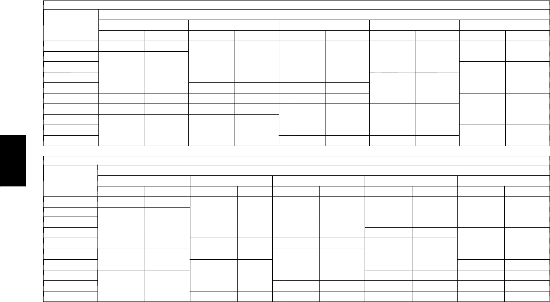
128
PERFORMANCE DATA (CONT)
Fan Performance — Vertical Supply/Return Units
48PGF24 (High Heat Units)
Airflow
(Cfm)
Available External Static Pressure (in. wg)
0.2 0.4 0.6 0.8 1.0
Rpm Bhp Rpm Bhp Rpm Bhp Rpm Bhp Rpm Bhp
5500 652 1.90
A
719 2.19
A
779 2.47
A
833 2.74 A884 3.01
6000
A
699 2.32 763 2.63 819 2.93 872 3.22 921 3.50
6500 746 2.79 807 3.12 861 3.44 911 3.75
B
958 4.05
7000 794 3.33 851 3.68 904 4.02
B
952 4.34 998 4.66
7500 842 3.93 897 4.30 947 4.65 994 5.00 1038 5.33
8000 891 4.59 943 4.98 B991 5.35 1036 5.71
C
1079 6.07
8500 940 5.32 B990 5.72
C
1036 6.11
C
1080 6.49 1121 6.87
9000
C
990 6.12
C
1037 6.54 1082 6.95 1124 7.35 1163 7.73
9500 1039 7.00 1085 7.43 1128 7.85 1168 8.27 D1207 8.67
10000 1089 7.95 1133 8.40 D1174 8.83 D1213 9.26 1251 9.69
48PGF24 (High Heat Units) (cont)
Airflow
(Cfm)
Available External Static Pressure (in. wg)
1.2 1.4 1.6 1.8 2.0
Rpm Bhp Rpm Bhp Rpm Bhp Rpm Bhp Rpm Bhp
5500 A933 3.27
B
979 3.54
B
1023 3.80
B
1066 4.06
B
1108 4.33
6000
B
967 3.79 1011 4.07 1054 4.35 1095 4.62 1135 4.90
6500 1003 4.35 1046 4.65 1087 4.94 1127 5.24 1165 5.53
7000 1041 4.98 1082 5.29 1122 5.60 C1160 5.91
D
1197 6.22
7500 1079 5.67 C1119 5.99 C1158 6.32
D
1195 6.64 1231 6.96
8000 C1119 6.42 1158 6.76
D
1195 7.10 1231 7.44 1267 7.78
8500 1160 7.23
D
1198 7.59 1234 7.95 1269 8.30 1303 8.65
9000
D
1202 8.12 1238 8.49 1273 8.87 1308 9.23 1341 9.60
9500 1244 9.07 1279 9.46 1314 9.85 1347 10.24 1379 10.62
10000 1287 10.10 1321 10.51 1355 10.91 1387 11.31 --- ---
LEGEND
Bhp --- Brake Horsepower Input to Fan
Boldface indicates field--- supplied drive required.
NOTES:
1. Motor drive ranges:
(A) Low Range: 685 to 939 rpm, 4.26 Bhp (208/230 and 460-v), 751 to 954
rpm, 5.75 Bhp (575-v)
(B) Mid-Low Range: 949 to 1206 rpm, 5.37 Bhp (208-v), 5.75 Bhp (230 and
460-v), 5.75 Bhp (575-v)
(C) Mid-High Range: 941 to 1176 rpm, 7.66 Bhp (208-v), 8.51 Bhp (230-v),
8.63 Bhp (460 and 575-v)
(D) High Range: 1014 to 1297 rpm, 9.94 Bhp (208-v), 10.45 Bhp (230-v),
11.19 Bhp (460-v), 11.50 Bhp (575-v)
All other rpms require field --- supplied drive.
2. See General Fan Performance Notes.
48PG
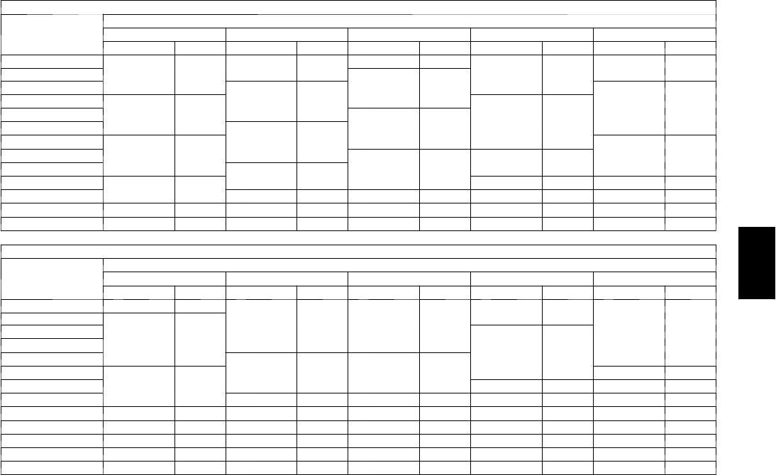
129
Fan Performance — Vertical Supply/Return Units
48PGD28 (Low Heat Units)
Airflow
(Cfm)
Available External Static Pressure (in. wg)
0.2 0.4 0.6 0.8 1.0
Rpm Bhp Rpm Bhp Rpm Bhp Rpm Bhp Rpm Bhp
6500
A
750 2.28 806 2.62 A854 2.93
B
898 3.25 B943 3.59
7000 797 2.78 A853 3.17
B
899 3.50 941 3.84 982 4.18
7500 845 3.34
B
900 3.78 945 4.15 985 4.51
C
1024 4.87
8000 892 3.97 948 4.48 991 4.88
C
1030 5.26 1067 5.64
8500 B939 4.68 995 5.25 1038 5.69 1076 6.10 1112 6.50
9000 986 5.46
C
1042 6.19 C1085 6.59 1122 7.04 1157 7.46
9500
C
1033 6.32 1090 7.04 1132 7.59 1169 8.07
D
1203 8.52
10000 2079 7.26 1137 8.07
D
1180 8.67 D1216 9.19 1249 9.68
10500 1126 8.28 D1184 9.20 1227 9.86 1263 10.43 1296 10.95
11000 D1172 9.40 1232 10.42 1274 11.15 — — — —
11500 1219 10.61 — — — — — — — —
12000 — — — — — — — — — —
12500 — — — — — — — — — —
48PGD28 (Low Heat Units) (cont)
Airflow
(Cfm)
Available External Static Pressure (in. wg)
1.2 1.4 1.6 1.8 2.0
Rpm Bhp Rpm Bhp Rpm Bhp Rpm Bhp Rpm Bhp
6500 A988 3.97
C
1035 4.40
C
1082 4.87 C1130 5.39
D
1177 5.95
7000
C
1024 4.56 1066 4.98 1109 5.43 1153 5.94 1197 6.48
7500 1063 5.25 1101 5.66 1141 6.10
D
1181 6.59 1222 7.12
8000 1104 6.03 1140 6.44 1176 6.88 1213 7.36 1251 7.87
8500 1146 6.91
D
1180 7.33 1214 7.77 1249 8.24 1283 8.74
9000
D
1190 7.89 1222 8.32 D1255 8.77 1287 9.24 1319 9.74
9500 1235 8.97 1266 9.42 1296 9.88 1327 10.36 1357 10.86
10000 1280 10.16 1310 10.63 1340 11.10 — — — —
10500 1326 11.45 — — — — — — — —
11000 — — — — — — — — — —
11500 — — — — — — — — — —
12000 — — — — — — — — — —
12500 — — — — — — — — — —
LEGEND
Bhp --- Brake Horsepower Input to Fan
Boldface indicates field--- supplied drive required.
NOTES:
1. Motor drive ranges:
(A) Low Range: 687 to 873 rpm, 5.37 Bhp (208--- v), 5.75 Bhp (230 and 460-v),
5.75 Bhp (575-v)
(B) Mid-Low Range: 805 to 1007 rpm, 5.37 Bhp (208-v), 5.75 Bhp (230 and
460-v), 5.75 Bhp (575-v)
(C) Mid-High Range: 941 to 1176 rpm, 7.66 Bhp (208-v), 8.51 Bhp (230-v),
8.63 Bhp (460 and 575-v)
(D) High Range: 1014 to 1297 rpm, 9.94 Bhp (208-v), 10.45 Bhp (230-v),
11.19 Bhp (460-v), 11.50 Bhp (575-v)
All other rpms require field --- supplied drive.
2. See General Fan Performance Notes.
48PG

130
PERFORMANCE DATA (CONT)
Fan Performance — Vertical Supply/Return Units
48PGE28 (Medium Heat Units)
Airflow
(Cfm)
Available External Static Pressure (in. wg)
0.2 0.4 0.6 0.8 1.0
Rpm Bhp Rpm Bhp Rpm Bhp Rpm Bhp Rpm Bhp
6500 A775 2.43 A825 2.75 A871 3.05
B
915 3.37 B959 3.72
7000 826 2.98
B
875 3.22 B918 3.58 959 3.98 1000 4.34
7500
B
878 3.60 925 3.89 966 4.28 1005 4.69
C
1043 5.05
8000 929 4.31 975 4.73
C
1015 5.11
C
1052 5.48 1088 5.86
8500 981 5.11
C
1026 5.56 1064 5.97 1100 6.37 1134 6.76
9000
C
1033 6.00 1076 6.49 1114 6.94 1148 7.36
D
1181 7.77
9500 1085 6.98 1128 7.53 1164 8.00
D
1198 8.45 1229 8.89
10000 1137 8.08
D
1179 8.66 D1214 9.18 1247 9.65 1278 10.12
10500 D1190 9.28 1230 9.91 1265 10.46 1297 10.97 1327 11.47
11000 1242 10.60 1282 11.28 — — — — — —
11500 — — — — — — — — — —
12000 — — — — — — — — — —
12500 — — — — — — — — — —
48PGE28 (Medium Heat Units) (cont)
Airflow
(Cfm)
Available External Static Pressure (in. wg)
1.2 1.4 1.6 1.8 2.0
Rpm Bhp Rpm Bhp Rpm Bhp Rpm Bhp Rpm Bhp
6500 B1004 4.11
C
1050 4.55
C
1098 5.04 C1145 5.57
D
1192 6.14
7000
C
1041 4.73 1083 5.15 1126 5.62 1170 6.14 1214 6.70
7500 1081 5.44 1120 5.86 1159 6.32
D
1199 6.82 1240 7.36
8000 1124 6.26 1160 6.68
D
1196 7.13 1233 7.62 1270 8.15
8500 1168 7.17
D
1202 7.60 1235 8.06 1269 8.54 1304 9.05
9000 D1214 8.20 1245 8.64 1277 9.10 1309 9.58 1341 10.09
9500 1260 9.33 1290 9.79 1320 10.25 1351 10.74 1381 11.25
10000 1308 10.58 1337 11.05 — — — — — —
10500 — — — — — — — — — —
11000 — — — — — — — — — —
11500 — — — — — — — — — —
12000 — — — — — — — — — —
12500 — — — — — — — — — —
LEGEND
Bhp --- Brake Horsepower Input to Fan
Boldface indicates field--- supplied drive required.
NOTES:
1. Motor drive ranges:
(A) Low Range: 687 to 873 rpm, 5.37 Bhp (208--- v), 5.75 Bhp (230 and 460-v),
5.75 Bhp (575-v)
(B) Mid-Low Range: 805 to 1007 rpm, 5.37 Bhp (208-v), 5.75 Bhp (230 and
460-v), 5.75 Bhp (575-v)
(C) Mid-High Range: 941 to 1176 rpm, 7.66 Bhp (208-v), 8.51 Bhp (230-v),
8.63 Bhp (460 and 575-v)
(D) High Range: 1014 to 1297 rpm, 9.94 Bhp (208-v), 10.45 Bhp (230-v),
11.19 Bhp (460-v), 11.50 Bhp (575-v)
All other rpms require field --- supplied drive.
2. See General Fan Performance Notes.
48PG

131
Fan Performance — Vertical Supply/Return Units
48PGF28 (High Heat Units)
Airflow
(Cfm)
Available External Static Pressure (in. wg)
0.2 0.4 0.6 0.8 1.0
Rpm Bhp Rpm Bhp Rpm Bhp Rpm Bhp Rpm Bhp
6500 A775 2.43 A825 2.75 A871 3.05
B
915 3.37 B959 3.72
7000 826 2.98
B
875 3.22 B918 3.58 959 3.98 1000 4.34
7500
B
878 3.60 925 3.89 966 4.28 1005 4.69
C
1043 5.05
8000 929 4.31 975 4.73
C
1015 5.11
C
1052 5.48 1088 5.86
8500 981 5.11
C
1026 5.56 1064 5.97 1100 6.37 1134 6.76
9000
C
1033 6.00 1076 6.49 1114 6.94 1148 7.36
D
1181 7.77
9500 1085 6.98 1128 7.53 1164 8.00
D
1198 8.45 1229 8.89
10000 1137 8.08
D
1179 8.66 D1214 9.18 1247 9.65 1278 10.12
10500 D1190 9.28 1230 9.91 1265 10.46 1297 10.97 1327 11.47
11000 1242 10.60 1282 11.28 — — — — — —
11500 — — — — — — — — — —
12000 — — — — — — — — — —
12500 — — — — — — — — — —
48PGF28 (High Heat Units) (cont)
Airflow
(Cfm)
Available External Static Pressure (in. wg)
1.2 1.4 1.6 1.8 2.0
Rpm Bhp Rpm Bhp Rpm Bhp Rpm Bhp Rpm Bhp
6500 B1004 4.11
C
1050 4.55
C
1098 5.04 C1145 5.57
D
1192 6.14
7000
C
1041 4.73 1083 5.15 1126 5.62 1170 6.14 1214 6.70
7500 1081 5.44 1120 5.86 1159 6.32
D
1199 6.82 1240 7.36
8000 1124 6.26 1160 6.68
D
1196 7.13 1233 7.62 1270 8.15
8500 1168 7.17
D
1202 7.60 1235 8.06 1269 8.54 1304 9.05
9000 D1214 8.20 1245 8.64 1277 9.10 1309 9.58 1341 10.09
9500 1260 9.33 1290 9.79 1320 10.25 1351 10.74 1381 11.25
10000 1308 10.58 1337 11.05 — — — — — —
10500 — — — — — — — — — —
11000 — — — — — — — — — —
11500 — — — — — — — — — —
12000 — — — — — — — — — —
12500 — — — — — — — — — —
LEGEND
Bhp --- Brake Horsepower Input to Fan
Boldface indicates field--- supplied drive required.
NOTES:
1. Motor drive ranges:
(A) Low Range: 687 to 873 rpm, 5.37 Bhp (208--- v), 5.75 Bhp (230 and 460-v),
5.75 Bhp (575-v)
(B) Mid-Low Range: 805 to 1007 rpm, 5.37 Bhp (208-v), 5.75 Bhp (230 and
460-v), 5.75 Bhp (575-v)
(C) Mid-High Range: 941 to 1176 rpm, 7.66 Bhp (208-v), 8.51 Bhp (230-v),
8.63 Bhp (460 and 575-v)
(D) High Range: 1014 to 1297 rpm, 9.94 Bhp (208-v), 10.45 Bhp (230-v),
11.19 Bhp (460-v), 11.50 Bhp (575-v)
All other rpms require field --- supplied drive.
2. See General Fan Performance Notes.
48PG

132
PERFORMANCE DATA (CONT)
Fan Performance — Horizontal Supply/Return Units
48PGD03 (Low Heat Units)
AIRFLOW
(Cfm)
AVAILABLEEXTERNALSTATICPRESSURE(in.wg)
0.2 0.4 0.6 0.8 1.0
Rpm Bhp Rpm Bhp Rpm Bhp Rpm Bhp Rpm Bhp
600 387 0.05 529 0.09 641 0.14 736 0.20 821 0.25
650 391 0.05 532 0.10 643 0.15 738 0.21 822 0.27
700 397 0.06 535 0.11 646 0.16 741 0.22 824 0.28
750 402 0.06 539 0.12 649 0.17 743 0.23 826 0.30
800 408 0.07 543 0.12 652 0.18 745 0.25 829 0.31
850 415 0.08 547 0.13 655 0.20 748 0.26 831 0.33
900 422 0.08 552 0.14 659 0.21 751 0.28 834 0.35
950 430 0.09 557 0.15 662 0.22 754 0.29 837 0.37
1000 437 0.10 562 0.16 666 0.23 758 0.31 839 0.38
48PGD03 (Low Heat Units) (cont)
AIRFLOW
(Cfm)
AVAILABLEEXTERNALSTATICPRESSURE(in.wg)
1.2 1.4 1.6 1.8 2.0
Rpm Bhp Rpm Bhp Rpm Bhp Rpm Bhp Rpm Bhp
600 897 0.31 967 0.38 1032 0.45 1094 0.51 1152 0.59
650 899 0.33 969 0.40 1034 0.47 1096 0.54 1154 0.61
700 900 0.35 970 0.42 1036 0.49 1097 0.56 1155 0.64
750 902 0.37 972 0.44 1038 0.51 1099 0.59 1157 0.66
800 904 0.38 974 0.46 1039 0.53 1101 0.61 1159 0.69
850 907 0.40 976 0.48 1041 0.56 1102 0.64 1160 0.72
900 909 0.42 978 0.50 1043 0.58 1104 0.66 1162 0.75
950 911 0.44 981 0.52 1045 0.61 1106 0.69 1164 0.78
1000 914 0.46 983 0.55 1048 0.63 1109 0.72 1166 0.81
LEGEND
B h p --- Brake Horsepower
NOTES:
1. Motor drive range is 482 to 736 rpm for low range motor/drive and 656 to 1001 rpm
for high range motor/drive. All other rpms require a field-supplied drive.
2. Maximum continuous bhp is 0.85 for low range motor/drive and 0.85 for high range
motor/drive.
3. See General Fan Performance Notes.
48PGD04 (Low Heat Units)
AIRFLOW
(Cfm)
AVAILABLEEXTERNALSTATICPRESSURE(in.wg)
0.2 0.4 0.6 0.8 1.0
Rpm Bhp Rpm Bhp Rpm Bhp Rpm Bhp Rpm Bhp
900 422 0.08 552 0.14 659 0.21 751 0.28 834 0.35
950 430 0.09 557 0.15 662 0.22 754 0.29 837 0.37
1000 437 0.10 562 0.16 666 0.23 758 0.31 839 0.38
1050 446 0.11 568 0.17 671 0.25 761 0.32 843 0.40
1100 454 0.12 573 0.19 675 0.26 765 0.34 846 0.42
1150 463 0.13 580 0.20 680 0.28 769 0.36 849 0.44
1200 473 0.14 586 0.21 685 0.29 773 0.37 853 0.46
1250 482 0.15 593 0.23 691 0.31 778 0.39 857 0.48
1300 492 0.16 601 0.24 697 0.32 783 0.41 861 0.50
1350 503 0.18 608 0.26 703 0.34 788 0.43 865 0.53
1400 513 0.19 616 0.27 709 0.36 793 0.45 870 0.55
1450 524 0.21 624 0.29 716 0.38 799 0.48 875 0.58
1500 535 0.23 633 0.31 722 0.40 804 0.50 880 0.60
48PGD04 (Low Heat Units) (cont)
AIRFLOW
(Cfm)
AVAILABLEEXTERNALSTATICPRESSURE(in.wg)
1.2 1.4 1.6 1.8 2.0
Rpm Bhp Rpm Bhp Rpm Bhp Rpm Bhp Rpm Bhp
900 909 0.42 978 0.50 1043 0.58 1104 0.66 1162 0.75
950 911 0.44 981 0.52 1045 0.61 1106 0.69 1164 0.78
1000 914 0.46 983 0.55 1048 0.63 1109 0.72 1166 0.81
1050 917 0.48 986 0.57 1050 0.66 1111 0.75 1168 0.84
1100 920 0.51 988 0.59 1053 0.68 1113 0.78 — —
1150 923 0.53 991 0.62 1055 0.71 1116 0.81 — —
1200 926 0.55 994 0.64 1058 0.74 1118 0.84 — —
1250 930 0.58 997 0.67 1061 0.77 — — — —
1300 933 0.60 1001 0.70 1064 0.80 — — — —
1350 937 0.63 1004 0.73 1067 0.83 — — — —
1400 941 0.65 1008 0.75 — — — — — —
1450 945 0.68 1012 0.78 — — — — — —
1500 950 0.71 1016 0.81 — — — — — —
LEGEND
B h p --- Brake Horsepower
NOTES:
1. Motor drive range is 482 to 736 rpm for low range motor/drive and 796 to 1128 rpm
for high range motor/drive. All other rpms require a field-supplied drive.
2. Maximum continuous bhp is 0.85 for low range motor/drive and 0.85 for high range
motor/drive.
3. See General Fan Performance Notes.
48PG

133
Fan Performance — Horizontal Supply/Return Units
48PGE04 (Medium Heat Units)
AIRFLOW
(Cfm)
AVAILABLEEXTERNALSTATICPRESSURE(in.wg)
0.2 0.4 0.6 0.8 1.0
Rpm Bhp Rpm Bhp Rpm Bhp Rpm Bhp Rpm Bhp
900 425 0.08 554 0.14 661 0.21 754 0.28 837 0.35
950 433 0.09 560 0.15 665 0.22 757 0.29 840 0.37
1000 442 0.10 565 0.16 669 0.24 761 0.31 843 0.39
1050 450 0.11 571 0.18 674 0.25 764 0.33 846 0.41
1100 459 0.12 577 0.19 679 0.26 768 0.34 849 0.43
1150 469 0.13 584 0.20 684 0.28 773 0.36 853 0.45
1200 478 0.14 591 0.22 689 0.29 777 0.38 857 0.47
1250 488 0.16 598 0.23 695 0.31 782 0.40 861 0.49
1300 498 0.17 606 0.25 701 0.33 787 0.42 865 0.51
1350 509 0.18 614 0.26 707 0.35 792 0.44 870 0.53
1400 520 0.20 622 0.28 714 0.37 798 0.46 874 0.56
1450 531 0.21 630 0.30 721 0.39 803 0.48 879 0.58
1500 542 0.23 639 0.32 728 0.41 809 0.51 885 0.61
48PGE04 (Medium Heat Units) (cont)
AIRFLOW
(Cfm)
AVAILABLEEXTERNALSTATICPRESSURE(in.wg)
1.2 1.4 1.6 1.8 2.0
Rpm Bhp Rpm Bhp Rpm Bhp Rpm Bhp Rpm Bhp
900 912 0.43 982 0.50 1047 0.59 1108 0.67 1167 0.75
950 915 0.45 984 0.53 1049 0.61 1110 0.70 1168 0.78
1000 917 0.47 987 0.55 1051 0.64 1113 0.72 1170 0.81
1050 920 0.49 989 0.57 1054 0.66 1115 0.75 1173 0.85
1100 923 0.51 992 0.60 1056 0.69 1117 0.78 — —
1150 926 0.53 995 0.62 1059 0.72 1120 0.81 — —
1200 930 0.56 998 0.65 1062 0.75 1122 0.84 — —
1250 933 0.58 1001 0.68 1065 0.77 — — — —
1300 937 0.61 1005 0.70 1068 0.80 — — — —
1350 941 0.63 1008 0.73 1071 0.83 — — — —
1400 945 0.66 1012 0.76 — — — — — —
1450 950 0.68 1016 0.79 — — — — — —
1500 955 0.71 1020 0.82 — — — — — —
LEGEND
B h p --- Brake Horsepower
NOTES:
1. Motor drive range is 482 to 736 rpm for low range motor/drive and 796 to 1128 rpm
for high range motor/drive. All other rpms require a field-supplied drive.
2. Maximum continuous bhp is 0.85 for low range motor/drive and 0.85 for high range
motor/drive.
3. See General Fan Performance Notes.
48PGF04 (High Heat Units)
AIRFLOW
(Cfm)
AVAILABLEEXTERNALSTATICPRESSURE(in.wg)
0.2 0.4 0.6 0.8 1.0
Rpm Bhp Rpm Bhp Rpm Bhp Rpm Bhp Rpm Bhp
900 432 0.09 560 0.15 667 0.21 760 0.28 843 0.36
950 441 0.09 566 0.16 671 0.23 763 0.30 846 0.37
1000 450 0.10 572 0.17 676 0.24 767 0.31 849 0.39
1050 459 0.11 578 0.18 680 0.25 771 0.33 852 0.41
1100 468 0.12 585 0.19 686 0.27 775 0.35 856 0.43
1150 478 0.14 592 0.21 691 0.28 780 0.37 860 0.45
1200 489 0.15 600 0.22 697 0.30 784 0.39 864 0.47
1250 499 0.16 608 0.24 703 0.32 790 0.41 868 0.50
1300 510 0.18 616 0.25 710 0.34 795 0.43 873 0.52
1350 521 0.19 624 0.27 717 0.36 801 0.45 878 0.54
1400 533 0.21 633 0.29 724 0.38 807 0.47 883 0.57
1450 545 0.23 642 0.31 731 0.40 813 0.49 888 0.59
1500 556 0.24 652 0.33 739 0.42 819 0.52 894 0.62
48PGF04 (High Heat Units) (cont)
AIRFLOW
(Cfm)
AVAILABLEEXTERNALSTATICPRESSURE(in.wg)
1.2 1.4 1.6 1.8 2.0
Rpm Bhp Rpm Bhp Rpm Bhp Rpm Bhp Rpm Bhp
900 919 0.43 989 0.51 1055 0.60 1117 0.68 1175 0.77
950 921 0.45 991 0.54 1057 0.62 1119 0.71 1177 0.80
1000 924 0.48 994 0.56 1059 0.65 1121 0.74 1179 0.83
1050 927 0.50 996 0.58 1061 0.67 1123 0.77 — —
1100 930 0.52 999 0.61 1064 0.70 1125 0.80 — —
1150 934 0.54 1002 0.63 1067 0.73 1128 0.83 — —
1200 937 0.57 1005 0.66 1070 0.76 — — — —
1250 941 0.59 1009 0.69 1073 0.79 — — — —
1300 945 0.62 1013 0.72 1076 0.82 — — — —
1350 949 0.64 1016 0.74 1080 0.85 — — — —
1400 954 0.67 1020 0.77 — — — — — —
1450 959 0.70 1025 0.80 — — — — — —
1500 964 0.73 1029 0.84 — — — — — —
LEGEND
B h p --- Brake Horsepower
NOTES:
1. Motor drive range is 482 to 736 rpm for low range motor/drive and 796 to 1128 rpm
for high range motor/drive. All other rpms require a field-supplied drive.
2. Maximum continuous bhp is 0.85 for low range motor/drive and 0.85 for high range
motor/drive.
3. See General Fan Performance Notes.
48PG
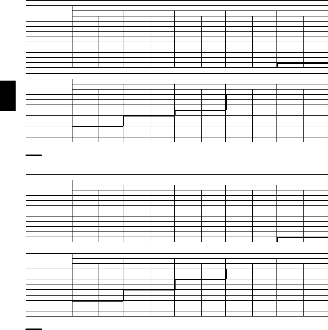
134
PERFORMANCE DATA (CONT)
Fan Performance — Horizontal Supply/Return Units
48PGD05 (Low Heat Units)
AIRFLOW
(Cfm)
AVAILABLEEXTERNALSTATICPRESSURE(in.wg)
0.2 0.4 0.6 0.8 1.0
Rpm Bhp Rpm Bhp Rpm Bhp Rpm Bhp Rpm Bhp
1200 436 0.12 559 0.19 661 0.27 753 0.35 839 0.45
1300 456 0.14 574 0.22 673 0.30 762 0.39 845 0.49
1400 477 0.17 592 0.25 687 0.34 774 0.43 853 0.53
1500 500 0.20 611 0.29 703 0.38 787 0.48 864 0.58
1600 523 0.24 631 0.33 721 0.43 801 0.53 877 0.63
1700 548 0.28 652 0.38 739 0.48 818 0.58 891 0.69
1800 573 0.32 674 0.43 759 0.54 835 0.64 906 0.76
1900 600 0.37 697 0.48 779 0.60 854 0.71 923 0.83
2000 627 0.43 720 0.55 801 0.67 873 0.79 941 0.91
48PGD05 (Low Heat Units) (cont)
AIRFLOW
(Cfm)
AVAILABLEEXTERNALSTATICPRESSURE(in.wg)
1.2 1.4 1.6 1.8 2.0
Rpm Bhp Rpm Bhp Rpm Bhp Rpm Bhp Rpm Bhp
1200 918 0.54 993 0.64 1063 0.75 1130 0.86 1193 0.97
1300 922 0.58 995 0.69 1064 0.80 1130 0.91 1193 1.03
1400 929 0.63 1000 0.74 1067 0.85 1132 0.97 1194 1.09
1500 937 0.69 1006 0.80 1072 0.91 1136 1.03 1196 1.16
1600 947 0.74 1015 0.86 1079 0.98 1141 1.10 1201 1.23
1700 959 0.81 1025 0.93 1088 1.05 1148 1.18 1207 1.31
1800 973 0.88 1037 1.00 1098 1.13 1157 1.26 1214 1.39
1900 988 0.95 1050 1.08 1110 1.21 1168 1.35 1223 1.48
2000 1004 1.04 1065 1.17 1123 1.30 1179 1.44 1234 1.58
LEGEND
B h p --- Brake Horsepower
High Range Motor/Drive Required
NOTES:
1. Motor drive range is 596 to 910 for low range motor/drive and 828 to 1173 rpm for
high range motor/drive. All other rpms require a field-supplied drive.
2. Maximum continuous bhp is 0.85 for low range motor/drive and 1.60 (single phase)
and 2.40 (3 phase) for high range motor/drive.
3. See General Fan Performance Notes.
48PGE05 (Medium Heat Units)
AIRFLOW
(Cfm)
AVAILABLEEXTERNALSTATICPRESSURE(in.wg)
0.2 0.4 0.6 0.8 1.0
Rpm Bhp Rpm Bhp Rpm Bhp Rpm Bhp Rpm Bhp
1200 443 0.12 564 0.20 666 0.27 758 0.36 842 0.45
1300 463 0.15 580 0.22 678 0.31 767 0.40 849 0.49
1400 485 0.17 598 0.26 693 0.34 778 0.44 858 0.54
1500 508 0.21 617 0.30 709 0.39 792 0.48 869 0.59
1600 532 0.24 638 0.34 727 0.43 807 0.54 882 0.64
1700 558 0.28 660 0.39 746 0.49 824 0.59 896 0.70
1800 584 0.33 682 0.44 766 0.55 842 0.66 912 0.77
1900 611 0.38 706 0.50 788 0.61 861 0.72 930 0.84
2000 639 0.44 731 0.56 810 0.68 882 0.80 948 0.92
48PGE05 (Medium Heat Units) (cont)
AIRFLOW
(Cfm)
AVAILABLEEXTERNALSTATICPRESSURE(in.wg)
1.2 1.4 1.6 1.8 2.0
Rpm Bhp Rpm Bhp Rpm Bhp Rpm Bhp Rpm Bhp
1200 922 0.55 996 0.65 1066 0.75 1133 0.86 1196 0.97
1300 926 0.59 999 0.69 1068 0.80 1133 0.92 1196 1.03
1400 933 0.64 1004 0.75 1071 0.86 1136 0.98 1197 1.10
1500 942 0.69 1011 0.80 1077 0.92 1140 1.04 1200 1.17
1600 952 0.75 1020 0.87 1084 0.99 1146 1.11 1205 1.24
1700 965 0.82 1030 0.94 1093 1.06 1153 1.19 1211 1.32
1800 979 0.89 1043 1.01 1104 1.14 1163 1.27 1220 1.41
1900 995 0.97 1057 1.09 1116 1.22 1174 1.36 1229 1.50
2000 1012 1.05 1072 1.18 1130 1.32 1186 1.46 1240 1.60
LEGEND
B h p --- Brake Horsepower
High Range Motor/Drive Required
NOTES:
1. Motor drive range is 596 to 910 for low range motor/drive and 828 to 1173 rpm for
high range motor/drive. All other rpms require a field-supplied drive.
2. Maximum continuous bhp is 0.85 for low range motor/drive and 1.60 (single phase)
and 2.40 (3 phase) for high range motor/drive.
3. See General Fan Performance Notes.
48PG
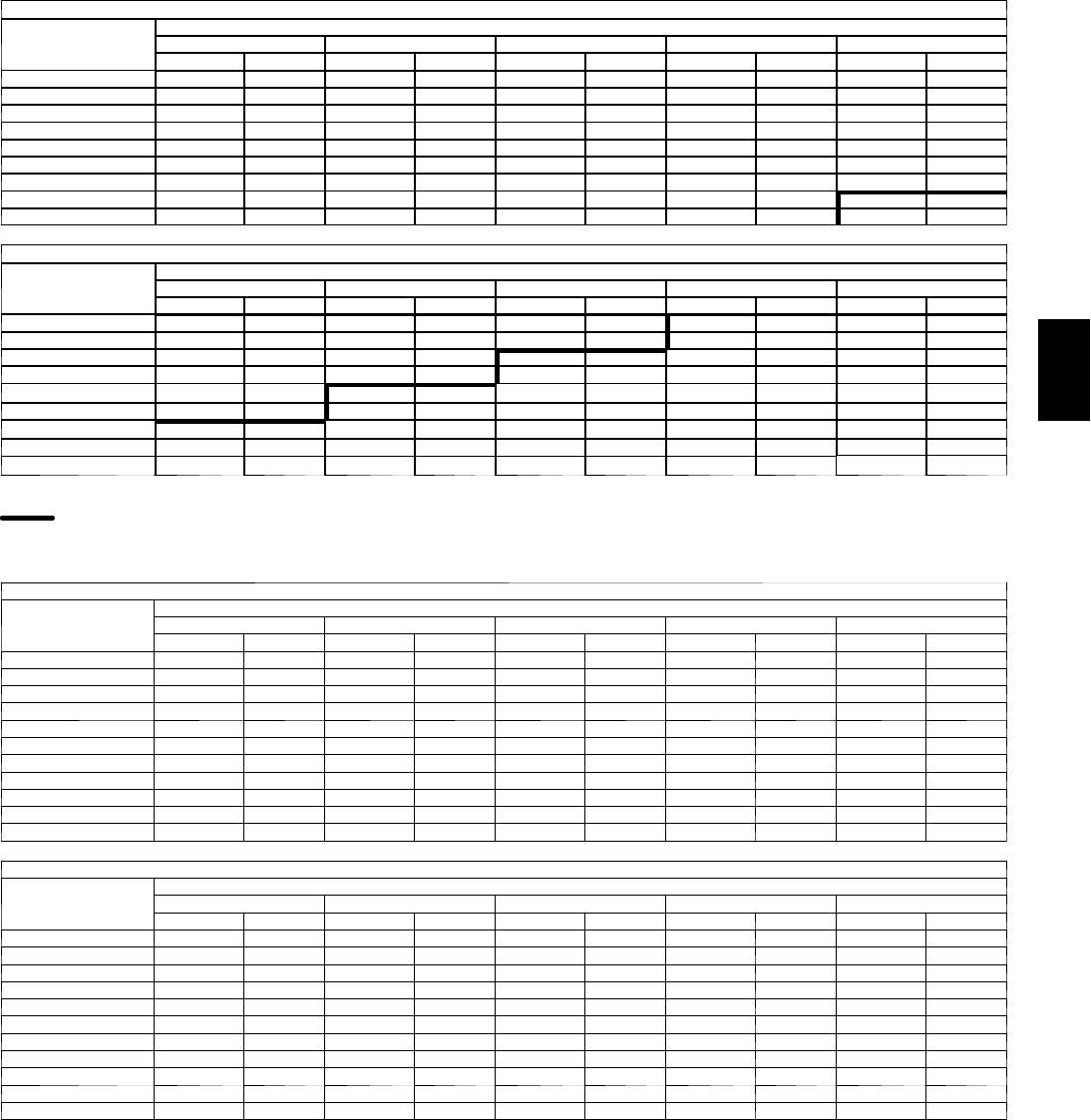
135
Fan Performance — Horizontal Supply/Return Units
48PGF05 (High Heat Units)
AIRFLOW
(Cfm)
AVAILABLEEXTERNALSTATICPRESSURE(in.wg)
0.2 0.4 0.6 0.8 1.0
Rpm Bhp Rpm Bhp Rpm Bhp Rpm Bhp Rpm Bhp
1200 456 0.13 574 0.20 675 0.28 766 0.37 850 0.46
1300 477 0.16 591 0.23 688 0.32 776 0.41 857 0.50
1400 500 0.18 610 0.27 703 0.36 788 0.45 867 0.55
1500 524 0.22 630 0.31 720 0.40 802 0.50 879 0.60
1600 550 0.26 652 0.35 739 0.45 819 0.55 893 0.66
1700 576 0.30 675 0.40 759 0.50 836 0.61 908 0.72
1800 604 0.35 699 0.46 781 0.57 856 0.68 925 0.79
1900 633 0.41 724 0.52 804 0.63 876 0.75 944 0.87
2000 662 0.47 750 0.59 828 0.71 898 0.83 964 0.95
48PGF05 (High Heat Units) (cont)
AIRFLOW
(Cfm)
AVAILABLEEXTERNALSTATICPRESSURE(in.wg)
1.2 1.4 1.6 1.8 2.0
Rpm Bhp Rpm Bhp Rpm Bhp Rpm Bhp Rpm Bhp
1200 929 0.56 1003 0.66 1073 0.76 1139 0.87 1202 0.98
1300 934 0.60 1006 0.71 1075 0.82 1140 0.93 1202 1.05
1400 941 0.65 1012 0.76 1079 0.87 1143 0.99 1204 1.11
1500 951 0.71 1020 0.82 1085 0.94 1148 1.06 1208 1.18
1600 963 0.77 1029 0.89 1093 1.01 1155 1.13 1214 1.26
1700 976 0.84 1041 0.96 1103 1.08 1163 1.21 1221 1.34
1800 991 0.91 1054 1.04 1115 1.16 1174 1.30 1230 1.43
1900 1008 0.99 1070 1.12 1129 1.25 1186 1.39 1241 1.53
2000 1026 1.08 1086 1.21 1144 1.35 1199 1.49 1253 1.63
LEGEND
B h p --- Brake Horsepower
High Range Motor/Drive Required
NOTES:
1. Motor drive range is 596 to 910 for low range motor/drive and 828 to 1173 rpm for
high range motor/drive. All other rpms require a field-supplied drive.
2. Maximum continuous bhp is 0.85 for low range motor/drive and 1.60 (single phase)
and 2.40 (3 phase) for high range motor/drive.
3. See General Fan Performance Notes.
48PGD06 (Low Heat Units)
AIRFLOW
(Cfm)
AVAILABLEEXTERNALSTATICPRESSURE(in.wg)
0.2 0.4 0.6 0.8 1.0
Rpm Bhp Rpm Bhp Rpm Bhp Rpm Bhp Rpm Bhp
1500 521 0.22 628 0.31 718 0.40 800 0.49 877 0.60
1600 546 0.25 649 0.35 737 0.45 816 0.55 890 0.65
1700 572 0.30 671 0.40 757 0.50 834 0.61 906 0.72
1800 599 0.35 695 0.45 777 0.56 852 0.67 922 0.79
1900 627 0.40 719 0.51 799 0.63 872 0.74 940 0.86
2000 655 0.46 745 0.58 822 0.70 893 0.82 959 0.94
2100 684 0.53 771 0.66 846 0.78 915 0.91 979 1.03
2200 714 0.61 797 0.74 871 0.87 938 1.00 1001 1.13
2300 744 0.69 824 0.83 896 0.96 961 1.10 1022 1.24
2400 775 0.78 852 0.92 922 1.06 985 1.21 1045 1.35
2500 806 0.88 880 1.03 948 1.18 1010 1.32 1069 1.47
48PGD06 (Low Heat Units) (cont)
AIRFLOW
(Cfm)
AVAILABLEEXTERNALSTATICPRESSURE(in.wg)
1.2 1.4 1.6 1.8 2.0
Rpm Bhp Rpm Bhp Rpm Bhp Rpm Bhp Rpm Bhp
1500 949 0.70 1018 0.82 1083 0.93 1146 1.05 1207 1.18
1600 961 0.77 1027 0.88 1091 1.00 1153 1.13 1212 1.26
1700 974 0.83 1039 0.95 1101 1.08 1161 1.21 1219 1.34
1800 988 0.91 1052 1.03 1112 1.16 1171 1.29 1227 1.43
1900 1004 0.99 1066 1.11 1125 1.25 1182 1.38 1238 1.52
2000 1022 1.07 1082 1.20 1139 1.34 1195 1.48 1249 1.62
2100 1040 1.17 1099 1.30 1155 1.44 1209 1.59 1262 1.73
2200 1060 1.27 1117 1.41 1172 1.55 1225 1.70 1277 1.85
2300 1081 1.38 1136 1.52 1190 1.67 1242 1.82 1292 1.98
2400 1102 1.50 1156 1.65 1209 1.80 1259 1.96 1309 2.12
2500 1124 1.62 1177 1.78 1228 1.94 1278 2.10 1326 2.26
LEGEND
B h p --- Brake Horsepower
NOTES:
1. Motor drive range is 690 to 978 for low range motor/drive and 929 to 1261 rpm for
high range motor/drive. All other rpms require a field-supplied drive.
2. Maximum continuous bhp is 0.85 (single phase) and 2.40 (3 phase) for low range
motor/drive and 1.60 (single phase) and 2.40 (3 phase) for high range motor/drive.
3. See General Fan Performance Notes.
48PG

136
PERFORMANCE DATA (CONT)
Fan Performance — Horizontal Supply/Return Units
48PGE06 (Medium Heat Units)
AIRFLOW
(Cfm)
AVAILABLEEXTERNALSTATICPRESSURE(in.wg)
0.2 0.4 0.6 0.8 1.0
Rpm Bhp Rpm Bhp Rpm Bhp Rpm Bhp Rpm Bhp
1500 536 0.23 640 0.32 729 0.41 811 0.51 887 0.61
1600 563 0.27 663 0.36 749 0.46 828 0.56 901 0.67
1700 590 0.31 686 0.42 770 0.52 846 0.62 917 0.74
1800 619 0.37 711 0.47 792 0.58 866 0.69 935 0.81
1900 648 0.43 737 0.54 816 0.65 887 0.77 954 0.89
2000 678 0.49 764 0.61 840 0.73 909 0.85 975 0.98
2100 709 0.56 792 0.69 865 0.81 933 0.94 996 1.07
2200 740 0.65 820 0.78 891 0.91 957 1.04 1019 1.17
2300 772 0.73 849 0.87 918 1.01 982 1.14 1042 1.28
2400 804 0.83 879 0.97 946 1.12 1008 1.26 1066 1.40
2500 837 0.94 909 1.09 974 1.24 1034 1.38 1092 1.53
48PGE06 (Medium Heat Units) (cont)
AIRFLOW
(Cfm)
AVAILABLEEXTERNALSTATICPRESSURE(in.wg)
1.2 1.4 1.6 1.8 2.0
Rpm Bhp Rpm Bhp Rpm Bhp Rpm Bhp Rpm Bhp
1500 958 0.72 1027 0.83 1092 0.95 1154 1.07 1214 1.20
1600 971 0.78 1037 0.90 1101 1.02 1162 1.15 1221 1.28
1700 985 0.85 1049 0.97 1111 1.10 1171 1.23 1228 1.36
1800 1001 0.93 1063 1.05 1124 1.18 1182 1.32 1238 1.45
1900 1018 1.01 1079 1.14 1138 1.27 1194 1.41 1249 1.55
2000 1036 1.10 1096 1.24 1153 1.37 1208 1.51 1262 1.66
2100 1056 1.20 1114 1.34 1170 1.48 1224 1.63 1276 1.78
2200 1077 1.31 1134 1.45 1188 1.60 1241 1.75 1292 1.90
2300 1099 1.43 1154 1.57 1207 1.72 1259 1.88 1309 2.03
2400 1122 1.55 1176 1.70 1228 1.86 1278 2.02 1327 2.18
2500 1146 1.69 1198 1.84 1249 2.00 1298 2.16 1346 2.33
LEGEND
B h p --- Brake Horsepower
NOTES:
1. Motor drive range is 690 to 978 for low range motor/drive and 929 to 1261 rpm for
high range motor/drive. All other rpms require a field-supplied drive.
2. Maximum continuous bhp is 0.85 (single phase) and 2.40 (3 phase) for low range
motor/drive and 1.60 (single phase) and 2.40 (3 phase) for high range motor/drive.
3. See General Fan Performance Notes.
48PGF06 (High Heat Units)
AIRFLOW
(Cfm)
AVAILABLEEXTERNALSTATICPRESSURE(in.wg)
0.2 0.4 0.6 0.8 1.0
Rpm Bhp Rpm Bhp Rpm Bhp Rpm Bhp Rpm Bhp
1500 551 0.24 653 0.33 741 0.42 821 0.52 896 0.62
1600 579 0.28 676 0.38 761 0.48 839 0.58 912 0.69
1700 608 0.33 701 0.43 783 0.54 858 0.64 929 0.76
1800 638 0.39 727 0.49 807 0.60 879 0.71 948 0.83
1900 668 0.45 755 0.56 831 0.68 902 0.79 968 0.91
2000 700 0.52 783 0.64 857 0.76 925 0.88 990 1.01
2100 732 0.60 812 0.72 884 0.85 950 0.97 1013 1.11
2200 765 0.68 842 0.81 912 0.95 976 1.08 1037 1.21
2300 799 0.78 873 0.92 940 1.05 1002 1.19 1062 1.33
2400 833 0.88 904 1.03 969 1.17 1030 1.31 1087 1.46
2500 867 1.00 936 1.15 999 1.30 1058 1.44 1114 1.60
48PGF06 (High Heat Units) (cont)
AIRFLOW
(Cfm)
AVAILABLEEXTERNALSTATICPRESSURE(in.wg)
1.2 1.4 1.6 1.8 2.0
Rpm Bhp Rpm Bhp Rpm Bhp Rpm Bhp Rpm Bhp
1500 968 0.73 1035 0.85 1100 0.97 1162 1.09 1222 1.21
1600 981 0.80 1047 0.92 1110 1.04 1171 1.16 1229 1.29
1700 996 0.87 1060 0.99 1121 1.12 1181 1.25 1238 1.38
1800 1013 0.95 1075 1.08 1135 1.21 1193 1.34 1248 1.48
1900 1031 1.04 1092 1.17 1150 1.30 1206 1.44 1261 1.58
2000 1051 1.14 1110 1.27 1166 1.41 1221 1.55 1275 1.69
2100 1072 1.24 1129 1.38 1185 1.52 1238 1.67 1290 1.82
2200 1094 1.35 1150 1.50 1204 1.64 1256 1.79 1307 1.95
2300 1118 1.48 1172 1.62 1225 1.77 1275 1.93 1325 2.09
2400 1142 1.61 1195 1.76 1246 1.92 1296 2.07 1344 2.24
2500 1168 1.75 1219 1.91 1269 2.07 1317 2.23 1365 2.40
LEGEND
B h p --- Brake Horsepower
NOTES:
1. Motor drive range is 690 to 978 for low range motor/drive and 929 to 1261 rpm for
high range motor/drive. All other rpms require a field-supplied drive.
2. Maximum continuous bhp is 0.85 (single phase) and 2.40 (3 phase) for low range
motor/drive and 1.60 (single phase) and 2.40 (3 phase) for high range motor/drive.
3. See General Fan Performance Notes.
48PG

137
Fan Performance — Horizontal Supply/Return Units
48PGD07 (Low Heat Units)
AIRFLOW
(Cfm)
AVAILABLEEXTERNALSTATICPRESSURE(in.wg)
0.2 0.4 0.6 0.8 1.0
Rpm Bhp Rpm Bhp Rpm Bhp Rpm Bhp Rpm Bhp
1800 614 0.36 707 0.47 788 0.58 863 0.69 932 0.80
1900 642 0.42 732 0.53 811 0.64 883 0.76 950 0.88
2000 671 0.48 758 0.60 835 0.72 905 0.84 970 0.97
2100 701 0.55 785 0.68 859 0.80 927 0.93 991 1.06
2200 731 0.63 812 0.76 884 0.89 950 1.02 1012 1.16
2300 762 0.72 840 0.85 910 0.99 975 1.13 1035 1.27
2400 793 0.81 869 0.95 937 1.10 999 1.24 1058 1.38
2500 825 0.91 898 1.06 964 1.21 1025 1.36 1082 1.51
2600 856 1.03 927 1.18 991 1.33 1051 1.49 1107 1.64
2700 889 1.15 957 1.31 1019 1.47 1077 1.63 1132 1.79
2800 921 1.28 987 1.44 1048 1.61 1104 1.78 1158 1.94
2900 953 1.42 1017 1.59 1076 1.76 1132 1.94 1184 2.11
3000 986 1.57 1048 1.75 1106 1.93 1160 2.10 1211 2.28
48PGD07 (Low Heat Units) (cont)
AIRFLOW
(Cfm)
AVAILABLEEXTERNALSTATICPRESSURE(in.wg)
1.2 1.4 1.6 1.8 2.0
Rpm Bhp Rpm Bhp Rpm Bhp Rpm Bhp Rpm Bhp
1800 997 0.92 1060 1.05 1121 1.18 1179 1.31 1235 1.45
1900 1014 1.01 1075 1.13 1134 1.27 1191 1.40 1246 1.54
2000 1032 1.09 1092 1.23 1149 1.36 1204 1.50 1258 1.65
2100 1051 1.19 1109 1.33 1165 1.47 1219 1.61 1272 1.76
2200 1071 1.30 1128 1.44 1183 1.58 1235 1.73 1287 1.88
2300 1093 1.41 1148 1.56 1201 1.70 1253 1.86 1303 2.01
2400 1115 1.53 1168 1.68 1220 1.84 1271 1.99 1320 2.15
2500 1137 1.66 1190 1.82 1241 1.98 1290 2.14 1338 2.30
2600 1161 1.80 1212 1.96 1262 2.12 1310 2.29 — —
2700 1185 1.95 1235 2.12 1284 2.28 — — — —
2800 1209 2.11 1259 2.28 — — — — — —
2900 1235 2.28 — — — — — — — —
3000 — — — — — — — — — —
LEGEND
B h p --- Brake Horsepower
NOTES:
1. Motor drive range is 796 to 1128 for low range motor/drive and 1150 to 1438 rpm for
high range motor/drive. All other rpms require a field-supplied drive.
2. Maximum continuous bhp is 2.40 for low range motor/drive and 3.10 for high range
motor/drive.
3. See General Fan Performance Notes.
48PGE07 (Medium Heat Units)
AIRFLOW
(Cfm)
AVAILABLEEXTERNALSTATICPRESSURE(in.wg)
0.2 0.4 0.6 0.8 1.0
Rpm Bhp Rpm Bhp Rpm Bhp Rpm Bhp Rpm Bhp
1800 633 0.38 723 0.49 803 0.60 876 0.71 944 0.83
1900 663 0.44 750 0.56 827 0.67 898 0.79 964 0.91
2000 694 0.51 777 0.63 852 0.75 921 0.87 985 1.00
2100 725 0.59 806 0.71 878 0.84 945 0.96 1007 1.09
2200 757 0.67 835 0.80 905 0.93 969 1.06 1030 1.20
2300 789 0.76 864 0.90 932 1.04 995 1.17 1055 1.31
2400 822 0.86 894 1.01 960 1.15 1022 1.29 1079 1.44
2500 855 0.98 925 1.12 989 1.27 1049 1.42 1105 1.57
2600 889 1.10 956 1.25 1018 1.40 1076 1.56 1131 1.71
2700 923 1.23 988 1.39 1048 1.55 1105 1.71 1158 1.87
2800 957 1.37 1020 1.53 1079 1.70 1134 1.87 1186 2.03
2900 991 1.52 1052 1.69 1109 1.86 1163 2.04 1214 2.21
3000 1026 1.68 1085 1.86 1140 2.04 1193 2.22 1243 2.40
48PGE07 (Medium Heat Units) (cont)
AIRFLOW
(Cfm)
AVAILABLEEXTERNALSTATICPRESSURE(in.wg)
1.2 1.4 1.6 1.8 2.0
Rpm Bhp Rpm Bhp Rpm Bhp Rpm Bhp Rpm Bhp
1800 1010 0.95 1072 1.07 1132 1.20 1190 1.33 1246 1.47
1900 1027 1.03 1088 1.16 1146 1.30 1203 1.43 1258 1.57
2000 1047 1.13 1106 1.26 1162 1.40 1218 1.54 1271 1.68
2100 1067 1.23 1124 1.37 1180 1.51 1234 1.65 1286 1.80
2200 1089 1.34 1145 1.48 1199 1.63 1251 1.78 1302 1.93
2300 1111 1.46 1166 1.60 1218 1.76 1269 1.91 1319 2.07
2400 1135 1.59 1188 1.74 1239 1.89 1289 2.05 1338 2.21
2500 1159 1.73 1211 1.88 1261 2.04 1310 2.20 1357 2.37
2600 1184 1.87 1235 2.03 1284 2.20 1331 2.37 — —
2700 1210 2.03 1259 2.20 1307 2.37 — — — —
2800 1236 2.20 1284 2.37 — — — — — —
2900 1263 2.38 — — — — — — — —
3000 — — — — — — — — — —
LEGEND
B h p --- Brake Horsepower
NOTES:
1. Motor drive range is 796 to 1128 for low range motor/drive and 1150 to 1438 rpm for
high range motor/drive. All other rpms require a field-supplied drive.
2. Maximum continuous bhp is 2.40 for low range motor/drive and 3.10 for high range
motor/drive.
3. See General Fan Performance Notes.
48PG
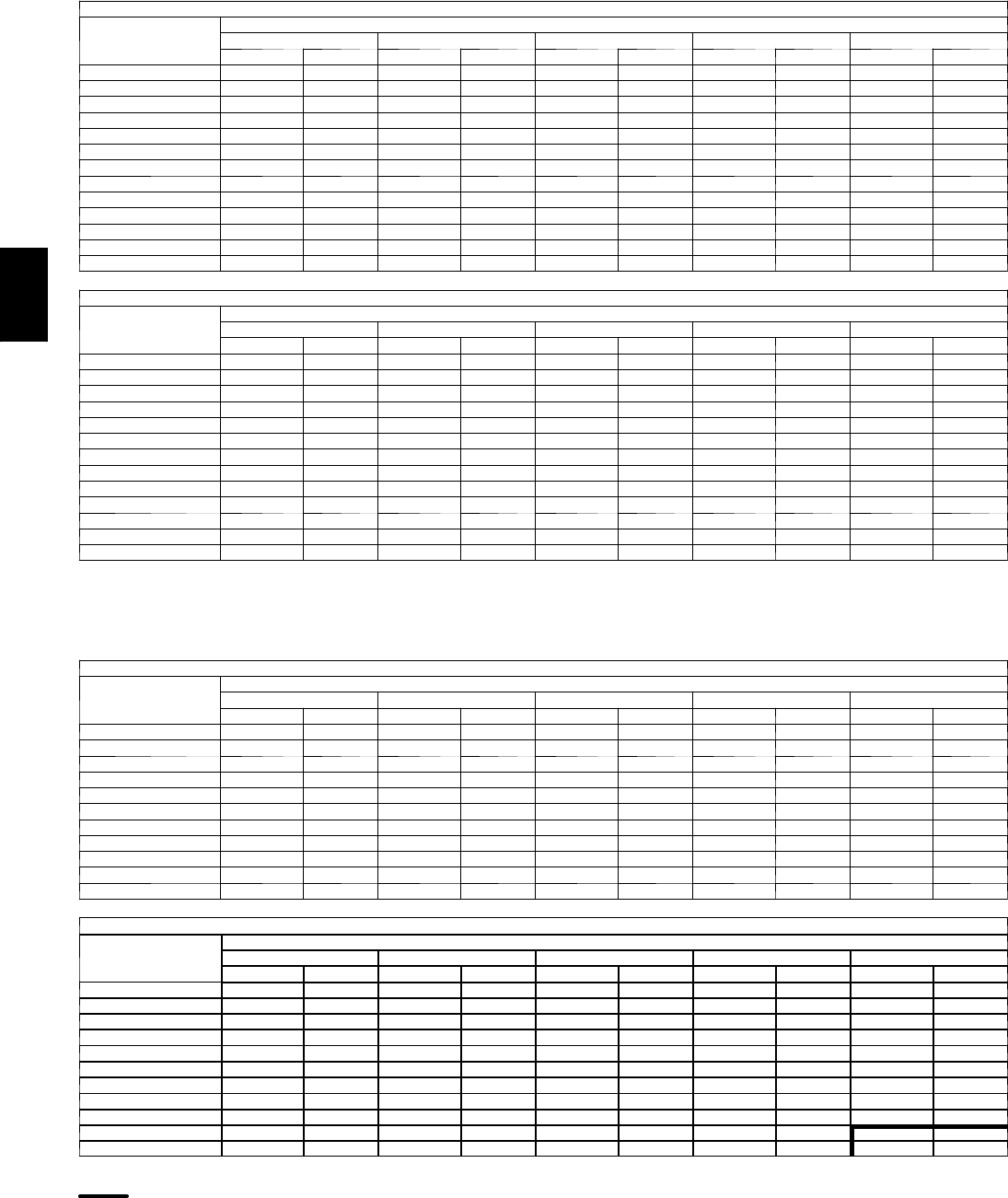
138
PERFORMANCE DATA (CONT)
Fan Performance — Horizontal Supply/Return Units
48PGF07 (High Heat Units)
AIRFLOW
(Cfm)
AVAILABLEEXTERNALSTATICPRESSURE(in.wg)
0.2 0.4 0.6 0.8 1.0
Rpm Bhp Rpm Bhp Rpm Bhp Rpm Bhp Rpm Bhp
1800 651 0.40 739 0.51 817 0.62 889 0.73 957 0.85
1900 683 0.47 767 0.58 843 0.69 912 0.81 978 0.93
2000 715 0.54 796 0.66 869 0.78 937 0.90 1000 1.03
2100 748 0.62 826 0.75 896 0.87 962 1.00 1024 1.13
2200 781 0.71 856 0.84 925 0.97 988 1.10 1048 1.24
2300 815 0.81 888 0.95 954 1.08 1015 1.22 1074 1.36
2400 850 0.92 919 1.06 983 1.20 1043 1.35 1100 1.49
2500 885 1.04 952 1.18 1014 1.33 1072 1.48 1127 1.63
2600 920 1.17 985 1.32 1045 1.47 1101 1.63 1155 1.79
2700 956 1.31 1018 1.47 1076 1.63 1131 1.79 1184 1.95
2800 992 1.46 1052 1.62 1108 1.79 1162 1.96 1213 2.12
2900 1028 1.62 1086 1.79 1141 1.96 1193 2.14 1243 2.31
3000 1064 1.80 1121 1.98 1174 2.15 1225 2.33 — —
48PGF07 (High Heat Units) (cont)
AIRFLOW
(Cfm)
AVAILABLEEXTERNALSTATICPRESSURE(in.wg)
1.2 1.4 1.6 1.8 2.0
Rpm Bhp Rpm Bhp Rpm Bhp Rpm Bhp Rpm Bhp
1800 1022 0.97 1083 1.10 1143 1.23 1201 1.36 1256 1.50
1900 1041 1.06 1101 1.19 1159 1.32 1215 1.46 1269 1.60
2000 1061 1.16 1119 1.29 1176 1.43 1230 1.57 1283 1.72
2100 1083 1.26 1140 1.40 1194 1.55 1248 1.69 1299 1.84
2200 1106 1.38 1161 1.52 1214 1.67 1266 1.82 1317 1.98
2300 1130 1.51 1183 1.65 1236 1.81 1286 1.96 1335 2.12
2400 1155 1.64 1207 1.80 1258 1.95 1307 2.11 1355 2.27
2500 1180 1.79 1231 1.95 1281 2.11 1329 2.27 — —
2600 1207 1.95 1257 2.11 1305 2.27 — — — —
2700 1234 2.11 1283 2.28 — — — — — —
2800 1262 2.29 — — — — — — — —
2900 — — — — — — — — — —
3000 — — — — — — — — — —
LEGEND
B h p --- Brake Horsepower
NOTES:
1. Motor drive range is 796 to 1128 for low range motor/drive and 1150 to 1438 rpm for
high range motor/drive. All other rpms require a field-supplied drive.
2. Maximum continuous bhp is 2.40 for low range motor/drive and 3.10 for high range
motor/drive.
3. See General Fan Performance Notes.
48PGD08 (Low Heat Units)
AIRFLOW
(Cfm)
AVAILABLEEXTERNALSTATICPRESSURE(in.wg)
0.2 0.4 0.6 0.8 1.0
Rpm Bhp Rpm Bhp Rpm Bhp Rpm Bhp Rpm Bhp
2250 409 0.29 493 0.39 567 0.50 636 0.62 700 0.75
2400 422 0.33 503 0.44 576 0.56 642 0.68 704 0.81
2550 436 0.38 515 0.49 585 0.62 650 0.74 710 0.88
2700 450 0.43 527 0.55 595 0.68 658 0.81 717 0.95
2850 465 0.49 539 0.62 606 0.75 667 0.89 724 1.03
3000 480 0.56 552 0.69 617 0.83 676 0.97 732 1.12
3150 496 0.63 566 0.77 629 0.91 687 1.06 741 1.21
3300 511 0.70 579 0.85 641 1.00 698 1.16 751 1.31
3450 527 0.79 593 0.94 653 1.10 709 1.26 761 1.42
3600 543 0.88 608 1.04 666 1.21 721 1.37 772 1.54
3750 560 0.98 622 1.15 680 1.32 733 1.49 783 1.66
48PGD08 (Low Heat Units) (cont)
AIRFLOW
(Cfm)
AVAILABLEEXTERNALSTATICPRESSURE(in.wg)
1.2 1.4 1.6 1.8 2.0
Rpm Bhp Rpm Bhp Rpm Bhp Rpm Bhp Rpm Bhp
2250 760 0.88 817 1.01 871 1.16 923 1.30 972 1.45
2400 763 0.94 819 1.09 872 1.23 923 1.38 972 1.54
2550 768 1.02 822 1.16 874 1.32 924 1.47 973 1.63
2700 773 1.10 826 1.25 877 1.40 927 1.56 974 1.73
2850 779 1.18 831 1.34 881 1.50 929 1.66 976 1.83
3000 786 1.27 837 1.43 886 1.60 933 1.77 979 1.94
3150 793 1.37 843 1.54 891 1.70 938 1.88 983 2.06
3300 802 1.48 851 1.65 898 1.82 943 2.00 987 2.18
3450 811 1.59 859 1.76 905 1.94 949 2.12 992 2.31
3600 820 1.71 867 1.89 912 2.07 956 2.26 998 2.45
3750 830 1.84 876 2.02 920 2.21 963 2.40 1005 2.60
LEGEND
B h p --- Brake Horsepower
High Range Motor/Drive Required
NOTES:
1. Motor drive range is 568 to 771 for low range motor/drive and 812 to 1015 rpm for
high range motor/drive. All other rpms require a field-supplied drive.
2. Maximum continuous bhp is 2.40 for low range motor/drive and 3.10 for high range
motor/drive.
3. See General Fan Performance Notes.
48PG
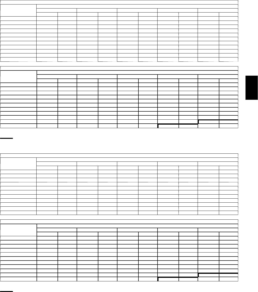
139
Fan Performance — Horizontal Supply/Return Units
48PGE08 (Medium Heat Units)
AIRFLOW
(Cfm)
AVAILABLEEXTERNALSTATICPRESSURE(in.wg)
0.2 0.4 0.6 0.8 1.0
Rpm Bhp Rpm Bhp Rpm Bhp Rpm Bhp Rpm Bhp
2250 408 0.28 492 0.39 567 0.50 635 0.62 699 0.74
2400 424 0.33 505 0.44 577 0.56 644 0.68 706 0.81
2550 440 0.38 519 0.50 588 0.62 653 0.75 713 0.88
2700 457 0.44 532 0.56 600 0.69 662 0.82 721 0.96
2850 473 0.50 547 0.63 612 0.77 673 0.90 730 1.05
3000 490 0.57 561 0.71 625 0.85 684 0.99 740 1.14
3150 507 0.65 576 0.79 638 0.94 695 1.08 750 1.24
3300 524 0.73 591 0.88 651 1.03 708 1.19 760 1.34
3450 542 0.82 606 0.98 665 1.13 720 1.29 772 1.46
3600 559 0.92 622 1.08 679 1.24 733 1.41 783 1.58
3750 577 1.02 638 1.19 694 1.36 746 1.53 795 1.71
48PGE08 (Medium Heat Units) (cont)
AIRFLOW
(Cfm)
AVAILABLEEXTERNALSTATICPRESSURE(in.wg)
1.2 1.4 1.6 1.8 2.0
Rpm Bhp Rpm Bhp Rpm Bhp Rpm Bhp Rpm Bhp
2250 760 0.88 817 1.01 871 1.16 923 1.30 972 1.45
2400 765 0.95 820 1.09 874 1.24 924 1.39 973 1.54
2550 770 1.03 825 1.17 877 1.32 927 1.48 975 1.64
2700 777 1.11 830 1.26 881 1.42 930 1.58 977 1.74
2850 784 1.20 836 1.35 886 1.51 934 1.68 981 1.85
3000 793 1.29 843 1.45 892 1.62 939 1.79 985 1.96
3150 801 1.40 851 1.56 899 1.73 945 1.91 990 2.09
3300 811 1.51 859 1.68 906 1.85 951 2.03 995 2.21
3450 821 1.63 868 1.80 914 1.98 958 2.16 1001 2.35
3600 831 1.75 878 1.93 923 2.11 966 2.30 1008 2.49
3750 843 1.89 888 2.07 932 2.26 974 2.45 1016 2.65
LEGEND
B h p --- Brake Horsepower
High Range Motor/Drive Required
NOTES:
1. Motor drive range is 568 to 771 for low range motor/drive and 812 to 1015 rpm for
high range motor/drive. All other rpms require a field-supplied drive.
2. Maximum continuous bhp is 2.40 for low range motor/drive and 3.10 for high range
motor/drive.
3. See General Fan Performance Notes.
48PGF08 (High Heat Units)
AIRFLOW
(Cfm)
AVAILABLEEXTERNALSTATICPRESSURE(in.wg)
0.2 0.4 0.6 0.8 1.0
Rpm Bhp Rpm Bhp Rpm Bhp Rpm Bhp Rpm Bhp
2250 413 0.29 496 0.39 571 0.51 639 0.63 703 0.75
2400 429 0.34 510 0.45 581 0.57 647 0.69 709 0.82
2550 446 0.39 524 0.51 593 0.63 657 0.76 717 0.89
2700 464 0.45 538 0.57 605 0.70 667 0.83 726 0.97
2850 481 0.52 553 0.65 618 0.78 678 0.92 735 1.06
3000 499 0.59 569 0.72 632 0.86 690 1.01 746 1.16
3150 517 0.67 584 0.81 646 0.95 703 1.10 756 1.26
3300 535 0.75 600 0.90 660 1.05 715 1.21 768 1.37
3450 553 0.85 617 1.00 675 1.16 729 1.32 780 1.48
3600 571 0.95 633 1.11 690 1.27 742 1.44 792 1.61
3750 590 1.06 650 1.23 705 1.40 756 1.57 805 1.74
48PGF08 (High Heat Units) (cont)
AIRFLOW
(Cfm)
AVAILABLEEXTERNALSTATICPRESSURE(in.wg)
1.2 1.4 1.6 1.8 2.0
Rpm Bhp Rpm Bhp Rpm Bhp Rpm Bhp Rpm Bhp
2250 763 0.88 820 1.02 874 1.16 925 1.31 974 1.46
2400 768 0.96 824 1.10 877 1.25 927 1.40 976 1.55
2550 774 1.04 829 1.18 881 1.33 930 1.49 978 1.65
2700 781 1.12 834 1.27 885 1.43 934 1.59 981 1.75
2850 789 1.21 841 1.37 891 1.53 939 1.70 985 1.87
3000 798 1.31 849 1.47 897 1.64 944 1.81 990 1.98
3150 808 1.42 857 1.58 905 1.75 951 1.93 995 2.11
3300 818 1.53 866 1.70 913 1.88 958 2.06 1001 2.24
3450 829 1.65 876 1.83 921 2.01 965 2.19 1008 2.38
3600 840 1.78 886 1.96 931 2.15 974 2.34 1016 2.53
3750 852 1.92 897 2.11 941 2.30 983 2.49 1024 2.69
LEGEND
B h p --- Brake Horsepower
High Range Motor/Drive Required
NOTES:
1. Motor drive range is 568 to 771 for low range motor/drive and 812 to 1015 rpm for
high range motor/drive. All other rpms require a field-supplied drive.
2. Maximum continuous bhp is 2.40 for low range motor/drive and 3.10 for high range
motor/drive.
3. See General Fan Performance Notes.
48PG
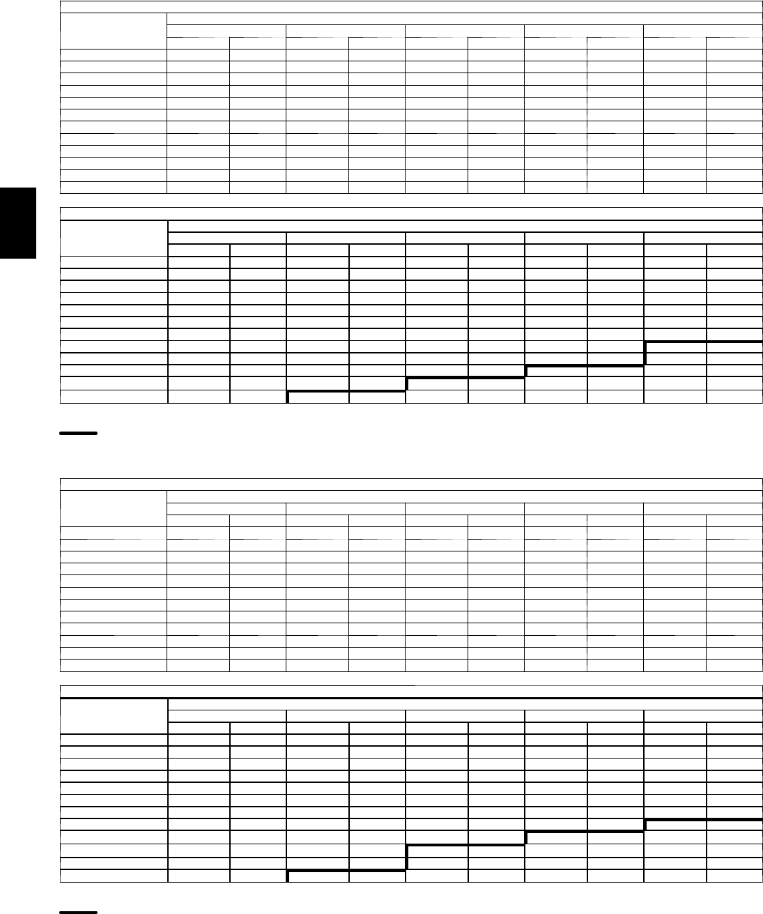
140
PERFORMANCE DATA (CONT)
Fan Performance — Horizontal Supply/Return Units
48PGD09 (Low Heat Units)
AIRFLOW
(Cfm)
AVAILABLEEXTERNALSTATICPRESSURE(in.wg)
0.2 0.4 0.6 0.8 1.0
Rpm Bhp Rpm Bhp Rpm Bhp Rpm Bhp Rpm Bhp
2550 436 0.38 515 0.49 585 0.62 650 0.74 710 0.88
2700 450 0.43 527 0.55 595 0.68 658 0.81 717 0.95
2850 465 0.49 539 0.62 606 0.75 667 0.89 724 1.03
3000 480 0.56 552 0.69 617 0.83 676 0.97 732 1.12
3150 496 0.63 566 0.77 629 0.91 687 1.06 741 1.21
3300 511 0.70 579 0.85 641 1.00 698 1.16 751 1.31
3450 527 0.79 593 0.94 653 1.10 709 1.26 761 1.42
3600 543 0.88 608 1.04 666 1.21 721 1.37 772 1.54
3750 560 0.98 622 1.15 680 1.32 733 1.49 783 1.66
3900 576 1.08 637 1.26 693 1.44 745 1.61 794 1.79
4050 593 1.19 652 1.38 707 1.56 758 1.75 806 1.93
4200 610 1.32 668 1.51 721 1.70 771 1.89 818 2.08
48PGD09 (Low Heat Units) (cont)
AIRFLOW
(Cfm)
AVAILABLEEXTERNALSTATICPRESSURE(in.wg)
1.2 1.4 1.6 1.8 2.0
Rpm Bhp Rpm Bhp Rpm Bhp Rpm Bhp Rpm Bhp
2550 768 1.02 822 1.16 874 1.32 924 1.47 973 1.63
2700 773 1.10 826 1.25 877 1.40 927 1.56 974 1.73
2850 779 1.18 831 1.34 881 1.50 929 1.66 976 1.83
3000 786 1.27 837 1.43 886 1.60 933 1.77 979 1.94
3150 793 1.37 843 1.54 891 1.70 938 1.88 983 2.06
3300 802 1.48 851 1.65 898 1.82 943 2.00 987 2.18
3450 811 1.59 859 1.76 905 1.94 949 2.12 992 2.31
3600 820 1.71 867 1.89 912 2.07 956 2.26 998 2.45
3750 830 1.84 876 2.02 920 2.21 963 2.40 1005 2.60
3900 841 1.98 886 2.16 929 2.35 971 2.55 1012 2.75
4050 852 2.12 896 2.31 938 2.51 980 2.71 1020 2.91
4200 863 2.27 906 2.47 948 2.67 989 2.88 1028 3.09
LEGEND
B h p --- Brake Horsepower
High Range Motor/Drive Required
NOTES:
1. Motor drive range is 568 to 771 for low range motor/drive and 812 to 1015 rpm for
high range motor/drive. All other rpms require a field-supplied drive.
2. Maximum continuous bhp is 2.40 for low range motor/drive and 3.70 for high range
motor/drive.
3. See General Fan Performance Notes.
48PGE09 (Medium Heat Units)
AIRFLOW
(Cfm)
AVAILABLEEXTERNALSTATICPRESSURE(in.wg)
0.2 0.4 0.6 0.8 1.0
Rpm Bhp Rpm Bhp Rpm Bhp Rpm Bhp Rpm Bhp
2550 440 0.38 519 0.50 588 0.62 653 0.75 713 0.88
2700 457 0.44 532 0.56 600 0.69 662 0.82 721 0.96
2850 473 0.50 547 0.63 612 0.77 673 0.90 730 1.05
3000 490 0.57 561 0.71 625 0.85 684 0.99 740 1.14
3150 507 0.65 576 0.79 638 0.94 695 1.08 750 1.24
3300 524 0.73 591 0.88 651 1.03 708 1.19 760 1.34
3450 542 0.82 606 0.98 665 1.13 720 1.29 772 1.46
3600 559 0.92 622 1.08 679 1.24 733 1.41 783 1.58
3750 577 1.02 638 1.19 694 1.36 746 1.53 795 1.71
3900 594 1.13 654 1.31 708 1.49 759 1.66 808 1.84
4050 612 1.25 670 1.44 723 1.62 773 1.80 821 1.99
4200 630 1.38 686 1.57 738 1.76 787 1.95 834 2.14
48PGE09 (Medium Heat Units) (cont)
AIRFLOW
(Cfm)
AVAILABLEEXTERNALSTATICPRESSURE(in.wg)
1.2 1.4 1.6 1.8 2.0
Rpm Bhp Rpm Bhp Rpm Bhp Rpm Bhp Rpm Bhp
2550 770 1.03 825 1.17 877 1.32 927 1.48 975 1.64
2700 777 1.11 830 1.26 881 1.42 930 1.58 977 1.74
2850 784 1.20 836 1.35 886 1.51 934 1.68 981 1.85
3000 793 1.29 843 1.45 892 1.62 939 1.79 985 1.96
3150 801 1.40 851 1.56 899 1.73 945 1.91 990 2.09
3300 811 1.51 859 1.68 906 1.85 951 2.03 995 2.21
3450 821 1.63 868 1.80 914 1.98 958 2.16 1001 2.35
3600 831 1.75 878 1.93 923 2.11 966 2.30 1008 2.49
3750 843 1.89 888 2.07 932 2.26 974 2.45 1016 2.65
3900 854 2.03 898 2.22 941 2.41 983 2.61 1024 2.81
4050 866 2.18 909 2.37 951 2.57 992 2.77 1032 2.98
4200 878 2.34 921 2.54 962 2.74 1002 2.95 1041 3.16
LEGEND
B h p --- Brake Horsepower
High Range Motor/Drive Required
NOTES:
1. Motor drive range is 568 to 771 for low range motor/drive and 812 to 1015 rpm for
high range motor/drive. All other rpms require a field-supplied drive.
2. Maximum continuous bhp is 2.40 for low range motor/drive and 3.70 for high range
motor/drive.
3. See General Fan Performance Notes.
48PG
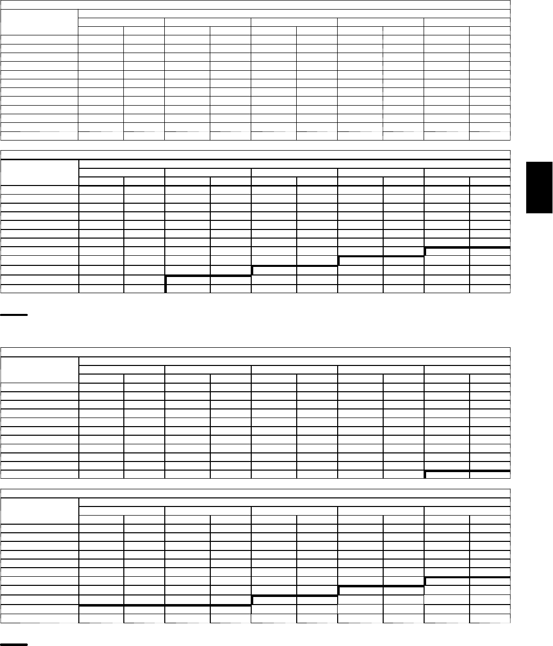
141
Fan Performance — Horizontal Supply/Return Units
48PGF09 (High Heat Units)
AIRFLOW
(Cfm)
AVAILABLEEXTERNALSTATICPRESSURE(in.wg)
0.2 0.4 0.6 0.8 1.0
Rpm Bhp Rpm Bhp Rpm Bhp Rpm Bhp Rpm Bhp
2550 446 0.39 524 0.51 593 0.63 657 0.76 717 0.89
2700 464 0.45 538 0.57 605 0.70 667 0.83 726 0.97
2850 481 0.52 553 0.65 618 0.78 678 0.92 735 1.06
3000 499 0.59 569 0.72 632 0.86 690 1.01 746 1.16
3150 517 0.67 584 0.81 646 0.95 703 1.10 756 1.26
3300 535 0.75 600 0.90 660 1.05 715 1.21 768 1.37
3450 553 0.85 617 1.00 675 1.16 729 1.32 780 1.48
3600 571 0.95 633 1.11 690 1.27 742 1.44 792 1.61
3750 590 1.06 650 1.23 705 1.40 756 1.57 805 1.74
3900 608 1.18 667 1.35 720 1.53 771 1.71 819 1.89
4050 627 1.30 684 1.49 736 1.67 786 1.85 832 2.04
4200 646 1.44 701 1.63 752 1.82 801 2.01 846 2.20
48PGF09 (High Heat Units) (cont)
AIRFLOW
(Cfm)
AVAILABLEEXTERNALSTATICPRESSURE(in.wg)
1.2 1.4 1.6 1.8 2.0
Rpm Bhp Rpm Bhp Rpm Bhp Rpm Bhp Rpm Bhp
2550 774 1.04 829 1.18 881 1.33 930 1.49 978 1.65
2700 781 1.12 834 1.27 885 1.43 934 1.59 981 1.75
2850 789 1.21 841 1.37 891 1.53 939 1.70 985 1.87
3000 798 1.31 849 1.47 897 1.64 944 1.81 990 1.98
3150 808 1.42 857 1.58 905 1.75 951 1.93 995 2.11
3300 818 1.53 866 1.70 913 1.88 958 2.06 1001 2.24
3450 829 1.65 876 1.83 921 2.01 965 2.19 1008 2.38
3600 840 1.78 886 1.96 931 2.15 974 2.34 1016 2.53
3750 852 1.92 897 2.11 941 2.30 983 2.49 1024 2.69
3900 864 2.07 908 2.26 951 2.46 993 2.65 1033 2.86
4050 877 2.23 920 2.42 962 2.62 1003 2.83 1042 3.03
4200 890 2.40 933 2.60 974 2.80 1013 3.01 1052 3.22
LEGEND
B h p --- Brake Horsepower
High Range Motor/Drive Required
NOTES:
1. Motor drive range is 568 to 771 for low range motor/drive and 812 to 1015 rpm for
high range motor/drive. All other rpms require a field-supplied drive.
2. Maximum continuous bhp is 2.40 for low range motor/drive and 3.70 for high range
motor/drive.
3. See General Fan Performance Notes.
48PGD12 (Low Heat Units)
AIRFLOW
(Cfm)
AVAILABLEEXTERNALSTATICPRESSURE(in.wg)
0.2 0.4 0.6 0.8 1.0
Rpm Bhp Rpm Bhp Rpm Bhp Rpm Bhp Rpm Bhp
3000 502 0.60 571 0.73 634 0.87 693 1.01 748 1.16
3200 525 0.70 592 0.85 652 0.99 709 1.14 762 1.30
3400 549 0.82 613 0.97 671 1.13 726 1.29 777 1.45
3600 573 0.95 634 1.11 691 1.28 743 1.44 793 1.61
3800 597 1.10 656 1.27 711 1.44 762 1.62 810 1.79
4000 621 1.26 678 1.44 731 1.62 781 1.80 828 1.99
4200 645 1.43 700 1.62 752 1.81 800 2.00 846 2.20
4400 669 1.62 723 1.83 772 2.02 819 2.22 864 2.42
4600 694 1.83 745 2.04 794 2.25 839 2.46 883 2.67
4800 719 2.06 768 2.28 815 2.50 860 2.71 902 2.93
5000 743 2.30 791 2.53 837 2.76 880 2.98 922 3.21
48PGD12 (Low Heat Units) (cont)
AIRFLOW
(Cfm)
AVAILABLEEXTERNALSTATICPRESSURE(in.wg)
1.2 1.4 1.6 1.8 2.0
Rpm Bhp Rpm Bhp Rpm Bhp Rpm Bhp Rpm Bhp
3000 800 1.32 851 1.48 899 1.64 946 1.82 992 1.99
3200 813 1.46 862 1.63 909 1.80 955 1.98 999 2.16
3400 827 1.62 874 1.79 920 1.97 964 2.15 1007 2.34
3600 841 1.79 887 1.97 932 2.15 975 2.34 1017 2.53
3800 857 1.97 901 2.16 945 2.35 986 2.55 1027 2.75
4000 873 2.18 916 2.37 958 2.56 999 2.77 1039 2.97
4200 889 2.39 932 2.59 973 2.80 1013 3.00 1051 3.22
4400 907 2.63 948 2.83 988 3.04 1027 3.26 1065 3.48
4600 925 2.88 965 3.09 1004 3.31 1042 3.53 — —
4800 943 3.15 982 3.37 1020 3.59 — — — —
5000 962 3.44 1000 3.67 — — — — — —
LEGEND
B h p --- Brake Horsepower
High Range Motor/Drive Required
NOTES:
1. Motor drive range is 690 to 893 for low range motor/drive and 852 to 1055 rpm for
high range motor/drive. All other rpms require a field-supplied drive.
2. Maximum continuous bhp is 3.10 for low range motor/drive and 3.70 for high range
motor/drive.
3. See General Fan Performance Notes.
48PG
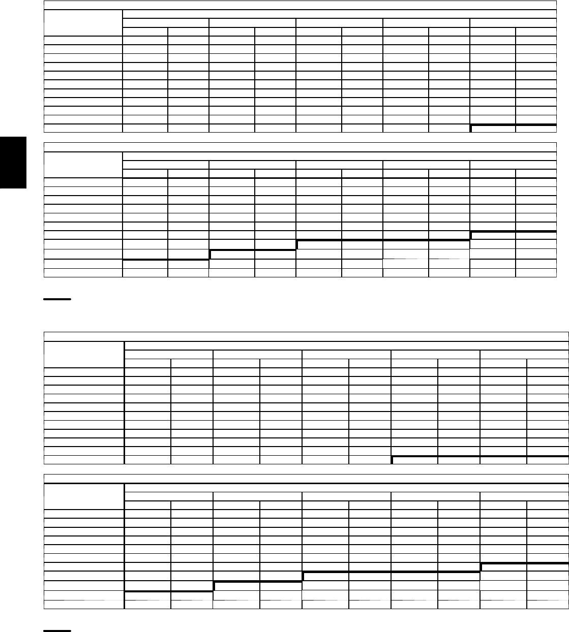
142
PERFORMANCE DATA (CONT)
Fan Performance — Horizontal Supply/Return Units
48PGE12 (Medium Heat Units)
AIRFLOW
(Cfm)
AVAILABLEEXTERNALSTATICPRESSURE(in.wg)
0.2 0.4 0.6 0.8 1.0
Rpm Bhp Rpm Bhp Rpm Bhp Rpm Bhp Rpm Bhp
3000 510 0.61 579 0.75 641 0.89 699 1.03 754 1.18
3200 535 0.72 600 0.87 660 1.01 716 1.16 769 1.32
3400 560 0.84 623 1.00 680 1.15 734 1.31 785 1.48
3600 585 0.98 645 1.14 701 1.31 753 1.47 802 1.65
3800 610 1.14 668 1.31 722 1.48 772 1.65 820 1.83
4000 635 1.30 691 1.48 743 1.66 792 1.85 839 2.03
4200 661 1.49 715 1.68 765 1.87 813 2.06 858 2.25
4400 687 1.69 739 1.89 788 2.09 834 2.29 878 2.49
4600 713 1.91 763 2.12 811 2.33 855 2.53 898 2.74
4800 739 2.15 788 2.37 834 2.58 877 2.80 919 3.02
5000 765 2.41 812 2.63 857 2.86 899 3.08 940 3.31
48PGE12 (Medium Heat Units) (cont)
AIRFLOW
(Cfm)
AVAILABLEEXTERNALSTATICPRESSURE(in.wg)
1.2 1.4 1.6 1.8 2.0
Rpm Bhp Rpm Bhp Rpm Bhp Rpm Bhp Rpm Bhp
3000 806 1.34 856 1.50 905 1.66 951 1.84 997 2.01
3200 820 1.48 868 1.65 915 1.82 961 2.00 1005 2.18
3400 834 1.64 881 1.82 927 2.00 971 2.18 1014 2.37
3600 850 1.82 896 2.00 940 2.19 983 2.38 1024 2.57
3800 866 2.01 911 2.20 954 2.39 995 2.59 1036 2.79
4000 884 2.22 927 2.42 969 2.61 1009 2.82 1049 3.02
4200 902 2.45 944 2.65 984 2.85 1024 3.06 1062 3.28
4400 920 2.69 961 2.90 1001 3.11 1039 3.33 1077 3.55
4600 939 2.96 979 3.17 1018 3.39 1055 3.61 — —
4800 959 3.24 998 3.46 1035 3.69 — — — —
5000 979 3.54 — — — — — — — —
LEGEND
B h p --- Brake Horsepower
High Range Motor/Drive Required
NOTES:
1. Motor drive range is 690 to 893 for low range motor/drive and 852 to 1055 rpm for
high range motor/drive. All other rpms require a field-supplied drive.
2. Maximum continuous bhp is 3.10 for low range motor/drive and 3.70 for high range
motor/drive.
3. See General Fan Performance Notes.
48PGF12 (High Heat Units)
AIRFLOW
(Cfm)
AVAILABLEEXTERNALSTATICPRESSURE(in.wg)
0.2 0.4 0.6 0.8 1.0
Rpm Bhp Rpm Bhp Rpm Bhp Rpm Bhp Rpm Bhp
3000 514 0.62 583 0.75 645 0.89 702 1.04 757 1.19
3200 540 0.73 605 0.88 665 1.02 720 1.18 773 1.33
3400 565 0.86 628 1.01 685 1.17 739 1.33 790 1.49
3600 591 1.00 651 1.16 706 1.33 758 1.49 808 1.66
3800 617 1.16 675 1.33 728 1.50 778 1.67 826 1.85
4000 643 1.33 699 1.51 750 1.69 799 1.87 845 2.06
4200 670 1.52 723 1.71 773 1.90 820 2.09 865 2.28
4400 696 1.72 748 1.92 796 2.12 842 2.32 885 2.52
4600 723 1.95 772 2.16 819 2.37 864 2.57 906 2.78
4800 749 2.19 797 2.41 843 2.63 886 2.84 927 3.06
5000 776 2.46 823 2.69 867 2.91 909 3.14 949 3.36
48PGF12 (High Heat Units) (cont)
AIRFLOW
(Cfm)
AVAILABLEEXTERNALSTATICPRESSURE(in.wg)
1.2 1.4 1.6 1.8 2.0
Rpm Bhp Rpm Bhp Rpm Bhp Rpm Bhp Rpm Bhp
3000 809 1.35 859 1.51 908 1.67 954 1.85 999 2.02
3200 823 1.50 872 1.66 919 1.84 964 2.01 1008 2.20
3400 839 1.66 886 1.83 931 2.01 975 2.20 1018 2.39
3600 855 1.84 900 2.02 944 2.21 987 2.40 1029 2.59
3800 872 2.04 916 2.22 959 2.42 1000 2.61 1041 2.81
4000 890 2.25 933 2.44 974 2.64 1015 2.85 1054 3.05
4200 908 2.48 950 2.68 990 2.89 1030 3.10 1068 3.31
4400 927 2.73 968 2.94 1007 3.15 1046 3.37 1083 3.59
4600 947 3.00 987 3.21 1025 3.43 1062 3.65 — —
4800 967 3.28 1006 3.51 — — — — — —
5000 988 3.59 — — — — — — — —
LEGEND
B h p --- Brake Horsepower
High Range Motor/Drive Required
NOTES:
1. Motor drive range is 690 to 893 for low range motor/drive and 852 to 1055 rpm for
high range motor/drive. All other rpms require a field-supplied drive.
2. Maximum continuous bhp is 3.10 for low range motor/drive and 3.70 for high range
motor/drive.
3. See General Fan Performance Notes.
48PG

143
Fan Performance — Horizontal Supply/Return Units
48PGD14 (Low Heat Units)
AIRFLOW
(Cfm)
AVAILABLEEXTERNALSTATICPRESSURE(in.wg)
0.2 0.4 0.6 0.8 1.0
Rpm Bhp Rpm Bhp Rpm Bhp Rpm Bhp Rpm Bhp
3750 591 1.06 651 1.23 706 1.40 757 1.57 806 1.75
3950 615 1.22 672 1.40 726 1.57 776 1.75 823 1.94
4150 639 1.39 695 1.58 746 1.76 795 1.95 841 2.14
4350 663 1.58 717 1.77 767 1.97 814 2.17 859 2.36
4550 688 1.78 740 1.99 788 2.19 834 2.40 878 2.60
4750 712 2.00 763 2.22 810 2.43 855 2.65 897 2.86
4950 737 2.24 786 2.47 832 2.69 875 2.91 917 3.14
5150 762 2.50 809 2.73 853 2.97 896 3.20 937 3.43
5350 787 2.77 832 3.02 876 3.26 917 3.50 957 3.75
5550 811 3.07 856 3.33 898 3.58 938 3.83 977 4.08
5750 836 3.39 879 3.65 920 3.92 960 4.18 998 4.44
5950 861 3.72 903 4.00 943 4.28 982 4.55 1019 4.81
6150 886 4.09 927 4.37 966 4.66 1004 4.94 1040 5.21
6250 899 4.28 939 4.57 977 4.85 1015 5.14 — —
48PGD14 (Low Heat Units) (cont)
AIRFLOW
(Cfm)
AVAILABLEEXTERNALSTATICPRESSURE(in.wg)
1.2 1.4 1.6 1.8 2.0
Rpm Bhp Rpm Bhp Rpm Bhp Rpm Bhp Rpm Bhp
3750 853 1.93 898 2.11 941 2.30 983 2.49 1025 2.69
3950 869 2.12 912 2.31 955 2.51 996 2.71 1036 2.91
4150 885 2.34 928 2.53 969 2.74 1009 2.94 1048 3.15
4350 902 2.57 944 2.77 984 2.98 1023 3.19 1061 3.41
4550 920 2.81 961 3.03 1000 3.24 1038 3.46 1075 3.68
4750 938 3.08 978 3.30 1016 3.52 1053 3.75 1090 3.98
4950 957 3.36 996 3.59 1033 3.82 1069 4.05 1105 4.29
5150 976 3.67 1014 3.90 1050 4.14 1086 4.38 1121 4.62
5350 995 3.99 1032 4.23 1068 4.48 1103 4.72 1137 4.97
5550 1015 4.33 1051 4.58 1086 4.84 1120 5.09 — —
5750 1035 4.70 1070 4.96 1105 5.22 — — — —
5950 1055 5.08 — — — — — — — —
6150 — — — — — — — — — —
6250 — — — — — — — — — —
LEGEND
B h p --- Brake Horsepower
High Range Motor/Drive Required
NOTES:
1. Motor drive range is 690 to 893 for low range motor/drive and 852 to 1055 rpm for
high range motor/drive. All other rpms require a field-supplied drive.
2. Maximum continuous bhp is 3.70 for low range motor/drive and 5.25 for high range
motor/drive.
3. See General Fan Performance Notes.
48PG

144
PERFORMANCE DATA (CONT)
Fan Performance — Horizontal Supply/Return Units
48PGE14 (Medium Heat Units)
AIRFLOW
(Cfm)
AVAILABLEEXTERNALSTATICPRESSURE(in.wg)
0.2 0.4 0.6 0.8 1.0
Rpm Bhp Rpm Bhp Rpm Bhp Rpm Bhp Rpm Bhp
3750 604 1.10 662 1.26 717 1.43 767 1.61 816 1.78
3950 629 1.26 686 1.44 738 1.62 787 1.80 834 1.98
4150 655 1.44 709 1.63 760 1.82 808 2.00 853 2.20
4350 681 1.64 733 1.83 782 2.03 829 2.23 873 2.43
4550 706 1.85 757 2.06 805 2.26 850 2.47 893 2.68
4750 732 2.09 782 2.30 828 2.52 872 2.73 914 2.95
4950 759 2.34 806 2.56 851 2.79 894 3.01 935 3.24
5150 785 2.61 831 2.85 874 3.08 916 3.31 956 3.54
5350 811 2.91 856 3.15 898 3.39 939 3.63 978 3.88
5550 838 3.22 881 3.48 922 3.73 961 3.98 999 4.23
5750 864 3.56 906 3.82 946 4.08 985 4.34 1022 4.60
5950 891 3.92 931 4.19 970 4.46 1008 4.73 1044 5.00
6150 917 4.31 957 4.59 995 4.87 1032 5.15 — —
6250 931 4.51 970 4.80 1007 5.08 — — — —
48PGE14 (Medium Heat Units) (cont)
AIRFLOW
(Cfm)
AVAILABLEEXTERNALSTATICPRESSURE(in.wg)
1.2 1.4 1.6 1.8 2.0
Rpm Bhp Rpm Bhp Rpm Bhp Rpm Bhp Rpm Bhp
3750 862 1.96 907 2.15 950 2.34 992 2.53 1033 2.73
3950 879 2.17 923 2.36 965 2.56 1006 2.76 1045 2.96
4150 897 2.39 939 2.59 980 2.79 1020 3.00 1059 3.21
4350 915 2.63 957 2.84 996 3.05 1035 3.26 1073 3.48
4550 934 2.89 975 3.10 1013 3.32 1051 3.54 1088 3.76
4750 954 3.16 993 3.39 1031 3.61 1068 3.84 1104 4.07
4950 974 3.46 1012 3.69 1049 3.92 1085 4.16 1120 4.39
5150 994 3.78 1032 4.02 1068 4.25 1103 4.50 1137 4.74
5350 1015 4.12 1051 4.36 1087 4.61 1121 4.86 1155 5.11
5550 1036 4.48 1072 4.73 1106 4.99 1140 5.24 — —
5750 1058 4.86 1092 5.12 — — — — — —
5950 — — — — — — — — — —
6150 — — — — — — — — — —
6250 — — — — — — — — — —
LEGEND
B h p --- Brake Horsepower
High Range Motor/Drive Required
NOTES:
1. Motor drive range is 690 to 893 for low range motor/drive and 852 to 1055 rpm for
high range motor/drive. All other rpms require a field-supplied drive.
2. Maximum continuous bhp is 3.70 for low range motor/drive and 5.25 for high range
motor/drive.
3. See General Fan Performance Notes.
48PG

145
Fan Performance — Horizontal Supply/Return Units
48PGF14 (High Heat Units)
AIRFLOW
(Cfm)
AVAILABLEEXTERNALSTATICPRESSURE(in.wg)
0.2 0.4 0.6 0.8 1.0
Rpm Bhp Rpm Bhp Rpm Bhp Rpm Bhp Rpm Bhp
3750 611 1.12 669 1.28 723 1.45 773 1.63 821 1.80
3950 637 1.28 693 1.46 745 1.64 794 1.82 840 2.01
4150 663 1.47 717 1.66 767 1.84 815 2.03 860 2.22
4350 690 1.67 742 1.87 790 2.06 836 2.26 880 2.46
4550 716 1.89 766 2.10 813 2.30 858 2.51 901 2.72
4750 743 2.13 791 2.35 837 2.56 880 2.77 922 2.99
4950 770 2.39 816 2.62 861 2.84 903 3.06 944 3.29
5150 796 2.67 842 2.90 885 3.14 926 3.37 965 3.60
5350 823 2.97 867 3.22 909 3.46 949 3.70 988 3.94
5550 850 3.29 893 3.55 933 3.80 972 4.05 1010 4.30
5750 877 3.64 918 3.90 958 4.16 996 4.42 1033 4.68
5950 904 4.01 944 4.28 983 4.55 1020 4.82 1056 5.09
6150 931 4.41 970 4.69 1008 4.97 1044 5.24 — —
6250 945 4.61 983 4.90 1020 5.18 — — — —
48PGF14 (High Heat Units) (cont)
AIRFLOW
(Cfm)
AVAILABLEEXTERNALSTATICPRESSURE(in.wg)
1.2 1.4 1.6 1.8 2.0
Rpm Bhp Rpm Bhp Rpm Bhp Rpm Bhp Rpm Bhp
3750 868 1.99 912 2.17 955 2.36 997 2.56 1038 2.76
3950 885 2.19 928 2.39 970 2.58 1011 2.79 1051 2.99
4150 904 2.42 946 2.62 986 2.82 1026 3.03 1065 3.24
4350 923 2.66 963 2.87 1003 3.08 1042 3.30 1079 3.52
4550 942 2.93 982 3.14 1021 3.36 1058 3.58 1095 3.81
4750 962 3.21 1001 3.43 1039 3.66 1075 3.88 1111 4.12
4950 983 3.51 1020 3.74 1057 3.97 1093 4.21 1128 4.45
5150 1004 3.84 1040 4.07 1076 4.31 1111 4.56 1146 4.80
5350 1025 4.18 1061 4.43 1096 4.67 1130 4.92 1164 5.18
5550 1046 4.55 1082 4.80 1116 5.06 — — — —
5750 1068 4.94 1103 5.20 — — — — — —
5950 — — — — — — — — — —
6150 — — — — — — — — — —
6250 — — — — — — — — — —
LEGEND
B h p --- Brake Horsepower
High Range Motor/Drive Required
NOTES:
1. Motor drive range is 690 to 893 for low range motor/drive and 852 to 1055 rpm for
high range motor/drive. All other rpms require a field-supplied drive.
2. Maximum continuous bhp is 3.70 for low range motor/drive and 5.25 for high range
motor/drive.
3. See General Fan Performance Notes.
48PG

146
PERFORMANCE DATA (CONT)
Fan Performance — Horizontal Supply/Return Units
48PGD16 (Low Heat Units)
Airflow
(Cfm)
Available External Static Pressure (in. wg)
0.2 0.4 0.6 0.8 1.0
Rpm Bhp Rpm Bhp Rpm Bhp Rpm Bhp Rpm Bhp
4500 633 1.01 709 1.32 771 1.62 826 1.91 877 2.20
4800 663 1.18 738 1.52 799 1.84 853 2.15 903 2.46
5100 694 1.37 768 1.73 828 2.07 881 2.41 930 2.74
5400 725 1.57 797 1.96 857 2.33 909 2.68 957 3.04
5700 757 1.80 828 2.22 886 2.61 938 2.99 985 3.36
6000 788 2.05 858 2.49 916 2.91 967 3.31 1013 3.71
6300 820 2.33 888 2.79 945 3.24 996 3.66 1042 4.08
6600 852 2.63 919 3.12 975 3.59 1025 4.04 1070 4.48
6900 884 2.95 949 3.47 1005 3.96 1055 4.44 1099 4.90
7200 916 3.31 980 3.85 1036 4.37 1084 4.87 1129 5.36
7500 949 3.69 1011 4.25 1066 4.80 1114 5.33 1158 5.84
48PGD16 (Low Heat Units) (cont)
Airflow
(Cfm)
Available External Static Pressure (in. wg)
1.2 1.4 1.6 1.8 2.0
Rpm Bhp Rpm Bhp Rpm Bhp Rpm Bhp Rpm Bhp
4500 925 2.50 971 2.80 1015 3.10 1059 3.41 1101 3.73
4800 950 2.77 994 3.09 1037 3.41 1079 3.73 1120 4.06
5100 975 3.07 1019 3.40 1060 3.74 1101 4.08 1140 4.42
5400 1002 3.39 1044 3.74 1085 4.09 1124 4.45 1162 4.81
5700 1029 3.73 1070 4.10 1110 4.47 1148 4.84 1185 5.22
6000 1056 4.10 1097 4.49 1136 4.88 1173 5.27 1210 5.66
6300 1084 4.49 1124 4.90 1162 5.31 1199 5.72 1235 6.13
6600 1112 4.91 1152 5.34 1189 5.77 1226 6.20 1260 6.63
6900 1141 5.36 1180 5.81 1217 6.26 1252 6.71 1287 7.15
7200 1170 5.84 1208 6.31 1245 6.78 1280 7.25 — —
7500 1199 6.35 1237 6.84 1273 7.33 — — — —
LEGEND
B h p --- Brake Horsepower
Mid--- Low Range Motor/Drive Required
High---Range Motor/Drive Required
NOTES:
1. Motor drive range is 710 to 879 for low range motor/drive, 872 to 1066 rpm for mid---
low range motor/drive, and 1066 to 1260 rpm for high range motor/drive. All other
rpms require a field-supplied drive.
2. Maximum continuous bhp is 3.70 for low range motor/drive, 5.25 for mid---low range
motor/drive, and 7.50 for high range motor/drive.
3. See General Fan Performance Notes.
48PG
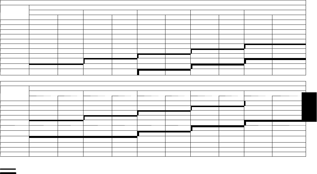
147
Fan Performance — Horizontal Supply/Return Units
48PGE16 (Medium Heat Units)
Airflow
(Cfm)
Available External Static Pressure (in. wg)
0.2 0.4 0.6 0.8 1.0
Rpm Bhp Rpm Bhp Rpm Bhp Rpm Bhp Rpm Bhp
4500 664 1.13 735 1.44 795 1.74 849 2.04 900 2.34
4800 698 1.33 767 1.66 826 1.99 878 2.30 927 2.62
5100 732 1.55 800 1.91 857 2.25 908 2.59 956 2.93
5400 767 1.79 832 2.17 889 2.54 939 2.90 985 3.26
5700 801 2.05 865 2.46 920 2.86 970 3.24 1015 3.61
6000 836 2.35 899 2.78 953 3.20 1001 3.60 1046 4.00
6300 871 2.67 932 3.13 985 3.57 1033 4.00 1077 4.42
6600 906 3.02 966 3.50 1018 3.97 1065 4.42 1108 4.87
6900 941 3.40 1000 3.91 1051 4.40 1097 4.88 1140 5.35
7200 977 3.81 1034 4.35 1084 4.87 1130 5.37 1171 5.86
7500 1012 4.26 1068 4.83 1118 5.37 1162 5.89 1203 6.41
48PGE16 (Medium Heat Units) (cont)
Airflow
(Cfm)
Available External Static Pressure (in. wg)
1.2 1.4 1.6 1.8 2.0
Rpm Bhp Rpm Bhp Rpm Bhp Rpm Bhp Rpm Bhp
4500 947 2.64 993 2.95 1038 3.26 1081 3.58 1123 3.90
4800 974 2.94 1018 3.26 1061 3.59 1102 3.92 1143 4.26
5100 1001 3.26 1044 3.60 1086 3.95 1126 4.29 1165 4.65
5400 1029 3.61 1071 3.97 1112 4.33 1151 4.69 1189 5.06
5700 1058 3.99 1099 4.37 1139 4.75 1177 5.13 1214 5.51
6000 1088 4.40 1128 4.79 1166 5.19 1203 5.59 1239 5.99
6300 1118 4.84 1157 5.25 1195 5.67 1231 6.08 1266 6.50
6600 1148 5.31 1187 5.74 1224 6.18 1259 6.61 1294 7.05
6900 1179 5.81 1217 6.26 1253 6.72 1288 7.17 — —
7200 1211 6.34 1248 6.82 1283 7.30 — — — —
7500 1242 6.91 1279 7.41 — — — — — —
LEGEND
B h p --- Brake Horsepower
Mid--- Low Range Motor/Drive Required
High---Range Motor/Drive Required
NOTES:
1. Motor drive range is 710 to 879 for low range motor/drive, 872 to 1066 rpm for mid---
low range motor/drive, and 1066 to 1260 rpm for high range motor/drive. All other
rpms require a field-supplied drive.
2. Maximum continuous bhp is 3.70 for low range motor/drive, 5.25 for mid---low range
motor/drive, and 7.50 for high range motor/drive.
3. See General Fan Performance Notes.
48PG
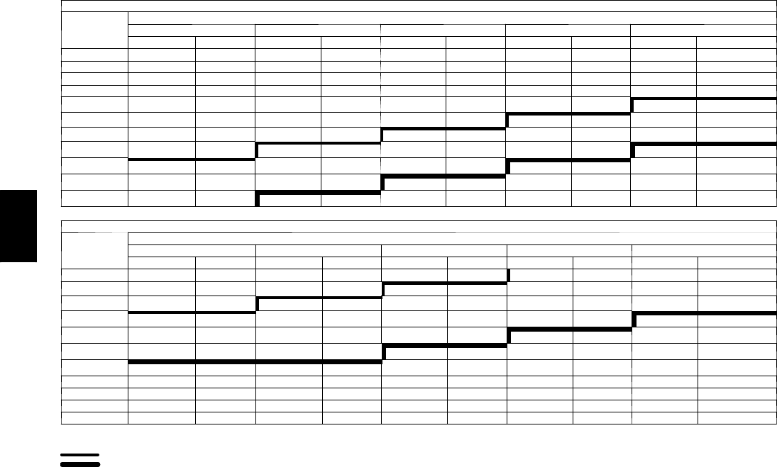
148
PERFORMANCE DATA (CONT)
Fan Performance — Horizontal Supply/Return Units
48PGF16 (High Heat Units)
Airflow
(Cfm)
Available External Static Pressure (in. wg)
0.2 0.4 0.6 0.8 1.0
Rpm Bhp Rpm Bhp Rpm Bhp Rpm Bhp Rpm Bhp
4500 705 1.31 771 1.62 828 1.92 881 2.23 931 2.54
4800 743 1.54 806 1.87 862 2.20 913 2.53 961 2.85
5100 781 1.80 842 2.16 896 2.51 946 2.85 993 3.20
5400 819 2.09 878 2.47 931 2.84 979 3.21 1025 3.57
5700 857 2.41 915 2.82 966 3.21 1013 3.60 1057 3.98
6000 896 2.76 952 3.19 1002 3.61 1048 4.02 1091 4.43
6300 935 3.15 989 3.60 1038 4.05 1083 4.48 1125 4.91
6600 974 3.57 1027 4.05 1074 4.52 1118 4.97 1159 5.42
6900 1013 4.03 1064 4.54 1111 5.03 1153 5.51 1194 5.98
7200 1052 4.54 1102 5.06 1148 5.58 1189 6.08 1229 6.57
7500 1092 5.08 1140 5.63 1185 6.17 1226 6.69 1264 7.21
48PGF16 (High Heat Units) (cont)
Airflow
(Cfm)
Available External Static Pressure (in. wg)
1.2 1.4 1.6 1.8 2.0
Rpm Bhp Rpm Bhp Rpm Bhp Rpm Bhp Rpm Bhp
4500 979 2.85 1024 3.16 1069 3.49 1112 3.82 1154 4.15
4800 1007 3.18 1051 3.51 1094 3.85 1136 4.20 1176 4.55
5100 1037 3.54 1080 3.90 1121 4.25 1161 4.61 1200 4.97
5400 1068 3.94 1109 4.31 1149 4.68 1188 5.06 1226 5.44
5700 1099 4.37 1140 4.76 1178 5.15 1216 5.54 1253 5.94
6000 1132 4.83 1171 5.24 1209 5.65 1245 6.06 1281 6.47
6300 1165 5.33 1203 5.76 1240 6.19 1275 6.61 ——
6600 1198 5.87 1235 6.32 1271 6.76 — — — —
6900 1232 6.45 1268 6.91 — — — — — —
7200 1266 7.06 — — — — — — — —
7500 — — — — — — — — — —
LEGEND
B h p --- Brake Horsepower
Mid--- Low Range Motor/Drive Required
High---Range Motor/Drive Required
NOTES:
1. Motor drive range is 710 to 879 for low range motor/drive, 872 to 1066 rpm for mid---
low range motor/drive, and 1066 to 1260 rpm for high range motor/drive. All other
rpms require a field-supplied drive.
2. Maximum continuous bhp is 3.70 for low range motor/drive, 5.25 for mid---low range
motor/drive, and 7.50 for high range motor/drive.
3. See General Fan Performance Notes.
48PG
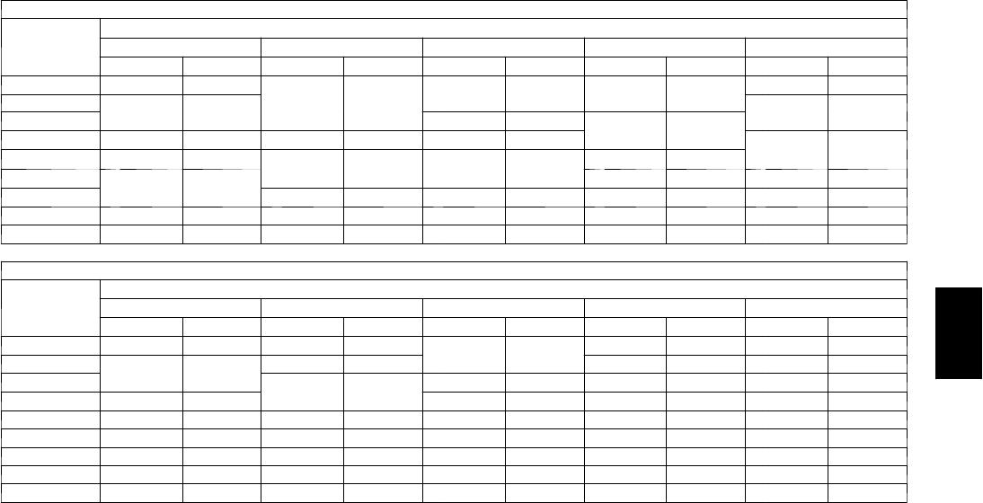
149
Fan Performance — Horizontal Supply/Return Units
48PGD20 (Low Heat Units)
Airflow
(Cfm)
Available External Static Pressure (in. wg)
0.2 0.4 0.6 0.8 1.0
Rpm Bhp Rpm Bhp Rpm Bhp Rpm Bhp Rpm Bhp
5000 862 2.65 917 2.93 F969 3.21 F1019 3.17 F1066 3.52
5500 F937 3.26 F988 3.56 1036 3.53 1083 3.90 G1127 4.28
6000 1013 3.58 1060 3.96 1105 4.35 G1149 4.75 1191 5.16
6500 1089 4.48 G1133 4.89 G1175 5.31 1216 5.73 H1256 6.17
7000 G1166 5.52 H1207 5.96 H1247 6.41 H1285 6.86 1323 7.32
7500 H1243 6.71 1282 7.18 1319 7.66 1355 8.14 1391 8.63
8000 1320 8.07 1356 8.57 — — — — — —
8500 — — — — — — — — — —
9000 — — — — — — — — — —
48PGD20 (Low Heat Units) (cont)
Airflow
(Cfm)
Available External Static Pressure (in. wg)
1.2 1.4 1.6 1.8 2.0
Rpm Bhp Rpm Bhp Rpm Bhp Rpm Bhp Rpm Bhp
5000 F1112 3.88 F1156 4.25 G1199 4.63 G1240 5.02 G1280 5.42
5500 G1171 4.67 G1212 5.06 1253 5.47 H1292 5.88 H1331 6.30
6000 1232 5.57 H1271 6.00 H1310 6.43 1348 6.87 1384 7.31
6500 H1295 6.61 1333 7.06 1369 7.52 — — — —
7000 1360 7.80 1396 8.27 — — — — — —
7500 — — — — — — — — — —
8000 — — — — — — — — — —
8500 — — — — — — — — — —
9000 — — — — — — — — — —
LEGEND
Bhp --- Brake Horsepower Input to Fan
Boldface indicates field--- supplied drive required.
NOTES:
1. Motor drive ranges:
(E) Low Range: Not Used
(F) Mid-Low Range: 896 to 1227 rpm, 4.26 Bhp (208/230 and 460-v), 873 to 1108 rpm, 5.75 Bhp (575-v)
(G) Mid-High Range: 1113 to 1414 rpm, 5.37 Bhp (208-v), 5.75 Bhp (230 and 460-v), 5.75 Bhp (575-v)
(H) High Range: 1096 to 1339 rpm, 7.76 Bhp (208-v), 8.51 Bhp (230-v), 8.63 Bhp (460 and 575-v)
All other rpms require field --- supplied drive.
2. See General Fan Performance Notes.
48PG

150
PERFORMANCE DATA (CONT)
Fan Performance — Horizontal Supply/Return Units
48PGE20 (Medium Heat Units)
Airflow
(Cfm)
Available External Static Pressure (in. wg)
0.2 0.4 0.6 0.8 1.0
Rpm Bhp Rpm Bhp Rpm Bhp Rpm Bhp Rpm Bhp
5000 875 2.74 931 3.04 F984 3.34 F1035 3.33 F1083 3.69
5500 F952 3.38 F1003 3.32 1053 3.70 1100 4.09 G1145 4.49
6000 1029 3.74 1077 4.15 G1123 4.56 G1167 4.98 1210 5.41
6500 1106 4.67 G1151 5.11 1194 5.56 H1236 6.01 H1276 6.47
7000 G1184 5.75 H1226 6.23 H1266 6.71 1306 7.19 1344 7.68
7500 H1262 7.00 1302 7.50 1340 8.01 1377 8.53 — —
8000 1341 8.41 — — — — — — — —
8500 — — — — — — — — — —
9000 — — — — — — — — — —
48PGE20 (Medium Heat Units) (cont)
Airflow
(Cfm)
Available External Static Pressure (in. wg)
1.2 1.4 1.6 1.8 2.0
Rpm Bhp Rpm Bhp Rpm Bhp Rpm Bhp Rpm Bhp
5000 F1130 4.07 G1174 4.45 G1218 4.84 G1259 5.23 G1300 5.63
5500 G1189 4.90 1232 5.31 1273 5.72 H1313 6.15 1352 6.58
6000 H1251 5.85 H1292 6.29 H1331 6.74 1369 7.19 — —
6500 1315 6.94 1354 7.41 1391 7.89 — — — —
7000 1381 8.18 — — — — — — — —
7500 — — — — — — — — — —
8000 — — — — — — — — — —
8500 — — — — — — — — — —
9000 — — — — — — — — — —
LEGEND
Bhp --- Brake Horsepower Input to Fan
Boldface indicates field--- supplied drive required.
NOTES:
1. Motor drive ranges:
(E) Low Range: Not Used
(F) Mid-Low Range: 896 to 1227 rpm, 4.26 Bhp (208/230 and 460-v), 873 to 1108 rpm, 5.75 Bhp (575-v)
(G) Mid-High Range: 1113 to 1414 rpm, 5.37 Bhp (208-v), 5.75 Bhp (230 and 460-v), 5.75 Bhp (575-v)
(H) High Range: 1096 to 1339 rpm, 7.66 Bhp (208-v), 8.51 Bhp (230-v), 8.63 Bhp (460 and 575-v)
All other rpms require field --- supplied drive.
2. See General Fan Performance Notes.
48PG
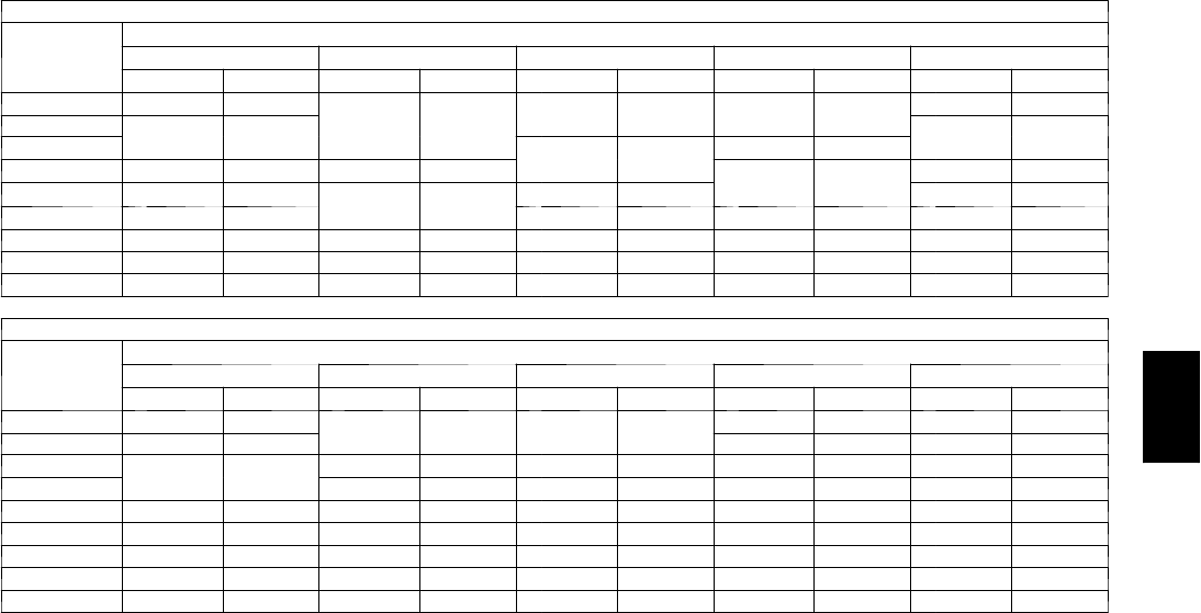
151
Fan Performance — Horizontal Supply/Return Units
48PGF20 (High Heat Units)
Airflow
(Cfm)
Available External Static Pressure (in. wg)
0.2 0.4 0.6 0.8 1.0
Rpm Bhp Rpm Bhp Rpm Bhp Rpm Bhp Rpm Bhp
5000 875 2.74 931 3.04 F984 3.34 F1035 3.33 F1083 3.69
5500 F952 3.38 F1003 3.32 1053 3.70 1100 4.09 G1145 4.49
6000 1029 3.74 1077 4.15 G1123 4.56 G1167 4.98 1210 5.41
6500 1106 4.67 G1151 5.11 1194 5.56 H1236 6.01 H1276 6.47
7000 G1184 5.75 H1226 6.23 H1266 6.71 1306 7.19 1344 7.68
7500 H1262 7.00 1302 7.50 1340 8.01 1377 8.53 — —
8000 1341 8.41 1378 8.95 — — — — — —
8500 — — — — — — — — — —
9000 — — — — — — — — — —
48PGF20 (High Heat Units) (cont)
Airflow
(Cfm)
Available External Static Pressure (in. wg)
1.2 1.4 1.6 1.8 2.0
Rpm Bhp Rpm Bhp Rpm Bhp Rpm Bhp Rpm Bhp
5000 F1130 4.07 G1174 4.45 G1218 4.84 G1259 5.23 G1300 5.63
5500 G1189 4.90 1232 5.31 1273 5.72 H1313 6.15 1352 6.58
6000 H1251 5.85 H1292 6.29 H1331 6.74 1369 7.19 — —
6500 1315 6.94 1354 7.41 1391 7.89 — — — —
7000 1381 8.18 — — — — — — — —
7500 — — — — — — — — — —
8000 — — — — — — — — — —
8500 — — — — — — — — — —
9000 — — — — — — — — — —
LEGEND
Bhp --- Brake Horsepower Input to Fan
Boldface indicates field--- supplied drive required.
NOTES:
1. Motor drive ranges:
(E) Low Range: Not Used
(F) Mid-Low Range: 896 to 1227 rpm, 4.26 Bhp (208/230 and 460-v), 873 to 1108 rpm, 5.75 Bhp (575-v)
(G) Mid-High Range: 1113 to 1414 rpm, 5.37 Bhp (208-v), 5.75 Bhp (230 and 460-v), 5.75 Bhp (575-v)
(H) High Range: 1096 to 1339 rpm, 7.66 Bhp (208-v), 8.51 Bhp (230-v), 8.63 Bhp (460 and 575-v)
All other rpms require field --- supplied drive.
2. See General Fan Performance Notes.
48PG
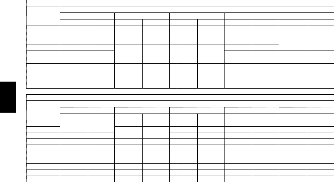
152
PERFORMANCE DATA (CONT)
Fan Performance — Horizontal Supply/Return Units
48PGD24 (Low Heat Units)
Airflow
(Cfm)
Available External Static Pressure (in. wg)
0.2 0.4 0.6 0.8 1.0
Rpm Bhp Rpm Bhp Rpm Bhp Rpm Bhp Rpm Bhp
5500 F937 3.26 F988 3.56 F1036 3.53 F1083 3.90 G1127 4.28
6000 1013 3.58 1060 3.96 1105 4.35 G1149 4.75 1191 5.16
6500 1089 4.48 G1133 4.89 G1175 5.31 1216 5.73 H1256 6.17
7000 G1166 5.52 H1207 5.96 H1247 6.41 H1285 6.86 1323 7.32
7500 H1243 6.71 1282 7.18 1319 7.66 1355 8.14 1391 8.63
8000 1320 8.07 1356 8.57 — — — — — —
8500 — — — — — — — — — —
9000 — — — — — — — — — —
9500 — — — — — — — — — —
10000 — — — — — — — — — —
48PGD24 (Low Heat Units) (cont)
Airflow
(Cfm)
Available External Static Pressure (in. wg)
1.2 1.4 1.6 1.8 2.0
Rpm Bhp Rpm Bhp Rpm Bhp Rpm Bhp Rpm Bhp
5500 G1171 4.67 G1212 5.06 G1253 5.47 H1292 5.88 H1331 6.30
6000 1232 5.57 H1271 6.00 H1310 6.43 1348 6.87 1384 7.31
6500 H1295 6.61 1333 7.06 1369 7.52 — — — —
7000 1360 7.80 1396 8.27 — — — — — —
7500 — — — — — — — — — —
8000 — — — — — — — — — —
8500 — — — — — — — — — —
9000 — — — — — — — — — —
9500 — — — — — — — — — —
10000 — — — — — — — — — —
LEGEND
Bhp --- Brake Horsepower Input to Fan
Boldface indicates field--- supplied drive required.
NOTES:
1. Motor drive ranges:
(E) Low Range: Not Used
(F) Mid-Low Range: 896 to 1227 rpm, 4.26 Bhp (208/230 and 460-v), 873 to 1108 rpm, 5.75 Bhp (575-v)
(G) Mid-High Range: 1113 to 1414 rpm, 5.37 Bhp (208-v), 5.75 Bhp (230 and 460-v), 5.75 Bhp (575-v)
(H) High Range: 1096 to 1339 rpm, 7.66 Bhp (208-v), 8.51 Bhp (230-v), 8.63 Bhp (460 and 575-v)
All other rpms require field --- supplied drive.
2. See General Fan Performance Notes.
48PG
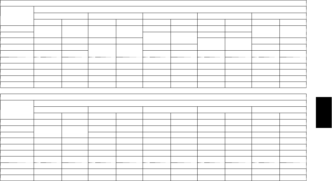
153
Fan Performance — Horizontal Supply/Return Units
48PGE24 (Medium Heat Units)
Airflow
(Cfm)
Available External Static Pressure (in. wg)
0.2 0.4 0.6 0.8 1.0
Rpm Bhp Rpm Bhp Rpm Bhp Rpm Bhp Rpm Bhp
5500 F952 3.38 F1003 3.32 F1053 3.70 F1100 4.09 G1145 4.49
6000 1029 3.74 1077 4.15 G1123 4.56 G1167 4.98 1210 5.41
6500 1106 4.67 G1151 5.11 1194 5.56 H1236 6.01 H1276 6.47
7000 G1184 5.75 H1226 6.23 H1266 6.71 1306 7.19 1344 7.68
7500 H1262 7.00 1302 7.50 1340 8.01 1377 8.53 — —
8000 1341 8.41 — — — — — — — —
8500 — — — — — — — — — —
9000 — — — — — — — — — —
9500 — — — — — — — — — —
10000 — — — — — — — — — —
48PGE24 (Medium Heat Units) (cont)
Airflow
(Cfm)
Available External Static Pressure (in. wg)
1.2 1.4 1.6 1.8 2.0
Rpm Bhp Rpm Bhp Rpm Bhp Rpm Bhp Rpm Bhp
5500 G1189 4.90 G1232 5.31 G1273 5.72 H1313 6.15 1352 6.58
6000 H1251 5.85 H1292 6.29 H1331 6.74 1369 7.19 — —
6500 1315 6.94 1354 7.41 1391 7.89 — — — —
7000 1381 8.18 — — — — — — — —
7500 — — — — — — — — — —
8000 — — — — — — — — — —
8500 — — — — — — — — — —
9000 — — — — — — — — — —
9500 — — — — — — — — — —
10000 — — — — — — — — — —
LEGEND
Bhp --- Brake Horsepower Input to Fan
Boldface indicates field--- supplied drive required.
NOTES:
1. Motor drive ranges:
(E) Low Range: Not Used
(F) Mid-Low Range: 896 to 1227 rpm, 4.26 Bhp (208/230 and 460-v), 873 to 1108 rpm, 5.75 Bhp (575-v)
(G) Mid-High Range: 1113 to 1414 rpm, 5.37 Bhp (208-v), 5.75 Bhp (230 and 460-v), 5.75 Bhp (575-v)
(H) High Range: 1096 to 1339 rpm, 7.66 Bhp (208-v), 8.51 Bhp (230-v), 8.63 Bhp (460 and 575-v)
All other rpms require field --- supplied drive.
2. See General Fan Performance Notes.
48PG
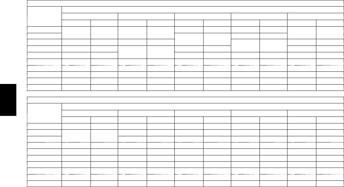
154
PERFORMANCE DATA (CONT)
Fan Performance — Horizontal Supply/Return Units
48PGF24 (High Heat Units)
Airflow
(Cfm)
Available External Static Pressure (in. wg)
0.2 0.4 0.6 0.8 1.0
Rpm Bhp Rpm Bhp Rpm Bhp Rpm Bhp Rpm Bhp
5500 F952 3.38 F1003 3.32 F1053 3.70 F1100 4.09 G1145 4.49
6000 1029 3.74 1077 4.15 G1123 4.56 G1167 4.98 1210 5.41
6500 1106 4.67 G1151 5.11 1194 5.56 H1236 6.01 H1276 6.47
7000 G1184 5.75 H1226 6.23 H1266 6.71 1306 7.19 1344 7.68
7500 H1262 7.00 1302 7.50 1340 8.01 1377 8.53 — —
8000 1341 8.41 — — — — — — — —
8500 — — — — — — — — — —
9000 — — — — — — — — — —
9500 — — — — — — — — — —
10000 — — — — — — — — — —
48PGF24 (High Heat Units) (cont)
Airflow
(Cfm)
Available External Static Pressure (in. wg)
1.2 1.4 1.6 1.8 2.0
Rpm Bhp Rpm Bhp Rpm Bhp Rpm Bhp Rpm Bhp
5500 G1189 4.90 G1232 5.31 G1273 5.72 H1313 6.15 1352 6.58
6000 H1251 5.85 H1292 6.29 H1331 6.74 1369 7.19 — —
6500 1315 6.94 1354 7.41 1391 7.89 — — — —
7000 1381 8.18 — — — — — — — —
7500 — — — — — — — — — —
8000 — — — — — — — — — —
8500 — — — — — — — — — —
9000 — — — — — — — — — —
9500 — — — — — — — — — —
10000 — — — — — — — — — —
LEGEND
Bhp --- Brake Horsepower Input to Fan
Boldface indicates field--- supplied drive required.
NOTES:
1. Motor drive ranges:
(E) Low Range: Not Used
(F) Mid-Low Range: 896 to 1227 rpm, 4.26 Bhp (208/230 and 460-v), 873 to 1108 rpm, 5.75 Bhp (575-v)
(G) Mid-High Range: 1113 to 1414 rpm, 5.37 Bhp (208-v), 5.75 Bhp (230 and 460-v), 5.75 Bhp (575-v)
(H) High Range: 1096 to 1339 rpm, 7.66 Bhp (208-v), 8.51 Bhp (230-v), 8.63 Bhp (460 and 575-v)
All other rpms require field --- supplied drive.
2. See General Fan Performance Notes.
48PG

155
Fan Performance — Horizontal Supply/Return Units
48PGD28 (Low Heat Units)
Airflow
(Cfm)
Available External Static Pressure (in. wg)
0.2 0.4 0.6 0.8 1.0
Rpm Bhp Rpm Bhp Rpm Bhp Rpm Bhp Rpm Bhp
6500 E786 2.50 E819 2.70 E857 2.96
F
899 3.25 F943 3.59
7000 842 3.09 871 3.30
F
905 3.55 943 3.85 983 4.19
7500 F898 3.77 F925 3.99 955 4.24 989 4.54
G
1026 4.88
8000 955 4.55 979 4.77 1007 5.03
G
1037 5.33 1070 5.67
8500
G
1012 5.42
G
1034 5.65
G
1059 5.92 1087 6.22 1117 6.56
9000 1069 6.41 1090 6.65 1113 6.92 1138 7.23 1165 7.57
9500 1127 7.51 1146 7.76 1167 8.04
H
1190 8.35 H1215 8.69
10000 H1184 8.74 H1202 8.99 H1221 9.28 1243 9.59 1266 9.93
10500 1242 10.09 1258 10.35 1276 10.64 1296 10.96 1318 11.31
11000 — — — — — — — — — —
11500 — — — — — — — — — —
12000 — — — — — — — — — —
12500 — — — — — — — — — —
48PGD28 (Low Heat Units) (cont)
Airflow
(Cfm)
Available External Static Pressure (in. wg)
1.2 1.4 1.6 1.8 2.0
Rpm Bhp Rpm Bhp Rpm Bhp Rpm Bhp Rpm Bhp
6500 F988 3.97
G
1035 4.39
G
1082 4.87 G1129 5.39
H
1177 5.95
7000
G
1024 4.57 1066 4.98 1109 5.43 1153 5.93 1197 6.48
7500 1063 5.25 1102 5.66 1141 6.11
H
1181 6.59 1221 7.11
8000 1105 6.04 1140 6.45 1176 6.89 1213 7.36 1250 7.87
8500 1149 6.94
H
1181 7.34
H
1215 7.78 1249 8.25 1283 8.74
9000
H
1194 7.94 1225 8.35 1256 8.79 1287 9.25 1319 9.74
9500 1242 9.07 1270 9.47 1298 9.91 1328 10.37 1358 10.87
10000 1290 10.31 1316 10.72 1343 11.16 — — ——
10500 — — — — — — — — — —
11000 — — — — — — — — — —
11500 — — — — — — — — — —
12000 — — — — — — — — — —
12500 — — — — — — — — — —
LEGEND
Bhp --- Brake Horsepower Input to Fan
Boldface indicates field--- supplied drive required.
NOTES:
1. Motor drive ranges:
(E) Low Range: 687 to 873 rpm, 5.37 Bhp (208---v), 5.75 Bhp (230 and 460--- v), 5.75 Bhp (575---v)
(F) Mid-Low Range: 805 to 1007 rpm, 5.37 Bhp (208-v), 5.75 bhp (230 and 460--- v), 5.75 Bhp (575-v)
(G) Mid-High Range: 941 to 1176 rpm, 7.66 Bhp (208-v), 8.51 Bhp (230-v), 8.63 Bhp (460 and 575-v)
(H) High Range: 1014 to 1297 rpm, 9.94 Bhp (208-v), 10.45 Bhp (230-v), 11.19 Bhp (460-v), 11.50 Bhp (575---v)
All other rpms require field --- supplied drive.
2. See General Fan Performance Notes.
48PG
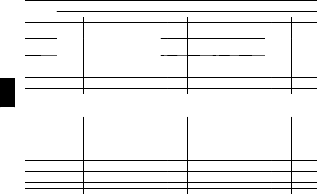
156
PERFORMANCE DATA (CONT)
Fan Performance — Horizontal Supply/Return Units
48PGE28 (Medium Heat Units)
Airflow
(Cfm)
Available External Static Pressure (in. wg)
0.2 0.4 0.6 0.8 1.0
Rpm Bhp Rpm Bhp Rpm Bhp Rpm Bhp Rpm Bhp
6500 E799 2.58 E883 2.79 E872 3.05
F
914 3.36 F958 3.71
7000 856 3.19 887 3.41 F921 3.67 958 3.98 999 4.33
7500 F913 3.89 F941 4.12 972 4.39 1006 4.69 1042 5.04
8000 971 4.69 996 4.93
G
1024 5.20
G
1055 5.51 G1088 5.86
8500
G
1029 5.60
G
1052 5.85 1078 6.12 1106 6.44 1136 6.78
9000 1087 6.62 1108 6.87 1132 7.16 1158 7.47
H
1185 7.82
9500 1145 7.75 1165 8.02 H1187 8.31 H1211 8.63 1236 8.99
10000 H1203 9.01 H1222 9.29 1243 9.59 1265 9.92 1288 10.28
10500 1261 10.40 1279 10.69 1299 11.00 1319 11.34 — —
11000 — — — — — — — — — —
11500 — — — — — — — — — —
12000 — — — — — — — — — —
12500 — — — — — — — — — —
48PGE28 (Medium Heat Units) (cont)
Airflow
(Cfm)
Available External Static Pressure (in. wg)
0.2 0.4 0.6 0.8 1.0
Rpm Bhp Rpm Bhp Rpm Bhp Rpm Bhp Rpm Bhp
6500 F1005 4.12
G
1052 4.57
G
1100 5.06 G1148 5.60
H
1195 6.17
7000
G
1041 4.72 1084 5.16 1128 5.64 1172 6.17 1217 6.74
7500 1080 5.43 1119 5.86 1160 6.33
H
1201 6.84 1242 7.40
8000 1122 6.24 1158 6.66
H
1195 7.13 1233 7.63 1272 8.17
8500 1167 7.16
H
1200 7.58 1234 8.04 1269 8.53 1304 9.06
9000 H1214 8.21 1244 8.62 1275 9.07 1308 9.56 1340 10.08
9500 1262 9.37 1290 9.78 1319 10.23 1349 10.71 1379 11.23
10000 1312 10.66 1338 11.08 — — — — — —
10500 — — — — — — — — — —
11000 — — — — — — — — — —
11500 — — — — — — — — — —
12000 — — — — — — — — — —
12500 — — — — — — — — — —
LEGEND
Bhp --- Brake Horsepower Input to Fan
Boldface indicates field--- supplied drive required.
NOTES:
1. Motor drive ranges:
(E) Low Range: 687 to 873 rpm, 5.37 Bhp (208---v), 5.75 Bhp (230 and 460--- v), 5.75 Bhp (575---v)
(F) Mid-Low Range: 805 to 1007 rpm, 5.37 Bhp (208-v), 5.75 bhp (230 and 460--- v), 5.75 Bhp (575-v)
(G) Mid-High Range: 941 to 1176 rpm, 7.66 Bhp (208-v), 8.51 Bhp (230-v), 8.63 Bhp (460 and 575-v)
(H) High Range: 1014 to 1297 rpm, 9.94 Bhp (208-v), 10.45 Bhp (230-v), 11.19 Bhp (460-v), 11.50 Bhp (575---v)
All other rpms require field --- supplied drive.
2. See General Fan Performance Notes.
48PG
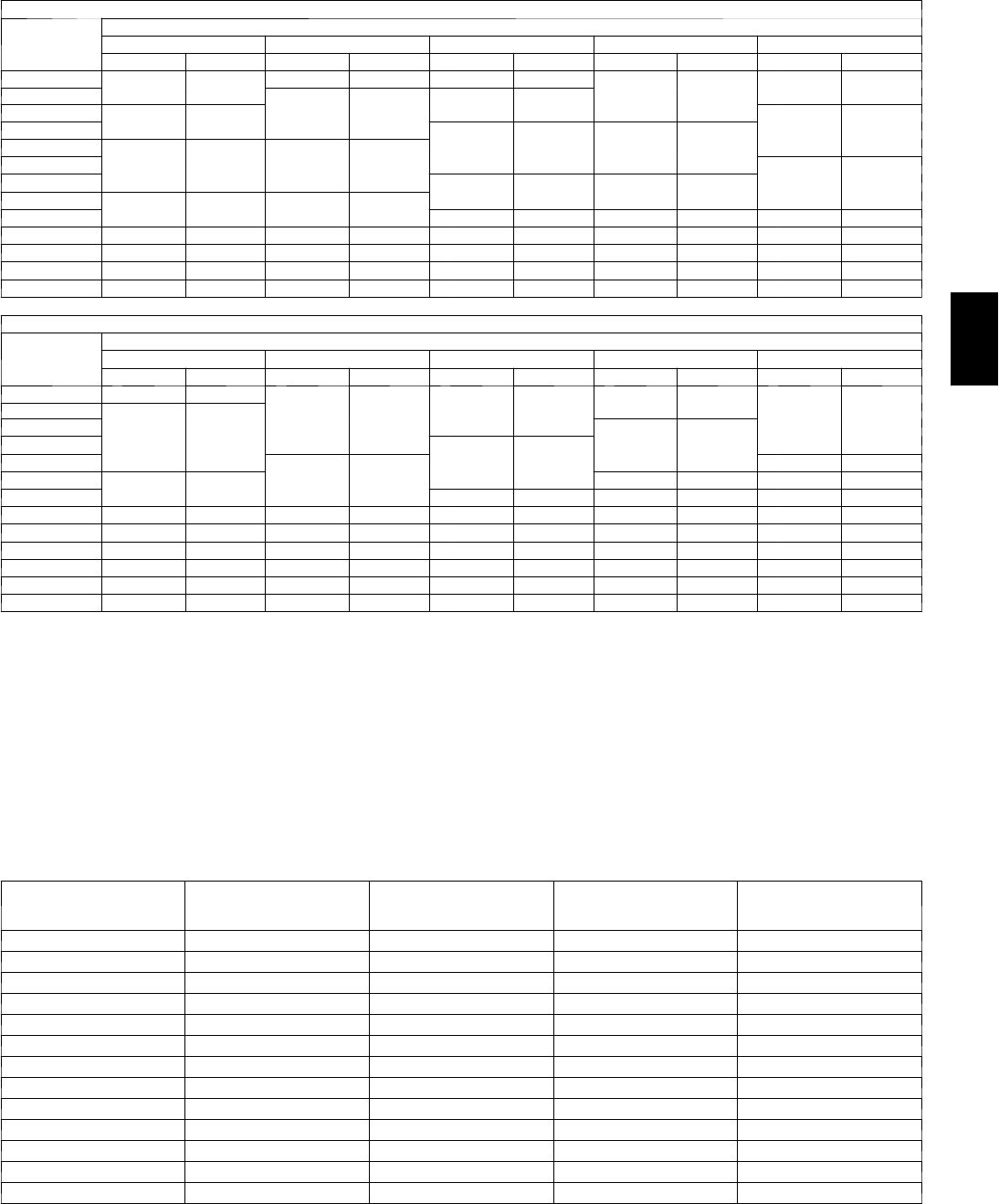
157
Fan Performance — Horizontal Supply/Return Units
48PGF28 (High Heat Units)
Airflow
(Cfm)
Available External Static Pressure (in. wg)
0.2 0.4 0.6 0.8 1.0
Rpm Bhp Rpm Bhp Rpm Bhp Rpm Bhp Rpm Bhp
6500 E799 2.58 E883 2.79 E872 3.05
F
914 3.36 F958 3.71
7000 856 3.19 887 3.41 F921 3.67 958 3.98 999 4.33
7500 F913 3.89 F941 4.12 972 4.39 1006 4.69 1042 5.04
8000 971 4.69 996 4.93
G
1024 5.20
G
1055 5.51 G1088 5.86
8500
G
1029 5.60
G
1052 5.85 1078 6.12 1106 6.44 1136 6.78
9000 1087 6.62 1108 6.87 1132 7.16 1158 7.47
H
1185 7.82
9500 1145 7.75 1165 8.02 H1187 8.31 H1211 8.63 1236 8.99
10000 H1203 9.01 H1222 9.29 1243 9.59 1265 9.92 1288 10.28
10500 1261 10.40 1279 10.69 1299 11.00 1319 11.34 — —
11000 — — — — — — — — — —
11500 — — — — — — — — — —
12000 — — — — — — — — — —
12500 — — — — — — — — — —
48PGF28 (High Heat Units) (cont)
Airflow
(Cfm)
Available External Static Pressure (in. wg)
0.2 0.4 0.6 0.8 1.0
Rpm Bhp Rpm Bhp Rpm Bhp Rpm Bhp Rpm Bhp
6500 F1005 4.12
G
1052 4.57
G
1100 5.06 G1148 5.60
H
1195 6.17
7000
G
1041 4.72 1084 5.16 1128 5.64 1172 6.17 1217 6.74
7500 1080 5.43 1119 5.86 1160 6.33
H
1201 6.84 1242 7.40
8000 1122 6.24 1158 6.66
H
1195 7.13 1233 7.63 1272 8.17
8500 1167 7.16
H
1200 7.58 1234 8.04 1269 8.53 1304 9.06
9000 H1214 8.21 1244 8.62 1275 9.07 1308 9.56 1340 10.08
9500 1262 9.37 1290 9.78 1319 10.23 1349 10.71 1379 11.23
10000 1312 10.66 1338 11.08 — — — — — —
10500 — — — — — — — — — —
11000 — — — — — — — — — —
11500 — — — — — — — — — —
12000 — — — — — — — — — —
12500 — — — — — — — — — —
LEGEND
Bhp --- Brake Horsepower Input to Fan
Boldface indicates field--- supplied drive required.
NOTES:
1. Motor drive ranges:
(E) Low Range: 687 to 873 rpm, 5.37 Bhp (208---v), 5.75 Bhp (230 and 460--- v), 5.75 Bhp (575---v)
(F) Mid-Low Range: 805 to 1007 rpm, 5.37 Bhp (208-v), 5.75 bhp (230 and 460--- v), 5.75 Bhp (575-v)
(G) Mid-High Range: 941 to 1176 rpm, 7.66 Bhp (208-v), 8.51 Bhp (230-v), 8.63 Bhp (460 and 575-v)
(H) High Range: 1014 to 1297 rpm, 9.94 Bhp (208-v), 10.45 Bhp (230-v), 11.19 Bhp (460-v), 11.50 Bhp (575---v)
All other rpms require field --- supplied drive.
2. See General Fan Performance Notes.
Accessory/Fiop Pressure Drop (in. wg)* — 48PG03--07
AIRFLOW
(CFM)
ECONOMIZER
(VERTICAL)
(Sizes 03 --- 07)
ECONOMIZER
(HORIZONTAL)
(Sizes 03 --- 07)
HUMIDI --- MIZER™SYSTEM
(Sizes 03 --- 04)
HUMIDI --- MIZER SYSTEM
(Sizes 05 --- 07)
600 0.01 0.03 0.01 —
800 0.01 0.05 0.02 —
1000 0.02 0.07 0.03 —
1200 0.03 0.10 0.04 0.02
1400 0.04 0.14 0.04 0.03
1600 0.06 0.17 0.05 0.03
1800 0.07 0.22 —0.04
2000 0.09 0.26 —0.04
2200 0.11 0.31 —0.05
2400 0.13 0.37 —0.06
2600 0.15 0.43 —0.06
2800 0.18 0.49 —0.07
3000 0.21 0.56 —0.08
LEGEND
FIOP --- F a c t o r y --- I n s t a l l e d O p t i o n
* The static pressure must be added to the external static pressure. The sum and the
evaporator entering--- air cfm should then be used in conjunction with the Fan Perform-
ance tables to determine blower rpm and watts.
48PG

158
PERFORMANCE DATA (CONT)
Accessory/Fiop Pressure Drop (in.wg)* — 48PG08--14
AIRFLOW
(CFM)
ECONOMIZER
Vertical
ECONOMIZER
Horizontal
HUMIDI-MIZER
SYSTEM
2250 0.05 0.10 0.03
2650 0.06 0.13 0.03
3050 0.08 0.17 0.04
3450 0.09 0.21 0.05
3850 0.10 0.26 0.06
4250 0.12 0.31 0.07
4650 0.13 0.37 0.08
5050 0.15 0.44 0.09
5450 0.17 0.50 0.10
5850 0.18 0.58 0.11
6250 0.20 0.66 0.12
LEGEND
FIOP --- F a c t o r y --- I n s t a l l e d O p t io n
*The static pressure must be added to the external static pressure. The sum
and the evaporator entering---air cfm should then be used in conjunction
with the Fan Performance tables to determine blower rpm and watts.
Accessory/Fiop Pressure Drop (in.wg)* — 48PG16
AIRFLOW
(CFM)
ECONOMIZER HUMIDI-MIZER
SYSTEM
Vertical Horizontal
4500 0.03 0.31 0.02
4800 0.04 0.35 0.02
5100 0.04 0.38 0.03
5400 0.05 0.41 0.03
5700 0.05 0.45 0.04
6000 0.06 0.49 0.04
6300 0.06 0.52 0.05
6600 0.07 0.56 0.05
6900 0.08 0.61 0.06
7200 0.08 0.65 0.07
7500 0.09 0.69 0.07
LEGEND
FIOP --- F a c t o r y --- I n s t a l l e d O p t io n
*The static pressure must be added to the external static pressure. The sum
and the evaporator entering---air cfm should then be used in conjunction
with the Fan Performance tables to determine blower rpm and watts.
Accessory/Fiop Pressure Drop (in.wg)* — 48PG20--28
COMPONENT CFM
4,000 4,500 5,000 5,500 6,000 6,500 7,000 7,500 8,000 8,500 9,000 9,500 10,000 10,500 11,000 11,500 12,000
Economizer 0.02 0.03 0.04 0.05 0.06 0.07 0.08 0.09 0.10 0.11 0.12 0.13 0.15 0.16 0.17 0.19 0.20
Humidi-MiZer™
(20,24) — — — 0.24 0.27 0.31 0.35 0.39 0.43 0.48 0.52 0.57 0.62 ————
Humidi-MiZer
(28) —————0.19 0.21 0.23 0.26 0.29 0.31 0.34 0.37 0.40 0.43 0.46 0.50
LEGEND
FIOP --- F a c t o r y --- I n s t a l l e d O p t io n
*The static pressure must be added to the external static pressure. The sum and the evaporator entering---air cfm should then be used in conjunction with the
Fan Performance tables to determine blower rpm and watts.
Power Exhaust Performance -- 48PG03--16
C08189
Barometric Relief Flow Capacity -- 48PG03--16
0
50
0
100
0
150
0
200
0
250
0
0.05 0.15 0.25
STATIC PRESSURE (in. wg)
FLOW IN CUBIC FEET PER MINUTE (cfm)
BAROMETRIC RELIEF AIR
48PG03-07
48PG08-16
C08190
Outdoor Air Damper Leakage -- 48PG03--16
0
5
10
15
20
25
30
0.13 0.20 0.22 0.25 0.30 0.35 0.40 0.45 0.50
STATIC PRESSURE (in. wg)
FLOW IN CUBIC FEET PER MINUTE (cfm)
48PG03-07
48PG08-16
C08191
48PG
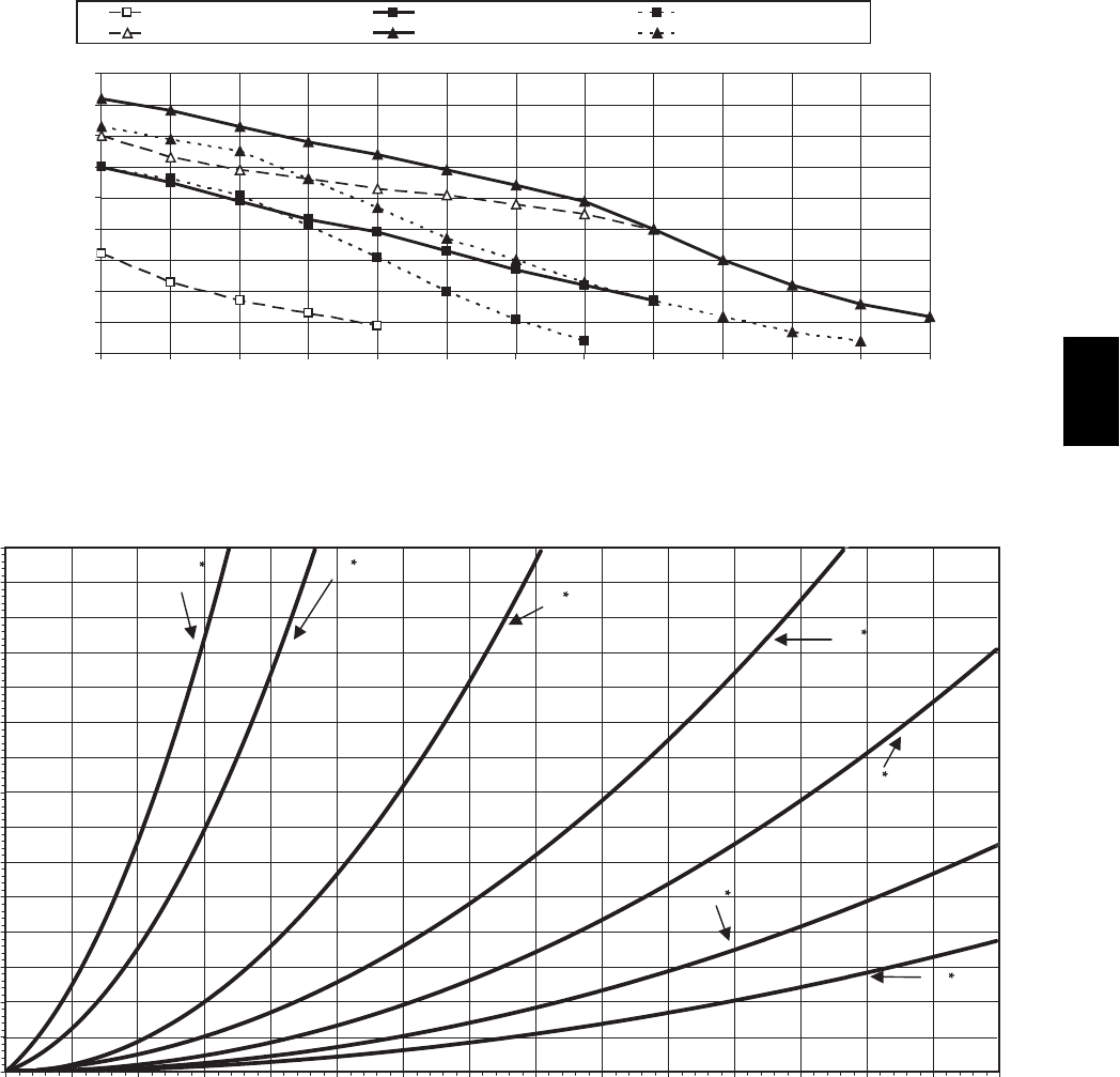
159
Power Exhaust Fan Performance -- 48PG20--28
0
0.1
0.2
0.3
0.4
0.5
0.6
0.7
0.8
0.9
3250 3350 3450 3550 3650 3750 3850 3950 4050 4250 4450 4650 4850
Exhaust Airflow (CFM)
Static Pressure Between Return Duct and OA (in. wg)
Low Speed 208 V Med Speed 208 V High Speed 208 V
Low Speed 230,460,575V Med Speed 230,460,575V High Speed 230,460,575V
C08197
48PG03--07 Two--Position Damper Performance
0.75
0.70
0.65
0.60
0.55
0.50
0.45
0.40
0.35
0.30
0.25
0.20
0.15
0.10
0.05
0.00
0 200 400 600 800 1000 1200 1400 1600 1800 2000 2200 2400 2600 2800 3000
CFM (Cubic Feet Per Minute)
0.4 0.5
0.6
0.7
0
.
8
0.9
1.0
C08192
48PG
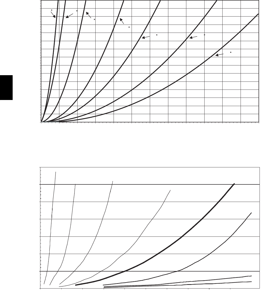
160
48PG08--14 Two--Position Damper Performance
0.75
0.70
0.65
0.60
0.55
0.50
0.45
0.40
0.35
0.30
0.25
0.20
0.15
0.10
0.05
0.00
0 500 1000 1500 2000 2500 3000 3500 4000 4500 5000 5500 6000
CFM (Cubic Feet Per Minute)
Static Pressure (in . wg)
1.0
0.90.8
0.7
0.6
0.5
0.4
Return Duct
C08193
48PG16 Two--Position Damper Performance
0.00
0.20
0.40
0.60
0.80
1.00
1.20
1.40
0 500 1000 1500 2000 2500 3000 3500 4000 4500 5000
CFM (Cubic Feet Per Minute)
0.5
0.
0.8
1.0
RETURN DUCT STATIC PRESSURE (in.wg)
0.1*
0.2*
0.3*
0.4*
0.5*
0.5
0.6*
0.
0.5
0.8*
0.
0.5
1.0*
*
Two-position damper position (outdoor air marking on actuator).
pg131a
C08194
48PG
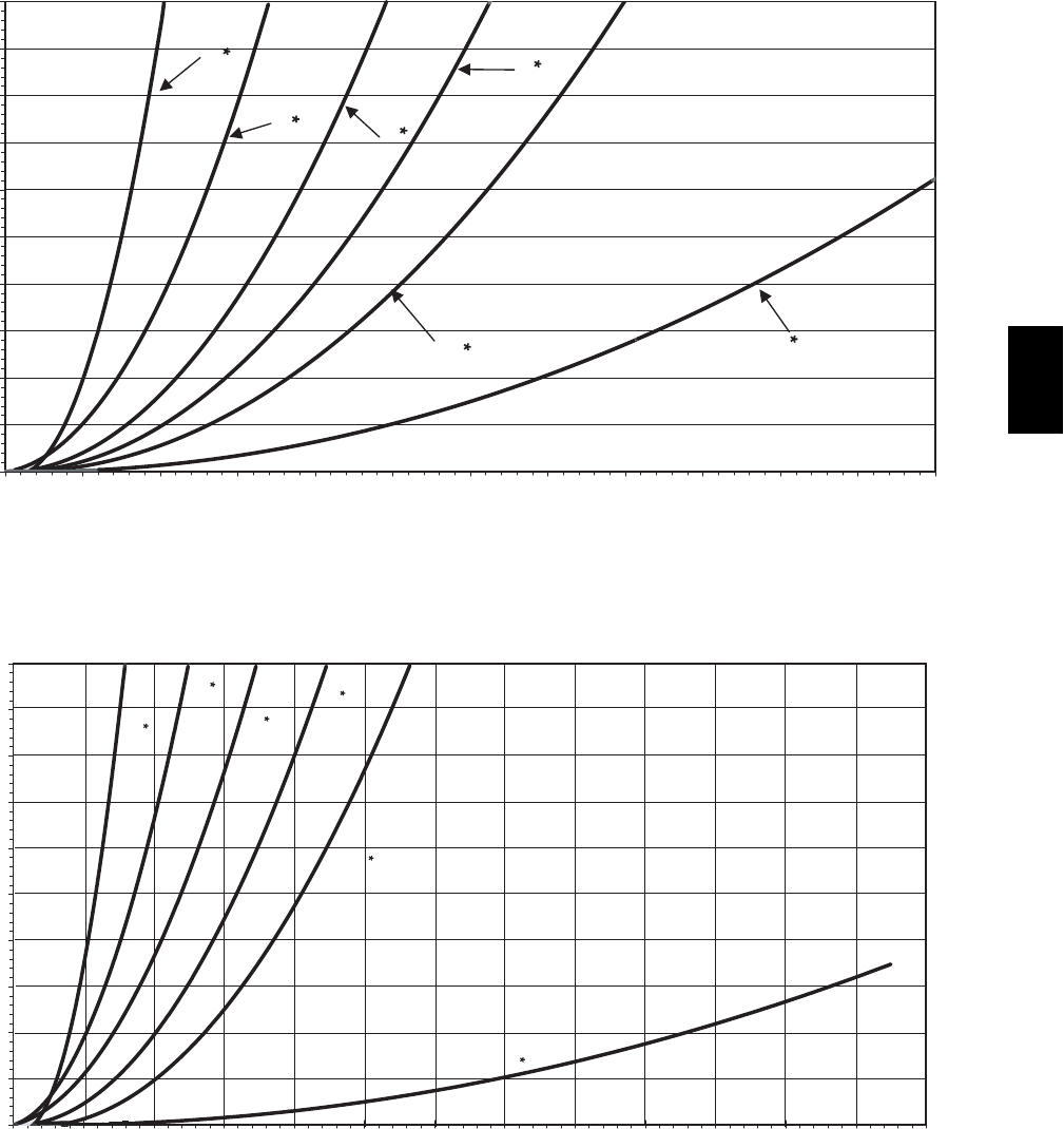
161
48PG03--07 Manual Air Damper Performance
1.00
0.90
0.80
0.70
0.60
0.50
0.40
0.30
0.20
0.10
0.00
0 250 500 750 1000 1250 1500 1750 2000 2250 2500 2750 3000
CFM (Cubic Feet Per Minute)
Static Pressure (in. wg)
5
.2
5
"
4"
3"
2"
1"
2
5
.
5
"
Return Duct
(BLADE REMOVED)
C08195
48PG08--16 Manual Air Damper Performance
1.00
0.90
0.80
0.70
0.60
0.50
0.40
0.30
0.20
0.10
0.00
0 500 1000 1500 2000 2500 3000 3500 4000 4500 5000 5500 6000 6500
CFM (Cubic Feet Per Minute)
Static Pressure (in. wg)
20"
5.25"
4"
3"
2"
1"
Return Duct
C08196
48PG
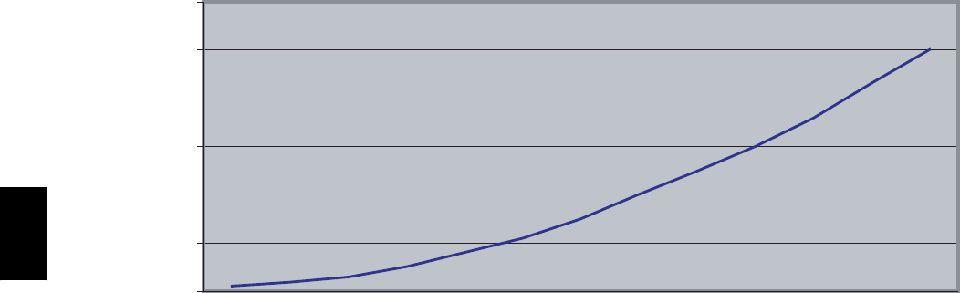
162
48PG20--28 Barometric Relief Flow Capacity
0
0.1
0.2
0.3
0.4
0.5
0.6
250 500 750 1000 1250 1500 1750 2000 2250 2500 2750 3000 3250
CFM
PD
C08198
48PG
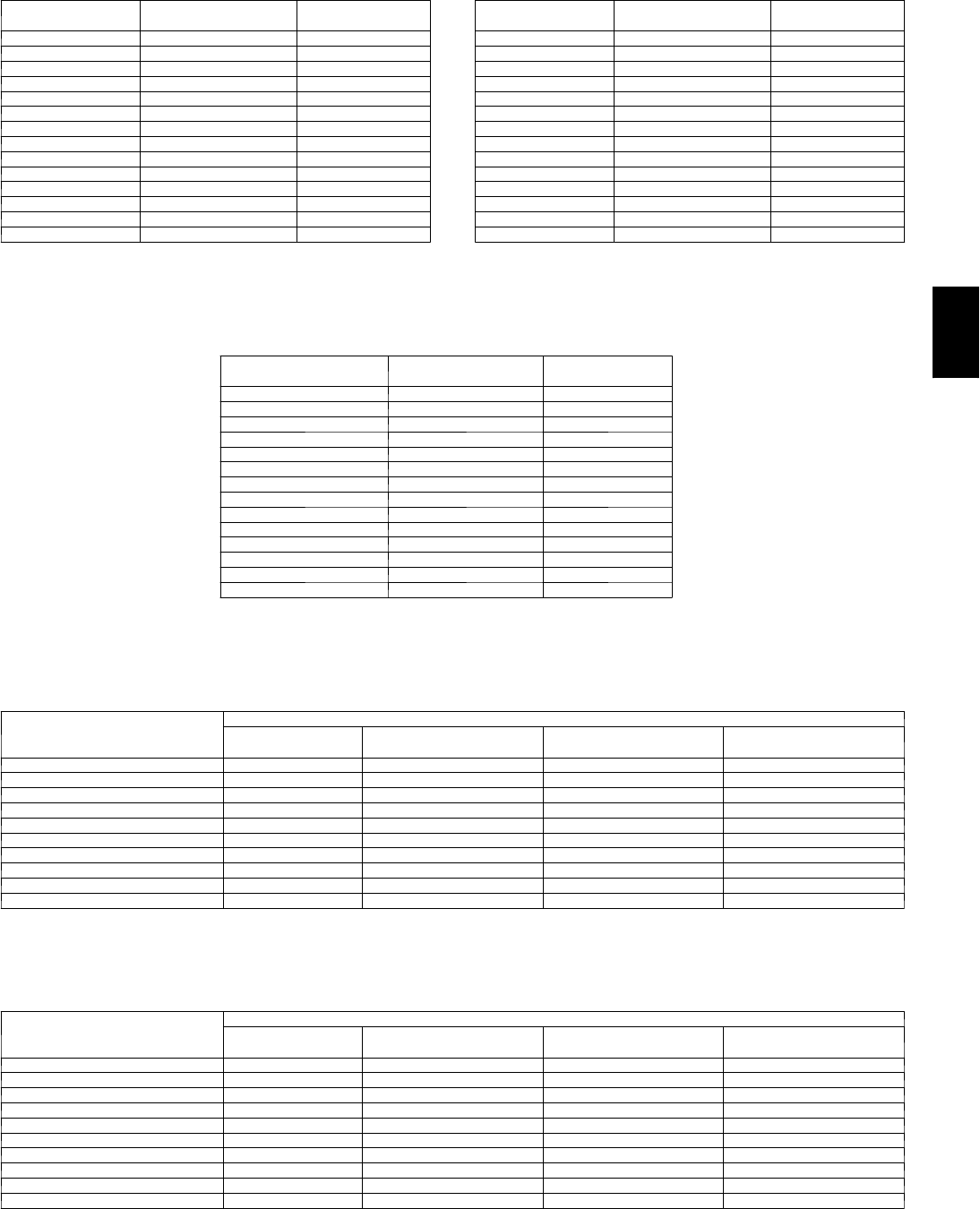
163
Altitude Compensation* — 48PG03--07
ELEVATION
(ft)
NATURAL GAS
ORIFICE SIZE{
LP
ORIFICE SIZE{
0 --- 1,999 45 52
2,000 47 52
3,000 47 53
4,000 47 53
5,000 48 53
6,000 48 53
7,000 48 53
8,000 49 54
9,000 49 54
10,000 50 54
11,000 51 54
12,000 51 55
13,000 52 55
14,000 52 56
* As the height above sea level increases, there is less oxygen per cubic foot of
air. Therefore, heat input rate should be reduced at higher altitudes. Includes a 4%
input reduction per each 1000 ft.
{Orifices available through your local Carrier dealer.
Altitude Compensation* — 48PG08--14
ELEVATION
(ft)
NATURAL GAS
ORIFICE SIZE{
LP
ORIFICE SIZE{
0 --- 1,999 43 50
2,000 44 51
3,000 44 51
4,000 44 51
5,000 45 51
6,000 45 52
7,000 47 52
8,000 47 52
9,000 47 53
10,000 48 53
11,000 49 53
12,000 50 54
13,000 50 54
14,000 51 55
* As the height above sea level increases, there is less oxygen per cubic foot of
air. Therefore, heat input rate should be reduced at higher altitudes. Includes a 4%
input reduction per each 1000 ft.
{Orifices available through your local Carrier dealer.
Altitude Compensation* — 48PG16
ELEVATION
(ft)
NATURAL GAS
ORIFICE SIZE{
LP
ORIFICE SIZE{
0--1,999 30 38
2,000 30 40
3,000 31 40
4,000 31 41
5,000 31 41
6,000 31 42
7,000 32 42
8,000 32 43
9,000 32 43
10,000 35 44
11,000 36 44
12,000 37 45
13,000 38 46
14,000 39 47
* As the height above sea level increases, there is less oxygen per cubic foot of air.
Therefore, heat input rate should be reduced at higher altitudes. Includes a 4% input
reduction per each 1000 ft.
{Orifices available through your local Carrier dealer.
Altitude Compensation* — 48PG20--28 (Natural Gas)
ELEVATION (FT)
NATURAL GAS ORIFICE SIZE{
LOW HEAT MEDIUM HEAT HIGH HEAT
(6 CELL)
HIGH HEAT
(8 CELL)
0 --- 1,999 29 30 29 29
2,000 29 30 29 29
3,000 30 31 30 30
4,000 30 31 30 30
5,000 30 31 30 30
6,000 30 31 30 30
7,000 31 32 31 31
8,000 31 32 31 31
9,000 31 32 31 31
10,000 32 33 32 32
* As the height above sea level increases, there is less oxygen per cubic foot of air. Therefore, heat input rate should be reduced at higher altitudes. Includes a
4% input reduction per each 1000 ft.
{Orifices available through your local Carrier dealer.
Altitude Compensation* — 48PG20--28 (Propane Gas)
ELEVATION (FT)
PROPANE GAS ORIFICE SIZE[
LOW HEAT MEDIUM HEAT HIGH HEAT
(6 CELL)
HIGH HEAT
(8 CELL)
0 --- 1,999 35 38 35 35
2,000 36 39 36 36
3,000 36 39 36 36
4,000 37 40 37 37
5,000 37 40 37 37
6,000 38 41 38 38
7,000 39 42 39 39
8,000 40 43 40 40
9,000 41 44 41 41
10,000 42 45 42 42
* As the height above sea level increases, there is less oxygen per cubic foot of air. Therefore, heat input rate should be reduced at higher altitudes. Includes a
4% input reduction per each 1000 ft.
{Orifices available through your local Carrier dealer.
48PG
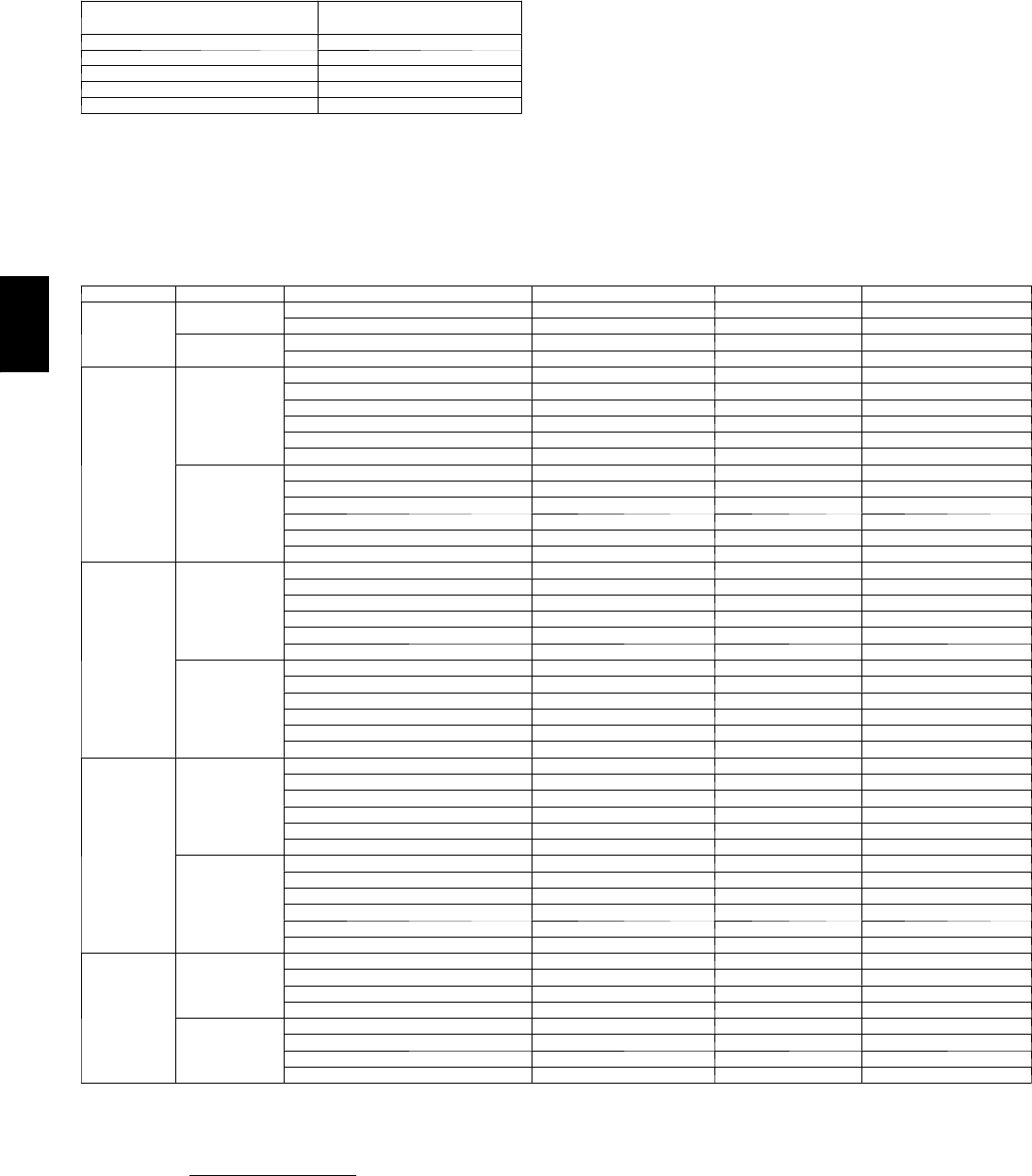
164
PERFORMANCE DATA (CONT)
Altitude Derating Factor* — 48PG03--28
ELEVATION
(ft)
MAXIMUM HEATING
(Btu/ft3)
0 --- 2,000 1,100
2,001 --- 3,000 1,050
3,001 --- 4,000 1,000
4,001 --- 5,000 950
5,001 --- 6,000 900
* Derating of the gas heating equipment to compensate for the effects of
altitude is always required. Orifice change is not required if the fuel heating
value (at sea level) is below the limits listed in the table above. Derating
conditions must be 4% per thousand ft above sea level. For example, at 400
ft, if the heating value of the gas exceeds 100 Btu/ft3, the unit will require a
16% derating. For elevations above 600 ft, the same formula applies. For
example, at 7000 ft, the unit will require a 28% derating of the maximum
heating value per the National Fuel Gas Code.
Evaporator Fan Motor Specifications — 48PG03--16
48PG DRIVE VOLTAGE/PHASE EFFICIENCY MAX BHP MAX AMPS
03
Low 208/1ph 0.73 0.85 4.0
230/1ph 0.73 0.85 4.0
High 208/1ph 0.73 0.85 4.0
230/1ph 0.73 0.85 4.0
04
Low
208/1ph 0.73 0.85 4.0
230/1ph 0.73 0.85 4.0
208/3ph 0.73 0.85 4.0
230/3ph 0.73 0.85 4.0
460/3ph 0.73 0.85 2.0
575/3ph 0.73 0.85 1.6
High
208/1ph 0.73 0.85 4.0
230/1ph 0.73 0.85 4.0
208/3ph 0.73 0.85 4.0
230/3ph 0.73 0.85 4.0
460/3ph 0.73 0.85 2.0
575/3ph 0.73 0.85 1.6
05
Low
208/1ph 0.73 0.85 4.0
230/1ph 0.73 0.85 4.0
208/3ph 0.73 0.85 4.0
230/3ph 0.73 0.85 4.0
460/3ph 0.73 0.85 2.0
575/3ph 0.73 0.85 1.6
High
208/1ph 0.78 1.6 8.3
230/1ph 0.78 1.6 8.3
208/3ph 0.80 2.4 6.4
230/3ph 0.80 2.4 6.4
460/3ph 0.80 2.4 3.2
575/3ph 0.80 2.4 2.4
06
Low
208/1ph 0.73 0.85 4.0
230/1ph 0.73 0.85 4.0
208/3ph 0.80 2.4 6.4
230/3ph 0.80 2.4 6.4
460/3ph 0.80 2.4 3.2
575/3ph 0.80 2.4 2.4
High
208/1ph 0.78 1.6 8.3
230/1ph 0.78 1.6 8.3
208/3ph 0.80 2.4 6.4
230/3ph 0.80 2.4 6.4
460/3ph 0.80 2.4 3.2
575/3ph 0.80 2.4 2.4
07
Low
208/3ph 0.80 2.4 6.4
230/3ph 0.80 2.4 6.4
460/3ph 0.80 2.4 3.2
575/3ph 0.80 2.4 2.4
High
208/3ph 0.84 3.1 8.8
230/3ph 0.84 3.1 8.8
460/3ph 0.84 3.1 4.4
575/3ph 0.82 3.1 4.2
NOTES:
1. Extensive motor and electrical testing ensures that the motors can be utilized with confidence up to the maximum applied bhp, watts, and amps. Using the fan
motor up to the maximum ratings shown will not result in nuisance tripping or premature motor failure. Unit warranty will not be affected.
2. Convert bhp to watts using the following formula:
watts = bhp (746)
motor efficiency
3. The EPACT (Energy Policy Act of 1992) regulates energy requirements for specific types of indoor fan motors. Motors regulated by EPACT include any gener
al purpose, T---frame (three ---digit, 143 and larger), single---speed, foot mounted, polyphase, squirrel cage induction motors of NEMA (National Electrical
Manufacturers Association) design A and B, manufactured for use in the United States. Ranging from 1 to 200 Hp, these continuous---duty motors operateon
230 and 460 volt, 60 Hz power. If a motor does not fit into these specifications, the motor does not have to be replaced by an EPACT---compliant energy---effi
cient motor. Variable---speed motors are exempt from EPACT compliance requirements. Therefore, the indoor fan motors for Carrier 48PG03---16 unitsare
exempt from these requirements.
48PG
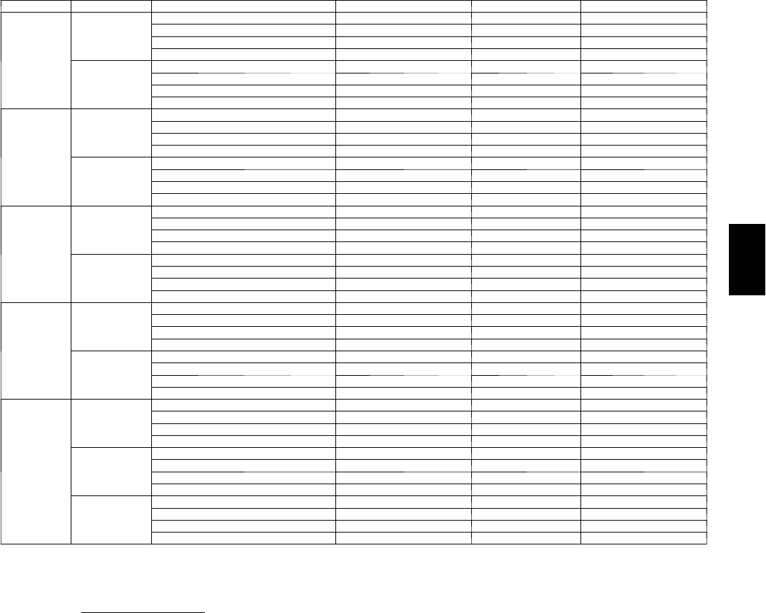
165
Evaporator Fan Motor Specifications (cont) — 48PG03--16
48PG DRIVE VOLTAGE/PHASE EFFICIENCY MAX BHP MAX AMPS
08
Low
208/3ph 0.80 2.4 6.4
230/3ph 0.80 2.4 6.4
460/3ph 0.80 2.4 3.2
575/3ph 0.80 2.4 2.4
High
208/3ph 0.84 3.1 8.8
230/3ph 0.84 3.1 8.8
460/3ph 0.84 3.1 4.4
575/3ph 0.82 3.1 4.2
09
Low
208/3ph 0.80 2.4 6.4
230/3ph 0.80 2.4 6.4
460/3ph 0.80 2.4 3.2
575/3ph 0.80 2.4 2.4
High
208/3ph 0.83 3.7 11.0
230/3ph 0.83 3.7 11.0
460/3ph 0.83 3.7 5.5
575/3ph 0.82 3.7 4.2
12
Low
208/3ph 0.84 3.1 8.8
230/3ph 0.84 3.1 8.8
460/3ph 0.84 3.1 4.4
575/3ph 0.82 3.1 4.2
High
208/3ph 0.83 3.7 11.0
230/3ph 0.83 3.7 11.0
460/3ph 0.83 3.7 5.5
575/3ph 0.82 3.7 4.2
14
Low
208/3ph 0.83 3.7 11.0
230/3ph 0.83 3.7 11.0
460/3ph 0.83 3.7 5.5
575/3ph 0.82 3.7 4.2
High
208/3ph 0.81 5.25 14.8
230/3ph 0.81 5.25 14.8
460/3ph 0.81 5.25 7.4
575/3ph 0.81 5.25 5.9
16
Low
208/3ph 0.83 3.7 10.3
230/3ph 0.83 3.7 10.3
460/3ph 0.83 3.7 5.2
575/3ph 0.83 3.7 4.2
M i d --- L o w
208/3ph 0.81 5.25 12.7
230/3ph 0.81 5.25 12.7
460/3ph 0.81 5.25 6.4
575/3ph 0.81 5.25 5.9
High
208/3ph 0.89 7.5 19.4
230/3ph 0.89 7.5 19.4
460/3ph 0.89 7.5 9.7
575/3ph 0.81 7.5 7.8
NOTES:
1. Extensive motor and electrical testing ensures that the motors can be utilized with confidence up to the maximum applied bhp, watts, and amps. Using the fan
motor up to the maximum ratings shown will not result in nuisance tripping or premature motor failure. Unit warranty will not be affected.
2. Convert bhp to watts using the following formula:
watts = bhp (746)
motor efficiency
3. The EPACT (Energy Policy Act of 1992) regulates energy requirements for specific types of indoor fan motors. Motors regulated by EPACT include any gener
al purpose, T---frame (three ---digit, 143 and larger), single---speed, foot mounted, polyphase, squirrel cage induction motors of NEMA (National Electrical
Manufacturers Association) design A and B, manufactured for use in the United States. Ranging from 1 to 200 Hp, these continuous---duty motors operateon
230 and 460 volt, 60 Hz power. If a motor does not fit into these specifications, the motor does not have to be replaced by an EPACT---compliant energy---effi
cient motor. Variable---speed motors are exempt from EPACT compliance requirements. Therefore, the indoor fan motors for Carrier 48PG03---16 unitsare
exempt from these requirements.
48PG
166
PERFORMANCE DATA (CONT)
Evaporator Fan Motor Specifications (cont) — 48PG20--28
UNIT
48PG DRIVE ORIENTATION VOLTAGE EFFICIENCY % MAX BHP MAX AMPS
20
Low Vertical
208 85.8 4.26 10.6
230 85.8 4.26 9.6
460 85.8 4.26 4.8
575 87.5 5.75 6.0
M i d --- L o w Vertical
208 87.5 5.37 15.8
230 87.5 5.75 15.4
460 87.5 5.75 7.7
575 87.5 5.75 6.0
M i d --- H i g h Vertical
208 88.5 7.66 22.0
230 88.5 8.51 22.0
460 88.5 8.63 11.6
575 88.5 8.63 9.4
High Vertical
208 89.5 9.94 28.0
230 89.5 10.45 28.0
460 89.5 11.19 15.0
575 89.5 11.50 12.0
Low Horizontal
208 N/A N/A N/A
230 N/A N/A N/A
460 N/A N/A N/A
575 N/A N/A N/A
M i d --- L o w Horizontal
208 85.8 4.26 10.6
230 85.8 4.26 9.6
460 85.8 4.26 4.8
575 87.5 5.75 6.0
M i d --- H i g h Horizontal
208 87.5 5.37 15.8
230 87.5 5.75 15.4
460 87.5 5.75 7.7
575 87.5 5.75 6.0
High Horizontal
208 88.5 7.66 22.0
230 88.5 8.51 22.0
460 88.5 8.63 11.6
575 88.5 8.63 9.4
24
Low Vertical
208 85.8 4.26 10.6
230 85.8 4.26 9.6
460 85.8 4.26 4.8
575 87.5 5.75 6.0
M i d --- L o w Vertical
208 87.5 5.37 15.8
230 87.5 5.75 15.4
460 87.5 5.75 7.7
575 87.5 5.75 6.0
M i d --- H i g h Vertical
208 88.5 7.66 22.0
230 88.5 8.51 22.0
460 88.5 8.63 11.6
575 88.5 8.63 9.4
High Vertical
208 89.5 9.94 28.0
230 89.5 10.45 28.0
460 89.5 11.19 15.0
575 89.5 11.50 12.0
Low Horizontal
208 N/A N/A N/A
230 N/A N/A N/A
460 N/A N/A N/A
575 N/A N/A N/A
M i d --- L o w Horizontal
208 85.8 4.26 10.6
230 85.8 4.26 9.6
460 85.8 4.26 4.8
575 87.5 5.75 6.0
M i d --- H i g h Horizontal
208 87.5 5.37 15.8
230 87.5 5.75 15.4
460 87.5 5.75 7.7
575 87.5 5.75 6.0
High Horizontal
208 88.5 7.66 22.0
230 88.5 8.51 22.0
460 88.5 8.63 11.6
575 88.5 8.63 9.4
48PG
167
Evaporator Fan Motor Specifications — 48PG20--28 (cont)
UNIT
48PG DRIVE ORIENTATION VOLTAGE EFFICIENCY % MAX BHP MAX AMPS
28
Low Vertical
208 87.5 5.37 15.8
230 87.5 5.75 15.4
460 87.5 5.75 7.7
575 87.5 5.75 6.0
M i d --- L o w Vertical
208 87.5 5.37 15.8
230 87.5 5.75 15.4
460 87.5 5.75 7.7
575 87.5 5.75 6.0
M i d --- H i g h Vertical
208 88.5 7.66 22.0
230 88.5 8.51 22.0
460 88.5 8.63 11.6
575 88.5 8.63 9.4
High Vertical
208 89.5 9.94 28.0
230 89.5 10.45 28.0
460 89.5 11.19 15.0
575 89.5 11.50 12.0
Low Horizontal
208 87.5 5.37 15.8
230 87.5 5.75 15.4
460 87.5 5.75 7.7
575 87.5 5.75 6.0
M i d --- L o w Horizontal
208 87.5 5.37 15.8
230 87.5 5.75 15.4
460 87.5 5.75 7.7
575 87.5 5.75 6.0
M i d --- H i g h Horizontal
208 88.5 7.66 22.0
230 88.5 8.51 22.0
460 88.5 8.63 11.6
575 88.5 8.63 9.4
High Horizontal
208 89.5 9.94 28.0
230 89.5 10.45 28.0
460 89.5 11.19 15.0
575 89.5 11.50 12.0
NOTES:
1. Extensive motor and electrical testing ensures that the motors can be utilized with confidence up to the maximum applied bhp, watts, and amps. Using the fan
motor up to the maximum ratings shown will not result in nuisance tripping or premature motor failure. Unit warranty will not be affected.
2. All Indoor---fan motors 5 hp and larger meet the minimum efficiency requirements as established by the Energy Policy Act of 1992 (EPACT) effective October
24, 1997.
Fan Rpm at Motor Pulley Settings* — 48PG03--16
UNIT 48PG DRIVE MOTOR PULLEY TURNS OPEN
01/2 11--1/2 22--1/2 33--1/2 44--1/2 5
03 Low 736 710 685 660 634 609 583 558 533 507 482
High 1001 966 932 897 863 828 794 759 725 690 656
04 Low 736 710 685 660 634 609 583 558 533 507 482
High 1128 1095 1062 1028 995 962 929 896 863 829 796
05 Low 910 878 847 815 784 753 721 690 659 627 596
High 1173 1139 1104 1070 1035 1001 966 932 897 863 828
06 Low 978 949 920 891 863 834 805 776 748 719 690
High 1261 1227 1194 1161 1128 1095 1062 1028 995 962 929
07 Low 1128 1095 1062 1028 995 962 929 896 863 829 796
High 1438 1409 1380 1351 1323 1294 1265 1236 1208 1179 1150
08 Low 771 751 731 710 690 670 649 629 609 589 568
High 1015 994 974 954 934 913 893 873 852 832 812
09 Low 771 751 731 710 690 670 649 629 609 589 568
High 1015 994 974 954 934 913 893 873 852 832 812
12 Low 893 873 852 832 812 791 771 751 731 710 690
High 1055 1035 1015 994 974 954 934 913 893 873 852
14 Low 893 873 852 832 812 791 771 751 731 710 690
High 1055 1035 1015 994 974 954 934 913 893 873 852
16
Low 879 863 846 829 812 795 778 761 744 727 710
M i d --- L o w 1066 1047 1027 1008 988 969 950 930 911 892 872
High 1260 1240 1221 1202 1182 1163 1144 1124 1105 1085 1066
* Approximate fan rpm shown, based on 1725 rpm motor.
NOTE: Factory speed setting is at 5 turns open.
48PG
168
PERFORMANCE DATA (CONT)
Fan Rpm at Motor Pulley Settings* — 48PG20--28
UNIT 48PG DRIVE
MOTOR PULLEY TURNS OPEN
01/2 11 --- 1 /
222 --- 1 /
233 --- 1 /
244 --- 1 /
255 --- 1 /
26
20 and
24
(230 and
460 volt)
Vertical
Low 685 706 727 749 770 791 812 833 854 876 897 918 939
M i d --- L o w 949 970 992 1013 1035 1056 1078 1099 1120 1142 1163 1185 1206
M i d --- H i g h 941 961 980 1000 1019 1039 1059 1078 1098 1117 1137 1156 1176
High 1014 1038 1061 1085 1108 1132 1156 1179 1203 1226 1250 1273 1297
Horizontal
Low n/a n/a n/a n/a n/a n/a n/a n/a n/a n/a n/a n/a n/a
M i d --- L o w 896 924 951 979 1006 1034 1062 1089 1117 1144 1172 1199 1227
M i d --- H i g h 1113 1138 1163 1188 1213 1238 1264 1289 1314 1339 1364 1389 1414
High 1096 1116 1137 1157 1177 1197 1218 1238 1258 1278 1299 1319 1339
20 and
24
(575 volt)
Vertical
Low 751 768 785 802 819 836 853 869 886 903 920 937 954
M i d --- L o w 949 970 992 1013 1035 1056 1078 1099 1120 1142 1163 1185 1206
M i d --- H i g h 941 961 980 1000 1019 1039 1059 1078 1098 1117 1137 1156 1176
High 1014 1038 1061 1085 1108 1132 1156 1179 1203 1226 1250 1273 1297
Horizontal
Low n/a n/a n/a n/a n/a n/a n/a n/a n/a n/a n/a n/a n/a
M i d --- L o w 873 893 912 932 951 971 991 1010 1030 1049 1069 1088 1108
M i d --- H i g h 1113 1138 1163 1188 1213 1238 1264 1289 1314 1339 1364 1389 1414
High 1096 1116 1137 1157 1177 1197 1218 1238 1258 1278 1299 1319 1339
28
(all
voltages)
Vertical
Low 687 703 718 734 749 765 780 796 811 827 842 858 873
M i d --- L o w 805 822 839 856 872 889 906 923 940 957 973 990 1007
M i d --- H i g h 941 961 980 1000 1019 1039 1059 1078 1098 1117 1137 1156 1176
High 1014 1038 1061 1085 1108 1132 1156 1179 1203 1226 1250 1273 1297
Horizontal
Low 687 703 718 734 749 765 780 796 811 827 842 858 873
M i d --- L o w 805 822 839 856 872 889 906 923 940 957 973 990 1007
M i d --- H i g h 941 961 980 1000 1019 1039 1059 1078 1098 1117 1137 1156 1176
High 1014 1038 1061 1085 1108 1132 1156 1179 1203 1226 1250 1273 1297
LEGEND
n/a --- n o t a v a i l a b l e
* Approximate fan rpm shown.
NOTE: Factory pulley speed setting is at 3 turns open.
48PG

169
ELECTRICAL DATA
Units Without Optional Convenience Outlet — 48PG03--07
UNIT
48PG
NOMINAL
POWER SUPPLY
V O LT S --- P H --- H Z
VOLTAGE
RANGE COMPRESSOR OFM COMBUSTION
FAN MOTOR
FLA
POWER
EXHAUST
FLA (ea)
IFM
TYPE
IFM
FLA
POWER SUPPLY DISCONNECT
SIZE
Min Max RLA LRA Qty FLA
(ea) MCA MOCP FLA LRA
03 208/230--- 1---60 187 253 12.8 60 11.0 0.52
—Low 4.9 21.9/21.9 30/30 22/22 74/74
High 4.9 21.9/21.9 30/30 22/22 74/74
1.4 Low 4.9 23.3/23.3 30/30 23/23 76/76
High 4.9 23.3/23.3 30/30 23/23 76/76
04
208/230--- 1---60 187 253 15.4 83 11.0 0.52
—Low 4.9 25.2/25.2 30/30 24/24 97/97
High 4.9 25.2/25.2 30/30 24/24 97/97
1.4 Low 4.9 26.6/26.6 40/40 26/26 99/99
High 4.9 26.6/26.6 40/40 26/26 99/99
208/230--- 3---60 187 253 11.5 77 11.0 0.52
—Low 4.9 20.3/20.3 30/30 20/20 91/91
High 4.9 20.3/20.3 30/30 20/20 91/91
1.4 Low 4.9 21.7/21.7 30/30 22/22 93/93
High 4.9 21.7/21.7 30/30 22/22 93/93
4 6 0 --- 3 --- 6 0 414 506 5.1 35 10.5 0.30
—Low 2.1 9.0 15 942
High 2.1 9.0 15 942
0.6 Low 2.1 9.6 15 10 43
High 2.1 9.6 15 10 43
5 7 5 --- 3 --- 6 0 518 633 4.3 31 10.5 0.24
—Low 2.1 8.0 15 837
High 2.1 8.0 15 837
1.4 Low 2.1 9.4 15 10 39
High 2.1 9.4 15 10 39
05
208/230--- 1---60 187 253 20.5 109 11.0 0.52
—Low 4.9 31.5/31.5 50/50 30/30 123/123
High 7.0 33.6/33.6 50/50 33/33 148/148
1.4 Low 4.9 32.9/32.9 50/50 32/32 125/125
High 7.0 35.0/35.5 50/50 34/34 150/150
208/230--- 3---60 187 253 14.6 91 11.0 0.52
—Low 4.9 24.2/24.2 30/30 24/24 105/105
High 5.2 24.5/24.5 30/30 24/24 123/123
1.4 Low 4.9 25.6/25.6 30/30 25/25 107/107
High 5.2 25.9/25.9 30/30 26/26 125/125
4 6 0 --- 3 --- 6 0 414 506 7.1 46 10.5 0.30
—Low 2.1 11.5 15 11 53
High 2.6 12.0 15 12 62
0.6 Low 2.1 12.1 15 12 54
High 2.6 12.6 15 12 63
5 7 5 --- 3 --- 6 0 518 633 5.1 34 10.5 0.24
—Low 2.1 9.0 15 940
High 2.0 8.9 15 946
1.4 Low 2.1 10.4 15 10 42
High 2.0 10.3 15 10 48
06
208/230--- 1---60 187 253 26.9 145 11.5 0.52
—Low 4.9 40.0/40.0 60/60 38/38 160/160
High 7.0 42.1/42.1 60/60 41/41 185/185
1.4 Low 4.9 41.4/41.4 60/60 40/40 162/162
High 7.0 43.5/43.5 60/60 42/42 187/187
208/230--- 3---60 187 253 17.6 123 11.5 0.52
—Low 5.2 28.7/28.7 45/45 28/28 156/156
High 5.2 28.7/28.7 45/45 28/28 156/156
1.4 Low 5.2 30.1/30.1 45/45 30/30 158/158
High 5.2 30.1/30.1 45/45 30/30 158/158
4 6 0 --- 3 --- 6 0 414 506 9.6 62 10.8 0.30
—Low 2.6 13.0 20 13 67
High 2.6 13.0 20 13 67
0.6 Low 2.6 13.6 20 13 68
High 2.6 13.6 20 13 68
5 7 5 --- 3 --- 6 0 518 633 6.1 40 10.8 0.24
—Low 2.0 10.4 15 10 53
High 2.0 10.4 15 10 53
1.4 Low 2.0 11.8 15 12 55
High 2.0 11.8 15 12 55
07
208/230--- 3---60 187 253 20.5 149 11.5 0.52
—Low 5.2 32.3/32.3 50/50 31/31 182/182
High 7.5 34.6/34.6 50/50 34/34 208/208
1.4 Low 5.2 33.7/33.7 50/50 33/33 184/184
High 7.5 36.0/36.0 50/50 36/36 210/210
4 6 0 --- 3 --- 6 0 414 506 9.6 75 10.8 0.30
—Low 2.6 15.4 25 15 92
High 3.4 16.2 25 16 105
0.6 Low 2.6 16.0 25 16 93
High 3.4 16.8 25 17 106
5 7 5 --- 3 --- 6 0 518 633 7.6 54 10.8 0.24
—Low 2.0 12.3 15 12 67
High 2.8 13.1 20 13 78
1.4 Low 2.0 13.7 20 14 69
High 2.8 14.5 20 14 80
LEGEND
FLA --- F u l l L o a d A m p s
HACR --- Heating, Air Conditioning and Refrigeration
IFM --- Indoor (Evaporator) Fan Motor
LRA --- L o ck e d R o t o r A mp s
MCA --- Minimum Circuit Amps
MOCP --- Maximum Overcurrent Protection
NEC --- National Electrical Code
OFM --- Outdoor (Condenser) Fan Motor
RLA --- RatedLoadAmps
NOTES:
1. In compliance with NEC requirements for multimotor and combination load equipment (refer
to NEC Articles 430 and 440), the overcurrent protective device for the unit shall be fuse or
HACR breaker. Canadian units may be fuse or circuit breaker.
2. Unbalanced 3-Phase Supply Voltage
Never operate a motor where a phase imbalance in supply voltage is greater than 2%. Use
the following formula to determine the percentage of voltage imbalance.
% Voltage Imbalance = 100 x max voltage deviation from average voltage
average voltage
Example: Supply voltage is 230-3-60
AB = 224 v
BC = 231 v
AC = 226 v
Average Voltage = 224 + 231 + 226
3
681
3
=
227
=
Determine maximum deviation from average voltage.
(AB) 227 – 224 = 3 v
(BC) 231 – 227 = 4 v
(AC) 227 – 226 = 1 v
Maximum deviation is 4 v.
Determine percent of voltage imbalance.
% Voltage Imbalance = 100 x
4
227
= 1.76%
This amount of phase imbalance is satisfactory as it is below the maximum allowable 2%.
IMPORTANT: If the supply voltage phase imbalance is more than 2%, contact your local electric
utility company immediately.
48PG

170
Units Without Optional Convenience Outlet — 48PG08--14
UNIT
48PG
NOMINAL
POWER
SUPPLY
(V-Ph-Hz)
VOLTAGE
RANGE
COMPRESSOR
(Each) OFM COMBUSTION
FAN MOTOR
FLA
PWR EXH
FLA (ea)
IFM
TYPE
IFM
FLA
POWER SUPPLY DISCONNECT
SIZE
Min Max RLA LRA Qty FLA
(ea) MCA MOCP FLA LRA
08
208/230-3-60 187 253 13.5 88 21.5 0.52
—Low 5.2 38.6/38.6 50/50 40/40 212/212
High 7.5 40.9/40.9 50/50 43/43 238/238
3.0 Low 5.2 41.6/41.6 50/50 44/44 216/216
High 7.5 43.9/43.9 50/50 47/47 242/242
460-3-60 414 506 6.4 39 20.8 0.30
—Low 2.6 18.6 25 20 97
High 3.4 19.4 25 20 110
1.2 Low 2.6 19.8 25 21 100
High 3.4 20.6 25 22 113
575-3-60 518 633 5.1 34 20.8 0.24
—Low 2.0 15.1 20 16 83
High 2.8 15.9 20 17 94
3.0 Low 2.0 18.1 20 19 87
High 2.8 18.9 25 20 98
09
208/230-3-60 187 253 16.0 91 21.5 0.52
—Low 5.2 44.2/44.2 60/60 46/46 218/218
High 10.2 49.2/49.2 60/60 52/52 261/261
3.0 Low 5.2 47.2/47.2 60/60 50/50 222/222
High 10.2 52.2/52.2 60/60 55/55 265/265
460-3-600 414 506 7.1 46 20.8 0.30
—Low 2.6 20.2 25 21 111
High 4.8 22.4 25 24 133
1.2 Low 2.6 21.4 25 23 114
High 4.8 23.6 30 25 136
575-3-60 518 633 5.6 37 20.8 0.24
—Low 2.0 16.2 20 17 89
High 2.8 17 20 18 100
3.0 Low 2.0 19.2 25 20 93
High 2.8 20 25 21 104
12
208/230-3-60 187 253 17.6 123 21.9 0.52
—Low 7.5 50.9/50.9 60/60 53/53 310/310
High 10.2 53.6/53.6 60/60 57/57 327/327
3.0 Low 7.5 53.9/53.9 60/60 57/57 314/314
High 10.2 56.6/56.6 70/70 60/60 331/331
460-3-60 414 506 9.6 62 21.0 0.30
—Low 3.4 22.7 30 24 132
High 4.8 24.1 30 26 141
1.2 Low 3.4 23.9 30 25 135
High 4.8 25.3 30 27 144
575-3-60 518 633 6.1 40 20.8 0.24
—Low 2.8 18.1 20 19 106
High 2.8 18.1 20 19 106
3.0 Low 2.8 21.1 25 23 110
High 2.8 21.1 25 23 110
14
208/230-3-60 187 253 22.4 149 21.9 0.52
—Low 10.2 64.4/64.4 80/80 68/68 379/379
High 15.0 69.2/69.2 90/90 73/73 388/388
3.0 Low 10.2 67.4/67.4 80/80 71/71 383/383
High 15.0 72.2/72.2 90/90 77/77 392/392
460-3-60 414 506 10.6 75 21.0 0.30
—Low 4.8 30.7 40 32 191
High 7.4 33.3 40 35 195
1.2 Low 4.8 31.9 40 34 194
High 7.4 34.5 45 37 198
575-3-60 518 633 7.7 54 20.8 0.24
—Low 2.8 21.7 25 23 134
High 5.6 24.5 30 26 148
3.0 Low 2.8 24.7 30 26 138
High 5.6 27.5 30 29 152
LEGEND
FLA --- F u l l L o a d A m p s
HACR --- Heating, Air Conditioning and Refrigeration
IFM --- Indoor (Evaporator) Fan Motor
LRA --- L o ck e d R o t o r A mp s
MCA --- Minimum Circuit Amps
MOCP --- Maximum Overcurrent Protection
NEC --- National Electrical Code
OFM --- Outdoor (Condenser) Fan Motor
RLA --- RatedLoadAmps
NOTES:
1. In compliance with NEC requirements for multimotor and combination load equipment (refer
to NEC Articles 430 and 440), the overcurrent protective device for the unit shall be fuse or
HACR breaker. Canadian units may be fuse or circuit breaker.
2. Unbalanced 3-Phase Supply Voltage
Never operate a motor where a phase imbalance in supply voltage is greater than 2%. Use
the following formula to determine the percentage of voltage imbalance.
% Voltage Imbalance = 100 x max voltage deviation from average voltage
average voltage
Example: Supply voltage is 230-3-60
AB = 224 v
BC = 231 v
AC = 226 v
Average Voltage = 224 + 231 + 226
3
681
3
=
227
=
Determine maximum deviation from average voltage.
(AB) 227 – 224 = 3 v
(BC) 231 – 227 = 4 v
(AC) 227 – 226 = 1 v
Maximum deviation is 4 v.
Determine percent of voltage imbalance.
% Voltage Imbalance = 100 x
4
227
= 1.76%
This amount of phase imbalance is satisfactory as it is below the maximum allowable 2%.
IMPORTANT: If the supply voltage phase imbalance is more than 2%, contact your local electric
utility company immediately.
48PG
171
ELECTRICAL DATA
Units Without Optional Convenience Outlet — 48PG16
UNIT
48PG
NOMINAL
POWER
SUPPLY
(V-Ph-Hz)
VOLTAGE
RANGE
COMPRESSOR OFM
FLA COMBUSTION
FAN
MOTOR
FLA
PWR
EXH
FLA*
IFM
TYPE
IFM
FLA
POWER
SUPPLY
DISCONNECT
SIZE
No. 1 No. 2 No. 3
Min Max RLA LRA RLA LRA RLA LRA Qty FLA
(ea) MCA MOCP FLA LRA
16
208/230-3-60 187 253 18.1 137 18.1 137 17.6 123 31.9 0.52
—
Low 10.2 74.2/74.2 90/ 90 80/80 482/482
Mid-Low 15.0 79.0/79.0 90/ 90 86/86 491/491
High 19.4 83.8/83.8 100/100 91/91 529/529
3.0
Low 10.2 77.2/77.2 90/ 90 84/84 486/486
Mid-Low 15.0 82.0/82.0 100/100 89/89 495/495
High 19.4 86.8/86.8 100/100 94/94 533/533
460-3-60 414 506 9.0 62 9.0 62 9.0 62 31.0 0.30
—
Low 4.8 35.8 40 39 217
Mid-Low 7.4 38.4 45 42 221
High 9.7 40.8 50 44 240
1.2
Low 4.8 37 45 40 220
Mid-Low 7.4 39.6 45 43 224
High 9.7 42 50 46 243
575-3-60 518 633 6.8 50 6.8 50 6.1 40 30.8 0.24
—
Low 2.8 26.6 30 29 168
Mid-Low 5.6 29.4 35 32 182
High 7.8 31.9 35 34 197
3.0
Low 2.8 29.6 35 32 172
Mid-Low 5.6 32.4 35 35 186
High 7.8 34.9 40 38 201
LEGEND
FLA --- F u l l L o a d A m p s
HACR --- Heating, Air Conditioning and Refrigeration
IFM --- Indoor (Evaporator) Fan Motor
LRA --- L o ck e d R o t o r A mp s
MCA --- Minimum Circuit Amps
MOCP --- Maximum Overcurrent Protection
NEC --- National Electrical Code
OFM --- Outdoor (Condenser) Fan Motor
RLA --- RatedLoadAmps
* Power exhaust FLA is the sum of the FLA of two power exhaust motors.
NOTES:
1. In compliance with NEC requirements for multimotor and combination load equipment (refer
to NEC Articles 430 and 440), the overcurrent protective device for the unit shall be fuse or
HACR breaker. Canadian units may be fuse or circuit breaker.
2. Unbalanced 3-Phase Supply Voltage
Never operate a motor where a phase imbalance in supply voltage is greater than 2%. Use
the following formula to determine the percentage of voltage imbalance.
% Voltage Imbalance = 100 x max voltage deviation from average voltage
average voltage
Example: Supply voltage is 230-3-60
AB = 224 v
BC = 231 v
AC = 226 v
Average Voltage = 224 + 231 + 226
3
681
3
=
227
=
Determine maximum deviation from average voltage.
(AB) 227 – 224 = 3 v
(BC) 231 – 227 = 4 v
(AC) 227 – 226 = 1 v
Maximum deviation is 4 v.
Determine percent of voltage imbalance.
% Voltage Imbalance = 100 x
4
227
= 1.76%
This amount of phase imbalance is satisfactory as it is below the maximum allowable 2%.
IMPORTANT: If the supply voltage phase imbalance is more than 2%, contact your local electric
utility company immediately.
48PG
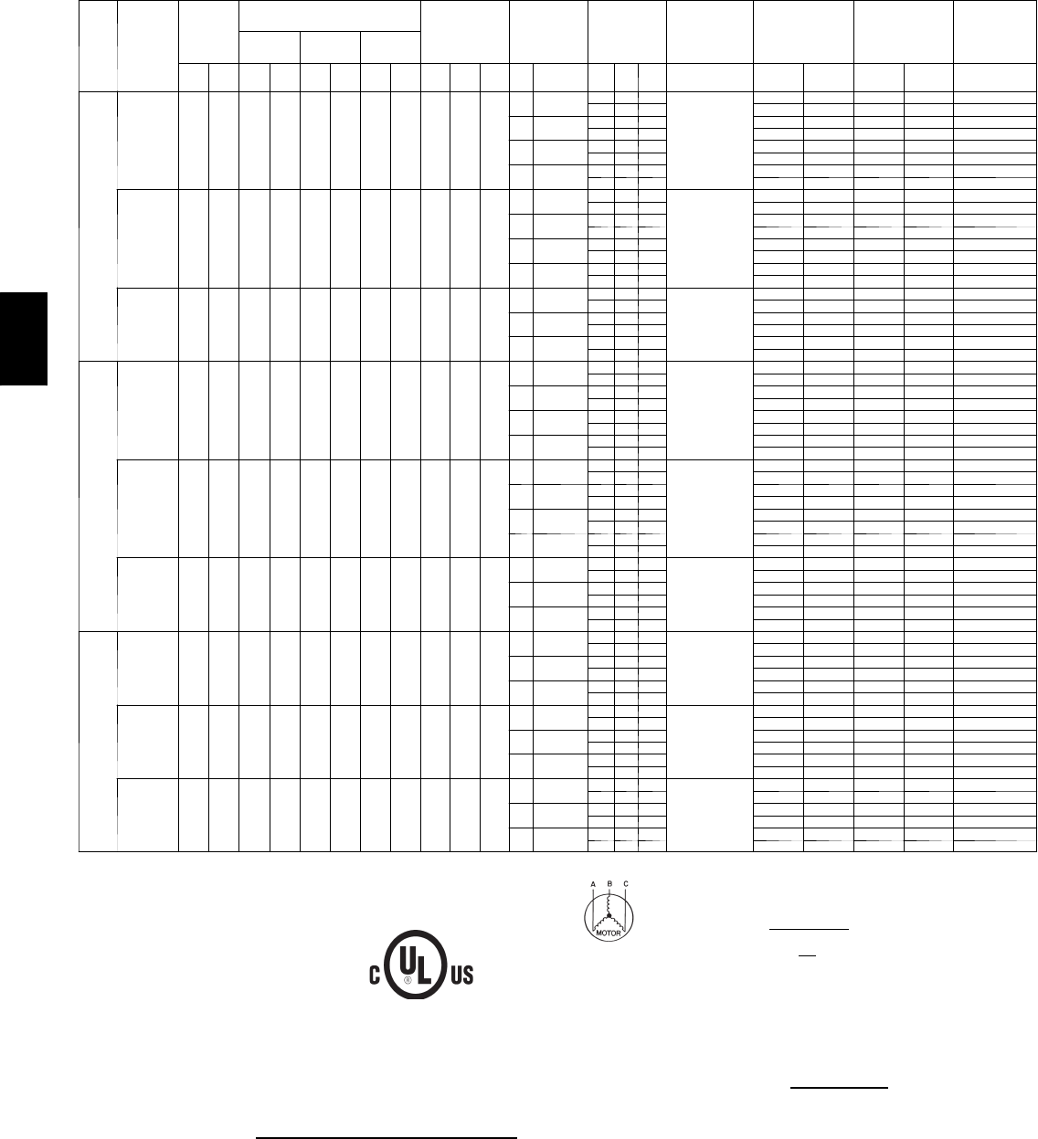
172
Units Without Optional Powered Convenience Outlet — 48PG20--28
UNIT
SIZE
48PG
NOMINAL
VOLTAGE
(3 Ph, 60
Hz)
VOLTAGE
RANGE
COMPRESSOR
OFM IFM POWER
EXHAUST
COMBUSTION
FAN MOTOR
POWER
SUPPLY*
POWER SUPPLY
UNITS WITH
OPTIONAL
HACR
BREAKER
DISCONNECT
SIZE
No. 1 No. 2 No. 3
Min Max RLA LRA RLA LRA RLA LRA Qty Hp FLA
(ea) Hp FLA Qty Hp FLA
(ea) FLA MCA MOCP MCA MOCP FLA
20
208/230 187 253 28.2 208 28.2 208 — — 4 0.25 1.5
3.7 10.6/ 9.6 — — —
0.5
80/ 79 100/100 80/ 80 100/100 84/ 83
2 1 5.9 92/ 91 100/100 92/ 92 100/100 98/ 96
516.7/15.2 — — — 86/ 85 100/100 86/ 86 100/100 91/ 89
2 1 5.9 98/ 96 100/100 98/ 98 100/100 105/103
7.5 24.2/22 — — — 94/ 91 100/100 94/ 94 100/100 100/ 97
2 1 5.9 105/103 125/125 105/105 125/125 113/111
10 30.8/28 — — — 101/ 97 125/100 101/101 125/125 107/104
2 1 5.9 113/109 125/125 113/113 125/125 121/118
460 414 506 15.4 104 15.4 104 — — 4 0.25 0.7
3.7 4.8 — — —
0.3
42 50 42 50 44
2 1 3.1 48 60 48 60 51
57.6 — — — 45 60 45 60 47
2 1 3.1 51 60 51 60 55
7.5 11 — — — 48 60 48 60 51
2 1 3.1 55 60 55 60 58
10 14 — — — 51 60 51 60 55
2 1 3.1 58 60 58 60 62
575 518 633 12.8 83 12.8 83 — — 4 0.25 0.7
56.1 — — —
0.24
38 50 38 50 40
2 1 2.4 43 50 43 50 45
7.5 9— — — 41 50 41 50 43
2 1 2.4 45 50 45 50 49
10 11 — — — 43 50 43 50 45
2 1 2.4 47 60 47 60 51
24
208/230 187 253 32.1 240 32.1 240 — — 6 0.25 1.5
3.7 10.6/9.6 — — —
0.5
92/ 91 100/100 92/ 92 100/100 96/ 95
2 1 5.9 104/103 125/125 104/104 125/125 110/109
516.7/15.2 — — — 98/ 96 100/100 98/ 98 100/100 103/102
2 1 5.9 110/108 125/125 110/110 125/125 117/115
7.5 24.2/22 — — — 105/103 125/125 105/105 125/125 112/109
2 1 5.9 117/115 125/125 117/117 125/125 126/123
10 30.8/28 — — — 112/109 125/125 112/112 125/125 120/116
2 1 5.9 124/121 150/150 124/124 150/150 133/130
460 414 506 15.4 110 15.4 110 — — 6 0.25 0.7
3.7 4.8 — — —
0.3
44 50 44 50 46
2 1 3.1 50 60 50 60 53
57.6 — — — 46 60 46 60 49
2 1 3.1 53 60 53 60 56
7.5 11 — — — 50 60 50 60 53
2 1 3.1 56 60 56 60 60
10 14 — — — 53 60 53 60 56
2 1 3.1 59 60 59 60 63
575 518 633 12.8 88 12.8 88 — — 6 0.25 0.7
56.1 — — —
0.24
39 50 39 50 41
2 1 2.4 44 50 44 50 47
7.5 9— — — 42 50 42 50 45
2 1 2.4 47 50 47 50 50
10 11 — — — 44 50 44 50 47
2 1 2.4 49 60 49 60 52
28
208/230 187 253 28.2 208 28.2 208 28.2 208 60.25 1.5
516.7/15.2 — — —
0.5
117/116 125/125 117/117 125/125 127/125
2 1 5.9 129/128 150/150 129/129 150/150 140/139
7.5 24.2/22 — — — 125/123 150/150 125/125 150/150 135/133
2 1 5.9 137/134 150/150 137/137 150/150 149/147
10 30.8/28 — — — 132/129 150/150 132/132 150/150 143/140
2 1 5.9 144/140 150/150 144/144 150/150 157/153
460 414 506 15.4 104 15.4 104 15.4 104 60.25 0.7
57.6 — — —
0.3
62 70 62 70 67
2 1 3.1 68 80 68 80 74
7.5 11 — — — 65 80 65 80 71
2 1 3.1 71 80 71 80 78
10 14 — — — 68 80 68 80 74
2 1 3.1 74 80 74 80 81
575 518 633 12.8 83 12.8 83 12.8 83 60.25 0.7
56.1 — — —
0.24
52 60 52 60 56
2 1 2.4 57 60 57 60 62
7.5 9— — — 55 60 55 60 59
2 1 2.4 60 60 60 60 65
10 11 — — — 57 60 57 60 62
2 1 2.4 62 70 62 70 67
LEGEND
FLA --- F u l l L o a d A m p s
HACR --- Heating, Air Conditioning and Refrigeration
IFM --- Indoor (Evaporator) Fan Motor
LRA --- L o ck e d R o t o r A mp s
MCA --- Minimum Circuit Amps
MOCP --- Maximum Overcurrent Protection
NEC --- National Electrical Code
OFM --- Outdoor (Condenser) Fan Motor
RLA --- RatedLoadAmps
* Fuse or HACR circuit breaker.
NOTES:
1. In compliance with NEC requirements for multimotor and combination load equipment (refer
to NEC Articles 430 and 440), the overcurrent protective device for the unit shall be fuse or
HACR breaker. Canadian units may be fuse or circuit breaker.
2. Unbalanced 3-Phase Supply Voltage
Never operate a motor where a phase imbalance in supply voltage is greater than 2%. Use
the following formula to determine the percentage of voltage imbalance.
% Voltage Imbalance = 100 x max voltage deviation from average voltage
average voltage
Example: Supply voltage is 230-3-60
AB = 224 v
BC = 231 v
AC = 226 v
Average Voltage = 224 + 231 + 226
3
681
3
=
227
=
Determine maximum deviation from average voltage.
(AB) 227 – 224 = 3 v
(BC) 231 – 227 = 4 v
(AC) 227 – 226 = 1 v
Maximum deviation is 4 v.
Determine percent of voltage imbalance.
% Voltage Imbalance = 100 x
4
227
= 1.76%
This amount of phase imbalance is satisfactory as it is below the maximum allowable 2%.
IMPORTANT: If the supply voltage phase imbalance is more than 2%, contact your local electric
utility company immediately.
48PG
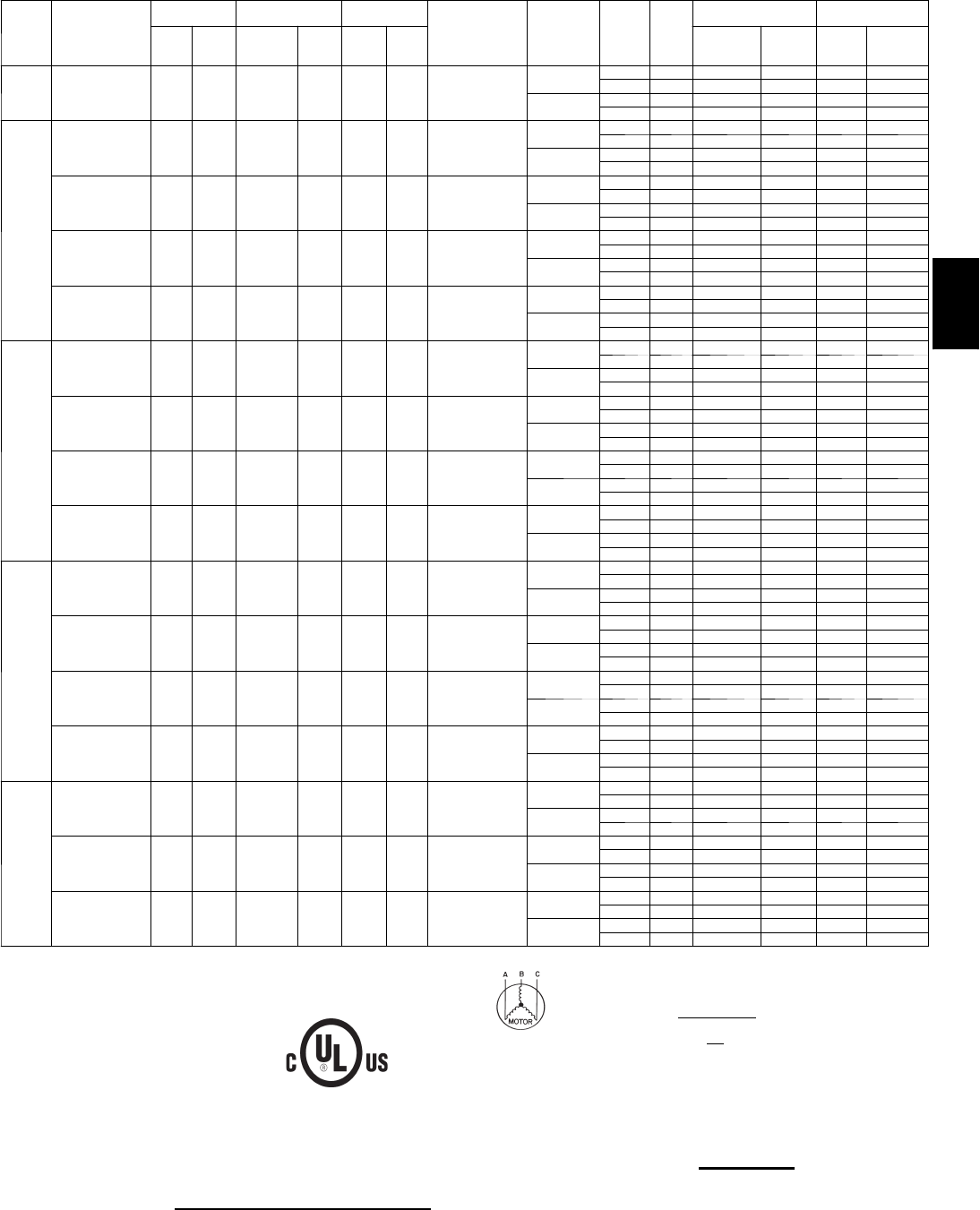
173
ELECTRICAL DATA
Units With Optional Powered Convenience Outlet — 48PG03--07
UNIT
48GP
NOMINAL
POWER SUP-
P LY V O L T S ---
P H --- H Z
VOLTAGE
RANGE COMPRESSOR OFM COMBUSTION
FAN MOTOR
FLA
POWER
EXHAUST
FLA
(EA)
IFM
TYPE
IFM
FLA
POWER SUPPLY DISCONNECT
SIZE
Min Max RLA LRA
Qty
FLA
(ea)
FLA MCA MOCP FLA LRA
03 208/230--- 1---60 187 253 12.8 60 11.0 0.52
—Low 4.9 26.7/26.7 30/30 27/27 79/ 79
High 4.9 26.7/26.7 30/30 27/27 79/79
1.4 Low 4.9 28.1/28.1 40/40 29/29 81/ 81
High 4.9 28.1/28.1 40/40 29/29 81 / 81
04
208/230--- 1---60 187 253 15.4 83 11.0 0.52
—Low 4.9 30.0/30.0 45/45 30/30 102/102
High 4.9 30.0/30.0 45/45 30/30 102/102
1.4 Low 4.9 31.4/31.4 45/45 32/32 104/104
High 4.9 31.4/31.4 45/45 32/32 104/104
208/230--- 3---60 187 253 11.5 77 11.0 0.52
—Low 4.9 25.1/25.1 30/30 26/26 96/ 96
High 4.9 25.1/25.1 30/30 26/26 96/ 96
1.4 Low 4.9 26.5/26.5 30/30 27/27 98/ 98
High 4.9 26.5/26.5 30/30 27/27 98/ 98
4 6 0 --- 3 --- 6 0 414 506 5.1 35 10.5 0.30
—Low 2.1 11.2 15 11 44
High 2.1 11.2 15 11 44
0.6 Low 2.1 11.8 15 12 45
High 2.1 11.8 15 12 45
5 7 5 --- 3 --- 6 0 518 633 4.3 31 10.5 0.24
—Low 2.1 9.7 15 10 39
High 2.1 9.7 15 10 39
1.4 Low 2.1 11.1 15 12 41
High 2.1 11.1 15 12 41
05
208/230--- 1---60 187 253 20.5 109 11.0 0.52
—Low 4.9 36.3/36.3 50/50 36/36 128/128
High 7.0 38.4/38.4 50/50 38/38 153/153
1.4 Low 4.9 37.7/37.7 50/50 37/37 130/130
High 7.0 39.8/39.8 60/60 40/40 155/155
208/230--- 3---60 187 253 14.6 91 11.0 0.52
—Low 4.9 29.0/29.0 40/40 29/29 110/110
High 5.2 29.3/29.3 40/40 29/29 128/128
1.4 Low 4.9 30.4/30.4 40/40 31/31 112/112
High 5.2 30.7/30.7 45/45 31/31 130/130
4 6 0 --- 3 --- 6 0 414 506 7.1 46 10.5 0.30
—Low 2.1 13.7 20 14 55
High 2.6 14.2 20 14 64
0.6 Low 2.1 14.3 20 14 56
High 2.6 14.8 20 15 65
5 7 5 --- 3 --- 6 0 518 633 5.1 34 10.5 0.24
—Low 2.1 10.7 15 11 42
High 2.0 10.6 15 11 48
1.4 Low 2.1 12.1 15 12 44
High 2.0 12.0 15 12 50
06
208/230--- 1---60 187 253 26.9 145 11.5 0.52
—Low 4.9 44.8/44.8 60/60 44/44 165/165
High 7.0 46.9/46.9 60/60 46/46 190/190
1.4 Low 4.9 46.2/46.2 60/60 45/45 167/167
High 7.0 48.3/48.3 60/60 48/48 192/192
208/230--- 3---60 187 253 17.6 123 11.5 0.52
—Low 5.2 33.5/33.5 50/50 33/33 161/161
High 5.2 33.5/33.5 50/50 33/33 161/161
1.4 Low 5.2 34.9/34.9 50/50 35/35 163/163
High 5.2 34.9/34.9 50/50 35/35 163/163
4 6 0 --- 3 --- 6 0 414 506 7.7 50 10.8 0.30
—Low 2.6 15.2 20 15 69
High 2.6 15.2 20 15 69
0.6 Low 2.6 15.8 20 16 70
High 2.6 15.8 20 16 70
5 7 5 --- 3 --- 6 0 518 633 6.1 40 10.8 0.24
—Low 2.0 12.1 15 12 55
High 2.0 12.1 15 12 55
1.4 Low 2.0 13.5 20 14 57
High 2.0 13.5 20 14 57
07
208/230--- 3---60 187 253 20.5 149 11.5 0.52
—Low 5.2 37.1/37.1 50/50 37/37 187/187
High 7.5 39.4/39.4 50/50 39/39 213/213
1.4 Low 5.2 38.5/38.5 50/50 38/38 189/189
High 7.5 40.8/40.8 60/60 41/41 215/215
4 6 0 --- 3 --- 6 0 414 506 9.6 75 10.8 0.30
—Low 2.6 17.6 25 17 94
High 3.4 18.4 25 18 107
0.6 Low 2.6 18.2 25 18 95
High 3.4 19.0 25 19 108
5 7 5 --- 3 --- 6 0 518 633 7.6 54 10.8 0.24
—Low 2.0 14.0 20 14 69
High 2.8 14.8 20 15 80
1.4 Low 2.0 15.4 20 16 71
High 2.8 16.2 20 16 82
LEGEND
FLA --- F u l l L o a d A m p s
HACR --- Heating, Air Conditioning and Refrigeration
IFM --- Indoor (Evaporator) Fan Motor
LRA --- L o ck e d R o t o r A mp s
MCA --- Minimum Circuit Amps
MOCP --- Maximum Overcurrent Protection
NEC --- National Electrical Code
OFM --- Outdoor (Condenser) Fan Motor
RLA --- RatedLoadAmps
NOTES:
1. In compliance with NEC requirements for multimotor and combination load equipment (refer
to NEC Articles 430 and 440), the overcurrent protective device for the unit shall be fuse or
HACR breaker. Canadian units may be fuse or circuit breaker.
2. Unbalanced 3-Phase Supply Voltage
Never operate a motor where a phase imbalance in supply voltage is greater than 2%. Use
the following formula to determine the percentage of voltage imbalance.
% Voltage Imbalance = 100 x max voltage deviation from average voltage
average voltage
Example: Supply voltage is 230-3-60
AB = 224 v
BC = 231 v
AC = 226 v
Average Voltage = 224 + 231 + 226
3
681
3
=
227
=
Determine maximum deviation from average voltage.
(AB) 227 – 224 = 3 v
(BC) 231 – 227 = 4 v
(AC) 227 – 226 = 1 v
Maximum deviation is 4 v.
Determine percent of voltage imbalance.
% Voltage Imbalance = 100 x 4
227
= 1.76%
This amount of phase imbalance is satisfactory as it is below the maximum allowable 2%.
IMPORTANT: If the supply voltage phase imbalance is more than 2%, contact your local electric
utility company immediately.
48PG
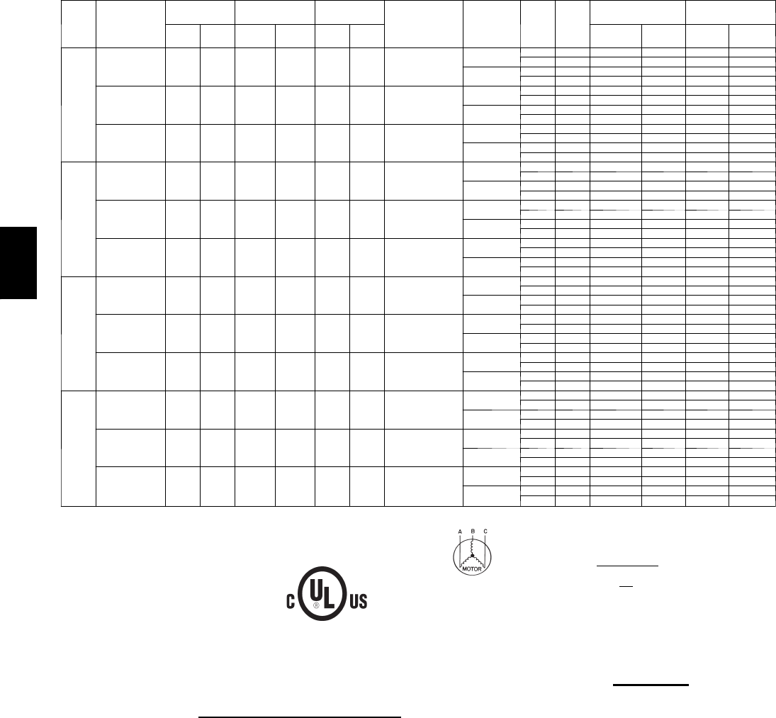
174
Units With Optional Powered Convenience Outlet — 48PG08--14
UNIT
48PG
NOMINAL
POWER
SUPPLY
(V-Ph-Hz)
VOLTAGE
RANGE
COMPRESSOR
(Each) OFM COMBUSTION
FAN MOTOR
FLA
PWR EXH
FLA (ea)
IFM
TYPE
IFM
FLA
POWER SUPPLY DISCONNECT
SIZE
Min Max RLA LRA Qty FLA
(ea) MCA MOCP FLA LRA
08
208/230-3-60 187 253 13.5 88 21.5 0.52
—Low 5.2 43.4/43.4 50/50 46/46 217/217
High 7.5 45.7/45.7 50/50 49/49 243/243
3.0 Low 5.2 46.4/46.4 50/50 49/49 221/221
High 7.5 48.7/48.7 60/60 52/52 247/247
460-3-60 414 506 6.4 39 20.8 0.30
—Low 2.6 20.8 25 22 99
High 3.4 21.6 25 23 112
1.2 Low 2.6 22 25 23 102
High 3.4 22.8 25 24 115
575-3-60 518 633 5.1 34 20.8 0.24
—Low 2.0 16.8 20 18 85
High 2.8 17.6 20 19 96
3.0 Low 2.0 19.8 25 21 89
High 2.8 20.6 25 22 100
09
208/230-3-60 187 253 16.0 91 21.5 0.52
—Low 5.2 49.0/49.0 60/60 52/52 223/223
High 10.2 54.0/54.0 60/60 58/58 266/266
3.0 Low 5.2 52.0/52.0 60/60 55/55 227/227
High 10.2 57.0/57.0 70/70 61/61 270/270
460-3-60 414 506 7.1 46 20.8 0.30
—Low 2.6 22.4 25 24 113
High 4.8 24.6 30 26 135
1.2 Low 2.6 23.6 30 25 116
High 4.8 25.8 30 28 138
575-3-60 518 633 5.6 37 20.8 0.24
—Low 2.0 17.9 20 19 91
High 2.8 18.7 25 20 102
3.0 Low 2.0 20.9 25 22 95
High 2.8 21.7 25 23 106
12
208/230-3-60 187 253 17.6 123 21.9 0.52
—Low 7.5 55.7/55.7 70/70 59/59 315/315
High 10.2 58.4/58.4 70/70 62/62 332/332
3.0 Low 7.5 58.7/58.7 70/70 62/62 319/319
High 10.2 61.4/61.4 70/70 66/66 336/336
460-3-60 414 506 7.7 50 21.0 0.30
—Low 3.4 24.9 30 26 134
High 4.8 26.3 30 28 143
1.2 Low 3.4 26.1 30 28 137
High 4.8 27.5 30 29 146
575-3-60 518 633 6.1 40 20.8 0.24
—Low 2.8 19.8 25 21 108
High 2.8 19.8 25 21 108
3.0 Low 2.8 22.8 25 24 112
High 2.8 22.8 25 24 112
14
208/230-3-60 187 253 22.4 149 21.9 0.52
—Low 10.2 69.2/69.2 90/90 73/73 384/384
High 15.0 74.0/74.0 90/90 79/79 393/393
3.0 Low 10.2 72.2/72.2 90/90 77/77 388/388
High 15.0 77.0/77.0 90/90 82/82 397/397
460-3-60 414 506 10.6 75 21.0 0.30
—Low 4.8 32.9 40 35 193
High 7.4 35.5 45 38 197
1.2 Low 4.8 34.1 40 36 196
High 7.4 36.7 45 39 200
575-3-60 518 633 7.7 54 20.8 0.24
—Low 2.8 23.4 30 25 136
High 5.6 26.2 30 28 150
3.0 Low 2.8 26.4 30 28 140
High 5.6 29.2 35 31 154
LEGEND
FLA --- F u l l L o a d A m p s
HACR --- Heating, Air Conditioning and Refrigeration
IFM --- Indoor (Evaporator) Fan Motor
LRA --- L o ck e d R o t o r A mp s
MCA --- Minimum Circuit Amps
MOCP --- Maximum Overcurrent Protection
NEC --- National Electrical Code
OFM --- Outdoor (Condenser) Fan Motor
RLA --- RatedLoadAmps
NOTES:
1. In compliance with NEC requirements for multimotor and combination load equipment (refer
to NEC Articles 430 and 440), the overcurrent protective device for the unit shall be fuse or
HACR breaker. Canadian units may be fuse or circuit breaker.
2. Unbalanced 3-Phase Supply Voltage
Never operate a motor where a phase imbalance in supply voltage is greater than 2%. Use
the following formula to determine the percentage of voltage imbalance.
% Voltage Imbalance = 100 x max voltage deviation from average voltage
average voltage
Example: Supply voltage is 230-3-60
AB = 224 v
BC = 231 v
AC = 226 v
Average Voltage = 224 + 231 + 226
3
681
3
=
227
=
Determine maximum deviation from average voltage.
(AB) 227 – 224 = 3 v
(BC) 231 – 227 = 4 v
(AC) 227 – 226 = 1 v
Maximum deviation is 4 v.
Determine percent of voltage imbalance.
% Voltage Imbalance = 100 x 4
227
= 1.76%
This amount of phase imbalance is satisfactory as it is below the maximum allowable 2%.
IMPORTANT: If the supply voltage phase imbalance is more than 2%, contact your local electric
utility company immediately.
48PG
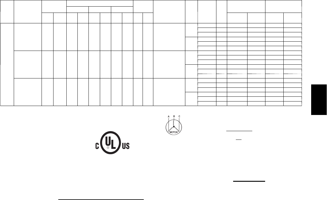
175
ELECTRICAL DATA
Units With Optional Powered Convenience Outlet — 48PG16
UNIT
48PG
NOMINAL
POWER
SUPPLY
(V-Ph-Hz)
VOLTAGE
RANGE
COMPRESSOR OFM
FLA COMBUSTION
FAN
MOTOR
FLA
PWR
EXH
FLA*
IFM
TYPE
IFM
FLA
POWER
SUPPLY
DISCONNECT
SIZE
No. 1 No. 2 No. 3
Min Max RLA LRA RLA LRA RLA LRA Qty FLA
(ea) MCA MOCP FLA LRA
16
208/230-3-60 187 253 18.1 137 18.1 137 17.6 123 31.9 0.52
—
Low 10.2 79.0/79.0 90/ 90 86/ 86 487/487
Mid-Low 15.0 83.8/83.8 100/100 91/ 91 496/496
High 19.4 88.6/88.6 100/100 96/ 96 534/534
3.0
Low 10.2 82.0/82.0 100/100 89/ 89 491/491
Mid-Low 15.0 86.8/86.8 100/100 95/ 95 500/500
High 19.4 91.6/91.6 100/100 100/100 538/538
460-3-60 414 506 9.0 62 9.0 62 7.7 50 31.0 0.30
—
Low 4.8 38.0 45 41 219
Mid-Low 7.4 40.6 45 44 223
High 9.7 43.0 50 47 242
1.2
Low 4.8 39.2 45 42 222
Mid-Low 7.4 41.8 50 45 226
High 9.7 44.2 50 48 245
575-3-60 518 633 6.8 50 6.8 50 6.1 40 30.8 0.24
—
Low 2.8 28.3 35 31 170
Mid-Low 5.6 31.1 35 34 184
High 7.8 33.6 40 36 199
3.0
Low 2.8 31.3 35 34 174
Mid-Low 5.6 34.1 40 37 188
High 7.8 36.6 40 40 203
LEGEND
FLA --- F u l l L o a d A m p s
HACR --- Heating, Air Conditioning and Refrigeration
IFM --- Indoor (Evaporator) Fan Motor
LRA --- L o ck e d R o t o r A mp s
MCA --- Minimum Circuit Amps
MOCP --- Maximum Overcurrent Protection
NEC --- National Electrical Code
OFM --- Outdoor (Condenser) Fan Motor
RLA --- RatedLoadAmps
*Power exhaust FLA is the sum of the FLA of two power exhaust motors.
NOTES:
1. In compliance with NEC requirements for multimotor and combination load equipment (refer
to NEC Articles 430 and 440), the overcurrent protective device for the unit shall be fuse or
HACR breaker. Canadian units may be fuse or circuit breaker.
2. Unbalanced 3-Phase Supply Voltage
Never operate a motor where a phase imbalance in supply voltage is greater than 2%. Use
the following formula to determine the percentage of voltage imbalance.
% Voltage Imbalance = 100 x max voltage deviation from average voltage
average voltage
Example: Supply voltage is 230-3-60
AB = 224 v
BC = 231 v
AC = 226 v
Average Voltage = 224 + 231 + 226
3
681
3
=
227
=
Determine maximum deviation from average voltage.
(AB) 227 – 224 = 3 v
(BC) 231 – 227 = 4 v
(AC) 227 – 226 = 1 v
Maximum deviation is 4 v.
Determine percent of voltage imbalance.
%VoltageImbalance =100 x 4
227
= 1.76%
This amount of phase imbalance is satisfactory as it is below the maximum allowable 2%.
IMPORTANT: If the supply voltage phase imbalance is more than 2%, contact your local electric
utility company immediately.
48PG
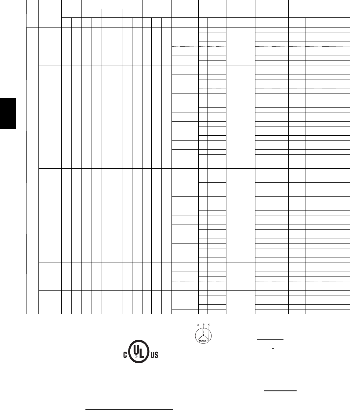
176
Units With Optional Powered Convenience Outlet — 48PG20--28
UNIT
SIZE
48PG
NOMINAL
VOLTAGE
(3 Ph, 60
Hz)
VOLTAGE
RANGE
COMPRESSOR
OFM IFM POWER
EXHAUST
COMBUSTION
FAN MOTOR
POWER
SUPPLY*
POWER SUPPLY
UNITS WITH
OPTIONAL HACR
BREAKER
DISCONNECT
SIZE
No. 1 No. 2 No. 3
Min Max RLA LRA RLA LRA RLA LRA Qty Hp FLA
(ea) Hp FLA Qty Hp FLA
(ea) FLA MCA MOCP MCA MOCP FLA
20
208/230 187 253 28.2 208 28.2 208 — — 4 0.25 1.5
3.7 10.6/9.6 — — —
0.5
85/ 84 100/100 85/ 85 100/100 90/ 89
2 1 5.9 97/ 96 100/100 97/ 97 100/100 103/102
516.7/15.2 — — — 91/ 90 100/100 91/ 91 100/100 97/ 95
2 1 5.9 103/101 125/125 103/103 125/125 110/109
7.5 24.2/22 — — — 99/ 96 100/100 99/ 99 100/100 105/103
2 1 5.9 110/108 125/125 110/110 125/125 119/116
10 30.8/28 — — — 106/102 125/125 106/106 125/125 113/110
2 1 5.9 118/114 125/125 118/118 125/125 127/123
460 414 506 15.4 104 15.4 104 — — 4 0.25 0.7
3.7 4.8 — — —
0.3
45 60 45 60 48
2 1 3.1 51 60 51 60 55
57.6 — — — 48 60 48 60 51
2 1 3.1 54 60 54 60 58
7.5 11 — — — 51 60 51 60 55
2 1 3.1 58 60 58 60 62
10 14 — — — 54 60 54 60 58
2 1 3.1 61 70 61 70 65
575 518 633 12.8 83 12.8 83 — — 4 0.25 0.7
56.1 — — —
0.24
41 50 41 50 43
2 1 2.4 46 50 46 50 49
7.5 9— — — 44 50 44 50 46
2 1 2.4 48 60 48 60 52
10 11 — — — 46 50 46 50 49
2 1 2.4 50 60 50 60 54
24
208/230 187 253 32.1 240 32.1 240 — — 6 0.25 1.5
3.7 10.6/ 9.6 — — —
0.5
97/ 96 100/100 97/ 97 100/100 102/101
2 1 5.9 109/108 125/125 109/109 125/125 116/115
516.7/15.2 — — — 103/101 125/125 103/103 125/125 109/107
2 1 5.9 115/113 125/125 115/115 125/125 123/121
7.5 24.2/22 — — — 110/108 125/125 110/110 125/125 118/115
2 1 5.9 122/120 150/150 122/122 150/150 131/129
10 30.8/28 — — — 117/114 125/125 117/117 125/125 125/122
2 1 5.9 129/126 150/150 129/129 150/150 139/136
460 414 506 15.4 110 15.4 110 — — 6 0.25 0.7
3.7 4.8 — — —
0.3
47 60 47 60 49
2 1 3.1 53 60 53 60 56
57.6 — — — 49 60 49 60 52
2 1 3.1 56 60 56 60 60
7.5 11 — — — 53 60 53 60 56
2 1 3.1 59 60 59 60 63
10 14 — — — 56 60 56 60 60
2 1 3.1 62 70 62 70 67
575 518 633 12.8 88 12.8 88 — — 6 0.25 0.7
56.1 — — —
0.24
42 50 42 50 45
2 1 2.4 47 50 47 50 50
7.5 9— — — 45 50 45 50 48
2 1 2.4 50 60 50 60 54
10 11 — — — 47 50 47 50 50
2 1 2.4 52 60 52 60 56
28
208/230 187 253 28.2 208 28.2 208 28.2 208 60.25 1.5
516.7/15.2 — — —
0.5
122/121 150/125 122/122 150/150 133/131
2 1 5.9 134/133 150/150 134/134 150/150 146/144
7.5 24.2/22 — — — 130/128 150/150 130/130 150/150 141/139
2 1 5.9 142/139 150/150 142/142 150/150 155/152
10 30.8/28 — — — 137/134 150/150 137/137 150/150 149/146
2 1 5.9 149/145 175/150 149/149 175/175 162/159
460 414 506 15.4 104 15.4 104 15.4 104 60.25 0.7
57.6 — — —
0.3
65 80 65 80 70
2 1 3.1 71 80 71 80 77
7.5 11 — — — 68 80 68 80 74
2 1 3.1 74 80 74 80 81
10 14 — — — 71 80 71 80 78
2 1 3.1 77 90 77 90 85
575 518 633 12.8 83 12.8 83 12.8 83 60.25 0.7
56.1 — — —
0.24
55 60 55 60 59
2 1 2.4 60 60 60 60 65
7.5 9— — — 58 60 58 60 63
2 1 2.4 63 70 63 70 68
10 11 — — — 60 60 60 60 65
LEGEND
FLA --- F u l l L o a d A m p s
HACR --- Heating, Air Conditioning and Refrigeration
IFM --- Indoor (Evaporator) Fan Motor
LRA --- L o ck e d R o t o r A mp s
MCA --- Minimum Circuit Amps
MOCP --- Maximum Overcurrent Protection
NEC --- National Electrical Code
OFM --- Outdoor (Condenser) Fan Motor
RLA --- RatedLoadAmps
*Fuse or HACR circuit breaker.
NOTES:
1. In compliance with NEC requirements for multimotor and combination load equipment (refer
to NEC Articles 430 and 440), the overcurrent protective device for the unit shall be fuse or
HACR breaker. Canadian units may be fuse or circuit breaker.
2. Unbalanced 3-Phase Supply Voltage
Never operate a motor where a phase imbalance in supply voltage is greater than 2%. Use
the following formula to determine the percentage of voltage imbalance.
% Voltage Imbalance = 100 x max voltage deviation from average voltage
average voltage
Example: Supply voltage is 460-3-60
AB = 452 v
BC = 464 v
AC = 455 v
Average Voltage = 452 + 464 + 455
3
1371
3
=
457
=
Determine maximum deviation from average voltage.
(AB) 457 – 452 = 5 v
(BC) 464 – 457 = 7 v
(AC) 457 – 455 = 2 v
Maximum deviation is 7 v.
Determine percent of voltage imbalance.
%VoltageImbalance =100 x 7
457
= 1.53%
This amount of phase imbalance is satisfactory as it is below the maximum allowable 2%.
IMPORTANT: If the supply voltage phase imbalance is more than 2%, contact your local electric
utility company immediately.
3. The original powered convenience outlet full load amps (FLA) are 5, 3, and 3 for 208/230,
460, 575---v units, respectively.
48PG
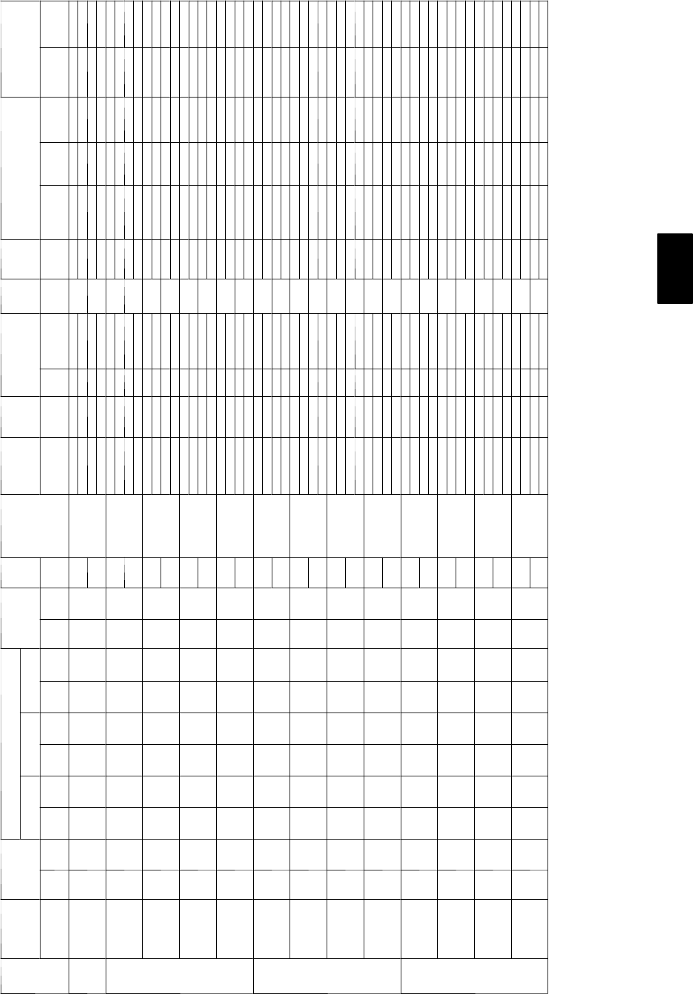
177
ELECTRICAL DATA
Units Without Powered Convenience Outlet and with EnergyX — 48PG03--16
UNIT
48PG
NOMINAL
POWER
SUPPLY
VOLTAGE
RANGE
COMPRESSOR
OFM IFM COMBUSTION
FAN MOTOR
FLA
ERV Supply ERV
Wheel ERV Exhaust IFM ERV POWER SUPPLY DISCONNECT SIZE
No. 1 No. 2 No. 3
(v- Ph- Hz) Min Max RLA LRA RLA LRA RLA LRA Qty FLA
(ea) FLA FLA (ea) FLA
(ea) Qty FLA (ea) TYPE TYPE MCA
Fuse or
HACR
Brkr
MOCP FLA LRA
03 208/230--1--60 187 253 12.8 60 -- -- -- -- 11.0
4.9
0.52
1.92/1.74 0.33/0.3 31.92/1.74 LOW LOW 29.9/29.2 40/40 -- / -- 31/30 83
8.02/7.25 0.33/0.3 211.47/10.375 HIGH 61.2/57.5 -- / -- 70/70 67/62 336
4.9 1.92/1.74 0.33/0.3 31.92/1.74 HIGH LOW 29.9/29.2 40/40 -- / -- 31/30 83
8.02/7.25 0.33/0.3 211.47/10.375 HIGH 61.2/57.5 -- / -- 70/70 67/62 336
04
208/230--1--60 187 253 15.4 83 -- -- -- -- 11.0
4.9
0.52
1.92/1.74 0.33/0.3 31.92/1.74 LOW LOW 33.2/32.4 45/45 -- / -- 34/33 106
8.02/7.25 0.33/0.3 211.47/10.375 HIGH 64.5/60.7 -- / -- 70/70 70/65 359
4.9 1.92/1.74 0.33/0.3 31.92/1.74 HIGH LOW 33.2/32.4 45/45 -- / -- 34/33 106
8.02/7.25 0.33/0.3 211.47/10.375 HIGH 64.5/60.7 -- / -- 70/70 70/65 359
208/230--3--60 187 253 11. 5 77 -- -- -- -- 11.0
4.9
0.52
1.92/1.74 0.33/0.3 31.92/1.74 LOW LOW 28.3/27.5 35/35 -- / -- 29/28 100
3.32/3.0 0.33/0.3 27.08/6.4 HIGH 41.4/39.4 50/50 -- / -- 44/42 219
4.9 1.92/1.74 0.33/0.3 31.92/1.74 HIGH LOW 28.3/27.5 35/35 -- / -- 29/28 100
3.32/3.0 0.33/0.3 27.08/6.4 HIGH 41.4/39.4 50/50 -- / -- 44/42 219
460--3--60 414 506 5.1 35 -- -- -- -- 10.5
2.1
0.30
0.87 0.15 30.87 LOW LOW 12.6 15 -- 13 46
1.5 0.15 23.2 HIGH 18.5 20 -- 20 100
2.1 0.87 0.15 30.87 HIGH LOW 12.6 15 -- 13 46
1.5 0.15 23.2 HIGH 18.5 20 -- 20 100
575--3--60 518 633 4.3 31 -- -- -- -- 10.5
2.1
0.24
0.695 0.12 30.695 LOW LOW 10.9 15 -- 11 40
1.1 0.12 22.4 HIGH 15.1 20 -- 16 87
2.1 0.695 0.12 30.695 HIGH LOW 10.9 15 -- 11 40
1.1 0.12 22.4 HIGH 15.1 20 -- 16 87
05
208/230--1--60 187 253 20.5 109 -- -- -- -- 11.0
4.9
0.52
1.92/1.74 0.33/0.3 31.92/1.74 LOW LOW 39.5/38.8 60/50 -- / -- 40/39 132
8.02/7.25 0.33/0.3 211.47/10.375 HIGH 70.8/67.1 -- / -- 90/80 76/71 385
7.0 1.92/1.74 0.33/0.3 31.92/1.74 HIGH LOW 41.6/40.9 60/60 -- / -- 42/41 157
8.02/7.25 0.33/0.3 211.47/10.375 HIGH 72.9/69.2 -- / -- 90/80 78/74 410
208/230--3--60 187 253 14.6 91 -- -- -- -- 11.0
4.9
0.52
1.92/1.74 0.33/0.3 31.92/1.74 LOW LOW 32.2/31.4 45/45 -- / -- 33/32 114
3.32/3.0 0.33/0.3 27.08/6.4 HIGH 45.3/43.3 50/50 -- / -- 48/46 233
5.2 1.92/1.74 0.33/0.3 31.92/1.74 HIGH LOW 32.5/31.7 45/45 -- / -- 33/32 132
3.32/3.0 0.33/0.3 27.08/6.4 HIGH 45.6/43.6 60/50 -- / -- 48/46 251
460--3--60 414 506 7.1 46 -- -- -- -- 10.5
2.1
0.30
0.87 0.15 30.87 LOW LOW 15.1 20 -- 15 57
1.5 0.15 23.2 HIGH 21 25 -- 22 111
2.6 0.87 0.15 30.87 HIGH LOW 15.6 20 -- 16 66
1.5 0.15 23.2 HIGH 21.5 25 -- 23 120
575--3--60 518 633 5.1 34 -- -- -- -- 10.5
2.1
0.24
0.695 0.12 30.695 LOW LOW 11. 9 15 -- 12 43
1.1 0.12 22.4 HIGH 16.1 20 -- 17 90
2.0 0.695 0.12 30.695 HIGH LOW 11 . 8 15 -- 12 49
1.1 0.12 22.4 HIGH 16 20 -- 17 96
06
208/230--1--60 187 253 26.9 145 -- -- -- -- 11.5
4.9
0.52
1.92/1.74 0.33/0.3 31.92/1.74 LOW LOW 48.0/47.3 60/60 -- / -- 48/47 169
8.02/7.25 0.33/0.3 211.47/10.375 HIGH 79.3/75.6 -- / -- 100/100 84/79 422
7.0 1.92/1.74 0.33/0.3 31.92/1.74 HIGH LOW 50.1/49.4 60/60 -- / -- 50/49 194
8.02/7.25 0.33/0.3 211.47/10.375 HIGH 81.4/77.7 -- / -- 100/100 86/82 447
208/230--3--60 187 253 17.6 123 -- -- -- -- 11.5
5.2
0.52
1.92/1.74 0.33/0.3 31.92/1.74 LOW LOW 36.7/36.0 50/50 -- / -- 37/36 165
3.32/3.0 0.33/0.3 27.08/6.4 HIGH 49.8/47.8 60/60 -- / -- 52/50 284
5.2 1.92/1.74 0.33/0.3 31.92/1.74 HIGH LOW 36.7/36.0 50/50 -- / -- 37/36 165
3.32/3.0 0.33/0.3 27.08/6.4 HIGH 49.8/47.8 60/60 -- / -- 52/50 284
460--3--60 414 506 9.6 62 -- -- -- -- 10.8
2.6
0.30
0.87 0.15 30.87 LOW LOW 19 25 -- 19 83
1.5 0.15 23.2 HIGH 25 30 -- 26 137
2.6 0.87 0.15 30.87 HIGH LOW 19 25 -- 19 83
1.5 0.15 23.2 HIGH 25 30 -- 26 137
575--3--60 518 633 6.1 40 -- -- -- -- 10.8
2.0
0.24
0.695 0.12 30.695 LOW LOW 13.3 15 -- 14 56
1.1 0.12 22.4 HIGH 17.5 20 -- 18 103
2.0 0.695 0.12 30.695 HIGH LOW 13.3 15 -- 14 56
1.1 0.12 22.4 HIGH 17.5 20 -- 18 103
48PG
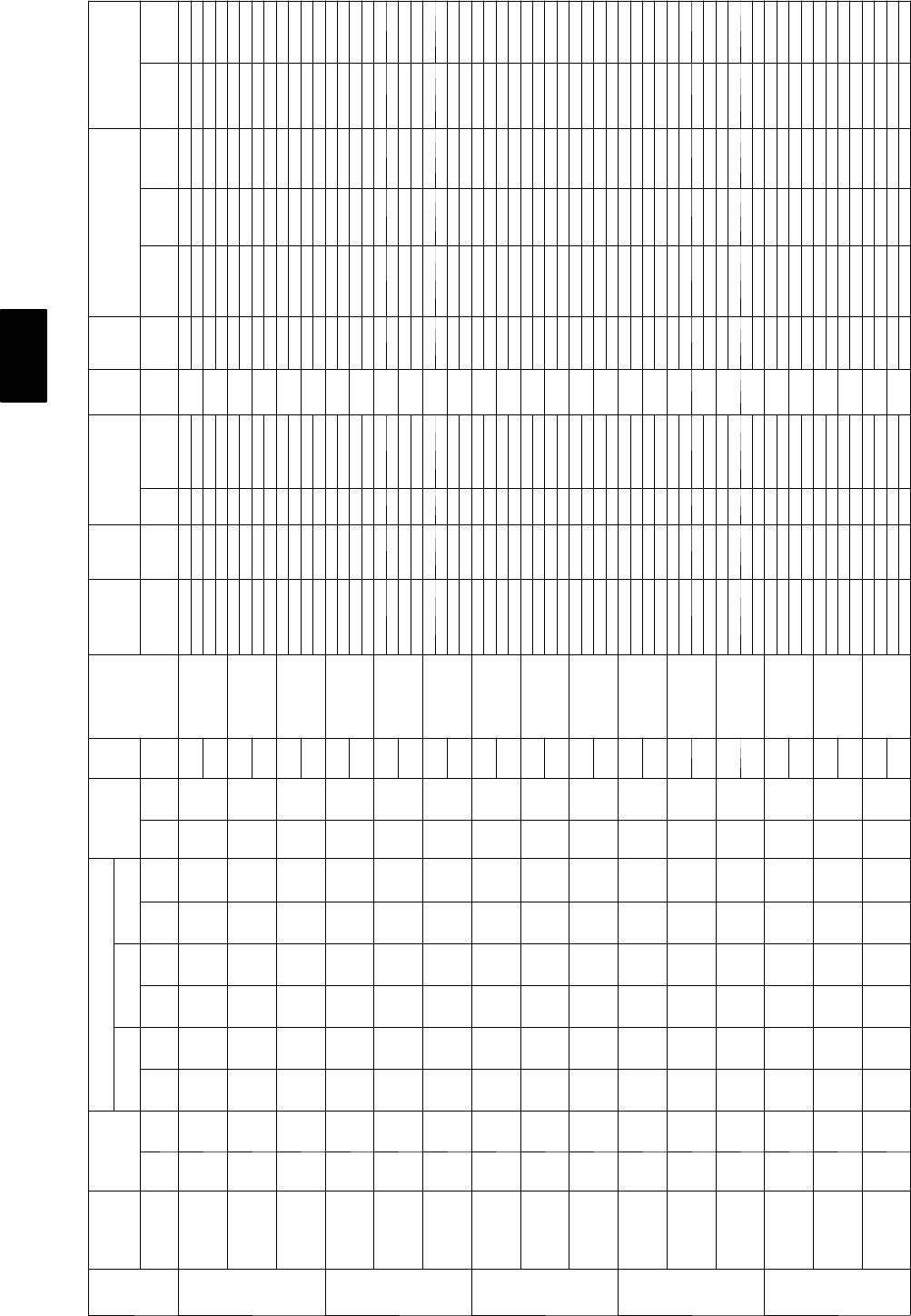
178
Units Without Powered Convenience Outlet and with EnergyX — 48PG03--16 (cont)
UNIT
48PG
NOMINAL
POWER
SUPPLY
VOLTAGE
RANGE
COMPRESSOR
OFM IFM COMBUSTION
FAN MOTOR
FLA
ERV Supply ERV
Wheel ERV Exhaust IFM ERV POWER SUPPLY DISCONNECT SIZE
No. 1 No. 2 No. 3
(v- Ph- Hz) Min Max RLA LRA RLA LRA RLA LRA Qty FLA
(ea) FLA FLA (ea) FLA
(ea) Qty FLA (ea) TYPE TYPE MCA
Fuse or
HACR
Brkr
MOCP FLA LRA
07
208/230--3--60 187 253 20.5 149 -- -- -- -- 11.5
5.2
0.52
1.92/1.74 0.33/0.3 31.92/1.74 LOW LOW 40.3/39.6 60/60 -- / -- 40/40 191
3.32/3.0 0.33/0.3 27.08/6.4 HIGH 53.5/51.4 60/60 -- / -- 56/53 310
7.5 1.92/1.74 0.33/0.3 31.92/1.74 HIGH LOW 42.6/41.9 60/60 -- / -- 43/42 217
3.32/3.0 0.33/0.3 27.08/6.4 HIGH 55.8/53.7 70/60 -- / -- 58/56 336
460--3--60 414 506 9.6 75 -- -- -- -- 10.8
2.6
0.30
0.87 0.15 30.87 LOW LOW 19 25 -- 19 96
1.5 0.15 23.2 HIGH 25 30 -- 26 150
3.4 0.87 0.15 30.87 HIGH LOW 19.8 25 -- 20 109
1.5 0.15 23.2 HIGH 25.8 30 -- 27 163
575--3--60 518 633 7.6 54 -- -- -- -- 10.8
2.0
0.24
0.695 0.12 30.695 LOW LOW 15.2 20 -- 15 70
1.1 0.12 22.4 HIGH 19.4 25 -- 20 117
2.8 0.695 0.12 30.695 HIGH LOW 16 20 -- 16 81
1.1 0.12 22.4 HIGH 20.2 25 -- 21 128
08
208/230--3--60 187 253 13.5 88 13.5 88 -- -- 21.5
5.2
0.52
3.32/3.0 0.33/0.3 28.85/8.0 LOW LOW 63.2/60.9 -- / -- 70/70 69/66 318
8.85/8.0 0.66/0.6 27.08/6.4 HIGH 71.1/68.0 -- / -- 80/80 78/74 370
7.5 3.32/3.0 0.33/0.3 28.85/8.0 HIGH LOW 65.5/63.2 -- / -- 70/70 71/69 344
8.85/8.0 0.66/0.6 27.08/6.4 HIGH 73.4/70.3 -- / -- 80/80 81/77 396
460--3--60 414 506 6.4 39 6.4 39 -- -- 20.8
2.6
0.30
1.5 0.15 2 4 LOW LOW 29.8 35 -- 32 145
40.35 23.2 HIGH 33.4 35 -- 37 169
3.4 1.5 0.15 2 4 HIGH LOW 30.6 35 -- 33 158
40.35 23.2 HIGH 34.2 40 -- 37 182
575--3--60 518 633 5.1 34 5.1 34 -- -- 20.8
2.0
0.24
1.1 0.12 23.3 LOW LOW 24 30 -- 26 137
3.3 0.3 22.4 HIGH 26.8 30 -- 29 160
2.8 1.1 0.12 23.3 HIGH LOW 24.8 30 -- 27 148
3.3 0.3 22.4 HIGH 27.6 30 -- 30 171
09
208/230--3--60 187 253 16.0 91 16.0 91 -- -- 21.5
5.2
0.52
3.32/3.0 0.33/0.3 28.85/8.0 LOW LOW 68.9/66.5 -- / -- 80/80 75/72 324
8.85/8.0 0.66/0.6 27.08/6.4 HIGH 76.7/73.6 -- / -- 90/80 84/80 376
10.2 3.32/3.0 0.33/0.3 28.85/8.0 HIGH LOW 73.9/71.5 -- / -- 80/80 80/78 367
8.85/8.0 0.66/0.6 27.08/6.4 HIGH 81.7/78.6 -- / -- 90/90 89/86 419
460--3--60 414 506 7.1 46 7.1 46 -- -- 20.8
2.6
0.30
1.5 0.15 2 4 LOW LOW 31.3 35 -- 34 159
40.35 23.2 HIGH 34.9 40 -- 38 183
4.8 1.5 0.15 2 4 HIGH LOW 33.5 40 -- 37 181
40.35 23.2 HIGH 37.1 40 -- 41 205
575--3--60 518 633 5.6 37 5.6 37 -- -- 20.8
2.0
0.24
1.1 0.12 23.3 LOW LOW 25.1 30 -- 27 143
3.3 0.3 22.4 HIGH 27.9 30 -- 30 166
2.8 1.1 0.12 23.3 HIGH LOW 25.9 30 -- 28 154
3.3 0.3 22.4 HIGH 28.7 35 -- 31 177
12
208/230--3--60 187 253 17.6 123 17.6 123 -- -- 21.9
7.5
0.52
3.32/3.0 0.33/0.3 28.85/8.0 LOW LOW 75.6/73.2 -- / -- 90/90 82/79 416
8.85/8.0 0.66/0.6 27.08/6.4 HIGH 83.4/80.3 -- / -- 100/90 91/87 468
10.2 3.32/3.0 0.33/0.3 28.85/8.0 HIGH LOW 78.3/75.9 -- / -- 90/90 85/82 433
8.85/8.0 0.66/0.6 27.08/6.4 HIGH 86.1/83.0 -- / -- 100/100 94/90 485
460--3--60 414 506 9.6 62 9.6 62 -- -- 21.0
3.4
0.30
1.5 0.15 2 4 LOW LOW 38.2 45 -- 41 204
40.35 23.2 HIGH 41.8 50 -- 45 228
4.8 1.5 0.15 2 4 HIGH LOW 39.6 45 -- 43 213
40.35 23.2 HIGH 43.2 50 -- 47 237
575--3--60 518 633 6.1 40 6.1 40 -- -- 20.8
2.8
0.24
1.1 0.12 23.3 LOW LOW 27 30 -- 29 160
3.3 0.3 22.4 HIGH 29.8 35 -- 33 183
2.8 1.1 0.12 23.3 HIGH LOW 27 30 -- 29 160
3.3 0.3 22.4 HIGH 29.8 35 -- 33 183
14
208/230--3--60 187 253 22.4 149 22.4 149 -- -- 21.9
10.2
0.52
3.32/3.0 0.33/0.3 28.85/8.0 LOW LOW 89.1/86.7 -- / -- 100/100 96/93 485
8.85/8.0 0.66/0.6 27.08/6.4 HIGH 96.9/93.8 -- / -- 110/100 105/101 537
15.0 3.32/3.0 0.33/0.3 28.85/8.0 HIGH LOW 93.9/91.5 -- / -- 100/100 102/99 494
8.85/8.0 0.66/0.6 27.08/6.4 HIGH 101.7/98.6 -- / -- 110/110 111/107 546
460--3--60 414 506 10.6 75 10.6 75 -- -- 21.0
4.8
0.30
1.5 0.15 2 4 LOW LOW 41.8 50 -- 45 239
40.35 23.2 HIGH 45.4 50 -- 49 263
7.4 1.5 0.15 2 4 HIGH LOW 44.4 50 -- 48 243
40.35 23.2 HIGH 48 60 -- 52 267
575--3--60 518 633 7.7 54 7.7 54 -- -- 20.8
2.8
0.24
1.1 0.12 23.3 LOW LOW 30.6 35 -- 33 188
3.3 0.3 22.4 HIGH 33.4 40 -- 36 211
5.6 1.1 0.12 23.3 HIGH LOW 33.4 40 -- 36 202
3.3 0.3 22.4 HIGH 36.2 40 -- 39 225
48PG
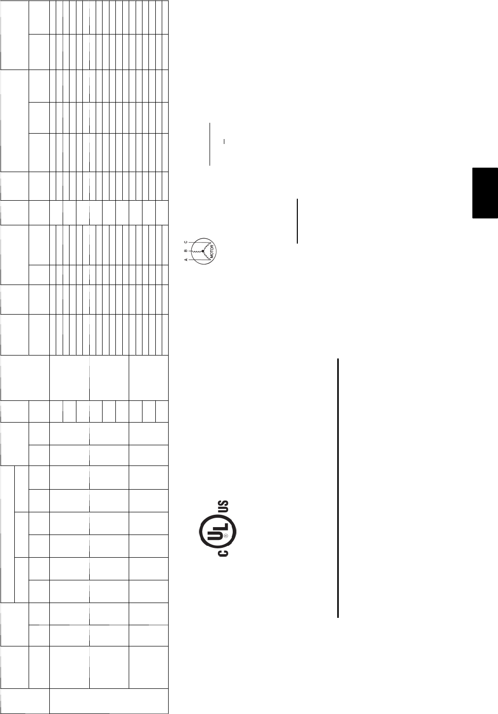
179
ELECTRICAL DATA
Units Without Powered Convenience Outlet and with EnergyX — 48PG03--16 (cont)
UNIT
48PG
NOMINAL
POWER
SUPPLY
VOLTAGE
RANGE
COMPRESSOR
OFM IFM COMBUSTION
FAN MOTOR
FLA
ERV Supply ERV
Wheel ERV Exhaust IFM ERV POWER SUPPLY DISCONNECT SIZE
No. 1 No. 2 No. 3
(v- Ph- Hz) Min Max RLA LRA RLA LRA RLA LRA Qty FLA
(ea) FLA FLA (ea) FLA
(ea) Qty FLA (ea) TYPE TYPE MCA
Fuse or
HACR
Brkr
MOCP FLA LRA
16
208/230--3--60 187 253 18.1 137 18.1 137 17.6 123 31.9
10.2
0.52
7.08/6.4 0.66/0.6 28.85/8.0 LOW LOW 106.7/103.6 -- / -- 125/110 118/114 640
8.85/8.0 0.66/0.6 27.08/6.4 HIGH 106.7/103.6 -- / -- 125/110 118/114 640
15.0 7.08/6.4 0.66/0.6 28.85/8.0 MID--
LO
W
LOW 111.5/108.4 -- / -- 125/125 123/119 649
8.85/8.0 0.66/0.6 27.08/6.4 HIGH 111.5/108.4 -- / -- 125/125 123/119 649
19.4 7.08/6.4 0.66/0.6 28.85/8.0 HIGH LOW 116.3/113.2 -- / -- 125/125 128/125 687
8.85/8.0 0.66/0.6 27.08/6.4 HIGH 116.3/113.2 -- / -- 125/125 128/125 687
460--3--60 414 506 9.0 62 9.0 62 9.6 62 31.0
4.8
0.30
3.2 0.35 2 4 LOW LOW 52.6 60 -- 58 301
40.35 23.2 HIGH 52.6 60 -- 58 301
7.4 3.2 0.35 2 4 MID--
LO
W
LOW 55.2 60 -- 61 305
40.35 23.2 HIGH 55.2 60 -- 61 305
9.7 3.2 0.35 2 4 HIGH LOW 57.5 60 -- 63 324
40.35 23.2 HIGH 57.5 60 -- 63 324
575--3--60 518 633 6.8 50 6.8 50 6.1 40 30.8
2.8
0.24
2.4 0.3 23.3 LOW LOW 38.3 45 -- 42 245
3.3 0.3 22.4 HIGH 38.3 45 -- 42 245
5.6 2.4 0.3 23.3 MID--
LO
W
LOW 41.1 45 -- 45 259
3.3 0.3 22.4 HIGH 41.1 45 -- 45 259
7.8 2.4 0.3 23.3 HIGH LOW 43.6 50 -- 48 274
3.3 0.3 22.4 HIGH 43.6 50 -- 48 274
LEGEND
FLA --- F u l l L o a d A m p s
HACR --- Heating, Air Conditioning and Refrigeration
IFM --- Indoor (Evaporator) Fan Motor
LRA --- L o ck e d R o t o r A mp s
MCA --- Minimum Circuit Amps
MOCP --- Maximum Overcurrent Protection
NEC --- National Electrical Code
OFM --- Outdoor (Condenser) Fan Motor
RLA --- RatedLoadAmps
NOTES:
1. In compliance with NEC requirements for multimotor and combination load equipment (refer to NEC Articles 430 and 440), the overcurrent
protective device for the unit shall be fuse or HACR breaker.
2. Unbalanced 3-Phase Supply Voltage
Never operate a motor where a phase imbalance in supply voltage is greater than 2%. Use the following formula to determine the percentage
of voltage imbalance.
% Voltage Imbalance = 100 x
max voltage deviation from average voltage
average voltage
E x a m p l e : S u p p l y v o l t a g e i s 2 3 0 --- 3 --- 6 0
AB = 224 v
BC = 231 v
AC = 226 v
Average Voltage = 224 + 231 + 226
3
681
3
=
227
=
Determine maximum deviation from average voltage.
(AB) 227 – 224 = 3 v
(BC) 231 – 227 = 4 v
(AC) 227 – 226 = 1 v
Maximum deviation is 7 v.
Determine percent of voltage imbalance.
% Voltage Imbalance = 100 x 4
227
= 1.76%
This amount of phase imbalance is satisfactory as it is below the maximum allowable 2%.
IMPORTANT: If the supply voltage phase imbalance is more than 2%, contact your local electric utility company immediately.
48PG
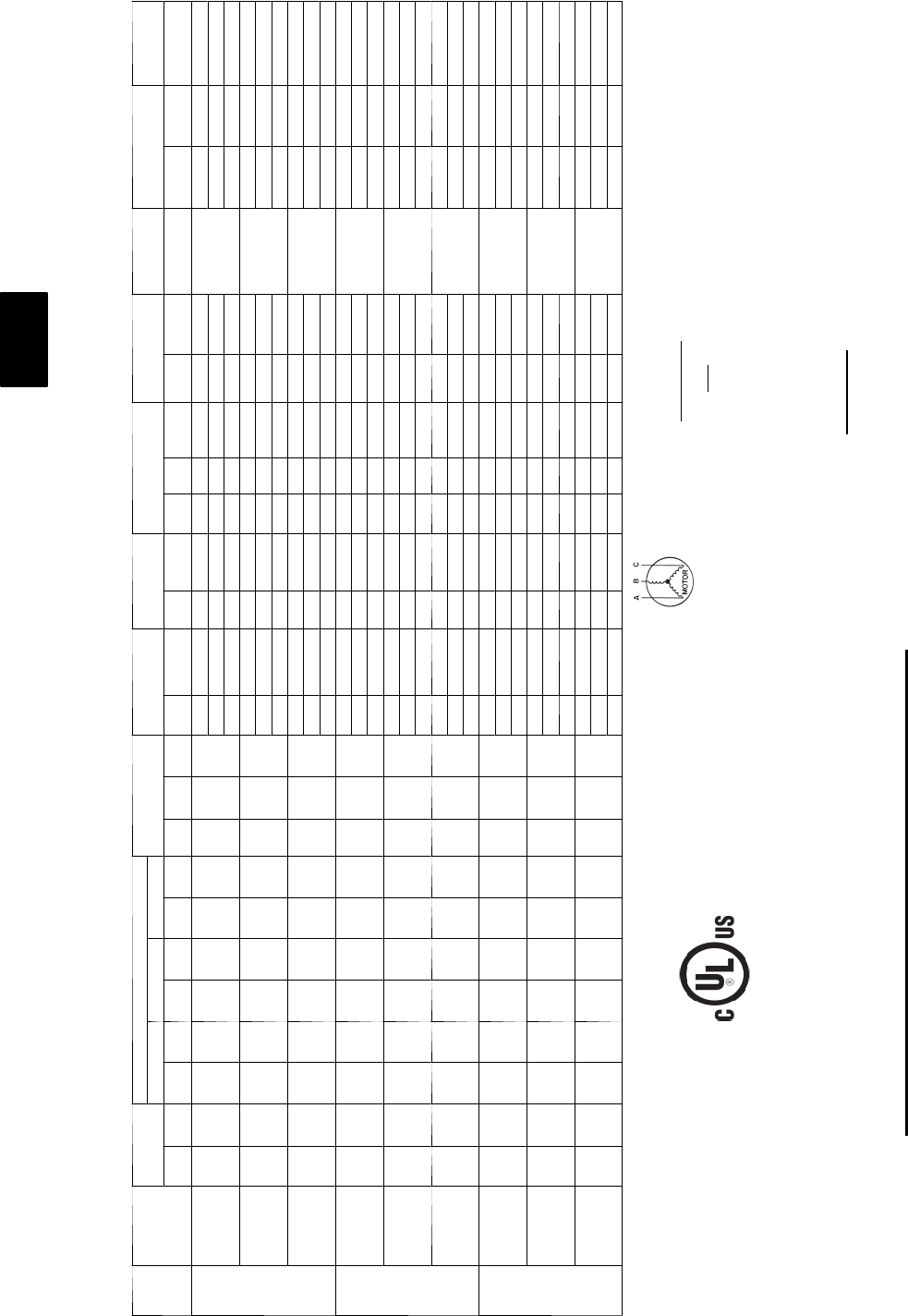
180
ELECTRICAL DATA
Units Without Powered Convenience Outlet and with EnergyX — 48PG20--28
UNIT
48PG
NOMINAL
POWER
SUPPLY
V-Ph-Hz)
VOLTAGE
RANGE
COMPRESSOR OFM IFM ERV SUPPLY ERV EXHAUST ERV WHEEL COMBUSTION
FAN MOTOR POWER SUPPLY DISCONNECT
SIZE
No. 1 No. 2 No. 3
Min Max RLA LRA RLA LRA RLA LRA Qty Hp FLA
(ea) Hp FLA Hp FLA
(ea) Qty Hp FLA
(ea) Hp FLA FLA MCA MOCP FLA
20
208/230--3--60 187 253 28.2 208 28.2 208 -- -- 40.25 1.5
516.7/15.2 27.08/6.4 2 3 8.85/8.0 0.167 0.66/0.6
0.5
112/108 125/125 120/116
7.5 24.2/22 27.08/6.4 2 3 8.85/8.0 0.167 0.66/0.6 119/114 125/125 129/124
10 30.8/28 27.08/6.4 2 3 8.85/8.0 0.167 0.66/0.6 126/120 150/125 136/130
460--3--60 414 506 15.4 104 15.4 104 -- -- 40.25 0.7
57.6 23.2 2 3 4 0.167 0.35
0.3
57 60 61
7.5 11 23.2 2 3 4 0.167 0.35 60 60 65
10 14 23.2 2 3 4 0.167 0.35 63 70 68
575--3--60 518 633 12.8 83 12.8 83 -- -- 40.25 0.7
56.1 22.4 2 3 3.3 0.167 0.3
0.24
47 50 50
7.5 9 2 2.4 2 3 3.3 0.167 0.3 50 60 54
10 11 22.4 2 3 3.3 0.167 0.3 52 60 56
24
208/230--3--60 187 253 32.1 240 32.1 240 -- -- 60.25 1.5
516.7/15.2 27.08/6.4 2 3 8.85/8.0 0.167 0.66/0.6
0.5
123/119 150/150 133/128
7.5 24.2/22 27.08/6.4 2 3 8.85/8.0 0.167 0.66/0.6 131/126 150/150 141/136
10 30.8/28 27.08/6.4 2 3 8.85/8.0 0.167 0.66/0.6 137/132 150/150 149/143
460--3--60 414 506 15.4 110 15.4 110 -- -- 60.25 0.7
57.6 23.2 2 3 4 0.167 0.35
0.3
58 60 62
7.5 11 23.2 2 3 4 0.167 0.35 61 70 66
10 14 23.2 2 3 4 0.167 0.35 64 70 70
575--3--60 518 633 12.8 88 12.8 88 -- -- 60.25 0.7
56.1 22.4 2 3 3.3 0.167 0.3
0.24
48 60 52
7.5 9 2 2.4 2 3 3.3 0.167 0.3 51 60 55
10 11 22.4 2 3 3.3 0.167 0.3 53 60 58
28
208/230--3--60 187 253 28.2 208 28.2 208 28.2 208 60.25 1.5
516.7/15.2 27.08/6.4 2 3 8.85/8.0 0.167 0.66/0.6
0.5
143/139 150/150 156/152
7.5 24.2/22 27.08/6.4 2 3 8.85/8.0 0.167 0.66/0.6 150/146 175/150 165/159
10 30.8/28 27.08/6.4 2 3 8.85/8.0 0.167 0.66/0.6 158/152 175/175 172/166
460--3--60 414 506 15.4 104 15.4 104 15.4 104 60.25 0.7
57.6 23.2 2 3 4 0.167 0.35
0.3
73 80 80
7.5 11 23.2 2 3 4 0.167 0.35 77 90 84
10 14 23.2 2 3 4 0.167 0.35 80 90 87
575--3--60 518 633 12.8 83 12.8 83 12.8 83 60.25 0.7
56.1 22.4 2 3 3.3 0.167 0.3
0.24
61 70 67
7.5 9 2 2.4 2 3 3.3 0.167 0.3 64 70 70
10 11 22.4 2 3 3.3 0.167 0.3 66 70 72
LEGEND
FLA --- F u l l L o a d A m p s
HACR --- Heating, Air Conditioning and Refrigeration
IFM --- Indoor (Evaporator) Fan Motor
LRA --- L o ck e d R o t o r A mp s
MCA --- Minimum Circuit Amps
MOCP --- Maximum Overcurrent Protection
NEC --- National Electrical Code
OFM --- Outdoor (Condenser) Fan Motor
RLA --- RatedLoadAmps
*Fuse or HACR circuit breaker
NOTES:
1. In compliance with NEC requirements for multimotor and combination load equipment (refer to NEC Articles 430 and 440), the overcurrent
protective device for the unit shall be fuse or HACR breaker.
2. Unbalanced 3-Phase Supply Voltage
Never operate a motor where a phase imbalance in supply voltage is greater than 2%. Use the following formula to determine the percentage
of voltage imbalance.
% Voltage Imbalance = 100 x
max voltage deviation from average voltage
average voltage
E x a m p l e : S u p p l y v o l t a g e i s 4 6 0 --- 3 --- 6 0
AB = 452 v
BC = 464 v
AC = 455 v
Average Voltage = 452 + 464 + 455
3
1371
3
=
457
=
Determine maximum deviation from average voltage.
(AB) 457 – 452 = 5 v
(BC) 464 – 457 = 7 v
(AC) 457 – 455 = 2 v
Maximum deviation is 7 v.
Determine percent of voltage imbalance.
% Voltage Imbalance = 100 x 7
457
= 1.53%
This amount of phase imbalance is satisfactory as it is below the maximum allowable 2%.
IMPORTANT: If the supply voltage phase imbalance is more than 2%, contact your local electric utility company immediately.
48PG

181
Units With Powered Convenience Outlet and with EnergyX — 48PG03--16
UNIT
48PG
NOMINAL
POWER
SUPPLY
(V-Ph-Hz)
VOLTAGE
RANGE
COMPRESSOR OFM IFM COMBUSTION
FAN MOTOR
FLA
ERV
Supply
ERV
Wheel ERV Exhaust IFM ERV POWER SUPPLY DISCONNECT SIZE
No. 1 No. 2 No. 3
Min Max RLA LRA RLA LRA RLA LRA Qty FLA
(ea) FLA FLA
(ea)
FLA
(ea) Qty FLA (ea) TYPE TYPE MCA
Fuse or
HACR
Brkr
MOCP FLA LRA
03 208/230--1--60 187 253 12.8 60 -- -- -- -- 11.0
4.9
0.52
1.92/1.74 0.33/0.3 31.92/1.74 LOW LOW 34.7/34.0 45/45 -- / -- 36/35 88
8.02/7.25 0.33/0.3 211.47/10.375 HIGH 66.0/62.3 -- / -- 70/70 72/68 341
4.9 1.92/1.74 0.33/0.3 31.92/1.74 HIGH LOW 34.7/34.0 45/45 -- / -- 36/35 88
8.02/7.25 0.33/0.3 211.47/10.375 HIGH 66.0/62.3 -- / -- 70/70 72/68 341
04
208/230--1--60 187 253 15.4 83 -- -- -- -- 11.0
4.9
0.52
1.92/1.74 0.33/0.3 31.92/1.74 LOW LOW 38.0/37.2 50/50 -- / -- 39/38 111
8.02/7.25 0.33/0.3 211.47/10.375 HIGH 69.3/65.5 -- / -- 80/80 75/71 364
4.9 1.92/1.74 0.33/0.3 31.92/1.74 HIGH LOW 38.0/37.2 50/50 -- / -- 39/38 111
8.02/7.25 0.33/0.3 211.47/10.375 HIGH 69.3/65.5 -- / -- 80/80 75/71 364
208/230--3--60 187 253 11.5 77 -- -- -- -- 11.0
4.9
0.52
1.92/1.74 0.33/0.3 31.92/1.74 LOW LOW 33.1/32.3 40/40 -- / -- 35/34 105
3.32/3.0 0.33/0.3 27.08/6.4 HIGH 46.2/44.2 50/50 -- / -- 50/47 224
4.9 1.92/1.74 0.33/0.3 31.92/1.74 HIGH LOW 33.1/32.3 40/40 -- / -- 35/34 105
3.32/3.0 0.33/0.3 27.08/6.4 HIGH 46.2/44.2 50/50 -- / -- 50/47 224
460--3--60 414 506 5.1 35 -- -- -- -- 10.5
2.1
0.30
0.87 0.15 30.87 LOW LOW 14.8 20 -- 16 48
1.5 0.15 23.2 HIGH 20.7 25 -- 22 102
2.1 0.87 0.15 30.87 HIGH LOW 14.8 20 -- 16 48
1.5 0.15 23.2 HIGH 20.7 25 -- 22 102
575--3--60 518 633 4.3 31 -- -- -- -- 10.5
2.1
0.24
0.695 0.12 30.695 LOW LOW 12.6 15 -- 13 42
1.1 0.12 22.4 HIGH 16.8 20 -- 18 89
2.1 0.695 0.12 30.695 HIGH LOW 12.6 15 -- 13 42
1.1 0.12 22.4 HIGH 16.8 20 -- 18 89
05
208/230--1--60 187 253 20.5 109 -- -- -- -- 11.0
4.9
0.52
1.92/1.74 0.33/0.3 31.92/1.74 LOW LOW 44.3/43.6 60/60 -- / -- 45/44 137
8.02/7.25 0.33/0.3 211.47/10.375 HIGH 75.6/71.9 -- / -- 90/90 81/77 390
7.0 1.92/1.74 0.33/0.3 31.92/1.74 HIGH LOW 46.4/45.7 60/60 -- / -- 48/47 162
8.02/7.25 0.33/0.3 211.47/10.375 HIGH 77.7/74.0 -- / -- 90/90 84/79 415
208/230--3--60 187 253 14.6 91 -- -- -- -- 11.0
4.9
0.52
1.92/1.74 0.33/0.3 31.92/1.74 LOW LOW 37.0/36.2 50/50 -- / -- 38/37 119
3.32/3.0 0.33/0.3 27.08/6.4 HIGH 50.1/48.1 60/60 -- / -- 53/51 238
5.2 1.92/1.74 0.33/0.3 31.92/1.74 HIGH LOW 37.3/36.5 50/50 -- / -- 39/38 137
3.32/3.0 0.33/0.3 27.08/6.4 HIGH 50.4/48.4 60/60 -- / -- 54/51 256
460--3--60 414 506 7.1 46 -- -- -- -- 10.5
2.1
0.30
0.87 0.15 30.87 LOW LOW 17.3 20 -- 18 59
1.5 0.15 23.2 HIGH 23.2 30 -- 25 11 3
2.6 0.87 0.15 30.87 HIGH LOW 17.8 20 -- 18 68
1.5 0.15 23.2 HIGH 23.7 30 -- 25 122
575--3--60 518 633 5.1 34 -- -- -- -- 10.5
2.1
0.24
0.695 0.12 30.695 LOW LOW 13.6 15 -- 14 45
1.1 0.12 22.4 HIGH 17.8 20 -- 19 92
2.0 0.695 0.12 30.695 HIGH LOW 13.5 15 -- 14 51
1.1 0.12 22.4 HIGH 17.7 20 -- 19 98
06
208/230--1--60 187 253 26.9 145 -- -- -- -- 11.5
4.9
0.52
1.92/1.74 0.33/0.3 31.92/1.74 LOW LOW 52.8/52.1 60/60 -- / -- 53/52 174
8.02/7.25 0.33/0.3 211.47/10.375 HIGH 84.1/80.4 -- / -- 100/100 89/85 427
7.0 1.92/1.74 0.33/0.3 31.92/1.74 HIGH LOW 54.9/54.2 -- / -- 80/80 55/55 199
8.02/7.25 0.33/0.3 211.47/10.375 HIGH 86.2/82.5 -- / -- 100/100 91/87 452
208/230--3--60 187 253 17.6 123 -- -- -- -- 11.5
5.2
0.52
1.92/1.74 0.33/0.3 31.92/1.74 LOW LOW 41.5/40.8 50/50 -- / -- 43/42 170
3.32/3.0 0.33/0.3 27.08/6.4 HIGH 54.6/52.6 60/60 -- / -- 58/55 289
5.2 1.92/1.74 0.33/0.3 31.92/1.74 HIGH LOW 41.5/40.8 50/50 -- / -- 43/42 170
3.32/3.0 0.33/0.3 27.08/6.4 HIGH 54.6/52.6 60/60 -- / -- 58/55 289
460--3--60 414 506 9.6 62 -- -- -- -- 10.8
2.6
0.30
0.87 0.15 30.87 LOW LOW 21.2 30 -- 22 85
1.5 0.15 23.2 HIGH 27.2 30 -- 28 139
2.6 0.87 0.15 30.87 HIGH LOW 21.2 30 -- 22 85
1.5 0.15 23.2 HIGH 27.2 30 -- 28 139
575--3--60 518 633 6.1 40 -- -- -- -- 10.8
2.0
0.24
0.695 0.12 30.695 LOW LOW 15 20 -- 16 58
1.1 0.12 22.4 HIGH 19.2 25 -- 20 105
2.0 0.695 0.12 30.695 HIGH LOW 15 20 -- 16 58
1.1 0.12 22.4 HIGH 19.2 25 -- 20 105
48PG
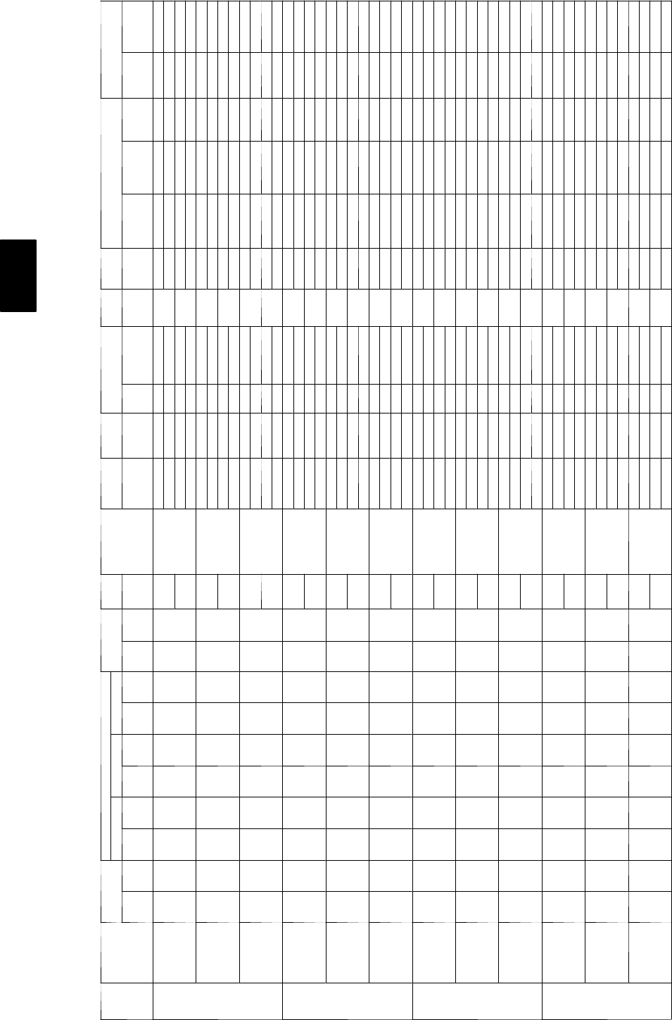
182
ELECTRICAL DATA
Units With Powered Convenience Outlet and with EnergyX — 48PG03--16 (cont)
UNIT
48PG
NOMINAL
POWER
SUPPLY
(V-Ph-Hz)
VOLTAGE
RANGE
COMPRESSOR OFM IFM COMBUSTION
FAN MOTOR
FLA
ERV
Supply
ERV
Wheel ERV Exhaust IFM ERV POWER SUPPLY DISCONNECT SIZE
No. 1 No. 2 No. 3
Min Max RLA LRA RLA LRA RLA LRA Qty FLA
(ea) FLA FLA
(ea)
FLA
(ea) Qty FLA (ea) TYPE TYPE MCA
Fuse or
HACR
Brkr
MOCP FLA LRA
07
208/230--3--60 187 253 20.5 149 -- -- -- -- 11.5
5.2
0.52
1.92/1.74 0.33/0.3 31.92/1.74 LOW LOW 45.1/44.4 60/60 -- / -- 46/45 196
3.32/3.0 0.33/0.3 27.08/6.4 HIGH 58.3/56.2 -- / -- 70/70 61/59 315
7.5 1.92/1.74 0.33/0.3 31.92/1.74 HIGH LOW 47.4/46.7 60/60 -- / -- 49/48 222
3.32/3.0 0.33/0.3 27.08/6.4 HIGH 60.6/58.5 -- / -- 80/70 64/61 341
460--3--60 414 506 9.6 75 -- -- -- -- 10.8
2.6
0.30
0.87 0.15 30.87 LOW LOW 21.2 30 -- 22 98
1.5 0.15 23.2 HIGH 27.2 30 -- 28 152
3.4 0.87 0.15 30.87 HIGH LOW 22 30 -- 23 111
1.5 0.15 23.2 HIGH 28 35 -- 29 165
575--3--60 518 633 7.6 54 -- -- -- -- 10.8
2.0
0.24
0.695 0.12 30.695 LOW LOW 16.9 20 -- 17 72
1.1 0.12 22.4 HIGH 21.1 25 -- 22 11 9
2.8 0.695 0.12 30.695 HIGH LOW 17.7 25 -- 18 83
1.1 0.12 22.4 HIGH 21.9 25 -- 23 130
08
208/230--3--60 187 253 13.5 88 13.5 88 -- -- 21.5
5.2
0.52
3.32/3.0 0.33/0.3 28.85/8.0 LOW LOW 68.0/65.7 -- / -- 80/70 74/72 323
8.85/8.0 0.66/0.6 27.08/6.4 HIGH 75.9/72.8 -- / -- 80/80 83/80 375
7.5 3.32/3.0 0.33/0.3 28.85/8.0 HIGH LOW 70.3/68.0 -- / -- 80/80 77/74 349
8.85/8.0 0.66/0.6 27.08/6.4 HIGH 78.2/75.1 -- / -- 90/80 86/82 401
460--3--60 414 506 6.4 39 6.4 39 -- -- 20.8
2.6
0.30
1.5 0.15 2 4 LOW LOW 32 35 -- 35 147
40.35 23.2 HIGH 35.6 40 -- 39 171
3.4 1.5 0.15 2 4 HIGH LOW 32.8 35 -- 36 160
40.35 23.2 HIGH 36.4 40 -- 40 184
575--3--60 518 633 5.1 34 5.1 34 -- -- 20.8
2.0
0.24
1.1 0.12 23.3 LOW LOW 25.7 30 -- 28 139
3.3 0.3 22.4 HIGH 28.5 30 -- 31 162
2.8 1.1 0.12 23.3 HIGH LOW 26.5 30 -- 29 150
3.3 0.3 22.4 HIGH 29.3 35 -- 32 173
09
208/230--3--60 187 253 16.0 91 16.0 91 -- -- 21.5
5.2
0.52
3.32/3.0 0.33/0.3 28.85/8.0 LOW LOW 73.7/71.3 -- / -- 80/80 80/77 329
8.85/8.0 0.66/0.6 27.08/6.4 HIGH 81.5/78.4 -- / -- 90/90 89/86 381
10.2 3.32/3.0 0.33/0.3 28.85/8.0 HIGH LOW 78.7/76.3 -- / -- 90/90 86/83 372
8.85/8.0 0.66/0.6 27.08/6.4 HIGH 86.5/83.4 -- / -- 100/90 95/91 424
460--3--60 414 506 7.1 46 7.1 46 -- -- 20.8
2.6
0.30
1.5 0.15 2 4 LOW LOW 33.5 40 -- 37 161
40.35 23.2 HIGH 37.1 40 -- 41 185
4.8 1.5 0.15 2 4 HIGH LOW 35.7 40 -- 39 183
40.35 23.2 HIGH 39.3 45 -- 43 207
575--3--60 518 633 5.6 37 5.6 37 -- -- 20.8
2.0
0.24
1.1 0.12 23.3 LOW LOW 26.8 30 -- 29 145
3.3 0.3 22.4 HIGH 29.6 35 -- 32 168
2.8 1.1 0.12 23.3 HIGH LOW 27.6 30 -- 30 156
3.3 0.3 22.4 HIGH 30.4 35 -- 33 179
12
208/230--3--60 187 253 17.6 123 17.6 123 -- -- 21.9
7.5
0.52
3.32/3.0 0.33/0.3 28.85/8.0 LOW LOW 80.4/78.0 -- / -- 90/90 87/85 421
8.85/8.0 0.66/0.6 27.08/6.4 HIGH 88.2/85.1 -- / -- 100/100 96/93 473
10.2 3.32/3.0 0.33/0.3 28.85/8.0 HIGH LOW 83.1/80.7 -- / -- 100/90 90/88 438
8.85/8.0 0.66/0.6 27.08/6.4 HIGH 90.9/87.8 -- / -- 100/100 99/96 490
460--3--60 414 506 9.6 62 9.6 62 -- -- 21.0
3.4
0.30
1.5 0.15 2 4 LOW LOW 40.4 45 -- 44 206
40.35 23.2 HIGH 44 50 -- 48 230
4.8 1.5 0.15 2 4 HIGH LOW 41.8 50 -- 45 215
40.35 23.2 HIGH 45.4 50 -- 49 239
575--3--60 518 633 6.1 40 6.1 40 -- -- 20.8
2.8
0.24
1.1 0.12 23.3 LOW LOW 28.7 35 -- 31 162
3.3 0.3 22.4 HIGH 31.5 35 -- 35 185
2.8 1.1 0.12 23.3 HIGH LOW 28.7 35 -- 31 162
3.3 0.3 22.4 HIGH 31.5 35 -- 35 185
48PG
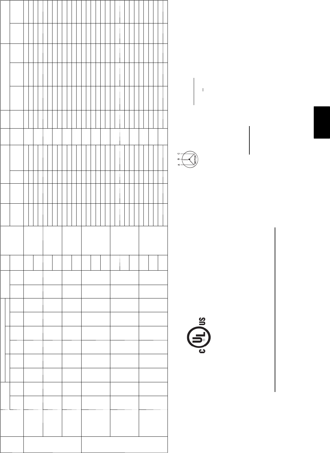
183
Units With Powered Convenience Outlet and with EnergyX — 48PG03--16 (cont)
UNIT
48PG
NOMINAL
POWER
SUPPLY
(V-Ph-Hz)
VOLTAGE
RANGE
COMPRESSOR OFM IFM COMBUSTION
FAN MOTOR
FLA
ERV
Supply
ERV
Wheel ERV Exhaust IFM ERV POWER SUPPLY DISCONNECT SIZE
No. 1 No. 2 No. 3
Min Max RLA LRA RLA LRA RLA LRA Qty FLA
(ea) FLA FLA
(ea)
FLA
(ea) Qty FLA (ea) TYPE TYPE MCA
Fuse or
HACR
Brkr
MOCP FLA LRA
14
208/230--3--60 187 253 22.4 149 22.4 149 -- -- 21.9
10.2
0.52
3.32/3.0 0.33/0.3 28.85/8.0 LOW LOW 93.9/91.5 -- / -- 100/100 102/99 490
8.85/8.0 0.66/0.6 27.08/6.4 HIGH 101.7/98.6 -- / -- 110/110 111/107 542
15.0 3.32/3.0 0.33/0.3 28.85/8.0 HIGH LOW 98.7/96.3 -- / -- 110/110 107/104 499
8.85/8.0 0.66/0.6 27.08/6.4 HIGH 106.5/103.4 -- / -- 125/125 116/112 551
460--3--60 414 506 10.6 75 10.6 75 -- -- 21.0
4.8
0.30
1.5 0.15 2 4 LOW LOW 44 50 -- 48 241
40.35 23.2 HIGH 47.6 60 -- 52 265
7.4 1.5 0.15 2 4 HIGH LOW 46.6 50 -- 51 245
40.35 23.2 HIGH 50.2 60 -- 55 269
575--3--60 518 633 7.7 54 7.7 54 -- -- 20.8
2.8
0.24
1.1 0.12 23.3 LOW LOW 32.3 40 -- 35 190
3.3 0.3 22.4 HIGH 35.1 40 -- 38 213
5.6 1.1 0.12 23.3 HIGH LOW 35.1 40 -- 38 204
3.3 0.3 22.4 HIGH 37.9 45 -- 41 227
16
208/230--3--60 187 253 18.1 137 18.1 137 17.6 123 31.9
10.2
0.52
7.08/6.4 0.66/0.6 28.85/8.0 LOW LOW 111.5/108.4 -- / -- 125/125 123/119 645
8.85/8.0 0.66/0.6 27.08/6.4 HIGH 111.5/108.4 -- / -- 125/125 123/119 645
15.0 7.08/6.4 0.66/0.6 28.85/8.0 MID--
LOW
LOW 116.3/113.2 -- / -- 125/125 129/125 654
8.85/8.0 0.66/0.6 27.08/6.4 HIGH 116.3/113.2 -- / -- 125/125 129/125 654
19.4 7.08/6.4 0.66/0.6 28.85/8.0 HIGH LOW 121.1/118.0 -- / -- 150/125 134/130 692
8.85/8.0 0.66/0.6 27.08/6.4 HIGH 121.1/118.0 -- / -- 150/125 134/130 692
460--3--60 414 506 9.0 62 9.0 62 9.6 62 31.0
4.8
0.30
3.2 0.35 2 4 LOW LOW 54.8 60 -- 60 303
40.35 23.2 HIGH 54.8 60 -- 60 303
7.4 3.2 0.35 2 4 MID--
LOW
LOW 57.4 60 -- 63 307
40.35 23.2 HIGH 57.4 60 -- 63 307
9.7 3.2 0.35 2 4 HIGH LOW 59.7 -- 70 66 326
40.35 23.2 HIGH 59.7 -- 70 66 326
575--3--60 518 633 6.8 50 6.8 50 6.1 40 30.8
2.8
0.24
2.4 0.3 23.3 LOW LOW 40 45 -- 44 247
3.3 0.3 22.4 HIGH 40 45 -- 44 247
5.6 2.4 0.3 23.3 MID--
LOW
LOW 42.8 45 -- 47 261
3.3 0.3 22.4 HIGH 42.8 45 -- 47 261
7.8 2.4 0.3 23.3 HIGH LOW 45.3 50 -- 50 276
3.3 0.3 22.4 HIGH 45.3 50 -- 50 276
LEGEND
FLA --- F u l l L o a d A m p s
HACR --- Heating, Air Conditioning and Refrigeration
IFM --- Indoor (Evaporator) Fan Motor
LRA --- L o ck e d R o t o r A mp s
MCA --- Minimum Circuit Amps
MOCP --- Maximum Overcurrent Protection
NEC --- National Electrical Code
OFM --- Outdoor (Condenser) Fan Motor
RLA --- RatedLoadAmps
NOTES:
1. In compliance with NEC requirements for multimotor and combination load equipment (refer to NEC Articles 430 and 440), the overcurrent
protective device for the unit shall be fuse or HACR breaker.
2. Unbalanced 3-Phase Supply Voltage
Never operate a motor where a phase imbalance in supply voltage is greater than 2%. Use the following formula to determine the percentage
of voltage imbalance.
% Voltage Imbalance = 100 x
max voltage deviation from average voltage
average voltage
E x a m p l e : S u p p l y v o l t a g e i s 2 3 0 --- 3 --- 6 0
AB = 224 v
BC = 231 v
AC = 226 v
Average Voltage = 224 + 231 + 226
3
681
3
=
227
=
Determine maximum deviation from average voltage.
(AB) 227 – 224 = 3 v
(BC) 231 – 227 = 4 v
(AC) 227 – 226 = 1 v
Maximum deviation is 7 v.
Determine percent of voltage imbalance.
% Voltage Imbalance = 100 x 4
227
= 1.76%
This amount of phase imbalance is satisfactory as it is below the maximum allowable 2%.
IMPORTANT: If the supply voltage phase imbalance is more than 2%, contact your local electric utility company immediately.
48PG
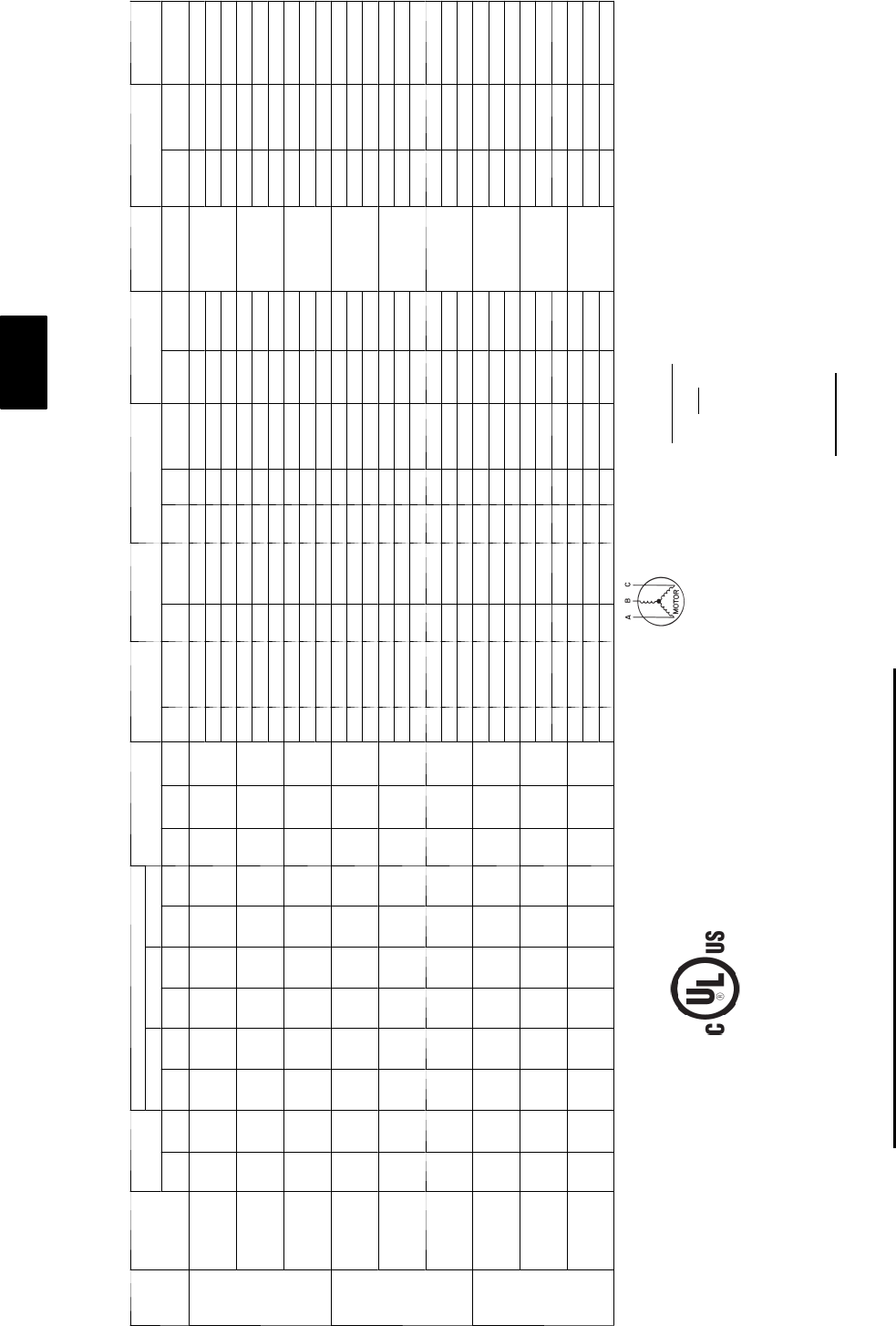
184
ELECTRICAL DATA
Units With Powered Convenience Outlet and EnergyX — 48PG20--28
UNIT
SIZE
48PG
NOMINAL
POWER
SUPPLY
(V-Ph-Hz)
VOLTAGE
RANGE
COMPRESSOR OFM IFM ERV SUPPLY ERV EXHAUST ERV WHEEL COMBUSTION
FAN MOTOR POWER SUPPLY DISCONNECT
SIZE
No. 1 No. 2 No. 3
Min Max RLA LRA RLA LRA RLA LRA Qty Hp FLA
(ea) Hp FLA Hp FLA
(ea) Qty Hp FLA
(ea) Hp FLA FLA MCA MOCP FLA
20
208/230--3--60 187 253 28.2 208 28.2 208 -- -- 40.25 1.5
516.7/15.2 27.08/6.4 2 3 8.85/8.0 0.167 0.66/0.6
0.5
117/113 125/125 126/121
7.5 24.2/22 27.08/6.4 2 3 8.85/8.0 0.167 0.66/0.6 124/119 150/125 135/129
10 30.8/28 27.08/6.4 2 3 8.85/8.0 0.167 0.66/0.6 131/125 150/150 142/136
460--3--60 414 506 15.4 104 15.4 104 -- -- 40.25 0.7
57.6 23.2 2 3 4 0.167 0.35
0.3
60 60 64
7.5 11 23.2 2 3 4 0.167 0.35 63 70 68
10 14 23.2 2 3 4 0.167 0.35 66 80 71
575--3--60 518 633 12.8 83 12.8 83 -- -- 40.25 0.7
56.1 22.4 2 3 3.3 0.167 0.3
0.24
50 60 54
7.5 9 2 2.4 2 3 3.3 0.167 0.3 53 60 57
10 11 22.4 2 3 3.3 0.167 0.3 55 60 59
24
208/230--3--60 187 253 32.1 240 32.1 240 -- -- 60.25 1.5
516.7/15.2 27.08/6.4 2 3 8.85/8.0 0.167 0.66/0.6
0.5
128/124 150/150 138/134
7.5 24.2/22 27.08/6.4 2 3 8.85/8.0 0.167 0.66/0.6 136/131 150/150 147/142
10 30.8/28 27.08/6.4 2 3 8.85/8.0 0.167 0.66/0.6 142/137 150/150 155/149
460--3--60 414 506 15.4 110 15.4 110 -- -- 60.25 0.7
57.6 23.2 2 3 4 0.167 0.35
0.3
61 70 66
7.5 11 23.2 2 3 4 0.167 0.35 64 70 70
10 14 23.2 2 3 4 0.167 0.35 67 80 73
575--3--60 518 633 12.8 88 12.8 88 -- -- 60.25 0.7
56.1 22.4 2 3 3.3 0.167 0.3
0.24
51 60 55
7.5 9 2 2.4 2 3 3.3 0.167 0.3 54 60 59
10 11 22.4 2 3 3.3 0.167 0.3 56 60 61
28
208/230--3--60 187 253 28.2 208 28.2 208 28.2 208 60.25 1.5
516.7/15.2 27.08/6.4 2 3 8.85/8.0 0.167 0.66/0.6
0.5
148/144 175/150 162/157
7.5 24.2/22 27.08/6.4 2 3 8.85/8.0 0.167 0.66/0.6 155/151 175/175 170/165
10 30.8/28 27.08/6.4 2 3 8.85/8.0 0.167 0.66/0.6 163/157 175/175 178/172
460--3--60 414 506 15.4 104 15.4 104 15.4 104 60.25 0.7
57.6 23.2 2 3 4 0.167 0.35
0.3
76 90 83
7.5 11 23.2 2 3 4 0.167 0.35 80 90 87
10 14 23.2 2 3 4 0.167 0.35 83 90 91
575--3--60 518 633 12.8 83 12.8 83 12.8 83 60.25 0.7
56.1 22.4 2 3 3.3 0.167 0.3
0.24
64 70 70
7.5 9 2 2.4 2 3 3.3 0.167 0.3 67 70 73
10 11 22.4 2 3 3.3 0.167 0.3 69 80 76
LEGEND
FLA --- F u l l L o a d A m p s
HACR --- Heating, Air Conditioning and Refrigeration
IFM --- Indoor (Evaporator) Fan Motor
LRA --- L o ck e d R o t o r A mp s
MCA --- Minimum Circuit Amps
MOCP --- Maximum Overcurrent Protection
NEC --- National Electrical Code
OFM --- Outdoor (Condenser) Fan Motor
RLA --- RatedLoadAmps
*Fuse or HACR circuit breaker
NOTES:
1. In compliance with NEC requirements for multimotor and combination load equipment (refer to NEC Articles 430 and 440), the overcurrent
protective device for the unit shall be fuse or HACR breaker.
2. Unbalanced 3-Phase Supply Voltage
Never operate a motor where a phase imbalance in supply voltage is greater than 2%. Use the following formula to determine the percentage
of voltage imbalance.
% Voltage Imbalance = 100 x
max voltage deviation from average voltage
average voltage
E x a m p l e : S u p p l y v o l t a g e i s 4 6 0 --- 3 --- 6 0
AB = 452 v
BC = 464 v
AC = 455 v
Average Voltage = 452 + 464 + 455
3
1371
3
=
457
=
Determine maximum deviation from average voltage.
(AB) 457 – 452 = 5 v
(BC) 464 – 457 = 7 v
(AC) 457 – 455 = 2 v
Maximum deviation is 7 v.
Determine percent of voltage imbalance.
% Voltage Imbalance = 100 x 7
457
= 1.53%
This amount of phase imbalance is satisfactory as it is below the maximum allowable 2%.
IMPORTANT: If the supply voltage phase imbalance is more than 2%, contact your local electric utility company immediately.
48PG
185
ELECTRICAL DATA
Units With Optional HACR with EnergyX — 48PG20--28
UNIT
SIZE
48PG
NOMINAL
POWER
SUPPLY
(V-Ph-Hz)
VOLTAGE
RANGE
COMPRESSOR OFM IFM ERV SUPPLY ERV EXHAUST ERV WHEEL COMBUSTION
FAN MOTOR POWER SUPPLY DISCONNECT
SIZE
No. 1 No. 2 No. 3
Min Max RLA LRA RLA LRA RLA LRA Qty Hp FLA
(ea) Hp FLA Hp FLA
(ea) Qty Hp FLA
(ea) Hp FLA FLA MCA MOCP FLA
20
208/230--3--60 187 253 28.2 208 28.2 208 -- -- 40.25 1.5
516.7/15.2 27.08/6.4 3 3 8.85/8.0 0.167 0.66/0.6
0.5
120/120 125/125 130/125
7.5 24.2/22 27.08/6.4 3 3 8.85/8.0 0.167 0.66/0.6 128/128 150/150 139/133
10 30.8/28 27.08/6.4 3 3 8.85/8.0 0.167 0.66/0.6 135/135 150/150 147/140
460--3--60 414 506 15.4 104 15.4 104 -- -- 40.25 0.7
57.6 23.2 3 3 4 0.167 0.35
0.3
61 70 65
7.5 11 23.2 3 3 4 0.167 0.35 64 70 69
10 14 23.2 3 3 4 0.167 0.35 67 80 73
575--3--60 518 633 12.8 83 12.8 83 -- -- 40.25 0.7
56.1 22.4 3 3 3.3 0.167 0.3
0.24
50 60 54
7.5 9 2 2.4 3 3 3.3 0.167 0.3 53 60 58
10 11 22.4 3 3 3.3 0.167 0.3 55 60 60
24
208/230--3--60 187 253 32.1 240 32.1 240 -- -- 60.25 1.5
516.7/15.2 27.08/6.4 3 3 8.85/8.0 0.167 0.66/0.6
0.5
132/132 150/150 143/137
7.5 24.2/22 27.08/6.4 3 3 8.85/8.0 0.167 0.66/0.6 140/140 150/150 151/145
10 30.8/28 27.08/6.4 3 3 8.85/8.0 0.167 0.66/0.6 146/146 175/175 159/152
460--3--60 414 506 15.4 110 15.4 110 -- -- 60.25 0.7
57.6 23.2 3 3 4 0.167 0.35
0.3
62 70 67
7.5 11 23.2 3 3 4 0.167 0.35 65 80 71
10 14 23.2 3 3 4 0.167 0.35 68 80 74
575--3--60 518 633 12.8 88 12.8 88 -- -- 60.25 0.7
56.1 22.4 3 3 3.3 0.167 0.3
0.24
52 60 56
7.5 9 2 2.4 3 3 3.3 0.167 0.3 55 60 59
10 11 22.4 3 3 3.3 0.167 0.3 57 60 61
28
208/230--3--60 187 253 28.2 208 28.2 208 28.2 208 60.25 1.5
516.7/15.2 27.08/6.4 3 3 8.85/8.0 0.167 0.66/0.6
0.5
152/152 175/175 166/161
7.5 24.2/22 27.08/6.4 3 3 8.85/8.0 0.167 0.66/0.6 159/159 175/175 175/169
10 30.8/28 27.08/6.4 3 3 8.85/8.0 0.167 0.66/0.6 166/166 175/175 182/175
460--3--60 414 506 15.4 104 15.4 104 15.4 104 60.25 0.7
57.6 23.2 3 3 4 0.167 0.35
0.3
77 90 85
7.5 11 23.2 3 3 4 0.167 0.35 81 90 88
10 14 23.2 3 3 4 0.167 0.35 84 90 92
575--3--60 518 633 12.8 83 12.8 83 12.8 83 60.25 0.7
56.1 22.4 3 3 3.3 0.167 0.3
0.24
65 70 70
7.5 9 2 2.4 3 3 3.3 0.167 0.3 67 80 74
10 11 22.4 3 3 3.3 0.167 0.3 69 80 76
LEGEND
FLA --- F u l l L o a d A m p s
HACR --- Heating, Air Conditioning and Refrigeration
IFM --- Indoor (Evaporator) Fan Motor
LRA --- L o ck e d R o t o r A mp s
MCA --- Minimum Circuit Amps
MOCP --- Maximum Overcurrent Protection
NEC --- National Electrical Code
OFM --- Outdoor (Condenser) Fan Motor
RLA --- RatedLoadAmps
*Fuse or HACR circuit breaker
NOTES:
1. In compliance with NEC requirements for multimotor and combination load equipment (refer to NEC Articles 430 and 440), the overcurrent
protective device for the unit shall be fuse or HACR breaker.
2. Unbalanced 3-Phase Supply Voltage
Never operate a motor where a phase imbalance in supply voltage is greater than 2%. Use the following formula to determine the percentage
of voltage imbalance.
% Voltage Imbalance = 100 x
max voltage deviation from average voltage
average voltage
E x a m p l e : S u p p l y v o l t a g e i s 4 6 0 --- 3 --- 6 0
AB = 452 v
BC = 464 v
AC = 455 v
Average Voltage = 452 + 464 + 455
3
1371
3
=
457
=
Determine maximum deviation from average voltage.
(AB) 457 – 452 = 5 v
(BC) 464 – 457 = 7 v
(AC) 457 – 455 = 2 v
Maximum deviation is 7 v.
Determine percent of voltage imbalance.
% Voltage Imbalance = 100 x 7
457
= 1.53%
This amount of phase imbalance is satisfactory as it is below the maximum allowable 2%.
IMPORTANT: If the supply voltage phase imbalance is more than 2%, contact your local electric utility company immediately.
48PG
186
Units With Optional Powered Convenience Outlet and HACR with EnergyX — 48PG20--28
UNIT
SIZE
48PG
NOMINAL
POWER
SUPPLY
(V-Ph-Hz)
VOLTAGE
RANGE
COMPRESSOR OFM IFM ERV SUPPLY ERV EXHAUST ERV WHEEL COMBUSTION
FAN MOTOR POWER SUPPLY DISCONNECT
SIZE
No. 1 No. 2 No. 3
Min Max RLA LRA RLA LRA RLA LRA Qty Hp FLA
(ea) Hp FLA Hp FLA
(ea) Qty Hp FLA
(ea) Hp FLA FLA MCA MOCP FLA
20
208/230--3--60 187 253 28.2 208 28.2 208 -- -- 40.25 1.5
516.7/15.2 27.08/6.4 2 3 8.85/8.0 0.167 0.66/0.6
0.5
117/117 125/125 126/121
7.5 24.2/22 27.08/6.4 2 3 8.85/8.0 0.167 0.66/0.6 124/124 150/150 135/129
10 30.8/28 27.08/6.4 2 3 8.85/8.0 0.167 0.66/0.6 131/131 150/150 142/136
460--3--60 414 506 15.4 104 15.4 104 -- -- 40.25 0.7
57.6 23.2 2 3 4 0.167 0.35
0.3
60 60 64
7.5 11 23.2 2 3 4 0.167 0.35 63 70 68
10 14 23.2 2 3 4 0.167 0.35 66 80 71
575--3--60 518 633 12.8 83 12.8 83 -- -- 40.25 0.7
56.1 22.4 2 3 3.3 0.167 0.3
0.24
50 60 54
7.5 9 2 2.4 2 3 3.3 0.167 0.3 53 60 57
10 11 22.4 2 3 3.3 0.167 0.3 55 60 59
24
208/230--3--60 187 253 32.1 240 32.1 240 -- -- 60.25 1.5
516.7/15.2 27.08/6.4 2 3 8.85/8.0 0.167 0.66/0.6
0.5
128/128 150/150 138/134
7.5 24.2/22 27.08/6.4 2 3 8.85/8.0 0.167 0.66/0.6 136/136 150/150 147/142
10 30.8/28 27.08/6.4 2 3 8.85/8.0 0.167 0.66/0.6 142/142 150/150 155/149
460--3--60 414 506 15.4 11 0 15.4 11 0 -- -- 60.25 0.7
57.6 23.2 2 3 4 0.167 0.35
0.3
61 70 66
7.5 11 23.2 2 3 4 0.167 0.35 64 70 70
10 14 23.2 2 3 4 0.167 0.35 67 80 73
575--3--60 518 633 12.8 88 12.8 88 -- -- 60.25 0.7
56.1 22.4 2 3 3.3 0.167 0.3
0.24
51 60 55
7.5 9 2 2.4 2 3 3.3 0.167 0.3 54 60 59
10 11 22.4 2 3 3.3 0.167 0.3 56 60 61
28
208/230--3--60 187 253 28.2 208 28.2 208 28.2 208 60.25 1.5
516.7/15.2 27.08/6.4 2 3 8.85/8.0 0.167 0.66/0.6
0.5
148/148 175/175 162/157
7.5 24.2/22 27.08/6.4 2 3 8.85/8.0 0.167 0.66/0.6 155/155 175/175 170/165
10 30.8/28 27.08/6.4 2 3 8.85/8.0 0.167 0.66/0.6 163/163 175/175 178/172
460--3--60 414 506 15.4 104 15.4 104 15.4 104 60.25 0.7
57.6 23.2 2 3 4 0.167 0.35
0.3
76 90 83
7.5 11 23.2 2 3 4 0.167 0.35 80 90 87
10 14 23.2 2 3 4 0.167 0.35 83 90 91
575--3--60 518 633 12.8 83 12.8 83 12.8 83 60.25 0.7
56.1 22.4 2 3 3.3 0.167 0.3
0.24
64 70 70
7.5 9 2 2.4 2 3 3.3 0.167 0.3 67 70 73
10 11 22.4 2 3 3.3 0.167 0.3 69 80 76
LEGEND
FLA --- F u l l L o a d A m p s
HACR --- Heating, Air Conditioning and Refrigeration
IFM --- Indoor (Evaporator) Fan Motor
LRA --- L o ck e d R o t o r A mp s
MCA --- Minimum Circuit Amps
MOCP --- Maximum Overcurrent Protection
NEC --- National Electrical Code
OFM --- Outdoor (Condenser) Fan Motor
RLA --- RatedLoadAmps
*Fuse or HACR circuit breaker
NOTES:
1. In compliance with NEC requirements for multimotor and combination load equipment (refer to NEC Articles 430 and 440), the overcurrent
protective device for the unit shall be fuse or HACR breaker.
2. Unbalanced 3-Phase Supply Voltage
Never operate a motor where a phase imbalance in supply voltage is greater than 2%. Use the following formula to determine the percentage
of voltage imbalance.
% Voltage Imbalance = 100 x
max voltage deviation from average voltage
average voltage
E x a m p l e : S u p p l y v o l t a g e i s 4 6 0 --- 3 --- 6 0
AB = 452 v
BC = 464 v
AC = 455 v
Average Voltage = 452 + 464 + 455
3
1371
3
=
457
=
Determine maximum deviation from average voltage.
(AB) 457 – 452 = 5 v
(BC) 464 – 457 = 7 v
(AC) 457 – 455 = 2 v
Maximum deviation is 7 v.
Determine percent of voltage imbalance.
% Voltage Imbalance = 100 x 7
457
= 1.53%
This amount of phase imbalance is satisfactory as it is below the maximum allowable 2%.
IMPORTANT: If the supply voltage phase imbalance is more than 2%, contact your local electric utility company immediately.
48PG
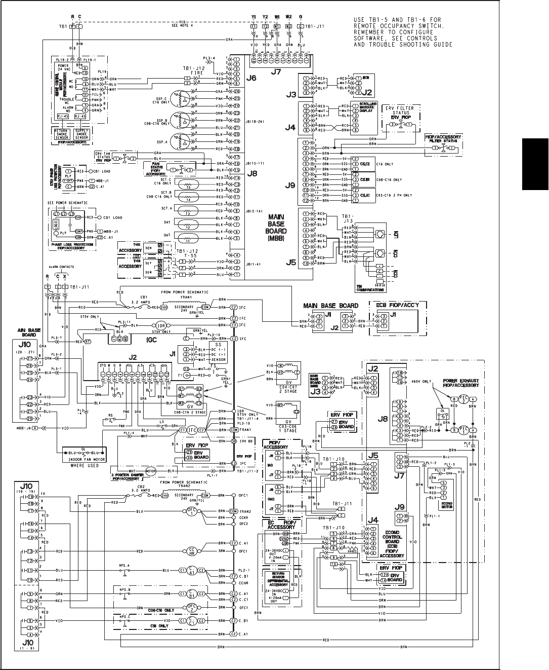
187
TYPICAL WIRING SCHEMATICS
Typical Control Wiring Schematic -- 48PG03--16 with ComfortLinktControls
C07501
*See Legend on page 189.
48PG
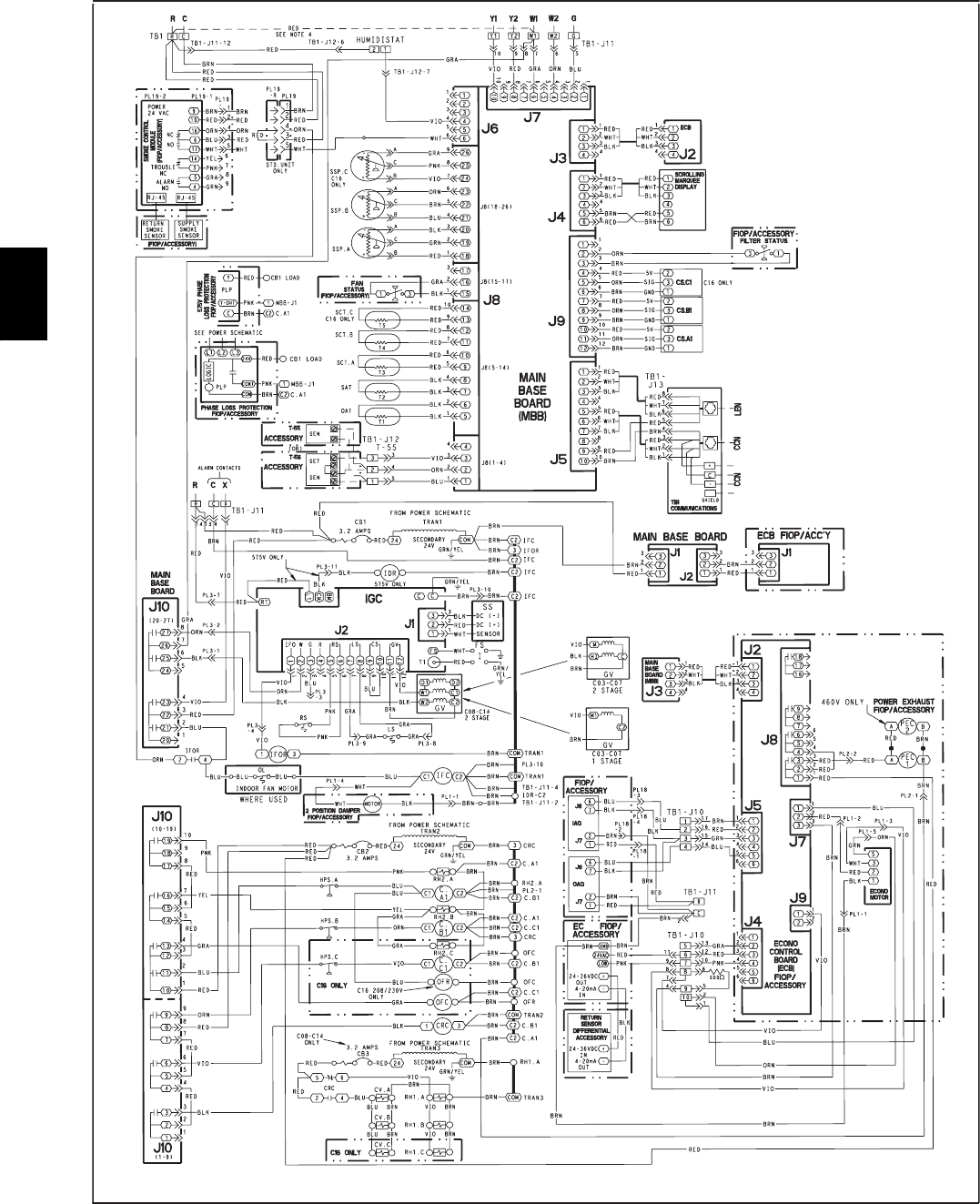
188
TYPICAL WIRING SCHEMATICS (CONT)
Typical Control Wiring Schematic -- 48PG03--16 with Humidi--MiZertControls
NOTES:
1. Use TB1-5 and TB1-6 for remote
occupancy switch. Remember to configure
software. See Controls and troubleshooting
guide.
C07526
* See Legend on page 189.
48PG
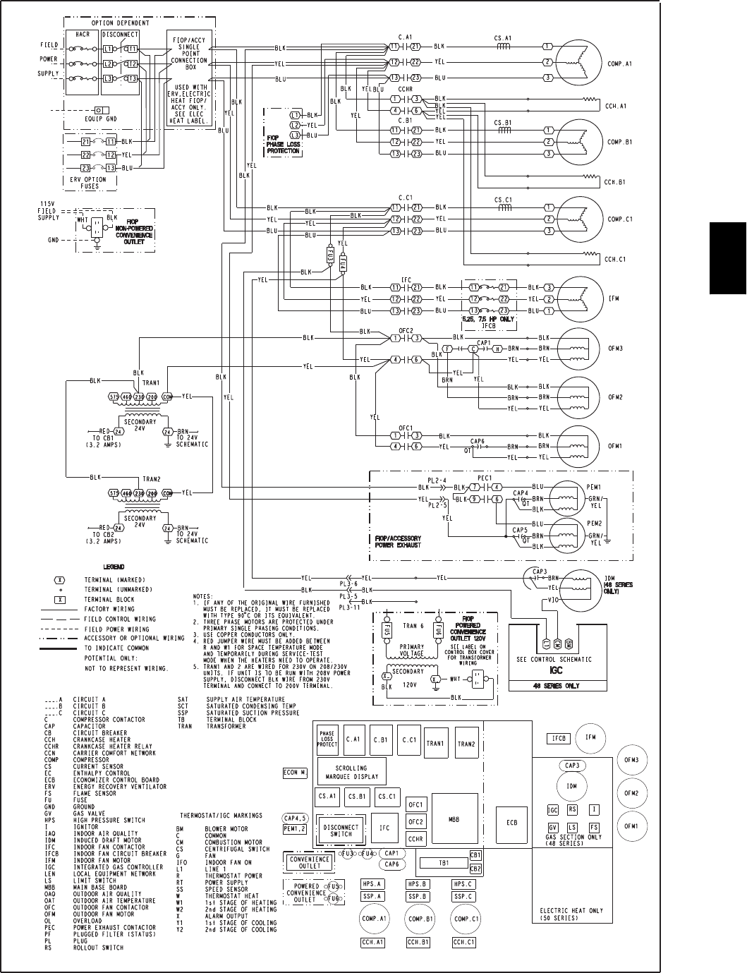
189
Typical Power Schematic -- 48PG03--16
C07498
48PG
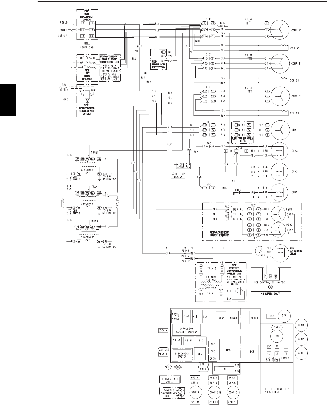
190
TYPICAL WIRING SCHEMATICS (CONT)
Typical Power Schematic -- 48PG03--16 with Humidi--MiZertSystem
C07291
* See Legend on page 189.
48PG
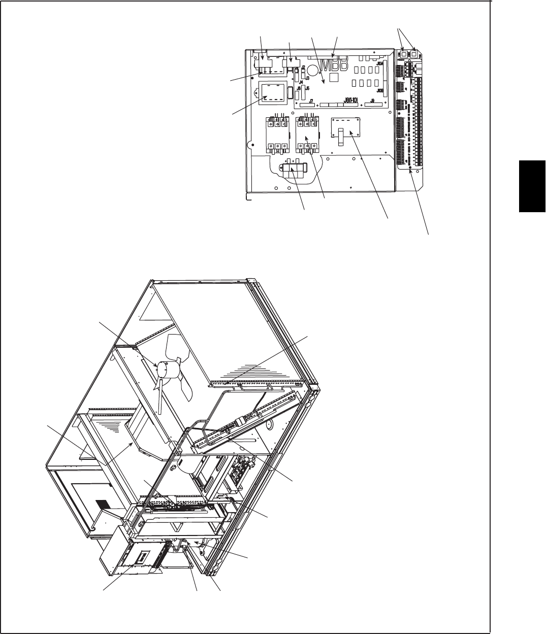
191
Typical Unit Component Locations -- 48PG03--14 (Sizes 03--07 Shown)
SAT
OFM
TXV
IFM
SCROLLING
MARQUEE
DISPLAY
HPS
SSP
COMPRESSOR(S)
OAT
SCT
COMPRESSOR
CONTACTOR
CAPACITOR
CURRENT
SENSOR
TB1
(LOW VOLTAGE TERMINAL STRIP)
OFC
CCHR
MBB
ECB
CB
IGC
TRAN 1 TRAN 2
UNIT CONTROL BOX
IFC
C07527
* See Legend on page 189.
48PG
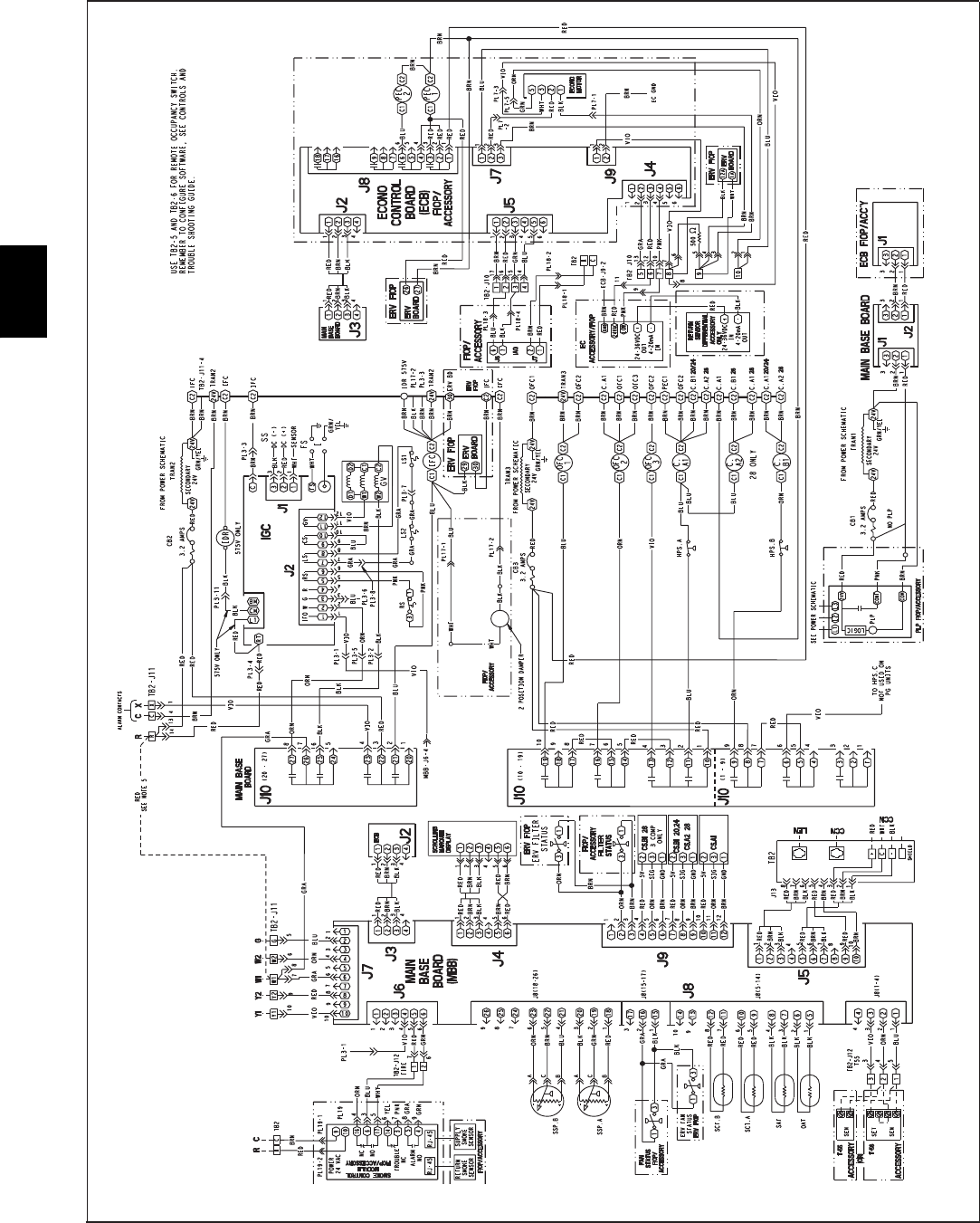
192
TYPICAL WIRING SCHEMATICS (CONT)
Low Voltage Control Schematic -- 48PG20--28 Units
C07502
48PG
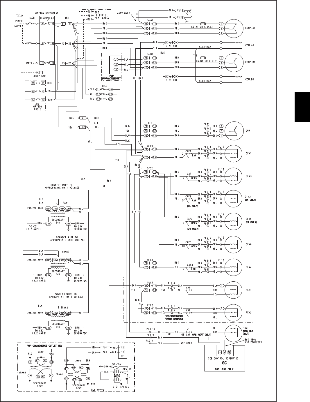
193
Power Schematic -- 48PG20--28 Units
C07499
48PG
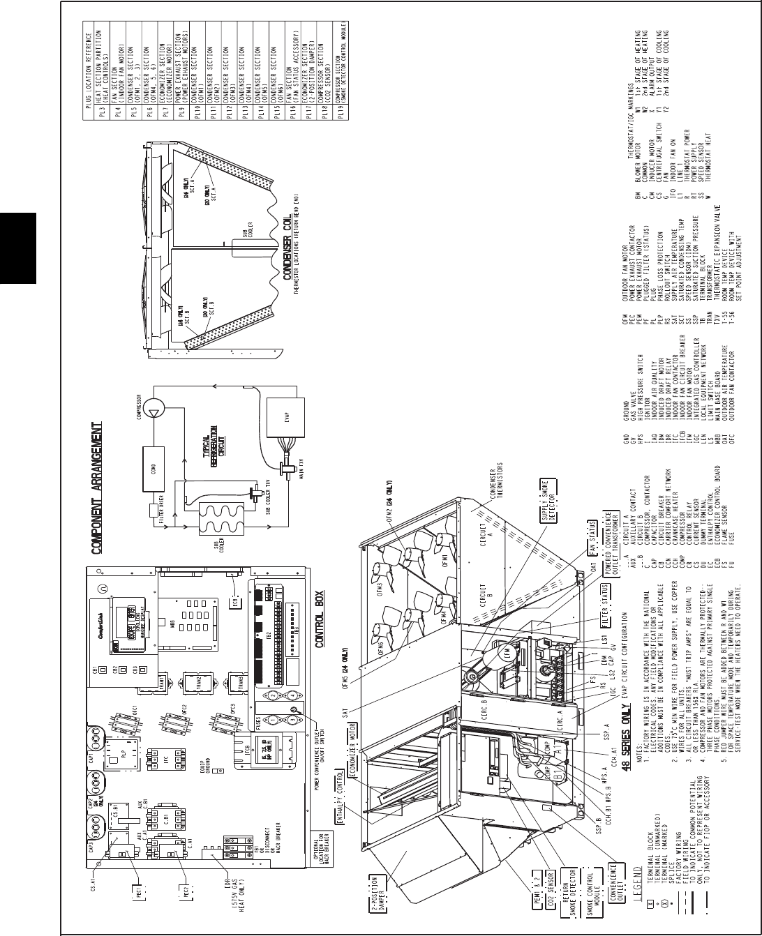
194
Component Arrangement -- 48PG20--28 Units
C07528
48PG
195
CONTROLS
Operating sequence, 48PG03--16 units
Heating
NOTE: The 48PG units have 1 or 2 stages of gas heat.
When the thermostat calls for heating, power is sent to W on the
IGC (integrated gas unit controller) board. An LED (light--emitting
diode) on the IGC board will be on during normal operation. A
check is made to ensure that the rollout switch and limit switch are
closed and the induced--draft motor is running. The induced--draft
motor is then energized, and when speed is proven with the hall
effect sensor on the motor, the ignition activation period begins.
The burners will ignite within 5 seconds.
If the burners do not light, there is a 22--second delay before
another 5--second attempt. If the burners still do not light, this
sequence is repeated for 15 minutes. After the 15 minutes have
elapsed, if the burners still have not lit, heating is locked out. To
reset the control, break 24--v power to the thermostat.
When ignition occurs the IGC board will continue to monitor the
condition of the rollout and limit switches, the hall effect sensor, as
well as the flame sensor. If the unit is controlled through a room
thermostat set for fan auto., 45 seconds after ignition occurs, the
indoor--fan motor will be energized (and the outdoor--air dampers
will open to their minimum position). If for some reason the
overtemperature limit opens prior to the start of the indoor fan
blower, on the next attempt, the 45--second delay will be shortened
to 5 seconds less than the time from initiation of heat to when the
limit tripped. Gas will not be interrupted to the burners and heating
will continue. Once modified, the fan on delay will not change
back to 45 seconds unless power is reset to the control.
On units with 2 stages of heat, when additional heat is required,
W2 closes and initiates power to the second stage of the main gas
valve. When the thermostat is satisfied, W1 and W2 open and the
gas valve closes, interrupting the flow of gas to the main burners. If
the call for W1 lasted less than 1 minute, the heating cycle will not
terminate until 1 minute after W1 became active. If the unit is
controlled through a room thermostat set for fan auto., the
indoor--fan motor will continue to operate for an additional 45
seconds then stop. If the overtemperature limit opens after the
indoor motor is stopped within 10 minutes of W1 becoming
inactive, on the next cycle the time will be extended by 15 seconds.
The maximum delay is 3 minutes. Once modified, the fan off delay
will not change back to 45 seconds unless power is reset to the
control.
A LED indicator is provided on the IGC to monitor operation. The
IGC is located by removing the heat section side panel. During
normal operation, the LED is continuously on.
For units with economizers, the outdoor--air damper stays at the
Economizer Minimum Position while the evaporator fan is
operating. The outdoor--air damper is closed when the indoor fan is
not operating.
IGC LEd Indications
ERROR CODE LED INDICATION
Normal Operation On
Hardware Failure Off
Fan On/Off Delay Modified 1Flash
Limit Switch Fault 2Flashes
Flame Sense Fault 3Flashes
Five Consecutive Limit Switch Faults 4Flashes
Ignition Lockout Fault 5Flashes
Inducer Switch Fault 6Flashes
Rollout Switch Fault 7Flashes
Internal Control Fault 8Flashes
LEGEND
I G C --- Integrated Gas Unit Controller
L E D --- L i g h t --- E m i t t i n g D i o d e
NOTES:
1. There is a 3---second pause between error code displays.
2. If more than one error code exists, all applicable error codes will be dis-
played in numerical sequence.
3. Error codes on the IGC will be lost if power to the unit is interrupted.
Cooling
Economizer Control
If the economizer is available for cooling, the unit will always try
to meet demand using the economizer before turning on a
compressor. The economizer is available for cooling when:
SThe outdoor temperature is below the Economizer High
Temperature Lockout (ECL.H) and above the Economizer
Low Temperature Lockout (ECL.L)
SThe outdoor enthalpy is low. If the economizer is not available
for cooling, the economizer will move to the Economizer
Minimum Position (MIN.P).
If the economizer is available for cooling and yet it is unable to
meet demand, the unit will continue to modulate the economizer
while cycling the compressors to increase total cooling capacity.
If the indoor fan is not operating, the economizer will be closed.
The 48PG units can also be equipped with optional CO2sensors
for additional indoor air quality control. Consult the Controls and
Troubleshooting Guide for more information on IAQ features.
Cooling Using Space Sensor (T55 or T56) Control
To operate the unit in Space Sensor mode, Unit Control Type must
be set to Space Sensor (3) and a wire must be added between R and
W1 on TB1 (see controls schematic). While in this mode, the unit
tries to maintain the Space Temperature (SPT) at one of 4 different
set points: the Occupied Cool Set Point (OCSP), the Unoccupied
Cool Set Point (UCSP), the Occupied Heat Set Point (OHSP), or
the Unoccupied Heat Set Point (UHSP). The building’s occupancy
is affected by a number of different factors (see Controls and
Troubleshooting Guide for details). When the building is occupied,
the occupied set points are active. When the building in
unoccupied, the unoccupied set points are active. In Space Sensor
mode, the control will switch automatically between cooling and
heating to maintain temperature. However, to minimize
unnecessary cool to heat and heat to cool changes, there is a
10--minute delay after the last stage turns off before the control will
switch modes.
48PG
196
To maintain temperature while cooling, the unit will turn on
compressors as needed when the economizer is either unavailable
or not providing enough cooling. The minimum on--time for each
compressor is 3 minutes and the minimum off--time is 5 minutes.
Units with 1 compressor (48PG03--07) have 1 stage of cooling.
Units with 2 compressors (48PG08--14) have 2 stages of cooling.
Units with 3 compressors (48PG16) have 2 stages of cooling. The
economizer is not considered a stage of cooling even though it can
provide cooling in certain situations. In general, the minimum time
between increasing stages (from 1 to 2 and from 2 to 3) is 7.5
minutes, however, the minimum time between stages can be further
reduced in certain situations (see Controls and Troubleshooting
Guide). The minimum time between decreasing stages (3 to 1 and
2to0)is5minutes.
Consult the Controls and Troubleshooting Guide for additional
information on configuring the controls for space sensor control
and adjusting the minimum compressor on--time, minimum
compressor off--time, and the minimum time between decreasing
stages.
Cooling Using Thermostat Control
Thermostat cooling begins when the Y1 input is energized. If the
economizer is available for cooling, the economizer will try to
maintain the Supply Air Temperature (SAT) at either the Low Cool
Supply Air Set Point (LCS) for a Y1 call or the High Cool Supply
Air Set Point (HCS) for a Y2 call. If the economizer operates at
100% for 5 minutes or the economizer cooling is not available, the
unit will begin to stage compressors. While the compressors are
operating, the economizer will try to maintain its position at 100%.
However, if low suction pressures are experienced, the economizer
will begin to close in order to protect the compressors from
damage.
Three different compressor--staging algorithms are available with
ComfortLinktcontrol. They are called Adaptive, 1--stage Y1 and
2--stage Y1. In Adaptive mode, once compressor staging begins
(see above), at least one compressor will run as long as there is a
Y1 call. On a three--circuit machine with only a Y1 call, the second
circuit will cycle depending upon the trend in the supply--air
temperature (SAT). If there is a Y2 call, compressors will stage up
to the maximum number available.
The 1--stage Y1 and 2--stage Y1 modes are identical if there are
only two circuits. In both cases, the stages follow the thermostat
calls directly. For either mode, all stages will operate immediately
if there is a Y2 call.
If fan request G is energized, but Y1 is not energized, the indoor
fan will operate and the economizer position will be maintained at
MIN.P.
Operating sequence, 48PG20--28 units
Heating
NOTE: The 48PG units have 2 stages of gas heat.
When the thermostat calls for heating, power is sent to W on the
IGC (integrated gas unit controller) board. An LED (light--emitting
diode) on the IGC board will be on during normal operation. A
check is made to ensure that the rollout switch and limit switch are
closed and the induced--draft motor is running. The induced--draft
motor is then energized, and when speed is proven with the hall
effect sensor on the motor, the ignition activation period begins.
The burners will ignite within 5 seconds.
If the burners do not light, there is a 22--second delay before
another 5--second attempt. If the burners still do not light, this
sequence is repeated for 15 minutes. After the 15 minutes have
elapsed, if the burners still have not lit, heating is locked out. To
reset the control, break 24--v power to the thermostat.
When ignition occurs the IGC board will continue to monitor the
condition of the rollout and limit switches, the hall effect sensor, as
well as the flame sensor. If the unit is controlled through a room
thermostat set for fan auto., 45 seconds after ignition occurs, the
indoor--fan motor will be energized (and the outdoor--air dampers
will open to their minimum position). If for some reason the
overtemperature limit opens prior to the start of the indoor fan
blower, on the next attempt, the 45--second delay will be shortened
to 5 seconds less than the time from initiation of heat to when the
limit tripped. Gas will not be interrupted to the burners and heating
will continue. Once modified, the fan on delay will not change
back to 45 seconds unless power is reset to the control.
When additional heat is required, W2 closes and initiates power to
the second stage of the main gas valve. When the thermostat is
satisfied, W1 and W2 open and the gas valve closes, interrupting
the flow of gas to the main burners. If the call for W1 lasted less
than 1 minute, the heating cycle will not terminate until 1 minute
after W1 became active. If the unit is controlled through a room
thermostat set for fan auto., the indoor--fan motor will continue to
operate for an additional 45 seconds then stop. If the
overtemperature limit opens after the indoor motor is stopped
within 10 minutes of W1 becoming inactive, on the next cycle the
time will be extended by 15 seconds. The maximum delay is 3
minutes. Once modified, the fan off delay will not change back to
45 seconds unless power is reset to the control.
A LED indicator is provided on the IGC to monitor operation. The
IGC is located by removing the heat section side panel. During
normal operation, the LED is continuously on.
For units with economizers, the outdoor--air damper stays at the
Economizer Minimum Position while the evaporator fan is
operating. The outdoor--air damper is closed when the indoor fan is
not operating.
IGC LEd Indications
ERROR CODE LED INDICATION
Normal Operation On
Hardware Failure Off
Fan On/Off Delay Modified 1Flash
Limit Switch Fault 2Flashes
Flame Sense Fault 3Flashes
Five Consecutive Limit Switch Faults 4Flashes
Ignition Lockout Fault 5Flashes
Inducer Switch Fault 6Flashes
Rollout Switch Fault 7Flashes
Internal Control Fault 8Flashes
LEGEND
I G C --- Integrated Gas Unit Controller
L E D --- L i g h t --- E m i t t i n g D i o d e
NOTES:
1. There is a 3---second pause between error code displays.
2. If more than one error code exists, all applicable error codes will be dis-
played in numerical sequence.
3. Error codes on the IGC will be lost if power to the unit is interrupted.
Cooling
Economizer Control
If the economizer is available for cooling, the unit will always try
to meet demand using the economizer before turning on a
compressor. The economizer is available for cooling when:
SThe outdoor temperature is below the Economizer High
Temperature Lockout (ECL.H) and above the Economizer
Low Temperature Lockout (ECL.L)
SThe outdoor enthalpy is low.
48PG

197
CONTROLS (CONT)
If the economizer is not available for cooling, the economizer will
move to the Economizer Minimum Position (MIN.P). If the
economizer is available for cooling and yet it is unable to meet
demand, the unit will continue to modulate the economizer while
cycling the compressors to increase total cooling capacity.
If the indoor fan is not operating, the economizer will be closed.
The 48PG units can also be equipped with optional CO2sensors
for additional indoor air quality control. Consult the Controls and
Troubleshooting Guide for more information on IAQ features.
Cooling Using Space Sensor (T55 or T56) Control
To operate the unit in Space Sensor mode, Unit Control Type must
be set to Space Sensor (3) and a wire must be added between R and
W1 on TB2 (see controls schematic). While in this mode, the unit
tries to maintain the Space Temperature (SPT) at one of 4 different
set points: the Occupied Cool Set Point (OCSP), the Unoccupied
Cool Set Point (UCSP), the Occupied Heat Set Point (OHSP), or
the Unoccupied Heat Set Point (UHSP). The building’s occupancy
is affected by a number of different factors (see Controls and
Troubleshooting Guide for details). When the building is occupied,
the occupied set points are active. When the building in
unoccupied, the unoccupied set points are active. In Space Sensor
mode, the control will switch automatically between cooling and
heating to maintain temperature. However, to minimize
unnecessary cool to heat and heat to cool changes, there is a
10--minute delay after the last stage turns off before the control will
switch modes.
To maintain temperature while cooling, the unit will turn on
compressors as needed when the economizer is either unavailable
or not providing enough cooling. The minimum on--time for each
compressor is 3 minutes and the minimum off--time is 5 minutes.
All units have 2 stages of cooling. The 48PG20 and 24 units have
2 compressors. The 48PG28 units have 3 compressors. The
economizer is not considered a stage of cooling even though it can
provide cooling in certain situations. In general, the minimum time
between increasing stages (from 1 to 2 and from 2 to 3) is 7.5
minutes, however, the minimum time between stages can be further
reduced in certain situations (see Controls and Troubleshooting
Guide). The minimum time between decreasing stages (3 to 1 and
2to0)is5minutes.
Consult the Controls and Troubleshooting Guide for additional
information on configuring the controls for space sensor control
and adjusting the minimum compressor on--time, minimum
compressor off--time, and the minimum time between decreasing
stages.
Cooling Using Thermostat Control
Thermostat cooling begins when the Y1 input is energized. If the
economizer is available for cooling, the economizer will try to
maintain the Supply Air Temperature (SAT) at either the Low Cool
Supply Air Set Point (LCS) for a Y1 call or the High Cool Supply
Air Set Point (HCS) for a Y2 call. If the economizer operates at
100% for 5 minutes or the economizer cooling is not available, the
unit will begin to stage compressors. While the compressors are
operating, the economizer will try to maintain its position at 100%.
However, if low suction pressures are experienced, the economizer
will begin to close in order to protect the compressors from
damage.
Three different compressor--staging algorithms are available with
ComfortLink control. They are called Adaptive, 1--stage Y1 and
2--stage Y1. In Adaptive mode, once compressor staging begins
(see above), at least one compressor will run as long as there is a
Y1 call. In addition, internal timers affect the rate at which
compressors are turned on and off.
The 1--stage Y1 and 2--stage Y1 modes are identical. In both cases,
the stages follow the thermostat calls directly. For either mode, all
stages will operate immediately if there is a Y2 call.
If fan request G is energized, but Y1 is not energized, the indoor
fan will operate and the economizer position will be maintained at
MIN.P.
Optional Humidi--MiZertDehumidification
System
Units with the factory--equipped Humidi--MiZer option are capable
of providing multiple modes of improved dehumidification as a
variation of the normal cooling cycle. The Humidi--MiZer option
includes additional valves in the liquid line and discharge line of
each refrigerant circuit, a small reheat condenser coil downstream
of the evaporator, and MotormasterRvariable--speed control of
some or all outdoor fans. Operation of the revised refrigerant
circuit for each mode is described below.
NOTE: x = refrigerant circuit A, B, or C.
48PG03--16
Normal Cooling
Refrigerant flows from the outdoor condenser through the
normally open Cooling Valve (CV.x) to the expansion device.
Reheat1 Valve (RH1.x) and Reheat2 Valve (RH2.x) are closed.
Reheat1 (Subcooling Mode) -- 48PG03--16
This mode increases latent cooling and decreases sensible cooling
compared to normal cooling. Refrigerant flows from the outdoor
condenser, through the normally open Reheat1 Valve (RH1.x), and
through the reheat condenser coil to the expansion device. Cooling
Valve (CV.x) and Reheat2 Valve (RH2.x) are closed.
Reheat2 (Hot Gas Reheat Mode) -- 48PG03--16
This mode provides maximum latent cooling with little to no
sensible capacity. This mode can operate to provide
dehumidification when there is no cooling demand. Like Reheat1
mode, refrigerant flows from the outdoor condenser, through the
normally open Reheat1 Valve (RH1.x), and through the reheat
condenser coil to the expansion device. The Cooling Valve (CV.x)
is closed. Reheat2 Valve (RH2.x) is open which provides some
compressor discharge gas to the reheat condenser to further
increase the reheat of the evaporator airstream.
48PG

198
Normal Cooling Mode -- Humidi--MiZertSystem (48PG03--16)
COMP
COND COIL HUMIDI-MIZER COIL
EVAP COIL
INDOOR ENTERING
AIR
OUTDOOR AIR
METERING
DEVICE
CLOSED VALVE
OPEN VALVE
RH1.x
RH2.x
CV.x
a48-8172
C07119
Subcooling Mode (Reheat1) -- Humidi--MiZer System (48PG03--16)
COMP
COND COIL HUMIDI-MIZER COIL
EVAP COIL
INDOOR ENTERING
AIR
OUTDOOR AIR
METERING
DEVICE
CLOSED VALVE
OPEN VALVE
RH1.x
RH2.x
CV.x
a48-8173
C07120
48PG
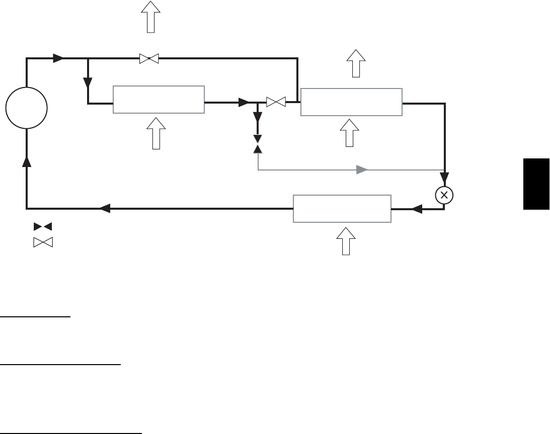
199
Hot Gas Reheat Mode (Reheat2) -- Humidi--MiZer System (48PG03--16)
COMP
COND COIL HUMIDI-MIZER COIL
EVAP COIL
INDOOR ENTERING
AIR
OUTDOOR AIR
METERING
DEVICE
CLOSED VALVE
OPEN VALVE
RH1.x
RH2.x
CV.x
a48-8174
C07121
48PG20--28
Normal Cooling
Refrigerant flows from the outdoor condenser through the
de--energized 3--way (RH1.x) to the expansion device. Reheat2
Valve (RH2.x) is closed.
Reheat1 (Subcooling Mode)
This mode increases latent cooling and decreases sensible cooling
compared to normal cooling. Refrigerant flows from the outdoor
condenser, through the energized 3--way Valve (RH1.x), and
through the reheat condenser coil to the expansion device. Reheat2
Valve (RH2.x) is closed.
Reheat2 (Hot Gas Reheat Mode)
This mode provides maximum latent cooling with little to no
sensible capacity. This mode can operate to provide
dehumidification when there is no cooling demand. Like Reheat1
mode, refrigerant flows from the outdoor condenser, through the
energized 3--way Valve (RH1.x), and through the reheat condenser
coil to the expansion device. Reheat2 Valve (RH2.x) is open which
provides some compressor discharge gas to the reheat condenser to
further increase the reheat of the evaporator airstream.
Units with multiple circuits can operate with additional staging of
the cooling and dehumidification capacity. When there is only
cooling demand, based on a space temperature sensor or
thermostat, one or more circuits will operate in normal cooling
mode. When there is only dehumidification demand, based on a
space humidity sensor or switch, all circuits will operate in Reheat2
mode. When there is both cooling demand and dehumidification
demand, all circuits will operate in either Reheat1 or Reheat2
mode, with the portion of Reheat1 circuits determined from the
cooling demand.
Outdoor fan control for Humidi--MiZertsystem units includes a
Motormaster variable--speed control of some or all outdoor fans,
depending on unit model size. The Motormaster control
automatically adjusts the outdoor fan speed to maintain
approximately 80_to 100_F condenser temperature for circuit A at
all outdoor ambient temperatures. Some model sizes have
additional on/off staging of some outdoor fans. This staging is
controlled by both outdoor temperature and condenser coil
temperature.
Compressor staging control for Humid--MiZer units requires that
circuit A always operate when either circuits B or C are on. This
applies to normal operation, service test, and for control alarm
responses. This operation difference is required due to the fact that
the Motormaster outdoor fan control senses circuit A only.
48PG
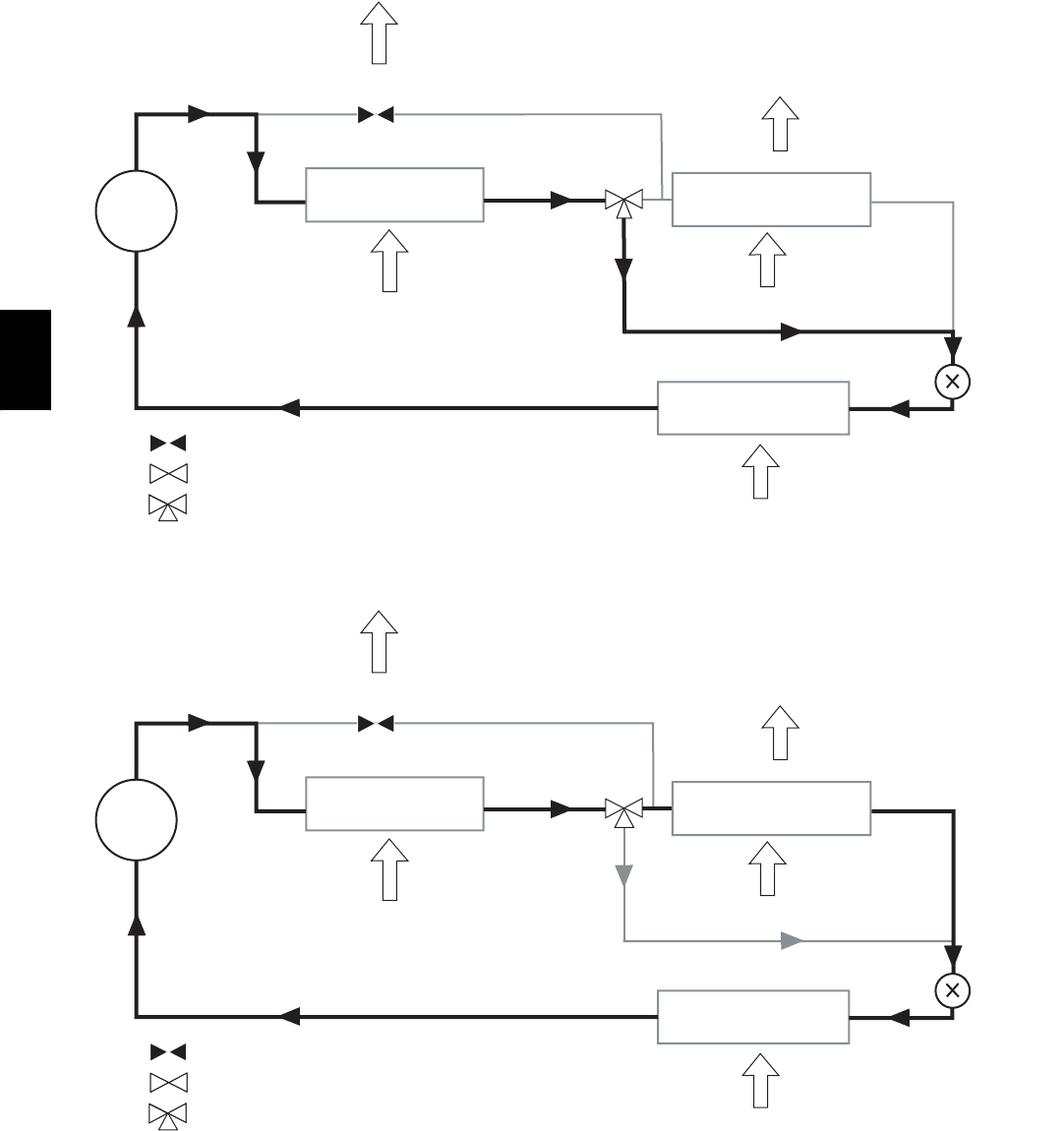
200
Normal Cooling Mode -- Humidi--MiZertSystem (48PG20--28)
a48-8172
COMP
COND COIL HUMIDI-MIZER COIL
EVAP COIL
INDOOR ENTERING
AIR
OUTDOOR AIR
METERING
DEVICE
CLOSED VALVE
OPEN VALVE
3-WAY VALVE
RH1.x
RH2.x
a48-8222
C07122
Subcooling Mode (Reheat1) -- Humidi--MiZer System (48PG20--28)
COMP
COND COIL HUMIDI-MIZER COIL
EVAP COIL
INDOOR ENTERING
AIR
OUTDOOR AIR
METERING
DEVICE
CLOSED VALVE
OPEN VALVE
3-WAY VALVE
RH1.x
RH2.x
C07123
48PG
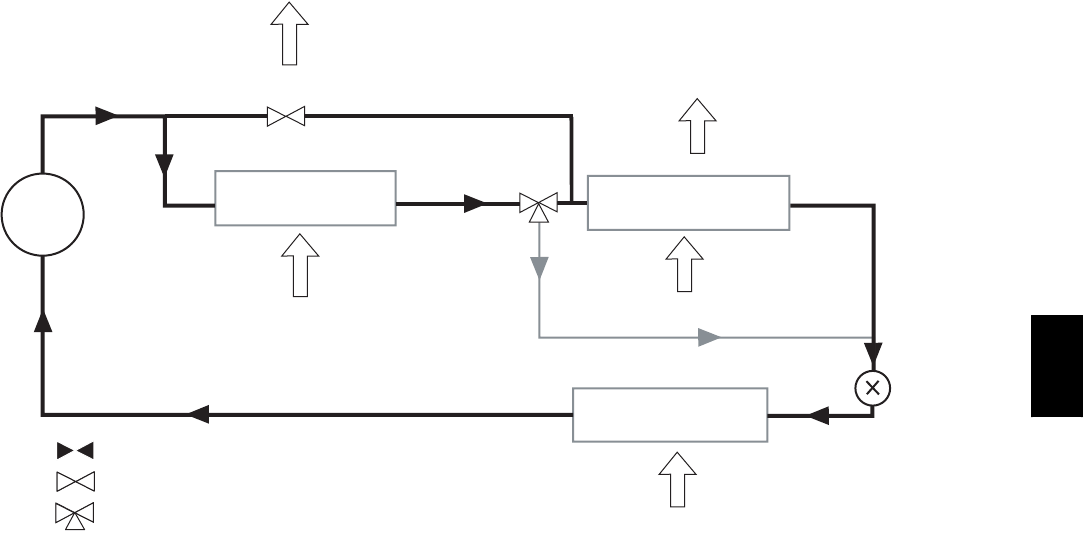
201
Hot Gas Reheat Mode (Reheat2) -- Humidi--MiZer System (48PG20--28)
COMP
COND COIL HUMIDI-MIZER COIL
EVAP COIL
INDOOR ENTERING
AIR
OUTDOOR AIR
METERING
DEVICE
CLOSED VALVE
OPEN VALVE
3-WAY VALVE
RH1.x
RH2.x
C07124
APPLICATION DATA
Ductwork
Ductwork should be attached to the curb on all units. Interior
installation may proceed before unit is set in place on roof. If
ductwork will be attached to the unit, do not drill in condensate
drain pan area -- leaks may result.
Thru--the--Bottom Service Connections
Roof curb connections allow field power wires and control wires to
enter through the roof curb opening and bottom of unit.
Thermostat/Space Temperature Sensor (T55, T56,
or T58)
Either a 2--stage cooling thermostat or a space temperature sensor is
required for all units. A field--supplied jumper is required when
using a space temperature sensor. The jumper is placed between
terminals R and W1 on the unit thermostat terminal block (TB1 or
TB2). Refer to wiring diagram for details.
Heating--to--Cooling Changeover
All units are automatic changeover from heating to cooling when
automatic changeover thermostat and subbase or space temperature
sensors are used.
Airflow
Units are draw--thru on cooling and blow--thru on heating.
Maximum Airflow
To minimize the possibility of condensate blow--off from
evaporator, airflow through units should not exceed 500
cfm/nominal ton.
Minimum Airflow
The minimum airflow for cooling is 300 cfm/nominal ton.
Operation Air Quantity Limits table for minimum airflow cfm for
heating.
IMPORTANT: The minimum heating cfm must be maintained to
ensure proper operation in the Heating mode. The minimum
heating cfm value takes precedence over the minimum cooling cfm
value.
Minimum Ambient Cooling Operation
Temperature
All units with ComfortLinktcontrols are designed to operate at
outdoor temperatures down to 0_F. Electromechanical operation
downto40_F.
Maximum Operating Outdoor--Air Temperature
For cooling, this temperature is 125_F. Refer to the Cooling
Capacity tables for further details.
High Altitude
A change to the gas orifice may be required at high altitudes. Refer
to Altitude Compensation charts.
Minimum Heating Entering Air Temperature
The minimum temperature of air entering the dimpled heat
exchanger is 50_F continuous and 45_F intermittent for aluminum
heat exchangers and 40_F continuous and 35_F intermittent for
stainless steel heat exchangers. To operate at lower mixed--air
temperatures, a field--supplied outdoor--air thermostat must be used
to initiate both stages of heat when the temperature is below the
minimum required temperature to ensure full fire operation. Wire
the outdoor--air thermostat (part no. HH22AG106) in series with
the second stage gas valve as shown below. Set the outdoor--air
thermostat at 35_F for stainless steel heat exchangers or 45_Ffor
aluminum heat exchangers. This temperature setting will bring on
the second stage of heat whenever the ambient temperature is
below the thermostat set point. Indoor comfort may be
compromised when heating is initiated using low entering air
temperatures with insufficient heating temperature rise.
48PG
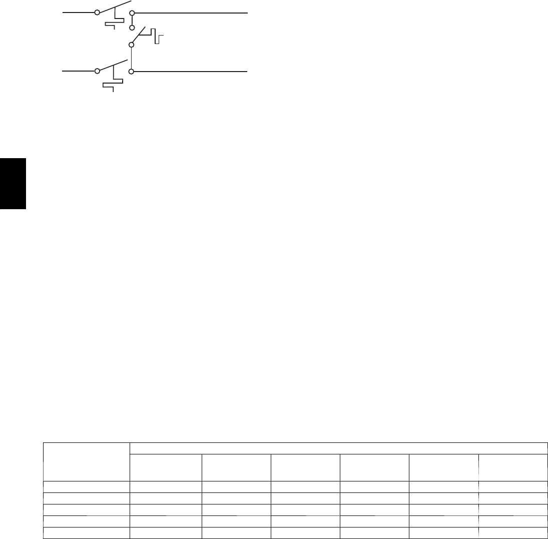
202
Wiring of Outdoor--Air Thermostat
W1
W2
FIELD-INSTALLED
OUTDOOR-AIR THERMOSTAT
TO UNIT THERMOSTAT
CONNECTIONS
C07529
Motor Data
Due to Carrier’s internal unit design (draw--thru over the motor),
air path, and specially designed motors, the full horsepower
(maximum continuous bhp) listed in the Physical Data table and
the notes following each Fan Performance table can be utilized
with extreme confidence.
Using Carrier motors with the values listed in the Physical and Fan
Performance Data tables will not result in nuisance tripping or
premature motor failure. The unit warranty will not be affected.
Condenser coil protection (Enviro--Shieldt)
Pre--coated aluminum--fin coils have a durable epoxyphenolic
coating applied to the fin prior to the fin stamping process to
provide protection in mildly corrosive coastal environments.
Pre--coated coils have an inert barrier between the aluminum fin
and copper tube. This barrier electrically disconnects the dissimilar
metals to minimize the potential for galvanic corrosion. This
economical option provides substantial corrosion protection for
mild coastal environments beyond the standard uncoated coil
construction.
Copper--fin coils provide increased corrosion resistance in
moderate coastal environments where industrial air pollution is not
present. All copper coils eliminate bi--metallic construction to
eliminate the potential for galvanic corrosion. Use of copper fin
coils in industrial environments is not recommended due to
potential attack from sulfur, sulfur oxide, nitrogen oxides, carbon
and several other industrial air--borne contaminants. In moderate
seacoast environments, copper--fin coils have extended life
compared to standard or pre--coated aluminum--fin coils.
E--Coated aluminum--fin coils undergo a precisely controlled
scientific process that bonds an impermeable epoxy coating to the
specially prepared fin coil surface. E--Coating produces a smooth,
consistent coating that is less brittle, more resilient and more
durable than previous postcoating processes. E--Coated
aluminum--fin coils offer economical protection and improved coil
life in industrial and combined coastal and industrial environments.
E--Coated copper--fin coils provide maximum protection in
virtually all environments, this option combines the continuous,
impenetrable barrier of the E--Coating process with the natural
resistance of an all--copper construction. E--Coated copper--fin coil
assemblies ensure long life in severe coastal conditions.
Indoor Air Quality
An indoor air quality sensor, which senses CO2,isa
factory--installed option. The sensor in conjunction with the
economizer is used to maintain indoor air quality. By selecting this
option, the minimum economizer position can be reduced because
the control will adjust economizer position to maintain indoor air
quality to the desired set point. A wall--mounted indoor air quality
sensor is a field--installed accessory.
Enthalpy Sensor
Enthalpy switches are available as field--installed accessories. If
only one switch is used, it is used to measure return air enthalpy. If
two switches are used they should be wired in a differential
configuration to measure the difference in the return and outdoor
enthalpies. The enthalpy switches signify when the outdoor air is
suitable for free cooling.
Plugged Filter Indicator
A plugged filter indicator (filter status switch) is available as a
factory--installed option and a field--installed accessory. By
measuring the pressure differential across the evaporator section, it
signals when the evaporator filters should be cleaned.
Fan Status
A fan status switch is available as a factory--installed option and a
field--installed accessory. By sensing the pressure differential
generated by the indoor fan, it signals the ComfortLinktsystem
when the indoor fan blower is operating and therefore it is very
useful for detecting broken belts, etc.
Condenser Coil Protection Applications
DESCRIPTION
(ENVIRO--- SHIELDt
OPTION)
ENVIRONMENT
STANDARD,
N O N --- C O R R O S I V E MILD COASTAL MODERATE
COASTAL SEVERE COASTAL INDUSTRIAL
COMBINED
COASTAL AND
INDUSTRIAL
Standard, Al/Cu X
P r e --- c o a t e d A l / C u X
Cu/Cu X
E --- C o a t e d A l / C u X X
E--- Coated Cu/Cu X
Legend
Al/Cu --- Aluminum Fin with Copper Tube Coil
Cu/Cu --- Copper Fin with Copper Tube Coil
E n v i r o --- S h i e l d --- Family of Coil Protection Options
E --- C o a t e d --- Extremely Flexible and Durable Epoxy Coating Uniformly
Applied to the Coil Surfaces
P r e --- C o a t e d --- Epoxy Coating Applied to Fin Stock Material
48PG

203
GUIDE SPECIFICATIONS
Unit with Gas Heat -- Constant Volume
Application with Puron R--410A Refrigerant
HVAC Guide Specifications
Size Range: 2to25Tons,NominalCooling
51,000 to 400,000 Btuh
Nominal (Input Heating) (Gas Units)
Carrier Model Numbers:
48PGD/L, 48PGE/M, 48PGF/N
Part 1 -- General
1.01 SYSTEM DESCRIPTION
Unit is an outdoor rooftop mounted, electrically controlled
heating and cooling unit utilizing fully
hermetic scroll compressors with on demand crankcase
heaters for cooling duty and induced draft gas
combustion for heating duty. Supply air shall be discharged
downward or horizontally, as shown on
contract drawings.
Units shall be of ultra high cooling efficiency and
utilize environmentally friendly Puron (R--410A)
refrigerant.
1.02 QUALITY ASSURANCE
A. Unit shall well exceed ASHRAE 90.1--2001 and Energy
ENERGY STAR efficiency standards.
On 03 to 06 sizes -- SEER shall be as high as 14.8.
On 06 to 16 sizes -- EER shall be as high as 12.5
and on sizes 20 to 28 -- EER shall be as high as
11.6.
B. Unit shall be rated in accordance with ARI Standards 210
(03--12) and 360 on all others. All units shall be designed in
accordance with UL Standard 1995. Unit shall be rated in
accordance with ARI sound standards 270 or 370.
C. Unit shall be designed to conform to ASHRAE 15.
D. Unit shall be UL and UL, Canada, tested and certified in
accordance with ANSI Z21.47 Standards as a total package.
E. Roof curb shall be designed to conform to NRCA Standards.
F. Insulation and adhesive shall meet NFPA 90A requirements for
flame spread and smoke generation.
G. Unit casing shall be capable of withstanding 500--hour salt
spray exposure per ASTM B117 (scribed specimen).
H. Unit shall be manufactured in a facility registered to ISO
9001:2000.
I. Each unit shall be subjected to a completely automated
run testing on the assembly line.
1.03 DELIVERY, STORAGE, AND HANDLING
Unit shall be stored and handled per manufacturer’s
recommendations.
Part 2 -- Products
2.01 EQUIPMENT (STANDARD)
A. General
The 48PG unit shall be a fully factory assembled, pre--tested,
single--piece heating and cooling unit. Contained within the
unit enclosure shall be all factory wiring, piping, controls,
Puron refrigerant charge (R--410A), and special features
required prior to field start--up. Outdoor sound ratings on sizes
03--06 shall be as low as 72 dB, on sizes 08 to 16 as low as 80
dB and on sizes 20 to 28 as low as 82 dB.
B. Unit Cabinet
1. Constructed of galvanized steel, bonderized and coated with
a pre--painted baked enamel finish on all externally exposed
surfaces. Internal surfaces shall be of a primer coated finish.
2. All airstream interior surfaces shall be insulated with a
minimum 1/2--in. thick, 1 lb density foil faced cleanable
insulation. Insulation shall be bonded with a thermosetting
resin (8 to 12% by weight nominal, phenol formaldehyde
typical), and coated with an acrylic or other material that
meets the NFPA 90 flame retardance requirements and has
an “R” value of 3.70. Insulation shall also be encapsulated
with panel design or tape edges ensuring secure fit.
3. Cabinet panels shall be hinged with integrated non--corros-
ive hinges. Large area hinged access panels for the filter,
compressors, evaporator fan, and control box and heat
section areas. Each panel shall use multiple quarter--turn
latches and handles. Each major external hinged access
panel shall be double--wall construction and permanently
attached to the rooftop unit. Panels shall also include
tiebacks.
4. Return air filters shall be accessible through a dedicated
hinged access panel and be on a slide--out track using
standard size filters. Filter shall be standard off the shelve
sizes and be the size per cabinet. Capability for 2 or 4 inch
filters shall be on all sizes.
5. Holes shall be provided in the base rails (minimum 16
gauge) for rigging shackles and level travel and movement
during overhead rigging operations.
6. Fork lift slots shall be available from three sides of the unit
(end and 2 sides) for sizes 03--14 and two sides of the unit
(end and side) for other sizes.
7. Unit shall have a factory--installed internally sloped
condensate drain pan, providing a minimum 3/4--in.--14
NPT connection to prevent standing water from
accumulating. Pan shall be fabricated of high impact
polycarbonate material and shall slide out for cleaning and
or maintenance on 03--16 sizes. An alternate vertical drain
(3/4--in. NPT) connection is also available. Pan shall be
fabricated of epoxy powder coated steel for other sizes. All
drain pans conform to ASHRAE 62 self--draining
provisions.
8. Unit shall have standard thru--the--bottom power and
control wiring connection capability.
C. Fans
1. Indoor blower (evaporator fan):
a. Centrifugal supply air blower shall have
rubber--isolated, cartridge type ball bearings (03--16) or
pillow--block ball bearings (20--28) and adjustable belt
drive.
b. Fan wheel shall be made from steel with a corrosion
resistant finish. It shall be a dynamically balanced,
double--inlet type with forward--curved blades.
c. The indoor fan system (blower wheels, motors, belts,
and both bearings) shall slide out for easy access.
d. Evaporator--fan motors shall be continuous operation,
open drip--proof. Bearings shall be sealed, permanently
lubricated ballbearing type for longer life and lower
maintenance.
e. On sizes 03 to 16, fan belt shall be located on opposite
side of evaporator coil to prevent damage from broken
fan belts. On 20 to 28 sizes a fan belt catch system shall
be used.
2. Condenser fans shall be of the direct--driven propeller type,
with corrosion--resistant aluminum blades riveted to
corrosion--resistant steel supports. They shall be
dynamically balanced and discharge air upwards.
Condenser--fan motors shall be totally enclosed, thermally
protected, and be of a shaft down design to protect from
direct contact from harsh environments.
48PG

204
3. Induced--draft blower shall be of the direct driven, single
inlet, forward--curved, centrifugal type. It shall be made
from aluminized steel with a corrosion--resistant finish and
shall be dynamically balanced.
D. Compressor(s)
1. Fully hermetic, scroll type with on demand crankcase
heaters, internal high--pressure and temperature protection.
2. Factory mounted on rubber grommets and internally spring
mounted for vibration isolation.
3. Be mounted on dedicated mounting plate to ensure secure
design and reduced sound levels.
E. Coils
1. Standard evaporator and condenser coils shall have
aluminum lanced plate fins mechanically bonded to
seamless internally grooved copper tubes with all joints
brazed.
2. Dual circuit models (08--28) shall have face--split type
evaporator coil.
3. Condenser and evaporator coils shall be single slab, single
pass design to facilitate easy coil cleaning. Composite coils
or coils that require unit top panels removed shall be
unacceptable.
4. Coils shall be leak tested at 170 psig and pressure tested at
1875 psig.
5. Optional Coils:
a. Optional pre--coated aluminum--fin coils shall have a
durable epoxy--phenolic coating to provide protection in
mildly corrosive coastal environments. Coating shall be
applied to the aluminum fin stock prior to the fin
stamping process to create an inert barrier between the
aluminum fin and copper tube. Epoxy--phenolic barrier
shall minimize galvanic action between dissimilar
metals.
b. Optional copper--fin coils shall be constructed of copper
fins mechanically bonded to copper tubes and copper
tube sheets. Galvanized steel tube sheets shall not be
acceptable. A polymer strip shall prevent coil assembly
from contacting the sheet metal coil pan to minimize
potential for galvanic corrosion between coil and pan.
All copper construction shall provide protection in
moderate coastal environments.
c. Optional E--Coated aluminum--fin coils shall have a
flexible epoxy polymer coating uniformly applied to all
coil surface areas without material bridging between
fins. Coating process shall ensure complete coil
encapsulation. Color shall be high gloss black with
gloss -- 60 deg of 65 to 90% per ASTM D523--89.
Uniform dry film thickness from 0.8 to 1.2 mil on all
surface areas including fin edges. Superior hardness
characteristics of 2H per ASTM D3363--92A and
crosshatch adhesion of 4B--5B per ASTM D3359--93.
Impact resistance shall be up to 160 in./lb (ASTM
D2794--93). Humidity and water immersion resistance
shall be up to minimum 1000 and 250 hours
respectively (ASTM D2247--92 and ASTM D870-- 92).
Corrosion durability shall be confirmed through testing
to be no less than 1000 hours salt spray per ASTM
B117--90. Coil construction shall be aluminum fins
mechanically bonded to copper tubes. E--Coated
aluminum-- fin coils shall provide protection in
industrial and industrial and coastal combined
environments.
d. Optional E--Coated copper--fin coils shall have a flexible
epoxy polymer coating uniformly applied to all coil
surface areas without material bridging between fins.
Coating process shall ensure complete coil
encapsulation. Color shall be high gloss black with
gloss -- 60 deg of 65 to 90% per ASTM D523--89.
Uniform dry film thickness from 0.8 to 1.2 mil on all
surface areas including fin edges. Superior hardness
characteristics of 2H per ASTM D3363--92A and
crosshatch adhesion of 4B--5B per ASTM D3359--93.
Impact resistance shall be up to 160 in./lb (ASTM
D2794--93). Humidity and water immersion resistance
shall be up to minimum 1000 and 250 hours
respectively (ASTM D2247--92 and ASTM D870-- 92).
Corrosion durability shall be confirmed through testing
to be no less than 1000 hours salt spray per ASTM
B117--90. Coil construction shall be copper fins
mechanically bonded to copper tubes with copper tube
sheets. Galvanized steel tube sheets shall not be
acceptable. A polymer strip shall prevent coil assembly
from contacting sheet metal coil pan to maintain coating
integrity and minimize corrosion potential between coil
and pan. E--Coated copper--fin coils shall provide
protection in severe coastal environments.
F. Heating Section
1. Induced--draft combustion type with energy saving
direct--spark ignition system and redundant main gas valve
with 2--stage capability on all 3--phase units.
2. Heat Exchanger:
a. The standard aluminized heat exchanger shall be of the
tubular--section type constructed of a minimum of
20--gage steel
coated with a nominal 1.2 mil aluminumsilicone alloy
for corrosion resistance.
b. The optional stainless steel heat exchanger shall be of
the tubular--section type, constructed of a minimum of
20--gage type 409 stainless steel, including stainless
steel tubes, vestibule plate, and collector box.
3. Burners shall be of the in--shot type constructed of
aluminum--coated steel.
4. All gas piping shall enter the unit at a single location. Gas
entry shall be capable through side or bottom for unit.
5. All factory--installed orifices are for operation up to 2,000
feet of altitude. For altitudes between 2,000 ft and 7,000 ft,
a factory certified kit shall be furnished for field installation.
6. The integrated gas controller (IGC) board shall include gas
heat operation fault notification using an LED
(light--emitting diode).
7. Unit shall be equipped with anti--cycle protection with one
short cycle on unit flame rollout switch or 4 continuous
short cycles on the hightemperature limit switch. Fault
indication shall be made using an LED.
8. The IGC board shall contain algorithms that modify
evaporator--fan operation to prevent future cycling on
high--temperature limit switch.
9. The LED shall be visible without removal of control box
access panel.
10. Gas burner tray, when disconnected, shall easily slide out
for maintenance.
G. Refrigerant Components
Each refrigerant circuit shall include:
1. 1. Balanced port thermostatic expansion valve (TXV) with
removable power element.
2. Solid core refrigerant filter driers with pressure ports.
3. Refrigerant pressure gage ports and connections on suction,
discharge, and liquid lines.
48PG

205
H. Filter Section
1. Standard filter section shall consist of factoryinstalled 2--in.
thick disposable fiberglass filters and shall be on a dedicated
slide out track to easily facilitate access and replacement.
2. Filter section shall use standard size filters and be of
common sizes within cabinet sizes.
3. Optional MERV--8 pleated filters of commercially available
sizes shall be available.
4. Standard 2--in. filter rack shall be field convertible to 4--in.
by removing a spacer rack on 03--16 sizes. A 4--in. filter
capability shall be available as factory--installed option on
the other sizes.
I. Controls and Safeties
1. Unit ComfortLinktControls:
a. Scrolling Marquee display.
b. CCN (Carrier Comfort Networkt) capable.
c. Unit control with standard suction pressure transducers
and condensing temperature thermistors.
d. Shall provide a 5_F temperature difference between
cooling and heating set points to meet ASHRAE 90.1
Energy Standard.
e. Shall provide and display a current alarm list and an
alarm history list.
f. Automatic compressor redundancy on units without
Humidi--MiZer system.
g. Service run test capability.
h. Shall accept input from a CO2sensor (both indoor and
outdoor).
i. Configurable alarm light shall be provided which
activates when certain types of alarms occur.
j. Compressor minimum run time (3 minutes) and
minimum off time (5 minutes) are provided.
k. Service diagnostic mode.
l. Economizer control (optional).
m. Multiple capacity stages (on size 08--28 units).
n. Unit shall be complete with self--contained low--voltage
control circuit.
o. Unit shall have 0_F low ambient cooling operation.
2. Safeties:
a. Unit shall incorporate a solid--state compressor lockout
that provides optional reset capability at the space
thermostat, should any of the following safety devices
trip and shut off compressor:
1. Compressor lockout protection provided for either internal
or external overload.
2. Low--pressure protection.
3. Freeze protection (evaporator coil).
4. High--pressure protection (high pressure switch or internal).
5. Compressor reverse rotation protection (ComfortLink units
only).
6. Loss of charge protection.
7. Start assist on singe--phase units.
b. Supply--air sensor shall be located in the unit and detect
both heating and cooling operation.
c. Induced draft heating section shall be provided with the
following minimum protections:
(1.) High--temperature limit switch.
(2.) Induced--draft motor speed sensor.
(3.) Flame rollout switch.
(4.) Flame proving controls.
(5.) Redundant gas valve.
J. Operating Characteristics
1. Unit shall be capable of starting and running at 125_F
ambient outdoor temperature per maximum load criteria of
ARI Standard 210 (03--12 sizes) and 360 (16--28 sizes).
2. Unit with ComfortLink controls will operate in cooling
down to an outdoor ambient temperature of 0_F.
Electro--mechanical shall operate down to 40_F.
3. Unit shall be provided with fan time delay to prevent cold
air delivery in Heating mode.
K. Electrical Requirements
All unit power wiring shall enter unit cabinet at a single loca-
tion -- side or bottom.
L. Motors
1. Compressor motors shall be cooled by refrigerant gas
passing through motor windings and shall have line break
thermal and current overload protection.
2. Evaporator fan motor shall have permanently lubricated,
sealed bearings and inherent automatic--reset thermal
overload protection or manual reset calibrated circuit
breakers. Evaporator motors are designed specifically for
Carrier and do not have conventional horsepower (hp)
ratings listed on the motor nameplate. Motors are designed
and qualified in the “air--over” location downstream of the
cooling coil and carry a maximum continuous bhp rating
that is the maximum application bhp rating for the motor;
no “safety factors“ above that rating may be applied.
3. All evaporator fan motors 5 hp and larger shall meet the
minimum efficiency requirements as established by the
Energy Policy Act of 1992 (EPACT), effective October 24,
1997.
4. Totally enclosed condenser--fan motor shall have
permanently lubricated, sealed bearings, and inherent
automatic--reset thermal overload protection.
5. Induced--draft motor shall have permanently lubricated
sealed bearings and inherent automatic-- reset thermal
overload protection.
M. Special Features
Certain features are not applicable when the features designated
* are specified. For assistance in amending the specifications,
contact your local Carrier Sales Office.
1. * Full Perimeter Roof Curbs (Horizontal and Vertical):
a. Formed of 14--gage galvanized steel with wood nailer
strip and shall be capable of supporting entire unit
weight. Shall be interlocking design.
b. Permits installing and securing ductwork to curb prior
to mounting unit on the curb. Field assembly required.
c. Shall be available in both 14--in. and 24--in. height.
2. * Adapter Roof Curb:
Shall be available for fit up to previously installed Carrier
DJ,TJ,LJ,TF,HJ,TMroofcurb(03--14sizes).
3. * Integrated Economizer:
a. Tilt--out economizer (16--28 slide out) shall be furnished
and installed complete with outside air dampers and
controls.
b. Low--leakage (less than 2%), opposing, gear--driven
dampers with UL approved gears.
c. Capable of introducing up to 100% outdoor air for
minimum ventilation as well as free cooling.
d. Damper actuator shall be electronic 4 to 20 mA/2 to 10
vdc fully modulating design.
e. Economizer outdoor hood shall be prepainted and fully
assembled on 03 to 16 sizes. Economizer outdoor hood
requires field assemble on other sizes.
f. Economizer shall be available for both field or factory
installation.
48PG

206
4. * Two--Position Motorized Outdoor Air Damper:
a. The damper shall admit up to 50% outdoor air. Spring
return damper closes when unit is off.
b. The package shall include a multiple--blade damper and
motors.
c. Shall be available as factory--installed option and
field--installed accessory.
5. * Manual Outdoor Air Damper:
a. The damper shall admit up to 33% outdoor air.
b. Shall include hood, damper plate, and screen (03--16
sizes) or cleanable aluminum filter (20--28 sizes).
c. Shall be available as factory--installed option and
field--installed accessory.
6. * Barometric Relief Damper Package:
a. Package shall include damper, seals, hardware, and
hoods to relieve excess internal pressure.
b. Integrated barometric relief capabilities on economizer
shall be available on 03--16 sizes.
c. Damper shall close due to gravity upon unit shutdown.
7. * Power Exhaust:
a. For 03--16 sizes, package shall include two (2) propeller
exhaust fans, 0.25 Hp (03--07) or 0.5 Hp (08--16)
208--230 v, 460 v directdrive motor on each, and
damper for units with economizer to control
over--pressurization of building. Single--stage control.
b. For 20--28 sizes, package shall include two (2)
centrifugal exhaust fans, 1 Hp 208--230, 460 v
(factory--wired for 460 v) three--speed direct--drive
motor on each, and damper for units with economizer to
control over--pressurization of building. Two--stage
exhaust capability through ComfortLink control shall be
available.
c. Power exhaust shall fit on both vertical and horizontal
configured unit.
d. Power exhaust shall be available for both field or
factory installation.
8. Single Enthalpy Sensor:
The enthalpy sensor shall provide economizer control based
on outdoor air enthalpy. The economizer control shall
include logic to calculate the wet bulb and dry bulb
temperatures of the outdoor air.
9. Differential Enthalpy Sensor:
a. For use with economizer only.
b. Capable of comparing heat content (temperature and
humidity) of outdoor air and indoor air and controlling
economizer cut--in point at the most economical level.
10. Convenience Outlet:
a. Optional factory--installed powered convenience outlet
shall be internally mounted with an externally accessible
115--v, 2--plug female receptacle with hinged cover.
Shall include 15 amp GFI with independent fuse
protection and service receptacle disconnect. The
convenience outlet is powered from the unit main power
wiring through a factory--installed step down trans-
former. The power wiring for the transformer needs to
be field connected per local codes. This may mean wir-
ing before the disconnect switch or after.
b. Optional factory--installed non--powered convenience
outlet shall be internally mounted with an externally
accessible 115--v, 2--plug female receptacles with hinged
cover. There is no step down transformer installed from
the factory.
11. * Non--Fused Disconnect Switch:
Shall be factory--installed, internally mounted, NEC and UL
approved. Non--fused switch shall provide unit power
shutoff. Shall be accessible from outside the unit and shall
provide power off lockout capability.
12. * HACR Circuit Breaker:
Shall be factory--installed, internally mounted, NEC and UL
approved. HACR breaker shall provide unit power shutoff.
Shall be accessible from outside the unit and shall provide
power off lockout capability.
13. CO2Sensor:
The duct--mounted or wall--mounted CO2sensor shall have
the ability to monitor CO2levels and relay information to
the controller. The controller will use CO2 level information
to modulate the economizer and provide demand control
ventilation. The sensor shall be available as field or
factory--installed.
14. Return Air/Supply Air Smoke Detector:
The smoke detector shall send input to the controller to shut
down the unit in case smoke is detected. The smoke
detector shall be factory installed in the return air section or
shall be available as a field--installed accessory.
15. Filter Status:
The filter status switch shall be a pressure switch and will
indicate a dirty filter. The switch shall be available as field
or factory--installed.
16. Fan Status:
The fan status switch shall be a pressure switch and will
indicate indoor fan operation. The switch shall be available
as field or factory installed.
17. * MERV--8 Pleated Return Air Filters:
The filters shall be MERV--8 efficient. The filters shall be
2--in., pleated filters.
18. * Four--in. Return Air Filter Capability:
a. The unit shall be capable of accepting fieldsupplied
4--in. filters by removing a spacer rack on 03--16 sizes
standard units.
b. The unit with factory--installed option of 4--in. filter
capability (20--28) shall be capable of accepting
field--supplied 4--in. filters by removal of the
factory--supplied 2--in. filters and filter retainer.
19. * Low Range Fan Performance Motor/Drive: This
motor/drive option shall provide low range motor and drive
capability to enhance evaporator fan performance.
20. * Mid--Low Fan Performance Motor/Drive (16--28 sizes):
This motor/drive shall provide low to medium motor and
drive capability to enhance evaporator fan performance.
21. * Mid--High Fan Performance Motor/Drive (20--28 sizes):
This motor/drive option shall provide medium to high
motor and drive capability to enhance evaporator fan
performance.
22. * High Fan Performance Motor/Drive:
This motor/drive offering shall provide high range motor
and drive capability to enhance evaporator fan performance.
23. Hail Guard, Condenser Coil Grille:
Shall protect the condenser coil from hail, flying debris, and
damage by large objects without increasing unit clearances.
24. Horizontal Kit:
a. Horizontal kit shall contain all the necessary hardware to
convert a vertical airflow unit to a horizontal airflow
unit (16--28 sizes).
b. The unit shall also be available as a horizontal airflow
unit directly from the factory.
48PG

207
25. Phase Loss Protection (3--phase units only):
Shall provide unit shutdown when an electrical phase loss is
detected -- automatic reset type.
26. Roof Curb Burglar Bar:
Shall be 1/2--in diameter rod with 9--in. on center design
grid pattern. Shall mount in roof curb openings.
27. * Electronic Programmable Thermostat:
Capable of using deluxe full--featured electronic thermostat.
28. * Thermostats and Subbases:
To provide staged heating and cooling in addition to
automatic (or manual) changeover and fan control.
29. Flue Discharge Deflector:
Aluminum flue discharge deflector directs unit flue exhaust
vertically instead of horizontally. UL listed.
30. Liquefied Propane Conversion Kit:
Kit shall contain all the necessary hardware and instructions
to convert a standard natural gas unit for use with liquefied
propane gas.
31. Natural Gas High Altitude Kit:
Shall provide the necessary orifices and instructions re-
quired to operate unit in altitude from 2,000 ft to 7,000 ft.
32. Thru--The--Curb Gas Connection Kit:
Shall provide hardware for through the curb routing of gas
piping. Minimize roof penetration.
33. Thru--The--Bottom Gas Connection Kit:
Shall provide hardware for through the unit bottom routing
of gas piping. Minimize roof penetration.
34. Gas Heat options (sizes 04--06):
a. Single--stage gas heat shall be provided in lieu of
two--stage heat.
b. NOx reduction shall be provided to reduce nitrous
oxide emissions to meet the California Air Quality
Management NOx requirement of 40 nanograms/joule
or less.
c. Primary tubes on low NOx units shall be 409 stainless
steel. Other components shall be aluminized steel.
35. Humidi--MiZer Adaptive Dehumidification System:
a. The Humidi--MiZer dehumidification system shall be
factory--installed in the 48PG03--28 rooftop units, and
shall provide greater dehumidification of the occupied
space by two modes of dehumidification operations
beside its normal design cooling mode:
(1.) Subcooling mode further subcools the hot liquid
refrigerant leaving the condenser coil when both
temperature and humidity in the space are not
satisfied.
(2.) Hot gas reheat mode shall mix a portion of the hot
gas from the discharge of the compressor with the
hot liquid refrigerant leaving the condenser coil to
create a two--phase heat transfer in the system,
resulting in a neutral leaving-- air temperature when
only humidity in the space is not satisfied.
b. The system shall consist of a subcooling/ reheat
dehumidification coil located downstream of the
standard evaporator coil. This dehumidification coil is a
single--row coil on 48PG03--16 units. This
dehumidification coil is a two--row coil on 48PG20--28
units.
c. The system shall include crankcase heater(s) for the
scroll compressor(s).
d. The system shall include a low outdoor air temperature
switch to lock out both subcooling and hot gas reheat
mode when the outdoor--air temperature is below 40 F.
e. The system shall include a Motormaster low ambient
control to ensure the normal design cooling mode
capable of down to 0_F low ambient operation.
f. The system shall include a low--pressure switch on the
suction line to ensure low pressure start--up of hot gas
reheat mode at lower outdoor temperature condition.
g. The system operation may be controlled by a
field--installed, wall--mounted humidistat. The
dehumidification circuit will then operate only when
needed. Field connections for the humidistat are made in
the low--voltage compartment of the unit control box.
The sensor can be set for any level between 55% and
80% relative humidity.
h. The system shall include a thermostatic expansion valve
(TXV) to ensure a positive superheat condition.
i. For units with two or three compressors (sizes 08--28),
depending on the conditions required to maintain the
space set points, one or all the compressors can operate
in subcooling mode, one compressor could operate in
subcooling mode while the other(s) operate in hot gas
reheat mode, or one or all the compressors can operate
in hot gas reheat mode.
48PG

208
GUIDE SPECIFICATIONS
EnergyXt-- Packaged Energy Recovery
Ventilators
HVAC Guide Specifications
Nominal Capacity Range: 350 cfm to 3,000 cfm
Model Numbers: 48PG03--16 -- Low and High
EnergyX cfm range
48PG20--28 -- Low EnergyX
cfm range
Part 1 — General
1.01 System Description
One--piece EnergyX (Energy Recovery Ventilation) unit is an
electrically controlled ventilation air pre--conditioner utilizing an
ARI 1060 Certified Energy Recovery Cassette to reduce the
cooling and heating loads placed on the primary HVAC unit by
untreated outdoor air. Building exhaust air shall be introduced to
the EnergyX unit through ductwork. Unit shall be designed as a
factory--installed option to be used with 48PG units for use in
Vertical applications only.
1.02 Quality Assurance
A. Unit shall be designed in accordance with UL Standard
1995 Ver.3.
B. Unit shall be ETL tested and certified.
C. Roof curb or curb extension shall be designed to conform
to NRCA Standards.
D. Insulation and adhesive shall meet NFPA 90A
requirements for flame spread and smoke generation.
E. Unit casing shall be capable of withstanding ASTM No.
141 (Method 6061) 500--hour salt spray test.
F. Unit shall contain ARI 1060 Certified Energy Recovery
Cassette.
G. Unit shall help meet ASHRAE Standard 62--1989
requirements.
Part2—Products
2.01 Equipment (Standard)
A. General
The EnergyX unit shall be a factory assembled, single
piece unit. Contained within the unit enclosure shall be all
factory wiring with a single, pre--determined point of
power input and a single point of 24--volt control wiring.
B. Unit Cabinet
1. Unit cabinet shall be constructed of galvanized steel
coated with a prepainted baked enamel finish.
2. All models shall have hoods installed over outside air
intake and exhaust openings. Outside air hood shall
have aluminum mist eliminator filters.
3. All models have 1--in., 2 pound density foil faced in-
sulation.
4. Hinged access doors shall be provided on all units for
access to fans and filters. Hinged doors shall be
provided with at least one handle capable of being
locked. Access doors shall have gasket.
5. Exhaust and supply airstreams shall have back--draft
dampers to prevent air penetration during off cycles.
6. Holes shall be provided in the base rails for rigging
shackles to facilitate overhead rigging.
C. Blowers
1. 2--6 Ton PG unit with Low cfm EnergyX unit:
Blowers shall be direct drive. Single--phase units shall
have four--speed motors. Three--phase units shall have
four--speed motors.
2. All other sizes:
Blowers shall be belt--driven. Drives shall include an
adjustable pulley.
3. Blower wheel shall be made from steel with a
corrosion resistant finish. It shall be a dynamically
balanced, double--inlet type with forward--curved
blades.
4. Blowers shall be mounted on neoprene vibration
isolation pads (except sizes 03--07 Low CFM).
5. Motors shall be high efficiency (80--87%) and have
thermal overload protection.
D. Filter Section
Standard filter section shall accept commercially avail-
able, 2--in. pleated filter(s), MERV--11 efficiency rating.
E. Controls and Safeties
The EnergyX unit shall operate in conjunction with
rooftop unit fan.
F. Electrical Requirements
All unit power wiring shall enter unit cabinet at a single
location.
G. Energy Recovery Cassette
1. The energy recovery media shall have a minimum of
70% effectiveness at nominal unit airflow.
2. Energy wheel performance shall be ARI Standard
1060 Certified and bear the ARI Certified Product
Seal.
3. The energy recovery cassette shall be an UL
Recognized component for electrical and fire safety.
4. The wheel shall be coated with silica gel desiccant,
permanently bonded without the use of binders or
adhesives.
5. Coated wheels shall be washable with detergent or
alkaline coil cleaner and water.
6. The silica gel shall not dissolve or deliquesce in the
presence of water or high humidity.
7. The substrate shall be made of a lightweight polymer
and shall not degrade or require additional coatings for
application in coastal environments.
8. The wheel polymer layers shall be wound
continuously with one flat and one structured layer in
an ideal parallel plate geometry providing laminar
flow and minimum pressure drop.
9. The polymer layers shall be captured in a stainless
steel wheel frame or aluminum and stainless steel
segment frames that provide a rigid and
self--supporting matrix.
10. Energy recovery wheels greater than 19 inches in
diameter shall be provided with removable wheel
segments.
11. Wheel frame shall be a welded hub, spoke and rim
assembly of stainless, plated, and or coated steel and
shall be self supporting without the wheel segments in
place.
12. Wheel segments shall be removable without the use of
tools to facilitate maintenance and cleaning.
13. Wheel rim shall be continuous rolled stainless steel
and the wheel shall be connected to the shaft by means
of taper locks.
14. Wheel bearings shall provide an L--10 life of 400,000
hours.
48PG

209
15. Drive belts of stretch urethane shall be provided for
wheel rim drive without the need for external
tensioners or adjustment.
H. Air filters
Factory--installed exhaust and outdoor air filters shall be
2--in. pleated type with a MERV 8 minimum efficiency
rating.
I. Airflow test ports
Pressure test ports shall be factory--installed on the outside
of unit cabinet. They shall allow measurement of
EnergyXtwheel pressure drop on both the intake and
exhaust sections to facilitate blower setup and air
balancing.
2.02 Special Features (Options)
1. Supply and exhaust air frost control option
a. Factory--installed frost protection module shall
sense pressure differential across the energy recov-
ery cassette.
b. Supply blower shall be shut--off if the pressure dif-
ferential across the energy recovery cassette exceeds
an adjustable set point. Blower shall remain off 5
minutes.
c. Exhaust blower and wheel shall remain in operation
in order to remove any frost build--up on the wheel.
2. EnergyX maintenance indicator package
Pressure switches are used when blowers are not run-
ning and alarm is sent.
Proxy sensor is used to monitor the EnergyX wheel
and alarm is sent.
3. EnergyX filter maintenance indicator
A factory--installed differential pressure switch shall
measure pressure drop across the outside air filter and
activate a field--supplied 24--v indicator when airflow
is restricted (all sizes except 03--07 Low and Med
CFM). It shall not interrupt EnergyX operation.
Switch set point shall be adjustable. Exhaust air filters
are also included in this option.
4. EnergyX free cooling with enthalpy and stop/jog
control
a. Both enthalpy sensors shall prevent the wheel from
rotation, if outside air and exhaust air are at the
same enthalpy levels. The blower will remain ON
in Non--Economizer unit.
b. Stop--Jog--Control shall energize the wheel period-
ically during the free cooling operation of the En-
ergyX or when Outside Air and Return Air are at
the same enthalpy levels to prevent dirt build--up on
the wheel.
5. Motorized supply damper option
The supply damper shall be motorized with factory--
installed, 2 position, 24--volt motor (Non--Economizer
version only).
6. Motorized exhaust damper option
The exhaust damper shall be motorized with
factory--installed, 2--position, 24--volt motor (Non--
Economizer version only).
7. Roof Curb Extension is required in conjunction with
standard base unit PG roofcurb (PG20--28 sizes with
EnergyX)or Full Perimeter Roof Curb (PG03--16 with
EnergyX) Accessory for use with EnergyX units.
a. Curb shall be constructed of heavy gauge galvan-
ized steel with wood nailer strip and shall be cap-
able of supporting entire unit weight.
b. Curb shall permit installing and securing ductwork
to curb prior to mounting unit on the curb.
48PG

210
Copyright 2008 Carrier Corp. S7310 W. Morris St. SIndianapolis, IN 46231 Printed in U.S.A. Edition Date: 4/08
Manufacturer reserves the right to change, at any time, specifications and designs without notice and without obligations.
Catalog No:48PG---5PD
Replaces: 48PG---4PD
48PG
