48hj_working.auto 48HE003 006 48h 1pd
User Manual: 48HE003---006
Open the PDF directly: View PDF ![]() .
.
Page Count: 217 [warning: Documents this large are best viewed by clicking the View PDF Link!]
- FEATURES/BENEFITS
- MODEL NUMBER NOMENCLATURE
- ARI CAPACITY RATINGS
- PHYSICAL DATA 48HE
- PHYSICAL DATA 48HJ
- OPTIONS AND ACCESSORIES
- BASE UNIT DIMENSIONS 48HE
- BASE UNIT DIMENSIONS 48HJ
- BASE UNIT DIMENSIONS COBRA
- ACCESSORY DIMENSIONS
- SELECTION PROCEDURE
- PERFORMANCE DATA 48HE
- PERFORMANCE DATA 48HJ
- ELECTRICAL DATA 48HE
- ELECTRICAL DATA 48HJ
- TYPICAL WIRING SCHEMATICS
- TYPICAL PIPING AND WIRING
- CONTROLS
- APPLICATION DATA
- GUIDE SPECS 48HE003-006
- GUIDE SPECS 48HJ
- GUIDE SPECS COBRA
Copyright 2006 Carrier Corporation Form 48H-1PD
High-Efficiency (HJ and HE) units
well exceed ASHRAE 90.1 energy
efficiency requirements. Gas heat-
ing with electric cooling rooftop
units offer:
• A wide assortment of factory-installed
options available, including high-static
drives that provide additional
performance range
• Optional factory-installed COBRA™
energy recovery unit (option on
48HE003-006 and 48HJ004-014 units
only)
• Factory-installed PremierLink™
digital communicating controls
• Factory-installed optional gear driven
EconoMi$er IV (vertical return for
sizes 004-014 only) for use with
standard rooftop unit controls
(includes CO2 sensor control
capability)
• Factory-installed optional gear driven
EconoMi$er2 (vertical return only) for
use with PremierLink DDC controls
(includes 4 to 20 mA actuator for
demand control ventilation)
• Humidi-MiZer™ adaptive dehumidi-
fication system (48HE003-006 and
48HJ004-014)
WEATHERMASTER® 48HJ004-028
48HE003-006
Single-Package Rooftop Units
Gas Heating/Electric Cooling
2 to 25 Nominal Tons
Product
Data
48HJ008-014
48HJ015,017
48HJ020-028
48HE003-006
48HJ004-007

2
Features/Benefits
Every compact one-piece
unit arrives fully assembled,
charged, tested, and ready to
run.
48 Series — gas heat models
All ignition components are contained in
the compact IGC (integrated gas control-
ler) which is easily accessible for servic-
ing. The IGC control board, designed and
manufactured exclusively for Carrier
rooftop units, provides built-in diagnostic
capability. An LED (light-emitting diode)
simplifies troubleshooting by providing
visual fault notification and system status
confirmation.
The IGC also contains an exclusive
anti-cycle protection for gas heat opera-
tion. After 4 continuous cycles on the unit
high-temperature limit switch, the gas
heat operation is disabled, and an error
code is issued. This feature greatly im-
proves reliability of the rooftop unit.
The IGC also contains burner control
logic for accurate and dependable gas ig-
nition. The LED is visible without remov-
ing the unit control box access panel. This
LED fault-notification system reduces
service person troubleshooting time and
minimizes service costs. The IGC also
maximizes heating efficiency by control-
ling evaporator-fan on and off delays.
Tubular, dimpled gas heat exchangers
optimize heat transfer for improved effi-
ciency. The tubular design permits hot
gases to make multiple passes across the
path of the supply air. The dimpled design
creates a turbulent gas flow to maximize
heating efficiency.
The efficient in-shot burners and
all ignition components are contained in
an easily removable, compact assembly.
The California Air Quality Manage-
ment Districts NOx requirement of
40 nanograms/joule or less is met on 004-
006 size Low NOx models.
The extra thick Alumagard™ heat ex-
changer coating provides corrosion resis-
tance and ensures long life
(optional stainless steel heat exchangers
are available).
The unsightly appearance of flue stacks
is eliminated and the effects of wind on
heating operations are diminished by the
induced draft combustion system. The in-
ducer fan draws hot combustion gas
through the heat exchanger at the opti-
mum rate for the most effective heat
Table of contents
Page
Features/Benefits. . . . . . . . . . . . . . . . . . . . . . . . . . . . . . . . . . . . . . . . . . . . . . . . . . . . 2-5
Model Number Nomenclature . . . . . . . . . . . . . . . . . . . . . . . . . . . . . . . . . . . . . . . . . 6-9
ARI Capacity Ratings. . . . . . . . . . . . . . . . . . . . . . . . . . . . . . . . . . . . . . . . . . . . . . 10-15
Options and Accessories. . . . . . . . . . . . . . . . . . . . . . . . . . . . . . . . . . . . . . . . . . . . 26-35
48HE/HJ
Physical Data . . . . . . . . . . . . . . . . . . . . . . . . . . . . . . . . . . . . . . . . . . . . . . . . . . . . . 16-25
Base Unit Dimensions. . . . . . . . . . . . . . . . . . . . . . . . . . . . . . . . . . . . . . . . . . . . . . . 36-44
Accessory Dimensions . . . . . . . . . . . . . . . . . . . . . . . . . . . . . . . . . . . . . . . . . . . . . . 45-52
Selection Procedure . . . . . . . . . . . . . . . . . . . . . . . . . . . . . . . . . . . . . . . . . . . . . . . . 53-55
Performance Data . . . . . . . . . . . . . . . . . . . . . . . . . . . . . . . . . . . . . . . . . . . . . . . . . 56-131
Electrical Data. . . . . . . . . . . . . . . . . . . . . . . . . . . . . . . . . . . . . . . . . . . . . . . . . . . 132-149
Typical Wiring Schematics . . . . . . . . . . . . . . . . . . . . . . . . . . . . . . . . . . . . . . . . . 150-163
Typical Piping and Wiring . . . . . . . . . . . . . . . . . . . . . . . . . . . . . . . . . . . . . . . . . 164, 165
Guide Specifications. . . . . . . . . . . . . . . . . . . . . . . . . . . . . . . . . . . . . . . . . . . . . . 181-215
Controls . . . . . . . . . . . . . . . . . . . . . . . . . . . . . . . . . . . . . . . . . . . . . . . . . . . . . . . 166-176
Application Data . . . . . . . . . . . . . . . . . . . . . . . . . . . . . . . . . . . . . . . . . . . . . . . . 177-180
Index. . . . . . . . . . . . . . . . . . . . . . . . . . . . . . . . . . . . . . . . . . . . . . . . . . . . . . . . . . . . . .216
3
transfer. The heat exchanger operates un-
der negative pressure, preventing flue gas
leakage into the indoor supply air.
During the Heating mode, the evapora-
tor-fan relay automatically starts the
evaporator fan after the heat exchanger
warms up to a suitable temperature. The
30-second fan delay prevents cold air
from entering the supply duct system
when the conditioned space is calling for
heat to maximize efficiency.
The direct-spark ignition system saves
operating expense when compared to pi-
lot ignition systems. No crossover tube is
required, therefore no sooting or pilot
fouling problems can occur.
All standard units are designed for nat-
ural gas, but an accessory LP (liquid pro-
pane) conversion kit is available.
All units have a flame rectification sen-
sor to quickly sense the burner flame and
ignite burners almost immediately. Fast
shutdown is a certainty since the sensor
reacts quickly to any flame outage or sys-
tem failure. In the event of a shutdown, an
error code is issued at the IGC board.
Safety is also assured due to the heating
safety controls which will shut down the
unit if there is a problem. If excessive
temperatures develop, limit switches shut
off the gas valve. After 4 continuous short
cycles of the high-temperature limit
switch, the IGC board locks out the gas
heat cycle to prevent any further short cy-
cles. This safety feature is provided ex-
clusively on Carrier rooftop units. The
rollout switch also deenergizes the gas
valve in the event of a flame rollout.
Quiet, efficient operation and
dependable performance
Compressors have vibration isolators for
quiet operation. Efficient fan and motor
design permits operation at low sound
levels.
Unit sizes 008-028 offer lower utility
costs through part-load operation using 2
or 3 stages of cooling.
Quiet and efficient operation is provid-
ed by belt-driven evaporator fans (stan-
dard on all units over 5 tons). The belt-
driven evaporator-fan is equipped with
variable-pitch pulleys which allow adjust-
ment within the rpm ranges of the factory-
supplied pulleys.
Increased operating efficiency is
achieved through computer-designed
coils featuring staggered internally en-
hanced copper tubes. Fins are ripple-
edged for strength, lanced, and double
waved for higher heat transfer.
Durable, dependable construction
Designed for durability in any climate,
the weather-resistant cabinets are con-
structed of galvanized steel and bonder-
ized, and all exterior panels are coated
with a prepainted baked enamel finish.
The paint finish is non-chalking, and is
capable of withstanding ASTM (Ameri-
can Society for Testing and Materials)
B117 500-hour Salt Spray Test. All inter-
nal cabinet panels are primed, permitting
longer life and a more attractive appear-
ance for the entire unit.
In addition, all size 003-014 units are
designed with a single, continuous top
piece to eliminate any possible leaks at
seams or gasketing. Totally enclosed con-
denser-fan motors and permanently lubri-
cated bearings provide additional unit de-
pendability.
Easy installation and conversion
All units are shipped in the vertical
duct configuration for fit-up to standard
roof curbs. The contractor can order and
install the roof curb early in the construc-
tion stage, before decisions on size re-
quirements are made.
All units feature a base rail design with
forklift slots and rigging holes for easier
maneuvering. Durable packaging pro-
tects all units during shipment and stor-
age.
The units can be easily converted from
a vertical to a horizontal duct configura-
tion by relocating the panels supplied
with the unit (size 003-014 only).
To convert 003-014 units from vertical
to horizontal discharge, simply relocate 2
panels. The same basic unit can be used
for a variety of applications and can be
quickly modified at the job site.
To convert 015-028 units from vertical
to horizontal discharge, use the optional
horizontal supply/return adapter roof curb
(48HJ015,017) or accessory conversion
kit (48HJ020-028).
Convenient duct openings in the unit
basepans permit side-by-side or concen-
tric duct connections (see Application
data section) without requiring internal
unit modification.
NOTE: On units using horizontal supply
and return, the accessory barometric relief
or power exhaust MUST be installed on
the return ductwork.
Thru-the-bottom service connection ca-
pability comes standard with the rooftop
unit to allow power and control wiring
and gas connections to be routed through
the unit’s basep an, thereby minimizing
roof penetrations (to prevent water leaks).
(003-014 units thru-the-bottom connec-
tion requires a thru-the-bottom accessory
kit.) Power, gas and control connections
are made on the same side of the unit to
simplify installation.
The non-corrosive sloped condensate
drain pan (size 003-014) permits either
an external horizontal side condensate
drain (outside the roof curb) or an internal
vertical bottom drain (inside the roof
curb). Both options require an external,
field-supplied P-trap.
Standard 2-in. throwaway filters are
easily accessed through a removable pan-
el located above the air intake hood. No
tools are required to change unit filters.
Belt-driven evaporator-fan motors
allow maximum on-site flexibility with-
out changing motors or drives.
Low voltage wiring connections are eas-
ily made thanks to the large terminal
board which is located for quick, conve-
nient access.
In addition, color-coded wires permit
easy tracing and diagnostics.
Proven compressor reliability
Design techniques feature computer-pro-
grammed balance between compressor,
condenser, and evaporator. Carrier-speci-
fied hermetic compressors are equipped
with compressor overcurrent and over-
temperature protection to ensure depend-
ability.
4
All units have Carrier’s exclusive
Acutrol™ (003-014) or TXV (thermostat-
ic expansion valve) metering device (015-
028) which precisely controls refrigerant
flow, preventing
slugging and flood-back, while maintain-
ing optimum unit performance. Refriger-
ant filter driers are standard.
Integrated economizers and out-
door-air dampers
Available as options or accessories, econ-
omizers and manual outdoor-air dampers
introduce outdoor air which mixes with
the conditioned air, improving indoor-air
quality and often reducing energy con-
sumption.
During a first stage call for cooling, if
the outdoor-air temperature is below the
economizer control changeover
set point, the mixed-air sensor modulates
the economizer outdoor-air damper open
to take advantage of free cooling provided
by the outside air. When second-stage
cooling is called for, the compressor is en-
ergized in addition to the economizer. If
the outdoor-air temperature is above the
changeover set point, the first stage
of compression is activated and the econ-
omizer damper stays at minimum posi-
tion.
Accessory upgrade kits allow for
control by differential dry-bulb tempera-
ture (outdoor vs return), outdoor air en-
thalpy changeover, or more precise differ-
ential enthalpy control.
Units can be equipped with different
economizer options to meet specific con-
trols applications. The factory-installed or
field-installed EconoMi$er IV and
EconoMi$er2 are available. The
EconoMi$er IV is used with the standard
rooftop unit controls and includes an indus-
try standard, stand-alone, solid-state con-
troller. The control can be used with a CO2
sensor for DCV (demand control ventila-
tion) operation. For direct digital control
(DDC) applications, the EconoMi$er2 can
be operated using PremierLink controls or
a third party controller. The EconoMi$er2
includes 4 to 20 mA actuator capability for
demand control ventilation applications.
All economizers incorporate a parallel
blade, gear-driven damper system for effi-
cient air mixing and reliable control. In
addition, the standard damper actuator in-
cludes a spring return to provide reliable
closure on power loss. The economizers
for sizes 003-014 are equipped with up to
100% barometric relief capability for high
outdoor airflow operations. Factory-in-
stalled economizers for unit sizes 003-014
are available for vertical return only.
Economizers for unit sizes 015-028 are
compatible for vertical or horizontal re-
turn. An optional field-installed baromet-
ric relief package is available for size 015-
028 units.
In addition, single-stage power
exhaust is available as a field-installed
accessory for EconoMi$er IV to help
maintain proper building pressure.
For units without economizer, year-
round ventilation is enhanced by an op-
tional manual outdoor-air damper. On
003-014 units, a 25% or 50% manual
damper is available as a field-installed ac-
cessory. Unit sizes 015-028 are equipped
with a manual 25% damper.
Service options (48HJ015-017 units
only)
Servicing a rooftop unit has never been
easier with the factory-installed service
options for these rooftop units. These op-
tions include the following:
• Hinged access panels are provided for
the filter/indoor-fan motor, compres-
sors, evaporator fan, and control box
areas. Quick access to major compo-
nents is accomplished by simply
unlatching and swinging open the vari-
ous panels. Each hinged panel is per-
manently mounted to the unit, thereby
eliminating the concern of a dropped or
wind-blown panel puncturing delicate
roof materials. The 4 extended access
panels are also equipped with ‘‘tie
back’’ retaining devices to hold the
door in the open position while servic-
ing the unit.
• An external, covered, 115-v Ground
Fault Interrupt (GFI) receptacle is pro-
vided as a convenient power source for
drills, lights, refrigerant recovery units,
or other electrical service tools. A fac-
tory-supplied step down transformer is
connected to the “load” side of the unit
main power connection (size 003-014).
For sizes 015, 017, connect the outlet
to a field-supplied and properly fused
branch circuit power supply.
• An integral non-fused disconnect
switch within the rooftop unit reduces
installation time, labor and material
costs. Safety is assured by an interlock
which prevents access to the control
box unless the switch is in the OFF
position. In addition, the externally
mounted handle incorporates power
lockout capability to further protect
service personnel.
Carrier PremierLink™ controls
add reliability, efficiency, and sim-
plification
The PremierLink direct digital controls
can be ordered as a factory-installed op-
tion (003-014 only) or as a field-installed
accessory (003-028). Designed and manu-
factured exclusively by Carrier, the con-
trols can be used to actively monitor and
control all modes of operations, as well as
monitor the following diagnostics and
features: unit number, zone temperature,
zone set point, zone humidity set point,
discharge air temperatures, fan status,
stages of heating, stages of cooling,
damper position, outdoor-air temperature,
outdoor humidity level, filter
status, fire shutdown status, IAQ (indoor
air quality) set point, enthalpy status, dif-
ferential enthalpy status, heat/cool lock-
out, cfm set point, pre-occupancy purge,
economizer controls and early morning
warm-up.
This controller has a 38.4K baud com-
munications capability and is compatible
with ComfortLink™ controls, CCN (Car-
rier Comfort Network®) and Comfort-
VIEW™ software. The Scrolling Mar-
quee and Navigator™ display are optional
tools that can be used for programming
and monitoring the unit for optimal per-
formance. The addition of the Carrier CO2
sensor in the conditioned space provides
ASHRAE (American Society of Heating,
Refrigeration, and Air Conditioning Engi-
neers) 62-99 compliance and Demand
Control Ventilation.
The PremierLink peer-to-peer, Internet
ready communicating control is designed
specifically for Constant Volume (CV)
and Variable Volume and Temperature
(VVT®) applications. This comprehen-
sive controls system allows all Carrier 3
to 25 ton rooftops with a 3-wire commu-
nications bus to be daisy chained together
on a roof to create a fully functional
HVAC (heating, ventilation, and air con-
ditioning) automation system.
Features/Benefits (cont)
5
Indoor-air quality (IAQ) begins
with Carrier rooftops
Sloped condensate pans minimize biolog-
ical growth in rooftop units in accordance
with ASHRAE Standard 62. Two-inch fil-
ters with optional dirty filter indicator
switch provide for greater particle reduc-
tion in the return air. The face-split evapo-
rator coils improve the dehumidification
capability of standard units, maximize
building humidity control.
Optional proportional reacting CO2
sensor is available with the Econo-Mi$er
IV outdoor air damper option/accessory
to aid the IAQ benefits.
Humidi-MiZer™ adaptive dehu-
midification system (003-014)
Carrier’s Humidi-MiZer adaptive dehu-
midification system is an all-inclusive
factory-installed option that can be
ordered with any Weathermaster®
48HE003-006 and 48HJ004-014 rooftop
unit to meet the demand for providing a
flexible and high performing solution to
accommodate all of these design related
issues. This system expands the envelope
of operation of Carrier’s Weathermaster
48HJ004-014, 2-12.5 tons rooftop prod-
ucts to provide unprecedented flexibility
to meet year-round comfort conditions.
The Humidi-MiZer adaptive dehumidifi-
cation system has the industry’s only dual
dehumidification mode setting. The
Humidi-MiZer system includes two new
modes of operation. The Weathermaster
rooftop coupled with the Humidi-MiZer
system is capable of operating in normal
design cooling mode, subcooling mode,
and hot gas reheat mode. Normal Design
Cooling mode is when the unit will oper-
ate under its normal sequence of opera-
tion by cycling compressors to maintain
comfort conditions. Subcooling mode
will operate to satisfy part load type con-
ditions when the space requires combined
sensible and a higher proportion of latent
load control. Hot Gas Reheat mode will
operate when outdoor temperatures
diminish and the need for latent capacity
is required for sole humidity control. Hot
Gas Reheat mode will provide neutral air
for maximum dehumidification opera-
tion.The Humidi-MiZer™ option
includes a low ambient controller and
compressor crank case heaters.
COBRA™ energy recovery units
(sizes 003-014 only)
Carrier’s factory-installed optional CO-
BRA units recover energy from the build-
ing exhaust air and pre-condition ventila-
tion air for the rooftop unit during winter
and summer operation. These units are
designed to satisfy the higher ventilation
requirements and other building codes
while minimizing energy costs.
Factory installation of the 62AQ sec-
tion provides the benefit of reduced field-
installation time, single point power con-
nections, and the assurance of a factory
test for the complete COBRA unit. The
COBRA energy recovery section re-
quires less maintenance than other energy
recovery systems and can be serviced by
any qualified refrigeration technician.
The COBRA energy recovery units uti-
lize Carrier’s high-efficiency 48HE003-
006 or 48HJ004-014 rooftop units and
provide 2 to 121/2 tons of cooling capacity
with the capability to pre-condition 600 to
3000 cfm of outdoor air.
Indoor-air quality (IAQ) generally re-
fers to the level of pollutants inside a
building. These pollutants include ciga-
rette smoke, carbon dioxide exhaled by
occupants, radon gas, car exhaust, paint
fumes, and odors.
Concern over increased indoor air pol-
lutants has been spurred by several issues:
1) changes in new building construction
methods and retrofit of older buildings
have reduced air infiltration rates; 2) Syn-
thetic materials release airborne particles,
odors, and chemicals; and 3) HVAC sys-
tems that bring in minimal fresh air.
In 1989, IAQ concerns caused
ASHRAE to recommend increased venti-
lation for all public buildings. Simply in-
troducing fresh air into a building, how-
ever, is not always practical or cost effec-
tive. Additional ventilation can overload
HVAC systems, increase energy costs and
if not properly addressed can increase the
indoor humidity levels.
Carrier’s COBRA energy recovery unit
solves this dilemma by providing in-
creased fresh air while keeping increased
costs to a minimum. In addition, the CO-
BRA energy recovery unit helps reduce
humidity levels, which helps to prevent
deterioration of building materials and re-
tards the growth of mold and mildew. Ad-
ditionally, the COBRA unit can be com-
bined with the Humidi-MiZer Adaptive
Dehumidification system for maximum
humidity control.
The COBRA energy recovery unit pro-
vides the best solution to retaining the en-
ergy-conserving benefits of today’s tight-
er building construction while improving
indoor-air quality.
6
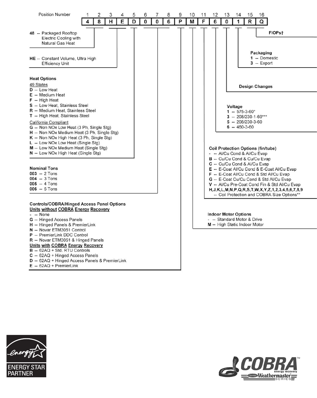
48HE003-006
LEGEND
NOTE: “COBRA” models are designated in the 9th and 11th position.
The 9th position indicates if a FIOP 62AQ is required. The 11th position
determines 62AQ size required.
Al — Aluminum
Cu — Copper
DDC — Direct Digital Controls
FIOP — Factory-Installed Option
48HE003-006 UNITS ARE
ENERGY STAR QUALIFIED
Quality Assurance
Certified to ISO 9001:2000
H -- Humidi-MiZer & High Static M
J -- Humidi-MiZer, Cu/Cu cond coil, & High
StaticMotor
K -- E-coated Humidi-MiZer and Al/Cu coils
w/High StaticMotor
Model number nomenclature
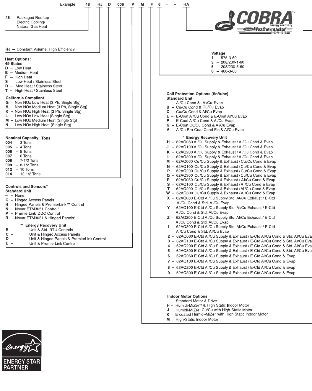
7
48HJ004-014
COBRA
COBRA
COBRA
COBRA
COBRA
COBRA
Factory-Installed Options†
LEGEND
*Contact factory for availability and applications.
†Refer to 48HJ Price Pages, Quote Builder software or contact your
local Carrier Representative for FIOP code table.
NOTE: Hinged Access Panels include: Filter Panel, Control Box Panel,
Fan Motor Panel, Compressor Panel.
Al — Aluminum
Cu — Copper
DDC — Direct Digital Controls
E-Ctd — E-Coated
FIOP — Factory-Installed Option
48HJ004-012 UNITS ARE
ENERGY STAR QUALIFIED
Quality Assurance
Certified to ISO 9001:2000
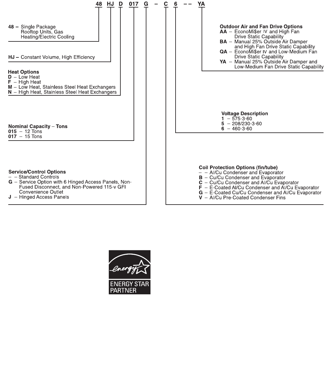
8
48HJ015,017
Model number nomenclature (cont)
LEGEND
Al — Aluminum
Cu — Copper
Quality Assurance
Certified to ISO 9001:2000
48HJ015-017 UNITS ARE
ENERGY STAR QUALIFIED
9
*
Heating Options
D– Low Gas Heat with Aluminized Steel
Heat Exchanger
E – Medium Gas Heat with Aluminized
Steel Heat Exchanger
F– High Gas Heat with Aluminized Steel
Heat Exchanger
K– Low Gas Heat with Stainless Steel
Heat Exchanger
L– Medium Gas Heat with Stainless Steel
Heat Exchanger
M– High Gas Heat with Stainless Steel
Heat Exchanger
Coil Protection Options (fin/tube)
–– Al/Cu Cond & Evap
A– Al/Cu Pre-Coat Cond & Al/Cu Evap
B– Al/Cu E-Coat Cond & Al/Cu Evap
C– Al/Cu E-Coat Cond & Evap
D– Cu/Cu Cond & Al/Cu Evap
E– Cu/Cu Cond & Evap
F– Cu/Cu E-Coat Cond & Al/Cu Evap
G– Cu/Cu E-Coat Cond & Cu/Cu Evap
H– Cu/Cu E-Coat Cond & Evap
Nominal Capacity – Tons
020 –18 Tons
024 –20 Tons
028 –25 Tons
Factory-Installed Options
48HJ D 024 – A C 6 – – AA
Voltage Description
1– 575-3-60
5– 208/230-3-60
6– 460-3-60
Service/Control Options
– – Mechanical Controls
U– Mechanical Controls with Return Smoke Detector
V– Mechanical Controls with Supply and Return Smoke Detectors
Indoor Motor Options
A– Low Range, Vertical Supply/Return
B– Mid-Low Range, Vertical Supply/Return
C– Mid-High Range, Vertical Supply/Return
48HJ – Single Package Rooftop Units, Gas
Heating/Electric Cooling, Constant Volume
D– High Range, Vertical Supply/Return
E– Low Range, Horizontal Supply/Return
F– Mid-Low Range, Horizontal Supply/Return
G– Mid-High Range, Horizontal Supply/Return
H– High Range, Horizontal Supply/Return
J– Low Range, Vertical Supply/Return with Hinged Panels
K– Mid-Low Range, Vertical Supply/Return with Hinged Panels
L– Mid-Range, Vertical Supply/Return with Hinged Panels
M– High Range, Vertical Supply/Return with Hinged Panels
N– Low Range, Horizontal Supply/Return with Hinged Panels
P– Mid-Low Range, Horizontal Supply/Return with Hinged Panels
R– High Range, Horizontal Supply/Return with Hinged Panels
Q– Mid-High Range, Horizontal Supply/Return with Hinged Panels
LEGEND
Al — Aluminum
Cu — Copper
FIOP — Factory-Installed Option
*Refer to 48HJ price pages or contact your local Carrier representative for FIOP code table.
Quality Assurance
Certified to ISO 9001:2000
48HJ020-028
*
48HJ020-028 UNITS ARE
ENERGY STAR QUALIFIED
10
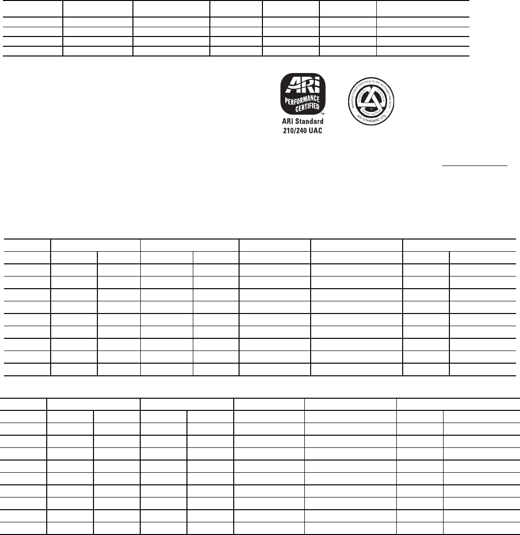
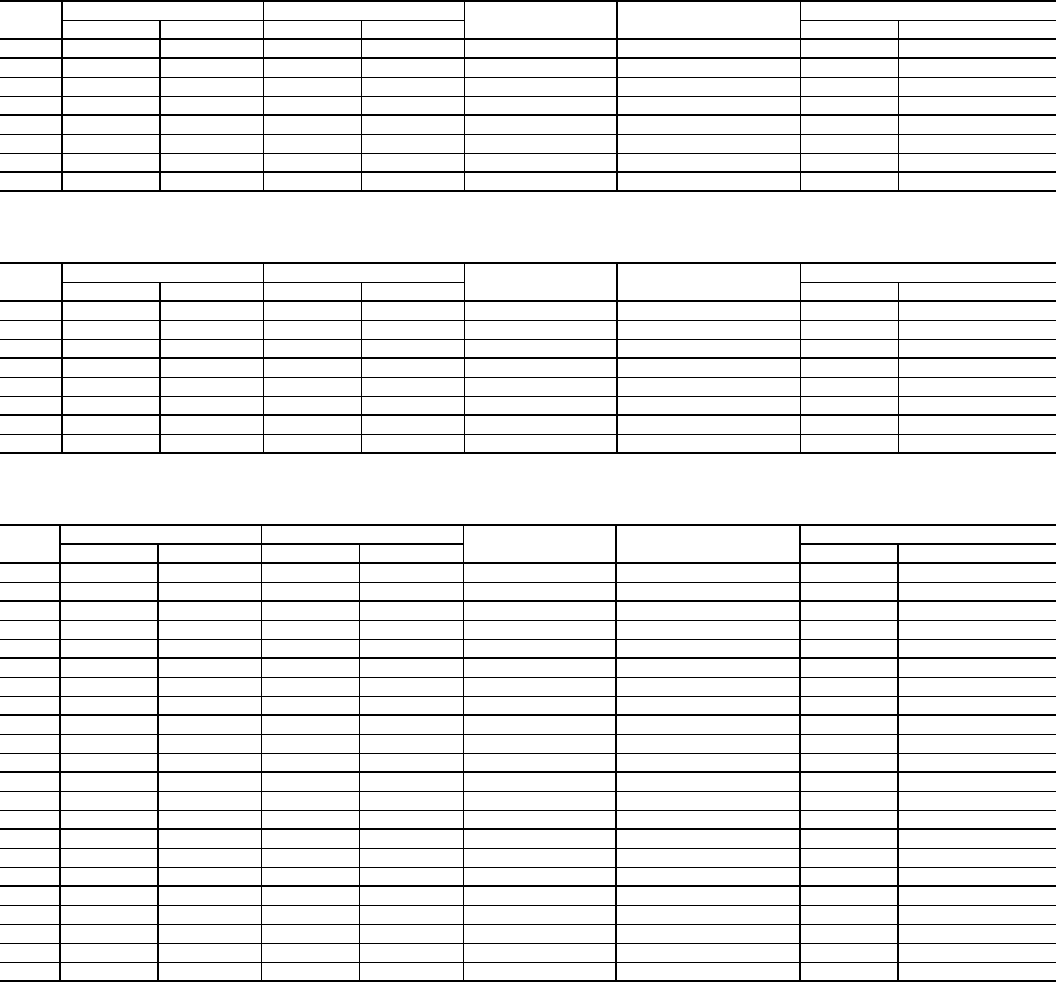
**ARI* CAPACITY RATINGS — 48HE003-006
LEGEND
*Air-Conditioning & Refrigeration Institute.
**ARI does not require EER ratings for unit with capacity below 65,000 Btuh. For
these units, the EER rating at ARI standard conditions is provided for informa-
tion only.
NOTES:
1. Rated in accordance with ARI Standard 210-94 or 360-93.
2. Ratings are net values, reflecting the effects of circulating fan heat.
3. Ratings are based on:
Cooling Standard: 80 F db, 67 wb indoor entering-air temperature and 95 F
db outdoor entering-air temperature.
IPLV Standard: 80 F db, 67 F wb indoor entering-air temperature and 80 F
db outdoor entering-air temperature.
4. All 48HE003-006 units are in compliance with ASHRAE 90.1 2001, 2004
Energy Standard for minimum SEER and EER requirements. Refer to state
and local codes or visit the following website: http://bcap-energy.org to
determine if compliance with this standard pertains to a given geographical
area of the United States.
HEATING CAPACITIES AND EFFICIENCIES — 48HE003-006
208/230-1-60 — SINGLE-STAGE GAS HEAT
208/230-1-60 — SINGLE-STAGE GAS HEAT — LOW NOx
AFUE — Annual Fuel Utilization Efficiency
NOTE: Capacities for stainless steel heat exchanger units (S/R/T) are the same
as standard units (D/E/F).
UNIT
48HE
NOMINAL
TONS
COOLING
(Btuh)
TOTAL
kW SEER EER SOUND RATING
(decibels)
003 2 24,000 3.2 14.1 12.0** 76
004 3 36,200 4.1 14.0 11.8** 76
005 4 46,000 5.5 14.0 11.7** 76
006 5 59,000 6.7 14.0 11.9 80
EER — Energy Efficiency Ratio
SEER — Seasonal Energy Efficiency Ratio
UNIT INPUT CAPACITY OUTPUT CAPACITY TEMPERATURE MINIMUM HEATING EFFICIENCY
48HE 1st Stage 2nd Stage 1st Stage 2nd Stage RISE (°F) AIRFLOW (CFM) AFUE (%) Steady State (%)
E/R003 50,000 — 40,500 — 25-65 575 81.00 81
E/R004 72,000 — 59,040 — 25-55 1004 82.80 82
F/T004 115,000 — 92,000 — 55-85 1002 80.00 80
D/S005 72,000 — 58,000 — 25-55 1004 82.80 82
E/R005 115,000 — 92,000 — 35-65 1320 81.00 81
F/T005 150,000 — 118,000 — 50-80 1396 80.40 80
D/S006 72,000 — 58,000 — 25-55 1004 82.80 82
E/R006 115,000 — 92,000 — 35-65 1327 81.00 81
F/T006 150,000 — 118,000 — 50-80 1314 80.40 80
UNIT INPUT CAPACITY OUTPUT CAPACITY TEMPERATURE MINIMUM HEATING EFFICIENCY
48HE 1st Stage 2nd Stage 1st Stage 2nd Stage RISE (°F) AIRFLOW (CFM) AFUE (%) Steady State (%)
M003 50,000 — 40,500 — 25-65 575 81.00 81
M004 60,000 — 50,000 — 20-50 930 80.20 81
N004 90,000 — 74,000 — 30-60 1150 81.00 81
L005 60,000 — 50,000 — 20-50 930 80.20 81
M005 90,000 — 74,000 — 30-60 1150 81.00 81
N005 120,000 — 101,000 — 40-70 1340 80.70 82
L006 60,000 — 50,000 — 20-50 930 80.20 81
M006 90,000 — 74,000 — 30-60 1150 81.00 81
N006 120,000 — 101,000 — 40-70 1340 80.70 82
ARI* capacity ratings
11
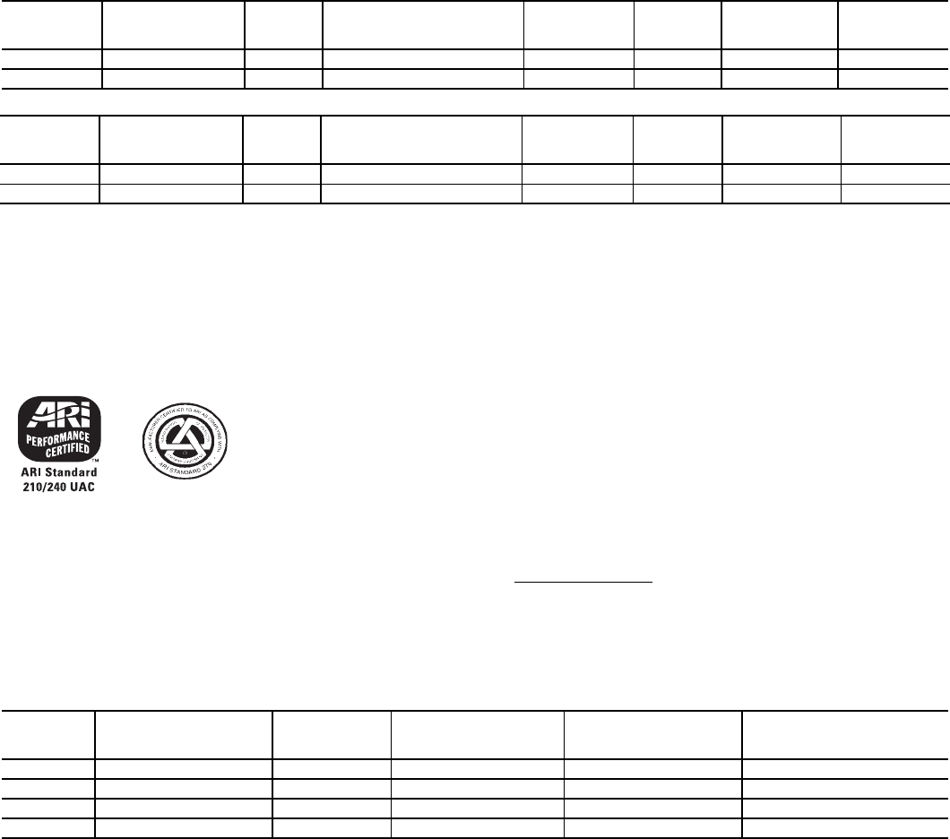
HEATING CAPACITIES AND EFFICIENCIES — 48HE003-006 (cont)
208/230/460-3-60 — SINGLE-STAGE GAS HEAT — LOW NOx
208/230/460-3-60 — SINGLE-STAGE GAS HEAT
208/230/460/575-3-60 — 2-STAGE GAS HEAT
AFUE — Annual Fuel Utilization Efficiency
NOTE: Capacities for stainless steel heat exchanger units (S/R/T) are the same
as standard units (D/E/F).
UNIT INPUT CAPACITY OUTPUT CAPACITY TEMPERATURE MINIMUM HEATING EFFICIENCY
48HE 1st Stage 2nd Stage 1st Stage 2nd Stage RISE (°F) AIRFLOW (CFM) AFUE (%) Steady State (%)
M004 60,000 — 50,000 — 20-50 930 80.20 81
N004 90,000 — 74,000 — 30-60 1150 81.00 81
L005 60,000 — 50,000 — 20-50 930 80.20 81
M005 90,000 — 74,000 — 30-60 1150 81.00 81
N005 120,000 — 101,000 — 40-70 1340 80.70 82
L006 60,000 — 50,000 — 20-50 930 80.20 81
M006 90,000 — 74,000 — 30-60 1150 81.00 81
N006 120,000 — 101,000 — 40-70 1340 80.70 82
UNIT INPUT CAPACITY OUTPUT CAPACITY TEMPERATURE MINIMUM HEATING EFFICIENCY
48HE 1st Stage 2nd Stage 1st Stage 2nd Stage RISE (°F) AIRFLOW (CFM) AFUE (%) Steady State (%)
H004 72,000 — 59,040 — 25-55 1000 82.00 82
K004 115,000 — 92,000 — 55-85 1020 80.00 81
G005 72,000 — 59,040 — 25-55 1000 82.00 82
H005 115,000 — 93,150 — 30-60 1440 81.00 81
K005 150,000 — 120,000 — 50-80 1390 80.00 80
G006 72,000 — 59,040 — 25-55 1220 82.00 82
H006 115,000 — 93,150 — 35-65 1330 81.00 81
K006 150,000 — 120,000 — 50-80 1390 80.00 80
UNIT INPUT CAPACITY OUTPUT CAPACITY TEMPERATURE MINIMUM HEATING EFFICIENCY
48HE 1st Stage 2nd Stage 1st Stage 2nd Stage RISE (°F) AIRFLOW (CFM) AFUE (%) Steady State (%)
E004 50,000 72,000 41,000 59,040 25-55 1004 82.80 82
F004 82,000 115,000 65,600 93,150 55-85 1002 80.00 80
D005 50,000 72,000 41,000 59,040 25-55 1094 82.80 82
E005 82,000 115,000 66,420 93,150 35-65 1330 81.00 81
F005 120,000 150,000 96,000 120,000 50-80 1390 80.40 80
D006 50,000 72,000 41,000 59,040 25-55 1004 82.80 82
E006 82,000 115,000 66,420 93,150 35-65 1330 81.00 81
F006 120,000 150,000 96,000 120,000 50-80 1370 80.40 80
12
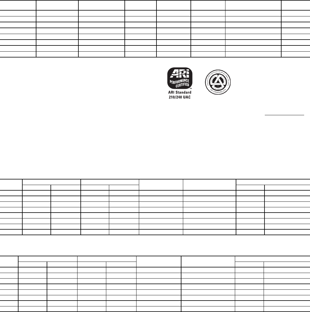
**ARI* CAPACITY RATINGS — 48HJ004-014
LEGEND
*Air-Conditioning & Refrigeration Institute.
†Applies only to units with capacity of 65,000 Btuh or less.
**ARI does not require EER ratings for unit with capacity below 65,000 Btuh. For
these units, the EER rating at ARI standard conditions is provided for informa-
tion only.
††The IPLV is not applicable to single-compressor units.
NOTES:
1. Rated in accordance with ARI Standard 210-94 or 360-93.
2. Ratings are net values, reflecting the effects of circulating fan heat.
3. Ratings are based on:
Cooling Standard: 80 F db, 67 wb indoor entering-air temperature and 95 F
db outdoor entering-air temperature.
IPLV Standard: 80 F db, 67 F wb indoor entering-air temperature and 80 F
db outdoor entering-air temperature.
4. All 48HJ004-014 units are in compliance with ASHRAE 90.1 2001, 2004
Energy Standard for minimum SEER and EER requirements. Refer to state
and local codes or visit the following website: http://bcap-energy.org to
determine if compliance with this standard pertains to a given geographical
area of the United States.
HEATING CAPACITIES AND EFFICIENCIES — 48HJ004-014
208/230-1-60 — SINGLE-STAGE GAS HEAT
208/230-1-60 — SINGLE-STAGE GAS HEAT — LOW NOx
AFUE — Annual Fuel Utilization Efficiency
NOTE: Capacities for stainless steel heat exchanger units (S/R/T) are the same
as standard units (D/E/F).
UNIT
48HJ
NOMINAL
TONS
COOLING
(Btuh)
TOTAL
kW SEER† EER SOUND RATING
(decibels) IPLV††
004 3 36,000 3.2 13.0 11.2** 76 N/A
005 4 46,000 4.1 13.0 11.1** 76 N/A
006 5 61,000 5.5 13.0 11.0** 80 N/A
007 6 73,000 6.7 — 11.0 80 N/A
008 71/290,000 8.2 — 11.0 82 11.6
009 81/2103,000 8.9 — 11.6 82 12.8
012 10 120,000 10.9 — 11.0 84 11.4
014 12.5 138,000 14.4 — 9.6 86 10.3
EER — Energy Efficiency Ratio
IPLV — Integrated Part-Load Value
SEER — Seasonal Energy Efficiency Ratio
UNIT
48HJ
INPUT CAPACITY OUTPUT CAPACITY TEMPERATURE
RISE (°F)
MINIMUM HEATING
AIRFLOW (CFM)
EFFICIENCY
1st Stage 2nd Stage 1st Stage 2nd Stage AFUE (%) Steady State (%)
E/R004 72,000 — 58,000 — 25-55 1004 82.8% 82.0
F/T004 115,000 — 90,000 — 55-85 1002 80.0% 80.0
D/S005 72,000 — 58,000 — 25-55 1004 82.8% 82.0
E/R005 115,000 — 92,000 — 35-65 1320 81.0% 81.0
F/T005 150,000 — 118,000 — 50-80 1396 80.4% 80.0
D/S006 72,000 — 58,000 — 25-55 1004 82.8% 82.0
E/R006 115,000 — 92,000 — 35-65 1327 81.0% 81.0
F/T006 150,000 — 118,000 — 50-80 1314 80.4% 80.0
UNIT
48HJ
INPUT CAPACITY OUTPUT CAPACITY TEMPERATURE
RISE (°F)
MINIMUM HEATING
AIRFLOW (CFM)
EFFICIENCY
1st Stage 2nd Stage 1st Stage 2nd Stage AFUE (%) Steady State (%)
M004 60,000 — 50,000 — 20-50 930 80.2% 81.2
N004 90,000 — 74,000 — 30-60 1150 81.0% 81.4
L005 60,000 — 50,000 — 20-50 930 80.2% 81.2
M005 90,000 — 74,000 — 30-60 1150 81.0% 81.4
N005 120,000 — 101,000 — 40-70 1340 80.7% 82.4
L006 60,000 — 50,000 — 20-50 930 80.2% 81.2
M006 90,000 — 74,000 — 30-60 1150 81.0% 81.4
N006 120,000 — 101,000 — 40-70 1340 80.7% 82.4
ARI* capacity ratings (cont)
13
HEATING CAPACITIES AND EFFICIENCIES — 48HJ004-014 (cont)
208/230/460-3-60 — SINGLE-STAGE GAS HEAT — LOW NOx
208/230/460-3-60 — SINGLE-STAGE GAS HEAT
208/230/460/575-3-60 — 2-STAGE GAS HEAT
AFUE — Annual Fuel Utilization Efficiency
NOTE: Capacities for stainless steel heat exchanger units (S/R/T) are the same
as standard units (D/E/F).
UNIT
48HJ
INPUT CAPACITY OUTPUT CAPACITY TEMPERATURE
RISE (°F)
MINIMUM HEATING
AIRFLOW (CFM)
EFFICIENCY
1st Stage 2nd Stage 1st Stage 2nd Stage AFUE (%) Steady State (%)
M004 60,000 — 50,000 — 20-50 930 80.2% 81.2
N004 90,000 — 74,000 — 30-60 1150 81.0% 81.4
L005 60,000 — 50,000 — 20-50 930 80.2% 81.2
M005 90,000 — 74,000 — 30-60 1150 81.0% 81.4
N005 120,000 — 101,000 — 40-70 1340 80.7% 82.4
L006 60,000 — 50,000 — 20-50 930 80.2% 81.2
M006 90,000 — 74,000 — 30-60 1150 81.0% 81.4
N006 120,000 — 101,000 — 40-70 1340 80.7% 82.4
UNIT
48HJ
INPUT CAPACITY OUTPUT CAPACITY TEMPERATURE
RISE (°F)
MINIMUM HEATING
AIRFLOW (CFM)
EFFICIENCY
1st Stage 2nd Stage 1st Stage 2nd Stage AFUE (%) Steady State (%)
H004 72,000 — 59,040 — 25-55 1000 82.0% 82.0
K004 115,000 — 93,150 — 55-85 1020 80.0% 81.0
G005 72,000 — 59,040 — 25-55 1000 82.0% 82.0
H005 115,000 — 93,150 — 30-60 1440 81.0% 81.0
K005 150,000 — 120,000 — 50-80 1390 80.0% 80.0
G006 72,000 — 59,040 — 25-55 1220 82.0% 82.0
H006 115,000 — 93,150 — 35-65 1330 81.0% 81.0
K006 150,000 — 120,000 — 50-80 1390 80.0% 80.0
UNIT
48HJ
INPUT CAPACITY OUTPUT CAPACITY TEMPERATURE
RISE (°F)
MINIMUM HEATING
AIRFLOW (CFM)
EFFICIENCY
1st Stage 2nd Stage 1st Stage 2nd Stage AFUE (%) Steady State (%)
E004 50,000 72,000 41,000 59,040 25-55 1004 82.8% 82.0
F004 82,000 115,000 65,600 93,150 55-85 1002 80.0% 80.0
D005 50,000 72,000 41,000 59,040 25-55 1094 82.8% 82.0
E005 82,000 115,000 66,420 93,150 35-65 1330 81.0% 81.0
F005 120,000 150,000 96,000 120,000 50-80 1390 80.4% 80.0
D006 50,000 72,000 41,000 59,040 25-55 1004 82.8% 82.0
E006 82,000 115,000 66,420 93,150 35-65 1330 81.0% 81.0
F006 120,000 150,000 96,000 120,000 50-80 1370 80.4% 80.0
D007 50,000 72,000 41,000 59,040 25-55 1220 82.0% 82.0
E007 82,000 115,000 66,420 93,150 35-65 1330 81.0% 81.0
F007 120,000 150,000 96,000 120,000 50-80 1390 80.0% 80.0
D008 90,000 125,000 73,800 102,500 20-50 1900 82.0% 82.0
E008 120,000 180,000 98,400 147,600 35-65 2100 82.0% 82.0
F008 180,000 224,000 147,600 183,680 45-75 2230 82.0% 82.0
D009 90,000 125,000 73,800 102,500 20-50 1900 82.0% 82.0
E009 120,000 180,000 98,400 147,600 35-65 2100 82.0% 82.0
F009 180,000 224,000 147,600 183,680 45-75 2230 82.0% 82.0
D012 120,000 180,000 98,400 147,600 35-65 2100 82.0% 82.0
E012 180,000 224,000 147,600 183,680 35-65 2570 82.0% 82.0
F012 200,000 250,000 160,000 200,000 40-70 2650 80.0% 80.0
D014 180,000 224,000 147,600 183,680 35-65 2570 82.0% 82.0
E014 200,000 250,000 160,000 200,000 40-70 2650 80.0% 80.0
14
ARI* CAPACITY RATINGS — 48HJ015,017
LEGEND
*Air Conditioning and Refrigeration Institute.
NOTES:
1. Rated in accordance with ARI Standards 360-93 and 270-95.
2. ARI ratings are net values, reflecting the effects of circulating fan heat.
3. Ratings are based on:
Cooling Standard: 80 F db, 67 F wb indoor entering-air temperature and 95 F db air entering outdoor unit.
IPLV Standard: 80 F db, 67 F wb indoor entering-air temperature and 80 F db outdoor entering-air temperature.
4. All 48HJ015,017 units are in compliance with ASHRAE 90.1 2001 Energy Standard for minimum EER
requirements. Refer to state and local codes or visit the following website: http://bcap-energy.org to deter-
mine if compliance with this standard pertains to a given geographical area of the United States.
HEATING CAPACITIES AND EFFICIENCIES — 48HJ015,017
*All units are 2-stage heat.
†Minimum heating cfm must be maintained to ensure proper heating operation.
NOTE: Minimum allowable temperature of mixed air entering the heat exchanger during first stage
heating is 45 F. There is no minimum mixed-air limitation during second-stage heating.
UNIT
48HJD
NOMINAL
TONS CFM
NET COOLING
CAPACITY
(Btuh)
TOTAL
WATTS EER
SOUND
RATING
(decibels)
IPLV
015 12 3750 152,000 14,074 10.8 88 11.8
017 15 4500 176,000 16,296 10.8 88 11.7
UNIT
48HJF
NOMINAL
TONS CFM
NET COOLING
CAPACITY
(Btuh)
TOTAL
WATTS EER
SOUND
RATING
(decibels)
IPLV
015 12 3750 152,000 14,074 10.8 88 11.8
017 15 4500 176,000 16,296 10.8 88 11.7
db — Dry Bulb
EER — Energy Efficiency Ratio
IPLV — Integrated Part-Load Values
wb — Wet Bulb
UNIT 48
HEATING
INPUT (Btuh)
Stage 2/Stage 1*
OUTPUT
CAPACITY
(Btuh)
TEMPERATURE
RISE (F)
STEADY STATE
EFFICIENCY (%)
MINIMUM HEATING
CFM†
HJD/M015 230,000/172,000 186,000 15-45 81.0 3750
HJF/N015 300,000/225,000 243,000 30-60 81.0 3830
HJD/M017 275,000/206,000 223,000 15-45 81.0 4580
HJF/N017 360,000/270,000 292,000 20-50 81.0 5400
ARI* capacity ratings (cont
15
ARI* CAPACITY RATINGS — 48HJ020-028
LEGEND
*Air Conditioning and Refrigeration Institute.
†IPLV values are calculated based on control configuration T.CTL = 2
(2 Stage Y1).
**Size 028 unit is not listed with ARI, but is tested to ARI standards.
NOTES:
1. Rated in accordance with ARI Standards 360-93 and 270-95.
2. ARI ratings are net values, reflecting the effects of circulating fan heat.
3. Ratings are based on:
Cooling Standard: 80 F db, 67 F wb indoor entering-air temperature and 95
F db air entering outdoor unit.
IPLV Standard: 80 F db, 67 F wb indoor entering-air temperature and 80 F
db outdoor entering-air temperature.
4. All 48HJ020-028 units are in compliance with ASHRAE 90.1 2001, 2004
Energy Standard for minimum EER requirements. Refer to state and local
codes or visit the following website: http:///bcap-energy.org to determine if
compliance with this standard pertains to a given geographical area of the
United States.
HEATING CAPACITIES AND EFFICIENCIES — 48HJ020-028
VERTICAL SUPPLY — NATURAL GAS
NOTE: All units are 2-stage gas heat.
HORIZONTAL SUPPLY — NATURAL GAS
*7000 cfm minimum recommended above 1.0 in. wg external static pressure. NOTE: All units are 2-stage gas heat.
VERTICAL SUPPLY — PROPANE
NOTE: All units are 2-stage gas heat. HORIZONTAL SUPPLY — PROPANE
*7000 cfm minimum recommended above 1.0 in. wg external static pressure. NOTE: All units are 2-stage gas heat.
UNIT
48HJ
NOMINAL
TONS CFM NET COOLING
CAPACITY (Btuh)
TOTAL
kW EER SOUND RATING
(dB) IPLV†
020 18 5,500 200,000 18.5 10.8 81.7 12.0
024 20 6,000 234,000 21.7 10.8 81.7 11.9
028** 25 7,500 278,000 27.8 10.0 84.6 10.9
db — Dry Bulb
EER — Energy Efficiency Ratio
IPLV — Integrated Part-Load Values
wb — Wet Bulb
UNIT
48HJ
HEATING INPUT
(Btuh) Stage 2/Stage 1
OUTPUT CAPACITY
(Btuh)
TEMPERATURE
RISE (F)
STEADY-STATE
EFFICIENCY %
MINIMUM
HEATING CFM
D/L020 250,000/199,000 205,000 15-45 82% 4218
E/M020 365,000/281,000 296,000 25-55 81% 4977
F/N020 400,000/317,000 328,000 25-55 82% 5522
D/L024 250,000/199,000 205,000 15-45 82% 4218
E/M024 365,000/281,000 296,000 25-55 81% 4977
F/N024 400,000/317,000 328,000 25-55 82% 5522
D/L028 250,000/199,000 205,000 15-45 82% 4218
E/M028 365,000/281,000 296,000 25-55 81% 4977
F/N028 400,000/317,000 328,000 25-55 82% 5522
UNIT
48HJ
HEATING INPUT
(Btuh) Stage 2/Stage 1
OUTPUT CAPACITY
(Btuh)
TEMPERATURE
RISE (F)
STEADY-STATE
EFFICIENCY %
MINIMUM
HEATING CFM
D/L020 250,000/199,000 205,000 15-45 82% 4218
E/M020 365,000/281,000 296,000 25-55 81% 4977
F/N020 400,000/317,000 328,000 25-55 82% 5522
D/L024 250,000/199,000 205,000 15-45 82% 4218
E/M024 365,000/281,000 296,000 25-55 81% 4977
F/N024 400,000/317,000 328,000 25-55 82% 5522
D/L028 250,000/199,000 205,000 15-45 82% 4218
E/M028 365,000/281,000 296,000 25-55 81% 4977*
F/N028 400,000/317,000 325,000 25-55 82% 5522*
UNIT
48HJ
HEATING INPUT
(Btuh) Stage 2/Stage 1
OUTPUT CAPACITY
(Btuh)
TEMPERATURE
RISE (F)
STEADY-STATE
EFFICIENCY %
MINIMUM
HEATING CFM
D/L020 250,000/207,000 205,000 15-45 82% 4218
E/M020 365,000/291,000 296,000 25-55 81% 4480
F/N020 400,000/331,000 328,000 25-55 82% 5522
D/L024 250,000/207,000 205,000 15-45 82% 4218
E/M024 365,000/291,000 296,000 25-55 81% 4480
F/N024 400,000/331,000 328,000 25-55 82% 5522
D/L028 250,000/207,000 205,000 15-45 82% 4218
E/M028 365,000/291,000 296,000 25-55 81% 4480
F/N028 400,000/331,000 328,000 25-55 82% 5522
UNIT
48HJ
HEATING INPUT
(Btuh) Stage 2/Stage 1
OUTPUT CAPACITY
(Btuh)
TEMPERATURE
RISE (F)
STEADY-STATE
EFFICIENCY %
MINIMUM
HEATING CFM
D/L020 225,000/207,000 185,000 15-45 82% 3807
E/M020 329,000/291,000 266,000 25-55 81% 4480
F/N020 356,000/331,000 292,000 25-55 82% 4916
D/L024 225,000/207,000 184,500 15-45 82% 3796
E/M024 329,000/291,000 266,000 25-55 81% 4480
F/N024 356,000/331,000 292,000 25-55 82% 4916
D/L028 225,000/207,000 185,000 15-45 82% 3807
E/M028 329,000/291,000 266,000 25-55 81% 4480*
F/N028 356,000/331,000 292,000 25-55 82% 4920*
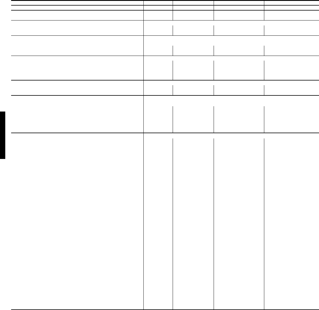
16
LEGEND
*Single/three phase .
**Base unit weight does not include any options or accessaries. See Options and
Accessary weight tables for additioinal weight information.
†Indicates automatic reset.
BASE UNIT 48HE HD/E/F003 HE/F/H/K/M/N004 H/E/F/G/H/K/L/M/N005 HD/E/F/G/H/K/L/M/N006
NOMINAL CAPACITY (tons) 2 3 4 5
OPERATING WEIGHT(lb)
Base Unit** 530 540 560 635
COMPRESSOR Scroll
Quantity 1 1 1 1
Oil (oz) 25 42 56 53
REFRIGERANT TYPE R-22
Expansion Device Operating Charge (lb-oz) Acutrol™ MeteringDevice
Standard Unit 5---3 7---11 8---8 12---11
Unit With Humidi-Mizer Adaptive Dehumidification System 10---2 14---0 14---13 21---0
CONDENSER FAN Propeller
Quantity...Diameter (in.) 1...22 1...22 1...22 1...22
Nominal Cfm 3000 3500 3500 4100
Motor Hp...Rpm 1/8...825 1/8...825 1/8...825 1/4...1100
Watts Input (Total) 180 180 180 320
CONDENSER COIL Enhanced Copper Tubes, Aluminum LancedFins
Rows...Fins/in. 1...17 1...17 2...17 2...17
Total Face Area (sq ft) 14.6 14.6 16.5 16.5
EVAPORATOR COIL Enhanced Copper Tubes, Aluminum Double-Wavy Fins
Standard Unit
Rows...Fins/in. 2...15 2...15 2...15 4...15
Total Face Area (sq ft) 4.2 5.5 5.5 5.5
Humidi-Mizer Coil Adaptive Dehumidification System
Rows...Fins/in. 1...17 1...17 2...17 2...17
Total Face Area (sq ft) 3.5 3.9 3.9 3.9
EVAPORATOR FAN Centrifugal Type, Belt Drive
Quantity...Size (in.) 1...10 x 10 1...10 x 10 1...10 x 10 1...10 x 10
Nominal Cfm 800 1200 1600 2000
Maximum Continuous Bhp Std 0.58 1.20 1.20 1.30/2.40*
Hi-Static 2.40 2.40 2.40 2.90
Motor Frame Size Std 48 48 48 48/56†
Hi-Static 56 56 56
Motor Rpm Std 1620 1620 1620 1725
Hi-Static 1725 1725 1725
Fan Rpm Range Std 400-1000 680-1044 770-1185 1035-1460
Hi-Static 1075-1455 1075-1455 1300-1685
Motor Bearing Type Ball Ball Ball Ball
Maximum Fan Rpm 1620 2100 2100 2100
Motor Pulley Pitch Diameter A/B (in.) Std 2.4/3.2 1.9/2.9 1.9/2.0 2.4/3.4
Hi-Static 2.8/3.8 2.8/3.8 3.4/4.4
Nominal Motor Shaft Diameter (in.) Std 5/81/21/25/8
Hi-Static 7/8 5/85/85/8
Fan Pulley Pitch Diameter (in.) Std 4.0 4.5 4.0 4.0
Hi-Static 4.5 4.5 4.0 4.5
Belt — Type...Length (in.) Std 1...A...36 1...A...36 1....4...36 1...A...40
Hi-Static 1...A...39 1...A...39 1...A...39 1...A...40
Pulley Center Line Distance (in.) 10.0 -12.4 10.0-12.4 10.0-12.4 14.7-15.5
Speed Change per Full Turn of Movable Pulley Flange
(rpm) Std 60 65 70 75
Hi-Static 65 65 60
Movable Pulley Maximum Full Turns from Closed
Position Std 55 5 6
Hi-Static 66 5
Factory Setting — Full Turns Open Std 33 3 3
Hi-Static 31/2 31/2 31/2
Factory Speed Setting(rpm) Std 756 826 936 1248
Hi-Static 1233 1233 1396
Fan Shaft Diameter at Pulley (in.) 5/8 5/8 5/8 5/8
Bhp — Brake Horsepower
Physical data — 48HE
48HE
17
LEGEND
*Single phase/three phase. Stainless steel models use the same orifices as
equivalent standard heat exchangers.
†Indicates automatic reset.
**60,000 and <72,000 Btuh heat input units have 2 burners. 90,000 and 120,000 Btuh heat
input units have 3 burners. 115,000 Btuh heat input units and 150,000 Btuh Heat input units
have 3 burners.
††An LP kit is available as an accessory. If an LP kit is used with Low NOx units, the Low NOx
baffle must be removed and the units will no longer be classified as Low NOx units.
||Three-phase standard models have heating inputs as shown. Single-phase standard mod-
els have one-stage heating with heating input values as follows:
HJD005-006,HJE004 — 72,000 Btuh
HJE005-006,HJF004 — 115,000 Btuh
HJF005-006 — 150,000 Btuh (shown in heating capicty tables)
***California compliant three-phase models.
†††California SCAQMD compliant low NOx models have combustion products that are con-
trolled to 40 nanograms per joule or less.
NOTE: Capacities for stainless steel heat exchanger units (S/R/T) are the same as standard
units (D/E/F).
BASE UNIT 48HE HD/E/F003 HE/F/H/K/M/N004 HD/E/F/G/H/K/L/M/N005 HD/E/F/G/H/K/L/M/N006
FURNACE SECTION
Rollout Switch Cutout Temp(F)† 195 195 195 195
Burner Orifice Diameter (in....drill size)**
Natural Gas—Std* HJE .113...33 HJD .113...33 HJD .113...33
HEE .089...43 HJF .113...33 HJE .113...33 HJE .113...33
—HJF .129...30 HJF .129...30
—HJH .113...33 HJG .113...33 HJG .113...33
—HJK .113...33 HJH .113...33 HJH .113...33
——HJK .129...30 HJK .129...30
HEM .089...43 HJM .102...38 HJL .102...38 HJL .102...38
—HJN .102...38 HJM .102...38 HJM .102...38
——HJN .116...32 HJN .116...32
Liquid Propane—Alt†† HEE .073...49 HJE .089...43 HJD .089...43 HJD .089...43
HJF .089...43 HJE .089...43 HJE .089...43
—HJF .104...37 HJF .104...37
—HJH .089...43 HJG .089...43 HJG .089...43
—HJK .089...43 HJH .089...43 HJH .089...43
——HJK .102...37 HJK .104...37
—
—
—
—
Thermostat Heat Anticipator Setting (amps)
208/230/460/575v
First Stage 0.14 0.14 0.14 0.14
Second Stage 0.14 0.14 0.14 0.14
Gas Input (Btuh)
First Stage/Second Stage HEE 50,000/— HEE || 50,000/72,000 HED || 50,000/72,000 HED || 50,000/72,000
HEF || 82,000/115,000 HEE || 82,000/115,000 HEE || 82,000/115,000
—HEF || 120,000/150,000 HEF || 120,000/150,000
—HEH*** —/72,000 HEG*** —/72,000 HEG *** —/72,000
—HJK*** —/115,000 HEH*** —/115,000 HEH *** —/115,000
——HEK*** —/150,000 HEK *** —/150,000
—HEM††† —/60,000 HEL††† —/60,000 HEL††† —/60,000
—HEN††† —/90,000 HEM††† —/90,000 HEM††† —/90,000
——HEN††† —/120,000 HEN††† —/120,000
Efficiency (Steady State ) (%) HEE 81 HEE 82.8 HED 82.8 HED 82.8
HEF 80 HEE 81 HEE 81
—HEF 80.4 HEF 80.4
—HEH 82 HEG 82 HEG 82
—HEK 80 HEH 81 HEH 81
——HEK 80 HEK 80
—HEM 80.2 HEL 80.2 HEL 80.2
HEM 81 HEN 81 HEM 81 HEM 81
——HEN 80.7 HEN 80.7
Temperature Rise Range HEE 25-55 HED 25-25 HED 25-55
HEE 25-65 HEF 55-85 HEE 35-65 HEE 35-65
—HEF 50-80 HEF 50-80
—HEG 25-55 HEG 25-55 HEG 25-55
—HEK 55-85 HEH 35-65 HEH 35-65
——HEK 50-80 HEK 50-80
—HEM 20-50 HEL 20-50 HEL 20-50
—HEN 30-60 HEM 30-60 HEM 30-60
——HEN 40-70 HEN 40-70
Manifold Pressure (in.wg)
Natural Gas—Std 3.5 3.5 3.5 3.5
Liquid Propane—Alt†† 3.5 3.5 3.5 3.5
Gas Valve Quanity 1 1 1 1
Gas Valve Pressure (line pressure)
psig 0.180-0.469 0.180-0.469 0.180-0.469 0.180-0.469
in wg 5.0-13.0 5.0-13.0 5.0-13.0 5.0-13.0
Field Gas Connection Size (in.) 1/2 1/2 1/2 1/2
HIGH-PRESSURE SWITCH (psig)
Standard CompressorInternal Relief 450±50
Cutout 428
Reset (Auto.) 320
LOSS-OF-CHARGE SWITCH (LiquidLIne) (psig)
Cutout 7±3
22±5Reset(Auto.)
FREEZE PROTECTION THERMOSTAT 30±5
45±5
Opens(F)
Closes(F)
OUTDOOR-AIR INLET SCREENS Cleanable Screen quantity and size varies with option selected.
RETURN-AIRFILTERS Throw away
Quantity...Size (in.) 2...16x25x2
Bhp — Brake Horsepower
Physical data — 48HE (cont)
48HE
18
LEGEND
*Single phase/three phase.
†Indicates automatic reset.
**Base unit weight does not include any options or accessaries. See Options and
Accessary weight tables for additioinal weight information.
BASE UNIT 48HJ HJE/F/H/K/M/N004 HJD/E/F/G/H/K/L/M/N005 HJD/E/F/G/H/K/L/M/N006 HJD/E/F007
NOMINAL CAPACITY (tons) 3 4 5 6
OPERATING WEIGHT (lb)
Base Unit** 530 540 560 635
COMPRESSOR Scroll
Quantity 1 1 1 1
Oil (oz) 42 53 50 60
REFRIGERANT TYPE R-22
Expansion Device Operating Charge (lb-oz) Acutrol™ MeteringDevice
Standard Unit 5-8 10-2 10-0 12-8
Unit With Humidi-Mizer Adaptive Dehumidification
System 12-5 18-8
20-5 23-14
CONDENSER FAN Propeller
Quantity...Diameter (in.) 1...22 1...22 1...22 1...22
Nominal Cfm 3500 3500 4100 4100
Motor Hp...Rpm 1/8...825 1/8...825 1/4...1100 1/4...1100
Watts Input (Total) 180 180 320 320
CONDENSER COIL Enhanced Copper Tubes, Aluminum LancedFins
Rows...Fins/in. 1...17 2...17 2...17 2...17
Total Face Area (sq ft) 14.6 16.5 16.5 21.3
EVAPORATOR COIL Standard Unit Enhanced Copper Tubes, Aluminum Double-Wavy Fins
Rows...Fins/in. 2...15 2...15 4...15 4...15
Total Face Area (sq ft) 5.5 5.5 5.5 7.3
Humidi-Mizer Coil Adaptive Dehumidification System
Rows...Fins/in. 1...17 2...17 2...17 2...17
Total Face Area (sq ft) 3.9 3.9 3.9 5.2
EVAPORATOR FAN Centrifugal Type, Belt Drive
Quantity...Size (in.) 1...10 x 10 1...10 x 10 1...10 x 10 1...10 x 10
Nominal Cfm 1200 1600 2000 2400
Maximum Continuous Bhp Std 1.20 1.20 1.30/2.40* 2.40
Hi-Static 2.40 2.40 2.90 2.90
Motor RPM Std 1620 1620 1725 1725
Hi-Static 1725 1725 1725 1725
Motor Frame Size Std 48 48 48/56† 56
Hi-Static 56 56 56 56
Fan Rpm Range Std 680-1044 770-1185 1035-1460 1119-1585
Hi-Static 1075-145 1300-1685 1300-1685
Motor Bearing Type Ball Ball Ball Ball
Maximum Fan Rpm 2100 2100 2100 2100
Motor Pulley Pitch Diameter A/B (in.) Std 1.9/2.9 1.9/2.0 2.4/3.4 2.4/3.4
Hi-Static 2.8/3.8 2.8/3.8 3.4/4.4 3.4/3.4
Nominal Motor Shaft Diameter (in.) Std 1/2 1/2 5/8 5/8
Hi-Static 5/8 5/8 5/8 7/8
Fan Pulley Pitch Diameter (in.) Std 4.5 4.0 4.0 4.0
Hi-Static 4.5 4.0 4.5 4.5
Belt — Type...Length (in.) Std 1...A...36 1...A...36 1...A...39 1...A...38
Hi-Static 1...A...39 1...A...39 1...A...40 1...A...40
Pulley Center Line Distance (in.) 10.0-12.4 10.0-12.4 14.7-15.5 14.7-15.5
Speed Change per Full Turn of Movable
Pulley Flange (rpm)
Std 65
70 75 95
Hi-Static 65 65 60 60
Movable Pulley Maximum Full Turns
from Closed Position
Std 5
565
Hi-Static 665 5
Factory Setting — Full Turns Open Std 3 3 3 3
Hi-Static 31/2 31/2 31/2 31/2
Factory Speed Setting(rpm) Std 826 936 1248 1305
Hi-Static 1233 1233 1396 1396
Fan Shaft Diameter at Pulley (in.) 5/8 5/8 5/8 5/8
Bhp — Brake Horsepower
Physical data — 48HJ
48HJ
19
LEGEND
*Single phase/three phase. Stainless steel models use the same orifices as
equivalent standard heat exchangers.
†Indicates automatic reset.
**60,000 and <72,000 Btuh heat input units have 2 burners. 90,000 and 120,000
Btuh heat input units have 3 burners. 115,000 Btuh heat input units and 150,000
Btuh Heat input units have 3 burners.
††An LP kit is available as an accessory. If an LP kit is used with Low NOx units,
the Low NOx baffle must be removed and the units will no longer be classified
as Low NOx units.
||Three-phase standard models have heating inputs as shown. Single-phase
standard models have one-stage heating with heating input values as follows:
HJD005-006,HJE004 — 72,000 Btuh
HJE005-006,HJF004 — 115,000 Btuh
HJF005-006 — 150,000 Btuh (shown in heating capicty tables)
***California compliant three-phase models.
†††California SCAQMD compliant low NOx models have combustion products that
are controlled to 40 nanograms per joule or less.
NOTE: Capacities for stainless steel heat exchanger units (S/R/T) are the same
as standard units (D/E/F).
BASE UNIT 48HJ HJE/F/H/K/M/N004 HJD/E/F/G/H/K/L/M/N005 HJD/E/F/G/H/K/L/M/N006 HJD/E/F007
FURNACE SECTION
Rollout Switch Cutout Temp(F)† 195 195 195 195
Burner Orifice Diameter (in. ...drill size)**
Natural Gas — Std* HJE .113...33 HJD .113...33 HJD .113...33 HJD .113...33
HJF.113...33 HJE .113...33 HJE .113...33 HJE .113...33
—HJF.129...30 HJF.129...30 HJF.129...30
HJH .113...33 HJG .113...33 HJG .113...33 —
HJK.113...33 HJH .113...33 HJH .113...33 —
—HJK.129...30 HJK.129...30 —
HJM .102...38 HJL .102...38 HJL .102...38 —
HJN.102...38 HJM .102...38 HJM .102...38 —
— HJN.116...32 HJN.116...32 —
Liquid Propane — Alt†† HJE .089...43 HJD .089...43 HJD .089...43 HJD .089...43
HJF.089...43 HJE .089...43 HJE .089...43 HJE .089...43
— HJF.104...37 HJF.104...37 HJF.104...37
HJH .089...43 HJG .089...45 HJG .089...43 —
HJK.089...43 HJH .089...45 HJH .089...43 —
— HJK.102...38 HJK.104...37 —
HJM .082...45 HJL .082...45 HJL .082...45 —
HJN.082...45 HJM .082...45 HJM .082...45 —
— HJN.094...42 HJN.094...42 —
Thermostat Heat Anticipator Setting (amps)
208/230/460/575 v
First Stage .14 .14 .14 .14
SecondStage .14 .14 .14 .14
Gas Input (Btuh)
First Stage/Second Stage HJE||50,000/ 72,000 HJD|| 50,000/ 72,000 HJD|| 50,000/ 72,000 HJD 50,000/ 72,000
HJF||82,000/115,000 HJE|| 82,000/115,000 HJE|| 82,000/115,000 HJE 82,000/115,000
—HJF||120,000/150,000 HJF||120,000/150,000 HJF 120,000/150,000
HJH*** —/ 72,000 HJG*** —/ 72,000 HJG*** —/ 72,000 —
HJK***—/115,000 HJH*** —/115,000 HJH*** —/115,000 —
—HJK*** —/150,000 HJK*** —/150,000 —
HJM††† —/ 60,000 HJL††† —/ 60,000 HJL††† —/ 60,000 —
HJN††† —/ 90,000 HJM††† —/ 90,000 HJM†††—/ 90,000 —
—HJN††† —/120,000 HJN††† —/120,000 —
Efficiency (Steady State)(%) HJE 82.8 HJD 82.8 HJD 82.8 HJD 82
HJF 80 HJE 81 HJE 81 HJE 81
— HJF 80.4 HJF 80.4 HJF 80
HJH 82 HJG 82 HJG 82 —
HJK 80 HJH 81 HJH 81 —
— HJK 80 HJK 80 —
HJM 80.2 HJL 80.2 HJL 80.2 —
HJN 81 HJM 81 HJM 81 —
— HJN 80.7 HJN 80.7 —
Temperature Rise Range HJE 25-55 HJD 25-25 HJD 25-55 HJD 25-55
HJF 55-85 HJE 35-65 HJE 35-65 HJE 35-65
—HJF 50-80 HJF 50-80 HJF 50-80
HJH 25-55 HJG 25-55 HJG 25-55 —
HJK 55-85 HJH 35-65 HJH 35-65 —
— HJK 50-80 HJK 50-80 —
HJM 20-50 HJL 20-50 HJL 20-50 —
HJN 30-60 HJM 30-60 HJM 30-60 —
— HJN 40-70 HJN 40-70 —
Manifold Pressure (in. wg)
Natural Gas — Std 3.5 3.5 3.5 3.5
Liquid Propane — Alt†† 3.5 3.5 3.5 3.5
Gas Valve Quanity 1 1 1 1
Gas Valve Pressure (line pressure)
psig 0.180-0.469 0.180-0.469 0.180-0.469 0.180-0.469
in wg 5.0-13.0 5.0-13.0 5.0-13.0 5.0-13.0
Field Gas Connection Size (in.) 1/21/2 1/2 1/2
HIGH-PRESSURE SWITCH (psig)
Standard Compressor Internal Relief 450 ± 50
Cutout 428
Reset (Auto.) 320
LOSS-OF-CHARGE SWITCH/LOW-PRESSURE
(LiquidLIne) (psig)
Cutout 7 ± 3
Reset (Auto.) 22 ± 5
FREEZE PROTECTIONTHERMOSTAT
Opens (F) 30 ± 5
Closes (F) 45 ± 5
OUTDOOR-AIR INLET SCREENS Cleanable. Screen quantity and size varies with option selected.
RETURN-AIR FILTERS Throwaway
Quantity...Size (in.) 2...16 x 25 x 2 4...16 x 16 x 2
Bhp — Brake Horsepower
48HJ
20
LEGEND
*Indicates automatic reset.
**Base unit weight does not include any options or accessaries. See Options and
Accessary weight tables for additioinal weight information.
†An LP kit is available as an accessory.
UNIT SIZE 48HJ D/E/F/S/R/T008 D/E/F/S/R/T009 D/E/F/S/R/T012 D/E/S/R014
NOMINAL CAPACITY (tons) 71/281/210 121/2
OPERATING WEIGHT (lb)
Base Unit** 870 1015 1035 1050
COMPRESSOR Scroll
Quantity 2222
Oil (oz) (each compressor) 53 50 50 60
REFRIGERANT TYPE R-22
Expansion Device Acutrol™ Metering Device
Operating Charge (lb-oz)
Standard Unit
Circuit 1 7-10 9- 8 9-6 9-8
Circuit 2 8-28-1310-9 9-5
Unit with Humidi-MiZer Adaptive Dehumidification System
Circuit 1 13-0 16-0 16-8 15-3
Circuit 2 13-6 16-8 17-8 16-6
CONDENSER FAN Propeller
Quantity...Diameter (in.) 2...22 2...22 2...22 2...22
Nominal Cfm 6500 6500 7000 7000
Motor Hp...Rpm 1/4...1100 1/4...1100 1/4...1100 1/4...1100
Watts Input (Total) 650 650 650 650
CONDENSER COIL Enhanced Copper Tubes, Aluminum Lanced Fins
Rows...Fins/in. 2...17 2...17 2...17 2...17
Total Face Area (sq ft) 20.5 25.0 25.0 25.0
EVAPORATOR COIL Enhanced Copper Tubes, Aluminum Double-Wavy Fins, Face-Split
Standard Unit
Rows...Fins/in. 3...15 4...15 4...15 4...15
Total Face Area (sq ft) 8.9 11.1 11.1 11.1
Humidi-MiZer Coil Adaptive Dehumidification System
Rows...Fins/in. 2...17 2...17 2...17 2...17
Total Face Area (sq ft) 6.3 8.4 8.4 8.4
EVAPORATOR FAN Centrifugal
Size (in.) 15 x 15 15 x 15 15 x 15 15 x 15
Type Drive Belt Belt Belt Belt
Nominal Cfm 3000 3400 4000 5000
Maximum Continuous Bhp Std 2.90 2.90 3.70 5.25
Hi-Static 4.20 4.20 5.25 —
Motor Frame 56 56 56 56
Fan Rpm Range Std 840-1085 840-1085 860-1080 830-1130
Hi-Static 860-1080 860-1080 830-1130 —
Motor RPM Std 1725 1725 1725 1740
Hi-Static 1725 1725 1740 —
Motor Bearing Type Ball Ball Ball Ball
Maximum Fan Rpm 2100 2100 2100 2100
Motor Pulley Pitch Diameter
A/B (in.)
Std 3.4/4.4 3.4/4.4 4.0/5.0 2.8/3.8
Hi-Static 4.0/5.0 4.0/5.0 2.8/3.8 —
Nominal Motor Shaft Diameter (in.) 7/87/87/87/8
Fan Pulley Pitch Diameter (in.) Std 7.0 7.0 8.0 5.8
Hi-Static 8.0 8.0 5.8 —
Belt — Type...Length (in.) Std A...48 A...51 A...51 BX...46
Hi-Static A...55 A...55 BX...46 —
Pulley Center Line Distance (in.) 16.75-19.25 16.75-19.25 15.85-17.50 15.85-17.50
Speed Change per Full Turn of
Movable Pulley Flange (rpm)
Std 50 50 45 60
Hi-Static 60 60 60 —
Movable Pulley Maximum Full
Turns from Closed Position
Std 5556
Hi-Static 556—
Factory Setting — Full Turns Open Std 5555
Hi-Static 555—
Factory Speed Setting (rpm) Std 840 840 860 887
Hi-Static 860 860 890 —
Fan Shaft Diameter at Pulley (in.) 1111
Bhp — Brake Horsepower
Physical data — 48HJ (cont)
48HJ
21
LEGEND
*Indicates automatic reset.
†An LP kit is available as an accessory.
UNIT SIZE 48HJ D/E/F/S/R/T008 D/E/F/S/R/T009 D/E/F/S/R/T012 D/E/S/R014
FURNACE SECTION
Rollout Switch Cutout Temp (F)* 195 195 195 195
Burner Orifice Diameter (in. ...drill size)
Natural Gas — Std HJD .120...31 HJD .120...31 HJD .120...31 HJD .120...31
HJE .120...31 HJE .120...31 HJE .120...31 HJE .129...30
HJF .120...31 HJF .120...31 HJF .129...30
Liquid Propane — Alt† HJD .096...41 HJD .096...41 HJD .096...41 HJD .096...41
HJE .096...41 HJE .096...41 HJE .096...41 HJE .102...38
HJF .096...41 HJF .096...41 HJF .102...38
Thermostat Heat Anticipator Setting (amps)
Stage 1 HJD .14 HJD .14 HJD .14 HJD .14
HJE .14 HJE .14 HJE .14 HJE .14
HJF .14 HJF .14 HJF .14
Stage 2 HJD .14 HJD .14 HJD .20 HJD .20
HJE .20 HJE .20 HJE .20 HJE .20
HJF .20 HJF .20 HJF .20
Gas Input (Btuh) Stage 1 HJD 90,000 HJD 90,000 HJD 120,000 HJD 180,000
HJE 120,000 HJE 120,000 HJE 180,000 HJE 200,000
HJF 180,000 HJF 180,000 HJF 200,000
Stage 2 HJD 125,000 HJD 125,000 HJD 180,000 HJD 224,000
HJE 180,000 HJE 180,000 HJE 224,000 HJE 250,000
HJF 224,000 HJF 224,000 HJF 250,000
Efficiency (Steady State) (%) HJD 82 HJD 82 HJD 82 HJD 82
HJE 82 HJE 82 HJE 82 HJE 80
HJF 82 HJF 82 HJF 80
Temperature Rise Range HJD 20-50 HJD 20-50 HJD 35-65 HJD 35-65
HJE 35-65 HJE 35-65 HJE 35-65 HJE 40-70
HJF 45-75 HJF 45-75 HJF 40-70
Manifold Pressure (in. wg)
Natural Gas — Std 3.5 3.5 3.5 3.5
Liquid Propane — Alt† 3.5 3.5 3.5 3.5
Gas Valve Quanity 11 11
Gas Valve Pressure (line pressure)
psig 0.180-0.469 0.180-0.469 0.180-0.469 0.180-0.469
in wg 5.0-13.0 5.0-13.0 5.0-13.0 5.0-13.0
Field Gas Connection Size (in.) HJD .50 HJD .50 HJD .75 HJD .75
HJE .75 HJE .75 HJE .75 HJE .75
HJF .75 HJF .75 HJF .75
HIGH-PRESSURE SWITCH (psig)
Standard Compressor Internal Relief 450 ± 50
Cutout 428
Reset (Auto.) 320
LOSS-OF-CHARGE SWITCH (Liquid LIne)
(psig)
Cutout 7 ± 3
Reset (Auto.) 22 ± 7
FREEZE PROTECTION THERMOSTAT
Opens (F) 30 ± 5
Closes (F) 45 ± 5
OUTDOOR-AIR INLET SCREENS Cleanable. Screen quantity and size varies with option selected.
RETURN-AIR FILTERS Throwaway
Quantity...Size (in.) 4...16 x 20 x 2 4...20 x 20 x 2 4...20 x 20 x 2 4...20 x 20 x 2
Bhp — Brake Horsepower
LP — Liquid Propane
48HJ
22
LEGEND
*Evaporator coil fin material/condenser coil fin material. Base unit weight does not include
any options or accessaries. See Options and Accessary weight tables for additioinal weight
information.
†Weight of 14-in. roof curb.
**Circuit 1 uses the lower portion of condenser coil and lower portion of evaporator coils, and
Circuit 2 uses the upper portion of both coils.
††Due to belt and pulley style, moveable pulley cannot be set to 0 to 1/2 turns open.
***Rollout switch is manual reset.
†††A Liquid Propane kit is available as an accessory.
UNIT 48HJ 015D/F 017D/F
208/230 460 575 208/230 460 575
NOMINAL CAPACITY (tons) 12 15
OPERATING WEIGHT (lb)
Base Unit* 1875 1950
COMPRESSOR
Quantity...Model (Ckt 1, Ckt 2) 2...ZR72KC 1...ZR94KC, 1...ZR72KC
Number of Refrigerant Circuits 22
Loading (% of full capacity) 0,53,100 0,60,100
Crankcase Heater Watts 70 70
Oil (oz) (Ckt 1, Ckt 2) 60,60 85,60
REFRIGERANT TYPE R-22
Expansion Device TXV
Operating Charge (lb)
Circuit 1** 20.7 19.5
Circuit 2 13.4 13.45
CONDENSER FAN Propeller Type
Nominal Cfm 10,500 10,500
Quantity...Diameter (in.) 3...22 3...22
Motor Hp...Rpm 1/2...1050 1/2...1050
Watts Input (Total) 1100 1100
CONDENSER COIL Cross-Hatched 3/8-in. Copper Tubes, Aluminum Lanced, Aluminum
Pre-Coated, or Copper Plate Fins
Rows...Fins/in. 4...15 4...15
Total Face Area (sq ft) 21.7 21.7
EVAPORATOR FAN Centrifugal Type
Quantity...Size (in.) 2...12 X 12 2...12 x 12
Type Drive Belt Belt
Nominal Cfm 5200 6000
Std Motor Hp 2.9 3.0 5
Opt Motor Hp 3.7 N/A N/A
Motor Nominal Rpm 1725 1745
Std Maximum Continuous Bhp 3.13 3.38 6.13
Opt Maximum Continuous Bhp 4.26 N/A
Motor Frame Size 56H 184T
Fan Rpm Range Low-Medium Static 895-1147 895-1147 873-1021
High Static 1040-1315 N/A 1025-1200
Motor Bearing Type Ball Ball
Maximum Allowable Rpm 1550 1550
Motor Pulley Pitch Dia. Low-Medium Static 3.1/4.1 3.1/4.1 4.9/5.9
High Static 3.7/4.7 N/A 4.9/5.9
Nominal Motor Shaft Diameter (in.) 7/87/811/8
Fan Pulley Pitch Diameter (in.) Low-Medium Static 6.0 6.0 9.4
High Static 6.0 6.0 8.0
Nominal Fan Shaft Diameter (in.) 13/16 13/16 17/16
Belt, Quantity...Type... Length (in.) Low-Medium Static 1...BX...45 1...BX...45 1...BX...50
High Static 1...BX...45 1...BX...45 1...BX...48
Pulley Center Line Distance (in.) 14.5-16.0 14.5-16.0 13.3-14.8
Speed Change per Full Turn of Movable
Pulley Flange (Rpm) Low-Medium Static 45 45 37
High Static 45 N/A 44
Movable Pulley Maximum
Full Turns From Closed Position 66 4††
Factory Speed 3.5 3.5 3.5
Factory Speed Setting (Rpm) Low-Medium Static 987 987 965
High Static 1155 N/A 1134
EVAPORATOR COIL Cross-Hatched 3/8-in. Copper Tubes, Aluminum Lanced or Copper Plate Fins, Face Split
Rows...Fins/in. 4...15 4...15
Total Face Area (sq ft) 17.5 17.5
FURNACE SECTION
Rollout Switch Cutout Temp (F)*** 190 190
Burner Orifice Diameter (in...drill size)
Natural Gas Std 0.1285...30/ 0.136...29 0.1285...30/ 0.136...29
Liquid Propane††† Alt 0.1065...36/0.1065...36 0.1065...36/0.1065...36
Thermostat Heat Anticipator Setting
208/230/460/575 v
Stage 1 (amps) 0.98 0.8 0.98 0.98 0.8 0.98
Stage 2 (amps) 0.44 0.44 0.44 0.44 0.44 0.44
Gas Input (Btuh) Stage 1 172,000/230,000 206,000/270,000
Stage 2 225,000/300,000 275,000/360,000
Efficiency (Steady State) (%) 81 81
Temperature Rise Range 15-45/30-60 15-45/20-50
Manifold Pressure (in. wg)
Natural Gas Std 3.3 3.3
Liquid Propane††† Alt 3.3 3.3
Gas Valve Quantity 11
Gas Valve Pressure Range (Min-Max Allowable) (in. wg) 5.5-13.5 5.5-13.5
(psig) .235-.487 .235-.487
Field Gas Connection Size (in.-FPT) 3/43/4
HIGH-PRESSURE SWITCH (psig)
Cutout 426
Reset (Auto.) 320
LOW-PRESSURE SWITCH (psig)
Cutout 27
Reset (Auto.) 44
FREEZE PROTECTION THERMOSTAT (F)
Opens 30 ± 5
Closes 45 ± 5
OUTDOOR-AIR INLET SCREENS Cleanable
Quantity...Size (in.) 2...20 x 25 x 1
1...20 x 20 x 1
RETURN-AIR FILTERS Throwaway
Quantity...Size (in.) 4...20 x 20 x 2
4...16 x 20 x 2
Al — Aluminum
Bhp — Brake Horsepower
Cu — Copper
TXV — Thermostatic Expansion Valve
Physical data — 48HJ (cont)
48HJ

23
LEGEND
*Base unit weight does not include any options or accessaries.
See Options and Accessary weight tables for additioinal weight
information
UNIT 48HJ 020 024 028
NOMINAL CAPACITY (tons) 18 20 25
OPERATING WEIGHT (lb)
Al/Cu base unit* 2224 2272 2526
COMPRESSOR
Quantity 332
Number of Refrigerant Circuits 332
Oil (ounces) Ckt A...Ckt B...Ckt C 68...68...90 90...90...90 110...110...NA
REFRIGERANT TYPE
Expansion Device TXV TXV TXV
Operating Charge (lb)
Circuit A 13.1 13.8 21.8
Circuit B 12.7 13.9 20.3
Circuit C 15.2 15.5 NA
CONDENSER FAN
Nominal Cfm (Total, all fans) 14,000 14,000 21,000
Quantity...Diameter (in.) 4...22 4...22 6...22
Motor Hp...Rpm 1/4...1100 1/4...1100 1/4...1100
Watts Input (Total) 1400 1400 2100
CONDENSER COIL
Rows...Fins/in. 2...17 2...17 2...17
Total Face Area (sq ft) 57.78 57.78 66.67
EVAPORATOR FAN
Quantity...Size 2...15x11 2...15x11 2...15x11
Type Drive Belt Belt Belt
Nominal Cfm 7000 8000 10,000
Motor Bearing Type Ball Ball Ball
Maximum Allowable Fan Rpm 1400 1400 1400
EVAPORATOR COIL
Rows...Fins/in. 3...15 4...15 4...15
Total Face Area (sq ft) 23.33 23.33 27.22
FURNACE SECTION
Rollout Switch Cutout Temp (F) 225 225 225
Burner Orifice Diameter (in. ...drill size) 0.136...29 0.136...29 0.136...29
Gas Natural Natural Natural
Thermostat Heat Anticipator Setting
Stage 1 (amps) 0.98 0.98 0.98
Stage 2 (amps) 0.44 0.44 0.44
Gas Input (Btuh) HIGH HEAT Stage 1 317,000 317,000 317,000
Stage 2 400,000 400,000 400,000
Efficiency (Steady State) % Vertical 82 82 82
Temperature Rise Range 25-55 25-55 25-55
Gas Input (Btuh) MEDIUM HEAT Stage 1 281,000 281,000 281,000
Stage 2 365,000 365,000 365,000
Efficiency (Steady State) % Vertical 81 81 81
Temperature Rise Range 25-55 25-55 25-55
Gas Input (Btuh) LOW HEAT Stage 1 199,000 199,000 199,000
Stage 2 250,000 250,000 250,000
Efficiency (Steady State) % Vertical 82 82 82
Temperature Rise Range (F) 15-45 15-45 15-45
Manifold Pressure
Natural Gas (in. wg) Vertical 3.00 3.00 3.00
Natural Gas (in. wg) Horizontal 2.95 2.95 2.95
Gas Valve Quantity 111
Gas Valve Pressure Range (line pressure) (in. wg) 5.5-13.0 5.5-13.0 5.5-13.0
Min-Max Allowable (psig) .235-.469 .235-.469 .235-.469
Field Gas Connection Size (in. FPT) 3/43/43/4
HIGH-PRESSURE SWITCH (psig)
Cutout 426 426 426
Reset (Auto) 320 320 320
OUTDOOR-AIR INLET SCREENS
Quantity...Size (in.) 3...20x25 3...20x25 3...20x25
RETURN-AIR FILTERS
Quantity...Size (in.) 9...16x25 9...16x25 9...20x25
TXV — Thermostatic Expansion Valve
48HJ

24
EVAPORATOR FAN DATA — 48HJ020-028 VERTICAL SUPPLY/RETURN UNITS
LEGEND
48HJ 020 024 028
203/230 and 460 V 575 V 203/230 and 460 V 575 V 203/230 and 460 V 575 V
LOW RANGE
Motor Hp N/A N/A 3.7 5 5 5
Motor Nominal Rpm N/A N/A 1725 1745 1745 1745
Maximum Continuous Bhp N/A N/A 4.25 5.75 5.75 5.75
Maximum Continuous Watts N/A N/A 3698 4900 4900 4900
Motor Frame Size N/A N/A 56HZ 184T S184T 184T
Motor Shaft Diameter (in.) N/A N/A 7/811/811/811/8
Fan Rpm Range N/A N/A 685-939 751-954 687-873 687-873
Motor Pulley Min. Pitch Diameter (in.) N/A N/A 2.7 3.7 3.7 3.7
Motor Pulley Max. Pitch Diameter (in.) N/A N/A 3.7 4.7 4.7 4.7
Blower Pulley Pitch Diameter (in.) N/A N/A 6.8 8.6 9.4 9.4
Blower Pulley Shaft Diameter (in.) N/A N/A 1.1875 1.1875 1.1875 1.1875
Blower Pulley Type N/A N/A Fixed Fixed Fixed Fixed
Pulley Center Line Distance (in.) N/A N/A 11.293-13.544 9.81-13.055 9.81-13.055 9.81-13.055
Belt, Quantity...Type...Length (in.) N/A N/A 1...BX...38 1...BX...40 1...BX...41 1...BX...41
Speed Change Per Turn — Moveable Pulley (rpm) N/A N/A 51 41 37 37
Moveable Pulley Maximum Full Turns N/AN/A6666
Factory Speed Setting (rpm) N/A N/A 812 853 780 780
MID-LOW RANGE
Motor Hp 3.73 5555
Motor Nominal RPM 1725 1725 1745 1745 1745 1745
Maximum Continuous Bhp 4.25 3.45 5.75 5.75 5.75 5.75
Maximum Continuous Watts 3698 3149 4900 4900 4900 4900
Motor Frame Size 56HZ 56HZ S184T 184T S184T 184T
Motor Shaft Diameter (in.) 7/87/811/811/811/811/8
Fan Rpm Range 647-886 810-1072 949-1206 949-1206 805-1007 805-1007
Motor Pulley Min. Pitch Diameter (in.) 2.7 3.1 3.7 3.7 4.8 4.8
Motor Pulley Max. Pitch Diameter (in.) 3.7 4.1 4.7 4.7 6.0 6.0
Blower Pulley Pitch Diameter (in.) 7.2 6.6 6.8 6.8 10.4 10.4
Blower Pulley Shaft Diameter (in.) 1.1875 1.1875 1.1875 1.1875 1.1875 1.1875
Blower Pulley Type Fixed Fixed Fixed Fixed Fixed Fixed
Pulley Center Line Distance (in.) 11.293-13.544 11.286-14.475 9.81-13.055 9.81-13.055 9.81-13.055 9.81-13.055
Belt, Quantity...Type...Length (in.) 1...BX...38 1...BX...38 1...BX...38 1...BX...38 1...BX...45 1...BX...45
Speed Change Per Turn — Moveable Pulley (rpm) 48 52 51 51 40 40
Moveable Pulley Maximum Full Turns 6 6 6666
Factory Speed Setting (rpm) 767 941 1078 1078 906 906
MID-HIGH RANGE
Motor Hp 5 5 7.5 7.5 7.5 7.5
Motor Nominal Rpm 1745 1745 1745 1745 1745 1745
Maximum Continuous Bhp 5.75 5.75 8.63 8.63 8.63 8.63
Maximum Continuous Watts 4900 4900 7267 7267 7267 7267
Motor Frame Size S184T 184T S213T S213T S213T S213T
Motor Shaft diameter (in.) 11/811/813/813/813/813/8
Fan Rpm Range 897-1139 873-1108 941-1176 941-1176 941-1176 941-1176
Motor Pulley Min. Pitch Diameter (in.) 3.7 3.7 4.8 4.8 4.8 4.8
Motor Pulley Max. Pitch Diameter (in.) 4.7 4.7 6.0 6.0 6.0 6.0
Blower Pulley Pitch Diameter (in.) 7.2 7.4 8.9 8.9 8.9 8.9
Blower Pulley Shaft Diameter (in.) 1.1875 1.1875 1.1875 1.1875 1.1875 1.1875
Blower Pulley Type Fixed Fixed Fixed Fixed Fixed Fixed
Pulley Center Line Distance (in.) 9.81-13.055 9.81-13.055 9.025-12.179 9.025-12.179 9.025-12.179 9.025-12.179
Belt, Quantity...Type...Length (in.) 1...BX...38 1...BX...38 1...BX...42 1...BX...42 1...BX...42 1...BX...42
Speed Change Per Turn — Moveable Pulley (rpm) 48 47 47 47 47 47
Moveable Pulley Maximum Full Turns 6 6 6666
Factory Speed Setting (rpm) 1018 991 1059 1059 1059 1059
HIGH RANGE
Motor Hp 7.5 7.5 10 10 10 10
Motor Nominal Rpm 1745 1745 1745 1745 1745 1745
Maximum Continuous Bhp 8.63 8.63 11.5 11.5 11.5 11.5
Maximum Continuous Watts 7267 7267 9582 9582 9582 9582
Motor Frame Size S213T S213T S215T S215T S215T S215T
Motor Shaft Diameter (in.) 13/813/813/813/813/813/8
Fan Rpm Range 1078-1274 1078-1274 1014-1297 1014-1297 1014-1297 1014-1297
Motor Pulley Min. Pitch Diameter (in.) 5.5 5.5 4.3 4.3 4.3 4.3
Motor Pulley Max. Pitch Diameter (in.) 6.5 6.5 5.5 5.5 5.5 5.5
Blower Pulley Pitch Diameter (in.) 8.9 8.9 7.4 7.4 7.4 7.4
Blower Pulley Shaft Diameter (in.) 1.1875 1.1875 1.1875 1.1875 1.1875 1.1875
Blower Pulley Type Fixed Fixed Fixed Fixed Fixed Fixed
Pulley Center Line Distance (in.) 9.025-12.179 9.025-12.179 9.025-12.179 9.025-12.179 9.025- 2.179 9.025-12.179
Belt, Quantity...Type...Length (in.) 1...BX...42 1...BX...42 2...BX...38 2...BX...38 2...BX...38 2...BX...38
Speed Change Per Turn — Moveable Pulley (rpm) 39 39 57 57 57 57
Moveable Pulley Maximum Full Turns 6 6 6666
Factory Speed Setting (rpm) 1176 1176 1156 1156 1156 1156
Bhp — Brake Horsepower
Physical data — 48HJ (cont
48HJ

25
EVAPORATOR FAN DATA — 48HJ020-028 HORIZONTAL SUPPLY/RETURN UNITS
LEGEND
48HJ 020 024 028
203/230 and 460 V 575 V 203/230 and 460 V 575 V 203/230 and 460 V 575 V
LOW RANGE
Motor Hp N/A N/A N/A N/A 5 5
Motor Nominal Rpm N/A N/A N/A N/A 1745 1745
Maximum Continuous Bhp N/A N/A N/A N/A 5.75 5.75
Maximum Continuous Watts N/A N/A N/A N/A 4900 4900
Motor Frame Size N/A N/A N/A N/A S184T 184T
Motor Shaft Diameter (in.) N/A N/A N/A N/A 11/811/8
Fan Rpm Range N/A N/A N/A N/A 687-873 687-873
Motor Pulley Min. Pitch Diameter (in.) N/A N/A N/A N/A 3.7 3.7
Motor Pulley Max. Pitch Diameter (in.) N/A N/A N/A N/A 4.7 4.7
Blower Pulley Pitch Diameter (in.) N/A N/A N/A N/A 9.4 9.4
Blower Pulley Shaft Diameter (in.) N/A N/A N/A N/A 1.1875 1.1875
Blower Pulley Type N/A N/A N/A N/A Fixed Fixed
Pulley Center Line Distance (in.) N/A N/A N/A N/A 9.81-13.055 9.81-13.055
Belt, Quantity...Type...Length (in.) N/A N/A N/A N/A 1...BX...41 1...BX...41
Speed Change Per Turn — Moveable Pulley (rpm) N/A N/A N/A N/A 37 37
Moveable Pulley Maximum Full Turns N/A N/A N/A N/A 6 6
Factory Speed Setting (rpm) N/A N/A N/A N/A 780 780
MID-LOW RANGE
Motor Hp 3.7 3 3.7 5 5 5
Motor Nominal Rpm 1725 1725 1725 1745 1745 1745
Maximum Continuous Bhp 4.25 3.45 4.25 5.75 5.75 5.75
Maximum Continuous Watts 3698 3149 3698 4900 4900 4900
Motor Frame Size 56HZ 56HZ 56HZ 184T S184T 184T
Motor Shaft Diameter (in.) 7/87/87/811/811/811/8
Fan Rpm Range 896-1227 863-1141 896-1227 873-1108 805-1007 805-1007
Motor Pulley Min. Pitch Diameter (in.) 2.7 3.1 2.7 3.7 4.8 4.8
Motor Pulley Max. Pitch Diameter (in.) 3.7 4.1 3.7 4.7 6.0 6.0
Blower Pulley Pitch Diameter (in.) 5.2 6.2 5.2 7.4 10.4 10.4
Blower Pulley Shaft Diameter (in.) 1.1875 1.1875 1.1875 1.1875 1.1875 1.1875
Blower Pulley Type Fixed Fixed Fixed Fixed Fixed Fixed
Pulley Center Line Distance (in.) 11.293-13.544 11.286-14.475 11.293-13.544 9.81-13.055 9.81-13.055 9.81-13.055
Belt, Quantity...Type...Length (in.) 1...BX...35 1...BX...38 1...BX...35 1...BX...38 1...BX...45 1...BX...45
Speed Change Per Turn — Moveable Pulley (rpm) 66 56 66 47 40 40
Moveable Pulley Maximum Full Turns 6 6 6666
Factory Speed Setting (rpm) 1062 1002 1062 991 906 906
MID-HIGH RANGE
Motor Hp 55557.57.5
Motor Nominal Rpm 1745 1745 1745 1745 1745 1745
Maximum Continuous Bhp 5.75 5.75 5.75 5.75 8.63 8.63
Maximum Continuous Watts 4900 4900 4900 4900 7267 7267
Motor Frame Size S184T 184T S184T 184T S213T S213T
Motor Shaft Diameter (in.) 11/811/811/811/813/813/8
Fan Rpm Range 1113-1414 1042-1285 1113-1414 1113-1414 941-1176 941-1176
Motor Pulley Min. Pitch Diameter (in.) 3.7 4.3 3.7 3.7 4.8 4.8
Motor Pulley Max. Pitch Diameter (in.) 4.7 5.3 4.7 4.7 6.0 6.0
Blower Pulley Pitch Diameter (in.) 5.8 7.2 5.8 5.8 8.9 8.9
Blower Pulley Shaft Diameter (in.) 1.1875 1.1875 1.1875 1.1875 1.1875 1.1875
Blower Pulley Type Fixed Fixed Fixed Fixed Fixed Fixed
Pulley Center Line Distance (in.) 9.81-13.055 9.81-13.055 9.81-13.055 9.81-13.055 9.025-12.179 9.025-12.179
Belt, Quantity...Type...Length (in.) 1...BX...35 1...BX...38 1...BX...35 1...BX...35 1...BX...42 1...BX...42
Speed Change Per Turn — Moveable Pulley (rpm) 60 48 60 60 47 47
Moveable Pulley Maximum Full Turns 6 6 6666
Factory Speed Setting (rpm) 1264 1164 1264 1264 1059 1059
HIGH RANGE
Motor Hp 7.5 7.5 7.5 7.5 10 10
Motor Nominal Rpm 1745 1745 1745 1745 1745 1745
Maximum Continuous Bhp 8.63 8.63 8.63 8.63 11.5 11.5
Maximum Continuous Watts 7267 7267 7267 7267 9582 9582
Motor Frame Size S213T S213T S213T S213T S215T S215T
Motor Shaft Diameter (in.) 13/813/813/813/813/813/8
Fan Rpm Range 1096-1339 1096-1339 1096-1339 1096-1339 1014-1297 1014-1297
Motor Pulley Min. Pitch Diameter (in.) 5.4 5.4 5.4 5.4 4.3 4.3
Motor Pulley Max. Pitch Diameter (in.) 6.6 6.6 6.6 6.6 5.5 5.5
Blower Pulley Pitch Diameter (in.) 8.6 8.6 8.6 8.6 7.4 7.4
Blower Pulley Shaft Diameter (in.) 1.1875 1.1875 1.1875 1.1875 1.1875 1.1875
Blower Pulley Type Fixed Fixed Fixed Fixed Fixed Fixed
Pulley Center Line Distance (in.) 9.025-12.179 9.025-12.179 9.025-12.179 9.025-12.179 9.025-12.179 9.025-12.179
Belt, Quantity...Type...Length (in.) 1...BX...42 1...BX...42 1...BX...42 1...BX...42 1...BX...38 1...BX...38
Speed Change Per Turn — Moveable Pulley (rpm) 49 49 49 49 57 57
Moveable Pulley Maximum Full Turns 6 6 6666
Factory Speed Setting (rpm) 1218 1218 1218 1218 1156 1156
Bhp — Brake Horsepower
48HJ
26
OPTIONS AND ACCESSORIES — 48HE003-006 and 48HJ004-014
(Weight Adders)
LEGEND
OPTIONS AND ACCESSORIES — 48HJ015,017
(Weight Adders)
LEGEND
OPTIONS AND ACCESSORIES — 48HJ020-028
(Weight Adders)
LEGEND
*Base units contain Al/Cu (tubes/fins) condensor and evaporator coils.
Option / Accessory
OPTION/ACCESSORY WEIGHTS
003 004 005 006 007 008 009 012 014
lb kg lb kg lb kg lb kg lb kg lb kg lb kg lb kg lb kg
Humidi-MiZer Adaptive Dehumidification System 13 6 15 7 2310251129134420512351235123
Power Exhaust - vertical 50 23 50 23 50 23 50 23 50 23 75 34 75 34 75 34 75 34
Power Exhaust - horizontal 30 14 30 14 30 14 30 14 30 14 30 14 30 14 30 14 30 14
EconoMi$er ( IV or 2) 50 23 50 23 50 23 50 23 50 23 75 34 75 34 75 34 75 34
Two Position damper (25%) 22 10 22 10 22 10 22 10 22 10 32 15 32 15 32 15 32 15
Two Position damper (100%) 39 18 39 18 39 18 39 18 39 18 58 26 58 26 58 26 58 26
Manual Dampers 125125125125188 188 188 188 188
Hail Guard (louvered) 16 7 16 7 16 7 16 7 16 7 34 15 34 15 34 15 34 15
Hail Guard (standard hood assembly) 25 11 25 11 25 11 25 11 25 11 38 17 50 23 50 23 50 23
Cu/Cu Condenser Coil 5 2 6 3 13 6 13 6157 125 231023102310
Cu/Cu Condenser and Evaporator Coils 10 5 12 5 19 9 21 10 26 12 25 11 49 22 49 22 49 22
Roof Curb (14-in. curb) 115 52 115 52 115 52 115 52 115 52 143 65 143 65 143 65 143 65
Roof Curb (24-in. curb) 197 89 197 89 197 89 197 89 197 89 245 111 245 111 245 111 245 111
Cu — Copper
Option / Accessory
OPTION/ACCESSORY WEIGHTS
015 017
lb kg lb kg
Barometric Relief Damper 50 23 50 23
Power Exhaust 85 39 85 39
EconoMi$er (IV or 2) 90 41 90 41
Two Position (motorized) Damper 120 54 120 54
Hail Guard 60 27 60 27
Cu/Cu evaporator 130 59 130 59
Cu/Cu Condenser Coil 150 68 150 68
Cu/Cu Condenser and Evaporator Coils 280 127 280 127
Roof Curb (14-in. curb) 170 77 170 77
Roof Curb (24-in. curb) 343 156 286 130
Horizontal Adapter Roof Curb (Preassembled) 250 113 250 113
Horizontal Adapter Roof Curb (Field-assembled) 343 156 343 156
Cu — Copper
OPTION/
ACCESSORY
OPTION/ACCESSORY WEIGHTS
48HJ020 48HJ024 48HJ028
lb kg lb kg lb kg
Barometric Relief Damper 50 23 50 23 50 23
Power Exhaust 125 57 125 57 125 57
Economizer 170 77 170 77 195 88
Cu/Cu Condenser Coil* 162 73 162 73 202 92
Cu/Cu Condenser and Evaporator Coils* 316 143 290 132 365 166
5-Cell Gas Heat Assembly 85 39 85 39 85 39
8-Cell Gas Heat Assembly 113 51 113 51 113 51
Roof Curb (14 inch) 210 95 210 95 210 95
Optional Indoor Motor 28 13 28 13 20 9
Two-Position Damper 45 20 45 20 45 20
Hail Guard 85 39 85 39 100 45
Horizontal Airflow 90 41 90 41 90 41
CO2 Sensor 525252
Return Smoke Detector 525252
Supply Smoke Detector 525252
Non-Fused Disconnect 15 7 15 7 15 7
Non-Powered Convenience Outlet 20 9 20 9 20 9
Enthalpy Sensor 212121
Differential Enthalpy Sensor 313131
Drip Edge 525252
Manual Damper 25 11 25 11 25 11
Cu — Copper
HACR — Heating, Air Conditioning and Refrigeration
Options and accessories
48HE/HJ

27
48HE003-006 and 48HJ004-014
*Factory-installed.
†Field-installed.
NOTES:
1. Refer to unit price pages or contact your local representative for
accessory and option package information.
2. Some options may increase product lead times.
Category ITEM OPTION* ACCESSORY†
Cabinet Hinged Access Panels X
Hinged Panel Kit for Economizer X
Thru-the-Bottom Connections (gas, power, controls, conv outlet) X
Coil Options Copper Fins - condenser coil X
Copper Fins - evaporator and condenser coil X
E-Coat outdoor coil (Al / Cu) and indoor coil (Al / Cu) X
E-Coat outdoor coil (Al / Cu) X
E-Coat outdoor coil (Cu / Cu) X
Pre-Coated Aluminum condenser fins X
Condenser Protection Condenser Coil Grille X
Condenser Coil Hail Guard (louvered) X
Condenser Coil Hail Guard (standard hood assembly) X
Dehumidification & IAQ Humidi-MiZer™ Adaptive Dehumidification Package X
Demand Control Ventilation CO2 Sensors X
UV Lights X
Economizers & Outdoor Air EconoMi$er IV (for Electro-Mech unit, includes barometric relief) X X
EconoMi$er 2 (for DDC unit, includes barometric relief) X X
100% Two-Position Damper (motorized) X
25% Two-Position Damper (motorized) X
Manual Outdoor-Air Damper X
Power Exhaust (prop fan) X
Economizer Sensors Return Air Temperature Sensor X
Return Air Enthalpy Sensor X
Outdoor Air Differential Temperature Sensor X
Outdoor Air Differential Enthalpy Sensor X
Return Air CO2 Sensor (duct mounted) X
Space CO2 Sensor (wall mounted) X
Electrical & Controls PremierLink™ DDC Communicating Controller X X
Novar 3051 Controller X
Convenience Outlet (Load Side powered) X
Unit-Mounted Non-Fused Disconnect X
Time Guard II Compressor Cycle Delay X
Fan/Filter Status switches X
Energy Recovery Energy Recovery Ventilator (62M) X
Energy Recovery heatpump (COBRA™ ) X
Energy Recovery heatpump (62AQ Energy$Recycler™ ) X
Gas Heat Exchanger Stainless Steel Heat exchanger X
Flue Discharge Deflector X
Low NOx heat exchanger (003-006) X
LP (Liquid Propane) Conversion Kit X
Indoor Motor & Drive Standard Static Motor and Drive X
High-Static Motor and Drive X
Low Ambient Control Motormaster® Head Pressure Controller (Kit) X
Roof Curbs Roof Curbs 14" (Vertical or Horizontal Supply/Return) X
Roof Curbs 24" (Vertical or Horizontal Supply/Return) X
62M Full Perimeter curb X
COBRA Full Perimeter Roof Curb X
COBRA or 62AQ Sleeper Rail (for use with Standard Unit Roof Curb) X
Thermostats Light Commercial Thermidistat™ Device X
Humidistat X
Communicating Thermostat X
Non-communicating Thermostat X
48HE/HJ

28
48HJ015,017
*Factory-installed.
†Field-installed.
**Available as a special order only.
NOTES:
1. Refer to unit price pages or contact your local representative for
accessory and option package information.
2. Some options may increase product lead times.
Category ITEM OPTION* ACCESSORY†
Cabinet Hinged Access Panels X
Service Option with (6) Hinged Access Panels, Non-Fused
Disconnect and Non-Powered 115 v GFI Convenience Outlet X
Coil Options Copper Fins - condenser coil X
Copper Fins - evaporator and condenser coil X
E-Coat outdoor coil (Al / Cu) X
E-Coat outdoor coil (Cu / Cu) X
Pre-Coat aluminum Fins on outdoor coil X
Condenser Protection Condenser Coil Hail Guard (standard hood assembly) X
Dehumidification & IAQ Demand Control Ventilation CO2 Sensors X
UV Lights X
Economizers & Outdoor Air EconoMi$er IV (for Electro-Mech unit) X X
EconoMi$er 2 (for DDC unit) X X
Barometric Relief X
25% Two-Position Damper (motorized) X
25% Manual Outdoor-Air Damper X
Power Exhaust (prop fan) X
Economizer Sensors Return Air Temperature Sensor X
Return Air Enthalpy Sensor X
Outdoor Air Differential Temperature Sensor X
Outdoor Air Differential Enthalpy Sensor X
Return Air CO2 Sensor (duct mounted) X
Space CO2 Sensor (wall mounted) X
Electrical & Controls PremierLink™ DDC Communicating Controller X X
Convenience Outlet (non-powered) X
Energy Recovery Energy Recovery Ventilator (62M) X
Gas Heat Exchanger Stainless Steel Heat exchanger X
LP (Liquid Propane) Conversion Kit X
Indoor Motor & Drive Low-Medium Static Fan Drive X
High-Static Fan Drive X
Low Ambient Control Motormaster® Head Pressure Controller (Kit X
Roof Curbs Roof Curbs 14" (Vertical Supply & Return) X
Roof Curbs 24" (Vertical Supply & Return) X
Horizontal Adapter Curb (Horizontal Supply & Return) X
62M Full Perimeter curb X
Thermostats Light Commercial Thermidistat™ Device X
Humidistat X
Communicating Thermostat X
Non-communicating Thermostat X
Options and accessories (cont)
48HJ

29
48HJ020-028
*Factory-installed.
†Field-installed.
NOTES:
1. Refer to unit price pages or contact your local representative for
accessory and option package information.
2. Some options may increase product lead times.
Category ITEM OPTION* ACCESSORY†
Cabinet Hinged Access Panels X
Drip Edge Kit X
Horizontal Conversion Kit (not required on 020 & 024) X X
Coil Options Copper Fins - condenser coil X
Copper Fins - evaporator and condenser coil X
E-Coat outdoor coil (Al / Cu) and indoor coil (Al / Cu) X
E-Coat outdoor coil (Al / Cu) X
E-Coat outdoor coil (Cu / Cu) X
E-Coat outdoor coil and indoor coil (Cu / Cu) X
Pre-Coat aluminum Fins on outdoor coil X
Condenser Protection Condenser Coil Hail Guard X X
Dehumidification & IAQ Demand Control Ventilation CO2 Sensors X
UV Lights X
Economizers & Outdoor Air EconoMi$er IV (for Electro-Mech unit) X X
EconoMi$er 2 (for DDC unit) X
Barometric Relief X X
Two-Position Damper (motorized) X X
Manual Outdoor-Air Damper X X
Power Exhaust (prop fan) X X
Economizer Sensors Return Air Temperature Sensor X
Return Air Enthalpy Sensor X
Outdoor Air Differential Temperature Sensor X
Outdoor Air Differential Enthalpy Sensor X
Return Air CO2 Sensor (duct mounted) X
Space CO2 Sensor (wall mounted) X
Electrical & Controls PremierLink™ DDC Communicating Controller X
Non-Fused Disconnect X
Convenience Outlet (line-side powered) X
Convenience Outlet (non-powered) X
Return and Supply Smoke Detector X
Return Smoke Detector X X
Supply Smoke Detector X
Condensate Overflow Switch X
Phase Loss Detection X
Energy Recovery Energy Recovery Ventilator (62M) X
Gas Heat Exchanger Stainless Steel Heat exchanger X
LP (Liquid Propane) Conversion Kit X
Indoor Motor & Drive Low Range Drive X
Mid-Low Range Drive X
Mid-High Range Drive X
High Range Drive X
Roof Curbs Roof Curbs 14" (Vertical or Horizontal Supply & Return) X
Roof Curbs 24" (Vertical or Horizontal Supply & Return) X
62M Full Perimeter curb X
Thermostats Light Commercial Thermidistat™ Device X
Humidistat X
Communicating Thermostat X
Non-communicating Thermostat X
48HJ

30
Carrier PremierLink™ controls are available as a factory-
installed option or as a field-installed accessory. The controls
can be used to actively monitor and control all modes of opera-
tions.
Roof curbs (horizontal and vertical) permit installation and
securing of ductwork to curb prior to mounting unit on the
curb. Both 14-in. and 24-in. roof curbs are available as field-
installed accessories.
EconoMi$er IV is available as a factory-installed option in
vertical supply/return configuration only for unit sizes 003-
014. Vertical or horizontal configuration is available for unit
sizes 015-028. (The EconoMi$er IV is available as a field-
installed accessory for horizontal and/or vertical supply return
configurations.) The EconoMi$er IV is provided with an indus-
try standard, stand-alone, solid-state controller that is easy to
configure and troubleshoot. The EconoMi$er IV is compatible
with non-DDC applications. The EconoMi$er IV is equipped
with a barometric relief damper capable of relieving up to
100% return air (for unit sizes 003-014 only). Dry bulb out-
door-air temperature sensor is provided as standard. The return
air sensor, indoor enthalpy sensor, and outdoor enthalpy sensor
are provided as field-installed accessories to provide enthalpy
control, differential enthalpy control, and differential dry bulb
temperature control.
EconoMi$er2 is available as a factory-installed option in verti-
cal supply/return configuration only. (The Econo-Mi$er2 is
available as a field-installed accessory for horizontal and/or
vertical supply return configurations.) The EconoMi$er2 is
provided without a controller for use with factory-installed Pre-
mierLink controls or field-installed third-party controls. The
EconoMi$er2 is equipped with a barometric relief damper
capable of relieving up to 100% return air. Dry bulb outdoor-air
temperature sensor is provided as standard. The enthalpy, dif-
ferential temperature (adjustable), and differential enthalpy
control are provided as field-installed accessories. The
EconoMi$er2 is capable of control from a 4 to 20 mA signal
through optional 4 to 20 mA design without microprocessor
control (required for PremierLink™ or third party control inter-
face).
Manual outdoor-air damper can be preset to admit up to 50%
outdoor air for year round ventilation and is available as a field-
installed accessory.
Two-position damper package is available as an accessory.
Both 25% or 100% outdoor air dampers are available.
Head pressure control (Motormaster) accessory package
maintains condensing temperature between 90 F and 110 F at
outdoor ambient temperatures down to –20 F by condenser-fan
speed modulation or condenser-fan cycling and wind baffles.
Unit-mounted, non-fused disconnect switch provides unit
power shutoff. The switch is accessible from outside the unit,
provides power off lockout capability and is available as a fac-
tory-installed option.
Convenience outlet is factory-installed and internally mounted
with easily accessible 115-v female receptacle for temporary
use of service tools. The device connects to the load-side of the
disconnect. For a line-side convenience outlet, contact your
local Carrier representative.
Compressor cycle delay (Time Guard II) accessory prevents
unit from restarting for minimum of 5 minutes after shutdown.
Thru-the-bottom utility connectors permit electrical connec-
tions to be brought to the unit through the basepan. Only
required on 003-014 models. Connectors are available as field-
installed accessories.
Fan/filter status switch accessory provides status of indoor
(evaporator) fan (ON/OFF) or filter (CLEAN/DIRTY).
62AQ Energy$Recycler™ heat pump unit recovers energy
from building exhaust air and pre-conditions ventilation air to
allow higher ventilation requirements and minimizing energy
cost. Energy$Recycler unit is a field-installed accessory.
62M Energy Recovery Ventilator is a wheel device that
recovers energy from the building exhaust air and pre-condi-
tions ventilation air. The 62M is a field-installed accessory.
Power exhaust accessory will provide system exhaust of up to
100% of return air (vertical only). The power exhaust is a field-
installed accessory (separate vertical and horizontal design).
Ultraviolet germicidal lamps eliminate odor causing mold
and fungus that may develop in the wet area of the evaporator
section of the unit. The high output, low temperature germi-
cidal lamps are field installed in the evaporator section of the
unit, aimed at the evaporator coil and condensate pan (UV light
option not compatable with the Humidi-MiZer option).
Hinged panel option provides hinged access panels for the fil-
ter, compressor, evaporator fan, and control box areas. Filter
hinged panels permit tool-less entry for changing filters. Each
hinged panel is permanently attached to the rooftop unit.
Hinged panels are a factory-installed option.
Options and accessories (cont)
48HJ
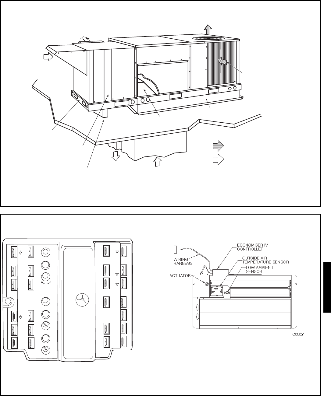
31
ECONOMI$ER IV CONTROLLER
ACCESSORY ENERGY$RECYLERTM UNIT (3 TO 12 1/2 TON UNITS ONLY)
EXHAUST
AIR
CONDENSER-FAN
DISCHARGE AIR
FRESH AIR
INLET
MOUNTING
KIT
FILTER
ACCESS
OUTDOOR-AIR
INLET
RETURN AIR
BAFFLE
ROOF CURB
RETURN AIR
SUPPLY AIR
OUTDOOR AIRFLOW
INDOOR AIRFLOW
ACCESSORY SUPPORT RAIL
TR1
24 Vac
COM
TR
24
Va c
HOT
12
34
5
EF EF1
+_
P1
T1
P
T
N
EXH
2V 10V
EXH
Set
Set
2V 10V
2V 10V
DCV
DCV
Free
Cool
BC
AD
SO+
SR+
SR
SO
AQ1
AQ
DCV
Min
Pos
Open
Max
N1
GEAR-DRIVEN ECONOMI$ER IV COMPONENT PARTS
(Required when standard roof curb is used)
48HE/HJ
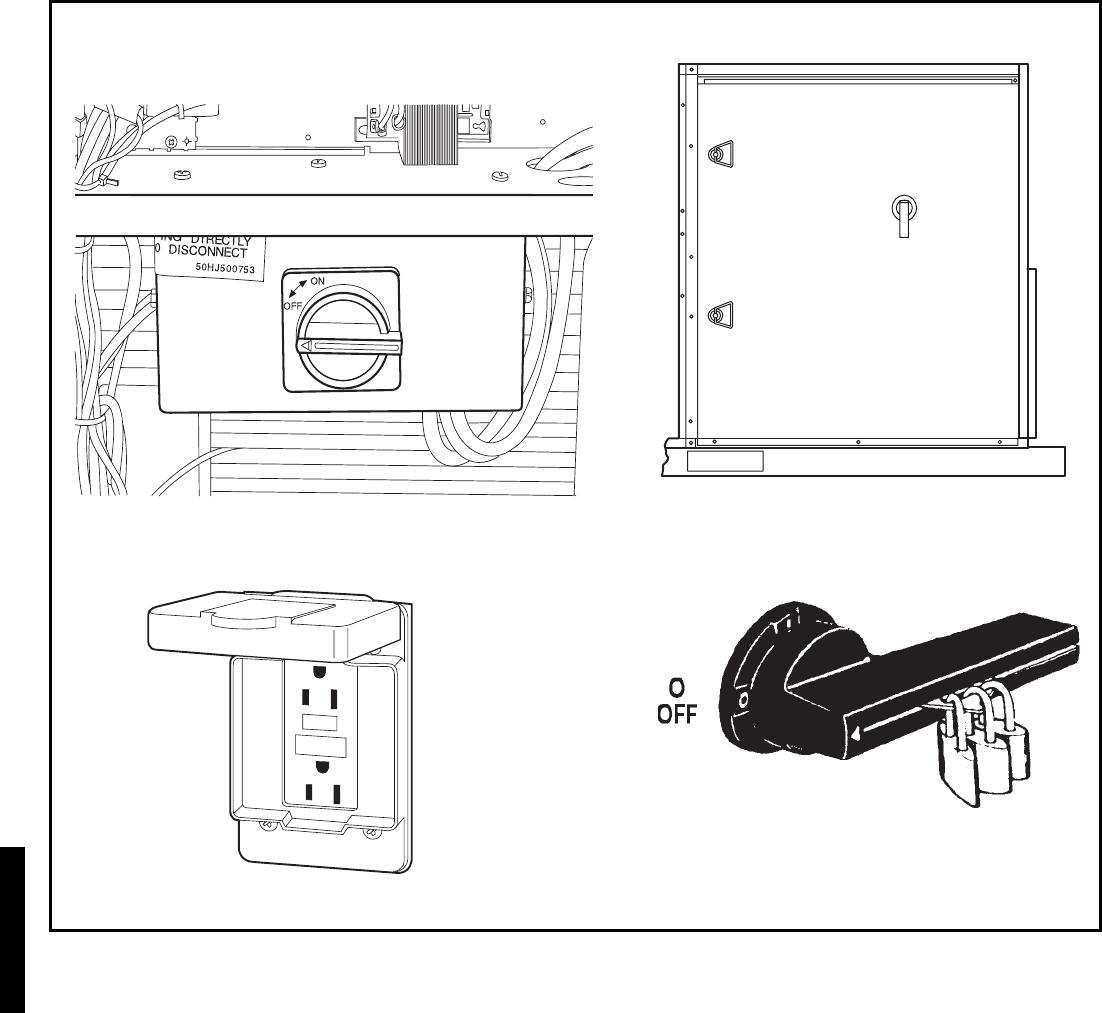
32
UNIT-MOUNTED DISCONNECT (Sizes 004-012)
CONVENIENCE OUTLET
UNIT-MOUNTED DISCONNECT (Sizes 014, 016)
Options and accessories (cont)
48HJ
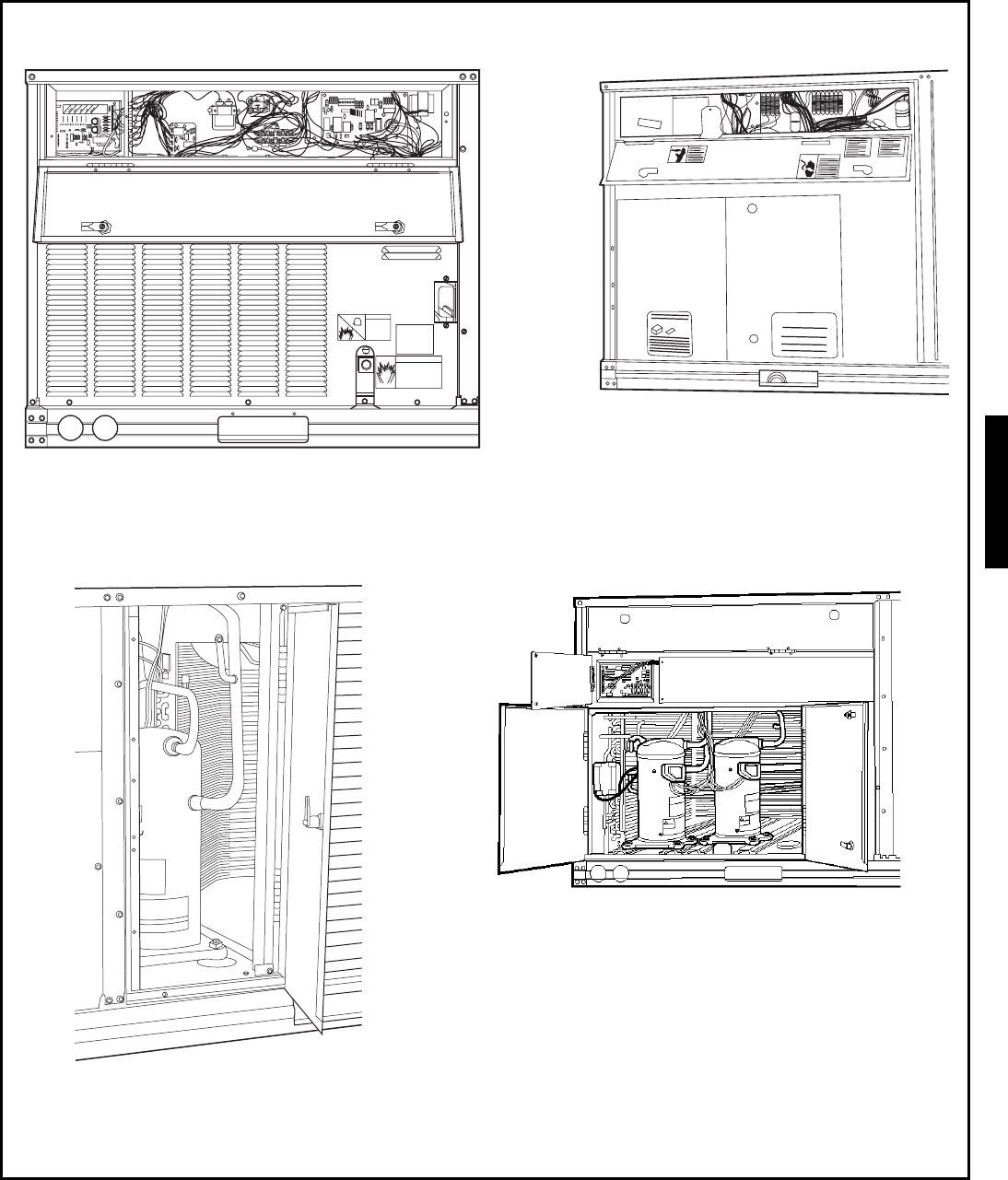
33
CONTROL BOX HINGED PANEL OPTION
48HJ004-007 UNITS SHOWN
COMPRESSOR HINGED PANEL OPTION
48HJ004-006 UNITS SHOWN
CONTROL BOX HINGED PANEL OPTION
48HJ008-0014 UNITS SHOWN
COMPRESSOR HINGED PANEL OPTION
48HJ008-014 UNITS SHOWN
48HJ
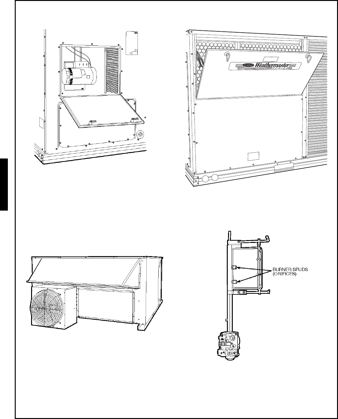
34
EVAPORATOR-FAN HINGED PANEL OPTION FILTER HINGED PANEL OPTION
BAROMETRIC RELIEF OR POWER EXHAUST
(015-028 Shown) LP CONVERSION KIT
Options and accessories (cont)
48HJ
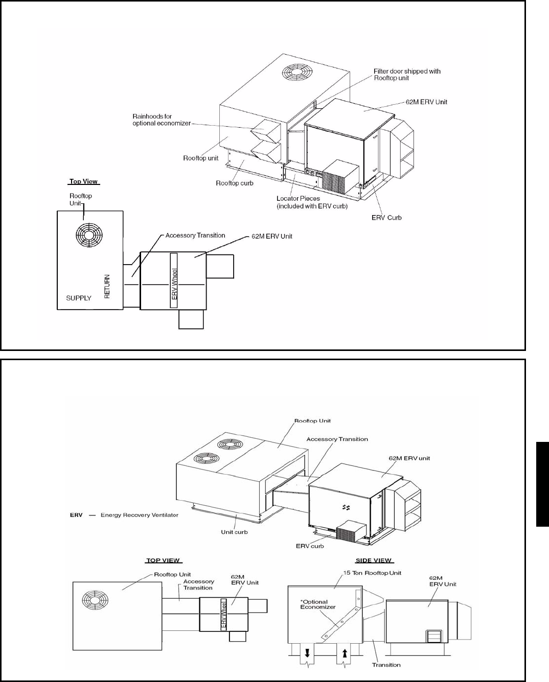
35
62M MATED WITH 48HJ004-014
62M MATED WITH 48HJ017
48HJ
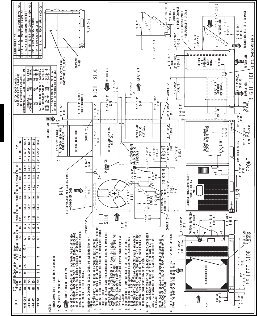
36
Base unit dimensions — 48HE003-006
48HE
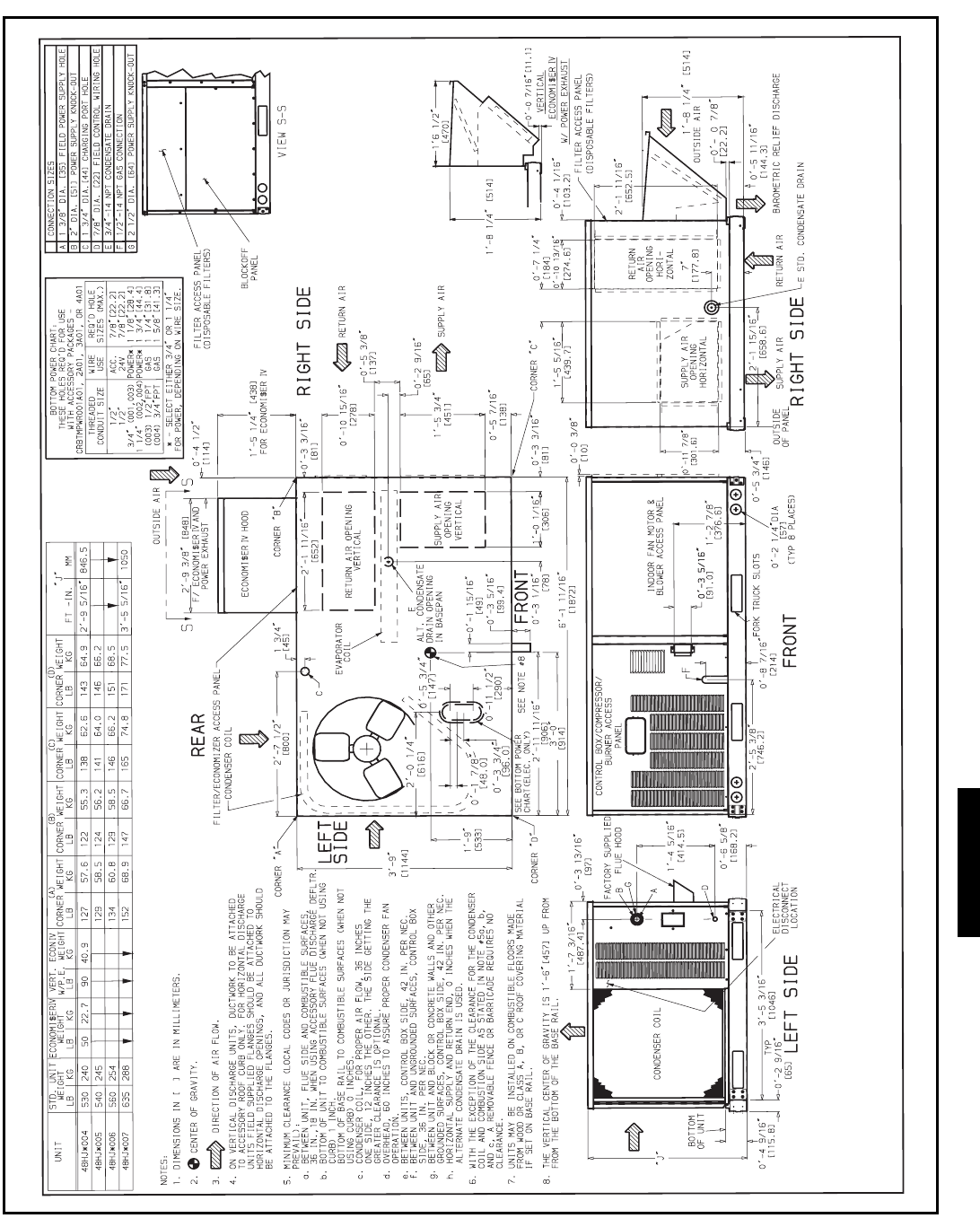
37
Base unit dimensions — 48HJ004-007
48HJ
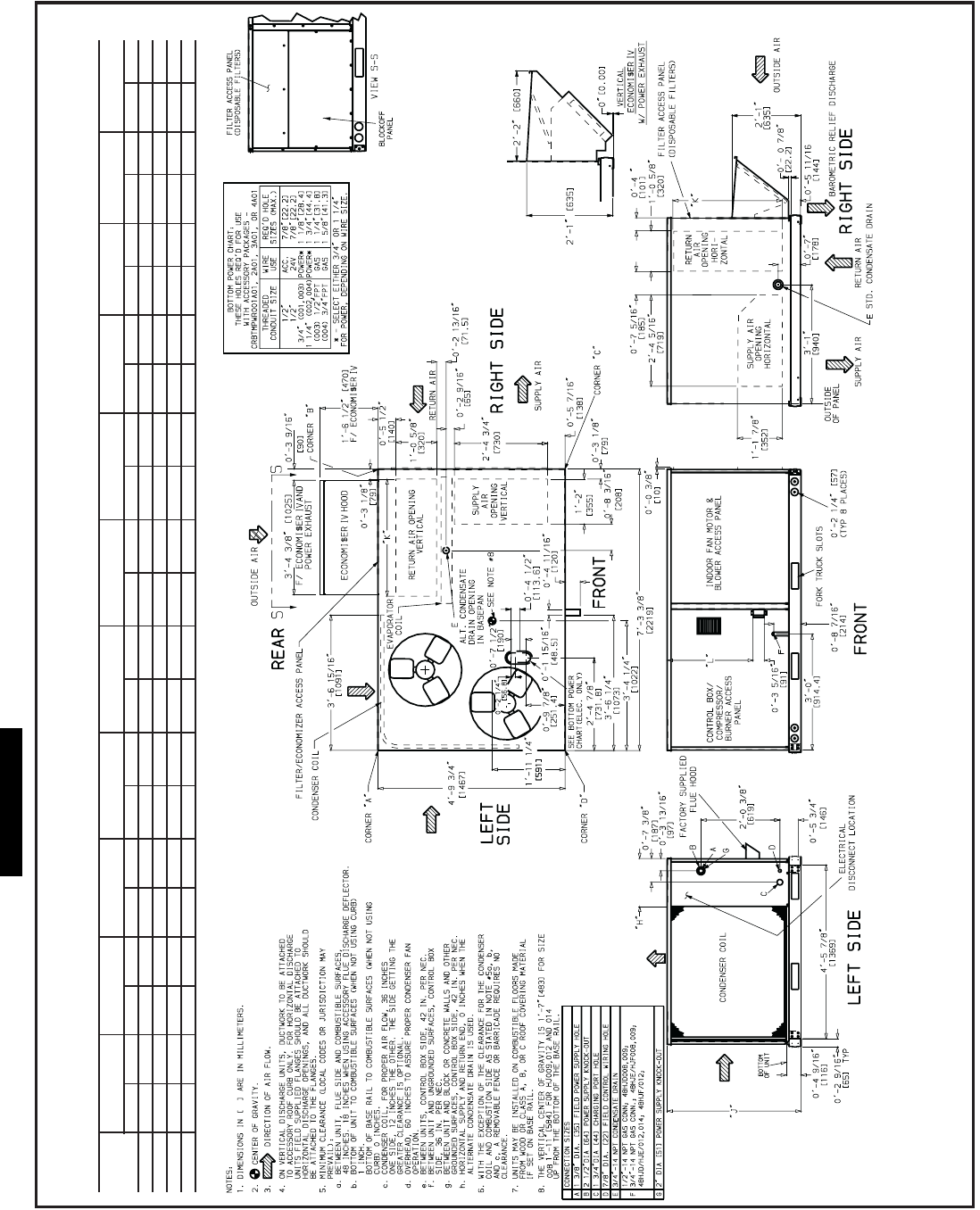
38
UNIT
STD UNIT
WEIGHT
ECONOMI$ER IV
WEIGHT
VERT. ECON IV
W/P.E. WEIGHT
(A)
CORNER WEIGHT
(B)
CORNER WEIGHT
(C)
CORNER WEIGHT
(D)
CORNER WEIGHT “H” “J” “K” “L”
Lb Kg Lb Kg Lb Kg Lb Kg Lb Kg Lb Kg Lb Kg ft-in. mm ft-in. mm ft-in. mm ft-in. mm
48HJ008 870 395 75 34.1 145 65.9 189 86 161 73 239 109 280 127 2-0
7
/
8
632 3-5
5
/
16
1050 2-9
11
/
16
856 2- 2
7
/
16
672
48HJ009 1015 460 75 34.1 145 65.9 223 101 188 85 279 126 327 148 1-2
7
/
8
378 4-1
5
/
16
1253 3-0
3
/
8
924 2-10
7
/
16
875
48HJ012 1035 469 75 34.1 145 65.9 225 102 192 87 285 129 333 151 1-2
7
/
8
378 4-1
5
/
16
1253 3-0
3
/
8
924 2-10
7
/
16
875
48HJ014 1050 476 75 34.1 145 65.9 228 103 195 88 289 131 338 153 1-2
7
/
8
378 4-1
5
/
16
1253 3-0
3
/
8
924 2-10
7
/
16
875
Base unit dimensions — 48HJ008-014
48HJ
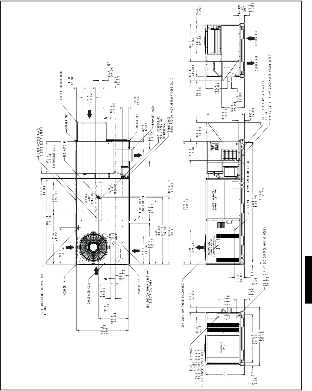
39
COBRA ENERGY RECOVERY UNIT - 48HE003-006 AND 48HJ004-007 WITH 62AQ060,100
RIGHT
SIDE
REAR
RIGHT SIDE
FRONT
LEFT SIDE
FRONT
LEFT
SIDE
CO BRA
E
N
E
RGY R
E
CO V
E
RY UN
I
T
—
48 HJ004- 007 W
I
TH 62 AQ060, 10 0
Base unit dimensions — COBRATM units
48HJ48HJ
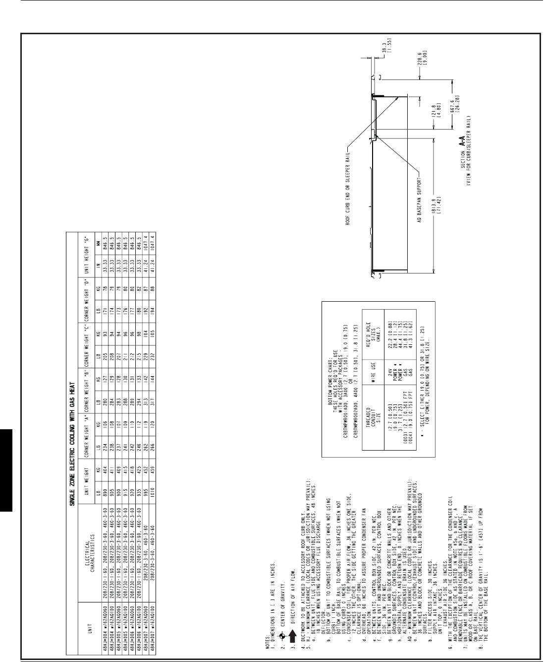
40
COBRA ENERGY RECOVERY UNIT - 48HE003-006 AND 48HJ004-007 WITH 62AQ060,100 (cont)
9. THIS DRAWING IS NOT APPLICABLE FOR ACCESSORY 62AQ UNITS.
CO BRA
E
N
E
RGY R
E
CO V
E
RY UN
I
T
—
48 HJ004 -007 W
I
TH 62 AQ060, 100 (
cont
)
Base unit dimensions — COBRATM units (cont)
48HJ48HJ
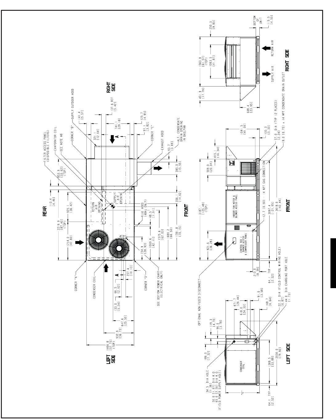
41
COBRATM ENERGY RECOVERY UNIT - 48HJ008-014 WITH 62AQ200,300
CO BRA
™
E
N
E
RGY R
E
CO V
E
RY UN
I
T
—
48 HJ008 -014 W
I
TH 62 AQ200, 300
48HJ
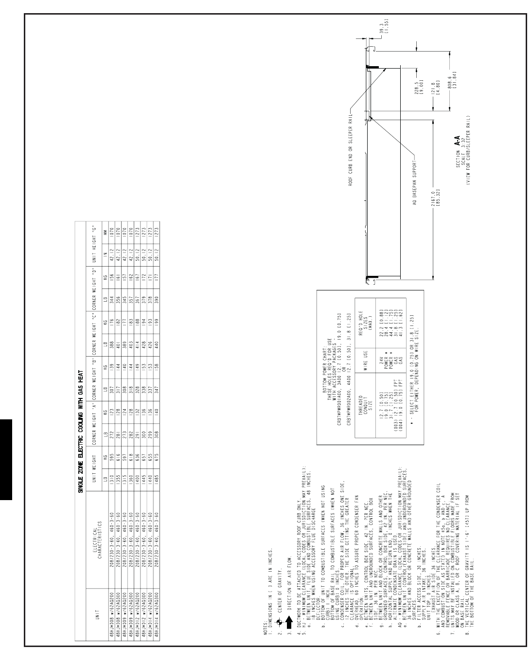
42
COBRATM ENERGY RECOVERY UNIT - 48HJ008-014 WITH 62AQ200,300 (cont)
9. THIS DRAWING IS NOT APPLICABLE FOR ACCESSORY 62AQ UNITS.
CO BRA
E
N
E
RGY R
E
CO V
E
RY UN
I
T
—
48H J008- 014 W
I
TH 62 AQ2 0 0 ,300 (
cont
)
Base unit dimensions — COBRATM units (cont)
48HJ48HJ
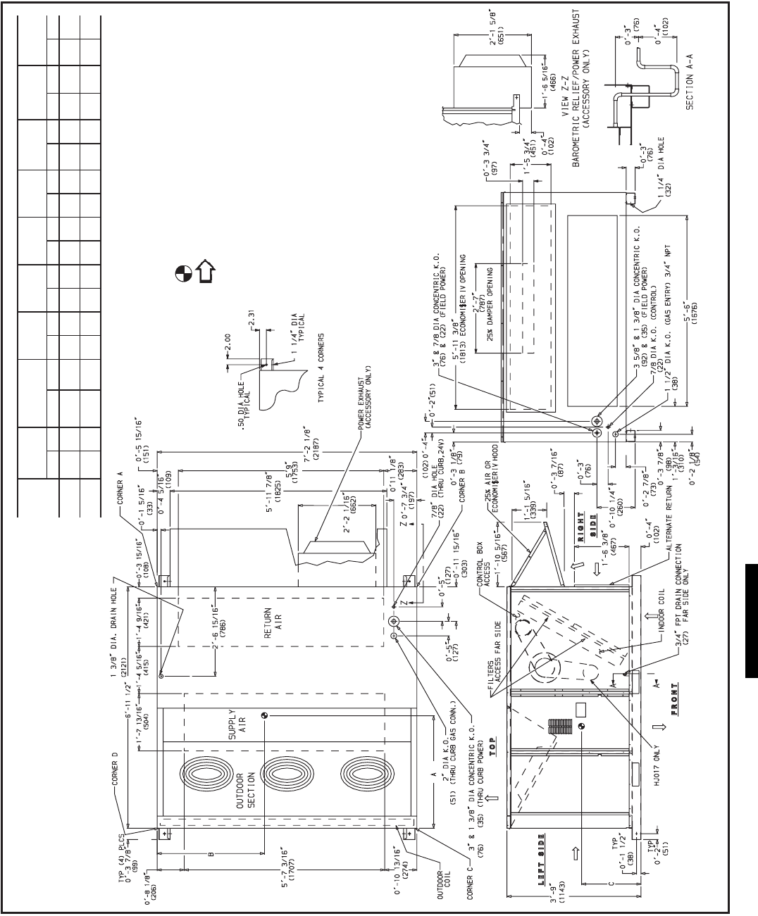
43
UNIT
STD UNIT
WEIGHT
ECONOMI$ER
IV
WEIGHT
CORNER
A
CORNER
B
CORNER
C
CORNER
DDIM A DIM B DIM C
Lb Kg Lb Kg Lb Kg Lb Kg Lb Kg Lb Kg ft-in. mm ft-in. mm ft-in. mm
48HJD,
HJF015 1725 782 90 41 407 185 375 170 383 174 410 186 3-3 991 3- 5 1051 1-10 559
48HJD,
HJF017 1800 816 90 41 417 189 399 181 481 218 503 228 3- 2 961 3-6 1070 1-10 559
NOTES:
1. Refer to print for roof curb accessory dimensions.
2. Dimensions in ( ) are in millimeters.
3. Center of Gravity.
4. Direction of airflow.
5. Ductwork to be attached to accessory roof curb only.
6. Minimum clearance:
Rear: 7 -0 (2134) for coil removal. This dimension can be reduced to
4-0 (1219) if conditions permit coil removal from the top.
4-0 (1219) to combustible surfaces, all four sides (includes between
units).
Left side: 4 -0 (1219) for proper condenser coil airflow.
Front: 4 -0 (1219) for control box access.
Right side: 4 -0 (1219) for proper operation of damper and power
exhaust if so equipped.
Top: 6 -0 (1829) to assure proper condenser fan operation.
Bottom: 14 (356) to combustible surfaces (when not using curb).
Control box side: 3 -0 (914) to ungrounded surfaces, non-combustible.
Control box side: 3 -6 (1067) to block or concrete walls, or other
grounded surfaces.
Local codes or jurisdiction may prevail.
7. With the exception of clearance for the condenser coil and the damper/
power exhaust as stated in Note #6, a removable fence or barricade
requires no clearance.
8. Dimensions are from outside of corner post. Allow 0 -
5
/
16
(8) on each side
for top cover drip edge.
9. See drawing 50TJ500352 for service option details.
Base unit dimensions — 48HJ015, 017
48HJ
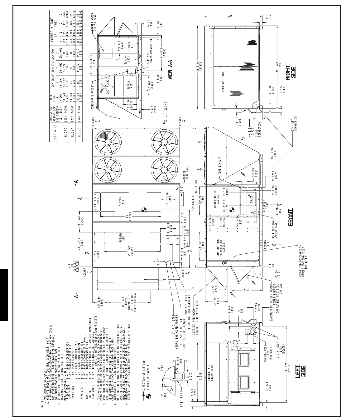
44
Base unit dimensions — 48HJ020, 028
48HJ48HJ
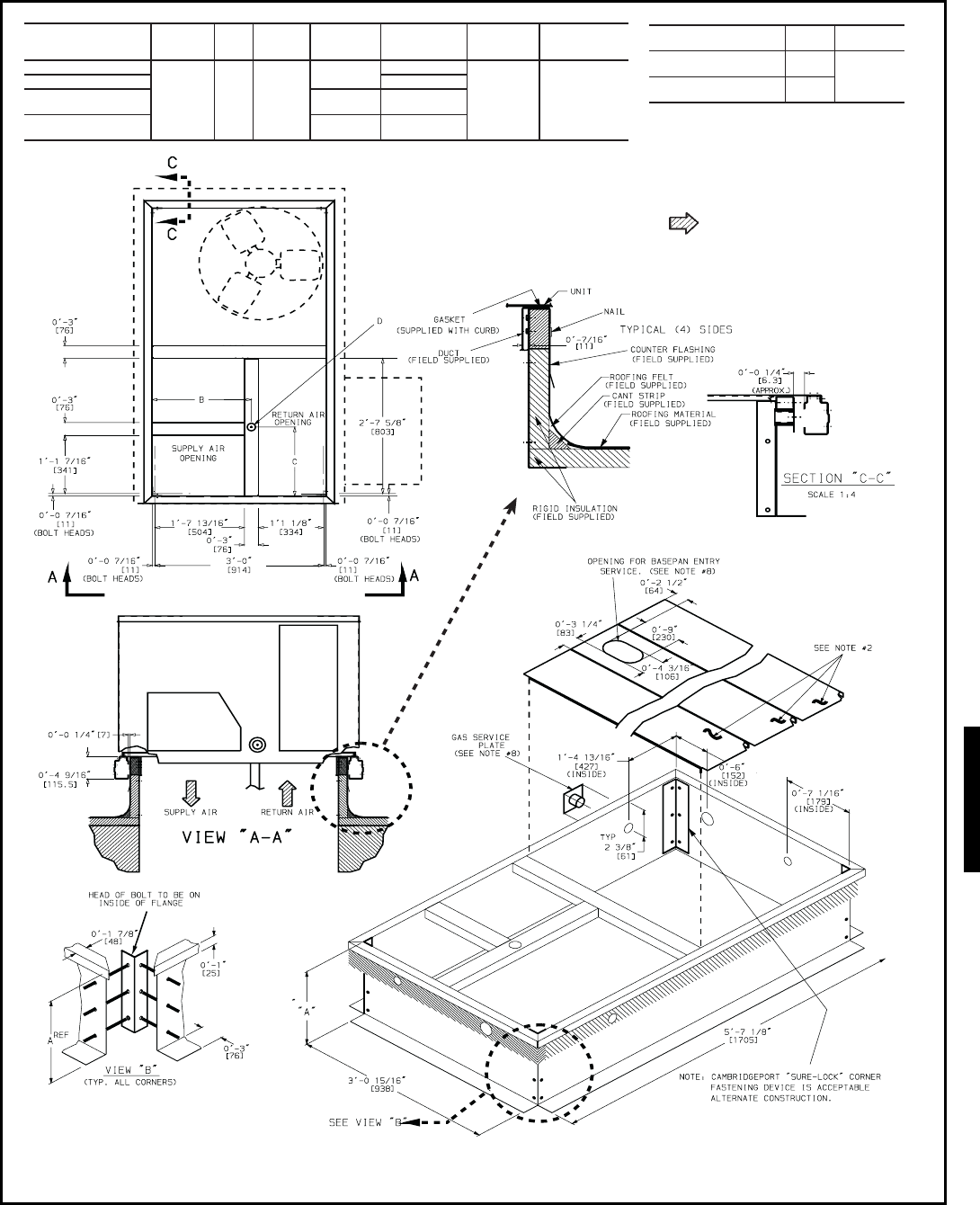
45
ROOF CURB
ACCESSORY AUNIT
SIZE
CRRFCURB001A01 1 -2
[356]
CRRFCURB002A01 2 -0
[610]
NOTES:
1. Roof curb accessory is shipped disassembled.
2. Insulated panels.
3. Dimensions in [ ] are in millimeters.
4. Roof curb: galvanized steel.
5. Attach ductwork to curb (flanges of duct rest
on curb).
6. Service clearance: 4 ft on each side.
7. Direction of airflow.
8. Connector packages CRBTMPWR001A01
and 002A01 are for thru-the-curb type gas.
Packages CRBTMPWR003A01 and 004A01
are for thru-the-bottom type gas connections.
CONNECTOR
PKG. ACCY. BC
DALT
DRAIN
HOLE
GAS POWER CONTROL ACCESSORY
POWER
CRBTMPWR001A01
1 -9
11
/
16
[551]
1 -4
[406]
1
3
/
4
[44.5]
3
/
4
[19] NPT
3
/
4
[19] NPT
1
/
2
[12.7]
1
/
2
[12.7]
CRBTMPWR002A01 1
1
/
4
[31.7]
CRBTMPWR003A01
1
/
2
[12.7] NPT
3
/
4
[19] NPT
CRBTMPWR004A01
3
/
4
[19] NPT 1
1
/
4
[31.7]
48HJ004-007
48HE003-006
Accessory dimensions — 48HJ004-007
48HJ
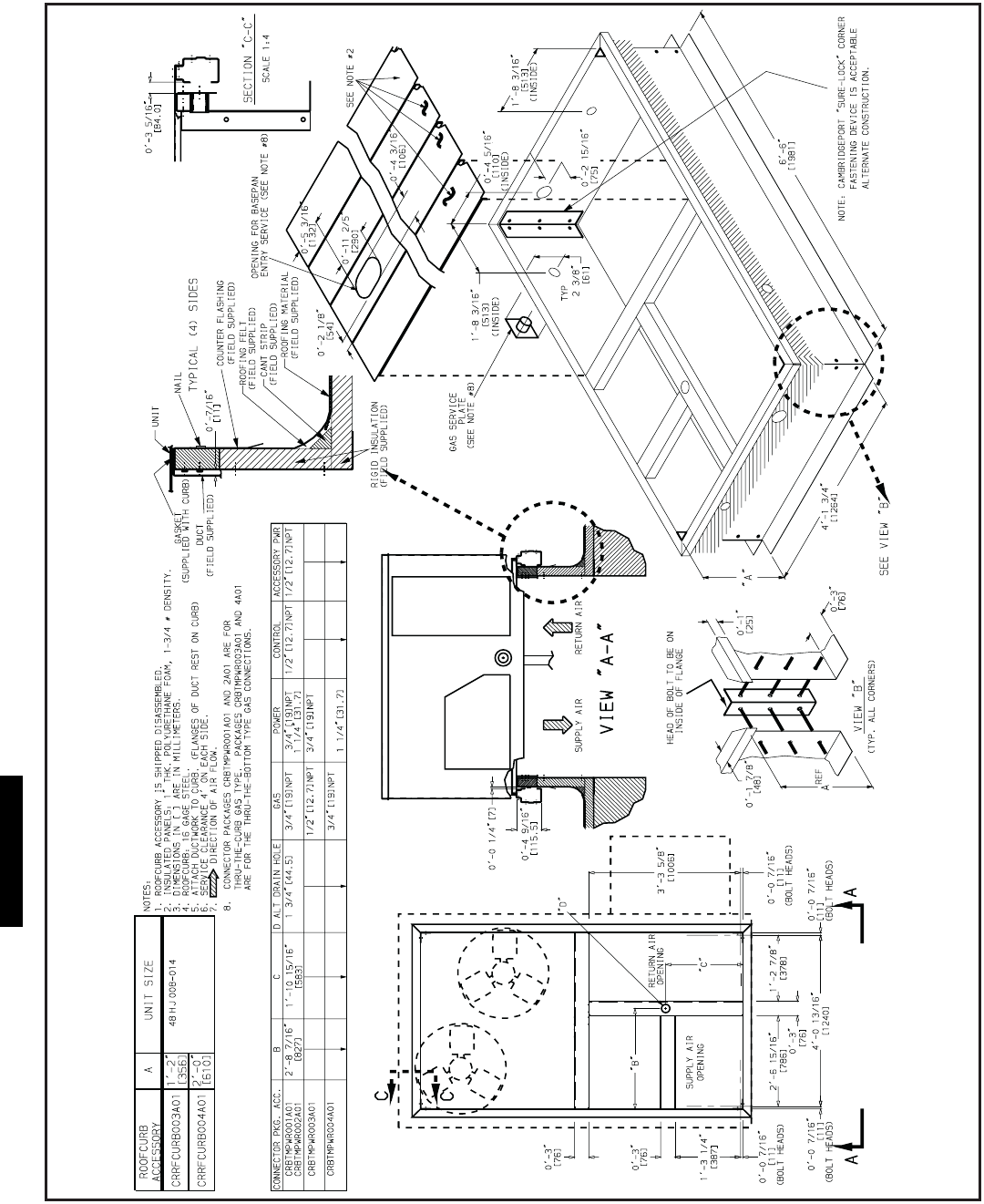
46
Accessory dimensions — 48HJ008-014
48HJ48HJ
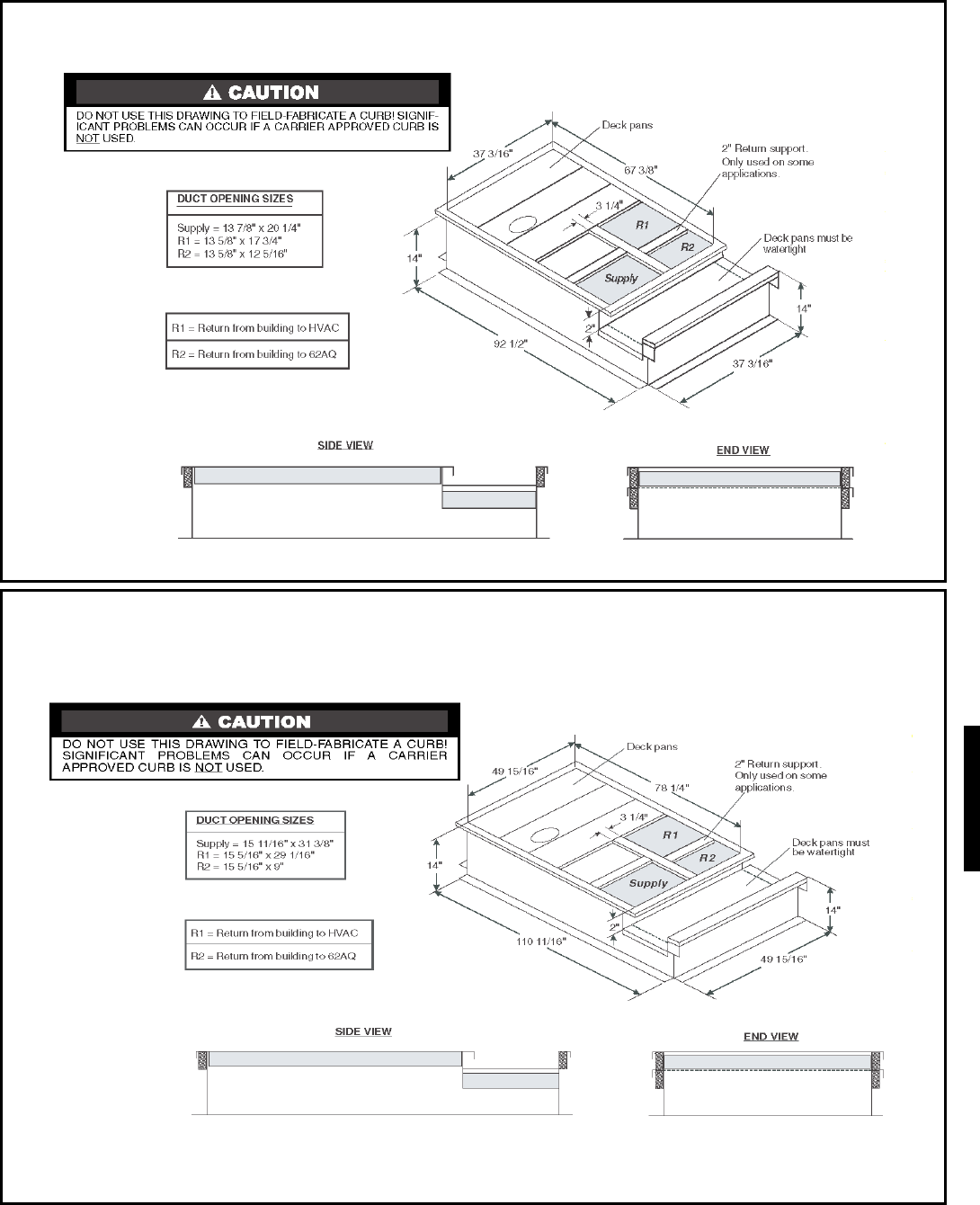
47
COBRA™ ENERGY RECOVERY UNIT FULL-PERIMETER ROOF CURB — 48HJ004-007 WITH 62AQ060,100
COBRA ENERGY RECOVERY UNIT FULL-PERIMETER ROOF CURB — 48HJ008-014 WITH 62AQ200,300
Accessory dimensions — 48HJ004-014
48HJ
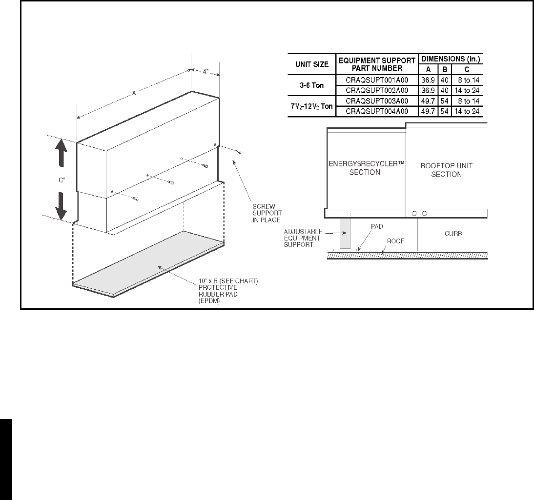
48
SUPPLEMENTAL ENERGY RECOVERY SECTION EQUIPMENT SUPPORT
(Required on a COBRA or Field Installed 62AQ unit when a standard roofcurb is used)
Accessory dimensions — 48HJ004-014 (cont)
48HJ48HJ
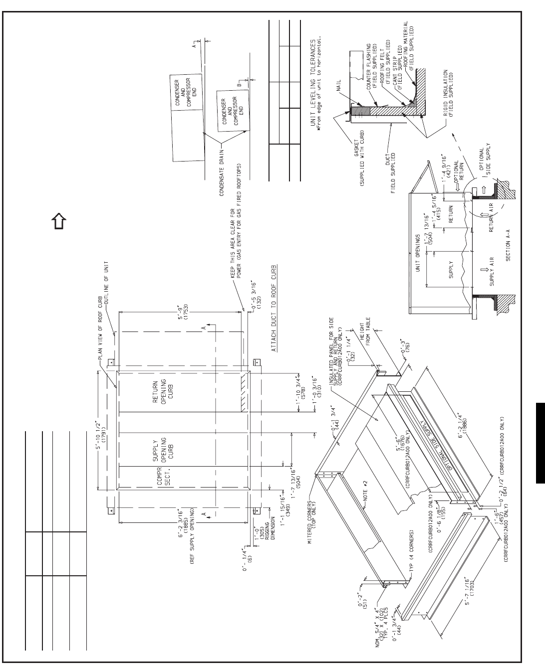
49
PKG. NO. REF. CURB
HEIGHT DESCRIPTION
CRRFCURB010A00 1-2 (305) Standard Curb 14 High
CRRFCURB011A00 2-0 (610) Standard Curb for Units
Requiring High Installation
CRRFCURB012A00 2-0 (610) Side Supply and Return
Curb for High Installation
NOTES:
1. Roof curb accessory is shipped disassembled.
2. Insulated panels: 1 thick neoprene coated 1
1
/
2
lb density.
3. Dimensions in ( ) are in millimeters.
4. Direction of airflow.
5. Roof curb: 16 ga. (VA03-56) stl.
6. A 90 degree elbow must be installed on the supply ductwork
below the unit discharge for units equipped with electric heaters.
7. To prevent the hazard of stagnant water build-up in the drain pan of the
indoor section, unit can only be pitched as shown.
DIMENSIONS* (degrees and inches)
UNIT AB
Deg.in.Deg.in.
ALL
.28 .45 .28 .43
48H J015, 017
Accessory dimensions — 48HJ015, 017
48HJ
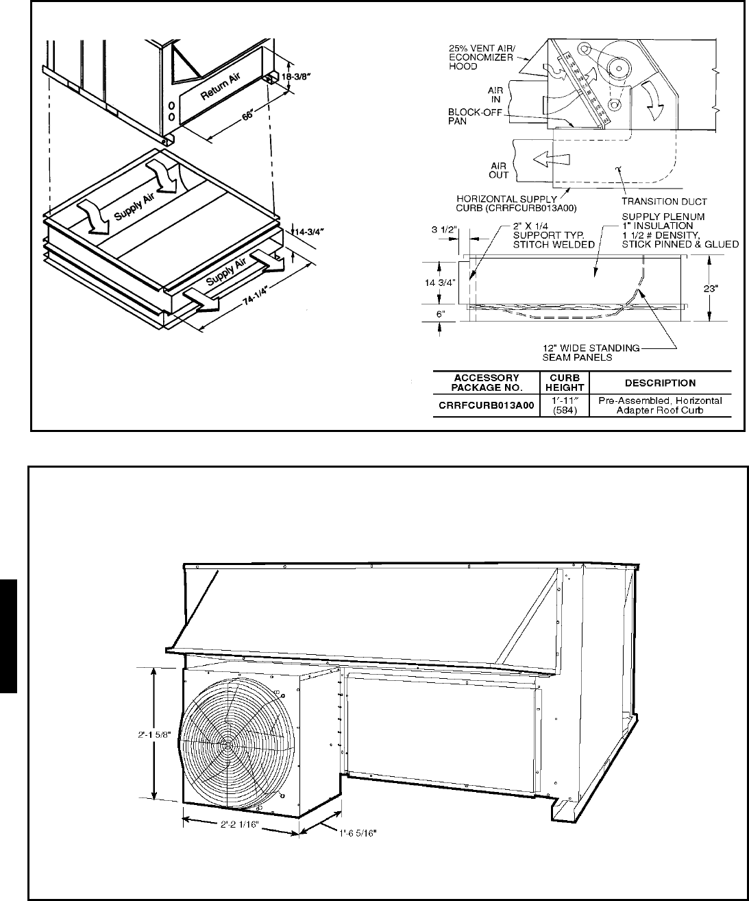
50
HORIZONTAL SUPPLY/RETURN ADAPTER INSTALLATION — (48HJ015,017)
NOTES: CRRFCURB013A00 is fully preassembled horizontal
adapter and includes an insulated transition duct. The pressure drop
through the adapter curb is negligible.
For horizontal return applications: The power exhaust and baromet-
ric relief dampers must be installed in the return air duct.
BAROMETRIC RELIEF/POWER EXHAUST — (48HJ015,017)
Accessory dimensions — 48HJ015, 017 (cont)
48HJ48HJ
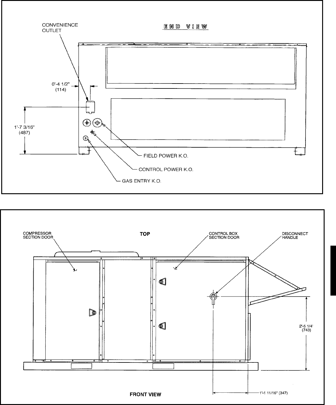
51
FACTORY-INSTALLED CONVENIENCE OUTLET — 48HJ015,017
FACTORY-INSTALLED NON-FUSED DISCONNECT — 48HJ015,017
48HJ
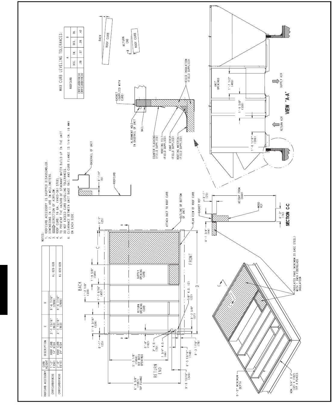
52
48 HJ
Accessory dimensions — 48HJ020-028
48HJ48HJ

53
I Determine cooling and heating loads at design conditions.
Given:
Required Cooling Capacity (TC). . . . . . . . . . 67,000 Btuh
Sensible Heat Capacity (SHC) . . . . . . . . . . . 46,000 Btuh
Required Heating Capacity . . . . . . . . . . . . . . 85,000 Btuh
Outdoor Entering-Air Temperature db . . . . . . . . . . . 95 F
Outdoor Entering-Air Temperature wb . . . . . . . . . . . 75 F
Outdoor-Air Entering Airflow Cfm. . . . . . . . . . . 450 cfm
Outdoor-Air Winter Design Temperature . . . . . . . . . .0° F
Indoor-Air Winter Design Temperature . . . . . . . . . . 70 F
Air to room including outdoor air . . . . . . . . . . . 2000 cfm
External Static Pressure. . . . . . . . . Supply — 0.60 in. wg
Return — 0.2 in. wg
Indoor-Air Temperature db (room air) . . . . . . . . . . . 78 F
Indoor-Air Temperature wb (room air) . . . . . . . . . . . 65 F
Indoor-Air Exhaust Cfm . . . . . . . . . . . . . . . . . . . 450 cfm
Electrical Characteristics (V-Ph-Hz) . . . . . . . . . .230-3-60
Vertical discharge unit with Energy$Recycler™ device
required.
II Determine fan speed and power requirements at design
conditions.
Before entering the Fan Performance tables, calculate the
total static pressure required based on unit component.
From the given find:
External static pressure supply 0.6 in. wg
External static pressure return 0.2 in. wg
Accessory static — None 0.0 in. wg
Total Static 0.8 in. wg
Enter the Fan Performance table for vertical discharge,
standard motor, 48HJ006 at 0.80 in. wg and 2000 cfm.
The rpm is 1326 and bhp is 1.37.
NOTE: Convert bhp to Fan Heat and Watts using the for-
mula found in the note following the Evaporator-Fan Mo-
tor Efficiency table on page 214.
For this example:
Watts = (746 x Bhp)/(motor efficiency)
Watts = (746 x 1.37)/(0.74) = 1381 watts
Indoor Fan Heat = watts x 3.413 Btuh/watt
= 1381 x 3.413 = 4713 Btuh
III Select Energy$Recycler device based on outdoor
entering cfm (optional).
Using Energy$Recycler cooling rating tables found in the
Energy$Recycler Product Data choose 62AQ060 unit.
Using 450 cfm outdoor supply airflow, 95 F OD db, and
75 F OD wb find performance of the 62AQ060 at these
conditions:
Energy$Recycler Gross Cooling
Capacity is 13,000 Btuh
Energy$Recycler Gross Sensible
Capacity is 10,100 Btuh
Compressor power is 1.06 kW
Energy$Recycler Leaving db is 73 F
Energy$Recycler Leaving wb is 66.9 F
IV Using the simplified* method below, calculate the
approximate mixed air temperature for the Small
Rooftop (SRT) evaporator coil.
Using the outdoor air entering cfm, the room cfm and the
room exhaust airflow with their respective db and wb
temperatures determine the db and wb entering the roof-
top evaporator coil.
a) Estimate the mixed air db to the evaporator coil.
t mix db = ((cfm oa x t oa db) + ((cfm ra – cfm exh) x
t rm db)) / ((cfm oa + (cfm ra – cfm exh)))
= ((450 cfm x 73.0 F) + ((2000 cfm – 450 cfm)
x 78 F)) / ((450 cfm + (2000 cfm – 450 cfm)))
= 76.9 F mixed air into the rooftop evaporator coil
b) Estimate the mixed air wb to the evaporator coil.
t mix wb* = ((cfm oa x t oa wb) + ((cfm ra – cfm exh)
x t rm wb)) / ((cfm oa + (cfm ra – cfm exh)))
= ((450 cfm x 66.9 F) + ((2000 cfm – 450 cfm) x 65
F)) / ((450 cfm + (2000 cfm – 450 cfm)))
= 65.4 F wb mixed air temperature into the rooftop
evaporator
*Simplified method of determining wet bulb (wb)
temperature of mixture. This approximation is used
because the wb lines in the area of the psychrometric
chart used in the calculation is relatively linear, pro-
viding a close approximation. A more accurate solu-
tion can be found using the E-Cat program.
LEGEND
V Determine the cooling load requirement for the rooftop
unit.
Required Cooling Capacity is 67,000 Btuh
Less Cooling Capacity supplied
by the Energy$Recycler device –13,000 Btuh
Rooftop cooling load required is 54,000 Btuh
VI Select the rooftop unit based on mixed air entering
conditions and cooling load.
Enter cooling capacity table at outdoor entering tempera-
ture 95 F, mixed air entering evaporator at 2000 cfm, 76.9
F db, and 65.4 F wb.
The 48HJ006 will provide a total gross cooling capacity
of 59,420 Btuh and sensible cooling of 43,420 Btuh.
Because these values were not at 80 F entering db, they
were calculated based on the notes following the Cooling
Capacity tables.
NOTE: Unit ratings are gross capacities and do not in-
clude the effect of evaporator-fan motor heat. To calculate
net capacities see Steps VII and VIII.
cfm — cubic feet per minute of air
db — dry bulb
exh — Energy$Recycler discharge
mix — mixture of outdoor + return air
oa — outside air leaving Energy$Recycler
ra — return air
sa — supply air at coil (sa = oa + ra – exh)
t—temperature
TC — total capacity gross
SHC — sensible capacity
wb — wet bulb
Selection procedure (with 48HJ006 example)
48HJ

54
VII Select net heating capacity of unit to meet design
condition requirements.
Enter the 62AQ060 Heating Rating table found in the En-
ergy$Recycler™ Product Data. At 450 cfm, 70° F and 0°
F find the heating value for the Energy$Recycler device to
be 15.2 Btuh. Since the Energy$Recycler device uses
room air, the instantaneous heat is also the Integrated Heat
Rating.
The customer heat requirement is 85,000 Btuh.
Fan heat from Step II 4,713 Btuh
Energy$Recycler Heat Capacity 15,200 Btuh
add Energy$Recycler optional
supply fan heat if supplied + 0 Btuh
Total Unit heat with Energy$Recycler 19,913 Btuh
Determine additional electric heat capacity in kW.
The required heating capacity is 85,000 Btuh. Therefore,
65,087 Btuh (85,000 – 19,913) additional heat is required.
The output capacity for the 48HJE006 is 93,150 Btuh,
which is sufficient.
Total unit net heating capacity is 113,063 Btuh (93,150 +
19,913).
VIII Determine net cooling capacity.
Cooling capacities are gross capacities and do not include
indoor (evaporator) or optional Energy$Recycler supply
fan heat.
Determine net cooling capacity using the following for-
mula:
Net Capacity = (Gross Capacity Rooftop Unit + Gross
Capacity Energy$Recycler) – (IFM Heat + Optional Ener-
gy$Recycler Supply Fan motor heat)
Gross Total Cooling
Rooftop unit 59,420 Btuh
Energy$Recycler 13,000 Btuh
Total 72,420 Btuh
Less
IFM heat (from Step II) –4,713 Btuh
Optional Energy$Recycler Supply
Fan Motor Heat none
Net Total Capacity 67,707 Btuh
Gross Sensible Cooling
Rooftop unit 43,420 Btuh
Energy$Recycler 10,090 Btuh
Total 53,510 Btuh
Less
IFM heat (from Step II) –4,713 Btuh
Optional Energy$Recycler Supply
Fan Motor Heat none
Net Sensible Capacity 48,797 Btuh
IX Determine the operating watts of the unit.
a) Cooling with Energy$Recycler device in operation:
Rooftop unit:
Compressor watts from cooling
capacity tables . . . . . . . . . . . . . . . . . . . . . .4,440 watts
Indoor fan motor from Step II† . . . . . . . . .1,381 watts
Outdoor fan motor from Physical Data table
find 1/4 hp†.
Assume OD motor efficiency is 0.75.
Watts = (746 x hp)/(motor Eff)
= (746 x 1/4)/(0.75) = 249 watts
†Dual circuit units will have two indoor and two out-
door fans, double values.
b) Energy$Recycler:
Compressor watts from
Energy$Recycler Product Data 1,060 watts
Optional supply fan from
Energy$Recycler Product Data
fan curves none
Exhaust fan, from Energy$Recycler
Product Data fan curve
at 450 cfm, 0.2 in. wg Static 110 watts
Total watts for the unit in operation
at design conditions 7,240 watts
X Electrical data RLA, FLA, LRA, MCA and MOCP.
Separate Power Supply:
If the 62AQ is wired for separate power see the Electrical
Data table.
Single Power Supply with Unit:
The unit is 230-3-60 Hz. Look up the 48JH006 without
convenience outlet in the Electrical Data Table. Find unit
electrical data. For the rooftop unit the data is MCA =
28.9 amps, MOCP = 35 amps, Min Unit Disconnect Size
FLA = 28, and LRA = 168.
From the Table of “X” and “Y” values in the Energy$Re-
cycler Product Data literature, find 230 v, for
62AQ060300, “X” = 8.1 amps and “Y” = 9.3 amps.
Add “X” amps to the MCA and MOCP and add “Y” amps
to the minimum disconnect size.
**The calculated MOCP is 43.1 amps; it is rounded down
to 40 amps. Compare it to MCA; it must be larger than
the MCA of 37.0 amps, so it is acceptable as is.
MCA MOCP FLA LRA
SRT 28.9 35 28 168
62AQ 8.1 8.1 9.3 31.7
Total 37.0 amps 43.1** amps 37.3 amps 199.7 amps
48HJ48HJ

55
The wiring of the unit must be suitable for the MCA cal-
culated above, and the Maximum Overcurrent Protec-
tion (MOCP) device must be selected to meet the calcu-
lated MOCP.
If the overcurrent protective device for the combination
load is equal to or less than 60 amps, a single disconnect
may be used for BOTH the main unit and the 62AQ unit
provided that the wire ampacity supplying the 62AQ unit
is sized for a minimum of 33% larger than the overcurrent
protection device value (i.e., 60 amps x 0.33 = 20 amps),
no further subfusing would be required.
If the overcurrent protection device is greater than 60
amps and the old overcurrent protection device was less
than 60 amps, a FUSED disconnect no greater than 60
amps must be provided for the main unit and a SEPA-
RATE FUSED disconnect must be provided for the 62AQ
unit.
If the old overcurrent protection device is greater than 60
amps, a disconnect is required for the MAIN UNIT as
well as a FUSED DISCONNECT for the 62AQ unit.
Selection procedure (with 48HJ006 example) (cont)
48HJ
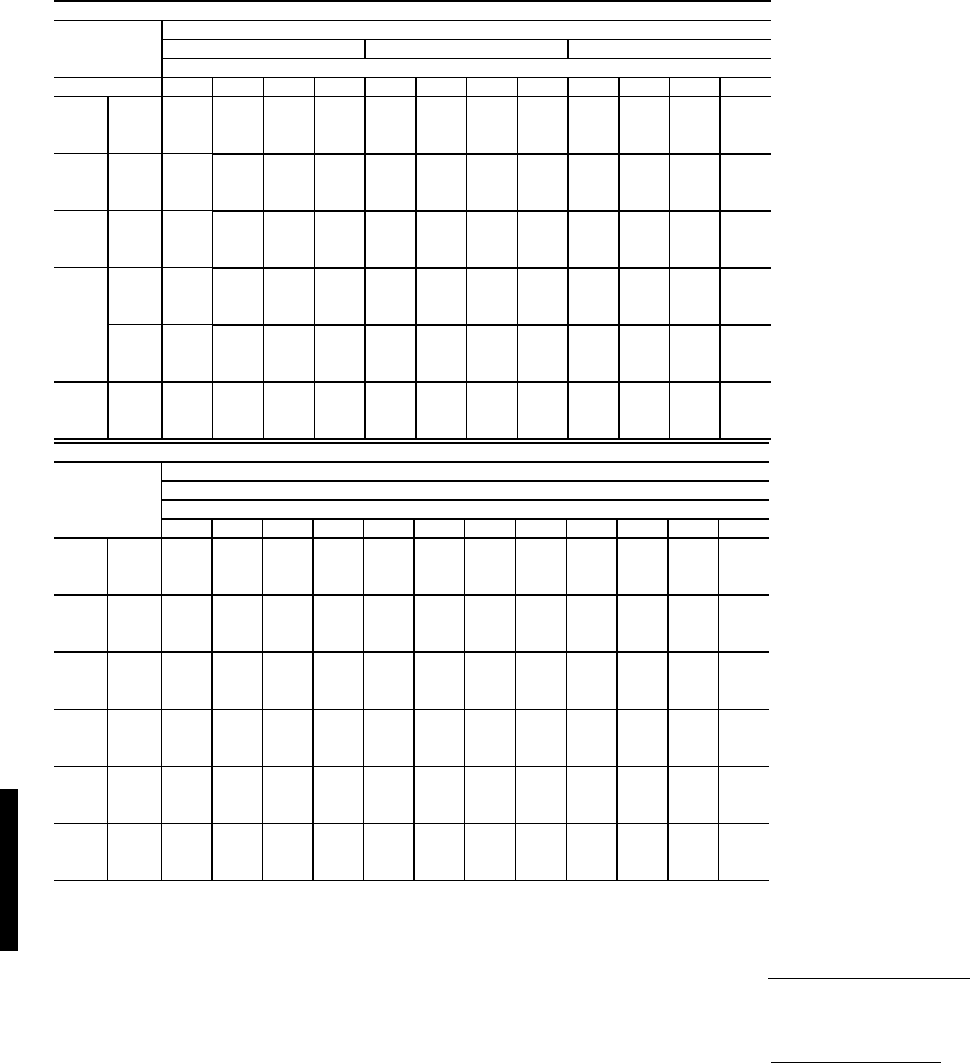
56
COOLING CAPACITIES — 48HE003-006 STANDARD UNITS
LEGEND
NOTES:
1. Direct interpolation is permissible. Do not extrapolate.
2. The following formulas may be used:
Where: hewb = Enthalpy of air entering evaporator coil.
3. The SHC is based on 80 F edb temperature of air entering evapo-
rator coil.
Below 80 F edb, subtract (corr factor x cfm) from SHC.
Above 80 F edb, add (corr factor x cfm) to SHC.
Correction Factor = 1.10 x (1 – BF) x (edb – 80).
48HE003 (2 Tons)
Temp (F) Air Entering Evaporator -- CFM/BF
Air Ent 600/0.12 800/0.14 1000/0.18
Condenser Air Entering Evaporator -- Ewb (F)
(Edb) 576267725762677257626772
75
TCG 22.6 24.3 26.7 29 25 25.7 28.1 30.2 26.6 26.8 29 30.9
SHG 21.7 19.5 16.4 13 24 22.9 18.6 14.1 25.6 25.4 20.6 15.1
CMP 1.18 1.19 1.2 1.21 1.19 1.19 1.2 1.21 1.19 1.2 1.21 1.22
85
TCG 21.3 23 25.7 28 24.2 24.7 27.2 29.6 25.9 25.9 27.9 30.2
SHG 20.5 19 16 12.7 23.3 22.4 18.4 14.1 24.9 24.9 20.3 15.1
CMP 1.36 1.37 1.38 1.39 1.38 1.38 1.39 1.4 1.38 1.38 1.39 1.4
95
TCG 19.9 21 24.7 27.2 23.1 23.3 26 28.6 25 24.9 26.9 29.3
SHG 19.1 18.2 15.7 12.4 22.2 21.9 18.1 13.9 24 24 20.2 15.1
CMP 1.56 1.57 1.59 1.6 1.58 1.58 1.59 1.61 1.59 1.59 1.6 1.61
105
TCG 18.4 18.8 23.2 26 21.3 21.3 24.8 27.4 23.9 23.9 25.6 28.2
SHG 17.7 17.3 15.1 12 20.5 20.5 17.7 13.5 23 23 19.9 14.8
CMP 1.78 1.78 1.81 1.82 1.8 1.8 1.82 1.83 1.81 1.81 1.82 1.84
115
TCG 16.6 16.5 20.5 24.7 19.7 19.7 22.4 26 22 22 24.1 26.7
SHG 16 15.9 14.1 11.6 19 19 16.9 13.1 21.1 21.1 19.5 14.5
CMP 2.01 2.01 2.05 2.08 2.05 2.05 2.06 2.08 2.06 2.06 2.07 2.09
125
TCG 15 15 17.7 22.2 17.7 17.7 19.6 24.4 19.7 19.8 20.5 25.2
SHG 14.5 14.5 13.2 10.8 17 17 16 12.7 19 19 18.3 14.1
CMP 2.27 2.27 2.3 2.34 2.3 2.3 2.32 2.35 2.32 2.32 2.33 2.36
48HE004 (3 Tons)
Temp (F) Air Entering Evaporator -- CFM/BF
Air Ent 900/0.10 1200/0.13 1500/0.16
Condenser Air Entering Evaporator -- Ewb (F)
(Edb) 57 62 67 72 57 62 67 72 57 62 67 72
75
TCG 32 34.5 38.9 42.8 35.1 37.1 40.9 44.9 38.1 38.5 42.2 45.9
SHG 32 28.9 25 20.4 35.1 33.6 28.3 22.3 38.1 37.4 31.2 23.9
CMP 1.94 1.96 1.98 2 1.96 1.97 1.99 2.01 1.98 1.98 2 2.02
85
TCG 30.9 33.2 37.5 41.4 33.8 34.9 39.4 43.3 36.9 37 40.5 44.3
SHG 30.9 28.3 24.5 19.8 33.8 32.5 27.8 21.8 36.9 36.7 30.7 23.3
CMP 2.19 2.21 2.24 2.26 2.22 2.23 2.25 2.27 2.24 2.24 2.26 2.28
95
TCG 29.5 31.4 35.4 39.7 31.8 32.3 37.7 41.5 35.1 35.2 38.8 42.5
SHG 29.5 27.3 23.6 19.2 31.8 31.2 27.2 21.2 35 35.2 30 22.8
CMP 2.47 2.49 2.52 2.54 2.5 2.51 2.54 2.56 2.53 2.53 2.54 2.56
105
TCG 28 29.5 33 38 29.5 29.5 34.7 39.7 32.3 32.2 36.8 40.8
SHG 28 26.4 22.6 18.6 29.4 29.4 26 20.7 32.3 32.2 29.5 22.5
CMP 2.78 2.79 2.83 2.86 2.81 2.81 2.85 2.87 2.84 2.84 2.86 2.88
115
TCG 26.3 27.1 30.7 35.2 27.6 27.6 31.1 37.6 29.6 29.5 32.9 38.5
SHG 26.3 25.3 21.7 17.7 27.6 27.6 24.5 20 29.6 29.5 27.8 21.9
CMP 3.1 3.11 3.16 3.2 3.15 3.15 3.18 3.22 3.17 3.17 3.2 3.23
125
TCG 24.4 24.7 28.1 32.1 25.5 25.5 27.5 33.7 27 27 28.5 35.8
SHG 24.4 24.1 20.7 16.6 25.5 25.4 22.9 18.8 27 27 26 21.2
CMP 3.45 3.46 3.51 3.56 3.51 3.51 3.53 3.59 3.53 3.53 3.55 3.6
BF — Bypass Factor
Edb — Entering Dry Bulb
Ewb — Entering Wet Bulb
COMP — Compressor Power kw
SHG — Gross Sensible Capacity (1000 Btuh)
TCG — Compressor Cooling Capicity (1000 Btuh)
tldb =t
edb –sensible capacity (Btuh)
1.10 x cfm
tlwb = Wet-bulb temperature corresponding to enthalpy of air
leaving evaporator coil (hlwb)
hlwb =h
ewb –total capacity (Btuh)
4.5 x cfm
Performance data — 48HE
48HE
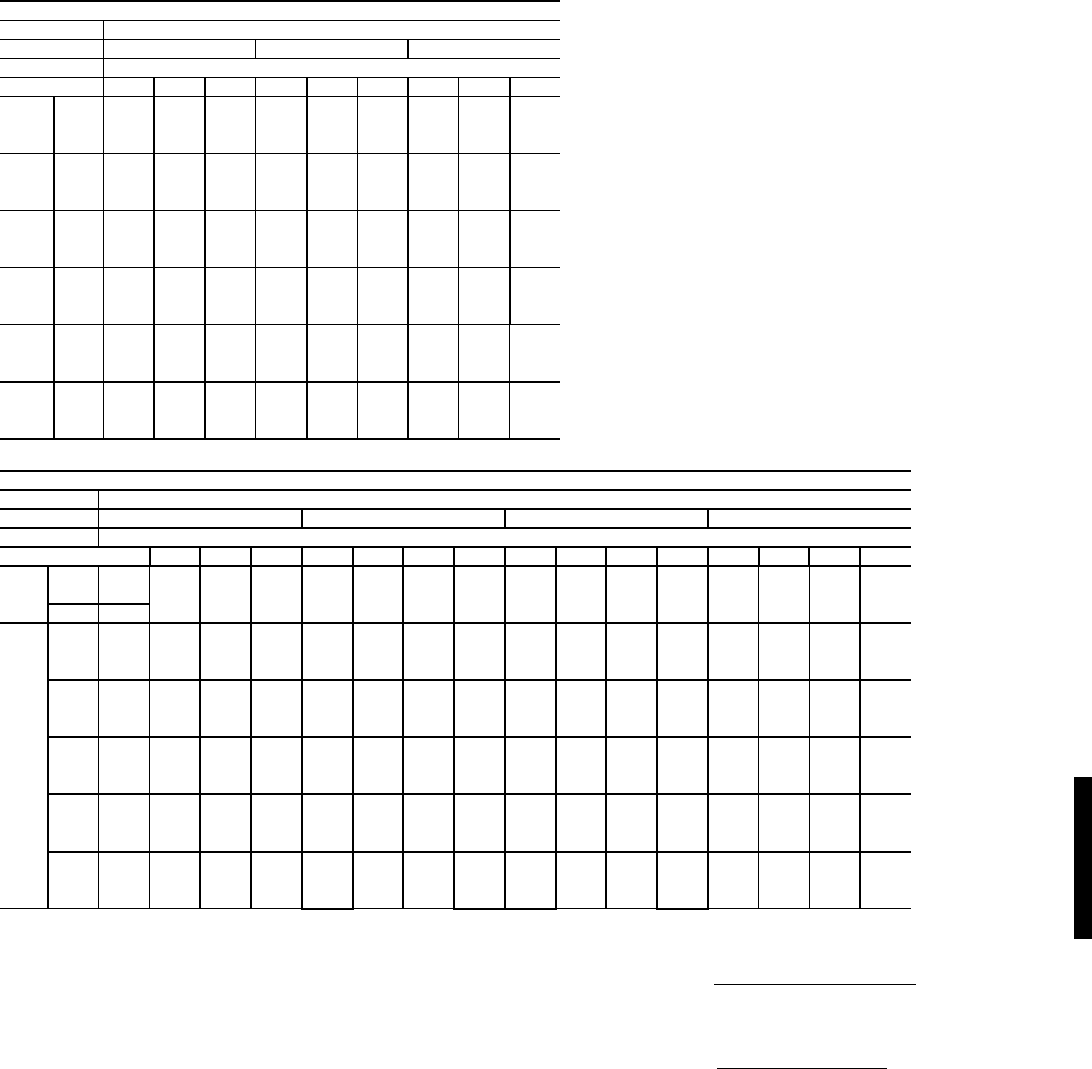
57
COOLING CAPACITIES — 48HE003-006 STANDARD UNITS (cont)
LEGEND NOTES:
1. Direct interpolation is permissible. Do not extrapolate.
2. The following formulas may be used:
Where: hewb = Enthalpy of air entering evaporator coil.
3. The SHC is based on 80 F edb temperature of air entering evapo-
rator coil.
Below 80 F edb, subtract (corr factor x cfm) from SHC.
Above 80 F edb, add (corr factor x cfm) to SHC.
Correction Factor = 1.10 x (1 – BF) x (edb – 80).
48HE005 (4 Tons)
Temp (F) Air Entering Evaporator -- CFM/BF
Air Ent 1200/0.05 1600/0.07 2000/0.09
Condenser Air Entering Evaporator -- Ewb (F)
(Edb) 626772626772626772
75
TCG 46.3 51.1 55.7 48.8 53.5 58 50.7 54.9 59.1
SHG 39.9 33.8 27.1 46.3 38.6 29.8 50.6 42.7 32
CMP 2.36 2.37 2.38 2.37 2.38 2.39 2.37 2.38 2.39
85
TCG 42.9 49 54 46.2 51.5 56.4 49.2 52.8 57.4
SHG 38.5 33 26.6 45.2 37.9 29.4 49.1 42.2 31.7
CMP 2.69 2.71 2.72 2.71 2.72 2.74 2.72 2.72 2.74
95
TCG 38.7 45.8 51.9 42.6 48.8 54.2 46.8 50.4 55.5
SHG 36.5 31.8 25.9 42.5 37.1 28.9 46.8 41.6 31.4
CMP 3.05 3.08 3.11 3.07 3.1 3.12 3.1 3.11 3.12
105
TCG 34.4 41.1 49.1 39 43.8 51.5 43.3 46.3 52.8
SHG 34.3 30 24.9 39 35.3 28.2 43.3 40.4 30.9
CMP 3.42 3.48 3.53 3.47 3.5 3.54 3.5 3.52 3.54
115
TCG 31.4 36.3 44.7 35.8 38.4 47.3 39.2 40.6 49.5
SHG 31.4 28.1 23.5 35.8 33.3 26.9 39.2 38.1 30.1
CMP 3.85 3.9 3.96 3.9 3.92 3.98 3.93 3.94 4
125
TCG 28.2 31.1 39.8 31.9 33 41.6 35.3 35.4 43.9
SHG 28.1 26.2 21.8 31.9 31.1 25.1 35.3 35.4 28.4
CMP 4.31 4.35 4.42 4.36 4.37 4.44 4.4 4.4 4.46
48HE006 (5 Tons)
Temp (F) Indoor Entering Air -- CFM/BF
Outdoor 1500/0.26 1750/.31 2000/.35 2500/.45
Air Ent Indoor Entering Air -- Ewb (F)
(Edb) 57626772576267725762677257626772
75
TCG 57 60.2 66.5 72 60.3 62.3 68.5 73.8 63.2 64.1 69.7 75.6 67.4 67.4 71.8 77.6
SHG 55.3 50.5 42.4 33.5 58.6 55.2 45.7 35.4 61.3 59.5 48.6 37.4 65.5 65.5 54.4 40.7
CMP 3.1 3.11 3.12 3.14 3.11 3.12 3.13 3.15 3.11 3.12 3.13 3.16 3.12 3.12 3.14 3.17
85
TCG 54.1 56.9 64 70.2 58.3 59.7 65.9 72 60.9 61.4 67.3 73.4 65.3 65.2 69.6 75.3
SHG 52.6 49.1 41.4 33 56.6 54.1 44.8 35 59.2 58.4 48 36.9 63.4 63.4 54.4 40.4
CMP 3.5 3.52 3.54 3.56 3.52 3.53 3.54 3.57 3.53 3.54 3.54 3.58 3.54 3.54 3.56 3.59
95
TCG 50.2 53 61.1 67.5 55 55.6 62.9 69.3 58.6 58.6 64.3 70.6 62.8 62.8 66.4 72.7
SHG 48.8 47.4 40.3 32.2 53.4 52.3 43.8 34.2 56.9 56.8 47.2 36.1 61 61 53.4 40
CMP 3.94 3.95 3.99 4.02 3.97 3.97 4.01 4.03 3.99 3.99 4.02 4.03 4.01 4.01 4.02 4.05
105
TCG 47.4 47.9 56.5 64.3 50.9 51 59.5 66.1 54.7 54.8 60.9 67.4 59.9 60 62.9 69
SHG 46 45.2 38.7 31.1 49.5 49.5 42.6 33.2 53.1 53.2 45.9 35.2 58.2 58.3 52.4 38.8
CMP 4.42 4.42 4.48 4.51 4.44 4.44 4.5 4.53 4.47 4.47 4.51 4.54 4.5 4.5 4.52 4.54
115
TCG 43.1 43.2 50.3 60.8 47.3 47.3 52.6 62.6 50.1 50.1 55.6 63.9 56 55.9 58.2 65.4
SHG 41.8 42 36.4 30 45.9 45.9 40.2 32.1 48.7 48.7 44.1 34.2 54.4 54.3 50.8 37.9
CMP 4.92 4.92 4.98 5.05 4.96 4.96 5 5.07 4.98 4.98 5.02 5.08 5.03 5.03 5.05 5.08
125
TCG 39 39 43.9 55.7 42.3 42.3 46.9 58.5 46.1 46.1 48.2 59.7 50.9 50.9 51.3 61.4
SHG 37.9 37.9 34.1 28.3 41.1 41 38.2 30.8 44.8 44.8 41.6 32.9 49.4 49.4 48.2 36.9
CMP 5.47 5.46 5.52 5.62 5.51 5.51 5.55 5.64 5.54 5.54 5.56 5.66 5.59 5.59 5.59 5.66
BF — Bypass Factor
Edb — Entering Dry Bulb
Ewb — Entering Wet Bulb
COMP — Compressor Power kw
SHG — Gross Sensible Capacity (1000 Btuh)
TCG — Compressor Cooling Capicity (1000 Btuh)
tldb =t
edb –sensible capacity (Btuh)
1.10 x cfm
tlwb = Wet-bulb temperature corresponding to enthalpy of air
leaving evaporator coil (hlwb)
hlwb =h
ewb –total capacity (Btuh)
4.5 x cfm
Performance data — 48HE (cont)
48HE
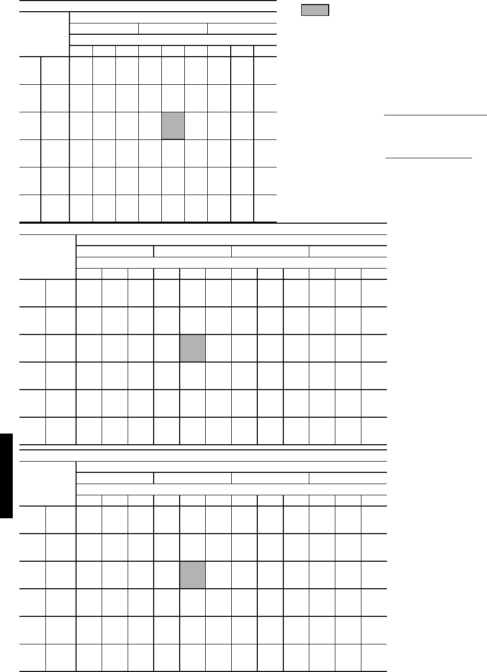
58
COOLING CAPACITIES — 48HJ004-006 STANDARD UNITS
Standard Ratings
LEGEND
NOTES:
1. Direct interpolation is permissible. Do not extrapolate.
2. The following formulas may be used:
Where: hewb = Enthalpy of air entering evaporator coil.
3. The SHC is based on 80 F edb temperature of air entering evapo-
rator coil.
Below 80 F edb, subtract (corr factor x cfm) from SHC.
Above 80 F edb, add (corr factor x cfm) to SHC.
Correction Factor = 1.10 x (1 – BF) x (edb – 80).
48HJ004 (3 TONS)
Temp (F)
Air Ent
Condenser
(Edb)
Air Entering Evaporator — Cfm/BF
900/0.14 1200/0.17 1500/0.20
Air Entering Evaporator — Ewb (F)
72 67 62 72 67 62 72 67 62
75
TC 41.9 38.7 35.7 43.5 40.8 37.7 44.8 41.8 39.0
SHC 20.4 25.2 29.7 21.8 28.2 33.8 23.3 30.7 37.0
kW 2.19 2.16 2.12 2.21 2.18 2.15 2.23 2.19 2.16
85
TC 40.7 37.5 34.5 42.1 39.3 36.4 43.5 40.4 37.6
SHC 19.9 24.7 29.2 21.5 27.7 33.2 23.2 30.3 36.4
kW 2.46 2.42 2.39 2.47 2.44 2.41 2.50 2.45 2.42
95
TC 39.3 36.1 33.1 40.8 37.8 34.9 42.0 38.9 36.1
SHC 19.5 24.1 28.4 21.1 27.2 32.5 22.8 29.9 35.6
kW 2.75 2.71 2.66 2.77 2.73 2.69 2.79 2.74 2.71
105
TC 37.7 34.6 31.7 39.3 36.2 33.4 40.1 37.2 34.7
SHC 18.8 23.5 27.8 20.7 26.6 31.8 22.1 29.3 34.7
kW 3.06 3.02 2.98 3.09 3.04 3.01 3.10 3.06 3.03
115
TC 36.0 33.0 29.7 37.4 34.5 31.5 38.1 35.5 33.2
SHC 18.3 22.9 26.7 19.9 26.1 30.9 21.3 28.7 33.2
kW 3.41 3.36 3.31 3.43 3.39 3.34 3.44 3.41 3.37
125
TC 34.2 31.3 27.8 35.6 32.7 29.4 36.3 33.6 31.9
SHC 17.6 22.2 25.8 19.4 25.4 29.4 20.8 28.0 31.8
kW 3.78 3.73 3.66 3.80 3.76 3.71 3.81 3.78 3.75
BF — Bypass Factor
Edb — Entering Dry Bulb
Ewb — Entering Wet Bulb
kW — Compressor Motor Power Input
SHC — Sensible Heat Capacity (1000 Btuh) Gross
TC — Total Capacity (1000 Btuh) Gross
tldb =t
edb –sensible capacity (Btuh)
1.10 x cfm
tlwb = Wet-bulb temperature corresponding to enthalpy of air
leaving evaporator coil (hlwb)
hlwb =h
ewb –total capacity (Btuh)
4.5 x cfm
48HJ005 (4 TONS)
Temp (F)
Air Ent
Condenser
(Edb)
Air Entering Evaporator — Cfm/BF
1200/0.17 1450/0.19 1600/0.21 2000/0.24
Air Entering Evaporator — Ewb (F)
72 67 62 72 67 62 72 67 62 72 67 62
75 TC 54.0 50.7 44.2 55.9 52.2 47.7 56.4 52.8 49.1 58.1 54.5 50.6
SHC 26.1 32.7 37.5 27.6 35.1 41.8 28.2 36.2 43.8 30.2 39.5 47.5
kW 2.81 2.80 2.76 2.83 2.81 2.78 2.83 2.80 2.79 2.84 2.82 2.79
85 TC 52.2 48.9 41.9 54.1 50.4 45.9 54.5 51.0 47.2 55.3 52.3 48.7
SHC 25.4 32.0 36.4 26.9 34.5 40.8 27.5 35.7 42.8 28.6 38.5 46.6
kW 3.20 3.19 3.15 3.22 3.20 3.17 3.22 3.20 3.18 3.22 3.20 3.18
95 TC 50.7 46.9 39.5 51.9 48.4 43.5 52.5 48.9 45.2 53.9 50.1 46.7
SHC 24.9 31.1 35.0 26.1 33.6 39.6 26.8 34.7 41.8 28.8 37.5 45.6
kW 3.64 3.61 3.57 3.65 3.62 3.60 3.65 3.62 3.60 3.67 3.63 3.61
105 TC 48.8 44.5 36.7 49.8 46.2 40.7 50.2 46.7 42.1 51.5 48.2 44.7
SHC 24.3 30.2 33.6 25.3 32.8 38.2 26.0 33.9 40.3 27.9 37.4 44.4
kW 4.12 4.09 4.03 4.12 4.09 4.06 4.12 4.09 4.07 4.14 4.11 4.08
115 TC 46.5 41.1 34.3 47.7 43.3 37.0 48.0 44.4 38.5 48.9 45.7 42.0
SHC 23.4 28.9 32.4 24.9 31.8 36.3 25.4 33.4 38.3 27.1 36.9 42.0
kW 4.64 4.59 4.53 4.65 4.62 4.55 4.64 4.63 4.56 4.65 4.63 4.60
125 TC 43.8 37.5 32.4 45.1 39.0 33.8 45.3 40.1 35.4 46.3 42.6 38.8
SHC 22.5 27.4 31.5 24.1 30.2 33.7 24.7 31.9 35.4 26.5 35.9 38.8
kW 5.19 5.13 5.05 5.20 5.15 5.09 5.19 5.17 5.11 5.20 5.19 5.15
48HJ006 (5 TONS)
Temp (F)
Air Ent
Condenser
(Edb)
Air Entering Evaporator — Cfm/BF
1500/0.08 1750/0.09 2000/0.11 2500/0.13
Air Entering Evaporator — Ewb (F)
72 67 62 72 67 62 72 67 62 72 67 62
75 TC 70.8 65.4 58.5 72.5 67.3 61.1 73.0 68.4 62.8 74.8 70.3 64.8
SHC 34.1 42.7 49.9 35.7 45.5 54.2 36.8 48.0 57.8 39.6 53.0 63.4
kW 3.53 3.49 3.44 3.55 3.50 3.46 3.55 3.51 3.47 3.57 3.54 3.48
85 TC 68.9 63.2 55.3 70.5 65.1 57.9 72.2 66.4 60.2 73.2 68.1 62.9
SHC 33.5 41.8 48.4 35.0 44.8 52.8 37.0 47.6 56.8 39.3 52.5 62.4
kW 3.98 3.94 3.87 4.00 3.96 3.90 4.03 3.97 3.92 4.04 3.99 3.94
95 TC 66.8 60.6 52.4 68.3 62.5 54.3 69.3 63.8 56.6 71.2 65.6 60.6
SHC 32.8 40.7 47.0 34.5 43.8 51.1 36.0 46.7 55.0 39.1 51.8 60.5
kW 4.48 4.43 4.35 4.50 4.45 4.37 4.51 4.46 4.40 4.55 4.48 4.44
105 TC 64.3 57.7 49.9 65.9 59.8 51.7 66.9 61.1 54.1 68.4 62.8 58.4
SHC 32.0 39.6 45.8 33.7 42.8 49.7 35.3 45.7 53.5 38.4 51.0 58.4
kW 5.03 4.96 4.87 5.05 4.99 4.90 5.06 5.00 4.93 5.08 5.02 4.98
115 TC 61.5 54.8 47.3 62.8 56.7 49.1 64.0 58.2 51.6 65.4 59.9 56.1
SHC 31.0 38.4 44.5 32.5 41.6 48.2 34.4 44.6 51.6 37.4 50.0 56.1
kW 5.61 5.55 5.46 5.62 5.58 5.49 5.65 5.60 5.52 5.67 5.61 5.57
125 TC 58.7 51.6 44.5 59.9 53.4 46.2 60.8 54.9 49.0 62.2 56.8 53.5
SHC 30.0 37.2 43.1 31.7 40.4 46.2 33.3 43.4 48.9 36.4 48.9 53.4
kW 6.27 6.19 6.09 6.28 6.21 6.13 6.29 6.24 6.17 6.31 6.27 6.22
Performance data — 48HJ
48HJ48HJ
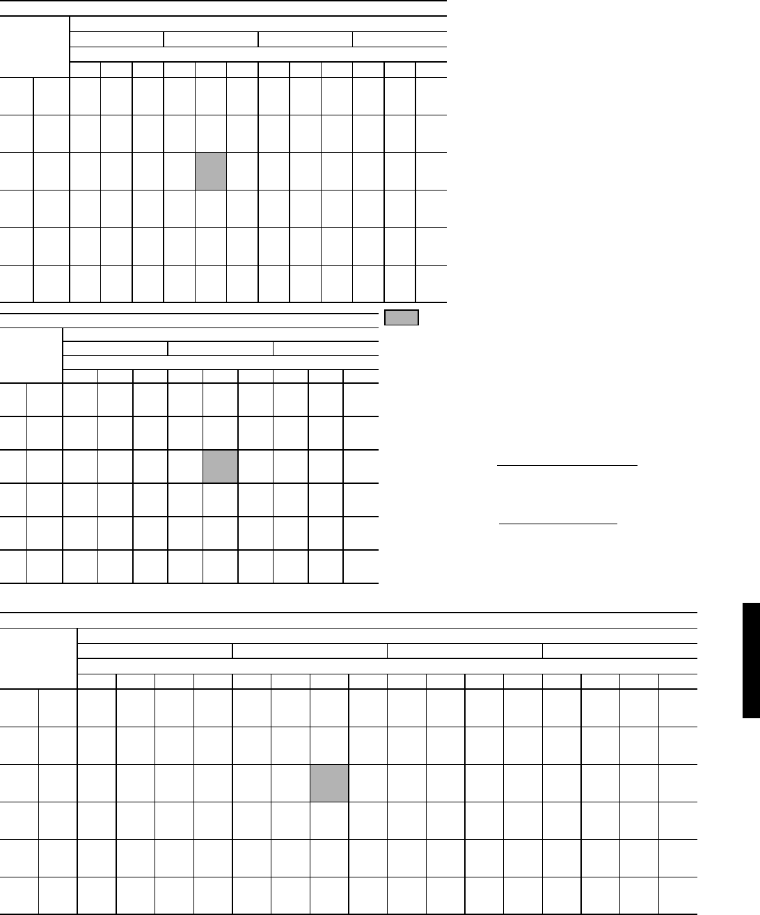
59
COOLING CAPACITIES — 48HJ007-009 STANDARD UNITS (cont)
Standard Ratings
LEGEND
NOTES:
1. Direct interpolation is permissible. Do not extrapolate.
2. The following formulas may be used:
Where: hewb = Enthalpy of air entering evaporator coil.
3. The SHC is based on 80 F edb temperature of air entering evapo-
rator coil.
Below 80 F edb, subtract (corr factor x cfm) from SHC.
Above 80 F edb, add (corr factor x cfm) to SHC.
Correction Factor = 1.10 x (1 – BF) x (edb – 80).
48HJ007 (6 TONS)
Temp (F)
Air Ent
Condenser
(Edb)
Air Entering Evaporator — Cfm/BF
1800/0.05 2100/0.06 2400/0.06 3000/0.08
Air Entering Evaporator — Ewb (F)
72 67 62 72 67 62 72 67 62 72 67 62
75 TC 86.7 80.7 74.4 88.8 82.7 76.6 90.5 84.4 78.2 92.6 86.3 81.0
SHC 43.0 53.7 63.8 45.0 57.4 68.9 47.2 61.2 73.6 51.2 67.4 80.7
kW 4.58 4.46 4.33 4.63 4.50 4.38 4.67 4.55 4.41 4.72 4.58 4.47
85 TC 84.1 78.2 72.0 86.4 80.3 74.1 88.2 81.7 75.7 90.2 84.0 78.8
SHC 42.0 52.6 62.7 44.5 56.6 68.0 46.8 60.2 72.5 50.6 67.4 78.7
kW 5.10 4.97 4.85 5.16 5.03 4.90 5.21 5.06 4.93 5.26 5.12 4.99
95 TC 81.3 75.3 69.2 83.4 77.3 71.3 85.1 78.9 72.9 87.2 80.6 76.2
SHC 41.0 51.4 61.4 43.4 55.3 66.6 45.8 59.2 71.2 50.2 65.8 76.2
kW 5.65 5.52 5.39 5.71 5.57 5.44 5.77 5.62 5.48 5.83 5.66 5.55
105 TC 77.9 72.0 66.1 80.0 73.8 68.0 81.6 75.3 69.6 83.4 77.1 73.2
SHC 39.7 50.2 60.0 42.2 54.0 65.2 44.6 57.8 69.3 49.0 64.5 73.2
kW 6.22 6.08 5.94 6.29 6.13 6.00 6.34 6.17 6.04 6.40 6.22 6.12
115 TC 74.7 68.4 61.8 75.9 70.0 64.1 77.6 71.3 66.5 78.7 73.0 70.1
SHC 38.7 48.8 58.1 40.8 52.6 63.2 43.3 56.4 66.4 46.9 63.2 70.0
kW 6.84 6.68 6.49 6.87 6.71 6.56 6.93 6.75 6.63 6.96 6.80 6.72
125 TC 70.3 63.6 57.2 71.8 65.5 59.1 72.9 66.8 61.9 74.0 68.6 66.4
SHC 37.2 47.0 55.8 39.5 51.0 59.1 41.7 55.0 61.9 45.4 61.8 66.3
kW 7.43 7.25 7.03 7.48 7.30 7.13 7.51 7.35 7.22 7.54 7.41 7.33
48HJ008 (71/2 TONS)
Temp (F)
Air Ent
Condenser
(Edb)
Air Entering Evaporator — Cfm/BF
2250/0.10 3000/0.11 3750/0.14
Air Entering Evaporator — Ewb (F)
72 67 62 72 67 62 72 67 62
75
TC 105.5 96.9 87.6 107.3 99.6 90.7 110.3 101.9 93.8
SHC 50.6 63.6 75.7 53.3 69.2 83.7 58.0 76.6 92.2
kW 5.15 5.07 5.04 5.16 5.11 5.06 5.20 5.13 5.07
85
TC 102.5 93.6 83.6 105.1 96.5 87.5 107.7 99.0 90.6
SHC 49.7 62.4 73.9 52.8 68.4 82.2 57.3 75.9 90.0
kW 5.86 5.79 5.73 5.89 5.82 5.77 5.93 5.86 5.78
95
TC 98.9 90.1 79.3 101.6 92.9 83.5 103.8 95.3 87.4
SHC 48.5 61.2 71.9 51.9 67.2 80.2 56.2 74.9 87.3
kW 6.65 6.58 6.49 6.69 6.61 6.53 6.72 6.64 6.57
105
TC 95.3 86.2 75.7 97.6 88.8 79.6 100.0 91.0 84.1
SHC 47.3 59.6 70.2 50.7 65.9 78.0 55.3 73.6 84.1
kW 7.51 7.44 7.31 7.55 7.48 7.36 7.59 7.50 7.41
115
TC 91.0 82.0 71.6 93.2 84.5 75.4 95.6 86.6 80.7
SHC 45.9 58.0 68.1 49.3 64.2 75.3 54.2 72.1 80.7
kW 8.43 8.33 8.20 8.46 8.37 8.27 8.52 8.42 8.34
125
TC 86.2 77.8 68.1 88.3 80.0 71.9 90.0 81.9 77.2
SHC 44.1 56.4 66.3 47.5 62.6 71.8 52.1 70.1 77.2
kW 9.38 9.29 9.14 9.43 9.34 9.24 9.47 9.38 9.32
BF — Bypass Factor
Edb — Entering Dry Bulb
Ewb — Entering Wet Bulb
kW — Compressor Motor Power Input
SHC — Sensible Heat Capacity (1000 Btuh) Gross
TC — Total Capacity (1000 Btuh) Gross
tldb =t
edb –sensible capacity (Btuh)
1.10 x cfm
tlwb = Wet-bulb temperature corresponding to enthalpy of air
leaving evaporator coil (hlwb)
hlwb =h
ewb –total capacity (Btuh)
4.5 x cfm
48HJ009 (81/2 TONS)
Temp (F)
Air Ent
Condenser
(Edb)
Air Entering Evaporator — Cfm/BF
2550/0.11 3000/0.12 3400/0.13 4250/0.17
Air Entering Evaporator — Ewb (F)
57 62 67 72 57 62 67 57 62 67 72 57 62 67 72 57
75
TC 94.6 101.0 110.0 119.2 100.4 104.4 113.4 121.8 104.2 106.8 115.8 123.4 109.8 111.0 119.0 125.8
SHC 94.6 84.4 69.4 54.4 100.4 92.4 75.0 57.2 104.2 99.0 80.0 59.8 109.8 110.4 89.4 64.2
kW 5.72 5.76 5.76 5.82 5.74 5.76 5.80 5.86 5.74 5.76 5.82 5.88 5.76 5.78 5.84 5.90
85
TC 91.0 97.4 106.8 115.8 97.4 101.0 110.0 119.6 101.2 103.0 112.0 121.6 108.0 108.0 116.0 123.4
SHC 91.0 83.0 68.8 53.2 97.4 91.2 74.2 57.0 101.2 97.6 78.8 59.6 108.0 108.0 89.4 64.2
kW 6.46 6.5 6.52 6.58 6.50 6.52 6.54 6.60 6.50 6.52 6.54 6.64 6.54 6.54 6.60 6.64
95
TC 85.2 91.4 103.0 112.8 93.4 96.6 106.2 116.0 98.2 99.2 108.4 117.8 104.6 104.6 111.6 121.2
SHC 85.2 80.4 67.2 52.6 93.4 89.4 73.0 55.8 98.2 96.2 78.2 58.8 104.6 104.6 88.0 64.6
kW 7.24 7.28 7.36 7.42 7.30 7.32 7.38 7.44 7.34 7.36 7.4 7.46 7.36 7.36 7.42 7.50
105
TC 80.0 82.2 98.6 108.6 87.0 87.8 101.6 111.8 93.4 93.6 103.8 114.0 101.0 100.8 106.8 116.6
SHC 80.0 76.6 65.6 51.2 87.0 85.6 71.6 54.8 93.4 93.2 76.6 57.8 101.0 100.8 86.8 63.6
kW 8.08 8.12 8.26 8.32 8.16 8.16 8.28 8.36 8.20 8.20 8.3 8.38 8.28 8.28 8.30 8.40
115
TC 73.6 74.6 89.4 103.4 81.0 81.2 95.2 106.4 86.2 86.2 98.4 108.4 96.4 96.4 101.6 111.8
SHC 73.6 73.0 62.2 49.6 81.0 81.2 69.4 53.0 86.2 86.2 75.0 56.4 96.4 96.4 85.4 62.8
kW 9.00 9.00 9.16 9.28 9.08 9.08 9.22 9.30 9.14 9.14 9.26 9.34 9.22 9.22 9.30 9.38
125
TC 68.6 68.6 80.2 98.2 74.4 74.4 84.0 101.0 79.2 79.2 86.8 102.8 88.0 88.0 93.8 105.6
SHC 68.6 68.6 59.0 48.0 74.4 74.4 65.4 51.6 79.2 79.2 71.0 54.6 88.0 88.0 82.8 61.0
kW 9.98 9.98 10.14 10.32 10.06 10.06 10.18 10.36 10.14 10.14 10.22 10.38 10.24 10.24 10.28 10.42
48HJ48HJ
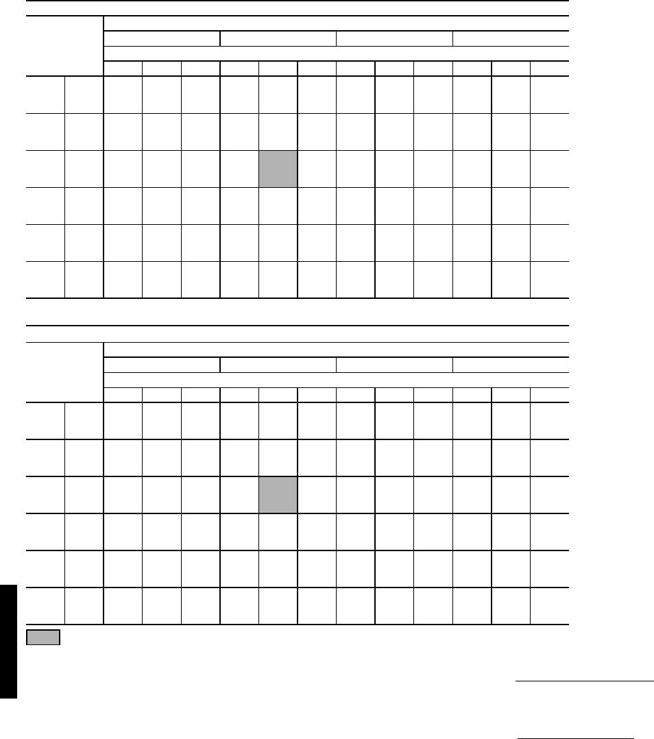
60
COOLING CAPACITIES — 48HJ012, 014 STANDARD UNITS (cont)
Standard Ratings
LEGEND
NOTES:
1. Direct interpolation is permissible. Do not extrapolate.
2. The following formulas may be used:
Where: hewb = Enthalpy of air entering evaporator coil.
3. The SHC is based on 80 F edb temperature of air entering evapo-
rator coil.
Below 80 F edb, subtract (corr factor x cfm) from SHC.
Above 80 F edb, add (corr factor x cfm) to SHC.
Correction Factor = 1.10 x (1 – BF) x (edb – 80).
48HJ012 (10 TONS)
Temp (F)
Air Ent
Condenser
(Edb)
Air Entering Evaporator — Cfm/BF
3000/0.03 3200/0.03 4000/0.04 5000/0.04
Air Entering Evaporator — Ewb (F)
72 67 62 72 67 62 72 67 62 72 67 62
75
TC 140.3 129.4 115.0 141.2 130.4 118.1 145.2 134.0 122.1 147.5 136.6 125.3
SHC 65.6 82.2 97.4 66.7 84.4 101.5 71.3 93.1 113.5 77.9 103.7 124.7
kW 7.35 7.21 7.12 7.37 7.23 7.13 7.46 7.31 7.17 7.51 7.37 7.22
85 TC 137.7 125.3 110.0 138.9 126.6 113.6 142.6 130.6 117.7 144.6 133.3 122.3
SHC 65.0 81.2 95.2 66.3 83.6 99.7 71.0 92.8 112.0 76.9 103.1 122.2
kW 8.29 8.13 8.02 8.32 8.16 8.03 8.40 8.24 8.09 8.45 8.31 8.16
95 TC 133.8 120.7 103.0 135.1 121.9 107.2 138.8 125.8 112.8 141.7 128.5 118.5
SHC 63.9 79.6 92.2 65.2 82.0 97.0 70.6 91.5 109.7 76.9 102.5 118.4
kW 9.33 9.16 8.98 9.35 9.18 9.00 9.44 9.27 9.07 9.51 9.33 9.19
105 TC 128.7 115.4 96.5 129.8 116.6 99.7 133.7 120.3 107.1 136.7 122.8 114.5
SHC 62.3 77.6 89.4 63.6 80.2 93.5 69.4 89.6 106.8 76.0 100.6 114.3
kW 10.46 10.28 10.00 10.47 10.30 10.07 10.57 10.38 10.21 10.66 10.43 10.31
115 TC 123.2 109.1 90.8 124.3 110.3 92.2 127.9 114.4 100.8 130.9 116.8 110.1
SHC 60.4 75.1 86.6 61.9 77.8 90.0 67.6 87.6 100.7 74.6 98.7 109.9
kW 11.66 11.47 11.20 11.68 11.51 11.25 11.77 11.60 11.41 11.89 11.66 11.58
125 TC 117.5 101.8 86.2 118.5 103.0 87.4 121.6 107.1 96.0 124.1 110.3 104.8
SHC 58.5 72.5 84.5 60.0 75.0 87.3 65.8 85.1 96.0 72.5 96.9 104.8
kW 12.99 12.77 12.50 13.02 12.81 12.55 13.10 12.92 12.74 13.19 13.01 12.91
48HJ014 (121/2 TONS)
Temp (F)
Air Ent
Condenser
(Edb)
Air Entering Evaporator — Cfm/BF
3750/0.08 4300/0.09 5000/0.11 6250/0.13
Air Entering Evaporator — Ewb (F)
72 67 62 72 67 62 72 67 62 72 67 62
75
TC 167.1 154.3 142.0 169.8 157.7 144.8 173.5 160.6 148.4 176.5 164.5 153.3
SHC 82.5 103.5 123.6 85.8 109.7 132.0 90.3 117.7 141.9 98.2 130.7 153.1
kW 9.44 9.18 8.95 9.50 9.26 9.01 9.60 9.33 9.07 9.68 9.43 9.17
85
TC 162.3 149.3 135.6 165.1 152.5 139.5 168.8 155.3 143.5 172.1 159.2 149.3
SHC 80.9 101.4 120.9 84.4 107.9 129.9 89.6 115.8 139.8 97.6 129.3 149.1
kW 10.49 10.18 9.97 10.55 10.27 10.02 10.67 10.32 10.11 10.75 10.43 10.21
95
TC 156.5 143.7 126.3 159.6 146.8 131.3 162.3 149.8 136.5 166.5 153.2 144.5
SHC 79.1 99.5 116.5 83.0 106.1 126.0 87.6 114.2 135.8 95.8 127.7 144.4
kW 11.60 11.30 11.01 11.69 11.39 11.10 11.75 11.47 11.20 11.87 11.56 11.35
105
TC 150.0 136.2 115.7 153.0 139.3 120.9 155.6 142.5 138.5 158.8 145.9 138.8
SHC 76.5 96.7 111.2 80.8 103.5 120.0 85.7 112.3 128.4 93.6 125.9 138.7
kW 12.76 12.42 12.09 12.83 12.52 12.20 12.91 12.62 12.32 12.96 12.72 12.52
115
TC 141.8 122.2 104.4 144.3 126.1 110.8 147.7 129.4 118.9 150.7 135.2 130.1
SHC 73.6 91.2 104.2 77.9 98.5 110.8 83.4 107.3 118.4 91.8 121.9 129.9
kW 13.85 13.55 13.22 13.94 13.64 13.35 14.05 13.73 13.50 14.15 13.86 13.70
125
TC 132.5 108.6 93.9 134.8 111.4 100.7 137.6 114.4 106.6 140.3 122.9 120.1
SHC 70.9 85.7 93.8 74.8 92.9 100.7 80.2 101.4 106.5 89.0 116.3 120.1
kW 15.04 14.66 14.44 15.14 14.75 14.55 15.23 14.85 14.72 15.29 14.94 14.84
BF — Bypass Factor
Edb — Entering Dry Bulb
Ewb — Entering Wet Bulb
kW — Compressor Motor Power Input
SHC — Sensible Heat Capacity (1000 Btuh) Gross
TC — Total Capacity (1000 Btuh) Gross
tldb =t
edb –sensible capacity (Btuh)
1.10 x cfm
tlwb = Wet-bulb temperature corresponding to enthalpy of air
leaving evaporator coil (hlwb)
hlwb =h
ewb –total capacity (Btuh)
4.5 x cfm
Performance data — 48HJ (cont)
48HJ48HJ

61
COOLING CAPACITIES — 48HJ015 STANDARD UNITS (cont)
LEGEND
NOTES:
1. Direct interpolation is permissible. Do not extrapolate.
2. The following formulas may be used:
tlwb = Wet-bulb temperature corresponding to enthalpy of air leaving evapo-
rator coil (hlwb)
Where: hewb = Enthalpy of air entering evaporator coil
3. The SHC is based on 80 F edb temperature of air entering evaporator coil.
Below 80 F edb, subtract (corr factor x cfm) from SHC.
Above 80 F edb, add (corr factor x cfm) to SHC.
Interpolation is permissible.
Correction Factor = 1.10 x (1 – BF) x (edb – 80).
4. Use chart below for bypass factor.
48HJ015 (12 Tons)
Temp (F)
Air Ent
Cond
Evap Air — Cfm/BF
3600/0.01 4375/0.01 5000/0.01
Evap Air — Ewb (F)
54 58 62 67 72 76 80 54 58 62 67 72 76 80 54 58 62 67 72 76 80
60
TC 152 156 161 174 189 201 213 161 164 167 180 195 207 218 169 171 172 184 199 211 222
SHC 152 144 135 114 92.9 75.4 57.5 161 156 150 125 99.6 78.7 57.5 169 166 162 134 105 81.3 57.4
kW 7.567.657.748.018.33 8.6 8.867.767.827.888.148.468.728.977.927.957.988.248.558.829.06
70
TC 148 152 156 169 183 195 206 157 160 162 174 189 200 211 165 166 167 179 193 204 214
SHC 148 141 133 112 90.6 73.2 55.4 157 153 148 123 97.3 76.5 55.3 165 162 160 132 103 79.1 55.3
kW 8.5 8.58 8.67 8.97 9.26 9.53 9.8 8.7 8.75 8.81 9.07 9.39 9.66 9.91 8.86 8.89 8.91 9.16 9.49 9.76 9.99
75
TC 146 150 154 166 181 192 204 155 158 160 172 186 197 208 163 164 164 176 189 201 212
SHC 146 139 132 111 89.7 72.2 54.6 155 151 146 122 96.2 75.5 54.6 163 161 158 131 101 78.1 54.5
kW 9.02 9.1 9.18 9.45 9.8 10.1 10.4 9.22 9.27 9.31 9.58 9.91 10.2 10.5 9.39 9.41 9.43 9.68 9.99 10.3 10.6
85
TC 142 145 149 161 175 186 196 151 153 154 166 179 190 200 158 159 159 170 183 194 203
SHC 142 136 129 109 87.4 70 52.4 151 147 144 119 93.9 73.2 52.3 158 157 155 128 99.1 75.8 52.2
kW 10.1 10.2 10.3 10.6 10.9 11.2 11.5 10.3 10.4 10.4 10.7 11 11.3 11.6 10.5 10.5 10.5 10.8 11.1 11.4 11.7
95
TC 138 141 143 155 168 179 189 147 148 149 160 173 183 192 153 153 154 164 177 187 195
SHC 138 133 127 106 85 67.7 50.1 147 144 141 117 91.6 70.9 50 153 153 152 126 96.9 73.5 49.9
kW 11.4 11.4 11.5 11.8 12.2 12.4 12.7 11.6 11.6 11.6 11.9 12.3 12.6 12.8 11.8 11.8 11.8 12 12.4 12.7 12.9
105
TC 134 136 138 149 162 172 181 141 142 143 153 166 176 184 148 148 148 157 169 179 186
SHC 134 129 124 104 82.4 65.3 47.7 141 139 137 114 89 68.4 47.5 148 148 148 123 94.3 70.9 47.4
kW 12.7 12.8 12.8 13.2 13.5 13.8 14.1 12.9 13 13 13.3 13.6 13.9 14.2 13.1 13.1 13.1 13.4 13.7 14 14.3
115
TC 129 130 132 143 155 164 172 136 137 138 146 158 168 175 142 142 142 149 161 171 177
SHC 129 125 121 101 79.8 62.7 45.1 136 135 133 111 86.3 65.9 45 142 142 142 120 91.6 68.4 45
kW 14.2 14.2 14.3 14.6 15 15.3 15.6 14.4 14.4 14.5 14.7 15.1 15.5 15.7 14.6 14.6 14.6 14.8 15.2 15.6 15.7
125
TC 124 125 126 136 147 156 163 131 131 132 140 150 159 165 136 136 136 142 153 162 167
SHC 124 121 118 98.2 77 60.1 42.5 131 130 128 109 83.5 63.2 42.5 136 136 136 117 88.7 65.7 42.4
kW 15.8 15.8 15.9 16.2 16.6 17 17.2 16.1 16.1 16.1 16.4 16.7 17.1 17.3 16.3 16.2 16.2 16.4 16.8 17.2 17.4
48HJ015 (12 Tons) (cont)
Temp (F)
Air Ent
Cond
Evap Air — Cfm/BF
5625/0.02 6250/0.02
Evap Air — Ewb (F)
54 58 62 67 72 76 80 54 58 62 67 72 76 80
60
TC 175 175 176 187 202 214 224 180 180 180 190 204 216 226
SHC 175 173 171 142 110 83.8 57.3 180 180 180 151 115 86.2 57.2
kW 8.03 8.05 8.07 8.3 8.61 8.87 9.1 8.14 8.15 8.16 8.36 8.66 8.93 9.14
70
TC 170 171 171 181 195 207 216 175 176 176 184 198 209 218
SHC 170 169 168 140 108 81.5 55.2 175 176 176 148 113 84 55.1
kW 8.98 8.99 9.01 9.23 9.55 9.81 10 9.09 9.1 9.11 9.3 9.61 9.87 10.1
75
TC 168 168 169 179 192 203 213 173 173 173 181 195 206 215
SHC 168 167 166 139 107 80.5 54.4 173 173 173 147 112 83 54.3
kW 9.5 9.51 9.52 9.75 10.1 10.3 10.6 9.62 9.62 9.62 9.81 10.1 10.4 10.6
85
TC 163 163 164 172 185 196 205 168 168 168 175 188 198 206
SHC 163 162 162 136 104 78.2 52.2 168 168 168 145 109 80.6 52.1
kW 10.6 10.6 10.6 10.9 11.2 11.5 11.7 10.7 10.7 10.8 10.9 11.2 11.5 11.8
95
TC 158 158 158 166 178 189 196 162 162 162 168 180 190 197
SHC 158 157 157 134 102 75.9 49.8 162 162 162 142 107 78.3 49.7
kW 11.9 11.9 11.9 12.1 12.4 12.7 12.9 12 12 12 12.1 12.5 12.8 13
105
TC 152 152 152 159 171 181 187 157 157 157 161 173 182 188
SHC 152 152 152 131 99.3 73.3 47.4 157 157 157 139 104 75.7 47.4
kW 13.2 13.2 13.2 13.4 13.8 14.1 14.3 13.4 13.4 13.4 13.5 13.9 14.2 14.4
115
TC 146 146 146 151 163 172 177 150 150 150 153 165 174 178
SHC 146 146 146 128 96.6 70.7 44.9 150 150 150 136 102 73.1 44.8
kW 14.7 14.7 14.7 14.9 15.3 15.6 15.8 14.9 14.9 14.9 14.9 15.4 15.7 15.8
125
TC 140 140 140 144 155 163 167 144 144 144 146 156 164 168
SHC 140 140 140 125 93.7 67.9 42.4 144 144 144 133 98.7 70.2 42.3
kW 16.4 16.4 16.4 16.5 16.9 17.2 17.4 16.5 16.5 16.5 16.6 17 17.3 17.4
BF — Bypass Factor
Edb — Entering Dry-Bulb
Ewb — Entering Wet-Bulb
kW — Compressor Motor Power Input
ldb — Leaving Dry-Bulb
lwb — Leaving Wet-Bulb
SHC — Sensible Heat Capacity (1000 Btuh) Gross
TC — Total Capacity (1000 Btuh) Gross
tldb = tedb – sensible capacity (Btuh)
1.10 x cfm
hlwb = hewb – total capacity (Btuh)
4.5 x cfm
BYPASS
FACTOR
(BF)
ENTERING AIR DRY-BULB TEMP (F)
79 78 77 76 75 under 75
81 82 83 84 85 over 85
Correction Factor
.05 1.04 2.07 3.11 4.14 5.18
Use formula
shown below.
.10 .98 1.96 2.94 3.92 4.90
.20 .87 1.74 2.62 3.49 4.36
.30 .76 1.53 2.29 3.05 3.82
CFM
ENTERING WET-BULB (F)
54 58 62 67 72 76 80
Bypass Factor
3600 0.355 0.158 0.054 0.038 0.049 0.000 0.000
4375 0.439 0.255 0.112 0.043 0.057 0.000 0.000
5000 0.486 0.314 0.126 0.054 0.037 0.000 0.000
5625 0.525 0.360 0.174 0.066 0.073 0.000 0.000
6250 0.551 0.410 0.202 0.080 0.079 0.000 0.000
48HJ48HJ
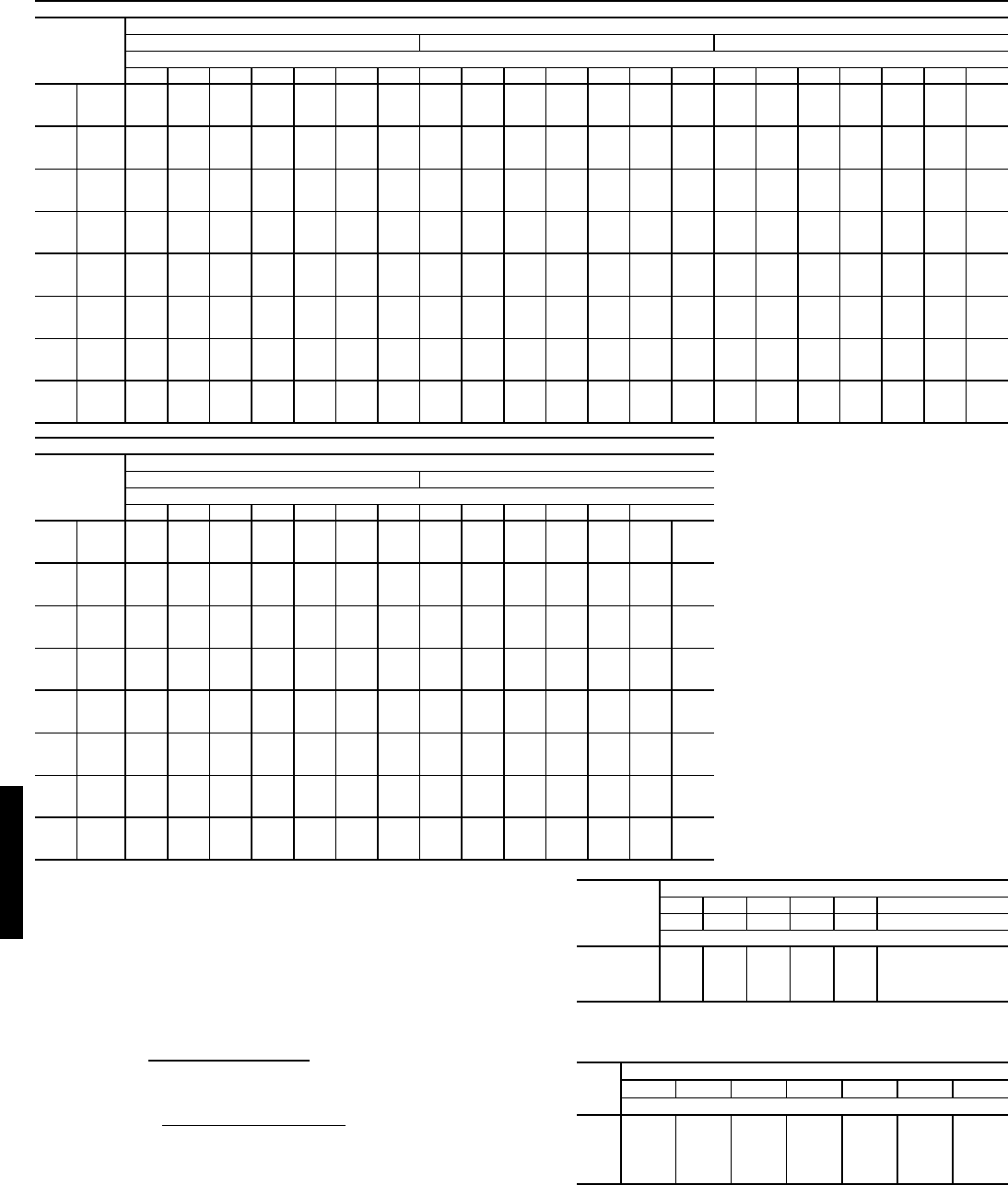
62
COOLING CAPACITIES — 48HJ017 STANDARD UNITS (cont)
LEGEND
NOTES:
1. Direct interpolation is permissible. Do not extrapolate.
2. The following formulas may be used:
tlwb = Wet-bulb temperature corresponding to enthalpy of air leaving evapo-
rator coil (hlwb)
Where: hewb = Enthalpy of air entering evaporator coil
3. The SHC is based on 80 F edb temperature of air entering evaporator coil.
Below 80 F edb, subtract (corr factor x cfm) from SHC.
Above 80 F edb, add (corr factor x cfm) to SHC.
Interpolation is permissible.
Correction Factor = 1.10 x (1 – BF) x (edb – 80).
4. Use chart below for bypass factor.
48HJ017 (15 Tons)
Temp (F)
Air Ent
Cond
Evap Air — Cfm/BF
4500/0.01 5250/0.01 6000/0.01
Evap Air — Ewb (F)
54 58 62 67 72 76 80 54 58 62 67 72 76 80 54 58 62 67 72 76 80
60
TC 180.5 184.6 188.7 203.5 219.9 233.7 247 189.3 191.7 194.2 208.7 224.1 238 251 198.1 198.8 199.6 212.9 229.3 242 255
SHC 180.5 172.4 159.4 132.3 104.7 87.9 65.7 189.3 183.2 173.2 142.8 110.4 91 65.5 198.1 195.1 185.1 153.1 116.7 94 65.4
kW 9.41 9.49 9.58 9.87 10.19 10.47 10.78 9.58 9.63 9.68 9.97 10.29 10.57 10.87 9.75 9.77 9.79 10.07 10.39 10.67 10.95
70
TC 176.7 180.5 184.4 199 215.1 227.8 242 185.3 187.5 189.8 203 219.2 231.8 245 193 194.5 195.1 208.1 224.3 237 248
SHC 176.7 169 155.8 129.4 102.4 86 63.9 185.3 179.7 169.3 138.9 108 89.1 63.8 193 191.4 181 149.7 114.2 92.2 63.7
kW 10.5 10.57 10.64 10.96 11.35 11.62 11.95 10.68 10.72 10.76 11.06 11.45 11.72 12.04 10.85 10.87 10.89 11.17 11.55 11.82 12.13
75
TC 174.7 177.5 181 196 213 224.2 238 182.3 184.4 186 201 217 229.2 242 190.9 191.3 189 204 219 233.1 246
SHC 174.7 167.2 147 124 99 84.9 62.9 182.3 177.9 160 133 105 88 62.8 190.9 189.5 173 143 113 91 62.7
kW 11.07 11.14 11.2 11.6 12 12.23 12.57 11.25 11.3 11.3 11.7 12.1 12.33 12.66 11.45 11.45 11.4 11.8 12.1 12.44 12.75
85
TC 169.6 172.2 175 190 205 218.1 230.8 177.2 179 180 194 209 221.9 233.3 185.6 185.9 183 198 212 225.7 237
SHC 169.6 163.3 145 121 97 82.5 60.7 177.2 174.1 157 130 102 85.6 60.5 185.6 184.7 168 139 106 88.6 60.4
kW 12.29 12.35 12.3 12.7 13.1 13.5 13.86 12.47 12.51 12.5 12.8 13.2 13.61 13.96 12.67 12.68 12.6 12.9 13.3 13.71 14.05
95
TC 164.3 166.5 168 182 197 209.8 221.2 171.7 172.6 172 187 201 213.4 224.6 179.1 179.3 176 190 203 217.1 228
SHC 164.3 158.9 142 118 93 79.8 57.9 171.7 168.8 154 127 98 82.8 57.9 179.1 178.7 164 136 102 86 57.8
kW 13.59 13.65 13.5 13.9 14.3 14.85 15.23 13.8 13.82 13.6 14 14.4 14.96 15.32 14 14 13.8 14.1 14.5 15.07 15.43
105
TC 158.1 159.8 161 174 188 200.3 212.4 165.2 166 165 178 191 203.8 214.6 172.3 172.3 169 181 193 207.3 216.8
SHC 158.1 154.2 138 115 91 76.8 55.2 165.2 163.1 150 124 95 79.9 55.1 172.3 172.2 158 132 98 83 54.9
kW 14.97 15.02 14.8 15.2 15.6 16.28 16.69 15.19 15.21 14.9 15.3 15.7 16.39 16.77 15.41 15.4 15.1 15.4 15.7 16.5 16.86
115
TC 151.8 152.8 152 165 179 190.6 201.3 158.4 158.8 157 168 180 194 204.5 165 164.9 161 171 181 197.3 206.6
SHC 151.8 149.1 134 111 87 73.7 52.1 158.4 157 145 120 91 76.7 52.1 165 164.9 151 128 94 79.8 51.9
kW 16.45 16.48 16.1 16.5 16.9 17.79 18.21 16.68 16.68 16.2 16.6 17 17.91 18.3 16.89 16.88 16.4 16.7 17 18.01 18.39
125
TC 144.7 145.4 146 157.1 170.5 180.7 191.1 150.8 151.1 151.5 160.2 172.9 183.9 192 156.8 156.9 157 163.2 175.4 186.2 193.9
SHC 144.7 143.5 123.4 102.2 81.16 70.4 48.9 150.8 150.2 135.2 109.6 85.15 73.4 48.8 156.8 156.9 145.6 117.4 89.3 76.4 48.7
kW 17.96 18.01 18.05 18.49 18.99 19.44 19.85 18.18 18.22 18.25 18.6 19.11 19.5 19.89 18.42 18.44 18.46 18.72 19.14 19.65 19.93
48HJ017 (15 Tons) (cont)
Temp (F)
Air Ent
Cond
Evap Air — Cfm/BF
6750/0.01 7500/0.02
Evap Air — Ewb (F)
54 58 62 67 72 76 80 54 58 62 67 72 76 80
60
TC 203.8 204.2 204.6 216.3 231.7 244 257 209.5 209.5 209.6 218.8 235 248 259
SHC 203.8 201.8 191.2 164.1 124.1 97 65.4 209.5 209.5 196.6 173.7 138.1 100 65.2
kW 9.88 9.88 9.89 10.13 10.45 10.72 11 9.99 9.99 9.99 10.19 10.51 10.78 11.05
70
TC 199.6 199.8 200.1 210.5 226.5 239 250 205.2 205.1 205.1 213.8 228.8 241 252
SHC 199.6 197.8 187 159.7 121.3 95.2 63.5 205.2 205.1 192.4 169.8 134.5 98.2 63.5
kW 10.99 10.99 11 11.24 11.6 11.88 12.18 11.12 11.11 11.11 11.31 11.65 11.94 12.22
75
TC 196.4 196.6 194 206 220 235 247 201.9 201.9 198 208 223 237 249
SHC 196.4 195.7 181 153 120 94 62.5 201.9 201.9 186 163 163 97.1 62.5
kW 11.58 11.58 11.6 11.9 12.2 12.5 12.8 11.71 11.7 11.7 11.9 11.9 12.56 12.84
85
TC 191 191.1 188 200 213 227.8 239 196.4 196.4 192 202 214 229.8 241
SHC 191 190.5 175 148 115 91.6 60.2 196.4 196.4 180 157 119 94.6 60.2
kW 12.81 12.81 12.7 13 13.3 13.77 14.1 12.96 12.95 12.8 13.1 13.4 13.84 14.13
95
TC 184.4 184.5 181 192 205 219.1 229.7 189.7 189.7 185 194 206 221.1 230.5
SHC 184.4 184.2 170 144 108 88.9 57.7 189.7 189.7 174 153 113 91.9 57.6
kW 14.15 14.15 13.9 14.2 14.6 15.14 15.47 14.29 14.29 14 14.3 14.6 15.2 15.51
105
TC 176.7 176.7 173 182 194 209.2 218.5 181.9 181.9 177 184 194 211.1 220.1
SHC 176.7 176.7 162 140 103 86 54.9 181.9 181.9 166 148 107 88.9 54.7
kW 15.55 15.55 15.2 15.5 15.8 16.57 16.9 15.7 15.7 15.3 15.5 15.8 16.64 16.94
115
TC 169.5 169.4 166 172 183 198.2 207.1 173.9 173.8 169 174 183 200 208.6
SHC 169.5 169.4 155 136 98 82.7 51.8 173.9 173.8 158 142 101 85.6 51.7
kW 17.05 17.04 16.6 16.8 17.1 18.08 18.42 17.2 17.2 16.7 16.9 17.1 18.15 18.45
125
TC 160.9 161.1 161.2 165.6 177.4 187.9 195.4 165.1 165.2 165.4 167.8 179.2 188.6 196
SHC 160.9 161.1 150.7 125.6 95.04 79.4 48.7 165.1 165.2 155.2 133.2 105.3 82.3 48.6
kW 18.57 18.59 18.62 18.81 19.18 19.68 20.06 18.72 18.75 18.78 18.91 19.33 19.71 20.09
BF — Bypass Factor
Edb — Entering Dry-Bulb
Ewb — Entering Wet-Bulb
kW — Compressor Motor Power Input
ldb — Leaving Dry-Bulb
lwb — Leaving Wet-Bulb
SHC — Sensible Heat Capacity (1000 Btuh) Gross
TC — Total Capacity (1000 Btuh) Gross
tldb = tedb – sensible capacity (Btuh)
1.10 x cfm
hlwb = hewb – total capacity (Btuh)
4.5 x cfm
BYPASS
FACTOR
(BF)
ENTERING AIR DRY-BULB TEMP (F)
79 78 77 76 75 under 75
81 82 83 84 85 over 85
Correction Factor
.05 1.04 2.07 3.11 4.14 5.18
Use formula
shown below.
.10 .98 1.96 2.94 3.92 4.90
.20 .87 1.74 2.62 3.49 4.36
.30 .76 1.53 2.29 3.05 3.82
CFM
ENTERING WET-BULB (F)
54 58 62 67 72 76 80
Bypass Factor
4500 0.396 0.193 0.054 0.053 0.067 0.000 0.000
5250 0.455 0.272 0.077 0.065 0.077 0.000 0.000
6000 0.504 0.337 0.121 0.077 0.088 0.000 0.000
6750 0.544 0.390 0.193 0.094 0.100 0.000 0.000
7500 0.578 0.436 0.244 0.108 0.114 0.000 0.000
Performance data — 48HJ (cont)
48HJ48HJ

63
COOLING CAPACITIES — 48HJ020 STANDARD UNITS (cont)
LEGEND
NOTES:
1. Direct interpolation is permissible. Do not extrapolate.
2. The following formulas may be used:
tlwb = Wet-bulb temperature corresponding to enthalpy of air leaving evapo-
rator coil (hlwb)
Where: hewb = Enthalpy of air entering evaporator coil
3. The SHC is based on 80 F edb temperature of air entering evaporator coil.
Below 80 F edb, subtract (corr factor x cfm) from SHC.
Above 80 F edb, add (corr factor x cfm) to SHC.
Interpolation is permissible.
Correction Factor = 1.10 x (1 – BF) x (edb – 80).
4. Use chart below for bypass factor.
48HJ020 (18 Tons)
Temp (F)
Air Ent
Cond
Evap Air — Cfm/BF
5400/0.05 6300/0.06 7200/0.07
Evap Air — Ewb (F)
54 58 62 67 72 76 80 54 58 62 67 72 76 80 54 58 62 67 72 76 80
60
TC 202 206 211 229 248 263 279 212 215 218 235 254 269 285 220 221 223 239 259 273 289
SHC 202 193 184 155 124 99.3 74.7 212 205 199 166 131 103 74.9 220 216 213 177 138 106 75
kW 10.2 10.3 10.4 10.6 10.8 11 11.2 10.4 10.4 10.4 10.7 10.9 11.1 11.3 10.5 10.5 10.5 10.7 11 11.2 11.4
70
TC 197 202 206 223 242 256 272 207 209 212 228 247 262 277 215 216 217 233 252 267 282
SHC 197 189 181 152 122 97 72.5 207 202 196 163 129 101 72.7 215 212 210 174 135 104 72.8
kW 11.4 11.5 11.5 11.8 12 12.2 12.5 11.6 11.6 11.6 11.9 12.1 12.3 12.6 11.7 11.7 11.7 11.9 12.2 12.4 12.6
75
TC 195 199 203 219 238 253 268 204 206 209 225 244 258 273 212 213 214 229 248 263 277
SHC 195 187 180 150 120 95.8 71.3 204 199 195 162 127 99.3 71.4 212 210 208 173 134 103 71.5
kW 12.1 12.2 12.2 12.5 12.7 13 13.2 12.3 12.3 12.3 12.6 12.8 13 13.3 12.4 12.4 12.4 12.6 12.9 13.1 13.3
85
TC 190 193 196 213 231 246 260 199 201 202 218 236 251 264 206 207 208 222 240 255 268
SHC 190 183 177 148 118 93.4 68.8 199 195 191 159 125 96.9 68.9 206 205 204 170 131 100 69
kW 13.5 13.5 13.6 13.8 14.1 14.4 14.6 13.6 13.7 13.7 13.9 14.2 14.5 14.7 13.7 13.8 13.8 14 14.3 14.5 14.8
95
TC 184 187 190 205 222 236 250 193 194 195 210 227 241 254 200 200 201 214 231 245 258
SHC 184 179 173 144 114 90.2 65.9 193 190 187 156 121 93.7 66.1 200 199 199 167 128 97.1 66.2
kW 15 15 15.1 15.4 15.7 15.9 16.2 15.1 15.2 15.2 15.5 15.8 16 16.3 15.3 15.3 15.3 15.5 15.8 16.1 16.3
105
TC 178 180 182 197 213 228 240 186 187 188 201 217 232 244 193 193 193 205 221 235 247
SHC 178 173 169 141 111 87.3 62.9 186 184 183 152 118 90.8 63.1 193 193 193 163 124 94.1 63.2
kW 16.6 16.7 16.7 17 17.3 17.7 17.9 16.8 16.8 16.8 17.1 17.4 17.8 18 16.9 16.9 16.9 17.2 17.5 17.8 18
115
TC 171 172 174 188 203 217 228 179 179 179 192 207 221 232 185 185 185 195 210 224 235
SHC 171 168 165 137 107 83.6 59.6 179 178 178 149 114 87.1 59.7 185 185 185 159 121 90.4 59.9
kW 18.4 18.4 18.4 18.8 19.1 19.4 19.7 18.6 18.6 18.6 18.9 19.2 19.5 19.8 18.7 18.7 18.7 19 19.3 19.6 19.9
125
TC 164 165 165 178 192 205 216 171 171 171 182 196 208 219 177 177 177 185 199 211 222
SHC 164 162 160 134 104 79.8 56.1 171 171 171 145 110 83.2 56.3 177 177 177 155 117 86.5 56.4
kW 20.2 20.3 20.3 20.6 21 21.3 21.6 20.4 20.4 20.4 20.8 21.1 21.4 21.7 20.6 20.6 20.6 20.8 21.2 21.5 21.8
48HJ020 (18 Tons) (cont)
Temp (F)
Air Ent
Cond
Evap Air — Cfm/BF
8100/0.08 9000/0.09
Evap Air — Ewb (F)
54 58 62 67 72 76 80 54 58 62 67 72 76 80
60
TC 227 227 228 243 262 277 293 233 233 233 246 265 280 295
SHC 227 226 224 187 144 109 75.1 233 233 233 198 151 113 75.1
kW 10.5 10.6 10.6 10.7 11 11.2 11.4 10.6 10.6 10.6 10.8 11 11.3 11.5
70
TC 222 222 222 236 255 271 284 228 228 227 239 258 272 287
SHC 222 221 221 185 142 107 72.8 228 228 227 195 148 110 72.9
kW 11.8 11.8 11.8 12 12.2 12.5 12.7 11.9 11.9 11.8 12 12.3 12.5 12.7
75
TC 219 219 219 232 251 266 280 225 224 224 235 254 268 282
SHC 219 218 218 183 140 106 71.6 225 224 224 193 147 109 71.7
kW 12.5 12.5 12.5 12.7 12.9 13.2 13.4 12.6 12.5 12.5 12.7 13 13.2 13.4
85
TC 213 213 213 225 243 258 271 218 218 218 228 245 260 273
SHC 213 213 213 180 138 103 69.1 218 218 218 190 144 107 69.2
kW 13.8 13.8 13.8 14.1 14.3 14.6 14.8 13.9 13.9 13.9 14.1 14.4 14.6 14.8
95
TC 206 206 206 217 234 248 260 211 211 211 220 236 250 262
SHC 206 206 206 177 134 100 66.3 211 211 211 187 141 103 66.4
kW 15.4 15.4 15.4 15.6 15.9 16.1 16.4 15.5 15.5 15.5 15.6 15.9 16.2 16.4
105
TC 199 199 199 208 224 238 249 203 203 204 210 226 240 251
SHC 199 199 199 173 131 97.2 63.2 203 203 204 183 137 100 63.4
kW 17 17.1 17.1 17.3 17.6 17.9 18.1 17.2 17.2 17.2 17.3 17.6 17.9 18.1
115
TC 191 191 191 198 213 226 237 195 195 195 201 215 228 238
SHC 191 191 191 169 127 93.5 60 195 195 195 179 133 96.6 60
kW 18.8 18.8 18.8 19 19.3 19.7 19.9 18.9 18.9 18.9 19.1 19.4 19.7 19.9
125
TC 182 182 182 188 201 213 224 186 186 186 190 203 215 225
SHC 182 182 182 165 123 89.6 56.5 186 186 186 174 129 92.6 56.6
kW 20.7 20.7 20.7 20.9 21.2 21.6 21.9 20.9 20.9 20.9 21 21.3 21.6 21.9
BF — Bypass Factor
Edb — Entering Dry-Bulb
Ewb — Entering Wet-Bulb
kW — Compressor Motor Power Input
ldb — Leaving Dry-Bulb
lwb — Leaving Wet-Bulb
SHC — Sensible Heat Capacity (1000 Btuh) Gross
TC — Total Capacity (1000 Btuh) Gross
tldb = tedb – sensible capacity (Btuh)
1.10 x cfm
hlwb = hewb – total capacity (Btuh)
4.5 x cfm
BYPASS
FACTOR
(BF)
ENTERING AIR DRY-BULB TEMP (F)
79 78 77 76 75 under 75
81 82 83 84 85 over 85
Correction Factor
.05 1.04 2.07 3.11 4.14 5.18
Use formula
shown below.
.10 .98 1.96 2.94 3.92 4.90
.20 .87 1.74 2.62 3.49 4.36
.30 .76 1.53 2.29 3.05 3.82
CFM
ENTERING WET-BULB (F)
54 58 62 67 72 76 80
Bypass Factor
5400 0.424 0.238 0.125 0.120 0.138 0.000 0.000
6300 0.478 0.304 0.153 0.132 0.145 0.000 0.000
7200 0.525 0.364 0.190 0.144 0.153 0.000 0.000
8100 0.562 0.414 0.231 0.156 0.162 0.000 0.000
9000 0.594 0.456 0.281 0.168 0.170 0.000 0.000
48HJ48HJ

64
COOLING CAPACITIES — 48HJ024 STANDARD UNITS (cont)
LEGEND
NOTES:
1. Direct interpolation is permissible. Do not extrapolate.
2. The following formulas may be used:
tlwb = Wet-bulb temperature corresponding to enthalpy of air leaving evapo-
rator coil (hlwb)
Where: hewb = Enthalpy of air entering evaporator coil
3. The SHC is based on 80 F edb temperature of air entering evaporator coil.
Below 80 F edb, subtract (corr factor x cfm) from SHC.
Above 80 F edb, add (corr factor x cfm) to SHC.
Interpolation is permissible.
Correction Factor = 1.10 x (1 – BF) x (edb – 80).
4. Use chart below for bypass factor.
48HJ024 (20 Tons)
Temp (F)
Air Ent
Cond
Evap Air — Cfm/BF
6,000/0.04 7,000/0.05 8,000/0.05
Evap Air — Ewb (F)
54 58 62 67 72 76 80 54 58 62 67 72 76 80 54 58 62 67 72 76 80
60
TC 235 242 248 267 288 306 323 247 251 256 274 296 312 330 257 259 262 279 300 317 333
SHC 235 224 212 178 143 115 86.6 247 238 230 191 151 119 87 257 251 246 204 159 123 86.7
kW 11.5 11.6 11.7 12 12.4 12.7 13 11.7 11.8 11.8 12.1 12.5 12.8 13.1 11.9 11.9 11.9 12.2 12.6 12.9 13.1
70
TC 231 237 242 261 282 300 316 242 246 250 268 289 305 323 252 254 256 273 293 310 326
SHC 231 220 209 175 141 113 84.5 242 234 227 189 149 117 84.9 252 247 243 201 156 120 84.6
kW 13.1 13.2 13.3 13.6 14 14.3 14.6 13.3 13.3 13.4 13.7 14.1 14.4 14.8 13.4 13.5 13.5 13.8 14.2 14.5 14.8
75
TC 228 234 239 257 278 295 311 239 243 246 264 285 301 318 249 250 252 269 290 305 322
SHC 228 218 208 174 139 112 83.1 239 232 225 187 147 115 83.6 249 245 241 199 155 119 83.5
kW 13.9 14 14.1 14.5 14.9 15.2 15.6 14.1 14.2 14.2 14.6 15 15.3 15.7 14.3 14.3 14.4 14.7 15.1 15.4 15.8
85
TC 223 227 231 250 270 287 303 234 236 238 256 277 292 310 243 244 245 261 282 296 314
SHC 223 213 204 171 136 109 80.5 234 227 221 184 144 112 80.9 243 240 236 196 152 116 81.3
kW 15.6 15.7 15.8 16.2 16.6 17.1 17.4 15.8 15.9 15.9 16.3 16.8 17.2 17.6 16 16.1 16.1 16.5 16.9 17.3 17.7
95
TC 216 219 223 241 260 277 292 226 228 230 247 267 282 298 235 235 236 251 272 285 303
SHC 216 208 200 167 132 105 77.2 226 221 217 180 141 109 77.7 235 233 231 192 148 112 78
kW 17.4 17.5 17.6 18.1 18.6 19 19.4 17.7 17.7 17.8 18.2 18.7 19.1 19.6 17.9 17.9 17.9 18.3 18.9 19.2 19.7
105
TC 208 211 214 231 249 265 279 218 219 220 236 256 270 285 226 226 226 241 260 273 290
SHC 208 202 195 163 129 101 73.6 218 215 212 176 137 105 74 226 226 225 188 145 108 74.4
kW 19.3 19.4 19.5 20 20.6 21 21.5 19.6 19.6 19.7 20.2 20.8 21.2 21.6 19.9 19.9 19.9 20.3 20.9 21.3 21.8
115
TC 200 202 204 220 237 253 266 209 210 210 225 243 257 271 217 217 217 229 248 260 275
SHC 200 195 190 158 124 97.2 69.5 209 207 206 171 132 101 70 217 217 217 183 140 104 70.4
kW 21.3 21.4 21.5 22 22.7 23.2 23.6 21.7 21.7 21.7 22.2 22.9 23.3 23.8 21.9 21.9 21.9 22.4 23 23.4 23.9
125
TC 191 192 193 208 224 239 251 199 199 200 212 230 243 255 207 207 206 216 232 245 257
SHC 191 188 185 153 120 92.8 65.3 199 199 199 166 128 96.4 65.7 207 207 206 178 135 99.8 65.5
kW 23.5 23.5 23.6 24.2 24.8 25.4 25.9 23.8 23.8 23.8 24.4 25 25.5 26 24.1 24.1 24.1 24.5 25.1 25.7 26.1
48HJ024 (20 Tons) (cont)
Temp (F)
Air Ent
Cond
Evap Air — Cfm/BF
9,000/0.06 10,000/0.07
Evap Air — Ewb (F)
54 58 62 67 72 76 80 54 58 62 67 72 76 80
60
TC 265 266 267 284 305 321 338 272 272 272 287 307 325 340
SHC 265 262 260 216 166 126 87 272 271 271 227 173 130 86.7
kW 12 12 12 12.3 12.7 12.9 13.2 12.1 12.1 12.1 12.4 12.7 13 13.3
70
TC 260 261 261 277 298 315 331 266 267 267 281 301 317 333
SHC 260 258 256 213 164 124 85 266 267 267 225 171 127 84.7
kW 13.6 13.6 13.6 13.9 14.3 14.6 14.9 13.7 13.7 13.7 14 14.3 14.6 15
75
TC 256 257 258 273 294 310 326 263 263 263 277 296 312 327
SHC 256 255 254 211 162 123 83.7 263 263 263 223 169 126 83.4
kW 14.5 14.5 14.5 14.8 15.2 15.5 15.8 14.6 14.6 14.6 14.9 15.2 15.6 15.9
85
TC 250 250 250 265 285 301 316 257 256 256 268 287 303 317
SHC 250 250 249 208 159 120 81 257 256 256 220 166 123 80.7
kW 16.2 16.2 16.2 16.5 17 17.4 17.7 16.4 16.4 16.4 16.6 17 17.4 17.7
95
TC 242 242 242 255 274 288 304 248 248 248 258 276 292 306
SHC 242 242 242 204 155 116 77.8 248 248 248 215 162 120 77.6
kW 18.1 18.1 18.1 18.4 18.9 19.3 19.7 18.3 18.3 18.2 18.5 19 19.4 19.7
105
TC 233 233 233 244 263 275 291 239 239 239 247 264 279 291
SHC 233 233 233 200 152 112 74.2 239 239 239 211 158 116 73.9
kW 20.1 20.1 20.1 20.4 21 21.4 21.8 20.3 20.2 20.2 20.5 21 21.5 21.8
115
TC 223 223 223 232 250 262 276 229 228 228 235 251 263 276
SHC 223 223 223 195 147 108 70.2 229 228 228 206 154 111 69.9
kW 22.2 22.1 22.1 22.5 23.1 23.5 24 22.3 22.3 22.3 22.6 23.1 23.6 24
125
TC 213 212 212 219 234 247 258 218 217 217 222 235 248 259
SHC 213 212 212 189 142 103 65.4 218 217 217 200 148 106 65.2
kW 24.3 24.3 24.3 24.6 25.2 25.7 26.2 24.5 24.5 24.5 24.7 25.3 25.8 26.2
BF — Bypass Factor
Edb — Entering Dry-Bulb
Ewb — Entering Wet-Bulb
kW — Compressor Motor Power Input
ldb — Leaving Dry-Bulb
lwb — Leaving Wet-Bulb
SHC — Sensible Heat Capacity (1000 Btuh) Gross
TC — Total Capacity (1000 Btuh) Gross
tldb = tedb – sensible capacity (Btuh)
1.10 x cfm
hlwb = hewb – total capacity (Btuh)
4.5 x cfm
BYPASS
FACTOR
(BF)
ENTERING AIR DRY-BULB TEMP (F)
79 78 77 76 75 under 75
81 82 83 84 85 over 85
Correction Factor
.05 1.04 2.07 3.11 4.14 5.18
Use formula
shown below.
.10 .98 1.96 2.94 3.92 4.90
.20 .87 1.74 2.62 3.49 4.36
.30 .76 1.53 2.29 3.05 3.82
CFM
ENTERING WET-BULB (F)
54 58 62 67 72 76 80
Bypass Factor
6,000 0.386 0.197 0.108 0.109 0.134 0.000 0.000
7,000 0.444 0.260 0.131 0.121 0.138 0.000 0.000
8,000 0.492 0.321 0.163 0.133 0.145 0.000 0.000
9,000 0.532 0.375 0.205 0.146 0.154 0.000 0.000
10,000 0.566 0.420 0.245 0.158 0.164 0.000 0.000
Performance data — 48HJ (cont)
48HJ48HJ
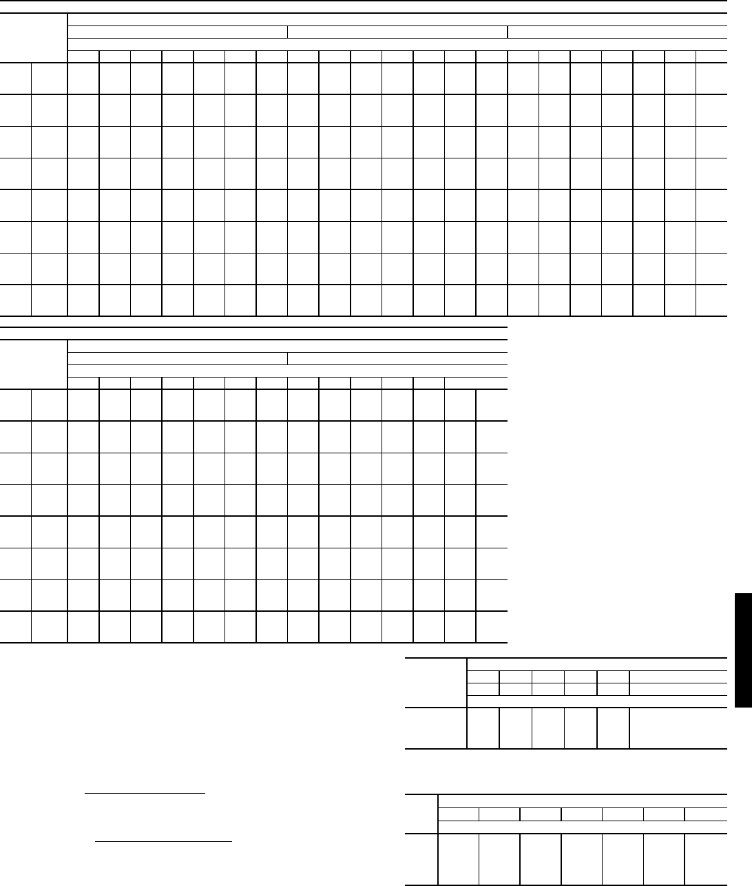
65
COOLING CAPACITIES — 48HJ028 STANDARD UNITS (cont)
LEGEND
NOTES:
1. Direct interpolation is permissible. Do not extrapolate.
2. The following formulas may be used:
tlwb = Wet-bulb temperature corresponding to enthalpy of air leaving evapo-
rator coil (hlwb)
Where: hewb = Enthalpy of air entering evaporator coil
3. The SHC is based on 80 F edb temperature of air entering evaporator coil.
Below 80 F edb, subtract (corr factor x cfm) from SHC.
Above 80 F edb, add (corr factor x cfm) to SHC.
Interpolation is permissible.
Correction Factor = 1.10 x (1 – BF) x (edb – 80).
4. Use chart below for bypass factor.
48HJ028 (25 Tons)
Temp (F)
Air Ent
Cond
Evap Air — Cfm/BF
7,500/0.05 8,250/0.06 9,500/0.07
Evap Air — Ewb (F)
54 58 62 67 72 76 80 54 58 62 67 72 76 80 54 58 62 67 72 76 80
60
TC 287 296 304 331 359 385 408 297 304 310 336 367 390 414 311 315 319 345 375 398 421
SHC 287 274 261 220 178 145 110 297 285 273 229 185 148 110 311 303 294 246 194 152 111
kW 15.5 15.7 15.9 16.5 17.3 17.9 18.6 15.7 15.9 16 16.7 17.4 18.1 18.7 16 16.1 16.2 16.9 17.6 18.3 19
70
TC 279 286 293 318 345 367 392 288 293 298 323 350 372 397 301 303 306 329 357 381 403
SHC 279 267 255 214 173 139 105 288 278 268 224 178 142 105 301 294 287 239 188 147 105
kW 17 17.2 17.3 18 18.7 19.3 20 17.2 17.3 17.5 18.1 18.8 19.4 20.1 17.5 17.6 17.7 18.3 19 19.7 20.3
75
TC 275 281 287 311 338 360 383 283 288 293 316 343 365 388 296 298 300 323 349 372 394
SHC 275 264 252 212 170 136 102 283 274 265 221 176 139 103 296 290 284 237 185 144 103
kW 17.9 18.1 18.2 18.8 19.5 20.1 20.8 18.1 18.2 18.4 18.9 19.7 20.3 20.9 18.4 18.5 18.5 19.1 19.8 20.5 21.1
85
TC 267 272 277 299 324 345 366 274 278 282 304 329 350 370 286 287 289 311 334 355 375
SHC 267 257 247 207 165 131 97.3 274 267 259 216 171 134 97.3 286 282 278 232 180 139 97.3
kW 19.8 19.9 20 20.6 21.2 21.8 22.4 20 20.1 20.1 20.7 21.4 22 22.6 20.2 20.3 20.3 20.9 21.5 22.1 22.7
95
TC 259 263 267 288 311 331 350 267 270 273 293 315 335 354 278 279 281 299 322 340 358
SHC 259 251 242 202 160 126 92.5 267 261 255 212 166 129 92.5 278 276 273 227 175 134 92.4
kW 22.1 22.2 22.3 22.8 23.4 23.9 24.5 22.3 22.4 22.5 22.9 23.5 24 24.6 22.6 22.6 22.6 23.1 23.6 24.2 24.7
105
TC 253 256 260 279 301 318 335 260 262 264 282 304 322 338 269 270 270 287 308 326 342
SHC 253 246 239 198 156 122 87.9 260 255 250 207 162 125 87.8 269 268 267 222 171 129 87.7
kW 24.9 25 25.1 25.4 25.9 26.4 26.9 25.1 25.1 25.1 25.5 26 26.5 26.9 25.2 25.2 25.2 25.6 26.1 26.6 27.1
115
TC 246 249 252 270 291 305 320 253 255 256 274 294 309 323 262 262 262 277 298 312 328
SHC 246 240 235 195 152 118 83.5 253 250 246 204 158 121 83.4 262 261 261 218 167 125 83.9
kW 28.1 28.2 28.3 28.6 29 29.3 29.6 28.3 28.3 28.3 28.6 29 29.4 29.7 28.4 28.4 28.4 28.7 29.1 29.4 29.9
125
TC 238 240 242 259 279 293 305 245 246 246 262 281 295 310 253 253 253 266 284 298 313
SHC 238 234 230 190 148 114 79.2 245 243 240 199 153 116 79.7 253 253 253 214 162 120 79.9
kW 31.6 31.7 31.7 32 32.4 32.6 32.9 31.8 31.8 31.8 32.1 32.4 32.7 33 31.9 31.9 31.9 32.1 32.5 32.7 33.1
48HJ028 (25 Tons) (cont)
Temp (F)
Air Ent
Cond
Evap Air — Cfm/BF
10,750/0.08 12,000/0.09
Evap Air — Ewb (F)
54 58 62 67 72 76 80 54 58 62 67 72 76 80
60
TC 322 324 327 351 380 404 429 332 333 334 357 386 410 432
SHC 322 317 313 260 203 157 111 332 330 329 276 212 162 111
kW 16.3 16.4 16.4 17 17.8 18.5 19.2 16.6 16.6 16.6 17.2 18 18.6 19.2
70
TC 311 312 314 336 364 386 408 320 320 321 341 368 392 414
SHC 311 308 305 255 198 151 105 320 320 319 269 206 156 106
kW 17.8 17.8 17.9 18.4 19.2 19.8 20.5 18 18 18 18.5 19.3 20 20.6
75
TC 306 307 308 329 356 378 398 315 315 315 333 360 383 404
SHC 306 304 302 252 195 149 103 315 314 314 266 203 153 103
kW 18.7 18.7 18.7 19.3 20 20.6 21.3 18.9 18.9 18.9 19.4 20.1 20.8 21.4
85
TC 295 296 297 315 340 362 379 303 303 303 319 344 365 385
SHC 295 295 294 246 189 144 97.3 303 303 303 260 198 148 97.9
kW 20.5 20.5 20.5 21 21.7 22.3 22.8 20.7 20.7 20.7 21.1 21.8 22.4 23
95
TC 286 286 286 303 327 344 364 293 293 294 307 330 347 366
SHC 286 286 286 241 185 138 93 293 293 294 255 193 142 92.8
kW 22.7 22.7 22.7 23.1 23.8 24.3 24.9 22.9 22.9 22.9 23.2 23.9 24.4 24.9
105
TC 277 277 277 290 312 329 347 284 284 285 295 314 331 352
SHC 277 277 277 236 179 133 88.3 284 284 285 250 188 137 88.7
kW 25.4 25.4 25.4 25.7 26.2 26.7 27.2 25.5 25.6 25.6 25.8 26.3 26.7 27.3
115
TC 268 269 269 281 300 315 332 274 274 275 283 303 317 333
SHC 268 269 269 232 176 129 84.4 274 274 275 245 184 133 84
kW 28.5 28.5 28.5 28.7 29.2 29.5 30 28.6 28.6 28.6 28.8 29.2 29.5 30
125
TC 260 259 259 269 287 300 316 265 265 264 271 289 302 318
SHC 260 259 259 227 171 125 80 265 265 264 240 179 129 80.1
kW 32 32 32 32.1 32.5 32.8 33.2 32.1 32.1 32.1 32.2 32.5 32.8 33.3
BF — Bypass Factor
Edb — Entering Dry-Bulb
Ewb — Entering Wet-Bulb
kW — Compressor Motor Power Input
ldb — Leaving Dry-Bulb
lwb — Leaving Wet-Bulb
SHC — Sensible Heat Capacity (1000 Btuh) Gross
TC — Total Capacity (1000 Btuh) Gross
tldb = tedb – sensible capacity (Btuh)
1.10 x cfm
hlwb = hewb – total capacity (Btuh)
4.5 x cfm
BYPASS
FACTOR
(BF)
ENTERING AIR DRY-BULB TEMP (F)
79 78 77 76 75 under 75
81 82 83 84 85 over 85
Correction Factor
.05 1.04 2.07 3.11 4.14 5.18
Use formula
shown below.
.10 .98 1.96 2.94 3.92 4.90
.20 .87 1.74 2.62 3.49 4.36
.30 .76 1.53 2.29 3.05 3.82
CFM
ENTERING WET-BULB (F)
54 58 62 67 72 76 80
Bypass Factor
7,500 0.407 0.208 0.097 0.104 0.123 0.000 0.000
8,250 0.443 0.256 0.110 0.112 0.128 0.000 0.000
9,500 0.494 0.324 0.138 0.123 0.136 0.000 0.000
10,750 0.536 0.380 0.181 0.134 0.145 0.000 0.000
12,000 0.571 0.427 0.232 0.145 0.154 0.000 0.000
48HJ48HJ

66
COOLING CAPACITIES — UNITS WITH HUMIDI-MIZER™ ADAPTIVE DEHUMIDIFICATION SYSTEM OPTION
LEGEND
NOTES:
1. Direct interpolation is permissible. Do not extrapolate.
2. The following formulas may be used:
Where: hewb = Enthalpy of air entering evaporator coil.
3. The SHC is based on 80 F edb temperature of air entering evapo-
rator coil.
Below 80 F edb, subtract (corr factor x cfm) from SHC.
Above 80 F edb, add (corr factor x cfm) to SHC.
Correction Factor = 1.10 x (1 – BF) x (edb – 80).
48HJ004 (3 TONS) — SUBCOOLING MODE
Temp (F)
Air Ent
Condenser
(Edb)
Air Entering Evaporator — Cfm/BF
900/0.14 1200/0.17 1500/0.20
Air Entering Evaporator — Ewb (F)
72 67 62 72 67 62 72 67 62
75
TC 41.3 37.3 34.3 43.5 39.2 35.9 45.5 41.6 38.2
SHC 17.5 22.4 26.7 19.6 25.5 31.2 21.5 28.5 35.2
kW 2.19 2.14 2.10 2.21 2.16 2.14 2.24 2.19 2.16
85
TC 38.6 34.4 31.6 41.3 37.5 33.3 43.5 38.6 35.5
SHC 15.2 20.1 25.1 17.1 23.2 29.0 18.9 26.3 32.9
kW 2.46 2.40 2.37 2.47 2.43 2.40 2.51 2.45 2.42
95
TC 35.9 31.4 28.8 39.2 35.9 30.6 41.3 35.7 32.9
SHC 13.0 17.9 23.3 14.5 21.1 26.9 16.1 24.2 30.6
kW 2.74 2.68 2.63 2.76 2.74 2.67 2.80 2.75 2.71
105
TC 33.8 29.7 27.4 36.3 32.2 28.7 38.1 32.8 30.4
SHC 10.9 15.8 21.0 12.5 18.9 24.6 14.0 21.7 28.1
kW 3.05 3.00 2.97 3.09 3.04 2.99 3.12 3.07 3.03
115
TC 31.8 28.0 25.5 33.2 28.7 26.5 34.9 30.0 27.9
SHC 9.0 13.7 18.4 10.3 16.8 22.3 11.9 19.3 25.2
kW 3.40 3.36 3.31 3.45 3.38 3.32 3.48 3.41 3.37
125
TC 28.7 26.3 23.4 29.7 25.5 22.9 31.3 27.1 25.5
SHC 6.9 12.2 17.3 7.9 14.5 20.6 9.2 17.3 22.3
kW 3.78 3.73 3.66 3.84 3.77 3.71 3.87 3.79 3.75
48HJ004 (3 TONS) — HOT GAS REHEAT MODE
Temp (F)
Air Ent
Condenser
(Edb)
Air Entering Evaporator — Ewb (F)
75 Dry Bulb
62.5 Wet Bulb
(50% Relative)
75 Dry Bulb
64 Wet Bulb
(55% Relative)
75 Dry Bulb
65.3 Wet Bulb
(60% Relative)
Air Entering Evaporator — Cfm
900 1200 1500 900 1200 1500 900 1200 1500
80
TC 12.83 15.84 18.20 13.24 16.31 18.73 13.58 16.72 19.18
SHC 4.06 5.69 6.98 2.21 3.83 5.12 .59 2.20 3.50
kW 2.12 2.12 2.12 2.13 2.13 2.13 2.14 2.14 2.14
75
TC 13.61 16.44 18.67 14.03 16.93 19.20 14.39 17.34 19.67
SHC 4.62 6.16 7.37 2.89 4.43 5.65 1.40 2.93 4.15
kW 2.11 2.11 2.11 2.12 2.12 2.12 2.14 2.14 2.14
70
TC 14.39 17.05 19.14 14.82 17.54 19.68 15.19 17.96 20.15
SHC 5.17 6.62 7.77 3.58 5.03 6.18 2.20 3.65 4.80
kW 2.10 2.10 2.10 2.12 2.12 2.12 2.13 2.13 2.13
60
TC 15.95 18.26 20.08 16.40 18.77 20.63 16.79 19.21 21.11
SHC 6.27 7.55 8.56 4.95 6.23 7.24 3.81 5.09 6.10
kW 2.09 2.09 2.09 2.11 2.11 2.11 2.12 2.12 2.12
50
TC 17.50 19.48 21.02 17.98 20.00 21.58 18.40 20.45 22.07
SHC 7.37 8.47 9.35 6.32 7.43 8.30 5.42 6.52 7.39
kW 2.07 2.07 2.07 2.10 2.10 2.10 2.12 2.12 2.12
40
TC 19.06 20.69 21.07 19.56 21.23 22.54 20.00 21.70 23.03
SHC 8.47 9.40 10.13 7.71 8.63 9.36 7.02 7.95 8.69
kW 2.06 2.06 2.06 2.08 2.08 2.08 2.11 2.11 2.11
BF — Bypass Factor
Edb — Entering Dry Bulb
Ewb — Entering Wet Bulb
kW — Compressor Motor Power Input
SHC — Sensible Heat Capacity (1000 Btuh) Gross
TC — Total Capacity (1000 Btuh) Gross
tldb =t
edb –sensible capacity (Btuh)
1.10 x cfm
tlwb = Wet-bulb temperature corresponding to enthalpy of air
leaving evaporator coil (hlwb)
hlwb =h
ewb –total capacity (Btuh)
4.5 x cfm
Performance data — 48HJ (cont)
48HJ48HJ
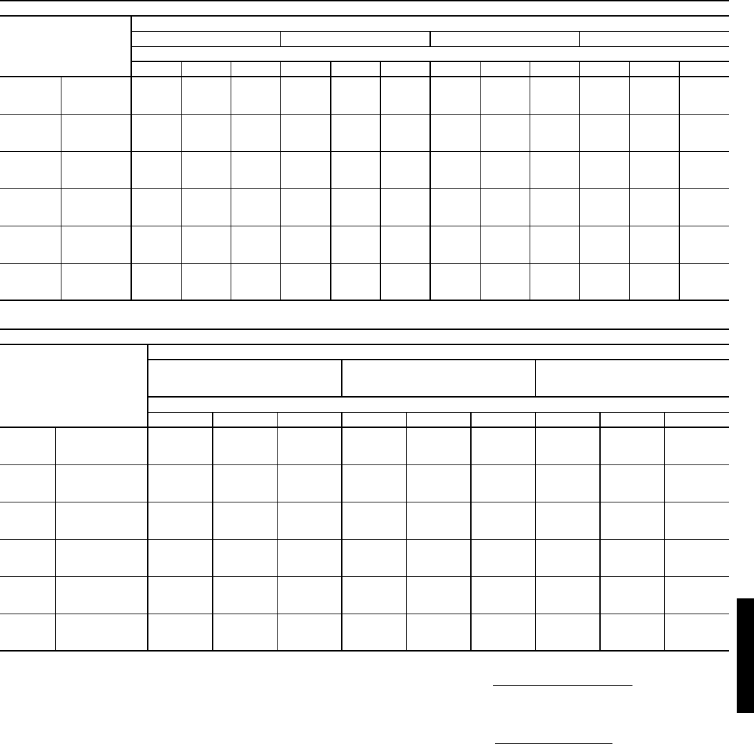
67
COOLING CAPACITIES — UNITS WITH HUMIDI-MIZER™ ADAPTIVE DEHUMIDIFICATION SYSTEM OPTION (cont)
LEGEND
*Negative SHC value indicates that the air entering the coil is being
heated.
NOTES:
1. Direct interpolation is permissible. Do not extrapolate.
2. The following formulas may be used:
Where: hewb = Enthalpy of air entering evaporator coil.
3. The SHC is based on 80 F edb temperature of air entering evapo-
rator coil.
Below 80 F edb, subtract (corr factor x cfm) from SHC.
Above 80 F edb, add (corr factor x cfm) to SHC.
Correction Factor = 1.10 x (1 – BF) x (edb – 80).
48HJ005 (4 TONS) — SUBCOOLING MODE
Temp (F)
Air Ent
Condenser
(Edb)
Air Entering Evaporator — Cfm/BF
1200/0.17 1450/0.19 1600/0.21 2000/0.24
Air Entering Evaporator — Ewb (F)
72 67 62 72 67 62 72 67 62 72 67 62
75
TC 52.9 47.5 41.5 55.7 50.9 47.5 57.0 51.7 48.1 60.5 55.6 52.1
SHC 22.7 28.4 33.4 26.1 34.1 38.9 25.9 33.7 41.6 29.4 39.1 47.5
kW 2.87 2.86 2.82 2.89 2.87 2.84 2.89 2.86 2.85 2.90 2.88 2.85
85
TC 49.2 43.8 37.1 52.1 47.2 43.6 52.9 47.9 43.7 55.4 51.4 47.0
SHC 19.8 25.5 30.4 22.2 29.5 35.8 22.4 31.1 38.7 24.2 36.0 44.3
kW 3.26 3.25 3.21 3.28 3.26 3.23 3.28 3.26 3.24 3.28 3.26 3.24
95
TC 45.8 40.1 32.8 48.2 43.6 39.4 48.8 44.0 39.3 51.7 47.4 43.0
SHC 17.2 22.5 27.3 18.4 24.8 32.6 19.0 28.1 35.9 20.7 33.0 41.0
kW 3.71 3.68 3.64 3.72 3.69 3.67 3.72 3.69 3.67 3.74 3.70 3.68
105
TC 41.6 37.0 29.7 43.2 38.9 35.4 43.9 39.7 34.7 46.5 41.4 37.5
SHC 13.5 19.5 23.9 14.7 21.7 29.2 15.0 23.7 30.6 16.4 27.8 35.1
kW 4.20 4.17 4.11 4.20 4.17 4.14 4.20 4.17 4.15 4.22 4.19 4.16
115
TC 37.2 33.2 27.1 38.4 34.0 30.8 39.4 35.5 30.0 41.3 35.2 31.9
SHC 9.9 16.4 20.7 11.3 18.5 25.6 11.2 19.7 25.4 12.4 22.4 28.6
kW 4.73 4.68 4.62 4.74 4.71 4.64 4.73 4.72 4.65 4.74 4.72 4.69
125
TC 32.4 28.1 24.9 33.8 28.1 27.4 35.3 30.5 26.6 36.1 32.0 28.7
SHC 7.2 12.9 18.3 8.4 14.5 21.9 16.8 21.1 21.2 9.5 18.3 24.1
kW 5.29 5.23 5.15 5.30 5.25 5.19 5.29 5.27 5.21 5.30 5.29 5.25
48HJ005 (4 TONS) — HOT GAS REHEAT MODE*
Temp (F)
Air Ent
Condenser
(Edb)
Air Entering Evaporator — Ewb (F)
75 Dry Bulb
62.5 Wet Bulb
(50% Relative)
75 Dry Bulb
64 Wet Bulb
(55% Relative)
75 Dry Bulb
65.3 Wet Bulb
(60% Relative)
Air Entering Evaporator — Cfm
1200 1450 1600 1200 1450 1600 1200 1450 1600
80
TC 12.13 14.30 15.43 14.98 17.20 18.36 17.44 19.71 20.90
SHC 1.01 1.60 1.90 -0.18 0.41 0.72 -1.20 -0.61 -0.30
kW 2.76 2.76 2.76 2.75 2.75 2.75 2.74 2.74 2.74
75
TC 13.25 15.28 16.34 15.96 18.05 19.14 18.31 20.44 21.56
SHC 1.602.142.430.501.051.34-0.450.110.40
kW 7.54 7.54 7.57 7.61 7.64 7.66 7.66 7.70 7.71
70
TC 14.37 16.27 17.26 16.94 18.90 19.92 19.17 21.17 22.22
SHC 2.18 2.69 2.96 1.17 1.69 1.96 0.30 0.82 1.10
kW 2.70 2.70 2.70 2.70 2.70 2.70 2.70 2.70 2.70
60
TC 16.60 18.24 19.10 18.91 20.60 21.48 20.91 22.64 23.54
SHC 3.35 3.79 4.03 2.52 2.97 3.21 1.80 2.25 2.50
kW 2.64 2.64 2.64 2.65 2.65 2.65 2.65 2.65 2.65
50
TC 18.83 20.22 20.94 20.87 22.30 23.04 22.65 24.10 24.86
SHC 4.51 4.89 5.09 3.86 4.25 4.45 3.30 3.69 3.89
kW 2.59 2.59 2.59 2.60 2.60 2.60 2.61 2.61 2.61
40
TC 21.06 22.19 22.78 22.84 24.00 24.61 24.38 25.57 26.19
SHC 5.68 5.99 6.16 5.21 5.53 5.69 4.80 5.12 5.29
kW 2.53 2.53 2.53 2.55 2.55 2.55 2.57 2.57 2.57
BF — Bypass Factor
Edb — Entering Dry Bulb
Ewb — Entering Wet Bulb
kW — Compressor Motor Power Input
SHC — Sensible Heat Capacity (1000 Btuh) Gross
TC — Total Capacity (1000 Btuh) Gross
tldb =t
edb –sensible capacity (Btuh)
1.10 x cfm
tlwb = Wet-bulb temperature corresponding to enthalpy of air
leaving evaporator coil (hlwb)
hlwb =h
ewb –total capacity (Btuh)
4.5 x cfm
48HJ48HJ
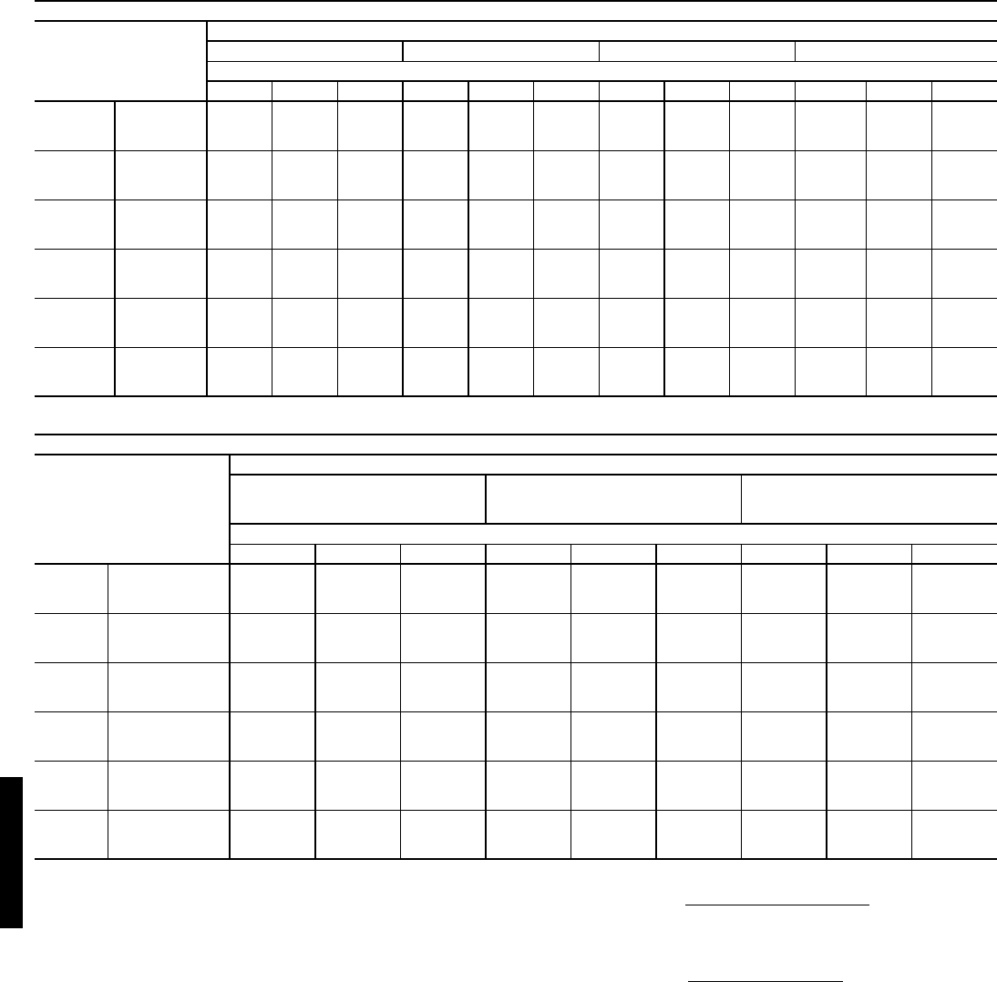
68
COOLING CAPACITIES — UNITS WITH HUMIDI-MIZER™ ADAPTIVE DEHUMIDIFICATION SYSTEM OPTION (cont)
LEGEND
*Negative SHC value indicates that the air entering the coil is being
heated.
NOTES:
1. Direct interpolation is permissible. Do not extrapolate.
2. The following formulas may be used:
Where: hewb = Enthalpy of air entering evaporator coil.
3. The SHC is based on 80 F edb temperature of air entering evapo-
rator coil.
Below 80 F edb, subtract (corr factor x cfm) from SHC.
Above 80 F edb, add (corr factor x cfm) to SHC.
Correction Factor = 1.10 x (1 – BF) x (edb – 80).
48HJ006 (5 TONS) — SUBCOOLING MODE
Temp (F)
Air Ent
Condenser
(Edb)
Air Entering Evaporator — Cfm/BF
1500/0.08 1750/0.09 2000/0.11 2500/0.13
Air Entering Evaporator — Ewb (F)
72 67 62 72 67 62 72 67 62 72 67 62
75 TC 69.9 62.7 56.2 74.7 67.3 61.0 78.5 71.2 64.8 81.7 75.5 69.3
SHC 29.0 36.9 43.9 31.7 40.5 51.2 34.5 44.2 55.4 37.8 52.0 62.8
kW 3.61 3.55 3.51 3.64 3.58 3.49 3.65 3.60 3.51 3.62 3.58 3.51
85 TC 65.9 59.1 51.7 70.6 63.2 56.3 75.5 66.8 60.7 78.1 70.8 65.1
SHC 25.3 34.0 41.9 27.5 37.6 48.0 30.7 41.6 52.0 33.8 47.4 58.0
kW 4.05 3.97 3.91 4.07 4.01 3.92 4.11 4.00 3.95 4.08 4.02 3.96
95 TC 61.9 55.2 47.7 66.5 58.8 51.3 70.4 61.9 55.7 74.2 65.9 60.6
SHC 21.6 31.1 40.0 23.5 34.5 44.6 26.0 38.6 47.9 30.0 42.8 52.6
kW 4.53 4.43 4.35 4.55 4.47 4.37 4.56 4.42 4.41 4.58 4.49 4.44
105 TC 57.7 51.1 44.9 61.8 54.5 47.7 65.1 57.2 50.8 68.4 60.3 56.1
SHC 18.1 27.8 35.7 20.0 31.2 40.1 22.1 34.3 43.5 26.1 38.9 48.5
kW 5.05 4.93 4.84 5.09 4.97 4.88 5.11 4.96 4.92 5.11 5.03 4.98
115 TC 53.4 47.2 42.0 56.6 50.0 44.2 59.6 52.5 46.2 62.6 54.9 51.6
SHC 14.7 24.6 31.5 16.5 27.8 35.7 18.2 30.0 39.0 22.1 34.9 44.3
kW 5.60 5.49 5.40 5.64 5.52 5.45 5.69 5.55 5.48 5.69 5.61 5.57
125 TC 48.7 42.0 36.9 51.3 45.0 39.0 54.1 46.8 40.9 56.9 49.2 45.9
SHC 10.9 19.6 28.0 12.5 22.2 31.5 13.5 24.0 34.0 16.5 28.0 38.8
kW 6.26 6.12 6.02 6.28 6.18 6.09 6.33 6.18 6.13 6.33 6.27 6.22
48HJ006 (5 TONS) — HOT GAS REHEAT MODE*
Temp (F)
Air Ent
Condenser
(Edb)
Air Entering Evaporator — Ewb (F)
75 Dry Bulb
62.5 Wet Bulb
(50% Relative)
75 Dry Bulb
64 Wet Bulb
(55% Relative)
75 Dry Bulb
65.3 Wet Bulb
(60% Relative)
Air Entering Evaporator — Cfm
1500 1750 2000 1500 1750 2000 1500 1750 2000
80
TC 17.67 19.23 20.59 17.51 19.09 20.48 17.37 18.98 20.39
SHC -0.39 0.07 0.46 -1.61 -1.15 -0.75 -2.67 -2.21 -1.80
kW 3.45 3.45 3.45 3.48 3.48 3.48 3.50 3.50 3.50
75
TC 18.55 20.03 21.32 18.45 19.95 21.27 18.36 19.89 21.23
SHC 0.28 0.71 1.09 -0.85 -0.42 -0.04 -1.83 -1.39 -1.01
kW 3.43 3.43 3.43 3.46 3.46 3.46 3.49 3.49 3.49
70
TC 19.44 20.83 22.06 19.39 20.81 22.06 19.35 20.80 22.07
SHC 0.95 1.36 1.71 -0.09 0.32 0.68 -0.99 -0.58 -0.22
kW 3.42 3.42 3.42 3.45 3.45 3.45 3.48 3.48 3.48
60
TC 21.20 22.44 23.53 21.27 22.54 23.65 21.33 22.62 23.75
SHC 2.30 2.65 2.95 1.44 1.80 2.11 0.70 1.06 1.37
kW 3.38 3.38 3.38 3.42 3.42 3.42 3.46 3.46 3.46
50
TC 22.96 24.05 25.00 23.15 24.26 25.23 23.31 24.43 25.42
SHC 3.64 3.94 4.20 2.97 3.27 3.53 2.39 2.69 2.96
kW 3.35 3.35 3.35 3.40 3.40 3.40 3.43 3.43 3.43
40
TC 24.73 25.66 26.48 25.03 25.98 26.81 25.28 26.25 27.10
SHC 4.99 5.23 5.45 4.50 4.75 4.96 4.07 4.32 4.54
kW 3.32 3.32 3.32 3.37 3.37 3.37 3.41 3.41 3.41
BF — Bypass Factor
Edb — Entering Dry Bulb
Ewb — Entering Wet Bulb
kW — Compressor Motor Power Input
SHC — Sensible Heat Capacity (1000 Btuh) Gross
TC — Total Capacity (1000 Btuh) Gross
tldb =t
edb –sensible capacity (Btuh)
1.10 x cfm
tlwb = Wet-bulb temperature corresponding to enthalpy of air
leaving evaporator coil (hlwb)
hlwb =h
ewb –total capacity (Btuh)
4.5 x cfm
Performance data — 48HJ (cont)
48HJ48HJ
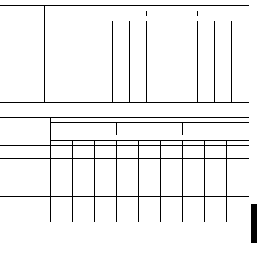
69
COOLING CAPACITIES — UNITS WITH HUMIDI-MIZER™ ADAPTIVE DEHUMIDIFICATION SYSTEM OPTION (cont)
LEGEND
*Negative SHC value indicates that the air entering the coil is being
heated.
NOTES:
1. Direct interpolation is permissible. Do not extrapolate.
2. The following formulas may be used:
Where: hewb = Enthalpy of air entering evaporator coil.
3. The SHC is based on 80 F edb temperature of air entering evapo-
rator coil.
Below 80 F edb, subtract (corr factor x cfm) from SHC.
Above 80 F edb, add (corr factor x cfm) to SHC.
Correction Factor = 1.10 x (1 – BF) x (edb – 80).
48HJ007 (6 TONS) — SUBCOOLING MODE
Temp (F)
Air Ent
Condenser
(Edb)
Air Entering Evaporator — Cfm/BF
1800/0.05 2100/0.06 2400/0.06 3000/0.08
Air Entering Evaporator — Ewb (F)
72 67 62 72 67 62 72 67 62 72 67 62
75 TC 82.6 75.6 68.5 84.9 78.0 70.9 85.9 79.5 73.5 89.1 82.7 77.0
SHC 36.0 44.8 55.4 37.5 49.1 59.7 38.8 51.1 64.0 41.8 58.1 70.2
kW 4.60 4.52 4.36 4.67 4.57 4.46 4.70 4.57 4.45 4.77 4.61 4.51
85 TC 78.2 71.6 64.5 80.9 73.4 65.8 82.0 74.4 67.9 85.8 78.2 72.3
SHC 31.4 41.2 51.7 33.0 44.7 55.8 34.7 47.4 60.1 37.6 54.3 66.7
kW 5.16 5.03 4.89 5.22 5.11 4.96 5.26 5.09 4.97 5.32 5.17 5.04
95 TC 73.8 67.4 60.2 76.3 68.3 60.5 77.5 69.3 62.3 82.0 72.8 67.5
SHC 27.0 37.6 47.9 28.2 40.0 51.6 30.2 43.7 56.2 33.6 49.2 62.9
kW 5.75 5.60 5.44 5.80 5.66 5.48 5.84 5.68 5.53 5.90 5.73 5.60
105 TC 68.4 62.6 55.9 71.4 64.3 56.2 72.1 64.6 58.3 75.7 67.0 62.4
SHC 22.3 33.5 43.5 23.4 36.5 48.0 25.4 38.4 50.2 29.1 45.2 56.2
kW 6.37 6.22 6.06 6.45 6.27 6.10 6.46 6.29 6.16 6.53 6.36 6.24
115 TC 63.4 57.8 50.7 66.0 60.1 51.5 66.4 59.6 54.5 68.8 60.8 57.5
SHC 18.1 29.5 38.9 18.8 32.9 44.1 20.7 33.3 43.8 24.3 41.4 49.7
kW 7.04 6.89 6.68 7.10 6.91 6.74 7.12 6.95 6.83 7.16 7.01 6.92
125 TC 55.5 49.6 45.8 58.4 52.4 46.1 57.6 52.1 49.5 59.2 52.8 53.1
SHC 15.3 24.0 35.2 15.7 27.5 39.0 17.5 27.5 38.4 20.9 34.6 44.4
kW 7.80 7.61 7.38 7.83 7.67 7.49 7.89 7.72 7.58 7.92 7.78 7.70
48HJ007 (6 TONS) — HOT GAS REHEAT MODE*
Temp (F)
Air Ent
Condenser
(Edb)
Air Entering Evaporator — Ewb (F)
75 Dry Bulb
62.5 Wet Bulb
(50% Relative)
75 Dry Bulb
64 Wet Bulb
(55% Relative)
75 Dry Bulb
65.3 Wet Bulb
(60% Relative)
Air Entering Evaporator — Cfm
1800 2100 2400 1800 2100 2400 1800 2100 2400
80
TC 27.41 28.12 28.75 27.25 27.98 28.62 27.12 27.86 28.51
SHC 5.74 7.61 9.25 1.68 3.52 5.14 -1.85 -0.03 1.58
kW 4.40 4.39 4.39 4.44 4.44 4.44 4.49 4.49 4.49
75
TC 27.98 28.66 29.24 27.89 28.58 29.18 27.81 28.52 29.13
SHC 5.737.489.021.923.655.18-1.380.341.85
kW 4.45 4.45 4.45 4.50 4.50 4.50 4.55 4.55 4.55
70
TC 28.55 29.19 29.74 28.53 29.18 29.74 28.51 29.17 29.74
SHC 5.71 7.35 8.79 2.17 3.79 5.22 -0.91 0.70 2.12
kW 4.51 4.51 4.51 4.57 4.57 4.57 4.62 4.62 4.62
60
TC 29.70 30.25 30.74 29.80 30.37 30.86 29.89 30.47 30.97
SHC 5.67 7.09 8.34 2.65 4.06 5.29 0.04 1.43 2.65
kW 4.62 4.62 4.62 4.69 4.69 4.69 4.75 4.75 4.75
50
TC 30.84 31.32 31.73 31.07 31.56 31.98 31.27 31.77 32.20
SHC 5.63 6.83 7.89 3.14 4.33 5.37 0.98 2.15 3.19
kW 4.74 4.74 4.74 4.82 4.82 4.82 4.89 4.89 4.89
40
TC 31.99 32.38 32.73 32.35 32.75 33.12 32.66 33.07 33.43
SHC 5.60 6.57 7.43 3.63 4.59 5.44 1.92 2.88 3.72
kW 4.86 4.86 4.86 4.95 4.95 4.95 5.02 5.02 5.02
BF — Bypass Factor
Edb — Entering Dry Bulb
Ewb — Entering Wet Bulb
kW — Compressor Motor Power Input
SHC — Sensible Heat Capacity (1000 Btuh) Gross
TC — Total Capacity (1000 Btuh) Gross
tldb =t
edb –sensible capacity (Btuh)
1.10 x cfm
tlwb = Wet-bulb temperature corresponding to enthalpy of air
leaving evaporator coil (hlwb)
hlwb =h
ewb –total capacity (Btuh)
4.5 x cfm
48HJ48HJ
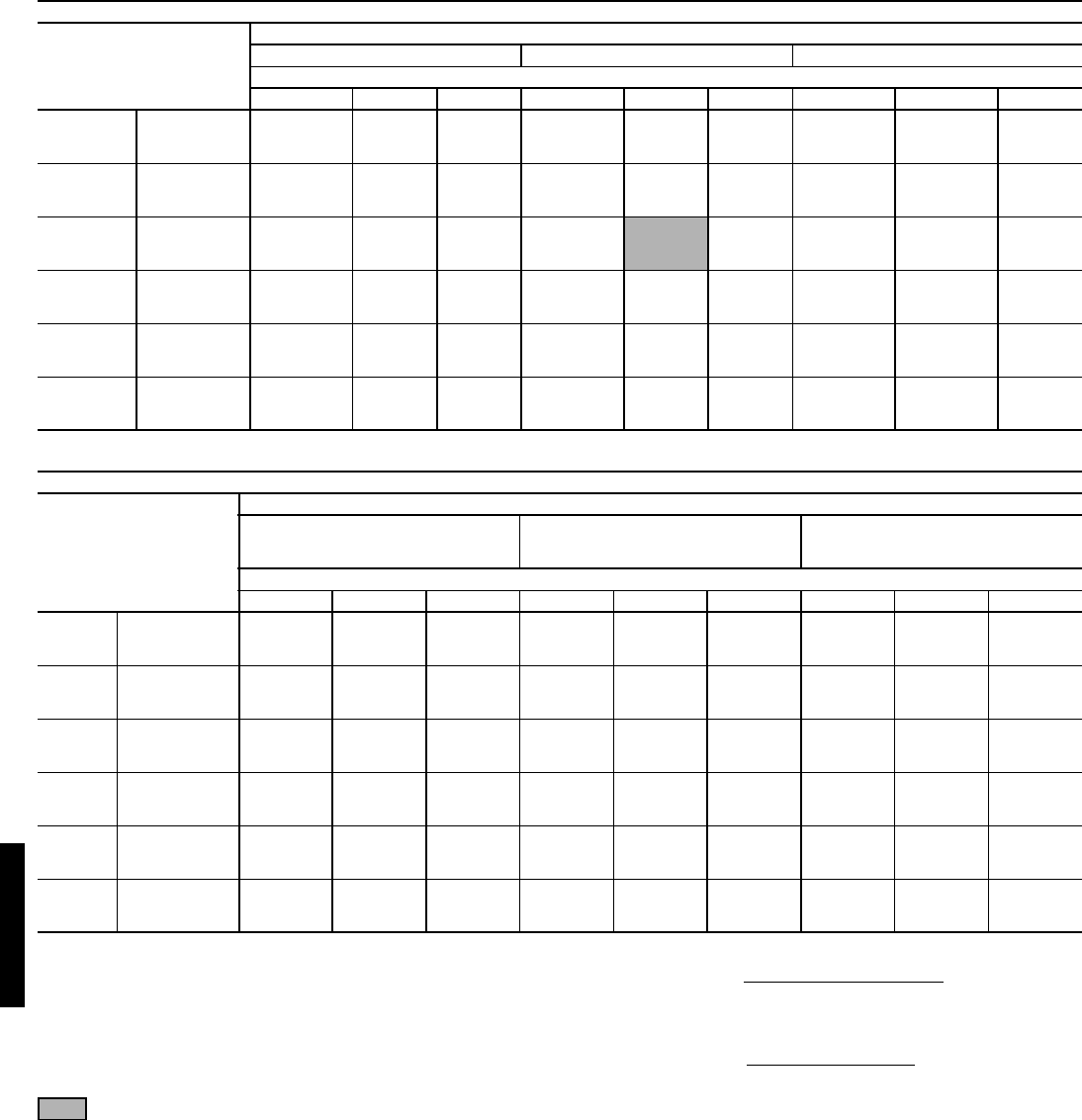
70
COOLING CAPACITIES — UNITS WITH HUMIDI-MIZER™ ADAPTIVE DEHUMIDIFICATION SYSTEM OPTION (cont)
LEGEND
*Negative SHC value indicates that the air entering the coil is being
heated.
Standard Ratings
NOTES:
1. Direct interpolation is permissible. Do not extrapolate.
2. The following formulas may be used:
Where: hewb = Enthalpy of air entering evaporator coil.
3. The SHC is based on 80 F edb temperature of air entering evapo-
rator coil.
Below 80 F edb, subtract (corr factor x cfm) from SHC.
Above 80 F edb, add (corr factor x cfm) to SHC.
Correction Factor = 1.10 x (1 – BF) x (edb – 80).
48/50HJ008 (71/2 TONS) — SUBCOOLING MODE
Temp (F)
Air Ent
Condenser
(Edb)
Air Entering Evaporator — Cfm/BF
2250/0.10 3000/0.11 3750/0.14
Air Entering Evaporator — Ewb (F)
72 67 62 72 67 62 72 67 62
75
TC 98.4 99.1 81.1 103.7 97.8 91.8 105.8 101.3 94.1
SHC 44.5 55.4 67.0 50.4 65.4 80.5 54.5 72.4 89.5
kW 5.05 4.96 4.87 5.09 5.04 4.97 5.16 5.04 4.99
85
TC 94.2 85.8 76.9 100.3 92.4 85.2 103.5 96.8 89.0
SHC 39.7 51.3 62.7 46.2 58.3 75.7 50.6 68.2 84.3
kW 5.74 5.65 5.55‘ 5.81 5.75 5.64 5.89 5.74 5.70
95
TC 89.9 80.5 72.6 96.9 86.8 78.6‘ 101.1 92.2 83.8
SHC 34.8 47.2 58.3 41.9 51.2 71.0 46.6 63.9 79.1
kW 6.42 6.33 6.22 6.52 6.45 6.31 6.62 6.43 6.40
105
TC 84.6 75.3 68.0 91.6 81.3 73.4 94.5 86.3 78.4
SHC 30.0 42.5 53.9 36.9 49.3 66.4 41.4 59.2 73.8
kW 7.26 7.16 7.05 7.36 7.25 7.15 7.46 7.29 7.23
115
TC 79.2 70.1 63.3 86.2 75.8 68.1 87.9 80.3 72.9
SHC 25.2 37.8 49.4 31.9 47.4 61.9 36.1 54.4 68.5
kW 8.10 7.99 7.87 8.20 8.05 7.98 8.30 8.14 8.05
125
TC 7.28 64.5 57.2 78.0 69.8 62.3 81.6 73.2 69.2
SHC 20.1 33.4 44.1 25.4 42.5 56.5 31.1 48.9 64.7
kW 9.10 8.94 8.83 9.23 9.05 8.95 9.26 9.10 8.99
48HJ008 (71/2 TONS) — HOT GAS REHEAT MODE*
Temp (F)
Air Ent
Condenser
(Edb)
Air Entering Evaporator — Ewb (F)
75 Dry Bulb
62.5 Wet Bulb
(50% Relative)
75 Dry Bulb
64 Wet Bulb
(55% Relative)
75 Dry Bulb
65.3 Wet Bulb
(60% Relative)
Air Entering Evaporator — Cfm
2250 3000 3750 2250 3000 3750 2250 3000 3750
80
TC 37.74 40.54 42.68 38.48 41.35 43.55 39.12 42.05 44.29
SHC 10.67 15.63 19.63 5.01 9.84 13.74 0.10 4.82 8.63
kW 4.92 4.92 4.92 4.97 4.97 4.97 5.01 5.01 5.01
75
TC 37.34 39.95 41.95 38.08 40.75 42.81 38.72 41.45 43.55
SHC 9.83 14.48 18.24 4.52 9.05 12.70 -0.09 4.34 7.91
kW 5.19 5.19 5.19 5.25 5.25 5.25 5.30 5.30 5.30
70
TC 36.93 39.36 41.22 37.67 40.16 42.07 38.31 40.85 42.80
SHC 8.99 13.33 16.84 4.02 8.26 11.67 -0.28 3.86 7.19
kW 5.46 5.46 5.46 5.52 5.52 5.52 5.58 5.58 5.58
60
TC 36.13 38.18 39.75 36.87 38.97 40.58 37.51 39.66 41.31
SHC 7.31 11.04 14.04 3.04 6.67 9.60 -0.66 2.89 5.75
kW 5.99 5.99 5.99 6.08 6.08 6.08 6.15 6.15 6.15
50
TC 35.32 37.00 38.29 36.06 37.78 39.10 36.75 38.46 39.81
SHC 5.63 8.74 11.25 2.06 5.09 7.53 -1.03 1.93 4.32
kW 6.52 6.52 6.52 6.63 6.63 6.63 6.73 6.73 6.73
40
TC 34.52 35.82 36.82 35.26 36.60 37.62 35.90 37.27 38.32
SHC 3.94 6.44 8.45 1.08 3.51 5.47 -1.41 0.97 2.88
kW 7.05 7.05 7.05 7.18 7.18 7.18 7.30 7.30 7.30
BF — Bypass Factor
Edb — Entering Dry Bulb
Ewb — Entering Wet Bulb
kW — Compressor Motor Power Input
SHC — Sensible Heat Capacity (1000 Btuh) Gross
TC — Total Capacity (1000 Btuh) Gross
tldb =t
edb –sensible capacity (Btuh)
1.10 x cfm
tlwb = Wet-bulb temperature corresponding to enthalpy of air
leaving evaporator coil (hlwb)
hlwb =h
ewb –total capacity (Btuh)
4.5 x cfm
Performance data — 48HJ (cont)
48HJ48HJ
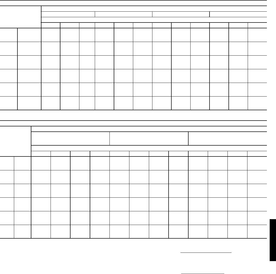
71
COOLING CAPACITIES — UNITS WITH HUMIDI-MIZER™ ADAPTIVE DEHUMIDIFICATION SYSTEM OPTION (cont)
LEGEND
NOTES:
1. Direct interpolation is permissible. Do not extrapolate.
2. The following formulas may be used:
Where: hewb = Enthalpy of air entering evaporator coil.
3. The SHC is based on 80 F edb temperature of air entering evapo-
rator coil.
Below 80 F edb, subtract (corr factor x cfm) from SHC.
Above 80 F edb, add (corr factor x cfm) to SHC.
Correction Factor = 1.10 x (1 – BF) x (edb – 80).
48HJ009 (81/2 TONS) — SUBCOOLING MODE
Temp (F)
Air Ent
Condenser
(Edb)
Air Entering Evaporator — Cfm/BF
2550/0.08 3000/0.09 3400/0.11 4250/0.13
Air Entering Evaporator — Ewb (F)
72 67 62 72 67 62 72 67 62 72 67 62
75 TC 114.1 104.1 97.8 116.3 108.5 103.4 117.6 111.9 108.0 122.2 118.9 111.4
SHC 49.8 64.2 81.2 52.6 70.8 89.0 55.4 76.9 95.4 62.0 87.0 107.2
kW 5.57 5.46 5.44 5.59 5.50 5.44 5.60 5.51 5.44 5.62 5.62 5.69
85 TC 107.3 98.4 92.6 111.0 101.8 98.0 113.0 104.2 102.0 117.1 111.4 106.1
SHC 42.2 58.3 76.0 47.1 64.5 83.5 51.2 70.2 89.2 57.3 81.2 101.2
kW 6.32 6.30 6.15 6.32 6.27 6.18 6.34 6.22 6.20 6.30 6.31 6.45
95 TC 101.9 92.4 86.8 105.3 95.5 92.8 107.4 97.7 96.5 112.1 103.7 100.3
SHC 35.4 51.9 70.3 40.1 58.5 77.9 44.9 64.9 83.7 52.1 74.0 94.8
kW 7.06 7.13 6.93 7.06 7.06 6.95 7.06 6.99 6.98 7.01 7.04 7.17
105 TC 94.5 85.4 77.0 97.6 88.3 82.4 99.9 90.6 88.0 104.1 96.1 94.0
SHC 29.7 45.7 63.2 33.9 52.2 70.1 38.0 58.3 75.7 44.4 67.6 88.5
kW 7.99 8.00 7.81 8.01 7.97 7.85 8.02 7.94 7.89 7.96 7.96 8.08
115 TC 86.4 75.0 68.3 89.3 80.2 74.1 91.4 83.2 78.4 96.5 88.4 87.1
SHC 24.0 38.7 56.4 27.4 45.6 62.9 31.1 51.9 67.0 37.0 60.8 81.8
kW 8.91 8.83 8.66 8.93 8.86 8.76 8.97 8.86 8.84 8.91 8.93 8.90
125 TC 78.6 65.5 60.2 81.3 68.9 64.7 83.3 71.6 68.2 88.5 78.8 78.9
SHC 18.3 32.0 48.8 21.2 38.0 53.5 24.1 44.1 57.5 29.4 53.3 73.8
kW 9.81 9.65 9.53 9.86 9.68 9.64 9.89 9.71 9.75 9.90 9.72 9.88
48HJ009 (81/2 TONS) — HOT GAS REHEAT MODE
Temp (F)
Air Ent
Condenser
(Edb)
Air Entering Evaporator — Ewb (F)
75 Dry Bulb
62.5 Wet Bulb
(50% Relative)
75 Dry Bulb
64 Wet Bulb
(55% Relative)
75 Dry Bulb
65.3 Wet Bulb
(60% Relative)
Air Entering Evaporator — Cfm
2550 3000 3400 4250 2550 3000 3400 4250 2550 3000 3400 4250
80
TC 43.44 46.26 48.45 52.38 45.26 48.15 50.39 54.43 46.84 49.79 52.08 56.20
SHC 12.34 16.78 20.29 26.74 5.79 10.15 13.60 19.93 0.11 4.40 7.80 14.03
kW 6.31 6.31 6.31 6.31 6.05 6.05 6.05 6.05 5.83 5.83 5.83 5.83
75
TC 44.33 47.00 49.06 52.78 46.12 48.85 50.97 54.78 47.67 50.46 52.63 56.52
SHC 12.92 17.12 20.44 26.54 6.81 10.94 14.20 20.20 1.51 5.58 8.79 14.70
kW 6.38 6.38 6.8 6.38 6.15 6.15 6.15 6.15 5.95 5.95 5.95 5.95
70
TC 45.22 47.73 49.68 53.18 46.98 49.55 51.55 55.14 48.51 51.14 53.18 56.84
SHC 13.50 17.47 20.59 26.34 7.83 11.73 14.81 20.46 2.92 6.76 9.79 15.36
kW 6.46 6.46 6.46 6.46 6.25 6.25 6.25 6.25 6.07 6.07 6.07 6.07
60
TC 46.99 49.19 50.90 53.97 48.70 50.96 52.71 55.86 50.18 52.49 54.27 57.49
SHC 14.67 18.15 20.90 25.95 9.88 13.31 16.01 20.99 5.73 9.11 11.78 16.68
kW 6.60 6.60 6.60 6.60 6.45 6.45 6.45 6.45 6.32 6.32 6.32 6.32
50
TC 48.77 50.66 52.13 54.77 50.42 52.36 53.87 56.57 51.85 53.83 55.37 58.14
SHC 15.83 18.83 21.20 25.56 11.93 14.89 17.22 21.51 8.55 11.47 13.77 18.01
kW 6.74 6.74 6.74 6.74 6.64 6.64 6.64 6.64 6.56 6.56 6.56 6.56
40
TC 50.54 52.13 53.35 55.56 52.14 53.76 55.02 57.29 53.53 55.18 56.47 58.78
SHC 17.00 19.52 21.51 25.16 13.98 16.47 18.43 22.04 11.36 13.82 15.76 19.33
kW 6.88 6.88 6.88 6.88 6.84 6.84 6.84 6.84 6.81 6.81 6.81 6.81
BF — Bypass Factor
Edb — Entering Dry Bulb
Ewb — Entering Wet Bulb
kW — Compressor Motor Power Input
SHC — Sensible Heat Capacity (1000 Btuh) Gross
TC — Total Capacity (1000 Btuh) Gross
tldb =t
edb –sensible capacity (Btuh)
1.10 x cfm
tlwb = Wet-bulb temperature corresponding to enthalpy of air
leaving evaporator coil (hlwb)
hlwb =h
ewb –total capacity (Btuh)
4.5 x cfm
48HJ48HJ
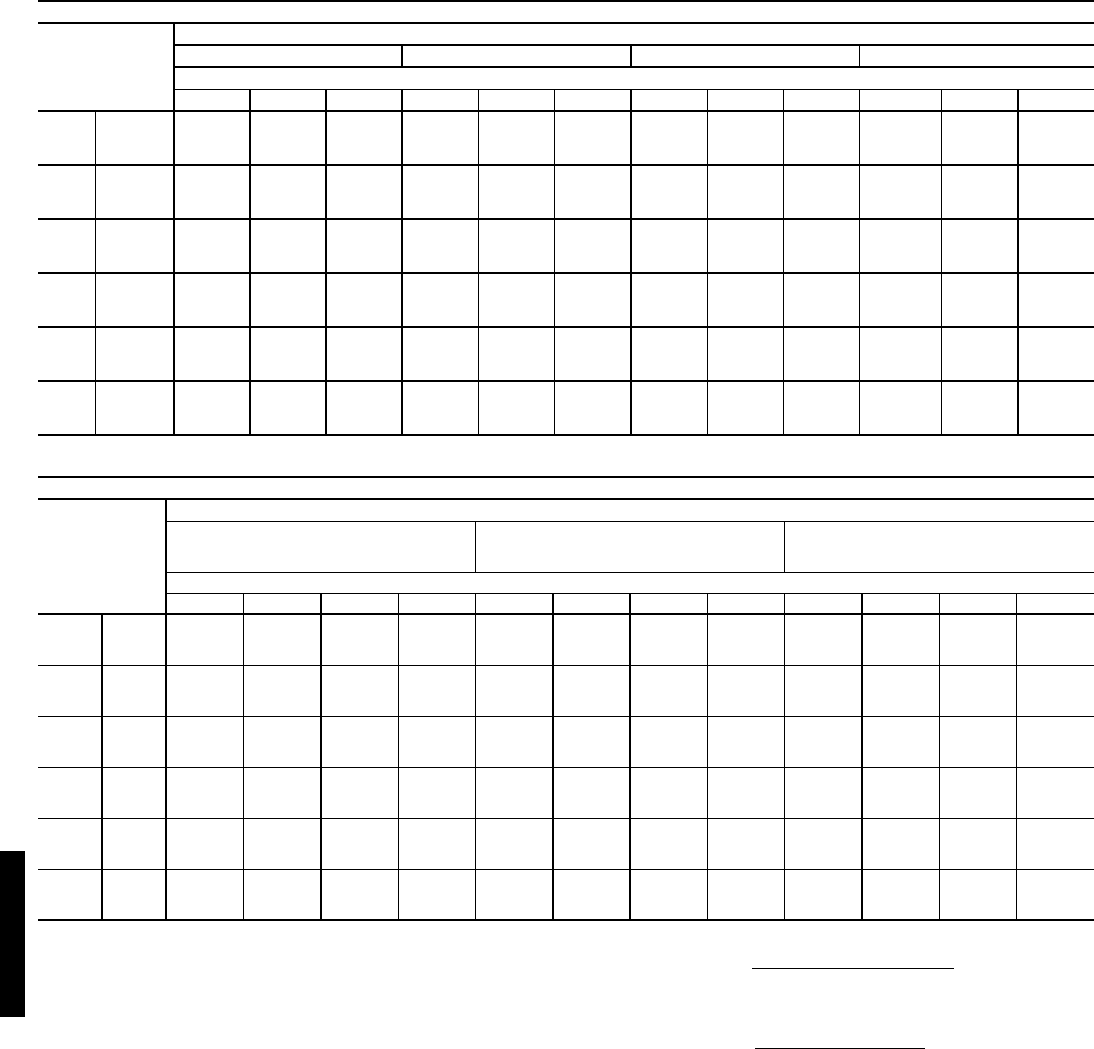
72
COOLING CAPACITIES — UNITS WITH HUMIDI-MIZER™ ADAPTIVE DEHUMIDIFICATION SYSTEM OPTION (cont)
LEGEND
*Negative SHC value indicates that the air entering the coil is being heated.
NOTES:
1. Direct interpolation is permissible. Do not extrapolate.
2. The following formulas may be used:
Where: hewb = Enthalpy of air entering evaporator coil.
3. The SHC is based on 80 F edb temperature of air entering evaporator
coil.
Below 80 F edb, subtract (corr factor x cfm) from SHC.
Above 80 F edb, add (corr factor x cfm) to SHC.
Correction Factor = 1.10 x (1 – BF) x (edb – 80).
48HJ012 (10 TONS) — SUBCOOLING MODE
Temp (F)
Air Ent
Condenser
(Edb)
Air Entering Evaporator — Cfm/BF
3000/0.03 3200/0.03 4000/0.04 5000/0.04
Air Entering Evaporator — Ewb (F)
72 67 62 72 67 62 72 67 62 72 67 62
75 TC 134.3 122.5 111.4 135.8 124.3 113.0 138.4 129.5 123.5 143.3 136.5 130.2
SHC 60.0 76.1 93.7 61.3 79.1 97.4 68.0 89.5 109.4 75.2 100.9 123.3
kW 7.03 6.84 6.72 7.01 6.89 6.77 7.10 6.92 6.77 7.15 7.03 6.88
85 TC 127.6 115.4 104.6 128.9 118.1 107.0 132.5 121.5 116.6 137.2 128.0 122.9
SHC 51.5 68.8 87.2 53.9 72.0 91.2 61.0 82.7 102.4 68.6 93.6 115.9
kW 7.96 7.86 7.59 7.94 7.78 7.51 8.02 7.84 7.69 8.02 7.94 7.79
95 TC 120.9 108.3 97.8 121.9 111.8 101.0 126.5 113.4 109.7 131.1 119.4 115.5
SHC 43.0 61.5 80.6 46.5 64.8 84.9 53.9 75.9 95.4 62.0 86.2 108.4
kW 8.88 8.87 8.46 8.86 8.66 8.26 8.94 8.76 8.60 8.89 8.85 8.69
105 TC 112.0 99.9 90.4 113.1 103.2 93.4 117.2 105.0 100.7 122.1 110.5 105.9
SHC 36.1 54.1 73.8 38.8 57.8 78.9 45.6 68.2 86.8 53.0 78.3 99.7
kW 10.0 10.0 9.6 10.0 9.8 9.5 10.1 9.9 9.8 10.1 10.0 9.9
115 TC 103.0 91.5 83.1 104.3 94.6 85.9 107.8 96.7 91.7 113.0 101.6 96.4
SHC 29.2 46.7 66.9 31.2 50.7 72.9 37.3 60.6 78.3 44.0 70.3 90.9
kW 11.2 11.1 10.8 11.2 11.0 10.7 11.3 11.1 11.0 11.3 11.2 11.1
125 TC 94.1 83.1 75.7 95.5 86.0 78.3 98.5 88.3 82.7 104.0 92.7 86.8
SHC 22.3 39.3 60.1 23.5 43.7 66.8 29.0 52.9 69.7 35.0 62.4 82.2
kW 12.35 12.15 11.94 12.38 12.13 11.92 12.48 12.27 12.25 12.53 12.30 12.28
48HJ012 (10 TONS) — HOT GAS REHEAT MODE*
Temp (F)
Air Ent
Condenser
(Edb)
Air Entering Evaporator — Ewb (F)
75 Dry Bulb
62.5 Wet Bulb
(50% Relative)
75 Dry Bulb
64 Wet Bulb
(55% Relative)
75 Dry Bulb
65.3 Wet Bulb
(60% Relative)
Air Entering Evaporator — Cfm
3000 3200 4000 5000 3000 3200 4000 5000 3000 3200 4000 5000
80
TC 49.15 50.16 53.80 57.72 51.04 52.08 55.86 59.94 52.67 53.74 57.65 61.86
SHC 9.58 12.02 20.74 29.89 2.88 5.29 13.88 22.89 -2.92 -0.55 7.93 16.83
kW 7.39 7.38 7.38 7.37 7.45 7.45 7.44 7.43 7.50 7.50 7.49 7.49
75
TC 49.60 50.61 54.30 58.28 51.45 52.50 56.33 60.45 53.05 54.14 58.09 62.34
SHC 10.07 12.38 20.60 29.23 3.82 6.09 14.20 22.70 -1.60 0.64 8.65 17.05
kW 7.56 7.56 7.55 7.55 7.63 7.63 7.62 7.62 7.69 7.69 7.69 7.68
70
TC 50.04 51.07 54.81 58.83 51.86 52.92 56.80 60.96 53.43 54.53 58.52 62.82
SHC 10.56 12.73 20.47 28.58 4.75 6.89 14.52 22.52 -0.28 1.83 9.36 17.26
kW 7.73 7.73 7.72 7.72 7.81 7.81 7.81 7.80 7.89 7.88 7.88 7.87
60
TC 50.93 51.98 55.81 59.93 52.68 53.77 57.73 61.99 54.20 55.32 59.39 63.77
SHC 11.54 13.44 20.19 27.28 6.62 8.49 15.16 22.15 2.36 4.21 10.79 17.70
kW 8.07 8.07 8.07 8.06 8.18 8.18 8.17 8.17 8.27 8.27 8.26 8.26
50
TC 51.82 52.90 56.81 61.03 53.50 54.62 58.66 63.01 54.96 56.10 60.26 64.73
SHC 12.53 14.14 19.92 25.98 8.50 10.09 15.80 21.78 5.00 6.58 12.22 18.14
kW 8.42 8.42 8.41 8.41 8.54 8.54 8.54 8.54 8.66 8.65 8.65 8.65
40
TC 52.71 53.81 57.82 62.13 54.32 55.46 59.59 64.04 55.72 56.89 61.13 65.69
SHC 13.51 14.85 19.64 24.67 10.37 11.70 16.43 21.41 7.64 8.96 13.65 18.58
kW 8.76 8.76 8.76 8.75 8.91 8.91 8.91 8.90 9.04 9.04 9.04 9.03
BF — Bypass Factor
Edb — Entering Dry Bulb
Ewb — Entering Wet Bulb
kW — Compressor Motor Power Input
SHC — Sensible Heat Capacity (1000 Btuh) Gross
TC — Total Capacity (1000 Btuh) Gross
tldb =t
edb –sensible capacity (Btuh)
1.10 x cfm
tlwb = Wet-bulb temperature corresponding to enthalpy of air
leaving evaporator coil (hlwb)
hlwb =h
ewb –total capacity (Btuh)
4.5 x cfm
Performance data — 48HJ (cont)
48HJ48HJ
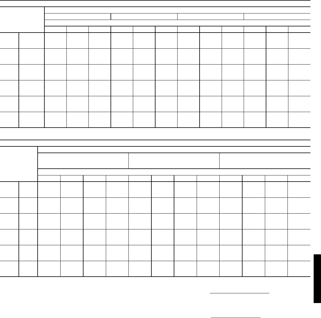
73
COOLING CAPACITIES — UNITS WITH HUMIDI-MIZER™ ADAPTIVE DEHUMIDIFICATION SYSTEM OPTION (cont)
LEGEND
*Negative SHC value indicates that the air entering the coil is being
heated.
NOTES:
1. Direct interpolation is permissible. Do not extrapolate.
2. The following formulas may be used:
Where: hewb = Enthalpy of air entering evaporator coil.
3. The SHC is based on 80 F edb temperature of air entering evapo-
rator coil.
Below 80 F edb, subtract (corr factor x cfm) from SHC.
Above 80 F edb, add (corr factor x cfm) to SHC.
Correction Factor = 1.10 x (1 – BF) x (edb – 80).
48HJ014 (121/2 TONS) — SUBCOOLING MODE
Temp (F)
Air Ent
Condenser
(Edb)
Air Entering Evaporator — Cfm/BF
3750/0.08 4300/0.09 5000/0.11 6250/0.13
Air Entering Evaporator — Ewb (F)
72 67 62 72 67 62 72 67 62 72 67 62
75
TC 156.3 144.2 132.3 160.0 148.4 136.2 162.8 150.6 138.2 169.0 157.5 145.6
SHC 66.6 87.6 112.1 72.5 94.8 121.3 76.9 99.6 127.5 87.0 115.5 142.7
kW 9.28 8.98 8.59 9.35 9.08 8.80 9.40 9.18 8.9 9.43 9.18 8.93
85
TC 147.6 136.2 123.7 150.7 140.1 127.2 154.1 140.8 127.9 161.1 148.0 135.4
SHC 58.7 80.0 103.8 63.5 86.5 112.2 68.7 91.0 118.1 77.7 107.8 133.2
kW 10.29 9.93 9.58 10.36 10.08 9.77 10.40 10.34 10.03 10.45 10.18 9.88
95
TC 138.9 128.2 115.1 141.4 131.8 118.3 145.3 131.0 117.6 153.1 138.4 125.1
SHC 50.8 72.3 95.5 54.4 78.1 103.2 60.5 82.3 108.7 68.5 100.0 123.7
kW 11.29 10.87 10.57 11.37 11.08 10.74 11.40 11.50 11.1 11.46 11.17 10.83
105
TC 129.1 117.8 105.8 131.7 121.0 108.7 134.8 119.9 107.7 140.9 126.9 115.9
SHC 42.1 63.5 86.5 45.4 69.0 93.9 51.2 74.2 101.3 57.7 90.2 113.6
kW 12.59 12.14 11.82 12.67 12.34 11.96 12.70 12.67 12.28 12.79 12.46 12.08
115
TC 119.2 107.3 96.4 122.1 110.2 99.0 124.2 108.8 97.8 128.7 115.3 106.7
SHC 33.5 54.8 77.5 36.4 59.8 84.7 41.9 66.1 93.8 46.8 80.5 103.5
kW 13.90 13.40 13.08 13.98 13.59 13.18 14.00 13.83 13.41 14.11 13.75 13.33
125
TC 109.4 96.9 87.1 112.4 99.4 89.3 113.7 97.7 87.8 116.5 103.8 97.5
SHC 24.8 46.0 68.5 27.4 50.7 75.5 32.6 58.0 86.4 36.0 70.7 93.5
kW 15.20 14.67 14.33 15.28 14.85 14.40 15.30 15.00 14.54 15.44 15.04 14.58
48HJ014 (121/2 TONS) — HOT GAS REHEAT MODE*
Temp (F)
Air Ent
Condenser
(Edb)
Air Entering Evaporator — Ewb (F)
75 Dry Bulb
62.5 Wet Bulb
(50% Relative)
75 Dry Bulb
64 Wet Bulb
(55% Relative)
75 Dry Bulb
65.3 Wet Bulb
(60% Relative)
Air Entering Evaporator — Cfm
3750 4300 5000 6250 3750 4300 5000 6250 3750 4300 5000 6250
80
TC 43.54 45.21 47.05 49.78 45.46 47.16 49.05 51.85 47.11 48.86 50.78 53.64
SHC -4.36 0.76 6.50 15.20 -9.51 -4.35 1.45 10.22 -13.97 -8.77 -2.93 5.90
kW 8.70 8.70 8.70 8.70 8.82 8.82 8.82 8.82 8.92 8.92 8.92 8.92
75
TC 44.45 46.02 47.75 50.32 46.33 47.94 49.71 52.34 47.96 49.60 51.41 54.10
SHC -3.84 0.96 6.36 14.53 -8.66 -3.81 1.63 9.86 -12.84 -7.96 -2.48 5.82
kW 8.90 8.90 8.90 8.90 9.03 9.03 9.03 9.03 9.14 9.14 9.14 9.14
70
TC 45.36 46.82 48.45 50.86 47.20 48.71 50.37 52.84 48.80 50.34 52.04 54.55
SHC -3.32 1.17 6.21 13.85 -7.81 -3.28 1.80 9.50 -11.71 -7.14 -2.02 5.74
kW 9.10 9.10 9.10 9.10 9.24 9.24 9.24 9.24 9.36 9.36 9.36 9.36
60
TC 47.17 48.44 49.84 51.93 48.95 50.25 51.69 53.83 50.49 51.82 53.29 55.47
SHC -2.28 1.59 5.93 12.50 -6.12 -2.22 2.16 8.79 -9.45 -5.52 -1.11 5.57
kW 9.51 9.51 9.51 9.51 9.66 9.66 9.66 9.66 9.80 9.80 9.80 9.80
50
TC 48.98 50.05 51.24 53.00 50.70 51.80 53.01 54.82 52.18 53.31 54.55 56.39
SHC -1.24 2.00 5.64 11.15 -4.43 -1.15 2.52 8.07 -7.18 -3.89 -0.19 5.41
kW 9.91 9.91 9.91 9.91 10.09 10.09 10.09 10.09 10.24 10.24 10.24 10.24
40
TC 50.79 51.67 52.64 54.07 52.44 53.34 54.33 55.80 53.87 54.79 55.80 57.30
SHC -0.20 2.41 5.35 9.80 -2.73 -.019 2.87 7.36 -4.92 -2.26 0.72 5.24
kW 10.31 10.31 10.31 10.31 10.51 10.51 10.51 10.51 10.68 10.68 10.68 10.68
BF — Bypass Factor
Edb — Entering Dry Bulb
Ewb — Entering Wet Bulb
kW — Compressor Motor Power Input
SHC — Sensible Heat Capacity (1000 Btuh) Gross
TC — Total Capacity (1000 Btuh) Gross
tldb =t
edb –sensible capacity (Btuh)
1.10 x cfm
tlwb = Wet-bulb temperature corresponding to enthalpy of air
leaving evaporator coil (hlwb)
hlwb =h
ewb –total capacity (Btuh)
4.5 x cfm
48HJ48HJ
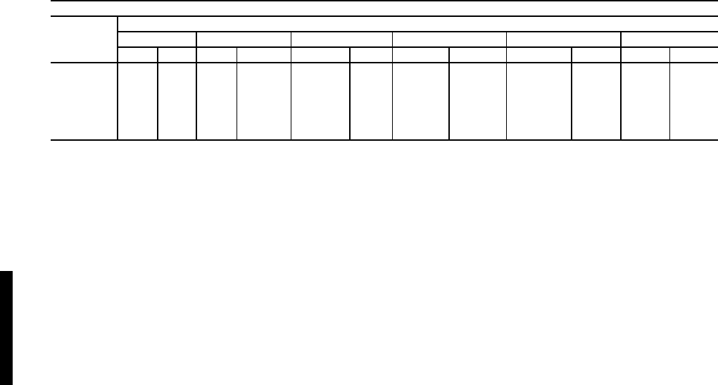
74
FAN PERFORMANCE — VERTICAL DISCHARGE UNITS
LEGEND
*Motor drive range: 680 to 1044 rpm. All other rpms require field-
supplied drive.
Refer to page 99 for general Fan Performance Data notes.
NOTES:
1. Boldface indicates field-supplied drive is required.
2. Maximum continuous bhp is 1.20.
48HE003 (2 Tons) - STANDARD MOTOR (BELT DRIVE)
AIRFLOW
(Cfm)
EXTERNALSTATIC PRESSURE (in. wg)
0.1 0.2 0.4 0.6 0.8 1.0
Rpm Bhp Rpm Bhp Rpm Bhp Rpm Bhp Rpm Bhp Rpm Bhp
600 500 0.08 531 0.08 607 0.14 713 0.21 788 0.29 878 0.37
700 529 0.09 567 0.09 633 0.16 739 0.24 816 0.32 902 0.41
800 547 0.1 592 0.12 660 0.19 761 0.27 845 0.37 937 0.47
900 570 0.13 620 0.14 691 0.22 793 0.32 870 0.42 957 0.53
1000 599 0.15 650 0.16 717 0.26 818 0.36 894 0.47 981 0.58
Bhp — Brake Horsepower
Watts — Input Watts to Motor
Performance data — 48HE/HJ (cont)
48HE/HJ
75
FAN PERFORMANCE — VERTICAL DISCHARGE UNITS
LEGEND
*Motor drive range: 680 to 1044 rpm. All other rpms require field-
supplied drive.
Refer to page 99 for general Fan Performance Data notes.
NOTES:
1. Boldface indicates field-supplied drive is required.
2. Maximum continuous bhp is 1.20.
LEGEND
*Motor drive range: 1075 to 1455 rpm. All other rpms require field-
supplied drive.
Refer to page 99 for general Fan Performance Data notes.
NOTES:
1. Boldface indicates field-supplied drive is required.
2. Maximum continuous bhp is 2.40.
3. See page 163 for general fan performance notes.
48HE/HJ004 (3 TONS) — STANDARD MOTOR (BELT DRIVE)*
Airflow
(Cfm)
External Static Pressure (in. wg)
0.2 0.4 0.6 0.8 1.0
Rpm Bhp Watts Rpm Bhp Watts Rpm Bhp Watts Rpm Bhp Watts Rpm Bhp Watts
900 567 0.15 145 688 0.22 222 786 0.30 296 871 0.37 368 947 0.44 437
1000 599 0.18 177 717 0.27 265 814 0.35 349 897 0.43 430 972 0.51 509
1100 632 0.22 215 747 0.31 313 842 0.41 407 925 0.50 498 999 0.59 587
1200 666 0.26 257 778 0.37 367 871 0.47 471 952 0.57 572 1025 0.67 670
1300 701 0.31 306 810 0.43 426 901 0.54 540 981 0.65 651 1053 0.76 760
1400 737 0.36 361 842 0.49 491 931 0.62 616 1010 0.74 738 1081 0.86 856
1500 773 0.42 422 875 0.57 564 963 0.70 699 1040 0.84 831 1110 0.96 960
48HE/HJ004 (3 TONS) — STANDARD MOTOR (BELT DRIVE)* (cont)
Airflow
(Cfm)
External Static Pressure (in. wg)
1.2 1.4 1.6 1.8 2.0
Rpm Bhp Watts Rpm Bhp Watts Rpm Bhp Watts Rpm Bhp Watts Rpm Bhp Watts
900 1016 0.51 505 1080 0.57 572 1139 0.64 637 1195 0.71 702 1249 0.77 765
1000 1041 0.59 587 1104 0.67 662 1163 0.74 737 1219 0.81 811 1272 0.89 883
1100 1066 0.68 674 1129 0.76 759 1188 0.85 843 1243 0.93 925 1296 1.01 1007
1200 1093 0.77 767 1155 0.87 861 1213 0.96 955 1268 1.05 1047 1321 1.14 1137
1300 1119 0.87 866 1181 0.98 970 1239 1.08 1073 1294 1.18 1175 ———
1400 1147 0.98 972 1208 1.09 1086 —————————
1500 1175 1.09 1086 ————————————
Bhp — Brake Horsepower
Watts — Input Watts to Motor
48HE/HJ004 (3 TONS) — HIGH-STATIC MOTOR (BELT DRIVE)*
Airflow
(Cfm)
External Static Pressure (in. wg)
0.2 0.4 0.6 0.8 1.0
Rpm Bhp Watts Rpm Bhp Watts Rpm Bhp Watts Rpm Bhp Watts Rpm Bhp Watts
900 567 0.15 145 688 0.22 222 786 0.30 296 871 0.37 368 947 0.44 437
1000 599 0.18 177 717 0.27 265 814 0.35 349 897 0.43 430 972 0.51 509
1100 632 0.22 215 747 0.31 313 842 0.41 407 925 0.50 498 999 0.59 587
1200 666 0.26 257 778 0.37 367 871 0.47 471 952 0.57 572 1025 0.67 670
1300 701 0.31 306 810 0.43 426 901 0.54 540 981 0.65 651 1053 0.76 760
1400 737 0.36 361 842 0.49 491 931 0.62 616 1010 0.74 738 1081 0.86 856
1500 773 0.42 422 875 0.57 564 963 0.70 699 1040 0.84 831 1110 0.96 960
48HE/HJ004 (3 TONS) — HIGH-STATIC MOTOR (BELT DRIVE)* (cont)
Airflow
(Cfm)
External Static Pressure (in. wg)
1.2 1.4 1.6 1.8 2.0
Rpm Bhp Watts Rpm Bhp Watts Rpm Bhp Watts Rpm Bhp Watts Rpm Bhp Watts
900 1016 0.51 505 1080 0.57 572 1139 0.64 637 1195 0.71 702 1249 0.77 765
1000 1041 0.59 587 1104 0.67 662 1163 0.74 737 1219 0.81 811 1272 0.89 883
1100 1066 0.68 674 1129 0.76 759 1188 0.85 843 1243 0.93 925 1296 1.01 1007
1200 1093 0.77 767 1155 0.87 861 1213 0.96 955 1268 1.05 1047 1321 1.14 1137
1300 1119 0.87 866 1181 0.98 970 1239 1.08 1073 1294 1.18 1175 1346 1.28 1275
1400 1147 0.98 972 1208 1.09 1086 1265 1.21 1199 1320 1.32 1310 1371 1.43 1419
1500 1175 1.09 1086 1235 1.22 1209 1292 1.34 1332 1346 1.46 1452 1397 1.58 1572
Bhp — Brake Horsepower
Watts — Input Watts to Motor
48HE/HJ
76
FAN PERFORMANCE — VERTICAL DISCHARGE UNITS (cont)
LEGEND
*Motor drive range: 770 to 1185 rpm. All other rpms require field-
supplied drive.
Refer to page 99 for general Fan Performance Data notes.
NOTES:
1. Boldface indicates field-supplied drive is required.
2. Maximum continuous bhp is 1.20.
LEGEND
*Motor drive range: 1075 to 1455 rpm. All other rpms require field-
supplied drive.
Refer to page 99 for general Fan Performance Data notes.
NOTES:
1. Boldface indicates field-supplied drive is required.
2. Maximum continuous bhp is 2.40.
48HE/HJ005 (4 TONS) — STANDARD MOTOR (BELT DRIVE)*
Airflow
(Cfm)
External Static Pressure (in. wg)
0.2 0.4 0.6 0.8 1.0
Rpm Bhp Watts Rpm Bhp Watts Rpm Bhp Watts Rpm Bhp Watts Rpm Bhp Watts
1200 666 0.26 257 778 0.37 367 871 0.47 471 952 0.57 572 1025 0.67 670
1300 701 0.31 306 810 0.43 426 901 0.54 540 981 0.65 651 1053 0.76 760
1400 737 0.36 361 842 0.49 491 931 0.62 616 1010 0.74 738 1081 0.86 856
1500 773 0.42 422 875 0.57 564 963 0.70 699 1040 0.84 831 1110 0.96 960
1600 810 0.49 491 909 0.65 643 994 0.79 790 1070 0.94 932 1140 1.08 1070
1700 847 0.57 567 943 0.73 730 1027 0.89 888 1101 1.05 1040 1170 1.20 1189
1800 885 0.66 652 978 0.83 826 1060 1.00 994 1133 1.16 1157 — — —
1900 923 0.75 745 1014 0.94 930 1093 1.11 1109 ——————
2000 962 0.85 847 1049 1.05 1043 —————————
48HE/HJ005 (4 TONS) — STANDARD MOTOR (BELT DRIVE)* (cont)
Airflow
(Cfm)
External Static Pressure (in. wg)
1.2 1.4 1.6 1.8 2.0
Rpm Bhp Watts Rpm Bhp Watts Rpm Bhp Watts Rpm Bhp Watts Rpm Bhp Watts
1200 1093 0.77 767 1155 0.87 861 1213 0.96 955 1268 1.05 1047 1321 1.14 1137
1300 1119 0.87 866 1181 0.98 970 1239 1.08 1073 1294 1.18 1175 ———
1400 1147 0.98 972 1208 1.09 1086 —————————
1500 1175 1.09 1086 — — — —————————
1600 ———————————————
1700 ———————————————
1800 ———————————————
1900 ———————————————
2000 ———————————————
Bhp — Brake Horsepower
Watts — Input Watts to Motor
48HE/HJ005 (4 TONS) — HIGH-STATIC MOTOR (BELT DRIVE)*
Airflow
(Cfm)
External Static Pressure (in. wg)
0.2 0.4 0.6 0.8 1.0
Rpm Bhp Watts Rpm Bhp Watts Rpm Bhp Watts Rpm Bhp Watts Rpm Bhp Watts
1200 666 0.26 257 778 0.37 367 871 0.47 471 952 0.57 572 1025 0.67 670
1300 701 0.31 306 810 0.43 426 901 0.54 540 981 0.65 651 1053 0.76 760
1400 737 0.36 361 842 0.49 491 931 0.62 616 1010 0.74 738 1081 0.86 856
1500 773 0.42 422 875 0.57 564 963 0.70 699 1040 0.84 831 1110 0.96 960
1600 810 0.49 491 909 0.65 643 994 0.79 790 1070 0.94 932 1140 1.08 1070
1700 847 0.57 567 943 0.73 730 1027 0.89 888 1101 1.05 1040 1170 1.20 1189
1800 885 0.66 652 978 0.83 826 1060 1.00 994 1133 1.16 1157 1200 1.32 1316
1900 923 0.75 745 1014 0.94 930 1093 1.11 1109 1165 1.29 1283 1231 1.46 1453
2000 962 0.85 847 1049 1.05 1043 1127 1.24 1233 1198 1.42 1417 1263 1.61 1598
48HE/HJ005 (4 TONS) — HIGH-STATIC MOTOR (BELT DRIVE)* (cont)
Airflow
(Cfm)
External Static Pressure (in. wg)
1.2 1.4 1.6 1.8 2.0
Rpm Bhp Watts Rpm Bhp Watts Rpm Bhp Watts Rpm Bhp Watts Rpm Bhp Watts
1200 1093 0.77 767 1155 0.87 861 1213 0.96 955 1268 1.05 1047 1321 1.14 1137
1300 1119 0.87 866 1181 0.98 970 1239 1.08 1073 1294 1.18 1175 1346 1.28 1275
1400 1147 0.98 972 1208 1.09 1086 1265 1.21 1199 1320 1.32 1310 1371 1.43 1419
1500 1175 1.09 1086 1235 1.22 1209 1292 1.34 1332 1346 1.46 1452 1397 1.58 1572
1600 1204 1.21 1207 1263 1.35 1340 1320 1.48 1472 1373 1.61 1603 1424 1.74 1732
1700 1233 1.34 1336 1292 1.49 1480 1348 1.63 1622 1401 1.77 1762 1451 1.91 1901
1800 1262 1.48 1473 1321 1.64 1627 1376 1.79 1779 1428 1.94 1930 1479 2.09 2078
1900 1293 1.63 1620 1350 1.79 1784 1405 1.96 1946 1457 2.12 2106 1506 2.28 2265
2000 1323 1.79 1776 1380 1.96 1950 1434 2.13 2123 1486 2.31 2293 ———
Bhp — Brake Horsepower
Watts — Input Watts to Motor
Performance data — 48HE/HJ (cont)
48HE/HJ
77
FAN PERFORMANCE — VERTICAL DISCHARGE UNITS (cont)
LEGEND
*Motor drive range: 1035 to 1460 rpm. All other rpms require field-supplied drive.
Refer to page 99 for general Fan Performance Data notes.
NOTES:
1. Boldface indicates field-supplied drive is required.
2. Maximum continuous bhp is 1.30.
LEGEND
*Motor drive range: 1035 to 1460 rpm. All other rpms require field-supplied drive.
Refer to page 99 for general Fan Performance Data notes.
NOTES:
1. Boldface indicates field-supplied drive is required.
2. Maximum continuous bhp is 2.40.
48HE/HJ006 (5 TONS) — STANDARD MOTOR (BELT DRIVE)* — SINGLE-PHASE UNITS
Airflow
(Cfm)
External Static Pressure (in. wg)
0.2 0.4 0.6 0.8 1.0
Rpm Bhp Watts Rpm Bhp Watts Rpm Bhp Watts Rpm Bhp Watts Rpm Bhp Watts
1500 848 0.42 371 968 0.55 486 1069 0.68 600 1158 0.80 715 1238 0.94 831
1600 887 0.49 433 1004 0.63 556 1103 0.76 678 1190 0.90 800 1269 1.04 922
1700 927 0.57 502 1040 0.71 633 1137 0.86 763 1223 1.00 892 1302 1.15 1022
1800 967 0.65 579 1077 0.81 718 1172 0.96 856 1257 1.12 993 1334 1.27 1130
1900 1007 0.75 663 1115 0.91 811 1208 1.08 957 1291 1.24 1101 — — —
2000 1048 0.85 757 1153 1.03 913 1244 1.20 1066 — — ————
2100 1090 0.97 859 1191 1.15 1023 —————————
2200 1131 1.09 970 1230 1.29 1143 —————————
2300 11731.231091————————————
2400 ———————————————
2500 ———————————————
48HE/HJ006 (5 TONS) — STANDARD MOTOR (BELT DRIVE)* — SINGLE-PHASE UNITS (cont)
Airflow
(Cfm)
External Static Pressure (in. wg)
1.2 1.4 1.6 1.8 2.0
Rpm Bhp Watts Rpm Bhp Watts Rpm Bhp Watts Rpm Bhp Watts Rpm Bhp Watts
1500 1312 1.07 948 1380 1.20 1067 —————————
1600 13421.181047————————————
1700 13741.301153————————————
1800 ———————————————
1900 ———————————————
2000 ———————————————
2100 ———————————————
2200 ———————————————
2300 ———————————————
2400 ———————————————
2500 ———————————————
Bhp — Brake Horsepower
Watts — Input Watts to Motor
48HE/HJ006 (5 TONS) — STANDARD MOTOR (BELT DRIVE)* — THREE-PHASE UNITS
Airflow
(Cfm)
External Static Pressure (in. wg)
0.2 0.4 0.6 0.8 1.0
Rpm Bhp Watts Rpm Bhp Watts Rpm Bhp Watts Rpm Bhp Watts Rpm Bhp Watts
1500 848 0.42 371 968 0.55 486 1069 0.68 600 1158 0.80 715 1238 0.94 831
1600 887 0.49 433 1004 0.63 556 1103 0.76 678 1190 0.90 800 1269 1.04 922
1700 927 0.57 502 1040 0.71 633 1137 0.86 763 1223 1.00 892 1302 1.15 1022
1800 967 0.65 579 1077 0.81 718 1172 0.96 856 1257 1.12 993 1334 1.27 1130
1900 1007 0.75 663 1115 0.91 811 1208 1.08 957 1291 1.24 1101 1368 1.40 1246
2000 1048 0.85 757 1153 1.03 913 1244 1.20 1066 1326 1.37 1219 1401 1.54 1371
2100 1090 0.97 859 1191 1.15 1023 1281 1.33 1185 1361 1.51 1345 1435 1.69 1505
2200 1131 1.09 970 1230 1.29 1143 1318 1.48 1313 1397 1.67 1481 1470 1.86 1649
2300 1173 1.23 1091 1269 1.43 1273 1355 1.63 1451 1433 1.83 1627 1505 2.03 1803
2400 1215 1.38 1223 1309 1.59 1413 1393 1.80 1600 1470 2.01 1784 1540 2.21 1967
2500 1258 1.54 1365 1349 1.76 1564 1431 1.98 1759 1506 2.20 1951 ———
48HE/HJ006 (5 TONS) — STANDARD MOTOR (BELT DRIVE)* — THREE-PHASE UNITS (cont)
Airflow
(Cfm)
External Static Pressure (in. wg)
1.2 1.4 1.6 1.8 2.0
Rpm Bhp Watts Rpm Bhp Watts Rpm Bhp Watts Rpm Bhp Watts Rpm Bhp Watts
1500 1312 1.07 948 1380 1.20 1067 1445 1.34 1189 1506 1.48 1312 1564 1.62 1437
1600 1342 1.18 1047 1411 1.32 1173 1474 1.46 1300 1535 1.61 1429 1593 1.76 1560
1700 1374 1.30 1153 1441 1.45 1286 1505 1.60 1420 1565 1.75 1555 1622 1.91 1692
1800 1406 1.43 1268 1473 1.58 1407 1535 1.74 1548 1595 1.90 1690 1652 2.06 1833
1900 1438 1.57 1391 1504 1.73 1537 1567 1.90 1685 1626 2.06 1833 1682 2.23 1983
2000 1471 1.72 1523 1536 1.89 1677 1598 2.06 1831 1657 2.24 1986 ———
2100 1504 1.87 1665 1569 2.06 1825 1630 2.24 1986 ——————
2200 1538 2.04 1816 1602 2.23 1984 —————————
2300 1572 2.23 1978 ————————————
2400 ———————————————
2500 ———————————————
Bhp — Brake Horsepower
Watts — Input Watts to Motor
48HE/HJ
78
FAN PERFORMANCE — VERTICAL DISCHARGE UNITS (cont)
LEGEND
*Motor drive range: 1300 to 1685 rpm. All other rpms require field-supplied drive.
Refer to page 99 for general Fan Performance Data notes.
NOTES:
1. Boldface indicates field-supplied drive is required.
2. Maximum continuous bhp is 2.90.
LEGEND
*Motor drive range: 1119 to 1585 rpm. All other rpms require field-supplied drive.
Refer to page 99 for general Fan Performance Data notes.
NOTES:
1. Boldface indicates field-supplied drive is required.
2. Maximum continuous bhp is 2.40.
48HE/HJ006 (5 TONS) — HIGH-STATIC MOTOR (BELT DRIVE)*
Airflow
(Cfm)
External Static Pressure (in. wg)
0.2 0.4 0.6 0.8 1.0
Rpm Bhp Watts Rpm Bhp Watts Rpm Bhp Watts Rpm Bhp Watts Rpm Bhp Watts
1500 848 0.42 371 968 0.55 486 1069 0.68 600 1158 0.80 715 1238 0.94 831
1600 887 0.49 433 1004 0.63 556 1103 0.76 678 1190 0.90 800 1269 1.04 922
1700 927 0.57 502 1040 0.71 633 1137 0.86 763 1223 1.00 892 1302 1.15 1022
1800 967 0.65 579 1077 0.81 718 1172 0.96 856 1257 1.12 993 1334 1.27 1130
1900 1007 0.75 663 1115 0.91 811 1208 1.08 957 1291 1.24 1101 1368 1.40 1246
2000 1048 0.85 757 1153 1.03 913 1244 1.20 1066 1326 1.37 1219 1401 1.54 1371
2100 1090 0.97 859 1191 1.15 1023 1281 1.33 1185 1361 1.51 1345 1435 1.69 1505
2200 1131 1.09 970 1230 1.29 1143 1318 1.48 1313 1397 1.67 1481 1470 1.86 1649
2300 1173 1.23 1091 1269 1.43 1273 1355 1.63 1451 1433 1.83 1627 1505 2.03 1803
2400 1215 1.38 1223 1309 1.59 1413 1393 1.80 1600 1470 2.01 1784 1540 2.21 1967
2500 1258 1.54 1365 1349 1.76 1564 1431 1.98 1759 1506 2.20 1951 1576 2.41 2142
48HE/HJ006 (5 TONS) — HIGH-STATIC MOTOR (BELT DRIVE)* (cont)
Airflow
(Cfm)
External Static Pressure (in. wg)
1.2 1.4 1.6 1.8 2.0
Rpm Bhp Watts Rpm Bhp Watts Rpm Bhp Watts Rpm Bhp Watts Rpm Bhp Watts
1500 1312 1.07 948 1380 1.20 1067 1445 1.34 1189 1506 1.48 1312 1564 1.62 1437
1600 1342 1.18 1047 1411 1.32 1173 1474 1.46 1300 1535 1.61 1429 1593 1.76 1560
1700 1374 1.30 1153 1441 1.45 1286 1505 1.60 1420 1565 1.75 1555 1622 1.91 1692
1800 1406 1.43 1268 1473 1.58 1407 1535 1.74 1548 1595 1.90 1690 1652 2.06 1833
1900 1438 1.57 1391 1504 1.73 1537 1567 1.90 1685 1626 2.06 1833 1682 2.23 1983
2000 1471 1.72 1523 1536 1.89 1677 1598 2.06 1831 1657 2.24 1986 1713 2.41 2142
2100 1504 1.87 1665 1569 2.06 1825 1630 2.24 1986 1688 2.42 2149 1744 2.60 2312
2200 1538 2.04 1816 1602 2.23 1984 1663 2.42 2152 1720 2.61 2321 1775 2.81 2491
2300 1572 2.23 1978 1635 2.42 2153 1695 2.62 2328 1753 2.82 2504 ———
2400 1607 2.42 2150 1669 2.63 2332 1729 2.83 2515 ——————
2500 1642 2.63 2333 1704 2.84 2523 —————————
Bhp — Brake Horsepower
Watts — Input Watts to Motor
48HJ007 (6 TONS) — STANDARD MOTOR (BELT DRIVE)*
Airflow
(Cfm)
External Static Pressure (in. wg)
0.2 0.4 0.6 0.8 1.0
Rpm Bhp Watts Rpm Bhp Watts Rpm Bhp Watts Rpm Bhp Watts Rpm Bhp Watts
1800 967 0.63 563 1075 0.80 715 1170 0.97 861 1255 1.13 1002 1333 1.28 1139
1900 1008 0.72 643 1112 0.91 805 1205 1.08 960 1289 1.25 1111 1366 1.42 1258
2000 1049 0.82 731 1151 1.02 903 1241 1.20 1068 1323 1.38 1228 1399 1.56 1384
2100 1091 0.93 827 1189 1.14 1008 1278 1.33 1183 1358 1.52 1353 1433 1.71 1519
2200 1133 1.05 933 1229 1.26 1123 1315 1.47 1308 1393 1.67 1487 1467 1.87 1662
2300 1176 1.18 1047 1268 1.40 1247 1352 1.62 1441 1429 1.84 1630 1501 2.04 1815
2400 1218 1.32 1170 1308 1.55 1380 1390 1.78 1584 1466 2.01 1782 1537 2.23 1977
2500 1261 1.47 1304 1349 1.72 1523 1429 1.96 1736 1503 2.19 1945 — — —
2600 1305 1.63 1448 1390 1.89 1677 1468 2.14 1900 1540 2.38 2117 — — —
2700 1348 1.80 1602 1431 2.07 1841 1507 2.33 2073 — — ————
2800 1392 1.99 1768 1472 2.27 2016 —————————
2900 14352.191945————————————
3000 14792.402135————————————
48HJ007 (6 TONS) — STANDARD MOTOR (BELT DRIVE)* (cont)
Airflow
(Cfm)
External Static Pressure (in. wg)
1.2 1.4 1.6 1.8 2.0
Rpm Bhp Watts Rpm Bhp Watts Rpm Bhp Watts Rpm Bhp Watts Rpm Bhp Watts
1800 1406 1.43 1273 1475 1.58 1403 1540 1.72 1531 1601 1.87 1657 1660 2.00 1780
1900 1438 1.58 1401 1505 1.73 1541 1569 1.89 1678 1630 2.04 1813 1689 2.19 1945
2000 1470 1.73 1537 1537 1.90 1686 1600 2.06 1833 1660 2.23 1977 1718 2.38 2118
2100 1502 1.89 1681 1568 2.07 1840 1631 2.25 1996 ——————
2200 1535 2.06 1834 1600 2.25 2002 —————————
2300 15692.251996————————————
2400 ———————————————
2500 ———————————————
2600 ———————————————
2700 ———————————————
2800 ———————————————
2900 ———————————————
3000 ———————————————
Bhp — Brake Horsepower
Watts — Input Watts to Motor
Performance data — 48HE/HJ (cont)
48HE/HJ
79
FAN PERFORMANCE — VERTICAL DISCHARGE UNITS (cont)
LEGEND
*Motor drive range: 1300 to 1685 rpm. All other rpms require field-
supplied drive.
Refer to page 99 for general Fan Performance Data notes.
NOTES:
1. Boldface indicates field-supplied drive is required.
2. Maximum continuous bhp is 2.90.
48HJ007 (6 TONS) — HIGH-STATIC MOTOR (BELT DRIVE)*
Airflow
(Cfm)
External Static Pressure (in. wg)
0.2 0.4 0.6 0.8 1.0
Rpm Bhp Watts Rpm Bhp Watts Rpm Bhp Watts Rpm Bhp Watts Rpm Bhp Watts
1800 967 0.63 563 1075 0.80 715 1170 0.97 861 1255 1.13 1002 1333 1.28 1139
1900 1008 0.72 643 1112 0.91 805 1205 1.08 960 1289 1.25 1111 1366 1.42 1258
2000 1049 0.82 731 1151 1.02 903 1241 1.20 1068 1323 1.38 1228 1399 1.56 1384
2100 1091 0.93 827 1189 1.14 1008 1278 1.33 1183 1358 1.52 1353 1433 1.71 1519
2200 1133 1.05 933 1229 1.26 1123 1315 1.47 1308 1393 1.67 1487 1467 1.87 1662
2300 1176 1.18 1047 1268 1.40 1247 1352 1.62 1441 1429 1.84 1630 1501 2.04 1815
2400 1218 1.32 1170 1308 1.55 1380 1390 1.78 1584 1466 2.01 1782 1537 2.23 1977
2500 1261 1.47 1304 1349 1.72 1523 1429 1.96 1736 1503 2.19 1945 1572 2.42 2149
2600 1305 1.63 1448 1390 1.89 1677 1468 2.14 1900 1540 2.38 2117 1608 2.62 2331
2700 1348 1.80 1602 1431 2.07 1841 1507 2.33 2073 1578 2.59 2301 1645 2.84 2524
2800 1392 1.99 1768 1472 2.27 2016 1547 2.54 2258 1616 2.81 2495 — — —
2900 1435 2.19 1945 1514 2.48 2203 1587 2.76 2455 ——————
3000 1479 2.40 2135 1556 2.70 2402 —————————
48HJ007 (6 TONS) — HIGH-STATIC MOTOR (BELT DRIVE)* (cont)
Airflow
(Cfm)
External Static Pressure (in. wg)
1.2 1.4 1.6 1.8 2.0
Rpm Bhp Watts Rpm Bhp Watts Rpm Bhp Watts Rpm Bhp Watts Rpm Bhp Watts
1800 1406 1.43 1273 1475 1.58 1403 1540 1.72 1531 1601 1.87 1657 1660 2.00 1780
1900 1438 1.58 1401 1505 1.73 1541 1569 1.89 1678 1630 2.04 1813 1689 2.19 1945
2000 1470 1.73 1537 1537 1.90 1686 1600 2.06 1833 1660 2.23 1977 1718 2.38 2118
2100 1502 1.89 1681 1568 2.07 1840 1631 2.25 1996 1690 2.42 2149 1747 2.59 2300
2200 1535 2.06 1834 1600 2.25 2002 1662 2.44 2167 1721 2.62 2330 1778 2.80 2490
2300 1569 2.25 1996 1633 2.45 2174 1694 2.64 2348 1752 2.84 2520 ———
2400 1603 2.44 2167 1666 2.65 2355 1727 2.86 2539 ——————
2500 1638 2.64 2349 1700 2.87 2546 —————————
2600 1673 2.86 2541 — — — —————————
2700 ———————————————
2800 ———————————————
2900 ———————————————
3000 ———————————————
Bhp — Brake Horsepower
Watts — Input Watts to Motor
48HJ
80
FAN PERFORMANCE — VERTICAL DISCHARGE UNITS (cont)
LEGEND
*Motor drive range: 840 to 1085 rpm. All other rpms require field-
supplied drive.
Refer to page 99 for general Fan Performance Data notes.
NOTES:
1. Boldface indicates field-supplied drive is required.
2. Maximum continuous bhp is 2.90.
48HJ008 (71/2 TONS) — STANDARD MOTOR (BELT DRIVE)*
Airflow
(Cfm)
External Static Pressure (in. wg)
0.2 0.4 0.6 0.8 1.0
Rpm Bhp Watts Rpm Bhp Watts Rpm Bhp Watts Rpm Bhp Watts Rpm Bhp Watts
2250 513 0.54 505 595 0.76 713 665 1.01 940 728 1.27 1187 786 1.56 1453
2300 521 0.57 531 601 0.79 741 671 1.04 972 734 1.31 1222 791 1.60 1489
2400 535 0.63 584 615 0.86 802 684 1.11 1038 745 1.39 1293 802 1.68 1566
2500 551 0.69 642 628 0.93 866 696 1.19 1109 757 1.47 1369 813 1.77 1647
2550 558 0.72 673 635 0.97 900 702 1.23 1146 763 1.51 1409 818 1.81 1689
2600 566 0.76 705 642 1.00 935 709 1.27 1183 769 1.55 1450 824 1.86 1732
2700 582 0.83 771 656 1.08 1008 721 1.35 1263 781 1.65 1535 835 1.95 1823
2800 597 0.90 842 670 1.16 1086 734 1.44 1347 793 1.74 1625 847 2.06 1917
2900 613 0.98 918 684 1.25 1169 748 1.54 1436 805 1.84 1720 859 2.16 2019
3000 629 1.07 999 699 1.35 1256 761 1.64 1530 818 1.95 1820 871 2.28 2125
3100 645 1.16 1085 713 1.45 1349 775 1.75 1630 831 2.06 1925 883 2.40 2235
3200 662 1.26 1176 728 1.55 1448 788 1.86 1734 844 2.18 2036 895 2.52 2352
3300 678 1.36 1272 743 1.66 1551 802 1.98 1845 857 2.31 2152 908 2.65 2475
3400 694 1.47 1374 758 1.78 1660 816 2.10 1961 870 2.44 2275 920 2.79 2603
3500 711 1.59 1482 773 1.90 1775 831 2.23 2082 884 2.58 2402 — — —
3600 727 1.71 1596 789 2.03 1896 845 2.37 2210 897 2.72 2537 — — —
3700 744 1.84 1716 804 2.17 2023 860 2.51 2343 911 2.87 2677 — — —
3750 752 1.91 1778 812 2.24 2089 867 2.59 2413 — — — — — —
48HJ008 (71/2 TONS) — STANDARD MOTOR (BELT DRIVE)* (cont)
Airflow
(Cfm)
External Static Pressure (in. wg)
1.2 1.4 1.6 1.8 2.0
Rpm Bhp Watts Rpm Bhp Watts Rpm Bhp Watts Rpm Bhp Watts Rpm Bhp Watts
2250 839 1.86 1735 889 2.18 2032 935 2.52 2345 980 2.87 2673 — — —
2300 844 1.90 1773 893 2.22 2073 940 2.56 2389 — — — — — —
2400 854 1.99 1855 903 2.32 2159 950 2.66 2478 — — — — — —
2500 865 2.08 1940 913 2.41 2249 959 2.76 2573 — — — — — —
2550 870 2.13 1985 918 2.46 2296 964 2.81 2622 — — — — — —
2600 875 2.18 2031 923 2.51 2344 969 2.87 2673 — — — — — —
2700 886 2.28 2126 934 2.62 2445 — — — — — — — — —
2800 897 2.39 2227 944 2.73 2550 — — — — — — — — —
2900 908 2.50 2333 955 2.85 2661 — — — — — — — — —
3000 920 2.62 2443 — — — — — — — — — — — —
3100 931 2.75 2560 — — — — — — — — — — — —
3200 943 2.88 2682 — — — — — — — — — — — —
3300 ———————————————
3400 ———————————————
3500 ———————————————
3600 ———————————————
3700 ———————————————
3750 ———————————————
Bhp — Brake Horsepower Input to Fan
Watts — Input Watts to Motor
Performance data — 48HJ (cont)
48HJ48HJ
81
FAN PERFORMANCE — VERTICAL DISCHARGE UNITS (cont)
LEGEND
*Motor drive range: 860 to 1080 rpm. All other rpms require field-
supplied drive.
Refer to page 99 for general Fan Performance Data notes.
NOTES:
1. Boldface indicates field-supplied drive is required.
2. Maximum continuous bhp is 4.20.
48HJ008 (71/2 TONS) — HIGH-STATIC MOTOR (BELT DRIVE)*
Airflow
(Cfm)
External Static Pressure (in. wg)
0.2 0.4 0.6 0.8 1.0
Rpm Bhp Watts Rpm Bhp Watts Rpm Bhp Watts Rpm Bhp Watts Rpm Bhp Watts
2250 513 0.54 505 595 0.76 713 665 1.01 940 728 1.27 1187 786 1.56 1453
2300 521 0.57 531 601 0.79 741 671 1.04 972 734 1.31 1222 791 1.60 1489
2400 535 0.63 584 615 0.86 802 684 1.11 1038 745 1.39 1293 802 1.68 1566
2500 551 0.69 642 628 0.93 866 696 1.19 1109 757 1.47 1369 813 1.77 1647
2550 558 0.72 673 635 0.97 900 702 1.23 1146 763 1.51 1409 818 1.81 1689
2600 566 0.76 705 642 1.00 935 709 1.27 1183 769 1.55 1450 824 1.86 1732
2700 582 0.83 771 656 1.08 1008 721 1.35 1263 781 1.65 1535 835 1.95 1823
2800 597 0.90 842 670 1.16 1086 734 1.44 1347 793 1.74 1625 847 2.06 1917
2900 613 0.98 918 684 1.25 1169 748 1.54 1436 805 1.84 1720 859 2.16 2019
3000 629 1.07 999 699 1.35 1256 761 1.64 1530 818 1.95 1820 871 2.28 2125
3100 645 1.16 1085 713 1.45 1349 775 1.75 1630 831 2.06 1925 883 2.40 2235
3200 662 1.26 1176 728 1.55 1448 788 1.86 1734 844 2.18 2036 895 2.52 2352
3300 678 1.36 1272 743 1.66 1551 802 1.98 1845 857 2.31 2152 908 2.65 2475
3400 694 1.47 1374 758 1.78 1660 816 2.10 1961 870 2.44 2275 920 2.79 2603
3500 711 1.59 1482 773 1.90 1775 831 2.23 2082 884 2.58 2402 933 2.93 2737
3600 727 1.71 1596 789 2.03 1896 845 2.37 2210 897 2.72 2537 946 3.09 2877
3700 744 1.84 1716 804 2.17 2023 860 2.51 2343 911 2.87 2677 959 3.24 3023
3750 752 1.91 1778 812 2.24 2089 867 2.59 2413 918 2.95 2750 966 3.32 3100
48HJ008 (71/2 TONS) — HIGH-STATIC MOTOR (BELT DRIVE)* (cont)
Airflow
(Cfm)
External Static Pressure (in. wg)
1.2 1.4 1.6 1.8 2.0
Rpm Bhp Watts Rpm Bhp Watts Rpm Bhp Watts Rpm Bhp Watts Rpm Bhp Watts
2250 839 1.86 1735 889 2.18 2032 935 2.52 2345 980 2.87 2673 1022 3.23 3015
2300 844 1.90 1773 893 2.22 2073 940 2.56 2389 984 2.91 2718 1027 3.28 3062
2400 854 1.99 1855 903 2.32 2159 950 2.66 2478 993 3.02 2812 1035 3.39 3159
2500 865 2.08 1940 913 2.41 2249 959 2.76 2573 1003 3.12 2911 1044 3.50 3261
2550 870 2.13 1985 918 2.46 2296 964 2.81 2622 1008 3.18 2962 1049 3.55 3315
2600 875 2.18 2031 923 2.51 2344 969 2.87 2673 1012 3.23 3014 1054 3.61 3370
2700 886 2.28 2126 934 2.62 2445 979 2.98 2777 1022 3.35 3123 1063 3.74 3483
2800 897 2.39 2227 944 2.73 2550 989 3.10 2888 1032 3.47 3238 1073 3.86 3601
2900 908 2.50 2333 955 2.85 2661 1000 3.22 3003 1042 3.60 3358 1083 4.00 3725
3000 920 2.62 2443 966 2.98 2777 1010 3.35 3123 1052 3.74 3484 1093 4.14 3856
3100 931 2.75 2560 977 3.11 2899 1021 3.49 3250 1063 3.88 3615 — — —
3200 943 2.88 2682 989 3.25 3026 1032 3.63 3383 1074 4.02 3752 — — —
3300 955 3.01 2810 1000 3.39 3159 1043 3.78 3521 1084 4.18 3896 —— —
3400 967 3.16 2945 1012 3.54 3299 1055 3.93 3667 — — — — — —
3500 980 3.31 3084 1024 3.69 3445 1066 4.09 3817 — — — — — —
3600 992 3.46 3230 1036 3.86 3596 — — — — — — — — —
3700 1005 3.63 3383 1048 4.03 3755 — — — — — — — — —
3750 1011 3.71 3462 1054 4.11 3836 — — — — — — — — —
Bhp — Brake Horsepower Input to Fan
Watts — Input Watts to Motor
48HJ
82
FAN PERFORMANCE — VERTICAL DISCHARGE UNITS (cont)
LEGEND
*Motor drive range: 840 to 1085 rpm. All other rpms require field-
supplied drive.
Refer to page 99 for general Fan Performance Data notes.
NOTES:
1. Boldface indicates field-supplied drive is required.
2. Maximum continuous bhp is 2.90.
48HJ009 (81/2 TONS) — STANDARD MOTOR (BELT DRIVE)*
Airflow
(Cfm)
External Static Pressure (in. wg)
0.2 0.4 0.6 0.8 1.0
Rpm Bhp Watts Rpm Bhp Watts Rpm Bhp Watts Rpm Bhp Watts Rpm Bhp Watts
2500 541 0.50 467 624 0.66 614 701 0.83 771 771 1.00 936 837 1.19 1109
2600 556 0.55 513 637 0.71 665 711 0.89 827 781 1.07 996 845 1.26 1173
2700 571 0.60 562 650 0.77 720 722 0.95 885 790 1.14 1059 854 1.33 1241
2800 586 0.66 615 663 0.83 777 734 1.02 948 800 1.21 1126 863 1.41 1312
2900 601 0.72 672 676 0.90 839 745 1.09 1014 811 1.28 1197 872 1.49 1387
3000 616 0.79 732 689 0.97 904 757 1.16 1083 821 1.36 1271 882 1.57 1465
3100 632 0.85 796 703 1.04 972 769 1.24 1157 832 1.45 1349 892 1.66 1548
3200 648 0.93 864 717 1.12 1045 782 1.32 1235 843 1.53 1431 902 1.75 1635
3300 663 1.00 936 731 1.20 1122 795 1.41 1316 855 1.63 1517 912 1.85 1725
3400 679 1.09 1012 745 1.29 1203 808 1.50 1402 867 1.72 1608 923 1.95 1820
3500 695 1.17 1092 760 1.38 1288 821 1.60 1492 879 1.83 1703 934 2.06 1920
3600 711 1.26 1177 774 1.48 1379 834 1.70 1587 891 1.93 1802 945 2.17 2024
3700 728 1.36 1266 789 1.58 1473 848 1.81 1686 904 2.04 1906 957 2.29 2132
3800 744 1.46 1361 804 1.69 1572 861 1.92 1790 916 2.16 2015 969 2.41 2246
3900 760 1.57 1460 819 1.80 1676 875 2.04 1899 929 2.28 2128 981 2.53 2364
4000 777 1.68 1563 834 1.91 1785 889 2.16 2012 942 2.41 2247 993 2.67 2487
4100 793 1.79 1672 850 2.04 1899 904 2.29 2132 956 2.54 2371 1006 2.80 2615
4200 810 1.92 1786 865 2.16 2018 918 2.42 2255 969 2.68 2499 — — —
4300 826 2.04 1906 880 2.30 2142 932 2.56 2385 983 2.82 2633 — — —
48HJ009 (81/2 TONS) — STANDARD MOTOR (BELT DRIVE)* (cont)
Airflow
(Cfm)
External Static Pressure (in. wg)
1.2 1.4 1.6 1.8 2.0
Rpm Bhp Watts Rpm Bhp Watts Rpm Bhp Watts Rpm Bhp Watts Rpm Bhp Watts
2500 900 1.38 1289 959 1.58 1476 1015 1.79 1669 1069 2.00 1868 1121 2.22 2073
2600 907 1.46 1357 965 1.66 1548 1021 1.87 1745 1074 2.09 1948 1125 2.31 2158
2700 914 1.53 1429 972 1.74 1624 1027 1.96 1825 1079 2.18 2032 1130 2.41 2245
2800 922 1.61 1505 979 1.83 1704 1033 2.05 1909 1085 2.27 2120 1135 2.51 2337
2900 931 1.70 1584 986 1.92 1787 1040 2.14 1996 1091 2.37 2211 1141 2.61 2432
3000 939 1.79 1667 994 2.01 1874 1047 2.24 2087 1098 2.47 2307 1147 2.71 2532
3100 948 1.88 1753 1002 2.11 1965 1054 2.34 2183 1105 2.58 2406 1153 2.83 2635
3200 957 1.98 1844 1011 2.21 2060 1062 2.45 2283 1112 2.69 2510 —— —
3300 967 2.08 1939 1020 2.32 2160 1070 2.56 2386 1119 2.81 2618 —— —
3400 977 2.19 2039 1029 2.43 2264 1079 2.67 2494 — — — — — —
3500 987 2.30 2143 1038 2.54 2372 1088 2.80 2607 —— — —— —
3600 998 2.41 2251 1048 2.66 2485 — — — — — — — — —
3700 1008 2.54 2364 1058 2.79 2602 — — — — — — — — —
3800 1019 2.66 2482 — — — — — — — — — — — —
3900 1031 2.79 2605 — — — — — — — — — — — —
4000 ———————————————
4100 ———————————————
4200 ———————————————
4300 ———————————————
Bhp — Brake Horsepower Input to Fan
Watts — Input Watts to Motor
Performance data — 48HJ (cont)
48HJ48HJ
83
FAN PERFORMANCE — VERTICAL DISCHARGE UNITS (cont)
LEGEND
*Motor drive range: 860 to 1080 rpm. All other rpms require field-
supplied drive.
Refer to page 99 for general Fan Performance Data notes.
NOTES:
1. Boldface indicates field-supplied drive is required.
2. Maximum continuous bhp is 4.20.
48HJ009 (81/2 TONS) — HIGH-STATIC MOTOR (BELT DRIVE)*
Airflow
(Cfm)
External Static Pressure (in. wg)
0.2 0.4 0.6 0.8 1.0
Rpm Bhp Watts Rpm Bhp Watts Rpm Bhp Watts Rpm Bhp Watts Rpm Bhp Watts
2500 541 0.50 467 624 0.66 614 701 0.83 771 771 1.00 936 837 1.19 1109
2600 556 0.55 513 637 0.71 665 711 0.89 827 781 1.07 996 845 1.26 1173
2700 571 0.60 562 650 0.77 720 722 0.95 885 790 1.14 1059 854 1.33 1241
2800 586 0.66 615 663 0.83 777 734 1.02 948 800 1.21 1126 863 1.41 1312
2900 601 0.72 672 676 0.90 839 745 1.09 1014 811 1.28 1197 872 1.49 1387
3000 616 0.79 732 689 0.97 904 757 1.16 1083 821 1.36 1271 882 1.57 1465
3100 632 0.85 796 703 1.04 972 769 1.24 1157 832 1.45 1349 892 1.66 1548
3200 648 0.93 864 717 1.12 1045 782 1.32 1235 843 1.53 1431 902 1.75 1635
3300 663 1.00 936 731 1.20 1122 795 1.41 1316 855 1.63 1517 912 1.85 1725
3400 679 1.09 1012 745 1.29 1203 808 1.50 1402 867 1.72 1608 923 1.95 1820
3500 695 1.17 1092 760 1.38 1288 821 1.60 1492 879 1.83 1703 934 2.06 1920
3600 711 1.26 1177 774 1.48 1379 834 1.70 1587 891 1.93 1802 945 2.17 2024
3700 728 1.36 1266 789 1.58 1473 848 1.81 1686 904 2.04 1906 957 2.29 2132
3800 744 1.46 1361 804 1.69 1572 861 1.92 1790 916 2.16 2015 969 2.41 2246
3900 760 1.57 1460 819 1.80 1676 875 2.04 1899 929 2.28 2128 981 2.53 2364
4000 777 1.68 1563 834 1.91 1785 889 2.16 2012 942 2.41 2247 993 2.67 2487
4100 793 1.79 1672 850 2.04 1899 904 2.29 2132 956 2.54 2371 1006 2.80 2615
4200 810 1.92 1786 865 2.16 2018 918 2.42 2255 969 2.68 2499 1018 2.95 2748
4300 826 2.04 1906 880 2.30 2142 932 2.56 2385 983 2.82 2633 1031 3.10 2888
48HJ009 (81/2 TONS) — HIGH-STATIC MOTOR (BELT DRIVE)* (cont)
Airflow
(Cfm)
External Static Pressure (in. wg)
1.2 1.4 1.6 1.8 2.0
Rpm Bhp Watts Rpm Bhp Watts Rpm Bhp Watts Rpm Bhp Watts Rpm Bhp Watts
2500 900 1.38 1289 959 1.58 1476 1015 1.79 1669 1069 2.00 1868 1121 2.22 2073
2600 907 1.46 1357 965 1.66 1548 1021 1.87 1745 1074 2.09 1948 1125 2.31 2158
2700 914 1.53 1429 972 1.74 1624 1027 1.96 1825 1079 2.18 2032 1130 2.41 2245
2800 922 1.61 1505 979 1.83 1704 1033 2.05 1909 1085 2.27 2120 1135 2.51 2337
2900 931 1.70 1584 986 1.92 1787 1040 2.14 1996 1091 2.37 2211 1141 2.61 2432
3000 939 1.79 1667 994 2.01 1874 1047 2.24 2087 1098 2.47 2307 1147 2.71 2532
3100 948 1.88 1753 1002 2.11 1965 1054 2.34 2183 1105 2.58 2406 1153 2.83 2635
3200 957 1.98 1844 1011 2.21 2060 1062 2.45 2283 1112 2.69 2510 1160 2.94 2743
3300 967 2.08 1939 1020 2.32 2160 1070 2.56 2386 1119 2.81 2618 1167 3.06 2855
3400 977 2.19 2039 1029 2.43 2264 1079 2.67 2494 1127 2.93 2730 1174 3.19 2971
3500 987 2.30 2143 1038 2.54 2372 1088 2.80 2607 1135 3.05 2847 1181 3.32 3092
3600 998 2.41 2251 1048 2.66 2485 1097 2.92 2724 1144 3.18 2968 1189 3.45 3218
3700 1008 2.54 2364 1058 2.79 2602 1106 3.05 2846 1152 3.32 3094 1198 3.59 3348
3800 1019 2.66 2482 1068 2.92 2725 1116 3.19 2972 1162 3.46 3226 1206 3.74 3484
3900 1031 2.79 2605 1079 3.06 2852 1126 3.33 3104 1171 3.61 3362 1215 3.89 3624
4000 1042 2.93 2733 1090 3.20 2984 1136 3.48 3241 1180 3.76 3503 1224 4.04 3770
4100 1054 3.07 2866 1101 3.35 3122 1146 3.63 3383 1190 3.91 3649 1233 4.20 3921
4200 1066 3.22 3004 1112 3.50 3264 1157 3.79 3530 1200 4.08 3801 —— —
4300 1078 3.38 3148 1123 3.66 3413 1167 3.95 3683 —— — —— —
Bhp — Brake Horsepower Input to Fan
Watts — Input Watts to Motor
48HJ
84
FAN PERFORMANCE — VERTICAL DISCHARGE UNITS (cont)
LEGEND
*Motor drive range: 860 to 1080 rpm. All other rpms require field-
supplied drive.
Refer to page 99 for general Fan Performance Data notes.
NOTES:
1. Boldface indicates field-supplied drive is required.
2. Maximum continuous bhp is 3.70.
48HJ012 (10 TONS) — STANDARD MOTOR (BELT DRIVE)*
Airflow
(Cfm)
External Static Pressure (in. wg)
0.2 0.4 0.6 0.8 1.0
Rpm Bhp Watts Rpm Bhp Watts Rpm Bhp Watts Rpm Bhp Watts Rpm Bhp Watts
3000 616 0.79 732 689 0.97 904 757 1.16 1083 821 1.36 1271 882 1.57 1465
3100 632 0.85 796 703 1.04 972 769 1.24 1157 832 1.45 1349 892 1.66 1548
3200 648 0.93 864 717 1.12 1045 782 1.32 1235 843 1.53 1431 902 1.75 1635
3300 663 1.00 936 731 1.20 1122 795 1.41 1316 855 1.63 1517 912 1.85 1725
3400 679 1.09 1012 745 1.29 1203 808 1.50 1402 867 1.72 1608 923 1.95 1820
3500 695 1.17 1092 760 1.38 1288 821 1.60 1492 879 1.83 1703 934 2.06 1920
3600 711 1.26 1177 774 1.48 1379 834 1.70 1587 891 1.93 1802 945 2.17 2024
3700 728 1.36 1266 789 1.58 1473 848 1.81 1686 904 2.04 1906 957 2.29 2132
3800 744 1.46 1361 804 1.69 1572 861 1.92 1790 916 2.16 2015 969 2.41 2246
3900 760 1.57 1460 819 1.80 1676 875 2.04 1899 929 2.28 2128 981 2.53 2364
4000 777 1.68 1563 834 1.91 1785 889 2.16 2012 942 2.41 2247 993 2.67 2487
4100 793 1.79 1672 850 2.04 1899 904 2.29 2132 956 2.54 2371 1006 2.80 2615
4200 810 1.92 1786 865 2.16 2018 918 2.42 2255 969 2.68 2499 1018 2.95 2748
4300 826 2.04 1906 880 2.30 2142 932 2.56 2385 983 2.82 2633 1031 3.10 2888
4400 843 2.18 2031 896 2.44 2272 947 2.70 2520 996 2.97 2773 1044 3.25 3032
4500 860 2.32 2161 912 2.58 2408 962 2.85 2660 1010 3.13 2918 1057 3.41 3182
4600 876 2.46 2297 927 2.73 2549 977 3.01 2807 1024 3.29 3070 1070 3.58 3338
4700 893 2.62 2439 943 2.89 2696 992 3.17 2958 1038 3.46 3226 — — —
4800 910 2.77 2587 959 3.06 2849 1007 3.34 3116 1053 3.63 3390 — — —
4900 927 2.94 2741 975 3.23 3008 1022 3.52 3280 — — — — — —
5000 944 3.11 2901 991 3.40 3173 1037 3.70 3451 — — — — — —
48HJ012 (10 TONS) — STANDARD MOTOR (BELT DRIVE)* (cont)
Airflow
(Cfm)
External Static Pressure (in. wg)
1.2 1.4 1.6 1.8 2.0
Rpm Bhp Watts Rpm Bhp Watts Rpm Bhp Watts Rpm Bhp Watts Rpm Bhp Watts
3000 939 1.79 1667 994 2.01 1874 1047 2.24 2087 1098 2.47 2307 1147 2.71 2532
3100 948 1.88 1753 1002 2.11 1965 1054 2.34 2183 1105 2.58 2406 1153 2.83 2635
3200 957 1.98 1844 1011 2.21 2060 1062 2.45 2283 1112 2.69 2510 1160 2.94 2743
3300 967 2.08 1939 1020 2.32 2160 1070 2.56 2386 1119 2.81 2618 1167 3.06 2855
3400 977 2.19 2039 1029 2.43 2264 1079 2.67 2494 1127 2.93 2730 1174 3.19 2971
3500 987 2.30 2143 1038 2.54 2372 1088 2.80 2607 1135 3.05 2847 1181 3.32 3092
3600 998 2.41 2251 1048 2.66 2485 1097 2.92 2724 1144 3.18 2968 1189 3.45 3218
3700 1008 2.54 2364 1058 2.79 2602 1106 3.05 2846 1152 3.32 3094 1198 3.59 3348
3800 1019 2.66 2482 1068 2.92 2725 1116 3.19 2972 1162 3.46 3226 —— —
3900 1031 2.79 2605 1079 3.06 2852 1126 3.33 3104 1171 3.61 3362 —— —
4000 1042 2.93 2733 1090 3.20 2984 1136 3.48 3241 —— — —— —
4100 1054 3.07 2866 1101 3.35 3122 1146 3.63 3383 —— — —— —
4200 1066 3.22 3004 1112 3.50 3264 —— — —— — —— —
4300 1078 3.38 3148 1123 3.66 3413 —— — —— — —— —
4400 1090 3.54 3297 ————————————
4500 1103 3.70 3451 ————————————
4600 ———————————————
4700 ———————————————
4800 ———————————————
4900 ———————————————
5000 ———————————————
Bhp — Brake Horsepower Input to Fan
Watts — Input Watts to Motor
Performance data — 48HJ (cont)
48HJ48HJ
85
FAN PERFORMANCE — VERTICAL DISCHARGE UNITS (cont)
LEGEND
*Motor drive range: 830 to 1130 rpm. All other rpms require field-
supplied drive.
Refer to page 99 for general Fan Performance Data notes.
NOTES:
1. Boldface indicates field-supplied drive is required.
2. Maximum continuous bhp is 5.25.
48HJ012 (10 TONS) — HIGH-STATIC MOTOR (BELT DRIVE)*
Airflow
(Cfm)
External Static Pressure (in. wg)
0.2 0.4 0.6 0.8 1.0
Rpm Bhp Watts Rpm Bhp Watts Rpm Bhp Watts Rpm Bhp Watts Rpm Bhp Watts
3000 616 0.79 732 689 0.97 904 757 1.16 1083 821 1.36 1271 882 1.57 1465
3100 632 0.85 796 703 1.04 972 769 1.24 1157 832 1.45 1349 892 1.66 1548
3200 648 0.93 864 717 1.12 1045 782 1.32 1235 843 1.53 1431 902 1.75 1635
3300 663 1.00 936 731 1.20 1122 795 1.41 1316 855 1.63 1517 912 1.85 1725
3400 679 1.09 1012 745 1.29 1203 808 1.50 1402 867 1.72 1608 923 1.95 1820
3500 695 1.17 1092 760 1.38 1288 821 1.60 1492 879 1.83 1703 934 2.06 1920
3600 711 1.26 1177 774 1.48 1379 834 1.70 1587 891 1.93 1802 945 2.17 2024
3700 728 1.36 1266 789 1.58 1473 848 1.81 1686 904 2.04 1906 957 2.29 2132
3800 744 1.46 1361 804 1.69 1572 861 1.92 1790 916 2.16 2015 969 2.41 2246
3900 760 1.57 1460 819 1.80 1676 875 2.04 1899 929 2.28 2128 981 2.53 2364
4000 777 1.68 1563 834 1.91 1785 889 2.16 2012 942 2.41 2247 993 2.67 2487
4100 793 1.79 1672 850 2.04 1899 904 2.29 2132 956 2.54 2371 1006 2.80 2615
4200 810 1.92 1786 865 2.16 2018 918 2.42 2255 969 2.68 2499 1018 2.95 2748
4300 826 2.04 1906 880 2.30 2142 932 2.56 2385 983 2.82 2633 1031 3.10 2888
4400 843 2.18 2031 896 2.44 2272 947 2.70 2520 996 2.97 2773 1044 3.25 3032
4500 860 2.32 2161 912 2.58 2408 962 2.85 2660 1010 3.13 2918 1057 3.41 3182
4600 876 2.46 2297 927 2.73 2549 977 3.01 2807 1024 3.29 3070 1070 3.58 3338
4700 893 2.62 2439 943 2.89 2696 992 3.17 2958 1038 3.46 3226 1084 3.75 3500
4800 910 2.77 2587 959 3.06 2849 1007 3.34 3116 1053 3.63 3390 1098 3.93 3668
4900 927 2.94 2741 975 3.23 3008 1022 3.52 3280 1067 3.82 3558 1111 4.12 3841
5000 944 3.11 2901 991 3.40 3173 1037 3.70 3451 1082 4.00 3733 1125 4.31 4021
48HJ012 (10 TONS) — HIGH-STATIC MOTOR (BELT DRIVE)* (cont)
Airflow
(Cfm)
External Static Pressure (in. wg)
1.2 1.4 1.6 1.8 2.0
Rpm Bhp Watts Rpm Bhp Watts Rpm Bhp Watts Rpm Bhp Watts Rpm Bhp Watts
3000 939 1.79 1667 994 2.01 1874 1047 2.24 2087 1098 2.47 2307 1147 2.71 2532
3100 948 1.88 1753 1002 2.11 1965 1054 2.34 2183 1105 2.58 2406 1153 2.83 2635
3200 957 1.98 1844 1011 2.21 2060 1062 2.45 2283 1112 2.69 2510 1160 2.94 2743
3300 967 2.08 1939 1020 2.32 2160 1070 2.56 2386 1119 2.81 2618 1167 3.06 2855
3400 977 2.19 2039 1029 2.43 2264 1079 2.67 2494 1127 2.93 2730 1174 3.19 2971
3500 987 2.30 2143 1038 2.54 2372 1088 2.80 2607 1135 3.05 2847 1181 3.32 3092
3600 998 2.41 2251 1048 2.66 2485 1097 2.92 2724 1144 3.18 2968 1189 3.45 3218
3700 1008 2.54 2364 1058 2.79 2602 1106 3.05 2846 1152 3.32 3094 1198 3.59 3348
3800 1019 2.66 2482 1068 2.92 2725 1116 3.19 2972 1162 3.46 3226 1206 3.74 3484
3900 1031 2.79 2605 1079 3.06 2852 1126 3.33 3104 1171 3.61 3362 1215 3.89 3624
4000 1042 2.93 2733 1090 3.20 2984 1136 3.48 3241 1180 3.76 3503 1224 4.04 3770
4100 1054 3.07 2866 1101 3.35 3122 1146 3.63 3383 1190 3.91 3649 1233 4.20 3921
4200 1066 3.22 3004 1112 3.50 3264 1157 3.79 3530 1200 4.08 3801 1243 4.37 4077
4300 1078 3.38 3148 1123 3.66 3413 1167 3.95 3683 1210 4.24 3958 1252 4.54 4238
4400 1090 3.54 3297 1135 3.82 3566 1179 4.12 3841 1221 4.42 4121 1262 4.72 4405
4500 1103 3.70 3451 1147 4.00 3726 1190 4.29 4005 1232 4.60 4289 1273 4.91 4578
4600 1115 3.87 3612 1159 4.17 3891 1201 4.48 4175 1243 4.79 4464 1283 5.10 4757
4700 1128 4.05 3778 1171 4.36 4062 1213 4.67 4350 1254 4.98 4644 —— —
4800 1141 4.24 3951 1183 4.55 4239 1225 4.86 4532 1265 5.18 4830 —— —
4900 1154 4.43 4130 1196 4.74 4422 1237 5.06 4720 —— — —— —
5000 1167 4.63 4314 1209 4.95 4611 —— — —— — —— —
Bhp — Brake Horsepower Input to Fan
Watts — Input Watts to Motor
48HJ
86
FAN PERFORMANCE — VERTICAL DISCHARGE UNITS (cont)
LEGEND
*Motor drive range: 830 to 1130 rpm. All other rpms require field-
supplied drive.
Refer to page 99 for general Fan Performance Data notes.
NOTES:
1. Boldface indicates field-supplied drive is required.
2. Maximum continuous bhp is 5.25.
48HJ014 (121/2 TONS) — STANDARD MOTOR (BELT DRIVE)*
Airflow
(Cfm)
External Static Pressure (in. wg)
0.2 0.4 0.6 0.8 1.0
Rpm Bhp Watts Rpm Bhp Watts Rpm Bhp Watts Rpm Bhp Watts Rpm Bhp Watts
3700 728 1.36 1266 789 1.58 1473 848 1.81 1686 904 2.04 1906 957 2.29 2132
3800 744 1.46 1361 804 1.69 1572 861 1.92 1790 916 2.16 2015 969 2.41 2246
3900 760 1.57 1460 819 1.80 1676 875 2.04 1899 929 2.28 2128 981 2.53 2364
4000 777 1.68 1563 834 1.91 1785 889 2.16 2012 942 2.41 2247 993 2.67 2487
4100 793 1.79 1672 850 2.04 1899 904 2.29 2132 956 2.54 2371 1006 2.80 2615
4200 810 1.92 1786 865 2.16 2018 918 2.42 2255 969 2.68 2499 1018 2.95 2748
4300 826 2.04 1906 880 2.30 2142 932 2.56 2385 983 2.82 2633 1031 3.10 2888
4400 843 2.18 2031 896 2.44 2272 947 2.70 2520 996 2.97 2773 1044 3.25 3032
4500 860 2.32 2161 912 2.58 2408 962 2.85 2660 1010 3.13 2918 1057 3.41 3182
4600 876 2.46 2297 927 2.73 2549 977 3.01 2807 1024 3.29 3070 1070 3.58 3338
4700 893 2.62 2439 943 2.89 2696 992 3.17 2958 1038 3.46 3226 1084 3.75 3500
4800 910 2.77 2587 959 3.06 2849 1007 3.34 3116 1053 3.63 3390 1098 3.93 3668
4900 927 2.94 2741 975 3.23 3008 1022 3.52 3280 1067 3.82 3558 1111 4.12 3841
5000 944 3.11 2901 991 3.40 3173 1037 3.70 3451 1082 4.00 3733 1125 4.31 4021
5100 961 3.29 3068 1007 3.59 3345 1053 3.89 3627 1096 4.20 3915 1139 4.51 4208
5200 978 3.48 3241 1024 3.78 3523 1068 4.09 3811 1111 4.40 4103 1153 4.72 4400
5300 995 3.67 3420 1040 3.98 3707 1084 4.29 4000 1126 4.61 4298 1168 4.93 4600
5400 1012 3.87 3606 1056 4.18 3899 1099 4.50 4196 1141 4.82 4499 1182 5.15 4806
5500 1029 4.07 3799 1073 4.39 4097 1115 4.72 4400 1156 5.05 4707 —— —
5600 1046 4.29 3999 1089 4.61 4302 1131 4.94 4610 —— — —— —
5700 1063 4.51 4207 1105 4.84 4515 1146 5.18 4827 —— — —— —
5800 1080 4.74 4420 1122 5.08 4734 — — — — — — — — —
5900 1098 4.98 4642 — — — — — — — — — — — —
6000 1115 5.22 4872 — — — — — — — — — — — —
6100 ———————————————
6200 ———————————————
6300 ———————————————
48HJ014 (121/2 TONS) — STANDARD MOTOR (BELT DRIVE)* (cont)
Airflow
(Cfm)
External Static Pressure (in. wg)
1.2 1.4 1.6 1.8 2.0
Rpm Bhp Watts Rpm Bhp Watts Rpm Bhp Watts Rpm Bhp Watts Rpm Bhp Watts
3700 1008 2.54 2364 1058 2.79 2602 1106 3.05 2846 1152 3.32 3094 1198 3.59 3348
3800 1019 2.66 2482 1068 2.92 2725 1116 3.19 2972 1162 3.46 3226 1206 3.74 3484
3900 1031 2.79 2605 1079 3.06 2852 1126 3.33 3104 1171 3.61 3362 1215 3.89 3624
4000 1042 2.93 2733 1090 3.20 2984 1136 3.48 3241 1180 3.76 3503 1224 4.04 3770
4100 1054 3.07 2866 1101 3.35 3122 1146 3.63 3383 1190 3.91 3649 1233 4.20 3921
4200 1066 3.22 3004 1112 3.50 3264 1157 3.79 3530 1200 4.08 3801 1243 4.37 4077
4300 1078 3.38 3148 1123 3.66 3413 1167 3.95 3683 1210 4.24 3958 1252 4.54 4238
4400 1090 3.54 3297 1135 3.82 3566 1179 4.12 3841 1221 4.42 4121 1262 4.72 4405
4500 1103 3.70 3451 1147 4.00 3726 1190 4.29 4005 1232 4.60 4289 1273 4.91 4578
4600 1115 3.87 3612 1159 4.17 3891 1201 4.48 4175 1243 4.79 4464 1283 5.10 4757
4700 1128 4.05 3778 1171 4.36 4062 1213 4.67 4350 1254 4.98 4644 —— —
4800 1141 4.24 3951 1183 4.55 4239 1225 4.86 4532 1265 5.18 4830 —— —
4900 1154 4.43 4130 1196 4.74 4422 1237 5.06 4720 —— — —— —
5000 1167 4.63 4314 1209 4.95 4611 —— — —— — —— —
5100 1181 4.83 4505 1221 5.16 4808 —— — —— — —— —
5200 1194 5.04 4703 ————————————
5300 ———————————————
5400 ———————————————
5500 ———————————————
5600 ———————————————
5700 ———————————————
5800 ———————————————
5900 ———————————————
6000 ———————————————
6100 ———————————————
6200 ———————————————
6300 ———————————————
Bhp — Brake Horsepower Input to Fan
Watts — Input Watts to Motor
Performance data — 48HJ (cont)
48HJ48HJ
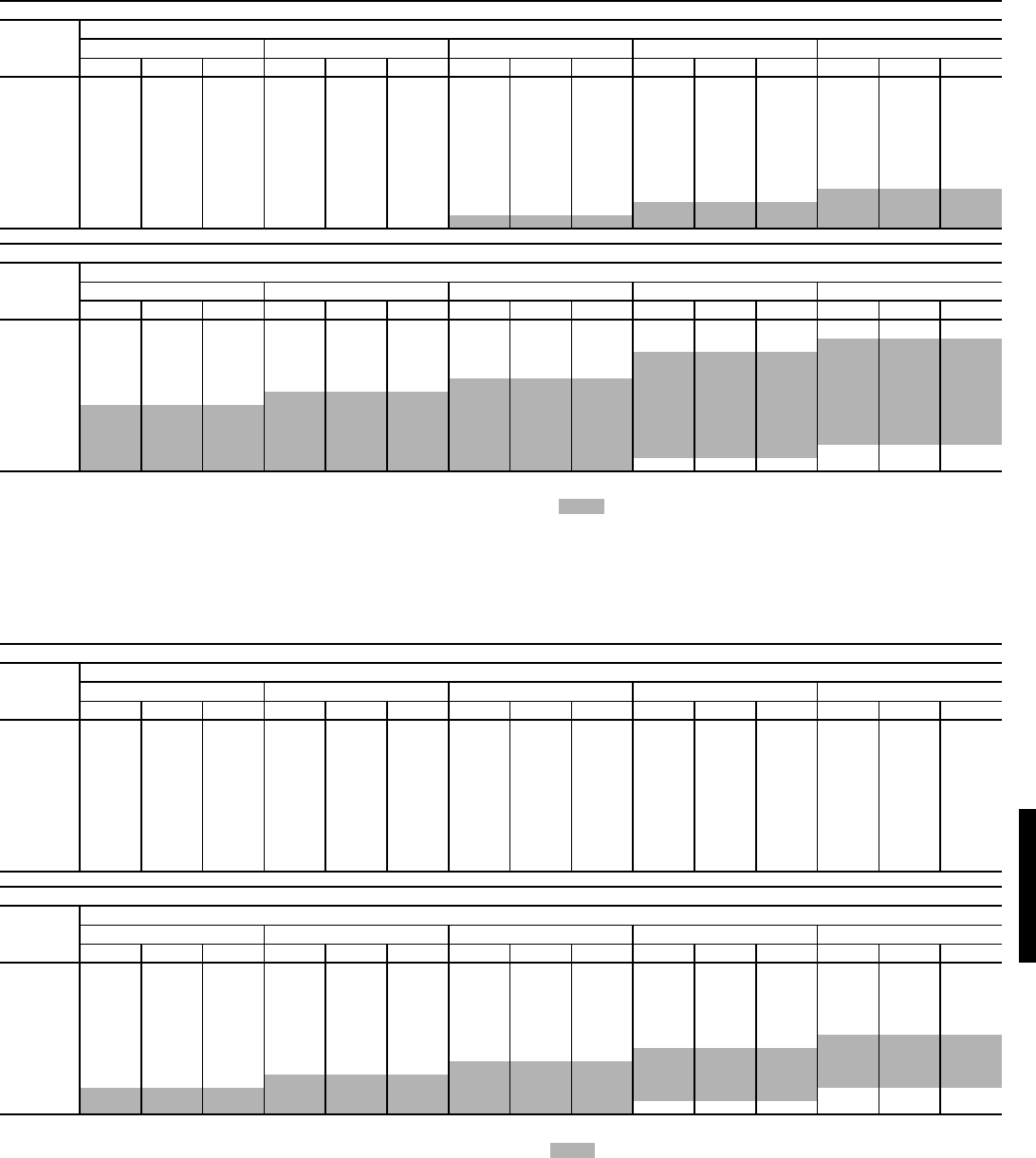
87
FAN PERFORMANCE — VERTICAL DISCHARGE UNITS (cont)
LEGEND
*Standard low-medium static drive range is 895 to 1147 rpm. Other rpms require a
field-supplied drive.
Refer to page 99 for general Fan Performance Data notes.
NOTES:
1. Field-supplied motor required.
2. Maximum continuous bhp for the standard motor is 3.13 (for 208/230 and
460-v units) or 3.38 (for 575-v units). The maximum continuous watts is
2700 (for 208/230 and 460-v units) or 3065 (for 575-v units). Do not adjust
motor rpm such that motor maximum bhp and/or watts is exceeded at the
maximum operating cfm. See Evaporator Fan Motor Data tables for more
information.
3. Fan performance is identical for horizontal discharge applications using
Carrier horizontal adapter curb.
LEGEND
*Alternate high-static drive range is 1040 to 1315 (for 208/230 and 460-v
units). The alternate high-static drive is not available for 575-v units. Other
rpms require a field-supplied drive.
Refer to page 99 for general Fan Performance Data notes.
NOTES:
1. Field-supplied motor required.
2. Maximum continuous bhp for the optional motor is 4.26. Maximum continuous
watts for the optional motor is 3610. Do not adjust motor rpm such that motor
maximum bhp and/or watts is exceeded at the maximum operating cfm. See
Evaporator Fan Motor Data tables for more information.
3. Fan performance is identical for horizontal discharge applications using
Carrier horizontal adapter curb.
48HJD015 (12 TONS) WITH STANDARD MOTOR (Low Heat Units)*
Airflow
(Cfm)
Available External Static Pressure (in. wg)
0.2 0.4 0.6 0.8 1.0
Rpm Watts Bhp Rpm Watts Bhp Rpm Watts Bhp Rpm Watts Bhp Rpm Watts Bhp
3750 597 895 0.84 692 967 1.07 781 1150 1.33 858 1342 1.59 928 1527 1.85
4000 625 1014 0.98 714 1097 1.21 800 1292 1.48 876 1495 1.75 945 1689 2.03
4250 653 1141 1.13 737 1236 1.36 820 1442 1.64 895 1656 1.93 963 1859 2.22
4500 682 1274 1.29 761 1382 1.54 840 1599 1.82 914 1824 2.11 982 2037 2.42
4750 711 1415 1.48 786 1538 1.73 861 1765 2.01 934 2001 2.32 1001 2224 2.63
5000 740 1563 1.68 812 1702 1.94 884 1940 2.22 954 2188 2.53 1020 2419 2.86
5250 769 1719 1.89 839 1875 2.16 907 2125 2.45 974 2384 2.77 1039 2625 3.10
5500 799 1884 2.13 867 2060 2.41 931 2321 2.70 996 2592 3.02 1059 2841 3.36
5750 828 2058 2.38 894 2256 2.67 956 2528 2.97 1018 2810 3.29 1080 3069 3.64
6000 857 2243 2.64 923 2464 2.96 982 2748 3.26 1041 3042 3.59 1101 3308 3.94
6250 885 2438 2.93 951 2687 3.27 1008 2981 3.58 1065 3286 3.91 1122 3559 4.26
48HJD015 (12 TONS) WITH STANDARD MOTOR (Low Heat Units)* (cont)
Airflow
(Cfm)
Available External Static Pressure (in. wg)
1.2 1.4 1.6 1.8 2.0
Rpm Watts Bhp Rpm Watts Bhp Rpm Watts Bhp Rpm Watts Bhp Rpm Watts Bhp
3750 992 1756 2.12 1053 1988 2.40 1112 2236 2.68 1169 2497 2.97 1224 2769 3.27
4000 1009 1931 2.31 1069 2173 2.59 1126 2431 2.88 1181 2702 3.18 1234 2984 3.48
4250 1026 2114 2.51 1085 2366 2.80 1141 2634 3.10 1194 2914 3.40 1246 3206 3.72
4500 1044 2304 2.72 1102 2566 3.02 1157 2844 3.33 1209 3133 3.65 1260 3433 3.97
4750 1062 2504 2.95 1120 2775 3.26 1174 3062 3.58 1226 3360 3.91 1275 3666 4.23
5000 1081 2712 3.19 1138 2993 3.52 1191 3288 3.85 1242 3592 4.18 1291 3905 4.52
5250 1100 2931 3.44 1156 3220 3.79 1209 3523 4.13 1260 3832 4.47 1308 4148 4.82
5500 1119 3160 3.72 1175 3457 4.07 1228 3765 4.43 1278 4077 4.78 1326 4395 5.14
5750 1138 3399 4.00 1194 3702 4.37 1246 4014 4.74 1296 4328 5.11 1343 4644 5.48
6000 1158 3649 4.31 1213 3957 4.69 1265 4270 5.07 1315 4581 5.45———
6250 1179 3910 4.64 1233 4219 5.02 1284 4531 5.41——————
Bhp — Brake Horsepower
Watts — Input Watts to Motor
48HJD015 (12 TONS) WITH OPTIONAL MOTOR (Low Heat Units)*
Airflow
(Cfm)
Available External Static Pressure (in. wg)
0.2 0.4 0.6 0.8 1.0
Rpm Watts Bhp Rpm Watts Bhp Rpm Watts Bhp Rpm Watts Bhp Rpm Watts Bhp
3750 597 895 0.84 692 967 1.07 781 1150 1.33 858 1342 1.59 928 1527 1.85
4000 625 1014 0.98 714 1097 1.21 800 1292 1.48 876 1495 1.75 945 1689 2.03
4250 653 1141 1.13 737 1236 1.36 820 1442 1.64 895 1656 1.93 963 1859 2.22
4500 682 1274 1.29 761 1382 1.54 840 1599 1.82 914 1824 2.11 982 2037 2.42
4750 711 1415 1.48 786 1538 1.73 861 1765 2.01 934 2001 2.32 1001 2224 2.63
5000 740 1563 1.68 812 1702 1.94 884 1940 2.22 954 2188 2.53 1020 2419 2.86
5250 769 1719 1.89 839 1875 2.16 907 2125 2.45 974 2384 2.77 1039 2625 3.10
5500 799 1884 2.13 867 2060 2.41 931 2321 2.70 996 2592 3.02 1059 2841 3.36
5750 828 2058 2.38 894 2256 2.67 956 2528 2.97 1018 2810 3.29 1080 3069 3.64
6000 857 2243 2.64 923 2464 2.96 982 2748 3.26 1041 3042 3.59 1101 3308 3.94
6250 885 2438 2.93 951 2687 3.27 1008 2981 3.58 1065 3286 3.91 1122 3559 4.26
48HJD015 (12 TONS) WITH OPTIONAL MOTOR (Low Heat Units)* (cont)
Airflow
(Cfm)
Available External Static Pressure (in. wg)
1.2 1.4 1.6 1.8 2.0
Rpm Watts Bhp Rpm Watts Bhp Rpm Watts Bhp Rpm Watts Bhp Rpm Watts Bhp
3750 992 1756 2.12 1053 1988 2.40 1112 2236 2.68 1169 2497 2.97 1224 2769 3.27
4000 1009 1931 2.31 1069 2173 2.59 1126 2431 2.88 1181 2702 3.18 1234 2984 3.48
4250 1026 2114 2.51 1085 2366 2.80 1141 2634 3.10 1194 2914 3.40 1246 3206 3.72
4500 1044 2304 2.72 1102 2566 3.02 1157 2844 3.33 1209 3133 3.65 1260 3433 3.97
4750 1062 2504 2.95 1120 2775 3.26 1174 3062 3.58 1226 3360 3.91 1275 3666 4.23
5000 1081 2712 3.19 1138 2993 3.52 1191 3288 3.85 1242 3592 4.18 1291 3905 4.52
5250 1100 2931 3.44 1156 3220 3.79 1209 3523 4.13 1260 3832 4.47 1308 4148 4.82
5500 1119 3160 3.72 1175 3457 4.07 1228 3765 4.43 1278 4077 4.78 1326 4395 5.14
5750 1138 3399 4.00 1194 3702 4.37 1246 4014 4.74 1296 4328 5.11 1343 4644 5.48
6000 1158 3649 4.31 1213 3957 4.69 1265 4270 5.07 1315 4581 5.45———
6250 1179 3910 4.64 1233 4219 5.02 1284 4531 5.41——————
Bhp — Brake Horsepower
Watts — Input Watts to Motor
48HJ
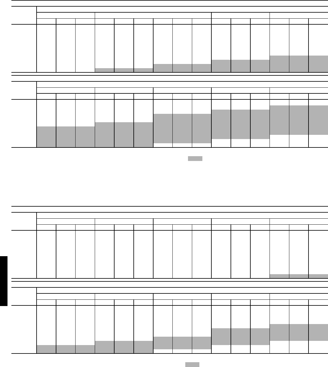
88
FAN PERFORMANCE — VERTICAL DISCHARGE UNITS (cont)
LEGEND
*Standard low-medium static drive range is 895 to 1147 rpm. Other rpms require a
field-supplied drive.
Refer to page 99 for general Fan Performance Data notes.
NOTES:
1. Field-supplied motor required.
2. Maximum continuous bhp for the standard motor is 3.13 (for 208/230 and
460-v units) or 3.38 (for 575-v units). The maximum continuous watts is
2700 (for 208/230 and 460-v units) or 3065 (for 575-v units). Do not adjust
motor rpm such that motor maximum bhp and/or watts is exceeded at the
maximum operating cfm. See Evaporator Fan Motor Data tables for more
information.
3. Fan performance is identical for horizontal discharge applications using
Carrier horizontal adapter curb.
LEGEND
*Alternate high-static drive range is 1040 to 1315. Other rpms require a field-
supplied drive.
Refer to page 99 for general Fan Performance Data notes.
NOTES:
1. Field-supplied motor required.
2. Maximum continuous bhp for the optional motor is 4.26. The maximum contin-
uous watts is 3610. Do not adjust motor rpm such that motor maximum bhp
and/or watts is exceeded at the maximum operating cfm. See Evaporator Fan
Motor Data tables for more information.
3. Fan performance is identical for horizontal discharge applications using
Carrier horizontal adapter curb.
48HJF015 (12 TONS) WITH STANDARD MOTOR (High Heat Units)*
Airflow
(Cfm)
Available External Static Pressure (in. wg)
0.2 0.4 0.6 0.8 1.0
Rpm Watts Bhp Rpm Watts Bhp Rpm Watts Bhp Rpm Watts Bhp Rpm Watts Bhp
3750 622 888 0.89 713 1027 1.13 795 1234 1.37 869 1454 1.63 936 1584 1.89
4000 652 1015 1.04 738 1168 1.28 818 1388 1.54 890 1620 1.80 956 1756 2.07
4250 682 1151 1.20 763 1317 1.45 841 1550 1.72 911 1793 1.99 976 1937 2.27
4500 713 1295 1.38 790 1474 1.63 864 1719 1.91 934 1973 2.20 997 2126 2.49
4750 744 1448 1.58 817 1641 1.84 889 1896 2.12 956 2159 2.42 1019 2326 2.72
5000 776 1610 1.80 845 1817 2.06 914 2081 2.35 979 2353 2.66 1041 2536 2.97
5250 808 1783 2.04 874 2003 2.31 940 2277 2.60 1003 2556 2.91 1064 2757 3.24
5500 840 1967 2.29 903 2200 2.57 966 2482 2.87 1028 2768 3.19 1087 2991 3.52
5750 872 2163 2.57 933 2410 2.86 993 2699 3.16 1053 2990 3.49 1110 3237 3.83
6000 905 2373 2.87 963 2634 3.16 1021 2929 3.47 1078 3225 3.81 1134 3497 4.15
6250 937 2596 3.19 994 2872 3.49 1049 3172 3.81 1105 3473 4.15 1159 3769 4.50
48HJF015 (12 TONS) WITH STANDARD MOTOR (High Heat Units)* (cont)
Airflow
(Cfm)
Available External Static Pressure (in. wg)
1.2 1.4 1.6 1.8 2.0
Rpm Watts Bhp Rpm Watts Bhp Rpm Watts Bhp Rpm Watts Bhp Rpm Watts Bhp
3750 999 1829 2.15 1059 2091 2.42 1117 2343 2.70 1174 2521 2.99 1228 2801 3.29
4000 1017 2010 2.35 1076 2279 2.63 1132 2540 2.91 1186 2738 3.21 1239 3023 3.51
4250 1036 2198 2.56 1093 2474 2.85 1148 2743 3.14 1201 2962 3.44 1253 3251 3.75
4500 1056 2395 2.78 1112 2675 3.08 1166 2951 3.39 1217 3194 3.70 1267 3487 4.01
4750 1077 2601 3.03 1132 2885 3.34 1184 3168 3.65 1235 3435 3.97 1284 3731 4.29
5000 1098 2816 3.29 1152 3104 3.61 1204 3392 3.93 1253 3683 4.26 1301 3981 4.59
5250 1120 3042 3.56 1173 3332 3.90 1224 3626 4.23 1273 3940 4.57 1320 4239 4.91
5500 1142 3279 3.86 1195 3570 4.20 1245 3870 4.55 1293 4203 4.89 1339 4501 5.24
5750 1165 3528 4.18 1217 3819 4.53 1266 4125 4.88 1313 4471 5.24———
6000 1188 3789 4.51 1239 4080 4.88 1288 4389 5.24——————
6250 1212 4062 4.87 1262 4351 5.24—————————
Bhp — Brake Horsepower
Watts — Input Watts to Motor
48HJF015 (12 TONS) WITH OPTIONAL MOTOR (High Heat Units)*
Airflow
(Cfm)
Available External Static Pressure (in. wg)
0.2 0.4 0.6 0.8 1.0
Rpm Watts Bhp Rpm Watts Bhp Rpm Watts Bhp Rpm Watts Bhp Rpm Watts Bhp
3750 622 888 0.89 713 1027 1.13 795 1234 1.37 869 1454 1.63 936 1584 1.89
4000 652 1015 1.04 738 1168 1.28 818 1388 1.54 890 1620 1.80 956 1756 2.07
4250 682 1151 1.20 763 1317 1.45 841 1550 1.72 911 1793 1.99 976 1937 2.27
4500 713 1295 1.38 790 1474 1.63 864 1719 1.91 934 1973 2.20 997 2126 2.49
4750 744 1448 1.58 817 1641 1.84 889 1896 2.12 956 2159 2.42 1019 2326 2.72
5000 776 1610 1.80 845 1817 2.06 914 2081 2.35 979 2353 2.66 1041 2536 2.97
5250 808 1783 2.04 874 2003 2.31 940 2277 2.60 1003 2556 2.91 1064 2757 3.24
5500 840 1967 2.29 903 2200 2.57 966 2482 2.87 1028 2768 3.19 1087 2991 3.52
5750 872 2163 2.57 933 2410 2.86 993 2699 3.16 1053 2990 3.49 1110 3237 3.83
6000 905 2373 2.87 963 2634 3.16 1021 2929 3.47 1078 3225 3.81 1134 3497 4.15
6250 937 2596 3.19 994 2872 3.49 1049 3172 3.81 1105 3473 4.15 1159 3769 4.50
48HJF015 (12 TONS) WITH OPTIONAL MOTOR (High Heat Units)* (cont)
Airflow
(Cfm)
Available External Static Pressure (in. wg)
1.2 1.4 1.6 1.8 2.0
Rpm Watts Bhp Rpm Watts Bhp Rpm Watts Bhp Rpm Watts Bhp Rpm Watts Bhp
3750 999 1829 2.15 1059 2091 2.42 1117 2343 2.70 1174 2521 2.99 1228 2801 3.29
4000 1017 2010 2.35 1076 2279 2.63 1132 2540 2.91 1186 2738 3.21 1239 3023 3.51
4250 1036 2198 2.56 1093 2474 2.85 1148 2743 3.14 1201 2962 3.44 1253 3251 3.75
4500 1056 2395 2.78 1112 2675 3.08 1166 2951 3.39 1217 3194 3.70 1267 3487 4.01
4750 1077 2601 3.03 1132 2885 3.34 1184 3168 3.65 1235 3435 3.97 1284 3731 4.29
5000 1098 2816 3.29 1152 3104 3.61 1204 3392 3.93 1253 3683 4.26 1301 3981 4.59
5250 1120 3042 3.56 1173 3332 3.90 1224 3626 4.23 1273 3940 4.57 1320 4239 4.91
5500 1142 3279 3.86 1195 3570 4.20 1245 3870 4.55 1293 4203 4.89 1339 4501 5.24
5750 1165 3528 4.18 1217 3819 4.53 1266 4125 4.88 1313 4471 5.24———
6000 1188 3789 4.51 1239 4080 4.88 1288 4389 5.24——————
6250 1212 4062 4.87 1262 4351 5.24—————————
Bhp — Brake Horsepower
Watts — Input Watts to Motor
Performance data — 48HJ (cont)
48HJ48HJ
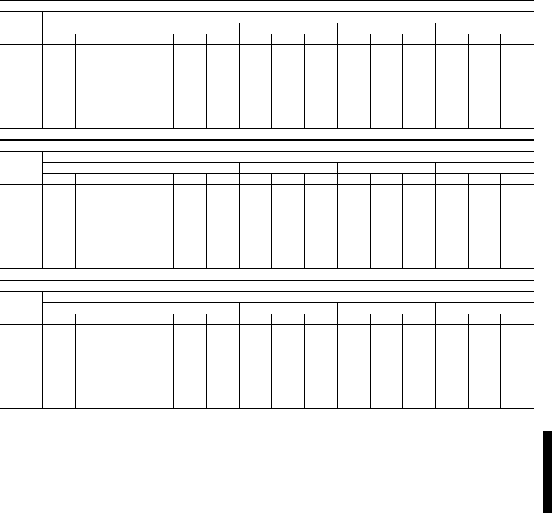
89
FAN PERFORMANCE — VERTICAL DISCHARGE UNITS (cont)
LEGEND
*Standard low-medium static drive range is 873 to 1021 rpm. Alternate
high-static drive range is 1025 to 1200. Other rpms require a field-
supplied drive.
Refer to page 99 for general Fan Performance Data notes.
NOTES:
1. Maximum continuous bhp for the standard motor is 6.13. The max-
imum continuous watts is 5180. Do not adjust motor rpm such that
motor maximum bhp and/or watts is exceeded at the maximum
operating cfm. See Evaporator Fan Motor Data tables for more
information.
2. Fan performance is identical for horizontal discharge applications
using Carrier horizontal adapter curb.
48HJD017 (15 TONS) (Low Heat Units)*
Airflow
(Cfm)
Available External Static Pressure (in. wg)
0.2 0.4 0.6 0.8 1.0
Rpm Watts Bhp Rpm Watts Bhp Rpm Watts Bhp Rpm Watts Bhp Rpm Watts Bhp
4500 753 1307 1.53 761 1330 1.56 840 1572 1.84 912 1822 2.14 980 2080 2.44
4800 747 1384 1.62 790 1515 1.78 866 1765 2.07 936 2023 2.37 1002 2289 2.68
5100 741 1465 1.72 820 1718 2.01 893 1977 2.32 961 2243 2.63 1025 2516 2.95
5700 810 1911 2.24 882 2182 2.56 950 2459 2.88 1014 2741 3.21 1075 3029 3.55
6000 844 2164 2.54 914 2444 2.87 980 2730 3.20 1042 3021 3.54 1100 3317 3.89
6300 879 2439 2.86 947 2729 3.20 1010 3023 3.55 1070 3322 3.90 1127 3626 4.25
6600 915 2737 3.21 980 3035 3.56 1041 3338 3.91 1099 3645 4.28 1155 3957 4.64
6900 950 3057 3.59 1013 3364 3.95 1072 3675 4.31 1129 3991 4.68 1183 4311 5.06
7200 986 3401 3.99 1047 3717 4.36 1104 4037 4.74 1159 4361 5.11 1211 4689 5.50
7500 1022 3770 4.42 1081 4095 4.80 1136 4423 5.19 1189 4755 5.58 1241 5091 5.97
48HJD017 (15 TONS) (Low Heat Units)* (cont)
Airflow
(Cfm)
Available External Static Pressure (in. wg)
1.2 1.4 1.6 1.8 2.0
Rpm Watts Bhp Rpm Watts Bhp Rpm Watts Bhp Rpm Watts Bhp Rpm Watts Bhp
4500 1044 2345 2.75 1105 2619 3.07 1163 2899 3.40 1218 3187 3.74 1271 3481 4.08
4800 1065 2561 3.00 1124 2841 3.33 1180 3127 3.67 1235 3420 4.01 1287 3720 4.36
5100 1086 2795 3.28 1144 3082 3.61 1199 3375 3.96 1252 3674 4.31 1304 3979 4.67
5700 1132 3324 3.90 1187 3624 4.25 1240 3929 4.61 1291 4241 4.97 1341 4558 5.35
6000 1157 3619 4.24 1210 3925 4.60 1262 4239 4.97 1312 4557 5.34 1361 4880 5.72
6300 1182 3935 4.62 1234 4249 4.98 1285 4569 5.36 1334 4894 5.74 — — —
6600 1208 4274 5.01 1259 4595 5.39 1309 4922 5.77 — — — — — —
6900 1235 4636 5.44 1285 4964 5.82 —————————
7200 1262 5021 5.89 ————————————
7500 ———————————————
48HJD017 (15 TONS) (Low Heat Units)* (cont)
Airflow
(Cfm)
Available External Static Pressure (in. wg)
2.2 2.4 2.6 2.8 3.0
Rpm Watts Bhp Rpm Watts Bhp Rpm Watts Bhp Rpm Watts Bhp Rpm Watts Bhp
4500 1322 3781 4.43 1372 4088 4.79 1419 4400 5.16 1466 4719 5.53 1511 5042 5.91
4800 1337 4025 4.72 1386 4337 5.09 1433 4655 5.46 1479 4978 5.84 — — —
5100 1353 4290 5.03 1401 4607 5.40 1448 4930 5.78 — — — — — —
5700 1388 4881 5.72 ————————————
6000 ———————————————
6300 ———————————————
6600 ———————————————
6900 ———————————————
7200 ———————————————
7500 ———————————————
Bhp — Brake Horsepower
FIOP — Factory-Installed Option
Watts — Input Watts to Motor
48HJ
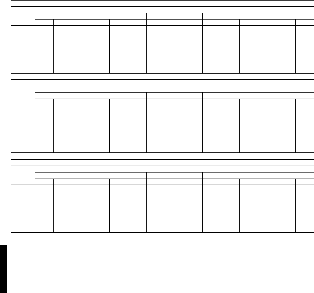
90
FAN PERFORMANCE — VERTICAL DISCHARGE UNITS (cont)
LEGEND
*Standard low-medium static drive range is 873 to 1021 rpm. Alternate
high-static drive range is 1025 to 1200. Other rpms require a field-
supplied drive.
Refer to page 99 for general Fan Performance Data notes.
NOTES:
1. Maximum continuous bhp for the standard motor is 6.13. The max-
imum continuous watts is 5180. Do not adjust motor rpm such that
motor maximum bhp and/or watts is exceeded at the maximum
operating cfm. See Evaporator Fan Motor Data tables for more
information.
2. Fan performance is identical for horizontal discharge applications
using Carrier horizontal adapter curb.
48HJF017 (15 TONS) (High Heat Units)*
Airflow
(Cfm)
Available External Static Pressure (in. wg)
0.2 0.4 0.6 0.8 1.0
Rpm Watts Bhp Rpm Watts Bhp Rpm Watts Bhp Rpm Watts Bhp Rpm Watts Bhp
4500 753 1307 1.53 786 1404 1.65 861 1644 1.93 932 1893 2.22 997 2150 2.52
4800 747 1384 1.62 818 1603 1.88 890 1852 2.17 958 2108 2.47 1022 2373 2.78
5100 775 1571 1.84 850 1822 2.14 920 2079 2.44 986 2344 2.75 1048 2616 3.07
5700 849 2054 2.41 918 2323 2.73 982 2598 3.05 1044 2879 3.38 1102 3166 3.71
6000 886 2329 2.73 952 2607 3.06 1015 2891 3.39 1074 3180 3.73 1130 3474 4.08
6300 924 2628 3.08 987 2915 3.42 1047 3207 3.76 1105 3504 4.11 1160 3807 4.46
6600 962 2951 3.46 1023 3246 3.81 1081 3547 4.16 1136 3853 4.52 1190 4163 4.88
6900 1000 3298 3.87 1059 3603 4.23 1115 3912 4.59 1168 4225 4.96 1220 4543 5.33
7200 1038 3672 4.31 1095 3986 4.67 1149 4303 5.05 1201 4625 5.42 1251 4950 5.81
7500 1077 4072 4.78 1131 4394 5.15 1184 4720 5.54 1234 5050 5.92 — — —
48HJF017 (15 TONS) (High Heat Units)* (cont)
Airflow
(Cfm)
Available External Static Pressure (in. wg)
1.2 1.4 1.6 1.8 2.0
Rpm Watts Bhp Rpm Watts Bhp Rpm Watts Bhp Rpm Watts Bhp Rpm Watts Bhp
4500 1060 2414 2.83 1119 2685 3.15 1175 2964 3.48 1230 3250 3.81 1282 3542 4.15
4800 1082 2644 3.10 1140 2922 3.43 1195 3207 3.76 1248 3498 4.10 1299 3795 4.45
5100 1106 2894 3.39 1163 3178 3.73 1216 3470 4.07 1268 3767 4.42 1319 4071 4.77
5700 1157 3459 4.06 1211 3757 4.41 1262 4061 4.76 1312 4371 5.13 1360 4686 5.50
6000 1184 3774 4.43 1236 4080 4.79 1287 4391 5.15 1335 4707 5.52 1382 5029 5.90
6300 1212 4114 4.83 1263 4427 5.19 1312 4745 5.57 1359 5067 5.94 — — —
6600 1241 4478 5.25 1290 4798 5.63 1338 5122 6.01 — — — — — —
6900 1270 4866 5.71 — — ——————————
7200 ———————————————
7500 ———————————————
48HJF017 (15 TONS) (High Heat Units)* (cont)
Airflow
(Cfm)
Available External Static Pressure (in. wg)
2.2 2.4 2.6 2.8 3.0
Rpm Watts Bhp Rpm Watts Bhp Rpm Watts Bhp Rpm Watts Bhp Rpm Watts Bhp
4500 1332 3841 4.50 1381 4145 4.86 1428 4456 5.23 1473 4772 5.60 1518 5095 5.98
4800 1349 4100 4.81 1397 4409 5.17 1443 4725 5.54 1488 5046 5.92 — — —
5100 1367 4380 5.14 1414 4695 5.51 1460 5016 5.88 — — — — — —
5700 1407 5007 5.87 — — ——————————
6000 ———————————————
6300 ———————————————
6600 ———————————————
6900 ———————————————
7200 ———————————————
7500 ———————————————
Bhp — Brake Horsepower
Watts — Input Watts to Motor
Performance data — 48HJ (cont)
48HJ48HJ
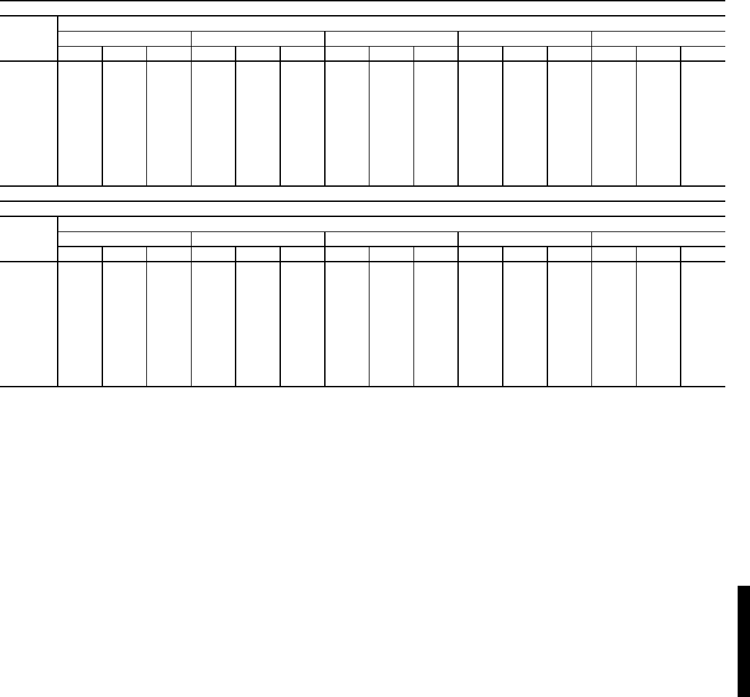
91
FAN PERFORMANCE — VERTICAL DISCHARGE UNITS (cont)
LEGEND
*Motor drive ranges:
Low Range: Not Used
Mid-Low Range: 647-886 (208/230 and 460-v), 810-1072 (575-v)
Mid-High Range: 897-1139 (208/230 and 460-v), 873-1108 (575-v)
High Range: 1078-1274
All other rpms require field-supplied drive.
Refer to page 99 for general Fan Performance Data notes.
NOTE: Maximum continuous bhp is:
Low Range: Not Used
Mid-Low Range: 4.25 (208/230 and 460-v), 3.45 (575-v)
Mid-High Range: 5.75
High Range: 8.63
48HJD020 (18 TONS) (Low Heat Units)*
Airflow
(Cfm)
Available External Static Pressure (in. wg)
0.2 0.4 0.6 0.8 1.0
Rpm Watts Bhp Rpm Watts Bhp Rpm Watts Bhp Rpm Watts Bhp Rpm Watts Bhp
3500 460 591 0.68 548 774 0.89 623 951 1.09 692 1126 1.29 755 1301 1.50
4000 499 774 0.89 581 976 1.12 653 1170 1.35 717 1361 1.56 777 1551 1.78
4500 538 990 1.14 617 1212 1.39 685 1423 1.64 746 1630 1.88 803 1835 2.11
5000 579 1243 1.43 654 1485 1.71 719 1715 1.97 778 1938 2.23 832 2158 2.48
5500 621 1536 1.77 693 1798 2.07 755 2045 2.35 811 2285 2.63 864 2520 2.90
6000 664 1871 2.15 732 2152 2.48 792 2417 2.78 846 2673 3.07 897 2925 3.36
6500 707 2250 2.59 772 2550 2.93 830 2834 3.26 883 3106 3.57 932 3373 3.88
7000 751 2676 3.08 813 2994 3.44 869 3295 3.79 920 3585 4.12 967 3868 4.45
7500 795 3150 3.62 855 3487 4.01 909 3805 4.38 958 4112 4.73 1004 4411 5.07
8000 839 3676 4.23 897 4029 4.63 949 4366 5.02 997 4689 5.39 1042 5004 5.75
8500 884 4253 4.89 940 4625 5.32 990 4978 5.73 1037 5318 6.12 1080 5649 6.50
48HJD020 (18 TONS) (Low Heat Units)* (cont)
Airflow
(Cfm)
Available External Static Pressure (in. wg)
1.2 1.4 1.6 1.8 2.0
Rpm Watts Bhp Rpm Watts Bhp Rpm Watts Bhp Rpm Watts Bhp Rpm Watts Bhp
3500 814 1476 1.70 871 1650 1.90 924 1825 2.10 975 1999 2.30 1023 2173 2.50
4000 834 1740 2.00 888 1930 2.22 939 2119 2.44 988 2308 2.65 1035 2497 2.87
4500 857 2039 2.35 909 2243 2.58 958 2446 2.81 1005 2650 3.05 1051 2853 3.28
5000 884 2376 2.73 933 2594 2.98 980 2811 3.23 1026 3028 3.48 1070 3244 3.73
5500 913 2753 3.17 960 2984 3.43 1006 3215 3.70 1049 3445 3.96 1092 3674 4.23
6000 945 3172 3.65 990 3417 3.93 1034 3662 4.21 1076 3905 4.49 1117 4147 4.77
6500 978 3636 4.18 1022 3895 4.48 1064 4153 4.78 1104 4409 5.07 1144 4665 5.37
7000 1012 4145 4.77 1055 4419 5.08 1095 4691 5.39 1135 4960 5.70 1173 5229 6.01
7500 1047 4703 5.41 1089 4992 5.74 1128 5277 6.07 1167 5561 6.40 1204 5842 6.72
8000 1084 5311 6.11 1124 5615 6.46 1163 5915 6.80 1200 6211 7.14 1236 6506 7.48
8500 1121 5972 6.87 1160 6290 7.23 1198 6604 7.60 1234 6914 7.95 1269 7223 8.31
Bhp — Brake Horsepower Input to Fan
Watts — Input Watts to Motor
48HJ

92
FAN PERFORMANCE — VERTICAL DISCHARGE UNITS (cont)
LEGEND
*Motor drive ranges:
Low Range: Not Used
Mid-Low Range: 647-886 (208/230 and 460-v), 810-1072 (575-v)
Mid-High Range: 897-1139 (208/230 and 460-v), 873-1108 (575-v)
High Range: 1078-1274
All other rpms require field-supplied drive.
Refer to page 99 for general Fan Performance Data notes.
NOTE: Maximum continuous bhp is:
Low Range: Not Used
Mid-Low Range: 4.25 (208/230 and 460-v), 3.45 (575-v)
Mid-High Range: 5.75
High Range: 8.63
48HJE020 (18 TONS) (Medium Heat Units)*
Airflow
(Cfm)
Available External Static Pressure (in. wg)
0.2 0.4 0.6 0.8 1.0
Rpm Watts Bhp Rpm Watts Bhp Rpm Watts Bhp Rpm Watts Bhp Rpm Watts Bhp
3500 470 611 0.70 556 791 0.91 630 967 1.11 697 1141 1.31 760 1314 1.51
4000 511 802 0.92 591 1001 1.15 661 1194 1.37 725 1383 1.59 784 1572 1.81
4500 553 1029 1.18 629 1248 1.44 695 1458 1.68 756 1663 1.91 812 1866 2.15
5000 597 1297 1.49 669 1534 1.76 732 1761 2.03 789 1982 2.28 843 2201 2.53
5500 641 1606 1.85 709 1862 2.14 770 2106 2.42 825 2343 2.70 876 2577 2.96
6000 686 1961 2.26 751 2234 2.57 809 2495 2.87 862 2749 3.16 911 2997 3.45
6500 732 2363 2.72 794 2653 3.05 849 2931 3.37 900 3201 3.68 948 3465 3.99
7000 779 2815 3.24 837 3122 3.59 891 3416 3.93 940 3702 4.26 986 3981 4.58
7500 826 3320 3.82 882 3642 4.19 933 3953 4.55 980 4254 4.89 1025 4549 5.23
8000 873 3879 4.46 926 4217 4.85 975 4542 5.22 1021 4860 5.59 1065 5169 5.95
8500 921 4495 5.17 972 4847 5.57 1019 5189 5.97 1063 5521 6.35 1105 5846 6.72
48HJE020 (18 TONS) (Medium Heat Units)* (cont)
Airflow
(Cfm)
Available External Static Pressure (in. wg)
1.2 1.4 1.6 1.8 2.0
Rpm Watts Bhp Rpm Watts Bhp Rpm Watts Bhp Rpm Watts Bhp Rpm Watts Bhp
3500 818 1488 1.71 874 1661 1.91 927 1835 2.11 978 2008 2.31 1026 2182 2.51
4000 840 1760 2.02 893 1948 2.24 943 2136 2.46 992 2324 2.67 1039 2512 2.89
4500 865 2068 2.38 915 2270 2.61 964 2472 2.84 1011 2673 3.07 1056 2876 3.31
5000 893 2417 2.78 942 2632 3.03 988 2848 3.28 1033 3063 3.52 1076 3278 3.77
5500 925 2808 3.23 971 3037 3.49 1016 3266 3.76 1059 3494 4.02 1100 3721 4.28
6000 958 3243 3.73 1003 3486 4.01 1045 3728 4.29 1087 3970 4.57 1127 4210 4.84
6500 993 3725 4.28 1036 3982 4.58 1077 4238 4.87 1117 4492 5.17 1156 4745 5.46
7000 1029 4256 4.90 1071 4528 5.21 1111 4797 5.52 1150 5064 5.82 1187 5330 6.13
7500 1067 4838 5.56 1107 5124 5.89 1146 5407 6.22 1184 5688 6.54 1220 5967 6.86
8000 1106 5474 6.30 1145 5774 6.64 1182 6071 6.98 1219 6365 7.32 1254 6657 7.66
8500 1145 6165 7.09 1183 6479 7.45 1220 6790 7.81 1255 7098 8.16 1290 7403 8.51
Bhp — Brake Horsepower Input to Fan
Watts — Input Watts to Motor
Performance data — 48HJ (cont)
48HJ48HJ

93
FAN PERFORMANCE — VERTICAL DISCHARGE UNITS (cont)
LEGEND
*Motor drive ranges:
Low Range: Not Used
Mid-Low Range: 647-886 (208/230 and 460-v), 810-1072 (575-v)
Mid-High Range: 897-1139 (208/230 and 460-v), 873-1108 (575-v)
High Range: 1078-1274
All other rpms require field-supplied drive.
Refer to page 99 for general Fan Performance Data notes.
NOTE: Maximum continuous bhp is:
Low Range: Not Used
Mid-Low Range: 4.25 (208/230 and 460-v), 3.45 (575-v)
Mid-High Range: 5.75
High Range: 8.63
48HJF020 (18 TONS) (High Heat Units)*
Airflow
(Cfm)
Available External Static Pressure (in. wg)
0.2 0.4 0.6 0.8 1.0
Rpm Watts Bhp Rpm Watts Bhp Rpm Watts Bhp Rpm Watts Bhp Rpm Watts Bhp
3500 470 611 0.70 556 791 0.91 630 967 1.11 697 1141 1.31 760 1314 1.51
4000 511 802 0.92 591 1001 1.15 661 1194 1.37 725 1383 1.59 784 1572 1.81
4500 553 1029 1.18 629 1248 1.44 695 1458 1.68 756 1663 1.91 812 1866 2.15
5000 597 1297 1.49 669 1534 1.76 732 1761 2.03 789 1982 2.28 843 2201 2.53
5500 641 1606 1.85 709 1862 2.14 770 2106 2.42 825 2343 2.70 876 2577 2.96
6000 686 1961 2.26 751 2234 2.57 809 2495 2.87 862 2749 3.16 911 2997 3.45
6500 732 2363 2.72 794 2653 3.05 849 2931 3.37 900 3201 3.68 948 3465 3.99
7000 779 2815 3.24 837 3122 3.59 891 3416 3.93 940 3702 4.26 986 3981 4.58
7500 826 3320 3.82 882 3642 4.19 933 3953 4.55 980 4254 4.89 1025 4549 5.23
8000 873 3879 4.46 926 4217 4.85 975 4542 5.22 1021 4860 5.59 1065 5169 5.95
8500 921 4495 5.17 972 4847 5.57 1019 5189 5.97 1063 5521 6.35 1105 5846 6.72
48HJF020 (18 TONS) (High Heat Units)* (cont)
Airflow
(Cfm)
Available External Static Pressure (in. wg)
1.2 1.4 1.6 1.8 2.0
Rpm Watts Bhp Rpm Watts Bhp Rpm Watts Bhp Rpm Watts Bhp Rpm Watts Bhp
3500 818 1488 1.71 874 1661 1.91 927 1835 2.11 978 2008 2.31 1026 2182 2.51
4000 840 1760 2.02 893 1948 2.24 943 2136 2.46 992 2324 2.67 1039 2512 2.89
4500 865 2068 2.38 915 2270 2.61 964 2472 2.84 1011 2673 3.07 1056 2876 3.31
5000 893 2417 2.78 942 2632 3.03 988 2848 3.28 1033 3063 3.52 1076 3278 3.77
5500 925 2808 3.23 971 3037 3.49 1016 3266 3.76 1059 3494 4.02 1100 3721 4.28
6000 958 3243 3.73 1003 3486 4.01 1045 3728 4.29 1087 3970 4.57 1127 4210 4.84
6500 993 3725 4.28 1036 3982 4.58 1077 4238 4.87 1117 4492 5.17 1156 4745 5.46
7000 1029 4256 4.90 1071 4528 5.21 1111 4797 5.52 1150 5064 5.82 1187 5330 6.13
7500 1067 4838 5.56 1107 5124 5.89 1146 5407 6.22 1184 5688 6.54 1220 5967 6.86
8000 1106 5474 6.30 1145 5774 6.64 1182 6071 6.98 1219 6365 7.32 1254 6657 7.66
8500 1145 6165 7.09 1183 6479 7.45 1220 6790 7.81 1255 7098 8.16 1290 7403 8.51
Bhp — Brake Horsepower Input to Fan
Watts — Input Watts to Motor
48HJ
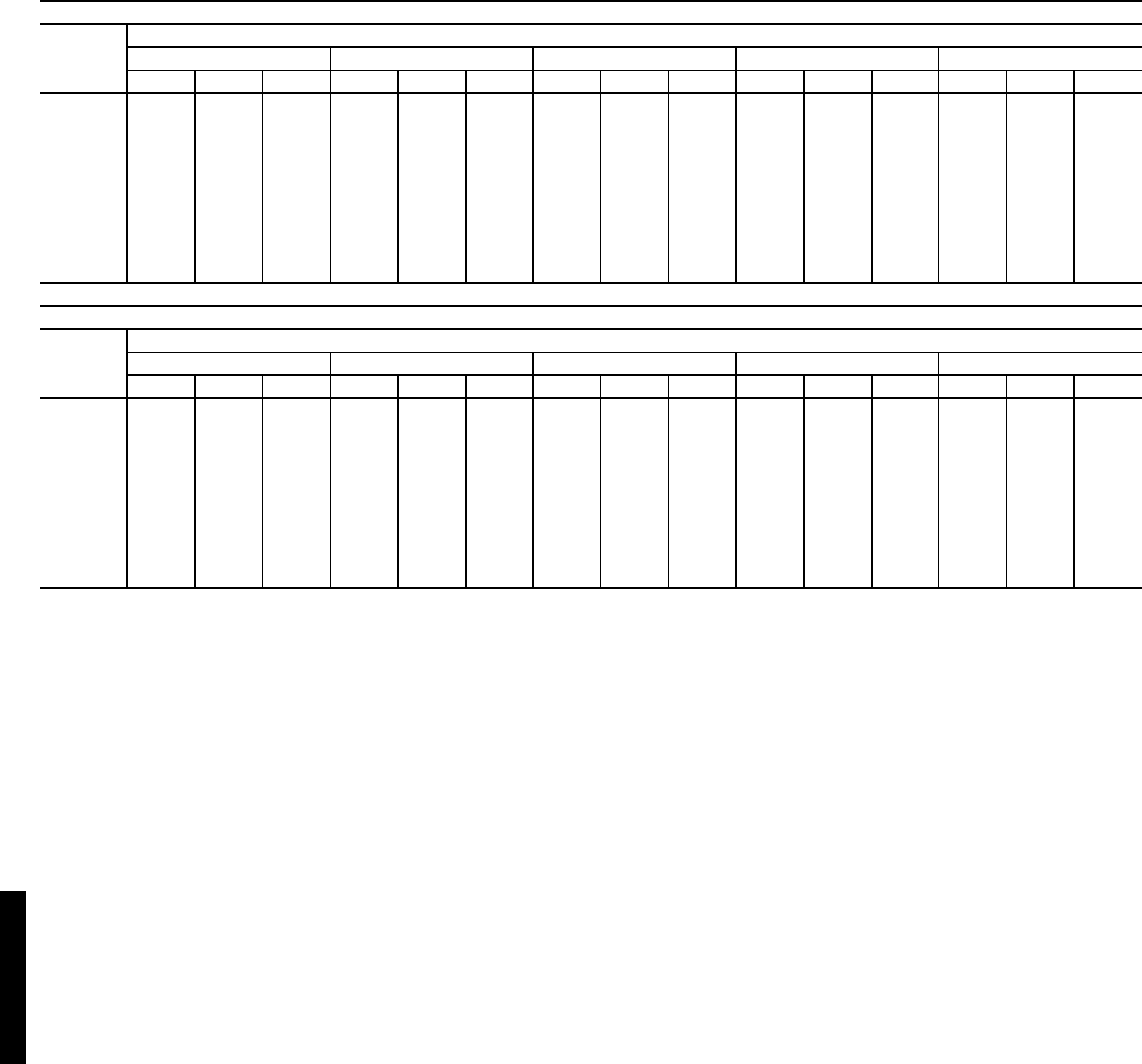
94
FAN PERFORMANCE — VERTICAL DISCHARGE UNITS (cont)
LEGEND
*Motor drive ranges:
Low Range: 685-939 (208/230 and 460-v), 751-954 (575-v)
Mid-Low Range: 949-1206
Mid-High Range: 941-1176
High Range: 1014-1297
All other rpms require field-supplied drive.
Refer to page 99 for general Fan Performance Data notes.
NOTE: Maximum continuous bhp is:
Low Range: 4.25 (208/230 and 460-v), 5.75 (575-v)
Mid-Low Range: 5.75
Mid-High Range: 8.63
High Range: 11.50
48HJD024 (20 TONS) (Low Heat Units)*
Airflow
(Cfm)
Available External Static Pressure (in. wg)
0.2 0.4 0.6 0.8 1.0
Rpm Watts Bhp Rpm Watts Bhp Rpm Watts Bhp Rpm Watts Bhp Rpm Watts Bhp
5,000 590 1276 1.47 663 1516 1.74 727 1745 2.01 786 1968 2.26 840 2189 2.52
5,500 633 1579 1.82 703 1838 2.11 764 2084 2.40 820 2324 2.67 872 2560 2.94
6,000 677 1925 2.21 744 2203 2.53 803 2467 2.84 857 2723 3.13 907 2974 3.42
6,500 722 2317 2.67 786 2614 3.01 842 2896 3.33 894 3167 3.64 942 3434 3.95
7,000 767 2758 3.17 828 3073 3.53 883 3371 3.88 933 3660 4.21 979 3942 4.53
7,500 813 3250 3.74 871 3582 4.12 924 3897 4.48 972 4202 4.83 1017 4500 5.18
8,000 859 3795 4.36 915 4143 4.77 966 4475 5.15 1012 4797 5.52 1056 5110 5.88
8,500 906 4394 5.05 959 4759 5.47 1008 5107 5.87 1053 5445 6.26 1096 5774 6.64
9,000 952 5051 5.81 1004 5432 6.25 1051 5797 6.67 1095 6150 7.07 1136 6494 7.47
9,500 999 5767 6.63 1049 6163 7.09 1094 6544 7.53 1137 6913 7.95 1177 7272 8.36
10,000 1047 6544 7.53 1094 6956 8.00 1138 7352 8.46 1180 7736 8.90 1219 8111 9.33
48HJD024 (20 TONS) (Low Heat Units)* (cont)
Airflow
(Cfm)
Available External Static Pressure (in. wg)
1.2 1.4 1.6 1.8 2.0
Rpm Watts Bhp Rpm Watts Bhp Rpm Watts Bhp Rpm Watts Bhp Rpm Watts Bhp
5,000 891 2408 2.77 940 2625 3.02 987 2843 3.27 1032 3060 3.52 1076 3277 3.77
5,500 921 2792 3.21 968 3024 3.48 1014 3255 3.74 1057 3485 4.01 1099 3716 4.27
6,000 954 3221 3.70 999 3467 3.99 1042 3711 4.27 1084 3955 4.55 1125 4198 4.83
6,500 988 3696 4.25 1032 3956 4.55 1073 4214 4.85 1114 4470 5.14 1153 4726 5.44
7,000 1024 4219 4.85 1066 4493 5.17 1106 4764 5.48 1145 5034 5.79 1183 5303 6.10
7,500 1060 4792 5.51 1101 5080 5.84 1140 5365 6.17 1178 5649 6.50 1215 5930 6.82
8,000 1098 5417 6.23 1138 5719 6.58 1176 6018 6.92 1213 6315 7.26 1249 6610 7.60
8,500 1137 6096 7.01 1175 6413 7.38 1212 6726 7.74 1248 7036 8.09 1283 7344 8.45
9,000 1176 6831 7.86 1214 7163 8.24 1250 7490 8.61 1285 7814 8.99 1319 8135 9.36
9,500 1216 7624 8.77 1253 7970 9.17 1288 8312 9.56 1322 8649 9.95 1355 8984 10.33
10,000 1256 8478 9.75 1292 8838 10.16 1327 9193 10.57 1360 9545 10.98 1393 9893 11.38
Bhp — Brake Horsepower Input to Fan
Watts — Input Watts to Motor
Performance data — 48HJ (cont)
48HJ48HJ

95
FAN PERFORMANCE — VERTICAL DISCHARGE UNITS (cont)
LEGEND
*Motor drive ranges:
Low Range: 685-939 (208/230 and 460-v), 751-954 (575-v)
Mid-Low Range: 949-1206
Mid-High Range: 941-1176
High Range: 1014-1297
All other rpms require field-supplied drive.
Refer to page 99 for general Fan Performance Data notes.
NOTE: Maximum continuous bhp is:
Low Range: 4.25 (208/230 and 460-v), 5.75 (575-v)
Mid-Low Range: 5.75
Mid-High Range: 8.63
High Range: 11.50
48HJE024 (20 TONS) (Medium Heat Units)*
Airflow
(Cfm)
Available External Static Pressure (in. wg)
0.2 0.4 0.6 0.8 1.0
Rpm Watts Bhp Rpm Watts Bhp Rpm Watts Bhp Rpm Watts Bhp Rpm Watts Bhp
5,000 607 1329 1.53 677 1565 1.80 740 1791 2.06 797 2013 2.31 850 2231 2.57
5,500 652 1648 1.90 719 1902 2.19 779 2145 2.47 833 2382 2.74 884 2616 3.01
6,000 699 2013 2.32 763 2285 2.63 819 2545 2.93 872 2798 3.22 921 3046 3.50
6,500 746 2428 2.79 807 2716 3.12 861 2993 3.44 911 3262 3.75 958 3525 4.05
7,000 794 2895 3.33 851 3198 3.68 904 3491 4.02 952 3776 4.34 998 4055 4.66
7,500 842 3415 3.93 897 3735 4.30 947 4043 4.65 994 4343 5.00 1038 4637 5.33
8,000 891 3992 4.59 943 4327 4.98 991 4650 5.35 1036 4966 5.71 1079 5274 6.07
8,500 940 4628 5.32 990 4977 5.72 1036 5316 6.11 1080 5646 6.49 1121 5970 6.87
9,000 990 5325 6.12 1037 5688 6.54 1082 6042 6.95 1124 6386 7.35 1163 6724 7.73
9,500 1039 6085 7.00 1085 6462 7.43 1128 6829 7.85 1168 7188 8.27 1207 7541 8.67
10,000 1089 6911 7.95 1133 7301 8.40 1174 7682 8.83 1213 8055 9.26 1251 8421 9.69
48HJE024 (20 TONS) (Medium Heat Units)* (cont)
Airflow
(Cfm)
Available External Static Pressure (in. wg)
1.2 1.4 1.6 1.8 2.0
Rpm Watts Bhp Rpm Watts Bhp Rpm Watts Bhp Rpm Watts Bhp Rpm Watts Bhp
5,000 900 2448 2.82 949 2664 3.06 995 2879 3.31 1040 3095 3.56 1083 3310 3.81
5,500 933 2847 3.27 979 3077 3.54 1023 3305 3.80 1066 3534 4.06 1108 3762 4.33
6,000 967 3292 3.79 1011 3535 4.07 1054 3778 4.35 1095 4019 4.62 1135 4260 4.90
6,500 1003 3785 4.35 1046 4043 4.65 1087 4298 4.94 1127 4553 5.24 1165 4806 5.53
7,000 1041 4330 4.98 1082 4601 5.29 1122 4870 5.60 1160 5138 5.91 1197 5404 6.22
7,500 1079 4926 5.67 1119 5212 5.99 1158 5495 6.32 1195 5776 6.64 1231 6055 6.96
8,000 1119 5578 6.42 1158 5878 6.76 1195 6174 7.10 1231 6468 7.44 1267 6761 7.78
8,500 1160 6288 7.23 1198 6601 7.59 1234 6912 7.95 1269 7219 8.30 1303 7524 8.65
9,000 1202 7056 8.12 1238 7384 8.49 1273 7708 8.87 1308 8029 9.23 1341 8347 9.60
9,500 1244 7887 9.07 1279 8228 9.46 1314 8566 9.85 1347 8900 10.24 1379 9231 10.62
10,000 1287 8781 10.10 1321 9137 10.51 1355 9488 10.91 1387 9836 11.31 — — —
Bhp — Brake Horsepower Input to Fan
Watts — Input Watts to Motor
48HJ

96
FAN PERFORMANCE — VERTICAL DISCHARGE UNITS (cont)
LEGEND
*Motor drive ranges:
Low Range: 685-939 (208/230 and 460-v), 751-954 (575-v)
Mid-Low Range: 949-1206
Mid-High Range: 941-1176
High Range: 1014-1297
All other rpms require field-supplied drive.
Refer to page 99 for general Fan Performance Data notes.
NOTE: Maximum continuous bhp is:
Low Range: 4.25 (208/230 and 460-v), 5.75 (575-v)
Mid-Low Range: 5.75
Mid-High Range: 8.63
High Range: 11.50
48HJF024 (20 TONS) (High Heat Units)*
Airflow
(Cfm)
Available External Static Pressure (in. wg)
0.2 0.4 0.6 0.8 1.0
Rpm Watts Bhp Rpm Watts Bhp Rpm Watts Bhp Rpm Watts Bhp Rpm Watts Bhp
5,000 607 1329 1.53 677 1565 1.80 740 1791 2.06 797 2013 2.31 850 2231 2.57
5,500 652 1648 1.90 719 1902 2.19 779 2145 2.47 833 2382 2.74 884 2616 3.01
6,000 699 2013 2.32 763 2285 2.63 819 2545 2.93 872 2798 3.22 921 3046 3.50
6,500 746 2428 2.79 807 2716 3.12 861 2993 3.44 911 3262 3.75 958 3525 4.05
7,000 794 2895 3.33 851 3198 3.68 904 3491 4.02 952 3776 4.34 998 4055 4.66
7,500 842 3415 3.93 897 3735 4.30 947 4043 4.65 994 4343 5.00 1038 4637 5.33
8,000 891 3992 4.59 943 4327 4.98 991 4650 5.35 1036 4966 5.71 1079 5274 6.07
8,500 940 4628 5.32 990 4977 5.72 1036 5316 6.11 1080 5646 6.49 1121 5970 6.87
9,000 990 5325 6.12 1037 5688 6.54 1082 6042 6.95 1124 6386 7.35 1163 6724 7.73
9,500 1039 6085 7.00 1085 6462 7.43 1128 6829 7.85 1168 7188 8.27 1207 7541 8.67
10,000 1089 6911 7.95 1133 7301 8.40 1174 7682 8.83 1213 8055 9.26 1251 8421 9.69
48HJF024 (20 TONS) (High Heat Units)* (cont)
Airflow
(Cfm)
Available External Static Pressure (in. wg)
1.2 1.4 1.6 1.8 2.0
Rpm Watts Bhp Rpm Watts Bhp Rpm Watts Bhp Rpm Watts Bhp Rpm Watts Bhp
5,000 900 2448 2.82 949 2664 3.06 995 2879 3.31 1040 3095 3.56 1083 3310 3.81
5,500 933 2847 3.27 979 3077 3.54 1023 3305 3.80 1066 3534 4.06 1108 3762 4.33
6,000 967 3292 3.79 1011 3535 4.07 1054 3778 4.35 1095 4019 4.62 1135 4260 4.90
6,500 1003 3785 4.35 1046 4043 4.65 1087 4298 4.94 1127 4553 5.24 1165 4806 5.53
7,000 1041 4330 4.98 1082 4601 5.29 1122 4870 5.60 1160 5138 5.91 1197 5404 6.22
7,500 1079 4926 5.67 1119 5212 5.99 1158 5495 6.32 1195 5776 6.64 1231 6055 6.96
8,000 1119 5578 6.42 1158 5878 6.76 1195 6174 7.10 1231 6468 7.44 1267 6761 7.78
8,500 1160 6288 7.23 1198 6601 7.59 1234 6912 7.95 1269 7219 8.30 1303 7524 8.65
9,000 1202 7056 8.12 1238 7384 8.49 1273 7708 8.87 1308 8029 9.23 1341 8347 9.60
9,500 1244 7887 9.07 1279 8228 9.46 1314 8566 9.85 1347 8900 10.24 1379 9231 10.62
10,000 1287 8781 10.10 1321 9137 10.51 1355 9488 10.91 1387 9836 11.31 — — —
Bhp — Brake Horsepower Input to Fan
Watts — Input Watts to Motor
Performance data — 48HJ (cont)
48HJ48HJ

97
FAN PERFORMANCE — VERTICAL DISCHARGE UNITS (cont)
LEGEND
*Motor drive ranges:
Low Range: 687-873
Mid-Low Range: 805-1007
Mid-High Range: 941-1176
High Range: 1014-1297
All other rpms require field-supplied drive.
Refer to page 99 for general Fan Performance Data notes.
NOTE: Maximum continuous bhp is:
Low Range: 5.75
Mid-Low Range: 5.75
Mid-High Range: 8.63
High Range: 11.50
48HJD028 (25 TONS) (Low Heat Units)*
Airflow
(Cfm)
Available External Static Pressure (in. wg)
0.2 0.4 0.6 0.8 1.0
Rpm Watts Bhp Rpm Watts Bhp Rpm Watts Bhp Rpm Watts Bhp Rpm Watts Bhp
6,500 750 2,468 2.84 806 2,767 3.18 854 3,031 3.49 898 3,298 3.79 943 3,584 4.12
7,000 797 2,942 3.38 853 3,276 3.77 899 3,557 4.09 941 3,832 4.41 982 4,118 4.74
7,500 845 3,468 3.99 900 3,840 4.42 945 4,142 4.76 985 4,430 5.09 1024 4,721 5.43
8,000 892 4,045 4.65 948 4,462 5.13 991 4,789 5.51 1030 5,092 5.86 1067 5,391 6.20
8,500 939 4,677 5.38 995 5,141 5.91 1038 5,497 6.32 1076 5,818 6.69 1112 6,129 7.05
9,000 986 5,364 6.17 1042 5,882 6.76 1085 6,269 7.21 1122 6,611 7.60 1157 6,936 7.98
9,500 1033 6,108 7.03 1090 6,684 7.69 1132 7,105 8.17 1169 7,470 8.59 1203 7,813 8.99
10,000 1079 6,911 7.95 1137 7,550 8.68 1180 8,007 9.21 1216 8,399 9.66 1249 8,761 10.08
10,500 1126 7,773 8.94 1184 8,480 9.75 1227 8,978 10.33 1263 9,399 10.81 1296 9,782 11.25
11,000 1172 8,696 10.00 1232 9,475 10.90 1274 10,017 11.52 1310 10,468 12.04 1342 10,876 12.51
11,500 1219 9,681 11.13 1279 10,539 12.12 1322 11,127 12.80 1357 11,611 13.35 — — —
12,000 1265 10,732 12.34 1326 11,669 13.42 — — — — — — — — —
12,500 1311 11,848 13.63 — — — — — — — — — — — —
48HJD028 (25 TONS) (Low Heat Units)* (cont)
Airflow
(Cfm)
Available External Static Pressure (in. wg)
1.2 1.4 1.6 1.8 2.0
Rpm Watts Bhp Rpm Watts Bhp Rpm Watts Bhp Rpm Watts Bhp Rpm Watts Bhp
6,500 988 3,900 4.49 1035 4,250 4.89 1082 4,634 5.33 1130 5,053 5.81 1177 5,499 6.32
7,000 1024 4,426 5.09 1066 4,760 5.48 1109 5,126 5.90 1153 5,524 6.35 1197 5,953 6.85
7,500 1063 5,026 5.78 1101 5,351 6.15 1141 5,702 6.56 1181 6,081 6.99 1222 6,490 7.46
8,000 1104 5,698 6.55 1140 6,020 6.92 1176 6,361 7.32 1213 6,727 7.74 1251 7,118 8.19
8,500 1146 6,443 7.41 1180 6,765 7.78 1214 7,103 8.17 1249 7,459 8.58 1283 7,837 9.01
9,000 1190 7,259 8.35 1222 7,586 8.73 1255 7,925 9.11 1287 8,276 9.52 1319 8,645 9.94
9,500 1235 8,148 9.37 1266 8,483 9.76 1296 8,824 10.15 1327 9,176 10.55 1357 9,541 10.97
10,000 1280 9,111 10.48 1310 9,456 10.88 1340 9,804 11.28 1369 10,158 11.68 1398 10,522 12.10
10,500 1326 10,147 11.67 1355 10,505 12.08 1384 10,862 12.49 — — — — — —
11,000 1372 11,259 12.95 — — — — — — — — — — — —
11,500 —— ——— ——— ——— ——— —
12,000 —— ——— ——— ——— ——— —
12,500 —— ——— ——— ——— ——— —
Bhp — Brake Horsepower Input to Fan
Watts — Input Watts to Motor
48HJ
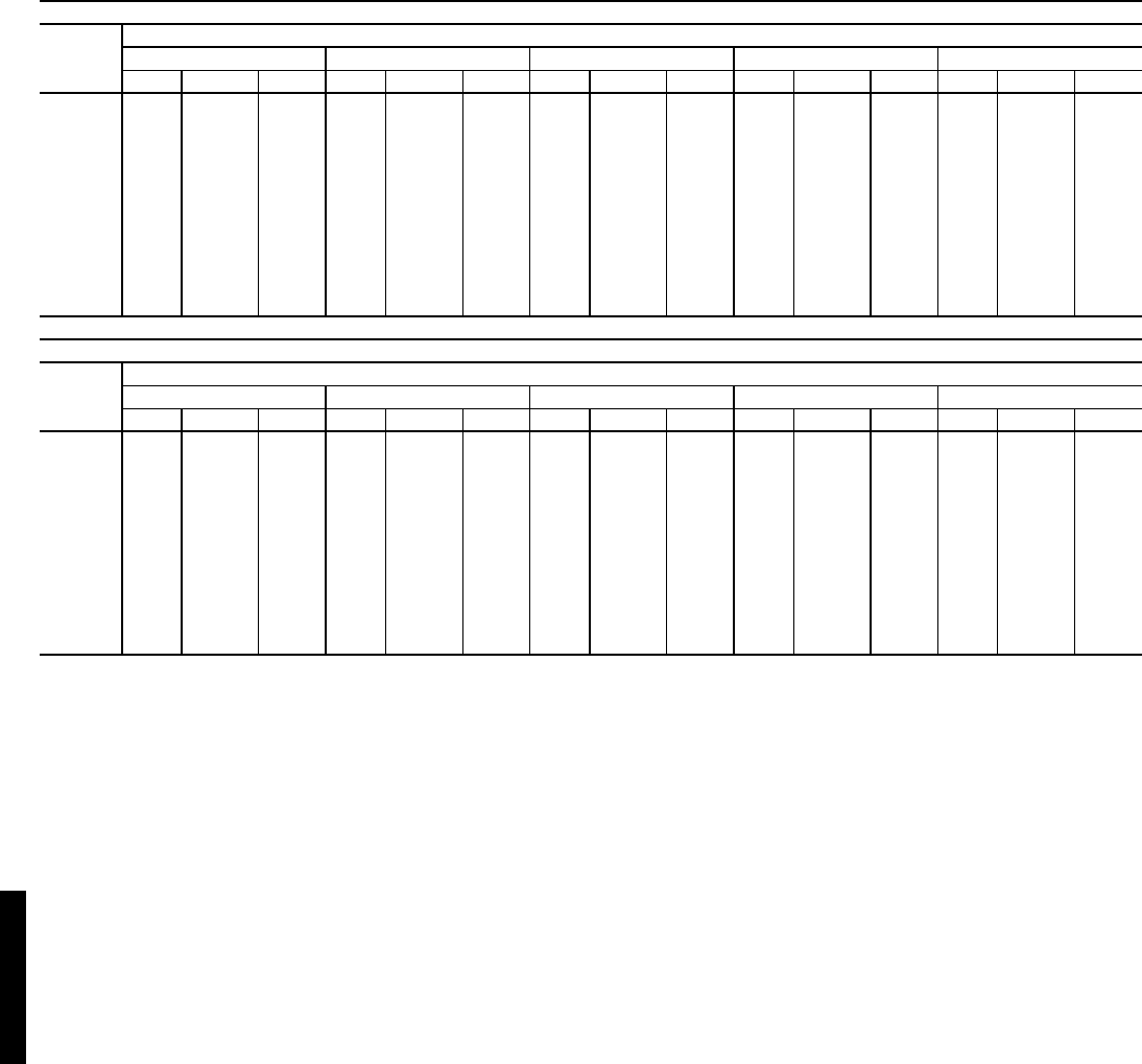
98
FAN PERFORMANCE — VERTICAL DISCHARGE UNITS (cont)
LEGEND
*Motor drive ranges:
Low Range: 687-873
Mid-Low Range: 805-1007
Mid-High Range: 941-1176
High Range: 1014-1297
All other rpms require field-supplied drive.
Refer to page 99 for general Fan Performance Data notes.
NOTE: Maximum continuous bhp is:
Low Range: 5.75
Mid-Low Range: 5.75
Mid-High Range: 8.63
High Range: 11.50
48HJE028 (25 TONS) (Medium Heat Units)*
Airflow
(Cfm)
Available External Static Pressure (in. wg)
0.2 0.4 0.6 0.8 1.0
Rpm Watts Bhp Rpm Watts Bhp Rpm Watts Bhp Rpm Watts Bhp Rpm Watts Bhp
6,500 775 2,600 2.99 825 2,872 3.30 871 3,130 3.60 915 3,400 3.91 959 3,692 4.25
7,000 826 3,115 3.58 875 3,408 3.92 918 3,679 4.23 959 3,954 4.55 1000 4,245 4.88
7,500 878 3,690 4.24 925 4,006 4.61 966 4,292 4.94 1005 4,575 5.26 1043 4,868 5.60
8,000 929 4,326 4.98 975 4,667 5.37 1015 4,970 5.72 1052 5,265 6.06 1088 5,564 6.40
8,500 981 5,029 5.78 1026 5,395 6.20 1064 5,717 6.58 1100 6,025 6.93 1134 6,332 7.28
9,000 1033 5,799 6.67 1076 6,191 7.12 1114 6,533 7.51 1148 6,856 7.89 1181 7,173 8.25
9,500 1085 6,640 7.64 1128 7,058 8.12 1164 7,421 8.54 1198 7,761 8.93 1229 8,091 9.31
10,000 1137 7,553 8.69 1179 8,000 9.20 1214 8,385 9.64 1247 8,741 10.05 1278 9,086 10.45
10,500 1190 8,542 9.82 1230 9,016 10.37 1265 9,424 10.84 1297 9,799 11.27 1327 10,158 11.68
11,000 1242 9,609 11.05 1282 10,111 11.63 1316 10,542 12.12 1347 10,937 12.58 1376 11,311 13.01
11,500 1294 10,756 12.37 1333 11,287 12.98 1367 11,741 13.50 — — — — — —
12,000 1347 11,985 13.78 — — — — — — — — — — — —
12,500 —— ——— ——— ——— ——— —
48HJE028 (25 TONS) (Medium Heat Units)* (cont)
Airflow
(Cfm)
Available External Static Pressure (in. wg)
1.2 1.4 1.6 1.8 2.0
Rpm Watts Bhp Rpm Watts Bhp Rpm Watts Bhp Rpm Watts Bhp Rpm Watts Bhp
6,500 1004 4,016 4.62 1050 4,374 5.03 1098 4,769 5.48 1145 5,195 5.97 1192 5646 6.49
7,000 1041 4,559 5.24 1083 4,902 5.64 1126 5,277 6.07 1170 5,685 6.54 1214 6122 7.04
7,500 1081 5,179 5.96 1120 5,512 6.34 1159 5,872 6.75 1199 6,261 7.20 1240 6680 7.68
8,000 1124 5,875 6.76 1160 6,203 7.13 1196 6,553 7.54 1233 6,928 7.97 1270 7329 8.43
8,500 1168 6,647 7.64 1202 6,974 8.02 1235 7,318 8.42 1269 7,684 8.84 1304 8071 9.28
9,000 1214 7,495 8.62 1245 7,825 9.00 1277 8,168 9.39 1309 8,527 9.81 1341 8905 10.24
9,500 1260 8,421 9.69 1290 8,756 10.07 1320 9,100 10.47 1351 9,457 10.88 1381 9830 11.31
10,000 1308 9,425 10.84 1337 9,768 11.23 1365 10,116 11.63 1394 10,474 12.05 — — —
10,500 1356 10,510 12.09 1384 10,862 12.49 — — — — — — — — —
11,000 —— ——— ——— ——— ——— —
11,500 —— ——— ——— ——— ——— —
12,000 —— ——— ——— ——— ——— —
12,500 —— ——— ——— ——— ——— —
Bhp — Brake Horsepower Input to Fan
Watts — Input Watts to Motor
Performance data — 48HJ (cont)
48HJ48HJ
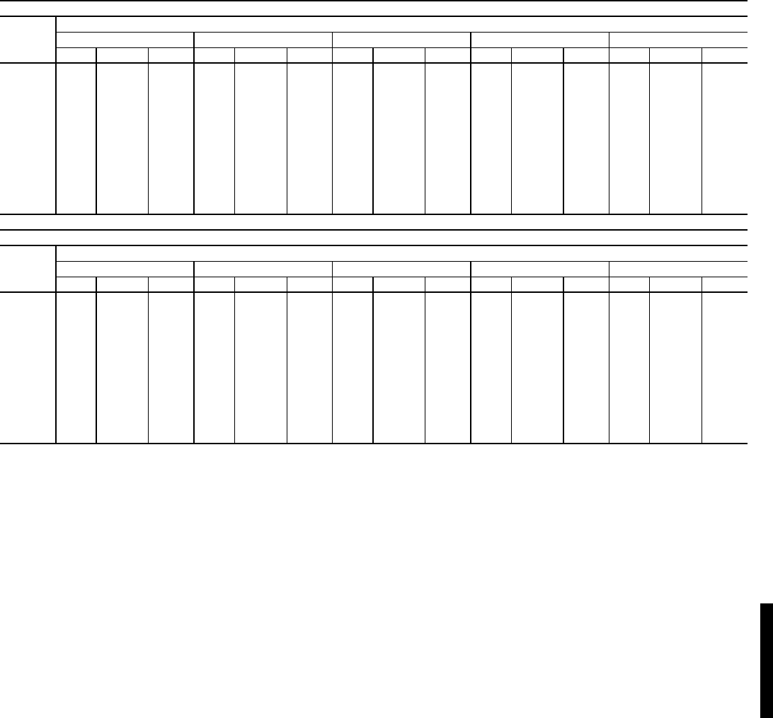
99
FAN PERFORMANCE — VERTICAL DISCHARGE UNITS (cont)
LEGEND
*Motor drive ranges:
Low Range: 687-873
Mid-Low Range: 805-1007
Mid-High Range: 941-1176
High Range: 1014-1297
All other rpms require field-supplied drive.
Refer to this page for general Fan Performance Data notes.
NOTE: Maximum continuous bhp is:
Low Range: 5.75
Mid-Low Range: 5.75
Mid-High Range: 8.63
High Range: 11.50
GENERAL NOTES FOR FAN PERFORMANCE DATA TABLES
1. Static pressure losses (i.e., EconoMi$er IV) must be added to
external static pressure before entering Fan Performance table.
2. Interpolation is permissible. Do not extrapolate.
3. Fan performance is based on wet coils, clean filters, and casing
losses. See Accessory/FIOP Static Pressure table on page 216.
4. Extensive motor and drive testing on these units ensures that the
full horsepower and watts range of the motor can be utilized with
confidence. Using the fan motors up to the watts or bhp rating
shown will not result in nuisance tripping or premature motor fail-
ure. Unit warranty will not be affected.
5. Use of a field-supplied motor may affect wire size. Contact your
Carrier representative for details.
6. Field-supplied drive requires changing belt and motor pulley to
meet desired air flow. See application data or contact your local
Carrier representative for details.
48HJF028 (25 TONS) (High Heat Units)*
Airflow
(Cfm)
Available External Static Pressure (in. wg)
0.2 0.4 0.6 0.8 1.0
Rpm Watts Bhp Rpm Watts Bhp Rpm Watts Bhp Rpm Watts Bhp Rpm Watts Bhp
6,500 775 2,600 2.99 825 2,872 3.30 871 3,130 3.60 915 3,400 3.91 959 3,692 4.25
7,000 826 3,115 3.58 875 3,408 3.92 918 3,679 4.23 959 3,954 4.55 1000 4,245 4.88
7,500 878 3,690 4.24 925 4,006 4.61 966 4,292 4.94 1005 4,575 5.26 1043 4,868 5.60
8,000 929 4,326 4.98 975 4,667 5.37 1015 4,970 5.72 1052 5,265 6.06 1088 5,564 6.40
8,500 981 5,029 5.78 1026 5,395 6.20 1064 5,717 6.58 1100 6,025 6.93 1134 6,332 7.28
9,000 1033 5,799 6.67 1076 6,191 7.12 1114 6,533 7.51 1148 6,856 7.89 1181 7,173 8.25
9,500 1085 6,640 7.64 1128 7,058 8.12 1164 7,421 8.54 1198 7,761 8.93 1229 8,091 9.31
10,000 1137 7,553 8.69 1179 8,000 9.20 1214 8,385 9.64 1247 8,741 10.05 1278 9,086 10.45
10,500 1190 8,542 9.82 1230 9,016 10.37 1265 9,424 10.84 1297 9,799 11.27 1327 10,158 11.68
11,000 1242 9,609 11.05 1282 10,111 11.63 1316 10,542 12.12 1347 10,937 12.58 1376 11,311 13.01
11,500 1294 10,756 12.37 1333 11,287 12.98 1367 11,741 13.50 — — — — — —
12,000 1347 11,985 13.78 — — — — — — — — — — — —
12,500 —— ——— ——— ——— ——— —
48HJF028 (25 TONS) (High Heat Units)* (cont)
Airflow
(Cfm)
Available External Static Pressure (in. wg)
1.2 1.4 1.6 1.8 2.0
Rpm Watts Bhp Rpm Watts Bhp Rpm Watts Bhp Rpm Watts Bhp Rpm Watts Bhp
6,500 1004 4,016 4.62 1050 4,374 5.03 1098 4,769 5.48 1145 5,195 5.97 1192 5646 6.49
7,000 1041 4,559 5.24 1083 4,902 5.64 1126 5,277 6.07 1170 5,685 6.54 1214 6122 7.04
7,500 1081 5,179 5.96 1120 5,512 6.34 1159 5,872 6.75 1199 6,261 7.20 1240 6680 7.68
8,000 1124 5,875 6.76 1160 6,203 7.13 1196 6,553 7.54 1233 6,928 7.97 1270 7329 8.43
8,500 1168 6,647 7.64 1202 6,974 8.02 1235 7,318 8.42 1269 7,684 8.84 1304 8071 9.28
9,000 1214 7,495 8.62 1245 7,825 9.00 1277 8,168 9.39 1309 8,527 9.81 1341 8905 10.24
9,500 1260 8,421 9.69 1290 8,756 10.07 1320 9,100 10.47 1351 9,457 10.88 1381 9830 11.31
10,000 1308 9,425 10.84 1337 9,768 11.23 1365 10,116 11.63 1394 10,474 12.05 — — —
10,500 1356 10,510 12.09 1384 10,862 12.49 — — — — — — — — —
11,000 —— ——— ——— ——— ——— —
11,500 —— ——— ——— ——— ——— —
12,000 —— ——— ——— ——— ——— —
12,500 —— ——— ——— ——— ——— —
Bhp — Brake Horsepower Input to Fan
Watts — Input Watts to Motor
48HJ
100
FAN PERFORMANCE — HORIZONTAL DISCHARGE UNITS
LEGEND
*Motor drive range: 680 to 1044 rpm. All other rpms require field-
supplied drive.
See page 99 for general fan performance notes.
NOTES:
1. Boldface indicates field-supplied drive is required.
2. Maximum continuous bhp is 1.20.
48HE003 (2Tons)
AIRFLOW
(Cfm)
EXTERNALSTATIC PRESSURE (in. wg)
0.1 0.2 0.4 0.6 0.8 1.0
Rpm Bhp Rpm Bhp Rpm Bhp Rpm Bhp Rpm Bhp Rpm Bhp
600 490 0.08 521 0.08 597 0.14 703 0.21 788 0.29 868 0.37
700 519 0.09 557 0.09 623 0.16 729 0.24 816 0.32 892 0.41
800 537 0.1 582 0.12 650 0.19 751 0.27 845 0.37 927 0.47
900 560 0.13 610 0.14 681 0.22 783 0.32 870 0.42 947 0.53
1000 589 0.15 640 0.16 707 0.26 808 0.36 894 0.47 971 0.58
Bhp — Brake Horsepower
Watts — Input Watts to Motor
Performance data — 48HE/HJ (cont)
48HE/HJ

101
FAN PERFORMANCE — HORIZONTAL DISCHARGE UNITS
LEGEND
*Motor drive range: 680 to 1044 rpm. All other rpms require field-
supplied drive.
See page 99 for general fan performance notes.
NOTES:
1. Boldface indicates field-supplied drive is required.
2. Maximum continuous bhp is 1.20.
LEGEND
*Motor drive range: 1075 to 1455 rpm. All other rpms require field-
supplied drive.
See page 99 for general fan performance notes.
NOTES:
1. Boldface indicates field-supplied drive is required.
2. Maximum continuous bhp is 2.40.
48HE/HJ004 (3 TONS) — STANDARD MOTOR (BELT DRIVE)*
Airflow
(Cfm)
External Static Pressure (in. wg)
0.2 0.4 0.6 0.8 1.0
Rpm Bhp Watts Rpm Bhp Watts Rpm Bhp Watts Rpm Bhp Watts Rpm Bhp Watts
900 553 0.14 134 681 0.22 221 782 0.32 316 870 0.42 417 948 0.53 526
1000 582 0.16 163 707 0.26 257 807 0.36 358 894 0.47 466 971 0.58 580
1100 612 0.20 196 734 0.30 297 833 0.41 405 919 0.52 519 995 0.64 639
1200 643 0.23 234 762 0.34 343 859 0.46 458 944 0.58 579 1020 0.71 705
1300 675 0.28 277 790 0.40 394 886 0.52 517 969 0.65 644 1044 0.78 777
1400 707 0.33 326 819 0.45 452 913 0.58 581 996 0.72 716 1070 0.86 855
1500 740 0.38 382 849 0.52 515 941 0.66 653 1023 0.80 795 1096 0.95 941
48HE/HJ004 (3 TONS) — STANDARD MOTOR (BELT DRIVE)* (cont)
Airflow
(Cfm)
External Static Pressure (in. wg)
1.2 1.4 1.6 1.8 2.0
Rpm Bhp Watts Rpm Bhp Watts Rpm Bhp Watts Rpm Bhp Watts Rpm Bhp Watts
900 1019 0.64 640 1084 0.76 760 1146 0.89 885 1203 1.02 1016 1258 1.16 1152
1000 1042 0.70 700 1107 0.83 825 1168 0.96 956 1225 1.10 1091 ———
1100 1065 0.77 765 1130 0.90 896 1190 1.04 1032 1247 1.18 1173 ———
1200 1089 0.84 837 1153 0.98 974 1213 1.12 1115 ——————
1300 1113 0.92 915 1177 1.06 1058 —————————
1400 1138 1.01 1000 1201 1.15 1149 —————————
1500 1163 1.10 1092 ————————————
Bhp — Brake Horsepower
Watts — Input Watts to Motor
48HE/HJ004 (3 TONS) — HIGH-STATIC MOTOR (BELT DRIVE)*
Airflow
(Cfm)
External Static Pressure (in. wg)
0.2 0.4 0.6 0.8 1.0
Rpm Bhp Watts Rpm Bhp Watts Rpm Bhp Watts Rpm Bhp Watts Rpm Bhp Watts
900 553 0.14 134 681 0.22 221 782 0.32 316 870 0.42 417 948 0.53 526
1000 582 0.16 163 707 0.26 257 807 0.36 358 894 0.47 466 971 0.58 580
1100 612 0.20 196 734 0.30 297 833 0.41 405 919 0.52 519 995 0.64 639
1200 643 0.23 234 762 0.34 343 859 0.46 458 944 0.58 579 1020 0.71 705
1300 675 0.28 277 790 0.40 394 886 0.52 517 969 0.65 644 1044 0.78 777
1400 707 0.33 326 819 0.45 452 913 0.58 581 996 0.72 716 1070 0.86 855
1500 740 0.38 382 849 0.52 515 941 0.66 653 1023 0.80 795 1096 0.95 941
48HE/HJ004 (3 TONS) — HIGH-STATIC MOTOR (BELT DRIVE)* (cont)
Airflow
(Cfm)
External Static Pressure (in. wg)
1.2 1.4 1.6 1.8 2.0
Rpm Bhp Watts Rpm Bhp Watts Rpm Bhp Watts Rpm Bhp Watts Rpm Bhp Watts
900 1019 0.64 640 1084 0.76 760 1146 0.89 885 1203 1.02 1016 1258 1.16 1152
1000 1042 0.70 700 1107 0.83 825 1168 0.96 956 1225 1.10 1091 1279 1.24 1232
1100 1065 0.77 765 1130 0.90 896 1190 1.04 1032 1247 1.18 1173 1301 1.33 1319
1200 1089 0.84 837 1153 0.98 974 1213 1.12 1115 1270 1.27 1262 1324 1.42 1413
1300 1113 0.92 915 1177 1.06 1058 1237 1.21 1205 1293 1.36 1358 1347 1.52 1514
1400 1138 1.01 1000 1201 1.15 1149 1261 1.31 1303 1317 1.47 1461 1370 1.63 1623
1500 1163 1.10 1092 1226 1.25 1247 1285 1.41 1407 1341 1.58 1571 1394 1.75 1740
Bhp — Brake Horsepower
Watts — Input Watts to Motor
48HE/HJ
102
FAN PERFORMANCE — HORIZONTAL DISCHARGE UNITS (cont)
LEGEND
*Motor drive range: 770 to 1185 rpm. All other rpms require field-
supplied drive.
See page 99 for general fan performance notes.
NOTES:
1. Boldface indicates field-supplied drive is required.
2. Maximum continuous bhp is 1.20.
LEGEND
*Motor drive range: 1075 to 1455 rpm. All other rpms require field-
supplied drive.
See page 99 for general fan performance notes.
NOTES:
1. Boldface indicates field-supplied drive is required.
2. Maximum continuous bhp is 2.40.
48HE/HJ005 (4 TONS) — STANDARD MOTOR (BELT DRIVE)*
Airflow
(Cfm)
External Static Pressure (in. wg)
0.2 0.4 0.6 0.8 1.0
Rpm Bhp Watts Rpm Bhp Watts Rpm Bhp Watts Rpm Bhp Watts Rpm Bhp Watts
1200 643 0.23 234 762 0.34 343 859 0.46 458 944 0.58 579 1020 0.71 705
1300 675 0.28 277 790 0.40 394 886 0.52 517 969 0.65 644 1044 0.78 777
1400 707 0.33 326 819 0.45 452 913 0.58 581 996 0.72 716 1070 0.86 855
1500 740 0.38 382 849 0.52 515 941 0.66 653 1023 0.80 795 1096 0.95 941
1600 773 0.45 444 879 0.59 586 970 0.73 731 1050 0.88 880 1123 1.04 1034
1700 807 0.52 513 910 0.67 663 999 0.82 817 1078 0.98 973 1150 1.14 1134
1800 841 0.59 589 942 0.75 749 1029 0.91 910 1106 1.08 1074 — — —
1900 875 0.68 674 974 0.85 842 1059 1.02 1012 1135 1.19 1184 — — —
2000 910 0.77 767 1006 0.95 944 1090 1.13 1122 ——————
48HE/HJ005 (4 TONS) — STANDARD MOTOR (BELT DRIVE)* (cont)
Airflow
(Cfm)
External Static Pressure (in. wg)
1.2 1.4 1.6 1.8 2.0
Rpm Bhp Watts Rpm Bhp Watts Rpm Bhp Watts Rpm Bhp Watts Rpm Bhp Watts
1200 1089 0.84 837 1153 0.98 974 1213 1.12 1115 ——————
1300 1113 0.92 915 1177 1.06 1058 —————————
1400 1138 1.01 1000 1201 1.15 1149 —————————
1500 1163 1.10 1092 — — — —————————
1600 1189 1.20 1191 ————————————
1700 ———————————————
1800 ———————————————
1900 ———————————————
2000 ———————————————
Bhp — Brake Horsepower
Watts — Input Watts to Motor
48HE/HJ005 (4 TONS) — HIGH-STATIC MOTOR (BELT DRIVE)*
Airflow
(Cfm)
External Static Pressure (in. wg)
0.2 0.4 0.6 0.8 1.0
Rpm Bhp Watts Rpm Bhp Watts Rpm Bhp Watts Rpm Bhp Watts Rpm Bhp Watts
1200 643 0.23 234 762 0.34 343 859 0.46 458 944 0.58 579 1020 0.71 705
1300 675 0.28 277 790 0.40 394 886 0.52 517 969 0.65 644 1044 0.78 777
1400 707 0.33 326 819 0.45 452 913 0.58 581 996 0.72 716 1070 0.86 855
1500 740 0.38 382 849 0.52 515 941 0.66 653 1023 0.80 795 1096 0.95 941
1600 773 0.45 444 879 0.59 586 970 0.73 731 1050 0.88 880 1123 1.04 1034
1700 807 0.52 513 910 0.67 663 999 0.82 817 1078 0.98 973 1150 1.14 1134
1800 841 0.59 589 942 0.75 749 1029 0.91 910 1106 1.08 1074 1177 1.25 1242
1900 875 0.68 674 974 0.85 842 1059 1.02 1012 1135 1.19 1184 1205 1.37 1360
2000 910 0.77 767 1006 0.95 944 1090 1.13 1122 1165 1.31 1302 1234 1.49 1485
48HE/HJ005 (4 TONS) — HIGH-STATIC MOTOR (BELT DRIVE)* (cont)
Airflow
(Cfm)
External Static Pressure (in. wg)
1.2 1.4 1.6 1.8 2.0
Rpm Bhp Watts Rpm Bhp Watts Rpm Bhp Watts Rpm Bhp Watts Rpm Bhp Watts
1200 1089 0.84 837 1153 0.98 974 1213 1.12 1115 1270 1.27 1262 1324 1.42 1413
1300 1113 0.92 915 1177 1.06 1058 1237 1.21 1205 1293 1.36 1358 1347 1.52 1514
1400 1138 1.01 1000 1201 1.15 1149 1261 1.31 1303 1317 1.47 1461 1370 1.63 1623
1500 1163 1.10 1092 1226 1.25 1247 1285 1.41 1407 1341 1.58 1571 1394 1.75 1740
1600 1189 1.20 1191 1252 1.36 1353 1310 1.53 1520 1365 1.70 1690 1418 1.87 1865
1700 1216 1.31 1299 1277 1.48 1468 1335 1.65 1640 1390 1.83 1817 1442 2.01 1998
1800 1242 1.42 1414 1303 1.60 1590 1361 1.78 1770 1415 1.96 1953 1467 2.15 2140
1900 1270 1.55 1538 1330 1.73 1721 1387 1.92 1908 1441 2.11 2098 1493 2.30 2292
2000 1297 1.68 1672 1357 1.87 1862 1414 2.07 2055 1467 2.26 2252 ———
Bhp — Brake Horsepower
Watts — Input Watts to Motor
Performance data — 48HE/HJ (cont)
48HE/HJ
103
FAN PERFORMANCE — HORIZONTAL DISCHARGE UNITS (cont)
LEGEND
*Motor drive range: 1035 to 1460 rpm. All other rpms require field-
supplied drive.
See page 99 for general fan performance notes.
NOTES:
1. Boldface indicates field-supplied drive is required.
2. Maximum continuous bhp is 1.30.
LEGEND
*Motor drive range: 1035 to 1460 rpm. All other rpms require field-
supplied drive.
See page 99 for general fan performance notes.
NOTES:
1. Boldface indicates field-supplied drive is required.
2. Maximum continuous bhp is 2.40.
48HE/HJ006 (5 TONS) — STANDARD MOTOR (BELT DRIVE)* — SINGLE-PHASE UNITS
Airflow
(Cfm)
External Static Pressure (in. wg)
0.2 0.4 0.6 0.8 1.0
Rpm Bhp Watts Rpm Bhp Watts Rpm Bhp Watts Rpm Bhp Watts Rpm Bhp Watts
1500 800 0.39 350 904 0.49 438 999 0.60 535 1087 0.72 640 1169 0.85 753
1600 839 0.46 412 938 0.57 505 1030 0.68 605 1115 0.80 714 1195 0.93 829
1700 879 0.54 483 974 0.65 580 1062 0.77 684 1144 0.90 796 1221 1.03 914
1800 919 0.63 561 1010 0.75 663 1095 0.87 771 1174 1.00 886 1250 1.14 1008
1900 960 0.73 648 1047 0.85 754 1129 0.98 867 1206 1.11 986 1279 1.25 1111
2000 1001 0.84 744 1085 0.96 855 1163 1.09 972 1238 1.23 1095 — — —
2100 1043 0.96 850 1123 1.09 965 1199 1.22 1086 ——————
2200 1085 1.09 966 1162 1.22 1086 —————————
2300 1127 1.23 1092 — — — —————————
2400 ———————————————
2500 ———————————————
48HE/HJ006 (5 TONS) — STANDARD MOTOR (BELT DRIVE)* — SINGLE-PHASE UNITS (cont)
Airflow
(Cfm)
External Static Pressure (in. wg)
1.2 1.4 1.6 1.8 2.0
Rpm Bhp Watts Rpm Bhp Watts Rpm Bhp Watts Rpm Bhp Watts Rpm Bhp Watts
1500 1247 0.98 873 1320 1.13 1002 1390 1.28 1137 ——————
1600 1270 1.07 952 1342 1.22 1083 —————————
1700 1295 1.17 1040 — — — —————————
1800 1321 1.28 1137 — — — —————————
1900 ———————————————
2000 ———————————————
2100 ———————————————
2200 ———————————————
2300 ———————————————
2400 ———————————————
2500 ———————————————
Bhp — Brake Horsepower
Watts — Input Watts to Motor
48HE/HJ006 (5 TONS) — STANDARD MOTOR (BELT DRIVE)* — THREE-PHASE UNITS
Airflow
(Cfm)
External Static Pressure (in. wg)
0.2 0.4 0.6 0.8 1.0
Rpm Bhp Watts Rpm Bhp Watts Rpm Bhp Watts Rpm Bhp Watts Rpm Bhp Watts
1500 800 0.39 350 904 0.49 438 999 0.60 535 1087 0.72 640 1169 0.85 753
1600 839 0.46 412 938 0.57 505 1030 0.68 605 1115 0.80 714 1195 0.93 829
1700 879 0.54 483 974 0.65 580 1062 0.77 684 1144 0.90 796 1221 1.03 914
1800 919 0.63 561 1010 0.75 663 1095 0.87 771 1174 1.00 886 1250 1.14 1008
1900 960 0.73 648 1047 0.85 754 1129 0.98 867 1206 1.11 986 1279 1.25 1111
2000 1001 0.84 744 1085 0.96 855 1163 1.09 972 1238 1.23 1095 1309 1.38 1224
2100 1043 0.96 850 1123 1.09 965 1199 1.22 1086 1271 1.37 1213 1340 1.52 1346
2200 1085 1.09 966 1162 1.22 1086 1235 1.36 1211 1305 1.51 1342 1372 1.67 1479
2300 1127 1.23 1092 1201 1.37 1217 1272 1.52 1347 1340 1.67 1482 1405 1.83 1623
2400 1169 1.38 1229 1241 1.53 1359 1310 1.68 1493 1375 1.84 1633 1439 2.00 1778
2500 1212 1.55 1378 1281 1.70 1513 1348 1.86 1652 1412 2.02 1796 1473 2.19 1945
48HE/HJ006 (5 TONS) — STANDARD MOTOR (BELT DRIVE)* — THREE-PHASE UNITS (cont)
Airflow
(Cfm)
External Static Pressure (in. wg)
1.2 1.4 1.6 1.8 2.0
Rpm Bhp Watts Rpm Bhp Watts Rpm Bhp Watts Rpm Bhp Watts Rpm Bhp Watts
1500 1247 0.98 873 1320 1.13 1002 1390 1.28 1137 1457 1.44 1280 1522 1.61 1430
1600 1270 1.07 952 1342 1.22 1083 1411 1.37 1221 1476 1.54 1365 1540 1.71 1517
1700 1295 1.17 1040 1365 1.32 1173 1432 1.48 1313 1497 1.64 1459 1559 1.82 1612
1800 1321 1.28 1137 1390 1.43 1273 1455 1.59 1415 1518 1.76 1563 1579 1.93 1718
1900 1348 1.40 1243 1415 1.56 1381 1479 1.72 1526 1541 1.89 1677 1601 2.06 1834
2000 1377 1.53 1359 1442 1.69 1500 1505 1.86 1648 1565 2.03 1801 1624 2.21 1961
2100 1406 1.67 1485 1470 1.83 1629 1531 2.00 1780 1591 2.18 1936 1648 2.36 2098
2200 1437 1.83 1621 1499 1.99 1769 1559 2.16 1923 1617 2.34 2082 ———
2300 1468 1.99 1769 1529 2.16 1920 1587 2.34 2077 ——————
2400 1500 2.17 1928 1559 2.35 2083 —————————
2500 1533 2.36 2098 ————————————
Bhp — Brake Horsepower
Watts — Input Watts to Motor
48HE/HJ
104
FAN PERFORMANCE — HORIZONTAL DISCHARGE UNITS (cont)
LEGEND
*Motor drive range: 1300 to 1685 rpm. All other rpms require field-supplied
drive.
See page 99 for general fan performance notes.
NOTES:
1. Boldface indicates field-supplied drive is required.
2. Maximum continuous bhp is 2.90.
LEGEND
*Motor drive range: 1119 to 1585 rpm. All other rpms require field-supplied
drive.
See page 99 for general fan performance notes.
NOTES:
1. Boldface indicates field-supplied drive is required.
2. Maximum continuous bhp is 2.40.
48HE/HJ006 (5 TONS) — HIGH-STATIC MOTOR (BELT DRIVE)*
Airflow
(Cfm)
External Static Pressure (in. wg)
0.2 0.4 0.6 0.8 1.0
Rpm Bhp Watts Rpm Bhp Watts Rpm Bhp Watts Rpm Bhp Watts Rpm Bhp Watts
1500 800 0.39 350 904 0.49 438 999 0.60 535 1087 0.72 640 1169 0.85 753
1600 839 0.46 412 938 0.57 505 1030 0.68 605 1115 0.80 714 1195 0.93 829
1700 879 0.54 483 974 0.65 580 1062 0.77 684 1144 0.90 796 1221 1.03 914
1800 919 0.63 561 1010 0.75 663 1095 0.87 771 1174 1.00 886 1250 1.14 1008
1900 960 0.73 648 1047 0.85 754 1129 0.98 867 1206 1.11 986 1279 1.25 1111
2000 1001 0.84 744 1085 0.96 855 1163 1.09 972 1238 1.23 1095 1309 1.38 1224
2100 1043 0.96 850 1123 1.09 965 1199 1.22 1086 1271 1.37 1213 1340 1.52 1346
2200 1085 1.09 966 1162 1.22 1086 1235 1.36 1211 13051.51134213721.671479
2300 1127 1.23 1092 1201 1.37 1217 1272 1.52 1347 13401.67148214051.831623
2400 1169 1.38 1229 1241 1.53 1359 1310 1.68 1493 1375 1.84 1633 1439 2.00 1778
2500 1212 1.55 1378 1281 1.70 1513 1348 1.86 1652 1412 2.02 1796 1473 2.19 1945
48HE/HJ006 (5 TONS) — HIGH-STATIC MOTOR (BELT DRIVE)* (cont)
Airflow
(Cfm)
External Static Pressure (in. wg)
1.2 1.4 1.6 1.8 2.0
Rpm Bhp Watts Rpm Bhp Watts Rpm Bhp Watts Rpm Bhp Watts Rpm Bhp Watts
1500 1247 0.98 873 1320 1.13 1002 1390 1.28 1137 1457 1.44 1280 1522 1.61 1430
1600 1270 1.07 952 1342 1.22 1083 1411 1.37 1221 1476 1.54 1365 1540 1.71 1517
1700 1295 1.17 1040 1365 1.32 1173 1432 1.48 1313 1497 1.64 1459 1559 1.82 1612
1800 1321 1.28 1137 1390 1.43 1273 1455 1.59 1415 1518 1.76 1563 1579 1.93 1718
1900 1348 1.40 1243 1415 1.56 1381 1479 1.72 1526 1541 1.89 1677 1601 2.06 1834
2000 1377 1.53 1359 1442 1.69 1500 1505 1.86 1648 1565 2.03 1801 1624 2.21 1961
2100 1406 1.67 1485 1470 1.83 1629 1531 2.00 1780 1591 2.18 1936 1648 2.36 2098
2200 1437 1.83 1621 1499 1.99 1769 1559 2.16 1923 1617 2.34 2082 1673 2.53 2246
2300 1468 1.99 1769 1529 2.16 1920 1587 2.34 2077 1644 2.52 2239 1699 2.71 2406
2400 1500 2.17 1928 1559 2.35 2083 1616 2.53 2243 1672 2.71 2408 1726 2.90 2579
2500 15332.36209815912.54225716472.732421——————
Bhp — Brake Horsepower
Watts — Input Watts to Motor
48HJ007 (6 TONS) — STANDARD MOTOR (BELT DRIVE)*
Airflow
(Cfm)
External Static Pressure (in. wg)
0.2 0.4 0.6 0.8 1.0
Rpm Bhp Watts Rpm Bhp Watts Rpm Bhp Watts Rpm Bhp Watts Rpm Bhp Watts
1800 913 0.64 569 1010 0.80 715 1098 0.98 869 11781.16103212521.351203
1900 952 0.73 652 1046 0.91 805 1131 1.09 965 1210 1.28 1134 1282 1.48 1311
2000 992 0.84 744 1083 1.02 903 1166 1.21 1070 1242 1.40 1245 1313 1.61 1427
2100 1032 0.95 844 1120 1.14 1010 1200 1.33 1184 1275 1.54 1365 1345 1.75 1553
2200 1073 1.07 954 1158 1.27 1127 1236 1.47 1307 1308 1.68 1495 1377 1.90 1689
2300 1114 1.21 1074 1196 1.41 1254 1272 1.62 1440 1343 1.84 1634 1409 2.07 1834
2400 1155 1.36 1204 1234 1.57 1391 1308 1.78 1584 1377 2.01 1784 1443 2.24 1990
2500 1196 1.51 1345 1273 1.73 1538 1345 1.96 1738 1412 2.19 1945 — — —
2600 1238 1.69 1497 1312 1.91 1697 1382 2.14 1904 1448 2.38 2117 — — —
2700 12801.87166013522.10186714202.342081——————
2800 13222.07183513922.312050—————————
2900 13642.282023————————————
3000 ———————————————
48HJ007 (6 TONS) — STANDARD MOTOR (BELT DRIVE)* (cont)
Airflow
(Cfm)
External Static Pressure (in. wg)
1.2 1.4 1.6 1.8 2.0
Rpm Bhp Watts Rpm Bhp Watts Rpm Bhp Watts Rpm Bhp Watts Rpm Bhp Watts
1800 1322 1.56 1382 1388 1.77 1568 1451 1.98 1762 1510 2.21 1962 ———
1900 1351 1.68 1495 1416 1.90 1686 1477 2.12 1885 1536 2.35 2090 — — —
2000 13801.82161714442.04181415052.272017——————
2100 14111.97174814732.201950—————————
2200 14412.13189015032.362097—————————
2300 14732.302041————————————
2400 ———————————————
2500 ———————————————
2600 ———————————————
2700 ———————————————
2800 ———————————————
2900 ———————————————
3000 ———————————————
Bhp — Brake Horsepower
Watts — Input Watts to Motor
Performance data — 48HE/HJ (cont)
48HE/HJ
105
FAN PERFORMANCE — HORIZONTAL DISCHARGE UNITS (cont)
LEGEND
*Motor drive range: 1300 to 1686 rpm. All other rpms require field-
supplied drive.
See page 99 for general fan performance notes.
NOTES:
1. Boldface indicates field-supplied drive is required.
2. Maximum continuous bhp is 2.90.
48HJ007 (6 TONS) — HIGH-STATIC MOTOR (BELT DRIVE)*
Airflow
(Cfm)
External Static Pressure (in. wg)
0.2 0.4 0.6 0.8 1.0
Rpm Bhp Watts Rpm Bhp Watts Rpm Bhp Watts Rpm Bhp Watts Rpm Bhp Watts
1800 913 0.64 569 1010 0.80 715 1098 0.98 869 1178 1.16 1032 1252 1.35 1203
1900 952 0.73 652 1046 0.91 805 1131 1.09 965 1210 1.28 1134 1282 1.48 1311
2000 992 0.84 744 1083 1.02 903 1166 1.21 1070 1242 1.40 1245 1313 1.61 1427
2100 1032 0.95 844 1120 1.14 1010 1200 1.33 1184 1275 1.54 1365 1345 1.75 1553
2200 1073 1.07 954 1158 1.27 1127 1236 1.47 1307 1308 1.68 1495 1377 1.90 1689
2300 1114 1.21 1074 1196 1.41 1254 1272 1.62 1440 1343 1.84 1634 1409 2.07 1834
2400 1155 1.36 1204 1234 1.57 1391 1308 1.78 1584 1377 2.01 1784 1443 2.24 1990
2500 1196 1.51 1345 1273 1.73 1538 1345 1.96 1738 1412 2.19 1945 1477 2.43 2157
2600 1238 1.69 1497 1312 1.91 1697 1382 2.14 1904 1448 2.38 2117 1511 2.63 2335
2700 1280 1.87 1660 1352 2.10 1867 1420 2.34 2081 1484 2.59 2300 1546 2.84 2526
2800 1322 2.07 1835 1392 2.31 2050 1458 2.56 2270 1521 2.81 2496 — — —
2900 13642.28202314322.53224514962.782472——————
3000 14062.50222414722.762452—————————
48HJ007 (6 TONS) — HIGH-STATIC MOTOR (BELT DRIVE)* (cont)
Airflow
(Cfm)
External Static Pressure (in. wg)
1.2 1.4 1.6 1.8 2.0
Rpm Bhp Watts Rpm Bhp Watts Rpm Bhp Watts Rpm Bhp Watts Rpm Bhp Watts
1800 1322 1.56 1382 1388 1.77 1568 1451 1.98 1762 1510 2.21 1962 1568 2.44 2169
1900 1351 1.68 1495 1416 1.90 1686 1477 2.12 1885 1536 2.35 2090 1593 2.59 2302
2000 1380 1.82 1617 1444 2.04 1814 1505 2.27 2017 1563 2.51 2227 1619 2.75 2443
2100 1411 1.97 1748 1473 2.20 1950 1533 2.43 2159 1590 2.67 2374 — — —
2200 1441 2.13 1890 1503 2.36 2097 1562 2.60 2311 1618 2.85 2532 — — —
2300 14732.30204115332.54225415912.792474——————
2400 15052.48220315642.732422—————————
2500 15372.682376————————————
2600 15712.882560————————————
2700 ———————————————
2800 ———————————————
2900 ———————————————
3000 ———————————————
Bhp — Brake Horsepower
Watts — Input Watts to Motor
48HJ
106
FAN PERFORMANCE — HORIZONTAL DISCHARGE UNITS (cont)
LEGEND
*Motor drive range: 840 to 1085 rpm. All other rpms require field-
supplied drive.
See page 99 for general fan performance notes.
NOTES:
1. Boldface indicates field-supplied drive is required.
2. Maximum continuous bhp is 2.90.
48HJ008 (71/2 TONS) — STANDARD MOTOR (BELT DRIVE)*
Airflow
(Cfm)
External Static Pressure (in. wg)
0.2 0.4 0.6 0.8 1.0
Rpm Bhp Watts Rpm Bhp Watts Rpm Bhp Watts Rpm Bhp Watts Rpm Bhp Watts
2250 505 0.52 484 586 0.73 681 657 0.97 901 722 1.22 1142 782 1.50 1403
2300 513 0.55 509 592 0.76 708 663 1.00 931 727 1.26 1174 787 1.54 1437
2400 527 0.60 561 605 0.82 766 674 1.07 993 738 1.33 1241 796 1.62 1508
2500 543 0.66 617 618 0.89 828 686 1.14 1060 748 1.41 1312 806 1.70 1583
2550 550 0.69 647 625 0.92 860 692 1.17 1095 754 1.45 1349 811 1.74 1623
2600 558 0.73 677 632 0.96 894 698 1.21 1131 759 1.49 1388 816 1.78 1664
2700 574 0.80 742 645 1.03 964 710 1.29 1207 770 1.58 1469 826 1.88 1749
2800 589 0.87 811 659 1.11 1039 723 1.38 1287 782 1.67 1554 837 1.97 1839
2900 605 0.95 885 673 1.20 1119 736 1.47 1372 794 1.76 1644 848 2.07 1933
3000 621 1.03 963 688 1.29 1204 749 1.57 1463 806 1.87 1740 859 2.18 2033
3100 637 1.12 1046 702 1.39 1293 762 1.67 1558 818 1.97 1840 871 2.29 2139
3200 654 1.22 1135 717 1.49 1388 776 1.78 1658 831 2.09 1946 882 2.41 2249
3300 670 1.32 1228 732 1.60 1488 789 1.89 1764 843 2.21 2057 894 2.54 2365
3400 686 1.42 1328 747 1.71 1593 803 2.01 1876 856 2.33 2174 907 2.67 2488
3500 703 1.54 1433 762 1.83 1705 817 2.14 1993 870 2.46 2297 919 2.81 2616
3600 720 1.66 1543 777 1.95 1822 832 2.27 2116 883 2.60 2425 — — —
3700 736 1.78 1660 793 2.09 1944 846 2.41 2245 896 2.75 2560 — — —
3750 745 1.85 1721 801 2.15 2008 853 2.48 2312 903 2.82 2630 — — —
48HJ008 (71/2 TONS) — STANDARD MOTOR (BELT DRIVE)* (cont)
Airflow
(Cfm)
External Static Pressure (in. wg)
1.2 1.4 1.6 1.8 2.0
Rpm Bhp Watts Rpm Bhp Watts Rpm Bhp Watts Rpm Bhp Watts Rpm Bhp Watts
2250 838 1.81 1683 891 2.12 1981 941 2.46 2297 988 2.82 2629 — — —
2300 842 1.84 1719 895 2.17 2019 944 2.51 2336 992 2.86 2669 — — —
2400 851 1.92 1793 903 2.25 2097 952 2.59 2416 — — — — — —
2500 860 2.01 1873 911 2.34 2180 960 2.68 2502 — — — — — —
2550 865 2.05 1914 916 2.38 2223 964 2.73 2547 — — — — — —
2600 869 2.10 1957 920 2.43 2267 968 2.78 2593 — — — — — —
2700 879 2.19 2046 929 2.53 2360 976 2.88 2689 — — — — — —
2800 889 2.29 2140 938 2.64 2458 — — — — — — — — —
2900 899 2.40 2239 948 2.75 2561 — — — — — — — — —
3000 910 2.51 2343 958 2.86 2670 — — — — — — — — —
3100 921 2.63 2453 — — — — — — — — — — — —
3200 932 2.75 2569 — — — — — — — — — — — —
3300 943 2.88 2690 — — — — — — — — — — — —
3400 ———————————————
3500 ———————————————
3600 ———————————————
3700 ———————————————
3750 ———————————————
Bhp — Brake Horsepower Input to Fan
Watts — Input Watts to Motor
Performance data — 48HJ (cont)
48HJ48HJ
107
FAN PERFORMANCE — HORIZONTAL DISCHARGE UNITS (cont)
LEGEND
*Motor drive range: 860 to 1080 rpm. All other rpms require field-
supplied drive.
See page 99 for general fan performance notes.
NOTES:
1. Boldface indicates field-supplied drive is required.
2. Maximum continuous bhp is 4.20.
48HJ008 (71/2 TONS) — HIGH-STATIC MOTOR (BELT DRIVE)*
Airflow
(Cfm)
External Static Pressure (in. wg)
0.2 0.4 0.6 0.8 1.0
Rpm Bhp Watts Rpm Bhp Watts Rpm Bhp Watts Rpm Bhp Watts Rpm Bhp Watts
2250 505 0.52 484 586 0.73 681 657 0.97 901 722 1.22 1142 782 1.50 1403
2300 513 0.55 509 592 0.76 708 663 1.00 931 727 1.26 1174 787 1.54 1437
2400 527 0.60 561 605 0.82 766 674 1.07 993 738 1.33 1241 796 1.62 1508
2500 543 0.66 617 618 0.89 828 686 1.14 1060 748 1.41 1312 806 1.70 1583
2550 550 0.69 647 625 0.92 860 692 1.17 1095 754 1.45 1349 811 1.74 1623
2600 558 0.73 677 632 0.96 894 698 1.21 1131 759 1.49 1388 816 1.78 1664
2700 574 0.80 742 645 1.03 964 710 1.29 1207 770 1.58 1469 826 1.88 1749
2800 589 0.87 811 659 1.11 1039 723 1.38 1287 782 1.67 1554 837 1.97 1839
2900 605 0.95 885 673 1.20 1119 736 1.47 1372 794 1.76 1644 848 2.07 1933
3000 621 1.03 963 688 1.29 1204 749 1.57 1463 806 1.87 1740 859 2.18 2033
3100 637 1.12 1046 702 1.39 1293 762 1.67 1558 818 1.97 1840 871 2.29 2139
3200 654 1.22 1135 717 1.49 1388 776 1.78 1658 831 2.09 1946 882 2.41 2249
3300 670 1.32 1228 732 1.60 1488 789 1.89 1764 843 2.21 2057 894 2.54 2365
3400 686 1.42 1328 747 1.71 1593 803 2.01 1876 856 2.33 2174 907 2.67 2488
3500 703 1.54 1433 762 1.83 1705 817 2.14 1993 870 2.46 2297 919 2.81 2616
3600 720 1.66 1543 777 1.95 1822 832 2.27 2116 883 2.60 2425 932 2.95 2750
3700 736 1.78 1660 793 2.09 1944 846 2.41 2245 896 2.75 2560 944 3.10 2889
3750 745 1.85 1721 801 2.15 2008 853 2.48 2312 903 2.82 2630 951 3.18 2962
48HJ008 (71/2 TONS) — HIGH-STATIC MOTOR (BELT DRIVE)* (cont)
Airflow
(Cfm)
External Static Pressure (in. wg)
1.2 1.4 1.6 1.8 2.0
Rpm Bhp Watts Rpm Bhp Watts Rpm Bhp Watts Rpm Bhp Watts Rpm Bhp Watts
2250 838 1.81 1683 891 2.12 1981 941 2.46 2297 988 2.82 2629 1033 3.19 2976
2300 842 1.84 1719 895 2.17 2019 944 2.51 2336 992 2.86 2669 1037 3.24 3018
2400 851 1.92 1793 903 2.25 2097 952 2.59 2416 999 2.95 2752 1043 3.33 3104
2500 860 2.01 1873 911 2.34 2180 960 2.68 2502 1006 3.05 2842 1051 3.43 3196
2550 865 2.05 1914 916 2.38 2223 964 2.73 2547 1010 3.10 2888 1054 3.48 3243
2600 869 2.10 1957 920 2.43 2267 968 2.78 2593 1014 3.15 2935 1058 3.53 3292
2700 879 2.19 2046 929 2.53 2360 976 2.88 2689 1022 3.25 3035 1066 3.64 3395
2800 889 2.29 2140 938 2.64 2458 985 2.99 2791 1030 3.37 3140 1073 3.76 3503
2900 899 2.40 2239 948 2.75 2561 994 3.11 2898 1039 3.49 3250 1082 3.88 3616
3000 910 2.51 2343 958 2.86 2670 1004 3.23 3011 1048 3.61 3366 1090 4.01 3736
3100 921 2.63 2453 968 2.98 2783 1013 3.35 3128 1057 3.74 3488 1099 4.14 3861
3200 932 2.75 2569 978 3.11 2903 1023 3.49 3252 1066 3.88 3616 — — —
3300 943 2.88 2690 989 3.25 3029 1033 3.63 3382 1076 4.02 3749 — — —
3400 954 3.02 2816 1000 3.39 3159 1044 3.77 3518 1086 4.17 3889 —— —
3500 966 3.16 2950 1011 3.54 3297 1054 3.92 3660 — — — — — —
3600 978 3.31 3088 1022 3.69 3442 1065 4.08 3808 — — — — — —
3700 990 3.47 3233 1034 3.85 3591 — — — — — — — — —
3750 996 3.55 3308 1040 3.93 3669 — — — — — — — — —
Bhp — Brake Horsepower Input to Fan
Watts — Input Watts to Motor
48HJ

108
FAN PERFORMANCE — HORIZONTAL DISCHARGE UNITS (cont)
LEGEND
*Motor drive range: 840 to 1085 rpm. All other rpms require field-
supplied drive.
See page 99 for general fan performance notes.
NOTES:
1. Boldface indicates field-supplied drive is required.
2. Maximum continuous bhp is 2.90.
48HJ009 (81/2 TONS) — STANDARD MOTOR (BELT DRIVE)*
Airflow
(Cfm)
External Static Pressure (in. wg)
0.2 0.4 0.6 0.8 1.0
Rpm Bhp Watts Rpm Bhp Watts Rpm Bhp Watts Rpm Bhp Watts Rpm Bhp Watts
2500 513 0.45 423 603 0.62 576 682 0.78 732 753 0.96 892 817 1.13 1055
2600 526 0.50 463 614 0.67 621 692 0.84 783 761 1.02 948 825 1.20 1117
2700 539 0.54 505 625 0.72 670 702 0.90 837 770 1.08 1008 834 1.27 1182
2800 552 0.59 551 637 0.77 721 712 0.96 894 780 1.15 1070 842 1.34 1250
2900 565 0.64 599 648 0.83 775 722 1.02 954 789 1.22 1136 851 1.42 1321
3000 579 0.70 651 660 0.89 832 732 1.09 1017 799 1.29 1204 860 1.50 1395
3100 592 0.76 706 672 0.96 893 743 1.16 1083 808 1.37 1276 869 1.58 1471
3200 606 0.82 764 684 1.03 957 754 1.24 1153 818 1.45 1351 878 1.66 1552
3300 620 0.88 825 696 1.10 1024 765 1.31 1225 829 1.53 1429 888 1.75 1636
3400 634 0.95 890 709 1.17 1095 777 1.40 1302 839 1.62 1511 897 1.85 1723
3500 648 1.03 958 721 1.25 1169 788 1.48 1381 850 1.71 1597 907 1.95 1815
3600 662 1.10 1030 734 1.34 1246 800 1.57 1465 860 1.81 1686 917 2.05 1909
3700 676 1.19 1106 747 1.42 1328 811 1.66 1552 871 1.91 1779 927 2.15 2008
3800 690 1.27 1185 760 1.52 1414 823 1.76 1644 882 2.01 1876 938 2.26 2111
3900 705 1.36 1269 773 1.61 1503 835 1.86 1739 894 2.12 1977 948 2.38 2217
4000 719 1.45 1357 786 1.71 1597 848 1.97 1838 905 2.23 2082 959 2.50 2328
4100 734 1.55 1449 799 1.82 1695 860 2.08 1942 917 2.35 2192 970 2.62 2443
4200 748 1.66 1545 813 1.93 1797 872 2.20 2050 928 2.47 2305 981 2.75 2562
4300 763 1.76 1646 826 2.04 1903 885 2.32 2162 940 2.60 2423 992 2.88 2686
48HJ009 (81/2 TONS) — STANDARD MOTOR (BELT DRIVE)* (cont)
Airflow
(Cfm)
External Static Pressure (in. wg)
1.2 1.4 1.6 1.8 2.0
Rpm Bhp Watts Rpm Bhp Watts Rpm Bhp Watts Rpm Bhp Watts Rpm Bhp Watts
2500 877 1.31 1222 933 1.49 1392 986 1.68 1565 1037 1.87 1742 1085 2.06 1921
2600 885 1.38 1289 940 1.57 1464 993 1.76 1643 1043 1.96 1824 1091 2.15 2008
2700 892 1.46 1359 948 1.65 1540 1000 1.85 1723 1049 2.05 1909 1097 2.25 2099
2800 900 1.54 1432 955 1.74 1618 1007 1.94 1807 1056 2.14 1998 1103 2.35 2192
2900 908 1.62 1508 963 1.82 1699 1014 2.03 1893 1063 2.24 2089 1110 2.45 2289
3000 917 1.70 1587 970 1.91 1784 1021 2.13 1983 1070 2.34 2185 1117 2.56 2389
3100 925 1.79 1670 979 2.01 1872 1029 2.23 2076 1077 2.45 2283 1123 2.67 2492
3200 934 1.88 1756 987 2.10 1963 1037 2.33 2172 1085 2.56 2384 1131 2.79 2599
3300 943 1.98 1845 995 2.21 2057 1045 2.44 2272 1092 2.67 2490 —— —
3400 952 2.08 1939 1004 2.31 2156 1053 2.55 2376 1100 2.79 2599 —— —
3500 961 2.18 2035 1013 2.42 2258 1062 2.66 2483 — — — — — —
3600 971 2.29 2135 1022 2.53 2364 1070 2.78 2595 — — — — — —
3700 981 2.40 2240 1031 2.65 2473 — — — — — — — — —
3800 990 2.52 2348 1040 2.77 2587 — — — — — — — — —
3900 1000 2.64 2459 1050 2.90 2705 — — — — — — — — —
4000 1011 2.76 2576 — — — — — — — — — — — —
4100 1021 2.89 2697 — — — — — — — — — — — —
4200 ———————————————
4300 ———————————————
Bhp — Brake Horsepower Input to Fan
Watts — Input Watts to Motor
Performance data — 48HJ (cont)
48HJ48HJ

109
FAN PERFORMANCE — HORIZONTAL DISCHARGE UNITS (cont)
LEGEND
*Motor drive range: 860 to 1080 rpm. All other rpms require field-
supplied drive.
See page 99 for general fan performance notes.
NOTES:
1. Boldface indicates field-supplied drive is required.
2. Maximum continuous bhp is 4.20.
48HJ009 (81/2 TONS) — HIGH-STATIC MOTOR (BELT DRIVE)*
Airflow
(Cfm)
External Static Pressure (in. wg)
0.2 0.4 0.6 0.8 1.0
Rpm Bhp Watts Rpm Bhp Watts Rpm Bhp Watts Rpm Bhp Watts Rpm Bhp Watts
2500 513 0.45 423 603 0.62 576 682 0.78 732 753 0.96 892 817 1.13 1055
2600 526 0.50 463 614 0.67 621 692 0.84 783 761 1.02 948 825 1.20 1117
2700 539 0.54 505 625 0.72 670 702 0.90 837 770 1.08 1008 834 1.27 1182
2800 552 0.59 551 637 0.77 721 712 0.96 894 780 1.15 1070 842 1.34 1250
2900 565 0.64 599 648 0.83 775 722 1.02 954 789 1.22 1136 851 1.42 1321
3000 579 0.70 651 660 0.89 832 732 1.09 1017 799 1.29 1204 860 1.50 1395
3100 592 0.76 706 672 0.96 893 743 1.16 1083 808 1.37 1276 869 1.58 1471
3200 606 0.82 764 684 1.03 957 754 1.24 1153 818 1.45 1351 878 1.66 1552
3300 620 0.88 825 696 1.10 1024 765 1.31 1225 829 1.53 1429 888 1.75 1636
3400 634 0.95 890 709 1.17 1095 777 1.40 1302 839 1.62 1511 897 1.85 1723
3500 648 1.03 958 721 1.25 1169 788 1.48 1381 850 1.71 1597 907 1.95 1815
3600 662 1.10 1030 734 1.34 1246 800 1.57 1465 860 1.81 1686 917 2.05 1909
3700 676 1.19 1106 747 1.42 1328 811 1.66 1552 871 1.91 1779 927 2.15 2008
3800 690 1.27 1185 760 1.52 1414 823 1.76 1644 882 2.01 1876 938 2.26 2111
3900 705 1.36 1269 773 1.61 1503 835 1.86 1739 894 2.12 1977 948 2.38 2217
4000 719 1.45 1357 786 1.71 1597 848 1.97 1838 905 2.23 2082 959 2.50 2328
4100 734 1.55 1449 799 1.82 1695 860 2.08 1942 917 2.35 2192 970 2.62 2443
4200 748 1.66 1545 813 1.93 1797 872 2.20 2050 928 2.47 2305 981 2.75 2562
4300 763 1.76 1646 826 2.04 1903 885 2.32 2162 940 2.60 2423 992 2.88 2686
48HJ009 (81/2 TONS) — HIGH-STATIC MOTOR (BELT DRIVE)* (cont)
Airflow
(Cfm)
External Static Pressure (in. wg)
1.2 1.4 1.6 1.8 2.0
Rpm Bhp Watts Rpm Bhp Watts Rpm Bhp Watts Rpm Bhp Watts Rpm Bhp Watts
2500 877 1.31 1222 933 1.49 1392 986 1.68 1565 1037 1.87 1742 1085 2.06 1921
2600 885 1.38 1289 940 1.57 1464 993 1.76 1643 1043 1.96 1824 1091 2.15 2008
2700 892 1.46 1359 948 1.65 1540 1000 1.85 1723 1049 2.05 1909 1097 2.25 2099
2800 900 1.54 1432 955 1.74 1618 1007 1.94 1807 1056 2.14 1998 1103 2.35 2192
2900 908 1.62 1508 963 1.82 1699 1014 2.03 1893 1063 2.24 2089 1110 2.45 2289
3000 917 1.70 1587 970 1.91 1784 1021 2.13 1983 1070 2.34 2185 1117 2.56 2389
3100 925 1.79 1670 979 2.01 1872 1029 2.23 2076 1077 2.45 2283 1123 2.67 2492
3200 934 1.88 1756 987 2.10 1963 1037 2.33 2172 1085 2.56 2384 1131 2.79 2599
3300 943 1.98 1845 995 2.21 2057 1045 2.44 2272 1092 2.67 2490 1138 2.91 2710
3400 952 2.08 1939 1004 2.31 2156 1053 2.55 2376 1100 2.79 2599 1145 3.03 2824
3500 961 2.18 2035 1013 2.42 2258 1062 2.66 2483 1108 2.91 2711 1153 3.15 2942
3600 971 2.29 2135 1022 2.53 2364 1070 2.78 2595 1116 3.03 2827 1161 3.29 3063
3700 981 2.40 2240 1031 2.65 2473 1079 2.91 2709 1125 3.16 2948 1169 3.42 3189
3800 990 2.52 2348 1040 2.77 2587 1088 3.03 2828 1133 3.30 3073 1177 3.56 3319
3900 1000 2.64 2459 1050 2.90 2705 1097 3.17 2951 1142 3.43 3201 1186 3.70 3452
4000 1011 2.76 2576 1059 3.03 2826 1106 3.30 3079 1151 3.58 3334 1194 3.85 3591
4100 1021 2.89 2697 1069 3.17 2953 1116 3.44 3210 1160 3.72 3471 1203 4.00 3733
4200 1031 3.03 2822 1079 3.31 3083 1125 3.59 3347 1169 3.87 3612 1212 4.16 3880
4300 1042 3.16 2951 1089 3.45 3218 1135 3.74 3487 1179 4.03 3758 —— —
Bhp — Brake Horsepower Input to Fan
Watts — Input Watts to Motor
48HJ
110
FAN PERFORMANCE — HORIZONTAL DISCHARGE UNITS (cont)
LEGEND
*Motor drive range: 860 to 1080 rpm. All other rpms require field-
supplied drive.
See page 99 for general fan performance notes.
NOTES:
1. Boldface indicates field-supplied drive is required.
2. Maximum continuous bhp is 3.70.
48HJ012 (10 TONS) — STANDARD MOTOR (BELT DRIVE)*
Airflow
(Cfm)
External Static Pressure (in. wg)
0.2 0.4 0.6 0.8 1.0
Rpm Bhp Watts Rpm Bhp Watts Rpm Bhp Watts Rpm Bhp Watts Rpm Bhp Watts
3000 579 0.70 651 660 0.89 832 732 1.09 1017 799 1.29 1204 860 1.50 1395
3100 592 0.76 706 672 0.96 893 743 1.16 1083 808 1.37 1276 869 1.58 1471
3200 606 0.82 764 684 1.03 957 754 1.24 1153 818 1.45 1351 878 1.66 1552
3300 620 0.88 825 696 1.10 1024 765 1.31 1225 829 1.53 1429 888 1.75 1636
3400 634 0.95 890 709 1.17 1095 777 1.40 1302 839 1.62 1511 897 1.85 1723
3500 648 1.03 958 721 1.25 1169 788 1.48 1381 850 1.71 1597 907 1.95 1815
3600 662 1.10 1030 734 1.34 1246 800 1.57 1465 860 1.81 1686 917 2.05 1909
3700 676 1.19 1106 747 1.42 1328 811 1.66 1552 871 1.91 1779 927 2.15 2008
3800 690 1.27 1185 760 1.52 1414 823 1.76 1644 882 2.01 1876 938 2.26 2111
3900 705 1.36 1269 773 1.61 1503 835 1.86 1739 894 2.12 1977 948 2.38 2217
4000 719 1.45 1357 786 1.71 1597 848 1.97 1838 905 2.23 2082 959 2.50 2328
4100 734 1.55 1449 799 1.82 1695 860 2.08 1942 917 2.35 2192 970 2.62 2443
4200 748 1.66 1545 813 1.93 1797 872 2.20 2050 928 2.47 2305 981 2.75 2562
4300 763 1.76 1646 826 2.04 1903 885 2.32 2162 940 2.60 2423 992 2.88 2686
4400 778 1.88 1751 840 2.16 2014 898 2.44 2279 952 2.73 2546 1004 3.02 2814
4500 792 1.99 1860 853 2.28 2130 910 2.57 2401 964 2.87 2673 1015 3.16 2947
4600 807 2.12 1975 867 2.41 2250 923 2.71 2527 976 3.01 2805 1027 3.31 3085
4700 822 2.25 2094 881 2.55 2375 936 2.85 2658 989 3.15 2942 1038 3.46 3227
4800 837 2.38 2218 895 2.69 2505 949 3.00 2794 1001 3.31 3083 1050 3.62 3375
4900 852 2.52 2347 909 2.83 2640 963 3.15 2935 1014 3.46 3230 — — —
5000 867 2.66 2482 923 2.98 2781 976 3.30 3081 1026 3.63 3383 — — —
48HJ012 (10 TONS) — STANDARD MOTOR (BELT DRIVE)* (cont)
Airflow
(Cfm)
External Static Pressure (in. wg)
1.2 1.4 1.6 1.8 2.0
Rpm Bhp Watts Rpm Bhp Watts Rpm Bhp Watts Rpm Bhp Watts Rpm Bhp Watts
3000 917 1.70 1587 970 1.91 1784 1021 2.13 1983 1070 2.34 2185 1117 2.56 2389
3100 925 1.79 1670 979 2.01 1872 1029 2.23 2076 1077 2.45 2283 1123 2.67 2492
3200 934 1.88 1756 987 2.10 1963 1037 2.33 2172 1085 2.56 2384 1131 2.79 2599
3300 943 1.98 1845 995 2.21 2057 1045 2.44 2272 1092 2.67 2490 1138 2.91 2710
3400 952 2.08 1939 1004 2.31 2156 1053 2.55 2376 1100 2.79 2599 1145 3.03 2824
3500 961 2.18 2035 1013 2.42 2258 1062 2.66 2483 1108 2.91 2711 1153 3.15 2942
3600 971 2.29 2135 1022 2.53 2364 1070 2.78 2595 1116 3.03 2827 1161 3.29 3063
3700 981 2.40 2240 1031 2.65 2473 1079 2.91 2709 1125 3.16 2948 1169 3.42 3189
3800 990 2.52 2348 1040 2.77 2587 1088 3.03 2828 1133 3.30 3073 1177 3.56 3319
3900 1000 2.64 2459 1050 2.90 2705 1097 3.17 2951 1142 3.43 3201 1186 3.70 3452
4000 1011 2.76 2576 1059 3.03 2826 1106 3.30 3079 1151 3.58 3334 —— —
4100 1021 2.89 2697 1069 3.17 2953 1116 3.44 3210 —— — —— —
4200 1031 3.03 2822 1079 3.31 3083 1125 3.59 3347 —— — —— —
4300 1042 3.16 2951 1089 3.45 3218 —— — —— — —— —
4400 1053 3.31 3085 1100 3.60 3357 —— — —— — —— —
4500 1064 3.46 3224 — — — — — — — — — — — —
4600 1075 3.61 3367 — — — — — — — — — — — —
4700 ———————————————
4800 ———————————————
4900 ———————————————
5000 ———————————————
Bhp — Brake Horsepower Input to Fan
Watts — Input Watts to Motor
Performance data — 48HJ (cont)
48HJ48HJ

111
FAN PERFORMANCE — HORIZONTAL DISCHARGE UNITS (cont)
LEGEND
*Motor drive range: 830 to 1130 rpm. All other rpms require field-
supplied drive.
See page 99 for general fan performance notes.
NOTES:
1. Boldface indicates field-supplied drive is required.
2. Maximum continuous bhp is 5.25.
48HJ012 (10 TONS) — HIGH-STATIC MOTOR (BELT DRIVE)*
Airflow
(Cfm)
External Static Pressure (in. wg)
0.2 0.4 0.6 0.8 1.0
Rpm Bhp Watts Rpm Bhp Watts Rpm Bhp Watts Rpm Bhp Watts Rpm Bhp Watts
3000 579 0.70 651 660 0.89 832 732 1.09 1017 799 1.29 1204 860 1.50 1395
3100 592 0.76 706 672 0.96 893 743 1.16 1083 808 1.37 1276 869 1.58 1471
3200 606 0.82 764 684 1.03 957 754 1.24 1153 818 1.45 1351 878 1.66 1552
3300 620 0.88 825 696 1.10 1024 765 1.31 1225 829 1.53 1429 888 1.75 1636
3400 634 0.95 890 709 1.17 1095 777 1.40 1302 839 1.62 1511 897 1.85 1723
3500 648 1.03 958 721 1.25 1169 788 1.48 1381 850 1.71 1597 907 1.95 1815
3600 662 1.10 1030 734 1.34 1246 800 1.57 1465 860 1.81 1686 917 2.05 1909
3700 676 1.19 1106 747 1.42 1328 811 1.66 1552 871 1.91 1779 927 2.15 2008
3800 690 1.27 1185 760 1.52 1414 823 1.76 1644 882 2.01 1876 938 2.26 2111
3900 705 1.36 1269 773 1.61 1503 835 1.86 1739 894 2.12 1977 948 2.38 2217
4000 719 1.45 1357 786 1.71 1597 848 1.97 1838 905 2.23 2082 959 2.50 2328
4100 734 1.55 1449 799 1.82 1695 860 2.08 1942 917 2.35 2192 970 2.62 2443
4200 748 1.66 1545 813 1.93 1797 872 2.20 2050 928 2.47 2305 981 2.75 2562
4300 763 1.76 1646 826 2.04 1903 885 2.32 2162 940 2.60 2423 992 2.88 2686
4400 778 1.88 1751 840 2.16 2014 898 2.44 2279 952 2.73 2546 1004 3.02 2814
4500 792 1.99 1860 853 2.28 2130 910 2.57 2401 964 2.87 2673 1015 3.16 2947
4600 807 2.12 1975 867 2.41 2250 923 2.71 2527 976 3.01 2805 1027 3.31 3085
4700 822 2.25 2094 881 2.55 2375 936 2.85 2658 989 3.15 2942 1038 3.46 3227
4800 837 2.38 2218 895 2.69 2505 949 3.00 2794 1001 3.31 3083 1050 3.62 3375
4900 852 2.52 2347 909 2.83 2640 963 3.15 2935 1014 3.46 3230 1062 3.78 3528
5000 867 2.66 2482 923 2.98 2781 976 3.30 3081 1026 3.63 3383 1074 3.95 3685
48HJ012 (10 TONS) — HIGH-STATIC MOTOR (BELT DRIVE)* (cont)
Airflow
(Cfm)
External Static Pressure (in. wg)
1.2 1.4 1.6 1.8 2.0
Rpm Bhp Watts Rpm Bhp Watts Rpm Bhp Watts Rpm Bhp Watts Rpm Bhp Watts
3000 917 1.70 1587 970 1.91 1784 1021 2.13 1983 1070 2.34 2185 1117 2.56 2389
3100 925 1.79 1670 979 2.01 1872 1029 2.23 2076 1077 2.45 2283 1123 2.67 2492
3200 934 1.88 1756 987 2.10 1963 1037 2.33 2172 1085 2.56 2384 1131 2.79 2599
3300 943 1.98 1845 995 2.21 2057 1045 2.44 2272 1092 2.67 2490 1138 2.91 2710
3400 952 2.08 1939 1004 2.31 2156 1053 2.55 2376 1100 2.79 2599 1145 3.03 2824
3500 961 2.18 2035 1013 2.42 2258 1062 2.66 2483 1108 2.91 2711 1153 3.15 2942
3600 971 2.29 2135 1022 2.53 2364 1070 2.78 2595 1116 3.03 2827 1161 3.29 3063
3700 981 2.40 2240 1031 2.65 2473 1079 2.91 2709 1125 3.16 2948 1169 3.42 3189
3800 990 2.52 2348 1040 2.77 2587 1088 3.03 2828 1133 3.30 3073 1177 3.56 3319
3900 1000 2.64 2459 1050 2.90 2705 1097 3.17 2951 1142 3.43 3201 1186 3.70 3452
4000 1011 2.76 2576 1059 3.03 2826 1106 3.30 3079 1151 3.58 3334 1194 3.85 3591
4100 1021 2.89 2697 1069 3.17 2953 1116 3.44 3210 1160 3.72 3471 1203 4.00 3733
4200 1031 3.03 2822 1079 3.31 3083 1125 3.59 3347 1169 3.87 3612 1212 4.16 3880
4300 1042 3.16 2951 1089 3.45 3218 1135 3.74 3487 1179 4.03 3758 1221 4.32 4031
4400 1053 3.31 3085 1100 3.60 3357 1145 3.90 3632 1188 4.19 3909 1230 4.49 4187
4500 1064 3.46 3224 1110 3.76 3502 1155 4.06 3782 1198 4.36 4064 1239 4.66 4348
4600 1075 3.61 3367 1121 3.91 3650 1165 4.22 3937 1208 4.53 4224 1249 4.84 4514
4700 1086 3.77 3515 1131 4.08 3805 1175 4.39 4096 1217 4.71 4389 1258 5.02 4684
4800 1097 3.93 3668 1142 4.25 3963 1186 4.57 4260 1228 4.89 4559 1268 5.21 4860
4900 1109 4.10 3826 1153 4.43 4128 1196 4.75 4430 1238 5.08 4734 —— —
5000 1120 4.28 3990 1164 4.61 4296 1207 4.94 4604 —— — —— —
Bhp — Brake Horsepower Input to Fan
Watts — Input Watts to Motor
48HJ
112
FAN PERFORMANCE — HORIZONTAL DISCHARGE UNITS (cont)
LEGEND
*Motor drive range: 830 to 1130 rpm. All other rpms require field-
supplied drive.
See page 99 for general fan performance notes.
NOTES:
1. Boldface indicates field-supplied drive is required.
2. Maximum continuous bhp is 5.25.
REFER TO 48HJ015,017 VERTICAL FAN PERFORMANCE TABLES ON PAGES 87-90 FOR FAN PERFORMANCE WITH HORIZONTAL ADAPTER
CURB.
48HJ014 (121/2 TONS) — STANDARD MOTOR (BELT DRIVE)*
Airflow
(Cfm)
External Static Pressure (in. wg)
0.2 0.4 0.6 0.8 1.0
Rpm Bhp Watts Rpm Bhp Watts Rpm Bhp Watts Rpm Bhp Watts Rpm Bhp Watts
3700 676 1.19 1106 747 1.42 1328 811 1.66 1552 871 1.91 1779 927 2.15 2008
3800 690 1.27 1185 760 1.52 1414 823 1.76 1644 882 2.01 1876 938 2.26 2111
3900 705 1.36 1269 773 1.61 1503 835 1.86 1739 894 2.12 1977 948 2.38 2217
4000 719 1.45 1357 786 1.71 1597 848 1.97 1838 905 2.23 2082 959 2.50 2328
4100 734 1.55 1449 799 1.82 1695 860 2.08 1942 917 2.35 2192 970 2.62 2443
4200 748 1.66 1545 813 1.93 1797 872 2.20 2050 928 2.47 2305 981 2.75 2562
4300 763 1.76 1646 826 2.04 1903 885 2.32 2162 940 2.60 2423 992 2.88 2686
4400 778 1.88 1751 840 2.16 2014 898 2.44 2279 952 2.73 2546 1004 3.02 2814
4500 792 1.99 1860 853 2.28 2130 910 2.57 2401 964 2.87 2673 1015 3.16 2947
4600 807 2.12 1975 867 2.41 2250 923 2.71 2527 976 3.01 2805 1027 3.31 3085
4700 822 2.25 2094 881 2.55 2375 936 2.85 2658 989 3.15 2942 1038 3.46 3227
4800 837 2.38 2218 895 2.69 2505 949 3.00 2794 1001 3.31 3083 1050 3.62 3375
4900 852 2.52 2347 909 2.83 2640 963 3.15 2935 1014 3.46 3230 1062 3.78 3528
5000 867 2.66 2482 923 2.98 2781 976 3.30 3081 1026 3.63 3383 1074 3.95 3685
5100 882 2.81 2622 937 3.14 2926 989 3.47 3232 1039 3.80 3540 1086 4.13 3849
5200 897 2.97 2766 951 3.30 3077 1003 3.63 3389 1052 3.97 3702 1099 4.31 4017
5300 912 3.13 2917 966 3.47 3233 1016 3.81 3551 1065 4.15 3870 1111 4.49 4191
5400 927 3.30 3073 980 3.64 3395 1030 3.99 3719 1078 4.34 4044 1123 4.69 4370
5500 943 3.47 3234 994 3.82 3563 1044 4.17 3892 1091 4.53 4223 1136 4.88 4555
5600 958 3.65 3402 1009 4.01 3736 1057 4.37 4071 1104 4.73 4408 1149 5.09 4746
5700 973 3.83 3575 1023 4.20 3915 1071 4.56 4256 1117 4.93 4599 — — —
5800 988 4.03 3754 1038 4.40 4100 1085 4.77 4447 1130 5.14 4796 — — —
5900 1004 4.22 3939 1052 4.60 4292 1099 4.98 4645 — — — — — —
6000 1019 4.43 4131 1067 4.81 4489 1113 5.20 4848 — — — — — —
6100 1034 4.64 4329 1082 5.03 4693 — — — — — — — — —
6200 1050 4.86 4533 — — — — — — — — — — — —
6300 1065 5.09 4744 — — — — — — — — — — — —
48HJ014 (121/2 TONS) — STANDARD MOTOR (BELT DRIVE)* (cont)
Airflow
(Cfm)
External Static Pressure (in. wg)
1.2 1.4 1.6 1.8 2.0
Rpm Bhp Watts Rpm Bhp Watts Rpm Bhp Watts Rpm Bhp Watts Rpm Bhp Watts
3700 981 2.40 2240 1031 2.65 2473 1079 2.91 2709 1125 3.16 2948 1169 3.42 3189
3800 990 2.52 2348 1040 2.77 2587 1088 3.03 2828 1133 3.30 3073 1177 3.56 3319
3900 1000 2.64 2459 1050 2.90 2705 1097 3.17 2951 1142 3.43 3201 1186 3.70 3452
4000 1011 2.76 2576 1059 3.03 2826 1106 3.30 3079 1151 3.58 3334 1194 3.85 3591
4100 1021 2.89 2697 1069 3.17 2953 1116 3.44 3210 1160 3.72 3471 1203 4.00 3733
4200 1031 3.03 2822 1079 3.31 3083 1125 3.59 3347 1169 3.87 3612 1212 4.16 3880
4300 1042 3.16 2951 1089 3.45 3218 1135 3.74 3487 1179 4.03 3758 1221 4.32 4031
4400 1053 3.31 3085 1100 3.60 3357 1145 3.90 3632 1188 4.19 3909 1230 4.49 4187
4500 1064 3.46 3224 1110 3.76 3502 1155 4.06 3782 1198 4.36 4064 1239 4.66 4348
4600 1075 3.61 3367 1121 3.91 3650 1165 4.22 3937 1208 4.53 4224 1249 4.84 4514
4700 1086 3.77 3515 1131 4.08 3805 1175 4.39 4096 1217 4.71 4389 1258 5.02 4684
4800 1097 3.93 3668 1142 4.25 3963 1186 4.57 4260 1228 4.89 4559 1268 5.21 4860
4900 1109 4.10 3826 1153 4.43 4128 1196 4.75 4430 1238 5.08 4734 —— —
5000 1120 4.28 3990 1164 4.61 4296 1207 4.94 4604 —— — —— —
5100 1132 4.46 4159 1175 4.79 4471 1218 5.13 4784 —— — —— —
5200 1144 4.65 4333 1187 4.99 4651 —— — —— — —— —
5300 1155 4.84 4512 1198 5.19 4836 —— — —— — —— —
5400 1167 5.04 4697 ————————————
5500 1179 5.24 4889 ————————————
5600 ———————————————
5700 ———————————————
5800 ———————————————
5900 ———————————————
6000 ———————————————
6100 ———————————————
6200 ———————————————
6300 ———————————————
Bhp — Brake Horsepower Input to Fan
Watts — Input Watts to Motor
Performance data — 48HJ (cont)
48HJ48HJ
113
FAN PERFORMANCE — HORIZONTAL DISCHARGE UNITS (cont)
LEGEND
*Motor drive ranges:
Low Range: Not Used
Mid-Low Range: 896-1227 (208/230 and 460-v), 863-1141 (575-v)
Mid-High Range: 1113-1414 (208/230 and 460-v), 1042-1285 (575-v)
High Range: 1096-1339
All other rpms require field-supplied drive.
Refer to page 99 for general Fan Performance Data notes.
NOTE: Maximum continuous bhp is:
Low Range: Not Used
Mid-Low Range: 4.25 (208/230 and 460-v), 3.45 (575-v)
Mid-High Range: 5.75
High Range: 8.63
48HJD020 (18 TONS) (Low Heat Units)*
Airflow
(Cfm)
External Static Pressure (in. wg)
0.2 0.4 0.6 0.8 1.0
Rpm Bhp Watts Rpm Bhp Watts Rpm Bhp Watts Rpm Bhp Watts Rpm Bhp Watts
3,500 635 1064 1.22 709 1278 1.47 776 1492 1.72 838 1708 1.96 896 1924 2.21
4,000 707 1402 1.61 773 1627 1.87 835 1853 2.13 892 2080 2.39 947 2307 2.65
4,500 780 1802 2.07 840 2037 2.34 897 2273 2.61 950 2510 2.89 1001 2465 2.84
5,000 853 2264 2.60 909 2510 2.89 961 2756 3.17 1011 2710 3.12 1059 3015 3.47
5,500 928 2794 3.21 979 3049 3.51 1028 3012 3.46 1075 3333 3.83 1120 3661 4.21
6,000 1003 3047 3.50 1051 3376 3.88 1096 3714 4.27 1140 4059 4.67 1182 4411 5.07
6,500 1079 3812 4.38 1123 4166 4.79 1166 4529 5.21 1207 4898 5.63 1247 5274 6.07
7,000 1155 4697 5.40 1196 5078 5.84 1236 5465 6.29 1275 5859 6.74 1313 6260 7.20
7,500 1231 5714 6.57 1270 6120 7.04 1308 6533 7.51 1345 6952 8.00 1381 7378 8.49
8,000 1308 6871 7.90 1344 7303 8.40 1380 7741 8.90 — — — — — —
8,500 1385 8177 9.40 — — — — — — — — — — — —
9,000 ———————————————
9,500 ———————————————
10,000 ———————————————
48HJD020 (18 TONS) (Low Heat Units)* (cont)
Airflow
(Cfm)
External Static Pressure (in. wg)
1.2 1.4 1.6 1.8 2.0
Rpm Bhp Watts Rpm Bhp Watts Rpm Bhp Watts Rpm Bhp Watts Rpm Bhp Watts
3,500 951 2143 2.46 1003 2120 2.44 1052 2387 2.75 1100 2662 3.06 1146 2944 3.39
4,000 998 2535 2.92 1048 2548 2.93 1095 2835 3.26 1141 3129 3.60 1184 3432 3.95
4,500 1050 2756 3.17 1097 3055 3.51 1142 3363 3.87 1185 3678 4.23 1227 4001 4.60
5,000 1105 3329 3.83 1150 3651 4.20 1192 3979 4.58 1234 4315 4.96 1274 4658 5.36
5,500 1163 3997 4.60 1205 4342 4.99 1246 4692 5.40 1286 5051 5.81 1324 5415 6.23
6,000 1224 4771 5.49 1263 5138 5.91 1302 5511 6.34 1340 5892 6.78 1377 6278 7.22
6,500 1286 5658 6.51 1324 6048 6.96 1361 6445 7.41 1397 6847 7.87 — — —
7,000 1350 6668 7.67 1386 7081 8.14 — — — — — — — — —
7,500 ———————————————
8,000 ———————————————
8,500 ———————————————
9,000 ———————————————
9,500 ———————————————
10,000 ———————————————
Bhp — Brake Horsepower Input to Fan
Watts — Input Watts to Motor
48HJ

114
FAN PERFORMANCE — HORIZONTAL DISCHARGE UNITS (cont)
LEGEND
*Motor drive ranges:
Low Range: Not Used
Mid-Low Range: 896-1227 (208/230 and 460-v), 863-1141 (575-v)
Mid-High Range: 1113-1414 (208/230 and 460-v), 1042-1285 (575-v)
High Range: 1096-1339
All other rpms require field-supplied drive.
Refer to page 99 for general Fan Performance Data notes.
NOTE: Maximum continuous bhp is:
Low Range: Not Used
Mid-Low Range: 4.25 (208/230 and 460-v), 3.45 (575-v)
Mid-High Range: 5.75
High Range: 8.63
48HJE020 (18 TONS) (Medium Heat Units)*
Airflow
(Cfm)
External Static Pressure (in. wg)
0.2 0.4 0.6 0.8 1.0
Rpm Bhp Watts Rpm Bhp Watts Rpm Bhp Watts Rpm Bhp Watts Rpm Bhp Watts
3,500 645 1105 1.27 720 1329 1.53 788 1549 1.78 851 1767 2.03 910 1982 2.28
4,000 718 1454 1.67 785 1692 1.95 848 1926 2.22 906 2158 2.48 962 2388 2.75
4,500 792 1866 2.15 853 2117 2.43 911 2364 2.72 965 2609 3.00 1017 2583 2.97
5,000 867 2343 2.69 923 2605 3.00 977 2865 3.30 1027 2845 3.27 1076 3163 3.64
5,500 943 2889 3.32 995 3162 3.64 1044 3158 3.63 1092 3497 4.02 1138 3843 4.42
6,000 1019 3177 3.65 1067 3532 4.06 1113 3892 4.48 1158 4259 4.90 1201 4631 5.33
6,500 1096 3973 4.57 1141 4354 5.01 1184 4742 5.45 1226 5136 5.91 1267 5535 6.37
7,000 1173 4894 5.63 1215 5304 6.10 1256 5719 6.58 1295 6140 7.06 1334 6567 7.55
7,500 1250 5952 6.85 1290 6389 7.35 1328 6832 7.86 1366 7281 8.37 — — —
8,000 1328 7153 8.23 1365 7620 8.76 — — — — — — — — —
8,500 ———————————————
9,000 ———————————————
9,500 ———————————————
10,000 ———————————————
48HJE020 (18 TONS) (Medium Heat Units)* (cont)
Airflow
(Cfm)
External Static Pressure (in. wg)
1.2 1.4 1.6 1.8 2.0
Rpm Bhp Watts Rpm Bhp Watts Rpm Bhp Watts Rpm Bhp Watts Rpm Bhp Watts
3,500 965 2195 2.53 1018 2181 2.51 1068 2442 2.81 1116 2708 3.11 1162 2979 3.43
4,000 1014 2364 2.72 1064 2644 3.04 1112 2930 3.37 1158 3221 3.70 1202 3517 4.05
4,500 1067 2882 3.31 1114 3187 3.67 1160 3498 4.02 1204 3814 4.39 1246 4135 4.76
5,000 1123 3489 4.01 1168 3820 4.39 1211 4156 4.78 1253 4497 5.17 1294 4844 5.57
5,500 1182 4194 4.82 1224 4551 5.23 1266 4913 5.65 1306 5280 6.07 1345 5652 6.50
6,000 1243 5008 5.76 1283 5391 6.20 1323 5779 6.65 1361 6172 7.10 1398 6569 7.56
6,500 1306 5939 6.83 1345 6349 7.30 1382 6763 7.78 — — — — — —
7,000 1371 6997 8.05 — — — — — — — — — — — —
7,500 ———————————————
8,000 ———————————————
8,500 ———————————————
9,000 ———————————————
9,500 ———————————————
10,000 ———————————————
Bhp — Brake Horsepower Input to Fan
Watts — Input Watts to Motor
Performance data — 48HJ (cont)
48HJ48HJ

115
FAN PERFORMANCE — HORIZONTAL DISCHARGE UNITS (cont)
LEGEND
*Motor drive ranges:
Low Range: Not Used
Mid-Low Range: 896-1227 (208/230 and 460-v), 863-1141 (575-v)
Mid-High Range: 1113-1414 (208/230 and 460-v), 1042-1285 (575-v)
High Range: 1096-1339
All other rpms require field-supplied drive.
Refer to page 99 for general Fan Performance Data notes.
NOTE: Maximum continuous bhp is:
Low Range: Not Used
Mid-Low Range: 4.25 (208/230 and 460-v), 3.45 (575-v)
Mid-High Range: 5.75
High Range: 8.63
48HJF020 (18 TONS) (High Heat Units)*
Airflow
(Cfm)
External Static Pressure (in. wg)
0.2 0.4 0.6 0.8 1.0
Rpm Bhp Watts Rpm Bhp Watts Rpm Bhp Watts Rpm Bhp Watts Rpm Bhp Watts
3,500 645 1105 1.27 720 1329 1.53 788 1549 1.78 851 1767 2.03 910 1982 2.28
4,000 718 1454 1.67 785 1692 1.95 848 1926 2.22 906 2158 2.48 962 2388 2.75
4,500 792 1866 2.15 853 2117 2.43 911 2364 2.72 965 2609 3.00 1017 2583 2.97
5,000 867 2343 2.69 923 2605 3.00 977 2865 3.30 1027 2845 3.27 1076 3163 3.64
5,500 943 2889 3.32 995 3162 3.64 1044 3158 3.63 1092 3497 4.02 1138 3843 4.42
6,000 1019 3177 3.65 1067 3532 4.06 1113 3892 4.48 1158 4259 4.90 1201 4631 5.33
6,500 1096 3973 4.57 1141 4354 5.01 1184 4742 5.45 1226 5136 5.91 1267 5535 6.37
7,000 1173 4894 5.63 1215 5304 6.10 1256 5719 6.58 1295 6140 7.06 1334 6567 7.55
7,500 1250 5952 6.85 1290 6389 7.35 1328 6832 7.86 1366 7281 8.37 — — —
8,000 1328 7153 8.23 1365 7620 8.76 — — — — — — — — —
8,500 ———————————————
9,000 ———————————————
9,500 ———————————————
10,000 ———————————————
48HJF020 (18 TONS) (High Heat Units)* (cont)
Airflow
(Cfm)
External Static Pressure (in. wg)
1.2 1.4 1.6 1.8 2.0
Rpm Bhp Watts Rpm Bhp Watts Rpm Bhp Watts Rpm Bhp Watts Rpm Bhp Watts
3,500 965 2195 2.53 1018 2181 2.51 1068 2442 2.81 1116 2708 3.11 1162 2979 3.43
4,000 1014 2364 2.72 1064 2644 3.04 1112 2930 3.37 1158 3221 3.70 1202 3517 4.05
4,500 1067 2882 3.31 1114 3187 3.67 1160 3498 4.02 1204 3814 4.39 1246 4135 4.76
5,000 1123 3489 4.01 1168 3820 4.39 1211 4156 4.78 1253 4497 5.17 1294 4844 5.57
5,500 1182 4194 4.82 1224 4551 5.23 1266 4913 5.65 1306 5280 6.07 1345 5652 6.50
6,000 1243 5008 5.76 1283 5391 6.20 1323 5779 6.65 1361 6172 7.10 1398 6569 7.56
6,500 1306 5939 6.83 1345 6349 7.30 1382 6763 7.78 — — — — — —
7,000 1371 6997 8.05 — — — — — — — — — — — —
7,500 ———————————————
8,000 ———————————————
8,500 ———————————————
9,000 ———————————————
9,500 ———————————————
10,000 ———————————————
Bhp — Brake Horsepower Input to Fan
Watts — Input Watts to Motor
48HJ

116
FAN PERFORMANCE — HORIZONTAL DISCHARGE UNITS (cont)
LEGEND
*Motor drive ranges:
Low Range: Not Used
Mid-Low Range: 896-1227 (208/230 and 460-v), 873-1108 (575-v)
Mid-High Range: 1113-1414
High Range: 1096-1339
All other rpms require field-supplied drive.
Refer to page 99 for general Fan Performance Data notes.
NOTE: Maximum continuous bhp is:
Low Range: Not Used
Mid-Low Range: 4.25 (208/230 and 460-v), 5.75 (575-v)
Mid-High Range: 5.75
High Range: 8.63
48HJD024 (20 TONS) (Low Heat Units)*
Airflow
(Cfm)
External Static Pressure (in. wg)
0.2 0.4 0.6 0.8 1.0
Rpm Bhp Watts Rpm Bhp Watts Rpm Bhp Watts Rpm Bhp Watts Rpm Bhp Watts
3,500 642 1082 1.24 714 1296 1.49 781 1510 1.74 843 1726 1.98 901 1943 2.23
4,000 714 1426 1.64 780 1651 1.90 841 1877 2.16 898 2103 2.42 952 2330 2.68
4,500 787 1831 2.11 847 2067 2.38 904 2303 2.65 957 2540 2.92 1008 2501 2.88
5,000 862 2301 2.65 917 2547 2.93 969 2793 3.21 1019 2755 3.17 1066 3062 3.52
5,500 937 2838 3.26 988 3094 3.56 1036 3067 3.53 1083 3390 3.90 1127 3719 4.28
6,000 1013 3113 3.58 1060 3445 3.96 1105 3783 4.35 1149 4130 4.75 1191 4484 5.16
6,500 1089 3893 4.48 1133 4250 4.89 1175 4615 5.31 1216 4986 5.73 1256 5364 6.17
7,000 1166 4798 5.52 1207 5181 5.96 1247 5570 6.41 1285 5965 6.86 1323 6369 7.32
7,500 1243 5837 6.71 1282 6244 7.18 1319 6658 7.66 1355 7080 8.14 1391 7507 8.63
8,000 1320 7017 8.07 1356 7450 8.57 1392 7890 9.08 — — — — — —
8,500 1398 8350 9.60 — — — — — — — — — — — —
9,000 ———————————————
9,500 ———————————————
10,000 ———————————————
48HJD024 (20 TONS) (Low Heat Units)* (cont)
Airflow
(Cfm)
External Static Pressure (in. wg)
1.2 1.4 1.6 1.8 2.0
Rpm Bhp Watts Rpm Bhp Watts Rpm Bhp Watts Rpm Bhp Watts Rpm Bhp Watts
3,500 955 2160 2.48 1007 2142 2.46 1056 2409 2.77 1104 2684 3.09 1149 2968 3.41
4,000 1004 2299 2.64 1053 2578 2.96 1100 2865 3.29 1145 3160 3.63 1189 3463 3.98
4,500 1056 2793 3.21 1103 3093 3.56 1147 3402 3.91 1191 3718 4.28 1233 4041 4.65
5,000 1112 3376 3.88 1156 3699 4.25 1199 4029 4.63 1240 4366 5.02 1280 4710 5.42
5,500 1171 4057 4.67 1212 4402 5.06 1253 4754 5.47 1292 5114 5.88 1331 5480 6.30
6,000 1232 4845 5.57 1271 5213 6.00 1310 5588 6.43 1348 5970 6.87 1384 6358 7.31
6,500 1295 5749 6.61 1333 6141 7.06 1369 6538 7.52 — — — — — —
7,000 1360 6778 7.80 1396 7193 8.27 — — — — — — — — —
7,500 ———————————————
8,000 ———————————————
8,500 ———————————————
9,000 ———————————————
9,500 ———————————————
10,000 ———————————————
Bhp — Brake Horsepower Input to Fan
Watts — Input Watts to Motor
Performance data — 48HJ (cont)
48HJ48HJ

117
FAN PERFORMANCE — HORIZONTAL DISCHARGE UNITS (cont)
LEGEND
*Motor drive ranges:
Low Range: Not Used
Mid-Low Range: 896-1227 (208/230 and 460-v), 873-1108 (575-v)
Mid-High Range: 1113-1414
High Range: 1096-1339
All other rpms require field-supplied drive.
Refer to page 99 for general Fan Performance Data notes.
NOTE: Maximum continuous bhp is:
Low Range: Not Used
Mid-Low Range: 4.25 (208/230 and 460-v), 5.75 (575-v)
Mid-High Range: 5.75
High Range: 8.63
48HJE024 (20 TONS) (Medium Heat Units)*
Airflow
(Cfm)
External Static Pressure (in. wg)
0.2 0.4 0.6 0.8 1.0
Rpm Bhp Watts Rpm Bhp Watts Rpm Bhp Watts Rpm Bhp Watts Rpm Bhp Watts
3,500 652 1123 1.29 726 1347 1.55 793 1567 1.80 856 1784 2.05 914 2000 2.30
4,000 725 1479 1.70 792 1716 1.97 854 1950 2.24 912 2182 2.51 967 2412 2.77
4,500 800 1897 2.18 861 2148 2.47 918 2395 2.75 972 2639 3.04 1024 2620 3.01
5,000 875 2383 2.74 931 2645 3.04 984 2904 3.34 1035 2892 3.33 1083 3212 3.69
5,500 952 2937 3.38 1003 2883 3.32 1053 3217 3.70 1100 3558 4.09 1145 3905 4.49
6,000 1029 3249 3.74 1077 3605 4.15 1123 3966 4.56 1167 4334 4.98 1210 4707 5.41
6,500 1106 4061 4.67 1151 4445 5.11 1194 4834 5.56 1236 5229 6.01 1276 5629 6.47
7,000 1184 5003 5.75 1226 5414 6.23 1266 5831 6.71 1306 6253 7.19 1344 6681 7.68
7,500 1262 6083 7.00 1302 6522 7.50 1340 6967 8.01 1377 7417 8.53 — — —
8,000 1341 7312 8.41 1378 7779 8.95 — — — — — — — — —
8,500 ———————————————
9,000 ———————————————
9,500 ———————————————
10,000 ———————————————
48HJE024 (20 TONS) (Medium Heat Units)* (cont)
Airflow
(Cfm)
External Static Pressure (in. wg)
1.2 1.4 1.6 1.8 2.0
Rpm Bhp Watts Rpm Bhp Watts Rpm Bhp Watts Rpm Bhp Watts Rpm Bhp Watts
3,500 970 2213 2.55 1022 2203 2.53 1072 2464 2.83 1120 2730 3.14 1166 3002 3.45
4,000 1019 2393 2.75 1069 2673 3.07 1117 2959 3.40 1163 3251 3.74 1207 3548 4.08
4,500 1073 2920 3.36 1120 3226 3.71 1165 3537 4.07 1209 3854 4.43 1252 4176 4.80
5,000 1130 3537 4.07 1174 3870 4.45 1218 4207 4.84 1259 4549 5.23 1300 4896 5.63
5,500 1189 4257 4.90 1232 4614 5.31 1273 4977 5.72 1313 5345 6.15 1352 5719 6.58
6,000 1251 5086 5.85 1292 5469 6.29 1331 5859 6.74 1369 6253 7.19 — — —
6,500 1315 6035 6.94 1354 6446 7.41 1391 6861 7.89 — — — — — —
7,000 1381 7114 8.18 — — — — — — — — — — — —
7,500 ———————————————
8,000 ———————————————
8,500 ———————————————
9,000 ———————————————
9,500 ———————————————
10,000 ———————————————
Bhp — Brake Horsepower Input to Fan
Watts — Input Watts to Motor
48HJ
118
FAN PERFORMANCE — HORIZONTAL DISCHARGE UNITS (cont)
LEGEND
*Motor drive ranges:
Low Range: Not Used
Mid-Low Range: 896-1227 (208/230 and 460-v), 873-1108 (575-v)
Mid-High Range: 1113-1414
High Range: 1096-1339
All other rpms require field-supplied drive.
Refer to page 99 for general Fan Performance Data notes.
NOTE: Maximum continuous bhp is:
Low Range: Not Used
Mid-Low Range: 4.25 (208/230 and 460-v), 5.75 (575-v)
Mid-High Range: 5.75
High Range: 8.63
48HJF024 (20 TONS) (High Heat Units)*
Airflow
(Cfm)
External Static Pressure (in. wg)
0.2 0.4 0.6 0.8 1.0
Rpm Bhp Watts Rpm Bhp Watts Rpm Bhp Watts Rpm Bhp Watts Rpm Bhp Watts
3,500 652 1123 1.29 726 1347 1.55 793 1567 1.80 856 1784 2.05 914 2000 2.30
4,000 725 1479 1.70 792 1716 1.97 854 1950 2.24 912 2182 2.51 967 2412 2.77
4,500 800 1897 2.18 861 2148 2.47 918 2395 2.75 972 2639 3.04 1024 2620 3.01
5,000 875 2383 2.74 931 2645 3.04 984 2904 3.34 1035 2892 3.33 1083 3212 3.69
5,500 952 2937 3.38 1003 2883 3.32 1053 3217 3.70 1100 3558 4.09 1145 3905 4.49
6,000 1029 3249 3.74 1077 3605 4.15 1123 3966 4.56 1167 4334 4.98 1210 4707 5.41
6,500 1106 4061 4.67 1151 4445 5.11 1194 4834 5.56 1236 5229 6.01 1276 5629 6.47
7,000 1184 5003 5.75 1226 5414 6.23 1266 5831 6.71 1306 6253 7.19 1344 6681 7.68
7,500 1262 6083 7.00 1302 6522 7.50 1340 6967 8.01 1377 7417 8.53 — — —
8,000 1341 7312 8.41 1378 7779 8.95 — — — — — — — — —
8,500 ———————————————
9,000 ———————————————
9,500 ———————————————
10,000 ———————————————
48HJF024 (20 TONS) (High Heat Units)* (cont)
Airflow
(Cfm)
External Static Pressure (in. wg)
1.2 1.4 1.6 1.8 2.0
Rpm Bhp Watts Rpm Bhp Watts Rpm Bhp Watts Rpm Bhp Watts Rpm Bhp Watts
3,500 970 2213 2.55 1022 2203 2.53 1072 2464 2.83 1120 2730 3.14 1166 3002 3.45
4,000 1019 2393 2.75 1069 2673 3.07 1117 2959 3.40 1163 3251 3.74 1207 3548 4.08
4,500 1073 2920 3.36 1120 3226 3.71 1165 3537 4.07 1209 3854 4.43 1252 4176 4.80
5,000 1130 3537 4.07 1174 3870 4.45 1218 4207 4.84 1259 4549 5.23 1300 4896 5.63
5,500 1189 4257 4.90 1232 4614 5.31 1273 4977 5.72 1313 5345 6.15 1352 5719 6.58
6,000 1251 5086 5.85 1292 5469 6.29 1331 5859 6.74 1369 6253 7.19 — — —
6,500 1315 6035 6.94 1354 6446 7.41 1391 6861 7.89 — — — — — —
7,000 1381 7114 8.18 — — — — — — — — — — — —
7,500 ———————————————
8,000 ———————————————
8,500 ———————————————
9,000 ———————————————
9,500 ———————————————
10,000 ———————————————
Bhp — Brake Horsepower Input to Fan
Watts — Input Watts to Motor
Performance data — 48HJ (cont)
48HJ48HJ

119
FAN PERFORMANCE — HORIZONTAL DISCHARGE UNITS (cont)
LEGEND
*Motor drive ranges:
Low Range: 687-873
Mid-Low Range: 805-1007
Mid-High Range: 941-1176
High Range: 1014-1297
All other rpms require field-supplied drive.
Refer to page 99 for general Fan Performance Data notes.
NOTE: Maximum continuous bhp is:
Low Range: 5.75
Mid-Low Range: 5.75
Mid-High Range: 8.63
High Range: 11.50
48HJD028 (25 TONS) (Low Heat Units)*
Airflow
(Cfm)
External Static Pressure (in. wg)
0.2 0.4 0.6 0.8 1.0
Rpm Bhp Watts Rpm Bhp Watts Rpm Bhp Watts Rpm Bhp Watts Rpm Bhp Watts
6,500 786 2,658 3.06 819 2,835 3.26 857 3,052 3.51 899 3,304 3.80 943 3,586 4.12
7,000 842 3,208 3.69 871 3,386 3.89 905 3,599 4.14 943 3,847 4.42 983 4,123 4.74
7,500 898 3,827 4.40 925 4,006 4.61 955 4,217 4.85 989 4,460 5.13 1026 4,733 5.44
8,000 955 4,518 5.20 979 4,699 5.40 1007 4,908 5.65 1037 5,148 5.92 1070 5,416 6.23
8,500 1012 5,284 6.08 1034 5,466 6.29 1059 5,675 6.53 1087 5,912 6.80 1117 6,176 7.10
9,000 1069 6,127 7.05 1090 6,312 7.26 1113 6,521 7.50 1138 6,757 7.77 1165 7,017 8.07
9,500 1127 7,050 8.11 1146 7,238 8.32 1167 7,448 8.57 1190 7,682 8.84 1215 7,940 9.13
10,000 1184 8,057 9.27 1202 8,247 9.49 1221 8,460 9.73 1243 8,693 10.00 1266 8,948 10.29
10,500 1242 9,149 10.52 1258 9,344 10.75 1276 9,557 10.99 1296 9,791 11.26 1318 10,046 11.55
11,000 1299 10,331 11.88 1315 10,529 12.11 1332 10,745 12.36 1350 10,979 12.63 1370 11,232 12.92
11,500 1357 11,604 13.35 1372 11,806 13.58 — — — — — — — — —
12,000 — — —— — —— — —— — —— — —
12,500 — — —— — —— — —— — —— — —
48HJD028 (25 TONS) (Low Heat Units)* (cont)
Airflow
(Cfm)
External Static Pressure (in. wg)
1.2 1.4 1.6 1.8 2.0
Rpm Bhp Watts Rpm Bhp Watts Rpm Bhp Watts Rpm Bhp Watts Rpm Bhp Watts
6,500 988 3,900 4.49 1035 4,248 4.89 1082 4,632 5.33 1129 5,050 5.81 1177 5,499 6.32
7,000 1024 4,428 5.09 1066 4,760 5.48 1109 5,124 5.89 1153 5,521 6.35 1197 5,950 6.84
7,500 1063 5,031 5.79 1102 5,354 6.16 1141 5,703 6.56 1181 6,081 6.99 1221 6,487 7.46
8,000 1105 5,709 6.57 1140 6,025 6.93 1176 6,364 7.32 1213 6,729 7.74 1250 7,116 8.18
8,500 1149 6,465 7.44 1181 6,777 7.79 1215 7,109 8.18 1249 7,463 8.58 1283 7,838 9.02
9,000 1194 7,302 8.40 1225 7,608 8.75 1256 7,935 9.13 1287 8,282 9.53 1319 8,649 9.95
9,500 1242 8,222 9.46 1270 8,524 9.80 1298 8,847 10.17 1328 9,189 10.57 1358 9,548 10.98
10,000 1290 9,227 10.61 1316 9,525 10.96 1343 9,845 11.32 1370 10,181 11.71 1399 10,536 12.12
10,500 1340 10,321 11.87 1364 10,617 12.21 1389 10,932 12.57 — — — — — —
11,000 1391 11,505 13.23 — — — — — — — — — — — —
11,500 —— —————————————
12,000 —— —————————————
12,500 —— —————————————
Bhp — Brake Horsepower Input to Fan
Watts — Input Watts to Motor
48HJ
120
FAN PERFORMANCE — HORIZONTAL DISCHARGE UNITS (cont)
LEGEND
*Motor drive ranges:
Low Range: 687-873
Mid-Low Range: 805-1007
Mid-High Range: 941-1176
High Range: 1014-1297
All other rpms require field-supplied drive.
Refer to page 99 for general Fan Performance Data notes.
NOTE: Maximum continuous bhp is:
Low Range: 5.75
Mid-Low Range: 5.75
Mid-High Range: 8.63
High Range: 11.50
48HJE028 (25 TONS) (Medium Heat Units)*
Airflow
(Cfm)
External Static Pressure (in. wg)
0.2 0.4 0.6 0.8 1.0
Rpm Bhp Watts Rpm Bhp Watts Rpm Bhp Watts Rpm Bhp Watts Rpm Bhp Watts
6,500 799 2,730 3.14 833 2,914 3.35 872 3,135 3.61 914 3,392 3.90 958 3,687 4.24
7,000 856 3,294 3.79 887 3,481 4.00 921 3,699 4.25 958 3,950 4.54 999 4,235 4.87
7,500 913 3,929 4.52 941 4,118 4.74 972 4,335 4.99 1006 4,582 5.27 1042 4,860 5.59
8,000 971 4,637 5.33 996 4,829 5.55 1024 5,046 5.80 1055 5,290 6.08 1088 5,562 6.40
8,500 1029 5,421 6.24 1052 5,617 6.46 1078 5,835 6.71 1106 6,077 6.99 1136 6,345 7.30
9,000 1087 6,285 7.23 1108 6,484 7.46 1132 6,703 7.71 1158 6,946 7.99 1185 7,211 8.29
9,500 1145 7,231 8.32 1165 7,433 8.55 1187 7,655 8.80 1211 7,898 9.08 1236 8,161 9.39
10,000 1203 8,262 9.50 1222 8,468 9.74 1243 8,693 10.00 1265 8,936 10.28 1288 9,199 10.58
10,500 1261 9,381 10.79 1279 9,592 11.03 1299 9,820 11.29 1319 10,065 11.58 1341 10,327 11.88
11,000 1320 10,592 12.18 1337 10,807 12.43 1355 11,038 12.70 1374 11,284 12.98 1394 11,547 13.28
11,500 1378 11,896 13.68 — — — — — — — — — — — —
12,000 —————————————— —
12,500 —————————————— —
48HJE028 (25 TONS) (Medium Heat Units)* (cont)
Airflow
(Cfm)
External Static Pressure (in. wg)
1.2 1.4 1.6 1.8 2.0
Rpm Bhp Watts Rpm Bhp Watts Rpm Bhp Watts Rpm Bhp Watts Rpm Bhp Watts
6,500 1005 4,020 4.62 1052 4,390 5.05 1100 4,791 5.51 1148 5,221 6.00 1195 5673 6.52
7,000 1041 4,555 5.24 1084 4,908 5.64 1128 5,294 6.09 1172 5,710 6.57 1217 6153 7.08
7,500 1080 5,168 5.94 1119 5,508 6.33 1160 5,878 6.76 1201 6,279 7.22 1242 6708 7.71
8,000 1122 5,862 6.74 1158 6,190 7.12 1195 6,548 7.53 1233 6,934 7.97 1272 7347 8.45
8,500 1167 6,638 7.63 1200 6,959 8.00 1234 7,305 8.40 1269 7,677 8.83 1304 8076 9.29
9,000 1214 7,499 8.63 1244 7,813 8.99 1275 8,149 9.37 1308 8,511 9.79 1340 8896 10.23
9,500 1262 8,447 9.72 1290 8,754 10.07 1319 9,084 10.45 1349 9,437 10.85 1379 9812 11.28
10,000 1312 9,482 10.91 1338 9,785 11.25 1365 10,110 11.63 1392 10,454 12.02 — — —
10,500 1363 10,608 12.20 1387 10,909 12.55 — — — — — — — — —
11,000 — — —— — —— — —— — —— — —
11,500 — — —— — —— — —— — —— — —
12,000 — — —— — —— — —— — —— — —
12,500 — — —— — —— — —— — —— — —
Bhp — Brake Horsepower Input to Fan
Watts — Input Watts to Motor
Performance data — 48HJ (cont)
48HJ48HJ
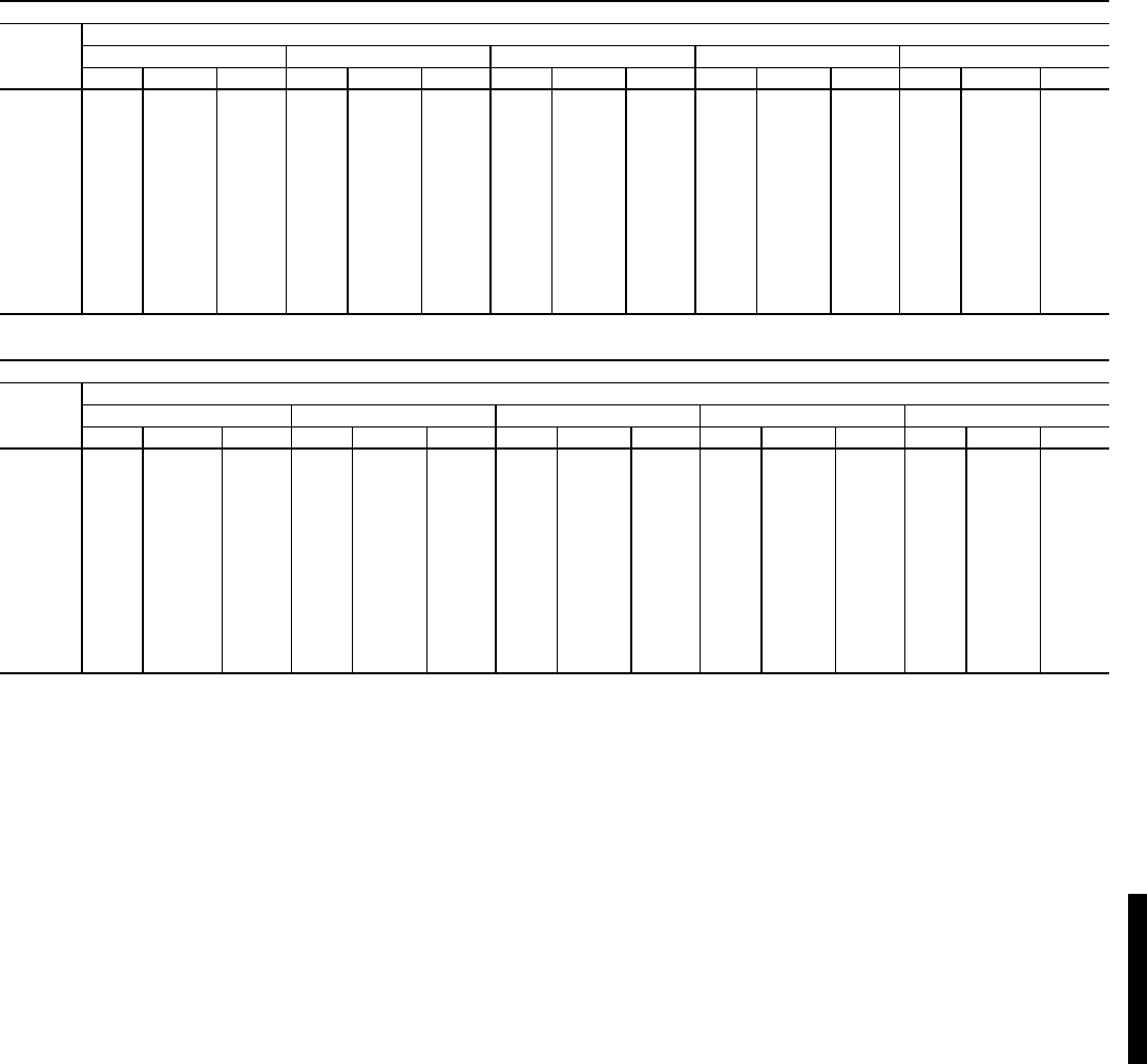
121
FAN PERFORMANCE — HORIZONTAL DISCHARGE UNITS (cont)
LEGEND
*Motor drive ranges:
Low Range: 687-873
Mid-Low Range: 805-1007
Mid-High Range: 941-1176
High Range: 1014-1297
All other rpms require field-supplied drive.
Refer to page 99 for general Fan Performance Data notes.
NOTE: Maximum continuous bhp is:
Low Range: 5.75
Mid-Low Range: 5.75
Mid-High Range: 8.63
High Range: 11.50
48HJF028 (25 TONS) (High Heat Units)*
Airflow
(Cfm)
External Static Pressure (in. wg)
0.2 0.4 0.6 0.8 1.0
Rpm Bhp Watts Rpm Bhp Watts Rpm Bhp Watts Rpm Bhp Watts Rpm Bhp Watts
6,500 799 2,730 3.14 833 2,914 3.35 872 3,135 3.61 914 3,392 3.90 958 3,687 4.24
7,000 856 3,294 3.79 887 3,481 4.00 921 3,699 4.25 958 3,950 4.54 999 4,235 4.87
7,500 913 3,929 4.52 941 4,118 4.74 972 4,335 4.99 1006 4,582 5.27 1042 4,860 5.59
8,000 971 4,637 5.33 996 4,829 5.55 1024 5,046 5.80 1055 5,290 6.08 1088 5,562 6.40
8,500 1029 5,421 6.24 1052 5,617 6.46 1078 5,835 6.71 1106 6,077 6.99 1136 6,345 7.30
9,000 1087 6,285 7.23 1108 6,484 7.46 1132 6,703 7.71 1158 6,946 7.99 1185 7,211 8.29
9,500 1145 7,231 8.32 1165 7,433 8.55 1187 7,655 8.80 1211 7,898 9.08 1236 8,161 9.39
10,000 1203 8,262 9.50 1222 8,468 9.74 1243 8,693 10.00 1265 8,936 10.28 1288 9,199 10.58
10,500 1261 9,381 10.79 1279 9,592 11.03 1299 9,820 11.29 1319 10,065 11.58 1341 10,327 11.88
11,000 1320 10,592 12.18 1337 10,807 12.43 1355 11,038 12.70 1374 11,284 12.98 1394 11,547 13.28
11,500 1378 11,896 13.68 — — — — — — — — — — — —
12,000 — — —— — —— — —— — —— — —
12,500 — — —— — —— — —— — —— — —
48HJF028 (25 TONS) (High Heat Units)* (cont)
Airflow
(Cfm)
External Static Pressure (in. wg)
1.2 1.4 1.6 1.8 2.0
Rpm Bhp Watts Rpm Bhp Watts Rpm Bhp Watts Rpm Bhp Watts Rpm Bhp Watts
6,500 1005 4,020 4.62 1052 4,390 5.05 1100 4,791 5.51 1148 5,221 6.00 1195 5673 6.52
7,000 1041 4,555 5.24 1084 4,908 5.64 1128 5,294 6.09 1172 5,710 6.57 1217 6153 7.08
7,500 1080 5,168 5.94 1119 5,508 6.33 1160 5,878 6.76 1201 6,279 7.22 1242 6708 7.71
8,000 1122 5,862 6.74 1158 6,190 7.12 1195 6,548 7.53 1233 6,934 7.97 1272 7347 8.45
8,500 1167 6,638 7.63 1200 6,959 8.00 1234 7,305 8.40 1269 7,677 8.83 1304 8076 9.29
9,000 1214 7,499 8.63 1244 7,813 8.99 1275 8,149 9.37 1308 8,511 9.79 1340 8896 10.23
9,500 1262 8,447 9.72 1290 8,754 10.07 1319 9,084 10.45 1349 9,437 10.85 1379 9812 11.28
10,000 1312 9,482 10.91 1338 9,785 11.25 1365 10,110 11.63 1392 10,454 12.02 — — —
10,500 1363 10,608 12.20 1387 10,909 12.55 — — — — — — — — —
11,000 —— —————————————
11,500 —— —————————————
12,000 —— —————————————
12,500 —— —————————————
Bhp — Brake Horsepower Input to Fan
Watts — Input Watts to Motor
48HJ
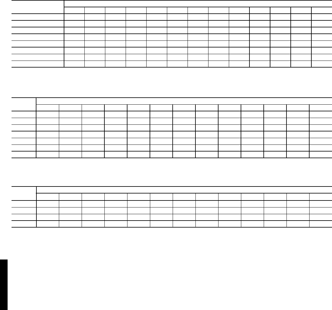
122
FAN RPM AT MOTOR PULLEY SETTING WITH STANDARD MOTOR* — 48HE003-007 and 48HJ004-014
*Approximate fan rpm shown (standard motor/drive).
FAN RPM AT MOTOR PULLEY SETTING WITH HIGH-STATIC MOTOR* — 48HE003-006 and 48HJ004-014
*Approximate fan rpm shown (high-static motor/drive).
FAN RPM AT MOTOR PULLEY SETTINGS* — 48HJ015,017
*Approximate fan rpm shown.
†Indicates standard drive package.
**Indicates alternate drive package.
††Due to belt and pulley style, pulley cannot be set to this number of turns open.
UNIT
48HJ/HE
MOTOR PULLEY TURNS OPEN
01/211
1/222
1/233
1/244
1/255
1/26
003 936 906 876 846 816 786 756 726 696 656 639 — —
004 1044 1008 971 935 898 862 826 789 753 716 680 — —
005 1185 1144 1102 1061 1019 978 936 895 853 812 770 — —
006 1460 1425 1389 1354 1318 1283 1248 1212 1177 1141 1106 1070 1035
007 1585 1538 1492 1445 1399 1352 1305 1259 1212 1166 1119 — —
008,009 1085 1060 1035 1010 985 960 935 910 890 865 840 — —
012 1080 1060 1035 1015 990 970 950 925 905 880 860 — —
014 1130 1112 1087 1062 1037 1212 987 962 937 912 887 962 830
UNIT
48HE/HJ
MOTOR PULLEY TURNS OPEN
01/211
1/222
1/233
1/244
1/255
1/26
004 1455 1423 1392 1360 1328 1297 1265 1233 1202 1170 1138 1107 1075
005 1455 1423 1392 1360 1328 1297 1265 1233 1202 1170 1138 1107 1075
006 1685 1589 1557 1525 1493 1460 1428 1396 1364 1332 1300 — —
007 1685 1589 1557 1525 1493 1460 1428 1396 1364 1332 1300 — —
008 1080 1025 1007 988 970 952 933 915 897 878 860 — —
009 1080 1025 1007 988 970 952 933 915 897 878 860 — —
012 1130 1112 1087 1062 1037 1212 987 962 937 912 887 962 830
UNIT
48HJ
MOTOR PULLEY TURNS OPEN
01/211
1/222
1/233
1/244
1/255
1/26
015† 1147 1124 1101 1078 1055 1032 1010 987 964 941 918 895 ††
015** 1315 1292 1269 1246 1223 1200 1178 1155 1132 1109 1086 1063 1040
017† †† †† †† †† 1021 1002 984 965 947 928 910 891 873
017** †† †† †† †† 1200 1178 1156 1134 1112 1091 1069 1047 1025
Performance data — 48HE/HJ (cont)
48HJ48HE/HJ
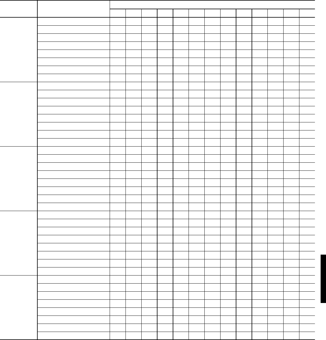
123
48HJ FAN RPM AT MOTOR PULLEY SETTINGS* — 48HJ020-028
*Approximate fan rpm shown.
48HJ DRIVE MOTOR PULLEY TURNS OPEN
01/211
1/222
1/233
1/244
1/255
1/26
020
(208/230 and
460 volt)
Low Range Vertical N/A N/A N/A N/A N/A N/A N/A N/A N/A N/A N/A N/A N/A
Mid-Low Range Vertical 647 667 687 707 727 747 767 786 806 826 846 866 886
Mid-High Range Vertical 897 917 937 958 978 998 1018 1038 1058 1079 1099 1119 1139
High Range Vertical 1078 1094 1111 1127 1143 1160 1176 1192 1209 1225 1241 1258 1274
Low Range Horizontal N/A N/A N/A N/A N/A N/A N/A N/A N/A N/A N/A N/A N/A
Mid-Low Range Horizontal 896 924 951 979 1006 1034 1062 1089 1117 1144 1172 1199 1227
Mid-High Range Horizontal 1113 1138 1163 1188 1213 1238 1264 1289 1314 1339 1364 1389 1414
High Range Horizontal 1096 1116 1137 1157 1177 1197 1218 1238 1258 1278 1299 1319 1339
020
(575 volt)
Low Range Vertical N/A N/A N/A N/A N/A N/A N/A N/A N/A N/A N/A N/A N/A
Mid-Low Range Vertical 810 832 854 876 897 919 941 963 985 1007 1028 1050 1072
Mid-High Range Vertical 873 893 912 932 951 971 991 1010 1030 1049 1069 1088 1108
High Range Vertical 1078 1094 1111 1127 1143 1160 1176 1192 1209 1225 1241 1258 1274
Low Range Horizontal N/A N/A N/A N/A N/A N/A N/A N/A N/A N/A N/A N/A N/A
Mid-Low Range Horizontal 863 886 909 933 956 979 1002 1025 1048 1072 1095 1118 1141
Mid-High Range Horizontal 1042 1062 1083 1103 1123 1143 1164 1184 1204 1224 1245 1265 1285
High Range Horizontal 1096 1116 1137 1157 1177 1197 1218 1238 1258 1278 1299 1319 1339
024
(208/230 and
460 volt)
Low Range Vertical 685 706 727 749 770 791 812 833 854 876 897 918 939
Mid-Low Range Vertical 949 970 992 1013 1035 1056 1078 1099 1120 1142 1163 1185 1206
Mid-High Range Vertical 941 961 980 1000 1019 1039 1059 1078 1098 1117 1137 1156 1176
High Range Vertical 1014 1038 1061 1085 1108 1132 1156 1179 1203 1226 1250 1273 1297
Low Range Horizontal N/A N/A N/A N/A N/A N/A N/A N/A N/A N/A N/A N/A N/A
Mid-Low Range Horizontal 896 924 951 979 1006 1034 1062 1089 1117 1144 1172 1199 1227
Mid-High Range Horizontal 1113 1138 1163 1188 1213 1238 1264 1289 1314 1339 1364 1389 1414
High Range Horizontal 1096 1116 1137 1157 1177 1197 1218 1238 1258 1278 1299 1319 1339
024
(575 volt)
Low Range Vertical 751 768 785 802 819 836 853 869 886 903 920 937 954
Mid-Low Range Vertical 949 970 992 1013 1035 1056 1078 1099 1120 1142 1163 1185 1206
Mid-High Range Vertical 941 961 980 1000 1019 1039 1059 1078 1098 1117 1137 1156 1176
High Range Vertical 1014 1038 1061 1085 1108 1132 1156 1179 1203 1226 1250 1273 1297
Low Range Horizontal N/A N/A N/A N/A N/A N/A N/A N/A N/A N/A N/A N/A N/A
Mid-Low Range Horizontal 873 893 912 932 951 971 991 1010 1030 1049 1069 1088 1108
Mid-High Range Horizontal 1113 1138 1163 1188 1213 1238 1264 1289 1314 1339 1364 1389 1414
High Range Horizontal 1096 1116 1137 1157 1177 1197 1218 1238 1258 1278 1299 1319 1339
028
(all voltages)
Low Range Vertical 687 703 718 734 749 765 780 796 811 827 842 858 873
Mid-Low Range Vertical 805 822 839 856 872 889 906 923 940 957 973 990 1007
Mid-High Range Vertical 941 961 980 1000 1019 1039 1059 1078 1098 1117 1137 1156 1176
High Range Vertical 1014 1038 1061 1085 1108 1132 1156 1179 1203 1226 1250 1273 1297
Low Range Horizontal 687 703 718 734 749 765 780 796 811 827 842 858 873
Mid-Low Range Horizontal 805 822 839 856 872 889 906 923 940 957 973 990 1007
Mid-High Range Horizontal 941 961 980 1000 1019 1039 1059 1078 1098 1117 1137 1156 1176
High Range Horizontal 1014 1038 1061 1085 1108 1132 1156 1179 1203 1226 1250 1273 1297
48HE/HJ

124
EVAPORATOR-FAN MOTOR PERFORMANCE — STANDARD MOTOR — 48HE003-006, 48HJ004-014
LEGEND
Bhp — Brake Horsepower
*Extensive motor and electrical testing on these units ensures that the full horsepower and watts range of the
motors can be utilized with confidence. Using the fan motors up to the ratings shown in this table will not
result in nuisance tripping or premature motor failure. Unit warranty will not be affected.
EVAPORATOR-FAN MOTOR PERFORMANCE — HIGH-STATIC MOTORS — 48HE004-006, 48HJ004-014
LEGEND
Bhp — Brake Horsepower
*Extensive motor and electrical testing on these units ensures that the full horsepower and watts range of the
motors can be utilized with confidence. Using the fan motors up to the ratings shown in this table will not
result in nuisance tripping or premature motor failure. Unit warranty will not be affected.
UNIT
48HE
48HJ
UNIT
PHASE
MAXIMUM
CONTINUOUS BHP*
MAXIMUM
OPERATING WATTS* UNIT VOLTAGE MAXIMUM
AMP DRAW
003 Single 0.58 580 208/230 2.0
004
Single 1.20 1000 208/230 4.9
Three 1.20 1000
208/230 4.9
460 2.2
575 2.2
005
Single 1.20 1000 208/230 4.9
Three 1.20 1000
208/230 4.9
460 2.2
575 2.2
006
Single 1.30 1650 208/230 9.2
Three 2.40 2120
208/230 6.7
460 3.0
575 3.0
007 Three 2.40 2120
208/230 6.7
460 3.0
575 3.0
008,009 Three 2.90 2615
208/230 8.6
460 3.9
575 3.9
012 Three 3.70 3775
208/230 12.2
460 5.5
575 5.5
014 Three 5.25 4400
208/230 17.3
460 8.5
575 8.5
UNIT
48HE
48HJ
UNIT
PHASE
MAXIMUM
CONTINUOUS BHP*
MAXIMUM
OPERATING WATTS* UNIT VOLTAGE MAXIMUM
AMP DRAW
004 Three 2.40 2120
208/230 6.7
460 3.0
575 3.0
005 Three 2.40 2120
208/230 6.7
460 3.0
575 3.0
006 Three 2.90 2615
208/230 8.6
460 3.9
575 3.9
007 Three 2.90 2615
208/230 8.6
460 3.9
575 3.9
008,009 Three 4.20 3775
208/230 12.2
460 5.5
575 5.5
012 Three 5.25 4400
208/230 17.3
460 8.5
575 8.5
Performance data — 48HE/HJ (cont)
48HJ48HE/HJ
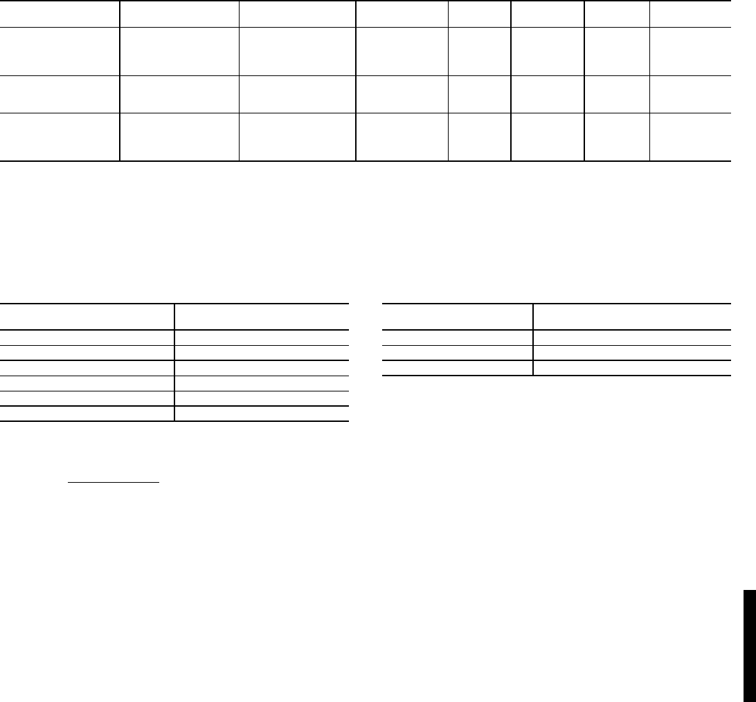
125
EVAPORATOR FAN MOTOR SPECIFICATIONS — 48HJ015,017
LEGEND
EVAPORATOR-FAN MOTOR EFFICIENCY —
48HE003-006, 48HJ004-014
*Single phase/3 phase.
NOTES:
1. Convert bhp to watts using the following formula:
2. The EPACT (Energy Policy Act of 1992) regulates energy require-
ments for specific types of indoor fan motors. Motors regulated by
EPACT include any general purpose, T-frame (three-digit, 143 and
larger), single-speed, foot mounted, polyphase, squirrel cage
induction motors of NEMA (National Electrical Manufacturers
Association) design A and B, manufactured for use in the United
States. Ranging from 1 to 200 Hp, these continuous-duty motors
operate on 230 and 460 volt, 60 Hz power. If a motor does not fit
into these specifications, the motor does not have to be replaced
by an EPACT-compliant energy-efficient motor. Variable-speed
motors are exempt from EPACT compliance requirements. There-
fore, the indoor fan motors for Carrier 48HE003-006 and 48HJ004-
014 units are exempt from these requirements.
EVAPORATOR-FAN MOTOR EFFICIENCY —
48HJ015,017
NOTE: All indoor-fan motors 5 hp and larger meet the minimum effi-
ciency requirements as established by the Energy Policy Act of 1992
(EPACT) effective October 24, 1997.
UNIT 48HJ NOMINAL
HP VOLTAGE MAX
WATTS
EFF.
%
MAX
BHP
MAX
BkW
MAX
AMPS
015
(Standard
Motor)
2.9 208 2700 85.8 3.13 2.34 9.46
2.9 230 2700 85.8 3.13 2.34 8.6
2.9 460 2700 85.8 3.13 2.34 4.3
3 575 3065 81.7 3.38 2.53 3.9
015
(Optional
Motor)
3.7 208 3610 85.8 4.38 3.27 10.5
3.7 230 3610 85.8 4.38 3.27 10.5
3.7 460 3610 85.8 4.38 3.27 4.8
017
5 208 5180 87.5 6.13 4.57 15.8
5 230 5180 87.5 6.13 4.57 15.8
5 460 5180 87.5 6.13 4.57 7.9
5 575 5180 87.5 6.13 4.57 6.0
BHP — Brake Horsepower
BkW — Brake Kilowatts
UNIT SIZE
48HE/HJ EFFICIENCY%
003, 004,005 75
006 74/84*
007 84
008,009 80
012 85
014 87
watts = bhp (746)
motor efficiency
MOTOR
HORSEPOWER
MOTOR EFFICIENCY
(%)
3.0 81.7
2.9, 3.7 85.8
5.0 87.5
48HE/HJ
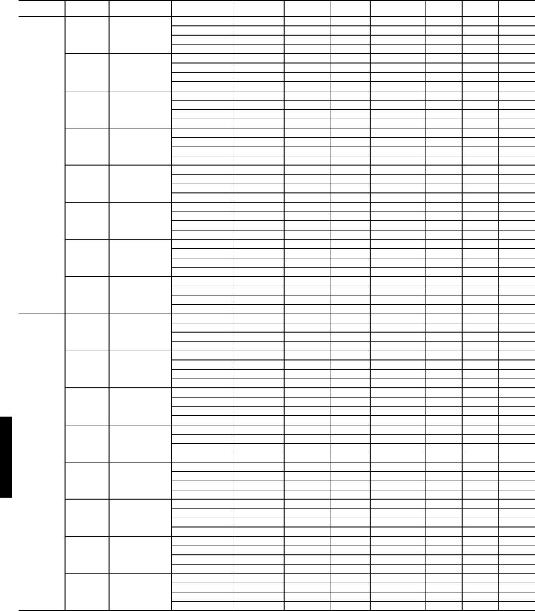
126
48HJ EVAPORATOR FAN MOTOR SPECIFICATIONS — 48HJ020-028
LEGEND
UNIT DRIVE ORIENTATION MOTOR
P/N
NOMINAL
HP VOLTAGE MAX
WATTS
EFFICIENCY
%
MAX
BHP
MAX
BkW
MAX
AMPS
48HJ020
Low Vertical
N/A N/A 208 N/A N/A N/A N/A N/A
N/A N/A 230 N/A N/A N/A N/A N/A
N/A N/A 460 N/A N/A N/A N/A N/A
N/A N/A 575 N/A N/A N/A N/A N/A
Mid-Low Vertical
HD60FK651 3.7 208 3698 85.8 4.25 3.17 10.6
HD60FK651 3.7 230 3698 85.8 4.25 3.17 9.6
HD60FK651 3.7 460 3698 85.8 4.25 3.17 4.8
HD58DL575 3 575 3149 81.7 3.45 2.57 3.9
Mid-High Vertical
HD60FL650 5 208 4900 87.5 5.75 4.29 16.7
HD60FL650 5 230 4900 87.5 5.75 4.29 15.2
HD60FL650 5 460 4900 87.5 5.75 4.29 7.6
HD60FL575 5 575 4900 87.5 5.75 4.29 6.1
High Vertical
HD62FL650 7.5 208 7267 88.5 8.63 6.43 24.2
HD62FL650 7.5 230 7267 88.5 8.63 6.43 22
HD62FL650 7.5 460 7267 88.5 8.63 6.43 11
HD62FL575 7.5 575 7267 88.5 8.63 6.43 9
Low Horizontal
N/A N/A 208 N/A N/A N/A N/A N/A
N/A N/A 230 N/A N/A N/A N/A N/A
N/A N/A 460 N/A N/A N/A N/A N/A
N/A N/A 575 N/A N/A N/A N/A N/A
Mid-Low Horizontal
HD60FK651 3.7 208 3698 85.8 4.25 3.17 10.6
HD60FK651 3.7 230 3698 85.8 4.25 3.17 9.6
HD60FK651 3.7 460 3698 85.8 4.25 3.17 4.8
HD58DL575 3 575 3149 81.7 3.45 2.57 3.9
Mid-High Horizontal
HD60FL650 5 208 4900 87.5 5.75 4.29 16.7
HD60FL650 5 230 4900 87.5 5.75 4.29 15.2
HD60FL650 5 460 4900 87.5 5.75 4.29 7.6
HD60FL575 5 575 4900 87.5 5.75 4.29 6.1
High Horizontal
HD62FL650 7.5 208 7267 88.5 8.63 6.43 24.2
HD62FL650 7.5 230 7267 88.5 8.63 6.43 22
HD62FL650 7.5 460 7267 88.5 8.63 6.43 11
HD62FL575 7.5 575 7267 88.5 8.63 6.43 9
48HJ024
Low Vertical
HD60FK651 3.7 208 3698 85.8 4.25 3.17 10.6
HD60FK651 3.7 230 3698 85.8 4.25 3.17 9.6
HD60FK651 3.7 460 3698 85.8 4.25 3.17 4.8
HD60FL575 5 575 4900 87.5 5.75 4.29 6.1
Mid-Low Vertical
HD60FL650 5 208 4900 87.5 5.75 4.29 16.7
HD60FL650 5 230 4900 87.5 5.75 4.29 15.2
HD60FL650 5 460 4900 87.5 5.75 4.29 7.6
HD60FL575 5 575 4900 87.5 5.75 4.29 6.1
Mid-High Vertical
HD62FL650 7.5 208 7267 88.5 8.63 6.43 24.2
HD62FL650 7.5 230 7267 88.5 8.63 6.43 22
HD62FL650 7.5 460 7267 88.5 8.63 6.43 11
HD62FL575 7.5 575 7267 88.5 8.63 6.43 9
High Vertical
HD64FL650 10 208 9582 89.5 11.5 8.58 30.8
HD64FL650 10 230 9582 89.5 11.5 8.58 28
HD64FL650 10 460 9582 89.5 11.5 8.58 14
HD64FL575 10 575 9582 89.5 11.5 8.58 11
Low Horizontal
N/A N/A 208 N/A N/A N/A N/A N/A
N/A N/A 230 N/A N/A N/A N/A N/A
N/A N/A 460 N/A N/A N/A N/A N/A
N/A N/A 575 N/A N/A N/A N/A N/A
Mid-Low Horizontal
HD60FK651 3.7 208 3698 85.8 4.25 3.17 10.6
HD60FK651 3.7 230 3698 85.8 4.25 3.17 9.6
HD60FK651 3.7 460 3698 85.8 4.25 3.17 4.8
HD60FL575 5 575 4900 87.5 5.75 4.29 6.1
Mid-High Horizontal
HD60FL650 5 208 4900 87.5 5.75 4.29 16.7
HD60FL650 5 230 4900 87.5 5.75 4.29 15.2
HD60FL650 5 460 4900 87.5 5.75 4.29 7.6
HD60FL575 5 575 4900 87.5 5.75 4.29 6.1
High Horizontal
HD62FL650 7.5 208 7267 88.5 8.63 6.43 24.2
HD62FL650 7.5 230 7267 88.5 8.63 6.43 22
HD62FL650 7.5 460 7267 88.5 8.63 6.43 11
HD62FL575 7.5 575 7267 88.5 8.63 6.43 9
BHP — Brake Horsepower
BkW — Brake Kilowatts
Performance data — 48HJ (cont)
48HJ
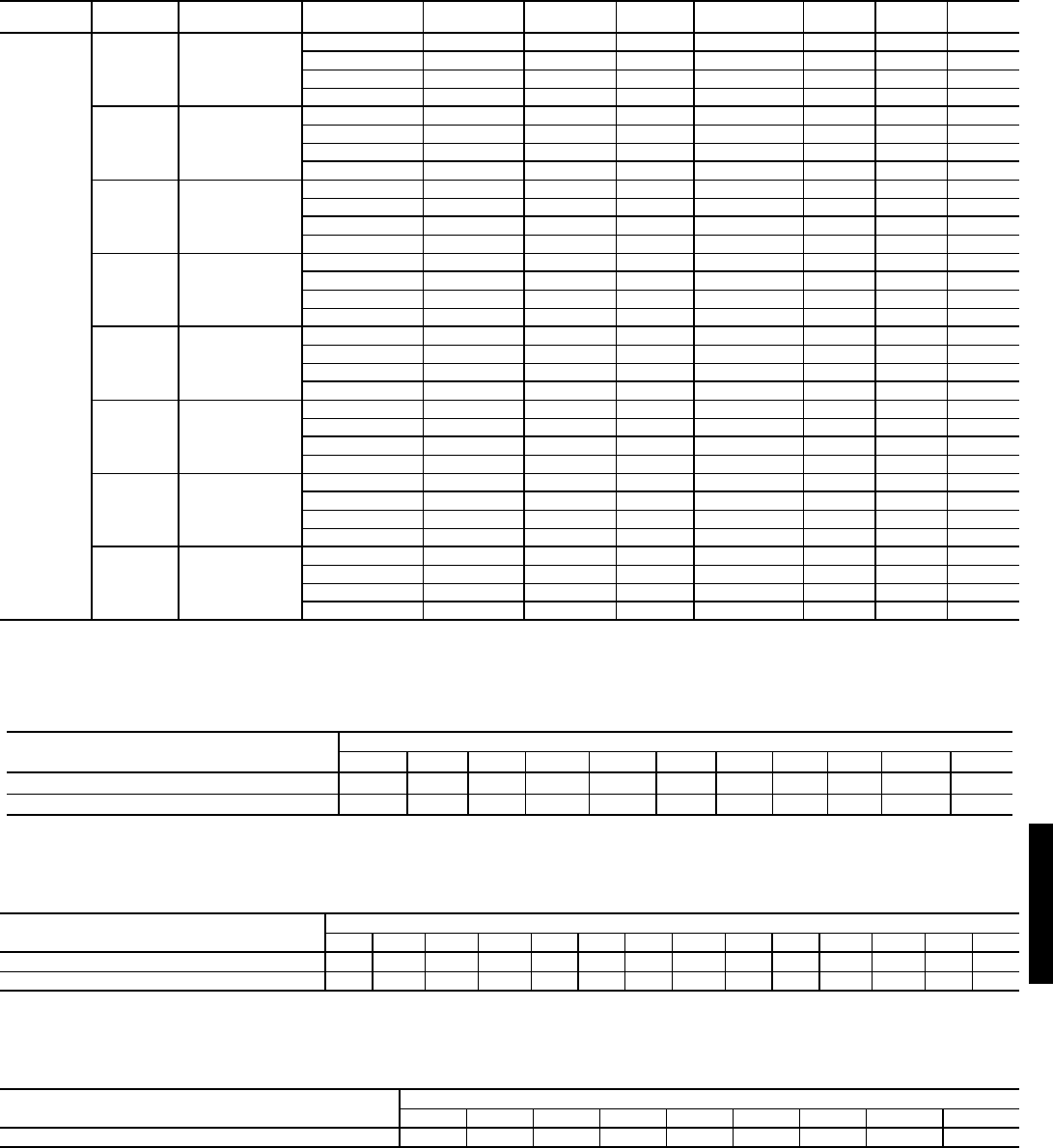
127
48HJ FAN RPM AT MOTOR PULLEY SETTINGS* — 48HJ020-028 (cont)
LEGEND
ACCESSORY/FIOP STATIC PRESSURE* (in. wg) — 48HE003-006, 48HJ004-007
LEGEND *The static pressure must be added to external static pressure. The sum and the
evaporator entering-air cfm should be used in conjunction with the Fan Perfor-
mance tables to determine indoor blower rpm and watts.
ACCESSORY/FIOP STATIC PRESSURE* (in. wg) — 48HJ008-014
LEGEND *The static pressure must be added to external static pressure. The sum and the
evaporator entering-air cfm should be used in conjunction with the Fan Perfor-
mance tables to determine indoor blower rpm and watts.
ACCESSORY/FIOP STATIC PRESSURE (in. wg)* — 48HJ015,017
LEGEND *The static pressure must be added to external static pressure. The sum and the
evaporator entering-air cfm should then be used in conjunction with the Fan Per-
formance tables to determine blower rpm and watts.
UNIT DRIVE ORIENTATION MOTOR
P/N
NOMINAL
HP VOLTAGE MAX
WATTS
EFFICIENCY
%
MAX
BHP
MAX
BkW
MAX
AMPS
48HJ028
Low Vertical
HD60FL650 5 208 4900 87.5 5.75 4.29 16.7
HD60FL650 5 230 4900 87.5 5.75 4.29 15.2
HD60FL650 5 460 4900 87.5 5.75 4.29 7.6
HD60FL575 5 575 4900 87.5 5.75 4.29 6.1
Mid-Low Vertical
HD60FL650 5 208 4900 87.5 5.75 4.29 16.7
HD60FL650 5 230 4900 87.5 5.75 4.29 15.2
HD60FL650 5 460 4900 87.5 5.75 4.29 7.6
HD60FL575 5 575 4900 87.5 5.75 4.29 6.1
Mid-High Vertical
HD62FL650 7.5 208 7267 88.5 8.63 6.43 24.2
HD62FL650 7.5 230 7267 88.5 8.63 6.43 22
HD62FL650 7.5 460 7267 88.5 8.63 6.43 11
HD62FL575 7.5 575 7267 88.5 8.63 6.43 9
High Vertical
HD64FL650 10 208 9582 89.5 11.5 8.58 30.8
HD64FL650 10 230 9582 89.5 11.5 8.58 28
HD64FL650 10 460 9582 89.5 11.5 8.58 14
HD64FL575 10 575 9582 89.5 11.5 8.58 11
Low Horizontal
HD60FL650 5 208 4900 87.5 5.75 4.29 16.7
HD60FL650 5 230 4900 87.5 5.75 4.29 15.2
HD60FL650 5 460 4900 87.5 5.75 4.29 7.6
HD60FL575 5 575 4900 87.5 5.75 4.29 6.1
Mid-Low Horizontal
HD60FL650 5 208 4900 87.5 5.75 4.29 16.7
HD60FL650 5 230 4900 87.5 5.75 4.29 15.2
HD60FL650 5 460 4900 87.5 5.75 4.29 7.6
HD60FL575 5 575 4900 87.5 5.75 4.29 6.1
Mid-High Horizontal
HD62FL650 7.5 208 7267 88.5 8.63 6.43 24.2
HD62FL650 7.5 230 7267 88.5 8.63 6.43 22
HD62FL650 7.5 460 7267 88.5 8.63 6.43 11
HD62FL575 7.5 575 7267 88.5 8.63 6.43 9
High Horizontal
HD64FL650 10 208 9582 89.5 11.5 8.58 30.8
HD64FL650 10 230 9582 89.5 11.5 8.58 28
HD64FL650 10 460 9582 89.5 11.5 8.58 14
HD64FL575 10 575 9582 89.5 11.5 8.58 11
BHP — Brake Horsepower
BkW — Brake Kilowatts
COMPONENT CFM
600 800 1000 1250 1500 1750 2000 2250 2500 2750 3000
Vertical EconoMi$er IV and EconoMi$er2 0.10 0.20 0.35 0.045 0.065 0.08 0.12 0.145 0.175 0.22 0.255
Horizontal EconoMi$er IV and EconoMi$er2 — — — — — 0.1 0.125 0.15 0.18 0.225 0.275
FIOP — Factory-Installed Option
COMPONENT CFM
2250 2500 2750 3000 3250 3500 3750 4000 4250 4500 4750 5000 5250 6250
Vertical EconoMi$er IV and EconoMi$er2 0.06 0.075 0.09 0.115 0.13 0.15 0.17 0.195 0.22 0.25 0.285 0.325 0.36 —
Horizontal EconoMi$er IV and EconoMi$er2 — 0.1 0.125 0.15 0.18 0.21 0.25 0.275 0.3 0.34 0.388 — — —
FIOP — Factory-Installed Option
COMPONENT CFM
4500 5000 5400 6000 7200 7500 9000 10,000 11,250
EconoMi$er IV 0.040 0.050 0.060 0.070 0.090 0.100 0.110 0.120 0.140
FIOP — Factory-Installed Option
48HE/HJ
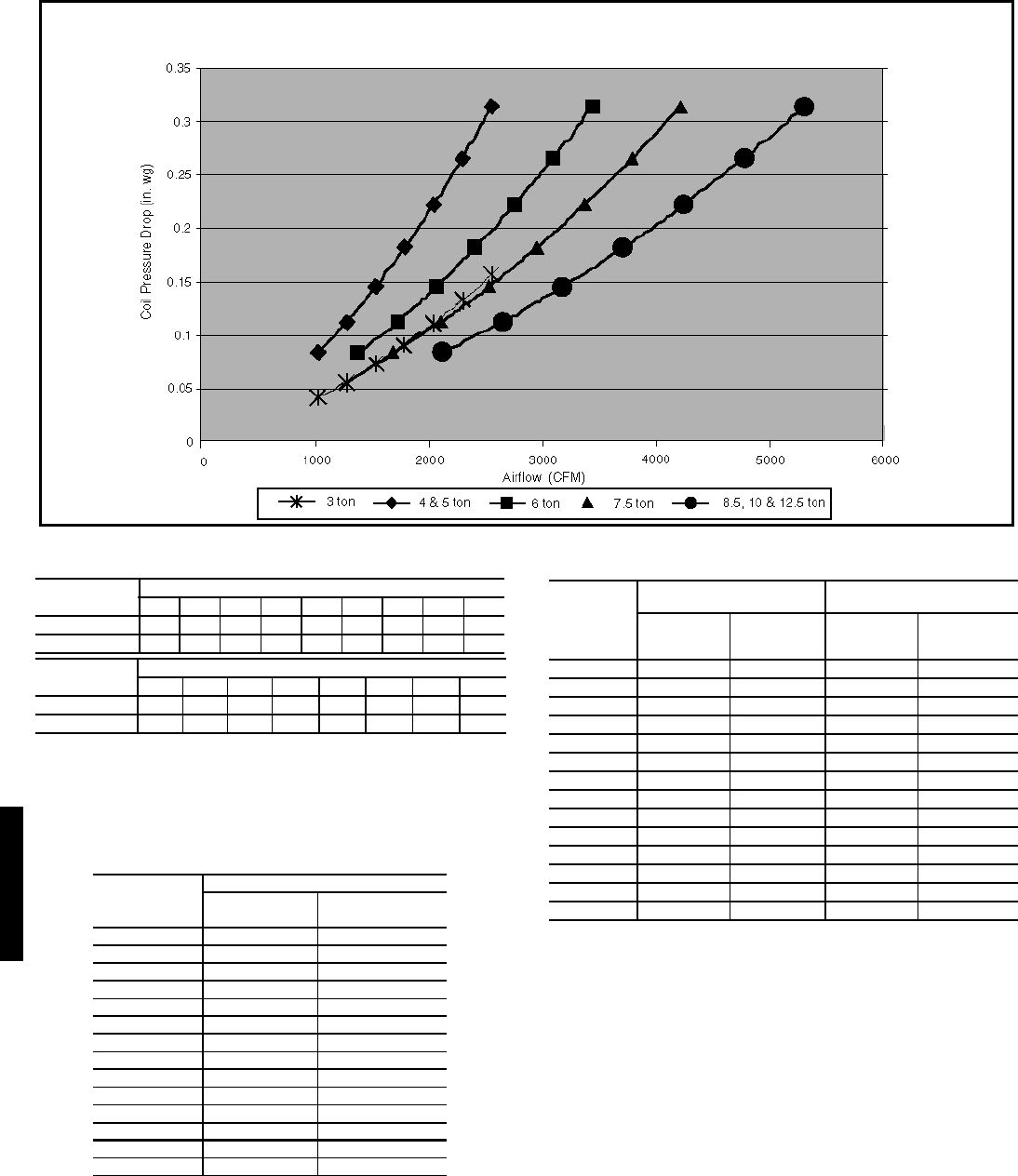
128
ACCESSORY/FIOP STATIC PRESSURE
(in. wg)* — 48HJ020-028
LEGEND
*The static pressure must be added to the external static pressure. The sum
and the evaporator entering-air cfm should then be used in conjunction with
the Fan Performance tables to determine blower rpm and watts.
†Four-inch filters are field-supplied.
ALTITUDE COMPENSATION* — 48HE003
STANDARD UNIT
*As the height above sea level increases, there is less oxygen per cubic foot
of air. Therefore, heat input rate should be reduced at higher altitudes.
†Orifices available through your Carrier distributor.
ALTITUDE COMPENSATION* — 48HJ004-007
STANDARD UNITS
*As the height above sea level increases, there is less oxygen per cubic foot
of air. Therefore, heat input rate should be reduced at higher altitudes.
†Orifices available through your Carrier distributor.
HUMIDI-MIZER™ ADAPTIVE DEHUMIDIFICATION COIL PRESSURE DROP
COMPONENT CFM
4,000 4,500 5,000 5,500 6,000 6,500 7,000 7,500 8,000
Economizer 0.02 0.03 0.04 0.05 0.06 0.07 0.08 0.09 0.10
4-in. Filters† 0.00 0.02 0.03 0.05 0.06 0.08 0.09 0.11 0.12
COMPONENT CFM
8,500 9,000 9,500 10,000 10,500 11,000 11,500 12,000
Economizer 0.11 0.12 0.13 0.15 0.16 0.17 0.19 0.20
4-in. Filters† 0.14 0.15 0.17 0.18 0.20 0.21 0.23 0.24
FIOP — Factory-Installed Option
ELEVATION
(ft)
50,000 BTUH NOMINAL INPUT
Natural Gas
Orifice Size†
Liquid Propane
Orifice Size†
0-2,000 43 49
2,000 44 50
3,000 44 50
4,000 44 50
5,000 45 51
6,000 45 51
7,000 46 51
8,000 47 52
9,000 47 52
10,000 48 52
11,000 49 53
12,000 50 54
13,000 51 55
14,000 52 56
ELEVATION
(ft)
72,000 AND 115,000 BTUH
NOMINAL INPUT
150,000 BTUH
NOMINAL INPUT
Natural Gas
Orifice Size†
Liquid
Propane
Orifice Size†
Natural Gas
Orifice Size†
Liquid
Propane
Orifice Size†
0-2,000 33 43 30 37
2,000 36 44 31 39
3,000 36 45 31 40
4,000 37 45 32 41
5,000 38 46 32 42
6,000 40 47 34 43
7,000 41 48 35 43
8,000 42 49 36 44
9,000 43 50 37 45
10,000 44 50 39 46
11,000 45 51 41 47
12,000 46 52 42 48
13,000 47 52 43 49
14,000 48 53 44 50
Performance data — 48HE/HJ (cont)
48HE/HJ
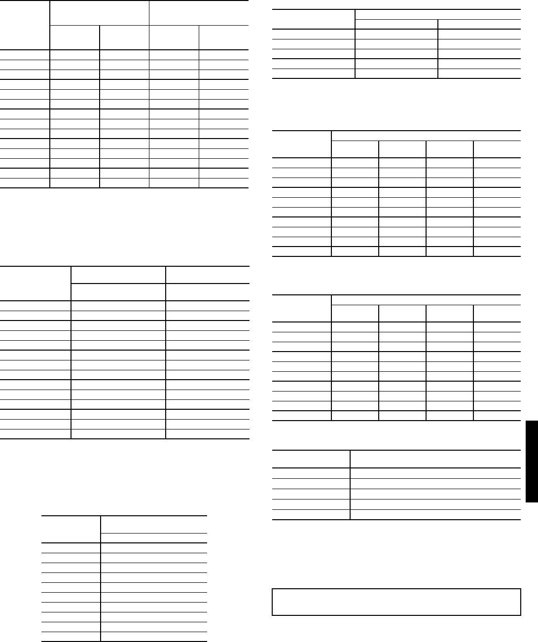
129
ALTITUDE COMPENSATION* — 48HJ008-014
*As the height above sea level increases, there is less oxygen per cubic foot
of air. Therefore, the input rate should be reduced at higher altitudes.
†Orifices are available through your local Carrier distributor.
ALTITUDE COMPENSATION* — 48HE003-006 and
48HJ004-006 LOW NOx UNITS
*As the height above sea level increases, there is less oxygen per cubic foot of
air. Therefore, the input rate should be reduced at higher altitudes.
†Orifices are available through your local Carrier distributor.
ALTITUDE COMPENSATION —
48HJ015,017 (LP Gas Units)
ALTITUDE COMPENSATION* —
48HJ015,017
*Includes a 4% input reduction per each 1,000 feet.
†Orifices available through your Carrier dealer.
ALTITUDE COMPENSATION — 48HJ020-028
(Natural Gas)
ALTITUDE COMPENSATION — 48HJ020-028
(LP Gas)
ALTITUDE DERATING FACTOR*
*Derating of the gas heating equipment to compensate for the effects of alti-
tude is always required. Orifice change is not required if the fuel heating
value (at sea level) is below the limits listed in the table at left. Derating con-
ditions must be 4% per thousand ft above 2000 ft. For example, at 4000 ft, if
the heating value of the gas exceeds 1000 Btu/ft3, the unit will require a
16% derating. For elevations above 6000 ft, the same formula applies. For
example, at 7000 ft, the unit will require a 28% derating of the maximum
heating value per the National Fuel Gas Code.
ELEVATION
(ft)
125,000, 180,000, AND
224,000 BTUH
NOMINAL INPUT
250,000 BTUH
NOMINAL INPUT
Natural Gas
Orifice Size†
Liquid
Propane
Orifice Size†
Natural Gas
Orifice
Size†
Liquid
Propane
Orifice Size†
0-2,000 31 41 30 38
2,000 32 42 30 39
3,000 32 42 31 40
4,000 32 42 32 41
5,000 33 43 33 42
6,000 34 43 34 43
7,000 35 44 35 43
8,000 36 44 36 44
9,000 37 45 37 44
10,000 38 46 38 45
11,000 39 47 39 45
12,000 40 47 40 46
13,000 41 48 41 47
14,000 42 48 42 47
ELEVATION
(ft)
60,000 AND 90,000 BTUH
NOMINAL INPUT
120,000 BTUH
NOMINAL INPUT
Natural Gas
Orifice Size†
Natural Gas
Orifice Size
0-2,000 38 32
2,000 40 33
3,000 41 35
4,000 42 36
5,000 43 37
6,000 43 38
7,000 44 39
8,000 45 41
9,000 46 42
10,000 47 43
11,000 48 44
12,000 49 44
13,000 50 46
14,000 51 47
ELEVATION
(ft)
LIQUID PROPANE
ORIFICE SIZE
Low Heat and High Heat
0-2,000 36
2,000 37
3,000 38
4,000 38
5,000 39
6,000 40
7,000 41
8,000 41
9,000 42
10,000 43
ELEVATION
(ft)
NATURAL GAS ORIFICE SIZE†
Low Heat High Heat
0-3,000 30 29
3,000- 7,000 31 30
7,000- 9,000 32 31
9,000-10,000 33 31
above 10,000 35 32
ELEVATION
(ft)
ORIFICE SIZE — NATURAL GAS
Low
Heat
Medium
Heat
High Heat
(6 Cell)
High Heat
(8 Cell)
0-2,000 29 30 29 29
2,000 29 30 29 29
3,000 30 31 30 30
4,000 30 31 30 30
5,000 30 31 30 30
6,000 30 31 30 30
7,000 31 32 31 31
8,000 31 32 31 31
9,000 31 32 31 31
above 10,000 32 33 32 32
ELEVATION
(ft)
ORIFICE SIZE — LP GAS
Low
Heat
Medium
Heat
High Heat
(6 Cell)
High Heat
(8 Cell)
0-2,000 35 38 35 35
2,000 36 39 36 36
3,000 36 39 36 36
4,000 37 40 37 37
5,000 37 40 37 37
6,000 38 41 38 38
7,000 39 42 39 39
8,000 40 43 40 40
9,000 41 44 41 41
above 10,000 42 45 42 42
ELEVATION MAXIMUM HEATING VALUE
AT SEA LEVEL (Btu/ft3)
0-2000 1100
2001-3000 1050
3001-4000 1000
4001-5000 950
5001-6000 900
IMPORTANT: Local utility companies may be reducing heat content of gas at
altitudes above 2000 ft. If this is being done, changing spuds may not be
required.
48HJ
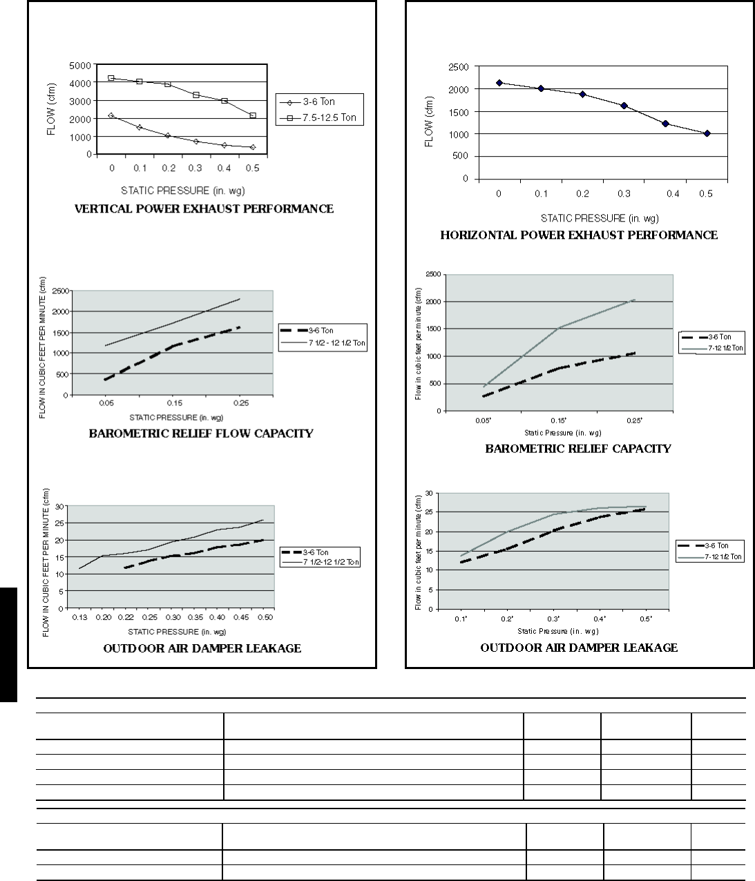
130
*
* Single or three phase rooftop unit.
Vertical - Mounted in Economizer hood
Power Exhaust Part No. Power Exhaust Description Application
Usage
Power Output
(Hp per fan)
Fans per
PE
CRPWREXH021A01 Power Exhaust System (460-3-60) 004-007 0.24 2
CRPWREXH022A01 Power Exhaust System (208/230-1-60) 008-014 0.47 2
CRPWREXH023A01 Power Exhaust System (460-3-60) 008-014 0.37 2
CRPWREXH030A01 Power Exhaust System (208/230-1-60) 004-007* 0.23 2
Horizontal - Mounted in Return Ductwork
Power Exhaust Part No. Power Exhaust Description Application
Usage
Power Output
(Hp per fan)
Fans per
PE
CRPWREXH028A01 Power Exhaust System (208/230-1-60) ALL* 0.48 1
CRPWREXH029A01 Power Exhaust System (460-3-60) ALL 0.48 1
VERTICAL ECONOMI$ER IV AND ECONOMI$ER2 PER-
FORMANCE DATA (48HJ003-014)
VERTICAL POWER EXHAUST PERFORMANCE
HORIZONTAL ECONOMI$ER IV AND ECONOMI$ER2
PERFORMANCE DATA (48HJ003-014)
HORIZONTAL POWER EXHAUST PERFORMANCE
BAROMETRIC RELIEF FLOW CAPACITY
OUTDOOR AIR DAMPER LEAKAGE
BAROMETRIC RELIEF CAPACITY
OUTDOOR AIR DAMPER LEAKAGE
Performance data — 48HJ (cont)
48HJ
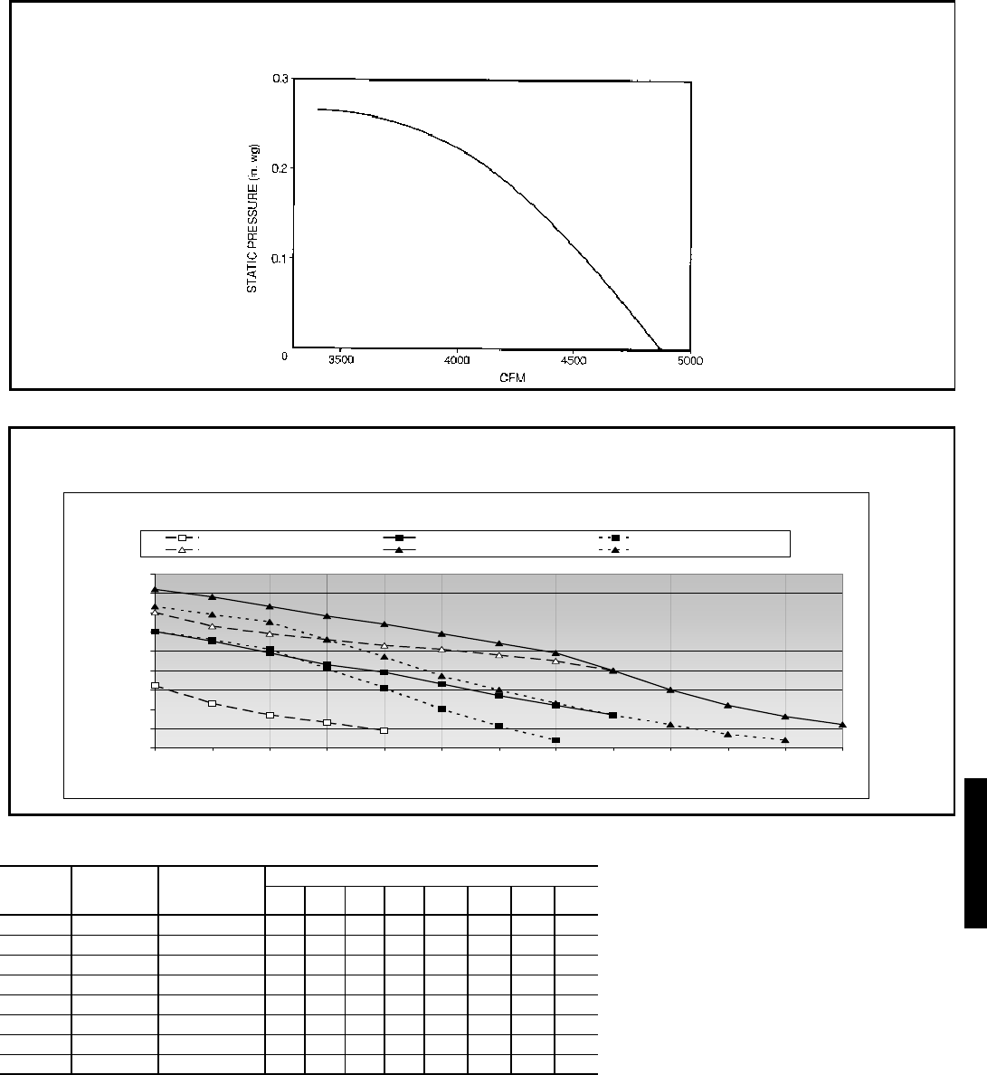
131
OUTDOOR SOUND POWER (TOTAL UNIT)
LEGEND
NOTE: Indoor sound power is available in Carrier’s Electronic Catalog Program (ECAT) for
specific operating parameters.
UNIT
48HE/HJ
ARI
RATING
(decibels)
A-WEIGHTED
(db)
OCTAVE BANDS
63 125 250 500 1000 2000 4000 8000
003-005 76 76.0 55.9 66.0 64.0 66.2 68.4 64.5 61.7 57.3
006,007 80 80.0 59.1 68.9 68.7 71.9 74.0 68.9 65.7 59.0
008,009 82 82.0 62.2 69.3 71.5 74.7 76.2 72.9 68.7 61.5
012 84 84.0 64.6 71.1 73.3 76.9 77.6 73.7 70.6 63.7
014 86 86.0 63.7 69.9 72.5 78.2 81.1 77.3 73.3 66.8
015,017 88 87.6 90.8 88.7 86.4 84.3 83.5 78.4 75.6 66.8
020-024 82 81.7 90.2 84.8 80.7 79.0 77.6 71.4 66.7 60.7
028 85 84.9 90.0 86.3 83.6 82.9 80.3 74.9 71.4 66.5
ARI — Air Conditioning and Refrigeration Institute
FAN PERFORMANCE USING ACCESSORY POWER EXHAUST (48HJ015,017)
0
0.1
0.2
0.3
0.4
0.5
0.6
0.7
0.8
0.9
3250 3350 3450 3550 3650 3750 3850 3950 4050 4250 4450 4650 4850
Exhaust AirFlow (CFM)
ESP Between Return Duct and OA ("wg)
Low Speed 208 V Med Speed 208 V High Speed 208 V
Low Speed 230,460,575V Med Speed 230,460,575V High Speed 230,460,575V
c
POWER EXHAUST PERFORMANCE (48HJ020-028)
48HE/HJ
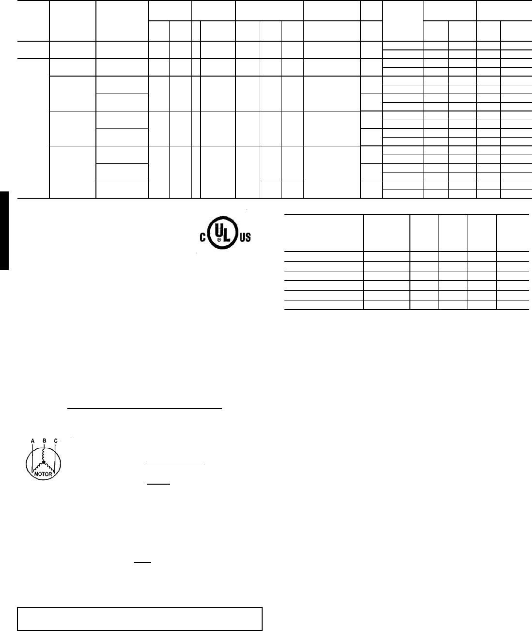
132
48HE003-004 UNITS
LEGEND
*The values listed in this table do not include power exhaust. See table at right
for power exhaust requirements.
**Fuse or HACR circuit breaker.
†460v motor
NOTES:
1. In compliance with NEC requirements for multimotor and combination load
equipment (refer to NEC Articles 430 and 440), the overcurrent protective
device for the unit shall be fuse or HACR breaker. The UL, Canada units
may be fuse or circuit breaker.
2. Electrical data based on 95 F ambient outdoor-air temperature ± 10%
voltage.
3. Unbalanced 3-Phase Supply Voltage
Never operate a motor where a phase imbalance in supply voltage is greater
than 2%. Use the following formula to determine the percent of voltage
imbalance.
Example: Supply voltage is 460-3-60.
AB = 452 v
BC = 464 v
AC = 455 v
Determine maximum deviation from average voltage.
(AB) 457 – 452 = 5 v
(BC) 464 – 457 = 7 v
(AC) 457 – 455 = 2 v
Maximum deviation is 7 v.
Determine percent of voltage imbalance.
This amount of phase imbalance is satisfactory as it is below the maximum
allowable 2%.
POWER EXHAUST ELECTRICAL DATA
* — Single or three phase rooftop unit
N/A — Not available
NOTE: If a single power source is to be used, size wire to include power
exhaust MCA and MOCP.
Check MCA and MOCP when power exhaust is powered through the unit.
Determine the new MCA including the power exhaust using the following
formula:
MCA New = MCA unit only + MCA of Power Exhaust
For example, using a 48HJD006---5 unit with MCA = 28.9 and MOCP = 35,
with CRPWREXH030A01 power exhaust.
MCA New = 28.9 amps + 1.6 amps = 30.5 amps
If the new MCA does not exceed the published MOCP, then MOCP would
not change. The MOCP in this example is 35 amps and the MCA New is
below 35; therefore the MOCP is acceptable. If “MCA New” is larger than the
published MOCP, raise the MOCP to the next larger size. For separate
power, the MOCP for the power exhaust will be 15 amps per NEC.
UNIT
SIZE
NOMINAL
V-PH-Hz IFM TYPE
VOLTAGE
RANGE
COMPRESSO
ROFM
COMBUSTION
FAN MOTOR IFM CONV
OUTLET
POWER SUPPLY
*
MINIMUM UNIT
DISCONNECT
SIZE
Min Max
Q
T
Y
RLA LRA QTY FLA FLA FLA MCA MOCP
** FLA LRA
003
(2 tons)
208/
230-1-60 STD 187 254 1 10.9 63 1 0.7 0.6 2.0 NO 16.3 20 15.6 69
YES 22.3 25 21.2 73
004
(3 tons)
208/
230-1-60 STD 187 254 1 16 88 1 0.7 0.6 4.9 NO 25.6 30 24.8 101
YES 31.6 35 30.4 106
208/
230-3-60
STD
187 254 1 10.3 77 1 0.7 0.6
4.9 NO 18.5 25 18.3 90
YES 24.5 30 23.8 95
HS 5.8 NO 19.4 25 19.3 120
YES 25.4 30 24.9 124
460-3-60
STD
414 508 1 5.1 39 1 0.4 0.3
2.2 NO 9.0 15 8.9 46
YES 11.7 15 11.4 48
HS 2.6 NO 9.4 15 9.3 60
YES 12.1 15 11.8 63
575-3-60
STD
518 632 1 4.2 31
10.4
0.3†
1.9 NO 7.6 10 7.5 36
YES 9.7 15 9.5 38
HS 2.0 NO 7.7 10 7.6 43
YES 9.8 15 9.6 44
HumidiMi$er 1 0.4† 2.6†
NO 7.7 10 8.0 48
YES 9.8 15 9.6 50
FLA — Full Load Amps
HACR — Heating, Air Conditioning and Refrigeration
IFM — Indoor (Evaporator) Fan Motor
LRA — Locked Rotor Amps
MCA — Minimum Circuit Amps
MOCP — Maximum Overcurrent Protection
NEC — National Electrical Code
OFM — Outdoor (Condenser) Fan Motor
RLA — Rated Load Amps
UL — Underwriters’ Laboratories
= 100 x max voltage deviation from average voltage
average voltage
Average Voltage = 452 + 464 + 455
3
= 1371
3
= 457
% Voltage Imbalance = 100 x 7
457
= 1.53%
IMPORTANT: If the supply voltage phase imbalance is more than 2%, contact
your local electric utility company immediately.
POWER EXHAUST
PART NO.
Application
usage
MCA
(230 v)
MCA
(460 v)
MCA
(575 v)
MOCP
(for
separate
power
source)
CRPWREXH030A01 004-007* 1.6 N/A 0.64 15
CRPWREXH021A01 004-007 N/A 0.68 N/A 15
CRPWREXH022A01 008-014 3.4 N/A 1.32 15
CRPWREXH023A01 008-014 N/A 1.4 N/A 15
CRPWREXH028A01 ALL* 1.7 N/A 0.68 15
CRPWREXH029A01 ALL N/A 0.7 N/A 15
Electrical data — 48HE
48HE
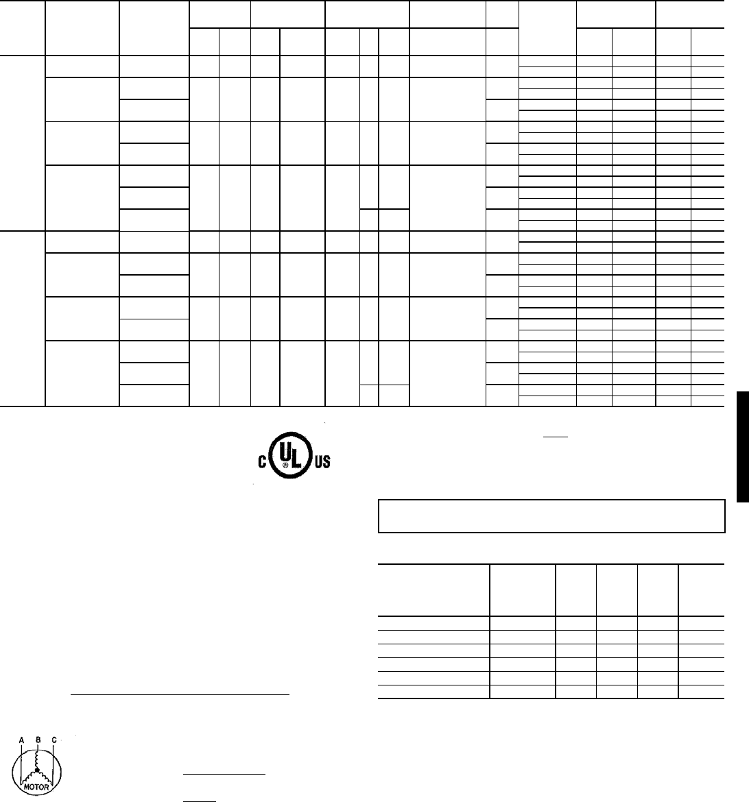
133
48HE005-006 UNITS
LEGEND
*The values listed in this table do not include power exhaust. See table at right
for power exhaust requirements.
**Fuse or HACR circuit breaker.
†460v motor
NOTES:
1. In compliance with NEC requirements for multimotor and combination load
equipment (refer to NEC Articles 430 and 440), the overcurrent protective
device for the unit shall be fuse or HACR breaker. The UL, Canada units
may be fuse or circuit breaker.
2. Electrical data based on 95 F ambient outdoor-air temperature ± 10%
voltage.
3. Unbalanced 3-Phase Supply Voltage
Never operate a motor where a phase imbalance in supply voltage is greater
than 2%. Use the following formula to determine the percent of voltage
imbalance.
Example: Supply voltage is 460-3-60.
AB = 452 v
BC = 464 v
AC = 455 v
Determine maximum deviation from average voltage.
(AB) 457 – 452 = 5 v
(BC) 464 – 457 = 7 v
(AC) 457 – 455 = 2 v
Maximum deviation is 7 v.
Determine percent of voltage imbalance.
This amount of phase imbalance is satisfactory as it is below the maximum
allowable 2%.
POWER EXHAUST ELECTRICAL DATA
* — Single or three phase rooftop unit
N/A — Not available
NOTE: If a single power source is to be used, size wire to include power
exhaust MCA and MOCP.
Check MCA and MOCP when power exhaust is powered through the unit.
Determine the new MCA including the power exhaust using the following
formula:
MCA New = MCA unit only + MCA of Power Exhaust
For example, using a 48HJD006---5 unit with MCA = 28.9 and MOCP = 35,
with CRPWREXH030A01 power exhaust.
MCA New = 28.9 amps + 1.6 amps = 30.5 amps
If the new MCA does not exceed the published MOCP, then MOCP would
not change. The MOCP in this example is 35 amps and the MCA New is
below 35; therefore the MOCP is acceptable. If “MCA New” is larger than the
published MOCP, raise the MOCP to the next larger size. For separate
power, the MOCP for the power exhaust will be 15 amps per NEC.
UNIT
SIZE
NOMINAL
V-PH-Hz IFM TYPE
VOLTAGE
RANGE COMPRESSOR OFM
COMBUSTION
FAN MOTOR IFM CONV
OUTLET
POWER SUPPLY *
MINIMUM UNIT
DISCONNECT
SIZE
Min Max QTY RLA LRA
Q
T
Y
FLA FLA FLA MCA MOCP
** FLA LRA
005
(4 tons)
208/230-1-60 STD 197 254 1 21 115 1 1.5 0.6 4.9 NO 32.7 40 31.5 130
YES 38.7 45 37.0 135
208/230-3-60
STD
187 254 1 14.1 95 1 1.5 0.6
4.9 NO 24.0 30 23.6 110
YES 30.0 35 29.1 115
HS 5.8 NO 24.9 30 24.6 140
YES 30.9 35 30.1 145
460-3-60
STD
414 508 1 7.1 45 1 0.8 0.3
2.2 NO 11.9 15 11.6 53
YES 14.6 20 14.1 55
HS 2.6 NO 12.3 15 12.1 67
YES 15.0 20 14.6 70
575-3-60
STD
518 632 1 6.1 38
10.6
0.3†
1.9 NO 10.1 15 9.9 44
YES 12.3 15 11.9 46
HS 2.0 NO 10.2 15 10.0 51
YES 12.4 15 12.0 52
HumidiMi$er 1 0.8† 2.6†
NO 10.3 15 10.1 56
YES 12.5 15 12.1 58
006
(5 tons)
208/230-1-60 STD 187 254 1 25 150 1 1.5 0.6 6.6 NO 39.4 50 38.1 187
YES 45.4 60 43.6 191
208/230-3-60
STD
187 254 1 17.3 123 1 1.5 0.6
5.8 NO 28.9 35 28.3 168
YES 34.9 40 33.8 173
HS 7.5 NO 30.6 35 30.2 187
YES 36.6 40 35.8 192
460-3-60
STD
414 508 1 8.4 70 1 0.8 0.3†
2.6 NO 13.9 20 13.6 92
YES 16.6 20 16.1 95
HS 3.4 NO 14.7 20 14.5 102
YES 17.4 20 17.0 104
575-3-60
STD
518 632 1 7.1 53
10.6
0.3†
2.0 NO 11.5 15 11.2 66
YES 13.6 15 13.2 67
HS 2.8 NO 12.3 15 12.1 75
YES 14.4 20 14.1 76
HumidiMi$er 1 1.9† 3.4†
NO 12.2 15 12.0 79
YES 14.4 20 14.0 80
FLA — Full Load Amps
HACR — Heating, Air Conditioning and Refrigeration
IFM — Indoor (Evaporator) Fan Motor
LRA — Locked Rotor Amps
MCA — Minimum Circuit Amps
MOCP — Maximum Overcurrent Protection
NEC — National Electrical Code
OFM — Outdoor (Condenser) Fan Motor
RLA — Rated Load Amps
UL — Underwriters’ Laboratories
= 100 x max voltage deviation from average voltage
average voltage
Average Voltage = 452 + 464 + 455
3
= 1371
3
= 457
% Voltage Imbalance = 100 x 7
457
= 1.53%
IMPORTANT: If the supply voltage phase imbalance is more than 2%, contact
your local electric utility company immediately.
POWER EXHAUST
PART NO.
Application
usage
MCA
(230 v)
MCA
(460 v)
MCA
(575 v)
MOCP
(for
separate
power
source)
CRPWREXH030A01 004-007* 1.6 N/A 0.64 15
CRPWREXH021A01 004-007 N/A 0.68 N/A 15
CRPWREXH022A01 008-014 3.4 N/A 1.32 15
CRPWREXH023A01 008-014 N/A 1.4 N/A 15
CRPWREXH028A01 ALL* 1.7 N/A 0.68 15
CRPWREXH029A01 ALL N/A 0.7 N/A 15
48HE
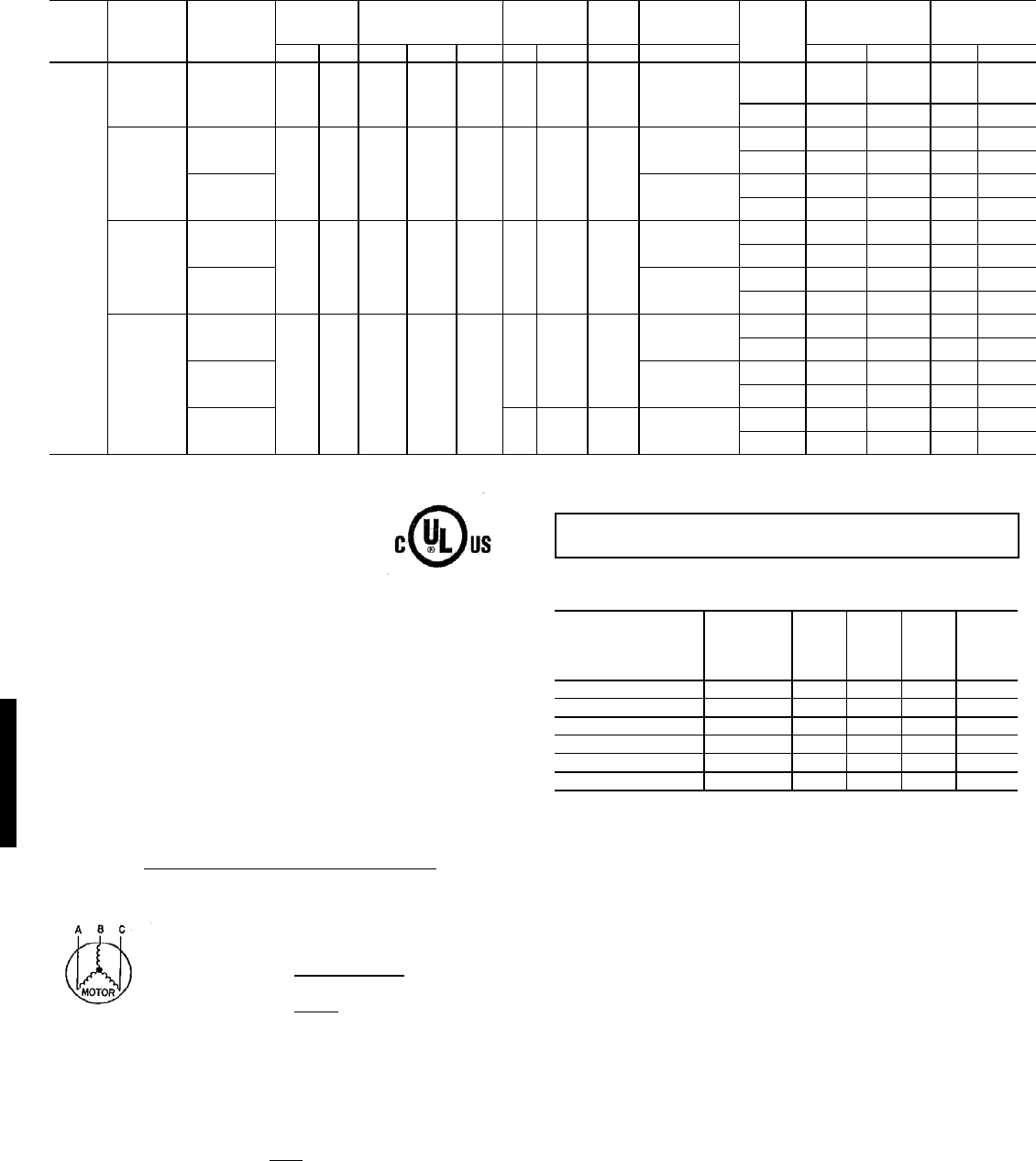
134
48HJ004-014 UNITS
LEGEND
*The values listed in this table do not include power exhaust. See table at right
for power exhaust requirements.
**Fuse or HACR circuit breaker.
†460v motor
NOTES:
1. In compliance with NEC requirements for multimotor and combination load
equipment (refer to NEC Articles 430 and 440), the overcurrent protective
device for the unit shall be fuse or HACR breaker. The UL, Canada units
may be fuse or circuit breaker.
2. Electrical data based on 95 F ambient outdoor-air temperature ± 10%
voltage.
3. Unbalanced 3-Phase Supply Voltage
Never operate a motor where a phase imbalance in supply voltage is greater
than 2%. Use the following formula to determine the percent of voltage
imbalance.
Example: Supply voltage is 460-3-60.
AB = 452 v
BC = 464 v
AC = 455 v
Determine maximum deviation from average voltage.
(AB) 457 – 452 = 5 v
(BC) 464 – 457 = 7 v
(AC) 457 – 455 = 2 v
Maximum deviation is 7 v.
Determine percent of voltage imbalance.
This amount of phase imbalance is satisfactory as it is below the maximum
allowable 2%.
POWER EXHAUST ELECTRICAL DATA
* — Single or three phase rooftop unit
N/A — Not available
NOTE: If a single power source is to be used, size wire to include power
exhaust MCA and MOCP.
Check MCA and MOCP when power exhaust is powered through the unit.
Determine the new MCA including the power exhaust using the following
formula:
MCA New = MCA unit only + MCA of Power Exhaust
For example, using a 48HJD006---5 unit with MCA = 28.9 and MOCP = 35,
with CRPWREXH030A01 power exhaust.
MCA New = 28.9 amps + 1.6 amps = 30.5 amps
If the new MCA does not exceed the published MOCP, then MOCP would
not change. The MOCP in this example is 35 amps and the MCA New is
below 35; therefore the MOCP is acceptable. If “MCA New” is larger than the
published MOCP, raise the MOCP to the next larger size. For separate
power, the MOCP for the power exhaust will be 15 amps per NEC.
UNIT
48HJ
NOMINAL
VOLTAGE
(V-Ph-Hz)
IFM Type
VOLTAGE
RANGE
COMPRESSOR
(each)
OFM
(each) IFM COMBUSTION
FAN MOTOR Conv
Outlet
POWER SUPPLY*
MINIMUM UNIT
DISCONNECT
SIZE
Min Max Qty RLA LRA Qty FLA FLA FLA MCA MOCP** FLA LRA
004
(3 Tons)
208/
230-1-60 STD 187 254 1 16 88 1 0.7 0.6 4.9 NO 25.6 30 25 101
YES 31.6 35 30 106
208/
230-3-60
STD
187 254 1 10.3 77 1 0.7 0.6
4.9 NO 18.5 25 18 90
YES 24.5 30 24 95
HS 5.2 NO 19.4 25 19 120
YES 25.4 30 25 124
460-3-60
STD
414 508 1 5.1 39 1 0.4 0.3
2.2 NO 9.0 15 9 46
YES 11.7 15 11 48
HS 2.6 NO 9.4 15 9 60
YES 12.1 15 12 63
575-3-60
STD
518 632 1 4.2 31
1 0.4 0.3†
1.9 NO 7.6 10 7 36
YES 9.7 15 9 38
HS 2.0 NO 7.7 10 8 43
YES 9.8 15 10 44
HumidiMi$er 1 0.4† 0.9† 2.6† NO 8.3 10 8 52
YES 10.4 15 10 54
FLA — Full Load Amps
HACR — Heating, Air Conditioning and Refrigeration
IFM — Indoor (Evaporator) Fan Motor
LRA — Locked Rotor Amps
MCA — Minimum Circuit Amps
MOCP — Maximum Overcurrent Protection
NEC — National Electrical Code
OFM — Outdoor (Condenser) Fan Motor
RLA — Rated Load Amps
UL — Underwriters’ Laboratories
= 100 x max voltage deviation from average voltage
average voltage
Average Voltage = 452 + 464 + 455
3
= 1371
3
= 457
% Voltage Imbalance = 100 x 7
457
= 1.53%
IMPORTANT: If the supply voltage phase imbalance is more than 2%, contact
your local electric utility company immediately.
POWER EXHAUST
PART NO.
Application
usage
MCA
(230 v)
MCA
(460 v)
MCA
(575 v)
MOCP
(for
separate
power
source)
CRPWREXH030A01 004-007* 1.6 N/A 0.64 15
CRPWREXH021A01 004-007 N/A 0.68 N/A 15
CRPWREXH022A01 008-014 3.4 N/A 1.32 15
CRPWREXH023A01 008-014 N/A 1.4 N/A 15
CRPWREXH028A01 ALL* 1.7 N/A 0.68 15
CRPWREXH029A01 ALL N/A 0.7 N/A 15
Electrical data — 48HJ
48HJ
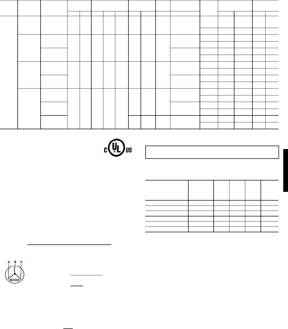
135
48HJ004-014 UNITS (Cont)
LEGEND
*The values listed in this table do not include power exhaust. See table at right
for power exhaust requirements.
**Fuse or HACR circuit breaker.
†460v motor
NOTES:
1. In compliance with NEC requirements for multimotor and combination load
equipment (refer to NEC Articles 430 and 440), the overcurrent protective
device for the unit shall be fuse or HACR breaker. The UL, Canada units
may be fuse or circuit breaker.
2. Electrical data based on 95 F ambient outdoor-air temperature ± 10%
voltage.
3. Unbalanced 3-Phase Supply Voltage
Never operate a motor where a phase imbalance in supply voltage is greater
than 2%. Use the following formula to determine the percent of voltage
imbalance.
Example: Supply voltage is 460-3-60.
AB = 452 v
BC = 464 v
AC = 455 v
Determine maximum deviation from average voltage.
(AB) 457 – 452 = 5 v
(BC) 464 – 457 = 7 v
(AC) 457 – 455 = 2 v
Maximum deviation is 7 v.
Determine percent of voltage imbalance.
This amount of phase imbalance is satisfactory as it is below the maximum
allowable 2%.
POWER EXHAUST ELECTRICAL DATA
* — Single or three phase rooftop unit
N/A — Not available
NOTE: If a single power source is to be used, size wire to include power
exhaust MCA and MOCP.
Check MCA and MOCP when power exhaust is powered through the unit.
Determine the new MCA including the power exhaust using the following
formula:
MCA New = MCA unit only + MCA of Power Exhaust
For example, using a 48HJD006---5 unit with MCA = 28.9 and MOCP = 35,
with CRPWREXH030A01 power exhaust.
MCA New = 28.9 amps + 1.6 amps = 30.5 amps
If the new MCA does not exceed the published MOCP, then MOCP would
not change. The MOCP in this example is 35 amps and the MCA New is
below 35; therefore the MOCP is acceptable. If “MCA New” is larger than the
published MOCP, raise the MOCP to the next larger size. For separate
power, the MOCP for the power exhaust will be 15 amps per NEC.
UNIT
48HJ
NOMINAL
VOLTAGE
(V-Ph-Hz)
IFM Type
VOLTAGE
RANGE
COMPRESSOR
(each)
OFM
(each) IFM COMBUSTION
FAN MOTOR Conv
Outlet
POWER SUPPLY*
MINIMUM UNIT
DISCONNECT
SIZE†
Min Max Qty RLA LRA Qty FLA FLA FLA MCA MOCP** FLA LRA
005
(4 Tons)
208/230-1-60 STD 187 254 1 23.7 126 1 0.7 0.6 4.9
NO 35.2 45 34 139
YES 41.2 50 39 144
208/230-3-60
STD
187 254 1 13.5 93 1 0.7 0.6
4.9
NO 22.5 30 22 106
YES 28.5 35 27 111
HS 5.8
NO 23.4 30 23 136
YES 29.4 35 29 140
460-3-60
STD
414 508 1 6.4 46.5 1 0.4 0.3
2.2
NO 10.6 15 10 54
YES 13.3 15 13 56
HS 2.6
NO 11.0 15 11 68
YES 13.7 15 13 70
575-3-60
STD
518 632 1 6.4 40
10.40.3†
1.9
NO 10.3 15 10 45
YES 12.5 15 12 47
HS 2.0
NO 10.4 15 10 52
YES 12.6 15 12 53
HumidiMi$er 1 0.4 0.9† 2.6†
NO 11.0 15 11 61
YES 13.2 15 13 63
FLA — Full Load Amps
HACR — Heating, Air Conditioning and Refrigeration
IFM — Indoor (Evaporator) Fan Motor
LRA — Locked Rotor Amps
MCA — Minimum Circuit Amps
MOCP — Maximum Overcurrent Protection
NEC — National Electrical Code
OFM — Outdoor (Condenser) Fan Motor
RLA — Rated Load Amps
UL — Underwriters’ Laboratories
= 100 x max voltage deviation from average voltage
average voltage
Average Voltage = 452 + 464 + 455
3
= 1371
3
= 457
% Voltage Imbalance = 100 x 7
457
= 1.53%
IMPORTANT: If the supply voltage phase imbalance is more than 2%, contact
your local electric utility company immediately.
POWER EXHAUST
PART NO.
Application
usage
MCA
(230 v)
MCA
(460 v)
MCA
(575 v)
MOCP
(for
separate
power
source)
CRPWREXH030A01 004-007* 1.6 N/A 0.64 15
CRPWREXH021A01 004-007 N/A 0.68 N/A 15
CRPWREXH022A01 008-014 3.4 N/A 1.32 15
CRPWREXH023A01 008-014 N/A 1.4 N/A 15
CRPWREXH028A01 ALL* 1.7 N/A 0.68 15
CRPWREXH029A01 ALL N/A 0.7 N/A 15
48HJ
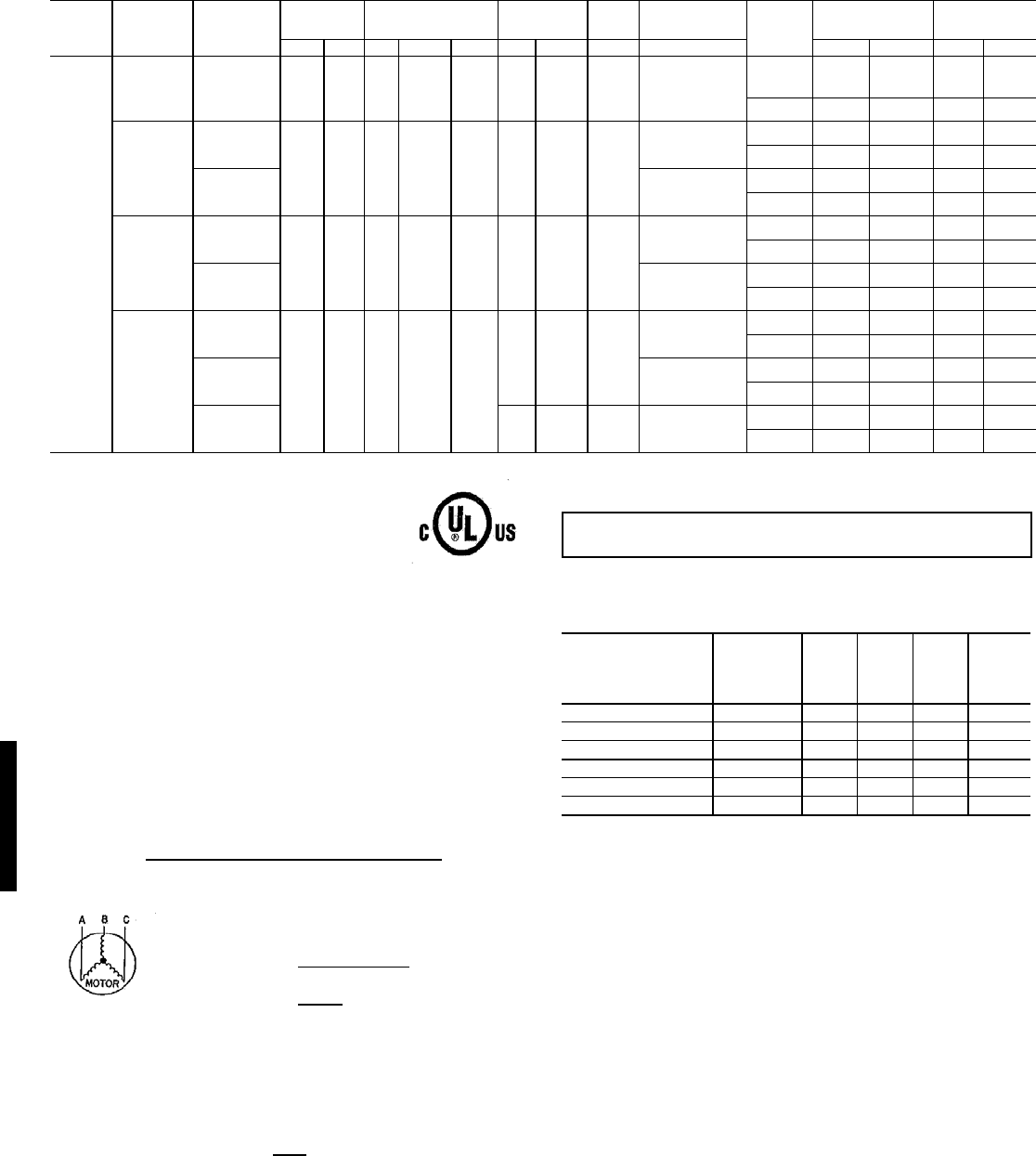
136
48HJ004-014 UNITS (Cont)
LEGEND
*The values listed in this table do not include power exhaust. See table at right
for power exhaust requirements.
**Fuse or HACR circuit breaker.
†460v motor
NOTES:
1. In compliance with NEC requirements for multimotor and combination load
equipment (refer to NEC Articles 430 and 440), the overcurrent protective
device for the unit shall be fuse or HACR breaker. The UL, Canada units
may be fuse or circuit breaker.
2. Electrical data based on 95 F ambient outdoor-air temperature ± 10%
voltage.
3. Unbalanced 3-Phase Supply Voltage
Never operate a motor where a phase imbalance in supply voltage is greater
than 2%. Use the following formula to determine the percent of voltage
imbalance.
Example: Supply voltage is 460-3-60.
AB = 452 v
BC = 464 v
AC = 455 v
Determine maximum deviation from average voltage.
(AB) 457 – 452 = 5 v
(BC) 464 – 457 = 7 v
(AC) 457 – 455 = 2 v
Maximum deviation is 7 v.
Determine percent of voltage imbalance.
This amount of phase imbalance is satisfactory as it is below the maximum
allowable 2%.
POWER EXHAUST ELECTRICAL DATA
* — Single or three phase rooftop unit
N/A — Not available
NOTE: If a single power source is to be used, size wire to include power
exhaust MCA and MOCP.
Check MCA and MOCP when power exhaust is powered through the unit.
Determine the new MCA including the power exhaust using the following
formula:
MCA New = MCA unit only + MCA of Power Exhaust
For example, using a 48HJD006---5 unit with MCA = 28.9 and MOCP = 35,
with CRPWREXH030A01 power exhaust.
MCA New = 28.9 amps + 1.6 amps = 30.5 amps
If the new MCA does not exceed the published MOCP, then MOCP would
not change. The MOCP in this example is 35 amps and the MCA New is
below 35; therefore the MOCP is acceptable. If “MCA New” is larger than the
published MOCP, raise the MOCP to the next larger size. For separate
power, the MOCP for the power exhaust will be 15 amps per NEC.
UNIT
48HJ
NOMINAL
VOLTAGE
(V-Ph-Hz)
IFM Type
VO LTAGE
RANGE
COMPRESSOR
(each)
OFM
(each) IFM COMBUSTION
FAN MOTOR Conv
Outlet
POWER SUPPLY*
MINIMUM UNIT
DISCONNECT
SIZE
Min Max Qty RLA LRA Qty FLA FLA FLA MCA MOCP** FLA LRA
006
(5 Tons)
208/230-1-60 STD 187 254 1 28.8 169 1 1.5 0.6 6.6
NO 44.1 60 42 206
YES 50.1 60 48 210
208/230-3-60
STD
187 254 1 17.3 123 1 1.5 0.6
5.8
NO 28.9 35 28 168
YES 34.9 40 34 173
HS 7.5
NO 30.6 35 30 187
YES 36.6 40 36 192
460-3-60
STD
414 508 1 9 62 1 0.8 0.3
2.6
NO 14.7 20 14 84
YES 17.4 20 17 87
HS 3.4
NO 15.5 20 15 94
YES 18.2 20 18 96
575-3-60
STD
518 632 1 7.1 50
10.60.3†
2.0
NO 11.5 15 11 63
YES 13.6 15 13 64
HS 2.8
NO 12.3 15 12 72
YES 14.4 20 14 73
HumidiMi$er 1 0.8† 0.3† 3.4†
NO 12.2 15 12 76
YES 14.4 20 14 77
FLA — Full Load Amps
HACR — Heating, Air Conditioning and Refrigeration
IFM — Indoor (Evaporator) Fan Motor
LRA — Locked Rotor Amps
MCA — Minimum Circuit Amps
MOCP — Maximum Overcurrent Protection
NEC — National Electrical Code
OFM — Outdoor (Condenser) Fan Motor
RLA — Rated Load Amps
UL — Underwriters’ Laboratories
= 100 x max voltage deviation from average voltage
average voltage
Average Voltage = 452 + 464 + 455
3
= 1371
3
= 457
% Voltage Imbalance = 100 x 7
457
= 1.53%
IMPORTANT: If the supply voltage phase imbalance is more than 2%, contact
your local electric utility company immediately.
POWER EXHAUST
PART NO.
Application
usage
MCA
(230 v)
MCA
(460 v)
MCA
(575 v)
MOCP
(for
separate
power
source)
CRPWREXH030A01 004-007* 1.6 N/A 0.64 15
CRPWREXH021A01 004-007 N/A 0.68 N/A 15
CRPWREXH022A01 008-014 3.4 N/A 1.32 15
CRPWREXH023A01 008-014 N/A 1.4 N/A 15
CRPWREXH028A01 ALL* 1.7 N/A 0.68 15
CRPWREXH029A01 ALL N/A 0.7 N/A 15
Electrical data — 48HJ (cont)
48HJ
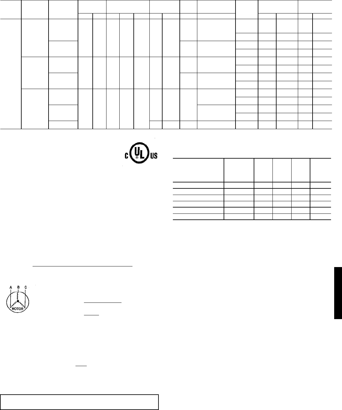
137
48HJ004-014 UNITS (Cont)
LEGEND
*The values listed in this table do not include power exhaust. See table at right
for power exhaust requirements.
**Fuse or HACR circuit breaker.
†460v motor
NOTES:
1. In compliance with NEC requirements for multimotor and combination load
equipment (refer to NEC Articles 430 and 440), the overcurrent protective
device for the unit shall be fuse or HACR breaker. The UL, Canada units
may be fuse or circuit breaker.
2. Electrical data based on 95 F ambient outdoor-air temperature ± 10%
voltage.
3. Unbalanced 3-Phase Supply Voltage
Never operate a motor where a phase imbalance in supply voltage is greater
than 2%. Use the following formula to determine the percent of voltage
imbalance.
Example: Supply voltage is 460-3-60.
AB = 452 v
BC = 464 v
AC = 455 v
Determine maximum deviation from average voltage.
(AB) 457 – 452 = 5 v
(BC) 464 – 457 = 7 v
(AC) 457 – 455 = 2 v
Maximum deviation is 7 v.
Determine percent of voltage imbalance.
This amount of phase imbalance is satisfactory as it is below the maximum
allowable 2%.
POWER EXHAUST ELECTRICAL DATA
* — Single or three phase rooftop unit
N/A — Not available
NOTE: If a single power source is to be used, size wire to include power
exhaust MCA and MOCP.
Check MCA and MOCP when power exhaust is powered through the unit.
Determine the new MCA including the power exhaust using the following
formula:
MCA New = MCA unit only + MCA of Power Exhaust
For example, using a 48HJD006---5 unit with MCA = 28.9 and MOCP = 35,
with CRPWREXH030A01 power exhaust.
MCA New = 28.9 amps + 1.6 amps = 30.5 amps
If the new MCA does not exceed the published MOCP, then MOCP would
not change. The MOCP in this example is 35 amps and the MCA New is
below 35; therefore the MOCP is acceptable. If “MCA New” is larger than the
published MOCP, raise the MOCP to the next larger size. For separate
power, the MOCP for the power exhaust will be 15 amps per NEC.
UNIT
48HJ
NOMINAL
VOLTAGE
(V-Ph-Hz)
IFM Type
VO LTAGE
RANGE
COMPRESSOR
(each)
OFM
(each) IFM COMBUSTION
FAN MOTOR Conv
Outlet
POWER SUPPLY*
MINIMUM UNIT
DISCONNECT
SIZE
Min Max Qty RLA LRA Qty FLA FLA FLA MCA MOCP** FLA LRA
007
(6 Tons)
208/230-3-60
STD
187 254 1 20.5 156 1 1.4
0.6 5.8
NO 32.8 40 32 200
YES 38.8 45 37 205
HS 0.6 7.5
NO 34.5 40 34 219
YES 40.5 45 39 224
460-3-60
STD
414 508 1 9.6 75 1 0.6
0.3 2.6
NO 15.2 20 15 97
YES 17.9 20 17 99
HS 0.3 3.4
NO 16.0 20 16 107
YES 18.7 25 18 109
575-3-60
STD
518 632 1 7.7 56
10.80.3†
2.0
NO 12.4 15 12 69
YES 14.6 20 14 70
HS 2.8
NO 13.2 20 13 79
YES 15.4 20 15 80
HumidiMi$er 1 0.6† 0.3† 3.4† NO 12.8 15 13 81
FLA — Full Load Amps
HACR — Heating, Air Conditioning and Refrigeration
IFM — Indoor (Evaporator) Fan Motor
LRA — Locked Rotor Amps
MCA — Minimum Circuit Amps
MOCP — Maximum Overcurrent Protection
NEC — National Electrical Code
OFM — Outdoor (Condenser) Fan Motor
RLA — Rated Load Amps
UL — Underwriters’ Laboratories
= 100 x max voltage deviation from average voltage
average voltage
Average Voltage = 452 + 464 + 455
3
= 1371
3
= 457
% Voltage Imbalance = 100 x 7
457
= 1.53%
IMPORTANT: If the supply voltage phase imbalance is more than 2%, contact
your local electric utility company immediately.
POWER EXHAUST
PART NO.
Application
usage
MCA
(230 v)
MCA
(460 v)
MCA
(575 v)
MOCP
(for
separate
power
source)
CRPWREXH030A01 004-007* 1.6 N/A 0.64 15
CRPWREXH021A01 004-007 N/A 0.68 N/A 15
CRPWREXH022A01 008-014 3.4 N/A 1.32 15
CRPWREXH023A01 008-014 N/A 1.4 N/A 15
CRPWREXH028A01 ALL* 1.7 N/A 0.68 15
CRPWREXH029A01 ALL N/A 0.7 N/A 15
48HJ
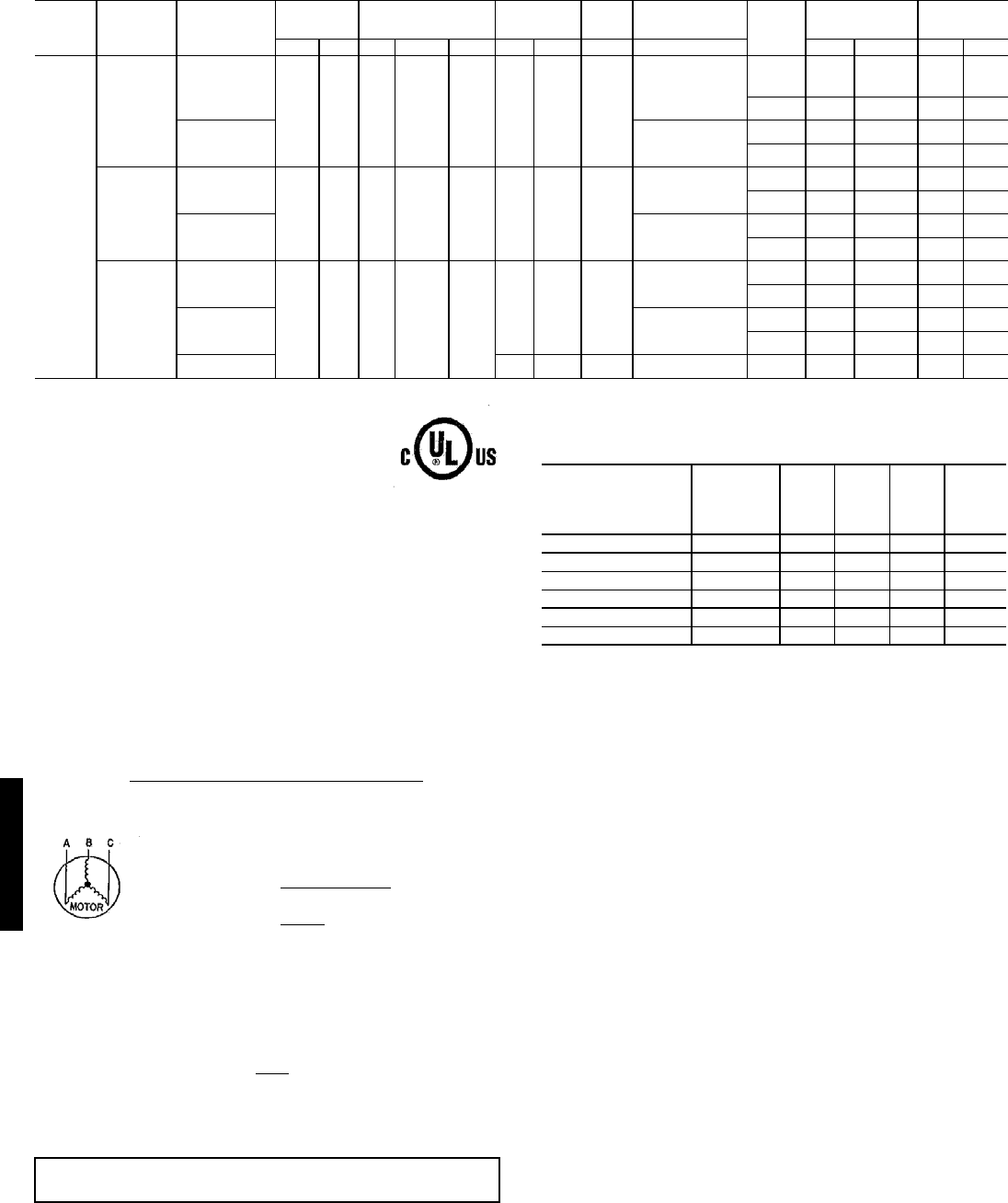
138
48HJ004-014 UNITS (Cont)
LEGEND
*The values listed in this table do not include power exhaust. See table at right
for power exhaust requirements.
**Fuse or HACR circuit breaker.
†460v motor
NOTES:
1. In compliance with NEC requirements for multimotor and combination load
equipment (refer to NEC Articles 430 and 440), the overcurrent protective
device for the unit shall be fuse or HACR breaker. The UL, Canada units
may be fuse or circuit breaker.
2. Electrical data based on 95 F ambient outdoor-air temperature ± 10%
voltage.
3. Unbalanced 3-Phase Supply Voltage
Never operate a motor where a phase imbalance in supply voltage is greater
than 2%. Use the following formula to determine the percent of voltage
imbalance.
Example: Supply voltage is 460-3-60.
AB = 452 v
BC = 464 v
AC = 455 v
Determine maximum deviation from average voltage.
(AB) 457 – 452 = 5 v
(BC) 464 – 457 = 7 v
(AC) 457 – 455 = 2 v
Maximum deviation is 7 v.
Determine percent of voltage imbalance.
This amount of phase imbalance is satisfactory as it is below the maximum
allowable 2%.
POWER EXHAUST ELECTRICAL DATA
* — Single or three phase rooftop unit
N/A — Not available
NOTE: If a single power source is to be used, size wire to include power
exhaust MCA and MOCP.
Check MCA and MOCP when power exhaust is powered through the unit.
Determine the new MCA including the power exhaust using the following
formula:
MCA New = MCA unit only + MCA of Power Exhaust
For example, using a 48HJD006---5 unit with MCA = 28.9 and MOCP = 35,
with CRPWREXH030A01 power exhaust.
MCA New = 28.9 amps + 1.6 amps = 30.5 amps
If the new MCA does not exceed the published MOCP, then MOCP would
not change. The MOCP in this example is 35 amps and the MCA New is
below 35; therefore the MOCP is acceptable. If “MCA New” is larger than the
published MOCP, raise the MOCP to the next larger size. For separate
power, the MOCP for the power exhaust will be 15 amps per NEC.
UNIT
48HJ
NOMINAL
VOLTAGE
(V-Ph-Hz)
IFM Type
VOLTAGE
RANGE
COMPRESSOR
(each)
OFM
(each) IFM COMBUSTION
FAN MOTOR Conv
Outlet
POWER SUPPLY*
MINIMUM UNIT
DISCONNECT
SIZE†
Min Max Qty RLA LRA Qty FLA FLA FLA MCA MOCP** FLA LRA
008
(71/2
To ns )
208/230-3-60
STD
187 254 2 12.4 88 2 1.4 0.6
7.5
NO 38.2 45 40 242
YES 44.2 50 46 247
HS 10.6
NO 41.3 45 44 267
YES 47.3 50 49 271
460-3-60
STD
414 508 2 6.4 44 2 0.7 0.3
3.4
NO 19.2 25 20 121
YES 21.9 25 23 123
HS 4.8
NO 20.6 25 22 134
YES 23.3 25 24 136
575-3-60
STD
518 632 2 4.8 34
2 0.6 0.3†
2.8
NO 14.6 20 15 95
YES 16.8 20 17 95
HS 3.3
NO 15.3 20 17 104
YES 17.5 20 19 104
HumidiMi$er 2 0.7† 0.3† 4.8† NO 15.8 20 17 104
FLA — Full Load Amps
HACR — Heating, Air Conditioning and Refrigeration
IFM — Indoor (Evaporator) Fan Motor
LRA — Locked Rotor Amps
MCA — Minimum Circuit Amps
MOCP — Maximum Overcurrent Protection
NEC — National Electrical Code
OFM — Outdoor (Condenser) Fan Motor
RLA — Rated Load Amps
UL — Underwriters’ Laboratories
= 100 x max voltage deviation from average voltage
average voltage
Average Voltage = 452 + 464 + 455
3
= 1371
3
= 457
% Voltage Imbalance = 100 x 7
457
= 1.53%
IMPORTANT: If the supply voltage phase imbalance is more than 2%, contact
your local electric utility company immediately.
POWER EXHAUST
PART NO.
Application
usage
MCA
(230 v)
MCA
(460 v)
MCA
(575 v)
MOCP
(for
separate
power
source)
CRPWREXH030A01 004-007* 1.6 N/A 0.64 15
CRPWREXH021A01 004-007 N/A 0.68 N/A 15
CRPWREXH022A01 008-014 3.4 N/A 1.32 15
CRPWREXH023A01 008-014 N/A 1.4 N/A 15
CRPWREXH028A01 ALL* 1.7 N/A 0.68 15
CRPWREXH029A01 ALL N/A 0.7 N/A 15
Electrical data — 48HJ (cont)
48HJ
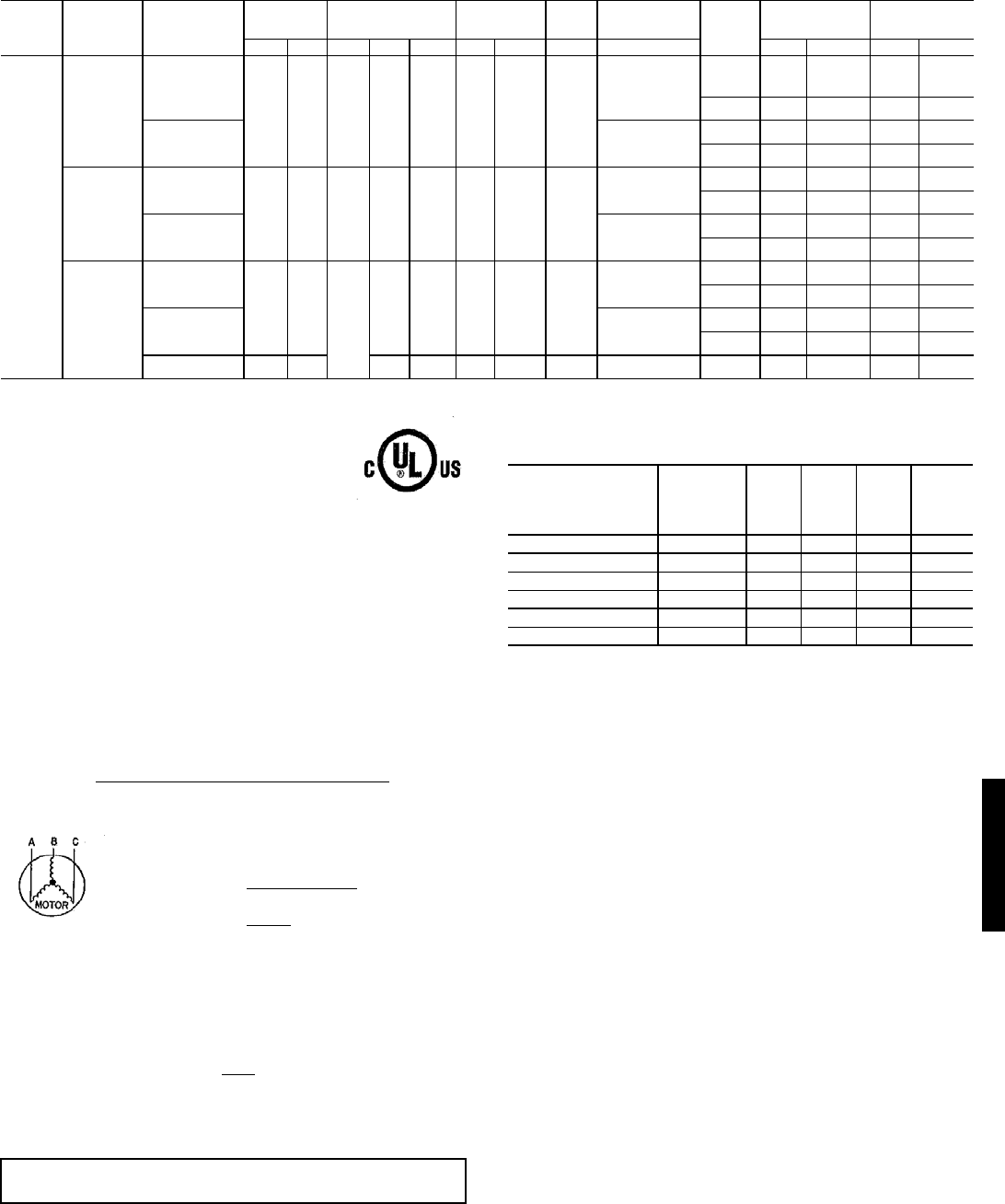
139
48HJ004-014 UNITS (Cont)
LEGEND
*The values listed in this table do not include power exhaust. See table at right
for power exhaust requirements.
**Fuse or HACR circuit breaker.
†460v motor
NOTES:
1. In compliance with NEC requirements for multimotor and combination load
equipment (refer to NEC Articles 430 and 440), the overcurrent protective
device for the unit shall be fuse or HACR breaker. The UL, Canada units
may be fuse or circuit breaker.
2. Electrical data based on 95 F ambient outdoor-air temperature ± 10%
voltage.
3. Unbalanced 3-Phase Supply Voltage
Never operate a motor where a phase imbalance in supply voltage is greater
than 2%. Use the following formula to determine the percent of voltage
imbalance.
Example: Supply voltage is 460-3-60.
AB = 452 v
BC = 464 v
AC = 455 v
Determine maximum deviation from average voltage.
(AB) 457 – 452 = 5 v
(BC) 464 – 457 = 7 v
(AC) 457 – 455 = 2 v
Maximum deviation is 7 v.
Determine percent of voltage imbalance.
This amount of phase imbalance is satisfactory as it is below the maximum
allowable 2%.
POWER EXHAUST ELECTRICAL DATA
* — Single or three phase rooftop unit
N/A — Not available
NOTE: If a single power source is to be used, size wire to include power
exhaust MCA and MOCP.
Check MCA and MOCP when power exhaust is powered through the unit.
Determine the new MCA including the power exhaust using the following
formula:
MCA New = MCA unit only + MCA of Power Exhaust
For example, using a 48HJD006---5 unit with MCA = 28.9 and MOCP = 35,
with CRPWREXH030A01 power exhaust.
MCA New = 28.9 amps + 1.6 amps = 30.5 amps
If the new MCA does not exceed the published MOCP, then MOCP would
not change. The MOCP in this example is 35 amps and the MCA New is
below 35; therefore the MOCP is acceptable. If “MCA New” is larger than the
published MOCP, raise the MOCP to the next larger size. For separate
power, the MOCP for the power exhaust will be 15 amps per NEC.
UNIT
48HJ
NOMINAL
VOLTAGE
(V-Ph-Hz)
IFM Type
VOLTAGE
RANGE
COMPRESSOR
(each)
OFM
(each) IFM COMBUSTION
FAN MOTOR Conv
Outlet
POWER SUPPLY*
MINIMUM UNIT
DISCONNECT
SIZE†
Min Max Qty RLA LRA Qty FLA FLA FLA MCA MOCP** FLA LRA
009
(81/2
To ns )
208/230-3-60
STD
187 254 2 13.1 105 2 1.4 0.6
7.5
NO 40.2 45 42 276
YES 46.2 50 48 281
HS 10.6
NO 43.3 50 46 301
YES 49.3 60 51 305
460-3-60
STD
414 508 2 7.4 55 2 0.7 0.3
3.4
NO 21.5 25 23 143
YES 24.2 30 25 145
HS 4.8
NO 22.9 25 24 156
YES 25.6 30 27 158
575-3-60
STD
518 632
2
6.4 44 2 0.6 0.3†
2.8
NO 18.2 20 19 115
YES 20.4 25 21 116
HS 3.3
NO 18.9 25 20 124
YES 21.1 25 22 126
HumidiMi$er 518 632 6.4 44 2 0.7† 0.3† 4.8† NO 19.4 25 20 124
FLA — Full Load Amps
HACR — Heating, Air Conditioning and Refrigeration
IFM — Indoor (Evaporator) Fan Motor
LRA — Locked Rotor Amps
MCA — Minimum Circuit Amps
MOCP — Maximum Overcurrent Protection
NEC — National Electrical Code
OFM — Outdoor (Condenser) Fan Motor
RLA — Rated Load Amps
UL — Underwriters’ Laboratories
= 100 x max voltage deviation from average voltage
average voltage
Average Voltage = 452 + 464 + 455
3
= 1371
3
= 457
% Voltage Imbalance = 100 x 7
457
= 1.53%
IMPORTANT: If the supply voltage phase imbalance is more than 2%, contact
your local electric utility company immediately.
POWER EXHAUST
PART NO.
Application
usage
MCA
(230 v)
MCA
(460 v)
MCA
(575 v)
MOCP
(for
separate
power
source)
CRPWREXH030A01 004-007* 1.6 N/A 0.64 15
CRPWREXH021A01 004-007 N/A 0.68 N/A 15
CRPWREXH022A01 008-014 3.4 N/A 1.32 15
CRPWREXH023A01 008-014 N/A 1.4 N/A 15
CRPWREXH028A01 ALL* 1.7 N/A 0.68 15
CRPWREXH029A01 ALL N/A 0.7 N/A 15
48HJ
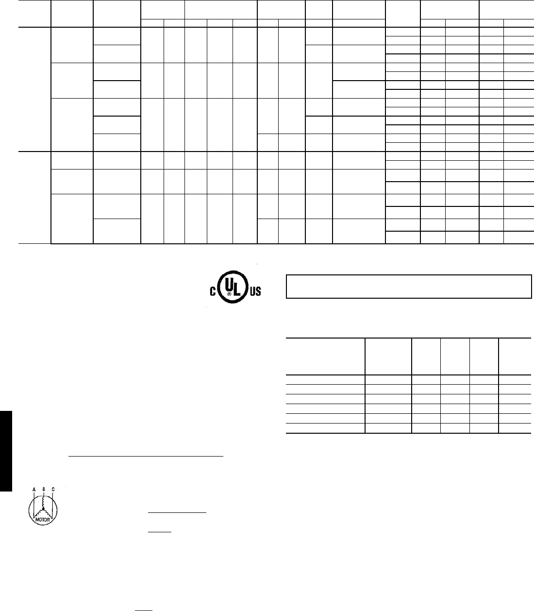
140
48HJ004-014 UNITS (Cont)
LEGEND
*The values listed in this table do not include power exhaust. See table at right
for power exhaust requirements.
**Fuse or HACR circuit breaker.
†460v motor
NOTES:
1. In compliance with NEC requirements for multimotor and combination load
equipment (refer to NEC Articles 430 and 440), the overcurrent protective
device for the unit shall be fuse or HACR breaker. The UL, Canada units
may be fuse or circuit breaker.
2. Electrical data based on 95 F ambient outdoor-air temperature ± 10%
voltage.
3. Unbalanced 3-Phase Supply Voltage
Never operate a motor where a phase imbalance in supply voltage is
greater than 2%. Use the following formula to determine the percent of volt-
age imbalance.
Example: Supply voltage is 460-3-60.
AB = 452 v
BC = 464 v
AC = 455 v
Determine maximum deviation from average voltage.
(AB) 457 – 452 = 5 v
(BC) 464 – 457 = 7 v
(AC) 457 – 455 = 2 v
Maximum deviation is 7 v.
Determine percent of voltage imbalance.
This amount of phase imbalance is satisfactory as it is below the maximum
allowable 2%.
POWER EXHAUST ELECTRICAL DATA
* — Single or three phase rooftop unit
N/A — Not available
NOTE: If a single power source is to be used, size wire to include power
exhaust MCA and MOCP.
Check MCA and MOCP when power exhaust is powered through the unit.
Determine the new MCA including the power exhaust using the following
formula:
MCA New = MCA unit only + MCA of Power Exhaust
For example, using a 48HJD006---5 unit with MCA = 28.9 and MOCP = 35,
with CRPWREXH030A01 power exhaust.
MCA New = 28.9 amps + 1.6 amps = 30.5 amps
If the new MCA does not exceed the published MOCP, then MOCP would
not change. The MOCP in this example is 35 amps and the MCA New is
below 35; therefore the MOCP is acceptable. If “MCA New” is larger than
the published MOCP, raise the MOCP to the next larger size. For separate
power, the MOCP for the power exhaust will be 15 amps per NEC.
UNIT
48HJ
NOMINAL
VOLTAGE
(V-Ph-Hz) IFM Type VOLTAGE
RANGE COMPRESSOR
(each) OFM
(each) IFM COMBUSTION
FAN MOTOR Conv
Outlet POWER SUPPLY* MINIMUM UNIT
DISCONNECT
SIZE†
Min Max Qty RLA LRA Qty FLA FLA FLA MCA MOCP** FLA LRA
012
(10 Tons)
208/230-3-60
STD
187 254 2 17.6 125 2 1.4
0.6 10.6 NO 53.0 60 56 341
YES 59.0 70 61 345
HS 0.6 15.0 NO 57.4 70 61 364
YES 63.4 70 66 369
460-3-60
STD
414 508 2 8.3 62.5 2 0.7 0.3
4.8 NO 24.9 30 26 171
YES 27.6 30 29 173
HS 7.4 NO 27.5 30 29 182
YES 30.2 35 32 184
575-3-60
STD
518 632 2 6.3 50
20.6
0.3† 3.3 NO 19.1 25 20 136
YES 21.3 25 22 138
HS 0.3† 5.6 NO 21.0 25 23 146
YES 23.1 25 25 148
HumidiMi$er 2 0.7† 0.3† 7.4† NO 21.2 25 23 146
YES 23.4 25 25 148
014
(12 1/2
Tons)
208/230-3-60 STD 187 254 2 19 156 2 1.4 0.6 15.0 NO 60.6 70 64 426
YES 66.6 70 70 431
460-3-60 STD 414 508 2 9 75 2 0.7 7.4 0.3 NO 29.1 35 31 207
YES 31.8 35 33 209
575-3-60
STD
518 632 2 7.4 54
2 0.6 5.6 0.3 NO 23.5 30 25 154
YES 25.6 30 27 156
HumidiMi$er 2 0.7 7.4 0.3 NO 23.7 30 25 154
YES 25.9 30 27 156
FLA — Full Load Amps
HACR — Heating, Air Conditioning and Refrigeration
IFM — Indoor (Evaporator) Fan Motor
LRA — Locked Rotor Amps
MCA — Minimum Circuit Amps
MOCP — Maximum Overcurrent Protection
NEC — National Electrical Code
OFM — Outdoor (Condenser) Fan Motor
RLA — Rated Load Amps
UL — Underwriters’ Laboratories
= 100 x max voltage deviation from average voltage
average voltage
Average Voltage = 452 + 464 + 455
3
= 1371
3
= 457
% Voltage Imbalance = 100 x 7
457
= 1.53%
IMPORTANT: If the supply voltage phase imbalance is more than 2%, contact
your local electric utility company immediately.
POWER EXHAUST
PART NO. Application
usage MCA
(230 v) MCA
(460 v) MCA
(575 v)
MOCP
(for
separate
power
source)
CRPWREXH030A01 004-007* 1.6 N/A 0.64 15
CRPWREXH021A01 004-007 N/A 0.68 N/A 15
CRPWREXH022A01 008-014 3.4 N/A 1.32 15
CRPWREXH023A01 008-014 N/A 1.4 N/A 15
CRPWREXH028A01 ALL* 1.7 N/A 0.68 15
CRPWREXH029A01 ALL N/A 0.7 N/A 15
Electrical data — 48HJ (cont)
48HJ
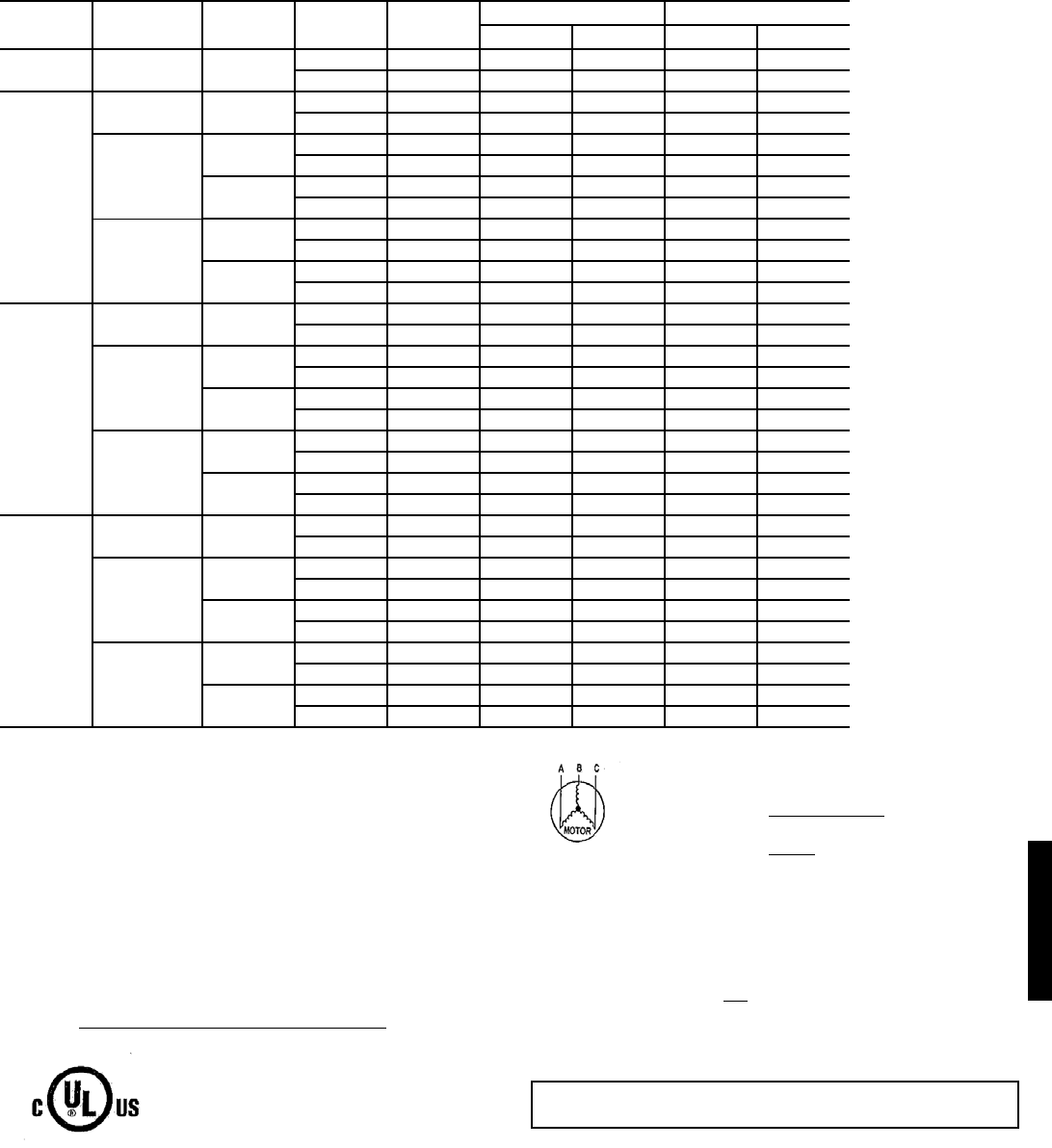
141
COBRA™ ENERGY RECOVERY UNITS (48HE003-006 UNITS WITH 62AQ060)
LEGEND
*Used to determine minimum disconnect per NEC.
NOTES:
1. In compliance with NEC requirements for multimotor and combination load
equipment (refer to NEC Articles 430 and 440), the overcurrent protective
device for the unit shall be fuse or HACR breaker. UL, Canada units may be
fuse or circuit breaker.
2. Unbalanced 3-Phase Supply Voltage
Never operate a motor where a phase imbalance in supply voltage is greater
than 2%. Use the following formula to determine the percent of voltage
imbalance.
Example: Supply voltage is 460-3-60.
AB = 452 v
BC = 464 v
AC = 455 v
= 457
Determine maximum deviation from average voltage.
(AB) 457 – 452 = 5 v
(BC) 464 – 457 = 7 v
(AC) 457 – 455 = 2 v
Maximum deviation is 7 v.
Determine percent of voltage imbalance.
% Voltage Imbalance = 100 x
= 1.53%
This amount of phase imbalance is satisfactory as it is below the maximum allow-
able 2%.
BASE
UNIT SIZE
N O M I N A L
V-PH-Hz IFM TYPE CONV
OUTLET
62AQ
FLA
POWER SUPPLY * DISCONNECT SIZE
MCA MOCP** FLA LRA
003 208/230-1-60 STD NO 9.2 25.5 30 26 103
YES 9.2 31.5 35 32 107
004
208/230-1-60 STD NO 9.2 34.8 40 35 135
YES 9.2 40.8 45 41 140
208/230-3-60
STD NO 9.2 27.7 35 29 124
YES 9.2 33.7 40 34 129
HS NO 9.2 28.6 35 30 154
YES 9.2 34.6 40 35 158
460-3-60
STD NO 9.2 13.6 15 14 63
YES 9.2 16.3 20 17 65
HS NO 9.2 14.0 20 15 77
YES 9.2 16.7 20 17 80
005
208/230-1-60 STD NO 9.2 41.9 50 42 164
YES 9.2 47.9 60 48 169
208/230-3-60
STD NO 9.2 33.2 40 34 144
YES 9.2 39.2 45 40 149
HS NO 9.2 34.1 40 35 174
YES 9.2 40.1 45 41 179
460-3-60
STD NO 9.2 16.5 20 17 70
YES 9.2 19.2 25 19 72
HS NO 9.2 16.9 20 17 84
YES 9.2 19.6 25 20 87
006
208/230-1-60 STD NO 9.2 48.6 60 49 221
YES 9.2 54.6 60 54 225
208/230-3-60
STD NO 9.2 38.1 45 39 202
YES 9.2 44.1 50 44 207
HS NO 9.2 39.8 45 41 221
YES 9.2 45.8 50 46 226
460-3-60
STD NO 9.2 19.3 25 20 101
YES 9.2 22.0 25 22 104
HS NO 9.2 20.1 25 20 111
YES 9.2 22.8 25 23 113
FLA — Full Load Amps
HACR — Heating, Air Conditioning and Refrigeration
IFM — Indoor (Evaporator) Fan Motor
LRA — Locked Rotor Amps
MCA — Minimum Circuit Amps
NEC — National Electrical Code
UL — Underwriters’ Laboratories
= 100 x max voltage deviation from average voltage
average voltage
Average Voltage = 452 + 464 + 455
3
= 1371
3
IMPORTANT: If the supply voltage phase imbalance is more than 2%, contact
your local electric utility company immediately.
7
457
48HE
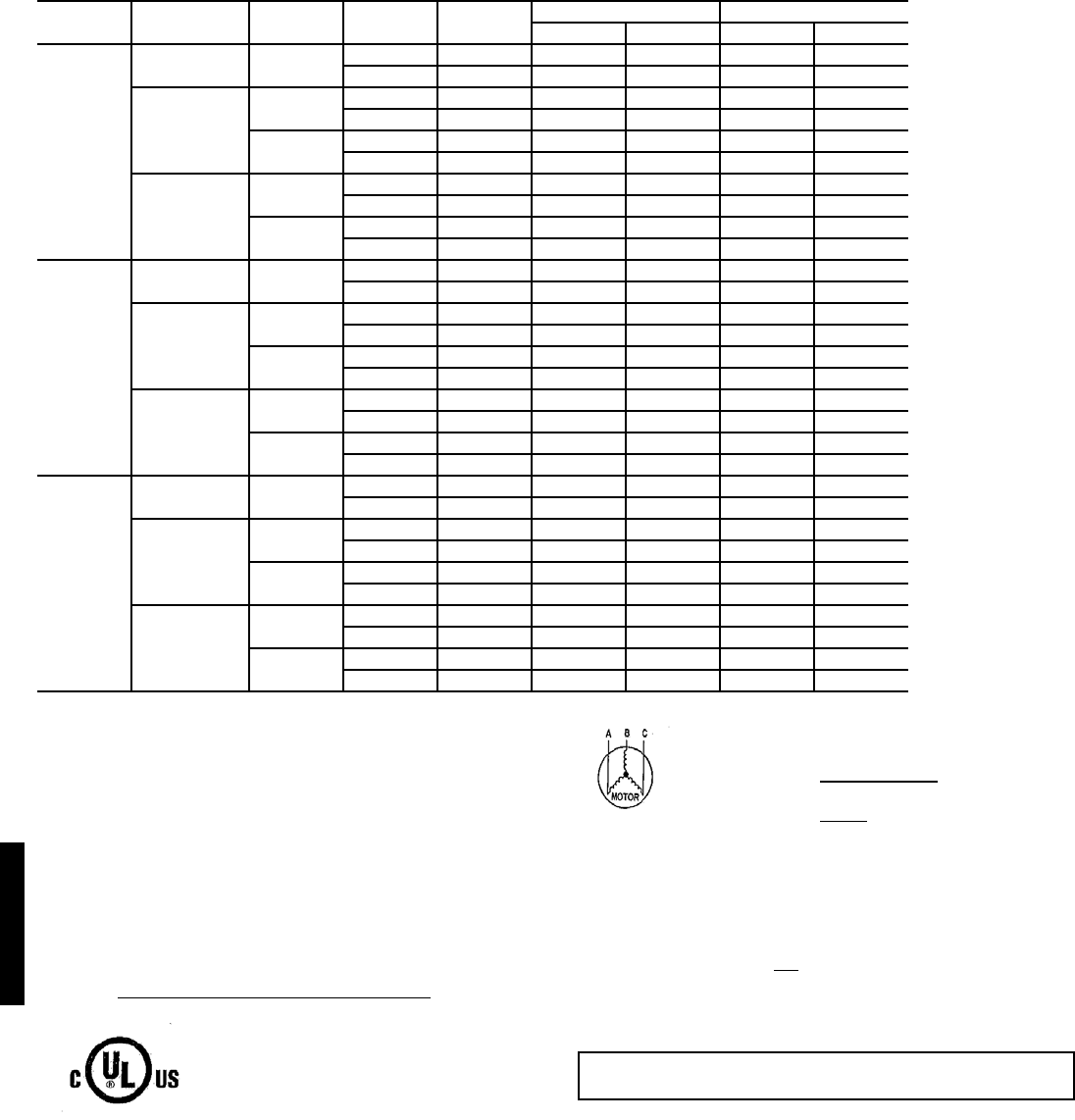
142
COBRA™ ENERGY RECOVERY UNITS (48HE004-006 UNITS WITH 62AQ100)
LEGEND
*Used to determine minimum disconnect per NEC.
NOTES:
1. In compliance with NEC requirements for multimotor and combination load
equipment (refer to NEC Articles 430 and 440), the overcurrent protective
device for the unit shall be fuse or HACR breaker. UL, Canada units may be
fuse or circuit breaker.
2. Unbalanced 3-Phase Supply Voltage
Never operate a motor where a phase imbalance in supply voltage is greater
than 2%. Use the following formula to determine the percent of voltage
imbalance.
Example: Supply voltage is 460-3-60.
AB = 452 v
BC = 464 v
AC = 455 v
= 457
Determine maximum deviation from average voltage.
(AB) 457 – 452 = 5 v
(BC) 464 – 457 = 7 v
(AC) 457 – 455 = 2 v
Maximum deviation is 7 v.
Determine percent of voltage imbalance.
% Voltage Imbalance = 100 x
= 1.53%
This amount of phase imbalance is satisfactory as it is below the maximum allow-
able 2%.
BASE
UNIT SIZE
N O M I N A L
V-PH-Hz IFM TYPE CONV
OUTLET
62AQ
FLA
POWER SUPPLY * DISCONNECT SIZE
MCA MOCP ** FLA LRA
004
208/230-1-60 STD NO 15.1 40.7 45 42 161
YES 15.1 46.7 50 48 166
208/230-3-60
STD NO 15.1 33.6 40 36 150
YES 15.1 39.6 45 41 155
HS NO 15.1 34.5 40 37 180
YES 15.1 40.5 45 42 184
460-3-60
STD NO 15.1 16.5 20 18 76
YES 15.1 19.2 20 20 78
HS NO 15.1 16.9 20 18 90
YES 15.1 19.6 25 20 93
005
208/230-1-60 STD NO 15.1 47.8 60 49 190
YES 15.1 53.8 60 54 195
208/230-3-60
STD NO 15.1 39.1 45 41 170
YES 15.1 45.1 50 46 175
HS NO 15.1 40.0 45 42 200
YES 15.1 46.0 50 48 205
460-3-60
STD NO 15.1 19.4 25 20 83
YES 15.1 22.1 25 23 85
HS NO 15.1 19.8 25 21 97
YES 15.1 22.5 25 23 100
006
208/230-1-60 STD NO 15.1 54.5 70 55 247
YES 15.1 60.5 70 61 251
208/230-3-60
STD NO 15.1 44.0 50 46 228
YES 15.1 50.0 60 51 233
HS NO 15.1 45.7 60 48 247
YES 15.1 51.7 60 53 252
460-3-60
STD NO 15.1 21.5 25 22 122
YES 15.1 24.2 30 25 125
HS NO 15.1 22.3 25 23 132
YES 15.1 25.0 30 26 134
FLA — Full Load Amps
HACR — Heating, Air Conditioning and Refrigeration
IFM — Indoor (Evaporator) Fan Motor
LRA — Locked Rotor Amps
MCA — Minimum Circuit Amps
NEC — National Electrical Code
UL — Underwriters’ Laboratories
= 100 x max voltage deviation from average voltage
average voltage
Average Voltage = 452 + 464 + 455
3
= 1371
3
IMPORTANT: If the supply voltage phase imbalance is more than 2%, contact
your local electric utility company immediately.
7
457
Electrical data — 48HE
48HE
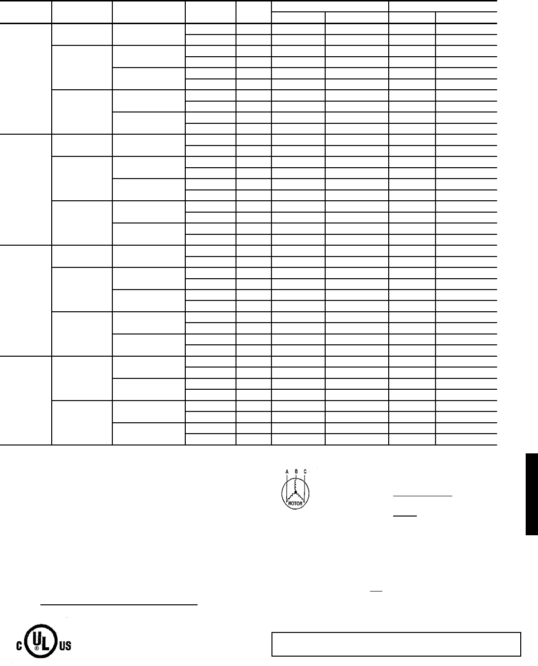
143
COBRA™ ENERGY RECOVERY UNITS (48HJ004-007 UNITS WITH 62AQ060)
LEGEND
*Used to determine minimum disconnect per NEC.
NOTES:
1. In compliance with NEC requirements for multimotor and combination load
equipment (refer to NEC Articles 430 and 440), the overcurrent protective
device for the unit shall be fuse or HACR breaker. UL, Canada units may be
fuse or circuit breaker.
2. Unbalanced 3-Phase Supply Voltage
Never operate a motor where a phase imbalance in supply voltage is greater
than 2%. Use the following formula to determine the percent of voltage
imbalance.
Example: Supply voltage is 460-3-60.
AB = 452 v
BC = 464 v
AC = 455 v
= 457
Determine maximum deviation from average voltage.
(AB) 457 – 452 = 5 v
(BC) 464 – 457 = 7 v
(AC) 457 – 455 = 2 v
Maximum deviation is 7 v.
Determine percent of voltage imbalance.
% Voltage Imbalance = 100 x
= 1.53%
This amount of phase imbalance is satisfactory as it is below the maximum allow-
able 2%.
UNIT SIZE NOMINAL
V-PH-Hz IFM TYPE CONV
OUTLET
62AQ
FLA
POWER SUPPLY* DISCONNECT SIZE
MCA MOCP† FLA LRA
48HJ004
208/230-1-60 STD NO 9.2 34.8/34.8 40/40 35/35 135/135
YES 9.2 40.8/40.8 45/45 41/41 140/140
208/230-3-60
STD NO 9.2 27.7/27.7 35/35 29/29 124/124
YES 9.2 33.7/33.7 40/40 34/34 129/129
HIGH NO 9.2 28.6/28.6 35/35 30/30 154/154
YES 9.2 34.6/34.6 40/40 35/35 158/158
460-3-60
STD NO 9.2 13.6 15 14 63
YES 9.2 16.3 20 17 65
HIGH NO 9.2 14.0 20 15 77
YES 9.2 16.7 20 17 80
48HJ005
208/230-1-60 STD NO 9.2 44.4/44.4 60/60 44/44 173/173
YES 9.2 50.4/50.4 60/60 50/50 178/178
208/230-3-60
STD NO 9.2 31.7/31.7 40/40 33/33 140/140
YES 9.2 37.7/37.7 40/40 38/38 145/145
HIGH NO 9.2 32.6/32.6 40/40 34/34 170/170
YES 9.2 38.6/38.6 45/45 39/39 174/174
460-3-60
STD NO 9.2 15.2 20 16 71
YES 9.2 17.9 20 18 73
HIGH NO 9.2 15.6 20 16 85
YES 9.2 18.3 20 19 87
48HJ006
208/230-1-60 STD NO 9.2 53.3/53.3 70/70 53/53 240/240
YES 9.2 59.3/59.3 70/70 59/59 244/244
208/230-3-60
STD NO 9.2 38.1/38.1 45/45 39/39 202/202
YES 9.2 44.1/44.1 50/50 44/44 207/207
HIGH NO 9.2 39.8/39.8 45/45 41/41 221/221
YES 9.2 45.8/45.8 50/50 46/46 226/226
460-3-60
STD NO 9.2 19.3 25 20 101
YES 9.2 22.0 25 22 104
HIGH NO 9.2 20.1 25 20 111
YES 9.2 22.8 25 23 113
48HJ007
208/230-3-60
STD NO 9.2 42.0/42.0 50/50 42/42 234/234
YES 9.2 48.0/48.0 60/60 48/48 239/239
HIGH NO 9.2 43.7/43.7 50/50 44/44 253/253
YES 9.2 49.7/49.7 60/60 50/50 258/258
460-3-60
STD NO 9.2 19.8 25 20 114
YES 9.2 22.5 25 23 116
HIGH NO 9.2 20.6 25 21 124
YES 9.2 23.3 30 23 126
FLA — Full Load Amps
HACR — Heating, Air Conditioning and Refrigeration
IFM — Indoor (Evaporator) Fan Motor
LRA — Locked Rotor Amps
MCA — Minimum Circuit Amps
NEC — National Electrical Code
UL — Underwriters’ Laboratories
= 100 x max voltage deviation from average voltage
average voltage
Average Voltage = 452 + 464 + 455
3
= 1371
3
IMPORTANT: If the supply voltage phase imbalance is more than 2%, contact
your local electric utility company immediately.
7
457
48HJ
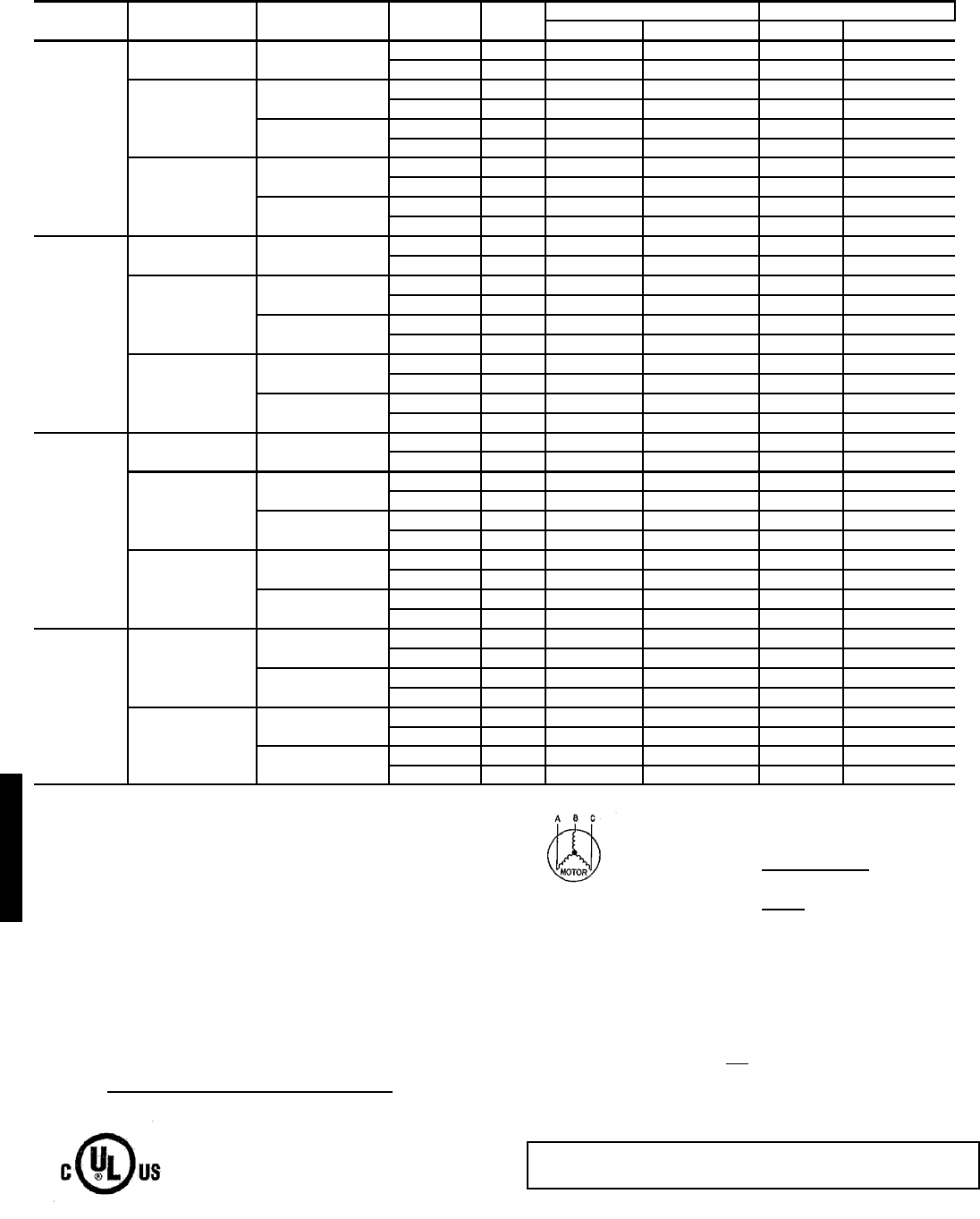
144
COBRA™ ENERGY RECOVERY UNITS (48HJ004-007 UNITS WITH 62AQ100)
LEGEND
*Used to determine minimum disconnect per NEC.
NOTES:
1. In compliance with NEC requirements for multimotor and combina-
tion load equipment (refer to NEC Articles 430 and 440), the overcur-
rent protective device for the unit shall be fuse or HACR breaker. UL,
Canada units may be fuse or circuit breaker.
2. Unbalanced 3-Phase Supply Voltage
Never operate a motor where a phase imbalance in supply voltage is
greater than 2%. Use the following formula to determine the percent
of voltage imbalance.
Example: Supply voltage is 460-3-60.
AB = 452 v
BC = 464 v
AC = 455 v
= 457
Determine maximum deviation from average voltage.
(AB) 457 – 452 = 5 v
(BC) 464 – 457 = 7 v
(AC) 457 – 455 = 2 v
Maximum deviation is 7 v.
Determine percent of voltage imbalance.
% Voltage Imbalance = 100 x
= 1.53%
This amount of phase imbalance is satisfactory as it is below the maxi-
mum allowable 2%.
UNIT SIZE NOMINAL
V-PH-Hz IFM TYPE CONV
OUTLET
62AQ
FLA
POWER SUPPLY* DISCONNECT SIZE
MCA MOCP† FLA LRA
48HJ004
208/230-1-60 STD NO 15.1 40.7/40.7 45/45 42/42 161/161
YES 15.1 46.7/46.7 50/50 48/48 166/166
208/230-3-60
STD NO 15.1 33.6/33.6 40/40 36/36 150/150
YES 15.1 39.6/39.6 45/45 41/41 155/155
HIGH NO 15.1 34.5/34.5 40/40 37/37 180/180
YES 15.1 40.5/40.5 45/45 42/42 184/184
460-3-60
STD NO 15.1 16.5 20 18 76
YES 15.1 19.2 20 20 78
HIGH NO 15.1 16.9 20 18 90
YES 15.1 19.6 25 20 93
48HJ005
208/230-1-60 STD NO 15.1 50.3/50.3 60/60 51/51 199/199
YES 15.1 56.3/56.3 70/70 57/57 204/204
208/230-3-60
STD NO 15.1 37.6/37.6 45/45 39/39 166/166
YES 15.1 43.6/43.6 50/50 45/45 171/171
HIGH NO 15.1 38.5/38.5 45/45 40/40 196/196
YES 15.1 44.5/44.5 50/50 46/46 200/200
460-3-60
STD NO 15.1 18.2 20 19 84
YES 15.1 20.9 25 22 86
HIGH NO 15.1 18.6 25 19 98
YES 15.1 21.3 25 22 100
48HJ006
208/230-1-60 STD NO 15.1 59.2/59.2 70/70 60/60 266/266
YES 15.1 65.2/65.2 80/80 65/65 270/270
208/230-3-60
STD NO 15.1 44.0/44.0 50/50 46/46 228/228
YES 15.1 50.0/50.0 60/60 51/51 233/233
HIGH NO 15.1 45.7/45.7 60/60 48/48 247/247
YES 15.1 51.7/51.7 60/60 53/53 252/252
460-3-60
STD NO 15.1 22.2 25 23 114
YES 15.1 24.9 30 25 117
HIGH NO 15.1 23.0 30 24 124
YES 15.1 25.7 30 26 126
48HJ007
208/230-3-60
STD NO 15.1 47.9/47.9 60/60 49/49 260/260
YES 15.1 53.9/53.9 60/60 55/55 265/265
HIGH NO 15.1 49.6/49.6 60/60 51/51 279/279
YES 15.1 55.6/55.6 60/60 57/57 284/284
460-3-60
STD NO 15.1 22.8 30 23 127
YES 15.1 25.5 30 26 129
HIGH NO 15.1 23.6 30 24 137
YES 15.1 26.3 30 27 139
FLA — Full Load Amps
HACR — Heating, Air Conditioning and Refrigeration
IFM — Indoor (Evaporator) Fan Motor
LRA — Locked Rotor Amps
MCA — Minimum Circuit Amps
NEC — National Electrical Code
UL — Underwriters’ Laboratories
= 100 x max voltage deviation from average voltage
average voltage
Average Voltage = 452 + 464 + 455
3
= 1371
3
IMPORTANT: If the supply voltage phase imbalance is more than
2%, contact your local electric utility company immediately.
7
457
Electrical data — 48HJ (cont)
48HJ
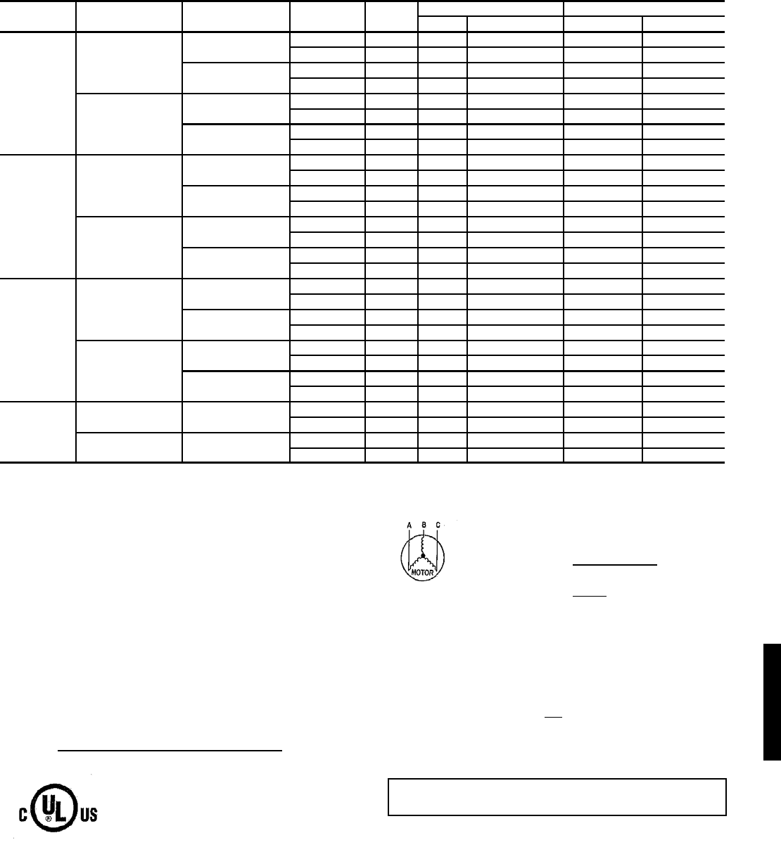
145
COBRA™ ENERGY RECOVERY UNITS (48HJ008-014 UNITS WITH 62AQ200)
LEGEND
*Used to determine minimum disconnect per NEC.
†Single point box with fuse is part of base unit.
NOTES:
1. In compliance with NEC requirements for multimotor and combina-
tion load equipment (refer to NEC Articles 430 and 440), the overcur-
rent protective device for the unit shall be fuse or HACR breaker. UL,
Canada units may be fuse or circuit breaker.
2. Unbalanced 3-Phase Supply Voltage
Never operate a motor where a phase imbalance in supply voltage is
greater than 2%. Use the following formula to determine the percent
of voltage imbalance.
Example: Supply voltage is 460-3-60.
AB = 452 v
BC = 464 v
AC = 455 v
= 457
Determine maximum deviation from average voltage.
(AB) 457 – 452 = 5 v
(BC) 464 – 457 = 7 v
(AC) 457 – 455 = 2 v
Maximum deviation is 7 v.
Determine percent of voltage imbalance.
% Voltage Imbalance = 100 x
= 1.53%
This amount of phase imbalance is satisfactory as it is below the maxi-
mum allowable 2%.
UNIT SIZE NOMINAL
V-PH-HZ IFM TYPE CONV
OUTLET
62AQ
FLA
POWER SUPPLY* DISCONNECT SIZE
MCA MOCP† FLA LRA
48HJ008
208/230-3-60
STD NO 21.9 60.1 70 66 366
YES 21.9 66.1 70 71 371
HIGH NO 21.9 63.2 70 69 391
YES 21.9 69.2 80 75 395
460-3-60
STD NO 10.2 29.4 35 32 184
YES 10.2 32.1 35 34 186
HIGH NO 10.2 30.8 35 34 197
YES 10.2 33.5 35 36 199
48HJ009
208/230-3-60
STD NO 21.9 62.1 70 68 400
YES 21.9 68.1 70 73 405
HIGH NO 21.9 65.2 70 71 425
YES 21.9 71.2 80 77 429
460-3-60
STD NO 10.2 31.7 35 34 206
YES 10.2 34.4 40 37 208
HIGH NO 10.2 33.1 35 36 219
YES 10.2 35.8 40 38 221
48HJ012
208/230-3-60
STD NO 21.9 74.9 80 81 465
YES 21.9 80.9 90 87 469
HIGH NO 21.9 79.3 90 86 488
YES 21.9 85.3 90 92 493
460-3-60
STD NO 10.2 35.1 40 38 234
YES 10.2 37.8 45 40 236
HIGH NO 10.2 37.7 40 41 245
YES 10.2 40.4 45 43 247
48HJ014
208/230-3-60 STD NO 21.9 82.5 90 89 550
YES 21.9 88.5 100 95 555
460-3-60 STD
NO 10.2 39.3 45 43 270
YES 10.2 42.0 50 45 272
FLA — Full Load Amps
HACR — Heating, Air Conditioning and Refrigeration
IFM — Indoor (Evaporator) Fan Motor
LRA — Locked Rotor Amps
MCA — Minimum Circuit Amps
NEC — National Electrical Code
UL — Underwriters’ Laboratories
= 100 x max voltage deviation from average voltage
average voltage
Average Voltage = 452 + 464 + 455
3
= 1371
3
IMPORTANT: If the supply voltage phase imbalance is more than
2%, contact your local electric utility company immediately.
7
457
48HJ
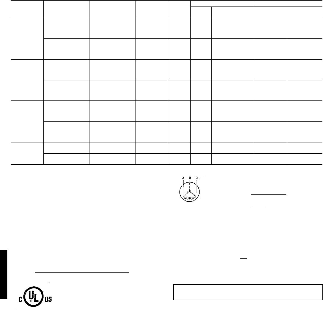
146
COBRA™ ENERGY RECOVERY UNITS (48HJ008-014 UNITS WITH 62AQ300)
LEGEND
*Used to determine minimum disconnect per NEC.
†Single point box with fuse is part of base unit.
NOTES:
1. In compliance with NEC requirements for multimotor and combina-
tion load equipment (refer to NEC Articles 430 and 440), the overcur-
rent protective device for the unit shall be fuse or HACR breaker. UL,
Canada units may be fuse or circuit breaker.
2. Unbalanced 3-Phase Supply Voltage
Never operate a motor where a phase imbalance in supply voltage is
greater than 2%. Use the following formula to determine the percent
of voltage imbalance.
Example: Supply voltage is 460-3-60.
AB = 452 v
BC = 464 v
AC = 455 v
= 457
Determine maximum deviation from average voltage.
(AB) 457 – 452 = 5 v
(BC) 464 – 457 = 7 v
(AC) 457 – 455 = 2 v
Maximum deviation is 7 v.
Determine percent of voltage imbalance.
% Voltage Imbalance = 100 x
= 1.53%
This amount of phase imbalance is satisfactory as it is below the maxi-
mum allowable 2%.
UNIT NOMINAL
V-PH-Hz
IFM
TYPE
CONV
OUTLET
62AQ
FLA
POWER SUPPLY DISCONNECT SIZE*
MCA FUSE OR
HACR BKR FLA LRA
48HJ008
208/230-3-60
STD NO 29.8 68.0 80 75 420
STD YES 29.8 74.0 80 80 425
HIGH STATIC NO 29.8 71.1 80 78 445
HIGH STATIC YES 29.8 77.1 80 84 449
460-3-60
STD NO 15.8 35.0 40 38 211
STD YES 15.8 37.7 40 41 213
HIGH STATIC NO 15.8 36.4 40 40 224
HIGH STATIC YES 15.8 39.1 45 43 226
48HJ009
208/230-3-60
STD NO 29.8 70.0 80 77 454
STD YES 29.8 76.0 80 82 459
HIGH STATIC NO 29.8 73.1 80 80 479
HIGH STATIC YES 29.8 79.1 80 86 483
460-3-60
STD NO 15.8 37.3 40 41 233
STD YES 15.8 40.0 45 43 235
HIGH STATIC NO 15.8 38.7 45 42 246
HIGH STATIC YES 15.8 41.4 45 45 248
48HJ012
208/230-3-60†
STD NO 29.8 82.8 90 90 519
STD YES 29.8 88.8 100 96 523
HIGH STATIC NO 29.8 87.2 100 95 542
HIGH STATIC YES 29.8 93.2 100 101 547
460-3-60
STD NO 15.8 40.7 45 44 261
STD YES 15.8 43.4 45 47 263
HIGH STATIC NO 15.8 43.3 50 47 272
HIGH STATIC YES 15.8 46.0 50 50 274
48HJ014
208/230-3-60† STD NO 29.8 90.4 100 98 604
STD YES 29.8 96.4 100 104 609
460-3-60 STD NO 15.8 44.9 50 49 297
STD YES 15.8 47.6 50 51 299
FLA — Full Load Amps
HACR — Heating, Air Conditioning and Refrigeration
IFM — Indoor (Evaporator) Fan Motor
LRA — Locked Rotor Amps
MCA — Minimum Circuit Amps
NEC — National Electrical Code
UL — Underwriters’ Laboratories
= 100 x max voltage deviation from average voltage
average voltage
Average Voltage = 452 + 464 + 455
3
= 1371
3
IMPORTANT: If the supply voltage phase imbalance is more than
2%, contact your local electric utility company immediately.
7
457
Electrical data — 48HJ (cont)
48HJ
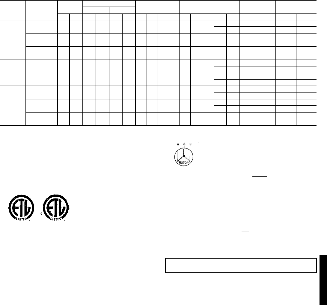
147
ELECTRICAL DATA — 48HJ015,017
LEGEND
*Fuse or HACR circuit breaker.
NOTES:
1. In compliance with NEC requirements for multimotor and combina-
tion load equipment (refer to NEC Articles 430 and 440), the over-
current protective device for the unit shall be fuse or HACR
breaker. Canadian units may be fuse or circuit breaker.
2. Unbalanced 3-Phase Supply Voltage
Never operate a motor where a phase imbalance in supply voltage
is greater than 2%. Use the following formula to determine the per-
cent of voltage imbalance.
% Voltage Imbalance
Example: Supply voltage is 460-3-60.
AB = 452 v
BC = 464 v
AC = 455 v
= 457
Determine maximum deviation from average voltage.
(AB) 457 – 452 = 5 v
(BC) 464 – 457 = 7 v
(AC) 457 – 455 = 2 v
Maximum deviation is 7 v.
Determine percent of voltage imbalance.
% Voltage Imbalance = 100 x
= 1.53%
This amount of phase imbalance is satisfactory as it is below the
maximum allowable 2%.
UNIT
48HJ
NOMINAL
VOLTAGE
(3 Ph, 60 Hz)
VOLTAGE
RANGE
COMPRESSOR OFM IFM POWER
EXHAUST
COMBUSTION
FAN MOTOR
POWER
SUPPLY
No. 1 No. 2
Min Max RLA LRA RLA LRA Qty Hp FLA (ea) Hp FLA FLA LRA FLA MCA MOCP*
015
(Standard
IFM)
208/230 187 253 20.7 156 20.7 156 3 0.5 1.70 2.9 8.8/ 8.4 — — 0.57 60/60 80/80
4.6 18.8 0.57 65/65 80/80
460 414 506 10.0 75 10.0 75 3 0.5 0.80 2.9 4.2 — — 0.30 29 35
2.3 6.0 0.30 31 40
575 518 633 8.2 54 8.2 54 3 0.5 0.75 3.0 3.9 — — 0.57 25 30
2.1 4.8 0.57 27 30
015
(Optional
IFM)
208/230 187 253 20.7 156 20.7 156 3 0.5 1.70 3.7 10.5/11.0 — — 0.57 62/63 80/80
4.6 18.8 0.57 67/67 80/80
460 414 506 10.0 75 10.0 75 3 0.5 0.80 3.7 4.8 — — 0.30 30 35
2.3 6.0 0.30 32 40
017
208/230 187 253 32.1 195 20.7 156 3 0.5 1.70 5.0 15.8/15.8 — — 0.57 82/82 110/110
4.6 18.8 0.57 86/86 110/110
460 414 506 16.4 95 10.0 75 3 0.5 0.80 5.0 7.9 — — 0.30 41 50
2.3 6.0 0.30 43 50
575 518 633 12.0 80 8.2 54 3 0.5 0.75 5.0 6.0 — — 0.57 31 40
2.1 4.8 0.57 34 45
FLA — Full Load Amps
HACR — Heating, Air Conditioning and Refrigeration
IFM — Indoor (Evaporator) Fan Motor
LRA — Locked Rotor Amps
MCA — Minimum Circuit Amps
MOCP — Maximum Overcurrent Protection
NEC — National Electrical Code
OFM — Outdoor (Condenser) Fan Motor
RLA — Rated Load Amps
= 100 x max voltage deviation from average voltage
average voltage
Average Voltage = 452 + 464 + 455
3
= 1371
3
IMPORTANT: If the supply voltage phase imbalance is more than 2%,
contact your local electric utility company immediately.
7
457
48HJ
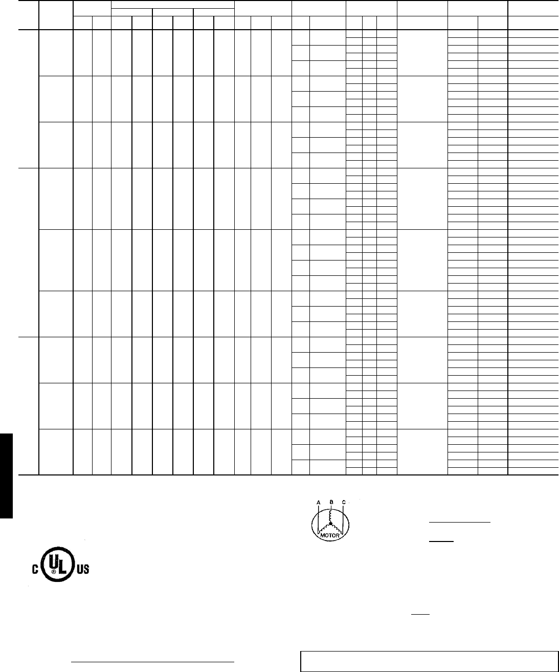
148
ELECTRICAL DATA — 48HJ020-028 WITHOUT CONVENIENCE OUTLET
LEGEND
*Fuse or HACR circuit breaker.
NOTES:
1. In compliance with NEC requirements for multimotor and combination load equipment
(refer to NEC Articles 430 and 440), the overcurrent protective device for the unit shall be
fuse or HACR breaker. Canadian units may be fuse or circuit breaker.
2. Unbalanced 3-Phase Supply Voltage
Never operate a motor where a phase imbalance in supply voltage is greater than 2%.
Use the following formula to determine the percent of voltage imbalance.
% Voltage Imbalance
Example: Supply voltage is 460-3-60.
AB = 452 v
BC = 464 v
AC = 455 v
Determine maximum deviation from average voltage.
(AB) 457 – 452 = 5 v
(BC) 464 – 457 = 7 v
(AC) 457 – 455 = 2 v
Maximum deviation is 7 v.
Determine percent of voltage imbalance.
This amount of phase imbalance is satisfactory as it is below the maximum allowable
2%.
UNIT
48HJ
NOMINAL
VO LTAGE
(3 Ph,
60 Hz)
VOLTAGE
RANGE
COMPRESSOR OFM IFM POWER
EXHAUST
COMBUSTION
FAN MOTOR POWER SUPPLY DISCONNECT
SIZE
No. 1No. 2No. 3
Min Max RLA LRA RLA LRA RLA LRA Qty Hp FLA
(ea) Hp FLA Qty Hp FLA
(ea) FLA MCA MOCP* FLA
020
208/230 187 253 16.7 130 16.7 130 22.4 184 4 0.25 1.5
3.7 10.6/ 9.6 —— —
0.5
78/ 77 100/ 90 83/ 82
2 1 5.9 90/ 89 100/100 97/ 96
5 16.7/15.2 — — — 84/ 83 100/100 90/ 89
2 1 5.9 96/ 94 100/100 104/102
7.5 24.2/22 — — — 92/ 89 100/100 99/ 96
2 1 5.9 104/101 125/110 112/110
460 414 506 9 70 9 70 10.7 90 4 0.25 0.7
3.7 4.8 —— —
0.3
39 45 42
213.1 45 50 49
57.6—— — 42 50 45
213.1 48 50 52
7.5 11 —— — 45 50 49
213.1 51 60 56
575 518 633 7 55 7 55 9.3 73 4 0.25 0.7
33.9—— —
0.24
32 40 35
212.4 37 45 40
56.1—— — 35 40 37
212.4 39 45 43
7.5 9 —— — 37 45 40
212.4 42 50 46
024
208/230 187 253 22.4 184 22.4 184 22.4 184 4 0.25 1.5
3.7 10.6/ 9.6 —— —
0.5
89/ 88 100/100 96/ 95
2 1 5.9 101/100 110/110 110/109
5 16.7/15.2 — — — 96/ 94 100/100 103/102
2 1 5.9 107/106 125/125 117/115
7.5 24.2/22 — — — 103/101 125/110 112/109
2 1 5.9 115/113 125/125 126/123
10 30.8/28 — — — 112/108 125/125 120/116
2 1 5.9 124/120 150/125 133/130
460 414 506 10.7 90 10.7 90 10.7 90 4 0.25 0.7
3.7 4.8 —— —
0.3
42 50 46
213.1 49 50 53
57.6—— — 45 50 49
213.1 51 60 56
7.5 11 —— — 49 50 53
213.1 55 60 60
10 14 —— — 52 60 56
213.1 59 60 63
575 518 633 9.3 73 9.3 73 9.3 73 4 0.25 0.7
56.1—— —
0.24
39 45 42
212.4 44 50 48
7.5 9 —— — 42 50 46
212.4 47 50 51
10 11 —— — 44 50 48
212.4 49 60 53
028
208/230 187 253 47.1 245 47.1 245 — — 6 0.25 1.5
5 16.7/15.2 —— —
0.5
132/130 175/175 138/136
2 1 5.9 143/142 175/175 151/150
7.5 24.2/22 — — — 139/137 175/175 147/144
2 1 5.9 151/149 175/175 160/158
10 30.8/28 — — — 146/143 175/175 154/151
2 1 5.9 158/155 200/200 168/164
460 414 506 19.6 125 19.6 125 — — 6 0.25 0.7
57.6—— —
0.3
56 60 59
213.1 62 80 66
7.5 11 —— — 59 60 63
213.1 66 80 70
10 14 —— — 62 80 66
213.1 69 80 73
575 518 633 15.8 100 15.8 100 — — 6 0.25 0.7
56.1—— —
0.24
46 60 48
212.4 51 60 54
7.5 9 —— — 49 60 52
212.4 54 60 57
10 11 —— — 51 60 54
212.4 56 60 59
FLA — Full Load Amps MCA — Minimum Circuit Amps
HACR — Heating, Air Conditioning and MOCP— Maximum Overcurrent Protection
Refrigeration NEC — National Electrical Code
IFM — Indoor (Evaporator) Fan Motor OFM — Outdoor (Condenser) Fan Motor
LRA — Locked Rotor Amps RLA — Rated Load Amps
MCA — Minimum Circuit Amps
= 100 x max voltage deviation from average voltage
average voltage
Average Voltage = 452 + 464 + 455
3
= 1371
3
= 457
% Voltage Imbalance = 100 x 7
457
= 1.53%
IMPORTANT: If the supply voltage phase imbalance is more than 2%, contact your local
electric utility company immediately.
Electrical data — 48HJ (cont)
48HJ
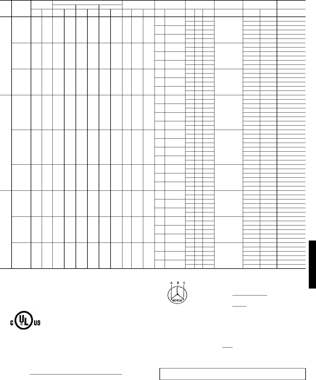
149
ELECTRICAL DATA — 48HJ020-028 WITH OPTIONAL CONVENIENCE OUTLET
LEGEND
*Fuse or HACR circuit breaker.
NOTES:
1. In compliance with NEC requirements for multimotor and combination load equipment
(refer to NEC Articles 430 and 440), the overcurrent protective device for the unit shall be
fuse or HACR breaker. Canadian units may be fuse or circuit breaker.
2. Unbalanced 3-Phase Supply Voltage
Never operate a motor where a phase imbalance in supply voltage is greater than 2%.
Use the following formula to determine the percent of voltage imbalance.
% Voltage Imbalance
Example: Supply voltage is 460-3-60.
AB = 452 v
BC = 464 v
AC = 455 v
Determine maximum deviation from average voltage.
(AB) 457 – 452 = 5 v
(BC) 464 – 457 = 7 v
(AC) 457 – 455 = 2 v
Maximum deviation is 7 v.
Determine percent of voltage imbalance.
This amount of phase imbalance is satisfactory as it is below the maximum allowable
2%.
UNIT
48HJ
NOMINAL
VO LTAGE
(3 Ph,
60 Hz)
VOLTAGE
RANGE
COMPRESSOR OFM IFM POWER
EXHAUST
COMBUSTION
FAN MOTOR POWER SUPPLY DISCONNECT
SIZE
No. 1No. 2No. 3
Min Max RLA LRA RLA LRA RLA LRA Qty Hp FLA
(ea) Hp FLA Qty Hp FLA
(ea) FLA MCA MOCP* FLA
020
208/230 187 253 16.7 130 16.7 130 22.4 184 4 0.25 1.5
3.7 10.6/ 9.6 —— —
0.5
83/ 82 100/100 89/ 88
2 1 5.9 95/ 94 100/100 103/101
5 16.7/15.2 — — — 89/ 88 100/100 96/ 94
2 1 5.9 101/ 99 110/100 110/108
7.5 24.2/22 — — — 97/ 94 100/100 105/102
2 1 5.9 109/106 125/125 118/116
460 414 506 9 70 9 70 10.7 90 4 0.25 0.7
3.7 4.8 —— —
0.3
42 50 45
213.1 48 50 52
57.6—— — 45 50 48
213.1 51 60 56
7.5 11 —— — 48 50 52
213.1 54 60 59
575 518 633 7 55 7 55 9.3 73 4 0.25 0.7
33.9—— —
0.24
35 40 38
212.4 40 45 43
56.1—— — 38 45 40
212.4 42 50 46
7.5 9 —— — 40 45 44
212.4 45 50 49
024
208/230 187 253 22.4 184 22.4 184 22.4 184 4 0.25 1.5
3.7 10.6/ 9.6 —— —
0.5
94/ 93 100/100 102/101
2 1 5.9 106/105 125/125 116/115
5 16.7/15.2 — — — 101/ 99 110/100 109/107
2 1 5.9 112/111 125/125 123/121
7.5 24.2/22 — — — 108/106 125/125 118/115
2 1 5.9 120/118 125/125 131/129
10 30.8/28 — — — 117/113 125/125 125/122
2 1 5.9 129/125 150/150 139/136
460 414 506 10.7 90 10.7 90 10.7 90 4 0.25 0.7
3.7 4.8 —— —
0.3
45 50 49
213.1 52 60 56
57.6—— — 48 50 52
213.1 54 60 59
7.5 11 —— — 52 60 56
213.1 58 60 63
10 14 —— — 55 60 60
213.1 62 70 67
575 518 633 9.3 73 9.3 73 9.3 73 4 0.25 0.7
56.1—— —
0.24
42 50 46
212.4 47 50 51
7.5 9 —— — 45 50 49
212.4 50 50 55
10 11 —— — 47 50 51
212.4 52 60 57
028
208/230 187 253 47.1 245 47.1 245 — — 6 0.25 1.5
5 16.7/15.2 —— —
0.5
137/135 175/175 144/142
2 1 5.9 148/147 175/175 157/155
7.5 24.2/22 — — — 144/142 175/175 152/150
2 1 5.9 156/154 200/200 166/163
10 30.8/28 — — — 151/148 175/175 160/157
2 1 5.9 163/160 200/200 173/170
460 414 506 19.6 125 19.6 125 — — 6 0.25 0.7
57.6—— —
0.3
59 60 62
213.1 65 80 69
7.5 11 —— — 62 80 66
213.1 69 80 73
10 14 —— — 65 80 69
213.1 72 90 77
575 518 633 15.8 100 15.8 100 - - 6 0.25 0.7
56.1—— —
0.24
49 60 52
212.4 54 60 57
7.5 9 —— — 52 60 55
212.4 57 60 60
10 11 —— — 54 60 57
212.4 59 60 63
FLA — Full Load Amps MCA — Minimum Circuit Amps
HACR — Heating, Air Conditioning and MOCP— Maximum Overcurrent Protection
Refrigeration NEC — National Electrical Code
IFM — Indoor (Evaporator) Fan Motor OFM — Outdoor (Condenser) Fan Motor
LRA — Locked Rotor Amps RLA — Rated Load Amps
MCA — Minimum Circuit Amps
= 100 x max voltage deviation from average voltage
average voltage
Average Voltage = 452 + 464 + 455
3
= 1371
3
= 457
% Voltage Imbalance = 100 x 7
457
= 1.53%
IMPORTANT: If the supply voltage phase imbalance is more than 2%, contact your local
electric utility company immediately.
48HJ
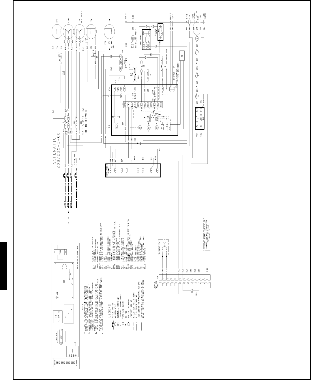
150
SIZES 003-007 (48HJ004-005, 208/230-3-60 SHOWN)
Typical wiring schematics — 48HJ
48HJ
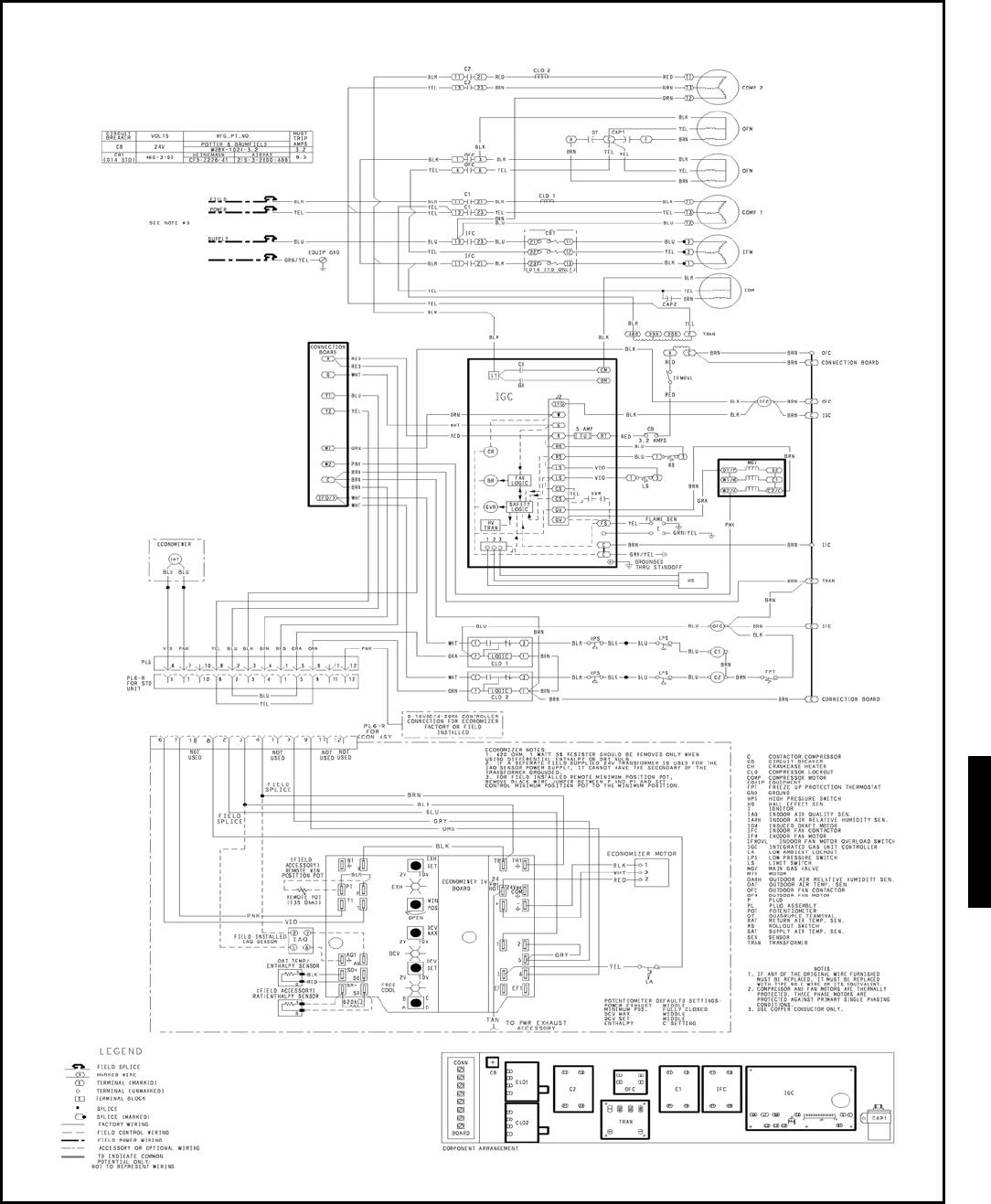
151
SIZES 008-014 (48HJ008-014, 460-3-60 SHOWN)
48HJ
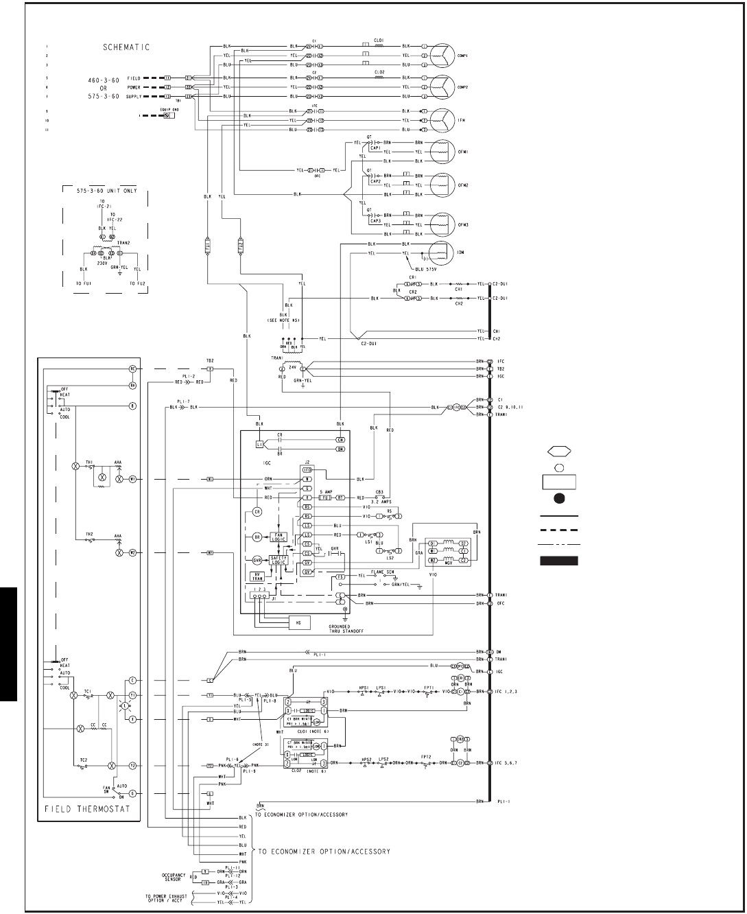
152
LEGEND
AHA — Adjustable Heat Anticipator
C—Contactor, Compressor
CAP — Capacitor
CB — Circuit Breaker
CC — Cooling Compensator
CH — Crankcase Heater
CLO — Compressor Lockout
COMP — Compressor Motor
CR — Control Relay
DM — Damper Motor
DU — Dummy Terminal
EQUIP — Equipment
FPT — Freeze Protection Thermostat
FU — Fuse
GND — Ground
HPS — High-Pressure Switch
HS — Hall Effect Sensor
HV — High Voltage
I—Ignitor
IDM — Induced Draft Motor
IFC — Indoor Fan Contactor
IFCB — Indoor Fan Circuit Breaker
IFM — Indoor (Evaporator) Fan Motor
IGC — Integrated Gas Unit Controller
L—Light
LOR — Lockout Relay
LPS — Low-Pressure Switch
LS — Limit Switch
MGV — Main Gas Valve
OFC — Outdoor Fan Contactor
OFM — Outdoor Fan Motor
PL — Plug Assembly
PRI — Primary
QT — Quadruple Terminal
RS — Rollout Switch
SEN — Sensor
SW — Switch
TB — Terminal Block
TC — Thermostat-Cooling
TH — Thermostat-Heating
TRAN — Transformer
Terminal (Marked)
Te rminal (Unmarked)
Terminal Block
Splice
Factory Wiring
Field Wiring
Option/Accessory Wiring
To indicate common potential
only. Not to represent wiring.
SIZES 015,017 (48HJ015, 460-3-60 SHOWN)
Typical wiring schematics — 48HJ (cont)
48HJ
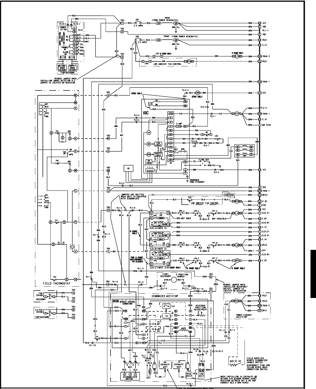
153
LOW VOLTAGE CONTROL SCHEMATIC — 48HJ020-028
48HJ
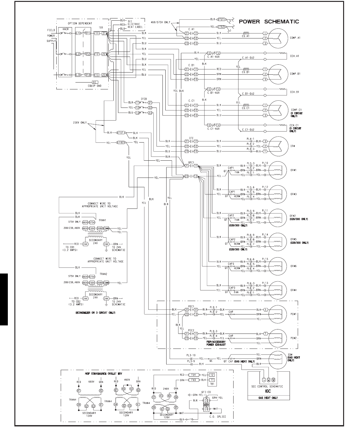
154
POWER SCHEMATIC — 48HJ020-028
Typical wiring schematics — 48HJ (cont)
48HJ
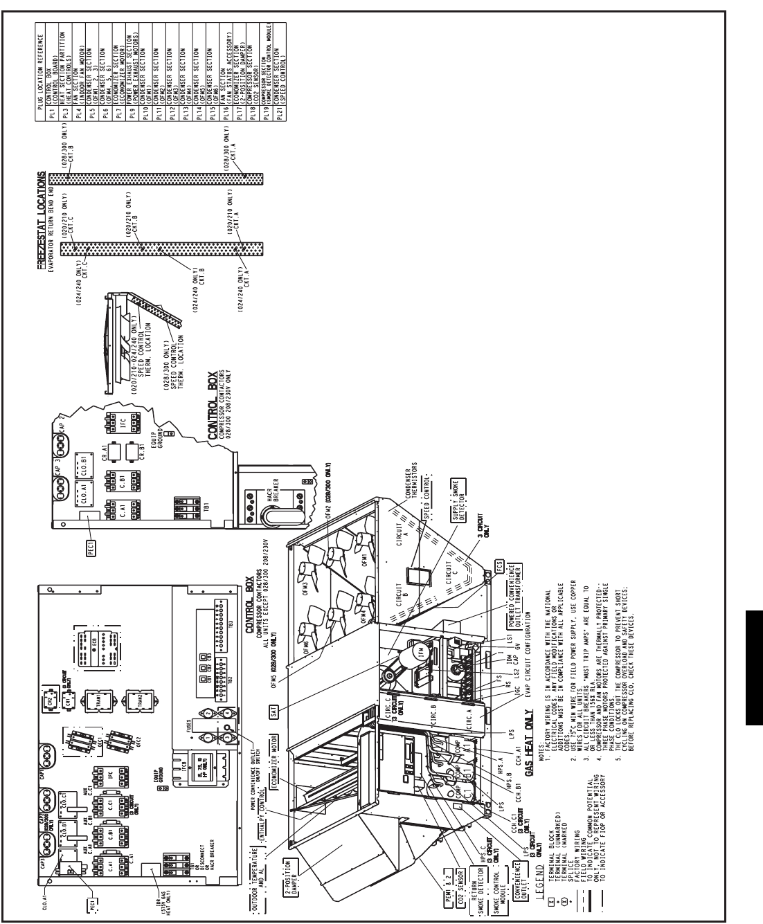
155
CO
M
PO N
E
NT A RRANG
E
M
E
NT
—
4 8 HJ020- 028
---A — Circuit A
AUX — Auxiliary Contact
AL — Ambient Limit
---B — Circuit B
---C — Circuit C
C—Compressor, Contactor
CAP — Capacitor
CB — Circuit Breaker
CCH — Crankcase Heater
CLO — Compressor Lockout
COMP — Compressor
CR — Control Relay
ECB — Economizer Control Board
FCS — Fan Cycling Switch
FIOP — Factory-Installed Option
FPT — Freeze Protect Thermostat
FS — Flame Sensor
GV — Gas Valve
HACR — Heating, Air Conditioning,
and Refrigeration
THERMOSTAT/IGC MARKINGS
BM — Blower Motor
C—Common
CM — Combustion Motor
CS — Centrifugal Switch
G—Fan
IFO — Indoor Fan On
L1 — Line 1
R—Thermostat Power
RT — Power Supply
SS — Speed Sensor
W—Thermostat Heat
W1 — 1st Stage of Heating
W2 — 2nd Stage of Heating
X—Alarm Output
Y1 — 1st Stage of Cooling
Y2 — 2nd Stage of Cooling
HPS — High-Pressure Switch
I—Ignitor
IAQ — Indoor Air Quality
IDM — Induced Draft Motor
IDR — Induced Draft Relay
IFC — Indoor Fan Contactor
IFCB — Indoor Fan Circuit Breaker
IFM — Indoor Fan Motor
IGC — Integrated Gas Controller
LPS — Low-Pressure Switch
LS — Limit Switch
OAT — Outdoor Air Temperature
OFC — Outdoor Fan Contactor
OFM — Outdoor Fan Motor
PEC — Power Exhaust Contactor
PEM — Power Exhaust Motor
PL — Plug
RS — Rollout Switch
SAT — Supply-Air Temperature
TB — Te r m i n a l B l o c k
TRAN — Transformer
LEGEND
48HJ
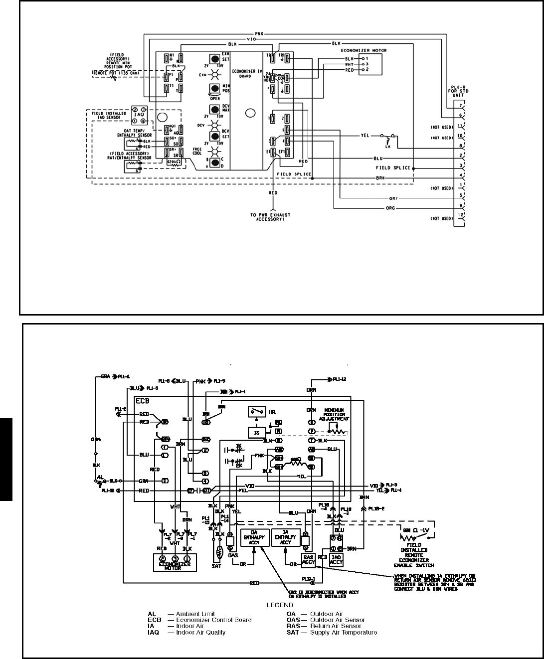
156
ECONOMI$ER IV WIRING — 48HJ004-014 UNITS
ECONOMI$ER IV WIRING — 48HJ015,017 UNITS
NOTES:
Potentiometer Default settings:
Power Exhaust Middle
Minimum Pos. Fully Closed
DCV Max. Middle
DCV Set Middle
Enthalpy C Setting
NOTES:
1. 620 ohm, 1 watt 5% resister schould be removed only when using differential
enthalpy or dry bulb
2. If a seperate field-supplied 24v transfomer is used for the IAQ sensor power
supply, it cannot have the secondary of the transformer grounded.
3. For field-installed remote minimum position POT, remove black wire jumper
between P and P1 and set control minimum position POT to the minimum
position.
LEGEND
IAQ — Indoor Air Quality
LA — Low Ambient Lockout Device
POT — Potentiometer
OAT — Outdoor-Air Tempeture
RAT — Return-Air Temperature
Typical wiring schematics — 48HJ (cont)
48HJ
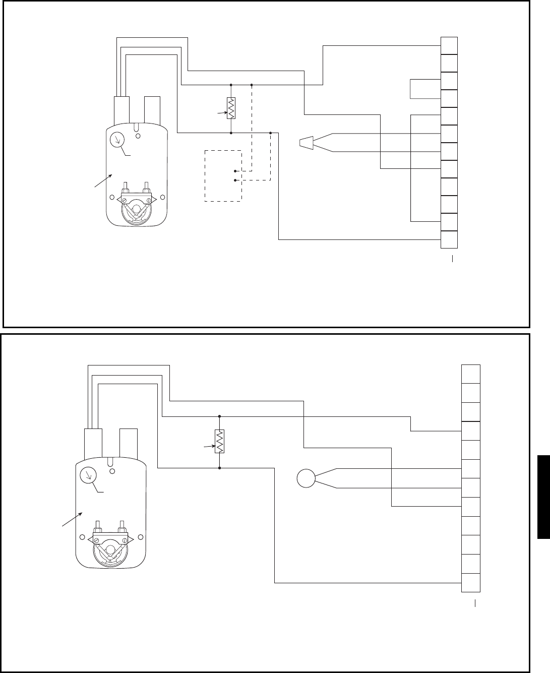
157
ECONOMI$ER2 WIRING — 48HE003-006 and 48HJ004-014 UNITS
ECONOMI$ER2 WIRING — 48HJ015,017 UNITS
NOTES:
1. Switch on actuator must be in run position for economizer to operate.
2. PremierLink™ control requires that the standard 50HJ540569 outside-air sensor be replaced by either the CROASENR001A00 dry bulb sensor or HH57A077
enthalpy sensor.
3. 50HJ540573 actuator consists of the 50HJ540567 actuator and a harness with 500-ohm resistor.
LEGEND
OAT — Outdoor Air Temperature Sensor
NOTES:
1. Switch on actuator must be in run position for economizer to operate.
2. 50HJ540573 actuator consists of the 50HJ540567 actuator and a harness with 500-ohm resistor.
4
3
5
2
8
6
7
1
10
11
9
12
PINK
BLACK
BLUE
NOTE 1
NOTE 2
RUN
500 OHM
RESISTOR
50HJ540573
ACTUATOR
ASSEMBLY
RED
WHITE
ECONOMISER2 PLUG
DIRECT DRIVE
ACTUATOR
OAT
4
3
5
2
8
6
7
1
10
11
9
12
PINK
VIOLET
BLACK
BLUE
YELLOW
NOTE 1
NOTE 3
RUN
500 OHM
RESISTOR
-
+
OPTIONAL CO
SENSOR 4 - 20 mA
OUTPUT
50HJ540573
ACTUATOR
ASSEMBLY
RED
WHITE
ECONOMISER2 PLUG
DIRECT DRIVE
ACTUATOR
2
48HE/HJ
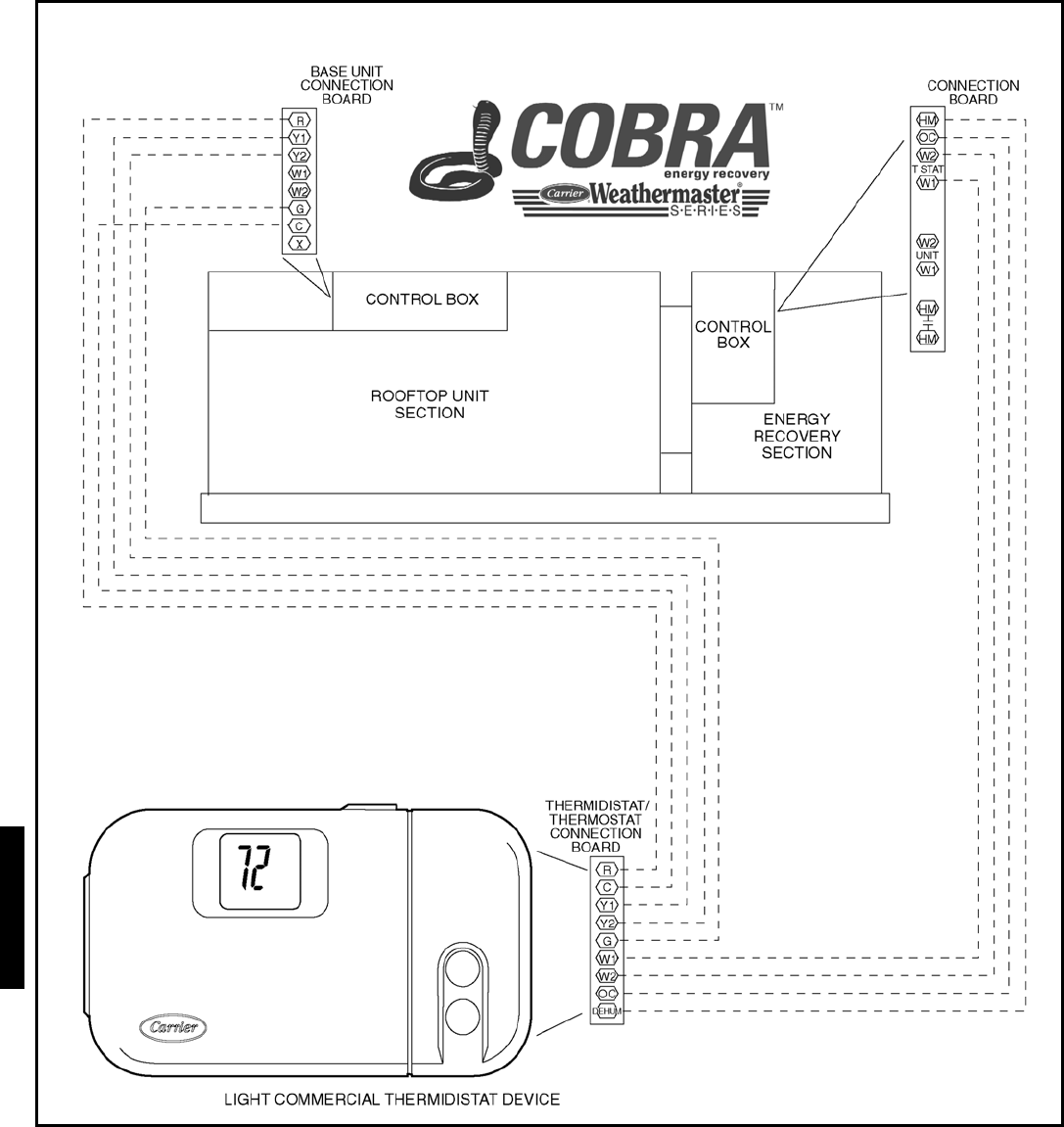
158
TYPICAL COBRA™ ENERGY RECOVERY UNIT CONTROL WIRING
WITH THERMIDISTAT™ DEVICE AND STANDARD CONTROLS
Typical wiring schematics — 48HJ (cont)
48HJ
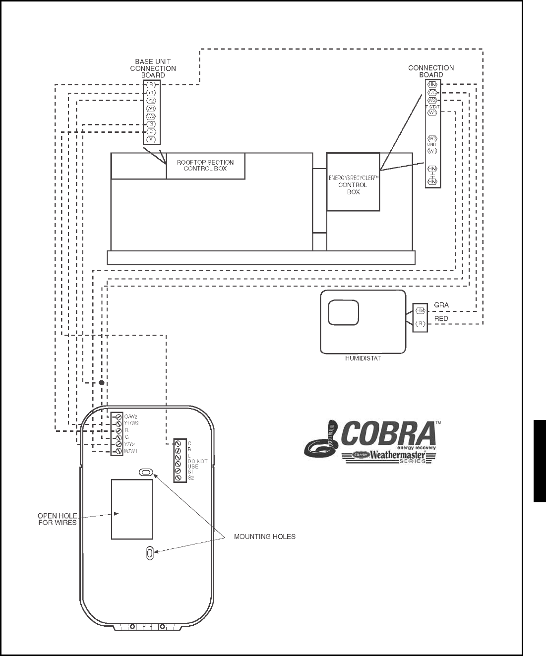
159
TYPICAL COBRA™ ENERGY RECOVERY UNIT CONTROL WIRING WITH DIGITAL THERMOSTAT,
HUMIDISTAT, AND ELECTRO-MECHANICAL CONTROLS
48HJ
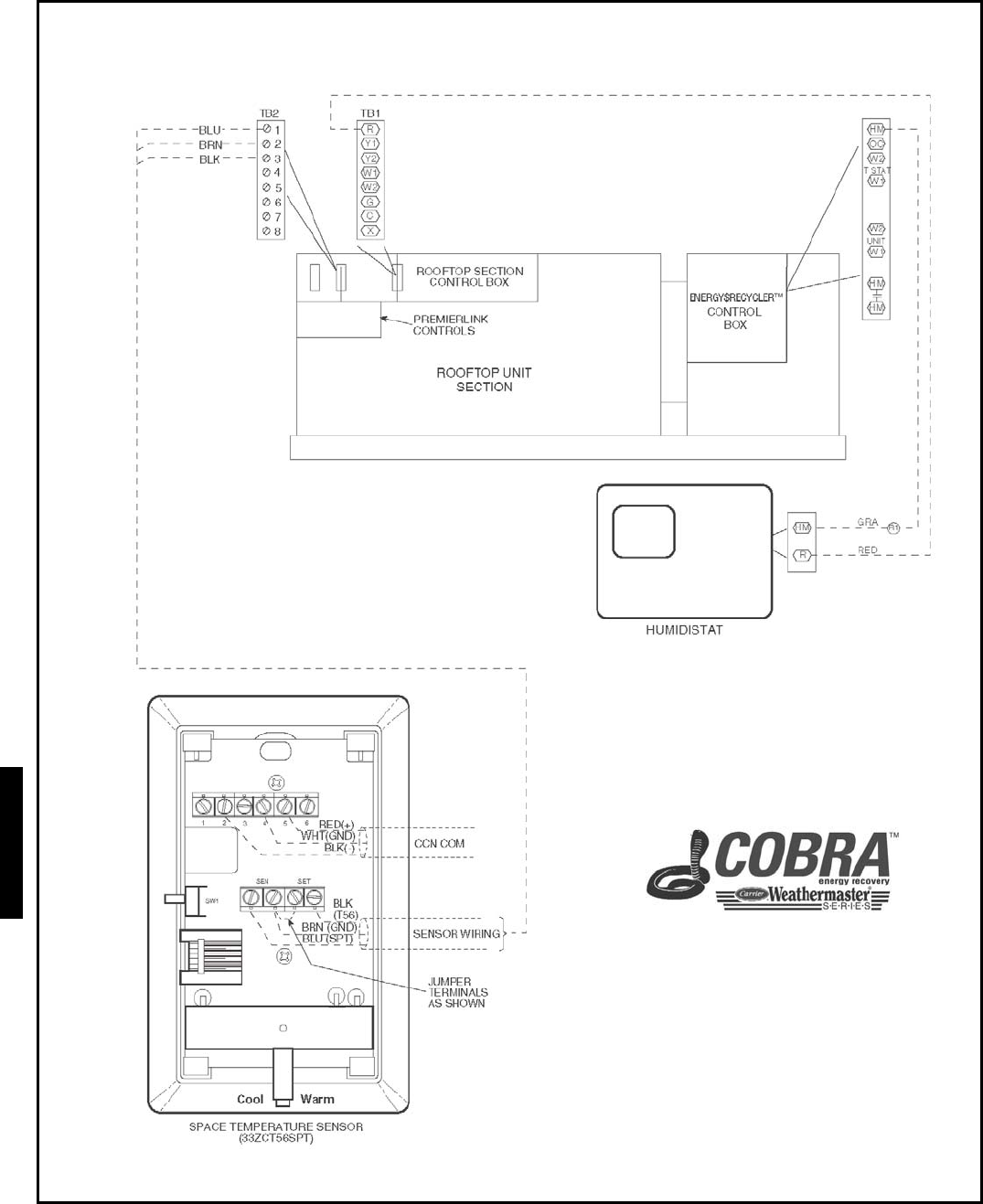
160
TYPICAL COBRA™ ENERGY RECOVERY UNIT CONTROL WIRING WITH HUMIDISTAT,
SPACE TEMPERATURE SENSOR, AND PREMIERLINK™ CONTROLS
Typical wiring schematics — 48HJ (cont)
48HJ
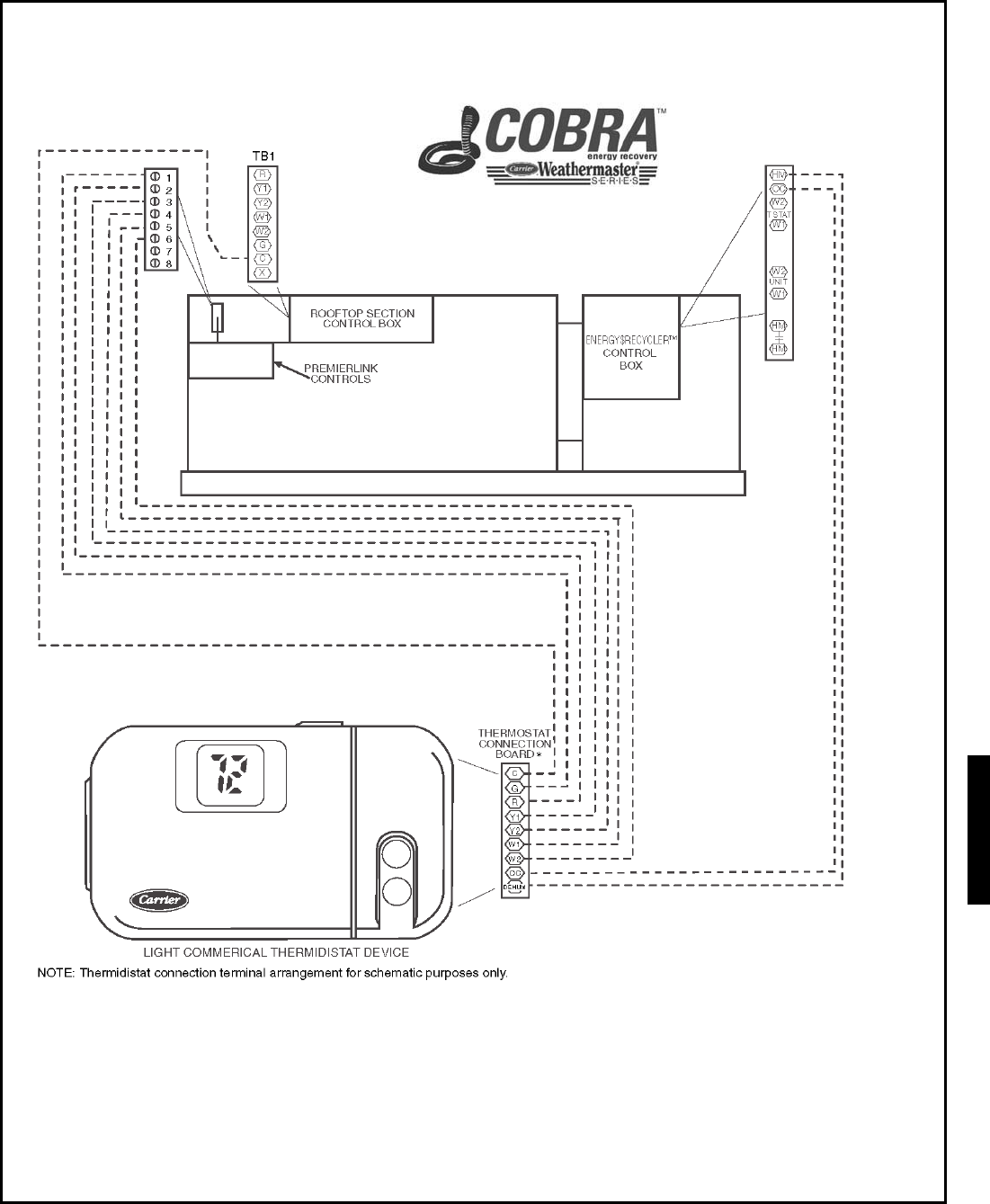
161
TYPICAL COBRA™ ENERGY RECOVERY UNIT CONTROL WIRING WITH THERMIDSTAT™,
AND PREMIERLINK™ CONTROLS
48HJ
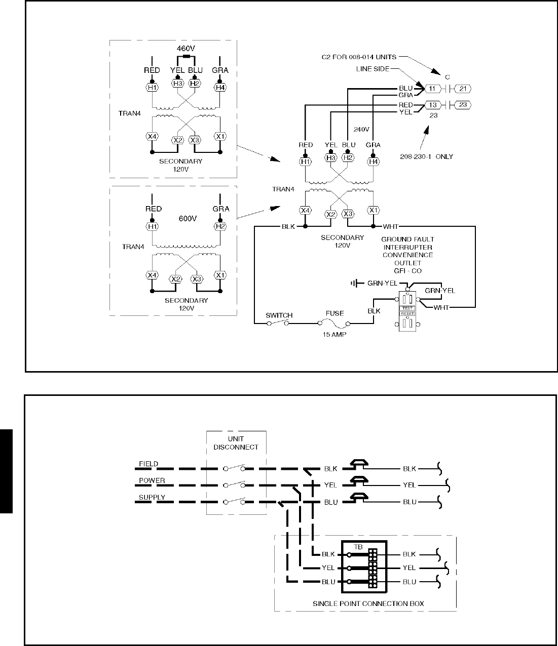
162
CONVENIENCE OUTLET (OPTIONAL) — SIZES 48HJ004-014
NON-FUSED DISCONNECT (OPTIONAL) — SIZES 48HJ004-014
NOTE: Use copper conductors only.
NOTE:
Convenience outlet is intended for intermittent use of service equipment and not as a power source for extended operation of electrical loads.
Typical wiring schematics — 48HJ (cont)
48HJ
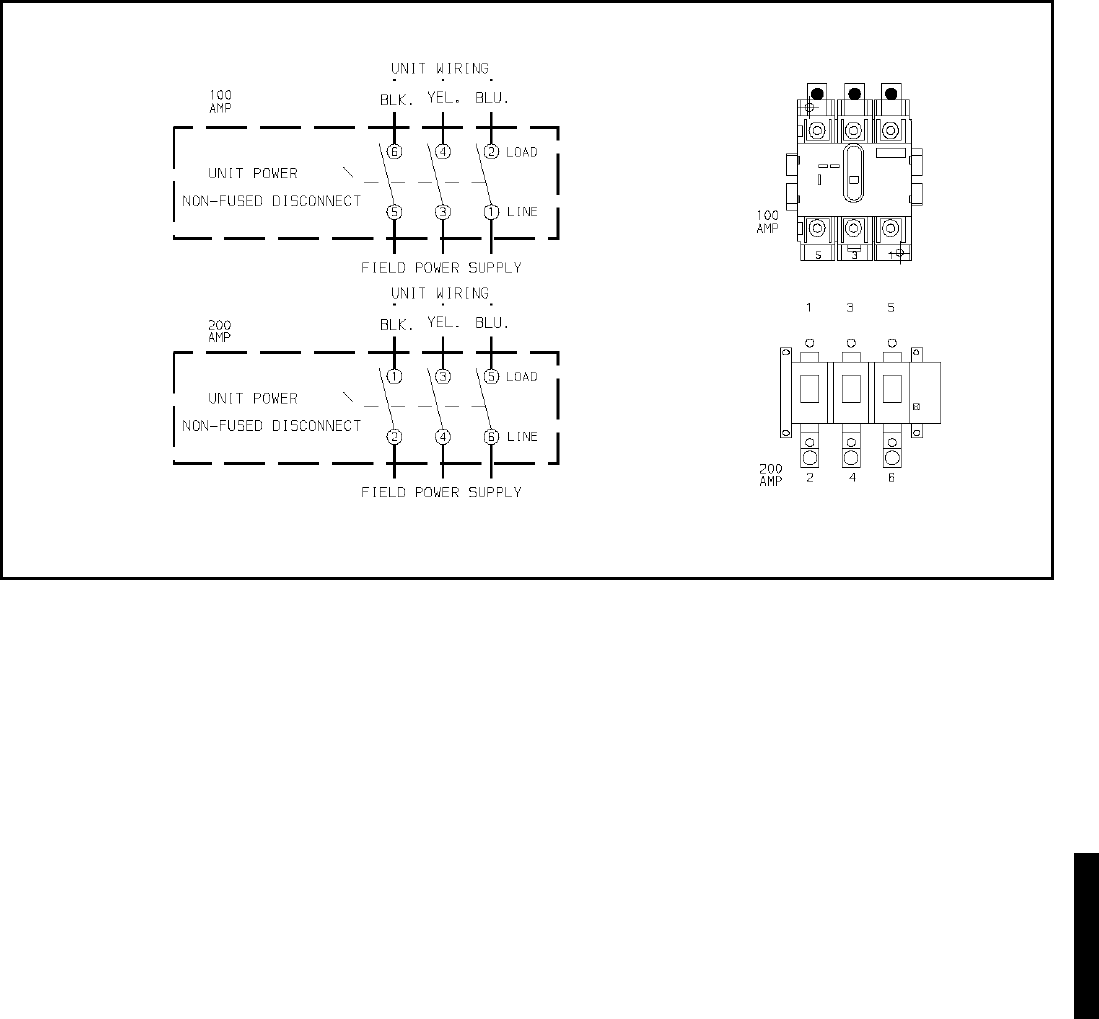
163
NON-FUSED DISCONNECT (OPTIONAL) — 48HJ015,017
NOTES:
1. If the Non-Fused Disconnect Service Option is ordered for size 015,017 units, the Non-Fused Disconnect will be factory-installed.
2. The Disconnect takes the place of TB-1 as shown on the unit wiring diagram label and the component arrangement label.
48HJ
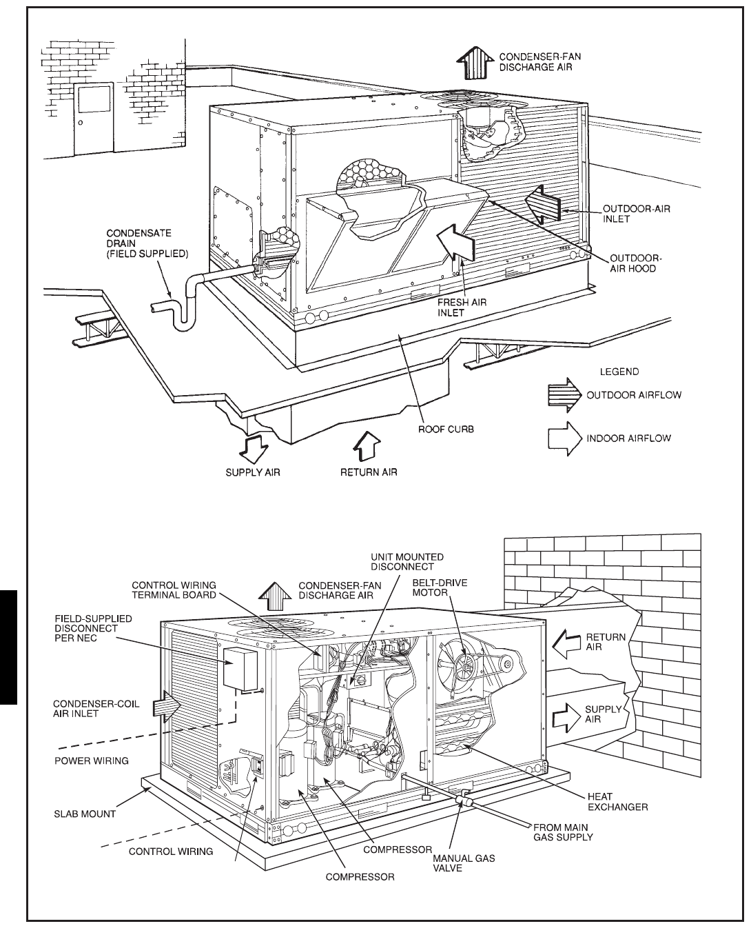
164
VERTICAL DISCHARGE DUCTING
HORIZONTAL DISCHARGE DUCTING
NEC — National Electrical Code
NO.2
NO.1
CONVENIENCE
OUTLET
V
E
RT
I
CA
L
D
I
SCHA RG
E
DUCT
I
NG
HOR
I
Z
ONTA
L
D
I
SCH ARG
E
D UCT
I
NG
NEC — National Electrical Code
Typical piping and wiring — 48HE003-006 and 48HJ004-014
48HJ
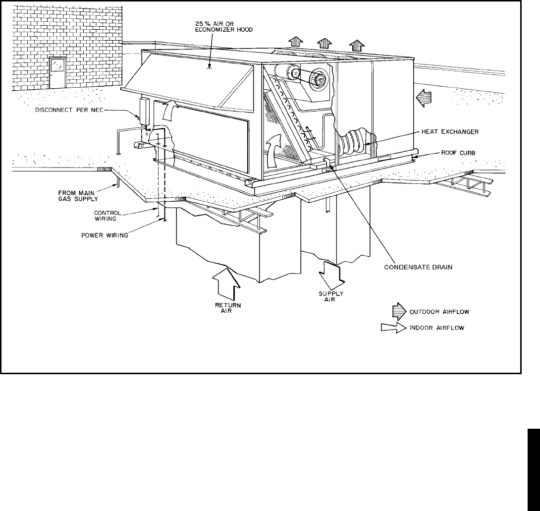
165
LEGEND
NEC — National Electrical Code
Typical piping and wiring — 48HJ015 and 017
48HJ

166
PremierLink™ Direct Digital Controls — The PremierLink
Direct Digital Controls (DDC) require the use of a Carrier elec-
tronic thermostat or a CCN connection for time broadcast to
initiate its internal timeclock. This is necessary for broadcast of
time of day functions (occupied/unoccupied). Refer to Premier-
LinkTM literature for more information
PremierLink Features:
• Equipment Control Functions
Cooling Stages
Heating Stages
Indoor-Fan Motor
4-Way Valve
• Economizer Control Functions
Dry Bulb Control
Enthalpy Control
Differential Enthalpy
Power Exhaust
• Advanced Control Functions
Smoke Detection
Optimal Start (90.1)
Unoccupied Free Cool
Smart Staging and Optimal Staging
• Network Protocol
CCN
Internet Ready 38.4 K baud rate
• Diagnostics/Advanced Service Features
Diagnostics
Onboard display
• Scheduling
Via Communicating Stat
• User Interface
Navigator (LEN protocol)
LID2B (CCN)
PC with Carrier software (CCN)
Indoor Air Quality (IAQ) Monitoring — An indoor air qual-
ity (IAQ) controller will maintain indoor air quality within the
space at the set point level. The set point is calculated from the
differential air quality that is configured by the user. As air
quality within the space changes, the position of the econo-
mizer damper will also change thus allowing more or less out-
door air into the space. If IAQ is configured for low priority, the
positioning of the economizer damper can be overridden by
comfort requirements. If IAQ is configured for high priority,
the controller will check the air quality every 30 seconds and
will perform supply air tempering when in IAQ mode if the fol-
lowing criteria are met:
• IAQ priority is high
• Outdoor temperature is less than 55 F
• Heat and cool set points have not been exceeded
Demand Control Ventilation — Certain criteria must be con-
sidered when using the PremierLink™ controller for demand
control ventilation. When selecting the heating and cooling
capacity of the equipment, the maximum ventilation rate must
be evaluated for design conditions along with the maximum
damper position to achieve desired conditioning of the space.
Typical maximum ventilation rate should be ASHRAE occu-
pied design crfm +5 to 10%.
The PremierLink controller can also provide tempering of the
supply air when the space or return air temperature falls be-
tween the occupied heat and cool set points or there is not a call
for heating or cooling in the Thermostat mode. The maximum
ventilation airflow rate should be checked by evaluating the
unit’s heating capability to raise the supply air to an acceptable
level during tempering of supply air.
After determining the maximum ventilation airflow rate the
IAQ maximum damper configuration needs to be configured.
Demand control ventilation software may be used to assist in
determining the CO2 maximum ventilation recovery rate. The
recovery rate can be accomplished by using either proportion-
al-anticipatory strategy or proportional integral (PI) control.
CCN POINTS FOR PREMIERLINK CONTROL
DESCRIPTION STATUS UNITS POINT LIMITS ACCESS
Space Temperature xxx.x dF SPT –40.0 to 245.0 dF R/W
Supply Air Temperature xxx.x dF SAT –40.0 to 245.0 dF R/W
Outside Air Temperature xxx.x dF OAT –40.0 to 245.0 dF R/W
Control Setpoint xxx.x dF CLSP R
Cooling % Total Capacity xxx % CCAP 0 to 100 % R
Heating % Total Capacity xxx % HCAP 0 to 100 % R
Economizer Active No/Yes ECOS 0 to 1 R
Supply Fan Relay Off/On SF 0 to 1 R/W
Supply Fan Status Off/On SFS 0 to 1 R
Economizer Position xxx.x % ECONPOS 0.0 to 100.0 % R/W
Current Min Damper Pos xxx.x % IQMP 0.0 to 100.0 % R
Filter Status Clean/Dirty FLTS 0 to 1 R/W
Remote Occupied Mode Off/On RMTOCC 0 to 1 R/W
Heat Stage 1 Off/On HS1 0 to 1 R
Heat Stage 2 Off/On HS2 0 to 1 R
Heat 3/Exhaust/Rev Valve Off/On H3_EX_RV 0 to 1 R
Enthalpy Low/High ENTH 0 to 1 R/W
Indoor Air Quality xxxx.x IAQI 0.0 to 5000.0 R/W
Indoor Air Quality Setpt xxxx.x IAQS 0.0 to 5000.0 R
Outdoor Air Quality xxxx.x OAQ 0.0 to 5000.0 R/W
Fire Shutdown Normal/Alarm FSD 0 to 1 R/W
SPT Offset xx.x ^F STO –15.0 to 15.0 ^F R/W
Compressor 1 Off/On CMP1 0 to 1 R
Compressor 2 Off/On CMP2 0 to 1 R
Compressor Safety Off/On CMPSAFE 0 to 1 R
Controls
48HJ
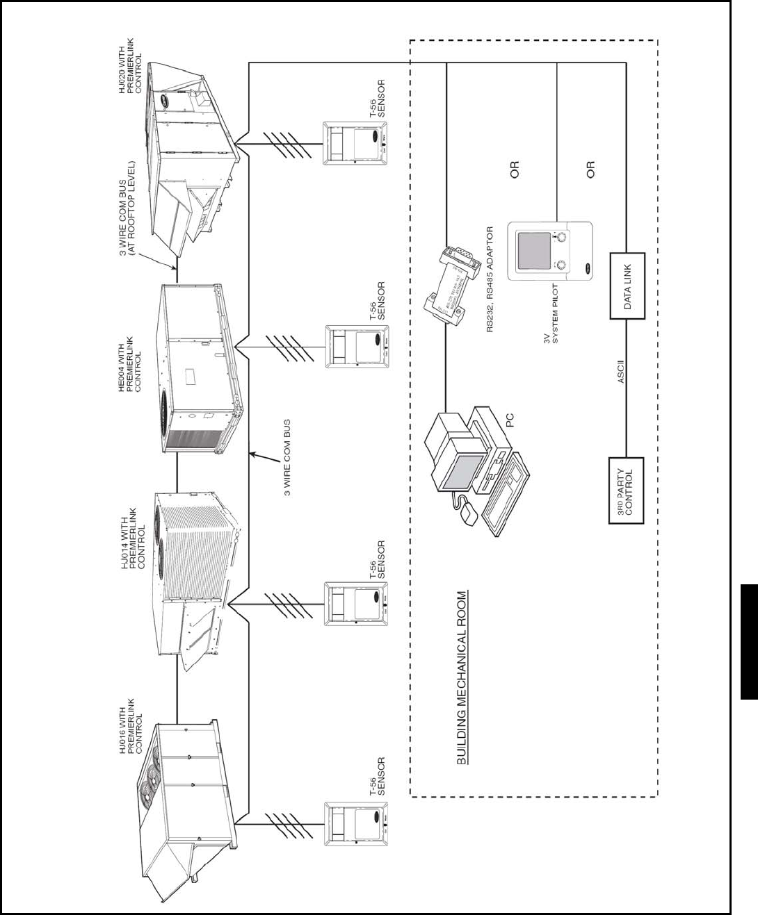
167
CARRIER CONTROL NETWORK
48HJ
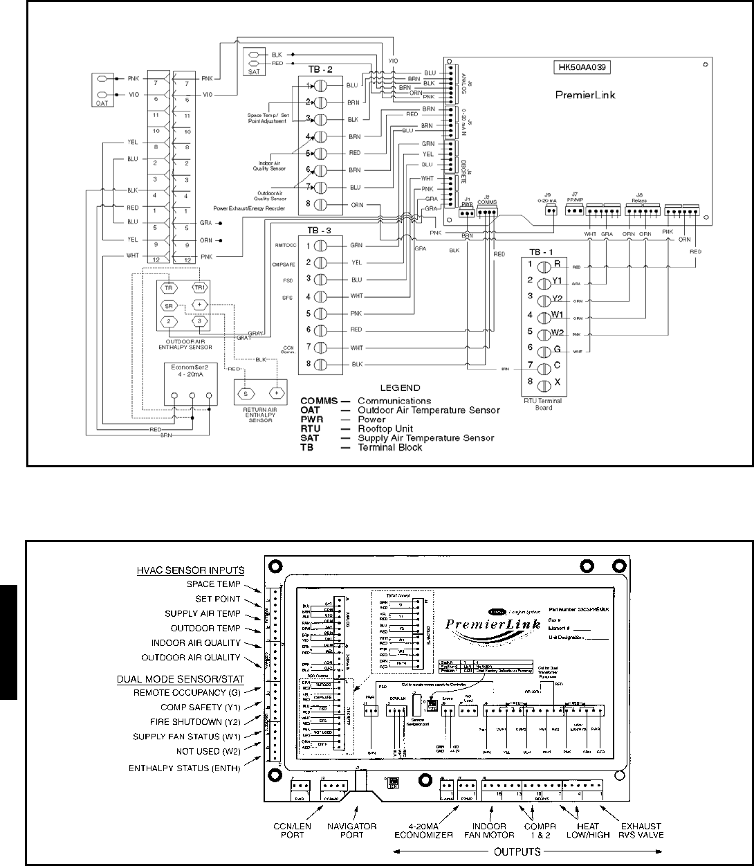
168
TYPICAL PREMIERLINK™ CONTROLS WIRING (48HJ 004-014)
Controls (cont)
48HJ
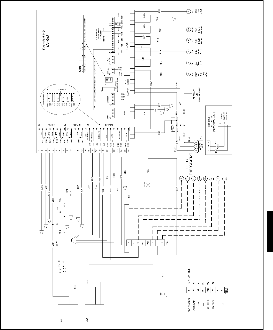
169
TYPICAL PREMIERLINK™ CONTROLS WIRING (48HJ015,017)
48HJ

170
Operating sequence, 48HE003-006, 48HJ 004-014
units
Cooling, units without economizer — When thermostat calls
for cooling, terminals G and Y1 are energized. The indoor-fan
contactor (IFC) and compressor contactor are energized and in-
door-fan motor, compressor, and outdoor fan starts. The out-
door-fan motor runs continuously while unit is cooling.
For units with 2 stages of cooling, if the thermostat calls for
a second stage of cooling by energizing Y2, compressor con-
tactor no. 2 (C2) is energized and compressor no. 2 starts.
Heating, units without economizer — When the thermostat
calls for heating, terminal W1 is energized. To prevent thermo-
stat short-cycling, the unit is locked into the Heating mode for
at least 1 minute when W1 is energized. The induced-draft mo-
tor is energized and the burner ignition sequence begins. The
indoor (evaporator) fan motor (IFM) is energized 45 seconds
after a flame is ignited. On units equipped for two stages of
heat, when additional heat is needed, W2 is energized and the
high-fire solenoid on the main gas valve (MGV) is energized.
When the thermostat is satisfied and W1 is deenergized, the
IFM stops after a 45-second time-off delay.
Cooling, units with EconoMi$er IV — When free cooling is
not available, the compressors will be controlled by the zone
thermostat. When free cooling is available, the outdoor-air
damper is modulated by the EconoMi$er IV control to provide
a 50 to 55 F mixed-air temperature into the zone. As the mixed-
air temperature fluctuates above 55 or below 50 F, the dampers
will be modulated (open or close) to bring the mixed-air tem-
perature back within control.
If mechanical cooling is utilized with free cooling, the
outdoor-air damper will maintain its current position at the time
the compressor is started. If the increase in cooling capacity
causes the mixed-air temperature to drop below 45 F, then the
outdoor-air damper position will be decreased to the minimum
position. If the mixed-air temperature continues to fall, the out-
door-air damper will close. Control returns to normal once the
mixed-air temperature rises above 48 F.
If optional power exhaust is installed, as the outdoor-air
damper opens and closes, the power exhaust fans will be ener-
gized and deenergized.
If field-installed accessory CO2 sensors are connected to the
EconoMi$er IV control, a demand controlled ventilation strate-
gy will begin to operate. As the CO2 level in the zone increases
above the CO2 set point, the minimum position of the damper
will be increased proportionally. As the CO2 level decreases
because of the increase in fresh air, the outdoor-air damper will
be proportionally closed.
For EconoMi$er IV operation, there must be a thermostat
call for the fan (G). If the unit is occupied and the fan is on, the
damper will operate at minimum position. Otherwise, the
damper will be closed.
When the EconoMi$er IV control is in the occupied mode
and a call for cooling exists (Y1 on the thermostat), the control
will first check for indoor fan operation. If the fan is not on,
then cooling will not be activated. If the fan is on, then the con-
trol will open the EconoMi$er IV damper to the minimum po-
sition.
On the initial power to the EconoMi$er IV control, it will
take the damper up to 21/2 minutes before it begins to position
itself. Any change in damper position will take up to 30 sec-
onds to initiate. Damper movement from full closed to full
open (or vice versa) will take between 11/2 and 21/2 minutes.
If free cooling can be used as determined from the appropri-
ate changeover command (switch, dry bulb, enthalpy curve,
differential dry bulb, or differential enthalpy), then the control
will modulate the dampers open to maintain the mixed-air tem-
perature set point at 50 to 55 F.
If there is a further demand for cooling (cooling second stage
— Y2 is energized), then the control will bring on compressor
stage 1 to maintain the mixed-air temperature set point. The
EconoMi$er IV damper will be open at maximum position.
EconoMi$er IV operation is limited to a single compressor.
Heating, units with economizer
NOTE: The units have 2 stages of heat.
When the thermostat calls for heating, power is sent to W1
on the IGC (integrated gas unit controller) board. An LED
(light-emitting diode) on the IGC board will be on during nor-
mal operation. A check is made to ensure that the rollout switch
and limit switch are closed and the induced-draft motor is run-
ning. The induced-draft motor is then energized, and when
speed is proven with the hall effect sensor on the motor, the ig-
nition activation period begins. The burners will ignite within 5
seconds.
If the burners do not light, there is a 22-second delay before
another 5-second attempt. If the burners still do not light, this
sequence is repeated for 15 minutes. After the 15 minutes have
elapsed, if the burners still have not lit, heating is locked out.
To reset the control, break 24-v power to the thermostat.
When ignition occurs the IGC board will continue to monitor
the condition of the rollout and limit switches, the hall effect
sensor, as well as the flame sensor. If the unit is controlled
through a room thermostat set for fan auto., 45 seconds after
ignition occurs, the indoor-fan motor will be energized (and the
outdoor-air dampers will open to their minimum position). If
for some reason the overtemperature limit opens prior to the
start of the indoor fan blower, on the next attempt, the 45-sec-
ond delay will be shortened to 5 seconds less than the time
from initiation of heat to when the limit tripped. Gas will not be
interrupted to the burners and heating will continue. Once mod-
ified, the fan on delay will not change back to 45 seconds
unless power is reset to the control.
When additional heat is required, W2 closes and initiates
power to the second stage of the main gas valve. When the ther-
mostat is satisfied, W1 and W2 open and the gas valve closes,
interrupting the flow of gas to the main burners. If the call for
W1 lasted less than 1 minute, the heating cycle will not termi-
nate until 1 minute after W1 became active. If the unit is con-
trolled through a room thermostat set for fan auto., the indoor-
fan motor will continue to operate for an additional 45 seconds
then stop (and the outdoor-air dampers will close). If the over-
temperature limit opens after the indoor motor is stopped with-
in 10 minutes of W1 becoming inactive, on the next cycle the
time will be extended by 15 seconds. The maximum delay is 3
minutes. Once modified, the fan off delay will not change back
to 45 seconds unless power is reset to the control.
Controls (cont)
48HE/HJ

171
When the thermostat is satisfied and W1 and W2 are deener-
gized, the IFM continues to run and the economizer damper
then moves to the minimum position.
Cooling, units with EconoMi$er2, PremierLink™ control
and a thermostat — When free cooling is not available, the
compressors will be controlled by the PremierLink control in
response to the Y1 and Y2 inputs from the thermostat.
The PremierLink control will use the following information
to determine if free cooling is available:
• Indoor fan has been on for at least 30 seconds.
• The SPT, SAT, and OAT inputs must have valid readings.
• OAT must be less than 75 F.
• OAT must be less than SPT.
• Enthalpy must be LOW (may be jumpered if an enthalpy
sensor not available).
• Economizer position is NOT forced.
Pre-cooling occurs when the is no call from the thermostat
except G. Pre-cooling is defined as the economizer modulates
to provide 70 F supply air.
When free cooling is available the PremierLink control will
control the compressors and economizer to provide a supply-air
temperature determined to meet the Y1 and Y2 calls from the
thermostat.
If optional power exhaust is installed, as the outdoor-air
damper opens and closes, the power exhaust fans will be ener-
gized and deenergized.
If field-installed accessory CO2 sensors are connected to the
PremierLink control, a PID-controlled demand ventilation
strategy will begin to operate. As the CO2 level in the zone in-
creases above the CO2 set point, the minimum position of the
damper will be increased proportionally. As the CO2 level de-
creases because of the increase in fresh air, the outdoor-air
damper will be proportionally closed.
Heating, units with EconoMi$er2, PremierLink control and
a thermostat — When the thermostat calls for heating, termi-
nal W1 is energized. The PremierLink control will move the
economizer damper to the minimum position if there is a call
for G and closed if there is a call for W1 without G. In order to
prevent thermostat from short cycling, the unit is locked into
the heating mode for at least 10 minutes when W1 is energized.
The induced-draft motor is then energized and the burner igni-
tion sequence begins.
On units equipped for two stages of heat, when additional
heat is needed, W2 is energized and the high-fire solenoid on
the main gas valve (MGV) is energized. When the thermostat is
satisfied and W1 is deenergized, the IFM stops after a 45-sec-
ond time-off delay unless G is still maintained.
Cooling, units with EconoMi$er2, PremierLink Control and
a room sensor — When free cooling is not available, the com-
pressors will be controlled by the PremierLink controller using
a PID Error reduction calculation as indicated below.
The PremierLink controller will use the following informa-
tion to determine if free cooling is available:
• Indoor fan has been on for at least 30 seconds.
• The SPT, SAT, and OAT inputs must have valid readings.
• OAT must be less than 75 F.
• OAT must be less than SPT.
• Enthalpy must be LOW (may be jumpered if an enthalpy
sensor is not available).
• Economizer position is NOT forced.
When free cooling is available, the outdoor-air damper is po-
sitioned through the use of a Proportional Integral (PID) con-
trol process to provide a calculated supply-air temperature into
the zone. The supply air will maintain the space temperature
between the heating and cooling set points.
The PremierLink control will integrate the compressors stag-
es with the economizer based on logic built into the controller.
If an optional power exhaust is installed, as the outdoor-air
damper opens and closes, the power exhaust fans will be ener-
gized and deenergized.
If field-installed accessory CO2 sensors are connected to the
PremierLink™ control, a PID-controlled demand ventilation
strategy will begin to operate. As the CO2 level in the zone in-
creases above the CO2 set point, the minimum position of the
damper will be increased proportionally. As the CO2 level de-
creases because of the increase in fresh air, the outdoor-air
damper will be proportionally closed.
Heating, unit with EconoMi$er2, PremierLink control and
a room sensor — Every 40 seconds the controller will calcu-
late the required heat stages (maximum of 3) to maintain Sup-
ply Air Temperature (SAT) if the following qualifying
conditions are met:
• Indoor fan has been on for at least 30 seconds.
• COOL mode is not active.
• OCCUPIED, TEMP.COMPENSATED START or HEAT
mode is active.
• SAT reading is available.
• Fire shutdown mode is not active.
If all of the above conditions are met, the number of heat
stages is calculated; otherwise the required number of heat
stages will be set to 0.
If the PremierLink controller determines that heat stages are
required, the economizer damper will be moved to minimum
position if occupied and closed if unoccupied.
48HJ
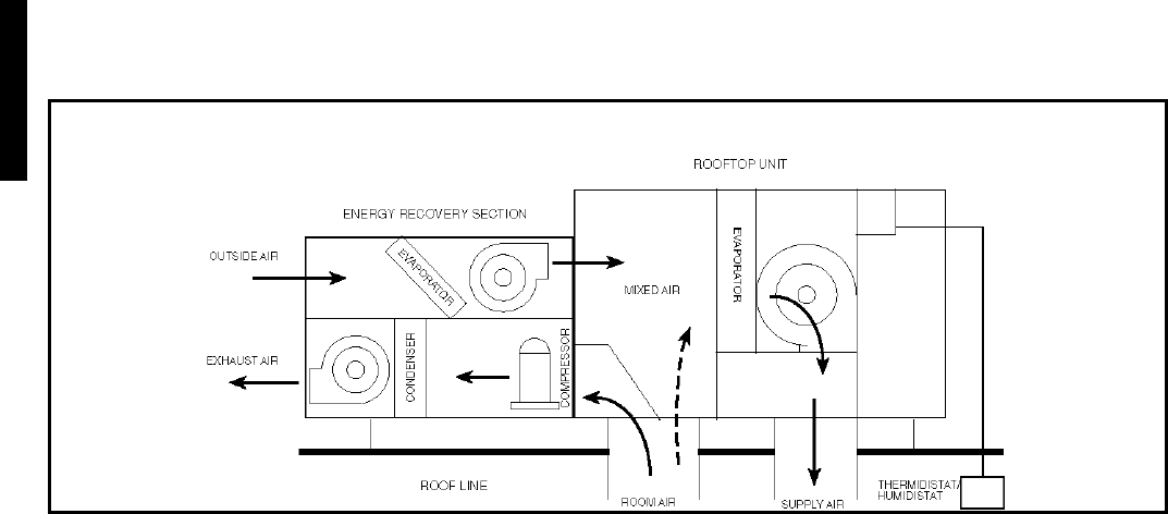
172
Operating sequence, COBRA™ energy
recovery units (48HE003-006 and 48HJ004-014)
Cooling, units with COBRA™ energy recovery — The cool-
ing changeover thermostat located on COBRA energy recovery
unit hood determines when the COBRA energy recovery unit
goes into economizer mode. When the outdoor temperature is
below the cooling set point the unit will be in economizer
mode.
In the unoccupied mode, fans are normally set for AUTO
operation, causing the fans to cycle on only as needed for heat-
ing or cooling. If the Light Commercial Thermidistat™ device
is set for “AUTO” fan, the rooftop unit fan will be off except
when cooling or humidity control is required. The COBRA
energy recovery unit fans will be off except when unit is run-
ning in the economizer mode. If the Light Commercial Thermi-
distat device is set to “ON” for fan, the COBRA energy
recovery unit and rooftop unit fans will run continuously. If
outdoor air is below the outdoor air thermostat set point, the
compressors are locked off and the unit operates in economizer
mode when cooling is required. If outdoor air is unsuitable due
to humidity or quality, the COBRA energy recovery unit is off
and only the rooftop unit compressor runs when cooling is
required. Note that the COBRA energy recovery unit does not
run and dampers are closed when the outdoor air is unsuitable
for cooling and the mode is unoccupied. If outdoor air is suit-
able, first stage cooling is COBRA energy recovery unit in
economizer mode and all compressors are off. Second stage
cooling adds the COBRA energy recovery unit compressor and
rooftop unit compressor no. 1.
In occupied mode, when the COBRA energy recovery unit
compressor runs in cooling mode, it is extracting heat from the
incoming outdoor air and rejecting heat to the exhaust air. The
COBRA energy recovery unit and rooftop unit fans run contin-
uously. On a first stage call, all compressors will be off if the
outdoor air is suitable for free cooling. Otherwise, the COBRA
energy recovery unit compressor and rooftop unit compressor
no. 1 will run whenever there is a first stage demand for cool-
ing. On a second stage call, the COBRA energy recovery unit
compressor and rooftop unit compressor no. 1 and 2 will run
whenever there is a demand for cooling. If there is a demand
for humidity control but not cooling, only the COBRA energy
recovery unit compressor will run. If there is a field-installed
CO2 sensor and the levels are below that sensor set point, then
the unit will operate in the unoccupied mode sequence
(i.e.,COBRA energy recovery unit dampers closed and rooftop
unit operation only to maintain space conditions).
Heating, units with COBRA energy recovery — The heating
changeover thermostat located on the COBRA energy recovery
unit hood determines the stage 1 to stage 2 switchover point in
heating mode.
In unoccupied mode, the COBRA energy recovery unit is off
and all compressors are locked off. First stage heat is rooftop
unit heat at 50%. Second stage heat is rooftop unit heat at
100%.
In unoccupied mode, when the COBRA energy recovery unit
compressor runs in heat mode, it is extracting heat from the
exhaust air and rejecting heat to the incoming outdoor air. So it
is returning energy to the building that otherwise would be
“thrown away”. The COBRA energy recovery unit and rooftop
unit fans run continuously. The rooftop unit compressors are
always off. On a first stage call, the COBRA energy recovery
unit compressor is on in heat mode. Rooftop unit heat is off if
the outdoor air is above the set point. Rooftop unit heat is on at
50% if the outdoor air is below the set point. On a second stage
call, the COBRA energy recovery unit compressor is on in heat
mode. Rooftop unit heat is on a 50% if the outdoor air is above
the set point. Rooftop unit heat is on at 100% if the outdoor air
is below the set point.
Defrost — If the temperature of the 62AQ section condenser
(exhaust air) coil drops below 28 F at the defrost thermostat
(DFT) and the defrost timer is at the end of a timed period (ad-
justable to 30, 50 or 90 minutes), then the reversing valve sole-
noid (RVS) is energized and the condenser fan contactor(s) are
deenergized. This switches the position of the reversing valve
and shuts off the 62AQ section condenser (exhaust air) fan. The
unit continues to defrost until the coil temperature measured at
the DFT reaches 65 F or the defrost cycle completes a 10-
minute cycle. At the end of the defrost cycle the RVS deener-
gizes and the exhaust fan motor energizes to put the unit in
heating mode. If the space thermostat is satisfied during a de-
frost cycle, then the 62AQ section will continue in the Defrost
mode until the defrost cycle is complete.
TYPICAL COBRA ENERGY RECOVERYTM UNIT AIRFLOW DIAGRAM
Controls (cont)
48HE/HJ

173
Operating sequence, 48HJ015,017 units
Cooling, units without economizer — When thermostat calls
for cooling, terminals G and Y1 are energized. The indoor
(evaporator) fan contactor (IFC) and compressor contactor no.
1 (C1) are energized, and evaporator-fan motor (IFM), com-
pressor no. 1 and condenser fan(s) start. The condenser-fan mo-
tor(s) runs continuously while unit is cooling. When the ther-
mostat calls for a second stage of cooling by energizing Y2,
compressor contactor no. 2 (C2) is energized and compressor
no. 2 starts.
Heating, units without economizer — When the thermostat
calls for heating, power is sent to W on the IGC (integrated gas
unit controller) board. An LED (light-emitting diode) on the
IGC board will be on during normal operation. A check is made
to ensure that the rollout switch and limit switch are closed.
The induced-draft motor is then energized, and when speed is
proven with the hall effect sensor on the motor, the ignition ac-
tivation period begins. The burners will ignite within 5 sec-
onds.
If the burners do not light, there is a 22-second delay before
another 5-second attempt. If the burners still do not light, this
sequence is repeated for 15 minutes. After the 15 minutes have
elapsed, if the burners still have not lit, heating is locked out.
To reset the control, break 24-v power to the thermostat.
When ignition occurs the IGC board will continue to monitor
the condition of the rollout and limit switches, the hall effect
sensor, as well as the flame sensor. If the unit is controlled
through a room thermostat set for fan auto., 45 seconds after ig-
nition occurs, the indoor-fan motor will be energized. If for
some reason the overtemperature limit opens prior to the start
of the indoor fan blower, on the next attempt, the 45-second de-
lay will be shortened to 5 seconds less than the time from initi-
ation of heat to when the limit tripped. Gas will not be inter-
rupted to the burners and heating will continue. Once modified,
the fan on delay will not change back to 45 seconds unless
power is reset to the control.
When additional heat is required, W2 closes and initiates
power to the second stage of the main gas valve. When the ther-
mostat is satisfied, W1 and W2 open and the gas valve closes,
interrupting the flow of gas to the main burners. If the call for
W1 lasted less than 1 minute, the heating cycle will not termi-
nate until 1 minute after W1 became active. If the unit is con-
trolled through a room thermostat set for fan auto., the indoor-
fan motor will continue to operate for an additional 45 seconds
then stop. If the overtemperature limit opens after the indoor
motor is stopped within 10 minutes of W1 becoming inactive,
on the next cycle the time will be extended by 15 seconds. The
maximum delay is 3 minutes. Once modified, the fan off delay
will not change back to 45 seconds unless power is reset to the
control.
An LED indicator is provided on the IGC to monitor opera-
tion. The IGC is located by removing the side panel and view-
ing the IGC through the view port located in the control box ac-
cess panel. During normal operation, the LED is continuously
on.
Cooling, units with EconoMi$er IV — When free cooling is
not available, the compressors will be controlled by the zone
thermostat. When free cooling is available, the outdoor-air
damper is modulated by the EconoMi$er IV control to provide
a 50 to 55 F mixed-air temperature into the zone. As the mixed-
air temperature fluctuates above 55 or below 50 F, the dampers
will be modulated (open or close) to bring the mixed-air tem-
perature back within control.
If mechanical cooling is utilized with free cooling, the
outdoor-air damper will maintain its current position at the time
the compressor is started. If the increase in cooling capacity
causes the mixed-air temperature to drop below 45 F, then the
outdoor-air damper position will be decreased to the minimum
position. If the mixed-air temperature continues to fall, the out-
door-air damper will close. Control returns to normal once the
mixed-air temperature rises above 48 F.
If optional power exhaust is installed, as the outdoor-air
damper opens and closes, the power exhaust fans will be ener-
gized and deenergized.
If field-installed accessory CO2 sensors are connected to the
EconoMi$er IV control, a demand controlled ventilation strate-
gy will begin to operate. As the CO2 level in the zone increases
above the CO2 set point, the minimum position of the damper
will be increased proportionally. As the CO2 level decreases
because of the increase in fresh air, the outdoor-air damper will
be proportionally closed.
For EconoMi$er IV operation, there must be a thermostat
call for the fan (G). If the unit is occupied and the fan is on, the
damper will operate at minimum position. Otherwise, the
damper will be closed.
When the EconoMi$er IV control is in the occupied mode
and a call for cooling exists (Y1 on the thermostat), the control
will first check for indoor fan operation. If the fan is not on,
then cooling will not be activated. If the fan is on, then the con-
trol will open the EconoMi$er IV damper to the minimum po-
sition.
On the initial power to the EconoMi$er IV control, it will
take the damper up to 21/2 minutes before it begins to position
itself. Any change in damper position will take up to 30 sec-
onds to initiate. Damper movement from full closed to full
open (or vice versa) will take between 11/2 and 21/2 minutes.
If free cooling can be used as determined from the appropri-
ate changeover command (switch, dry bulb, enthalpy curve,
differential dry bulb, or differential enthalpy), then the control
will modulate the dampers open to maintain the mixed-air tem-
perature set point at 50 to 55 F.
If there is a further demand for cooling (cooling second stage
— Y2 is energized), then the control will bring on compressor
stage 1 to maintain the mixed-air temperature set point. The
EconoMi$er IV damper will be open at maximum position.
EconoMi$er IV operation is limited to a single compressor.
Heating, units with economizer
NOTE: The units have 2 stages of heat.
When the thermostat calls for heating, power is sent to W1
on the IGC (integrated gas unit controller) board. An LED
(light-emitting diode) on the IGC board will be on during nor-
mal operation. A check is made to ensure that the rollout switch
and limit switch are closed and the induced-draft motor is run-
ning. The induced-draft motor is then energized, and when
speed is proven with the hall effect sensor on the motor, the ig-
nition activation period begins. The burners will ignite within 5
seconds.
48HJ

174
If the burners do not light, there is a 22-second delay before
another 5-second attempt. If the burners still do not light, this
sequence is repeated for 15 minutes. After the 15 minutes have
elapsed, if the burners still have not lit, heating is locked out.
To reset the control, break 24-v power to the thermostat.
When ignition occurs the IGC board will continue to monitor
the condition of the rollout and limit switches, the hall effect
sensor, as well as the flame sensor. If the unit is controlled
through a room thermostat set for fan auto., 45 seconds after ig-
nition occurs, the indoor-fan motor will be energized (and the
outdoor-air dampers will open to their minimum position). If
for some reason the overtemperature limit opens prior to the
start of the indoor fan blower, on the next attempt, the 45-sec-
ond delay will be shortened to 5 seconds less than the time
from initiation of heat to when the limit tripped. Gas will not be
interrupted to the burners and heating will continue. Once mod-
ified, the fan on delay will not change back to 45 seconds un-
less power is reset to the control.
When additional heat is required, W2 closes and initiates
power to the second stage of the main gas valve. When the ther-
mostat is satisfied, W1 and W2 open and the gas valve closes,
interrupting the flow of gas to the main burners. If the call for
W1 lasted less than 1 minute, the heating cycle will not termi-
nate until 1 minute after W1 became active. If the unit is con-
trolled through a room thermostat set for fan auto., the indoor-
fan motor will continue to operate for an additional 45 seconds
then stop (and the outdoor-air dampers will close). If the over-
temperature limit opens after the indoor motor is stopped with-
in 10 minutes of W1 becoming inactive, on the next cycle the
time will be extended by 15 seconds. The maximum delay is 3
minutes. Once modified, the fan off delay will not change back
to 45 seconds unless power is reset to the control.
When the thermostat is satisfied and W1 and W2 are deener-
gized, the IFM continues to run and the economizer damper
then moves to the minimum position.
Cooling, units with EconoMi$er2, PremierLink™ control
and a thermostat — When free cooling is not available, the
compressors will be controlled by the PremierLink control in
response to the Y1 and Y2 inputs from the thermostat.
The PremierLink control will use the following information
to determine if free cooling is available:
• Indoor fan has been on for at least 30 seconds.
• The SPT, SAT, and OAT inputs must have valid readings.
• OAT must be less than 75 F.
• OAT must be less than SPT.
• Enthalpy must be LOW (may be jumpered if an enthalpy
sensor not available).
• Economizer position is NOT forced.
Pre-cooling occurs when the is no call from the thermostat
except G. Pre-cooling is defined as the economizer modulates
to provide 70 F supply air.
When free cooling is available the PremierLink control will
control the compressors and economizer to provide a supply-air
temperature determined to meet the Y1 and Y2 calls from the
thermostat.
If optional power exhaust is installed, as the outdoor-air
damper opens and closes, the power exhaust fans will be ener-
gized and deenergized.
If field-installed accessory CO2 sensors are connected to the
PremierLink control, a PID-controlled demand ventilation
strategy will begin to operate. As the CO2 level in the zone in-
creases above the CO2 set point, the minimum position of the
damper will be increased proportionally. As the CO2 level de-
creases because of the increase in fresh air, the outdoor-air
damper will be proportionally closed.
Heating, units with EconoMi$er2, PremierLink control and
a thermostat — When the thermostat calls for heating, termi-
nal W1 is energized. The PremierLink control will move the
economizer damper to the minimum position if there is a call
for G and closed if there is a call for W1 without G. In order to
prevent thermostat from short cycling, the unit is locked into
the heating mode for at least 10 minutes when W1 is energized.
The induced-draft motor is then energized and the burner igni-
tion sequence begins.
On units equipped for two stages of heat, when additional
heat is needed, W2 is energized and the high-fire solenoid on
the main gas valve (MGV) is energized. When the thermostat is
satisfied and W1 is deenergized, the IFM stops after a 45-sec-
ond time-off delay unless G is still maintained.
Cooling, units with EconoMi$er2, PremierLink™ control
and a room sensor — When free cooling is not available, the
compressors will be controlled by the PremierLink controller
using a PID Error reduction calculation as indicated below.
The PremierLink controller will use the following informa-
tion to determine if free cooling is available:
• Indoor fan has been on for at least 30 seconds.
• The SPT, SAT, and OAT inputs must have valid readings.
• OAT must be less than 75 F.
• OAT must be less than SPT.
• Enthalpy must be LOW (may be jumpered if an enthalpy
sensor is not available).
• Economizer position is NOT forced.
When free cooling is available, the outdoor-air damper is po-
sitioned through the use of a Proportional Integral (PID) con-
trol process to provide a calculated supply-air temperature into
the zone. The supply air will maintain the space temperature
between the heating and cooling set points.
The PremierLink will integrate the compressors stages with
the economizer based on logic built into the controller.
If an optional power exhaust is installed, as the outdoor-air
damper opens and closes, the power exhaust fans will be ener-
gized and deenergized.
If field-installed accessory CO2 sensors are connected to
the PremierLink control, a PID-controlled demand ventilation
strategy will begin to operate. As the CO2 level in the zone in-
creases above the CO2 set point, the minimum position of the
damper will be increased proportionally. As the CO2 level de-
creases because of the increase in fresh air, the outdoor-air
damper will be proportionally closed.
Heating, unit with EconoMi$er2, PremierLink control and a
room sensor — Every 40 seconds the controller will calculate
the required heat stages (maximum of 3) to maintain Supply
Air Temperature (SAT) if the following qualifying conditions
are met:
• Indoor fan has been on for at least 30 seconds.
• COOL mode is not active.
Controls (cont)
48HJ

175
• OCCUPIED, TEMP.COMPENSATED START or HEAT
mode is active.
• SAT reading is available.
• Fire shutdown mode is not active.
If all of the above conditions are met, the number of heat
stages is calculated; otherwise the required number of heat
stages will be set to 0.
If the PremierLink controller determines that heat stages are
required, the economizer damper will be moved to minimum
position if occupied and closed if unoccupied.
Operating sequence 48HJ020-028
Cooling, units without economizer — When thermostat calls
for cooling, terminals G and Y1 are energized. The indoor-fan
contactor (IFC) and compressor contactors A1 and B1 (except
028 units) are energized and indoor-fan motor, compressor, and
outdoor fan starts. The outdoor fan motor runs continuously
while unit is cooling. If further cooling is required, the Y2 out-
put from the thermostat energizes compressor contactor C1 (B1
on 028 units).
Heating, units without economizer
NOTE: The 48HJ020-028 units have 2 stages of heat.
When the thermostat calls for heating, power is sent to W on
the IGC (integrated gas unit controller) board. An LED (light-
emitting diode) on the IGC board will be on during normal
operation. A check is made to ensure that the rollout switch and
limit switch are closed and the induced-draft motor is running.
The induced-draft motor is then energized, and when speed is
proven with the hall effect sensor on the motor, the ignition
activation period begins. The burners will ignite within 5 sec-
onds.
If the burners do not light, there is a 22-second delay before
another 5-second attempt. If the burners still do not light, this
sequence is repeated for 15 minutes. After the 15 minutes have
elapsed, if the burners still have not lit, heating is locked out.
To reset the control, break 24-v power to the thermostat. When
ignition occurs the IGC board will continue to monitor the con-
dition of the rollout and limit switches, the hall effect sensor, as
well as the flame sensor. If the unit is controlled through a room
thermostat set for fan auto., 45 seconds after ignition occurs,
the indoor-fan motor will be energized (and the outdoor-air
dampers will open to their minimum position). If for some rea-
son the overtemperature limit opens prior to the start of the
indoor fan blower, on the next attempt, the 45-second delay
will be shortened to 5 seconds less than the time from initiation
of heat to when the limit tripped. Gas will not be interrupted to
the burners and heating will continue.
Once modified, the fan on delay will not change back to 45
seconds unless power is reset to the control.
When additional heat is required, W2 closes and initiates
power to the second stage of the main gas valve. When the ther-
mostat is satisfied, W1 and W2 open and the gas valve closes,
interrupting the flow of gas to the main burners. If the call for
W1 lasted less than 1 minute, the heating cycle will not termi-
nate until 1 minute after W1 became active. If the unit is con-
trolled through a room thermostat set for fan auto., the indoor-
fan motor will continue to operate for an additional 45 seconds
then stop (and the outdoor-air dampers will close).
If the overtemperature limit opens after the indoor motor is
stopped within 10 minutes of W1 becoming inactive, on the
next cycle the time will be extended by 15 seconds. The maxi-
mum delay is 3 minutes. Once modified, the fan off delay will
not change back to 45 seconds unless power is reset to the con-
trol.
A LED indicator is provided on the IGC to monitor opera-
tion. The IGC is located by removing the side panel and view-
ing the IGC through the view port located in the control box
access panel. During normal operation, the LED is continu-
ously on.
Cooling, units with EconoMi$er IV — When free cooling is
not available, the compressors will be controlled by the zone
thermostat. When free cooling is available, the outdoor-air
damper is modulated by the EconoMi$er IV control to provide
a 50 to 55 F mixed-air temperature into the zone. As the mixed-
air temperature fluctuates above 55 or below 50 F, the dampers
will be modulated (open or close) to bring the mixed-air tem-
perature back within control.
If mechanical cooling is utilized with free cooling, the
outdoor-air damper will maintain its current position at the time
the compressor is started. If the increase in cooling capacity
causes the mixed-air temperature to drop below 45 F, then the
outdoor-air damper position will be decreased to the minimum
position. If the mixed-air temperature continues to fall, the out-
door-air damper will close. Control returns to normal once the
mixed-air temperature rises above 48 F.
If optional power exhaust is installed, as the outdoor-air
damper opens and closes, the power exhaust fans will be ener-
gized and deenergized.
If field-installed accessory CO2 sensors are connected to the
EconoMi$er IV control, a demand controlled ventilation strate-
gy will begin to operate. As the CO2 level in the zone increases
above the CO2 set point, the minimum position of the damper
will be increased proportionally. As the CO2 level decreases
because of the increase in fresh air, the outdoor-air damper will
be proportionally closed.
For EconoMi$er IV operation, there must be a thermostat
call for the fan (G). If the unit is occupied and the fan is on, the
damper will operate at minimum position. Otherwise, the
damper will be closed.
When the EconoMi$er IV control is in the occupied mode
and a call for cooling exists (Y1 on the thermostat), the control
will first check for indoor fan operation. If the fan is not on,
then cooling will not be activated. If the fan is on, then the con-
trol will open the EconoMi$er IV damper to the minimum po-
sition.
On the initial power to the EconoMi$er IV control, it will
take the damper up to 21/2 minutes before it begins to position
itself. Any change in damper position will take up to 30 sec-
onds to initiate. Damper movement from full closed to full
open (or vice versa) will take between 11/2 and 21/2 minutes.
If free cooling can be used as determined from the appropri-
ate changeover command (switch, dry bulb, enthalpy curve,
differential dry bulb, or differential enthalpy), then the control
will modulate the dampers open to maintain the mixed-air tem-
perature set point at 50 to 55 F.
If there is a further demand for cooling (cooling second
stage — Y2 is energized), then the control will bring on com-
pressor stage 1 to maintain the mixed-air temperature set point.
The EconoMi$er IV damper will be open at maximum posi-
48HJ

176
tion. EconoMi$er IV operation is limited to a single compres-
sor.
Heating, units with economizer
NOTE: The units have 2 stages of heat.
When the thermostat calls for heating, power is sent to W1
on the IGC (integrated gas unit controller) board. An LED
(light-emitting diode) on the IGC board will be on during nor-
mal operation. A check is made to ensure that the rollout switch
and limit switch are closed and the induced-draft motor is run-
ning. The induced-draft motor is then energized, and when
speed is proven with the hall effect sensor on the motor, the ig-
nition activation period begins. The burners will ignite within 5
seconds.
If the burners do not light, there is a 22-second delay before
another 5-second attempt. If the burners still do not light, this
sequence is repeated for 15 minutes. After the 15 minutes have
elapsed, if the burners still have not lit, heating is locked out.
To reset the control, break 24-v power to the thermostat.
When ignition occurs the IGC board will continue to monitor
the condition of the rollout and limit switches, the hall effect
sensor, as well as the flame sensor. If the unit is controlled
through a room thermostat set for fan auto., 45 seconds after ig-
nition occurs, the indoor-fan motor will be energized (and the
outdoor-air dampers will open to their minimum position). If
for some reason the overtemperature limit opens prior to the
start of the indoor fan blower, on the next attempt, the 45-sec-
ond delay will be shortened to 5 seconds less than the time
from initiation of heat to when the limit tripped. Gas will not be
interrupted to the burners and heating will continue. Once mod-
ified, the fan on delay will not change back to 45 seconds un-
less power is reset to the control.
When additional heat is required, W2 closes and initiates
power to the second stage of the main gas valve. When the ther-
mostat is satisfied, W1 and W2 open and the gas valve closes,
interrupting the flow of gas to the main burners. If the call for
W1 lasted less than 1 minute, the heating cycle will not termi-
nate until 1 minute after W1 became active. If the unit is con-
trolled through a room thermostat set for fan auto., the indoor-
fan motor will continue to operate for an additional 45 seconds
then stop (and the outdoor-air dampers will close). If the over-
temperature limit opens after the indoor motor is stopped with-
in 10 minutes of W1 becoming inactive, on the next cycle the
time will be extended by 15 seconds. The maximum delay is 3
minutes. Once modified, the fan off delay will not change back
to 45 seconds unless power is reset to the control.
When the thermostat is satisfied and W1 and W2 are deener-
gized, the IFM continues to run and the economizer damper
then moves to the minimum position.
Controls (cont)
48HJ
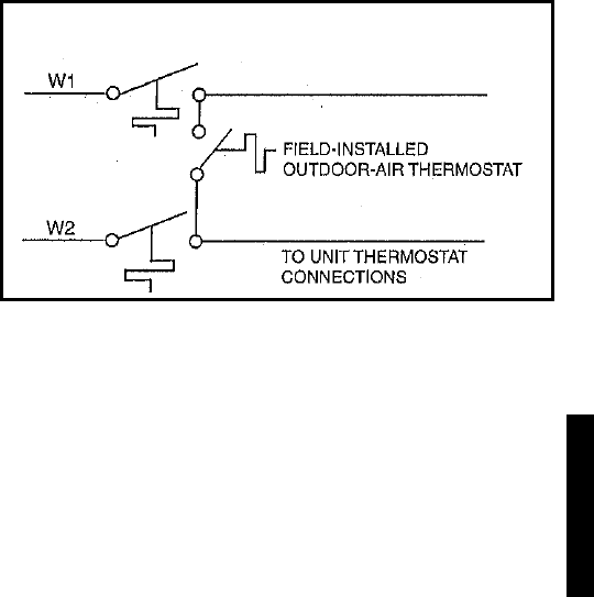
177
Condensate drain pan
A sloped condensate drain pan is supplied on all units. The con-
densate pan must be externally trapped. Condensate drains are
located on both the bottom and end of the unit.
Ductwork
All ductwork must be attached to flanges. If no flanges are
present, they must be field supplied. Secure vertical discharge
ductwork to roof curb. For horizontal discharge applications,
attach ductwork to flanges. Field-supplied flanges can be at-
tached to horizontal discharge openings and all ductwork at-
tached to flanges.
Thermostat
Use of 2-stage cooling thermostat is recommended for all units
equipped with economizer. A 2-stage cooling thermostat is re-
quired for size 015-028 units with integrated economizer.
Heating-to-cooling changeover
All units are automatic changeover from heating to cooling
when automatic changeover thermostat and subbase are used.
Airflow
Units are draw-thru on cooling and blow-thru on heating.
Maximum airflow
To minimize possibility of condensate blow-off from evapora-
tor, airflow through units should not exceed 500 cfm/ton (sizes
004-025) and 11,250 cfm (size 028).
Minimum airflow
Minimum airflow for cooling is 300 cfm/ton (size 004-025) and
280 cfm/ton (028 units). Refer to Heating Capacities and Effi-
ciencies table for minimum heating airflow.
Minimum ambient operating temperature
Minimum ambient operating temperature for size 004-014 stan-
dard units is 25 F. With accessory Motormaster® I, II, or IV units
can operate at outdoor temperatures down to –20 F.
Unit sizes 015-028 are designed to operate at outdoor tem-
peratures down to 40 F. With accessory Motormaster I or Mo-
tormaster V control, units can operate at outdoor temperatures
down to –20 F.
NOTE: Under most application circumstances, if the rooftop
unit is equipped with an economizer, low ambient controls are
not required. Unless the outdoor air is unsatisfactory for free
cooling due to high temperature, excessive humidity, or poor
air quality, outdoor air should be used.
Maximum operating outdoor-air temperature
Maximum outdoor operating temperature for cooling is shown
below (60 Hz):
48HE003-006 125 F
48HJ004-015 125 F
48HJ017 120 F
48HJ020 125 F
48HJ024 125 F
48HJ028 125 F
High altitudes
These may require a change to the gas orifice. Refer to Alti-
tude Compensation tables.
Minimum heating entering air temperature
The minimum temperature of air entering the dimpled heat ex-
changer is 50 F continuous and 45 F intermittent for aluminum
heat exchangers and 40 F continuous and 35 F intermittent for
stainless steel heat exchangers. To operate at lower mixed-air
temperatures, a field-supplied outdoor-air thermostat must be
used to initiate both stages of heat when the temperature is be-
low the minimum required temperature to ensure full fire oper-
ation. Wire the outdoor-air thermostat (part no. HH22AG106)
in series with the second stage gas valve as shown below. Set
the outdoor-air thermostat at 35 F for stainless steel heat ex-
changers or 45 F for aluminum heat exchangers. This tempera-
ture setting will bring on the second stage of heat whenever the
ambient temperature is below the thermostat set point. Indoor
comfort may be compromised when heating is initiated using
low entering air temperatures with insufficient heating temper-
ature rise.
Motor data
Due to Carrier’s internal unit design (draw-thru over the mo-
tor), air path, and specially designed motors, the full horsepow-
er (maximum continuous bhp) listed in the Physical Data tables
and the notes following each Fan Performance table can be uti-
lized with extreme confidence.
Using Carrier motors to the values listed in the Physical Da-
ta, Fan Performance, and Evaporator-Fan Motor Data tables
will not result in nuisance tripping or premature motor failure.
In addition, the unit warranty will not be affected.
Carrier PremierLink™ controls
The Carrier PremierLink controls can be used with any thermo-
stat.
Thru-the-bottom connections
The accessory thru-the-bottom connections are needed to en-
sure proper connections when routing wiring and piping
through the basep an and roof curb. This accessory is used for
electric and control power only or electric, control power, and
gas piping depending on which accessory is selected.
WIRING OF OUTDOOR-AIR THERMOSTAT
Application data
48HE/HJ
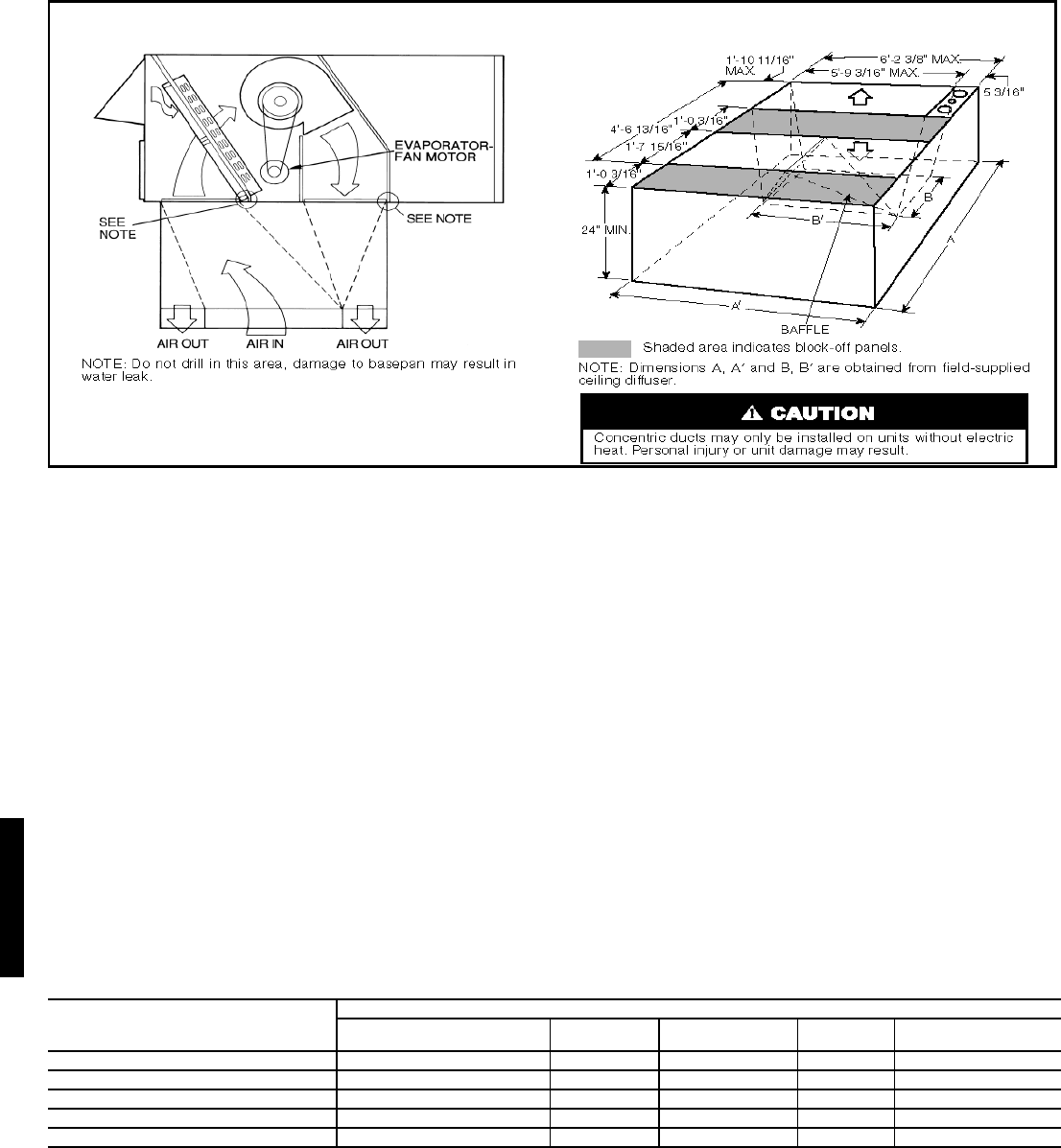
178
Concentric duct details
Field-supplied fan drives
If the factory drive sets must be changed to obtain other wheel
speeds, consult the nearest Browning Manufacturing Co. sales
office with the required new wheel speed and the data from
Physical Data tables (center distances, motor and fan shaft di-
ameters, motor horsepower) for a modified drive set selection.
For minor speed changes, the fan sheave size should be
changed. (Do not reduce the size of the motor sheave; this will
result in reduced belt horse-power ratings and reduced belt
life.)
Condenser coil protection
Pre-coated aluminum-fin coils have a durable epoxy- phe-
nolic coating applied to the fin prior to the fin stamping process
to provide protection in mildly corrosive coastal environments.
Pre-coated coils have an inert barrier between the aluminum fin
and copper tube. This barrier electrically disconnects the dis-
similar metals to minimize the potential for galvanic corrosion.
This economical option provides substantial corrosion protec-
tion beyond the standard uncoated coil construction.
Copper-fin coils provide increased corrosion resistance in
moderate coastal environments where industrial air pollution is
not present. All copper coils eliminate bi-metallic construction
to eliminate the potential for galvanic corrosion. Application in
industrial environments is not recommended due to potential
attack from sulfur, sulfur oxide, nitrogen oxides, carbon and
several other industrial airborne contaminants. In moderate
seacoast environments, copper-fin coils have extended life
compared to standard or pre-coated aluminum-fin coils.
E-Coated aluminum-fin coils undergo a precisely controlled
scientific process that bonds an impermeable epoxy coating to
the specially prepared fin coil surface. E-Coating produces a
smooth, consistent coating that is less brittle, more resilient and
more durable than previous post coating processes. E-Coated
aluminum-fin coils offer economical protection and improved
coil life in many contaminated environments.
E-Coated copper-fin coils provide maximum protection in
virtually all environments, this option combines the continu-
ous, impenetrable barrier of the E-Coating process with the nat-
ural resistance of an all-copper construction. E-Coated copper-
fin coil assemblies ensure long life, even in environments that
combine harsh coastal conditions with industrial contamina-
tion.
CONDENSER COIL PROTECTION APPLICATIONS
LEGEND
CONCENTRIC DUCT DISTRIBUTION CONCENTRIC DUCT DETAILS
DESCRIPTION
(Enviro-Shield™ Option)
ENVIRONMENT
Standard, Non-Corrosive Mild Coastal Severe Coastal Industrial Combined Coastal
and Industrial
Standard, Al/Cu X
Pre-Coated Al/Cu X
Cu/Cu X
E-Coated Al/Cu XX
E-Coated Cu/Cu X
Al/Cu — Aluminum Fin with Copper Tube Coil E-Coated — Extremely Flexible and Durable Epoxy Coating Uniformly
Cu/Cu — Copper Fin with Copper Tube Coil Applied to the Coil Surfaces
Enviro-Shield —Family of Coil Protection Options Pre-Coated — Epoxy Coating Applied to Fin Stock Material
48HJ

179
EconoMi$er IV
The EconoMi$er IV factory-installed economizer package in-
cludes a gear-driven damper system that modulates the return
air and outdoor air supply to the rooftop unit in order to take ad-
vantage of “free cooling” with outdoor air when conditions are
suitable. The system utilizes industry proven technology avail-
able for integrating the use of outdoor air for cooling with me-
chanical cooling for 3 through 25-ton rooftop units. The intui-
tive EconoMi$er IV microprocessor-based controller optimizes
and enhances rooftop operation through reduced energy con-
sumption, optimal zone comfort, and efficient equipment cy-
cling. This is accomplished by operating the compressors when
the outdoor air temperature is too warm, integrating the com-
pressors with outdoor air when free cooling is available, and
locking out the compressor when outdoor air temperature is too
cold. The detailed sequence of operation is described in the
Controls section with a brief description of selected application
items here.
Thermostat interface — The EconoMi$er IV control was de-
signed to work with conventional thermostats that have Y1
(cooling stage 1), Y2 (cooling stage 2), W1 (heat stage 1), W2
(heat stage 2), and G (fan). In addition, the EconoMi$er IV will
support an occupied/unoccupied switch (typically integrated
into the thermostat or Thermidistat™ device). When the switch
is closed, it provides a 24-vac signal to the unit for occupied
mode, and provides no signal to indicate unoccupied mode.
The EconoMi$er IV control can be configured to allow differ-
ent minimum economizer damper positions and to allow the
use of mechanical cooling in the occupied mode.
Control features — The EconoMi$er IV controller provides
superior functionality for rooftop unit operation. EconoMi$er
IV control features are included as follows:
Remote minimum position — The EconoMi$er IV controller
can be used with a field-supplied and field-installed remote
minimum position control switch that will enable and disable
the EconoMi$er IV to open or close the damper beyond the
minimum position for modified ventilation, providing 2 to 10
vdc output.
NOTE: Minimum position signal takes priority over the DCV
(demand control ventilation) maximum position signal.
Demand control ventilation (DCV) — The EconoMi$er IV has
DCV capability when using an IAQ sensor. This sensor is typi-
cally installed in the return duct or occupied space. When im-
plementing a DCV control scheme with the EconoMi$er IV, the
control algorithm will modulate the position of the damper be-
tween two user-configured damper positions, Maximum DCV
Position and Minimum Occupied position. Design airflow rates
for these two damper positions should be such that when the
damper is at the Maximum DCV position, enough fresh venti-
lation air will be brought in to remove contaminants and CO2
generated by sources other than people (i.e., since in unoccu-
pied mode). The Maximum DCV position is intended to satisfy
the IAQ “Base Ventilation Rate.” The Minimum Occupied po-
sition design airflow rate should be sufficient to satisfy ventila-
tion requirements for removing CO2 from all sources including
people at the maximum occupancy.
IAQ sensors — EconoMi$er IV can be utilized with any IAQ
(CO2) sensor that provides a 2 to 10 vdc output. The controller
will modulate the outdoor air damper to provide ventilation
based on the sensor output and the IAQ setting of the controller.
When used, an IAQ sensor will modulate the damper from the
minimum position (base ventilation rate based on CO2 levels)
to maximum position (full occupancy ventilation rate).
Damper operation — The EconoMi$er IV allows the damper to
be configured for two adjustable damper positions including
maximum position and occupied minimum positions. The two
(2) position damper capability is a unique feature of
EconoMi$er IV and includes operation flexibility as follows:
1. Minimum Occupied Position: This adjustable position
allows a minimum ventilation (base ventilation rate) air-
flow rate through the unit during occupied periods.
2. Demand Control Ventilation (DCV) Maximum Position:
A DCV maximum occupied position is provided when
using an IAQ sensor for DCV. See DCV and Control sec-
tions for sequence. The DCV Maximum Position limits
outdoor airflow into the rooftop when the DCV routine
overrides the mixed air sensor. Setting the DCV Maxi-
mum Position of the outdoor air damper prevents large
amounts of hot or cold air into the space.
Power exhaust — The EconoMi$er IV has the capability to
control one stage of power exhaust for maintaining air balance
and pressurization. Control is activated based on outdoor air
damper position (adjustable); factory-set at the “middle” posi-
tion (dampers halfway open).
Compressor staging — The EconoMi$er IV is an integrated
economizer and has the ability to utilize simultaneous outdoor
air and compressors. The EconoMi$er IV can be configured to
support economizer and compressor operation. Only one or
two compressor operation is available with 3 to 121/2 ton units.
Changeover strategies — The EconoMi$er IV controller can
be configured to accommodate all available economizer control
strategies that place the rooftop unit in economizer mode in-
cluding:
Remote Minimum Position — Used when a remote signal from
a remote minimum position control will enable and disable the
EconoMi$er IV (remote enable control).
Outdoor dry bulb — EconoMi$er IV will be enabled based on
the outdoor-air temperature. This is provided standard with the
EconoMi$er IV.
Differential dry bulb — EconoMi$er IV will be enabled when-
ever the outdoor-air temperature is lower than the return-air
temperature.
Outside air enthalpy — EconoMi$er IV will be enabled based
on the outside air enthalpy curves as shown in the EconoMi$er
IV Changeover diagram below. The A, B, C, and D curves
shown have been in use for many years and have been included
as part of the latest ASHRAE 90.1 energy efficiency code. The
curves are designed to take into consideration both outdoor
temperature and humidity. These curves are used to set up the
EconoMi$er IV controller to use the EconoMi$er IV for free
cooling when the conditions to the left of the curve exist. When
the conditions are to the right of the curve, then outdoor air
cooling will not be used and the outdoor air damper position
will be set at the minimum position.
IMPORTANT: When the DCV Maximum Position is set
below the minimum position, the minimum position over-
rides the maximum position, negating most DCV functions.
48HJ
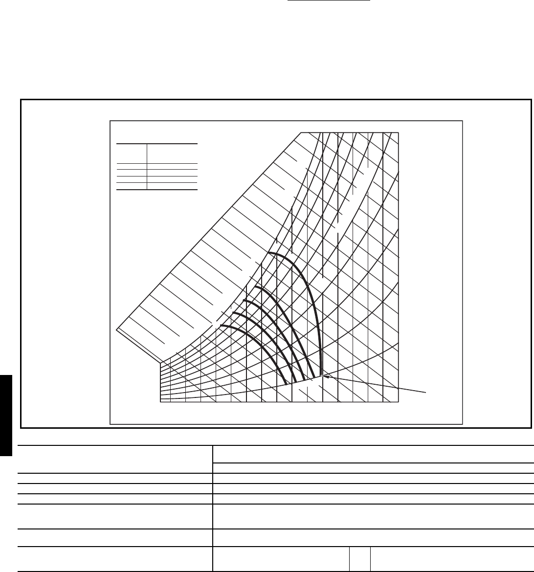
180
Deciding which curve is used is a function of the outdoor cli-
mate and the type of economizer utilized. Since EconoMi$er
IV is a fully integrated economizer, the range where outdoor air
can be utilized for free cooling is expanded and the A and B
curves may be used. The control point table in the EconoMi$er
IV Changeover diagram below provides assistance for whether
the A and B curves will be suitable. In general terms, a hot and
humid climate may be a reason not to use the A curve, while a
cooler climate might be more applicable for using the A or B
curve.
The EconoMi$er IV has expanded outdoor air capability. For
a changeover economizer which cannot utilize simultaneous
economizer and compression, both A and B curves would po-
tentially be undesirable since the temperature and humidity lev-
els are too high without compression assistance to provide ef-
fective cooling. Therefore, most changeover economizers uti-
lize the D curve.
Differential enthalpy — The EconoMi$er IV will be enabled
based on the comparison of the enthalpy of the return air and
outside air. When the outside air enthalpy is lower than he re-
turn side, the unit will be in economizer mode.
Using the EconoMi$er IV controller for implementing dif-
ferent control changeover strategies requires the use of differ-
ent combinations of dry bulb and humidity sensors as outlined
in the EconoMi$er IV Sensor Usage table.
ECONOMI$ER II SENSOR USAGE CHART
*CRENTDIF004A00 and CRTEMPSN002A00 accessories are used on
many different base units. As such, these kits may contain parts that will
not be needed for installation.
†33ZCSENCO2 is an accessory CO2 sensor.
**33ZCASPCO2 is an accessory aspirator box required for duct-mounted
applications.
††CRCBDIOX005A00 is an accessory that contains both 33ZCSENCO2
and 33ZCASPCO2 accessories.
APPLICATION
ECONOMI$ER IV WITH OUTDOOR AIR
DRY BULB SENSOR
Accessories Required
Outdoor Air Dry Bulb None. The outdoor air dry bulb sensor is factory installed.
Differential Dry Bulb CRTEMPSN002A00*
Single Enthalpy HH57AC078
Differential Enthalpy
HH57AC078
and
CRENTDIF004A00*
CO2 for DCV Control using a
Wall-Mounted CO2 Sensor 33ZCSENCO2
CO2 for DCV Control using a
Duct-Mounted CO2 Sensor
33ZCSENCO2†
and
33ZCASPCO2**
OR
CRCBDIOX005A00††
ECONOMI$ER CHANGEOVER CURVES
CONTROL
CURVE
A
B
C
D
CONTROL POINT
APPROX.
deg. F (deg. C)
AT 50% RH
73 (23)
70 (21)
67 (19)
63 (17)
12 14 16 18 20 22 24 26 28 30 32 34 36 38 40 42 44 46
90
100
80
70
60
50
40
30
20
10
ENTHALPY BTU PER POUND DRY AIR
85
(29) 90
(32) 95
(35) 100
(38) 105
(41) 110
(43)
35
(2)
35
(2)
40
(4)
40
(4)
105
(41) 110
(43)
45
(7)
45
(7)
50
(10)
50
(10)
55
(13)
55
(13)
60
(16)
60
(16)
65
(18)
65
(18)
70
(21)
70
(21)
75
(24)
75
(24)
80
(27)
80
(27)
85
(29) 90
(32) 95
(35) 100
(38)
A
A
B
B
C
C
D
D
RELATIVE HUMIDITY (%)
HIGH LIMIT
CURVE
APPROXIMATE DRY BULB TEMPERATURE--degrees F (degrees C)
Application data (cont)
48HJ

181
Packaged Rooftop Electric Cooling Unit with
Gas Heat – Constant Volume Application
HVAC Guide Specifications
Size Range: 24,000 to 60,000 Btuh,
Nominal (Input Heating)
2 to 5 Tons, Nominal (Cooling)
Carrier Model
Numbers:
48HE D/L/G/S 003 - 006
48HE E/M/H/R 003 - 006
48HE F/N/K/T 003 - 006
Part 1 — General
1.01 SYSTEM DESCRIPTION
Outdoor rooftop mounted, electrically controlled heat-
ing and cooling unit utilizing a hermetic compressor(s)
for cooling duty and gas combustion for heating duty.
Unit shall discharge supply air vertically or horizontally
as shown on contract drawings.
1.02 QUALITY ASSURANCE
A. Unit exceeds ASHRAE 90.1-2004 Energy Standards.
Units 003-006 are Energy Star qualified.
B. Unit shall be rated in accordance with ARI Standards
210 or 360 as applicable. Designed in accordance with
UL Standard 1995.
C. Unit shall be designed to conform to ASHRAE 15, latest
revision.
D. Unit shall be UL-tested and certified in accordance with
ANSI Z21.47 Standards and UL-listed and certified
under Canadian standards as a total package for safety
requirements.
E. Roof curb shall be designed to conform to NRCA Stan-
dards.
F. Insulation and adhesive shall meet NFPA 90A require-
ments for flame spread and smoke generation.
G. Unit casing shall be capable of withstanding 500-hour
salt spray exposure per ASTM B117 (scribed specimen).
H. Unit shall be designed in accordance with ISO
9001:2000, and shall be manufactured in a facility regis-
tered to ISO 9001:2000.
I. Each unit shall be subjected to a completely automated
run testing on the assembly line. A factory-supplied
printout indicating tested pressures, amperages, data,
and inspectors; providing certification of the unit status
at the time of manufacture; shall be available upon
request.
1.03 DELIVERY, STORAGE, AND HANDLING
Unit shall be stored and handled per manufacturer’s rec-
ommendations.
Part 2 — Product
2.01 EQUIPMENT (STANDARD)
A. General:
Factory assembled, single-piece heating and cooling
unit. Contained within the unit enclosure shall be all fac-
tory wiring, piping, controls, refrigerant charge (R-22),
and special features required prior to field start-up.
B. Unit Cabinet:
1. Unit cabinet shall be constructed of galvanized
steel, and shall be bonderized and coated with a
prepainted baked enamel finish on all externally
exposed surfaces.
2. Evaporator fan compartment interior cabinet sur-
faces shall be insulated with a minimum 1/2-in.
thick, 1 lb density, flexible fiberglass insulation,
neoprene coated on the air side. Aluminum foil-
faced fiberglass insulation shall be used in the gas
heat compartment.
3. Cabinet panels shall be easily removable for servic-
ing.
4. Holes shall be provided in the base rails for rigging
shackles to facilitate maneuvering and overhead
rigging.
5. Unit shall have a factory-installed, sloped conden-
sate drain pan made of a non-corrosive material,
providing a minimum 3/4-in.-14 NPT. connection
with both vertical and horizontal drains, and shall
comply with ASHRAE Standard 62.
6. Unit shall have a factory-installed filter access
panel to provide filter access with tool-less
removal.
7. Unit shall have standard thru-the-bottom gas and
power connection capability (accessory kit is
required).
C. Fans:
1. Evaporator Fan:
a. Fan shall be belt driven as shown on the equip-
ment drawings. Belt drive shall include an
adjustable-pitch motor pulley.
b. Fan wheel shall be double-inlet type with for-
ward-curved blades.
c. Bearings shall be sealed, permanently lubri-
cated ball-bearing type for longer life and lower
maintenance.
SIZE 003-006 UNITS
ARE ENERGY STAR
QUALIFIED
Guide specifications — 48HE003-006
48HE

182
2. Evaporator fan shall be made from steel with a cor-
rosion-resistant finish and shall be dynamically
balanced.
3. Condenser fan shall be of the direct-driven (with
totally enclosed motors) propeller type and shall
discharge air vertically.
4. Condenser fan shall have aluminum blades riveted
to corrosion-resistant steel spiders and shall be
dynamically balanced.
5. Induced-draft blower shall be of the direct-driven,
single inlet, forward-curved centrifugal type, made
from steel with a corrosion-resistant finish and
shall be dynamically balanced.
D. Compressor(s):
1. Fully hermetic type, internally protected scroll-
type.
2. Factory mounted on rubber grommets and inter-
nally spring mounted for vibration isolation.
3. Units shall be electrically and mechanically single
circuits (one compressor per circuit).
E. Coils:
1. Standard evaporator and condenser coils shall have
aluminum lanced plate fins mechanically bonded to
seamless internally grooved copper tubes with all
joints brazed.
2. Testing:
a. Evaporator and condenser coils shall be quali-
fied to UL 1995 burst test at 2,200 psi.
b. Evaporator and condenser coils shall be leak
tested to 150 psig and pressure tested to 400
psig.
3. Optional Coils:
a. Optional pre-coated aluminum-fin coils shall
have a durable epoxy-phenolic coating to pro-
vide protection in mildly corrosive coastal envi-
ronments. Coating shall be applied to the
aluminum fin stock prior to the fin stamping
process to create an inert barrier between the
aluminum fin and copper tube. Epoxy-phenolic
barrier shall minimize galvanic action between
dissimilar metals.
b. Copper-fin coils shall be constructed of copper
fins mechanically bonded to copper tubes and
copper tube sheets. Galvanized steel tube sheets
shall not be acceptable. A polymer strip shall
prevent coil assembly from contacting the sheet
metal coil pan to minimize potential for gal-
vanic corrosion between coil and pan. All cop-
per construction shall provide protection in
moderate coastal environments.
c. E-Coated aluminum-fin coils shall have a flexi-
ble epoxy polymer coating uniformly applied to
all coil surface areas without material bridging
between fins. Coating process shall ensure com-
plete coil encapsulation. Color shall be high
gloss black with gloss — 60 deg of 65 to 90%
per ASTM D523-89. Uniform dry film thick-
ness from 0.8 to 1.2 mil on all surface areas
including fin edges. Superior hardness charac-
teristics of 2H per ASTM D3363-92A and
cross-hatch adhesion of 4B-5B per ASTM
D3359-93. Impact resistance shall be up to 160
in.-lb (ASTM D2794-93). Humidity and water
immersion resistance shall be up to minimum
1000 and 250 hours respectively (ASTM
D2247-92 and ASTM D870-92). Corrosion
durability shall be confirmed through testing to
be no less than 1000 hours salt spray per ASTM
B117-90. Coil construction shall be aluminum
fins mechanically bonded to copper tubes.
d. E-Coated copper-fin coils shall have a flexible
epoxy polymer coating uniformly applied to all
coil surface areas without material bridging
between fins. Coating process shall ensure com-
plete coil encapsulation. Color shall be high
gloss black with gloss — 60 deg of 65 to 90%
per ASTM D523-89. Uniform dry film thick-
ness from 0.8 to 1.2 mil on all surface areas
including fin edges. Superior hardness charac-
teristics of 2H per ASTM D3363-92A and
cross-hatch adhesion of 4B-5B per ASTM
D3359-93. Impact resistance shall be up to 160
in.-lb (ASTM D2794-93). Humidity and water
immersion resistance shall be up to minimum
1000 and 250 hours respectively (ASTM
D2247-92 and ASTM D870-92). Corrosion
durability shall be confirmed through testing to
be no less than 1000 hours salt spray per ASTM
B117-90. Coil construction shall be copper fins
mechanically bonded to copper tubes with cop-
per tube sheets. Galvanized steel tube sheets
shall not be acceptable. A polymer strip shall
prevent coil assembly from contacting sheet
metal coil pan to maintain coating integrity and
minimize corrosion potential between coil and
pan.
F. Heating Section:
1. Induced-draft combustion type with energy saving
direct-spark ignition system and redundant main
gas valve.
2. Heat Exchanger:
a. The standard heat exchanger shall be of the
tubular-section type constructed of a minimum
of 20-gage steel coated with a nominal 1.2 mil
aluminum-silicone alloy for corrosion resis-
tance.
b. The optional stainless steel heat exchanger shall
be of the tubular-section type, constructed of a
minimum of 20-gage type 409 stainless steel.
3. Burners shall be of the in-shot type constructed of
aluminum-coated steel.
Guide specifications — 48HE003-006 (cont)
48HE

183
4. All gas piping shall enter the unit cabinet at a single
location on side of unit (horizontal plane).
5. The integrated gas controller (IGC) board shall
include gas heat operation fault notification using
an LED (light-emitting diode).
6. Unit shall be equipped with anti-cycle protection
with one short cycle on unit flame rollout switch or
4 continuous short cycles on the high-temperature
limit switch. Fault indication shall be made using
an LED.
7. The IGC board shall contain algorithms that mod-
ify evaporator-fan operation to prevent future
cycling on high-temperature limit switch.
8. The LED shall be visible without removal of con-
trol box access panel.
G. Refrigerant Components:
Refrigerant circuit components shall include:
1. Fixed orifice metering system (AcutrolTM device).
2. Refrigerant filter drier.
3. Service gage connections on suction, discharge,
and liquid lines.
H. Filter Section:
1. Standard filter section shall consist of factory-
installed, low velocity, throwaway 2-in. thick fiber-
glass filters of commercially available sizes.
2. Filter face velocity shall not exceed 320 fpm at
nominal airflows.
3. Filter section should use only one size filter.
4. Filters shall be accessible through an access panel
with “no-tool” removal.
I. Controls and Safeties:
1. Unit Controls:
Unit shall be complete with self-contained low-
voltage control circuit protected by a fuse on the
24-v transformer side.
2. Safeties:
a. a.Unit shall incorporate a solid-state compressor
protector which provides anti-cycle reset capa-
bility at the space thermostat, should any of the
following standard safety devices trip and shut
off compressor.
1) Compressor overtemperature, overcurrent.
2) Loss-of-charge/low-pressure switch.
3) Freeze-protection thermostat, evaporator
coil.
4) High-pressure switch.
5) Automatic reset motor thermal overload
protector.
The lockout protection shall be easily discon-
nected at the control board, if necessary.
b. Heating section shall be provided with the fol-
lowing minimum protections:
1) High-temperature limit switches.
2) Induced draft motor speed sensor.
3) Flame rollout switch.
4) Flame proving controls.
J. Operating Characteristics:
1. Unit shall be capable of starting and running at 125
F ambient outdoor temperature, meeting maximum
load criteria of ARI Standard 210/240 or 360 at +
10% voltage.
2. Compressor with standard controls shall be capable
of operation down to 25 F ambient outdoor temper-
ature.
K. Electrical Requirements:
All unit power wiring shall enter unit cabinet at a
single factory-predrilled location.
L. Motors:
1. Compressor motors shall be cooled by refrigerant
gas passing through motor windings and shall have
line break thermal and current overload protection.
2. Evaporator-fan motor shall have permanently
lubricated bearings and inherent automatic-reset
thermal overload protection. Evaporator motors are
designed specifically for Carrier and do not have
conventional horsepower (HP) ratings listed on the
motor nameplate. Motors are designed and quali-
fied in the “air-over” location downstream of the
cooling coil and carry a maximum continuous bhp
rating that is the maximum application bhp rating
for the motor; no “safety factors” above that rating
may be applied.
3. Totally enclosed condenser-fan motor shall have
permanently lubricated bearings, and inherent
automatic-reset thermal overload protection.
4. Induced-draft motor shall have permanently lubri-
cated sealed bearings and inherent automatic-reset
thermal overload protection.
M. Special Features:
Certain features are not applicable when the
features designated * are specified. For
assistance in amending the specifications,
contact your local Carrier Sales Office.
48HE

184
*1. Carrier PremierLink™ Controls:
a. Shall be available as a factory-installed or as a
field-installed accessory.
b. Shall work with Carrier 3V, Comfort Network®
(CCN) and ComfortVIEW™ software.
c. Shall be compatible with ComfortLink™ con-
trollers.
d. Shall be ASHRAE 62-2001 compliant.
e. Shall accept a CO2 sensor in the conditioned
space — Demand Control Ventilation (DCV)
ready.
f. Shall have baud communication rate of 38.4K
or faster.
g. Shall be Internet ready.
h. Shall include an integrated economizer control-
ler.
i. If an economizer is specified, the
“EconoMi$er2 with 4 to 20 mA actuator and no
microprocessor control” is required.
2. Roof Curbs (Horizontal and Vertical):
a. Formed galvanized steel with wood nailer strip
and shall be capable of supporting entire unit
weight.
b. Permits installation and securing of ductwork to
curb prior to mounting unit on the curb.
*3. Integrated Economizers:
a. Integrated integral modulating type capable of
simultaneous economizer and compressor oper-
ation.
b. Available as a factory-installed option in verti-
cal supply/return configuration only. (Available
as a field-installed accessory for dedicated hori-
zontal and/or vertical supply return configura-
tions.)
c. Includes all hardware and controls to provide
cooling with outdoor air.
d. Equipped with low-leakage dampers, not to
exceed 2% leakage at 1 in. wg pressure differ-
ential.
e. Capable of introducing up to 100% outdoor air.
f. EconoMi$er IV and EconoMi$er2 shall be
equipped with a barometric relief damper capa-
ble of relieving up to 100% return air.
g. Designed to close damper(s) during loss-of-
power situations with spring return built into
motor.
h. Dry bulb outdoor-air temperature sensor shall
be provided as standard. Outdoor air sensor set
point is adjustable and shall range from 40 to
100 F. For the EconoMi$er IV, the return air
sensor, indoor enthalpy sensor, and outdoor
enthalpy sensor shall be provided as field-
installed accessories to provide enthalpy con-
trol, differential enthalpy control, and differen-
tial dry bulb temperature control. For the
EconoMi$er2, the enthalpy, differential temper-
ature (adjustable), and differential enthalpy con-
trol shall be provided as field-installed
accessories.
i. The EconoMi$er IV and EconoMi$er2 shall
have a gear-driven parallel blade design.
j. EconoMi$er IV microprocessor control shall
provide control of internal building pressure
through its accessory power exhaust function.
Factory set at 100%, with a range of 0% to
100%.
k. EconoMi$er2 shall be capable of control from a
4 to 20 mA signal through optional 4 to 20 mA
design without microprocessor control
(required for PremierLink™ or third party con-
trol interface).
l. EconoMi$er IV Microprocessor Occupied Min-
imum Damper Position Setting maintains the
minimum airflow into the building during occu-
pied period providing design ventilation rate for
full occupancy (damper position during heat-
ing). A remote potentiometer may be used to
override the set point.
m. EconoMi$er IV Microprocessor Unoccupied
Minimum Damper Position Setting — The
EconoMi$er IV dampers shall be closed when
the unit is in the occupied mode.
n. EconoMi$er IV Microprocessor IAQ/DCV
Maximum Damper Position Setting — Setting
the maximum position of the damper prevents
the introduction of large amounts of hot or cold
air into the space. This position is intended to
satisfy the base minimum ventilation rate.
o. EconoMi$er IV Microprocessor IAQ/DCV con-
trol modulates the outdoor-air damper to pro-
vide ventilation based on the optional 2 to 10
vdc CO2 sensor input.
p. Compressor lockout sensor (opens at 35 F,
closes at 50 F).
q. Actuator shall be direct coupled to economizer
gear, eliminating linkage arms and rods.
r. Control LEDs:
1) When the outdoor air damper is capable of
providing free cooling, the “Free Cool”
LED shall illuminate.
2) The IAQ LED indicates when the module
is on the DCV mode.
3) The EXH LED indicates when the exhaust
fan contact is closed.
s. Remote Minimum Position Control — A field-
installed accessory remote potentiometer allows
the outdoor air damper to be opened or closed
beyond the minimum position in the occupied
mode for modified ventilation.
Guide specifications — 48HE003-006 (cont)
48HE

185
4. Manual Outdoor-Air Damper:
Manual damper package shall consist of damper,
birdscreen, and rainhood which can be preset to
admit up to 50% outdoor air for year round ventila-
tion.
*5. 100% Two-Position Damper:
a. Two-position damper package shall include sin-
gle blade damper and motor. Admits up to
100% outdoor air.
b. Damper shall close upon indoor (evaporator)
fan shutoff.
c. Designed to close damper during loss of power
situations.
d. Equipped with 15% barometric relief damper.
6. 25% Two-Position Damper:
a. Two-position damper package shall include sin-
gle blade damper and motor. Admits up to 25%
outdoor air.
b. Damper shall close upon indoor (evaporator)
fan shutoff.
*7. Head Pressure Control Package:
Consists of solid-state control and condenser-coil
temperature sensor to maintain condensing temper-
ature between 90 F and 110 F at outdoor ambient
temperatures down to –20 F by condenser-fan
speed modulation or condenser-fan cycling and
wind baffles.
8. LP (Liquid Propane) Conversion Kit:
Package shall contain all the necessary hardware
and instructions to convert a standard natural gas
unit for use with liquefied propane (valid up to
2000 ft elevation).
*9. Electronic Programmable Thermostat:
Units shall be capable of using deluxe full-featured
electronic thermostat. Thermostat shall use built-in
compressor cycle delay control for both heating
and cooling duty. Thermostat shall be capable of
working with Carrier direct digital controls.
10. Light Commercial Thermidistat™ Device:
Field-installed wall-mounted thermostat is used to
control temperature and activation of the dehumidi-
fication package. The Thermidistat device can be
set for humidity settings from 50% to 90% relative
humidity. Automatic humidity control adjusts
indoor humidity based on the outdoor temperature
sensor.
*11. Flue Shield:
Flue shield shall provide protection from the hot
sides of the gas flue hood.
*12. Thermostat and Subbase:
Thermostat and subbase shall provide staged cool-
ing and heating automatic (or manual) changeover,
fan control, and indicator light.
*13. Condenser Coil Hail Guard Assembly:
Hail guard shall protect against damage from hail
and flying debris.
14. Unit-Mounted, Non-Fused Disconnect Switch:
Switch shall be factory-installed, internally
mounted. NEC and UL approved non-fused switch
shall provide unit power shutoff. Switch shall be
accessible from outside the unit and shall provide
power off lockout capability.
15. Convenience Outlet:
Outlet shall be factory-installed and internally
mounted with easily accessible 115-v female recep-
tacle. Shall include 15 amp GFI receptacle with
independent fuse protection. Voltage required to
operate convenience outlet shall be provided by a
factory-installed step-down transformer. Shall be
accessible from outside the unit.
16. High-Static Indoor Fan Motor(s) and Drive(s)
(004-012):
High-static motor(s) and drive(s) shall be factory-
installed to provide additional performance range.
17. Flue Discharge Deflector:
Flue discharge deflector directs unit exhaust verti-
cally instead of horizontally.
18. Condenser Coil Grille:
The grille protects the condenser coil from damage
by large objects without increasing unit clearances.
19. Compressor Cycle Delay:
Unit shall be prevented from restarting for mini-
mum of 5 minutes after shutdown.
20. Thru-the-Bottom Utility Connectors:
Kit shall provide connectors to permit gas and elec-
trical connections to be brought to the unit through
the basepan.
21. Fan/Filter Status Switch:
Switch shall provide status of indoor (evaporator)
fan (ON/OFF) or filter (CLEAN/DIRTY). Status
shall be displayed over communication bus when
used with direct digital controls or with an indica-
tor light at the thermostat.
48HE

186
22. Energy$Recycler™ Energy Recovery System:
The package shall be an outdoor rooftop, surface
mounted, electronically controlled, air-to-air heat
pump unit utilizing a hermetic compressor for cool-
ing and heating duty.
The Energy$Recycler system shall recover energy
from building exhaust air and pre-condition venti-
lation air to allow higher ventilation requirements
and minimizing energy cost.
This option shall be available with the following:
a. A mounting kit for the Energy$Recycler device
for cantilever mounting off of the rooftop unit
with out the use of a slab or a roof curb.
b. A supplementary supply air fan kit to provide
increased air movement into the 62AQ unit.b.
An accessory sleeper rail is available for use
with a standard unit roof curb.
c. A field-installed 460-v to 208/230-v trans-
former to provide power when the 208-230/1/60
62AQ060 or 100 size Energy$Recycler device
is used with a 460-v rooftop unit.
d. A field-installed 575-v to 208/230-v trans-
former to provide power when an
Energy$Recycler device is used with a 575-v
unit.
23. Power Exhaust Accessory for EconoMi$er IV or
EconoMi$er2:
Power exhaust shall be used in conjunction with
EconoMi$er IV or EconoMi$er2 to provide system
exhaust of up to 100% of return air (vertical only).
The power exhaust is a field-installed accessory
(separate vertical and horizontal design).
NOTE: Horizontal power exhaust is intended to
mount in return ductwork.
As the outdoor-air damper opens and closes, both
propeller fans are energized and deenergized
through the EconoMi$er IV controller. The set
point is factory set at 100% of outdoor-air, and is
adjustable 0 to 100% to meet specific job require-
ments. Available in 208/230-1-60 v or 460-3-60 v.
An LED light on the controller indicates when the
power exhaust is operating.
For the EconoMi$er2, the power exhaust shall be
controlled by the PremierLink™ or third party con-
trols.
24. Outdoor Air Enthalpy Sensor (EconoMi$er IV or
EconoMi$er2):
The outdoor air enthalpy sensor shall be used with
the EconoMi$er IV or EconoMi$er2 device to pro-
vide single enthalpy control. When used in con-
junction with a return air enthalpy sensor, the
EconoMi$er IV or EconoMi$er2 device will pro-
vide differential enthalpy control. The sensor
allows the EconoMi$er IV or EconoMi$er2 con-
troller to determine if outside air is suitable for free
cooling.
25. Return Air Enthalpy Sensor (EconoMi$er IV or
EconoMi$er2):
The return air enthalpy sensor shall be used with
the EconoMi$er IV or EconoMi$er2 device. When
used in conjunction with an outdoor air enthalpy
sensor, the EconoMi$er IV or EconoMi$er2 device
will provide differential enthalpy control.
26. Return Air Temperature Sensor (EconoMi$er IV or
EconoMi$er2):
The return air temperature sensor shall be used
with the EconoMi$er IV or EconoMi$er2 device.
When used in conjunction with the standard out-
door air temperature sensor, the EconoMi$er IV or
EconoMi$er2 device will provide differential tem-
perature control.
27. Indoor Air Quality (CO2) Sensor (EconoMi$er2):
a. Shall have the ability to provide demand venti-
lation indoor air quality (IAQ) control through
the EconoMi$er2 with an IAQ sensor.
b. The IAQ sensor shall be available in duct
mount, wall mount, and wall mount with LED
display. The set point shall have adjustment
capability.
c. Requires EconoMi$er2, PremierLink, or Apollo
control options.
28. Indoor Air Quality (CO2) Room Sensor
(EconoMi$er IV):
Sensor shall have the ability to provide demand
ventilation control through the EconoMi$er IV. The
IAQ sensor shall be wall mounted with an LED
display in parts per million. The set point shall
have adjustment capability.
29. Return Air CO2 Sensor (EconoMi$er IV):
Sensor shall have the ability to provide demand
ventilation control through the EconoMi$er IV. The
IAQ sensor shall be duct mounted. The set point
shall have adjustment capability.
30. Gas Heat options (sizes 004-006):
a. Single-stage gas heat shall be provided in lieu
of two-stage heat.
b. NOx reduction shall be provided to reduce
nitrous oxide emissions to meet the California
Air Quality Management NOx requirement of
40 nanograms/joule or less.
c. Primary tubes on low NOx units shall be 409
stainless steel. Other components shall be alu-
minized steel.
Guide specifications — 48HE003-006 (cont)
48HE

187
31. Ultraviolet Germicidal Lamps:
Ultraviolet germicidal lamps are designed to elimi-
nate odor causing mold and fungus that may
develop in the wet area of the evaporator section of
the unit. The high output, low temperature germi-
cidal lamps are field installed in the evaporator sec-
tion of the unit, aimed at the evaporator coil and
condensate pan. The short wavelength ultraviolet
light inhibits and kills mold, fungus and microbial
growth. The lamps have an output rating at 45F in
400 fpm airflow of 120 microwatts/cm2 at 1 meter.
32. Humidi-MiZer™ Adaptive Dehumidification Sys-
tem:
a. The Humidi-MiZer dehumidification system
shall be factory-installed in the rooftop unit, and
shall provide greater dehumidification of the
occupied space by two modes of dehumidifica-
tion operations beside its normal design cooling
mode:
1) Subcooling mode further subcools the hot
liquid refrigerant leaving the condenser coil
when both temperature and humidity in the
space are not satisfied.
2) Hot gas reheat mode shall mix a portion of
the hot gas from the discharge of the com-
pressor with the hot liquid refrigerant leav-
ing the condenser coil to create a two-phase
heat transfer in the system, resulting in a
neutral leaving-air temperature when only
humidity in the space is not satisfied.
b. The system shall consist of a subcooling/ reheat
dehumidification coil located downstream of
the standard evaporator coil. This dehumidifica-
tion coil is a two-row coil on the 005 and 006
units, and a one-row coil on 003 and 004 units.
c. The system shall include crankcase heater(s) for
the scroll compressor(s).
d. The system shall include a low outdoor air tem-
perature switch to lock out both subcooling and
hot gas reheat mode when the outdoor-air tem-
perature is below 40 F.
e. The system shall include a Motormaster® low
ambient control to ensure the normal design
cooling mode capable of down to 0° F low
ambient operation.
f. The system shall include a low-pressure switch
on the suction line to ensure low pressure start-
up of hot gas reheat mode at lower outdoor tem-
perature condition.
g. The system operation may be controlled by a
field-installed, wall-mounted humidistat. The
dehumidification circuit will then operate only
when needed. Field connections for the humi-
distat are made in the low-voltage compartment
of the unit control box. The sensor can be set for
any level between 55% and 80% relative
humidity.
h. The system shall include a Thermal Expansion
Valve (TXV) to ensure a positive superheat con-
dition and a balance of pressure drop.
33. Humidistat:
Field-installed, wall-mounted humidistat is used to
control activation of the dehumidification package.
The humidistat can be set for humidity levels
between 20% and 80% relative humidity.
34. Hinged Panel Option:
Hinged panel option provides hinged access panels
for the filter, compressor, evaporator fan, and con-
trol box areas. Filter hinged panels permit tool-less
entry for changing filters. Each hinged panel is per-
manently attached to the rooftop unit.
48HE
188
Packaged Rooftop Electric Cooling Unit with
Gas Heat — Constant Volume Application
HVAC Guide Specifications
Size Range: 3 to 121/2 Tons, Nominal (Cooling)
60,000 to 250,000 Btuh, Nominal
(Input Heating)
Carrier Model
Numbers:
Part 1 — General
1.01 SYSTEM DESCRIPTION
Outdoor rooftop mounted, electrically controlled heat-
ing and cooling unit utilizing a hermetic compressor(s)
for cooling duty and gas combustion for heating duty.
Unit shall discharge supply air vertically or horizontally
as shown on contract drawings.
1.02 QUALITY ASSURANCE
A. Unit well exceeds ASHRAE 90.1-2001 Energy Stan-
dards. Units 004-012 are Energy Star qualified.
B. Unit shall be rated in accordance with ARI Standards
210 or 360. Designed in accordance with UL Standard
1995.
C. Unit shall be designed to conform to ASHRAE 15, latest
revision.
D. Unit shall be UL-tested and certified in accordance with
ANSI Z21.47 Standards and UL-listed and certified
under Canadian standards as a total package for safety
requirements.
E. Roof curb shall be designed to conform to NRCA Stan-
dards.
F. Insulation and adhesive shall meet NFPA 90A require-
ments for flame spread and smoke generation.
G. Unit casing shall be capable of withstanding 500-hour
salt spray exposure per ASTM B117 (scribed specimen).
H. Unit shall be designed in accordance with ISO
9001:2000, and shall be manufactured in a facility regis-
tered to ISO 9001:2000.
I. Each unit shall be subjected to a completely automated
run testing on the assembly line. A factory-supplied
printout indicating tested pressures, amperages, data,
and inspectors; providing certification of the unit status
at the time of manufacture shall be available upon
request.
1.03 DELIVERY, STORAGE, AND HANDLING
Unit shall be stored and handled per manufacturer’s rec-
ommendations.
Part 2 — Products
2.01 EQUIPMENT (STANDARD)
A. General:
Factory assembled, single-piece heating and cooling
unit. Contained within the unit enclosure shall be all fac-
tory wiring, piping, controls, refrigerant charge (R-22),
and special features required prior to field start-up.
B. Unit Cabinet:
1. Unit cabinet shall be constructed of galvanized
steel, and shall be bonderized and coated with a
prepainted baked enamel finish on all externally
exposed surfaces.
2. Evaporator fan compartment interior cabinet sur-
faces shall be insulated with a minimum 1/2-in.
thick, 1 lb density, flexible fiberglass insulation,
neoprene coated on the air side. Aluminum foil-
faced fiberglass insulation shall be used in the gas
heat compartment.
3. Cabinet panels shall be easily removable for servic-
ing.
4. Holes shall be provided in the base rails for rigging
shackles to facilitate maneuvering and overhead
rigging.
5. Unit shall have a factory-installed, sloped conden-
sate drain pan made of a non-corrosive material,
providing a minimum 3/4-in.-14 NPT. connection
with both vertical and horizontal drains, and shall
comply with ASHRAE Standard 62.
6. Unit shall have a factory-installed filter access
panel to provide filter access with tool-less
removal.
7. Unit shall have standard thru-the-bottom gas and
power connection capability (accessory kit is
required).
C. Fans:
1. Evaporator Fan:
a. Fan shall be direct or belt driven as shown on
the equipment drawings. Belt drive shall
include an adjustable-pitch motor pulley.
b. Fan wheel shall be double-inlet type with for-
ward-curved blades.
c. Bearings shall be sealed, permanently lubri-
cated ball-bearing type for longer life and lower
maintenance.
2. Evaporator fan shall be made from steel with a cor-
rosion-resistant finish and shall be dynamically
balanced.
3. Condenser fan shall be of the direct-driven (with
totally enclosed motors) propeller type and shall
discharge air vertically.
4. Condenser fan shall have aluminum blades riveted
to corrosion-resistant steel spiders and shall be
dynamically balanced.
48HJD/L/G/S
48HJE/M/H/R
48HJF/N/K/T
SIZE 004-012 UNITS
ARE ENERGY STAR
QUALIFIED
Guide specifications — 48HJ004-014
48HJ

189
5. Induced-draft blower shall be of the direct-driven,
single inlet, forward-curved centrifugal type, made
from steel with a corrosion-resistant finish and
shall be dynamically balanced.
D. Compressor(s):
1. Fully hermetic type, internally protected scroll-
type.
2. Factory mounted on rubber grommets and inter-
nally spring mounted for vibration isolation.
3. On dual electrically and mechanically independent
circuits (008-014).
E. Coils:
1. Standard evaporator and condenser coils shall have
aluminum lanced plate fins mechanically bonded to
seamless internally grooved copper tubes with all
joints brazed.
2. Dual compressor models (size 008-014) shall have
face-split type evaporator coil (circuit no. 1 on bot-
tom).
3. Testing:
a. Evaporator and condenser coils shall be quali-
fied to UL 1995 burst test at 2,200 psi.
b. Evaporator and condenser coils shall be leak
tested to 150 psig and pressure tested to 400
psig.
4. Optional Coils:
a. Optional pre-coated aluminum-fin coils shall
have a durable epoxy-phenolic coating to pro-
vide protection in mildly corrosive coastal envi-
ronments. Coating shall be applied to the
aluminum fin stock prior to the fin stamping
process to create an inert barrier between the
aluminum fin and copper tube. Epoxy-phenolic
barrier shall minimize galvanic action between
dissimilar metals.
b. Copper-fin coils shall be constructed of copper
fins mechanically bonded to copper tubes and
copper tube sheets. Galvanized steel tube sheets
shall not be acceptable. A polymer strip shall
prevent coil assembly from contacting the sheet
metal coil pan to minimize potential for gal-
vanic corrosion between coil and pan. All cop-
per construction shall provide protection in
moderate coastal environments.
c. E-Coated aluminum-fin coils shall have a flexi-
ble epoxy polymer coating uniformly applied to
all coil surface areas without material bridging
between fins. Coating process shall ensure com-
plete coil encapsulation. Color shall be high
gloss black with gloss — 60 deg of 65 to 90%
per ASTM D523-89. Uniform dry film thick-
ness from 0.8 to 1.2 mil on all surface areas
including fin edges. Superior hardness charac-
teristics of 2H per ASTM D3363-92A and
cross-hatch adhesion of 4B-5B per ASTM
D3359-93. Impact resistance shall be up to 160
in.-lb (ASTM D2794-93). Humidity and water
immersion resistance shall be up to minimum
1000 and 250 hours respectively (ASTM
D2247-92 and ASTM D870-92). Corrosion
durability shall be confirmed through testing to
be no less than 1000 hours salt spray per ASTM
B117-90. Coil construction shall be aluminum
fins mechanically bonded to copper tubes.
d. E-Coated copper-fin coils shall have a flexible
epoxy polymer coating uniformly applied to all
coil surface areas without material bridging
between fins. Coating process shall ensure com-
plete coil encapsulation. Color shall be high
gloss black with gloss — 60 deg of 65 to 90%
per ASTM D523-89. Uniform dry film thick-
ness from 0.8 to 1.2 mil on all surface areas
including fin edges. Superior hardness charac-
teristics of 2H per ASTM D3363-92A and
cross-hatch adhesion of 4B-5B per ASTM
D3359-93. Impact resistance shall be up to 160
in.-lb (ASTM D2794-93). Humidity and water
immersion resistance shall be up to minimum
1000 and 250 hours respectively (ASTM
D2247-92 and ASTM D870-92). Corrosion
durability shall be confirmed through testing to
be no less than 1000 hours salt spray per ASTM
B117-90. Coil construction shall be copper fins
mechanically bonded to copper tubes with cop-
per tube sheets. Galvanized steel tube sheets
shall not be acceptable. A polymer strip shall
prevent coil assembly from contacting sheet
metal coil pan to maintain coating integrity and
minimize corrosion potential between coil and
pan.
F. Heating Section:
1. Induced-draft combustion type with energy saving
direct-spark ignition system and redundant main
gas valve.
2. Heat Exchanger:
a. The standard heat exchanger shall be of the
tubular-section type constructed of a minimum
of 20-gage steel coated with a nominal 1.2 mil
aluminum-silicone alloy for corrosion resis-
tance.
b. The optional stainless steel heat exchanger shall
be of the tubular-section type, constructed of a
minimum of 20-gage type 409 stainless steel.
3. Burners shall be of the in-shot type constructed of
aluminum-coated steel.
4. All gas piping shall enter the unit cabinet at a single
location on side of unit (horizontal plane).
5. The integrated gas controller (IGC) board shall
include gas heat operation fault notification using
an LED (light-emitting diode).
48HJ

190
6. Unit shall be equipped with anti-cycle protection
with one short cycle on unit flame rollout switch or
4 continuous short cycles on the high-temperature
limit switch. Fault indication shall be made using
an LED.
7. The IGC board shall contain algorithms that mod-
ify evaporator-fan operation to prevent future
cycling on high-temperature limit switch.
8. The LED shall be visible without removal of con-
trol box access panel.
G. Refrigerant Components:
Refrigerant circuit components shall include:
1. Fixed orifice metering system (AcutrolTM device).
2. Refrigerant filter drier.
3. Service gage connections on suction, discharge,
and liquid lines.
H. Filter Section:
1. Standard filter section shall consist of factory-
installed, low velocity, throwaway 2-in. thick fiber-
glass filters of commercially available sizes.
2. Filter face velocity shall not exceed 320 fpm at
nominal airflows.
3. Filter section should use only one size filter.
4. Filters shall be accessible through an access panel
with “no-tool” removal.
I. Controls and Safeties:
1. Unit Controls:
Unit shall be complete with self-contained low-
voltage control circuit protected by a fuse on the
24-v transformer side (008-014 units have a reset-
table circuit breaker).
2. Safeties:
a. Unit shall incorporate a solid-state compressor
protector which provides anti-cycle reset capa-
bility at the space thermostat, should any of the
following standard safety devices trip and shut
off compressor.
1) Compressor overtemperature, overcurrent.
2) Loss-of-charge/low-pressure switch.
3) Freeze-protection thermostat, evaporator
coil.
4) High-pressure switch.
5) Automatic reset motor thermal overload
protector.
The lockout protection shall be easily discon-
nected at the control board, if necessary.
b. Heating section shall be provided with the fol-
lowing minimum protections:
1) High-temperature limit switches.
2) Induced draft motor speed sensor.
3) Flame rollout switch.
4) Flame proving controls.
J. Operating Characteristics:
1. Unit shall be capable of starting and running at 125
F ambient outdoor temperature, meeting maximum
load criteria of ARI Standard 210/240 or 360 at +
10% voltage.
2. Compressor with standard controls shall be capable
of operation down to 25 F ambient outdoor temper-
ature.
K. Electrical Requirements:
All unit power wiring shall enter unit cabinet at a single
factory-predrilled location.
L. Motors:
1. Compressor motors shall be cooled by refrigerant
gas passing through motor windings and shall have
line break thermal and current overload protection.
2. Evaporator-fan motor shall have permanently lubri-
cated bearings and inherent automatic-reset thermal
overload protection. Evaporator motors are
designed specifically for Carrier and do not have
conventional horsepower (HP) ratings listed on the
motor nameplate. Motors are designed and quali-
fied in the “air-over” location downstream of the
cooling coil and carry a maximum continuous bhp
rating that is the maximum application bhp rating
for the motor; no “safety factors” above that rating
may be applied.
3. Totally enclosed condenser-fan motor shall have
permanently lubricated bearings, and inherent
automatic-reset thermal overload protection.
4. Induced-draft motor shall have permanently lubri-
cated sealed bearings and inherent automatic-reset
thermal overload protection.
M. Special Features:
Certain features are not applicable when the features
designated * are specified. For assistance in amending
the specifications, contact your local Carrier Sales
Office.
* 1. Carrier PremierLink™ Controls:
a. Shall be available as a factory-installed or as a
field-installed accessory.
b. Shall work with Carrier Comfort Network®
(CCN) and ComfortVIEW™ software.
c. Shall be compatible with ComfortLink™ con-
trollers.
d. Shall be ASHRAE 62-2001 compliant.
e. Shall accept a CO2 sensor in the conditioned
space — Demand Control Ventilation (DCV)
ready.
f. Shall have baud communication rate of 38.4K
or faster.
g. Shall be Internet ready.
h. Shall include an integrated economizer control-
ler.
Guide specifications — 48HJ004-014 (cont)
48HJ

191
i. If an economizer is specified, the
“EconoMi$er2 with 4 to 20 mA actuator and no
microprocessor control” is required.
2. Roof Curbs (Horizontal and Vertical):
a. Formed galvanized steel with wood nailer strip
and shall be capable of supporting entire unit
weight.
b. Permits installation and securing of ductwork to
curb prior to mounting unit on the curb.
* 3. Integrated Economizers:
a. Integrated integral modulating type capable of
simultaneous economizer and compressor oper-
ation. During economizer operation, up to two
compressors on sizes 008-014 will operate.
b. Available as a factory-installed option in verti-
cal supply/return configuration only. (Available
as a field-installed accessory for dedicated hori-
zontal and/or vertical supply return configura-
tions.)
c. Includes all hardware and controls to provide
cooling with outdoor air.
d. Equipped with low-leakage dampers, not to
exceed 2% leakage at 1 in. wg pressure dif-
ferential.
e. Capable of introducing up to 100% outdoor air.
f. EconoMi$er IV and EconoMi$er2 shall be
equipped with a barometric relief damper capa-
ble of relieving up to 100% return air.
g. Designed to close damper(s) during loss-of-
power situations with spring return built into
motor.
h. Dry bulb outdoor-air temperature sensor shall
be provided as standard. Outdoor air sensor set
point is adjustable and shall range from 40 to
100 F. For the EconoMi$er IV, the return air
sensor, indoor enthalpy sensor, and outdoor
enthalpy sensor shall be provided as field-
installed accessories to provide enthalpy con-
trol, differential enthalpy control, and differen-
tial dry bulb temperature control. For the
EconoMi$er2, the enthalpy, differential temper-
ature (adjustable), and differential enthalpy
control shall be provided as field-installed
accessories.
i. The EconoMi$er IV and EconoMi$er2 shall
have a gear-driven parallel blade design.
j. EconoMi$er IV microprocessor control shall
provide control of internal building pressure
through its accessory power exhaust function.
Factory set at 100%, with a range of 0% to
100%.
k. EconoMi$er2 shall be capable of control from a
4 to 20 mA signal through optional 4 to 20 mA
design without microprocessor control
(required for PremierLink™ or third party con-
trol interface).
l. EconoMi$er IV Microprocessor Occupied Min-
imum Damper Position Setting maintains the
minimum airflow into the building during occu-
pied period providing design ventilation rate for
full occupancy (damper position during heat-
ing). A remote potentiometer may be used to
override the set point.
m. EconoMi$er IV Microprocessor Unoccupied
Minimum Damper Position Setting — The
EconoMi$er IV dampers shall be closed when
the unit is in the occupied mode.
n. EconoMi$er IV Microprocessor IAQ/DCV
Maximum Damper Position Setting — Setting
the maximum position of the damper prevents
the introduction of large amounts of hot or cold
air into the space. This position is intended to
satisfy the base minimum ventilation rate.
o. EconoMi$er IV Microprocessor IAQ/DCV con-
trol modulates the outdoor-air damper to pro-
vide ventilation based on the optional 2 to 10
vdc CO2 sensor input.
p. Compressor lockout sensor (opens at 35 F,
closes at 50 F).
q. Actuator shall be direct coupled to economizer
gear, eliminating linkage arms and rods.
r. Control LEDs:
1) When the outdoor air damper is capable of
providing free cooling, the “Free Cool”
LED shall illuminate.
2) The IAQ LED indicates when the module
is on the DCV mode.
3) The EXH LED indicates when the exhaust
fan contact is closed.
s. Remote Minimum Position Control — A field-
installed accessory remote potentiometer allows
the outdoor air damper to be opened or closed
beyond the minimum position in the occupied
mode for modified ventilation.
4. Manual Outdoor-Air Damper:
Manual damper package shall consist of damper,
birdscreen, and rainhood which can be preset to
admit up to 50% outdoor air for year round ventila-
tion.
* 5. 100% Two-Position Damper:
a. Two-position damper package shall include sin-
gle blade damper and motor. Admits up to
100% outdoor air.
b. Damper shall close upon indoor (evaporator)
fan shutoff.
48HJ

192
c. Designed to close damper during loss of power
situations.
d. Equipped with 15% barometric relief damper.
* 6. 25% Two-Position Damper:
a. Two-position damper package shall include sin-
gle blade damper and motor. Admits up to 25%
outdoor air.
b. Damper shall close upon indoor (evaporator)
fan shutoff.
* 7. Head Pressure Control Package:
Consists of solid-state control and condenser-coil
temperature sensor to maintain condensing temper-
ature between 90 F and 110 F at outdoor ambient
temperatures down to –20 F by condenser-fan
speed modulation or condenser-fan cycling and
wind baffles.
8. LP (Liquid Propane) Conversion Kit:
Package shall contain all the necessary hardware
and instructions to convert a standard natural gas
unit for use with liquefied propane (valid up to
2000 ft elevation).
* 9. Electronic Programmable Thermostat:
Units shall be capable of using deluxe full-featured
electronic thermostat. Thermostat shall use built-in
compressor cycle delay control for both heating
and cooling duty. Thermostat shall be capable of
working with Carrier direct digital controls.
10. Light Commercial Thermidistat™ Device:
Field-installed wall-mounted thermostat is used to
control temperature and activation of the dehumidi-
fication package. The Thermidistat device can be
set for humidity settings from 50% to 90% relative
humidity. Automatic humidity control adjusts
indoor humidity based on the outdoor temperature
sensor.
* 11. Flue Shield:
Flue shield shall provide protection from the hot
sides of the gas flue hood.
* 12. Thermostat and Subbase:
Thermostat and subbase shall provide staged cool-
ing and heating automatic (or manual) changeover,
fan control, and indicator light.
* 13. Condenser Coil Hail Guard Assembly:
Hail guard shall protect against damage from hail
and flying debris.
14. Unit-Mounted, Non-Fused Disconnect Switch:
Switch shall be factory-installed, internally
mounted. NEC and UL approved non-fused switch
shall provide unit power shutoff. Switch shall be
accessible from outside the unit and shall provide
power off lockout capability.
15. Convenience Outlet:
Outlet shall be factory-installed and internally
mounted with easily accessible 115-v female recep-
tacle. Shall include 15 amp GFI receptacle with
independent fuse protection. Voltage required to
operate convenience outlet shall be provided by a
factory-installed step-down transformer. Shall be
accessible from outside the unit.
16. High-Static Indoor Fan Motor(s) and Drive(s)
(004-012):
High-static motor(s) and drive(s) shall be factory-
installed to provide additional performance range.
17. Flue Discharge Deflector:
Flue discharge deflector directs unit exhaust verti-
cally instead of horizontally.
18. Condenser Coil Grille:
The grille protects the condenser coil from damage
by large objects without increasing unit clearances.
19. Compressor Cycle Delay:
Unit shall be prevented from restarting for mini-
mum of 5 minutes after shutdown.
20. Thru-the-Bottom Utility Connectors:
Kit shall provide connectors to permit gas and elec-
trical connections to be brought to the unit through
the basepan.
21. Fan/Filter Status Switch:
Switch shall provide status of indoor (evaporator)
fan (ON/OFF) or filter (CLEAN/DIRTY). Status
shall be displayed over communication bus when
used with direct digital controls or with an indica-
tor light at the thermostat.
22. Energy$Recycler™ Energy Recovery System:
The package shall be an outdoor rooftop, surface
mounted, electronically controlled, air-to-air heat
pump unit utilizing a hermetic compressor for cool-
ing and heating duty.
The Energy$Recycler system shall recover energy
from building exhaust air and pre-condition venti-
lation air to allow higher ventilation requirements
and minimizing energy cost.
This option shall be available with the following:
a. A mounting kit for the Energy$Recycler device
for cantilever mounting off of the rooftop unit
with out the use of a slab or a roof curb.
b. An accessory sleeper rail is available for use
with a standard unit roof curb.
c. A supplementary supply air fan kit to provide
increased air movement into the 62AQ unit.
d. A field-installed 460-v to 208/230-v trans-
former to provide power when the 208-230/1/60
62AQ060 or 100 size Energy$Recycler device
is used with a 460-v rooftop unit.
e. A field-installed 575-v to 208/230-v trans-
former to provide power when an
Energy$Recycler device is used with a 575-v
unit.
Guide specifications — 48HJ004-014 (cont)
48HJ

193
23. Power Exhaust Accessory for EconoMi$er IV or
EconoMi$er2:
Power exhaust shall be used in conjunction with
EconoMi$er IV or EconoMi$er2 to provide system
exhaust of up to 100% of return air (vertical only).
The power exhaust is a field-installed accessory
(separate vertical and horizontal design).
NOTE: Horizontal power exhaust is intended to
mount in return ductwork.
As the outdoor-air damper opens and closes, both
propeller fans are energized and de-energized
through the EconoMi$er IV controller. The set
point is factory set at 100% of outdoor-air, and is
adjustable 0 to 100% to meet specific job require-
ments. Available in 208/230-1-60 v or 460-3-60 v.
An LED light on the controller indicates when the
power exhaust is operating.
For the EconoMi$er2, the power exhaust shall be
controlled by the PremierLink™ or third party con-
trols.
24. Outdoor Air Enthalpy Sensor (EconoMi$er IV or
EconoMi$er2):
The outdoor air enthalpy sensor shall be used with
the EconoMi$er IV or EconoMi$er2 device to pro-
vide single enthalpy control. When used in con-
junction with a return air enthalpy sensor, the
EconoMi$er IV or EconoMi$er2 device will pro-
vide differential enthalpy control. The sensor
allows the EconoMi$er IV or EconoMi$er2 con-
troller to determine if outside air is suitable for free
cooling.
25. Return Air Enthalpy Sensor (EconoMi$er IV or
EconoMi$er2):
The return air enthalpy sensor shall be used with
the EconoMi$er IV or EconoMi$er2 device. When
used in conjunction with an outdoor air enthalpy
sensor, the EconoMi$er IV or EconoMi$er2 device
will provide differential enthalpy control.
26. Return Air Temperature Sensor (EconoMi$er IV or
EconoMi$er2):
The return air temperature sensor shall be used with
the EconoMi$er IV or EconoMi$er2 device. When
used in conjunction with the standard outdoor air
temperature sensor, the EconoMi$er IV or
EconoMi$er2 device will provide differential tem-
perature control.
27. Indoor Air Quality (CO2) Sensor (EconoMi$er2):
a. Shall have the ability to provide demand venti-
lation indoor air quality (IAQ) control through
the EconoMi$er2 with an IAQ sensor.
b. The IAQ sensor shall be available in duct
mount, wall mount, and wall mount with LED
display. The set point shall have adjustment
capability.
c. Requires EconoMi$er2, PremierLink, or Apollo
control options.
28. Indoor Air Quality (CO2) Room Sensor
(EconoMi$er IV):
Sensor shall have the ability to provide demand
ventilation control through the EconoMi$er IV. The
IAQ sensor shall be wall mounted with an LED
display in parts per million. The set point shall
have adjustment capability.
29. Return Air CO2 Sensor (EconoMi$er IV):
Sensor shall have the ability to provide demand
ventilation control through the EconoMi$er IV. The
IAQ sensor shall be duct mounted. The set point
shall have adjustment capability.
30. Gas Heat options (sizes 004-006):
a. Single-stage gas heat shall be provided in lieu
of two-stage heat.
b. NOx reduction shall be provided to reduce
nitrous oxide emissions to meet the California
Air Quality Management NOx requirement of
40 nanograms/joule or less.
c. Primary tubes on low NOx units shall be 409
stainless steel. Other components shall be alu-
minized steel.
31. Ultraviolet Germicidal Lamps:
Ultraviolet germicidal lamps are designed to elimi-
nate odor causing mold and fungus that may
develop in the wet area of the evaporator section of
the unit. The high output, low temperature germi-
cidal lamps are field installed in the evaporator sec-
tion of the unit, aimed at the evaporator coil and
condensate pan. The short wavelength ultraviolet
light inhibits and kills mold, fungus and microbial
growth. The lamps have an output rating at 45F in
400 fpm airflow of 120 microwatts/cm2 at 1 meter.
32. Humidi-MiZer™ Adaptive Dehumidification
System:
a. The Humidi-MiZer dehumidification system
shall be factory-installed in the rooftop units,
and shall provide greater dehumidification of
the occupied space by two modes of dehumidi-
fication operations beside its normal design
cooling mode:
1) Subcooling mode further subcools the hot
liquid refrigerant leaving the condenser coil
when both temperature and humidity in the
space are not satisfied.
48HJ

194
2) Hot gas reheat mode shall mix a portion of
the hot gas from the discharge of the com-
pressor with the hot liquid refrigerant leav-
ing the condenser coil to create a two-phase
heat transfer in the system, resulting in a
neutral leaving-air temperature when only
humidity in the space is not satisfied.
b. The system shall consist of a subcooling/reheat
dehumidification coil located downstream of
the standard evaporator coil. This dehumidifica-
tion coil is a two-row coil with the exception of
the 004 unit, which has a one-row coil.
c. The system shall include crankcase heater(s) for
the scroll compressor(s).
d. The system shall include a low outdoor air tem-
perature switch to lock out both subcooling and
hot gas reheat mode when the outdoor-air tem-
perature is below 40 F.
e. The system shall include a Motormaster® low
ambient control to ensure the normal design
cooling mode capable of down to 0° F low
ambient operation.
f. The system shall include a low-pressure switch
on the suction line to ensure low pressure start-
up of hot gas reheat mode at lower outdoor tem-
perature condition.
g. The system operation may be controlled by a
field-installed, wall-mounted humidistat. The
dehumidification circuit will then operate only
when needed. Field connections for the humi-
distat are made in the low-voltage compartment
of the unit control box. The sensor can be set for
any level between 55% and 80% relative
humidity.
h. The system shall include a Thermal Expansion
Valve (TXV) to ensure a positive superheat con-
dition and a balance of pressure drop.
i. For units with two compressors (sizes 008-014),
depending on the conditions required to main-
tain the space set points, one or both compres-
sors can operate in subcooling mode, one
compressor could operate in subcooling mode
while the other operates in hot gas reheat mode,
or one or both compressors can operate in hot
gas reheat mode.
33. Humidistat:
Field-installed, wall-mounted humidistat is used to
control activation of the dehumidification package.
The humidistat can be set for humidity levels
between 20% and 80% relative humidity.
34. Hinged Panel Option:
Hinged panel option provides hinged access panels
for the filter, compressor, evaporator fan, and con-
trol box areas. Filter hinged panels permit tool-less
entry for changing filters. Each hinged panel is per-
manently attached to the rooftop unit.
35. 62M Energy Recovery Ventilator
One-piece energy recovery ventilation (ERV) unit
utilizing an ARI 1060 certified energy recovery
cassette with permanently bonded silica gel desic-
cant. UL std 1995, ETL tested and certified. Fac-
tory assembled single piece unit with single point
power connections. Unit shall be designed as a
stand-alone ERV or may be mated with any 2-25
ton Carrier rooftop unit. For mated applications,
the ERV unit shall operate in conjunction with
rooftop unit fan. For additional specifications refer
to the 62M Product Data
Guide specifications — 48HJ004-014 (cont)
48HJ

195
Packaged Rooftop Electric Cooling Unit with Gas Heat and
Energy Recovery Capability –
HVAC Guide Specifications
Constant Volume Applications
Size Range: 2 to 5 Tons, Nominal (Cooling)
24,000 to 60,000 Btuh, Nominal
(Input Heating)
600 to 1000 cfm of outdoor air
Carrier Model
Numbers:
48HE D/L/G/S
48HE E/M/H/R
48HE F/N/K/T
Part 1 — General
1.01 SYSTEM DESCRIPTION
Outdoor rooftop mounted, electrically controlled heat-
ing and cooling unit utilizing a hermetic compressor(s)
for cooling duty and gas combustion for heating duty.
Energy recovery section is electrically controlled using
a rotary compressor for cooling and heating duty. Unit
shall discharge supply air vertically.
1.02 QUALITY ASSURANCE
A. Unit well exceeds ASHRAE 90.1-2001 Energy Stan-
dards. Units are Energy Star qualified.
B. Unit shall be rated in accordance with ARI Standards
21. Designed in accordance with UL Standard 1812/
1995.
C. Unit shall be designed to conform to ASHRAE 15, latest
revision.
D. Unit shall be UL-tested and certified in accordance with
ANSI Z21.47 Standards and UL-listed and certified
under Canadian standards as a total package for safety
requirements.
E. Roof curb shall be designed to conform to NRCA Stan-
dards.
F. Insulation and adhesive shall meet NFPA 90A require-
ments for flame spread and smoke generation.
G. Unit casing shall be capable of withstanding 500-hour
salt spray exposure per ASTM B117 (scribed specimen).
H. Unit casing shall be capable of withstanding Federal
Test Method Standard No. 141 (Method 6061) 5000-
hour salt spray.
I. Unit shall be designed in accordance with ISO
9001:2000, and shall be manufactured in a facility regis-
tered to ISO 9001:2000.
J. Each unit shall be subjected to a completely automated
run testing on the assembly line. A factory-supplied
printout indicating tested pressures, amperages, data,
and inspectors; providing certification of the unit status
at the time of manufacture shall be available upon
request.
1.03 DELIVERY, STORAGE, AND HANDLING
Unit shall be stored and handled per manufacturer’s rec-
ommendations.
Part 2 — Product
2.01 EQUIPMENT (STANDARD)
A. General:
Factory assembled, single-piece heating and cooling
rooftop unit with energy recovery capability for vertical
discharge applications. Contained within the unit enclo-
sure shall be all factory wiring, piping, controls, refrig-
erant charge (R-22), and special features required prior
to field start-up.
B. Unit Cabinet:
1. General:
a. Unit cabinet shall be constructed of galvanized
steel, and shall be bonderized and coated with a
prepainted baked enamel finish on all externally
exposed surfaces.
b. Cabinet panels shall be easily removable for
servicing.
c. Holes shall be provided in the base rails for rig-
ging shackles to facilitate maneuvering and
overhead rigging.
d. Unit shall have 2 factory-installed, sloped con-
densate drain pans made of a non-corrosive
material, providing a common connection with
a minimum 3/4-in. drain, and shall comply with
ASHRAE Standard 62. Condensate drain must
be installed per manufacturer’s recommenda-
tions.
e. Unit shall have one factory-installed filter
access panel to provide filter access with tool-
less removal.
2. Rooftop Section:
a. Evaporator fan compartment interior cabinet
surfaces shall be insulated with a minimum 1/2-
in. thick, 1 lb density, flexible fiberglass insula-
tion, neoprene coated on the air side. Alumi-
num foil-faced fiberglass insulation shall be
used in the gas heat compartment.
b. Unit shall have standard thru-the-bottom gas
and power connection capability (accessory kit
is required).
3. Energy Recovery Section:
a. All internal panels shall be primer coated.
b. Cabinet interior shall be insulated with a mini-
mum 1/2-in. thick, rigid foam board insulation
with foil facing on the air side.
C. Fans:
1. Evaporator Fan (rooftop section):
a. Fan shall be direct or belt driven as shown on
the equipment drawings. Belt drive shall
include an adjustable-pitch motor pulley.
b. Fan wheel shall be double-inlet type with for-
ward-curved blades.
c. Bearings shall be sealed, permanently lubri-
cated ball-bearing type for longer life and lower
maintenance.
d. Evaporator fan shall be made from steel with a
corrosion-resistant finish and shall be dynami-
cally balanced.
Guide specifications — 48HE003-006 COBRA™
energy recovery units
48HE

196
2. Condenser Fan (Rooftop Section):
a. Fan shall be of the direct-driven (with totally
enclosed motors) propeller type and shall dis-
charge air vertically.
b. Fan shall have aluminum blades riveted to cor-
rosion-resistant steel spiders and shall be
dynamically balanced.
3. Supply Fan and Exhaust Air Fan (Energy Recovery
Section):
a. Fans shall be of the double-inlet forward-curved
centrifugal type.
b. Fan wheels shall be made from steel with a cor-
rosion-resistant finish and shall be statically and
dynamically balanced.
c. Bearings shall be sealed and permanently lubri-
cated for longer life and lower maintenance.
4. Induced-draft blower shall be of the direct-driven,
single inlet, forward-curved centrifugal type, made
from steel with a corrosion-resistant finish and
shall be dynamically balanced.
D. Compressors:
1. Rooftop Section:
a. Fully hermetic type, internally protected scroll-
type.
b. Factory mounted on rubber grommets and inter-
nally spring mounted for vibration isolation.
2. Energy Recovery Section:
a. Fully hermetic type with electrical overload
protection.
b. Factory rubber shock mounted vibration isola-
tion.
E. Coils:
1. Rooftop Section:
a. Standard evaporator and condenser coils shall
have aluminum lanced plate fins mechanically
bonded to seamless internally grooved copper
tubes with all joints brazed.
2. Energy Recovery Section:
a. Supply and exhaust air coils shall have alumi-
num plate fins mechanically bonded to inter-
nally enhanced seamless copper tubes with all
joints brazed.
b. Tube sheet openings shall be belled to prevent
tube wear.
3. Optional Coils:
a. Copper-fin coils shall be constructed of copper
fins mechanically bonded to copper tubes and
copper tube sheets. Galvanized steel tube sheets
shall not be acceptable. A polymer strip shall
prevent coil assembly from contacting the sheet
metal coil pan to minimize potential for gal-
vanic corrosion between coil and pan. All cop-
per construction shall provide protection in
moderate coastal environments.
b. E-Coated aluminum-fin coils shall have a flexi-
ble epoxy polymer coating uniformly applied to
all coil surface areas without material bridging
between fins. Coating process shall ensure com-
plete coil encapsulation. Color shall be high
gloss black with gloss — 60 deg of 65 to 90%
per ASTM D523-89. Uniform dry film thick-
ness from 0.8 to 1.2 mil on all surface areas
including fin edges. Superior hardness charac-
teristics of 2H per ASTM D3363-92A and
cross-hatch adhesion of 4B-5B per ASTM
D3359-93. Impact resistance shall be up to 160
in.-lb (ASTM D2794-93). Humidity and water
immersion resistance shall be up to minimum
1000 and 250 hours respectively (ASTM
D2247-92 and ASTM D870-92). Corrosion
durability shall be confirmed through testing to
be no less than 1000 hours salt spray per ASTM
B117-90. Coil construction shall be aluminum
fins mechanically bonded to copper tubes.
F. Rooftop Heating Section:
1. Induced-draft combustion type with energy saving
direct-spark ignition system and redundant main
gas valve.
2. The heat exchanger shall be of the tubular-section
type constructed of a minimum of 20-gage steel
coated with a nominal 1.2 mil aluminum-silicone
alloy for corrosion resistance.
3. Burners shall be of the in-shot type constructed of
aluminum-coated steel.
4. All gas piping shall enter the unit cabinet at a single
location on side of unit (horizontal plane).
5. The integrated gas controller (IGC) board shall
include gas heat operation fault notification using
an LED (light-emitting diode).
6. Unit shall be equipped with anti-cycle protection
with one short cycle on unit flame rollout switch or
4 continuous short cycles on the high-temperature
limit switch. Fault indication shall be made using
an LED.
7. The IGC board shall contain algorithms that mod-
ify evaporator-fan operation to prevent future
cycling on high-temperature limit switch.
8. The LED shall be visible without removal of con-
trol box access panel.
9. Optional Stainless Steel Heat Exchanger:
a. Complete stainless steel heat exchanger allows
for greater application flexibility.
b. 409 stainless steel used in heat exchanger tubes
and vestibule plate.
G. Refrigerant Components:
1. Rooftop section refrigerant circuit components
shall include:
a. Fixed orifice metering system (AcutrolTM
device).
b. Refrigerant filter drier.
c. Service gage connections on suction, discharge,
and liquid lines.
2. Energy recovery section refrigerant circuit compo-
nents shall include:
a. Fixed orifice metering device combined with
maximum overcurrent protection (MOCP) type
thermostatic expansion valve (TXV) to prevent
compressor overloading.
b. Service gage connections on suction and dis-
charge lines to charge and evacuate the system.
c. Ability to route gage hoses through the energy
recovery section side panel to eliminate air
bypass during diagnostic periods.
Guide specifications — 48HE003-006 COBRA™
energy recovery units (cont)
48HE

197
d. Reversing valve.
e. Accumulator located in compressor suction
line.
H. Filter Section:
1. Rooftop Section:
a. Standard filter section shall consist of factory-
installed, low velocity, throwaway 2-in. thick
fiberglass filters of commercially available
sizes.
b. Filter face velocity shall not exceed 320 fpm at
nominal airflows.
c. Filter section should use only one size filter.
d. Filters shall be accessible through an access
panel with “no-tool” removal.
2. Energy Recovery Section:
a. Standard filter section shall consist of factory-
installed low-velocity, throwaway fiberglass fil-
ters of commercially available sizes.
b. Filter face velocity shall not exceed 300 fpm at
nominal airflows.
I. Controls and Safeties:
1. Unit Controls:
Unit shall be complete with self-contained low-
voltage control circuit protected by a fuse on the
24-v transformer side.
2. Safeties:
a. Rooftop cooling section:
1) Unit shall incorporate a solid-state com-
pressor protector which provides anti-cycle
reset capability at the space thermostat,
should any of the following standard safety
devices trip and shut off compressor.
2) Compressor over temperature, overcurrent.
3) Loss-of-charge/low-pressure switch.
4) Freeze-protection thermostat, evaporator
coil.
5) High-pressure switch.
6) Automatic reset motor thermal overload
protector.
7) The lockout protection shall be easily dis-
connected at the control board, if necessary.
b. Rooftop heating section shall be provided with
the following minimum protections:
1) High-temperature limit switches.
2) Induced draft motor speed sensor.
3) Flame rollout switch.
4) Flame proving controls.
c. Energy recovery section shall be provided with
the following minimum protections:
1) High-pressure switch.
2) Unit shall incorporate an outdoor coil
defrost system to prevent excessive frost
accumulation during heating duty, Defrost
system shall be initiated on the basis of
time and coil temperature. A 30/50/90
minute timer shall activate defrost cycle
only if coil temperature is low enough to
indicate a heavy frost condition. Defrost
cycle shall terminate when the defrost ther-
mostat is satisfied and shall have a positive
termination time of 10 minutes. A 5-minute
time delay shall be built into the defrost
control to prevent compressor short
cycling.
J. Operating Characteristics:
1. Rooftop Section:
a. Unit shall be capable of starting and running at
125 F ambient outdoor temperature, meeting
maximum load criteria of ARI Standard 210/
240 at ± 10% voltage.
b. Compressor with standard controls shall be
capable of operation down to 25 F ambient out-
door temperature.
2. Energy Recovery Section:
a. Unit shall be capable of starting and running at
125 F ambient outdoor temperature, meeting
maximum load criteria of ARI Standard 210/
240 ± 10% voltage.
b. Compressor with standard controls shall be
capable of operation down to 55 F ambient out-
door temperature in cooling mode and –20 F
ambient outdoor temperature in heating mode.
K. Electrical Requirements:
All unit power wiring shall enter unit cabinet at a single
factory-predrilled location.
L. Motors:
1. Rooftop Section:
a. Compressor motors shall be cooled by refriger-
ant gas passing through motor windings and
shall have line break thermal and current over-
load protection.
b. Evaporator-fan motor shall have permanently
lubricated bearings and inherent automatic-reset
thermal overload protection. Evaporator motors
are designed specifically for Carrier and do not
have conventional horsepower (hp) ratings
listed on the motor nameplate. Motors are
designed and qualified in the “air-over” location
downstream of the cooling coil and carry a
maximum continuous bhp rating that is the
maximum application bhp rating for the motor;
no “safety factors” above that rating may be
applied.
c. Totally enclosed condenser-fan motor shall
have permanently lubricated bearings, and
inherent automatic-reset thermal overload pro-
tection.
d. Induced-draft motor shall have permanently
lubricated sealed bearings and inherent auto-
matic-reset thermal overload protection.
2. Energy Recovery Section:
a. Compressor motors shall be cooled by refriger-
ant gas passing through motor windings and
shall include thermal overload protection.
b. Supply and exhaust-air fan motor shall have
permanently lubricated bearings and inherent
automatic reset thermal overload protection.
M. Energy Recovery Section Supply and Exhaust Air
Damper:
1. Modulating type supply air damper opens to preset
position any time system fans are energized to pro-
vide specified ventilation airflow.
2. Motorized spring return supply air damper auto-
matically closes on loss of power.
48HE

198
3. Capable of providing up to 100% outside air when
matched to proper size rooftop unit.
4. Functions as economizer when outdoor air
enthalpy sufficient to provide free cooling.
5. Barometric type exhaust air damper with adjustable
stops to limit exhaust airflow to specified cfm.
Gravity type damper closes automatically on loss
of power or fan shut down.
6. Supply and exhaust rain hoods with cleanable alu-
minum mesh filters on supply air inlet and bird
screens on exhaust air outlet standard.
N. Special Features:
Certain features are not applicable when the features
designated * are specified. For assistance in amending
the specifications, contact your local Carrier Sales
Office.
1. Carrier PremierLink™ Controls:
a. Shall be available as a factory-installed or as a
field-installed accessory.
b. Shall work with Carrier Comfort Network®
(CCN) and ComfortVIEW™ software.
c. Shall be compatible with ComfortLink™ con-
trollers.
d. Shall be ASHRAE 62-2001 compliant.
e. Shall accept a CO2 sensor in the conditioned
space — Demand Control Ventilation (DCV)
ready.
f. Shall have baud communication rate of 38.4K
or faster.
g. Shall be Internet ready.
h. Shall include an integrated economizer control-
ler.
2. Electronic Programmable Light Commercial Ther-
midistat™ Accessory:
The Light Commercial Thermidistat accessory is a
fully programmable thermostat with a built-in
humidistat.
a. Provides direct control of energy recovery con-
trol and rooftop unit fans in response to occu-
pied/unoccupied output signals.
b. Liquid crystal display (LCD) equipment func-
tion indicators display operating mode.
c. Five-minute compressor delay with override
functions.
d. Keypad lock feature to prevent unauthorized
changing of program control.
e. Holiday Mode — With a single touch of a but-
ton mode adjusts all comfort levels for optimum
efficiency while the home is unoccupied and
restores the settings to normal upon return.
f. Comfort and energy savings — Seven-day pro-
gramming with 4 temperature changes and
humidity set point changes provided per day,
means proper ventilation during occupied peri-
ods and savings through reduced energy usage
when the building is unoccupied.
g. Easy to use — Simple instructions are located
inside the thermostat’s door.
h. Duplicate Programming — Copy the pro-
grammed schedule of one day to the next using
the copy function.
i. Override Capability — Hold function allows
the regular schedule to be bypassed with a tem-
porary setting.
j. Battery-Free — Non-volatile RAM chip
requires no battery backup. Retained in memory
so reprogramming is not required after power
loss.
3. Roof Curbs (Vertical):
a. Full perimeter roof curb with exhaust capability
providing separate airstreams for energy recov-
ery from the exhaust air without supply air con-
tamination.
b. Formed galvanized steel with wood nailer strip
and shall be capable of supporting entire unit
weight.
c. Permits installation and securing of ductwork to
curb prior to mounting unit on the curb.
4. Head Pressure Control Package:
Consists of solid-state control and condenser-coil
temperature sensor to maintain condensing temper-
ature between 90 F and 110 F at outdoor ambient
temperatures down to –20 F by condenser-fan
speed modulation or condenser-fan cycling and
wind baffles.
5. LP (Liquid Propane) Conversion Kit:
Package shall contain all the necessary hardware
and instructions to convert a standard natural gas
unit for use with liquefied propane.
6. Flue Shield:
Provides protection from the hot sides of the gas
flue hood.
7. Condenser Coil Hail Guard Assembly:
Hail guard shall protect against damage from hail
and flying debris.
8. Unit-Mounted, Non-Fused Disconnect Switch:
Shall be factory-installed, internally mounted. NEC
and UL approved non-fused switch shall provide
unit power shutoff. Shall be accessible from out-
side the unit and shall provide power off lockout
capability. (80 amp MAXIMUM)
9. Convenience Outlet:
Shall be factory-installed and internally mounted
with easily accessible 115-v female receptacle.
Shall include 15-amp GFI receptacle with indepen-
dent fuse protection. Voltage required to operate
convenience outlet shall be provided by a factory-
installed step-down transformer. Shall be accessi-
ble from outside the unit.
10. High-Static Indoor Fan Motor(s) and Drive(s)
(004-006):
High-static motor(s) and drive(s) shall be factory-
installed to provide additional performance range.
11. Flue Discharge Deflector:
Flue discharge deflector directs unit exhaust verti-
cally instead of horizontally.
12. Condenser Coil Grille:
The grille protects the condenser coil from damage
by large objects without increasing unit clearances.
13. Compressor Cycle Delay:
Unit shall be prevented from restarting for mini-
mum of 5 minutes after shutdown.
Guide specifications — 48HE003-006 COBRA™
energy recovery units (cont)
48HE

199
14. Thru-the-Bottom Utility Connectors:
Kit shall provide connectors to permit gas and elec-
trical connections to be brought to the unit through
the basepan.
15. Fan/Filter Status Switch:
Provides status of indoor (evaporator) fan (ON/
OFF) or filter (CLEAN/DIRTY). Status shall be
displayed over communication bus when used with
direct digital controls or with an indicator light at
the thermostat.
16. Outdoor Air Enthalpy Sensor:
The outdoor air enthalpy sensor shall be used to
provide single enthalpy control. When used in con-
junction with a return air enthalpy sensor, the unit
will provide differential enthalpy control. The sen-
sor allows the unit to determine if outside air is
suitable for free cooling.
17. Return Air Enthalpy Sensor:
The return air enthalpy sensor shall be used in con-
junction with an outdoor air enthalpy sensor to pro-
vide differential enthalpy control.
18. Indoor Air Quality (CO2) Sensor:
a. Shall have the ability to provide demand venti-
lation indoor air quality (IAQ) control.
b. The IAQ sensor shall be available in duct
mount, wall mount, and wall mount with LED
display. The set point shall have adjustment
capability.
19. Gas Heat options:
a. Single-stage gas heat shall be provided in lieu
of two-stage heat.
b. NOx reduction shall be provided to reduce
nitrous oxide emissions to meet the California
Air Quality Management NOx requirement of
40 nanograms/joule or less.
c. Primary tubes and vestibule plates on low NOx
units shall be 409 stainless steel. Other compo-
nents shall be aluminized steel.
48HE

200
Packaged Rooftop Electric Cooling Unit with
Gas Heat and Energy Recovery Capability —
Constant Volume Applications
HVAC Guide Specifications
Size Range: 3 to 121/2 Tons, Nominal (Cooling)
60,000 to 250,000 Btuh, Nominal
(Input Heating)
600 to 3000 cfm of outdoor air
Carrier Model
Numbers:
Part 1 — General
1.01 SYSTEM DESCRIPTION
Outdoor rooftop mounted, electrically controlled heat-
ing and cooling unit utilizing a hermetic compressor(s)
for cooling duty and gas combustion for heating duty.
Energy recovery section is electrically controlled using
a rotary compressor for cooling and heating duty. Unit
shall discharge supply air vertically.
1.02 QUALITY ASSURANCE
A. Unit well exceeds ASHRAE 90.1-2001 Energy Stan-
dards. Units are Energy Star qualified.
B. Unit shall be rated in accordance with ARI Standards
210 and 360. Designed in accordance with UL Standard
1812/1995.
C. Unit shall be designed to conform to ASHRAE 15, latest
revision.
D. Unit shall be UL-tested and certified in accordance with
ANSI Z21.47 Standards and UL-listed and certified
under Canadian standards as a total package for safety
requirements.
E. Roof curb shall be designed to conform to NRCA Stan-
dards.
F. Insulation and adhesive shall meet NFPA 90A require-
ments for flame spread and smoke generation.
G. Unit casing shall be capable of withstanding 500-hour
salt spray exposure per ASTM B117 (scribed specimen).
H. Unit casing shall be capable of withstanding Federal
Test Method Standard No. 141 (Method 6061) 5000-
hour salt spray.
I. Unit shall be designed in accordance with ISO
9001:2000, and shall be manufactured in a facility regis-
tered to ISO 9001:2000.
J. Each unit shall be subjected to a completely automated
run testing on the assembly line a factory-supplied print-
out indicating tested pressures, amperages, data, and
inspectors; providing certification of the unit status at
the time of manufacture shall be avaliable upon request.
1.03 DELIVERY, STORAGE, AND HANDLING
Unit shall be stored and handled per manufacturer’s rec-
ommendations.
Part 2 — Products
2.01 EQUIPMENT (STANDARD)
A. General:
Factory assembled, single-piece heating and cooling
rooftop unit with energy recovery capability for vertical
discharge applications. Contained within the unit enclo-
sure shall be all factory wiring, piping, controls, refrig-
erant charge (R-22), and special features required prior
to field start-up.
B. Unit Cabinet:
1. General:
a. Unit cabinet shall be constructed of galvanized
steel, and shall be bonderized and coated with a
prepainted baked enamel finish on all externally
exposed surfaces.
b. Cabinet panels shall be easily removable for
servicing.
c. Holes shall be provided in the base rails for rig-
ging shackles to facilitate maneuvering and
overhead rigging.
d. Unit shall have 2 factory-installed, sloped con-
densate drain pans made of a non-corrosive
material, providing a common connection with
a minimum 3/4-in. drain, and shall comply with
ASHRAE Standard 62. Condensate drain must
be installed per manufacturer’s recommenda-
tions.
e. Unit shall have one factory-installed filter
access panel to provide filter access with tool-
less removal.
2. Rooftop Section:
a. Evaporator fan compartment interior cabinet
surfaces shall be insulated with a minimum 1/2-
in. thick, 1 lb density, flexible fiberglass insula-
tion, neoprene coated on the air side. Aluminum
foil-faced fiberglass insulation shall be used in
the gas heat compartment.
b. Unit shall have standard thru-the-bottom gas
and power connection capability (accessory kit
is required).
3. Energy Recovery Section:
a. All internal panels shall be primer coated.
b. Cabinet interior shall be insulated with a mini-
mum 1/2-in. thick, rigid foam board insulation
with foil facing on the air side.
C. Fans:
1. Evaporator Fan (rooftop section):
a. Fan shall be direct or belt driven as shown on
the equipment drawings. Belt drive shall
include an adjustable-pitch motor pulley.
48HJD/L/G/S
48HJE/M/H/R
48HJF/N/K/T
Guide specifications — 48HJ004-014 COBRA™
energy recovery units
48HJ

201
b. Fan wheel shall be double-inlet type with for-
ward-curved blades.
c. Bearings shall be sealed, permanently lubri-
cated ball-bearing type for longer life and lower
maintenance.
d. Evaporator fan shall be made from steel with a
corrosion-resistant finish and shall be dynami-
cally balanced.
2. Condenser Fan (Rooftop Section):
a. Fan shall be of the direct-driven (with totally
enclosed motors) propeller type and shall dis-
charge air vertically.
b. Fan shall have aluminum blades riveted to cor-
rosion-resistant steel spiders and shall be
dynamically balanced.
3. Supply Fan and Exhaust Air Fan (Energy Recovery
Section):
a. Fans shall be of the double-inlet forward-curved
centrifugal type.
b. Fan wheels shall be made from steel with a cor-
rosion-resistant finish and shall be statically and
dynamically balanced.
c. Bearings shall be sealed and permanently lubri-
cated for longer life and lower maintenance.
4. Induced-draft blower shall be of the direct-driven,
single inlet, forward-curved centrifugal type, made
from steel with a corrosion-resistant finish and
shall be dynamically balanced.
D. Compressor(s):
1. Rooftop Section:
a. Fully hermetic type, internally protected scroll-
type.
b. Factory mounted on rubber grommets and inter-
nally spring mounted for vibration isolation.
c. On independent circuits (sizes 008-014).
2. Energy Recovery Section:
a. Fully hermetic type with electrical overload
protection.
b. Factory rubber shock mounted vibration isola-
tion.
E. Coils:
1. Rooftop Section:
a. Standard evaporator and condenser coils shall
have aluminum lanced plate fins mechanically
bonded to seamless internally grooved copper
tubes with all joints brazed.
b. Dual compressor models (size 008-014) shall
have face-split type evaporator coil (circuit no.
1 on bottom).
2. Energy Recovery Section:
a. Supply and exhaust air coils shall have alumi-
num plate fins mechanically bonded to inter-
nally enhanced seamless copper tubes with all
joints brazed.
b. Tube sheet openings shall be belled to prevent
tube wear.
3. Optional Coils:
a. Copper-fin coils shall be constructed of copper
fins mechanically bonded to copper tubes and
copper tube sheets. Galvanized steel tube sheets
shall not be acceptable. A polymer strip shall
prevent coil assembly from contacting the sheet
metal coil pan to minimize potential for gal-
vanic corrosion between coil and pan. All cop-
per construction shall provide protection in
moderate coastal environments.
b. E-Coated aluminum-fin coils shall have a flexi-
ble epoxy polymer coating uniformly applied to
all coil surface areas without material bridging
between fins. Coating process shall ensure com-
plete coil encapsulation. Color shall be high
gloss black with gloss — 60 deg of 65 to 90%
per ASTM D523-89. Uniform dry film thick-
ness from 0.8 to 1.2 mil on all surface areas
including fin edges. Superior hardness charac-
teristics of 2H per ASTM D3363-92A and
cross-hatch adhesion of 4B-5B per ASTM
D3359-93. Impact resistance shall be up to 160
in.-lb (ASTM D2794-93). Humidity and water
immersion resistance shall be up to minimum
1000 and 250 hours respectively (ASTM
D2247-92 and ASTM D870-92). Corrosion
durability shall be confirmed through testing to
be no less than 1000 hours salt spray per ASTM
B117-90. Coil construction shall be aluminum
fins mechanically bonded to copper tubes.
F. Rooftop Heating Section:
1. Induced-draft combustion type with energy saving
direct-spark ignition system and redundant main
gas valve.
2. The heat exchanger shall be of the tubular-section
type constructed of a minimum of 20-gage steel
coated with a nominal 1.2 mil aluminum-silicone
alloy for corrosion resistance.
3. Burners shall be of the in-shot type constructed of
aluminum-coated steel.
4. All gas piping shall enter the unit cabinet at a single
location on side of unit (horizontal plane).
5. The integrated gas controller (IGC) board shall
include gas heat operation fault notification using
an LED (light-emitting diode).
6. Unit shall be equipped with anti-cycle protection
with one short cycle on unit flame rollout switch or
4 continuous short cycles on the high-temperature
limit switch. Fault indication shall be made using
an LED.
7. The IGC board shall contain algorithms that mod-
ify evaporator-fan operation to prevent future
cycling on high-temperature limit switch.
8. The LED shall be visible without removal of con-
trol box access panel.
9. Optional Stainless Steel Heat Exchanger:
48HJ

202
a. Complete stainless steel heat exchanger allows
for greater application flexibility.
b. 409 stainless steel used in heat exchanger tubes
and vestibule plate.
G. Refrigerant Components:
1. Rooftop section refrigerant circuit components
shall include:
a. Fixed orifice metering system (AcutrolTM
device).
b. Refrigerant filter drier.
c. Service gage connections on suction, discharge,
and liquid lines.
2. Energy recovery section refrigerant circuit compo-
nents shall include:
a. Fixed orifice metering device combined with
maximum overcurrent protection (MOCP) type
thermostatic expansion valve (TXV) to prevent
compressor overloading.
b. Service gage connections on suction and dis-
charge lines to charge and evacuate the system.
c. Ability to route gage hoses through the energy
recovery section side panel to eliminate air
bypass during diagnostic periods.
d. Reversing valve.
e. Accumulator located in compressor suction
line.
H. Filter Section:
1. Rooftop Section:
a. Standard filter section shall consist of factory-
installed, low velocity, throwaway 2-in. thick
fiberglass filters of commercially available
sizes.
b. Filter face velocity shall not exceed 320 fpm at
nominal airflows.
c. Filter section should use only one size filter.
d. Filters shall be accessible through an access
panel with “no-tool” removal.
2. Energy Recovery Section:
a. Standard filter section shall consist of factory-
installed low-velocity, throwaway fiberglass fil-
ters of commercially available sizes.
b. Filter face velocity shall not exceed 300 fpm at
nominal airflows.
I. Controls and Safeties:
1. Unit Controls:
Unit shall be complete with self-contained low-
voltage control circuit protected by a fuse on the
24-v transformer side (008-014 units have a reset-
table circuit breaker).
2. Safeties:
a. Rooftop cooling section:
1) Unit shall incorporate a solid-state com-
pressor protector which provides anti-cycle
reset capability at the space thermostat,
should any of the following standard safety
devices trip and shut off compressor.
2) Compressor overtemperature,
overcurrent.
3) Loss-of-charge/low-pressure switch.
4) Freeze-protection thermostat, evaporator
coil.
5) High-pressure switch.
6) Automatic reset motor thermal overload
protector.
7) The lockout protection shall be easily dis-
connected at the control board, if necessary.
b. Rooftop heating section shall be provided with
the following minimum protections:
1) High-temperature limit switches.
2) Induced draft motor speed sensor.
3) Flame rollout switch.
4) Flame proving controls.
c. Energy recovery section shall be provided with
the following minimum protections:
1) High-pressure switch.
2) Unit shall incorporate an outdoor coil
defrost system to prevent excessive frost
accumulation during heating duty, Defrost
system shall be initiated on the basis of
time and coil temperature. A 30/50/90
minute timer shall activate defrost cycle
only if coil temperature is low enough to
indicate a heavy frost condition. Defrost
cycle shall terminate when the defrost ther-
mostat is satisfied and shall have a positive
termination time of 10 minutes. A 5-minute
time delay shall be built into the defrost
control to prevent compressor short
cycling.
J. Operating Characteristics:
1. Rooftop Section:
a. Unit shall be capable of starting and running
at 125 F ambient outdoor temperature, meeting
maximum load criteria of ARI Standard 210/
240 or 360 at ± 10% voltage.
b. Compressor with standard controls shall be
capable of operation down to 25 F ambient out-
door temperature.
2. Energy Recovery Section:
a. Unit shall be capable of starting and running
at 125 F ambient outdoor temperature, meeting
maximum load criteria of ARI Standard
210/240 ± 10% voltage.
b. Compressor with standard controls shall be
capable of operation down to 55 F ambient out-
door temperature in cooling mode and –20 F
ambient outdoor temperature in heating mode.
K. Electrical Requirements:
All unit power wiring shall enter unit cabinet at a single
factory-predrilled location.
Guide specifications — 48HJ004-014 COBRA™
energy recovery units (cont)
48HJ

203
L. Motors:
1. Rooftop Section:
a. Compressor motors shall be cooled by refriger-
ant gas passing through motor windings and
shall have line break thermal and current over-
load protection.
b. Evaporator-fan motor shall have permanently
lubricated bearings and inherent automatic-reset
thermal overload protection. Evaporator motors
are designed specifically for Carrier and do not
have conventional horsepower (hp) ratings
listed on the motor nameplate. Motors are
designed and qualified in the “air-over” location
downstream of the cooling coil and carry a
maximum continuous bhp rating that is the
maximum application bhp rating for the motor;
no “safety factors” above that rating may be
applied.
c. Totally enclosed condenser-fan motor shall
have permanently lubricated bearings, and
inherent automatic-reset thermal overload pro-
tection.
d. Induced-draft motor shall have permanently
lubricated sealed bearings and inherent auto-
matic-reset thermal overload protection.
2. Energy Recovery Section:
a. Compressor motors shall be cooled by refriger-
ant gas passing through motor windings and
shall include thermal overload protection.
b. Supply and exhaust-air fan motor shall have
permanently lubricated bearings and inherent
automatic reset thermal overload protection.
M. Energy Recovery Section Supply and Exhaust Air
Damper:
1. Modulating type supply air damper opens to preset
position any time system fans are energized to pro-
vide specified ventilation airflow.
2. Motorized spring return supply air damper auto-
matically closes on loss of power.
3. Capable of providing up to 100% outside air when
matched to proper size rooftop unit.
4. Functions as economizer when outdoor air
enthalpy sufficient to provide free cooling.
5. Barometric type exhaust air damper with adjustable
stops to limit exhaust airflow to specified cfm.
Gravity type damper closes automatically on loss
of power or fan shut down.
6. Supply and exhaust rain hoods with cleanable alu-
minum mesh filters on supply air inlet and bird
screens on exhaust air outlet standard.
N. Special Features:
Certain features are not applicable when the features
designated * are specified. For assistance in amending
the specifications, contact your local Carrier Sales
Office.
* 1. Carrier PremierLink™ Controls:
a. Shall be available as a factory-installed or as a
field-installed accessory.
b. Shall work with Carrier Comfort Network®
(CCN) and ComfortVIEW™ software.
c. Shall be compatible with ComfortLink™ con-
trollers.
d. Shall be ASHRAE 62-2001 compliant.
e. Shall accept a CO2 sensor in the conditioned
space — Demand Control Ventilation (DCV)
ready.
f. Shall have baud communication rate of 38.4K
or faster.
g. Shall be Internet ready.
h. Shall include an integrated economizer control-
ler.
2. Electronic Programmable Light Commercial Ther-
midistat™ Accessory:
The Light Commercial Thermidistat accessory is a
fully programmable thermostat with a built-in
humidistat.
a. Provides direct control of energy recovery con-
trol and rooftop unit fans in response to occu-
pied/unoccupied output signals.
b. Liquid crystal display (LCD) equipment func-
tion indicators display operating mode.
c. Five-minute compressor delay with override
functions.
d. Keypad lock feature to prevent unauthorized
changing of program control.
e. Holiday Mode — With a single touch of a but-
ton mode adjusts all comfort levels for opti-
mum efficiency while the home is unoccupied
and restores the settings to normal upon return.
f. Comfort and energy savings — Seven-day pro-
gramming with 4 temperature changes and
humidity set point changes provided per day,
means proper ventilation during occupied peri-
ods and savings through reduced energy usage
when the building is unoccupied.
g. Easy to use — Simple instructions are located
inside the thermostat’s door.
h. Duplicate Programming — Copy the pro-
grammed schedule of one day to the next using
the copy function.
i. Override Capability — Hold function allows
the regular schedule to be bypassed with a tem-
porary setting.
48HJ

204
j. Battery-Free — Non-volatile RAM chip
requires no battery backup. Retained in mem-
ory so reprogramming is not required after
power loss.
3. Roof Curbs (Vertical):
a. Full perimeter roof curb with exhaust capability
providing separate airstreams for energy recov-
ery from the exhaust air without supply air con-
tamination.
b. Formed galvanized steel with wood nailer strip
and shall be capable of supporting entire unit
weight.
c. Permits installation and securing of ductwork to
curb prior to mounting unit on the curb.
* 4. Head Pressure Control Package:
Consists of solid-state control and condenser-coil
temperature sensor to maintain condensing temper-
ature between 90 F and 110 F at outdoor ambient
temperatures down to –20 F by condenser-fan
speed modulation or condenser-fan cycling and
wind baffles.
5. LP (Liquid Propane) Conversion Kit:
Package shall contain all the necessary hardware
and instructions to convert a standard natural gas
unit for use with liquefied propane.
* 6. Flue Shield:
Provides protection from the hot sides of the gas
flue hood.
* 7. Condenser Coil Hail Guard Assembly:
Hail guard shall protect against damage from hail
and flying debris.
8. Unit-Mounted, Non-Fused Disconnect Switch:
Shall be factory-installed, internally mounted. NEC
and UL approved non-fused switch shall provide
unit power shutoff. Shall be accessible from out-
side the unit and shall provide power off lockout
capability. (80 amp MAXIMUM)
9. Convenience Outlet:
Shall be factory-installed and internally mounted
with easily accessible 115-v female receptacle.
Shall include 15-amp GFI receptacle with indepen-
dent fuse protection. Voltage required to operate
convenience outlet shall be provided by a factory-
installed step-down transformer. Shall be accessible
from outside the unit.
10. High-Static Indoor Fan Motor(s) and Drive(s)
(004-012):
High-static motor(s) and drive(s) shall be factory-
installed to provide additional performance range.
11. Flue Discharge Deflector:
Flue discharge deflector directs unit exhaust verti-
cally instead of horizontally.
12. Condenser Coil Grille:
The grille protects the condenser coil from damage
by large objects without increasing unit clearances.
13. Compressor Cycle Delay:
Unit shall be prevented from restarting for mini-
mum of 5 minutes after shutdown.
14. Thru-the-Bottom Utility Connectors:
Kit shall provide connectors to permit gas and elec-
trical connections to be brought to the unit through
the basepan.
15. Fan/Filter Status Switch:
Provides status of indoor (evaporator) fan (ON/
OFF) or filter (CLEAN/DIRTY). Status shall be
displayed over communication bus when used with
direct digital controls or with an indicator light at
the thermostat.
16. Outdoor Air Enthalpy Sensor:
The outdoor air enthalpy sensor shall be used to
provide single enthalpy control. When used in con-
junction with a return air enthalpy sensor, the unit
will provide differential enthalpy control. The sen-
sor allows the unit to determine if outside air is
suitable for free cooling.
17. Return Air Enthalpy Sensor:
The return air enthalpy sensor shall be used in con-
junction with an outdoor air enthalpy sensor to pro-
vide differential enthalpy control.
18. Indoor Air Quality (CO2) Sensor:
a. Shall have the ability to provide demand venti-
lation indoor air quality (IAQ) control.
b. The IAQ sensor shall be available in duct
mount, wall mount, and wall mount with LED
display. The set point shall have adjustment
capability.
19. Gas Heat options (sizes 004-006):
a. Single-stage gas heat shall be provided in lieu
of two-stage heat.
b. NOx reduction shall be provided to reduce
nitrous oxide emissions to meet the California
Air Quality Management NOx requirement of
40 nanograms/joule or less.
c. Primary tubes on low NOx units shall be 409
stainless steel. Other components shall be alu-
minized steel.
Guide specifications — 48HJ004-014 COBRA™
energy recovery units (cont)
48HJ

205
20. Humidi-MiZer™ Adaptive Dehumidification
System:
a. The Humidi-MiZer dehumidification system
shall be factory-installed in the Weathermas-
ter® 48HJ004-014 rooftop units, and shall pro-
vide greater dehumidification of the occupied
space by two modes of dehumidification opera-
tions beside its normal design cooling mode:
1) Subcooling mode further subcools the hot
liquid refrigerant leaving the condenser coil
when both temperature and humidity in the
space are not satisfied.
2) Hot gas reheat mode shall mix a portion of
the hot gas from the discharge of the com-
pressor with the hot liquid refrigerant leav-
ing the condenser coil to create a two-phase
heat transfer in the system, resulting in a
neutral leaving-air temperature when only
humidity in the space is not satisfied.
b. The system shall consist of a subcooling/reheat
dehumidification coil located downstream of
the standard evaporator coil. This dehumidifica-
tion coil is a two-row coil with the exception of
the 004 unit, which has a one-row coil.
c. The system shall include crankcase heater(s) for
the scroll compressor(s).
d. The system shall include a low outdoor air tem-
perature switch to lock out both subcooling and
hot gas reheat mode when the outdoor-air tem-
perature is below 40° F.
e. The system shall include a Motormaster® low
ambient control to ensure the normal design
cooling mode capable of down to 0° F low
ambient operation.
f. The system shall include a low-pressure switch
on the suction line to ensure low pressure start-
up of hot gas reheat mode at lower outdoor tem-
perature condition.
g. The system operation may be controlled by a
field-installed, wall-mounted humidistat. The
dehumidification circuit will then operate only
when needed. Field connections for the humi-
distat are made in the low-voltage compartment
of the unit control box. The sensor can be set for
any level between 55% and 80% relative
humidity.
h. The system shall include a Thermal Expansion
Valve (TXV) to ensure a positive superheat con-
dition and a balance of pressure drop.
i. For units with two compressors (sizes 008-014),
depending on the conditions required to main-
tain the space set points, one or both compres-
sors can operate in subcooling mode, one
compressor could operate in subcooling mode
while the other operates in hot gas reheat mode,
or one or both compressors can operate in hot
gas reheat mode.
21. Humidistat:
Field-installed, wall-mounted humidistat is used to
control activation of the dehumidification package.
The humidistat can be set for humidity levels
between 20% and 80% relative humidity.
22. Hinged Panel Option:
Hinged panel option provides hinged access panels
for the filter, compressor, evaporator fan, and con-
trol box areas. Filter hinged panels permit tool-less
entry for changing filters. Each hinged panel is per-
manently attached to the rooftop unit.
48HJ

206
Packaged Rooftop Electric Cooling Unit with
Gas Heat — Constant Volume Application
HVAC Guide Specifications
Size Range: 12 and 15 Tons Nominal (Cooling)
172,000 to 360,000 Btuh, Nominal
(Input Heating)
Carrier Model
Numbers:
48HJD, 48HJF
48HJM, 48HJN
Part 1 — General
1.01 SYSTEM DESCRIPTION
Unit is an outdoor rooftop mounted, electrically con-
trolled heating and cooling unit utilizing scroll hermetic
compressors for cooling duty and gas combustion for
heating duty. Supply air shall be discharged downward
or horizontally (with horizontal supply/return curb
adapter assembly), as shown on contract drawings. Stan-
dard unit shall include a manual outdoor-air inlet.
1.02 QUALITY ASSURANCE
A. Units shall well exceed the energy efficiency require-
ments of ASHRAE standard 90.1-2001. Units are
Energy Star qualified.
B. Unit shall be rated in accordance with ARI Standards
270 and 360 and all units shall be designed in accor-
dance with UL Standard 1995.
C. Unit shall be designed to conform to ASHRAE 15.
D. Unit shall be ETL and ETL, Canada tested and certified
in accordance with ANSI Z21.47 Standards as a total
package.
E. Roof curb shall be designed to conform to NRCA Stan-
dards.
F. Insulation and adhesive shall meet NFPA 90A require-
ments for flame spread and smoke generation.
G. Unit casing shall be capable of withstanding 500-hour
salt spray exposure per ASTM B117 (scribed specimen).
H. Unit shall be manufactured in a facility registered to
ISO 9001:2000.
1.03 DELIVERY, STORAGE, AND HANDLING
Unit shall be stored and handled per manufacturer’s rec-
ommendations.
Part 2 — Products
2.01 EQUIPMENT (STANDARD)
A. General:
Each unit shall be a factory assembled, single-piece
heating and cooling unit. Contained within the unit
enclosure shall be all factory wiring, piping, controls,
refrigerant charge (R-22), and special features required
prior to field start-up.
B. Unit Cabinet:
1. Constructed of galvanized steel (G90 — 1.8 oz. of
zinc per square foot [550 grams per square meter]
of sheet metal), bonderized and primer-coated on
both sides and coated with a baked polyester ther-
mosetting powdercoating finish on the outer sur-
face.
2. Indoor blower compartment interior surfaces shall
be insulated with a minimum 1/2-in. thick, 1 lb den-
sity fiberglass insulation. Fiberglass insulation shall
be bonded with a thermosetting resin (8 to 12% by
weight nominal, phenol formaldehyde typical), and
coated with an acrylic or other material that meets
the NFPA 90 flame retardance requirements and has
an ‘‘R’’ Value of 3.70. Aluminum foil-faced fiber-
glass insulation shall be used in the gas heat com-
partment.
3. Cabinet panels shall be easily removable for servic-
ing. Cabinet panels are minimum 20 gage. Panels
shall have 1/2-in. thick, 1.5-lb. density insulation.
4. Filters shall be accessible through an access panel.
5. Holes shall be provided in the base rails (minimum
12 gage) for rigging shackles to facilitate overhead
rigging.
6. Unit shall contain a sloped drain pan, to prevent
standing water from accumulating. Pan shall be
fabricated of hot dipped zinc coated minimum
spangle steel. Zinc coating shall be G90 designa-
tion according to ASTM Standard A653. Unit shall
contain a factory-installed nonferrous main con-
densate drain connection.
C. Fans:
1. Indoor blower (evaporator fan):
a. Fan shall be belt driven. Belt drive shall include
an adjustable pulley. The standard fan drive
shall have a factory-installed low-medium static
pressure fan drive. The alternate fan drive
option shall have a factory-installed high static
pressure fan drive.
b. Fan wheel shall be made from steel with a cor-
rosion resistant finish. It shall be a dynamically
balanced, double-inlet type with forward-
curved blades.
2. Condenser fans shall be of the direct-driven propel-
ler type, with corrosion-resistant blades riveted to
corrosion-resistant steel supports. They shall be
dynamically balanced and discharge air upwards.
3. Induced-draft blower shall be of the direct-driven,
single inlet, forward-curved, centrifugal type. It shall
be made from steel with a corrosion-resistant finish
and shall be dynamically balanced.
D. Compressor(s):
1. Fully hermetic, scroll type, internally protected.
2. Factory spring-shock mounted and internally
spring mounted for vibration isolation.
3. On electrically and mechanically independent
refrigerant circuits.
Guide specifications — 48HJ015,017
48HJ

207
4. All compressors shall have 70 W crankcase heat-
ers.
E. Coils:
1. Standard evaporator and condenser coils shall have
aluminum plate fins mechanically bonded to seam-
less internally grooved copper tubes with all joints
brazed.
2. Coils shall be leak tested at 150 psig (1034 kPa) and
pressure tested at 450 psig (3103 kPa).
F. Heating Section:
1. Induced-draft combustion type with energy saving
direct-spark ignition system and redundant main
gas valve.
2. a. The heat exchanger shall be of the tubular-section
type constructed of a minimum of 20-gage steel
coated with a nominal 1.2 mil aluminum-sili-
cone alloy for corrosion resistance.
b. The optional stainless steel heat exchangers shall
be tubular-section design and shall be con-
structed of a minimum 20 gage, 409 stainless
steel.
3. Burners shall be of the in-shot type constructed of
aluminum-coated steel.
4. All gas piping shall enter the unit at a single loca-
tion.
5. Gas piping shall be capable of being routed through
the roof curb directly into unit.
G. Refrigerant Components:
Refrigerant circuit components shall include:
1. Thermostatic expansion valve (TXV).
2. Filter driers.
3. Gage port and connections on suction, discharge,
and liquid lines.
H. Filter Section:
Standard filter section shall consist of 2 sizes of factory-
installed 2-in. thick throwaway fiberglass filters of com-
mercially available sizes. Filters shall be approximately
10% efficient with an airside pressure drop of approxi-
mately 0.07 in. wg (clean).
I. Controls and Safeties:
1. Unit Controls:
a. Economizer control (optional)
b. Capacity control (2-step)
c. Unit shall be complete with self-contained low-
voltage control circuit.
2. Safeties:
a. Unit shall incorporate a solid-state compressor
lockout which provides reset capability at the
space thermostat, should any of the following
safety devices trip and shut off compressor:
1) Compressor lockout protection provided
for either internal or external overload.
2) Low-pressure switch.
3) Dual freezestats (evaporator coil).
4) High-pressure switch.
b. Supply-air thermostat shall be located in the
unit.
c. Heating section shall be provided with the fol-
lowing minimum protections:
1) High-temperature limit switch.
2) Induced-draft motor speed sensor.
3) Flame rollout switch.
4) Flame proving controls.
5) Redundant gas valve.
J. Operating Characteristics:
1. Unit shall be capable of starting and running at 120
F (size 017) or 125 F (size 015) ambient outdoor
temperature per maximum load criteria of ARI
Standard 360.
2. Unit with standard controls will operate in cooling
down to an outdoor ambient temperature of 40 F.
3. Unit shall be provided with fan time delay to pre-
vent cold air delivery.
K. Electrical Requirements:
All unit power wiring shall enter unit cabinet at a single
location.
L. Motors:
1. Compressor motors shall be cooled by refrigerant
gas passing through motor windings and shall have
line break thermal and current overload protection.
2. All fan motors shall have permanently lubricated,
sealed bearings and inherent automatic-reset ther-
mal overload protection or manual reset calibrated
circuit breakers. Evaporator motors are designed
specifically for Carrier and do not have conven-
tional horsepower (HP) ratings listed on the motor
nameplate. Motors are designed and qualified in the
“air-over” location downstream of the cooling coil
and carry a maximum continuous bhp rating that is
the maximum application bhp rating for the motor;
no “safety factors” above that rating may be
applied.
3. All indoor-fan motors 5 hp and larger shall meet
the minimum efficiency requirements as estab-
lished by the Energy Policy Act of 1992 (EPACT)
effective October 24, 1997.
M. Special Features:
Certain features are not applicable when the features
designated * are specified. For assistance in amending
the specifications, contact your local Carrier Sales
Office.
* 1. Carrier PremierLink™ Controls:
a. Shall be available as a factory-installed or as a
field-installed accessory.
b. Shall work with Carrier Comfort Network™
(CCN) and ComfortVIEW™ software.
c. Shall be compatible with ComfortLink™ con-
trollers.
d. Shall be ASHRAE 62-2001 compliant.
48HJ

208
e. Shall accept a CO2 sensor in the conditionel
space — Demand Control Ventilation (DCV)
ready.
f. Shall have baud communication rate of 38.4K
or faster.
g. Shall be Internet ready.
h. Shall include an integrated economizer control-
ler.
2. Optional Coils:
a. Optional pre-coated aluminum-fin coils shall
have a durable epoxy-phenolic coating to pro-
vide protection in mildly corrosive coastal envi-
ronments. Coating shall be applied to the
aluminum fin stock prior to the fin stamping
process to create an inert barrier between the
aluminum fin and copper tube. Epoxy-phenolic
barrier shall minimize galvanic action between
dissimilar metals.
b. Optional copper-fin coils shall be constructed of
copper fins mechanically bonded to copper
tubes and copper tube sheets. Galvanized steel
tube sheets shall not be acceptable. A polymer
strip shall prevent coil assembly from contact-
ing the sheet metal coil pan to minimize poten-
tial for galvanic corrosion between coil and pan.
All copper construction shall provide protection
in moderate coastal environments.
c. Optional E-Coated aluminum-fin coils shall
have a flexible epoxy polymer coating uni-
formly applied to all coil surface areas without
material bridging between fins. Coating process
shall ensure complete coil encapsulation. Color
shall be high gloss black with gloss — 60 deg of
65 to 90% per ASTM D523-89. Uniform dry
film thickness from 0.8 to 1.2 mil on all surface
areas including fin edges. Superior hardness
characteristics of 2H per ASTM D3363-92A
and cross-hatch adhesion of 4B-5B per ASTM
D3359-93. Impact resistance shall be up to 160
in./lb (ASTM D2794-93). Humidity and water
immersion resistance shall be up to minimum
1000 and 250 hours respectively (ASTM
D2247-92 and ASTM D870-92). Corrosion
durability shall be confirmed through testing to
be no less than 1000 hours salt spray per ASTM
B117-90. Coil construction shall be aluminum
fins mechanically bonded to copper tubes.
d. Optional E-Coated copper-fin coils shall have a
flexible epoxy polymer coating uniformly
applied to all coil surface areas without material
bridging between fins. Coating process shall
ensure complete coil encapsulation. Color shall
be high gloss black with gloss — 60 deg of 65
to 90% per ASTM D523-89. Uniform dry film
thickness from 0.8 to 1.2 mil on all surface
areas including fin edges. Superior hardness
characteristics of 2H per ASTM D3363-92A
and cross-hatch adhesion of 4B-5B per ASTM
D3359-93. Impact resistance shall be up to 160
in./lb (ASTM D2794-93). Humidity and water
immersion resistance shall be up to minimum
1000 and 250 hours respectively (ASTM
D2247-92 and ASTM D870-92). Corrosion
durability shall be confirmed through testing to
be no less than 1000 hours salt spray per ASTM
B117-90. Coil construction shall be copper fins
mechanically bonded to copper tubes with cop-
per tube sheets. Galvanized steel tube sheets
shall not be acceptable. A polymer strip shall
prevent coil assembly from contacting sheet
metal coil pan to maintain coating integrity and
minimize corrosion potential between coil and
pan.
3. Roof Curbs (Horizontal and Vertical):
a. Formed of 16-gage galvanized steel with wood
nailer strip and shall be capable of supporting
entire unit weight.
b. Permits installing and securing ductwork to
curb prior to mounting unit on the curb.
4. Horizontal Adapter Roof Curb:
Includes factory-assembled adapter and internal
duct.
NOTE: Power exhaust or barometric relief must be
mounted in the return ductwork when used in con-
junction with this accessory.
* 5. Integrated Economizers:
a. Integrated integral modulating type capable of
simultaneous economizer and compressor oper-
ation.
b. Available as a factory-installed option in verti-
cal supply/return configuration only. (Available
as a field-installed accessory for horizontal and/
or vertical supply return configurations.)
c. Includes all hardware and controls to provide
cooling with outdoor air.
d. Equipped with low-leakage dampers, not to
exceed 2% leakage at 1 in. wg pressure differ-
ential.
e. Capable of introducing up to 100% outdoor air.
f. EconoMi$er IV and EconoMi$er2 shall be
equipped with a barometric relief damper.
g. Designed to close damper(s) during loss-of-
power situations with spring return built into
motor.
h. Dry bulb outdoor-air temperature sensor shall
be provided as standard. Outdoor air sensor set
point is adjustable and shall range from 40 to
100 F. For the EconoMi$er IV, the return air
sensor, indoor enthalpy sensor, and outdoor
enthalpy sensor shall be provided as field-
installed accessories to provide enthalpy con-
trol, differential enthalpy control, and differen-
tial dry bulb temperature control. For the
EconoMi$er2, the enthalpy, differential temper-
ature (adjustable), and differential enthalpy con-
Guide specifications — 48HJ015,017 (cont)
48HJ

209
trol shall be provided as field-installed
accessories.
i. The EconoMi$er IV and EconoMi$er2 shall
have a gear-driven parallel blade design.
j. EconoMi$er IV microprocessor control shall
provide control of internal building pressure
through its accessory power exhaust function.
Factory set at 100%, with a range of 0% to
100%.
k. EconoMi$er2 shall be capable of control from a
4 to 20 mA signal through optional 4 to 20 mA
design without microprocessor control
(required for PremierLink™ or third party con-
trol interface).
l. EconoMi$er IV Microprocessor Occupied Min-
imum Damper Position Setting maintains the
minimum airflow into the building during occu-
pied period providing design ventilation rate for
full occupancy (damper position during heat-
ing). A remote potentiometer may be used to
override the set point.
m. EconoMi$er IV Microprocessor Unoccupied
Minimum Damper Position Setting — The
EconoMi$er IV dampers shall be completely
closed when the unit is in the occupied mode.
n. EconoMi$er IV Microprocessor IAQ/DCV
Maximum Damper Position Setting — Setting
the maximum position of the damper prevents
the introduction of large amounts of hot or cold
air into the space. This position is intended to
satisfy the base minimum ventilation rate.
o. EconoMi$er IV Microprocessor IAQ/DCV con-
trol modulates the outdoor-air damper to pro-
vide ventilation based on the optional 2 to 10
vdc CO2 sensor input.
p. Compressor lockout sensor (opens at 35 F,
closes at 50 F).
q. Actuator shall be direct coupled to economizer
gear, eliminating linkage arms and rods.
r. Control LEDs:
1) When the outdoor air damper is capable of
providing free cooling, the “Free Cool”
LED shall illuminate.
2) The IAQ LED indicates when the module
is on the DCV mode.
3) The EXH LED indicates when the exhaust
fan contact is closed.
s. Remote Minimum Position Control — A field-
installed accessory remote potentiometer allows
the outdoor air damper to be opened or closed
beyond the minimum position in the occupied
mode for modified ventilation.
6. Two-Position Damper:
Two-position damper package shall include single
blade damper and 24-v motor. Admits up to 25%
outdoor air, and shall close upon unit shutoff.
Damper shall cover 3.8-in. high by 17.75-in. wide
(117.8 sq. in.) opening in return air upper panel.
7. Accessory Compressor Cycle Delay:
Compressor shall be prevented from restarting for a
minimum of 5 minutes after shutdown.
* 8. Thermostats and Subbases:
Thermostat and subbase shall provide staged heat-
ing and cooling in addition to automatic (or man-
ual) changeover and fan control.
* 9. Barometric Relief Damper Package:
a. Package shall include damper, seals, hardware,
and hoods to relieve excess internal pressure.
b. Damper shall close due to gravity upon unit
shutdown.
c. Damper package must be field-installed in
return-air ductwork when used with optional
side return connections.
*10. Power Exhaust:
Package shall include an exhaust (propeller style)
fan, 1/2 Hp 208-230, 460 v (factory-wired for 460 v)
direct drive motor, and damper for vertical flow
units with economizer to control over-pressuriza-
tion of building. Power Exhaust package must be
field-installed in return-air ductwork when used
with optional side return connections.
*11. Head Pressure Control Package:
Package shall consist of an accessory outdoor-air
package and a solid-state control with condenser
coil temperature sensor for controlling condenser-
fan motor speed to maintain condensing tempera-
ture between 90 F and 100 F at outdoor ambient
temperature down to –20 F.
12. Low-Ambient Kits:
When used, low-ambient kits allow units to operate
at lower outdoor ambient temperatures down to 20
F.
13. Electronic Programmable Thermostat:
Thermostat shall be capable of using deluxe full-
featured electronic thermostat.
14. Winter Start Time-Delay Relay:
Relay shall be used in conjunction with the acces-
sory low-ambient kit or head pressure control
device, permits operation in cooling at lower out-
door ambient temperatures. See price pages for
more information.
15. Liquid Propane Conversion Kit:
Kit shall contain all the necessary hardware and
instructions to convert a standard natural gas unit
for use with liquefied propane gas.
16. Service Option Package:
a. Hinged access panels for the filter, compressors,
evaporator fan, and control box areas. Filter
hinged access panels permit tool-less entry for
changing filters. Evaporator fan hinged access
panel shall be field-convertible to a tool-less
entry by removing and discarding screws. Each
external hinged access panel shall be perma-
nently attached to the rooftop unit.
48HJ

210
b. Convenience outlet shall be factory-installed
and internally mounted with an externally
accessible 115-v, 15-amp GFI, female recepta-
cle with hinged cover. Voltage and circuit pro-
tection required to operate convenience outlet
shall be provided by a field- supplied and
properly fused separate branch circuit.
c. Non-fused disconnect switch shall be factory-
installed, internally mounted, NEC and UL
approved non-fused switch; shall provide unit
power shutoff. The control access door shall be
interlocked with the non-fused disconnect. The
disconnect switch must be in the OFF position
to open the control box access door. Shall be
accessible from outside the unit and shall pro-
vide power off lockout capability.
17. Alternate Drive:
Drive shall provide higher static drive capability to
enhance evaporator-fan performance rpm range.
18. Hail Guard:
Hail guard shall protect the condenser coil from
hail, flying debris, and damage by large objects
without increasing unit clearances.
19. Ultraviolet Germicidal Lamps:
Ultraviolet germicidal lamps are designed to elimi-
nate odor causing mold and fungus that may
develop in the wet area of the evaporator section of
the unit. The high output, low temperature germi-
cidal lamps are field installed in the evaporator sec-
tion of the unit, aimed at the evaporator coil and
condensate pan. The short wavelength ultraviolet
light inhibits and kills mold, fungus and microbial
growth. The lamps have an output rating at 45 F in
400 fpm airflow of 120 microwatts/cm2 at 1 meter.
20. Stainless Steel Condensate Pan:
Stainless steel condensate pans shall be available
for condensate collection.
21. Indoor Air Quality (CO2) Room Sensor
(EconoMi$er IV):
Sensor shall have the ability to provide demand
ventilation control through the EconoMi$er IV. The
IAQ sensor shall be wall mounted with an LED
display in parts per million. The set point shall
have adjustment capability.
22. Return Air CO2 Sensor (EconoMi$er IV):
Sensor shall have the ability to provide demand
ventilation control through the EconoMi$er IV. The
IAQ sensor shall be duct mounted. The set point
shall have adjustment capability.
23. Outdoor Air Enthalpy Sensor (EconoMi$er IV or
EconoMi$er2):
The outdoor air enthalpy sensor shall be used to
provide single enthalpy control. When used in con-
junction with a return air enthalpy sensor, the con-
troller will provide differential enthalpy control.
The sensor allows the controller to determine if
outside air is suitable for free cooling.
24. Return Air Enthalpy Sensor (EconoMi$er IV or
EconoMi$er2):
The return air enthalpy sensor shall be used with
the EconoMi$er IV or EconoMi$er2 device. When
used in conjunction with an outdoor air enthalpy
sensor, the controller will provide differential
enthalpy control.
25. Return Air Temperature Sensor (EconoMi$er IV or
EconoMi$er2):
The return air temperature sensor shall be used
with the EconoMi$er IV or EconoMi$er2 device.
When used in conjunction with the standard out-
door air temperature sensor, the EconoMi$er IV or
EconoMi$er2 device will provide differential tem-
perature control.
26. Humidistat:
Field-installed, wall-mounted humidistat is used to
control activation of the dehumidification package.
The humidistat can be set for humidity levels
between 20% and 80% relative humidity.
27. Light Commercial Thermidistat™ Device:
Field-installed wall-mounted Thermidistat device
is used to control temperature and activation of the
dehumidification package. The Thermidistat
device can be set for humidity settings from 50% to
90% relative humidity.
28. Manual Outdoor-Air Damper:
Manual damper package shall consist of damper,
birdscreen, and rainhood which can be preset to
admit up to 50% outdoor air for year round ventila-
tion.
29. Fan/Filter Status Switch:
Switch shall provide status of indoor (evaporator)
fan (ON/OFF) or filter (CLEAN/DIRTY). Status
shall be displayed over communication bus when
used with direct digital controls or with an indica-
tor light at the thermostat.
30. Indoor Air Quality (CO2) Sensor (EconoMi$er2):
a. Shall have the ability to provide demand venti-
lation indoor air quality (IAQ) control through
the EconoMi$er2 with an IAQ sensor.
b. The IAQ sensor shall be available in duct
mount, wall mount, and wall mount with LED
display. The set point shall have adjustment
capability.
c. Requires EconoMi$er2 or PremierLink control
options.
Guide specifications — 48HJ015,017 (cont)
48HJ

211
Packaged Rooftop Electric Cooling Unit with
Gas Heat — Constant Volume Application
HVAC Guide Specifications
Size Range: 18 to 25 Tons, Nominal (Cooling)
250,000 to 400,000 Btuh, Nominal
(Input Heating)
Carrier Model
Numbers:
48HJD, 48HJE,
48HJF, 48HJK,
48HJL, 48HJM
Part 1 — General
1.01 SYSTEM DESCRIPTION
Unit is an outdoor rooftop mounted, electrically con-
trolled heating and cooling unit utilizing scroll hermetic
compressors with crankcase heaters for cooling duty
and gas combustion heat for heating duty. Supply air
shall be discharged downward or horizontally, as shown
on contract drawings.
1.02 QUALITY ASSURANCE
A. Unit shall well exceed the energy efficiency require-
ments of ASHRAE standard 90.1-2001. Unit shall be
Energy Star qualified.
B. Unit shall be rated in accordance with ARI Standards
270 and 360 and all units shall be designed in accor-
dance with UL Standard 1995.
C. Unit shall be designed to conform to ASHRAE 15.
D. Unit shall be UL and UL, Canada, tested and certified in
accordance with ANSI Z21.47 Standards as a total pack-
age.
E. Roof curb shall be designed to conform to NRCA Stan-
dards.
F. Insulation and adhesive shall meet NFPA 90A require-
ments for flame spread and smoke generation.
G. Unit casing shall be capable of withstanding 500-hour
salt spray exposure per ASTM B117 (scribed specimen).
H. Unit shall be manufactured in a facility registered to
ISO 9001:2000.
1.03 DELIVERY, STORAGE, AND HANDLING
Unit shall be stored and handled per manufacturer’s rec-
ommendations.
Part 2 — Products
2.01 EQUIPMENT (STANDARD)
A. General:
The 48HJ unit shall be a factory assembled, single-piece
heating and cooling unit. Contained within the unit
enclosure shall be all factory wiring, piping, controls,
refrigerant charge (R-22), and special features required
prior to field start-up.
B. Unit Cabinet:
1. Constructed of galvanized steel (G90 — 1.8 oz. of
zinc per square foot of sheet metal), bonderized
and primer-coated on both sides and coated with a
baked polyester thermosetting powdercoating fin-
ish on the outer surface.
2. Indoor blower compartment interior surfaces shall
be insulated with a minimum 1/2-in. thick, 1 lb den-
sity fiberglass insulation. Fiberglass insulation
shall be bonded with a thermosetting resin (8 to
12% by weight nominal, phenol formaldehyde typ-
ical), and coated with an acrylic or other material
that meets the NFPA 90 flame retardance require-
ments and has an ‘‘R’’ Value of 3.70. Aluminum
foil-faced fiberglass insulation shall be used in the
gas heat compartment.
3. Cabinet panels shall have minimum 1/2-in. thick,
1.5-lb. density insulation. Each external access panel
shall be permanently attached to the rooftop unit.
Panels shall also include tiebacks.
4. Filters shall be accessible through an access panel.
5. Holes shall be provided in the base rails (minimum
14 gage) for rigging shackles and level travel and
movement during overhead rigging operations.
6. Fork lift slots shall be available from two sides of
the unit (end and side).
7. Unit shall contain a sloped drain pan, to prevent
standing water from accumulating. Pan shall be
fabricated of epoxy powder coated steel.
C. Fans:
1. Indoor blower (evaporator fan):
a. Centrifugal supply air blower shall have pillow-
block ball bearings and adjustable belt drive.
Blower assembly shall slide out of unit for ser-
vicing.
b. Fan wheel shall be made from steel with a cor-
rosion resistant finish. It shall be a dynamically
balanced, double-inlet type with forward-
curved blades.
c. The indoor fan system (blower wheels, motors,
belts, and both bearings) shall slide out for easy
access.
2. Condenser fans shall be of the direct-driven propel-
ler type, with corrosion-resistant blades riveted to
corrosion-resistant steel supports. They shall be
dynamically balanced and discharge air upwards.
Condenser fan motors shall be totally enclosed and
be of a shaft down design.
3. Induced-draft blower shall be of the direct-driven,
single inlet, forward-curved, centrifugal type. It
shall be made from steel with a corrosion-resistant
finish and shall be dynamically balanced.
D. Compressor(s):
1. Fully hermetic, scroll type, internally protected.
2. Factory spring-shock mounted and internally
spring mounted for vibration isolation.
3. On electrically and mechanically independent
refrigerant circuits.
4. Reverse rotation protection capability.
Guide specifications — 48HJ020-028
48HJ

212
5. Crankcase heaters shall only be activated during
compressor OFF mode.
E. Coils:
1. Standard evaporator and condenser coils shall have
copper or aluminum plate fins mechanically
bonded to seamless internally grooved copper
tubes with all joints brazed.
2. Coils shall be leak tested at 150 psig (1034 kPa)
and pressure tested at 450 psig (3103 kPa).
3. Optional pre-coated aluminum-fin coils shall have
a durable epoxy-phenolic coating to provide pro-
tection in mildly corrosive coastal environments.
Coating shall be applied to the aluminum fin stock
prior to the fin stamping process to create an inert
barrier between the aluminum fin and copper tube.
Epoxy-phenolic barrier shall minimize galvanic
action between dissimilar metals.
4. Copper-fin coils shall be constructed of copper fins
mechanically bonded to copper tubes and copper
tube sheets. Galvanized steel tube sheets shall not
be acceptable. A polymer strip shall prevent coil
assembly from contacting the sheet metal coil pan
to minimize potential for galvanic corrosion
between coil and pan. All copper construction shall
provide protection in moderate coastal environ-
ments.
5. E-Coated aluminum-fin coils shall have a flexible
epoxy polymer coating uniformly applied to all coil
surface areas without material bridging between
fins. Coating process shall ensure complete coil
encapsulation. Color shall be high gloss black with
gloss — 60 deg of 65 to 90% per ASTM D523-89.
Uniform dry film thickness from 0.8 to 1.2 mil on
all surface areas including fin edges. Superior hard-
ness characteristics of 2H per ASTM D3363-92A
and cross-hatch adhesion of 4B-5B per ASTM
D3359-93. Impact resistance shall be up to 160 in./
lb (ASTM D2794-93). Humidity and water immer-
sion resistance shall be up to minimum 1000 and
250 hours respectively (ASTM D2247-92 and
ASTM D870-92). Corrosion durability shall be
confirmed through testing to be no less than 1000
hours salt spray per ASTM B117-90. Coil con-
struction shall be aluminum fins mechanically
bonded to copper tubes.
6. E-Coated copper-fin coils shall have a flexible
epoxy polymer coating uniformly applied to all coil
surface areas without material bridging between
fins. Coating process shall ensure complete coil
encapsulation. Color shall be high gloss black with
gloss — 60 deg of 65 to 90% per ASTM D523-89.
Uniform dry film thickness from 0.8 to 1.2 mil on
all surface areas including fin edges. Superior hard-
ness characteristics of 2H per ASTM D3363-92A
and cross-hatch adhesion of 4B-5B per ASTM
D3359-93. Impact resistance shall be up to 160 in./
lb (ASTM D2794-93). Humidity and water immer-
sion resistance shall be up to minimum 1000 and
250 hours respectively (ASTM D2247-92 and
ASTM D870-92). Corrosion durability shall be
confirmed through testing to be no less than 1000
hours salt spray per ASTM B117-90. Coil con-
struction shall be copper fins mechanically bonded
to copper tubes with copper tube sheets. Galva-
nized steel tube sheets shall not be acceptable. A
polymer strip shall prevent coil assembly from con-
tacting sheet metal coil pan to maintain coating
integrity and minimize corrosion potential between
coil and pan.
F. Heating Section:
1. Induced-draft combustion type with energy saving
direct-spark ignition system and redundant main
gas valve with 2-stage capability.
2. The heat exchanger shall be of the tubular-section
type constructed of a minimum of 20-gage steel
coated with a nominal 1.2 mil aluminum-silicone
alloy for corrosion resistance.
3. Burners shall be of the in-shot type constructed of
aluminum-coated steel.
4. All gas piping shall enter the unit at a single loca-
tion.
5. Stainless steel heat exchanger shall be available.
G. Refrigerant Components:
Each refrigerant circuit shall include:
1. Thermostatic expansion valve (TXV) with remov-
able power element.
2. Filter driers.
3. Gage port and connections on suction and dis-
charge.
H. Filter Section:
Standard filter section shall consist of factory-installed
2-in. thick throwaway fiberglass filters.
I. Controls and Safeties:
1. Electro-Mechanical Control:
a. Economizer control (optional).
b. Capacity control (2-step).
c. Unit shall be complete with self-contained low-
voltage control circuit.
2. Safeties:
a. Unit shall incorporate a solid-state compressor
lockout which provides optional reset capability
at the space thermostat, should any of the fol-
lowing safety devices trip and shut off compres-
sor:
1) Compressor lockout protection provided
for either internal or external overload.
2) Low-pressure protection.
3) Freeze protection (evaporator coil).
4) High-pressure protection (high pressure
switch or internal).
b. Induced draft heating section shall be provided
with the following minimum protections:
1) High-temperature limit switch.
2) Induced-draft motor speed sensor.
3) Flame rollout switch.
4) Flame proving controls.
Guide specifications — 48HJ020-028 (cont)
48HJ

213
5) Redundant gas valve.
J. Operating Characteristics:
1. Unit shall be capable of starting and running at 125
F ambient outdoor temperature per maximum load
criteria of ARI Standard 360.
2. Unit with standard controls will operate in cooling
down to an outdoor ambient temperature of 40 F.
3. Size 18 and 20 ton units shall have 3 fully indepen-
dent refrigerant circuits to allow for 33% capacity
per circuit.
K. Electrical Requirements:
All unit power wiring shall enter unit cabinet at a single
location.
L. Motors:
1. Compressor motors shall be cooled by refrigerant
gas passing through motor windings and shall have
line break thermal and current overload protection.
2. All fan motors shall have permanently lubricated,
sealed bearings and inherent automatic-reset ther-
mal overload protection or manual reset calibrated
circuit breakers.
3. All indoor-fan motors 5 hp and larger shall meet
the minimum efficiency requirements as estab-
lished by the Energy Policy Act of 1992 (EPACT),
effective October 24, 1997.
M. Special Features:
Certain features are not applicable when the features
designated * are specified. For assistance in amending
the specifications, contact your local Carrier Sales
Office.
1. Full Perimeter Roof Curbs (Horizontal and Verti-
cal):
a. Formed of 14-gage galvanized steel with wood
nailer strip and shall be capable of supporting
entire unit weight.
b. Permits installing and securing ductwork to
curb prior to mounting unit on the curb.
c. Retrofit roof curb kit shall be available for fit up
to existing Carrier DP, DR, TJ roof curbs.
* 2. Integrated Economizer:
a. Integrated integral modulating type capable of
simultaneous economizer and compressor oper-
ation.
b. Available as a factory-installed option in verti-
cal supply/return configuration only. (Available
as a field-installed accessory for dedicated hori-
zontal and/or vertical supply return configura-
tions.)
c. Includes all hardware and controls to provide
cooling with outdoor air.
d. Equipped with low-leakage dampers, not to
exceed 2% leakage at 1 in. wg pressure differ-
ential.
e. Capable of introducing up to 100% outdoor air.
f. Designed to close damper(s) during loss-of-
power situations with spring return built into
motor.
g. Dry bulb outdoor-air temperature sensor shall
be provided as standard. Outdoor air sensor set
point is adjustable and shall range from 40 to
100 F. For the EconoMi$er IV, the return air
sensor, indoor enthalpy sensor, and outdoor
enthalpy sensor shall be provided as field-
installed accessories to provide enthalpy con-
trol, differential enthalpy control, and differen-
tial dry bulb temperature control.
h. The EconoMi$er IV shall have a gear-driven
parallel blade design.
i. EconoMi$er IV microprocessor control shall
provide control of internal building pressure
through its accessory power exhaust function.
Factory set at 100%, with a range of 0% to
100%.
j. EconoMi$er IV Microprocessor Occupied Min-
imum Damper Position Setting maintains the
minimum airflow into the building during occu-
pied period providing design ventilation rate for
full occupancy (damper position during heat-
ing). A remote potentiometer may be used to
override the set point.
k. EconoMi$er IV Microprocessor Unoccupied
Minimum Damper Position Setting — The
EconoMi$er IV dampers shall be completely
closed when the unit is in the occupied mode.
l. EconoMi$er IV Microprocessor IAQ/DCV con-
trol modulates the outdoor-air damper to pro-
vide ventilation based on the optional 2 to 10
vdc CO2 sensor input.
m. Compressor lockout sensor (opens at 35 F,
closes at 50 F).
n. Actuator shall be direct coupled to economizer
gear, eliminating linkage arms and rods.
o. Control LEDs:
1) When the outdoor air damper is capable of
providing free cooling, the “Free Cool”
LED shall illuminate.
2) The IAQ LED indicates when the module
is on the DCV mode.
3) The EXH LED indicates when the exhaust
fan contact is closed.
p. Remote Minimum Position Control — A field-
installed accessory remote potentiometer allows
the outdoor air damper to be opened or closed
beyond the minimum position in the occupied
mode for modified ventilation.
* 3. Barometric Relief Damper Package:
a. Package shall include damper, seals, hardware,
and hoods to relieve excess internal pressure.
b. Damper shall close due to gravity upon unit
shutdown.
48HJ

214
* 4. Power Exhaust:
Package shall include an exhaust (centrifugal style)
fan, 1 Hp 208-230, 460 v (factory-wired for 460 v)
direct-drive motor, and damper for vertical flow
units with economizer to control over-pressuriza-
tion of building.
* 5. Thermostats and Subbases:
Units shall provide staged heating and cooling in
addition to automatic (or manual) changeover and
fan control.
* 6. Electronic Programmable Thermostat:
Thermostat shall be capable of using deluxe full-
featured electronic thermostat.
7. Liquefied Propane Conversion Kit:
Kit shall contain all the necessary hardware and
instructions to convert a standard natural gas unit
for use with liquefied propane gas.
8. Convenience Outlet:
Outlet shall be factory-installed and internally
mounted with an externally accessible 115-v, 15
amp GFI, female receptacle with hinged cover. A
step down transformer shall be included so no addi-
tional wiring is necessary.
9. Non-Fused Disconnect Switch:
Switch shall be factory-installed, internally
mounted, NEC and UL approved. Non-fused
switch shall provide unit power shutoff. Shall be
accessible from outside the unit and shall provide
power off lockout capability.
10. Hail Guard, Condenser Coil Grille:
Grille shall protect the condenser coil from hail,
flying debris, and damage by large objects without
increasing unit clearances.
11. Horizontal Kit:
Horizontal kit shall contain all the necessary hard-
ware to convert a vertical airflow unit to a horizon-
tal airflow unit.
The unit shall also be available as a horizontal air-
flow unit directly from the factory.
12. Return Air Smoke Detector:
The smoke detector shall send input to the control-
ler to shut down the unit in case smoke is detected.
The smoke detector shall be factory installed in the
return air section or shall be available as a field-
installed accessory.
13. Two-Position Damper:
The damper shall admit up to 25% outdoor air and
shall close upon shutdown. The package shall
include a single-blade damper and motor.
14. Manual Damper:
The damper shall have a manually adjustable out-
side air intake for up to 33% outside air.
15. 30% Filters:
The filters shall be 30% efficient. The filters shall
be 2-in., pleated filters.
16. Standard Motor with Alternate Drive:
The alternate drive shall provide high-static drive
capability to enhance evaporator fan performance.
17. Alternate Motor with Standard Drive:
The alternate motor shall provide high-static motor
capability to enhance evaporator fan performance.
18. Alternate Motor with Optional Drive:
The alternate motor and optional drive shall pro-
vide high-static motor and drive capability to
enhance evaporator fan performance.
19. Supply Air Smoke Detector:
The smoke detector shall send input to the control-
ler to shut down the unit in case smoke is detected.
The smoke detector shall be factory installed in the
supply air section or shall be available as a field-
installed accessory.
20. Supply and Return Air Smoke Detector:
The smoke detector shall send input to the control-
ler to shut down the unit in case smoke is detected.
The smoke detector shall be factory installed in the
supply and return air sections or shall be available
as a field-installed accessory.
21. HACR Breaker:
The HACR circuit breaker shall be factory
installed.
22. Thru-the-Curb Utility Connectors:
Kit shall provide connectors to permit gas and elec-
trical connections to be brought to the unit through
the roof curb.
23. Condensate Overflow Switch:
The condensate overflow switch shall close when
the condensate level in the pan rises above switch.
24. Outdoor Air Enthalpy Sensor (EconoMi$er IV):
The outdoor air enthalpy sensor is used to sense
outdoor air enthalpy for the EconoMi$er IV device.
The outdoor air humidity sensor, in conjunction
with the standard outdoor air temperature sensor,
shall be used with the EconoMi$er IV device to
provide outdoor enthalpy. Outdoor air enthalpy
shall be calculated by the EconoMi$er IV device
from the outdoor air temperature and enthalpy
readings. When the outdoor air enthalpy sensor is
installed, the EconoMi$er IV can perform Outdoor
Air Enthalpy control. With the additional installa-
tion of an accessory return air temperature sensor
and return air enthalpy sensor, differential enthalpy
control can also be performed.
Guide specifications — 48HJ020-028 (cont)
48HJ

215
25. Return Air Enthalpy Sensor (EconoMi$er IV):
The return air enthalpy sensor is used to sense
return air enthalpy for the EconoMi$er IV device.
The return air enthalpy sensor, in conjunction
with the accessory return air temperature sensor,
shall be used with the EconoMi$er IV device to
provide return air enthalpy. Return air enthalpy
shall be calculated by the EconoMi$er IV device
from the return air temperature and humidity read-
ings. With the additional installation of an acces-
sory return air temperature sensor and outdoor air
enthalpy sensor, differential enthalpy control can
also be performed.
26. Return Air Temperature Sensor (EconoMi$er IV):
The return air temperature sensor is used to sense
return air temperature for the Econo-Mi$er IV
device. When the return air temperature sensor is
installed, the EconoMi$er IV can perform Differ-
ential Temperature control. The return air tempera-
ture sensor, in conjunction with the accessory
return air humidity sensor, shall be used with the
EconoMi$er IV device to provide return air
enthalpy. Return air enthalpy shall be calculated by
the EconoMi$er IV device from the return air tem-
perature and humidity readings. With the additional
installation of an accessory return air enthalpy sen-
sor and outdoor air humidity sensor, differential
enthalpy control can also be performed.
27. Indoor Air Quality (CO2) Room Sensor
(EconoMi$er IV:
Sensor shall have the ability to provide demand
ventilation control through the EconoMi$er IV. The
IAQ sensor shall be wall mounted with an LED
display in parts per million. The set point shall
have adjustment capability.
28. Return Air CO2 Sensor (EconoMi$er IV):
Sensor shall have the ability to provide demand
ventilation control through the EconoMi$er IV. The
IAQ sensor shall be duct mounted. The set point
shall have adjustment capability.
48HJ
216
Airflow
Configuration 177
Maximum 177
Minimum 177
Altitude compensation 128, 129
Altitude derating factor 129
Application data 177-180
ARI capacity ratings 10-15
Barometric relief 50, 129
Changeover, heating to cooling 177
COBRA™ Energy Recovery Units 5,
39-42, 47, 48, 158-161, 172
Concentric duct details 178
Condenser coil protection 178
Controls 165-176
Convenience outlet 30, 32, 51, 162
Convert vertical to horizontal discharge 3
Cooling capacities
48HE/HJ 56-65
48HJ004-014 with Humidi-MiZer™
option 66-73
Dimensions
Accessory
48HJ 45-52
COBRA™ energy recovery
units 39-42
Base unit
48HE/HJ 36-38, 43, 44
Drain pan 3, 178
Ductwork 3, 178
EconoMi$er IV 35, 129, 156, 179, 180
EconoMi$er2 35, 127, 130, 157
Outdoor air leakage
48HJ 130
Electrical data
48HE/HJ 132-140, 147-149
COBRA™ Energy Recovery
Units 141-146
Energy$Recycler™ unit 30, 31
Evaporator fan motor
Efficiency
48HJ 125
Performance
48HE003-014 (high-static motor) 124
48HJ004-014 (standard motor) 124
48HJ015,017 125
48HJ020-028 126, 127
Fan performance tables
48HE003-006 74-78
48HJ004-014 74-86, 100-112
48HJ015,017 87-90
48HJ015,017 with horizontal
adapter 87-90
48HJ020-028 91-99, 113-121
Fan rpm at motor pulley settings
48HE/HJ 122, 123
Features/Benefits 2-5
Field-supplied fan drives 178
Guide specifications
48HE/HJ 181-194, 206-215
COBRA™ Energy Recovery
Units 195-205
Heating capacities
48HE003-006 10, 11
48HJ004-014 12, 13
48HJ015,017 14
48HJ020-028 15
High altitudes 177
Hinged panels 30, 33, 34
Humidistat 159, 160
Humidi-MiZer adaptive dehumidification
system 5
48HJ004-014 128
Indoor Air Quality (IAQ) 5
Maximum operating temperature 177
Minimum ambient operating temperature 177
Minimum temperature 177
Model number nomenclature
48HJ 6-9
Motormaster® options 30
Options and accessories 26-35
Performance data
48HE/HJ 56-131
Physical data
48HE/HJ 16-25
Piping and wiring
48HJ 163, 164
Power exhaust
48HJ015,017 131
with Economizer
48HJ004-014 130
PremierLink™ controls 4, 30, 166-171, 177
Roof curb dimensions
48HJ 45, 46, 49, 52
COBRA™ energy recovery
units 47, 48
Selection procedure
48HJ004-028 53-55
Service options 4
Sound data
48HE/HJ 131
Static pressure drop
Economizer
48HE/HJ 127, 128
Humidi-MiZer
48HJ004-014 128
Thermidistat™ device 158, 161
Thermostat
Application data 177
Thru-the-bottom connections 3, 30, 177
Unit-mounted disconnect 30, 51, 162, 163
Wiring
48HE/HJ 149-163
COBRA energy recovery units 158-161
EconoMi$er IV 156
EconoMi$er2 157
Index
Manufacturer reserves the right to change, at any time, specifications and designs without notice and without obligations. Replaces: New
Copyright Carrier Corp. • Indianapolis IN, 46231 Printed in U.S.A. Edition Date:12/06 Catalog No. 48H-1PD
