ServMan_Cover_A 49D14_A Basic_Service_Manual_EN 49D14 A Basic Service Manual EN
User Manual: 49D14_A Basic_Service_Manual_EN
Open the PDF directly: View PDF ![]() .
.
Page Count: 66

Commercial Series
CP040 Portable Radio
Basic Service Manual
6866549D14-A
Issue: October 2004

ii
Computer Software Copyrights
The Motorola products described in this manual may include copyrighted Motorola computer programs stored
in semiconductor memories or other media. Laws in the United States and other countries preserve for
Motorola certain exclusive rights for copyrighted computer programs, including the exclusive right to copy or
reproduce in any form, the copyrighted computer program. Accordingly, any copyrighted Motorola computer
programs contained in the Motorola products described in this manual may not be copied or reproduced in
any manner without the express written permission of Motorola. Furthermore, the purchase of Motorola
products shall not be deemed to grant, either directly or by implication, estoppel or otherwise, any license
under the copyrights, patents or patent applications of Motorola, except for the normal non-exclusive
royalty-free license to use that arises by operation of law in the sale of a product.

iii
SAFETY INFORMATION
Read this information before using the radio.
PRODUCT SAFETY AND RF EXPOSURE FOR PORTABLE TWO-WAY RADIOS.
This document provides information and instructions for the safe and efficient operation of Motorola
Portable Two-Way Radios. The information provided in this document supersedes information
contained in user guides published prior to February 2002.
RF Energy Exposure Awareness and Control Information and Operational
Instructions for Occupational Use
Note:This Radio is intended for use in occupational/controlled applications, where users have been
made aware of the potential for exposure and can exercise control over their exposure. This radio
device is NOT authorized for general population, consumer or similar use.
This two-way radio uses electromagnetic energy in the radio frequency (RF) spectrum to provide
communications between two or more users over a distance. It uses radio frequency (RF) energy or
radio waves to send and receive calls. RF energy is one form of electromagnetic energy. Other forms
include, but are not limited to, sunlight and x-rays. RF energy, however, should not be confused with
these other forms of electromagnetic energy, which when used improperly, can cause biological
damage. Very high levels of x-rays, for example, can damage tissues and genetic material.
Experts in science, engineering, medicine, health, and industry work with organizations to develop
standards for safe exposure to RF energy. These standards provide recommended levels of RF
exposure for both workers and the general public. These recommended RF exposure levels include
substantial margins of protection.
All Motorola two-way radios are designed, manufactured, and tested to ensure they meet
government-established RF exposure levels. In addition, manufacturers also recommend specific
operating instructions to users of two-way radios. These instructions are important because they
inform users about RF energy exposure and provide simple procedures on how to control it.
Please refer to the following websites for more information on what RF energy exposure is and how to
control your exposure to assure compliance with established RF exposure limits:
http://www.fcc.gov/oet/rfsafety/rf-faqs.html
http://www.osha.gov/SLTC/radiofrequencyradiation/index.html
Federal Communication Commission (FCC) Regulations (US markets only)
The FCC rules require manufacturers to comply with the FCC RF energy exposure limits for portable
two-way radios before they can be marketed in the U.S. When two-way radios are used as a
consequence of employment, the FCC requires users to be fully aware of and able to control their
exposure to meet occupational requirements. Exposure awareness can be facilitated by the use of a
product label directing users to specific user awareness information. Your Motorola two-way radio has
a RF Exposure Product Label. Do not remove this RF Exposure Label from the device. Also, your
Motorola user manual, or separate safety booklet includes information and operating instructions
required to control your RF exposure and to satisfy compliance requirements.

iv
Compliance with RF Exposure Standards
Your Motorola two-way radio is designed and tested to comply with a number of national and
International standards and guidelines (listed below) for human exposure to radio frequency
electromagnetic energy. This radio complies with the IEEE (FCC) and ICNIRP exposure limits for
occupational/controlled RF exposure environments at operating duty factors of up to 50% talk-
50% listen and is authorized by the IEEE/ICNIRP for occupational use only.
In terms of measuring RF energy for compliance with these exposure guidelines, your radio
generates measurable RF energy only while it is transmitting (during talking), not when it is
receiving (listening) or in standby mode.
Note: The approved batteries, supplied with this radio, are rated for a 5-5-90 duty cycle (5% talk–5%
listen–90% standby), even though this radio complies with IEEE/ICNIRP occupational exposure limits
at usage factors of up to 50% talk.
Your Motorola two-way radio complies with the following RF energy exposure standards and
guidelines:
●United States Federal Communications Commission, Code of Federal Regulations; 47 CFR part 2
sub-part J
●American National Standards Institute (ANSI) / Institute of Electrical and Electronic Engineers
(IEEE) C95. 1-1992
●Institute of Electrical and Electronic Engineers (IEEE) C95.1-1999 Edition
●International Commission on Non-Ionizing Radiation Protection (ICNIRP) 1998
●Ministry of Health (Canada) Safety Code 6. Limits of Human Exposure to Radiofrequency
Electromagnetic Fields in the Frequency Range from 3 kHz to 300 GHz, 1999
●Australian Communications Authority Radiocommunications (Electromagnetic Radiation - Human
Exposure) Standard 2003
●ANATEL ANNEX to Resolution No. 303 of July 2, 2002 "Regulation of limitation of exposure to
electrical, magnetic and electromagnetic fields in the radio frequency range between 9 KHz and
300 GHz" and "Attachment to resolution # 303 from July 2, 2002"
RF Exposure Compliance and Control Guidelines and Operating Instructions
To control your exposure and ensure compliance with the occupational/controlled environment expo-
sure limits, always adhere to the following procedures:
Guidelines:
●User awareness instructions should accompany device when transferred to other users.
●Do not use this device if the operational requirements described herein are not met.
Operating Instructions
●Transmit no more than the rated duty factor of 50% of the time. To transmit (talk), push the Push-To-
Talk (PTT) button. To receive calls, release the PTT button.
Transmitting 50% of the time, or less, is important because this radio generates measurable RF
energy exposure only when transmitting (in terms of measuring for standards compliance).
●When worn on the body, always place the radio in a Motorola-approved clip, holder, holster, case,
or body harness for this product. Using approved body-worn accessories is important because the
use of non-Motorola-approved accessories may result in exposure levels, which exceed the IEEE/
ICNIRP occupational/controlled environment RF exposure limits.
●If you are not using a body-worn accessory and are not using the radio in the intended use position,
along side the head in the phone mode (TETRA only), in front of the face in the hand held mode,
then ensure the antenna and the radio are kept 2.5 cm (one inch) from the body when transmitting.
Keeping the radio at a proper distance is important because RF exposures decrease with
increasing distance from the antenna.

v
Hand-held Mode - Operating Instructions
●Hold the radio in a vertical position in front of the face with the microphone (and other
parts of the radio including the antenna) at least 2.5 cm (one inch) away from the nose or
lips. Antenna should be kept away from the eye. Keeping the radio at a proper distance is
important since RF exposures decrease with increasing distance from the antenna.
Phone Mode (TETRA only) - Operating Instructions
●When placing or receiving a phone call, hold your radio product as you would a wireless telephone.
Speak directly into the microphone.
Approved Accessories
●Use only Motorola-approved supplied or replacement antennas, batteries, and accessories. Use of
non–
Motorola - approved antennas, batteries and accessories may exceed IEEE/ICNIRP RF exposure
guidelines.
For a list of Motorola-approved antennas, batteries, and other accessories please see your dealer
or local Motorola contact. Your nearest dealer can be found at the following web site:
http://www.motorola.com/cgiss/emea/dealerlocator.html
Additional Information
For additional information on exposure requirements or other training information, visit
http://www.motorola.com/rfhealth.

vi
ELECTROMAGNETIC INTERFERENCE/COMPATIBILITY
NOTE: Nearly every electronic device is susceptible to electromagnetic interference (EMI) if
inadequately shielded, designed or otherwise configured for electromagnetic compatibility.
Facilities
To avoid electromagnetic interference and/or compatibility conflicts, turn off your radio in any facility
where posted notices instruct you to do so. Hospitals or health care facilities may be using equipment
that is sensitive to external RF energy.
Aircraft
When instructed to do so, turn off your radio when on board an aircraft. Any use of a radio must be in
accordance with applicable regulations per airline crew instructions.
Medical Devices
Pacemakers
The Advanced Medical Technology Association (AdvaMed) recommends that a minimum separation
of 15 cms (6 inches) be maintained between a handheld wireless radio and a pacemaker.These
recommendations are consistent with those of the U.S. Food and Drug Administration.
Persons with pacemakers should:
●ALWAYS keep the radio more than 15 cms from their pacemaker when the radio is turned ON.
●Not carry the radio in the breast pocket.
●Use the ear opposite the pacemaker to minimize the potential for interference.
●Turn the radio OFF immediately if you have any reason to suspect that interference is taking place.
Hearing Aids
Some digital wireless radios may interfere with some hearing aids. In the event of such interference,
you may want to consult your hearing aid manufacturer to discuss alternatives.
Other Medical Devices
If you use any other personal medical device, consult the manufacturer of your device to determine if
it is adequately shielded from RF energy. Your physician may be able to assist you in obtaining this
information.
Use of Communication Devices While Driving
Always check the laws and regulations on the use of radios in the areas where you drive.
●Give full attention to driving and to the road.
●Use hands-free operation, if available.
●Pull off the road and park before making or answering a call, if driving conditions or regulations so
require.
vii
OPERATIONAL WARNINGS
Vehicles with an air bag
Refer to vehicle manufacturer's manual prior to installation of electronic equipment to avoid
interference with air bag wiring.
Potentially explosive atmospheres
(Explosive atmospheres refers to hazard classified locations that may contain hazardous gas,
vapors, or dusts.)
Blasting caps and areas
OPERATIONAL CAUTIONS
Antennas
Batteries
WARNING: Do not place a portable radio in the area over an air bag or in the air bag
deployment area. Air bags inflate with great force. If a portable radio is placed in the air bag
deployment area and the air bag inflates, the radio may be propelled with great force and
cause serious injury to occupants of the vehicle.
WARNING: Turn off your radio prior to entering any area with a potentially explosive
atmosphere, unless it is a radio type especially qualified for use in such areas as
"Intrinsically Safe" (for example, Factory Mutual, CSA, UL, CENELEC or ATEX Approved). Do
not remove, install, or charge batteries in such areas. Sparks in a potentially explosive
atmosphere can cause an explosion or fire resulting in bodily injury or even death.
NOTE The areas with potentially explosive atmospheres referred to above include fuelling areas such as
below decks on boats, fuel or chemical transfer or storage facilities, areas where the air contains
chemicals or particles, such as grain, dust or metal powders. Areas with potentially explosive
atmospheres are often but not always posted.
WARNING: To avoid possible interference with blasting operations, turn off your radio when
you are near electrical blasting caps, in a blasting area, or in areas posted:
"Turn off two-way radio". Obey all signs and instructions.
CAUTION: Do not use any portable radio that has a damaged antenna. If a damaged antenna
comes into contact with your skin, a minor burn can result.
CAUTION: All batteries can cause property damage and/or bodily injury such as burns if a
conductive material such as jewellery, keys, or beaded chains touch exposed terminals. The
conductive material may complete an electrical circuit (short circuit) and become quite hot.
Exercise care in handling any charged battery, particularly when placing it inside a pocket,
purse, or other container with metal objects.
!
!
!
!
!

viii
INTRINSICALLY SAFE RADIO INFORMATION
The Intrinsically safe approval unit refers to a product that has been approved as intrinsically safe by
an approval agency (for example FM Approvals, CSA, UL, CENELEC or ATEX) and certifies that a
particular product meets the Agency's applicable intrinsic safety standards for specific types of
hazardous classified locations. A portable radio that has been approved for intrinsic safety will have
Approval label attached to the radio to identify the unit as being Approved for specified hazardous
atmospheres. This label specifies the hazardous Class/Division/Group along with the part number of
the battery that must be used. The Intrinsically Safe Approval Label will be located on the portable
radio unit.
Operational Cautions for Intrinsic Safe Equipment
Warnings for Radios Approved as Intrinsically Safe
Radios must ship from the Motorola manufacturing facility with the hazardous atmosphere capability
and the intrinsic safety approval labelling (FM, UL, CSA, CENELEC or ATEX). Radios will not be
upgraded to this capability and labeled once they have been shipped to the field.
A modification changes the unit’s hardware from its original design configuration. Modifications can
only be made by the original product manufacturer.
●Do not operate radio communications equipment in a hazardous atmosphere unless it is a
type especially qualified (for example, FM, UL, CSA, or CENELEC or ATEX approved). An
explosion or fire may result.
●Do not operate a radio unit that has been approved as intrinsically safe product in a
hazardous atmosphere if it has been physically damaged (for example, cracked housing).
An explosion or fire may result.
●Do not replace or charge batteries in a hazardous atmosphere. Contact sparking may
occur while installing or removing batteries and cause an explosion or fire.
●Do not replace or changeaccessories in a hazardous atmosphere. Contact sparking
may occur while installing or removing accessories and cause an explosion or fire.
●Turn the radio off before removing or installing a battery or accessory.
●Do not disassemble an intrinsically safe product in any way that exposes the
internal circuits of the unit.
●Failure to use an intrinsically safe approved battery or Approved accessories
specifically approved for the radio unit may result in the dangerously unsafe
condition of an unapproved radio combination being used in a hazardous location.
●Unauthorized or incorrect modification of the intrinsically safe approved Product
will negate the approval rating of the product.
●Incorrect repair or relabeling of any intrinsically safe Agency-approved radio could
adversely affect the Approval rating of the unit.
●Use of a radio that is not intrinsically safe in a hazardous atmosphere could result
in serious injury or death.
!
!

ix
Repair
A repair constitutes something done internally to the unit that would bring it back to its original
condition.
Items not considered as repairs are those in which an action is performed on a unit which does not
require the outer casing of the unit to be opened in a manner which exposes the internal electrical
circuits of the unit.
Do Not Substitute Options or Accessories
The Motorola communications equipment certified as intrinsically safe by the approving agency, (FM,
UL, CSA, CENELEC or ATEX) is tested as a complete system which consists of the listed agency
Approved portable, Approved battery, and Approved accessories or options, or both. This Approved
portable and battery combination must be strictly observed. There must be no substitution of items,
even if the substitute has been previously Approved with a different Motorola communications
equipment unit. Approved configurations are listed by the Approving Agency (FM, UL, CSA,
CENELEC or ATEX).
The Intrinsically Safe Approval Label affixed to radio refers to the intrinsically safe classification of that
radio product, and the approved batteries that can be used with that system.
The manual PN referenced on the Intrinsically Safe Approval Label identifies the approved
Accessories and or options that can be used with that portable radio unit.
Using a non Motorola intrinsically safe battery and or accessory with the Motorola approved radio unit
will void the intrinsically safe approval of that radio unit.
REPAIRS FOR MOTOROLA PRODUCTS WITH INTRINSICALLY SAFE APPROVAL ARE
THE RESPONSIBILITY OF THE USER.
●Repairs to a Motorola FM approved radio product should only be done at a location
that has been FM audited under the FM 3605 repairs and service standard.
●Contact Motorola for assistance regarding repairs and service of Motorola
intrinsically safe equipment.
!

x

xi
Table of Contents
SAFETY INFORMATION........................................................................................iii
Chapter 1 INTRODUCTION
1.0 Scope of Manual ..................................................................................................1-1
2.0 Warranty and Service Support.............................................................................1-1
2.1 Warranty Period and Return Instructions .......................................................1-1
2.2 After Warranty Period .....................................................................................1-1
2.3 European Radio Support Centre (ERSC).......................................................1-2
2.4 Piece Parts .....................................................................................................1-2
2.5 Technical Support...........................................................................................1-3
3.0 Radio Model Information......................................................................................1-4
Chapter 2 MAINTENANCE
1.0 Introduction ..........................................................................................................2-1
2.0 Preventive Maintenance ......................................................................................2-1
2.1 Inspection .......................................................................................................2-1
2.2 Cleaning Procedures ......................................................................................2-1
3.0 Safe Handling of CMOS and LDMOS Devices ....................................................2-2
4.0 Repair Procedures and Techniques — General ..................................................2-3
5.0 Disassembling and Reassembling the Radio — General ....................................2-3
6.0 Radio Disassembly - Detailed..............................................................................2-4
6.1 Front Cover from Chassis Disassembly .........................................................2-4
6.2 Dust Cover Disassembly ................................................................................2-6
6.3 Speaker Disassembly.....................................................................................2-6
6.4 PTT Disassembly ...........................................................................................2-7
6.5 Chassis Disassembly .....................................................................................2-8
7.0 Radio Assembly - Detailed...................................................................................2-9
7.1 Chassis Assembly/Reassembly .....................................................................2-9
7.2 PTT-Assembly ................................................................................................2-9
7.3 Speaker Assembly........................................................................................2-10
7.4 Dust Cover Assembly ...................................................................................2-10
7.5 Chassis and Front Cover Assembly .............................................................2-11
8.0 Mechanical View and Parts Lists .......................................................................2-13
8.1 CP040 Exploded View and Parts List...........................................................2-13
9.0 Service Aids .......................................................................................................2-15
10.0 Test Tools and Equipment .................................................................................2-16
11.0 Programming/Test Cable ..................................................................................2-17
12.0 Wiring of the Connectors ...................................................................................2-17

xii
Chapter 3 TRANSCEIVER PERFORMANCE TESTING
1.0 General ................................................................................................................ 3-1
2.0 Setup ...................................................................................................................3-1
3.0 Test Mode ...........................................................................................................3-2
3.1 RF Test Mode ................................................................................................3-2
Chapter 4 RADIO TUNING AND PROGRAMMING
1.0 Introduction .......................................................................................................... 4-1
2.0 CPS Programming/Flashing Setup with RIB .......................................................4-1
3.0 CPS Programming Setup ....................................................................................4-2
4.0 Radio to Radio Cloning........................................................................................ 4-2
Chapter 5 POWER UP SELF-TEST
1.0 Self-Test Routine .................................................................................................5-1
Chapter 6 ACCESSORIES
1.0 Accessories .........................................................................................................6-1
1.1 Antennas ........................................................................................................ 6-1
1.2 Audio Accessories..........................................................................................6-1
1.3 Headsets ........................................................................................................ 6-2
1.4 Remote Speaker Microphone.........................................................................6-2
1.5 Chargers.........................................................................................................6-3
1.6 Batteries .........................................................................................................6-3
1.7 Carrying Accessories ..................................................................................... 6-3
Chapter 7 MODEL CHART AND SPECIFICATION
1.0 Model Chart VHF1 136-162 MHz ........................................................................7-1
2.0 VHF1 136-162 MHz Specifications......................................................................7-2
3.0 Model Chart VHF2 146-174 MHz ........................................................................7-3
4.0 VHF 146-174 MHz Specifications........................................................................7-4
5.0 Model Chart UHF1 403-440MHz .........................................................................7-5
6.0 UHF1 403-440 MHz Specifications......................................................................7-6
7.0 Model Chart UHF2 438-470 MHz ........................................................................7-7
8.0 UHF2 438-470 MHz Specifications......................................................................7-8
9.0 Model Chart UHF3 465-495 MHz ........................................................................7-9
10.0 UHF3 465-495 MHz Specifications....................................................................7-10
11.0 MIL Standards ..................................................................................................7-12
GLOSSARY...................................................................................................................... 1

Chapter 1
INTRODUCTION
1.0 Scope of Manual
This manual is intended for use by service technicians familiar with similar types of equipment. It
contains service information required for the equipment described and is current as of the printing
date. Changes which occur after the printing date may be incorporated by a complete Manual
revision or alternatively as additions.
2.0 Warranty and Service Support
Motorola offers long term support for its products. This support includes full exchange and/or repair
of the product during the warranty period, and service/ repair or spare parts support out of warranty.
Any "return for exchange" or "return for repair" by an authorised Motorola Dealer must be
accompanied by a Warranty Claim Form. Warranty Claim Forms are obtained by contacting an
Authorised Motorola Dealer.
2.1 Warranty Period and Return Instructions
The terms and conditions of warranty are defined fully in the Motorola Dealer or Distributor or
Reseller contract. These conditions may change from time to time and the following notes are for
guidance purposes only.
In instances where the product is covered under a "return for replacement" or "return for repair"
warranty, a check of the product should be performed prior to shipping the unit back to Motorola.
This is to ensure that the product has been correctly programmed or has not been subjected to
damage outside the terms of the warranty.
Prior to shipping any radio back to the appropriate Motorola warranty depot, please contact
Customer Resources (Please see page 2 and page 3 in this Chapter). All returns must be
accompanied by a Warranty Claim Form, available from your Customer Services representative.
Products should be shipped back in the original packaging, or correctly packaged to ensure no
damage occurs in transit.
2.2 After Warranty Period
After the Warranty period, Motorola continues to support its products in two ways.
1. Motorola's Radio Aftermarket and Accessory Division (AAD) offers a repair service to both
end users and dealers at competitive prices.
2. AAD supplies individual parts and modules that can be purchased by dealers who are
technically capable of performing fault analysis and repair.
NOTE Before operating or testing these units, please read the Safety Information Section in the
front of this manual.

1-2 INTRODUCTION
2.3 European Radio Support Centre (ERSC)
The ERSC Customer Information Desk is available through the following service numbers:
Austria: 08 00 29 75 41 Italy: 80 08 77 387
Belgium: 08 00 72 471 Luxemburg: 08 00 23 27
Denmark: 80 88 05 72 Netherlands: 08 00 22 45 13
Finland: 08 00 11 49 910 Norway: 80 01 11 15
France: 08 00 90 30 90 Portugal: 08 00 84 95 70
Germany: 08 00 18 75 240 Spain: 90 09 84 902
Greece: 00 80 04 91 29 020 Sweden: 02 07 94 307
UK : 08 00 96 90 95 Switzerland: 08 00 55 30 82
Ireland: 18 00 55 50 21 Iceland: 80 08 147
Or dial the European Repair and Service Centre:
Tel: +49 30 6686 1555
Please use these numbers for repair enquiries only.
2.4 Piece Parts
Some replacement parts, spare parts, and/or product information can be ordered directly. If a
complete Motorola part number is assigned to the part, it is available from Motorola Radio
Aftermarket and Accessory Division (AAD). If no part number is assigned, the part is not normally
available from Motorola. If the part number is appended with an asterisk, the part is serviceable by
Motorola Depot only. If a parts list is not included, this generally means that no user-serviceable
parts are available for that kit or assembly.
All part orders should be directed to :
Motorola GmbH
Customer Care
Am Borsigturm 130
13507 Berlin
Germany.

Warranty and Service Support 1-3
2.5 Technical Support
Motorola Product Services is available to assist the dealer/distributors in resolving any malfunctions
which may be encountered.
UK/Ireland - Richard Russell
Telephone: +44 (0) 1256 488 082
Fax: +44 01256 488 080
Email: BRR001@email.mot.com
Central/East Europe - Siggy Punzenberger
Telephone: +49 (0) 6128 70 2342
Fax: +49 (0) 6128 95 1096
Email: TFG003@email.mot.com
Scandinavia
Telephone: +46 8 735 9282
Fax: +46 8 735 9280
Email: C14749@email.mot.com
Germany -Customer Connect Team
Telephone: +49 (0) 30 6686 1539
Fax: +49 (0) 30 6686 1916
Email: cgiss.emea@europe.mot.com
France - Lionel Lhermitte
Telephone: +33 1 6929 5722
Fax: +33 1 6929 5904
Email: TXE037@email.mot.com
Italy - Ugo Gentile
Telephone: +39 0 2822 0325
Fax: +39 0 2822 0334
Email: C13864@email.mot.com
Africa & Middle East - Armand Roy
Telephone: +33 1 6929 5715
Fax: +33 1 6929 5778
Email: armand.roy@Motorola.com
1-4 INTRODUCTION
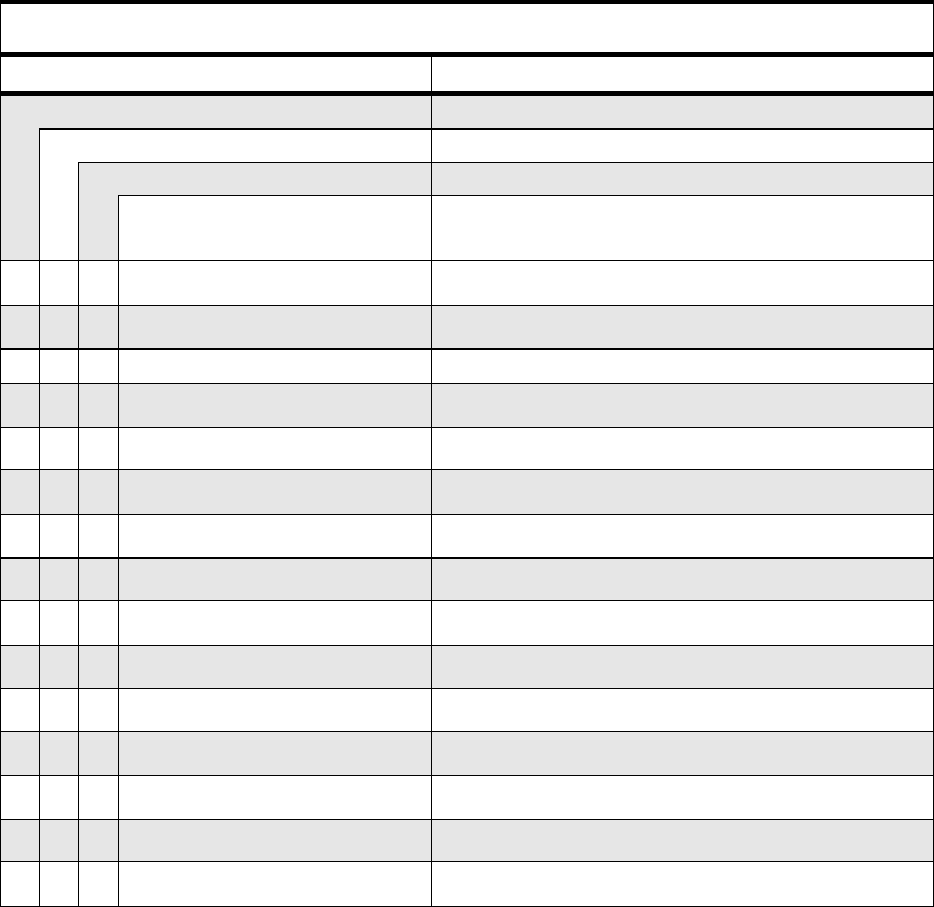
3.0 Radio Model Information
The model number and serial number are located on a label attached to the back of your radio. You
can determine the RF output power, frequency band, protocols, and physical packages. The
example below shows one mobile radio model number and its specific characteristics.
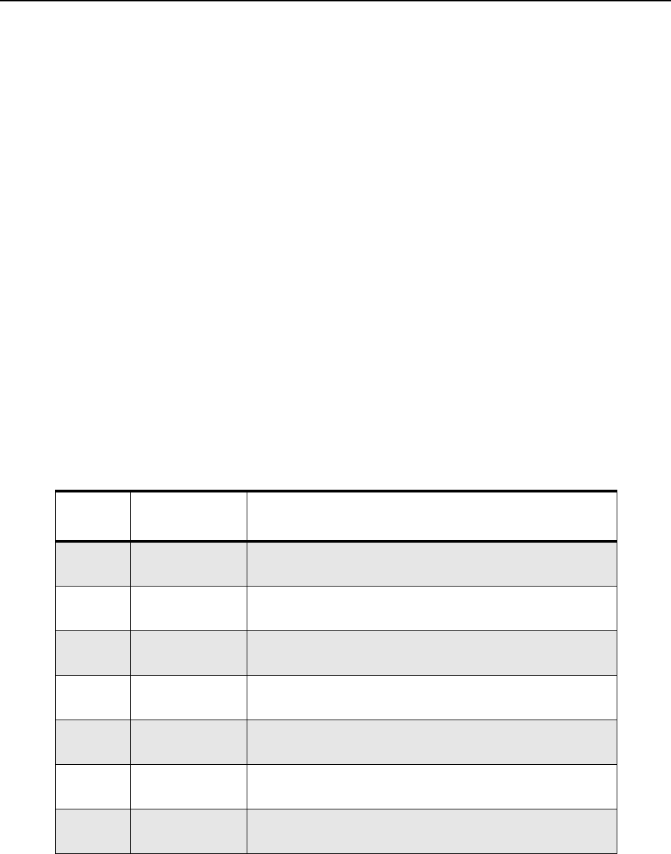
Table 1-1 Radio Model Number (Example: MDH50KDC9AA2_N)
Type of
Unit Model
Series Freq.
Band Power
Level Physical
Packages Channel
Spacing Protocol Feature
Level Model
Revision Model
Package
MD H 50 J
VHF1
(136-162
MHz)
K
VHF
(146-174
MHz)
Q
UHF1
(403-440
MHz)
R
UHF2
(438-470
MHz)
S
UHF3
(465-495
MHz)
D
4W or
5W
C
2W
C
No
Display
9
Program-
mable
AA
Conven-
tional
1
4 channel
2
16 channel
AN
MD = Motorola Internal Use
H = Portable

Chapter 2
MAINTENANCE
1.0 Introduction
This chapter provides details about the following:
❑Preventive maintenance (inspection and cleaning).
❑Safe handling of CMOS and LDMOS devices.
❑Disassembly and reassembly of the radio.
❑Repair procedures and techniques.
2.0 Preventive Maintenance
The radios do not require a scheduled preventive maintenance program; however, periodic visual
inspection and cleaning is recommended.
2.1 Inspection
Check that the external surfaces of the radio are clean, and that all external controls and switches
are functional. It is not recommended to inspect the interior electronic circuitry.
2.2 Cleaning Procedures
The following procedures describe the recommended cleaning agents and the methods to be used
when cleaning the external and internal surfaces of the radio. External surfaces include the front
cover and housing assembly. These surfaces should be cleaned whenever a periodic visual
inspection reveals the presence of smudges, grease, and/or grime.
The only recommended agent for cleaning the external radio surfaces is a 0.5% solution of a mild
dishwashing detergent in water. The only factory recommended liquid for cleaning the printed circuit
boards and their components is isopropyl alcohol (70% by volume).
Cleaning External Plastic Surfaces
Apply the 0.5% detergent-water solution sparingly with a stiff, non-metallic, short-bristled brush to
work all loose dirt away from the radio. Use a soft, absorbent, lintless cloth or tissue to remove the
solution and dry the radio. Make sure that no water remains entrapped near the connectors, cracks,
or crevices.
NOTE Internal surfaces should be cleaned only when the radio is disassembled for service or
repair.
CAUTION: The effects of certain chemicals and their vapors can have harmful results on
certain plastics. Avoid using aerosol sprays, tuner cleaners, and other chemicals.
!

2-2 MAINTENANCE
Cleaning Internal Circuit Boards and Components
Isopropyl alcohol (100%) may be applied with a stiff, non-metallic, short-bristled brush to dislodge
embedded or caked materials located in hard-to-reach areas. The brush stroke should direct the
dislodged material out and away from the inside of the radio. Make sure that controls are not soaked
with alcohol. Do not use high-pressure air to hasten the drying process since this could cause the
liquid to collect in unwanted places. After completing of the cleaning process, use a soft, absorbent,
lintless cloth to dry the area. Do not brush or apply any isopropyl alcohol to the frame, front cover, or
top cover.
3.0 Safe Handling of CMOS and LDMOS Devices
Complementary metal-oxide semiconductor (CMOS) devices are used in this family of radios, and
are susceptible to damage by electrostatic or high voltage charges. Damage can be latent, resulting
in failures occurring weeks or months later. Therefore, special precautions must be taken to prevent
device damage during disassembly, troubleshooting, and repair.
Handling precautions are mandatory for CMOS circuits and are especially important in low humidity
conditions. DO NOT attempt to disassemble the radio without first referring to the following
CAUTION statement.
NOTE Always use a fresh supply of alcohol and a clean container to prevent contamination by
dissolved material (from previous usage).
CAUTION: This radio contains static-sensitive devices. Do not open the radio unless you are
properly grounded. Take the following precautions when working on this unit:
❑Store and transport all CMOS devices in conductive material so that all exposed
leads are shorted together. Do not insert CMOS devices into conventional plastic
“snow” trays used for storage and transportation of other semiconductor devices.
❑Ground the working surface of the service bench to protect the CMOS device. We
recommend using the Motorola Static Protection Assembly (part number
0180386A82), which includes a wrist strap, two ground cords, a table mat, and a
floor mat.
❑Wear a conductive wrist strap in series with a 100k resistor to ground.
(Replacement wrist straps that connect to the bench top covering are Motorola part
number 4280385A59)
❑Do not wear nylon clothing while handling CMOS devices.
❑Do not insert or remove CMOS devices with power applied. Check all power
supplies used for testing CMOS devices to be certain that there are no voltage
transients present.
❑When straightening CMOS pins, provide ground straps for the apparatus used.
❑When soldering, use a grounded soldering iron.
❑If at all possible, handle CMOS devices by the package and not by the leads. Prior
to touching the unit, touch an electrical ground to remove any static charge that you
may have accumulated. The package and substrate may be electrically common. If
so, the reaction of a discharge to the case would cause the same damage as
touching the leads.
!

Repair Procedures and Techniques — General 2-3
4.0 Repair Procedures and Techniques — General
Parts Replacement and Substitution
When damaged parts are replaced, identical parts should be used. If the identical replacement part
is not locally available, check the parts list for the proper Motorola part number and order the part
from the nearest Motorola Parts centre listed in the “Piece Parts” section in Chapter 1 of this manual.
Rigid Circuit Boards
This family of radios uses bonded, multi-layer, printed circuit boards. Since the inner layers are not
accessible, some special considerations are required when soldering and unsoldering components.
The printed-through holes may interconnect multiple layers of the printed circuit. Therefore, exercise
care to avoid pulling the plated circuit out of the hole.
When soldering near the connectors, potentiometers and circuit components:
❑Avoid accidentally getting solder in the connector.
❑Be careful not to form solder bridges between the connector pins.
❑Examine your work closely for shorts due to solder bridges.
5.0 Disassembling and Reassembling the Radio — General
Since these radios may be disassembled and reassembled with the use of only four (board to
casting) screws, it is important to pay particular attention to the snaps and tabs, and how parts align
with each other.
The following tools are required for disassembling/assembling the radio:
❑Small flat blade screwdriver
❑knob remover/chassis opener
❑TORX™ T6 screwdriver
If a unit requires more complete testing or service than is customarily performed at the basic level,
send this unit to a Motorola Authorized Service Centre. (See Chapter 1 for a list of authorized
service centres.)
The following disassembly procedures should be performed only if necessary:
❑Speaker Disassembly (Figure2-5)
❑PTT Disassembly (Figure 2-6)
❑Chassis Disassembly (Figure 2.7)
2-4 MAINTENANCE
6.0 Radio Disassembly - Detailed
6.1 Front Cover from Chassis Disassembly
1. Turn off the radio.
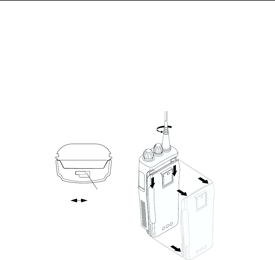
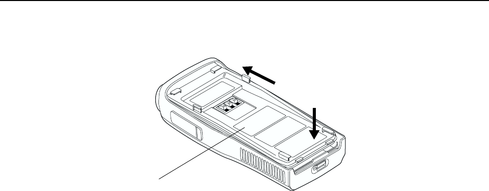
2. Remove the battery (Figure 2-1) :
a. Slide the battery latch into the unlock position. Disengage by pushing downward and
holding the latch towards the front of the radio.
b. With the battery latch disengaged, slide the battery down from the top of the radio about
15mm. Once the battery is free from the battery rails, lift it directly away from the radio.
c. Remove the battery from the radio.
3. Remove the antenna.
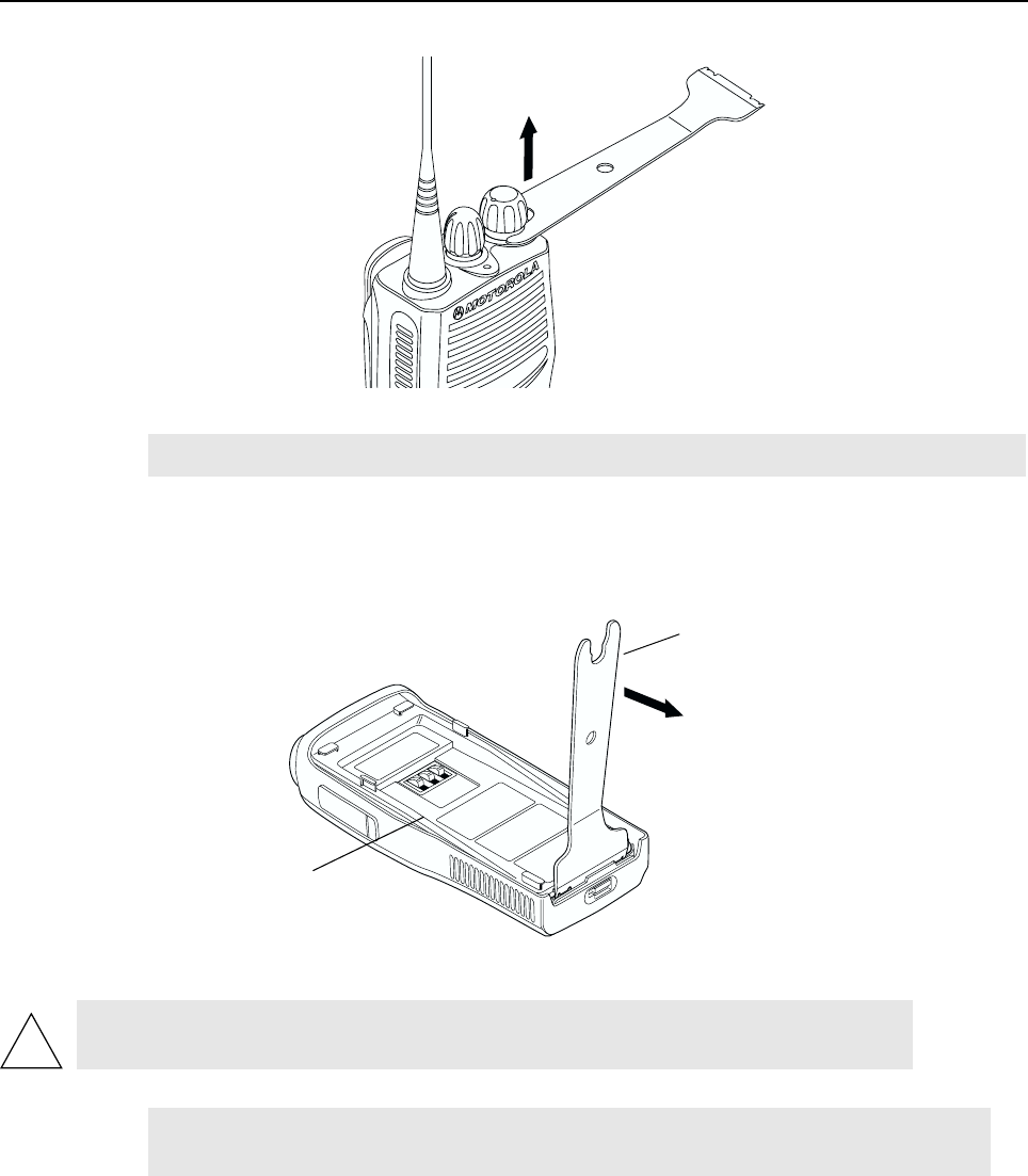
4. Pry off the volume and channel selector knobs from their shafts using the knob remover/chassis
opener tool (Motorola part No.6686533Z01) (Figure 2.2).
Figure 2-1 Battery Removal
Battery Latch
Lock Unlock
Radio Disassembly - Detailed 2-5
5. Separate the chassis from the front housing assembly by using the knob remover/chassis opener
tool. Place the broad side of the opener into the slots located at the base of the radio (Figure 2.3).
Press the handle of the opener downwards. This pressing action forces the thin inner plastic wall
toward the base of the radio, releasing the two chassis base tabs.
6. Pull the chassis assembly out of the front cover.
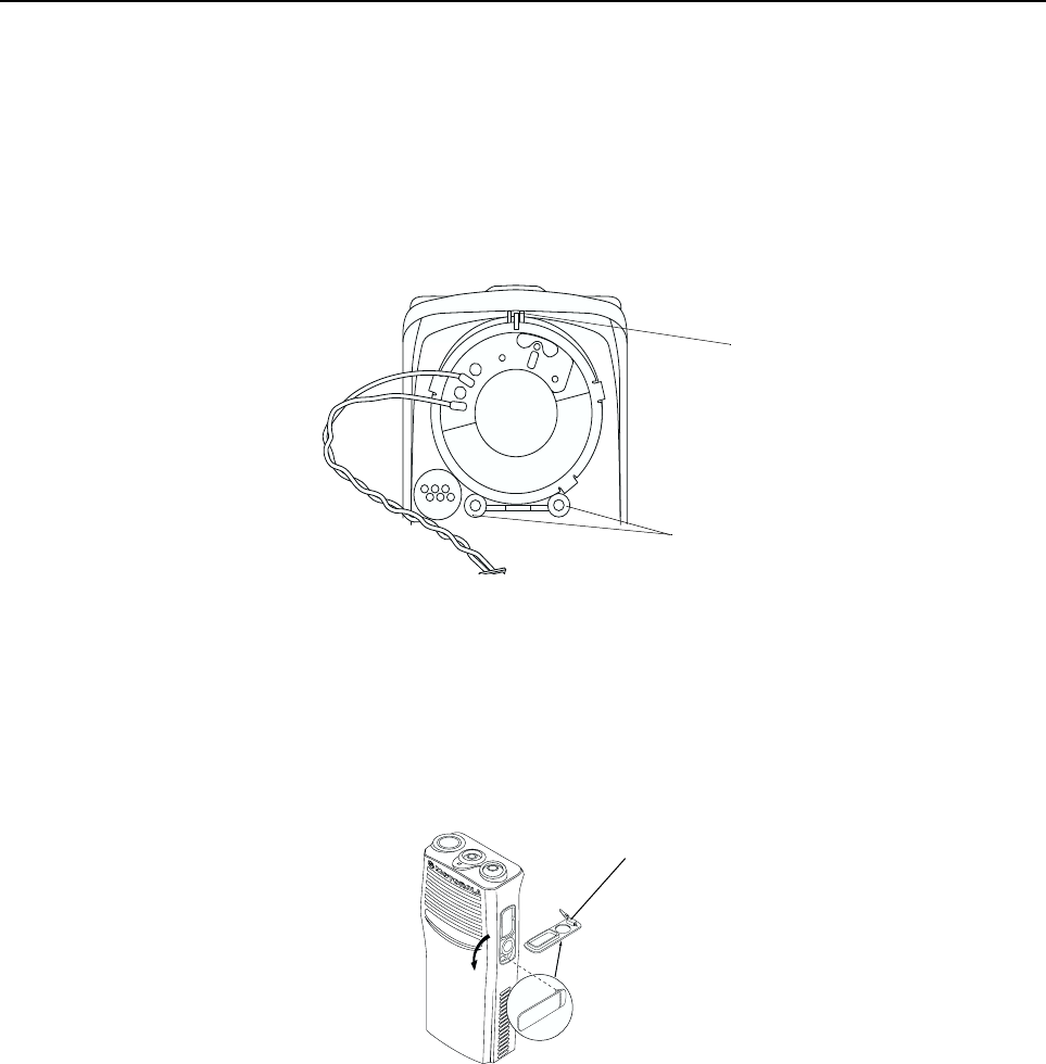
7. Unplug the speaker wire assembly from the 2-pin connector.
Figure 2-2 Knob Removal
NOTE: Both knobs slide on and off. However, they are supposed to fit very tightly on their shafts.
Figure 2-3 Chassis Removal
CAUTION: Marring the front cover O-ring sealing area will prevent the radio from sealing
properly. If the O-ring is damaged, replace it with a new one.
NOTE: The speaker wire assembly connecting the front housing assembly, and the chassis
prevent you from completely separating the two units.
Radio Chassis
Knob Remover/
Chassis Opener
!
2-6 MAINTENANCE
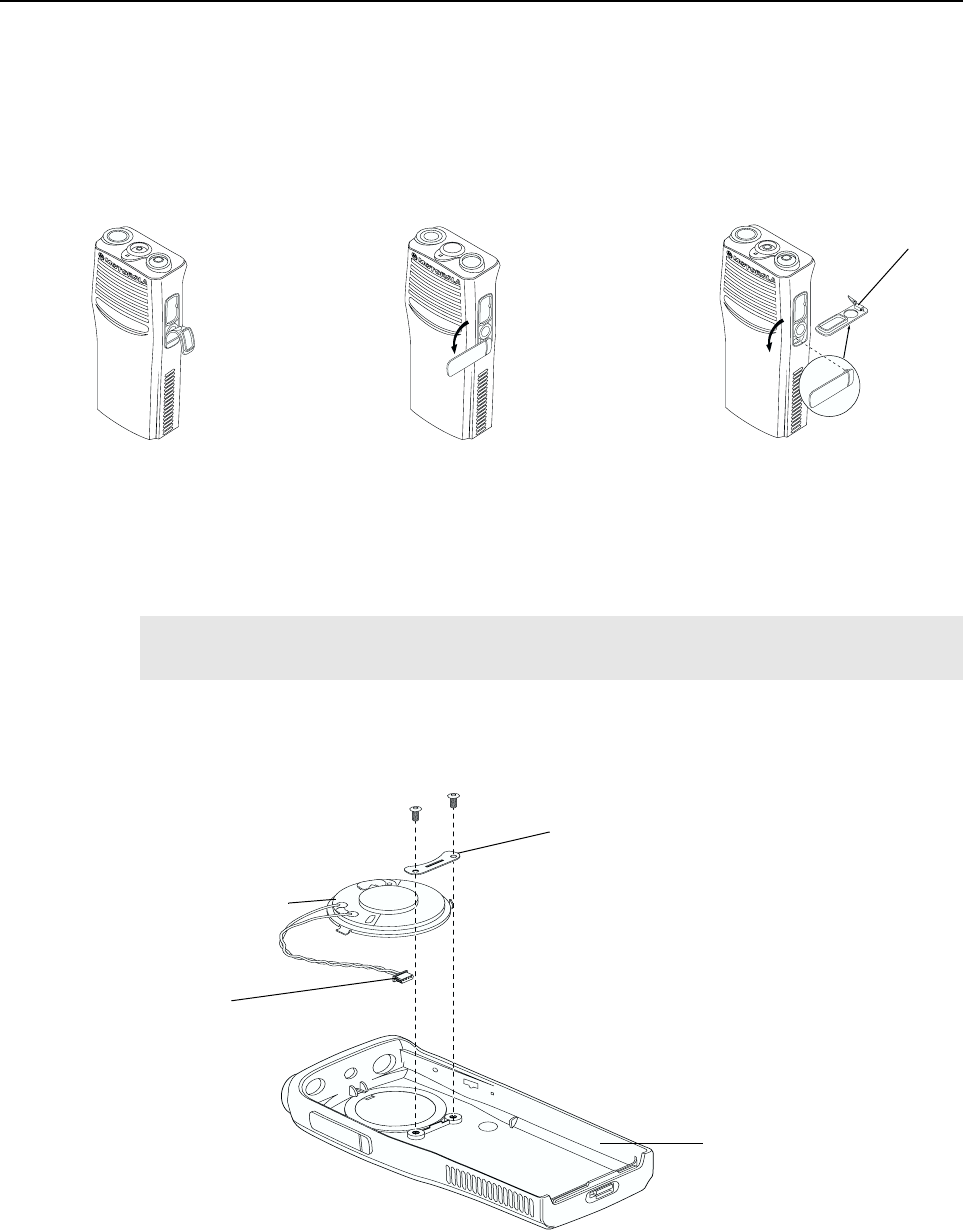
6.2 Dust Cover Disassembly
a. Gently pry the top of the dust cover away from the body of the radio (Figure 2.4).
b. Rotate the dust cover 90° in a counter clockwise direction to allow the key to be
removed.
c. Separate the dust cover away from the body of the radio. The dust cover key is fragile;
apply only light pressure to the key while removing the dust cover.
Figure 2-4 Dust Cover Removal
6.3 Speaker Disassembly
1. Remove the two screws from the speaker retainer using a T6 Torx screwdriver.
2. Lift the speaker out from the front housing.
NOTE: The speaker is held in place with a retainer bracket. Be careful not to damage the speaker
when removing the retainer bracket.
Figure 2-5 Removal Speaker-Microphone Assembly
key
c. Separate dust
cover from body.
b. Rotate dust cover 90° to
a. Pry dust cover from body.
allow key to be removed.
Retainer Bracket
Speaker
Radio Housing
Wire Connector
Radio Disassembly - Detailed 2-7
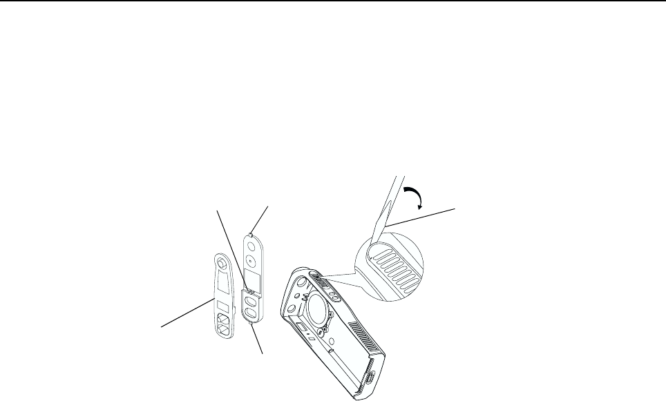
6.4 PTT Disassembly
1. If required, the PTT (Figure 2-6) can be disassembled using a small screwdriver, as follows:
a. Insert the tip of a small screwdriver underneath the PTT and unsnap the top tab.
b. Pry the PTT away from the radio housing.
c. Inspect the two hooks. If bent or broken, the PTT must be replaced.
d. Remove the PTT seal.
Figure 2-6 PTT Removal
Flat Blade
Screwdriver
PTT Seal
Ta b
Ta b
Hooks
2-8 MAINTENANCE
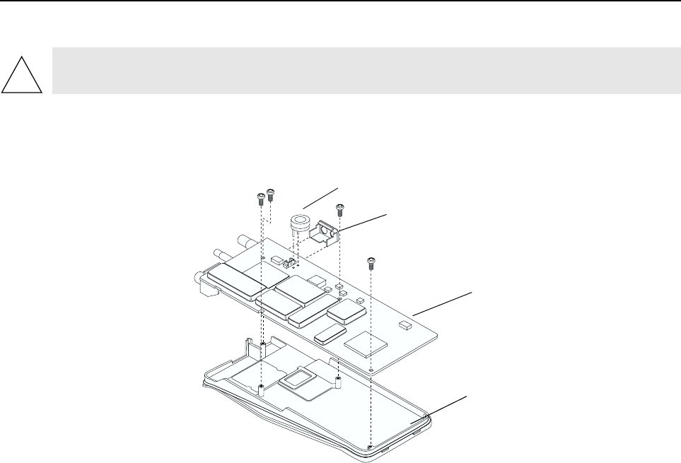
6.5 Chassis Disassembly
1. Remove the O-ring.
2. Use a Torx™ screwdriver with a T6 bit to remove the four screws (Figure 2.7) holding the main
board to the chassis.
3. The microphone boot assembly can be unplugged from the main board. If you are replacing the
microphone, remove it from the rubber boot.
4. The audio jack shroud can be removed from the main board.
5. Lift the main board from the chassis (Figure 2-7).
6. Remove the battery contact seal.
CAUTION: Refer to the CMOS CAUTION paragraph (see 3.3) before removing the main board. Be sure
to use Electrostatic Discharge protection when handling circuit boards.
Figure 2-7 Removal of Main Board from Chassis
!
Main Board
Radio Chassis
Audio Jack Shroud
Mi
crop
h
one
A
ssem
bl
y
Radio Assembly — Detailed 2-9
7.0 Radio Assembly — Detailed
7.1 Chassis Assembly/Reassembly
1. Replace the battery contact seal (if necessary) surrounding the battery contact.
2. Remove the old Interface Pad from the chassis by scraping off the pad and adhesive with a
straight razor. Use rubbing alcohol and a cloth to completely remove the adhesive from the
chassis surface. With the chassis clean and dry, add a new Interface Pad to the chassis.
3. Place the main circuit board straight down on top of the chassis.
4. Use the T6 Torx screwdriver to fasten the screws holding the main board to the chassis. Tighten
to 0.34Nm (3 in/lb).
5. Replace the O-ring by positioning it in the top groove by the volume/frequency switches. Stretch
the O-ring to place it into the retaining groove at the bottom end of the chassis.
6. Replace the audio jack shroud.
7. Replace the microphone boot assembly.
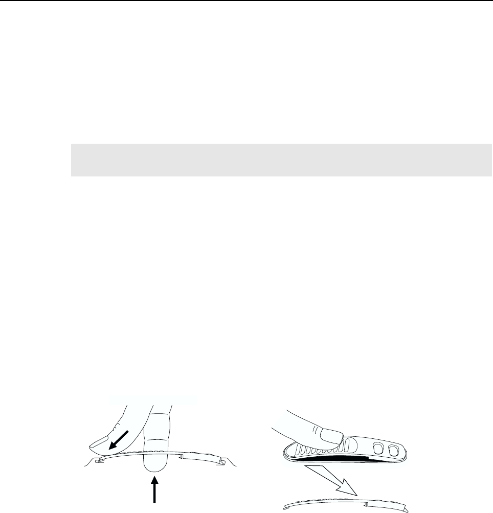
7.2 PTT Assembly
1. Place the PTT seal over the ridge around the top hole. Press down to seat the seal around the
ridge.
2. Place the bottom tab in the slot inside the front housing PTT opening. Slightly slide down the PTT
and bow it by placing one finger under the middle of the PTT, so that the top tab can be aligned
and inserted into the top slot (Figure 2-8a).
3. Press the PTT assembly against the front cover opening (Figure 2-8b).
NOTE: Be sure the battery contact seal protrudes through the chassis and is not pinched under the
chassis.
Figure 2-8 PTT Assembly
a. Place bottom tab into bottom slot.
Place top tab into top slot.
b. Push down on ribs toward bottom
of radio so hooks do not get crushed.
2-10 MAINTENANCE
7.3 Speaker Reassembly
1. Align the speaker as shown in Figure 2.9.
2. Insert the top of the speaker under the two rails in the housing.
3. Place the speaker retainer bracket onto the two screw bosses. Make sure the tab fits into the
retainer bracket slot.
4. Use the T6 Torx screwdriver to fasten the screws holding the retainer bracket to the front cover.
Tighten to 0.23Nm (2 in/lb).
7.4 Dust Cover Assembly
a. Insert the dust cover key into the housing at a 90° angle.
b. Rotate the dust cover 90° in a clockwise direction to allow the key to fully insert into the
housing.
c. Press the key and dust cover into the housing.
Figure 2-9 Speaker Assembly
Rails
Screw Bosses
a. Insert dust cover key into housing
at 90° angle.
Figure 2-10 Dust Cover Assembly
Key
Radio Assembly — Detailed 2-11
7.5 Chassis and Front Cover Assembly
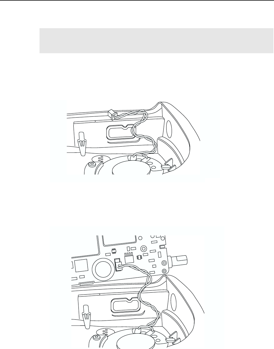
1. Dress and connect the speaker wires.
a. Form the wires into an “M” shape so it can collapse on itself like an accordion with all of
the wire up in the top corner of the radio away from the shields. Place three bends in the
wires spaced approximately 1cm apart to give the wire an “M” shape (Figure 2-11).
b. Bend the wires up from the speaker so the wires are positioned toward the top of the
radio (Figure 2-11).
c. Connect the speaker wire assembly into the 2-pin connector on the main board and
bend the wires at the board connector so the wires are positioned toward the top of the
radio (Figure 2-12).
2. Slide the volume potentiometer and frequency switch shafts into their respective holes in the front
cover. Look through the accessory connector opening to make certain that the wires are not pinched.
NOTE: Care should be taken when dressing the speaker wires to avoid pinching them between the
speaker magnet and shield, under the microphone boot or between the accessory
connector and housing.
Figure 2-11 Bend the Wires into an “M” Shape
Figure 2-12 Connect Speaker Wire Assembly
2-12 MAINTENANCE
3. Push the chassis assembly completely into the top of the front cover (Figure 2-13) until it settles
in place.
4. Make sure the O-ring is properly seated.
5. Snap the bottom of the chassis into the front cover.
6. Reassemble the knobs, antenna, and battery.
Figure 2-13 Fastening the Chassis
Radio Chassis
Mechanical View and Parts List 2-13
8.0 Mechanical View and Parts List
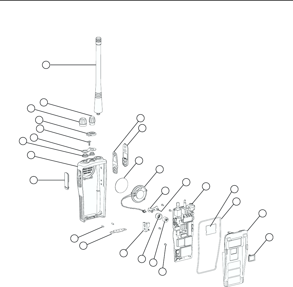
8.1 CP040 Exploded View and Parts List
Figure 2-14 CP040 Radio Exploded View
1
2
3
4
5
6
7
8
9
10
11
12
13 14
15
16
17
18
19
21
22
23
24
25
26
20

2-14 MAINTENANCE
Item Motorola
Part Number Description
1See Chapter 6 Antenna
2 3680530Z02 Knob, Frequency
33680529Z01 Knob, Volume
4 1386440Z01
1386440Z02
Escutcheon, Top; 4 Ch.
Escutcheon, Top; 16 Ch.
56186446Z02 Lightpipe
6 3386443Z01 Label, Escutcheon Seal
73286432Z01 Seal, Control Shaft
8 1586390Z01 Housing, Front
93886441Z01 Cap, Dust
10 4105944K01 Spring, latch; 2 used
11 5586445Z02 Latch assembly
12 1586437Z02 Shroud, audio jack
13 0786469Z01 Boot, microphone
14 5080258E16 Microphone
15 0304726J05 Screws, chassis; 4 used
16 3286435Z01 Seal, battery contact block
17 2786389Z02 Chassis
18 3286431Z05 Seal, main O-ring
19 7586436Z01 Pad, PA interface
20 Refer to Chapter
7 - Model Charts
Main Board Tanapa
21 0386434Z01 Screws, speaker retainer;
2 used
22 0786433Z02 Retainer, speaker
23 5005679X04 Speaker
24 3586092Z02 Felt, speaker
25 4586439Z01 PTT, plastic
26 3886489Z01 PTT, rubber
NON-REFERENCED ITEMS
3386488Z01 Nameplate, Motorola
3386409Z04 Nameplate, CP040

Service Aids 2-15
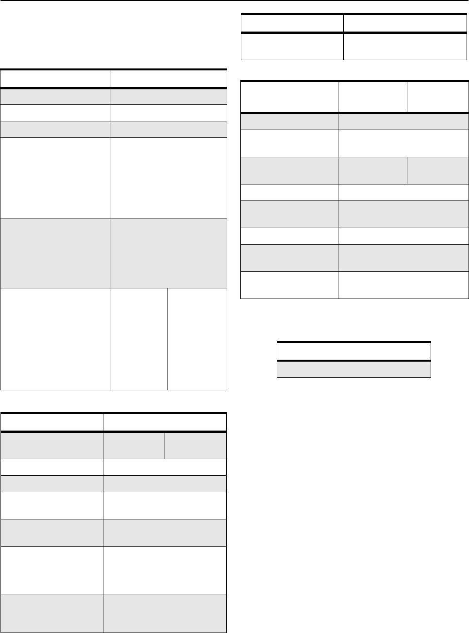
9.0 Service Aids
Table 2-1 lists the service aids recommended for working on the radio. While all of these items are
available from Motorola, most are standard workshop equipment items, and any equivalent item
capable of the same performance may be substituted for the item listed.
Table 2-1 Service Aids
Motorola Part
No. Description Application
RLN4460 Portable Test Set Enables connection to the audio/accessory jack.
Allows switching for radio testing.
RLN4510 Battery Interface Regulates DC current and voltage between radio and
power supply.
PMKN4004 Programming Test Cable Connects radio to RIB (RLN4008).
PMKN4003 Radio to Radio Cloning Cable Allows a radio to be duplicated from a master radio by
transferring programmed data from the master radio to
the other.
RLN4008 Radio Interface Box Enables communications between the radio and the
computer’s serial communications adapter.
5886564Z01 RF BNC Adaptor Adapts radio’s antenna port to BNC cabling of test
equipment.
0180305K08 Shop Battery Eliminator Interconnects radio to power supply.
EPN4040_ Wall-Mounted Power Supply (UK) Used to supply power to the RIB
EPN4041_ Wall-Mounted Power Supply
(220VAC)
Used to supply power to the RIB
HSN9412 Wall-Mounted Power Supply
(120VAC)
Used to supply power to the RIB
3080369B71 or
3080369B72
Computer Interface Cable Use B72 for the IBM PC AT or newer (9-pin serial port).
Use B71 for older models (25-pin serial port). Connects
the computer’s serial communications adapter to the
RIB (RLN4008).
HKN9216 IBM Computer Interface Cable Connection from computer to RIB.
6680702Z01 Knob Remover/Chassis Opener Used to remove the front cover assembly.
RSX4043A TORX screwdriver Tighten and remove chassis screws
6680387A70 T6 TORX bit Removable TORX screwdriver bit
WADN4055A Portable Soldering Station Digitally controlled soldering iron
6604008K01 0.4mm replacement tip For WADN4055A Soldering iron
6604008K02 0.8mm replacement tip For WADN4055A Soldering iron
0180386A82 Anti-static Grounding Kit Used for all radio assembly/disassembly procedures
6684253C72 Straight Prober
6680384A98 Brush
1010041A86 Solder (RMA type) 63/37, 0.5mm diameter, 2.2kg (1lb) spool.

2-16 MAINTENANCE
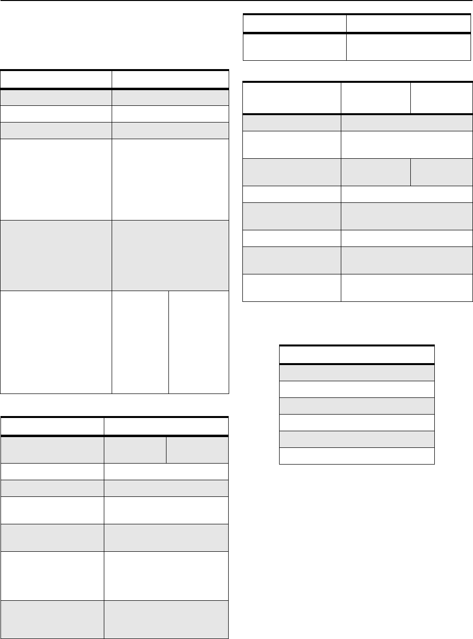
10.0 Test Equipment
Table 2-2 lists test equipment required to service the CP040 Radio and other two-way radios.
Table 2-2 Recommended Test Equipment
Motorola Part No. Description Characteristics Application
R2600 series Comms System
analyzer (non MPT)
This item will substitute for
items with an asterisk (*)
Frequency/deviation meter and
signal generator for wide-range
troubleshooting and alignment
*R1074_ Fluke 87 digital multi-
meter
True RMS metering,
200 kHz frequency
counter, 32-segment
bargraph with backlit
display
Digital voltmeter is
recommended for AC/DC
voltage and current
measurements
*R1377_ AC voltmeter 1mV to 300mV, 10 mega-
ohm input impedance
Audio voltage measurements
R1611_ Dual channel
100 MHz
oscilloscope
(Agillent)
Two-channel, 100 MHz
bandwidth, 200M sample
rate/sec, 2MB memory/
channel
Waveform measurements
S1339_ RF millivolt meter 100µV to 3V RF, 10 kHz to
1 GHz frequency range
RF level measurements
*R1013_ or
*R1370_
SINAD meter or
SINAD meter with
RMS
Without RMS audio
voltmeter or
With RMS audio voltmeter
Receiver sensitivity
measurements
S1348D Programmable DC
power supply
0-20V DC, 0-5 amps,
current limited
Bench supply for 7.5 V DC
R1440A
0180305F14
0180305F30
0180305F39
RLN4610A
T1013
Wattmeter,
Plug-in Element
Plug-in Element
Plug-in Element
Carry case
RF Dummy Load
Thruline 50-Ohm, ±5%
accuracy
10W, 25 - 60 MHz
10W, 100 - 250 MHz
10W, 200 - 500 MHz
Wattmeter and
6 elements
Transmitter power output
measurements
Programming/Test Cable 2-17
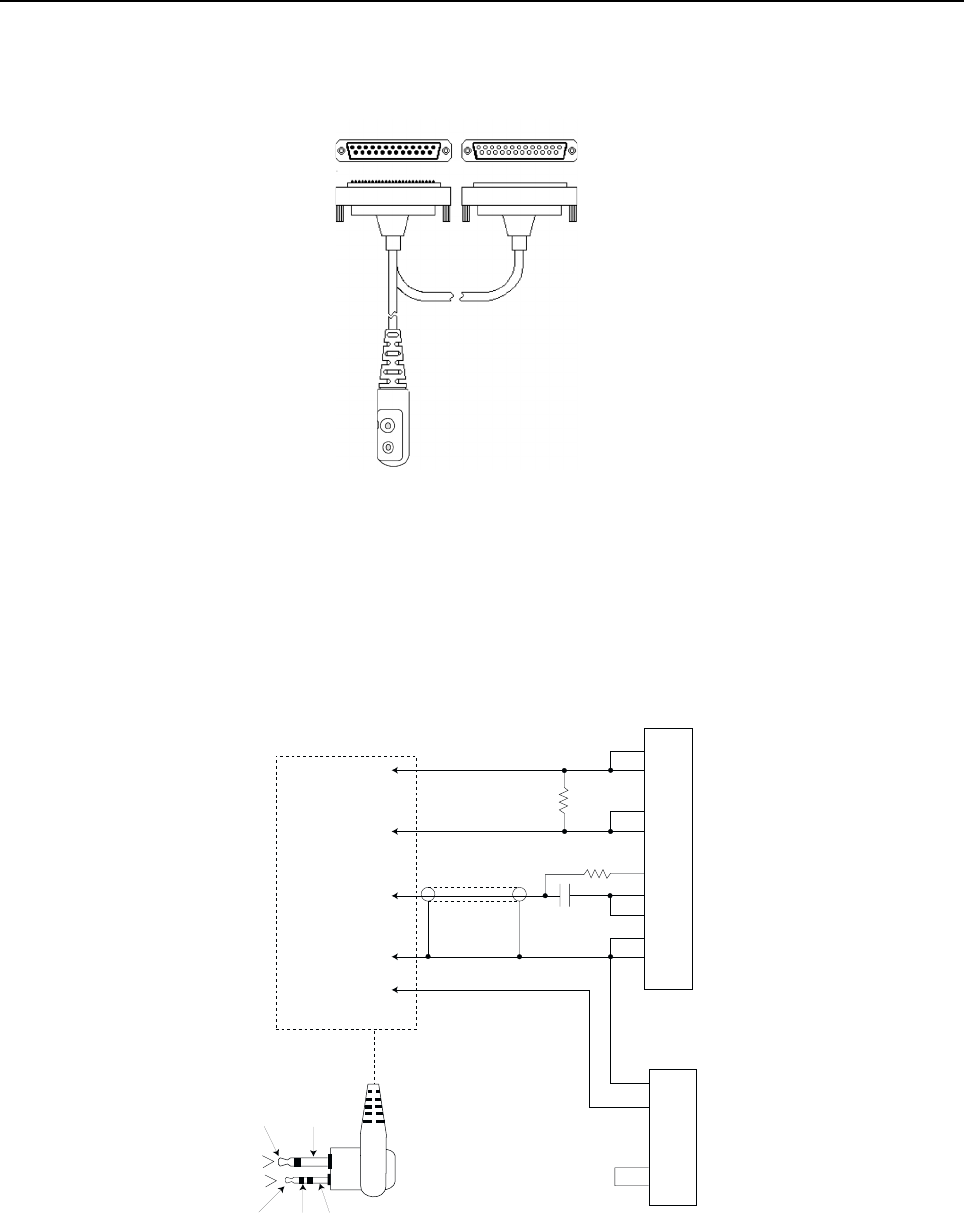
11.0 Programming/Test Cable
12.0 Wiring of the Connectors
Figure 2-15 Programming/Test Cable
Figure 2-16 Wiring of the Connectors
25 POSITION
FEMALE CONNECTOR
25 POSITION
MALE CONNECTOR
36.0”
CABLE
36.0”
CABLE
P1
P2 P3
P2
25 pin Male D Connector
Components molded inside
1
5
24
7
20
8
15
16
9
47
ohm
33K
+
1UF,16V 5%
Orange
Blue
White
Spiral
Yellow
P1
2.5mm stereo and
3.5mm
1
2
5
3
4
3.5mm Tip
(Speaker +)
3.5mm
Sleeve
2.5mm Tip
(Microphone)
2.5mm
2.5mm
Center
P3
25 pin Female
D Connector
1
15
4
11
1
2
3
4
5
3.5mm mono
2.5mm stereo
To Test Box
To Test Box

2-18 MAINTENANCE

Chapter 3
TRANSCEIVER PERFORMANCE TESTING
1.0 General
These radios meet published specifications through their manufacturing process by utilizing high-
accuracy laboratory-quality test equipment. The recommended field service equipment approaches
the accuracy of the manufacturing equipment with few exceptions. This accuracy must be
maintained in compliance with the manufacturer’s recommended calibration schedule.
2.0 Setup
Supply voltage can be connected from the battery eliminator. The equipment required for alignment
procedures is connected as shown in the Radio Tuning Setup diagram (Chapter 4, Figure 4-1).
Initial equipment control settings should be as indicated in the following table and should hold for all
alignment procedures.
Table 3-1 Initial Equipment Control Settings
Service Monitor Test Set Power Supply
Monitor Mode: Power Monitor Spkr set: A Voltage: 7.5Vdc
RF Attenuation: -70 Spkr/load:
Speaker
DC on/standby:
Standby
AM, CW, FM: FM PTT: OFF Volt Range: 10V
Oscilloscope Source: Mod
Oscilloscope Horiz: 10mSec/Div
Oscilloscope Vert: 2.5kHz/Div
Oscilloscope Trig: Auto
Monitor Image: Hi
Monitor BW: Nar
Monitor Squelch: mid CW
Monitor Vol: 1/4 CW
Current: 2.5A
3-2 TRANSCEIVER PERFORMANCE TESTING
3.0 Test Mode
3.1 RF Test Mode
The RF Test Mode is a special routine that has been incorporated in the radio. This mode allows
bench testing of the radio at various test frequencies across the entire band, at both high and low
transmit power (if applicable), at various channel spacings, and with different coded or carrier squelch
types. Any customer specific programming in the radio will not be changed or affected by use of the
RF Test Mode.
To enter test mode:
1. Turn the radio on.
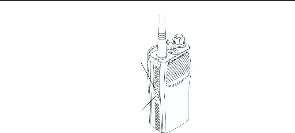
2. Within ten seconds after the self test is complete (self test tone is heard), press SB2
(Side Button 2 in Chapter 4, Figure 4-3) five times in succession. If the self test complete tone
is not heard, see Error Codes information in Chapter 5. Entry into the test mode is indicated
by a positive indicator tone followed by a good key chirp (GKC).
3. Upon entering test mode, the radio is on carrier squelch mode.
4. Press SB1 (Side Button 1) and scroll through and access test environments as shown in
Table 3-2.
5. Press SB2 and scroll through the channel spacing available as shown in Table 3-3.
6. Turn the channel selector knob to change the test channel for that environment as shown in
Table 3-4.
7. Press the PTT on a test channel to cause the radio to transmit at the test frequency for the
channel.
Note: “BKC” means Bad Key Chirp, “GKC” means Good Key Chirp
Table 3-2 Te s t E n v i r o n m e n t s
No. of
Beeps Description Function
1
GKC
Carrier Squelch RX: unsquelch if carrier detected
TX: mic audio
1
BKC
To n e
Private-Line
RX: unsquelch if carrier and tone (192.8Hz) detected
TX: mic audio + tone (192.8Hz)
2
BKC
Digital
Private-Line
RX: unsquelch if carrier and digital code (131) detected
TX: mic audio + digital code (131)
5
BKC
Unsquelch
Open
RX: constant unsquelch
TX: mic audio
9
BKC
High-Speed
Signaling
RX: unsquelch if carrrier detected
TX: 1500Hz tone
11
BKC
Companding RX: unsquelch if carrier detected
TX: mic audio
12
BKC
Low-Level
Expansion
Unsupported
Test Mode 3-3
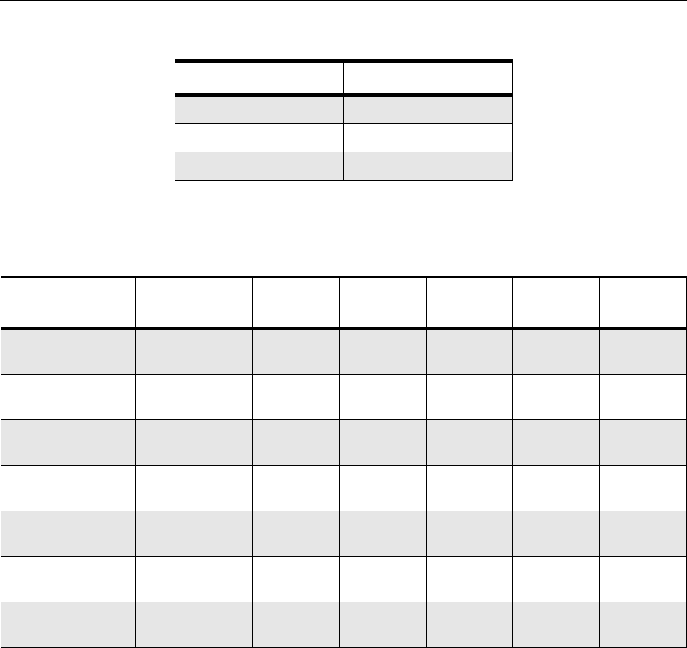
Table 3-3 Test Channel Spacing
No. of BKC Channel Spacing
125 kHz
2 12.5 kHz
320 kHz
Table 3-4 Test Frequencies
Channel Selector
Switch Position Test Channel VHF1 VHF2 UHF1 UHF2 UHF3
1 Low Power
8 High Power
TX#1 or #8
RX#1 or #8 136.625 146.625 403.625 438.625 465.625
2 Low Power
9 High Power
TX#2 or #9
RX#2 or #9 140.325 150.775 409.775 443.775 470.775
3 Low Power
10 High Power
TX#3 or #10
RX#3 or #10 144.525 155.275 415.275 448.275 475.275
4 Low Power
11 High Power
TX#4 or #11
RX#4 or #11 148.875 160.125 421.125 454.125 480.125
5 Low Power
12 High Power
TX#5 or #12
RX#5 or #12 153.325 164.475 427.475 459.475 485.475
6 Low Power
13 High Power
TX#6 or #13
RX#6 or #13 157.875 169.475 443.475 464.475 490.475
7 Low Power
14 High Power
TX#7 or #14
RX#7 or #14 161.975 173.875 439.875 469.875 494.875

3-4 TRANSCEIVER PERFORMANCE TESTING
Table 3-5 Receiver Performance Checks
Test Name Communications Analyzer Radio Test Set Comments
Reference
Frequency
Mode: PWR MON
4th channel test frequency
*
Monitor: Frequency error
Input at RF In/Out
TEST MODE,
Test Channel
4 carrier
squelch out-
put at
antenna
PTT to continuous
(during the
performance
check)
Frequency error to
be ±200 Hz VHF
±500 Hz UHF
Rated Audio Mode: GEN
Output level: 1.0mV RF
4th channel test frequency
*
Mod: 1kHz tone at
3kHz deviation
Monitor: DVM: AC Volts
TEST MODE
Test Channel
4 carrier
squelch
PTT to OFF
(center),
meter selector to
Audio PA
Set volume control
to 3.46Vrms
Distortion As above, except to distor-
tion
As above As above Distortion <3.0%
Sensitivity
(SINAD)
As above, except SINAD,
lower the RF level for 12dB
SINAD.
As above PTT to OFF
(center)
RF input to be
<0.30µV (0.25 µV
typical).
Noise
Squelch
Threshold
(only radios
with conven-
tional sys-
tem need to
be tested)
RF level set to 1mV RF As above PTT to OFF
(center),
meter selection to
Audio PA, spkr/
load to speaker
Set volume control
to 3.46Vrms
As above, except change
frequency to a conventional
system. Raise RF level from
zero until radio unsquelches.
out of TEST
MODE; select
a conven-
tional system
As above Unsquelch to
occur at <0.25µV.
Preferred SINAD =
6-9 dB
* See Table 3-4

Test Mode 3-5
Table 3-6 Transmitter Performance Checks
Test Name Communications Analyzer Radio Test Set Comments
Reference
Frequency
Mode: PWR MON
4th channel test frequency
*
Monitor: Frequency error
Input at RF In/Out
TEST MODE,
Test Channel
4 carrier
squelch
Output at
antenna
PTT to continuous
(during the
performance
check)
Frequency error to be
±200 Hz VHF
±500 Hz UHF
Power RF As above As above As above Refer to Maintenance
Specifications
Voice
Modulation
Mode: PWR MON
4th channel test frequency
*
atten to -70, input to RF In/
Out
Monitor: DVM, AC Volts
Set 1 kHz Mod Out level for
0.025Vrms at test set,
80mVrms at AC/DC test set
jack
As above As above, meter
selector to mic
Deviation:
VHF, UHF
≥ 4.0 kHz but ≤ 5.0
kHz (25 kHz Ch Sp).
Voice
Modulation
(internal)
Mode: PWR MON
4th channel test frequency
*
atten to -70, input to RF In/
Out
TEST MODE,
Test Channel
4 carrier
squelch
Output at
antenna
Remove
modulation input
Press PTT switch on
radio. Say “four”
loudly into the radio
mic. Measure devia-
tion: VHF, UHF
≥ 4.0 kHz but ≤ 5.0
kHz (25 kHz Ch Sp)
DTMF
Modulation
As above,
4th channel test frequency
*
TEST MODE,
Test Channel
4 DTMF
Output at
antenna
As above Deviation:
VHF, UHF ≥ 3.05 kHz
but ≤ 3.45 kHz
(25 kHz Ch Sp)
PL/DPL
Modulation
As above
4th channel test frequency
*
BW to narrow
TEST MODE,
Test Channel
4
TPL
DPL
As above Deviation:
VHF, UHF ≥ 500Hz
but ≤ 1000Hz
(25 kHz Ch Sp).
* See Table 3-4

3-6 TRANSCEIVER PERFORMANCE TESTING
Chapter 4
RADIO TUNING AND PROGRAMMING
1.0 Introduction
This chapter provides an overview of the Customer Programming Software (CPS) and tuner
program designed for use in a Windows 98/ME/NT/2000/XP environment. A CPS/Tuner Installation
Manual (6866549D08) is included in this Product Manual.
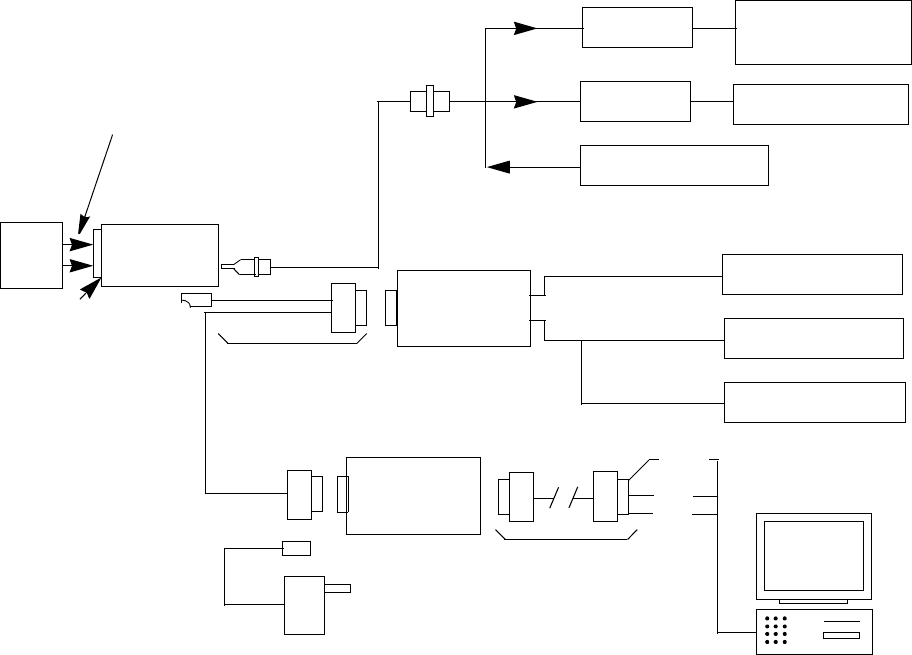
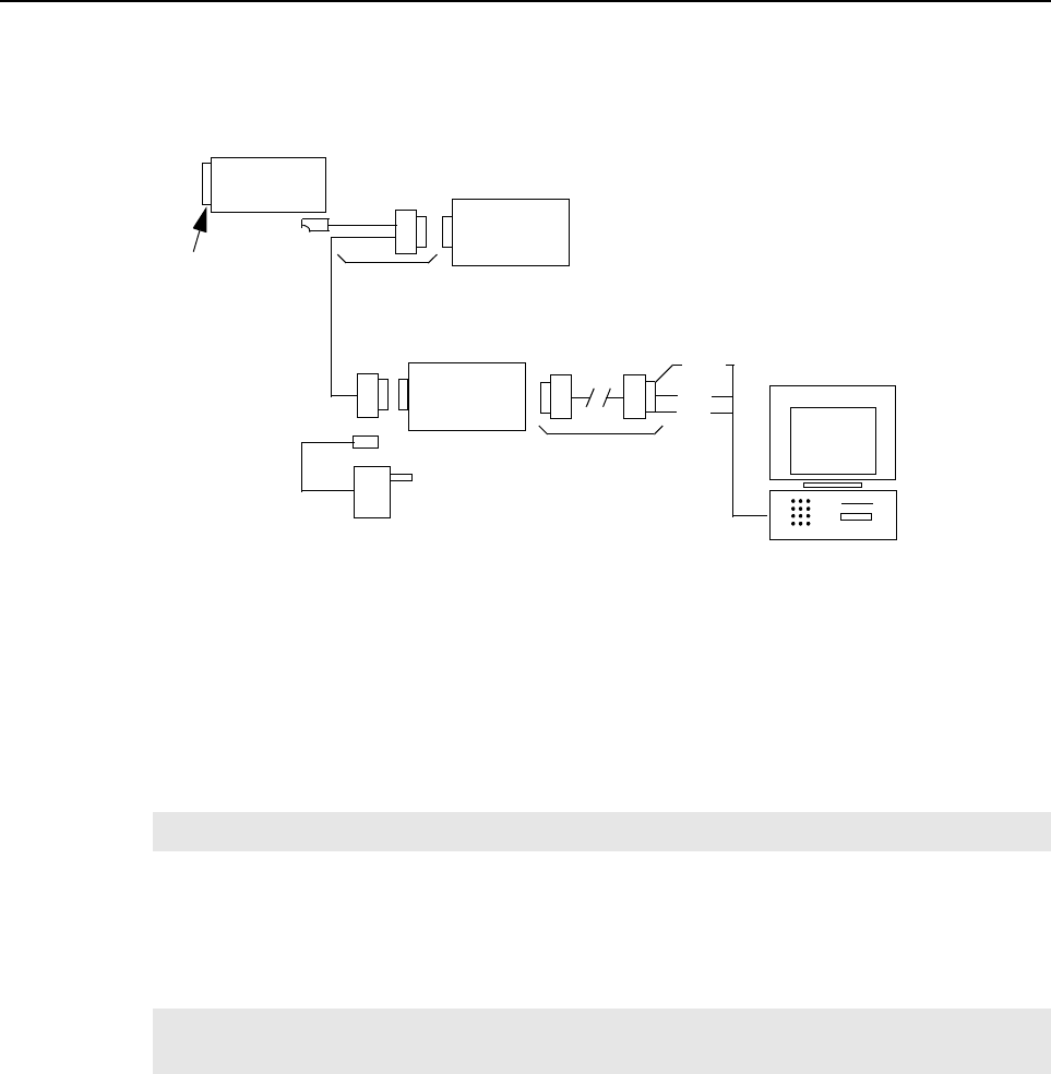
2.0 CPS Programming/Flashing Setup with RIB
A Windows 98/NT4/2000/ME/XP PC (personal computer) and Global Tuner are required to tune the
radio. To perform the tuning procedures, the radio must be connected to the PC, RIB (Radio Interface
Box) and Universal Test Set as shown in Figure 4-1, Radio Tuning Setup, below. Refer to online help
files for the tuning procedures.
Figure 4-1. Radio Tuning Setup
Service Monitor or
Counter
Wattmeter
Audio Generator
Sinad Meter
AC Voltmeter
30 dB Pad
30 dB Pad
Battery
Eliminator
Power
Supply Audio In Tx
Rx
Receive
Transmit
RF Generator
BNC
RF Adaptor
5886564Z01
RIB
RLN4008
RIB Power Supply
RLN4460
Te s t B o x
Rx
Gnd
Data
Tx Data
Radio
Computer Interface
Cable
Program/Test Cable
PMKN4004
RLN4510
Power Cable
4-2 RADIO TUNING AND PROGRAMMING
3.0 CPS Programming Setup
Refer to online help files for the CPS Programming procedures.
4.0 Radio to Radio Cloning
Cloning is the process of copying the content of one radio (source radio) into another radio
(destination radio). Radio content refers to system-type features such as frequency, squelch type
options, trunking, etc.
Radio functionality inherent in one radio cannot be cloned to another radio that does not contain the
same functionality. Tuning and alignment information are not transferable and are not affected by
cloning.
Signaling Identification Numbers (IDs) are duplicated in the cloning process. Unique IDs may be
assigned with the CPS.
Procedure:
1. Turn source and target radios off.
2. Connect cloning cable (PMKN4003) to the side connector of both radios.
3. Turn on the destination radio.
4. Press and hold the two side buttons at the same time on the source radio and then power up the
source radio (Figure 4-3 Side Button Locations). Both radios produce a “clone-entry” tone.
5. Release both side buttons.
6. When cloning is completed, the source radio produce’s a “clone-exit” tone and both the source
and destination radios reset.
7. Turn both radios off.
8. Disconnect the cloning cable from both radios and turn them on for normal operation.
Figure 4-2 CPS Programming Setup
NOTE The source radio’s serial number cannot be blank.
NOTE Unsuccessful cloning attempts generates a continuous tone and may be an indication that
the destination radio’s codeplug is corrupted.
RIB
RLN4008
RIB Power Supply
RLN4460
Test Box
Rx
Gnd
Data
Tx Data
Radio
Battery
Computer Interface
Cable
Program/
PMKN4004
Test Cable
Radio to Radio Cloning 4-3
Figure 4-3 Side Button Locations
Side Button 1
Side Button 2

4-4 RADIO TUNING AND PROGRAMMING
Chapter 5
POWER UP SELF-TEST
1.0 Self-Test Routine
Turning on the radio using the on/off volume control starts a self-test routine which checks the RAM,
EEPROM hardware and EEPROM checksum. Pressing and holding SB1 while turning on the radio
causes the self-test routine to check for the ROM checksum as well. If these checks are successfully
completed, the radio will generate the Self-Test Pass Tone. If the self-test is not successful, a
Self-Test Fail Tone is heard.

5-2 POWER UP SELF-TEST

Chapter 6
ACCESSORIES
1.0 Accessories
To order, refer to Chapter 1 (paragraph 2.4 - ‘Piece Parts’) of this manual.
1.1 Antennas
1.2 Audio Accessories
HAD9338AR VHF Heliflex Antenna 16cm (136-162 MHz)
NAD6502 VHF Heliflex Antenna 15cm (146-174 MHz)
HAD9742 VHF Stubby Antenna, 9cm (146-162 MHz)
HAD9743 VHF Stubby Antenna, 7.5cm (162-174 MHz)
NAE6522 UHF Heliflex Stubby Antenna 7.5cm (438-470 MHz)
8505816K26 UHF Heliflex Stubby 6.5cm (470-520 MHz)
NAE6483 Flexible Whip Antenna 17cm (403-520 MHz)
HMN9752 Earpiece with Volume Control, 1-Wire (plastic earloop) (Beige)
HMN9727 Earpiece without Volume Control, 1-Wire (plastic earloop) (Beige)
RLN4894 Earpiece without Volume Control, 1-Wire (plastic earloop) (Black)
HMN9754 Earpiece with Microphone & PTT Combined, 2-Wire (Beige)
RLN4895 Earpiece with Microphone & PTT Combined, 2-Wire (Black)
HMN9036 Earbud with Microphone & PTT Combined, 2-Wire (Black)
HLN9132 Earbud Single Wire Receive Only (Black)
NTN8370 Extreme Noise Kit
NTN8371 Low Noise Kit
RLN4760 Small Custom Clear Earpiece, Right Ear
RLN4763 Small Custom Clear Earpiece, Left Ear
RLN4761 Medium Custom Clear Earpiece, Right Ear
RLN4764 Medium Custom Clear Earpiece, Left Ear
RLN4762 Large Custom Clear Earpiece, Right Ear
RLN4765 Large Custom Clear Earpiece, Left Ear
BDN6646 Std 95dB Ear Microphone with PTT Interface Module
BDN6706 Std 95dB Ear Microphone with VOX and PTT Interface Module
0180358B38 Ring PTT Switch for Ear Mic Systems
6-2 ACCESSORIES
1.3 Headsets
1.4 Remote Speaker Microphones
0180300E83 Body PTT Switch for Ear Mic Systems
0180358B33 Medium Earholder for Ear Mic Systems
MDPMLN4442 Earbud with Microphone and PTT Combined
MDPMLN4443 Flexible Ear Receiver with Microphone and PTT Combined
PMMN4001 Ultra-Lite Earset with Mic and PTT
PMLN4445 Ultra-light Headset with Boom Microphone
RLN5238 Lightweight Headset with In-line PTT, NFL Style
HMN9021 Medium Weight Over the Head Dual Muff Headset
HMN9022 Medium Weight Behind the Head Dual Muff Headset
BDN6647 Medium Weight Single Speaker Headset
BDN6648 Heavy Duty Dual Muff Headset with Noise Canceling Microphone
5080371E66 Replacement Ear Pad for BDN6647
RMN5015 Heavy Duty Dual Muff Racing Headset
(requires RKN4090 Headset Adapter Cable)
REX4648 Ear Pad and Windscreen Kit
RKN4090 Adapter Cable for use with RMN5015
RMN4051 2-way Hard Hat Mount (Black) Noise Reduction 22dB
RMN4054 Receive Only Hard Hat Mount Headset with 3.5mm right angle plug
RMN4055 Receive Only Headband Style Headset
HLN9133 VOX Adapter Kit for (Receive Headsets only)
RKN4094 GP300 inline PTT Adapter
(for use with RMN4051, RMN4052, RMN4053 only)
HMN9030 Remote Speaker Microphone
PMMN4008 Remote Speaker Microphone
Accessories 6-3
1.5 Chargers
1.6 Batteries
1.7 Carrying Accessories
MDWPLN4139 Desktop Rapid Charger 230V with Euro Plug
MDWPLN4162 Rapid Multi Unit Charger 230V with Euro Plug
MDWPLN4140 Desktop Rapid Charger 230V with UK Plug
MDWPLN4163 Rapid Multi Unit Charger 230V with UK Plug
MDWPLN4137 Desktop Rapid Charger (Base Only)
EPNN7990 Power Supply for Desktop Rapid Charger (Base Only) (UK)
EPNN7991 Power Supply for Desktop Rapid Charger (Base Only) (Euro)
NNTN4497 Li-lon, High Capacity
NNTN4970 Slim Li-Ion
NNTN4851 NiMH
RLN5383 Hard Leather Case with Belt Loop and D-Shaped Rings
RLN5384 Hard Leather Case with High Activity 2-1/2 inch Swivel Belt Loop
RLN5385 Hard Leather Case with High Activity 3 inch Swivel Belt Loop
HLN9701 Nylon Carry Case with Belt Loop and D-Shaped Rings
HLN8255 3 inch Spring Action Belt Clip
HLN6602 Universal Chest Pack
1505596Z02 Replacement Strap for HLN6602 Universal Chest Pack
RLN4815 Universal RadioPak
4280384F89 Replacement Belt Lengthener for RLN4815 Universal RadioPak
NTN5243 Shoulder Strap for Hard Leather Cases
(attaches to D-Shaped Rings on case)
HLN9985 Waterproof Bag

6-4 ACCESSORIES
Chapter 7
MODEL CHART AND SPECIFICATION
1.0 VHF1 136-162 MHz
CP040 VHF1 136-162 MHz
Model Description
MDH50JDC9AA1_N CP040 136-162 MHz 5W 4-Ch
MDH50JDC9AA2_N CP040 136-162 MHz 5W 16-Ch
Item Description
X PMUD1981_ CP040 136-162 MHz 5W 4-Ch Tanapa
X PMUD1982_ CP040 136-162 MHz 5W 16-Ch Tanapa
XPMLD4239_ CP040, Back Cover Kit 136-162 MHz 4-Ch
X PMLD4240_ CP040, Back Cover Kit 136-162 MHz 16-Ch
X PMLN4552_ Plain, Front Housing Kit, 4-Ch
X PMLN4553_ Plain, Front Housing Kit, 16-Ch
XX NTN4497_R Li-Ion Battery, High Capacity
XXWPLN4166 Rapid Desktop Charger (Base Only)
XX EPNN7990_ Power Supply for Rapid Desktop Charger (UK)
XXEPNN7991_ Power Supply for Rapid Desktop Charger (Euro)
XX HLN8255 Belt Clip
XXHAD9338AR Antenna, 136-162 MHz, Heliflex
XX6866549D01_ CP040 Basic User Guide
XX6864117B25_ Safety Leaflet
XX6866546D03_ RTTE Leaflet
X = Indicates one of each is required
7-2 VHF1 136-162 MHz Specifications
2.0 VHF1 136-162 MHz
Specifications
General
Transmitter
Receiver
All specifications are subject to change without notice.
Self-Quieter Frequencies
VHF
Frequency: 136-162 MHz
Channel Capacity: 4 or 16 Channels
Power Supply: 7.5 Volts ±20%
Dimensions:
with High Capacity
Li-Ion Battery and
with Standard
NiMH Battery:
with Slim Li-Ion Battery:
128.7mm H x 61.7mm W
x 44.1mm D
128.7mm H x 61.7mm W
x 41.3mm D
Weight:
with Slim Li-Ion Battery
with High Capacity
Li-Ion Battery:
with Standard
NiMH Battery:
365g
420g
480g
Average Battery Life @
(5-5-90 Duty
Cycle):
with Slim
Li-Ion Battery:
with High Capacity
Li-Ion Battery:
with Standard
NiMH Battery:
1 W
17Hrs.
19 Hrs.
13 Hrs.
5 W
12 Hrs.
14 Hrs
10 Hrs
VHF
RF Output
NiMH @ 7.5V:
Low
1 W
High
5W
Frequency: 136-162 MHz
Channel Spacing: 12.5/20/25 kHz
Freq. Stability:
(-30°C to +60°C)
0.00025%
Spurs/Harmonics: -36 dBm < 1 GHz
-30 dBm > 1 GHz
Audio Response:
(from 6 dB/oct. Pre-
emphasis, 300 to
3000Hz)
+1, -3 dB
Audio Distortion:
@ 1000 Hz, 60%
Rated Max. Dev.
<3%
FM Noise: -40 dB (12.5 kHz)
-45 dB (25 kHz)
VHF
12.5 kHz VHF
20/25kHz
Frequency: 136-162 MHz
Sensitivity
12dB EIA SINAD:
0.25 µV (typical)
Adjacent Channel
Selectivity:
-65 dB -70 dB
Intermodulation: - 70dB
Freq. Stability
(-30°C to +60°C):
0.00025%
Spur Rejection: -75 dB
Image and 1/2 I-F
Rejection:
-70 dB
Audio Output
@ <5% Distortion:
500 mW
VHF
151.200
VHF

VHF2 146-174 MHz 7-3
3.0 VHF2 146-174 MHz
CP040 VHF2 146-174 MHz
Model Description
MDH50KDC9AA1_N CP040 146-174 MHz 5W 4-Ch
MDH50KDC9AA2_N CP040 146-174 MHz 5W 16-Ch
Item Description
X PMUD1820_ CP040 146-174 MHz 5W 4-Ch Tanapa
X PMUD1822_ CP040 146-174 MHz 5W 16-Ch Tanapa
XPMLD4204_ CP040, Back Cover Kit 146-174 MHz 4-Ch
X PMLD4205_ CP040, Back Cover Kit 146-174 MHz 16-Ch
X PMLN4552_ Plain, Front Housing Kit, 4-Ch
X PMLN4553_ Plain, Front Housing Kit, 16-Ch
XX NTN4497_R Li-Ion Battery, High Capacity
XXWPLN4166 Rapid Desktop Charger (Base Only)
XX EPNN7990_ Power Supply for Rapid Desktop Charger (UK)
XXEPNN7991_ Power Supply for Rapid Desktop Charger (Euro)
XX HLN8255 Belt Clip
XXNAD6502_ Antenna, 146-174 MHz, 15cm
XX6866549D01_ CP040 Basic User Guide
XX6864117B25_ Safety Leaflet
XX6866546D03_ RTTE Leaflet
X = Indicates one of each is required
7-4 VHF2 146-174 MHz Specifications
4.0 VHF2 146-174 MHz
Specifications
General
Transmitter
Receiver
All specifications are subject to change without notice.
Self-Quieter Frequencies
VHF
Frequency: 146-174 MHz
Channel Capacity: 4 or 16 Channels
Power Supply: 7.5 Volts ±20%
Dimensions:
with High Capacity
Li-Ion Battery and
with Standard
NiMH Battery:
with Slim Li-Ion Battery:
128.7mm H x 61.7mm W
x 44.1mm D
128.7mm H x 61.7mm W
x 41.3mm D
Weight:
with Slim Li-Ion Battery
with High Capacity
Li-Ion Battery:
with Standard
NiMH Battery:
365g
420g
480g
Average Battery Life @
(5-5-90 Duty
Cycle):
with Slim
Li-Ion Battery:
with High Capacity
Li-Ion Battery:
with Standard
NiMH Battery:
1 W
17Hrs.
19 Hrs.
13 Hrs.
5 W
12 Hrs.
14 Hrs
10 Hrs
VHF
RF Output
NiMH @ 7.5V:
Low
1 W
High
5W
Frequency: 146-174 MHz
Channel Spacing: 12.5/20/25 kHz
Freq. Stability:
(-30°C to +60°C)
0.00025%
Spurs/Harmonics: -36 dBm < 1 GHz
-30 dBm > 1 GHz
Audio Response:
(from 6 dB/oct. Pre-
emphasis, 300 to
3000Hz)
+1, -3 dB
Audio Distortion:
@ 1000 Hz, 60%
Rated Max. Dev.
<3%
FM Noise: -40 dB (12.5 kHz)
-45 dB (25 kHz)
VHF
12.5 kHz VHF
20/25kHz
Frequency: 146-174 MHz
Sensitivity
12dB EIA SINAD:
0.25 µV (typical)
Adjacent Channel
Selectivity:
-65 dB -70 dB
Intermodulation: - 70dB
Freq. Stability
(-30°C to +60°C):
0.00025%
Spur Rejection: -75 dB
Image and 1/2 I-F
Rejection:
-70 dB
Audio Output
@ <5% Distortion:
500 mW
VHF
151.19375
151.200
151.20625
167.99375
168.000
168.00625
VHF
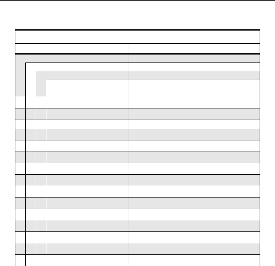
UHF1 403-440 MHz 7-5
5.0 UHF1 403-440 MHz
CP040 UHF1 403-440 MHz
Model Description
MDH50QDC9AA1_N CP040 403-440 MHz 4W 4-Ch
MDH50QDC9AA2_N CP040 403-440 MHz 4W 16-Ch
Item Description
X PMUE1984_ CP040 403-440 MHz 4W 4-Ch Tanapa
X PMUE1985_ CP040 403-440 MHz 4W 16-Ch Tanapa
XPMLE4297_ CP040, Back Cover Kit 403-440 MHz 4-Ch
X PMLE4298_ CP040, Back Cover Kit 403-440 MHz 16-Ch
X PMLN4552_ Plain, Front Housing Kit, 4-Ch
X PMLN4553_ Plain, Front Housing Kit, 16-Ch
XX NTN4497_R Li-Ion Battery, High Capacity
XXWPLN4166 Rapid Desktop Charger (Base Only)
XX EPNN7990_ Power Supply for Rapid Desktop Charger (UK)
XXEPNN7991_ Power Supply for Rapid Desktop Charger (Euro)
XX HLN8255 Belt Clip
XX 8505816K24_ Antenna, 400-440 MHz, Heliflex Stubby
XX6866549D01_ CP040 Basic User Guide
XX6864117B25_ Safety Leaflet
XX6866546D03_ RTTE Leaflet
X = Indicates one of each is required
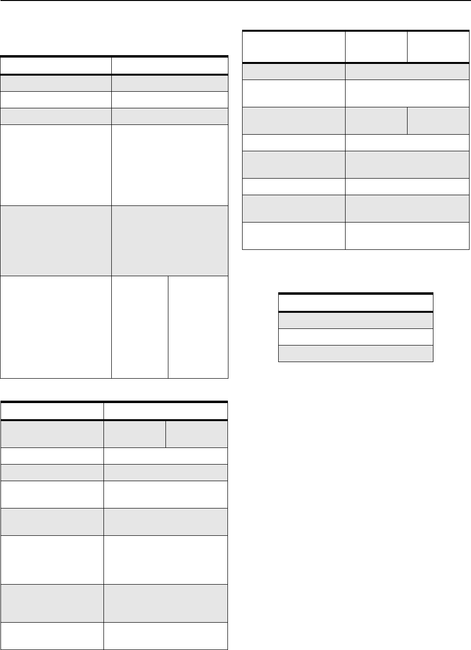
7-6 UHF1 403-440 MHz Specifications
6.0 UHF1 403-440 MHz Specifications
General
Transmitter
Receiver
All specifications are subject to change without notice.
Self-Quieter Frequencies
UHF1
Frequency: 403-440 MHz
Channel Capacity: 4 or 16 Channels
Power Supply: 7.5 Volts ±20%
Dimensions:
with High Capacity
Li-Ion Battery and
with Standard
NiMH Battery:
with Slim Li-Ion Battery:
128.7mm H x 61.7mm W
x 44.1mm D
128.7mm H x 61.7mm W
x 41.3mm D
Weight:
with Slim Li-Ion Battery
with High Capacity
Li-Ion Battery:
with Standard
NiMH Battery:
365g
420g
480g
Average Battery Life @
(5-5-90 Duty
Cycle):
with Slim
Li-Ion Battery:
with High Capacity
Li-Ion Battery:
with Standard
NiMH Battery:
1 W
17Hrs.
19 Hrs.
13 Hrs.
4 W
12 Hrs.
14 Hrs
10 Hrs
UHF1
RF Output
NiMH @ 7.5V:
Low
1 W
High
4W
Frequency: 403-440 MHz
Channel Spacing: 12.5/20/25 kHz
Freq. Stability:
(-30°C to +60°C)
0.00025%
Spurs/Harmonics: -36 dBm < 1 GHz
-30 dBm > 1 GHz
Audio Response:
(from 6 dB/oct. Pre-
emphasis, 300 to
3000Hz)
+1, -3 dB
Audio Distortion:
@ 1000 Hz, 60%
Rated Max. Dev.
<3%
FM Noise: -40 dB (12.5 kHz)
-45 dB (25 kHz)
UHF1
12.5 kHz UHF1
20/25kHz
Frequency: 403-440 MHz
Sensitivity
12dB EIA SINAD:
0.25 µV (typical)
Adjacent Channel
Selectivity:
-60 dB -70 dB
Intermodulation: -70 dB
Freq. Stability
(-30°C to +60°C):
0.00025%
Spur Rejection: -75 dB
Image and 1/2 I-F
Rejection:
-70 dB
Audio Output
@ <5% Distortion:
500 mW
UHF1
419.993750
420.000000
420.006250 (420+/- 6.25kHz)

UHF2 438-470 MHz 7-7
7.0 UHF2 438-470 MHz
CP040 UHF2 438-470 MHz
Model Description
MDH50RDC9AA1_N CP040 438-470 MHz 4W 4-Ch
MDH50RDC9AA2_N CP040 438-470 MHz 4W 16-Ch
Item Description
X PMUE1949_ CP040 438-470 MHz 4W 4-Ch Tanapa
XPMUE1951_ CP040 438-470 MHz 4W 16-Ch Tanapa
XPMLE4255_ CP040, Back Cover Kit 438-470 MHz 4-Ch
X PMLE4254_ CP040, Back Cover Kit 438-470 MHz 16-Ch
X PMLN4552_ Plain, Front Housing Kit, 4-Ch
X PMLN4553_ Plain, Front Housing Kit, 16-Ch
XX NTN4497_R Li-Ion Battery, High Capacity
XXWPLN4166 Rapid Desktop Charger (Base Only)
XX EPNN7990_ Power Supply for Rapid Desktop Charger (UK)
XXEPNN7991_ Power Supply for Rapid Desktop Charger (Euro)
XX HLN8255 Belt Clip
XX NAE6522_ Antenna, 438-470 MHz, 7.5cm
XX6866549D01_ CP040 Basic User Guide
XX6864117B25_ Safety Leaflet
XX6866546D03_ RTTE Leaflet
X = Indicates one of each is required
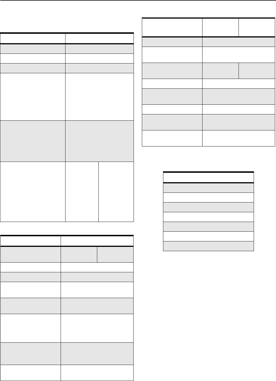
7-8 UHF2 438-470 MHz Specifications
8.0 UHF2 438-470 MHz Specifications
General
Transmitter
Receiver
All specifications are subject to change without notice.
Self-Quieter Frequencies
UHF2
Frequency: 438-470 MHz
Channel Capacity: 4 or 16 Channels
Power Supply: 7.5 Volts ±20%
Dimensions:
with High Capacity
Li-Ion Battery and
with Standard
NiMH Battery:
with Slim Li-Ion Battery:
128.7mm H x 61.7mm W
x 44.1mm D
128.7mm H x 61.7mm W
x 41.3mm D
Weight:
with Slim Li-Ion Battery
with High Capacity
Li-Ion Battery:
with Standard
NiMH Battery:
365g
420g
480g
Average Battery Life @
(5-5-90 Duty
Cycle):
with Slim
Li-Ion Battery:
with High Capacity
Li-Ion Battery:
with Standard
NiMH Battery:
1 W
17Hrs.
19 Hrs.
13 Hrs.
4 W
12 Hrs.
14 Hrs
10 Hrs
UHF2
RF Output
NiMH @ 7.5V:
Low
1 W
High
4W
Frequency: 438-470 MHz
Channel Spacing: 12.5/20/25 kHz
Freq. Stability:
(-30°C to +60°C)
0.00025%
Spurs/Harmonics: -36 dBm < 1 GHz
-30 dBm > 1 GHz
Audio Response:
(from 6 dB/oct. Pre-
emphasis, 300 to
3000Hz)
+1, -3 dB
Audio Distortion:
@ 1000 Hz, 60%
Rated Max. Dev.
<3%
FM Noise: -40 dB (12.5 kHz)
-45 dB (25 kHz)
UHF2
12.5 kHz UHF2
20/25kHz
Frequency: 438-470 MHz
Sensitivity
12dB EIA SINAD:
0.25 µV (typical)
Adjacent Channel
Selectivity:
-60 dB -70 dB
Intermodulation: -70 dB
Freq. Stability
(-30°C to +60°C):
0.00025%
Spur Rejection: -75 dB
Image and 1/2 I-F
Rejection:
-70 dB
Audio Output
@ <5% Distortion:
500 mW
UHF2
443.93125
443.9375
443.94375
443.950
443.95625
443.9625
443.96875

UHF3 465-495 MHz 7-9
9.0 UHF3 465-495 MHz
CP040 UHF3 465-495 MHz
Model Description
MDH50SDC9AA1_N CP040 465-495 MHz 4W 4-Ch
MDH50SDC9AA2_N CP040 465-495 MHz 4W 16-Ch
Item Description
X PMUE1986_ CP040 465-495 MHz 4W 4-Ch Tanapa
X PMUE1987_ CP040 465-495 MHz 4W 16-Ch Tanapa
XPMLE4299_ CP040, Back Cover Kit 465-495 MHz 4-Ch
X PMLE4300_ CP040, Back Cover Kit 465-495 MHz 16-Ch
X PMLN4552_ Plain, Front Housing Kit, 4-Ch
X PMLN4553_ Plain, Front Housing Kit, 16-Ch
XX NTN4497_R Li-Ion Battery, High Capacity
XXWPLN4166 Rapid Desktop Charger (Base Only)
XX EPNN7990_ Power Supply for Rapid Desktop Charger (UK)
XXEPNN7991_ Power Supply for Rapid Desktop Charger (Euro)
XX HLN8255 Belt Clip
XX NAE6483_ Antenna, 403-520 MHz, Flexible Whip
XX6866549D01_ CP040 Basic User Guide
XX6864117B25_ Safety Leaflet
XX6866546D03_ RTTE Leaflet
X = Indicates one of each is required
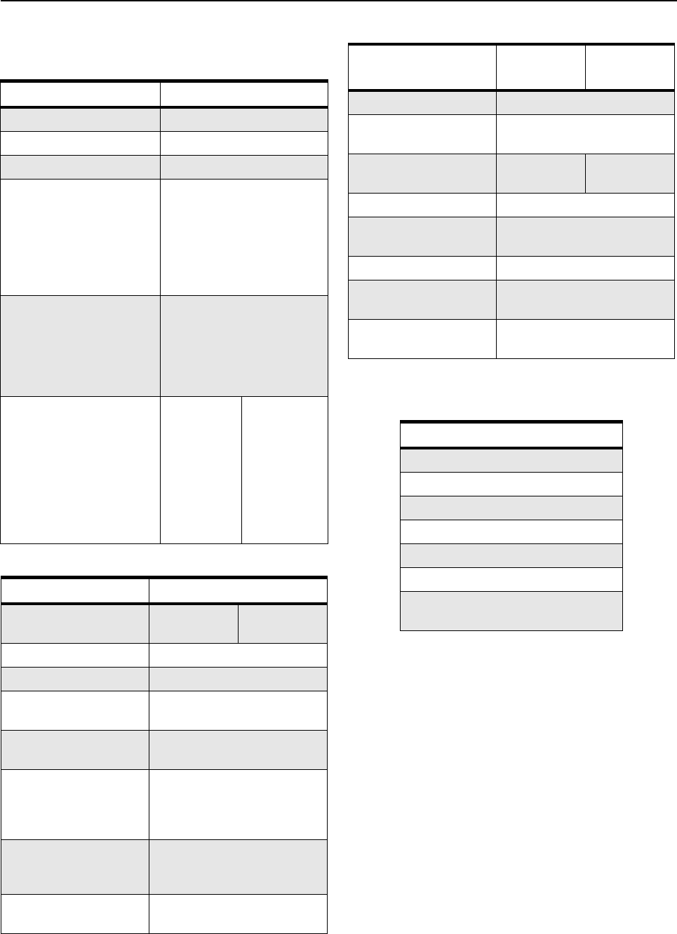
7-10 UHF3 465-495 MHz Specifications
10.0 UHF3 465-495 MHz Specifications
General
Transmitter
Receiver
All specifications are subject to change without notice.
Self-Quieter Frequencies
UHF3
Frequency: 465-495 MHz
Channel Capacity: 4 or 16 Channels
Power Supply: 7.5 Volts ±20%
Dimensions:
with High Capacity
Li-Ion Battery and
with Standard
NiMH Battery:
with Slim Li-Ion Battery:
128.7mm H x 61.7mm W
x 44.1mm D
128.7mm H x 61.7mm W
x 41.3mm D
Weight:
with Slim Li-Ion Battery
with High Capacity
Li-Ion Battery:
with Standard
NiMH Battery:
365g
420g
480g
Average Battery Life @
(5-5-90 Duty
Cycle):
with Slim
Li-Ion Battery:
with High Capacity
Li-Ion Battery:
with Standard
NiMH Battery:
1 W
17Hrs.
19 Hrs.
13 Hrs.
4 W
12 Hrs.
14 Hrs
10 Hrs
UHF3
RF Output
NiMH @ 7.5V:
Low
1 W
High
4W
Frequency: 465-495 MHz
Channel Spacing: 12.5/20/25 kHz
Freq. Stability:
(-30°C to +60°C)
0.00025%
Spurs/Harmonics: -36 dBm < 1 GHz
-30 dBm > 1 GHz
Audio Response:
(from 6 dB/oct. Pre-
emphasis, 300 to
3000Hz)
+1, -3 dB
Audio Distortion:
@ 1000 Hz, 60%
Rated Max. Dev.
<3%
FM Noise: -40 dB (12.5 kHz)
-45 dB (25 kHz)
UHF3
12.5 kHz UHF3
20/25kHz
Frequency: 465-495 MHz
Sensitivity
12dB EIA SINAD:
0.25 µV (typical)
Adjacent Channel
Selectivity:
-60 dB -70 dB
Intermodulation: -70 dB
Freq. Stability
(-30°C to +60°C):
0.00025%
Spur Rejection: -75 dB
Image and 1/2 I-F
Rejection:
-70 dB
Audio Output
@ <5% Distortion:
500 mW
UHF3
488.326250
488.332500
488.338750
488.345000
488.351250
488.357500
488.363750
(488.345MHz +/- 18.75kHz)
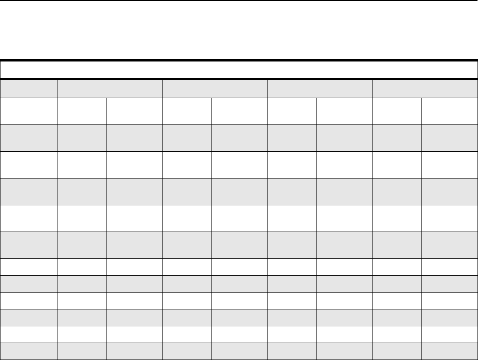
MIL Standards 7-11
11.0 MIL Standards
MIL STDS 810 C, D, E, and F: Applicable to UHF and VHF Specifications (8.2 and 8.4)
Military Standards 810 C, D, E, & F: Parameters/Methods/Procedures
810C 810D 810E 810F
Applicable
MIL-STD Methods Procedures Methods Procedures Methods Procedures Methods Procedures
Low
Pressure
500.1 1 500.2 2 500.3 2 500.4 1
High Tem-
perature
501.1 1,2 501.2 1,2 501.3 1,2 501.4 1,2
Low
Temperature
502.1 1 502.2 1,2 502.3 1,2 501.4 1,2
Tempera-
ture Shock
503.1 1 503.2 1 503.3 1 503.4 1
Solar Radia-
tion
505.1 1 505.2 1 505.3 1 505.4 1
Rain 506.1 1,2 506.2 1,2 506.3 1,2 506.4 1
Humidity 507.1 2 507.2 2,3 507.3 2,3 507.4 3
Salt Fog 509.1 1 509.2 1 509.3 1 509.4 1
Dust 510.1 1 510.2 1 510.3 1 510.4 1
Vibration 514.2 8,10 514.3 1 514.4 1 514.5 1
Shock 516.2 1,2,5 516.3 1,4 516.4 1,4 516.5 1

7-12 MODEL CHART AND SPECIFICATION

Glossary 1
GLOSSARY
Glossary of Terms
Term Definition
ALC Automatic Level Control: a circuit in the transmit RF path that controls RF pow-
er amplifier output, provides leveling over frequency and voltage, and protects
against high VSWR (voltage standing wave ratio).
ASFIC Audio Signalling Filter Integrated Circuit
BKC Bad Key Chirp
CD Compact Disk
CMP Compression
CPS Customer Programming Software
CSQ Carrier Squelch
DTMF Dual-Tone Multifrequency
DPL Digital Private-Line™
EEPROM Electronically Erasable/Programmable Read-Only Memory: used by the radio
to store its personality
Firmware Software, or a software/hardware combination of computer programs and da-
ta, with a fixed logic configuration stores in a read-only memory. Information
cannot be altered or reprogrammed.
FGU Frequency Generation Unit
GaAs Gallium Arsenide: a type of crystalline material used in some semiconductors.
GKC Good Key Chirp
ISW Inbound Signalling Word: data transmitted on the control channel from a sub-
scriber unit to the central control unit.
LH DATA Longhorn Data: a bidirectional 0-5V, RS-232 line protocol that uses the micro-
controller’s integrated RS-232 asynchronous serial communications interface
(SCI) peripheral.
LLE Low Level Expander: slight amount of volume expansion; used to improve the
signal to noise ratio.
MCU Micro Controller Unit
MRTI Motorola Radio-Telephone Interconnect: a system that provides a repeater
connection to the Public Switched Telephone Network (PSTN). The MRTI al-
lows the radio to access the telephone network when the proper access code
is received.

2Glossary
OMPAC Over-Molded Pad-Array Carrier: a Motorola custom package, distinguished by
the presence of solder balls on the bottom pads.
PC Board Printed Circuit Board
PL Private-Line® tone squelch: a continuous sub-audible tone that is transmitted
along with the carrier.
PLL Phase-Locked Loop: a circuit in which an oscillator is kept in phase with a ref-
erence, usually after passing through a frequency divider.
PTT Push-To-Talk: the switch located on the left side of the radio; when pressed,
causes the radio to transmit.
RAM Random Access Memory: the radio’s RAM is loaded with a copy of the EE-
PROM data.
Registers Short-term data-storage circuits within the microcontroller.
RESET Reset line: an input to the microcontroller that restarts execution.
RF PA Radio Frequency Power Amplifier
RIB Radio Interface Box
ROM Read Only Memory
RSSI Received Signal-Strength Indicator: a dc voltage proportional to the received
RF signal strength.
RPT/TA Repeater/Talk-Around
Softpot A computer-adjustable electronic attenuator
Software Computer programs, procedures, rules, documentation, and data pertaining to
the operation of a system.
SPI (clock and data
lines)
Serial Peripheral Interface: how the microcontroller communicates to modules
and ICs through the CLOCK and DATA lines.
Squelch Muting of audio circuits when received signal levels fall below a pre-deter-
mined value.
Standby Mode An operating mode whereby the radio is muted but still continues to receive
data
TOT Time-Out Timer: a timer that limits the length of a transmission.
TPL Tone Private-line
µC Microcontroller
UHF Ultra High Frequency
Glossary 3
µP Microprocessor
VCO Voltage-Controlled Oscillator: an oscillator whereby the frequency of oscillation
can be varied by changing a control voltage.
VCOBIC Voltage-Controlled Oscillator Buffer Integrated Circuit
VHF Very High Frequency
VSWR Voltage Standing Wave Ratio

4Glossary
